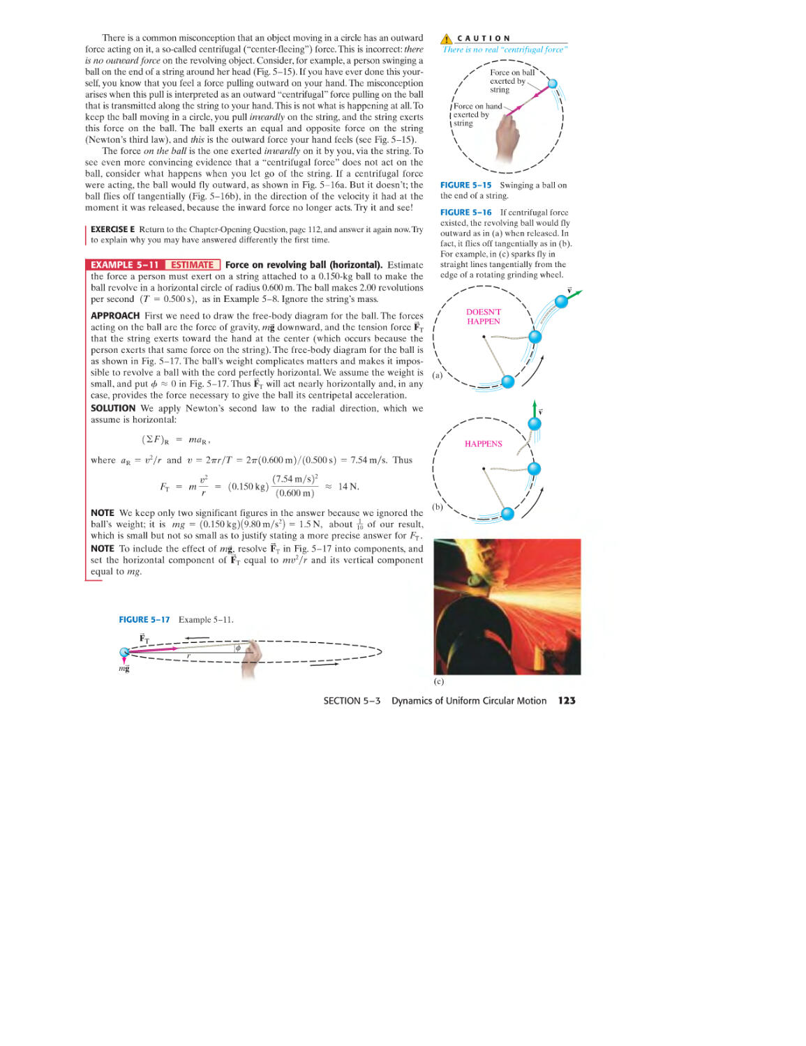
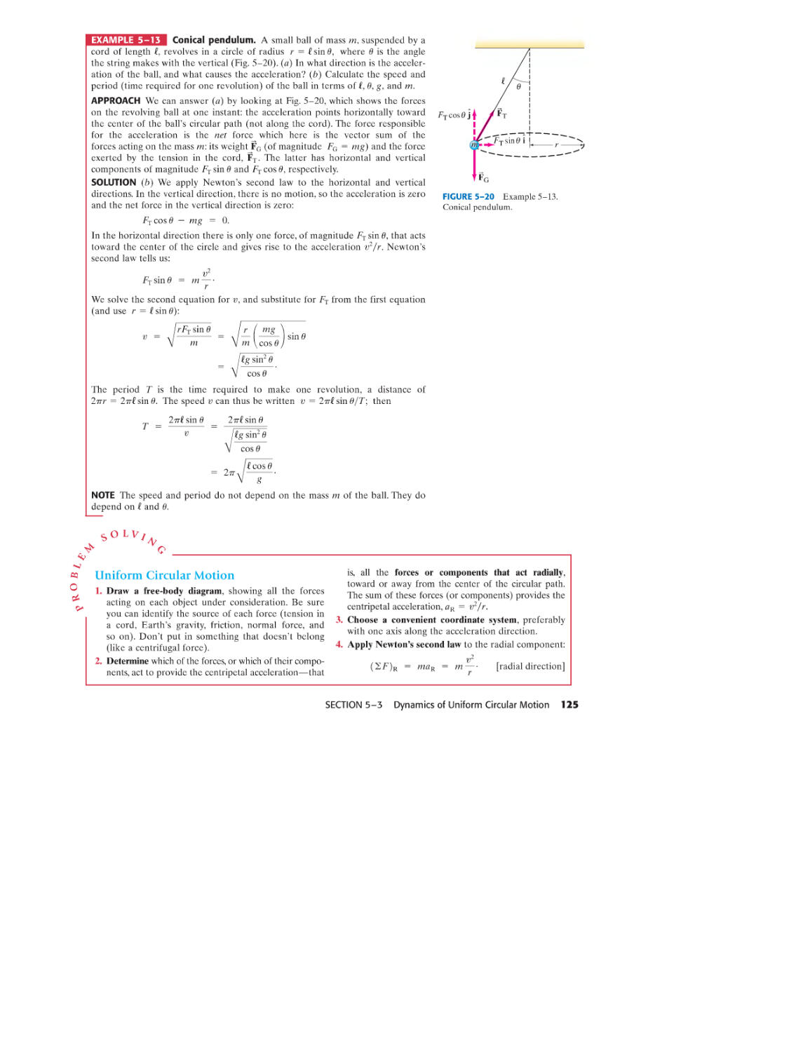
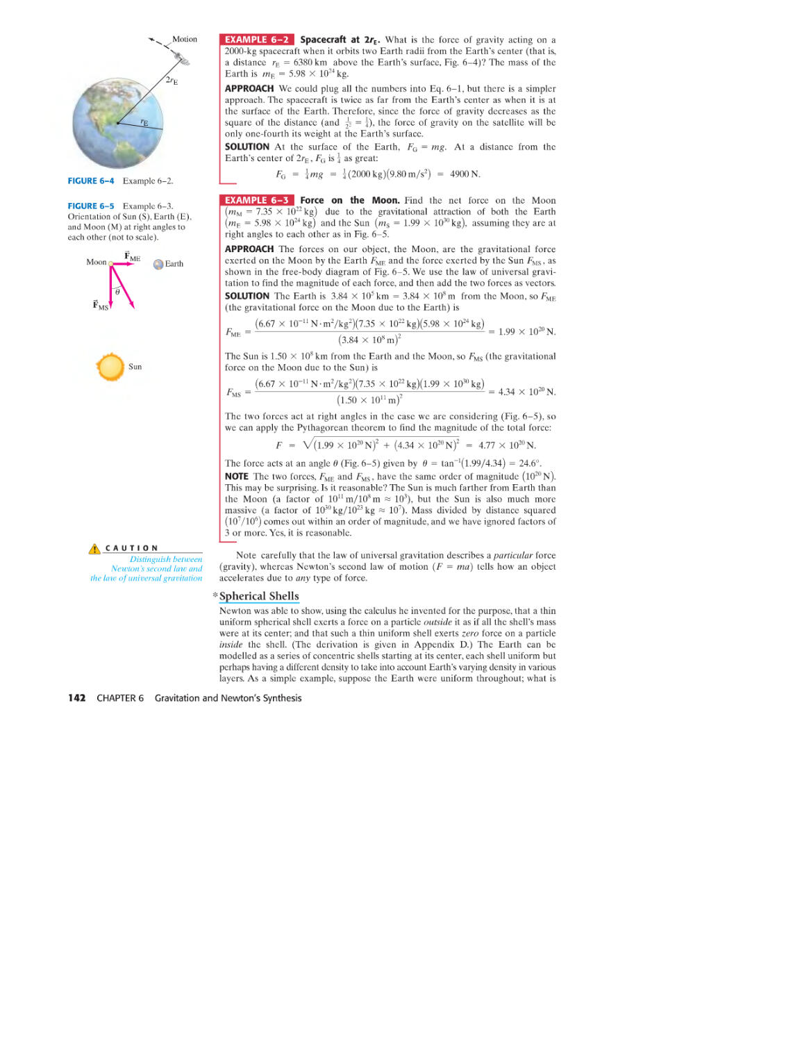
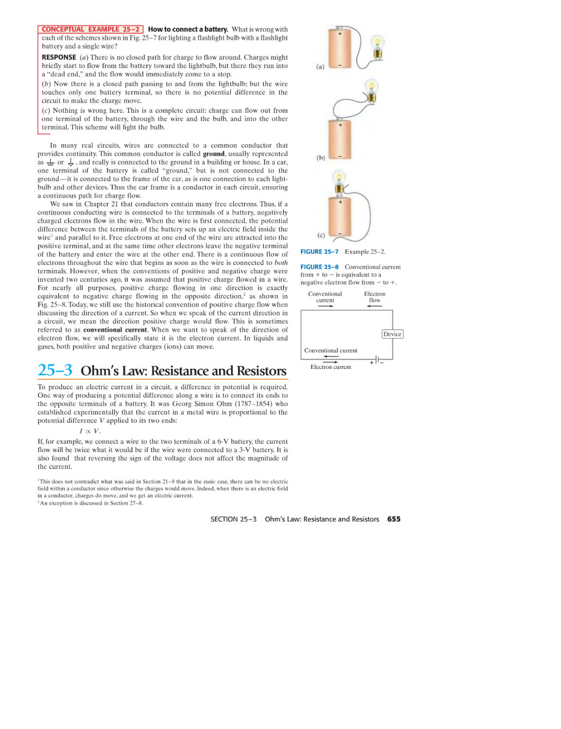
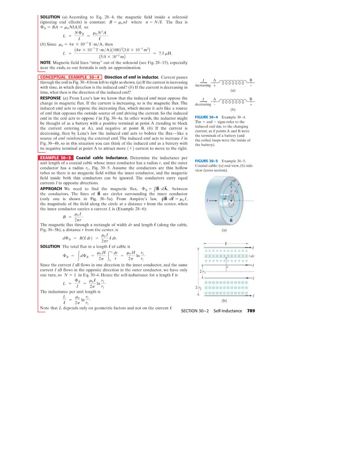
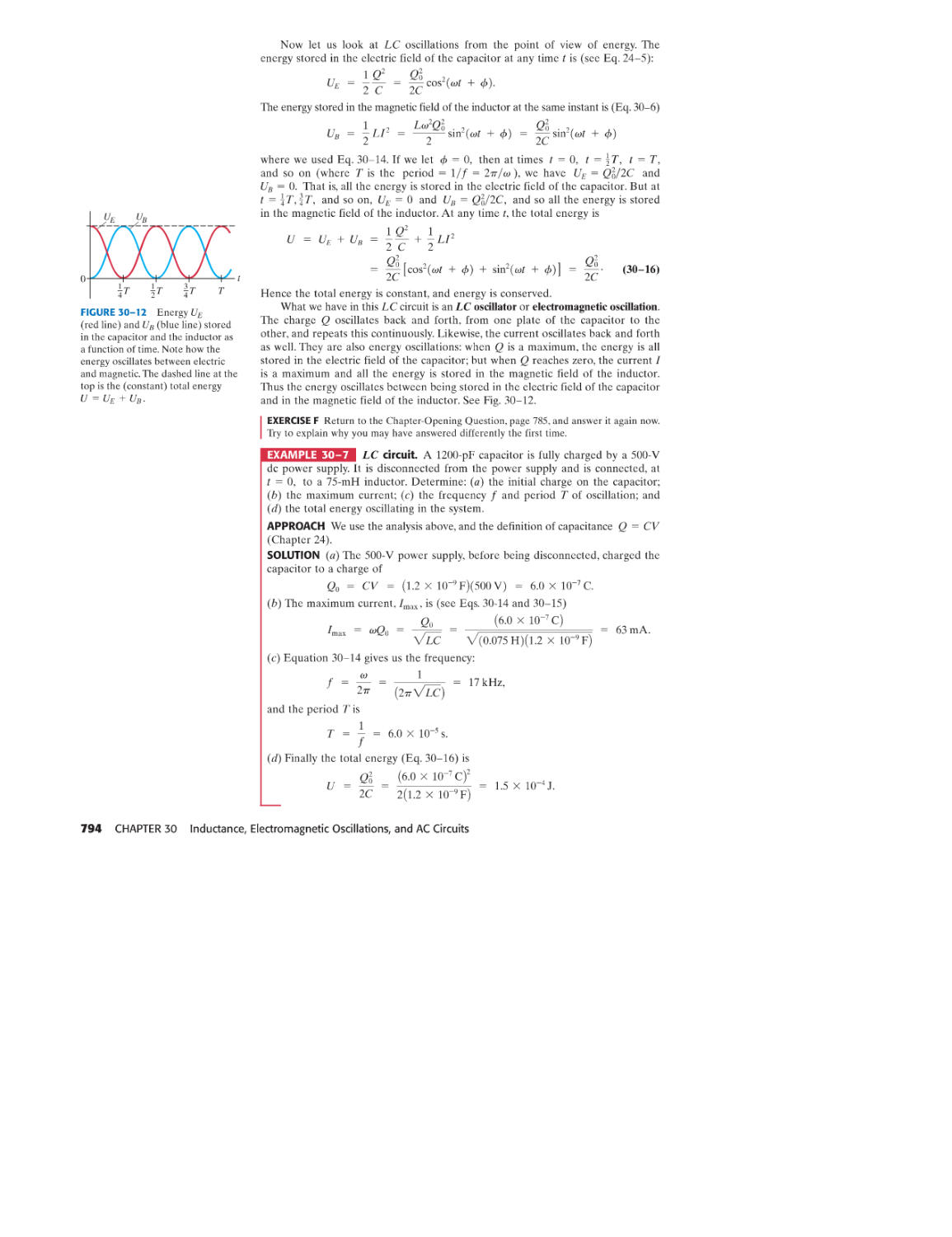
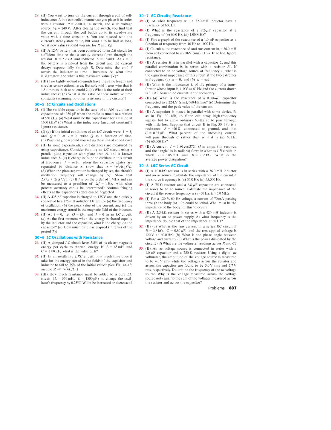
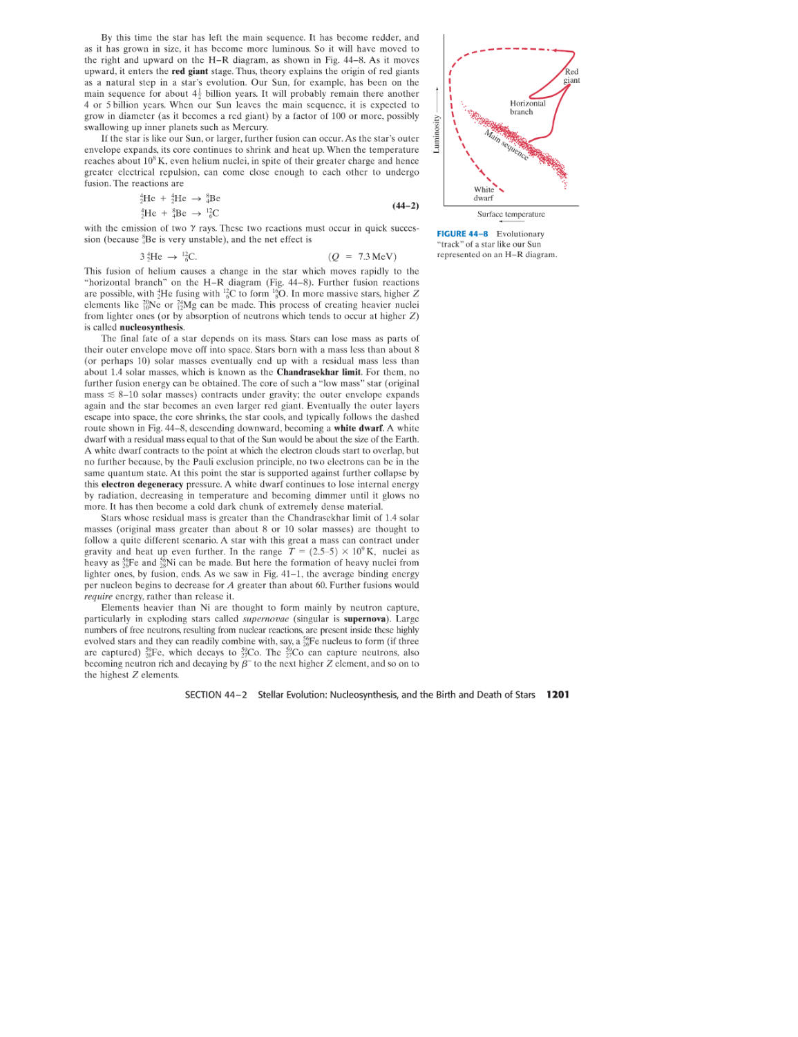
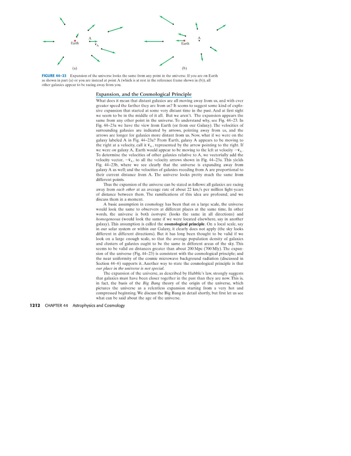
/


Текст
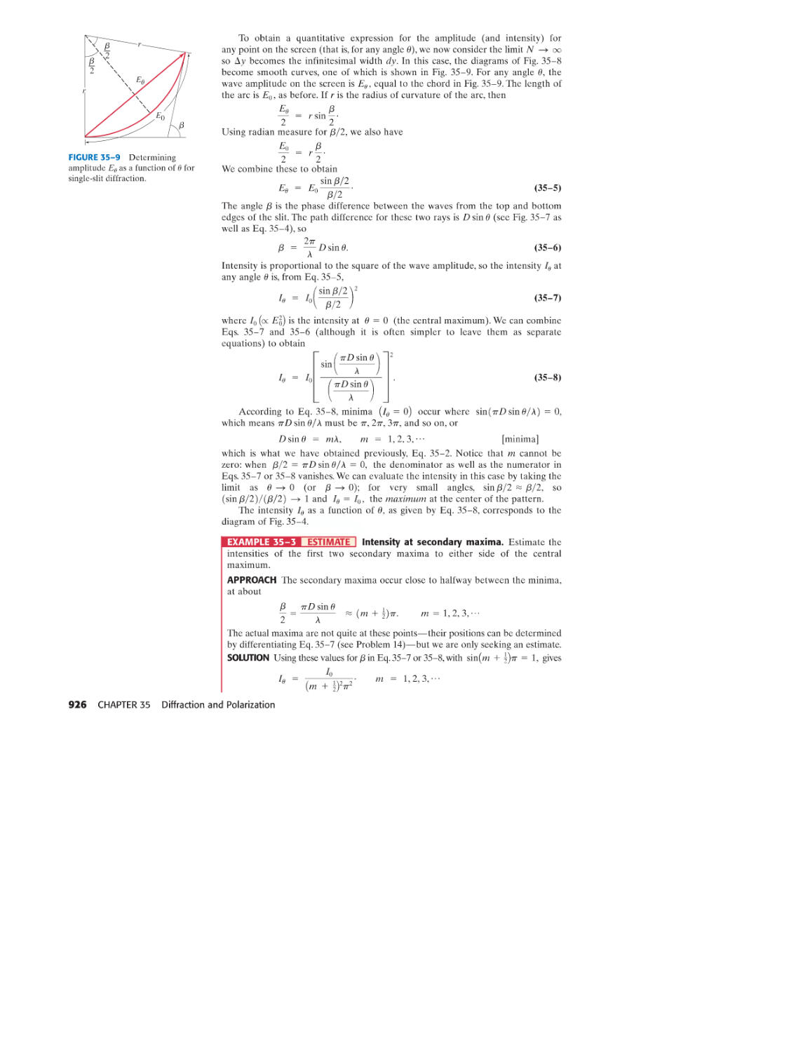
i>\J 1T10 <,\!
r...,
::::
o
o
for
SCIENTISTS & ENGINEERS
-with Modern Physics
DOUGLAS C. GIANCOLI
PEARSON
Prentice
Hall
Upper Saddle River, New Jersey 07458
Library of Congress Cataloging-in-Publication Data
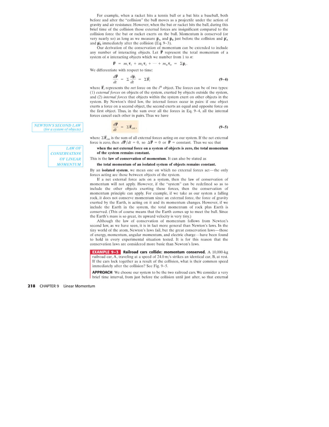
Giancoli, Douglas e.
Physics for scientists and engineers with modern physics / Douglas C.
Giancoli.-4th ed.
p.cm.
Includes bibliographical references and index.
ISBN 0-13-149508-9
1. Physics-Textbooks. 1. Title.
QC21.3.G5392008
530-dc22
2006039431
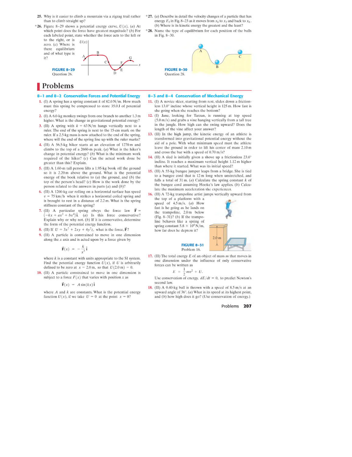
President, Science: Paul Corey
Sponsoring Editor: Christian Botting
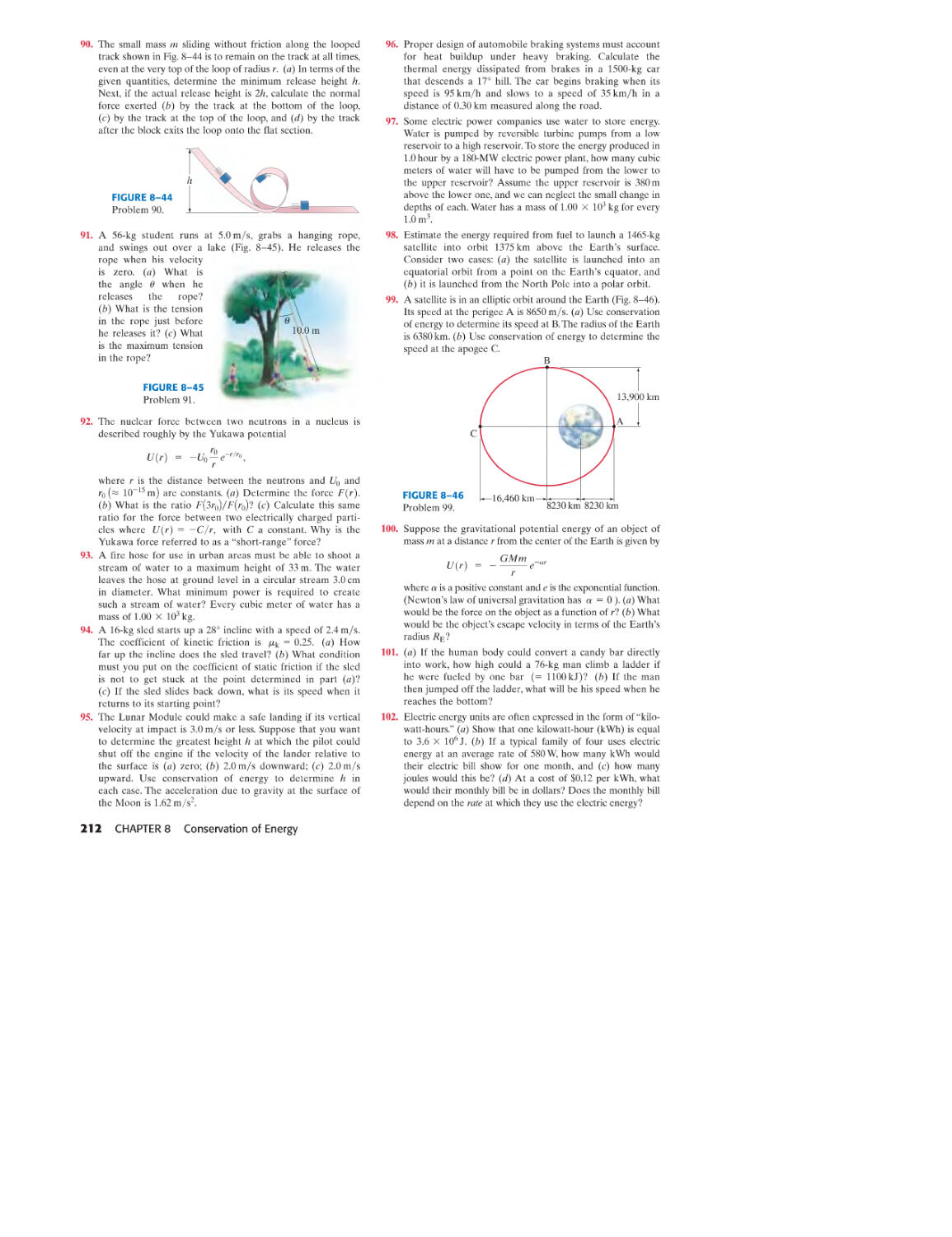
Executive Development Editor: Karen Karlin
Production Editor: Clare Romeo
Senior Managing Editor: Scott Disanno
Art Director and Interior & Cover Designer: John Christiana
Manager, Art Production: Sean Hogan
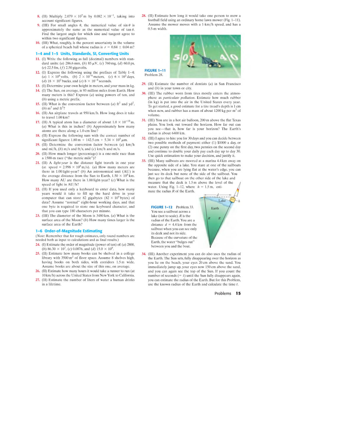
Copy Editor: Jocelyn Phillips
Proofreaders: Karen Bosch, Gina Cheselka, Traci Douglas, Nancy Stevenson,
and Susan Fisher
Senior Operations Specialist: Alan Fischer
Art Production Editor: Connie Long
Illustrators: Audrey Simonetti and Mark Landis
Photo Researchers: Mary Teresa Giancoli and Truitt & Marshall
Senior Administrative Coordinator: Trisha Tarricone
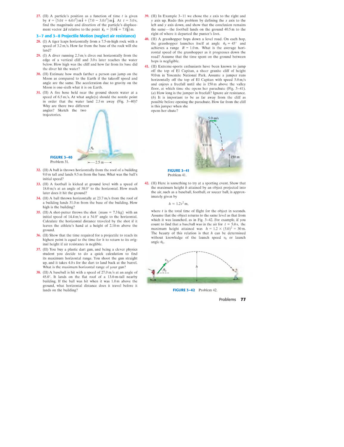
Composition: Emilcomp/Prepare Inc.;
Pearson Education/Lissette Quinones, Clara Bartunek
Photo credits appear on page A-72 which constitutes
a continuation of the copyright page.
@ 2009,2000,1989,1984 by Douglas C. Giancoli
Published by Pearson Education, Inc.
Pearson Prentice Hall
Pearson Education, Inc.
Upper Saddle River, NJ 07458
All rights reserved. No part of this book may be
reproduced, in any form or by any means,
without permission in writing from the publisher.
Pearson Prentice Hall™ is a trademark of Pearson Education, Inc.
Printed in the United States of America
10 9 8 7 6 5 4 3 2 1
PEARSON
Prentice
Hall
ISBN-13: 978-0-13-149508-1
ISBN-10: 0-13-149508-9
Pearson Education LTD., London
Pearson Education Australia PTY, Limited, Sydney
Pearson Education Singapore, Pte. Ltd.
Pearson Education North Asia Ltd., Hong Kong
Pearson Education Canada, Ltd., Toronto
Pearson Educaci6n de Mexico, S.A. de e.v.
Pearson Education-Japan, Tokyo
Pearson Education Malaysia, Pte. Ltd.
Contents
3
KINEMATICS IN Two OR
THREE DIMENSIONS; VECTORS
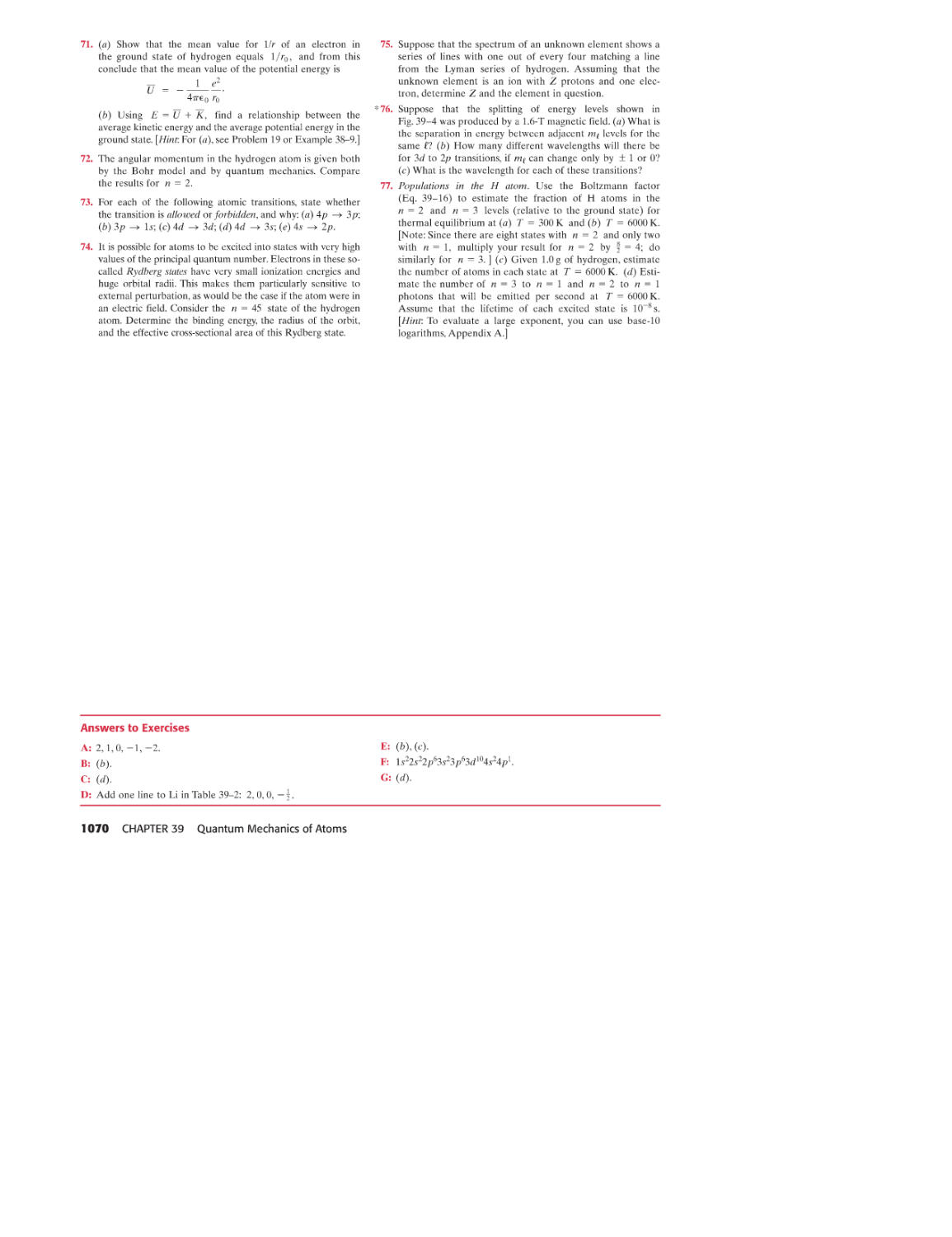
51
3-1 Vectors and Scalars 52
3-2 Addition of Vectors-Graphical Methods 52
3-3 Subtraction of Vectors, and
Multiplication of a Vector by a Scalar 54
3-4 Adding Vectors by Components 55
3-5 Unit Vectors 59
3-6 Vector Kinematics 59
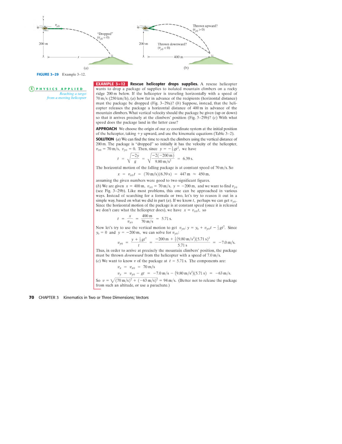
3-7 Projectile Motion 62
3-8 Solving Problems: Projectile Motion 64
3-9 Relative Velocity 71
SUMMARY 74 QUESTIONS 75
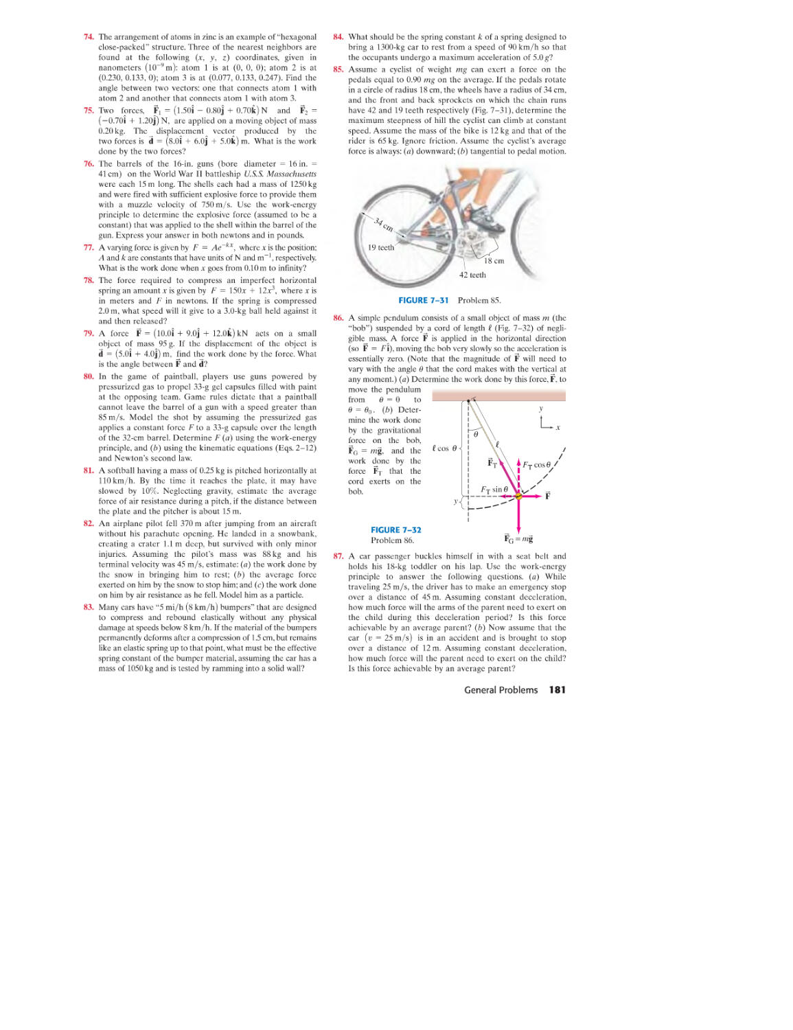
PROBLEMS 75 GENERAL PROBLEMS 80
4
DYNAMICS:
NEWTON'S LAws OF MOTION
83
ApPLICATIONS LIST
PREFACE
To STUDENTS
USE OF COLOR
XlI
XIV
XVlIl
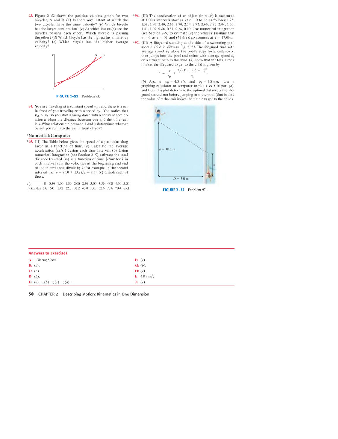
XIX
4-1 Force 84
4-2 N ewton's First Law of Motion 84
4-3 Mass 86
4-4 N ewton's Second Law of Motion 86
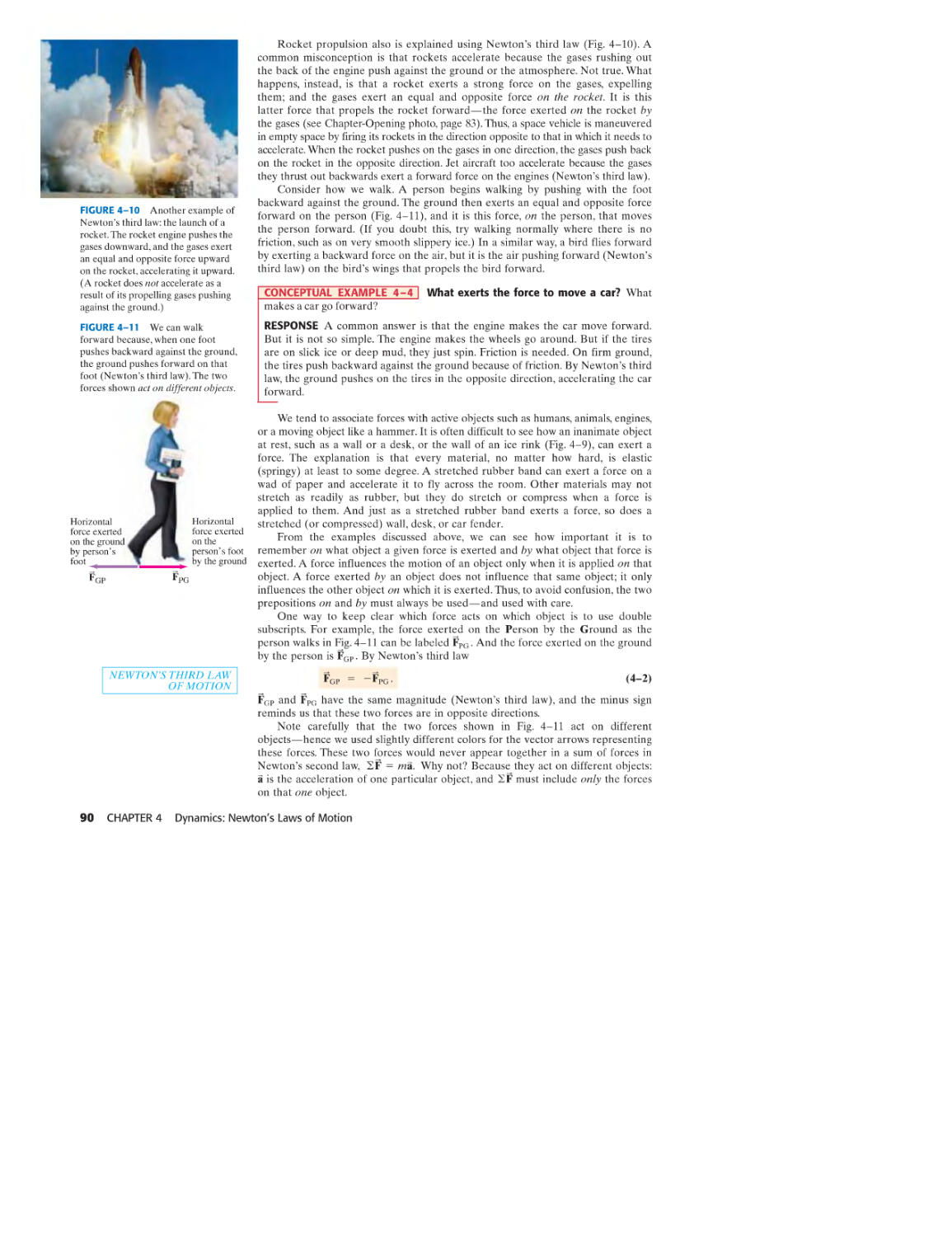
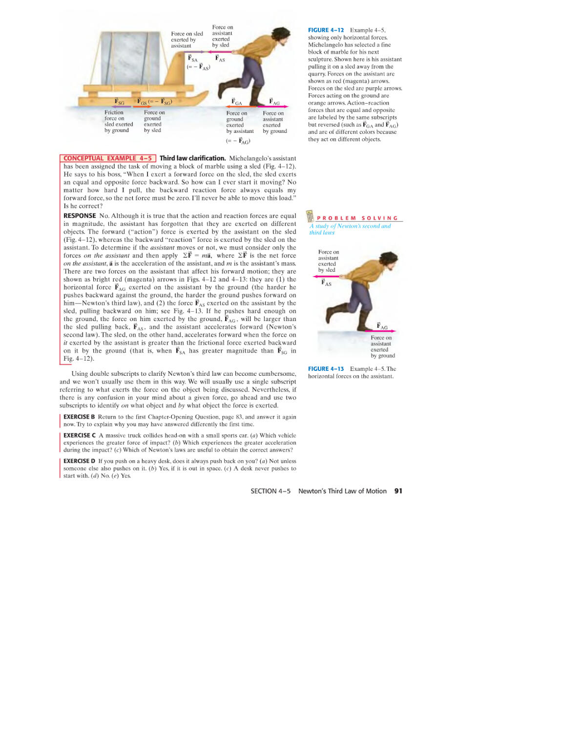
4-5 N ewton's Third Law of Motion 89
4-6 Weight-the Force of Gravity; the N onnal Force 92
4-7 Solving Problems with Newton's Laws:
Free-Body Diagrams 95
4-8 Problem Solving-A General Approach 102
SUMMARY 102 QUESTIONS 103
PROBLEMS 104 GENERAL PROBLEMS 109
Volume 1
1
INTRODUCTION,
MEASUREMENT, ESTIMATING
1 5 USING NEWTON'S LAws: FRICfION,
2 CIRCUlAR ManON, DRAG FORCES 112
2 5-1 Applications of Newton's Laws
Involving Friction 113
3 5-2 Uniform Circular Motion-Kinematics 119
6 5-3 Dynamics of Uniform Circular Motion 122
8 5-4 Highway Curves: Banked and Unbanked 126
9 *5-5 Nonuniform Circular Motion 128
12 *5-6 Velocity- Dependent Forces:
Drag and Terminal Velocity 129
SUMMARY 130 QUESTIONS 131
PROBLEMS 132 GENERAL PROBLEMS 136
1-1 The Nature of Science
1-2 Models, Theories, and Laws
1-3 Measurement and Uncertainty;
Significant Figures
1-4 Units, Standards, and the SI System
1-5 Converting Units
1-6 Order of Magnitude: Rapid Estimating
*1-7 Dimensions and Dimensional Analysis
SUMMARY 14 QUESTIONS 14
PROBLEMS 14 GENERAL PROBLEMS 16
2
DESCRIBING MOTION:
KINEMATICS IN ONE DIMENSION 18
2-1
2-2
2-3
2-4
2-5
2-6
2-7
*2-8
*2-9
Reference Frames and Displacement 19
Average Velocity 20
Instantaneous Velocity 22
Acceleration 24
Motion at Constant Acceleration 28
Solving Problems 30
Freely Falling Objects 34
Variable Acceleration; Integral Calculus 39
Graphical Analysis and
Numerical Integration 40
SUMMARY 43 QUESTIONS 43
PROBLEMS 44 GENERAL PROBLEMS 48
iii
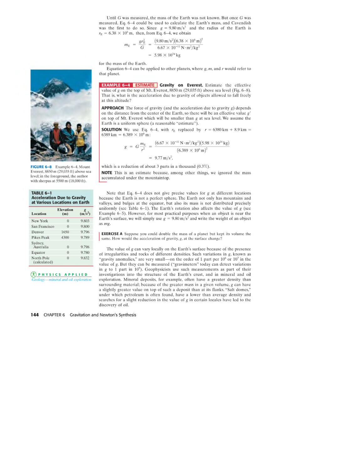
6 GRAVITATION AND 9
NEwrON'S SYNTHESIS 139 LINEAR MOMENTUM 214
6-1 Newton's Law of Universal Gravitation 140 9-1 Momentum and Its Relation to Force 215
6-2 Vector Form of Newton's Law of 9-2 Conservation of Momentum 217
Universal Gravitation 143 9-3 Collisions and Impulse 220
6-3 Gravity Near the Earth's Surface; 9-4 Conservation of Energy and
Geophysical Applications 143 Momentum in Collisions 222
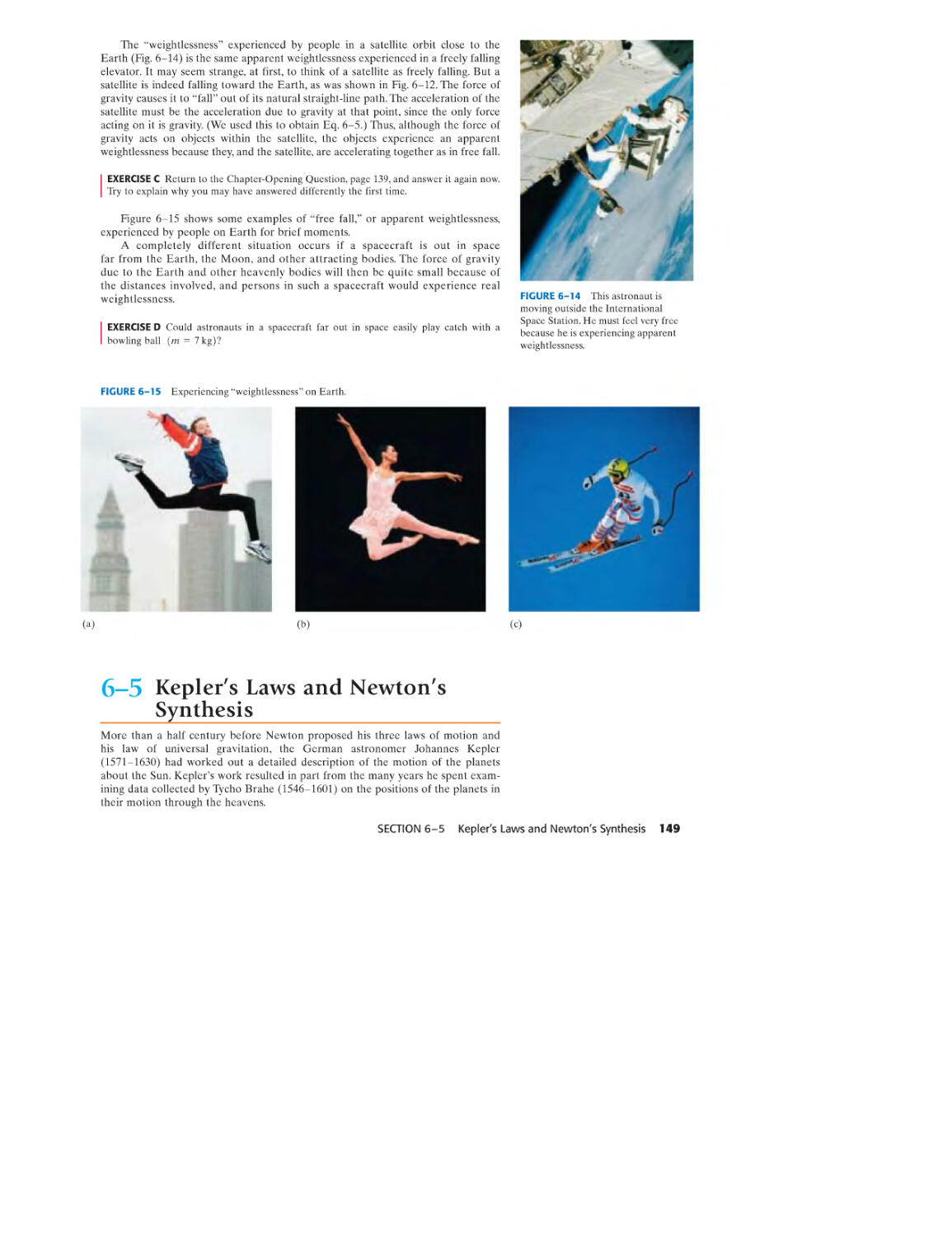
6-4 Satellites and "Weightlessness" 146 9-5 Elastic Collisions in One Dimension 222
6-5 Kepler's Laws and Newton's Synthesis 149 9-6 Inelastic Collisions 225
*6-6 Gravitational Field 154 9-7 Collisions in Two or Three Dimensions 227
6-7 Types of Forces in Nature 155 9-8 Center of Mass (CM) 230
*6-8 Principle of Equivalence; 9-9 Center of Mass and Translational Motion 234
Curvature of Space; Black Holes 155 *9-10 Systems of Variable Mass; Rocket Propulsion 236
SUMMARY 157 QUESTIONS 157 SUMMARY 239 QUESTIONS 239
PROBLEMS 158 GENERAL PROBLEMS 160 PROBLEMS 240 GENERAL PROBLEMS 245
Force 10 ROTATIONAL MOTION 248
Displacement
------------------------------
7
WORK AND ENERGY
163
7-1
7-2
7-3
7-4
Work Done by a Constant Force 164
Scalar Product of Two Vectors 167
Work Done by a Varying Force 168
Kinetic Energy and the
Work-Energy Principle 172
SUMMARY 176 QUESTIONS 177
PROBLEMS 177 GENERAL PROBLEMS 180
8
CONSERVATION OF ENERGY 183
8-1
8-2
8-3
8-4
8-5
8-6
8-7
8-8
*8-9
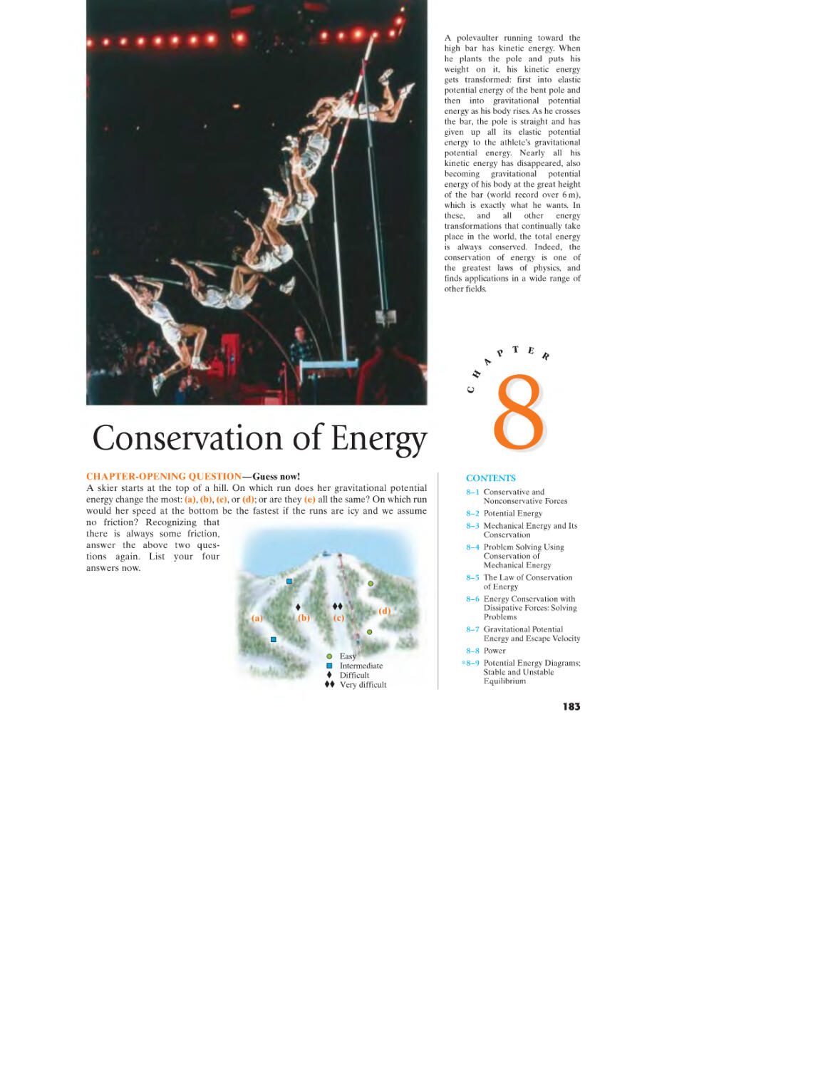
Conservative and N onconservative Forces 184
Potential Energy 186
Mechanical Energy and Its Conservation 189
Problem Solving Using
Conservation of Mechanical Energy 190
The Law of Conservation of Energy 196
Energy Conservation with
Dissipative Forces: Solving Problems 197
Gravitational Potential Energy and
Escape Velocity 199
Power 201
Potential Energy Diagrams;
Stable and Unstable Equilibrium 204
SUMMARY 205 QUESTIONS 205
PROBLEMS 207 GENERAL PROBLEMS 211
iv CONTENTS
10-1 Angular Quantities 249
10-2 Vector Nature of Angular Quantities 254
10-3 Constant Angular Acceleration 255
10-4 Torque 256
10-5 Rotational Dynamics;
Torque and Rotational Inertia 258
10-6 Solving Problems in Rotational Dynamics 260
10-7 Determining Moments of Inertia 263
10-8 Rotational Kinetic Energy 265
10-9 Rotational Plus Translational Motion; Rolling 267
*10-10 Why Does a Rolling Sphere Slow Down? 273
SUMMARY 274 QUESTIONS 275
PROBLEMS 276 GENERAL PROBLEMS 281
11
ANGUlAR MOMENTUM;
GENERAL ROTATION
284
11-1 Angular Momentum-Objects
Rotating About a Fixed Axis 285
11-2 Vector Cross Product; Torque as a Vector 289
11-3 Angular Momentum of a Particle 291
11-4 Angular Momentum and Torque for
a System of Particles; General Motion 292
11-5 Angular Momentum and
Torque for a Rigid Object 294
11-6 Conservation of Angular Momentum 297
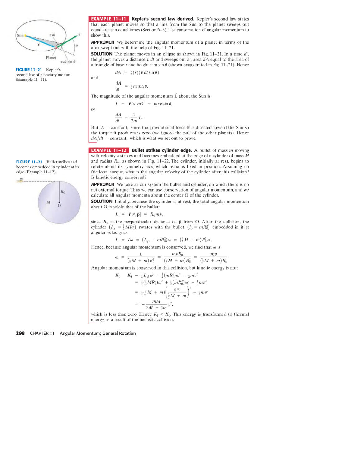
*11-7 The Spinning Top and Gyroscope 299
* 11-8 Rotating Frames of Reference; Inertial Forces 300
*11-9 The Coriolis Effect 301
SUMMARY 302
QUESTIONS 303
PROBLEMS 303
GENERAL
PROBLEMS 308
12 STATIC EQUILIBRIUM;
ElASTICITY AND FRACTURE 311
12-1 The Conditions for Equilibrium 312
12-2 Solving Statics Problems 313
12-3 Stability and Balance 317
12-4 Elasticity; Stress and Strain 318
12-5 Fracture 322
*12-6 Trusses and Bridges 324
*12-7 Arches and Domes 327
SUMMARY 329 QUESTIONS 329
PROBLEMS 330 GENERAL PROBLEMS 334
13 FLUIDS
339
13-1 Phases of Matter 340
13-2 Density and Specific Gravity 340
13-3 Pressure in Fluids 341
13-4 Atmospheric Pressure and
Gauge Pressure 345
13-5 Pascal's Principle 346
13-6 Measurement of Pressure;
Gauges and the Barometer 346
13-7 Buoyancy and Archimedes' Principle 348
13-8 Fluids in Motion; Flow Rate
and the Equation of Continuity 352
13-9 Bernoulli's Equation 354
13-10 Applications of Bernoulli's Principle:
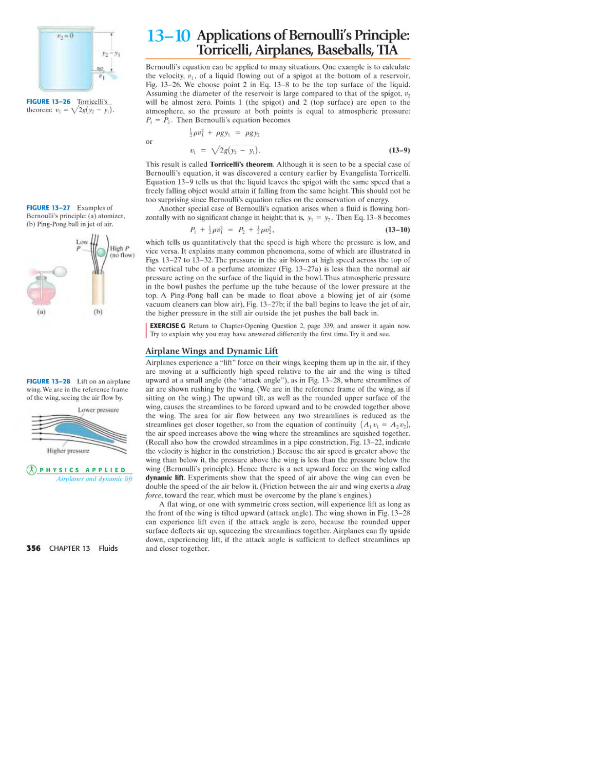
Torricelli, Airplanes, Baseballs, TIA 356
*13-11 Viscosity 358
*13-12 Flow in Tubes: Poiseuille's
Equation, Blood Flow 358
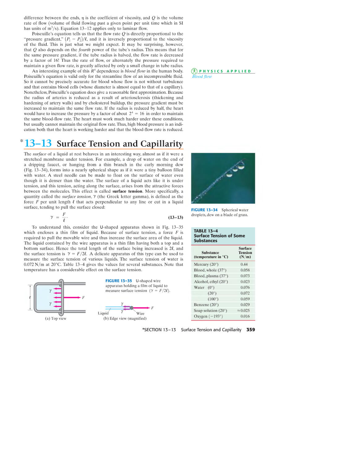
*13-13 Surface Tension and Capillarity 359
*13-14 Pumps, and the Heart 361
SUMMARY 361 QUESTIONS 362
PROBLEMS 363 GENERAL PROBLEMS 367
14 OSCIllATIONS
369
14-1 Oscillations of a Spring 370
14-2 Simple Harmonic Motion 372
14-3 Energy in the Simple
Harmonic Oscillator 377
14-4 Simple Harmonic Motion Related
to Uniform Circular Motion 379
14-5 The Simple Pendulum 379
*14-6 The Physical Pendulum and
the Torsion Pendulum 381
14-7 Damped Harmonic Motion 382
14-8 Forced Oscillations; Resonance 385
SUMMARY 387 QUESTIONS 388
PROBLEMS 388 GENERAL PROBLEMS 392
15 WAVE MOTION
395
15-1 Characteristics of Wave Motion 396
15-2 Types of Waves:
Transverse and Longitudinal 398
15-3 Energy Transported by Waves 402
15-4 Mathematical Representation of a
Traveling Wave 404
*15-5 The Wave Equation 406
15-6 The Principle of Superposition 408
15-7 Reflection and Transmission 409
15-8 Interference 410
15-9 Standing Waves; Resonance 412
*15-10 Refraction 415
*15-11 Diffraction 416
SUMMARY 417 QUESTIONS 417
PROBLEMS 418 GENERAL PROBLEMS 422
16 SOUND
424
16-1 Characteristics of Sound 425
16-2 Mathematical Representation
of Longitudinal Waves 426
16-3 Intensity of Sound: Decibels 427
16-4 Sources of Sound:
Vibrating Strings and Air Columns 431
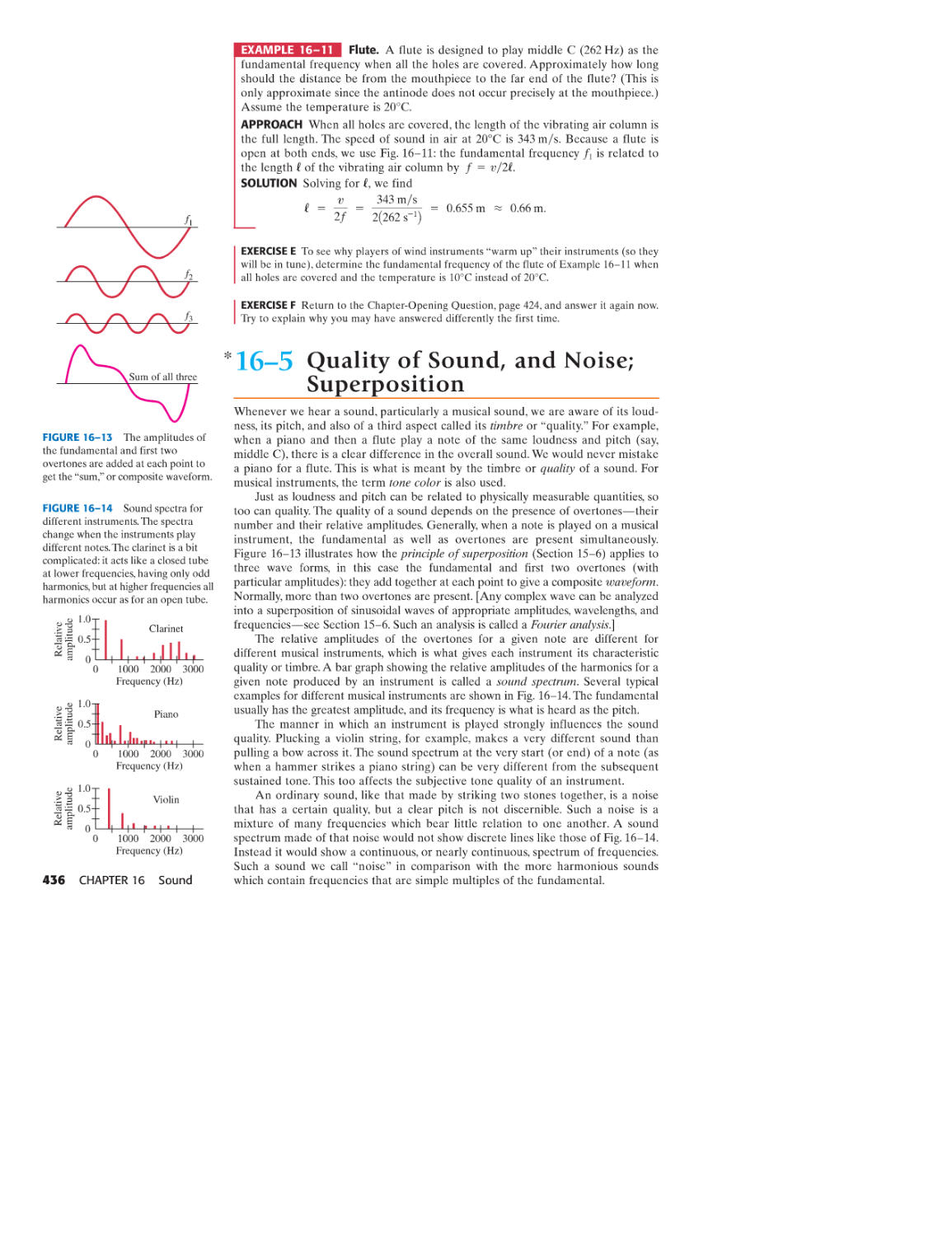
*16-5 Quality of Sound, and Noise;
Superposition 436
16-6 Interference of Sound Waves; Beats 437
16-7 Doppler Effect 439
*16-8 Shock Waves and the Sonic Boom 443
*16-9 Applications: Sonar, Ultrasound,
and Medical Imaging 444
SUMMARY 446 QUESTIONS 447
PROBLEMS 448 GENERAL PROBLEMS 451
CONTENTS v
TEMPERATURE,
17 THERMAL EXPANSION,
AND THE IDEAL GAS LAw
17-1 Atomic Theory of Matter
17-2 Temperature and Thermometers
17-3 Thermal Equilibrium and the
Zeroth Law of Thermodynamics
17-4 Thermal Expansion
*17-5 Thermal Stresses
17-6 The Gas Laws and
Absolute Temperature
17-7 The Ideal Gas Law
17-8 Problem Solving with the
Ideal Gas Law
17-9 Ideal Gas Law in Terms of Molecules:
Avogadro's Number
*17-10 Ideal Gas Temperature Scale-
a Standard
SUMMARY 470 QUESTIONS 471
PROBLEMS 471 GENERAL PROBLEMS 474
18 KINETIC THEORY OF GASES 476
18-1 The Ideal Gas Law and the Molecular
Interpretation of Temperature
Distribution of Molecular Speeds
Real Gases and Changes of Phase
Vapor Pressure and Humidity
Van der Waals Equation of State
Mean Free Path
Diffusion
SUMMARY 490 QUESTIONS 491
PROBLEMS 492 GENERAL PROBLEMS 494
18-2
18-3
18-4
*18-5
*18-6
*18-7
vi CONTENTS
454
455
456
459
459
463
463
465
466
468
469
476
480
482
484
486
487
489
19 HEAT AND THE FIRST LAw
OF THERMODYNAMICS 496
19-1 Heat as Energy Transfer 497
19-2 Internal Energy 498
19-3 Specific Heat 499
19-4 Calorimetry-Solving Problems 500
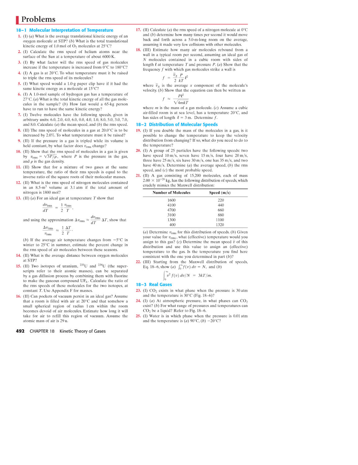
19-5 Latent Heat 502
19-6 The First Law of Thermodynamics 505
19-7 The First Law of Thermodynamics
Applied; Calculating the Work 507
19-8 Molar Specific Heats for Gases,
and the Equipartition of Energy 511
19-9 Adiabatic Expansion of a Gas 514
19-10 Heat Transfer: Conduction,
Convection, Radiation 515
SUMMARY 520 QUESTIONS 521
PROBLEMS 522 GENERAL PROBLEMS 526
20 SECOND LAW OF
THERMODYNAMICS 528
20-1 The Second Law of
Thermodynamics- Introduction 529
20-2 Heat Engines 530
20-3 Reversible and Irreversible
Processes; the Carnot Engine 533
20-4 Refrigerators, Air Conditioners, and
Heat Pumps 536
20-5 Entropy 539
20-6 Entropy and the Second Law of
Thermodynamics 541
20-7 Order to Disorder 544
20-8 Unavailability of Energy; Heat Death 545
*20-9 Statistical Interpretation of Entropy
and the Second Law 546
*20-10 Thermodynamic Temperature;
Third Law of Thermodynamics 548
*20-11 Thermal Pollution, Global Warming,
and Energy Resources 549
SUMMARY 551 QUESTIONS 552
PROBLEMS 552 GENERAL PROBLEMS 556
Volume 2
21 ELECTRIC CHARGE AND
ELECTRIC FIELD
559
21-1 Static Electricity; Electric
Charge and Its Conservation 560
21-2 Electric Charge in the Atom 561
21-3 Insulators and Conductors 561
21-4 Induced Charge; the Electroscope 562
21-5 Coulomb's Law 563
21-6 The Electric Field 568
21-7 Electric Field Calculations for
Continuous Charge Distributions 572
21-8 Field Lines 575
21-9 Electric Fields and Conductors 577
21-10 Motion of a Charged Particle in
an Electric Field 578
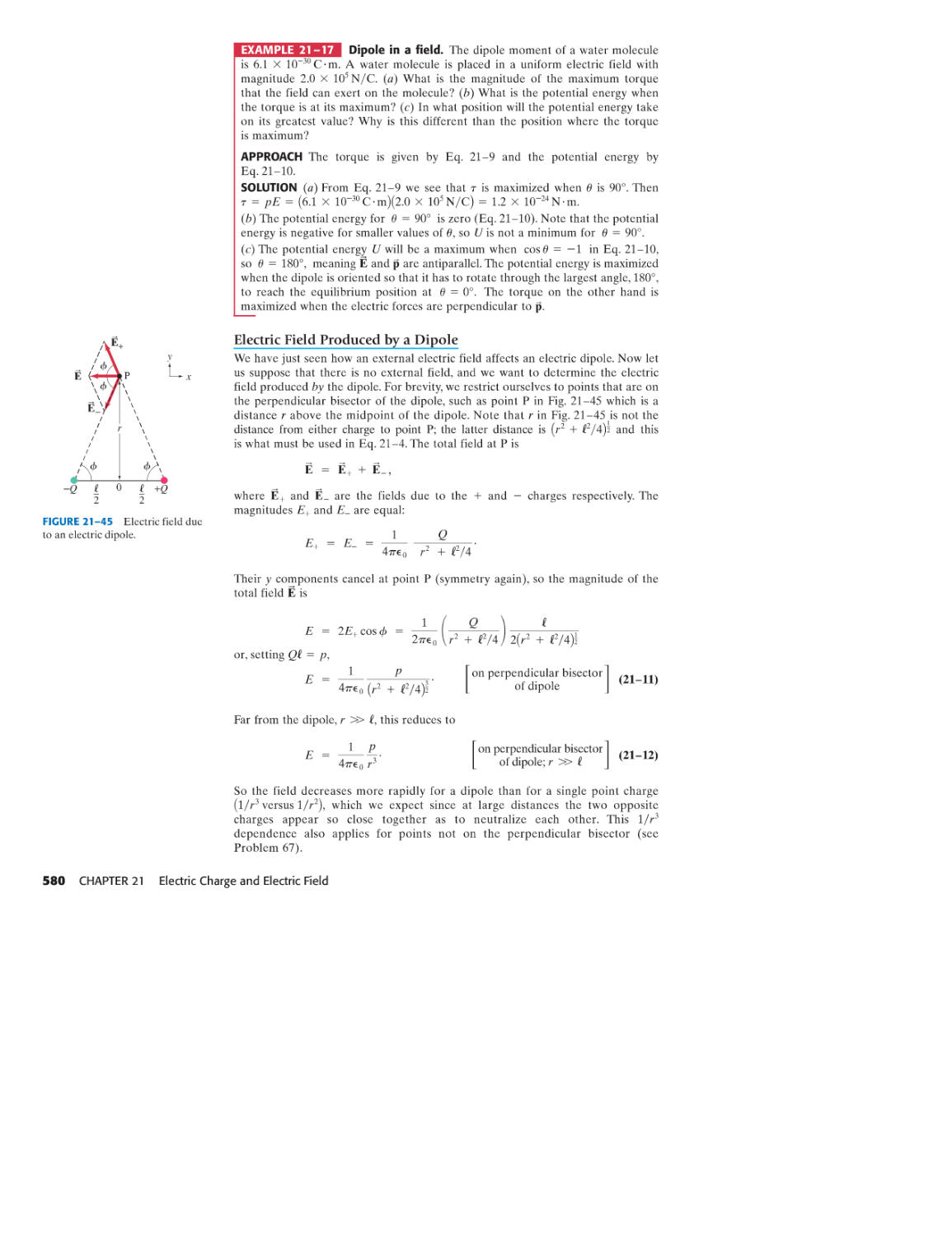
21-11 Electric Dipoles 579
*21-12 Electric Forces in Molecular Biology;
DNA 581
*21-13 Photocopy Machines and Computer
Printers Use Electrostatics 582
SUMMARY 584 QUESTIONS 584
PROBLEMS 585 GENERAL PROBLEMS 589
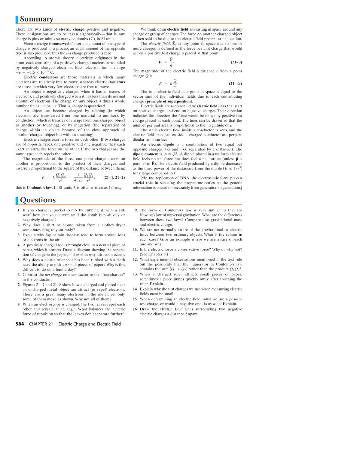
lE.dA = Qencl
J EO
22 GAuss's LAw
591
22-1 Electric Flux 592
22-2 Gauss's Law 593
22-3 Applications of Gauss's Law 595
*22-4 Experimental Basis of Gauss's and
Coulomb's Laws 600
SUMMARY 601 QUESTIONS 601
PROBLEMS 601 GENERAL PROBLEMS 605
23 ELEcrRIC POTENTIAL
607
23-1 Electric Potential Energy and
Potential Difference 607
23-2 Relation between Electric Potential
and Electric Field 610
23-3 Electric Potential Due to Point Charges 612
23-4 Potential Due to Any Charge Distribution 614
23-5 Equipotential Surfaces 616
23-6 Electric Dipole Potential 617
23-7 E Determined from V 617
23-8 Electrostatic Potential Energy; the
Electron Volt 619
*23-9 Cathode Ray Tube: TV and Computer
Monitors, Oscilloscope 620
SUMMARY 622 QUESTIONS 622
PROBLEMS 623 GENERAL PROBLEMS 626
24 CAPACITANCE, DIELECTRICS,
ELECTRIC ENERGY STORAGE 628
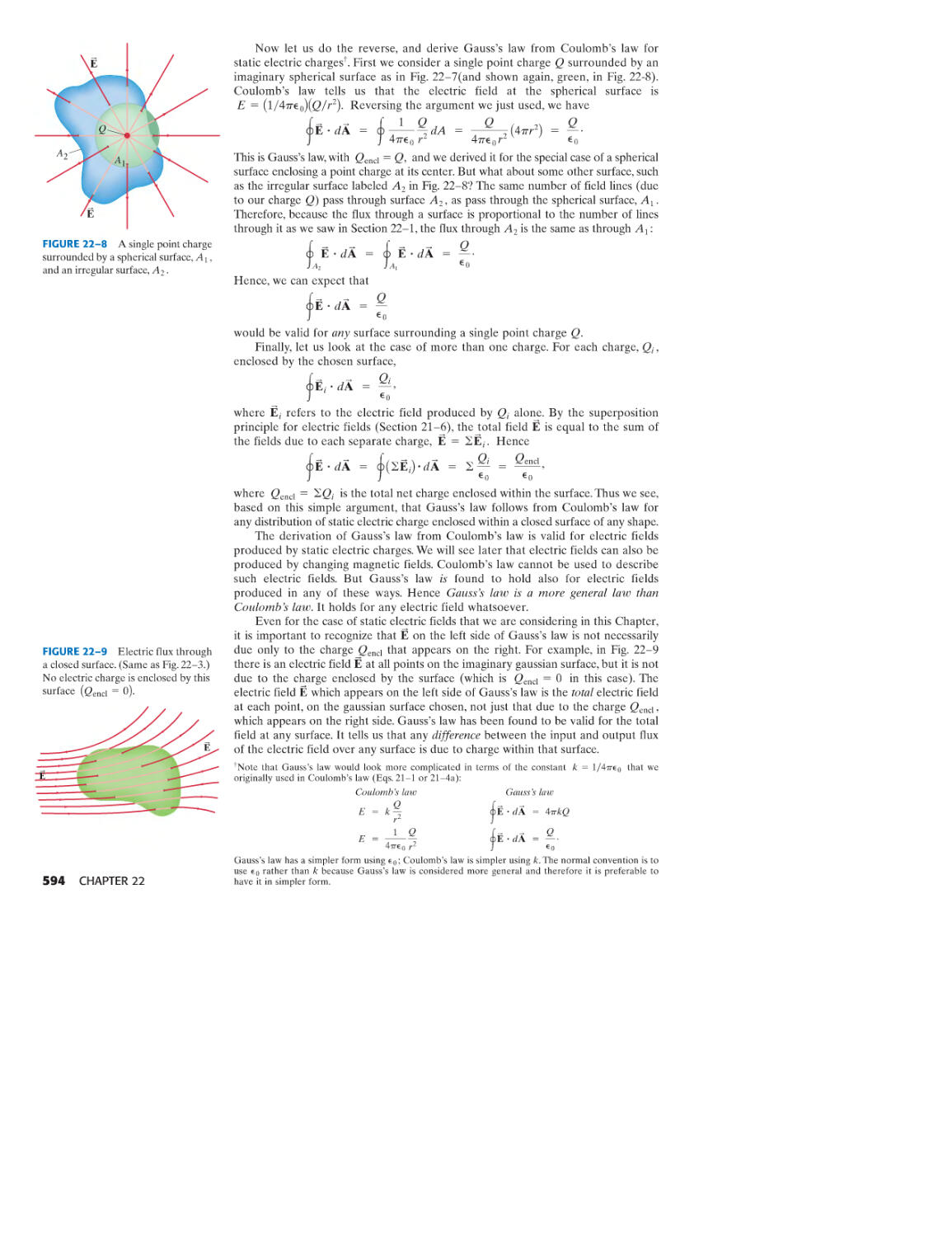
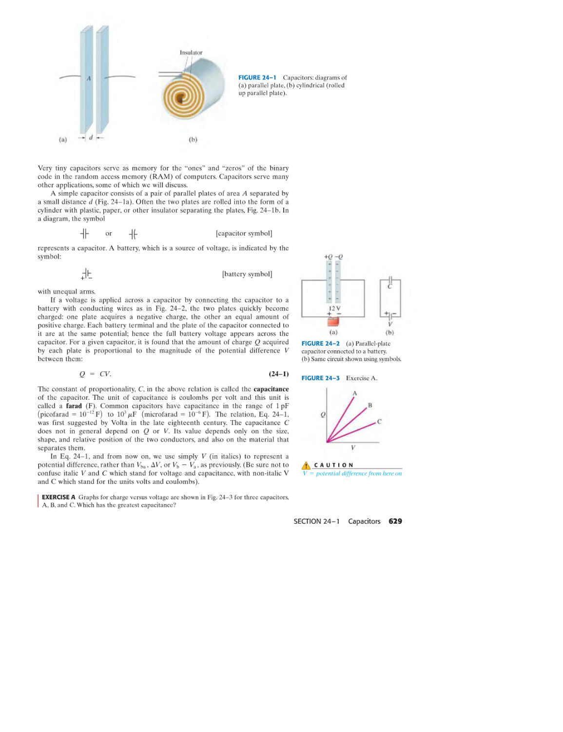
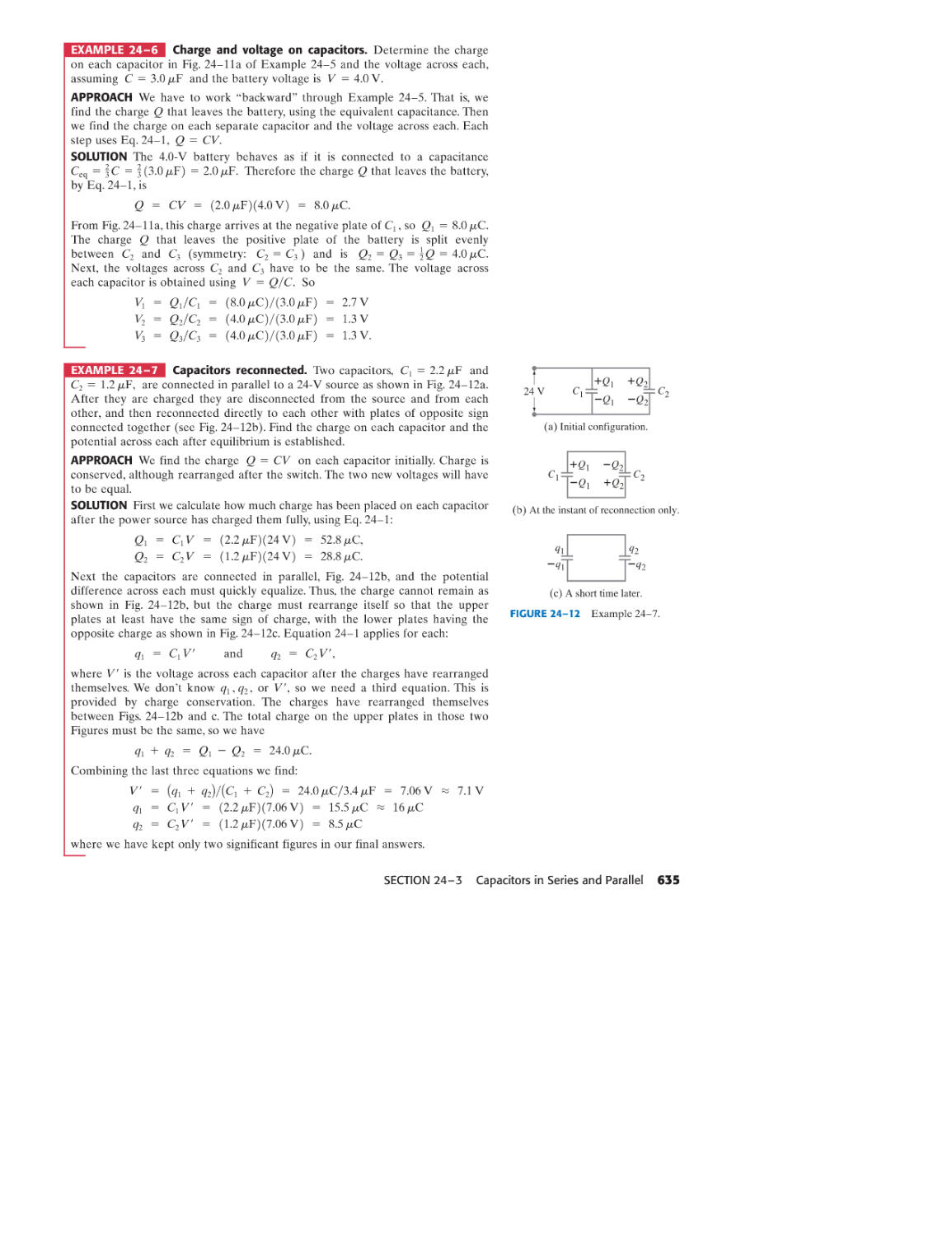
Capacitors
Determination of Capacitance
Capacitors in Series and Parallel
Electric Energy Storage
Dielectrics
Molecular Description of Dielectrics
SUMMARY 643 QUESTIONS 643
PROBLEMS 644 GENERAL PROBLEMS 648
25 ELECTRIC CURRENTS
AND RESISTANCE 651
24-1
24-2
24-3
24-4
24-5
*24-6
628
630
633
636
638
640
25-1 The Electric Battery 652
25-2 Electric Current 654
25-3 Ohm's Law: Resistance and Resistors 655
25-4 Resistivity 658
25-5 Electric Power 660
25-6 Power in Household Circuits 662
25-7 Alternating Current 664
25-8 Microscopic View of Electric Current:
Current Density and Drift Velocity 666
*25-9 Superconductivity 668
*25-10 Electrical Conduction in the Nervous System 669
SUMMARY 671 QUESTIONS 671
PROBLEMS 672 GENERAL PROBLEMS 675
26 DC CIRCUITS 677
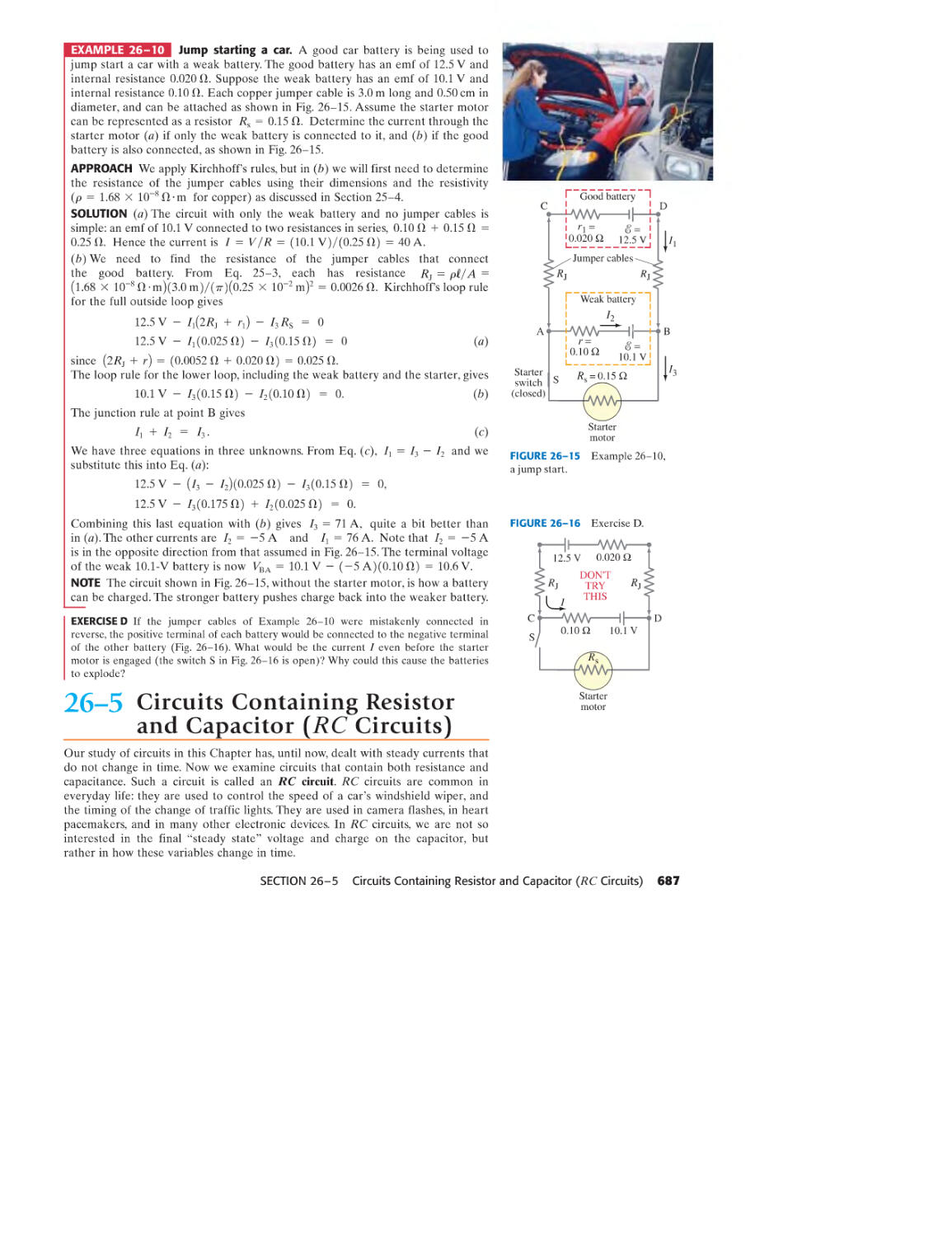
26-1 EMF and Terminal Voltage 678
26-2 Resistors in Series and in Parallel 679
26-3 Kirchhoff's Rules 683
26--4 Series and Parallel EMFs; Battery Charging 686
26-5 Circuits Containing Resistor
and Capacitor (RC Circuits) 687
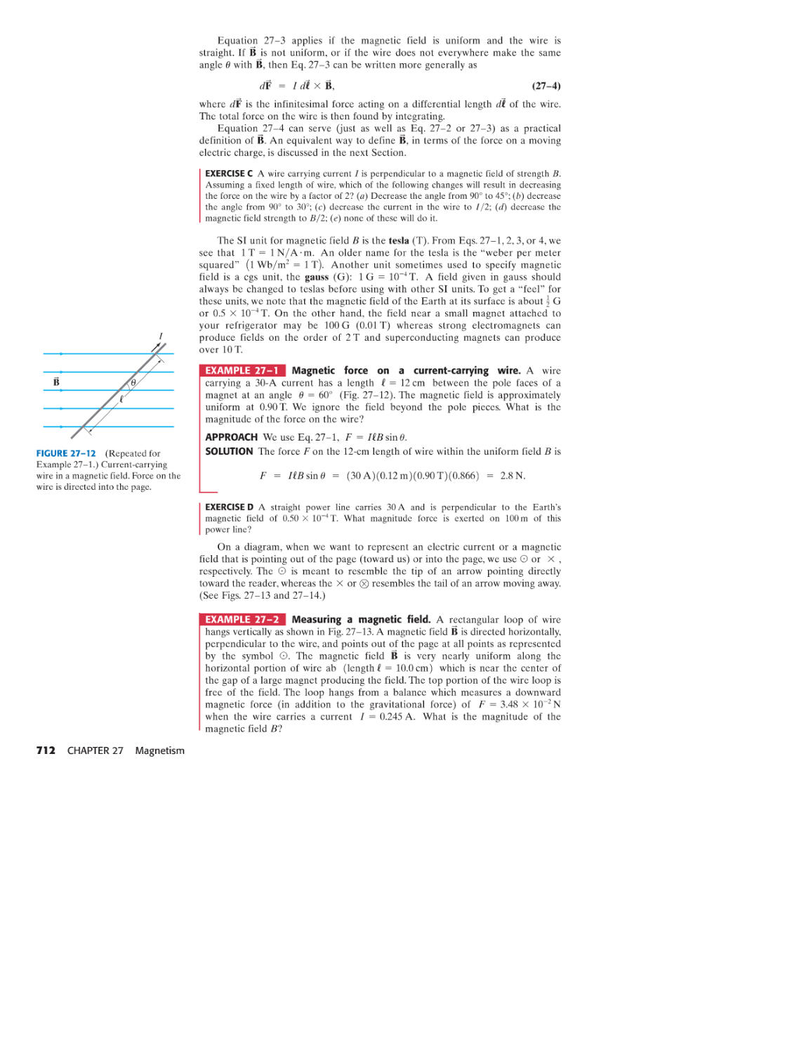
26-6 Electric Hazards 692
*26-7 Ammeters and Voltmeters 695
SUMMARY 698 QUESTIONS 698
PROBLEMS 699 GENERAL PROBLEMS 704
CONTENTS vii
J!
27 MAGNETISM
707
27-1 Magnets and Magnetic Fields 707
27-2 Electric Currents Produce Magnetic Fields 710
27-3 Force on an Electric Current in a
Magnetic Field; Definition of B 710
27-4 Force on an Electric Charge Moving
in a Magnetic Field 714
27-5 Torque on a Current Loop; Magnetic
Dipole Moment 718
*27-6 Applications: Motors, Loudspeakers,
Galvanometers 720
27-7 Discovery and Properties of the
Electron 721
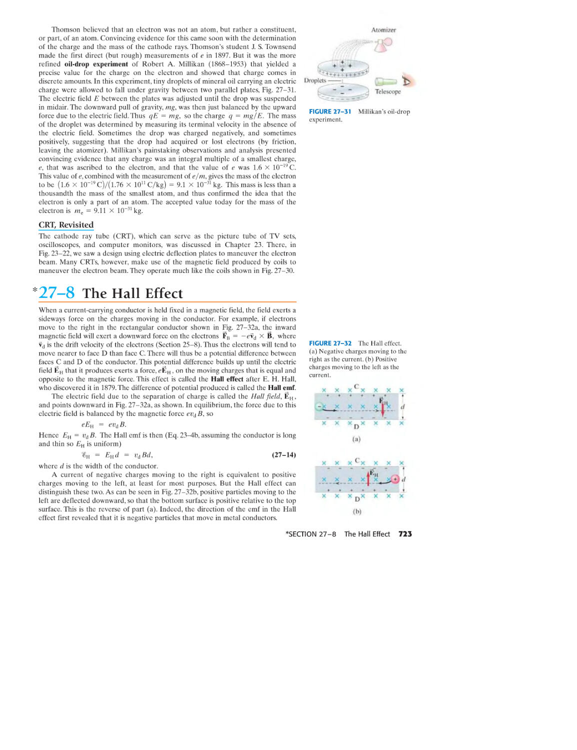
27-8 The Hall Effect 723
*27-9 Mass Spectrometer 724
SUMMARY 725 QUESTIONS 726
PROBLEMS 727 GENERAL PROBLEMS 730
28 SOURCES OF MAGNETIC FIELD
733
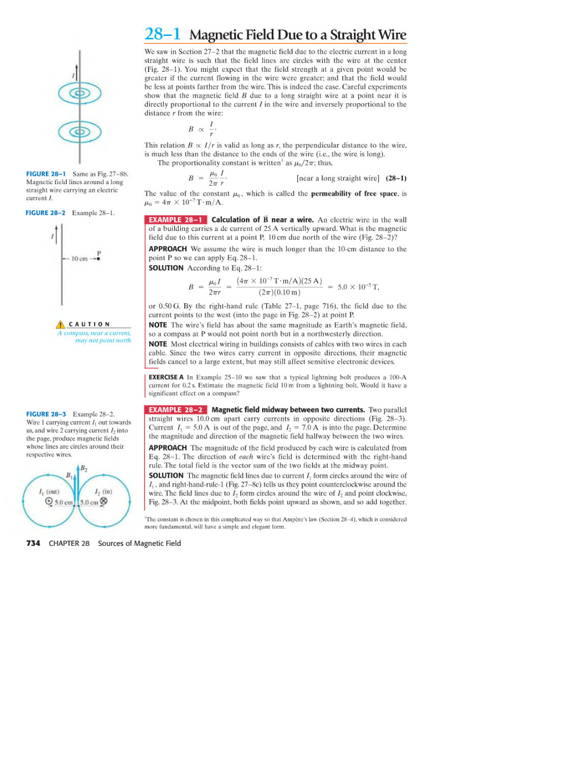
28-1 Magnetic Field Due to a Straight Wire 734
28-2 Force between Two Parallel Wires 735
28-3 Definitions of the Ampere and the
Coulomb 736
28-4 Ampere's Law 737
28-5 Magnetic Field of a Solenoid and
a Toroid 741
28-6 Biot-Savart Law 743
28-7 Magnetic Materials-Ferromagnetism 746
*28-8 Electromagnets and
Solenoids-Applications 747
*28-9 Magnetic Fields in Magnetic Materials;
Hysteresis 748
*28-10 Paramagnetism and Diamagnetism 749
SUMMARY 750 QUESTIONS 751
PROBLEMS 751 GENERAL PROBLEMS 755
viii CONTENTS
29 ELECTROMAGNETIC INDUCTION
AND FARADAy'S LAW 758
29-1 Induced EMF 759
29-2 Faraday's Law of Induction; Lenz's Law 760
29-3 EMF Induced in a Moving Conductor 765
29-4 Electric Generators 766
*29-5 Back EMF and Counter Torque;
Eddy Currents 768
29-6 Transformers and Transmission of Power 770
29-7 A Changing Magnetic Flux Produces an
Electric Field 773
*29-8 Applications of Induction:
Sound Systems, Computer Memory,
Seismograph, GFCI 775
SUMMARY 777 QUESTIONS 777
PROBLEMS 778 GENERAL PROBLEMS 782
30 INDUCTANCE, ELECfROMAGNETIC
OSCILlATIONS, AND AC CIRCUITS 785
30-1 Mutual Inductance 786
30-2 Self-Inductance 788
30-3 Energy Stored in a Magnetic Field 790
30-4 LR Circuits 790
30-5 LC Circuits and Electromagnetic
Oscillations 793
30-6 LC Oscillations with Resistance
(LRC Circuit) 795
30-7 AC Circuits with AC Source 796
30-8 LRC Series AC Circuit 799
30-9 Resonance in AC Circuits 802
*30-10 Impedance Matching 802
*30-11 Three-Phase AC 803
SUMMARY 804 QUESTIONS 804
PROBLEMS 805 GENERAL PROBLEMS 809
31
MAxwELLS EQUATIONS AND
ELECTROMAGNETIC WAVES
812
31-1 Changing Electric Fields Produce
Magnetic Fields; Ampere's Law and
Displacement Current 813
31-2 Gauss's Law for Magnetism 816
31-3 Maxwell's Equations 817
31-4 Production of Electromagnetic Waves 817
31-5 Electromagnetic Waves, and
Their Speed, from Maxwell's Equations 819
31-6 Light as an Electromagnetic Wave
and the Electromagnetic Spectrum 823
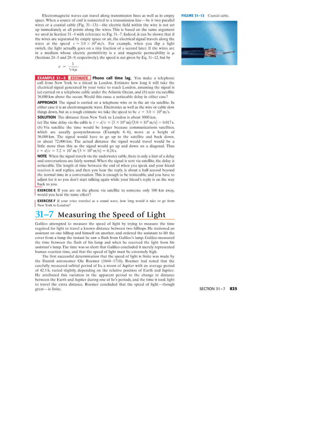
31-7 Measuring the Speed of Light 825
31-8 Energy in EM Waves; the Poynting Vector 826
31-9 Radiation Pressure 828
31-10 Radio and Television;
Wireless Communication 829
SUMMARY 832 QUESTIONS 832
PROBLEMS 833 GENERAL PROBLEMS 835
32 LIGHT: REFLECTION
AND REFRACTION
837
32-1 The Ray Model of Light 838
32-2 Reflection; Image Formation by a
Plane Mirror 838
32-3 Formation of Images by Spherical
Mirrors 842
32-4 Index of Refraction 850
32-5 Refraction: Snell's Law 850
32-6 Visible Spectrum and Dispersion 852
32-7 Total Internal Reflection; Fiber Optics 854
*32-8 Refraction at a Spherical Surface 856
SUMMARY 858 QUESTIONS 859
PROBLEMS 860 GENERAL PROBLEMS 864
33 LENSES AND OPTICAL
INSTRUMENTS
866
33-1 Thin Lenses; Ray Tracing 867
33-2 The Thin Lens Equation; Magnification 870
33-3 Combinations of Lenses 874
*33-4 Lensmaker's Equation 876
33-5 Cameras: Film and Digital 878
33-6 The Human Eye; Corrective Lenses 882
33-7 Magnifying Glass 885
33-8 Telescopes 887
*33-9 Compound Microscope 890
*33-10 Aberrations of Lenses and Mirrors 891
SUMMARY 892 QUESTIONS 893
PROBLEMS 894 GENERAL PROBLEMS 897
34 THE WAVE NATURE OF LIGHT;
INTERFERENCE 900
34-1 Waves Versus Particles; Huygens'
Principle and Diffraction 901
34-2 Huygens' Principle and the Law of
Refraction 902
34-3 Interference- Young's Double-Slit
Experiment 903
*34-4 Intensity in the Double-Slit
Interference Pattern 906
34-5 Interference in Thin Films 909
*34-6 Michelson Interferometer 914
*34-7 Luminous Intensity 915
SUMMARY 915 QUESTIONS 916
PROBLEMS 916 GENERAL PROBLEMS 918
35 DIFFRACTION
AND POLARIZATION 921
35-1 Diffraction by a Single Slit or Disk 922
*35-2 Intensity in Single-Slit Diffraction
Pattern 924
*35-3 Diffraction in the Double-Slit Experiment 927
35-4 Limits of Resolution; Circular Apertures 929
35-5 Resolution of Telescopes and
Microscopes; the A Limit 931
*35-6 Resolution of the Human Eye
and Useful Magnification 932
35-7 Diffraction Grating 933
35-8 The Spectrometer and Spectroscopy 935
*35-9 Peak Widths and Resolving Power for a
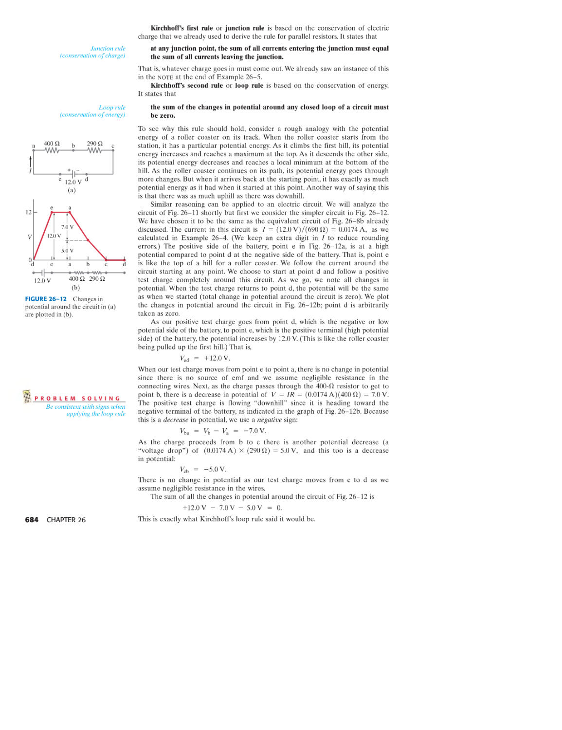
Diffraction Grating 937
35-10 X-Rays and X-Ray Diffraction 938
35-11 Polarization 940
*35-12 Liquid Crystal Displays (LCD) 943
*35-13 Scattering of Light by the Atmosphere 945
SUMMARY 945 QUESTIONS 946
PROBLEMS 946 GENERAL PROBLEMS 949
CONTENTS ix
Volume 3
36 SPECIAL THEORY OF RElATIVITY 951
36-1 Galilean-Newtonian Relativity 952
*36-2 The Michelson-Morley Experiment 954
36-3 Postulates of the Special Theory of Relativity 957
36-4 Simultaneity 958
36-5 Time Dilation and the Twin Paradox 960
36-6 Length Contraction 964
36-7 Four-Dimensional Space-Time 967
36-8 Galilean and Lorentz Transformations 968
36-9 Relativistic Momentum and Mass 971
36-10 The Ultimate Speed 974
36-11 E = mc 2 ; Mass and Energy 974
*36-12 Doppler Shift for Light 978
36-13 The Impact of Special Relativity 980
SUMMARY 981 QUESTIONS 981
PROBLEMS 982 GENERAL PROBLEMS 985
3 7 EARLY QUANTUM THEORY AND
MODELS OF THE ATOM 987
37-1 Blackbody Radiation;
Planck's Quantum Hypothesis 987
37-2 Photon Theory; Photoelectric Effect 989
37-3 Photon Energy, Mass, and Momentum 993
37-4 Compton Effect 994
37-5 Photon Interactions; Pair Production 996
37-6 Wave-Particle Duality; the Principle of
Complementarity 997
37-7 Wave Nature of Matter 997
*37-8 Electron Microscopes 1000
37-9 Early Models of the Atom 1000
37-10 Atomic Spectra: Key to Atomic Structure 1001
37-11 The Bohr Model 1003
37-12 deBroglie's Hypothesis Applied to Atoms 1009
SUMMARY 1010 QUESTIONS 1011
PROBLEMS 1012 GENERAL PROBLEMS 1014
38 QUANTUM MECHANICS 1017
38-1 Quantum Mechanics-A New Theory 1018
38-2 The Wave Function and Its Interpretation;
the Double-Slit Experiment 1018
38-3 The Heisenberg Uncertainty Principle 1020
38-4 Philosophic Implications; Probability
Versus Determinism
38-5 The Schrodinger Equation in One
Dimension- Time-Independent Form 1025
*38-6 Time-Dependent Schrodinger Equation 1027
38-7 Free Particles; Plane Waves and Wave Packets 1028
38-8 Particle in an Infinitely Deep
Square Well Potential (a Rigid Box)
38-9 Finite Potential Well
38-10 Tunneling through a Barrier
SUMMARY 1039 QUESTIONS 1039
PROBLEMS 1040 GENERAL PROBLEMS 1042
x CONTENTS
1024
1030
1035
1036
39 QUANTUM MECHANICS OF
ATOMS
1044
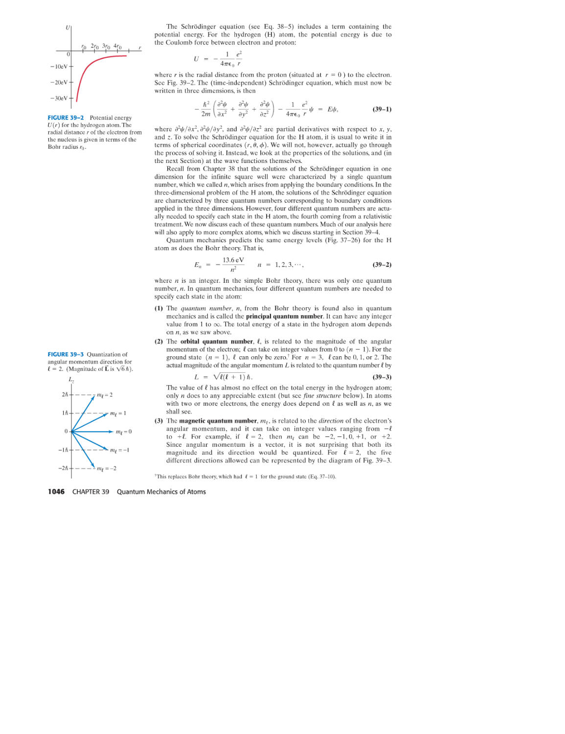
39-1 Quantum-Mechanical View of Atoms 1045
39-2 Hydrogen Atom: Schrodinger Equation
and Quantum Numbers 1045
39-3 Hydrogen Atom Wave Functions 1049
39-4 Complex Atoms; the Exclusion Principle 1052
39-5 Periodic Table of Elements 1053
39-6 X-Ray Spectra and Atomic Number 1054
*39-7 Magnetic Dipole Moment;
Total Angular Momentum
39-8 Fluorescence and Phosphorescence
39-9 Lasers
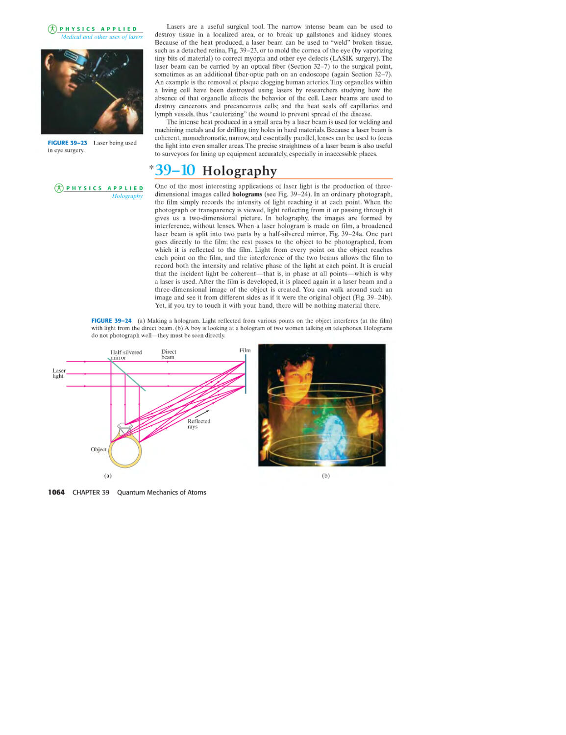
*39-10 Holography
SUMMARY 1066 QUESTIONS 1066
PROBLEMS 1067 GENERAL PROBLEMS 1069
1057
1060
1061
1064
40 MOLECULES AND SOLIDS
40-1 Bonding in Molecules
40-2 Potential-Energy Diagrams
for Molecules
40-3 Weak (van der Waals) Bonds
40-4 Molecular Spectra
40-5 Bonding in Solids
40-6 Free-Electron Theory of Metals;
Fermi Energy 1086
40-7 Band Theory of Solids 1090
40-8 Semiconductors and Doping 1093
40-9 Semiconductor Diodes 1094
40-10 Transistors and Integrated Circuits (Chips) 1097
SUMMARY 1098 QUESTIONS 1099
PROBLEMS 1099 GENERAL PROBLEMS 1102
1071
1071
1074
1077
1080
1085
41
NUCLEAR PHYSICS AND
RADIOACTIVITY
1104
41-1 Structure and Properties of the Nucleus 1105
41-2 Binding Energy and Nuclear Forces 1108
41-3 Radioactivity 1110
41-4 Alpha Decay 1111
41-5 Beta Decay 1114
41-6 Gamma Decay 1116
41-7 Conservation of Nucleon Number
and Other Conservation Laws
41-8 Half-Life and Rate of Decay
41-9 Decay Series
41-10 Radioactive Dating
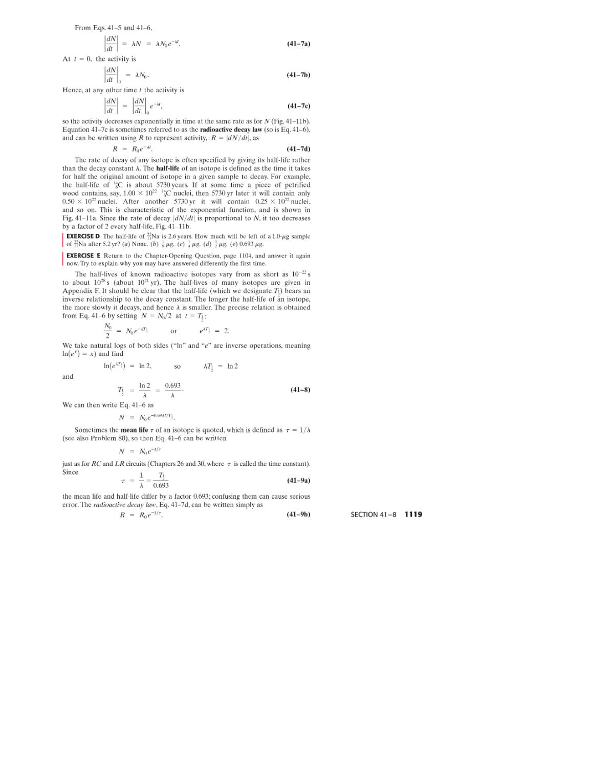
41-11 Detection of Radiation
SUMMARY 1126 QUESTIONS 1126
PROBLEMS 1127 GENERAL PROBLEMS 1129
42 NUCLEAR ENERGY; EFFECTS
AND USES OF RADIATION
1117
1117
1121
1122
1124
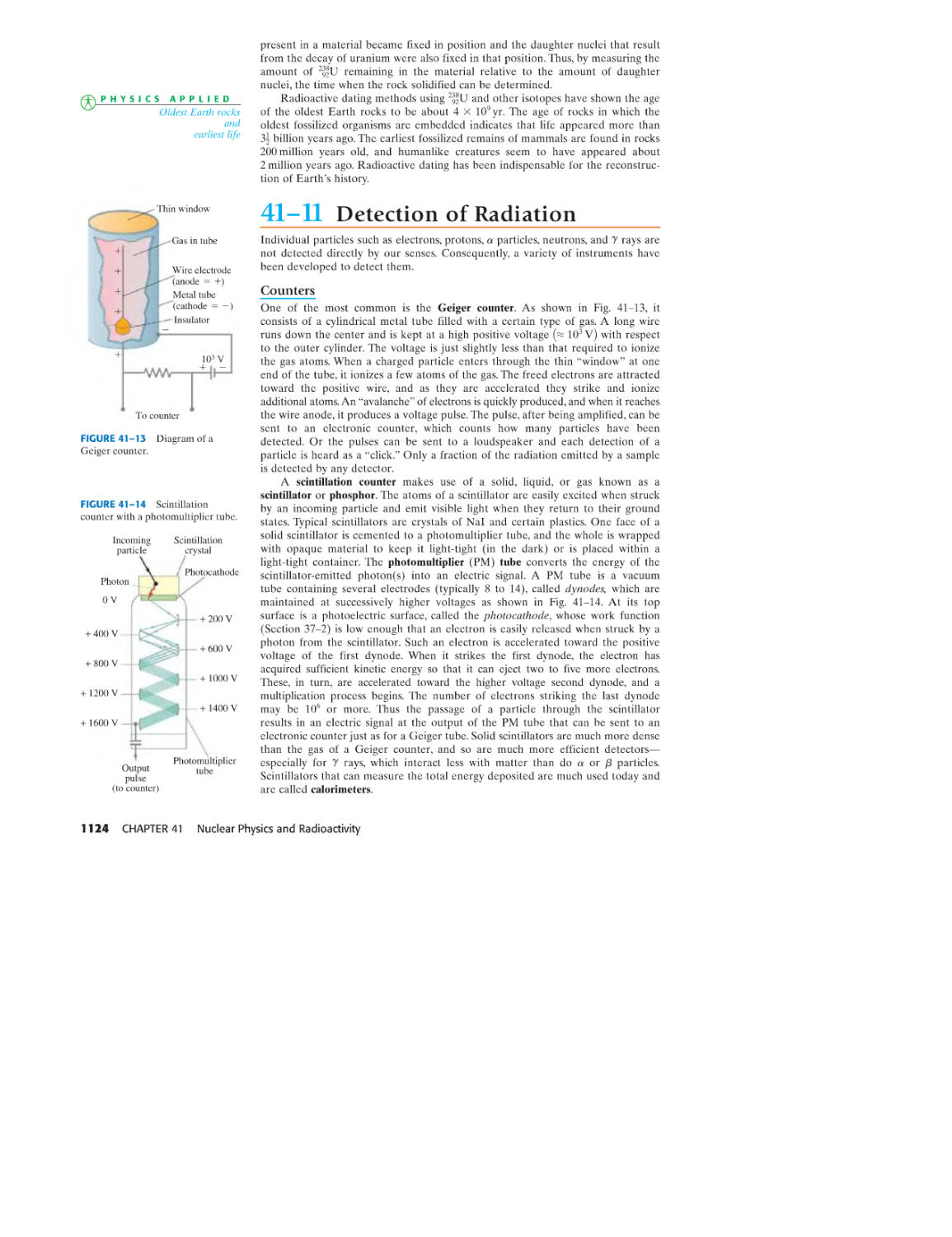
1131
42-1 Nuclear Reactions and the
Transmutation of Elements
42-2 Cross Section
42-3 Nuclear Fission; Nuclear Reactors
42-4 Nuclear Fusion
42-5 Passage of Radiation Through Matter;
Radiation Damage 1146
Measurement of Radiation-Dosimetry 1147
Radiation Therapy 1150
Tracers in Research and Medicine 1151
Imaging by Tomography: CAT Scans
and Emission Tomography
*42-10 Nuclear Magnetic Resonance (NMR);
Magnetic Resonance Imaging (MRI)
SUMMARY 1159 QUESTIONS 1159
PROBLEMS 1160 GENERAL PROBLEMS 1162
42-6
*42-7
*42-8
*42-9
1132
1135
1136
1141
1153
1156
43 ELEMENTARY PARTICLES
1164
43-1 High-Energy Particles and Accelerators 1165
43-2 Beginnings of Elementary Particle
Physics-Particle Exchange 1171
43-3 Particles and Antiparticles 1174
43-4 Particle Interactions and Conservation Laws 1175
43-5 Neutrinos-Recent Results 1177
43-6 Particle Classification 1178
43-7 Particle Stability and Resonances 1180
43-8 Strangeness? Chann? Towards a New Model 1181
43-9 Quarks 1182
43-10 The Standard Model: QCD and
Electroweak Theory
43-11 Grand Unified Theories
43-12 Strings and Supersymmetry
SUMMARY 1189 QUESTIONS 1190
PROBLEMS 1190 GENERAL PROBLEMS 1191
1184
1187
1189
44 ASTROPHYSICS AND COSMOLOGY 1193
44-1 Stars and Galaxies
44-2 Stellar Evolution: Nucleosynthesis,
and the Birth and Death of Stars
44-3 Distance Measurements
44-4 General Relativity: Gravity and the
Curvature of Space
44-5 The Expanding Universe: Redshift and
Hubble's Law
44-6 The Big Bang and the Cosmic
Microwave Background
44-7 The Standard Cosmological Model:
Early History of the Universe
44-8 Inflation
44-9 Dark Matter and Dark Energy
44-10 Large-Scale Structure of the Universe
44-11 Finally. . .
SUMMARY 1225 QUESTIONS 1226
PROBLEMS 1226 GENERAL PROBLEMS 1227
ApPENDICES
1194
1197
1203
1205
1209
1213
1216
1219
1221
1224
1224
A MATHEMATICAL FORMULAS A-I
B DERIVATIVES AND INTEGRALS A-6
C MORE ON DIMENSIONAL ANALYSIS A-S
D GRAVITATIONAL FORCE DUE TO A
SPHERICAL MASS DISTRIBUTION A-9
E DIFFERENTIAL FORM OF MAxwELLS EQUATIONS A-12
F SELECTED ISOTOPES A-14
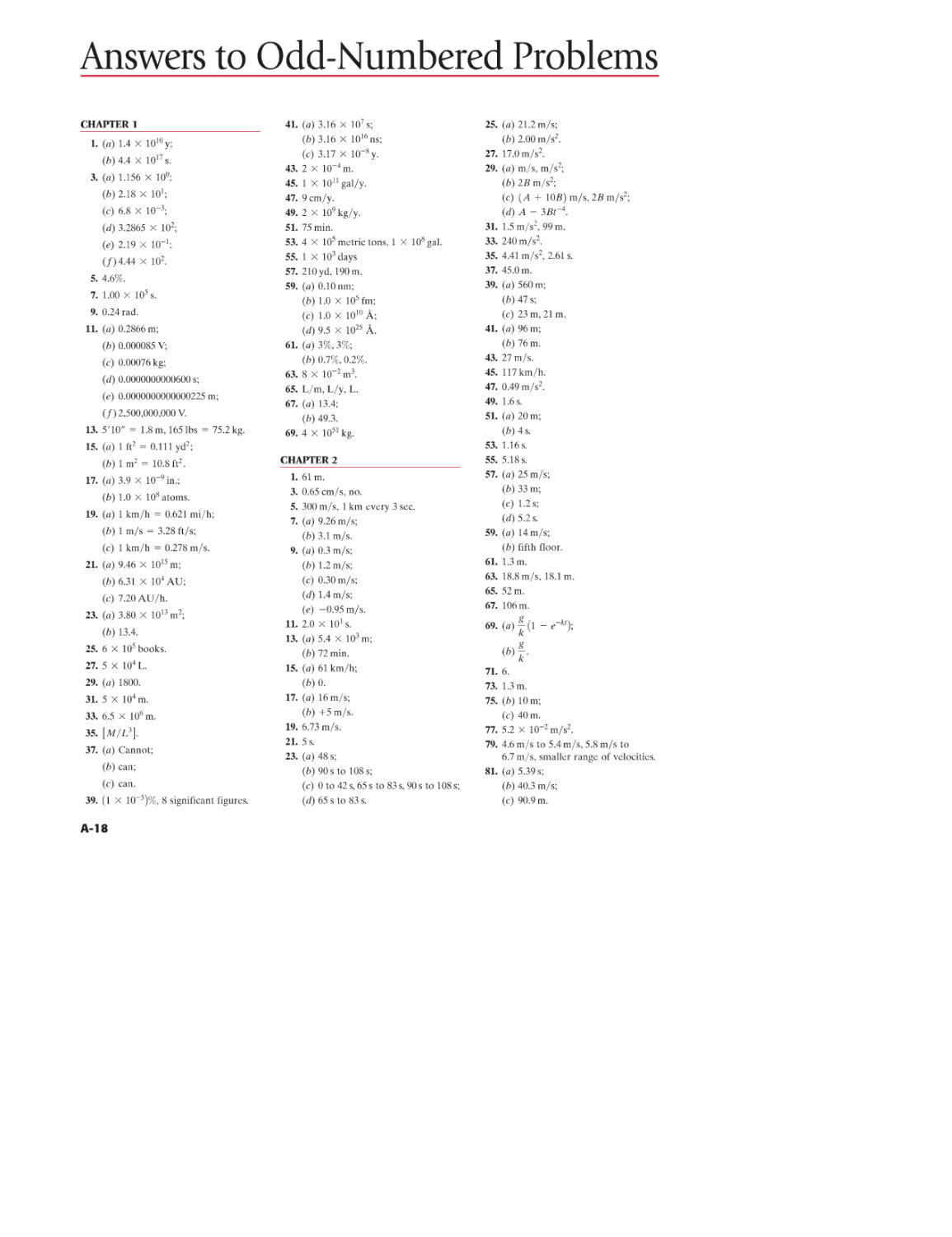
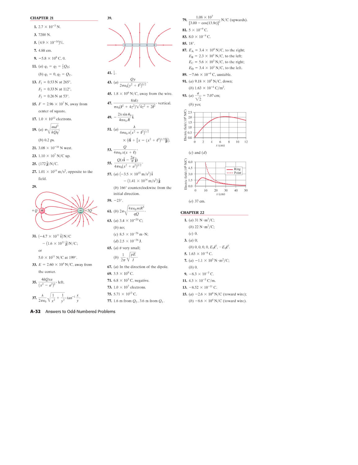
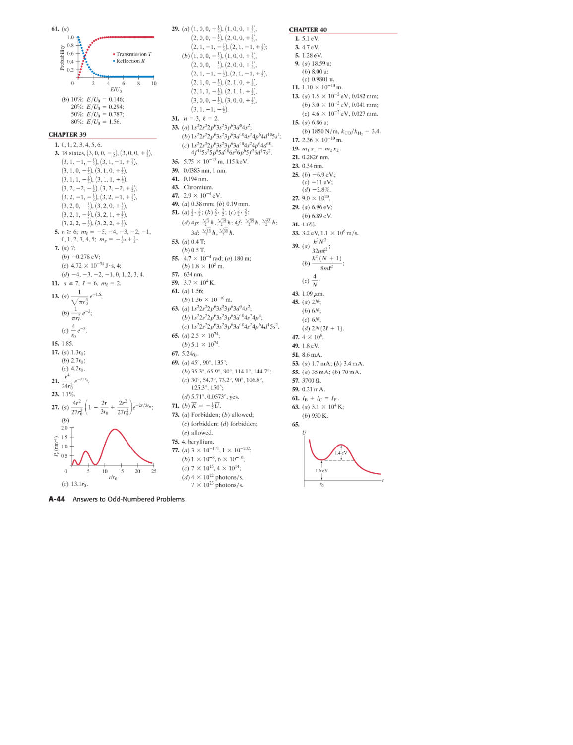
ANSWERS TO ODD-NuMBERED PROBLEMS A-IS
INDEX A-47
PHOTO CREDITS A-72
CONTENTS xi
ApPLICATIONS (SELECTED)
Chapter 1
The 8000- m peaks
Estimating volume of a lake
Height by triangulation
Radius of the Earth
Heartbeats in a lifetime
Particulate pollution (Pr30)
Global positioning satellites (Pr39)
Lung capacity (Pr65)
Chapter 2
Airport runway design
Automobile air bags
Braking distances
CD error correction (Prl0)
CD playing time (Pr13)
Golfing uphill or down (Pr79)
Rapid transit (Pr83)
Chapter 3
Kicked football
Ball sports (Problems)
Extreme sports (Pr41)
Chapter 4
Rocket acceleration 90
What force accelerates a car? 90
How we walk 90
Elevator and countcrwcight 99
Mechanical advantage of pulley 100
Bear sling (Q24) 104
High-speed elevators (Pr19) 105
Mountain climbing (Pr31, 82, 83) 106,110
City planning, cars on hills (Pr71) 109
Bicyclists (Pr72, 73) 109
"Doomsday" asteroid (Pr84) 110
Chapter 5
Push or pull a sled?
Centrifugation
Not skidding on a curve
Banked highways
Simulated gravity (Q18, Pr48)
"Rotor-ride" (Pr82)
Chapter 6
Oil/mineral exploration
Artificial Earth satellites
Geosynchronous satellites
Weightlessness
Free fall in athletics
Planet discovery, extrasolar planets
Black holes
Asteroids (Pr44,78)
N avstar GPS (Pr58)
Black hole, galaxy center
(Pr61,64)
Tides (Pr75)
Chapter 7
Car stopping distance of v 2
Lever (Pr6)
Spiderman (Pr54)
Bicycling on hills, gears (Pr85)
Child safety in car (Pr87)
Rock climber's rope (Pr90)
Chapter 8
Downhill ski runs
Roller coaster
Pole vault
Toy dart gun
xii APPLICATIONS
66,69
77,81,82
77
116
122
126-7
127
131,134
136
144,420
146
147
148
149
152
156
159,162
160
160,161
162
183
191,198
192-3
193
Escape velocity from Earth or Moon
Stair climbing power
Power needs of car
Cardiac treadmill (Prl 04)
Chapter 9
Tennis serve
Rocket propulsion
Rifle recoil
Karate blow
Billiards/bowling
Nuclear collisions
Ballistic pendulum
Conveyor belt
Gravitational slingshot (Prl05)
Crashworthiness (Prl09)
Asteroids, planets (Prll0, 112, 113)
Chapter 10
Hard drive and bit speed
Wrench/tire iron
Flywheel energy
Yo-yo
Car braking forces
Bicycle odometer calibration (Ql)
Tightrope walker (Qll)
Triceps muscle and throwing
(Pr38,39)
CD speed (Pr84)
Bicycle gears (Pr89)
Chapter 11
Rotating skaters, divers
Neutron star collapse
Auto wheel balancing
Top and gyroscope
Coriolis effect
Hurricanes
SUV possible rollover (Pr67)
Triple axel jump (Pr79)
Bat's "sweet spot" (Pr82)
Chapter 12
Tragic collapse 311,323
Lever's mechanical advantage 313
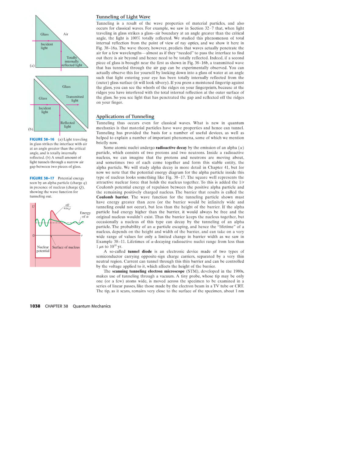
Cantilever 315
Biceps muscle force 315
Human balance with loads 318
Trusses and bridges 324-6, 335
Architecture: arches and domes 327-8
Forces on vertebrae (Pr87) 337
Chapter 13
Lifting water
Hydraulic lift, brakes
Pressure gauges
Hydrometer
Helium balloon lift
Blood flow
Airplane wings, lift
Sailing against the wind
Baseball curve
Blood to the brain, TIA
Blood flow and heart disease
Surface tension, capillarity
Walking on water
Pumps and the heart
Reynolds number (Pr69)
Chapter 14
Car shock absorbers
Resonance damage
8
10
11
11
12
15
16
17
29
31
32
44
45
48
49
174
177
179
181
181
182
201
202
202-3
213
216
219,236-8
220
221
223,228
225,228
226
237
246
247
247
253
256
266,281
271
272-3
275
275
278
281
281
284,286,309
287
296
299-300
301-2
302
308
309
310
345,348
346
346-7
351
352,368
353,357,361
356
357
357
357
359
359-60
360
361
366
Chapter 15
Echolocation by animals
Earthquake waves
Chapter 16
Distance from lightning
Autofocus camera
Wide range of human hearing
Loudspeaker response
Stringed instruments
Wind instruments
Tuning with beats
Doppler blood t10w meter
Sonar: sonic boom
Ultrasound medical imaging
Motion sensor (Pr5)
Chapter 17
Hot air balloon 454
Expansion joints, highways 456,460,463
G as tank overflow 462
Life under ice 462
Cold and hot tire pressure 468
Molecules in a breath 469
Thermostat (QI0) 471
Scuba/snorkeling (Pr38, 47, 82, 85) 473,475
Chapter 18
Chemical reactions, temperature
dependence
Superfluidity
Evaporation cools
Humidity, weather
Chromatography
Pressure cooker (Pr35)
Chapter 19
Working off the calories
Cold floors
Heat loss through windows
How clothes insulate
R-values for thermal insulation
Convective house heating
Human radiative heat loss
Room comfort and metabolism
Radiation from Sun
Medical thermography
Astronomy-size of a star
Thermos bottle (Q30)
Weather, air parcel, adiabatic lapse
rate (Pr56)
Chapter 20
Steam engine 530
Internal combustion engine 531,535-6
Car efficiency 532
Refrigerators, air conditioners 537-8
Heat pump 538
Biological evolution, development 545
Thermal pollution, global warming 549-51
Energy resources 550
Diesel engine (Pr7) 553
Chapter 21
Static electricity
Photocopiers
Electric shielding, safety
DNA structure and replication
Biological cells: electric forces
and kinetic theory
Laser & inkjet printers
383
386
400
401,403,416
425
426
427-8,431
428
432-3
433-6
439
442,453
444
445-6
448
481
483
484,505
485-6
490
493
498
516
516
516-7
517
517
518
519
519
519
520
521
525
560, 589 (Pr78)
569,582-3
577
581-2
581-2,617
583
Chapter 23
Breakdown voltage
Lightning rods, corona
CRT, oscilloscopes,
TV monitors
Photocell (Pr75)
Geiger counter (Pr83)
Van de Graaff (Pr84)
Chapter 24
Capacitor uses
Very high capacitance
Computer key
Camera flash
Heart defibrillator
DRAM (PrlO, 57)
Electrostatic air cleaner (Pr20)
CMOS circuits (Pr53)
Chapter 25
Light bulb
Battery construction
Loudspeaker wires
Resistance thermometer
Heating elements, bulb filament
Why bulbs burn out at turn on
Lightning bolt
Household circuits, shorts
Fuses, circuit breakers
Extension cord danger
Nervous system, conduction
Strain gauge (Pr 24)
Chapter 26
Car battery charging, jump start
RC applications: flashers, wipers
Heart pacemaker
Electric hazards
Proper grounding
Heart fibrillation
Meters, analog and digital
Potentiometers and bridges (Pr)
Chapter 27
Compass and declination 709
Aurora borealis 717
Motors, loudspeakers, galvonometers 720-1
Mass spectrometer 724-5
Electromagnetic pumping (Q14) 726
Cyclotron (Pr66) 731
Beam steering (Pr67) 731
Chapter 28
Coaxial cable
Solenoid switches: car starters,
doorbell
Circuit breakers, magnetic
Relay (Q16)
Atom trap (Pr73)
Chapter 29
Induction stove
EM blood-t1ow meter
Power plant generators
Car alternators
Motor overload
Airport metal detector
Eddy current damping
Transformers and uses, power
Car ignition, bulb ballast
Microphone
Read/write on disks and tape
Digital coding
Credit card swipe
612
612
620-1,723
626
627
627,607
628,631
631
631
636
638
644,647
645
647
651,653,660
653
659
660
660
661
662
662-3
662-3,747,776
663
669-70
673
686,687
691
692, 787
692-4
693-4
692
695-7
704,705
740,789
747
747, 776
751
757
762
765
766-7
768
769
770
770
770-3
772, 773
775
775
775
776
Ground fault circuit interrupter
(GFCI)
Betatron (Pr55)
Search coil (Pr68)
Inductive battery charger (Pr81)
Chapter 30
Spark plug
Pacemaker
Surge protector
LC oscillators, resonance
Capacitors as filters
Loudspeaker cross-over
Impedance matching
Three-phase AC
Q-value (Pr86,87)
Chapter 31
Antennas
Phone call lag time
Solar sail
Optical tweezers
Wireless: AM/FM, TV, tuning,
cell phones, remotes
Chapter 32
How tall a mirror do you need
Close up and wide-view
mIrrors 842,849,859
Where you can see yourself in a
concave mirror
Optical illusions
Apparent depth in water
Rainbows
Colors underwater
Prism binoculars
Fiber optics in
telecomm unica tions
Medical endoscopes
Highway reflectors (Pr86)
Chapter 33
Where you can see a lens image
Cameras, digital and film
Camera adjustments
Pixels and resolution
Human eye
Corrective lenses
Contact lenses
Seeing under water
Magnifying glass
Telescopes
Microscopes
Chapter 34
Bubbles, reflected color
Mirages
Colors in thin soap film, details
Lens coatings
Multiple coating (Pr52)
Chapter 35
Lens and mirror resolution
Hubble Space Telescope
Eye resolution,
useful magnification
Radiotelescopes
Telescope resolution, A rule
Spectroscopy
X-ray diffraction in biology
Polarized sunglasses
LCDs-liquid crystal displays
Sky color
776
782
783
784
785
787
792
794,802
799
799
802-3
803
810
824,831
825
829
829
829-32
840-1
848
851,903
852
853
854
855
855-6,865
856
865
869
878
879-80
881
882-5,892
883-5
885
885
885-7
887-9,931-2
890-1,931,933
900,912-3
903
912-3
913-4
919
929-30
930
930,932-3
931
931
935-6
939
942
943-4
945
Chapter 36
Space travel
Global positioning system (GPS)
Chapter 37
Photocells
Photodiodes
Photosynthesis
Measuring bone density
Electron microscopes
Chapter 38
Tunneling through a QM barrier
Scanning tunneling electron
microscope
Chapter 39
Fluorescence analysis
Fluorescent bulbs
Phosphorescence, watch dials
Lasers
DVD and CD players
Barcodes
Laser surgery
Holography
Chapter 40
Cell energy-activation energy,ATP 1075-7
Weak bonds in cells, DNA 1077-8
Protein synthesis 1079-80
Transparency 1092
Semiconductor diodes, transistors 1094-8
Rectifier circuits 1096
LED displays; photodiodes 1096
Integrated circuits (Chips) 1098
Chapter 41
Smoke detectors 1114
Carbon-14 dating 1122-3
Archeological, geological dating 1123-4
Oldest Earth rocks and earliest life 1124
Chapter 42
Nuclear reactors and power plants 1138--40
Manhattan Project 1141
Stellar fusion 1142-3
Fusion energy reactors 1131,1144-6
Biological radiation damage 1146-7
Radiation dosimetry 1147-9
Radon 1148,1150
Human radiation exposure 1148-9
Radiation sickness 1149
Radiation therapy 1150-1
Proton therapy 1151
Tracers in medicine and biology 1151-2
X-ray imaging 1153
CAT scans 1153-5
Emission tomography: PET
and SPET
NMR and MRI
Chapter 43
Antimatter
Chapter 44
Stars and galaxies 1194-9
Star evolution 1200-2
Supernovae 1201,1202,1203
Star distances 1194,1203-4
Black holes 1202, 1208-9
Curved space 1207-8
Big Bang 1212, 1213-6
Evolution of universe 1216-9
Dark matter and dark energy 1221-3
APPLICATIONS xiii
963
964
992
992
993
995
1000
1038
1038-9
1060
1060
1061
1061-5
1063
1063
1064
1064-5
1156
1156-9
1174-5,1188
F, v, Ii
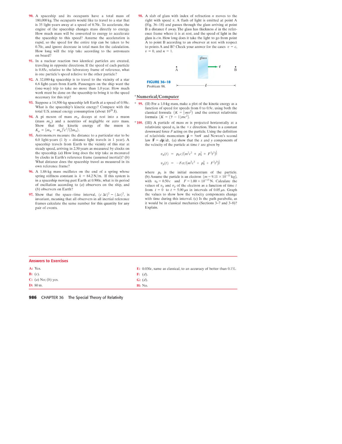
xiv PREFACE
Preface
I was motivated from the beginning to write a textbook different from others that
present physics as a sequence of facts, like a Sears catalog: "here are the facts and
you better learn them." Instead of that approach in which topics are begun
formally and dogmatically, I have sought to begin each topic with concrete
observations and experiences students can relate to: start with specifics and only then
go to the great generalizations and the more formal aspects of a topic, showing why
we believe what we believe. This approach ref1ects how science is actually practiced.
Why a Fourth Edition?
Two recent trends in physics texbooks are disturbing: (1) their revision cycles
have become short-they are being revised every 3 or 4 years; (2) the books are
getting larger, some over 1500 pages. I don't see how either trend can be of
benefit to students. My response: (1) It has been 8 years since the previous
edition of this book. (2) This book makes use of physics education research,
although it avoids the detail a Professor may need to say in class but in a book shuts
down the reader. And this book still remains among the shortest.
This new edition introduces some important new pedagogic tools. It contains
new physics (such as in cosmology) and many new appealing applications (list on
previous page). Pages and page breaks have been carefully formatted to make the
physics easier to follow: no turning a page in the middle of a derivation or Example.
Great efforts were made to make the book attractive so students will want to read it.
Some of the new features are listed below.
What's New
Chapter-Opening Questions: Each Chapter begins with a multiple-choice question,
whose responses include common misconceptions. Students are asked to answer
before starting the Chapter, to get them involved in the material and to get any
preconceived notions out on the table. The issues reappear later in the Chapter,
usually as Exercises, after the material has been covered. The Chapter-Opening
Questions also show students the power and usefulness of Physics.
APPROACH paragraph in worked-out numerical Examples: A short introductory
paragraph before the Solution, outlining an approach and the steps we can take to
get started. Brief NOTES after the Solution may remark on the Solution, may give
an alternate approach, or mention an application.
Step-by-Step Examples: After many Problem Solving Strategies (more than 20 in
the book), the next Example is done step-by-step following precisely the steps just
seen.
Exercises within the text, after an Example or derivation, give students a chance to
see if they have understood enough to answer a simple question or do a simple
calculation. Many are multiple choice.
Greater clarity: No topic, no paragraph in this book was overlooked in the search
to improve the clarity and conciseness of the presentation. Phrases and sentences
that may slow down the principal argument have been eliminated: keep to the
essentials at first, give the elaborations later.
Vector notation, arrows: The symbols for vector quantities in the text and Figures
now have a tiny arrow over them, so they are similar to what we write by hand.
Cosmological Revolution: With generous help from top experts in the field,
readers have the latest results.
Page layout: more than in the previous edition, serious attention has been paid to
how each page is formatted. Examples and all important derivations and
arguments are on facing pages. Students then don't have to turn back and forth.
Throughout, readers see, on two facing pages, an important slice of physics.
New Applications: LCDs, digital cameras and electronic sensors (CCD, CMOS),
electric hazards, GFCIs, photocopiers, inkjet and laser printers, metal detectors,
underwater vision, curve balls, airplane wings, DNA, how we actually see images.
(Turn back a page to see a longer list)
Examples modified: more math steps are spelled out, and many new Examples
added. About 10% of all Examples are Estimation Examples.
This Book is Shorter than other complete full-service books at this level. Shorter
explanations are easier to understand and more likely to be read.
Content and Organizational Changes
· Rotational Motion: Chapters 10 and 11 have been reorganized. All of angular
momentum is now in Chapter 11.
· First law of thermodynamics, in Chapter 19, has been rewritten and extended.
The full form is given: K + U + Eint = Q - W, where internal energy is
E int , and U is potential energy; the form Q - W is kept so that dW = P dV.
· Kinematics and Dynamics of Circular Motion are now treated together in
Chapter 5.
· Work and Energy, Chapters 7 and 8, have been carefully revised.
· Work done by friction is discussed now with energy conservation (energy
terms due to friction).
· Chapters on Inductance and AC Circuits have been combined into one:
Chapter 30.
· Graphical Analysis and Numerical Integration is a new optional Section 2-9.
Problems requiring a computer or graphing calculator are found at the end
of most Chapters.
· Length of an object is a script f rather than normall, which looks like 1 or I
(moment of inertia, current), as in F = IfB. Capital L is for angular
momentum, latent heat, inductance, dimensions of length [L].
· Newton's law of gravitation remains in Chapter 6. Why? Because the 1/r2
law is too important to relegate to a late chapter that might not be covered
at all late in the semester; furthermore, it is one of the basic forces in nature.
In Chapter 8 we can treat real gravitational potential energy and have a fine
instance of using U = - IF. dl.
· New Appendices include the differential form of Maxwell's equations and
more on dimensional analysis.
· Problem Solving Strategies are found on pages 30, 58, 64, 96, 102, 125, 166,
198,229,261,314,504,551,571,685,716, 740, 763, 849, 871, and 913.
Organization
Some instructors may find that this book contains more material than can be
covered in their courses. The text offers great flexibility. Sections marked with a
star * are considered optional. These contain slightly more advanced physics
material, or material not usually covered in typical courses and/or interesting
applications; they contain no material needed in later Chapters (except perhaps in
later optional Sections). For a brief course, all optional material could be dropped
as well as major parts of Chapters 1, 13, 16, 26, 30, and 35, and selected parts of
Chapters 9, 12, 19,20, 33, and the modern physics Chapters. Topics not covered in
class can be a valuable resource for later study by students. Indeed, this text can
serve as a useful reference for years because of its wide range of coverage.
Versions of this Book
Complete version: 44 Chapters
including 9 Chapters of modern
physics.
Classic version: 37 Chapters
including one each on relativity
and quantum theory.
3 Volume version: Available
separately or packaged together
(Vols. 1 & 2 or all 3 Volumes):
Volume 1: Chapters 1-20 on
mechanics, including fluids,
oscillations, waves, plus heat
and thermodynamics.
Volume 2: Chapters 21-35 on
electricity and magnetism, plus
light and optics.
Volume 3: Chapters 36-44 on
modern physics: relativity,
quantum theory, atomic physics,
condensed matter, nuclear
physics, elementary particles,
cosmology and astrophysics.
PREFACE xv
Thanks
Many physics professors provided input or direct feedback on every aspect of this
textbook. They are listed below, and I owe each a debt of gratitude.
Mario Affatigato, Coe College
Lorraine Allen, United States Coast Guard Academy
Zaven Altounian, McGill University
Bruce Barnett, Johns Hopkins University
Michael Barnett, Lawrence Berkeley Lab
Anand Batra, Howard University
Cornelius Bennhold, George Washington University
Bruce Birkett, University of California Berkeley
Dr. Robert Boivin, Auburn University
Subir Bose, University of Central Florida
David Branning, Trinity College
Meade Brooks, Collin County Community College
Bruce Bunker, University of Notre Dame
Grant Bunker, Illinois Institute of Technology
Wayne Carr, Stevens Institute of Technology
Charles Chiu, University of Texas Austin
Robert Coakley, University of Southern Maine
David Curott, University of North Alabama
Biman Das, SUNY Potsdam
Bob Davis, Taylor University
Kaushik De, University of Texas Arlington
Michael Dennin, University of California Irvine
Kathy Dimiduk, University of New Mexico
John DiN ardo, Drexel University
Scott Dudley, United States Air Force Academy
John Essick, Reed College
Cassandra Fesen, Dartmouth College
Alex Filippenko, University of California Berkeley
Richard Firestone, Lawrence Berkeley Lab
Mike Fortner, Northern Illinois University
Tom Furtak, Colorado School of Mines
Edward Gibson, California State University Sacramento
John Hardy, Texas A&M
1. Erik Hendrickson, University of Wisconsin Eau Claire
Laurent Hodges, Iowa State University
David Hogg, New York University
Mark Hollabaugh, Normandale Community College
Andy Hollerman, University of Louisiana at Lafayette
William Holzapfel, University of California Berkeley
Bob Jacobsen, University of California Berkeley
Teruki Kamon, Texas A&M
Daryao Khatri, University of the District of Columbia
Jay Kunze, Idaho State University
Jim LaBelle, Dartmouth College
M.A.K. Lodhi, Texas Tech
Bruce Mason, University of Oklahoma
Dan Mazilu, Virginia Tech
Linda McDonald, North Park College
Bill McNairy, Duke University
Raj Mohanty, Boston University
Giuseppe Molesini, Istituto N azionale di Ottica Florence
Lisa K. Morris, Washington State University
Blaine N orum, University of Virginia
Alexandria Oakes, Eastern Michigan University
Michael Ottinger, Missouri Western State University
Lyman Page, Princeton and WMAP
Bruce Partridge, Haverford College
R. Daryl Pedigo, University of Washington
Robert Pelcovitz, Brown University
Vahe Peroomian, UCLA
James Rabchuk, Western Illinois University
Michele Rallis, Ohio State University
Paul Richards, University of California Berkeley
Peter Riley, University of Texas Austin
Larry Rowan, University of North Carolina Chapel Hill
Cindy Schwarz, Vassar College
Peter Sheldon, Randolph-Macon Woman's College
Natalia A. Sidorovskaia, University of Louisiana at Lafayette
James Siegrist, UC Berkeley, Director Physics Division LBNL
George Smoot, University of California Berkeley
Mark Sprague, East Carolina University
Michael Strauss, University of Oklahoma
Laszlo Takac, University of Maryland Baltimore Co.
Franklin D. Trumpy, Des Moines Area Community College
Ray Turner, Clemson University
Som Tyagi, Drexel University
John Vasut, Baylor University
Robert Webb, Texas A&M
Robert Weidman, Michigan Technological University
Edward A. Whittaker, Stevens Institute of Technology
John Wolbeck, Orange County Community College
Stanley George Wojcicki, Stanford University
Edward Wright, UCLA
Todd Young, Wayne State College
William Younger, College of the Albemarle
Hsiao-Ling Zhou, Georgia State University
I owe special thanks to Prof. Bob Davis for much valuable input, and especially for
working out all the Problems and producing the Solutions Manual for all Problems, as
well as for providing the answers to odd-numbered Problems at the end of this book.
Many thanks also to 1. Erik Hendrickson who collaborated with Bob Davis on the
solutions, and to the team they managed (Profs. Anand Batra, Meade Brooks, David
Currott, Blaine N orum, Michael Ottinger, Larry Rowan, Ray Turner, John Vasut,
William Younger). I am grateful to Profs. John Essick, Bruce Barnett, Robert Coakley,
Biman Das, Michael Dennin, Kathy Dimiduk, John DiNardo, Scott Dudley,
David Hogg, Cindy Schwarz, Ray Turner, and Som Tyagi, who inspired many of
the Examples, Questions, Problems, and significant clarifications.
Crucial for rooting out errors, as well as providing excellent suggestions, were
Profs. Kathy Dimiduk, Ray Turner, and Lorraine Allen. A huge thank you to them
and to Prof. Giuseppe Molesini for his suggestions and his exceptional photographs
for optics.
xvi PREFACE
For Chapters 43 and 44 on Particle Physics and Cosmology and Astrophysics,
I was fortunate to receive generous input from some of the top experts in the field,
to whom I owe a debt of gratitude: George Smoot, Paul Richards, Alex Filippenko,
James Siegrist, and William Holzapfel (UC Berkeley), Lyman Page (Princeton and
WMAP), Edward Wright (UCLA and WMAP), and Michael Strauss (University
of Oklahoma).
I especially wish to thank Profs. Howard Shugart, Chair Frances Hellman, and
many others at the University of California, Berkeley, Physics Department for
helpful discussions, and for hospitality. Thanks also to Prof. Tito Arecchi and others
at the Istituto N azionale di Ottica, Florence, Italy.
Finally, I am grateful to the many people at Prentice Hall with whom I
worked on this project, especially Paul Corey, Karen Karlin, Christian Botting,
John Christiana, and Sean Hogan.
The final responsibility for all errors lies with me. I welcome comments,
corrections, and suggestions as soon as possible to benefit students for the next reprint.
email: Paul.Corey@Pearson.com
Post: Paul Corey
One Lake Street
Upper Saddle River, NJ 07458
About the Author
D.C.G.
Douglas C. Giancoli obtained his BA in physics (summa cum laude) from the
University of California, Berkeley, his MS in physics at the Massachusetts Institute
of Technology, and his PhD in elementary particle physics at the University of Cali-
fornia, Berkeley. He spent 2 years as a post-doctoral fellow at UC Berkeley's Virus
lab developing skills in molecular biology and biophysics. His mentors include
Nobel winners Emilio Segre and Donald Glaser.
He has taught a wide range of undergraduate courses, traditional as well as
innovative ones, and continues to update his texbooks meticulously, seeking ways to
better provide an understanding of physics for students.
Doug's favorite spare-time activity is the outdoors, especially climbing peaks
(here on a dolomite summit, Italy). He says climbing peaks is like learning physics:
it takes effort and the rewards are great.
Online Supplements (partial list)
MasteringPhysics™ (www.masteringphysics.com)
is a sophisticated online tutoring and homework system devel-
oped specially for courses using calculus-based physics.
Originally developed by David Pritchard and collaborators at
MIT, MasteringPhysics provides students with individualized online
tutoring by responding to their wrong answers and providing
hints for solving multi-step problems when they get stuck. It gives
them immediate and up-to-date assessment of their progress, and
shows where they need to practice more. MasteringPhysics
provides instructors with a fast and effective way to assign tried-
and-tested online homework assignments that comprise a range of
problem types. The powerful post-assignment diagnostics allow
instructors to assess the progress of their class as a whole as well
as individual students, and quickly identify areas of difficulty.
WebAssign (www.webassign.com)
CAPA and LON-CAPA (www.lon-capa.org)
Student Supplements (partial list)
Student Study Guide & Selected Solutions Manual (Volume I:
0-13-227324-1, Volumes II & III: 0-13-227325-X) by Frank Wolfs
Student Pocket Companion (0-13-227326-8) by Biman Das
Tutorials in Introductory Physics (0-13-097069-7)
by Lillian e. McDermott, Peter S. Schaffer, and the Physics
Education Group at the University of Washington
Physlet@ Physics (0-13-101969-4)
by Wolfgang Christian and Mario Belloni
Ranking Task Exercises in Physics, Student Edition (0-13-144851-X)
by Thomas L. O'Kuma, David P. Maloney, and Curtis 1. Hieggelke
E&M TIPERs: Electricity & Magnetism Tasks Inspired by Physics
Education Research (0-13-185499-2) by Curtis 1. Hieggelke,
David P. Maloney, Stephen E. Kanim, and Thomas L. O'Kuma
Mathematics for Physics with Calculus (0-13-191336-0)
by Biman Das
PREFACE xvii
To Students
HOW TO STUDY
1. Read the Chapter. Learn new vocabulary and notation. Try to respond to
questions and exercises as they occur.
2. Attend all class meetings. Listen. Take notes, especially about aspects you do
not remember seeing in the book. Ask questions (everyone else wants to, but
maybe you will have the courage). You will get more out of class if you read
the Chapter first.
3. Read the Chapter again, paying attention to details. Follow derivations and
worked-out Examples. Absorb their logic. Answer Exercises and as many of
the end of Chapter Questions as you can.
4. Solve 10 to 20 end of Chapter Problems (or more), especially those assigned.
In doing Problems you find out what you learned and what you didn't. Discuss
them with other students. Problem solving is one of the great learning tools.
Don't just look for a formula-it won't cut it.
NOTES ON THE FORMAT AND PROBLEM SOLVING
1. Sections marked with a star (*) are considered optional. They can be omitted
without interrupting the main flow of topics. No later material depends on
them except possibly later starred Sections. They may be fun to read, though.
2. The customary conventions are used: symbols for quantities (such as m for
mass) are italicized, whereas units (such as m for meter) are not italicized.
Symbols for vectors are shown in boldface with a small arrow above: F.
3. Few equations are valid in all situations. Where practical, the limitations of
important equations are stated in square brackets next to the equation. The
equations that represent the great laws of physics are displayed with a tan
background, as are a few other indispensable equations.
4. At the end of each Chapter is a set of Problems which are ranked as Level I, II, or
III, according to estimated difficulty. Level I Problems are easiest, Level II are
standard Problems, and Level III are "challenge problems." These ranked
Problems are arranged by Section, but Problems for a given Section may depend
on earlier material too. There follows a group of General Problems, which are not
arranged by Section nor ranked as to difficulty. Problems that relate to optional
Sections are starred (*). Most Chapters have 1 or 2 Computer/Numerical
Problems at the end, requiring a computer or graphing calculator. Answers to
odd-numbered Problems are given at the end of the book.
5. Being able to solve Problems is a crucial part of learning physics, and provides
a powerful means for understanding the concepts and principles. This book
contains many aids to problem solving: (a) worked-out Examples and their
solutions in the text, which should be studied as an integral part of the text;
(b) some of the worked-out Examples are Estimation Examples, which show
how rough or approximate results can be obtained even if the given data are
sparse (see Section 1-6); ( c) special Problem Solving Strategies placed
throughout the text to suggest a step-by-step approach to problem solving
for a particular topic-but remember that the basics remain the same;
most of these "Strategies" are followed by an Example that is solved by
explicitly following the suggested steps; (d) special problem-solving Sections;
(e) "Problem Solving" marginal notes which refer to hints within the text for
solving Problems; (f) Exercises within the text that you should work out imme-
diately, and then check your response against the answer given at the bottom of
the last page of that Chapter; (g) the Problems themselves at the end of each
Chapter (point 4 above).
6. Conceptual Examples pose a question which hopefully starts you to think and
come up with a response. Give yourself a little time to come up with your own
response before reading the Response given.
7. Math review, plus some additional topics, are found in Appendices. Useful data,
conversion factors, and math formulas are found inside the front and back covers.
xviii PREFACE
USE OF COLOR
Vectors
A general vector
resultant vector (sum) is slightly thicker
components of any vector are dashed
Displacement (D, i)
Velocity (v)
Acceleration (3)
Force (F)
Force on second or
third object in same figure
Momentum (p or In v)
Angular momentum (L)
Angular velocity (W)
Torque (-7")
Electric field (E)
Magnetic field (8)
----
Electric field lines
Electricity and magnetism
Electric circuit symbols
Equipotentiallines
Magnetic field lines
Electric charge (+)
Electric charge (-)
e or . +
e or .-
Wire, with switch S ----/ -
S
Resistor --'\IVV\r-
Capacitor --1
Inductor
Battery -II-
Ground .L
Optics
Other
Light rays
Object
Real image
( dashed)
-
t
.
Virtual image .
(dashed and paler)
Energy level
(atom, etc.)
Measurement lines I+- 1.0 m---+!
Path of a moving - - - --....
object
Direction of motion
or current
PREFACE xix
Image of the Earth from a NASA satellite. The sky
appears black from out in space because
there are so few molecules to
refled light. (Why the sky
appears blue to us on
Earth has to do with
scattering of light by
molecules of the
atmosphere, as
discussed in
Chapter 35.)
Note the
storm off
the coast
of Mexico.
Introduction,
Measurement, Estimating
CHAPTER-OPENING QUESTION-Guess now!
Suppose you wanted to actually measure the radius of the Earth, at least roughly,
rather than taking other people's word for what it is. Which response below
describes the best approach?
(a) Give up; it is impossible using ordinary means.
(b) Use an extremely long measuring tape.
(c) It is only possible by flying high enough to see the actual curvature of the Earth.
(d) Use a standard measuring tape, a step ladder, and a large smooth lake.
(e) Use a laser and a mirror on the Moon or on a satellite.
[We start each Chapter with a Question, like the one above. Try to answer it right away. Don't worry
about getting the right answer now-the idea is to get your preconceived notions out on the table. If they
are misconception5 we expect them to be cleared up as you read the Chapter. You will usually get another
chance at the Question later in the Chapter when the appropriate material has been covered. These
Chapter-Opening Questions will also help you to see the power and usefulness of physics.]
\?
T E
CONTENTS
1-1 The Nature of Science
1-2 Models, Theories, and Laws
1-3 Measurement and Uncertainty;
Significant Figures
1-4 Units, Standards, and
the SI System
1-5 Converting Units
1-6 Order of Magnitude:
Rapid Estimating
* 1-7 Dimensions and Dimensional
Analysis
1
(a)
(b)
FIGURE 1-1 (a) This Roman
aqueduct was built 2000 years ago
and still stands. (b) The Hartford
Civic Center collapsed in 1978, just
two years after it was built.
2 CHAPTER 1
P hysics is the most basic of the sciences. It deals with the behavior and
structure of matter. The field of physics is usually divided into classical physics
which includes motion, fluids, heat, sound, light, electricity and magnetism;
and modern physics which includes the topics of relativity, atomic structure,
condensed matter, nuclear physics, elementary particles, and cosmology and astrophysics.
We will cover all these topics in this book, beginning with motion (or mechanics, as it
is often called) and ending with the most recent results in our study of the cosmos.
An understanding of physics is crucial for anyone making a career in science
or technology. Engineers, for example, must know how to calculate the forces within
a structure to design it so that it remains standing (Fig. 1-1a). Indeed, in Chapter 12
we will see a worked-out Example of how a simple physics calculation-or even
intuition based on understanding the physics of forces-would have saved
hundreds of lives (Fig. 1-1b). We will see many examples in this book of how
physics is useful in many fields, and in everyday life.
1-1 The Nature of Science
The principal aim of all sciences, including physics, is generally considered to be
the search for order in our observations of the world around us. Many people
think that science is a mechanical process of collecting facts and devising theories.
But it is not so simple. Science is a creative activity that in many respects resem-
bles other creative activities of the human mind.
One important aspect of science is observation of events, which includes the
design and carrying out of experiments. But observation and experiment require
imagination, for scientists can never include everything in a description of what
they observe. Hence, scientists must make judgments about what is relevant in
their observations and experiments.
Consider, for example, how two great minds, Aristotle (384-322 B.C.) and
Galileo (1564-1642), interpreted motion along a horizontal surface. Aristotle
noted that objects given an initial push along the ground (or on a tabletop) always
slow down and stop. Consequently, Aristotle argued that the natural state of an
object is to be at rest. Galileo, in his reexamination of horizontal motion in the
1600s, imagined that if friction could be eliminated, an object given an initial
push along a horizontal surface would continue to move indefinitely without
stopping. He concluded that for an object to be in motion was just as natural as for
it to be at rest. By inventing a new approach, Galileo founded our modern view of
motion (Chapters 2,3, and 4), and he did so with a leap of the imagination. Galileo
made this leap conceptually, without actually eliminating friction.
Observation, with careful experimentation and measurement, is one side of the
scientific process. The other side is the invention or creation of theories to explain
and order the observations. Theories are never derived directly from observations.
Observations may help inspire a theory, and theories are accepted or rejected based
on the results of observation and experiment.
The great theories of science may be compared, as creative achievements, with
great works of art or literature. But how does science differ from these other
creative activities? One important difference is that science requires testing of its
ideas or theories to see if their predictions are borne out by experiment.
Although the testing of theories distinguishes science from other creative
fields, it should not be assumed that a theory is "proved" by testing. First of all, no
measuring instrument is perfect, so exact confirmation is not possible. Further-
more, it is not possible to test a theory in every single possible circumstance. Hence
a theory cannot be absolutely verified. Indeed, the history of science tells us that
long-held theories can be replaced by new ones.
1-2 Models, Theories, and Laws
When scientists are trying to understand a particular set of phenomena, they often
make use of a model. A model, in the scientist's sense, is a kind of analogy or
mental image of the phenomena in terms of something we are familiar with. One
example is the wave model of light. We cannot see waves of light as we can water
waves. But it is valuable to think of light as made up of waves because experiments
indicate that light behaves in many respects as water waves do.
The purpose of a model is to give us an approximate mental or visual picture-
something to hold on to-when we cannot see what actually is happening. Models
often give us a deeper understanding: the analogy to a known system (for instance,
water waves in the above example) can suggest new experiments to perform and can
provide ideas about what other related phenomena might occur.
You may wonder what the difference is between a theory and a model. Usually
a model is relatively simple and provides a structural similarity to the phenomena
being studied. A theory is broader, more detailed, and can give quantitatively testable
predictions, often with great precision.
It is important, however, not to confuse a model or a theory with the real
system or the phenomena themselves.
Scientists give the title law to certain concise but general statements about
how nature behaves (that energy is conserved, for example). Sometimes the state-
ment takes the form of a relationship or equation between quantities (such as
Newton's second law, F = ma).
To be called a law, a statement must be found experimentally valid over a wide
range of observed phenomena. For less general statements, the term principle is
often used (such as Archimedes' principle).
Scientific laws are different from political laws in that the latter are
prescriptive: they tell us how we ought to behave. Scientific laws are descriptive:
they do not say how nature should behave, but rather are meant to describe how
nature does behave. As with theories, laws cannot be tested in the infinite variety
of cases possible. So we cannot be sure that any law is absolutely true. We use the
term "law" when its validity has been tested over a wide range of cases, and when
any limitations and the range of validity are clearly understood.
Scientists normally do their research as if the accepted laws and theories were
true. But they are obliged to keep an open mind in case new information should
alter the validity of any given law or theory.
1-3 Measurement and Uncertainty;
Significant Figures
In the quest to understand the world around us, scientists seek to find relationships
among physical quantities that can be measured.
Uncertainty
Reliable measurements are an important part of physics. But no measurement is
absolutely precise. There is an uncertainty associated with every measurement. Among
the most important sources of uncertainty, other than blunders, are the limited accuracy
of every measuring instrument and the inability to read an instrument beyond some
fraction of the smallest division shown. For example, if you were to use a centimeter
ruler to measure the width of a board (Fig. 1-2), the result could be claimed to be
precise to about 0.1 cm (1 mm), the smallest division on the ruler, although half of this
value might be a valid claim as well. The reason is that it is difficult for the observer to
estimate (or interpolate) between the smallest divisions. Furthermore, the ruler itself
may not have been manufactured to an accuracy very much better than this.
When giving the result of a measurement, it is important to state the estimated
uncertainty in the measurement. For example, the width of a board might be
written as 8.8 1: 0.1 cm. The 1: 0.1 cm ("plus or minus 0.1 cm") represents the
estimated uncertainty in the measurement, so that the actual width most likely lies
between 8.7 and 8.9 cm. The percent uncertainty is the ratio of the uncertainty
to the measured value, multiplied by 100. For example, if the measurement is 8.8
and the uncertainty about 0.1 cm, the percent uncertainty is
0.1
- X 100% :::::; 1%,
8.8
where:::::; means "is approximately equal to."
FIGURE 1-2 Measuring the width
of a board with a centimeter ruler.
The uncertainty is about ::!: 1 mm.
SECTION 1-3 3
(a)
(b)
FIGURE 1-3 These two calculators
show the wrong number of significant
figures. In (a), 2.0 was divided by 3.0.
The correct final result would be 0.67.
In (b), 2.5 was multiplied by 3.2. The
correct result is 8.0.
PROBLEM SOLVING
Significant figure rule:
Number of significant figures in final
result should be same as the least
significant input value
. CAUTION
Calculators err with significant figures
WJ\ PRO B L EMS 0 L V I N G
Report only the proper number of
significant figures in the final result.
Keep extra digits during
the calculation
FIGURE 1-4 Example 1-1.
A protractor used to measure an angle.
4 CHAPTER 1
Often the uncertainty in a measured value is not specified explicitly. In such cases,
the uncertainty is generally assumed to be one or a few units in the last digit specified.
For example, if a length is given as 8.8 cm, the uncertainty is assumed to be about
0.1 em or 0.2 em. It is important in this case that you do not write 8.80 cm, for this
implies an uncertainty on the order of 0.01 cm; it assumes that the length is probably
between 8.79 cm and 8.81 cm, when actually you believe it is between 8.7 and 8.9 cm.
Significant Figures
The number of reliably known digits in a number is called the number of
significant figures. Thus there are four significant figures in the number 23.21 cm
and two in the number 0.062 cm (the zeros in the latter are merely place holders
that show where the decimal point goes). The number of significant figures may
not always be clear. Take, for example, the number 80. Are there one or two signif-
icant figures? We need words here: If we say it is roughly 80 km between two
cities, there is only one significant figure (the 8) since the zero is merely a place
holder. If there is no suggestion that the 80 is a rough approximation, then we can
often assume (as we will in this book) that it is 80 km within an accuracy of about
1 or 2 km, and then the 80 has two significant figures. If it is precisely 80 km, to
within I 0.1 km, then we write 80.0 km (three significant figures).
When making measurements, or when doing calculations, you should avoid the
temptation to keep more digits in the final answer than is justified. For example, to
calculate the area of a rectangle 11.3 cm by 6.8 cm, the result of multiplication would
be 76.84 cm 2 . But this answer is clearly not accurate to 0.01 cm 2 , since (using the
outer limits of the assumed uncertainty for each measurement) the result could be
between 11.2 cm X 6.7 cm = 75.04 cm 2 and 11.4 cm X 6.9 cm = 78.66 cm 2 . At best,
we can quote the answer as 77 cm 2 , which implies an uncertainty of about 1 or 2 cm 2 .
The other two digits (in the number 76.84 cm 2 ) must be dropped because they are not
significant. As a rough general rule (i.e., in the absence of a detailed consideration
of uncertainties), we can say that the final result of a multiplication or division should
have only as many digits as the number with the least number of significant figures
used in the calculation. In our example, 6.8 cm has the least number of significant
figures, namely two. Thus the result 76.84 cm 2 needs to be rounded off to 77 cm 2 .
I EXERCISE A The area of a rectangle 4.5 cm by 3.25 cm is correctly given by (a) 14.625 cm 2 ;
(b) 14.63cm 2 ; (c) 14.6cm 2 ; (d) 15cm 2 .
When adding or subtracting numbers, the final result is no more precise than
the least precise number used. For example, the result of subtracting 0.57 from 3.6
is 3.0 (and not 3.03).
Keep in mind when you use a calculator that all the digits it produces may not
be significant. When you divide 2.0 by 3.0, the proper answer is 0.67, and not some
such thing as 0.666666666. Digits should not be quoted in a result, unless they are
truly significant figures. However, to obtain the most accurate result, you should
normally keep one or more extra significant figures throughout a calculation, and
round off only in the final result. (With a calculator, you can keep all its digits in
intermediate results.) Note also that calculators sometimes give too few significant
figures. For example, when you multiply 2.5 X 3.2, a calculator may give the
answer as simply 8. But the answer is accurate to two significant figures, so the proper
answer is 8.0. See Fig. 1-3.
CONCEPTUAL EXAMPLE 1 -1 Significant figures. Using a protractor (Fig. 1-4),
you measure an angle to be 30°. (a) How many significant figures should you quote in
this measurement? (b) Use a calculator to find the cosine of the angle you measured.
RESPONSE (a) If you look at a protractor, you will see that the precision with
which you can measure an angle is about one degree (certainly not 0.1°). So you
can quote two significant figures, namely, 30° (not 30.0°). (b) If you enter cos 30°
in your calculator, you will get a number like 0.866025403. However, the angle
you entered is known only to two significant figures, so its cosine is correctly
given by 0.87; you must round your answer to two significant figures.
NOTE Cosine and other trigonometric functions are reviewed in Appendix A.
I EXERCISE B Do 0.00324 and 0.00056 have the same number of significant figures?
Be careful not to confuse significant figures with the number of decimal places.
I EXERCISE C For each of the following numbers, state the number of significant figures
and the number of decimal places: (a) 1.23; (b) 0.123; (c) 0.0123.
Scientific Notation
We commonly write numbers in "powers of ten," or "scientific" notation-for
instance 36,900 as 3.69 X 10 4 , or 0.0021 as 2.1 X 10- 3 . One advantage of scientific
notation is that it allows the number of significant figures to be clearly expressed.
For example, it is not clear whether 36,900 has three, four, or five significant
figures. With powers of ten notation the ambiguity can be avoided: if the number is
known to three significant figures, we write 3.69 X 10 4 , but if it is known to four,
we write 3.690 X 10 4 .
I EXERCISE D Write each of the following in scientific notation and state the number of
significant figures for each: (a) 0.0258, (b) 42,300, (c) 344.50.
Percent Uncertainty versus Significant Figures
The significant figures rule is only approximate, and in some cases may underestimate
the accuracy (or uncertainty) of the answer. Suppose for example we divide 97 by 92:
97
92 = 1.05 1.1.
Both 97 and 92 have two significant figures, so the rule says to give the answer
as 1.1. Yet the numbers 97 and 92 both imply an uncertainty of I 1 if no other
uncertainty is stated. Now 92 I 1 and 97 I 1 both imply an uncertainty of
about 1 % (1/92 0.01 = 1%). But the final result to two significant figures
is 1.1, with an implied uncertainty of I 0.1, which is an uncertainty of
0.1/1.1 0.1 10%. In this case it is better to give the answer as 1.05 (which is
three significant figures). Why? Because 1.05 implies an uncertainty of I 0.01
which is 0.01/1.05 0.01 1%, just like the uncertainty in the original
numbers 92 and 97.
SUGGESTION: Use the significant figures rule, but consider the % uncer-
tainty too, and add an extra digit if it gives a more realistic estimate of uncertainty.
Approximations
Much of physics involves approximations, often because we do not have the
means to solve a problem precisely. For example, we may choose to ignore air
resistance or friction in doing a Problem even though they are present in the real
world, and then our calculation is only an approximation. In doing Problems, we
should be aware of what approximations we are making, and be aware that the
precision of our answer may not be nearly as good as the number of significant
figures given in the result.
Accuracy versus Precision
There is a technical difference between "precision" and "accuracy." Precision in a strict
sense refers to the repeatability of the measurement using a given instrument. For
example, if you measure the width of a board many times, getting results like 8.81 cm,
8.85 cm, 8.78 cm, 8.82 cm (interpolating between the 0.1 cm marks as best as possible
each time), you could say the measurements give a precision a bit better than 0.1 cm.
Accuracy refers to how close a measurement is to the true value. For example, if the
ruler shown in Fig. 1-2 was manufactured with a 2% error, the accuracy of its
measurement of the board's width (about 8.8 cm) would be about 2% of 8.8 cm or
about I 0.2 cm. Estimated uncertainty is meant to take both accuracy and precision
into account.
SECTION 1 -3 Measurement, Uncertainty; Significant Figures S
TABLE 1-1 Some Typical
Lengths or Distances
(order of magnitude)
Length
(or Distance)
Meters
(approximate)
Neutron or proton 10- 15 m
(diameter)
Atom
(diameter) 10- 10 m
Virus [see Fig. 1-5a] 10- 7 m
Sheet of paper 10- 4
(thickness) m
Finger width 10- 2 m
Football field length 10 2 m
Height of Mt. Everest 10 4
[see Fig.1-5b] m
Earth diameter 10 7 m
Earth to Sun 1011 m
Earth to nearest star 10 16 m
Earth to nearest galaxy 10 22 m
Earth to farthest
galaxy visible 10 26 m
FIGURE 1-5 Some lengths:
(a) viruses (about 10- 7 m long)
attacking a cell; (b) Mt. Everest's
height is on the order of 10 4 m
(8850 m, to be precise).
(a)
(b)
1-4 Units, Standards, and the SI Systelll
The measurement of any quantity is made relative to a particular standard or unit,
and this unit must be specified along with the numerical value of the quantity. For
example, we can measure length in British units such as inches, feet, or miles, or in
the metric system in centimeters, meters, or kilometers. To specify that the length
of a particular object is 18.6 is meaningless. The unit must be given; for clearly,
18.6 meters is very different from 18.6 inches or 18.6 millimeters.
For any unit we use, such as the meter for distance or the second for time, we
need to define a standard which defines exactly how long one meter or one second
is. It is important that standards be chosen that are readily reproducible so that
anyone needing to make a very accurate measurement can refer to the standard in
the laboratory.
Length
The first truly international standard was the meter (abbreviated m) established as
the standard of length by the French Academy of Sciences in the 1790s. The stan-
dard meter was originally chosen to be one ten-millionth of the distance from the
Earth's equator to either pole,t and a platinum rod to represent this length was
made. (One meter is, very roughly, the distance from the tip of your nose to the tip
of your finger, with arm and hand stretched out to the side.) In 1889, the meter was
defined more precisely as the distance between two finely engraved marks on a
particular bar of platinum-iridium alloy. In 1960, to provide greater precision and
reproducibility, the meter was redefined as 1,650,763.73 wavelengths of a particular
orange light emitted by the gas krypton-86. In 1983 the meter was again redefined,
this time in terms of the speed of light (whose best measured value in terms of the
older definition of the meter was 299,792,458 mis, with an uncertainty of 1 m/s).
The new definition reads: "The meter is the length of path traveled by light in
vacuum during a time interval of 1/299,792,458 of a second.,,:j:
British units of length (inch, foot, mile) are now defined in terms of the
meter. The inch (in.) is defined as precisely 2.54 centimeters (cm; 1 cm = 0.01 m).
Other conversion factors are given in the Table on the inside of the front cover
of this book. Table 1-1 presents some typical lengths, from very small to very
large, rounded off to the nearest power of ten. See also Fig. 1-5. [Note that the
abbreviation for inches (in.) is the only one with a period, to distinguish it from
the word "in".]
Time
The standard unit of time is the second (s). For many years, the second was defined as
1/86,400 of a mean solar day (24 h/day X 60 min/h X 60 s/min = 86,400 s/day).
The standard second is now defined more precisely in terms of the frequency of radi-
ation emitted by cesium atoms when they pass between two particular states.
[Specifically, one second is defined as the time required for 9,192,631,770 periods of
this radiation.] There are, by definition, 60 s in one minute (min) and 60 minutes in
one hour (h). Table 1-2 presents a range of measured time intervals, rounded off to
the nearest power of ten.
Mass
The standard unit of mass is the kilogram (kg). The standard mass is a particular
platinum-iridium cylinder, kept at the International Bureau of Weights and
Measures near Paris, France, whose mass is defined as exactly 1 kg. A range of
masses is presented in Table 1-3. [For practical purposes, 1 kg weighs about
2.2 pounds on Earth.]
iModern measurements of the Earth's circumference reveal that the intended length is off by about
one-fiftieth of 1 %. Not bad!
jThe new definition of the meter has the effect of giving the speed of light the exact value of
299,792,458 m/s.
6 CHAPTER 1 Introduction, Measurement, Estimating
Time Interval
TABLE 1-3 Some Masses
Seconds (approximate)
10- 23 s
10- 22 S to 10 28 S
10- 6 S
10 0 s (= 1 s)
10 5 S
3 X 10 7 S
2 X 10 9 S
1011 S
10 14 S
10 17 S
10 18 S
Object
Electron
Proton, neutron
DNA molecule
Bacterium
Mosquito
Plum
Human
Ship
Earth
Sun
Galaxy
Lifetime of very unstable subatomic particle
Lifetime of radioactive elements
Lifetime of muon
Time between human heartbeats
One day
One year
Human life span
Length of recorded history
Humans on Earth
Life on Earth
Age of Universe
Kilograms (approximate)
10- 30 kg
10- 27 kg
10- 17 kg
10- 15 kg
10- 5 kg
10- 1 kg
10 2 kg
10 8 kg
6 X 10 24 kg
2 X 10 30 kg
10 41 kg
When dealing with atoms and molecules, we usually use the unified atomic
mass unit (u). In terms of the kilogram,
1 u = 1.6605 X 10- 27 kg.
The definitions of other standard units for other quantities will be given as we
encounter them in later Chapters. (Precise values of this and other numbers are
given inside the front cover.)
Unit Prefixes
In the metric system, the larger and smaller units are defined in multiples of 10 from
the standard unit, and this makes calculation particularly easy. Thus 1 kilometer (km)
is 1000 m, 1 centimeter is 160 m, 1 millimeter (mm) is I OO m or fa cm, and so on.
The prefixes "centi-," "kilo-," and others are listed in Table 1-4 and can be applied
not only to units of length but to units of volume, mass, or any other metric unit.
For example, a centiliter (cL) is 160 liter (L), and a kilogram (kg) is 1000 grams (g).
Systems of Units
When dealing with the laws and equations of physics it is very important to use a
consistent set of units. Several systems of units have been in use over the years.
Today the most important is the Systeme International (French for International
System), which is abbreviated SI. In SI units, the standard of length is the meter,
the standard for time is the second, and the standard for mass is the kilogram. This
system used to be called the MKS (meter-kilogram-second) system.
A second metric system is the cgs system, in which the centimeter, gram, and
second are the standard units of length, mass, and time, as abbreviated in the title.
The British engineering system has as its standards the foot for length, the pound
for force, and the second for time.
We use SI units almost exclusively in this book.
Base versus Derived Quantities
Physical quantities can be divided into two categories: base quantities and derived
quantities. The corresponding units for these quantities are called base units and
derived units. A base quantity must be defined in terms of a standard. Scientists, in the
interest of simplicity, want the smallest number of base quantities possible consistent
with a full description of the physical world. This number turns out to be seven, and
those used in the SI are given in Table 1-5. All other quantities can be defined in terms
of these seven base quantities;'- and hence are referred to as derived quantities. An
example of a derived quantity is speed, which is defined as distance divided by the time
it takes to travel that distance. A Table inside the front cover lists many derived
quantities and their units in terms of base units. To define any quantity, whether base or
derived, we can specify a rule or procedure, and this is called an operational definition.
i-The only exceptions are for angle (radians-see Chapter 8) and solid angle (steradian). No general
agreement has been reached as to whether these are base or derived quantities.
Prefix Abbreviation Value
yotta Y 10 24
zetta Z 10 21
exa E 10 18
peta P 10 15
tera T 10 12
glga G 10 9
mega M 10 6
kilo k 10 3
hecto h 10 2
deka da 10 1
deci d 10- 1
centi c 10- 2
milli m 10- 3
micro t f.L 10- 6
nano n 10- 9
plCO P 10- 12
femto f 10- 15
atto a 10- 18
zepto z 10- 21
yocto Y 10- 24
-; jJ. is the Greek letter "mu."
TABLE 1-5
SI Base Quantities and Units
Unit
Quantity Unit Abbreviation
Length meter m
Time second s
Mass kilogram kg
Electric
current ampere A
Temperature kelvin K
Amount
of substance mole mol
Luminous
intensity candela cd
SECTION 1 -4 Units, Standards, and the SI System 7
@ PHYSICS APPLIED
The world's tallest peaks
FIGURE 1-6 The world's second
highest peak, K2, whose summit is
considered the most difficult of the
"8000-ers." K2 is seen here from
the north (China).
TABLE 1-6
The 8000-m Peal<s
Peak
Mt. Everest
K2
Kangchenjunga
Lhotse
Makalu
Cho Oyu
Dhaulagiri
Manaslu
Nanga Parbat
Annapurna
Gasherbrum I
Broad Peak
Gasherbrum II
Shish a Pangma
Height (m)
8850
8611
8586
8516
8462
8201
8167
8156
8125
8091
8068
8047
8035
8013
1-5 Converting Units
Any quantity we measure, such as a length, a speed, or an electric current, consists
of a number and a unit. Often we are given a quantity in one set of units, but we
want it expressed in another set of units. For example, suppose we measure that a
table is 21.5 inches wide, and we want to express this in centimeters. We must use a
conversion factor, which in this case is (by definition) exactly
1 in. = 2.54 cm
or, written another way,
1 = 2.54 cm/in.
Since multiplying by one does not change anything, the width of our table, in cm, is
21.5 inches = (21.5 in-) x (2.54 :. ) = 54.6 em.
Note how the units (inches in this case) cancelled out. A Table containing many unit
conversions is found inside the front cover of this book. Let's consider some Examples.
EXAMPLE 1-2
The 8000-m peaks. The fourteen tallest peaks in the world
(Fig. 1-6 and Table 1-6) are referred to as "eight-thousanders," meaning their
summits are over 8000 m above sea level. What is the elevation, in feet, of an
elevation of 8000 m?
APPROACH We need simply to convert meters to feet, and we can start with the
conversion factor 1 in. = 2.54 cm, which is exact. That is, 1 in. = 2.5400 cm to
any number of significant figures, because it is defined to be.
SOLUTION One foot is 12 in., so we can write
1 ft = (12 in-) ( 2.54 :J = 30.48 em = 0.3048 tn,
which is exact. Note how the units cancel (colored slashes). We can rewrite this
equation to find the number of feet in 1 meter:
1 ft
1 m = 0.3048 = 3.28084 ft.
We multiply this equation by 8000.0 (to have five significant figures):
8000.0 m (8000.0 "m.) ( 3.28084 .: ) 26,247 ft.
An elevation of 8000 m is 26,247 ft above sea level.
NOTE We could have done the conversion all in one line:
8000.0 tn = (8000.0"m.) C :- ) ( 2. ) C .:.J = 26,247[l.
The key is to multiply conversion factors, each equal to one (= 1.0000), and to
make sure the units cancel.
EXERCISE E There are only 14 eight-thousand-meter peaks in the world (see Example 1-2),
and their names and elevations are given in Table 1-6. They are all in the Himalaya moun-
tain range in India, Pakistan, Tibet, and China. Determine the elevation of the world's
three highest peaks in feet.
8 CHAPTER 1 Introduction, Measurement, Estimating
EXAMPLE 1-3
Apartment area. You have seen a nice apartment whose
floor area is 880 square feet (ft 2 ). What is its area in square meters?
APPROACH We use the same conversion factor, 1 in. = 2.54 cm, but this time
we have to use it twice.
SOLUTION Because 1in. = 2.54cm = 0.0254m, then 1ft 2 = (12in.?(0.0254m/in.)2 =
0.0929 m 2 . So 880 ft 2 = (880 ft 2 )(0.0929 m 2 /ft 2 ) 82 m 2 .
NOTE As a rule of thumb, an area given in ft2 is roughly 10 times the number of
square meters (more precisely, about 10.8 x).
EXAMPLE 1-4
Speeds. Where the posted speed limit is 55 miles per hour
(mi/h or mph), what is this speed (a) in meters per second (m/s) and (b) in
kilometers per hour (km/h)?
APPROACH We again use the conversion factor 1 in. = 2.54 cm, and we recall
that there are 5280 ft in a mile and 12 inches in a foot; also, one hour contains
(60min/h) X (60s/min) = 3600s/h.
SOLUTION (a) We can write 1 mile as
1 tni (52ROk) (12 ::- ) ( 2.54 :: ) (,o :m ) 1609 tn.
We also know that 1 hour contains 3600 s, so
mi ( rni. ) ( m ) ( 1 11' )
55 h = 55 11' 1609 mi. 3600 s
m
25-,
s
where we rounded off to two significant figures.
(b) Now we use 1 mi = 1609 m = 1.609 km; then
mi ( rni. ) ( km ) km
55h = 55h 1.609 mi. = 88h'
NOTE Each conversion factor is equal to one. You can look up most conversion
factors in the Table inside the front cover.
I EXERCISE F Would a driver traveling at 15 m/s in a 35 mi/h zone be exceeding the speed
limit?
When changing units, you can avoid making an error in the use of conversion
factors by checking that units cancel out properly. For example, in our conversion
of 1 mi to 1609 m in Example 1-4(a), if we had incorrectly used the factor c ol m )
instead of ( l O m )' the centimeter units would not have cancelled out; we would not
have ended up with meters.
1-6 Order of Magnitude: Rapid Estilllating
We are sometimes interested only in an approximate value for a quantity. This
might be because an accurate calculation would take more time than it is worth
or would require additional data that are not available. In other cases, we may
want to make a rough estimate in order to check an accurate calculation made
on a calculator, to make sure that no blunders were made when the numbers
were entered.
A rough estimate is made by rounding off all numbers to one significant figure
and its power of 10, and after the calculation is made, again only one significant
figure is kept. Such an estimate is called an order-of-magnitude estimate and can
be accurate within a factor of 10, and often better. In fact, the phrase "order of
magnitude" is sometimes used to refer simply to the power of 10.
\
PROBLEM SOLVING
Conversion factors = 1
\
:N1 PROBLEM SOLVING
Unit conversion is wrong if units do
not cancel
\ PROBLEM SOLVING
How to make a rough estimate
SECTION 1 -6 Order of Magnitude: Rapid Estimating 9
(a)
@ PHYSICS APPLIED
Estimating the volume (or mass) of
a lake; see also Fig. 1-7
PROBLEM SOLVING
Use symmetry when possible
(b)
FIGURE 1-7 Example 1-5. (a) How
much water is in this lake? (Photo is of
one of the Rae Lakes in the Sierra
Nevada of California.) (b) Model of
the lake as a cylinder. [We could go one
step further and estimate the mass or
weight of this lake. We will see later
that water has a density of 1000 kg/m 3 ,
so this lake has a mass of about
(103 kg/m 3 )(10 7 m 3 ) 10 10 kg, which is
about 10 billion kg or 10 million metric
tons. (A metric ton is 1000 kg, about
2200 Ibs, slightly larger than a British
ton, 2000 Ibs.)]
EXAMPLE 1-5
ESTIMATE Volume of a lake. Estimate how much water
there is in a particular lake, Fig. 1-7a, which is roughly circular, about 1 km
across, and you guess it has an average depth of about 10 m.
APPROACH No lake is a perfect circle, nor can lakes be expected to have a
perfectly flat bottom. We are only estimating here. To estimate the volume, we
can use a simple model of the lake as a cylinder: we multiply the average depth
of the lake times its roughly circular surface area, as if the lake were a cylinder
(Fig. 1-7b).
SOLUTION The volume V of a cylinder is the product of its height h times the
area of its base: V = h7Tr 2 , where r is the radius of the circular base. t The radius r
is km = 500 m, so the volume is approximately
V = h7Tr 2 (10 m) X (3) X (5 X 10 2 m? 8 X 10 6 m 3 10 7 m 3 ,
where 7T was rounded off to 3. So the volume is on the order of 10 7 m 3 , ten
million cubic meters. Because of all the estimates that went into this calculation,
the order-of-magnitude estimate (10 7 m 3 ) is probably better to quote than the
8 X 10 6 m 3 figure.
NOTE To express our result in U.S. gallons, we see in the Table on the inside
front cover that 1 liter = 10- 3 m 3 gallon. Hence, the lake contains
(8 X 10 6 m 3 )( 1 gallon/4 X 10- 3 m 3 ) 2 X 10 9 gallons of water.
EXAMPLE 1-6
ESTIMATE Thickness of a page. Estimate the thickness
of a page of this book.
APPROACH At first you might think that a special measuring device, a micrometer
(Fig. 1-8), is needed to measure the thickness of one page since an ordinary
ruler clearly won't do. But we can use a trick or, to put it in physics terms, make
use of a symmetry: we can make the reasonable assumption that all the pages of
this book are equal in thickness.
SOLUTION We can use a ruler to measure hundreds of pages at once. If you
measure the thickness of the first 500 pages of this book (page 1 to page 500),
you might get something like 1.5 em. Note that 500 numbered pages,
tPormulas like this for volume, area, etc., are found inside the back cover of this book.
10 CHAPTER 1 Introduction, Measurement, Estimating
counted front and back, is 250 separate sheets of paper. So one page must have
a thickness of about
1.5 cm
6 X 10- 3 cm = 6 X 10- 2 mm,
250 pages
or less than a tenth of a millimeter (0.1 mm).
EXAMPLE 1-7
ESTIMATE Height by triangulation. Estimate the height
of the building shown in Fig. 1-9, by "triangulation," with the help of a bus-stop
pole and a friend.
APPROACH By standing your friend next to the pole, you estimate the height of
the pole to be 3 m. You next step away from the pole until the top of the pole is in
line with the top of the building, Fig. 1-9a. You are 5 ft 6 in. tall, so your eyes are
about 1.5 m above the ground. Your friend is taller, and when she stretches out her
arms, one hand touches you, and the other touches the pole, so you estimate that
distance as 2 m (Fig. 1-9a). You then pace off the distance from the pole to the
base of the building with big, I-m-Iong steps, and you get a total of 16 steps or 16 m.
SOLUTION Now you draw, to scale, the diagram shown in Fig. 1-9b using these
measurements. You can measure, right on the diagram, the last side of the
triangle to be about x = 13 m. Alternatively, you can use similar triangles to
obtain the height x:
1.5m
2m
x
so x 13 t m.
18m '
Finally you add in your eye height of 1.5 m above the ground to get your final
result: the building is about 15 m tall.
EXAMPLE 1-8
ESTIMATE Estimating the radius of Earth. Believe it or
not, you can estimate the radius of the Earth without having to go into space (see
the photograph on page 1). If you have ever been on the shore of a large lake,
you may have noticed that you cannot see the beaches, piers, or rocks at water
level across the lake on the opposite shore. The lake seems to bulge out between
you and the opposite shore-a good clue that the Earth is round. Suppose you
climb a stepladder and discover that when your eyes are 10 ft (3.0 m) above the
water, you can just see the rocks at water level on the opposite shore. From
a map, you estimate the distance to the opposite shore as d 6.1 km. Use
Fig. 1-10 with h = 3.0 m to estimate the radius R of the Earth.
APPROACH We use simple geometry, including the theorem of Pythagoras,
c 2 = a 2 + b 2 , where c is the length of the hypotenuse of any right triangle, and a
and b are the lengths of the other two sides.
SOLUTION For the right triangle of Fig. 1-10, the two sides are the radius of the
Earth R and the distance d = 6.1 km = 6100 m. The hypotenuse is approxi-
mately the length R + h, where h = 3.0 m. By the Pythagorean theorem,
R 2 + d 2 (R + h) 2
R 2 + 2hR + h 2 .
We solve algebraically for R, after cancelling R 2 on both sides:
d 2 - h 2 (6100 m)2 - (3.0 m)2
R = = 6.2 X 10 6 m = 6200 km.
2h 6.0 m
NOTE Precise measurements give 6380 km. But look at your achievement! With a
few simple rough measurements and simple geometry, you made a good estimate
of the Earth's radius. You did not need to go out in space, nor did you need a very long
measuring tape. Now you know the answer to the Chapter-Opening Question on p.l.
FIGURE 1-8 Example 1-6. Micrometer
used for measuring small thicknesses.
FIGURE 1-9 Example 1-7.
Diagrams are really useful!
FIGURE 1-10 Example 1-8, but
not to scale. You can see small rocks
at water level on the opposite shore
of a lake 6.1 km wide if you stand on
a stepladder.
SECTION 1 -6 Order of Magnitude: Rapid Estimating 11
\
\\\\ PRO B L EMS 0 L V I N G
Estimating how many piano tuners
there are in a city
EXAMPLE 1-9
ESTIMATE Total number of heartbeats. Estimate the
total number of beats a typical human heart makes in a lifetime.
APPROACH A typical resting heart rate is 70 beats/min. But during exercise it
can be a lot higher. A reasonable average might be 80 beats/min.
SOLUTION One year in terms of seconds is (24 h)(3600 s/h)(365 d) 3 X 10 7 s.
If an average person lives 70 years = (70 yr) (3 X 10 7 s/yr) 2 X 10 9 s, then the
total number of heartbeats would be about
( 80 be ts )( lmin ) (2X10⁹S) 3X10⁹,
mIn 60 s
or 3 trillion.
Another technique for estimating, this one made famous by Enrico Fermi to
his physics students, is to estimate the number of piano tuners in a city, say,
Chicago or San Francisco. To get a rough order-of-magnitude estimate of the
number of piano tuners today in San Francisco, a city of about 700,000 inhabitants,
we can proceed by estimating the number of functioning pianos, how often each
piano is tuned, and how many pianos each tuner can tune. To estimate the number
of pianos in San Francisco, we note that certainly not everyone has a piano.
A guess of 1 family in 3 having a piano would correspond to 1 piano per 12 persons,
assuming an average family of 4 persons. As an order of magnitude, let's say
1 piano per 10 people. This is certainly more reasonable than 1 per 100 people, or
1 per every person, so let's proceed with the estimate that 1 person in 10 has a
piano, or about 70,000 pianos in San Francisco. Now a piano tuner needs an hour
or two to tune a piano. So let's estimate that a tuner can tune 4 or 5 pianos a day.
A piano ought to be tuned every 6 months or a year-let's say once each year.
A piano tuner tuning 4 pianos a day, 5 days a week, 50 weeks a year can tune
about 1000 pianos a year. So San Francisco, with its (very) roughly 70,000 pianos,
needs about 70 piano tuners. This is, of course, only a rough estimate. t It tells us
that there must be many more than 10 piano tuners, and surely not as many as 1000.
* 1-7 Dilllensions and Dilllensional Analysis
When we speak of the dimensions of a quantity, we are referring to the type of base
units or base quantities that make it up. The dimensions of area, for example, are
always length squared, abbreviated [L2], using square brackets; the units can be
square meters, square feet, cm 2 , and so on. Velocity, on the other hand, can be
measured in units of kmlh, mis, or mi/h, but the dimensions are always a length [L]
divided by a time [T]: that is, [LIT].
The formula for a quantity may be different in different cases, but the dimen-
sions remain the same. For example, the area of a triangle of base b and height h is
A = 1 bh, whereas the area of a circle of radius r is A = nr 2 . The formulas are
different in the two cases, but the dimensions of area are always [L2].
Dimensions can be used as a help in working out relationships, a procedure
referred to as dimensional analysis. One useful technique is the use of dimensions
to check if a relationship is incorrect. Note that we add or subtract quantities only
if they have the same dimensions (we don't add centimeters and hours); and
the quantities on each side of an equals sign must have the same dimensions. (In
numerical calculations, the units must also be the same on both sides of an equation.)
For example, suppose you derived the equation v = vo + 1 at 2 , where v is the
speed of an object after a time t, Vo is the object's initial speed, and the object
undergoes an acceleration a. Let's do a dimensional check to see if this equation
t A check of the San Francisco Yellow Pages (done after this calculation) reveals about 50 listings. Each
of these listings may employ more than one tuner, but on the other hand, each may also do repairs as
well as tuning. In any case, our estimate is reasonable.
* Some Sections of this book, such as this one, may be considered optional at the discretion of the
instructor, and they are marked with an asterisk (*). See the Preface for more details.
12 CHAPTER 1 Introduction, Measurement, Estimating
could be correct or is surely incorrect. Note that numerical factors, like the here,
do not affect dimensional checks. We write a dimensional equation as follows,
remembering that the dimensions of speed are [L/T] and (as we shall see in
Chapter 2) the dimensions of acceleration are [L/T2]:
[ ] [ ] + [ 2 ] [T2] = [ ] + [L].
The dimensions are incorrect: on the right side, we have the sum of quantities
whose dimensions are not the same. Thus we conclude that an error was made in
the derivation of the original equation.
A dimensional check can only tell you when a relationship is wrong. It can't
tell you if it is completely right. For example, a dimensionless numerical factor (such
as or 27T) could be missing.
Dimensional analysis can also be used as a quick check on an equation you are
not sure about. For example, suppose that you can't remember whether the equa-
tion for the period of a simple pendulum T (the time to make one back-and-forth
swing) of length £ is T = 27TYfTi or T = 27TViTR-, where g is the acceleration
due to gravity and, like all accelerations, has dimensions [L/T2]. (Do not worry
about these formulas-the correct one will be derived in Chapter 14; what we are
concerned about here is a person's recalling whether it contains £/ g or g/£.)
A dimensional check shows that the former (£/ g) is correct:
[L] ,,
[L/T2] = V [T2] = [T],
whereas the latter (g/£) is not:
[T] =
[T] -:j=
[ L /T2]
[L]
!Il
= \I [T2] = [T(
Note that the constant 27T has no dimensions and so can't be checked using dimensions.
Further uses of dimensional analysis are found in Appendix C.
EXAMPLE 1-10
Planck length. The smallest meaningful measure of length is
called the "Planck length," and is defined in terms of three fundamental constants
in nature, the speed of light c = 3.00 X 10 8 mis, the gravitational constant
G = 6.67 X 10⁻¹¹m 3 /kg.s 2 , and Planck's constant h = 6.63 X 10- 34 kg.m 2 /s.
The Planck length A p (A is the Greek letter "lambda") is given by the following
combination of these three constants:
A p = Gh .
c 3
Show that the dimensions of A p are length [L], and find the order of magnitude of A p .
APPROACH We rewrite the above equation in terms of dimensions. The dimen-
sions of care [L/T], of G are [L 3 /MT 2 ], and of hare [ML2/T].
SOLUTION The dimensions of A p are
[L 3 / MT2][ ML2/T]
[L 3 /T 3 ]
vWJ = [L]
which is a length. The value of the Planck length is
A p = Gh = (6.67 X 10- 11 m 3 /kg. S2)( 6.63 X 10- 34 kg. m 2 /s) '" 4 X 10- 35 m,
c 3 (3.0 X 10 8 m/s r
which is on the order of 10- 34 or 10- 35 m.
NOTE Some recent theories (Chapters 43 and 44) suggest that the smallest particles
(quarks, leptons) have sizes on the order of the Planck length, 10- 35 m. These
theories also suggest that the "Big Bang," with which the Universe is believed to
have begun, started from an initial size on the order of the Planck length.
*SECTION 1 -7 Dimensions and Dimensional Analysis 13
I Summary
[The Summary that appears at the end of each Chapter in this book
gives a brief overview of the main ideas of the Chapter. The Summary
cannot serve to give an understanding of the material, which can be
accomplished only by a detailed reading of the Chapter.]
Physics, like other sciences, is a creative endeavor. It is not
simply a collection of facts. Important theories are created with
the idea of explaining observations. To be accepted, theories are
tested by comparing their predictions with the results of actual
experiments. Note that, in general, a theory cannot be "proved"
in an absolute sense.
Scientists often devise models of physical phenomena. A
model is a kind of picture or analogy that helps to describe the
phenomena in terms of something we already know. A theory,
often developed from a model, is usually deeper and more
complex than a simple model.
A scientific law is a concise statement, often expressed in
the form of an equation, which quantitatively describes a wide
range of phenomena.
I Questions
1. What are the merits and drawbacks of using a person's foot
as a standard? Consider both (a) a particular person's foot,
and (b) any person's foot. Keep in mind that it is
advantagous that fundamental standards be accessible (easy
to compare to), invariable (do not change), indestructible,
and reproducible.
2. Why is it incorrect to think that the more digits you
represent in your answer, the more accurate it is?
3. When traveling a highway in the mountains, you may see
elevation signs that read "914 m (3000 ft)." Critics of the
metric system claim that such numbers show the metric
system is more complicated. How would you alter such
signs to be more consistent with a switch to the metric
system?
4. What is wrong with this road sign:
Memphis 7 mi (11.263 km)?
5. For an answer to be complete, the units need to be speci-
fied. Why?
I Problems
[The Problems at the end of each Chapter are ranked I, II, or III
according to estimated difficulty, with (I) Problems being easiest.
Level (III) Problems are meant mainly as a challenge for the best
students, for "extra credit." The Problems are arranged by Sections,
meaning that the reader should have read up to and including that
Section, but not only that Section-Problems often depend on
earlier material. Each Chapter also has a group of General Problems
that are not arranged by Section and not ranked.]
1-3 Measurement, Uncertainty, Significant Figures
(Note: In Problems, assume a number like 6.4 is accurate to :t 0.1;
and 950 is :t 10 unless 950 is said to be "precisely" or "very nearly"
950, in which case assume 950 :t 1.)
1. (I) The age of the universe is thought to be about 14 billion
years. Assuming two significant figures, write this in powers
of ten in (a) years, (b) seconds.
14 CHAPTER 1 Introduction, Measurement, Estimating
Measurements playa crucial role in physics, but can never
be perfectly precise. It is important to specify the uncertainty
of a measurement either by stating it directly using the ::!::
notation, and/or by keeping only the correct number of
significant figures.
Physical quantities are always specified relative to a partic-
ular standard or unit, and the unit used should always be stated.
The commonly accepted set of units today is the Systeme
International (SI), in which the standard units of length, mass,
and time are the meter, kilogram, and second.
When converting units, check all conversion factors for
correct cancellation of units.
Making rough, order-of-magnitude estimates is a very
useful technique in science as well as in everyday life.
[*The dimensions of a quantity refer to the combination of
base quantities that comprise it. Velocity, for example, has
dimensions of [length/time] or [L/T]. Dimensional analysis can
be used to check a relationship for correct form.]
6. Discuss how the notion of symmetry could be used to
estimate the number of marbles in a i-liter jar.
7. You measure the radius of a wheel to be 4.16 cm. If you
multiply by 2 to get the diameter, should you write the
result as 8 em or as 8.32 em? Justify your answer.
8. Express the sine of 30.0° with the correct number of
significant figures.
9. A recipe for a souffle specifies that the measured ingredients
must be exact, or the souffle will not rise. The recipe calls for
6 large eggs. The size of "large" eggs can vary by 10%,
according to the USDA specifications. What does this ten you
about how exactly you need to measure the other ingredients?
10. List assumptions useful to estimate the number of car
mechanics in (a) San Francisco, (b) your hometown, and
then make the estimates.
11. Suggest a way to measure the distance from Earth to the Sun.
* 12. Can you set up a complete set of base quantities, as m
Table 1-5, that does not include length as one of them?
2. (1) How many significant figures do each of the following
numbers have: (a) 214, (b) 81.60, (c) 7.03, (d) 0.03,
(e) 0.0086, (f) 3236, and (g) 8700?
3. (I) Write the following numbers in powers of ten notation:
(a) 1.156, (b) 21.8, (c) 0.0068, (d) 328.65, (e) 0.219, and (f) 444.
4. (I) Write out the following numbers in full with the
correct number of zeros: (a) 8.69 X 10 4 , (b) 9.1 X 10 3 ,
(c) 8.8 X 10⁻¹, (d) 4.76 X 10 2 , and (e) 3.62 X 10- 5 .
5. (II) What is the percent uncertainty in the measurement
5.48 ::!:: 0.25 m?
6. (II) Time intervals measured with a stopwatch typically have
an uncertainty of about 0.2 s, due to human reaction time at
the start and stop moments. What is the percent uncertainty
of a hand-timed measurement of (a) 5 s, (b) 50 s, (c) 5 min?
7. (II) Add (9.2 X 10³s) + (8.3 X 10⁴s) + (0.008 X 10 6 s).
8. (II) Multiply 2.079 X 10 2 m by 0.082 X 10-\ taking into
account significant figures.
9. (III) For small angles e, the numerical value of sin e is
approximately the same as the numerical value of tan e.
Find the largest angle for which sine and tangent agree to
within two significant figures.
10. (III) What, roughly, is the percent uncertainty in the volume
of a spherical beach ball whose radius is l' = 0.84 ::!:: 0.04 m?
1-4 and 1-5 Units, Standards, SI, Converting Units
11. (I) Write the following as full (decimal) numbers with stan-
dard units: (a) 286.6mm, (b) 85f.LV, (c) 760mg, (d) 60.0ps,
( e) 22.5 fm, (f) 2.50 gigavolts.
12. (I) Express the following using the prefixes of Table 1-4:
(a) 1 X 10 6 volts, (b) 2 X 10- 6 meters, (c) 6 X 10 3 days,
(d) 18 X 10 2 bucks, and (e) 8 X 10- 8 seconds.
13. (I) Determine your own height in meters, and your mass in kg.
14. (I) The Sun, on average, is 93 million miles from Earth. How
many meters is this? Express (a) using powers of ten, and
(b) using a metric prefix.
15. (II) What is the conversion factor between (a) ft2 and yd 2 ,
(b) m 2 and ft 2 ?
16. (II) An airplane travels at 950 km/h. How long does it take
to travel 1.00 km?
17. (II) A typical atom has a diameter of about 1.0 X 10- 10 m.
(a) What is this in inches? (b) Approximately how many
atoms are there along a 1.0-cm line?
18. (II) Express the following sum with the correct number of
significant figures: 1.80 m + 142.5 em + 5.34 X 10 5 f.Lm.
19. (II) Determine the conversion factor between (a) km/h
and mi/h, (b) m/s and ft/s, and (c) km/h and m/s.
20. (II) How much longer (percentage) is a one-mile race than
a 1500-m race ("the metric mile")?
21. (II) A light-year is the distance light travels in one year
(at speed = 2.998 X 10 8 m/s). (a) How many meters are
there in 1.00 light-year? (b) An astronomical unit (AU) is
the average distance from the Sun to Earth, 1.50 X 10 8 km.
How many AU are there in 1.00 light-year? (c) What is the
speed of light in AU /h?
22. (II) If you used only a keyboard to enter data, how many
years would it take to fill up the hard drive in your
computer that can store 82 gigabytes (82 X 10 9 bytes) of
data? Assume "normal" eight-hour working days, and that
one byte is required to store one keyboard character, and
that you can type 180 characters per minute.
23. (III) The diameter of the Moon is 3480 km. (a) What is the
surface area of the Moon? (b) How many times larger is the
surface area of the Earth?
1-6 Order-of-Magnitude Estimating
(Note: Remember that for rough estimates, only round numbers are
needed both as input to calculations and as final results.)
24. (I) Estimate the order of magnitude (power of ten) of: (a) 2800,
(b) 86.30 X 10 2 , (c) 0.0076, and (d) 15.0 X 10 8 .
25. (II) Estimate how many books can be shelved in a college
library with 3500 m 2 of floor space. Assume 8 shelves high,
having books on both sides, with corridors 1.5 m wide.
Assume books are about the size of this one, on average.
26. (II) Estimate how many hours it would take a runner to run (at
10 km/h) across the United States from New York to California.
27. (II) Estimate the number of liters of water a human drinks
in a lifetime.
28. (II) Estimate how long it would take one person to mow a
football field using an ordinary home lawn mower (Fig. 1-11).
Assume the mower moves with a 1-km/h speed, and has a
0.5-m width.
FIGURE 1-11
Problem 28.
29. (II) Estimate the number of dentists (a) in San Francisco
and (b) in your town or city.
30. (III) The rubber worn from tires mostly enters the atmos-
phere as particulate pollution. Estimate how much rubber
(in kg) is put into the air in the United States every year.
To get started, a good estimate for a tire tread's depth is 1 cm
when new, and rubber has a mass of about 1200 kg per m 3 of
volume.
31. (III) You are in a hot air balloon, 200 m above the flat Texas
plains. You look out toward the horizon. How far out can
you see-that is, how far is your horizon? The Earth's
radius is about 6400 km.
32. (III) I agree to hire you for 30 days and you can decide between
two possible methods of payment: either (1) $1000 a day, or
(2) one penny on the first day, two pennies on the second day
and continue to double your daily pay each day up to day 30.
Use quick estimation to make your decision, and justify it.
33. (III) Many sailboats are moored at a marina 4.4 km away on
the opposite side of a lake. You stare at one of the sailboats
because, when you are lying t1at at the water's edge, you can
just see its deck but none of the side of the sailboat. You
then go to that sailboat on the other side of the lake and
measure that the deck is 1.5 m above the level of the
water. Using Fig. 1-12, where h = 1.5 m, esti-
mate the radius R of the Earth.
FIGURE 1-12 Problem 33.
You see a sailboat across a
lake (not to scale). R is the
radius of the Earth. You are a
distance d = 4.4 km from the
sailboat when you can see only
its deck and not its side.
Because of the curvature of the
Earth, the water "bulges out"
between you and the boat.
I ' d
Earth
R
34. (III) Another experiment you can do also uses the radius of
the Earth. The Sun sets, fully disappearing over the horizon as
you lie on the beach, your eyes 20 em above the sand. You
immediately jump up, your eyes now 150 cm above the sand,
and you can again see the top of the Sun. If you count the
number of seconds (= t) until the Sun fully disappears again,
you can estimate the radius of the Earth. But for this Problem,
use the known radius of the Earth and calculate the time t.
Problems IS
* 1-7 Dimensions
* 35. (I) What are the dimensions of density, which is mass per
volume?
* 36. (II) The speed v of an object is given by the equation
v = At 3 - Bt, where t refers to time. (a) What are the
dimensions of A and B? (b) What are the SI units for the
constants A and B?
* 37. (II) Three students derive the following equations in which
x refers to distance traveled, v the speed, a the acceleration
(m/s2), t the time, and the subscript zero (0) means a quantity
at time t = 0: (a) x = vt 2 + 2at, (b) x = vot + at2, and
(c) x = vot + 2at 2 . Which of these could possibly be
correct according to a dimensional check?
I General Problems
39. Global positioning satellites (GPS) can be used to deter-
mine positions with great accuracy. If one of the satellites is
at a distance of 20,000 km from you, what percent uncertainty
in the distance does a 2-m uncertainty represent? How
many significant figures are needed in the distance?
40. Computer chips (Fig. 1-13) etched on circular silicon wafers
of thickness 0.300 mm are sliced from a solid cylindrical
silicon crystal of length 25 em. If each wafer can hold
100 chips, what is the maximum number of chips that can be
produced from one entire cylinder?
FIGURE 1-13 Problem 40.
The wafer held by the hand (above)
is shown below, enlarged and
illuminated by colored light. Visible
are rows of integrated circuits (chips).
41. (a) How many seconds are there in 1.00 year? (b) How
many nanoseconds are there in 1.00 year? (c) How many
years are there in 1.00 second?
42. American football uses a field that is 100 yd long, whereas a
regulation soccer field is 100 m long. Which field is longer,
and by how much (give yards, meters, and percent)?
43. A typical adult human lung contains about 300 million tiny
cavities called alveoli. Estimate the average diameter of
a single alveolus.
44. One hectare is defined as 1.000 X 10 4 m 2 . One acre is
4.356 X 10 4 ft2. How many acres are in one hectare?
45. Estimate the number of gallons of gasoline consumed by
the total of all automobile drivers in the United States,
per year.
46. Use Table 1-3 to estimate the total number of protons or
neutrons in (a) a bacterium, (b) a DNA molecule, (c) the
human body, (d) our Galaxy.
47. An average family of four uses roughly 1200 L (about
300 gallons) of water per day (1 L = 1000cm 3 ). How much
depth would a lake lose per year if it uniformly covered an
area of 50 km 2 and supplied a local town with a population
of 40,000 people? Consider only population uses, and
neglect evaporation and so on.
16 CHAPTER 1 Introduction, Measurement, Estimating
* 38. (II) Show that the following combination of the three funda-
mental constants of nature that we used in Example 1-10
(that is G, c, and h) forms a quantity with the dimensions
of time:
t p = fGh .
\)7
This quantity, t p , is called the Planck time and is thought to
be the earliest time, after the creation of the Universe, at
which the currently known laws of physics can be applied.
48. Estimate the number of gumballs in the machine of Fig. 1-14.
FIGURE 1-14 Problem 48.
Estimate the number of
gumballs in the machine.
49. Estimate how many kilograms of laundry soap are used in
the U.S. in one year (and therefore pumped out of washing
machines with the dirty water). Assume each load of
laundry takes 0.1 kg of soap.
50. How big is a ton? That is, what is the volume of something
that weighs a ton? To be specific, estimate the diameter of a
i-ton rock, but first make a wild guess: will it be 1 ft across,
3 ft, or the size of a car? [Hint: Rock has mass per volume
about 3 times that of water, which is 1 kg per liter (10 3 cm 3 )
or 621b per cubic foot.]
51. A certain audio compact disc (CD) contains 783.216 megabytes
of digital information. Each byte consists of exactly 8 bits.
When played, a CD player reads the CD's digital information
at a constant rate of 1.4 megabits per second. How many
minutes does it take the player to read the entire CD?
52. Hold a pencil in front of your eye at a position where its
blunt end just blocks out the
Moon (Fig. 1-15). Make appro-
priate measurements to estimate
the diameter of the Moon, given
that the Earth-Moon distance is
3.8 X 10 5 km.
FIGURE 1-15 Problem 52.
How big is the Moon?
53. A heavy rainstorm dumps 1.0 cm of rain on a city 5 km wide
and 8 km long in a 2-h period. How many metric tons
(1 metric ton = 10 3 kg) of water fell on the city? (1 cm 3 of
water has a mass of 1 g = 10- 3 kg.) How many gallons
of water was this?
54. Noah's ark was ordered to be 300 cubits long, 50 cubits wide,
and 30 cubits high. The cubit was a unit of measure equal to
the length of a human forearm, elbow to the tip of the
longest finger. Express the dimensions of Noah's ark in
meters, and estimate its volume (m 3 ).
55. Estimate how many days it would take to walk around the
world, assuming 10 h walking per day at 4 km/h.
56. One liter (1000 cm 3 ) of oil is spilled onto a smooth lake. If
the oil spreads out uniformly until it makes an oil slick just
one molecule thick, with adjacent molecules just touching,
estimate the diameter of the oil slick. Assume the oil mole-
cules have a diameter of 2 X 10- 10 m.
57. Jean camps beside a wide river and wonders how wide it is.
She spots a large rock on the bank directly across from her.
She then walks upstream until she judges that the angle
between her and the rock, which she can still see clearly, is
now at an angle of 30° downstream (Fig. 1-16). Jean
measures her stride
to be about 1 yard
long. The distance
back to her camp is
120 strides. About
how far across, both
in yards and in
meters, is the river?
FIGURE 1-16
Problem 57.
58. A watch manufacturer claims that its watches gain or lose
no more than 8 seconds in a year. How accurate is this
watch, expressed as a percentage?
59. An angstrom (symbol A) is a unit of length, defined as
10- 10 m, which is on the order of the diameter of an atom.
(a) How many nanometers are in 1.0 angstrom? (b) How
many femtometers or fermis (the common unit of length in
nuclear physics) are in 1.0 angstrom? (c) How many
angstroms are in 1.0 m? (d) How many angstroms are in
1.0 light-year (see Problem 21)?
60. The diameter of the Moon is 3480 km. What is the volume
of the Moon? How many Moons would be needed to create
a volume equal to that of Earth?
61. Determine the percent uncertainty in e, and in sin e, when
(a) e = 15.0° I 0.5°, (b) e = 75.0° I 0.5°.
62. If you began walking along one of Earth's lines of longi-
tude and walked north until you had changed latitude by
1 minute of arc (there are 60 minutes per degree), how far
would you have walked (in miles)? This distance is called a
"nautical mile."
63. Make a rough estimate of the volume of your body (in m 3 ).
64. Estimate the number of bus drivers (a) in Washington, D.C.,
and (b) in your town.
65. The American Lung Association gives the following formula
for an average person's expected lung capacity V (in liters,
where 1 L = 10 3 cm 3 ):
V = 4.1 H - 0.018A - 2.69,
where H and A are the person's height (in meters), and
age (in years), respectively. In this formula, what are the
units of the numbers 4.1,0.018, and 2.69?
66. The density of an object is defined as its mass divided by its
volume. Suppose the mass and volume of a rock are
measured to be 8 g and 2.8325 cm 3 . To the correct number
of significant figures, determine the rock's density.
67. To the correct number of significant figures, use the infor-
mation inside the front cover of this book to determine the
ratio of (a) the surface area of Earth compared to the
surface area of the Moon; (b) the volume of Earth
compared to the volume of the Moon.
68. One mole of atoms consists of 6.02 X 10 23 individual atoms. If
a mole of atoms were spread uniformly over the surface of the
Earth, how many atoms would there be per square meter?
69. Recent findings in astrophysics suggest that the observable
Universe can be modeled as a sphere of radius
R = 13.7 X 10 9 light-years with an average mass density of
about 1 X 10- 26 kg/m 3 , where only about 4% of the
Universe's total mass is due to "ordinary" matter (such as
protons, neutrons, and electrons). Use this information to
estimate the total mass of ordinary matter in the observable
Universe. (1 light-year = 9.46 X 10 15 m.)
Answers to Exercises
A: (d).
B: No: they have 3 and 2, respectively.
C: All three have three significant figures, although the
number of decimal places is (a) 2, (b) 3, (c) 4.
D: (a) 2.58 X 10- 2 ,3; (b) 4.23 X 10 4 ,3 (probably);
(c) 3.4450 X 10 2 , 5.
E: Mt. Everest, 29,035 ft; K2, 28,251 ft; Kangchenjunga, 28,169 ft.
F: No: 15 m/s 34 mi/h.
General Problems 17
A high-speed car has released a parachute to reduce
its speed quickly. The directions of the car's velocity and
acceleration are shown by the green (v) and gold (3) arrows.
Motion is described using
the concepts of velocity and
acceleration. In the case shown
here, the acceleration 3 is in the
opposite direction from the
velocity v, which means the object
is slowing down. We examine
in detail motion with constant
acceleration, including the vertical
motion of objects falling under
gravity.
a
v
TEl(
U
Describing Motion:
Kinematics in One Dimension
CONTENTS
CHAPTER-OPENING QUESTION-Guess now!
[Don't worry about getting the right answer now-you will get another chance later in
the Chapter. See also p. 1 of Chapter 1 for more explanation.]
Two small heavy balls have the same diameter but one weighs twice as much as the
other. The balls are dropped from a second-story balcony at the exact same time.
The time to reach the ground below will be:
(a) twice as long for the lighter ball as for the heavier one.
(b) longer for the lighter ball, but not twice as long.
(c) twice as long for the heavier ball as for the lighter one.
(d) longer for the heavier ball, but not twice as long.
(e) nearly the same for both balls.
2-1 Reference Frames and
Displacement
2-2 Average Velocity
2-3 Instantaneous Velocity
2-4 Acceleration
2-5 Motion at Constant
Acceleration
2-6 Solving Problems
2-7 Freely Falling Objects
*2-8 Variable Acceleration;
Integral Calculus
*2-9 Graphical Analysis and
Numerical Integration
T he motion of objects-baseballs, automobiles, joggers, and even the Sun
and Moon-is an obvious part of everyday life. It was not until the
sixteenth and seventeenth centuries that our modern understanding of
motion was established. Many individuals contributed to this
understanding, particularly Galileo Galilei (1564-1642) and Isaac Newton (1642-1727).
18
The study of the motion of objects, and the related concepts of force and
energy, form the field called mechanics. Mechanics is customarily divided into two
parts: kinematics, which is the description of how objects move, and dynamics,
which deals with force and why objects move as they do. This Chapter and the next
deal with kinematics.
For now we only discuss objects that move without rotating (Fig. 2-1a). Such
motion is called translational motion. In this Chapter we will be concerned
with describing an object that moves along a straight-line path, which is
one-dimensional translational motion. In Chapter 3 we will describe translational
motion in two (or three) dimensions along paths that are not straight.
We will often use the concept, or model, of an idealized particle which is
considered to be a mathematical point with no spatial extent (no size). A point particle
can undergo only translational motion. The particle model is useful in many real
situations where we are interested only in translational motion and the object's
size is not significant. For example, we might consider a billiard ball, or even a
spacecraft traveling toward the Moon, as a particle for many purposes.
2 -1 Reference Frallles and Displacelllent
Any measurement of position, distance, or speed must be made with respect to a
reference frame, or frame of reference. For example, while you are on a train trav-
eling at 80 km/h, suppose a person walks past you toward the front of the train at
a speed of, say, 5 km/h (Fig. 2-2). This 5 km/h is the person's speed with respect to
the train as frame of reference. With respect to the ground, that person is moving
at a speed of 80 km/h + 5 km/h = 85 km/h. It is always important to specify the
frame of reference when stating a speed. In everyday life, we usually mean "with
respect to the Earth" without even thinking about it, but the reference frame must
be specified whenever there might be confusion.
When specifying the motion of an object, it is important to specify not only the
speed but also the direction of motion. Often we can specify a direction by using
the cardinal points, north, east, south, and west, and by "up" and "down." In
physics, we often draw a set of coordinate axes, as shown in Fig. 2-3, to represent
a frame of reference. We can always place the origin 0, and the directions of the x
and y axes, as we like for convenience. The x and y axes are always perpendicular
to each other. Objects positioned to the right of the origin of coordinates (0) on
the x axis have an x coordinate which we usually choose to be positive; then points
to the left of 0 have a negative x coordinate. The position along the y axis is usually
considered positive when above 0, and negative when below 0, although the
reverse convention can be used if convenient. Any point on the plane can be
specified by giving its x and y coordinates. In three dimensions, a z axis perpendicular
to the x and y axes is added.
For one-dimensional motion, we often choose the x axis as the line along
which the motion takes place. Then the position of an object at any moment is
given by its x coordinate. If the motion is vertical, as for a dropped object, we
usually use the y axis.
FIGURE 2-1 The pinecone in (a)
undergoes pure translation as it falls,
whereas in (b) it is rotating as well as
translating.
FIGURE 2-2 A person walks
toward the front of a train at 5 km/h.
The train is moving 80 km/h with
respect to the ground, so the walking
person's speed, relative to the
ground, is 85 km/h.
FIGURE 2-3 Standard set of xy
coordinate axes.
+y
-x
+x
o
-y
SECTION 2-1 Reference Frames and Displacement 19
. CAUTION
The displacement may not equal the
total distance traveled
y
70m
West 0 40 m 30 m
x
East
Displacement
FIGURE 2-4 A person walks 70 m
east, then 30 m west. The total
distance traveled is 100 m (path is
shown dashed in black); but the
displacement, shown as a solid blue
arrow, is 40 m to the east.
FIGURE 2-5 The arrow represents
the displacement X2 - Xl' Distances
are in meters.
y
Xl X2
o
10 20 30
Distance (m)
40
FIGURE 2-6 For the displacement
x = X2 - Xl = 10.0m - 30.0m,
the displacement vector points to
the left.
y
X2
Xl
o
10 20 30 40
Distance (m)
We need to make a distinction between the distance an object has traveled and
its displacement, which is defined as the change in position of the object. That is,
displacement is how far the object is from its starting point. To see the distinction
between total distance and displacement, imagine a person walking 70 m to the
east and then turning around and walking back (west) a distance of 30 m
(see Fig. 2-4). The total distance traveled is 100 m, but the displacement is only
40 m since the person is now only 40 m from the starting point.
Displacement is a quantity that has both magnitude and direction. Such quan-
tities are called vectors, and are represented by arrows in diagrams. For example, in
Fig. 2-4, the blue arrow represents the displacement whose magnitude is 40 m and
whose direction is to the right (east).
We will deal with vectors more fully in Chapter 3. For now, we deal only with
motion in one dimension, along a line. In this case, vectors which point in one
direction will have a positive sign, whereas vectors that point in the opposite direc-
tion will have a negative sign, along with their magnitude.
Consider the motion of an object over a particular time interval. Suppose that
at some initial time, call it t l , the object is on the x axis at the position Xl in the
coordinate system shown in Fig. 2-5. At some later time, t 2 , suppose the object has
moved to position X2' The displacement of our object is X2 - Xl' and is repre-
sented by the arrow pointing to the right in Fig. 2-5. It is convenient to write
X = X2 - Xl,
X
where the symbol (Greek letter delta) means "change in." Then x means "the
change in x," or "change in position," which is the displacement. Note that the "change
in" any quantity means the final value of that quantity, minus the initial value.
Suppose Xl = 10.0 m and X2 = 30.0 m. Then
x = X2 - Xl = 30.0m - 10.0m = 20.0m,
so the displacement is 20.0 m in the positive direction, Fig. 2-5.
N ow consider an object moving to the left as shown in Fig. 2-6. Here the
object, say, a person, starts at Xl = 30.0 m and walks to the left to the point
X2 = 10.0 m. In this case her displacement is
X = X2 - Xl = 10.0m - 30.0m = -20.0m,
and the blue arrow representing the vector displacement points to the left. For
one-dimensional motion along the X axis, a vector pointing to the right has a
positive sign, whereas a vector pointing to the left has a negative sign.
X
EXERCISE A An ant starts at X = 20 em on a piece of graph paper and walks along the
X axis to x = -20 em. It then turns around and walks back to x = -10 em. What is
the ant's displacement and total distance traveled?
2-2 Average Velocity
The most obvious aspect of the motion of a movIng object is how fast it is
moving-its speed or velocity.
The term "speed" refers to how far an object travels in a given time interval,
regardless of direction. If a car travels 240 kilometers (km) in 3 hours (h), we say its
average speed was 80 km/h. In general, the average speed of an object is defined as the
total distance traveled along its path divided by the time it takes to travel this distance:
distance traveled
average speed =
time elapsed
(2-1)
The terms "velocity" and "speed" are often used interchangeably in ordinary
language. But in physics we make a distinction between the two. Speed is simply a
20 CHAPTER 2 Describing Motion: Kinematics in One Dimension
positive number, with units. Velocity, on the other hand, is used to signify both the
magnitude (numerical value) of how fast an object is moving and also the direction
in which it is moving. (Velocity is therefore a vector.) There is a second difference
between speed and velocity: namely, the average velocity is defined in terms of
displacement, rather than total distance traveled:
. displacement final position - initial position
average velocIty = . .
tIme elapsed tIme elapsed
Average speed and average velocity have the same magnitude when the
motion is all in one direction. In other cases, they may differ: recall the walk we
described earlier, in Fig. 2-4, where a person walked 70 m east and then 30 m west.
The total distance traveled was 70 m + 30 m = 100 m, but the displacement was
40 m. Suppose this walk took 70 s to complete. Then the average speed was:
distance 100 m
time elapsed = = 1.4 m/ s.
The magnitude of the average velocity, on the other hand, was:
displacement 40 m
. = - = 0.57m/s.
tIme elapsed 70 s
This difference between the speed and the magnitude of the velocity can occur
when we calculate average values.
To discuss one-dimensional motion of an object in general, suppose that at
some moment in time, call it t l , the object is on the x axis at position Xl in a coor-
dinate system, and at some later time, t 2 , suppose it is at position X2' The elapsed
time is t = t 2 - t l ; during this time interval the displacement of our object is
x = X2 - Xl' Then the average velocity, defined as the displacement divided by
the elapsed time, can be written
-
v =
X2
t 2
X
'
(2-2)
Xl
t l
where v stands for velocity and the bar (-) over the v is a standard symbol
meaning "average."
For the usual case of the + x axis to the right, note that if X2 is less than Xl, the
object is moving to the left, and then x = X2 - Xl is less than zero. The sign of
the displacement, and thus of the average velocity, indicates the direction: the
average velocity is positive for an object moving to the right along the + X axis and
negative when the object moves to the left. The direction of the average velocity is
always the same as the direction of the displacement.
Note that it is always important to choose (and state) the elapsed time, or time
interval, t 2 - t l , the time that passes during our chosen period of observation.
EXAMPLE 2-1
Runner's average velocity. The position of a runner as a
function of time is plotted as moving along the X axis of a coordinate system.
During a 3.00-s time interval, the runner's position changes from Xl = 50.0 m to
X2 = 30.5 m, as shown in Fig. 2-7. What was the runner's average velocity?
APPROACH We want to find the average velocity, which is the displacement
divided by the elapsed time.
SOLUTION The displacement is x = X2 - Xl = 30.5 m - 50.0 m = -19.5 m.
The elapsed time, or time interval, is t = 3.00 s. The average velocity is
x -19.5 m
v = - = = -6.50m/s.
t 3.00 s
The displacement and average velocity are negative, which tells us that the
runner is moving to the left along the X axis, as indicated by the arrow in Fig. 2-7.
Thus we can say that the runner's average velocity is 6.50 m/s to the left.
. CAUTION
A verage speed is not necessarily
equal to the magnitude of the
average velocity
ro\
' PROBLEM SOLVING
+ or - sign can signify the direction
for linear motion
FIGURE 2-7 Example 2-1.
A person runs from Xl = 50.0 m to
X2 = 30.5 m. The displacement
is -19.5 m.
y
Finish Start
(x2) (x 1)
o
x
10 20 30 40 50 60
Distance (m)
SECTION 2-2 Average Velocity 21
FIGURE 2-8 Car speedometer
showing mi/h in white, and km/h in
orange.
FIGURE 2-9 Velocity of a car as a
function of time: (a) at constant
velocity; (b) with varying velocity.
?60
E
C, 40
>-.
'G 20
o
1)
:> 0
o
(a)
0.1 0.2 0.3 0.4 0.5
Time (h)
?60
240
>-.
'G 20
o
0
o
(b)
0.1 0.2 0.3 0.4 0.5
Time (h)
EXAMPLE 2-2
Distance a cyclist travels. How far can a cyclist travel in
2.5 h along a straight road if her average velocity is 18 km/h?
APPROACH We want to find the distance traveled, so we solve Eq. 2-2 for x.
SOLUTION We rewrite Eq. 2-2 as x = v t, and find
x = v t = (18 km/h)(2.5 h) = 45 km.
EXERCISE B A car travels at a constant 50 km/h for 100 km. It then speeds up to
100 km/h and is driven another 100 km. What is the car's average speed for the 200 km
trip? (a) 67 km/h; (b) 75 km/h; (c) 81 km/h; (d) 50 km/h.
2-3 Instantaneous Velocity
If you drive a car along a straight road for 150 km in 2.0 h, the magnitude of your
average velocity is 75 km/h. It is unlikely, though, that you were moving at
precisely 75 km/h at every instant. To describe this situation we need the concept
of instantaneous velocity, which is the velocity at any instant of time. (Its magni-
tude is the number, with units, indicated by a speedometer, Fig. 2-8.) More
precisely, the instantaneous velocity at any moment is defined as the average
velocity over an infinitesimally short time interval. That is, Eq. 2-2 is to be evalu-
ated in the limit of t becoming extremely small, approaching zero. We can write
the definition of instantaneous velocity, v, for one-dimensional motion as
. x
v = hm-.
M--+O t
(2-3)
The notation limM--+o means the ratio x/ t is to be evaluated in the limit of t
approaching zero. But we do not simply set t = 0 in this definition, for then x
would also be zero, and we would have an undefined number. Rather, we are
considering the ratio x/ t, as a whole. As we let t approach zero, x
approaches zero as well. But the ratio x/ t approaches some definite value,
which is the instantaneous velocity at a given instant.
In Eq. 2-3, the limit as t ---+ 0 is written in calculus notation as dx/ dt and is
called the derivative of x with respect to t:
. x dx
v = hm - = -.
M--+O t dt
(2-4)
This equation is the definition of instantaneous velocity for one-dimensional
motion.
For instantaneous velocity we use the symbol v, whereas for average velocity
we use v, with a bar above. In the rest of this book, when we use the term "velocity"
it will refer to instantaneous velocity. When we want to speak of the average
velocity, we will make this clear by including the word "average."
Note that the instantaneous speed always equals the magnitude of the instan-
taneous velocity. Why? Because distance traveled and the magnitude of the
displacement become the same when they become infinitesimally small.
If an object moves at a uniform (that is, constant) velocity during a particular
time interval, then its instantaneous velocity at any instant is the same as its
average velocity (see Fig. 2-9a). But in many situations this is not the case. For
example, a car may start from rest, speed up to 50 km/h, remain at that velocity for
a time, then slow down to 20 km/h in a traffic jam, and finally stop at its destina-
tion after traveling a total of 15 km in 30 min. This trip is plotted on the graph of
Fig. 2-9b. Also shown on the graph is the average velocity (dashed line), which is
v = x/ t = 15 km/0.50 h = 30 km/h.
22 CHAPTER 2 Describing Motion: Kinematics in One Dimension
To better understand instantaneous velocity, let us consider a graph of the
position of a particular particle versus time (x vs. t), as shown in Fig. 2-10. (Note
that this is different from showing the "path" of a particle on an x vs. y plot.) The
particle is at position Xl at a time t 1 , and at position X2 at time t 2 . PI and P 2 repre-
sent these two points on the graph. A straight line drawn from point PI (Xl, t 1 ) to
point P 2 (X2, t 2 ) forms the hypotenuse of a right triangle whose sides are x and t.
The ratio x/ t is the slope of the straight line PI P 2 . But x/ t is also the
average velocity of the particle during the time interval t = t 2 - tl' Therefore,
we conclude that the average velocity of a particle during any time interval
t = t 2 - t l is equal to the slope of the straight line (or chord) connecting the two
points (Xl, t 1 ) and (X2, t 2 ) on an x vs. t graph.
Consider now a time ti, intermediate between t 1 and t 2 , at which time the
particle is at Xi (Fig. 2-11). The slope of the straight line PI Pi is less than the slope
of PI P 2 in this case. Thus the average velocity during the time interval ti - t 1 is less
than during the time interval t 2 - t 1 .
Now let us imagine that we take the point Pi in Fig. 2-11 to be closer and
closer to point Pl' That is, we let the interval t i - t l , which we now call t, to
become smaller and smaller. The slope of the line connecting the two points
becomes closer and closer to the slope of a line tangent to the curve at point Pl'
The average velocity (equal to the slope of the chord) thus approaches the slope of
the tangent at point Pl' The definition of the instantaneous velocity (Eq. 2-3) is
the limiting value of the average velocity as t approaches zero. Thus the
instantaneous velocity equals the slope of the tangent to the curve at that point
(which we can simply call "the slope of the curve" at that point).
Because the velocity at any instant equals the slope of the tangent to the x vs. t
graph at that instant, we can obtain the velocity at any instant from such a graph.
For example, in Fig. 2-12 (which shows the same curve as in Figs. 2-10 and 2-11),
as our object moves from Xl to X2, the slope continually increases, so the velocity is
increasing. For times after t 2 , however, the slope begins to decrease and in fact
reaches zero (so v = 0) where x has its maximum value, at point P 3 in Fig. 2-12.
Beyond this point, the slope is negative, as for point P 4 . The velocity is therefore
negative, which makes sense since X is now decreasing-the particle is moving
toward decreasing values of x, to the left on a standard xy plot.
H an object moves with constant velocity over a particular time interval, its
instantaneous velocity is equal to its average velocity. The graph of X vs. t in this
case will be a straight line whose slope equals the velocity. The curve of Fig. 2-10
has no straight sections, so there are no time intervals when the velocity is constant.
x
P3
X2
FIGURE 2-12 Same x vs. t curve as in
Figs. 2-10 and 2-11, but here showing the slope
at four different points: At P3, the slope is zero,
so v = O. At P 4 the slope is negative, so v < O.
Xl
o
t 1
t2
t3
EXERCISE C What is your speed at the instant you turn around to move in the opposite
direction? (a) Depends on how quickly you turn around; (b) always zero; (c) always
negative; (d) none of the above.
The derivatives of various functions are studied in calculus courses, and this
book gives a summary in Appendix B. The derivatives of polynomial functions
(which we use a lot) are:
d dC
- ( Ct n ) = nCt n - 1 and 0
dt dt '
where C is any constant.
x
X2
Xl
o
t I
t2
FIGURE 2-10 Graph of a particle's
position x VS. time t. The slope of the
straight line Pi P 2 represents the
average velocity of the particle during
the time intervaillt = t 2 - t 1 .
FIGURE 2-11 Same position vs.
time curve as in Fig. 2-10, but note
that the average velocity over the time
interval ti - t 1 (which is the slope of
PI Pi) is less than the average velocity
over the time interval t 2 - t 1 . The
slope of the thin line tangent to the
curve at point PI equals the
instantaneous velocity at time t l .
x
X2
I
I
:P i :
PI I I
X I - '(\\ \' \ - L
e'0.\ I I
\'(\'0. I I
I I I
I I I
xi
o
t l
ti t2
SECTION 2-3 Instantaneous Velocity 23
(a)
x (m)
60
50
40
30
20
10
o
o
Tangent at P2 whose
slope is v 2 = 21.0 m/s
EXAMPLE 2-3
Given x as a function of t. A jet engine moves along an
experimental track (which we call the x axis) as shown in Fig. 2-13a. We will treat
the engine as if it were a particle. Its position as a function of time is given by the
equation x = At 2 + B, where A = 2.10 m/s2 and B = 2.80 m, and this equa-
tion is plotted in Fig. 2-13b. (a) Determine the displacement of the engine during
the time interval from t 1 = 3.00 s to t 2 = 5.00 s. (b) Determine the average
velocity during this time interval. (c) Determine the magnitude of the instanta-
neous velocity at t = 5.00 s.
APPROACH We substitute values for t 1 and t 2 in the given equation for x to obtain
Xl and X2' The average velocity can be found from Eq. 2-2. We take the deriva-
tive of the given x equation with respect to t to find the instantaneous velocity,
using the formulas just given.
SOLUTION (a) At t 1 = 3.00 s, the position (point PI in Fig. 2-13b) is
Xl = Ati + B = (2.10 m/s 2 )(3.00 s? + 2.80 m = 21.7 m.
At t 2 = 5.00 s, the position (P2 in Fig. 2-13b) is
X2 = (2.10 m/s2)( 5.00 s? + 2.80 m
55.3m.
The displacement is thus
X2 - Xl = 55.3 m - 21.7 m = 33.6 m.
(b) The magnitude of the average velocity can then be calculated as
v = LlX = X2 - Xl = 33.6m = 16.8m/s.
Llt t 2 - t 1 2.00 s
This equals the slope of the straight line joining points Pi and P 2 shown in
Fig.2-13b.
(c) The instantaneous velocity at t = t 2 = 5.00 s equals the slope of the tangent
to the curve at point P 2 shown in Fig. 2-13b. We could measure this slope off the
graph to obtain V2' But we can calculate v more precisely for any time t, using
the given formula
X = At 2 + B,
which is the engine's position X as a function of time t. We take the derivative of
X with respect to time (see formulas at bottom of previous page):
dx d
v = - = - (At 2 + B) = 2At.
dt dt
We are given A = 2.10 m/s2, so for t = t 2 = 5.00 s,
V2 = 2At = 2(2.10m/s 2 )(5.00s) = 21.0m/s.
2-4 Acceleration
An object whose velocity is changing is said to be accelerating. For instance, a car
whose velocity increases in magnitude from zero to 80 km/h is accelerating.
Acceleration specifies how rapidly the velocity of an object is changing.
Average Acceleration
Average acceleration is defined as the change in velocity divided by the time taken
to make this change:
change of velocity
time elapsed
In symbols, the average acceleration over a time interval Llt = t 2 - t 1 during
average acceleration
24 CHAPTER 2 Describing Motion: Kinematics in One Dimension
2
3 4 5
(b)
t (s)
6
FIGURE 2-13 Example 2-3.
(a) Engine traveling on a straight track.
(b) Graph of x vs. t: x = At 2 + B.
which the velocity changes by v = V2 - VI, is defined as
-
a
V 2
t 2
VI
t 1
V
t
(2-5)
Because velocity is a vector, acceleration is a vector too. But for one-dimensional
motion, we need only use a plus or minus sign to indicate acceleration direction
relative to a chosen coordinate axis.
EXAMPLE 2-4
Average acceleration. A car accelerates along a straight road
from rest to 90 km/h in 5.0 s, Fig. 2-14. What is the magnitude of its average
acceleration?
APPROACH Average acceleration is the change in velocity divided by the elapsed
time, 5.0 s. The car starts from rest, so Vi = O. The final velocity is
V2 = 90 km/h = 90 X 10 3 m/3600 s = 25 m/s.
SOLUTION From Eq. 2-5, the average acceleration is
v 2 - VI 25 m/ s - 0 m/ s m/ s
= = 5.0-.
t 2 - t 1 5.0 s s
-
a =
This is read as "five meters per second per second" and means that, on
average, the velocity changed by 5.0 m/s during each second. That is, assuming
the acceleration was constant, during the first second the car's velocity
increased from zero to 5.0 m/s. During the next second its velocity increased
by another 5.0 mis, reaching a velocity of 10.0 m/s at t = 2.0 s, and so on. See
Fig. 2-14.
FIGURE 2-14 Example 2-4. The car is
shown at the start with VI = 0 at t 1 = O.
The car is shown three more times, at
t = 1.0 s, t = 2.0 s, and at the end of our
time interval, t 2 = 5.0 s. We assume the
acceleration is constant and equals
5.0 m/s2. The green arrows represent the
velocity vectors; the length of each arrow
represents the magnitude of the velocity
at that moment. The acceleration vector
is the orange arrow. Distances are not
to scale.
We almost always write the units for acceleration as m/s2 (meters per second
squared) instead of mis/so This is possible because:
m/s m m
----;- = = .
According to the calculation in Example 2-4, the velocity changed on average by
5.0 m/s during each second, for a total change of 25 m/s over the 5.0 s; the average
acceleration was 5.0 m/s2.
Note that acceleration tells us how quickly the velocity changes, whereas
velocity tells us how quickly the position changes.
SECTION 2-4 Acceleration 2S
FIGURE 2-15 Example 2-6,
showing the position of the car at
times t 1 and t 2 , as well as the car's
velocity represented by the green
arrows. The acceleration vector
(orange) points to the left as the car
slows down while moving to the right.
& CAUTION
Deceleration means the magnitude
of the velocity is decreasing; a is not
necessarily negative
CONCEPTUAL EXAMPLE 2-5 Velocity and acceleration. (a) If the velocity of
an object is zero, does it mean that the acceleration is zero? (b) If the acceleration is
zero, does it mean that the velocity is zero? Think of some examples.
RESPONSE A zero velocity does not necessarily mean that the acceleration is
zero, nor does a zero acceleration mean that the velocity is zero. (a) For example,
when you put your foot on the gas pedal of your car which is at rest, the velocity
starts from zero but the acceleration is not zero since the velocity of the car
changes. (How else could your car start forward if its velocity weren't changing-
that is, accelerating?) (b) As you cruise along a straight highway at a constant
velocity of 100 km/h, your acceleration is zero: a = 0, v *- O.
I EXERCISE D A powerful car is advertised to go from zero to 60 mi/h in 6.0 s. What does
this say about the car: (a) it is fast (high speed); or (b) it accelerates well?
Car slowing down. An automobile is moving to the right
along a straight highway, which we choose to be the positive x axis (Fig. 2-15).
Then the driver puts on the brakes. If the initial velocity (when the driver hits the
brakes) is V1 = 15.0 mis, and it takes 5.0 s to slow down to V2 = 5.0 mis, what
was the car's average acceleration?
APPROACH We put the given initial and final velocities, and the elapsed time,
into Eq. 2-5 for a.
SOLUTION In Eq. 2-5, we call the initial time t 1 = 0, and set t 2 = 5.0 s.
(N ote that our choice of t 1 = 0 doesn't affect the calculation of a because only
j),t = t 2 - t l appears in Eq. 2-5.) Then
_ 5.0 m/s - 15.0 m/s
a -2.0 m/s2.
5.0 s
The negative sign appears because the final velocity is less than the initial
velocity. In this case the direction of the acceleration is to the left (in the negative
x direction)-even though the velocity is always pointing to the right. We say that the
acceleration is 2.0 m/s2 to the left, and it is shown in Fig. 2-15 as an orange arrow.
Deceleration
When an object is slowing down, we can say it is decelerating. But be careful: deceler-
ation does not mean that the acceleration is necessarily negative. The velocity of an
object moving to the right along the positive x axis is positive; if the object is slowing
down (as in Fig. 2-15), the acceleration is negative. But the same car moving to the left
(decreasing x), and slowing down, has positive acceleration that points to the right, as
shown in Fig. 2-16. We have a deceleration whenever the magnitude of the velocity is
decreasing, and then the velocity and acceleration point in opposite directions.
FIGURE 2-16 The car of Example 2-6,
now moving to the left and decelerating.
The acceleration is
V2 - Vi
!1t
(-5.0m/s) - (-15.0mjs)
5.0 s
-5.0 m/s + 15.0 m/s
5.0 s
a =
+2.0 m/s.
EXERCISE E A car moves along the x axis. What is the sign of the car's acceleration if it is
moving in the positive x direction with (a) increasing speed or (b) decreasing speed? What
is the sign of the acceleration if the car moves in the negative direction with (c) increasing
speed or (d) decreasing speed?
26 CHAPTER 2 Describing Motion: Kinematics in One Dimension
Instantaneous Acceleration
The instantaneous acceleration, a, is defined as the limiting value of the average
acceleration as we let ilt approach zero:
. ilv dv
a = hm - = -. (2-6)
M-+O ilt dt
This limit, dv/ dt, is the derivative of v with respect to t. We will use the term
"acceleration" to refer to the instantaneous value. If we want to discuss the
average acceleration, we will always include the word "average."
If we draw a graph of the velocity, v, vs. time, t, as shown in Fig. 2-17, then the
average acceleration over a time interval ilt = t 2 - t 1 is represented by the slope
of the straight line connecting the two points PI and P2 as shown. [Compare this to
the position vs. time graph of Fig. 2-10 for which the slope of the straight line
represents the average velocity.] The instantaneous acceleration at any time, say t l ,
is the slope of the tangent to the v vs. t curve at that time, which is also shown in
Fig. 2-17. Let us use this fact for the situation graphed in Fig. 2-17; as we go from
time t l to time t 2 the velocity continually increases, but the acceleration (the rate at
which the velocity changes) is decreasing since the slope of the curve is decreasing.
Acceleration given x(t). A particle is moving in a straight
line so that its position is given by the relation x = (2.10 m/s2)t 2 + (2.80 m), as
in Example 2-3. Calculate (a) its average acceleration during the time interval from
t 1 = 3.00 s to t 2 = 5.00 s, and (b) its instantaneous acceleration as a function of time.
APPROACH To determine acceleration, we first must find the velocity at t 1 and t 2
by differentiating x: v = dx/ dt. Then we use Eq. 2-5 to find the average
acceleration, and Eq. 2-6 to find the instantaneous acceleration.
SOLUTION (a) The velocity at any time t is
dx d
v = & = dt [(2.10m/s2)t 2 + 2.80m] = (4.20m/s 2 )t,
as we saw in Example 2-3c. Therefore, at t l = 3.00 S, VI = (4.20 m/s 2 )(3.00 s)
12.6 m/s and at t 2 = 5.00 S, V2 = 21.0 m/s. Therefore,
a = ilv = 21.0 m/s - 12.6 m/s = 4.20 m/s2.
ilt 5.00 s - 3.00 s
(b) With v = (4.20 m/s2)t, the instantaneous acceleration at any time is
a = = ::t [(4.20m/s2)t] = 4.20m/s 2 .
The acceleration in this case is constant; it does not depend on time. Figure 2-18
shows graphs of (a) x vs. t (the same as Fig. 2-13b), (b) v vs. t, which is linearly
increasing as calculated above, and (c) a vs. t, which is a horizontal straight line
because a = constant.
EXAMPLE 2-7
Like velocity, acceleration is a rate. The velocity of an object is the rate at
which its displacement changes with time; its acceleration, on the other hand, is the
rate at which its velocity changes with time. In a sense, acceleration is a "rate of a
rate." This can be expressed in equation form as follows: since a = dv/ dt and
v = dx/ dt, then
dv d ( dX ) d2X
a = & = dt & = dt2 '
Here d 2 x/ dt 2 is the second derivative of x with respect to time: we first take the
derivative of x with respect to time (dx/dt), and then we again take the derivative
with respect to time, (d/dt) (dx/dt), to get the acceleration.
EXERCISE F The position of a particle is given by the following equation:
x = (2.00m/s 3 )t 3 + (2.50m/s)t.
What is the acceleration of the particle at t = 2.00 s? (a) 13.0 m/s2; (b) 22.5 m/s2;
(c) 24.0 m/s2; (d) 2.00 m/s2.
Slope is average acceleration
v during I1t = t 2 - t l
v 2
Slope is
instantaneous
acceleration
aU l
VI
I V =V 2 -'V 1
o
t l
t 2
FIGURE 2-17 A graph of velocity V
vs. time t. The average acceleration
over a time interval I1t = t 2 - t 1 is
the slope of the straight line Pi P2 :
7i = I1v/l1t. The instantaneous
acceleration at time t l is the slope of
the V vs. t curve at that instant.
FIGURE 2-18 Example 2-7.
Graphs of (a) x vs. t, (b) v vs. t,
and ( c) a vs. t for the motion
x = At 2 + B. Note that v increases
linearly with t and that the
acceleration a is constant. Also, v is
the slope of the x vs. t curve, whereas
a is the slope of the v vs. t curve.
60
50
40
S
30
20
10
$
(\;.
j..
(',7'-
'"
'"
O.
).:
0 t (s)
1 2 3 4 5 6
(a)
25
20
rJJ
a 15
;;;:>10
5
0 t (s)
1 2 3 4 5 6
(b)
6
N
rJJ4
g
a = 4.20 mls 2
':::3
2
t (s)
0123456
(c)
SECTION 2-4 Acceleration 27
FIGURE 2-19 Example 2-8.
. CAUTION
A verage velocity, but only if
a = constant
28 CHAPTER 2
CONCEPTUAL EXAMPLE 2-8 Analyzing with graphs. Figure 2-19 shows
the velocity as a function of time for two cars accelerating from 0 to 100 km/h in a
time of 10.0 s. Compare (a) the average acceleration; (b) instantaneous acceleration;
and (c) total distance traveled for the two cars.
RESPONSE (a) Average acceleration is IJ.'v/ IJ.t. Both cars have the same IJ.1J
(100 km/h) and the same IJ.t (10.0 s), so the average acceleration is the same for
both cars. (b) Instantaneous acceleration is the slope of the tangent to the v vs. t
curve. For about the first 4 s, the top curve is steeper than the bottom curve, so
car A has a greater acceleration during this interval. The bottom curve is steeper
during the last 6 s, so car B has the larger acceleration for this period. (c) Except
at t = 0 and t = 10.0 s, car A is always going faster than car B. Since it is going
faster, it will go farther in the same time.
2-5 Motion at Constant Acceleration
We now examine the situation when the magnitude of the acceleration is
constant and the motion is in a straight line. In this case, the instantaneous and
average accelerations are equal. We use the definitions of average velocity and
acceleration to derive a set of valuable equations that relate x, v, a, and t when a is
constant, allowing us to determine anyone of these variables if we know the others.
To simplify our notation, let us take the initial time in any discussion to be zero,
and we call it to: t 1 = to = O. (This is effectively starting a stopwatch at to.) We can
then let t 2 = t be the elapsed time. The initial position (Xl) and the initial velocity ( V1)
of an object will now be represented by Xo and vo, since they represent X and v
at t = O. At time t the position and velocity will be called x and v (rather than
X2 and V2)' The average velocity during the time interval t - to will be (Eq. 2-2)
_ IJ.x x - Xo x - Xo
v=-= =
IJ.t t - to t
since we chose to = O. The acceleration, assumed constant in time, is (Eq. 2-5)
v - Vo
a =
t
A common problem is to determine the velocity of an object after any elapsed
time t, when we are given the object's constant acceleration. We can solve such
problems by solving for v in the last equation to obtain:
v = Vo + at. [constant acceleration] (2-7)
If an object starts from rest (vo = 0) and accelerates at 4.0 m/s2, after an elapsed
time t = 6.0 s its velocity will be v = at = (4.0 m/ S2) (6.0 s) = 24 m/ s.
Next, let us see how to calculate the position x of an object after a time t when
it undergoes constant acceleration. The definition of average velocity (Eq. 2-2) is
v = (x - xo)/t, which we can rewrite as
x = Xo + 15t. (2-8)
Because the velocity increases at a uniform rate, the average velocity, V, will be
midway between the initial and final velocities:
Vo + v
v =
[constant acceleration] (2-9)
2
(Careful: Equation 2-9 is not necessarily valid if the acceleration is not constant.)
We combine the last two Equations with Eq. 2-7 and find
x - Xo + 15t
Xo + ( "0 ; ,')t
Xo + ( "0 + o + at )t
or
x = Xo + vot + at2. [constant acceleration] (2-10)
Equations 2-7,2-9, and 2-10 are three of the four most useful equations for
motion at constant acceleration. We now derive the fourth equation, which is useful
in situations where the time t is not known. We substitute Eq. 2-9 into Eq. 2-8:
x = Xo + vI = Xo + ( v : v o ) t.
Next we solve Eq. 2-7 for t, obtaining
v - Vo
t = ,
a
and substituting this into the previous equation we have
x = Xo + ( v : Vo ) ( v a va ) = Xo + v' 2a V6
We solve this for v 2 and obtain
v 2 = V6 + 2a(x - xo), [constant acceleration] (2-11)
which is the useful equation we sought.
We now have four equations relating position, velocity, acceleration, and time,
when the acceleration a is constant. We collect these kinematic equations here in one
place for future reference (the tan background screen emphasizes their usefulness):
v - Vo + at [a = constant] (2-12a)
1 2 [a = constant] (2-12b) Kinematic equations
x - Xo + vot + zat
v 2 V6 + 2a(x - xo) [a = constant] (2-12c) for constant acceleration
- v + Vo (we'll use them a lot)
v 2 [a = constant] (2-12d)
These useful equations are not valid unless a is a constant. In many cases we can set
Xo = 0, and this simplifies the above equations a bit. Note that x represents posi-
tion, not distance, that x - Xo is the displacement, and that t is the elapsed time.
Runway design. You are designing an airport for small
planes. One kind of airplane that might use this airfield must reach a speed
before takeoff of at least 27.8 m/s (100 km/h), and can accelerate at 2.00 m/s2.
(a) If the runway is 150 m long, can this airplane reach the required speed for
takeoff? (b) If not, what minimum length must the runway have?
APPROACH The plane's acceleration is constant, so we can use the kinematic
equations fo r constant acceleration. In (a ), we want to find v, and we are given:
Known Wanted
Xo = 0 v
Vo = 0
x = 150 m
a = 2.00 mj s 2
SOLUTION (a) Of the above four equations, Eq. 2-12c will give us v when we
know vo, a, x, and xo:
v 2 V6 + 2a(x - xo)
= 0 + 2(2.00 m/s 2 )(150 m) 600 m 2 /s 2
v = V 600 m 2 /s 2 = 24.5 m/s.
This runway length is not sufficient.
(b) Now we want to find the minimum length of runway, x - Xo, given
v = 27.8 m/s and a = 2.00 m/s2. So we again use Eq. 2-12c, but rewritten as
v 2 - V6 (27.8 m/s)2 - 0
(x - xo) = = 193 m.
2a 2(2.00 m/s2)
A 200-m runway is more appropriate for this plane.
NOTE We did this Example as if the plane were a particle, so we round off our
answer to 200 m.
EXAMPLE 2-9
EXERCISE G A car starts from rest and accelerates at a constant 10 m/s2 during a mile
(402m) race. How fast is the car going at the finish line? (a) 8090m/s; (b) 90mjs;
(c) 81 m/s; (d) 809 m/s.
(tj PHYSICS APPLIED
Airport design
,
\ PROBLEM SOLVING
Equations 2-12 are valid only when
the acceleration is constant, which we
assume in this Example
SECTION 2-5 29
2-6 Solving Problellls
Before doing more worked-out Examples, let us look at how to approach problem
solving. First, it is important to note that physics is not a collection of equations to
be memorized. Simply searching for an equation that might work can lead you to a
wrong result and will surely not help you understand physics. A better approach is
to use the following (rough) procedure, which we put in a special "Problem
Solving Strategy." (Other such Problem Solving Strategies, as an aid, will be found
throughout the book.)
OLVl-tV
Q
o
1. Read and reread the whole problem carefully before
trying to solve it.
2. Decide what object ( or objects) you are going to
study, and for what time interval. You can often
choose the initial time to be t = O.
3. Draw a diagram or picture of the situation, with
coordinate axes wherever applicable. [You can place
the origin of coordinates and the axes wherever you
like to make your calculations easier.]
4. Write down what quantities are "known" or "given,"
and then what you want to know. Consider quanti-
ties both at the beginning and at the end of the
chosen time interval.
5. Think about which principles of physics apply in this
problem. Use common sense and your own experi-
ences. Then plan an approach.
6. Consider which equations (and/or definitions) relate
the quantities involved. Before using them, be sure
their range of validity includes your problem (for
example, Eqs. 2-12 are valid only when the accelera-
tion is constant). If you find an applicable equation
that involves only known quantities and one desired
unknown, solve the equation algebraically for the
unknown. Sometimes several sequential calculations,
or a combination of equations, may be needed. It is
often preferable to solve algebraically for the desired
unknown before putting in numerical values.
7. Carry out the calculation if it is a numerical problem.
Keep one or two extra digits during the calculations,
but round off the final answer( s) to the correct
number of significant figures (Section 1-3).
8. Think carefully about the result you obtain: Is it
reasonable? Does it make sense according to your
own intuition and experience? A good check is to do
a rough estimate using only powers of ten, as
discussed in Section 1-6. Often it is preferable to do
a rough estimate at the start of a numerical problem
because it can help you focus your attention on
finding a path toward a solution.
9. A very important aspect of doing problems is
keeping track of units. An equals sign implies the
units on each side must be the same, just as the
numbers must. If the units do not balance, a mistake
has no doubt been made. This can serve as a check
on your solution (but it only tells you if you're
wrong, not if you're right). Always use a consistent
set of units.
EXAMPLE 2-10
Acceleration of a car. How long does it take a car to cross
a 30.0-m-wide intersection after the light turns green, if the car accelerates from
rest at a constant 2.00 m/s2?
APPROACH We follow the Problem Solving Strategy above, step by step.
SOLUTION
1. Reread the problem. Be sure you understand what it asks for (here, a time
interval).
2. The object under study is the car. We choose the time interval: t = 0, the
initial time, is the moment the car starts to accelerate from rest (vo = 0);
the time t is the instant the car has traveled the full 30.0-m width of the
intersection.
3. Draw a diagram: the situation is shown in Fig. 2-20, where the car is shown
moving along the positive x axis. We choose Xo = 0 at the front bumper of the
car before it starts to move.
FIGURE 2-20 Example 2-10.
30 CHAPTER 2 Describing Motion: Kinematics in One Dimension
4. The "knowns" and the "wanted" are shown in the Table in the margin, and we
choose Xo = O. Note that "starting from rest" means v = 0 at t = 0; that is,
Va = O.
5. The physics: the motion takes place at constant acceleration, so we can use the
kinematic equations, Eqs. 2-12.
6. Equations: we want to find the time, given the distance and acceleration; Eq.
2-12b is perfect since the only unknown quantity is t. Setting V o = 0 and
Xo = 0 in Eq. 2-12b (x = Xo + vot + at2), we can solve for t:
x - lat 2
2 ,
t 2 2x
a
so .
t =
7. The calculation:
t =
2(30.0 m)
/ 2 = 5.48 s.
2.00 m s
This is our answer. Note that the units come out correctly.
8. We can check the reasonableness of the answer by calculating the final velocity
v = at = (2.00 m/s2)(5.48 s) = 10.96 mis, and then finding x = Xo + vt
o + (10.96 m/s + 0)(5.48 s) = 30.0 m, which is our given distance.
9. We checked the units, and they came out perfectly (seconds).
NOTE In steps 6 and 7, when we took the square root, we should have
written t = 1: \l2x/ a = 1: 5.48 s. Mathematically there are two solutions. But
the second solution, t = -5.48 s, is a time before our chosen time interval and
makes no sense physically. We say it is "unphysical" and ignore it.
We explicitly followed the steps of the Problem Solving Strategy for Example 2-10.
In upcoming Examples, we will use our usual "Approach" and "Solution" to avoid
being wordy.
EXAMPLE 2-11
ESTIMATE Air bags. Suppose you want to design an air-
bag system that can protect the driver at a speed of 100 km/h (60 mph) if the car
hits a brick wall. Estimate how fast the air bag must inflate (Fig. 2-21) to effec-
tively protect the driver. How does the use of a seat belt help the driver?
APPROACH We assume the acceleration is roughly constant, so we can use
Eqs. 2-12. Both Eqs. 2-12a and 2-12b contain t, our desired unknown. They both
contain a, so we must first find a, which we can do using Eq. 2-12c if we know the
distance x over which the car crumples. A rough estimate might be about 1 meter. We
choose the time interval to start at the instant of impact with the car moving at
Va = 100 km/h, and to end when the car comes to rest (v = 0) after traveling 1 m.
SOLUTION We convert the given initial speed to SI units: 100 km/h =
100 X 10 3 m/3600 s = 28 m/s. We then find the acceleration from Eq. 2-12c:
v5 (28 m/s)2
a = -- = - = -390m/s 2 .
2x 2.0 m
This enormous acceleration takes place in a time given by (Eq. 2-12a):
v - Va 0 - 28 m/s
t = = = 0.07 s.
a -390 m/s 2
To be effective, the air bag would need to inflate faster than this.
What does the air bag do? It spreads the force over a large area of the chest
(to avoid puncture of the chest by the steering wheel). The seat belt keeps the
person in a stable position against the expanding air bag.
Known
Xo = 0
x = 30.0m
a = 2.00 m/s2
Vo = 0
Wanted
@ PHYSICS APPLIED
Car safety-air bags
FIGURE 2-21 Example 2-11.
An air bag deploying on impact.
SECTION 2-6 Solving Problems 31
FIGURE 2-22 Example 2-12:
stopping distance for a braking car.
@ PHYSICS APPLIED
Braking distances
Part I: Reaction time
Known
t = 0.50 s
vo = 14 m / s
v = 14 m/s
a = 0
xo = 0
Wanted
x
Part 2: Braking
Known
xo=7.0m
Vo = 14 m / s
v=O
a = -6.0 m/s2
Wanted
x
FIGURE 2-23 Example 2-12.
Graphs of (a) v vs. t and (b) x vs. t.
14
12
10
8
'-"6
4
2
o 0.5 1.0 1.5 2.0 2.5
(a) t (s)
20
15
S
';;10
5
o 0.5 1.0 1.5 2.0 2.5
(b) t (s)
32 CHAPTER 2
v = constant = 14 m/s
t = 0.50 s
a=O
v decreases from 14 m/s to zero
a = -6.0 m/s 2
EXAMPLE 2-12
ESTIMATE Braking distances. Estimate the minimum
stopping distance for a car, which is important for traffic safety and traffic design.
The problem is best dealt with in two parts, two separate time intervals. (1) The
first time interval begins when the driver decides to hit the brakes, and ends
when the foot touches the brake pedal. This is the "reaction time" during which
the speed is constant, so a = O. (2) The second time interval is the actual
braking period when the vehicle slows down (a "# 0) and comes to a stop. The
stopping distance depends on the reaction time of the driver, the initial speed of
the car (the final speed is zero), and the acceleration of the car. For a dry road
and good tires, good brakes can decelerate a car at a rate of about 5 m/s2 to
8 m/s2. Calculate the total stopping distance for an initial velocity of 50 km/h
(= 14m/s 31mi/h) and assume the acceleration of the car is -6.0m/s 2 (the
minus sign appears because the velocity is taken to be in the positive x direction
and its magnitude is decreasing). Reaction time for normal drivers varies from
perhaps 0.3 s to about 1.0 s; take it to be 0.50 s.
APPROACH During the "reaction time," part (1), the car moves at constant
speed of 14 mis, so a = O. Once the brakes are applied, part (2), the acceleration
is a = -6.0 m/s2 and is constant over this time interval. For both parts a is
constant, so we can use Eqs. 2-12.
SOLUTION Part (1). We take Xo = 0 for the first time interval, when the driver
is reacting (0.50 s): the car travels at a constant speed of 14 m/s so a = O. See
Fig. 2-22 and the Table in the margin. To find x, the position of the car at
t = 0.50 s (when the brakes are applied), we cannot use Eq. 2-12c because x is
multiplied by a, which is zero. But Eq. 2-12b works:
x = Vo t + 0 = (14 m/s) (0.50 s) = 7.0 m.
Thus the car travels 7.0 m during the driver's reaction time, until the instant the
brakes are applied. We will use this result as input to part (2).
Part (2). During the second time interval, the brakes are applied and the car is
brought to rest. The initial position is Xo = 7.0 m (result of part (1)), and other
variables are shown in the second Table in the margin. Equation 2-12a doesn't
contain x; Eq. 2-12b contains x but also the unknown t. Equation 2-12c,
v 2 - V6 = 2a(x - xo), is what we want; after setting Xo = 7.0 m, we solve for x,
the final position of the car (when it stops):
v 2 - V6
x = Xo +
2a
o - (14 m/s )2
7.0 m + ( )
2 -6.0 m/s2
-196 m 2 /s 2
7.0m + 7
-12 m/s
7.0 m + 16 m = 23 m.
The car traveled 7.0 m while the driver was reacting and another 16 ill during the
braking period before coming to a stop, for a total distance traveled of 23 m.
Figure 2-23 shows graphs of (a) v vs. t and (b) x vs. t.
NOTE From the equation above for x, we see that the stopping distance after the
driver hit the brakes (= x - xo) increases with the square of the initial speed, not
just linearly with speed. If you are traveling twice as fast, it takes four times the
distance to stop.
EXAMPLE 2-13
ESTIMATE Two Moving Objects: Police and Speeder.
A car speeding at 150 km/h passes a still police car which immediately takes off
in hot pursuit. Using simple assumptions, such as that the speeder continues at
constant speed, estimate how long it takes the police car to overtake the speeder.
Then estimate the police car's speed at that moment and decide if the assump-
tions were reasonable.
APPROACH When the police car takes off, it accelerates, and the simplest
assumption is that its acceleration is constant. This may not be reasonable, but
let's see what happens. We can estimate the acceleration if we have noticed
automobile ads, which claim cars can accelerate from rest to 100 km/h in 5.0 s. So
the average acceleration of the police car could be approximately
= 100 km/h = 20 km/h ( 1000 m ) ( ) = m / 2
ap 5.0 s s 1 km 3600 s 5.6 s .
SOLUTION We need to set up the kinematic equations to determine the unknown
quantities, and since there are two moving objects, we need two separate sets of
equations. We denote the speeding car's position by Xs and the police car's
position by Xp. Because we are interested in solving for the time when the two
vehicles arrive at the same position on the road, we use Eq. 2-12b for each car:
Xs vost + ast2 (150km/h)t = (42m/s)t
Xp = vopt + apt2 = (5.6 m/s2)t 2 ,
where we have set vop = 0 and as = 0 (speeder assumed to move at constant
speed). We want the time when the cars meet, so we set Xs = Xp and solve for t:
(42m/s)t = (2.8m/s2)t 2 .
The solutions are
42 m/s
t = 0 and t = = 15 s.
2.8 m/ S2
The first solution corresponds to the instant the speeder passed the police car.
The second solution tells us when the police car catches up to the speeder, 15 s
later. This is our answer, but is it reasonable? The police car's speed at t = 15 s is
Vp = Vop + apt = 0 + (5.6 m/s2)(15 s) = 84 m/s
or 300 km/h ( 190 mi/h). Not reasonable, and highly dangerous.
NOTE More reasonable is to give up the assumption of constant acceleration. The
police car surely cannot maintain constant acceleration at those speeds. Also, the
speeder, if a reasonable person, would slow down upon hearing the police siren.
Figure 2-24 shows (a) x vs. t and (b) v vs. t graphs, based on the original assumption
of ap = constant, whereas ( c) shows v vs. t for more reasonable assumptions.
x
v
v
o
o
Speeder
Speeder
o
15 s
(a)
(b)
(c)
. CAUTION
Initial assumptions need to be
checked out for reasonableness
FIGURE 2-24 Example 2-13.
SECTION 2-6 Solving Problems 33
FIGURE 2-25 Galileo Galilei
(1564-1642).
. CAUTION
A freely falling object increases
in speed, but not in proportion
to its mass or weight
FIGURE 2-26 Multiflash
photograph of a falling apple, at equal
time intervals. The apple falls farther
during each successive interval, which
means it is accelerating.
Acceleration due to gravity
2-7 Freely Falling Objects
One of the most common examples of uniformly accelerated motion is that of an
object allowed to fall freely near the Earth's surface. That a falling object is accel-
erating may not be obvious at first. And beware of thinking, as was widely believed
before the time of Galileo (Fig. 2-25), that heavier objects fall faster than lighter
objects and that the speed of fall is proportional to how heavy the object is.
Galileo made use of his new technique of imagining what would happen in
idealized (simplified) cases. For free fall, he postulated that all objects would fall with
the same constant acceleration in the absence of air or other resistance. He showed
that this postulate predicts that for an object falling from rest, the distance traveled
will be proportional to the square of the time (Fig. 2-26); that is, d ex (2. We can see
this from Eq. 2-12b; but Galileo was the first to derive this mathematical relation.
To support his claim that falling objects increase in speed as they fall, Galileo
made use of a clever argument: a heavy stone dropped from a height of 2 m will
drive a stake into the ground much further than will the same stone dropped from
a height of only 0.2 m. Clearly, the stone must be moving faster in the former case.
Galileo claimed that all objects, light or heavy, fall with the same acceleration, at
least in the absence of air. If you hold a piece of paper horizontally in one hand and
a heavier object-say, a baseball-in the other, and release them at the same time as
in Fig. 2-27a, the heavier object will reach the ground first. But if you repeat the
experiment, this time crumpling the paper into a small wad (see Fig. 2-27b), you will
find that the two objects reach the floor at nearly the same time.
Galileo was sure that air acts as a resistance to very light objects that have a
large surface area. But in many ordinary circumstances this air resistance is negli-
gible. In a chamber from which the air has been removed, even light objects like a
feather or a horizontally held piece of paper will fall with the same acceleration as
any other object (see Fig. 2-28). Such a demonstration in vacuum was not possible
in Galileo's time, which makes Galileo's achievement all the greater. Galileo is
often called the "father of modern science," not only for the content of his science
(astronomical discoveries, inertia, free fall) but also for his approach to science
(idealization and simplification, mathematization of theory, theories that have
testable consequences, experiments to test theoretical predictions).
Galileo's specific contribution to our understanding of the motion of falling
objects can be summarized as follows:
at a given location on the Earth and in the absence of air resistance, all objects
fall with the same constant acceleration.
We call this acceleration the acceleration due to gravity on the surface of the
Earth, and we give it the symbol g. Its magnitude is approximately
g = 9.80 m/s2. [at surface of Earth]
In British units g is about 32 ft/s 2 . Actually, g varies slightly according to latitude and
elevation, but these variations are so small that we will ignore them for most
FIGURE 2-27 (a) A ball and a
light piece of paper are dropped at
the same time. (b) Repeated, with
the paper wadded up.
FIGURE 2-28 A rock
and a feather are dropped
simultaneously (a) in air,
(b) in a vacuum.
34 CHAPTER 2 Describing Motion: Kinematics in One Dimension
purposes. The effects of air resistance are often small, and we will neglect them for
the most part. However, air resistance will be noticeable even on a reasonably heavy
object if the velocity becomes large. t Acceleration due to gravity is a vector as is any
acceleration, and its direction is downward, toward the center of the Earth.
When dealing with freely falling objects we can make use of Eqs. 2-12, where
for a we use the value of g given above. Also, since the motion is vertical we will
substitute y in place of x, and Yo in place of Xo. We take Yo = 0 unless otherwise
specified. It is arbitrary whether we choose y to be positive in the upward direction
or in the downward direction; but we must be consistent about it throughout a
problem's solution.
I EXERCISE H Return to the Chapter-Opening Question, page 18, and answer it again now.
Try to explain why you may have answered differently the first time.
Falling from a tower. Suppose that a ball is dropped
(vo = 0) from a tower 70.0 m high. How far will it have fallen after a time
t 1 = 1.00 s, t 2 = 2.00 s, and t 3 = 3.00 s? Ignore air resistance.
APPROACH Let us take y as positive downward, so the acceleration is
a = g = +9.80 m/s2. We set V o = 0 and Yo = O. We want to find the position y
of the ball after three different time intervals. Equation 2-12b, with x replaced
by y, relates the given quantities (t, a, and vo) to the unknown y.
SOLUTION We set t = t 1 = 1.00 s in Eq. 2-12b:
Yl = v o t l + at1 = 0 + at1 = (9.80m/s2)(1.00s)2 = 4.90m.
The ball has fallen a distance of 4.90 m during the time interval t = 0 to
t 1 = 1.00 s. Similarly, after 2.00 s (= t 2 ), the ball's position is
Y2 = at = (9.80 m/s 2 )(2.00 s? = 19.6 m.
Finally, after 3.00 s (= t 3 ), the ball's position is (see Fig. 2-29)
Y3 = at = (9.80 m/s 2 )(3.00 S)2 = 44.1 m.
EXAMPLE 2-14
EXAMPLE 2-15
Thrown down from a tower. Suppose the ball in Example 2-14
is thrown downward with an initial velocity of 3.00 mis, instead of being dropped.
(a) What then would be its position after 1.00 sand 2.00 s? (b) What would its
speed be after 1.00 sand 2.00 s? Compare with the speeds of a dropped ball.
APPROACH Again we use Eq. 2-12b, but now Vo is not zero, it is Vo = 3.00 m/s.
SOLUTION (a) At t = 1.00 s, the position of the ball as given by Eq. 2-12b is
y = Vo t + 1at2 = (3.00 m/s) (1.00 s) + 1 (9.80 m/s 2 )(1.00 s? 7.90 m.
At t = 2.00 s, (time interval t = 0 to t = 2.00 s), the position is
y = vot + at2 = (3.00m/s)(2.00s) + (9.80m/s2)(2.00s? 25.6m.
As expected, the ball falls farther each second than if it were dropped with Vo = O.
(b) The velocity is obtained from Eq. 2-12a:
v Vo + at
= 3.00m/s + (9.80m/s 2 )(1.00s) = 12.8m/s [att 1 = 1.00s]
= 3.00m/s + (9.80m/s 2 )(2.00s) = 22.6m/s. [att 2 = 2.00s]
In Example 2-14, when the ball was dropped (vo = 0), the first term (vo) in
these equations was zero, so
v 0 + at
= (9.80 m/s 2 )(1.00 s) = 9.80 m/s [at t 1 = 1.00 s]
= (9.80 m/s 2 )(2.00 s) = 19.6 m/s. [at t 2 = 2.00 s]
NOTE For both Examples 2-14 and 2-15, the speed increases linearly in time by
9.80 m/s during each second. But the speed of the downwardly thrown ball at any
instant is always 3.00 m/s (its initial speed) higher than that of a dropped ball.
tThe speed of an object falling in air (or other fluid) does not increase indefinitely. If the object falls far
enough, it will reach a maximum velocity called the terminal velocity due to air resistance.
PROBLEM SOLVING
You can choose y to be positive
either up or down
FIGURE 2-29 Example 2-14.
(a) An object dropped from a tower
falls with progressively greater
speed and covers greater distance
with each successive second. (See
also Fig. 2-26.) (b) Graph of y vS. t.
Acceleration
due to
gravity
-- [ r---- y = 0
Yl = 4.90 m
(After 1.00 s)
Y2 = 19.6 m
(After 2.00 s)
+Y
Y3 = 44.1 m
(After 3.00 s)
+Y
(a)
4° tL
s 30
;: 20
10
(b) 0 1 2 3
t (s)
SECTION 2-7 Freely Falling Objects 3S
B(v = 0)
n
4 fg
vt fv
A.L.C
FIGURE 2-30 An object thrown
into the air leaves the thrower's
hand at A, reaches its maximum
height at B, and returns to the
original position at e. Examples
2-16,2-17,2-18, and 2-19.
. CAUTION
Quadratic equations have two
solutions. Sometimes only one
corresponds to reality,
sometimes both
EXAMPLE 2-16
Ball thrown upward, I. A person throws a ball upward into the
air with an initial velocity of 15.0 m/s. Calculate (a) how high it goes, and (b) how
long the ball is in the air before it comes back to the hand. Ignore air resistance.
APPROACH We are not concerned here with the throwing action, but only with
the motion of the ball after it leaves the thrower's hand (Fig. 2-30) and until it
comes back to the hand again. Let us choose y to be positive in the upward direc-
tion and negative in the downward direction. (This is a different convention from
that used in Examples 2-14 and 2-15, and so illustrates our options.) The acceleration
due to gravity is downward and so will have a negative sign, a = - g = -9.80 m/s2.
As the ball rises, its speed decreases until it reaches the highest point (B in Fig. 2-30),
where its speed is zero for an instant; then it descends, with increasing speed.
SOLUTION (a) We consider the time interval from when the ball leaves the
thrower's hand until the ball reaches the highest point. To determine the
maximum height, we calculate the position of the ball when its velocity equals
zero (v = 0 at the highest point). At t = 0 (point A in Fig. 2-30) we have
Yo = 0, Vo = 15.0 mis, and a = -9.80 m/s2. At time t (maximum height),
v = 0, a = -9.80 m/s2, and we wish to find y. We use Eq. 2-12c, replacing x
with y: v 2 = v5 + 2ay. We solve this equation for y:
y =
v 2 - v5
2a
o - (15.0 m/s)2
= = 11.5m.
2( -9.80 m/s2)
The ball reaches a height of 11.5 m above the hand.
(b) Now we need to choose a different time interval to calculate how long the
ball is in the air before it returns to the hand. We could do this calculation in two
parts by first determining the time required for the ball to reach its highest point,
and then determining the time it takes to fall back down. However, it is simpler
to consider the time interval for the entire motion from A to B to C (Fig. 2-30)
in one step and use Eq. 2-12b. We can do this because y represents position or
displacement, and not the total distance traveled. Thus, at both points A and C,
y = O. We use Eq. 2-12b with a = -9.80m/s 2 and find
y
o
Yo + vot + 1 at2
o + (15.0m/s)t + 1( -9.80m/s 2 )t 2 .
This equation is readily factored (we factor out one t):
(15.0 m/s - 4.90 m/s2 t)t = O.
There are two solutions:
15.0 m/s
t = 0 and t = / 2 = 3.06 s.
4.90 m s
The first solution (t = 0) corresponds to the initial point (A) in Fig. 2-30, when
the ball was first thrown from y = O. The second solution, [ = 3.06 s, corresponds
to point C, when the ball has returned to y = O. Thus the ball is in the air 3.06 s.
NOTE We have ignored air resistance, which could be significant, so our result is
only an approximation to a real, practical situation.
We did not consider the throwing action in this Example. Why? Because during
the throw, the thrower's hand is touching the ball and accelerating the ball at a rate
unknown to us-the acceleration is not g. We consider only the time when the ball
is in the air and the acceleration is equal to g.
Every quadratic equation (where the variable is squared) mathematically
produces two solutions. In physics, sometimes only one solution corresponds to the
real situation, as in Example 2-10, in which case we ignore the "unphysical"
solution. But in Example 2-16, both solutions to our equation in [2 are physically
meaningful: t = 0 and t = 3.06 s.
36 CHAPTER 2 Describing Motion: Kinematics in One Dimension
CONCEPTUAL EXAMPLE 2-17 Two possible misconceptions. Give examples
to show the error in these two common misconceptions: (1) that acceleration and
velocity are always in the same direction, and (2) that an object thrown upward has
zero acceleration at the highest point (B in Fig. 2-30).
RESPONSE Both are wrong. (1) Velocity and acceleration are not necessarily in
the same direction. When the ball in Example 2-16 is moving upward, its velocity
is positive (upward), whereas the acceleration is negative (downward). (2) At the
highest point (B in Fig. 2-30), the ball has zero velocity for an instant. Is the
acceleration also zero at this point? No. The velocity near the top of the arc
points upward, then becomes zero (for zero time) at the highest point, and then
points downward. Gravity does not stop acting, so a = - g = -9.80 m/s2 even
there. Thinking that a = 0 at point B would lead to the conclusion that upon
reaching point B, the ball would stay there: if the acceleration (= rate of change
of velocity) were zero, the velocity would stay zero at the highest point, and the
ball would stay up there without falling. In sum, the acceleration of gravity always
points down toward the Earth, even when the object is moving up.
EXAMPLE 2-18
Ball thrown upward, II. Let us consider again the ball thrown
upward of Example 2-16, and make more calculations. Calculate (a) how much
time it takes for the ball to reach the maximum height (point B in Fig. 2-30), and
(b) the velocity of the ball when it returns to the thrower's hand (point C).
APPROACH Again we assume the acceleration is constant, so we can use
Eqs. 2-12. We have the height of 11.5 m from Example 2-16. Again we take y as
positive upward.
SOLUTION (a) We consider the time interval between the throw (t = 0,
vo = 15.0m/s) and the top of the path (y = +11.5m, v = 0), and we want to
find t. The acceleration is constant at a = - g = -9.80 m/s2. Both Eqs. 2-12a
and 2-12b contain the time t with other quantities known. Let us use Eq. 2-12a
with a = -9.80 m/s2, vo = 15.0 mis, and v = 0:
v = Vo + at;
setting v = 0 and solving for t gives
t
Vo
a
15.0 m/s
2 = 1.53 s.
-9.80 m/s
This is just half the time it takes the ball to go up and fall back to its original
position [3.06 s, calculated in part (b) of Example 2-16]. Thus it takes the same
time to reach the maximum height as to fall back to the starting point.
(b) Now we consider the time interval from the throw (t = 0, Vo = 15.0 m/s)
until the ball's return to the hand, which occurs at t = 3.06 s (as calculated in
Example 2-16), and we want to find v when t = 3.06 s:
v = Vo + at = 15.0 m/s - (9.80 m/s 2 )(3.06 s) = -15.0 m/s.
NOTE The ball has the same speed (magnitude of velocity) when it returns to the
starting point as it did initially, but in the opposite direction (this is the meaning
of the negative sign). And, as we saw in part (a), the time is the same up as down.
Thus the motion is symmetrical about the maximum height.
The acceleration of objects such as rockets and fast airplanes is often given as
a multiple of g = 9.80 m/s2. For example, a plane pulling out of a dive and under-
going 3.00 g's would have an acceleration of (3.00)(9.80 m/s2) = 29.4 m/s2.
I EXERCISE I If a car is said to accelerate at 0.50 g, what is its acceleration in m/ s2?
. CAUTION
(1) Velocity and acceleration are
not always in the same direction;
the acceleration (of gravity) always
points down
(2) a =I- 0 even at the highest point
of a trajectory
SECTION 2-7 Freely Falling Objects 37
EXAMPLE 2-19
Ball thrown upward, III; the quadratic formula. For the
ball in Example 2-18, calculate at what time t the ball passes a point 8.00 m
above the person's hand. (See repeated Fig. 2-30 here).
APPROACH We choose the time interval from the throw (t = 0, Vo = 15.0 m/s)
until the time t (to be determined) when the ball is at position y = 8.00 m, using
Eq. 2-12b.
SOLUTION We want to find t, given y = 8.00 m, Yo = 0, Vo = 15.0 mis, and
a = -9.80 m/s 2 . We use Eq. 2-12b:
y Yo + Vo t + at 2
8.00m 0 + (15.0m/s)t + (-9.80m/s2)t2.
To solve any quadratic equation of the form at 2 + bt + c = 0, where a, b, and c
are constants (a is not acce leration h ere), we use the quadratic formula:
-b i: y b 2 - 4ac
t = .
2a
We rewrite our y equation just above in standard form, at 2 + bt + c = 0:
(4.90m/s 2 )t 2 - (15.0m/s)t + (8.00m) = O.
So the coefficient a is 4.90 m/s 2 , b is -15.0 mis, and c is 8.00 m. Putting these into
the quadratic formula, we obtain
15.0m/s i: y (15.0m/s? - 4(4.90m/s 2 )(8.00m)
t = ,
2(4.90 m/s2)
which gives us t = 0.69 sand t = 2.37 s. Are both solutions valid? Yes, because
the ball passes y = 8.00 m when it goes up (t = 0.69 s) and again when it
comes down (t = 2.37 s).
NOTE Figure 2-31 shows graphs of (a) y vs. t and (b) v vs. t for the ball thrown
upward in Fig. 2-30, incorporating the results of Examples 2-16,2-18, and 2-19.
B(v = 0)
fl
4 fg
vt fv
A..C
FIGURE 2-30
(Repeated for Example 2-19)
FIGURE 2-31 Graphs of (a) y vs. t, (b) v vs. t for a ball thrown upward,
Examples 2-16,2-18, and 2-19.
12 y=11.5m 20
10 15
10
8 5
if]
g 6 0
?-.
4 -5
-10
2 -15
0 -20
0 0.5 1 1.5 2 2.5 3 3.5 0 0.5 1 1.5 2 2.5 3 3.5
(a) t (s) (b) t (s)
EXAMPLE 2-20
Ball thrown upward at edge of cliff. Suppose that the
person of Examples 2-16, 2-18, and 2-19 is standing on the edge of a cliff, so
that the ball can fall to the base of the cliff 50.0 m below as in Fig. 2-32. (a) How
long does it take the ball to reach the base of the cliff? (b) What is the total
distance traveled by the ball? Ignore air resistance (likely to be significant, so
our result is an approximation).
APPROACH We again use Eq. 2-12b, but this time we set y = -50.0 m, the
bottom of the cliff, which is 50.0 m below the initial position (Yo = 0).
38 CHAPTER 2 Describing Motion: Kinematics in One Dimension
SOLUTION (a) We use Eq. 2-12b with a = -9.80 m/s2, Vo = 15.0 mis, Yo = 0,
and y = -50.0 m:
y = Yo + Vo t + 1 at 2
-50.0m = 0 + (15.0m/s)t -1(9.80m/s 2 )t 2 .
Rewriting in the standard form we have
(4.90m/s2)t 2 - (15.0m/s)t - (50.0m) = O.
Using the quadratic formula, we find as solutions t = 5.07 sand t = -2.01 s.
The first solution, t = 5.07 s, is the answer we are seeking: the time it takes
the ball to rise to its highest point and then fall to the base of the cliff.
To rise and fall back to the top of the cliff took 3.06 s (Example 2-16); so it
took an additional 2.01 s to fall to the base. But what is the meaning of the other
solution, t = -2.01 s? This is a time before the throw, when our calculation
begins, so it isn't relevant here. t
(h) From Example 2-16, the ball moves up 11.5 m, falls 11.5 m back down to the
top of the cliff, and then down another 50.0 m to the base of the cliff, for a total
distance traveled of 73.0 m. Note that the displacement, however, was -50.0 m.
Figure 2-33 shows the y vs. t graph for this situation.
EXERCISE J Two balls are thrown from a cliff. One is thrown directly up, the other directly
down, each with the same initial speed, and both hit the ground below the cliff. Which
ball hits the ground at the greater speed: (a) the ball thrown upward, (b) the ball thrown
downward, or (c) both the same? Ignore air resistance.
* 2-8 Variable Acceleration; Integral Calculus
In this brief optional Section we use integral calculus to derive the kinematic equa-
tions for constant acceleration, Eqs. 2-12a and b. We also show how calculus can
be used when the acceleration is not constant. If you have not yet studied simple
integration in your calculus course, you may want to postpone reading this Section
until you have. We discuss integration in more detail in Section 7-3, where we
begin to use it in the physics.
First we derive Eq. 2-12a, assuming as we did in Section 2-5 that an object
has velocity Va at t = 0 and a constant acceleration a. We start with the definition
of instantaneous acceleration, a = dv/ dt, which we rewrite as
dv = a dt.
We take the definite integral of both sides of this equation, using the same nota-
tion we did in Section 2-5:
r :: = 1 dt
which gives, since a = constant,
v - Vo = at.
This is Eq. 2-12a, v = Vo + at.
Next we derive Eq. 2-12b starting with the definition of instantaneous
velocity, Eq. 2-4, v = dx/ dt. We rewrite this as
dx v dt
or
dx (vo + at) dt
where we substituted in Eq. 2-12a.
tThe solution t = -2.01 s could be meaningful in a different physical situation. Suppose that a
person standing on top of a 50.0-m-high cliff sees a rock pass by him at t = 0 moving upward at
15.0 m/s; at what time did the rock leave the base of the cliff, and when did it arrive back at the base
of the cliff? The equations will be precisely the same as for our original Example, and the answers
t = -2.01 sand t = 5.07 s will be the correct answers. Note that we cannot put all the information
for a problem into the mathematics, so we have to use common sense in interpreting results.
e L '
f:
II
II
! y=O
T
t
I
I
I
I
I
I
I
I
I
e(
y = -50 m
FIGURE 2-32 Example 2-20.
The person in Fig. 2- 30 stands on
the edge of a cliff. The ball falls to
the base of the cliff, 50.0 m below.
FIGURE 2-33 Example 2-20,
the y vs. t graph.
Hand 10
O
-10
g -20
?-.
-30
-40
-50 4 5 6
/0 2 3
Base t (s)
of cliff
*SECTION 2-8 Variable Acceleration; Integral Calculus 39
N ow we integrate:
r " 15:'0 + at) dt
x - Xo ft dt + ft : dt
x - Xa Va t + at 2
since Vo and a are constants. This result is just Eq. 2-12b, x = Xo + vot + at2.
Finally let us use calculus to find velocity and displacement, given an accelera-
tion that is not constant but varies in time.
EXAMPLE 2-21
{ t a dt
J o
v - J:(7.00 mjs3)t dt
(7.00mjs3)( )I: = (7.00mjs3)( - 0)
At t = 2.00 s, v = (3.50 m/s 3 )(2.00 S)2 = 14.0 m/s.
(b) To get the displacement, we assume Xo = 0 and start with v = dx/ dt which
we rewrite as dx = v dt. Then we integrate from x = 0 at t = 0 to position
x at time t:
Integrating a time-varying acceleration. An experimental
vehicle starts from rest (vo = 0) at t = 0 and accelerates at a rate given by
a = (7.00m/s 3 )t. What is (a) its velocity and (b) its displacement 2.00s later?
APPROACH We cannot use Eqs. 2-12 because a is not constant. We integrate the
acceleration a = dv/ dt over time to find v as a function of time; and then
integrate v = dx/ dt to get the displacement.
SOLUTION From the definition of acceleration, a = dv/ dt, we have
dv = adt.
We take the integral of both sides from v = 0 at t = 0 to velocity v at an arbi-
trary time t:
{V dv
J o
(3.50 m/s 3 )t 2 .
{dX J:v dt
f 2.00 S t 3 1 2'00 S
X = (3.50 m/s3)t 2 dt = (3.50 m/s3)-
0 3 0
In sum, at t = 2.00 s, v = 14.0 m/s and x = 9.33 m.
9.33m.
*2-9 Graphical Analysis and
NUlllerical Integration
This Section is optional. It discusses how to solve certain Problems numerically,
often needing a computer to do the sums. Some of this material is also covered in
Chapter 7, Section 7-3.
If we are given the velocity v of an object as a function of time t, we can obtain the
displacement, x. Suppose the velocity as a function of time, v(t), is given as a graph
(rather than as an equation that could be integrated as discussed in Section 2-8), as
shown in Fig 2-34a. If we are interested in the time interval from t l to t 2 , as shown, we
divide the time axis into many small subintervals, Llt l , Llt 2 , Llt 3 , ... , which are indicated
by the dashed vertical lines. For each subinterval, a horizontal dashed line is drawn to
indicate the average velocity during that time interval. The displacement during any
subinterval is given by Llxi, where the subscript i represents the particular subinterval
40 CHAPTER 2 Describing Motion: Kinematics in One Dimension
(i = 1,2,3, ...). From the definition of average velocity (Eq. 2-2) we have
LlXi = Vi Llt i .
Thus the displacement during each subinterval equals the product of Vi and Llt i ,
and equals the area of the dark rectangle in Fig. 2-34a for that subinterval. The
total displacement between times t 1 and t 2 is the sum of the displacements over all
the subintervals:
t 2
X2 - Xl = 2. Vi Llt i ,
t 1
(2-13a)
where Xl is the position at t 1 and X2 is the position at t 2 . This sum equals the area
of all the rectangles shown.
It is often difficult to estimate Vi with precision for each subinterval from the
graph. We can get greater accuracy in our calculation of X 2 - Xl by breaking the
interval t 2 - t 1 into more, but narrower, subintervals. Ideally, we can let each Llt i
approach zero, so we approach (in principle) an infinite number of subintervals. In
this limit the area of all these infinitesimally thin rectangles becomes exactly equal
to the area under the curve (Fig. 2-34b). Thus the total displacement between any
two times is equal to the area between the velocity curve and the t axis between the
two times t 1 and t 2 . This limit can be written
t 2
X 2 - X l = lim '"\::' v. Llf.
M--+O f I I
or, using standard calculus notation,
I t 2
X2 - Xl = v(t) dt.
t l
We have let Llt 0 and renamed it dt to indicate that it is now infinitesimally small.
The average velocity, V, over an infinitesimal time dt is the instantaneous velocity at
that instant, which we have written v(t) to remind us that v is a function of t.
The symbol J is an elongated S and indicates a sum over an infinite number of
infinitesimal subintervals. We say that we are taking the integral of v(t) over dt from
time t 1 to time t 2 , and this is equal to the area between the v( t) curve and the taxis
between the times t 1 and t 2 (Fig. 2-34b). The integral in Eq. 2-13b is a definite integral,
since the limits t 1 and t 2 are specified.
Similarly, if we know the acceleration as a function of time, we can obtain the
velocity by the same process. We use the definition of average acceleration
(Eq. 2-5) and solve for Llv:
Llv = a Llt.
If a is known as a function of t over some time interval t 1 to t 2 , we can subdivide
this time interval into many subintervals, Llt i , just as we did in Fig. 2-34a. The
change in velocity during each subinterval is Ll Vi = ai Llt i . The total change in
velocity from time t 1 until time t 2 is
t 2
V2 - VI = 2. ai Llt i ,
t 1
where V2 represents the velocity at t 2 and Vi the velocity at t l . This relation can be written
as an integral by letting Llt 0 (the number of intervals then approaches infinity)
(2-13b)
(2-14a)
V2 - VI =
t 2
lim '"\::' a. Ll f.
M--+O f I I
or
V2 - VI = I t (t) dt. (2-14b)
t 1
Equations 2-14 will allow us to determine the velocity V 2 at some time t 2 if the
velocity is known at t 1 and a is known as a function of time.
If the acceleration or velocity is known at discrete intervals of time, we can use the
summation forms of the above equations, Eqs. 2-13a and 2-14a, to estimate velocity
or displacement. This technique is known as numerical integration. We now take an
Example that can also be evaluated analytically, so we can compare the results.
V
Vi
t 1
lIt.
l
t 2
(a)
V
t]
t 2
(b)
FIGURE 2-34 Graph of v vs. t for
the motion of a particle. In (a), the
time axis is broken into subintervals
of width j}.ti, the average velocity
during each j}.ti is Vi, and the area of
all the rectangles, 2:vi j}.ti, is
numerically equal to the total
displacement (X2 - Xl) during the
total time (t 2 - t 1 ). In (b), j}.ti ---+ 0
and the area under the curve is
equal to (X2 - Xl)'
*SECTION 2-9 Graphical Analysis and Numerical Integration 41
a (m/s 2 )
32.00
24.00
16.00
8.00
ell
o t (s)
o 0.50 1.00 ].50 2.00
FIGURE 2-35 Example 2-22.
42 CHAPTER 2
EXAMPLE 2-22
Numerical integration. An object starts from rest at t = 0
and accelerates at a rate a(t) = (8.00 m/s 4 )t 2 . Determine its velocity after 2.00 s
using numerical methods.
APPROACH Let us first divide up the interval t = 0.00 s to t = 2.00 s into four
subintervals each of duration ti = 0.50 s (Fig. 2-35). We use Eq. 2-14a with
V 2 = V, Vi = 0, t 2 = 2.00 s, and t 1 = O. For each of the subintervals we need to
estimate ai' There are various ways to do this and we use the simple method of
choosing ai to be the acceleration a(t) at the midpoint of each interval (an even
simpler but usually less accurate procedure would be to use the value of a at the
start of the subinterval). That is, we evaluate a(t) = (8.00 m/s4)t 2 at t = 0.25 s
(which is midway between 0.00 sand 0.50 s), 0.75 s, 1.25 s, and 1.75 s.
SOLUTION The results are as follows:
1 2 3 4
l1i (m/s2) 0.50 4.50 12.50 24.50
Now we use Eq. 2-14a, and note that all ti equal 0.50 s (so they can be factored out):
(=2.00 s
" a. t-
£.J 1 1
(=0
(0.50 m/ S2 + 4.50 m/ S2 + 12.50 m/ S2 + 24.50 m/ S2) (0.50 s)
21.0 m/ s.
We can compare this result to the analytic solution given by Eq. 2-14b since the
functional form for a is integrable analytically:
f 2.008 800m/s4 1 2.008
V = (8.00 m/s4)t 2 dt = ' t 3
o 3 0
8.00 m/ S4
3 [(2.00S)3 - (O?] = 21.33m/s
or 21.3 m/s to the proper number of significant figures. This analytic solution is
precise, and we see that our numerical estimate is not far off even though we only
used four t intervals. It may not be close enough for purposes requiring high accu-
racy. If we use more and smaller subintervals, we will get a more accurate result. If
we use 10 subintervals, each with t = 2.00 s/10 = 0.20 s, we have to evaluate
a(t ) at t = 0.10 s, 0.30 s, ... , 1.90 s to get the ai, and these are as follows:
1 2 3 4 5 6 7 8 9 10
l1i ( m/s2) 0.08 0.72 2.00 3.92 6.48 9.68 13.52 18.00 23.12 28.88
Then, from Eq. 2-14a we obtain
v( t = 2.00 s) = 2: ai ti
v(t = 2.00 s)
(2: ai)(0.200 s)
(106.4m/s 2 )(0.200s) = 21.28m/s,
where we have kept an extra significant figure to show that this result is much
closer to the (precise) analytic one but still is not quite identical to it. The
percentage difference has dropped from 1.4% (0.3 m/s2/21.3 m/s2) for the four-
subinterval computation to only 0.2% (0.05/21.3) for the 10-subinterval one.
In the Example above we were given an analytic function that was integrable, so
we could compare the accuracy of the numerical calculation to the known precise one.
But what do we do if the function is not integrable, so we can't compare our numerical
result to an analytic one? That is, how do we know if we've taken enough subintervals
so that we can trust our calculated estimate to be accurate to within some desired uncer-
tainty, say 1 percent? What we can do is compare two successive numerical calculations:
the first done with n subintervals and the second with, say, twice as many subintervals
(2n). If the two results are within the desired uncertainty (say 1 percent), we can usually
assume that the calculation with more subintervals is within the desired uncertainty of
the true value. If the two calculations are not that close, then a third calculation, with
more subintervals (maybe double, maybe 10 times as many, depending on how good
the previous approximation was) must be done, and compared to the previous one.
The procedure is easy to automate using a computer spreadsheet application.
If we wanted to also obtain the displacement x at some time, we would have to
do a second numerical integration over 1), which means we would first need to
calculate v for many different times. Programmable calculators and computers are
very helpful for doing the long sums.
Problems that use these numerical techniques are found at the end of many
Chapters of this book; they are labeled Numerical/Computer and are given an
asterisk to indicate that they are optional.
I Summary
[The Summary that appears at the end of each Chapter in this book
gives a brief overview of the main ideas of the Chapter. The Summary
cannot serve to give an understanding of the material, which can be
accomplished only by a detailed reading of the Chapter.]
Kinematics deals with the description of how objects move.
The description of the motion of any object must always be
given relative to some particular reference frame.
The displacement of an object is the change in position of
the object.
Average speed is the distance traveled divided by the
elapsed time or time interval, At, the time period over which we
choose to make our observations. An object's average velocity
over a particular time interval At is its displacement Ax during
that time interval, divided by At:
_ Ax
v = -. (2-2)
At
The instantaneous velocity, whose magnitude is the same as
the instantaneous speed, is defined as the average velocity taken
over an infinitesimally short time interval (At ---+ 0):
. Ax dx
v = 11m - = -, (2-4)
M O At dt
where dx/ dt is the derivative of x with respect to t.
I Questions
1. Does a car speedometer measure speed, velocity, or both?
2. Can an object have a varying speed if its velocity is
constant? Can it have varying velocity if its speed is
constant? If yes, give examples in each case.
3. When an object moves with constant velocity, does its
average velocity during any time interval differ from its
instantaneous velocity at any instant?
4. If one object has a greater speed than a second object, does
the first necessarily have a greater acceleration? Explain,
using examples.
5. Compare the acceleration of a motorcycle that accelerates
from 80 km/h to 90 km/h with the acceleration of a bicycle
that accelerates from rest to 10 km/h in the same time.
6. Can an object have a northward velocity and a southward
accelera tion? Explain.
7. Can the velocity of an object be negative when its accelera-
tion is positive? What about vice versa?
8. Give an example where both the velocity and acceleration
are negative.
9. Two cars emerge side by side from a tunnel. Car A is trav-
eling with a speed of 60 km/h and has an acceleration of
40 km/h/min. Car B has a speed of 40 km/h and has an
acceleration of 60 km/h/min. Which car is passing the other
as they come out of the tunnel? Explain your reasoning.
10. Can an object be increasing in speed as its acceleration
decreases? If so, give an example. If not, explain.
On a graph of position vs. time, the slope is equal to the
instantaneous velocity.
Acceleration is the change of velocity per unit time. An
object's average acceleration over a time interval At is
_ Av
a = M' (2-5)
where A v is the change of velocity during the time interval At.
Instantaneous acceleration is the average acceleration
taken over an infinitesimally short time interval:
. Av dv
a = Inll - = -.
M O At dt
If an object moves in a straight line with constant acceleration, the
velocity v and position x are related to the acceleration a, the elapsed
time t, the initial position Xo , and the initial velocity Vo by Eqs. 2-12:
v - Vo + at, x - Xo + Vo t + at2,
2 2 2 ( ) _ v v + Vo
v Vo + a x - Xo , .
Objects that move vertically near the surface of the Earth,
either falling or having been projected vertically up or down,
move with the constant downward acceleration due to gravity,
whose magnitude is g = 9.80 m/ s2 if air resistance can be ignored.
[*The kinematic Equations 2-12 can be derived using inte-
gral calculus.]
(2-6)
(2-12)
11. A baseball player hits a ball straight up into the air. It leaves the
bat with a speed of 120 km/h. In the absence of air resistance,
how fast would the ball be traveling when the catcher catches it?
12. As a freely falling object speeds up, what is happening to its
acceleration-does it increase, decrease, or stay the same?
(a) Ignore air resistance. (b) Consider air resistance.
13. You travel from point A to point B in a car moving at a
constant speed of 70 km/h. Then you travel the same
distance from point B to another point C, moving at a constant
speed of 90 km/h. Is your average speed for the entire trip
from A to C 80 km/h? Explain why or why not.
14. Can an object have zero velocity and nonzero acceleration
at the same time? Give examples.
15. Can an object have zero acceleration and nonzero velocity
at the same time? Give examples.
16. Which of these motions is not at constant acceleration: a
rock falling from a cliff, an elevator moving from the second
floor to the fifth floor making stops along the way, a dish
resting on a table?
17. In a lecture demonstration, a 3.0-m-long vertical string with ten
bolts tied to it at equal intervals is dropped from the ceiling of
the lecture hall. The string falls on a tin plate, and the class
hears the clink of each bolt as it hits the plate. The sounds will
not occur at equal time intervals. Why? Will the time between
clinks increase or decrease near the end of the fall? How could
the bolts be tied so that the clinks occur at equal intervals?
Questions 43
18. Describe in words the motion plotted in Fig. 2-36 in terms
of v, a, etc. [Hint: First try to duplicate the motion plotted
by walking or moving your hand.]
20
g
1O
10
50
20
30
40
t (s)
FIGURE 2-36 Question 18, Problems 9 and 86.
I Problems
[The Problems at the end of each Chapter are ranked I, II, or III
according to estimated difficulty, with (I) Problems being easiest.
Level III are meant as challenges for the best students. The Prob-
lems are arranged by Section, meaning that the reader should
have read up to and including that Section, but not only that
Section-Problems often depend on earlier material. Finally,
there is a set of unranked "General Problems" not arranged by
Section number.]
2 -1 to 2 - 3 Speed and Velocity
1. (I) If you are driving 110 km/h along a straight road and
you look to the side for 2.0 s, how far do you travel during
this inattentive period?
2. (I) What must your car's average speed be in order to travel
235 km in 3.25 h?
3. (I) A particle at t l = -2.0 s is at Xl = 4.3 em and at
t z = 4.5 s is at Xz = 8.5 cm. What is its average velocity?
Can you calculate its average speed from these data?
4. (I) A rolling ball moves from Xl = 3.4 cm to Xz = -4.2 em
during the time from t 1 = 3.0 s to t z = 5.1 s. What is its
average velocity?
5. (II) According to a rule-of-thumb, every five seconds between
a lightning flash and the following thunder gives the distance
to the flash in miles. Assuming that the flash of light arrives in
essentially no time at all, estimate the speed of sound in m/s
from this rule. What would be the rule for kilometers?
6. (II) You are driving home from school steadily at 95 km/h
for 130 km. It then begins to rain and you slow to 65 km/h.
You arrive home after driving 3 hours and 20 minutes.
(a) How far is your hometown from school? (b) What was
your average speed?
7. (II) A horse canters away from its trainer in a straight line,
moving 116 m away in 14.0 s. It then turns abruptly and
gallops halfway back in 4.8 s. Calculate (a) its average speed
and (b) its average velocity for the entire trip, using "away
from the trainer" as the positive direction.
8. (II) T
x = 34 + lOt - 2t 3 , where t is in seconds and x in meters.
(a) Plot X as a function of t from t = 0 to t = 3.0 s.
(b) Find the average velocity of the object between 0
and 3.0 s. (c) At what time between 0 and 3.0 s is the
instantaneous velocity zero?
19. Describe in words the motion of the object graphed in Fig. 2-37.
40
30
,.--.,
rf1
:g 20
;;;,
10
10 20 30 40 50 60 70 80 90 100 110 120
t (s)
FIGURE 2-37 Question 19, Problem 23.
9. (II) The position of a rabbit along a straight tunnel as a
function of time is plotted in Fig. 2-36. What is its instanta-
neous velocity (a) at t= 10.0s and (b) at t=30.0s?
What is its average velocity (c) between t = 0 and
t = 5.0 s, (d) between t = 25.0 sand t = 30.0 s, and
(e) between t = 40.0 sand t = 50.0 s?
10. (II) On an audio compact disc (CD), digital bits of information
are encoded sequentially along a spiral path. Each bit occupies
about 0.28 ILm. A CD player's readout laser scans along the
spiral's sequence of bits at a constant speed of about 1.2 m/s as
the CD spins. (a) Determine the number N of digital bits that a
CD player reads every second. (b) The audio information is
sent to each of the two loudspeakers 44,100 times per second.
Each of these samplings requires 16 bits and so one would (at
first glance) think the required bit rate for a CD player is
No = 2 ( 44,100 SamPlingS ) ( 16 bits. ) = 1.4 X 10 6 ,
second samplmg second
where the 2 is for the 2 loudspeakers (the 2 stereo channels).
Note that No is less than the number N of bits actually read
per second by a CD player. The excess number of bits
(= N - No) is needed for encoding and error-correction.
What percentage of the bits on a CD are dedicated to
encoding and error-correction?
11. (II) A car traveling 95 km/h is 110 m behind a truck trav-
eling 75 km/h. How long will it take the car to reach the
truck?
12. (II) Two locomotives approach each other on parallel
tracks. Each has a speed of 95 km/h with respect to the
ground. If they are initially 8.5 km apart, how long will it be
before they reach each other? (See Fig. 2-38).
FIGURE 2-38 Problem 12.
44 CHAPTER 2 Describing Motion: Kinematics in One Dimension
13. (II) Digital bits on a 12.0-cm diameter audio CD are
encoded along an outward spiraling path that starts at
radius R l = 2.5 em and finishes at radius R 2 = 5.8 em.
The distance between the centers of neighboring spiral-
windings is 1.6 JLm (= 1.6 X 10- 6 m). (a) Determine the
total length of the spiraling path. [Hint: Imagine
"unwinding" the spiral into a straight path of width 1.6 JLm,
and note that the original spiral and the straight path both
occupy the same area.] (b) To read information, a CD
player adjusts the rotation of the CD so that the player's
readout laser moves along the spiral path at a constant
speed of 1.25 m/s. Estimate the maximum playing time of
such a CD.
14. (II) An airplane travels 3100 km at a speed of 720 km/h,
and then encounters a tailwind that boosts its speed to
990 km/h for the next 2800 km. What was the total time for
the trip? What was the average speed of the plane for this
trip? [Hint: Does Eq. 2-12d apply, or not?]
15. (II) Calculate the average speed and average velocity of a
complete round trip in which the outgoing 250 km is
covered at 95 km/h, followed by a 1.0-h lunch break, and
the return 250 km is covered at 55 km/h.
16. (II) The position of a ball rolling in a straight line is given by
x = 2.0 - 3.6 t + 1.1 t 2 , where x is in meters and t in
seconds. (a) Determine the position of the ball at t = 1.0 s,
2.0 s, and 3.0 s. (b) What is the average velocity over the
interval t = 1.0 s to t = 3.0 s? (c) What is its instanta-
neous velocity at t = 2.0 s and at t = 3.0 s?
17. (II) A dog runs 120 m away from its master in a straight line
in 8.4 s, and then runs halfway back in one-third the time.
Calculate (a) its average speed and (b) its average velocity.
18. (III) An automobile traveling 95 km/h overtakes a 1.10-km-
long train traveling in the same direction on a track parallel
to the road. If the train's speed is 75 km/h, how long does it
take the car to pass it, and how far will the car have traveled
in this time? See Fig. 2-39. What are the results if the car
and train are traveling in opposite directions?
FIGURE 2-39 Problem 18.
19. (III) A bowling ball traveling with constant speed hits the
pins at the end of a bowling lane 16.5 m long. The bowler
hears the sound of the ball hitting the pins 2.50 s after the
ball is released from his hands. What is the speed of the ball,
assuming the speed of sound is 340 m/s?
2-4 Acceleration
20. (I) A sports car accelerates from rest to 95 km/h in 4.5 s.
What is its average acceleration in m/s2?
21. (I) At highway speeds, a particular automobile is capable of
an acceleration of about 1.8 m/s2. At this rate, how long
does it take to accelerate from 80 km/h to 110 km/h?
22. (I) A sprinter accelerates from rest to 9.00 m/s in 1.28 s.
What is her acceleration in (a) m/s2; (b) km/h2?
23. (I) Figure 2-37 shows the velocity of a train as a function of
time. (a) At what time was its velocity greatest? (b) During
what periods, if any, was the velocity constant? (c) During
what periods, if any, was the acceleration constant?
(d) When was the magnitude of the acceleration greatest?
24. (II) A sports car moving at constant speed travels 110 m in
5.0 s. If it then brakes and comes to a stop in 4.0 s, what is
the magnitude of its acceleration in m/s2, and in g's
(g = 9.80 m/s2)?
25. (II) A car moving in a straight line starts at x = 0 at t = O.
It passes the point x = 25.0 m with a speed of 11.0 m/s at
t = 3.00 s. It passes the point x = 385 m with a speed of
45.0 m/s at t = 20.0 s. Find (a) the average velocity and
(b) the average acceleration between t = 3.00 sand
t = 20.0 s.
26. (II) A particular automobile can accelerate approximately
as shown in the velocity vs. time graph of Fig. 2-40. (The
short flat spots in the curve represent shifting of the gears.)
Estimate the average acceleration of the car in (a) second
gear; and (b) fourth gear. (c) What is its average accelera-
tion through the first four gears?
50
40
30
rZJ
g
;;:, 20
10
0 t (s)
0 10 20 30 40
FIGURE 2-40 Problem 26. The velocity of a
high-performance automobile as a function of time,
starting from a dead stop. The flat spots in the curve
represent gear shifts.
27. (II) A particle moves along the x axis. Its position as a func-
tion of time is given by x = 6.8 t + 8.5 t 2 , where t is in
seconds and x is in meters. What is the acceleration as a
function of time?
28. (II) The position of a racing car, which starts from rest at
t = 0 and moves in a straight line, is given as a function of
time in the following Table. Estimate (a) its velocity and
(b) its acceleration as a function of time. Display each in a
Table and on a graph.
t(s) 0 0.25 0.50 0.75 1.00 1.50 2.00 2.50
x(m) 0 0.11 0.46 1.06 1.94 4.62 8.55 13.79
t(s) 3.00 3.50 4.00 4.50 5.00 5.50 6.00
x(m) 20.36 28.31 37.65 48.37 60.30 73.26 87.16
29. (II) The position of an object is given by x = At + Bt 2 ,
where x is in meters and t is in seconds. (a) What are the
units of A and B? (b) What is the acceleration as a function
of time? (c) What are the velocity and acceleration at
t = 5.0 s? (d) What is the velocity as a function of time if
x = At + Bt- 3 ?
Problems 4S
2-5 and 2-6 Motion at Constant Acceleration
30. (I) A car slows down from 25 m/ s to rest in a distance of
85 m. What was its acceleration, assumed constant?
31. (1) A car accelerates from 12 m/s to 21 m/s in 6.0 s. What
was its acceleration? How far did it travel in this time?
Assume constant acceleration.
32. (I) A light plane must reach a speed of 32 m/s for takeoff.
How long a runway is needed if the (constant) acceleration
is 3.0 m/s2?
33. (II) A baseball pitcher throws a baseball with a speed of
41 m/s. Estimate the average acceleration of the ball during
the throwing motion. In throwing the baseball, the pitcher
accelerates the ball through a displacement of about 3.5 m,
from behind the body to the point where it is released
(Fig. 2-41).
FIGURE 2-41
Problem 33.
34. (II) Show that v = (v + vo)/2 (see Eq. 2-12d) is not valid
when the acceleration a = A + Bt, where A and Bare
constants.
35. (II) A world-class sprinter can reach a top speed (of about
11.5 m/s) in the first 15.0 m of a race. What is the average
acceleration of this sprinter and how long does it take her to
reach that speed?
36. (II) An inattentive driver is traveling 18.0 m/s when he
notices a red light ahead. His car is capable of decelerating
at a rate of 3.65 m/s2. If it takes him 0.200 s to get the
brakes on and he is 20.0 m from the intersection when he
sees the light, will he be able to stop in time?
37. (II) A car slows down uniformly from a speed of 18.0 m/s to
rest in 5.00 s. How far did it travel in that time?
38. (II) In coming to a stop, a car leaves skid marks 85 m long
on the highway. Assuming a deceleration of 4.00 m/s2, esti-
mate the speed of the car just before braking.
39. (II) A car traveling 85 kmlh slows down at a constant
0.50 m/s2 just by "letting up on the gas." Calculate (a) the
distance the car coasts before it stops, (b) the time it takes
to stop, and (c) the distance it travels during the first and
fifth seconds.
40. (II) A car traveling at 105 km/h strikes a tree. The front end
of the car compresses and the driver comes to rest after
traveling 0.80 m. What was the magnitude of the average
acceleration of the driver during the collision? Express the
answer in terms of "g's," where 1.00 g = 9.80 m/s2.
41. (II) Determine the stopping distances for an automobile
with an initial speed of 95 km/h and human reaction time of
1.0 s: (a) for an acceleration a = -5.0 m/s2; (b) for
a = -7.0 m/s2.
42. (II) A space vehicle accelerates uniformly from 65 m/s at
t = 0 to 162 m/s at t = 10.0 s. How far did it move
between t = 2.0 sand t = 6.0 s?
43. (II) A 75-m-long train begins uniform acceleration from rest.
The front of the train has a speed of 23 m/s when it passes a
railway worker who is standing 180 m from where the front
of the train started. What will be the speed of the last car as
it passes the worker? (See Fig. 2-42.)
FIGURE 2-42 Problem 43.
44. (II) An unmarked police car traveling a constant 95 km/h is
passed by a speeder traveling 135 km/h. Precisely 1.00 s
after the speeder passes, the police officer steps on the
accelerator; if the police car's acceleration is 2.00 m/s2, how
much time passes before the police car overtakes the
speeder (assumed moving at constant speed)?
45. (III) Assume in Problem 44 that the speeder's speed is not
known. If the police car accelerates uniformly as given
above and overtakes the speeder after accelerating for
7.00 s, what was the speeder's speed?
46. (III) A runner hopes to complete the 10,000-m run in less
than 30.0 min. After running at constant speed for exactly
27.0 min, there are still 1100 m to go. The runner must then
accelerate at 0.20 m/s2 for how many seconds in order to
achieve the desired time?
47. (III) Mary and Sally are in a foot race (Fig. 2-43). When
Mary is 22 m from the finish line, she has a speed of 4.0 m/ s
and is 5.0 m behind Sally, who has a speed of 5.0 m/s. Sally
thinks she has an easy win and so, during the remaining
portion of the race, decelerates at a constant rate of
0.50 m/s2 to the finish line. What constant acceleration does
Mary now need during the remaining portion of the race, if
she wishes to cross the finish line side-by-side with Sally?
FIGURE 2-43 Problem 47.
2 - 7 Freely Falling Objects
[Neglect air resistance.]
48. (I) A stone is dropped from the top of a cliff. It is seen to hit
the ground below after 3.75 s. How high is the cliff?
49. (1) If a car rolls gently (vo = 0) off a vertical cliff, how long
does it take it to reach 55 km/h?
50. (I) Estimate (a) how long it took King Kong to fall straight
down from the top of the Empire State Building (380 m
high), and (b) his velocity just before "landing."
51. (II) A baseball is hit almost straight up into the air with a
speed of about 20 m/s. (a) How high does it go? (b) How
long is it in the air?
46 CHAPTER 2 Describing Motion: Kinematics in One Dimension
52. (II) A ball player catches a ball 3.2 s after throwing it verti-
cally upward. With what speed did he throw it, and what
height did it reach?
53. (II) A kangaroo jumps to a vertical height of 1.65 m. How
long was it in the air before returning to Earth?
54. (II) The best rebounders in basketball have a vertical leap
(that is, the vertical movement of a fixed point on their
body) of about 120 cm. (a) What is their initial "launch"
speed off the ground? (b) How long are they in the air?
55. (II) A helicopter is ascending vertically with a speed of
5.10 m/s. At a height of 105 m above the Earth, a package is
dropped from a window. How much time does it take for
the package to reach the ground? [Hint: Vo for the package
equals the speed of the helicopter.]
56. (II) For an object falling freely from rest, show that the
distance traveled during each successive second increases in
the ratio of successive odd integers (1, 3, 5, etc.). (This was
first shown by Galileo.) See Figs. 2-26 and 2-29.
57. (II) A baseball is seen to pass upward by a window 23 m
above the street with a vertical speed of 14 m/s. If the ball
was thrown from the street, (a) what was its initial speed,
(b) what altitude does it reach, (c) when was it thrown, and
(d) when does it reach the street again?
58. (II) A rocket rises vertically, from rest, with an acceleration
of 3.2 m/s2 until it runs out of fuel at an altitude of 950 m.
After this point, its acceleration is that of gravity, down-
ward. (a) What is the velocity of the rocket when it runs out
of fuel? (b) How long does it take to reach this point?
(c) What maximum altitude does the rocket reach? (d) How
much time (total) does it take to reach maximum altitude?
(e) With what velocity does it strike the Earth? (f) How
long (total) is it in the air?
59. (II) Roger sees water balloons fall past his window. He
notices that each balloon strikes the sidewalk 0.83 s after
passing his window. Roger's room is on the third floor, 15 m
above the sidewalk. (a) How fast are the balloons traveling
when they pass Roger's window? (b) Assuming the balloons
are being released from rest, from what floor are they being
released? Each floor of the dorm is 5.0 m high.
60. (II) A stone is thrown vertically upward with a speed of
24.0 m/s. (a) How fast is it moving when it reaches a height
of 13.0 m? (b) How much time is required to reach this
height? (c) Why are there two answers to (b)?
61. (II) A falling stone takes 0.33 s to travel past a window
2.2 m tall (Fig. 2-44). From what height above the top of the
window did the stone fall?
I
2.2m
1
To travel
this
distance
took
0.33 s
FIGURE 2-44 Problem 61.
62.
(II) Suppose you adjust your garden hose nozzle for a hard
stream of water. You point the nozzle vertically upward at a
height of 1.5 m above the ground (Fig. 2-45). When you
quickly turn off the nozzle, you
hear the water striking the
ground next to you for another
2.0 s. What is the water speed
as it leaves the nozzle?
t
!
1.5 m
FIGURE 2-45
Problem 62.
63. (III) A toy rocket moving vertically upward passes by a
2.0-m-high window whose sill is 8.0 m above the ground. The
rocket takes 0.15 s to travel the 2.0 m height of the window.
What was the launch speed of the rocket, and how high will it
go? Assume the propellant is burned very quickly at blastoff.
64. (III) A ball is dropped from the top of a 50.0-m-high cliff. At
the same time, a carefully aimed stone is thrown straight up
from the bottom of the cliff with a speed of 24.0 m/s. The
stone and ball collide part way up. How far above the base
of the cliff does this happen?
65. (III) A rock is dropped from a sea cliff and the sound of it
striking the ocean is heard 3.4 s later. If the speed of sound
is 340 mis, how high is the cliff?
66. (III) A rock is thrown vertically upward with a speed of
12.0 m/s. Exactly 1.00 s later, a ball is thrown up vertically
along the same path with a speed of 18.0 m/s. (a) At what
time will they strike each other? (b) At what height will the
collision occur? ( c) Answer (a) and (b) assuming that the
order is reversed: the ball is thrown 1.00 s before the rock.
* 2-8 Variable Acceleration; Calculus
*67. (II) Given v(t) = 25 + 18t, where v is in m/s and t is in s,
use calculus to determine the total displacement from
t 1 = 1.5 s to t 2 = 3.1 s.
*68. (III) The acceleration of a particle is given by a = A0
where A = 2.0 m/s 5 / 2 . At t = 0, v = 7.5 mls and x = O.
(a) What is the speed as a function of time? (b) What is the
displacement as a function of time? (c) What are the accel-
eration, speed and displacement at t = 5.0 s?
* 69. (III) Air resistance acting on a falling body can be
taken into account by the approximate relation for the
accelera tion:
dv
= g - kv,
dt
where k is a constant. (a) Derive a formula for the velocity
of the body as a function of time assuming it starts from rest
(v = 0 at t = 0). [Hint: Change variables by setting
u = g - kv.] (b) Determine an expression for the terminal
velocity, which is the maximum value the velocity reaches.
a -
* 2-9 Graphical Analysis and Numerical Integration
[See Problems 95-97 at the end of this Chapter.]
Problems 47
I General Problems
70. A fugitive tries to hop on a freight train traveling at a
constant speed of 5.0 m/s. Just as an empty box car passes
him, the fugitive starts from rest and accelerates at
a = 1.2 m/s2 to his maximum speed of 6.0 m/s. (a) How
long does it take him to catch up to the empty box car?
(b) What is the distance traveled to reach the box car?
71. The acceleration due to gravity on the Moon is about one-
sixth what it is on Earth. If an object is thrown vertically
upward on the Moon, how many times higher will it go than
it would on Earth, assuming the same initial velocity?
72. A person jumps from a fourth-story window 15.0 m above a
firefighter's safety net. The survivor stretches the net 1.0 m
before coming to rest, Fig. 2-46. (a) What was the average
deceleration experienced by the survivor when she was
slowed to rest by the net? (b) What would you do to
make it "safer" (that is, to generate a smaller
deceleration): would you stiffen or loosen
the net? Explain.
FIGURE 2-46
Problem 72.
73. A person who is properly restrained by an over-the-
shoulder seat belt has a good chance of surviving a car colli-
sion if the deceleration does not exceed 30 "g's"
(1.00 g = 9.80 m/s2). Assuming uniform deceleration of this
value, calculate the distance over which the front end of the
car must be designed to collapse if a crash brings the car to
rest from 100 km/h.
74. Pelicans tuck their wings and free-fall straight down when
diving for fish. Suppose a pelican starts its dive from a
height of 16.0 m and cannot change its path once
committed. If it takes a fish 0.20 s to perform evasive action,
at what minimum height must it spot the pelican to escape?
Assume the fish is at the surface of the water.
75. Suppose a car manufacturer tested its cars for front-end
collisions by hauling them up on a crane and dropping them
from a certain height. (a) Show that the speed just before
a car hits the ground, after falling from rest a vertical
distance H, is given by Y2g H . What height corresponds to
a collision at (b) 50km/h? (c) 100km/h?
76. A stone is dropped from the roof of a high building. A second
stone is dropped 1.50 s later. How far apart are the stones
when the second one has reached a speed of 12.0 m/s?
77. A bicyclist in the Tour de France crests a mountain pass as
he moves at 15 km/h. At the bottom, 4.0 km farther, his
speed is 75 km/h. What was his average acceleration
(in m/s2) while riding down the mountain?
78. Consider the street pattern shown in Fig. 2-47. Each inter-
section has a traffic signal, and the speed limit is 50 km/h.
Suppose you are driving from the west at the speed limit.
When you are 10.0 m from the first intersection, all the lights
turn green. The lights are green for 13.0 s each. (a) Calculate
the time needed to reach the third stoplight. Can you make
it through all three lights without stopping? (b) Another car
was stopped at the first light when all the lights turned
green. It can accelerate at the rate of 2.00 m/s2 to the speed
limit. Can the second car make it through all three lights
without stopping? By how many seconds would it make it
or not?
FIGURE 2-47 Problem 78.
79. In putting, the force with which a golfer strikes a ball is
planned so that the ball will stop within some small distance
of the cup, say 1.0 m long or short, in case the putt is missed.
Accomplishing this from an uphill lie (that is, putting the
ball downhill, see Fig. 2-48) is more difficult than from a
downhill lie. To see why, assume that on a particular green
the ball decelerates constantly at 1.8 m/s2 going downhill,
and constantly at 2.8 m/s2 going uphill. Suppose we have an
uphill lie 7.0 m from the cup. Calculate the allowable range
of initial velocities we may impart to the ball so that
it stops in the range 1.0 m short to 1.0 m long of the
cup. Do the same for a downhill lie 7.0 m from the cup.
What in your results suggests that the downhill putt is
more difficult?
FIGURE 2-48 Problem 79.
80. A robot used in a pharmacy picks up a medicine bottle at
t = O. It accelerates at 0.20 m/s2 for 5.0 s, then travels
without acceleration for 68 s and finally decelerates at
-0.40 m/s2 for 2.5 s to reach the counter where the pharma-
cist will take the medicine from the robot. From how far
away did the robot fetch the medicine?
48 CHAPTER 2 Describing Motion: Kinematics in One Dimension
81. A stone is thrown vertically upward with a speed of 12.5 m/s
from the edge of a cliff
75.0 m high (Fig. 2-49).
(a) How much later does
it reach the bottom of
the cliff? (b) What is its
speed just before hitting?
(c) What total distance did
it travel?
y = -75 m FIGURE 2-49
Problem 81.
82.
Figure 2-50 is a position versus time graph for the motion of an
object along the x axis. Consider the time interval from A to B.
(a) Is the object moving in the positive or negative direc-
tion? (b) Is the object speeding up or slowing down? (c) Is
the acceleration of the object positive or negative? Next,
consider the time interval from D to E. (d) Is the object
moving in the positive or negative direction? (e) Is the
object speeding up or slowing down? (f) Is the acceleration
of the 0 bj ect posi-
tive or negative?
(g) Finally, answer
these same three
questions for the
time interval from
C to D.
30
A
25
20
E
:g 15
k
10
5 \
C D
00 2 3 4 5 t (s) FIGURE 2-50 90.
6 Problem 82.
83. In the design of a rapid transit system, it is necessary to
balance the average speed of a train against the distance
between stops. The more stops there are, the slower the
train's average speed. To get an idea of this problem, calcu-
late the time it takes a train to make a 9.0-km trip in two
situations: (a) the stations at which the trains must stop are
1.8 km apart (a total of 6 stations, including those at the
ends); and (b) the stations are 3.0 km apart (4 stations
total). Assume that at each station the train accelerates at a
rate of 1.1 m/s2 until it reaches 95 km/h, then stays at this
speed until its brakes are applied for arrival at the next
station, at which time it decelerates at -2.0 m/s2. Assume it
stops at each intermediate station for 22 s.
84. A person jumps off a diving board 4.0 m above the water's
surface into a deep pool. The person's downward motion
stops 2.0 m below the surface of the water. Estimate the
average deceleration of the person while under the water.
85. Bill can throw a ball vertically at a speed 1.5 times faster than
Joe can. How many times higher will Bill's ball go than Joe's?
86. Sketch the v vs. t graph for the object whose displacement
as a function of time is given by Fig. 2-36.
87. A person driving her car at 45 km/h approaches an intersec-
tion just as the traffic light turns yellow. She knows that the
yellow light lasts only 2.0 s before turning to red, and she is
28 m away from the near side of the intersection (Fig. 2-51).
Should she try to stop, or should she speed up to cross the
intersection before the light turns red? The intersection is
15 m wide. Her car's maximum deceleration is -5.8 mjs2,
whereas it can accelerate from 45 km/h to 65 km/h in 6.0 s.
Ignore the length of her car and her reaction time.
FIGURE 2-51 Problem 87.
88. A car is behind a truck going 25 m/s on the highway. The
driver looks for an opportunity to pass, guessing that his car
can accelerate at 1.0 mjs2, and he gauges that he has to
cover the 20-m length of the truck, plus 10-m clear room at
the rear of the truck and 10 m more at the front of it. In the
oncoming lane, he sees a car approaching, probably also
traveling at 25 m/s. He estimates that the car is about 400 m
away. Should he attempt the pass? Give details.
89. Agent Bond is standing on a bridge, 13 m above the road
below, and his pursuers are getting too close for comfort. He
spots a flatbed truck approaching at 25 mis, which he
measures by knowing that the telephone poles the truck is
passing are 25 m apart in this country. The bed of the truck
is 1.5 m above the road, and Bond quickly calculates how
many poles away the truck should be when he jumps down
from the bridge onto the truck, making his getaway. How
many poles is it?
A police car at rest, passed by a speeder traveling at a
constant 130 km/h, takes off in hot pursuit. The police
officer catches up to the speeder in 750 m, maintaining a
constant acceleration. (a) Qualitatively plot the position vs.
time graph for both cars from the police car's start to the
catch-up point. Calculate (b) how long it took the police officer
to overtake the speeder, (c) the required police car accelera-
tion, and (d) the speed of the police car at the overtaking point.
91. A fast-food restaurant uses a conveyor belt to send the
burgers through a grilling machine. If the grilling machine is
1.1 m long and the burgers require 2.5 min to cook, how fast
must the conveyor belt travel? If the burgers are spaced 15 em
apart, what is the rate of burger production (in burgers/min)?
92. Two students are asked to find the height of a particular
building using a barometer. Instead of using the barometer
as an altitude-measuring device, they take it to the roof of the
building and drop it off, timing its fall. One student reports a
fall time of 2.0 s, and the other, 2.3 s. What % difference does
the 0.3 s make for the estimates of the building's height?
General Problems 49
93.
Figure 2-52 shows the position vs. time graph for two
bicycles, A and B. (a) Is there any instant at which the
two bicycles have the same velocity? (b) Which bicycle
has the larger acceleration? (c) At which instant(s) are the
bicycles passing each other? Which bicycle is passing
the other? (d) Which bicycle has the highest instantaneous
velocity? ( e) Which bicycle has the higher average
velocity?
x
A B
o
FIGURE 2-52 Problem 93.
94. You are traveling at a constant speed VM, and there is a car
in front of you traveling with a speed VA' You notice that
VM > VA, so you start slowing down with a constant acceler-
ation a when the distance between you and the other car
is x. What relationship between a and x determines whether
or not you run into the car in front of you?
* Numerical/Computer
* 95. (II) The Table below gives the speed of a particular drag
racer as a function of time. (a) Calculate the average
acceleration (m/s2) during each time interval. (b) Using
numerical integration (see Section 2-9) estimate the total
distance traveled (m) as a function of time. [Hint: for v in
each interval sum the velocities at the beginning and end
of the interval and divide by 2; for example, in the second
interval use v = (6.0 + 13.2)/2 = 9.6] (c) Graph each of
these.
t( s) 0 0.50 1.00 1.50 2.00 2.50 3.00 3.50 4.00 4.50 5.00
v(km/h) 0.0 6.0 13.2 22.3 32.2 43.0 53.5 62.6 70.6 78.4 85.1
*96.
(III) The acceleration of an object (in m/s2) is measured
at 1.00-s intervals starting at t = 0 to be as follows: 1.25,
1.58, 1.96, 2.40, 2.66, 2.70, 2.74, 2.72, 2.60, 2.30, 2.04, 1.76,
1.41,1.09,0.86,0.51,0.28,0.10. Use numerical integration
(see Section 2-9) to estimate (a) the velocity (assume that
V = 0 at t = 0) and (b) the displacement at t = 17.00 s.
(III) A lifeguard standing at the side of a swimming pool
spots a child in distress, Fig. 2-53. The lifeguard runs with
average speed VR along the pool's edge for a distance x,
then jumps into the pool and swims with average speed Vs
on a straight path to the child. (a) Show that the total time t
it takes the lifeguard to ge t to the child is given by
x V D 2 + (d - x)2
t = - +
VR Vs
(b) Assume VR = 4.0 m/s and Vs = 1.5 m/s. Use a
graphing calculator or computer to plot t vs. x in part (a),
and from this plot determine the optimal distance x the life-
guard should run before jumping into the pool (that is, find
the value of x that minimizes the time t to get to the child).
*97.
d = 10.0 m
x
D = 8.0 ill
FIGURE 2-53 Problem 97.
Answers to Exercises
A: - 30 em; 50 em.
B: (a).
C: (b).
D: (b).
E: (a) +; (b) -; (c) -; (d) +.
F: (c).
G: (b).
H: (e).
I: 4.9 m/s2.
J: (c).
50 CHAPTER 2 Describing Motion: Kinematics in One Dimension
t
g
Kinematics in Two or
Three Dimensions; Vectors
CHAPTER-OPENING QUESTION-Guess now!
[Don't worry about getting the right answer now-you will get another chance later in
the Chapter. See also p. 1 of Chapter 1 for more explanation.]
A small heavy box of emergency supplies is dropped from a moving helicopter at
point A as it flies along in a horizontal direction. Which path in the drawing below best
describes the path of the box (neglecting air resistance) as seen by a person
standing on the ground?
A B
. t) ) _ _ _ _ _ _ _ _ ) c\:J4 ,(.
/ --- -,
/ I" ................, "
/ , , '\
/ 1 " " \
/ 1 " ", I
( a) (b) ( c ) , ( d) ( e )
J 1 ,'\ 1
...... '\
I 1 ............ '\ 1
I 1 ............ \ 1
I 1 ...... \1
......
I n Chapter 2 we dealt with motion along a straight line. We now consider the
description of the motion of objects that move in paths in two (or three)
dimensions. To do so, we first need to discuss vectors and how they are added.
We will examine the description of motion in general, followed by an
interesting special case, the motion of projectiles near the Earth's surface. We also
discuss how to determine the relative velocity of an object as measured in different
reference frames.
This snowboarder flying through the
air shows an example of motion in
two dimensions. In the absence of
air resistance, the path would be a
perfect parabola. The gold arrow
represents the downward acceleration
of gravity, g. Galileo analyzed the
motion of objects in 2 dimensions
under the action of gravity near the
Earth's surface (now called "projectile
motion") into its horizontal and
vertical components.
We will discuss how to manipulate
vectors and how to add them. Besides
analyzing projectile motion, we will
also see how to work with relative
velocity.
T
E
U
CONTENTS
3-1 Vectors and Scalars
3-2 Addition of Vectors-
Graphical Methods
3-3 Subtraction of Vectors, and
Multiplication of a Vector
by a Scalar
3-4 Adding Vectors by
Components
3-5 Unit Vectors
3-6 Vector Kinematics
3-7 Projectile Motion
3-8 Solving Problems Involving
Projectile Motion
3-9 Relative Velocity
SI
I
I
/
f
Scale for velocity:
1 cm = 90 km/h
,
\
FIGURE 3-1 Car traveling on a
road, slowing down to round the
curve. The green arrows represent
the velocity vector at each position.
FIGURE 3-2 Combining vectors in
one dimension.
Resultant = 14 km (east)
o
x (km)
East
8km
6km
(a)
Resultant = 2 km (east)
/ 6km
o
x (km)
East
8km
(b)
3-1 Vectors and Scalars
We mentioned in Chapter 2 that the term velocity refers not only to how fast an
object is moving but also to its direction. A quantity such as velocity, which has
direction as well as magnitude, is a vector quantity. Other quantities that are also
vectors are displacement, force, and momentum. However, many quantities have no
direction associated with them, such as mass, time, and temperature. They are spec-
ified completely by a number and units. Such quantities are called scalar quantities.
Drawing a diagram of a particular physical situation is always helpful in
physics, and this is especially true when dealing with vectors. On a diagram, each
vector is represented by an arrow. The arrow is always drawn so that it points in
the direction of the vector quantity it represents. The length of the arrow is drawn
proportional to the magnitude of the vector quantity. For example, in Fig. 3-1,
green arrows have been drawn representing the velocity of a car at various places
as it rounds a curve. The magnitude of the velocity at each point can be read off
Fig. 3-1 by measuring the length of the corresponding arrow and using the scale
shown (1 cm = 90 km/h).
When we write the symbol for a vector, we will always use boldface type, with
a tiny arrow over the symbol. Thus for velocity we write v. If we are concerned
only with the magnitude of the vector, we will write simply v, in italics, as we do
for other symbols.
3-2 Addition of Vectors-Graphical
Methods
Because vectors are quantities that have direction as well as magnitude, they must
be added in a special way. In this Chapter, we will deal mainly with displacement
vectors, for which we now use the symbol 6, and velocity vectors, v. But the results
will apply for other vectors we encounter later.
We use simple arithmetic for adding scalars. Simple arithmetic can also be
used for adding vectors if they are in the same direction. For example, if a
person walks 8 km east one day, and 6 km east the next day, the person will
be 8 km + 6 km = 14 km east of the point of origin. We say that the net or
resultant displacement is 14 km to the east (Fig. 3-2a). If, on the other hand,
the person walks 8 km east on the first day, and 6 km west (in the reverse
direction) on the second day, then the person will end up 2 km from the origin
(Fig. 3-2b), so the resultant displacement is 2 km to the east. In this case, the
resultant displacement is obtained by subtraction: 8 km - 6 km = 2 km.
But simple arithmetic cannot be used if the two vectors are not along the same
line. For example, suppose a person walks 10.0 km east and then walks 5.0 km
north. These displacements can be represented on a graph in which the positive
y axis points north and the positive x axis points east, Fig. 3-3. On this graph, we
draw an arrow, labeled 6 1 , to represent the 10.0-km displacement to the east.
Then we draw a second arrow, 6 2 , to represent the 5.0-km displacement to the
north. Both vectors are drawn to scale, as in Fig. 3-3.
y (km)
North
'\'>\
c
).', s \'3':n
4 .\ u-\ .J( yo 'J-
s\.\\ \1 \
2
6
FIGURE 3-3 A person walks 10.0 km east and then 5.0 km north.
These two displacements are represented by the vectors D 1 and O 2 ,
which are shown as arrows. The resultant displacement vector, OR,
which is the vector sum of 0 1 and O 2 , is also shown. Measurement on
the graph with ruler and protractor shows that DR has a magnitude of
11.2 km and points at an angle 8 = 27° north of east.
x (km)
East
West
2 4 6 8
10
South
52 CHAPTER 3 Kinematics in Two or Three Dimensions; Vectors
After taking this walk, the person is now 10.0 km east and 5.0 km north of the
point of origin. The resultant displacement is represented by the arrow labeled DR
in Fig. 3-3. Using a ruler and a protractor, you can measure on this diagram that
the person is 11.2 km from the origin at an angle f} = 27° north of east. In other
words, the resultant displacement vector has a magnitude of 11.2 km and makes an
angle f} = 27° with the positive x axis. The magnitude (length) of DR can also be
obtained using the theorem of Pythagoras in this case, since D l , D 2 , and DR form a
right triangle with DR as the hypotenuse. Thus
DR YDi + D = Y (10.0km? + (5.0km?
Y 125 km 2 = 11.2 km.
You can use the Pythagorean theorem, of course, only when the vectors are
perpendicular to each other.
The resultant displacement vector, DR, is the sum of the vectors D l and D 2 .
Tha tis,
DR = D l + D 2 .
This is a vector equation. An important feature of adding two vectors that are not
along the same line is that the magnitude of the resultant vector is not equal to the
sum of the magnitudes of the two separate vectors, but is smaller than their sum.
Tha tis,
DR ::::; D l + D 2 ,
where the equals sign applies only if the two vectors point in the same direction.
In our example (Fig. 3-3), DR = 11.2 km, whereas D l + D 2 equals 15 km,
which is the total distance traveled. Note also that we cannot set DR equal
to 11.2 km, because we have a vector equation and 11.2 km is only a part of
the resultant vector, its magnitude. We could write something like this, though:
DR = D l + D 2 = (11.2 km, 27° N of E).
I EXERCISE A Under what conditions can the magnitude of the resultant vector above be
DR = D l + D 2 ?
Figure 3-3 illustrates the general rules for graphically adding two vectors
together, no matter what angles they make, to get their sum. The rules are as
follows:
1. On a diagram, draw one of the vectors-call it D l -to scale.
2. Next draw the second vector, D 2 , to scale, placing its tail at the tip of the first
vector and being sure its direction is correct.
3. The arrow drawn from the tail of the first vector to the tip of the second
vector represents the sum, or resultant, of the two vectors.
The length of the resultant vector represents its magnitude. Note that vectors can
be translated parallel to themselves (maintaining the same length and angle) to
accomplish these manipulations. The length of the resultant can be measured with
a ruler and compared to the scale. Angles can be measured with a protractor. This
method is known as the tail-to-tip method of adding vectors.
The resultant is not affected by the order in which the vectors are added. For
example, a displacement of 5.0 km north, to which is added a displacement of
10.0 km east, yields a resultant of 11.2 km and angle f} = 27° (see Fig. 3-4), the
same as when they were added in reverse order (Fig. 3-3). That is, now using V to
represent any type of vector,
Vi + V 2 = V 2 + VI'
[commutative property] (3-1a)
which is known as the commutative property of vector addition.
FIGURE 3-4 If the vectors are
added in reverse order, the resultant
is the same. (Compare to Fig. 3-3.)
y (lan)
North
6 6 1
4
6 2
2
West x (km)
2 4 6 8 10 East
South
SECTION 3-2 Addition of Vectors - Graphical Methods S3
FIGURE 3-5 The resultant of three vectors: Al
V R = VI + V 2 + V 3 . / T
+
V 2
+
V 3
=
V 3
The tail-to-tip method of adding vectors can be extended to three or more
vectors. The resultant is drawn from the tail of the first vector to the tip of the
last one added. An example is shown in Fig. 3-5; the three vectors could repre-
sent displacements (northeast, south, west) or perhaps three forces. Check for
yourself that you get the same resultant no matter in which order you add the
three vectors; that is,
(Vi + V 2 ) + y" = VI + (V 2 + V 3 ), [associative property] (3-1b)
which is known as the associative property of vector addition.
A second way to add two vectors is the parallelogram method. It is fully equiv-
alent to the tail-to-tip method. In this method, the two vectors are drawn starting
from a common origin, and a parallelogram is constructed using these two vectors
as adjacent sides as shown in Fig. 3-6b. The resultant is the diagonal drawn from
the common origin. In Fig. 3-6a, the tail-to-tip method is shown, and it is clear that
both methods yield the same result.
VI
+
/{
=
2
VI
(a) Tail-to-tip
FIGURE 3-6 Vector addition by
two different methods, (a) and (b).
Part (c) is incorrect.
=
V R
- £77
V 2 /
/
/
VI
(b) Parallelogram
. CAUTION
Be sure to use the correct diagonal
on parallelogram to get the resultant
/Z - - - - - - --I
V C /
2 CO /
\ /
VI
It is a common error to draw the sum vector as the diagonal running between
the tips of the two vectors, as in Fig. 3-6c. This is incorrect: it does not represent
the sum of the two vectors. (In fact, it represents their difference, V 2 - VI, as we
will see in the next Section.)
(c) Wrong
CONCEPTUAL EXAMPLE 3 -1 Range of vector lengths. Suppose two vectors
each have length 3.0 units. What is the range of possible lengths for the vector repre-
senting the sum of the two?
RESPONSE The sum can take on any value from 6.0 (= 3.0 + 3.0) where the
vectors point in the same direction, to 0 (= 3.0 - 3.0) when the vectors are
antiparallel.
I EXERCISE B If the two vectors of Example 3-1 are perpendicular to each other, what is
the resultant vector length?
FIGURE 3-7 The negative of a
vector is a vector having the same
length but opposite direction.
3- 3 Subtraction of Vectors, and
Multiplication of a Vector by a Scalar
y Iv
Given a vector v, we define the negative of this vector ( - V) to be a vector with
the same magnitude as V but opposite in direction, Fig. 3-7. Note, however, that
no vector is ever negative in the sense of its magnitude: the magnitude of every
vector is positive. Rather, a minus sign tells us about its direction.
54 CHAPTER 3 Kinematics in Two or Three Dimensions; Vectors
vi -
v}
=Vzj
+
-v}
(
-v}
= V2- V2
FIGURE 3-8 Subtracting two
vectors: V 2 - VI'
We can now define the subtraction of one vector from another: the difference
between two vectors V 2 - Vi is defined as
V 2 - VI = V 2 + (-VI)'
That is, the difference between two vectors is equal to the sum of the first plus the
negative of the second. Thus our rules for addition of vectors can be applied as
shown in Fig. 3-8 using the tail-to-tip method.
A vector V can be multiplied by a scalar c. We define their product so that cV
has the same direction as V and has magnitude c V. That is, multiplication of a vector
by a positive scalar c changes the magnitude of the vector by a factor c but doesn't
alter the direction. If c is a negative scalar, the magnitude of the product cV is
stilllclV (where Icl means the magnitude of c), but the direction is precisely opposite
to that of V. See Fig. 3-9.
FIGURE 3-9 Multiplying a vector V
by a scalar c gives a vector whose
magnitude is c times greater and in
the same direction as V (or opposite
direction if c is negative).
I EXE CISE -.C What does the "incorrect" vector in Fig. 3-6c represent? (a) V 2 - Vi,
(b) VI - V 2 , (c) something else (specify).
V 2 =1.5V /
i I /V 3 =-2.0V
3-4 Adding Vectors by COlllponents
Adding vectors graphically using a ruler and protractor is often not sufficiently
accurate and is not useful for vectors in three dimensions. We discuss now a more
powerful and precise method for adding vectors. But do not forget graphical
methods-they are useful for visualizing, for checking your math, and thus for
getting the correct result.
Consider first a vector V that lies in a particular plane. It can be expressed as the
sum of two other vectors, called the components of the original vector. The compo-
nents are usually chosen to be along two perpendicular directions, such as
the x and y axes. The process of finding the components is known as
resolving the vector into its components. An example is shown in Fig. 3-10;
the vector V could be a displacement vector that points at an angle () = 30°
north of east, where we have chosen the positive x axis to be to the east
and the positive y axis north. This vector V is resolved into its x and y compo-
nents by drawing dashed lines out from the tip (A) of the vector (lines AB and AC)
making them perpendicular to the x and y axes. Then the lines OB and OC represent
the x and y components of V, respectively, as shown in Fig. 3-10b. These vector
components are written V x and V y . We generally show vector components as arrows,
like vectors, but dashed. The scalar components, V x and V y , are the magnitudes of the
vector components, with units, accompanied by a positive or negative sign depending
on whether they point along the positive or negative x or y axis. As can be seen
in Fig. 3-10, V x + V y = V by the parallelogram method of adding vectors.
y
North
y
North
c
V y
FIGURE 3-10 Resolving a vector V into its components
along an arbitrarily chosen set of x and y axes. The
components, once found, themselves represent the vector.
That is, the components contain as much information as the
vector itself.
o
x
BEast
o
x
East
(a)
(b)
SECTION 3-4 Adding Vectors by Components SS
FIGURE 3-12 The components
of V = VI + V 2 are
V x V 1x + V2x
V y = V ly + V 2y '
y
I
I
I -.
IVy
I
I
90°1
o V x
V
sin 8 = J
V
V
cos 8 =
V
V
tan 8 = J
V x
V 2 = V + V;
FIGURE 3-11 Finding the
components of a vector using
trigonometric functions.
x
Space is made up of three dimensions, and sometimes it is necessary to resolve a
vector into components along three mutually perpendicular directions. In rectangular
coordinates the components are V x , V y , and V z . Resolution of a vector in three
dimensions is merely an extension of the above technique.
The use of trigonometric functions for finding the components of a vector is
illustrated in Fig. 3-11, where a vector and its two components are thought of as
making up a right triangle. (See also Appendix A for other details on trigonometric
functions and identities.) We then see that the sine, cosine, and tangent are as given in
Fig. 3-11. If we multiply the definition of sin 0 = Vy/V by V on both sides, we get
V y = V sin O. (3-2a)
Similarly, from the definition of cos 0, we obtain
V x = V cos O. (3-2b)
Note that 0 is chosen (by convention) to be the angle that the vector makes with
the positive x axis, measured positive counterclockwise.
The components of a given vector will be different for different choices of
coordinate axes. It is therefore crucial to specify the choice of coordinate system
when giving the components.
There are two ways to specify a vector in a given coordinate system:
1. We can give its components, V x and V Y '
2. We can give its magnitude V and the angle 0 it makes with the positive x axis.
We can shift from one description to the other using Eqs. 3-2, and, for the reverse,
by using the theorem of Pythagoras t and the definition of tangent:
V y V] + V} (3-3a)
tan 0 11), (3-3b)
= -
V x
as can be seen in Fig. 3 -11.
We can now discuss how to add vectors using components. The first step is to
resolve each vector into its components. Next we can see, using Fig. 3-12, that the
addition of any two vectors VI and V 2 to give a resultant, V = VI + V 2 , implies that
V x x + V;x
(3-4)
V y y + V;y'
That is, the sum of the x components equals the x component of the resultant, and
the sum of the y components equals the y component of the resultant, as can be
verified by a careful examination of Fig. 3-12. Note that we do not add x components
to y components.
tIn three dimensions, the theorem of Pythagoras becomes V = y v} + Vi + 2, where V z is the
component along the third, or z, axis.
y
Yx
r------------------
I
I
I
I
\j:
I
I
I
I
I
I
I V 2y
I
V 2 I
__x 1
x
o
56 CHAPTER 3 Kinematics in Two or Three Dimensions; Vectors
Mail carrier's displacement. A rural mail carrier leaves the
post office and drives 22.0 km in a northerly direction. She then drives in a direc-
tion 60.0° south of east for 47.0 km (Fig. 3-13a). What is her displacement from
the post office?
APPROACH We choose the positive x axis to be east and the positive y axis to
be north, since those are the compass directions used on most maps. The origin
of the xy coordinate system is at the post office. We resolve each vector into its
x and y components. We add the x components together, and then the y components
together, giving us the x and y components of the resultant.
SOLUTION Resolve each displacement vector into its components, as shown
in Fig. 3-13b. Since 6 1 has magnitude 22.0 km and points north, it has only a
y component:
D 1X = 0, DIy = 22.0 km.
6z has both x and y components:
Dzx + (47.0 km) (cos 60°) + (47.0 km)(0.500) +23.5 km
Dzy -(47.0km)(sin600) -(47.0km)(0.866) -40.7km. Dzy
Notice that Dzy is negative becau e this vector component points along the nega-
tive y axis. The resultant vector, D, has components:
If the magnitude and direction of the resultant vector are desired, they can be
obtained using Eqs. 3-3.
The components of a given vector depend on the choice of coordinate axes.
You can often reduce the work involved in adding vectors by a good choice of
axes- for example, by choosing one of the axes to be in the same direction as one
of the vectors. Then that vector will have only one nonzero component.
EXAMPLE 3-2
Dx
o km + 23.5 km
+23.5 km
-18.7 km.
D 1x + Dzx
Dy DIy + Dzy 22.0 km + (-40.7 km)
This specifies the resultant vector completely:
Dx = 23.5 km,
Dy = -18.7 km.
We can also specify the resultant vector by giving its magnitude and angle using
Eqs.3-3:
D y Dl + D; = y (23.5km)Z + (-18.7km)Z = 30.0km
Dy -18.7 km
tan () = = -0.796.
Dx 23.5 km
A calculator with an INV TAN, an ARC TAN, or a TAN- 1 key gives () = tan- 1 (-0.796)
- 38.5°. The negative sign means () = 38.5° below the x axis, Fig. 3-13c. So, the
resultant displacement is 30.0 km directed at 38.5° in a southeasterly direction.
NOTE Always be attentive about the quadrant in which the resultant vector
lies. An electronic calculator does not fully give this information, but a good
diagram does.
The signs of trigonometric functions depend on which "quadrant" the angle
falls in: for example, the tangent is positive in the first and third quadrants (from 0°
to 90°, and 180° to 270°), but negative in the second and fourth quadrants; see
Appendix A. The best way to keep track of angles, and to check any vector result,
is always to draw a vector diagram. A vector diagram gives you something tangible
to look at when analyzing a problem, and provides a check on the results.
The following Problem Solving Strategy should not be considered a prescription.
Rather it is a summary of things to do to get you thinking and involved in the
problem at hand.
y
North
x
East
Post
office
(a)
y
D]
o
x
D]
x
o
(c)
FIGURE 3-13 Example 3-2.
(a) The two displacement vectors,
D l and Dz . (b) Dz is resolved into
its components. (c) 0 1 and Dz are
added graphically to obtain the
resultant D. The component method
of adding the vectors is explained in
the Example.
\
'\ \\\\ PRO B L EMS 0 L V I N G
Identify the correct quadrant by
drawing a careful diagram
SECTION 3-4 Adding Vectors by Components S7
OLVl
Q
CQ
o
-x
-x
Adding Vectors
Pay careful attention to signs: any component that
points along the negative x or y axis gets a minus
sIgn.
5. Add the x components together to get the x compo-
nent of the resultant. Ditto for y:
V x = x + Y2x + any others
V y = y + Y2y + any others.
This is the answer: the components of the resultant
vector. Check signs to see if they fit the quadrant
shown in your diagram (point 1 above).
6. If you want to know the magnitude and direction of
the resultant vector, use Eqs. 3-3:
Here is a brief summary of how to add two or more
vectors using components:
1. Draw a diagram, adding the vectors graphically by
either the parallelogram or tail-to-tip method.
2. Choose x and y axes. Choose them in a way, if possible,
that will make your work easier. (For example, choose
one axis along the direction of one of the vectors so
that vector will have only one component.)
3. Resolve each vector into its x and y components,
showing each component along its appropriate (x or y)
axis as a (dashed) arrow.
4. Calculate each component (when not given) using
sines and cosines. If (Jl is the angle that vector VI
makes with the positive x axis, then:
x = VI cos (Jl , y = VI sin (Jl .
V y
V = y v; + Vi, tan (J
V x
The vector diagram you already drew helps to obtain
the correct position (quadrant) of the angle (J.
+y
North
EXAMPLE 3-3
o
+x
East
Three short trips. An airplane trip involves three legs, with
two stopovers, as shown in Fig. 3-14a. The first leg is due east for 620 km; the
second leg is southeast (45°) for 440 km; and the third leg is at 53° south of west,
for 550 km, as shown. What is the plane's total displacement?
APPROACH We follow the steps in the Problem Solving Strategy above.
SOLUTION
1. Draw a diagram such as Fig. 3-14a, where .0 1 , .0 2 , and .0 3 represent the three
legs of the trip, and DR is the plane's total displacement.
2. Choose axes: Axes are also shown in Fig. 3-14a: x is east, y north.
3. Resolve components: It is imperative to draw a good diagram. The components
are drawn in Fig. 3-14b. Instead of drawing all the vectors starting from a
common origin, as we did in Fig. 3-13b, here we draw them "tail-to-tip" style,
which is just as valid and may make it easier to see.
4. Calculate the components:
.0 1 : DlX + D l cos 0° D l = 620 km
DIy +Dl sin 0° Okm
.0 2 : D 2x + D 2 cos 45° + (440 km) (0.707) +311 km
Dzy -D 2 sin 45° -(440km)(0.707) -311km
D 3 :D 3x -D 3 cos53° -(550km)(0.602) -331km
D 3y - D3 sin 53° - (550 km) (0.799) -439 km.
We have given a minus sign to each component that in Fig. 3-14b points in the
- x or - y direction. The components are shown in the Table in the margin.
5. Add the components: We add the x components together, and we add the
y components together to obtain the x and y components of the resultant:
Dx = D IX + D 2X + D 3X = 620km + 311 km - 331 km = 600km
Dy = DIy + D 2y + D 3y = Okm - 311 km - 439km = -750km.
The x and y components are 600 km and -750 km, and point respectively to
the east and south. This is one way to give the answer.
6. Magnitude and direct ion: We c an also give the answer as
DR y D; + D} = y (600? + (-750)2 km = 960 km
Dy -750 km
tan(J Dx = 600km = -1.25, so(J = -51°.
Thus, the total displacement has magnitude 960 km and points 51 ° below the
x axis (south of east), as was shown in our original sketch, Fig. 3-14a.
-y
(a)
+y
North
-0] D 2x
o
+x
East
-y
(b)
FIGURE 3-14 Example 3-3.
Vector
Components
x (km) y (km)
620 0
311 -311
-331 -439
600 -750
-0 1
-0 2
-0 3
-OR
58 CHAPTER 3
3-5 Unit Vectors
Vectors can be conveniently written in terms of unit vectors. A unit vector is defined
to have a magnitude exactly equal to one (1). It is useful to define unit vectors that
point along coordinate axes, and in an x, y, z rectangular coordinate system these
unit vectors are called i, j, and k. They point, respectively, along the positive x, y,
and z axes as shown in Fig. 3-15. Like other vectors, i, j, and k do not have to be
placed at the origin, but can be placed elsewhere as long as the direction and unit
length remain unchanged. It is common to write unit vectors with a "hat": i, j, k
(and we will do so in this book) as a reminder that each is a unit vector.
Because of the definition of multiplication of a vector by a scalar (Section 3-3), the
components of a ector V can be written V x = vxi, V y = vyj, and V z = Vzk.
Hence any vector V can be written in terms of its components as
V = vxi + vj + Vzk. (3-5)
Unit vectors are helpful when adding vectors analytically by components. For
example, Eq. 3-4 can be seen to be true by using unit vector notation for each
vector (which we write for the two-dimensional case, with the extension to three
dimensions being straightforward):
V = (vx)i + ( v)j VI + V 2
(v lx i + yj) + (VZx i + VZyj)
(v lX + VZx) i + ( y + VZy)j.
Comparing the first line to the third line, we get Eq. 3-4.
Using unit vectors. Write the vectors of Example 3-2 in unit
vector notation, and perform the addition.
APPROACH We use the components we found in Example 3-2,
D IX = 0, DIy = 22.0 km, and D 2X = 23.5 km, D 2y = -40.7 km,
and we now write them in the form of Eq. 3-5.
SOLUTION We have
0 1 oi + 22.0 km j
O 2 23.5 km i 40.7 km j.
EXAMPLE 3-4
Then
o = 0 1 + O 2 (0 + 23.5) km i + (22.0 - 40.7) km j
23.5 km i - 18.7 km j.
The components of the resultan displaceme nt, 0, are Dx = 23.5 km and Dy =
-18.7km. The magnitude of D is D = V (23.5km)2 + (18.7km)2 = 30.0km,
just as in Example 3-2.
3-6 Vector Kinelllatics
We can now extend our definitions of velocity and acceleration in a formal way to
two- and three-dimensional motion. Suppose a particle follows a path in the xy plane
as shown in Fig. 3-16. At time t l , the particle is at point PI' and at time t 2 , it is at
point P 2 . The vector i\ is the position vector of the particle at time t l (it represents
the displacement of the particle from the origin of the coordinate system). And r 2
is the position vector at time t 2 .
In one dimension, we defined displacement as the change in position of the
particle. In the more general case of two or three dimensions, the displacement
vector is defined as the vector representing change in position. We call it Llr,t
where
Llr = r 2 - r l .
This represents the displacement during the time interval Llt = t 2 - t l .
tWe used :fi for the displacement vector earlier in the Chapter for illustrating vector addition. The new
notation here, Llr, emphasizes that it is the difference between two position vectors.
y
j
x
z
FIGURE 3-15 Unit vectors i, 1, and
k along the x, y, and z axes.
FIGURE 3-16 Path of a particle in
the xy plane. At time tl the particle is
at point PI given by the position
vector rl; at t 2 the particle is at point
P2 given by the position vector r2 .
The displacement vector for the time
interval t 2 - t l is Llr = r2 - rl'
y
x
o
SECTION 3-6 S9
y
---
.......
"-
\
\
\
'..
o
(a)
y
PI
VI
-.r-
--
.......
"-
\
\
\
'..
o
(b)
FIGURE 3-17 (a) As we take t::.t
and t::.i smaller and smaller [compare
to Fig. 3-16] we see that the direction
of t::.r and of the instantaneous
velocity (t::.i/ t::.t, where t::.t ---+ 0) is
(b) tangent to the curve at PI .
FIGURE 3-18 (a) Velocity vectors VI
and Y2 at instants t l and t 2 for a particle
at points PI and P 2 , as in Fig. 3-16.
(b) The direction of the average
acceleration is in the direction of
t::.Y=Y2- Y l'
y
PI
x
0
(a)
Qv
v 2
(b)
In unit vector notation, we can write
i l = xli + Yl1 + zlk,
where Xl, Yl, and Zl are the coordinates of point PI' Similarly,
f 2 = x2 i + Y21 + Z2 k .
(3-6a)
Hence
L1f = (X2 - xl)i + (Y2 - Yl)1 + (Z2 - zl)k.
(3-6b)
x
If the motion is along the X axis only, then Y2 - Yl = 0, Z2 - Zl = 0, and the
magnitude of the displacement is L1r = X2 - Xl, which is consistent with our
earlier one-dimensional equation (Section 2-1). Even in one dimension, displace-
ment is a vector, as are velocity and acceleration.
The average velocity vector over the time interval L1t = t 2 - t l is defined as
I . L1f (3 )
average ve OCIty = M' -7
N ow let us consider shorter and shorter time intervals-that is, we let L1t approach
zero so that the distance between points P 2 and PI also approaches zero, Fig. 3-17.
We define the instantaneous velocity vector as the limit of the average velocity as
L1t approaches zero:
L1i
v = lim-
M--+O L1t
df
dt
(3-8)
x
The direction of v at any moment is along the line tangent to the path at that
moment (Fig. 3-17).
Note that the magnitude of the average velocity in Fig. 3-16 is not equal to the
average speed, which is the actual distance traveled along the path, L1£, divided by
L1t. In some special cases, the average speed and average velocity are equal (such
as motion along a straight line in one direction), but in general they are not.
However, in the limit L1t 0, L1r always approaches L1£, so the instantaneous
speed always equals the magnitude of the instantaneous velocity at any time.
The instantaneous velocity (Eq. 3-8) is equal to the derivative of the position
vector with respect to time. Equation 3-8 can be written in terms of components
starting with Eq. 3-6a as:
df dx dy dz"
v = - = -I + -J +-k
dt dt dt dt
" "
vxi + vyj + vzk,
(3-9)
where V x = dx/dt, v y dy/dt,,,v z = dZ/"dt are the x, Y, and Z components of the
velocity. Note that di/ dt = dj/ dt = dk/ dt = 0 since these unit vectors are
constant in both magnitude and direction.
Acceleration in two or three dimensions is treated in a similar way. The
average acceleration vector, over a time interval L1t = t 2 - t 1 is defined as
. L1 V V2 - VI
average acceleratIOn = - = (3-10)
L1t t 2 - t l
where L1 v is the change in the instantaneous velocity vector during that time
interval: L1 v = V2 - Vi' Note that V2 in many cases, such as in Fig. 3-18a, may not
be in the same direction as VI' Hence the average acceleration vector may be in a
different direction from either VI or V2 (Fig. 3-18b). Furthermore, V2 and Vi may have
the same magnitude but different directions, and the difference of two such vectors
will not be zero. Hence acceleration can result from either a change in the magnitude
of the velocity, or from a change in direction of the velocity, or from a change in both.
The instantaneous acceleration vector is defined as the limit of the average
acceleration vector as the time interval L1t is allowed to approach zero:
. L1 V dv
a = hm - = -, (3-11)
Ll--+O L1t dt
and is thus the derivative of v with respect to t.
60 CHAPTER 3 Kinematics in Two or Three Dimensions; Vectors
We can write a using components:
dv
a = -
dt
dv x dv y dv z A
-I +-J +-k
dt dt dt
axi + a y ] + azk, (3-12)
where ax = dv x / dt, etc. Because V x = dx/ dt, then ax = dv x / dt = d 2 x/ dt 2 , as
we saw in Section 2-4. Thus we can also write the acceleration as
d 2 X d 2 y d 2 Z A
a = dt 2 1 + dt 2 J + dt 2 k.
(3-12c)
The instantaneous acceleration will be nonzero not only when the magnitude of
the velocity changes but also if its direction changes. For example, a person riding
in a car traveling at constant speed around a curve, or a child riding on a merry-go-
round, will both experience an acceleration because of a change in the direction of
the velocity, even though the speed may be constant. (More on this in Chapter 5.)
In general, we will use the terms "velocity" and "acceleration" to mean the instan-
taneous values. If we want to discuss average values, we will use the word "average."
EXAMPLE 3-5
Position given as a function of time. The position of a
particle as a function of time is given by
f = [(5.0m/s)t + (6.0m/s2)t 2 ]i + [(7.0m) - (3.0m/s 3 )t 3 ]1,
where r is in meters and t is in seconds. (a) What is the particle's displacement
between t 1 = 2.0 sand t 2 = 3.0 s? (b) Determine the particle's instantaneous
velocity and acceleration as a function of time. (c) Evaluate v and a at t = 3.0 s.
APPROACH For (a), we find Llf = f2 - f1, inserting t 1 = 2.0 s for finding f1,
and t 2 = 3.0 s for f2' For (b), we take derivatives (Eqs. 3-9 and 3-11), and for
(c) we substitute t = 3.0 s into our results in (b).
SOLUTION (a) At t 1 = 2.0 s,
f 1 [(5.0m/s)(2.0s) + (6.0m/s 2 )(2.0s)2]i + [(7.0m) - (3.0m/s 3 )(2.0s)3]1
(34 m) i - (17 m)j.
Similarly, at t z = 3.0 s,
fZ = (15 m + 54 m) i + (7.0 m - 81 m)]
(69m)i - (74m)j.
Thus
Llf
fZ - f 1
(69 m - 34 m) i + (-74 m + 17 m) ]
(35m)i - (57m)j.
That is, Llx = 35 m, and Lly = -57 m.
(b) To find velocity, we take the derivative of the given f with respect to time,
noting (Appendix B-2) that d(t Z )/ dt = 2t, and d(t 3 )/ dt = 3t 2 :
V = : = [5.0m/s + (12m/s2)t]i + [0 - (9.0m/s3)t 2 ]1.
The acceleration is (keeping only two significant figures):
dv ( ) "- ( ) "-
a = dt = 12m/s2 i - 18m/s3 tj.
Thus ax = 12 m/s2 is constant; but a y = -(18 m/s3)t depends linearly on
time, increasing in magnitude with time in the negative y direction.
(c) We substitute t = 3.0 s into the equations we just derived for v and a:
v (5.0m/s + 36m/s)i - (81 m/s)] = (41 m/s)i - (81 m/s)]
a (12m/s2)i - (54m/sZ)j.
Their m agnitudes at t = 3.0 s are v = V (41 m/s? + (81 m/s? = 91 mis, and
a = \/ (12 m/s2)Z + (54 m/s2)2 = 55 m/s2.
SECTION 3-6 Vector Kinematics 61
FIGURE 3-19 This strobe
photograph of a ball making a series
of bounces shows the characteristic
"parabolic" path of projectile motion.
62 CHAPTER 3
Constant Acceleration
In Chapter 2 we studied the important case of one-dimensional motion for
which the acceleration is constant. In two or three dimensions, if the acceleration
vector, a, is constant in magnitude and direction, then ax = constant, a y = constant,
a z = constant. The average acceleration in this case is equal to the instantaneous
acceleration at any moment. The equations we derived in Chapter 2 for one
dimension, Eqs. 2-12a, b, and c, apply separately to each perpendicular component
of two- or three-dimensional motion. In two dimensions we let Yo = vxoi + v y ol
be the initial velocity, and we apply Eqs. 3-6a, 3-9, and 3-12b for the position
vector, f, velocity, V, and acceleration, a. We can then write Eqs. 2-12a, b, and c, for
two dimensions as shown in Table 3-1.
x Component (horizontal)
y Component (vertical)
V x = Vxo + axt
x = Xo +vxot + axt2
v = v o + 2a x (x - xo)
(Eq.2-12a)
(Eq. 2-12b)
(Eq. 2-12c)
V y = vyo + ayt
- t 1 t 2
Y - Yo + Vyo + 'lay
V = V o + 2a y (Y - Yo)
The first two of the equations in Table 3-1 can be written more formally in
vector notation.
v = vo + at [a = constant] (3-13a)
f = fo + Yo ( + a(2. [a = constant] (3-13b)
Here, f is the position vector at any time, and fo is the position vector at ( = O.
These equations are the vector equivalent of Eqs. 2-12a and b. In practical situa-
tions, we usually use the component form given in Table 3-1.
3-7 Projectile Motion
In Chapter 2, we studied one-dimensional motion of an object in terms of displace-
ment, velocity, and acceleration, including purely vertical motion of a falling object
undergoing acceleration due to gravity. Now we examine the more general transla-
tional motion of objects moving through the air in two dimensions near the
Earth's surface, such as a golf ball, a thrown or batted baseball, kicked footballs,
and speeding bullets. These are all examples of projectile motion (see Fig. 3-19),
which we can describe as taking place in two dimensions.
Although air resistance is often important, in many cases its effect can be
ignored, and we will ignore it in the following analysis. We will not be concerned now
with the process by which the object is thrown or projected. We consider only its
motion after it has been projected, and before it lands or is caught-that is, we
analyze our projected object only when it is moving freely through the air under the
action of gravity alone. Then the acceleration of the object is that due to gravity,
which acts downward with magnitude g = 9.80 m/s2, and we assume it is constant. t
Galileo was the first to describe projectile motion accurately. He showed that
it could be understood by analyzing the horizontal and vertical components of the
motion separately. For convenience, we assume that the motion begins at time
( = 0 at the origin of an xy coordinate system (so xo = Yo = 0).
Let us look at a (tiny) ball rolling off the end of a horizontal table with an
initial velocity in the horizontal (x) direction, vxo' See Fig. 3-20, where an object
falling vertically is also shown for comparison. The velocity vector Y at each instant
points in the direction of the ball's motion at that instant and is always tangent to
the path. Following Galileo's ideas, we treat the horizontal and vertical compo-
nents of the velocity, V x and v Y ' separately, and we can apply the kinematic
equations (Eqs. 2-12a through 2-12c) to the x and y components of the motion.
First we examine the vertical (y) component of the motion. At the instant the
ball leaves the table's top (t = 0), it has only an x component of velocity. Once the
tThis restricts us to objects whose distance traveled and maximum height above the Earth are small
compared to the Earth's radius (6400 km).
FIGURE 3-20 Projectile motion of a small ball projected
horizontally. The dashed black line represents the path of the
object. The velocity vector v at each point is in the direction of
motion and thus is tangent to the path. The velocity vectors are
green arrows, and velocity components are dashed. (A vertically
falling object starting at the same point is shown at the left for
comparison; v y is the same for the falling object and the projectile.)
y
vxo
-* .a g
"
K vx
I Projectile
" \" motion
'v
v y ,
r\
\
,
I
I rticill
ball leaves the table (at t = 0), it experiences a vertically downward acceleration g,
the acceleration due to gravity. Thus v y is initially zero (v yo = 0) but increases
continually in the downward direction (until the ball hits the ground). Let us take y
to be positive upward. Then a y = - g, and from Eq. 2-12a we can write v y = - gt
since we set v yo = O. The vertical displacement is given by y = - gt 2 .
In the horizontal direction, on the other hand, the acceleration is zero (we are
ignoring air resistance). With ax = 0, the horizontal component of velocity, v x , remains
constant, equal to its initial value, Vxo, and thus has the same magnitude at each
point on the path. The horizontal displacement is then given by x = Vxo t. The two
vector components, V x and v Y ' can be added vectorially at any instant to obtain the
velocity v at that time (that is, for each point on the path), as shown in Fig. 3-20.
One result of this analysis, which Galileo himself predicted, is that an object
projected horizontally will reach the ground in the saffle time as an object dropped
vertically. This is because the vertical motions are the same in both cases, as
shown in Fig. 3-20. Figure 3-21 is a multiple-exposure photograph of an experi-
ment that confirms this.
I EXERCISE D Return to the Chapter-Opening Question, page 51, and answer it again now.
Try to explain why you may have answered differently the first time.
If an object is projected at an upward angle, as in Fig. 3-22, the analysis is
similar, except that now there is an initial vertical component of velocity, vyo.
Because of the downward acceleration of gravity, the upward component of
velocity Vv gradually decreases with time until the object reaches the highest point
on its path, at which point v y = O. Subsequently the object moves downward
(Fig. 3-22) and v y increases in the downward direction, as shown (that is,
becoming more negative). As before, V x remains constant.
y
v yO
o
vxo
FIGURE 3-22 Path of a projectile fired with
initial velocity Yo at angle 8 0 to the horizontal. Path
is shown dashed in black, the velocity vectors are
green arrows, and velocity components are
dashed. The acceleration a = dy / dt is downward.
That is, a = g = - gj where j is the unit vector in
the positive y direction.
v y = 0 at this point
/
v _
v y ! -- --.............. v x
// ;- v y '" V
V ",
,
,
,
\ v x
a = g = - gj
x
v
FIGURE 3-21 Multiple-exposure
photograph showing positions of
two balls at equal time intervals.
One ball was dropped from rest at
the same time the other was
projected horizontally outward. The
vertical position of each ball is seen
to be the same at each instant.
SECTION 3-7 Projectile Motion 63
3-8 Solving Problellls Involving
Projectile Motion
We now work through several Examples of projectile motion quantitatively.
We can simplify Eqs. 2-12 (Table 3-1) for the case of projectile motion
because we can set ax = O. See Table 3-2, which assumes y is positive upward,
so a y = - g = -9.80 m/s2. Note that if 8 is chosen relative to the + x axis, as in
Fig. 3-22, then
Vxo Vo cos 8 0 ,
vyo Vo sin 8 0 .
I PROBLEM SOLVING
Choice of time interval
In doing problems involving projectile motion, we must consider a time interval
for which our chosen object is in the air, influenced only by gravity. We do not
consider the throwing (or projecting) process, nor the time after the object lands
or is caught, because then other influences act on the object, and we can no
longer set a = g.
TABLE 3-2 Kinematic Equations for Projectile Motion
(y positive upward; ax = 0, a y = - g = - 9.80 m/s2)
Horizontal Motion
(ax = 0, V x = constant)
V x = vxo
x = Xo + vxot
(Eq.2-12a)
(Eq. 2-12b)
(Eq.2-12c)
Vertical Motion t
(a y = - g = constant)
v y = vyo - gt
_ 1 2
Y - Yo + vyo t - "2 gt
v = v o - 2g(y - Yo)
t If y is taken positive downward, the minus ( - ) signs in front of g become plus ( + ) signs.
The x and y motions are connected by the common
time.
5. Examine the horizontal (x) and vertical (y) motions
separately. If you are given the initial velocity, you
may want to resolve it into its x and y components.
6. List the known and unknown quantities, choosing
ax = 0 and a y = - g or + g, where g = 9.80 m/s2,
and using the + or - sign, depending on whether
you choose y positive down or up. Remember that V x
never changes throughout the trajectory, and that
v y = 0 at the highest point of any trajectory that
returns downward. The velocity just before landing is
generally not zero.
7. Think for a minute before jumping into the equations.
A little planning goes a long way. Apply the relevant
equations (Table 3-2), combining equations if neces-
sary. You may need to combine components of a vector
to get magnitude and direction (Eqs. 3-3).
OL\Tll\I
Q
o
Projectile Motion
Our approach to solving problems in Section 2-6
also applies here. Solving problems involving projec-
tile motion can require creativity, and cannot be done
just by following some rules. Certainly you must
avoid just plugging numbers into equations that seem
to "work."
1. As always, read carefully; choose the object (or
objects) you are going to analyze.
2. Draw a careful diagram showing what is happening
to the object.
3. Choose an origin and an xy coordinate system.
4. Decide on the time interval, which for projectile
motion can only include motion under the effect of
gravity alone, not throwing or landing. The time
interval must be the same for the x and y analyses.
64 CHAPTER 3 Kinematics in Two or Three Dimensions; Vectors
EXAMPLE 3-6
Driving off a cliff. A movie stunt driver on a motorcycle
speeds horizontally off a 50.0-m-high cliff. How fast must the motorcycle leave
the cliff top to land on level ground below, 90.0 m from the base of the cliff where
the cameras are? Ignore air resistance.
APPROACH We explicitly follow the steps of the Problem Solving Strategy above.
SOLUTION
1. and 2. Read, choose the object, and draw a diagram. Our object is the
motorcycle and driver, taken as a single unit. The diagram is shown in Fig. 3-23.
3. Choose a coordinate system. We choose the y direction to be positive upward,
with the top of the cliff as Yo = O. The x direction is horizontal with Xo = 0
at the point where the motorcycle leaves the cliff.
4. Choose a time interval. We choose our time interval to begin (t = 0) just as
the motorcycle leaves the cliff top at position Xo = 0, Yo = 0; our time
interval ends just before the motorcycle hits the ground below.
5. Examine x and y motions. In the horizontal (x) direction, the acceleration
ax = 0, so the velocity is constant. The value of x when the motorcycle
reaches the ground is x = +90.0 m. In the vertical direction, the accelera-
tion is the acceleration due to gravity, a y = - g = -9.80 m/s2. The value of
y when the motorcycle reaches the ground is y = -50.0 m. The initial
velocity is horizontal and is our unknown, Vxo; the initial vertical velocity is
zero, vyo = O.
6. List knowns and unknowns. See the Table in the margin. Note that in addition
to not knowing the initial horizontal velocity Vxo (which stays constant until
landing), we also do not know the time t when the motorcycle reaches the
ground.
7. Apply relevant equations. The motorcycle maintains constant V x as long as it is
in the air. The time it stays in the air is determined by the y motion-when it
hits the ground. So we first find the time using the y motion, and then use this
time value in the x equations. To find out how long it takes the motorcycle to
reach the ground below, we use Eq. 2-12b (Table 3-2) for the vertical (y)
direction with Yo = 0 and vyo = 0:
1 2
Y Yo + vyot + 2 a y t
o + 0 + ( - g ) t 2
or
Y _ gt2.
We solve for t and set y = - 50.0 m:
y 2(-50.0m)
t ? = 3.19 s.
= -g = -9.80 m/s-
To calculate the initial velocity, V xo , we again use Eq. 2-12b, but this time for
the horizontal (x) direction, with ax = 0 and Xo = 0:
x - Xo + Vxo t + ax t 2
o + Vxo t + 0
or
x - vxot.
Then
x 90.0 m
Vxo = - = 1 = 28.2 m/ s,
t 3. 9 s
which is about 100 km/h (roughly 60 mi/h).
NOTE In the time interval of the projectile motion, the only acceleration is g in
the negative y direction. The acceleration in the x direction is zero.
T"t.. x --_", p=i!
50.0 ill "
j y=-so.o:\
1 · 90.0 ill -I
FIGURE 3-23 Example 3-6.
Known Unknown
Xo = Yo = 0 vxo
x = 90.0 m t
y = -50.0m
ax = 0
a y = - g = -9.80 m/s2
vyo = 0
SECTION 3-8 Solving Problems Involving Projectile Motion 6S
FIGURE 3-24 Example 3-7.
PHYSICS APPLIED
Sports
y v y = 0 at this point
( _ . v
________v.Q: -_
vyO I ........
370° I ........
. I .......
x
o
VxO
tit = g = - gj
EXAMPLE 3-7
A kicked football. A football is kicked at an angle 8 0 = 37.0°
with a velocity of 20.0 mis, as shown in Fig. 3-24. Calculate (a) the maximum
height, (b) the time of travel before the football hits the ground, (c) how far away
it hits the ground, (d) the velocity vector at the maximum height, and (e) the
acceleration vector at maximum height. Assume the ball leaves the foot at
ground level, and ignore air resistance and rotation of the ball.
APPROACH This may seem difficult at first because there are so many questions.
But we can deal with them one at a time. We take the y direction as positive
upward, and treat the x and y motions separately. The total time in the air is again
determined by the y motion. The x motion occurs at constant velocity. The y
component of velocity varies, being positive (upward) initially, decreasing to zero
at the highest point, and then becoming negative as the football falls.
SOLUTION We resolve the initial velocity into its components (Fig. 3-24):
Vxo = Vo cos 37.0° = (20.0 m/s) (0.799) = 16.0 m/s
v yo = vosin37.0° = (20.0m/s)(0.602) = 12.0m/s.
(a) We consider a time interval that begins just after the football loses contact
with the foot until it reaches its maximum height. During this time interval, the
acceleration is g downward. At the maximum height, the velocity is horizontal
(Fig. 3-24), so v y = 0; and this occurs at a time given by v y = vyo - gt with
'v y = 0 (see Eq. 2-12a in Table 3-2). Thus
vyo (12.0 m/s)
t = - 1.224 s 1.22 s.
g (9.80 m/s2)
From Eq. 2-12b, with Yo = 0, we have
_ 1 2
Y - vyot - 2 gt
= (12.0m/s)(1.224s) - (9.80m/s2)(1.224s? = 7.35m.
Alternatively, we could have used Eq. 2-12c, solved for y, and found
v3'0 - v (12.0 m/s)2 - (0 m/s )2
y = ( ) = 7.35 m.
2g 2 9.80 m/s2
The maximum height is 7.35 m.
(b) To find the time it takes for the ball to return to the ground, we consider a
different time interval, starting at the moment the ball leaves the foot
(t = 0, Yo = 0) and ending just before the ball touches the ground (y = 0
again). We can use Eq. 2-12b with Yo = 0 and also set y = 0 (ground level):
_ 1 2
Y - Yo + vyo t - 2 gt
o = 0 + Vyo t - gt 2 .
This equation can be easily factored:
t( gt - vyo) = O.
There are two solutions, t = 0 (which corresponds to the initial point, Yo), and
2v y o 2(12.0 m/s)
t = g = (9.80 m/s2) = 2.45 s,
which is the total travel time of the football.
66 CHAPTER 3 Kinematics in Two or Three Dimensions; Vectors
NOTE The time needed for the whole trip, t = 2v y o I g = 2.45 s, is double the
time to reach the highest point, calculated in (a). That is, the time to go up equals
the time to come back down to the same level (ignoring air resistance).
(c) The total distance traveled in the x direction is found by applying Eq. 2-12b
with Xo = 0, ax = 0, vxo = 16.0 m/s:
x = vxot = (16.0m/s)(2.45s) = 39.2m.
(d) At the highest point, there is no vertical component to the velocity. There is
only the horizontal component (which remains constant throughout the flight),
so v = Vxo = Vo cos 37.0° = 16.0 m/s.
( e) The acceleration vector is the same at the highest point as it is throughout the
flight, which is 9.80 m/s 2 downward.
NOTE We treated the football as if it were a particle, ignoring its rotation. We
also ignored air resistance. Because air resistance is significant on a football, our
results are only estimates.
EXERCISE E Two balls are thrown in the air at different angles, but each reaches the same
height. Which ball remains in the air longer: the one thrown at the steeper angle or the
one thrown at a shallower angle?
CONCEPTUAL EXAMPLE 3-8 Where does the apple land? A child sits
upright in a wagon which is moving to the right at constant speed as shown in
Fig. 3-25. The child extends her hand and throws an apple straight upward (from
her own point of view, Fig. 3-25a), while the wagon continues to travel forward
at constant speed. If air resistance is neglected, will the apple land (a) behind
the wagon, (b) in the wagon, or ( c) in front of the wagon?
RESPONSE The child throws the apple straight up from her own reference frame
with initial velocity vyo (Fig. 3-25a). But when viewed by someone on the
ground, the apple also has an initial horizontal component of velocity equal to
the speed of the wagon, vxo. Thus, to a person on the ground, the apple will
follow the path of a projectile as shown in Fig. 3-25b. The apple experiences no
horizontal acceleration, so v xO will stay constant and equal to the speed of the
wagon. As the apple follows its arc, the wagon will be directly under the apple at
all times because they have the same horizontal velocity. When the apple comes
down, it will drop right into the outstretched hand of the child. The answer is (b).
FICURE 3-25 Example 3-8.
CONCEPTUAL EXAMPLE 3-9 The wrong strategy. A boy on a small hill aims
his water-balloon slingshot horizontally, straight at a second boy hanging from a tree
branch a distance d away, Fig. 3-26. At the instant the water balloon is released, the
second boy lets go and falls from the tree, hoping to avoid being hit. Show that he
made the wrong move. (He hadn't studied physics yet.) Ignore air resistance.
RESPONSE Both the water balloon and the boy in the tree start falling at the
same instant, and in a time t they each fall the same vertical distance y = gt 2 ,
much like Fig. 3-21. In the time it takes the water balloon to travel the horizontal
distance d, the balloon will have the same y position as the falling boy. Splat. If
the boy had stayed in the tree, he would have avoided the humiliation.
y = 0 FICURE 3-26 Example 3-9.
y
SECTION 3-8 Solving Problems Involving Projectile Motion 67
y
y = 0 again here
(where x = R)
xo=O
Yo= 0
x
R
(a)
Y
60°
.......
/' "
/.(' - -
/?-300- 5°
x
(b)
FIGURE 3-27 Example 3-10.
(a) The range R of a projectile;
(b) there are generally two angles 8 0
that will give the same range. Can
you show that if one angle is 8m,
the other is 8 02 = 90° - 8m ?
EXAMPLE 3-10
Level horizontal range. (a) Derive a formula for the hori-
zontal range R of a projectile in terms of its initial speed Vo and angle 8 0 , The
horizontal range is defined as the horizontal distance the projectile travels
before returning to its original height (which is typically the ground); that is,
y(final) = Yo. See Fig. 3-27a. (b) Suppose one of Napoleon's cannons had a
muzzle speed, vo, of 60.0 m/s. At what angle should it have been aimed (ignore
air resistance) to strike a target 320 m away?
APPROACH The situation is the same as in Example 3-7, except we are now not
given numbers in (a). We will algebraically manipulate equations to obtain our
result.
SOLUTION (a) We set Xo = 0 and Yo = 0 at t = O. After the projectile travels
a horizontal distance R, it returns to the same level, y = 0, the final point. We
choose our time interval to start (t = 0) just after the projectile is fired and to
end when it returns to the same vertical height. To find a general expression for R,
we set both y = 0 and Yo = 0 in Eq. 2-12b for the vertical motion, and obtain
y
1 ?
Yo + vyot + 2 a y t-
so
O 0 1 2
+ vyo t - 2 gt .
We solve for t, which gives two solutions: t = 0 and t = 2v y ol g. The first solu-
tion corresponds to the initial instant of projection and the second is the time
when the projectile returns to y = O. Then the range, R, will be equal to x at the
moment t has this value, which we put into Eq. 2-12b for the horizontal motion
(x = vxot, with Xo = 0). Thus we have:
_ _ ( 2V yo ) _ 2v x o vyo _ 2V5 sin 8 0 cos 8 0
R - vxo t - vxo g - g - g ,
[y = Yo]
where we have written vxo = Vo cos 8 0 and vyo = Vo sin 8 0 .
sought. It can be rewritten, using the trigonometric identity
(Appendix A or inside the rear cover):
v5 sin 28 0
R =
g
This is the result we
2 sin 8 cos 8 = sin 28
[only if y (final) = Yo]
We see that the maximum range, for a given initial velocity Vo, is obtained when
sin 28 takes on its maximum value of 1.0, which occurs for 28 0 = 90°; so
8 0 = 45° for maximum range, and Rmax = v51 g.
[When air resistance is important, the range is less for a given vo, and the
maximum range is obtained at an angle smaller than 45°.]
NOTE The maximum range increases by the square of vo, so doubling the muzzle
velocity of a cannon increases its maximum range by a factor of 4.
(b) We put R = 320 m into the equation we just derived, and (assuming, unreal-
istically, no air resistance) we solve it to find
. Rg (320 m)(9.80 m/s2)
sln28 0 = 2 = ( I ) 2 = 0.871.
Vo 60.0 m s
We want to solve for an angle 8 0 that is between 0° and 90°, which means 28 0
in this equation can be as large as 180°. Thus, 28 0 = 60.6° is a solution, but
28 0 = 180° - 60.6° = 119.4° is also a solution (see Appendix A-9). In general
we will have two solutions (see Fig. 3-27b), which in the present case are given by
8 0 = 30.3° or 59.7°.
Either angle gives the same range. Only when sin 28 0 = 1 (so 8 0 = 45°) is there
a single solution (that is, both solutions are the same).
68 CHAPTER 3 Kinematics in Two or Three Dimensions; Vectors
EXERCISE F The maximum range of a projectile is found to be 100 m. If the projectile
strikes the ground a distance of 82 m away, what was the angle of launch? (a) 35° or 55°;
(b) 30° or 60°; (c) 27.5° or 72.5°; (d) 13.75° or 76.25°.
The level range formula derived in Example 3-10 applies only if takeoff
and landing are at the same height (y = Yo)' Example 3-11 below considers a
case where they are not equal heights (y =1= Yo)'
EXAMPLE 3-11
A punt. Suppose the football in Example 3-7 was punted and
left the punter's foot at a height of 1.00 m above the ground. How far did the
football travel before hitting the ground? Set Xo = 0, Yo = O.
APPROACH The x and y motions are again treated separately. But we cannot use
the range formula from Example 3-10 because it is valid only if y (final) = Yo,
which is not the case here. Now we have Yo = 0, and the football hits the ground
where y = -1.00 m (see Fig. 3-28). We choose our time interval to start when
the ball leaves his foot (t = 0, Yo = 0, Xo = 0) and end just before the ball hits
the ground (y = -LOOm). We can get x from Eq. 2-12b, x = vxot, since we
know that Vxo = 16.0 m/s from Example 3-7. But first we must find t, the time
at which the ball hits the ground, which we obtain from the y motion.
SOLUTION With y = -1.00 m and vyo = 12.0 m/s (see Example 3-7), we use
the equation
y
1 2
Yo + vyot - 2g t ,
and obtain
-LOOm = 0 + (12.0m/s)t - (4.90m/s 2 )t 2 .
We rearrange this equation into standard form (ax 2 + bx + c
use the quadratic formula:
(4.90m/s2)t 2 - (12.0m/s)t - (LOOm) O.
The quadratic formula (Appendix A-1) gives
12.0 m/s i: V (-12.0 m/s? - 4(4.90 m/s2)( -1.00 m)
t =
2( 4.90 m/s2)
2.53 s or -0.081 s.
0) so we can
The second solution would correspond to a time prior to our chosen time interval
that begins at the kick, so it doesn't apply. With t = 2.53 s for the time at which
the ball touches the ground, the horizontal distance the ball traveled is (using
Vxo = 16.0 m/s from Example 3-7):
x = vxot = (16.0m/s)(2.53s) = 40.5m.
Our assumption in Example 3-7 that the ball leaves the foot at ground level
would result in an underestimate of about 1.3 m in the distance our punt traveled.
@ PHYSICS APPLIED
Sports
\ PROBLEM SOLVING
Do not use any formula unless you
are sure its range of validity fits the
problem; the range formula does
not apply here because y -=I=- Yo
FIGURE 3-28 Example 3-11: the football
leaves the punter's foot at y = 0, and reaches
the ground where y = -1.00 m.
SECTION 3-8 Solving Problems Involving Projectile Motion 69
y
r
1
200m
t.
v xo
.
------_........ Thrown upward?
...............(v o >O)
--- .......y
-- "
................ "
................ "
............... '\
Thrown downward? ....... \
(V yO < 0) .............. \
.......
--...........................
........ ........ "Dropped"
.............. VyO = 0)
"
"
"
\
x
(a)
FIGURE 3-29 Example 3-12.
(lj PHYSICS APPLIED
Reaching a target
from a moving helicopter
1
200m
t.
400m
(b)
EXAMPLE 3-12
Rescue helicopter drops supplies. A rescue helicopter
wants to drop a package of supplies to isolated mountain climbers on a rocky
ridge 200 m below. If the helicopter is traveling horizontally with a speed of
70 m/s (250 km/h), (a) how far in advance of the recipients (horizontal distance)
must the package be dropped (Fig. 3-29a)? (b) Suppose, instead, that the heli-
copter releases the package a horizontal distance of 400 m in advance of the
mountain climbers. What vertical velocity should the package be given (up or down)
so that it arrives precisely at the climbers' position (Fig. 3-29b)? (e) With what
speed does the package land in the latter case?
APPROACH We choose the origin of our xy coordinate system at the initial position
of the helicopter, taking + y upward, and use the kinematic equations (Table 3-2).
SOWTION (a) We can find the time to reach the climbers using the vertical distance of
200 m. The package is "dropped" so initially it has the velocity of the helicopter,
Vxo = 70 mis, Vyo = O. Then, since y = - gt 2 , we have
_ ) -2y _ -2( -200m) _
t - - / ? - 6.39 s.
g 9.80 m s-
The horizontal motion of the falling package is at constant speed of 70 m/s. So
x = vxot = (70m/s)(6.39s) = 447m 450m,
assuming the given numbers were good to two significant figures.
(b) We are given x = 400 m, Vxo = 70 m/ s, y = - 200 m, and we want to find vyo
(see Fig. 3-29b). Like most problems, this one can be approached in various
ways. Instead of searching for a formula or two, let's try to reason it out in a
simple way, based on what we did in part (a). If we know t, perhaps we can get vvo.
Since the horizontal motion of the package is at constant speed (once it is released
we don't care what the helicopter does), we have x = vxot, so
x 400 m
t = - = = 5.71 s.
V X () 70 m/s
N ow let's try to use the vertical motion to get vyo: y = Yo + vyo t - gt 2 . Since
Yo = 0 and y = -200 m, we can solve for vyo:
y + gt2 -200m + (9.80m/s2)(5.71 S)2
vyo = = 5 1 = -7.0m/s.
t .7 s
Thus, in order to arrive at precisely the mountain climbers' position, the package
must be thrown downward from the helicopter with a speed of 7.0 m/s.
(e) We want to know v of the package at t = 5.71 s. The components are:
V x = Vxo = 70 m/ s
v y = vyo - gt = -7 .0 m/s - (9.80 m/s 2 )(5.71 s) = -63 m/s.
So v = y (70 m/s)2 + (-63 m/s)2 = 94 m/s. (Better not to release the package
from such an altitude, or use a parachute.)
70 CHAPTER 3 Kinematics in Two or Three Dimensions; Vectors
Projectile Motion Is Parabolic
We now show that the path followed by any projectile is a parabola, if we can
ignore air resistance and can assume that g is constant. To do so, we need to find y
as a function of x by eliminating t between the two equations for horizontal and
vertical motion (Eq. 2-12b in Table 3-2), and for simplicity we set Xo = Yo = 0:
x - vxot
Y vyot - gt2
From the first equation, we have t = x/vxo, and we substitute this into the second
one to obtain
_ ( Vyo ) ( g ) 2
y- -x--x
vxo 2vio'
(3-14)
We see that y as a function of x has the form
y = Ax - Bx 2 ,
where A and B are constants for any specific projectile motion. This is the well-known
equation for a parabola. See Figs. 3-19 and 3-30.
The idea that projectile motion is parabolic was, in Galileo's day, at the forefront
of physics research. Today we discuss it in Chapter 3 of introductory physics!
FIGURE 3-30 Examples of projectile motion-sparks (small hot glowing pieces of metal), water, and fireworks. The
parabolic path characteristic of projectile motion is affected by air resistance.
3-9 Relative Velocity
We now consider how observations made in different frames of reference are
related to each other. For example, consider two trains approaching one another,
each with a speed of 80 km/h with respect to the Earth. Observers on the Earth
beside the train tracks will measure 80 km/hr for the speed of each of the trains.
Observers on either one of the trains (a different frame of reference) will measure
a speed of 160 km/h for the train approaching them.
Similarly, when one car traveling 90 km/h passes a second car traveling in the
same direction at 75 km/h, the first car has a speed relative to the second car of
90 km/h - 75 km/h = 15 km/h.
When the velocities are along the same line, simple addition or subtraction is
sufficient to obtain the relative velocity. But if they are not along the same line, we
must make use of vector addition. We emphasize, as mentioned in Section 2-1, that
when specifying a velocity, it is important to specify what the reference frame is.
SECTION 3-9 Relative Velocity 71
FIGURE 3-31 To move directly
across the river, the boat must head
upstream at an angle e. Velocity
vectors are shown as green arrows:
YBS = velocity of Boat with
respect to the Shore,
YBW = velocity of Boat with
respect to the Water,
Yws = velocity of the Water with
respect to the Shore (river
current).
When determining relative velocity, it is easy to make a mistake by adding or
subtracting the wrong velocities. It is important, therefore, to draw a diagram and
use a careful labeling process. Each velocity is labeled by two subscripts: the first
refers to the obfect, the second to the reference frame in which it has this velocity.
For example, suppose a boat is to cross a river to the opposite side, as shown in
Fig. 3-31. We let VBW be the velocity of the Boat with respect to the Water. (This is
also what the boat's velocity would be relative to the shore if the water were still.)
Similarly, YBS is the velocity of the Boat with respect to the Shore, and Yws is the
velocity of the Water with respect to the Shore (this is the river current). Note that
YBW is what the boat's motor produces (against the water), whereas YBS is equal to
YBW plus the effect of the current, vws. Therefore, the velocity of the boat relative
to the shore is (see vector diagram, Fig. 3-31)
YBS = YBW + Yws,
(3-15)
By writing the subscripts using this convention, we see that the inner subscripts
(the two W's) on the right-hand side of Eq. 3-15 are the same, whereas the outer
subscripts on the right of Eq. 3-15 (the B and the S) are the same as the two
subscripts for the sum vector on the left, YBS' By following this convention (first
subscript for the object, second for the reference frame), you can write down the
correct equation relating velocities in different reference frames."!" Figure 3-32
gives a derivation of Eq. 3-15.
Equation 3-15 is valid in general and can be extended to three or more veloc-
ities. For example, if a fisherman on the boat walks with a velocity Y FB relative to
the boat, his velocity relative to the shore is Y FS = YFB + Y BW + vws, The equations
involving relative velocity will be correct when adjacent inner subscripts are
identical and when the outermost ones correspond exactly to the two on the velocity
on the left of the equation. But this works only with plus signs (on the right), not
min us sIgns.
It is often useful to remember that for any two objects or reference frames,
A and B, the velocity of A relative to B has the same magnitude, but opposite
direction, as the velocity of B relative to A:
YBA = -YAB'
(3-16)
For example, if a train is traveling 100 km/h relative to the Earth in a certain direc-
tion, objects on the Earth (such as trees) appear to an observer on the train to be
traveling 100 km/h in the opposite direction.
tWe thus would know by inspection that (for example) the equation Y BW = Y BS + Y ws is wrong.
FIGURE 3-32 Derivation of relative velocity equation (Eq. 3-15), in this case for
a person walking along the corridor in a train. We are looking down on the train
and two reference frames are shown: xy on the Earth and x' y' fixed on the train.
We have:
fPT position vector of person (P) relative to train (T),
fPE position vector of person (P) relative to Earth (E),
fTE position vector of train's coordinate system (T) relative to Earth (E).
From the diagram we see that
fPE = fPT + fTE'
We take the derivative with respect to time to obtain
d d d
dt (r pE ) = dt (r pT ) + dt (r TE )'
or, since dfjdt = Y,
YPE = YPT + YTE'
This is the equivalent of Eq. 3-15 for the present situation (check the subscripts!).
72 CHAPTER 3 Kinematics in Two or Three Dimensions; Vectors
CONCEPTUAL EXAMPLE 3-13 Crossing a river. A woman in a small motor
boat is trying to cross a river that flows due west with a strong current. The woman
starts on the south bank and is trying to reach the north bank directly north from her
starting point. Should she (a) head due north, (b) head due west, (c) head in a north-
westerly direction, (d) head in a northeasterly direction?
RESPONSE If the woman heads straight across the river, the current will drag the
boat downstream (westward). To overcome the river's westward current, the boat
must acquire an eastward component of velocity as well as a northward compo-
nent. Thus the boat must (d) head in a northeasterly direction (see Fig. 3-33).
The actual angle depends on the strength of the current and how fast the boat
moves relative to the water. If the current is weak and the motor is strong, then
the boat can head almost, but not quite, due north.
EXAMPLE 3-14
Heading upstream. A boat's speed in still water is
VBW = 1.85 m/ s. If the boat is to travel directly across a river whose current has
speed Vws = 1.20 mis, at what upstream angle must the boat head? (See Fig. 3-33.)
APPROACH We reason as in Example 3-13, and use subscripts as in Eq. 3-15.
Figure 3-33 has been drawn with YBS, the velocity of the Boat relative to the
Shore, pointing directly across the river because this is how the boat is supposed
to move. (Note that YBS = YBW + Yws.) To accomplish this, the boat needs to
head upstream to offset the current pulling it downstream.
SOLUTION Vector YBW points upstream at an angle () as shown. From the diagram,
VWS 1.20 m/s
sin () = - = = 0.6486.
VBW 1.85 m/ s
Thus () = 40.4°, so the boat must head upstream at a 40.4° angle.
EXAMPLE 3-15
Heading across the river. The same boat (v BW = 1.85 m/s)
now heads directly across the river whose current is still 1.20 m/s. (a) What is the
velocity (magnitude and direction) of the boat relative to the shore? (b) If the
river is 110 m wide, how long will it take to cross and how far downstream will
the boat be then?
APPROACH The boat now heads directly across the river and is pulled down-
stream by the current, as shown in Fig. 3-34. The boat's velocity with respect to
the shore, YBS, is the sum of its velocity with respect to the water, YBW, plus the
velocity of the water with respect to the shore, Yws:
YBS = YBW + Yws,
just as before.
SOLUTION (a) Since YBW is perpendicular to Yws, we can get VBS uSIng the
theorem of Pythagoras:
VBS = V v w + v s V (l.85 m/s)2 + (1.20 m/s? = 2.21 m/s.
We can obtain the angle (note how () is defined in the diagram) from:
tan () = VWS/v BW = (1.20 m/s)/(1.85 m/s) = 0.6486.
Thus () = tan 1 (0.6486) = 33.0°. Note that this angle is not equal to the angle
calculated in Example 3-14.
(b) The travel time for the boat is determined by the time it takes to cross the river.
Given the river's width D = 110 m, we can use the velocity component in the
direction of D, VBW = D/t. Solving for t, we get t = 110 m/1.85 m/s = 59.5 s.
The boat will have been carried downstream, in this time, a distance
d = vwst = (1.20m/s)(59.5s) = 71.4m 71m.
NOTE There is no acceleration in this Example, so the motion involves only
constant velocities (of the boat or of the river).
River current
(
N
W+E
S
YBS
FIGURE 3-33 Examples 3-13
and 3-14.
FIGURE 3-34 Example 3-15.
A boat heading directly across a
river whose current moves at
1.20 m/s.
River current
(
Y ws
SECTION 3-9 Relative Velocity 73
2 v2E 2
At
) rest
v E2
f'E vlE
-v2E
2;J V
v12 = 1E
FIGURE 3-35 Example 3-16. IIIIII vlE - v2E
(a) (b) (c)
EXAMPLE 3-16
Car velocities at 90°. Two automobiles approach a street corner
at right angles to each other with the same speed of 40.0 km/h (= 11.11 m/s), as
shown in Fig. 3-35a. What is the relative velocity of one car with respect to the
other? That is, determine the velocity of car 1 as seen by car 2.
APPROACH Figure 3-35a shows the situation in a reference frame fixed to the
Earth. But we want to view the situation from a reference frame in which car 2 is
at rest, and this is shown in Fig. 3-35b. In this reference frame (the world as seen
by the driver of car 2), the Earth moves toward car 2 with velocity VE2 (speed of
40.0 km/h), which is of course equal and opposite to V2E, the velocity of car 2
with respect to the Earth (Eq. 3-16):
V2E = -VE2'
Then the velocity of car 1 as seen by car 2 is (see Eq. 3-15)
V12 = VIE + VE2
SOLUTION Because VE2 = -V2E, then
V12 = VIE - V2E'
That is, the velocity of car 1 as seen by car 2 is the difference of their velocities,
VIE - V2E, both measured relative to the Earth (see Fig. 3-35c). Since the
magnitudes of VIE, V2E, and VE2 are equal (40.0km/h = 11.11m/s), we see
(Fig. 3-35b) that V12 p oints at a 45° angle toward ca r 2; the speed is
V12 = V (11.11 m/s? + (11.11 m/s)2 = 15.7m/s (= 56.6km/h).
I Summary
A quantity that has both a magnitude and a direction is called a
vector. A quantity that has only a magnitude is called a scalar.
Addition of vectors can be done graphically by placing the
tail of each successive arrow (representing each vector) at the
tip of the previous one. The sum, or resultant vector, is the arrow
drawn from the tail of the first to the tip of the last. Two vectors
can also be added using the parallelogram method.
Vectors can be added more accurately using the analytical
method of adding their components along chosen axes with the
aid of trigonometric functions. A vector of magnitude V making
an angle 0 with the x axis has components
V x = V cosO V y = V sinO. (3-2)
Given the components, we can find the magnitude and direction from
V y
tanO = -.
V x
It is often helpful to express a vector in terms of its components
along chosen axes using unit vectors, which are vectors of unit
length along the chosen coordinate axes; for Cartesian coordinates
the unit vectors along the x, y, and z axes are called i, 1, and k.
The general definitions for the instantaneous velocity, V,
and acceleration, a, of a particle (in one, two, or three dimen-
sions) are
(3-3)
di
dt
dv
dr'
where i is the position vector of the particle. The kinematic
equations for motion with constant acceleration can be written
for each of the x, y, and z components of the motion and have
the same form as for one-dimensional motion (Eqs. 2-12). Or
they can be written in the more general vector form:
v = v 0 + at
i = io + vol + at2 (3-13)
Projectile motion of an object moving in the air near the
Earth's surface can be analyzed as two separate motions if air
v
(3-8)
a
(3-11)
V = V V2 + V 2 .
x y.
74 CHAPTER 3 Kinematics in Two or Three Dimensions; Vectors
resistance can be ignored. The horizontal component of the
motion is at constant velocity, whereas the vertical component is
at constant acceleration, g, just as for an object falling vertically
under the action of gravity.
I Questions
1. One car travels due east at 40 km/h, and a second car travels
north at 40 km/h. Are their velocities equal? Explain.
2. Can you conclude that a car is not accelerating if its
speedometer indicates a steady 60 km/h?
3. Can you give several examples of an object's motion in
which a great distance is traveled but the displacement is
zero?
4. Can the displacement vector for a particle moving in two
dimensions ever be longer than the length of path traveled
by the particle over the same time interval? Can it ever be
less? Discuss.
5. During baseball practice, a batter hits a very high fly ball
and then runs in a straight line and catches it. Which had the
greater displacement, the player or the ball?
6. If V = VI + V 2 , is V necessarily greater than VI and/or
112 ? Discuss.
7. Two vectors have length VI = 3.5 km and V 2 = 4.0 km.
What are the maximum and minimum magnitudes of their
vector sum?
8. Can two vectors, of unequal magnitude, add up to give the zero
vector? Can three unequal vectors? Under what conditions?
9. Can the magnitude of a vector ever (a) equal, or (b) be less
than, one of its components?
10. Can a particle with constant speed be accelerating? What if
it has constant velocity?
11. Does the odometer of a car measure a scalar or a vector
quantity? What about the speedometer?
12. A child wishes to determine the speed a slingshot imparts to
a rock. How can this be done using only a meter stick, a
rock, and the slingshot?
13. In archery, should the arrow be aimed directly at the target?
How should your angle of aim depend on the distance to
the target?
I Problems
3-2 to 3-5 Vector Addition; Unit Vectors
1. (I) A car is driven 225 km west and then 78 km southwest (45°).
What is the displacement of the car from the point of origin
(magnitude and direction)? Draw a diagram.
2. (I) A delivery truck travels 28 blocks north, 16 blocks east,
and 26 blocks south. What is its final displacement from the
origin? Assume the blocks are equal length.
3. (I) If V x = 7.80 units and Yy = -6.40 units, determine the
magnitude and direction of V.
4. (II) Graphically determine the resultant of the following three
vector displacements: (1) 24 m, 36° north of east; (2) 18 m,
37° east of north; and (3) 26 m, 33° west of south.
5. (II) V is a vector 24.8 units in magnitude and points at an
angle of 23.4° above the negative x axis. (a) Sketch this vector.
(b) Calculate V x and V y . (c) U!e V x and V y to obtain (again) the
magnitude and direction of V. [Note: Part (c) is a good way
to check if you've resolved your vector correctly.]
The velocity of an object relative to one frame of reference
can be found by vector addition if its velocity relative to a
second frame of reference, and the relative velocity of the two
reference frames, are known.
14. A projectile is launched at an upward angle of 30° to the
horizontal with a speed of 30 m/s. How does the horizontal
component of its velocity 1.0 s after launch compare with its
horizontal component of velocity 2.0 s after launch, ignoring
air resistance?
15. A projectile has the least speed at what point in its path?
16. It was reported in World War I that a pilot flying at an
altitude of 2 km caught in his bare hands a bullet fired at
the plane! Using the fact that a bullet slows down consid-
erably due to air resistance, explain how this incident
occurred.
17. Two cannonballs, A and B, are fired from the ground with
identical initial speeds, but with (j A larger than 8 B . (a) Which
cannonball reaches a higher elevation? (b) Which stays longer
in the air? (c) Which travels farther?
18. A person sitting in an enclosed train car, moving at constant
velocity, throws a ball straight up into the air in her refer-
ence frame. (a) Where does the ball land? What is your
answer if the car (b) accelerates, (c) decelerates, (d) rounds
a curve, (e) moves with constant velocity but is open to
the air?
19. If you are riding on a train that speeds past another train
moving in the same direction on an adjacent track, it
appears that the other train is moving backward. Why?
20. Two rowers, who can row at the same speed in still water,
set off across a river at the same time. One heads straight
across and is pulled downstream somewhat by the current.
The other one heads upstream at an angle so as to arrive at
a point opposite the starting point. Which rower reaches the
opposite side first?
21. If you stand motionless under an umbrella in a rainstorm
where the drops fall vertically you remain relatively dry.
However, if you start running, the rain begins to hit your
legs even if they remain under the umbrella. Why?
6. (II) Figure 3-36 shows two vectors, A and 8, whose magni-
tudes are A = 6.8 units and B = 5.5 units. Determine C if
(a) C = A + 8, (b) C = A - 8, (c) C = 8 - A. Give the
magnitude and direction for each.
y
A
8
x
FIGURE 3-36 Problem 6.
Problems 7S
7. (II) An airplane is traveling 835 km/h in a direction 41.5° west
of north (Fig. 3-37). (a) Find
the components of the
velocity vector in
the northerly and v
westerly directions. (835 km/h)
(b) How far north
and how far west
has the plane trav- W
eled after 2.50 h?
N
FIGURE 3-37
Problem 7.
s
8. (II) Let Vi = -6.oi + 8.0] and V 2 = 4.5i - 5.0.1. Deter-
mine the magnitude and direction of (a) VI, (b) V 2 ,
(c) VI + V 2 and (d) V 2 - Vi'
9. (II) (a) Determine the magnitude and direction of the
sum of the three vectors Vi = 4.oi - 8.0j, V 2 = i + j, and
V 3 = -2.oi + 4.0.1. (b) Determine VI - V 2 + V 3 .
10. (II) Three vectors are shown in Fig. 3-38. Their magnitudes
are given in arbitrary units. Determine the sum of the
three vectors. Give the resultant in terms of (a) components,
(b) magnitude and angle with x axis.
y
FIGURE 3-38
Problems 10,11,12,13, and 14.
Vector magnitudes are given
in arbitrary units.
C (C = 31.0)
11. (II) (a) Given the vectors A and B shown in Fig. 3-38,
determine B - A. (b) Determine A - B without using
your answer in (a). Then compare your results and see if
they are opposite.
12. (II) Determine the vector A - C, given the vectors A and C
in Fig. 3-38.
13. (II) For the vectors shown in Fig. 3-38, determine (a) 8 - 2A,
(b)2A - 38 + 2C.
14. (II) For the vectors given in Fig. 3-38, determine
(a) A - 8 + C, (b) A + 8 - C, and (c) C - A - 8.
15. (II) The summit of a mountain, 2450 m above base camp, is
measured on a map to be 4580 m horizontally from the
camp in a direction 32.4° west of north. What are the
components of the displacement vector from camp to
summit? What is its magnitude? Choose the x axis east,
y axis north, and z axis up.
16. (III) You are given a vector in the xy plane that has a
magnitude of 90.0 units and a y component of -55.0 units.
(a) What are the two possibilities for its x component?
(b) Assuming the x component is known to be positive,
specify the vector which, if you add it to the original one,
would give a resultant vector that is 80.0 units long and
points entirely in the - x direction.
E
3-6 Vector Kinematics
17. (1) The position of a particular particle as a function of time
is given by r = (9.60 ti + 8.85j - 1.00 t 2 k) m. Determine
the particle's velocity and acceleration as a function of time.
18. (I) What was the average velocity of the particle in Problem 17
between t = 1.00 sand t = 3.00 s? What is the magnitude
of the instantaneous velocity at t = 2.00 s?
19. (II) What is the shape of the path of the particle of
Problem 17?
20. (II) A car is moving with speed 18.0 m/s due south at one
moment and 27.5 m/s due east 8.00 s later. Over this time
interval, determine the magnitude and direction of (a) its
average velocity, (b) its average acceleration. (c) What is its
average speed. [Hint: Can you determine all these from the
information given?]
21. (II) At t = 0, a particle starts from rest at x = 0, y = 0,
and moves in the xy plane with an acceleration
a = (4.01 + 3.0]) m/s2. Determine (a) the x and y compo-
nents of velocity, (b) the speed of the particle, and (c) the
position of the particle, all as a function of time. (d) Eval-
uate all the above at t = 2.0 s.
22. (II) (a) A skier is accelerating down a 30.0° hill at 1.80 m/s2
(Fig. 3-39). What is the vertical component of her accelera-
tion? (b) How long will it take her to reach the bottom of
the hill, assuming she starts from rest and accelerates
uniformly, if the elevation change is 325 m?
a = 1.80 m/s2
x
FIGURE 3-39 Problem 22.
23. (II) An ant walks on a piece of graph paper straight along the
x axis a distance of 10.0 em in 2.00 s. It then turns left 30.0°
and walks in a straight line another 10.0 cm in 1.80 s. Finally,
it turns another 70.0° to the left and walks another 10.0 cm
in 1.55 s. Determine (a) the x and y components of the ant's
average velocity, and (b) its magnitude and direction.
24. (II) A particle starts from the origin at t = 0 with an initial
velocity of 5.0 m/s along the positive x axis. If the accelera-
tion is (-3.01 + 4.5]) m/s2, determine the velocity and posi-
tion of the particle at the moment it reaches its maximum
x coordinate.
25. (II) Suppose the position of an object is given by
r = (3.0t 2 i - 6.0t 3 j) m. (a) Determine its velocity v and
acceleration a, as a function of time. (b) Determine r and v
at time t = 2.5 s.
26. (II) An object, which is at the origin at time t = 0, has
initial velocity Vo = (-14.01 - 7.0j) m/s and constant
acceleration a = (6.01 + 3.0]) m/ s2. Find the position r
where the object comes to rest (momentarily).
76 CHAPTER 3 Kinematics in Two or Three Dimensions; Vectors
27. (II) A particle's position as a function of time t is given
by r = (5.0t + 6.0t 2 )mi + (7.0 - 3.0t 3 )mf. At t = 5.0s,
find the magnitude and direction of the particle's displace-
ment vector Llr relative to the point ro = (o.oi + 7.0.1) m.
3-7 and 3-8 Projectile Motion (neglect air resistance)
28. (I) A tiger leaps horizontally from a 7.5-m-high rock with a
speed of 3.2 m/s. How far from the base of the rock will she
land?
29. (I) A diver running 2.3 m/s dives out horizontally from the
edge of a vertical cliff and 3.0 s later reaches the water
below. How high was the cliff and how far from its base did
the diver hit the water?
30. (II) Estimate how much farther a person can jump on the
Moon as compared to the Earth if the takeoff speed and
angle are the same. The acceleration due to gravity on the
Moon is one-sixth what it is on Earth.
31. (II) A fire hose held near the ground shoots water at a
speed of 6.5 m/s. At what angle(s) should the nozzle point
in order that the water land 2.5 m away (Fig. 3-40)?
Why are there two different
angles? Sketch the two
traj ectories.
FIGURE 3-40
Problem 31.
I--- 2.5 m-----l
32. (II) A ball is thrown horizontally from the roof of a building
9.0 m tall and lands 9.5 m from the base. What was the ball's
initial speed?
33. (II) A football is kicked at ground level with a speed of
18.0 m/s at an angle of 38.0° to the horizontal. How much
later does it hit the ground?
34. (II) A ball thrown horizontally at 23.7 m/s from the roof of
a building lands 31.0 m from the base of the building. How
high is the building?
35. (II) A shot-putter throws the shot (mass = 7.3 kg) with an
initial speed of 14.4 m/s at a 34.0° angle to the horizontal.
Calculate the horizontal distance traveled by the shot if it
leaves the athlete's hand at a height of 2.10 m above the
ground.
36. (II) Show that the time required for a projectile to reach its
highest point is equal to the time for it to return to its orig-
inal height if air resistance is neglible.
37. (II) You buy a plastic dart gun, and being a clever physics
student you decide to do a quick calculation to find
its maximum horizontal range. You shoot the gun straight
up, and it takes 4.0 s for the dart to land back at the barrel.
What is the maximum horizontal range of your gun?
38. (II) A baseball is hit with a speed of 27.0 m/s at an angle of
45.0°. It lands on the flat roof of a 13.0-m-tall nearby
building. If the ball was hit when it was 1.0 m above the
ground, what horizontal distance does it travel before it
lands on the building?
39. (II) In Example 3-11 we chose the x axis to the right and
y axis up. Redo this problem by defining the x axis to the
left and y axis down, and show that the conclusion remains
the same-the football lands on the ground 40.5 m to the
right of where it departed the punter's foot.
40. (II) A grasshopper hops down a level road. On each hop,
the grasshopper launches itself at angle (}o = 45° and
achieves a range R = 1.0 m. What is the average hori-
zontal speed of the grasshopper as it progresses down the
road? Assume that the time spent on the ground between
hops is negligible.
41. (II) Extreme-sports enthusiasts have been known to jump
off the top of El Capitan, a sheer granite cliff of height
910 m in Yosemite National Park. Assume a jumper runs
horizontally off the top of El Capitan with speed 5.0 m/s
and enjoys a freefall until she is 150 m above the valley
Door, at which time she opens her parachute (Fig. 3-41).
(a) How long is the jumper in freefall? Ignore air resistance.
(b) It is important to be as far away from the cliff as
possible before opening the parachute. How far from the cliff
is this jumper when she
opens her chute?
5.0 mls
.I
'\
\
\
\
\
\
11 ,
+
I
FIGURE 3-41
Problem 41.
42. (II) Here is something to try at a sporting event. Show that
the maximum height h attained by an object projected into
the air, such as a baseball, football, or soccer ball, is approx-
imately given by
h 1.2t 2 m,
where t is the total time of flight for the object in seconds.
Assume that the object returns to the same level as that from
which it was launched, as in Fig. 3-42. For example, if you
count to find that a baseball was in the air for t = 5.0 s, the
maximum height attained was h = 1.2 X (5.0)2 = 30 m.
The beauty of this relation is that h can be determined
without knowledge of the launch speed Vo or launch
angle (}o.
-- 1 --
...--- --........
.......... -
//..... -',
V a // "
/ ",
- 8 _ i '.,
FIGURE 3-42 Problem 42.
Problems 77
43. (II) The pilot of an airplane traveling 170 km/h wants to
drop supplies to flood victims isolated on a patch of land
150 m below. The supplies should be dropped how many
seconds before the plane is directly overhead?
44. (II) (a) A long jumper leaves the ground at 45° above the
horizontal and lands 8.0 m away. What is her "takeoff"
speed vo? (b) Now she is out on a hike and comes to the left
bank of a river. There is no bridge and the right bank is
10.0 m away horizontally and 2.5 m, vertically below. If she
long jumps from the edge of the left bank at 45° with the
speed calculated in (a), how long, or short, of the opposite
bank will she land (Fig. 3-43)?
FIGURE 3-43 Problem 44.
45. (II) A high diver leaves the end of a 5.0-m-high diving
board and strikes the water 1.3 slater, 3.0 m beyond the end
of the board. Considering the diver as a particle, determine
(a) her initial velocity, vo; (b) the maximum height reached;
and (c) the velocity Vf with which she enters the water.
46. (II) A projectile is shot from the edge of a cliff 115 m above
ground level with an initial speed of 65.0 m/s at an angle of
35.0° with the horizontal, as shown in Fig. 3-44. (a) Deter-
mine the time taken by the projectile to hit point P at
ground level. (b) Determine the distance X of point P
from the base of the vertical cliff. At the instant just
before the projectile hits point P, find (c) the horizontal and
the vertical components of its velocity, (d) the magnitude of
the velocity, and (e) the angle made by the velocity vector
with the horizontal. (f) Find the maximum height above the
cliff top reached by the projectile.
FIGURE 3-44 Problem 46.
47. (II) Suppose the kick in Example 3-7 is attempted 36.0 m
from the goalposts, whose crossbar is 3.00 m above the
ground. If the football is directed perfectly between the
goalposts, will it pass over the bar and be a field goal? Show
why or why not. If not, from what horizontal distance must
this kick be made if it is to score?
48. (II) Exactly 3.0 s after a projectile is fired into the air from the
ground, it is observed to have a velocity v = (8.6i + 4.8.1) m/ s,
where the x axis is horizontal and the y axis is positive
upward. Determine (a) the horizontal range of the projectile,
(b) its maximum height above the ground, and (c) its speed
and angle of motion just before it strikes the ground.
49. (II) Revisit Example 3-9, and assume that the boy with the
slingshot is below the boy in the tree (Fig. 3-45) and so aims
upward, directly at the boy in the tree. Show that again the
boy in the tree makes the wrong move by letting go at the
moment the water balloon is shot.
FIGURE 3-45 Problem 49.
50. (II) A stunt driver wants to make his car jump over 8 cars
parked side by side below a horizontal ramp (Fig. 3-46).
(a) With what minimum speed must he drive off the hori-
zontal ramp? The vertical height of the ramp is 1.5 m above
the cars and the horizontal distance he must clear is 22 m. (b) If
the ramp is now tilted upward, so that "takeoff angle" is 7.0°
above the horizontal, what is the new minimum speed?
FIGURE 3-46 Problem 50.
51. (II) A ball is thrown horizontally from the top of a cliff
with initial speed Vo (at t = O).At any moment, its direction
of motion makes an angle () to the horizontal (Fig. 3-47).
Derive a formula for () as a function of time, t, as the ball
follows a projectile's path.
FIGURE 3-47 Problem 51.
78 CHAPTER 3 Kinematics in Two or Three Dimensions; Vectors
52. (II) At what projection angle will the range of a projectile
equal its maximum height?
53. (II) A projectile is fired with an initial speed of 46.6 m/s at
an angle of 42.2° above the horizontal on a long flat firing
range. Determine (a) the maximum height reached by the
projectile, (b) the total time in the air, (c) the total hori-
zontal distance covered (that is, the range), and (d) the
velocity of the projectile 1.50 s after firing.
54. (II) An athlete executing a long jump leaves the ground at a
27.0° angle and lands 7.80 m away. (a) What was the takeoff
speed? (b) If this speed were increased by just 5.0%, how
much longer would the jump be?
55. (Ill) A person stands at the base of a hill that is a straight
incline making an angle 4> with the horizontal (Fig. 3-48).
For a given initial speed vo, at what angle 8 (to the hori-
zontal) should objects be thrown so that the distance d they
land up the hill is as large as possible?
m:J
FIGURE 3-48 Problem 55.
Given 4> and vo, determine 8
to make d maximum.
56. (III) Derive a formula for the horizontal range R, of a
projectile when it lands at a height h above its initial point.
(For h < 0, it lands a distance -h below the starting point.)
Assume it is projected at an angle 8 0 with initial speed Vo.
3-9 Relative Velocity
57. (I) A person going for a morning jog on the deck of a cruise
ship is running toward the bow (front) of the ship at 2.0 m/s
while the ship is moving ahead at 8.5 m/ s. What is the velocity
of the jogger relative to the water? Later, the jogger is
moving toward the stern (rear) of the ship. What is the
jogger's velocity relative to the water now?
58. (I) Huck Finn walks at a speed of 0.70 m/s across his raft
(that is, he walks perpendicular to the raft's motion relative
to the shore). The raft is traveling down the Mississippi
River at a speed of
1.50 m/ s relative to the
river bank (Fig. 3-49).
What is Huck's velocity
(speed and direction)
relative to the river
bank?
FIGURE 3-49
Problem 58.
59. (II) Determine the speed of the boat with respect to the
shore in Example 3-14.
60. (II) Two planes approach each other head-on. Each has a
speed of 780 km/h, and they spot each other when they are
initially 12.0 km apart. How much time do the pilots have to
take evasive action?
61. (II) A child, who is 45 m from the bank of a river, is being
carried helplessly downstream by the river's swift current of
1.0 m/ s. As the child passes a lifeguard on the river's bank,
the lifeguard starts swimming in a straight line until she
reaches the child at a point downstream (Fig. 3-50). If
the lifeguard can swim at a speed of 2.0 m/ s relative to the
water, how long does it take her to reach the child? How far
downstream does the lifeguard intercept the child?
FIGURE 3-50 Problem 61.
62. (II) A passenger on a boat moving at 1.70 m/s on a still lake
walks up a flight of stairs at a speed of 0.60 mis, Fig. 3-51.
The stairs are angled at 45° pointing in the direction of
motion as shown. Write the vector velocity of the passenger
relative to the water.
FIGURE 3-51 Problem 62.
63. (II) A person in the passenger basket of a hot-air balloon
throws a ball horizontally outward from the basket with
speed 10.0 m/s (Fig. 3-52). What initial velocity (magnitude
and direction) does
the ball have relative
to a person standing
on the ground (a) if
the hot -air balloon is
rising at 5.0 m/s rela-
tive to the ground
during this throw,
(b) if the hot-air
balloon is descending
at 5.0 m/s relative to
the ground.
FIGURE 3-52
Problem 63.
Problems 79
64. (II) An airplane is heading due south at a speed of 580 km/h.
If a wind begins blowing from the southwest at a speed of
90.0 km/h (average), calculate (a) the velocity (magnitude
and direction) of the plane, relative to the ground, and
(b) how far from its intended position it will be after
11.0 min if the pilot takes no corrective action. [Hint: First
draw a diagram.]
65. (II) In what direction should the pilot aim the plane in
Problem 64 so that it will fly due south?
66. (II) Two cars approach a street corner at right angles to
each other (see Fig. 3-35). Car 1 travels at 35 km/h and
car 2 at 45 km/h. What is the relative velocity of car 1
as seen by car 2? What is the velocity of car 2 relative to
car 1 ?
67. (II) A swimmer is capable of swimming 0.60 m/s in still
water. (a) If she aims her body directly across a 55-m-wide
river whose current is 0.50 mis, how far downstream (from a
point opposite her starting point) will she land? (b) How
long will it take her to reach the other side?
68. (II) (a) At what upstream angle must the swimmer in
Problem 67 aim, if she is to arrive at a point directly across
the stream? (b) How long will it take her?
I General Problems
72. Two vectors, Vi and V 2 , add to a resultant V = V 1 + V 2 .
. . 22 2
Descnbe Vi and V 2 if (a) V = V 1 + V 2 , (b) V = Vi + V 2 ,
(c)V 1 + V 2 = V l - V 2 .
73. A plumber steps out of his truck, walks 66 m east and 35 m
south, and then takes an elevator 12 m into the subbasement
of a building where a bad leak is occurring. What is the
displacement of the plumber relative to his truck? Give
your answer in components; also give the magnitude and
angles, with respect to the x axis, in the vertical and horizontal
plane. Assume x is east, y is north, and z is up.
74. On mountainous downhill roads, escape routes are sometimes
placed to the side of the road for trucks whose brakes might
faiL Assuming a constant upward slope of 26°, calculate the
horizontal and vertical components of the acceleration of a
truck that slowed from 110 km/h to rest in 7.0 s. See Fig. 3-54.
FIGURE 3-54
Problem 74.
75. A light plane is headed due south with a speed relative to
still air of 185 km/h. After 1.00 h, the pilot notices that
they have covered only 135 km and their direction is not
south but southeast (45.0°). What is the wind velocity?
76. An Olympic long jumper is capable of jumping 8.0 m.
Assuming his horizontal speed is 9.1 m/s as he leaves the
ground, how long is he in the air and how high does he go?
Assume that he lands standing upright-that is, the same
way he left the ground.
69. (II) A motorboat whose speed in still water is 3.40 m/s must aim
upstream at an angle of 19.5° (with respect to a line perpendic-
ular to the shore) in order to travel directly across the stream.
(a) What is the speed of the current? (b) What is the resultant
speed of the boat with respect to the shore? (See Fig. 3-31.)
70. (11) A boat, whose speed in still water is 2.70 mis, must cross
a 280-m-widc rivcr
and arrive at a
point 120 m upstream
from where it starts
(Fig. 3-53). To do
so, the pilot must head
the boat at a 45.0°
upstream angle. What
is the speed of the
river's current?
FIGURE 3-53
Problem 70.
71. (III) An airplane, whose air speed is 580 km/h, is supposed
to fly in a straight path 38.0° N of E. But a steady 72 km/h
wind is blowing from the north. In what direction should the
plane head?
77. Romeo is chucking pebbles gently up to Juliet's window,
and he wants the pebbles
to hit the window with
only a horizontal compo-
nent of velocity. He is
standing at the edge of a
rose garden 8.0 m below
her window and 9.0 m
from the base of the wall
(Fig. 3-55). How fast are
the pebbles going when
they hit her window?
FIGURE 3-55
Problem 77.
78. Raindrops make an angle () with the vertical when viewed
through a moving train window (Fig. 3-56). If the speed of the
train is VT, what is the
speed of the raindrops
in the reference frame
of the Earth in which
they are assumed to
fall vertically?
FIGURE 3-56
Problem 78.
79. Apollo astronauts took a "nine iron" to the Moon and hit a
golf ball about 180 m. Assuming that the swing, launch
angle, and so on, were the same as on Earth where the same
astronaut could hit it only 32 m, estimate the acceleration
due to gravity on the surface of the Moon. (We neglect air
resistance in both cases, but on the Moon there is none.)
80 CHAPTER 3 Kinematics in Two or Three Dimensions; Vectors
80. A hunter aims directly at a target (on the same level) 68.0 m
away. (a) If the bullet leaves the gun at a speed of 175 mis,
by how much will it miss the target? (b) At what angle
should the gun be aimed so the target will be hit?
81. The cliff divers of Acapulco push off horizontally from rock
platforms about 35 m above the water, but
they must clear rocky outcrops at water level
that extend out into the water 5.0 m from
the base of the cliff directly under their
launch point. See Fig. 3-57. What
minimum pushoff speed is necessary to
clear the rocks? How long are they
in the air?
FIGURE 3-57
Problem 81.
82. When Babe Ruth hit a homer over the 8.0-m-high right-
field fence 98 m from home plate, roughly what was the
minimum speed of the ball when it left the bat? Assume the
ball was hit 1.0 m above the ground and its path initially
made a 36° angle with the ground.
83. The speed of a boat in still water is v. The boat is to make a
round trip in a river whose current travels at speed u. Derive
a formula for the time needed to make a round trip of total
distance D if the boat makes the round trip by moving
(a) upstream and back downstream, and (b) directly across
the river and back. We must assume u < v; why?
84. At serve, a tennis player aims to hit the ball horizontally.
What minimum speed is required for the ball to clear the
0.90-m-high net about 15.0 m from the server if the ball is
"launched" from a height of 2.50 m? Where will the ball
land if it just clears the net (and will it be "good" in the
sense that it lands within 7.0 m of the net)? How long will it
be in the air? See Fig. 3-58.
FIGURE 3-58 Problem 84.
85. Spymaster Chris, flying a constant 208 km/h horizontally in
a low-flying helicopter, wants to drop secret documents into
her contact's open car which is traveling 156 km/h on a
level highway 78.0 m below. At what angle (with the hori-
zontal) should the car be in her sights when the packet is
released (Fig. 3-59)?
FIGURE 3-59
Problem 85.
86. A basketball leaves a player's hands at a height of 2.10 m
above the floor. The basket is 3.05 m above the floor. The
player likes to shoot the ball at a 38.0° angle. If the shot is
made from a horizontal distance of 11.00 m and must be
accurate to :::!:: 0.22 m (horizontally), what is the range of
initial speeds allowed to make the basket?
87. A particle has a velocity of v = (-2.oi + 3.5tj)m/s. The
particle starts at r = (1.5i - 3.1j)m at t = O. Give the
position and acceleration as a function of time. What is
the shape of the resulting path?
88. A projectile is launched from ground level to the top of a
cliff which is 195 m away and 135 m high (see Fig. 3-60). If
the projectile lands on top of the cliff 6.6 s after it is fired,
find the initial velocity of the projectile (magnitude and
direction). Neglect air resistance.
FIGU RE 3-60
Problem 88.
89. In hot pursuit, Agent Logan of the FBI must get directly
across a 1200-m-wide river in minimum time. The river's
current is 0.80 mis, he can row a boat at 1.60 mis, and he
can run 3.00 m/s. Describe the path he should take (rowing
plus running along the shore) for the minimum crossing
time, and determine the minimum time.
90. A boat can travel 2.20 m/s in still water. (a) If the boat
points its prow directly across a stream whose current is
1.30 mis, what is the velocity (magnitude and direction) of
the boat relative to the shore? (b) What will be the position
of the boat, relative to its point of origin, after 3.00 s?
91. A boat is traveling where there is a current of 0.20 m/s east
(Fig. 3-61). To avoid some offshore rocks, the boat must
clear a buoy that is NNE (22.5°) and 3.0 km away. The
boat's speed through still water is 2.1 m/s. If the boat wants
to pass the buoy 0.15 km on its right, at what angle should
the boat head?
FIGURE 3-61
Problem 91.
92. A child runs down a 12° hill and then suddenly jumps upward
at a 15° angle above horizontal and lands 1.4 m down the hill
as measured along the hill. What was the child's initial speed?
General Problems 81
93. A basketball is shot from an initial height of 2.4 m
(Fig. 3-62) with an initial speed Vo = 12 m/s directed at an
angle 8 0 = 35° above the horizontal. (a) How far from the
basket was the player if he made a basket? (b) At what
angle to the horizontal did the ball enter the basket?
FIGURE 3-62
Problem 93.
94. You are driving south on a highway at 25 m/s (approxi-
mately 55 mi/h) in a snowstorm. When you last stopped, you
noticed that the snow was coming down vertically, but it is
passing the windows of the moving car at an angle of 37° to
the horizontal. Estimate the speed of the snowflakes rela-
tive to the car and relative to the ground.
95. A rock is kicked horizontally at 15 m/s from a hill with a
45° slope (Fig. 3-63). How long does it take for the rock to
hit the ground?
FIGURE 3-63
Problem 95.
96. A batter hits a fly ball which leaves the bat 0.90 m above the
ground at an angle of 61 ° with an initial speed of 28 m/s head-
ing toward centerfield. Ignore air resistance. (a) How far from
home plate would the ball land if not caught? (b) The ball is
caught by the centerfielder who, starting at a distance of 105 m
from homc platc, runs straight toward homc platc at a constant
speed and makes the catch at ground level. Find his speed.
97. A ball is shot from the top of a building with an initial
velocity of 18 m/s at an angle 8 = 42° above the horizontal.
(a) What are the horizontal and vertical components of the
initial velocity? (b) If a nearby building is the same height
and 55 m away, how far below the top of the building will
the ball strike the nearby building?
98. At t = 0 a batter hits a baseball with an initial speed of 28 m/s
at a 55° angle to the horizontal. An outfielder is 85 m from
the batter at t = 0 and, as seen from home plate, the line
of sight to the outfielder makes a horizontal angle of 22°
with the plane in which the ball moves (see Fig. 3-64).
What speed and direction must the fielder take to catch the
ball at the same height from which it was struck? Give the angle
with respect to
the outfielder's
line of sight to
home plate.
FIGURE 3-64
Problem 98.
* Numerical/Computer
*99. (II) Students shoot a plastic ball horizontally from a
projectile launcher. They measure the distance x the ball
travels horizontally, the distance y the ball falls vertically,
and the total time t the ball is in the air for six different
heights of the projectile launcher. Here is their data.
Time,
t (s)
0.217
0.376
0.398
0.431
0.478
0.491
Horizontal distance,
x (m)
0.642
1.115
1.140
1.300
1.420
1.480
Vertical distance,
y (m)
0.260
0.685
0.800
0.915
1.150
1.200
(a) Determine the best-fit straight line that represents x as
a function of t. What is the initial speed of the ball
obtained from the best-fit straight line? (b) Determine the
best-fit quadratic equation that represents y as a function
of t. What is the acceleration of the ball in the vertical
direction?
* 100. (III) A shot-putter throws from a height h = 2.1 m above
the ground as shown in Fig. 3-65, with an initial speed of
Vo = 13.5 m/s. (a) Derive a relation that describes how the
distance traveled d depends on the release angle 8 0 ,
(b) Using the given values for Vo and h, use a graphing
calculator or computer to plot d vs. 8 0 , According to your
plot, what value for 8 0 maximizes d?
Answers to Exercises
FIGURE 3-65 Problem 100.
A: When the two vectors D l and D 2 point in the same direction.
B: 30 = 4.24.
C: (a).
D: (d).
E: Both balls reach the same height, so are in the air for the
same length of time.
F: (c).
82 CHAPTER 3 Kinematics in Two or Three Dimensions; Vectors
F GR
Dynamics:
Newton's Laws of Motion
CHAPTER-OPENING QUESTIONS-Guess now!
A 150-kg football player collides head-on with a 75-kg running back. During the
collision, the heavier player exerts a force of magnitude FA on the smaller player.
If the smaller player exerts a force F B back on the heavier player, which response
is most accurate?
(a) F B = FA'
(b) F B < FA-
(c) F B > FA-
(d) F B = O.
(e) We need more information.
Second Question:
A line by the poet T. S. Eliot (from Murder in the Cathedral) has the women of
Canterbury say "the earth presses up against our feet." What force is this?
(a) Gravity.
(b) The normal force.
(c) A friction force.
(d) Centrifugal force.
(e) No force-they are being poetic.
The space shuttle Discovery is
carried out into space by powerful
rockets. They are accelerating,
increasing in speed rapidly. To do so,
a force must be exerted on them
according to Newton's second law,
F = ma. What exerts this force?
The rocket engines exert a force on
the gases they push out (expel) from
the rear of the rockets (labeled F GR ).
According to Newton's third law,
these ejected gases exert an equal
and opposite force on the rockets
in the forward direction. It is this
"reaction" force exerted on the
rockets by the gases, labeled F RG ,
that accelerates the rockets forward.
T E
U
CONTENTS
4-1 Force
4-2 Newton's First Law of
Motion
4-3 Mass
4-4 Newton's Second Law of
Motion
4-5 Newton's Third Law of
Motion
4-6 Weight-the Force of Gravity;
and the Norma] Force
4-7 Solving Problems with Newton's
Laws: Free-Body Diagrams
4-8 Problem Solving-A
Genera] Approach
83
FIGURE 4-1 A force exerted on a
grocery cart-in this case exerted by
a person.
W e have discussed how motion is described in terms of velocity and
acceleration. Now we deal with the question of why objects move as
they do: What makes an object at rest begin to move? What causes an
object to accelerate or decelerate? What is involved when an object
moves in a curved path? We can answer in each case that a force is required. In this
Chapter\ we will investigate the connection between force and motion, which is the
subject called dynamics.
4-1 Force
Intuitively, we experience force as any kind of a push or a pull on an object. When
you push a stalled car or a grocery cart (Fig. 4-1), you are exerting a force on it.
When a motor lifts an elevator, or a hammer hits a nail, or the wind blows the
leaves of a tree, a force is being exerted. We often call these contact forces because
the force is exerted when one object comes in contact with another object. On the
other hand, we say that an object falls because of the force of gravity.
If an object is at rest, to start it moving requires force-that is, a force is
needed to accelerate an object from zero velocity to a nonzero velocity. For an
object already moving, if you want to change its velocity-either in direction or in
magnitude-a force is required. In other words, to accelerate an object, a force is
always required. In Section 4-4 we discuss the precise relation between acceleration
and net force, which is Newton's second law.
One way to measure the magnitude (or strength) of a force is to use a spring
scale (Fig. 4-2). Normally, such a spring scale is used to find the weight of an
object; by weight we mean the force of gravity acting on the object (Section 4-6).
The spring scale, once calibrated, can be used to measure other kinds of forces as
well, such as the pulling force shown in Fig. 4-2.
A force exerted in a different direction has a different effect. Force has
direction as well as magnitude, and is indeed a vector that follows the rules of
vector addition discussed in Chapter 3. We can represent any force on a diagram
by an arrow, just as we did with velocity. The direction of the arrow is the direction of
the push or pull, and its length is drawn proportional to the magnitude of the force.
FIGURE 4-2 A spring scale used to
measure a force.
4-2 Newton's First Law of Motion
What is the relationship between force and motion? Aristotle (384-322 B.c.)
believed that a force was required to keep an object moving along a horizontal
plane. To Aristotle, the natural state of an object was at rest, and a force was
believed necessary to keep an object in motion. Furthermore, Aristotle argued, the
greater the force on the object, the greater its speed.
Some 2000 years later, Galileo disagreed: he maintained that it is just as natural
for an object to be in motion with a constant velocity as it is for it to be at rest.
To understand Galileo's idea, consider the following observations involving
motion along a horizontal plane. To push an object with a rough surface along a
tWe treat everyday objects in motion here; the treatment of the submicroscopic world of atoms
and molecules, and when velocities are extremely high, close to the speed of light (3.0 X 10⁹ m/s), are
treated using quantum theory (Chapter 37 ff), and the theory of relativity (Chapter 36).
84 CHAPTER 4 Dynamics: Newton's Laws of Motion
tabletop at constant speed requires a certain amount of force. To push an equally
heavy object with a very smooth surface across the table at the same speed will
require less force. If a layer of oil or other lubricant is placed between the surface of
the object and the table, then almost no force is required to keep the object moving.
Notice that in each successive step, less force is required. As the next step, we imagine
that the object does not rub against the table at all-or there is a perfect lubricant
between the object and the table-and theorize that once started, the object would
move across the table at constant speed with no force applied. A steel ball bearing
rolling on a hard horizontal surface approaches this situation. So does a puck on an
air table, in which a thin layer of air reduces friction almost to zero.
It was Galileo's genius to imagine such an idealized world-in this case, one
where there is no friction-and to see that it could lead to a more accurate and
richer understanding of the real world. This idealization led him to his remarkable
conclusion that if no force is applied to a moving object, it will continue to move
with constant speed in a straight line. An object slows down only if a force is exerted
on it. Galileo thus interpreted friction as a force akin to ordinary pushes and pulls.
To push an object across a table at constant speed requires a force from your
hand that can balance out the force of friction (Fig. 4-3). When the object moves
at constant speed, your pushing force is equal in magnitude to the friction force,
but these two forces are in opposite directions, so the net force on the object (the
vector sum of the two forces) is zero. This is consistent with Galileo's viewpoint,
for the object moves with constant speed when no net force is exerted on it.
Upon this foundation laid by Galileo, Isaac Newton (Fig. 4-4) built his great
theory of motion. Newton's analysis of motion is summarized in his famous "three
laws of motion." In his great work, the Principia (published in 1687), Newton
readily acknowledged his debt to Galileo. In fact, Newton's first law of motion is
close to Galileo's conclusions. It states that
Every object continues in its state of rest, or of uniform velocity in a straight
line, as long as no net force acts on it.
The tendency of an object to maintain its state of rest or of uniform velocity in a straight
line is called inertia. As a result, Newton's first law is often called the law of inertia.
CONCEPTUAL EXAMPLE 4-1 Newton's first law. A school bus comes to a
sudden stop, and all of the backpacks on the floor start to slide forward. What force
causes them to do that?
RESPONSE It isn't "force" that does it. By Newton's first law, the backpacks
continue their state of motion, maintaining their velocity. The backpacks slow
down if a force is applied, such as friction with the floor.
Inertial Reference Frames
Newton's first law does not hold in every reference frame. For example, if your
reference frame is fixed in an accelerating car, an object such as a cup resting on the
dashboard may begin to move toward you (it stayed at rest as long as the car's
velocity remained constant). The cup accelerated toward you, but neither you nor
anything else exerted a force on it in that direction. Similarly, in the reference frame
of the decelerating bus in Example 4-1, there was no force pushing the backpacks
forward. In accelerating reference frames, Newton's first law does not hold. Refer-
ence frames in which Newton's first law does hold are called inertial reference
frames (the law of inertia is valid in them). For most purposes, we usually make the
approximation that a reference frame fixed on the Earth is an inertial frame. This is
not precisely true, due to the Earth's rotation, but usually it is close enough.
Any reference frame that moves with constant velocity (say, a car or an
airplane) relative to an inertial frame is also an inertial reference frame. Reference
frames where the law of inertia does not hold, such as the accelerating reference
frames discussed above, are called noninertial reference frames. How can we be
sure a reference frame is inertial or not? By checking to see if Newton's first law
holds. Thus Newton's first law serves as the definition of inertial reference frames.
F
.
FIGURE 4-3 F represents the force
applied by the person and F fr
represents the force of friction.
NEWTON'S FIRST LAW
OF MOTION
FIGURE 4-4
Isaac Newton (1642-1727).
SECTION 4-2 Newton's First Law of Motion 8S
. CAUTION
Distinguish mass from weight
FIGURE 4-5 The bobsled
accelerates because the team exerts
a force.
NEWTON'S SECOND LAW
OF MOTION
4-3 Mass
Newton's second law, which we come to in the next Section, makes use of the
concept of mass. Newton used the term mass as a synonym for quantity of matter.
This intuitive notion of the mass of an object is not very precise because the
concept "quantity of matter" is not very well defined. More precisely, we can say
that mass is a measure of the inertia of an object. The more mass an object has, the
greater the force needed to give it a particular acceleration. It is harder to start it
moving from rest, or to stop it when it is moving, or to change its velocity sideways
out of a straight-line path. A truck has much more inertia than a baseball moving
at the same speed, and a much greater force is needed to change the truck's
velocity at the same rate as the ball's. The truck therefore has much more mass.
To quantify the concept of mass, we must define a standard. In SI units, the
unit of mass is the kilogram (kg) as we discussed in Chapter 1, Section 1-4.
The terms mass and weight are often confused with one another, but it is
important to distinguish between them. Mass is a property of an object itself
(a measure of an object's inertia, or its "quantity of matter"). Weight, on the other
hand, is a force, the pull of gravity acting on an object. To see the difference,
suppose we take an object to the Moon. The object will weigh only about one-sixth
as much as it did on Earth, since the force of gravity is weaker. But its mass will be
the same. It will have the same amount of matter as on Earth, and will have just as
much inertia-for in the absence of friction, it will be just as hard to start it
moving on the Moon as on Earth, or to stop it once it is moving. (More on weight
in Section 4-6.)
4-4 Newton's Second Law of Motion
N ewton's first law states that if no net force is acting on an object at rest, the
object remains at rest; or if the object is moving, it continues moving with constant
speed in a straight line. But what happens if a net force is exerted on an object?
Newton perceived that the object's velocity will change (Fig. 4-5). A net force
exerted on an object may make its velocity increase. Or, if the net force is in a
direction opposite to the motion, the force will reduce the object's velocity. If the
net force acts sideways on a moving object, the direction of the object's velocity
changes (and the magnitude may as well). Since a change in velocity is an acceleration
(Section 2-4), we can say that a net force causes acceleration.
What precisely is the relationship between acceleration and force? Everyday
experience can suggest an answer. Consider the force required to push a cart when
friction is small enough to ignore. (If there is friction, consider the net force, which
is the force you exert minus the force of friction.) If you push the cart with a gentle
but constant force for a certain period of time, you will make the cart accelerate
from rest up to some speed, say 3 km/h. If you push with twice the force, the cart
will reach 3 km/h in half the time. The acceleration will be twice as great. If you
triple the force, the acceleration is tripled, and so on. Thus, the acceleration of an
object is directly proportional to the net applied force. But the acceleration
depends on the mass of the object as well. If you push an empty grocery cart with
the same force as you push one that is filled with groceries, you will find that the
full cart accelerates more slowly. The greater the mass, the less the acceleration for
the same net force. The mathematical relation, as Newton argued, is that the
acceleration of an object is inversely proportional to its mass. These relationships
are found to hold in general and can be summarized as follows:
The acceleration of an object is directly proportional to the net force acting
on it, and is inversely proportional to the object's mass. The direction of the
acceleration is in the direction of the net force acting on the object.
This is Newton's second law of motion.
86 CHAPTER 4 Dynamics: Newton's Laws of Motion
Newton's second law can be written as an equation:
LF
a =-,
m
where a stands for acceleration, m for the mass, and LF for the net force on the object.
The symbol L (Greek "sigma") stands for "sum of"; F stands for force, so LF means
the vector sum of all forces acting on the object, which we define as the net force.
We rearrange this equation to obtain the familiar statement of Newton's
second law:
LF = nla. (4-1a)
Newton's second law relates the description of motion (acceleration) to the cause
of motion (force). It is one of the most fundamental relationships in physics. From
Newton's second law we can make a more precise definition of force as an action
capable of accelerating an object.
Every force F is a vector, with magnitude and direction. Equation 4-1a is a
vector equation valid in any inertial reference frame. It can be written in component
form in rectangular coordinates as
LFx = max, LFy = may, LFz = nla z , (4-1b)
where
F = Fxi + FyJ + Fzk.
The component of acceleration in each direction is affected only by the component
of the net force in that direction.
In SI units, with the mass in kilograms, the unit of force is called the newton (N).
One newton, then, is the force required to impart an acceleration of 1 m/s2 to a
mass of 1 kg. Thus 1 N = 1 kg'm/s2.
In cgs units, the unit of mass is the gram (g) as mentioned earlier. t The unit of force
is the dyne, which is defined as the net force needed to impart an acceleration of 1 cm/ S2
to a mass of 1 g. Thus 1 dyne = 1 g' cm/s 2 . It is easy to show that 1 dyne = 10- 5 N.
In the British system, the unit of force is the pound (abbreviated lb), where
lIb = 4.448222 N 4.45 N. The unit of mass is the slug, which is defined as that
mass which will undergo an acceleration of 1 ft/s 2 when a force of lIb is applied to
it. Thus lIb = 1 slug' ft/s 2 . Table 4-1 summarizes the units in the different systems.
It is very important that only one set of units be used in a given calculation or
problem, with the SI being preferred. If the force is given in, say, newtons, and the
mass in grams, then before attempting to solve for the acceleration in SI units, we
must change the mass to kilograms. For example, if the force is given as 2.0 N along
the x axis and the mass is 500 g, we change the latter to 0.50 kg, and the accelera-
tion will then automatically come out in m/s2 when Newton's second law is used:
LFx 2.0 N 2.0 kg' m/s2 2
ax m 0.50 kg = 0.50 kg = 4.0 m/s .
ESTIMATE Force to accelerate a fast car. Estimate the net
force needed to accelerate (a) a 1000-kg car at g; (h) a 200-g apple at the same rate.
APPROACH We use Newton's second law to find the net force needed for
each object. This is an estimate (the is not said to be precise) so we round off to
one significant figure.
SOLUTION (a) The car's acceleration is a = g = (9.8 m/s2) 5 m/s2. We use
N ewton's second law to get the net force needed to achieve this acceleration:
LF = ma (1000 kg)(5 m/s2) = 5000 N.
(If you are used to British units, to get an idea of what a 5000-N force is, you can
divide by 4.45 N/lb and get a force of about 1000 lb.)
(b) For the apple, nl = 200 g = 0.2 kg, so
LF = ma (0.2 kg)(5 m/s2) = 1 N.
EXAMPLE 4-2
tBe careful not to confuse g for gram with g for the acceleration due to gravity. The latter is always
italicized (or boldface when a vector).
NEWTON'S SECOND LAW
OF MOTION
TABLE 4-1
Units for Mass and Force
Mass
Force
System
SI
kilogram
(kg)
gram (g)
newton (N)
(=kg'm/s2)
dyne
(= g'cm/s2)
pound (lb)
British
slug
Conversion factors: 1 dyne = 10- 5 N;
lIb ;:::0 4.45 N.
' PROBLEM SOLVING
Use a consistent set of units
SECTION 4-4 Newton's Second Law of Motion 87
cgs
EXAMPLE 4-3
Force to stop a car. What average net force is required to
bring a 1500-kg car to rest from a speed of 100 km/h within a distance of 55 m?
APPROACH We use Newton's second law, "LF = ma, to determine the force,
but first we need to calculate the acceleration a. We assume the acceleration is
constant, so we can use the kinematic equations, Eqs. 2-12, to calculate it.
FIGURE 4-6
Example 4-3.
SOLUTION We assume the motion is along the + x axis (Fig. 4-6). We are given
the initial velocity Va = 100 km/h = 27.8 m/s (Section 1-5), the final velocity
v = 0, and the distance traveled x - xo = 55 m. From Eq. 2-12c, we have
v 2 = V5 + 2a(x xo),
so
? ? o - (27.8 m/s)2
v- va -7.0 m/s2.
a - 2(x - xo)
2(55 m)
The net force required is then
"LF = ma = (1500 kg)( -7.1 m/s2) = -1.1 X 10 4 N.
The force must be exerted in the direction opposite to the initial velocity, which is
what the negative sign means.
NOTE If the acceleration is not precisely constant, then we are determining an
"average" acceleration and we obtain an "average" net force.
Newton's second law, like the first law, is valid only in inertial reference frames
(Section 4-2). In the noninertial reference frame of an accelerating car, for
example, a cup on the dashboard starts sliding-it accelerates-even though the
net force on it is zero; thus "LF = ma doesn't work in such an accelerating refer-
ence frame ("LF = 0, but a -=I- 0 in this noninertial frame).
EXERCISE A Suppose you watch a cup slide on the (smooth) dashboard of an accelerating car
as we just discussed, but this time from an inertial reference frame outside the car, on the
street. From your inertial frame, Newton's laws are valid. What force pushes the cup off
the dashboard?
Precise Definition of Mass
As mentioned in Section 4-3, we can quantify the concept of mass using its defin-
ition as a measure of inertia. How to do this is evident from Eq. 4-1a, where we
see that the acceleration of an object is inversely proportional to its mass. If the same
net force "LF acts to accelerate each of two masses, ml and m2, then the ratio of
their masses can be defined as the inverse ratio of their accelerations:
m 2 a 1
nIl a2
If one of the masses is known (it could be the standard kilogram) and the two
accelerations are precisely measured, then the unknown mass is obtained from this
definition. For example, if ml = 1.00 kg, and for a particular force al = 3.00 m/s2
and az = 2.00 m/ S2, then m2 = 1.50 kg.
88 CHAPTER 4 Dynamics: Newton's Laws of Motion
4-5 Newton's Third Law of Motion
Newton's second law of motion describes quantitatively how forces affect motion. But
where, we may ask, do forces come from? Observations suggest that a force exerted on
any object is always exerted by another object. A horse pulls a wagon, a person pushes
a grocery cart, a hammer pushes on a nail, a magnet attracts a paper clip. In each of
these examples, a force is exerted on one object, and that force is exerted by another
object. For example, the force exerted on the nail is exerted by the hammer.
But Newton realized that things are not so one-sided. True, the hammer exerts
a force on the nail (Fig. 4-7). But the nail evidently exerts a force back on the
hammer as well, for the hammer's speed is rapidly reduced to zero upon contact.
Only a strong force could cause such a rapid deceleration of the hammer. Thus,
said Newton, the two objects must be treated on an equal basis. The hammer
exerts a force on the nail, and the nail exerts a force back on the hammer. This is
the essence of Newton's third law of motion:
Whenever one object exerts a force on a second object, the second exerts an
equal force in the opposite direction on the first.
This law is sometimes paraphrased as "to every action there is an equal and
opposite reaction." This is perfectly valid. But to avoid confusion, it is very
important to remember that the "action" force and the "reaction" force are
acting on different objects.
As evidence for the validity of Newton's third law, look at your hand when
you push against the edge of a desk, Fig. 4-8. Your hand's shape is distorted, clear
evidence that a force is being exerted on it. You can see the edge of the desk
pressing into your hand. You can even feel the desk exerting a force on your hand;
it hurts! The harder you push against the desk, the harder the desk pushes back on
your hand. (You only feel forces exerted on you; when you exert a force on
another object, what you feel is that object pushing back on you.)
Force exerted
on hand
by desk ""
Force
on desk by hand
FIGURE 4-8 If your hand
pushes against the edge of a desk
(the force vector is shown in red),
the desk pushes back against your
hand (this force vector is shown
in a different color, violet,
to remind us that this force
acts on a different object).
The force the desk exerts on your hand has the same magnitude as the force
your hand exerts on the desk. This is true not only if the desk is at rest but is true
even if the desk is accelerating due to the force your hand exerts.
As another demonstration of Newton's third law, consider the ice skater in
Fig. 4-9. There is very little friction between her skates and the ice, so she will
move freely if a force is exerted on her. She pushes against the wall; and then she
starts moving backward. The force she exerts on the wall cannot make her start
moving, for that force acts on the wall. Something had to exert a force on her to
start her moving, and that force could only have been exerted by the wall. The
force with which the wall pushes on her is, by Newton's third law, equal and oppo-
site to the force she exerts on the wall.
When a person throws a package out of a small boat (initially at rest), the boat
starts moving in the opposite direction. The person exerts a force on the package. The
package exerts an equal and opposite force back on the person, and this force
propels the person (and the boat) backward slightly.
FIGURE 4-7 A hammer striking a
nail. The hammer exerts a force on the
nail and the nail exerts a force back on
the hammer. The latter force decelerates
the hammer and brings it to rest.
NEWTON'S THIRD LAW
OF MOTION
. CAUTION
Action and reaction forces act
on different objects
FIGURE 4-9 An example of
Newton's third law: when an ice
skater pushes against the wall, the
wall pushes back and this force
causes her to accelerate away.
.......
Force Force
on on
skater wall
SECTION 4-5 Newton's Third Law of Motion 89
FIGURE 4-10 Another example of
Newton's third law: the launch of a
rocket. The rocket engine pushes the
gases downward, and the gases exert
an equal and opposite force upward
on the rocket, accelerating it upward.
(A rocket does not accelerate as a
result of its propelling gases pushing
against the ground.)
FIGURE 4-11 We can walk
forward because, when one foot
pushes backward against the ground,
the ground pushes forward on that
foot (Newton's third law). The two
forces shown act on different objects.
Horizontal
force exerted
on the ground
by person's
foot t
Fop
Horizontal
force exerted
on the
person's foot
by the ground
)
F po
NEWTON'S THIRD LAW
OF MOTION
Rocket propulsion also is eXplained using Newton's third law (Fig. 4-10). A
common misconception is that rockets accelerate because the gases rushing out
the back of the engine push against the ground or the atmosphere. Not true. What
happens, instead, is that a rocket exerts a strong force on the gases, expelling
them; and the gases exert an equal and opposite force on the rocket. It is this
latter force that propels the rocket forward-the force exerted on the rocket by
the gases (see Chapter-Opening photo, page 83). Thus, a space vehicle is maneuvered
in empty space by firing its rockets in the direction opposite to that in which it needs to
accelerate. When the rocket pushes on the gases in one direction, the gases push back
on the rocket in the opposite direction. Jet aircraft too accelerate because the gases
they thrust out backwards exert a forward force on the engines (Newton's third law).
Consider how we walk. A person begins walking by pushing with the foot
backward against the ground. The ground then exerts an equal and opposite force
forward on the person (Fig. 4-11), and it is this force, on the person, that moves
the person forward. (If you doubt this, try walking normally where there is no
friction, such as on very smooth slippery ice.) In a similar way, a bird flies forward
by exerting a backward force on the air, but it is the air pushing forward (Newton's
third law) on the bird's wings that propels the bird forward.
CONCEPTUAL EXAMPLE 4-4 What exerts the force to move a car? What
makes a car go forward?
RESPONSE A common answer is that the engine makes the car move forward.
But it is not so simple. The engine makes the wheels go around. But if the tires
are on slick ice or deep mud, they just spin. Friction is needed. On firm ground,
the tires push backward against the ground because of friction. By Newton's third
law, the ground pushes on the tires in the opposite direction, accelerating the car
forward.
We tend to associate forces with active objects such as humans, animals, engines,
or a moving object like a hammer. It is often difficult to see how an inanimate object
at rest, such as a wall or a desk, or the wall of an ice rink (Fig. 4-9), can exert a
force. The explanation is that every material, no matter how hard, is elastic
(springy) at least to some degree. A stretched rubber band can exert a force on a
wad of paper and accelerate it to fly across the room. Other materials may not
stretch as readily as rubber, but they do stretch or compress when a force is
applied to them. And just as a stretched rubber band exerts a force, so does a
stretched (or compressed) wall, desk, or car fender.
From the examples discussed above, we can see how important it is to
remember on what object a given force is exerted and by what object that force is
exerted. A force influences the motion of an object only when it is applied on that
object. A force exerted by an object does not influence that same object; it only
influences the other object on which it is exerted. Thus, to avoid confusion, the two
prepositions on and by must always be used-and used with care.
One way to keep clear which force acts on which object is to use double
subscripts. For example, the force exerted on the Person by the Ground as the
person walks in Fig. 4-11 can be labeled F po . And the force exerted on the ground
by the person is FoP' By Newton's third law
Fop = -F po .
(4-2)
Fop and F po have the same magnitude (Newton's third law), and the minus sign
reminds us that these two forces are in opposite directions.
N ate carefully that the two forces shown in Fig. 4-11 act on different
objects-hence we used slightly different colors for the vector arrows representing
these forces. These two forces would never appear together in a sum of forces in
Newton's second law, LF = ma. Why not? Because they act on different objects:
a is the acceleration of one particular object, and LF must include only the forces
on that one object.
90 CHAPTER 4 Dynamics: Newton's Laws of Motion
Force on sled
exerted by
assistant
Force on
assistant
exerted
by sled
(
F AS
F SA
(= - F AS )
FSG
(
Friction
force on
sled exerted
by ground
F GS (= - F sG )
t
Force on
ground
exerted
by sled
F GA
(
Force on
ground
exerted
by assistant
(= - FAG)
FAG
)
Force on
assistant
exerted
by ground
CONCEPTUAL EXAMPLE 4-5 Third law clarification. Michelangelo's assistant
has been assigned the task of moving a block of marble using a sled (Fig. 4-12).
He says to his boss, "When I exert a forward force on the sled, the sled exerts
an equal and opposite force backward. So how can I ever start it moving? No
matter how hard I pull, the backward reaction force always equals my
forward force, so the net force must be zero. I'll never be able to move this load."
Is he correct?
RESPONSE No. Although it is true that the action and reaction forces are equal
in magnitude, the assistant has forgotten that they are exerted on different
objects. The forward ("action") force is exerted by the assistant on the sled
(Fig. 4-12), whereas the backward "reaction" force is exerted by the sled on the
assistant. To determine if the assistant moves or not, we must consider only the
forces on the assistant and then apply LF = ma, where LF is the net force
on the assistant, a is the acceleration of the assistant, and m is the assistant's mass.
There are two forces on the assistant that affect his forward motion; they are
shown as bright red (magenta) arrows in Figs. 4-12 and 4-13: they are (1) the
horizontal force FAG exerted on the assistant by the ground (the harder he
pushes backward against the ground, the harder the ground pushes forward on
him-Newton's third law), and (2) the force F AS exerted on the assistant by the
sled, pulling backward on him; see Fig. 4-13. If he pushes hard enough on
the ground, the force on him exerted by the ground, FAG, will be larger than
the sled pulling back, F AS, and the assistant accelerates forward (Newton's
second law). The sled, on the other hand, accelerates forward when the force on
it exerted by the assistant is greater than the frictional force exerted backward
on it by the ground (that is, when F SA has greater magnitude than FSG in
Fig. 4-12).
Using double subscripts to clarify Newton's third law can become cumbersome,
and we won't usually use them in this way. We will usually use a single subscript
referring to what exerts the force on the object being discussed. Nevertheless, if
there is any confusion in your mind about a given force, go ahead and use two
subscripts to identify on what object and by what object the force is exerted.
I EXERCISE B Return to the first Chapter-Opening Question, page 83, and answer it again
now. Try to explain why you may have answered differently the first time.
EXERCISE C A massive truck collides head-on with a small sports car. (a) Which vehicle
experiences the greater force of impact? (b) Which experiences the greater acceleration
during the impact? (c) Which of Newton's laws are useful to obtain the correct answers?
EXERCISE D If you push on a heavy desk, does it always push back on you? (a) Not unless
someone else also pushes on it. (b) Yes, if it is out in space. (c) A desk never pushes to
start with. (d) No. (e) Yes.
FIGURE 4-12 Example 4-5,
showing only horizontal forces.
Michelangelo has selected a fine
block of marble for his next
sculpture. Shown here is his assistant
pulling it on a sled away from the
quarry. Forces on the assistant are
shown as red (magenta) arrows.
Forces on the sled are purple arrows.
Forces acting on the ground are
orange arrows. Action-reaction
forces that are equal and opposite
are labeled by the same subscripts
but reversed (such as F GA and FAG)
and are of different colors because
they act on different objects.
\ PROBLEM SOLVING
A study of Newton's second and
third laws
Force on
assistant
exerted
by sled
(
F AS
FAG
)
Force on
assistant
exerted
by ground
FIGURE 4-13 Example 4-5. The
horizontal forces on the assistant.
SECTION 4-5 Newton's Third Law of Motion 91
FIGURE 4-14 (a) The net force on
an object at rest is zero according to
Newton's second law. Therefore the
downward force of gravity (F G ) on
an object at rest must be balanced
by an upward force (the normal
force F N ) exerted by the table in this
case. (b) FN is the force exerted on
the table by the statue and is the
reaction force to FN by Newton's
third law. (F N is shown in a different
color to remind us it acts on a
different object.) The reaction force
to FG is not shown.
. CAUTION
Weight and normal force are not
action-reaction pairs
4-6 Weight-the Force of Gravity;
and the Norlllal Force
As we saw in Chapter 2, Galileo claimed that all objects dropped near the surface
of the Earth would fall with the same acceleration g, if air resistance was
negligible. The force that causes this acceleration is called the force of gravity or
gravitational force. What exerts the gravitational force on an object? It is the Earth,
as we will discuss in Chapter 6 and the force acts verticallyt downward toward the
center of the Earth. Let us apply Newton s second law to an object of mass m falling
freely due to gravity. For the acceleration a, we use the downward acceleration due
to gravity g. Thus, the gravitational force on an object, FG can be written as
FG = mg. (4-3)
The direction of this force is down toward the center of the Earth. The magnitude
of the force of gravity on an object, mg is commonly called the object's weight.
In SI units g = 9.80 m/s2 = 9.80 N/kg :j: so the weight of a 1.00-kg mass on
Earth is 1.00 kg X 9.80 m/s2 = 9.80 N. We will mainly be concerned with the
weight of objects on Earth, but we note that on the Moon, on other planets, or in
space the weight of a given mass will be different than it is on Earth. For example,
on the Moon the acceleration due to gravity is about one-sixth what it is on Earth,
and a 1.0-kg mass weighs only 1.6 N. Although we will not use British units, we
note that for practical purposes on the Earth, a mass of 1 kg weighs about 2.2lb.
(On the Moon, 1 kg weighs only about 0.4 lb.)
The force of gravity acts on an object when it is falling. When an object is at
rest on the Earth, the gravitational force on it does not disappear, as we know if
we weigh it on a spring scale. The same force, given by Eq. 4-3 continues to act.
Why, then doesn t the object move? From Newton's second law, the net force on
an object that remains at rest is zero. There must be another force on the object to
balance the gravitational force. For an object resting on a table, the table exerts
this upward force; see Fig. 4-14a. The table is compressed slightly beneath the
object and due to its elasticity it pushes up on the object as shown. The force
exerted by the table is often called a contact force, since it occurs when two objects
are in contact. (The force of your hand pushing on a cart is also a contact force.)
When a contact force acts perpendicular to the common surface of contact it is
referred to as the normal force ("normal" means perpendicular); hence it is
labeled FN in Fig. 4-14a.
The two forces shown in Fig. 4-14a are both acting on the statue which
remains at rest so the vector sum of these two forces must be zero (Newton's
second law). Hence FG and FN must be of equal magnitude and in opposite direc-
tions. But they are not the equal and opposite forces spoken of in Newton s third
law. The action and reaction forces of Newton's third law act on different objects,
whereas the two forces shown in Fig. 4-14a act on the same object. For each of the
forces shown in Fig. 4-14a, we can ask, "What is the reaction force?" The upward
force, FN on the statue is exerted by the table. The reaction to this force is a force
exerted by the statue downward on the table. It is shown in Fig. 4-14b where it is
labeled FN' This force F N , exerted on the table by the statue, is the reaction force
to FN in accord with Newton's third law. What about the other force on the statue
the force of gravity FG exerted by the Earth? Can you guess what the reaction is to
this force? We will see in Chapter 6 that the reaction force is also a gravitational
force exerted on the Earth by the statue.
I EXERCISE E Return to the second Chapter-Opening Question, page 83, and answer it
again now. Try to explain why you may have answered differently the first time.
iThe concept of "vertical" is tied to gravity. The best definition of vertical is that it is the direction in
which objects fall. A surface that is "horizontal," on the other hand, is a surface on which a round object
won't start rolling: gravity has no effect. Horizontal is perpendicular to vertical.
iSince 1 N = 1 kg' m/s2 (Section 4-4), then 1 m/s2 = 1 N/kg.
92 CHAPTER 4 Dynamics: Newton's Laws of Motion
EXAMPLE 4-6
Weight, normal force, and a box. A friend has given you a
special gift, a box of mass 10.0 kg with a mystery surprise inside. The box is
resting on the smooth (frictionless) horizontal surface of a table (Fig. 4-15a).
(a) Determine the weight of the box and the normal force exerted on it by the
table. (b) Now your friend pushes down on the box with a force of 40.0 N, as in
Fig. 4-15b. Again determine the normal force exerted on the box by the table.
( c) If your friend pulls upward on the box with a force of 40.0 N (Fig. 4-15c),
what now is the normal force exerted on the box by the table?
APPROACH The box is at rest on the table, so the net force on the box in each
case is zero (Newton's second law). The weight of the box has magnitude mg in
all three cases.
SOLUTION (a) The weight of the box is mg = (10.0 kg)(9.80 m/s2) = 98.0 N,
and this force acts downward. The only other force on the box is the normal force
exerted upward on it by the table, as shown in Fig. 4-15a. We chose the upward
direction as the positive y direction; then the net force "'22Fy on the box is
"'22Fy = FN - mg; the minus sign means mg acts in the negative y direction
(m and g are magnitudes). The box is at rest, so the net force on it must be zero
(Newton's second law, "'22Fy = may, and a y = 0). Thus
"'22Fy may
FN - mg = 0,
so we have
FN = mg.
The normal force on the box, exerted by the table, is 98.0 N upward, and has
magnitude equal to the box's weight.
(b) Your friend is pushing down on the box with a force of 40.0 N. So instead of
only two forces acting on the box, now there are three forces acting on the box,
as shown in Fig. 4-15b. The weight of the box is still mg = 98.0 N. The net force
is "'22Fy = FN - mg - 40.0 N, and is equal to zero because the box remains at
rest (a = 0). Newton's second law gives
"'22Fy = FN - mg - 40.0 N = O.
We solve this equation for the normal force:
FN = mg + 40.0 N = 98.0 N + 40.0 N = 138.0 N,
which is greater than in (a). The table pushes back with more force when a person
pushes down on the box. The normal force is not always equal to the weight!
(c) The box's weight is still 98.0 N and acts downward. The force exerted by your
friend and the normal force both act upward (positive direction), as shown in
Fig. 4-15c. The box doesn't move since your friend's upward force is less than the
weight. The net force, again set to zero in Newton's second law because a = 0, is
"'22Fy = FN - mg + 40.0 N = 0,
so
FN = mg - 40.0N = 98.0N - 40.0N = 58.0N.
The table does not push against the full weight of the box because of the upward
pull exerted by your friend.
NOTE The weight of the box (= nlg) does not change as a result of your friend's
push or pull. Only the normal force is affected.
Recall that the normal force is elastic in origin (the table in Fig. 4-15 sags
slightly under the weight of the box). The normal force in Example 4-6 is vertical,
perpendicular to the horizontal table. The normal force is not always vertical,
however. When you push against a wall, for example, the normal force with
which the wall pushes back on you is horizontal (Fig. 4-9). For an object on a
plane inclined at an angle to the horizontal, such as a skier or car on a hill, the
normal force acts perpendicular to the plane and so is not vertical.
FIGURE 4-15 Example 4-6.
(a) A 10-kg gift box is at rest on a
table. (b) A person pushes down on
the box with a force of 40.0 N.
( c) A person pulls upward on the
box with a force of 40.0 N. The forces
are all assumed to act along a line;
they are shown slightly displaced in
order to be distinguishable. Only
forces acting on the box are shown.
. CAUTION
The normal force is not
always equal to the weight
. CAUTION
The no rmalfo rce, F N , is
not necessarily vertical
SECTION 4-6 Weight-the Force of Gravity; and the Normal Force 93
FIGURE 4-16 Example 4-7.
The box accelerates upward because
F p > mg.
FIGURE 4-17 Example 4-8. The
acceleration vector is shown in gold
to distinguish it from the red force
vectors.
EXAMPLE 4-7
Accelerating the box. What happens when a person pulls
upward on the box in Example 4-6c with a force equal to, or greater than, the
box's weight? For example, let F p = 100.0 N (Fig. 4-16) rather than the 40.0 N
shown in Fig. 4-15c.
APPROACH We can start just as in Example 4-6, but be ready for a surprise.
SOLUTION The net force on the box is
22Fy FN - mg + F p
FN - 98.0 N + 100.0 N,
and if we set this equal to zero (thinking the acceleration might be zero), we
would get FN = -2.0 N. This is nonsense, since the negative sign implies FN
points downward, and the table surely cannot pull down on the box (unless
there's glue on the table). The least FN can be is zero, which it will be in this case.
What really happens here is that the box accelerates upward because the net
force is not zero. The net force (setting the normal force FN = 0) is
22Fy = F p - nlg
100.0 N - 98.0 N
2.0N
upward. See Fig. 4-16. We apply Newton's second law and see that the box
moves upward with an acceleration
22Fy
2.0N
10.0 kg
0.20 m/s2 .
a =
y
m
EXAMPLE 4-8
Apparent weight loss. A 65-kg woman descends in an
elevator that briefly accelerates at 0.20g downward. She stands on a scale that
reads in kg. (a) During this acceleration, what is her weight and what does the
scale read? (b) What does the scale read when the elevator descends at a
constant speed of 2.0 m/s?
APPROACH Figure 4-17 shows all the forces that act on the woman (and only
those that act on her). The direction of the acceleration is downward, so we
choose the positive direction as down (this is the opposite choice from Examples
4-6 and 4-7).
SOLUTION (a) From Newton's second law,
22F
ma
mg - FN
We solve for F N :
m(0.20g).
FN = lng - 0.20mg = 0.80mg,
and it acts upward. The normal force FN is the force the scale exerts on the
person, and is equal and opposite to the force she exerts on the scale:
FN = 0.80nlg downward. Her weight (force of gravity on her) is still
mg = (65 kg)(9.8m/s 2 ) = 640 N. But the scale, needing to exert a force of only
0.80mg, will give a reading of 0.80m = 52 kg.
(b) Now there is no acceleration, a = 0, so by Newton's second law,
mg - FN = 0 and FN = mg. The scale reads her true mass of 65 kg.
NOTE The scale in (a) may give a reading of 52 kg (as an "apparent mass"), but
her mass doesn't change as a result of the acceleration: it stays at 65 kg.
94 CHAPTER 4 Dynamics: Newton's Laws of Motion
4-7 Solving Problellls with Newton's laws:
Free-Body Diagrams
Newton's second law tells us that the acceleration of an object is proportional to
the net force acting on the object. The net force, as mentioned earlier, is the
vector sum of all forces acting on the object. Indeed, extensive experiments have
shown that forces do add together as vectors precisely according to the rules we
developed in Chapter 3. For example, in Fig. 4-18, two forces of equal magni-
tude (100 N each) are shown acting on an object at right angles to each other.
Intuitively, we can see that the object will start moving at a 45° angle and thus
the net force acts at a 45° angle. This is just what the rules of vector addition
give. Fro m the theorem of Pythagoras, the magnitude of the resultant force is
F R = y (100 N)2 + (100 N)2 = 141 N.
EXAMPLE 4-9
Adding force vectors. Calculate the sum of the two forces
exerted on the boat by workers A and B in Fig. 4-19a.
APPROACH We add force vectors like any other vectors as described in Chapter 3.
The first step is to choose an xy coordinate system (see Fig. 4-19a), and then
resolve vectors into their components.
SOLUTION The two force vectors are shown resolved into components in Fig. 4-19b.
We add the forces using the method of components. The components of FA are
FAX = FA cos 45.0° (40.0 N)(0.707) 28.3 N,
FAy = FA sin 45.0° (40.0 N)(0.707) 28.3 N.
The components of F B are
F Bx + F B cos 37.0° +(30.0 N)(0.799) +24.0 N,
F By - F B sin 37.0° -(30.0 N)(0.602) -18.1 N.
F By is negative because it points along the negative y axis. The components of the
resultant force are (see Fig. 4-19c)
F Rx FAX + F Bx 28.3 N + 24.0 N 52.3 N,
FRy FAy + F By 28.3 N - 18.1 N 10.2 N.
To find the magnitude of the result ant for ce, we use the Py thagorean theorem
F R = Y F x + F y = y (52.3)2 + (10.2)2 N = 53.3 N.
The only remaining question is the angle e that the net force F R makes with the x axis.
We use:
FRy
tane = -
F Rx
10.2 N - 1 5
52.3 N - O. 9 ,
and tan- l (0.195) = 11.0°. The net force on the boat has magnitude 53.3 Nand
acts at an 11.0 0 angle to the x axis.
When solving problems involving Newton's laws and force, it is very important
to draw a diagram showing all the forces acting on each object involved. Such a
diagram is called a free-body diagram, or force diagram: choose one object, and
draw an arrow to represent each force acting on it. Include every force acting on
that object. Do not show forces that the chosen object exerts on other objects. To
help you identify each and every force that is exerted on your chosen object, ask
yourself what other objects could exert a force on it. If your problem involves
more than one object, a separate free-body diagram is needed for each object. For
now, the likely forces that could be acting are gravity and contact forces (one
object pushing or pulling another, normal force, friction). Later we will consider air
resistance, drag, buoyancy, pressure, as well as electric and magnetic forces.
F B = 100 N I----- -
I x
I '\
I F B
i
F A = lOON I
I 45°
FA
(b)
(a)
FIGURE 4-18 (a) Two forcesj\
and F B , exerted by workers A and B,
act on a crate. (b) The sum, or
resultant, of 1\ and F B is FR'
FIGURE 4-19 Example 4-9: Two
force vectors act on a boat.
(a)
y
FAy
x
F By
\
\ \\\\\ PRO B L EMS 0 L V I N G
Free-body diagram
SECTION 4-7 Solving Problems with Newton's Laws: Free-Body Diagrams 9S
FIGURE 4-20 Example 4-10.
Which is the correct free-body
diagram for a hockey puck sliding
across frictionless ice?
CONCEPTUAL EXAMPLE 4-10 The hocl<ey pucl<. A hockey puck is sliding at
constant velocity across a flat horizontal ice surface that is assumed to be frictionless.
Which of the sketches in Fig. 4-20 is the correct free-body diagram for this puck?
What would your answer be if the puck slowed down?
RESPONSE Did you choose (a)? If so, can you answer the question: what exerts
the horizontal force labeled F on the puck? If you say that it is the force needed to
maintain the motion, ask yourself: what exerts this force? Remember that another
object must exert any force-and there simply isn't any possibility here. Therefore,
(a) is wrong. Besides, the force F in Fig. 4-20a would give rise to an acceleration by
N ewton's second law. It is (b) that is correct. No net force acts on the puck, and the
puck slides at constant velocity across the ice.
In the real world, where even smooth ice exerts at least a tiny friction force,
then (c) is the correct answer. The tiny friction force is in the direction opposite
to the motion, and the puck's velocity decreases, even if very slowly.
Here now is a brief summary of how to approach solving problems involving
Newton's laws.
OLVll\t
Q
o
0"
Newton's Laws; Free-Body Diagrams
1. Draw a sketch of the situation.
2. Consider only one 0 bj ect (at a time), and draw a
free-body diagram for that object, showing all the
forces acting on that object. Include any unknown
forces that you have to solve for. Do not show any
forces that the chosen object exerts on other objects.
Draw the arrow for each force vector reasonably
accurately for direction and magnitude. Label each force
acting on the object, including forces you must solve for,
as to its source (gravity, person, friction, and so on).
If several objects are involved, draw a free-body
diagram for each object separately, showing all the forces
acting on that object (and only forces acting on that
object). For each (and every) force, you must be clear
about: on what object that force acts, and by what object
that force is exerted. Only forces acting on a given object
can be included in LF = ma for that object.
3. Newton's second law involves vectors, and it is usually
important to resolve vectors into components. Choose
x and y axes in a way that simplifies the calculation. For
example, it often saves work if you choose one coordi-
nate axis to be in the direction of the acceleration.
4. For each object, apply Newton's second law to the
x and y components separately. That is, the x compo-
nent of the net force on that object is related to the
x component of that object's acceleration: LFx = nta x ,
and similarly for the y direction.
5. Solve the equation or equations for the unknown(s).
This Problem Solving Strategy should not be considered a prescription. Rather it is
a summary of things to do that will start you thinking and getting involved in the
problem at hand.
When we are concerned only about translational motion, all the forces on a given
object can be drawn as acting at the center of the object, thus treating the object as
a point particle. However, for problems involving rotation or statics, the place where
each force acts is also important, as we shall see in Chapters 10, 11, and 12.
In the Examples that follow, we assume that all surfaces are very smooth so that
friction can be ignored. (Friction, and Examples using it, are discussed in Chapter 5).
. CAUTION
Treating an object as a particle
96 CHAPTER 4 Dynamics: Newton's Laws of Motion
EXAMPLE 4-11
Pulling the mystery box. Suppose a friend asks to examine
the 10.0-kg box you were given (Example 4-6, Fig. 4-15), hoping to guess what is
inside; and you respond, "Sure, pull the box over to you." She then pulls the box
by the attached cord, as shown in Fig. 4-21a, along the smooth surface of the
table. The magnitude of the force exerted by the person is F p = 40.0 N, and it is
exerted at a 30.0° angle as shown. Calculate (a) the acceleration of the box, and
(b) the magnitude of the upward force FN exerted by the table on the box.
Assume that friction can be neglected.
APPROACH We follow the Problem Solving Strategy on the previous page.
SOLUTION
1. Draw a sketch: The situation is shown in Fig. 4-21a; it shows the box and the
force applied by the person, F p .
2. Free-body diagram: Figure 4-21b shows the free-body diagram of the box. To draw
it correctly, we show all the forces acting on the box and only the forces acting on
the box. They are: the force of gravity mg; the normal force exerted by the
table F N ; and the force exerted by the person F p . We are interested only in
translational motion, so we can show the three forces acting at a point, Fig. 4-21c.
3. Choose axes and resolve vectors: We expect the motion to be horizontal, so we
choose the x axis horizontal and the y axis vertical. The pull of 40.0 N has
components
F px = (40.0 N)( cas 30.0°) = (40.0 N)(0.866) = 34.6 N,
F py = (40.0 N)(sin 30.0°) = (40.0 N)(0.500) = 20.0 N.
In the horizontal (x) direction, FN and n7g have zero components. Thus the
horizontal component of the net force is F px '
4. (a) Apply Newton's second law to determine the x component of the acceleration:
F px = ma x .
s. (a) Solve:
F px (34.6 N) 2
= 3.46m/s .
m (10.0 kg)
The acceleration of the box is 3.46 m/s2 to the right.
(b) Next we want to find FN'
4'. (b) Apply Newton's second law to the vertical (y) direction, with upward as positive:
""iFy = nw y
FN - mg + F py = may.
5'. (b) Solve: We have mg = (10.0 kg)(9.80 m/s2) = 98.0 N and, from point 3
above, F py = 20.0 N. Furthermore, since F py < mg, the box does not move
vertically, so a y = O. Thus
FN - 98.0N + 20.0N = 0,
ax
so
FN = 78.0N.
NOTE FN is less than mg: the table does not push against the full weight of the
box because part of the pull exerted by the person is in the upward direction.
EXERCISE F A 10.0-kg box is dragged on a horizontal frictionless surface by a horizontal
force of 10.0 N. If the applied force is doubled, the normal force on the box will
(a) increase; (b) remain the same; ( c) decrease.
Tension in a Flexible Cord
When a flexible cord pulls on an object, the cord is said to be under tension, and
the force it exerts on the object is the tension FT' If the cord has negligible mass,
the force exerted at one end is transmitted undiminished to each adjacent piece of
cord along the entire length to the other end. Why? Because ""iF = lna = 0 for
the cord if the cord's mass m is zero (or negligible) no matter what a is. Hence the
forces pulling on the cord at its two ends must add up to zero (FT and - F T ). Note
that flexible cords and strings can only pull. They can't push because they bend.
Fp= 40.0 N
J
(a)
y
Fp
x
mg
(b)
y
FN
Fp
x
mg
(c)
FIGURE 4-21 (a) Pulling the box,
Example 4-11; (b) is the free-body
diagram for the box, and ( c) is the
free-body diagram considering all
the forces to act at a point (transla-
tional motion only, which is what we
have here).
' & \ PROBLEM SOLVING
Cords can pull but can't push;
tension exists throughout a cord
SECTION 4-7 Solving Problems with Newton's Laws: Free-Body Diagrams 97
y
Lx
x
Fp
)
FIGURE 4-22 Example 4-12. (a) Two boxes, A and B,
are connected by a cord. A person puBs horizontally on
box A with force F p = 40.0 N. (b) Free-body diagram
for box A. (c) Free-body diagram for box B.
,
40.0N
BoxB
Box A
(a)
y
Our next Example involves two boxes connected by a cord. We can refer to
this group of objects as a system. A system is any group of one or more objects we
choose to consider and study.
FAN"
Fp
x
EXAMPLE 4-12
Two boxes connected by a cord. Two boxes, A and B, are
connected by a lightweight cord and are resting on a smooth (frictionless) table.
The boxes have masses of 12.0 kg and 10.0 kg. A horizontal force F p of 40.0 N is
applied to the 10.0-kg box, as shown in Fig. 4-22a. Find (a) the acceleration of
each box, and (b) the tension in the cord connecting the boxes.
APPROACH We streamline our approach by not listing each step. We have two boxes
so we draw a free-body diagram for each. To draw them correctly, we must consider
the forces on each box by itself, so that Newton's second law can be applied to each.
The person exerts a force F p on box A. Box A exerts a force F T on the connecting
cord, and the cord exerts an opposite but equal magnitude force F T back on box A
(Newton's third law). These two horizontal forces on box A are shown in Fig. 4-22b,
along with the force of gravity mAg downward and the normal force FAN exerted
upward by the table. The cord is light, so we neglect its mass. The tension at each end
of the cord is thus the same. Hence the cord exerts a force F T on the second box.
Figure 4-22c shows the forces on box B, which are F T , nIB g, and the normal
force F BN . There will be only horizontal motion. We take the positive x axis to the right.
SOLUTION (a) We apply 22Fx = ma x to box A:
mAg
(b)
Y
F BN
F T X
mBg
(c)
"LFx = F p - F T = mAaA'
For box B, the only horizontal force is F T , so
22ft = F T = mB aB' [box B]
The boxes are connected, and if the cord remains taut and doesn't stretch, then
the two boxes will have the same acceleration a. Thus aA = aB = a. We are
given mA = 10.0 kg and mB = 12.0 kg. We can add the two equations above to
eliminate an unknown (F T ) and obtain
(mA + mB)a F p - F T + F T = F p
[box A]
or
a =
F p
lnA + mB
40.0N
22.0 kg
1.82 m/ S2.
. CAUTION
For any object, use only
the forces on that object in
calculating 'LF = ma
This is what we sought.
Alternate Solution We would have obtained the same result had we considered
a single system, of mass m A + mB, acted on by a net horizontal force equal to F p .
(The tension forces F T would then be considered internal to the system as a
whole, and summed together would make zero contribution to the net force on
the whole system.)
(b) From the equation above for box B (F T = mB aB)' the tension in the cord is
F T = mB a = (12.0 kg)(1.82 m/s2) = 21.8 N.
Thus, F T is less than F p (= 40.0 N), as we expect, since F T acts to accelerate only mB .
NOTE It might be tempting to say that the force the person exerts, F p , acts not
only on box A but also on box B. It doesn't. F p acts only on box A. It affects
box B via the tension in the cord, F T , which acts on box B and accelerates it.
98 CHAPTER 4 Dynamics: Newton's Laws of Motion
EXAMPLE 4-13
Elevator and countelWeight (Atwood's machine). A system
of two objects suspended over a pulley by a f1exible cable, as shown in Fig. 4-23a, is
sometimes referred to as an Atwood's machine. Consider the real-life application of
an elevator (mE) and its counterweight (me). To minimize the work done by the
motor to raise and lower the elevator safely, mE and me are made similar in mass. We
leave the motor out of the system for this calculation, and assume that the cable's
mass is negligible and that the mass of the pulley, as well as any friction, is small
and ignorable. These assumptions ensure that the tension F T in the cable has the
same magnitude on both sides of the pulley. Let the mass of the counterweight be
me = 1000 kg. Assume the mass of the empty elevator is 850 kg, and its mass when
carrying four passengers is mE = 1150 kg. For the latter case (mE = 1150 kg),
calculate (a) the acceleration of the elevator and (b) the tension in the cable.
APPROACH Again we have two objects, and we will need to apply Newton's
second law to each of them separately. Each mass has two forces acting on it:
gravity downward and the cable tension pulling upward, FT' Figures 4-23b
and c show the free-body diagrams for the elevator (nzE) and for the counter-
weight (nle). The elevator, being the heavier, will accelerate downward,
whereas the counterweight will accelerate upward. The magnitudes of their
accelerations will be equal (we assume the cable doesn't stretch). For the
counterweight, me g = (1000 kg)(9.80 m/s2) = 9800 N, so F T must be greater
than 9800 N (in order that me will accelerate upward). For the elevator,
nlE g = (1150 kg)(9.80 m/s2) = 11,300 N, which must have greater magnitude
than F T so that mE accelerates downward. Thus our calculation must give F T
between 9800 Nand 11,300 N.
SOLUTION (a) To find F T as well as the acceleration a, we apply Newton's
second law, "2-F = ma, to each object. We take upward as the positive y direc-
tion for both objects. With this choice of axes, ae = a because me accelerates
upward, and aE = -a because mE accelerates downward. Thus
F T
F T
mEg
meg
mEaE
-mEa
+me a .
meae
We can subtract the first equation from the second to get
(nlE - me)g = (mE + me)a,
where a is now the only unknown. We solve this for a:
mE me 1150 kg 1000 kg
a = g = g = 0.070g = 0.68 m/s2.
mE + me 1150 kg + 1000 kg
The elevator (mE) accelerates downward (and the counterweight me upward) at
a = 0.070g = 0.68 m/s2.
(b) The tension in the cable F T can be obtained from either of the two "2-F = ma
equations, setting a = 0.070g = 0.68 m/s2:
F T = mEg - mEa
mE(g - a)
1150 kg (9.80 m/s2 - 0.68 m/s2)
10,500 N,
or
F T
me(g + a)
1000 kg (9.80 m/s2 + 0.68 m/s2) = 10,500 N,
meg + mea
which are consistent. As predicted, our result lies between 9800 Nand 11,300 N.
NOTE We can check our equation for the acceleration a in this Example by
noting that if the masses were equal (mE = me), then our equation above for a
would give a = 0, as we should expect. Also, if one of the masses is zero (say,
me = 0), then the other mass (mE =1= 0) would be predicted by our equation to
accelerate at a = g, again as expected.
@ PHYSICS APPLIED
Elevator (as Atwood's machine)
FIGURE 4-23 Example 4-13.
(a) Atwood's machine in the form of
an elevator-counterweight system.
(b) and (c) Free-body diagrams for
the two objects.
\
\ \ PRO B L EMS 0 L V I N G
Check your result by seeing if it
works in situations where the
answer is easily guessed
SECTION 4-7 Solving Problems with Newton's Laws: Free-Body Diagrams 99
FIGURE 4-24 Example 4-14.
(l) PHYSICS APPLIED
Accelerometer
FIGURE 4-25 Example 4-15.
CONCEPTUAL EXAMPLE 4-14 The advantage of a pulley. A mover is trying
to lift a piano (slowly) up to a second-story apartment (Fig. 4-24). He is using a rope
looped over two pulleys as shown. What force must he exert on the rope to slowly
lift the piano's 2000-N weight?
RESPONSE The magnitude of the tension force F T within the rope is the same at
any point along the rope if we assume we can ignore its mass. First notice the forces
acting on the lower pulley at the piano. The weight of the piano pulls down on the
pulley via a short cable. The tension in the rope, looped through this pulley, pulls up
twice, once on each side of the pulley. Let us apply Newton's second law to the
pulley-piano combination (of mass m), choosing the upward direction as positive:
2F T - mg = ma.
To move the piano with constant speed (set a = 0 in this equation) thus
requires a tension in the rope, and hence a pull on the rope, of F T = mg /2. The
mover can exert a force equal to half the piano's weight. We say the pulley has
given a mechanical advantage of 2, since without the pulley the mover would
have to exert twice the force.
EXAMPLE 4-15
Accelerometer. A small mass m hangs from a thin string and
can swing like a pendulum. You attach it above the window of your car as shown
in Fig. 4-25a. When the car is at rest, the string hangs vertically. What angle f)
does the string make (a) when the car accelerates at a constant a = 1.20m/s2,
and (b) when the car moves at constant velocity, v = 90 km/h?
APPROACH The free-body diagram of Fig. 4-25b shows the pendulum at
some angle f) and the forces on it: mg downward, and the tension F T in the
cord. These forces do not add up to zero if f) #- 0, and since we have an accel-
eration a, we therefore expect f) #- O. Note that f) is the angle relative to the
vertical.
SOLUTION (a) The acceleration a = 1.20 m/s2 is horizontal, so from Newton's
second law,
ma = F T sin f)
for the horizontal component, whereas the vertical component gives
o = FTcosf) - mg.
Dividing these two equations, we obtain
or
F T sin f) ma a
tan f) =
F T COS f) mg g
tan f) 1.20 m/s2
9.80 m/s2
0.122,
f) = 7.0°.
so
(b) The velocity is constant, so a = 0 and tan f) = O. Hence the pendulum
hangs vertically (f) = 0°).
NOTE This simple device is an accelerometer-it can be used to measure
acceleration.
100 CHAPTER 4 Dynamics: Newton's Laws of Motion
Inclines
Now we consider what happens when an object slides down an incline, such as a
hill or ramp. Such problems are interesting because gravity is the accelerating
force, yet the acceleration is not vertical. Solving such problems is usually easier if
we choose the xy coordinate system so that one axis points in the direction of the
acceleration. Thus we often take the x axis to point along the incline and the y axis
perpendicular to the incline, as shown in Fig. 4-26a. Note also that the normal
force is not vertical, but is perpendicular to the plane, Fig. 4-26b.
EXAMPLE 4-16
Box slides down an incline. A box of mass m is placed on
a smooth (frictionless) incline that makes an angle e with the horizontal, as
shown in Fig. 4-26a. (a) Determine the normal force on the box. (b) Determine
the box's acceleration. (c) Evaluate for a mass m = 10 kg and an incline
of e = 30°.
APPROACH We expect the motion to be along the incline, so we choose the
x axis along the slope, positive down the slope (the direction of motion). The
y axis is perpendicular to the incline, upward. The free-body diagram is shown in
Fig. 4-26b. The forces on the box are its weight mg vertically downward, which is
shown resolved into its components parallel and perpendicular to the incline, and
the normal force FN' The incline acts as a constraint, allowing motion along its
surface. The "constraining" force is the normal force.
SOLUTION (a) There is no motion in the y direction, so a y = O. Applying
N ewton's second law we have
Fy may
FN - mg cos e
0,
where FN and the y component of gravity (mg cos e) are all the forces acting on
the box in the y direction. Thus the normal force is given by
FN = mg cos e.
Note carefully that unless e = 0°, FN has magnitude less than the weight mg.
(b) In the x direction the only force acting is the x component of lng, which we
see from the diagram is mg sin e. The acceleration a is in the x direction so
Fx ma x
mg sin e ma,
and we see that the acceleration down the plane is
a = g sin e.
Thus the acceleration along an incline is always less than g, except at e = 90°,
for which sin e = 1 and a = g. This makes sense since e = 90° is pure vertical
fall. For e = 0°, a = 0, which makes sense because e = 0° means the plane is
horizontal so gravity causes no acceleration. Note too that the acceleration does
not depend on the mass m.
( c) For e = 30°, cos e = 0.866 and sin e = 0.500, so
FN = 0.866nlg = 85 N,
and
a = 0.500g = 4.9 m/s2.
We will discuss more Examples of motion on an incline in the next Chapter,
where friction will be included.
\
\ \ PROBLEM SOLVING
Good choice of coordinate system
simplifies the calculation
(a)
(b)
FIGURE 4-26 Example 4-16.
(a) Box sliding on inclined plane.
(b) Free-body diagram of box.
SECTION 4-7 Solving Problems with Newton's Laws: Free-Body Diagrams 101
4-8 Problelll Solving-A General Approach
A basic part of a physics course is solving problems effectively. The approach
discussed here, though emphasizing Newton's laws, can be applied generally for
other topics discussed throughout this book.
SO LVIJ\;
Q
t:Q
o
In General
1. Read and reread written problems carefully. A
common error is to skip a word or two when reading,
which can completely change the meaning of a
problem.
2. Draw an accurate picture or diagram of the situa-
tion. (This is probably the most overlooked, yet
most crucial, part of solving a problem.) Use arrows
to represent vectors such as velocity or force, and
label the vectors with appropriate symbols. When
dealing with forces and applying Newton's laws,
make sure to include all forces on a given object,
including unknown ones, and make clear what
forces act on what object (otherwise you may make
an error in determining the net force on a particular
object ).
3. A separate free-body diagram needs to be drawn for
each object involved, and it must show all the forces
acting on a given object (and only on that object).
Do not show forces that act on other objects.
4. Choose a convenient xy coordinate system (one that
makes your calculations easier, such as one axis in the
direction of the acceleration). Vectors are to be
resolved into components along the coordinate axes.
When using Newton's second law, apply LF = ma
separately to x and y components, remembering that
x direction forces are related to a x' and similarly for y.
If more than one object is involved, you can choose
different (convenient) coordinate systems for each.
5. List the knowns and the unknowns (what you are
trying to determine), and decide what you need in
order to find the unknowns. For problems in the
present Chapter, we use Newton's laws. More gener-
ally, it may help to see if one or more relationships
(or equations) relate the unknowns to the knowns.
But be sure each relationship is applicable in the
given case. It is very important to know the limita-
tions of each formula or relationship-when it is
valid and when not. In this book, the more general
equations have been given numbers, but even these
can have a limited range of validity (often stated in
brackets to the right of the equation).
6. Try to solve the problem approximately, to see if it is
doable (to check if enough information has been given)
and reasonable. Use your intuition, and make rough
calculations-see "Order of Magnitude Estimating" in
Section 1-6. A rough calculation, or a reasonable guess
about what the range of final answers might be, is very
useful. And a rough calculation can be checked against
the final answer to catch errors in calculation, such as
in a decimal point or the powers of 10.
7. Solve the problem, which may include algebraic
manipulation of equations and/or numerical calcula-
tions. Recall the mathematical rule that you need as
many independent equations as you have unknowns;
if you have three unknowns, for example, then you
need three independent equations. It is usually best
to work out the algebra symbolically before putting
in the numbers. Why? Because (a) you can then solve a
whole class of similar problems with different numer-
ical values; (b) you can check your result for cases
already understood (say, 8 = 0° or 90°); (c) there may
be cancellations or other simplifications; (d) there is
usually less chance for numerical error; and (e) you
may gain better insight into the problem.
8. Be sure to keep track of units, for they can serve as
a check (they must balance on both sides of any
equation).
9. Again consider if your answer is reasonable. The use
of dimensional analysis, described in Section 1-7, can
also serve as a check for many problems.
I Summary
Newton's three laws of motion are the basic classical laws
describing motion.
Newton's first law (the law of inertia) states that if the net
force on an object is zero, an object originally at rest remains at
rest, and an object in motion remains in motion in a straight line
with constant velocity.
102 CHAPTER 4 Dynamics: Newton's Laws of Motion
Newton's second law states that the acceleration of an
object is directly proportional to the net force acting on it, and
inversely proportional to its mass:
2:F = ma. (4-1a)
Newton's second law is one of the most important and funda-
mental laws in classical physics.
Newton's third law states that whenever one object exerts a
force on a second object, the second object always exerts a force
on the first object which is equal in magnitude but opposite in
direction:
F AB
-F BA ,
(4-2)
where F BA is the force on object B exerted by object A. This is
true even if objects are moving and accelerating, and/or have
different masses.
The tendency of an object to resist a change in its motion is
called inertia. Mass is a measure of the inertia of an object.
Weight refers to the gravitational force on an object, and is
I Questions
1. Why does a child in a wagon seem to fall backward when
you give the wagon a sharp pull forward?
2. A box rests on the (frictionless) bed of a truck. The truck
driver starts the truck and accelerates forward. The box
immediately starts to slide toward the rear of the truck bed.
Discuss the motion of the box, in terms of Newton's laws, as
seen (a) by Andrea standing on the ground beside the truck,
and (b) by Jim who is riding on the truck (Fig. 4-27).
a
Box
FIGURE 4-27 Question 2.
3. If the acceleration of an object is zero, are no forces acting
on it? Explain.
4. If an object is moving, is it possible for the net force acting
on it to be zero?
5. Only one force acts on an object. Can the object have zero
acceleration? Can it have zero velocity? Explain.
6. When a golf ball is dropped to the pavement, it bounces
back up. (a) Is a force needed to make it bounce back up?
(b) If so, what exerts the force?
7. If you walk along a log floating on a lake, why does the log
move in the opposite direction?
8. Why might your foot hurt if you kick a heavy desk or a wall?
9. When you are running and want to stop quickly, you must
decelerate quickly. (a) What is the origin of the force that
causes you to stop? (b) Estimate (using your own experi-
ence) the maximum rate of deceleration of a person running
at top speed to come to rest.
10. (a) Why do you push down harder on the pedals of a bicycle
when first starting out than when moving at constant speed?
(b) Why do you need to pedal at all when cycling at
constant speed?
equal to the product of the object's mass m and the acceleration
of gravity g:
Fo = mg.
(4-3)
Force, which is a vector, can be considered as a push or pull;
or, from Newton's second law, force can be defined as an action
capable of giving rise to acceleration. The net force on an object
is the vector sum of all forces acting on that object.
For solving problems involving the forces on one or more
objects, it is essential to draw a free-body diagram for each object,
showing all the forces acting on only that object. Newton's second
law can be applied to the vector components for each object.
11. A father and his young daughter are ice skating. They face
each other at rest and push each other, moving in opposite
directions. Which one has the greater final speed?
12. Suppose that you are standing on a cardboard carton that
just barely supports you. What would happen to it if you
jumped up into the air? It would (a) collapse; (b) be unaf-
fected; (c) spring upward a bit; (d) move sideways.
13. A stone hangs by a fine thread from the ceiling, and a
section of the same thread dangles from the bottom of the
stone (Fig. 4-28). If a person gives a sharp pull on the
dangling thread, where is the thread likely to break: below
the stone or above it? What if the person gives a slow and
steady pull? Explain your answers.
FIGURE 4-28
Question 13.
14. The force of gravity on a 2-kg rock is twice as great as that on
a i-kg rock. Why then doesn't the heavier rock fall faster?
15. Would a spring scale carried to the Moon give accurate
results if the scale had been calibrated on Earth, (a) in
pounds, or (b) in kilograms?
16. You pull a box with a constant force across a frictionless
table using an attached rope held horizontally. If you now
pull the rope with the same force at an angle to the hori-
zontal (with the box remaining flat on the table), does the
acceleration of the box (a) remain the same, (b) increase, or
(c) decrease? Explain.
17. When an object falls freely under the int1uence of gravity
there is a net force mg exerted on it by the Earth. Yet by
Newton's third law the object exerts an equal and opposite
force on the Earth. Does the Earth move?
18. Compare the effort (or force) needed to lift a 10-kg object
when you are on the Moon with the force needed to lift it
on Earth. Compare the force needed to throw a 2-kg object
horizontally with a given speed on the Moon and on Earth.
Questions 103
19. Which of the following objects weighs about 1 N: (a) an apple,
(b) a mosquito, (c) this book, (d) you?
20. According to Newton's third law, each team in a tug of war
(Fig. 4-29) pulls with equal force on the other team. What,
then, determines which team will win?
FIGURE 4-29 Question 20. A tug of war. Describe
the forces on each of the teams and on the rope.
21. When you stand still on the ground, how large a force does
the ground exert on you? Why doesn't this force make you
rise up into the air?
22. Whiplash sometimes results from an automobile accident
when the victim's car is struck violently from the rear.
Explain why the head of the victim seems to be thrown
backward in this situation. Is it really?
I Problems
4-4 to 4-6 Newton's Laws, Gravitational Force,
Normal Force
1. (I) What force is needed to accelerate a child on a sled
(total mass = 55 kg) at 1.4 m/s2?
2. (I) A net force of 265 N accelerates a bike and rider at
2.30 m/s2. What is the mass of the bike and rider together?
3. (I) What is the weight of a 68-kg astronaut (a) on Earth,
(b) on the Moon (g = 1.7 m/s2), (c) on Mars (g = 3.7 m/s2),
(d) in outer space traveling with constant velocity?
4. (I) How much tension must a rope withstand if it is used
to accelerate a 1210-kg car horizontally along a frictionless
surface at 1.20 m/ S2?
5. (II) Superman must stop a 120-km/h train in 150 m to keep
it from hitting a stalled car on the tracks. If the train's mass
is 3.6 X 10 5 kg, how much force must he exert? Compare to
the weight of the train (give as %). How much force does the
train exert on Superman?
6. (II) What average force is required to stop a 950-kg car in
8.0 s if the car is traveling at 95 km/h?
7. (II) Estimate the average force exerted by a shot-putter on
a 7.0-kg shot if the shot is moved through a distance of 2.8 m
and is released with a speed of 13 m/s.
8. (II) A 0.140-kg baseball traveling 35.0 m/s strikes the catcher's
mitt, which, in bringing the ball to rest, recoils backward 11.0 em.
What was thc avcragc forcc applicd by thc ball on thc glovc?
9. (II) A fisherman yanks a fish vertically out of the water with
an acceleration of 2.5 m/s2 using very light fishing line that
has a breaking strength of 18 N ( 4 Ib ). The fisherman
unfortunately loses the fish as the line snaps. What can you
say about the mass of the fish?
104 CHAPTER 4 Dynamics: Newton's Laws of Motion
23. Mary exerts an upward force of 40 N to hold a bag of
groceries. Describe the "reaction" force (Newton's third
law) by stating (a) its magnitude, (b) its direction, (c) on
what object it is exerted, and (d) by what object it is exerted.
24. A bear sling, Fig. 4-30, is used in some national parks for
placing backpackers' food out of the reach of bears. Explain
why the force needed to pull the backpack up increases as
the backpack gets higher and higher. Is it possible to pull
the rope hard enough so that it doesn't sag at all?
FIGURE 4-30 Question 24.
10. (II) A 20.0-kg box rests on a table. (a) What is the weight of
the box and the normal force acting on it? (b) A 10.0-kg box
is placed on top of the 20.0-kg box, as shown in Fig. 4-31.
Determine the normal force that the table exerts on the
20.0-kg box and the normal force that the 20.0-kg box exerts
on the 10.0-kg box.
FIGURE 4-31
Problem 10.
11. (II) What average force is needed to accelerate a 9.20-gram
pellet from rest to 125 m/ s over a distance of 0.800 m along
the barrel of a rifle?
12. (II) How much tension must a cable withstand if it is used
to accelerate a 1200-kg car vertically upward at 0.70 m/s2?
13. (II) A 14.0-kg bucket is lowered vertically by a rope in
which there is 163 N of tension at a given instant. What is
the acceleration of the bucket? Is it up or down?
14. (II) A particular race car can cover a quarter-mile track
(402 m) in 6.40 s starting from a standstill. Assuming the
acceleration is constant, how many "g's" does the driver
experience? If the combined mass of the driver and race car is
535 kg, what horizontal force must the road exert on the tires?
15. (II) A 75-kg petty thief wants to escape from a third-story
jail window. Unfortunately, a makeshift rope made of sheets
tied together can support a mass of only 58 kg. How might
the thief use this "rope" to escape? Give a quantitative
answer.
16. (II) An elevator (mass 4850 kg) is to be designed so that the
maximum acceleration is 0.0680g. What are the maximum
and minimum forces the motor should exert on the
supporting cable?
17. (II) Can cars "stop on a dime"? Calculate the acceleration
of a 1400-kg car if it can stop from 35 kmlh on a dime
(diameter = 1.7 em.) How many g's is this? What is the
force felt by the 68-kg occupant of the car?
18. (II) A person stands on a bathroom scale in a motionless
elevator. When the elevator begins to move, the scale
briefly reads only 0.75 of the person's regular weight.
Calculate the acceleration of the elevator, and find the
direction of acceleration.
19. (II) High-speed elevators function under two limitations:
(1) the maximum magnitude of vertical acceleration that a
typical human body can experience without discomfort is
about 1.2 m/s2, and (2) the typical maximum speed
attainable is about 9.0 m/s. You board an elevator on a
skyscraper's ground floor and are transported 180 m above
the ground level in three steps: acceleration of magnitude
1.2 m/s2 from rest to 9.0 mis, followed by constant upward
velocity of 9.0 mis, then deceleration of magnitude 1.2 m/s2
from 9.0 m/s to rest. (a) Determine the elapsed time for
each of these 3 stages. (b) Determine the change in the
magnitude of the normal force, expressed as a % of your
normal weight during each stage. ( c) What fraction of the
total transport time does the normal force not equal the
person's weight?
20. (II) Using focused laser light, optical tweezers can apply a
force of about 10 pN to a 1.0-J.Lm diameter polystyrene
bead, which has a density about equal to that of water: a
volume of 1.0 cm 3 has a mass of about 1.0 g. Estimate the
bead's acceleration in g's.
21. (II) A rocket with a mass of 2.75 X 10 6 kg exerts a vertical
force of 3.55 X 10 7 N on the gases it expels. Determine (a)
the acceleration of the rocket, (b) its velocity after 8.0 s, and
( c) how long it takes to reach an altitude of 9500 m. Assume
g remains constant, and ignore the mass of gas expelled (not
realistic ).
22. (II) (a) What is the acceleration of two falling sky divers
(mass = 132 kg including parachute) when the upward force
of air resistance is equal to one-fourth of their weight? (b) After
popping open the parachute, the divers descend leisurely to the
ground at constant speed. What now is the force of air resis-
tance on the sky divers and their parachute? See Fig. 4-32.
FIGURE 4-32 Problem 22.
23. (II) An exceptional standing jump would raise a person 0.80 m
off the ground. To do this, what force must a 68-kg person
exert against the ground? Assume the person crouches a
distance of 0.20 m prior to jumping, and thus the upward force
has this distance to act over before he leaves the ground.
24. (II) The cable supporting a 2125-kg elevator has a maximum
strength of 21,750 N. What maximum upward acceleration
can it give the elevator without breaking?
25. (III) The 100-m dash can be run by the best sprinters in
10.0 s. A 66-kg sprinter accelerates uniformly for the first
45 m to reach top speed, which he maintains for the
remaining 55 m. (a) What is the average horizontal compo-
nent of force exerted on his feet by the ground during accel-
eration? (b) What is the speed of the sprinter over the last
55 m of the race (i.e., his top speed)?
26. (III) A person jumps from the roof of a house 3.9-m high.
When he strikes the ground below, he bends his knees so
that his torso decelerates over an approximate distance of
0.70 m. If the mass of his torso (excluding legs) is 42 kg, find
(a) his velocity just before his feet strike the ground, and
(b) the average force exerted on his torso by his legs during
deceleration.
4-7 Using Newton's Laws
27. (I) A box weighing 77.0 N rests on a table. A rope tied to the
box runs vertically upward over a pulley and a weight is hung
from the other end (Fig. 4-33).
Determine the force that the
table exerts on the box if the
weight hanging on the other side
of the pulley weighs (a) 30.0 N,
(b) 60.0N, and (c) 90.0N.
FIGURE 4-33
Problem 27.
28. (I) Draw the free-body diagram for a basketball player
(a) just before leaving the
ground on a jump, and (b)
while in the air. See Fig. 4-34.
FIGURE 4-34
Problem 28.
29. (I) Sketch the free-body diagram of a baseball (a) at the
moment it is hit by the bat, and again (b) after it has left the
bat and is flying toward the outfield.
Problems 10S
30. (I) A 650- N force acts in a northwesterly direction. A
second 650-N force must be exerted in what direction so
that the resultant of the two forces points westward? Illus-
trate your answer with a vector diagram.
31. (II) Christian is making a Tyrolean traverse as shown in
Fig. 4-35. That is, he traverses a chasm by stringing a rope
between a tree on one side of the chasm and a tree on the
opposite side, 25 m away. The rope must sag sufficiently so it
won't break. Assume the rope can provide a tension force of
up to 29 kN before breaking, and use a "safety factor" of 10
(that is, the rope should only be required to undergo a
tension force of 2.9 kN) at the center of the Tyrolean
traverse. (a) Determine the distance x that the rope must
sag if it is to be within its recommended safety range and
Christian's mass is 72.0 kg. (b) If the Tyrolean traverse is
incorrectly set up so that the rope sags by only one-fourth
the distance found in (a), determine the tension force in the
rope. Will the rope break?
FIGURE 4-35 Problem 31.
32. (II) A window washer pulls herself upward using the
bucket-pulley apparatus shown in Fig. 4-36. (a) How hard
must she pull downward to raise herself slowly at
constant speed? (b) If she increases this force by
15%, what will her acceleration be? The mass of
the person plus the bucket is 72 kg.
FIGURE 4-36
Problem 32.
33. (II) One 3.2-kg paint bucket is hanging by a massless cord
from another 3.2-kg paint bucket, also hanging by a mass-
less cord, as shown in Fig. 4-37. (a) If the buckets are at
rest, what is the tension in each cord? (b) If
the two buckets are pulled upward with an
acceleration of 1.25 m/sz by the upper cord,
calculate the tension in each cord.
FIGURE 4-37
Problems 33 and 34.
34. (II) The cords accelerating the buckets in Problem 33b,
Fig. 4-37, each has a weight of 2.0 N. Determine the tension
in each cord at the three points of attachment.
106 CHAPTER 4 Dynamics: Newton's Laws of Motion
35. (II) Two snowcats in Antarctica are towing a housing unit to
a new location, as
shown in Fig. 4-38.
The sum of the forces
FA and F B exerted
on the unit by the
horizontal cables is
parallel to the line L,
and FA = 4500 N.
Determine F B and
the magnitude of
FA + F B .
FIGURE 4-38
Problem 35.
36. (II) A train locomotive is pulling two cars of the same mass
behind it, Fig. 4-39. Determine the ratio of the tension in
the coupling (think of it as a cord) between the locomotive
and the first car (Fn), to that between the first car and the
second car (F T2 ), for any nonzero acceleration of the train.
FIGURE 4-39 Problem 36.
37. (II) The two forces F l and Fz shown in Fig. 4-40a and b
(looking down) act on a 18.5-kg object on a frictionless
tabletop. If F l = 10.2 Nand F 2 = 16.0 N, find the net
force on the 0 bj ect and its acceleration for (a) and (b).
y y
F 2
1\
x x
90 0 Fl
F 2
(a) (b)
FIGURE 4-40 Problem 37.
38. (II) At the instant a race began, a 65-kg sprinter exerted a
force of 720 N on the starting block at a 22° angle with
respect to the ground. (a) What was the horizontal accelera-
tion of the sprinter? (b) If the force was exerted for 0.32 s,
with what speed did the sprinter leave the starting block?
39. (II) A mass m is at rest on a horizontal frictionless surface
at t = O. Then a constant force Fo acts on it for a time to.
Suddenly the force doubles to 2Fo and remains constant
until t = 2t o . Determine the total distance traveled from
t = 0 to t = 2t o .
40. (II) A 3.0-kg object has the following two forces acting on it:
F l = (16i + 121) N
F 2 = (-10i + 221) N
If the object is initially at rest, determine its velocity v at
t = 3.0 s.
41. (II) Uphill escape ramps are sometimes provided to the
side of steep downhill highways for trucks with overheated
brakes. For a simple 11 ° upward ramp, what length would be
needed for a runaway truck traveling 140 km/h? Note the
large size of your calculated length. (If sand is used for the
bed of the ramp, its length can be reduced by a factor of
about 2.)
42. (II) A child on a sled reaches the bottom of a hill with a
velocity of 10.0 m/s and travels 25.0 m along a horizontal
straightaway to a stop. If the child and sled together have a
mass of 60.0 kg, what is the average retarding force on the
sled on the horizontal straightaway?
43. (II) A skateboarder, with an initial speed of 2.0 mis, rolls virtu-
ally friction free down a straight incline of length 18 m in 3.3 s.
At what angle () is the incline oriented above the horizontal?
44. (II) As shown in Fig. 4-41, five balls (masses 2.00, 2.05,
2.10, 2.15, 2.20 kg) hang from a crossbar. Each mass is
supported by "5-1b test" fishing line which will break
when its tension force exceeds 22.2 N (= 51b). When this
device is placed in an elevator,
which accelerates upward,
only the lines attached
to the 2.05 and
2.00 kg masses do not
break. Within what
range is the elevator's
acceleration?
FIGURE 4-41
Problem 44.
45. (II) A 27-kg chandelier hangs from a ceiling on a vertical
4.0-m-long wire. (a) What horizontal force would be neces-
sary to displace its position 0.15 m to one side? (b) What
will be the tension in the wire?
46. (II) Three blocks on a frictionless horizontal surface are in
contact with each other as shown in Fig. 4-42. A force F is
applied to block A (mass mA)' (a) Draw a free-body
diagram for each block. Determine (b) the acceleration of
the system (in terms of mA, mB, and me), (c) the net force
on each block, and (d) the force of contact that each block
exerts on its neighbor. (e) If mA = mB = me = 10.0 kg and
F = 96.0 N, give numerical answers to (b), (c), and (d).
Explain how your answers make sense intuitively.
FIGURE 4-42 Problem 46.
47. (II) Redo Example 4-13 but (a) set up the equations so that
the direction of the acceleration a of each object is in the
direction of motion of that object. (In Example 4-13, we
took a as positive upward for both masses.) (b) Solve the
equations to obtain the same answers as in Example 4-13.
48. (II) The block shown in Fig. 4-43 has mass m = 7.0 kg
and lies on a fixed smooth frictionless plane tilted at an angle
() = 22.0° to the horizontal. (a) Determine the acceleration
of the block as it slides down the plane. (b) If the block starts
from rest 12.0 m up the plane from its base, what will be the
block's speed when it
reaches the bottom of
the incline?
FIGURE 4-43
Block on inclined
plane. Problems 48
and 49.
49. (II) A block is given an initial speed of 4.5 m/s up the
22° plane shown in Fig. 4-43. (a) How far up the plane will
it go? (b) How much time elapses before it returns to its
starting point? Ignore friction.
50. (II) An object is hanging by a string from your rearview
mirror. While you are accelerating at a constant rate from
rest to 28 m/s in 6.0 s,
what angle () does the
string make with the
vertical? See Fig. 4-44.
FIGURE 4-44
Problem 50.
51. (II) Figure 4-45 shows a block (mass mA) on a smooth hori-
zontal surface, connected by a thin cord that passes over a
pulley to a second block (mB)' which hangs vertically. (a) Draw
a free-body diagram for each block, showing the force of
gravity on each, the force (tension) exerted by the cord, and any
normal force. (b) Apply Newton's second law to find formulas
for the acceleration of the system and for the tension in the
cord. Ignore friction and
the masses of the pulley
and cord.
FIGURE 4-45
Problems 51, 52,
and 53. Mass mA rests
on a smooth horizontal
surface, mB hangs
vertically.
52. (II) (a) If mA = 13.0 kg and mB = 5.0 kg in Fig. 4-45,
determine the acceleration of each block. (b) If initially mA
is at rest 1.250 m from the edge of the table, how long does
it take to reach the edge of the table if the system is allowed
to move freely? (c) If mB = 1.0 kg, how large must mA be
if the acceleration of the system is to be kept at 160 g?
53. (III) Determine a formula for the acceleration of the system
shown in Fig. 4-45 (see Problem 51) if the cord has a
non-negligible mass me. Specify in terms of fA and f B , the
lengths of cord from the respective masses to the pulley.
(The total cord length is f = fA + f B .)
Problems 107
54. (III) Suppose the pulley in Fig. 4-46 is suspended by a
cord e. Determine the
tension in this cord after the
masses are released and
before one hits the ground.
Ignore the mass of the
pulley and cords.
FIGURE 4-46
Problem 54.
55. (III) A small block of mass m rests on the sloping side of a
triangular block of mass M which itself rests on a horizontal
table as shown in Fig. 4-47. Assuming all surfaces are
frictionless, determine the magnitude of the force F that
must be applied to M so that m remains in a fixed position
relative to M (that
is, m doesn't move
on the incline).
[Hint: Take x and y
axes horizontal and
vertical. ]
FIGURE 4-47
Problem 55.
56. (III) The double Atwood machine shown In Fig. 4-48
has frictionless, massless
pulleys and cords. Deter-
mine (a) the acceleration
of masses mA, mE, and
mc, and (b) the tensions
F TA and FTC in the cords.
FIGURE 4-48
Problem 56.
57. (III) Suppose two boxes on a frictionless table are
connected by a heavy cord of mass 1.0 kg. Calculate the
acceleration of each box and the tension at each end of the
cord, using the free-body diagrams shown in Fig. 4-49.
Assume F p = 35.0 N, and ignore sagging of the cord.
Compare your results to Example 4-12 and Fig. 4-22.
58. (III) The two masses shown in Fig. 4-50 are each initially
1.8 m above the ground, and the massless frictionless
pulley is 4.8 m above the ground. What maximum height
does the lighter object reach after the system is released?
[Hint: First determine the acceleration of the lighter mass and
then its velocity at the
moment the heavier
one hits the ground.
This is its "launch"
speed. Assume the mass
doesn't hit the pulley.
Ignore the mass of
the cord.]
FIGURE 4-50
Problem 58.
59. (III) Determine a formula for the magnitude of the force F
exerted on the large block (me) in Fig. 4-51 so that the
mass mA does not move relative to me. Ignore all friction.
Assume mE does not make contact with me.
FIGURE 4-51 Problem 59.
60. (III) A particle of mass m, initially at rest at x = 0, is
accelerated by a force that increases in time as F = Ct 2 .
Determine its velocity v and position x as a function
of time.
61. (III) A heavy steel cable of length £ and mass M passes over a
small massless, frictionless pulley. (a) If a length y hangs on one
side of the pulley (so £ - y hangs on the other side), calculate
the acceleration of the cable as a function of y. (b) Assuming
the cable starts from rest with length Yo on one side of the
pulley, determine the velocity Vf at the moment the whole
cable has fallen from the pulley. (c) Evaluate Vf for Yo = £.
[Hint: Use the chain rule, dvjdt = (dv/dy) (dy/dt), and
integrate.]
FIGURE 4-49 Problem 57. Free-body diagrams for each of the objects of the system shown in Fig. 4-22a.
Vertical forces, FN and F G , are not shown.
108 CHAPTER 4 Dynamics: Newton's Laws of Motion
I General Problems
62. A person has a reasonable chance of surviving an automobile
crash if the deceleration is no more than 30 g's. Calculate the
force on a 65-kg person accelerating at this rate. What distance
is traveled if brought to rest at this rate from 95 km/h?
63. A 2.0-kg purse is dropped 58 m from the top of the Leaning
Tower of Pisa and falls 55 m before reaching the ground
with a speed of 27 m/s. What was the average force of air
resistance?
64. Tom's hang glider supports his weight using the six ropes
shown in Fig. 4-52. Each rope is designed to support an
equal fraction of Tom's weight. Tom's mass is 74.0 kg. What
is the tension in each of the support ropes?
FIGURE 4-52 Problem 64.
65. A wet bar of soap (m = 150 g) slides freely down a ramp
3.0 m long inclined at 8.5°. How long does it take to reach the
bottom? How would this change if the soap's mass were 300 g?
66. A crane's trolley at point P in Fig. 4-53 moves for a few
seconds to the right with constant acceleration, and the
870-kg load hangs at a 5.0° angle to the vertical as shown.
What is the acceleration of the trolley and load?
FIGURE 4-53 Problem 66.
67. A block (mass mA) lying on a fixed frictionless inclined plane is
connected to a mass mB by a cord passing over a pulley, as
shown in Fig. 4-54. (a) Determine a formula for the acceler-
ation of the system in terms of mA, mB, 8, and g. (b) What
conditions apply to masses mA and mB for the acceleration
to be in one direction (say, mA down the plane), or in the
opposite direction? Ignore the mass of the
cord and pulley.
FIGURE 4-54
Problems 67
and 68.
68. (a) In Fig. 4-54, if mA = mB = 1.00 kg and 8 = 33.0°, what
will be the acceleration of the system? (b) If m A = 1.00 kg
and the system remains at rest, what must the mass mB be?
(c) Calculate the tension in the cord for (a) and (b).
69. The masses mA and mB slide on the smooth (frictionless)
inclines fixed as shown in Fig. 4-55. (a) Determine a formula
for the acceleration of the system in terms of m A , m B , 8 A , 8 B ,
and g. (b) If 8 A = 32°, 8 B = 23°, and mA = 5.0 kg, what
value of mB would keep the system at rest? What would be the
tension in the cord (negligible mass) in this case? (c) What
ratio, mA/mB, would allow the masses to move at constant
speed along their ramps in either direction?
FIGURE 4-55
Problem 69.
70. A 75.0-kg person stands on a scale in an elevator. What does
the scale read (in N and in kg) when (a) the elevator is at
rest, (b) the elevator is climbing at a constant speed of
3.0m/s, (c) the elevator is descending at 3.0m/s, (d) the
elevator is accelerating upward at 3.0 m/s2, (e) the elevator
is accelerating downward at 3.0 m/s2?
71. A city planner is working on the redesign of a hilly portion
of a city. An important consideration is how steep the roads
can be so that even low-powered cars can get up the hills
without slowing down. A particular small car, with a mass of
920 kg, can accelerate on a level road from rest to 21 m/ s
(75 km/h) in 12.5 s. Using these data, calculate the maximum
steepness of a hill.
72. If a bicyclist of mass 65 kg (including the bicycle) can coast
down a 6.5° hill at a steady speed of 6.0 km/h because of air
resistance, how much force must be applied to climb the hill
at the same speed (and the same air resistance)?
73. A bicyclist can coast down a 5.0° hill at a constant speed of
6.0 km/h. If the force of air resistance is proportional to the
speed v so that Fair = cv, calculate (a) the value of the
constant c, and (b) the average force that must be applied in
order to descend the hill at 18.0 km/h. The mass of the
cyclist plus bicycle is 80.0 kg.
74. Francesca dangles her watch from a thin piece of string
while the jetliner she is in accelerates for takeoff, which
takes about 16 s. Estimate the takeoff speed of the aircraft
if the string makes an angle of 25° with
respect to the vertical, Fig. 4-56.
FIGURE 4-56
Problem 74.
General Problems 109
75. (a) What minimum force Fis needed to lift the piano (mass M)
using the pulley apparatus shown in
Fig. 4-57? (b) Determine the tension
in each section of rope: Fn, F T2 , F T3 ,
and F T4 .
FIGURE 4-57
Problem 75.
76. In the design of a supermarket, there are to be several
ramps connecting different parts of the store. Customers
will have to push grocery carts up the ramps and it is obvi-
ously desirable that this not be too difficult. The engineer
has done a survey and found that almost no one complains
if the force required is no more than 18 N. Ignoring friction,
at what maximum angle 8 should the ramps be built,
assuming a full 25-kg grocery cart?
77. A jet aircraft is accelerating at 3.8 m/s2 as it climbs at an
angle of 18° above the horizontal (Fig. 4-58). What is the
total force that the cockpit seat exerts on the 75-kg pilot?
FIGURE 4-58
Problem 77.
78. A 7650-kg helicopter accelerates upward at 0.80 m/s2 while
lifting a 1250-kg frame at a construction site, Fig. 4-59.
(a) What is the lift force
exerted by the air on
the helicopter rotors?
(b) What is the tension in
the cable (ignore its mass)
that connects the frame to
the helicopter? (c) What
force does the cable exert
on the helicopter?
FIGURE 4-59
Problem 78.
79. A super high-speed 14-car Italian train has a mass of
640 metric tons (640,000 kg). It can exert a maximum force of
400 kN horizontally against the tracks, whereas at maximum
constant velocity (300 km/h), it exerts a force of about 150 kN.
Calculate (a) its maximum acceleration, and (b) estimate the
force of ftiction and air resistance at top speed.
110 CHAPTER 4 Dynamics: Newton's Laws of Motion
80. A fisherman in a boat is using a "10-1b test" fishing line. This
means that the line can exert a force of 45 N without
breaking (lib = 4.45 N). (a) How heavy a fish can the fish-
erman land if he pulls the fish up vertically at constant
speed? (b) If he accelerates the fish upward at 2.0 m/s2,
what maximum weight fish can he land? (c) Is it possible to
land a 15-1b trout on 10-1b test line? Why or why not?
81. An elevator in a tall building is allowed to reach a maximum
speed of 3.5 m/ s going down. What must the tension be in
the cable to stop this elevator over a distance of 2.6 m if the
elevator has a mass of 1450 kg including occupants?
82. Two rock climbers, Bill and Karen, use safety ropes of
similar length. Karen's rope is more elastic, called a dynamic
rope by climbers. Bill has a static rope, not recommended for
safety purposes in pro climbing. (a) Karen falls freely about
2.0 m and then the rope
stops her over a distance
of 1.0 m (Fig. 4-60). Esti-
mate how large a force
(assume constant) she
will feel from the rope.
(Express the result in
multiples of her weight.)
(b) In a similar fall, Bill's
rope stretches by only
30 em. How many times
his wcight will the ropc
pull on him? Which
climber is more likely to
be hurt?
FIGURE 4-60
Problem 82.
83. Three mountain climbers who are roped together in a line
are ascending an icefield inclined at 31.0° to the horizontal
(Fig. 4-61). The last climber slips, pulling the second climber
off his feet. The first climber is able to hold them both. If
each climber has a mass of 75 kg, calculate the tension in
each of the two sections of rope between the three climbers.
Ignore friction between the ice and the fallen climbers.
FIGURE 4-61 Problem 83.
84. A "doomsday" asteroid with a mass of 1.0 X 10 10 kg is
hurtling through space. Unless the asteroid's speed is
changed by about 0.20 cm/s, it will collide with Earth and
cause tremendous damage. Researchers suggest that a small
"space tug" sent to the asteroid's surface could exert a gentle
constant force of 2.5 N. For how long must this force act?
85. A 450-kg piano is being unloaded from a truck by rolling it
down a ramp inclined at 22°. There is negligible friction and
the ramp is 11.5 m long. Two workers slow the rate at which
the piano moves by pushing with a combined force of
1420 N parallel to the ramp. If the piano starts from rest,
how fast is it moving at the bottom?
86. Consider the system shown in Fig. 4-62 with mA = 9.5 kg
and mE = 11.5 kg. The angles 8 A = 59° and 8 B = 32°.
(a) In the absence of friction, what force F would be
required to pull the masses at a constant
velocity up the fixed inclines? (b) The
force F is now removed. What
is the magnitude and direc-
tion of the acceleration of
the two blocks? (c) In
the absence of F,
what is the tension
in the string?
FIGURE 4-62
Problem 86.
87. A 1.5-kg block rests on top of a 7.5-kg block (Fig. 4-63).
The cord and pulley have negligible mass, and there is no
significant friction anywhere. (a) What force F must be
applied to the bottom block so the top block accelerates to
the right at 2.5 m/s2? (b) What is the tension in the
connecting cord?
FIGURE 4-6:5
Problem 87.
88. You are driving home in your 750-kg car at 15 m/s. At a point
45 m from the beginning of an intersection, you see a green
traffic light change to yellow, which you expect will last 4.0 s,
and the distance to the far side of the intersection is 65 m
(Fig. 4-64). (a) If you choose to accelerate, your car's engine
will furnish a forward force of 1200 N. Will you make it
completely through the intersection before the light turns red?
(b) If you decide to panic stop, your brakes will provide a
force of 1800 N. Will you stop before entering the intersection?
FIGURE 4-64 Problem 88.
* Numerical/Computer
* 89. (II) A large crate of mass 1500 kg starts sliding from rest
along a frictionless ramp, whose length is R. and whose incli-
nation with the horizontal is 8. (a) Determine as a function
of 8: (i) the acceleration a of the crate as it goes downhill,
(ii) the time t to reach the bottom of the incline, (iii) the
final velocity v of the crate when it reaches the bottom of
the ramp, and (iv) the normal force FN on the crate. (b) Now
assume R. = 100 m. Use a spreadsheet to calculate and
graph a, t, v, and FN as functions of 8 from 8 = 0° to 90° in
1 ° steps. Are your results consistent with the known result
for the limiting cases () = 0° and () = 90°?
Answers to Exercises
A: No force is needed. The car accelerates out from under the
cup. Think of Newton's first law (see Example 4-1).
B: (a).
C: (a) The same; (b) the sports car; (c) third law for part (a),
second law for part (b).
D: (e).
E: (b).
F: (b).
General Problems 111
T
E
U
CONTENTS
5-1 Applications of Newton's
Laws Involving Friction
5-2 Uniform Circular
Motion - Kinematics
5-3 Dynamics of Uniform
Circular Motion
5-4 Highway Curves: Banked
and Unbanked
* 5-5 Nonuniform Circular
Motion
*5-6 Velocity-Dependent
Forces: Drag and Terminal
Velocity
112
Newton's laws are fundamental in physics.
These photos show two situations of using
Newton's laws which involve some new
elements in addition to those discussed in
the previous Chapter. The downhill skier
illustrates friction on an incline, although at
this moment she is not touching the snow, and
so is retarded only by air resistance which is a
velocity-dependent force (an optional topic in
this Chapter). The people on the rotating
amusement park ride below illustrate the
dynamics of circular motion.
Using Newton's Laws: Friction,
Circular Motion, Drag Forces
CHAPTER-OPENING QUESTION-Guess now!
You revolve a ball around you in a horizontal circle
at constant speed on a string, as shown here from
above. Which path will the ball follow if you
let go of the string at point P?
T his chapter continues our study of Newton's laws and emphasizes their
fundamental importance in physics. We cover some important applications
of Newton's laws, including friction and circular motion. Although some
material in this Chapter may seem to repeat topics covered in Chapter 4, in
fact, new elements are involved.
5-1 Applications of Newton's Laws
Involving Friction
Until now we have ignored friction, but it must be taken into account in most prac-
tical situations. Friction exists between two solid surfaces because even the
smoothest looking surface is quite rough on a microscopic scale, Fig. 5-1. When we
try to slide an object across another surface, these microscopic bumps impede the
motion. Exactly what is happening at the microscopic level is not yet fully under-
stood. It is thought that the atoms on a bump of one surface may come so close to
the atoms of the other surface that attractive electric forces between the atoms
could "bond" as a tiny weld between the two surfaces. Sliding an object across a
surface is often jerky, perhaps due to the making and breaking of these bonds.
Even when a round object rolls across a surface, there is still some friction, called
rolling friction, although it is generally much less than when objects slide across a
surface. We focus our attention now on sliding friction, which is usually called
kinetic friction (kinetic is from the Greek for "moving").
When an object slides along a rough surface, the force of kinetic friction acts
opposite to the direction of the object's velocity. The magnitude of the force of
kinetic friction depends on the nature of the two sliding surfaces. For given
surfaces, experiment shows that the friction force is approximately proportional to
the normal force between the two surfaces, which is the force that either object
exerts on the other and is perpendicular to their common surface of contact (see
Fig. 5-2). The force of friction between hard surfaces in many cases depends very
little on the total surface area of contact; that is, the friction force on this book is
roughly the same whether it is being slid on its wide face or on its spine, assuming
the surfaces have the same smoothness. We consider a simple model of friction in
which we make this assumption that the friction force is independent of area. Then
we write the proportionality between the magnitudes of the friction force F fr and
the normal force FN as an equation by inserting a constant of proportionality, J.Lk:
F fr = J.Lk FN . [kinetic friction]
This relation is not a fundamental law; it is an experimental relation between
the magnitude of the friction force F fr , which acts parallel to the two surfaces,
and the magnitude of the normal force F N , which acts perpendicular to the surfaces.
It is not a vector equation since the two forces have directions perpendicular to
one another. The term J.Lk is called the coefficient of kinetic friction, and its value
depends on the nature of the two surfaces. Measured values for a variety of
surfaces are given in Table 5-1. These are only approximate, however, since J.L
depends on whether the surfaces are wet or dry, on how much they have been
sanded or rubbed, if any burrs remain, and other such factors. But J.Lk is roughly
independent of the sliding speed, as well as the area in contact.
TABLE 5-1 Coefficients of Friction t
Surfaces
Coefficient of
Static Friction, J.ts
Coefficient of
Kinetic Friction, J.tk
Wood on wood
Ice on ice
Metal on metal (lubricated)
Steel on steel (unlubricated)
Rubber on dry concrete
Rubber on wet concrete
Rubber on other solid surfaces
Teflon@ on Teflon in air
Teflon on steel in air
Lu bricated ball bearings
Synovial joints (in human limbs)
0.4
0.1
0.15
0.7
1.0
0.7
1-4
0.04
0.04
<0.01
0.01
0.2
0.03
0.07
0.6
0.8
0.5
1
0.04
0.04
<0.01
0.01
tValues are approximate and intended only as a guide.
v
- -- ....,,-
FIGURE 5-1 An object moving to
the right on a table or floor. The two
surfaces in contact are rough, at least
on a microscopic scale.
FIGURE 5-2 When an object is
pulled along a surface by an
applied force (FA)' the force of
friction Ffr opposes the motion.
The magnitude of F fr is proportional
to the magnitude of the normal
force (FN)'
FN
mg
SECTION 5-1 113
FN
mg
FIGURE 5-2 Repeated for
Example 5-1.
FIGURE 5-3 Example 5-1.
Magnitude of the force of friction as
a function of the external force
applied to an object initially at rest.
As the applied force is increased in
magnitude, the force of static friction
increases linearly to just match it,
until the applied force equals t-ts FN'
If the applied force increases
further, the object will begin to
move, and the friction force drops to
a roughly constant value
characteristic of kinetic friction.
50
49__ f =:'
<t1
k,
cS 30
()
I-<
<8 20
!:i
.,2
.
I-<
o Applied force, FA
I
I
Static I Kinetic
friction: friction
20 30 :40 50 60 70
{lsFN
sliding-
no
f--- motion
. I.
What we have been discussing up to now is kinetic friction, when one object slides
over another. There is also static friction, which refers to a force parallel to the two
surfaces that can arise even when they are not sliding. Suppose an object such as a desk
is resting on a horizontal floor. If no horizontal force is exerted on the desk, there also
is no friction force. But now suppose you try to push the desk, and it doesn't move. You
are exerting a horizontal force, but the desk isn't moving, so there must be another
force on the desk keeping it from moving (the net force is zero on an object at rest).
This is the force of static friction exerted by the floor on the desk. If you push with a
greater force without moving the desk, the force of static friction also has increased. If
you push hard enough, the desk will eventually start to move, and kinetic friction takes
over. At this point, you have exceeded the maximum force of static friction, which is
given by (Fir)max = J.Ls F N , where J.Ls is the coefficient of static friction (Table 5-1).
Because the force of static friction can vary from zero to this maximum value, we write
Fir:::; J.Ls FN . [static friction]
You may have noticed that it is often easier to keep a heavy object sliding than
it is to start it sliding in the first place. This is consistent with J.Ls generally being
greater than J.Lk (see Table 5-1).
EXAMPLE 5-1
Friction: static and kinetic. Our 10.0-kg mystery box rests on
a horizontal floor. The coefficient of static friction is J.Ls = 0.40 and the coeffi-
cient of kinetic friction is J.Lk = 0.30. Determine the force of friction, Fir, acting
on the box if a horizontal external applied force FA is exerted on it of magnitude:
(a) 0, (b) 10 N, (c) 20 N, (d) 38 N, and (e) 40 N.
APPROACH We don't know, right off, if we are dealing with static friction or
kinetic friction, nor if the box remains at rest or accelerates. We need to draw a
free-body diagram, and then determine in each case whether or not the box will
move: the box starts moving if FA is greater than the maximum static friction
force (Newton's second law). The forces on the box are gravity mg, the normal
force exerted by the floor F N , the horizontal applied force FA, and the friction
force Fir' as shown in Fig. 5-2.
SOLUTION The free-body diagram of the box is shown in Fig. 5-2. In the vertical
direction there is no motion, so Newton's second law in the vertical direction
gives 2:.Fy = may = 0, which tells us FN - mg = O. Hence the normal force is
FN = mg = (10.0 kg)(9.80 m/s2) = 98.0 N.
(a) Because FA = 0 in this first case, the box doesn't move, and F fr = O.
(b) The force of static friction will oppose any applied force up to a maximum of
J.Ls FN = (0.40) (98.0 N) = 39 N.
When the applied force is FA = 10 N, the box will not move. Newton's second
law gives 2:.Fx = FA - F fr = 0, so F fr = 10 N.
(c) An applied force of 20 N is also not sufficient to move the box. Thus
FIr = 20 N to balance the applied force.
(d) The applied force of 38 N is still not quite large enough to move the box; so
the friction force has now increased to 38 N to keep the box at rest.
( e) A force of 40 N will start the box moving since it exceeds the maximum force
of static friction, J.LsFN = (0.40)(98 N) = 39 N. Instead of static friction, we now
have kinetic friction, and its magnitude is
F fr = J.Lk FN = (0.30) (98.0 N) = 29 N.
There is now a net (horizontal) force on the box of magnitude F = 40 N - 29 N =
11 N, so the box will accelerate at a rate
2:.F 11 N
a = - = = 1.1 m/s2
x m 10.0 kg
as long as the applied force is 40 N. Figure 5-3 shows a graph that summarizes
this Example.
114 CHAPTER 5 Using Newton's Laws: Friction, Circular Motion, Drag Forces
Friction can be a hindrance. It slows down moving objects and causes heating
and binding of moving parts in machinery. Friction can be reduced by using lubri-
cants such as oil. More effective in reducing friction between two surfaces is to
maintain a layer of air or other gas between them. Devices using this concept,
which is not practical for most situations, include air tracks and air tables in which
the layer of air is maintained by forcing air through many tiny holes. Another tech-
nique to maintain the air layer is to suspend objects in air using magnetic fields
("magnetic levitation"). On the other hand, friction can be helpful. Our ability to
walk depends on friction between the soles of our shoes (or feet) and the ground.
(Walking involves static friction, not kinetic friction. Why?) The movement of a
car, and also its stability, depend on friction. When friction is low, such as on ice,
safe walking or driving becomes difficult.
CONCEPTUAL EXAMPLE 5-2 A box against a wall. You can hold a box
against a rough wall (Fig. 5-4) and prevent it from slipping down by pressing hard
horizontally. How does the application of a horizontal force keep an object from
moving vertically?
RESPONSE This won't work well if the wall is slippery. You need friction. Even
then, if you don't press hard enough, the box will slip. The horizontal force you
apply produces a normal force on the box exerted by the wall (net force horizontally
is zero since box doesn't move horizontally.) The force of gravity mg, acting
downward on the box, can now be balanced by an upward static friction force
whose maximum magnitude is proportional to the normal force. The harder you
push, the greater FN is and the greater F fr can be. If you don't press hard enough,
then mg > ILs FN and the box begins to slide down.
I EXERCISE A If J-ts = 0.40 and mg = 20 N, what minimum force F will keep the box
from falling: (a) 100 N; (b) 80 N; (c) 50 N; (d) 20 N; (e) 8 N?
Pulling against friction. A 10.0-kg box is pulled along a
horizontal surface by a force F p of 40.0 N applied at a 30.0° angle above horizontal.
This is like Example 4-11 except now there is friction, and we assume a coefficient
of kinetic friction of 0.30. Calculate the acceleration.
APPROACH The free-body diagram is shown in Fig. 5-5. It is much like that in
Fig. 4-21, but with one more force, that of friction.
SOLUTION The calculation for the vertical (y) direction is just the same
as in Example 4-11, mg = (10.0 kg)(9.80 m/s2) = 98.0 Nand F py =
(40.0 N) (sin 30.0°) = 20.0 N. With Y positive upward and a y = 0, we have
FN - mg + F py = may
FN - 98.0N + 20.0N = 0,
so the normal force is FN = 78.0 N. Now we apply Newton's second law for the
horizontal (x) direction (positive to the right), and include the friction force:
F px - Fir = ma x .
The friction force is kinetic as long as F[r = ILk FN is less than F px =
(40.0 N) cos 30.0° = 34.6 N, which it is:
Fir = fLkFN = (0.30)(78.0 N) = 23.4 N.
Hence the box does accelerate:
_ F px - Fir _ 34.6 N - 23.4 N _ 11 / 2
ax - m - 10.0 kg -. m s .
In the absence of friction, as we saw in Example 4-11, the acceleration would be
much greater than this.
NOTE Our final answer has only two significant figures because our least significant
input value (ILk = 0.30) has two.
EXAMPLE 5-3
I EXERCISE B If f-tk FN were greater than F px , what would you conclude?
mg
FIGURE 5-4 Example 5-2.
FIGURE 5-5 Example 5-3.
mg
SECTION 5-1 Applications of Newton's Laws Involving Friction lIS
FN
F fr
( c) mg
F
FN , F
F fr
(d) :;
FIGURE 5-6 Example 5-4.
FIGURE 5-7 Example 5-5.
FN
mAg
(b)
F T
mBg
(c)
CONCEPTUAL EXAMPLE 5-4 To push or to pull a sled? Your little sister
wants a ride on her sled. If you are on flat ground, will you exert less force if you push
her or pull her? See Figs. 5-6a and b. Assume the same angle () in each case.
RESPONSE Let us draw free-body diagrams for the sled-sister combination, as
shown in Figs. 5-6c and d. They show, for the two cases, the forces exerted by
you, F (an unknown), by the snow, FN and Fin and gravity mg. (a) If you push
her, and () > 0, there is a vertically downward component to your force. Hence
the normal force upward exerted by the ground (Fig. 5-6c) will be larger than mg
(where m is the mass of sister plus sled). (b) If you pull her, your force has a
vertically upward component, so the normal force FN will be less than mg,
Fig. 5-6d. Because the friction force is proportional to the normal force, Fir will
be less if you pull her. So you exert less force if you pull her.
EXAMPLE 5-5
Two boxes and a pulley. In Fig. 5-7a, two boxes are
connected by a cord running over a pulley. The coefficient of kinetic friction
between box A and the table is 0.20. We ignore the mass of the cord and pulley and
any friction in the pulley, which means we can assume that a force applied to one
end of the cord will have the same magnitude at the other end. We wish to find the
acceleration, a, of the system, which will have the same magnitude for both boxes
assuming the cord doesn't stretch. As box B moves down, box A moves to the right.
APPROACH The free-body diagrams for each box are shown in Figs. 5-7b and c.
The forces on box A are the pulling force of the cord F T , gravity mAg, the normal
force exerted by the table F N , and a friction force exerted by the table F fr ; the
forces on box B are gravity mB g, and the cord pulling up, FT'
SOLUTION Box A does not move vertically, so Newton's second law tells us the
normal force just balances the weight,
FN = nlAg = (5.0 kg)(9.8 m/s2) = 49 N.
In the horizontal direction, there are two forces on box A (Fig. 5-7b): F T , the
tension in the cord (whose value we don't know), and the force of friction
Fir = ILk FN = (0.20) (49 N) = 9.8 N.
The horizontal acceleration is what we wish to find; we use Newton's second law
in the x direction, FAX = mA ax, which becomes (taking the positive direction
to the right and setting aAx = a):
FAX = F T - Fir = mAa. [box A]
Next consider box B. The force of gravity nlB g = (2.0 kg)(9.8 m/s2) = 19.6 N
pulls downward; and the cord pulls upward with a force FT' So we can write
Newton's second law for box B (taking the downward direction as positive):
FBY = mBg - F T = mBa. [box B]
[Notice that if a =1= 0, then F T is not equal to mB g.]
We have two unknowns, a and F T , and we also have two equations. We solve
the box A equation for F T :
F T = Fir + mAa,
and substitute this into the box B equation:
mBg - Fir - mAa = mBa.
N ow we solve for a and put in numerical values:
mBg - Fir 19.6 N - 9.8 N
a = = 1.4 m/s2,
nlA + mB 5.0 kg + 2.0 kg
which is the acceleration of box A to the right, and of box B down.
If we wish, we can calculate F T using the third equation up from here:
F T = Fir + mAa = 9.8N + (5.0kg)(1.4m/s 2 ) = 17N.
NOTE Box B is not in free fall. It does not fall at a = g because an additional
force, F T , is acting upward on it.
116 CHAPTER 5 Using Newton's Laws: Friction, Circular Motion, Drag Forces
In Chapter 4 we examined motion on ramps and inclines, and saw that it is usually
an advantage to choose the x axis along the plane, in the direction of acceleration.
There we ignored friction, but now we take it into account.
EXAMPLE 5-6
The skier. The skier in Fig. 5-8a is descending a 30° slope, at
constant speed. What can you say about the coefficient of kinetic friction f-Lk?
APPROACH We choose the x axis along the slope, positive pointing downslope in
the direction of the skier's motion. The y axis is perpendicular to the surface
as shown in Fig. 5-8b, which is the free-body diagram for our system which
we choose as the skier and her skis (total mass m). The forces acting are
gravity, Fa = mg, which points vertically downward (not perpendicular to the
slope), and the two forces exerted on her skis by the snow-the normal force
perpendicular to the snowy slope (not vertical), and the friction force parallel to
the surface. These three forces are shown acting at one point in Fig. 5-8b,
for convenience.
SOLUTION We have to resolve only one vector into components, the weight Fa,
and its components are shown as dashed lines in Fig. 5-8c:
Fax
mg sin 8,
- mg cos 8,
Fay
where we have stayed general by using 8 rather than 30° for now. There
is no acceleration, so Newton's second law applied to the x and y components
gIves
22Fy FN - mg cos 8 = may = 0
22Fx mg sin 8 - f-Lk FN = ma x = O.
From the first equation, we have FN = mg cos 8. We substitute this into the
second equation:
mg sin 8
f-Lk (m g co s 8)
O.
N ow we solve for f-Lk:
mg sin 8
f-Lk =
nlg cos 8
sin 8
cos 8
tan 8
which for 8 = 30° IS
f-Lk = tan 8 = tan 30° = 0.58.
Notice that we could use the equation
f-Lk = tan 8
to determine f-Lk under a variety of conditions. All we need to do is observe at
what slope angle the skier descends at constant speed. Here is another reason
why it is often useful to plug in numbers only at the end: we obtained a general
result useful for other situations as well.
In problems involving a slope or "inclined plane," avoid making errors
in the directions of the normal force and gravity. The normal force is not
vertical: it is perpendicular to the slope or plane. And gravity is not perpen-
dicular to the slope-gravity acts vertically downward toward the center of
the Earth.
(3) PHYSICS APPLIED
Skiing
FIGURE 5-8 Example 5-6. A
skier descending a slope; Fa = mg
is the force of gravity (weight) on
the skier.
30 0 (
(a)
F G = mg
(b)
FG
(c)
. CAUTION
Directions of gravity and
the normal force
SECTION 5-1 Applications of Newton's Laws Involving Friction 117
FIGURE 5-9 Example 5-7. Note
choice of x and y axes.
EXAMPLE 5-7
A ramp, a pulley, and two boxes. A box of mass mA = 10.0 kg
rests on a surface inclined at () = 37° to the horizontal. It is connected by a light-
weight cord, which passes over a massless and frictionless pulley, to a second box
of mass mB, which hangs freely as shown in Fig. 5-9a. (a) If the coefficient of
static friction is fLs = 0040, determine what range of values for mass mB will
keep the system at rest. (b) If the coefficient of kinetic friction is fLk = 0.30, and
mB = 10.0 kg, determine the acceleration of the system.
APPROACH Figure 5-9b shows two free-body diagrams for box mA because the
force of friction can be either up or down the slope, depending on which direction
the box slides: (i) if nlB = 0 or is sufficiently small, m A would tend to slide down the
incline, so F fr would be directed up the incline; (ii) if mB is large enough, mA will
tend to be pulled up the plane, so F fr would point down the plane. The tension
force exerted by the cord is labeled FT'
SOLUTION (a) For both cases (i) and (ii), Newton's second law for the y direction
(perpendicular to the plane) is the same:
FN - mAg cos () = m A a y = 0
since there is no y motion. So
FN = nlAg cos ().
Now for the x motion. We consider case (i) first for which "2.F = ma gIves
mAg sin () - F T - F fr = mAa X '
We want ax = 0 and we solve for F T since F T is related to mB (whose value we
are seeking) by F T = nlBg (see Fig. 5-9c). Thus
mAg sin () - F fr = F T = mBg.
We solve this for nlB and set F fr at its maximum value fLs FN = fLs mA g cos () to
find the minimum value that mB can have to prevent motion (ax = 0):
mB nlA sin () - fLs mA cos ()
(10.0kg)(sin37° - OAOcos37°) = 2.8 kg.
Thus if mE < 2.8 kg, then box A will slide down the incline.
N ow for case (ii) in Fig. 5-9b, box A being pulled up the incline. Newton's second
law is
mAg sin () + F fr - F T = mAa X = O.
118 CHAPTER 5 Using Newton's Laws: Friction, Circular Motion, Drag Forces
Then the maximum value mE can have without causing acceleration is given by
F T = mE g = mAg sin e + /J.;s mAg cos e
or
mE mA sin e + /J.;smA cos e
(10.0kg)(sin37° + OAOcos37°)
9.2 kg.
Thus, to prevent motion, we have the condition
2.8 kg < m B < 9.2 kg.
(b) If mB = 10.0 kg and /J.;k = 0.30, then mB will fall and mA will rise up the
plane (case ii). To find their acceleration a, we use "LF = ma for box A:
mAa = F T - mAg sin e - /J.;kFN'
Since mB accelerates downward, Newton's second law for box B (Fig. 5-9c) tells
us mB a = mB g - F T , or F T = nlB g - mB a, and we substitute this into the
equation above:
m A a = mB g - mB a - mAg sin e - /J.;k FN .
We solve for the acceleration a and substitute FN = mAg cos e, and then
m A = mB = 10.0 kg, to find
mBg
mAg sin e - /J.;kmAg cos e
mA + mB
a=
(10.0 kg)(9.80 m/s2)(1 - sin 37° - 0.30 cos 37°)
20.0 kg
= 0.079g = 0.78 m/s2.
NOTE It is worth comparing this equation for acceleration a with that obtained
in Example 5-5: if here we let e = 0, the plane is horizontal as in Example 5-5,
and we obtain a = (mBg - /J.;kmAg)/(nlA + mB) just as in Example 5-5.
5-2 Unifonn Circular Motion - KineIllatics
An object moves in a straight line if the net force on it acts in the direction of
motion, or the net force is zero. If the net force acts at an angle to the direction of
motion at any moment, then the object moves in a curved path. An example of the
latter is projectile motion, which we discussed in Chapter 3. Another important case
is that of an object moving in a circle, such as a ball at the end of a string revolving
around one's head, or the nearly circular motion of the Moon about the Earth.
An object that moves in a circle at constant speed v is said to experience
uniform circular motion. The magnitude of the velocity remains constant in this
case, but the direction of the velocity continuously changes as the object moves
around the circle (Fig. 5-10). Because acceleration is defined as the rate of change
of velocity, a change in direction of velocity constitutes an acceleration, just as a
change in magnitude of velocity does. Thus, an object revolving in a circle is contin-
uously accelerating, even when the speed remains constant (VI = V2 = V). We
now investigate this acceleration quantitatively.
FIGURE 5-10 A small object
moving in a circle, showing how the
velocity changes. At each point,
the instantaneous velocity is in a
direction tangent to the circular path.
,.-
./
/
/
/
I
I
I
\
\
\
,
"-
" ./
...... ,.
.........--.......
VI
......
"
"-
\
\
\
\
I
I
SECTION 5-2 Uniform Circular Motion-Kinematics 119
,\
A
l'
c
(a)
Vi
V=V2-Vl
(b)
Acceleration is defined as
dv
1 . v
a = 1m - = -,
M-+O t dt
where v is the change in velocity during the short time interval t. We will eventually
consider the situation in which t approaches zero and thus obtain the instantaneous
acceleration. But for purposes of making a clear drawing (Fig. 5-11), we consider a
nonzero time interval. During the time interval t, the particle in Fig. 5-11a moves
from point A to point B, covering a distance £ along the arc which subtends an
angle 8. The change in the velocity vector is V2 - V1 = v, and is shown in Fig. 5-11b.
N ow we let t be very small, approaching zero. Then £ and 8 are also very
small, and V2 will be almost parallel to V1 (Fig. 5-11c); v will be essentially
perpendicular to them. Thus v points toward the center of the circle. Since a, by
definition, is in the same direction as v, it too must point toward the center of the
circle. Therefore, this acceleration is called centripetal acceleration ("center-
pointing" acceleration) or radial acceleration (since it is directed along the radius,
toward the center of the circle), and we denote it by aR'
We next determine the magnitude of the radial (centripetal) acceleration, aR'
Because CA in Fig. 5 -lla is perpendicular to v 1 , and CB is perpendicular to V2,
it follows that the angle 8, defined as the angle between CA and CB, is also
the angle between VI and V2' Hence the vectors V1, V2, and v in Fig. 5-11b
form a triangle that is geometrically similar t to triangle CAB in Fig. 5-11a.
If we take 8 to be very small (letting t be very small) and setting v = VI = V2
because the magnitude of the velocity is assumed not to change, we can write
v £
v r
or
v £.
l' r
c
(c)
FIGURE 5-11 Determining the
change in velocity, L1 V, for a particle
moving in a circle. The length L1£ is the
distance along the arc, from A to B.
. CAUTION
In uniform circular motion, the speed is
constant, but the acceleration is not zero
FIGURE 5-12 For uniform circular
motion, it is always perpendicular to V.
__ V2
/
//' a2',
/ \
I \
I \
\\ . ;Z l I
, A
....... /'
........---/
vI
120 CHAPTER 5
This is an exact equality when t approaches zero, for then the arc length £
equals the chord length AB. We want to find the instantaneous acceleration, aR, so
we use the expression above to write
1 . v 1 . v £
aR 1m - 1m --.
M-+O t M-+O r t
Then, because
1 . £
1m-
M-+O t
is just the linear speed, v, of the object, we have for the centripetal (radial) acceleration
v 2
aR = -. [centripetal (radial) acceleration] (5-1)
r
Equation 5-1 is valid even when v is not constant.
To summarize, an obJect nzoving in a circle of radius r at constant speed v has
an acceleration whose direction is toward the center of the circle and whose magni-
tude is aR = v 2 lr. It is not surprising that this acceleration depends on v and r.
The greater the speed v, the faster the velocity changes direction; and the larger
the radius, the less rapidly the velocity changes direction.
The acceleration vector points toward the center of the circle. But the velocity
vector always points in the direction of motion, which is tangential to the circle.
Thus the velocity and acceleration vectors are perpendicular to each other at every
point in the path for uniform circular motion (Fig. 5-12). This is another example
that illustrates the error in thinking that acceleration and velocity are always in the
same direction. For an object falling vertically, a and v are indeed parallel. But in
circular motion, a and v are perpendicular, not parallel (nor were they parallel in
projectile motion, Section 3-7).
EXERCISE C Can Equations 2-12, the kinematic equations for constant acceleration, be
used for uniform circular motion? For example, could Eq. 2-12b be used to calculate the
time for the revolving ball in Fig. 5-12 to make one revolution?
t Appendix A contains a review of geometry.
Circular motion is often described in terms of the frequency f, the number of
revolutions per second. The period T of an object revolving in a circle is
the time required for one complete revolution. Period and frequency are related by
1
T = 7' (5-2)
For example, if an object revolves at a frequency of 3 rev Is, then each revolution
takes s. For an object revolving in a circle (of circumference 21Tr) at constant
speed v, we can write
21Tr
v = -,
T
since in one revolution the object travels one circumference.
EXAMPLE 5-8
Acceleration of a revolving ball. A 150-g ball at the end of a
string is revolving uniformly in a horizontal circle of radius 0.600 m, as in Fig. 5-10 or
5-12. The ball makes 2.00 revolutions in a second. What is its centripetal acceleration?
APPROACH The centripetal acceleration is aR = v 2 /r. We are given r, and we
can find the speed of the ball, v, from the given radius and frequency.
SOLUTION If the ball makes two complete revolutions per second, then the ball
travels in a complete circle in a time interval equal to 0.500 s, which is its
period T. The distance traveled in this time is the circumference of the circle, 21Tr,
where r is the radius of the circle. Therefore, the ball has speed
21Tr 21T(0.600 m)
v = - = ( ) = 7.54 m/s.
T 0.500 s
The centripetal acceleration t is
v 2 (7.54 m/s?
aR = - 94.7 m/s2.
r (0.600 m)
I EXERCISE D If the radius is doubled to 1.20 m but the period stays the same, by what
factor will the centripetal acceleration change? (a) 2, (b) 4, (c) L (d) L (e) none of these.
Moon's centripetal acceleration. The Moon's nearly circular
orbit about the Earth has a radius of about 384,000 km and a period T of 27.3
days. Determine the acceleration of the Moon toward the Earth.
APPROACH Again we need to find the velocity v in order to find aR' We will
need to convert to SI units to get v in m/s.
SOLUTION In one orbit around the Earth, the Moon travels a distance 21Tr,
where r = 3.84 X 10 8 m is the radius of its circular path. The time required for
one complete orbit is the Moon's period of 27.3 d. The speed of the Moon in its
orbit about the Earth is v = 21Tr /T. The period T in seconds is
T = (27.3 d)(24.0 h/d)(3600 s/h) = 2.36 X 10 6 s. Therefore,
v 2 (21Tr)2 41T 2 r 41T2(3.84 X 10 8 m)
aR = -
r T 2 r T 2 (2.36 X 10 6 S)2
0.00272 m/s2 = 2.72 X 10- 3 m/s2.
We can write this acceleration in terms of g = 9.80 m/s2 (the acceleration of
gravity at the Earth's surface) as
a = 2.72 X 10- 3 m/s 2 ( g ? ) = 2.78 X 10- 4 g.
9.80 m/s-
NOTE The centripetal acceleration of the Moon, a = 2.78 X 10- 4 g, is not the
acceleration of gravity for objects at the Moon's surface due to the Moon's
gravity. Rather, it is the acceleration due to the Earth's gravity for any object
(such as the Moon) that is 384,000 km from the Earth. Notice how small this
acceleration is compared to the acceleration of objects near the Earth's surface.
EXAMPLE 5-9
i"Differences in the final digit can depend on whether you keep all digits in your calculator for v (which
gives aR = 94.7 m/s2), or if you use v = 7.54 m/s in which case you get aR = 94.8 m/s2. Both results
are valid since our assumed accuracy is about::!:: 0.1 m/s (see Section 1-3).
. CAUTION
Distinguish the Moon's gravity
on objects at its surface,
from the Earth s gravity acting
on the Moon (this Example)
SECTION 5-2 121
PHYSICS APPLIED
Centrifuge
FIGURE 5-13 Two positions of a
rotating test tube in a centrifuge (top
view). At A, the green dot represents a
macromolecule or other particle being
sedimented. It would tend to follow
the dashed line, heading toward the
bottom of the tube, but the fluid resists
this motion by exerting a force on the
particle as shown at point B.
FIGURE 5-14 A force is required
to keep an object moving in a circle.
If the speed is constant, the force is
directed toward the circle's center.
0
\
I
I
/
/
/
/
. CAUTION
Centripetal force is not a new
kind offorce (Every force must
be exerted by an object)
* Centrifugation
Centrifuges and very high speed ultracentrifuges, are used to sediment materials
quickly or to separate materials. Test tubes held in the centrifuge rotor are accelerated
to very high rotational speeds: see Fig. 5-13, where one test tube is shown in
two positions as the rotor turns. The small green dot represents a small particle,
perhaps a macromolecule, in a fluid-filled test tube. At position A the particle has
a tendency to move in a straight line, but the fluid resists the motion of the particles,
exerting a centripetal force that keeps the particles moving nearly in a circle. The
resistive force exerted by the fluid (liquid, gas, or gel, depending on the application)
usually does not quite equal mv 2 I r, and the particles move slowly toward the bottom
of the tube. A centrifuge provides an "effective gravity" much larger than normal
gravity because of the high rotational speeds, thus causing more rapid sedimentation.
Ultracentrifuge. The rotor of an ultracentrifuge rotates at
50,000 rpm (revolutions per minute). A particle at the top of a test tube (Fig. 5-13)
is 6.00 crn from the rotation axis. Calculate its centripetal acceleration, in "g's."
APPROACH We calculate the centripetal acceleration from aR = v 2 lr.
SOLUTION The test tube makes 5.00 X 10 4 revolutions each minute, or, dividing
by 60 s/min, 833 rev Is. The time to make one revolution, the period T, is
1 _ -3
T = ( I ) - 1.20 X 10 s/rev.
833 rev s
At the top of the tube, a particle revolves in a circle of circumference
21T"r = (21T") (0.0600 m) = 0.377 m per revolution. The speed of the particle is then
v = 21T"r = ( 0.377 m/rev ) = 3.14 X 10 2 m/s.
T 1.20 X 10- 3 s/rev
The centripetal acceleration is
v 2 ( 3.14 X 10 2 m I s )2
aR = = 1.64 X 10 6 m/s 2 ,
r 0.0600 m
which, dividing by g = 9.80 m/s 2 , is 1.67 X 10 5 g's = 167,000 g's.
EXAMPLE 5-10
5- 3 DynaI1lics ofUnifonn Circular Motion
According to Newton's second law (LF = mil), an object that is accelerating
must have a net force acting on it. An object moving in a circle, such as a ball on
the end of a string, must therefore have a force applied to it to keep it moving in
that circle. That is, a net force is necessary to give it centripetal acceleration. The
magnitude of the required force can be calculated using Newton's second law for
the radial component, LF R = maR, where aR is the centripetal acceleration,
aR = v 2 lr, and LF R is the total (or net) force in the radial direction:
v 2
LF R = maR = In -. [circular motion] (5-3)
r
For uniform circular motion (v = constant), the acceleration is aR, which is
directed toward the center of the circle at any moment. Thus the net force too must
be directed toward the center of the circle, Fig. 5-14. A net force is necessary
because if no net force were exerted on the object, it would not move in a circle
but in a straight line, as Newton's first law tells us. The direction of the net force is
continually changing so that it is always directed toward the center of the circle.
This force is sometimes called a centripetal ("pointing toward the center") force.
But be aware that "centripetal force" does not indicate some new kind of force.
The term merely describes the direction of the net force needed to provide a
circular path: the net force is directed toward the circle's center. The force must be
applied by other objects. For example, to swing a ball in a circle on the end of a
string, you pull on the string and the string exerts the force on the ball. (Try it.)
122 CHAPTER 5 Using Newton's Laws: Friction, Circular Motion, Drag Forces
There is a common misconception that an object moving in a circle has an outward
force acting on it, a so-called centrifugal ("center-t1eeing") force. This is incorrect: there
is no outward force on the revolving object. Consider, for example, a person swinging a
ball on the end of a string around her head (Fig. 5-15). If you have ever done this your-
self, you know that you feel a force pulling outward on your hand. The misconception
arises when this pull is interpreted as an outward "centrifugal" force pulling on the ball
that is transmitted along the string to your hand. This is not what is happening at all. To
keep the ball moving in a circle, you pull inwardly on the string, and the string exerts
this force on the ball. The ball exerts an equal and opposite force on the string
(Newton's third law), and this is the outward force your hand feels (see Fig. 5-15).
The force on the ball is the one exerted inwardly on it by you, via the string. To
see even more convincing evidence that a "centrifugal force" does not act on the
ball, consider what happens when you let go of the string. If a centrifugal force
were acting, the ball would t1y outward, as shown in Fig. 5-16a. But it doesn't; the
ball t1ies off tangentially (Fig. 5-16b), in the direction of the velocity it had at the
moment it was released, because the inward force no longer acts. Try it and see!
I EXERCISE E Return to the Chapter-Opening Question, page 112, and answer it again now. Try
to explain why you may have answered differently the first time.
EXAMPLE 5-11
ESTIMATE Force on revolving ball (horizontal). Estimate
the force a person must exert on a string attached to a 0.150-kg ball to make the
ball revolve in a horizontal circle of radius 0.600 m. The ball makes 2.00 revolutions
per second (T = 0.500 s), as in Example 5-8. Ignore the string's mass.
APPROACH First we need to draw the free-body diagram for the ball. The forces
acting on the ball are the force of gravity, mg downward, and the tension force F\
that the string exerts toward the hand at the center (which occurs because the
person exerts that same force on the string). The free-body diagram for the ball is
as shown in Fig. 5-17. The ball's weight complicates matters and makes it impos-
sible to revolve a ball with the cord perfectly horizontal. We assume the weight is
small, and put cP 0 in Fig. 5-17. Thus F T will act nearly horizontally and, in any
case, provides the force necessary to give the ball its centripetal acceleration.
SOLUTION We apply Newton's second law to the radial direction, which we
assume is horizontal:
('2.F)R = maR,
where a R = v 2 I rand
v = 27T'r1T = 27T'(0.600m)/(0.500s) = 7.54mjs. Thus
v 2 (7.54 mjs?
m- = (0.150kg) (6 ) 14N.
r O. 00 m
F T =
NOTE We keep only two significant figures in the answer because we ignored the
ball's weight; it is mg = (0.150 kg)(9.80 m/s2) = 1.5 N, about -fa of our result,
which is small but not so small as to justify stating a more precise answer for FT'
NOTE To include the effect of mg, resolve F\ in Fig. 5-17 into components, and
set the horizontal component of F T equal to mv 2 1r and its vertical component
equal to mg.
FIGURE 5-17 Example 5-11.
F T ----- .------
, ::=___ - )0/ -======:>
-------------- -
mg
. CAUTION
There is no real "centrifugal force "
.....--.......
" .......
,/ ="
//' Force on ball "-
/ exert d by
/ string
(Force on hand \
I ex rted by I
\ stflng I
\ I
\ /
\ /
" /
"- /'
" ,/
,........-----*"""
FIGURE 5-15 Swinging a ball on
the end of a string.
FIGURE 5-16 If centrifugal force
existed, the revolving ball would fly
outward as in (a) when released. In
fact, it flies off tangentially as in (b).
For example, in (c) sparks fly in
straight lines tangentially from the
edge of a rotating grinding wheel.
.......--.........
........
"
"
DOESN'T
HAPPEN
",.....--.........,
,/ "
/ "
/ \
/ HAPPENS
I \
\, s: 11
(b ", // J
........ /
SECTION 5-3 Dynamics of Uniform Circular Motion 123
(c)
" -- ""
,- F TI ......
/ "'-
/ '\.
/ mg \
/ \
I \
I \
I \
I I
\ I
\ F T2 I
\ /
\ /
'\. /
"'- /
...... 2 ,-
"" "
mg
FIGURE 5-18 Example 5-12. Free-
body diagrams for positions 1 and 2.
. CAUTION
Circular motion only if cord
is under tension
EXAMPLE 5-12
Revolving ball (vertical circle). A 0.150-kg ball on the end
of a 1.10-m-Iong cord (negligible mass) is swung in a vertical circle. (a) Determine
the minimum speed the ball must have at the top of its arc so that the ball
continues moving in a circle. (b) Calculate the tension in the cord at the bottom
of the are, assuming the ball is moving at twice the speed of part (a).
APPROACH The ball moves in a vertical circle and is not undergoing uniform circular
motion. The radius is assumed constant, but the speed v changes because of gravity.
Nonetheless, Eq. 5-1 is valid at each point along the circle, and we use it at the top and
bottom points. The free-body diagram is shown in Fig. 5-18 for both positions.
SOLUTION (a) At the top (point 1), two forces act on the ball: mg, the force
of gravity, and F TI , the tension force the cord exerts at point 1. Both act down-
ward, and their vector sum acts to give the ball its centripetal acceleration a R . We
apply Newton's second law, for the vertical direction, choosing downward as posi-
tive since the acceleration is downward (toward the center):
('2.F)R maR
vi
m-'
r
From this equation we can see that the tension force F T1 at point 1 will get larger
if VI (ball's speed at top of circle) is made larger, as expected. But we are asked
for the minimum speed to keep the ball moving in a circle. The cord will remain
taut as long as there is tension in it. But if the tension disappears (because VI is
too small) the cord can go limp, and the ball will fall out of its circular path. Thus,
the minimum speed will occur if F T1 = 0, for which we have
v 2
mg = m ' [minimum speed at top]
r
We solve for VI, keeping an ex tra digit for use in ( b):
VI = vgr = V (9.80 m/s 2 )(1.10 m) = 3.283 m/s.
This is the minimum speed at the top of the circle if the ball is to continue
moving in a circular path.
(b) When the ball is at the bottom of the circle (point 2 in Fig. 5-18), the cord
exerts its tension force F T2 upward, whereas the force of gravity, mg, still acts
downward. Choosing upward as positive, Newton's second law gives:
('22F)R maR
vi
m-'
r
The speed V2 is given as twice that in (a), namely 6.566 m/s. We solve for F T2 :
vi
F T2 = m - + mg
r
(6.566m/s?
(0.150kg) (1.10m) + (0.150kg)(9.80m/s 2 )
F TI + nlg
[at top]
F T2 - mg
[at bottom]
7.35N.
EXERCISE F A rider on a Ferris wheel moves in a vertical circle of radius l' at constant speed v
(Fig. 5-19). Is the normal force that the seat exerts on the rider at the top of the wheel (a) less
than, (b) more than, or (c) the same as, the force the seat exerts at the bottom of the wheel?
FN
FIGURE 5-19 Exercise F.
124 CHAPTER 5
mg
EXAMPLE 5-13
Conical pendulum. A small ball of mass m, suspended by a
cord of length £, revolves in a circle of radius r = £ sin 8, where 8 is the angle
the string makes with the vertical (Fig. 5-20). (a) In what direction is the acceler-
ation of the ball, and what causes the acceleration? (b) Calculate the speed and
period (time required for one revolution) of the ball in terms of £,8, g, and m.
APPROACH We can answer (a) by looking at Fig. 5-20, which shows the forces
on the revolving ball at one instant: the acceleration points horizontally toward
the center of the ball's circular path (not along the cord). The force responsible
for the acceleration is the net force which here is the vector sum of the
forces acting on the mass m: its weight Fo (of magnitude Fo = mg) and the force
exerted by the tension in the cord, FT' The latter has horizontal and vertical
components of magnitude F T sin 8 and F T cos 8, respectively.
SOLUTION (b) We apply Newton's second law to the horizontal and vertical
directions. In the vertical direction, there is no motion, so the acceleration is zero
and the net force in the vertical direction is zero:
FTcos8 - mg = O.
In the horizontal direction there is only one force, of magnitude F T sin 8, that acts
toward the center of the circle and gives rise to the acceleration v 2 lr. Newton's
second law tells us:
F T sin 8
v 2
m-'
r
-- -r---
;JTsinei I---r
.................-----------........"".,
FG
FICURE 5-20 Example 5-13.
Conical pendulum.
1. Draw a free-body diagram, showing all the forces
acting on each object under consideration. Be sure
you can identify the source of each force (tension in
a cord, Earth's gravity, friction, normal force, and
so on). Don't put in something that doesn't belong
(like a centrifugal force).
2. Determine which of the forces, or which of their compo-
nents, act to provide the centripetal acceleration-that
is, all the forces or components that act radially,
toward or away from the center of the circular path.
The sum of these forces (or components) provides the
centripetal acceleration, aR = v 2 lr.
3. Choose a convenient coordinate system, preferably
with one axis along the acceleration direction.
4. Apply Newton's second law to the radial component:
v 2
('2.F)R = nzaR = m -. [radial direction]
r
We solve the second equation for v, and substitute for F T from the first equation
(and use r = £ sin 8):
rF T sin 8
( !!!L ) sin 8
m cos8
£g sin 2 8
cos 8
The period T is the time required to make one revolution, a distance of
27Tr = 27T£ sin 8. The speed v can thus be written v = 27T£ sin {} IT; then
v =
m
27T£ sin {}
£g sin 2 {}
cos8
21T £ c s 8 ,
NOTE The speed and period do not depend on the mass m of the ball. They do
depend on £ and 8.
27T£ sin {}
T =
v
SO LVll\t
Q
o
Uniform Circular Motion
SECTION 5-3 Dynamics of Uniform Circular Motion 12S
FIGURE 5-22 Race car heading
into a curve. From the tire marks we
see that most cars experienced a
sufficient friction force to give them
the needed centripetal acceleration
for rounding the curve safely. But, we
also see tire tracks of cars on which
there was not sufficient force-and
which unfortunately followed more
nearly straight-line paths.
FIGURE 5-23 Example 5-14.
Forces on a car rounding a curve on a
t1at road. (a) Front view, (b) top view.
FIGURE 5-21 The road exerts an
inward force on a car (friction against
the tires) to make it move in a
circle. The car exerts an inward force
on the passenger.
5-4 Highway Cmves: Banked and Unbanked
An example of circular dynamics occurs when an automobile rounds a curve, say to
the left. In such a situation, you may feel that you are thrust outward toward the right
side door. But there is no mysterious centrifugal force pulling on you. What is
happening is that you tend to move in a straight line, whereas the car has begun to
follow a curved path. To make you go in the curved path, the seat (friction) or the
door of the car (direct contact) exerts a force on you (Fig. 5-21). The car also must
have a force exerted on it toward the center of the curve if it is to move in that curve.
On a flat road, this force is supplied by friction between the tires and the pavement.
If the wheels and tires of the car are rolling normally without slipping or
sliding, the bottom of the tire is at rest against the road at each instant; so the fric-
tion force the road exerts on the tires is static friction. But if the static friction
force is not great enough, as under icy conditions or high speed, sufficient friction
force cannot be applied and the car will skid out of a circular path into a more
nearly straight path. See Fig. 5-22. Once a car skids or slides, the friction force
becomes kinetic friction, which is less than static friction.
Skidding on a curve. A 1000-kg car rounds a curve on a flat
road of radius 50 m at a speed of 15 m/s (54 km/h). Will the car follow the curve,
or will it skid? Assume: (a) the pavement is dry and the coefficient of static fric-
tion is fLs = 0.60; (b) the pavement is icy and fLs = 0.25.
APPROACH The forces on the car are gravity mg downward, the normal force FN
exerted upward by the road, and a horizontal friction force due to the road. They
are shown in Fig. 5-23, which is the free-body diagram for the car. The car will
follow the curve if the maximum static friction force is greater than the mass
times the centripetal acceleration.
SOLUTION In the vertical direction there is no acceleration. Newton's second
law tells us that the normal force FN on the car is equal to the weight mg:
FN = lng = (1000 kg)(9.80 m/s2) = 9800 N.
In the horizontal direction the only force is friction, and we must compare it to the
force needed to produce the centripetal acceleration to see if it is sufficient. The net
horizontal force required to keep the car moving in a circle around the curve is
v 2 (15 m/s?
C2.F)R = maR = m ---;: = (1000 kg) (50 m) = 4500 N.
Now we compute the maximum total static friction force (the sum of the friction
forces acting on each of the four tires) to see if it can be large enough to provide
a safe centripetal acceleration. For (a), fLs = 0.60, and the maximum friction
force attainable (recall from Section 5-1 that F fr :::; fLs F N ) is
(Ffr)max = fLsFN = (0.60)(9800N) = 5880N.
Since a force of only 4500 N is needed, and that is, in fact, how much will be
exerted by the road as a static friction force, the car can follow the curve. But in
126 CHAPTER 5 Using Newton's Laws: Friction, Circular Motion, Drag Forces
(b) the maximum static friction force possible is
(Ffr)max = f.Ls FN = (0.25) (9800 N) = 2450 N.
The car will skid because the ground cannot exert sufficient force (4500 N is
needed) to keep it moving in a curve of radius 50 m at a speed of 54 km/h.
The banking of curves can reduce the chance of skidding. The normal force
exerted by a banked road, acting perpendicular to the road, will have a component
toward the center of the circle (Fig. 5-24), thus reducing the reliance on friction.
For a given banking angle (), there will be one speed for which no friction at all is
required. This will be the case when the horizontal component of the normal force
toward the center of the curve, FN sin () (see Fig. 5-24), is just equal to the force
required to give a vehicle its centripetal acceleration-that is, when
v 2
FN sin () = m -. [no friction required]
r
The banking angle of a road, (), is chosen so that this condition holds for a partic-
ular speed, called the "design speed."
Banking angle. (a) For a car traveling with speed v around a
curve of radius r, determine a formula for the angle at which a road should be
banked so that no friction is required. (b) What is this angle for an expressway
off-ramp curve of radius 50 m at a design speed of 50 km/h?
APPROACH Even though the road is banked, the car is still moving along a horizontal
circle, so the centripetal acceleration needs to be horizontal. We choose our x and y
axes as horizontal and vertical so that aR, which is horizontal, is along the x axis. The
forces on the car are the Earth's gravity mg downward, and the normal force FN
exerted by the road perpendicular to its surface. See Fig. 5-24, where the components
of FN are also shown. We don't need to consider the friction of the road because we
are designing a road to be banked so as to eliminate dependence on friction.
SOLUTION (a) Since there is no vertical motion, 22Fy = may gives us
FN cos () - mg = O.
EXAMPLE 5-15
Thus,
mg
FN =-.
co s ()
[Note in this case that FN 2:: mg since cos () :::; 1.]
We substitute this relation for FN into the equation for the horizontal motion,
v 2
FN sin () = m -,
r
and obtain
mg v 2
-sin{) m-
cos () r
or
tan ()
v 2
rg
This is the formula for the banking angle (): no friction needed at speed v.
(b) For r = 50m and v = 50km/h (or 14m/s),
(14 m/s )2
( 2 ) = 0040.
(50 m) 9.8 m/s .
tan () =
so () = 22°.
EXERCISE G The banking angle of a curve for a design speed v is 8 1 , What banking angle 8 2
is needed for a design speed of 2v? (a) 8 2 = 48 1 ; (b) 8 2 = 28 1 ; (c) tan 8 2 = 4 tan 8 1 ;
(d) tan 8 2 = 2 tan 8 1 ,
I EXERCISE H Can a heavy truck and a small car travel safely at the same speed around an
icy banked-curve road?
@ PHYSICS APPLIED
Banked curves
FIGURE 5-24 Normalforce on a
car rounding a banked curve, resolved
into its horizontal and vertical
components. The centripetal
acceleration is horizontal (not parallel
to the sloping road). The friction force
on the tires, not shown, could point up
or down along the slope, depending on
the car's speed. The friction force will
be zero for one particular speed.
. CAUTION
FN is not always equal to mg
SECTION 5-4 Highway Curves: Banked and Unbanked 127
_ _ F um l-. ""
// I -.1 '..."
/ I FI "
,I FRt__ 1 "
I \
I . I
\ I
\ I
, /
\ /
" /
'........ "../
........---.......
(a)
/--
1/ t l a 1 ",
, a R _ _ 1 \
I \
I . I
\ I
\ I
, /
\ /
" /
'........ "../
.......... --- ---
(b)
FIGURE 5-25 The speed of an
object moving in a circle changes if
the force on it has a tangential
component, Ftan. Part (a) shows the
force F and its vector components;
part (b) shows the acceleration
vector and its vector components.
* 5-5 N onuniforlll Circular Motion
Circular motion at constant speed occurs when the net force on an object is
exerted toward the center of the circle. If the net force is not directed toward the
center but is at an angle, as shown in Fig. 5-25a, the force has two components.
The component directed toward the center of the circle, F R , gives rise to the
centripetal acceleration, aR, and keeps the object moving in a circle. The
component tangent to the circle, Ftan , acts to increase (or decrease) the speed, and
thus gives rise to a component of the acceleration tangent to the circle, atan. When
the speed of the object is changing, a tangential component of force is acting.
When you first start revolving a ball on the end of a string around your head, you
must give it tangential acceleration. You do this by pulling on the string with your hand
displaced from the center of the circle. In athletics, a hammer thrower accelerates the
hammer tangentially in a similar way so that it reaches a high speed before release.
The tangential component of the acceleration, at an, has magnitude equal to
the rate of change of the magnitude of the object's velocity:
dv
atan = &' (5-4)
The radial (centripetal) acceleration arises from the change in direction of the
velocity and, as we have seen, has magnitude
v 2
aR = -.
r
The tangential acceleration always points in a direction tangent to the circle, and is
in the direction of motion (parallel to V, which is always tangent to the circle) if
the speed is increasing, as shown in Fig. 5-25b. If the speed is decreasing, atan
points antiparallel to V. In either case, atan and aR are always perpendicular to each
other; and their directions change continually as the object moves along its circular
path. The total vector acceleration a is the sum of the two components:
a = atan + aR'
(5-5)
Since aR and atan are always perpendicular to each other, the magnitude of a at any
moment is
a = V atan + a .
EXAMPLE 5-16
Two components of acceleration. A race car starts from
rest in the pit area and accelerates at a uniform rate to a speed of 35 m/s in 11 s,
moving on a circular track of radius 500 m. Assuming constant tangential
acceleration, find (a) the tangential acceleration, and (b) the radial acceleration,
at the instant when the speed is v = 15 m/ s.
APPROACH The tangential acceleration relates to the change in speed of the car,
and can be calculated as atan = D..v/ D..t. The centripetal acceleration relates to the
change in the direction of the velocity vector and is calculated using aR = v 2 /r.
SOLUTION (a) During the ll-s time interval, we assume the tangential
acceleration atan is constant. Its magnitude is
_ D..v _ (35m/s - Om/s) _ 2
atan - M - 11 s - 3.2 m/s .
(b) When v = 15 m/ s, the centripetal acceleration is
_ v 2 _ (15 m/ s f _ 2
a R - --;: - (500 m) - 0.45 m/s .
NOTE The radial acceleration increases continually, whereas the tangential accel-
eration stays constant.
I EXERCISE I When the speed of the race car in Example 5-16 is 30mjs, how are (a) atan
and (b) aR changed?
128 CHAPTER 5 Using Newton's Laws: Friction, Circular Motion, Drag Forces
These concepts can be used for an object moving along any curved path, such as
that shown in Fig. 5-26. We can treat any portion of the curve as an arc of a circle with
a "radius of curvature" r. The velocity at any point is always tangent to the path. The
acceleration can be written, in general, as a vector sum of two components: the tangen-
tial component atan = dv / dt, and the radial (centripetal) component a R = v 2 / r.
* 5-6 Velocity-Dependent Forces:
Drag and Terlllinal Velocity
When an object slides along a surface, the force of friction acting on the object is
nearly independent of how fast the object is moving. But other types of resistive forces
do depend on the object's velocity. The most important example is for an object
moving through a liquid or gas, such as air. The fluid offers resistance to the motion of
the object, and this resistive force, or drag force, depends on the velocity of the object. t
The way the drag force varies with velocity is complicated in general. But for small
objects at very low speeds, a good approximation can often be made by assuming that
the drag force, F D , is directly proportional to the magnitude of the velocity, v:
F D = -bv. (5-6)
The minus sign is necessary because the drag force opposes the motion. Here b is a
constant (approximately) that depends on the viscosity of the fluid and on the size
and shape of the object. Equation 5-6 works well for small objects moving at low
speed in a viscous liquid. It also works for very small objects moving in air at very
low speeds, such as dust particles. For objects moving at high speeds, such as an
airplane, a sky diver, a baseball, or an automobile, the force of air resistance can be
better approximated as being proportional to v 2 :
F D ex v 2 .
For accurate calculations, however, more complicated forms and numerical
integration generally need to be used. For objects moving through liquids, Eq. 5-6
works well for everyday objects at normal speeds (e.g., a boat in water).
Let us consider an object that falls from rest, through air or other fluid, under
the action of gravity and a resistive force proportional to v. The forces acting on
the object are the force of gravity, mg, acting downward, and the drag force, - bv,
acting upward (Fig. 5-27a). Since the velocity v points downward, let us take the
positive direction as downward. Then the net force on the object can be written
"2.F = mg - bv.
From Newton's second law "2.F = ma, we have
dv
mg - bv = m-, (5-7)
dt
where we have written the acceleration according to its definition as rate of change of
velocity, a = dv/ dt. At t = 0, we set v = 0 and the acceleration dv/ dt = g. As
the object falls and increases in speed, the resistive force increases, and this reduces the
acceleration, dv/ dt (see Fig. 5-27b). The velocity continues to increase, but at a slower
rate. Eventually, the velocity becomes so large that the magnitude of the resistive force,
bv, approaches that of the gravitational force, mg; when the two are equal, we have
mg - bv = O. (5-8)
At this point dv / dt = 0 and the object no longer increases in speed. It has
reached its terminal velocity and continues to fall at this constant velocity until it
hits the ground. This sequence of events is shown in the graph of Fig. 5-27b. The
value of the terminal velocity V T can be obtained from Eq. 5-8.
mg
VT = -. (5-9)
b
If the resistive force is assumed proportional to v 2 , or an even higher power of v,
the sequence of events is similar and a terminal velocity reached, although it will
not be given by Eq. 5-9.
t Any buoyant force (Chapter 13) is ignored in this Section.
--
/'
/
/
/
I
I
\
\
\
" /
" /'
.........---."""".
FIGURE 5-26 Object following a
curved path (solid line). At point P
the path has a radius of curvature r.
The object has velocity V, tangential
acceleration at an (the object is here
increasing in speed), and radial
(centripetal) acceleration aR
(magnitude aR = v 2 /r) which
points toward the center of
curvature e.
FIGURE 5-27 (a) Forces acting on
an object falling downward.
(b) Graph of the velocity of an object
falling due to gravity when the air
resistance drag force is F D = -bv.
Initially, v = 0 and dv/dt = g, but
as time goes on dv / dt (= slope of
curve) decreases because of F D .
Eventually, v approaches a
maximum value, VT, the terminal
velocity, which occurs when F D has
magnitude equal to mg.
F D = -by
mg
(a)
v
v T -----------
(b)
*SECTION 5-6 129
EXAMPLE 5-17
Force proportional to velocity. Determine the velocity as a
function of time for an object falling vertically from rest when there is a resistive
force linearly proportional to v.
APPROACH This is a derivation and we start with Eq. 5-7, which we rewrite as
dv b
- = g - -v.
dt m
SOLUTION In this equation there are two variables, v and t. We collect variables
of the same type on one or the other side of the equation:
dV b = dt or dV mg - dt.
g - -v v
m b
N ow we can integrate, remembering v = 0 at t = 0:
Jo v dv = - J t dt
nlg m 0
v b
which gives
In ( v - g ) In ( - g )
or
b
--t
m
v - mg/b b
In = - - t.
-mg/b m
We raise each side to the exponential [note that the natural log and the exponen-
tial are inverse operations of each other: e 1nx = x, or In (eX) = x] and obtain
mg mg -Ikt
v--=--e
b b
so
mg
v = -(1
b
b
e -m t ).
This relation gives the velocity v as a function of time and corresponds to the
graph of Fig. 5-27b. As a check, note that at t = 0, and v = 0
dv mg d -Qt mg ( b )
a(t = 0) = - = --(1 - em) = - - = g
dt b dt b m '
-Qt
as expected (see also Eq. 5-7). At large t, e m approaches zero, so v approaches
mg/b, which is the terminal velocity, VT, as we saw earlier. If we set T = m/b,
then v = VT (1 - e- t / T ). So T = m/b is the time required for the velocity to
reach 63% of the terminal velocity (since e- 1 = 0.37). Figure 5-27b shows a plot
of speed v vs. time t, where the terminal velocity VT = mg/b.
I Summary
When two objects slide over one another, the force of friction
that each exerts on the other can be written approximately as
Fir = fJ.-k F N , where FN is the normal force (the force each object
exerts on the other perpendicular to their contact surfaces), and /-tk
is the coefficient of kinetic friction. If the objects are at rest relative
to each other, even though forces act, then Fir is just large enough
to hold them at rest and satisfies the inequality Fir ::; /-ts FN , where
/-ts is the coefficient of static friction.
An object moving in a circle of radius l' with constant speed 'v
is said to be in uniform circular motion. It has a radial acceleration
aR that is directed radially toward the center of the circle (also
called centripetal acceleration), and has magnitude
v 2
aR = -. (5-1)
I'
The direction of the velocity vector and that of the accelera-
tion 3R are continually changing in direction, but are perpen-
dicular to each other at each moment.
A force is needed to keep an object revolving uniformly
in a circle, and the direction of this force is toward the
center of the circle. This force may be gravity (as for
the Moon), or tension in a cord, or a component of the
normal force, or another type of force or a combination of
forces.
[*When the speed of circular motion is not constant, the
acceleration has two components, tangential as well as radial.
The force too has tangential and radial components.]
[* A drag force acts on an object moving through a fluid,
such as air or water. The drag force F D can often be approxi-
mated by F D = -bv or F D ex: v 2 , where v is the speed of the
object relative to the fluid.]
130 CHAPTER 5 Using Newton's Laws: Friction, Circular Motion, Drag Forces
I Questions
1. A heavy crate rests on the bed of a flatbed truck. When the
truck accelerates, the crate remains where it is on the truck, so
it, too, accelerates. What force causes the crate to accelerate?
2. A block is given a push so that it slides up a ramp. After the
block reaches its highest point, it slides back down, but
the magnitude of its acceleration is less on the descent than
on the ascent. Why?
3. Why is the stopping distance of a truck much shorter than
for a train going the same speed?
4. Can a coefficient of friction exceed 1.0?
5. Cross-country skiers prefer their skis to have a large coeffi-
cient of static friction but a small coefficient of kinetic fric-
tion. Explain why. [Hint: Think of uphill and downhilL]
6. When you must brake your car very quickly, why is it safer
if the wheels don't lock? When driving on slick roads, why is
it advisable to apply the brakes slowly?
7. When attempting to stop a car quickly on dry pavement, which
of the following methods will stop the car in the least time?
(a) Slam on the brakes as hard as possible, locking the wheels
and skidding to a stop. (b) Press the brakes as hard as possible
without locking the wheels and rolling to a stop. Explain.
8. You are trying to push your stalled car. Although you apply
a horizontal force of 400 N to the car, it doesn't budge, and
neither do you. Which force(s) must also have a magnitude
of 400 N: (a) the force exerted by the car on you; (b) the
friction force exerted by the car on the road; (c) the normal
force exerted by the road on you; (d) the friction force
exerted by the road on you?
9. It is not easy to walk on an icy sidewalk without slipping. Even
your gait looks different than on dry pavement. Describe what
you need to do differently on the icy surface and why.
10. A car rounds a curve at a steady 50 km/h. If it rounds the
same curve at a steady 70 km/h, will its acceleration be any
different? Explain.
11. Will the acceleration of a car be the same when a car
travels around a sharp curve at a constant 60 km/h as when
it travels around a gentle curve at the same speed? Explain.
12. Describe all the forces acting on a child riding a horse on a
merry-go-round. Which of these forces provides the
centripetal acceleration of the child?
13. A child on a sled comes flying over the crest of a small hill,
as shown in Fig. 5-28. His sled does not leave the ground,
but he feels the normal force between his chest and the
sled decrease as he
goes over the hill.
Explain this decrease
using Newton's second
law.
FIGURE 5-28
Question 13.
14. Sometimes it is said that water is removed from clothes in a
spin dryer by centrifugal force throwing the water outward.
Is this correct? Discuss.
15. Technical reports often specify only the rpm for centrifuge
experiments. Why is this inadequate?
16. A girl is whirling a ball on a string around her head in a
horizontal plane. She wants to let go at precisely the right
time so that the ball will hit a target on the other side of the
yard. When should she let go of the string?
17. The game of tetherball is played with a ball tied to a pole
with a string. When the ball is struck,
it whirls around the pole as shown in
Fig. 5-29. In what direction is the
acceleration of the ball, and what
causes the acceleration?
FIGURE 5-29
Problem 17.
18. Astronauts who spend long periods in outer space could be
adversely affected by weightlessness. One way to simulate
gravity is to shape the spaceship like a cylindrical shell that
rotates, with the astronauts walking on the inside surface
(Fig. 5-30). Explain how
this simulates gravity.
Consider (a) how objects
fall, (b) the force we feel
on our feet, and ( c) any
other aspects of gravity
you can think of.
FIGURE 5-30
Question 18.
19. A bucket of water can be whirled in a vertical circle without
the water spilling out, even at the top of the circle when the
bucket is upside down. Explain.
20. A car maintains a constant speed v as it traverses the hill
and valley shown in Fig. 5-31. Both the hill and valley have
a radius of curvature R. At which point, A, B, or C, is the
normal force acting on the car (a) the largest, (b) the
smallest? Explain. ( c) Where would the driver feel heaviest
and (d) lightest? Explain. (e) How fast can the car go
without losing contact with the road at A?
FIGURE 5-31 Question 20.
21. Why do bicycle riders lean in when rounding a curve at high
speed?
22. Why do airplanes bank when they turn? How would you
compute the banking angle given the airspeed and radius of
the turn? [Hint: Assume an aerodynamic "lift" force acts
perpendicular to the wings.]
* 23. For a drag force of the form F = - bv, what are the units
of b?
* 24. Suppose two forces act on an object, one force proportional
to v and the other proportional to v 2 . Which force domi-
nates at high speed?
Questions 131
I Problems
5-1 Friction and Newton's Laws
1. (I) If the coefficient of kinetic friction between a 22-kg crate
and the floor is 0.30, what horizontal force is required to
move the crate at a steady speed across the floor? What
horizontal force is required if ILk is zero?
2. (I) A force of 35.0 N is required to start a 6.0-kg box moving
across a horizontal concrete floor. (a) What is the coefficient
of static friction between the box and the floor? (b) If the
35.0-N force continues, the box accelerates at 0.60 m/s2.
What is the coefficient of kinetic friction?
3. (I) Suppose you are standing on a train accelerating at 0.20 g.
What minimum coefficient of static friction must exist
between your feet and the t100r if you are not to slide?
4. (I) The coefficient of static friction between hard rubber
and normal street pavement is about 0.90. On how steep a
hill (maximum angle) can you leave a car parked?
5. (I) What is the maximum acceleration a car can undergo if
the coefficient of static friction between the tires and the
ground is 0.90?
6. (II) (a) A box sits at rest on a rough 33 ° inclined plane.
Draw the free-body diagram, showing all the forces acting
on the box. (b) How would the diagram change if the box
were sliding down the plane. (c) How would it change if the
box were sliding up the plane after an initial shove?
7. (II) A 25.0-kg box is released on a 27° incline and accelerates
down the incline at 0.30 m/s2. Find the friction force impeding
its motion. What is the coefficient of kinetic friction?
8. (II) A car can decelerate at -3.80 m/s2 without skidding
when coming to rest on a level road. What would its decel-
eration be if the road is inclined at 9.3° and the car moves
uphill? Assume the same static friction coefficient.
9. (II) A skier moves down a 27° slope at constant speed. What
can you say about the coefficient of friction, ILk? Assume
the speed is low enough that air resistance can be ignored.
10. (II) A wet bar of soap slides freely down a ramp 9.0 m long
inclined at 8.0°. How long does it take to reach the bottom?
Assume ILk = 0.060.
11. (II) A box is given a push so that it slides across the floor.
How far will it go, given that the coefficient of kinetic friction
is 0.15 and the push imparts an initial speed of 3.5 m/s?
12. (II) (a) Show that the minimum stopping distance for an
automobile traveling at speed v is equal to v 2 /2 /-Ls g, where ILs
is the coefficient of static friction between the tires and the
road, and g is the acceleration of gravity. (b) What is this
distance for a 1200-kg car traveling 95 km/h if ILs = 0.65?
(c) What would it be if the car were on the Moon (the accel-
eration of gravity on the Moon is about g/6) but all else
stayed the same?
13. (II) A 1280-kg car pulls a 350-kg trailer. The car exerts a hori-
zontal force of 3.6 X 10 3 N against the ground in order to
accelerate. What force does the car exert on the trailer?
Assume an effective friction coefficient of 0.15 for the trailer.
14. (II) Police investigators, examining the scene of an accident
involving two cars, measure 72-m-long skid marks of one of
the cars, which nearly came to a stop before colliding. The
coefficient of kinetic friction between rubber and the pave-
ment is about 0.80. Estimate the initial speed of that car
assuming a level road.
15. (II) Piles of snow on slippery roofs can become dangerous
projectiles as they melt. Consider a chunk of snow at the
ridge of a roof with a slope of 34°. (a) What is the minimum
value of the coefficient of static friction that will keep the
snow from sliding down? (b) As the snow begins to melt the
coefficient of static friction decreases and the snow finally
slips. Assuming that the distance from the chunk to the edge
of the roof is 6.0 m and the coefficient of kinetic friction is
0.20, calculate the speed of the snow chunk when it slides off
the roof. (c) If the edge of the roof is 10.0 m above ground,
estimate the speed of the snow when it hits the ground.
16. (II) A small box is held in place against a rough vertical wall by
someone pushing on it with a force directed upward at 28°
above the horizontal. The coefficients of static and kinetic
friction between the box and wall are 0.40 and 0.30, respec-
tively. The box slides down unless the applied force has
magnitude 23 N. What is the mass of the box?
17. (II) Two crates, of mass 65 kg and 125 kg, are in contact and t
rest on a horizontal surface (Fig. 5-32). A 650-N force IS
exerted on the 65-kg crate. If the coefficient of kinetic friction
is 0.18, calculate (a) the acceleration of the system, and (b) the
force that each crate exerts on the other. (c) Repeat with the
crates reversed.
FIGURE 5-32
Problem 17.
18. (II) The crate shown in Fig. 5-33 lies on a plane tilted at
an angle () = 25.0° to the horizontal, with ILk = 0.19.
(a) Determine the acceleration of the
crate as it slides down the plane.
(b) If the crate starts from rest
8.15 m up the plane from its base,
what will be the crate's speed
when it reaches the bottom of
the incline?
FIGURE 5-33
Crate on inclined plane.
Problems 18 and 19.
19. (II) A crate is given an initial speed of 3.0 m/s up the
25.0° plane shown in Fig. 5-33. (a) How far up the plane will
it go? (b) How much time elapses before it returns to its
starting point? Assume ILk = 0.17.
20. (II) Two blocks made of different materials connected together
by a thin cord, slide down a plane ramp inclined at an angle ()
to the horizontal as shown in Fig. 5-34 (block B is above
block A). The masses of the blocks are mA and mB, and the
coefficients of friction are ILA and ILB' If mA = mB = 5.0 kg,
and /-LA = 0.20 and ILB = 0.30, deter-
mine (a) the acceleration of the
blocks and (b) the tension in the
cord, for an angle () = 32°.
FIGURE 5-34
Problems 20 and 21.
132 CHAPTER 5 Using Newton's Laws: Friction, Circular Motion, Drag Forces
21. (II) For two blocks, connected by a cord and sliding down
the incline shown in Fig. 5-34 (see Problem 20), describe
the motion (a) if ILA < ILB, and (b) if ILA > ILB' (c) Deter-
mine a formula for the acceleration of each block and the
tension F T in the cord in terms of mA, mB, and (); interpret
your results in light of your answers to (a) and (b).
22. (II) A flatbed truck is carrying a heavy crate. The coefficient
of static friction between the crate and the bed of the truck
is 0.75. What is the maximum rate at which the driver can
decelerate and still avoid having the crate slide against the
cab of the truck?
23. (II) In Fig. 5-35 the coefficient of static friction between
mass m A and the table is 0.40, whereas the coefficient of
kinetic friction is 0.30 (a) What minimum value of mA
will keep the system from starting to move? (b) What
value(s) of mA will keep the system moving at constant
speed?
FIGURE 5-35 Problems 23 and 24.
24. (II) Determine a formula for the acceleration of the system
shown in Fig. 5-35 in terms of mA, mE, and the mass of the
cord, me. Define any other variables needed.
25. (II) A small block of mass m is given an initial speed Vo up
a ramp inclined at angle () to the horizontal. It travels a
distance d up the ramp and comes to rest. (a) Determine
a formula for the coefficient of kinetic friction between
block and ramp. (b) What can you say about the value of
the coefficient of static friction?
26. (II) A 75-kg snowboarder has an initial velocity of 5.0 m/s
at the top of a 28° incline (Fig. 5-36). After sliding down the
110-m long incline (on which the coefficient of kinetic
friction is ILk = 0.18), the snowboarder has attained a
velocity v. The snowboarder then slides along a flat surface
(on which Mk = 0.15) and comes to rest after a distance x.
Use Newton's second law to find the snowboarder's
acceleration while on the incline and while on the flat
surface. Then use these accelerations to determine x.
FIGURE 5-36 Problem 26.
27. (II) A package of mass m is dropped vertically onto a hori-
zontal conveyor belt whose speed is v = 1.5 mis, and the
coefficient of kinetic friction between the package and the
belt is ILk = 0.70. (a) For how much time does the package
slide on the belt (until it is at rest relative to the belt)?
(b) How far does the package move during this time?
28. (II) Two masses mA = 2.0 kg and mB = 5.0 kg are on
inclines and are connected together by a string as shown in
Fig. 5-37. The coefficient of kinetic friction between each
mass and its incline is fJ-k = 0.30. If m A moves up, and mB
moves down, determine their acceleration.
FIGURE 5-37 Problem 28.
29. (II) A child slides down a slide with a 34° incline, and at the
bottom her speed is precisely half what it would have been
if the slide had been frictionless. Calculate the coefficient of
kinetic friction between the slide and the child.
30. (II) (a) Suppose the coefficient of kinetic friction between
mA and the plane in Fig. 5-38 is ILk = 0.15, and that
mA = mE = 2.7 kg. As mE moves down, determine the
magnitude of the acceleration of mA and mE, given
() = 34°. (b) What smallest value of ILk will keep the system
from accelerating?
FIGURE 5-38 Problem 30.
31. (III) A 3.0-kg block sits on top of a 5.0-kg block which is on
a horizontal surface. The 5.0-kg block is pulled to the right
with a force F as shown in Fig. 5-39. The coefficient of static
friction between all surfaces is 0.60 and the kinetic coeffi-
cient is 0.40. (a) What is the minimum value of F needed to
move the two blocks? (b) If the force is 10% greater than
your answer for (a), what is the acceleration of each block?
FIGURE 5-39 Problem 31.
Problems 133
32. (III) A 4.0-kg block is stacked on top of a 12.0-kg block,
which is accelerating along a horizontal table at a = 5.2 m/s2
(Fig. 5-40). Let ILk = /1-s = /1-. (a) What minimum coefficient
of friction /1- between the two blocks will prevent the 4.0-kg
block from sliding off? (b) If /1- is only half this minimum
value, what is the acceleration of the 4.0-kg block with respect
to the table, and (c) with respect to the 12.0-kg block?
(d) What is the force
that must be applied to
the 12.0-kg block in (a)
and in (b), assuming that
the table is frictionless?
FIGURE 5-40
Problem 32.
a = 5.2 m/s 2
33. (III) A small block of mass m rests on the rough, sloping side
of a triangular block of mass M which itself rests on a hori-
zontal frictionless table as shown in Fig. 5-41. If the coeffi-
cient of static friction is /1-, determine the minimum horizontal
force F applied to M
that will cause the
small block m to
start moving up the F
incline.
FIGURE 5-41
Problem 33.
5-2 to 5-4 Uniform Circular Motion
34. (I) What is the maximum speed with which a 1200-kg car
can round a turn of radius 80.0 m on a flat road if the coeffi-
cient of friction between tires and road is 0.65? Is this result
independent of the mass of the car?
35. (I) A child sitting 1.20 m from the center of a merry-go-
around moves with a speed of 1.30 m/s. Calculate (a) the
centripetal acceleration of the child and (b) the net hori-
zontal force exerted on the child (mass = 22.5 kg).
36. (I) A jet plane traveling 1890 km/h (525 m/s) pulls out of a
dive by moving in an arc of radius 4.80 km. What is the
plane's acceleration in g's?
37. (II) Is it possible to whirl a bucket of water fast enough in a
vertical circle so that the water won't fall out? If so, what is
the minimum speed? Define all quantities needed.
38. (II) How fast (in rpm) must a centrifuge rotate if a particle
8.00 em from the axis of rotation is to experience an acceler-
ation of 125,000 g's?
39. (II) Highway curves are marked with a suggested speed. If
this speed is based on what would be safe in wet weather,
estimate the radius of curvature for a curve marked 50 km/h.
Use Table 5-1.
40. (II) At what minimum speed must a roller coaster be
traveling when upside down
at the top of a circle
(Fig. 5-42) so that the
passengers do not fall out?
Assume a radius of curva-
ture of 7.6 m.
FIGURE 5-42
Problem 40.
41. (II) A sports car crosses the bottom of a valley with a radius
of curvature equal to 95 m. At the very bottom, the normal
force on the driver is twice his weight. At what speed was
the car traveling?
42. (II) How large must the coefficient of static friction be
between the tires and the road if a car is to round a level
curve of radius 85 m at a speed of 95 km/h?
43. (II) Suppose the space shuttle is in orbit 400 km from the
Earth's surface, and circles the Earth about once every
90 min. Find the centripetal acceleration of the space shuttle
in its orbit. Express your answer in terms of g, the gravita-
tional acceleration at the Earth's surface.
44. (II) A bucket of mass 2.00 kg is whirled in a vertical circle of
radius 1.10 m. At the lowest point of its motion the tension
in the rope supporting the bucket is 25.0 N. (a) Find the
speed of the bucket. (b) How fast must the bucket move at
the top of the circle so that the rope does not go slack?
45. (II) How many revolutions per minute would a 22-m-
diameter Ferris wheel need to make for the passengers to
feel "weightless" at the topmost point?
46. (II) Use dimensional analysis (Section 1-7) to obtain the
form for the centripetal acceleration, aR = v 2 /r.
47. (II) A jet pilot takes his aircraft in a vertical loop
(Fig. 5-43). (a) If the jet is moving at a speed of 1200 km/h
at the lowest point of the loop, determine the minimum
radius of the circle so that the centripetal acceleration at the
lowest point does not exceed 6.0 g's. (b) Calculate the 78-kg
pilot's effective weight (the
force with which the seat pushes
up on him) at the bottom of the
circle, and (c) at the top of the
circle (assume the same speed).
FIGURE 5-43
Problem 47.
48. (II) A proposed space station consists of a circular tube that
will rotate about its center (like a tubular bicycle tire),
Fig. 5-44. The circle formed by the tube has a diameter of
about 1.1 km. What must be the rotation speed (revolutions
per day) if an effect equal to
gravity at the surface of the
Earth (1.0 g) is to be felt?
FIGURE 5-44
Problem 48.
49. (II) On an ice rink two skaters of equal mass grab hands
and spin in a mutual circle once every 2.5 s. If we assume
their arms are each 0.80 m long and their individual masses
are 60.0 kg, how hard are they pulling on one another?
50. (II) Redo Example 5-11, precisely this time, by not ignoring
the weight of the ball which revolves on a string 0.600 m long.
In particular, find the magnitude of F T , and the angle it makes
with the horizontal. [Hint: Set the horizontal component of F T
equal to maR; also, since there is no vertical motion, what can
you say about the vertical component of F T ?]
134 CHAPTER 5 Using Newton's Laws: Friction, Circular Motion, Drag Forces
51. (II) A coin is placed 12.0 cm from the axis of a rotating
turntable of variable speed. When the speed of the turntable
is slowly increased, the coin remains fixed on the turntable
until a rate of 35.0 rpm (revolutions per minute) is reached,
at which point the coin slides off. What is the coefficient of
static friction between the coin and the turntable?
52. (II) The design of a new road includes a straight stretch that
is horizontal and flat but that suddenly dips down a steep
hill at 22°. The transition should be rounded with what
minimum radius so that cars traveling 95 km/h will not leave
the road (Fig. 5-45)?
53.
FIGURE 5-45
Problem 52.
(II) A 975-kg sports car (including driver) crosses the
rounded top of a hill (radius = 88.0 m) at 12.0 m/s.
Determine (a) the normal force exerted by the road on the
car, (b) the normal force exerted by the car on the 72.0-kg
driver, and ( c) the car speed at which the normal force on
the driver equals zero.
(II) Two blocks, with masses mA and mB, are connected to
each other and to a central post by cords as shown in
Fig. 5-46. They rotate about the post at frequency f
(revolutions per second) on a frictionless horizontal surface
at distances l' A and rB from the post. Derive an algebraic
expression for the tension in each segment of the cord
(assumed massless).
54.
_ -- mB
- A -
"",,"""'" .",.,..------ "
/' /' - rA,,"
( ( rB J \
,,, /' J
" -------- /
" ./
- -
...............-- -----.""",
FIGURE 5-46 Problem 54.
55.
(II) Tarzan plans to cross a gorge by swinging in an arc from
a hanging vine (Fig. 5-47). If his arms are capable of
exerting a force of 1350 N on the rope, what is the maximum
speed he can tolerate at the
lowest point of his swing? His
mass is 78 kg and the vine is
5.2 m long.
FIGURE 5-47
Problem 55.
( ,
56. (II) A pilot performs an evasive maneuver by diving verti-
cally at 310 m/s. If he can withstand an acceleration of
9.0 g's without blacking out, at what altitude must he begin
to pull out of the dive to avoid crashing into the sea?
57. (III) The position of a particle moving in the xy plane is
given by r = 2.0 cos (3.0 rad/s t) i + 2.0 sin (3.0 rad/s t)j,
where l' is in meters and t is in seconds. (a) Show that this
represents circular motion of radius 2.0 m centered at the
origin. (b) Determine the velocity and acceleration vectors as
functions of time. ( c) Determine the speed and magnitude of
the acceleration. (d) Show that a = v 2 /r. (e) Show that the
acceleration vector always points toward the center of the
circle.
58. (III) If a curve with a radius of 85 m is properly banked for a
car traveling 65 km/h, what must be the coefficient of static
friction for a car not to skid when traveling at 95 km/h?
59. (III) A curve of radius 68 m is banked for a design speed of
85 km/h. If the coefficient of static friction is 0.30 (wet pave-
ment), at what range of speeds can a car safely make the
curve? [Hint: Consider the direction of the friction force
when the car goes too slow or too fast.]
* 5-5 Nonuniform Circular Motion
* 60. (II) A particle starting from rest revolves with uniformly
increasing speed in a clockwise circle in the xy plane. The
center of the circle is at the origin of an xy coordinate
system. At t = 0, the particle is at x = 0.0, y = 2.0 m. At
t = 2.0 s, it has made one-quarter of a revolution and is at
x = 2.0 m, y = 0.0. Determine (a) its speed at t = 2.0 s,
(b) the average velocity vector, and (c) the average acceler-
ation vector during this interval.
* 61. (II) In Problem 60 assume the tangential acceleration is
constant and determine the components of the instantaneous
acceleration at (a) t = 0.0, (b) t = LOs, and (c) t = 2.0s.
* 62. (II) An object moves in a circle of radius 22 m with its speed
given by v = 3.6 + 1.5t 2 , with v in meters per second and t
in seconds. At t = 3.0 s, find (a) the tangential acceleration
and (b) the radial acceleration.
* 63. (III) A particle rotates in a circle of radius 3.80 m. At a
particular instant its acceleration is 1.15 m/s2 in a direction
that makes an angle of 38.0° to its direction of motion.
Determine its speed (a) at this moment and (b) 2.00 slater,
assuming constant tangential acceleration.
* 64. (III) An object of mass m is constrained to move in a circle of
radius r. Its tangential acceleration as a function of time is given
by atan = b + ct 2 , where band c are constants. If v = Vo at
t = 0, determine the tangential and radial components of the
force, Ftan and F R , acting on the object at any time t > O.
* 5-6 Velocity-Dependent Forces
*65. (I) Use dimensional analysis (Section 1-7) in Example 5-17
to determine if the time constant T is T = m/b or T = b/m.
*66. (II) The terminal velocity of a 3 X 10- 5 kg raindrop is about
9 m/s. Assuming a drag force F D = -bv, determine (a) the
value of the constant band (b) the time required for such a
drop, starting from rest, to reach 63% of terminal velocity.
* 67. (II) An object moving vertically has v = Vo at t = O.
Determine a formula for its velocity as a function of time
assuming a resistive force F = - b'v as well as gravity for
two cases: (a) Vo is downward and (b) Vo is upward.
Problems 13S
* 68. (III) The drag force on large objects such as cars, planes, and
sky divers moving through air is more nearly F D = - bv 2 .
(a) For this quadratic dependence on v, determine a
formula for the terminal velocity VT, of a vertically falling
object. (b) A 75-kg sky diver has a terminal velocity of
about 60 m/s; determine the value of the constant b.
(c) Sketch a curve like that of Fig. 5-27b for this case of
F D ex: v 2 . For the same terminal velocity, would this curve lie
above or below that in Fig. 5-27? Explain why.
* 69. (III) A bicyclist can coast down a 7.0° hill at a steady
9.5 km/h. If the drag force is proportional to the square of
the speed v, so that F D = -cv 2 , calculate (a) the value of
the constant c and (b) the average force that must be applied
in order to descend the hill at 25 km/h. The mass of the
cyclist plus bicycle is 80.0 kg. Ignore other types of friction.
* 70. (III) Two drag forces act on a bicycle and rider: F D 1 due to
rolling resistance, which is essentially velocity independent;
and F D2 due to air resistance, which is proportional to v 2 .
For a specific bike plus rider of total mass 78 kg,
F D 1 4.0 N; and for a speed of 2.2 mis, F D2 1.0 N.
(a) Show that the total drag force is
F D = 4.0 + 0.21v 2 ,
where v is in m/ s, and F D is in N and opposes the motion.
(b) Determine at what slope angle () the bike and rider can
coast downhill at a constant speed of 8.0 m/s.
I General Problems
76. A coffee cup on the horizontal dashboard of a car slides
forward when the driver decelerates from 45 km/h to rest
in 3.5 s or less, but not if she decelerates in a longer time.
What is the coefficient of static friction between the cup
and the dash? Assume the road and the dashboard are
level (horizontal).
77. A 2.0-kg silverware drawer does not slide readily. The
owner gradually pulls with more and more force, and when
the applied force reaches 9.0 N, the drawer suddenly
opens, throwing all the utensils to the floor. What is the
coefficient of static friction between the drawer and the
cabinet?
78. A roller coaster reaches the top of the steepest hill with a
speed of 6.0 km/h. It then descends the hill, which is at an
average angle of 45° and is 45.0 m long. What will its
speed be when it reaches the bottom? Assume ILk = 0.12.
79. An 18.0-kg box is rcleascd on a 37.0° inclinc and acccleratcs
down the incline at 0.220 m/s2. Find the friction force
impeding its motion. How large is the coefficient of friction?
80. A flat puck (mass M) is revolved in a circle on a frictionless
air hockey table top, and is held in this orbit by a light cord
which is connected to a dangling mass (mass m) through a
central hole as shown in Fig . 5-48. S how that the speed of
the puck is given by v = V mg R/ M.
: :. . . ,:.:, :.:":.: ':.:"::: ( S '7' ':"':.j.j; :::":.:' ,:.:, :.:. :.:..:.... ,:.:,
m
FIGURE 5-48 Problem 80.
* 71. (III) Determine a formula for the position and acceleration
of a falling object as a function of time if the object starts
from rest at t = 0 and undergoes a resistive force
F = -bv, as in Example 5-17.
* 72. (III) A block of mass m slides along a horizontal surface
lubricated with a thick oil which provides a drag force
proportional to the square root of velocity:
1
F D = -bv 2 .
If v = Vo at t = 0, determine v and x as functions of
time.
* 73. (III) Show that the maximum distance the block in Problem 72
can travel is 2m v8/ 2 /3b.
* 74. (III) You dive straight down into a pool of water. You hit the
water with a speed of 5.0 mis, and your mass is 75 kg. Assuming
a drag force of the form F D = -(1.00 X 10 4 kg/s) v, how
long does it take you to reach 2% of your original speed?
(Ignore any effects of buoyancy.)
* 75. (III) A motorboat traveling at a speed of 2.4 m/s shuts off
its engines at t = O. How far does it travel before coming
to rest if it is noted that after 3.0 s its speed has dropped to
half its original value? Assume that the drag force of the
water is proportional to v.
81. A motorcyclist is coasting with the engine off at a steady
speed of 20.0 m/s but enters a sandy stretch where the coef-
ficient of kinetic friction is 0.70. Will the cyclist emerge from
the sandy stretch without having to start the engine if the
sand lasts for 15 m? If so, what will be the speed upon
emerging?
82. In a "Rotor-ride" at a carnival, people rotate in a vertical
cylindrically walled "room." (See Fig. 5-49). If the room
radius was 5.5 m, and the rotation frequency 0.50 revo-
lutions per second when the floor drops out, what
minimum coefficient of static friction keeps the people from
slipping down? People on this ride said they were "pressed
against the wall." Is there really an outward force pressing
them against the wall? If so, what is its source? If not, what
is the proper description of their situation (besides nausea)?
[Hint: Draw a free-body diagram for a person.]
FIGURE 5-49 Problem 82.
83. A device for training astronauts and jet fighter pilots is
designed to rotate the trainee in a horizontal circle of radius
11.0 m. If the force felt by the trainee is 7.45 times her own
weight, how fast is she rotating? Express your answer in
both m/ s and rev / s.
136 CHAPTER 5 Using Newton's Laws: Friction, Circular Motion, Drag Forces
84. A 1250-kg car rounds a curve of radius 72 m banked at an
angle of 14°. If the car is traveling at 85 km/h, will a friction
force be required? If so, how much and in what direction?
85. Determine the tangential and centripetal components of the
net force exerted on a car (by the ground) when its speed is
27 mis, and it has accelerated to this speed from rest in 9.0 s
on a curve of radius 450 m. The car's mass is 1150 kg.
86. The 70.0-kg climber in Fig. 5-50 is supported in the
"chimney" by the friction forces exerted on his shoes and
back. The static coefficients of fric-
tion between his shoes and the wall,
and between his back and the wall,
are 0.80 and 0.60, respectively. What
is the minimum normal force he
must exert? Assume the walls are
vertical and that the static friction
forces are both at their maximum.
Ignore his grip on the rope.
FIGURE 5-50
Problem 86.
87. A small mass m is set on the surface of a sphere, Fig. 5-51.
If the coefficient of static
friction is Ms = 0.70, at
what angle 4> would the
mass start sliding?
FIGURE 5-51
Problem 87.
88. A 28.0-kg block is connected to an empty 2.00-kg bucket by
a cord running over a frictionless pulley (Fig. 5-52). The
coefficient of static friction between the table and the block
is 0.45 and the coefficient of kinetic friction between the
table and the block is 0.32.
Sand is gradually added
to the bucket until the
system just begins to move.
(a) Calculate the mass of
sand added to the bucket.
(b) Calculate the accelera-
tion of the system.
FIGURE 5-52
Problem 88.
89. A car is heading down a slippery road at a speed of 95 km/h.
The minimum distance within which it can stop without
skidding is 66 m. What is the sharpest curve the car can
negotiate on the icy surface at the same speed without
skidding?
90. What is the acceleration experienced by the tip of the
1.5-cm-long sweep second hand on your wrist watch?
91. An airplane traveling at 480 km/h needs to reverse its course.
The pilot decides to accomplish this by banking the wings at
an angle of 38°. (a) Find the time needed to reverse course.
(b) Describe any additional force the passengers experience
during the turn. [Hint: Assume an
aerodynamic "lift" force that acts
perpendicularly to the flat wings; see
Fig. 5-53.]
FIGURE 5-53
Problem 91.
92. A banked curve of radius R in a new highway is designed so
that a car traveling at speed Vo can negotiate the turn safely
on glare ice (zero friction). If a car travels too slowly then it
will slip toward the center of the circle. If it travels too fast,
it will slip away from the center of the circle. If the
coefficient of static friction increases, it becomes possible for
a car to stay on the road while traveling at a speed within
a range from Vrnin to v rnax . Derive formulas for Vrnin and
V rnax as functions of Ms , vo, and R.
93. A small bead of mass m is constrained to slide without
friction inside a circular vertical hoop of radius l' which
rotates about a vertical axis
(Fig. 5-54) at a frequency .f.
(a) Determine the angle ()
where the bead will be in
equilibrium-that is, where
it will have no tendency to
move up or down along the
hoop. (b) If f = 2.00 rev /s
and l' = 22.0 em, what is ()?
( c) Can the bead ride as
high as the center of the
circle (() = 90°)? Explain.
FIGURE 5-54
Problem 93.
94. Earth is not quite an inertial frame. We often make measure-
ments in a reference frame fixed on the Earth, assuming
Earth is an inertial reference frame. But the Earth rotates, so
this assumption is not quite valid. Show that this assumption
is off by 3 parts in 1000 by calculating the acceleration of an
object at Earth's equator due to Earth's daily rotation, and
compare to g = 9.80 m/s2, the acceleration due to gravity.
95. While fishing, you get bored and start to swing a sinker
weight around in a circle below you on a 0.45-m piece of
fishing line. The weight makes a complete circle every 0.50 s.
What is the angle that the fishing line makes with the
vertical? [Hint: See Fig. 5-20.]
96. Consider a train that rounds a curve with a radius of 570 m
at a speed of 160 km/h (approximately 100 mijh). (a) Calcu-
late the friction force needed on a train passenger of mass
75 kg if the track is not banked and the train does not tilt.
(b) Calculate the friction force on the passenger if the train
tilts at an angle of 8.0° toward the center of the curve.
97. A car starts rolling down a 1-in-4 hill (1-in-4 means that for
each 4 m traveled along the road, the elevation change is
1 m). How fast is it going when it reaches the bottom after
traveling 55 m? (a) Ignore friction. (b) Assume an effective
coefficient of friction equal to 0.10.
General Problems 137
98.
The sides of a cone make an angle cp with the vertical. A
small mass m is placed on the inside of the cone and the cone,
with its point down, is revolved at a frequency f (revolutions
per second) about its symmetry axis. If the coefficient of static
friction is ILs, at what positions on the cone can the mass be
placed without sliding on the cone? (Give the maximum and
minimum distances, 1', from the axis).
A 72-kg water skier is being accelerated by a ski boat on a
flat ("glassy") lake. The coefficient of kinetic friction
between the skier's skis and the water surface is ILk = 0.25
(Fig. 5-55). (a) What is the skier's acceleration if the rope
pulling the skier behind the boat applies a horizontal tension
force of magnitude F T = 240 N to the skier (8 = 0°)?
(b) What is the skier's horizontal acceleration if the rope
pulling the skier exerts a force of F T = 240 N on the skier
at an upward angle 8 = 12°? (c) Explain why the skier's
acceleration in part (b) is greater than that in part (a).
99.
F T = 240 N
__ ___l(L_
ILk = 0.25
100.
FIGURE 5-55 Problem 99.
A ball of mass m = 1.0 kg at the end of a thin cord of length
I' = 0.80 m revolves in a vertical circle about point 0, as
shown in Fig. 5-56. During the time we observe it, the only
forces acting on the ball are gravity and the tension in the
cord. The motion is circular but not uniform because of the
force of gravity. The ball increases in speed as it descends and
decelerates as it rises on the other side of the circle. At the
moment the cord makes an angle 8 = 30° below the
horizontal, the ball's
speed is 6.0 m/s. At
this point, determine
the tangential accel-
eration, the radial
acceleration, and the
tension in the cord,
FT' Take 8 increasing
downward as shown.
FIGURE 5-56
Problem 100.
.""....---.........
/' .......
/ '"
/ ,
/ \
( 0 _ ____ -_ )
l' e - J
\ F T
\ nIl
\
,
"'....... /'
---,
mg cos e e
.....
.....
.....
.....
mg
101. A car drives at a constant speed around a banked circular
track with a diameter of 127 m. The motion of the car can
be described in a coordinate system with its origin at the
center of the circle. At a particular instant the car's accel-
eration in the horizontal plane is given by
a = (-15.7i - 23.2]) m/s2.
(a) What is the car's speed? (b) Where (x and y) is the car
at this instant?
* Numerical/Computer
* 102. (III) The force of air resistance (drag force) on a rapidly
falling body such as a skydiver has the form F D = - kv 2 , so
that Newton's second law applied to such an object is
dv ,.,
mdi = mg - kv"",
where the downward direction is taken to be positive.
(a) Use numerical integration [Section 2-9] to estimate
(within 2%) the position, speed, and acceleraton, from t = 0
up to t = 15.0 s, for a 75-kg skydiver who starts from rest,
assuming k = 0.22 kg/m. (b) Show that the diver eventually
reaches a steady speed, the terminal speed, and explain why
this happens. (c) How long does it take for the skydiver to
reach 99.5% of the terminal speed?
* 103. (III) The coefficient of kinetic friction ILk between two
surfaces is not strictly independent of the velocity of the
object. A possible expression for ILk for wood on wood is
0.20
ILk = ,
(1 + 0.0020v 2 )2
where v is in m/s. A wooden block of mass 8.0 kg is at rest
on a wooden floor, and a constant horizontal force of 41 N
acts on the block. Use numerical integration [Section 2-9]
to determine and graph (a) the speed of the block, and (b) its
position, as a function of time from 0 to 5.0 s. (c) Determine
the percent difference for the speed and position at 5.0 s
if ILk is constant and equal to 0.20.
* 104. (III) Assume a net force F = - mg - kv 2 acts during the
upward vertical motion of a 250-kg rocket, starting at
the moment (t = 0) when the fuel has burned out and the
rocket has an upward speed of 120 m/s. Let k = 0.65 kg/m.
Estimate v and y at 1.0-s intervals for the upward motion
only, and estimate the maximum height reached. Compare
to free-t1ight conditions without air resistance (k = 0).
Answers to Exercises
A: (c).
B: F px is insufficient to keep the box moving for long.
C: No-the acceleration is not constant (in direction).
D: (a), it doubles.
E: (d).
F: (a).
G: (c).
H: Yes.
I: (a) No change; (b) 4 times larger.
138 CHAPTER 5 Using Newton's Laws: Friction, Circular Motion, Drag Forces
Gravitation and
Newton's Synthesis
CHAPTER-OPENING QUESTION-Guess now!
A space station revolves around the Earth as a satellite, 100 km above Earth's
surface. What is the net force on an astronaut at rest inside the space station?
(a) Equal to her weight on Earth.
(b) A little less than her weight on Earth.
(c) Less than half her weight on Earth.
(d) Zero (she is weightless).
(e) Somewhat larger than her weight on Earth.
S ir Isaac Newton not only put forth the three great laws of motion that serve as
the foundation for the study of dynamics. He also conceived of another
great law to describe one of the basic forces in nature, gravitation, and he
applied it to understand the motion of the planets. This new law, published
in 1687 in his book Philosophiae Naturalis Principia Mathematica (the Principia,
for short), is called Newton's law of universal gravitation. It was the capstone of
Newton's analysis of the physical world. Indeed, Newtonian mechanics, with its
three laws of motion and the law of universal gravitation, was accepted for
centuries as a mechanical basis for the way the universe works.
The astronauts in the upper left of
this photo are working on the Space
Shuttle. As they orbit the Earth-at
a rather high speed-they experience
apparent weightlessness. The Moon,
in the background, also is orbiting
the Earth at high speed. What keeps
the Moon and the space shuttle (and
its astronauts) from moving off in a
straight line away from Earth? It is
the force of gravity. Newton's law of
universal gravitation states that all
objects attract all other objects with
a force proportional to their masses
and inversely proportional to the
square of the distance between them.
TEl(
U
CONTENTS
6-1 Newton's Law of Universal
Gravitation
6-2 Vector Form of Newton's Law
of Universal Gravitation
6-3 Gravity Near the Earth's
Surface; Geophysical
Applications
6-4 Satellites and "Weightlessness"
6-5 Kepler's Laws and Newton's
Synthesis
*6-6 Gravitational Field
6-7 Types of Forces in Nature
*6-8 Principle of Equivalence;
Curvature of Space; Black
Holes
139
F)
...-.....,....
FG
G
FIGURE 6-1 Anywhere on Earth,
whether in Alaska, Australia, or
Peru, the force of gravity acts
downward toward the center of the
Earth.
FIGURE 6-2 The gravitational
force one object exerts on a second
object is directed toward the first
object, and is equal and opposite to
the force exerted by the second
object on the first.
Mo n.
Gravitational
force exerled on
Moon by Earth
Earth '. Gravitational force
( exerted on Earth
by the Moon
6-1 Newton's Law of Universal Gravitation
Among his many great accomplishments, Sir Isaac Newton examined the motion
of the heavenly bodies-the planets and the Moon. In particular, he wondered
about the nature of the force that must act to keep the Moon in its nearly circular
orbit around the Earth.
Newton was also thinking about the problem of gravity. Since falling objects
accelerate, Newton had concluded that they must have a force exerted on them, a
force we call the force of gravity. Whenever an object has a force exerted on it, that
force is exerted by some other object. But what exerts the force of gravity? Every
object on the surface of the Earth feels the force of gravity, and no matter where
the object is, the force is directed toward the center of the Earth (Fig. 6-1).
Newton concluded that it must be the Earth itself that exerts the gravitational
force on objects at its surface.
According to legend, Newton noticed an apple drop from a tree. He is said to
have been struck with a sudden inspiration: If gravity acts at the tops of trees, and
even at the tops of mountains, then perhaps it acts all the way to the Moon! With
this idea that it is Earth's gravity that holds the Moon in its orbit, Newton devel-
oped his great theory of gravitation. But there was controversy at the time. Many
thinkers had trouble accepting the idea of a force "acting at a distance." Typical
forces act through contact-your hand pushes a cart and pulls a wagon, a bat hits
a ball, and so on. But gravity acts without contact, said Newton: the Earth exerts a
force on a falling apple and on the Moon, even though there is no contact, and the
two objects may even be very far apart.
Newton set about determining the magnitude of the gravitational force that
the Earth exerts on the Moon as compared to the gravitational force on objects at
the Earth's surface. At the surface of the Earth, the force of gravity accelerates
objects at 9.80 m/s2. The centripetal acceleration of the Moon is calculated from
aR = v 2 /r (see Example 5-9) and gives aR = 0.00272 m/s2. In terms of the
acceleration of gravity at the Earth's surface, g, this is equivalent to
0.00272 m/s2 1
aR = 9.80 m/s2 g 3600 g.
That is, the acceleration of the Moon toward the Earth is about 3loo as great as the
acceleration of objects at the Earth's surface. The Moon is 384,000 km from the
Earth, which is about 60 times the Earth's radius of 6380 km. That is, the Moon is
60 times farther from the Earth's center than are objects at the Earth's surface.
But 60 X 60 = 60 2 = 3600. Again that number 36001 Newton concluded that the
gravitational force F exerted by the Earth on any object decreases with the square
of its distance, r, from the Earth's center:
1
F ex: -.
r 2
The Moon is 60 Earth radii away, so it feels a gravitational force only 6 2 3loo
times as strong as it would if it were a point at the Earth's surface.
Newton realized that the force of gravity on an object depends not only on
distance but also on the object's mass. In fact, it is directly proportional to its mass,
as we have seen. According to Newton's third law, when the Earth exerts its gravi-
tational force on any object, such as the Moon, that object exerts an equal and
opposite force on the Earth (Fig. 6-2). Because of this symmetry, Newton
reasoned, the magnitude of the force of gravity must be proportional to both the
masses. Thus
mEmB
F ex: 2 '
r
where mE is the mass of the Earth, mB the mass of the other object, and r the
distance from the Earth's center to the center of the other object.
140 CHAPTER 6 Gravitation and Newton's Synthesis
Newton went a step further in his analysis of gravity. In his examination of the
orbits of the planets, he concluded that the force required to hold the different
planets in their orbits around the Sun seems to diminish as the inverse square of
their distance from the Sun. This led him to believe that it is also the gravitational
force that acts between the Sun and each of the planets to keep them in their
orbits. And if gravity acts between these objects, why not between all objects? Thus
he proposed his law of universal gravitation, which we can state as follows:
Every particle in the universe attracts every other particle with a force that is
proportional to the product of their masses and inversely proportional to the
square of the distance between them. This force acts along the line joining the
two particles.
The magnitude of the gravitational force can be written as
ml m 2
F = G-,
r 2
(6-1)
where ml and m2 are the masses of the two particles, r is the distance between
them, and G is a universal constant which must be measured experimentally and
has the same numerical value for all objects.
The value of G must be very small, since we are not aware of any force of
attraction between ordinary-sized objects, such as between two baseballs. The force
between two ordinary objects was first measured by Henry Cavendish in 1798,
over 100 years after Newton published his law. To detect and measure the incred-
ibly small force between ordinary objects, he used an apparatus like that shown in
Fig. 6-3. Cavendish confirmed Newton's hypothesis that two objects attract one
another and that Eq. 6-1 accurately describes this force. In addition, because
Cavendish could measure F, ml, m2, and r accurately, he was able to determine
the value of the constant G as well. The accepted value today is
G = 6.67 X 10- 11 N . m 2 jkg 2 .
(See Table inside front cover for values of all constants to highest known precision.)
Strictly speaking, Eq. 6-1 gives the magnitude of the gravitational force that one
particle exerts on a second particle that is a distance r away. For an extended object
(that is, not a point), we must consider how to measure the distance r. You might
think that r would be the distance between the centers of the objects. This is true for
two spheres, and is often a good approximation for other objects. A correct calculation
treats each extended body as a collection of particles, and the total force is the
sum of the forces due to all the particles. The sum over all these particles is often
best done using integral calculus, which Newton himself invented. When extended
bodies are small compared to the distance between them (as for the Earth-Sun
system), little inaccuracy results from considering them as point particles.
Newton was able to show (see derivation in Appendix D) that the gravitational
force exerted on a particle outside a sphere, with a spherically symmetric mass
distribution, is the same as if the entire mass of the sphere was concentrated at its
center. Thus Eq. 6-1 gives the correct force between two uniform spheres where r is
the distance between their centers.
EXAMPLE 6-1
ESTI MATE Can you attract another person gravitationally?
A 50-kg person and a 70-kg person are sitting on a bench close to each other.
Estimate the magnitude of the gravitational force each exerts on the other.
APPROACH This is an estimate: we let the distance between the centers of the
two people be m (about as close as you can get).
SOLUTION We use Eq. 6-1, which gives
(6.67 X 10- 11 N'm 2 jkg 2 )(50kg)(70kg)
F = :::::; 10- 6 N,
(0.5 m?
rounded off to an order of magnitude. Such a force is unnoticeably small unless
extremely sensitive instruments are used.
NOTE As a fraction of their weight, this force is (10- 6 N)j (70 kg)(9.8 mjs2) :::::; 10- 9 .
NEWTON'S
LAW
OF
UNIVERSAL
GRAVITATION
FIGURE 6-3 Schematic diagram of
Cavendish's apparatus. Two spheres
are attached to a light horizontal
rod, which is suspended at its center
by a thin fiber. When a third sphere
(labeled A) is brought close to one of
thesuspendedsphere the
gravitational force causes the latter
to move, and this twists the fiber
slightly. The tiny movement is
magnified by the use of a narrow
light beam directed at a mirror
mounted on the fiber. The beam
reflects onto a scale. Previous
determination of how large a force
will twist the fiber a given amount
then allows the experimenter to
determine the magnitude of the
gravitational force between two
objects.
Fiber
Scale
- - -
,
,
"
,
Light )
source
(narrow beam)
SECTION 6-1 Newton's Law of Universal Gravitation 141
......... Motion
-<
FIGURE 6-4 Example 6-2.
FIGURE 6-5 Example 6-3.
Orientation of Sun (S), Earth (E),
and Moon (M) at right angles to
each other (not to scale).
F
M:
o Earth
Sun
. CAUTION
Distinguish between
Newton's second law and
the law of universal gravitation
EXAMPLE 6-2
Spacecraft at 2r E . What is the force of gravity acting on a
2000-kg spacecraft when it orbits two Earth radii from the Earth's center (that is,
a distance rE = 6380 km above the Earth's surface, Fig. 6-4)? The mass of the
Earth is mE = 5.98 X 10 24 kg.
APPROACH We could plug all the numbers into Eq. 6-1, but there is a simpler
approach. The spacecraft is twice as far from the Earth's center as when it is at
the surface of the Earth. Therefore, since the force of gravity decreases as the
square of the distance (and = i), the force of gravity on the satellite will be
only one-fourth its weight at the Earth's surface.
SOLUTION At the surface of the Earth, Fa = mg. At a distance from the
Earth's center of 2rE, Fa is as great:
Fa = mg = (2000 kg)(9.80 m/s2) = 4900 N.
EXAMPLE 6-3
Force on the Moon. Find the net force on the Moon
(mM = 7.35 X 10 22 kg) due to the gravitational attraction of both the Earth
(mE = 5.98 X 10 24 kg) and the Sun (ms = 1.99 X 10 30 kg), assuming they are at
right angles to each other as in Fig. 6-5.
APPROACH The forces on our object, the Moon, are the gravitational force
exerted on the Moon by the Earth F ME and the force exerted by the Sun F MS , as
shown in the free-body diagram of Fig. 6-5. We use the law of universal gravi-
tation to find the magnitude of each force, and then add the two forces as vectors.
SOLUTION The Earth is 3.84 X 10 5 km = 3.84 X 10 8 m from the Moon, so F ME
(the gravitational force on the Moon due to the Earth) is
(6.67 X 10- 11 N. m 2 /kg 2 )(7.35 X 10 22 kg)(5.98 X 10 24 kg)
F ME = (? = 1.99 X 10 2o N.
3.84 X 10 8 m
The Sun is 1.50 X 10 8 km from the Earth and the Moon, so F MS (the gravitational
force on the Moon due to the Sun) is
(6.67 X 10⁻¹¹N.m 2 /kg 2 )(7.35 X 10 22 kg)(1.99 X 10 30 kg)
F MS = ( ) 7 = 4.34 X 10 20 N.
1.50 X 10¹¹ m
The two forces act at right angles in the case we are considering (Fig. 6-5), so
we can apply the Pyth agorean theorem to find the magni tude of the total force:
F = V (1.99 X 10 20 N? + (4.34 X 10 20 N? = 4.77 X 10 20 N.
The force acts at an angle f) (Fig. 6-5) given by f) = tan- 1 (1.99/4.34) = 24.6°.
NOTE The two forces, F ME and F MS , have the same order of magnitude (10 20 N).
This may be surprising. Is it reasonable? The Sun is much farther from Earth than
the Moon (a factor of 1011 m/l0 8 m 10 3 ), but the Sun is also much more
massive (a factor of 10 30 kg/l0 23 kg 10 7 ). Mass divided by distance squared
(107/106) comes out within an order of magnitude, and we have ignored factors of
3 or more. Yes, it is reasonable.
N ate carefully that the law of universal gravitation describes a particular force
(gravity), whereas Newton's second law of motion (F = ma) tells how an object
accelerates due to any type of force.
* Spherical Shells
Newton was able to show, using the calculus he invented for the purpose, that a thin
uniform spherical shell exerts a force on a particle outside it as if all the shell's mass
were at its center; and that such a thin uniform shell exerts zero force on a particle
inside the shell. (The derivation is given in Appendix D.) The Earth can be
modelled as a series of concentric shells starting at its center, each shell uniform but
perhaps having a different density to take into account Earth's varying density in various
layers. As a simple example, suppose the Earth were uniform throughout; what is
142 CHAPTER 6 Gravitation and Newton's Synthesis
the gravitational force on a particle placed exactly halfway from Earth's center to
its surface? Only the mass inside this radius , = 'E would exert a net force on this
particle. The mass of a sphere is proportional to its volume V = 11T,3, so the mass m
inside , = 'E is ( )3 = the mass of the entire Earth. The gravitational force
on the particle at , = 'E, which is proportional to In/,2 (Eq. 6-1), is reduced to
( )/( )2 = the gravitational force it would experience at Earth's surface.
6-2 Vector Forlll of Newton's Law of
Universal Gravitation
We can write Newton's law of universal gravitation in vector form as
-> m1 m2 A
F 12 = -G r21' (6-2)
'21
where F 12 is the vector force on particle 1 (of mass m1) exerted by particle 2
(of mass m 2 ), which is a distance '21 away; f 21 is a unit vector that points from
particle 2 toward particle 1 along the line joining them so that f21 = i 21 /'21,
where i 21 is the displacement vector as shown in Fig. 6-6. The minus sign in
Eq. 6-2 is necessary because the force on particle 1 due to particle 2 points
toward m2, in the direction opposite to [21' The displacement vector i 12 is a vector
of the same magnitude as i 21 , but it points in the opposite direction so that
i 12 = -i 21 .
By Newton's third law, the force F 21 acting on m2 exerted by m1 must have the
same magnitude as F 12 but acts in the opposite direction (Fig. 6-7), so that
-> -> m 1 nI2 A
F 21 = -F 12 = G r21
'21
m2 m1 A
= -G r12'
'12
The force of gravity exerted on one particle by a second particle is always
directed toward the second particle, as in Fig. 6-6. When many particles interact,
the total gravitational force on a given particle is the vector sum of the forces
exerted by each of the others. For example, the total force on particle number 1 is
n
1\ = F 12 + F13 + F 14 + ... + FIn = F li (6-3)
i=2
where F 1i means the force on particle 1 exerted by particle i, and n is the total
number of particles.
This vector notation can be very helpful, especially when sums over many
particles are needed. However, in many cases we do not need to be so formal and
we can deal with directions by making careful diagrams.
6-3 Gravity Near the Earth's Surface;
Geophysical Applications
When Eq. 6-1 is applied to the gravitational force between the Earth and an
object at its surface, m1 becomes the mass of the Earth mE, m2 becomes the mass
of the object m, and, becomes the distance of the object from the Earth's center,
which is the radius of the Earth 'E' This force of gravity due to the Earth is the
weight of the object, which we have been writing as mg. Thus,
mmE
mg = G-.
,
We can solve this for g, the acceleration of gravity at the Earth's surface:
mE
g = G-. (6-4)
,
Thus, the acceleration of gravity at the surface of the Earth, g, is determined
by mE and 'E' (Don't confuse G with g; they are very different quantities, but are
related by Eq. 6-4.)
Fl .
ml
m2
FIGURE 6-6 The displacement
vector i 21 points from particle of
mass m2 to particle of mass mi' The
unit vector shown, f21 is in the same
direction as i 21 , but is defined as
having length one.
FIGURE 6-7 By Newton's third
law, the gravitational force on
particle 1 exerted by particle 2, F 12,
is equal and opposite to that on
particle 2 exerted by particle 1, F 21 ;
that is F 21 = - F 12 .
ml
A
./
./
./
./
./
y/
m2
. CAUTION
Distinguish G from g
SECTION 6-3 Gravity Near the Earth's Surface; Geophysical Applications 143
FIGURE 6-8 Example 6-4. Mount
Everest, 8850 m (29,035 ft) above sea
level; in the foreground, the author
with sherpas at 5500 m (18,000 ft).
TABLE 6-1
Acceleration Due to Gravity
at Various Locations on Earth
Location
New York
San Francisco
Denver
Pikes Peak
Sydney,
Australia
Equator
North Pole
( calculated)
Elevation
(m)
o
o
1650
4300
g
(m/s 2 )
9.803
9.800
9.796
9.789
o
o
o
9.798
9.780
9.832
@ PHYSICS APPLIED
Geology-mineral and oil exploration
Until G was measured, the mass of the Earth was not known. But once G was
measured, Eq. 6-4 could be used to calculate the Earth's mass, and Cavendish
was the first to do so. Since g = 9.80 m/s2 and the radius of the Earth is
'E = 6.38 X 10 6 m, then, from Eq. 6-4, we obtain
g' (9.80m/s 2 )(6.38 X 10⁶m)2
mE = G 6.67 X 10- 11 N . m 2 /kg 2
5.98 X 10 24 kg
for the mass of the Earth.
Equation 6-4 can be applied to other planets, where g, m, and, would refer to
that planet.
EXAMPLE 6-4
ESTIMATE Gravity on Everest. Estimate the effective
value of g on the top of Mt. Everest, 8850 m (29,035 ft) above sea level (Fig. 6-8).
That is, what is the acceleration due to gravity of objects allowed to fall freely
at this altitude?
APPROACH The force of gravity (and the acceleration due to gravity g) depends
on the distance from the center of the Earth, so there will be an effective value g'
on top of Mt. Everest which will be smaller than g at sea level. We assume the
Earth is a uniform sphere (a reasonable "estimate").
SOLUTION We use Eq. 6-4, with 'E replaced by , = 6380 km + 8.9 km =
6389 km = 6.389 X 10 6 m:
g
mE
G-
,2
(6.67 X 10⁻¹¹N.m 2 /kg 2 )(5.98 X 10 24 kg)
(6.389 X 10 6 m)2
= 9.77 m/s2,
which is a reduction of about 3 parts in a thousand (0.3%).
NOTE This is an estimate because, among other things, we ignored the mass
accumulated under the mountaintop.
Note that Eq. 6-4 does not give precise values for g at different locations
because the Earth is not a perfect sphere. The Earth not only has mountains and
valleys, and bulges at the equator, but also its mass is not distributed precisely
uniformly (see Table 6-1). The Earth's rotation also affects the value of g (see
Example 6-5). However, for most practical purposes when an object is near the
Earth's surface, we will simply use g = 9.80 m/s2 and write the weight of an object
as mg.
I EXERCISE A Suppose you could double the mass of a planet but kept its volume the
same. How would the acceleration of gravity, g, at the surface change?
The value of g can vary locally on the Earth's surface because of the presence
of irregularities and rocks of different densities. Such variations in g, known as
"gravity anomalies," are very small-on the order of 1 part per 10 6 or 10 7 in the
value of g. But they can be measured ("gravimeters" today can detect variations
in g to 1 part in 10 9 ). Geophysicists use such measurements as part of their
investigations into the structure of the Earth's crust, and in mineral and oil
exploration. Mineral deposits, for example, often have a greater density than
surrounding material; because of the greater mass in a given volume, g can have
a slightly greater value on top of such a deposit than at its flanks. "Salt domes,"
under which petroleum is often found, have a lower than average density and
searches for a slight reduction in the value of g in certain locales have led to the
discovery of oil.
144 CHAPTER 6 Gravitation and Newton's Synthesis
EXAMPLE 6-5
Effect of Earth's rotation on g. Assuming the Earth is a
perfect sphere, determine how the Earth's rotation affects the value of g at the
equator compared to its value at the poles.
APPROACH Figure 6-9 shows a person of mass m standing on a doctor's scale
at two places on the Earth. At the North Pole there are two forces acting on the
mass m: the force of gravity, FG = mg, and the force with which the scale pushes
up on the mass, W. We call this latter force w because it is what the scale reads as
the weight of the object, and by Newton's third law it equals the force with which the
mass pushes down on the scale. Since the mass is not accelerating, Newton's
second law tells us
mg - w = 0,
so w = mg. Thus the weight w that the spring registers equals mg, which is no
surprise. Next, at the equator, there is an acceleration because the Earth is
rotating. The same magnitude of the force of gravity FG = mg acts downward (we are
letting g represent the acceleration of gravity in the absence of rotation and we ignore
the slight bulging of the equator). The scale pushes upward with a force w'; w'
is also the force with which the person pushes down on the scale (Newton's third
law) and hence is the weight registered on the scale. From Newton's second law
we now have (see Fig. 6-9)
v 2
mg - w' = m-,
r E
because the person of mass m now has a centripetal acceleration due to Earth's
rotation; rE = 6.38 X 10 6 m is the Earth's radius and v is the speed of m due to the
Earth's daily rotation.
SOLUTION First we determine the speed v of an object at rest on the Earth's
equator, rembering that Earth makes one rotation (distance = circumference of
Earth = 27TrE) in 1 day = (24h)(60min/h)(60s/min) = 8.64 X 10 4 s:
27TrE (6.283)(6.38 X 10 6 m)
v =-
1 day (8.64 X 10⁴s)
4.640 X 10 2 m/s.
The effective weight is w' = mg' where g' is the effective value of g, and so
g' = w' /m. Solving the equation above for w', we have
10' = m( g - )
so
g'
w'
?
v-
g --.
r E
m
Hence
(4.640 X 10 2 m/s)2
(6.38 X 10 6 m)
0.0337 m/s2,
which is about Llg 0.003g, a difference of 0.3%.
NOTE In Table 6-1 we see that the difference in g at the pole and equator is actually
greater than this: (9.832 - 9.780) m/s2 = 0.052 m/s2. This discrepancy is due mainly
to the Earth being slightly fatter at the equator (by 21 km) than at the poles.
NOTE The calculation of the effective value of g at latitudes other than at the
poles or equator is a two-dimensional problem because F G acts radially toward
the Earth's center whereas the centripetal acceleration is directed perpendicular
to the axis of rotation, parallel to the equator and that means that a plumb line (the
effective direction of g) is not precisely vertical except at the equator and the poles.
Llg
v 2
g - g'
rE
- (
W ! mg
\
\
\
"
t W
4 -
N orth'Roie
Earth
Equator
FIGURE 6-9 Example 6-5.
----------- -
SECTION 6-3 Gravity Near the Earth's Surface; Geophysical Applications 14S
(tJ PHYSICS APPLIED
Artificial Earth satellites
Earth as Inertial Reference Frame
We often make the assumption that reference frames fixed on the Earth are
inertial reference frames. Our calculation in Example 6-5 above shows that this
assumption can result in errors no larger than about 0.3% in the use of Newton's
second law, for example. We discuss the effects of Earth's rotation and reference
frames in more detail in Chapter 11, including the Coriolis effect.
6-4 Satellites and "Weightlessness"
Satellite Motion
Artificial satellites circling the Earth are now commonplace (Fig. 6-10). A satellite
is put into orbit by accelerating it to a sufficiently high tangential speed
with the use of rockets, as shown in Fig. 6-11. If the speed is too high, the
spacecraft will not be confined by the Earth's gravity and will escape, never to
return. If the speed is too low, it will return to Earth. Satellites are usually put
into circular (or nearly circular) orbits, because such orbits require the least
takeoff speed.
FIGURE 6-10 A satellite, the International Space
Station, circling the Earth.
FIGURE 6-12 A moving satellite
"falls" out of a straight-line path
toward the Earth.
FIGURE 6-11 Artificial satellites launched at
different speeds.
It is sometimes asked: "What keeps a satellite up?" The answer is: its high
speed. If a satellite stopped moving, it would fall directly to Earth. But at the very
high speed a satellite has, it would quickly fly out into space (Fig. 6-12) if it
weren't for the gravitational force of the Earth pulling it into orbit. In fact, a
satellite is falling (accelerating toward Earth), but its high tangential speed keeps it
from hitting Earth.
For satellites that move in a circle (at least approximately), the needed
acceleration is centripetal and equals v 2 lr. The force that gives a satellite this
acceleration is the force of gravity exerted by the Earth, and since a satellite may
be at a considerable distance from the Earth, we must use Newton's law of
universal gravitation (Eq. 6-1) for the force acting on it. When we apply Newton's
second law, 2: F R = lnaR in the radial direction, we find
mmE
G-=
r 2
v 2
m-,
r
(6-5)
where m is the mass of the satellite. This equation relates the distance of the satellite
from the Earth's center, r, to its speed, v, in a circular orbit. Note that only one
force-gravity-is acting on the satellite, and that r is the sum of the Earth's
radius rE plus the satellite's height h above the Earth: r = rE + h.
146 CHAPTER 6 Gravitation and Newton's Synthesis
EXAMPLE 6-6
Geosynchronous satellite. A geosynchronous satellite is one
that stays above the same point on the Earth, which is possible only if it is above
a point on the equator. Such satellites are used for TV and radio transmission, for
weather forecasting, and as communication relays. Determine (a) the height
above the Earth's surface such a satellite must orbit, and (b) such a satellite's speed.
(c) Compare to the speed of a satellite orbiting 200 km above Earth's surface.
APPROACH To remain above the same point on Earth as the Earth rotates, the
satellite must have a period of 24 hours. We can apply Newton's second law,
F = ma, where a = v 2 1r if we assume the orbit is circular.
SOLUTION (a) The only force on the satellite is the force of universal gravitation
due to the Earth. (We can ignore the gravitational force exerted by the Sun.
Why?) We apply Eq. 6-5, assuming the satellite moves in a circle:
mSat mE v 2
G 2 = mSat -.
r r
This equation has two unknowns, rand v. But the satellite revolves around the
Earth with the same period that the Earth rotates on its axis, namely once in
24 hours. Thus the speed of the satellite must be
27Tr
v = -,
T
where T = 1 day = (24 h)(3600 s/h) = 86,400 s. We substitute this into the
"satellite equation" above and obtain (after canceling mSat on both sides)
mE (27Tr)2
G- = .
r 2 rT 2
After cancelling an r, we can solve for r 3 :
GmE T 2 (6.67 X 10- 11 N . m 2 Ikg 2 )( 5.98 X 10 24 kg)(86,400 S)2
r 3 =
4 4
7.54 X 10 22 m 3 .
We take the cube root and find
r = 4.23 X 10 7 m,
or 42,300 km from the Earth's center. We subtract the Earth's radius of 6380 km
to find that a geosynchronous satellite must orbit about 36,000 km (about 6 rE)
above the Earth's surface.
(b) We solve for v in the satellite equation, Eq. 6-5:
v = GmE = (6.67 X 10- 11 N .m' /kg')(S.98 X 10 24 kg) 3070 m/s.
r ( 4.23 X 10 7 m)
We get the same result if we use v = 27Tr IT.
(c) The equation in part (b) for v shows v ex . So for r = rE + h =
6380 km + 200 km = 6580 km, we get
rr ( 42,300 km)
v' = v\j--;; = (3070m/s) (6580km) = 7780m/s.
NOTE The center of a satellite orbit is always at the center of the Earth; so it is
not possible to have a satellite orbiting above a fixed point on the Earth at any
latitude other than 0°.
CONCEPTUAL EXAMPLE 6-7 Catching a satellite. You are an astronaut in the
space shuttle pursuing a satellite in need of repair. You find yourself in a circular orbit
of the same radius as the satellite, but 30 km behind it. How will you catch up with it?
RESPONSE We saw in Example 6-6 (or see Eq. 6-5) that the velocity is propor-
tional to 1/0. Thus you need to aim for a smaller orbit in order to increase your
speed. Note that you cannot just increase your speed without changing your orbit.
After passing the satellite, you will need to slow down and rise upward again.
(l) PHYSICS APPLIED
Geosynchronous satellites
SEGION 6-4 Satellites and "Weightlessness" 147
FIGURE 6-13 (a) An object in an
elevator at rest exerts a force on a
spring scale equal to its weight.
(b) In an elevator accelerating upward
at g, the object's apparent weight is
1 times larger than its true weight.
(c) In a freely falling elevator, the
object experiences "weightlessness":
the scale reads zero.
EXERCISE B Two satellites orbit the Earth in circular orbits of the same radius. One satel-
lite is twice as massive as the other. Which of the following statements is true about the
speeds of these satellites? (a) The heavier satellite moves twice as fast as the lighter one.
(b) The two satellites have the same speed. (c) The lighter satellite moves twice as fast as
the heavier one. (d) The heavier satellite moves four times as fast as the lighter one.
Weightlessness
People and other objects in a satellite circling the Earth are said to experience
apparent weightlessness. Let us first look at a simpler case, that of a falling
elevator. In Fig. 6-13a, an elevator is at rest with a bag hanging from a spring scale.
The scale reading indicates the downward force exerted on it by the bag. This
force, exerted on the scale, is equal and opposite to the force exerted by the scale
upward on the bag, and we call its magnitude w. Two forces act on the bag: the
downward gravitational force and the upward force exerted by the scale equal to
w. Because the bag is not accelerating (a = 0) when we apply 2-F = ma to the
bag in Fig. 6-13a we obtain
w - mg = 0,
where mg is the weight of the bag. Thus, w = mg, and since the scale indicates the
force w exerted on it by the bag, it registers a force equal to the weight of the bag,
as we expect.
N ow let the elevator have an acceleration, a. Applying Newton's second law,
2-F = ma, to the bag as seen from an inertial reference frame (the elevator itself
is not an inertial frame) we have
w - mg = ma.
Solving for w, we have
w = nlg + ma.
[a is + upward]
We have chosen the positive direction up. Thus, if the acceleration a is up, a is posi-
tive; and the scale, which measures w, will read more than mg. We call w the
apparent weight of the bag, which in this case would be greater than its actual
weight (mg). If the elevator accelerates downward, a will be negative and w, the
apparent weight, will be less than mg. The direction of the velocity v doesn't
matter. Only the direction of the acceleration a (and its magnitude) influences the
scale reading.
Suppose, for example, the elevator's acceleration is g upward; then we find
w = mg + m( g) = mg.
That is, the scale reads 1 times the actual weight of the bag (Fig. 6-13b). The
apparent weight of the bag is 1 times its real weight. The same is true of the person:
her apparent weight (equal to the normal force exerted on her by the elevator
floor) is 1 times her real weight. We can say that she is experiencing 1! g's, just as
astronauts experience so many g's at a rocket's launch.
If, instead, the elevator's acceleration is a = - g (downward), then
w = mg - mg = mg. That is, the scale reads half the actual weight. If the
elevator is in free fall (for example, if the cables break), then a = - g and
w = mg - mg = O. The scale reads zero. See Fig. 6-13c. The bag appears
weightless. If the person in the elevator accelerating at - g let go of a pencil, say,
it would not fall to the floor. True, the pencil would be falling with acceleration g.
But so would the floor of the elevator and the person. The pencil would hover
right in front of the person. This phenomenon is called apparent weightlessness
because in the reference frame of the person, objects don't fall or seem to have
weight-yet gravity does not disappear. Gravity is still acting on each object,
whose weight is still mg. The person and other objects seem weightless only
because the elevator is accelerating in free fall, and there is no contact force on
the person to make her feel the weight.
148 CHAPTER 6 Gravitation and Newton's Synthesis
The "weightlessness" experienced by people in a satellite orbit close to the
Earth (Fig. 6-14) is the same apparent weightlessness experienced in a freely falling
elevator. It may seem strange, at first, to think of a satellite as freely falling. But a
satellite is indeed falling toward the Earth, as was shown in Fig. 6-12. The force of
gravity causes it to "fall" out of its natural straight-line path. The acceleration of the
satellite must be the acceleration due to gravity at that point, since the only force
acting on it is gravity. (We used this to obtain Eq. 6-5.) Thus, although the force of
gravity acts on objects within the satellite, the objects experience an apparent
weightlessness because they, and the satellite, are accelerating together as in free fall.
I EXERCISE C Return to the Chapter-Opening Question, page 139, and answer it again now.
Try to explain why you may have answered differently the first time.
Figure 6-15 shows some examples of "free fall," or apparent weightlessness,
experienced by people on Earth for brief moments.
A completely different situation occurs if a spacecraft is out in space
far from the Earth, the Moon, and other attracting bodies. The force of gravity
due to the Earth and other heavenly bodies will then be quite small because of
the distances involved, and persons in such a spacecraft would experience real
weightlessness.
I EXERCISE D Could astronauts in a spacecraft far out in space easily play catch with a
bowling ball (m = 7 kg)?
FIGURE 6-15 Experiencing "weightlessness" on Earth.
(a)
(b)
6-5 Kepler's Laws and Newton's
Synthesis
More than a half century before Newton proposed his three laws of motion and
his law of universal gravitation, the German astronomer Johannes Kepler
(1571-1630) had worked out a detailed description of the motion of the planets
about the Sun. Kepler's work resulted in part from the many years he spent exam-
ining data collected by Tycho Brahe (1546-1601) on the positions of the planets in
their motion through the heavens.
FIGURE 6-14 This astronaut is
moving outside the International
Space Station. He must feel very free
because he is experiencing apparent
weigh tlessness.
(c)
SECTION 6-5 Kepler's Laws and Newton's Synthesis 149
FIGURE 6-16 Kepler's first law. An ellipse is a closed curve such that the
sum of the distances from any point P on the curve to two fixed points (called
the foci, F l and Fz) remains constant. That is, the sum of the distances,
F 1 P + FzP, is the same for all points on the curve. A circle is a special case of
an ellipse in which the two foci coincide, at the center of the circle. The
semimajor axis is s (that is, the long axis is 2s) and the semiminor axis is b, as
shown. The eccentricity, e, is defined as the ratio of the distance from either
focus to the center divided by the semimajor axis a. Thus es is the distance
from the center to either focus, as shown. For a circle, e = O. The Earth and
most of the other planets have nearly circular orbits. For Earth e = 0.017.
FIGURE 6-17 Kepler's second law.
The two shaded regions have equal
areas. The planet moves from point 1
to point 2 in the same time as it takes
to move from point 3 to point 4.
Planets move fastest in that part of
their orbit where they are closest to
the Sun. Exaggerated scale.
TABLE 6-2 Planetary Data
Applied to Kepler's Third Law
Mean
Distance s3/T2
from Sun, s Period, T ( 24 km 3 )
Planet (10 6 km) (Earth yr) \10 yr2
Mercury
Venus
Earth
Mars
Jupiter
Saturn
Uranus
Neptune
Pluto
57.9
108.2
149.6
227.9
778.3
1427
2870
4497
5900
3.34
3.35
3.35
3.35
3.35
3.34
3.35
3.34
3.34
0.241
0.615
1.0
1.88
11.86
29.5
84.0
165
248
p
R
4
Among Kepler's writings were three empirical findings that we now refer to as
Kepler's laws of planetary motion. These are summarized as follows, with addi-
tional explanation in Figs. 6-16 and 6-17.
Kepler's first law: The path of each planet about the Sun is an ellipse with the
Sun at one focus (Fig. 6-16).
Kepler's second law: Each planet moves so that an imaginary line drawn from the
Sun to the planet sweeps out equal areas in equal periods of time (Fig. 6-17).
Kepler's third law: The ratio of the squares of the periods of any two planets
revolving about the Sun is equal to the ratio of the cubes of their semimajor
axes. [The semimajor axis is half the long (major) axis of the orbit, as shown
in Fig. 6-16, and represents the planet's mean distance from the Sun. t ]
That is, if T 1 and Tz represent the periods (the time needed for one revolution
about the Sun) for any two planets, and S1 and Sz represent their semimajor
axes, then
3
( J ( :; r
We can rewrite this as
sf s
Ti = T '
meaning that s 3 1T z should be the same for each planet. Present-day data are
given in Table 6-2; see the last column.
Kepler arrived at his laws through careful analysis of experimental data. Fifty
years later, Newton was able to show that Kepler's laws could be derived mathe-
matically from the law of universal gravitation and the laws of motion. He also
showed that for any reasonable form for the gravitational force law, only one that
depends on the inverse square of the distance is fully consistent with Kepler's
laws. He thus used Kepler's laws as evidence in favor of his law of universal
gravitation, Eq. 6-1.
We will derive Kepler's second law later, in Chapter 11. Here we derive
Kepler's third law, and we do it for the special case of a circular orbit, in which
case the semimajor axis is the radius r of the circle. (Most planetary orbits are
close to a circle.) First, we write Newton's second law of motion, "LF = nza. For F
we use the law of universal gravitation (Eq. 6-1) for the force between the Sun
and a planet of mass m1, and for a the centripetal acceleration, V Z Ir. We assume
the mass of the Sun Ms is much greater than the mass of its planets, so we
ignore the effects of the planets on each other. Then
"LF
ma
ml M S
G-
ri
vi
m -.
1 r1
tThe semimajor axis is equal to the planet's mean distance from the Sun in the sense that it equals
half the sum of the planet's nearest and farthest distances from the Sun (points Q and R in Fig. 6-16).
Most planetary orbits are close to circles, and for a circle the semimajor axis is the radius of the circle.
ISO CHAPTER 6 Gravitation and Newton's Synthesis
Here ml is the mass of a particular planet, rl its distance from the Sun, and VI its
average speed in orbit; Ms is the mass of the Sun, since it is the gravitational attrac-
tion of the Sun that keeps each planet in its orbit. The period T 1 of the planet is the
time required for one complete orbit, which is a distance equal to 21TrI, the
circumference of a circle. Thus
21Trl
Vi =-.
T l
We substitute this formula for VI into the equation above:
mIMs
G-
rI
41T2rl
m-'
1 Tt
We rearrange this to get
Tt
d
41T 2
GMs
(6-6)
We derived this for planet 1 (say, Mars). The same derivation would apply for a
second planet (say, Saturn) orbiting the Sun,
T 41T 2
d GMs '
where T 2 and r2 are the period and orbit radius, respectively, for the second
planet. Since the right sides of the two previous equations are equal, we have
T2 j r 3 = T2 j r 3 or rearran g in g
1 1 2 2, ,
( :)' ( ::)' ,
(6-7)
which is Kepler's third law. Equations 6-6 and 6-7 are valid also for elliptical
orbits if we replace r with the semimajor axis s.
The derivations of Eqs. 6-6 and 6-7 (Kepler's third law) compared two
planets revolving around the Sun. But they are general enough to be applied to
other systems. For example, we could apply Eq. 6-6 to our Moon revolving around
Earth (then Ms would be replaced by ME, the mass of the Earth). Or we could
apply Eq. 6-7 to compare two moons revolving around Jupiter. But Kepler's third
law, Eq. 6-7, applies only to objects orbiting the same attracting center. Do not use
Eq. 6-7 to compare, say, the Moon's orbit around the Earth to the orbit of Mars
around the Sun because they depend on different attracting centers.
In the following Examples, we assume the orbits are circles, although it is not
quite true in general.
EXAMPLE 6-8
Where is Mars? Mars' period (its "year") was first noted by
Kepler to be about 687 days (Earth-days), which is (687 dj365 d) = 1.88 yr
(Earth years). Determine the mean distance of Mars from the Sun using the
Earth as a reference.
APPROACH We are given the ratio of the periods of Mars and Earth. We can
find the distance from Mars to the Sun using Kepler's third law, given the
Earth-Sun distance as 1.50 X 10¹¹ m (Table 6-2; also Table inside front cover).
SOLUTION Let the distance of Mars from the Sun be rMS, and the Earth-Sun
distance be rES = 1.50 X 10¹¹ m. From Kepler's third law (Eq. 6-7):
rMS = ( TM ) = ( 1.88 yr ) = 1.52.
rES T E 1 yr
So Mars is 1.52 times the Earth's distance from the Sun, or 2.28 X 10¹¹ m.
. CAUTION
Compare orbits of objects
only around the same center
SECTION 6-5 Kepler's Laws and Newton's Synthesis ISI
FIGURE 6-18 Our solar system (a) is
compared to recently discovered planets
orbiting (b) the star 47 Ursae Majoris and
( c) the star Upsilon Andromedae with at (b)
least three planets. mJ is the mass of
Jupiter. (Sizes not to scale.)
PHYSICS APPLIED
Determining the
Sun's mass
PHYSICS APPLIED
Perturbations and
discovery of planets
PHYSICS APPLIED
Planets around
other stars
EXAMPLE 6-9
The Sun's mass determined. Determine the mass of the Sun
given the Earth's distance from the Sun as rES = 1.5 X lOll m.
APPROACH Equation 6-6 relates the mass of the Sun Ms to the period and
distance of any planet. We use the Earth.
SOLUTION The Earth's period is T E = 1 yr = (365 d)(24 h/d)(3600 s/h) =
3.16 X 10 7 s. We solve Eq. 6-6 for Ms:
4172r s 417 2 (1.5 X lOll m?
Ms = 2.0 X 10 30 kg.
GT (6.67 X 10- 11 N . m 2 Ikg 2 )( 3.16 X 10 7 S)2
I EXERCISE E Suppose there were a planet in circular orbit exactly halfway between
the orbits of Mars and Jupiter. What would its period be in Earth-years? Use Table 6-2.
Accurate measurements on the orbits of the planets indicated that they did not
precisely follow Kepler's laws. For example, slight deviations from perfectly elliptical
orbits were observed. Newton was aware that this was to be expected because any
planet would be attracted gravitationally not only by the Sun but also (to a much lesser
extent) by the other planets. Such deviations, or perturbations, in the orbit of Saturn
were a hint that helped Newton formulate the law of universal gravitation, that all
objects attract gravitationally. Observation of other perturbations later led to the
discovery of Neptune and Pluto. Deviations in the orbit of Uranus, for example, could
not all be accounted for by perturbations due to the other known planets. Careful calcu-
lation in the nineteenth century indicated that these deviations could be accounted for
if another planet existed farther out in the solar system. The position of this planet was
predicted from the deviations in the orbit of Uranus, and telescopes focused on that
region of the sky quickly found it; the new planet was called Neptune. Similar but much
smaller perturbations of Neptune's orbit led to the discovery of Pluto in 1930.
Starting in the mid 1990s, planets revolving about distant stars (Fig. 6-18) were
inferred from the regular "wobble" of each star due to the gravitational attraction of
the revolving planet(s). Many such "extrasolar" planets are now known.
The development by Newton of the law of universal gravitation and the three
laws of motion was a major intellectual achievement: with these laws, he was able
to describe the motion of objects on Earth and in the heavens. The motions of
heavenly bodies and objects on Earth were seen to follow the same laws (not
recognized previously). For this reason, and also because Newton integrated the
results of earlier scientists into his system, we sometimes speak of Newton's synthesis.
The laws formulated by Newton are referred to as causal laws. By causality we
mean the idea that one occurrence can cause another. When a rock strikes a
window, we infer that the rock causes the window to break. This idea of "cause and
effect" relates to Newton's laws: the acceleration of an object was seen to be
caused by the net force acting on it.
As a result of Newton's theories the universe came to be viewed by many
scientists and philosophers as a big machine whose parts move in a deterministic
way. This deterministic view of the universe, however, had to be modified by
scientists in the twentieth century (Chapter 38).
t>
&" ;:s>
$ J:q
.c,
o/
Jupiter
(a) Sun
mJ
47
Ursae
Majoris
Planet
3mJ
A
B
c
(c)
Upsilon
Andromedae
0.7mJ 2mJ
4mJ
IS2 CHAPTER 6 Gravitation and Newton's Synthesis
EXAMPLE 6-10
Lagrange Point. The mathematician Joseph-Louis Lagrange
discovered five special points in the vicinity of the Earth's orbit about the Sun
where a small satellite (mass m) can orbit the Sun with the same period T as
Earth's (= 1 year). One of these "Lagrange Points," called L1, lies between the
Earth (mass ME) and Sun (mass Ms), on the line connecting them (Fig. 6-19).
That is, the Earth and the satellite are always separated by a distance d. If the Earth's
orbital radius is RES, then the satellite's orbital radius is (RES - d). Determine d.
APPROACH We use Newton's law of universal gravitation and set it equal to the
mass times the centripetal acceleration. But how could an object with a smaller
orbit than Earth's have the same period as Earth? Kepler's third law clearly tells
us a smaller orbit around the Sun results in a smaller period. But that law
depends on only the Sun's gravitational attraction. Our mass m is pulled by both
the Sun and the Earth.
SOLUTION Because the satellite is assumed to have negligible mass in comparison
to the masses of the Earth and Sun, to an excellent approximation the Earth's
orbit will be determined solely by the Sun. Applying Newton's second law to the
Earth gives
GMEMs
R s
v 2
ME-
RES
ME (21T RES?
RES T 2
or
GMs 41T 2 R ES
R s T 2
Next we apply Newton's second law to the satellite m (which has the same period T
as Earth), including the pull of both Sun and Earth (see simplified form, Eq. (i))
GMs GM E 41T 2 (REs - d)
--
(RES - d? d 2 T 2
which we rewrite as
G s ( 1 _ ) -2 _ G E = 41T2 ES ( 1 _ ) .
REs RES d T RES
We now use the binomial expansion (1 + x t 1 + nx, if x « 1.
x = d/ RES and assuming d « RES, we have
GMs ( d ) GME 41T 2 R ES ( d )
- 1 + 2- - - = 1
R s RES d 2 T 2 - RES .
Substituting GMs/ R s from Eq. (i) into Eq. (ii) we find
GMs ( d ) GME GMs ( d )
R s 1 + 2 RES - -----;[2 = R s 1 - RES .
Simplifying, we have
s ( 3 R:J
We solve for d to find
( ME ) t
d = 3 Ms RES'
Substituting in values we find
d = 1.0 X 10- 2 R Es = 1.5 X 10 6 km.
Setting
GM E
d 2
NOTE Since d/ RES = 10- 2 , we were justified in using the binomial expansion.
NOTE Placing a satellite at L1 has two advantages: the satellite's view of the Sun
is never eclipsed by the Earth, and it is always close enough to Earth to transmit
data easily. The L1 point of the Earth-Sun system is currently home to the Solar
and Reliospheric Observatory (SORa) satellite, Fig. 6-20.
-----.......
'"
'"
""
/
/
/
/
/
,
I
,
I
,
\
\
\
\
\
\
,
,
"
.....
.....
"
"
,
,
\
\
\
\ \
\ \
\ \
m--d-8
, Ea rth
RES t' ' , I
/ '
/ /
/ /
/
/
/
""
",""
- --
..... ....
'"
"
,
\
/
/
/
/
I
,
\
\
\
\
,
"
Sun
I.
........-----.......
FIGURE 6-19 Finding the position
of the Lagrange Point Ll for a
satellite that can remain along the
revolving line between the Sun and
Earth, at distance d from the Earth.
Thus a mass m at Ll has the same
period around the Sun as the
Earth has. (Not to scale.)
(i)
(ii)
FIGURE 6-20 Artist's rendition
of the Solar and Heliospheric
Observatory (SOHO) satellite
in orbit.
SECTION 6-5 Kepler's Laws and Newton's Synthesis IS3
* 6-6 Gravitational Field
Most of the forces we meet in everyday life are contact forces: you push or
pull on a lawn mower, a tennis racket exerts a force on a tennis ball when
they make contact, or a ball exerts a force on a window when they make
contact. But the gravitational force acts over a distance: there is a force
even when the two objects are not in contact. The Earth, for example, exerts
a force on a falling apple. It also exerts a force on the Moon, 384,000 km
away. And the Sun exerts a gravitational force on the Earth. The idea of
a force acting at a distance was a difficult one for early thinkers. Newton
himself felt uneasy with this concept when he published his law of universal
gravitation.
Another point of view that helps with these conceptual difficulties is
the concept of the field, developed in the nineteenth century by Michael
Faraday (1791-1867) to aid understanding of electric and magnetic forces
which also act over a distance. Only later was it applied to gravity. According to
the field concept, a gravitational field surrounds every object that has mass, and
this field permeates all of space. A second object at a particular location near the
first object experiences a force because of the gravitational field that exists
there. Because the gravitational field at the location of the second mass is
considered to act directly on this mass, we are a little closer to the idea of a
con tact force.
To be quantitative, we can define the gravitational field as the gravitational
force per unit mass at any point in space. If we want to measure the gravitational
field at any point, we place a small "test" mass m at that point and measure the
force If exerted on it (making sure only gravitational forces are acting). Then the
gravitational field, g, at that point is defined as
g
If
[gravitational field] (6-8)
m
The units of g are N/kg.
From Eq. 6-8 we see that the gravitational field an object experiences has
magnitude equal to the acceleration due to gravity at that point. (When we speak
of acceleration, however, we use units m/s2, which is equivalent to N /kg, since
1 N = 1 kg.m/s 2 .)
If the gravitational field is due to a single spherically symmetric (or small)
object of mass M, such as when m is near the Earth's surface, then the gravitational
field at a distance r from M has magnitude
1 mM
g = - G -----;;-
m r
M
G-.
r 2
In vector notation we write
g
GM"
- r,
r
r due to a 1
single mass M
where r is a unit vector pointing radially outward from mass M, and the minus
sign reminds us that the field points toward mass M (see Eqs. 6-1, 6-2, and 6-4).
If several different bodies contribute significantly to the gravitational field, then
we write the gravitational field g as the vector sum of all these contributions.
In interplanetary space, for example, g at any point in space is the vector sum
of terms due to the Earth, Sun, Moon, and other bodies that contribute. The
gravitational field g at any point in space does not depend on the value of our
test mass, m, placed at that point; g depends only on the masses (and locations)
of the bodies that create the field there.
IS4 CHAPTER 6 Gravitation and Newton's Synthesis
6-7 Types of Forces in Nature
We have already discussed that Newton's law of universal gravitation, Eq. 6-1,
describes how a particular type of force-gravity-depends on the distance
between, and masses of, the objects involved. Newton's second law, F = ma, on
the other hand, tells how an object will accelerate due to any type of force. But what
are the types of forces that occur in nature besides gravity?
In the twentieth century, physicists came to recognize four different funda-
mental forces in nature: (1) the gravitational force; (2) the electromagnetic force
(we shall see later that electric and magnetic forces are intimately related); (3) the
strong nuclear force; and (4) the weak nuclear force. In this Chapter, we discussed
the gravitational force in detail. The nature of the electromagnetic force will be
discussed in detail in Chapters 21 to 31. The strong and weak nuclear forces
operate at the level of the atomic nucleus; although they manifest themselves in
such phenomena as radioactivity and nuclear energy (Chapters 41 to 43), they are
much less obvious in our daily lives.
Physicists have been working on theories that would unify these four forces-that
is, to consider some or all of these forces as different manifestations of the same basic
force. So far, the electromagnetic and weak nuclear forces have been theoretically
united to form electro weak theory, in which the electromagnetic and weak forces are
seen as two different manifestations of a single electro weak force. Attempts to further
unify the forces, such as in grand unified theories (GUT), are hot research topics today.
But where do everyday forces fit into this scheme? Ordinary forces, other than
gravity, such as pushes, pulls, and other contact forces like the normal force and
friction, are today considered to be due to the electromagnetic force acting at the
atomic level. For example, the force your fingers exert on a pencil is the result of
electrical repulsion between the outer electrons of the atoms of your finger and
those of the pencil.
*6-8 Principle of Equivalence;
Curvature of Space; Black Holes
We have dealt with two aspects of mass. In Chapter 4, we defined mass as a
measure of the inertia of a body. Newton's second law relates the force acting on a
body to its acceleration and its inertial mass, as we call it. We might say that
inertial mass represents a resistance to any force. In this Chapter we have dealt
with mass as a property related to the gravitational force-that is, mass as a
quantity that determines the strength of the gravitational force between two
bodies. This we call the gravitational mass.
It is not obvious that the inertial mass of a body should be equal to its gravitational
mass. The force of gravity might have depended on a different property of a body, just
as the electrical force depends on a property called electric charge. Newton's and
Cavendish's experiments indicated that the two types of mass are equal for a body,
and modern experiments confirm it to a precision of about 1 part in 10 12 .
Albert Einstein (1879-1955) called this equivalence between gravitational and
inertial masses the principle of equivalence, and he used it as a foundation for his
general theory of relati1Jity (c. 1916). The principle of equivalence can be stated in
another way: there is no experiment observers can perform to distinguish if an
acceleration arises because of a gravitational force or because their reference
frame is accelerating. If you were far out in space and an apple fell to the floor of
your spacecraft, you might assume a gravitational force was acting on the apple.
But it would also be possible that the apple fell because your spacecraft accelerated
upward (relative to an inertial system). The effects would be indistinguishable,
according to the principle of equivalence, because the apple's inertial and
gravitational masses-that determine how a body "reacts" to outside influences-are
indistinguisha ble.
*SECTION 6-8 Principle of Equivalence; Curvature of Space; Black Holes ISS
t t
t t
FIGURE 6-21 (a) Light beam goes
straight across an elevator that is not
accelerating. (b) The light beam bends
(exaggerated) in an elevator accelerating
in an upward direction.
FIGURE 6-22 (a) Three stars in
the sky. (b) If the light from one of
these stars passes very near the Sun,
whose gravity bends the light beam,
the star will appear higher than it
actually is.
d
Stars
(a)
*
(b)
Hole
\\taJIIIII "lIh'
rr-
I I II II I II I III I
(a)
(b)
The principle of equivalence can be used to show that light ought to be
deflected due to the gravitational force of a massive object. Let us consider a thought
experiment in an elevator in free space where virtually no gravity acts. If a light
beam enters a hole in the side of the elevator, the beam travels straight across the
elevator and makes a spot on the opposite side if the elevator is at rest (Fig. 6-21a).
If the elevator is accelerating upward as in Fig. 6-21b, the light beam still travels
straight as observed in the original reference frame at rest. In the upwardly
accelerating elevator, however, the beam is observed to curve downward. Why?
Because during the time the light travels from one side of the elevator to the
other, the elevator is moving upward at ever-increasing speed.
According to the equivalence principle, an upwardly accelerating reference frame
is equivalent to a downward gravitational field. Hence, we can picture the curved light
path in Fig. 6-21b as being the effect of a gravitational field. Thus we expect gravity
to exert a force on a beam of light and to bend it out of a straight-line path!
Einstein's general theory of relativity predicts that light should be affected by
gravity. It was calculated that light from a distant star would be deflected by 1.75"
of arc (tiny but detectable) as it passed near the Sun, as shown in Fig. 6-22. Such a
deflection was measured and confirmed in 1919 during an eclipse of the Sun. (The
eclipse reduced the brightness of the Sun so that the stars in line with its edge at
that moment would be visible.)
That a light beam can follow a curved path suggests that space itse f is curved
and that it is gravitational mass that causes the curvature. The curvature is greatest
near very massive objects. To visualize this curvature of space, we might think of
space as being like a thin rubber sheet; if a heavy weight is hung from it, it curves
as shown in Fig. 6-23. The weight corresponds to a huge mass that causes space
(space itself!) to curve.
The extreme curvature of space-time shown in Fig. 6-23 could be produced by
a black hole, a star that becomes so dense and massive that gravity would be so strong
that even light could not escape it. Light would be pulled back in by the force of
gravity. Since no light could escape from such a massive star, we could not see it-it
would be black. An object might pass by it and be deflected by its gravitational field,
but if the object came too close it would be swallowed up, never to escape. Hence the
name black holes. Experimentally there is good evidence for their existence.
One likely possibility is a giant black hole at the center of our Galaxy and probably
at the center of other galaxies.
FIGURE 6-23 Rubber-sheet
analogy for space (technically
space-time) curved by matter.
IS6 CHAPTER 6 Gravitation and Newton's Synthesis
Weight
I Summary
Newton's law of universal gravitation states that every particle
in the universe attracts every other particle with a force propor-
tional to the product of their masses and inversely proportional
to the square of the distance between them:
F
ml m 2
G-.
r 2
(6-1)
The direction of this force is along the line joining the two parti-
cles, and is always attractive. It is this gravitational force that
keeps the Moon revolving around the Earth and the planets
revolving around the Sun.
The total gravitational force on any object is the vector sum
of the forces exerted by all other objects; frequently the effects
of all but one or two objects can be ignored.
Satellites revolving around the Earth are acted on by
gravity, but "stay up" because of their high tangential speed.
I Questions
1. Does an apple exert a gravitational force on the Earth? If
so, how large a force? Consider an apple (a) attached to a
tree and (b) falling.
2. The Sun's gravitational pull on the Earth is much larger
than the Moon's. Yet the Moon's is mainly responsible for
the tides. Explain. [Hint: Consider the difference in gravita-
tional pull from one side of the Earth to the other.]
3. Will an object weigh more at the equator or at the poles?
What two effects are at work? Do they oppose each other?
4. Why is more fuel required for a spacecraft to travel from
the Earth to the Moon than it does to return from the Moon
to the Earth?
5. The gravitational force on the Moon due to the Earth is only
about half the force on the Moon due to the Sun (see
Example 6-3). Why isn't the Moon pulled away from the Earth?
6. How did the scientists of Newton's era determine the
distance from the Earth to the Moon, despite not knowing
about spaceflight or the speed of light? [Hint: Think about
why two eyes are useful for depth perception.]
7. If it were possible to drill a hole all the way through the
Earth along a diameter, then it would be possible to drop a
ball through the hole. When the ball was right at the center
of the Earth, what would be the total gravitational force
exerted on it by the Earth?
8. Why is it not possible to put a satellite in geosynchronous
orbit above the North Pole?
9. Which pulls harder gravitationally, the Earth on the Moon,
or the Moon on the Earth? Which accelerates more?
10. Would it require less speed to launch a satellite (a) toward
the east or (b) toward the west? Consider the Earth's rota-
tion direction.
11. An antenna loosens and becomes detached from a satellite in a
circular orbit around the Earth. Describe the antenna's motion
subsequently. If it will land on the Earth, describe where; if not,
describe how it could be made to land on the Earth.
12. Describe how careful measurements of the variation in g in
the vicinity of an ore deposit might be used to estimate the
amount of ore present.
Newton's three laws of motion, plus his law of universal
gravitation, constituted a wide-ranging theory of the universe.
With them, motion of objects on Earth and in the heavens could
be accurately described. And they provided a theoretical base
for Kepler's laws of planetary motion.
[* According to the field concept, a gravitational field
surrounds every object that has mass, and it permeates all of
space. The gravitational field at any point in space is the vector
sum of the fields due to all massive objects and can be defined as
F
g = - (6-8)
m
where F is the force acting on a small "test" mass m placed at
that point.]
The four fundamental forces in nature are (1) the gravita-
tional force, (2) electromagnetic force, (3) strong nuclear force,
and (4) weak nuclear force. The first two fundamental forces are
responsible for nearly all "everyday" forces.
13. The Sun is below us at midnight, nearly in line with the
Earth's center. Are we then heavier at midnight, due to the
Sun's gravitational force on us, than we are at noon? Explain.
14. When will your apparent weight be the greatest, as
measured by a scale in a moving elevator: when the elevator
(a) accelerates downward, (b) accelerates upward, (c) is in
free fall, or (d) moves upward at constant speed? In which
case would your apparent weight be the least? When would
it be the same as when you are on the ground?
15. If the Earth's mass were double what it actually is, in what
ways would the Moon's orbit be different?
16. The source of the Mississippi River is closer to the center of
the Earth than is its outlet in Louisiana (since the Earth is
fatter at the equator than at the poles). Explain how the
Mississippi can flow "uphill."
17. People sometimes ask, "What keeps a satellite up in its orbit
around the Earth?" How would you respond?
18. Explain how a runner experiences "free fall" or "apparent
weightlessness" between steps.
19. If you were in a satellite orbiting the Earth, how might you cope
with walking, drinking, or putting a pair of scissors on a table?
20. Is the centripetal acceleration of Mars in its orbit around
the Sun larger or smaller than the centripetal acceleration
of the Earth?
21. The mass of the planet Pluto was not known until it was
discovered to have a moon. Explain how this enabled an
estimate of Pluto's mass.
22. The Earth moves faster in its orbit around the Sun in
January than in July. Is the Earth closer to the Sun in
January, or in July? Explain. [Note: This is not much of a
factor in producing the seasons-the main factor is the tilt
of the Earth's axis relative to the plane of its orbit.]
23. Kepler's laws tell us that a planet moves faster when it is
closer to the Sun than when it is farther from the Sun. What
causes this change in speed of the planet?
* 24. Does your body directly sense a gravitational field?
(Compare to what you would feel in free fall.)
* 25. Discuss the conceptual differences between g as accelera-
tion due to gravity and g as gravitational field.
Questions IS7
I Problems
6-1 to 6-3 Law of Universal Gravitation
1. (I) Calculate the force of Earth's gravity on a spacecraft
2.00 Earth radii above the Earth's surface if its mass is 1480 kg.
2. (I) Calculate the acceleration due to gravity on the Moon.
The Moon's radius is 1.74 X 10 6 m and its mass IS
7.35 X 10 22 kg.
3. (I) A hypothetical planet has a radius 2.3 times that of
Earth, but has the same mass. What is the acceleration due
to gravity near its surface?
4. (I) A hypothetical planet has a mass 1.80 times that of
Earth, but the same radius. What is g near its surface?
5. (I) If you doubled the mass and tripled the radius of a
planet, by what factor would g at its surface change?
6. (II) Calculate the effective value of g, the acceleration of gravity,
at (a) 6400 m, and (b) 6400 km, above the Earth's surface.
7. (II) You are explaining to friends why astronauts feel
weightless orbiting in the space shuttle, and they respond that
they thought gravity was just a lot weaker up there. Convince
them and yourself that it isn't so by calculating how much
weaker gravity is 300 km above the Earth's surface.
8. (II) Every few hundred years most of the planets line up on
the same side of the Sun. Calculate the total force on the Earth
due to Venus, Jupiter, and Saturn, assuming all four planets
are in a line, Fig. 6-24. The masses are My = 0.815 ME,
M J = 318 ME, MSat = 95.1 ME, and the mean distances
of the four planets from the Sun are 108, 150, 778, and
1430 million km. What fraction of the Sun's force on the
Earth is this?
<:;> «;
. ,, <.
\V
v
'?
Sun
.
.
FIGURE 6-24 Problem 8 (not to scale).
9. (II) Four 8.5-kg spheres are located at the corners of a square
of side 0.80 m. Calculate the magnitude and direction of the
gravitational force exerted on one sphere by the other three.
10. (II) Two objects attract each other gravitationally with a
force of 2.5 X 10- 10 N when they are 0.25 m apart. Their
total mass is 4.00 kg. Find their individual masses.
11. (II) Four masses are arranged as shown in Fig. 6-25.
Determine the x and y components of the gravitational
force on the mass at
the origin (m). Write
the force in vector
notation (i, j).
y
Yo
4m 3m
-------------.
Xo I
I
I
I
IYo
I
I
I
I
FIGURE 6-25
Problem 11.
m
Xo
2m
12. (II) Estimate the acceleration due to gravity at the surface
of Europa (one of the moons of Jupiter) given that its mass
is 4.9 X 10 22 kg and making the assumption that its density
is the same as Earth's.
IS8 CHAPTER 6 Gravitation and Newton's Synthesis
13. (II) Suppose the mass of the Earth were doubled, but it
kept the same density and spherical shape. How would the
weight of objects at the Earth's surface change?
14. (II) Given that the acceleration of gravity at the surface of
Mars is 0.38 of what it is on Earth, and that Mars' radius is
3400 km, determine the mass of Mars.
15. (II) At what distance from the Earth will a spacecraft trav-
eling directly from the Earth to the Moon experience zero
net force because the Earth and Moon pull with equal and
opposite forces?
16. (II) Determine the mass of the Sun using the known value
for the period of the Earth and its distance from the Sun.
[Hint: The force on the Earth due to the Sun is related to
the centripetal acceleration of the Earth.] Compare your
answer to that obtained using Kepler's laws, Example 6-9.
17. (II) Two identical point masses, each of mass M, always
remain separated by a distance of 2R. A third mass m is then
placed a distance x along the perpendicular bisector of the
original two masses, as shown in Fig. 6-26. Show that the
gravitational force on the third
mass is directed inward along
the perpendicular bisector and
has a magnitude of R
2GMmx
F = 3
(x 2 + R2)'i
18.
1
'M
1
1
1 nl
1---------.
1 x
R 1
1
.M
Problem 17. 1
(II) A mass M is ring shaped with radius r. A small mass m
is placed at a distance x along the ring's axis as shown in
Fig. 6-27. Show that the gravitational force on the mass m due
to the ring is directed inward along the axis and has magnitude
GMmx
F =
(x 2 + r2)
[Hint: Think of the ring as made up
of many small point masses dM; sum
over the forces due to each dM, and
use symmetry.]
FIGURE 6-26
m
----e
x
x
FIGURE 6-27
Problem 18.
19. (III) (a) Use the binomial expansion
n n( n - 1) 'J
(1 ::I: x) = 1::!:: nx + x + ...
2 -
to show that the value of g is altered by approximately
L1r
L1g -2g-
rE
at a height L1r above the Earth's surface, where rE is the
radius of the Earth, as long as L1r « rE' (b) What is the
meaning of the minus sign in this relation? (c) Use this
result to compute the effective value of g at 125 km above
the Earth's surface. Compare to a direct use of Eq. 6-1.
20. (III) The center of a 1.00 km diameter spherical pocket of oil
is 1.00 km beneath the Earth's surface. Estimate by what
percentage g directly above the pocket of oil would differ
from the expected value of g for a uniform Earth? Assume
the density of oil is 8.0 X 10 2 kg/m 3 .
21. (III) Determine the magnitude and direction of the effec-
tive value of g at a latitude of 45° on the Earth. Assume the
Earth is a rotating sphere.
*22. (III) It can be shown (Appendix D) that for a uniform sphere
the force of gravity at a point inside the sphere depends only
on the mass closer to the center than that point. The net force
of gravity due to points outside the radius of the point
cancels. How far would you have to drill into the Earth, to
reach a point where your weight is reduced by 5.0%?
Approximate the Earth as a uniform sphere.
6-4 Satellites and Weightlessness
23. (I) The space shuttle releases a satellite into a circular orbit
680 km above the Earth. How fast must the shuttle be
moving (relative to Earth's center) when the release occurs?
24. (I) Calculate the speed of a satellite moving in a stable
circular orbit about the Earth at a height of 5800 km.
25. (II) You know your mass is 65 kg, but when you stand on a
bathroom scale in an elevator, it says your mass is 76 kg. What
is the acceleration of the elevator, and in which direction?
26. (II) A 13.0-kg monkey hangs from a cord suspended from the
ceiling of an elevator. The cord can withstand a tension of
185 N and breaks as the elevator accelerates. What was the
elevator's minimum acceleration (magnitude and direction)?
27. (II) Calculate the period of a satellite orbiting the Moon,
120 km above the Moon's surface. Ignore effects of the
Earth. The radius of the Moon is 1740 km.
28. (II) Two satellites orbit Earth at altitudes of 5000 km and
15,000 km. Which satellite is faster, and by what factor?
29. (II) What will a spring scale read for the weight of a 53-kg
woman in an elevator that moves (a) upward with constant
speed 5.0 mis, (b) downward with constant speed 5.0 mis,
(c) upward with acceleration 0.33 g, (d) downward with
acceleration 0.33 g, and (e) in free fall?
30. (II) Determine the time it takes for a satellite to orbit the
Earth in a circular "near-Earth" orbit. A "near-Earth" orbit
is at a height above the surface of the Earth that is very small
compared to the radius of the Earth. [Hint: You may take the
acceleration due to gravity as essentially the same as that on the
surface.] Does your result depend on the mass of the satellite?
31. (II) What is the apparent weight of a 75-kg astronaut
2500 km from the center of the Earth's Moon in a space
vehicle (a) moving at constant velocity and (b) accelerating
toward the Moon at 2.3 m/s2? State "direction" in each case.
32. (II) A Ferris wheel 22.0 m in diameter rotates once every
12.5 s (see Fig. 5-19). What is the ratio of a person's apparent
weight to her real weight (a) at the top, and (b) at the bottom?
33. (II) Two equal-mass stars maintain a constant distance apart
of 8.0 X 10¹¹ m and rotate about a point midway between
them at a rate of one revolution every 12.6 yr. (a) Why don't
the two stars crash into one another due to the gravitational
force between them? (b) What must be the mass of each star?
34. (III) (a) Show that if a satellite orbits very near the surface of a
planet with period T, the density (= mass per unit volume) of
the planet is p = m/V = 37T/GT2. (b) Estimate the density
of the Earth, given that a satellite near the surface orbits with a
period of 85 min. Approximate the Earth as a uniform sphere.
35. (III) Three bodies of identical mass M form the vertices of
an equilateral triangle of side £ and rotate in circular orbits
about the center of the triangle. They are held in place by
their mutual gravitation. What is the speed of each?
36. (III) An inclined plane, fixed to the inside of an elevator,
makes a 32° angle with the floor. A mass m slides on the
plane without friction. What is its acceleration relative to
the plane if the elevator (a) accelerates upward at 0.50 g,
(b) accelerates downward at 0.50 g, (c) falls freely, and
(d) moves upward at constant speed?
6- 5 Kepler's Laws
37. (I) Use Kepler's laws and the period of the Moon (27.4 d) to
determine the period of an artificial satellite orbiting very
near the Earth's surface.
38. (I) Determine the mass of the Earth from the known period
and distance of the Moon.
39. (I) Neptune is an average distance of 4.5 X 10 9 km from the
Sun. Estimate the length of the Neptunian year using the fact
that the Earth is 1.50 X 10 8 km from the Sun on the average.
40. (II) Planet A and planet B are in circular orbits around a
distant star. Planet A is 9.0 times farther from the star than
is planet B. What is the ratio of their speeds VA/VB?
41. (II) Our Sun rotates about the center of our Galaxy
(ma 4 X 10 41 kg) at a distance of about 3 X 10 4 light-years
[11y = (3.00 X 10 8 m/s). (3.16 X 10 7 s/yr). (1.00 yr)]. What is the
period of the Sun's orbital motion about the center of the Galaxy?
42. (II) Table 6-3 gives the mean distance, period, and mass for
the four largest moons of Jupiter (those discovered by
Galileo in 1609). (a) Determine the mass of Jupiter using the
data for 10. (b) Determine the mass of Jupiter using data for
each of the other three moons. Are the results consistent?
TABLE 6-3 Principal Moons of Jupiter
(Problems 42, 43, and 47)
Period MeaD distaDce
MOOD Mass (kg) (Earth days) from Jupiter (km)
10 8.9 X 10 22 1.77 422 X 10 3
Europa 4.9 X 10 22 3.55 671 X 10 3
Ganymede 15 X 10 22 7.16 1070 X 10 3
Callisto 11 X 10 22 16.7 1883 X 10 3
43. (II) Determine the mean distance from Jupiter for each of
Jupiter's moons, using Kepler's third law. Use the distance
of 10 and the periods given in Table 6-3. Compare your
results to the values in the Table.
44. (II) The asteroid belt between Mars and Jupiter consists of
many fragments (which some space scientists think came
from a planet that once orbited the Sun but was destroyed).
(a) If the mean orbital radius of the asteroid belt (where the
planet would have been) is about three times farther from
the Sun than the Earth is, how long would it have taken this
hypothetical planet to orbit the Sun? (b) Can we use these
data to deduce the mass of this planet?
45. (III) The comet Hale- Bopp has a period of 2400 years.
(a) What is its mean distance from the Sun? (b) At its
closest approach, the comet is about 1.0 AU from the Sun
(1 AU = distance from Earth to the Sun). What is the
farthest distance? (c) What is the ratio of the speed at the
closest point to the speed at the farthest point?
46. (III) (a) Use Kepler's second law to show that the ratio of the
speeds of a planet at its nearest and farthest points from the
Sun is equal to the inverse ratio of the near and far distances:
1YN/ Vf: = d F / d N . (b) Given that the Earth's distance from the
Sun varies from 1.47 to 1.52 X 10¹¹ m, determine the minimum
and maximum velocities of the Earth in its orbit around the Sun.
Problems IS9
47. (III) The orbital periods T and mean orbital distances I'
for Jupiter's four largest moons are given in Table 6-3, on the
previous page. (a) Starting with Kepler's third law in the form
( 4 2 )
T 2 = r 3 ,
GmJ
where mJ is the mass of Jupiter, show that this relation
implies that a plot of 10g(T) vs. log(r) will yield a straight
line. Explain what Kepler's third law predicts about the
slope and y-intercept of this straight-line plot. (b) Using the
data for Jupiter's four moons, plot 10g(T) vs. log(r) and
show that you get a straight line. Determine the slope of
this plot and compare it to the value you expect if the data are
consistent with Kepler's third law. Determine the y-intercept
of the plot and use it to compute the mass of Jupiter.
I General Problems
51.
How far above the Earth's surface will the acceleration of
gravity be half what it is at the surface?
At the surface of a certain planet, the gravitational accelera-
tion g has a magnitude of 12.0 m/s2. A 13.0-kg brass ball is
transported to this planet. What is (a) the mass of the brass
ball on the Earth and on the planet, and (b) the weight of
the brass ball on the Earth and on the planet?
A certain white dwarf star was once an average star like our
Sun. But now it is in the last stage of its evolution and is the
size of our Moon but has the mass of our Sun. (a) Estimate
gravity on the surface on this star. (b) How much would a 65-kg
person weigh on this star? (c) What would be the speed of a
baseball dropped from a height of 1.0 m when it hit the surface?
What is the distance from the Earth's center to a point out-
side the Earth where the gravitational acceleration due to
the Earth is Yo of its value at the Earth's surface?
The rings of Saturn are composed of chunks of ice that orbit
the planet. The inner radius of the rings is 73,000 km, while
the outer radius is 170,000 km. Find the period of an
orbiting chunk of ice at the inner radius and the period of a
chunk at the outer radius. Compare your numbers with
Saturn's mean rotation period of 10 hours and 39 minutes.
The mass of Saturn is 5.7 X 10 26 kg.
During an Apollo lunar landing mission, the command
module continued to orbit the Moon at an altitude of about
100 km. How long did it take to go around the Moon once?
Halley's comet orbits the Sun roughly once every 76 years. It
comes very close to the surface of the Sun on its closest
approach (Fig. 6-28). Estimate the greatest distance of the
comet from the Sun. Is it still "in" the
solar system? What planet's orbit is
nearest when it is out there?
52.
53.
54.
55.
56.
57.
--- --
Halley's comet ,B'\
Sun V ;
./
"..,
---
58.
FIGURE 6-28
Problem 57. ---
The Navstar Global Positioning System (GPS) utilizes a group
of 24 satellites orbiting the Earth. Using "triangulation" and
signals transmitted by these satellites, the position of a receiver
on the Earth can be determined to within an accuracy of a few
centimeters. The satellite orbits are distributed evenly around
the Earth, with four satellites in each of six orbits, allowing
continuous navigational "fixes." The satellites orbit at an alti-
tude of approximately 11,000 nautical miles [1 nautical mile =
1.852 km = 6076 ft]. (a) Determine the speed of each satellite.
(b) Determine the period of each satellite.
160 CHAPTER 6 Gravitation and Newton's Synthesis
* 6-6 Gravitational Field
* 48. (II) What is the magnitude and direction of the gravitational
field midway between the Earth and Moon? Ignore effects
of the Sun.
*49. (II) (a) What is the gravitational field at the surface of the
Earth due to the Sun? (b) Will this affect your weight
significantly?
* 50. (III) Two identical particles, each of mass m, are located on
the x axis at x = + Xo and x = - Xo. (a) Determine a
formula for the gravitational field due to these two particles
for points on the y axis; that is, write g as a function of y, m,
Xo, and so on. (b) At what point (or points) on the y axis is
the magnitude of g a maximum value, and what is its value
there? [Hint: Take the derivative dg/dy.]
59. Jupiter is about 320 times as massive as the Earth. Thus,
it has been claimed that a person would be crushed by
the force of gravity on a planet the size of Jupiter since
people can't survive more than a few g's. Calculate the
number of g's a person would experience at the equator
of such a planet. Use the following data for Jupiter:
mass = 1.9 X 10 27 kg, equatorial radius = 7.1 X 10 4 km,
rotation period = 9 hr 55 min. Take the centripetal accelera-
tion into account.
60. The Sun rotates about the center of the Milky Way
Galaxy (Fig. 6-29) at a distance of about 30,000 light-
years from the center (11y = 9.5 X 10 15 m). If it takes
about 200 million years to make one rotation, estimate
the mass of our Galaxy. Assume that the mass distribu-
tion of our Galaxy is concentrated mostly in a central
uniform sphere. If all the stars had about the mass of our
Sun (2 X 10 30 kg), how many stars would there be in our
Galaxy?
Sun
\
I--- 30,000 ly-----j
FIGURE 6-29 Edge-on view of our galaxy. Problem 60.
61. Astronomers have observed an otherwise normal star,
called S2, closely orbiting an extremely massive but small
object at the center of the Milky Way Galaxy called SgrA.
S2 moves in an elliptical orbit around SgrA with a period of
15.2 yr and an eccentricity e = 0.87 (Fig. 6-16). In 2002, S2
reached its closest approach to SgrA, a distance of only
123 AU (1 AU = 1.50 X 10¹¹ m is the mean Earth-Sun
distance). Determine the mass M of SgrA, the massive
compact object (believed to be a supermassive black hole)
at the ccntcr of our Galaxy. Statc M in kg and in tcrms of thc
mass of our Sun.
62. A satellite of mass 5500 kg orbits the Earth and has a period
of 6200 s. Determine (a) the radius of its circular orbit,
(b) the magnitude of the Earth's gravitational force on the
satellite, and (c) the altitude of the satellite.
63. Show that the rate of change of your weight is
mEm
-2G-v
1'3
if you are traveling directly away from Earth at constant
speed v. Your mass is m, and l' is your distance from the
center of the Earth at any moment.
64. Astronomers using the Hubble Space Telescope deduced the
presence of an extremely massive core in the distant galaxy
M87, so dense that it could be a black hole (from which no
light escapes). They did this by measuring the speed of gas
clouds orbiting the core to be 780 km/ s at a distance of
60 light-years (5.7 X 10 17 m) from the core. Deduce the mass
of the core, and compare it to the mass of our Sun.
65. Suppose all the mass of the Earth were compacted into a small
spherical ball. What radius must the sphere have so that the
acceleration due to gravity at the Earth's new surface was equal
to the acceleration due to gravity at the surface of the Sun?
66. A plumb bob (a mass m hanging on a string) is deflected from
the vertical by an angle () due to a massive mountain nearby
(Fig. 6-30). (a) Find an approximate formula for () in terms of
the mass of the mountain, mM, the distance to its center, ,
and the radius and mass of the Earth. (b) Make a rough estimate
of the mass of Mt. Everest, assuming it has the shape of a cone
4000 m high and base of diameter 4000 m. Assume its mass
per unit volume is 3000 kg per m 3 . ( c) Estimate the angle () of
the plumb bob if it is 5 km from the center of Mt. Everest.
FIGURE 6-30 Problem 66.
67. A geologist searching for oil finds that the gravity at a
certain location is 2 parts in 10 7 smaller than average.
Assume that a deposit of oil is located 2000 m directly
below. Estimate the size of the deposit, assumed spherical.
Take the density (mass per unit volume) of rock to be
3000 kg/m 3 and that of oil to be 800 kg/m 3 .
68. You are an astronaut in the space shuttle pursuing a satellite
in need of repair. You are in a circular orbit of the same
radius as the satellite (400 km above the Earth), but 25 km
behind it. (a) How long will it take to overtake the satellite if
you reduce your orbital radius by 1.0 km? (b) By how much
must you reduce your orbital radius to catch up in 7.0 h?
69. A science-fiction tale describes an artificial "planet" in the
form of a band completely encircling a sun (Fig. 6-31). The
inhabitants live on the inside surface (where it is always
noon). Imagine that this sun is exactly like our own, that the
distance to the band is the same as the Earth-Sun distance
(to make the climate temperate), and that the ring rotates
quickly enough to produce an apparent gravity of g as on
Earth. What will be
the period of revo-
lution, this planet's
year, in Earth days?
FIGURE 6-31
Problem 69.
70. How long would a day be if the Earth were rotating so fast
that objects at the equator were apparently weightless?
71. An asteroid of mass m is in a circular orbit of radius l'
around the Sun with a speed v. It has an impact with
another asteroid of mass M and is kicked into a new circular
orbit with a speed of 1.5 v. What is the radius of the new
orbit in terms of r?
72. Newton had the data listed in Table 6-4, plus the relative
sizes of these objects: in terms of the Sun's radius R, the
radii of Jupiter and Earth were 0.0997 Rand 0.0109R.
Newton used this information to determine that the
average density P (= mass/volume) of Jupiter is slightly
less than that of the Sun, while the average density of
the Earth is four times that of the Sun. Thus, without leaving
his home planet, Newton was able to predict that the
composition of the Sun and Jupiter is markedly different
than that of Earth. Reproduce Newton's calculation
and find his values for the ratios PJ/ PSun and PEl PSun
(the modern values for these ratios are 0.93 and 3.91,
respectively).
TABLE 6-4 Problem 72
Orbital Radius, R
(in AU =
1.50 X 10¹¹ m)
0.724
0.01253
0.003069
Orbital Period, T
(Earth days)
224.70
16.69
27.32
Venus about Sun
Callisto about Jupiter
Moon about Earth
73. A satellite circles a spherical planet of unknown mass in a
circular orbit of radius 2.0 X 10 7 m. The magnitude of the
gravitational force exerted on the satellite by the planet is
120 N. (a) What would be the magnitude of the gravitational
force exerted on the satellite by the planet if the radius of
the orbit were increased to 3.0 X 10 7 m? (b) If the satellite
circles the planet once every 2.0 h in the larger orbit, what is
the mass of the planet?
74. A uniform sphere has mass M and radius r. A spherical
cavity (no mass) of radius 1'/2 is then carved within this
sphere as shown in Fig. 6-32 (the cavity's surface passes
through the sphere's center and just touches the sphere's
outer surface). The centers of the original sphere and the
cavity lie on a straight line, which defines the x axis.
With what gravitational force will the hollowed-out sphere
attract a point mass m which lies on the x axis a distance d
from the sphere's center? [Hint: Subtract the effect of
the "small" sphere (the cavity) from that of the larger entire
sphere.]
FIGURE 6-32 Problem 74.
General Problems 161
75. The gravitational force at different places on Earth due to
the Sun and the Moon depends on each point's distance
from the Sun or Moon, and this variation is what causes the
tides. Use the values inside the front cover of this book for
the Earth-Moon distance Rav!, the Earth-Sun distance RES,
the Moon's mass MM, the Sun's mass, Ms, and the Earth's
radius R E . (a) First consider two small pieces of the Earth,
each of mass m, one on the side of the Earth nearest the Moon,
the other on the side farthest from the Moon. Show that the
ratio of the Moon's gravitational forces on these two masses is
( Fnear ) = 1.0687.
Ffar M
(b) Next consider two small pieces of the Earth, each of
mass m, one on the nearest point of Earth to the Sun, the
other at the farthest point from the Sun. Show that
the ratio of the Sun's gravitational forces on these two
masses IS
( Fnear ) = 1.000171.
Ffar S
(c) Show that the ratio of the Sun's average gravitational
force on the Earth compared to that of the Moon's is
( Fs ) = 178.
FM avg
Note that the Moon's smaller force varies much more
across the Earth's diameter than the Sun's larger force.
(d) Estimate the resulting "force difference" (the cause of
the tides)
( Fnear ) ( Fnear )
dF = Fnear - Ffar = Ffar - - 1 :::::! Favg - - 1
Ffar Ffar
for the Moon and for the Sun. Show that the ratio of the
tide-causing force differences due to the Moon compared to
the Sun is
dF M
dFs :::::! 2.3.
Thus the Moon's influence on tide production is over two
times as great as the Sun's.
* 76. A particle is released at a height rE (radius of Earth) above
the Earth's surface. Determine its velocity when it hits the
Earth. Ignore air resistance. [Hint: Use Newton's second law,
the law of universal gravitation, the chain rule, and integrate.]
77. Estimate the value of the gravitational constant G in
Newton's law of universal gravitation using the following
data: the acceleration due to gravity at the Earth's surface is
about 10 m/s2; the Earth has a circumference of about
40 X 10 6 m; rocks found on the Earth's surface typically
have densities of about 3000 kg/m 3 and assume this density
is constant throughout (even though you suspect it is not true).
78. Between the orbits of Mars and Jupiter, several thousand
small objects called asteroids move in nearly circular orbits
around the Sun. Consider an asteroid that is spherically
shaped with radius l' and density 2700 kg/m 3 . (a) You find
yourself on the surface of this asteroid and throw a baseball at
a speed of 22 m/s (about 50 mi/h). If the baseball is to travel
around the asteroid in a circular orbit, what is the largest
radius asteroid on which you are capable of accomplishing
this feat? (b) After you throw the baseball, you turn around
and face the opposite direction and catch the basebalL How
much time T elapses between your throw and your catch?
* Numerical/Computer
* 79. (II) The accompanying table shows the data for the mean
distances of planets (except Pluto) from the Sun in our solar
system, and their periods of revolution about the Sun.
Planet
Mean Distance (AU)
Period (Years)
Mercury
Venus
Earth
Mars
Jupiter
Saturn
Uranus
Neptune
0.387
0.723
1.000
1.524
5.203
9.539
19.18
30.06
0.241
0.615
1.000
1.881
11.88
29.46
84.01
164.8
(a) Graph the square of the periods as a function of the
cube of the average distances, and find the best-fit straight
line. (b) If the period of Pluto is 247.7 years, estimate the
mean distance of Pluto from the Sun from the best-fit line.
Answers to Exercises
A: g would double.
B: (b).
c: (b).
D: No; even though they are experiencing weightlessness, the
massive ball would require a large force to throw and to
decelerate when caught (inertial mass, Newton's second law).
E: 6.17 yr.
162 CHAPTER 6 Gravitation and Newton's Synthesis
Force .
) Displacement
------------------------------
This baseball pitcher is about to accelerate the
baseball to a high velocity by exerting a force on it. He
will be doing work on the ball as he exerts the force over a
displacement of several meters, from behind his head until he
releases the ball with arm outstretched in front of him. The
total work done on the ball will be equal to the kinetic
energy ( mv2) acquired by the ball, a result known as the
work-energy principle.
Work and Energy
CHAPTER-OPENING QUESTION-Guess now!
You push very hard on a heavy desk, trying to move it. You do work on the desk:
(a) Whether or not it moves, as long as you are exerting a force.
(b) Only if it starts moving.
(c) Only if it doesn't move.
(d) Never-it does work on you.
(e) None of the above.
U ntil now we have been studying the translational motion of an object in
terms of Newton's three laws of motion. In that analysis, force has
played a central role as the quantity determining the motion. In this
Chapter and the two that follow, we discuss an alternative analysis of
the translational motion of objects in terms of the quantities energy and
momentum. The significance of energy and momentum is that they are conserved.
In quite general circumstances they remain constant. That conserved quantities
exist gives us not only a deeper insight into the nature of the world but also gives
us another way to approach solving practical problems.
The conservation laws of energy and momentum are especially valuable in
dealing with systems of many objects, in which a detailed consideration of the
forces involved would be difficult or impossible. These laws are applicable to a
wide range of phenomena, including the atomic and subatomic worlds, where
Newton's laws cannot be applied.
This Chapter is devoted to the very important concept of energy and the
closely related concept of work. These two quantities are scalars and so have no
direction associated with them, which often makes them easier to work with than
vector quantities such as acceleration and force.
TEl(
u
CONTENTS
7 -1 Work Done by a Constant
Force
7-2 Scalar Product of Two
Vectors
7-3 Work Done by a Varying
Force
7 -4 Kinetic Energy and the
Work-Energy Principle
163
FIGURE 7-1 A person pulling a
crate along the floor. The work done
by the force F is W = F d cos e,
where d is the displacement.
FIGURE 7-2 The person does no
work on the bag of groceries since F p
is perpendicular to the displacement d.
Fp
...... d
mg
164 CHAPTER 7 Work and Energy
-"""'
d
7 -1 Work Done by a Constant Force
The word work has a variety of meanings in everyday language. But in physics,
work is given a very specific meaning to describe what is accomplished when a
force acts on an object, and the object moves through a distance. We consider only
translational motion for now and, unless otherwise explained, objects are assumed
to be rigid with no complicating internal motion, and can be treated like particles. Then
the work done on an object by a constant force (constant in both magnitude and
direction) is defined to be the product of the magnitude of the displacement times the
component of the force parallel to the displacement. In equation form, we can write
W = Fi1d,
where Fil is the component of the constant force F parallel to the displacement a.
We can also write
W = Fd cos fJ, (7-1)
where F is the magnitude of the constant force, d is the magnitude of the displace-
ment of the object, and fJ is the angle between the directions of the force and the
displacement (Fig. 7-1). The cos fJ factor appears in Eq. 7-1 because F cos fJ (= Fil)
is the component of F that is parallel to a. Work is a scalar quantity-it has only
magnitude, which can be positive or negative.
Let us consider the case in which the motion and the force are in the same
direction, so fJ = 0 and cos fJ = 1; in this case, W = Fd. For example, if you
push a loaded grocery cart a distance of 50 m by exerting a horizontal force of
30 N on the cart, you do 30 N X 50 m = 1500 N . m of work on the cart.
As this example shows, in SI units work is measured in newton-meters (N' m).
A special name is given to this unit, the joule (J): 1 J = 1 N. m.
[In the cgs system, the unit of work is called the erg and is defined as
1 erg = 1 dyne. cm. In British units, work is measured in foot-pounds. It is easy to
show that 1 J = 10 7 erg = 0.7376 ft. lb.]
A force can be exerted on an object and yet do no work. If you hold a
heavy bag of groceries in your hands at rest, you do no work on it. You do exert a
force on the bag, but the displacement of the bag is zero, so the work done by
you on the bag is W = O. You need both a force and a displacement to do work.
You also do no work on the bag of groceries if you carry it as you walk horizontally
across the floor at constant velocity, as shown in Fig. 7-2. No horizontal force is
required to move the bag at a constant velocity. The person shown in Fig. 7-2 does exert
an upward force F p on the bag equal to its weight. But this upward force is perpendicular
to the horizontal displacement of the bag and thus is doing no work. This conclusion
comes from our definition ofwork,Eq. 7-1: W = 0, because fJ = 90° and cos 90° = O.
Thus, when a particular force is perpendicular to the displacement, no work is done
by that force. When you start or stop walking, there is a horizontal acceleration and
you do briefly exert a horizontal force, and thus do work on the bag.
When we deal with work, as with force, it is necessary to specify whether you
are talking about work done by a specific object or done on a specific object. It is
also important to specify whether the work done is due to one particular force
(and which one), or the total (net) work done by the net force on the object.
. CAUTION
State that work is done
on or Qy an object
EXAMPLE 7-1
Worl< done on a crate. A person pulls a 50-kg crate 40 m along
a horizontal floor by a constant force F p = 100 N, which acts at a 37° angle as
shown in Fig. 7-3. The floor is smooth and exerts no friction force. Determine (a) the
work done by each force acting on the crate, and (b) the net work done on the crate.
FIGURE 7-3 Example 7 -1.
A 50-kg crate is pulled along a
smooth t100r.
APPROACH We choose our coordinate system so that x can be the vector that
represents the 40-m displacement (that is, along the x axis). Three forces act on
the crate, as shown in Fig. 7-3: the force exerted by the person F p ; the gravitational
force exerted by the Earth, mg; and the normal force FN exerted upward by the
floor. The net force on the crate is the vector sum of these three forces.
SOLUTION (a) The work done by the gravitational and normal forces is zero,
since they are perpendicular to the displacement x (0 = 90° in Eq. 7-1):
W o = mgx cos 90° 0
W N = FNx cos 90° O.
The work done by F p is
W p = Fpx cos 0 = (100 N)( 40 m) cos 37° = 3200 J.
(b) The net work can be calculated in two equivalent ways:
(1) The net work done on an object is the algebraic sum of the work done by
each force, since work is a scalar:
W net W o + W N + W p
o + 0 + 3200 J = 3200 J.
(2) The net work can also be calculated by first determining the net force on the
object and then taking its component along the displacement: (Fnet)x = F p cos O.
Then the net work is
W net = (Fnet)xx = (FpcosO)x
= (100N)(cos37°)(40m) = 3200J.
In the vertical (y) direction, there is no displacement and no work done.
EXERCISE A A box is dragged a distance d across a floor by a force F p which makes an angle (j
with the horizontal as in Fig. 7-1 or 7-3. If the magnitude of F p is held constant but the angle (j
is increased, the work done by F p (a) remains the same; (b) increases; ( c) decreases;
(d) first increases, then decreases.
I EXERCISE B Return to the Chapter-Opening Question, page 163, and answer it again now. Try
to explain why you may have answered differently the first time.
SECTION 7 -1 Work Done by a Constant Force 16S
OL\111\1
Work Q
t::Q
o
1. Draw a free-body diagram showing all the forces
acting on the 0 bj ect you choose to study.
2. Choose an xy coordinate system. If the object is in
motion, it may be convenient to choose one of the
coordinate directions as the direction of one of the
forces, or as the direction of motion. [Thus, for an
object on an incline, you might choose one coordi-
nate axis to be parallel to the incline.]
3. Apply Newton's laws to determine any unknown
forces.
4. Find the work done by a specific force on the object
by using W = Fd cos e for a constant force. Note
that the work done is negative when a force tends to
oppose the displacement.
5. To find the net work done on the object, either
(a) find the work done by each force and add the
results algebraically; or (b) find the net force on
the object, Fnet, and then use it to find the net work
done, which for constant net force is:
W net = Fnet d cos e.
EXAMPLE 7-2
Work on a backpack. (a) Determine the work a hiker must
do on a 15.0-kg backpack to carry it up a hill of height h = 10.0 m, as shown in
Fig. 7 -4a. Determine also (b) the work done by gravity on the backpack, and
(c) the net work done on the backpack. For simplicity, assume the motion is
smooth and at constant velocity (i.e., acceleration is zero).
APPROACH We explicitly follow the steps of the Problem Solving Strategy above.
SOLUTION
1. Draw a free-body diagram. The forces on the backpack are shown in Fig. 7 -4b:
the force of gravity, nlg, acting downward; and F H , the force the hiker must
exert upward to support the backpack. The acceleration is zero, so horizontal
forces on the backpack are negligible.
2. Choose a coordinate system. We are interested in the vertical motion of the
backpack, so we choose the y coordinate as positive vertically upward.
3. Apply Newton's laws. Newton's second law applied in the vertical direction to
the backpack gives
:LFy = may
F H - mg = 0
SInce a y = O. Hence,
F H = mg = (15.0 kg)(9.80 m/s2) = 147 N.
4. Work done by a specific force. (a) To calculate the work done by the hiker on
the backpack, we write Eq. 7-1 as
W H = FH(d cos e),
and we note from Fig. 7 -4a that d cos e = h. So the work done by the hiker is
W H = FH(d cos e) = FHh = mgh
= (147 N)(10.0 m) = 1470 J.
Note that the work done depends only on the change in elevation and not on
the angle of the hill, e. The hiker would do the same work to lift the pack
vertically the same height h.
(b) The work done by gravity on the backpack is (from Eq. 7-1 and Fig. 7-4c)
W G = FGdcos(180° - e).
Since cos(180° - e) = -cos e, we have
W G = FG d( -cos e) mg( -d cos e)
= -mgh
= -(15.0kg)(9.80m/s 2 )(10.0m) = -1470J.
NOTE The work done by gravity (which is negative here) doesn't depend on the
angle of the incline, only on the vertical height h of the hill. This is because gravity acts
vertically, so only the vertical component of displacement contributes to work done.
5. Net work done. ( c) The net work done on the backpack is W net = 0, since the
net force on the backpack is zero (it is assumed not to accelerate significantly).
We can also determine the net work done by adding the work done by each force:
W net = W G + W H = -1470J + 1470J = O.
NOTE Even though the net work done by all the forces on the backpack is zero,
the hiker does do work on the backpack equal to 14701.
FIGURE 7-4 Example 7-2.
h
-----------
(a)
y
Lx
(b)
F H
"
"
,,/" 8
"
"
"
mg
(c)
PROBLEM SOLVING
Work done by gravity depends on
the height of the hill and
not on the angle of incline
166 CHAPTER 7
CONCEPTUAL EXAMPLE 7-3 Does the Earth do worl( on the Moon? The
Moon revolves around the Earth in a nearly circular orbit, with approximately constant
tangential speed, kept there by the gravitational force exerted by the Earth. Does
gravity do (a) positive work, (b) negative work, or (c) no work at all on the Moon?
RESPONSE The gravitational force Fa on the Moon (Fig. 7-5) acts toward the Earth
and provides its centripetal force, inward along the radius of the Moon's orbit. The
Moon's displacement at any moment is tangent to the circle, in the direction of its
velocity, perpendicular to the radius and perpendicular to the force of gravity.
Hence the angle 8 between the force Fa and the instantaneous displacement of
the Moon is 90°, and the work done by gravity is therefore zero (cos 90° = 0).
This is why the Moon, as well as artificial satellites, can stay in orbit without
expenditure of fuel: no work needs to be done against the force of gravity.
7 -2 Scalar Product of Two Vectors
Although work is a scalar, it involves the product of two quantities, force and
displacement, both of which are vectors. Therefore, we now investigate the
multiplication of vectors, which will be useful throughout the book, and apply it
to work.
Because vectors have direction as well as magnitude, they cannot be
multiplied in the same way that scalars are. Instead we must define what the
operation of vector multiplication means. Among the possible ways to define
how to multiply vectors, there are three ways that we find useful in physics:
(1) multiplication of a vector by a scalar, which was discussed in Section 3-3;
(2) multiplication of one vector by a second vector to produce a scalar;
(3) multiplication of one vector by a second vector to produce another vector.
The third type, called the vector product, will be discussed later, in Section 11-2.
We now discuss the second type, called the scalar product, or dot product
(because a dot is used to indicate the multiplication). If we have two vectors, A
and B, then their scalar (or dot) product is defined to be
A . B = AB cos 8,
(7-2)
where A and B are the magnitudes of the vectors and () is the angle « 180°)
between them when their tails touch, Fig. 7-6. Since A, B, and cos 8 are scalars,
then so is the scalar product A . B (read "A dot B").
This definition, Eq. 7-2, fits perfectly with our definition of the work done by
a constant force, Eq. 7-1. That is, we can write the work done by a constant force
as the scalar product of force and displacement:
W = F. a = F d cos 8.
(7-3)
Indeed, the definition of scalar product, Eq. 7-2, is so chosen because many physically
important quantities, such as work (and others we will meet later), can be described
as the scalar product of two vectors.
An equivalent definition of the scalar product is that it is the product of the
magnitude of one vector (say B) and the component (or projection) of the other
vector along the direction of the first (A cos 8). See Fig. 7-6.
Since A, B, and cos 8 are scalars, it doesn't matter in what order they are
multiplied. Hence the scalar product is commutative:
A . B = B. A.
[commutative property]
It is also easy to show that it is distributive (see Problem 33 for the proof):
A . (B + c) = A. B + A . C.
[ distributive property]
/)_V i: o:",
/ FG '\
/ \
/ \
/ \
/ \
I \
J I
\ I
\ EMili /
\ /
\ /
\ /
'\ /
, /
" /
........ ...-
.........--------..,.,.,.
FIGURE 7-5 Example 7 -3.
FIGURE 7-6 The scalar product, or
dot product, of two vectors A and Ii
is A . Ii = AB cos O. The scalar
product can be interpreted as the
magnitude of one vector (B in this
case) times the projection of the
other vector, A cos 0, onto Ii.
A
Ii
SECTION 7-2 Scalar Product of Two Vectors 167
Let us write our vectors X and B in terms of their rectangular components
using unit vectors (Section 3-5, Eq. 3-5) as
X Axi + Ay] + Azk
B Bxi + By] + Bzk.
We will take the scalar product, X . B, of these two vectors, remembering that the
unit vectors, i, ], and k, are perpendicular to each other
i . i j . j k.k
i . j i . k j .k
1
O.
Thus the scalar product equals
X.B
(Axi + Ay] + Azk) . (Bxi + By] + Bzk)
AxBx + AyBy + AzBz.
(7-4)
Equation 7-4 is very useful.
If X is perpendicular to B, then Eq. 7-2 tells us A . B = AB cos 90° = O. But
the converse, given that X. B = 0, can come about in three different ways:
A = 0, B = 0, or X ..l B.
FIGURE 7-7 Example 7-4. Work
done by a force F p acting at an angle (]
to the ground is W = F p . d.
y
Lx
Fp
.Ai
a
EXAMPLE 7-4
Using the dot product. The force shown in Fig. 7-7 has
magnitude F p = 20 N and makes an angle of 30° to the ground. Calculate the
work done by this force using Eq. 7-4 when the wagon is dragged 100 m along
the ground.
APPROACH We choose the x axis horizontal to the right and the y axis vertically
upward, and write F p and d in terms of unit vectors.
SOLUTION
F p = Fxi + Fy] = (Fpcos300)i + (F p sin300)] (17N)i + (ION)],
whereas d = (100 m) i. Then, using Eq. 7-4,
W = F p . d = ( 17 N)( 100 m) + (ION) ( 0 ) + ( 0 ) ( 0) = 1700 J.
Note that by choosing the x axis along d we simplified the calculation because d
then has only one component.
7 -3 Work Done by a Varying Force
If the force acting on an object is constant, the work done by that force
can be calculated using Eq. 7-1. In many cases, however, the force varies in
magnitude or direction during a process. For example, as a rocket moves
away from Earth, work is done to overcome the force of gravity, which
varies as the inverse square of the distance from the Earth's center. Other
examples are the force exerted by a spring, which increases with the amount of
stretch, or the work done by a varying force exerted to pull a box or cart up an
uneven hill.
168 CHAPTER 7 Work and Energy
y
FIGURE 7-8 A particle acted on
by a variable force, if, moves along
the path shown from point a to point b.
a
x
Figure 7-8 shows the path of an object in the xy plane as it moves from
point a to point b. The path has been divided into short intervals each of
length Ll£l, Ll£2"." Ll£7' A force F acts at each point on the path, and is
indicated at two points as Fl and Fs. During each small interval Ll£, the force is
approximately constant. For the first interval, the force does work Ll W of
approximately (see Eq. 7-1)
Ll W F j cas ()1 Ll£j .
In the second interval the work done is approximately F 2 cas ()2 Ll£2, and so on. The
total work done in moving the particle the total distance £ = Ll£l + Ll£2 + ... + Ll£7
is the sum of all these terms:
7
W "LFjCOS()iLl£i'
i=l
(7 -5)
We can examine this graphically by plotting F cas () versus the distance £
along the path as shown in Fig. 7 -9a. The distance £ has been subdivided
into the same seven intervals (see the vertical dashed lines). The value of
F cas () at the center of each interval is indicated by the horizontal dashed
lines. Each of the shaded rectangles has an area (Fj cas ())( Ll£i), which is a good
estimate of the work done during the interval. The estimate of the work done along
the entire path given by Eq. 7-5, equals the sum of the areas of all the rectangles.
If we subdivide the distance into a greater number of intervals, so that each Ll£i is
smaller, the estimate of the work done becomes more accurate (the assumption that F
is constant over each interval is more accurate). Letting each Ll£i approach zero (so we
approach an infinite number of intervals), we obtain an exact result for the work done:
W = lim 'LFj cas ()i Ll£i = {b F cas () d£. (7-6)
Mi O J a
This limit as Ll£i ---+ 0 is the integral of (F cas () d£) from point a to point b. The
symbol for the integral, I, is an elongated S to indicate an infinite sum; and Ll£ has
been replaced by d£, meaning an infinitesimal distance. [We also discussed this in
the optional Section 2-9.]
In this limit as Ll£ approaches zero, the total area of the rectangles (Fig. 7 - 9a)
approaches the area between the (F cas ()) curve and the £ axis from a to b as
shown shaded in Fig. 7 -9b. That is, the work done by a variable force in moving
an object between two points is equal to the area under the (F cas ()) versus (£) curve
between those two points.
In the limit as Ll£ approaches zero, the infinitesimal distance d£ equals
the magnitude of the infinitesimal displacement vector dl. The direction of
the vector dl is along the tangent to the path at that point, so () is the angle
between F and dl at any point. Thus we can rewrite Eq. 7-6, using dot-product
notation:
w = r Ii . dl.
(7 -7)
This is a general definition of work. In this equation, a and b represent
two points in space, (xa, Ya, Za) and (Xb, Yb, Zb)' The integral in Eq. 7-7 is called a
line integral since it is the integral of F cas () along the line that represents the path
of the object. (Equation 7-1 for a constant force is a special case of Eq. 7-7.)
g 200
CD
o
()
i:.1., 100
200
CD
o
()
i:.1., 100
FIGURE 7-9 Work done by a
force F is (a) approximately equal to
the sum of the areas of the
rectangles, (b) exactly equal to the
area under the curve of F cos () vs. £.
300
F 1 cos e
o
(a)
a il£j il£2 il£3 il£4 il£s il£6 il£7 b
Distance, £
300
o a
(b)
b
Distance, £
SECTION 7-3 169
=o
(a) Un stretched
i X -- j
I
I
I
I
I
I
I
I--X_----1
---> F"
F ,
p
(b) Stretched
( c) Compressed
FIGURE 7-10 (a) Spring in normal
(unstretched) position. (b) Spring is
stretched by a person exerting a
force F p to the right (positive
direction). The spring pulls back
with a force Fs where Fs = -kx.
(c) Person compresses the spring
(x < 0), and the spring pushes back
with a force Fs = - kx where
Fs > 0 because x < o.
FIGURE 7-11 Work done to
stretch a spring a distance x equals
the triangular area under the
curve F = kx. The area of a
triangle is! X base X altitude,
so W = ! (x)(kx) = kx2.
F
170 CHAPTER 7 Work and Energy
In rectangular coordinates, any force can be written
F = Fxi + FyJ + Fzk
and the displacement dl is
dl = dxi + dYJ + dzk.
Then the work done can be written
I I h I 4
W = Fx dx + Fy dy + Fz dz.
Xa Ya Za
To actually use Eq. 7-6 or 7 -7 to calculate the work, there are several options:
(1) If F cos () is known as a function of position, a graph like that of Fig. 7 -9b can
be made and the area determined graphically. (2) Another possibility is to use
numerical integration (numerical summing), perhaps with the aid of a computer or
calculator. (3) A third possibility is to use the analytical methods of integral
calculus, when it is doable. To do so, we must be able to write F as a function of
position, F (x, y, z), and we must know the path. Let's look at some specific examples.
Work Done by a Spring Force
Let us determine the work needed to stretch or compress a coiled spring, such as
that shown in Fig. 7-10. For a person to hold a spring either stretched or
compressed an amount x from its normal (relaxed) length requires a force F p that
is directly proportional to x. That is,
F p = kx,
where k is a constant, called the spring constant (or spring stiffness constant), and is
a measure of the stiffness of the particular spring. The spring itself exerts a force in
the opposite direction (Fig. 7-10b or c):
Fs = - kx. (7-8)
This force is sometimes called a "restoring force" because the spring exerts
its force in the direction opposite the displacement (hence the minus sign),
and thus acts to return the spring to its normal length. Equation 7-8 is known
as the spring equation or Hooke's law, and is accurate for springs as long as x is
not too great (see Section 12-4) and no permanent deformation occurs.
Let us calculate the work a person does to stretch (or compress) a spring
from its normal (unstretched) length, Xa = 0, to an extra length, Xb = x.
We assume the stretching is done slowly, so that the acceleration is essentially
zero. The force F p is exerted parallel to the axis of the spring, along the x axis,
so F p and dl are parallel. Hence, since dl = dxi in this case, the work done by
the person is t
W p = I X[ (x)i]. [dxi] = rXFp(x)dx = rXkxdx = !kx' i x = kX2.
xa=O Jo Jo 0
(As is frequently done, we have used x to represent both the variable of integra-
tion, and the particular value of x at the end of the interval Xa = 0 to Xb = x.)
Thus we see that the work needed is proportional to the square of the distance
stretched (or compressed), x.
This same result can be obtained by computing the area under the graph of F vs. x
(with cos () = 1 in this case) as shown in Fig. 7-11. Since the area is a triangle of
altitude kx and base x, the work a person does to stretch or compress a spring an
amount x is
W = (x)(kx) = kX2,
which is the same result as before. Because W ex x 2 , it takes the same amount of
work to stretch a spring or compress it the same amount x.
x
iS ee the Table of Integrals, Appendix B.
EXAMPLE 7-5
Worl< done on a spring. (a) A person pulls on the spring in
Fig. 7-10, stretching it 3.0 cm, which requires a maximum force of 75 N. How
much work does the person do? (b) If, instead, the person compresses the
spring 3.0 cm, how much work does the person do?
APPROACH The force F = kx holds at each point, including X max ' Hence Fmax
occurs at x = X max '
SOLUTION (a) First we need to calculate the spring constant k:
Fmax
k =-
X max
75N
= 2.5 X 10 3 N/m.
0.030 m
Then the work done by the person on the spring is
W = tkx;nax = t(2.5 X 10 3 N/m)(0.030 m? = 1.1 J.
(b) The force that the person exerts is still F p = kx, though now both x and F p
are negative (x is positive to the right). The work done is
I x=-0.030 ill (X=-0.030 ill 1 -0.030 ill
W p = x: (x) dx = Jo kx dx = t kx2 0
t (2.5 X 10 3 N/m)( -0.030 m)2 1.1 J,
which is the same as for stretching it.
NOTE We cannot use W = F d (Eq. 7-1) for a spring because the force is not
constant.
A More Complex Force Law-Robot Arm
Force as function of x. A robot arm that controls the
position of a video camera (Fig. 7-12) in an automated surveillance system
is manipulated by a motor that exerts a force on the arm. The force is
given by
EXAMPLE 7-6
( 1 x 2 )
F (x) = Fo 1 + (; x5 '
where Fo = 2.0 N, Xo = 0.0070 m, and x is the posItIOn of the end of the
arm. If the arm moves from Xl = 0.010 m to X2 = 0.050 m, how much
work did the motor do?
APPROACH The force applied by the motor is not a linear function of x. We can
determine the integral f F(x) dx, or the area under the F(x) curve (shown in
Fig. 7-13).
SOLUTION We integrate to find the work done by the motor:
W M = F o I X 2 ( 1 + X 2 2 ) dx = Fo l xdx + F02 I x 2 dx
Xl 6xo X j 6xo Xl
( 1 x 3 ) 1 X2
Fo x + -----z - .
6xo 3 Xl
We put in the values given and obtain
[ (0.050m)3 - (0.010m)3 ]
W M = 2.0 N (0.050 m - 0.010 m) + ( )( 2
3 6)(0.0070 m)
0.36J.
FIGURE 7-12 Robot arm positions
a video camera.
FIGURE 7-13 Example 7-6.
20.0 F (N)
17.5
15.0
12.5
10.0
7.5
5.0
2.5
o x(m)
o 0.01 0.02 0.03 0.04 0.05
SECTION 7 -3 Work Done by a Varying Force 171
FIGURE 7-14 A constant net force
Fnet accelerates a car from speed VI
to speed 'V2 over a displacement d.
The net work done is W net = Fnet d.
Kinetic energy
(defined)
172 CHAPTER 7 Work and Energy
7 -4 Kinetic Energy and the
Work-Energy Principle
Energy is one of the most important concepts in science. Yet we cannot give a
simple general definition of energy in only a few words. Nonetheless, each specific
type of energy can be defined fairly simply. In this Chapter we define translational
kinetic energy; in the next Chapter, we take up potential energy. In later Chapters
we will examine other types of energy, such as that related to heat (Chapters 19
and 20). The crucial aspect of all the types of energy is that the sum of all types, the
total energy, is the same after any process as it was before: that is, energy is a
conserved quantity.
For the purposes of this Chapter, we can define energy in the traditional way
as "the ability to do work." This simple definition is not very precise, nor is it really
valid for all types of energy. t It works, however, for mechanical energy which we
discuss in this Chapter and the next. We now define and discuss one of the basic
types of energy, kinetic energy.
A moving object can do work on another object it strikes. A flying cannonball
does work on a brick wall it knocks down; a moving hammer does work on a nail
it drives into wood. In either case, a moving object exerts a force on a second
object which undergoes a displacement. An object in motion has the ability to do
work and thus can be said to have energy. The energy of motion is called kinetic
energy, from the Greek word kinetikos, meaning "motion."
To obtain a quantitative definition for kinetic energy, let us consider a simple
rigid object of mass m (treated as a particle) that is moving in a straight line with
an initial speed Vi' To accelerate it uniformly to a speed V2, a constant net force
Fnet is exerted on it parallel to its motion over a displacement d, Fig. 7-14.
VI
-
Je t
d
.1
V2
) I
Then the net work done on the object is W net = Fnet d. We apply Newton's
second law, Fnet = ma, and use Eq. 2-12c (v = vI + 2ad), which we rewrite as
v vI
a =
2d
where VI is the initial speed and V2 the final speed. Substituting this into Fnet = ma,
we determine the work done:
W net
Fnet d
( V - VI ) ( V -vI )
mad=nz d=m
2d 2
or
W net = mv - mvI.
(7-9)
We define the quantity mv 2 to be the translational kinetic energy, K, of the object:
K = mv2.
(7-10)
(We call this "translational" kinetic energy to distinguish it from rotational kinetic
energy, which we discuss in Chapter 10.) Equation 7-9, derived here for one-
dimensional motion with a constant force, is valid in general for translational
motion of an object in three dimensions and even if the force varies, as we will
show at the end of this Section.
iEnergy associated with heat is often not available to do work, as we will discuss in Chapter 20.
We can rewrite Eq. 7-9 as:
W net K 2 - Kl
or
W net = I1K
nLV - mvi.
(7-11)
Equation 7-11 (or Eq. 7-9) is a useful result known as the work-energy principle.
It can be stated in words:
The net work done on an object is equal to the change in the object's
kinetic energy.
Notice that we made use of Newton's second law, Fnet = ma, where Fnet is the net
force-the sum of all forces acting on the object. Thus, the work-energy principle
is valid only if W is the net work done on the object-that is, the work done by all
forces acting on the object.
The work-energy principle is a very useful reformulation of Newton's
laws. It tells us that if (positive) net work W is done on an object, the object's
kinetic energy increases by an amount W. The principle also holds true for
the reverse situation: if the net work W done on an object is negative,
the object's kinetic energy decreases by an amount W. That is, a net force
exerted on an object opposite to the object's direction of motion decreases its
speed and its kinetic energy. An example is a moving hammer (Fig. 7-15)
striking a nail. The net force on the hammer (-Fin Fig. 7-15, where F is
assumed constant for simplicity) acts toward the left, whereas the displacement a.
of the hammer is toward the right. So the net work done on the hammer,
W h = (F)(d)(cos 180°) = -Fd, is negative and the hammer's kinetic energy
decreases (usually to zero).
Figure 7-15 also illustrates how energy can be considered the ability to
do work. The hammer, as it slows down, does positive work on the nail:
W n = (+ F) ( +d) (cos 0°) = F d and is positive. The decrease in kinetic energy of
the hammer (= Fd by Eq. 7-11) is equal to the work the hammer can do on
another object, the nail in this case.
The translational kinetic energy (= mv 2 ) is directly proportional to the mass
of the object, and it is also proportional to the square of the speed. Thus, if the
mass is doubled, the kinetic energy is doubled. But if the speed is doubled, the
object has four times as much kinetic energy and is therefore capable of doing four
times as much work.
Because of the direct connection between work and kinetic energy, energy is
measured in the same units as work: joules in SI units. [The energy unit is ergs in
the cgs, and foot-pounds in the British system.] Like work, kinetic energy is a
scalar quantity. The kinetic energy of a group of objects is the sum of the kinetic
energies of the individual objects.
The work-energy principle can be applied to a particle, and also to an object
that can be approximated as a particle, such as an object that is rigid or whose
internal motions are insignificant. It is very useful in simple situations, as we will
see in the Examples below. The work-energy principle is not as powerful and
encompassing as the law of conservation of energy which we treat in the next
Chapter, and should not itself be considered a statement of energy conservation.
Kinetic energy and worl< done on a baseball. A 145-g baseball
is thrown so that it acquires a speed of 25 m/s. (a) What is its kinetic energy?
(b) What was the net work done on the ball to make it reach this speed, if it started
from rest?
APPROACH We use K = mv2, and the work-energy principle, Eq. 7-11.
SOLUTION (a) The kinetic energy of the ball after the throw is
K = mv2 = (0.145kg)(25m/s)2 = 45J.
(b) Since the initial kinetic energy was zero, the net work done is just equal to the
final kinetic energy, 45 1.
EXAMPLE 7-7
I WORK-ENERGY PRINCIPLE I
I WORK-ENERGY PRINCIPLE I
. CAUTION
Work-energy valid only for net work
f7
-F F
n hammer) (on nail)
FIGURE 7-15 A moving hammer
strikes a nail and comes to rest. The
hammer exerts a force F on the nail;
the nail exerts a force - F on the
hammer (Newton's third law). The
work done on the nail by the
hammer is positive (W n = Fd > 0).
The work done on the hammer by
the nail is negative (W h = - Fd).
SECTION 7 -4 Kinetic Energy and the Work-Energy Principle 173
FIGURE 7-16 Example 7-8.
FIGURE 7-17 Example 7-9.
(3j PHYSICS APPLIED
Car's stopping distance ex
initial speed squared
174 CHAPTER 7 Work and Energy
EXAMPLE 7-8
ESTIMATE Work on a car, to increase its kinetic energy.
How much net work is required to accelerate a 1000-kg car from 20 mls to 30 mls
(Fig.7-16)?
APPROACH A car is a complex system. The engine turns the wheels and tires
which push against the ground, and the ground pushes back (see Example 4-4).
We aren't interested right now in those complications. Instead, we can get a
useful result using the work -energy principle, but only if we model the car as a
particle or simple rigid object.
SOLUTION The net work needed is equal to the increase in kinetic energy:
W K K - 1 mv 2 - _ 2 1 mv 2 1
2 - 1 -"2 2
(1000 kg) (30 m/s? - (1000 kg) (20 m/s)2
2.5 X 10 5 J.
EXERCISE C (a) Make a guess: will the work needed to accelerate the car in Example 7-8
from rest to 20 m/s be more than, less than, or equal to the work already calculated to
accelerate it from 20 m/s to 30 m/s? (b) Make the calculation.
CONCEPTUAL EXAMPLE 7-9 Work to stop a car. A car traveling 60 kmlh
can brake to a stop within a distance d of 20 m (Fig. 7 -17a). If the car is going twice
as fast, 120 kmlh, what is its stopping distance (Fig. 7 -17b)? Assume the maximum
braking force is approximately independent of speed.
RESPONSE Again we model the car as if it were a particle. Because the net
stopping force F is approximately constant, the work needed to stop the car, Fd, is
proportional to the distance traveled. We apply the work-energy principle, noting
that F and a. are in opposite directions and that the final speed of the car is zero:
W net Fd cos 180 0 = - Fd.
Then
-Fd
mv - mvT
I1K
o
1 2
- "2 mVl .
Thus, since the force and mass are constant, we see that the stopping distance, d,
increases with the square of the speed:
d ex v 2 .
If the car's initial speed is doubled, the stopping distance is (2? = 4 times as
great, or 80 m.
I EXERCISE D Can kinetic energy ever be negative?
I EXERCISE E (a) If the kinetic energy of an arrow is doubled, by what factor has its speed
increased? (b) If its speed is doubled, by what factor does its kinetic energy increase?
EXAMPLE 7-10
A compressed spring. A horizontal spring has spring
constant k = 360 N/m. (a) How much work is required to compress it from its
uncompressed length (x = 0) to x = 11.0 cm? (b) If a 1.85-kg block is placed
against the spring and the spring is released, what will be the speed of the block
when it separates from the spring at x = O? Ignore friction. (c) Repeat part (b)
but assume that the block is moving on a table as in Fig. 7-18 and that some kind
of constant drag force F D = 7.0 N is acting to slow it down, such as friction
(or perhaps your finger).
FIGURE 7-18 Example 7-10.
APPROACH We use our result from Section 7-3 that the net work, W, needed to
stretch or compress a spring by a distance x is W = kX2. In (b) and (c) we use
the work-energy principle.
SOLUTION (a) The work needed to compress the spring a distance x = 0.110 m is
W = (360N/m)(0.110m? = 2.18J,
where we have converted all units to SI.
(b) In returning to its uncompressed length, the spring does 2.18 J of work on the
block (same calculation as in part (a), only in reverse). According to the work-energy
principle, the block acquires kinetic energy of 2.181. Since K = nlv 2 , the block's
speed must be
v _ 2:
2(2.18 J)
1.85 kg = 1.54 m/s.
( c) There are two forces on the block: that exerted by the spring and that exerted
by the drag force, F D . Work done by a force such as friction is complicated. For one
thing, heat (or, rather, "thermal energy") is produced-try rubbing your hands
together. Nonetheless, the product F D . a for the drag force, even when it is
friction, can be used in the work-energy principle to give correct results for a
particle-like object. The spring does 2.18 J of work on the block. The work done
by the friction or drag force on the block, in the negative x direction, is
W D = -FDx = -(7.0N)(0.110m) = -0.77J.
This work is negative because the drag force acts in the direction opposite to the
displacement x. The net work done on the block is W net = 2.18 J - 0.77 J = 1.41 J.
From the work-energy principle, Eq. 7-11 (with v 2 = v and VI = 0), we have
V =
2W nct
nl
2(1.41 J)
= 1.23 m/s
1.85 kg
for the block's speed at the moment it separates from the spring (x = 0).
SECTION 7 -4 Kinetic Energy and the Work-Energy Principle 17S
General Derivation of the Work-Energy Principle
We derived the work-energy principle, Eq. 7-11, for motion in one dimension with
a constant force. It is valid even if the force is variable and the motion is in two or
three dimensions, as we now show. Suppose the net force Fnet on a particle varies in
both magnitude and direction, and the path of the particle is a curve as in Fig. 7-8.
The net force may be considered to be a function of £, the distance along the curve.
The net work done is (Eq. 7-6):
W nel = I Fncl . it = I Fncl cos (J d£ = I Pil d£,
where Fli represents the component of the net force parallel to the curve at any point.
By Newton's second law,
y
a
x
FIGURE 7-8 (repeated)
A particle acted on by a variable
force F, moves along the path shown
from point a to point b.
Fli = nW11
dv
m-,
dt
where all' the component of a parallel to the curve at any point, is equal to the rate
of change of speed, dv / dt. We can think of v as a function of £, and using the chain
rule for derivatives, we have
dv
dt
dv d£
d£ dt
dv
d£ v,
since d£/ dt is the speed v. Thus (letting 1 and 2 refer to the initial and final quantities,
respectively):
W nel I'Fi' d£ = I'm d£ = I' mv d£ = I' mv dv,
which integrates to
U1 1 2 1 2 A K
rr net = "2 mV2 - "2 mVl = L.1 .
This is again the work-energy principle, which we have now derived for motion in
three dimensions with a variable net force, using the definitions of work and
kinetic energy plus Newton's second law.
Notice in this derivation that only the component of Fnet parallel to the
motion, FlI' contributes to the work. Indeed, a force (or component of a force)
acting perpendicular to the velocity vector does no work. Such a force changes
only the direction of the velocity. It does not affect the magnitude of the velocity.
One example of this is uniform circular motion in which an object moving with
constant speed in a circle has a ("centripetal") force acting on it toward the center of
the circle. This force does no work on the object, because (as we saw in Example 7-3)
it is always perpendicular to the object's displacement d£.
I Summary
Work is done on an object by a force when the object moves
through a distance, d. The work W done by a constant force F on
an object whose position changes by a displacement d is given by
W = F d cos 8 = F. d,
(7-1,7-3)
where 8 is the angle between F and d.
The last expression is called the scalar product of F and d.
In general, the scalar product of any two vectors A and B is
defined as
A . B = AB cos 8
(7-2)
where 8 is the angle between A and B. In rectangular coordi-
nates we can also write
A. B = AxBx + AyBy + AzBz. (7-4)
The work W done by a variable force F on an object that
176 CHAPTER 7 Work and Energy
moves from point a to point b is
W {"ii. dl {"F cos 8 dR, (7-7)
where dl represents an infinitesimal displacement along the
path of the object and 8 is the angle between dl and F at each
point of the object's path.
The translational kinetic energy, K, of an object of mass m
moving with speed v is defined to be
K = mv2. (7-10)
The work-energy principle states that the net work done on an
object by the net resultant force is equal to the change in kinetic
energy of the object:
W net = dK = mv - mvr. (7-11)
I Questions
12.
In Example 7-10, it was stated that the block separates
from the compressed spring when the spring reached its
equilibrium length (x = 0). Explain why separation
doesn't take place before (or after) this point.
Two bullets are fired at the same time with the same kinetic
energy. If one bullet has twice the mass of the other, which
has the greater speed and by what factor? Which can do the
most work?
Does the net work done on a particle depend on the choice
of reference frame? How does this affect the work-energy
principle?
A hand exerts a constant horizontal force on a block that is free
to slide on a frictionless surface (Fig. 7-19). The block starts
from rest at point A, and by the time it has traveled a distance d
to point B it is traveling with speed VB' When the block has
traveled another distance d to point C, will its
speed be greater than, less than, or equal to
2VB? Explain your reasoning.
1. In what ways is the word "work" as used in everyday
language the same as defined in physics? In what ways is it
different? Give examples of both.
2. A woman swimming upstream is not moving with respect to
the shore. Is she doing any work? If she stops swimming and
merely floats, is work done on her?
3. Can a centripetal force ever do work on an object? Explain.
4. Why is it tiring to push hard against a solid wall even
though you are doing no work?
5. Does the scalar product of two vectors depend on the
choice of coordinate system?
6. Can a dot product ever be negative? If yes, under what
conditions?
7. If A . C = Ii . C, is it necessarily true that A = Ii?
8. Does the dot product of two vectors have direction as well
as magnitude?
9. Can the normal force on an object ever do work? Explain.
10. You have two springs that are identical except that spring 1
is stiffer than spring 2 (kl > k 2 ). On which spring is more
work done: (a) if they are stretched using the same force;
(b) if they are stretched the same distance?
11. If the speed of a particle triples, by what factor does its
kinetic energy increase?
I Problems
13.
14.
15.
d ==+-d===l
FIGURE 7-19
Question 15.
A
B
c
7 -1 Work, Constant Force
1. (I) How much work is done by the gravitational force when
a 280-kg pile driver falls 2.80 m?
2. (I) How high will a 1.85-kg rock go if thrown straight up
by someone who does 80.0 J of work on it? Neglect air
resistance.
3. (I) A 75.0-kg firefighter climbs a flight of stairs 20.0 m high.
How much work is required?
4. (I) A hammerhead with a mass of 2.0 kg is allowed to fall
onto a nail from a height of 0.50 m. What is the maximum
amount of work it could do on the nail? Why do people
not just "let it fall" but add their own force to the hammer
as it falls?
5. (II) Estimate the work you do to mow a lawn 10 m by 20 m
with a 50-em wide mower. Assume you push with a force of
about 15 N.
6. (II) A lever such as that shown in Fig. 7-20 can be used
to lift objects we might
not otherwise be able to
lift. Show that the ratio
of output force, Fa, to
input force, F I , is related
to the lengths £ 1 and
£a from the pivot by
Fa/ F I = £Ii£a. Ignore
friction and the mass of
the lever, and assume the
work output equals work
input.
/ £
I
(a)
Z;
£a
i'
,,
" Fa t
'"'
'"'
'"'
,""
FIGURE 7-20
A lever. Problem 6.
fF I
(b)
7. (II) What is the minimum work needed to push a 950-kg car
310 m up along a 9.0° incline? Ignore friction.
8. (II) Eight books, each 4.0 cm thick with mass 1.8 kg, lie flat
on a table. How much work is required to stack them one
on top of another?
9. (II) A box of mass 6.0 kg is accelerated from rest by a force
across a t100r at a rate of 2.0 m/s2 for 7.0 s. Find the net
work done on the box.
10. (II) (a) What magnitude force is required to give a
helicopter of mass M an acceleration of 0.10 g upward?
(b) What work is done by this force as the helicopter moves
a distance h upward?
11. (II) A 380-kg piano slides 3.9 m down a 27° incline and is
kept from accelerating by a man who is pushing back on it
parallel to the incline (Fig. 7-21). Determine: (a) the force
exerted by the man, (b) the
work done by the man on the
piano, (c) the work done by
the force of gravity, and
(d) the net work done on
the piano. Ignore friction.
FIGURE 7-21
Problem 11.
12. (II) A gondola can carry 20 skiers, with a total mass of up to
2250 kg. The gondola ascends at a constant speed from the base
of a mountain, at 2150 m, to the summit at 3345 m. (a) How
much work does the motor do in moving a full gondola up the
mountain? (b) How much work does gravity do on the
gondola? (c) If the motor is capable of generating 10% more
work than found in (a), what is the acceleration of the gondola?
Problems 177
13. (II) A 17,000-kg jet takes off from an aircraft carrier via a cata-
pult (Fig. 7-22a). The gases thrust out from the jet's engines
exert a constant force of 130 kN on the jet; the force exerted
on the jet by the catapult is plotted in Fig. 7-22b. Determine:
(a) the work done on the jet by the gases expelled by its
engines during launch of the jet; and (b) the work done on
the jet by the catapult during launch of the jet.
F (kN)
1100
65
o
x (m)
(b)
(a)
FIGURE 7-22 Problem 13.
14. (II) A 2200-N crate rests on the floor. How much work is
required to move it at constant speed (a) 4.0 m along the
floor against a drag force of 230 N, and (b) 4.0 m vertically?
15. (II) A grocery cart with mass of 16 kg is being pushed at
constant speed up a t1at 12° ramp by a force F p which acts
at an angle of 17° below the horizontal. Find the work done
by each of the forces (mg, F N, F p) on the cart if the ramp is
15 m long.
7-2 Scalar Product
- 2A A A
16. (I) What is the dot product of A = 2.0x i - 4.0xj + 5.0k
and 8 = 11.01 + 2.5x,]?
17. (I) For any vector V = v x 1 + V y ,] + Vzk show that
V x = 1. V, V y = ,]. V, V Z = k' V.
18. (I) Calculate the angle between the vectors:
A = 6.81 - 3.4j - 6.2k and 8 8.21 + 2.3j - 7.0k.
19. (I) Show that A. (-8) = -A. 8.
20. (I) Vector VI points along the z axis and has magnitude
Vi = 75. Vector V 2 lies in the xz plane, has magnitude
V 2 = 58, and makes a -48° angle with the x axis (points
below x axis). What is the scalar product VI . V 2 ?
21. (II) Given the vector A = 3.01 + 1.5,], find a vector 8 that
is perpendicular to A.
22. (II) A constant force F = (2.oi + 4.0,]) N acts on an object
as it moves along a straight-line path. If the object's displace-
ment is d = (1.01 + 5.0,]) m, calculate the work done by
F using these alternate ways of writing the dot product:
(a) W = Fdcos(); (b) W = Fxdx + Fyd y .
23. (II) If A = 9.oi - 8.5,], 8 = -8.oi + 7.1,] + 4.2k, and
C = 6.8i - 9.2,], determine (a) A . (B + c); (b) (A + c) . 8;
(c) (8 + A) . C.
24. (II) Prove that A. 8 = AxBx + AyBy + AzBz, starting
from Eq. 7-2 and using the distributive property (p. 167,
proved in Problem 33).
25. (II) Given vectors A = -4.8i + 6.8,] and 8 = 9.61 + 6.7,],
determine the vector C that lies in the xy plane perpendic-
ular to 8 and whose dot product with A is 20.0.
26. (II) Show that if two nonparallel vectors have the same
magnitude, their sum must be perpendicular to their difference.
27. (II) Let V = 20.oi + 22.01 - 14.0k. What angles does this
vector make with the x, y, and z axes?
178 CHAPTER 7 Work and Energy
28. (II) Use the scalar product to prove the law of cosines for a
triangle:
c 2 = a 2 + b 2 - 2ab cos (),
85
where a, b, and c are the lengths of the sides of a triangle
and () is the angle opposite side c.
29. (II) Vectors A and 8 are in the xy plane and their scalar
product is 20.0 units. If A makes a 27.4° angle with the x axis
and has magnitude A = 12.0 units, and 8 has magnitude
B = 24.0 units, what can you say about the direction of 8?
30. (II) A and 8 are two vectors in the xy plane that make
angles a and {3 with the x axis respectively. Evaluate the scalar
product of A and 8 and deduce the following trigonometric
identity: cos(a - (3) = cos a cos {3 + sin a sin f3.
31. (II) Suppose A = 1.0i + 1.01 - 2.0k and B =
-1.0i + 1.oj + 2.0k, (a) what is the angle between these
two vectors? (b) Explain the significance of the sign in part (a).
32. (II) Find a vector of unit length in the xy plane that is
perpendicular to 3.oi + 4.0j.
33. (III) Show that the scalar product of two vectors is distributive:
A . (8 + c) = A . 8 + A . C. [Hint: Use a diagram showing
all three vectors in a plane and indicate dot products on the
diagram.]
7-3 Work, Varying Force
34. (1) In pedaling a bicycle uphill, a cyclist exerts a downward
force of 450 N during each stroke. If the diameter of the
circle traced by each pedal is 36 em, calculate how much
work is done in each stroke.
35. (II) A spring has k = 65 N /m. Draw a graph like that in
Fig. 7-11 and use it to determine the work needed to stretch
the spring from x = 3.0 em to x = 6.5 em, where x = 0
refers to the spring's unstretched length.
36. (II) If the hill in Example 7-2 (Fig. 7-4) was not an even
slope but rather an irregular curve as in Fig. 7-23, show that
the same result would be obtained as in Example 7-2:
namely, that the work done by gravity depends
on ly on the height of the hill and not on its
shape or the path taken.
FIGURE 7-23
Problem 36.
37. (II) The net force exerted on a particle acts in the positive
x direction. Its magnitude increases linearly from zero at
x = 0, to 380 N at x = 3.0 m. It remains constant at 380 N
from x = 3.0 m to x = 7.0 m, and then decreases linearly
to zero at x = 12.0 m. Determine the work done to move
the particle from x = 0 to x = 12.0 m graphically, by
determining the area under the Fx versus x graph.
38. (II) If it requires 5.0 J of work to stretch a particular spring
by 2.0 cm from its equilibrium length, how much more
work will be required to stretch it an additional 4.0 em?
39. (II) In Fig. 7-9 assume the distance axis is the x axis and
that a = 10.0 m and b = 30.0 m. Estimate the work done
by this force in moving a 3.50-kg object from a to b.
40. (II) The force on a particle, acting along the x axis, varies as
shown in Fig. 7-24. Determine the work done by this force
to move the particle along the x axis: (a) from x = 0.0 to
x = 10.0 m; (b) from x = 0.0 to x = 15.0 m.
400
300
Z 200
'-' 100
k.,
o
-100
-200
FIGURE 7-24
Problem 40.
41. (II) A child is pulling a wagon down the sidewalk. For 9.0 m
the wagon stays on the sidewalk and the child pulls with a
horizontal force of 22 N. Then one wheel of the wagon goes
off on the grass so the child has to pull with a force of 38 N
at an angle of 12° to the side for the next 5.0 m. Finally the
wagon gets back on the sidewalk so the child makes the rest
of the trip, 13.0 m, with a force of 22 N. How much total
work did the child do on the wagon?
42. (II) The resistance of a packing material to a sharp object
penetrating it is a force proportional to the fourth power of
the penetration depth x; that is, F = kx 4 i. Calculate the work
done to force a sharp object a distance d into the material.
43. (II) The force needed to hold a particular spring
compressed an amount x from its normal length is given by
F = kx + ax 3 + bx 4 . How much work must be done to
compress it by an amount X, starting from x = O?
44. (II) At the top of a pole vault, an athlete actually can do
work pushing on the pole before releasing it. Suppose the
pushing force that the pole exerts back on the athlete is given by
F(x) = (1.5 X 10 2 N/m)x - (1.9 X 10 2 N/m 2 )x 2 acting over
a distance of 0.20 m. How much work is done on the athlete?
45. (II) Consider a force F 1 = A/vX which acts on an object
during its journey along the x axis from x = 0.0 to
x = 1.0 m, where A = 2.0 N . m 112 . Show that during this
journey, even though F 1 is infinite at x = 0.0, the work
done on the object by this force is finite.
46. (II) ssumAe that A a force acting on an object is given
by F = axi + byj, where the constants a = 3.0 N 'm- 1
and b = 4.0 N . m -1. Determine the work done on the
object by this force as it moves in a straight line from the
origin to r = (lo.oi + 20.0j) m.
47. (II) An object, moving along the circumference of a circle
with radius R, is acted upon by a force of constant magni-
tude F. The force is --->
directed at all times at a 30°'
30° angle with respect to .; - - - - -......
the tangent to the circle d£ / "
as shown in Fig. 7-25. / "
Determine the work done /;' R \
by this force when the A J \
object moves along the , T B
half circle from A to B. \ /
\ /
FIGURE 7-25', //
Problem 47. ......-__--/
48. (III) A 2800-kg space vehicle, initially at rest, falls vertically
from a height of 3300 km above the Earth's surface.
Determine how much work is done by the force of
gravity in bringing the vehicle to the Earth's surface.
49. (III) A 3.0-m-long steel chain is stretched out along the top
level of a horizontal scaffold at a construction site, in such a
way that 2.0 m of the chain remains on the top level and
1.0 m hangs vertically, Fig. 7-26. At this point, the force on
the hanging segment is sufficient to pull the entire chain
over the edge. Once the chain is moving, the kinetic friction
is so small that it can be neglected. How much work is
performed on the chain by the force of gravity as the chain
falls from the point where 2.0 m remains on the scaffold to the
point where the entire chain has left the scaffold? (Assume
that the chain has a I . 2.0 ill
linear weight density
of 18 N/m.)
FIGURE 7-26
Problem 49.
T
1.0m
1
7 -4 Kinetic Energy; Work-Energy Principle
50. (1) At room temperature, an oxygen molecule, with mass of
5.31 X 10- 26 kg, typically has a kinetic energy of about
6.21 X 10- 21 J. How fast is it moving?
51. (1) (a) If the kinetic energy of a particle is tripled, by what
factor has its speed increased? (b) If the speed of a particle
is halved, by what factor does its kinetic energy change?
52. (I) How much work is required to stop an electron
(m = 9.11 X 10- 31 kg) which is moving with a speed of
1.40 X 10 6 m/s?
53. (I) How much work must be done to stop a 1300-kg car
traveling at 95 km/h?
54. (II) Spiderman uses his spider webs to save a runaway
train, Fig. 7-27. His web stretches a few city blocks before the
10 4 -kg train comes to a stop. Assuming the web acts like a
spring, estimate the spring constant.
FIGURE 7-27
Problem 54.
55. (II) A baseball (m = 145 g) traveling 32 m/s moves a
fielder's glove backward 25 em when the ball is caught. What
was the average force exerted by the ball on the glove?
56. (II) An 85-g arrow is fired from a bow whose string exerts
an average force of 105 N on the arrow over a distance of
75 em. What is the speed of the arrow as it leaves the bow?
57. (II) A mass m is attached to a spring which is held stretched a
distance x by a force F (Fig. 7-28), and then released. The
spring compresses, pulling the mass. Assuming there is no
friction, determine the speed of the mass m when the
spring returns: (a) to its normal length (x = 0);
(b) to half its orig-
inal extension (x/2).
FIGURE 7-28
Problem 57.
Problems 179
58. (II) If the speed of a car is increased by 50%, by what factor
will its minimum braking distance be increased, assuming all
else is the same? Ignore the driver's reaction time.
59. (II) A 1200-kg car rolling on a horizontal surface has speed
v = 66 km/h when it strikes a horizontal coiled spring and
is brought to rest in a distance of 2.2 m. What is the spring
constant of the spring?
60. (II) One car has twice the mass of a second car, but only
half as much kinetic energy. When both cars increase their
speed by 7.0 mis, they then have the same kinetic energy.
What were the original speeds of the two cars?
61. (II) A 4.5-kg object moving in two dimensions initially has a
velocity Vi = (lo.oi + 20.01) m/s. A net force if' then acts
on the object for 2.0 s, after which the object's velocity
is V2 = (15.oi + 30.01) m/s. Determine the work done by
if' on the object.
62. (II) A 265-kg load is lifted 23.0 m vertically with an acceler-
ation a = 0.150 g by a single cable. Determine (a) the
tension in the cable; (b) the net work done on the load;
( c) the work done by the cable on the load; (d) the work
done by gravity on the load; (e) the final speed of the load
assuming it started from rest.
63. (II) (a) How much work is done by the horizontal force
F p = 150 N on the 18-kg block of Fig. 7-29 when the
force pushes the block 5.0 m up along the 32° frictionless
incline? (b) How much work is done by the gravitational
force on the block during this displacement? (c) How
much work is done by the normal force? (d) What
is the speed of the block (assume that it is zero initially)
after this displacement? [Hint: Work-energy involves net
work done.]
F p =
J
150N
FIGURE 7-29
Problems 63 and 64.
64. (II) Repeat Problem 63 assuming a coefficient of friction
ILk = 0.10.
65. (II) At an accident scene on a level road, investigators
measure a car's skid mark to be 98 m long. It was a rainy
day and the coefficient of friction was estimated to be 0.38.
Use these data to determine the speed of the car when the
driver slammed on (and locked) the brakes. (Why does the
car's mass not matter?)
I General Problems
70. (a) A 3.0-g locust reaches a speed of 3.0 m/s during its jump.
What is its kinetic energy at this speed? (b) If the locust
transforms energy with 35% efficiency, how much energy is
required for the jump?
71. In a certain library the first shelf is 12.0 em off the ground,
and the remaining 4 shelves are each spaced 33.0 em above
the previous one. If the average book has a mass of 1.40 kg
with a height of 22.0 cm, and an average shelf holds 28
books (standing vertically), how much work is required to
fill all the shelves, assuming the books are all laying t1at on
the floor to start?
180 CHAPTER 7 Work and Energy
66. (II) A 46.0-kg crate, starting from rest, is pulled across a
floor with a constant horizontal force of 225 N. For the first
11.0 m the floor is frictionless, and for the next 10.0 m the
coefficient of friction is 0.20. What is the final speed of the
crate after being pulled these 21.0 m?
67. (II) A train is moving along a track with constant speed Vi
relative to the ground. A person on the train holds a ball of
mass m and throws it toward the front of the train with a
speed V2 relative to the train. Calculate the change in kinetic
energy of the ball (a) in the Earth frame of reference, and
(b) in the train frame of reference. (c) Relative to each
frame of reference, how much work was done on the ball?
(d) Explain why the results in part (b) are not the same for
the two frames-after all, it's the same ball.
68. (III) We usually neglect the mass of a spring if it is small
compared to the mass attached to it. But in some applications,
the mass of the spring must be taken into account. Consider
a spring of unstretched length £ and mass Ms uniformly
distributed along the length of the spring. A mass m is
attached to the end of the spring. One end of the spring is
fixed and the mass m is allowed to vibrate horizontally
without friction (Fig. 7-30). Each point on the spring moves
with a velocity proportional to the distance from that point
to the fixed end. For example, if the mass on the end moves
with speed vo, the midpoint of the spring moves with speed
vo/2. Show that the kinetic energy of the mass plus spring
when the mass is moving with velocity v is
K = M v 2
where M = m + Ms is the "effective mass" of the system.
[Hint: Let D be the total length of the stretched spring. Then
the velocity of a mass dm of a spring of length dx
located at x is vex) = vo(x/D). Note also that
dm = dx(Ms/ D).]
FIGURE 7-30
Problem 68.
69. (III) An elevator cable breaks when a 925-kg elevator
is 22.5 m above the top of a huge spring (k =
8.00 X 10 4 N/m) at the bottom of the shaft. Calculate
(a) the work done by gravity on the elevator before it hits
the spring; (b) the speed of the elevator just before
striking the spring; (c) the amount the spring compresses
(note that here work is done by both the spring and
gravity).
72. A 75-kg meteorite buries itself 5.0 m into soft mud. The
force between the meteorite and the mud is given by
F(x) = (640N/m 3 )x 3 , where x is the depth in the mud.
What was the speed of the meteorite when it initially impacted
the mud?
73. A 6.10-kg block is pushed 9.25 m up a smooth 37.0° inclined
plane by a horizontal force of 75.0 N. If the initial speed of
the block is 3.25 m/s up the plane, calculate (a) the initial
kinetic energy of the block; (b) the work done by the
75.0-N force; (c) the work done by gravity; (d) the work done
by the normal force; (e) the final kinetic energy of the block.
74. The arrangement of atoms in zinc is an example of "hexagonal
close-packed" structure. Three of the nearest neighbors are
found at the following (x, y, z) coordinates, given in
nanometers (10- 9 m): atom 1 is at (0, 0, 0); atom 2 is at
(0.230, 0.133, 0); atom 3 is at (0.077, 0.133, 0.247). Find the
angle between two vectors: one that connects atom 1 with
atom 2 and another that connects atom 1 with atom 3.
75. Two forces, i<\ = (1.50i - 0.801 + 0.70k) Nand F 2 =
(-0.70i + 1.201) N, are applied on a moving object of mass
0.20 kg. The displacement vector produced by the
two forces is d = (8.oi + 6.01 + 5.0k) m. What is the work
done by the two forces?
76. The barrels of the 16-in. guns (bore diameter = 16 in. =
41 em) on the World War II battleship U.S.S. Massachusetts
were each 15 m long. The shells each had a mass of 1250 kg
and were fired with sufficient explosive force to provide them
with a muzzle velocity of 750 m/s. Use the work-energy
principle to determine the explosive force (assumed to be a
constant) that was applied to the shell within the barrel of the
gun. Express your answer in both newtons and in pounds.
77. A varying force is given by F = Ae- kX , where x is the position;
A and k are constants that have units of Nand m -1, respectively.
What is the work done when x goes from 0.10m to infinity?
78. The force required to compress an imperfect horizontal
spring an amount x is given by F = 150x + 12x 3 , where x is
in meters and F in newtons. If the spring is compressed
2.0 m, what speed will it give to a 3.0-kg ball held against it
and then released?
79. A force F = (1o.oi + 9.01 + 12.0k) kN acts on a small
object of mass 95 g. If the displacement of the object is
d = (5.oi + 4.0j) m, find the work done by the force. What
is the angle between F and d?
80. In the game of paintball, players use guns powered by
pressurized gas to propel 33-g gel capsules filled with paint
at the opposing team. Game rules dictate that a paintball
cannot leave the barrel of a gun with a speed greater than
85 m/ s. Model the shot by assuming the pressurized gas
applies a constant force F to a 33-g capsule over the length
of the 32-cm barrel. Determine F (a) using the work-energy
principle, and (b) using the kinematic equations (Eqs.2-12)
and Newton's second law.
81. A softball having a mass of 0.25 kg is pitched horizontally at
110 km/h. By the time it reaches the plate, it may have
slowed by 10%. Neglecting gravity, estimate the average
force of air resistance during a pitch, if the distance between
the plate and the pitcher is about 15 m.
82. An airplane pilot fell 370 m after jumping from an aircraft
without his parachute opening. He landed in a snowbank,
creating a crater 1.1 m deep, but survived with only minor
injuries. Assuming the pilot's mass was 88 kg and his
terminal velocity was 45 mis, estimate: (a) the work done by
the snow in bringing him to rest; (b) the average force
exerted on him by the snow to stop him; and (c) the work done
on him by air resistance as he fell. Model him as a particle.
83. Many cars have "5 mi/h (8 km/h) bumpers" that are designed
to compress and rebound elastically without any physical
damage at speeds below 8 km/h. If the material of the bumpers
permanently deforms after a compression of 1.5 em, but remains
like an elastic spring up to that point, what must be the effective
spring constant of the bumper material, assuming the car has a
mass of 1050 kg and is tested by ramming into a solid wall?
84. What should be the spring constant k of a spring designed to
bring a 1300-kg car to rest from a speed of 90 km/h so that
the occupants undergo a maximum acceleration of 5.0 g?
85. Assume a cyclist of weight mg can exert a force on the
pedals equal to 0.90 mg on the average. If the pedals rotate
in a circle of radius 18 cm, the wheels have a radius of 34 em,
and the front and back sprockets on which the chain runs
have 42 and 19 teeth respectively (Fig. 7-31), determine the
maximum steepness of hill the cyclist can climb at constant
speed. Assume the mass of the bike is 12 kg and that of the
rider is 65 kg. Ignore friction. Assume the cyclist's average
force is always: (a) downward; (b) tangential to pedal motion.
A simple pendulum consists of a small object of mass m (the
"bob") suspended by a cord of length £ (Fig. 7-32) of negli-
gible mass. A force F is applied in the horizontal direction
(so F = Fi), moving the bob very slowly so the acceleration is
essentially zero. (Note that the magnitude of F will need to
vary with the angle e that the cord makes with the vertical at
any moment.) (a) Determine the work done by this force, F, to
move the pendulum
from e = 0 to
e = eo. (b) Deter-
mine the work done
by the gravitational
force on the bob,
FG = mg, and the f cos e
work done by the
force F T that the
cord exerts on the
bob.
'3.
<Ie
IJJ.,
19 teeth
FIGURE 7-31
86.
o
\ 1 8 cm
42 teeth
Problem 85.
FIGURE 7-32
Problem 86.
Lx
£ /
}\ FTcose II
I /
I /
/
F T sin e /'--->
F
) 1 "1 .....
----
I
I
FG = mg
87. A car passenger buckles himself in with a seat belt and
holds his 18-kg toddler on his lap. Use the work-energy
principle to answer the following questions. (a) While
traveling 25 m/ s, the driver has to make an emergency stop
over a distance of 45 m. Assuming constant deceleration,
how much force will the arms of the parent need to exert on
the child during this deceleration period? Is this force
achievable by an average parent? (b) Now assume that the
car (v = 25 m/ s) is in an accident and is brought to stop
over a distance of 12 m. Assuming constant deceleration,
how much force will the parent need to exert on the child?
Is this force achievable by an average parent?
General Problems 181
88. As an object moves along the x axis from x = 0.0 m
to x = 20.0 m it is acted upon by a force given by
F = (100 - (x - 10)2)N. Determine the work done by the
force on the object: (a) by first sketching the F vs. x graph
and estimating the area under this curve; (b) by evaluating
th . t I I X=20m F d
em egra x=O.Om x.
89. A cyclist starts from rest and coasts down a 4.0 0 hill.
The mass of the cyclist plus bicycle is 85 kg. After the cyclist
has traveled 250 m, (a) what was the net work
done by gravity on the cyclist? (b) How fast is the
cyclist going? Ignore air resistance.
90. Stretchable ropes are used to safely arrest the fall of
rock climbers. Suppose one end of a rope with unstretched
length R is anchored to a cliff and a climber of mass m is
attached to the other end. When the climber is a height R
above the anchor point, he slips and falls under the influence of
gravity for a distance 2£, after which the rope becomes taut
and stretches a distance x as it stops the climber (see Fig. 7-33).
Assume a stretchy rope behaves as a spring with spring
constant k. (a) Applying the work-energy principle, show that
x = mg [ 1 + 1 + 4k£ ] .
k mg
(b) Assuming m = 85 kg, R. = 8.0 m and k = 850 N/m,
determine x/£ (the
fractional stretch of
the rope) and kx/mg , __ Fall begins
(the force that the
rope exerts on the
climber compared to £
his own weight) at
the moment the
climber's fall has
been stopped.
FIGURE 7-33
Problem 90.
£
---Rope begins
to stretch
-- Fall stops
91. A small mass m hangs at rest from a vertical rope of
length R that is fixed to the ceiling. A force if' then pushes on
the mass, perpendicular to the taut rope at all times, until
the rope is oriented at an angle e = eo and the mass has
been raised by a vertical distance h (Fig. 7-34). Assume the
force's magnitude F is adjusted so that the mass moves at
constant speed along its curved trajectory. Show that the
work done by if' during this process equals mgh, which is
equivalent to the amount of work it takes to slowly lift a
mass m straight up by a height h. [Hint: When the angle is
increased by de (in radians), the mass moves along an arc
length ds = R. de.]
FIGURE 7-34
Problem 91.
I
I
I
I
I
I
L---
Ih
x
, Numerical/Computer
* 92. (II) The net force along the linear path of a particle of
mass 480 g has been measured at 10.0-cm intervals, starting
at x = 0.0, to be 26.0,28.5,28.8,29.6,32.8,40.1,46.6,42.2,
48.8,52.6,55.8,60.2,60.6,58.2,53.7,50.3,45.6, 45.2, 43.2, 38.9,
35.1, 30.8, 27.2, 21.0, 22.2, and 18.6, all in newtons. Determine
the total work done on the particle over this entire range.
* 93. (II) When different masses are suspended from a spring,
the spring stretches by different amounts as shown in the
Table below. Masses are I 1.0 gram.
Mass (g) 0 50 100 150 200 250 300 350 400
Stretch (cm) 0 5.0 9.8 14.8 19.4 24.5 29.6 34.1 39.2
(a) Graph the applied force (in Newtons) versus the stretch (in
meters) of the spring, and determine the best-fit straight line.
(b) Determine the spring constant (N/m) of the spring from
the slope of the best-fit line. (c) If the spring is stretched by
20.0 cm, estimate the force acting on the spring using the
best-fit line.
Answers to Exercises
A: (c).
B: (b).
C: (b) 2.0 x 10⁵J(i.e.,less).
D: No, because the speed v would be the square root of a
negative number, which is not real.
E: (a) \12, (b) 4.
182 CHAPTER 7 Work and Energy
Conservation of Energy
CHAPTER-OPENING QUESTION-Guess now!
A skier starts at the top of a hill. On which run does her gravitational potential
energy change the most: (a), (b), (c), or (d); or are they (e) all the same? On which run
would her speed at the bottom be the fastest if the runs are icy and we assume
no friction? Recognizing that
there is always some friction,
answer the above two ques-
tions again. List your four
answers now.
.
(a)
.
.
(b)
.
.
(d)
. Easy
. Intermediate
. Difficult
.. Very difficult
A polevaulter running toward the
high bar has kinetic energy. When
he plants the pole and puts his
weight on it, his kinetic energy
gets transformed: first into elastic
potential energy of the bent pole and
then into gravitational potential
energy as his body rises. As he crosses
the bar, the pole is straight and has
given up all its elastic potential
energy to the athlete's gravitational
potential energy. Nearly all his
kinetic energy has disappeared, also
becoming gravitational potential
energy of his body at the great height
of the bar (world record over 6 m),
which is exactly what he wants. In
these, and all other energy
transformations that continually take
place in the world, the total energy
is always conserved. Indeed, the
conservation of energy is one of
the greatest laws of physics, and
finds applications in a wide range of
other fields.
T
E
U
CONTENTS
8-1 Conservative and
Nonconservative Forces
8-2 Potential Energy
8-3 Mechanical Energy and Its
Conservation
8-4 Problem Solving Using
Conservation of
Mechanical Energy
8-5 The Law of Conservation
of Energy
8-6 Energy Conservation with
Dissipative Forces: Solving
Problems
8-7 Gravitational Potential
Energy and Escape Velocity
8-8 Power
*8-9 Potential Energy Diagrams;
Stable and Unstable
Equilibrium
183
FIGURE 8-1 Object of mass m:
(a) falls a height h vertically;
(b) is raised along an arbitrary
two-dimensional path.
(a)
y
Y2 r--- {l;==::--
YI 1 m:
o
(b)
T his chapter continues the discussion of the concepts of work and energy
begun in Chapter 7 and introduces additional types of energy, in particular
potential energy. Now we will see why the concept of energy is so
important. The reason, ultimately, is that energy is conserved-the total
energy always remains constant in any process. That a quantity can be defined
which remains constant, as far as our best experiments can tell, is a remarkable
statement about nature. The law of conservation of energy is, in fact, one of the
great unifying principles of science.
The law of conservation of energy also gives us another tool, another
approach, to solving problems. There are many situations for which an analysis
based on Newton's laws would be difficult or impossible-the forces may not be
known or accessible to measurement. But often these situations can be dealt with
using the law of conservation of energy.
In this Chapter we will mainly treat objects as if they were particles or rigid
objects that undergo only translational motion, with no internal or rotational
motion.
8-1 Conservative and Nonconservative
Forces
We will find it important to categorize forces into two types: conservative and
nonconservative. By definition, we call any force a conservative force if
the work done by the force on an object moving from one point to another
depends only on the initial and final positions of the object, and is independent of the
particular path taken.
A conservative force can be a function only of position, and cannot depend on
other variables like time or velocity.
We can readily show that the force of gravity is a conservative force. The
gravitational force on an object of mass m near the Earth's surface is F = mg,
where g is a constant. The work done by this gravitational force on an object
that falls a vertical distance h is W G = Fd = mgh (see Fig. 8-1a). Now
suppose that instead of moving vertically downward or upward, an object follows
some arbitrary path in the xy plane, as shown in Fig. 8-1b. The object starts at a
vertical height Yl and reaches a height Y2, where Y2 - Yl = h. To calculate the
work done by gravity, W G , we use Eq. 7-7:
W G f,'FG. dt
f,'m g cos e di.
We now let = 180 0 - () be the angle between d£ and its vertical component dy,
as shown in Fig. 8-1 b. Then, since cos () = -cos and dy = df cos , we have
I h
W G = - mg dy
Yl
- mg(Y2 - Yl)'
(8-1)
x
Since (Y2 - Yl) is the vertical height h, we see that the work done depends only on
the vertical height and does not depend on the particular path taken! Hence, by
definition, gravity is a conservative force.
Note that in the case shown in Fig. 8-1 b, Y2 > Yl and therefore the work done
by gravity is negative. If on the other hand Y2 < Yl, so that the object is falling,
then W G is positive.
184 CHAPTER 8 Conservation of Energy
We can give the definition of a conservative force III another, completely
equivalent way:
a force is conservative if the net work done by the force on an object moving
around any closed path is zero.
To see why this is equivalent to our earlier definition, consider a small object that
moves from point 1 to point 2 via either of two paths labeled A and B in Fig. 8-2a. If
we assume a conservative force acts on the object, the work done by this force is the
same whether the object takes path A or path B, by our first definition. This work to get
from point 1 to point 2 we will call W. Now consider the round trip shown in Fig. 8-2b.
The object moves from 1 to 2 via path A and our force does work W. Our object then
returns to point 1 via path B. How much work is done during the return? In going from
1 to 2 via path B the work done is W, which by definition equals J: F . d£. In doing the
reverse, going from 2 to 1, the force F at each point is the same, but d£ is directed in
precisely the opposite direction. Consequently F . d£ has the opposite sign at each
point so the total work done in making the return trip from 2 to 1 must be - W.
Hence the total work done in going from 1 to 2 and back to 1 is W + (- W) = 0,
which proves the equivalence of the two above definitions for a conservative force.
The second definition of a conservative force illuminates an important aspect of
such a force: the work done by a conservative force is recoverable in the sense that if
positive work is done by an object (on something else) on one part of a closed path,
an equivalent amount of negative work will be done by the object on its return.
As we saw above, the force of gravity is conservative, and it is easy to show
that the elastic force (F = -kx) is also conservative.
-. Fp F 'r
F -----
IT F
- P
/ ,
/ ,
/ ,
-------- --------
1 F fr Fp 2
FIGURE 8-3 A crate is pushed at constant speed across a rough floor
from position 1 to position 2 via two paths, one straight and one curved.
The pushing force if p is always in the direction of motion. (The friction
force opposes the motion.) Hence for a constant magnitude pushing
force, the work it does is W = F p d, so if d is greater (as for the curved
path), then W is greater. The work done does not depend only on
points 1 and 2; it also depends on the path taken.
Many forces, such as friction and a push or pull exerted by a person, are
nonconservative forces since any work they do depends on the path. For example,
if you push a crate across a floor from one point to another, the work you do
depends on whether the path taken is straight, or is curved. As shown in Fig. 8-3,
if a crate is pushed from point 1 to point 2 along the longer semicircular path, you
do more work against friction than if you push it along the straight path. This is
because the distance is greater and, unlike the gravitational force, the pushing
force F p is always in the direction of motion. Thus the work done by the person in
Fig. 8-3 does not depend only on points 1 and 2; it depends also on the path taken.
The force of kinetic friction, also shown in Fig. 8-3, always opposes the motion; it too is
a nonconservative force, and we discuss how to treat it later in this Chapter
(Section 8-6). Table 8-1 lists a few conservative and nonconservative forces.
1
(a)
2
2
(b)
FIGURE 8-2 (a) A tiny object
moves between points 1 and 2 via
two different paths, A and B. (b) The
object makes a round trip, via path A
from point 1 to point 2 and via path B
back to point 1.
TABLE 8-1 Conservative and
Nonconservative Forces
Conservative
Forces
N onconservative
Forces
Friction
Air resistance
Tension in cord
Motor or rocket
propulsion
Push or pull by
a person
SECTION 8-1 Conservative and Nonconservative Forces 18S
Gravitational
Elastic
Electric
Y2 --- r --r-----:
d L---F-" (exerted
ext
by hand)
h
F G = mg
r-----
Yl ----- I :
L____.J
FIGURE 8-4 A person exerts an
upward force Fext = mg to lift a
brick from Yl to Y2'
186 CHAPTER 8
8-2 Potential Energy
In Chapter 7 we discussed the energy associated with a moving object, which is its
kinetic energy K = mv 2 . Now we introduce potential energy, which is the
energy associated with forces that depend on the position or configuration of
objects relative to the surroundings. Various types of potential energy
can be defined, and each type is associated with a particular conservative force.
The wound-up spring of a toy is an example of potential energy. The spring
acquired its potential energy because work was done on it by the person winding
the toy. As the spring unwinds, it exerts a force and does work to make the toy move.
Gravitational Potential Energy
Perhaps the most common example of potential energy is gravitational potential
energy. A heavy brick held above the ground has potential energy because of its
position relative to the Earth. The raised brick has the ability to do work, for if it is
released, it will fall to the ground due to the gravitational force, and can do work
on a stake, driving it into the ground. Let us seek the form for the gravitational
potential energy of an object near the surface of the Earth. For an object of
mass m to be lifted vertically, an upward force at least equal to its weight, mg, must
be exerted on it, say by a person's hand. To lift it without acceleration a vertical
displacement of height h, from position YI to Y2 in Fig. 8-4 (upward direction
chosen positive), a person must do work equal to the product of the "external"
force she exerts, Fext = nzg upward, times the vertical displacement h. That is,
W ext = Fext. a = mgh cos 0° = mgh = mg(Y2 - Yl)
where both Fext and a point upward. Gravity is also acting on the object as it
moves from Yl to Y2, and does work on the object equal to
W G = FG. a = mgh cos 180° = - mgh = - mg(Y2 - Yl),
where f} = 180° because FG and a point in opposite directions. Since FG is
downward and a is upward, W G is negative. If the object follows an arbitrary path,
as in Fig. 8-1b, the work done by gravity still depends only on the change in
vertical height (Eq. 8-1): W G = -mg(Y2 - YI) = -mgh.
N ext, if we allow the object to start from rest and fall freely under the action of
gravity, it acquires a velocity given by v 2 = 2gh (Eq. 2-12c) after falling a height h.
It then has kinetic energy mv 2 = m(2gh) = mgh, and if it strikes a stake it can do
work on the stake equal to mgh.
To summarize, raising an object of mass m to a height h requires an amount of
work equal to mgh. And once at height h, the object has the ability to do an
amount of work equal to mgh. Thus we can say that the work done in lifting the
object has been stored as gravitational potential energy.
Indeed, we can define the change in gravitational potential energy V, when an
object moves from a height YI to a height Y2, as equal to the work done by a net
external force to accomplish this without acceleration:
Ll V = V 2 - VI = W ext = nzg(Y2 - Yl)'
Equivalently, we can define the change in gravitational potential energy as equal
to the negative of the work done by gravity itself in the process:
LlV = V 2 - VI = - W G = mg(Y2 - YI)' (8-2)
Equation 8-2 defines the change in gravitational potential energy when an
object of mass m moves between two points near the surface of the Earth. t
The gravitational potential energy, V, at any point a vertical height Y above some
reference point (the origin of the coordinate system) can be defined as
V grav = mgy. [gravity only] (8-3)
Note that the potential energy is associated with the force of gravity between the
Earth and the mass m. Hence V grav represents the gravitational potential energy,
not simply of the mass m alone, but of the mass-Earth system.
tSection 8-7 deals with the 1/r2 dependence of Newton's law of universal gravitation.
Gravitational potential energy depends on the vertical height of the object above
sonle reference level, U = mgy. Sometimes you may wonder from what point to
measure y. The gravitational potential energy of a book held high above a table, for
example, depends on whether we measure y from the top of the table, from the floor,
or from some other reference point. What is physically important in any situation is
the change in potential energy, U, because that is what is related to the work
done, and it is U that can be measured. We can thus choose to measure y from
any reference point that is convenient, but we must choose the reference point
at the start and be consistent throughout any given calculation. The change
in potential energy between any two points does not depend on this choice.
Potential energy belongs to a system, and not to a single object alone. Potential
energy is associated with a force, and a force on one object is always exerted by
some other object. Thus potential energy is a property of the system as a whole. For
an object raised to a height y above the Earth's surface, the change in gravitational
potential energy is mgy. The system here is the object plus the Earth, and properties
of both are involved: object (m) and Earth (g). In general, a system is one or more
objects that we choose to study. The choice of what makes up a system is always
ours, and we often try to choose a simple system. Below, when we deal with the
potential energy of an object in contact with a spring, our system will be the object
and the spring.
I EXERCISE A Return to the Chapter-Opening Question, page 183, and answer it again now.
Try to explain why you may have answered differently the first time.
EXAMPLE 8-1
Potential energy changes for a roller coaster. A 1000-kg
roller-coaster car moves from point 1, Fig. 8-5, to point 2 and then to point 3.
(a) What is the gravitational potential energy at points 2 and 3 relative to point 1?
That is, take y = 0 at point 1. (b) What is the change in potential energy when
the car goes from point 2 to point 3? (c) Repeat parts (a) and (b), but take the
reference point (y = 0) to be at point 3.
APPROACH We are interested in the potential energy of the car-Earth system.
We take upward as the positive y direction, and use the definition of gravitational
potential energy to calculate the potential energy.
SOLUTION (a) We measure heights from point 1 (Yl = 0), which means initially
that the gravitational potential energy is zero. At point 2, where Y2 = 10 m,
U 2 = mgY2 = (1000 kg)(9.8 m/s 2 )(10 m) = 9.8 X 10 4 J.
At point 3, Y3 = -15 m, since point 3 is below point 1. Therefore,
U 3 = mgY3 = (1000 kg)(9.8 m/s2)( -15 m) = -1.5 X 10 5 J.
(b) In going from point 2 to point 3, the potential energy change (Urinal - nitial) is
U 3 - U z = (-1.5 X 10 5 J) - (9.8 X 10 4 J) = -2.5 X 10 5 J.
The gravitational potential energy decreases by 2.5 X 10 5 J.
(c) Now we set Y3 = O. Then Yl = +15 m at point 1, so the potential energy
initially (at point 1) is
U l = (1000 kg)(9.8 m/sZ)(15 m) = 1.5 X 10 5 J.
At point 2, Yz = 25 m, so the potential energy is
U z = 2.5 X 10 5 J.
At point 3, Y3 = 0, so the potential energy is zero. The change in potential
energy going from point 2 to point 3 is
U 3 - U z = 0 - 2.5 X 10 5 J = -2.5 X 10 5 J,
which is the same as in part (b).
NOTE Work done by gravity depends only on the vertical height, so changes
in gravitational potential energy do not depend on the path taken.
I EXERCISE B By how much does the potential energy change when a 1200-kg car climbs to
the top of a 300-m-tall hill? (a) 3.6 X 10 5 J; (b) 3.5 X 10 6 J; (c) 4 J; (d) 40 J; (e) 39.21.
. CAUTION
Change in potential energy is
what is physically meaningful
. CAUTION
Potential energy belongs to a system,
not to a single obJect
2
FIGURE 8-5 Example 8-1.
SECTION 8-2 187
. CAUTION
Potential energy can be defined
only for conservative forces
FIGURE 8-6 A spring (a) can
store energy (elastic potential
energy) when compressed (b), which
can be used to do work when
released (c) and (d).
y
x=o
(a)
F
(b)
I s
(c)
Irwvw ·
(d)
Potential Energy in General
We have defined the change in gravitational potential energy (Eq. 8-2) to be
equal to the negative of the work done by gravity when the object moves from
height Yl to Y2, which we now write as
!lU = - W G = - fFG . at.
There are other types of potential energy besides gravitational. In general, we
define the change in potential energy associated with a particular conservative
force if as the negative of the work done by that force:
!lU = U 2 - U , = - fF' at = - W. (8-4)
However, we cannot use this definition to define a potential energy for all possible
forces. It makes sense only for conservative forces such as gravity, for which the
integral depends only on the end points and not on the path taken. It does not
apply to non conservative forces like friction, because the integral in Eq. 8-4 would
not have a unique value depending on the end points 1 and 2. Thus the concept of
potential energy cannot be defined and is meaningless for a nonconservative force.
x
Elastic Potential Energy
We consider now potential energy associated with elastic materials, which includes a
great variety of practical applications.
Consider a simple coil spring as shown in Fig. 8-6, whose mass is so small
that we can ignore it. When the spring is compressed and then released, it can do
work on a ball (mass m). Thus the spring-ball system has potential energy when
compressed (or stretched). Like other elastic materials, a spring is described by
Hooke's law (see Section 7-3) as long as the displacement x is not too great. Let
us take our coordinate system so the end of the uncompressed spring is at x = 0
(Fig. 8-6a) and x is positive to the right. To hold the spring compressed (or
stretched) a distance x from its natural (unstretched) length requires the
person's hand to exert a force F p = kx on the spring (Fig. 8-6b), where k
is the spring stiffness constant. The spring pushes back with a force (Newton's
third law),
Fs = -kx,
Fig. 8-6c. The negative sign appears because the force if s is in the direction opposite
to the displacement x. From Eq. 8-4, the change in potential energy when the
spring is compressed or stretched from Xl = 0 (its uncompressed position) to
X2 = x (where x can be + or -) is
!lU = U(x) - U(O) = - fl\ . at = - r( -kx) dx = kx2.
Here, U(x) means the potential energy at x, and U(O) means U at x = O. It is
usually convenient to choose the potential energy at x = 0 to be zero: U(O) = 0,
so the potential energy of a spring compressed or stretched an amount x from
equilibrium is
U e1 ( x) = kx 2 . [elastic spring] (8-5)
Potential Energy Related to Force (1- D)
In the one-dimensional case, where a conservative force can be written as a function
of x, say, the potential energy can be written as an indefinite integral
U(x) = - I F(x) dx + C,
where the constant C represents the value of U at x = 0; we can sometimes
(8-6)
188 CHAPTER 8 Conservation of Energy
choose C = O. Equation 8-6 tells us how to obtain U(x) when given F(x). If,
instead, we are given U(x), we can obtain F(x) by inverting the above equation:
that is, we take the derivative of both sides, remembering that integration and
differentiation are inverse operations:
Thus
:x f F(x) dx = F(x).
dU(x)
F(x) = - dx .
(8-7)
EXAMPLE 8-2
Determine F from U. Suppose U(x) = -axj(b 2 + x 2 ), where
a and b are constants. What is F as a function of x?
APPROACH Since U (x) depends only on x, this is a one-dimensional problem.
SOLUTION Equation 8-7 gives
dU d [ ax ] a ax a(b 2 - x 2 )
F (x) = - dx = - dx - b 2 + x 2 = b 2 + x 2 - (b 2 + x 2 ? 2x = (b2 + x 2 ? .
* Potential Energy in Three Dimensions
In three dimensions, we can write the relation between F(x, y, z) and U as:
F =
x
au
Fy
au
--,
ay
Fz
au
--,
az
--,
ax
or
au au " au
F(x,y,z) = -l--J--k-'
ax ay az
Here, ajax, ajay and ajaz are called partial derivatives; ajax, for example, means
that although U may be a function of x, y, and z, written U(x, y, z), we take the
derivative only with respect to x with the other variables held constant.
8-3 Mechanical Energy and Its ConselVation
Let us consider a conservative system (meaning only conservative forces do work)
in which energy is transformed from kinetic to potential or vice versa. Again, we
must consider a system because potential energy does not exist for an isolated
object. Our system might be a mass m oscillating on the end of a spring or moving
in the Earth's gravitational field.
According to the work-energy principle (Eq. 7-11), the net work W net done on
an object is equal to its change in kinetic energy:
W net = I1K.
(If more than one object of our system has work done on it, then W net and I1K can
represent the sum for all of them.) Since we assume a conservative system, we can
write the net work done on an object or objects in terms of the change in total potential
energy (see Eq. 8-4) between points 1 and 2:
f 2
11 [{atal = - 1 Fnet . d£ = - W net .
(8-8)
We combine the previous two equations, letting U be the total potential energy:
I1K + I1U
o
[conservative forces only] (8-9a)
or
(K2 - K 1 ) + (U 2 - U l )
O.
[conservative forces only] (8-9b)
SECTION 8-3 Mechanical Energy and Its Conservation 189
CONSERVATION OF
MECHANICAL ENERGY
CONSERVATION OF
MECHANICAL ENERGY
FIGURE 8-7 The rock's potential
energy changes to kinetic energy as
it falls. Note bar graphs representing
potential energy U and kinetic
energy K for the three different
positions.
all potential L v K
energy
Yl =h
111111) 11
half U, I
half K Y
,-
11 k ". }') - 0
a metlc -
energy
190 CHAPTER 8
U K
J
We now define a quantity E, called the total mechanical energy of our system, as
the sum of the kinetic energy plus the potential energy of the system at any moment
E = K + V.
We can rewrite Eq. 8-9b as
K 2 + V 2 = K 1 + VI
[conservative forces only] (8-10a)
or
E 2 = E 1 = constant. [conservative forces only] (8-10b)
Equations 8-10 express a useful and profound principle regarding the total
mechanical energy-it is a conserved quantity, as long as no nonconservative
forces do work; that is, the quantity E = K + V at some initial time 1 is equal
to K + V at any later time 2.
To say it another way, consider Eq. 8-9a which tells us V = - K; that is, if
the kinetic energy K increases, then the potential energy U must decrease by an
equivalent amount to compensate. Thus the total, K + V, remains constant. This is
called the principle of conservation of mechanical energy for conservative forces:
If only conservative forces are doing work, the total mechanical energy of a system
neither increases nor decreases in any process. It stays constant-it is conserved.
We now see the reason for the term "conservative force" -because for such forces,
mechanical energy is conserved.
If only one object of a system t has significant kinetic energy, then Eqs. 8-10 become
E = mv 2 + V = constant. [conservative forces only] (8-11a)
If we let VI and VI represent the velocity and potential energy at one instant, and
V 2 and V 2 represent them at a second instant, then we can rewrite this as
mVI + VI = mv + V 2 . [conservative system] (8-11b)
From this equation we can see again that it doesn't make any difference where we
choose the potential energy to be zero: adding a constant to V merely adds a
constant to both sides of Eq. 8-11 b, and these cancel. A constant also doesn't
affect the force obtained using Eq. 8-7, F = -dV / dx, since the derivative of a
constant is zero. Only changes in the potential energy matter.
8-4 Problell1 Solving Using
Conservation of Mechanical Energy
A simple example of the conservation of mechanical energy (neglecting air resistance)
is a rock allowed to fall due to Earth's gravity from a height h above the ground, as
shown in Fig. 8-7. If the rock starts from rest, all of the initial energy is potential
energy. As the rock falls, the potential energy lngy decreases (because y decreases),
but the rock's kinetic energy increases to compensate, so that the sum of the two
remains constant. At any point along the path, the total mechanical energy is given by
E = K + V = mv 2 + n1gy
where y is the rock's height above the ground at a given instant and V is its speed
at that point. If we let the subscript 1 represent the rock at one point along its path
(for example, the initial point), and the subscript 2 represent it at some other
point, then we can write
total mechanical energy at point 1 = total mechanical energy at point 2
or (see also Eq. 8-11b)
n'zVI + nzgYI = mv + mgY2' [gravity only] (8-12)
Just before the rock hits the ground, where we chose Y = 0, all of the initial
potential energy will have been transformed into kinetic energy.
iPor an object moving under the influence of Earth's gravity, the kinetic energy of the Earth can usually
be ignored. For a mass oscillating at the end of a spring, the mass of the spring, and hence its kinetic
energy, can often be ignored.
EXAMPLE 8-3
Falling rock. If the original height of the rock in Fig. 8-7 is Yl =
h = 3.0 m, calculate the rock's speed when it has fallen to 1.0 m above the ground.
APPROACH We apply the principle of conservation of mechanical energy, Eq. 8-12,
with only gravity acting on the rock. We choose the ground as our reference level
(y = 0).
SOLUTION At the moment of release (point 1) the rock's position is Yl = 3.0 m
and it is at rest: Vl = O. We want to find V2 when the rock is at position
Y2 = 1.0 m. Equation 8-12 gives
mvt + mgYl = mv + mgY2'
The m's cancel o ut; setting V l = 0 a nd solving for V2 we find
V2 = Y 2g(Yl - Y2) = y 2(9.8 m/s2)[ (3.0 m) - (1.0 m)] 6.3 m/s.
The rock's speed 1.0 m above the ground is 6.3 m/s downward.
NOTE The velocity of the rock is independent of the rock's mass.
I EXERCISE C In Example 8-3, what is the rock's speed just before it hits the ground?
(a) 6.5 m/s; (b) 7.0 m/s; (c) 7.7 m/s; (d) 8.3 m/s; (e) 9.8 m/s.
Equation 8-12 can be applied to any object moving without friction under the
action of gravity. For example, Fig. 8-8 shows a roller-coaster car starting from rest
at the top of a hill, and coasting without friction to the bottom and up the hill on the
other side. True, there is another force besides gravity acting on the car, the normal
force exerted by the tracks. But this "constraint" force acts perpendicular to the
direction of motion at each point and so does zero work. We ignore rotational
motion of the car's wheels and treat the car as a particle undergoing simple translation.
Initially, the car has only potential energy. As it coasts down the hill, it loses potential
energy and gains in kinetic energy, but the sum of the two remains constant. At the
bottom of the hill it has its maximum kinetic energy, and as it climbs up the other
side the kinetic energy changes back to potential energy. When the car comes to rest
again at the same height from which it started, all of its energy will be potential
energy. Given that the gravitational potential energy is proportional to the vertical
height, energy conservation tells us that (in the absence of friction) the car comes to
rest at a height equal to its original height. If the two hills are the same height, the
car will just barely reach the top of the second hill when it stops. If the second hill
is lower than the first, not all of the car's kinetic energy will be transformed to
potential energy and the car can continue over the top and down the other side. If
the second hill is higher, the car will only reach a height on it equal to its original
height on the first hill. This is true (in the absence of friction) no matter how steep
the hill is, since potential energy depends only on the vertical height.
Roller-coaster car speed using energy conseavation. Assuming
the height of the hill in Fig. 8-8 is 40 m, and the roller-coaster car starts from rest at
the top, calculate (a) the speed of the roller-coaster car at the bottom of the hill, and
(b) at what height it will have half this speed. Take Y = 0 at the bottom of the hill.
APPROACH We choose point 1 to be where the car starts from rest (Vl = 0) at
the top of the hill (Yl = 40 m). Point 2 is the bottom of the hill, which we choose
as our reference level, so Y2 = O. We use conservation of mechanical energy.
SOLUTION (a) We use Eq. 8-12 with Vl = 0 and Y2 = 0, which gives
1 2
mgYl Zmv2
EXAMPLE 8-4
or
V2 = = y 2(9.8m/s 2 )(40m) 28m/s.
(b) We again use conservation of energy,
1mvt + mgYl = mv + mgY2,
but now V2 = (28 m/s) = 14 mis, Vl = 0, and Y2 is the unknown. Thus
v
Y2 = Yl - - = 30 m.
2g
That is, the car has a speed of 14 m/s when it is 30 vertical meters above the lowest
point, both when descending the left-hand hill and when ascending the right-hand hill.
FIGURE 8-8 A roller-coaster car
moving without friction illustrates
the conservation of mechanical
energy.
SECTION 8-4 191
FIGURE 8-9 Example 8-5.
W ,PROBLEM SOLVING
Use energy, or Newton's laws?
(lj PHYSICS APPLIED
Sports
FIGURE 8-10 Transformation of
energy during a pole vault.
The mathematics of the roller-coaster Example 8-4 is almost the same as in
Example 8-3. But there is an important difference between them. In Example 8-3
the motion is all vertical and could have been solved using force, acceleration, and
the kinematic equations (Eqs. 2-12). But for the roller coaster, where the motion is
not vertical, we could not have used Eqs. 2-12 because a is not constant on the
curved track; but energy conservation readily gives us the answer.
CONCEPTUAL EXAMPLE 8-5 Speeds on two water slides. Two water slides
at a pool are shaped differently, but start at the same height h (Fig. 8-9). Two riders,
Paul and Kathleen, start from rest at the same time on different slides. (a) Which
rider, Paul or Kathleen, is traveling faster at the bottom? (b) Which rider makes it to
the bottom first? Ignore friction and assume both slides have the same path length.
RESPONSE (a) Each rider's initial potential energy mgh gets transformed to kinetic
energy, so the speed v at the bottom is obtained from mv 2 = mgh. The mass
cancels and so the speed will be the same, regardless of the mass of the rider. Since
they descend the same vertical height, they will finish with the same speed. (b) Note
that Kathleen is consistently at a lower elevation than Paul at any instant, until the
end. This means she has converted her potential energy to kinetic energy earlier.
Consequently, she is traveling faster than Paul for the whole trip, and because the
distance is the same, Kathleen gets to the bottom first.
EXERCISE D Two balls are released from the same height above the floor. Ball A falls
freely through the air, whereas ball B slides on a curved frictionless track to the floor. How
do the speeds of the balls compare when they reach the floor?
You may wonder sometimes whether to approach a problem using work and
energy, or instead to use Newton's laws. As a rough guideline, if the force(s)
involved are constant, either approach may succeed. If the forces are not constant,
and/or the path is not simple, energy is probably the better approach.
There are many interesting examples of the conservation of energy in sports,
such as the pole vault illustrated in Fig. 8-10. We often have to make approximations,
but the sequence of events in broad outline for the pole vault is as follows. The
initial kinetic energy of the running athlete is transformed into elastic potential
energy of the bending pole and, as the athlete leaves the ground, into gravitational
potential energy. When the vaulter reaches the top and the pole has straightened
out again, the energy has all been transformed into gravitational potential energy
(if we ignore the vaulter's low horizontal speed over the bar). The pole does not
supply any energy, but it acts as a device to store energy and thus aid in the
transformation of kinetic energy into gravitational potential energy, which is the net
result. The energy required to pass over the bar depends on how high the center of
mass (CM) of the vaulter must be raised. By bending their bodies, pole vaulters
keep their CM so low that it can actually pass slightly beneath the bar (Fig. 8-11),
thus enabling them to cross over a higher bar than would otherwise be possible.
(Center of mass is covered in Chapter 9.)
FIGURE 8-11 By bending their bodies,
pole vaulters can keep their center of mass
so low that it may even pass below the bar.
By changing their kinetic energy (of running)
into gravitational potential energy (= mgy)
in this way, vaulters can cross over a higher
bar than if the change in potential energy
were accomplished without carefully bending
the body.
192 CHAPTER 8 Conservation of Energy
EXAMPLE 8-6
ESTIMATE Pole vault. Estimate the kinetic energy and the
speed required for a 70-kg pole vaulter to just pass over a bar 5.0 m high. Assume
the vaulter's center of mass is initially 0.90 m off the ground and reaches its
maximum height at the level of the bar itself.
APPROACH We equate the total energy just before the vaulter places the end of
the pole onto the ground (and the pole begins to bend and store potential
energy) with the vaulter's total energy when passing over the bar (we ignore the
small amount of kinetic energy at this point). We choose the initial position of the
vaulter's center of mass to be YI = O. The vaulter's body must then be raised to
a height Y2 = 5.0 m - 0.9 m = 4.1 m.
SOLUTION We use Eq. 8-12,
mvi + 0 = 0 + mgY2
so
K 1 mVT = mgY2 = (70 kg)(9.8 m/s2)( 4.1 m) 2.8 X 10 3 J.
The speed is
VI = 2KI = 2(2800 J) = 8.9 m/s "" 9 m/s.
m 70 kg
NOTE This is an approximation because we have ignored such things as the
vaulter's speed while crossing over the bar, mechanical energy transformed when
the pole is planted in the ground, and work done by the vaulter on the pole. All
would increase the needed initial kinetic energy.
As another example of the conservation of mechanical energy, let us consider
an object of mass m connected to a horizontal spring (Fig. 8-6) whose
own mass can be neglected and whose spring stiffness constant is k. The mass m has
speed v at any moment. The potential energy of the system (object plus spring)
is kX2, where x is the displacement of the spring from its unstretched length. If
neither friction nor any other force is acting, conservation of mechanical energy
tells us that
I 2 I k 2 - I 2 I k 2 [ 1 . 1 ] (8 13)
"2 mVI + "2 Xl - "2 mV2 + "2 X2, e ashc PE on y -
where the subscripts 1 and 2 refer to the velocity and displacement at two different
moments.
EXAMPLE 8-7
Toy dart gun. A dart of mass 0.100 kg is pressed against the
spring of a toy dart gun as shown in Fig. 8-12a. The spring (with spring stiffness
constant k = 250 N/m and ignorable mass) is compressed 6.0 cm and released. If
the dart detaches from the spring when the spring reaches its natural length (x = 0),
what speed does the dart acquire?
APPROACH The dart is initially at rest (point 1), so K l = O. We ignore friction
and use conservation of mechanical energy; the only potential energy is elastic.
SOLUTION We use Eq. 8-13 with point 1 being at the maximum compression of
the spring, so Vi = 0 (dart not yet released) and Xl = -0.060 m. Point 2 we
choose to be the instant the dart flies off the end of the spring (Fig. 8-12b), so
X2 = 0 and we want to find V2' Thus Eq. 8-13 can be written
O l k 2 - I 2 0
+ "2 Xl - "2 mV2 + .
Then
V
kXT
m
and
(250N/m)( -0.060m)2
V2 = = 3.0 m/s.
(0.100 kg)
NOTE In the horizontal direction, the only force on the dart (neglecting friction)
was the force exerted by the spring. Vertically, gravity was counterbalanced by
the normal force exerted on the dart by the gun barrel. After it leaves the barrel,
the dart will follow a projectile's path under gravity.
FIGURE 8-12 Example 8-7.
(a) A dart is pushed against a spring,
compressing it 6.0 cm. The dart is
then released, and in (b) it leaves the
spring at velocity V 2 .
SECTION 8-4 Problem Solving Using Conservation of Mechanical Energy 193
T- -T--- Y=Yj = h
h h
1 IIII J
--- ---- -T--Y Y2 O
y
--Y=Y3=-Y
(a)
(b)
(c)
FIGURE 8-13 Example 8-8.
PROBLEM SOLVING
Alternate Solution
EXAMPLE 8-8
Two kinds of potential energy. A ball of mass m = 2.60 kg,
starting from rest, falls a vertical distance h = 55.0 cm before striking a vertical
coiled spring, which it compresses an amount Y = 15.0 cm (Fig. 8-13). Deter-
mine the spring stiffness constant of the spring. Assume the spring has negligible
mass, and ignore air resistance. Measure all distances from the point where the
ball first touches the uncompressed spring (y = 0 at this point).
APPROACH The forces acting on the ball are the gravitational pull of the Earth and
the elastic force exerted by the spring. Both forces are conservative, so we can use
conservation of mechanical energy, including both types of potential energy. We must
be careful, however: gravity acts throughout the fall (Fig. 8-13), whereas the elastic
force does not act until the ball touches the spring (Fig. 8-13b ). We choose Y positive
upward, and Y = 0 at the end of the spring in its natural (uncompressed) state.
SOLUTION We divide this solution into two parts. (An alternate solution follows.)
Part 1: Let us first consider the energy changes as the ball falls from a height
Yl = h = 0.55 m, Fig. 8-13a, to Y2 = 0, just as it touches the spring, Fig. 8-13b.
Our system is the ball acted on by gravity plus the spring (which up to this point
doesn't do anything). Thus
1 2 _ 1 2
2: mv l + mgYl - 2: mv 2 + mgY2
o + mgh = t mv + O.
We solve for V2 = V2gJi = y 2(9.80 m/s 2 )(0.550 m) = 3.283 m/s 3.28 m/s.
This is the speed of the ball just as it touches the top of the spring, Fig. 8-13b.
Part 2: As the ball compresses the spring, Figs. 8-13b to c, there are two conservative
forces on the ball-gravity and the spring force. So our conservation of energy
equation is
E 2 (ball touches spring)
1 2 l k 2
2: mv 2 + mgY2 + 2: Y2
E3 (spring compressed)
1 2 l k 2
2: mV3 + mg Y3 + 2: Y 3 .
Substituting Y2 = 0, V2 = 3.283 mis, V3 = 0 (the ball comes to rest for an instant),
and Y3 = - Y = -0.150 m, we have
tmv + 0 + 0 = 0 - mgY + tk(-Yf.
We know m, V2, and Y, so we can solve for k:
2 [ 1 2 ] _ nl [ 2 ]
k = y 2 2:mv2 + mgY - y 2 V2 + 2gY
(2.60 kg)
(0.150m)2 [(3.283m/s)2 + 2(9.80m/s 2 )(0.150m)] = 1590N/m.
Alternate Solution Instead of dividing the solution into two parts, we can do it
all at once. After all, we get to choose what two points are used on the left and
right of the energy equation. Let us write the energy equation for points 1 and 3
in Fig. 8-13. Point 1 is the initial point just before the ball starts to fall
(Fig. 8-13a), so VI = 0, and Yl = h = 0.550 m. Point 3 is when the spring is
fully compressed (Fig. 8-13c), so V3 = 0, Y3 = - Y = -0.150 m. The forces on
the ball in this process are gravity and (at least part of the time) the spring. So
conservation of energy tells us
1 2 + + _ 2 1 k(0) 2
2: mVl n7gYl
o + n7gh + 0
tmv + mgY3 + tky
o mgY + tky 2
where we have set Y = 0 for the spring at point 1 because it is not acting and is
not compressed or stretched. We solve for k:
2n7g(h + y) 2(2.60kg)(9.80m/s 2 )(0.550m + 0.150m)
k = y 2 = (0.150 m)2 1590 N/m
just as in our first method of solution.
194 CHAPTER 8 Conservation of Energy
EXAMPLE 8-9
A swinging pendulum. The simple pendulum shown in
Fig. 8-14 consists of a small bob of mass m suspended by a massless cord of
length £. The bob is released (without a push) at t = 0, where the cord makes
an angle 8 = 8 0 to the vertical. (a) Describe the motion of the bob in terms of
kinetic energy and potential energy. Then determine the speed of the bob (b) as
a function of position 8 as it swings back and forth, and (c) at the lowest point of
the swing. (d) Find the tension in the cord, FT' Ignore friction and air resistance.
APPROACH We use the law of conservation of mechanical energy (only the conser-
vative force of gravity does work), except in (d) where we use Newton's second law.
SOLUTION (a) At the moment of release, the bob is at rest, so its kinetic energy
K = O. As the bob moves down, it loses potential energy and gains kinetic energy.
At the lowest point its kinetic energy is a maximum and the potential energy
is a minimum. The bob continues its swing until it reaches an equal height and
angle (8 0 ) on the opposite side, at which point the potential energy is a maximum
and K = O. It continues the swinging motion as U ---+ K ---+ U and so on, but it
can never go higher than 8 = I 8 0 (conservation of mechanical energy).
(b) The cord is assumed to be massless, so we need to consider only the bob's
kinetic energy, and the gravitational potential energy. The bob has two forces
acting on it at any moment: gravity, mg, and the force the cord exerts on it, FT'
The latter (a constraint force) always acts perpendicular to the motion, so it does
no work. We need be concerned only with gravity, for which we can write the
potential energy. The mechanical energy of the system is
E = 1mv2 + nlgy,
where y is the vertical height of the bob at any moment. We take y = 0 at the
lowest point of the bob's swing. Hence at t = 0,
Y = Yo = £ - £ cos 8 0 = £(1 - cos 8 0 )
as can be seen from the diagram. At the moment of release
E = mgyo,
since v = Vo = O. At any other point along the swing
E = 1mv2 + n7gy = mgyo.
We solve this for v:
v = Y 2g(yo - y).
In terms of the angle 8 of the cord, we can write
(Yo - y) = (£ - £cos8 0 ) - (£ - £cos8) £(cos8 - cos8 0 )
so
v = y 2g£( cos 8-cos 8 0 ),
(c) At the lowest point, y = 0, so
v-
or
v - y 2g£(1 - cos 8 0 ),
(d) The tension in the cord is the force F T that the cord exerts on the bob. As
we've seen, there is no work done by this force, but we can calculate the force
simply by using Newton's second law F = ma and by noting that at any point
the acceleration of the bob in the inward radial direction is v 2 / £, since the bob is
constrained to move in an arc of a circle of radius £. In the radial direction, F T acts
inward, and a component of gravity equal to mg cos 8 acts outward. Hence
v 2
m£ = F T - n7g cos8.
We solve for F T and use the result of part (b) for v 2 :
F T m C 2 + gCOSII) 2mg(cosli cosllo) + mgcosll
(3 cos 8 - 2 cos 80)mg.
/
/
/ 0
/ q::,
I rfJ
/ 8
£ / """
___-T_l+_____---
'-i-£cos8 Q /'
_______ .d_ _1_ _ ___
1
1
mg
FIGURE 8-14 Example 8-9: a
simple pendulum; y is measured
positive upward.
y = Yo
y=o
SECTION 8-4 Problem Solving Using Conservation of Mechanical Energy 19S
FIGURE 8-15 The burning of fuel
(a chemical reaction) releases
energy to boil water in this steam
engine. The steam produced expands
against a piston to do work in
turning the wheels.
LAW OF CONSERVATION
OF ENERGY
LAW OF CONSERVATION
OF ENERGY
8-5 The Law of Conservation of Energy
We now take into account nonconservative forces such as friction, since they are
important in real situations. For example, consider again the roller-coaster car in
Fig. 8-8, but this time let us include friction. The car will not in this case reach the
same height on the second hill as it had on the first hill because of friction.
In this, and in other natural processes, the mechanical energy (sum of the
kinetic and potential energies) does not remain constant but decreases. Because
frictional forces reduce the mechanical energy (but not the total energy), they
are called dissipative forces. Historically, the presence of dissipative forces hindered
the formulation of a comprehensive conservation of energy law until well into
the nineteenth century. It was not until then that heat, which is always produced
when there is friction (try rubbing your hands together), was interpreted in
terms of energy. Quantitative studies in the nineteenth-century (Chapter 19)
demonstrated that if heat is considered as a transfer of energy (sometimes called
thermal energy), then the total energy is conserved in any process. For example, if
the roller-coaster car in Fig. 8-8 is subject to frictional forces, then the initial total
energy of the car will be equal to the car's kinetic energy plus the potential energy
at any subsequent point along its path plus the amount of thermal energy produced
in the process. A block sliding freely across a table, for example, comes to rest
because of friction. Its initial kinetic energy is all transformed into thermal energy.
The block and table are a little warmer as a result of this process: both have
absorbed some thermal energy. Another example of the transformation of kinetic
energy into thermal energy can be observed by vigorously striking a nail several
times with a hammer and then gently touching the nail with your finger.
According to the atomic theory, thermal energy represents kinetic energy of
rapidly moving molecules. We shall see in Chapter 18 that a rise in temperature
corresponds to an increase in the average kinetic energy of the molecules. Because
thermal energy represents the energy of atoms and molecules that make up an
object, it is often called internal energy. Internal energy, from the atomic point of
view, can include not only kinetic energy of molecules but also potential energy
(usually electrical in nature) because of the relative positions of atoms within
molecules. On a macroscopic level, thermal or internal energy corresponds to
nonconservative forces such as friction. But at the atomic level, the energy is partly
kinetic, partly potential corresponding to forces that are conservative. For
example, the energy stored in food or in a fuel such as gasoline can be regarded as
potential energy stored by virtue of the relative positions of the atoms within a
molecule due to electric forces between atoms (referred to as chemical bonds). For
this energy to be used to do work, it must be released, usually through chemical
reactions (Fig. 8-15). This is analogous to a compressed spring which, when
released, can do work.
To establish the more general law of conservation of energy, it required nine-
teenth-century physicists to recognize electrical, chemical, and other forms of
energy in addition to heat and to explore if in fact they could fit into a conserva-
tion law. For each type of force, conservative or non conservative, it has always
been found possible to define a type of energy that corresponds to the work done
by such a force. And it has been found experimentally that the total energy E
always remains constant. That is, the change in the total energy, kinetic plus poten-
tial plus all other forms of energy, equals zero:
K + U + [change in all other forms of energy] = O.
(8-14)
This is one of the most important principles in physics. It is called the law of
conservation of energy and can be stated as follows:
The total energy is neither increased nor decreased in any process. Energy can
be transformed from one form to another, and transferred from one object to
another, but the total amount remains constant.
196 CHAPTER 8 Conservation of Energy
For conservative mechanical systems, this law can be derived from Newton's laws
(Section 8-3) and thus is equivalent to them. But in its full generality, the validity
of the law of conservation of energy rests on experimental observation.
Even though Newton's laws have been found to fail in the submicroscopic
world of the atom, the law of conservation of energy has been found to hold there
and in every experimental situation so far tested.
8-6 Energy Conservation with
Dissipative Forces: Solving Problellls
In Section 8-4 we discussed several Examples of the law of conservation of energy
for conservative systems. Now let us consider in detail some examples that involve
nonconservative forces.
Suppose, for example, that the roller-coaster car rolling on the hills of Fig. 8-8
is subject to frictional forces. In going from some point 1 to a second point 2, the
energy dissipated by the friction force F fr acting on the car (treating it as a particle) is
I: F fr . dl. If F fr is constant in magnitude, the energy dissipated is simply F fr £, where £ is
the actual distance along the path traveled by the object from point 1 to point 2. Thus
we write our conservation of energy equation, Eq. 8-14, as
!1K + !1U + F fr £ = 0,
or
m(v - vi) + mg(Y2 - Y1) + F fr £ = O.
We can rewrite this, comparing the initial energy £1 to the final energy £2:
1 2 1 2 r gravity and 1
"2 mV 1 + mgY1 "2 mV 2 + mgY2 + F fr £.
friction acting
(8-15)
Tha tis,
£1 = £2
initial energy = final energy (including thermal energy).
On the left we have the mechanical energy of the system initially. It equals the
mechanical energy at any subsequent point along the path plus the amount of
thermal (or internal) energy produced in the process.
Other nonconservative forces can be treated similarly. If you are not sure
about the sign of the last term (I F . dl) on the right, use your intuition: is the
mechanical energy increased or decreased in the process.
Work-Energy versus Energy Conservation
The law of conservation of energy is more general and more powerful than the work-
energy principle. Indeed, the work -energy principle should not be viewed as a statement
of conservation of energy. It is nonetheless useful for some mechanical problems; and
whether you use it, or use the more powerful conservation of energy, can depend on your
choice of the system under study. If you choose as your system a particle or rigid object
on which external forces do work, then you can use the work -energy principle: the work
done by the external forces on your object equals the change in its kinetic energy.
On the other hand, if you choose a system on which no external forces do
work, then you need to apply conservation of energy to that system directly.
Consider, for example, a spring connected to a block on a frictionless table
(Fig. 8-16). If you choose the block as your system, then the work done on the block
by the spring equals the change in kinetic energy of the block: the work-energy
principle. (Energy conservation does not apply to this system-the block's energy
changes.) If instead you choose the block plus the spring as your system, no
external forces do work (since the spring is part of the chosen system). To this
system you need to apply conservation of energy: if you compress the spring and then
release it, the spring still exerts a force on the block, but the subsequent motion
can be discussed in terms of kinetic energy ( mv2) plus potential energy ( kX2),
whose total remains constant.
FIGURE 8-16 A spring connected
to a block on a frictionless table. If
you choose your system to be the
block plus spring, then
E = mv2 + kx2
is conserved.
SECTION 8-6 Energy Conservation with Dissipative Forces: Solving Problems 197
Problem solving is not a process that can be done by simply following a set
of rules. The following Problem Solving Strategy, like all others, is thus not a
prescription, but is a summary to help you get started solving problems
involving energy.
OLVIJ\l
Q
o
Conservation of Energy
1. Draw a picture of the physical situation.
2. Determine the system for which you will apply
energy conservation: the object or objects and the
forces acting.
3. Ask yourself what quantity you are looking for, and
choose initial (point 1) and final (point 2) positions.
4. If the object under investigation changes its height
during the problem, then choose a reference frame
with a convenient Y = 0 level for gravitational
potential energy; the lowest point in the problem is
often a good choice.
If springs are involved, choose the unstretched
spring position to be x (or y) = O.
5. Is mechanical energy conserved? If no friction or
other non conservative forces act, then conservation
of mechanical energy holds:
KI + VI = K 2 + V 2 .
6. Apply conservation of energy. If friction (or other
nonconservative forces) are present, then an additional
term of the form J F . d£ will be needed. For a constant
friction force acting over a distance R.
K I + VI = K 2 + V 2 + Fir R..
For other nonconservative forces use your intuition
for the sign of J F . d£: is the total mechanical energy
increased or decreased in the process?
7. Use the equation(s) you develop to solve for the
unknown quantity.
ESTIMATE Friction on the roller-coaster car. The roller-
coaster car in Example 8-4 reaches a vertical height of only 25 m on the second
hill before coming to a momentary stop (Fig. 8-17). It traveled a total distance of
400 m. Determine the thermal energy produced and estimate the average friction
force (assume it is roughly constant) on the car, whose mass is 1000 kg.
APPROACH We explicitly follow the Problem Solving Strategy above.
SOLUTION
1. Draw a picture. See Fig. 8-17.
2. The system. The system is the roller-coaster car and the Earth (which exerts
the gravitational force). The forces acting on the car are gravity and friction.
(The normal force also acts on the car, but does no work, so it does not affect
the energy.)
3. Choose initial and final positions. We take point 1 to be the instant when the
car started coasting (at the top of the first hill), and point 2 to be the instant it
stopped 25 m up the second hill.
4. Choose a reference frame. We choose the lowest point in the motion to be
y = 0 for the gravitational potential energy.
5. Is mechanical energy conserved? No. Friction is present.
6. Apply conservation of energy. There is friction acting on the car, so we use
conservation of energy in the form of Eq. 8-15, with VI = 0, YI = 40 m,
V2 = 0, Y2 = 25 m, and R. = 400 m. Thus
o + (1000 kg)(9.8 m/s2)( 40 m) = 0 + (1000 kg)(9.8 m/s2)(25 m) + FirR..
FIGURE 8-17 Example 8-10.
Because of friction, a roller-coaster
car does not reach the original
height on the second hill. (Not to scale)
EXAMPLE 8-10
7. Solve. We solve the above equation for FirR., the energy dissipated to thermal
energy: FirR. = (1000kg)(9.8m/s 2 )(40m - 25m) = 147,0001. The average
force of friction was Fir = (1.47 X 10 5 1)/400 m = 370 N. [This result is only
a rough average: the friction force at various points depends on the normal
force, which varies with slope.]
198 CHAPTER 8 Conservation of Energy
EXAMPLE 8-11
Friction with a spring. A block of mass m sliding along a
rough horizontal surface is traveling at a speed Vo when it strikes a massless
spring head-on (see Fig. 8-18) and compresses the spring a maximum distance X.
If the spring has stiffness constant k, determine the coefficient of kinetic friction
between block and surface.
APPROACH At the moment of collision, the block has K = mv and the
spring is presumably uncompressed, so U = O. Initially the mechanical energy of
the system is mV5. By the time the spring reaches maximum compression,
K = 0 and U = kX 2 . In the meantime, the friction force (= ILk FN = ILk mg)
has transformed energy FfrX = ILk mgX into thermal energy.
SOLUTION Conservation of energy allows us to write
energy (initial)
mv6
energy (final)
kX2 + ILkmg X .
We solve for ILk and find
V6 kX
ILk = - - -.
2gX 2mg
8-7 Gravitational Potential Energy and
Escape Velocity
We have been dealing with gravitational potential energy so far in this Chapter
assuming the force of gravity is constant, F = mg. This is an accurate assumption for
ordinary objects near the surface of the Earth. But to deal with gravity more
generally, for points not close to the Earth's surface, we must consider that the
gravitational force exerted by the Earth on a particle of mass m decreases inversely
as the square of the distance , from the Earth's center. The precise relationship is
given by Newton's law of universal gravitation (Sections 6-1 and 6-2):
-0 mM E [ ]
F = -G-r '>'E
,2
where ME is the mass of the Earth and r is a unit vector (at the position of m)
directed radially away from the Earth's center. The minus sign indicates that the
force on m is directed toward the Earth's center, in the direction opposite to r. This
equation can also be used to describe the gravitational force on a mass m in the
vicinity of other heavenly bodies, such as the Moon, a planet, or the Sun, in which case
ME must be replaced by that body's mass.
Suppose an object of mass m moves from one position to another along an
arbitrary path (Fig. 8-19) so that its distance from the Earth's center changes
from '1 to '2' The work done by the gravitational force is
w = J 2F. dl = -GmME J 2 r . :1 ,
1 1 ,
where dl represents an infinitesimal displacement. Since r. dl = d, IS the
component of dl along r (see Fig. 8-19), then
W = -GmM E f r 2 d = GmME ( l _ l )
r1 ' '2'1
or
GmM E
W =
'2
GmM E
'1
Because the value of the integral depends only on the position of the end points
('1 and '2) and not on the path taken, the gravitational force is a conservative force.
FIGURE 8-18 Example 8-11.
FIGURE 8-19 Arbitrary path of
particle of mass m moving from
point 1 to point 2.
SECTION 8-7 Gravitational Potential Energy and Escape Velocity 199
u
rE
o
l'
r
FIGURE 8-20 Gravitational
potential energy plotted as a
function of r, the distance from
Earth's center. Valid only for points
l' > rE, the radius of the Earth.
We can therefore use the concept of potential energy for the gravitational force.
Since the change in potential energy is always defined (Section 8-2) as the
negative of the work done by the force, we have
GmM E GmM E
flU = U 2 - U 1 = - + .
r2 rl
(8-16)
From Eq. 8-16 the potential energy at any distance r from the Earth's center can
be written:
U(r) =
GmM E
+ C,
r
where C is a constant. It is usual to choose C = 0, so that
U(r) = _ GlnM E .
r
[ gravity ] (8-17)
(r > rE)
With this choice for C, U = 0 at r = 00. As an object approaches the Earth, its
potential energy decreases and is always negative (Fig. 8-20).
Equation 8-16 reduces to Eq. 8-2, fl U = mg(Y2 - Yl), for objects near the
surface of the Earth (see Problem 48).
For a particle of mass m, which experiences only the force of the Earth's
gravity, the total energy is conserved because gravity is a conservative force.
Therefore we can write
mvi
nlM E
G-
rl
[ gravity ] (8-18)
only
mM E
G-
r2
mv
constant.
EXAMPLE 8-12
Package dropped from high-speed rocket. A box of
empty film canisters is allowed to fall from a rocket traveling outward from
Earth at a speed of 1800 mjs when 1600 km above the Earth's surface. The
package eventually falls to the Earth. Estimate its speed just before impact.
Ignore air resistance.
APPROACH We use conservation of energy. The package initially has a speed
relative to Earth equal to the speed of the rocket from which it falls.
SOLUTION Conservation of energy in this case is expressed by Eq. 8-18:
mvt
mM E
G-
rl
mM E
mv - G-
r2
where VI = 1.80 X 10 3 mjs, rl = (1.60 X 10 6 m) + (6.38 X 10 6 m) = 7.98 X 10 6 m,
and r2 = 6.38 X 10 6 m (the radius of the Earth). We solve for V2:
v 2
) V 2 - 2GM ( . - )
1 E r 1 r2
(1.80 X 10 3 mjs)2 - 2(6.67 X 10- 11 N .m 2 jkg 2 )(5.98 X 10 24 kg)
X (7.98 10 6 m - 6.38 10 6 m)
= 5320 mj s.
NOTE In reality, the speed will be considerably less than this because of air
resistance. Note, incidentally, that the direction of the velocity never entered into
this calculation, and this is one of the advantages of the energy method. The rocket
could have been heading away from the Earth, or toward it, or at some other
angle, and the result would be the same.
200 CHAPTER 8 Conservation of Energy
Escape Velocity
When an object is projected into the air from the Earth, it will return to Earth unless
its speed is very high. But if the speed is high enough, it will continue out into space
never to return to Earth (barring other forces or collisions). The minimum initial
velocity needed to prevent an object from returning to the Earth is called the escape
velocity from Earth, v esc ' To determine V esc from the Earth's surface (ignoring air
resistance), we use Eq. 8-18 with Vi = V esc and 1'1 = rE = 6.38 X 10 6 m, the radius
of the Earth. Since we want the minimum speed for escape, we need the object to
reach 1'2 = CX) with merely zero speed, V2 = O. Applying Eq. 8-18 we have
1 2 mM E
zmv esc G- 0 + 0
rE
or
V esc = y 2GM E /rE = 1.12 X 10 4 m/s (8-19)
or 11.2 km/s. It is important to note that although a mass can escape from the
Earth (or solar system) never to return, the force on it due to the Earth's gravitational
field is never actually zero for a finite value of r.
EXAMPLE 8-13
Escaping the Earth or the Moon. (a) Compare the escape
velocities of a rocket from the Earth and from the Moon. (b) Compare the
energies required to launch the rockets. For the Moon, MM = 7.35 X 10 22 kg and
rM = 1.74 X 10 6 m, and for Earth, ME = 5.98 X 10 24 kg and rE = 6.38 X 10 6 m.
APPROACH We use Eq. 8-19, replacing ME and rE with MM and rM for finding
V esc from the Moon.
SOLUTION (a) Using Eq. 8-19, the ratio of the escape velocities is
vcsc(Earth) = ME rM = 4.7.
vesc(Moon) MM rE
To escape Earth requires a speed 4.7 times that required to escape the Moon.
(b) The fuel that must be burned provides energy proportional to v 2 (K = i mv 2 );
so to launch a rocket to escape Earth requires (4.7)2 = 22 times as much energy
as to escape from the Moon.
8-8 Power
Power is defined as the rate at which work is done. The average power, P, equals
the work W done divided by the time t it takes to do it:
W
P = -. (8-20a)
t
Since the work done in a process involves the transformation of energy from
one type (or object) to another, power can also be defined as the rate at which energy
is transformed:
W energy transformed
t time
The instantaneous power, P, is
dW
P =-.
dt
The work done in a process is equal to the energy transferred from one
object to another. For example, as the potential energy stored in the spring of
Fig. 8-6c is transformed to kinetic energy of the ball, the spring is doing work on the
ball. Similarly, when you throw a ball or push a grocery cart, whenever work is
done, energy is being transferred from one body to another. Hence we can also say
that power is the rate at which energy is transformed:
dE
P =-.
dt
The power of a horse refers to how much work it can do per unit of time.
P
(8-20b)
(8-20c)
SECTION 8-8 Power 201
FIGURE 8-21 Example 8-14.
(3j PHYSICS APPLIED
Power needs of a car
The power rating of an engine refers to how much chemical or electrical energy
can be transformed into mechanical energy per unit of time. In SI units, power is
measured in joules per second, and this unit is given a special name, the watt (W):
1 W = 1 J Is. We are most familiar with the watt for electrical devices: the rate at
which an electric lightbulb or heater changes electric energy into light or thermal
energy. But the watt is used for other types of energy transformation as well. In the
British system, the unit of power is the foot -pound per second (ft. Ibis). For practical
purposes a larger unit is often used, the horsepower. One horsepower t (hp) is
defined as 550 ft. Ibis, which equals 746 watts. An engine's power is usually
specified in hp or in kW (1 kW 1 hp).
To see the distinction between energy and power, consider the following
example. A person is limited in the work he or she can do, not only by the
total energy required, but also by how fast this energy is transformed: that is, by
power. For example, a person may be able to walk a long distance or climb many
flights of stairs before having to stop because so much energy has been expended.
On the other hand, a person who runs very quickly up stairs may feel exhausted
after only a flight or two. He or she is limited in this case by power, the rate at
which his or her body can transform chemical energy into mechanical energy.
EXAMPLE 8-14
Stair-climbing power. A 60-kg jogger runs up a long flight
of stairs in 4.0 s (Fig. 8-21). The vertical height of the stairs is 4.5 m. (a) Estimate
the jogger's power output in watts and horsepower. (b) How much energy did
this require?
APPROACH The work done by the jogger is against gravity, and equals
W = mgy. To find her average output, we divide W by the time it took.
SOLUTION (a) TIle average power output was
W mgy (60kg)(9.8m/s 2 )(4.5m)
p = - = - = = 660W.
t t 4.0 s
Since there are 746 W in 1 hp, the jogger is doing work at a rate of just under 1 hp.
A human cannot do work at this rate for very long.
(b) The energy required is E = pt = (660 J Is) (4.0 s) = 2600 J. This result
equals W = mgy.
NOTE The person had to transform more energy than this 2600 J. The total energy
transformed by a person or an engine always includes some thermal energy (recall
how hot you get running up stairs).
Automobiles do work to overcome the force of friction (and air resistance), to
climb hills, and to accelerate. A car is limited by the rate it can do work, which is
why automobile engines are rated in horsepower. A car needs power most when it
is climbing hills and when accelerating. In the next Example, we will calculate how
much power is needed in these situations for a car of reasonable size. Even when a
car travels on a level road at constant speed, it needs some power just to do work
to overcome the retarding forces of internal friction and air resistance. These
forces depend on the conditions and speed of the car, but are typically in the range
400 N to 1000 N.
It is often convenient to write the power in terms of the net force F
applied to an object and its velocity v. Since P = dW I dt and dW = if . dl
(Eq. 7 -7), then
P
dW
dt
-> dl
F.-
dt
(8-21)
if . v.
tThe unit was chosen by James Watt (1736-1819), who needed a way to specify the power of his newly
developed steam engines. He found by experiment that a good horse can work all day at an average
rate of about 360 ft .lb / s. So as not to be accused of exaggeration in the sale of his steam engines, he
multiplied this by roughly 1 t when he defined the hp.
202 CHAPTER 8 Conservation of Energy
EXAMPLE 8-15
Power needs of a car. Calculate the power required of a
1400-kg car under the following circumstances: (a) the car climbs a 10° hill (a
fairly steep hill) at a steady 80 km/h; and (b) the car accelerates along a level
road from 90 to 110 km/h in 6.0 s to pass another car. Assume that the average
retarding force on the car is F R = 700 N throughout. See Fig. 8-22.
APPROACH First we must be careful not to confuse F R , which is due to air resis-
tance and friction that retards the motion, with the force F needed to accelerate
the car, which is the frictional force exerted by the road on the tires- the reaction
to the motor-driven tires pushing against the road. We must determine the latter
force F before calculating the power.
SOLUTION (a) To move at a steady speed up the hill, the car must, by Newton's
second law, exert a force F equal to the sum of the retarding force, 700 N, and the
component of gravity parallel to the hill, mg sin 10°. Thus
F 700 N + mg sin 10°
= 700 N + (1400 kg)(9.80 m/s 2 )(0.174) = 3100 N.
Since 15 = 80 km/h = 22 m/s and is parallel to F, then (Eq. 8-21) the power is
P = F15 = (3100 N) (22 m/s) = 6.80 X 10 4 W = 68.0 kW = 91 hp.
(b) The car accelerates from 25.0m/s to 30.6m/s (90to 110km/h). Thus the car
must exert a force that overcomes the 700-N retarding force plus that required to
give it the acceleration
_ _ (30.6m/s - 25.0m/s) _ 2
ax - - 0.93m/s.
6.0 s
We apply Newton's second law with x being the direction of motion:
ma x = 2:.Fx = F - FR'
We solve for the force required, F:
F = ma x + F R
= (1400 kg)(0.93 m/s2) + 700 N = 1300 N + 700 N = 2000 N.
Since P = F . V, the required power increases with speed and the motor must
be able to provide a maximum power output of
P = (2000N)(30.6m/s) = 6.12 X 10 4 W = 61.2kW = 82hp.
NOTE Even taking into account the fact that only 60 to 80% of the engine's
power output reaches the wheels, it is clear from these calculations that an engine
of 75 to 100 kW (100 to 130 hp) is adequate from a practical point of view.
We mentioned in the Example above that only part of the energy output of a
car engine reaches the wheels. Not only is some energy wasted in getting from the
engine to the wheels, in the engine itself much of the input energy (from the
gasoline) does not end up doing useful work. An important characteristic of all
engines is their overall efficiency e, defined as the ratio of the useful power output
of the engine, Pout, to the power input, I1n:
Pout
e =-.
I1n
The efficiency is always less than 1.0 because no engine can create energy, and in
fact, cannot even transform energy from one form to another without some going
to friction, thermal energy, and other nonuseful forms of energy. For example, an
automobile engine converts chemical energy released in the burning of gasoline
into mechanical energy that moves the pistons and eventually the wheels. But
nearly 85% of the input energy is "wasted" as thermal energy that goes into the cooling
system or out the exhaust pipe, plus friction in the moving parts. Thus car engines are
roughly only about 15% efficient. We discuss efficiency in detail in Chapter 20.
FIGURE 8-22 Example 8-15:
Calculation of power needed for a
car to climb a hill.
SECTION 8-8 Power 203
Vex)
E3
E 2
E 1
EO
o
xs
x4 x3 Xo x1 x 2
FIGURE 8-23 A potential energy
diagram.
* 8-9 Potential Energy Diagralllsi
Stable and Unstable Equilibriulll
x
If only conservative forces do work on an object, we can learn a great deal
about its motion simply by examining a potential energy diagram-the graph of
U(x) versus x. An example of a potential energy diagram is shown in Fig. 8-23. The
rather complex curve represents some complicated potential energy U(x). The
total energy E = K + U is constant and can be represented as a horizontal line
on this graph. Four different possible values for E are shown, labeled Eo, E l , E 2 ,
and E3' What the actual value of E will be for a given system depends on the
initial conditions. (For example, the total energy E of a mass oscillating on the end
of a spring depends on the amount the spring is initially compressed or stretched.)
Kinetic energy K = mv 2 cannot be less than zero (v would be imaginary), and
because E = U + K = constant, then U (x) must be less than or equal to E for all
situations: U(x) :::; E. Thus the minimum value which the total energy can take
for the potential energy shown in Fig. 8-23 is that labeled Eo. For this value of E,
the mass can only be at rest at x = Xo. The system has potential energy but no kinetic
energy at this position.
If the system's total energy E is greater than Eo, say it is Elan our plot, the
system can have both kinetic and potential energy. Because energy is conserved,
x6
K = E - U(x).
Since the curve represents U(x) at each x, the kinetic energy at any value of x is
represented by the distance between the E line and the curve U (x) at that value
of x. In the diagram, the kinetic energy for an object at Xl' when its total energy
is E l , is indicated by the notation K l .
An object with energy El can oscillate only between the points X2 and X3' This
is because if x > X2 or x < X3, the potential energy would be greater than E,
meaning K = mv 2 < 0 and v would be imaginary, and so impossible. At X2 and
X3 the velocity is zero, since E = U at these points. Hence X2 and X3 are called the
turning points of the motion. If the object is at Xo, say, moving to the right, its
kinetic energy (and speed) decreases until it reaches zero at x = X2' The object
then reverses direction, proceeding to the left and increasing in speed until it
passes Xo again. It continues to move, decreasing in speed until it reaches x = X3,
where again v = 0, and the object again reverses direction.
If the object has energy E = E 2 in Fig. 8-23, there are four turning points. The
object can move in only one of the two potential energy "valleys," depending on
where it is initially. It cannot get from one valley to the other because of the barrier
between them-for example at a point such as X4, U > E 2 , which means v would
be imaginary. t For energy E 3 , there is only one turning point since U (x) < E3 for
all x > Xs. Thus our object, if moving initially to the left, varies in speed as it passes
the potential valleys but eventually stops and turns around at x = Xs. It then
proceeds to the right indefinitely, never to return.
How do we know the object reverses direction at the turning points? Because
of the force exerted on it. The force F is related to the potential energy U by
Eq. 8-7, F = -dU / dx. The force F is equal to the negative of the slope of the
U-versus-x curve at any point x. At x = X2, for example, the slope is positive so the
force is negative, which means it acts to the left (toward decreasing values of x).
At x = Xo the slope is zero, so F = O. At such a point the particle is said to
be in equilibrium. This term means simply that the net force on the object is zero.
Hence, its acceleration is zero, and so if it is initially at rest, it remains at rest. If the
object at rest at x = Xo were moved slightly to the left or right, a nonzero force
would act on it in the direction to move it back toward Xo. An object that returns
t Although this is true according to Newtonian physics, modern quantum mechanics predicts that
objects can "tunnel" through such a barrier, and such processes have been observed at the atomic and
subatomic level.
204 CHAPTER 8 Conservation of Energy
toward its equilibrium point when displaced slightly is said to be at a point of
stable equilibrium. Any minimum in the potential energy curve represents a point
of stable equilibrium.
An object at x = X4 would also be in equilibrium, since F = - d V / dx = O.
If the object were displaced a bit to either side of x 4 , a force would act to pull the
object away from the equilibrium point. Points like X4, where the potential energy
curve has a maximum, are points of unstable equilibrium. The object will not
return to equilibrium if displaced slightly, but instead will move farther away.
When an object is in a region over which V is constant, such as near x = X6 in
Fig. 8-23, the force is zero over some distance. The object is in equilibrium and if
displaced slightly to one side the force is still zero. The object is said to be in
neutral equilibrium in this region.
I Summary
A conservative force is one for which the work done by the
force in moving an object from one position to another depends
only on the two positions and not on the path taken. The work
done by a conservative force is recoverable, which is not true for
non conservative forces, such as friction.
Potential energy, V, is energy associated with conservative
forces that depend on the position or configuration of objects.
Gravitational potential energy is
V grav = mgy, (8-3)
where the mass m is near the Earth's surface, a height y above
some reference point. Elastic potential energy is given by
Vel = kx 2 (8-5)
for a spring with stiffness constant k stretched or compressed a
displacement x from equilibrium. Other potential energies include
chemical, electrical, and nuclear energy.
Potential energy is always associated with a conservative
force, and the change in potential energy, V, between two
points under the action of a conservative force if' is defined as
the negative of the work done by the force:
!!.U U, - U , - fii . dl. (8-4)
Inversely, we can write, for the one-dimensional case,
dV(x)
F= --.
dx
Only changes in potential energy are physically meaningful, so
the position where V = 0 can be chosen for convenience.
(8-7)
I Questions
1. List some everyday forces that are not conservative, and
explain why they aren't.
2. You lift a heavy book from a table to a high shelf. List the
forces on the book during this process, and state whether
each is conservative or nonconservative.
3. The net force acting on a particle is conservative and
increases the kinetic energy by 3001. What is the change in
(a) the potential energy, and (b) the total energy, of the
particle?
4. When a "superball" is dropped, can it rebound to a greater
height than its original height?
Potential energy is not a property of an object but is associated
with the interaction of two or more objects.
When only conservative forces act, the total mechanical
energy, E, defined as the sum of kinetic and potential energies,
is conserved:
E = K + V = constant.
(8-10)
If nonconservative forces also act, additional types of energy are
involved, such as thermal energy. It has been found experimen-
tally that, when all forms of energy are included, the total
energy is conserved. This is the law of conservation of energy:
K + V + ( other energy types) = O.
(8-14)
The gravitational force as described by Newton's law of
universal gravitation is a conservative force. The potential
energy of an object of mass m due to the gravitational force
exerted on it by the Earth is given by
GmM E
VCr) = - ,
l'
(8-17)
where ME is the mass of the Earth and l' is the distance of the
object from the Earth's center (I' :::=: radius of Earth).
Power is defined as the rate at which work is done or the
rate at which energy is transformed from one form to another:
dW dE
P = - dr' (8-20)
dt
or
p if'. V. (8-21)
5. A hill has a height h. A child on a sled (total mass m)
slides down starting from rest at the top. Does the velocity
at the bottom depend on the angle of the hill if (a) it is
icy and there is no friction, and (b) there is friction (deep
snow)?
6. Why is it tiring to push hard against a solid wall cvcn
though no work is done?
7. Analyze the motion of a simple swinging pendulum in
terms of energy, (a) ignoring friction, and (b) taking friction
into account. Explain why a grandfather clock has to be
wound up.
Questions 20S
8. Describe precisely what is "wrong" physically in the famous
Escher drawing shown in Fig. 8-24.
FIGURE 8-24
Question 8.
9. In Fig. 8-25, water balloons are tossed from the roof of a
building, all with the same speed
but with different launch angles.
Which one has the highest speed
when it hits the ground? Ignore
air resistance.
FIGURE 8-25
Question 9.
10. A coil spring of mass m rests upright on a table. If you
compress the spring by pressing down with your hand and
then release it, can the spring leave the table? Explain using
the law of conservation of energy.
11. What happens to the gravitational potential energy when
water at the top of a waterfall falls to the pool below?
12. Experienced hikers prefer to step over a fallen log in their
path rather than stepping on top and jumping down on the
other side. Explain.
13. (a) Where does the kinetic energy come from when a car
accelerates uniformly starting from rest? (b) How is the
increase in kinetic energy related to the friction force the
road exerts on the tires?
14. The Earth is closest to the Sun in winter (Northern Hemi-
sphere). When is the gravitational potential energy the
greatest?
15. Can the total mechanical energy E = K + U ever be
negative? Explain.
16. Suppose that you wish to launch a rocket from the surface
of the Earth so that it escapes the Earth's gravitational field.
You wish to use minimum fuel in doing this. From what
point on the surface of the Earth should you make the
launch and in what direction? Do the launch location and
direction matter? Explain.
206 CHAPTER 8 Conservation of Energy
17. Recall from Chapter 4, Example 4-14, that you can use a
pulley and ropes to decrease the force needed
to raise a heavy load (see Fig. 8-26). But
for every meter the load is raised, how
much rope must be pulled up? Account
for this, using energy concepts.
FIGURE 8-26
Question 17.
18. Two identical arrows, one with twice the speed of the other,
are fired into a bale of hay. Assuming the hay exerts a
constant "frictional" force on the arrows, the faster arrow
will penetrate how much farther than the slower arrow?
Explain.
19. A bowling ball is hung from the ceiling by a steel
wire (Fig. 8-27). The
instructor pulls the ball
back and stands against
the wall with the ball
against his nose. To avoid
injury the instructor is
supposed to release the
ball without pushing it.
Why?
FIGURE 8-27
Question 19.
20. A pendulum is launched from a point that is a height h
above its lowest point in two different ways (Fig. 8-28).
During both launches, the pendulum is given an initial speed
of 3.0 m/s. On the first launch, the initial velocity of the
pendulum is directed upward along
the trajectory, and on the second
launch it is directed downward
along the trajectory. Which
launch will cause the
highest speed when
the pendulum bob
passes the
lowest point
of its swing?
Explain.
FIGURE 8-28
Question 20.
21. Describe the energy transformations when a child hops
around on a pogo stick.
22. Describe the energy transformations that take place when a
skier starts skiing down a hill, but after a time is brought to
rest by striking a snowdrift.
23. Suppose you lift a suitcase from the floor to a table. The
work you do on the suitcase depends on which of the
following: (a) whether you lift it straight up or along a more
complicated path, (b) the time the lifting takes, ( c) the
height of the table, and (d) the weight of the suitcase?
24. Repeat Question 23 for the power needed instead of the
work.
25. Why is it easier to climb a mountain via a zigzag trail rather
than to climb straight up?
*26. Figure 8-29 shows a potential energy curve, Vex). (a) At
which point does the force have greatest magnitude? (b) For
each labeled point, state whether the force acts to the left or
to the right, or is Vex)
zero. ( c) Where is
there equilibrium
and of what type is B
it?
FIGURE 8-29
Question 26.
D
I Problems
8-1 and 8-2 Conservative Forces and Potential Energy
1. (I) A spring has a spring constant k of 82.0 N /m. How much
must this spring be compressed to store 35.0 J of potential
energy?
2. (I) A 6.0-kg monkey swings from one branch to another 1.3 m
higher. What is the change in gravitational potential energy?
3. (II) A spring with k = 63 N/m hangs vertically next to a
ruler. The end of the spring is next to the 15-cm mark on the
ruler. If a 2.5-kg mass is now attached to the end of the spring,
where will the end of the spring line up with the ruler marks?
4. (II) A 56.5-kg hiker starts at an elevation of 1270 m and
climbs to the top of a 2660-m peak. (a) What is the hiker's
change in potential energy? (b) What is the minimum work
required of the hiker? ( c) Can the actual work done be
greater than this? Explain.
5. (II) A 1.60-m tall person lifts a 1.95-kg book off the ground
so it is 2.20 m above the ground. What is the potential
energy of the book relative to (a) the ground, and (b) the
top of the person's head? (c) How is the work done by the
person related to the answers in parts (a) and (b)?
6. (II) A 1200-kg car rolling on a horizontal surface has speed
v = 75 km/h when it strikes a horizontal coiled spring and
is brought to rest in a distance of 2.2 m. What is the spring
stiffness constant of the spring?
7. (II) A particular spring obeys the force law F =
( -kx + ax 3 + bx 4 ) i. (a) Is this force conservative?
Explain why or why not. (b) If it is conservative, determine
the form of the potential energy function.
8. (II) If V = 3x 2 + 2xy + 4y2z, what is the force, F?
9. (II) A particle is constrained to move in one dimension
along the x axis and is acted upon by a force given by
k A
F(x) = --i
x 3
where k is a constant with units appropriate to the SI system.
Find the potential energy function Vex), if V is arbitrarily
defined to be zero at x = 2.0 m, so that V(2.0 m) = O.
10. (II) A particlc constraincd to movc in onc dimcnsion is
subject to a force F(x) that varies with position x as
F(x) = A sin(kx) i
where A and k are constants. What is the potential energy
function Vex), if we take V = 0 at the point x = O?
* 27. (a) Describe in detail the velocity changes of a particle that has
energy E3 in Fig. 8-23 as it moves from X6 to Xs and back to X6'
(b) Where is its kinetic energy the greatest and the least?
* 28. Name the type of equilibrium for each position of the balls
in Fig. 8-30.
x
c
B
FIGURE 8-30
Question 28.
8-3 and 8-4 Conservation of Mechanical Energy
11. (I) A novice skier, starting from rest, slides down a friction-
less 13.0° incline whose vertical height is 125 m. How fast is
she going when she reaches the bottom?
12. (I) Jane, looking for Tarzan, is running at top speed
(5.0 m/s) and grabs a vine hanging vertically from a tall tree
in the jungle. How high can she swing upward? Does the
length of the vine affect your answer?
13. (II) In the high jump, the kinetic energy of an athlete is
transformed into gravitational potential energy without the
aid of a pole. With what minimum speed must the athlete
leave the ground in order to lift his center of mass 2.10 m
and cross the bar with a speed of 0.70 m/s?
14. (II) A sled is initially given a shove up a frictionless 23.0°
incline. It reaches a maximum vertical height 1.12 m higher
than where it started. What was its initial speed?
15. (II) A 55-kg bungee jumper leaps from a bridge. She is tied
to a bungee cord that is 12 m long when unstretched, and
falls a total of 31 m. (a) Calculate the spring constant k of
the bungee cord assuming Hooke's law applies. (b) Calcu-
late the maximum acceleration she experiences.
16. (II) A 72-kg trampoline artist jumps vertically upward from
the top of a platform with a
speed of 4.5 m/s. (a) How
fast is he going as he lands on
the trampoline, 2.0 m below
(Fig. 8-31)? (b) If the trampo-
line behaves like a spring of
spring constant 5.8 X 10 4 N/m,
how far does he depress it?
FIGURE 8-31
Problem 16.
17. (II) The total energy E of an object of mass m that moves in
one dimension under the influence of only conservative
forces can be written as
E = ! mv 2 + U
2 .
Use conservation of energy, dE / dt = 0, to predict Newton's
second law.
18. (II) A 0.40-kg ball is thrown with a speed of 8.5 m/s at an
upward angle of 36°. (a) What is its speed at its highest point,
and (b) how high does it go? (Use conservation of energy.)
Problems 207
19. (II) A vertical spring (ignore its mass), whose spring
constant is 875 N /m, is attached to a table and is
compressed down by 0.160 m. (a) What upward speed can it
give to a 0.380-kg ball when released? (b) How high above
its original position (spring compressed) will the ball fly?
20. (II) A roller-coaster car shown in Fig. 8-32 is pulled up to
point 1 where it is released from rest. Assuming no friction,
calculate the speed at points 2, 3, and 4.
FIGURE 8-32
Problems 20
and 34.
21. (II) When a mass m sits at rest on a spring, the spring is
compressed by a distance d from its undeformed length
(Fig. 8-33a). Suppose instead that the mass is released
from rest when it barely touches the undeformed
spring (Fig. 8-33b).
Find the distance D
that the spring is
compressed before it
is able to stop the
mass. Does D = d?
If not, why not?
FIGURE 8-33
Problem 21.
22. (II) Two masses are connected by a string as shown in
Fig. 8-34. Mass mA = 4.0 kg rests on a frictionless inclined
plane, while mB = 5.0 kg is initially held at a height of
h = 0.75 m above the floor. (a) If mB is allowed to fall, what
will be the resulting acceleration of the masses? (b) If the
masses were initially at rest, use the kinematic equations
(Eqs. 2-12) to find their velocity just before mB hits the floor.
( c) Use conservation of energy to
find the velocity of the masses
just before mE hits the floor.
You should get the same
answer as in part (b).
FIGURE 8-34
Problem 22.
23. (II) A block of mass m is attached to the end of a spring (spring
stiffness constant k), Fig. 8-35. The mass is given an initial
displacement Xo from equilibrium, and an initial speed vo.
Ignoring friction and the mass of the spring, use energy
methods to find (a) its maximum speed, and (b) its maximum
stretch from equilibrium, in terms of the given quantities.
FIGURE 8-35 Problems 23,37, and 38.
208 CHAPTER 8 Conservation of Energy
24. (II) A cyclist intends to cycle up a 9.50° hill whose vertical
height is 125 m. The pedals turn in a circle of diameter
36.0 cm. Assuming the mass of bicycle plus person is 75.0 kg,
(a) calculate how much work must be done against gravity.
(b) If each complete revolution of the pedals moves the
bike 5.10 m along its path, calculate the average force that
must be exerted on the pedals tangent to their circular path.
Neglect work done by friction and other losses.
25. (II) A pendulum 2.00 m long is released (from rest) at an
angle 0 0 = 30.0° (Fig. 8-14). Determine the speed of the
70.0-g bob: (a) at the lowest point (0 = 0); (b) at 0 = 15.0°,
(c) at 0 = -15.0° (i.e., on the opposite side). (d) Determine
the tension in the cord at each of these three points. (e) If the
bob is given an initial speed Vo = 1.20 m/s when released at
o = 30.0°, recalculate the speeds for parts (a), (b), and (c).
26. (II) What should be the spring constant k of a spring designed
to bring a 1200-kg car to rest from a speed of 95 km/h so
that the occupants undergo a maximum acceleration of 5.0 g?
27. (III) An engineer is designing a spring to be placed at the
bottom of an elevator shaft. If the elevator cable breaks
when the elevator is at a height h above the top of the
spring, calculate the value that the spring constant k should
have so that passengers undergo an acceleration of no more
than 5.0 g when brought to rest. Let M be the total mass of
the elevator and passengers.
28. (III) A skier of mass m starts from rest at the top of a solid
sphere of radius l' and slides down its frictionless surface.
(a) At what angle 0 (Fig. 8-36) will the skier leave the
sphere? (b) If friction were present,
would the skier fly off at a greater or
lesser angle?
FIGURE 8-36
Problem 28.
8-5 and 8-6 Law of Conservation of Energy
29. (I) Two railroad cars, each of mass 56,000 kg, are traveling
95 km/h toward each other. They collide head-on and come
to rest. How much thermal energy is produced in this collision?
30. (I) A 16.0-kg child descends a slide 2.20 m high and reaches
the bottom with a speed of 1.25 m/s. How much thermal
energy due to friction was generated in this process?
31. (II) A ski starts from rest and slides down a 28° incline 85 m
long. (a) If the coefficient of friction is 0.090, what is the ski's
speed at the base of the incline? (b) If the snow is level at the
foot of the incline and has the same coefficient of friction, how
far will the ski travel along the level? Use energy methods.
32. (II) A 145-g baseball is dropped from a tree 14.0 m above
the ground. (a) With what speed would it hit the ground if
air resistance could be ignored? (b) If it actually hits the
ground with a speed of 8.00 mis, what is the average force
of air resistance exerted on it?
33. (II) A 96-kg crate, starting from rest, is pulled across a floor
with a constant horizontal force of 350 N. For the first 15 m
the floor is frictionless, and for the next 15 m the coefficient
of friction is 0.25. What is the final speed of the crate?
34. (II) Suppose the roller-coaster car in Fig. 8-32 passes point 1
with a speed of 1.70 m/s. If the average force of friction is
equal to 0.23 of its weight, with what speed will it reach
point 2? The distance traveled is 45.0 m.
35. (II) A skier traveling 9.0 m/s reaches the foot of a steady
upward 19° incline and glides 12 m up along this slope before
coming to rest. What was the average coefficient of friction?
36. (II) Consider the track shown in Fig. 8-37. The section AB
is one quadrant of a circle of radius 2.0 m and is frictionless.
B to C is a horizontal span 3.0 m long with a coefficient of
kinetic friction ILk = 0.25. The section CD under the spring is
frictionless. A block of mass 1.0 kg is released from rest at A.
After sliding on the track, it compresses the spring by
0.20 m. Determine: (a) the velocity of the block at point B;
(b) the thermal energy produced as the block slides from B
to C; (c) the velocity of the block at point C; (d) the stiffness
constant k for the spring.
FIGURE 8-37
Problem 36.
37. (II) A 0.620-kg wood block is firmly attached to a very light
horizontal spring (k = 180 N/m) as shown in Fig. 8-35.
This block-spring system, when compressed 5.0 em and
released, stretches out 2.3 em beyond the equilibrium posi-
tion before stopping and turning back. What is the coeffi-
cient of kinetic friction between the block and the table?
38. (II) A 180-g wood block is firmly attached to a very light
horizontal spring, Fig. 8-35. The block can slide along a
table where the coefficient of friction is 0.30. A force of 25 N
compresses the spring 18 em. If the spring is released from
this position, how far beyond its equilibrium position will it
stretch on its first cycle?
39. (II) You drop a ball ftom a height of 2.0 m, and it bounces back
to a height of 1.5 m. (a) What fraction of its initial energy is lost
during the bounce? (b) What is the ball's speed just before
and just after the bounce? (c) Where did the energy go?
40. (II) A 56-kg skier starts from rest at the top of a 1200-m-
long trail which drops a total of 230 m from top to bottom.
At the bottom, the skier is moving 11.0 m/s. How much
energy was dissipated by friction?
41. (II) How much does your gravitational energy change when
you jump as high as you can (say, 1.0 m)?
42. (III) A spring (k = 75 N/m) has an equilibrium length of
1.00 m. The spring is compressed to a length of 0.50 m and a
mass of 2.0 kg is placed at its free end on a frictionless slope
which makes an angle of 41 ° with respect to the horizontal
(Fig. 8-38). The spring is then released. (a) If the mass is not
attached to the spring, how far up the slope will the mass
move before coming to rest? (b) If the mass is attached to
the spring, how far up the slope will the mass move before
coming to rest? (c) Now the incline has a coefficient of
kinetic friction ILk. If the block, attached to the spring, is
observed to stop just as it reaches the spring's equilibrium
position, what is the coefficient of friction ILk?
FIGURE 8-38
Problem 42.
43. (III) A 2.0-kg block slides along a horizontal surface with a
coefficient of kinetic friction ILk = 0.30. The block has a
speed v = 1.3 m/s when it strikes a massless spring head-on
(as in Fig. 8-18). (a) If the spring has force constant
k = 120 N/m, how far is the spring compressed? (b) What
minimum value of the coefficient of static friction, ILs, will
assure that the spring remains compressed at the maximum
compressed position? (c) If ILs is less than this, what is the
speed of the block when it detaches from the decompressing
spring? [Hint: Detachment occurs when the spring reaches
its natural length (x = 0); explain why.]
44. (III) Early test flights for the space shuttle used a "glider"
(mass of 980 kg including pilot). After a horizontal launch at
480 km/h at a height of 3500 m, the glider eventually landed
at a speed of 210 km/h. (a) What would its landing speed
have been in the absence of air resistance? (b) What was the
average force of air resistance exerted on it if it came in at a
constant glide angle of 12° to the Earth's surface?
8-7 Gravitational Potential Energy
45. (1) For a satellite of mass ms in a circular orbit of radius rs
around the Earth, determine (a) its kinetic energy K, (b) its
potential energy V (V = 0 at infinity), and (c) the ratio K/V.
46. (I) Jill and her friends have built a small rocket that soon
after lift-off reaches a speed of 850 m/s. How high above
the Earth can it rise? Ignore air friction.
47. (I) The escape velocity from planet A is double that for
planet B. The two planets have the same mass. What is the
ra tio of their radii, l' A/ rB ?
48. (II) Show that Eq. 8-16 for gravitational potential energy
reduces to Eq. 8-2, !1 V = mg(Y2 - Yl), for objects near
the surface of the Earth.
49. (II) Determine the escape velocity from the Sun for an
object (a) at the Sun's surface (1' = 7.0 X 10 5 km,
M = 2.0 X 10 30 kg), and (b) at the average distance of the
Earth (1.50 X 10 8 km). Compare to the speed of the Earth
in its orbit.
50. (II) Two Earth satellites, A and B, each of mass m = 950 kg,
are launched into circular orbits around the Earth's center.
Satellite A orbits at an altitude of 4200 km, and satellite B
orbits at an altitude of 12,600 km. (a) What are the potential
energies of the two satellites? (b) What are the kinetic ener-
gies of the two satellites? (c) How much work would it require
to change the orbit of satellite A to match that of satellite B?
51. (II) Show that the escape velocity for any satellite in a
circular orbit is v2 times its velocity.
52. (II) (a) Show that the total mechanical energy of a satellite
(mass m) orbiting at a distance l' from the center of the
Earth (mass ME) is
1 GmM E
E = ---,
2 l'
if V = 0 at r = 00. (b) Show that although friction causes
the value of E to decrease slowly, kinetic energy must actu-
ally increase if the orbit remains a circle.
53. (II) Take into account the Earth's rotational speed (1 rev/day)
and determine the necessary speed, with respect to Earth, for a
rocket to escape if fired from the Earth at the equator in a
direction (a) eastward; (b) westward; ( c) vertically upward.
Problems 209
54. (II) (a) Determine a formula for the maximum height h that a
rocket will reach if launched vertically from the Earth's
surface with speed Vo « v esc )' Express in terms of vo, rE, ME,
and G. (b) How high does a rocket go if Vo = 8.35 km/s?
Ignore air resistance and the Earth's rotation.
55. (II) (a) Determine the rate at which the escape velocity from
the Earth changes with distance from the center of the Earth,
dv esc / dr. (b) Use the approximation Ll v (dv / dr) Ll l' to
determine the escape velocity for a spacecraft orbiting the
Earth at a height of 320 km.
56. (II) A meteorite has a speed of 90.0 m/s when 850 km above
the Earth. It is falling vertically (ignore air resistance) and
strikes a bed of sand in which it is brought to rest in 3.25 m.
(a) What is its speed just before striking the sand? (b) How much
work does the sand do to stop the meteorite (mass = 575 kg)?
(c) What is the average force exerted by the sand on the
meteorite? (d) How much thermal energy is produced?
57. (II) How much work would be required to move a satellite
of mass m from a circular orbit of radius 1'1 = 2rE about
the Earth to another circular orbit of radius 1'2 = 3rE?
(rE is the radius of the Earth.)
58. (II) (a) Suppose we have three masses, ml, m2, and m3,
that initially are infinitely far apart from each other. Show
that the work needed to bring them to the positions shown
in Fig. 8-39 is
( m 1 m 2 mlm3 m 2 m 3 )
W = -G - + - + - .
1'12 1'13 1'23
(b) Can we say that this formula also gives the potential
energy of the system, or the potential energy of one or two of
the objects? (c) Is Wequal
to the binding energy of
the system-that is, equal
to the energy required to
separate the components
by an infinite distance?
Explain.
(II) A NASA satellite has just observed an asteroid that is
on a collision course with the Earth. The asteroid has an
estimated mass, based on its size, of 5 X 10 9 kg. It is
approaching the Earth on a head-on course with a velocity
of 660 m/s relative to the Earth and is now 5.0 X 10 6 km
away. With what speed will it hit the Earth's surface,
neglecting friction with the atmosphere?
(II) A sphere of radius 1'1 has a concentric spherical cavity of
radius r2 (Fig. 8-40). Assume this spherical shell of thickness
1'1 - 1'2 is uniform and has a total mass M. Show that the
gravitational potential energy of a mass m at a distance l' from
the center of the shell
(1' > 1'1) is given by
GmM
FIGURE 8-39
Problem 58.
59.
60.
u =
l'
FIGURE 8-40
Problem 60.
m2
rl
ml _________ /
r \
.
m3
210 CHAPTER 8 Conservation of Energy
l'
61. (III) To escape the solar system, an interstellar spacecraft
must overcome the gravitational attraction of both the
Earth and Sun. Ignore the effects of other bodies in the
solar system. (a) Show that the escape velocity is
v = V v + (vs - VO)2 = 16.7 km/s,
where: VE is the e scape velocity from the Earth (Eq. 8-19);
Vs = v' 2GMs/rSE is the escape velocity from the gravita-
tional field of the Sun at the orbit of the Earth but far from
the Earth's influence (rSE is the Sun-Earth distance); and Vo is
the Earth's orbital velocity about the Sun. (b) Show that the
energy required is 1.40 X 10 8 J per kilogram of spacecraft
mass. [Hint: Write the energy equation for escape from Earth
with v' as the velocity, relative to Earth, but far from Earth;
then let v' + Vo be the escape velocity from the Sun.]
.
8-8 Power
62. (I) How long will it take a 1750-W motor to lift a 335-kg
piano to a sixth-story window 16.0 m above?
63. (I) If a car generates 18 hp when traveling at a steady
95 km/h, what must be the average force exerted on the car
due to friction and air resistance?
64. (I) An 85-kg football player traveling 5.0 m/s is stopped in
1.0 s by a tackler. (a) What is the original kinetic energy of
the player? (b) What average power is required to stop him?
65. (II) A driver notices that her 1080-kg car slows down from
95 km/h to 65 km/h in about 7.0 s on the level when it is in
neutral. Approximately what power (watts and hp) is
needed to keep the car traveling at a constant 80 km/h?
66. (II) How much work can a 3.0-hp motor do in 1.0 h?
67. (II) An outboard motor for a boat is rated at 55 hp. If it can
move a particular boat at a steady speed of 35 km/h, what is
the total force resisting the motion of the boat?
68. (II) A 1400-kg sports car accelerates from rest to 95 km/h in
7.4 s. What is the average power delivered by the engine?
69. (II) During a workout, football players ran up the stadium
stairs in 75 s. The stairs are 78 m long and inclined at an angle
of 33°. If a player has a mass of 92kg, estimate his average
power output on the way up. Ignore friction and air resistance.
70. (II) A pump lifts 21.0 kg of water per minute through a
height of 3.50 m. What minimum output rating (watts) must
the pump motor have?
71. (II) A ski area claims that its lifts can move 47,000 people
per hour. If the average lift carries people about 200 m
(vertically) higher, estimate the maximum total power
needed.
72. (II) A 75-kg skier grips a moving rope that is powered by an
engine and is pulled at constant speed to the top of a 23°
hill. The skier is pulled a distance x = 220 m along the
incline and it takes 2.0 min to reach the top of the hill. If the
coefficient of kinetic friction between the snow and skis is
ILk = 0.10, what horsepower engine is required if 30 such
skiers (max) are on the rope at one time?
73. (III) The position of a 280-g object is given (in meters) by
x = 5.0 t 3 - 8.0 t 2 - 44 t, where t is in seconds. Determine
the net rate of work done on this object (a) at t = 2.0 sand
(b) at t = 4.0 s. (c) What is the average net power input
during the interval from t = 0 s to t = 2.0 s, and in the
interval from t = 2.0 s to 4.0 s?
74. (III) A bicyclist coasts down a 6.0° hill at a steady speed of
4.0 m/s. Assuming a total mass of 75 kg (bicycle plus rider),
what must be the cyclist's power output to climb the same
hill at the same speed?
* 8-9 Potential Energy Diagrams
* 75. (II) Draw a potential energy diagram, U vs. x, and analyze
the motion of a mass m resting on a frictionless horizontal
table and connected to a horizontal spring with stiffness
constant k. The mass is pulled a distance to the right so that
the spring is stretched a distance Xo initially, and then the
mass is released from rest.
* 76. (II) The spring of Problem 75 has a stiffness constant
k = 160 N/m. The mass m = 5.0 kg is released from rest
when the spring is stretched Xo = 1.0 m from equilibrium.
Determine (a) the total energy of the system; (b) the kinetic
energy when x = !xo; (c) the maximum kinetic energy;
(d) the maximum speed and at what positions it occurs;
(e) the maximum acceleration and where it occurs.
I General Problems
79. What is the average power output of an elevator that lifts
885 kg a vertical height of 32.0 m in 11.0 s?
80. A projectile is fired at an upward angle of 48.0° from the
top of a 135-m-high cliff with a speed of 165 m/s. What will be its
speed when it strikes the ground below? (Use conservation
of energy.)
81. Water flows over a dam at the rate of 580 kg/s and falls
vertically 88 m before striking the turbine blades. Calculate
(a) the speed of the water just before striking the turbine
blades (neglect air resistance), and (b) the rate at which
mechanical energy is transferred to the turbine blades,
assuming 55% efficiency.
82. A bicyclist of mass 75 kg (including the bicycle) can coast
down a 4.0° hill at a steady speed of 12 km/h. Pumping hard,
the cyclist can descend the hill at a speed of 32 km/h. Using
the same power, at what speed can the cyclist climb the same
hill? Assume the force of friction is proportional to the
square of the speed v; that is, Ffr = bv 2 , where b is a constant.
83. A 62-kg skier starts from rest at the top of a ski jump, point A
in Fig. 8-41, and travels down the ramp. If friction and air
resistance can be neglected, (a) determine her speed VB when
she reaches the horizontal end of the ramp
at B. (b) Determine the distance s to
where she strikes the ground
at e.
FIGURE 8-41 Problems 83 and 84.
84. Repeat Problem 83, but now assume the ski jump turns
upward at point B and gives her a vertical component of
velocity (at B) of 3.0 m/s.
* 77. (III) The potential energy of the two atoms in a diatomic
(two-atom) molecule can be written
a b
VCr) = - - + -,
1'6 1'12
where ris the distance between the two atoms and a and b
are positive constants. (a) At what values of l' is VCr) a
minimum? A maximum? (b) At what values of l' is
VCr) = O? (c) Plot VCr) as a function of r from l' = 0 to l'
at a value large enough for all the features in (a) and (b) to
show. (d) Describe the motion of one atom with respect to
the second atom when E < 0, and when E > O. (e) Let F
be the force one atom exerts on the other. For what values
of r is F > 0, F < 0, F = O? (f) Determine F as a func-
tion of r.
* 78. (III) The binding energy of a two-particle system is defined
as the energy required to separate the two particles
from their state of lowest energy to l' = 00. Determine
the binding energy for the molecule discussed in
Problem 77.
85.
A ball is attached to a horizontal cord of length £ whose
other end is fixed, Fig. 8-42. (a) If the ball is released, what
will be its speed at the lowest point of its path? (b) A peg is
located a distance h directly I_ £
below the point of attach-
ment of the cord. If
h = 0.80£, what will be the
speed of the ball when it
reaches the top of its circular
path about the peg?
1
h
86.
\
\
\
\
\
,
"
" Peg
FIGURE 8-42 '.......
.......
Problems 85 and 86. --
Show that h must be greater than 0.60£ if the ball in Fig. 8-42
is to make a complete circle about the peg.
Show that on a roller coaster with a circular vertical loop
(Fig. 8-43), the difference in your apparent weight at the top of
the loop and the bottom of the loop is 6 g's- that is, six times
your weight. Ignore friction. Show also that as long as your
speed is above the
minimum needed,
this answer doesn't
depend on the size
of the loop or
how fast you go
through it.
87.
FIGURE 8-43
Problem 87.
88. If you stand on a bathroom scale, the spring inside the
scale compresses 0.50 mm, and it tells you your weight is
760 N. Now if you jump on the scale from a height of 1.0 m,
what does the scale read at its peak?
89. A 65-kg hiker climbs to the top of a 4200-m-high moun-
tain. The climb is made in 5.0 h starting at an elevation of
2800 m. Calculate (a) the work done by the hiker against
gravity, (b) the average power output in watts and in
horsepower, and (c) assuming the body is 15% efficient,
what rate of energy input was required.
General Problems 211
90. The small mass m sliding without friction along the looped
track shown in Fig. 8-44 is to remain on the track at all times,
even at the very top of the loop of radius r. (a) In terms of the
given quantities, determine the minimum release height h.
Next, if the actual release height is 2h, calculate the normal
force exerted (b) by the track at the bottom of the loop,
(c) by the track at the top of the loop, and (d) by the track
after the block exits the loop onto the flat section.
FIGURE 8-44
Problem 90.
91. A 56-kg student runs at 5.0 mis, grabs a hanging rope,
and swings out over a lake (Fig. 8-45). He releases the
rope when his velocity
is zero. (a) What is
the angle e when he
releases the rope?
(b) What is the tension
in the rope just before
he releases it? (c) What
is the maximum tension
in the rope?
10.Om
\
FIGURE 8-45
Problem 91.
92. The nuclear force between two neutrons 1ll a nucleus IS
described roughly by the Yukawa potential
U(r) =
-U o 1'0 e- r / ro ,
r
where r is the distance between the neutrons and U a and
1'0 (;::::: 10- 15 m) are constants. (a) Determine the force F(r).
(b) What is the ratio F(3ro)/F(ro)? (c) Calculate this same
ratio for the force between two electrically charged parti-
cles where U(r) = -C/r, with C a constant. Why is the
Yukawa force referred to as a "short-range" force?
93. A fire hose for use in urban areas must be able to shoot a
stream of water to a maximum height of 33 m. The water
leaves the hose at ground level in a circular stream 3.0 em
in diameter. What minimum power is required to create
such a stream of water? Every cubic meter of water has a
mass of 1.00 X 10 3 kg.
94. A 16-kg sled starts up a 28° incline with a speed of 2.4 m/s.
The coefficient of kinetic friction is f-tk = 0.25. (a) How
far up the incline does the sled travel? (b) What condition
must you put on the coefficient of static friction if the sled
is not to get stuck at the point determined in part (a)?
(c) If the sled slides back down, what is its speed when it
returns to its starting point?
95. The Lunar Module could make a safe landing if its vertical
velocity at impact is 3.0 m/s or less. Suppose that you want
to determine the greatest height h at which the pilot could
shut off the engine if the velocity of the lander relative to
the surface is (a) zero; (b) 2.0m/s downward; (c) 2.0m/s
upward. Use conservation of energy to determine h in
each case. The acceleration due to gravity at the surface of
the Moon is 1.62 m/s2.
212 CHAPTER 8 Conservation of Energy
96. Proper design of automobile braking systems must account
for heat buildup under heavy braking. Calculate the
thermal energy dissipated from brakes in a 1500-kg car
that descends a 17° hill. The car begins braking when its
speed is 95 km/h and slows to a speed of 35 km/h in a
distance of 0.30 km measured along the road.
97. Some electric power companies use water to store energy.
Water is pumped by reversible turbine pumps from a low
reservoir to a high reservoir. To store the energy produced in
1.0 hour by a 180-MW electric power plant, how many cubic
meters of water will have to be pumped from the lower to
the upper reservoir? Assume the upper reservoir is 380 m
above the lower one, and we can neglect the small change in
depths of each. Water has a mass of 1.00 X 10 3 kg for every
1.0 m 3 .
98. Estimate the energy required from fuel to launch a 1465-kg
satellite into orbit 1375 km above the Earth's surface.
Consider two cases: (a) the satellite is launched into an
equatorial orbit from a point on the Earth's equator, and
(b) it is launched from the North Pole into a polar orbit.
99. A satellite is in an elliptic orbit around the Earth (Fig. 8-46).
Its speed at the perigee A is 8650 m/s. (a) Use conservation
of energy to determine its speed at B. The radius of the Earth
is 6380 km. (b) Use conservation of energy to determine the
speed at the apogee C.
B
FIGURE 8-46
Problem 99.
r
13,900 km
8230 km 8230 km
100. Suppose the gravitational potential energy of an object of
mass m at a distance l' from the center of the Earth is given by
GMm
U(r) = - -e- ar
l'
where a is a positive constant and e is the exponential function.
(Newton's law of universal gravitation has a = 0). (a) What
would be the force on the object as a function of r? (b) What
would be the object's escape velocity in terms of the Earth's
radius R E ?
101. (a) If the human body could convert a candy bar directly
into work, how high could a 76-kg man climb a ladder if
he were fueled by one bar (= 1100 kJ)? (b) If the man
then jumped off the ladder, what will be his speed when he
reaches the bottom?
102. Electric energy units are often expressed in the form of "kilo-
watt-hours." (a) Show that one kilowatt-hour (kWh) is equal
to 3.6 X 10 6 J. (b) If a typical family of four uses electric
energy at an average rate of 580 W, how many kWh would
their electric bill show for one month, and (c) how many
joules would this be? (d) At a cost of $0.12 per kWh, what
would their monthly bill be in dollars? Does the monthly bill
depend on the rate at which they use the electric energy?
103. Chris jumps off a bridge with a bungee cord (a heavy
stretchable cord) tied around his ankle, Fig. 8-47. He falls
for 15 m before the bungee cord begins to stretch. Chris's
mass is 75 kg and we assume the cord obeys Hooke's law,
F = -kx, with k = 50 N/m. If we neglect air resistance,
estimate how far below the bridge Chris's foot will be before
coming to a stop. Ignore the mass of the cord (not realistic,
however) and treat Chris as a particle.
FIGURE 8-47 Problem 103. (a) Bungee jumper
about to jump. (b) Bungee cord at its unstretched
length. (c) Maximum stretch of cord.
104. In a common test for cardiac function (the "stress test"),
the patient walks on an inclined treadmill (Fig. 8-48).
Estimate the power required from a 75-kg patient when
the treadmill is sloping at an angle of 12° and the velocity
is 3.3 km/h. (How does this power compare to the power
rating of a lightbulb?)
FIGURE 8-48
Problem 104.
105. (a) If a volcano spews a 450-kg rock vertically upward
a distance of 320 m, what was its velocity when it left
the volcano? (b) If the volcano spews 1000 rocks of this size
every minute, estimate its power output.
106. A film of Jesse Owens's famous long jump (Fig. 8-49) in
the 1936 Olympics shows that
his center of mass rose 1.1 m
from launch point to the top of
the arc. What minimum speed
did he need at launch if he was
traveling at 6.5 m/s at the top
of the arc?
FIGURE 8-49
Problem 106.
107. An elevator cable breaks when a 920-kg elevator is 24 m
above a huge spring (k = 2.2 X 10 5 N/m) at the bottom
of the shaft. Calculate (a) the work done by gravity on the
elevator before it hits the spring, (b) the speed of the
elevator just before striking the spring, and (c) the amount
the spring compresses (note that work is done by both the
spring and gravity in this part).
108. A particle moves where its potential energy is given by
VCr) = V o [(2/1'2) - (1/1')]. (a) Plot VCr) versus r. Where
does the curve cross the V (1') = 0 axis? At what value
of l' does the minimum value of VCr) occur? (b) Suppose
that the particle has an energy of E = -0.050U o . Sketch in
the approximate turning points of the motion of the particle
on your diagram. What is the maximum kinetic energy of the
particle, and for what value of l' does this occur?
109. A particle of mass m moves under the influence of a
potential energy
a
Vex) = - + bx
x
where a and b are positive constants and the particle is
restricted to the region x > O. Find a point of equilibrium
for the particle and demonstrate that it is stable.
* Numerical/Computer
* 110. (III) The two atoms in a diatomic molecule exert an
attractive force on each other at large distances and a
repulsive force at short distances. The magnitude of the
force between two atoms in a diatomic molecule can
be approximated by the Lennard-Jones force, or
F(r) = Fo [2(u/r)13 - (u/rf], where l' is the separation
between the two atoms, and u and Fo are constant. For an
oxygen molecule (which is diatomic) Fo = 9.60 X 10- 11 N
and u = 3.50 X 10- 11 m. (a) Integrate the equation for
F (r) to determine the potential energy V (r) of the oxygen
molecule. (b) Find the equilibrium distance 1'0 between the
two atoms. (c) Graph F(r) and VCr) between 0.9 1'0 and 2.5 1'0'
Answers to Exercises
A: (e), (e); (e), (c).
B: (b).
c: (c).
D: Equal speeds.
General Problems 213
Conservation of linear momentum is another great conservation law of
physics. Collisions, such as between billiard or pool balls, illustrate this
vector law very nicely: the total vector momentum just before the
collision equals the total vector momentum just after the collision. In this
photo, the moving cue ball strikes the 11 ball at rest. Both balls move
after the collision, at angles, but the sum of their vector momenta equals
the initial vector momentum of the incoming cue ball.
We will consider both elastic collisions (where kinetic energy is also
conserved) and inelastic collisions. We also examine the concept of center
of mass, and how it helps us in the study of complex motion.
T E
U
CONTENTS
9-1 Momentum and Its
Relation to Force
9-2 Conservation of
Momentum
9-3 Collisions and Impulse
9-4 Conservation of Energy
and Momentum in
Collisions
9-5 Elastic Collisions in One
Dimension
9-6 Inelastic Collisions
9-7 Collisions in Two or Three
Dimensions
9-8 Center of Mass (CM)
9-9 Center of Mass and
Translational Motion
*9-10 Systems of Variable Mass;
Rocket Propulsion
214
nI2,,'2 (after)
/'
nIl"l (before)
J
m\v'\ (afler)
Linear Momentum
CHAPTER-OPENING QUESTIONS-Guess now!
1. A railroad car loaded with rocks coasts on a level track without friction. A worker
on board starts throwing the rocks horizontally backward from the car. Then what
happens?
(a) The car slows down.
(b) The car speeds up.
(c) First the car speeds up and then it slows down.
(d) The car's speed remains constant.
(e) None of these.
2. Which answer would you choose if the rocks fall out through a hole in the floor of
the car, one at a time?
T he law of conservation of energy, which we discussed in the previous
Chapter, is one of several great conservation laws in physics. Among the
other quantities found to be conserved are linear momentum, angular
momentum, and electric charge. We will eventually discuss all of these
because the conservation laws are among the most important ideas in science. In
this Chapter, we discuss linear momentum, and its conservation. The law of
conservation of momentum is essentially a reworking of Newton's laws that gives
us tremendous physical insight and problem-solving power.
We make use of the laws of conservation of linear momentum and of energy
to analyze collisions. Indeed, the law of conservation of momentum is particularly
useful when dealing with a system of two or more objects that interact with each
other, such as in collisions of ordinary objects or nuclear particles.
Our focus up to now has been mainly on the motion of a single object, often
thought of as a "particle" in the sense that we have ignored any rotation or
internal motion. In this Chapter we will deal with systems of two or more objects,
and toward the end of the Chapter, the concept of center of mass.
9-1 MOlDentulD and Its Relation to Force
The linear momentum (or "momentum" for short) of an object is defined as the
product of its mass and its velocity. Momentum (plural is momenta) is represented
by the symbol p. If we let m represent the mass of an object and v represent its
velocity, then its momentum p is defined as
p = my.
(9-1)
Velocity is a vector, so momentum too is a vector. The direction of the momentum
is the direction of the velocity, and the magnitude of the momentum is p = mv.
Because velocity depends on the reference frame, so does momentum; thus
the reference frame must be specified. The unit of momentum is that of
mass X velocity, which in SI units is kg' m/s. There is no special name for this unit.
Everyday usage of the term momentum is in accord with the definition above.
According to Eq. 9-1, a fast-moving car has more momentum than a slow-moving
car of the same mass; a heavy truck has more momentum than a small car moving
with the same speed. The more momentum an object has, the harder it is to stop it,
and the greater effect it will have on another object if it is brought to rest by
striking that object. A football player is more likely to be stunned if tackled by a
heavy opponent running at top speed than by a lighter or slower-moving tackler. A
heavy, fast-moving truck can do more damage than a slow-moving motorcycle.
A force is required to change the momentum of an object, whether it is to
increase the momentum, to decrease it, or to change its direction. Newton origi-
nally stated his second law in terms of momentum (although he called the product
mv the "quantity of motion"). Newton's statement of the second law of motion,
translated into modern language, is as follows:
The rate of change of momentum of an object is equal to the net force applied to it.
We can write this as an equation,
-> dp
LF = -,
dt
(9-2)
where LF is the net force applied to the object (the vector sum of all forces acting
on it). We can readily derive the familiar form of the second law, LF = ma, from
Eq. 9-2 for the case of constant mass. If v is the velocity of an object at any
moment, then Eq. 9-2 gives
-> dp d(mv)
LF = - =
dt dt
dv
m-
dt
ma
[constant mass]
because, by definition, a = dv / dt and we assume m = constant. Newton's state-
ment, Eq. 9-2, is actually more general than the more familiar one because it
includes the situation in which the mass may change. This is important in certain
circumstances, such as for rockets which lose mass as they burn fuel (Section 9-10)
and in relativity theory (Chapter 36).
EXERCISE A Light carries momentum, so if a light beam strikes a surface, it will exert a
force on that surface. If the light is reflected rather than absorbed, the force will be (a) the
same, (b) less, (c) greater, (d) impossible to tell, (e) none of these.
I NEWTON'S SECOND LAW I
. CAUTION
The change in the momentum vector
is in the direction of the net force
SECTION 9-1 Momentum and Its Relation to Force 21S
EXAMPLE 9-1
ESTIMATE Force of a tennis serve. For a top player, a
tennis ball may leave the racket on the serve with a speed of 55 m/s (about
120 mi/h), Fig. 9-1. If the ball has a mass of 0.060 kg and is in contact with the
racket for about 4 ms (4 X 10- 3 s), estimate the average force on the ball. Would
this force be large enough to lift a 60- kg person?
APPROACH We write Newton's second law, Eq. 9-2, for the average force as
P
Favg = M
mV2 - mVI
t
where mVI and mV2 are the initial and final momenta. The tennis ball is hit when
its initial velocity VI is very nearly zero at the top of the throw, so we set VI = 0,
whereas V2 = 55 m/ s is in the horizontal direction. We ignore all other forces on the
ball, such as gravity, in comparison to the force exerted by the tennis racket.
SOLUTION The force exerted on the ball by the racket is
P mV 2 - mV l (0.060kg)(55m/s) - 0
Favg = M t 0.004 s
800 N.
FIGURE 9-1 Example 9-1.
This is a large force, larger than the weight of a 60-kg person, which would
require a force mg = (60 kg)(9.8 m/s2) 600 N to lift.
NOTE The force of gravity acting on the tennis ball is mg = (0.060 kg)(9.8 m/s2) =
0.59 N, which justifies our ignoring it compared to the enormous force the
racket exerts.
NOTE High-speed photography and radar can give us an estimate of the contact
time and the velocity of the ball leaving the racket. But a direct measurement of
the force is not practical. Our calculation shows a handy technique for deter-
mining an unknown force in the real world.
EXAMPLE 9-2
Washing a car: momentum change and force. Water leaves
a hose at a rate of 1.5 kg/s with a speed of 20 m/s and is aimed at the side of a
car, which stops it, Fig. 9-2. (That is, we ignore any splashing back.) What is the
force exerted by the water on the car?
APPROACH The water leaving the hose has mass and velocity, so it has a
momentum Pinitial in the horizontal (x) direction, and we assume gravity doesn't
pull the water down significantly. When the water hits the car, the water loses this
momentum (Pfinal = 0). We use Newton's second law in the momentum form to
find the force that the car exerts on the water to stop it. By Newton's third law,
the force exerted by the water on the car is equal and opposite. We have a
continuing process: 1.5 kg of water leaves the hose in each 1.0-s time interval. So
let us write F = p/ t where t = LOs, and mVinitial = (1.5kg)(20m/s).
SOLUTION The force (assumed constant) that the car must exert to change the
momentum of the water is
P pfinal - Pinitial 0 - 30 kg' m/ s
F = - = = = -30N.
t t 1.0 s
FIGURE 9-2 Example 9-2.
The minus sign indicates that the force exerted by the car on the water is oppo-
site to the water's original velocity. The car exerts a force of 30 N to the left to
stop the water, so by Newton's third law, the water exerts a force of 30 N to the
right on the car.
NOTE Keep track of signs, although common sense helps too. The water is moving
to the right, so common sense tells us the force on the car must be to the right.
I EXERCISE B If the water splashes back from the car in Example 9-2, would the force on
the car be larger or smaller?
216 CHAPTER 9 Linear Momentum
9-2 Conservation of MOlllentulll
The concept of momentum is particularly important because, if no net external
force acts on a system, the total momentum of the system is a conserved quantity.
Consider, for example, the head-on collision of two billiard balls, as shown in
Fig. 9-3. We assume the net external force on this system of two balls is zero-that
is, the only significant forces during the collision are the forces that each ball exerts
on the other. Although the momentum of each of the two balls changes as a result
of the collision, the sun7 of their momenta is found to be the same before as after
the collision. If m A VA is the momentum of ball A and mB VB the momentum of
ball B, both measured just before the collision, then the total momentum of the
two balls before the collision is the vector sum mA VA + mB VB' Immediately after
the collision, the balls each have a different velocity and momentum, which we
designate by a "prime" on the velocity: mA VA and mB VB' The total momentum
after the collision is the vector sum mA VA + mB VB' No matter what the velocities
and masses are, experiments show that the total momentum before the collision is
the same as afterward, whether the collision is head-on or not, as long as no net
external force acts:
momentum before
momentum after
mA VA + mBVB
[ Fext = 0] (9-3)
mAvA + mBvB'
That is, the total vector momentum of the system of two colliding balls is
conserved: it stays constant.
Although the law of conservation of momentum was discovered experimen-
tally, it can be derived from Newton's laws of motion, which we now show.
Let us consider two objects of mass m A and m B that have momenta PA and PB
before they collide and PA and PB after they collide, as in Fig. 9-4. During the
collision, suppose that the force exerted by object A on object B at any instant is F.
Then, by Newton's third law, the force exerted by object B on object A is -F.
During the brief collision time, we assume no other (external) forces are acting
(or that F is much greater than any other external forces acting). Thus we have
if = dPB
dt
and
-F
dPA
dt
We add these two equations together and find
d(PA + PB)
o =
dt
which tells us that
PA + PB = constant.
The total momentum thus is conserved.
We have put this derivation in the context of a collision. As long as no
external forces act, it is valid over any time interval, and conservation of
momentum is always valid as long as no external forces act. In the real world,
external forces do act: friction on billiard balls, gravity acting on a tennis ball, and
so on. So it may seem that conservation of momentum cannot be applied. Or can
it? In a collision, the force each object exerts on the other acts only over a very
brief time interval, and is very strong relative to the other forces. If we measure the
momenta immediately before and after the collision, momentum will be very
nearly conserved. We cannot wait for the external forces to produce their effect
before measuring PA and PB .
7nAVA
7nBVB e -
-
\\/1
e
//\\
7nAVA
- e 7nBVB
-==-
-
x
FIGURE 9-3 Momentum is
conserved in a collision of two balls,
labeled A and B.
CONSERVATION OF MOMENTUM
(two obfects colliding)
FIGURE 9-4 Collision of two
objects. Their momenta before
collision are P A and PB , and after
collision are PA and PH . At any
moment during the collision each
exerts a force on the other of equal
magnitude but opposite direction.
Before
collision --=--
PB . -=-
PA
At
collision
After
collision
PBI
e
II 1/ /
/ /11/
PAl
SECTION 9-2 Conservation of Momentum 217
NEWTON'S SECOND LAW
(for a system of objects)
LAW OF
CONSERVATION
OF LINEAR
MOMENTUM
For example, when a racket hits a tennis ball or a bat hits a baseball, both
before and after the "collision" the ball moves as a projectile under the action of
gravity and air resistance. However, when the bat or racket hits the ball, during this
brief time of the collision those external forces are insignificant compared to the
collision force the bat or racket exerts on the ball. Momentum is conserved (or
very nearly so) as long as we measure P A and PB just before the collision and P
and PH immediately after the collision (Eq. 9-3).
Our derivation of the conservation of momentum can be extended to include
any number of interacting objects. Let P represent the total momentum of a
system of n interacting objects which we number from 1 to n:
P = mlvl + m2 v 2 + ... + mnv n = 2:Pi'
We differentiate with respect to time:
dP dp.
2: = 2:F. ( 9-4 )
dt dt 1
where F i represents the net force on the i th object. The forces can be of two types:
(1) external forces on objects of the system, exerted by objects outside the system,
and (2) internal forces that objects within the system exert on other objects in the
system. By Newton's third law, the internal forces occur in pairs: if one object
exerts a force on a second object, the second exerts an equal and opposite force on
the first object. Thus, in the sum over all the forces in Eq. 9-4, all the internal
forces cancel each other in pairs. Thus we have
dP ->
dt = 2: Fext ,
(9-5)
where 2:Fext is the sum of all external forces acting on our system. If the net external
force is zero, then dP I dt = 0, so P = 0 or P = constant. Thus we see that
when the net external force on a system of objects is zero, the total momentum
of the system remains constant.
This is the law of conservation of momentum. It can also be stated as
the total momentum of an isolated system of objects remains constant.
By an isolated system, we mean one on which no external forces act-the only
forces acting are those between objects of the system.
If a net external force acts on a system, then the law of conservation of
momentum will not apply. However, if the "system" can be redefined so as to
include the other objects exerting these forces, then the conservation of
momentum principle can apply. For example, if we take as our system a falling
rock, it does not conserve momentum since an external force, the force of gravity
exerted by the Earth, is acting on it and its momentum changes. However, if we
include the Earth in the system, the total momentum of rock plus Earth is
conserved. (This of course means that the Earth comes up to meet the ball. Since
the Earth's mass is so great, its upward velocity is very tiny.)
Although the law of conservation of momentum follows from Newton's
second law, as we have seen, it is in fact more general than Newton's laws. In the
tiny world of the atom, Newton's laws fail, but the great conservation laws-those
of energy, momentum, angular momentum, and electric charge- have been found
to hold in every experimental situation tested. It is for this reason that the
conservation laws are considered more basic than Newton's laws.
EXAMPLE 9-3
Railroad cars collide: momentum conserved. A 10,000-kg
railroad car, A, traveling at a speed of 24.0 mls strikes an identical car, B, at rest.
If the cars lock together as a result of the collision, what is their common speed
immediately after the collision? See Fig. 9-5.
APPROACH We choose our system to be the two railroad cars. We consider a very
brief time interval, from just before the collision until just after, so that external
218 CHAPTER 9 Linear Momentum
forces such as friction can be ignored. Then we apply conservation of momentum:
llnitial = Pfinal'
SOLUTION The initial total momentum is
llnitial = mA VA + mB VB = mA VA
because car B is at rest initially (VB = 0). The direction is to the right in the + x
direction. After the collision, the two cars become attached, so they will have the
same speed, call it Vi. Then the total momentum after the collision is
Pfinal = (mA + mB)v ' .
We have assumed there are no external forces, so momentum is conserved:
llnitial Pfinal
mA VA = (mA + mB)v ' .
Solving for Vi, we obtain
nZA ( 10,000 kg )
Vi = VA = (24.0m/s)
nlA + mB 10,000 kg + 10,000 kg
= 12.0 mis,
to the right. Their mutual speed after collision is half the initial speed of car A
because their masses are equal.
NOTE We kept symbols until the very end, so we have an equation we can use in
other (related) situations.
NOTE We haven't mentioned friction here. Why? Because we are examining
speeds just before and just after the very brief time interval of the collision, and
during that brief time friction can't do much-it is ignorable (but not for long:
the cars will slow down because of friction).
I EXERCISE C A 50-kg child runs off a dock at 2.0 m/s (horizontally) and lands in a waiting
rowboat of mass 150 kg. At what speed does the rowboat move away from the dock?
I EXERCISE D In Example 9-3, what result would you get if (a) mE = 3mA, (b) mE is much
larger than mA (mE » mA)' and (c) mE « mA?
The law of conservation of momentum is particularly useful when we are dealing
with fairly simple systems such as colliding objects and certain types of "explosions."
For example, rocket propulsion, which we saw in Chapter 4 can be understood on the
basis of action and reaction, can also be explained on the basis of the conservation of
momentum. We can consider the rocket and fuel as an isolated system if it is far out in
space (no external forces). In the reference frame of the rocket before any fuel is
ejected, the total momentum of rocket plus fuel is zero. When the fuel burns, the total
momentum remains unchanged: the backward momentum of the expelled gases is just
balanced by the forward momentum gained by the rocket itself (see Fig. 9-6). Thus, a
rocket can accelerate in empty space. There is no need for the expelled gases to push
against the Earth or the air (as is sometimes erroneously thought). Similar examples of
(nearly) isolated systems where momentum is conserved are the recoil of a gun when
a bullet is fired, and the movement of a rowboat just after a package is thrown from it.
FIGURE 9-5 Example 9-3.
FIGURE 9-6 (a) A rocket,
containing fuel, at rest in some
reference frame. (b) In the same
reference frame, the rocket fires, and
gases are expelled at high speed out
the rear. The total vector momentum,
P = Pgas + Procket, remains zero.
(3) PHYSICS APPLIED
Rocket propulsion
A CAUTION
A rocket pushes on the gases
released by the fuel, not on the
Earth or other objects
SECTION 9-2 Conservation of Momentum 219
FIGURE 9-7 Example 9-4.
FIGURE 9-8 Tennis racket striking
a ball. Both the ball and the racket
strings are deformed due to the
large force each exerts on the other.
FIGURE 9-9 Force as a function of
time during a typical collision: F can
become very large; f1t is typically
milliseconds for macroscopic
collisions.
g
k.
as
u
......
o
o Time, t (ms)
220 CHAPTER 9
EXAMPLE 9-4
Rifle recoil. Calculate the recoil velocity of a 5.0-kg rifle that
shoots a 0.020-kg bullet at a speed of 620 mis, Fig. 9-7.
APPROACH Our system is the rifle and the bullet, both at rest initially, just
before the trigger is pulled. The trigger is pulled, an explosion occurs, and we look
at the rifle and bullet just as the bullet leaves the barrel. The bullet moves to the
right (+ x), and the gun recoils to the left. During the very short time interval of
the explosion, we can assume the external forces are small compared to the
forces exerted by the exploding gunpowder. Thus we can apply conservation of
momentum, at least approximately.
SOLUTION Let subscript B represent the bullet and R the rifle; the final velocities
are indicated by primes. Then momentum conservation in the x direction gives
momentum before momentum after
mB VB + mR VR mB VB + mR vk
a + a mB VB + mR vk
so
mB VB (0.020 kg) (620 m/s)
VR = - - = -2.5m/s.
mR (5.0 kg)
Since the rifle has a much larger mass, its (recoil) velocity is much less than that
of the bullet. The minus sign indicates that the velocity (and momentum) of the
rifle is in the negative x direction, opposite to that of the bullet.
CONCEPTUAL EXAMPLE 9-5 Falling on or off a sled. (a) An empty sled is
sliding on frictionless ice when Susan drops vertically from a tree above onto the
sled. When she lands, does the sled speed up, slow down, or keep the same speed?
(b) Later: Susan falls sideways off the sled. When she drops off, does the sled speed
up, slow down, or keep the same speed?
RESPONSE (a) Because Susan falls vertically onto the sled, she has no initial
horizontal momentum. Thus the total horizontal momentum afterward equals the
momentum of the sled initially. Since the mass of the system (sled + person) has
increased, the speed must decrease. (b) At the instant Susan falls off, she is
moving with the same horizontal speed as she was while on the sled. At the
moment she leaves the sled, she has the same momentum she had an instant
before. Because momentum is conserved, the sled keeps the same speed.
I EXERCISE E Return to the Chapter-Opening Questions, page 214, and answer them again
now. Try to explain why you may have answered differently the first time.
9-3 Collisions and Illlpulse
Conservation of momentum is a very useful tool for dealing with everyday collision
processes, such as a tennis racket or a baseball bat striking a ball, two billiard balls
colliding, a hammer hitting a nail. At the subatomic level, scientists learn about the
structure of nuclei and their constituents, and about the nature of the forces
involved, by careful study of collisions between nuclei and/or elementary particles.
During a collision of two ordinary objects, both objects are deformed, often
considerably, because of the large forces involved (Fig. 9-8). When the collision occurs,
the force each exerts on the other usually jumps from zero at the moment of contact
to a very large value within a very short time, and then abruptly returns to zero again.
A graph of the magnitude of the force one object exerts on the other during a
collision, as a function of time, is something like the red curve in Fig. 9-9. The time
interval t is usually very distinct and usually very small.
From Newton's second law, Eq. 9-2, the net force on an object is equal to the
rate of change of its momentum:
-> dp
F =-.
dt
(We have written F instead of LF for the net force, which we assume is entirely
due to the brief but large force that acts during the collision.) This equation applies
to each of the objects in a collision. During the infinitesimal time interval dt, the
momen turn changes by
dp = F dt.
If we integrate this over the duration of a collision, we have
J .fd P = Pf - Pi = I tr F dt,
1
where Pi and Pf are the initial and final momenta of the object, just before and just
after the collision. The integral of the net force over the time interval during which it
acts is called the impulse, J:
J = I tf F dt.
tj
Thus the change in momentum of an object, P = Pf - Pi, IS equal to the
impulse acting on it:
P = Pf - Pi = I tf F dt 1. (9-6)
tj
The units for impulse are the same as for momentum, kg' m/ s (or N . s) in SI. Since
J = JF dt, we can state that the impulse J of a force is equal to the area under the
F versus t curve, as indicated by the shading in Fig. 9-9.
Equation 9-6 is true only if F is the net force on the object. It is valid for any
net force F where Pi and Pf correspond precisely to the times ti and t f . But the
impulse concept is really most useful for so-called impulsive forces-that is, for a
force like that shown in Fig. 9-9, which has a very large magnitude over a very
short time interval and is essentially zero outside this time interval. For most
collision processes, the impulsive force is much larger than any other force acting,
and the others can be neglected. For such an impulsive force, the time interval over
which we take the integral in Eq. 9-6 is not critical as long as we start before t i and
end after t f , since F is essentially zero outside this time interval. (Of course, if the
chosen time interval is too large, the effect of the other forces does become signif-
icant-such as the flight of a tennis ball which, after the impulsive force adminis-
tered by the racket, begins to fall under gravity.)
It is sometimes useful to speak of the average force, Favg, during a collision,
defined as that constant force which, if acting over the same time interval t = t f - ti
as the actual force, would produce the same impulse and change in momentum. Thus
Favg t = I tf Fdt .
tj
Figure 9-10 shows the magnitude of the average force, Favg , for the impulsive force of
Fig. 9-9. The rectangular area Favg t equals the area under the impulsive force curve.
EXAMPLE 9-6
ESTIMATE Karate blow. Estimate the impulse and the
average force delivered by a karate blow (Fig. 9-11) that breaks a board a few
em thick. Assume the hand moves at roughly 10 m/s when it hits the board.
APPROACH We use the momentum-impulse relation, Eq. 9-6. The hand's
speed changes from 10 m/s to zero over a distance of perhaps one em (roughly
how much your hand and the board compress before your hand comes to a stop,
or nearly so, and the board begins to give way). The hand's mass should probably
include part of the arm, and we take it to be roughly m 1 kg.
SOLUTION The impulse J equals the change in momentum
J = p = (1 kg)(10m/s - 0) = 10kg 'm/s.
We obtain the force from the definition of impulse Favg = J / t; but what is t?
The hand is brought to rest over the distance of roughly a centimeter: x 1 em.
The average speed during the impact is v = (10 m/s + 0)/2 = 5 m/s and equals
x/ t. Thus t = x/v (10- 2 m)/(5m/s) = 2 X 10- 3 s or about 2ms. The
force is thus (Eq. 9-6) about
J 10kg'm/s
F - - - 5000 N
avg - t - 2 X 10- 3 S
5kN.
SECTION 9-3
F
o
t.
1
tf
FIGURE 9-10 The average force
Favg acting over a very brief time
interval 6.t gives the same impulse
(Favg 6.t) as the actual force.
FIGURE 9-11 Example 9-6.
Collisions and Impulse
221
FIGURE 9-12 Two equal-mass
objects (a) approach each other with
equal speeds, (b) collide, and then
(c) bounce off with equal speeds in
the opposite directions if the
collision is elastic, or (d) bounce
back much less or not at all if the
collision is inelastic.
FIGURE 9-13 Two small objects of
masses m A and mB , (a) before the
collision and (b) after the collision.
9-4 Conservation of Energy and
MOlllentulll in Collisions
During most collisions, we usually don't know how the collision force varies over
time, and so analysis using Newton's second law becomes difficult or impossible.
But by making use of the conservation laws for momentum and energy, we can still
determine a lot about the motion after a collision, given the motion before the
collision. We saw in Section 9-2 that in the collision of two objects such as billiard
balls, the total momentum is conserved. If the two objects are very hard and no heat
or other form of energy is produced in the collision, then the kinetic energy of
the two objects is the same after the collision as before. For the brief moment
during which the two objects are in contact, some (or all) of the energy is stored
momentarily in the form of elastic potential energy. But if we compare the total
kinetic energy just before the collision with the total kinetic energy just after the
collision, and they are found to be the same, then we say that the total kinetic
energy is conserved. Such a collision is called an elastic collision. If we use the
subscripts A and B to represent the two objects, we can write the equation for
conservation of total kinetic energy as
total kinetic energy before = total kinetic energy after
1 2 + 1 2 _ 1 ,2 + 1 ,2
2 m A VA 2 m B VB - 2 m A VA 2 m B VB'
[elastic collision] (9-7)
Primed quantItIes (') mean after the collision, and unprimed mean before the
collision, just as in Eq. 9-3 for conservation of momentum.
At the atomic level the collisions of atoms and molecules are often elastic. But
in the "macroscopic" world of ordinary objects, an elastic collision is an ideal that
is never quite reached, since at least a little thermal energy (and perhaps sound
and other forms of energy) is always produced during a collision. The collision of
two hard elastic balls, such as billiard balls, however, is very close to being perfectly
elastic, and we often treat it as such.
We do need to remember that even when the kinetic energy is not conserved,
the total energy is always conserved.
Collisions in which kinetic energy is not conserved are said to be inelastic
collisions. The kinetic energy that is lost is changed into other forms of energy,
often thermal energy, so that the total energy (as always) is conserved. In this case,
K A + K B = K A + K B + thermal and other forms of energy.
See Fig. 9-12, and the details in its caption. We discuss inelastic collisions in Section 9-6.
9-5 Elastic Collisions in One Dilllension
We now apply the conservation laws for momentum and kinetic energy to an elastic
collision between two small objects that collide head-on, so all the motion is along a
line. Let us assume that the two objects are moving with velocities V A and VB along
the x axis before the collision, Fig. 9-13a. After the collision, their velocities are vA
and VB, Fig. 9-13b. For any V > 0, the object is moving to the right (increasing x),
whereas for V < 0, the object is moving to the left (toward decreasing values of x).
From conservation of momentum, we have
mA VA + mB VB = n A VA + mB VB'
Because the collision is assumed to be elastic, kinetic energy is also conserved:
1 2 + 1 2 _ 1 ,2 + 1 /2
2 m A VA 2 m B VB - 2 m A VA 2 m B VB'
We have two equations, so we can solve for two unknowns. If we know the masses
and velocities before the collision, then we can solve these two equations for the
222 CHAPTER 9 Linear Momentum
velocities after the collision, v and v . We derive a helpful result by rewriting the
momentum equation as
mA( VA - VA) = mB( V - VB)' (i)
and we rewrite the kinetic energy equation as
mA(vi - v1) = mB(V - v ).
Noting that algebraically (a - b) (a + b) = a 2 - b 2 , we write this last equation as
mA( VA - VA)( VA + VA) = mB( V - VB)( V + VB)' (ii)
We divide Eq. (ii) by Eq. (i), and (assuming VA *- VA and VB *- vB)t obtain
V A + v = v + VB'
We can rewrite this equation as
VA
VB - VA
VB
or
VA VB -(VA - vB)' [head-on (I-D) elastic collision] (9-8)
This is an interesting result: it tells us that for any elastic head-on collision, the
relative speed of the two objects after the collision has the same magnitude (but
opposite direction) as before the collision, no matter what the masses are.
Equation 9-8 was derived from conservation of kinetic energy for elastic collisions,
and can be used in place of it. Because the v's are not squared in Eq. 9-8, it is simpler to
use in calculations than the conservation of kinetic energy equation (Eq. 9-7) directly.
Equal masses. Billiard ball A of mass m moving with speed
VA collides head-on with ball B of equal mass. What are the speeds of the two
balls after the collision, assuming it is elastic? Assume (a) both balls are moving
initially (v A and VB), (b) ball B is initially at rest (VB = 0).
APPROACH There are two unknowns, VA and VB, so we need two independent
equations. We focus on the time interval from just before the collision until just
after. No net external force acts on our system of two balls (mg and the normal
force cancel), so momentum is conserved. Conservation of kinetic energy applies
as well because we are told the collision is elastic.
SOLUTION (a) The masses are equal (mA = mB = m) so conservation of
momentum gives
VA + VB = VA + VB'
We need a second equation, because there are two unknowns. We could use the
conservation of kinetic energy equation, or the simpler Eq. 9-8 derived from it:
VA - VB = VB - VA'
We add these two equations and obtain
VB = VA
and then subtract the two equations to obtain
VA = VB'
That is, the balls exchange velocities as a result of the collision: ball B acquires
the velocity that ball A had before the collision, and vice versa.
(b) If ball B is at rest initially, so that VB = 0, we have
VB = V A and VA = O.
That is, ball A is brought to rest by the collision, whereas ball B acquires the
original velocity of ball A. This result is often observed by billiard and pool
players, and is valid only if the two balls have equal masses (and no spin is given
to the balls). See Fig. 9-14.
EXAMPLE 9-7
tNote that Eqs. (i) and (ii), which are the conservation laws for momentum and kinetic energy, are
both satisfied by the solution vl = Vi and V2 = V2' This is a valid solution, but not very interesting.
It corresponds to no collision at all-when the two objects miss each other.
Relative speeds (1- D only)
FIGURE 9-14 In this multi-flash
photo of a head-on collision
between two balls of equal mass, the
white cue ball is accelerated from
rest by the cue stick and then strikes
the red ball, initially at rest. The
white ball stops in its tracks and the
(equal mass) red ball moves off with
the same speed as the white ball had
before the collision. See Example 9-7.
SECTION 9-5 223
EXAMPLE 9-8
Unequal masses, target at rest. A very common practical
situation is for a moving object (mA) to strike a second object (mB, the "target")
at rest (VB = 0). Assume the objects have unequal masses, and that the collision
is elastic and occurs along a line (head-on). (a) Derive equations for VB and VA
in terms of the initial velocity V A of mass m A and the masses m A and mB'
(b) Determine the final velocities if the moving object is much more massive
than the target (mA » mB)' (c) Determine the final velocities if the moving
object is much less massive than the target (mA « mB)'
APPROACH The momentum equation (with VB = 0) is
mB VB = mA( VA - VA)'
Kinetic energy is also conserved, and to use it we use Eq. 9-8 and rewrite it as
VA = VB - VA'
SOLUTION (a) We substitute the above VA equation into the momentum equation
and rearrange to find
VB = V A ( 2mA ) .
mA + mB
We substitute this value for VB back into the equation VA = VB - V A to obtain
VA = vA ( m A - m B ) .
mA + mB
To check these two equations we have derived, we let mA = mB, and we obtain
VB = VA and VA = O.
This is the same case treated in Example 9-7, and we get the same result: for
objects of equal mass, one of which is initially at rest, the velocity of the one
moving initially is completely transferred to the object originally at rest.
(b) We are given VB = 0 and fl7A » fl7B' A very heavy moving object strikes a
light object at rest, and we have, using the relations for VB and VA above,
VB 2VA
VA VA'
Thus the velocity of the heavy incoming object is practically unchanged, whereas
the light object, originally at rest, takes off with twice the velocity of the heavy
one. The velocity of a heavy bowling ball, for example, is hardly affected by
striking a much lighter bowling pin.
(c) This time we have VB = 0 and mA « mB' A moving light object strikes a
very massive object at rest. In this case, using the equations in part (a)
VB 0
VA -VA'
The massive object remains essentially at rest and the very light incoming object
rebounds with essentially its same speed but in the opposite direction. For
example, a tennis ball colliding head-on with a stationary bowling ball will hardly
affect the bowling ball, but will rebound with nearly the same speed it had
initially, just as if it had struck a hard wall.
It can readily be shown (it is given as Problem 40) for any elastic head-on
collision that
VB
( 2m A )
VA mA + mB
( m B - m A )
+ VB
mA + mB
and
VA = VA ( m A - nlB ) + VB ( 2mB ) .
mA + mB mA + mB
These general equations, however, should not be memorized. They can always be
derived quickly from the conservation laws. For many problems, it is simplest just to start
from scratch, as we did in the special cases above and as shown in the next Example.
224 CHAPTER 9 Linear Momentum
EXAMPLE 9-9
A nuclear collision. A proton (p) of mass 1.01 u (unified
atomic mass units) traveling with a speed of 3.60 X 10 4 m/s has an elastic head-
on collision with a helium (He) nucleus (mHe = 4.00 u) initially at rest. What are
the velocities of the proton and helium nucleus after the collision? (As
mentioned in Chapter 1, 1 u = 1.66 X 10- 27 kg, but we won't need this fact.)
Assume the collision takes place in nearly empty space.
APPROACH This is an elastic head-on collision. The only external force is Earth's
gravity, but it is insignificant compared to the strong force during the collision. So
again we use the conservation laws of momentum and of kinetic energy, and
apply them to our system of two particles.
SOLUTION Let the proton (p) be particle A and the helium nucleus (He) be
particle B. We have VB = VHe = 0 and VA = v p = 3.60 X 10 4 m/s. We want to
find the velocities v and vi-Ie after the collision. From conservation of momentum,
mp v p + 0 = nlp v + mHe VHe .
Because the collision is elastic, the kinetic energy of our system of two particles is
conserved and we can use Eq. 9-8, which becomes
v p - 0 = VHe - v .
Thus
V = VHe - v p ,
and substituting this into our momentum equation displayed above, we get
mpv p = mpVHe
Solving for VHe, we obtain
2mp v p
mpv p + mHeVHe'
2(1.01 u)(3.60 X 10 4 m/s)
5.01 u
1.45 X 10 4 m/s.
V , -
He -
mp + mHe
The other unknown is v , which we can now obtain from
v = VHe - v p = (1.45 X 10 4 m/s) - (3.60 X 10 4 m/s) = -2.15 X 10 4 m/s.
The minus sign for v tells us that the proton reverses direction upon collision,
and we see that its speed is less than its initial speed (see Fig. 9-15).
NOTE This result makes sense: the lighter proton would be expected to "bounce
back" from the more massive helium nucleus, but not with its full original velocity
as from a rigid wall (which corresponds to extremely large, or infinite, mass).
9-6 Inelastic Collisions
Collisions in which kinetic energy is not conserved are called inelastic collisions. Some
of the initial kinetic energy is transfonned into other types of energy, such as thermal or
potential energy, so the total kinetic energy after the collision is less than the total kinetic
energy before the collision. The inverse can also happen when potential energy (such as
chemical or nuclear) is released, in which case the total kinetic energy after the interac-
tion can be greater than the initial kinetic energy. Explosions are examples of this type.
Typical macroscopic collisions are inelastic, at least to some extent, and often to a
large extent. If two objects stick together as a result of a collision, the collision is said to
be completely inelastic. Two colliding balls of putty that stick together or two railroad
cars that couple together when they collide are examples of completely inelastic
collisions. The kinetic energy in some cases is all transformed to other forms of energy in
an inelastic collision, but in other cases only part of it is. In Example 9-3, for instance,
we saw that when a traveling railroad car collided with a stationary one, the coupled cars
traveled off with some kinetic energy. In a completely inelastic collision, the maximum
amount of kinetic energy is transfonned to other forms consistent with conservation of
momentum. Even though kinetic energy is not conserved in inelastic collisions, the
total energy is always conserved, and the total vector momentum is also conserved.
p
V p
. e
He
(a)
v p
vHe
(b)
FIGURE 9-15 Example 9-9:
( a) before collision, (b) after
collision.
SECTION 9-6 Inelastic Collisions 22S
FIGURE 9-16 Ballistic pendulum.
Example 9-11.
EXAMPLE 9-10
Railroad cars again. For the completely inelastic collision
of two railroad cars that we considered in Example 9-3, calculate how
much of the initial kinetic energy is transformed to thermal or other forms
of energy.
APPROACH The railroad cars stick together after the collision, so this is a
completely inelastic collision. By subtracting the total kinetic energy after the
collision from the total initial kinetic energy, we can find how much energy is
transformed to other types of energy.
SOLUTION Before the collision, only car A is moving, so the total initial kinetic
energy is mAvi = (10,000kg)(24.0m/s)2 = 2.88 X 10 6 J. After the collision,
both cars are moving with a speed of 12.0 mis, by conservation of momentum
(Example 9-3). So the total kinetic energy afterward is (20,000 kg)(12.0 m/s? =
1.44 X 10 6 J. Hence the energy transformed to other forms is
(2.88 X 10 6 J) - (1.44 X 10 6 J) = 1.44 X 10 6 J,
which is half the original kinetic energy.
EXAMPLE 9-11
Ballistic pendulum. The ballistic pendulum is a device used
to measure the speed of a projectile, such as a bullet. The projectile, of mass m, is
fired into a large block (of wood or other material) of mass M, which is
suspended like a pendulum. (Usually, M is somewhat greater than m.) As a result
of the collision, the pendulum and projectile together swing up to a maximum
height h, Fig. 9-16. Determine the relationship between the initial horizontal
speed of the projectile, v, and the maximum height h.
APPROACH We can analyze the process by dividing it into two parts or two time
intervals: (1) the time interval from just before to just after the collision itself,
and (2) the subsequent time interval in which the pendulum moves from the
vertical hanging position to the maximum height h.
In part (1), Fig. 9-16a, we assume the collision time is very short, so that the
projectile comes to rest in the block before the block has moved significantly
from its rest position directly below its support. Thus there is effectively no net
external force, and we can apply conservation of momentum to this completely
inelastic collision. In part (2), Fig. 9-16b, the pendulum begins to move, subject to
a net external force (gravity, tending to pull it back to the vertical position); so for
part (2), we cannot use conservation of momentum. But we can use conservation
of mechanical energy because gravity is a conservative force (Chapter 8). The
kinetic energy immediately after the collision is changed entirely to gravitational
potential energy when the pendulum reaches its maximum height, h.
SOLUTION In part (1) momentum is conserved:
total P before = total P after
mv = (m + M)v ' , (i)
where v'is the speed of the block and embedded projectile just after the collision,
before they have moved significantly.
In part (2), mechanical energy is conserved. We choose y = 0 when the
pendulum hangs vertically, and then y = h when the pendulum-projectile
system reaches its maximum height. Thus we write
(K + U) just after collision (K + U) at pendulum's maximum height
or
(m + M)V '2 + 0
We solve for v':
v' = V2gh.
Inserting this result for v' into Eq. (i) above, and solving for v, gives
v = m + M v' = m + M V2gh,
m m
which is our final result.
o + (m + M) gh.
(ii)
226 CHAPTER 9 Linear Momentum
FIGURE 9-18 Object A, the projectile, collides
with object B, the target. After the collision, they
move off with momenta PA and P13 at angles B A and
BB' The objects are shown here as particles, as we
would visualize them in atomic or nuclear physics.
But they could also be macroscopic pool balls.
NOTE The separation of the process into two parts was crucial. Such an analysis
is a powerful problem-solving tool. But how do you decide how to make such a
division? Think about the conservation laws. They are your tools. Start a problem
by asking yourself whether the conservation laws apply in the given situation.
Here, we determined that momentum is conserved only during the brief collision,
which we called part (1). But in part (1), because the collision is inelastic, the
conservation of mechanical energy is not valid. Then in part (2), conservation of
mechanical energy is valid, but not conservation of momentum.
Note, however, that if there had been significant motion of the pendulum
during the deceleration of the projectile in the block, then there would have been
an external force (gravity) during the collision, so conservation of momentum
would not have been valid in part (1).
9-7 Collisions in Two or Three Dilllensions
Conservation of momentum and energy can also be applied to collisions in
two or three dimensions, where the vector nature of momentum is especially
important. One common type of non-head-on collision is that in which a
moving object (called the "projectile") strikes a second object initially at rest
(the "target"). This is the common situation in games such as billiards and
pool, and for experiments in atomic and nuclear physics (the projectiles, from
radioactive decay or a high-energy accelerator, strike a stationary target nucleus;
Fig. 9-17).
Figure 9-18 shows the incoming projectile, mA, heading along the x axis
toward the target object, mB, which is initially at rest. If these are billiard balls, mA
strikes WlB not quite head-on and they go off at the angles 0A and 0B, respectively,
which are measured relative to mA's initial direction (the x axis).t
Let us apply the law of conservation of momentum to a collision like that of
Fig. 9-18. We choose the xy plane to be the plane in which the initial and final
momenta lie. Momentum is a vector, and because the total momentum is conserved,
its components in the x and y directions also are conserved. The x component of
momentum conservation gives
PAx + PBx = PAx + PBx
or, with PBx = mB VBX = 0,
mA VA = m A VA cos 0A + mB VB cos 0B,
(9-9a)
where the primes (') refer to quantities after the collision. Because there is no
motion in the y direction initially, the y component of the total momentum is
zero before the collision. The y component equation of momentum conservation
is then
PAy + PBy
PAy + PBy
or
o
mA VA sin 0A + mB VB sin 0B'
(9-9b)
When we have two independent equations, we can solve for two unknowns, at most.
y
mA
.
PA
--------- x
mB' (} '
" B
,
,
m
tThe objects may begin to deflect even before they touch if electric, magnetic, or nuclear forces act
between them. You might think, for example, of two magnets oriented so that they repel each other:
when one moves toward the other, the second moves away before the first one touches it.
I PROBLEM SOLVING
Use the conservation laws to
analyze a problem
FIGURE 9-17 A recent color-
enhanced version of a cloud-chamber
photograph made in the early days
(1920s) of nuclear physics. Green lines
are paths of helium nuclei (He)
coming from the left. One He,
highlighted in yellow, strikes a proton
of the hydrogen gas in the chamber,
and both scatter at an angle; the
scattered proton's path is shown in red.
Px conserved
Py conserved
SECTION 9-7 227
CI vA
y /=?
/
/ fY - 4 5 0
/ °A-
" 8 13 =-45°
?
FIGURE 9-19 Example 9-12.
. CAUTION
Equation 9-8 applies only in l-D
228 CHAPTER 9 Linear Momentum
EXAMPLE 9-12
x
Billiard ball collision in 2-D. Billiard ball A moving with
speed VA = 3.0m/s in the +x direction (Fig. 9-19) strikes an equal-mass
ball B initially at rest. The two balls are observed to move off at 45° to the x axis,
ball A above the x axis and ball B below. That is, () = 45° and ()B = -45°
in Fig. 9-19. What are the speeds of the two balls after the collision?
APPROACH There is no net external force on our system of two balls, assuming
the table is level (the normal force balances gravity). Thus momentum conservation
applies, and we apply it to both the x and y components using the xy coordinate
system shown in Fig. 9-19. We get two equations, and we have two unknowns, v
and VB' From symmetry we might guess that the two balls have the same speed.
But let us not assume that now. Even though we are not told whether the collision
is elastic or inelastic, we can still use conservation of momentum.
SOLUTION We apply conservation of momentum for the x and y components,
Eqs. 9-9a and b, and we solve for v and VB' We are given mA = mB(= m), so
(for x)
mVA
mv cos( 45°) + mVB cos( -45°)
and
(for y)
mv sin( 45°) + mVB sin( -45°).
o
The m's cancel out in both equations (the masses are equal). The second
equation yields [recall that sin( -()) = -sin ()]:
sin( 45°) ( sin 45° )
VB = -v sin( -450) = -v -sin 450 = v .
So they do have equal speeds as we guessed at first. The x component equation
gives [recall that cos( -()) = cos ()]:
VA v cos(45°) + vBcos(45°) = 2v cos(45°),
so
V
VA
2 cos( 45°)
3.0 m/s
2(0.707)
2.1 m/s.
VB
If we know that a collision is elastic, we can also apply conservation of kinetic
energy and obtain a third equation in addition to Eqs. 9-9a and b:
K A + K B = K + K
or, for the collision shown in Fig. 9-18 or 9-19,
1 2
"imA VA
1 ,2 + 1 ,2
"imA VA "im B VB'
[elastic collision] (9-9c)
If the collision is elastic, we have three independent equations and can solve for
three unknowns. If we are given n A, mB , VA (and VB , if it is not zero), we cannot,
for example, predict the final variables, v , VB , () , and ()B, because there are four
of them. However, if we measure one of these variables, say () , then the other
three variables (v , VB, and ()B) are uniquely determined, and we can determine
them using Eqs. 9-9a, b, and c.
A note of caution: Eq. 9-8 does not apply for two-dimensional collisions. It
works only when a collision occurs along a line.
EXAMPLE 9-13
Proton-proton collision. A proton traveling with speed
8.2 X 10 5 m/s collides elastically with a stationary proton in a hydrogen target as
in Fig. 9-18. One of the protons is observed to be scattered at a 60° angle. At
what angle will the second proton be observed, and what will be the velocities of
the two protons after the collision?
APPROACH We saw a two-dimensional collision in Example 9-12, where we
needed to use only conservation of momentum. Now we are given less information:
we have three unknowns instead of two. Because the collision is elastic, we can use
the kinetic energy equation as well as the two momentum equations.
SOLUTION Since mA = mB, Eqs. 9-9a, b, and c become
VA
VA cos (JA + VB cos (JB
VA sin (JA + VB sin (JB
v1 + v ,
(i)
(ii)
(iii)
where VA = 8.2 X 10 5 m/s and (JA = 60° are given. In the first and second equa-
tions, we move the VA terms to the left side and square both sides of the equations:
We add these two equations and use sin 2 (J + cos 2 (J = 1 to get:
vi - 2v A VA cos (JA + v1 = v .
Into this equation we substitute v = vi - v1, from equation (iii) above, and get
2v1 = 2v A VA cos (JA
VA = vAcos(JA = (8.2 X 10 5 m/s)(cos 60°) = 4.1 X 10 5 m/s.
To obtain vB, we use equation (iii) above (conservation of kinetic energy):
VB = y vi - v1 = 7.1 X 10 5 m/s.
Finally, from equation (ii), we have
V'
sin (J B ' = - sin (J'
, A
VB
( 4.1 X 10 5 m/s )
- 5 (0.866) = -0.50,
7.1 X 10 m/s
so (JB = - 30°. (The minus sign means particle B moves at an angle below the
x axis if particle A is above the axis, as in Fig. 9-19.) An example of such a
collision is shown in the bubble chamber photo of Fig. 9-20. Notice that the two
trajectories are at right angles to each other after the collision. This can be shown
to be true in general for non-head-on elastic collisions of two particles of equal
mass, one of which was at rest initially (see Problem 61).
FIGURE 9-20 Photo of a proton-
proton collision in a hydrogen bubble
chamber (a device that makes visible
the paths of elementary particles).
The many lines represent incoming
protons which can strike the protons
of the hydrogen in the chamber.
OL\Tll\t
Q
f:Q
o
Momentum Conservation and Collisions
1. Choose your system. If the situation is complex,
think about how you might break it up into separate
parts when one or more conservation laws apply.
2. If a significant net external force acts on your
chosen system, be sure the time interval !1t is so
short that the effect on momentum is negligible.
That is, the forces that act between the interacting
objects must be the only significant ones if
momentum conservation is to be used. [Note: If this
is valid for a portion of the problem, you can use
momentum conservation only for that portion.]
3. Draw a diagram of the initial situation, just before
the interaction (collision, explosion) takes place, and
represent the momentum of each object with an
arrow and a label. Do the same for the final situa-
tion, just after the interaction.
4. Choose a coordinate system and "+" and "-" direc-
tions. (For a head-on collision, you will need only an
x axis.) It is often convenient to choose the + x axis in
the direction of one object's initial velocity.
5. Apply the momentum conservation equation(s):
total initial momentum = total final momentum.
You have one equation for each component (x, y, z):
only one equation for a head-on collision.
6. If the collision is elastic, you can also write down a
conservation of kinetic energy equation:
total initial kinetic energy = total final kinetic energy.
[Alternately, you could use Eq. 9-8: VA - VB =
V - VA, if the collision is one dimensional (head-on).]
7. Solve for the unknown(s).
8. Check your work, check the units, and ask yourself
whether the results are reasonable.
o
vi
vi - 2VA VA cos (JA + v1 cos 2 (JA
v1 sin 2 (JA
V COS 2 (JB
V sin 2 (JB .
or
SECTION 9-7 Collisions in Two or Three Dimensions 229
/.,
/ "-
/ \
/ \
/ \
/ \
J ..
(a)
...
/
/
/
/
/
,
"
'\
\
\
\
\
\
\
\
\
I
(b)
FIGURE 9-21 The motion of the
diver is pure translation in (a), but is
translation plus rotation in (b). The
black dot represents the diver's CM
at each moment.
FIGURE 9-23 The center of mass
of a two-particle system lies on the
line joining the two masses. Here
mA > mB, so the CM is closer to mA
than to mB .
y
XB .1
xA
x
lnA lnB
x CM
9-8 Center of Mass (CM)
Momentum is a powerful concept not only for analyzing collisions but also for
analyzing the translational motion of real extended objects. Until now, whenever
we have dealt with the motion of an extended object (that is, an object that has
size), we have assumed that it could be approximated as a point particle or that it
undergoes only translational motion. Real extended objects, however, can undergo
rotational and other types of motion as well. For example, the diver in Fig. 9-21a
undergoes only translational motion (all parts of the object follow the same path),
whereas the diver in Fig. 9-21b undergoes both translational and rotational
motion. We will refer to motion that is not pure translation as general motion.
Observations indicate that even if an object rotates, or several parts of a
system of objects move relative to one another, there is one point that moves
in the same path that a particle would move if subjected to the same net force.
This point is called the center of mass (abbreviated CM). The general motion
of an extended object (or system of objects) can be considered as the sum of the
translational motion of the CM, plus rotational, vibrational, or other types of motion
about the CM.
As an example, consider the motion of the center of mass of the diver in Fig. 9-21;
the CM follows a parabolic path even when the diver rotates, as shown in Fig. 9-21b.
This is the same parabolic path that a projected particle follows when acted on only
by the force of gravity (projectile motion, Section 3-7). Other points in the rotating
diver's body, such as her feet or head, follow more complicated paths.
Figure 9-22 shows a wrench acted on by zero net force, translating and rotating
along a horizontal surface. Note that its CM, marked by a red cross, moves in a
straight line, as shown by the dashed white line.
)( )(
)( ..,.
..,.. + )( )( +
)( .,.
+
)(
..,. """
)(
FIGURE 9-22 Translation plus rotation: a wrench moving over a horizontal surface.
The CM, marked with a red cross, moves in a straight line.
We will show in Section 9-9 that the important properties of the CM follow
from Newton's laws if the CM is defined in the following way. We can consider any
extended object as being made up of many tiny particles. But first we consider a
system made up of only two particles (or small objects), of masses mA and mB' We
choose a coordinate system so that both particles lie on the x axis at positions XA
and XB, Fig. 9-23. The center of mass of this system is defined to be at the position
X CM , given by
X CM
mAxA + mBxB
mA + mB
mAxA + mBxB
M
where M = mA + mB is the total mass of the system. The center of mass lies on
the line joining mA and mB' If the two masses are equal (mA = mB = m), then
X CM is midway between them, since in this case
m(xA + XB) (XA + XB)
2m 2
X CM =
If one mass is greater than the other, say, mA > mB, then the CM is closer
to the larger mass. If all the mass is concentrated at XB, so mA = 0, then
X CM = (OX A + n7BXB)/(0 + mB) = XB, as we would expect.
230 CHAPTER 9 Linear Momentum
Now let us consider a system consisting of n particles, where n could be very
large. This system could be an extended object which we consider as being made
up of n tiny particles. If these n particles are all along a straight line (call it the
x axis), we define the CM of the system to be located at
n
m'x'
.£.J 1 1
i=l
ml Xl + mz Xz + ... + m n X n
m + m +... + nl
1 Z n
where m l , mz, ... m n are the masses of each particle and Xl' X2, ... X n are their
positions. The symbol i=l is the summation sign meaning to sum over all the
particles, where i takes on integer values from 1 to n. (Often we simply write
L.mi xi, leaving out the i = 1 to n.) The total mass of the system is M = L.mi'
(9-10)
X CM =
M
EXAMPLE 9-14
CM of three guys on a raft. Three people of roughly equal
masses m on a lightweight (air-filled) banana boat sit along the x axis at positions
XA = 1.0 m, XB = 5.0 m, and Xc = 6.0 m, measured from the left-hand end as
shown in Fig. 9-24. Find the position of the CM. Ignore the boat's mass.
APPROACH We are given the mass and location of the three people, so we
use three terms in Eq. 9-10. We approximate each person as a point particle.
Equivalently, the location of each person is the position of that person's own CM.
SOLUTION We use Eq. 9-10 with three terms:
mXA + mXB + mxc m(xA + XB + xc)
m + m + nl 3nI
(LOrn + 5.0m + 6.0m) 12.0m
= 3 = = 4.0 m.
The CM is 4.0 m from the left-hand end of the boat. This makes sense-it should
be closer to the two people in front than the one at the rear.
X CM =
Note that the coordinates of the CM depend on the reference frame or coordinate
system chosen. But the physical location of the CM is independent of that choice.
I EXERCISE F Calculate the CM of the three people in Example 9-14 taking the origin at
the driver (xc = 0) on the right. Is the physical location of the CM the same?
If the particles are spread out in two or three dimensions, as for a typical
extended object, then we define the coordinates of the CM as
L. nI i Xi L.mi Yi L.mi Zi
X CM = M YCM = ' ZCM = '
where Xi, Yi, Zi are the coordinates of the particle of mass mi and again M = L.mi
is the total mass.
Although from a practical point of view we usually calculate the components of
the CM (Eq. 9-11), it is sometimes convenient (for example, for derivations) to write
Eq. 9-11 in vector form. If ri = x;i + yj + Zi k is the position vector of the i th particle,
and rCM = X CM i + YCMJ + ZCM k is the position vector of the center of mass, then
L.n1i ri
(9-11)
rCM
(9-12)
M
EXAMPLE 9-15
Three particles in 2-D. Three particles, each of mass 2.50 kg,
are located at the corners of a right triangle whose sides are 2.00 m and 1.50 m
long, as shown in Fig. 9-25. Locate the center of mass.
APPROACH We choose our coordinate system as shown (to simplify calculations) with
nI A at the origin and mB on the x axis. Then m A has coordinates X A = Y A = 0; nIB has
coordinates XB = 2.0 m, YB = 0; and me has coordinates Xc = 2.0 m, Yc = 1.5 m.
SOLUTION From Eqs. 9-11,
(2.50 kg) (0) +
(2.50 kg) (2.00 m) + (2.50 kg) (2.00 m)
= 1.33 m
3(2.50 kg)
(2.50kg)(0) + (2.50kg)(0) + (2.50kg)(1.50m)
= 0.50 m.
7.50 kg
The CM and the position vector rCM are shown in Fig. 9-25, inside the "triangle" as
we should expect.
X CM
YCM =
SECTION 9-8
FIGURE 9-24 Example 9-14.
FIGURE 9-25 Example 9-15.
Y
r c
1.50 m
CM
.
mA mB x
I. 2.00m '1
Center of Mass (CM) 231
x
FIGURE 9-26 An extended object,
here shown in only two dimensions,
can be considered to be made up of
many tiny particles (n), each having
a mass I:1mi. One such particle is
shown located at a point
fi = xii + yd + Zi k. We take the
limit of n ---+ 00 so I:1mi becomes the
infinitesimal dm.
FIGURE 9-27 Example 9-16.
y
dm = It, dx
o .
x
.1 f-
dx
£
.1
y
EXERCISE G A diver does a high dive involving a flip and a half-pike (legs and arms
straight, but body bent in half). What can you say about the diver's center of mass? (a) It
accelerates with a magnitude of 9.8 m/s2 (ignoring air friction). (b) It moves in a circular
path because of the rotation of the diver. (c) It must always be roughly located inside the
diver's body, somewhere in the geometric center. (d) All of the above are true.
It is often convenient to think of an extended object as made up of a continuous
distribution of matter. In other words, we consider the object to be made up of
n particles, each of mass mi in a tiny volume around a point Xi, Yi, Zi, and we take
the limit of n approaching infinity (Fig. 9-26). Then mi becomes the infinitesimal
mass dm at points X, Y, z. The summations in Eqs. 9-11 and 9-12 become integrals:
X eM = J x dm, YeM = J Y dm, ZeM = J Z dm, (9-13)
where the sum over all the mass elements is J dm = M, the total mass of the
object. In vector notation, this becomes
reM = J r dm. (9-14)
A concept similar to center of mass is center of gravity (CG). The CG of an object
is that point at which the force of gravity can be considered to act. The force of gravity
actually acts on all the different parts or particles of an object, but for purposes of
determining the translational motion of an object as a whole, we can assume that the
entire weight of the object (which is the sum of the weights of all its parts) acts at
the CG. There is a conceptual difference between the center of gravity and the center
of mass, but for nearly all practical purposes, they are at the same point. t
CM of a thin rod. (a) Show that the CM of a uniform thin rod
of length £ and mass M is at its center. (b) Determine the CM of the rod assuming
its linear mass density A (its mass per unit length) varies linearly from A = Ao at
the left end to double that value, A = 2Ao, at the right end.
APPROACH We choose a coordinate system so that the rod lies on the x axis
with the left end at x = 0, Fig. 9-27. Then YCM = 0 and ZCM = O.
SOLUTION (a) The rod is uniform, so its mass per unit length (linear mass density A) is
constant and we write it as A = MI£. We now imagine the rod as divided into infin-
itesimal elements of length dx, each of which has mass dm = A dx. We use Eq. 9-13:
X CM = J £xdm = ( xdx = x2 1 £ = A£2 = i
M x=o M J 0 M 202M 2
where we used A = M I £. This result, X CM at the center, is what we expected.
(b) Now we have A = Ao at x = 0 and we are told that A increases linearly to
A = 2Ao at X = £. So we write
A = Ao(1 + ax)
which satisfies A = Ao at x = 0, increases linearly, and gives A = 2Ao at x = £
if (1 + a£) = 2. In other words, a = 1/£. Again we use Eq. 9-13, with
A = Ao (1 + x 1£):
x eM = J:::dx = AoJ} + i)xdx = ( 2 + ; )I: = £2,
Now let us write M in terms of Ao and £. We can write
M = f = .t dX = AoJ} + i) dx = AO(X + ;; )1: = %A o £
EXAMPLE 9-16
x
Then
= Ao £2 = £
X CM 6 M 9 '
which is more than halfway along the rod, as we would expect since there is more
mass to the right.
iThere would be a difference between the CM and CG only in the unusual case of an object so large that
the acceleration due to gravity, g, was different at different parts of the object.
232 CHAPTER 9 Linear Momentum
For symmetrically shaped objects of uniform composition, such as spheres,
cylinders, and rectangular solids, the CM is located at the geometric center of the
object. Consider a uniform circular cylinder, such as a solid circular disk. We expect
the CM to be at the center of the circle. To show that it is, we first choose a coordi-
nate system whose origin is at the center of the circle with the Z axis perpendicular
to the disk (Fig. 9-28). When we take the sum 'Lmixi in Eqs. 9-11, there is as
much mass at any + Xi as there is at - Xi' So all terms cancel out in pairs and
X CM = O. The same is true for YCM' In the vertical (z) direction, the CM must lie
halfway between the circular faces: if we choose our origin of coordinates at that
point, there is as much mass at any + Zi as at - Zi, so ZCM = O. For other uniform,
symmetrically shaped objects, we can make similar arguments to show that the CM
must lie on a line of symmetry. If a symmetric body is not uniform, then these
arguments do not hold. For example, the CM of a wheel or disk weighted on one
side is not at the geometric center but closer to the weighted side.
To locate the center of mass of a group of extended objects, we can use
Eqs. 9-11, where the mi are the masses of these objects and Xi, Yi, and Zi are the
coordinates of the CM of each of the objects.
CM of L-shaped flat object. Determine the CM of the
uniform thin L-shaped construction brace shown in Fig. 9-29.
APPROACH We can consider the object as two rectangles: rectangle A, which is
2.06 m X 0.20 m, and rectangle B, which is 1.48 m X 0.20 m. We choose the origin
at 0 as shown. We assume a uniform thickness t.
SOLUTION The CM of rectangle A is at
XA = 1.03 m, YA = 0.10 m.
The CM of B is at
XB = 1.96 m, YB = -0.74 m.
The mass of A, whose thickness is t, is
EXAMPLE 9-17
M A = (2.06m)(0.20m)(t)(p) = (0.412m 2 )(pt),
where p is the density (mass per unit volume). The mass of B is
M B = (1.48 m)(0.20 m)(pt) = (0.296 m 2 )(pt),
and the total mass is M = (0.708 m 2 )(pt). Thus
MAxA + MBxB (0.412m 2 )(1.03m) + (0.296m 2 )(1.96m)
M (0.708m 2 )
= 1.42m,
X CM =
where pt was canceled out in numerator and denominator. Similarly,
(0.412 m 2 )(0.10 m) + (0.296 m 2 )( -0.74 m)
YCM = ( ? ) = -0.25 m,
0.708 m-
which puts the CM approximately at the point so labeled in Fig. 9-29. In thickness,
ZCM = t /2, since the object is assumed to be uniform.
Note in this last Example that the CM can actually lie outside the object.
Another example is a doughnut whose CM is at the center of the hole.
It is often easier to determine the CM or CG of an extended object experimentally
rather than analytically. If an object is suspended from any point, it will swing
(Fig. 9-30) due to the force of gravity on it, unless it is placed so its CG lies on a
vertical line directly below the point from which it is suspended. If the object is
two-dimensional, or has a plane of symmetry, it need only be hung from two
different pivot points and the respective vertical (plumb) lines drawn. Then the CG
will be at the intersection of the two lines, as in Fig. 9-31. If the object doesn't
have a plane of symmetry, the CG with respect to the third dimension is found by
suspending the object from at least three points whose plumb lines do not lie in
the same plane. For symmetrically shaped objects, the CM is located at the
geometric center of the object.
z
x
FIGURE 9-28 Cylindrical disk with
origin of coordinates at geometric
center.
FIGURE 9-29 Example 9-17. This
L-shaped object has thickness t (not
shown on diagram).
y
- 2.06 m -----j 1
A 0.20 m
o x
CM A · B
CM
1.48 m
CM B 1
--j I+-
0.20 m
FIGURE 9-30 Determining the CM
of a flat uniform body.
FIGURE 9-31 Finding the CG.
I
I
I
a "
,,"
, I
I
I
I
I
SECTION 9-8 Center of Mass (CM) 233
NEWTON'S SECOND LAW
(for a system)
TRANSLATIONAL
MOTION OF CM
9-9 Center of Mass and Translational Motion
As mentioned in Section 9-8, a major reason for the importance of the concept of
center of mass is that the translational motion of the CM for a system of particles
(or an extended object) is directly related to the net force acting on the system as
a whole. We now show this, by examining the motion of a system of n particles of
total mass M, and we assume all the masses remain constant. We begin by
rewriting Eq. 9-12 as
Mi cM = 2- m i ii'
We differentiate this equation with respect to time:
dicM di i
M& 2-m i ----;jt
or
MV CM
2- m i Vi,
(9-15)
where Vi = diJ dt is the velocity of the i th particle of mass mi, and V CM is the
velocity of the CM. We take the derivative with respect to time again and obtain
dV CM
M - = 2-mi3i'
dt
where 3i = dvJ dt is the acceleration of the i th particle. Now dv CM/ dt is the
acceleration of the CM, 3 CM ' By Newton's second law, mi 3i = 1\ where 1\ is
the net force on the i th particle. Therefore
M3 CM = 1\ + 1'2 + ... + I' n
2-F i .
(9-16)
That is, the vector sum of all the forces acting on the system is equal to the total
mass of the system times the acceleration of its center of mass. Note that our
system of n particles could be the n particles that make up one or more extended
a bj ects.
The forces F i exerted on the particles of the system can be divided into two
types: (1) external forces exerted by objects outside the system and (2) internal
forces that particles within the system exert on one another. By Newton's third
law, the internal forces occur in pairs: if one particle exerts a force on a second
particle in our system, the second must exert an equal and opposite force on the
first. Thus, in the sum over all the forces in Eq. 9-16, these internal forces cancel
each other in pairs. We are left, then, with only the external forces on the right side
of Eq. 9-16:
M3 CM = 2- F ext,
[constant M] (9-17)
where 2-Fext is the sum of all the external forces acting on our system, which is the
net force acting on the system. Thus
the sum of all the forces acting on the system is equal to the total mass of the
system times the acceleration of its center of mass.
This is Newton's second law for a system of particles. It also applies to an extended
object (which can be thought of as a collection of particles), and to a system of
objects. Thus we conclude that
the center of mass of a system of particles (or objects) with total mass M
moves like a single particle of mass M acted upon by the same net external
force.
That is, the system translates as if all its mass were concentrated at the CM and all the
external forces acted at that point. We can thus treat the translational motion of any
object or system of objects as the motion of a particle (see Figs. 9-21 and 9-22).
234 CHAPTER 9 Linear Momentum
This result clearly simplifies our analysis of the motion of complex systems and
extended objects. Although the motion of various parts of the system may be
complicated, we may often be satisfied with knowing the motion of the center of
mass. This result also allows us to solve certain types of problems very easily, as
illustrated by the following Exampl e.
CONCEPTUAL EXAMPLE 9-18 A two-stage rocket. A rocket is shot into the
air as shown in Fig. 9-32. At the moment it reaches its highest point, a horizontal
distance d from its starting point, a prearranged explosion separates it into two parts
of equal mass. Part I is stopped in midair by the explosion and falls vertically to
Earth. Where does part II land? Assume g = constant.
RESPONSE After the rocket is fired, the path of the CM of the system continues
to follow the parabolic trajectory of a projectile acted on only by a constant
gravitational force. The CM will thus arrive at a point 2d from the starting point.
Since the masses of I and II are equal, the CM must be midway between them.
Therefore, part II lands a distance 3d from the starting point.
NOTE If part I had been given a kick up or down, instead of merely falling, the
solution would have been somewhat more complicated.
I EXERCISE H A woman stands up in a rowboat and walks from one end of the boat to the
other. How does the boat move, as seen from the shore?
We can write Eq. 9-17, Ma CM = LFext, in terms of the total momentum Ii of
a system of particles. Ii is defined, as we saw in Section 9-2 as
Ii = ml'\ + m2 v 2 + ... + mnv n = LPi'
From Eq. 9-15 (Mv CM = Ln1ivi) we have
Ii = Mv CM ' (9-18)
Thus, the total linear momentum of a system of particles is equal to the product of
the total mass M and the velocity of the center of mass of the system. Or, the linear
momentum of an extended object is the product of the object's mass and the velocity
of its CM.
If we differentiate Eq. 9-18 with respect to time, we obtain (assuming the total
mass M is constant)
dP
dt
dV cM
M-
dt
Ma CM '
From Eq. 9-17, we see that
dP ->
d1 = LFext,
[same as Eq. 9-5]
where LFext is the net external force on the system. This is just Eq. 9-5 obtained
earlier: Newton's second law for a system of objects. It is valid for any definite
fixed system of particles or objects. If we know LFext, we can determine how the
total momentum changes.
FIGURE 9-32 Example 9-18.
NEWTON'S SECOND LAW
(for a system)
SECTION 9-9 Center of Mass and Translational Motion 23S
PHYSICS APPLIED
Distant planets discovered
dM
(a)
(b)
FIGURE 9-33 (a) At time t, a mass
dM is about to be added to our
system M. (b) At time t + dt, the
mass dM has been added to our
system.
An interesting application is the discovery of nearby stars (see Section 6-5)
that seem to "wobble." What could cause such a wobble? It could be that a planet
orbits the star, and each exerts a gravitational force on the other. The planets are
too small and too far away to have been observed directly by existing telescopes.
But the slight wobble in the motion of the star suggests that both the planet and
the star (its sun) orbit about their mutual center of mass, and hence the star
appears to have a wobble. Irregularities in the star's motion can be obtained to
high accuracy, and from the data the size of the planets' orbits can be obtained
as well as their masses. See Fig. 6-18 in Chapter 6.
*9-10 Systellls of Variable MaSSi
Rocket Propulsion
We now treat objects or systems whose mass varies. Such systems could be
treated as a type of inelastic collision, but it is simpler to use Eq. 9-5,
dP / dt = 2: Fext , where P is the total momentum of the system and 2:Fext is the
net external force exerted on it. Great care must be taken to define the system,
and to include all changes in momentum. An important application is to rockets,
which propel themselves forward by the ejection of burned gases: the force
exerted by the gases on the rocket accelerates the rocket. The mass M of the
rocket decreases as it ejects gas, so for the rocket dM/ dt < O. Another
application is the dropping of material (gravel, packaged goods) onto a conveyor
belt. In this situation, the mass M of the loaded conveyor belt increases and
dM/dt> O.
To treat the general case of variable mass, let us consider the system
shown in Fig. 9-33. At some time t, we have a system of mass M and
momentum Mv. We also have a tiny (infinitesimal) mass dM traveling with
velocity ii which is about to enter our system. An infinitesimal time dt later,
the mass dM combines with the system. For simplicity we will refer to this as a
"collision." So our system has changed in mass from M to M + dM in the
time dt. Note that dM can be less than zero, as for a rocket propelled by
ejected gases whose mass M thus decreases.
In order to apply Eq. 9-5, dP / dt = 2: Fext , we must consider a definite
fixed system of particles. That is, in considering the change in momentum,
dP, we must consider the momentum of the same particles initially and
finally. We will define our total system as including M plus dM. Then
initially, at time t, the total momentum is Mv + ii dM (Fig. 9-33). At time
t + dt, after dM has combined with M, the velocity of the whole is now
v + dv and the total momentum is (M + dM)(v + dv). So the change in
momentum dP is
dP (M + dM)(v + dv) - (Mv + ii dM)
M dv + v dM + dM dv - ii dM.
The term dM dv is the product of two differentials and is zero even after we
"divide by dt," which we do, and apply Eq. 9-5 to obtain
-> dP M dv + v dM - ii dM
2: Fext = dt = dt
Thus we get
d dM
2: Fext = M d; - (0 - v) dr'
(9-19a)
Note that the quantity (ii - v) is the relative velocity, Vrel, of dM with respect to M.
236 CHAPTER 9 Linear Momentum
That is,
Vrel ii - V
is the velocity of the entering mass dM as seen by an observer on M. We can
rearrange Eq. 9-19a:
dv -> dM
Mdt = 2, Fext + Vrel d{'
(9-19b)
We can interpret this equation as follows. M dv / dt is the mass times the acceleration
of M. The first term on the right, 2, Fext , refers to the external force on the
mass M (for a rocket, it would include the force of gravity and air resistance). It
does not include the force that dM exerts on M as a result of their collision. This
is taken care of by the second term on the right, vrel(dM/dt), which represents
the rate at which momentum is being transferred into (or out of) the mass M
because of the mass that is added to (or leaves) it. It can thus be interpreted as
the force exerted on the mass M due to the addition (or ejection) of mass. For a
rocket this term is called the thrust, since it represents the force exerted on the
rocket by the expelled gases. For a rocket ejecting burned fuel, dM/ dt < 0, but
so is Vrel (gases are forced out the back), so the second term in Eq. 9-19b acts
to increase V.
EXAMPLE 9-19
Conveyor belt. You are designing a conveyor system for a
gravel yard. A hopper drops gravel at a rate of 75.0 kg/s onto a conveyor belt
that moves at a constant speed v = 2.20 m/s (Fig. 9-34). (a) Determine the
additional force (over and above internal friction) needed to keep the conveyor
belt moving as gravel falls on it. (b) What power output would be needed from
the motor that drives the conveyor belt?
APPROACH We assume that the hopper is at rest so u = 0, and that the hopper
has just begun dropping gravel so dM/ dt = 75.0 kg/so
SOLUTION (a) The belt needs to move at a constant speed (dv/dt = 0), so
Eq. 9-19 as written for one dimension, gives:
dv dM
Fext = M dt - (u - v)--:it
dM
O-(O-v)d{
dM
v dt = (2.20 m/s) (75.0 kg/s)
165N.
(b) This force does work at the rate (Eq. 8-21)
dW
dt = F ext . V
2 dM
v-
dt
363W,
which is the power output required of the motor.
NOTE This work does not all go into kinetic energy of the gravel, since
dK = ( l MV2 ) = l dM v2
dt dt 2 2 dt '
which is only half the work done by Fext. The other half of the external work
done goes into thermal energy produced by friction between the gravel and the
belt (the same friction force that accelerates the gravel).
@ PHYSICS APPLIED
Moving conveyor belt
FIGURE 9-34 Example 9-19.
Gravel dropped from hopper onto
conveyor belt.
*SECTION 9-10 Systems of Variable Mass; Rocket Propulsion 237
(lj PHYSICS APPLIED
Rocket propulsion
t "rocket
F
thrust
FG=Mg
-dM
f "gases
FIGURE 9-35 Example 9-20;
Vrel = V gases - Vrocket. M is the mass
of the rocket at any instant and is
decreasing until burnout.
238 CHAPTER 9 Linear Momentum
EXAMPLE 9-20
Rocket propulsion. A fully fueled rocket has a mass of
21,000 kg, of which 15,000 kg is fuel. The burned fuel is spewed out the rear at a
rate of 190 kg/s with a speed of 2800 m/s relative to the rocket. If the rocket is
fired vertically upward (Fig. 9-35) calculate: (a) the thrust of the rocket; (b) the
net force on the rocket at blastoff, and just before burnout (when all the fuel has
been used up); (c) the rocket's velocity as a function of time, and (d) its final
velocity at burnout. Ignore air resistance and assume the acceleration due to
gravity is constant at g = 9.80 m/s2.
APPROACH To begin, the thrust is defined (see discussion after Eq. 9-19b) as
the last term in Eq. 9-19b, vrel(dM/dt). The net force [for (b)] is the vector sum
of the thrust and gravity. The velocity is found from Eq. 9-19b.
SOLUTION (a) The thrust is:
dM
hrust = Vrel = (-2800 m/s)(-190 kg/s) = 5.3 X 10 5 N,
where we have taken upward as positive so Vrel is negative because it is down-
ward, and dM/ dt is negative because the rocket's mass is diminishing.
(b) Fext = M g = (2.1 X 10 4 kg)(9.80 m/s2) = 2.1 X 10 5 N initially, and at burnout
Fext = (6.0 X 10 3 kg)(9.80 m/s2) = 5.9 X 10 4 N. Hence, the net force on the rocket
at blastoff is
Fnet = 5.3 X 10 5 N - 2.1 X 10 5 N = 3.2 X 10 5 N,
[blastoff]
and just before burnout it is
Fnet = 5.3 X 10 5 N - 5.9 X 10 4 N = 4.7 X 10 5 N.
[burnout]
After burnout, of course, the net force is that of gravity, -5.9 X 10 4 N.
(c) From Eq. 9-19b we have
dv = Fext dt + dM
M Vrel M '
where Fext = - M g, and M is the mass of the rocket and is a function of time.
Since Vrel is constant, we can integrate this easily:
{V dv = _ (t g dt + Vrel J M
J Jo
or
M
v(t) = Vo - gt + vre1ln - ,
Mo
where v(t) is the rocket's velocity and M its mass at any time t. Note that Vrel is
negative (-2800 m/s in our case) because it is opposite to the motion, and
that In (M / Mo) is also negative because Mo > M. Hence, the last term-which
represents the thrust-is positive and acts to increase the velocity.
(d) The time required to reach burnout is the time needed to use up all the fuel
(15,000 kg) at a rate of 190 kg/s; so at burnout,
1.50 X 10 4 kg
t = 190kg/s = 79s.
If we take Vo = 0, then using the result of part (c):
( 6000 kg )
v = -(9.80 m/s2)(79 s) + (-2800 m/s) In k
21,000 g
2700 m/s.
I Summary
The linear momentum, P, of an object is defined as the product
of its mass times its velocity,
P = mv.
(9-1)
In terms of momentum, Newton's second law can be
written as
F
dp
dt
(9-2)
That is, the rate of change of momentum of an object equals the
net force exerted on it.
When the net external force on a system of objects is zero,
the total momentum remains constant. This is the law of conser-
vation of momentum. Stated another way, the total momentum
of an isolated system of objects remains constant.
The law of conservation of momentum is very useful in
dealing with the class of events known as collisions. In a colli-
sion, two (or more) objects interact with each other for a very
short time, and the force each exerts on the other during this
time interval is very large compared to any other forces acting.
The impulse of such a force on an object is defined as
j = f F dt
and is equal to the change in momentum of the object as long as
F is the net force on the object:
f t[
Llp = Pt - Pi = F dt = 1.
ti
Total momentum is conserved in any collision:
(9-6)
PA + PB = PA + PB.
The total energy is also conserved; but this may not be useful
unless kinetic energy is conserved, in which case the collision is
called an elastic collision:
mA vi + mB v = mA v1 + mB vI?
(9-7)
If kinetic energy is not conserved, the collision is called inelastic.
I Questions
1. We claim that momentum is conserved. Yet most moving
objects eventually slow down and stop. Explain.
2. Two blocks of mass ml and m2 rest on a frictionless table
and are connected by a spring. The blocks are pulled apart,
stretching the spring, and then released. Describe the subse-
quent motion of the two blocks.
3. A light object and a heavy object have the same kinetic
energy. Which has the greater momentum? Explain.
4. When a person jumps from a tree to the ground, what happens
to the momentum of the person upon striking the ground?
5. Explain, on the basis of conservation of momentum, how a
fish propels itself forward by swishing its tail back and forth.
6. Two children t10at motionlessly in a space station. The 20-kg
girl pushes on the 40-kg boy and he sails away at 1.0 m/s.
The girl (a) remains motionless; (b) moves in the same
direction at 1.0 m/s; (c) moves in the opposite direction at
1.0 m/s; (d) moves in the opposite direction at 2.0 m/s;
( e) none of these.
If two colliding objects stick together as the result of a collision,
the collision is said to be completely inelastic.
For a system of particles, or for an extended object that can
be considered as having a continuous distribution of matter, the
center of mass (CM) is defined as
mi Xi
X CM = '
22mi Yi
YCM = '
mi Zi
'7 = - ( 9-11 )
"'CM M
or
X CM = f x dm,
YCM = f Y dm,
ZCM = f Z dm,
(9-13)
where M is the total mass of the system.
The center of mass of a system is important because this point
moves like a single particle of mass M acted on by the same net
external force, Fext. In equation form, this is just Newton's
second law for a system of particles (or extended objects):
Ma CM = 22Fext,
(9-17)
where M is the total mass of the system, a CM is the acceleration
of the CM of the system, and 22Fext is the total (net) external
force acting on all parts of the system.
For a system of particles of total linear momentum
P = 22mivi = Mv CM ' Newton's second law is
dP ....
dt = 22Fext.
(9-5)
[*If the mass M of an object is not constant, then
dv .... dM
M - = F ext + Vrel-
dt dt
(9-19b)
where v is the velocity of the object at any instant and Vrel is the
relative velocity at which mass enters (or leaves) the object.]
7. A truck going 15 km/h has a head-on collision with a small car
going 30 km/h. Which statement best describes the situation?
(a) The truck has the greater change of momentum because it
has the greater mass. (b) The car has the greater change of
momentum because it has the greater speed. ( c) Neither the
car nor the truck changes its momentum in the collision
because momentum is conserved. (d) They both have the same
change in magnitude of momentum because momentum is
conserved. (e) None of the above is necessarily true.
8. If a falling ball were to make a perfectly elastic collision with
the floor, would it rebound to its original height? Explain.
9. A boy stands on the back of a rowboat and dives into the water.
What happcns to the rowboat as the boy leaves it? Explain.
10. It is said that in ancient times a rich man with a bag of gold
coins was stranded on the surface of a frozen lake. Because
the ice was frictionless, he could not push himself to shore
and froze to death. What could he have done to save himself
had he not been so miserly?
Questions 239
11. The speed of a tennis ball on the return of a serve can be
just as fast as the serve, even though the racket isn't swung
very fast. How can this be?
12. Is it possible for an object to receive a larger impulse from a
small force than from a large force? Explain.
13. How could a force give zero impulse over a nonzero time
interval even though the force is not zero for at least a part
of that time interval?
14. In a collision between two cars, which would you expect to
be more damaging to the occupants: if the cars collide and
remain together, or if the two cars collide and rebound
backward? Explain.
15. A superball is dropped from a height h onto a hard steel
plate (fixed to the Earth), from which it rebounds at very
nearly its original speed. (a) Is the momentum of the ball
conserved during any part of this process? (b) If we consider
the ball and the Earth as our system, during what parts of
the process is momentum conserved? (c) Answer part (b) for
a piece of putty that falls and sticks to the steel plate.
16. Cars used to be built as rigid as possible to withstand colli-
sions. Today, though, cars are designed to have "crumple
zones" that collapse upon impact. What is the advantage of
this new design?
17. At a hydroelectric power plant, water is directed at high
speed against turbine blades on an axle that turns an elec-
tric generator. For maximum power generation, should the
turbine blades be designed so that the water is brought to a
dead stop, or so that the water rebounds?
18. A squash ball hits a wall at a 45° angle as shown in Fig. 9-36.
What is the direction (a) of the change in
momentum of the ball, (b) of the force on the
wall?
FIGURE 9-36
Question 18.
19. Why can a batter hit a pitched baseball farther than a ball
he himself has tossed up in the air?
20. Describe a collision in which all kinetic energy is lost.
I Problems
9-1 Momentum
1. (I) Calculate the force exerted on a rocket when the
propelling gases are being expelled at a rate of 1300 kg/s
with a speed of 4.5 X 10 4 m/s.
2. (I) A constant friction force of 25 N acts on a 65-kg skier for
15 s. What is the skier's change in velocity?
3. (II) The momentum of a particle, in SI units, is given by p =
4.8 (2 i - 8.0j - 8.9 t k. What is the force as a function of time?
4. (II) The force on a particle of mass m is given by F = 26i - 12 (2 j
where F is in Nand ( in s. What will be the change in the
particle's momentum between ( = 1.0 sand ( = 2.0 s?
5. (II) A 145-g baseball, moving along the x axis with speed
30.0 mis, strikes a fence at a 45° angle and rebounds along
the y axis with unchanged speed. Give its change in
momentum using unit vector notation.
240 CHAPTER 9 Linear Momentum
21. Inelastic and elastic collisions are similar in that (a) momentum
and kinetic energy are conserved in both; (b) momentum is
conserved in both; (c) momentum and potential energy are
conserved in both; (d) kinetic energy is conserved in both.
22. If a 20-passenger plane is not full, sometimes passengers are
told they must sit in certain seats and may not move to
empty seats. Why might this be?
23. Why do you tend to lean backward when carrying a heavy
load in your arms?
24. Why is the CM of a 1-m length of pipe at its midpoint,
whereas this is not true for your arm or leg?
25. Show on a diagram how your CM shifts when you move
from a lying position to a sitting position.
26. Describe an analytic way of determining the CM of any thin,
triangular-shaped, uniform plate.
27. Place yourself facing the edge of an open door. Position
your feet astride the door with your nose and abdomen
touching the door's edge. Try to rise on your tiptoes. Why
can't this be done?
28. If only an external force can change the momentum of the
center of mass of an object, how can the internal force of
the engine accelerate a car?
29. A rocket following a parabolic path through the air
suddenly explodes into many pieces. What can you say
about the motion of this system of pieces?
30. How can a rocket change direction when it is far out in
space and essentially in a vacuum?
31. In observations of nuclear ,B-decay, the electron and recoil
nucleus often do not separate along the same line. Use
conservation of momentum in two dimensions to explain
why this implies the emission of at least one other particle
in the disintegration.
32. Bob and Jim decide to play tug-of-war on a frictionless (icy)
surface. Jim is considerably stronger than Bob, but Bob weighs
1601bs while Jim weighs 1451bs. Who loses by crossing over
the midline first?
33. At a carnival game you try to knock over a heavy cylinder by
throwing a small ball at it. You have a choice of throwing
either a ball that will stick to the cylinder, or a second ball of
equal mass and speed that will bounce backward off the
cylinder. Which ball is more likely to make the cylinder move?
6. (II) A 0.145-kg baseball pitched horizontally at 32.0 m/s
strikes a bat and is popped straight up to a height of 36.5 m.
If the contact time between bat and ball is 2.5 ms, calculate
the average force between the ball and bat during contact.
7. (II) A rocket of total mass 3180 kg is traveling in outer
space with a velocity of 115 m/s. To alter its course by 35.0°,
its rockets can be fired briefly in a direction perpendicular
to its original motion. If the rocket gases are expelled at a
speed of 1750 mis, how much mass must be expelled?
8. (III) Air in a 120-km/h wind strikes head-on the face of a
building 45 m wide by 65 m high and is brought to rest. If air
has a mass of 1.3 kg per cubic meter, determine the average
force of the wind on the building.
9-2 Conservation of Momentum
9. (I) A 7700-kg boxcar traveling 18 m/s strikes a second car.
The two stick together and move off with a speed of
5.0 m/s. What is the mass of the second car?
10. (I) A 9150-kg railroad car travels alone on a level frictionless
track with a constant speed of 15.0 m/s. A 4350-kg load,
initially at rest, is dropped onto the car. What will be the
car's new speed?
11. (I) An atomic nucleus at rest decays radioactively into an
alpha particle and a smaller nucleus. What will be the speed
of this recoiling nucleus if the speed of the alpha particle is
2.8 X 10 5 m/s? Assume the recoiling nucleus has a mass
57 times greater than that of the alpha particle.
12. (I) A 130-kg tackler moving at 2.5 m/s meets head-on (and
tackles) an 82-kg halfback moving at 5.0 m/s. What will be
their mutual speed immediately after the collision?
13. (II) A child in a boat throws a 5.70-kg package out horizontally
with a speed of 10.0 mis, Fig. 9-37. Calculate the velocity of
the boat immediately after, assuming it was initially at rest.
The mass of
the child is
24.0 kg and
that of the
boat is 35.0 kg.
v = 10.0 m/s
FIGURE 9-37
Problem 13.
14. (II) An atomic nucleus initially moving at 420 m/s emits an
alpha particle in the direction of its velocity, and the
remaining nucleus slows to 350 m/s. If the alpha particle has
a mass of 4.0 u and the original nucleus has a mass of 222 u,
what speed does the alpha particle have when it is emitted?
15. (II) An object at rest is suddenly broken apart into two frag-
ments by an explosion. One fragment acquires twice the
kinetic energy of the other. What is the ratio of their masses?
16. (II) A 22-g bullet traveling 210 m/s penetrates a 2.0-kg
block of wood and emerges going 150 m/ s. If the block is
stationary on a frictionless surface when hit, how fast does it
move after the bullet emerges?
17. (II) A rocket of mass m traveling with speed Vo along the
x axis suddenly shoots out fuel equal to one-third its mass,
perpendicular to the x axis (along the y axis) with speed 2'vo.
Express the final velocity of the rocket in i, j, k notation.
18. (II) The decay of a neutron into a proton, an electron, and a
neutrino is an example of a three-particle decay process.
Use the vector nature of momentum to show that if the
neutron is initially at rest, the velocity vectors of the three
must be coplanar (that is, all in the same plane). The result
is not true for numbers greater than three.
19. (II) A mass mA = 2.0 kg, moving with velocity VA =
(4.oi + 5.0j - 2.0k) mis, collides with mass mB = 3.0 kg,
which is initially at rest. Immediately after the collision, mass mA
is observed traveling at velocity VA = (-2.oi + 3.0k) m/s.
Find the velocity of mass mB after the collision. Assume no
outside force acts on the two masses during the collision.
20. (II) A 925-kg two-stage rocket is traveling at a speed of
6.60 X 10 3 m/s away from Earth when a predesigned explo-
sion separates the rocket into two sections of equal mass
that then move with a speed of 2.80 X 10 3 m/s relative to
each other along the original line of motion. (a) What is the
speed and direction of each section (relative to Earth) after
the explosion? (b) How much energy was supplied by the
explosion? [Hint: What is the change in kinetic energy as a
result of the explosion?]
21. (III) A 224-kg projectile, fired with a speed of 116 m/s at a
60.0° angle, breaks into three pieces of equal mass at the
highest point of its arc (where its velocity is horizontal). Two
of the fragments move with the same speed right after
the explosion as the entire projectile had just before the
explosion; one of these moves vertically downward and the
other horizontally. Determine (a) the velocity of the third
fragment immediately after the explosion and (b) the
energy released in the explosion.
9-3 Collisions and Impulse
22. (I) A 0.145-kg baseball pitched at 35.0 m/s is hit on a hori-
zontalline drive straight back at the pitcher at 56.0 m/s. If
the contact time between bat and ball is 5.00 X 10- 3 s, calcu-
late the force (assumed to be constant) between the ball
and bat.
23. (II) A golf ball of mass 0.045 kg is hit off the tee at a speed
of 45 m/s. The golf club was in contact with the ball for
3.5 X 10- 3 s. Find (a) the impulse imparted to the golf ball,
and (b) the average force exerted on the ball by the golf club.
24. (II) A 12-kg hammer strikes a nail at a velocity of 8.5 m/s
and comes to rest in a time interval of 8.0 ms. (a) What is the
impulse given to the nail? (b) What is the average force
acting on the nail?
25. (II) A tennis ball of mass m = 0.060 kg and speed
v = 25 m/s strikes a wall at a 45° angle and rebounds with
the same speed at 45° (Fig. 9-38). What
is the impulse (magnitude and direction)
given to the ball?
FIGURE 9-38
Problem 25.
26. (II) A 130-kg astronaut (including space suit) acquires a
speed of 2.50 m/ s by pushing off with his legs from a 1700-kg
space capsule. (a) What is the change in speed of the space
capsule? (b) If the push lasts 0.500 s, what is the average
force exerted by each on the other? As the reference frame,
use the position of the capsule before the push. (c) What is
the kinetic energy of each after the push?
27. (II) Rain is falling at the rate of 5.0 cm/h and accumulates
in a pan. If the raindrops hit at 8.0 mis, estimate the force on
the bottom of a 1.0 m 2 pan due to the impacting rain which
does not rebound. Water has a mass of 1.00 X 10 3 kg per m 3 .
28. (II) Suppose the force acting on a tennis ball (mass
0.060 kg) points in the + x direction and is given by the
graph of Fig. 9-39 as a function of time. Use graphical
methods to estimate (a) the total impulse given the ball, and
(b) the velocity of the
ball after being struck, 300
assuming the ball is
being served so it is 200
nearly at rest initially. 6
k.
100
\
I \
I \
Ji
FIGURE 9-39
Problem 28.
00
0.10
0.05
t (s)
Problems 241
29. (II) With what impulse does a 0.50-kg newspaper have to be
thrown to give it a velocity of 3.0 m/s?
30. (II) The force on a bullet is given by the formula
F = [740 - (2.3 X 10 5 s-l)t] N over the time interval
t = 0 to t = 3.0 X 10- 3 s. (a) Plot a graph of F versus t for
t = 0 to t = 3.0 ms. (b) Use the graph to estimate the
impulse given the bullet. (c) Determine the impulse by inte-
gration. (d) If the bullet achieves a speed of 260 m/ s as a
result of this impulse, given to it in the barrel of a gun, what
must the bullet's mass be? (e) What is the recoil speed of
the 4.5-kg gun?
31. (II) (a) A molecule of mass m and speed v strikes a wall at
right angles and rebounds back with the same speed. If the
collision time is I1t, what is the average force on the wall
during the collision? (b) If molecules, all of this type, strike
the wall at intervals a time t apart (on the average) what is
the average force on the wall averaged over a long time?
32. (Ill) (a) Calculate the impulse experienced when a 65-kg
person lands on firm ground after jumping from a height of
3.0 m. (b) Estimate the average force exerted on the
person's feet by the ground if the landing is stiff-legged, and
again (c) with bent legs. With stiff legs, assume the body
moves 1.0 em during impact, and when the legs are bent,
about 50 em. [Hint: The average net force on her which is
related to impulse, is the vector sum of gravity and the
force exerted by the ground.]
33. (III) A scale is adjusted so that when a large, shallow pan is
placed on it, it reads zero. A water faucet at height
h = 2.5 m above is turned on and water falls into the pan at
a rate R = 0.14 kg/so Determine (a) a formula for the scale
reading as a function of time t and (b) the reading for
t = 9.0 S. (c) Repeat (a) and (b), but replace the shallow pan
with a tall, narrow cylindrical container of area A = 20 cm 2
(the level rises in this case).
9-4 and 9-5 Elastic Collisions
34. (II) A 0.060-kg tennis ball, moving with a speed of 4.50 mis,
has a head-on collision with a 0.090-kg ball initially moving
in the same direction at a speed of 3.00 m/s. Assuming a
perfectly elastic collision, determine the speed and direction
of each ball after the collision.
35. (II) A 0.450-kg hockey puck, moving east with a speed of
4.80 mis, has a head-on collision with a 0.900-kg puck
initially at rest. Assuming a perfectly elastic collision, what
will be the speed and direction of each object after the
collision?
36. (II) A 0.280-kg croquet ball makes an elastic head-on
collision with a second ball initially at rest. The second ball
moves off with half the original speed of the first ball.
(a) What is the mass of the second ball? (b) What fraction
of the original kinetic energy (I1K/ K) gets transferred to
the second ball?
37. (II) A ball of mass 0.220 kg that is moving with a speed
of 7.5 m/s collides head-on and elastically with another ball
initially at rest. Immediately after the collision, the incoming
ball bounces backward with a speed of 3.8 m/s. Calculate
(a) the velocity of the target ball after the collision, and
(b) the mass of the target ball.
38. (II) A ball of mass m makes a head-on elastic collision with a
second ball (at rest) and rebounds with a speed equal to 0.350
its original speed. What is the mass of the second ball?
242 CHAPTER 9 Linear Momentum
39. (II) Determine the fraction of kinetic energy lost by a neutron
(ml = 1.01 u) when it collides head-on and elastically
with a target particle at rest which is (a) IH (m = 1.01 u);
(b) rH (heavy hydrogen, m = 2.01 u); (c) l C (m = 12.00 u);
(d) 2g Pb (lead, m = 208 u).
40. (II) Show that, in general, for any head-on one-dimensional
elastic collision, the speeds after collision are
vB = VA ( 2m A ) + VB ( m B - m A )
mA + mB mA + mB
and
41.
VA VA( :: : :: ) + VR( mA 2 : B mJ,
where VA and VB are the initial speeds of the two objects of
mass mA and mB'
(Ill) A 3.0-kg block slides along a frictionless tabletop at
8.0 m/s toward a second block (at rest) of mass 4.5 kg. A
coil spring, which obeys Hooke's law and has spring
constant k = 850 N /m, is attached to the second block in
such a way that it will be compressed when struck by the
moving block, Fig. 9-40. (a) What will be the maximum
compression of the spring? (b) What will be the final velocities
of the blocks after the collision? ( c) Is the collision elastic?
Ignore the mass of the spring.
v=8.0m/s
I
FIGURE 9-40 Problem 41.
9-6 Inelastic Collisions
42. (I) In a ballistic pendulum experiment, projectile 1 results in
a maximum height h of the pendulum equal to 2.6 em. A
second projectile (of the same mass) causes the the pendulum
to swing twice as high, h 2 = 5.2 cm. The second projectile
was how many times faster than the first?
43. (II) (a) Dcrivc a formula for thc fraction of kinctic cncrgy
lost, I1K/ K, in terms of m and M for the ballistic pendulum
collision of Example 9-11. (b) Evaluate for m = 16.0 g and
M = 380g.
44. (II) A 28-g rifle bullet traveling 210 m/s buries itself in a 3.6-kg
pendulum hanging on a 2.8-m-long string, which makes the
pendulum swing upward in an arc. Determine the vertical
and horizontal components of the pendulum's maximum
displacement.
45. (II) An internal explosion breaks an object, initially at rest,
into two pieces, one of which has 1.5 times the mass of the
other. If 7500 J is released in the explosion, how much
kinetic energy does each piece acquire?
46. (II) A 920-kg sports car collides into the rear end of a
2300-kg SUV stopped at a red light. The bumpers lock, the
brakes are locked, and the two cars skid forward 2.8 m before
stopping. The police officer, estimating the coefficient of
kinetic friction between tires and road to be 0.80, calculates
the speed of the sports car at impact. What was that speed?
47. (II) You drop a 12-g ball from a height of 1.5 m and it only
bounces back to a height of 0.75 m. What was the total impulse
on the ball when it hit the floor? (Ignore air resistance).
48. (II) Car A hits car B (initially at rest and of equal mass)
from behind while going 35 m/s. Immediately after the
collision, car B moves forward at 25 m/s and car A is at rest.
What fraction of the initial kinetic energy is lost in the collision?
49. (II) A measure of inelasticity in a head-on collision of two
objects is the coefficient of restitution, e, defined as
VA - VB
e =
VB - VA
where vA - VB is the relative velocity of the two objects after
the collision and VB - V A is their relative velocity before it.
(a) Show that e = 1 for a perfectly elastic collision, and
e = 0 for a completely inelastic collision. (b) A simple
method for measuring the coefficient of restitution for an
object colliding with a very hard surface like steel is to drop
the object onto a heavy steel plate, as shown in Fig. 9-41.
Determine a formula for e in
terms of the original height h
and the maximum height hi
reached after collision.
h
.
:.
I I
I I
I I
I I
I I
FIGURE 9-41 Problem 49.
Measurement of coefficient
of restitution.
50.
(II) A pendulum consists of a mass M hanging at the bottom
end of a massless rod of length R,
which has a frictionless pivot at its
top end. A mass m, moving as shown
in Fig. 9-42 with velocity v, impacts
M and becomes embedded. What is
the smallest value of V sufficient
to cause the pendulum (with
embedded mass m) to swing
clear over the top of its arc?
FIGURE 9-42
Problem 50.
m
-
--.......
"
"
"
'\
\
\
\
,
I · ;
R II
1 M - .... .... ,,/ /
51. (II) A bullet of mass m = 0.0010 kg embeds itself in a
wooden block with mass M = 0.999 kg, which then
compresses a spring (k = 120 N/m) by a distance
x = 0.050 m before coming to rest. The coefficient of
kinetic friction between the block and table is fL = 0.50.
(a) What is the initial speed of the bullet? (b) What fraction
of the bullet's initial kinetic energy is dissipated (in damage
to the wooden block, rising temperature, etc.) in the collision
between the bullet and the block?
52. (II) A 144-g baseball moving 28.0 m/s strikes a stationary
5.25-kg brick resting on small rollers so it moves without
significant friction. After hitting the brick, the baseball
bounces straight back, and the brick moves forward at
1.10 m/s. (a) What is the baseball's speed after the collision?
(b) Find the total kinetic energy before and after the
collision.
53. (II) A 6.0-kg object moving in the + x direction at 5.5 m/s
collides head-on with an 8.0-kg object moving in the
- x direction at 4.0 m/s. Find the final velocity of each mass if:
(a) the objects stick together; (b) the collision is elastic; (c) the
6.0-kg object is at rest after the collision; (d) the 8.0-kg
object is at rest after the collision; (e) the 6.0-kg object has a
velocity of 4.0 m/ s in the - x direction after the collision.
Are the results in (c), (d), and (e) "reasonable"? Explain.
9-7 Collisions in Two Dimensions
54. (II) Billiard ball A of mass mA = 0.120 kg moving with
speed VA = 2.80 m/s strikes ball B, initially at rest, of mass
mB = 0.140 kg. As a result of the collision, ball A is
deflected off at an angle of 30.0° with a speed VA = 2.10 m/s.
(a) Taking the x axis to be the original direction of motion of
ball A, write down the equations expressing the conservation
of momentum for the components in the x and y directions
separately. (b) Solve these equations for the speed, vB, and
angle, 8 13 , of ball B. Do not assume the collision is elastic.
55. (II) A radioactive nucleus at rest decays into a second
nucleus, an electron, and a neutrino. The electron and
neutrino are emitted at right angles and have momenta of
9.6 X 10- 23 kg' m/s and 6.2 X 10- 23 kg' mis, respectively.
Determine the magnitude and the direction of the
momentum of the second (recoiling) nucleus.
56. (II) Two billiard balls of equal mass move at right angles and
meet at the origin of an xy coordinate system. Initially ball A
is moving upward along the y axis at 2.0 m/ s, and ball B is
moving to the right along the x axis with speed 3.7 m/s. After
the collision ( assumed elastic),
the second ball is moving along
the positive y axis (Fig. 9-43).
What is the final direction
of ball A, and what are
the speeds of the two
balls?
+y
V'B
+x
VB= 3.7 m/s
o
VA = 2.0 m/s
FIGURE 9-43 Problem 56.
(Ball A after the collision is not shown.)
57. (II) An atomic nucleus of mass rn traveling with speed V
collides elastically with a target particle of mass 2m (initially
at rest) and is scattered at 90°. (a) At what angle does the
target particle move after the collision? (b) What are the final
speeds of the two particles? (c) What fraction of the initial
kinetic energy is transferred to the target particle?
58. (II) A neutron collides elastically with a helium nucleus (at
rest initially) whose mass is four times that of the neutron.
The helium nucleus is observed to move off at an angle
8i-rc = 45°. Determine the angle of the neutron, 8 , and
the speeds of the two particles, v and VHe, after the colli-
sion. The neutron's initial speed is 6.2 X 10 5 m/s.
59. (III) A neon atom (m = 20.0 u) makes a perfectly elastic
collision with another atom at rest. After the impact, the
neon atom travels away at a 55.6° angle from its original
direction and the unknown atom travels away at a
-50.0° angle. What is the mass (in u) of the unknown atom?
[Hint: You could use the law of sines.]
60. (III) For an elastic collision between a projectile particle of
mass mA and a target particle (at rest) of mass mB, show
that the scattering angle, 8 A , of the projectile (a) can take
any value, 0 to 180°, for mA < mB, but (b) has a maximum
angle <p given by cos 2 <p = 1 - (mB/mA)2 for mA > mB'
61. (III) Prove that in the elastic collision of two objects of
identical mass, with one being a target initially at rest, the
angle between their final velocity vectors is always 90°.
Problems 243
9-8 Center of Mass (eM)
62. (I) The CM of an empty 1250-kg car is 2.50 m behind the front
of the car. How far from the front of the car will the CM be
when two people sit in the front seat 2.80 m from the front of
the car, and three people sit in the back seat 3.90 m from the
front? Assume that each person has a mass of 70.0 kg.
63. (I) The distance between a carbon atom (m = 12 u) and an
oxygen atom (m = 16 u) in the CO molecule is
1.13 X 10- 10 m. How far from the carbon atom is the center
of mass of the molecule?
64. (II) Three cubes, of side £0, 2£0, and 3£0, are placed next to
one another (in contact) with their centers along a straight
line as shown in Fig. 9-44. What is the position, along this
line, of the CM of this
system? Assume the
cubes are made of the
same uniform material.
FIGURE 9-44
Problem 64.
65. (II) A square uniform raft, 18 m by 18 m, of mass 6200 kg, is
used as a ferryboat. If three cars, each of mass 1350 kg,
occupy the NE, SE, and SW corners, determine the CM of
the loaded ferryboat relative to the center of the raft.
66. (II) A uniform circular plate of radius 2R has a circular
hole of radius R cut out of
it. The center C' of the
smaller circle is a distance
0.80R from the center C of
the larger circle, Fig. 9-45.
What is the position of the
center of mass of the plate?
[Hint: Try subtraction.]
FIGURE 9-45
Problem 66.
67. (II) A uniform thin wire is bent into a semicircle of radius r.
Determine the coordinates of its center of mass with respect
to an origin of coordinates at the center of the "full" circle.
68. (II) Find the center of mass of the ammonia molecule. The
chemical formula is NH3' The hydrogens are at the corners
of an equilateral triangle (with sides 0.16 nm) that forms the
base of a pyramid, with nitrogen at the apex (0.037 nm verti-
cally above the plane of the triangle).
69. (III) Determine the CM of a machine part that is a uniform
cone of height h and radius R,
Fig. 9-46. [Hint: Divide the
cone into an infinite number
of disks of thickness dz, one of
which is shown.]
FIGURE 9-46
Problem 69.
70. (III) Determine the CM of a uniform pyramid that has four
triangular faces and a square base with equal sides all of
length s. [Hint: See Problem 69.]
71. (III) Determine the CM of a thin, uniform, semicircular plate.
244 CHAPTER 9 Linear Momentum
9-9 CM and Translational Motion
72. (II) Mass M A = 35 kg and mass M B = 25 kg. They have
velocities (in m/s) VA = 12i - 16] and VB = -20i + 14j.
Determine the velocity of the center of mass of the system.
73. (II) The masses of the Earth and Moon are 5.98 X 10 24 kg
and 7.35 X 10 22 kg, respectively, and their centers are sepa-
rated by 3.84 X 10 8 m. (a) Where is the CM of this system
located? (b) What can you say about the motion of the
Earth-Moon system about the Sun, and of the Earth and
Moon separately about the Sun?
74. (II) A mallet consists of a uniform cylindrical head of mass
2.80 kg and a diameter 0.0800 m mounted on a uniform
cylindrical handle of mass 0.500 kg and length 0.240 m, as
shown in Fig. 9-47. If this mallet is tossed, spinning, into the
air, how far above the bottom of the handle
is the point that will
follow a parabolic
trajectory?
FIGURE 9-47
Problem 74.
75. (II) A 55-kg woman and a 72-kg man stand 10.0 m apart on
frictionless ice. (a) How far from the woman is their CM?
(b) If each holds one end of a rope, and the man pulls on
the rope so that he moves 2.5 m, how far from the woman
will he be now? (c) How far will the man have moved when
he collides with the woman?
76. (II) Suppose that in Example 9-18 (Fig. 9-32), mIl = 3mI'
(a) Where then would mlliand? (b) What if mI = 3mll?
77. (II) Two people, one of mass 85 kg and the other of mass
55 kg, sit in a rowboat of mass 78 kg. With the boat initially
at rest, the two people, who have been sitting at opposite
ends of the boat, 3.0 m apart from each other, now exchange
seats. How far and in what direction will the boat move?
78. (Ill) A 280-kg flatcar 25 m long is moving with a speed of
6.0 m/s along horizontal frictionless rails. A 95-kg worker
starts walking from one end of the car to the other in the
direction of motion, with speed 2.0 m/s with respect to the
car. In the time it takes for him to reach the other end, how
far has the flatcar moved?
79. (III) A huge balloon and its gondola, of mass M, are in the
air and stationary with respect to the ground. A passenger,
of mass m, then climbs out and slides down a rope with
speed v, measured with respect to the balloon. With what
speed and direction (relative to Earth) does the balloon
then move? What happens if the passenger stops?
*9-10 Variable Mass
* 80. (II) A 3500-kg rocket is to be accelerated at 3.0 g at take-off
from the Earth. If the gases can be ejected at a rate of
27 kg/s, what must be their exhaust speed?
* 81. (II) Suppose the conveyor belt of Example 9-19 is retarded
by a friction force of 150 N. Determine the required output
power (hp) of the motor as a function of time from the moment
gravel first starts falling (t = 0) until 3.0 s after the gravel begins
to be dumped off the end of the 22-m-long conveyor belt.
* 82. (II) The jet engine of an airplane takes in 120 kg of air per second,
which is burned with 4.2 kg of fuel per second. The burned gases
leave the plane at a speed of 550 m/ s (relative to the plane). If
the plane is traveling 270m/s (600mijh), determine: (a) the
thrust due to ejected fuel; (b) the thrust due to accelerated air
passing through the engine; and (c) the power (hp) delivered.
* 83. (II) A rocket traveling 1850 m/s away from the Earth at an
altitude of 6400 km fires its rockets, which eject gas at a
speed of 1300 m/s (relative to the rocket). If the mass of
the rocket at this moment is 25,000 kg and an acceleration
of 1.5 m/s2 is desired, at what rate must the gases be
ej ected?
I General Problems
* 84. (III) A sled filled with sand slides without friction down a
32° slope. Sand leaks out a hole in the sled at a rate of
2.0 kg/ s. If the sled starts from rest with an initial total mass
of 40.0 kg, how long does it take the sled to travel 120 m
along the slope?
85.
A novice pool player is faced with the corner pocket shot
shown in Fig. 9-48. Relative dimensions are also shown. Should
the player worry that this
might be a "scratch shot," in
which the cue ball will also
fall into a pocket? Give
details. Assume equal mass
balls and an elastic collision.
During a Chicago storm, winds can whip horizontally at
speeds of 120 km/h. If the air strikes a person at the rate of
45 kg/s per square meter and is brought to rest, calculate
the force of the wind on a person. Assume the person is
1.60 m high and 0.50 m wide. Compare to the typical
maximum force of friction (J.L 1.0) between the person
and the ground, if the person has a mass of 75 kg.
A ball is dropped from a height of 1.50 m and rebounds to
a height of 1.20 m. Approximately how many rebounds will
the ball make before losing 90% of its energy?
In order to convert a tough split in bowling, it is necessary
to strike the pin a glancing blow as shown in Fig. 9-49.
Assume that the bowling ball, initially traveling at 13.0 mis,
has five times the mass of a pin and that the pin goes off at
75° from the original direction of the ball. Calculate the
speed (a) of the pin and (b) of
the ball just after collision,
and (c) calculate the angle
through which the ball was
deflected. Assume the colli-
sion is elastic and ignore any
spin of the ball.
A gun fires a bullet vertically into a 1.40-kg block of wood
at rest on a thin horizontal sheet,
Fig. 9-50. If the bullet has a mass 1.40 kg
of 24.0 g and a speed of 310 mis,
how high will the block rise into _
the air after the bullet becomes
embedded in it?
FIGURE 9-48
Problem 85.
86.
87.
88.
FIGURE 9-49
Problem 88.
89.
FIGURE 9-50
Problem 89.
4.0
t
ill-
i
.
. 1.0
@Cue ball
e 750
-
0- m
I
I
I
M
r= 3lOm!s
-
' 1
90. A hockey puck of mass 4 m has been rigged to explode, as
part of a practical joke. Initially the puck is at rest on a
frictionless ice rink. Then it bursts into three pieces. One
chunk, of mass m, slides across the ice at velocity vi.
Another chunk, of mass 2m, slides across the ice at velocity
2vj. Determine the velocity of the third chunk.
91. For the completely inelastic collision of two railroad cars
that we considered in Example 9-3, calculate how much of
the initial kinetic energy is transformed to thermal or
other forms of energy.
92. A 4800-kg open railroad car coasts along with a constant
speed of 8.60 m/s on a level track. Snow begins to fall verti-
cally and fills the car at a rate of 3.80 kg/min. Ignoring friction
with the tracks, what is the speed of the car after 60.0 min?
(See Section 9-2.)
* 93. Consider the railroad car of Problem 92, which is slowly
filling with snow. (a) Determine the speed of the car as a
function of time using Eqs. 9-19. (b) What is the speed of
the car after 60.0 min? Does this agree with the simpler
calculation (Problem 92)?
94. Two blocks of mass mA and mB, resting on a frictionless
table, are connected by a stretched spring and then released
(Fig. 9-51). (a) Is there a net external force on the system?
(b) Determine the ratio of their speeds, VA/VB' (c) What
is the ratio of their kinetic energies? (d) Describe the
motion of the CM of this system. (e) How would the pres-
ence of friction alter the above results?
.
FIGURE 9-51 Problem 94.
95. You have been hired as an expert witness in a court case
involving an automobile accident. The accident involved
car A of mass 1500 kg which crashed into stationary car B
of mass 1100 kg. The driver of car A applied his brakes
15 m before he skidded and crashed into car B. After the
collision, car A slid 18 m while car B slid 30 m. The coeffi-
cient of kinetic friction between the locked wheels and the
road was measured to be 0.60. Show that the driver of
car A was exceeding the 55-mi/h (90 km/h) speed limit
before applying the brakes.
96. A meteor whose mass was about 2.0 X 10 8 kg struck the
Earth (mE = 6.0 X 10 24 kg) with a speed of about 25 km/s
and came to rest in the Earth. (a) What was the Earth's
recoil speed (relative to Earth at rest before the collision)?
(b) What fraction of the meteor's kinetic energy was trans-
formed to kinetic energy of the Earth? (c) By how much did
the Earth's kinetic energy change as a result of this collision?
General Problems 24S
97. Two astronauts, one of mass 65 kg and the other 85 kg, are
initially at rest in outer space. They then push each other
apart. How far apart are they when the lighter astronaut
has moved 12 m?
98. A 22-g bullet strikes and becomes embedded in a 1.35-kg
block of wood placed on a horizontal surface just in front
of the gun. If the coefficient of kinetic friction between the
block and the surface is 0.28, and the impact drives the
block a distance of 8.5 m before it comes to rest, what was
the muzzle speed of the bullet?
99. Two balls, of masses mA = 45 g and mE = 65 g, are
suspended as shown in Fig. 9-52. The lighter ball is pulled
away to a 66° angle with the vertical and released.
(a) What is the velocity of the lighter ball before impact?
(b) What is the velocity
of each ball after the
elastic collision? (c) What
will be the maximum
height of each ball
after the elastic
collision?
FIGURE 9-52
Problem 99.
100. A block of mass m = 2.20 kg slides down a 30.0° incline
which is 3.60 m high. At the bottom, it strikes a block of mass
M = 7.00 kg which is at rest on a horizontal surface,
Fig. 9-53. (Assume a smooth transition at the bottom of the
incline.) If the collision is elastic, and friction can be ignored,
determine (a) the speeds of the two blocks after the collision,
and (b) how far back up the incline the smaller mass will go.
FIGURE 9-53 Problems 100 and 101.
101. In Problem 100 (Fig. 9-53), what is the upper limit on mass
m if it is to rebound from M, slide up the incline, stop, slide
down the incline, and collide with M again?
102. After a completely inelastic collision between two objects
of equal mass, each having initial speed, v, the two move
off together with speed v /3. What was the angle between
their initial directions?
246 CHAPTER 9 Linear Momentum
FIGURE 9-54
Problem 103.
103. A 0.25-kg skeet (clay target) is fired at an angle of 28° to
the horizon with a speed of 25 m/s (Fig. 9-54). When it
reaches the maximum height, h, it is hit from below by a 15-g
pellet traveling vertically upward at a speed of 230 m/ s.
The pellet is embedded in the skeet. (a) How much higher,
h', did the skeet go up? (b) How much extra distance, x,
does the skeet travel because of the collision?
104. A massless spring with spring constant k is placed between a
block of mass m and a block of mass 3 m. Initially the blocks
are at rest on a frictionless surface and they are held
together so that the spring between them is compressed by
an amount D from its equilibrium length. The blocks are
then released and the spring pushes them off in opposite
directions. Find the speeds of the two blocks when they
detach from the spring.
105. The gravitational slingshot effect. Figure 9-55 shows the
planet Saturn moving in the negative x direction at its
orbital speed (with respect to the Sun) of 9.6 km/s. The
mass of Saturn is 5.69 X 10 26 kg. A spacecraft with mass
825 kg approaches Saturn. When far from Saturn, it moves
in the + x direction at 10.4 km/s. The gravitational attrac-
tion of Saturn (a conservative force) acting on the space-
craft causes it to swing around the planet (orbit shown as
dashed line) and head off in the opposite direction. Esti-
mate the final speed of the spacecraft after it is far enough
away to be considered free of Saturn's gravitational pull.
FIGURE 9-55 Problem 105.
106. Two bumper cars in an amusement park ride collide elastically
as one approaches the other directly ftom the rear (Fig. 9-56).
Car A has a mass of 450 kg and car B 490 kg, owing to differ-
ences in passenger mass. If car A approaches at 4.50 m/ sand
car B is moving at 3.70 mis, calculate (a) their velocities
after the collision,
and (b) the change
in momentum of
each.
FIGURE 9-56
Problem 106:
( a) before collision,
(b) after collision.
107. In a physics lab, a cube slides down a frictionless incline as
shown in Fig. 9-57 and
elastically strikes another
cube at the bottom that is
only one-half its mass. If
the incline is 35 em high
and the table is 95 cm off
the floor, where does each
cube land? [Hint: Both
leave the incline moving
horizontally.]
95 cm
FIGURE 9-57
Problem 107.
108. The space shuttle launches an 850-kg satellite by ejecting it
from the cargo bay. The ejection mechanism is activated and
is in contact with the satellite for 4.0 s to give it a velocity of
0.30 m/s in the z-direction relative to the shuttle. The mass
of the shuttle is 92,000 kg. (a) Determine the component of
velocity Vf of the shuttle in the minus z-direction resulting
from the ejection. (b) Find the average force that the shuttle
exerts on the satellite during the ejection.
109. You are the design engineer in charge of the crashworthi-
ness of new automobile models. Cars are tested by smashing
them into fixed, massive barriers at 45 km/h. A new model
of mass 1500 kg takes 0.15 s from the time of impact until it
is brought to rest. (a) Calculate the average force exerted
on the car by the barrier. (b) Calculate the average decel-
eration of the car.
110. Astronomers estimate that a 2.0-km-wide asteroid collides
with the Earth once every million years. The collision
could pose a threat to life on Earth. (a) Assume a spherical
asteroid has a mass of 3200 kg for each cubic meter of
volume and moves toward the Earth at 15 km/ s. How
much destructive energy could be released when it embeds
itself in the Earth? (b) For comparison, a nuclear bomb
could release about 4.0 X 10 16 J. How many such bombs
would have to explode simultaneously to release the
destructive energy of the asteroid collision with the Earth?
111. An astronaut of mass 210 kg including his suit and jet pack
wants to acquire a velocity of 2.0 m/s to move back toward
his space shuttle. Assuming the jet pack can eject gas with a
velocity of 35 mis, what mass of gas will need to be ejected?
112. An extrasolar planet can be detected by observing the wobble it
produces on the star around which it revolves. Suppose an extra-
solar planet of mass m B revolves around its star of mass m A .
If no external force acts on this simple two-object system, then
its CM is stationary. Assume m A and mB are in circular orbits
with radii rA and rB about the system's CM. (a) Show that
mB
rA = -rB'
mA
(b) Now consider a Sun-like star and a single planet with the
same characteristics as Jupiter. That is, mB = 1.0 X 10⁻³ mA
and the planet has an orbital radius of 8.0 X 10¹¹ m. Deter-
mine the radius l' A of the star's orbit about the system's CM.
(c) When viewed from Earth, the distant system appears
to wobble over a distance of 2 l' A' If astronomers
are able to detect angular displacements () of about
1 milliarcsec (1 arcsec = 3loo of a degree), from what
distance d (in light-years) can the star's wobble be detected
(11y = 9.46 X 10 15 m)? (d) The star nearest to our Sun is
about 41y away. Assuming stars are uniformly distributed
throughout our region of the Milky Way Galaxy, about how
many stars can this technique be applied to in the search for
extrasolar planetary systems?
113. Suppose two asteroids strike head on. Asteroid A
(mA = 7.5 X 10 12 kg) has velocity 3.3 km/s before the
collision, and asteroid B (mB = 1.45 X 10¹³ kg) has
velocity 1.4 km / s before the collision in the opposite direction.
If the asteroids stick together, what is the velocity (magni-
tude and direction) of the new asteroid after the collision?
* Numerical/Computer
* 114. (III) A particle of mass m A traveling with speed v A
collides elastically head-on with a stationary particle of
smaller mass mB' (a) Show that the speed of mB after the
collision is
, 2VA
'VB =
1 + mB/mA
(b) Consider now a third particle of mass me at rest
between mA and mB so that mA first collides head on with
mc and then me collides head on with mB . Both collisions
are elastic. Show that in this case,
, _ memA
VB - 4v A .
(me + mA)(mB + me)
(c) From the result of part (b), show that for
maximum VB, me = YmAmB ' (d) Assume mB = 2.0 kg,
mA = 18.0 kg and VA = 2.0 m/s. Use a spreadsheet to
calculate and graph the values of 'VB from me = 0.0 kg to
mc = 50.0 kg in steps of 1.0 kg. For what value of mc is the
value of vB maximum? Does your numerical result agree
with your result in part (c)?
Answers to Exercises
A: (c) because the momentum change is greater.
B: Larger (l1p is greater).
C: 0.50 m/s.
D: (a) 6.0 m/s; (b) almost zero; (c) almost 24.0 m/s.
E: (b); (d).
F: X CM = -2.0 m; yes.
G: (a).
H: The boat moves in the opposite direction.
General Problems 247
You too can experience
rapid rotation-if your
stomach can take the high
angular velocity and
centripetal acceleration of
some of the faster
amusement park rides. If
not, try the slower merry-
go-round or Ferris wheel.
Rotating carnival rides have
rotational kinetic energy as
well as angular momentum.
Angular acceleration is
produced by a net torque,
and rotating objects have
rotational kinetic energy.
T E
U
CONTENTS
10-1 Angular Quantities
10-2 Vector Nature of Angular
Quantities
10-3 Constant Angular
Acceleration
10-4 Torque
10-5 Rotational Dynamics;
Torque and Rotational
Inertia
10-6 Solving Problems in
Rotational Dynamics
10-7 Determining Moments
of Inertia
10-8 Rotational Kinetic Energy
10-9 Rotational Plus
Translational Motion;
Rolling
* 10-10 Why Does a Rolling
Sphere Slow Down?
248
Rotational Motion
CHAPTER-OPENING QUESTION-Guess Now!
A solid ball and a solid cylinder roll down a ramp. They both start from rest at the
same time. Which gets to the bottom first?
(a) They get there at the same time.
(b) They get there at almost exactly the same time except for frictional differences.
(c) The ball gets there first.
(d) The cylinder gets there first.
(e) Can't tell without knowing the mass and radius of each.
U ntil now, we have been concerned mainly with translational motion. We
discussed the kinematics and dynamics of translational motion (the role
of force), and the energy and momentum associated with it. In this
Chapter and the next we will deal with rotational motion. We will
discuss the kinematics of rotational motion and then its dynamics (involving
torque), as well as rotational kinetic energy and angular momentum (the rotational
analog of linear momentum). Our understanding of the world around us will be
increased significantly-from rotating bicycle wheels and compact discs to
amusement park rides, a spinning skater, the rotating Earth, and a centrifuge-and
there may be a few surprises.
We will consider mainly the rotation of rigid objects. A rigid object is an object
with a definite shape that doesn't change, so that the particles composing it stay in
fixed positions relative to one another. Any real object is capable of vibrating or
deforming when a force is exerted on it. But these effects are often very small, so
the concept of an ideal rigid object is very useful as a good approximation.
Our development of rotational motion will parallel our discussion of translational
motion: rotational position, angular velocity, angular acceleration, rotational inertia,
and the rotational analog of force, "torque."
10-1 Angular Quantities
The motion of a rigid object can be analyzed as the translational motion of its center
of mass plus rotational motion about its center of mass (Sections 9-8 and 9-9). We
have already discussed translational motion in detail, so now we focus our attention
on purely rotational motion. By purely rotational motion of an object about a fixed
axis, we mean that all points in the object move in circles, such as the point P on the
rotating wheel of Fig. 10-1, and that the centers of these circles all lie on a line
called the axis of rotation. In Fig. 10-1 the axis of rotation is perpendicular to the
page and passes through point O. We assume the axis is fixed in an inertial reference
frame, but we will not always insist that the axis pass through the center of mass.
For a three-dimensional rigid object rotating about a fixed axis, we will use the
symbol R to represent the perpendicular distance of a point or particle from the axis
of rotation. We do this to distinguish R from r, which will continue to represent the
position of a particle with reference to the origin (point) of some coordinate system.
This distinction is illustrated in Fig. 10-2. This distinction may seem like a small
point, but not being fully aware of it can cause huge errors when working with
rotational motion. For a flat, very thin object, like a wheel, with the origin in the plane
of the object (at the center of a wheel, for example), Rand r will be nearly the same.
Every point in an object rotating about a fixed axis moves in a circle (shown
dashed in Fig. 10-1 for point P) whose center is on the axis of rotation and whose radius
is R, the distance of that point from the axis of rotation. A straight line drawn from the
axis to any point in the object sweeps out the same angle f) in the same time interval.
To indicate the angular position of the object, or how far it has rotated, we
specify the angle f) of some particular line in the object (red in Fig. 10-1) with respect
to some reference line, such as the x axis in Fig. 10-1. A point in the object, such as P
in Fig.l0-lb, moves through an angle f) when it travels the distance £ measured along
the circumference of its circular path. Angles are commonly stated in degrees, but the
mathematics of circular motion is much simpler if we use the radian for angular
measure. One radian (abbreviated rad) is defined as the angle subtended by an arc
whose length is equal to the radius. For example, in Fig. 10-1, point P is a distance R
from the axis of rotation, and it has moved a distance £ along the arc of a circle. The
arc length £ is said to "subtend" the angle f). In general, any angle f) is given by
£
f) = R ' [f) in radians] (10-la)
where R is the radius of the circle and £ is the arc length subtended by the angle f),
which is specified in radians. If £ = R, then f) = 1 rad.
The radian, being the ratio of two lengths, is dimensionless. We thus do not have
to mention it in calculations, although it is usually best to include it to remind us the
angle is in radians and not degrees. We can rewrite Eq. 10-la in terms of arc length £:
£ = Rf). (10-lb)
Radians can be related to degrees in the following way. In a complete circle there
are 360°, which must correspond to an arc length equal to the circumference of the
circle, £ = 21T R. Thus f) = £/ R = 21T R/ R = 21T rad in a complete circle, so
360° = 21T rad.
One radian is therefore 360° /21T 360° /6.28 57.3°. An object that makes one
complete revolution (rev) has rotated through 360°, or 21T radians:
1 rev = 360° = 21T rad.
FIGURE 10-1 Looking at a wheel
that is rotating counterclockwise
about an axis through the wheel's
center at 0 (axis perpendicular to
the page). Each point, such as point P,
moves in a circular path; 1: is the
distance P travels as the wheel
rotates through the angle e.
FIGURE 10-2 Showing the
distinction between i (the position
vector) and R (the distance from the
rotation axis) for a point P on the
edge of a cylinder rotating about the
z axis.
. CAUTION
Use radians in calculating,
not degrees
SECTION 10-1 Angular Quantities 249
R
Chord
Arc length
(a)
(b)
FIGURE 10-3 (a) Example 10-1.
(b) For small angles, arc length and
the chord length (straight line) are
nearly equal. For an angle as large as
15°, the error in making this estimate
is only 1 %. For larger angles the
error increases rapidly.
FIGURE 10-4 A wheel rotates
from (a) initial position 8 1 to
(b) final position 8 2 , The angular
displacement is ilf) = 8 2 - f)1'
/
/
/
/
I
/
/
/
/
x
(a)
x
(b)
EXAMPLE 10-1
Birds of prey-in radians. A particular bird's eye can just
distinguish objects that subtend an angle no smaller than about 3 X 10- 4 rad.
(a) How many degrees is this? (b) How small an object can the bird just distinguish
when flying at a height of 100 m (Fig. 10-3a)?
APPROACH For (a) we use the relation 360° = 21T rad. For (b) we use Eq.l0-lb,
R. = Re, to find the arc length.
SOLUTION (a) We convert 3 X 10- 4 rad to degrees:
(3 X 10- 4 rad) ( 360° ) = 0.017°,
21T rad
or about 0.02°.
(b) We use Eq.l0-lb, R. = Re. For small angles, the arc length R. and the chord length
are approximately the same (Fig. 10-3b). Since R = 100 m and e = 3 X 10- 4 rad.
we find
R. = (100 m)(3 X 10- 4 rad) = 3 X 10- 2 m = 3 cm.
A bird can distinguish a small mouse (about 3 cm long) from a height of 100 m.
That is good eyesight.
NOTE Had the angle been given in degrees, we would first have had to convert it
to radians to make this calculation. Equation 10-1 is valid only if the angle is
specified in radians. Degrees (or revolutions) won't work.
To describe rotational motion, we make use of angular quantities, such as
angular velocity and angular acceleration. These are defined in analogy to the
corresponding quantities in linear motion, and are chosen to describe the rotating
object as a whole, so they have the same value for each point in the rotating object.
Each point in a rotating object also has translational velocity and acceleration, but
they have different values for different points in the object.
When an object, such as the bicycle wheel in Fig. 10-4, rotates from
some initial position, specified by e 1 , to some final position, e 2 , its angular
displacement is
ile = e 2 - e 1 .
The angular velocity (denoted by w, the Greek lowercase letter omega) is
defined in analogy with linear (translational) velocity that was discussed in
Chapter 2. Instead of linear displacement, we use the angular displacement. Thus
the average angular velocity of an object rotating about a fixed axis is defined as
the time rate of change of angular position:
ile
w =-,
ilt
(10-2a)
where ile is the angle through which the object has rotated in the time interval ilt.
The instantaneous angular velocity is the limit of this ratio as ilt approaches zero:
. ile de
w = hm - = -.
M--+O ilt dt
Angular velocity has units of radians per second (rad/s). Note that all points in a
rigid object rotate with the same angular velocity, since every position in the object
moves through the same angle in the same time interval.
An object such as the wheel in Fig. 10-4 can rotate about a fixed axis either
clockwise or counterclockwise. The direction can be specified with a + or - sign,
just as we did in Chapter 2 for linear motion toward the + x or - x direction. The usual
convention is to choose the angular displacement ile and angular velocity w as
positive when the wheel rotates counterclockwise. If the rotation is clockwise,
then e would decrease, so ile and w would be negative.
(10-2b)
2S0 CHAPTER 10 Rotational Motion
Angular acceleration (denoted by a, the Greek lowercase letter alpha), in
analogy to linear acceleration, is defined as the change in angular velocity divided by
the time required to make this change. The average angular acceleration is defined as
W2 - WI W
t = t '
a =
(10-3a)
where Wi is the angular velocity initially, and W2 is the angular velocity after a time
interval t. Instantaneous angular acceleration is defined as the limit of this ratio
as t approaches zero:
. w dw
a = hm - = -. (10-3b)
Llt--+O t dt
Since w is the same for all points of a rotating object, Eq. 10-3 tells us that a also
will be the same for all points. Thus, wand a are properties of the rotating object
as a whole. With w measured in radians per second and t in seconds, a has units of
radians per second squared (radl S2).
Each point or particle of a rotating rigid object has, at any instant, a linear
velocity v and a linear acceleration a. We can relate the linear quantities at each
point, v and a, to the angular quantities, wand a, of the rotating object. Consider a
point P located a distance R from the axis of rotation, as in Fig. 10-5. If the object
rotates with angular velocity w, any point will have a linear velocity whose direction
is tangent to its circular path. The magnitude of that point's linear velocity is
v = d£ldt. From Eq. 10-lb, a change in rotation angle de (in radians) is related to
the linear distance traveled by d£ = R de. Hence
d£ de
v = - R-
dt dt
or
v = Rw,
(10-4)
where R is a fixed distance from the rotation axis and w is given in radl s. Thus,
although w is the same for every point in the rotating object at any instant, the
linear velocity v is greater for points farther from the axis (Fig. 10-6). Note that
Eq. 10-4 is valid both instantaneously and on the average.
CONCEPTUAL EXAMPLE 10-2 Is the lion faster than the horse? On a
rotating carousel or merry-go-round, one child sits on a horse near the outer edge
and another child sits on a lion halfway out from the center. (a) Which child has the
greater linear velocity? (b) Which child has the greater angular velocity?
RESPONSE (a) The linear velocity is the distance traveled divided by the time
interval. In one rotation the child on the outer edge travels a longer distance than
the child near the center, but the time interval is the same for both. Thus the child
at the outer edge, on the horse, has the greater linear velocity. (b) The angular
velocity is the angle of rotation divided by the time interval. In one rotation both
children rotate through the same angle (360° = 27T rad). The two children have
the same angular velocity.
If the angular velocity of a rotating object changes, the object as a whole-and
each point in it-has an angular acceleration. Each point also has a linear acceler-
ation whose direction is tangent to that point's circular path. We use Eq. 10-4
(v = Rw) to show that the angular acceleration a is related to the tangential
linear acceleration a tan of a point in the rotating object by
dv dw
a tan = dt R dt
or
a tan = Ra.
(10-5)
In this equation, R is the radius of the circle in which the particle is moving, and
the subscript "tan" in a tan stands for "tangential."
v
x
FIGURE 10-5 A point P on a
rotating wheel has a linear velocity v
at any moment.
FIGURE 10-6 A wheel rotating
uniformly counterclockwise. Two
points on the wheel, at distances R A
and R B from the center, have the
same angular velocity w because
they travel through the same angle ()
in the same time interval. But the
two points have different linear
velocities because they travel
different distances in the same time
interval. Since R B > R A , then
VB > VA (because V = Rw).
VB'
SECTION 10-1 Angular Quantities 2S1
y,
)P
aR
.
FIGURE 10-7 On a rotating wheel
whose angular speed is increasing, a
point P has both tangential and radial
(centripetal) components of linear
acceleration. (See also Chapter 5.)
The total linear acceleration of a point at any instant is the vector sum of two
components:
3 3tan + 3R,
where the radial component, 3 R , is the radial or "centripetal" acceleration and its
direction is toward the center of the point's circular path; see Fig. 10-7. We saw in
Chapter 5 (Eq. 5-1) that a particle moving in a circle of radius R with linear speed v
has a radial acceleration aR = v 2 / R; we can rewrite this in terms of W using Eq. 10-4:
v 2 (Rw)2
aR = - = - = w 2 R. (10-6)
R R
Equation 10-6 applies to any particle of a rotating object. Thus the centripetal
acceleration is greater the farther you are from the axis of rotation: the children
farthest out on a carousel experience the greatest acceleration.
Table 10-1 summarizes the relationships between the angular quantities
describing the rotation of an object to the linear quantities for each point of
the object.
Rota- Relation
Linear Type tional (8 in radians)
x displacement e x = Re
'V velocity w 'V = Rw
atan acceleration a atan = Ra
FIGURE 10-8 Example 10-3.
The total acceleration vector
3 = 3tan + 3R, at t = 8.0 s.
(a)
3tan
(b)
I Angular and linear velocities and accelerations. A carousel
is initially at rest. At t = 0 it is given a constant angular acceleration a =
0.060 rad/s 2 , which increases its angular velocity for 8.0 s. At t = 8.0 s, determine
the magnitude of the following quantities: (a) the angular velocity of the carousel;
(b) the linear velocity of a child (Fig. 10-8a) located 2.5 m from the center, point P
in Fig. 10-8b; (e) the tangential (linear) acceleration of that child; (d) the centripetal
acceleration of the child; and ( e) the total linear acceleration of the child.
APPROACH The angular acceleration a is constant, so we can use a = iJ.w/ iJ.t to
solve for w after a time t = 8.0 s. With this wand the given a, we determine the
other quantities using the relations we just developed, Eqs. 10-4, 10-5, and 10-6.
SOLUTION (a) In Eq.10-3a, a = (W2 - Wl)/ iJ.t, we put iJ.t = 8.0 s, a = 0.060 rad/s 2 ,
and WI = O. Solving for W2, we get
W2 = Wi + a iJ.t = 0 + (0.060 rad/s 2 )(8.0 s) = 0.48 rad/s.
During the 8.0-s interval, the carousel has accelerated from WI = 0 (rest) to
W2 = 0.48 rad/ s.
(b) The linear velocity of the child, with R = 2.5 m at time t = 8.0 s, is found
using Eq. 10-4:
v = Rw = (2.5 m)(0.48 rad/s) = 1.2 m/s.
Note that the "rad" has been dropped here because it is dimensionless (and only
a reminder)-it is a ratio of two distances, Eq. 10-la.
(e) The child's tangential acceleration is given by Eq. 10-5:
a tan = Ra = (2.5 m)(0.060 rad/s 2 ) = 0.15 m/s2,
and it is the same throughout the 8.0-s acceleration interval.
(d) The child's centripetal acceleration at t = 8.0 s is given by Eq. 10-6:
v 2 (1.2 m/sf ?
aR = Ii = (2.5 m) = 0.58 m/s-.
(e) The two components of linear acceleration calculated in parts (e) and (d) are
perpendicular to each other. Thus the total linear acceleration at t = 8.0 s has
magnitude
a = y atan + a = y (0.15 m/s2)2 + (0.58 m/s2? = 0.60 m/s2.
I ts direction (Fig. 1 0-8b) is
H tan- 1 ( a :n ) tan-1( : :;:: ) O.25rad,
so 8 15°.
NOTE The linear acceleration at this chosen instant is mostly centripetal, keeping
the child moving in a circle with the carousel. The tangential component that
speeds up the motion is smaller.
2S2 CHAPTER 10 Rotational Motion
We can relate the angular velocity w to the frequency of rotation, f. The
frequency is the number of complete revolutions (rev) per second, as we saw in
Chapter 5. One revolution (of a wheel, say) corresponds to an angle of 2'1T" radians,
and thus 1 rev /s = 2'1T" rad/s. Hence, in general, the frequency f is related to the
angular velocity w by
f w
=
2'1T"
or
w = 2'1T"f. (10-7)
The unit for frequency, revolutions per second (rev Is), is given the special name
the hertz (Hz). That is
1 Hz = 1 rev/so
Note that "revolution" is not really a unit, so we can also write 1 Hz = 1 S-l.
The time required for one complete revolution is the period T, and it is
related to the frequency by
1
T = -.
f
(10-8)
If a particle rotates at a frequency of three revolutions per second, then the period
of each revolution is s.
EXERCISE A In Example 10-3, we found that the carousel, after 8.0 s, rotates at an angular
velocity w = 0.48 rad/s, and continues to do so after t = 8.0 s because the acceleration
ceased. Determine the frequency and period of the carousel after it has reached a constant
angular velocity.
EXAMPLE 10-4
Hard drive. The platter of the hard drive of a computer
rotates at 7200 rpm (rpm = revolutions per minute = rev /min). (a) What is the
angular velocity (rad/s) of the platter? (b) If the reading head of the drive is
located 3.00 cm from the rotation axis, what is the linear speed of the point on the
platter just below it? (e) If a single bit requires 0.50}.Lm of length along the
direction of motion, how many bits per second can the writing head write when it
is 3.00 cm from the axis?
APPROACH We use the given frequency f to find the angular velocity w of
the platter and then the linear speed of a point on the platter (v = Rw). The
bit rate is found by dividing the linear speed by the length of one bit
(v = distance/time).
SOLUTION (a) First we find the frequency in rev / s, given f = 7200 rev / min:
(7200 rev/min)
f = . = 120 rev/s = 120 Hz.
. (60 s/mln)
Then the angular velocity is
w = 2'1T"f = 754 rad/s.
(b) The linear speed of a point 3.00 cm out from the axis is given by Eq. 10-4:
v = Rw = (3.00 X 10- 2 m)(754 rad/s) = 22.6 m/s.
(e) Each bit requires 0.50 X 10- 6 m, so at a speed of 22.6 m/s, the number of bits
passing the head per second is
22.6 m/ s
0.50 X 10- 6 m/bit
or 45 megabits/s (Mbps).
45 X 10 6 bits per second,
(3j PHYSICS APPLIED
Hard drive
and bit speed
SECTION 10-1 Angular Quantities 2S3
FIGURE 10-9 (a) Rotating wheel.
(b) Right-hand rule for obtaining
direction of Cd.
FIGURE 10-10 (a)Velocityisatrue
vector. The reflection of v points in
the same direction. (b) Angular
velocity is a pseudovector since it does
not follow this rule. As can be seen,
the reflection of the wheel rotates in
the opposite direction, so the direction
of Cd is opposite for the reflection.
EXAMPLE 10-5
Given w as function of time. A disk of radius R = 3.0 m
rotates at an angular velocity w = (1.6 + 1.2 t) radjs, where t is in seconds. At
the instant t = 2.0 s, determine (a) the angular acceleration, and (b) the speed v
and the components of the acceleration a of a point on the edge of the disk.
APPROACH We use a = dw j dt, v = Rw, atan = Ra, and aR = w 2 R, which
are Eqs. 10-3b, 10-4, 10-5 and 10-6. We can write w explicitly showing units of
the constants (in case we want to check later): w = [1.6 S-l + (1.2 S-2)t] which
will give us S-l (= radj s) for each term.
SOLUTION (a) The angular acceleration is
dw d
a = dt = dt (1.6 + 1.2 t)S-l = 1.2 radj s 2.
(b) The speed v of a point 3.0 m from the center of the rotating disk at t = 2.0 s
is, using Eq. 10-4,
v = Rw = (3.0m)(1.6 + 1.2t)S-1 = (3.0 m)(4.0 S-l) = 12.0mjs.
The components of the linear acceleration of this point at t = 2.0 s are
a tan
Ra = (3.0 m)(1.2 radj s 2) = 3.6 mj s 2
w 2 R = [(1.6 + 1.2t)s-1]\3.0m) = (4.0s- 1 )\3.0m)
48 mjs2.
aR
10-2 Vector Nature of Angular Quantities
Both wand a can be treated as vectors, and we define their directions in the
following way. Consider the rotating wheel shown in Fig. 10-9a. The linear
velocities of different particles of the wheel point in all different directions. The only
unique direction in space associated with the rotation is along the axis of rotation,
perpendicular to the actual motion. We therefore choose the axis of rotation to be
the direction of the angular velocity vector, w. Actually, there is still an ambiguity
since w could point in either direction along the axis of rotation (up or down
in Fig. 10-9a). The convention we use, called the right-hand rule, is this: when
the fingers of the right hand are curled around the rotation axis and point in the
direction of the rotation, then the thumb points in the direction of w. This is shown
in Fig. 10-9b. Note that w points in the direction a right-handed screw would move
when turned in the direction of rotation. Thus, if the rotation of the wheel in
Fig. 10-9a is counterclockwise, the direction of w is upward as shown in Fig. 10-9b.
If the wheel rotates clockwise, then w points in the opposite direction, downward. t
Note that no part of the rotating object moves in the direction of w.
If the axis of rotation is fixed in direction, then w can change only in magnitude.
Thus a = dwj dt must also point along the axis of rotation. If the rotation is counter-
clockwise as in Fig. 10-9a and the magnitude of w is increasing, then a points upward;
but if w is decreasing (the wheel is slowing down), a points downward. If the rotation is
clockwise, a points downward if w is increasing, and a points upward if w is decreasing.
tStrictly speaking, wand a are not quite vectors. The problem is that they do not behave like vectors
under reflection. Suppose, as we are looking directly into a mirror, a particle moving with velocity v to
the right passes in front of and parallel to the mirror. In the reflection of the mirror, v still points to the
right, Fig. la-lOa. Thus a true vector, like velocity, when pointing parallel to the face of the mirror has the
same direction in the reflection as in actuality. Now consider a wheel rotating in front of the mirror, so
w points to the right. (We will be looking at the edge of the wheel.) As viewed in the mirror,
Fig. lO-lOb, the wheel will be rotating in the opposite direction. So w will point in the opposite direction
(to the left) in the mirror. Because w is different under reflection than a true vector, w is called a
pseudo'vector or axial vector. The angular acceleration a is also a pseudovector, as are all cross
products of true vectors (Section 11-2). The difference between true vectors and pseudovectors is
important in elementary particle physics, but will not concern us in this book.
2S4 CHAPTER 10 Rotational Motion
10-3 Constant Angular Acceleration
In Chapter 2, we derived the useful kinematic equations (Eqs. 2-12) that relate
acceleration, velocity, distance, and time for the special case of uniform linear
acceleration. Those equations were derived from the definitions of linear velocity
and acceleration, assuming constant acceleration. The definitions of angular
velocity and angular acceleration are the same as those for their linear counter-
parts, except that f) has replaced the linear displacement x, w has replaced v, and a
has replaced a. Therefore, the angular equations for constant angular acceleration
will be analogous to Eqs. 2-12 with x replaced by f), v by w, and a by a, and they
can be derived in exactly the same way. We summarize them here, opposite their
linear equivalents (we have chosen Xo = 0 and ()o = 0 at the initial time t = 0):
Angular Linear
w Wo + at v - V o + at [constant a, a] (10-9a) Kinematic equations
f) wot + at2 x V o t + at 2 [constant a, a] (10-9b) for constant
w 2 w6 + 2a() v 2 v6 + 2ax [constant a, a] (10-9c) angular acceleration
w + Wo - v + Vo (xo = 0, 8 0 = 0)
w 2 v 2 [constant a, a] (10-9d)
Note that Wo represents the angular velocity at t = 0, whereas f) and w
represent the angular position and velocity, respectively, at time t. Since the angular
acceleration is constant, a = a.
EXAMPLE 10-6
Centrifuge acceleration. A centrifuge rotor is accelerated
from rest to 20,000 rpm in 30 s. (a) What is its average angular acceleration?
(b) Through how many revolutions has the centrifuge rotor turned during its
acceleration period, assuming constant angular acceleration?
APPROACH To determine a = D..w/ D..t, we need the initial and final angular
velocities. For (b), we use Eqs. 10-9 (recall that one revolution corresponds to
f) = 27T rad).
SOLUTION (a) The initial angular velocity is w = O. The final angular velocity is
(20,000 rev /min)
w = 27Tf = (27T rad/rev) (60 s/min) = 2100 rad/s.
Then, since ex = D..w/ D.t and D.t = 30 s, we have
_ w - Wo 2100rad/s - 0
ex = 70 rad/s 2 .
D.t 30 s
That is, every second the rotor's angular velocity increases by 70 rad/s, or by
(70/27T) = 11 revolutions per second.
(b) To find () we could use either Eq. 10-9b or 10-9c, or both to check our
answer. The former gives
f) = 0 + (70 rad/s 2 )(30 s? = 3.15 X 10 4 rad,
where we have kept an extra digit because this is an intermediate result. To find
the total number of revolutions, we divide by 27T rad/rev and obtain
3.15 X 10 4 rad = 5.0 X 10 3 rev.
27T rad/rev
NOTE Let us calculate () using Eq. 10-9c:
w 2 - w6 (2100 rad/s? - 0
() = 3.15 X 10 4 rad
2a 2(70 rad/s 2 )
which checks our answer using Eq. 10-9b perfectly.
(l) PHYSICS APPLIED
Centrifuge
SECTION 10-3 Constant Angular Acceleration 2SS
FIGURE 10-11 Top view of a door.
Applying the same force with
different lever arms, R A and R B . If
R A = 3R B , then to create the same
effect (angular acceleration), F B needs
to be three times FA, or FA = FB'
FIGURE 10-12 (a) A tire iron too
can have a long lever arm. (b) A
plumber can exert greater torque
using a wrench with a long lever arm.
FIGURE 10-13 (a) Forces acting at
different angles at the doorknob.
(b) The lever arm is defined as the
perpendicular distance from the axis
of rotation (the hinge) to the line of
action of the force.
10-4 Torque
We have so far discussed rotational kinematics-the description of rotational
motion in terms of angular position, angular velocity, and angular acceleration.
N ow we discuss the dynamics, or causes, of rotational motion. Just as we found
analogies between linear and rotational motion for the description of motion, so
rotational equivalents for dynamics exist as well.
To make an object start rotating about an axis clearly requires a force. But the
direction of this force, and where it is applied, are also important. Take, for
example, an ordinary situation such as the overhead view of the door in Fig. 10-11.
If you apply a force FA to the door as shown, you will find that the greater the
magnitude, FA, the more quickly the door opens. But now if you apply the same
magnitude force at a point closer to the hinge-say, F B in Fig. 10-11-the door
will not open so quickly. The effect of the force is less: where the force acts, as well
as its magnitude and direction, affects how quickly the door opens. Indeed, if only
this one force acts, the angular acceleration of the door is proportional not only to
the magnitude of the force, but is also directly proportional to the perpendicular
distance from the axis of rotation to the line along which the force acts. This distance
is called the lever arm, or moment arm, of the force, and is labeled R A and R B for
the two forces in Fig. 10-11. Thus, if R A in Fig. 10-11 is three times larger than R B ,
then the angular acceleration of the door will be three times as great, assuming
that the magnitudes of the forces are the same. To say it another way, if
R A = 3R B , then F B must be three times as large as FA to give the same angular
acceleration. (Figure 10-12 shows two examples of tools whose long lever arms are
very effective.)
The angular acceleration, then, is proportional to the product of the force times
the lever arm. This product is called the moment of the force about the axis, or, more
commonly, it is called the torque, and is represented by 7 (Greek lowercase letter
tau). Thus, the angular acceleration a of an object is directly proportional to the net
applied torque 7:
a ex 7,
and we see that it is torque that gives rise to angular acceleration. This is the rotational
analog of Newton's second law for linear motion, a ex F.
We defined the lever arm as the perpendicular distance from the axis of rotation
to the line of action of the force-that is, the distance which is perpendicular both to
the axis of rotation and to an imaginary line drawn along the direction of the force.
We do this to take into account the effect of forces acting at an angle. It is clear that
a force applied at an angle, such as Fe in Fig. 10-13, will be less effective than the
same magnitude force applied perpendicular to the door, such as FA (Fig. 10-13a).
And if you push on the end of the door so that the force is directed at the hinge (the
axis of rotation), as indicated by F D , the door will not rotate at all.
The lever arm for a force such as Fe is found by drawing a line along the direction
of Fe (this is the "line of action" of Fe). Then we draw another line, perpendicular to
this line of action, that goes to the axis of rotation and is perpendicular also to it.
The length of this second line is the lever arm for Fe and is labeled Re in Fig. 10-13b.
The lever arm for FA is the full distance from the hinge to the door knob, R A ; thus
Re is much smaller than R A .
The magnitude of the torque associated with Fe is then ReFe. This short lever
arm Re and the corresponding smaller torque associated with Fe is consistent with
the observation that Fe is less effective in accelerating the door than is FA' When
the lever arm is defined in this way, experiment shows that the relation a ex 7 is
valid in general. Notice in Fig. 10-13 that the line of action of the force F D passes
through the hinge, and hence its lever arm is zero. Consequently, zero torque is
associated with F D and it gives rise to no angular acceleration, in accord with
everyday experience.
2S6 CHAPTER 10 Rotational Motion
In general, then, we can write the magnitude of the torque about a given axis as
T = R.l F, (lO-lOa)
where R.l is the lever arm, and the perpendicular symbol (-.l) reminds us that we
must use the distance from the axis of rotation that is perpendicular to the line of
action of the force (Fig. 10-14a).
An equivalent way of determining the torque associated with a force is to
resolve the force into components parallel and perpendicular to the line that
connects the axis to the point of application of the force, as shown in Fig. 10-14b.
The component Fil exerts no torque since it is directed at the rotation axis (its
moment arm is zero). Hence the torque will be equal to F.l times the distance R from
the axis to the point of application of the force:
T = RF.l' (lO-lOb)
This gives the same result as Eq. 10-10a because F.l = F sin e and R.l = R sin e. So
T = RF sin e (lO-lOe)
in either case. [Note that e is the angle between the directions of F and R (radial
line from the axis to the point where F acts)]. We can use any of Eqs. 10-10 to
calculate the torque, whichever is easiest.
Because torque is a distance times a force, it is measured in units of m' N in SI
units,t cm' dyne in the cgs system, and ft .lb in the English system.
When more than one torque acts on an object, the angular acceleration a is
found to be proportional to the net torque. If all the torques acting on an object
tend to rotate it about a fixed axis of rotation in the same direction, the net torque
is the sum of the torques. But if, say, one torque acts to rotate an object in one
direction, and a second torque acts to rotate the object in the opposite direction
(as in Fig. 10-15), the net torque is the difference of the two torques. We normally
assign a positive sign to torques that act to rotate the object counterclockwise (just
as e is usually positive counterclockwise), and a negative sign to torques that act to
rotate the object clockwise, when the rotation axis is fixed.
EXAMPLE 10-7
Torque on a compound wheel. Two thin disk -shaped wheels,
of radii R A = 30 cm and R B = 50 cm, are attached to each other on an axle
that passes through the center of each, as shown in Fig. 10-15. Calculate
the net torque on this compound wheel due to the two forces shown, each of
magnitude 50 N.
APPROACH The force FA acts to rotate the system counterclockwise, whereas F B
acts to rotate it clockwise. So the two forces act in opposition to each other. We
must choose one direction of rotation to be positive-say, counterclockwise.
Then FA exerts a positive torque, T A = R A FA, since the lever arm is R A . On the
other hand, FE produces a negative (clockwise) torque and does not act perpen-
dicular to R B , so we must use its perpendicular component to calculate the
torque it produces: TB = - R B FB.l = - R B F B sin e, where e = 60°. (Note that e
must be the angle between F B and a radial line from the axis.)
SOLUTION The net torque is
T = RAF A - RBF B sin 60°
= (0.30m)(50N) - (0.50m)(50N)(0.866) = -6.7m'N.
This net torque acts to accelerate the rotation of the wheel in the clockwise
direction.
EXERCISE B Two forces (F B = 20 N and FA = 30 N) are applied to a meter stick which
can rotate about its left end, Fig. 10-16. Force F B is applied perpendicularly at the
midpoint. Which force exerts the greater torque: FA, F B , or both the same?
tNote that the units for torque are the same as those for energy. We write the unit for torque here as m' N
(in SI) to distinguish it from energy (N . m) because the two quantities are very different. An obvious differ-
ence is that energy is a scalar, whereas torque has a direction and is a vector (as we will see in Chapter 11).
The special name joule (1 J = 1 N. m) is used only for energy (and for work), never for torque.
FIGURE 10-14 Torque = R F = RF .
FIGURE 10-15 Example 10-7. The
torque due to FA tends to accelerate
the wheel counterclockwise, whereas
the torque due to F B tends to
accelerate the wheel clockwise.
FIGURE 10-16 Exercise B.
I.< i: I' I 't ' 1'1' I '
SECTION 10-4 Torque 2S7
/
/
/
I
I
\
\
\
"-
"
/....---....................
"- \ \t -
F
1 m
/
/
/
............----/
FIGURE 10-17 A mass m rotating
in a circle of radius R about a fixed
p oin t.
10-5 Rotational Dynalllics;
Torque and Rotational Inertia
We discussed in Section 10-4 that the angular acceleration Q' of a rotating object is
proportional to the net torque 7 applied to it:
Q' ex 2:7,
where we write 2:7 to remind us that it is the net torque (sum of all torques acting
on the object) that is proportional to Q'. This corresponds to Newton's second law
for translational motion, a ex 2:F, but here torque has taken the place of force,
and, correspondingly, the angular acceleration Q' takes the place of the linear
acceleration a. In the linear case, the acceleration is not only proportional to the
net force, but it is also inversely proportional to the inertia of the object, which we
call its mass, m. Thus we could write a = 2:F /nz. But what plays the role of mass
for the rotational case? That is what we now set out to determine. At the same
time, we will see that the relation Q' ex 2:7 follows directly from Newton's second
law, 2:F = ma.
We first consider a very simple case: a particle of mass m rotating in a circle of
radius R at the end of a string or rod whose mass we can ignore compared to m
(Fig. 10-17), and we assume that a single force F acts on m tangent to the circle as
shown. The torque that gives rise to the angular acceleration is 7 = RF. If we use
Newton's second law for linear quantities, 2:F = ma, and Eq. 10-5 relating
the angular acceleration to the tangential linear acceleration, a tan = RQ', then
we have
F ma
mRQ',
where Q' is given in rad/s 2 . When we multiply both sides of this equation by R, we
find that the torque 7 = RF = R( mRQ'), or
7 = nlR 2 Q'.
[single particle] (10-11)
Here at last we have a direct relation between the angular acceleration and the
applied torque 7. The quantity mR 2 represents the rotational inertia of the particle
and is called its moment of inertia.
Now let us consider a rotating rigid object, such as a wheel rotating about
a fixed axis through its center, such as an axle. We can think of the wheel as
consisting of many particles located at various distances from the axis of rotation.
We can apply Eq. 10-11 to each particle of the object; that is, we write 7i = mi R[ Q'
for the i th particle of the object. Then we sum over all the particles. The sum of the
various torques is just the total torque, 2:7, so we obtain:
2:7" = ( 2:m"R ) Q'
I 1 1
[axis fixed] (10-12)
where we factored out the Q' since it is the same for all the particles of a rigid
object. The resultant torque, 2:7, represents the sum of all internal torques that
each particle exerts on another, plus all external torques applied from the outside:
2:7 = 2:7ext + 2:7int. The sum of the internal torques is zero from Newton's third
law. Hence 2:7 represents the resultant external torque.
The sum 2:mi R[ in Eq. 10-12 represents the sum of the masses of each
particle in the object multiplied by the square of the distance of that particle from
the axis of rotation. If we give each particle a number (1,2, 3, .. .), then
2: m i R f = m1Ri + m2 R i + m3R + ....
2S8 CHAPTER 10 Rotational Motion
This summation is called the moment of inertia (or rotational inertia) I of the object:
I = 22m; Rt = ml RT + n 2 R + ....
(10-13)
Combining Eqs. 10-12 and 10-13, we can write
[ axis fixed in ]
inertial reference frame (10-14)
LT = I a.
This is the rotational equivalent of Newton's second law. It is valid for the rotation
of a rigid object about a fixed axis. t It can be shown (see Chapter 11) that
Eq. 10-14 is valid even when the object is translating with acceleration, as long as I
and a are calculated about the center of mass of the object, and the rotation axis
through the CM doesn't change direction. (A ball rolling down a ramp is an
example.) Then
(LT)CM = IcMa cM ,
[ axis fixed in direction, ] (10-15)
but may accelerate
where the subscript CM means "calculated about the center of mass."
We see that the moment of inertia, I, which is a measure of the rotational
inertia of an object, plays the same role for rotational motion that mass does for
translational motion. As can be seen from Eq. 10-13, the rotational inertia of an
object depends not only on its mass, but also on how that mass is distributed with
respect to the axis. For example, a large-diameter cylinder will have greater
rotational inertia than one of equal mass but smaller diameter (and therefore
greater length), Fig. 10-18. The former will be harder to start rotating, and harder
to stop. When the mass is concentrated farther from the axis of rotation, the
rotational inertia is greater. For rotational motion, the mass of an object cannot be
considered as concentrated at its center of mass.
Two weights on a bar: different axis, different 1. Two
small "weights," of mass 5.0 kg and 7.0 kg, are mounted 4.0 m apart on a light rod
(whose mass can be ignored), as shown in Fig. 10-19. Calculate the moment of
inertia of the system (a) when rotated about an axis halfway between the weights,
Fig. 10-19a, and (b) when rotated about an axis 0.50 m to the left of the 5.0-kg
mass (Fig. 10-19b).
APPROACH In each case, the moment of inertia of the system is found by
summing over the two parts using Eq. 10-13.
SOLUTION (a) Both weights are the same distance, 2.0 m, from the axis of rotation.
Thus
1 = 22mR 2
(5.0 kg)(2.0 m? + (7.0 kg)(2.0 m)2
20kg'm 2 + 28kg.m 2 = 48kg.m 2 .
(b) The 5.0-kg mass is now 0.50 m from the axis, and the 7.0-kg mass is 4.50 m
from the axis. Then
I = LmR 2
(5.0 kg)(0.50 m? + (7.0 kg)( 4.5 m?
1.3kg.m 2 + 142kg.m 2 = 143kg.m 2 .
NOTE This Example illustrates two important points. First, the moment of inertia
of a given system is different for different axes of rotation. Second, we see in
part (b) that mass close to the axis of rotation contributes little to the total moment
of inertia; here, the 5.0-kg object contributed less than 1 % to the total.
tThat is, the axis is fixed relative to the object and is fixed in an inertial reference frame. This includes
an axis moving at uniform velocity in an inertial frame, since the axis can be considered fixed in a
second inertial frame that moves with respect to the first.
NEWTON'S SECOND LAW
FOR ROTATION
----
----
_/
-----
FIGURE 10-18 A large-diameter
cylinder has greater rotational
inertia than one of equal mass but
smaller diameter.
. CAUTION
Mass can not be considered
concentrated at CM for rotational
motion
FIGURE 10-19 Example 10-8.
Calculating the moment of inertia.
u)
I
I, I , I
4.0m
. I .
5.0 kg I 7.0 kg
I
Axis
(a)
u)
I
10.50m , I
I' 4.0m
I . .
15.0kg 7.0 kg
I
Axis
(b)
. CAUTION
I depends on axis of rotation
and on distribution of mass
SECTION 10-5 Rotational Dynamics; Torque and Rotational Inertia 2S9
Location Moment of
Object of axis inertia
(a) Thin hoop, Through MR
radius Ro center
(b) Thin hoop, Through IMR 2 + lM 2
radius Ro central 2 0 12 W
width w diameter
(c)
Solid cylinder,
radius Ro
Through
center
IMR 2
2 0
(d) Hollow cylinder, Through IM(R 2 + R2)
inner radius R 1 center 2 1 2
outer radius R 2
(e) Uniform sphere, Through
radius 1'0 center 2 M 2
:5 1'0
(f)
Long uniform rod,
length £
Through
center
lM£2
12
FIGURE 10-20 Moments of inertia
for various objects of uniform
composition. [We use R for radial
distance from an axis, and l' for
distance from a point (only in e, the
sphere), as discussed in Fig. 10-2.]
(g)
Long uniform rod,
length £
Through
end
IM£2
3
(h)
Rectangular
thin plate,
length £, width w
Through
center
lM(£2 + w 2 )
12
For most ordinary objects, the mass is distributed continuously, and the calculation
of the moment of inertia, 2-mR 2 , can be difficult Expressions can, however, be worked
out (using calculus) for the moments of inertia of regularly shaped objects in terms of
the dimensions of the objects, as we will discuss in Section 10-7. Figure 10-20 gives
these expressions for a number of solids rotated about the axes specified. The only one
for which the result is obvious is that for the thin hoop or ring rotated about an axis
passing through its center perpendicular to the plane of the hoop (Fig. 10-20a).
For this hoop, all the mass is concentrated at the same distance from the axis, Ro.
Thus 2-mR 2 = (2-m )R5 = MR5, where M is the total mass of the hoop.
When calculation is difficult, I can be determined experimentally by measuring
the angular acceleration a about a fixed axis due to a known net torque, 2-7, and
applying Newton's second law, I = 2-7/a, Eq.l0-14.
10-6 Solving ProbleIlls in Rotational
DynaIllics
When working with torque and angular acceleration (Eq. 10-14), it is important to
use a consistent set of units, which in SI is: a in rad/s 2 ; 7 in m. N; and the moment
of inertia, I, in kg' m 2 .
260 CHAPTER 10 Rotational Motion
SOL\11
Q
CQ
o
0---
rotation (counterclockwise and clockwise), and assign
the correct sign to each torque.
5. Apply Newton's second law for rotation, LT = J a.
If the moment of inertia is not given, and it is not the
unknown sought, you need to determine it first.
Use consistent units, which in SI are: a in radjs2;
Tin m'N; and Jin kg.m 2 .
6. Also apply Newton's second law for translation,
LF = ma, and other laws or principles as needed.
7. Solve the resulting equation(s) for the unknown(s).
8. Do a rough estimate to determine if your answer is
reasonable.
Rotational Motion
1. As always, draw a clear and complete diagram.
2. Choose the object or objects that will be the system
to be studied.
3. Draw a free-body diagram for the object under consid-
eration (or for each object, if more than one), showing
all (and only) the forces acting on that object and exactly
where they act, so you can determine the torque due to
each. Gravity acts at the CG of the object (Section 9-8).
4. Identify the axis of rotation and determine the torques
about it. Choose positive and negative directions of
EXAMPLE 10-9
A heavy pulley. A 15.0-N force (represented by F T ) is applied
to a cord wrapped around a pulley of mass M = 4.00 kg and radius Ro = 33.0 cm,
Fig. 10-21. The pulley accelerates uniformly from rest to an angular speed of
30.0 radjs in 3.00 s. If there is a frictional torque Tfr = 1.10 m . N at the axle,
determine the moment of inertia of the pulley. The pulley rotates about its center.
APPROACH We follow the steps of the Problem Solving Strategy above.
SOLUTION
1. Draw a diagram. The pulley and the attached cord are shown in Fig. 10-21.
2. Choose the system: the pulley.
3. Draw a free-body diagram. The cord exerts a force F T on the pulley as shown
in Fig. 10-21. The friction force retards the motion and acts all around the
axle in a clockwise direction, as suggested by the arrow F fr in Fig. 10-21;
we are given its torque, which is all we need. Two other forces should be
included in the diagram: the force of gravity lng down, and whatever force
holds the axle in place. They do not contribute to the torque (their lever arms
are zero) and so we omit them for convenience (or tidiness).
4. Determine the torques. The torque exerted by the cord equals Ro F T and is
counterclockwise, which we choose to be positive. The frictional torque is
given as Tfr = 1.10 m . N; it opposes the motion and is negative.
5. Apply Newton's second law for rotation. The net torque is
LT = RoFT - Tfr = (0.330 m)(15.0 N) - 1.10 m' N = 3.85 m' N.
The angular acceleration a is found from the given data that it takes 3.0 s to
accelerate the pulley from rest to w = 30.0 radjs:
dw 30.0 radjs - 0 j 2
a = - = = 10.0 rad s .
dt 3.00 s
We can now solve for J in Newton's second law (see step 7).
6. Other calculations: None needed.
7. Solve for unknowns. We solve for J in Newton's second law for rotation,
LT = J a, and insert our values for LT and a:
LT 3.85m.N
J = - = . = 0.385 kg' m 2 .
a 10.0 radj s 2
8. Do a rough estimate. We can do a rough estimate of the moment of inertia by
assuming the pulley is a uniform cylinder and using Fig. 10-20c:
J t MR6 = t (4.00 kg)(0.330 m? = 0.218 kg' m 2 .
This is the same order of magnitude as our result, but numerically somewhat
less. This makes sense, though, because a pulley is not usually a uniform
cylinder but instead has more of its mass concentrated toward the outside
edge. Such a pulley would be expected to have a greater moment of inertia
than a solid cylinder of equal mass. A thin hoop, Fig. 10-20a, ought to have a
greater J than our pulley, and indeed it does: J = MR5 = 0.436 kg' m 2 .
FIGURE 10-21 Example 10-9.
ro\
PROBLEM SOLVING
Usefulness and power
of rough estimates
SECTION 10-6 261
FIGURE 10-22 Example 10-10.
(a) Pulley and falling bucket of
mass m. (b) Free-body diagram for
the bucket.
EXAMPLE 10-10
Pulley and bucket. Consider again the pulley in Fig. 10-21
and Example 10-9 with the same friction. But this time, instead of a constant
15.0-N force being exerted on the cord, we now have a bucket of weight
w = 15.0 N (mass m = wig = 1.53 kg) hanging from the cord. See Fig. 10-22a.
We assume the cord has negligible mass and does not stretch or slip on the pulley.
(a) Calculate the angular acceleration a of the pulley and the linear acceleration a of
the bucket. (b) Determine the angular velocity w of the pulley and the linear
velocity v of the bucket at t = 3.00 s if the pulley (and bucket) start from rest
at t = O.
APPROACH This situation looks a lot like Example 10-9, Fig. 10-21. But there is
a big difference: the tension in the cord is now an unknown, and it is no longer
equal to the weight of the bucket if the bucket accelerates. Our system has two
parts: the bucket, which can undergo translational motion (Fig. 10-22b is its
free-body diagram); and the pulley. The pulley does not translate, but it can rotate.
We apply the rotational version of Newton's second law to the pulley, LT = I a,
and the linear version to the bucket, LF = ma.
SOLUTION (a) Let F T be the tension in the cord. Then a force F T acts at the edge
of the pulley, and we apply Newton's second law, Eq. 10-14, for the rotation of
the pulley:
10' = LT = RoFT - T[r'
[pulley]
Next we look at the (linear) motion of the bucket of mass m. Figure 10-22b, the
free-body diagram for the bucket, shows that two forces act on the bucket: the
force of gravity mg acts downward, and the tension of the cord F T pulls upward.
Applying Newton's second law, LF = ma, for the bucket, we have (taking
downward as positive):
mg - F T = nza.
[bucket]
Note that the tension F T , which is the force exerted on the edge of the pulley, is
not equal to the weight of the bucket (= mg = 15.0 N). There must be a net
force on the bucket if it is accelerating, so F T < mg. Indeed from the last
equation above, F T = nlg - ma.
To obtain a, we note that the tangential acceleration of a point on the edge
of the pulley is the same as the acceleration of the bucket if the cord doesn't
stretch or slip. Hence we can use Eq. 10-5, atan = a = Ro a. Substituting
F T = mg - ma = mg - mRo a into the first equation above (Newton's second
law for rotation of the pulley), we obtain
10' = LT = RoFT - Tfr = Ro(mg - mRoa) - Tfr = mgR o - mR6a - Tfr.
The variable a appears on the left and in the second term on the right, so we
bring that term to the left side and solve for a:
nIgRa - Tfr
a =
I + mR6
The numerator (mgR o - Tfr) is the net torque, and the denominator (I + mR6) is
the total rotational inertia of the system. Then, since I = 0.385 kg' m 2 ,
nl = 1.53 kg, and Tfr = 1.10 m . N (from Example 10-9),
(15.0 N)(0.330 m) - 1.10 m' N
a - - 6.98 rad/s 2 .
- 0.385kg'm 2 + (1.53kg)(0.330m)2 -
The angular acceleration is somewhat less in this case than the 10.0 rad/s 2 of
Example 10-9. Why? Because F T (= mg - ma) is less than the 15.0-N weight
of the bucket, mg. The linear acceleration of the bucket is
a = RoO' = (0.330m)(6.98rad/s 2 ) = 2.30m/s 2 .
NOTE The tension in the cord F T is less than mg because the bucket accelerates.
262 CHAPTER 10 Rotational Motion
(b) Since the angular acceleration is constant, after 3.00 s
w = Wo + cd = 0 + (6.98 rad/s 2 )(3.00 s) = 20.9 rad/s.
The velocity of the bucket is the same as that of a point on the wheel's edge:
v = Row = (0.330m)(20.9rad/s) = 6.91m/s.
The same result can also be obtained by using the linear equation
v = Vo + at = 0 + (2.30 m/s 2 )(3.00 s) = 6.90 m/s. (The difference is due to
rounding off.)
EXAMPLE 10-11
Rotating rod. A uniform rod of mass M and length £ can
pivot freely (i.e., we ignore friction) about a hinge or pin attached to the case of a
large machine, as in Fig. 10-23. The rod is held horizontally and then released. At the
moment of release (when you are no longer exerting a force holding it up), determine
(a) the angular acceleration of the rod and (b) the linear acceleration of the tip of the
rod. Assume the force of gravity acts at the center of mass of the rod, as shown.
APPROACH (a) The only torque on the rod about the hinge is that due to
gravity, which acts with a force F = Mg downward with a lever arm £/2 at the
moment of release (the CM is at the center of a uniform rod). There is also a force
on the rod at the hinge, but with the hinge as axis of rotation, the lever arm of
this force is zero. The moment of inertia of a uniform rod pivoted about its end is
(Fig.l0-20g) I = M£2. In part (b) we use atan = Ra.
SOLUTION We use Eq. 10-14, solving for a to obtain the initial angular acceler-
ation of the rod:
£
Mg 2
lM£2
3
As the rod descends, the force of gravity on it is constant but the torque due to
this force is not constant since the lever arm changes. Hence the rod's angular
acceleration is not constant.
(b) The linear acceleration of the tip of the rod is found from the relation
a tan = Ra (Eq. 10-5) with R = £:
T
3 g
2 £
a =
I
a tan = £a = g.
NOTE The tip of the rod falls with an acceleration greater than g! A small object
balanced on the tip of the rod would be left behind when the rod is released. In
contrast, the CM of the rod, at a distance £/2 from the pivot, has acceleration
a tan = (£/2)a = ig.
10-7 Deterlllining MOlllents of Inertia
By Experiment
The moment of inertia of any object about any axis can be determined experi-
mentally, such as by measuring the net torque LT required to give the object an
angular acceleration a. Then, from Eq. 10-14, I = LT/a. See Example 10-9.
Using Calculus
For simple systems of masses or particles, the moment of inertia can be calculated
directly, as in Example 10-8. Many objects can be considered as a continuous
distribution of mass. In this case, Eq. 10-13 defining moment of inertia becomes
I = J R 2 dm, (10-16)
where dm represents the mass of any infinitesimal particle of the object and R is the
perpendicular distance of this particle from the axis of rotation. The integral is taken
over the whole object. This is easily done only for objects of simple geometric shape.
' 1
CM
FIGURE 10-23 Example 10-11.
Mg
SECTION 10-7 Determining Moments of Inertia 263
FIGURE 10-24 Determining the
moment of inertia of a hollow
cylinder (Example 10-12).
FIGURE 10-25 Example 10-13.
EXAMPLE 10-12
Cylinder, solid or hollow. (a) Show that the moment of inertia
of a uniform hollow cylinder of inner radius R 1 , outer radius R 2 , and mass M,
is I = M(RI + RD, as stated in Fig. 10-20d, if the rotation axis is through
the center along the axis of symmetry. (b) Obtain the moment of inertia for a
solid cylinder.
APPROACH We know that the moment of inertia of a thin ring of radius R is
mR 2 . So we divide the cylinder into thin concentric cylindrical rings or hoops of
thickness dR, one of which is indicated in Fig. 10-24. If the density (mass per unit
volume) is p, then
dm = p dV,
where dV is the volume of the thin ring of radius R, thickness dR, and height h.
Since dV = (21TR)(dR)(h), we have
dm = 21TphR dR.
SOLUTION (a) The moment of inertia is obtained by integrating (summing) over
all these rings:
I I R2 [ R4 - R 4 ] 1Tph
I = R 2 dm = R 1TPhR3 dR = 21Tph 2 4 1 = 2 (Ri - Ri),
where we are given that the cylinder has uniform density, p = constant. (If this
were not so, we would have to know p as a function of R before the integration
could be carried out.) The volume V of this hollow cylinder is V = (1T R - 1T Ri)h,
so its mass M is
M = pV = p1T(R - Ri)h.
Since (Ri - Ri) = (R - Ri)( R + Ri), we have
_ 1Tph ( 2 2 )( 2 2 ) _ 1 ( 2 2 )
I - 2 R 2 - Rl R 2 + Rl - 2 M Rl + R 2 ,
as stated in Fig. 10-20d.
(b) For a solid cylinder, R 1 = 0 and if we set R 2 = Ro, then
I = MR5,
which is that given in Fig. 10-20c for a solid cylinder of mass M and radius Ro.
The Parallel-Axis Theorem
There are two simple theorems that are helpful in obtaining moments of inertia.
The first is called the parallel-axis theorem. It relates the moment of inertia I of an
object of total mass M about any axis, and its moment of inertia ICM about an axis
passing through the center of mass and parallel to the first axis. If the two axes are
a distance h apart, then
I = ICM + Mh 2 . [parallel axis] (10-17)
Thus, for example, if the moment of inertia about an axis through the CM is known,
the moment of inertia about any axis parallel to this axis is easily obtained.
EXAMPLE 10-13
Parallel axis. Determine the moment of inertia of a solid
cylinder of radius Ro and mass M about an axis tangent to its edge and parallel
to its symmetry axis, Fig. 10-25.
APPROACH We use the parallel-axis theorem with lcM = MR5 (Fig.10-20c).
SOLUTION Since h = Ro, Eq. 10-17 gives
I = ICM + Mh 2 = MR5.
I EXERCISE C In Figs. 10-20f and g, the moments of inertia for a thin rod about two
different axes are given. Are they related by the parallel-axis theorem? Please show how.
264 CHAPTER 10 Rotational Motion
* Proof of the Parallel-Axis Theorem
The proof of the parallel-axis theorem is as follows. We choose our coordinate
system so the origin is at the CM, and ICM is the moment of inertia about the z axis.
Figure 10-26 shows a cross section of an object of arbitrary shape in the xy plane.
We let I represent the moment of inertia of the object about an axis parallel to
the z axis that passes through the point A in Fig. 10-26 where the point A has
coordinates XA and YA' Let Xi, Yi, and mi represent the coordinates and mass
of an arbitrary particle of the object. The square of the distance from this point
to A is [(Xi - XA)2 + (Yi - YA)2]. So the moment of inertia, I, about the axis
through A is
I Lmd (Xi - XA)2 + (Yi - YA)2]
Lmi(X[ + yT) - 2XA Lm i x i - 2YA Lm iYi + (LmJ(xi + yi).
The first term on the right is just ICM = Lmi (xI + yT) since the CM is at the
origin. The second and third terms are zero since, by definition of the CM,
Lmi Xi = Lmi Yi = 0 because X CM = YCM = O. The last term is Mh 2 since
Lmi = M and (xi + Yi) = h 2 where h is the distance of A from the CM. Thus
we have proved I = lcM + Mh 2 , which is Eq. 10-17.
* The Perpendicular-Axis Theorem
The parallel-axis theorem can be applied to any object. The second theorem, the
perpendicular-axis theorem, can be applied only to plane (flat) objects-that is, to
two-dimensional objects, or objects of uniform thickness whose thickness can be
neglected compared to the other dimensions. This theorem states that the sum of
the moments of inertia of a plane object about any two perpendicular axes in the
plane of the object, is equal to the moment of inertia about an axis through their
point of intersection perpendicular to the plane of the object. That is, if the object
is in the xy plane (Fig. 10-27),
Iz = Ix + Iy. [object in xy plane] (10-18)
Here Iz, Ix, Iy are moments of inertia about the z, x, and Y axes. The proof is
simple: since Ix = Lmi YI, Iy = Lmi XI, and Iz = Lmi (xI + yT), Eq. 10-18
follows directly.
10-8 Rotational Kinetic Energy
The quantity 1 mv 2 is the kinetic energy of an object undergoing translational
motion. An object rotating about an axis is said to have rotational kinetic energy.
By analogy with translational kinetic energy, we would expect this to be given by
the expression 1 I w 2 where I is the moment of inertia of the object and w is its
angular velocity. We can indeed show that this is true.
Consider any rigid rotating object as made up of many tiny particles, each of
mass mi' If we let R i represent the distance of anyone particle from the axis of
rotation, then its linear velocity is Vi = R i w. The total kinetic energy of the whole
object will be the sum of the kinetic energies of all its particles:
LGmiRlw 2 )
L( nli RT) w 2 .
We have factored out the and the w 2 since they are the same for every particle of
a rigid object. Since Lmi RI = I, the moment of inertia, we see that the kinetic
energy, K, of an object rotating about a fixed axis is, as expected,
K = IW2. [rotation about a fixed axis] (10-19)
K = LGmivT)
If the axis is not fixed in space, the rotational kinetic energy can take on a more
complicated form.
FIGURE 10-26 Derivation of the
parallel-axis theorem.
FIGURE 10-27 The perpendicular-
axis theorem.
SECTION 10-8 Rotational Kinetic Energy 26S
FIGURE 10-28 Calculating the
work done by a torque acting on a
rigid object rotating about a fixed
aXIS.
(tj PHVSICS APPLIED
Energy from a flywheel
The work done on an object rotating about a fixed axis can be written in
terms of angular quantities. Suppose a force If' is exerted at a point whose
distance from the axis of rotation is R, as in Fig. 10-28. The work done by this
force is
w = IF. dl = I F1- R de,
where dl is an infinitesimal distance perpendicular to R with magnitude d£ = R dB,
and F1- is the component of If' perpendicular to R and parallel to dl (Fig. 10-28).
But F1- R is the torque about the axis, so
f 82
W = T dB
8 j
(10-20)
is the work done by a torque T to rotate an object through the angle B 2 - B 1 .
The rate of work done, or power P, at any instant is
dW dB
P = - = T - = TW.
dt dt
(10-21)
The work-energy principle holds for rotation of a rigid object about a fixed
axis. From Eq.10-14 we have
dw dw dB dw
T = Ia = 1- = 1-- = Iw-,
dt dB dt dB
where we used the chain rule and w = dB / dt. Then T dB = I w dw and
f 82 f w2
W = T dB = I w dw = I w - I wi.
8l Wl
(10-22)
This is the work-energy principle for a rigid object rotating about a fixed axis. It states
that the work done in rotating an object through an angle B 2 - B 1 is equal to the
change in rotational kinetic energy of the object.
EXAMPLE 10-14
ESTIMATE Flywheel. Flywheels, which are simply large
rotating disks, have been suggested as a means of storing energy for solar-
powered generating systems. Estimate the kinetic energy that can be stored in an
80,000-kg (80-ton) flywheel with a diameter of 10 m (a three-story building).
Assume it could hold together (without flying apart due to internal stresses) at
100 rpm.
APPROACH We use Eq. 10-19, K = I w 2 , but only after changing 100 rpm to w
in rad/ s.
SOLUTION We are given
w = 100 rpm
= ( 100 r v ) ( 1 min ) ( 21T rad ) =
mIn 60 sec rev
10.5 rad/s.
The kinetic energy stored in the disk (for which I = MR5) is
( MR5)W2
(8.0 X 10 4 kg)(5 m)2(10.5 rad/s)2 = 5.5 X 10 7 J.
NOTE In terms of kilowatt-hours [1 kWh = (1000 J /s )(3600 s/h)(l h) =
3.6 X 10 6 J], this energy is only about 15 kWh, which is not a lot of energy
(one 3-kW oven would use it all in 5 h). Thus flywheels seem unlikely for this
application.
K - 1/£.,2
- 2 UJ
266 CHAPTER 10 Rotational Motion
EXAMPLE 10-15
Rotating rod. A rod of mass M is pivoted on a frictionless
hinge at one end, as shown in Fig. 10-29. The rod is held at rest horizontally and
then released. Determine the angular velocity of the rod when it reaches the
vertical position, and the speed of the rod's tip at this moment.
APPROACH We can use the work-energy principle here. The work done is due to
gravity, and is equal to the change in gravitational potential energy of the rod.
SOLUTION Since the CM of the rod drops a vertical distance £/2, the work done
by gravity is
w
£
Mg-'
2
The initial kinetic energy is zero. Hence, from the work-energy principle,
£
Iw 2 = Mg-'
2
Since I = M£2 for a rod pivoted about its end (Fig. 10-20g), we can solve
for w:
fj .
The tip of the rod will have a linear speed (see Eq. 10-4)
v = £w = v3g£.
w =
NOTE By comparison, an object that falls vertically a height £ has a speed
v = V2g£.
EXERCISE D Estimate the energy stored in the rotational motion of a hurricane. Model the
hurricane as a uniform cylinder 300 km in diameter and 5 km high, made of air whose mass
is 1.3 kg per m 3 . Estimate the outer edge of the hurricane to move at a speed of 200 km/h.
10-9 Rotational Plus Translational
Motion; Rolling
Rolling Without Slipping
The rolling motion of a ball or wheel is familiar in everyday life: a ball rolling
across the floor, or the wheels and tires of a car or bicycle rolling along the pavement.
Rolling without slipping depends on static friction between the rolling object and
the ground. The friction is static because the rolling object's point of contact with
the ground is at rest at each moment.
Rolling without slipping involves both rotation and translation. There is a simple
relation between the linear speed v of the axle and the angular velocity w of the
rotating wheel or sphere: namely, v = Rw, where R is the radius, as we now show.
Figure 10-30a shows a wheel rolling to the right without slipping. At the instant
shown, point P on the wheel is in contact with the ground and is momentarily at
rest. The velocity of the axle at the wheel's center C is v. In Fig. 10-30b we have
put ourselves in the reference frame of the wheel-that is, we are moving to the
right with velocity v relative to the ground. In this reference frame the axle C is at
rest, whereas the ground and point P are moving to the left with velocity -vas
shown. Here we are seeing pure rotation. We can then use Eq. 10-4 to obtain
v = Rw, where R is the radius of the wheel. This is the same v as in Fig. 10-30a, so
we see that the linear speed v of the axle relative to the ground is related to the
angular velocity w by
v = Rw,
[rolling without slipping]
This is valid only if there is no slipping.
I'
..L
T :
£ I
2 :
1.!cM
I
I
I
I
I
I
I
I
£
.r'l\/T
, I
I
)
FIGURE 10-29 Example 10-15.
FIGURE 10-30 (a) A wheel rolling
to the right. Its center C moves with
velocity v. Point P is at rest at this
instant. (b) The same wheel as seen
from a reference frame in which the
axle of the wheel C is at rest-that
is, we are moving to the right with
velocity v relative to the ground.
Point P, which was at rest in (a),
here in (b) is moving to the left with
velocity -vas shown. (See also
Section 3-9 on relative velocity.)
Rr
(a)
c
.
-v
t
p
(b)
SECTION 10-9 Rotational Plus Translational Motion; Rolling 267
FIGURE 10-31 (a) A rolling wheel rotates
about the instantaneous axis (perpendicular to
the page) passing through the point of contact
with the ground, P. The arrows represent the
instantaneous velocity of each point.
(b) Photograph of a rolling wheel. The spokes
are more blurred where the speed is greater.
/i
\ I I '
\ I I
\ CM V CM I
\ I
\ I I
I \ I I
\ I R I
\ I I
..... \ I I / \
............... \\ I II ///
.......... \ I I //
..... /
P
(a)
(b)
Instantaneous Axis
When a wheel rolls without slipping, the point of contact of the wheel with the
ground is instantaneously at rest. It is sometimes useful to think of the motion of
the wheel as pure rotation about this "instantaneous axis" passing through that
point P (Fig. 10-31a). Points close to the ground have a small linear speed, as they
are close to this instantaneous axis, whereas points farther away have a greater
linear speed. This can be seen in a photograph of a real rolling wheel (Fig. 10-31b):
spokes near the top of the wheel appear more blurry because they are moving
faster than those near the bottom of the wheel.
Translation
)
CM "CM
+
Rotation
.
CM
Total Kinetic Energy = KCM + Krot
An object that rotates while its center of mass (CM) undergoes translational
motion will have both translational and rotational kinetic energy. Equation 10-19,
K = I w 2 , gives the rotational kinetic energy if the rotation axis is fixed. If the
object is moving, such as a wheel rolling along the ground, Fig. 10-32, this equation
is still valid as long as the rotation axis is fixed in direction. To obtain the total
kinetic energy, we note that the rolling wheel undergoes pure rotation about its
instantaneous point of contact P, Fig. 10-31. As we saw above relative to the
discussion of Fig. 10-30, the speed v of the CM relative to the ground equals the
speed of a point on the edge of the wheel relative to its center. Both of these
speeds are related to the radius R by v = wR. Thus the angular velocity w about
point P is the same w for the wheel about its center, and the total kinetic energy is
K - I I 2
tot - :2 p w ,
FIGURE 10-32 A wheel rolling
without slipping can be considered
as translation of the wheel as a
whole with velocity "CM plus rotation
about the CM.
CM
where I p is the rolling object's moment of inertia about the instantaneous axis at P.
We can write Ktot in terms of the center of mass using the parallel-axis theorem:
I p = ICM + MR 2 , where we have substituted h = R in Eq. 10-17. Thus
Ktot = ICM w 2 + MR 2 w 2 .
Rolling
)
"CM
But Rw = V CM , the speed of the center of mass. So the total kinetic energy of a
rolling object is
K - I I 2 1 M 2
tot - :2 CM W +:2 V CM ,
(10-23)
where V CM is the linear velocity of the CM, ICM is the moment of inertia about an
axis through the CM, w is the angular velocity about this axis, and M is the total
mass of the object.
EXAMPLE 10-16
Sphere rolling down an incline. What will be the speed of
a solid sphere of mass M and radius To when it reaches the bottom of an incline if it
starts from rest at a vertical height H and rolls without slipping? See Fig. 10-33.
(Assume no slipping occurs because of static friction, which does no work.)
Compare your result to that for an object sliding down a frictionless incline.
APPROACH We use the law of conservation of energy with gravitational potential
energy, now including rotational as well as translational kinetic energy.
268 CHAPTER 10 Rotational Motion
SOLUTION The total energy at any point a vertical distance y above the base of the
incline is
1 M ? 1 1 ? M
"2 v- + "2 CM w- + gy,
where v is the speed of the center of mass, and Mgy is the gravitational potential
energy. Applying conservation of energy, we equate the total energy at the top
(y = H, v = 0, w = 0) to the total energy at the bottom (y = 0):
o + 0 + MgH = Mv 2 + ICM w 2 + O.
The moment of inertia of a solid sphere about an axis through its center of mass
is ICM = Mr6, Fig. 10-20e. Since the sphere rolls without slipping, we have
w = v/ro (recall Fig. 10-30). Hence
M g H = 1 Mv2 + 1 ( Mr2 )( V2 )
2 2 J 0 2'
ro
Canceling the M's and ro's we obtain
G + )V2 = gH
or
v = V¥J-gH .
We can compare this result for the speed of a rolling sphere to that for an object
sliding down a plane without rotating and without friction, mv2 = mgH (see
our energy equation above, removing the rotational term). For the sliding object,
v = V2gH , which is greater than for a rolling sphere. An object sliding without fric-
tion or rotation transforms its initial potential energy entirely into translational kinetic
energy (none into rotational kinetic energy), so the speed of its center of mass is greater.
NOTE Our result for the rolling sphere shows (perhaps surprisingly) that v is
independent of both the mass M and the radius ro of the sphere.
CONCEPTUAL EXAMPLE 10-17 Which is fastest? Several objects roll without
slipping down an incline of vertical height H, all starting from rest at the same
moment. The objects are a thin hoop (or a plain wedding band), a spherical marble,
a solid cylinder (a D-cell battery), and an empty soup can. In what order do they
reach the bottom of the incline? Compare also to a greased box that slides down an
incline at the same angle, ignoring sliding friction.
RESPONSE We use conservation of energy with gravitational potential energy
plus rotational and translational kinetic energy. The sliding box would be fastest
because the potential energy loss (MgH) is transformed completely into transla-
tional kinetic energy of the box, whereas for rolling objects the initial potential
energy is shared between translational and rotational kinetic energies, and so
the speed of the CM is less. For each of the rolling objects we can state that the loss
in potential energy equals the increase in kinetic energy:
M H - 1 M 2 1 1 2
g -"2 v +"2 CM w .
For all our rolling objects, the moment of inertia lcM is a numerical factor times
the mass M and the radius R 2 (Fig. 10-20). The mass M is in each term, so the
translational speed V CM doesn't depend on M; nor does it depend on the radius R
since w = v/ R, so R 2 cancels out for all the rolling objects. Thus the speed v at
the bottom depends only on that numerical factor in lcM which expresses how
the mass is distributed. The hoop, with all its mass concentrated at radius
R (ICM = MR 2 ), has the largest moment of inertia; hence it will have the lowest
V CM and will arrive at the bottom behind the D-cell (ICM = MR 2 ), which in
turn will be behind the marble (lcM = MR2). The empty can, which is mainly a
hoop plus a small disk, has most of its mass concentrated at R; so it will be a bit
faster than the pure hoop but slower than the D-cell. See Fig. 10-34.
NOTE The objects do not have to have the same radius: the speed at the bottom
does not depend on the object's mass M or radius R, but only on the shape (and
the height of the hill H).
FIGURE 10-33 A sphere rolling
down a hill has both translational
and rotational kinetic energy.
Example 10-16.
& CAUTION
Rolling objects go slower
than sliding objects because of
rotational kinetic energy
FIGURE 10-34 Example 10-17.
SECTION 10-9 Rotational Plus Translational Motion; Rolling 269
FIGURE 10-35 A sphere rolling to
the right on a plane surface. The
point in contact with the ground at
any moment, point P, is momentarily
at rest. Point A to the left of P is
moving nearly vertically upward at
the instant shown, and point B to the
right is moving nearly vertically
downward. An instant later, point B
will touch the plane and be at rest
momentarily. Thus no work is done
by the force of static friction.
it CAUTION
When is LT = fa valid?
FIGURE 10-36 Example 10-18.
If there had been little or no static friction between the rolling objects and the
plane in these Examples, the round objects would have slid rather than rolled, or a
combination of both. Static friction must be present to make a round object roll. We
did not need to take friction into account in the energy equation for the rolling
objects because it is static friction and does no work-the point of contact of a
sphere at each instant does not slide, but moves perpendicular to the plane (first
down and then up as shown in Fig. 10-35) as it rolls. Thus, no work is done
by the static friction force because the force and the motion (displacement) are
perpendicular. The reason the rolling objects in Examples 10-16 and 10-17 move
down the slope more slowly than if they were sliding is not because friction slows
them down. Rather, it is because some of the gravitional potential energy is converted
to rotational kinetic energy, leaving less for the translational kinetic energy.
I EXERCISE E Return to the Chapter-Opening Question, p. 248, and answer it again now.
Try to explain why you may have answered differently the first time.
Using TCM = IcMlrcM
We can examine objects rolling down a plane not only from the point of view of
kinetic energy, as we did in Examples 10-16 and 10-17, but also in terms of forces
and torques. If we calculate torques about an axis fixed in direction (even if the axis
is accelerating) which passes through the center of mass of the rolling sphere, then
LTcM = IcM(XcM
is valid, as we discussed in Section 10-5. See Eq. 10-15, whose validity we will show
in Chapter 11. Be careful, however: Do not assume LT = I (X is always valid. You
cannot just calculate T, I, and (X about any axis unless the axis is (1) fixed in an iner-
tial reference frame or (2) fixed in direction but passes through the CM of the object.
Analysis of a sphere on an incline using forces. Analyze
the rolling sphere of Example 10-16, Fig. 10-33, in terms of forces and torques. In
particular, find the velocity v and the magnitude of the friction force, Fir' Fig. 10-36.
APPROACH We analyze the motion as translation of the CM plus rotation about
the CM. Fir is due to static friction and we cannot assume Fir = fLs F N , only
Fir ::::::; fLs FN .
SOLUTION For translation in the x direction we have from LF = ma,
Mg sin 8 - Fir Ma,
and in the y direction
FN - Mg cos 8 = 0
since there is no acceleration perpendicular to the plane. This last equation
merely tells us the magnitude of the normal force,
FN = Mg cos 8.
For the rotational motion about the CM, we use Newton's second law for rotation
LTcM = IcM(XcM (Eq. 10-15), calculating about an axis passing through the CM
but fixed in direction:
FfrrO = ( Mr5)(X.
The other forces, FN and Mg, point through the axis of rotation (CM), so have
lever arms equal to zero and do not appear here. As we saw in Example 10-16
and Fig. 10-30, w = v/ro where v is the speed of the CM. Taking derivatives of w = v/ro
with respect to time we have (X = a/ ro; substituting into the last equation we find
Fir = M a.
When we substitute this into the top equation, we get
Mgsin 8 - Ma = Ma,
EXAMPLE 10-18
or
5 . 8
a = "7 g SIn .
We thus see that the acceleration of the CM of a rolling sphere is less than that
for an object sliding without friction (a = g sin 8). The sphere started from rest
270 CHAPTER 10 Rotational Motion
at the top of the incline (height H). To find the speed v at the bottom we use
Eq. 2-12c where the total distance traveled along the plane is x = H /sin ()
(see Fig. 10-36). Thus
v ) 2(%gSine) Ci e ) ) O gII.
This is the same result obtained in Example 10-16 although less effort was
needed there. To get the magnitude of the force of friction, we use the equations
obtained above:
F fr = Ma = M(tgsin(}) = Mgsin(}.
NOTE If the coefficient of static friction is sufficiently small, or () sufficiently
large so that F fr > f..LsFN (that is, if t tan () > f..Ls), the sphere will not simply roll but
will slip as it moves down the plane.
* More Advanced Examples
Here we do three more Examples, all of them fun and interesting. When they use
LT = I a, we must remember that this equation is valid only if T, a, and I are
calculated about an axis that either (1) is fixed in an inertial reference frame, or (2)
passes through the CM of the object and remains fixed in direction.
EXAMPLE 10-19
A falling yo-yo. String is wrapped around a uniform solid
cylinder (something like a yo-yo) of mass M and radius R, and the cylinder starts
falling from rest, Fig. 10-37a. As the cylinder falls, find (a) its acceleration and
(b) the tension in the string.
APPROACH As always we begin with a free-body diagram, Fig. 10-37b, which
shows the weight of the cylinder acting at the CM and the tension of the string F\
acting at the edge of the cylinder. We write Newton's second law for the linear
motion (down is positive)
Ma = LF
= Mg - FT'
Since we do not know the tension in the string, we cannot immediately solve for a.
So we try Newton's second law for the rotational motion, calculated about the
center of mass:
LTcM = IcMa cM
FTR = MR2a.
Because the cylinder "rolls without slipping" down the string, we have the additional
relation that a = aR (Eq. 10-5).
SOLUTION The torque equation becomes
FTR !MR2( ) = !MRa
1\
(a)
F T
FICURE 10-37 Example 10-19.
so
F T = Ma.
Substituting this into the force equation, we obtain
Ma = Mg - F T
= Mg - Ma.
Solving for a, we find that a = g. That is, the linear acceleration is less than
what it would be if the cylinder were simply dropped. This makes sense since
gravity is not the only vertical force acting; the tension in the string is acting as well.
(b) Since a= g, FT= Ma=tMg.
I EXERCISE F Find the acceleration a of a yo-yo whose spindle has radius R. Assume the
moment of inertia is still MR2 (ignore the mass of the spindle).
i" Ffr > fLs FN is equivalent to tan e > fLs because Ffr = Mg sin e and fLs FN = fLs Mg cos e.
SECTION 10-9 Rotational Plus Translational Motion; Rolling 271
FIGURE 10-38 Example 10-20.
@ PHYSICS APPLIED
Braking distribution of a car
FIGURE 10-39 Forces on a
braking car (Example 10-21).
EXAMPLE 10-20
What if a rolling ball slips? A bowling ball of mass M and
radius ro is thrown along a level surface so that initially (t = 0) it slides with a
linear speed Vo but does not rotate. As it slides, it begins to spin, and eventually
rolls without slipping. How long does it take to begin rolling without slipping?
APPROACH The free-body diagram is shown in Fig. 10-38, with the ball moving to
the right. The friction force does two things: it acts to slow down the translational
motion of the CM; and it immediately acts to start the ball rotating clockwise.
SOLUTION Newton's second law for translation gives
Max = 2.Fx = - F fr = -ILkFN = -ILkMg,
where ILk is the coefficient of kinetic friction because the ball is sliding. Thus
ax = -ILk g. The velocity of the CM is
V CM = Vo + axt = Vo - ILkg t .
Next we apply Newton's second law for rotation about the CM, ICM a CM = 2.T CM :
2 M 2
"5 r 0 a CM
F fr Yo
ILk Mgyo .
The angular acceleration is thus a CM = 5 ILk g /2ro, which is constant. Then the
angular velocity of the ball is (Eq. 10-9a)
5 ILk gt
W CM = Wo + a CM t = 0 +
2rO
The ball starts rolling immediately after it touches the ground, but it rolls and
slips at the same time to begin with. It eventually stops slipping, and then rolls
without slipping. The condition for rolling without slipping is that
V CM = WCMrO,
which is Eq. 10-4, and is not valid if there is slipping. This rolling without slipping
begins at a time t = t 1 given by V CM = W CM ro and we apply the equations
for V CM and W CM above:
ILk gt 1 5 ILk gt 1
Vo - 2ro Yo
so
t 1 2vo
-.
7 ILk g
_ ESTIMATE I Braking a car. When the brakes of a car are
applied, the front of the car dips down a bit; and the force on the front tires is
greater than on the rear tires. To see why, estimate the magnitude of the normal
forces, F N1 and F N2 , on the front and rear tires of the car shown in Fig. 10-39 when
the car brakes and decelerates at a rate a = 0.50 g. The car has mass M = 1200 kg,
the distance between the front and rear axles is 3.0 m, and its CM (where the force of
gravity acts) is midway between the axles 75 cm above the ground.
APPROACH Figure 10-39 is the free-body diagram showing all the forces on the
car. F 1 and F 2 are the frictional forces that decelerate the car. We let F 1 be
the sum of the forces on both front tires, and F 2 likewise for the two rear tires.
F Nl and F N2 are the normal forces the road exerts on the tires and, for our
estimate, we assume the static friction force acts the same for all the tires, so that
F 1 and F 2 are proportional respectively to F N1 and F N2 :
F 1 = ILFN1 and F 2 = ILF N2 .
272 CHAPTER 10 Rotational Motion
SOLUTION The friction forces FI and F 2 decelerate the car, so Newton's second
law gives
FI + F 2 Ma
(1200 kg)(0.50)(9.8 m/s2) = 5900 N.
While the car is braking its motion is only translational, so the net torque on the
car is zero. If we calculate the torques about the CM as axis, the forces F I , F 2 , and
F N2 all act to rotate the car clockwise, and only FNI acts to rotate it counterclock-
wise; so FNI must balance the other three. Hence, FNI must be significantly greater
than F N2 . Mathematically, we have for the torques calculated about the CM:
(1.5 m)FNl - (1.5 m)F N2 - (0.75 m)FI - (0.75 m)F 2 = O.
Since FI and F 2 are proportional t to FNI and F N2 (F I = /J.-F NI , F 2 = /J.-F N2 ), we
can write this as
(1.5 m)(FNI - F N2 ) - (0.75 m)(/J.-)(F Nl + F N2 )
O.
(ii)
Also, since the car does not accelerate vertically, we have
FI+F2
Mg = FNI + F N2 =
(iii)
/J.-
Comparing (iii) to (i), we see that /J.- = a/ g = 0.50. Now we solve (ii) for FNI
and use /J.- = 0.50 to obtain
F N1 = FN2 G : )
5
-R N ?'
3 -
Thus FNI is 1 times greater than F N2 . Actual magnitudes are determined from
(iii) and (i): FNI + F N2 = (5900N)/(0.50) = 11,800N which equals F N2 (1 + );
so F N2 = 4400 Nand FNI = 7400 N.
NOTE Because the force on the front tires is generally greater than on the rear
tires, cars are often designed with larger brake pads on the front wheels than on
the rear. Or, to say it another way, if the brake pads are equal, the front ones
wear out a lot faster.
* 10-10 Why Does a Rolling Sphere
Slow Down?
A sphere of mass M and radius ro rolling on a horizontal flat surface eventually
comes to rest. What force causes it to come to rest? You might think it is friction,
but when you examine the problem from a simple straightforward point of view, a
paradox seems to arise.
Suppose a sphere is rolling to the right as shown in Fig. 10-40, and is slowing
down. By Newton's second law, 2::F = Ma, there must be a force F (presumably
frictional) acting to the left as shown, so that the acceleration a will also point to
the left and v will decrease. Curiously enough, though, if we now look at the
torque equation (calculated about the center of mass), 2::T CM = leMa, we see
that the force F acts to increase the angular acceleration a, and thus to increase
the velocity of the sphere. Thus the paradox. The force F acts to decelerate the
sphere if we look at the translational motion, but speeds it up if we look at
the rotational motion.
t Our proportionality constant fL is not equal to fLs, the static coefficient of friction (Ffr ::; fLs F N ), unless
the car is just about to skid.
(i)
FIGURE 10-40 Sphere rolling to
the right.
v
*SECTION 10-10 Why Does a Rolling Sphere Slow Down? 273
FN
Mg
FIGURE 10-41 The normal force,
F N , exerts a torque that slows down
the sphere. The deformation of the
sphere and the surface it moves on
has been exaggerated for detail.
I Summary
The resolution of this apparent paradox is that some other force must be
acting. The only other forces acting are gravity, Mg, and the normal force
FN (= - Mg). These act vertically and hence do not affect the horizontal transla-
tional motion. If we assume the sphere and plane are rigid, so the sphere is in
contact at only one point, these forces give rise to no torques about the CM either,
since they act through the CM.
The only recourse we have to resolve the paradox is to give up our idealization
that the objects are rigid. In fact, all objects are deformable to some extent. Our
sphere flattens slightly and the level surface also acquires a slight depression
where the two are in contact. There is an area of contact, not a point. Hence there
can be a torque at this area of contact which acts in the opposite direction to the
torque associated with F, and thus acts to slow down the rotation of the sphere.
This torque is associated with the normal force FN that the table exerts on the
sphere over the whole area of contact. The net effect is that we can consider FN
acting vertically a distance £ in front of the CM as shown in Fig. 10-41 (where the
deformation is greatly exaggerated).
Is it reasonable that the normal force FN should effectively act in front of the
CM as shown in Fig. 10-41? Yes. The sphere is rolling, and the leading edge strikes
the surface with a slight impulse. The table therefore pushes upward a bit more
strongly on the front part of the sphere than it would if the sphere were at rest.
At the back part of the area of contact, the sphere is starting to move upward
and so the table pushes upward on it less strongly than when the sphere is at rest.
The table pushing up more strongly on the front part of the area of contact gives
rise to the necessary torque and justifies the effective acting point of FN being in
front of the CM.
When other forces are present, the tiny torque 'TN due to FN can usually be
ignored. For example, when a sphere or cylinder rolls down an incline, the force of
gravity has far more influence than 'TN, so the latter can be ignored. For many
purposes (but not all), we can assume a hard sphere is in contact with a hard
surface at essentially one point.
When a rigid object rotates about a fixed axis, each point of the
object moves in a circular path. Lines drawn perpendicularly
from the rotation axis to different points in the object all sweep
out the same angle 8 in any given time interval.
Angles are conveniently measured in radians. One radian is
the angle subtended by an arc whose length is equal to the radius, or
2'TT rad = 360° so 1 rad 57.3°.
All parts of a rigid object rotating about a fixed axis have
the same angular velocity wand the same angular acceleration a
at any instant, where
w =
d8
dt
and
(10- 2b )
dw
a = (10-3b)
dt
The units of wand a are rad/s and rad/s 2 .
The linear velocity and acceleration of any point in an object
rotating about a fixed axis are related to the angular quantities by
v - Rw (10-
a n Ra (W-
aR w 2 R (10-6)
where R is the perpendicular distance of the point from the
rotation axis, and atan and aR are the tangential and radial
274 CHAPTER 10 Rotational Motion
components of the linear acceleration. The
period T are related to w (rad / s) by
w = 2'TTf
T = 1/f.
frequency f and
(10-7)
(10-8)
Angular velocity and angular acceleration are vectors. For a
rigid object rotating about a fixed axis, both wand a point along
the rotation axis. The direction of w is given by the right-hand rule.
If a rigid object undergoes uniformly accelerated rotational
motion (a = constant), equations analogous to those for linear
motion are valid:
w Wo + at; 8 Wo t + at 2 ;
w 2 w + 2a8; w + Wo
w
2
(10-9)
The torque due to a force if' exerted on a rigid object is
equal to
7 = R F = RF = RF sin 8, (10-10)
where R , called the lever arm, is the perpendicular distance
from the axis of rotation to the line along which the force acts,
and 8 is the angle between F and R.
The rotational equivalent of Newton's second law is
2:7 = I a, (10-14)
where 1 = 2:mi Rr is the moment of inertia of the object about
the axis of rotation. This relation is valid for a rigid object
rotating about an axis fixed in an inertial reference frame, or
when 7, 1, and a are calculated about the center of mass of an
object even if the CM is moving.
The rotational kinetic energy of an object rotating about a
fixed axis with angular velocity w is
K = Iw2. (10-19)
For an object undergoing both translational and rotational
motion, the total kinetic energy is the sum of the translational
kinetic energy of the object's CM plus the rotational kinetic
energy of the object about its CM:
Ktot = MV M + 1CMW2
as long as the rotation axis is fixed in direction.
(10-23)
I Questions
1. A bicycle odometer (which counts revolutions and is
calibrated to report distance traveled) is attached near the
wheel hub and is calibrated for 27-inch wheels. What
happens if you use it on a bicycle with 24-inch wheels?
2. Suppose a disk rotates at constant angular velocity. Does a
point on the rim have radial and/or tangential acceleration?
If the disk's angular velocity increases uniformly, does the
point have radial and/or tangential acceleration? For which
cases would the magnitude of either component of linear
acceleration change?
3. Could a nonrigid object be described by a single value of
the angular velocity w? Explain.
4. Can a small force ever exert a greater torque than a larger
force? Explain.
5. Why is it more difficult to do a sit-up with your hands
behind your head than when your arms are stretched out in
front of you? A diagram may help you to answer this.
6. Mammals that depend on being able to run fast have slender
lower legs with flesh and muscle concentrated high, close to
the body (Fig. 10-42). On the basis of rotational dynamics,
explain why this distribution of mass is advantageous.
FIGURE 10-42
Question 6.
A gazelle.
7. If the net force on a system is zero, is the net torque also
zero? If the net torque on a system is zero, is the net force
zero?
8. Two inclines have the same height but make different angles
with the horizontal. The same steel ball is rolled down each
incline. On which incline will the speed of the ball at the
bottom be greater? Explain.
9. Two spheres look identical and have the same mass.
However, one is hollow and the other is solid. Describe an
experiment to determine which is which.
The following Table summarizes angular (or rotational)
quantities, comparing them to their translational analogs.
Translation Rotation Connection
x () x = R(}
v w v = Rw
a a a = Ra
m 1 1 = 2.mR 2
F 7 7 = RF sin ()
K = mv 2 1w2
W = Fd W = T(}
2.F = ma 2.7 = 10'
10. Two solid spheres simultaneously start rolling (from rest)
down an incline. One sphere has twice the radius and twice
the mass of the other. Which reaches the bottom of the
incline first? Which has the greater speed there? Which has
the greater total kinetic energy at the bottom?
11. Why do tightrope walkers (Fig. 10-43) carry a long, narrow
beam?
FIGURE 10-43 Question 11.
12. A sphere and a cylinder have the same radius and the same
mass. They start from rest at the top of an incline. Which
reaches the bottom first? Which has the greater speed at the
bottom? Which has the greater total kinetic energy at the
bottom? Which has the greater rotational kinetic energy?
13. The moment of inertia of this textbook would be the least
about which symmetry axis through its center?
14. The moment of inertia of a rotating solid disk about an axis
through its CM is MR2 (Fig. 10-20c). Suppose instead that a
parallel axis of rotation passes through a point on the edge
of the disk. Will the moment of inertia be the same, larger,
or smaller?
15. The angular velocity of a wheel rotating on a horizontal axle
points west. In what direction is the linear velocity of a
point on the top of the wheel? If the angular acceleration
points east, describe the tangential linear acceleration of
this point at the top of the wheel. Is the angular speed
increasing or decreasing?
Questions 27S
I Problems
10-1 Angular Quantities
1. (I) Express the following angles in radians: (a) 45.0°, (b) 60.0°,
(c) 90.0°, (d) 360.0°, and (e) 445°. Give as numerical values and
as fractions of 'Tr.
2. (I) The Sun subtends an angle of about 0.5° to us on Earth,
150 million km away. Estimate the radius of the Sun.
3. (I) A laser beam is directed at the Moon, 380,000 km from
Earth. The beam diverges at an angle () (Fig. 10-44) of
1.4 X 10- 5 rad. What diameter spot will it make on the
Moon?
FIGURE 10-44
Problem 3.
4. (I) The blades in a blender rotate at a rate of 6500 rpm.
When the motor is turned off during operation, the blades
slow to rest in 4.0 s. What is the angular acceleration as the
blades slow down?
5. (II) (a) A grinding wheel 0.35 m in diameter rotates at
2500 rpm. Calculate its angular velocity in rad/s. (b) What
are the linear speed and acceleration of a point on the edge
of the grinding wheel?
6. (II) A bicycle with tires 68 cm in diameter travels 7.2 km.
How many revolutions do the wheels make?
7. (II) Calculate the angular velocity of (a) the second hand,
(b) the minute hand, and (c) the hour hand, of a clock. State
in rad/s. (d) What is the angular acceleration in each case?
8. (II) A rotating merry-go-round makes one complete revolu-
tion in 4.0 s (Fig. 10-45). (a) What is the linear speed of a child
seated 1.2 m from the center? (b) What is her acceleration
(give components)?
FIGURE 10-45
Problem 8.
9. (II) What is the linear speed of a point (a) on the equator,
(b) on the Arctic Circle (la ti tude 66.5 ° N), and (c) at a
latitude of 45.0° N, due to the Earth's rotation?
10. (II) Calculate the angular velocity of the Earth (a) in its
orbit around the Sun, and (b) about its axis.
11. (II) How fast (in rpm) must a centrifuge rotate if a particle
7.0 em from the axis of rotation is to experience an acceler-
ation of 100,000 g's?
276 CHAPTER 10 Rotational Motion
12. (II) A 64-cm-diameter wheel accelerates uniformly about its
center from 130 rpm to 280 rpm in 4.0 s. Determine (a) its
angular acceleration, and (b) the radial and tangential
components of the linear acceleration of a point on the edge
of the wheel 2.0 s after it has started accelerating.
13. (II) In traveling to the Moon, astronauts aboard the Apollo
spacecraft put themselves into a slow rotation to distribute
the Sun's energy evenly. At the start of their trip, they accel-
erated from no rotation to 1.0 revolution every minute
during a 12-min time interval. The spacecraft can be thought
of as a cylinder with a diameter of 8.5 m. Determine (a) the
angular acceleration, and (b) the radial and tangential
components of the linear acceleration of a point on the skin
of the ship 7.0 min after it started this acceleration.
14. (II) A turntable of radius R 1 is turned by a circular rubber
roller of radius R 2 in contact with it at their outer edges.
Wha t is the ratio of their angular velocities, w1f W2?
10-2 Vector Nature of wand a
15. (II) The axle of a wheel is mounted on supports that rest on
a rotating turntable as shown in Fig. 10-46. The wheel has
angular velocity Wi = 44.0 rad/s about its axle, and the
turntable has angular velocity W2 = 35.0 rad/s about a
vertical axis. (Note arrows showing these motions in the
figure.) (a) What are the directions of Wi and W2 at the
instant shown? (b) What is the resultant angular velocity of
the wheel, as seen by an outside observer, at the instant
shown? Give the magnitude and direction. (c) What is the
magnitude and direction of the angular acceleration of the
wheel at the instant shown? Take the z axis vertically
upward and the direction of
the axle at the moment
shown to be the
x axis pointing to
the right.
FIGURE 10-46
Problem 15.
10-3 Constant Angular Acceleration
16. (1) An automobile engine slows down from 3500 rpm to
1200 rpm in 2.5 s. Calculate (a) its angular acceleration,
assumed constant, and (b) the total number of revolutions
the engine makes in this time.
17. (1) A centrifuge accelerates uniformly from rest to
15,000 rpm in 220 s. Through how many revolutions did it
turn in this time?
18. (I) Pilots can be tested for the stresses of flying high-speed
jets in a whirling "human centrifuge," which takes 1.0 min to
turn through 20 complete revolutions before reaching its
final speed. (a) What was its angular acceleration (assumed
constant), and (b) what was its final angular speed in rpm?
19. (II) A cooling fan is turned off when it is running at
850 rev/min. It turns 1350 revolutions before it comes to a
stop. (a) What was the fan's angular acceleration, assumed
constant? (b) How long did it take the fan to come to a
complete stop?
20. (II) Using calculus, derive the angular kinematic equations
10-9a and 10-9b for constant angular acceleration. Start
with a = dw/ dt.
21. (II) A small rubber wheel is used to drive a large pottery
wheel. The two wheels are mounted so that their circular
edges touch. The small wheel has a radius of 2.0 em and
accelerates at the rate of 7.2 rad/s 2 , and it is in contact with
the pottery wheel (radius 21.0 em) without slipping. Calcu-
late (a) the angular acceleration of the pottery wheel, and
(b) the time it takes the pottery wheel to reach its required
speed of 65 rpm.
22. (II) The angle through which a rotating wheel has turned in
time t is given by () = 8.5 t - 15.0 t 2 + 1.6 t 4 , where () is in
radians and t in seconds. Determine an expression (a) for
the instantaneous angular velocity wand (b) for the instan-
taneous angular acceleration a. ( c) Evaluate wand a at
t = 3.0 s. (d) What is the average angular velocity, and
(e) the average angular acceleration between t = 2.0 sand
t=3.0s?
23. (II) The angular acceleration of a wheel, as a function of
time, is a = 5.0 t 2 - 8.5 t, where a is in rad/s 2 and t in
seconds. If the wheel starts from rest (() = 0, w = 0, at
t = 0), determine a formula for (a) the angular velocity w
and (b) the angular position (), both as a function of time.
(c) Evaluate wand () at t = 2.0 s.
10-4 Torque
24. (I) A 62-kg person riding a bike puts all her weight on each
pedal when climbing a hill. The pedals rotate in a circle of
radius 17 em. (a) What is the maximum torque she exerts?
(b) How could she exert more torque?
25. (I) Calculate the net torque about the axle of the wheel
shown in Fig. 10-47. Assume that a friction torque of
0.40 m' N opposes the motion.
FIGURE 10-47
Problem 25.
26. (II) A person exerts a horizontal force of 32 N on the end of
a door 96 em wide. What is the magnitude of the torque if the
force is exerted (a) perpendicular to the door and (b) at a 60.0°
angle to the face of the door?
27. (II) Two blocks, each of mass m, are attached to the ends of
a massless rod which pivots as shown in Fig. 10-48. Initially
the rod is held in the horizontal position and then released.
Calculate the magnitude and direction of the net torque on
this system when it is first released.
FIGURE 10-48 Problem 27.
28. (II) A wheel of diameter 27.0 em is constrained to rotate in
the xy plane, about the z axis, which passes through its
center. A force F = (- 31.0i + 43.4]) N acts at a point on
the edge of the wheel that lies exactly on the x axis at a
particular instant. What is the torque about the rotation axis
at this instant?
29. (II) The bolts on the cylinder head of an engine require
tightening to a torque of 75 m. N. If a wrench is 28 em long,
what force perpendicular to the wrench must the mechanic
exert at its end? If the six-sided bolt head is 15 mm across
(Fig. 10-49), estimate the force applied near each of the six
points by a socket wrench.
FIGURE 10-49 Problem 29.
30. (II) Determine the net torque on the 2.0-m-long uniform
beam shown in Fig. 10-50.
Calculate about (a) point C,
the CM, and (b) point P at
one end.
FIGURE 10-50
Problem 30.
10-5 and 10-6 Rotational Dynamics
31. (I) Determine the moment of inertia of a 10.8-kg sphere of
radius 0.648 m when the axis of rotation is through its
cen ter.
32. (I) Estimate the moment of inertia of a bicycle wheel
67 cm in diameter. The rim and tire have a combined mass
of 1.1 kg. The mass of the hub can be ignored (why?).
33. (II) A potter is shaping a bowl on a potter's wheel rotating at
constant angular speed (Fig. 10-51). The friction force
between her hands and the clay is 1.5 N total. (a) How large is
her torque on the wheel, if the diameter of the bowl is 12 cm?
(b) How long would it take for the potter's wheel to stop
if the only torque
acting on it is due to
the potter's hand?
The initial angular
velocity of the wheel
is 1.6 rev / s, and the
moment of inertia of
the wheel and the
bowl is 0.11 kg' m 2 .
FIGURE 10-51
Problem 33.
Problems 277
34. (II) An oxygen molecule consists of two oxygen atoms whose
total mass is 5.3 X 10- 26 kg and whose moment of inertia
about an axis perpendicular to the line joining the two atoms,
midway between them, is 1.9 X 10- 46 kg' m 2 . From these
data, estimate the effective distance between the atoms.
35. (II) A softball player swings a bat, accelerating it from rest
to 2.7 rev /s in a time of 0.20 s. Approximate the bat as a
2.2-kg uniform rod of length 0.95 m, and compute the
torque the player applies to one end of it.
36. (II) A grinding wheel is a uniform cylinder with a radius of
8.50 em and a mass of 0.380 kg. Calculate (a) its moment of
inertia about its center, and (b) the applied torque needed
to accelerate it from rest to 1750 rpm in 5.00 s if it is known
to slow down from 1500 rpm to rest in 55.0 s.
37. (II) A small 650-g ball on the end of a thin, light rod is rotated
in a horizontal circle of radius l.2m. Calculate (a) the moment
of inertia of the ball about the center of the circle, and (b) the
torque needed to keep the ball rotating at constant angular
velocity if air resistance exerts a force of 0.020 N on the ball.
Ignore the rod's moment of inertia and air resistance.
38. (II) The forearm in Fig. 10-52 accelerates a 3.6-kg ball at
7.0 m/s2 by means of the triceps
muscle, as shown. Calculate (a) the
torque needed, and (b) the force
that must be exerted by the
triceps muscle. Ignore the mass
of the arm.
FIGURE 10-52
Problems 38 and 39.
39. (II) Assume that a 1.00-kg ball is thrown solely by the
action of the forearm, which rotates about the elbow joint
under the action of the triceps muscle, Fig. 10-52. The ball is
accelerated uniformly from rest to 8.5 m/s in 0.35 s, at
which point it is released. Calculate (a) the angular acceler-
ation of the arm, and (b) the force required of the triceps
muscle. Assume that the forearm has a mass of 3.7 kg and
rotates like a uniform rod about an axis at its end.
40. (II) Calculate the moment of inertia of the array of point
objects shown in Fig. 10-53 about (a) the vertical axis, and
(b) the horizontal axis. Assume m = 2.2 kg, M = 3.1 kg,
and the objects are wired together by very light, rigid pieces
of wire. The array is rectangular and is split through the
middle by the horizontal axis. (c) About which axis would it
be harder to accelerate this array?
FIGURE 10-53 Problem 40.
278 CHAPTER 10 Rotational Motion
41. (II) A merry-go-round accelerates from rest to 0.68 rad/s in
24 s. Assuming the merry-go-round is a uniform disk of
radius 7.0 m and mass 31,000 kg, calculate the net torque
required to accelerate it.
42. (II) A 0.72-m-diameter solid sphere can be rotated about an
axis through its center by a torque of 10.8 m. N which
accelerates it uniformly from rest through a total of 180
revolutions in 15.0 s. What is the mass of the sphere?
43. (II) Suppose the force F T in the cord hanging from the
pulley of Example 10-9, Fig. 10-21, is given by the relation
F T = 3.00 t - 0.20 t 2 (newtons) where t is in seconds. If the
pulley starts from rest, what is the linear speed of a point on
its rim 8.0 s later? Ignore friction.
44. (II) A dad pushes tangentially on a small hand-driven
merry-go-round and is able to accelerate it from rest to a
frequency of 15 rpm in 10.0 s. Assume the merry-go-round is
a uniform disk of radius 2.5 m and has a mass of 760 kg, and
two children (each with a mass of 25 kg) sit opposite each
other on the edge. Calculate the torque required to produce
the acceleration, neglecting frictional torque. What force is
required at the edge?
45. (II) Four equal masses M are spaced at equal intervals, f,
along a horizontal straight rod whose mass can be ignored.
The system is to be rotated about a vertical axis passing
through the mass at the left end of the rod and perpendicular
to it. (a) What is the moment of inertia of the system about
this axis? (b) What minimum force, applied to the farthest
mass, will impart an angular acceleration cr.? (c) What is the
direction of this force?
46. (II) Two blocks are connected by a light string passing over
a pulley of radius 0.15 m and moment of inertia 1. The
blocks move (towards the right) with an acceleration of
1.00 m/s2 along their frictionless inclines (see Fig. 10-54).
(a) Draw free-body diagrams for each of the two blocks and
the pulley. (b) Determine F TA and F TB , the tensions in the
two parts of the string. (c) Find the net torque acting on the
pulley, and determine its moment of inertia, I.
FIGURE 10-54 Problem 46.
47. (II) A helicopter rotor blade can be considered a long thin
rod, as shown in Fig. 10-55. (a) If each of the three rotor
helicopter blades is 3.75 m long and has a mass of 135 kg,
calculate the moment of inertia of the three rotor blades
about the axis of rotation. (b) How
much torque must the motor apply
to bring the blades from rest up to
a speed of 5.0 rev /s in 8.0 s?
FIGURE 10-55
Problem 47.
48. (II) A centrifuge rotor rotating at 10,300 rpm is shut off and
is eventually brought uniformly to rest by a frictional torque
of 1.20 m . N. If the mass of the rotor is 3.80 kg and it can be
approximated as a solid cylinder of radius 0.0710 m, through
how many revolutions will the rotor turn before coming to
rest, and how long will it take?
49. (II) When discussing moments of inertia, especially for
unusual or irregularly shaped objects, it is sometimes conve-
nient to work with the radius of gyration, k. This radius is
defined so that if all the mass of the object were concentrated
at this distance from the axis, the moment of inertia would be
the same as that of the original object. Thus, the moment of
inertia of any object can be written in terms of its mass M
and the radius of gyration as I = Mk 2 . Determine the
radius of gyration for each of the objects (hoop, cylinder,
sphere, etc.) shown in Fig. 10-20.
50. (II) To get a flat, uniform cylindrical satellite spinning at the
correct rate, engineers fire four tangential rockets as shown
in Fig. 10-56. If the satellite has a mass of 3600 kg, a radius of
4.0 m, and the rockets each add
a mass of 250 kg, what is the
required steady force
of each rocket if the
satellite is to reach
32 rpm in 5.0 min,
starting from rest?
FIGURE 10-56
Problem 50.
51. (III) An Atwood's machine consists of two masses, m A and
mB, which are connected by a massless inelastic cord that
passes over a pulley, Fig. 10-57. If the
pulley has radius R and moment of
inertia I about its axle, determine the
acceleration of the masses mA and mB,
and compare to the situation in which
the moment of inertia of the pulley is
ignored. [Hint: The tensions F TA and
F TB are not equal. We discussed the
Atwood machine in Example 4-13,
assuming I = 0 for the pulley.]
FIGURE 10-57 Problem 51.
Atwood's machine.
52. (III) A string passing over a pulley has a 3.80-kg mass
hanging from one end and a 3.15-kg mass hanging from the
other end. The pulley is a uniform solid cylinder of radius
4.0 cm and mass 0.80 kg. (a) If the bearings of the pulley
were frictionless, what would be the acceleration of the two
masses? (b) In fact, it is found that if the heavier mass is
given a downward speed of 0.20 mis, it comes to rest in 6.2 s.
What is the average frictional torque acting on the pulley?
53. (III) A hammer thrower accelerates the hammer
(mass = 7.30 kg) from rest within four full turns (revolutions)
and releases it at a speed of 26.5 m/ s. Assuming a uniform rate
of increase in angular velocity and a horizontal circular path of
radius 1.20 m, calculate (a) the angular acceleration, (b) the
(linear) tangential acceleration, (c) the centripetal acceleration
just before release, (d) the net force being exerted on the
hammer by the athlete just before release, and (e) the angle of
this force with respect to the radius of the circular motion.
Ignore gravity.
54. (III) A thin rod of length £ stands vertically on a table. The
rod begins to fall, but its lower end does not slide. (a) Deter-
mine the angular velocity of the rod as a function of the
angle cP it makes with the tabletop. (b) What is the speed of
the tip of the rod just before it strikes the table?
10-7 Moment of Inertia
55. (I) Use the parallel-axis theorem to show that the moment
of inertia of a thin rod about an axis perpendicular to the
rod at one end is I = M£2, given that if the axis passes
through the center, I = f2 M£2 (Fig. 10-2Of and g).
56. (II) Determine the moment of inertia of a 19-kg door that is
2.5 m high and 1.0 m wide and is hinged along one side.
Ignore the thickness of the door.
57. (II) Two uniform solid spheres of mass M and radius 1'0 are
connected by a thin (massless) rod of length 1'0 so that the
centers are 3ro apart. (a) Determine the moment of inertia
of this system about an axis perpendicular to the rod at its
center. (b) What would be the percentage error if the
masses of each sphere were assumed to be concentrated at
their centers and a very simple calculation made?
58. (II) A ball of mass M and radius 1'1 on the end of a thin
massless rod is rotated in a horizontal circle of radius Ro
about an axis of rotation AB, as shown in Fig. 10-58.
(a) Considering the mass of the ball to be concentrated at
its center of mass, calculate its moment of inertia about AB.
(b) U sing the parallel-axis theorem and considering the
finite radius of the ball, calculate the moment of inertia of
the ball about AB. (c) Calculate the percentage error intro-
duced by the point mass approximation for 1'1 = 9.0 em and
Ro = 1.0m.
FIGURE 10-58
Problem 58.
59. (II) A thin 7.0-kg wheel of radius 32 em is weighted to one
side by a 1.50-kg weight, small in size, placed 22 em from
the center of the wheel. Calculate (a) the position of the
center of mass of the weighted wheel and (b) the moment
of inertia about an axis through its CM, perpendicular to
its face.
60. (III) Derive the formula for the moment of inertia of a
uniform thin rod of length £ about an axis through its
center, perpendicular to the rod (see Fig. 10-20£).
61. (III) (a) Derive the formula given in Fig. 10-20h for the
moment of inertia of a uniform, flat, rectangular plate of
dimensions £ X w about an axis through its center,
perpendicular to the plate. (b) What is the moment of inertia
about each of the axes through the center that are parallel
to the edges of the plate?
10-8 Rotational Kinetic Energy
62. (I) An automobile engine develops a torque of 255 m . N at
3750 rpm. What is the horsepower of the engine?
63. (1) A centrifuge rotor has a moment of inertia of
4.25 X 10- 2 kg' m 2 . How much energy is required to bring it
from rest to 9750 rpm?
Problems 279
64. (II) A rotating uniform cylindrical platform of mass 220 kg and
radius 5.5 m slows down from 3.8 rev /s to rest in 16 s when
the driving motor is disconnected. Estimate the power
output of the motor (hp) required to maintain a steady
speed of 3.8 rev Is.
65. (II) A merry-go-round has a mass of 1640 kg and a radius of
7.50 m. How much net work is required to accelerate it from
rest to a rotation rate of 1.00 revolution per 8.00 s? Assume
it is a solid cylinder.
66. (II) A uniform thin rod of length f and mass M is suspended
freely from one end. It is pulled to the side an angle () and
released. If friction can be ignored, what is its angular
velocity, and the speed of its free end, at the lowest point?
67. (II) Two masses, mA = 35.0 kg and mB = 38.0 kg, are
connected by a rope that hangs
over a pulley (as in Fig. 10-59).
The pulley is a uniform cylinder of
radius 0.381 m and mass 3.1 kg.
Initially m A is on the ground and
mB rests 2.5 m above the ground.
If the system is released, use
conservation of energy to deter-
mine the speed of mB just before
it strikes the ground. Assume the
pulley bearing is frictionless.
FIGURE 10-59
Problem 67.
68. (III) A 4.00-kg mass and a 3.00-kg mass are attached to
opposite ends of a thin 42.0-cm-long horizontal rod
(Fig. 10-60). The system is rotating at angular speed
w = 5.60 rad/s about a vertical axle at the center of the
rod. Determine (a) the kinetic energy K of the system, and
(b) the net force on each mass. (c) Repeat parts (a) and (b)
assuming that the axle passes through the CM of the system.
FIGURE 10-60
Problem 68.
69. (III) A 2.30-m-long pole is balanced vertically on its tip. It
starts to fall and its lower end does not slip. What will be the
speed of the upper end of the pole just before it hits the
ground? [Hint: Use conservation of energy.]
10-9 Rotational Plus Translational Motion
70. (I) Calculate the translational speed of a cylinder when it
reaches the foot of an incline 7.20 m high. Assume it starts
from rest and rolls without slipping.
71. (I) A bowling ball of mass 7.3 kg and radius 9.0 cm rolls
without slipping down a lane at 3.7 m/s. Calculate its total
kinetic energy.
72. (I) Estimate the kinetic energy of the Earth with respect to
the Sun as the sum of two terms, (a) that due to its daily
rotation about its axis, and (b) that due to its yearly revolu-
tion about the Sun. [Assume the Earth is a uniform sphere
with mass = 6.0 X 10 24 kg, radius = 6.4 X 10 6 m, and is
1.5 X 10⁹ km from the Sun.]
280 CHAPTER 10 Rotational Motion
73. (II) A sphere of radius 1'0 = 24.5 cm and mass m = 1.20 kg
starts from rest and rolls without slipping down a 30.0°
incline that is 10.0 m long. (a) Calculate its translational and
rotational speeds when it reaches the bottom. (b) What is
the ratio of translational to rotational kinetic energy at the
bottom? Avoid putting in numbers until the end so you can
answer: ( c) do your answers in (a) and (b) depend on the
radius of the sphere or its mass?
74. (II) A narrow but solid spool of thread has radius Rand
mass M. If you pull up on the thread so that the CM of the
spool remains suspended in the air at the same place as it
unwinds, (a) what force must you exert on the thread?
(b) How much work have you done by the time the spool
turns with angular velocity w?
75. (II) A ball of radius 1'0 rolls on the inside of a track of radius Ro
(see Fig. 10-61). If the ball starts from rest at the vertical
edge of the track, what will be its speed when it reaches the
lowest point of the track, rolling without slipping?
FIGURE 10-61 Problems 75 and 81.
76. (II) A solid rubber ball rests on the t100r of a railroad car
when the car begins moving with acceleration a. Assuming
the ball rolls without slipping, what is its acceleration
relative to (a) the car and (b) the ground?
77. (II) A thin, hollow 0.545-kg section of pipe of radius 10.0 cm
starts rolling (from rest) down a 17.5° incline 5.60 m long.
(a) If the pipe rolls without slipping, what will be its speed at
the base of the incline? (b) What will be its total kinetic energy
at the base of the incline? (c) What minimum value must the
coefficient of static friction have if the pipe is not to slip?
*78. (II) In Example 10-20, (a) how far has the ball moved
down the lane when it starts rolling without slipping?
(b) What are its final linear and rotational speeds?
79. (III) The 1100-kg mass of a car includes four tires, each of
mass (including wheels) 35 kg and diameter 0.80 m. Assume
each tire and wheel combination acts as a solid cylinder.
Determine (a) the total kinetic energy of the car when trav-
eling 95 km/h and (b) the fraction of the kinetic energy in
the tires and wheels. (c) If the car is initially at rest and is
then pulled by a tow truck with a force of 1500 N, what is
the acceleration of the car? Ignore frictional losses. (d) What
percent error would you make in part (c) if you ignored the
rotational inertia of the tires and wheels?
* 80. (III) A wheel with rotational inertia I = MR 2 about its
central axle is set spinning with initial angular speed Wo and is
then lowered onto the ground so that it touches the ground
with no horizontal speed. Initially it slips, but then begins to
move forward and eventually rolls without slipping. (a) In
what direction does friction act on the slipping wheel?
(b) How long does the wheel slip before it begins to roll
without slipping? (c) What is the wheel's final translational
speed? [Hint: Use F = ma, TCM = IcM(XcM, and recall
that only when there is rolling without slipping is V CM = wR.]
81. (III) A small sphere of radius 1'0 = 1.5 em rolls without
slipping on the track shown in Fig. 10-61 whose radius is
Ro = 26.0 em. The sphere starts rolling at a height Ro above
the bottom of the track. When it leaves the track after
passing through an angle of 135° as shown, (a) what will be
its speed, and (b) at what distance D from the base of the
track will the sphere hit the ground?
I General Problems
83. A large spool of rope rolls on the ground with the end of
the rope lying on the top edge of the spool. A person grabs
the end of the rope and walks a distance R, holding onto it,
Fig. 10-62. The spool rolls behind the person without
slipping. What length of rope unwinds from the
spool? How far does the spool's center of
mass move?
FIGURE 10-62
Problem 83.
84. On a 12.0-cm-diameter audio compact disc (CD), digital bits
of information are encoded sequentially along an outward
spiraling path. The spiral starts at radius Rl = 2.5 em and
winds its way out to radius R 2 = 5.8 cm. To read the digital
information, a CD player rotates the CD so that the player's
readout laser scans along the spiral's sequence of bits at a
constant linear speed of 1.25 m/ s. Thus the player must accu-
rately adjust the rotational frequency f of the CD as the
laser moves outward. Determine the values for f (in units of
rpm) when the laser is located at Rl and when it is at R 2 .
85. (a) A yo-yo is made of two solid cylindrical disks, each of
mass 0.050 kg and diameter 0.075 m, joined by a (concentric)
thin solid cylindrical hub of mass 0.0050 kg and diameter
0.010 m. Use conservation of energy to calculate the linear
speed of the yo-yo just before it reaches the end of its
1.0-m-long string, if it is released from rest. (b) What fraction
of its kinetic energy is rotational?
86. A cyclist accelerates from rest at a rate of 1.00 m/s2. How
fast will a point at the top of the rim of the tire
(diameter = 68 em) be moving after 2.5 s? [Hint: At any
moment, the lowest point on the tire is in contact with the
ground and is at rest-see Fig. 10-
This point on tire
at rest momentarily
FIGURE 10-63 Problem 86.
87. Suppose David puts a 0.50-kg rock into a sling of length
1.5 m and begins whirling the rock in a nearly horizontal
circle, accelerating it from rest to a rate of 85 rpm after 5.0 s.
What is the torque required to achieve this feat, and where
does the torque come from?
* 10-10 Rolling Sphere Slows Down
* 82. (I) A rolling ball slows down because the normal force does
not pass exactly through the CM of the ball, but passes in front
of the CM. Using Fig. 10-41, show that the torque resulting from
the normal force (TN = RFN in Fig. 10-41) is of that due to
the frictional force, Tfr = 1'0 F where 1'0 is the ball's radius;
that is, show that TN = T[r.
88. A l.4-kg grindstone in the shape of a uniform cylinder of
radius 0.20 m acquires a rotational rate of 1800 rev /s from
rest over a 6.0-s interval at constant angular acceleration.
Calculate the torque delivered by the motor.
89. Bicycle gears: (a) How is the angular velocity WR of the rear
wheel of a bicycle related to the angular velocity WF of the
front sprocket and pedals? Let N F and N R be the number of
teeth on the front and rear sprockets, respectively, Fig. 10-64.
The teeth are spaced the same on both sprockets and the rear
sprocket is firmly attached to the rear wheel. (b) Evaluate the
ratio WR/ WF when the front and rear sprockets
have 52 and 13 teeth, respectively, and
( c) when they have 42
and 28 teeth.
FIGURE 10-64
Problem 89.
90. Figure 10-65 illustrates an H 2 0 molecule. The 0 - H bond
length is 0.96 nm and the H - 0 - H bonds make an angle
of 104°. Calculate the moment of inertia
for the H 2 0 molecule about an axis
passing through the center of the oxygen
atom (a) perpendicular to the plane of the
molecule, and (b) in the plane of the
molecule, bisecting the H - 0 - H bonds.
FIGURE 10-65
Problem 90.
91. One possibility for a low-pollution automobile is for it to use
energy stored in a heavy rotating flywheel. Suppose such a
car has a total mass of 1100 kg, uses a uniform cylindrical
flywheel of diameter 1.50 m and mass 240 kg, and should be
able to travel 350 km without needing a flywheel "spinup."
(a) Make reasonable assumptions (average frictional
retarding force = 450 N, twenty acceleration periods from
rest to 95 km/h, equal uphill and downhill, and that energy
can be put back into the flywheel as the car goes downhill),
and estimate what total energy needs to be stored in the
flywheel. (b) What is the angular velocity of the flywheel
when it has a full "energy charge"? (c) About how long
would it take a 150-hp motor to give the t1ywheel a full
energy charge before a trip?
General Problems 281
92. A hollow cylinder (hoop) is rolling on a horizontal surface
at speed v = 3.3 m/s when it reaches a 15° incline.
(a) How far up the incline will it go? (b) How long will it be
on the incline before it arrives back at the bottom?
93. A wheel of mass M has radius R. It is standing vertically on
the floor, and we want to exert a horizontal force F at its
axle so that it will climb a step against which it rests
(Fig. 10-66). The step has height h, where h < R. What
minimum force F is needed?
FIGURE 10-66 Problem 93.
94. A marble of mass m and radius l' rolls along the looped
rough track of Fig. 10-67. What is the minimum value of the
vertical height h that the marble must drop if it is to reach
the highest point of the loop without leaving the track?
(a) Assume 1'« R; (b) do not make this assumption.
Ignore frictional losses.
FIGURE 10-67 Problem 94.
95. The density (mass per unit length) of a thin rod of length f
increases uniformly from "-0 at one end to 3"-0 at the other
end. Determine the moment of inertia about an axis
perpendicular to the rod through its geometric center.
96. If a billiard ball is hit in just the right way by a cue stick, the
ball will roll without slipping immediately after losing
contact with the stick. Consider a billiard ball (radius r,
mass M) at rest on a horizontal pool table. A cue stick
exerts a constant horizontal force F on the ball for a
time t at a point that is a height h above the table's surface
(see Fig. 10-68). Assume that the coefficient of kinetic friction
between the ball and table is ILk. Determine the value for h
so that the ball will roll without slipping immediately after
losing contact with the stick.
FIGURE 10-68
Problem 96.
282 CHAPTER 10 Rotational Motion
97. If the coefficient of static friction between tires and pavement
is 0.65, calculate the minimum torque that must be applied
to the 66-cm-diameter tire of a 950-kg automobile in
order to "lay rubber" (make the wheels spin, slipping as
the car accelerates). Assume each wheel supports an equal
share of the weight.
98. A cord connected at one end to a block which can slide on
an inclined plane has its other end wrapped around a
cylinder resting in a depression at the top of the plane as
shown in Fig. 10-69. Determine the speed of the block after
it has traveled 1.80 m along the plane, starting from rest.
Assume (a) there is no friction, (b) the coefficient of friction
between all surfaces is f.L = 0.055. [Hint: In part (b) first
determine the normal force on the cylinder, and make any
reasonable assumptions needed.]
FIGURE 10-69 Problem 98.
99. The radius of the roll of paper shown in Fig. 10-70 is
7.6 cm and its moment of inertia is I = 3.3 X 10- 3 kg' m 2 .
A force of 2.5 N is exerted on the end of the roll for 1.3 s,
but the paper does not tear so it begins to unroll. A
constant friction torque of 0.11 m' N is exerted on the roll
which gradually brings it to a stop. Assuming that the
paper's thickness is negligible, calculate (a) the length of
paper that unrolls during the time that
the force is applied (1.3s) and (b) the
length of paper that unrolls from the
time the force ends to the time when
the roll has stopped moving.
FIGURE 10-70
Problem 99.
100. A solid uniform disk of mass 21.0 kg and radius 85.0 em is at
rest flat on a frictionless surface. Figure 10-71 shows a view
from above. A string is wrapped around the rim of the disk
and a constant force of 35.0 N is applied to the string. The
string does not slip on the rim. (a) In what direction does
the CM move? When the disk has moved a distance of 5.5 m,
determine (b) how fast it is moving, (c) how fast it is spinning
(in radians per second),
and (d) how much
string has unwrapped
from around the rim.
FIGURE 10-71
Problem 100, looking
down on the disk.
101. When bicycle and motorcycle riders "pop a whee lie," a
large acceleration causes the bike's front wheel to leave
the ground. Let M be the total mass of the bike-plus-rider
system; let x and y be the horizontal and vertical distance
of this system's CM from the rear wheel's point of contact
with the ground (Fig. 10-72). (a) Determine the horizontal
acceleration a required to barely lift the bike's front wheel
off of the ground. (b) To minimize the acceleration
necessary to pop a wheelie, should x be made as small or
as large as possible? How about y? How should a rider
position his or her body on the bike in order to achieve
these optimal values for x and y? ( c) If x = 35 em and
y = 95 cm, find a.
FIGURE 10-72 Problem 101.
102. A crucial part of a piece of machinery starts as a flat
uniform cylindrical disk of radius Ro and mass M. It then
has a circular hole of radius Rl drilled into it (Fig. 10-73).
The hole's center is a distance h from the center of the disk.
Find the moment of inertia of this disk (with off-center
hole) when rotated about its center, C. [Hint: Consider a
solid disk and "subtract" the hole; use the parallel-axis
theorem. ]
FIGURE 10-73
Problem 102.
103. A thin uniform stick of mass M and length i is
positioned vertically, with its tip on a frictionless table. It
is released and allowed to fall.
Determine the speed of its
CM just before it hits the
table (Fig. 10-74).
FIGURE 10-74
Problem 103.
* 104. (a) For the yo-yo-like cylinder of Example 10-19, we saw
that the downward acceleration of its CM was a = g.
If it starts from rest, what will be the CM velocity after it
has fallen a distance h? (b) Now use conservation of
energy to determine the cylinder's CM velocity after it has
fallen a distance h, starting from rest.
* Numerical/Computer
* 105. (II) Determine the torque produced about the support A of
the rigid structure, shown in Fig. 10-75, as a function of the
leg angle e if a force F = 500 N is applied at the point P
perpendicular to the leg end. Graph the values of the torque T
as a function of e from e = 0° to 90°, in 1 ° increments.
FIGURE 10-75 Problem 105.
* 106. (II) Use the expression that was derived in Problem 51 for
the acceleration of masses on an Atwood's machine
to investigate at what point the moment of inertia of
the pulley becomes negligible. Assume mA = 0.150 kg,
mE = 0.350 kg, and R = 0.040 m. (a) Graph the acceler-
ation as a function of the moment of inertia. (b) Find
the acceleration of the masses when the moment of
inertia goes to zero. (c) Using your graph to guide
you, at what minimum value of 1 does the calculated
acceleration deviate by 2.0% from the acceleration found
in part (b)? (d) If the pulley could be thought of as a
uniform disk, find the mass of the pulley using the 1 found
in part (c).
Answers to Exercises
A: f = 0.076 Hz; T = 13 s.
B: FA'
C: Yes; f2 Mi 2 + M( i)2 = * Mi 2 .
D: 4 X 10 17 J.
E: ( c).
F: a = * g.
General Problems 283
This skater is doing a spin. When her
arms are spread outward horizontally,
she spins less fast than when her
arms are held close to the axis of
rotation. This is an example of the
conservation of angular momentum.
Angular momentum, which we
study in this Chapter, is conserved
only if no net torque acts on the
object or system. Otherwise, the rate
of change of angular momentum is
proportional to the net applied
torque-which, if zero, means the
angular momentum is conserved. In
this Chapter we also examine more
complicated aspects of rotational
motion.
T E
U
CONTENTS
11-1 Angular Momentum-
Objects Rotating About a
Fixed Axis
11-2 Vector Cross Product;
Torque as a Vector
11-3 Angular Momentum of a
Particle
11-4 Angular Momentum and
Torque for a System of
Particles; General Motion
11-5 Angular Momentum and
Torque for a Rigid Object
11-6 Conservation of Angular
Momentum
* 11-7 The Spinning Top and
Gyroscope
* 11-8 Rotating Frames of
Reference; Inertial Forces
*11-9 The Coriolis Effect
284
Angular Momentum;
General Rotation
CHAPTER-OPENING QUESTION-Guess now!
You are standing on a platform at rest, but that is free to rotate. You hold a spinning
bicycle wheel by its axle as shown here. You then flip the wheel over so its axle
points down. What happens then?
(a) The platform starts rotating in the direction
the bicycle wheel was originally rotating.
(b) The platform starts rotating in the direction
opposite to the original rotation of the
bicycle wheel.
(c) The platform stays at rest.
(d) The platform turns only while you are
flipping the wheel.
(e) None of these is correct.
it
.
I n Chapter 10 we dealt with the kinematics and dynamics of the rotation of a
rigid object about an axis whose direction is fixed in an inertial reference
frame. We analyzed the motion in terms of the rotational equivalent of
Newton's laws (torque plays the role that force does for translational
motion), as well as rotational kinetic energy.
To keep the axis of a rotating object fixed, the object must usually be
constrained by external supports (such as bearings at the end of an axle). The
motion of objects that are not constrained to move about a fixed axis is more
difficult to describe and analyze. Indeed, the complete analysis of the general
rotational motion of an object (or system of objects) is very complicated,
and we will only look at some aspects of general rotational motion in this Chapter.
We start this Chapter by introducing the concept of angular momentum,
which is the rotational analog of linear momentum. We first treat angular
momentum and its conservation for an object rotating about a fixed axis. After
that, we examine the vector nature of torque and angular momentum. We will
derive some general theorems and apply them to some interesting types of motion.
11-1 Angular MOlllentulll-Objects
Rotating About a Fixed Axis
In Chapter 10 we saw that if we use the appropriate angular variables, the kinematic
and dynamic equations for rotational motion are analogous to those for ordinary
linear motion. In like manner, the linear momentum, p = mv, has a rotational
analog. It is called angular momentum, L, and for an object rotating about a fixed
axis with angular velocity w, it is defined as
L = Iw, (11-1)
where I is the moment of inertia. The SI units for L are kg' m 2 Is; there is no
special name for this unit.
We saw in Chapter 9 (Section 9-1) that Newton's second law can be written
not only as 2.F = ma, but also more generally in terms of momentum (Eq. 9-2),
2.F = dp I dt. In a similar way, the rotational equivalent of Newton's second law,
which we saw in Eqs. 10-14 and 10-15 can be written as 2.7 = I a, can also be
written in terms of angular momentum: since the angular acceleration a = dwl dt
(Eq. 10-3), then Ia = I(dwl dt) = d(Iw)1 dt = dLI dt, so
dL
2.7 = -. (11-2)
dt
This derivation assumes that the moment of inertia, I, remains constant. However,
Eq. 11-2 is valid even if the moment of inertia changes, and applies also to a
system of objects rotating about a fixed axis where 2.7 is the net external torque
(discussed in Section 11-4). Equation 11-2 is Newton's second law for rotational
motion about a fixed axis, and is also valid for a moving object if its rotation is
about an axis passing through its center of mass (as for Eq. 10-15).
Conservation of Angular Momentum
Angular momentum is an important concept in physics because, under certain
conditions, it is a conserved quantity. What are the conditions for which it is
conserved? From Eq. 11-2 we see immediately that if the net external torque 2.7 on
an object (or system of objects) is zero, then
dL
- = 0 and L = I w = constant. [2.7 = 0]
dt
This, then, is the law of conservation of angular momentum for a rotating object:
The total angular momentum of a rotating object remains constant if the net
external torque acting on it is zero.
The law of conservation of angular momentum is one of the great conservation
laws of physics, along with those for energy and linear momentum.
SECTION 11 -1 Angular Momentum-Objects Rotating About a Fixed Axis 185
NEWTON'S SECOND LAW
FOR ROTATION
CONSERVATION OF
ANGULAR MOMENTUM
FIGURE 11-1 A skater doing a spin
on ice, illustrating conservation of
angular momentum: (a) I is large and
(}) is small; (b) I is smaller so (}) is larger.
FIGURE 11-2 A diver rotates
faster when arms and legs are tucked
in than when they are outstretched.
Angular momentum is conserved.
FIGURE 11-3 Example 11-1.
When there is zero net torque acting on an object, and the object is rotating
about a fixed axis or about an axis through its center of mass whose direction
doesn't change, we can write
I W = 10 Wo = constant.
10 and Wo are the moment of inertia and angular velocity, respectively, about the axis
at some initial time (t = 0), and I and ware their values at some other time. The
parts of the object may alter their positions relative to one another, so that I changes.
But then w changes as well and the product 1 w remains constant.
Many interesting phenomena can be understood on the basis of conservation
of angular momentum. Consider a skater doing a spin on the tips of her skates,
Fig. 11-1. She rotates at a relatively low speed when her arms are outstretched,
but when she brings her arms in close to her body, she suddenly spins much faster.
From the definition of moment of inertia, 1 = "LmR 2 , it is clear that when she
pulls her arms in closer to the axis of rotation, R is reduced for the arms so her
moment of inertia is reduced. Since the angular momentum 1 w remains constant
(we ignore the small torque due to friction), if 1 decreases, then the angular
velocity w must increase. If the skater reduces her moment of inertia by a factor
of 2, she will then rotate with twice the angular velocity.
A similar example is the diver shown in Fig. 11-2. The push as she leaves the
board gives her an initial angular momentum about her center of mass. When she
curls herself into the tuck position, she rotates quickly one or more times. She then
stretches out again, increasing her moment of inertia which reduces the angular
velocity to a small value, and then she enters the water. The change in moment of
inertia from the straight position to the tuck position can be a factor of as much as 3 .
Note that for angular momentum to be conserved, the net torque must be
zero, but the net force does not necessarily have to be zero. The net force on the
diver in Fig. 11-2, for example, is not zero (gravity is acting), but the net torque
about her CM is zero because the force of gravity acts at her center of mass.
EXAMPLE 11-1
Object rotating on a string of changing length. A small
mass m attached to the end of a string revolves in a circle on a frictionless
tabletop. The other end of the string passes through a hole in the table (Fig. 11-3).
Initially, the mass revolves with a speed VI = 2.4 mls in a circle of radius
Rl = 0.80 m. The string is then pulled slowly through the hole so that the radius
is reduced to R 2 = 0.48 m. What is the speed, V2, of the mass now?
APPROACH There is no net torque on the mass m because the force exerted by
the string to keep it moving in a circle is exerted toward the axis; hence the lever
arm is zero. We can thus apply conservation of angular momentum.
SOLUTION Conservation of angular momentum gives
II WI = 1 2 W2 .
Our small mass is essentially a particle whose moment of inertia about the hole is
1 = mR 2 (Eq. 10-11), so we have
R 2 - R 2
m 1 WI - m 2 W2 ,
or
( RI )
W2 = WI R .
Then, since V = Rw, we can write
( Ri ) VI ( RI )
V2 = R 2 W2 = R 2 WI 2 = R 2 - 2
R 2 Rl R 2
Rl
= Vl-
R 2
( 0.80m )
= (2.4 m/s) 0.48 m = 4.0 m/s.
The speed increases as the radius decreases.
286 CHAPTER 11 Angular Momentum; General Rotation
EXAMPLE 11-2
Clutch. A simple clutch consists of two cylindrical plates that
can be pressed together to connect two sections of an axle, as needed, in a piece
of machinery. The two plates have masses M A = 6.0 kg and M B = 9.0 kg, with
equal radii Ro = 0.60 m. They are initially separated (Fig. 11-4). Plate M A is
accelerated from rest to an angular velocity WI = 7.2 radj s in time I1t = 2.0 s.
Calculate (a) the angular momentum of M A , and (b) the torque required to have
accelerated M A from rest to WI' (c) Next, plate M B , initially at rest but free to
rotate without friction, is placed in firm contact with freely rotating plate M A , and
the two plates both rotate at a constant angular velocity W2, which is considerably
less than WI' Why does this happen, and what is W2 ?
APPROACH We use the definition of angular momentum L = I W (Eq. 11-1)
plus Newton's second law for rotation, Eq. 11-2.
SOLUTION (a) The angular momentum of M A will be
LA = IAWI = MAR WI = (6.0kg)(0.60m)2(7.2radjs) = 7.8kg.m 2 js.
(b) The plate started from rest so the torque, assumed constant, was
I1L 7.8kg.m 2 js - 0
7 = I1t = 2.0 s = 3.9 m. N.
(c) Initially, M A is rotating at constant WI (we ignore friction). When plate B comes in
contact, why is their joint rotation speed less? You might think in terms of the torque
each exerts on the other upon contact. But quantitatively, it's easier to use conserva-
tion of angular momentum, since no external torques are assumed to act. Thus
angular momentum before angular momentum after
I A WI = (IA + I B )W2.
Solving for W2 we find
( IA ) ( MA ) ( 6.0 kg )
W2 = WI = WI = 15 0 k (7.2 radjs) = 2.9 radjs.
I A + I B M A + M B . g
EXAMPLE 11-3
ESTIMATE Neutron star. Astronomers detect stars that are
rotating extremely rapidly, known as neutron stars. A neutron star is believed to
form from the inner core of a larger star that collapsed, under its own gravitation, to
a star of very small radius and very high density. Before collapse, suppose the core of
such a star is the size of our Sun (, 7 X 10 5 km) with mass 2.0 times as great as the
Sun, and is rotating at a frequency of 1.0 revolution every 100 days. If it were to
undergo gravitational collapse to a neutron star of radius 10 km, what would its rota-
tion frequency be? Assume the star is a uniform sphere at all times, and loses no mass.
APPROACH We assume the star is isolated (no external forces), so we can use
conservation of angular momentum for this process. We use, for the radius of a
sphere, as compared to R used for distance from an axis of rotation or cylindrical
symmetry: see Fig. 10-2.
SOLUTION From conservation of angular momentum,
II wI = 1 2 w2 ,
where the subscripts 1 and 2 refer to initial (normal star) and final (neutron star),
respectively. Then, assuming no mass is lost in the process,
( II ) ( sml'l ) '1
W2 = 1 2 . WI = : : W, = W, .
S m2'2 '2
The frequency I = W j27T, so
2
W2 '1
12 = _ 2 2 11
7T '2
( 7 X 10 5 km ) 2 ( 1.0 rev ) 6 X 10 2 rev js.
10 km 100 d(24 hjd)(3600 sjh)
FIGURE 11-4 Example 11-2.
@ PHYSICS APPLIED
Neutron star
SECTION 11 -1 Angular Momentum-Objects Rotating About a Fixed Axis 187
FIGURE 11-5 (a) A person on
a circular platform, both initially
at rest, begins walking along the
edge at speed v. The platform,
assumed to be mounted on friction-
free bearings, begins rotating in the
opposite direction, so that the total
angular momentum remains zero, as
shown in (b).
Directional Nature of Angular Momentum
Angular momentum is a vector, as we shall discuss later in this Chapter. For now
we consider the simple case of an object rotating about a fixed axis, and the
direction of L is specified by a plus or minus sign, just as we did for one-dimensional
linear motion in Chapter 2.
For a symmetrical object rotating about a symmetry axis (such as a cylinder or
wheel), the direction of the angular momentum t can be taken as the direction of
the angular velocity ilJ. That is,
L = 1ilJ.
As a simple example, consider a person standing at rest on a circular platform
capable of rotating friction-free about an axis through its center (that is, a simplified
merry-go-round). If the person now starts to walk along the edge of the platform,
Fig. II-Sa, the platform starts rotating in the opposite direction. Why? One explanation
is that the person's foot exerts a force on the platform. Another explanation (and this
is the most useful analysis here) is as an example of the conservation of angular
momentum. If the person starts walking counterclockwise, the person's angular
momentum will be pointed upward along the axis of rotation (remember how we
defined the direction of ilJ using the right-hand rule in Section 10-2). The magnitude
of the person's angular momentum will be L = 1 w = (mR2)( v/ R), where v is the
person's speed (relative to the Earth, not the platform), R is his distance from
the rotation axis, m is his mass, and mR 2 is his moment of inertia if we consider
him a particle (mass concentrated at one point). The platform rotates in the opposite
direction, so its angular momentum points downward. If the initial total angular
momentum was zero (person and platform at rest), it will remain zero after the
person starts walking. That is, the upward angular momentum of the person just
balances the oppositely directed downward angular momentum of the platform
(Fig. 11-5b), so the total vector angular momentum remains zero. Even though the
person exerts a force (and torque) on the platform, the platform exerts an equal and
opposite torque on the person. So the net torque on the system of person plus
platform is zero (ignoring friction) and the total angular momentum remains constant.
EXAMPLE 11-4
Running on a circular platform. Suppose a 60-kg person
stands at the edge of a 6.0-m-diameter circular platform, which is mounted on
frictionless bearings and has a moment of inertia of 1800 kg. m 2 . The platform is
at rest initially, but when the person begins running at a speed of 4.2 m/s (with
respect to the Earth) around its edge, the platform begins to rotate in the
opposite direction as in Fig. 11-5. Calculate the angular velocity of the platform.
APPROACH We use conservation of angular momentum. The total angular
momentum is zero initially. Since there is no net torque, L is conserved and will
remain zero, as in Fig. 11-5. The person's angular momentum is L per = (mR2)( v/ R),
and we take this as positive. The angular momentum of the platform is L p1at = - 1 w.
SOLUTION Conservation of angular momentum gives
L L per + L p1at
o mR2( ) - Iw.
So
mRv (60kg)(3.0m)(4.2m/s)
w = - = = 0.42 rad/s.
1 1800 kg .m 2
NOTE The frequency of rotation is f = w/27T' = 0.067 rev /s and the period T =
1/ f = 15 s per revolution.
tpor more complicated situations of objects rotating about a fixed axis, there will be a component of L
along the direction of wand its magnitude will be equal to I w, but there could be other components as
well. If the total angular momentum is conserved, then the component I w will also be conserved. So
our results here can be applied to any rotation about a fixed axis.
288 CHAPTER 11 Angular Momentum; General Rotation
FIGURE 11-8 The vector B X A
equals - A X B; compare to Fig. 11-7.
FIGURE 11-9 Exercise D.
FIGURE 11-10 The torque due to
the force F (in the plane of the
wheel) starts the wheel rotating
counterclockwise so wand a point
out of the page.
FIGURE 11-11 f = i X F, where
i is the position vector.
Some properties of the cross product are the following:
XxX
XXB
X x (B + C)
d ( ---> ---»
- AXB
dt
o
-B X X
(X X B) + (X X C)
dX ---> ---> dB
- X B + A X -.
dt dt
(11-4a)
(11-4b)
[distributive law] (11-4c)
(11-4d)
Equation 11-4a follows from Eqs. 11-3 (since e = 0). So does Eq. 11-4b, since
the magnitude of B X X is the same as that for X X B, but by the right-hand
rule the direction is opposite (see Fig. 11-8). Thus the order of the two vectors is
crucial. If you change the order, you change the result. That is, the commutative
law does not hold for the cross product (X X B #- B xX), although it does hold
for the dot product of two vectors and for the product of scalars. Note in Eg. 11-4d
that the order of quantities in the two products on the right must not be changed
(because of Eq. 11-4b).
EXERCISE D For the vectors A and B in the plane of the page as shown in Fig. 11-9, in
what direction is (i) A . B, (ii) A X B, (iii) B X A? (a) Into the page; (b) out of the page;
(c) between A and B; (d) it is a scalar and has no direction; (e) it is zero and has no direction.
The Torque Vector
Torque is an example of a quantity that can be expressed as a cross product. To see this,
let us take a simple example: the thin wheel shown in Fig. 11-10 which is free to rotate
about an axis through its center at point O. A force F acts at the edge of the wheel, at a
point whose position relative to the center 0 is given by the position vector r as shown.
The force F tends to rotate the wheel (assumed initially at rest) counterclockwise, so
the angular velocity w will point out of the page toward the viewer (remember the
right-hand rule from Section 10-2). The torque due to F will tend to increase w so
ex also points outward along the rotation axis. The relation between angular acceleration
and torque that we developed in Chapter 10 for an object rotating about a fixed axis is
T = la,
(Eq. 10-14) where 1 is the moment of inertia. This scalar equation is the rotational
equivalent of F = ma, and we would like to make it a vector equation just
as F = ma is a vector equation. To do so in the case of Fig. 11-10 we must have
the direction of if point outward along the rotation axis, since ex (= dw/ dt) has
that direction; and the magnitude of the torque must be (see Eqs. 10-10 and
Fig. 11-10) T = rF.l = rF sin e. We can achieve this by defining the torque vector
to be the cross product of rand F:
if = r X F. (11-5)
From the definition of the cross product above (Eq.11-3a) the magnitude of if will
be r F sin e and the direction will be along the axis, as required for this special case.
We will see in Sections 11-3 through 11-5 that if we take Eq. 11-5 as the
general definition of torque, then the vector relation if = lex will hold in
general. Thus we state now that Eq. 11-5 is the general definition of torque. It
contains both magnitude and direction information. Note that this definition
involves the position vector r and thus the torque is being calculated about a point.
We can choose that point 0 as we wish.
For a particle of mass m on which a force F is applied, we define the torque
about a point 0 as
f=rXF
where r is the position vector of the particle relative to 0 (Fig. 11-11). If we have a
system of particles (which could be the particles making up a rigid object) the total
torque if on the system will be the sum of the torques on the individual particles:
if = ( r. X F. )
1 1 ,
where ri is the position vector of the i th particle and F i is the net force on the i th particle.
290 CHAPTER 11 Angular Momentum; General Rotation
EXAMPLE 11-6
Torque Vector. Suppose the vector i is in the xz plane, as in
Fig. 11-11, and is given by i = (1.2 m) i + (1.2 m) k. Calculate the torque
vector if if F = (150 N) i.
APPROACH We use the determinant form, Eq. 11-3b.
i j k
SOLUTION if = i X F = 12m 0 12m = oi + (180m'N)j + Ok.
150 N 0 0
So 7 has magnitude 180 m . N and points along the positive y axis.
I EXERCISE If F=5.0 i and r= .Omj, what is if? (a) 10mN, (b) -10mN,
(c) 10 mN k, (d) -10 mN j, (e) -10 mN k.
11-3 Angular Momentum of a Particle
The most general way of writing Newton's second law for the translational motion
of a particle (or system of particles) is in terms of the linear momentum p = mv as
given by Eq. 9-2 (or 9-5):
-> dp
F =-.
dt
The rotational analog of linear momentum is angular momentum. Just as the rate
of change of p is related to the net force F, so we might expect the rate of change
of angular momentum to be related to the net torque. Indeed, we saw this was true
in Section 11-1 for the special case of a rigid object rotating about a fixed axis.
N ow we will see it is true in general. We first treat a single particle.
Suppose a particle of mass m has momentum p and position vector i with
respect to the origin 0 in some chosen inertial reference frame. Then the general
definition of the angular momentum, L, of the particle about point 0 is the vector
cross product of i and p:
L = i X p. [particle] (11-6)
Angular momentum is a vector. t Its direction is perpendicular to both i and p as
given by the right-hand rule (Fig. 11-12). Its magnitude is given by
L r p sin e
or
L rp.l = r.lp
where e is the angle between i and p and P.l (= p sin e) and r1- (= r sin e) are the
components of p and i perpendicular to i and p, respectively.
N ow let us find the relation between angular momentum and torque for a
particle. If we take the derivative of L with respect to time we have
dL d di dp
- = - (r X p) = - X P + r x-.
dt dt dt dt
But
di
dt X P v X mv m( v X v) 0,
since sin e = 0 for this case. Thus
dL d
iX '
dt dt
If we let F represent the resultant force on the particle, then in an inertial reference
frame, F = dpjdt and
d dL
i X F = i X
dt dt
But i X F = if is the net torque on our particle. Hence
dL
if = dt' [particle, inertial frame] (11-7)
The time rate of change of angular momentum of a particle is equal to the net
torque applied to it Equation 11-7 is the rotational equivalent of Newton's
t Actually a pseudovector; see footnote in Section 10-2.
y
L=rxp
z
x
m
FIGURE 11-12 The angular
momentum of a particle of mass m is
given by L = i X P = i X my.
SECTION 11 -3 191
p=mv
/ -
/ J "
/ \
I r \
101
\ I
\ /
" /
" ./
,---.""..".
FIGURE 11-13 The angular
momentum of a particle of mass m
rotating in a circle of radius r
with velocity v is L = r X mv
(Example 11-7).
NEWTON'S SECOND LAW
(rotation, system of particles)
second law for a particle, written in its most general form. Equation 11-7 is valid
only in an inertial frame since only then is it true that 2:1' = dp/ dt, which was
used in the proof.
CONCEPTUAL EXAMPLE 11-7 A particle's angular momentum. What is the
angular momentum of a particle of mass m moving with speed v in a circle of radius r
in a counterclockwise direction?
RESPONSE The value of the angular momentum depends on the choice of the
point O. Let us calculate L with respect to the center of the circle, Fig. 11-13.
Then i is perpendicular to p so L = Ii X pi = rmv. By the right-hand rule,
the direction of L is perpendicular to the plane of the circle, outward toward the
viewer. Since v = wr and I = mr 2 for a single particle rotating about an axis a
distance r away, we can write
L = mvr = mr 2 w = I w.
11-4 Angular MOlllentulll and Torque for
a Systelll of Particles; General Motion
Relation Between Angular Momentum and Torque
Consider a system of n particles which have angular momenta L 1 , L 2 , ... , Ln. The
system could be anything from a rigid object to a loose assembly of particles whose
positions are not fixed relative to each other. The total angular momentum L of the
system is defined as the vector sum of the angular momenta of all the particles in
the system:
n
---> "'--->
L = .LJ L i .
i=1
(11-8)
The resultant torque acting on the system is the sum of the net torques acting on
all the particles:
if net = 2: if i .
This sum includes (1) internal torques due to internal forces that particles of the
system exert on other particles of the system, and (2) external torques due to
forces exerted by objects outside our system. By Newton's third law, the force each
particle exerts on another is equal and opposite (and acts along the same line as)
the force that the second particle exerts on the first. Hence the sum of all internal
torques adds to zero, and
if net = 2: if i = 2: if ext.
i
Now we take the time derivative of Eq. 11-8 and use Eq. 11-7 for each particle to
obtain
dL dL.
dt = dt l = 2: if ext
l
or
dL
dt
= 2: if ext.
[inertial reference frame] (11-9a)
This fundamental result states that the time rate of change of the total angular
momentum of a system of particles (or a rigid object) equals the resultant external
torque on the system. It is the rotational equivalent of Eq. 9-5, dP / dt = 2:Fext
for translational motion. Note that Land 2:if must be calculated about the same
origin O.
Equation 11-9a is valid when L and if ext are calculated with reference to a point
fixed in an inertial reference frame. (In the derivation, we used Eq. 11-7 which is
292 CHAPTER 11 Angular Momentum; General Rotation
valid only in this case.) It is also valid when if ext and [ are calculated about a point
which is moving uniformly in an inertial reference frame since such a point can be
considered the origin of a second inertial reference frame. It is not valid in general
when if ext and L are calculated about a point that is accelerating, except for one special
(and very important) case-when that point is the center of mass (CM) of the system:
dLcM
= L.J T CM' [even if accelerating] (11-9b)
Equation 11-9b is valid no matter how the CM moves, and 2:T CM is the net external
torque calculated about the center of mass. The derivation is in the optional
subsection below.
It is because of the validity of Eq. 11-9b that we are justified in describing the
general motion of a system of particles, as we did in Chapter 10, as translational
motion of the center of mass plus rotation about the center of mass. Equations 11-9b
plus 9-5 (dP CM / dt = 2:F ext ) provide the more general statement of this principle.
(See also Section 9-8.)
* Oerivation of dLcM/dt = fCM
The proof of Eq. 11-9b is as follows. Let ii be the position vector of the i th particle
in an inertial reference frame, and i CM be the position vector of the center of mass
of the system in this reference frame. The position of the i th particle with respect to
the CM is i7 where (see Fig. 11-14)
-. -.*
r i = f CM + f i .
If we multiply each term by mi and take the derivative of this equation, we can write
-. di i d ( * -. ) * + * +
Pi = mi dt = mi dt fi + rCM = mivi mivCM = Pi mivCM'
The angular momentum with respect to the CM is
LCM = 2: (i7 X p7) = 2: i7 X (Pi - mivCM)'
i i
Then, taking the time derivative, we have
CM = ( :7 X li7) + (i7 X 7 ).
The first term on the right is v7 X mv7 and equals zero because v7 is parallel to itself
(sin e = 0). Thus
dLcM
dt
-.* d ( -. )
ri X dt Pi - miVCM
1
i7 X i - ( mii7) X ;CM .
The second term on the right is zero since, by Eq. 9-12, 2:mi i7 = Mi M'
and i M = 0 by definition (the position of the CM is at the origin of the CM reference
frame). Furthermore, by Newton's second law we have
dPi
dt = F i ,
where F i is the net force on mi' (Note that dp7 / dt i=- F i because the CM may be
accelerating and Newton's second law does not hold in a noninertial reference
frame.) Consequently
dLcM
dt
2: i7 X F i = 2: (ifJCM = 2:if CM '
where 2: if CM is the resultant external torque on the entire system calculated about
the CM. (By Newton's third law, the sum over all the if i eliminates the net torque
due to internal forces, as we saw on p. 292.) This last equation is Eq. 11-9b, and this
concludes its proof.
NEWTON'S SECOND LAW
(for CM even if accelerating)
y
x
FIGURE 11-14 The position of mi
in the inertial frame is fi ; with
regard to the CM (which could be
accelerating) it is f7 , where
fi = f7 + fCM and fCM is the
position of the CM in the inertial
frame.
SECTION 11 -4 Angular Momentum and Torque for a System of Particles; General Motion 193
FIGURE 11-15
Calculating Lw = Lz = 2:.L iZ '
Note that L i is perpendicular to ii,
and R i is perpendicular to the z axis,
so the three angles marked 4Y are
equal.
Summary
To summarize, the relation
dL
2: Text = dt
is valid only when Text and L are calculated with respect to either (1) the origin of an
inertial reference frame or (2) the center of mass of a system of particles (or of a
rigid object).
11-5 Angular MOlllentulll and
Torque for a Rigid Object
Let us now consider the rotation of a rigid object about an axis that has a fixed
direction in space, using the general principles just developed.
Let us calculate the component of angular momentum along the rotation axis
of the rotating object. We will call this component Lw since the angular velocity iJJ
points along the rotation axis. For each particle of the object,
L i = ii X Pi'
Let cp be the angle between L i and the rotation axis. (See Fig. 11-15; cp is not
the angle between ii and Pi, which is 90°). Then the component of L i along the
rotation axis is
L iw = ri Pi cos cp = mi Vi ri cos cp,
where mi is the mass and Vi the velocity of the i th particle. Now Vi = R i w where w
is the angular velocity of the object and R i is the perpendicular distance of mi from
the axis of rotation. Furthermore, R i = ri cos cp, as can be seen in Fig. 11-15, so
L. = m.v. ( r. cos rI-.. ) = m.R?w
lW l l l '¥ l l .
We sum over all the particles to obtain
Lw = LiW = ( miRT )w.
But 2-mi Rt is the moment of inertia I of the object about the axis of rotation. There-
fore the component of the total angular momentum along the rotation axis is given by
Lw = Iw. (11-10)
Note that we would obtain Eq. 11-10 no matter where we choose the point 0
(for measuring iD as long as it is on the axis of rotation. Equation 11-10 is the
same as Eq. 11-1, which we have now proved from the general definition of
angular momentum.
If the object rotates about a symmetry axis through the center of mass, then Lw is
the only component of L, as we now show. For each point on one side of the axis
there will be a corresponding point on the opposite side. We can see from
Fig. 11-15 that each L i has a component parallel to the axis (L iw ) and a component
perpendicular to the axis. The components parallel to the axis add together for
each pair of opposite points, but the components perpendicular to the axis for
opposite points will have the same magnitude but opposite direction and so will
cancel. Hence, for an object rotating about a symmetry axis, the angular momentum
vector is parallel to the axis and we can write
L = IiJJ
,
[rotation axis = symmetry axis, through CM] (11-11)
where L is measured relative to the center of mass.
The general relation between angular momentum and torque is Eq. 11-9:
2:T = dL
dt
where 2-T and L are calculated either about (1) the origin of an inertial reference
frame, or (2) the center of mass of the system. This is a vector relation, and must
294 CHAPTER 11 Angular Momentum; General Rotation
therefore be valid for each component. Hence, for a rigid object, the component
along the rotation axis is
dLw d dw
:LTaxis = dt = dt (lw) = I dt = la,
which is valid for a rigid object rotating about an axis fixed relative to the object;
also this axis must be either (1) fixed in an inertial system or (2) passing through
the CM of the object. This is equivalent to Eqs. 10-14 and 10-15, which we now see
are special cases of Eq. 11-9, :Lf = dL/ dt.
EXAMPLE 11-8
Atwood's machine. An Atwood machine consists of two
masses, m A and mB , which are connected by an inelastic cord of negligible mass that
passes over a pulley, Fig. 11-16. If the pulley has radius Ro and moment of inertia I
about its axle, determine the acceleration of the masses m A and mB, and compare
to the situation where the moment of inertia of the pulley is ignored.
APPROACH We first determine the angular momentum of the system, and then
apply Newton's second law, T = dL/ dt.
SOLUTION The angular momentum is calculated about an axis along the axle
through the center 0 of the pulley. The pulley has angular momentum I w, where
w = v / Ro and v is the velocity of m A and m B at any instant. The angular momentum
of m A is ROmA v and that of m B is ROmB v. The total angular momentum is
v
L = (mA + mB)vR o + l-.
Ro
The external torque on the system, calculated about the axis 0 (taking clockwise
as positive), is
T = mBgR o - mAgR o .
(The force on the pulley exerted by the support on its axle gives rise to no torque
because the lever arm is zero.) We apply Eq. 11-9a:
dL
dt
dv I dv
( m + m ) R -- + --.
A B 0 dt Ro dt
T
(mB - mA)gR o
Solving for a = dv/ dt, we get
dv (mB - mA)g
a = -- = .
dt (m A + mB) + l/ R5
If we were to ignore l, a = (mB - mA)g/(mB + mA) and we see that the effect
of the moment of inertia of the pulley is to slow down the system. This is just
what we would expect.
CONCEPTUAL EXAMPLE 11 -9 Bicycle wheel. Suppose you are holding a
bicycle wheel by a handle connected to its axle as in Fig. 11-17a. The wheel is
spinning rapidly so its angular momentum L points horizontally as shown. Now you
suddenly try to tilt the axle upward as shown by the dashed line in Fig. 11-17 a (so the
CM moves vertically). You expect the wheel to go up (and it would if it weren't
rotating), but it unexpectedly swerves to the right! Explain.
RESPONSE To explain this seemingly odd behavior-you may need to do it to
believe it-we only need to use the relation f net = dL/ dt. In the short time t,
you exert a net torque (about an axis through your wrist) that points along the x axis
perpendicular to L. Thus the change in L is
L fnet t;
so L must also point (approximately) along the x axis, since f net does (Fig. 11-17b).
Thus the new angular momentum, L + L, points to the right, looking along
the axis of the wheel, as shown in Fig. 11-17b. Since the angular momentum is
directed along the axle of the wheel, we see that the axle, which now is along
L + L, must move sideways to the right, which is what we observe.
FIGURE 11-16 Atwood's machine,
Example 11-8. We also discussed
this in Example 4-13.
FIGURE 11-17 When you try to
tilt a rotating bicycle wheel vertically
upward, it swerves to the side instead.
SECTION 11-5 Angular Momentum and Torque for a Rigid Object 195
A CAUTION
L = I w is not
always valid
FIGURE 11-18 In this system L
and ware not parallel. This is an
example of rotational imbalance.
PHYSICS APPLIED
Automobile wheel balancing
FIGURE 11-19 Unbalanced
automobile wheel.
Although Eq. 11-11, L = I w, is often very useful, it is not valid in general
if the rotation axis is not along a symmetry axis through the center of mass.
Nonetheless, it can be shown that every rigid object, no matter what its
shape, has three "principal axes" about which Eq. 11-11 is valid (we will
not go into the details here). As an example of a case where Eq. 11-11 is not
valid, consider the nonsymmetrical object shown in Fig. 11-18. It consists of two
equal masses, mA and mB, attached to the ends of a rigid (massless) rod which
makes an angle cP with the axis of rotation. We calculate the angular momentum
about the CM at point O. At the moment shown, mA is coming toward the viewer,
and mB is moving away, so LA = i A X P A and L B = i B X PB are as shown. The
total angular momentum is L = LA + L B , which is clearly not along w
if cP i:- 90°.
* Rotational Imbalance
Let us go one step further with the system shown in Fig. 11-18, since it is a
fine illustration of 2:T = dLj dt. If the system rotates with constant angular
velocity, w, the magnitude of L will not change, but its direction will. As the
rod and two masses rotate about the z axis, L also rotates about the axis. At the
moment shown in Fig. 11-18, L is in the plane of the paper. A time dt later,
when the rod has rotated through an angle de = w dt, L will also have rotated
through an angle de (it remains perpendicular to the rod). L will then have a
component pointing into the page. Thus dL points into the page and so must dLj dt.
Because
dL
T = -,
dt
we see that a net torque, directed into the page at the moment shown, must be
applied to the axle on which the rod is mounted. The torque is supplied by
bearings (or other constraint) at the ends of the axle. The forces if exerted by the
bearings on the axle are shown in Fig. 11-18. The direction of each force if rotates
as the system does, always being in the plane of [ and w for this system. If the
torque due to these forces were not present, the system would not rotate about the
fixed axis as desired.
The axle tends to move in the direction of if and thus tends to wobble
as it rotates. This has many practical applications, such as the vibrations felt
in a car whose wheels are not balanced. Consider an automobile wheel that
is symmetrical except for an extra mass m A on one rim and an equal
mass mB opposite it on the other rim, as shown in Fig. 11-19. Because of the
nonsymmetry of mA and mB, the wheel bearings would have to exert a force
perpendicular to the axle at all times simply to keep the wheel rotating, just
as in Fig. 11-18. The bearings would wear excessively and the wobble of the
wheel would be felt by occupants of the car. When the wheels are balanced, they
rotate smoothly without wobble. This is why "dynamic balancing" of automobile
wheels and tires is important. The wheel of Fig. 11-19 would balance statically
just fine. If equal masses me and mD are added symmetrically, below m A and
above mB, the wheel will be balanced dynamically as well (L will be parallel to w,
and Text = 0).
EXAMPLE 11-10
Torque on imbalanced system. Determine the magnitude
of the net torque T net needed to keep the system turning in Fig. 11-18.
APPROACH Figure 11-20 is a view of the angular momentum vector, looking
down the rotation axis (z axis) of the object depicted in Fig. 11-18, as it rotates.
L cos cP is the component of L perpendicular to the axle (points to the right in
Fig. 11-18). We find dL from Fig. 11-20 and use Tnet = dLjdt.
296 CHAPTER 11 Angular Momentum; General Rotation
SOLUTION In a time dt, L changes by an amount (Fig. 11-20 and Eq. 10-2b)
dL = ( Leos cP ) de = Leos cP w dt,
where w = de / dt. Hence
dL
Tnet = dt = wL cos cPo
Now L = LA + L B = rAmAvA + rBmBvB = rAmA(wrAsincP) + rBmB(wrBsincP) =
(mArl + mBr )wsincP. Since I = (mArl + mBr )sin2cP is the moment of inertia
about the axis of rotation, then L = I w/sin cPo So
Tnet = wL cos cP = (mArl + mBr )w2 sin cP cos cP = Iw 2 /tan cPo
The situation of Fig. 11-18 illustrates the usefulness of the vector nature of
torque and angular momentum. If we had considered only the components of
angular momentum and torque along the rotation axis, we could not have calculated
the torque due to the bearings (since the forces F act at the axle and hence
produce no torque along that axis). By using the concept of vector angular
momentum we have a far more powerful technique for understanding and for
attacking problems.
11-6 Conservation of Angular Momentum
In Chapter 9 we saw that the most general form of Newton's second law for the
translational motion of a particle or system of particles is
dP
L.J Fext = d"t'
where P is the (linear) momentum, defined as mv for a particle, or MV CM for a
system of particles of total mass M whose CM moves with velocity V CM , and LFext is
the net external force acting on the particle or system. This relation is valid only in
an inertial reference frame.
In this Chapter, we have found a similar relation to describe the general rotation
of a system of particles (including rigid objects):
dL
Lf = d"t'
where Lf is the net external torque acting on the system, and L is the total angular
momentum. This relation is valid when Lf and L are calculated about a point fixed
in an inertial reference frame, or about the CM of the system.
For translational motion, if the net force on the system is zero, dP / dt = 0, so
the total linear momentum of the system remains constant. This is the law of
conservation of linear momentum. For rotational motion, if the net torque on the
system is zero, then
dL
dt
o and L
constant.
[Lf = 0] (11-12)
In words:
The total angular momentum of a system remains constant if the net external
torque acting on the system is zero.
This is the law of conservation of angular momentum in full vector form. It ranks
with the laws of conservation of energy and linear momentum (and others to be
discussed later) as one of the great laws of physics. In Section 11-1 we saw some
Examples of this important law applied to the special case of a rigid object rotating
about a fixed axis. Here we have it in general form. We use it now in interesting
Examples.
--\- dt,
'" ('3-\ t f/IIlr,
L C oS d L
de
L cos cp (at time t)
FIGURE 11-20 Angular momentum
vector looking down along the rotation
axis of the system of Fig. 11-18 as it
rotates during a time dt.
Axis
CONSERVATION OF
ANGULAR MOMENTUM
SECTION 11 -6 Conservation of Angular Momentum 197
FIGURE 11-21 Kepler's
second law of planetary motion
(Example 11-11).
FIGURE 11-22 Bullet strikes and
becomes embedded in cylinder at its
edge (Example 11-12).
EXAMPLE 11-11
Kepler's second law derived. Kepler's second law states
that each planet moves so that a line from the Sun to the planet sweeps out
equal areas in equal times (Section 6-5). Use conservation of angular momentum to
show this.
APPROACH We determine the angular momentum of a planet in terms of the
area swept out with the help of Fig. 11-21.
SOLUTION The planet moves in an ellipse as shown in Fig. 11-21. In a time dt,
the planet moves a distance v dt and sweeps out an area dA equal to the area of
a triangle of base r and height v dt sin 8 (shown exaggerated in Fig. 11-21). Hence
dA ( r ) ( v dt sin 8)
and
dA
dt
1 . 8
= 2 rv SIn .
The magnitude of the angular momentum L about the Sun is
L = Ii X mvl = mrv sin 8,
so
dA
dt
1
-L.
2m
But L = constant, since the gravitational force if' is directed toward the Sun so
the torque it produces is zero (we ignore the pull of the other planets). Hence
dAj dt = constant, which is what we set out to prove.
EXAMPLE 11-12
Bullet strikes cylinder edge. A bullet of mass m moving
with velocity v strikes and becomes embedded at the edge of a cylinder of mass M
and radius Ro, as shown in Fig. 11-22. The cylinder, initially at rest, begins to
rotate about its symmetry axis, which remains fixed in position. Assuming no
frictional torque, what is the angular velocity of the cylinder after this collision?
Is kinetic energy conserved?
APPROACH We take as our system the bullet and cylinder, on which there is no
net external torque. Thus we can use conservation of angular momentum, and we
calculate all angular momenta about the center 0 of the cylinder.
SOLUTION Initially, because the cylinder is at rest, the total angular momentum
about 0 is solely that of the bullet:
L = Ii X pi = Romv,
since Ro is the perpendicular distance of p from O. After the collision, the
cylinder (I cyl = MR5) rotates with the bullet (I b = mR5) embedded in it at
angular velocity w:
L = Iw = (I cyl + mR5)w = ( M + m)R5w.
Hence, because angular momentum is conserved, we find that w is
L mvR o mv
w = ( 1 M ) R 2 = ( 1 M ) R 2 = ( 1 M ) R .
2 +m 0 2 +m 0 2 +m 0
Angular momentum is conserved in this collision, but kinetic energy is not:
K K 1 I 2 1 ( R 2 ) 2 1 2
f - i 2 cyl w + 2 mow - 2 mv
GMR5)W2 + (mR5)w2 - mv2
( M + m) ( 1 Inv ) 2 _ mv2
2M + In
mM 2
2M + 4m v ,
which is less than zero. Hence K f < K i . This energy is transformed to thermal
energy as a result of the inelastic collision.
298 CHAPTER 11 Angular Momentum; General Rotation
* 11-7 The Spinning Top and Gyroscope
The motion of a rapidly spinning top, or a gyroscope, is an interesting example of
rotational motion and of the use of the vector equation
dL
L7 = dr'
Consider a symmetrical top of mass M spinning rapidly about its symmetry axis, as
in Fig. 11-23. The top is balanced on its tip at point 0 in an inertial reference
frame. If the axis of the top makes an angle 4> to the vertical (z axis), when the top
is carefully released its axis will move, sweeping out a cone about the vertical as
shown by the dashed lines in Fig. 11-23. This type of motion, in which a torque
produces a change in the direction of the rotation axis, is called precession. The
rate at which the rotation axis moves about the vertical (z) axis is called the
angular velocity of precession, 0 (capital Greek omega). Let us now try to
understand the reasons for this motion, and calculate 0.
If the top were not spinning, it would immediately fall to the ground when
released due to the pull of gravity. The apparent mystery of a top is that when it is
spinning, it does not immediately fall to the ground but instead precesses-it
moves slowly sideways. But this is not really so mysterious if we examine it from
the point of view of angular momentum and torque, which we calculate about the
point O. When the top is spinning with angular velocity w about its symmetry axis,
it has an angular momentum L directed along its axis, as shown in Fig. 11-23.
(There is also angular momentum due to the precessional motion, so that the total
L is not exactly along the axis of the top; but if 0 « w, which is usually the case,
we can ignore this.) To change the angular momentum, a torque is required. If no
torque were applied to the top, L would remain constant in magnitude and direction;
the top would neither fall nor precess. But the slightest tip to the side results in a
net torque about 0, equal to 7 net = i X Mg, where i is the position vector of the
top's center of mass with respect to 0, and M is the mass of the top. The direction
of 7 net is perpendicular to both i and Mg and by the right-hand rule is, as shown in
Fig. 11-23, in the horizontal (xy) plane. The change in L in a time dt is
dL = 7 net dt,
which is perpendicular to L and horizontal (parallel to 7 net), as shown in Fig. 11-23.
Since dL is perpendicular to L, the magnitude of L does not change. Only the
direction of L changes. Since L points along the axis of the top, we see that
this axis moves to the right in Fig. 11-23. That is, the upper end of the top's axis
moves in a horizontal direction perpendicular to L. This explains why the top
precesses rather than falls. The vector L and the top's axis move together in a
horizontal circle. As they do so, 7 net and dL rotate as well so as to be horizontal
and perpendicular to L.
To determine 0, we see from Fig. 11-23 that the angle de (which IS In a
horizontal plane) is related to dL by
dL = L sin 4> de,
since L makes an angle 4> to the z axis. The angular velocity of precession IS
o = de / dt, which becomes (since de = dL / L sin 4> )
o = 1 dL
L sin 4> dt
But Tnet = Ii XMgl = rMg sin 4>
Mgr
0=-.
L
T
[spinning top] (11-13a)
L sin 4>
[because sin( 7T - 4» = sin 4> ] so we can also write
[spinning top] (11-13b)
Thus the rate of precession does not depend on the angle 4>; but it is inversely
proportional to the top's angular momentum. The faster the top spins, the greater L is
and the slower the top precesses.
(lj PHYSICS APPLIED
A spinning top
------
--
/-
"-
\\ --------
\
\
,
\
\
\
\
\
\
\
\
\
\
\
\
\
\
\
\
\
o
x
z
-([rr-----.....
'===- >
_:_:::. 1
dL/
---> /
L /
/
/
/
/
/
/
c
/
/Mg
T
FIGURE 11-23 Spinning top.
*SECTION 11 -7 The Spinning Top and Gyroscope 199
y
FIGURE 11-24 A toy gyroscope.
From Eq. 11-1 (or Eq. 11-11) we can write L = Iw, where I and ware the
moment of inertia and angular velocity of the spinning top about its spin axis. Then
Eq. 11-13b for the top's precession angular velocity becomes
Mgr
n = -. (11-13c)
Iw
Equations 11-13 apply also to a toy gyroscope, which consists of a rapidly spinning
wheel mounted on an axle (Fig. 11-24). One end of the axle rests on a support.
The other end of the axle is free and will precess like a top if its "spin" angular
velocity w is large compared to the precession rate (w » n). As w decreases due
to friction and air resistance, the gyroscope will begin to fall, just as does a top.
* 11-8 Rotating FralTIes of Reference;
Inertial Forces
Inertial and N oninertial Reference Frames
Up to now, we have examined the motion of objects, including circular and rotational
motion, from the outside, as observers fixed on the Earth. Sometimes it is convenient
to place ourselves (in theory, if not physically) into a reference frame that is rotating.
Let us examine the motion of objects from the point of view, or frame of reference, of
persons seated on a rotating platform such as a merry-go-round. It looks to them as if
the rest of the world is going around them. But let us focus attention on what they
observe when they place a tennis ball on the floor of the rotating platform, which
we assume is frictionless. If they put the ball down gently, without giving it any
push, they will observe that it accelerates from rest and moves outward as shown
in Fig. 11-25a. According to Newton's first law, an object initially at rest should
stay at rest if no net force acts on it. But, according to the observers on the rotating
platform, the ball starts moving even though there is no net force acting on it. To
observers on the ground this is all very clear: the ball has an initial velocity when it is
released (because the platform is moving), and it simply continues moving in a
straight-line path as shown in Fig. 11-25b, in accordance with Newton's first law.
But what shall we do about the frame of reference of the observers on the rotating
platform? Since the ball moves without any net force on it, Newton's first law, the
law of inertia, does not hold in this rotating frame of reference. For this reason,
such a frame is called a noninertial reference frame. An inertial reference frame
(as we discussed in Chapter 4) is one in which the law of inertia-Newton's first
law-does hold, and so do Newton's second and third laws. In a noninertial reference
frame, such as our rotating platform, Newton's second law also does not hold. For
instance in the situation described above, there is no net force on the ball; yet, with
respect to the rotating platform, the ball accelerates.
Fictitious (Inertial) Forces
Because Newton's laws do not hold when observations are made with respect to a
rotating frame of reference, calculation of motion can be complicated. However, we
can still make use of Newton's laws in such a reference frame if we make use of a
trick. The ball on the rotating platform of Fig. 11-25a flies outward when released
(even though no force is actually acting on it). So the trick we use is to write down
the equation 2:.F = ma as if a force equal to mv 2 1r (or mw 2 r) were acting radially
outward on the object in addition to any other forces that may be acting. This extra
force, which might be designated as "centrifugal force" since it seems to act
outward, is called a fictitious force or pseudoforce. It is a pseudoforce ("pseudo"
means "false") because there is no object that exerts this force. Furthermore, when
viewed from an inertial reference frame, the effect doesn't exist at all. We have
made up this pseudoforce so that we can make calculations in a noninertial frame
using Newton's second law, 2:.F = ma. Thus the observer in the noninertial frame
of Fig. 11-25a uses Newton's second law for the ball's outward motion by assuming
that a force equal to mv 2 I r acts on it. Such pseudoforces are also called inertial
forces since they arise only because the reference frame is not an inertial one.
300 CHAPTER 11 Angular Momentum; General Rotation
FIGURE 11-25 Path of a ball
released on a rotating merry-go-
round (a) in the reference frame of
the merry-go-round, and (b) in a
reference frame fixed on the ground.
The Earth itself is rotating on its axis. Thus, strictly speaking, Newton's laws
are not valid on the Earth. However, the effect of the Earth's rotation is usually so
small that it can be ignored, although it does influence the movement of large air
masses and ocean currents. Because of the Earth's rotation, the material of the
Earth is concentrated slightly more at the equator. The Earth is thus not a perfect
sphere but is slightly fatter at the equator than at the poles.
* 11-9 The Coriolis Effect
In a reference frame that rotates at a constant angular speed w (relative to an
inertial frame), there exists another pseudoforce known as the Coriolis force. It
appears to act on an object in a rotating reference frame only if the object is
moving relative to that rotating reference frame, and it acts to deflect the object
sideways. It, too, is an effect of the rotating reference frame being noninertial and
hence is referred to as an inertial force. It too affects the weather.
To see how the Coriolis force arises, consider two people, A and B, at rest on a
platform rotating with angular speed w, as shown in Fig. 11-26a. They are situated
at distances rA and rB from the axis of rotation (at 0). The woman at A throws a
ball with a horizontal velocity v (in her reference frame) radially outward toward
the man at B on the outer edge of the platform. In Fig. 11-26a, we view the
situation from an inertial reference frame. The ball initially has not only the
velocity v radially outward, but also a tangential velocity VA due to the rotation of
the platform. Now Eq. 10-4 tells us that VA = rAw, where r A is the woman's
radial distance from the axis of rotation at O. If the man at B had this same
velocity VA, the ball would reach him perfectly. But his speed is VB = rB w, which
is greater than v A because rB > r A' Thus, when the ball reaches the outer edge of
the platform, it passes a point that the man at B has already gone by because his
speed in that direction is greater than the ball's. So the ball passes behind him.
Figure 11-26b shows the situation as seen from the rotating platform as frame
of reference. Both A and B are at rest, and the ball is thrown with velocity v
toward B, but the ball deflects to the right as shown and passes behind B as
previously described. This is not a centrifugal-force effect, for the latter acts
radially outward. Instead, this effect acts sideways, perpendicular to v, and is called
a Coriolis acceleration; it is said to be due to the Coriolis force, which is a fictitious
inertial force. Its explanation as seen from an inertial system was given above: it is
an effect of being in a rotating system, wherein a point farther from the rotation
axis has a higher linear speed. On the other hand, when viewed from the rotating
system, we can describe the motion using Newton's second law, 2:F = ma, if we
add a "pseudoforce" term corresponding to this Coriolis effect.
Let us determine the magnitude of the Coriolis acceleration for the simple
case described above. (We assume v is large and distances short, so we can ignore
gravity.) We do the calculation from the inertial reference frame (Fig. 11-26a). The
ball moves radially outward a distance rB - r A at speed v in a short time t given by
r B - r A = vt.
During this time, the ball moves to the side a distance SA given by
SA = VAt.
The man at B, in this time t, moves a distance
SB = vBt.
The ball therefore passes behind him a distance S (Fig. 11- 26a) given by
S = SB - SA = (VB - V A) t.
We saw earlier that VA = rAw and VB = rB w, so
S = (rB - rA)wt.
We substitute r B - r A = vt (see above) and get
S = wvt 2 . (11-14)
This same S equals the sideways displacement as seen from the noninertial rotating
system (Fig. 11-26b).
FIGURE 11-26 The origin of the
Corio lis effect. Looking down on a
rotating platform, (a) as seen from a
nonrotating inertial reference frame,
and (b) as seen from the rotating
platform as frame of reference.
*SECTION 11-9 The Coriolis Effect 301
FIGURE 11-27 (a) Winds (moving air masses) would flow directly toward a low-pressure
area if the Earth did not rotate. (b) and (c): Because of the Earth's rotation, the winds are
deflected to the right in the Northern Hemisphere (as in Fig. 11-26) as if a fictitious (Coriolis)
force were acting.
\ /
We see immediately that Eq. 11-14 corresponds to motion at constant
acceleration. For as we saw in Chapter 2 (Eq. 2-12b), y = at 2 for a constant
acceleration (with zero initial velocity in the y direction). Thus, if we write Eq. 11-14
in the form s = acart2, we see that the Coriolis acceleration aCar IS
This relation is valid for any velocity in the plane of rotation perpendicular to the
axis of rotation t (in Fig. 11-26, the axis through point 0 perpendicular to the page).
Because the Earth rotates, the Coriolis effect has some interesting manifestations
on the Earth. It affects the movement of air masses and thus has an influence on
weather. In the absence of the Coriolis effect, air would rush directly into a region
of low pressure, as shown in Fig. 11-27a. But because of the Corio lis effect, the
winds are deflected to the right in the Northern Hemisphere (Fig. 11-27b), since
the Earth rotates from west to east. So there tends to be a counterclockwise wind
pattern around a low-pressure area. The reverse is true in the Southern Hemisphere.
Thus cyclones rotate counterclockwise in the Northern Hemisphere and clockwise
in the Southern Hemisphere. The same effect explains the easterly trade winds
near the equator: any winds heading south toward the equator will be deflected
toward the west (that is, as if coming from the east).
The Coriolis effect also acts on a falling object. An object released from the
top of a high tower will not hit the ground directly below the release point, but will
be deflected slightly to the east. Viewed from an inertial frame, this happens
because the top of the tower revolves with the Earth at a slightly higher speed
than the bottom of the tower.
Low
pressure
GCar = 2wv.
(a)
/ \
\
Low
"' pressure
(b)
i\
(11-15)
(c)
-IThe Coriolis acceleration can be written in general in terms of the vector cross product as
3Cor = -2w X v where w has direction along the rotation axis; its magnitude is aCor = 2wvl. where
v 1. is the component of velocity perpendicular to the rotation axis.
I Summary
The angular momentum L of a rigid object rotating about a fixed
axis is given by
L = Iw. (11-1)
Newton's second law, in terms of angular momentum, is
dL
L7 = -. (11-2)
dt
If the net torque on an object is zero, dL/ dt = 0, so L =
constant. This is the law of conservation of angular momentum.
The vector product or cross product of two vectors A and B
is another vector C = A X B whose magnitude is AB sin () and
whose direction is perpendicular to both A and B in the sense
of the right-hand rule.
The torque T due to a force F is a vector quantity and is
always calculated about some point 0 (the origin of a coordinate
system) as follows:
T = i X F, (11-5)
where i is the position vector of the point at which the force Facts.
Angular momentum is also a vector. For a particle having
momentum p = my, the angular momentum L about some
point 0 is
L = i X p, (11-6)
where i is the position vector of the particle relative to the point 0
301 CHAPTER 11 Angular Momentum; General Rotation
at any instant. The net torque LT on a particle is related to its
angular momentum by
dL
LT = -.
dt
(11-7)
For a system of particles, the total angular momentum L = L L i .
The total angular momentum of the system is related to the total
net torque LT on the system by
LT = dL .
dt
(11-9)
This last relation is the vector rotational equivalent of Newton's
second law. It is valid when Land LT are calculated about an
origin (1) fixed in an inertial reference system or (2) situated at
the CM of the system. For a rigid object rotating about a fixed
axis, the component of angular momentum about the rotation
axis is given by Lw = Iw. If an object rotates about an axis of
symmetry, then the vector relation L = I w holds, but this is
not true in general.
If the total net torque on a system is zero, then the
total vector angular momentum L remains constant. This is
the important law of conservation of angular momentum.
It applies to the vector L and therefore also to each of its
components.
I Questions
1. If there were a great migration of people toward the Earth's
equator, would the length of the day (a) get longer because
of conservation of angular momentum; (b) get shorter
because of conservation of angular momentum; (c) get
shorter because of conservation of energy; (d) get longer
because of conservation of energy; or (e) remain unaffected?
2. Can the diver of Fig. 11-2 do a somersault without having
any initial rotation when she leaves the board?
3. Suppose you are sitting on a rotating stool holding a 2-kg
mass in each outstretched hand. If you suddenly drop the
masses, will your angular velocity increase, decrease, or stay
the same? Explain.
4. When a motorcyclist leaves the ground on a jump and
leaves the throttle on (so the rear wheel spins), why does
the front of the cycle rise up?
5. Suppose you are standing on the edge of a large freely rotating
turntable. What happens if you walk toward the center?
6. A shortstop may leap into the air to catch a ball and throw
it quickly. As he throws the ball, the upper part of his body
rotates. If you look quickly you will notice that his hips and
legs rotate in the
opposite direction
(Fig. 11-28). Explain.
FIGURE 11-28
Question 6. A
shortstop in the air,
throwing the ball.
7. If all the components of the vectors VI and V 2 were reversed
in direction, how would this alter VI X V 2 ?
8. Name the four different conditions that could make
VI X V 2 = o.
9. A force F = Fj is applied to an object at a position r =
xi + yj + zk where the origin is at the CM. Does the
torque about the CM depend on x? On y? On z?
10. A particle moves with constant speed along a straight line.
How does its angular momentum, calculated about any
point not on its path, change in time?
11. If the net force on a system is zero, is the net torque also zero?
If the net torque on a system is zero, is the net force zero?
Give examples.
12. Explain how a child "pumps" on a swing to make it go higher.
I Problems
11-1 Angular Momentum
1. (I) What is the angular momentum of a 0.210-kg ball
rotating on the end of a thin string in a circle of radius
1.35 m at an angular speed of lOA rad/s?
Describe the torque needed if the person in Fig. 11-17 is to
tilt the axle of the rotating wheel directly upward without it
swerving to the side.
An astronaut floats freely in a weightless environment.
Describe how the astronaut can move her limbs so as to
(a) turn her body upside down and (b) turn her body
about-face.
On the basis of the law of conservation of angular
momentum, discuss why a helicopter must have more
than one rotor (or propeller). Discuss one or more ways
the second propeller can operate in order to keep the
helicopter stable.
A wheel is rotating freely about a vertical axis with constant
angular velocity. Small parts of the wheel come loose and fly
off. How does this affect the rotational speed of the wheel?
Is angular momentum conserved? Is kinetic energy
conserved? Explain.
Consider the following vector quantities: displacement,
velocity, acceleration, momentum, angular momentum,
torque. (a) Which of these are independent of the choice
of origin of coordinates? (Consider different points as
origin which are at rest with respect to each other.)
(b) Which are independent of the velocity of the coordi-
nate system?
How does a car make a right turn? Where does the torque
come from that is needed to change the angular momentum?
The axis of the Earth precesses with a period of about
25,000 years. This is much like the precession of a top.
Explain how the Earth's equatorial bulge gives rise to
a torque exerted by the Sun and Moon on the Earth;
see Fig. 11-29, which is drawn for the winter solstice
(December 21). About what axis would you expect the
Earth's rotation axis to precess as a result
of the torque due to the Sun? Does
the torque exist three months later?
Explain.
13.
14.
15.
16.
17.
18.
*19.
FIGURE 11-29
Question 19.
(N ot to scale.)
-<- Orbit plane
Sun
Equator
North
Pole
South Pole
* 20. Why is it that at most locations on the Earth, a plumb bob
does not hang precisely in the direction of the Earth's center?
* 21. In a rotating frame of reference, Newton's first and second
laws remain useful if we assume that a pseudoforce equal to
muir is acting. What effect does this assumption have on the
validity of Newton's third law?
* 22. In the battle of the Falkland Islands in 1914, the shots of
British gunners initially fell wide of their marks because
their calculations were based on naval battles fought in the
Northern Hemisphere. The Falklands are in the Southern
Hemisphere. Explain the origin of their problem.
2. (I) (a) What is the angular momentum of a 2.8-kg uniform
cylindrical grinding wheel of radius 18 em when rotating at
1300 rpm? (b) How much torque is required to stop it in 6.0 s?
Problems 303
3. (II) A person stands, hands at his side, on a platform that is
rotating at a rate of 0.90 rev Is. If
he raises his arms to a horizontal
position, Fig. 11-30, the speed of
rotation decreases to 0.70 rev Is.
(a) Why? (b) By what factor has
his moment of inertia changed?
FIGURE 11-30
Problem 3.
4. (II) A figure skater can increase her spin rotation rate from
an initial rate of 1.0 rev every 1.5 s to a final rate of
2.5 rev Is. If her initial moment of inertia was 4.6 kg' m 2 ,
what is her final moment of inertia? How does she physi-
cally accomplish this change?
5. (II) A diver (such as the one shown in Fig. 11-2) can red ce
her moment of inertia by a factor of about 3.5 when changmg
from the straight position to the tuck position. If she makes
2.0 rotations in 1.5 s when in the tuck position, what is her
angular speed (rev Is) when in the straight position?
6. (II) A uniform horizontal rod of mass M and length £ rotates
with angular velocity w about a vertical axis through its
center. Attached to each end of the rod is a small mass m.
Determine the angular momentum of the system about
the axis.
7. (II) Determine the angular momentum of the Earth
(a) about its rotation axis (assume the Earth is a uniform
sphere), and (b) in its orbit around the Sun (treat the Earth
as a particle orbiting the Sun). The Earth has
mass = 6.0 X 10 24 kg and radius = 6.4 X 10 6 m, and is
1.5 X 10 8 km from the Sun.
8. (II) (a) What is the angular momentum of a figure skater
spinning at 2.8 rev Is with arms in close to her body,
assuming her to be a uniform cylinder with a height of
1.5 m, a radius of 15 cm, and a mass of 48 kg? (b) How much
torque is required to slow her to a stop in 5.0 s, assuming she
does not move her arms?
9. (II) A person stands on a platform, initially at rest, that can
rotate freely without friction. The moment of inertia of the
person plus the platform is I p . The person holds a spinning
bicycle wheel with its axis horizontal. The wheel has
moment of inertia Iw and angular velocity Ww. What will be
the angular velocity Wp of the platform if the person moves
the axis of the wheel so that it points (a) vertically upward,
(b) at a 60° angle to the vertical, ( c) vertically downward?
(d) What will Wp be if the person reaches up and stops the
wheel in part (a)?
10. (II) A uniform disk turns at 3.7 rev Is around a frictionless
spindle. A nonrotating rod, of the
same mass as the disk and length
equal to the disk's diameter, is
dropped onto the freely spinning
disk, Fig. 11-31. They then turn
together around the spindle with
their centers superposed. What is the
angular frequency in rev Is of the
combination?
FIGURE 11-31
Problem 10.
304 CHAPTER 11 Angular Momentum; General Rotation
11. (II) A person of mass 75 kg stands at the center of a rotating
merry-go-round platform of radius 3.0 m and moment of inertia
920 kg' m 2 . The platform rotates without friction with angular
velocity 0.95 radl s. The person walks radially to the edge of
the platform. (a) Calculate the angular velocity when the
person reaches the edge. (b) Calculate the rotational kinetic
energy of the system of platform plus person before and after
the person's walk.
12. (II) A potter's wheel is rotating around a vertical axis
through its center at a frequency of 1.5 rev Is. The wheel can
be considered a uniform disk of mass 5.0 kg and diameter
0.40 m. The potter then throws a 2.6-kg chunk of clay,
approximately shaped as a flat disk of radius 8.0 cm, onto
the center of the rotating wheel. What is the frequency of
the wheel after the clay sticks to it?
13. (II) A 4.2-m-diameter merry-go-round is rotating freely with
an angular velocity of 0.80 radl s. Its total moment of inertia is
1760 kg' m 2 . Four people standing on the ground, each of mass
65 kg, suddenly step onto the edge of the merry-go-round.
What is the angular velocity of the merry-go-round now? What
if the people were on it initially and then jumped off in a radial
direction (relative to the merry-go-round)?
14. (II) A woman of mass m stands at the edge of a solid
cylindrical platform of mass M and radius R. At t = 0, the
platform is rotating with negligible friction at angular
velocity Wo about a vertical axis through its center, and the
woman begins walking with speed v (relative to the platform)
toward the center of the platform. (a) Determine the
angular velocity of the system as a function of time.
(b) What will be the angular velocity when the woman
reaches the center?
15. (II) A nonrotating cylindrical disk of moment of inertia I is
dropped onto an identical disk rotating at angular speed w.
Assuming no external torques, what is the final common
angular speed of the two disks?
16. (II) Suppose our Sun eventually collapses into a white
dwarf, losing about half its mass in the process, and winding
up with a radius 1.0% of its existing radius. Assuming the
lost mass carries away no angular momentum, what would
the Sun's new rotation rate be? (Take the Sun's current
period to be about 30 days.) What would be its final kinetic
energy in terms of its initial kinetic energy of today?
17. (III) Hurricanes can involve winds in excess of 120 kmlh
at the outer edge. Make a crude estimate of (a) the energy,
and (b) the angular momentum, of such a hurricane,
approximating it as a rigidly rotating uniform cylinder
of air (density 1.3 kg/m 3 ) of radius 85 km and height
4.5km.
18. (III) An asteroid of mass 1.0 X 10 5 kg, traveling at a speed
of 35 km/s relative to the Earth, hits the Earth at the
equator tangentially, and in the direction of Earth's
rotation. Use angular momentum to estimate the percent
change in the angular speed of the Earth as a result of
the collision.
19. (III) Suppose a 65-kg person stands at the edge of a 6.5-m
diameter merry-go-round turntable that is mounted on
frictionless bearings and has a moment of inertia of
1850 kg' m 2 . The turntable is at rest initially, but when the
person begins running at a speed of 3.8 mls (with respect to
the turntable) around its edge, the turntable begins to rotate
in the opposite direction. Calculate the angular velocity of
the turntable.
11-2 Vector Cross Product and Torque
20. (I) If vector X points along the negative x axis and vector B
along the positive z axis, what is the direction of (a) X X B
and (b) B X X? (c) What is the magnitude of X X Band
8 X X?
21. (I) Show that (a) i X i = j X j = k X k = 0, (b) i X j = k,
i X k = -j, and j X k = i.
22. (I) The directions of vectors X and 8 are given below for
several cases. For each case, state the direction of X X B.
(a) X points east, B points south. (b) X points east, 8 points
straight down. (c) X points straight up, B points north.
(d) X points straight up, B points straight down.
23. (II) What is the angle () between two vectors X and 8,
if IX X BI = X . 8?
24. (II) A particle is located at i = (4.oi + 3.5j + 6.0k) m.
A force F = (9.0j - 4.0k) N acts on it. What is the torque,
calculated about the origin?
25. (II) Consider a particle of a rigid object rotating about a
fixed axis. Show that the tangential and radial vector
components of the linear acceleration are:
3tan = a X i and 3R = W X v.
26. (II) (a) Show that the cross product of two vectors,
X = Axi + Ayj + Azk, and B = Bxi + Byj + Bzk is
X X B = (AyBz - AzBy)i + (AzBx - AxBz)j
+ (Ax By - AyBx)k.
(b) Then show that the cross product can be written
i j k
XXB Ax Ay Az,
Bx By Bz
where we use the rules for evaluating a determinant. (Note,
however, that this is not really a determinant, but a
memory aid.)
27. (II) An engineer estimates that under the most adverse
expected weather condi-
tions, the total force
on the highway sign
III Fig. 11-32 will
be F = (I 2Ai - 4.1j) kN,
acting at the CM. What
torque does this force exert
about the base a?
FIGURE 11-32
Problem 27.
28. (II) The origin of a coordinate system is at the center of a
wheel which rotates in the xy plane about its axle which is the
z axis. A force F = 215 N acts in the xy plane, at a +33.0°
angle to the x axis, at the point x = 28.0 cm, y = 33.5 cm.
Determine the magnitude and direction of the torque
produced by this force about the axis.
29. (II) Use the result of Problem 26 to determine (a) the
vector product A X 8 and (b) the angle between X and B if
X = 5Ai - 3.5j and B = -8.5i + 5.6j + 2.0k.
30. (III) Show that the velocity v of any point in an object rotating
with angular velocity w about a fixed axis can be written
v=wxi
where i is the position vector of the point relative to an
origin a located on the axis of rotation. Can 0 be anywhere
on the rotation axis? Will v = w X i if a is located at a
point not on the axis of rotation?
31. (III) Let X, 8, and C be three vectors, which for generality
we assume do not all lie in the same plane. Show that
X . (8 X c) = 8 . (C X X) = C . (X X 8).
11 - 3 Angular Momentum of a Particle
32. (I) What are the x, y, and z components of the angular
momentum of a particle located at i = xi + yj + zk
which has momentum p = Px i + Pyj + pzk?
33. (I) Show that the kinetic energy K of a particle of mass m,
moving in a circular path, is K = L 2 /21, where L is its
angular momentum and I is its moment of inertia about the
center of the circle.
34. (I) Calculate the angular momentum of a particle of mass m
moving with constant velocity v for two cases (see Fig. 11-33):
(a) about origin 0,
and (b) about a'.
In
)
v
T -------+----
0'
d
10
FIGURE 11-33
Pro blem 34.
35. (II) Two identical particles have equal but opposite
momenta, p and -p, but they are not traveling along the
same line. Show that the total angular momentum of this
system does not depend on the choice of origin.
36. (II) Determine the angular momentum of a 75-g particle about
the origin of coordinates when the particle is at x = 404 m,
y = -6.0 m, and it has velocity v = (3.2i - 8.0k) m/s.
37. (II) A particle is at the position (x, y, z) = (1.0,2.0,3.0) m.
It is traveling with a vector velocity (-5.0, +2.8, -3.1) m/s.
Its mass is 3.8 kg. What is its vector angular momentum
about the origin?
11-4 and 11-5 Angular Momentum and Torque:
General Motion; Rigid Objects
38. (II) An Atwood machine (Fig. 11-16) consists of two
masses, mA = 7.0 kg and mE = 8.2 kg, connected by a
cord that passes over a pulley free to rotate about a fixed
axis. The pulley is a solid cylinder of radius Ro = 0040 m
and mass 0.80 kg. (a) Determine the acceleration a of each
mass. (b) What percentage of error in a would be made if
the moment of inertia of the pulley were ignored? Ignore
friction in the pulley bearings.
39. (II) Four identical particles of mass m are mounted at equal
intervals on a thin rod of length £ and mass M, with one
mass at each end of the rod. If the system is rotated with
angular velocity UJ about an axis perpendicular to the rod
through one of the end masses, determine (a) the kinetic
energy and (b) the angular momentum of the system.
Problems 305
40. (II) Two lightweight rods 24 cm in length are mounted
perpendicular to an axle and at 180° to each other
(Fig. 11-34). At the end of each rod is a 480-g mass. The
rods are spaced 42 em apart along the axle. The axle rotates
at 4.5 rad/s. (a) What is the component of the total angular
momentum along the axle? (b) What angle does the
vector angular momentum make with the axle? [Hint:
Remember that the vector
angular momentum must be
calculated about the same
point for both masses, which
could be the CM.]
FIGURE 11-34
Problem 40.
41. (II) Figure 11-35 shows two masses connected by a cord
passing over a pulley of radius Ro and moment of inertia [.
Mass M A slides on a frictionless surface, and M B hangs freely.
Determine a formula for (a) the angular momentum of
the system about the pulley axis, as a function of the speed v
of mass M A or M B ,
and (b) the accelera-
tion of the masses.
FIGURE 11-35
Problem 41.
42. (III) A thin rod of length £ and mass M rotates about a
vertical axis through its center with angular velocity w. The
rod makes an angle cp with the rotation axis. Determine the
magnitude and direction of L.
43. (III) Show that the total angular momentum L = Lri X Pi
of a system of particles about the origin of an inertial refer-
ence frame can be written as the sum of the angular
momentum about the CM, L* (spin angular momentum), plus
the angular momentum of the CM about the origin (orbital
angular momentum): L = L* + rCM X Mv CM ' [Hint: See
the derivation of Eq. 11-9b.]
* 44. (III) What is the magnitude of the force if exerted by each
bearing in Fig. 11-18 (Example 11-10)? The bearings are a
distance d from point O. Ignore the effects of gravity.
* 45. (III) Suppose in Fig. 11-18 that mB = 0; that is, only one
mass, m A, is actually present. If the bearings are each a
distance d from 0, determine the forces FA and F B at the
upper and lower bearings respectively. [Hint: Choose an
origin-different than 0 in Fig. 11-18-such that L is
parallel to w. Ignore effects of gravity.]
*46. (III) Suppose in Fig. 11-18 that mA = mB = 0.60 kg,
r A = rB = 0.30 m, and the distance between the bearings is
0.23 m. Evaluate the force that each bearing must exert on
the axle if cp = 34.0°, w = 11.0 rad/ s?
306 CHAPTER 11 Angular Momentum; General Rotation
11-6 Angular Momentum Conservation
47. (II) A thin rod of mass M and length £ is suspended vertically
from a frictionless pivot at its upper end. A mass m of putty
traveling horizontally with a speed v strikes the rod at its CM
and sticks there. How high does the bottom of the rod swing?
48. (II) A uniform stick 1.0 m long with a total mass of 270 g is
pivoted at its center. A 3.0-g bullet is
shot through the stick midway
between the pivot and one
end (Fig. 11-36). The bullet
approaches at 250 m/s and
leaves at 140 m/s. With what
angular speed is the stick spin-
ning after the collision?
FIGURE 11-36
Problems 48 and 83.
49. (II) Suppose a 5.8 X 10 10 kg meteorite struck the Earth
at the equator with a
speed v = 2.2 X 10 4 mis,
as shown in Fig. 11-37 and
remained stuck. By what
factor would this affect the
rotational frequency of the
Earth (1 rev/day)?
FIGURE 11-37
Problem 49.
50. (III) A 230-kg beam 2.7 m in length slides broadside down
the ice with a speed of 18 m/s
(Fig. 11-38). A 65-kg man at rest
grabs one end as it goes past and
hangs on as both he and the beam
go spinning down the ice. Assume
frictionless motion. (a) How fast does
the center of mass of the system
move after the collision? (b) With
what angular velocity does the
system rotate about its CM?
FIGURE 11-38
Problem 50.
51. (III) A thin rod of mass M and length £ rests on a friction-
less table and is struck at a point £/4
from its CM by a clay ball of mass m
moving at speed v (Fig. 11-39). The
ball sticks to the rod. Determine the
translational and rotational motion
of the rod after the collision.
FIGURE 11-39
Problems 51 and 84.
52. (III) On a level billiards table a cue ball, initially at rest at
point 0 on the table, is struck so that it leaves the cue stick with
a center-of-mass speed Vo and a "reverse" spin of angular speed
Wo (see Fig. 11-40). A kinetic friction force acts on the ball as it
initially skids across the table. (a) Explain why the ball's
angular momentum is conserved about point O. (b) Using
conservation of angular momentum, find the critical angular
speed We such that, if Wo = We, kinetic friction will bring the
ball to a complete (as opposed to momentary) stop. (c) If Wo is
10% smaller than We, i.e., Wo = 0.90 We, determine the
ball's CM velocity V CM when it starts to roll without slipping.
(d) If Wo is 10% larger than We, i.e., Wo = 1.10 We, determine
the ball's CM velocity V CM when it starts to roll without slipping.
[Hint: The ball possesses two types of angular momentum, the
first due to the linear speed V CM of its CM relative to point 0,
the second due to the spin at angular velocity W about its
own CM. The ball's total L about 0 is the sum of these
two angular
momenta.]
FIGURE 11-40
Problem 52.
* 11 -7 Spinning Top
* 53. (II) A 220-g top spinning at 15 rev I s makes an angle of 25°
to the vertical and precesses at a rate of 1.00 rev per 6.5 s. If
its CM is 3.5 cm from its tip along its symmetry axis, what is
the moment of inertia of the top?
* 54. (II) A toy gyroscope consists of a 170-g disk with a radius of
5.5 cm mounted at the center of a thin axle 21 cm long
(Fig. 11-41). The gyroscope spins at 45 rev I s. One end of its
axle rests on a stand and the other end precesses horizontally
about the stand. (a) How long does it take the gyro-
scope to precess once around? (b) If all the dimensions of the
gyroscope were doubled (radius = 11 em, axle = 42 cm),
how long would it take to
precess once?
FIGURE 11-41 A wheel,
rotating about a horizontal
axle supported at one end,
precesses. Problems 54,55,
and 56.
* 55. (II) Suppose the solid wheel of Fig. 11-41 has a mass of
300 g and rotates at 85 rad/s; it has radius 6.0 cm and is
mounted at the center of a horizontal thin axle 25 em long.
At what rate does the axle precess?
* 56. (II) If a mass equal to half the mass of the wheel in Problem 55
is placed at the free end of the axle, what will be the precession
rate now? Treat the extra mass as insignificant in size.
* 57. (II) A bicycle wheel of diameter 65 cm and mass m rotates
on its axle; two 20-cm-long wooden handles, one on each side of
the wheel, act as the axle. You tie a rope to a small hook on the
end of one of the handles, and then spin the bicycle wheel with
a flick of the hand. When you release the spinning wheel, it
precesses about the vertical axis defined by the rope, instead of
falling to the ground (as it would if it were not spinning). Esti-
mate the rate and direction of precession if the wheel rotates
counterclockwise at 2.0 rev Is and its axle remains horizontaL
* 11-8 Rotating Reference Frames
* 58. (II) If a plant is allowed to grow from seed on a rotating
platform, it will grow at an angle, pointing inward. Calculate
what this angle will be (put yourself in the rotating frame)
in terms of g, r, and w. Why does it grow inward rather than
outward?
* 59. (III) Let g' be the effective acceleration of gravity at a point
on the rotating Earth, equal to the vector sum of the "true"
value g plus the effect of the rotating reference frame (mw 2 r
term). See Fig. 11-42. Determine the magnitude and
direction of g' relative to a radial line from the center of the
Earth (a) at the North Pole, (b) at a
latitude of 45.0° north, and ( c) at
the equator. Assume that
g (if W were zero) is a
constant 9.80 m/s 2 .
FIGURE 11-42
Problem 59.
* 11-9 Coriolis Effect
*60. (II) Suppose the man at B in Fig. 11-26 throws the ball
toward the woman at A. (a) In what direction is the ball
deflected as seen in the noninertial system? (b) Determine a
formula for the amount of deflection and for the (Coriolis)
acceleration in this case.
* 61. (II) For what directions of velocity would the Coriolis effect
on an object moving at the Earth's equator be zero?
*62. (III) We can alter Eqs. 11-14 and 11-15 for use on Earth by
considering only the component of v perpendicular to the
axis of rotation. From Fig. 11-43, we see that this is v cos A
for a vertically falling object, where A is the latitude of the
place on the Earth. If a lead ball is dropped vertically
from a 110-m-high tower in Florence,
Italy (latitude = 44°), how far from
the base of the tower is
it deflected by the Coriolis
force?
FIGURE 11-43
Problem 62. Object of
mass m falling vertically
to Earth at a latitude A.
* 63. (III) An ant crawls with constant speed outward along a
radial spoke of a wheel rotating at constant angular velocity W
about a vertical axis. Write a vector equation for all the
forces (including inertial forces) acting on the ant. Take the
x axis along the spoke, y perpendicular to the spoke
pointing to the ant's left, and the z axis vertically upward.
The wheel rotates counterclockwise as seen from above.
Problems 307
I General Problems
64. A thin string is wrapped around a cylindrical hoop of radius
R and mass M. One end of the string is fixed, and the hoop
is allowed to fall vertically, starting from rest, as the string
unwinds. (a) Determine the angular momentum of the hoop
about its CM as a function of time. (b) What is the tension in
the string as function of time?
65. A particle of mass 1.00 kg is moving with velocity
v = (7.oi + 6.01) m/s. (a) Find the angular momentum
L relative to the origin when the particle is at
i = (2.01 + 4.0k) m. (b) At position i a force of F = 4.0 Ni
is applied to the particle. Find the torque relative to the
ongm.
66. A merry-go-round with a moment of inertia equal to
1260 kg' m 2 and a radius of 2.5 m rotates with negligible
friction at 1.70 rad/s. A child initially standing still next to
the merry-go-round jumps onto the edge of the platform
straight toward the axis of rotation causing the platform to
slow to 1.25 rad/s. What is her mass?
67. Why might tall narrow SUVs and buses be prone to
"rollover"? Consider a vehicle rounding a curve of radius R
on a flat road. When just on the verge of rollover, its tires on
the inside of the curve are about to leave the ground, so the
friction and normal force on these two tires are zero. The
total normal force on the outside tires is FN and the total
friction force is Ffr' Assume that the vehicle is not skidding.
(a) Analysts define a static stability factor SSF = w/2h,
where a vehicle's "track width" w is the distance between
tires on the same axle, and h is the height of the CM above
the ground. Show that the critical rollover speed is
VC= Rg(: ).
[Hint: Take torques about an axis through the center of
mass of the SUV, parallel to its direction of motion.]
(b) Determine the ratio of highway curve radii (minimum
possible) for a typical passenger car with SSF = 1.40 and
an SUV with SSF = 1.05 at a speed of 90 km/h.
68. A spherical asteroid with radius r = 123 m and mass
M = 2.25 X 10 10 kg rotates about an axis at four revolutions
per day. A "tug" spaceship attaches itself to the asteroid's
south pole (as defined by the axis of rotation) and fires its
engine, applying a force F tangentially to the asteroid's
surface as shown in Fig. 11-44. If
F = 265 N, how long will it take the
tug to rotate the asteroid's axis of
rotation through an angle of
10.0° by this method?
FIGURE 11-44
Problem 68.
308 CHAPTER 11 Angular Momentum; General Rotation
69. The time-dependent posItIon of a point object which
moves counterclockwise along the circumference of a circle
(radius R) in the xy plane with constant speed v is given by
i = i R cos wt + 1 R sin wt
where the constant w = v / R. Determine the velocity v and
angular velocity w of this object and then show that these
three vectors obey the relation v = w X i.
70. The position of a particle with mass m traveling on a helical
path (see Fig. 11-45) is given by
( 27TZ ) . ( 27TZ ) A
r = R cos d I + R sm d J + zk
where Rand d are the radius and pitch of the helix, respec-
tively, and z has time dependence z = V z t where V z is
the (constant) component of velocity in the z direction.
Determine the time-dependent angular momentum L of the
particle about the origin.
FIGURE 11-45 Problem 70.
71. A boy rolls a tire along a straight level street. The tire has
mass 8.0 kg, radius 0.32 m and moment of inertia about its
central axis of symmetry of 0.83 kg' m 2 . The boy pushes the
tire forward away from him at a speed of 2.1 m/s and sees that
the tire leans 12° to the right (Fig. 11-46). (a) How will the
resultant torque affect the subsequent
motion of the tire? (b) Compare the change
in angular momentum caused by this torque
in 0.20 s to the original magnitude of
angular momentum.
FIGURE 11-46
Problem 71.
72. A 70-kg person stands on a tiny rotating platform with arms
outstretched. (a) Estimate the moment of inertia of the
person using the following approximations: the body
(including head and legs) is a 60-kg cylinder, 12 em in radius
and 1.70 m high; and each arm is a 5.0-kg thin rod, 60 em
long, attached to the cylinder. (b) Using the same approxi-
mations, estimate the moment of inertia when the arms are
at the person's sides. (c) If one rotation takes 1.5 s when the
person's arms are outstretched, what is the time for each
rotation with arms at the sides? Ignore the moment of
inertia of the lightweight platform. (d) Determine the
change in kinetic energy when the arms are lifted from the
sides to the horizontal position. (e) From your answer to
part (d), would you expect it to be harder or easier to lift
your arms when rotating or when at rest?
73. Water drives a waterwheel (or turbine) of radius R = 3.0 m
as shown in Fig. 11-47. The water enters at a speed
VI = 7.0 m/s and exits from the waterwheel at a speed
V2 = 3.8 m/s. (a) If 85 kg of water passes through per
second, what is the rate at which the water delivers angular
momentum to the waterwheel? (b) What is the torque the
water applies to the waterwheel? (c) If the water causes the
waterwheel to make one revolu-
tion every 5.5 s, how much
power is delivered to the
wheel?
FIGURE 11-47
Problem 73.
74. The Moon orbits the Earth such that the same side always
faces the Earth. Determine the ratio of the Moon's spin
angular momentum (about its own axis) to its orbital
angular momentum. (In the latter case, treat the Moon as a
particle orbiting the Earth.)
75. A particle of mass m uniformly accelerates as it moves
counterclockwise along the circumference of a circle of
radius R:
r = i R cos e + j R sin e
with e = Wo t + at 2 , where the constants Wo and a are the
initial angular velocity and angular acceleration, respectively.
Determine the object's tangential acceleration atan and deter-
mine the torque acting on the object using (a) if = r X F,
(b) if = Iii.
76. A projectile with mass m is launched from the ground and
follows a trajectory given by
r (v xo t)1 + (vyot - gt 2 )j
where Vxo and vyo are the initial velocities in the x and
y direction, respectively, and g is the acceleration due to
gravity. The launch position is defined to be the origin.
Determine the torque acting on the projectile about the
origin using (a) if = r X F, (b) if = dL/ dt.
77. Most of our Solar System's mass is contained in the Sun, and
the planets possess almost all of the Solar System's angular
momentum. This observation plays a key role in theories
attempting to explain the formation of our Solar System.
Estimate the fraction of the Solar System's total angular
momentum that is possessed by planets using a simplified
model which includes only the large outer planets with the most
angular momentum. The central Sun (mass 1.99 X 10 30 kg,
radius 6.96 X 10 8 m) spins about its axis once every 25 days
and the planets Jupiter, Saturn, Uranus, and Neptune move
in nearly circular orbits around the Sun with orbital data
given in the Table below. Ignore each planet's spin about its
own aXIS.
Mean Distance from Orbital Period Mass
Planet Sun (x 10 6 km) (Earth Years) (x 10 25 kg)
Jupiter 778 11.9 190
S a turn 1427 29.5 56.8
Uranus 2870 84.0 8.68
Neptune 4500 165 10.2
78. A bicyclist traveling with speed V = 9.2 m/s on a flat road
is making a turn with a radius r = 12 m. The forces acting
on the cyclist and cycle are the normal force (F N ) and friction
force (Fir) exerted by the road on the tires and mg, the total
weight of the cyclist and cycle. Ignore the small mass of the
wheels. (a) Explain carefully why the angle e the bicycle
makes with the vertical (Fig. 11 - 48) must be given
by tan e = F ir / FN if the cyclist is to maintain balance.
(b) Calculate e for the values given. [Hint: Consider
the "circular" translational motion of the bicycle and
rideL] (c) If the coefficient of static friction between
tires and road is fLs = 0.65, what is the minimum turning
radius?
FIGURE 11-48 Problem 78.
79. Competitive ice skaters commonly perform single, double,
and triple axel jumps in which they rotate 1 , 2 , and
3 revolutions, respectively, about a vertical axis while airborne.
For all these jumps, a typical skater remains airborne for
about 0.70 s. Suppose a skater leaves the ground in an
"open" position (e.g., arms outstretched) with moment of
inertia 10 and rotational frequency fo = 1.2 rev Is, main-
taining this position for 0.10 s. The skater then assumes a
"closed" position (arms brought closer) with moment of
inertia I, acquiring a rotational frequency f, which is
maintained for 0.50 s. Finally, the skater immediately returns
to the "open" position for 0.10 s until landing (see Fig. 11- 49).
(a) Why is angular momentum conserved during the skater's
jump? Neglect air resistance. (b) Determine the minimum
rotational frequency f during the flight's middle section for
the skater to successfully complete a single and a triple axel.
(c) Show that, according to this model, a skater must be able
to reduce his or her moment of inertia in midflight by a
factor of about 2 and 5 in order to complete a single and
triple axel, respectively.
FIGURE 11-49 Problem 79.
General Problems 309
80. A radio transmission tower has a mass of 80 kg and is 12 m
high. The tower is anchored to the ground by a flexible joint
at its base, but it is secured by three cables 120 0 apart
(Fig. 11-50). In an analysis of a potential failure, a mechanical
engineer needs to determine the behavior of the tower if one
of the cables broke. The tower would fall away from the
broken cable, rotating about its base. Determine the speed of
the top of the tower as a function of the rotation angle ().
Start your analysis with the rotational dynamics equation of
motion dL/ dt = T net. Approximate the tower as a tall
thin rod.
FIGURE 11-50 Problem 80.
81. Suppose a star the size of our Sun, but with mass 8.0 times
as great, were rotating at a speed of 1.0 revolution every
9.0 days. If it were to undergo gravitational collapse to
a neutron star of radius 12 km, losing of its mass in
the process, what would its rotation speed be? Assume
the star is a uniform sphere at all times. Assume also
that the thrown-off mass carries off either (a) no angular
momentum, or (b) its proportional share ( ) of the initial
angular momentum.
82. A baseball bat has a "sweet spot" where a ball can be hit
with almost effortless transmission of energy. A careful
analysis of baseball dynamics shows that this special spot is
located at the point where an applied force would result in
pure rotation of the bat about the handle grip. Determine the
location of the sweet spot of the bat shown in Fig. 11-51.
The linear mass density of the bat is given roughly by
(0.61 + 3.3x 2 ) kg/m, where x is in meters measured from
the end of the handle. The entire bat is 0.84 m long. The
desired rotation point should be 5.0 em from the end where
the bat is held. [Hint: Where is the CM of the bat?]
FIGURE 11-51 Problem 82.
* Numerical/Computer
* 83. (II) A uniform stick 1.00 m long with a total mass of 330 g is
pivoted at its center. A 3.0-g bullet is shot through the stick
a distance x from the pivot. The bullet approaches at
250 m/s and leaves at 140 m/s (Fig. 11-36). (a) Determine a
formula for the angular speed of the spinning stick after the
collision as a function of x. (b) Graph the angular speed as a
function of x, from x = 0 to x = 0.50 m.
* 84. (III) Figure 11-39 shows a thin rod of mass M and length £
resting on a frictionless table. The rod is struck at a distance x
from its CM by a clay ball of mass m moving at speed v. The
ball sticks to the rod. (a) Determine a formula for the
rotational motion of the system after the collision. (b) Graph
the rotational motion of the system as a function of x, from
x = 0 to x = £/2, with values of M = 450 g, m = 15 g,
£ = 1.20 m, and v = 12 m/s. (c) Does the translational
motion depend on x? Explain.
Answers to Exercises
A: (b).
B: (a).
c: (b).
D: (i) (d); (ii) (a); (iii) (b).
E: (e).
310 CHAPTER 11 Angular Momentum; General Rotation
Static Equilibrium;
Elasticity and Fracture
CHAPTER-OPENING QUESTION-Guess Now!
The diving board shown here is held by two supports at A and B.
Which statement is true about the forces exerted on the diving board
at A and B?
(a) FA is down, F B is up, and F B is larger than FA'
(b) Both forces are up and F B is larger than FA'
(c) FA is down, F B is up, and FA is larger than F B .
(d) Both forces are down and approximately equal.
(e) F B is down, FA is up, and they are equal.
A
B
W e now study a special case in mechanics-when the net force and
the net torque on an object, or system of objects, are both zero. In this
case both the linear acceleration and the angular acceleration of the
object or system are zero. The object is either at rest, or its center of
mass is moving at constant velocity. We will be concerned mainly with the first
situation, in which the object or objects are at rest.
We will see how to determine the forces (and torques) that act within a
structure. Just how and where these forces act can be very important for buildings,
bridges, and other structures, and in the human body.
Statics is concerned with the calculation of the forces acting on and within
structures that are in equilibrium. Determination of these forces, which occupies us
in the first part of this Chapter, then allows a determination of whether the
structures can sustain the forces without significant deformation or fracture, since
any material can break or buckle if too much force is applied (Fig. 12-1).
Our whole built environment, from
modern bridges to skyscrapers, has
required architects and engineers to
determine the forces and stresses
within these structures. The object is
to keep these structures static-that
is, not in motion, especially not
falling down.
CONTENTS
12-1 The Conditions for Equilibrium
12-2 Solving Statics Problems
12-3 Stability and Balance
12-4 Elasticity; Stress and Strain
12-5 Fracture
* 12-6 Trusses and Bridges
*12-7 Arches and Domes
T E
""
FIGURE 12-1 Elevated walkway
collapse in a Kansas City hotel in
1981. How a simple physics
calculation could have prevented
the tragic loss of over 100 lives is
considered in Example 12-9.
311
FIGURE 12-2 The book is in
equilibrium; the net force on it is zero.
FIGURE 12-3 Example 12-1.
311 CHAPTER 12
12-1 The Conditions for Equilibrium
Objects in daily life have at least one force acting on them (gravity). If they are at
rest, then there must be other forces acting on them as well so that the net force is
zero. A book at rest on a table, for example, has two forces acting on it, the down-
ward force of gravity and the normal force the table exerts upward on it (Fig. 12-2).
Because the book is at rest, Newton's second law tells us the net force on it is zero.
Thus the upward force exerted by the table on the book must be equal in magnitude
to the force of gravity acting downward on the book. Such an object is said to be
in equilibrium (Latin for "equal forces" or "balance") under the action of these
two forces.
Do not confuse the two forces in Fig. 12-2 with the equal and opposite forces
of Newton's third law, which act on different objects. Here, both forces act on the
same object; and they add up to zero.
The First Condition for Equilibrium
For an object to be at rest, Newton's second law tells us that the sum of the forces
acting on it must add up to zero. Since force is a vector, the components of the net
force must each be zero. Hence, a condition for equilibrium is that
2:.Fx = 0, 2:.Fy = 0, 2:.Fz = O. (12-1)
We will mainly be dealing with forces that act in a plane, so we usually need only
the x and y components. We must remember that if a particular force component
points along the negative x or y axis, it must have a negative sign. Equations 12-1
are called the first condition for equilibrium.
Chandelier cord tension. Calculate the tensions FA and F B
in the two cords that are connected to the vertical cord supporting the 200-kg
chandelier in Fig. 12-3. Ignore the mass of the cords.
APPROACH We need a free-body diagram, but for which object? If we choose
the chandelier, the cord supporting it must exert a force equal to the chandelier's
weight mg = (200 kg)(9.8 m/s2) = 1960 N. But the forces FA and F B don't get
involved. Instead, let us choose as our object the point where the three cords
join (it could be a knot). The free-body diagram is then as shown in Fig. 12-3a.
The three forces- FA, F B , and the tension in the vertical cord equal to the weight of
the 200-kg chandelier-act at this point where the three cords join. For this junction
point we write 2:.Fx = 0 and 2:.Fy 0, since the problem is laid out in two
dimensions. The directions of FA and F B are known, since tension in a cord can
only be along the cord-any other direction would cause the cord to bend, as already
pointed out in Chapter 4. Thus, our unknowns are the magnitudes FA and F B .
SOLUTION We first resolve FA into its horizontal (x) and vertical (y) compo-
nents. Although we don't know the value of FA, we can write (see Fig. 12-3b)
FAX = - FA cas 60° and FAy = FA sin 60°. F B has only an x component. In the vertical
direction, we have the downward force exerted by the vertical cord equal to the
weight of the chandelier = (200 kg) (g), and the vertical component of FA upward:
2:.Fy 0
FA sin 60° - (200kg)(g) = 0
EXAMPLE 12-1
so
(200 kg)g
FA = . 600 = (231 kg)g
SIn
In the horizontal direction, with 2:.Fx = 0,
2:.Fx = F B - FA cas 60° = O.
2260 N.
Thus
F B = FA cas 60° = (231kg)(g)(0.500) = (115kg)g = 1130N.
The magnitudes of FA and F B determine the strength of cord or wire that must be
used. In this case, the cord must be able to hold more than 230 kg.
I EXERCISE A In Example 12-1, FA has to be greater than the chandelier's weight, mg. Why?
The Second Condition for Equilibrium
Although Eqs. 12-1 are a necessary condition for an object to be in equilibrium,
they are not always a sufficient condition. Figure 12-4 shows an object on which
the net force is zero. Although the two forces labeled F add up to give zero net
force on the object, they do give rise to a net torque that will rotate the object.
Referring to Eq. 10-14, 2:7 = I ex, we see that if an object is to remain at rest, the
net torque applied to it (calculated about any axis) must be zero. Thus we have the
second condition for equilibrium: that the sum of the torques acting on an object,
as calculated about any axis, must be zero:
2:7 = O.
(12-2)
This condition will ensure that the angular acceleration, ex, about any axis will be
zero. If the object is not rotating initially (w = 0), it will not start rotating. Equa-
tions 12-1 and 12-2 are the only requirements for an object to be in equilibrium.
We will mainly consider cases in which the forces all act in a plane (we call it the
xy plane). In such cases the torque is calculated about an axis that is perpendicular to
the xy plane. The choice of this axis is arbitrary. If the object is at rest, then 2:7 = 0
about any axis whatever. Therefore we can choose any axis that makes our calculation
easier. Once the axis is chosen, all torques must be calculated about that axis.
CONCEPTUAL EXAM PLE 12 - 2 A lever. The bar in Fig. 12-5 is being used as a lever
to pry up a large rock. The small rock acts as a fulcrum (pivot point). The force F p required
at the long end of the bar can be quite a bit smaller than the rock's weight mg, since it is the
torques that balance in the rotation about the fulcrum. If, however, the leverage isn't
sufficient, and the large rock isn't budged, what are two ways to increase the leverage?
RESPONSE One way is to increase the lever arm of the force F p by slipping a pipe
over the end of the bar and thereby pushing with a longer lever arm. A second way
is to move the fulcrum closer to the large rock. This may change the long lever arm
R only a little, but it changes the short lever arm r by a substantial fraction and
therefore changes the ratio of R/ r dramatically. In order to pry the rock, the torque
due to F p must at least balance the torque due to mg; that is, mgr = F p Rand
r F p
- == -.
R mg
With r smaller, the weight mg can be balanced with less force F p . The ratio of the
load force to your applied force (= mg/ F p here) is the mechanical advantage of
the system, and here equals R/r. A lever is a "simple machine." We discussed
another simple machine, the pulley, in Chapter 4, Example 4-14.
EXERCISE B For simplicity, we wrote the equation in Example 12-2 as if the lever were
perpendicular to the forces. Would the equation be valid even for a lever at an angle as
shown in Fig. 12-5?
12-2 Solving Statics Problems
The subject of statics is important because it allows us to calculate certain forces on (or
within) a structure when some of the forces on it are already known. We will mainly
consider situations in which all the forces act in a plane, so we can have two force
equations (x and y components) and one torque equation, for a total of three
equations. Of course, you do not have to use all three equations if they are not
needed. When using a torque equation, a torque that tends to rotate the object
counterclockwise is usually considered positive, whereas a torque that tends to rotate it
clockwise is considered negative. (But the opposite convention would be okay too.)
One of the forces that acts on objects is the force of gravity. As we discussed in
Section 9-8, we can consider the force of gravity on an object as acting at its center
of gravity (CG) or center of mass (CM), which for practical purposes are the same
point. For uniform symmetrically shaped objects, the CG is at the geometric center.
For more complicated objects, the CG can be determined as discussed in Section 9-8.
There is no single technique for attacking statics problems, but the following
procedure may be helpful.
FIGURE 12-4 Although the net
force on it is zero, the ruler will move
(rotate). A pair of equal forces acting
in opposite directions but at different
points on an object (as shown here)
is referred to as a couple.
A CAUTION
Axis choice for >T = 0 is arbitrary.
All torques must be calculated
about the same axis.
(lj PHYSICS APPLIED
The lever
FIGURE 12-5 Example 12-2.
A lever can "multiply" your force.
...\-
, \ \.
"--- J F v
mg
PROBLEM SOLVING
T > 0 counterclockwise
T < 0 clockwise
SECTION 12-2 313
SO LV11\I
Q
t:Q Statics
o
1. Choose one object at a time for consideration.
Make a careful free-body diagram by showing all
the forces acting on that object, including gravity,
and the points at which these forces act. If you
aren't sure of the direction of a force, choose a
direction; if the actual direction is opposite, your
eventual calculation will give a result with a minus
sIgn.
2. Choose a convenient coordinate system, and resolve
the forces into their components.
3. Using letters to represent unknowns, write down the
equilibrium equations for the forces:
2.Fx = 0 and 2.Fy = 0,
assuming all the forces act in a plane.
4. For the torque equation,
2.'7 = 0,
choose any axis perpendicular to the xy plane that
might make the calculation easier. (For example, you
can reduce the number of unknowns in the resulting
equation by choosing the axis so that one of the
unknown forces acts through that axis; then this force
will have zero lever arm and produce zero torque, and
so won't appear in the torque equation.) Pay careful
attention to determining the lever arm for each force
correctly. Give each torque a + or - sign to indicate
torque direction. For example, if torques tending to
rotate the object counterclockwise are positive, then
those tending to rotate it clockwise are negative.
5. Solve these equations for the unknowns. Three equa-
tions allow a maximum of three unknowns to be solved
for. They can be forces, distances, or even angles.
Balancing a seesaw. A board of mass M = 2.0 kg serves
as a seesaw for two children, as shown in Fig. 12-6a. Child A has a mass of 30 kg
and sits 2.5 m from the pivot point, P (his center of gravity is 2.5 m from the
pivot). At what distance x from the pivot must child B, of mass 25 kg, place
herself to balance the seesaw? Assume the board is uniform and centered over
the pivot.
APPROACH We follow the steps of the Problem Solving Strategy above.
SOLUTION
1. Free-body diagram. We choose the board as our object, and assume it is
horizontal. Its free-body diagram is shown in Fig. 12-6b. The forces acting on
the board are the forces exerted downward on it by each child, FA and F B , the
upward force exerted by the pivot F N , and the force of gravity on the board
(= Mg) which acts at the center of the uniform board.
2. Coordinate system. We choose y to be vertical, with positive upward, and x
horizontal to the right, with origin at the pivot.
3. Force equation. All the forces are in the y (vertical) direction, so
2.Fy = 0
FN - mAg - mBg - Mg = 0,
where FA = mAg and F B = mBg because each child is in equilibrium when
the seesaw is balanced.
4. Torque equation. Let us calculate the torque about an axis through the
board at the pivot point, P. Then the lever arms for FN and for the weight
of the board are zero, and they will contribute zero torque about point P.
Thus the torque equation will involve only the forces FA and F B , which are
equal to the weights of the children. The torque exerted by each child will be
mg times the appropriate lever arm, which here is the distance of each child
from the pivot point. Hence the torque equation is
(l) PHYSICS APPLIED
Balancing a seesaw
EXAMPLE 12-3
m A = 30 kg mB = 25 kg
t y
;fJ 2.5m-- l -x
(a)---1: p I
B
, .
t FN
-1-2.5 m g
FA = mAg
(b)
FIGURE 12-6 (a) Two children on a
seesaw, Example 12-3. (b) Free-body
diagram of the board.
x ' I
_ r
F B = mBg
2.'7 0
mAg(2.5m) - mBgx + Mg(Om) + FN(Om) 0
or
mAg(2.5 m) - mBgx 0,
where two terms were dropped because their lever arms were zero.
314 CHAPTER 12 Static Equilibrium; Elasticity and Fracture
5. Solve. We solve the torque equation for x and find
m A 30 kg
x = -(2.5m) = - 5k (2.5m) = 3.0m.
mB 2 g
To balance the seesaw, child B must sit so that her CM is 3.0 m from the pivot
point. This makes sense: since she is lighter, she must sit farther from the pivot
than the heavier child in order to provide equal torque.
I EXERCISE C We did not need to use the force equation to solve Example 12-3 because of
our choice of the axis. Use the force equation to find the force exerted by the pivot.
Figure 12-7 shows a uniform beam that extends beyond its support like a
diving board. Such a beam is called a cantilever. The forces acting on the beam in
Fig. 12-7 are those due to the supports, FA and F B , and the force of gravity which
acts at the CG, 5.0 m to the right of the right-hand support. If you follow the
procedure of the last Example and calculate FA and F B , assuming they point
upward as shown in Fig. 12-7, you will find that FA comes out negative. If the
beam has a mass of 1200 kg and a weight mg = 12,000 N, then F B = 15,000 N
and FA = -3000 N (see Problem 9). Whenever an unknown force comes out
negative, it merely means that the force actually points in the opposite direction
from what you assumed. Thus in Fig. 12-7 , FA actually points downward. With a
little reflection it should become clear that the left-hand support must indeed pull
downward on the beam (by means of bolts, screws, fasteners and/or glue) if the
beam is to be in equilibrium; otherwise the sum of the torques about the CG (or
about the point where F B acts) could not be zero.
I EXERCISE D Return to the Chapter-Opening Question, p. 311, and answer it again now.
Try to explain why you may have answered differently the first time.
EXAMPLE 12-4
Force exerted by biceps muscle. How much force must the
biceps muscle exert when a 5.0-kg ball is held in the hand (a) with the arm
horizontal as in Fig. 12-8a, and (b) when the arm is at a 45° angle as in Fig. 12-8b?
The biceps muscle is connected to the forearm by a tendon attached 5.0 cm from
the elbow joint. Assume that the mass of forearm and hand together is 2.0 kg and
their CG is as shown.
APPROACH The free-body diagram for the forearm is shown in Fig. 12-8; the forces
are the weights of the arm and ball, the upward force FM exerted by the muscle, and
a force FJ exerted at the joint by the bone in the upper arm (all assumed to act
vertically). We wish to find the magnitude of F M , which is done most easily by
using the torque equation and by choosing our axis through the joint so that FJ
contributes zero torque.
SOLUTION (a) We calculate torques about the point where FJ acts in Fig. 12-8a.
The T = 0 equation gives
(0.050 m)FM - (0.15 m)(2.0 kg)g - (0.35 m)(5.0 kg)g = O.
We solve for F M :
(0.15 m)(2.0 kg)g + (0.35 m)(5.0 kg)g
FM = 0.050 m = (41 kg)g = 400 N.
(b) The lever arm, as calculated about the joint, is reduced by the factor cas 45°
for all three forces. Our torque equation will look like the one just above, except
that each term will have its lever arm reduced by the same factor, which will
cancel out. The same result is obtained, FM = 400 N.
NOTE The force required of the muscle (400 N) is quite large compared to the
weight of the object lifted (= mg = 49 N). Indeed, the muscles and joints of the
body are generally subjected to quite large forces.
I EXERCISE E How much mass could the person in Example 12-4 hold in the hand with a
biceps force of 450 N if the tendon was attached 6.0 em from the elbow instead of 5.0 cm?
(lj PHYSICS APPLIED
Cantilever
\ \
\ PROBLEM SOLVING
If a force comes out negative
FA F B
20.0 m 30.0 m -----+1
CG I
FIGURE 12-7 A cantilever. The force
vectors shown are hypothetical-one
may even have a different direction.
(lj PHYSICS APPLIED
Forces in muscles and joints
FIGURE 12-8 Example 12-4.
F
J CG
S
:I (2.0 kg)g
-15 cm-j
( a ) . 35 em
, I
(b)
SECTION 12 - 2 Solving Statics Problems 315
y
Lx
Mg
FIGURE 12-9 Example 12-5.
316 CHAPTER 12
Our next Example involves a beam that is attached to a wall by a hinge and is
supported by a cable or cord (Fig. 12-9). It is important to remember that a
flexible cable can support a force only along its length. (If there were a component
of force perpendicular to the cable, it would bend because it is flexible.) But for a
rigid device, such as the hinge in Fig. 12-9, the force can be in any direction and we
can know the direction only after solving the problem. The hinge is assumed small
and smooth, so it can exert no internal torque (about its center) on the beam.
EXAMPLE 12-5
Hinged beam and cable. A uniform beam, 2.20 m long with
mass m = 25.0 kg, is mounted by a small hinge on a wall as shown in Fig. 12-9.
The beam is held in a horizontal position by a cable that makes an angle
8 = 30.0°. The beam supports a sign of mass M = 28.0 kg suspended from
its end. Determine the components of the force F H that the (smooth) hinge
exerts on the beam, and the tension F T in the supporting cable.
APPROACH Figure 12-9 is the free-body diagram for the beam, showing all the
forces acting on the beam. It also shows the components of F T and a guess for F H .
We have three unknowns, F HX , F Hy , and F T (we are given 8), so we will need all
three equations, 2.Fx = 0, 2.Fy = 0, 2.7 = O.
SOLUTION The sum of the forces in the vertical (y) direction is
2.Fy = 0
F Hy + F Ty - mg - Mg = O. (i)
In the horizontal (x) direction, the sum of the forces is
2.Fx = 0
F Hx - F Tx = O. (ii)
For the torque equation, we choose the axis at the point where F T and Mg act (so
our equation then contains only one unknown, F Hy )' We choose torques that tend
to rotate the beam counterclockwise as positive. The weight mg of the (uniform)
beam acts at its center, so we have
2.7
-(F Hy )(2.20 m) + mg(1.10 m)
We solve for F Hy :
( 1.10m )
F Hy = 2.20m mg = (0.500)(25.0kg)(9.80m/s 2 ) = 123N.
Next, since the tension F T in the cable acts along the cable (8 = 30.0°), we see
from Fig. 12-9 that tan 8 = F Ty / F TX , or
F Ty = F TX tan 8 = F TX ( tan 30.0°) = 0.577 F TX '
Equation (i) above gives
F Ty = (m + M)g - F Hy = (53.0 kg)(9.80 m/s2) - 123 N
Equations (iv) and (ii) give
F TX = F Ty /0.577 = 687 N;
F HX = F TX = 687 N.
The component s of F H are F Hy = 123 Nand F HX = 687 N. The tension in the
wire is F T = V F x + F y = 793 N.
Alternate Solution Let us see the effect of choosing a different axis for calculating
torques, such as an axis through the hinge. Then the lever arm for F H is zero, and
the torque equation (2.7 = 0) becomes
-mg(1.10 m) - Mg(2.20 m) + F Ty (2.20 m) = O.
We solve this for F Ty and find
m
F Ty = 2 g + Mg = (12.5 kg + 28.0 kg)(9.80 m/s2) = 397 N.
We get the same result, within the precision of our significant figures.
NOTE It doesn't matter which axis we choose for 2.7 = O. Using a second axis
can serve as a check.
o
O.
(iii )
(iv)
396 N;
EXAMPLE 12-6
Ladder. A 5.0-m-Iong ladder leans against a smooth wall at a
point 4.0 m above a cement floor as shown in Fig. 12-10. The ladder is uniform
and has mass m = 12.0 kg. Assuming the wall is frictionless (but the floor is
not), determine the forces exerted on the ladder by the floor and by the wall.
APPROACH Figure 12-10 is the free-body diagram for the ladder, showing all the
forces acting on the ladder. The wall, since it is frictionless, can exert a force only
perpendicular to the wall, and we label that force Fw. The cement floor exerts a force
Fe which has both horizontal and vertical force components: Fex is frictional and Fey
is the normal force. Finally, gravity exerts a force mg = (12.0 kg)(9.80 m/s2) =
118 N on the ladder at its midpoint, since the ladder is uniform.
SOLUTION Again we use the equilibrium conditions, 2.Fx = 0, 2.Fy = 0,
2.7 = O. We will need all three since there are three unknowns: Fw, Fex, and
Fey. The y component of the force equation is
2.Fy = Fey - mg = 0,
so immediately we have
Fey = mg = 118N.
The x component of the force equation is
2.Fx = Fex - Fw = O.
To determine both Fex and Fw, we need a torque equation. If we choose to calculate
torques about an axis through the point where the ladder touches the cement floor,
then Fe, which acts at this point, will have a lever arm of zero and so won't enter t he
equation. The ladder touches the floor a distance Xo = Y (5.0 m)2 - (4.0 m)2 =
3.0 m from the wall (right triangle, c 2 = a 2 + b 2 ). The lever arm for mg is half
this, or 1.5 m, and the lever arm for Fw is 4.0 m, Fig. 12-10. We get
2.7 (4.0 m)Fw - (1.5 m)mg = o.
(1.5 m)(12.0 kg)(9.8 m/s2)
Fw = = 44N.
4.0m
Then, from the x component of the force equation,
Fex = Fw = 44N.
Since the components of Fe are Fex = 44 N and Fey = 118 N, then
Fe = y (44N)2 + (118N)2 = 126N 130N
(rounded off to two significant figures), and it acts at an angle to the floor of
e = tan- 1 (118 N/44 N) = 70°.
NOTE The force Fe does not have to act along the ladder's direction because the
ladder is rigid and not flexible like a cord or cable.
Thus
I EXERCISE F Why is it reasonable to ignore friction along the wall, but not reasonable to
ignore it along the floor?
12-3 Stability and Balance
An object in static equilibrium, if left undisturbed, will undergo no translational or
rotational acceleration since the sum of all the forces and the sum of all the
torques acting on it are zero. However, if the object is displaced slightly, three
outcomes are possible: (1) the object returns to its original position, in which case
it is said to be in stable equilibrium; (2) the object moves even farther from its
original position, and it is said to be in unstable equilibrium; or (3) the object
remains in its new position, and it is said to be in neutral equilibrium.
Consider the following examples. A ball suspended freely from a string is in
stable equilibrium, for if it is displaced to one side, it will return to its original
position (Fig. 12-11a) due to the net force and torque exerted on it. On the other
hand, a pencil standing on its point is in unstable equilibrium. If its center of gravity
is directly over its tip (Fig. 12-11b), the net force and net torque on it will be zero.
But if it is displaced ever so slightly as shown-say, by a slight vibration or tiny air
current - there will be a torque on it, and this torque acts to make the pencil
continue to fall in the direction of the original displacement. Finally, an example of
an object in neutral equilibrium is a sphere resting on a horizontal tabletop. If it is
placed slightly to one side, it will remain in its new position-no net torque acts on it.
y
Lx
I '
xo
, I
FIGURE 12-10 A ladder leaning
against a wall. Example 12-6.
FIGURE 12-11 (a) Stable
equilibrium, and (b) unstable
equilibrium.
(a)
(b)
SECTION 12-3 317
FIGURE 12-12 Equilibrium of a
refrigerator resting on a flat floor.
FIGURE 12-13 Humans adjust
their posture to achieve stability
when carrying loads.
1/
FIGURE 12-14 Hooke's law:
d£ ex applied force.
In most situations, such as in the design of structures and in working with the
human body, we are interested in maintaining stable equilibrium, or balance, as we
sometimes say. In general, an object whose center of gravity (CG) is below its point
of support, such as a ball on a string, will be in stable equilibrium. If the CG is above
the base of support, we have a more complicated situation. Consider a standing
refrigerator (Fig. 12-12a). If it is tipped slightly, it will return to its original position
due to the torque on it as shown in Fig. 12-12b. But if it is tipped too far,
Fig. 12-12c, it will fall over. The critical point is reached when the CG shifts from
one side of the pivot point to the other. When the CG is on one side, the torque pulls
the object back onto its original base of support, Fig. 12-12b. If the object is tipped
further, the CG goes past the pivot point and the torque causes the object to topple,
Fig. 12-12c. In general, an object whose center of gravity is above its base of support
will be stable if a vertical line projected downward from the CG falls within the base
of support. This is because the normal force upward on the object (which balances
out gravity) can be exerted only within the area of contact, so if the force of gravity
acts beyond this area, a net torque will act to topple the object.
Stability, then, can be relative. A brick lying on its widest face is more stable
than a brick standing on its end, for it will take more of an effort to tip it over. In
the extreme case of the pencil in Fig. 12-11 b, the base is practically a point and the
slightest disturbance will topple it. In general, the larger the base and the lower the
CG, the more stable the object.
In this sense, humans are less stable than four-legged mammals, which have a
larger base of support because of their four legs, and most also have a lower center
of gravity. When walking and performing other kinds of movement, a person
continually shifts the body so that its CG is over the feet, although in the normal
adult this requires no conscious thought. Even as simple a movement as bending
over requires moving the hips backward so that the CG remains over the feet, and
you do this repositioning without thinking about it. To see this, position yourself
with your heels and back to a wall and try to touch your toes. You won't be able to
do it without falling. People carrying heavy loads automatically adjust their
posture so that the CG of the total mass is over their feet, Fig. 12-13.
12-4 Elasticity; Stress and Strain
In the first part of this Chapter we studied how to calculate the forces on objects in
equilibrium. In this Section we study the effects of these forces: any object changes
shape under the action of applied forces. If the forces are great enough, the object
will break, or fracture, as we will discuss in Section 12-5.
Elasticity and Hooke's Law
If a force is exerted on an object, such as the vertically suspended metal rod shown
in Fig. 12-14, the length of the object changes. If the amount of elongation, il£,
is small compared to the length of the object, experiment shows that il£ is
proportional to the force exerted on the object. This proportionality, as we saw in
Section 7-3, can be written as an equation:
F = k il£. (12-3)
Here F represents the force pulling on the object, il£ is the change in length, and k
is a proportionality constant. Equation 12-3, which is sometimes called Hooke's
law t after Robert Hooke (1635-1703), who first noted it, is found to be valid for
almost any solid material from iron to bone-but it is valid only up to a point. For
if the force is too great, the object stretches excessively and eventually breaks.
Figure 12-15 shows a typical graph of applied force versus elongation. Up to a
point called the proportional limit, Eq. 12-3 is a good approximation for many
"IThe term "law" applied to this relation is not really appropriate, since first of all, it is only an approxi-
mation, and second, it refers only to a limited set of phenomena. Most physicists prefer to reserve the
word "law" for those relations that are deeper and more encompassing and precise, such as Newton's
laws of motion or the law of conservation of energy.
318 CHAPTER 12 Static Equilibrium; Elasticity and Fracture
common materials, and the curve is a straight line. Beyond this point, the graph
deviates from a straight line, and no simple relationship exists between F and L1£.
Nonetheless, up to a point farther along the curve called the elastic limit, the object
will return to its original length if the applied force is removed. The region from the
origin to the elastic limit is called the elastic region. If the object is stretched beyond
the elastic limit, it enters the plastic region: it does not return to the original length
upon removal of the external force, but remains permanently deformed (such as a
bent paper clip). The maximum elongation is reached at the breaking point. The
maximum force that can be applied without breaking is called the ultimate strength
of the material (actually, force per unit area, as we discuss in Section 12-5).
Young's Modulus
The amount of elongation of an object, such as the rod shown in Fig. 12-14, depends
not only on the force applied to it, but also on the material of which it is made and on its
dimensions. That is, the constant kin Eq. 12-3 can be written in terms of these factors.
If we compare rods made of the same material but of different lengths and
cross-sectional areas, it is found that for the same applied force, the amount of
stretch (again assumed small compared to the total length) is proportional to the
original length and inversely proportional to the cross-sectional area. That is,
the longer the object, the more it elongates for a given force; and the thicker it is, the
less it elongates. These findings can be combined with Eq. 12-3 to yield
1 F
L1£ = E A £0' (12-4)
where £0 is the original length of the object, A is the cross-sectional area, and L1£ is
the change in length due to the applied force F. E is a constant of proportionalityt
known as the elastic modulus, or Young's modulus; its value depends only on the
material. The value of Young's modulus for various materials is given in Table 12-1
(the shear modulus and bulk modulus in this Table are discussed later in this Section).
Because E is a property only of the material and is independent of the object's size or
shape, Eq. 12-4 is far more useful for practical calculation than Eq. 12-3.
-IThe fact that E is in the denominator, so 1/ E is the actual proportionality constant, is merely a
convention. When we rewrite Eq. 12-4 to get Eq. 12-5, E is found in the numerator.
TABLE 12-1 Elastic Moduli
Material
Young's Modulus,
E (N 1m 2 )
Shear Modulus,
G (N/m 2 )
Bulk Modulus,
B (N 1m 2 )
Solids
Iron, cast
Steel
Brass
Aluminum
Concrete
Brick
Marble
Granite
Wood (pine) (parallel to grain)
(perpendicular to grain)
100 X 10 9
200 X 10 9
100 X 10 9
70 X 10 9
20 X 10 9
14 X 10 Y
50 X 10 Y
45 X 10 9
10 X 10 9
1 X 10 9
5 X 10 9
15 X 10 9
40 X 10 9
80 X 10 9
35 X 10 9
25 X 10 9
90 X 10 9
140 X 10 9
80 X 10 Y
70 X 10 Y
70 X 10 9
45 X 10 9
Nylon
Bone (limb)
Liquids
Water
Alcohol (ethyl)
Mercury
Gases t
Air, Hz, He, CO z
80 X 10 9
2.0 X 10 9
1.0 X 10 9
2.5 X 10 Y
1.01 X 10 5
t At normal atmospheric pressure; no variation in temperature during process.
Ultimate strength
Proportional limit . o
-plastic re'b
k,
as
u
;...,
o
Elongation, !l£
FIGURE 12-15 Applied force vs.
elongation for a typical metal under
tension.
SECTION 12-4 319
FIGURE 12-16 Stress exists within
the material.
if
if
if if
(a) (b)
EXAMPLE 12-7
Tension in piano wire. A 1.60-m-Iong steel piano wire has a
diameter of 0.20 cm. How great is the tension in the wire if it stretches 0.25 cm
when tightened?
APPROACH We assume Hooke's law holds, and use it in the form of Eq. 12-4,
finding E for steel in Table 12-1.
SOLUTION We solve for F in Eq. 12-4 and note that the area of the wire is
A = 7Tr 2 = (3.14)(0.0010m)2 = 3.14 X 10⁻⁶m 2 . Then
.:1£ ( 0.0025 m )
F = E - A = (2.0 X 10¹¹ N/m 2 ) (3.14 X 10- 6 m 2 ) = 980 N.
£0 1.60 m
NOTE The large tension in all the wires in a piano must be supported by a
strong frame.
EXERCISE G Two steel wires have the same length and are under the same tension. But wire A
has twice the diameter of wire B. Which of the following is true? (a) Wire B stretches twice as
much as wire A. (b) Wire B stretches four times as much as wire A. (c) Wire A stretches
twice as much as wire B. (d) Wire A stretches four times as much as wire B. (e) Both wires
stretch the same amount.
Stress and Strain
From Eq. 12-4, we see that the change in length of an object is directly proportional
to the product of the object's length £0 and the force per unit area F I A applied to it.
It is general practice to define the force per unit area as the stress:
force F
stress = - = -,
area A
which has SI units of N 1m 2 . Also, the strain is defined to be the ratio of the change
in length to the original length:
change in length .:1£
strain =
original length £0
and is dimensionless (no units). Strain is thus the fractional change in length of the
object, and is a measure of how much the rod has been deformed. Stress is applied
to the material by external agents, whereas strain is the material's response to the
stress. Equation 12-4 can be rewritten as
F
A
.:1£
E-
£0
(12-5)
or
FIA
E=-
.:1£1 £0
stress
strain
Thus we see that the strain is directly proportional to the stress, in the linear
( elastic) region of Fig. 12-15.
Tension, Compression, and Shear Stress
The rod shown in Fig. 12-16a is said to be under tension or tensile stress. Not only
is there a force pulling down on the rod at its lower end, but since the rod is in
equilibrium, we know that the support at the top is exerting an equal t upward
force on the rod at its upper end, Fig. 12-16a. In fact, this tensile stress exists
throughout the material. Consider, for example, the lower half of a suspended rod
as shown in Fig. 12-16b. This lower half is in equilibrium, so there must be an
upward force on it to balance the downward force at its lower end. What exerts
this upward force? It must be the upper part of the rod. Thus we see that external
forces applied to an object give rise to internal forces, or stress, within the material
itself.
-1- Or a greater force if the weight of the rod cannot be ignored compared to F.
320 CHAPTER 12 Static Equilibrium; Elasticity and Fracture
Strain or deformation due to tensile stress is but one type of stress to which
materials can be subjected. There are two other common types of stress: compressive
and shear. Compressive stress is the exact opposite of tensile stress. Instead of being
stretched, the material is compressed: the forces act inwardly on the object. Columns
that support a weight, such as the columns of a Greek temple (Fig. 12-17), are
subjected to compressive stress. Equations 12-4 and 12-5 apply equally well to
compression and tension, and the values for the modulus E are usually the same.
FIGURE 12-18 The three types of stress for rigid objects.
Figure 12-18 compares tensile and compressive stresses as well as the third
type, shear stress. An object under shear stress has equal and opposite forces applied
across its opposite faces. A simple example is a book or brick firmly attached to a
tabletop, on which a force is exerted parallel to the top surface. The table exerts an
equal and opposite force along the bottom surface. Although the dimensions of the
object do not change significantly, the shape of the object does change, Fig. 12-18c.
An equation similar to Eq. 12-4 can be applied to calculate shear strain:
il£ = F £ ( 12-6 )
G A 0,
but il£, £0' and A must be reinterpreted as indicated in Fig. 12-18c. Note that A is
the area of the surface parallel to the applied force (and not perpendicular as
for tension and compression), and il£ is perpendicular to £0' The constant of
proportionality G is called the shear modulus and is generally one-half to one-third
the value of Young's modulus E (see Table 12-1). Figure 12-19 suggests why
Ll£ ex £0: the fatter book shifts more for the same shearing force.
Volume Change-Bulk Modulus
If an object is subjected to inward forces from all sides, its volume will decrease. A
common situation is an object submerged in a fluid; in this case, the fluid exerts a
pressure on the object in all directions, as we shall see in Chapter 13. Pressure is
defined as force per unit area, and thus is the equivalent of stress. For this situation
the change in volume, Ll V, is proportional to the original volume, V o , and to the
change in the pressure, ilP. We thus obtain a relation of the same form as Eq. 12-4
but with a proportionality constant called the bulk modulus B:
ilV - ilP
V o B
(12-7)
or
LlP
Ll V /110
The minus sign means the volume decreases with an increase in pressure.
Values for the bulk modulus are given in Table 12-1. Since liquids and gases
do not have a fixed shape, only the bulk modulus (not the Young's or shear
moduli) applies to them.
B =
FIGURE 12-17 This Greek temple,
in Agrigento, Sicily, built 2500 years ago,
shows the post-and-beam construction.
The columns are under compression.
FIGURE 12-19 The fatter book (a)
shifts more than the thinner book (b)
with the same applied shear force.
(a)
(b)
SECTION 12-4 321
12-5 Fracture
FIGURE 12-20 Fracture as a result
of the three types of stress.
If the stress on a solid object is too great, the object fractures, or breaks (Fig. 12-20).
Table 12-2 lists the ultimate strengths for tension, compression, and shear for a
variety of materials. These values give the maximum force per unit area, or stress,
that an object can withstand under each of these three types of stress for various
types of materiaL They are, however, representative values only, and the actual value
for a given specimen can differ considerably. It is therefore necessary to maintain a
safety factor of from 3 to perhaps 10 or more-that is, the actual stresses on a
structure should not exceed one-tenth to one-third of the values given in the Table.
You may encounter tables of "allowable stresses" in which appropriate safety factors
have already been included.
TABLE 12-2 Ultimate Strengths of Materials (force/area)
Compressive
Tensile Strength Strength
Material (N/m 2 ) (N/m 2 )
Iron, cast 170 X 10 6 550 X 10 6
Steel 500 X 10 6 500 X 10 6
Brass 250 X 10 6 250 X 10 6
Aluminum 200 X 10 6 200 X 10 6
Concrete 2 X 10 6 20 X 10 6
Brick 35 X 10 6
Marble 80 X 10 6
Granite 170 X 10 6
Wood (pine) (parallel to grain) 40 X 10 6 35 X 10 6
(perpendicular to grain) 10 X 10 6
Nylon 500 X 10 6
Bone (limb) 130 X 10 6 170 X 10 6
Shear Strength
(N /m 2 )
170 X 10 6
250 X 10 6
200 X 10 6
200 X 10 6
2 X 10 6
5 X 10 6
EXAMPLE 12-8 ESTIMATE Breaking the piano wire. The steel piano wire
we discussed in Example 12-7 was 1.60 m long with a diameter of 0.20 em.
Approximately what tension force would break it?
APPROACH We set the tensile stress F / A equal to the tensile strength of steel
given in Table 12-2.
SOLUTION The area of the wire is A = 7;,,2, where r = 0.10 em = 1.0 X 10- 3 m.
Table 12-2 tells us
F = 500 X 10 6 N / m2
A '
so the wire would likely break if the force exceeded
F = (500 X 10 6 N/m 2 )(7T)(1.0 X 10⁻³m)2
1600 N.
As can be seen in Table 12-2, concrete (like stone and brick) is reasonably strong
under compression but extremely weak under tension. Thus concrete can be used as
vertical columns placed under compression, but is of little value as a beam because it
cannot withstand the tensile forces that result from the inevitable sagging of the lower
edge of a beam (see Fig. 12-21).
FIGURE 12-21 A beam sags, at least a little (but is
exaggerated here ), even under its own weight. The beam
thus changes shape: the upper edge is compressed, and
the lower edge is under tension (elongated). Shearing
stress also occurs within the beam.
322 CHAPTER 12 Static Equilibrium; Elasticity and Fracture
Reinforced concrete, in which iron rods are embedded in the concrete
(Fig. 12-22), is much stronger. Stronger still is prestressed concrete, which also
contains iron rods or a wire mesh, but during the pouring of the concrete, the rods
or wire are held under tension. After the concrete dries, the tension on the iron is
released, putting the concrete under compression. The amount of compressive
stress is carefully predetermined so that when loads are applied to the beam, they
reduce the compression on the lower edge, but never put the concrete into tension.
CONCEPTUAL EXAMPLE 12-9 A tragic substitution. Two walkways, one
above the other, are suspended from vertical rods attached to the ceiling of
a high hotel lobby, Fig. 12-23a. The original design called for single rods 14 m long,
but when such long rods proved to be unwieldy to install, it was decided to replace
each long rod with two shorter ones as shown schematically in Fig. 12-23b.
Determine the net force exerted by the rods on the supporting pin A (assumed
to be the same size) for each design. Assume each vertical rod supports a mass m of
each bridge.
RESPONSE The single long vertical rod in Fig. 12- 23a exerts an upward force
equal to mg on pin A to support the mass m of the upper bridge. Why?
Because the pin is in equilibrium, and the other force that balances this
is the downward force nlg exerted on it by the upper bridge (Fig. 12-23c).
There is thus a shear stress on the pin because the rod pulls up on one side
of the pin, and the bridge pulls down on the other side. The situation when
two shorter rods support the bridges (Fig. 12-23b) is shown in Fig. 12-23d,
in which only the connections at the upper bridge are shown. The lower rod
exerts a force mg downward on the lower of the two pins because it supports the
lower bridge. The upper rod exerts a force 2mg on the upper pin (labelled A)
because the upper rod supports both bridges. Thus we see that when the builders
substituted two shorter rods for each single long one, the stress in the supporting
pin A was doubled. What perhaps seemed like a simple substitution did, in fact,
lead to a tragic collapse in 1981 with a loss of life of over 100 people (see Fig. 12-1).
Having a feel for physics, and being able to make simple calculations based on (a)
physics, can have a great effect, literally, on people's lives.
EXAMPLE 12-10
Shear on a beam. A uniform pine beam, 3.6 m long and
9.5 cm X 14 cm in cross section, rests on two supports near its ends, as shown in
Fig. 12-24. The beam's mass is 25 kg and two vertical roof supports rest on it,
each one-third of the way from the ends. What maximum load force F L can each
of the roof supports exert without shearing the pine beam at its supports? Use a
safety factor of 5.0.
APPROACH The symmetry present simplifies our calculation. We first find the
shear strength of pine in Table 12-2 and use the safety factor of 5.0 to get F from
F / A ::::; (shear strength). Then we use 2: 7 = 0 to find FL'
SOLUTION Each support exerts an upward force F (there is symmetry) that can
be at most (see Table 12-2)
1 1
F = 5 A(5 X 10 6 N/m2) = 5 (0.095 m)(0.14 m)(5 X 10 6 N/m2) = 13,000 N.
To determine the maximum load force F L , we calculate the torque about the left
end of the beam (counterclockwise positive):
2:7 = - F L (1.2 m) - (25 kg)(9.8 m/s2)(1.8 m) - F L (2.4 m) + F(3.6 m) = 0
so each of the two roof supports can exert
(13,000 N) (3.6 m) - (250 N) (1.8 m)
F L = = 13,000 N.
(1.2 + 2.4)
The total mass of roof the beam can support is (2) (13,000 N)/(9.8 m/s2) = 2600 kg.
FIGURE 12-22 Steel rods around
which concrete is poured for strength.
(lj PHYSICS APPLIED
A tragic collapse
FIGURE 12-23 Example 12-9.
t
( c) Force on pin A
exerted by
vertical rod
(b)
.
mg
( d) Forces on pins
at A exerted by
vertical rods
FIGURE 12-24 Example 12-10.
F
F
F L
F L
SECTION 12-5 Fracture 323
Joints
FIGURE 12-25 A truss bridge.
FIGURE 12-26 A roof truss.
FIGURE 12-27 (a) Each massless
strut (or rod) of a truss is assumed to
be under tension or compression.
(b) The two equal and opposite
forces must be along the same
line or a net torque would exist.
(c) Real struts have mass, so the
forces 1\ and Fz at the joints do not
act precisely along the strut.
(d) Vector diagram of part (c).
324 CHAPTER 12
* 12-6 Trusses and Bridges
A beam used to span a wide space, as for a bridge, is subject to strong stresses of
all three types as we saw in Fig. 12-21: compression, tension and shear. A basic
engineering device to support large spans is the truss, an example of which is
shown in Fig. 12-25. Wooden truss bridges were first designed by the great archi-
tect Andrea Palladio (1518-1580), famous for his design of public buildings and
villas. With the introduction of steel in the nineteenth century, much stronger steel
trusses came into use, although wood trusses are still used to support the roofs of
houses and mountain lodges (Fig. 12-26).
Basically, a truss is a framework of rods or struts joined together at their ends
by pins or rivets, always arranged as triangles. (Triangles are relatively stable, as
compared to a rectangle, which easily becomes a parallelogram under sideways
forces and then collapses.) The place where the struts are joined by a pin is called
a joint.
It is commonly assumed that the struts of a truss are under pure compression
or pure tension-that is, the forces act along the length of each strut, Fig. 12-27a.
This is an ideal, valid only if a strut has no mass and supports no weight along
its length, in which case a strut has only two forces on it, at the ends, as shown
in Fig. 12-27a. If the strut is in equilibrium, these two forces must be equal
and opposite in direction (2:F = 0). But couldn't they be at an angle, as in
Fig. 12-27b? No, because then 2:f would not be zero. The two forces must
act along the strut if the strut is in equilibrium. But in a real case of a strut
with mass, there are three forces on the strut, as shown in Fig. 12-27c, and Fl
and F 2 do not act along the strut; the vector diagram in Fig. 12-27d shows
2:F = Fl + F 2 + mg = O. Can you see why Fl and F 2 both point above the strut?
(Do 2:7 about each end.)
F
mg l
-F
(a)
(b)
(c)
(d)
Consider again the simple beam in Example 12-5, Fig. 12-9. The force F H at
the pin is not along the beam, but acts at an upward angle. If that beam were mass-
less, we see from Eq. (iii) in Example 12-5 with m = 0, that F Hy = 0, and F H
would be along the beam.
The assumption that the forces in each strut of a truss are purely along the
strut is still very useful whenever the loads act only at the joints and are much
greater than the weight of the struts themselves.
EXAMPLE 12-11
A truss bridge. Determine the tension or compression in each
of the struts of the truss bridge shown in Fig. 12-28a. The bridge is 64 m long and
supports a uniform level concrete roadway whose total mass is 1.40 X 10 6 kg. Use
the method of joints, which involves (1) drawing a free-body diagram of the truss as
a whole, and (2) drawing a free-body diagram for each of the pins (joints), one by
one, and setting F = 0 for each pin. Ignore the mass of the struts. Assume all
triangles are equilateraL
APPROACH Any bridge has two trusses, one on each side of the roadway. Consider
only one truss, Fig. 12-28a, and it will support half the weight of the roadway. That
is, our truss supports a total mass M = 7.0 X 10 5 kg. First we draw a free-body
diagram for the entire truss as a single unit, which we assume rests on supports at
either end that exert upward forces F 1 and F 2 , Fig. 12-28b. We assume the mass of
the roadway acts entirely at the center, on pin C, as shown. From symmetry we can
see that each of the end supports carries half the weight [or do a torque equation
about, say, point A: (F 2 )(R) - Mg( R/2) = 0], so
F 1 = F 2 = Mg.
SOLUTION We look at pin A and apply F = 0 to it. We label the forces on
pin A due to each strut with two subscripts: F AB means the force exerted by the
strut AB and F AC is the force exerted by strut AC. F AB and F AC act along their
respective struts; but not knowing whether each is compressive or tensile, we could
draw four different free-body diagrams, as shown in Fig. 12-28c. Only the one on the
left could provide F = 0, so we immediately know the directions of F AB and F AC. t
These forces act on the pin. The force that pin A exerts on strut AB is opposite in
direction to F AB (Newton's third law), so strut AB is under compression and strut
AC is under tension. Now let's calculate the magnitudes of F AB and F AC' At pin A:
Fx F AC - F AB cos 60° = 0
Fy F 1 - F AB sin 60° O.
Thus
F 1 Mg 1
F AB = Mg
sin 60° V3 V3 '
which equals (7.0 X 10 5 kg)(9.8 m/s 2 )/V3 = 4.0 X 10 6 N; and
1
F AC = F AB cos 60° = ;;: Mg.
2v3
Next we look at pin B, and Fig. 12-28d is the free-body diagram. [Convince yourself
that if F BD or F BC were in the opposite direction, F could not be zero; note that
F BA = -F AB (and F BA = F AB ) because now we are at the opposite end of strut
AB.] We see that BC is under tension and BD compression. (Recall that the forces
on the struts are opposite to the forces shown which are on the pin.) We set F = 0:
Fx = F BA cos 60° + F BC cos 60° - F BD = 0
Fy = F BA sin 60° - F BC sin 60° O.
Then, because F BA = F AB , we have
1
F BC = F AB = V3 Mg,
and
1 ( 1 ) 1 ( 1 ) 1
F BD F AB COS 60° + F BC cos 60° = V3 Mg:2 + V3 Mg:2 = V3 Mg.
The solution is complete. By symmetry, F DE = F AB , F CE = F AC , and F CD = F BC '
NOTE As a check, calculate Fx and Fy for pin C and see if they equal zero.
Figure 12-28e shows the free-body diagram.
tlf we were to choose the direction of a force on a diagram opposite to what it really is, we would get a
minus sign.
PHYSICS APPLIED
A truss bridge
I PROBLEM SOLVING
Method of joints
(a)
£=64m
B
D
c
E
(b)
Mg
}\ -
F AC
120 0
F AB
( c) Pin A (different guesses)
y 1 t
F BA
FRD,
F Bc
(d) Pin B
F BC F CD
F AC F CE
CL g
( e) Pin C
FIGURE 12-28
Example 12-11. (a) A truss bridge.
Free-body diagrams:
(b) for the entire truss,
(c) for pin A (different guesses),
(d) for pin B and (e) for pin C.
*SECTION 12-6 Trusses and Bridges 325
FIGURE 12-29 (a) Truss with truck
of mass m at center of strut AC.
(b) Forces on strut AC.
@ PHYSICS APPLIED
Suspension bridge
FIGURE 12-30 Suspension
bridges (Brooklyn and Manhattan
bridges, NY).
FIGURE 12-31 Example 12-12.
Example 12-11 put the roadway load at the center, C. Now consider a
heavy load, such as a heavy truck, supported by strut AC at its middle, as shown
in Fig. 12-29a. The strut AC sags under this load, telling us there is shear stress
in strut AC. Figure 12-29b shows the forces exerted on strut AC: the weight of
the truck mg, and the forces FA and Fe that pins A and C exert on the strut.
[N ote that 1'1 does not appear because it is a force (exerted by external supports)
that acts on pin A, not on strut AC.] The forces that pins A and C exert on strut
AC will act not only along the strut, but will have vertical components too,
perpendicular to the strut to balance the weight of the truck, mg, creating
shear stress. The other struts, not bearing weight, remain under pure tension or
compression. Problems 53 and 54 deal with this situation, and an early step in
their solution is to calculate the forces FA and Fe by using torque equations for
the strut.
For very large bridges, truss structures are too heavy. One solution is to build
suspension bridges, with the load being carried by relatively light suspension cables
under tension, supporting the roadway by means of closely spaced vertical wires, as
shown in Fig. 12-30, and in the photo on the first page of this Chapter.
EXAMPLE 12-12
Suspension bridge. Determine the shape of the cable
between the two towers of a suspension bridge (as in Fig. 12-30), assuming the
weight of the roadway is supported uniformly along its length. Ignore the weight
of the cable.
APPROACH We take x = 0, Y = 0 at the center of the span, as shown in Fig. 12-31.
Let F To be the tension in the cable at x = 0; it acts horizontally as shown. Let F T be
the tension in the cable at some other place where the horizontal coordinate is x, as
shown. This section of cable supports a portion of the roadway whose weight w is
proportional to the distance x, since the roadway is assumed uniform; that is,
w = AX
where A is the weight per unit length.
SOLUTION We set LF = 0:
L Fx F T cos e - F TO = 0
LFy F T sin e - w = O.
We divide these two equations,
w AX
tane = - = -.
F TO F TO
The slope of our curve (the cable) at any point is
dy
= tan e
dx
or
dy
dx
A
-x.
F TO
We integrate this:
f d Y = f XdX
F TO
y=Ax 2 +B
where we set A = AI F TO and B is a constant of integration. This is just the equa-
tion of a parabola.
NOTE Real bridges have cables that do have mass, so the cables hang only
approximately as a parabola, although often it is quite close.
326 CHAPTER 12 Static Equilibrium; Elasticity and Fracture
* 12-7 Arches and DOllles
There are various ways that engineers and architects can span a space, such as
beams, trusses, and suspension bridges. In this Section we discuss arches and domes.
FIGURE 12-32 Round arches in
the Roman Forum. The one in the
background is the Arch of Titus.
FIGURE 12-33 An arch is used here to
good effect in spanning a chasm on the
California coast.
The semicircular arch (Figs. 12-32 and 12-33) was introduced by the ancient
Romans 2000 years ago. Aside from its aesthetic appeal, it was a tremendous
technological innovation. The advantage of the "true" or semicircular arch is that,
if well designed, its wedge-shaped stones experience stress which is mainly
compressive even when supporting a large load such as the wall and roof of a
cathedral. Because the stones are forced to squeeze against one another, they are
mainly under compression (see Fig. 12-34). Note, however, that the arch transfers
horizontal as well as vertical forces to the supports. A round arch consisting of
many well-shaped stones could span a very wide space. However, considerable
buttressing on the sides is needed to support the horizontal components of
the forces.
FIGURE 12-34 Stones in a
round arch (see Fig. 12-32) are
mainly under compression.
The pointed arch came into use about A.D. 1100 and became the hallmark of
the great Gothic cathedrals. It too was an important technical innovation, and was
first used to support heavy loads such as the tower and arch of a cathedral.
Apparently the builders realized that, because of the steepness of the pointed
arch, the forces due to the weight above could be brought down more nearly
vertically, so less horizontal buttressing would be needed. The pointed arch
reduced the load on the walls, so there could be more openness and light. The
smaller buttressing needed was provided on the outside by graceful flying
buttresses (Fig. 12-35).
(lj PHYSICS APPLIED
Architecture: Beams, arches
and domes
FIGURE 12-35 Flying buttresses
(on the cathedral of Notre Dame,
in Paris).
*SECTION 12-7 Arches and Domes 327
2.0m
6.0X10⁴Nf __J6.0X104N
/ t\
,-
/ /-
/ ,-
I /
I I 4.0 m
L/ 1 F
t Fy= 6.0 x 10⁴Nt H
1-8.0 m 1
(a)
2.0m
6.0x 10⁴Nf / t16.OX 104N
/ /
I /
I I
I I
/ /
/ /
/ / 1
I I
I I
( I
I_' FH
t Fy = 6.0 x 10 4 Nt
1-8.0m 1
(b)
FIGURE 12-36 (a) Forces in a
round arch, compared (b) with those
in a pointed arch.
FIGURE 12-37 Interior of the
Pantheon in Rome, built almost
2000 years ago. This view, showing the
great dome and its central opening
for light, was painted about 1740 by
Panini. Photographs do not capture
its grandeur as well as this painting
does.
328 CHAPTER 12
To make an accurate analysis of a stone arch is quite difficult in practice. But
if we make some simplifying assumptions, we can show why the horizontal
component of the force at the base is less for a pointed arch than for a round
one. Figure 12-36 shows a round arch and a pointed arch, each with an 8.0-m
span. The height of the round arch is thus 4.0 m, whereas that of the pointed
arch is larger and has been chosen to be 8.0 m. Each arch supports a weight
of 12.0 X 10 4 N (= 12,000 kg X g) which, for simplicity, we have divided into
two parts (each 6.0 X 10 4 N) acting on the two halves of each arch as shown.
To be in equilibrium, each of the supports must exert an upward force of
6.0 X 10 4 N. For rotational equilibrium, each support also exerts a horizontal
force, F H , at the base of the arch, and it is this we want to calculate. We
focus only on the right half of each arch. We set equal to zero the total torque
calculated about the apex of the arch due to the forces exerted on that half arch.
For the round arch, the torque equation (Lr = 0) is (see Fig. 12-36a)
(4.0m)(6.0 X 10 4 N) - (2.0m)(6.0 X 10 4 N) - (4.0m)(F H ) = O.
Thus F H = 3.0 X 10 4 N for the round arch. For the pointed arch, the torque
equation is (see Fig. 12-36b)
(4.0m)(6.0 X 10 4 N) - (2.0m)(6.0 X 10 4 N) - (8.0m)(F H ) = O.
Solving, we find that F H = 1.5 X 10 4 N -only half as much as for the round arch!
From this calculation we can see that the horizontal buttressing force required for
a pointed arch is less because the arch is higher, and there is therefore a longer
lever arm for this force. Indeed, the steeper the arch, the less the horizontal
component of the force needs to be, and hence the more nearly vertical is the force
exerted at the base of the arch.
Whereas an arch spans a two-dimensional space, a dome-which is basically
an arch rotated about a vertical axis-spans a three-dimensional space. The
Romans built the first large domes. Their shape was hemispherical and some still
stand, such as that of the Pantheon in Rome (Fig. 12-37), built 2000 years ago.
FIGURE 12-38 The skyline of Florence,
showing Brunelleschi's dome on the cathedral.
Fourteen centuries later, a new cathedral was being built in Florence. It was to
have a dome 43 m in diameter to rival that of the Pantheon, whose construction
has remained a mystery. The new dome was to rest on a "drum" with no external
abutments. Filippo Brunelleschi (1377-1446) designed a pointed dome (Fig. 12-38),
since a pointed dome, like a pointed arch, exerts a smaller side thrust against its
base. A dome, like an arch, is not stable until all the stones are in place. To support
smaller domes during construction, wooden frameworks were used. But no trees
big enough or strong enough could be found to span the 43-m space required.
Brunelleschi decided to try to build the dome in horizontal layers, each bonded to
the previous one, holding it in place until the last stone of the circle was placed.
Each closed ring was then strong enough to support the next layer. It was an
amazing feat. Only in the twentieth century were larger domes built, the largest
being that of the Superdome in New Orleans, completed in 1975. Its 200-m
diameter dome is made of steel trusses and concrete.
I Summary
An object at rest is said to be in equilibrium. The subject
concerned with the determination of the forces within a struc-
ture at rest is called statics.
The two necessary conditions for an object to be in equilib-
rium are that (1) the vector sum of all the forces on it must be
zero, and (2) the sum of all the torques (calculated about any
arbitrary axis) must also be zero. For a 2-dimensional problem
we can write
LFX = 0, LFy = 0, L'T = O. (12-1,12-2)
It is important when doing statics problems to apply the equilib-
rium conditions to only one object at a time.
An object in static equilibrium is said to be in (a) stable,
(b) unstable, or (c) neutral equilibrium, depending on whether a
slight displacement leads to (a) a return to the original position,
(b) further movement away from the original position, or
(c) rest in the new position. An object in stable equilibrium is
also said to be in balance.
I Questions
1. Describe several situations in which an object is not in equi-
librium, even though the net force on it is zero.
2. A bungee jumper momentarily comes to rest at the bottom
of the dive before he springs back upward. At that moment,
is the bungee jumper in equilibrium? Explain.
3. You can find the center of gravity of a meter stick by resting
it horizontally on your two index fingers, and then slowly
drawing your fingers together. First the meter stick will slip
on one finger, and then on the other, but eventually the
fingers meet at the CG. Why does this work?
4. Your doctor's scale has arms on which weights slide to
counter your weight, Fig. 12-39. These
weights are much lighter than you are.
How does this work?
Weights
FIGURE 12-39
Question 4.
5. A ground retaining wall is shown in Fig. 12-40a. The ground,
particularly when wet, can exert a significant force F on the
wall. (a) What force produces the torque to keep the wall
upright? (b) Explain why the retaining wall in Fig. 12-40b
would be much less likely to overturn than that in Fig. 12-40a.
:'»':
.
>
.. ....
,.", .. I
. .
>"":-.- F
. .
(a)
(b)
FIGURE 12-40 Question 5.
Hooke's law applies to many elastic solids, and states that the
change in length of an object is proportional to the applied force:
F = k Ll£. (12-3)
If the force is too great, the object will exceed its elastic limit,
which means it will no longer return to its original shape when
the distorting force is removed. If the force is even greater, the
ultimate strength of the material can be exceeded, and the
object will fracture. The force per unit area acting on an object
is the stress, and the resulting fractional change in length
is the strain. The stress on an object is present within the
object and can be of three types: compression, tension, or shear.
The ratio of stress to strain is called the elastic modulus of the
material. Young's modulus applies for compression and tension,
and the shear modulus for shear. Bulk modulus applies to an
object whose volume changes as a result of pressure on all sides.
All three moduli are constants for a given material when
distorted within the elastic region.
6. Can the sum of the torques on an object be zero while the
net force on the object is nonzero? Explain.
7. A ladder, leaning against a wall, makes a 60° angle with the
ground. When is it more likely to slip: when a person stands
on the ladder near the top or near the bottom? Explain.
8. A uniform meter stick supported at the 25-cm mark is in
equilibrium when a i-kg rock is suspended at the O-cm end
(as shown in Fig. 12-41). Is the mass of the meter stick
greater than, equal to, or less than the mass of the rock?
Explain your reasoning.
.
. .,!,;
i?,rr:
' ''I
'Y!A...
FIGURE 12-41 Question 8.
9. Why do you tend to lean backward when carrying a heavy
load in your arms?
10. Figure 12-42 shows a cone. Explain how to lay it on a flat
table so that it is in (a) stable equilibrium, (b) unstable equi-
librium, ( c) neutral equilibrium.
FIGURE 12-42 Question 10.
11. Place yourself facing the edge of an open door. Position
your feet astride the door with your nose and abdomen
touching the door's edge. Try to rise on your tiptoes. Why
can't this be done?
12. Why is it not possible to sit upright in a chair and rise to
your feet without first leaning forward?
Questions 329
13. Why is it more difficult to do sit-ups when your knees are
bent than when your legs are stretched out?
14. Which of the configurations of brick, (a) or (b) of Fig. 12-43,
is the more likely to be stable? Why?
FIGURE 12-43 Question 14. The dots indicate
the co of each brick. The fractions and indicate
what portion of each brick is hanging beyond its
support.
I Problems
12-1 and 12-2 Equilibrium
1. (I) Three forces are applied to a tree sapling, as shown in
Fig. 12-45, to stabilize it. If FA = 385N and FE = 475N,
find Fc in magnitude and direction.
FIGURE 12-45
Problem 1.
2. (I) Approximately what magnitude force, F M , must the
extensor muscle in the upper arm exert on the lower arm to
hold a 7.3-kg shot put (Fig. 12-46)? Assume the lower arm
has a mass of 2.3 kg and its co is 12.0 em from the elbow-joint
pivot.
FIGURE 12-46
Problem 2.
3. (I) Calculate the mass m needed in order to suspend the leg
shown in Fig. 12-47. Assume the leg (with cast) has a mass
of 15.0 kg, and its co is 35.0 cm from the hip joint; the sling
is 78.0 cm from the hip joint.
FIGURE 12-47 Problem 3.
330 CHAPTER 12 Static Equilibrium; Elasticity and Fracture
15. Name the type of equilibrium for each position of the ball in
Fig. 12-44.
FIGURE 12-44
Question 15.
16. Is the Young's modulus for a bungee cord smaller or larger
than that for an ordinary rope?
17. Examine how a pair of scissors or shears cuts through a
piece of cardboard. Is the name "shears" justified? Explain.
18. Materials such as ordinary concrete and stone are very
weak under tension or shear. Would it be wise to use such a
material for either of the supports of the cantilever shown
in Fig. 12-7? If so, which one(s)? Explain.
4. (I) A tower crane (Fig. 12-48a) must always be carefully
balanced so that there is no net torque tending to tip it.
A particular crane at a building site is about to lift a
2800-kg air-conditioning unit. The crane's dimensions are
shown in Fig. 12-48b.
(a) Where must
the crane's 9500-kg
counterweight be
placed when the
load is lifted from
the ground? (Note
that the counter-
weight is usually
moved automatically
via sensors and
motors to precisely
compensate for the
load.) (b) Determine
the maximum load
that can be lifted
with this counter-
weight when it is
placed at its full
extent. Ignore the
mass of the beam.
FIGURE 12-48
Problem 4.
5. (II) Calculate the forces FA and FE that the supports exert
on the diving board of Fig. 12-49 when a 52-kg person
stands at its tip. (a) Ignore the weight of the board. (b) Take
into account the board's mass of 28 kg. Assume
the board's co is at its center.
FIGURE 12-49
Problem 5.
6. (II) Two cords support a chandelier in the manner shown in
Fig 12-3 except that the upper cord makes an angle of 45°
with the ceiling. If the cords can sustain a force of 1660 N
without breaking, what is the maximum chandelier weight
that can be supported?
7. (II) The two trees in Fig. 12-50 are 6.6 m apart. A
back-packer is trying to lift his pack out of the reach of
bears. Calculate the magnitude of the force if that he
must exert down-
ward to hold a
19-kg backpack so
that the rope sags
at its midpoint by
(a) 1.5 m, (b) 0.15 m.
FIGURE 12-50
Problems 7 and 83.
8. (II) A 110-kg horizontal beam is supported at each end. A
320-kg piano rests a quarter of the way from one end. What
is the vertical force on each of the supports?
9. (II) Calculate FA and F B for the uniform cantilever shown
in Fig. 12-7 whose mass is 1200 kg.
10. (II) A 75-kg adult sits at one end of a 9.0-m-long board. His
25-kg child sits on the other end. (a) Where should the pivot
be placed so that the board is balanced, ignoring the board's
mass? (b) Find the pivot point if the board is uniform and
has a mass of 15 kg.
11. (II) Find the tension in the two cords shown in Fig. 12-51.
Neglect the mass of the cords,
and assume that the angle () is
33° and the mass m is 190 kg.
FIGURE 12-51
Problem 11.
12. (II) Find the tension in the two wires supporting the traffic
light shown in Fig. 12-52.
FIGURE 12-52
Problem 12.
13. (II) How close to the edge of the 24.0-kg table shown in
Fig. 12-53 can a
66.0-kg person sit
without tipping it
over?
FIGURE 12-53
Problem 13.
14. (II) The force required to pull the cork out of the top of a wine
bottle is in the range of 200 to 400 N. A common
bottle opener is shown
in Fig. 12-54. What
range of forces F is
required to open a
wine bottle with this
device?
FIGURE 12-54
Problem 14.
15. (II) Calculate FA and F B for the beam shown in Fig. 12-55.
The downward forces represent the weights of machinery
on the beam. Assume
the beam is uniform
and has a mass of
280 kg.
FIGURE 12-55
Problem 15.
16. (II) (a) Calculate the magnitude of the force, F M , required of
the "deltoid" muscle to hold up the outstretched arm shown in
Fig. 12-56. The total mass of the arm is 3.3 kg. (b) Calculate the
magnitude of the force FJ exerted by the shoulder joint on the
upper arm and the angle (to the horizontal) at which it acts.
FIGURE 12-56 Problems 16 and 17.
17. (II) Suppose the hand in Problem 16 holds an 8.5-kg mass.
What force, F M , is required of the deltoid muscle, assuming
the mass is 52 cm from the shoulder joint?
18. (II) Three children are trying to balance on a seesaw, which
includes a fulcrum rock acting as a pivot at the center,
and a very light board 3.2 m long (Fig. 12-57). Two play-
mates are already on either end. Boy A has a mass of 45 kg,
and boy B a mass of 35 kg. Where should girl C, whose mass
is 25 kg, place herself so as to balance the seesaw?
FIGURE 12-57 Problem 18.
Problems 331
19. (II) The Achilles tendon is attached to the rear of the foot as
shown in Fig. 12-58. When a person elevates himself just barely
off the floor on the "ball of one foot," estimate the tension F T
in the Achilles tendon (pulling upward), and the (downward)
force F B exerted by
the lower leg bone
on the foot. Assume
the person has a
mass of 72 kg and D
is twice as long as d.
FIGURE 12-58
Problem 19.
20. (II) A shop sign weighing 215 N is supported by a uniform
155-N beam as shown
in Fig. 12-59. Find the
tension in the guy wire
and the horizontal and
vertical forces exerted by
the hinge on the beam.
FIGURE 12-59
Problem 20.
21. (II) A traffic light hangs from a pole as shown in Fig. 12-60.
The uniform aluminum pole AB is 7.20 m long and has a
mass of 12.0 kg. The mass of the traffic light is 21.5 kg.
Determine (a) the
tension in the
horizontal massless
cable CD, and (b)
the vertical and hori-
zontal components
of the force exerted
by the pivot A on
the aluminum pole.
FIGURE 12-60
Problem 21.
22. (II) A uniform steel beam has a mass of 940 kg. On it is
resting half of an identical beam, as shown in Fig. 12-61.
What is the vertical
support force at
each end?
FIGURE 12-61
Problem 22.
23. (II) Two wires run from the top of a pole 2.6 m tall that
supports a volleyball net. The
two wires are anchored to
the ground 2.0 m apart, and
each is 2.0 m from the pole
(Fig. 12-62). The tension in
each wire is 115 N. What is the
tension in the net, assumed
horizontal and attached at the
top of the pole?
FIGURE 12-62
Problem 23.
331 CHAPTER 12 Static Equilibrium; Elasticity and Fracture
24. (II) A large 62.0-kg board is propped at a 45° angle against
the edge of a barn door that is 2.6 m wide. How great a hori-
zontal force must a person behind the door exert (at the
edge) in order to open it? Assume that there is negligible
friction between the door and the board but that the board
is firmly set against the ground.
25. (II) Repeat Problem 24 assuming the coefficient of friction
between the board and the door is 0.45.
26. (II) A 0.75-kg sheet hangs from a massless clothesline as
shown in Fig. 12-63. The clothesline on either side of the
sheet makes an angle of 3.5° with the horizontal. Calculate
the tension in the clothesline on either side of the sheet. Why
is the tension so
much greater than
the weight of the
sheet?
FIGURE 12-63
Problem 26.
27. (II) A uniform rod AB of length 5.0 m and mass M = 3.8 kg
is hinged at A and held in equilibrium by a light cord, as
shown in Fig. 12-64. A load W = 22 N hangs
from the rod at a distance x so that the tension
in the cord is 85 N. (a) Draw a free-body
diagram for the rod. (b) Determine
the vertical and horizontal
forces on the rod exerted by the
hinge. (c) Determine d from the
appropriate torque equation.
FIGURE 12-64
Problem 27.
28. (III) A 56.0-kg person stands 2.0 m from the bottom of the
stepladder shown in Fig. 12-65. Determine (a) the tension in
the horizontal tie rod, which is halfway up the ladder, (b) the
normal force the ground exerts on each side of the ladder, and
( c) the force (magnitude and direction)
that the left side of the ladder exerts on
the right side at the hinge on the top.
Ignore the mass of the ladder and
assume the ground is frictionless. [Hint:
Consider free-body diagrams for each
section of the ladder.]
FIGURE 12-65
Problem 28.
29. (III) A door 2.30 m high and 1.30 m wide has a mass of
13.0 kg. A hinge 0.40 m from the top and another hinge
0.40 m from the bottom each support
half the door's weight (Fig. 12-66).
Assume that the center of gravity is
at the geometrical center of the
door, and determine the horizontal
and vertical force components
exerted by each hinge on the door.
FIGURE 12-66
Problem 29.
30. (III) A cubic crate of side s = 2.0 m is top-heavy: its CG is 18 cm
above its true center. How steep an incline can the crate rest on
without tipping over? What would your answer be if the crate
were to slide at constant speed down the plane without tipping
over? [Hint: The normal force would act at the lowest corner.]
31. (III) A refrigerator is approximately a uniform rectangular
solid 1.9 m tall, 1.0 m wide, and 0.75 m deep. If it sits upright
on a truck with its 1.0-m dimension in the direction of travel,
and if the refrigerator cannot slide on the truck, how rapidly
can the truck accelerate without tipping the refrigerator over?
[Hint: The normal force would act at one corner.]
32. (III) A uniform ladder of mass m and length £ leans at an
angle 8 against a frictionless wall, Fig. 12-67. If the
coefficient of static friction between the ladder j
and the ground is /-Ls, determine a formula for
the minimum angle at which the ladder will
not slip. £
d
FIGURE 12-67
Problem 32.
12-3 Stability and Balance
33. (II) The Leaning Tower of Pisa is 55 m tall and about 7.0 m in
diameter. The top is 4.5 m off center. Is the tower in stable equi-
librium? If so, how much farther can it lean before it becomes
unstable? Assume the tower is of uniform composition.
12-4 Elasticity; Stress and Strain
34. (I) A nylon string on a tennis racket is under a tension of
275 N. If its diameter is 1.00 mm, by how much is it length-
ened from its untensioned length of 30.0 cm?
35. (I) A marble column of cross-sectional area 1.4 m 2 supports
a mass of 25,000 kg. (a) What is the stress within the
column? (b) What is the strain?
36. (I) By how much is the column in Problem 35 shortened if it
is 8.6 m high?
37. (I) A sign (mass 1700 kg) hangs from the end of a vertical
steel girder with a cross-sectional area of 0.012 m 2 . (a) What is
the stress within the girder? (b) What is the strain on the
girder? (c) If the girder is 9.50 m long, how much is it
lengthened? (Ignore the mass of the girder itself.)
38. (II) How much pressure is needed to compress the volume
of an iron block by 0.10%? Express your answer in N/m 2 ,
and compare it to atmospheric pressure (1.0 X 10 5 N 1m2).
39. (II) A 15-cm-Iong tendon was found to stretch 3.7 mm by a
force of 13.4 N. The tendon was approximately round with
an average diameter of 8.5 mm. Calculate Young's modulus
of this tendon.
40. (II) At depths of 2000 m in the sea, the pressure is about 200
times atmospheric pressure (1 atm = 1.0 X 10 5 N 1m2). By
what percentage does the interior space of an iron bathy-
sphere's volume change at this depth?
41. (III) A pole projects horizontally from the front wall of a shop.
A 6.1-kg sign hangs from the pole at a point 2.2 m from the
wall (Fig. 12-68). (a) What is the torque due to this sign calcu-
lated about the point where the pole meets the wall? (b) If the
pole is not to fall off, there must be
another torque exerted to balance
it. What exerts this torque? Use a
diagram to show how this torque
must act. ( c) Discuss whether
compression, tension, and/or shear
playa role in part (b).
FIGURE 12-68
Problem 41.
2.2m 1
Thre
&..
12-5 Fracture
42. (I) The femur bone in the human leg has a minimum effec-
tive cross section of about 3.0 cm 2 (= 3.0 X 10- 4 m 2 ). How
much compressive force can it withstand before breaking?
43. (II) (a) What is the maximum tension possible in a
1.00-mm-diameter nylon tennis racket string? (b) If you
want tighter strings, what do you do to prevent breakage:
use thinner or thicker strings? Why? What causes strings to
break when they are hit by the ball?
44. (II) If a compressive force of 3.3 X 10 4 N is exerted on the end
of a 22-cm-Iong bone of cross-sectional area 3.6 cm 2 , (a) will
the bone break, and (b) if not, by how much does it shorten?
45. (II) (a) What is the minimum cross-sectional area required
of a vertical steel cable from which is suspended a 270-kg
chandelier? Assume a safety factor of 7.0. (b) If the cable is
7.5 m long, how much does it elongate?
46. (II) Assume the supports of the uniform cantilever shown in
Fig. 12-69 (m = 2900 kg) are made of wood. Calculate the
minimum cross-sectional area F F
required of each, assuming a A B
safety factor of 9.0. 20.0 m
FIGURE 12-69
Problem 46.
47. (II) An iron bolt is used to connect two iron plates together.
The bolt must withstand shear forces up to about 3300 N.
Calculate the minimum diameter for the bolt, based on a
safety factor of 7.0.
48. (III) A steel cable is to support an elevator whose total
(loaded) mass is not to exceed 3100 kg. If the maximum
acceleration of the elevator is 1.2 m/s 2 , calculate the diam-
eter of cable required. Assume a safety factor of 8.0.
* 12-6 Trusses and Bridges
* 49. (II) A heavy load Mg = 66.0 kN hangs at point E of the
single cantilever truss shown in Fig. 12-70. (a) Use a torque
equation for the truss as a whole to determine the teEsion
F T in the support cable, and then determine the force FA on
the truss at pin A. (b) Determine Cable
the force in each member B
of the truss. Neglect the
weight of the trusses,
which is small compared
to the load.
FIGURE 12-70
Problem 49. Mg = 66.0 kN
* 50. (II) Figure 12-71 shows a simple truss that carries a load
at the center (C) of 1.35 X 10 4 N. B
(a) Calculate the force on each strut at
the pins, A, B, C, D, and (b) determine
which struts (ignore their masses)
are under tension and which
under compression.
FIGURE 12-71
Problem 50.
* 51. (II) (a) What minimum cross-sectional area must the trusses
have in Example 12-11 if they are of steel (and all the same
size for looks), using a safety factor of 7.0? (b) If at any time
the bridge may carry as many as 60 trucks with an average
mass of 1.3 X 10 4 kg, estimate again the area needed for the
truss members.
Problems 333
* 52. (II) Consider again Example 12-11 but this time assume the
roadway is supported uniformly so that its mass M
(= 7.0 X 10 5 kg) acts at the center and t M at each end support
(think of the bridge as two spans, AC and CE, so the center
pin supports two span ends). Calculate the magnitude of the
force in each truss member and compare to Example 12-11.
* 53. (III) The truss shown in Fig. 12-72 supports a railway bridge.
Determine the compressive or tension force in each strut if a
53-ton (1 ton = 10 3 kg) train locomotive is stopped at the
midpoint between the center and one end. Ignore the masses
of the rails and truss, and use only the mass of train
beca use there are two trusses
( one on each side of B D
the train). Assume all
triangles are equilateral.
[Hint: See Fig. 12-29.]
FIGURE 12-72
Problem 53.
I General Problems
57. The mobile in Fig. 12-74 is in equilibrium. Object B has
mass of 0.748 kg. Determine the masses of objects A, C, and
D. (Neglect the weights of the crossbars.)
30.00 cm 7.50 em
15.00 cm 5.0
A I
17.50 cm 5.00 cm
Ocm
B
D
c
FIGURE 12-74 Problem 57.
58. A tightly stretched "high wire" is 36 m long. It sags 2.1 m
when a 60.0-kg tightrope walker stands at its center. What is
the tension in the wire? Is it possible to increase the tension
in the wire so that there is no sag?
59. What minimum horizontal force F is needed to pull a wheel
of radius R and mass M over a step of height h as shown
in Fig. 12-75 (R > h)? (a) Assume the force is applied
at the top edge as shown.
(b) Assume the force is
applied instead at the
wheel's center.
FIGURE 12-75
Problem 59.
60. A 28-kg round table is supported by three legs equal
distances apart on the edge. What minimum mass, placed on
the table's edge, will cause the table to overturn?
h
334 CHAPTER 12 Static Equilibrium; Elasticity and Fracture
* 54.
(III) Suppose in Example 12-11, a 23-ton truck
(m = 23 X 10 3 kg) has its CM located 22 m from the left end
of the bridge (point A). Determine the magnitude of the
force and type of stress in each strut. [Hint: See Fig. 12-29.]
(III) For the "Pratt truss" shown in Fig. 12-73, determine
the force on each member and whether it is tensile or
compressive. Assume the truss is loaded as shown, and give
results in terms of F. The
vertical height is a and
each of the four
lower horizontal
spans has length a.
* 55.
B
G
D
FIGURE 12-73
Problem 55.
T
F F
I--a--l
F
* 12-7 Arches and Domes
* 56. (II) How high must a pointed arch be if it is to span a space
8.0 m wide and exert one-third the horizontal force at its
base that a round arch would?
61. When a wood shelf of mass 6.6 kg is fastened inside a slot in
a vertical support as shown in Fig. 12-76, the support exerts
a torque on the shelf. (a) Draw a free-body diagram for the
shelf, assuming three vertical forces (two exerted by the
support slot-explain why). Then calculate (b) the magni-
tudes of the three forces and (c) the torque exerted by the
support (about the left end of the shelf).
32'0cm , I I
FIGURE 12-76 3 0 cm
Problem 61. - - t
---j 2.0 cm
62. A 50-story building is being planned. It is to be 180.0 m high
with a base 46.0 m by 76.0 m. Its total mass will be about
1.8 X 10 7 kg, and its weight therefore about 1.8 X 10 8 N.
Suppose a 200-km/h wind exerts a force of 950 N/m2 over
the 76.0-m-wide face (Fig. 12-77). Calculate the torque
about the potential pivot point, the rear edge of the building
(where FE acts in Fig. 12-77), and determine whether the
building will topple. Assume the total force of the wind
acts at the midpoint of
the building's face, and
that the building is not
anchored in bedrock.
[Hint: if E in Fig. 12-77
represents the force that
the Earth would exert
on the building in the
case where the building
would just begin to tip.]
FIGURE 12-77 Forces
on a building subjected to
wind (if A)' gravity (mg),
and the force if E on the
building due to the Earth
if the building were just
about to tip. Problem 62.
r G
mg
FA
FE
63. The center of gravity of a loaded truck depends on how the
truck is packed. If it is 4.0 m
high and 2.4 m wide, and its
CG is 2.2 m above the
ground, how steep a slope
can the truck be parked
on without tipping over
(Fig. 12-78)?
FIGURE 12-78
Problem 63.
64. In Fig. 12-79, consider the right-hand (northernmost)
section of the Golden Gate Bridge, which has a length
d l = 343 m. Assume the CG of this span is halfway between
the tower and anchor. Determine Fn and F T2 (which act on
the northernmost cable) in terms of mg, the weight of the
northernmost span, and calculate the tower height h needed
for equilibrium. Assume the roadway is supported only by
the suspension cables, and neglect the mass of the cables and
vertical wires. [Hint: Fn does not act on this section.]
FIGURE 12-79 Problems 64 and 65.
65. Assume that a single-span suspension bridge such as the
Golden Gate Bridge has the symmetrical configuration indi-
cated in Fig. 12-79. Assume that the roadway is uniform over
the length of the bridge and that each segment of the suspension
cable provides the sole support for the roadway directly
below it. The ends of the cable are anchored to the ground
only, not to the roadway. What must the ratio of d 2 to d l be
so that the suspension cable exerts no net horizontal force
on the towers? Neglect the mass of the cables and the fact
that the roadway isn't precisely horizontal.
66. When a mass of 25 kg is hung from the middle of a fixed straight
aluminum wire, the wire sags to make an angle of 12° with
the horizontal as shown in Fig. 12-80. Determine the radius
of the wire.
FIGURE 12-80
Problem 66.
67. The forces acting on a 77,000-kg aircraft flying at constant
velocity are shown in Fig. 12-81. The engine thrust,
F T = 5.0 X 10 5 N, acts on a line 1.6 m below the CM. Deter-
mine the drag force F D and the distance above the CM that it
acts. Assume F D and F T
are horizontal. (FL is
the "lift" force on the
wing. )
FIGURE 12-81
Problem 67.
68. A uniform flexible steel cable of weight mg is suspended
between two points at the same elevation as shown in
Fig. 12-82, where () = 56°. Determine the tension in the
cable (a) at its lowest point, and (b) at the points of attachment.
(c) What is the direction of
the tension force in each
case?
FIGURE 12-82
Problem 68.
69. A 20.0-m-long uniform beam weighing 650 N rests on walls A
and B, as shown in Fig. 12-83. (a) Find the maximum weight
of a person who can walk to the extreme end D without
tipping the beam. Find the forces that the walls A and B exert
on the beam when the person is standing: (b) at D; (c) at a
point 2.0m to the right of B; (d) 2.0m to the right of A.
FIGURE 12-83
Problem 69.
70. A cube of side £ rests on a rough floor. It is subjected to a
steady horizontal pull F, exerted a distance h above the
floor as shown in Fig. 12-84. As F is increased, the block
will either begin to slide, or begin to tip over. Determine the
coefficient of static friction JLs so that (a) the block begins to
slide rather than tip; (b) the block
begins to tip. [Hint: Where will the
normal force on the block act if it tips?]
FIGURE 12-84
Problem 70.
71. A 65.0-kg painter is on a uniform 25-kg scaffold supported
from above by ropes (Fig. 12-85). There is a 4.0-kg pail of
paint to one side, as shown. Can
the painter walk safely to both
ends of the scaffold? If not, which
end( s) is dangerous, and how
close to the end can he approach
safely?
FIGURE 12-85
Problem 71.
72. A man doing push-ups pauses in the posItIon shown in
Fig. 12-86. His mass m = 68 kg. Determine the normal
force exerted by
the floor (a) on
each hand; (b) on
each foot.
FIGURE 12-86
Problem 72.
73. A 23-kg sphere rests between two smooth planes as shown in
Fig. 12-87. Determine the
magnitude of the force
acting on the sphere
exerted by each plane.
FIGURE 12-87
Problem 73.
General Problems 335
74. A 15.0-kg ball is supported from the ceiling by rope A.
Rope B pulls downward and to
the side on the ball. If the
angle of A to the vertical is 22°
and if B makes an angle of 53°
to the vertical (Fig. 12-88),
find the tensions in ropes
A and B.
FIGURE 12-88
Problem 74.
75. Parachutists whose chutes have failed to open have been
known to survive if they land in deep snow. Assume that a
75-kg parachutist hits the ground with an area of impact of
0.30 m 2 at a velocity of 55 mis, and that the ultimate
strength of body tissue is 5 X 10 5 N/m 2 . Assume that the
person is brought to rest in 1.0 m of snow. Show that the
person may escape serious injury.
76. A steel wire 2.3 mm in diameter stretches by 0.030% when a
mass is suspended from it. How large is the mass?
77. A 2500-kg trailer is attached to a stationary truck at point B,
Fig. 12-89. Determine the normal force exerted by the road
on the rear tires at A, and the vertical force exerted on the
trailer by the support B.
FIGURE 12-89 Problem 77.
78. The roof over a 9.0-m X 10.0-m room in a school has a total
mass of 13,600 kg. The roof is to be supported by vertical
"2 X 4s" (actually about 4.0 cm X 9.0 cm) equally spaced
along the 10.0-m sides. How many supports are required on
each side, and how far apart must they be? Consider only
compression, and assume a safety factor of 12.
79. A 25-kg object is being lifted by pulling on the ends of a
1.15-mm-diameter nylon cord that goes over two 3.00-m-high
poles that are 4.0 m apart, as shown in Fig. 12-90. How high
above the floor will the object be when the cord breaks?
FIGURE 12-90 Problem 79.
80. A uniform 6.0-m-Iong ladder of mass 16.0 kg leans against a
smooth wall (so the force exerted by the wall, Fw, is
perpendicular to the wall). The ladder makes an angle of
20.0° with the vertical wall, and the ground is rough. Deter-
mine the coefficient of static friction at the base of the
ladder if the ladder is not to slip when a 76.0-kg person
stands three-fourths of the way up the ladder.
336 CHAPTER 12 Static Equilibrium; Elasticity and Fracture
81. There is a maximum height of a uniform vertical column
made of any material that can support itself without buckling,
and it is independent of the cross-sectional area (why?).
Calculate this height for (a) steel (density 7.8 X 10 3 kg/m 3 ),
and (b) granite (density 2.7 X 10 3 kg/m 3 ).
82. A 95,000-kg train locomotive starts across a 280-m-Iong
bridge at time t = O. The bridge is a uniform beam of mass
23,000 kg and the train travels at a constant 80.0 km/h.
What are the magnitudes of the vertical forces, FA (t) and
F B (t), on the two end supports, written as a function of time
during the train's passage?
83. A 23.0-kg backpack is suspended midway between two trees
by a light cord as in Fig. 12-50. A bear grabs the backpack
and pulls vertically downward with a constant force, so that
each section of cord makes an angle of 27° below the hori-
zontal. Initially, without the bear pulling, the angle was 15°;
the tension in the cord with the bear pulling is double what
it was when he was not. Calculate the force the bear is
exerting on the backpack.
84. A uniform beam of mass M and length £ is mounted on a
hinge at a wall as shown in Fig. 12-91. It is held in a hori-
zontal position by a wire making an angle e as shown. A
mass m is placed on the beam a distance x from the wall,
and this distance can be
varied. Determine, as a func-
tion of x, (a) the tension in
the wire and (b) the compo-
nents of the force exerted by
the beam on the hinge.
FIGURE 12-91
Problem 84.
85. Two identical, uniform beams are symmetrically set up
against each other (Fig. 12-92) on a floor
with which they have a coefficient of fric-
tion f.Ls = 0.50. What is the minimum
angle the beams can make with the
floor and still not fall?
FIGURE 12-92
Problem 85.
86. If 35 kg is the maximum mass m that a person can hold in a
hand when the arm is positioned with a 105° angle at the
elbow as shown in Fig. 12-93, what is the maximum force
Fmax that the biceps muscle exerts on the forearm? Assume
the forearm and hand have a total mass of 2.0 kg with
a CG that is 15 cm from the elbow, and that
the biceps muscle attaches 5.0 em
from the elbow.
FIGURE 12-93
Problem 86.
87. (a) Estimate the magnitude of the force FM the muscles
exert on the back to support the upper body when a person
bends forward. Use the model shown in Fig. 12-94b.
(b) Estimate the magnitude and
direction of the force if v
acting on the fifth lumbar
vertebra (exerted by
the spine below).
FIGURE 12-94 Problem 87.
88. One rod of the square frame shown in Fig. 12-95 contains a
turnbuckle which, when turned, can put the rod under
tension or compression. If the turnbuckle puts rod AB
under a compressive force F, deter-
mine the forces produced in the other
rods. Ignore the mass of the rods and
assume the diagonal rods cross each
other freely at the center without fric-
tion. [Hint: Use the symmetry of the
situation.]
FIGURE 12-95
Problem 88.
89. A steel rod of radius R = 15 em and length fa stands
upright on a firm surface. A 65-kg man climbs atop the rod.
(a) Determine the percent decrease in the rod's length.
(b) When a metal is compressed, each atom throughout
its bulk moves closer to its neighboring atom by exactly
the same fractional amount. If iron atoms in steel are
normally 2.0 X 10- 10 m apart, by what distance did this
interatomic spacing have to change in order to produce
the normal force required to support the man? [Note:
Neighboring atoms repel each other, and this repulsion
accounts for the observed normal force.]
90. A home mechanic wants to raise the 280-kg engine out of a
car. The plan is to stretch a rope vertically from the engine
to a branch of a tree 6.0 m above, and back to the bumper
(Fig. 12-96). When the mechanic climbs up a stepladder
and pulls horizontally on the rope at its midpoint, the
engine rises out of the car.
(a) How much force must
the mechanic exert to hold
the engine 0.50 m above its
normal position? (b) What
is the system's mechanical
advantage?
FIGURE 12-96
Problem 90.
91. A 2.0-m-high box with a 1.0-m-square base is moved across
a rough floor as in Fig. 12-97. The uniform box weighs
250 N and has a coefficient of static friction with the floor of
0.60. What minimum force must be exerted on the box
to make it slide? What is the
maximum height h above the floor
that this force can be applied
without tipping the box over? Note
that as the box tips, the normal
force and the friction force will act
at the lowest corner.
FIGURE 12-97
Problem 91.
92. You are on a pirate ship and being forced to walk the plank
(Fig. 12-98). You are standing at the point marked C. The
plank is nailed onto the deck at point A, and rests on the
support 0.75 m away from A. The center of mass of the uniform
plank is located at
point B. Your mass is
65 kg and the mass of
the plank is 45 kg.
What is the minimum
downward force the
nails must exert on
the plank to hold it in
place?
FIGURE 12-98
Problem 92.
93. A uniform sphere of weight mg and radius ro is tethered to a
wall by a rope of length f. The rope is tied to the wall a
distance h above the contact point of the sphere, as shown in
Fig. 12-99. The rope makes an angle ()
with respect to the wall and is not in
line with the ball's center. The coefficient
of static friction between the wall and
sphere is J.L. (a) Determine the value of
the frictional force on the sphere due to
the wall. [Hint: A wise choice of axis will
make this calculation easy.] (b) Suppose
the sphere is just on the verge of
slipping. Derive an expression for J.L in
terms of hand ().
FIGURE 12-99
Problem 93.
* 94. Use the method of joints to determine the force in each
member of the truss
shown in Fig. 12-100.
State whether each
member is in tension
or compressIOn.
FIGURE 12-100
Problem 94.
General Problems 337
95. A uniform ladder of mass m and length £ leans at an angle
8 against a wall, Fig. 12-101. The coefficients of static fric-
tion between ladder-ground and ladder-wall are fLG and
fLw, respectively. The ladder will be on the verge of slipping
when both the static friction forces due to the ground and
due to the wall take on their maximum values. (a) Show that
the ladder will be stable if 8 2': 8min, where the minimum
angle 8min is given by
1
tan 8 m in = _ 2 (1 - fLG fLW)'
fLG
(b) "Leaning ladder problems" are often analyzed under the
seemingly unrealistic assumption that the wall is frictionless
(see Example 12-6). You wish to investigate the magnitude
of error introduced by modeling the wall as frictionless, if in
reality it is frictional. Using the relation found in part (a),
calculate the true value of 8min for a frictional wall,
taking fLG = fLw = 0.40. Then, determine the
approximate value of 8 m in for the "friction-
less wall" model by taking fLG = 0.40
and fLw = O. Finally, determine the
percent deviation of the approxi-
mate value of 8 m in from its true
value.
FIGURE 12-101
Problem 95.
96. In a mountain-climbing technique called the "Tyrolean
traverse," a rope is anchored on both ends (to rocks or strong
trees) across a deep chasm, and then a climber traverses the
rope while attached by a sling as in Fig. 12-102. This tech-
nique generates tremendous forces in the rope and anchors,
so a basic understanding of physics is crucial for safety. A
typical climbing rope can undergo a tension force of perhaps
29 kN before breaking, and a "safety factor" of 10 is usually
recommended. The length of rope used in the Tyrolean
traverse must allow for some "sag" to remain in the recom-
mended safety range. Consider a 75-kg climber at the center
of a Tyrolean traverse, spanning a 25-m chasm. (a) To be
within its recommended safety range, what minimum
distance x must the rope sag? (b) If the Tyrolean traverse is
set up incorrectly so that the rope sags by only one-fourth
the distance
found in (a),
determine the
tension in the
rope. Will the
rope break?
FIGURE 12-102
Problem 96.
* Numerical/Computer
* 97. (III) A metal cylinder has an original diameter of 1.00 cm
and a length of 5.00 cm. A tension test was performed on
the specimen and the data are listed in the Table. (a) Graph
the stress on the specimen vs. the strain. (b) Considering
only the elastic region, find the slope of the best-fit straight
line and determine the elastic modulus of the metal.
Load (kN)
o
1.50
4.60
8.00
11.00
11.70
11.80
12.00
16.60
20.00
21.50
19.50
18.50
Elongation (cm)
o
0.0005
0.0015
0.0025
0.0035
0.0050
0.0080
0.0200
0.0400
0.1000
0.2800
0.4000
0.4600
* 98. (III) Two springs, attached by a rope, are connected as shown
in Fig. 12-103. The length AB is 4.0 m and AC = BC.
The spring constant of each spring is k = 20.0 N 1m. A
force F acts downward at C on the rope. Graph 8 as a func-
tion of F from 8 = 0 to 75°, assuming the springs are
unstretched at 8 = O.
FIGURE 12-103 Problem 98.
Answers to Exercises
A: FA also has a component to balance the sideways force F B .
B: Yes: cos 8 (angle of bar with ground) appears on both sides
and cancels out.
C: FN = mAg + mBg + Mg = 560N.
D: (a).
E: 7.0 kg.
F: Static friction at the cement floor (= Fcx) is crucial, or else the
ladder would slip. At the top, the ladder can move and adjust, so
we wouldn't need or expect a strong static friction force there.
G: ( b).
338 CHAPTER 12 Static Equilibrium; Elasticity and Fracture
FBI
r B2
m2gf
md
Fluids
CHAPTER-OPENING QUESTIONS-Guess now!
1. Which container has the largest pressure at the bottom? Assume each container
holds the same volume of water.
2. Two balloons are tied and hang with their nearest edges about 3 cm apart. If you
blow between the balloons (not at the balloons, but at the opening between
them), what will happen?
(a) Nothing.
(b) The balloons will move closer together.
(c) The balloons will move farther apart.
Underwater divers and sea creatures
experience a buoyant force (F B ) that
closely balances their weight mg.
The buoyant force is equal to the
weight of the volume of fluid
displaced (Archimedes' principle) and
arises because the pressure increases
with depth in the fluid. Sea creatures
have a density very close to that of
water, so their weight very nearly
equals the buoyant force. Humans
have a density slightly less than
water, so they can float.
When fluids flow, interesting effects
occur because the pressure in the fluid
is lower where the fluid velocity is
higher (Bernoulli's principle).
T
E
U
CONTENTS
13-1 Phases of Matter
13-2 Density and Specific Gravity
13-3 Pressure in Fluids
13-4 Atmospheric Pressure and
Gauge Pressure
13-5 Pascal's Principle
13-6 Measurement of Pressure;
Gauges and the Barometer
13-7 Buoyancy and Archimedes'
Principle
13-8 Fluids in Motion; Flow Rate
and the Equation of Continuity
13-9 Bernoulli's Equation
13-10 Applications of Bernoulli's
Principle: Torricelli,
Airplanes, Baseballs, TIA
* 13-11 Viscosity
* 13-12 Flow in Tubes: Poiseuille's
Equation, Blood Flow
* 13-13 Surface Tension and Capillarity
* 13-14 Pumps, and the Heart
339
Substance
Density,
p (kg/m 3 )
Solids
Aluminum
Iron and steel
Copper
Lead
Gold
Concrete
Granite
Wood (typical)
Glass, common
Ice (H 2 0)
Bone
Liquids
Water (4°C)
Blood, plasma
Blood, whole
Sea water
Mercury
Alcohol, ethyl
Gasoline
Gases
Air
Helium
Carbon dioxide
Steam
(water, 100°C)
2.70 X 10 3
7.8 X 10 3
8.9 X 10 3
11.3 X 10 3
19.3 X 10 3
2.3 X 10 3
2.7 X 10 3
0.3 - 0.9 X 10 3
2.4 - 2.8 X 10 3
0.917 X 10 3
1.7 - 2.0 X 10 3
1.00 X 10 3
1.03 X 10 3
1.05 X 10 3
1.025 X 10 3
13.6 X 10 3
0.79 X 10 3
0.68 X 10 3
1.29
0.179
1.98
0.598
iDensities are given at aoc and 1 atm
pressure unless otherwise specified.
340 CHAPTER 13 Fluids
I n previous Chapters we considered objects that were solid and assumed to
maintain their shape except for a small amount of elastic deformation. We
sometimes treated objects as point particles. Now we are going to shift our
attention to materials that are very deformable and can flow. Such "fluids"
include liquids and gases. We will examine fluids both at rest (fluid statics) and in
motion (fluid dynamics).
13-1 Phases of Matter
The three common phases, or states, of matter are solid, liquid, and gas. We can
distinguish these three phases as follows. A solid maintains a fixed shape and a
fixed size; even if a large force is applied to a solid, it does not readily change in
shape or volume. A liquid does not maintain a fixed shape-it takes on the
shape of its container-but like a solid it is not readily compressible, and its
volume can be changed significantly only by a very large force. A gas has
neither a fixed shape nor a fixed volume-it will expand to fill its container.
For example, when air is pumped into an automobile tire, the air does not all
run to the bottom of the tire as a liquid would; it spreads out to fill the whole
volume of the tire. Since liquids and gases do not maintain a fixed shape, they
both have ability to flow; they are thus often referred to collectively as fluids.
The division of matter into three phases is not always simple. How, for
example, should butter be classified? Furthermore, a fourth phase of matter can
be distinguished, the plasma phase, which occurs only at very high temperatures
and consists of ionized atoms (electrons separated from the nuclei). Some scien-
tists believe that so-called colloids (suspensions of tiny particles in a liquid)
should also be considered a separate phase of matter. Liquid crystals, which are
used in TV and computer screens, calculators, digital watches, and so on, can be
considered a phase of matter intermediate between solids and liquids. However,
for our present purposes we will mainly be interested in the three ordinary
phases of matter.
13-2 Density and Specific Gravity
It is sometimes said that iron is "heavier" than wood. This cannot really be true
since a large log clearly weighs more than an iron nail. What we should say is that
iron is more dense than wood.
The density, p, of a substance (p is the lowercase Greek letter rho) is defined
as its mass per unit volume:
m
p = -, (13-1)
V
where m is the mass of a sample of the substance and V is its volume. Density is a
characteristic property of any pure substance. Objects made of a particular pure
substance, such as pure gold, can have any size or mass, but the density will be
the same for each.
We will sometimes use the concept of density, Eq. 13-1, to write the mass of
an object as
m = pV,
and the weight of an object as
mg = pVg.
The SI unit for density is kg/m 3 . Sometimes densities are given in g/cm 3 . Note
that since 1 kg/m 3 = 1000 g/ (100 cm? = 10 3 g/10 6 cm 3 = 10- 3 g/cm 3 , then a
density given in g/cm 3 must be multiplied by 1000 to give the result in kg/m 3 . Thus
the density of aluminum is p = 2.70 g/cm 3 , which is equal to 2700 kg/m 3 . The
densities of a variety of substances are given in Table 13-1. The Table specifies
temperature and atmospheric pressure because they affect the density of
substances (although the effect is slight for liquids and solids). Note that air is
roughly 1000 times less dense than water.
EXAMPLE 13-1
Mass, given volume and density. What is the mass of a
solid iron wrecking ball of radius 18 cm?
APPROACH First we use the standard formula V = 17Tr3 (see inside rear cover) to
obtain the volume of the sphere. Then Eq. 13-1 and Table 13-1 give us the mass m.
SOLUTION The volume of the sphere is
V = 17Tr3 = 1(3.14)(0.18m? = 0.024m 3 .
From Table 13-1, the density of iron is p = 7800 kg/m 3 , so Eq. 13-1 gives
m = pV = (7800 kg/m 3 )(0.024 m 3 ) = 190 kg.
The specific gravity of a substance is defined as the ratio of the density of that
substance to the density of water at 4.0°C. Because specific gravity (abbreviated SG)
is a ratio, it is a simple number without dimensions or units. The density of water is
1.00 g/cm 3 = 1.00 X 10 3 kg/m 3 , so the specific gravity of any substance will be
equal numerically to its density specified in g/ cm 3 , or 10- 3 times its density specified
in kg/m 3 . For example (see Table 13-1), the specific gravity of lead is 11.3, and that
of alcohol is 0.79.
The concepts of density and specific gravity are especially helpful in the study
of fluids because we are not always dealing with a fixed volume or mass.
13-3 Pressure in Fluids
Pressure and force are related, but they are not the same thing. Pressure is defined
as force per unit area, where the force F is understood to be the magnitude of the
force acting perpendicular to the surface area A:
F
pressure = P = A ' (13-2)
Although force is a vector, pressure is a scalar. Pressure has magnitude only. The
SI unit of pressure is N/m 2 . This unit has the official name pascal (Pa), in honor
of Blaise Pascal (see Section 13-5); that is, 1 Pa = 1 N/m 2 . However, for
simplicity, we will otten use N/m 2 . Other units sometimes used are dynes/cm 2 ,
and Ib/in. 2 (abbreviated "psi"). Several other units for pressure are discussed,
along with conversions between them, in Section 13-6 (see also the Table inside
the front cover).
EXAMPLE 13-2
Calculating pressure. The two feet of a 60- kg person cover an
area of 500 cm 2 . (a) Determine the pressure exerted by the two feet on the ground.
(b) If the person stands on one foot, what will the pressure be under that foot?
APPROACH Assume the person is at rest. Then the ground pushes up on her
with a force equal to her weight mg, and she exerts a force mg on the ground
where her feet ( or foot) contact it. Because 1 cm 2 = (10- 2 m)2 = 10- 4 m 2 , then
500 cm 2 = 0.050 m 2 .
SOLUTION (a) The pressure on the ground exerted by the two feet is
p = F = mg = (60 kg)(9.8 m/s2) = 12 X 103 N/m 2 .
A A (0.050 m 2 )
(b) If the person stands on one foot, the force is still equal to the person's
weight, but the area will be half as much, so the pressure will be twice as much:
24 X 10 3 N/m 2 .
Pressure is particularly useful for dealing with fluids. It is an experimental
observation that a fluid exerts pressure in any direction. This is well known to
swimmers and divers who feel the water pressure on all parts of their bodies. At
any depth in a fluid at rest, the pressure is the same in all directions at a given
depth. To see why, consider a tiny cube of the fluid (Fig. 13-1) which is so small
that we can consider it a point and can ignore the force of gravity on it. The
pressure on one side of it must equal the pressure on the opposite side. If this
weren't true, there would be a net force on the cube and it would start moving. If
the fluid is not flowing, then the pressures must be equal.
A CAUTION
Pressure is a scalar, not a vector
FIGURE 13-1 Pressure is the same
in every direction in a nonmoving
fluid at a given depth. If this weren't
true, the fluid would be in motion.
SECTION 13-3 341
FIGURE 13-2 If there were a
component of force parallel to the
solid surface of the container, the
liquid would move in response to it.
For a liquid at rest, Fli = O.
FIGURE 13-3 Calculating the
pressure at a depth h in a liquid.
FIGURE 13-4 Forces on a flat,
slablike volume of fluid for
determining the pressure P at a
height y in the fluid.
341 CHAPTER 13 Fluids
For a fluid at rest, the force due to fluid pressure always acts perpendicular to
any solid surface it touches. If there were a component of the force parallel to the
surface, as shown in Fig. 13-2, then according to Newton's third law the solid surface
would exert a force back on the fluid that also would have a component parallel to
the surface. Such a component would cause the fluid to flow, in contradiction to our
assumption that the fluid is at rest Thus the force due to the pressure in a fluid at
rest is always perpendicular to the surface.
Let us now calculate quantitatively how the pressure in a liquid of uniform
density varies with depth. Consider a point at a depth h below the surface of the
liquid, as shown in Fig. 13-3 (that is, the surface is a height h above this point). The
pressure due to the liquid at this depth h is due to the weight of the column of
liquid above it. Thus the force due to the weight of liquid acting on the area A is
F = mg = (pV)g = pAhg, where Ah is the volume of the column of liquid, p is
the density of the liquid (assumed to be constant), and g is the acceleration of
gravity. The pressure P due to the weight of liquid is then
F pAhg
- -
A A
P
P = pgh.
[liquid] (13-3)
Note that the area A doesn't affect the pressure at a given depth. The fluid
pressure is directly proportional to the density of the liquid and to the depth
within the liquid. In general, the pressure at equal depths within a uniform liquid
is the same.
I EXERCISE A Return to Chapter-Opening Question 1, page 339, and answer it again now.
Try to explain why you may have answered differently the first time.
Equation 13-3 tells us what the pressure is at a depth h in the liquid, due to the
liquid itself. But what if there is additional pressure exerted at the surface of the
liquid, such as the pressure of the atmosphere or a piston pushing down? And what
if the density of the fluid is not constant? Gases are quite compressible and hence
their density can vary significantly with depth. Liquids, too, can be compressed,
although we can often ignore the variation in density. (One exception is in the
depths of the ocean where the great weight of water above significantly compresses
the water and increases its density.) To cover these, and other cases, we now treat
the general case of determining how the pressure in a fluid varies with depth.
As shown in Fig. 13-4, let us determine the pressure at any height y above
some reference point t (such as the ocean floor or the bottom of a tank or swimming
pool). Within this fluid, at the height y, we consider a tiny, flat, slablike volume of the
fluid whose area is A and whose (infinitesimal) thickness is dy, as shown. Let the
pressure acting upward on its lower surface (at height y) be P. The pressure acting
downward on the top surface of our tiny slab (at height y + dy) is designated
P + dP. The fluid pressure acting on our slab thus exerts a force equal to PA
upward on our slab and a force equal to (P + dP)A downward on it. The only
other force acting vertically on the slab is the (infinitesimal) force of gravity dF G ,
which on our slab of mass dm is
dF G = (dm)g = pg dV = pgA dy,
where p is the density of the fluid at the height y. Since the fluid is assumed to be at
rest, our slab is in equilibrium so the net force on it must be zero. Therefore we have
PA - (P + dP)A - pgAdy = 0,
which when simplified becomes
dP
dy = -pg. (13-4)
This relation tells us how the pressure within the fluid varies with height above any
reference point. The minus sign indicates that the pressure decreases with an
increase in height; or that the pressure increases with depth (reduced height).
tNow we are measuring y positive upwards, the reverse of what we did to get Eq. 13-3 where we
measured the depth (i.e. downward as positive).
If the pressure at a height Yl in the fluid is PI, and at height Y2 it is P 2 , then we
can integrate Eq. 13-4 to obtain
f P7 dP - f Y2 pg dy
PI YI
P 2 - PI = - f Y2 pg dy, (13-5)
Yl
where we assume p is a function of height y: p = p(y). This is a general relation,
and we apply it now to two special cases: (1) pressure in liquids of uniform density
and (2) pressure variations in the Earth's atmosphere.
For liquids in which any variation in density can be ignored, p = constant
and Eq. 13-5 is readily integrated:
P 2 - PI = - pg(Y2 - Yl)' (13-6a)
For the everyday situation of a liquid in an open container-such as water in a glass, a
swimming pool, a lake, or the ocean-there is a free surface at the top exposed to the
atmosphere. It is convenient to measure distances from this top surface. That is, we
let h be the depth in the liquid where h = Y2 - Yl as shown in Fig. 13-5. If we let Y2
be the position of the top surface, then P 2 represents the atmospheric pressure, Po, at
the top surface. Then, from Eq. 13-6a, the pressure P ( = PI) at a depth h in the fluid is
P = Po + pgh. [h is depth in liquid] (13-6b)
Note that Eq. 13-6b is simply the liquid pressure (Eq. 13-3) plus the pressure Po
due to the atmosphere above.
Pressure at a faucet. The surface of the water in a storage tank
is 30 m above a water faucet in the kitchen of a house, Fig. 13-6. Calculate the differ-
ence in water pressure between the faucet and the surface of the water in the tank.
APPROACH Water is practically incompressible, so p is constant even for
h = 30 m when used in Eq. 13-6b. Only h matters; we can ignore the "route" of
the pipe and its bends.
SOLUTION We assume the atmospheric pressure at the surface of the water
in the storage tank is the same as at the faucet. So, the water pressure
difference between the faucet and the surface of the water in the tank is
P = pgh = (1.0 X 10 3 kg/m 3 )(9.8 m/s2)(30 m) = 2.9 X 10 5 N/m 2 .
NOTE The height h is sometimes called the pressure head. In this Example, the
head of water is 30 m at the faucet. The very different diameters of the tank and
faucet don't affect the result-only pressure does.
EXAMPLE 13-3
EXAMPLE 13-4
Force on aquarium window. Calculate the force due to
water pressure exerted on a 1.0 m X 3.0 m aquarium viewing window whose top
edge is 1.0 m below the water surface, Fig. 13-7.
APPROACH At a depth h, the pressure due to the water is given by Eq. 13-6b.
Divide the window up into thin horizontal strips of length £ = 3.0 m and thick-
ness dy, as shown in Fig. 13-7. We choose a coordinate system with Y = 0 at the
surface of the water and Y is positive downward. (With this choice, the minus sign
in Eq. 13-6a becomes plus, or we use Eq. 13-6b with Y = h.) The force due to
water pressure on each strip is dF = PdA = pgy£ dy.
SOLUTION The total force on the window is given by the integral:
f Y2 =2.0 ill
y;= n dy = pg£(yi - yD
= (1000 kg/m 3 )(9.8 m/s 2 )(3.0 m)[(2.0 m)2 - (1.0 m)2] = 44,000 N.
NOTE To check our answer, we can do an estimate: multiply the area of the
window (3.0 m 2 ) times the pressure at the middle of the window (h = 1.5 m)
using Eq.13-3, P = pgh = (1000 kg/m 3 )(9.8 m/s2)(1.5 m) 1.5 X 10 4 N/m 2 . So
F = P A (1.5 X 10 4 N/m 2 )(3.0 m)(1.0 m) 4.5 X 10 4 N. Good!
I EXERCISE B A dam holds back a lake that is 85 m deep at the dam. If the lake is 20 km
long, how much thicker should the dam be than if the lake were smaller, only 1.0 km long?
FIGURE 13-5 Pressure at a depth
h = (Y2 - Yl) in a liquid of density p
is P = Po + pgh, where Po is the
external pressure at the liquid's top
surface.
FIGURE 13-6 Example 13-3.
FIGURE 13-7 Example 13-4.
SECTION 13-3 343
344 CHAPTER 13 Fluids
Now let us apply Eq. 13-4 or 13-5 to gases. The density of gases is normally
quite small, so the difference in pressure at different heights can usually be ignored
if Y2 - Y1 is not large (which is why, in Example 13-3, we could ignore the
difference in air pressure between the faucet and the top of the storage tank).
Indeed, for most ordinary containers of gas, we can assume that the pressure is
the same throughout However, if Y2 - Y1 is very large, we cannot make this
assumption. An interesting example is the air of Earth's atmosphere, whose pressure at
sea level is about 1.013 X 10 5 N 1m 2 and decreases slowly with altitude.
Elevation effect on atmospheric pressure. (a) Determine
the variation in pressure in the Earth's atmosphere as a function of height Y
above sea level, assuming g is constant and that the density of the air is
proportional to the pressure. (This last assumption is not terribly accurate, in part
because temperature and other weather effects are important.) (b) At what
elevation is the air pressure equal to half the pressure at sea level?
APPROACH We start with Eq. 13-4 and integrate it from the surface of the Earth
where Y = 0 and P = Po, up to height Y at pressure P. In (b) we choose P = Po.
SOLUTION (a) We are assuming that P is proportional to P, so we can write
P P
EXAMPLE 13-5
- = -,
Po Po
where Po = 1.013 X 10 5 N/m 2 is atmospheric pressure at sea level and
Po = 1.29 kg/m 3 is the density of air at sea level at O°C (Table 13-1). From the
differential change in pressure with height, Eq. 13-4, we have
; -pg = -p( )g,
dP Po
- = --gdy.
P Po
We integrate this from y = 0 (Earth's surface) and P = Po, to the height y
where the pressure is P:
f P dP - Po g J Y dy
Po P Po a
P Po
In - - - gy
Po Po'
SInce In P - In Po = In(P I po). Then
P = Poe- (pog/Po)Y.
So, based on our assumptions, we find that the air pressure in our atmosphere
decreases approximately exponentially with height.
NOTE The atmosphere does not have a distinct top surface, so there is no natural
point from which to measure depth in the atmosphere, as we can do for a liquid.
(b) The constant (Po g I po) has the value
Po g (1.29 kg/m 3 )(9.80 m/s2) _ _ 1
- = = 1.25 X 10 4 m.
Po (1.013 X 10 5 N 1m2)
Then, when we set P = Po in our expression derived in (a), we obtain
1 - e - (1.25 x 10- 4 m- 1 )y
2 -
or, taking natural logarithms of both sides,
ln = (-1.25 X 10- 4 m- 1 )y
so (recallln = -In 2, Appendix A-7, Eq. ii)
y = (In2.00)/(1.25 X 10-4m- 1 ) = 5550m.
Thus, at an elevation of about 5500 m (about 18,000 ft), atmospheric pressure
drops to half what it is at sea level. It is not surprising that mountain climbers
often use oxygen tanks at very high altitudes.
so
13-4 Atlllospheric Pressure and
Gauge Pressure
Atmospheric Pressure
The pressure of the air at a given place on Earth varies slightly according to the
weather. At sea level, the pressure of the atmosphere on average is 1.013 X 10 5 N/m2
(or 14.7Ib/in. 2 ). This value lets us define a commonly used unit of pressure, the
atmosphere (abbreviated atm):
1 atm = 1.013 X 10 5 N/m2 = 101.3 kPa.
Another unit of pressure sometimes used (in meteorology and on weather maps)
is the bar, which is defined as
1 bar = 1.000 X 10 5 N/m 2 .
Thus standard atmospheric pressure is slightly more than 1 bar.
The pressure due to the weight of the atmosphere is exerted on all objects
immersed in this great sea of air, including our bodies. How does a human body
withstand the enormous pressure on its surface? The answer is that living cells
maintain an internal pressure that closely equals the external pressure, just as the
pressure inside a balloon closely matches the outside pressure of the atmosphere.
An automobile tire, because of its rigidity, can maintain internal pressures much
greater than the external pressure.
CONCEPTUAL EXAMPLE 13 -6 Finger holds water in a straw. You insert
a straw of length £ into a tall glass of water. You place your finger over the
top of the straw, capturing some air above the water but preventing any additional
air from getting in or out, and then you lift the straw from the water. You
find that the straw retains most of the water (see Fig. 13-8a). Does the air
in the space between your finger and the top of the water have a pressure P
that is greater than, equal to, or less than the atmospheric pressure Po outside
the straw?
RESPONSE Consider the forces on the column of water (Fig. 13-8b). Atmos-
pheric pressure outside the straw pushes upward on the water at the bottom
of the straw, gravity pulls the water downward, and the air pressure inside
the top of the straw pushes downward on the water. Since the water is in
equilibrium, the upward force due to atmospheric pressure Po must balance the
two downward forces. The only way this is possible is for the air pressure
inside the straw to be less than the atmosphere pressure outside the straw.
(When you initially remove the straw from the glass of water, a little water may
leave the bottom of the straw, thus increasing the volume of trapped air and
reducing its density and pressure.)
Gauge Pressure
It is important to note that tire gauges, and most other pressure gauges, register the
pressure above and beyond atmospheric pressure. This is called gauge pressure.
Thus, to get the absolute pressure, P, we must add the atmospheric pressure, Po, to
the gauge pressure, P G :
P = Po + P G .
If a tire gauge registers 220 kPa, the absolute pressure within the tire IS
220 kPa + 101 kPa = 321 kPa, equivalent to about 3.2 atm (2.2 atm gauge
pressure) .
PHYSICS APPLIED
Pressure on living cells
FIGURE 13-8 Example 13-6.
SECTION 13-4 Atmospheric Pressure and Gauge Pressure 345
Fin
. A in
1
Aout
(a)
(b)
Disk,
attached to wheel
FIGURE 13-9 Applications of
Pascal's principle: (a) hydraulic lift;
(b) hydraulic brakes in a car.
PHYSICS APPLIED
Hydraulic lift
PHYSICS APPLIED
Hydraulic brakes
346 CHAPTER 13 Fluids
13-5 Pascal's Principle
The Earth's atmosphere exerts a pressure on all objects with which it is in contact,
including other fluids. External pressure acting on a fluid is transmitted throughout that
fluid. For instance, according to Eq. 13-3, the pressure due to the water at a depth of
100m below the surface of a lake is P = pgh = (1000 kg/m 3 )(9.8 m/s 2 )(100 m) =
9.8 X 10 5 N/m2, or 9.7 atm. However, the total pressure at this point is due to the
pressure of water plus the pressure of the air above it. Hence the total pressure (if the
lake is near sea level) is 9.7 atm + 1.0 atm = 10.7 atm. This is just one example of a
general principle attributed to the French philosopher and scientist Blaise Pascal
(1623-1662). Pascal's principle states that if an external pressure is applied to a
confined fluid) the pressure at every point within the fluid increases by that amount.
A number of practical devices make use of Pascal's principle. One example
is the hydraulic lift, illustrated in Fig. 13-9a, in which a small input force is used
to exert a large output force by making the area of the output piston larger than
the area of the input piston. To see how this works, we assume the input and
output pistons are at the same height (at least approximately). Then the external
input force Fin, by Pascal's principle, increases the pressure equally throughout.
Therefore, at the same level (see Fig. 13-9a),
Pout = n
where the input quantities are represented by the subscript "in" and the output by
"out." Since P = F / A, we write the above equality as
Fout Fin
Aout = A in '
or
Fout Aout
Fin A in
The quantity Fout/ Fin is called the mechanical advantage of the hydraulic lift, and it
is equal to the ratio of the areas. For example, if the area of the output piston is
20 times that of the input cylinder, the force is multiplied by a factor of 20. Thus a
force of 200 lb could lift a 4000-lb car.
Figure 13-9b illustrates the brake system of a car. When the driver presses the
brake pedal, the pressure in the master cylinder increases. This pressure increase
occurs throughout the brake fluid, thus pushing the brake pads against the disk
attached to the car's wheel.
13-6 Measurelllent of Pressure;
Gauges and the Barollleter
Many devices have been invented to measure pressure, some of which are shown
in Fig. 13-10. The simplest is the open-tube manometer (Fig 13-10a) which is
a U-shaped tube partially filled with a liquid, usually mercury or water. The
pressure P being measured is related to the difference in height i1h of the two
levels of the liquid by the relation
P = Po + pg i1h,
where Po is atmospheric pressure (acting on the top of the liquid in the left-hand
tube), and p is the density of the liquid. Note that the quantity pg i1h is the gauge
pressure- the amount by which P exceeds atmospheric pressure Pc). If the liquid
in the left-hand column were lower than that in the right-hand column, P would
have to be less than atmospheric pressure (and i1h would be negative).
Instead of calculating the product pg i1h, sometimes only the change in height
i1h is specified. In fact, pressures are sometimes specified as so many "millimeters
of mercury" (mm-Hg) or "mm of water" (mm-H 2 0). The unit mm-Hg is equivalent
to a pressure of 133 N/m2, since pg i1h for 1 mm = 1.0 X 10- 3 m of mercury gives
pg i1h = (13.6 X 10 3 kg/m 3 )(9.80 m/s2)(1.00 X 10- 3 m) = 1.33 X 10 2 N/m 2 .
The unit mm-Hg is also called the torr in honor of Evangelista Torricelli
(1608-1647), a student of Galileo's who invented the barometer (see next page).
FIGURE 13-10 Pressure gauges: (a) open-tube manometer, (b) aneroid gauge, and
(c) common tire-pressure gauge.
Conversion factors among the various units of pressure (an incredible nuisance!)
are given in Table 13-2. It is important that only N/m2 = Pa, the proper SI unit,
be used in calculations involving other quantities specified in SI units.
TABLE 13-2 Conversion Factors Between Different Units of Pressure
In Terms of 1 Pa = 1 N/m2
1 atm = 1.013 X 10 5 N/m2
= 1.013 X 10 5 Pa = 101.3 kPa
1 bar = 1.000 X 10 5 N/m2
1 dyne/cm 2 = 0.1 N/m2
lIb /in. 2 = 6.90 X 10 3 N /m2
1 Ib/ft 2 = 47.9 N/m2
1 cm-Hg = 1.33 X 10 3 N/m2
1 mm-Hg = 133 N/m2
1 torr = 133 N/m2
1 mm-H 2 0 (4°C) = 9.80 N/m2
1 atm in Different Units
1 atm = 1.013 X 10 5 N/m2
1 atm = 1.013 bar
1 atm = 1.013 X 10 6 dyne/cm 2
1 atm = 14.71b/in. 2
1 atm = 2.12 X 10 3 1b/ft 2
1 atm = 76.0 cm-Hg
1 atm = 760 mm-Hg
1 atm = 760 torr
1 atm = 1.03 X 10 4 mm-H 2 0 ( 4°C)
Another type of pressure gauge is the aneroid gauge (Fig. 13-10b) in which
the pointer is linked to the flexible ends of an evacuated thin metal chamber. In an
electronic gauge, the pressure may be applied to a thin metal diaphragm whose
resulting distortion is translated into an electrical signal by a transducer. A
common tire gauge is shown in Fig. 13-10c.
Atmospheric pressure can be measured by a modified kind of mercury
manometer with one end closed, called a mercury barometer (Fig. 13-11). The
glass tube is completely filled with mercury and then inverted into the bowl of
mercury. If the tube is long enough, the level of the mercury will drop, leaving a
vacuum at the top of the tube, since atmospheric pressure can support a column of
mercury only about 76 cm high (exactly 76.0 cm at standard atmospheric pressure).
That is, a column of mercury 76 em high exerts the same pressure as the atmosphere t :
P = pg I1h
= (13.6 X 10 3 kg/m 3 )(9.80m/s 2 )(0.760m) = 1.013 X 10 5 N/m 2 = 1.00 atm.
-IThis calculation confirms the entry in Table 13-2, 1 atm = 76.0 cm-Hg.
PROBLEM SOLVING
In calculations, use SI units:
1 Pa = 1 N/m2
FIGURE 13-11 A mercury
barometer, invented by Torricelli, is
shown here when the air pressure is
standard atmospheric, 76.0 cm-Hg.
SECTION 13-6 Measurement of Pressure; Gauges and the Barometer 347
FIGURE 13-12 A water
barometer: a full tube of water is
inserted into a tub of water, keeping
the tube's spigot at the top closed.
When the bottom end of the tube is
unplugged, some water flows out of
the tube into the tub, leaving a
vacuum between the water's upper
surface and the spigot. Why? Because
air pressure can not support a column
of water more than 10 m high.
FIGURE 13-13 Determination of
the buoyant force.
348 CHAPTER 13 Fluids
A calculation similar to what we just did will show that atmospheric pressure
can maintain a column of water 10.3 m high in a tube whose top is under vacuum
(Fig. 13-12). No matter how good a vacuum pump is, water cannot be made to rise
more than about 10 m using normal atmospheric pressure. To pump water out of deep
mine shafts with a vacuum pump requires multiple stages for depths greater than 10 m.
Galileo studied this problem, and his student Torricelli was the first to explain it. The
point is that a pump does not really suck water up a tube-it merely reduces the pres-
sure at the top of the tube. Atmospheric air pressure pushes the water up the tube if
the top end is at low pressure (under a vacuum), just as it is air pressure that pushes (or
maintains) the mercury 76cm high in a barometer. [Force pumps (Section 13-14) that
push up from the bottom can exert higher pressure to push water more than 10 m high.]
CONCEPTUAL EXAMPLE 13-7 Suction. A student suggests suction-cup shoes
for Space Shuttle astronauts working on the exterior of a spacecraft. Having just
studied this Chapter, you gently remind him of the fallacy of this plan. What is it?
RESPONSE Suction cups work by pushing out the air underneath the cup. What holds
the suction cup in place is the air pressure outside it. (This can be a substantial
force when on Earth. For example, a 10-cm-diameter suction cup has an area of
7.9 X 10⁻³m 2 . The force of the atmosphere on it is (7.9 X 10⁻³m 2 )(1.0 X 10 5 N/m2)
800 N, about 180 lbs!) But in outer space, there is no air pressure to push the suction
cup onto the spacecraft.
We sometimes mistakenly think of suction as something we actively do. For
example, we intuitively think that we pull the soda up through a straw. Instead,
what we do is lower the pressure at the top of the straw, and the atmosphere
pushes the soda up the straw.
13-7 Buoyancy and Archimedes' Principle
Objects submerged in a fluid appear to weigh less than they do when outside the
fluid. For example, a large rock that you would have difficulty lifting off the
ground can often be easily lifted from the bottom of a stream. When the rock
breaks through the surface of the water, it suddenly seems to be much heavier.
Many objects, such as wood, float on the surface of water. These are two examples
of buoyancy. In each example, the force of gravity is acting downward. But in addi-
tion, an upward buoyant force is exerted by the liquid. The buoyant force on fish
and underwater divers (as in the Chapter-Opening photo) almost exactly balances
the force of gravity downward, and allows them to "hover" in equilibrium.
The buoyant force occurs because the pressure in a fluid increases with depth.
Thus the upward pressure on the bottom surface of a submerged object is greater
than the downward pressure on its top surface. To see this effect, consider a
cylinder of height I1h whose top and bottom ends have an area A and which is
completely submerged in a fluid of density PF, as shown in Fig. 13-13. The fluid
exerts a pressure Pi = PF gh i at the top surface of the cylinder (Eq. 13-3). The force
due to this pressure on top of the cylinder is Fi = Pi A = PF gh i A, and it is directed
downward. Similarly, the fluid exerts an upward force on the bottom of the cylinder
equal to F 2 = P 2 A = PF gh 2 A. The net force on the cylinder exerted by the fluid
pressure, which is the buoyant force, F B , acts upward and has the magnitude
F B = F 2 - Fi PFgA(h 2 - hi)
PF gA I1h
PF Vg
mFg,
where V = A I1h is the volume of the cylinder, the product PF V is the mass of
the fluid displaced, and PF V g = mF g is the weight of fluid which takes up a
volume equal to the volume of the cylinder. Thus the buoyant force on the cylinder
is equal to the weight of fluid displaced by the cylinder.
This result is valid no matter what the shape of the object. Its discovery is
credited to Archimedes (287?-212 B.C.), and it is called Archimedes' principle: the
buoyant force on an object immersed in a fluid is equal to the weight of the fluid
displaced by that object.
By "fluid displaced," we mean a volume of fluid equal to the submerged
volume of the object (or that part of the object that is submerged). If the object is
placed in a glass or tub initially filled to the brim with water, the water that flows
over the top represents the water displaced by the object.
We can derive Archimedes' principle in general by the following simple but
elegant argument. The irregularly shaped object D shown in Fig. 13-14a is acted on
by the force of gravity (its weight, mg, downward) and the buoyant force, F B ,
upward. We wish to determine F B . To do so, we next consider a body (D' in
Fig. 13-14b), this time made of the fluid itself, with the same shape and size
as the original object, and located at the same depth. You might think of this
body of fluid as being separated from the rest of the fluid by an imaginary
membrane. The buoyant force F B on this body of fluid will be exactly the same
as that on the original object since the surrounding fluid, which exerts F B , is
in exactly the same configuration. This body of fluid D' is in equilibrium (the fluid
as a whole is at rest). Therefore, F B = m' g, where m' g is the weight of the
body of fluid. Hence the buoyant force F B is equal to the weight of the body of
fluid whose volume equals the volume of the original submerged object, which is
Archimedes' principle.
Archimedes' discovery was made by experiment. What we have done in the
last two paragraphs is to show that Archimedes' principle can be derived from
Newton's laws.
CONCEPTUAL EXAMPLE 13 -8 Two pails of water. Consider two identical
pails of water filled to the brim. One pail contains only water, the other has a piece
of wood floating in it. Which pail has the greater weight?
RESPONSE Both pails weigh the same. Recall Archimedes' principle: the wood
displaces a volume of water with weight equal to the weight of the wood.
Some water will overflow the pail, but Archimedes' principle tells us the
spilled water has weight equal to the weight of the wood object; so the pails have
the same weight.
EXAMPLE 13-9
Recovering a submerged statue. A 70-kg ancient statue
lies at the bottom of the sea. Its volume is 3.0 X 10 4 cm 3 . How much force is
needed to lift it?
APPROACH The force F needed to lift the statue is equal to the statue's weight mg
minus the buoyant force F B . Figure 13-15 is the free-body diagram.
SOLUTION The buoyant force on the statue due to the water is equal to the weight of
3.0 X 10 4 cm 3 = 3.0 X 10- 2 m 3 of water (for seawater, p = 1.025 X 10 3 kg/m 3 ):
F B = mH 2 0g
PH 2 0 V g
(1.025 X 10 3 kg/m 3 )(3.0 X 10- 2 m 3 )(9.8 m/s2)
3.0 X 10 2 N.
The weight of the statue is mg = (70 kg)(9.8 m/s2) = 6.9 X 10 2 N. Hence the
force F needed to lift it is 690 N - 300 N = 390 N. It is as if the statue had a
mass of only (390 N)/(9.8 m/s2) = 40 kg.
NOTE Here F = 390 N is the force needed to lift the statue without accelera-
tion when it is under water. As the statue comes out of the water, the force F
increases, reaching 690 N when the statue is fully out of the water.
FIGURE 13-14
Archimedes' principle.
FIGURE 13-15 Example 13-9. The
force needed to lift the statue is F.
SECTION 13-7 Buoyancy and Archimedes' Principle 349
EXAMPLE 13-10
Archimedes, is said to have discovered his principle in his bath while thinking
how he might determine whether the king's new crown was pure gold or a fake.
Gold has a specific gravity of 19.3, somewhat higher than that of most metals, but
a determination of specific gravity or density is not readily done directly because,
even if the mass is known, the volume of an irregularly shaped object is not easily
calculated. However, if the object is weighed in air (= w) and also "weighed" while
it is under water (= w'), the density can be determined using Archimedes' prin-
ciple, as the following Example shows. The quantity w' is called the apparent
weight in water, and is what a scale reads when the object is submerged in water
(see Fig. 13-16); w' equals the true weight (w = mg) minus the buoyant force.
Archimedes: Is the crown gold? When a crown of mass 14.7 kg
is submerged in water, an accurate scale reads only 13.4 kg. Is the crown made of gold?
APPROACH If the crown is gold, its density and specific gravity must be very high,
SG = 19.3 (see Section 13-2 and Table 13-1). We determine the specific gravity
using Archimedes' principle and the two free-body diagrams shown in Fig. 13-16.
SOLUTION The apparent weight of the submerged object (the crown) is w'
(what the scale reads), and is the force pulling down on the scale hook. By
Newton's third law, w' equals the force F that the scale exerts on the crown in
Fig. 13-16b. The sum of the forces on the crown is zero, so w' equals the actual
weight w (= mg) minus the buoyant force F B :
w' = F = w - F B
so
w - w' = F B .
Let V be the volume of the completely submerged object and Po its density (so
Po V is its mass), and let PF be the density of the fluid (water). Then (PF V)g is the
weight of fluid displaced (= F B ). Now we can write
w = mg = Po Vg
w - w' = F B = PF Vg.
We divide these two equations and obtain
w = Po V g = Po .
w-w ' PFVg PF
We see that wj (w - w') is equal to the specific gravity of the object if the fluid
in which it is submerged is water (PF = 1.00 X 10 3 kgjm 3 ). Thus
Po w (14.7 kg)g 14.7 kg
- = 11.3.
PH 2 0 w - w' (14.7 kg - 13.4 kg)g 1.3 kg
This corresponds to a density of 11,300 kgjm 3 . The crown is not gold, but seems
to be made of lead (see Table 13-1).
FIGURE 13-16 (a) A scale reads the mass of an object
in air-in this case the crown of Example 13-10.
All objects are at rest, so the tension F T in the
connecting cord equals the weight w of the object:
F T = mg. We show the free-body diagram of the
crown, and F T is what causes the scale reading (it is
equal to the net downward force on the scale, by
N ewton's third law). (b) Submerged, the crown has
an additional force on it, the buoyant force F B .
The net force is zero, so F T + F B = mg (= w).
The scale now reads m ' = 13.4 kg, where m ' is
related to the effective weight by w' = m ' g.
Thus F T = w' = w - F B .
350 CHAPTER 13 Fluids
Archimedes' principle applies equally well to objects that float, such as
wood. In general, an object floats on a fluid if its density (Po) is less than that of
the fluid (PF)' This is readily seen from Fig. 13-17a, where a submerged log will
experience a net upward force and float to the surface if F B > mg; that is, if
PF Vg > Po Vg or PF > Po. At equilibrium-that is, when floating-the buoyant
force on an object has magnitude equal to the weight of the object. For example, a
log whose specific gravity is 0.60 and whose volume is 2.0 m 3 has a mass m = Po V =
(0.60 X 10 3 kg/m 3 )(2.0 m 3 ) = 1200 kg. If the log is fully submerged, it will displace
a mass of water mF = PF V = (1000 kg/m 3 )(2.0 m 3 ) = 2000 kg. Hence the buoyant
force on the log will be greater than its weight, and it will float upward to the surface
(Fig. 13-17). The log will come to equilibrium when it displaces 1200 kg of water, which
means that 1.2 m 3 of its volume will be submerged. This 1.2 m 3 corresponds to 60%
of the volume of the log (1.2/2.0 = 0.60), so 60% of the log is submerged.
In general when an object floats, we have F B = mg, which we can write as (see
Fig. 13-18)
F B = mg
PF Vdisplg = Po Vog,
where V o is the full volume of the object and Vdispl is the volume of fluid it
displaces (= volume submerged). Thus
Vdispl = Po .
V o PF
That is, the fraction of the object submerged is given by the ratio of the object's
density to that of the fluid. If the fluid is water, this fraction equals the specific
gravity of the object.
EXAMPLE 13-11
Hydrometer calibration. A hydrometer is a simple instrument
used to measure the specific gravity of a liquid by indicating how deeply the
instrument sinks in the liquid. A particular hydrometer (Fig. 13-19) consists of a glass
tube, weighted at the bottom, which is 25.0 cm long and 2.00 cm 2 in cross-sectional
area, and has a mass of 45.0 g. How far from the end should the 1.000 mark be placed?
APPROACH The hydrometer will float in water if its density P is less than
Pw = 1.000 g/cm 3 , the density of water. The fraction of the hydrometer
submerged (Vdisplaced/ otal) is equal to the density ratio p/ Pw'
SOLUTION The hydrometer has an overall density
m 45.0 g
P = - = = 0.900 g/cm 3 .
V (2.00 cm 2 )(25.0 cm)
Thus, when placed in water, it will come to equilibrium when 0.900 of its volume
is submerged. Since it is of uniform cross section, (0.900)(25.0 cm) = 22.5 cm of
its length will be submerged. The specific gravity of water is defined to be 1.000,
so the mark should be placed 22.5 cm from the weighted end.
I EXERCISE C On the hydrometer of Example 13-11, will the marks above the 1.000 mark
represent higher or lower values of density of the liquid in which it is submerged?
Archimedes' principle is also useful in geology. According to the theories of
plate tectonics and continental drift, the continents float on a fluid "sea" of slightly
deformable rock (mantle rock). Some interesting calculations can be done using
very simple models, which we consider in the Problems at the end of the Chapter.
Air is a fluid, and it too exerts a buoyant force. Ordinary objects weigh less in air
than they do if weighed in a vacuum. Because the density of air is so small, the effect
for ordinary solids is slight. There are objects, however, that float in air-helium-filled
balloons, for example, because the density of helium is less than the density of air.
EXERCISE D Which of the following objects, submerged in water, experiences the largest
magnitude of the buoyant force? (a) A i-kg helium balloon; (b) 1 kg of wood; (c) 1 kg of
ice; (d) 1 kg of iron; ( e) all the same.
(a)
(b)
FIGURE 13-17 (a) The fully
submerged log accelerates upward
because F B > mg. It comes to
equilibrium (b) when F = 0, so
F B = mg = (1200 kg)g. Thus 1200 kg,
or 1.2 m 3 , of water is displaced.
FIGURE 13-18 An object floating
in equilibrium: F B = mg.
FIGURE 13-19 A hydrometer.
Example 13-11.
(lJ PHYSICS APPLIED
Continental drift-plate tectonics
SECTION 13-7 Buoyancy and Archimedes' Principle 351
FIGURE 13-20 Example 13-12.
FIGURE 13-21 (a) Streamline, or
laminar, flow; (b) turbulent flow.
The photos show airflow around an
airfoil or airplane wing (more in
Section 13-10).
351 CHAPTER 13 Fluids
EXERCISE E Which of the following objects, submerged in water, experiences the largest
magnitude of the buoyant force? (a) A 1-m 3 helium balloon; (b) 1 m 3 of wood; (c) 1 m 3 of
ice; (d) 1 m 3 of iron; (e) all the same.
EXAMPLE 13-12
Helium balloon. What volume V of helium is needed if a
balloon is to lift a load of 180 kg (including the weight of the empty balloon)?
APPROACH The buoyant force on the helium balloon, FE, which is equal to the
weight of displaced air, must be at least equal to the weight of the helium plus
the weight of the balloon and load (Fig. 13-20). Table 13-1 gives the density of
helium as 0.179 kg/m 3 .
SOLUTION The buoyant force must have a minimum value of
FE = (mRe + 180 kg)g.
This equation can be written in terms of density using Archimedes' principle:
Pair Vg = (PRe V + 180 kg)g.
Solving now for V, we find
180 kg
V =
180 kg = 160 m 3 .
(1.29 kg/m 3 - 0.179 kg/m 3 )
Pair - PRe
NOTE This is the minimum volume needed near the Earth's surface, where
Pair = 1.29 kg/m 3 . To reach a high altitude, a greater volume would be needed
since the density of air decreases with altitude.
13-8 Fluids in Motion; FloW" Rate
and the Equation of Continuity
We now turn to the subject of fluids in motion, which is called fluid dynamics, or
(especially if the fluid is water) hydrodynamics.
We can distinguish two main types of fluid flow. If the flow is smooth, such
that neighboring layers of the fluid slide by each other smoothly, the flow is said to
be streamline or laminar flow. t In streamline flow, each particle of the fluid follows
a smooth path, called a streamline, and these paths do not cross one another
(Fig. 13-21a). Above a certain speed, the flow becomes turbulent. Turbulent flow
is characterized by erratic, small, whirlpool-like circles called eddy currents or
eddies (Fig. 13-21b). Eddies absorb a great deal of energy, and although a certain
amount of internal friction called viscosity is present even during streamline flow,
it is much greater when the flow is turbulent. A few tiny drops of ink or food
coloring dropped into a moving liquid can quickly reveal whether the flow is
streamline or turbulent.
tThe word laminar means "in layers."
::--
:
;
d
a
(a)
) ...j
1/ j
(b)
Let us consider the steady laminar flow of a fluid through an enclosed tube or
pipe as shown in Fig. 13-22. First we determine how the speed of the fluid changes
when the size of the tube changes. The mass flow rate is defined as the mass 11m of
fluid that passes a given point per unit time I1t:
11m
mass flow rate = I1t '
In Fig. 13-22, the volume of fluid passing point 1 (that is, through area A 1 ) in a
time I1t is A 1 11£1' where 11£1 is the distance the fluid moves in time I1t. Since the
velocityt of fluid passing point 1 is V1 = l1£l/l1t, the mass flow rate through area A 1 is
I1m1 P1 11 VI P1 A 1 11£1
I1t I1t I1t
where 11 VI = A 1 11£1 is the volume of mass I1m1, and P1 is the fluid density.
Similarly, at point 2 (through area A 2 ), the flow rate is P2 A 2 V2' Since no fluid flows
in or out the sides, the flow rates through A 1 and A 2 must be equal. Thus, since
I1m 1 11m2
- -,
I1t I1t
P1 A 1 V 1,
then
P1 A 1 V1 = P2 A 2 V2' (13-7a)
This is called the equation of continuity.
If the fluid is incompressible (p doesn't change with pressure), which is an
excellent approximation for liquids under most circumstances (and sometimes for
gases as well), then P1 = P2, and the equation of continuity becomes
A 1 V1 = A2V2' [p = constant] (13-7b)
The product Av represents the volume rate of flow (volume of fluid passing a
given point per second), since 11 V/l1t = A 11£/l1t = Av, which in SI units is m 3 /s.
Equation 13-7b tells us that where the cross-sectional area is large, the velocity is
small, and where the area is small, the velocity is large. That this is reasonable can
be seen by looking at a river. A river flows slowly through a meadow where it is
broad, but speeds up to torrential speed when passing through a narrow gorge.
EXAMPLE 13-13
ESTIMATE Blood flow. In humans, blood flows from the
heart into the aorta, from which it passes into the major arteries. These branch into
the small arteries (arterioles), which in turn branch into myriads of tiny capillaries,
Fig. 13-23. The blood returns to the heart via the veins. The radius of the aorta is
about 1.2 cm, and the blood passing through it has a speed of about 40 cm/s. A
typical capillary has a radius of about 4 X 10- 4 cm, and blood flows through it at a
speed of about 5 X 10- 4 m/s. Estimate the number of capillaries that are in the body.
APPROACH We assume the density of blood doesn't vary significantly from the
aorta to the capillaries. By the equation of continuity, the volume flow rate in
the aorta must equal the volume flow rate through all the capillaries. The total
area of all the capillaries is given by the area of one capillary multiplied by the
total number N of capillaries.
SOLUTION Let A 1 be the area of the aorta and A 2 be the area of all the capil-
laries through which blood flows. Then A 2 = N7T'r ap, where reap 4 X 10- 4 cm
is the estimated average radius of one capillary. From the equation of continuity
(Eq. 13-7b), we have
V2 A 2
V2 N 7T'r ap
v 1 A 1
2
V l 7T'r aorta
so
N = V 1 r orta = ( 0040 m/s ) ( 1.2 X 10- 2 m ) 2 7 X 10 9 ,
V2 r ap 5 X 10- 4 m/s 4 X 10- 6 m
or on the order of 10 billion capillaries.
"'"If there were no viscosity, the velocity would be the same across a cross section of the tube. Real fluids
have viscosity, and this internal friction causes different layers of the fluid to flow at different speeds. In
this case Vi and V2 represent the average speeds at each cross section.
-- I £ll-
Jl:B -M2
Vj D
Al A 2
FIGURE 13-22 Fluid flow through
a pipe of varying diameter.
PHYSICS APPLIED
Blood flow
FIGURE 13-23
Human circulatory system.
Head
v = valves
c = capillaries
SECTION 13 -8 353
(l) PHYSICS APPLIED
Heating duct
Point 1
Point 2
It
£2
t I
FIGURE 13-24 Example 13-14.
FIGURE 13-25 Fluid flow: for
derivation of Bernoulli's equation.
--1 £21-
Yl
(a)
--1 £21-
(b)
354 CHAPTER 13 Fluids
EXAMPLE 13-14
Heating duct to a room. What area must a heating duct
have if air moving 3.0 m/s along it can replenish the air every 15 minutes in a
room of volume 300 m 3 ? Assume the air's density remains constant.
APPROACH We apply the equation of continuity at constant density, Eq. 13-7b,
to the air that flows through the duct (point 1 in Fig. 13-24) and then into the
room (point 2). The volume flow rate in the room equals the volume of the room
divided by the 15-min replenishing time.
SOLUTION Consider the room as a large section of the duct, Fig. 13-24, and
think of air equal to the volume of the room as passing by point 2 in
t = 15 min = 900 s. Reasoning in the same way we did to obtain Eq. 13-7a
(changing t to t), we write V2 = £21t so A2v2 = A 2 £21t = V2lt, where V2
is the volume of the room. Then the equation of continuity becomes
Al VI = A 2 V2 = V2lt and
V2 300 m 3
Al = - = 0.11m 2 .
vIt (3.0m/s)(900s)
If the duct is square, then each side has length £ = vA = 0.33 m, or 33 cm.
A rectangular duct 20 cm X 55 cm will also do.
13-9 Bernoulli's Equation
Have you ever wondered why an airplane can fly, or how a sailboat can move
against the wind? These are examples of a principle worked out by Daniel
Bernoulli (1700-1782) concerning fluids in motion. In essence, Bernoulli's principle
states that where the velocity of a fluid is high, the pressure is low, and where the
velocity is low, the pressure is high. For example, if the pressures in the fluid at
points 1 and 2 of Fig. 13-22 are measured, it will be found that the pressure is lower
at point 2, where the velocity is greater, than it is at point 1, where the velocity is
smaller. At first glance, this might seem strange; you might expect that the greater
speed at point 2 would imply a higher pressure. But this cannot be the case. For if
the pressure in the fluid at point 2 were higher than at point 1, this higher pressure
would slow the fluid down, whereas in fact it has sped up in going from point 1 to
point 2. Thus the pressure at point 2 must be less than at point 1, to be consistent
with the fact that the fluid accelerates.
To help clarify any misconceptions, a faster fluid would exert a greater force on
an obstacle placed in its path. But that is not what we mean by the pressure in a
fluid, and besides we are not considering obstacles that interrupt the flow. We are
examining smooth streamline flow. The fluid pressure is exerted on the walls of a
tube or pipe, or on the surface of any material the fluid passes over.
Bernoulli developed an equation that expresses this principle quantitatively. To
derive Bernoulli's equation, we assume the flow is steady and laminar, the fluid is
incompressible, and the viscosity is small enough to be ignored. To be general, we
assume the fluid is flowing in a tube of nonuniform cross section that varies in height
above some reference level, Fig. 13-25. We will consider the volume of fluid shown in
color and calculate the work done to move it from the position shown in Fig. 13-25a
to that shown in Fig. 13-25b. In this process, fluid entering area Al flows a distance
£I and forces the fluid at area A 2 to move a distance £2' The fluid to the left of
area Al exerts a pressure PIon our section of fluid and does an amount of work
WI = FI £I = PI Al £I .
At area A 2 , the work done on our cross section of fluid is
W 2 = -P2A2 £2'
The negative sign is present because the force exerted on the fluid is opposite to the
motion (thus the fluid shown in color does work on the fluid to the right of point 2).
Work is also done on the fluid by the force of gravity. The net effect of the process
shown in Fig. 13-25 is to move a mass m of volume Al £I (= A 2 £2' since the
fluid is incompressible) from point 1 to point 2, so the work done by gravity is
W 3 = - mg(Y2 - Yl),
where Yl and Y2 are heights of the center of the tube above some (arbitrary) refer-
ence level. In the case shown in Fig. 13-25, this term is negative since the motion is
uphill against the force of gravity. The net work W done on the fluid is thus
W=W 1 +W 2 +W 3
W = P 1 Al fl - P 2 A 2 f2 - mgY2 + mgYl'
According to the work-energy principle (Section 7-4), the net work done on a
system is equal to its change in kinetic energy. Hence
mv - mvI = P1Al fl - P2A2 f2 - mgY2 + mgYl'
The mass m has volume Al fl = A 2 f2 for an incompressible fluid. Thus we can
substitute m = pA 1 fl = pA 2 f2' and then divide through by A 1 fl = A 2 f2 ,
to obtain
1 2 1 2 P P
"2 P V 2 - "2 PVl = 1 - 2 - pgY2 + pgYl,
which we rearrange to get
P 1 + pvI + pgYl = P 2 + pv + pgY2'
(13-8)
Bernoulli's equation
This is Bernoulli's equation. Since points 1 and 2 can be any two points along a
tube of flow, Bernoulli's equation can be written as
P + pv 2 + pgy = constant
at every point in the fluid, where Y is the height of the center of the tube above a
fixed reference level. [Note that if there is no flow (Vl = V2 = 0), then Eq. 13-8
reduces to the hydrostatic equation, Eq. 13-6a: P 2 - P 1 = - pg(Y2 - Yl)']
Bernoulli's equation is an expression of the law of energy conservation, since
we derived it from the work-energy principle.
I EXERCISE F As water in a level pipe passes from a narrow cross section of pipe to a wider
cross section, how does the pressure against the walls change?
EXAMPLE 13-15
Flow and pressure in a hot-water heating system. Water
circulates throughout a house in a hot-water heating system. If the water is
pumped at a speed of 0.50 m/s through a 4.0-cm-diameter pipe in the basement
under a pressure of 3.0 atm, what will be the flow speed and pressure in a
2.6-cm-diameter pipe on the second floor 5.0 m above? Assume the pipes do not
divide into branches.
APPROACH We use the equation of continuity at constant density to determine the
flow speed on the second floor, and then Bernoulli's equation to find the pressure.
SOLUTION We take V2 in the equation of continuity, Eq. 13-7, as the flow speed
on the second floor, and Vl as the flow speed in the basement. Noting that the
areas are proportional to the radii squared (A = 1Tr 2 ), we obtain
Vl Al vl1TrI (0.020 m)2
V2 = - = = (0.50m/s) ( ) 2 = 1.2m/s.
A 2 1Tr2 0.013 m
To find the pressure on the second floor, we use Bernoulli's equation (Eq. 13-8):
P 2 P 1 + pg(Yl - Y2) + P(vI - vD
(3.0 X 10 5 N/m2) + (1.0 X 10 3 kg/m 3 )(9.8 m/s2)( -5.0 m)
+ (1.0 X 10 3 kg/m 3 )[(0.50m/s)2 - (1.2m/s)2]
(3.0 X 10 5 N /m2) - (4.9 X 10 4 N /m2) - (6.0 X 10 2 N /m2)
2.5 X 10 5 N /m2 = 2.5 atm.
NOTE The velocity term contributes very little in this case.
SECTION 13-9 Bernoulli's Equation 355
FIGURE 13-26 Torricelli's
theorem: VI = V 2g(Y2 - YI)'
FIGURE 13-27 Examples of
Bernoulli's principle: (a) atomizer,
(b) Ping-Pong ball in jet of air.
FIGURE 13-28 Lift on an airplane
wing. We are in the reference frame
of the wing, seeing the air flow by.
(lj PHYSICS APPLIED
Airplanes and dynamic lift
356 CHAPTER 13 Fluids
13-10 Applications ofBeOloullfs Principle:
Torricelli, Airplanes, Baseballs, TIA
Bernoulli's equation can be applied to many situations. One example is to calculate
the velocity, VI' of a liquid flowing out of a spigot at the bottom of a reservoir,
Fig. 13-26. We choose point 2 in Eq. 13-8 to be the top surface of the liquid.
Assuming the diameter of the reservoir is large compared to that of the spigot, V2
will be almost zero. Points 1 (the spigot) and 2 (top surface) are open to the
atmosphere, so the pressure at both points is equal to atmospheric pressure:
PI = P 2 . Then Bernoulli's equation becomes
I 2 _
2 PVI + pgYI - pgY2
or
VI = V 2 g(Y2 - YI)'
(13-9)
This result is called Torricelli's theorem. Although it is seen to be a special case of
Bernoulli's equation, it was discovered a century earlier by Evangelista Torricelli.
Equation 13-9 tells us that the liquid leaves the spigot with the same speed that a
freely falling object would attain if falling from the same height. This should not be
too surprising since Bernoulli's equation relies on the conservation of energy.
Another special case of Bernoulli's equation arises when a fluid is flowing hori-
zontally with no significant change in height; that is, YI = Y2' Then Eq. 13-8 becomes
PI + pvi = P 2 + pvL (13-10)
which tells us quantitatively that the speed is high where the pressure is low, and
vice versa. It explains many common phenomena, some of which are illustrated in
Figs. 13-27 to 13-32. The pressure in the air blown at high speed across the top of
the vertical tube of a perfume atomizer (Fig. 13-27a) is less than the normal air
pressure acting on the surface of the liquid in the bowl. Thus atmospheric pressure
in the bowl pushes the perfume up the tube because of the lower pressure at the
top. A Ping-Pong ball can be made to float above a blowing jet of air (some
vacuum cleaners can blow air), Fig. 13-27b; if the ball begins to leave the jet of air,
the higher pressure in the still air outside the jet pushes the ball back in.
I EXERCISE G Return to Chapter-Opening Question 2, page 339, and answer it again now.
Try to explain why you may have answered differently the first time. Try it and see.
Airplane Wings and Dynamic Lift
Airplanes experience a "lift" force on their wings, keeping them up in the air, if they
are moving at a sufficiently high speed relative to the air and the wing is tilted
upward at a small angle (the "attack angle"), as in Fig. 13-28, where streamlines of
air are shown rushing by the wing. (We are in the reference frame of the wing, as if
sitting on the wing.) The upward tilt, as well as the rounded upper surface of the
wing, causes the streamlines to be forced upward and to be crowded together above
the wing. The area for air flow between any two streamlines is reduced as the
streamlines get closer together, so from the equation of continuity (AI VI = A 2 v 2 ),
the air speed increases above the wing where the streamlines are squished together.
(Recall also how the crowded streamlines in a pipe constriction, Fig. 13-22, indicate
the velocity is higher in the constriction.) Because the air speed is greater above the
wing than below it, the pressure above the wing is less than the pressure below the
wing (Bernoulli's principle). Hence there is a net upward force on the wing called
dynamic lift. Experiments show that the speed of air above the wing can even be
double the speed of the air below it. (Friction between the air and wing exerts a drag
force, toward the rear, which must be overcome by the plane's engines.)
A flat wing, or one with symmetric cross section, will experience lift as long as
the front of the wing is tilted upward (attack angle). The wing shown in Fig. 13-28
can experience lift even if the attack angle is zero, because the rounded upper
surface deflects air up, squeezing the streamlines together. Airplanes can fly upside
down, experiencing lift, if the attack angle is sufficient to deflect streamlines up
and closer together.
Our picture considers streamlines; but if the attack angle is larger than about
15°, turbulence sets in (Fig. 13-21 b) leading to greater drag and less lift, causing
the wing to "stall" and the plane to drop.
From another point of view, the upward tilt of a wing means the air moving
horizontally in front of the wing is deflected downward; the change in momentum
of the rebounding air molecules results in an upward force on the wing (Newton's
third law).
Sailboats
A sailboat can move against the wind, with the aid of the Bernoulli effect, by setting
the sails at an angle, as shown in Fig. 13-29. The air travels rapidly over the bulging
front surface of the sail, and the relatively still air filling the sail exerts a greater
pressure behind the sail, resulting in a net force on the sail, F wind' This force would tend
to make the boat move sideways if it weren't for the keel that extends vertically down-
ward beneath the water: the water exerts a force (Fwater) on the keel nearly perpendicular
to the keel. The resultant of these two forces (F R ) is almost directly forward as shown.
Baseball Curve
Why a spinning pitched baseball (or tennis ball) curves can also be explained using
Bernoulli's principle. It is simplest if we put ourselves in the reference frame of the
ball, with the air rushing by, just as we did for the airplane wing. Suppose the ball
is rotating counterclockwise as seen from above, Fig. 13-30. A thin layer of air
("boundary layer") is being dragged around by the ball. We are looking down on
the ball, and at point A in Fig. 13-30, this boundary layer tends to slow down the
oncoming air. At point B, the air rotating with the ball adds its speed to that
of the oncoming air, so the air speed is higher at B than at A. The higher speed
at B means the pressure is lower at B than at A, resulting in a net force toward B.
The ball's path curves toward the left (as seen by the pitcher).
Lack of Blood to the Brain - TIA
In medicine, one of many applications of Bernoulli's principle is to explain a TIA, a
transient ischemic attack (meaning a temporary lack of blood supply to the brain). A
person suffering a TIA may experience symptoms such as dizziness, double vision,
headache, and weakness of the limbs. A TIA can occur as follows. Blood normally
flows up to the brain at the back of the head via the two vertebral arteries-one
going up each side of the neck-which meet to form the basilar artery just below the
brain, as shown in Fig. 13-31. The vertebral arteries issue from the subclavian arteries,
as shown, before the latter pass to the arms. When an arm is exercised vigorously,
blood flow increases to meet the needs of the arm's muscles. If the subclavian artery
on one side of the body is partially blocked, however, as in arteriosclerosis (hardening
of the arteries), the blood velocity will have to be higher on that side to supply the
needed blood. (Recall the equation of continuity: smaller area means larger velocity
for the same flow rate, Eqs. 13-7.) The increased blood velocity past the opening to
the vertebral artery results in lower pressure (Bernoulli's principle). Thus blood rising
in the vertebral artery on the "good" side at normal pressure can be diverted down
into the other vertebral artery because of the low pressure on that side, instead of
passing upward to the brain. Hence the blood supply to the brain is reduced.
Other Applications
A venturi tube is essentially a pipe with a narrow constriction (the throat). The
flowing fluid speeds up as it passes through this constriction, so the pressure is lower
in the throat. A venturi meter, Fig. 13-32, is used to measure the flow speed of
gases and liquids, including blood velocity in arteries.
Why does smoke go up a chimney? It's partly because hot air rises (it's less
dense and therefore buoyant). But Bernoulli's principle also plays a role. When
wind blows across the top of a chimney, the pressure is less there than inside the
house. Hence, air and smoke are pushed up the chimney by the higher indoor
pressure. Even on an apparently still night there is usually enough ambient air flow
at the top of a chimney to assist upward flow of smoke.
FIGURE 13-29 Sailboat sailing
against the wind.
FIGURE 13-30 Looking down on a
pitched baseball heading toward home
plate. We are in the reference frame of
the baseball, with the air flowing by.
FIGURE 13-31 Rear of the head
and shoulders showing arteries leading
to the brain and to the arms. High
blood velocity past the constriction in
the left subclavian artery causes low
pressure in the left vertebral artery, in
which a reverse (downward) blood
flow can then occur, resulting in a TIA,
a loss of blood to the brain.
FIGURE 13-32 Venturi meter.
SECTION 13-10 357
Moving plate v
Fluid ))
Stationary plate
) 1
Velocity T
gradient t
1 -
FIGURE 13-33
Determination of viscosity.
TABLE 13-3
Coefficients of Viscosity
Fluid
(temperature
in °C)
Water (0°)
(20°)
(100°)
Whole blood (37°)
Blood plasma (37°)
Ethyl alcohol (20°)
Engine oil (30°)
(SAE 10)
Glycerine (20°)
Air (20°)
Hydrogen (0°)
Water vapor (100°)
Coefficient
of Viscosity,
'Y/ (Pa . s)t
1.8 X 10- 3
1.0 X 10- 3
0.3 X 10- 3
;:::;4 X 10- 3
;:::; 1.5 X 10- 3
1.2 X 10- 3
200 X 10- 3
1500 X 10- 3
0.018 X 10- 3
0.009 X 10- 3
0.013 X 10- 3
tlPa.s = lOP = lOOOcP.
358 CHAPTER 13 Fluids
Bernoulli's equation ignores the effects of friction (viscosity) and the
compressibility of the fluid. The energy that is transformed to internal (or potential)
energy due to compression and to thermal energy by friction can be taken into
account by adding terms to Eq. 13-8. These terms are difficult to calculate
theoretically and are normally determined empirically. They do not significantly
alter the explanations for the phenomena described above.
*13-ll Viscosity
) F
Real fluids have a certain amount of internal friction called viscosity, as mentioned
in Section 13-8. Viscosity exists in both liquids and gases, and is essentially a
frictional force between adjacent layers of fluid as the layers move past one
another. In liquids, viscosity is due to the electrical cohesive forces between the
molecules. In gases, it arises from collisions between the molecules.
The viscosity of different fluids can be expressed quantitatively by a coefficient of
viscosity, y] (the Greek lowercase letter eta), which is defined in the following way. A
thin layer of fluid is placed between two flat plates. One plate is stationary and the
other is made to move, Fig. 13-33. The fluid directly in contact with each plate is held
to the surface by the adhesive force between the molecules of the liquid and those of
the plate. Thus the upper surface of the fluid moves with the same speed v as the
upper plate, whereas the fluid in contact with the stationary plate remains stationary.
The stationary layer of fluid retards the flow of the layer just above it, which in turn
retards the flow of the next layer, and so on. Thus the velocity varies continuously
from 0 to v, as shown. The increase in velocity divided by the distance over which this
change is made-equal to v/i-is called the velocity gradient. To move the upper
plate requires a force, which you can verify by moving a flat plate across a puddle of
syrup on a table. For a given fluid, it is found that the force required, F, is propor-
tional to the area of fluid in contact with each plate, A, and to the speed, v, and is
inversely proportional to the separation, i, of the plates: F ex vA/£. For different
fluids, the more viscous the fluid, the greater is the required force. Hence the propor-
tionality constant for this equation is defined as the coefficient of viscosity, 17:
v
F = 17A £. (13-11)
Solving for Y], we find Y] = Fi/vA. The SI unit for Y] is N. s/m2 =
Pa. s (pascal. second). In the cgs system, the unit is dyne. s/cm 2 , which is called a
poise (P). Viscosities are often given in centipoise (1 cP = 10- 2 p). Table 13-3 lists
the coefficient of viscosity for various fluids. The temperature is also specified,
since it has a strong effect; the viscosity of liquids such as motor oil, for example,
decreases rapidly as temperature increases. t
* 13-12 Flow in Tubes: Poiseuille's
Equation, Blood Flow
If a fluid had no viscosity, it could flow through a level tube or pipe without a force
being applied. Viscosity acts like a sort of friction (between fluid layers moving at
slightly different speeds), so a pressure difference between the ends of a level tube
is necessary for the steady flow of any real fluid, be it water or oil in a pipe, or
blood in the circulatory system of a human.
The French scientist 1. L. Poiseuille (1799-1869), who was interested in the
physics of blood circulation (and after whom the poise is named), determined how
the variables affect the flow rate of an incompressible fluid undergoing laminar
flow in a cylindrical tube. His result, known as Poiseuille's equation, is:
7T R4( PI - P 2 )
Q = 817i ' (13-12)
where R is the inside radius of the tube, i is the tube length, PI - P 2 is the pressure
-IThe Society of Automotive Engineers assigns numbers to represent the viscosity of oils: 30 weight
(SAE 30) is more viscous than 10 weight. Multigrade oils, such as 20-50, are designed to maintain
viscosity as temperature increases; 20-50 means the oil is 20 wt when cool but is like a 50-wt pure oil
when it is hot (engine running temperature).
difference between the ends, YJ is the coefficient of viscosity, and Q is the volume
rate of flow (volume of fluid flowing past a given point per unit time which in SI
has units of m 3 Is). Equation 13-12 applies only to laminar flow.
Poiseuille's equation tells us that the flow rate Q is directly proportional to the
"pressure gradient," (PI - P 2 )/£, and it is inversely proportional to the viscosity
of the fluid. This is just what we might expect. It may be surprising, however,
that Q also depends on the fourth power of the tube's radius. This means that for
the same pressure gradient, if the tube radius is halved, the flow rate is decreased
by a factor of 16! Thus the rate of flow, or alternately the pressure required to
maintain a given flow rate, is greatly affected by only a small change in tube radius.
An interesting example of this R 4 dependence is blood flow in the human body.
Poiseuille's equation is valid only for the streamline flow of an incompressible fluid.
So it cannot be precisely accurate for blood whose flow is not without turbulence
and that contains blood cells (whose diameter is almost equal to that of a capillary).
Nonetheless, Poiseuille's equation does give a reasonable first approximation. Because
the radius of arteries is reduced as a result of arteriosclerosis (thickening and
hardening of artery walls) and by cholesterol buildup, the pressure gradient must be
increased to maintain the same flow rate. If the radius is reduced by half, the heart
would have to increase the pressure by a factor of about 2 4 = 16 in order to maintain
the same blood-flow rate. The heart must work much harder under these conditions,
but usually cannot maintain the original flow rate. Thus, high blood pressure is an indi-
cation both that the heart is working harder and that the blood-flow rate is reduced.
* 13-13 Surface Tension and Capillarity
The surface of a liquid at rest behaves in an interesting way, almost as if it were a
stretched membrane under tension. For example, a drop of water on the end of
a dripping faucet, or hanging from a thin branch in the early morning dew
(Fig. 13-34), forms into a nearly spherical shape as if it were a tiny balloon filled
with water. A steel needle can be made to float on the surface of water even
though it is denser than the water. The surface of a liquid acts like it is under
tension, and this tension, acting along the surface, arises from the attractive forces
between the molecules. This effect is called surface tension. More specifically, a
quantity called the surface tension, 'Y (the Greek letter gamma), is defined as the
force F per unit length £ that acts perpendicular to any line or cut in a liquid
surface, tending to pull the surface closed:
F
'Y = -.
£
(13-13)
To understand this, consider the U-shaped apparatus shown in Fig. 13-35
which encloses a thin film of liquid. Because of surface tension, a force F is
required to pull the movable wire and thus increase the surface area of the liquid.
The liquid contained by the wire apparatus is a thin film having both a top and a
bottom surface. Hence the total length of the surface being increased is 2£, and
the surface tension is 'Y = F 12£. A delicate apparatus of this type can be used to
measure the surface tension of various liquids. The surface tension of water is
0.072 N/m at 20°C. Table 13-4 gives the values for several substances. Note that
temperature has a considerable effect on the surface tension.
T y
£ F
1 y
(a) Top view
FIGURE 13-35 U-shaped wire
apparatus holding a film of liquid to
measure surface tension ('Y = F /2£).
/ Y: I I F
Liquid Y "" Wire
(b) Edge view (magnified)
PHYSICS APPLIED
Blood flow
FIGURE 13-34 Spherical water
droplets, dew on a blade of grass.
Substance
(temperature in DC)
Mercury (20°)
Blood, whole (37°)
Blood, plasma (37°)
Alcohol, ethyl (20°)
Water (0°)
(20°)
(100°)
Benzene (20°)
Soap solution (20°)
Oxygen (-193°)
Surface
Tension
(N/m)
0.44
0.058
0.073
0.023
0.076
0.072
0.059
0.029
0.025
0.016
*SECTION 13-13 Surface Tension and Capillarity 359
FIGURE 13-36 A water strider.
Water
(a)
(b)
FIGURE 13-38 (a) Water "wets"
the surface of glass, whereas (b)
mercury does not "wet" the glass.
FIGURE 13-39 Capillarity.
(a)
Glass tube
in water
(b)
Glass tube
III mercury
360 CHAPTER 13 Fluids
Because of surface tension, some insects (Fig. 13-36) can walk on water, and
objects more dense than water, such as a steel needle, can float on the surface.
Figure 13-37a shows how the surface tension can support the weight w of an
object. Actually, the object sinks slightly into the fluid, so w is the "effective
weight" of that object-its true weight less the buoyant force.
FIGURE 13-37 Surface tension
acting on (a) a sphere, and (b) an
insect leg. Example 13-16.
(a)
w
(b)
EXAMPLE 13-16
ESTIMATE Insect walks on water. The base of an
insect's leg is approximately spherical in shape, with a radius of about
2.0 X 10- 5 m. The 0.0030-g mass of the insect is supported equally by its six legs.
Estimate the angle 8 (see Fig. 13-37) for an insect on the surface of water.
Assume the water temperature is 20°C.
APPROACH Since the insect is in equilibrium, the upward surface tension force
is equal to the pull of gravity downward on each leg. We ignore the buoyant
force for this estimate.
SOLUTION For each leg, we assume the surface tension force acts all around a
circle of radius r, at an angle 8, as shown in Fig. 13-37a. Only the vertical compo-
nent, y cos 8, acts to balance the weight mg. So we set the length £ in Eq. 13-13
equal to the circumference of the circle, £ 21Tr. Then the net upward force due
to surface tension is Fy (y cos 8)£ 21Try cos 8. We set this surface tension
force equal to one-sixth the weight of the insect since it has six legs:
21Try cos 8 mg
(6.28)(2.0 X 10- 5 m)(0.072 N/m) cos 8 (3.0 X 10- 6 kg)(9.8 m/s2)
cos 8 0.49 = 0.54.
0.90
So 8 57°. If cos 8 had come out greater than 1, the surface tension would not
be great enough to support the insect's weight.
NOTE Our estimate ignored the buoyant force and ignored any difference
between the radius of the insect's "foot" and the radius of the surface depression.
Soaps and detergents lower the surface tension of water. This is desirable for
washing and cleaning since the high surface tension of pure water prevents it from
penetrating easily between the fibers of material and into tiny crevices. Substances
that reduce the surface tension of a liquid are called surfactants.
Surface tension plays a role in another interesting phenomenon, capillarity. It is a
common observation that water in a glass container rises up slightly where it touches
the glass, Fig. 13-38a. The water is said to "wet" the glass. Mercury, on the other hand,
is depressed when it touches the glass, Fig. 13-38b; the mercury does not wet the glass.
Whether a liquid wets a solid surface is determined by the relative strength of the
cohesive forces between the molecules of the liquid compared to the adhesive forces
between the molecules of the liquid and those of the container. Cohesion refers to the
force between molecules of the same type, whereas adhesion refers to the force between
molecules of different types. Water wets glass because the water molecules are more
strongly attracted to the glass molecules than they are to other water molecules. The
opposite is true for mercury: the cohesive forces are stronger than the adhesive forces.
In tubes having very small diameters, liquids are observed to rise or fall relative
to the level of the surrounding liquid. This phenomenon is called capillarity, and such
thin tubes are called capillaries. Whether the liquid rises or falls (Fig. 13-39) depends
on the relative strengths of the adhesive and cohesive forces. Thus water rises in a
glass tube, whereas mercury falls. The actual amount of rise (or fall) depends on the
surface tension-which is what keeps the liquid surface from breaking apart.
*13-14 Pumps, and the Heart
We conclude this Chapter with a brief discussion of pumps, including the heart.
Pumps can be classified into categories according to their function. A vacuum
pump is designed to reduce the pressure (usually of air) in a given vessel. A force
pump, on the other hand, is a pump that is intended to increase the pressure-for
example, to lift a liquid (such as water from a well) or to push a fluid through a
pipe. Figure 13-40 illustrates the principle behind a simple reciprocating pump. It
could be a vacuum pump, in which case the intake is connected to the vessel to be
evacuated. A similar mechanism is used in some force pumps, and in this case the
fluid is forced under increased pressure through the outlet.
A centrifugal pump (Fig. 13-41), or any force pump, can be used as a
circulating pump-that is, to circulate a fluid around a closed path, such as the
cooling water or lubricating oil in an automobile.
The heart of a human (and of other animals as well) is essentially a circulating
pump. The action of a human heart is shown in Fig. 13-42. There are actually two
separate paths for blood flow. The longer path takes blood to the parts of the body, via
the arteries, bringing oxygen to body tissues and picking up carbon dioxide, which it
carries back to the heart via veins. This blood is then pumped to the lungs (the second
path), where the carbon dioxide is released and oxygen is taken up. The oxygen-laden
blood is returned to the heart, where it is again pumped to the tissues of the body.
FIGURE 13-42 (a) In the diastole phase, the heart relaxes between beats. Blood
moves into the heart; both atria fill rapidly. (b) When the atria contract, the systole
or pumping phase begins. The contraction pushes the blood through the mitral and
tricuspid valves into the ventricles. (c) The contraction of the ventricles forces the
blood through the semilunar valves into the pulmonary artery, which leads to the
lungs, and to the aorta (the body's largest artery), which leads to the arteries serving
all the body. (d) When the heart relaxes, the semilunar valves close; blood fills the
atria, beginning the cycle again.
I Summary
The three common phases of matter are solid, liquid, and gas.
Liquids and gases are collectively called fluids, meaning they
have the ability to flow. The density of a material is defined as
its mass per unit volume:
m
p = -. (13-1)
V
Specific gravity is the ratio of the density of the material to
the density of water (at 4°C).
Pressure is defined as force per unit area:
F
P = -. (13-2)
A
The pressure P at a depth h in a liquid is given by
P = pgh, (13-3)
where p is the density of the liquid and g is the acceleration due
FIGURE 13-40 One kind of pump:
the intake valve opens and air (or
fluid that is being pumped) fills the
empty space when the piston moves
to the left. When the piston moves to
the right (not shown), the outlet
valve opens and fluid is forced out.
FIGURE 13-41 Centrifugal pump:
the rotating blades force fluid
through the outlet pipe; this kind of
pump is used in vacuum cleaners
and as a water pump in automobiles.
to gravity. If the density of a fluid is not uniform, the pressure P
varies with height y as
dP
dy = -pg.
(13-4)
Pascal's principle says that an external pressure applied to a
confined fluid is transmitted throughout the fluid.
Pressure is measured using a manometer or other type
of gauge. A barometer is used to measure atmospheric pres-
sure. Standard atmospheric pressure (average at sea level) is
1.013 X 10⁵N/m 2 . Gauge pressure is the total (absolute)
pressure less atmospheric pressure.
Archimedes' principle states that an object submerged
wholly or partially in a fluid is buoyed up by a force equal to the
weight of fluid it displaces (FB = mF g = PF Vdispl g).
Summary 361
Fluid flow can be characterized either as streamline (some-
times called laminar), in which the layers of fluid move
smoothly and regularly along paths called streamlines, or as
turbulent, in which case the flow is not smooth and regular but
is characterized by irregularly shaped whirlpools.
Fluid flow rate is the mass or volume of fluid that passes a
given point per unit time. The equation of continuity states that
for an incompressible fluid flowing in an enclosed tube, the
product of the velocity of flow and the cross-sectional area of
the tube remains constant:
Av = constant. (13-7b)
Bernoulli's principle tells us that where the velocity of a
I Questions
1. If one material has a higher density than another, must the mole-
cules of the first be heavier than those of the second? Explain.
2. Airplane travelers sometimes note that their cosmetics
bottles and other containers have leaked during a flight.
What might cause this?
3. The three containers in Fig. 13-43 are filled with water to the
same height and have the same surface area at the base; hence
the water pressure, and the total force on the base of each, is the
same. Yet the total weight of water is different for each. Explain
this "hydrostatic paradox."
FIGURE 13-43
Question 3.
4. Consider what happens when you push both a pin and the
blunt end of a pen against your skin with the same force.
Decide what determines whether your skin is cut-the net
force applied to it or the pressure.
5. A small amount of water is boiled in a i-gallon metal can.
The can is removed from the heat and the lid put on. As the
can cools, it collapses. Explain.
6. When blood pressure is measured, why must the cuff be
held at the level of the heart?
7. An ice cube floats in a glass of water filled to the brim.
What can you say about the density of ice? As the ice melts,
will the water overflow? Explain.
8. Will an ice cube float in a glass of alcohol? Why or why not?
9. A submerged can of Coke@ will sink, but a can of Diet
Coke@ will float. (Try it!) Explain.
10. Why don't ships made of iron sink?
11. Explain how the tube in Fig. 13-44, known as a siphon,
can transfer liquid from one
container to a lower one even
though the liquid must flow
uphill for part of its journey.
(N ote that the tube must be
filled with liquid to start with.)
FIGURE 13-44
Question 11. A siphon.
12. A barge filled high with sand approaches a low bridge over
the river and cannot quite pass under it. Should sand be
added to, or removed from, the barge? [Hint: Consider
Archimedes' principle.]
13. Explain why helium weather balloons, which are used to
measure atmospheric conditions at high altitudes, are normally
released while filled to only 10-20% of their maximum volume.
361 CHAPTER 13 Fluids
fluid is high, the pressure in it is low, and where the velocity is
low, the pressure is high. For steady laminar flow of an incom-
pressible and nonviscous fluid, Bernoulli's equation, which is
based on the law of conservation of energy, is
PI + p V 1 + pgYI = P 2 + pv + pgY2, (13-8)
for two points along the flow.
[*Viscosity refers to friction within a fluid and is essentially
a frictional force between adjacent layers of fluid as they move
past one another.]
[*Liquid surfaces hold together as if under tension (surface
tension), allowing drops to form and objects like needles and
insects to stay on the surface.]
14. A row boat floats in a swimming pool, and the level
of the water at the edge of the pool is marked. Consider the
following situations and explain whether the level of the water
will rise, fall, or stay the same. (a) The boat is removed from
the water. (b) The boat in the water holds an iron anchor which
is removed from the boat and placed on the shore. (c) The iron
anchor is removed from the boat and dropped in the pool.
15. Will an empty balloon have precisely the same apparent
weight on a scale as a balloon filled with air? Explain.
16. Why do you float higher in salt water than in fresh water?
17. If you dangle two pieces of paper vertically, a few inches
apart (Fig. 13-45), and blow between them, how do you
think the papers will move? Try it and see. Explain.
FIGURE 13-45
Question 17.
FIGURE 13-46
Question 18. Water
coming from a faucet.
18. Why does the stream of water from a faucet become
narrower as it falls (Fig. 13-46)?
19. Children are told to avoid standing too close to a rapidly
moving train because they might get sucked under it. Is this
possible? Explain.
20. A tall Styrofoam cup is filled with water. Two holes are
punched in the cup near the bottom, and water begins
rushing out. If the cup is dropped so it falls freely, will the
water continue to flow from the holes? Explain.
21. Why do airplanes normally take off into the wind?
22. Two ships moving in parallel paths close to one another risk
colliding. Why?
23. Why does the canvas top of a convertible bulge out when
the car is traveling at high speed? [Hint: The windshield
deflects air upward, pushing streamlines closer together.]
24. Roofs of houses are sometimes "blown" off (or are they
pushed off?) during a tornado or hurricane. Explain using
Bernoulli's principle.
I Problems
13 - 2 Density and Specific Gravity
1. (I) The approximate volume of the granite monolith known
as EI Capitan in Yosemite National Park (Fig. 13-47) is
about 10 8 m 3 . What is its approximate mass?
FIGURE 13-47 Problem 1.
2. (I) What is the approximate mass of air in a living room
5.6m X 3.8m X 2.8m?
3. (I) If you tried to smuggle gold bricks by filling your back-
pack, whose dimensions are 56 em X 28 em X 22 em, what
would its mass be?
4. (I) State your mass and then estimate your volume. [Hint:
Because you can swim on or just under the surface of the
water in a swimming pool, you have a pretty good idea of
your density.]
5. (II) A bottle has a mass of 35.00 g when empty and 98.44 g
when filled with water. When filled with another fluid, the
mass is 89.22 g. What is the specific gravity of this other fluid?
6. (II) If 5.0 L of antifreeze solution (specific gravity = 0.80)
is added to 4.0 L of water to make a 9.0-L mixture, what is
the specific gravity of the mixture?
7. (III) The Earth is not a uniform sphere, but has regions of
varying density. Consider a simple model of the Earth
divided into three regions-inner core, outer core, and
mantle. Each region is taken to have a unique constant
density (the average density of that region in the real Earth):
Radius Density
Region (km) (kg/m 3 )
Inner Core 0-1220 13,000
Outer Core 1220-3480 11,1 00 18.
Mantle 3480-6371 4,400
(a) Use this model to predict the average density of the entire
Earth. (b) The measured radius of the Earth is 6371 km and
its mass is 5.98 X 10 24 kg. Use these data to determine the
actual average density of the Earth and compare it (as a
percent difference) with the one you determined in (a).
13-3 to 13-6 Pressure; Pascal's Principle
8. (I) Estimate the pressure needed to raise a column of water
to the same height as a 35-m-tall oak tree.
9. (I) Estimate the pressure exerted on a floor by (a) one pointed
chair leg (66 kg on all four legs) of area = 0.020 cm 2 , and
(b) a 1300-kg elephant standing on one foot (area = 800 cm 2 ).
10. (I) What is the difference in blood pressure (mm-Hg)
between the top of the head and bottom of the feet of a
1.70-m-tall person standing vertically?
11. (II) How high would the level be in an alcohol barometer at
normal atmospheric pressure?
12. (II) In a movie, Tarzan evades his captors by hiding under-
water for many minutes while breathing through a long, thin
reed. Assuming the maximum pressure difference his lungs
can manage and still breathe is -85 mm-Hg, calculate the
deepest he could have been.
13. (II) The maximum gauge pressure in a hydraulic lift is
17.0 atm. What is the largest-size vehicle (kg) it can lift if the
diameter of the output line is 22.5 cm?
14. (II) The gauge pressure in each of the four tires of an auto-
mobile is 240 kPa. If each tire has a "footprint" of 220 cm 2 ,
estimate the mass of the car.
15. (II) (a) Determine the total force and the absolute pressure
on the bottom of a swimming pool 28.0 m by 8.5 m whose
uniform depth is 1.8 m. (b) What will be the pressure against
the side of the pool near the bottom?
16. (II) A house at the bottom of a hill is fed by a full tank of
water 5.0 m deep and connected to the house by a pipe
that is 110 m long at an angle of 58° from the horizontal
(Fig. 13-48). (a) Determine the water gauge pressure at the
house. (b) How
high could the
water shoot if it
came vertically
out of a broken
pipe in front of
the house?
FIGURE 13-48
Problem 16.
17. (II) Water and then oil (which don't mix) are poured into a
U-shaped tube, open at both ends.
They come to equilibrium as shown
in Fig. 13-49. What is the density of
the oil? [Hint: Pressures at points a
and b are equal. Why?]
FIGURE 13-49
Problem 17.
(II) In working out his principle, Pascal showed dramatically
how force can be multiplied with fluid pressure. He placed a
long, thin tube of radius r = 0.30 cm
vertically into a wine barrel of radius
R = 21 cm, Fig. 13-50. He found
that when the barrel was filled with
water and the tube filled to a height
of 12 m, the barrel burst. Calculate (a)
the mass of water in the tube, and (b)
the net force exerted by the water in
the barrel on the lid just before
rupture.
FIGURE 13-50
Problem 18 (not to scale).
Problems 363
19. (II) What is the normal pressure of the atmosphere at the
summit of Mt. Everest, 8850 m above sea level?
20. (II) A hydraulic press for compacting powdered samples has
a large cylinder which is 10.0 cm in diameter, and a small
cylinder with a diameter of 2.0 em (Fig. 13-51). A lever is
attached to the small cylinder as shown. The sample, which
is placed on the large cylinder, has an area of 4.0 cm 2 .
What is the pressure on the sample if 350 N is applied to
the lever?
FIGURE 13-51 Problem 20.
21. (II) An open-tube mercury manometer is used to measure
the pressure in an oxygen tank. When the atmospheric
pressure is 1040 mbar, what is the absolute pressure (in Pa)
in the tank if the height of the mercury in the open tube is
(a) 21.0 cm higher, (b) 5.2 cm lower, than the mercury in the
tube connected to the tank?
22. (III) A beaker of liquid accelerates from rest, on a horizontal
surface, with acceleration a to the right. (a) Show that the
surface of the liquid makes an angle () = tan -1 (a j g) with
the horizontal. (b) Which edge of the water surface is higher?
( c) How does the pressure vary with depth below the surface?
23. (III) Water stands at a height h behind a vertical dam of
uniform width b. (a) Use integration to show that the total
force of the water on the dam is F = ! pgh 2 b. (b) Show
that the torque about the base of the dam due to this force
can be considered to act with a lever arm equal to hj3.
(c) For a freestanding concrete dam of uniform thickness t and
height h, what minimum thickness is needed to prevent
overturning? Do you need to add in atmospheric pressure
for this last part? Explain.
24. (III) Estimate the density of the water 5.4 km deep in the
sea. (See Table 12-1 and Section 12-4 regarding bulk
modulus.) By what fraction does it differ from the density at
the surface?
25. (III) A cylindrical bucket of liquid (density p) is rotated
about its symmetry axis, which is vertical. If the angular
velocity is w, show that the pressure at a distance r from the
rotation axis is
P = Po + &puir 2 ,
where Po is the pressure at r = O.
13 - 7 Buoyancy and Archimedes' Principle
26. (I) What fraction of a piece of iron will be submerged
when it floats in mercury?
27. (I) A geologist finds that a Moon rock whose mass is 9.28 kg
has an apparent mass of 6.18 kg when submerged in water.
What is the density of the rock?
364 CHAPTER 13 Fluids
28. (II) A crane lifts the 16,000-kg steel hull of a sunken ship
out of the water. Determine (a) the tension in the crane's
cable when the hull is fully submerged in the water, and
(b) the tension when the hull is completely out of the water.
29. (II) A spherical balloon has a radius of 7.35 m and is filled
with helium. How large a cargo can it lift, assuming that the
skin and structure of the balloon have a mass of 930 kg?
Neglect the buoyant force on the cargo volume itself.
30. (II) A 74-kg person has an apparent mass of 54 kg (because
of buoyancy) when standing in water that comes up to the
hips. Estimate the mass of each leg. Assume the body has
SG = 1.00.
31. (II) What is the likely identity of a metal (see Table 13-1) if
a sample has a mass of 63.5 g when measured in air and an
apparent mass of 55.4 g when submerged in water?
32. (II) Calculate the true mass (in vacuum) of a piece of
aluminum whose apparent mass is 3.0000 kg when weighed
in air.
33. (II) Because gasoline is less dense than water, drums
containing gasoline will float in water. Suppose a 230-L steel
drum is completely full of gasoline. What total volume of
steel can be used in making the drum if the gasoline-filled
drum is to float in fresh water?
34. (II) A scuba diver and her gear displace a volume of 65.0 L
and have a total mass of 68.0 kg. (a) What is the buoyant force
on the diver in seawater? (b) Will the diver sink or float?
35. (II) The specific gravity of ice is 0.917, whereas that of
seawater is 1.025. What percent of an iceberg is above the
surface of the water?
36. (II) Archimedes' principle can be used not only to deter-
mine the specific gravity of a solid using a known liquid
(Example 13-10); the reverse can be done as well. (a) As an
example, a 3.80-kg aluminum ball has an apparent mass of
2.10 kg when submerged in a particular liquid: calculate the
density of the liquid. (b) Derive a formula for determining
the density of a liquid using this procedure.
37. (II) (a) Show that the buoyant force FE on a partially
submerged object such as a ship acts at the center of gravity
of the fluid before it is displaced. This point is called the
center of buoyancy. (b) To ensure that a ship is in stable
equilibrium, would it be better if its center of buoyancy was
above, below, or at the same point
as, its center of gravity? Explain.
(See Fig. 13-52.)
FIGURE 13-52
Problem 37.
38. (II) A cube of side length 10.0 em and made of unknown
material floats at the surface between water and oil. The oil
has a density of 810 kgjm 3 . If the cube floats so that it is
72% in the water and 28% in the oil, what is the mass of the
cube and what is the buoyant force on the cube?
39. (II) How many helium-filled balloons would it take to lift a
person? Assume the person has a mass of 75 kg and that
each helium-filled balloon is spherical with a diameter of
33cm.
40. (II) A scuba tank, when fully submerged, displaces 15.7 L of
seawater. The tank itself has a mass of 14.0 kg and, when
"full," contains 3.00 kg of air. Assuming only a weight and
buoyant force act, determine the net force (magnitude and
direction) on the fully submerged tank at the beginning of a
dive (when it is full of air) and at the end of a dive (when it
no longer contains any air).
41. (III) If an object floats in water, its density can be deter-
mined by tying a sinker to it so that both the object and the
sinker are submerged. Show that the specific gravity is given
by W/( WI - W2), where W is the weight of the object alone
in air, wI is the apparent weight when a sinker is tied to it
and the sinker only is submerged, and W2 is the apparent
weight when both the object and the sinker are submerged.
42. (III) A 3.25-kg piece of wood (SO = 0.50) floats on water.
What minimum mass of lead, hung from the wood by a
string, will cause it to sink?
13-8 to 13-10 Fluid Flow, Bernoulli's Equation
43. (I) A 15-cm-radius air duct is used to replenish the air of a
room 8.2 m X 5.0 m X 3.5 m every 12 min. How fast does
the air flow in the duct?
44. (I) Using the data of Example 13-13, calculate the average
speed of blood flow in the major arteries of the body which
have a total cross-sectional area of about 2.0 cm 2 .
45. (I) How fast does water flow from a hole at the bottom of a
very wide, 5.3-m-deep storage tank filled with water? Ignore
viscosity.
46. (II) A fish tank has dimensions 36 cm wide by 1.0 m long by
0.60 m high. If the filter should process all the water in the
tank once every 4.0 h, what should the flow speed be in the
3.0-cm-diameter input tube for the filter?
47. (II) What gauge pressure in the water mains is necessary if a
firehose is to spray water to a height of 18 m?
48. (II) A i-in. (inside) diameter garden hose is used to fill a
round swimming pool 6.1 m in diameter. How long will it
take to fill the pool to a depth of 1.2 m if water flows from
the hose at a speed of 0.40 m/s?
49. (II) A 180-km/h wind blowing over the flat roof of a house
causes the roof to lift off the house. If the house is
6.2 m X 12.4 m in size, estimate the weight of the roof.
Assume the roof is not nailed down.
50. (II) A 6.0-cm-diameter horizontal pipe gradually narrows to
4.5 cm. When water flows through this pipe at a certain rate,
the gauge pressure in these two sections is 32.0 kPa and
24.0 kPa, respectively. What is the volume rate of flow?
51. (II) Estimate the air pressure inside a category 5 hurricane,
where the wind speed is 300 km/h (Fig. 13-53).
FIGURE 13-53 Problem 51.
52. (II) What is the lift (in newtons) due to Bernoulli's principle on
a wing of area 88 m 2 if the air passes over the top and bottom
surfaces at speeds of 280 m/s and 150 mis, respectively?
53. (II) Show that the power needed to drive a fluid through a
pipe with uniform cross-section is equal to the volume rate
of flow, Q, times the pressure difference, PI - P 2 .
54. (II) Water at a gauge pressure of 3.8 atm at street level flows
into an office building
at a speed of 0.68 m/ s
through a pipe 5.0 cm
in diameter. The pipe
tapers down to 2.8 cm
in diameter by the
top floor, 18 m above
(Fig. 13-54), where the
faucet has been left
open. Calculate the
flow velocity and the
gauge pressure in the
pipe on the top floor.
Assume no branch pipes
and ignore viscosity.
FIGURE 13-54
Problem 54.
55. (II) In Fig. 13-55, take into account the speed of the top
surface of the tank and show that the speed of fluid leaving
the opening at the bottom is
2gh
VI = (1 - At/AD
where h = Y2 - YI, and Al and A 2 are the areas of the
opening and of the top surface, respectively. Assume A I «A 2
so that the flow remains
nearly steady and laminar.
FIGURE 13-55
Problems 55,56,58,
and 59.
56. (II) Suppose the top surface of the vessel in Fig. 13-55 is
subjected to an external gauge pressure P 2 . (a) Derive a
formula for the speed, VI, at which the liquid flows from the
opening at the bottom into atmospheric pressure, Po.
Assume the velocity of the liquid surface, V2, is approxi-
mately zero. (b) If P 2 = 0.85 atm and Y2 - YI = 2.4 m,
determine VI for water.
57. (II) You are watering your lawn with a hose when you put
your finger over the hose opening to increase the distance
the water reaches. If you are pointing the hose at the same
angle, and the distance the water reaches increases by a
factor of 4, what fraction of the hose opening did you block?
Problems 365
58. (III) Suppose the opening in the tank of Fig. 13-55 is a height hI
above the base and the liquid surface is a height h 2 above the
base. The tank rests on level ground. (a) At what horizontal
distance ftom the base of the
tank will the fluid strike the
ground? (b) At what other
height, hI, can a hole be
placed so that the emerging
liquid will have the same
"range"? Assume V2 i:::::! O.
FIGURE 13-55 (repeated)
Problems 55,56,58, and 59.
59. (III) (a) In Fig. 13-55, show that Bernoulli's principle predicts
that the level of the liquid, h = Y2 - YI, drops at a rate
dh = _ 2ghAy ,
dt A - At
where Al and A 2 are the areas of the opening and the top
surface, respectively, assuming AI« A 2 , and viscosity is
ignored. (b) Determine h as a function of time by integrating.
Let h = ho at t = O. (c) How long would it take to empty
a 10.6-cm-tall cylinder filled with 1.3 L of water if the
opening is at the bottom and has a 0.50-cm diameter?
60. (III) (a) Show that the flow speed measured by a venturi
meter (see Fig. 13-32) is given by th e relation
VI = A I 2( PI - P 2 )
2\/ p(At - AD
(b) A venturi meter is measuring the flow of water; it has a
main diameter of 3.0 cm tapering down to a throat diameter of
1.0 cm. If the pressure difference is measured to be 18 mm-Hg,
what is the speed of the water entering the venturi throat?
61. (III) Thrust of a rocket. (a) Use Bernoulli's equation and
the equation of continuity to show that the emission speed
of the propelling ga ses of a rocke t is
v = y 2(P - po)/p,
where p is the density of the gas, P is the pressure of the gas
inside the rocket, and Po is atmospheric pressure just outside
the exit orifice. Assume that the gas density stays approxi-
mately constant, and that the area of the exit orifice, Ao, is
much smaller than the cross-sectional area, A, of the inside
of the rocket (take it to be a large cylinder). Assume also
that the gas speed is not so high that significant turbulence
or nonsteady flow sets in. (b) Show that the thrust force on
the rocket due to the emitted gases is
F = 2Ao(P - po).
62. (III) A fire hose exerts a force on the person holding it. This
is because the water accelerates as it goes from the hose
through the nozzle. How much force is required to hold
a 7.0-cm-diameter hose delivering 450 L/min through a
0.75-cm-diameter nozzle?
* 13 -11 Viscosity
* 63. (II) A viscometer consists of two concentric cylinders, 10.20 em
and 10.60 cm in diameter. A liquid fills the space between them
to a depth of 12.0 em. The outer cylinder is fixed, and a torque
of 0.024 m . N keeps the inner cylinder turning at a steady rota-
tional speed of 57 rev/min. What is the viscosity of the liquid?
* 64. (III) A long vertical hollow tube with an inner diameter of
1.00 cm is filled with SAE 10 motor oil. A 0.900-cm-diameter,
30.0-cm-Iong 150-g rod is dropped vertically through the oil
in the tube. What is the maximum speed attained by the rod
as it falls?
366 CHAPTER 13 Fluids
* 13-12 Flow in Tubes; Poiseuille's Equation
*65. (I) Engine oil (assume SAE 10, Table 13-3) passes through
a fine 1.80-mm-diameter tube that is 8.6 cm long. What pressure
difference is needed to maintain a flow rate of 6.2 mL/min?
* 66. (I) A gardener feels it is taking too long to water a garden with
a -in.-diameter hose. By what factor will the time be cut using a
-in.-diameter hose instead? Assume nothing else is changed.
* 67. (II) What diameter must a 15.5-m-Iong air duct have if the
ventilation and heating system is to replenish the air in a
room 8.0 m X 14.0 m X 4.0 m every 12.0 min? Assume the
pump can exert a gauge pressure of 0.710 X 10- 3 atm.
* 68. (II) What must be the pressure difference between the two ends
of a 1.9-km section of pipe, 29 cm in diameter, if it is to transport
oil (p = 950 kg/m 3 , 1] = 0.20 Pa' s) at a rate of 650 cm 3 /s?
* 69. (II) Poiseuille's equation does not hold if the flow velocity is
high enough that turbulence sets in. The onset of turbulence
occurs when the Reynolds number, Re, exceeds approxi-
mately 2000. Re is defined as
215rp
Re =-,
1]
where v is the average speed of the fluid, p is its density, 1] is its
viscosity, and I' is the radius of the tube in which the fluid is
flowing. (a) Determine if blood flow through the aorta is
laminar or turbulent when the average speed of blood in the
aorta (r = 0.80 cm) during the resting part of the heart's
cycle is about 35 cm/s. (b) During exercise, the blood-flow
speed approximately doubles. Calculate the Reynolds number
in this case, and determine if the flow is laminar or turbulent.
* 70. (II) Assuming a constant pressure gradient, if blood flow is
reduced by 85%, by what factor is the radius of a blood
vessel decreased?
* 71. (III) A patient is to be given a blood transfusion. The blood
is to flow through a tube from a raised bottle to a needle
inserted in the vein (Fig. 13-56). The inside diameter of the
25-mm-Iong needle is 0.80 mm, and the
required flow rate is 2.0 cm 3 of blood per
minute. How high h should the bottle be
placed above the needle? Obtain p
and 1] from the Tables. Assume the
blood pressure is 78 torr above
atmospheric pressure.
FIGURE 13-56
Problems 71 and 79.
* 13 -13 Surface Tension and Capillarity
* 72. (I) If the force F needed to move the wire in Fig. 13-35 is
3.4 X 10- 3 N, calculate the surface tension y of the
enclosed fluid. Assume .f = 0.070 m.
* 73. (I) Calculate the force needed to move the wire in Fig. 13-35 if
it is immersed in a soapy solution and the wire is 24.5 cm long.
* 74. (II) The surface tension of a liquid can be determined by
measuring the force F needed to just lift a circular platinum
ring of radius r from the surface of the liquid. (a) Find a
formula for y in terms of F and r. (b) At 30°C, if
F = 5.80 X 10- 3 Nand l' = 2.8 em, calculate y for the
tested liquid.
* 75. (III) Estimate the diameter of a steel needle that can just
"float" on water due to surface tension.
* 76. (III) Show that inside a soap bubble, there must be a pressure
;j.p in excess of that outside equal to ;j.p = 4)1 j r, where l' is
the radius of the bubble and )I is the surface tension. [Hint:
Think of the bubble as two hemispheres in contact with each
other; and remember that there are two surfaces to the
bubble. Note that this result applies to any kind of membrane,
where 2)1 is the tension per unit length in that membrane.]
I General Problems
78. A 2.8- N force is applied to the plunger of a hypodermic
needle. If the diameter of the plunger is 1.3 cm and that
of the needle 0.20 mm, (a) with what force does the fluid leave
the needle? (b) What force on the plunger would be needed to
push fluid into a vein where the gauge pressure is 75 mm-Hg?
Answer for the instant just before the fluid starts to move.
79. Intravenous infusions are often made under gravity, as
shown in Fig. 13-56. Assuming the fluid has a density of
1.00 gjcm 3 , at what height h should the bottle be placed so
the liquid pressure is (a) 55 mm-Hg, and (b) 650 mm-H 2 0?
(c) If the blood pressure is 78 mm-Hg above atmospheric
pressure, how high should the bottle be placed so that the
fluid just barely enters the vein?
80. A beaker of water rests on an electronic balance that reads
998.0 g. A 2.6-cm-diameter solid copper ball attached to a
string is submerged in the water, but does not touch the
bottom. What are the tension in the string and the new
balance reading?
81. Estimate the difference in air pressure between the top and
the bottom of the Empire State building in New York City?
It is 380 m tall and is located at sea level. Express as a
fraction of atmospheric pressure at sea level.
82. A hydraulic lift is used to jack a 920-kg car 42 cm off the floor.
The diameter of the output piston is 18 cm, and the input force
is 350 N. (a) What is the area of the input piston? (b) What is
the work done in lifting the car 42 cm? (c) If the input piston
moves 13 cm in each stroke, how high does the car move up
for each stroke? (d) How many strokes are required to jack
the car up 42 cm? (e) Show that energy is conserved.
83. When you ascend or descend a great deal when driving in a
car, your ears "pop," which means that the pressure behind the
eardrum is being equalized to that outside. If this did not
happen, what would be the approximate force on an eardrum
of area 0.20 cm 2 if a change in altitude of 950 m takes place?
84. Giraffes are a wonder of cardiovascular engineering. Calcu-
late the difference in pressure (in atmospheres) that the
blood vessels in a giraffe's head must accommodate as the
head is lowered from a full upright position to ground level
for a drink. The height of an average giraffe is about 6 m.
85. Suppose a person can reduce the pressure in his lungs to
-75 mm-Hg gauge pressure. How high can water then be
"sucked" up a straw?
86. Airlines are allowed to maintain a minimum air pressure
within the passenger cabin equivalent to that at an altitude
of 8000 ft (2400 m) to avoid adverse health effects among
passengers due to oxygen deprivation. Estimate this
minimum pressure (in atm).
* 77. (III) A common effect of surface tension is the ability of a
liquid to rise up a narrow tube due to what is called capillary
action. Show that for a narrow tube of radius I' placed in a
liquid of density p and surface tension )I, the liquid in the tube
will reach a height h = 2)1 j pgr above the level of the liquid
outside the tube, where g is the gravitational acceleration.
Assume that the liquid "wets" the capillary (the liquid surface
is vertical at the contact with the inside of the tube).
87.
A simple model (Fig. 13-57) considers a continent as a
block (density 2800 kgjm 3 ) floating in the mantle rock
around it (density 3300 kgjm 3 ). Assuming the continent
is 35 km thick (the average thickness of the Earth's conti-
nental crust), esti-
mate the height of
the continent above
the surrounding rock.
F B
Continent
(density 2800 kg/m 3 )
FIGURE 13-57
Problem 87.
mg
Mantle rock (density 3300 kg/m 3 )
88. A ship, carrying fresh water to a desert island in the
Caribbean, has a horizontal cross-sectional area of 2240 m 2
at the waterline. When unloaded, the ship rises 8.50 m
higher in the sea. How many cubic meters of water was
delivered?
89. During ascent, and especially during descent, volume changes
of trapped air in the middle ear can cause ear discomfort
until the middle-ear pressure and exterior pressure are
equalized. (a) If a rapid descent at a rate of 7.0 m/s or
faster commonly causes ear discomfort, what is the
maximum rate of increase in atmospheric pressure (that is,
dPjdt) tolerable to most people? (b) In a 350-m-tall
building, what will be the fastest possible descent time for
an elevator traveling from the top to ground floor, assuming
the elevator is properly designed to account for human
physiology?
90. A raft is made of 1210gs lashed together. Each is 45 cm in
diameter and has a length of 6.1 m. How many people can the
raft hold before they start getting their feet wet, assuming the
average person has a mass of 68 kg? Do not neglect the weight
of the logs. Assume the specific gravity of wood is 0.60.
91. Estimate the total mass of the Earth's atmosphere, using
the known value of atmospheric pressure at sea level.
92. During each heartbeat, approximately 70 cm 3 of blood is
pushed from the heart at an average pressure of 105 mm-Hg.
Calculate the power output of the heart, in watts, assuming
70 beats per minute.
93. Four lawn sprinkler heads are fed by a 1.9-cm-diameter
pipe. The water comes out of the heads at an angle of 35°
to the horizontal and covers a radius of 7.0 m. (a) What is
the velocity of the water coming out of each sprinkler
head? (Assume zero air resistance.) (b) If the output diam-
eter of each head is 3.0 mm, how many liters of water do
the four heads deliver per second? ( c) How fast is the
water flowing inside the 1.9-cm-diameter pipe?
General Problems 367
94. A bucket of water is accelerated upward at 1.8 g. What is
the buoyant force on a 3.0-kg granite rock (SG = 2.7)
submerged in the water? Will the rock float? Why or why not?
95. The stream of water from a faucet decreases in diameter as it
falls (Fig. 13-58). Derive an equation for the diameter of the
stream as a function of the distance y
below the faucet, given that the water
has speed Va when it leaves the
faucet, whose diameter is d.
FIGURE 13-58 Problem 95.
Water coming from a faucet.
96. You need to siphon water from a clogged sink. The sink has
an area of 0.38 m 2 and is filled to a height of 4.0 cm. Your
siphon tube rises 45 cm above
the bottom of the sink and then
descends 85 cm to a pail as
shown in Fig. 13-59. The siphon
tube has a diameter of 2.0 cm.
(a) Assuming that the water
level in the sink has almost
zero velocity, estimate the water
velocity when it enters the paiL
(b) Estimate how long it will
take to empty the sink.
FIGURE 13-59
Pro blem 96.
97. An airplane has a mass of 1.7 X 10 6 kg, and the air flows
past the lower surface of the wings at 95 m/s. If the wings
have a surface area of 1200 m 2 , how fast must the air flow
over the upper surface of the wing if the plane is to stay in
the air?
98. A drinking fountain shoots water about 14 cm up in the air
from a nozzle of diameter 0.60 cm. The pump at the base of
the unit (1.1 m below the nozzle) pushes water into a 1.2-
em-diameter supply pipe that goes up to the nozzle. What
gauge pressure does the pump have to provide? Ignore the
viscosity; your answer will therefore be an underestimate.
99. A hurricane-force wind of 200 km/h blows across the face
of a storefront window. Estimate the force on the
2.0 m X 3.0 m window due to the difference in air pressure
inside and outside the window. Assume the store is airtight so
the inside pressure remains at 1.0 atm. (This is why you should
not tightly seal a building in preparation for a hurricane).
100. Blood from an animal is placed in a bottle 1.30 m above a
3.8-cm-long needle, of inside diameter 0.40 mm, from
which it flows at a rate of 4.1 cm 3 /min. What is the
viscosity of this blood?
101. Three forces act significantly on a freely floating helium-
filled balloon: gravity, air resistance (or drag force), and a
buoyant force. Consider a spherical helium-filled balloon
of radius r = 15 cm rising upward through O°C air,
and m = 2.8 g is the mass of the (deflated) balloon itself.
For all speeds V, except the very slowest ones, the flow of
air past a rising balloon is turbulent, and the drag force F D
is given by the relation
D - 1 C 2 2
1'D - "2 D Pair'TTr V
where the constant CD = 0.47 is the "drag coefficient" for
a smooth sphere of radius r. If this balloon is released from
rest, it will accelerate very quickly (in a few tenths of a second)
to its terminal velocity VT, where the buoyant force is
cancelled by the drag force and the balloon's total weight.
Assuming the balloon's acceleration takes place over a
negligible time and distance, how long does it take the
released balloon to rise a distance h = 12 m?
* 102. If cholesterol buildup reduces the diameter of an artery by
15%, by what % will the blood flow rate be reduced,
assuming the same pressure difference?
103. A two-component model used to determine percent body
fat in a human body assumes that a fraction f « 1) of the
body's total mass m is composed of fat with a density of
0.90 g/cm 3 , and that the remaining mass of the body is
composed of fat-free tissue with a density of 1.10 g/cm 3 . If
the specific gravity of the entire body's density is X, show
that the percent body fat (= f X 100) is given by
495
% Body fat = X 450.
* Numerical/Computer
* 104. (III) Air pressure decreases with altitude. The following data
show the air pressure at different altitudes.
Altitude (m)
o
1000
2000
3000
4000
5000
6000
7000
8000
9000
10,000
Pressure (kPa)
101.3
89.88
79.50
70.12
61.66
54.05
47.22
41.11
35.65
30.80
26.50
(a) Determine the best-fit quadratic equation that shows
how the air pressure changes with altitude. (b) Determine
the best-fit exponential equation that describes the change
of air pressure with altitude. (c) Use each fit to find the air
pressure at the summit of the mountain K2 at 8611 m, and
give the % difference.
Answers to Exercises
A: (d).
B: The same. Pressure depends on depth, not on length.
C: Lower.
D: (a).
E: ( e).
F: Increases.
G: (b).
368 CHAPTER 13 Fluids
Oscillations
CHAPTER-OPENING QUESTION-Guess now!
A simple pendulum consists of a mass m (the "bob") hanging on the end of a thin
string of length £ and negligible mass. The bob is pulled sideways so the string makes a
5.0 0 angle to the vertical; when released, it oscillates back
and forth at a frequency f. If the pendulum was raised to a
10.0 0 angle instead, its frequency would be
(a) twice as great.
(b) half as great. £
(c) the same, or very close to it.
(d) not quite twice as great.
(e) a bit more than half as great.
M any objects vibrate or oscillate-an object on the end of a spring, a
tuning fork, the balance wheel of an old watch, a pendulum, a plastic
ruler held firmly over the edge of a table and gently struck, the strings
of a guitar or piano. Spiders detect prey by the vibrations of their
webs; cars oscillate up and down when they hit a bump; buildings and bridges
vibrate when heavy trucks pass or the wind is fierce. Indeed, because most solids
are elastic (see Chapter 12), they vibrate (at least briefly) when given an impulse.
Electrical oscillations are necessary in radio and television sets. At the atomic level,
atoms vibrate within a molecule, and the atoms of a solid vibrate about their relatively
fixed positions. Because it is so common in everyday life and occurs in so many
areas of physics, oscillatory motion is of great importance. Mechanical oscillations
are fully described on the basis of Newtonian mechanics.
An object attached to a coil spring
can exhibit oscillatory motion. Many
kinds of oscillatory motion are
sinusoidal in time, or nearly so, and
are referred to as being simple
harmonic motion. Real systems
generally have at least some friction,
causing the motion to be damped.
The automobile spring shown here
has a shock absorber (yellow) that
purposefully dampens the oscillation
to make for a smooth ride. When an
external sinusoidal force is exerted
on a system able to oscillate,
resonance occurs if the driving force
is at or near the natural frequency of
oscillation.
T E Ii
U
I
CONTENTS
14-1 Oscillations of a Spring
14-2 Simple Harmonic Motion
14-3 Energy in the Simple
Harmonic Oscillator
14-4 Simple Harmonic Motion
Related to Uniform
Circular Motion
14-5 The Simple Pendulum
*14-6 The Physical Pendulum
and the Torsion Pendulum
14-7 Damped Harmonic
Motion
14-8 Forced Oscillations;
Resonance
369
When an object vibrates or oscillates back and forth, over the same path, each
oscillation taking the same amount of time, the motion is periodic. The simplest form
of periodic motion is represented by an object oscillating on the end of a uniform
coil spring. Because many other types of oscillatory motion closely resemble this
system, we will look at it in detail. We assume that the mass of the spring can be
ignored, and that the spring is mounted horizontally, as shown in Fig. 14-1a, so
that the object of mass m slides without friction on the horizontal surface. Any
spring has a natural length at which it exerts no force on the mass m. The position
of the mass at this point is called the equilibrium position. If the mass is moved
either to the left, which compresses the spring, or to the right, which stretches it,
the spring exerts a force on the mass that acts in the direction of returning the
mass to the equilibrium position; hence it is called a restoring force. We consider
the common situation where we can assume the restoring force F is directly
proportional to the displacement x the spring has been stretched (Fig. 14-1b) or
compressed (Fig. 14-1c) from the equilibrium position:
F = - kx. [force exerted by spring] (14-1)
Note that the equilibrium position has been chosen at x = 0 and the minus sign
in Eq. 14-1 indicates that the restoring force is always in the direction opposite to
the displacement x. For example, if we choose the positive direction to the right in
Fig. 14-1, x is positive when the spring is stretched (Fig. 14-1b), but the direction
of the restoring force is to the left (negative direction). If the spring is compressed,
x is negative (to the left) but the force F acts toward the right (Fig. 14-1c).
Equation 14-1 is often referred to as Hooke's law (Sections 7-3,8-2 and 12-4),
and is accurate only if the spring is not compressed to where the coils are close
to touching, or stretched beyond the elastic region (see Fig. 12-15). Hooke's law
works not only for springs but for other oscillating solids as well; it thus has wide
applicability, even though it is valid only over a certain range of F and x values.
The proportionality constant k in Eq. 14-1 is called the spring constant for that
particular spring, or its spring stiffness constant. To stretch the spring a distance x, one
has to exert an (external) force on the free end of the spring with a magnitude at least
equal to
Fext = + kx. [external force on spring]
The greater the value of k, the greater the force needed to stretch a spring a given
distance. That is, the stiffer the spring, the greater the spring constant k.
Note that the force F in Eq. 14-1 is not a constant, but varies with position.
Therefore the acceleration of the mass m is not constant, so we cannot use the
equations for constant acceleration developed in Chapter 2.
Let us examine what happens when our uniform spring is initially compressed a
distance x = - A, as shown in Fig. 14-2a, and then released on the frictionless surface.
The spring exerts a force on the mass that pushes it toward the equilibrium position.
But because the mass has inertia, it passes the equilibrium position with considerable
speed. Indeed, as the mass reaches the equilibrium position, the force on it decreases
(c) to zero, but its speed at this point is a maximum, V max (Fig. 14-2b).As the mass moves
farther to the right, the force on it acts to slow it down, and it stops for an instant at
x = A (Fig. 14-2c). It then begins moving back in the opposite direction, accelerating
until it passes the equilibrium point (Fig. 14-2d), and then slows down until it reaches
zero speed at the original starting point, x = - A (Fig. 14-2e). It then repeats the
motion, moving back and forth symmetrically between x = A and x = - A.
EXERCISE A An object is oscillating back and forth. Which of the following statements are
true at some time during the course of the motion? (a) The object can have zero velocity and,
simultaneously, nonzero acceleration. (b) The object can have zero velocity and, simultane-
ously, zero acceleration. (c) The object can have zero acceleration and, simultaneously, nonzero
velocity. (d) The object can have nonzero velocity and nonzero acceleration simultaneously.
EXERCISE B A mass is oscillating on a frictionless surface at the end of a horizontal spring.
Where, if anywhere, is the acceleration of the mass zero (see Fig. 14-2)? (a) At x = -A;
370 CHAPTER 14 Oscillations (b) at x = 0; (c) at x = +A; (d) at both x = -A and x = +A; (e) nowhere.
(a)
FIGURE 14-1 A mass oscillating at
the end of a uniform spring.
FIGURE 14-2 Force on, and
velocity of, a mass at different
positions of its oscillation cycle on a
frictionless surface.
14-1 Oscillations of a Spring
FIGURE 14-3
(a) Free spring, hung vertically.
(b) Mass m attached to spring in new
equilibrium position, which occurs when
"LF = a = mg - kxo.
To discuss oscillatory motion, we need to define a few terms. The distance x of
the mass from the equilibrium point at any moment is called the displacement. The
maximum displacement-the greatest distance from the equilibrium point-is
called the amplitude, A. One cycle refers to the complete to-and-fro motion from
some initial point back to that same point-say, from x = - A to x = A and back
to x = - A. The period, T, is defined as the time required to complete one cycle.
Finally, the frequency, f, is the number of complete cycles per second. Frequency is
generally specified in hertz (Hz), where 1 Hz = 1 cycle per second (S-l). It is easy
to see, from their definitions, that frequency and period are inversely related, as we
saw earlier (Eqs. 5-2 and 10-8):
f = l and
T
1
T = f'
(14-2)
for example, if the frequency is 5 cycles per second, then each cycle takes s.
The oscillation of a spring hung vertically is essentially the same as that of a hori-
zontal spring. Because of gravity, the length of a vertical spring with a mass m on the
end will be longer at equilibrium than when that same spring is horizontal, as shown
in Fig. 14-3. The spring is in equilibrium when 2:.F = 0 = mg - kxo, so the spring
stretches an extra amount Xo = mg / k to be in equilibrium. If x is measured from
this new equilibrium position, Eq. 14-1 can be used directly with the same value of k.
I EXERCISE C If an oscillating mass has a frequency of 1.25 Hz, it makes 100 oscillations in
(a) 12.5 s, (b) 125 s, (c) 80 s, (d) 8.0 s.
r
-----------f---
xo
J___
-- 1 - now
measured
x from here
1
(a)
(b)
EXAMPLE 14-1
Car springs. When a family of four with a total mass of
200 kg step into their 1200-kg car, the car's springs compress 3.0 cm. (a) What is
the spring constant of the car's springs (Fig. 14-4), assuming they act as a single
spring? (b) How far will the car lower if loaded with 300 kg rather than 200 kg?
APPROACH We use Hooke's law: the weight of the people, mg, causes a 3.0-cm
displacement.
SOLUTION (a) The added force of (200 kg)(9.8 m/s2) = 1960 N causes the
springs to compress 3.0 X 10- 2 m. Therefore (Eq. 14-1), the spring constant is
F 1960 N
k = - = = 6.5 X 10 4 N/m.
x 3.0 X 10- 2 m
(b) If the car is loaded with 300 kg, Hooke's law gives
F (300 kg)(9.8 m/s2)
x - - - = 4.5 X 10- 2 m,
- k - (6.5 X 10 4 N/m)
or 4.5 cm.
NOTE In (b), we could have obtained x without solving for k: since x is proportional
to F, if 200 kg compresses the spring 3.0 cm, then 1.5 times the force will compress
the spring 1.5 times as much, or 4.5 cm.
A CAUTION
For vertical spring, measure
displacement (x or y) from the
vertical equilibrium position
FIGURE 14-4 Photo of a car's
spring. (Also visible is the shock
absorber, in blue-see Section 14-7.)
SECTION 14-1 Oscillations of a Spring 371
A
-+--- Paper motion
x
o
-A
FIGURE 14-5 Sinusoidal nature of
SHM as a function of time. In this
case, x = A cos(27T't/T).
371 CHAPTER 14 Oscillations
14-2 Simple Harmonic Motion
Any oscillating system for which the net restoring force is directly proportional to
the negative of the displacement (as in Eq. 14-1, F = -kx) is said to exhibit
simple harmonic motion (SHM). Such a system is often called a simple harmonic
oscillator (SHO). We saw in Chapter 12 (Section 12-4) that most solid materials
stretch or compress according to Eq. 14-1 as long as the displacement is not too
great. Because of this, many natural oscillations are simple harmonic or close to it.
EXERCISE D Which of the following represents a simple harmonic oscillator: (a) F = -0.5x 2 ,
(b) F = -2.3y, (c) F = 8.6x, (d) F = -48?
Let us now determine the position x as a function of time for a mass attached
to the end of a simple spring with spring constant k. To do so, we make use of
Newton's second law, F = ma. Since the acceleration a = d 2 x/ dt 2 , we have
ma 2:.F
d 2 x
m- -kx,
dt 2
where m is the mass t which is oscillating. We rearrange this to obtain
d 2 x k
- + - x = 0 [ SHM ] ( 14-3 )
dt 2 m '
which is known as the equation of motion for the simple harmonic oscillator.
Mathematically it is called a differential equation, since it involves derivatives. We
want to determine what function of time, x(t), satisfies this equation. We might guess
the form of the solution by noting that if a pen were attached to an oscillating mass
(Fig. 14-5) and a sheet of paper moved at a steady rate beneath it, the pen would
trace the curve shown. The shape of this curve looks a lot like it might be sinusoidal
(such as cosine or sine) as a function of time, and its height is the amplitude A. Let
us then guess that the general solution to Eq. 14-3 can be written in a form such as
x = A cos( wt + 4», (14-4)
where we include the constant 4> in the argument to be general.+ Let us now put
this trial solution into Eq. 14-3 and see if it really works. We need to differentiate
the x = x( t) twice:
dx
dt
d 2 x
dt 2
We now put the latter into Eq. 14-3, along with Eq. 14-4 for x:
d 2 x k
- + -x 0
dt 2 m
k
- w 2 A cos (wt + 4» + - A cos (wt + 4» 0
m
d
dt [A cos (wt + 4»]
-wA sin( wt + 4»
= - w 2 A cos (wt + 4».
or
( - w 2 ) A cos (wt + <1» = O.
Our solution, Eq. 14-4, does indeed satisfy the equation of motion (Eq. 14-3) for
iIn the case of a mass, m', on the end of a spring, the spring itself also oscillates and at least a part of its mass
must be included. It can be shown-see the Problems-that approximately one-third the mass of the spring,
ms, must be included, so then m = m' + ms in our equation. Often ms is small enough to be ignored.
:j: Another possible way to write the solution is the combination x = a cos wt + b sin wt, where a and b
are constants. This is equivalent to Eq. 14-4 as can be seen using the trigonometric identity
cos(A ::!::: B) = cos A cos B =+= sin A sin B.
any time t, but only if (klnl - ul) = O. Hence
k
ui = -.
m
(14-5)
Equation 14-4 is the general solution to Eq. 14-3, and it contains two arbitrary
constants A and cP, which we should expect because the second derivative in
Eq. 14-3 implies that two integrations are needed, each yielding a constant. They
are "arbitrary" only in a calculus sense, in that they can be anything and still satisfy
the differential equation, Eq. 14-3. In real physical situations, however, A and cP
are determined by the initial conditions. Suppose, for example, that the mass is
started at its maximum displacement and is released from rest. This is, in fact, what
is shown in Fig. 14-5, and for this case x = A cos wt. Let us confirm it: we are
given v = 0 at t = 0, where
v = ; = t [Acos(wt + 1»] = -wAsin(wt + 1» = o.
[at t = 0]
For v to be zero at t = 0, then sin( wt + cP) = sin(O + cP) is zero if cP = 0
(cP could also be 1T, 21T, etc.), and when cP = 0, then
x = A cos wt,
as we expected. We see immediately that A is the amplitude of the motion, and it
is determined initially by how far you pulled the mass m from equilibrium before
releasing it.
Consider another interesting case: at t = 0, the mass m is at x = 0 and is
struck, giving it an initial velocity toward increasing values of x. Then at t = 0, x = 0,
so we can write x = A cos (wt + cP) = A cos cP = 0, which can happen only if
cP = ::I: 1T 12 (or ::I: 90°). Whether cP = + 1T 12 or -1T 12 depends on v = dx I dt =
-wA sin(wt + cP) = -wA sin cP at t = 0, which we are given as positive (v > 0 at
t = 0); hence cP = -1T 12 because sin( -90°) = -1. Thus our solution for this case is
x = A cos (wt - ; )
= A sin wt,
where we used cos( 8 - 1T 12) = sin 8. The solution in this case IS a pure sIne
wave, Fig. 14-6, where A is still the amplitude.
Many other situations are possible, such as that shown in Fig. 14-7. The
constant cP is called the phase angle, and it tells us how long after (or before)
t = 0 the peak at x = A is reached. Notice that the value of cP does not affect the
shape of the xU) curve, but only affects the displacement at some arbitrary time,
t = O. Simple harmonic motion is thus always sinusoidal. Indeed, simple harmonic
motion is defined as motion that is purely sinusoidal.
Since our oscillating mass repeats its motion after a time equal to its period T,
it must be at the same position and moving in the same direction at t = T as it
was at t = O. Since a sine or cosine function repeats itself after every 21T radians,
then from Eq. 14-4, we must have
wT = 21T.
Hence
21T
W = = 21Tf,
T
where f is the frequency of the motion. Strictly speaking, we call w the angular
frequency (units are rad/s) to distinguish it from the frequency f (units are S-l = Hz);
sometimes the word "angular" is dropped, so the symbol w or f needs to be specified.
Because w = 21Tf = 21T IT, we can write Eq. 14-4 as
x = A cos ( 2;t + 1> ) (14-6a)
or
x - A COS(21Tft + cP).
(14-6b)
x(t)
A
o
-A
FIGURE 14-6 Special case of SHM
where the mass m starts, at t = 0, at
the equilibrium position x = 0 and
has initial velocity toward positive
values of x (v > 0 at t = 0).
FIGURE 14-7 A plot of
x = A cos (wt + cp) when cp < O.
x
!1t = - !t
A / ;X=A cos (rot + </J)
A
o
-A
SECTION 14-2 Simple Harmonic Motion 373
@ PHYSICS APPLIED
Car sp rings
FIGURE 14-8 Displacement, x,
velocity, dx/ dt, and acceleration,
d 2 x/ dt 2 , of a simple harmonic
oscillator when cp = O.
v
S
v
u
ro
P..
r:/'J
Q
;:, V max
C
'u 0
o
-V max
(:j
I=i
.S
ca
.....
v
V
_kA
<e rn
A
o
-A
(a)
(b)
k
m A
o
(c)
374 CHAPTER 14 Oscillations
Because w = 27Tf = Vk/m (Eq. 14-5), then
f {k , (14-7a)
27T \j--;;;
T = 27T H " (14-7b)
Note that the frequency and period do not depend on the amplitude. Changing the
amplitude of a simple harmonic oscillator does not affect its frequency. Equation 14-7a
tells us that the greater the mass, the lower the frequency; and the stiffer the spring,
the higher the frequency. This makes sense since a greater mass means more inertia
and therefore a slower response (or acceleration); and larger k means greater
force and therefore quicker response. The frequency f (Eq. 14-7a) at which a SHO
oscillates naturally is called its natural frequency (to distinguish it from a frequency at
which it might be forced to oscillate by an outside force, as discussed in Section 14-8).
The simple harmonic oscillator is important in physics because whenever we
have a net restoring force proportional to the displacement (F = - kx), which is
at least a good approximation for a variety of systems, then the motion is simple
harmonic-that is, sinusoidal.
EXAMPLE 14-2
Car springs again. Determine the period and frequency of
the car in Example 14-la after hitting a bump. Assume the shock absorbers are
poor, so the car really oscillates up and down.
APPROACH We put m = 1400 kg and k = 6.5 X 10 4 N/m from Example 14-la
into Eqs. 14-7.
SOLUTION From Eq.14-7b,
(in 1400 kg
T = 27T \j k = 27T 6.5 X 10⁴ N/m = 0.92 s,
or slightly less than a second. The frequency f = l/T = 1.09 Hz.
EXERCISE E By how much should the mass on the end of a spring be changed to halve the
frequency of its oscillations? (a) No change; (b) doubled; (c) quadrupled; (d) halved;
(e) quartered.
I EXERCISE F The position of a SHO is given by x = (0.80 m) cos(3.14t - 0.25). The
frequency is (a) 3.14Hz, (b) 1.0 Hz, (c) 0.50 Hz, (d) 9.88 Hz, (e) 19.8 Hz.
Let us continue our analysis of a simple harmonic oscillator. The velocity and
acceleration of the oscillating mass can be obtained by differentiation of Eq. 14-4,
x = A cos (wt + 4»:
dx
v - dt -wA sin( wt + 4» (14-8a)
d 2 x dv
a = dt 2 dt = -w 2 Acos(wt + 4». (14-8b)
The velocity and acceleration of a SHO also vary sinusoidally. In Fig. 14-8 we plot
the displacement, velocity, and acceleration of a SHO as a function of time for the
case when 4> = O. As can be seen, the speed reaches its maximum
V max = wA = if A (14-9a)
when the oscillating object is passing through its equilibrium point, x = O. And
the speed is zero at points of maximum displacement, x = i: A. This is in accord
with our discussion of Fig. 14-2. Similarly, the acceleration has its maximum value
a max = w 2 A = A (14-9b)
m
which occurs where x = i: A; and a IS zero at x = 0, as we expect, since
ma = F = -kx.
For the general case when <p -=I- 0, we can relate the constants A and <p to the
initial values of x, v, and a by setting t = 0 in Eqs. 14-4, 14-8, and 14-9:
xo x(O) A cos <p
Va v(O) -wA sin <p = - V max sin <p
aa a(O) -w 2 A cos <p = -a max cos <p.
EXAMPLE 14-3
ESTIMATE A vibrating floor. A large motor in a factory
causes the floor to vibrate at a frequency of 10 Hz. The amplitude of the floor's
motion near the motor is about 3.0 mm. Estimate the maximum acceleration of the
floor near the motor.
APPROACH Assuming the motion of the floor is roughly SHM we can make an
estimate for the maximum acceleration using Eq. 14-9b.
SOLUTION Given w = 27rt = (27r)(10 S-l) = 62.8 rad/s, then Eq. 14-9b gives
a max = w 2 A = (62.8rad/s)2(0.0030m) = 12m/s2.
NOTE The maximum acceleration is a little over g, so when the floor accelerates
down, objects sitting on the floor will actually lose contact momentarily, which
will cause noise and serious wear.
EXAMPLE 14-4
Loudspeaker. The cone of a loudspeaker (Fig. 14-9) oscillates
in SHM at a frequency of 262 Hz ("middle C"). The amplitude at the center of
the cone is A = 1.5 X 10- 4 m, and at t = 0, x = A. (a) What equation
describes the motion of the center of the cone? (b) What are the velocity and
acceleration as a function of time? (c) What is the position of the cone at
t = 1.00 ms (= 1.00 X 10- 3 s)?
APPROACH The motion begins (t = 0) with the cone at its maximum displacement
(x = A at t = 0). So we use the cosine function, x = A cos wt, with <p = O.
SOLUTION (a) The amplitude A = 1.5 X 10- 4 m and
w = 27rt = (6.28 rad) (262 S-l) = 1650rad/s.
The motion is described as
x = Acoswt = (1.5 X 10- 4 m)cos(1650t),
where t is in seconds.
(b) The maximum velocity, from Eq. 14-9a, is
V max
wA = (1650rad/s)(1.5 X 10-4m)
0.25 mis,
so
V - - (0.25 m/s) sin(1650t).
From Eq. 14-9b the maximum acceleration is a max = w 2 A =
(1650rad/s)2(1.5 X 10-4m) = 410m/s 2 , which is more than 40 g's. Then
a = -(410 m/s2) cos(1650t).
(c) At t = 1.00 X 10- 3 S,
(1.5 X 10- 4 m)cos[(1650rad/s)(1.00 X 10-3s)]
(1.5 X 10- 4 m)cos(1.65rad) = -1.2 X 10- s m.
NOTE Be sure your calculator is set in RAD mode, not DEG mode, for these
cos wt calculations.
x = A cos wt
(lj PHYSICS APPLIED
Unwanted floor vibrations
FIGURE 14-9 Example 14-4.
A loudspeaker cone.
A CAUTION
Always be sure your calculator is in
the correct mode for angles
SECTION 14-2 Simple Harmonic Motion 375
376 CHAPTER 14 Oscillations
EXAMPLE 14-5
Spring calculations. A spring stretches 0.150 m when a
0.300-kg mass is gently attached to it as in Fig. 14-3b. The spring is then set up
horizontally with the 0.300-kg mass resting on a frictionless table as in Fig. 14-2.
The mass is pushed so that the spring is compressed 0.100 m from the equilibrium
point, and released from rest. Determine: (a) the spring stiffness constant k
and angular frequency w; (b) the amplitude of the horizontal oscillation A;
(c) the magnitude of the maximum velocity V max ; (d) the magnitude of the
maximum acceleration a max of the mass; (e) the period T and frequency f;
(f) the displacement x as a function of time; and (g) the velocity at t = 0.150 s.
APPROACH When the 0.300-kg mass hangs at rest from the spring as in Fig. 14-3b,
we apply Newton's second law for the vertical forces: 2:.F = 0 = mg - kxo, so
k = mg / Xo. For the horizontal oscillations, the amplitude is given, and the other
quantities can be found from Eqs.14-4, 14-5, 14-7, and 14-9. We choose x positive
to the right.
SOLUTION (a) The spring stretches 0.150 m due to the 0.300-kg load, so
mg (0.300 kg)(9.80 m/s2)
= 19.6 N/m.
Xo 0.150 m
k = F
Xo
From Eq. 14-5,
W = {k m k 19.6 N/m - 8 0 8 S -l
\!;;; 0.300 kg -. .
(b) The spring is now horizontal (on a table). It is compressed 0.100 m from
equilibrium and is given no initial speed, so A = 0.100 m.
(c) From Eq. 14-9a, the maximum velocity has magnitude
V max = wA = (8.08s- 1 )(0.100m) = 0.808m/s.
(d) Since F = ma, the maximum acceleration occurs where the force IS
greatest-that is, when x = 1: A = 1: 0.100 m. Thus its magnitude is
_ F _ kA _ (19.6 N/m)(0.100 m) _ 2
a max - - - - - k - 6.53 m/s .
m m 0.300 g
[This result could also have been obtained directly from Eq. 14-9b, but it is often
useful to go back to basics as we did here.]
(e) Equations 14-7b and 14-2 give
0.300 kg
T 21T - k = 21T
19.6 N/m
1
f = - = 1.29 Hz.
T
(f) The motion begins at a point of maximum compression. If we take x positive
to the right in Fig. 14-2, then at t = 0, x = - A = -0.100 m. So we need a
sinusoidal curve that has its maximum negative value at t = 0; this is just
a negative cosine:
x = - A cos wt.
0.777 s
To write this in the form of Eq. 14-4 (no minus sign), recall that
cos e = - cos (e - 1T). Then, putting in numbers, and recalling - cos e =
cos( 1T - e) = cos( e - 1T), we have
x = -(0.100m)cos8.08t
= (0.100 m) cos(8.08t - 1T),
where t is in seconds and x is in meters. Note that the phase angle (Eq. 14-4) is
4J = -1T or -180°.
(g) The velocity at any time t is dx/ dt (see also part c):
v = : = wA sin wt = (0.808 m/s) sin 8.08t.
At t = 0.150 s, v = (0.808m/s) sin (1.21rad) = 0.756 mis, and is to the right (+).
EXAMPLE 14-6
Spring is started with a push. Suppose the spring of
Example 14-5 is compressed 0.100 m from equilibrium (xo = -0.100 m) but is given
a shove to create a velocity in the + x direction of Vo = 00400 m/s. Determine (a) the
phase angle cP, (b) the amplitude A, and (c) the displacement x as a function of time, x ( t).
APPROACH We use Eq. 14-Sa, at t = 0, to write Va = -wA sin cP, and Eq.14-4
to write Xo = A cos cPo Combining these, we can obtain cPo We obtain A by using
Eq. 14-4 again at t = O. From Example 14-5, w = S.OS S-l.
SOLUTION (a) We combine Eqs. 14-Sa and 14-4 at t = 0 and solve for the tangent:
sin cP (vol -wA) Vo 00400 mls
tan cP = - = = - - = - = 00495.
coscP (xoIA) wXo (S.OSs-1)(-0.100m)
A calculator gives the angle as 26.3°, but we note from this equation that both the
sine and cosine are negative, so our angle is in the third quadrant. Hence
cP = 26.3° + lS0° = 206.3° = 3.60 rad.
(b) Again using Eq. 14-4 at t = 0, as given in the Approach above,
Xo (-0.100 m)
A = - = = 0.112 m.
cos cP cos(3.60 rad)
(c) x = A cos( wt + cP) = (0.112 m) cos(S.OSt + 3.60).
14-3 Energy in the Silllple
Harlllonic Oscillator
When forces are not constant, as is the case here with simple harmonic motion, it is
often convenient and useful to use the energy approach, as we saw in Chapters 7 and 8.
For a simple harmonic oscillator, such as a mass m oscillating on the end of a
massless spring, the restoring force is given by
F = -kx.
The potential energy function, as we saw in Chapter S, is given by
U = - I F dx = tkx 2 ,
where we set the constant of integration equal to zero so U = 0 at x = 0 (the
equilibrium position).
The total mechanical energy is the sum of the kinetic and potential energies,
E = mv2 + kX2,
where v is the velocity of the mass m when it is a distance x from the equilibrium
position. SHM can occur only if there is no friction, so the total mechanical energy E
remains constant. As the mass oscillates back and forth, the energy continuously changes
from potential energy to kinetic energy, and back again (Fig. 14-10). At the extreme
points, x = A and x = - A, all the energy is stored in the spring as potential energy
(and is the same whether the spring is compressed or stretched to the full amplitude). At
these extreme points, the mass stops for an instant as it changes direction, so v = 0 and:
E = m(0)2 + kA2 = kA2. (14-10a)
Thus, the total mechanical energy of a simple harmonic oscillator is proportional to the
square of the amplitude. At the equilibrium point, x = 0, all the energy is kinetic:
E = mv2 + k(0)2 = mv ax, (14-10b)
where V max is the maximum velocity during the motion. At intermediate points the
energy is part kinetic and part potential, and because energy is conserved
E = mv2 + kX2. (14-10c)
We can confirm Eqs. 14-10a and b explicitly by inserting Eqs. 14-4 and 14-Sa into
this last relation:
E = mw 2 A 2 sin 2 (wt + cP) + kA 2 cos 2 (wt + cP).
Substituting with w 2 = kim, or kA 2 = mw 2 A 2 = mV ax, and recalling the important
trigonometric identity sin 2 ( wt + cP) + cos 2 ( wt + cP) = 1, we obtain Eqs. 14-10a and b:
E - 1 kA 2 - 1 2
-"2 - "2 mv max'
[Note that we can check for consistency by solving this equation for V max , and we
do get Eq. 14-9a.]
E = kA 2
(a) x = -A x = 0 x = A
(v=O)
x = -A x = 0 x = A
E= kA2
x = -A x = 0 x = A
(v=O)
FIGURE 14-10 Energy changes
from potential energy to kinetic
energy and back again as the spring
oscillates. Energy bar graphs (on the
right) are described in Section 8-4.
SECTION 14-3 377
UK
L
UK
3
UK
L
UK
.l
>-..
01)
.....
iJ)
Vex)
Vex)
-A
o
x A
FIGURE 14-11 Graph of
potential energy, U = kx 2 .
K + U = E = constant for any
point x where - A :::; x :::; A. Values
of K and U are indicated for an
arbitrary position x.
378 CHAPTER 14 Oscillations
x
We can now obtain an equation for the velocity v as a function of x by solving
for v in Eq. 14-10c:
v = :!: (A 2 - x 2 ) (14-11a)
or, SInce V max = A Vk/m ,
v = :!: V max 1 - :: . (14-11b)
Again we see that v is a maximum at x = 0, and is zero at x = i:: A.
The potential energy, U = kx 2 , is plotted in Fig. 14-11 (see also Section 8-9).
The upper horizontal line represents a particular value of the total energy E = kA 2 .
The distance between the E line and the U curve represents the kinetic energy, K,
and the motion is restricted to x values between - A and + A. These results are, of
course, consistent with our full solution of the previous Section.
Energy conservation is a convenient way to obtain v, for example, if x is given
(or vice versa), without having to deal with time t.
Energy calculations. For the simple harmonic oscillation of
Example 14-5, determine (a) the total energy, (b) the kinetic and potential
energies as a function of time, (c) the velocity when the mass is 0.050 m from
equilibrium, (d) the kinetic and potential energies at half amplitude (x = i:: A/2).
APPROACH We use conservation of energy for a spring-mass system, Eqs. 14-10
and 14-11.
SOLUTION (a) From Example 14-5, k = 19.6 N/m and A = 0.100 m, so the
total energy E from Eq. 14-10a is
E = kA2 = (19.6N/m)(0.100m)2 = 9.80 X 10- 2 J.
(b) We have, from parts (f) and (g) of Example 14-5, x = -(0.100m) cos8.08t
and v = (0.808 m/ s) sin 8.08t, so
U = kX2 = (19.6N/m)(0.100m)2cos28.08t = (9.80 X 10- 2 J)cos 2 8.08t
K = mv2 = (0.300kg)(0.808m/s)2sin28.08t = (9.80 X 10- 2 J)sin 2 8.08t.
(c) We use Eq. 14-11b an d find
v = v max y 1 - x 2 /A2 = (0.808m/s) y 1 - ( )2 = 0.70m/s.
(d) At x = A/2 = 0.050 m, we have
U kx 2 = (19.6 N/m)(0.050 m)2 = 2.5 X 10- 2 J
K = E - U = 7.3 X 10- 2 J.
EXAMPLE 14-7
CONCEPTUAL EXAMPLE 14-8 Doubling the amplitude. Suppose the spring
in Fig. 14-10 is stretched twice as far (to x = 2A). What happens to (a) the energy
of the system, (b) the maximum velocity of the oscillating mass, ( c) the maximum
acceleration of the mass?
RESPONSE (a) From Eq. 14-10a, the total energy is proportional to the square of
the amplitude A, so stretching it twice as far quadruples the energy (2 2 = 4). You
may protest, "I did work stretching the spring from x = 0 to x = A. Don't I do
the same work stretching it from A to 2A?" No. The force you exert is proportional
to the displacement x, so for the second displacement, from x = A to 2A, you do
more work than for the first displacement (x = 0 to A). (b) From Eq. 14-10b, we
can see that when the energy is quadrupled, the maximum velocity must be
doubled. [v max ex: \IE ex: A.] (c) Since the force is twice as great when we stretch
the spring twice as far, the acceleration is also twice as great: a ex: F ex: x.
EXERCISE G Suppose the spring in Fig. 14-10 is compressed to x = -A, but is given a
push to the right so that the initial speed of the mass m is Vo. What effect does this push have
on (a) the energy of the system, (b) the maximum velocity, (c) the maximum acceleration?
14-4 Silllple Harlllonic Motion Related
to Unifonn Circular Motion
Simple harmonic motion has a simple relationship to a particle rotating in a circle
with uniform speed. Consider a mass m rotating in a circle of radius A with speed
VM on top of a table as shown in Fig. 14-12. As viewed from above, the motion is a
circle. But a person who looks at the motion from the edge of the table sees an
oscillatory motion back and forth, and this corresponds precisely to SHM as
we shall now see. What the person sees, and what we are interested in, is the
projection of the circular motion onto the x axis, Fig. 14-12. To see that this motion
is analogous to SHM, let us calculate the x component of the velocity VM which
is labeled v in Fig. 14-12. The two right triangles indicated in Fig. 14-12 are
similar, so
V VA 2 - x 2
VM A
or
R
v = v 1 - -.
M A 2
This is exactly the equation for the speed of a mass oscillating with SHM,
Eq. 14-11b, where VM = v max ' Furthermore, we can see from Fig. 14-12 that if
the angular displacement at t = 0 is 4>, then after a time t the particle will have
rotated through an angle () = wt, and so
x = A cos (() + 4» = A cos (wt + 4».
But what is w here? The linear velocity VM of our particle undergoing rotational
motion is related to w by VM = wA, where A is the radius of the circle (see Eq. 10-4,
v = Rw). To make one revolution requires a time T, so we also have VM = 27T A/T
where 27T A is the circle's circumference. Hence
w = VM = 27TA/T = 27T / T =
A A 27Tf
where T is the time required for one rotation and f is the frequency. This
corresponds precisely to the back-and-forth motion of a simple harmonic oscillator.
Thus, the projection on the x axis of a particle rotating in a circle has the same
motion as a mass undergoing SHM. Indeed, we can say that the projection of
circular motion onto a straight line is simple harmonic motion.
The projection of uniform circular motion onto the y axis is also simple
harmonic. Thus uniform circular motion can be thought of as two simple harmonic
motions operating at right angles.
14-5 The Simple Pendulum
A simple pendulum consists of a small object (the pendulum bob) suspended from
the end of a lightweight cord, Fig. 14-13. We assume that the cord does not stretch
and that its mass can be ignored relative to that of the bob. The motion of a simple
pendulum moving back and forth with negligible friction resembles simple
harmonic motion: the pendulum oscillates along the arc of a circle with equal
amplitude on either side of its equilibrium point and as it passes through the
equilibrium point (where it would hang vertically) it has its maximum speed. But is
it really undergoing SHM? That is, is the restoring force proportional to its
displacement? Let us find out.
y
Lx
(a)
v
t
=i
(b)
FIGURE 14-12 Analysis of simple
harmonic motion as a side view (b) of
circular motion (a).
FIGURE 14-13 Strobe-light photo
of an oscillating pendulum
photographed at equal time intervals.
SECTION 14-5 The Simple Pendulum 379
m
mg sin e
mg
FIGURE 14-14 Simple pendulum.
FIGURE 14-15 The swinging
motion of this lamp, hanging by a
very long cord from the ceiling of
the cathedral at Pisa, is said to have
been observed by Galileo and to
have inspired him to the conclusion
that the period of a pendulum does
not depend on amplitude.
PHYSICS APPLIED
Pendulum clock
380 CHAPTER 14 Oscillations
The displacement of the pendulum along the arc is given by x = £a, where a
is the angle (in radians) that the cord makes with the vertical and £ is the length of
the cord (Fig. 14-14). If the restoring force is proportional to x or to a, the motion
will be simple harmonic. The restoring force is the net force on the bob, equal to
the component of the weight, mg, tangent to the arc:
F = - mg sin a,
where g is the acceleration of gravity. The minus sign here, as in Eq. 14-1, means that
the force is in the direction opposite to the angular displacement a. Since F is
proportional to the sine of a and not to a itself, the motion is not SHM. However, if a
is small, then sin a is very nearly equal to a when the latter is specified in radians. This
can be seen by looking at the series expansion t of sin a (or by looking at the
trigonometry Table in Appendix A), or simply by noting in Fig. 14-14 that the arc
length x (= £a) is nearly the same length as the chord (= £ sin a) indicated by the
straight dashed line, if a is small. For angles less than 15°, the difference between a (in
radians) and sin a is less than 1%. Thus, to a very good approximation for small angles,
F = -mgsina -mga.
Substituting x = £a or a = xl£, we have
mg
F - TX'
Thus, for small displacements, the motion is essentially simple harmonic, since this
equation fits Hooke's law, F = -kx. The effective force constant is k = mgl£.
Thus we can write
a = a max cos (wt + 4»
where a max is the maximum angular displacement and w = 27Tf = 27T IT. To obtain w
w e use Eq. 14-5, where for k we substitute mg/£: that is,+ w = Vklm =
V (mgl£)lm, or
w = .Jt. [(J small] (14-12a)
Then the frequency f is
{g ,
27T 'J £
f =
27T
and the period T is
T = 7: = 21T -Ii . [(J small] (14-12c)
The mass m of the pendulum bob does not appear in these formulas for T and f.
Thus we have the surprising result that the period and frequency of a simple
pendulum do not depend on the mass of the pendulum bob. You may have noticed
this if you pushed a small child and then a large one on the same swing.
We also see from Eq. 14-12c that the period of a pendulum does not depend
on the amplitude (like any SHM, Section 14-2), as long as the amplitude a is
small. Galileo is said to have first noted this fact while watching a swinging lamp in
the cathedral at Pisa (Fig. 14-15). This discovery led to the invention of the
pendulum clock, the first really precise timepiece, which became the standard
for centuries.
Because a pendulum does not undergo precisely SHM, the period does depend
slightly on the amplitude, the more so for large amplitudes. The accuracy of a
pendulum clock would be affected, after many swings, by the decrease in
amplitude due to friction. But the mainspring in a pendulum clock (or the falling
weight in a grandfather clock) supplies energy to compensate for the friction and
to maintain the amplitude constant, so that the timing remains precise.
[a small] (14-12b)
(j3 e S e 7
I sin e = e - - + - - - + ...
3! 5! 7!
:fBe careful not to think that w = de / dt as in rotational motion. Here e is the angle of the pendulum
at any instant (Fig. 14-14), but we use w now to represent not the rate this angle e changes, but rather
a constant related to the period, w = 21ft = VfiTR..
EXERCISE H If a simple pendulum is taken from sea level to the top of a high mountain
and started at the same angle of 5°, it would oscillate at the top of the mountain
(a) slightly slower, (b) slightly faster, (c) at exactly the same frequency, (d) not at all-it
would stop, (e) none of these.
I EXERCISE I Return to the Chapter-Opening Question, p. 369, and answer it again now.
Try to explain why you may have answered differently the first time.
EXAMPLE 14-9
Measuring g. A geologist uses a simple pendulum that has a
length of 37.10 cm and a frequency of 0.8190 Hz at a particular location on the
Earth. What is the acceleration of gravity at this location?
APPROACH We can use the length £ and frequency f of the pendulum in Eq. 14-12b,
which contains our unknown, g.
SOLUTION We solve Eq. 14-12b for g and obtain
g = (27rf?£ = (6.283 X 0.8190 s-1)\0.3710 m) = 9.824 m/s2.
I EXERCISE J (a) Estimate the length of a simple pendulum that makes one swing back and
forth per second. (b) What would be the period of a 1.0-m-Iong pendulum?
* 14-6 The Physical PenduluDl and
the Torsion PenduluDl
Physical Pendulum
The term physical pendulum refers to any real extended object which oscillates back
and forth, in contrast to the rather idealized simple pendulum where all the mass is
assumed concentrated in the tiny pendulum bob. An example of a physical pendulum
is a baseball bat suspended from the point 0, as shown in Fig. 14-16. The force of
gravity acts at the center of gravity (CG) of the object located a distance h from the
pivot point O. The physical pendulum is best analyzed using the equations of
rotational motion. The torque on a physical pendulum, calculated about point 0, is
'[ = -mgh sin e.
Newton's second law for rotational motion, Eq. 10-14, states that
d 2 e
'[ = la = 1-,
dt 2
where I is the moment of inertia of the object about the pivot point and a = d 2 e / dt 2 is
the angular acceleration. Thus we have
d 2 8
I = - mgh sin e
dt
or
d 2 8 mgh
- + -sine = 0,
dt 2 I
where I is calculated about an axis through point O. For small angular amplitude,
sin e ;:::j 8, so we have
d 2 8 + ( mgh )8 - _ O.
dt 2 I [small angular displacement] (14-13)
This is just the equation for SHM, Eq. 14-3, except that e replaces x and mgh/ I
replaces k/ m. Thus, for small angular displacements, a physical pendulum undergoes
SHM, given by
e = e max cos( wt + cP),
where 8max is the maximum angular displacement and w = 27r /T. The period, T,
is (see Eq. 14-7b, replacing m/k with l/mgh):
T = 21T ) I . [small angular displacement] (14-14)
mgh
mg
I
I
I
I
"---y--I
d (= h sin e)
FIGURE 14-16 A physical
pendulum suspended from point O.
*SECTION 14-6 The Physical Pendulum and the Torsion Pendulum 381
FIGURE 14-17 Example 14-10.
FIGURE 14-18 A torsion
pendulum. The disc oscillates in
SHM between Bmax and -Bmax.
FIGURE 14-19 Damped harmonic
motion. The solid red curve represents
a cosine times a decreasing exponential
(the dashed curves).
381 CHAPTER 14 Oscillations
EXAMPLE 14-10
Moment of inertia measurement. An easy way to measure
the moment of inertia of an object about any axis is to measure the period of
oscillation about that axis. (a) Suppose a nonuniform 1.0-kg stick can be balanced at
a point 42 cm from one end. If it is pivoted about that end (Fig. 14-17), it oscillates
with a period of 1.6 s. What is its moment of inertia about this end? (b) What is its
moment of inertia about an axis perpendicular to the stick through its center of mass?
APPROACH We put the given values into Eq. 14-14 and solve for 1. For (b) we use
the parallel-axis theorem (Section 10-7).
SOLUTION (a) Given T = 1.6 s, and h = 0.42 m, Eq. 14-14 gives
I = mghT2/47T2 = 0.27kg.m 2 .
(b) We use the parallel-axis theorem, Eq. 10-17. The CM is where the stick
balanced, 42 cm from the end, so
ICM = I - mh 2 = 0.27kg'm 2 - (1.0kg)(0.42m)2 = 0.09kg'm 2 .
NOTE Since an object does not oscillate about its CM, we cannot measure ICM directly,
but the parallel-axis theorem provides a convenient method to determine I cM '
Torsion Pendulum
Another type of oscillatory motion is a torsion pendulum, in which a disc (Fig. 14-18)
or a bar (as in Cavendish's apparatus, Fig. 6-3) is suspended from a wire. The
twisting (torsion) of the wire serves as the elastic force. The motion here will be
SHM since the restoring torque is very closely proportional to the negative of the
angular displacement,
7 = - K8,
where K is a constant that depends on the wire stiffness. Then
w = vKTi.
There is no small angle restriction here, as there is for the physical pendulum (where
gravity acts), as long as the wire responds linearly in accordance with Hooke's law.
14-7 Damped Harmonic Motion
The amplitude of any real oscillating spring or swinging pendulum slowly decreases
in time until the oscillations stop altogether. Figure 14-19 shows a typical graph of
the displacement as a function of time. This is called damped harmonic motion. The
damping t is generally due to the resistance of air and to internal friction within
the oscillating system. The energy that is dissipated to thermal energy is reflected in
a decreased amplitude of oscillation.
Since natural oscillating systems are damped in general, why do we even talk
about (undamped) simple harmonic motion? The answer is that SHM is much
easier to deal with mathematically. And if the damping is not large, the oscillations
can be thought of as simple harmonic motion on which the damping is superposed,
as represented by the dashed curves in Fig. 14-19. Although damping does alter
the frequency of vibration, the effect is usually small if the damping is small. Let us
look at this in more detail.
The damping force depends on the speed of the oscillating object, and opposes
the motion. In some simple cases the damping force can be approximated as being
directly proportional to the speed:
Fdamping = - bv,
where b is a constant.:j: For a mass oscillating on the end of a spring, the restoring
force of the spring is F = -kx; so Newton's second law (ma = "2.F) becomes
ma = -kx - bv.
We bring all terms to the left side of the equation and substitute v = dx/ dt and
tTo "damp" means to diminish, restrain, or extinguish, as to "dampen one's spirits."
:1:Such velocity-dependent forces were discussed in Section 5-6.
a = d 2 x/ dt 2 to obtain
d 2 x dx
m - + b - dt + kx = 0,
dt 2
(14-15)
which is the equation of motion. To solve this equation, we guess at a solution and
then check to see if it works. If the damping constant b is small, x as a function
of t is as plotted in Fig. 14-19, which looks like a cosine function times a factor
(represented by the dashed lines) that decreases in time. A simple function that
does this is the exponential, e- Yt , and the solution that satisfies Eq. 14-15 is
x = Ae- yt cos wit,
(14-16)
where A, 'Y, and Wi are assumed to be constants, and x = A at t = O. We have
called the angular frequency Wi (and not w) because it is not the same as the w for
SHM without damping (w = Vk/m ).
If we substitute Eq. 14-16 into Eq. 14-15 (we do this in the optional subsection
below), we find that Eq. 14-16 is indeed a solution if 'Y and Wi have the values
b
'Y =
2m
Wi = / - .
\j m 4m 2
Thus x as a function of time t for a (lightly) damped harmonic oscillator is
x = Ae(-b/2m)t cos wit.
(14-17)
(14-18)
(14-19)
Of course a phase constant, cP, can be added to the argument of the cosine in
Eq. 14-19. As it stands with cP = 0, it is clear that the constant A in Eq. 14-19 is
simply the initial displacement, x = A at t = O. The frequency f is
Wi 1 / k b 2
f' = 21T = 21T \j m - 4m 2 ' (14-20)
The frequency is lower, and the period longer, than for undamped SHM. (In
many practical cases of light damping, however, Wi differs only slightly from
w = Vk/m .) This makes sense since we expect damping to slow down the motion.
Equation 14-20 reduces to Eq. 14-7a, as it should, when there is no damping
(b = 0). The constant 'Y = b/2m is a measure of how quickly the oscillations
decrease toward zero (Fig. 14-19). The time t L = 2m/b is the time taken for the
oscillations to drop to 1/ e of the original amplitude; t L is called the "mean lifetime" of
the oscillations. Note that the larger b is, the more quickly the oscillations die away.
The solution, Eq. 14-19, is not valid if b is so large that
b 2 > 4mk
since then Wi (Eq. 14-18) would become imaginary. In this case the system does not
oscillate at all but returns directly to its equilibrium position, as we now discuss.
Three common cases of heavily damped systems are shown in Fig. 14-20.
Curve C represents the situation when the damping is so large (b 2 » 4mk) that it
takes a long time to reach equilibrium; the system is overdamped. Curve A
represents an underdamped situation in which the system makes several swings
before coming to rest (b 2 < 4mk) and corresponds to a more heavily damped
version of Eq. 14-19. Curve B represents critical damping: b 2 = 4mk; in this case
equilibrium is reached in the shortest time. These terms all derive from the use of
practical damped systems such as door-closing mechanisms and shock absorbers in
a car (Fig. 14-21), which are usually designed to give critical damping. But as they
wear out, underdamping occurs: a door slams and a car bounces up and down
several times whenever it hits a bump.
In many systems, the oscillatory motion is what counts, as in clocks and
watches, and damping needs to be minimized. In other systems, oscillations are the
problem, such as a car's springs, so a proper amount of damping (i.e., critical)
is desired. Well-designed damping is needed for all kinds of applications. Large
buildings, especially in California, are now built (or retrofitted) with huge dampers
to reduce earthquake damage.
x
FIGURE 14-20 Underdamped (A),
critically damped (B), and
overdamped (C) motion.
FIGURE 14-21 Automobile spring
and shock absorber provide damping
so that a car won't bounce up and
down endlessly.
Attached to
car frame
Piston
Viscous
fluid
Attached to
car axle
SECTION 14-7 383
FIGURE 14-22 Example 14-11.
384 CHAPTER 14 Oscillations
EXAMPLE 14-11
Simple pendulum with damping. A simple pendulum has
a length of 1.0 m (Fig. 14-22). It is set swinging with small-amplitude oscillations.
After 5.0 minutes, the amplitude is only 50% of what it was initially. (a) What is
the value of Y for the motion? (b) By what factor does the frequency, f', differ
from f, the undamped frequency?
APPROACH We assume the damping force is proportional to angular speed, del dt.
The equation of motion for damped harmonic motion is
b k b 2
X = Ae- Yt cos wit where Y = - and Wi = - - -,
, 2m m 4m 2
for motion of a mass on the end of a spring. For the simple pendulum without
damping, we saw in Section 14-5 that
F = -mge
for small e. Since F = ma, where a can be written in terms of the angular
acceleration a = d 2 e 1 dt 2 as a = £a = £ d 2 e 1 dt 2 , then F = m£ d 2 e 1 dt 2 , and
d 2 e
£ + ge = O.
dt
Introducing a damping term, b( de 1 dt), we have
d 2 e de
£ dt 2 + b dt + ge = 0,
which is the same as Eq. 14-15 with e replacing x, and £ and g replacing m and k.
SOLUTION (a) We compare Eq. 14-15 with our equation just above and see that
our equation x = Ae- n cos wit becomes an equation for e with
y = £ and OJ' = t - ::2 '
At t = 0, we rewrite Eq. 14-16 with e replacing x as
eo = Ae-Y'ocosw'.O = A.
Then at t = 5.0 min = 300 s, the amplitude given by Eq. 14-16 has fallen to
0.50 A, so
0.50A = Ae-Y(300s).
We solve this for Y and obtain Y = In 2.01 (300 s) = 2.3 X 10- 3 S-l.
(b) We have £ = 1.0m, so b = 2Y£ = 2(2.3 X 10⁻³s-1)(1.0m) = 4.6 X 10⁻³m/s.
Thus (b 2 /4£2) is very much less than gl£ (= 9.8 S-2), and the angular frequency of
the motion remains almost the same as that of the undamped motion. Specifically
(see Eq. 14-20),
f' = rg l l - i ( !t ) J 1 !I l l - li ( !t ) J
21T \j £ g 4£2 21T \j £ 2 g 4£2
where we used the binomial expansion. Then, with f = (1/21T)Vifi (Eq.14-12b),
f - f' 1 £ ( b2 )
f 2g 4£2 = 2.7 X 10- 7 .
So f' differs from f by less than one part in a million.
* Showing x = Ae -'Yt cos w't is a Solution
We start with Eq. 14-16, to see if it is a solution to Eq. 14-15. First we take the
first and second derivatives
dx = _Y Ae- n cos wit - Wi Ae- n sin wit
dt
d 2 x
- = y 2 Ae- n cos wit + YAw' e- n sin wit + w'y Ae- n sin wit - W '2 Ae- n cos wit.
dt 2
We next substitute these relations back into Eq. 14-15 and reorganize to
obtain
Ae- Yt [ (my2 - mw '2 - bY + k) cos w't + (2w ' Ym - bw ' ) sin w't] = O. (i)
The left side of this equation must equal zero for all times t, but this can only be so
for certain values of Y and w'. To determine Y and w', we choose two values of t that
will make their evaluation easy. At t = 0, sin w't = 0, so the above relation reduces
to A( my 2 - mw '2 - bY + k) = 0, which means t that
my 2 - mw '2 - bY + k = O. (ii)
Then at t = 7T /2w ' , cos w't = 0 so Eq. (i) can be valid only if
2Ym - b = O.
From Eq. (iii) we have
b
Y =
2m
(iii)
and from Eq. (ii)
w' =
Y2
bY k
--+-
m m
k b'
---.
m 4m 2
Thus we see that Eq. 14-16 is a solution to the equation of motion for the damped
harmonic oscillator as long as Y and w' have these specific values, as already given
in Eqs. 14-17 and 14-18.
14-8 Forced Oscillations; Resonance
When an oscillating system is set into motion, it oscillates at its natural frequency
(Eqs. 14-7a and 14-12b). However, a system may have an external force applied
to it that has its own particular frequency and then we have a forced oscillation.
For example, we might pull the mass on the spring of Fig. 14-1 back and forth
at a frequency f. The mass then oscillates at the frequency f of the external force,
even if this frequency is different from the natural frequency of the spring, which
we will now denote by fa where (see Eqs. 14-5 and 14-7a)
"'0 = 21Tfo = .
In a forced oscillation the amplitude of oscillation, and hence the energy transferred
to the oscillating system, is found to depend on the difference between f and fo as
well as on the amount of damping, reaching a maximum when the frequency of the
external force equals the natural frequency of the system-that is, when
f = fa. The amplitude is plotted in Fig. 14-23 as a function of the external
frequency f. Curve A represents light damping and curve B heavy damping. The
amplitude can become large when the driving frequency f is near the natural
frequency, f fa, as long as the damping is not too large. When the damping is
small, the increase in amplitude near f = fa is very large (and often dramatic).
This effect is known as resonance. The natural frequency fa of a system is called its
resonant frequency.
A simple illustration of resonance is pushing a child on a swing. A swing, like
any pendulum, has a natural frequency of oscillation that depends on its length £.
If you push on the swing at a random frequency, the swing bounces around and
reaches no great amplitude. But if you push with a frequency equal to the natural
frequency of the swing, the amplitude increases greatly. At resonance, relatively
little effort is required to obtain a large amplitude.
tIt would also be satisfied by A = 0, but this gives the trivial and uninteresting solution x = 0 for
all t - that is, no oscillation.
S
4-<11.)
0......
e/:;
11.)>->
'"'de/:;
;:jOiJ
.-.;::
,......., .,..,
0........
S
-A"i .,..,
""""'U
e/:;
o
A
A
f
fo
External frequency f
FIGURE 14-23 Resonance for
lightly damped (A) and heavily
damped (B) systems. (See Fig. 14-26
for a more detailed graph.)
SECTION 14-8 Forced Oscillations; Resonance 385
FIGURE 14-24 This goblet breaks
as it vibrates in resonance to a
trumpet call.
FIGURE 14-25 (a) Large-amplitude
oscillations of the Tacoma Narrows
Bridge, due to gusty winds, led to its
collapse (1940). (b) Collapse of a
freeway in California, due to the 1989
earthquake.
(a)
(b)
386 CHAPTER 14 Oscillations
The great tenor Enrico Caruso was said to be able to shatter a crystal goblet
by singing a note of just the right frequency at full voice. This is an example of
resonance, for the sound waves emitted by the voice act as a forced oscillation on
the glass. At resonance, the resulting oscillation of the goblet may be large enough
in amplitude that the glass exceeds its elastic limit and breaks (Fig. 14-24).
Since material objects are, in general, elastic, resonance is an important
phenomenon in a variety of situations. It is particularly important in structural
engineering, although the effects are not always foreseen. For example, it has been
reported that a railway bridge collapsed because a nick in one of the wheels of a
crossing train set up a resonant oscillation in the bridge. Indeed, marching soldiers
break step when crossing a bridge to avoid the possibility that their normal
rhythmic march might match a resonant frequency of the bridge. The famous
collapse of the Tacoma Narrows Bridge (Fig. 14-25a) in 1940 occurred as a result
of strong gusting winds driving the span into large-amplitude oscillatory motion.
The Oakland freeway collapse in the 1989 California earthquake (Fig. 14-25b)
involved resonant oscillation of a section built on mudfill that readily transmitted
that frequency.
We will meet important examples of resonance later. We will also see that
vibrating objects often have not one, but many resonant frequencies.
* Equation of Motion and Its Solution
We now look at the equation of motion for a forced oscillation and its solution.
Suppose the external force is sinusoidal and can be represented by
Fext = Fo cos wt,
where w = 2nf is the angular frequency applied externally to the oscillator. Then
the equation of motion (with damping) is
ma = - kx - bv + Fo cos wt.
This can be written as
d 2 x dx
m- + b- dt + kx = Focoswt.
dt 2
(14-21)
The external force, on the right of the equation, is the only term that does not
involve x or one of its derivatives. Problem 68 asks you to show that
x = Ao sin( wt + <Po)
is a solution to Eq. 14-21, by direct substitution, where
Fo
Ao =
m y (w 2 - w ? + b 2 w 2 /m2
(14-22)
(14-23)
and
w 2 - w 2
<Po = tan- 1 0
w(b/m)
Actually, the general solution to Eq. 14-21 is Eq. 14-22 plus another term of the
form of Eq. 14-19 for the natural damped motion of the oscillator; this second
term approaches zero in time, so in many cases we need to be concerned only with
Eq.14-22.
The amplitude of forced harmonic motion, Ao, depends strongly on the
difference between the applied and the natural frequency. A plot of Ao (Eq. 14-23)
as a function of the applied frequency, w, is shown in Fig. 14-26 (a more
detailed version of Fig. 14-23) for three specific values of the damping constant b.
Curve A (b = imwo) represents light damping, curve B (b = imwo) fairly heavy
damping, and curve C (b = V2mwo) overdamped motion. The amplitude can
become large when the driving frequency is near the natural frequency, w wo,
as long as the damping is not too large. When the damping is small, the increase
in amplitude near w = Wo is very large and, as we saw, is known as resonance.
(14-24)
The natural oscillating frequency fo (= WO/27T) of a system is its resonant frequency.t
If b = 0, resonance occurs at W = Wo and the resonant peak (of Ao) becomes
infinite; in such a case, energy is being continuously transferred into the system and
none is dissipated. For real systems, b is never precisely zero, and the resonant peak
is finite. The peak does not occur precisely at w = Wo (because of the term b 2 w 2 / m 2
in the denominator of Eq. 14-23), although it is quite close to Wo unless the damping
is very large. If the damping is large, there is little or no peak (curve C in Fig. 14-26).
FO
5-
k
A
Aot
* Q value
The height and narrowness of a resonant peak is often specified by its quality
factor or Q value, defined as
mwo
Q =-.
b
In Fig. 14-26, curve A has Q = 6, curve B has Q = 2, and curve C has Q = 1/\/2.
The smaller the damping constant b, the larger the Q value becomes, and the higher
the resonance peak. The Q value is also a measure of the width of the peak. To see
why, let WI and W2 be the frequencies where the square of the amplitude Ao has half its
maximum value (we use the square because the power transferred to the system is
proportional to A5); then Llw = WI - W2, which is called the width of the resonance
peak, is related to Q by
Llw 1
- ==-.
Q
Wo
(14-25)
FO
k
o
2w o
W o
w
(14-26)
FIGURE 14-26 Amplitude of a
forced harmonic oscillator as a
function of w. Curves A, B, and C
correspond to light, heavy, and
overdamped systems, respectively
(Q = mwo/b = 6,2,0.71).
This relation is accurate only for weak damping. The larger the Q value, the
narrower will be the resonance peak relative to its height. Thus a large Q value,
representing a system of high quality, has a high, narrow resonance peak.
tSometimes the resonant frequency is defined as the actual value of w at which the amplitude has its
maximum value, and this depends somewhat on the damping constant. Except for very heavy damping,
this value is quite close to Wa.
I Summary
An oscillating object undergoes simple harmonic motion (SHM)
if the restoring force is proportional to the displacement,
F = -kx. (14-1)
The maximum displacement from equilibrium is called the
amplitude.
The period, T, is the time required for one complete cycle
(back and forth), and the frequency, f, is the number of cycles
per second; they are related by
1
f = T ' (14-2)
The period of oscillation for a mass m on the end of an
ideal massless spring is given by
T = 21T . (14-7b)
SHM is sinusoidal, which means that the displacement as a
function of time follows a sine or cosine curve. The general solu-
tion can be written
x = A cos (wt + <p) (14-4)
where A is the amplitude, <p is the phase angle, and
w = 217"f = (k . (14-5)
\j-;;;
The values of A and <p depend on the initial conditions (x and v
at t = 0 ).
During SHM, the total energy E = mv 2 + kx 2 is
continually changing from potential to kinetic and back again.
A simple pendulum of length £ approximates SHM if
its amplitude is small and friction can be ignored. For small
amplitudes, its period is given by
T 21T '
(14-12c)
where g is the acceleration of gravity.
When friction is present (for all real springs and pendulums),
the motion is said to be damped. The maximum displacement
decreases in time, and the mechanical energy is eventually all
transformed to thermal energy. If the friction is very large, so no
oscillations occur, the system is said to be overdamped. If the
friction is small enough that oscillations occur, the system is
underdamped, and the displacement is given by
x = Ae-I't cos w't,
(14-16)
where ]I and w' are constants. For a critically damped system, no
oscillations occur and equilibrium is reached in the shortest time.
If an oscillating force is applied to a system capable of
vibrating, the amplitude of vibration can be very large if the
frequency of the applied force is near the natural (or resonant)
frequency of the oscillator; this is called resonance.
Summary 387
I Questions
1. Give some examples of everyday vibrating objects. Which
exhibit SHM, at least approximately?
2. Is the acceleration of a simple harmonic oscillator ever
zero? If so, where?
3. Explain why the motion of a piston in an automobile engine
is approximately simple harmonic.
4. Real springs have mass. Will the true period and frequency be
larger or smaller than given by the equations for a mass
oscillating on the end of an idealized massless spring? Explain.
5. How could you double the maximum speed of a simple
harmonic oscillator (SHO)?
6. A 5.0-kg trout is attached to the hook of a vertical spring
scale, and then is released. Describe the scale reading as a
function of time.
7. If a pendulum clock is accurate at sea level, will it gain or
lose time when taken to high altitude? Why?
8. A tire swing hanging from a branch reaches nearly to the
ground (Fig. 14-27). How could you estimate the height of
the branch using only a stopwatch?
FIGURE 14-27 Question 8.
I Problems
14-1 and 14-2 Simple Harmonic Motion
1. (I) If a particle undergoes SHM with amplitude 0.18 m,
what is the total distance it travels in one period?
2. (I) An elastic cord is 65 cm long when a weight of 75 N
hangs from it but is 85 cm long when a weight of 180 N
hangs from it. What is the "spring" constant k of this
elastic cord?
3. (I) The springs of a 1500-kg car compress 5.0 mm when its
68-kg driver gets into the driver's seat. If the car goes over a
bump, what will be the frequency of oscillations? Ignore
damping.
388 CHAPTER 14 Oscillations
9. For a simple harmonic oscillator, when (if ever) are the
displacement and velocity vectors in the same direction?
When are the displacement and acceleration vectors in the
same direction?
10. A 100-g mass hangs from a long cord forming a pendulum.
The mass is pulled a short distance to one side and released
from rest. The time to swing over and back is carefully
measured to be 2.0 s. If the 100-g mass is replaced by a
200-g mass, which is then pulled over the same distance
and released from rest, the time will be (a) 1.0 s, (b) 1.41 s,
(c) 2.0 s, (d) 2.82 s, (e) 4.0 s.
11. Two equal masses are attached to separate identical springs
next to one another. One mass is pulled so its spring
stretches 20 cm and the other is pulled so its spring stretches
only 10 cm. The masses are released simultaneously. Which
mass reaches the equilibrium point first?
12. Does a car bounce on its springs faster when it is empty or
when it is fully loaded?
13. What is the approximate period of your walking step?
14. What happens to the period of a playground swing if you
rise up from sitting to a standing position?
* 15. A thin uniform rod of mass m is suspended from one end
and oscillates with a frequency f. If a small sphere of mass
2m is attached to the other end, does the frequency increase
or decrease? Explain.
16. A tuning fork of natural frequency 264 Hz sits on a table at
the front of a room. At the back of the room, two tuning
forks, one of natural frequency 260 Hz and one of 420 Hz
are initially silent, but when the tuning fork at the front of
the room is set into vibration, the 260-Hz fork sponta-
neously begins to vibrate but the 420- Hz fork does not.
Explain.
17. Why can you make water slosh back and forth in a pan only
if you shake the pan at a certain frequency?
18. Give several everyday examples of resonance.
19. Is a rattle in a car ever a resonance phenomenon? Explain.
20. Over the years, buildings have been able to be built out of
lighter and lighter materials. How has this affected the
natural oscillation frequencies of buildings and the prob-
lems of resonance due to passing trucks, airplanes, or by
wind and other natural sources of vibration?
4. (I) (a) What is the equation describing the motion of a mass
on the end of a spring which is stretched 8.8 cm from equi-
librium and then released from rest, and whose period is
0.66 s? (b) What will be its displacement after 1.8 s?
5. (II) Estimate the stiffness of the spring in a child's pogo
stick if the child has a mass of 35 kg and bounces once
every 2.0 seconds.
6. (II) A fisherman's scale stretches 3.6 cm when a 2.4-kg fish
hangs from it. (a) What is the spring stiffness constant and
(b) what will be the amplitude and frequency of oscillation
if the fish is pulled down 2.5 cm more and released so that it
oscillates up and down?
7. (II) Tall buildings are designed to sway in the wind. In a
100-km/h wind, for example, the top of the 110-story Sears
Tower oscillates horizontally with an amplitude of 15 cm.
The building oscillates at its natural frequency, which has a
period of 7.0 s. Assuming SHM, find the maximum hori-
zontal velocity and acceleration experienced by a Sears
employee as she sits working at her desk located on the top
floor. Compare the maximum acceleration (as a percentage)
with the acceleration due to gravity.
8. (II) Construct a Table indicating the position x of the mass
in Fig. 14-2 at times t = 0, T, T, T, T, and T, where T
is the period of oscillation. On a graph of x vs. t, plot these
six points. Now connect these points with a smooth curve.
Based on these simple considerations, does your curve
resemble that of a cosine or sine wave?
9. (II) A small fly of mass 0.25 g is caught in a spider's web. The
web oscillates predominately with a frequency of 4.0 Hz.
(a) What is the value of the effective spring stiffness constant k
for the web? (b) At what frequency would you expect the web
to oscillate if an insect of mass 0.50 g were trapped?
10. (II) A mass m at the end of a spring oscillates with a
frequency of 0.83 Hz. When an additional 680-g mass is
added to m, the frequency is 0.60 Hz. What is the value
of m?
11. (II) A uniform meter stick of mass M is pivoted on a hinge
at one end and held horizontal by a spring with spring
constant k attached at the other end (Fig. 14-28).
If the stick oscillates up and down slightly,
what is its frequency? [Hint: Write a torque
equation about the hinge.]
FIGURE 14-28
Problem 11.
12. (II) A balsa wood block of mass 55 g floats on a lake,
bobbing up and down at a frequency of 3.0 Hz. (a) What is
the value of the effective spring constant of the water?
(b) A partially filled water bottle of mass 0.25 kg and almost
the same size and shape of the balsa block is tossed into the
water. At what frequency would you expect the bottle to
bob up and down? Assume SHM.
13. (II) Figure 14-29 shows two examples of SHM, labeled A
and B. For each, what is (a) the amplitude, (b) the
frequency, and (c) the period? (d) Write the equations for
both A and B in the form of a sine or cosine.
x (m)
4
3
2
1
o
-1
-2
-3
-4
A
B
t (s)
FIGURE 14-29 Problem 13.
14. (II) Determine the phase constant cP in Eq. 14-4 if, at
t = 0, the oscillating mass is at (a) x = -A, (b) x = 0,
(c) x = A, (d) x = A, (e) x = - A, (f) x = A/V2.
15. (II) A vertical spring with spring stiffness constant 305 N/m
oscillates with an amplitude of 28.0 cm when 0.260 kg hangs
from it. The mass passes through the equilibrium point
(y = 0) with positive velocity at t = O. (a) What equation
describes this motion as a function of time? (b) At what
times will the spring be longest and shortest?
16. (II) The graph of displacement vs. time for a small
mass m at the end of a spring is shown in Fig. 14-30. At
t = 0, x = 0.43 em. (a) If m = 9.5 g, find the spring
constant, k. (b) Write the equation for displacement x as a
function of time.
x
0.82 cm
0.82 em
0.69 s
FIGURE 14-30 Problem 16.
17. (II) The position of a SHO as a function of time is given by
x = 3.8 COS(57Tt/4 + 7T/6) where t is in seconds and x in
meters. Find (a) the period and frequency, (b) the position
and velocity at t = 0, and (c) the velocity and acceleration
at t = 2.0 s.
18. (II) A tuning fork oscillates at a frequency of 441 Hz and
the tip of each prong moves 1.5 mm to either side of center.
Calculate (a) the maximum speed and (b) the maximum
acceleration of the tip of a prong.
19. (II) An object of unknown mass m is hung from a vertical
spring of unknown spring constant k, and the object is
observed to be at rest when the spring has extended by
14 cm. The object is then given a slight push and executes
SHM. Determine the period T of this oscillation.
20. (II) A 1.25-kg mass stretches a vertical spring 0.215 m.
If the spring is stretched an additional 0.130 m and
released, how long does it take to reach the (new) equilib-
rium position again?
21. (II) Consider two objects, A and B, both undergoing SHM,
but with different frequencies, as described by the equations
XA = (2.0 m) sin(2.0 t) and XB = (5.0 m) sin(3.0 t), where t
is in seconds. After t = 0, find the next three times t
at which both objects simultaneously pass through the
ongm.
22. (II) A 1.60-kg object oscillates from a vertically hanging
light spring once every 0.55 s. (a) Write down the equation
giving its position y ( + upward) as a function of time t,
assuming it started by being compressed 16 em from the
equilibrium position (where y = 0 ), and released. (b) How
long will it take to get to the equilibrium position for the
first time? (c) What will be its maximum speed? (d) What
will be its maximum acceleration, and where will it first be
attained?
Problems 389
23. (II) A bungee jumper with mass 65.0 kg jumps from a high
bridge. After reaching his lowest point, he oscillates up and
down, hitting a low point eight more times in 43.0 s. He
finally comes to rest 25.0 m below the level of the bridge.
Estimate the spring stiffness constant and the unstretched
length of the bungee cord assuming SHM.
24. (II) A block of mass m is supported by two identical
parallel vertical springs, each with spring
stiffness constant k (Fig. 14-31). What will be
the frequency of vertical oscillation?
FIGURE 14-31
Problem 24.
25. (III) A mass m is connected to two springs, with spring
constants k 1 and k 2 , in two different ways as shown in
Fig. 14-32a and b. Show that the period for the configura-
tion shown in part (a) is given by
T = 27T I m ( + )
\j k 1 k 2
and for that in part (b) is given by
T = 27T flil.
\j k;+k;
Ignore friction.
FIGURE 14-32
Problem 25.
26. (III) A mass m is at rest on the end of a spring of spring
constant k. At t = 0 it is given an impulse J by a hammer.
Write the formula for the subsequent motion in terms
of m, k, J, and t.
14-3 Energy in SHM
27. (I) A 1.15-kg mass oscillates according to the equation
x = 0.650 cos 7.40t where x is in meters and t in seconds.
Determine (a) the amplitude, (b) the frequency, (c) the total
energy, and (d) the kinetic energy and potential energy
when x = 0.260 m.
28. (I) (a) At what displacement of a SHO is the energy half
kinetic and half potential? (b) What fraction of the total
energy of a SHO is kinetic and what fraction potential when
the displacement is one third the amplitude?
29. (II) Draw a graph like Fig. 14-11 for a horizontal spring
whose spring constant is 95 N/m and which has a mass of
55 g on the end of it. Assume the spring was started with an
initial amplitude of 2.0 cm. Neglect the mass of the spring
and any friction with the horizontal surface. Use your graph
to estimate (a) the potential energy, (b) the kinetic energy,
and ( c) the speed of the mass, for x = 1.5 cm.
390 CHAPTER 14 Oscillations
30. (II) A 0.35-kg mass at the end of a spring oscillates 2.5 times
per second with an amplitude of 0.15 m. Determine (a) the
velocity when it passes the equilibrium point, (b) the velocity
when it is 0.10 m from equilibrium, (c) the total energy of the
system, and (d) the equation describing the motion of the
mass, assuming that at t = 0, x was a maximum.
31. (II) It takes a force of 95.0 N to compress the spring of a toy
popgun 0.175 m to "load" a 0.160-kg ball. With what speed
will the ball leave the gun if fired horizontally?
32. (II) A 0.0125-kg bullet strikes a 0.240-kg block attached
to a fixed horizontal spring whose spring constant is
2.25 X 10 3 N /m and sets it into oscillation with an ampli-
tude of 12.4 cm. What was the initial speed of the bullet if
the two objects move together after impact?
33. (II) If one oscillation has 5.0 times the energy of a second
one of equal frequency and mass, what is the ratio of their
amplitudes?
34. (II) A mass of 240 g oscillates on a horizontal frictionless
surface at a frequency of 3.0 Hz and with amplitude
of 4.5 cm. (a) What is the effective spring constant
for this motion? (b) How much energy is involved in
this motion?
35. (II) A mass resting on a horizontal, frictionless surface is
attached to one end of a spring; the other end is fixed to a
wall. It takes 3.6 J of work to compress the spring by 0.13 m.
If the spring is compressed, and the mass is released from
rest, it experiences a maximum acceleration of 15 m/ S2. Find
the value of (a) the spring constant and (b) the mass.
36. (II) An object with mass 2.7 kg is executing simple harmonic
motion, attached to a spring with spring constant
k = 280 N/m. When the object is 0.020 m from its equilib-
rium position, it is moving with a speed of 0.55 m/s.
(a) Calculate the amplitude of the motion. (b) Calculate the
maximum speed attained by the object.
37. (II) Agent Arlene devised the following method of
measuring the muzzle velocity of a rifle (Fig. 14-33). She
fires a bullet into a 4.648-kg wooden block resting on a
smooth surface, and attached to a spring of spring constant
k = 142.7 N/m. The bullet, whose mass is 7.870 g, remains
embedded in the wooden block. She measures the
maximum distance that the block compresses the spring to
be 9.460 cm. What is the speed v of the bullet?
FIGURE 14-33 Problem 37.
38. (II) Obtain the displacement x as a function of time
for the simple harmonic oscillator using the conservation
of energy, Eqs. 14-10. [Hint: Integrate Eq. 14-11a with
v = dx/dt.]
39. (II) At t = 0, a 785-g mass at rest on the end of a hori-
zontal spring (k = 184 N/m) is struck by a hammer which
gives it an initial speed of 2.26 m/s. Determine (a) the
period and frequency of the motion, (b) the amplitude,
(c) the maximum acceleration, (d) the position as a function
of time, (e) the total energy, and (f) the kinetic energy when
x = OAOA where A is the amplitude.
40. (II) A pinball machine uses a spring launcher that is
compressed 6.0 cm to launch a ball up a 15° ramp. Assume
that the pinball is a solid uniform sphere of radius
r = 1.0 cm and mass m = 25 g. If it is rolling without slip-
ping at a speed of 3.0 mls when it leaves the launcher, what
is the spring constant of the spring launcher?
14-5 Simple Pendulum
41. (I) A pendulum has a period of 1.35 s on Earth. What is its
period on Mars, where the acceleration of gravity is about
0.37 that on Earth?
42. (I) A pendulum makes 32 oscillations in exactly 50 s. What is
its (a) period and (b) frequency?
43. (II) A simple pendulum is 0.30 m long. At t = 0 it is
released from rest starting at an angle of 13°. Ignoring fric-
tion, what will be the angular position of the pendulum at
(a) t = 0.35 s, (b) t = 3045 s, and (c) t = 6.00 s?
44. (II) What is the period of a simple pendulum 53 cm long
(a) on the Earth, and (b) when it is in a freely falling elevator?
45. (II) A simple pendulum oscillates with an amplitude of
10.0°. What fraction of the time does it spend between +5.0°
and -5.0 0 ? Assume SHM.
46. (II) Your grandfather clock's pendulum has a length of
0.9930 m. If the clock loses 26 s per day, how should you
adjust the length of the pendulum?
47. (II) Derive a formula for the maximum speed V max of a
simple pendulum bob in terms of g, the length £, and the
maximum angle of swing Bmax.
* 14-6 Physical Pendulum and Torsion Pendulum
* 48. (II) A pendulum consists of a tiny bob of mass M and a
uniform cord of mass m and length .e. (a) Determine a
formula for the period using the small angle approximation.
(b) What would be the fractional error if you use the
formula for a simple pendulum, Eq. 14-12c?
* 49. (II) The balance wheel of a watch is a thin ring of radius
0.95 cm and oscillates with a frequency of 3.10 Hz. If a
torque of 1.1 X 10- 5 m . N causes the wheel to rotate 45°,
calculate the mass of the balance wheel.
* 50. (II) The human leg can be compared to a physical
pendulum, with a "natural" swinging period at which
walking is easiest. Consider the leg as two rods joined
rigidly together at the knee; the axis for the leg is the hip
joint. The length of each rod is about the same, 55 cm. The
upper rod has a mass of 7.0 kg and the lower rod has a mass
of 4.0 kg. (a) Calculate the natural swinging period of the
system. (b) Check your answer by standing on a chair and
measuring the time for one or more complete back-and-
forth swings. The effect of a shorter leg is a shorter swinging
period, enabling a faster "natural" stride.
* 51. (II) (a) Determine the equation of motion (for B as a
function of time) for a torsion pendulum, Fig. 14-18,
and show that the motion is simple harmonic. (b) Show
that the period T is T = 27T V I I K . [The balance wheel
of a mechanical watch is an example of a torsion pendulum
in which the restoring torque is applied by a coil spring.]
* 52. (II) A student wants to use a meter stick as a pendulum.
She plans to drill a small hole through the meter stick
and suspend it from a smooth pin
attached to the wall (Fig. 14-34).
Where in the meter stick should
she drill the hole to obtain the
shortest possible period? How
short an oscillation period can she
obtain with a meter stick in this
way?
FIGURE 14-34
Problem 52.
* 53. (II) A meter stick is hung at its center from a thin wire
(Fig. 14-35a). It is twisted and oscillates with a period of
5.0 s. The meter stick is sawed off to a length of 70.0 cm. This
piece is again balanced at its center and set in oscillation
(Fig. 14-35b). With what period does it oscillate?
FIGURE 14-35 Problem 53.
* 54. (II) An aluminum disk, 12.5 em in diameter and 375 g in
mass, is mounted on a vertical shaft with very low friction
(Fig. 14-36). One end of a flat coil spring is attached to the
disk, the other end to the base of the apparatus. The disk is
set into rotational oscillation and the frequency is 0.331 Hz.
What is the torsional spring constant K (7 = - KB)?
FIGURE 14-36 Problem 54.
* 55. (II) A plywood disk of radius 20.0 cm and mass 2.20 kg
has a small hole drilled through
it, 2.00 cm from its edge
(Fig. 14-37). The disk is hung
from the wall by means of a
metal pin through the hole, and
is used as a pendulum. What is
the period of this pendulum for
small oscillations?
FIGURE 14-37
Problem 55.
Problems 391
14-7 Damping
56. (II) A 0.835-kg block oscillates on the end of a spring whose
spring constant is k = 41.0 N/m. The mass moves in a
fluid which offers a resistive force F = -bv, where
b = 0.662 N. s/m. (a) What is the period of the motion?
(b) What is the fractional decrease in amplitude per cycle?
(c) Write the displacement as a function of time if at
t = 0, x = 0, and at t = 1.00 s, x = 0.120 m.
57. (II) Estimate how the damping constant changes when a
car's shock absorbers get old and the car bounces three
times after going over a speed bump.
58. (II) A physical pendulum consists of an 85-cm-long, 240-g-mass,
uniform wooden rod hung ftom a nail near one end (Fig. 14-38).
The motion is damped because of friction in
the pivot; the damping force is approximately
proportional to de / dt. The rod is set in
oscillation by displacing it 15° from its equi-
librium position and releasing it. After 8.0 s,
the amplitude of the oscillation has been
reduced to 5.5°. If the angular displacement
can be written as e = Ae-yt cos w't, find
(a) Y, (b) the approximate period of the
motion, and (c) how long it takes for the
amplitude to be reduced to of its original
value.
FIGU RE 14-38
Problem 58.
59. (II) A damped harmonic oscillator loses 6.0% of its mechanical
energy per cycle. (a) By what percentage does its frequency
differ from the natural frequency fo = (1/27T) Vk/m ?
(b) After how many periods will the amplitude have
decreased to 1/ e of its original value?
60. (II) A vertical spring of spring constant 115 N /m supports a
mass of 75 g. The mass oscillates in a tube of liquid. If the
mass is initially given an amplitude of 5.0 cm, the mass is
observed to have an amplitude of 2.0 cm after 3.5 s. Esti-
mate the damping constant b. Neglect buoyant forces.
61. (III) (a) Show that the total mechanical energy,
E = mv 2 + kx 2 , as a function of time for a lightly
damped harmonic oscillator is
E = lkA 2 e-(b/m)t = E o e-(b/m)t
2 ,
where Eo is the total mechanical energy at t = O. (Assume
w' » b/2m.) (b) Show that the fractional energy lost per
period is
dE 27Tb 27T
E mwo Q
where Wo = Vkj;;z and Q = mwo/ b is called the quality
factor or Q value of the system. A larger Q value means the
system can undergo oscillations for a longer time.
I General Problems
70. A 62-kg person jumps from a window to a fire net 20.0 m
below, which stretches the net 1.1 m. Assume that the net
behaves like a simple spring. (a) Calculate how much it
would stretch if the same person were lying in it. (b) How
much would it stretch if the person jumped from 38 m?
71. An energy-absorbing car bumper has a spring constant of
430 kN/m. Find the maximum compression of the bumper if
the car, with mass 1300 kg, collides with a wall at a speed of
2.0 m/s (approximately 5 mi/h).
391 CHAPTER 14 Oscillations
62. (III) A glider on an air track is connected by springs to
either end of the track (Fig. 14-39). Both springs have the
same spring constant, k, and the glider has mass M.
(a) Determine the frequency of the oscillation, assuming no
damping, if k = 125 N/m and M = 215 g. (b) It is
observed that after 55 oscillations, the amplitude of the
oscillation has dropped to one-half of its initial value. Esti-
mate the value of Y, using Eq. 14-16. (c) How long does it
take the amplitude to decrease to one-quarter of its initial
value?
FIGURE 14-39
Problem 62.
14-8 Forced Oscillations; Resonance
63. (II) (a) For a forced oscillation at resonance (w = wo), what
is the value of the phase angle cPo in Eq. 14-22? (b) What,
then, is the displacement at a time when the driving force
Fext is a maximum, and at a time when Fext = O? (c) What is
the phase difference (in degrees) between the driving force
and the displacement in this case?
64. (II) Differentiate Eq. 14-23 to show that the resonant
amplitude peaks at
w = I W5 - .
-V 2m 2
65. (II) An 1150 kg automobile has springs with k = 16,000 N/m.
One of the tires is not properly balanced; it has a little extra
mass on one side compared to the other, causing the car to
shake at certain speeds. If the tire radius is 42 cm, at
what speed will the wheel shake most?
* 66. (II) Construct an accurate resonance curve, from w = 0 to
w = 2wo, for Q = 6.0.
* 67. (II) The amplitude of a driven harmonic oscillator reaches a
value of 23.7F o /k at a resonant frequency of 382Hz. What is
the Q value of this system?
68. (III) By direct substitution, show that Eq. 14-22, with
Eqs. 14-23 and 14-24, is a solution of the equation of
motion (Eq. 14-21) for the forced oscillator. [Hint: To find
sin cPo and cos cPo from tan cPo, draw a right triangle.]
* 69. (III) Consider a simple pendulum (point mass bob) 0.50 m
long with a Q of 350. (a) How long does it take for the
amplitude (assumed small) to decrease by two-thirds? (b) If
the amplitude is 2.0 cm and the bob has mass 0.27 kg, what
is the initial energy loss rate of the pendulum in watts? (c) If
we are to stimulate resonance with a sinusoidal driving
force, how close must the driving frequency be to the
natural frequency of the pendulum (give df = f - fo)?
72. The length of a simple pendulum is 0.63 m, the pendulum bob
has a mass of 295 g, and it is released at an angle of 15° to the
vertical. (a) With what frequency does it oscillate? (b) What is
the pendulum bob's speed when it passes through the lowest
point of the swing? Assume SHM. (c) What is the total
energy stored in this oscillation assuming no losses?
73. A simple pendulum oscillates with frequency f. What is its
frequency if the entire pendulum accelerates at 0.50 g
(a) upward, and (b) downward?
74. A 0.650-kg mass oscillates according to the equation
x = 0.25 sin(5.50t) where x is in meters and t is in seconds.
Determine (a) the amplitude, (b) the frequency, (c) the
period, (d) the total energy, and (e) the kinetic energy and
potential energy when x is 15 em.
75. (a) A crane has hoisted a 1350-kg car at the junkyard. The
crane's steel cable is 20.0 m long and has a diameter of
6.4 mm. If the car starts bouncing at the end of the cable, what
is the period of the bouncing? [Hint: Refer to Table 12-1].
(b) What amplitude of bouncing will likely cause the cable
to snap? (See Table 12-2, and assume Hooke's law holds all
the way up to the breaking point.)
76. An oxygen atom at a particular site within a DNA molecule
can be made to execute simple harmonic motion when illu-
minated by infrared light. The oxygen atom is bound with a
spring-like chemical bond to a phosphorus atom, which is
rigidly attached to the DNA backbone. The oscillation of
the oxygen atom occurs with frequency f = 3.7 X 10¹³ Hz.
If the oxygen atom at this site is chemically replaced
with a sulfur atom, the spring constant of the bond is
unchanged (sulfur is just below oxygen in the Periodic Table).
Predict the frequency for a DNA molecule after the sulfur
substitution.
77. A "seconds" pendulum has a period of exactly 2.000 s. That
is, each one-way swing takes 1.000 s. What is the length of a
seconds pendulum in Austin, Texas, where g = 9.793 m/ S2 ?
If the pendulum is moved to Paris, where g = 9.809 m/s2,
by how many millimeters must we lengthen the pendulum?
What is the length of a seconds pendulum on the Moon,
where g = 1.62 m/s2?
78. A 320-kg wooden raft floats on a lake. When a 75-kg man
stands on the raft, it sinks 3.5 cm deeper into the water.
When he steps off, the raft oscillates for a while. (a) What is
the frequency of oscillation? (b) What is the total energy of
oscillation (ignoring damping)?
79. At what displacement from equilibrium is the speed of
a SHO half the maximum value?
80. A diving board oscillates with simple harmonic motion of
frequency 2.5 cycles per second. What is the maximum
amplitude with which the end of the board can oscillate in
order that a pebble placed there (Fig. 14-40) does not lose
contact with the board during the oscillation?
FIGURE 14-40
Problem 80.
81. A rectangular block of wood floats in a calm lake. Show
that, if friction is ignored, when the block is pushed gently
down into the water and then released, it will then oscillate
with SHM. Also, determine an equation for the force constant.
82. A 950-kg car strikes a huge spring at a speed of 25 m/s
(Fig. 14-41), compressing the spring 5.0 m. (a) What is the
spring stiffness constant of the spring? (b) How long is
the car in contact with the spring before it bounces off
in the opposite direction?
FIGURE 14-41
Problem 82.
83. A 1.60-kg table is supported on four springs. A 0.80-kg
chunk of modeling clay is held above the table and dropped
so that it hits the table with a speed of 1.65 m/s (Fig. 14-42).
The clay makes an inelastic collision with the table, and the
table and clay oscillate up and down. After
a long time the table comes to rest
6.0
(a) What is the effective
spring constant of all four
springs taken together?
(b) With what maximum
amplitude does the plat-
form oscillate?
FIGURE 14-42
Problem 83.
84. In some diatomic molecules, the force each atom exerts on
the other can be approximated by F = -C/r 2 + D/r 3 ,
where r is the atomic separation and C and D are positive
constants. (a) Graph Fvs. r from l' = 0.8D/C to r = 4D/C.
(b) Show that equilibrium occurs at l' = ro = D/C. (c) Let
r = I' - 1'0 be a small displacement from equilibrium,
where r « ro. Show that for such small displacements,
the motion is approximately simple harmonic, and (d) deter-
mine the force constant. (e) What is the period of such
motion? [Hint: Assume one atom is kept at rest.]
85. A mass attached to the end of a spring is stretched a
distance Xo from equilibrium and released. At what distance
from equilibrium will it have (a) velocity equal to half
its maximum velocity, and (b) acceleration equal to half its
maximum acceleration?
86. Carbon dioxide is a linear molecule. The carbon-oxygen bonds
in this molecule act very much like springs. Figure 14-43 shows
one possible way the oxygen atoms in this molecule can oscil-
late: the oxygen atoms oscillate symmetrically in and out, while
the central carbon atom remains at rest. Hence each oxygen
atom acts like a simple harmonic oscillator with a mass equal
to the mass of an oxygen atom. It is observed that this oscilla-
tion occurs with a frequency of f = 2.83 X 10 13 Hz. What is
the spring constant of the C - 0 bond?
FIGURE 14-43
Problem 86, the
CO 2 molecule.
87. Imagine that a 10-cm-diameter circular hole was drilled all
the way through the center of the Earth (Fig. 14-44). At
one end of the hole, you drop an apple into the hole. Show
that, if you assume that the Earth
has a constant density, the
subsequent motion of the
apple is simple harmonic.
How long will the apple
take to return? Assume
that we can ignore all fric-
tional effects. [Hint: See
Appendix D.]
FIGURE 14-44
Problem 87.
General Problems 393
A thin, straight, uniform rod of length £ = 1.00 m and mass
m = 215 g hangs from a pivot at one end. (a) What is its
period for small-amplitude oscillations? (b) What is the
length of a simple pendulum that will have the same period?
A mass m is gently placed on the end of a freely hanging
spring. The mass then falls 32.0 cm before it stops and begins
to rise. What is the frequency of the oscillation?
A child of mass m sits on top of a rectangular slab of mass
M = 35 kg, which in turn rests on the frictionless horizontal
floor at a pizza shop. The slab is attached to a horizontal
spring with spring constant k = 430 N/m (the other end is
attached to an immovable wall, Fig. 14-45). The coefficient
of static friction between the child and the top of the slab is
f.L = 0040. The shop owner's intention is that, when displaced
from the equilibrium position and released, the slab and
child (with no slippage between the two) execute SHM with
amplitude A = 0.50 m. Should there be
a weight restriction
for this ride? If so,
what is it?
88.
89.
90.
A
x . I
........--------
o
I
-A
I
)l = 0040
-
k = 450 N/m
FIGURE 14-45
Problem 90.
91.
92.
Estimate the effective spring constant of a trampoline.
In Section 14-5, the oscillation of a simple pendulum
(Fig. 14-46) is viewed as linear motion along the arc
length x and analyzed via F = ma. Alternatively, the
pendulum's movement can be regarded as rotational motion
about its point of support and analyzed using T = 1 a.
Carry out this alternative analysis and show that
0(/) Omax cos( Jt 1 + '" ),
where B(t) is the
angular displacement
of the pendulum
from the vertical at
time t, as long as
its maximum value is
less than about 15°.
I
I
I
I
I
I
I
..... I
-----.J__---
I x
I
FIGURE 14-46
Problem 92.
* Numerical/Computer
* 93. (II) A mass m on a frictionless surface is attached to a
spring with spring constant k as shown in Fig. 14-47. This
mass-spring system is then observed to execute simple
harmonic motion with a period T. The mass m is changed
several times and the associated period T is measured in
each case, generating the following data Table:
Mass m (kg)
0.5
1.0
2.0
3.0
4.5
Period T (s)
0.445
0.520
0.630
0.723
0.844
(a) Starting with Eq. 14-7b, show why a graph of T 2 vs. m is
expected to yield a straight line. How can k be determined
from the straight line's slope? What is the line's y-intercept
expected to be? (b) Using the data in the Table, plot T 2 vs. m
and show that this graph yields a straight line. Determine
the slope and (nonzero) y-intercept. (c) Show that a
nonzero y-intercept can be expected in our plot theoretically
if, rather than simply using m for the mass in Eq. 14-7b, we
use m + mo, where mo is a constant. That is, repeat part (a)
using m + mo for the mass in Eq. 14-7b. Then use the result
of this analysis to determine k and mo from your graph's
slope and y-intercept. (d) Offer a physical interpretation for
mo, a mass that appears to be oscillating in addition to the
attached mass m.
FIGURE 14-47 Problem 93.
* 94. (III) Damping proportional to v 2 . Suppose the oscillator
of Example 14-5 is damped by a force proportional to
the square of the velocity, Fdamping = -cv 2 , where
c = 0.275 kg/m is a constant. Numerically integrate t the
differential equation from t = 0 to t = 2.00 s to an
accuracy of 2%, and plot your results.
tS ee Section 2-9.
Answers to Exercises
A: (a), (c), (d).
B: (b).
c: (c).
D: (b), (d).
E: (c).
F: (c).
G: All are larger.
H: (a) .
I: ( c) .
J: (a) 25cm; (b) 2.0s.
394 CHAPTER 14 Oscillations
Waves-such as these water waves-spread outward from a source. The source in
this case is a small spot of water oscillating up and down briefly where a rock
was thrown in (left photo). Other kinds of waves include waves on a cord or
string, which also are produced by a vibration. Waves move away from their
source, but we also study waves that seem to stand still ("standing waves").
Waves reflect, and they can interfere with each other when they pass through
any point at the same time.
Wave Motion
CHAPTER-OPENING QUESTION-Guess now!
You drop a rock into a pond, and water waves spread out in circles.
(a) The waves carry water outward, away from where the rock hit. That moving
water carries energy outward.
(b) The waves only make the water move up and down. No energy is carried
outward from where the rock hit.
(c) The waves only make the water move up and down, but the waves do carry
energy outward, away from where the rock hit.
W hen you throw a stone into a lake or pool of water, circular waves
form and move outward, as shown in the photos above. Waves will
also travel along a cord that is stretched out flat on a table if you
vibrate one end back and forth as shown in Fig. 15-1. Water waves
and waves on a cord are two common examples of mechanical waves, which
propagate as oscillations of matter. We will discuss other kinds of waves in later
Chapters, including electromagnetic waves and light.
FIGURE 15-1 Wave traveling on a cord. The wave travels
to the right along the cord. Particles of the cord oscillate
back and forth on the tabletop.
f wave
T E
U
CONTENTS
15-1 Characteristics of Wave
Motion
15-2 Types of Waves:
Transverse and
Longitudinal
15-3 Energy Transported by
Waves
15-4 Mathematical
Representation of a
Traveling Wave
*15-5 The Wave Equation
15-6 The Principle of
Superposition
15-7 Reflection and
Transmission
15-8 Interference
15-9 Standing Waves;
Resonance
* 15-10 Refraction
* 15-11 Diffraction
395
If you have ever watched ocean waves moving toward shore before they break,
you may have wondered if the waves were carrying water from far out at sea onto
the beach. They don't.t Water waves move with a recognizable velocity. But each
particle (or molecule) of the water itself merely oscillates about an equilibrium
point. This is clearly demonstrated by observing leaves on a pond as waves move by.
The leaves (or a cork) are not carried forward by the waves, but simply oscillate
about an equilibrium point because this is the motion of the water itself.
CONCEPTUAL EXAMPLE 15-1 Wave vs. particle velocity. Is the velocity of a
wave moving along a cord the same as the velocity of a particle of the cord? See
Fig. 15-1.
RESPONSE No. The two velocities are different, both in magnitude and direction.
The wave on the cord of Fig. 15-1 moves to the right along the tabletop, but each
piece of the cord only vibrates to and fro. (The cord clearly does not travel in the
direction that the wave on it does.)
FIGURE 15-1 (repeated)
Wave traveling on a cord. The wave
travels to the right along the cord.
Particles of the cord oscillate back
and forth on the tabletop.
FIGURE 15-2 Motion of a wave
pulse to the right. Arrows indicate
velocity of cord particles.
",-
I (a)
I
(b)
",-
I (c)
",-
I (d)
396 CHAPTER 15 Wave Motion
f wave
Waves can move over large distances, but the medium (the water or the cord)
itself has only a limited movement, oscillating about an equilibrium point as in
simple harmonic motion. Thus, although a wave is not matter, the wave pattern can
travel in matter. A wave consists of oscillations that move without carrying matter
with them.
Waves carry energy from one place to another. Energy is given to a water wave,
for example, by a rock thrown into the water, or by wind far out at sea. The energy is
transported by waves to the shore. The oscillating hand in Fig. 15-1 transfers energy
to the cord, and that energy is transported down the cord and can be transferred to
an object at the other end. All forms of traveling waves transport energy.
I EXERCISE A Return to the Chapter-Opening Question, page 395, and answer it again now.
Try to explain why you may have answered differently the first time.
15-1 Characteristics of Wave Motion
Let us look a little more closely at how a wave is formed and how it comes to
"travel." We first look at a single wave bump, or pulse. A single pulse can be formed
on a cord by a quick up-and-down motion of the hand, Fig. 15-2. The hand pulls up
on one end of the cord. Because the end section is attached to adjacent sections,
these also feel an upward force and they too begin to move upward. As each
succeeding section of cord moves upward, the wave crest moves outward along the
cord. Meanwhile, the end section of cord has been returned to its original position by
the hand. As each succeeding section of cord reaches its peak position, it too is
pulled back down again by tension from the adjacent section of cord. Thus the
source of a traveling wave pulse is a disturbance, and cohesive forces between
adjacent sections of cord cause the pulse to travel. Waves in other media are created
"IDo not be confused by the "breaking" of ocean waves, which occurs when a wave interacts with the
ground in shallow water and hence is no longer a simple wave.
and propagate outward in a similar fashion. A dramatic example of a wave pulse is a
tsunami or tidal wave that is created by an earthquake in the Earth's crust under the
ocean. The bang you hear when a door slams is a sound wave pulse.
A continuous or periodic wave, such as that shown in Fig. 15-1, has as its
source a disturbance that is continuous and oscillating; that is, the source is a
vibration or oscillation. In Fig. 15-1, a hand oscillates one end of the cord. Water
waves may be produced by any vibrating object at the surface, such as your hand;
or the water itself is made to vibrate when wind blows across it or a rock is thrown
into it. A vibrating tuning fork or drum membrane gives rise to sound waves in air.
And we will see later that oscillating electric charges give rise to light waves.
Indeed, almost any vibrating object sends out waves.
The source of any wave, then, is a vibration. And it is a vibration that propagates
outward and thus constitutes the wave. If the source vibrates sinusoidally in SHM,
then the wave itself-if the medium is perfectly elastic-will have a sinusoidal shape
both in space and in time. (1) In space: if you take a picture of the wave in space at
a given instant of time, the wave will have the shape of a sine or cosine as a function
of position. (2) In time: if you look at the motion of the medium at one place over a
long period of time-for example, if you look between two closely spaced posts of a
pier or out of a ship's porthole as water waves pass by-the up-and-down motion of
that small segment of water will be simple harmonic motion. The water moves up
and down sinusoidally in time.
Some of the important quantities used to describe a periodic sinusoidal wave
are shown in Fig. 15-3. The high points on a wave are called crests; the low points,
troughs. The amplitude, A, is the maximum height of a crest, or depth of a trough,
relative to the normal (or equilibrium) level. The total swing from a crest to a
trough is twice the amplitude. The distance between two successive crests is called
the wavelength, A (the Greek letter lambda). The wavelength is also equal to the
distance between any two successive identical points on the wave. The frequency, f,
is the number of crests-or complete cycles-that pass a given point per unit time.
The period, T, equals 1/ f and is the time elapsed between two successive crests
passing by the same point in space.
FIGURE 15-3 Characteristics of a
single-frequency continuous wave
moving through space.
Trough
The wave velocity, v, is the velocity at which wave crests (or any other part of
the waveform) move forward. The wave velocity must be distinguished from the
velocity of a particle of the medium itself as we saw in Example 15-I.
A wave crest travels a distance of one wavelength, A, in a time equal to one
period, T. Thus the wave velocity is v = A/T. Then, since l/T = f,
v = Af.
(15-1)
For example, suppose a wave has a wavelength of 5 m and a frequency of 3 Hz.
Since three crests pass a given point per second, and the crests are 5 m apart, the first
crest (or any other part of the wave) must travel a distance of 15 m during the 1 s.
So the wave velocity is 15 m/s.
EXERCISE B You notice a water wave pass by the end of a pier with about 0.5 s between
crests. Therefore (a) the frequency is 0.5 Hz; (b) the velocity is 0.5 m/s; (c) the wavelength is
0.5 m; (d) the period is 0.5 s.
SECTION 15-1 Characteristics of Wave Motion 397
15-2 Types of Waves:
Transverse and Longitudinal
When a wave travels down a cord-say, from left to right as in Fig. 15-1-the
particles of the cord vibrate up and down in a direction transverse (that is, perpen-
dicular) to the motion of the wave itself. Such a wave is called a transverse wave
(Fig. 15-4a). There exists another type of wave known as a longitudinal wave. In a
longitudinal wave, the vibration of the particles of the medium is along the direc-
tion of the wave's motion. Longitudinal waves are readily formed on a stretched
spring or Slinky by alternately compressing and expanding one end. This is
shown in Fig. 15-4b, and can be compared to the transverse wave in Fig. 15-4a.
t
FIGURE 15-4 (a) Transverse wave;
(b) longitudinal wave.
(a)
f--- Wavelength
FIGURE 15-5 Production of a
sound wave, which is longitudinal,
shown at two moments in time about
a half period (! T) apart.
Drum
membrane
I
\//
Compression Expansion
/ /
Compression Expansion
(b)
Wavelength-l
A series of compressions and expansions propagate along the spring. The compressions
are those areas where the coils are momentarily close together. Expansions (some-
times called rarefactions) are regions where the coils are momentarily far apart
Compressions and expansions correspond to the crests and troughs of a transverse
wave.
An important example of a longitudinal wave is a sound wave in air. A vibrating
drumhead, for instance, alternately compresses and rarefies the air in contact with it,
producing a longitudinal wave that travels outward in the air, as shown in Fig. 15-5.
As in the case of transverse waves, each section of the medium in which a
longitudinal wave passes oscillates over a very small distance, whereas the wave
itself can travel large distances. Wavelength, frequency, and wave velocity all
have meaning for a longitudinal wave. The wavelength is the distance between
successive compressions (or between successive expansions), and frequency is the
number of compressions that pass a given point per second. The wave velocity is
the velocity with which each compression appears to move; it is equal to the
product of wavelength and frequency, v = Af (Eq. 15-1).
A longitudinal wave can be represented graphically by plotting the density of
air molecules (or coils of a Slinky) versus position at a given instant, as shown in
Fig. 15-6. Such a graphical representation makes it easy to illustrate what is
happening. Note that the graph looks much like a transverse wave.
(a)
FIGURE 15-6 (a) A longitudinal wave with
(b) its graphical representation at a particular
instant in time.
:-.. High
.
4-i
0
(b) >--. Normal
.'=
r/'J
IJ)
Q Low
x
398 CHAPTER 15 Wave Motion
Velocity of Transverse Waves
The velocity of a wave depends on the properties of the medium in which it travels.
The velocity of a transverse wave on a stretched string or cord, for example, depends
on the tension in the cord, F T , and on the mass per unit length of the cord, IL
(the Greek letter mu, where here IL = m/ f). For waves of small amplitude, the
relationship is
v = .
[ transverse ] (15-2)
wave on a cord
Before giving a derivation of this formula, it is worth noting that at least qualitatively
it makes sense on the basis of Newtonian mechanics. That is, we do expect the
tension to be in the numerator and the mass per unit length in the denominator.
Why? Because when the tension is greater, we expect the velocity to be greater since
each segment of cord is in tighter contact with its neighbor. And, the greater the
mass per unit length, the more inertia the cord has and the more slowly the wave
would be expected to propagate.
EXERCISE C A wave starts at the left end of a long cord (see Fig. 15-1) when someone
shakes the cord back and forth at the rate of 2.0 Hz. The wave is observed to move to the
right at 4.0 m/s. If the frequency is increased from 2.0 to 3.0 Hz, the new speed of the wave
is (a) 1.0 mis, (b) 2.0 mis, (c) 4.0 mis, (d) 8.0 mis, (e) 16.0 m/s.
(a)
I
FIGURE 15-7 Diagram of simple wave pulse on a
cord for derivation of Eq.15-2. The vector shown in
(b) as the resultant of F\ + F y has to be directed
along the cord because the cord is flexible. (Diagram
is not to scale: we assume Vi « v; the upward angle
of the cord is exaggerated for visibility.)
F\ .
Fy
F T
c
"--y-------l
vt (b)
We can make a simple derivation of Eq. 15-2 using a simple model of a cord
under a tension F T as shown in Fig. 15-7a. The cord is pulled upward at a speed Vi
by the force Fy. As shown in Fig. 15-7b all points of the cord to the left of point C
move upward at the speed Vi, and those to the right are still at rest. The speed
of propagation, v, of this wave pulse is the speed of point C, the leading edge of
the pulse. Point C moves to the right a distance vt in a time t, whereas the
end of the cord moves upward a distance v't. By similar triangles we have the
approximate relation
F T vt v
-,
Fy v't Vi
which is accurate for small displacements (v't « vt) so that F T does not change
appreciably. As we saw in Chapter 9, the impulse given to an object is equal to its
change in momentum. During the time t the total upward impulse is
Fyt = (v'/v)FTt. The change in momentum of the cord, IIp, is the mass of cord
moving upward times its velocity. Since the upward moving segment of cord has
mass equal to the mass per unit length IL times its length vt we have
Fy t IIp
v'
-F t
v T
(ILvt)V' .
Solving for v we find v = V F T / IL which is Eq. 15-2. Although it was derived for a
special case, it is valid for any wave shape since other shapes can be considered to
be made up of many tiny such lengths. But it is valid only for small displacements
(as was our derivation). Experiment is in accord with this result derived from
Newtonian mechanics.
SECTION 15-2 399
(l) PHYSICS APPLIED
Space perception
by animals, using sound waves
400 CHAPTER 15 Wave Motion
EXAMPLE 15-2
Pulse on a wire. An 80.0-m-Iong, 2.10-mm-diameter copper wire
is stretched between two poles. A bird lands at the center point of the wire, sending a
small wave pulse out in both directions. The pulses reflect at the ends and arrive back
at the bird's location 0.750 seconds after it landed. Determine the tension in the wire.
APPROACH From Eq. 15-2, the tension is given by F T = /LV 2 . The speed v is
distance divided by the time. The mass per unit length /L is calculated from the
density of copper and the dimensions of the wire.
SOLUTION Each wave pulse travels 40.0 m to the pole and back again (= 80.0 m) in
0.750 s. Thus their speed is v = (80.0 m)/(0.750 s) = 107 m/s. We take (Table 13-1)
the density of copper as 8.90 X 10 3 kg/m 3 . The volume of copper in the wire is the
cross-sectional area (1Tr2) times the length £, and the mass of the wire is the volume
times the density: m = p( 1Tr2) £ for a wire of radius r and length £. Then /L = m/ £ is
/L = p1Tr 2 £/£ = p1Tr 2 = (8.90 X 10 3 kg/m 3 )1T(1.05 X 10- 3 m)2 = 0.0308 kg/m.
Thus, the tension is F T = /LV 2 = (0.0308 kg/m)(107 m/s? = 353 N.
Velocity of Longitudinal Waves
The velocity of a longitudinal wave has a form similar to that for a transverse wave
on a cord (Eq. 15-2); that is,
elastic force factor
inertia factor
In particular, for a longitudinal wave traveling down a long solid rod,
v = {E , [ longitudinal ] (15-3)
-V P wave in a long rod
where E is the elastic modulus (Section 12-4) of the material and p is its density.
For a longitudinal wave traveling in a liquid or gas,
= (B [ longitudinal wave ] (15-4 )
v -V p , in a fl ui d
where B is the bulk modulus (Section 12-4) and p again is the density.
v =
EXAMPLE 15-3
Echolocation. Echolocation is a form of sensory perception
used by animals such as bats, toothed whales, and dolphins. The animal emits a
pulse of sound (a longitudinal wave) which, after reflection from objects, returns
and is detected by the animal. Echolocation waves can have frequencies of about
100,000 Hz. (a) Estimate the wavelength of a sea animal's echolocation wave. (b) If
an obstacle is 100 m from the animal, how long after the animal emits a wave is
its reflection detected?
APPROACH We first compute the speed of longitudinal (sound) waves in sea
water, using Eq. 15-4 and Tables 12-1 and 13-1. The wavelength is A = vii.
SOLUTION (a) The speed of longitudinal waves in sea water, which is slightly
more dense than pure water, is
(B 2.0 X 10 9 N/m 2
v = -V p = 1.025 X 10³ kg/m 3 1.4 X 10 3 m/s.
Then, using Eq. 15-1, we find
v (1.4 X 10 3 m/s)
A = - = = 14mm.
/ (1.0 X 10 5 Hz)
(b) The time required for the round-trip between the animal and the object is
distance 2(100 m)
t = 3 = 0.14 s.
speed 1.4 X 10 m/s
NOTE We shall see later that waves can be used to "resolve" (or detect) objects
only if the wavelength is comparable to or smaller than the object. Thus, a
dolphin can resolve objects on the order of a centimeter or larger in size.
* Deriving Velocity of Wave in a Fluid
We now derive Eq. 15-4. Consider a wave pulse traveling in a fluid in a long tube,
so that the wave motion is one dimensional. The tube is fitted with a piston at the
end and is filled with a fluid which, at t = 0, is of uniform density p and at
uniform pressure Po, Fig. 15-8a. At this moment the piston is abruptly made to
start moving to the right with speed v', compressing the fluid in front of it. In the
(short) time t the piston moves a distance v't. The compressed fluid itself also
moves with speed v', but the leading edge of the compressed region moves to the
right at the characteristic speed v of compression waves in that fluid; we assume
the wave speed v is much larger than the piston speed v'. The leading edge of the
compression (which at t = 0 was at the piston face) thus moves a distance vt in
time t as shown in Fig. 15-8b. Let the pressure in the compression be Po + P,
which is P higher than in the uncompressed fluid. To move the piston to the
right requires an external force (po + p)S acting to the right, where S is
the cross-sectional area of the tube. (S for "surface area"; we save A for amplitude.)
The net force on the compressed region of the fluid is
Fnet = (po + p)S - PoS = S P
since the uncompressed fluid exerts a force Po S to the left at the leading edge.
Hence the impulse given to the compressed fluid, which equals its change in
momen turn, is
Fnet t
S Pt
mv'
(pSvt)v' ,
where (pSvt) represents the mass of fluid which is given the speed v' (the compressed
fluid of area S moves a distance vt, Fig. 15-8, so the volume moved is Svt). Hence
we have
P = pvv'.
From the definition of the bulk modulus, B (Eq. 12-7):
P pvv'
B -- --
- -
V/ V/ )
where V /V o is the fractional change in volume due to compression. The original
volume of the compressed fluid is va = Svt (see Fig. 15-8), and it has been
compressed by an amount V = -Sv't (Fig. 15-8b). Thus
, ( Svt ) 2
Vivo = -pvv -Sv't = pv,
B =
pvv'
and so
v = 1% ,
which is what we set out to show, Eq. 15-4.
The derivation of Eq. 15-3 follows similar lines, but takes into account the
expansion of the sides of a rod when the end of the rod is compressed.
Other Waves
Both transverse and longitudinal waves are produced when an earthquake occurs.
The transverse waves that travel through the body of the Earth are called S waves
(S for shear), and the longitudinal waves are called P waves (P for pressure) or
compression waves. Both longitudinal and transverse waves can travel through a
solid since the atoms or molecules can vibrate about their relatively fixed positions
in any direction. But only longitudinal waves can propagate through a fluid, because
any transverse motion would not experience any restoring force since a fluid is readily
deformable. This fact was used by geophysicists to infer that a portion of the
Earth's core must be liquid: after an earthquake, longitudinal waves are detected
diametrically across the Earth, but not transverse waves.
FIGURE 15-8 Determining the
speed of a one-dimensional
longitudinal wave in a fluid
contained in a long narrow tube.
(tj PHYSICS APPLIED
Earthquake waves
SECTION 15-2 Types of Waves: Transverse and Longitudinal 401
(-)
-.....
FIGURE 15-9 A water wave is an
example of a surface wave, which is
a combination of transverse and
longitudinal wave motions.
FIGURE 15-10 How a wave
breaks. The green arrows represent
the local velocity of water molecules.
v __ _/;c >
:--< -;>:--
- .-;/;/;/
.
FIGURE 15-11 Calculating the
energy carried by a wave moving
with velocity v.
I
\£ = vt
401 CHAPTER 15 Wave Motion
Besides these two types of waves that can pass through the body of the Earth
(or other substance), there can also be surface waves that travel along the
boundary between two materials. A wave on water is actually a surface wave that
moves on the boundary between water and air. The motion of each particle of
water at the surface is circular or elliptical (Fig. 15-9), so it is a combination of
transverse and longitudinal motions. Below the surface, there is also transverse
plus longitudinal wave motion, as shown. At the bottom, the motion is only
longitudinal. (When a wave approaches shore, the water drags at the bottom and is
slowed down, while the crests move ahead at higher speed (Fig. 15-10) and "spill"
over the top.)
Surface waves are also set up on the Earth when an earthquake occurs. The
waves that travel along the surface are mainly responsible for the damage caused
by earthquakes.
Waves which travel along a line in one dimension, such as transverse waves on
a stretched string, or longitudinal waves in a rod or fluid-filled tube, are linear or
one-dimensional waves. Surface waves, such as the water waves pictured at the
start of this Chapter, are two-dimensional waves. Finally, waves that move out
from a source in all directions, such as sound from a loudspeaker or earthquake waves
through the Earth, are three-dimensional waves.
15-3 Energy Transported by Waves
Waves transport energy from one place to another. As waves travel through a
medium, the energy is transferred as vibrational energy from particle to particle
of the medium. For a sinusoidal wave of frequency f, the particles move in
simple harmonic motion (Chapter 14) as a wave passes, and each particle has
energy E = kA 2 where A is the maximum displacement (amplitude) of its
motion, either transversely or longitudinally (Eq. 14-10a). Using Eq. 14-7a we can
write k = 41T 2 mf2, where m is the mass of a particle (or small volume) of the
medium. Then in terms of the frequency f and amplitude A,
E = kA2 = 21T 2 mf2A2.
For three-dimensional waves traveling in an elastic medium, the mass m = pV,
where p is the density of the medium and V is the volume of a small slice
of the medium. The volume V = Sf where S is the cross-sectional area through
which the wave travels (Fig. 15-11), and we can write f as the distance the
wave travels in a time t as f = vt, where v is the speed of the wave. Thus
m = pV = pSf = pSvt and
E = 21T 2 pSvtf 2 A 2 .
(15-5)
From this equation we have the important result that the energy transported by a
wave is proportional to the square of the amplitude, and to the square of the
frequency. The average rate of energy transferred is the average power P:
- E
P = - = 21T 2 pSvf 2 A 2 .
t
(15-6)
Finally, the intensity, I, of a wave is defined as the average power transferred
across unit area perpendicular to the direction of energy flow:
P
I = S = 21T 2 Vpf2A2.
(15 - 7)
If a wave flows out from the source in all directions, it is a three-dimensional wave.
Examples are sound traveling in the open air, earthquake waves, and light waves.
If the medium is isotropic (same in all directions), the wave from a point source is
a spherical wave (Fig. 15-12). As the wave moves outward, the energy it carries
is spread over a larger and larger area since the surface area of a sphere of
radius r is 417r 2 . Thus the intensity of a wave is
p P
I = - = -.
5 417r 2
If the power output P is constant, then the intensity decreases as the Inverse
square of the distance from the source:
1
I ex: -.
r 2
[spherical wave] (15-8a)
If we consider two points at distances rl and r2 from the source, as in Fig. 15-12,
then 11 = PI 417rI and 1 2 = PI 417d, so
1 2
11
PI417d
PI417rI
(15-8b)
r 2
1
r
Thus, for example, when the distance doubles (r21 rl = 2), then the intensity is
reduced to of its earlier value: 1 2 11 1 = ( )2 = .
The amplitude of a wave also decreases with distance. Since the intensity is
proportional to the square of the amplitude (Eq.15-7), I ex: A 2 , the amplitude A must
decrease as 1/r, so that I can be proportional to 1/r 2 (Eq. 15-8a). Hence
1
A ex: -.
r
To see this directly from Eq. 15-6, consider again two different distances from the
source, rl and r2' For constant power output, 51 A I = 52 A where Aland A 2 are
the amplitudes of the wave at rl and r2, respectively. Since 51 = 417rI and
52 = 417rL we have (AI rI) = (A d), or
A 2 rl
- --.
Al r2
When the wave is twice as far from the source, the amplitude is half as large, and
so on (ignoring damping due to friction).
EXAMPLE 15-4
Earthquake intensity. The intensity of an earthquake P wave
traveling through the Earth and detected 100 km from the source is 1.0 X 10 6 W 1m 2 .
What is the intensity of that wave if detected 400 km from the source?
APPROACH We assume the wave is spherical, so the intensity decreases as the
square of the distance from the source.
SOLUTION At 400 km the distance is 4 times greater than at 100 km, so the
intensity will be ( ? = f6 of its value at 100 km, or (1.0 X 10 6 W Im 2 )/16 =
6.3 X 10 4 W 1m 2 .
NOTE Using Eq. 15-8b directly gives
1 2 = l 1 rI/d = (1.0 X 10 6 W/m 2 )(100 km)2/(400km)2 = 6.3 X 10 4 W/m 2 .
The situation is different for a one-dimensional wave, such as a transverse wave
on a string or a longitudinal wave pulse traveling down a thin uniform metal rod.
The area remains constant, so the amplitude A also remains constant (ignoring
friction). Thus the amplitude and the intensity do not decrease with distance.
In practice, frictional damping is generally present, and some of the energy is
transformed into thermal energy. Thus the amplitude and intensity of a one-
dimensional wave decrease with distance from the source. For a three-dimensional
wave, the decrease will be greater than that discussed above, although the effect
may often be small.
FIGURE 15-12 Wave traveling
outward from a point source has
spherical shape. Two different crests
(or compressions) are shown,
of radius rl and 1'2 .
SECTION 15-3 Energy Transported by Waves 403
y
R
wave at
t= 0
\
FIGURE 15-13 A traveling wave. In
time t, the wave moves a distance vt.
1- D wave moving in
positive x direction
1-D wave
moving in
positive x
direction
A CAUTION
Don't confuse wave number k
with spring constant k
404 CHAPTER 15 Wave Motion
15-4 Mathelllatical Representation of a
Traveling Wave
Let us now consider a one-dimensional wave traveling along the x axis. It could be,
for example, a transverse wave on a cord or a longitudinal wave traveling in a rod or
in a fluid-filled tube. Let us assume the wave shape is sinusoidal and has a particular
wavelength A and frequency f. At t = 0, suppose the wave shape is given by
. 21T
D(x) = A SIn T x, (15-9)
x
as shown by the solid curve in Fig. 15-13: D( x) is the displaeement t of the wave
(be it a longitudinal or transverse wave) at position x, and A is the amplitude
(maximum displacement) of the wave. This relation gives a shape that repeats
itself every wavelength, which is needed so that the displacement is the same at
x = 0, x = A, x = 2A, and so on (since sin 41T = sin 21T = sin 0).
N ow suppose the wave is moving to the right with velocity v. Then, after a
time t, each part of the wave (indeed, the whole wave "shape") has moved to the
right a distance vt; see the dashed curve in Fig. 15-13. Consider any point on the
wave at t = 0: say, a crest which is at some position x. After a time t, that crest
will have traveled a distance vt so its new position is a distance vt greater than its
old position. To describe this same point on the wave shape, the argument of the
sine function must be the same, so we replace x in Eq. 15-9 by (x - vt):
. [ 21T ]
D(x, t) = A SIn T (x - vt) .
(IS-lOa)
Said another way, if you are riding on a crest, the argument of the sine function,
(21T/A)(x - vt), remains the same (=1T/2, 51T/2, and so on); as t increases, x must
increase at the same rate so that (x - vt) remains constant.
Equation lS-10a is the mathematical representation of a sinusoidal wave
traveling along the x axis to the right (increasing x). It gives the displacement D(x, t)
of the wave at any chosen point x at any time t. The function D(x, t) describes a
curve that represents the actual shape of the wave in space at time t. Since v = Af
(Eq. 15-1) we can write Eq. 15-10a in other ways that are often convenient:
D(x,t) = ASin( 2:X - 2;t ), (IS-lOb)
where T = l/f = A/v is the period; and
D(x, t) = A sin(kx - wt), (15-10e)
where w = 21Tf = 21T /T is the angular frequency and
k = 21T (15-11)
A
is called the wave number. (Do not confuse the wave number k with the spring
constant k; they are very different quantities.) All three forms, Eqs. lS-10a, b, and c,
are equivalent; Eq. 15-10c is the simplest to write and is perhaps the most
common. The quantity (kx - wt), and its equivalent in the other two equations, is
called the phase of the wave. The velocity v of the wave is often called the phase
velocity, since it describes the velocity of the phase (or shape) of the wave and it
can be written in terms of wand k:
v = Af = ( 2: )( 2: ) = .
(15-12)
"I"Some books use y(x) in place of D(x). To avoid confusion, we reserve y (and z) for the coordinate
positions of waves in two or three dimensions. Our D(x) can stand for pressure (in longitudinal waves),
position displacement (transverse mechanical waves), or-as we will see later-electric or magnetic
fields (for electromagnetic waves).
For a wave traveling along the x axis to the left (decreasing values of x), we
start again with Eq. 15-9 and note that the velocity is now -v. A particular point
on the wave changes position by -vt in a time t, so x in Eq. 15-9 must be replaced
by (x + vt). Thus, for a wave traveling to the left with velocity v,
D(x, t) = A Sinr 2: (x + vt) 1 (15-13a)
A sin ( 2:X + 2;t ) (15-13b)
A sin(kx + wt). (15-13c)
In other words, we simply replace v in Eqs. 15-10 by -v.
Let us look at Eq. 15-13c (or, just as well, at Eq. 15-10c). At t = 0 we have
D(x,O) = A sin kx,
which is what we started with, a sinusoidal wave shape. If we look at the wave
shape in space at a particular later time t 1 , then we have
D( x, t 1 ) = A sin( kx + wt 1 ).
That is, if we took a picture of the wave at t = t 1 , we would see a sine wave with
a phase constant wt 1 . Thus, for fixed t = t 1 , the wave has a sinusoidal shape in
space. On the other hand, if we consider a fixed point in space, say x = 0, we can
see how the wave varies in time:
D(O, t) = A sin wt
where we used Eq. 15-13c. This is just the equation for simple harmonic motion
(Section 14-2). For any other fixed value of x, say x = Xl' D = A sin( wt + kx 1 )
which differs only by a phase constant kX1' Thus, at any fixed point in space,
the displacement undergoes the oscillations of simple harmonic motion in time.
Equations 15-10 and 15-13 combine both these aspects to give us the representation
for a traveling sinusoidal wave (also called a harmonic wave).
The argument of the sine in Eqs. 15-10 and 15-13 can in general contain a
phase angle cP, which for Eq. 15-10c is
D(x, t) = A sin(kx - wt + cP),
to adjust for the position of the wave at t = 0, x = 0, just as in Section 14-2 (see
Fig. 14-7). If the displacement is zero at t = 0, x = 0, as in Fig. 14-6 (or Fig. 15-13),
then cP = O.
N ow let us consider a general wave (or wave pulse) of any shape. If frictional
losses are small, experiment shows that the wave maintains its shape as it travels.
Thus we can make the same arguments as we did right after Eq. 15-9. Suppose our
wave has some shape at t = 0, given by
D(x,O) = D(x)
where D(x) is the displacement of the wave at x and is not necessarily sinusoidal.
At some later time, if the wave is traveling to the right along the x axis, the wave
will have the same shape but all parts will have moved a distance vt where v is the
phase velocity of the wave. Hence we must replace x by x - vt to obtain the
amplitude at time t:
D(x, t) = D(x - vt).
Similarly, if the wave moves to the left, we must replace x by x + vt, so
D(x, t) = D(x + vt).
(15-14)
(15-15)
Thus, any wave traveling along the x axis must have the form of Eq. 15-14 or 15-15.
EXERCISE D A wave is given by D(x, t) = (5.0 mm) sin(2.0x - 20.0t) where x is in
meters and t is in seconds. What is the speed of the wave? (a) 10 mis, (b) 0.10 mis,
(c) 40 mis, (d) 0.005 mis, (e) 2.5 X 10- 4 m/s.
I-D wave
moving in
negative x
direction
SECTION 15-4 Mathematical Representation of a Traveling Wave 405
y
Hand
t, ,-
Wave velocity
FIGURE 15-14 Example 15-5. The
wave at t = 0 (the hand is falling).
Not to scale.
FIGURE 15-15 Deriving the wave
equation from Newton's second law:
a segment of string under tension F T .
y
1 xr= F T
8 2
m = J.L x
406 CHAPTER 15 Wave Motion
EXAMPLE 15-5
x
A traveling wave. The left-hand end of a long horizontal
stretched cord oscillates transversely in SHM with frequency f = 250 Hz and
amplitude 2.6 cm. The cord is under a tension of 140 N and has a linear density
/.L = 0.12 kg/m. At t = 0, the end of the cord has an upward displacement of
1.6cm and is falling (Fig. 15-14). Determine (a) the wavelength of waves
produced and (b) the equation for the traveling wave.
APPROACH We first find the phase velocity of the transverse wave from Eq. 15-2;
then A = v / f. In (b), we need to find the phase q; using the initial conditions.
SOLUTION (a) The wave velocity is
1; 140N
v = 0.12 kg/m
Then
v 34 m/s = 0.14m
A = f 250 Hz
34 m/s.
or 14 cm.
(b) Let x = 0 at the left-hand end of the cord. The phase of the wave at t = 0
is not zero in general as was assumed in Eqs. 15-9, 10, and 13. The general form
for a wave traveling to the right is
D( x, t) = A sin (kx - wt + q;),
where q; is the phase angle. In our case, the amplitude A = 2.6 cm; and at
t = 0, x = 0, we are given D = 1.6 cm. Thus
1.6 = 2.6 sin q;,
so q; = sin- 1 (1.6/2.6) = 38° = 0.66 rad. We also have w = 2'1Tf = 1570 S-l
and k = 27T/ A = 27T/0.14 m = 45 m- 1 . Hence
D = (0.026 m) sin[(45 m- 1 )x - (1570 s)t + 0.66]
which we can write more simply as
D = 0.026 sin( 45x - 1570t + 0.66),
and we specify clearly that D and x are in meters and t in seconds.
* 15-5 The Wave Equation
x
Many types of waves satisfy an important general equation that is the equivalent
of Newton's second law of motion for particles. This "equation of motion for a
wave" is called the wave equation, and we derive it now for waves traveling on a
stretched horizontal string.
We assume the amplitude of the wave is small compared to the wavelength so
that each point on the string can be assumed to move only vertically and the
tension in the string, F T , does not vary during a vibration. We apply Newton's
second law, "LF = ma, to the vertical motion of a tiny section of the string as
shown in Fig. 15-15. The amplitude of the wave is small, so the angles 8 1 and 8 2
that the string makes with the horizontal are small. The length of this section is
then approximately x, and its mass is /.L x, where /.L is the mass per unit length
of the string. The net vertical force on this section of string is F T sin 8 2 - F T sin 8 1 .
So Newton's second law applied to the vertical (y) direction gives
"LFy may
a 2 D
( II. x ) -'
,..,.., at 2
We have written the acceleration as a y = a 2 D / at 2 since the motion is only vertical, and we
use the partial derivative notation because the displacement D is a function of both x and t.
F T sin 8 2 - F T sin 8 1
(i)
Because the angles e 1 and e 2 are assumed small, sin e tan e and tan e is equal to
the slope s of the string at each point:
. aD
SIn e tan e = - s.
ax
Thus our equation (i) at the bottom of the previous page becomes
a 2 D
F T ( S2 - S1) J.L Llx -
at 2
or
Lls
F T Llx
a 2 D
J.L at 2 '
(ii)
where Lls = S2 - S1 is the difference in the slope between the two ends of our
tiny section. Now we take the limit of Llx ----+ 0, so that
1 . Lls
F T 1m A
x-+o LlX
as
F-
T ax
a ( aD )
F- -
T ax ax
a 2 D
FT
ax
since the slope s = aD/ax,
labeled (ii) above gives
a 2 D
FT
ax
as we wrote above. Substituting this into the equation
a 2 D
J.L at 2
or
a 2 D J.L a 2 D
--.
ax 2 F T at 2
We saw earlier in this Chapter (Eq. 15-2) that the velocity of waves on a string is
given by v = V F T / J.L , so we can write this last equation as
fPD 1 a 2 D
ax2 = v2 at 2 . (15-16)
This is the one-dimensional wave equation, and it can describe not only small
amplitude waves on a stretched string, but also small amplitude longitudinal waves
(such as sound waves) in gases, liquids, and elastic solids, in which case D can refer
to the pressure variations. In this case, the wave equation is a direct consequence
of Newton's second law applied to a continuous elastic medium. The wave
equation also describes electromagnetic waves for which D refers to the electric or
magnetic field, as we shall see in Chapter 31. Equation 15-16 applies to waves
traveling in one dimension only. For waves spreading out in three dimensions, the
wave equation is the same, with the addition of a 2 D / ay2 and a 2 D / az 2 to the left
side of Eq. 15-16.
The wave equation is a linear equation: the displacement D appears singly
in each term. There are no terms that contain D 2 , or D( aD / ax), or the like in
which D appears more than once. Thus, if D 1 (x, t) and D 2 ( x, t) are two different
solutions of the wave equation, then the linear combination
D 3 (x, t) = aD 1 (x, t) + bD 2 (x, t),
where a and b are constants, is also a solution. This is readily seen by direct
substitution into the wave equation. This is the essence of the superposition
principle, which we discuss in the next Section. Basically it says that if two waves
pass through the same region of space at the same time, the actual displacement
is the sum of the separate displacements. For waves on a string, or for sound
waves, this is valid only for small-amplitude waves. If the amplitude is not small
enough, the equations for wave propagation may become nonlinear and the
principle of superposition would not hold and more complicated effects may occur.
*SECTION 15-5 The Wave Equation 407
FIGURE 15-16 The superposition
principle for one-dimensional waves.
Composite wave formed from three
sinusoidal waves of different
amplitudes and frequencies
(/0,2/ 0 ,3/ 0 ) at a certain instant in
time. The amplitude of the composite
wave at each point in space, at any
time, is the algebraic sum of the
amplitudes of the component waves.
Amplitudes are shown exaggerated;
for the superposition principle to
hold, they must be small compared
to the wavelengths.
h. D 2 (x, t) /'\.
-I '-/ '-/ x
-F D ?,(X, t)
- - " "
'-/ '-/ '-/ x
D(x, t) =DI (x, t) + D 2 (x, t) + D 3 (x, t)
408 CHAPTER 15 Wave Motion
EXAMPLE 15-6
Wave equation solution. Verify that the sinusoidal wave of
Eq.15-10c, D(x, t) = A sin(kx - wt), satisfies the wave equation.
APPROACH We substitute Eq. 15-10c into the wave equation, Eq. 15-16.
SOLUTION We take the derivative of Eq. 15-10c twice with respect to t:
aD
at
a 2 D
= -w 2 A sin(kx - wt).
at 2
-wA cos(kx - wt)
With respect to x, the derivatives are
aD
kA cos(kx - wt)
ax
a 2 D
= -k 2 A sin(kx - wt).
ax 2
If we now divide the second derivatives we get
a 2 Dlat 2 -w 2 Asin(kx wt) w 2
a 2 Dlax 2 -k 2 A sin(kx - wt) k 2
From Eq. 15-12 we have w 2 I k 2 = v 2 , so we see that Eq. 15-10 does satisfy the
wave equation (Eq. 15-16).
15-6 The Principle of Superposition
x
When two or more waves pass through the same region of space at the same time,
it is found that for many waves the actual displacement is the vector (or algebraic)
sum of the separate displacements. This is called the principle of superposition. It is
valid for mechanical waves as long as the displacements are not too large and there
is a linear relationship between the displacement and the restoring force of the
oscillating medium. t If the amplitude of a mechanical wave, for example, is so large
that it goes beyond the elastic region of the medium, and Hooke's law is no longer
operative, the superposition principle is no longer accurate.+ For the most part, we
will consider systems for which the superposition principle can be assumed to hold.
One result of the superposition principle is that if two waves pass through
the same region of space, they continue to move independently of one another.
You may have noticed, for example, that the ripples on the surface of water
(two-dimensional waves) that form from two rocks striking the water at different
places will pass through each other.
Figure 15-16 shows an example of the superposition principle. In this case
there are three waves present, on a stretched string, each of different amplitude
and frequency. At any time, such as at the instant shown, the actual amplitude at
any position x is the algebraic sum of the amplitude of the three waves at that
position. The actual wave is not a simple sinusoidal wave and is called a composite
(or complex) wave. (Amplitudes are exaggerated in Fig. 15-16.)
It can be shown that any complex wave can be considered as being composed of
many simple sinusoidal waves of different amplitudes, wavelengths, and frequencies.
This is known as Fourier's theorem. A complex periodic wave of period T can be
represented as a sum of pure sinusoidal terms whose frequencies are integral
multiples of f = liT. If the wave is not periodic, the sum becomes an integral
(called a Fourier integral). Although we will not go into the details here, we see the
importance of considering sinusoidal waves (and simple harmonic motion): because
any other wave shape can be considered a sum of such pure sinusoidal waves.
x
tPor electromagnetic waves in vacuum, Chapter 31, the superposition principle always holds.
+Intermodulation distortion in high-fidelity equipment is an example of the superposition principle not
holding when two frequencies do not combine linearly in the electronics.
CONCEPTUAL EXAMPLE 15-7 Making a square wave. At t = 0, three waves
are given by DI = A cos kx, D 2 = - A cos 3kx, and D3 = ! A cos 5kx, where
A = 1.0 m and k = 10 m- I . Plot the sum of the three waves from x = -0.4 m to
+ 0.4 m. (These three waves are the first three Fourier components of a "square wave.")
RESPONSE The first wave, D I , has amplitude of 1.0 m and wavelength
A = 27T I k = (27T 110) m = 0.628 m. The second wave, D 2 , has amplitude of
0.33 m and wavelength A = 27T/3k = (27T/30) m = 0.209 m. The third wave, D 3 ,
has amplitude of 0.20 m and wavelength A = 27T 15k = (27T 150) m = 0.126 m.
Each wave is plotted in Fig. 15-17a. The sum of the three waves is shown in
Fig. 15-17b. The sum begins to resemble a "square wave," shown in blue in Fig. 15-17b.
When the restoring force is not precisely proportional to the displacement for
mechanical waves in some continuous medium, the speed of sinusoidal waves
depends on the frequency. The variation of speed with frequency is called dispersion.
The different sinusoidal waves that compose a complex wave will travel with slightly
different speeds in such a case. Consequently, a complex wave will change shape as it
travels if the medium is "dispersive." A pure sine wave will not change shape under
these conditions, however, except by the influence of friction or dissipative forces. If
there is no dispersion (or friction), even a complex linear wave does not change shape.
15-7 Reflection and Translllission
When a wave strikes an obstacle, or comes to the end of the medium in which it is
traveling, at least a part of the wave is reflected. You have probably seen water
waves reflect off a rock or the side of a swimming pool. And you may have heard
a shout reflected from a distant cliff-which we call an "echo."
A wave pulse traveling down a cord is reflected as shown in Fig. 15-18. The
reflected pulse returns inverted as in Fig. 15-18a if the end of the cord is fixed; it
returns right side up if the end is free as in Fig. 15-18b. When the end is fixed to a
support, as in Fig. 15-18a, the pulse reaching that fixed end exerts a force (upward)
on the support. The support exerts an equal but opposite force downward on the
cord (Newton's third law). This downward force on the cord is what "generates"
the inverted reflected pulse.
(lj PHYSICS APPLIED
Square wave
FIGURE 15-17 Example 15-7.
Making a square wave.
FIGURE 15-18 Reflection of a wave pulse on
a cord lying on a table. (a) The end of the cord
is fixed to a peg. (b) The end of the cord is free
to move.
Consider next a pulse that travels down a cord which consists of a light section
and a heavy section, as shown in Fig. 15-19. When the wave pulse reaches the
boundary between the two sections, part of the pulse is reflected and part is
transmitted, as shown. The heavier the second section of the cord, the less the
energy that is transmitted. (When the second section is a wall or rigid support, very
little is transmitted and most is reflected, as in Fig. 15-18a.) For a periodic wave,
the frequency of the transmitted wave does not change across the boundary since
the boundary point oscillates at that frequency. Thus if the transmitted wave has a
lower speed, its wavelength is also less (A = vi!).
FIGURE 15-19 When a wave pulse
traveling to the right along a thin
cord (a) reaches a discontinuity
where the cord becomes thicker and
heavier, then part is reflected and
part is transmitted (b).
SECTION 15-7 409
-<
(1)
Ray
;
o
g
rJJ
Ray
(a)
(b)
FIGURE 15-20 Rays, signifying the
direction of motion, are always
perpendicular to the wave fronts
(wave crests). (a) Circular or
spherical waves near the source.
(b) Far from the source, the wave
fronts are nearly straight or flat, and
are called plane waves.
For a two- or three-dimensional wave, such as a water wave, we are concerned
with wave fronts, by which we mean all the points along the wave forming the
wave crest (what we usually refer to simply as a "wave" at the seashore). A line
drawn in the direction of motion, perpendicular to the wave front, is called a ray,
as shown in Fig. 15-20. Wave fronts far from the source have lost almost all their
curvature (Fig. 15-20b) and are nearly straight, as ocean waves often are; they are
then called plane waves.
For reflection of a two- or three-dimensional plane wave, as shown in Fig. 15-21,
the angle that the incoming or incident wave makes with the reflecting surface is
equal to the angle made by the reflected wave. This is the law of reflection:
the angle of reflection equals the angle of incidence.
The "angle of incidence" is defined as the angle (8 i ) the incident ray makes with
the perpendicular to the reflecting surface (or the wave front makes with a tangent
to the surface), and the "angle of reflection" is the corresponding angle (8r) for the
reflected wave.
Incident
ray
Reflected
ray
FIGURE 15-21
Law of reflection: Or = Oi.
FIGURE 15-22 Two wave pulses
pass each other. Where they overlap,
interference occurs: (a) destructive,
and (b) constructive.
410 CHAPTER 15
15-8 Interference
Interference refers to what happens when two waves pass through the same region
of space at the same time. Consider, for example, the two wave pulses on a cord
traveling toward each other as shown in Fig. 15-22. In Fig. 15-22a the two pulses have
the same amplitude, but one is a crest and the other a trough; in Fig. 15-22b they are
both crests. In both cases, the waves meet and pass right by each other. However, in
the region where they overlap, the resultant displacement is the algebraic sum of
their separate displacements (a crest is considered positive and a trough negative).
This is another example of the principle of superposition. In Fig. 15-22a, the two
waves have opposite displacements at the instant they pass one another, and they
add to zero. The result is called destructive interference. In Fig. 15-22b, at the instant
the two pulses overlap, they produce a resultant displacement that is greater than the
displacement of either separate pulse, and the result is constructive interference.
(a)
(b)
Pulses far apart, _
approaching - --v--
j
1\
Time
Pulses overlap
precisely
(for an instant)
Pulses far apart, _
receding -
[You may wonder where the energy is at the moment of destructive interference in
Fig. 15-22a; the cord may be straight at this instant, but the central parts of it are still
moving up or down.]
Constructive
interference
Destructive
interference
(a)
(b)
FIGURE 15-23 (a) Interference of water waves. (b) Constructive interference occurs where one wave's maximum (a crest)
meets the other's maximum. Destructive interference ("flat water") occurs where one wave's maximum (a crest)
meets the other's miminum (a trough).
When two rocks are thrown into a pond simultaneously, the two sets of
circular waves interfere with one another as shown in Fig. 15-23a. In some areas
of overlap, crests of one wave repeatedly meet crests of the other (and troughs
meet troughs), Fig. 15-23b. Constructive interference is occuring at these points,
and the water continuously oscillates up and down with greater amplitude than
either wave separately. In other areas, destructive interference occurs where the
water does not move up and down at all over time. This is where crests of one wave
meet troughs of the other, and vice versa. Figure 15-24a shows the displacement
of two identical waves graphically as a function of time, as well as their sum, for
the case of constructive interference. For constructive interference (Fig. 15-24a),
the two waves are in phase. At points where destructive interference occurs
(Fig. 15-24b) crests of one wave repeatedly meet troughs of the other wave and
the two waves are out of phase by one-half wavelength or 180 0 . The crests of one
wave occur a half wavelength behind the crests of the other wave. The relative
phase of the two water waves in Fig. 15-23 in most areas is intermediate between
these two extremes, resulting in partially destructive interference, as illustrated
in Fig. 15-24c. If the amplitudes of two interfering waves are not equal, fully
destructive interference (as in Fig. 15-24b) does not occur.
FIGURE 15-24 Graphs showing two identical waves, and their sum, as a function of time at three locations.
In (a) the two waves interfere constructively, in (b) destructively, and in (c) partially destructively.
I f\J\A1 /\/\/\ I
V V \
+ I I + 1 + 1
. /\. /\. I
VVV
1/\ 1\ 1\ 1 1 = 1
VV
(a) (b)
/\/\/\
V V \
1\ 1\ 1\
/ V V
/\ /\ /\
I V V '
(c)
SECTION 15-8 Interference 411
t Antinode
""
t - "G
NO
;Z:;t
(a)
t . NOd C
t- 0
(b)
!-
(c)
FIGURE 15-25 Standing waves
corresponding to three resonant
frequencies.
15-9 Standing Waves; Resonance
If you shake one end of a cord and the other end is kept fixed, a continuous wave will
travel down to the fixed end and be reflected back, inverted, as we saw in
Fig. 15-18a. As you continue to vibrate the cord, waves will travel in both directions,
and the wave traveling along the cord, away from your hand, will interfere with the
reflected wave coming back. Usually there will be quite a jumble. But if you vibrate the
cord at just the right frequency, the two traveling waves will interfere in such a way that
a large-amplitude standing wave will be produced, Fig. 15-25. It is called a "standing
wave" because it does not appear to be traveling. The cord simply appears to have
segments that oscillate up and down in a fixed pattern. The points of destructive
interference, where the cord remains still at all times, are called nodes. Points of
constructive interference, where the cord oscillates with maximum amplitude, are called
antinodes. The nodes and antinodes remain in fixed positions for a particular frequency.
Standing waves can occur at more than one frequency. The lowest frequency of
vibration that produces a standing wave gives rise to the pattern shown in
Fig. 15-25a. The standing waves shown in Figs. 15-25b and 15-25c are produced at
precisely twice and three times the lowest frequency, respectively, assuming the
tension in the cord is the same. The cord can also vibrate with four loops (four
antinodes) at four times the lowest frequency, and so on.
The frequencies at which standing waves are produced are the natural frequencies
or resonant frequencies of the cord, and the different standing wave patterns shown
in Fig. 15-25 are different "resonant modes of vibration." A standing wave on a cord
is the result of the interference of two waves traveling in opposite directions.
A standing wave can also be considered a vibrating object at resonance. Standing waves
represent the same phenomenon as the resonance of a vibrating spring or pendulum,
which we discussed in Chapter 14. However, a spring or pendulum has only one
resonant frequency, whereas the cord has an infinite number of resonant frequencies,
each of which is a whole-number multiple of the lowest resonant frequency.
Consider a string stretched between two supports that is plucked like a guitar or
violin string, Fig. 15-26a. Waves of a great variety of frequencies will travel in both
directions along the string, will be reflected at the ends, and will travel back in the
opposite direction. Most of these waves interfere with each other and quickly die
out. However, those waves that correspond to the resonant frequencies of the string
will persist. The ends of the string, since they are fixed, will be nodes. There may be
other nodes as well. Some of the possible resonant modes of vibration (standing
waves) are shown in Fig. 15-26b. Generally, the motion will be a combination of
these different resonant modes, but only those frequencies that correspond to a
resonant frequency will be present.
FIGURE 15-26 (a) A string is plucked. (b) Only standing waves corresponding to resonant frequencies persist for long.
t
I.
(a)
(b)
£
i
, I
Fundamental or first harmonic, ii
t:= ==::I f = tAj
411 CHAPTER 15 Wave Motion
ts
-=>I f= A2
=><
First overtone or second harmonic,f2 = 2ft
Pc>q f= A3
Second overtone or third harmonic, h = 3ft
To determine the resonant frequencies, we first note that the wavelengths of the
standing waves bear a simple relationship to the length £ of the string. The lowest
frequency, called the fundamental frequency, corresponds to one antinode (or loop).
And as can be seen in Fig. 15-26b, the whole length corresponds to one-half
wavelength. Thus £ = A 1 , where A 1 stands for the wavelength of the fundamental
frequency. The other natural frequencies are called overtones; for a vibrating string
they are whole-number (integral) multiples of the fundamental, and then are also
called harmonics, with the fundamental being referred to as the first harmonic. t The
next mode of vibration after the fundamental has two loops and is called the second
harmonic (or first overtone), Fig. 15-26b. The length of the string £ at the second
harmonic corresponds to one complete wavelength: £ = A 2 . For the third and fourth
harmonics, £ = A3, and £ = 2A 4 , respectively, and so on. In general, we can write
nA n
£ = 2' where n = 1,2,3, ....
The integer n labels the number of the harmonic: n = 1 for the fundamental,
n = 2 for the second harmonic, and so on. We solve for An and find
A = 2£ , 1 2 3 [ string fixed ] ( 1 5 -17 a)
n n n = , , ,.... at both ends
To find the frequency f of each vibration we use Eq.15-1, f = viA, and we see that
v v
fn = A = n 2£ = nfl' n = 1,2,3,"', (15-17b)
n
where f1 = v / A 1 = v /2£ is the fundamental frequency. We see that each resonant
frequency is an integer multiple of the fundamental frequency.
Because a standing wave is equivalent to two traveling waves moving in opposite
directions, the concept of wave velocity still makes sense and is given by Eq. 15-2
in terms of the tension F T in the string and its mass per unit length (J.L = m/£).
That is, v = V F T / J.L for waves traveling in both directions.
Piano string. A piano string is 1.1 0 m long and has a mass of
9.00 g. (a) How much tension must the string be under if it is to vibrate at a funda-
mental frequency of 131 Hz? (b) What are the frequencies of the first four harmonics?
APPROACH To determine the tension, we need to find the wave speed using
Eq. 15-1 (v = Af), and then use Eq. 15-2, solving it for FT'
SOLUTION (a) The wavelength of the fundamental is A = 2£ = 2.20 m
(Eq. 15-17a with n = 1). The speed of the wave on the string is v = Af =
(2.20m)(131 S-l) = 288m/s. Then we have (Eq.15-2)
m ( 9.00 X 10- 3 kg )
F T = J.LV 2 = -v 2 = (288m/s)2 = 679N.
£ 1.10 m
(b) The frequencies of the second, third, and fourth harmonics are two, three, and
four times the fundamental frequency: 262, 393, and 524 Hz, respectively.
NOTE The speed of the wave on the string is not the same as the speed of the
sound wave that the piano string produces in the air (as we shall see in Chapter 16).
EXAMPLE 15-8
A standing wave does appear to be standing in place (and a traveling wave
appears to move). The term "standing" wave is also meaningful from the point of view
of energy. Since the string is at rest at the nodes, no energy flows past these points.
Hence the energy is not transmitted down the string but "stands" in place in the string.
Standing waves are produced not only on strings, but on any object that is
struck, such as a drum membrane or an object made of metal or wood. The resonant
frequencies depend on the dimensions of the object, just as for a string they
depend on its length. Large objects have lower resonant frequencies than small
objects. All musical instruments, from stringed instruments to wind instruments (in
which a column of air vibrates as a standing wave) to drums and other percussion
instruments, depend on standing waves to produce their particular musical sounds,
as we shall see in Chapter 16.
tThe term "harmonic" comes from music, because such integral multiples of frequencies "harmonize."
SECTION 15-9 413
FIGURE 15-27 Example 15-9:
possible lengths for the string.
b
f = 1.57 ill
-=>C
£=3.14m
=>
£ = (n'TT/2.0) m = n(1.57 m)
414 CHAPTER 15
Mathematical Representation of a Standing Wave
As we saw, a standing wave can be considered to consist of two traveling waves that
move in opposite directions. These can be written (see Eqs.15-10c and 15-13c)
D 1 (x, t) = A sin(kx - wt) and D 2 (x, t) = A sin(kx + wt)
since, assuming no damping, the amplitudes are equal as are the frequencies and
wavelengths. The sum of these two traveling waves produces a standing wave
which can be written mathematically as
D = D 1 + D 2 = A[ sin(kx - wt) + sin(kx + wt)].
From the trigonometric identity sin 8 1 + sin 8 2 = 2 sin (8 1 + 8 2 ) cos (8 1 - 8 2 ), we
can rewrite this as
D = 2A sin kx cos wt.
(15-18)
If we let x = 0 at the left-hand end of the string, then the right-hand end is at
x = £ where £ is the length of the string. Since the string is fixed at its two ends
(Fig. 15-26), D(x, t) must be zero at x = 0 and at x = £. Equation 15-18
already satisfies the first condition (D = 0 at x = 0) and satisfies the second
condition if sin k£ = 0 which means
x
k£ = 7T,27T,37T,"',n7T,'"
where n = an integer. Since k = 27T/ A, then A = 2£/n, which is just Eq.15-17a.
Equation 15-18, with the condition A = 2£/ n, is the mathematical representation
of a standing wave. We see that a particle at any position x vibrates in simple
harmonic motion (because of the factor cos wt). All particles of the string vibrate with
the same frequency f = W/27T, but the amplitude depends on x and equals
2A sin kx. (Compare this to a traveling wave for which all particles vibrate
with the same amplitude.) The amplitude has a maximum, equal to 2A, when
kx = 7T /2, 37T /2, 57T /2, and so on-that is, at
A 3A 5A
x = -,-,-,....
4 4 4
These are, of course, the positions of the antinodes (see Fig. 15-26).
Wave forms. Two waves traveling in opposite directions on
a string fixed at x = 0 are described by the functions
D 1 = (0.20 m) sin(2.0x - 4.0t) and D 2 = (0.20 m) sin(2.0x + 4.0t)
(where x is in m, t is in s), and they produce a standing wave pattern. Determine (a)
the function for the standing wave, (b) the maximum amplitude at x = OA5 m,
(c) where the other end is fixed (x > 0), (d) the maximum amplitude, and where
it occurs.
APPROACH We use the principle of superposition to add the two waves. The
given waves have the form we used to obtain Eq. 15-18, which we thus can use.
SOLUTION (a) The two waves are of the form D = A sin(kx i:: wt), so
k = 2.0 m- 1 and w = 4.0 S-l.
These combine to form a standing wave of the form of Eq. 15-18:
D = 2Asinkxcoswt = (OAOm) sin(2.0x) cos(4.0t),
where x is in meters and t in seconds.
(b) At x = OA5m,
D = (OAO m) sin(0.90) cos( 4.0t) = (0.31 m) cos( 4.0t).
The maximum amplitude at this point is D = 0.31 m and occurs when cos( 4.0t) = 1.
(c) These waves make a standing wave pattern, so both ends of the string must be
nodes. Nodes occur every half wavelength, which for our string is
A 1 27T 7T
- = -- = -m = 1.57m.
2 2 k 2.0
If the string includes only one loop, its length is £ = 1.57 m. But without more
information, it could be twice as long, £ = 3.14 m, or any integral number times
1.57 m, and still provide a standing wave pattern, Fig. 15-27.
EXAMPLE 15-9
x
x
I (d) The nodes occur at x = 0, x = 1.57 m, and, if the string is longer than
£ = 1.57 m, at x = 3.14 m, 4.71 m, and so on. The maximum amplitude
(antinode) is 0040 m [from part (b) above] and occurs midway between the nodes.
For £ = 1.57 m, there is only one antinode, at x = 0.79 m.
* 15-10 Refraction t
When any wave strikes a boundary, some of the energy is reflected and some is
transmitted or absorbed. When a two- or three-dimensional wave traveling in one
medium crosses a boundary into a medium where its speed is different, the trans-
mitted wave may move in a different direction than the incident wave, as shown in
Fig. 15-28. This phenomenon is known as refraction. One example is a water wave;
the velocity decreases in shallow water and the waves refract, as shown in
Fig. 15-29 below. [When the wave velocity changes gradually, as in Fig. 15-29,
without a sharp boundary, the waves change direction (refract) gradually.]
In Fig. 15-28, the velocity of the wave in medium 2 is less than in medium 1. In
this case, the wave front bends so that it travels more nearly parallel to the
boundary. That is, the angle of refraction, 8r, is less than the angle of incidence, 8 i .
To see why this is so, and to help us get a quantitative relation between 8r and 8 i ,
let us think of each wave front as a row of soldiers. The soldiers are marching from
firm ground (medium 1) into mud (medium 2) and hence are slowed down after
the boundary. The soldiers that reach the mud first are slowed down first, and the
row bends as shown in Fig. 15-30a. Let us consider the wave front (or row of
soldiers) labeled A in Fig. 15-30b. In the same time t that Al moves a distance
£1 = VI t, we see that A 2 moves a distance £2 = V 2 t. The two right triangles in
Fig. 15-30b, shaded yellow and green, have the side labeled a in common. Thus
. £1 VI t
sIn 8 1 = -
a a
since a is the hypotenuse, and
. £2 V2 t
SIn 8 2 = - = -.
a a
Dividing these two equations, we obtain the law of refraction:
sin 8 2 V2
- = -. (15-19)
sin 8 1 VI
Since 8 1 is the angle of incidence (8 i ), and 8 2 is the angle of refraction (8r), Eq. 15-19
gives the quantitative relation between the two. If the wave were going in the opposite
direction, the geometry would not change; only 8 1 and 8 2 would change roles: 8 1 would
be the angle of refraction and 8 2 the angle of incidence. Clearly then, if the wave
travels into a medium where it can move faster, it will bend the opposite way,8 r > 8 i .
We see from Eq. 15-19 that if the velocity increases, the angle increases, and vice versa.
Earthquake waves refract within the Earth as they travel through rock layers of
different densities (and therefore the velocity is different) just as water waves do. Light
waves refract as well, and when we discuss light, we shall find Eq. 15-19 very useful.
-IThis Section and the next are covered in more detail in Chapters 32 to 35 on optics.
FIGURE 15-28 Refraction of
waves passing a boundary.
FIGURE 15-29 Water waves
refract gradually as they approach
the shore, as their velocity decreases.
There is no distinct boundary, as in
Fig. 15-28, because the wave
velocity changes gradually.
FIGURE 15-30 (a) Soldier analogy
to derive (b) law of refraction for
waves.
*SECTION 15-10 415
(l) PHYSICS APPLIED
Earthquake wave refraction
FIGURE 15-31 Wave diffraction.
The waves are coming from the
upper left. Note how the waves, as
they pass the obstacle, bend around
it, into the "shadow region" behind
the obstacle.
EXAMPLE 15-10
Refraction of an earthquake wave. An earthquake P wave
passes across a boundary in rock where its velocity increases from 6.5 km/s to
8.0 km/s. If it strikes this boundary at 30°, what is the angle of refraction?
APPROACH We apply the law of refraction, Eq. 15-19, sin 82/sin 8 1 = V2/Vl'
SOLUTION Since sin 30° = 0.50, Eq. 15-19 yields
. (8.0 m/s)
SIn 8 2 = (6.5 m/s) (0.50) = 0.62.
So 8 2 = sin- 1 (0.62) = 38°.
NOTE Be careful with angles of incidence and refraction. As we discussed in
Section 15-7 (Fig. 15-21), these angles are between the wave front and the
boundary line, or-equivalently-between the ray (direction of wave motion)
and the line perpendicular to the boundary. Inspect Fig. 15-30b carefully.
* 15-11 Diffraction
Waves spread as they travel. When they encounter an obstacle, they bend around it
somewhat and pass into the region behind it, as shown in Fig. 15-31 for water
waves. This phenomenon is called diffraction.
The amount of diffraction depends on the wavelength of the wave and on
the size of the obstacle, as shown in Fig. 15-32. If the wavelength is much
larger than the object, as with the grass blades of Fig. 15-32a, the wave bends
around them almost as if they are not there. For larger objects, parts (b) and ( c),
there is more of a "shadow" region behind the obstacle where we might not
expect the waves to penetrate-but they do, at least a little. Then notice in
part (d), where the obstacle is the same as in part (c) but the wavelength is
longer, that there is more diffraction into the shadow region. As a rule of thumb,
only if the wavelength is smaller than the size of the object will there be a
significant shadow region. This rule applies to reflection from an obstacle as well.
Very little of a wave is reflected unless the wavelength is smaller than the size of
the obstacle.
A rough guide to the amount of diffraction is
(J ( radians) "" 1,
where 8 is roughly the angular spread of waves after they have passed through an
opening of width £ or around an obstacle of width £.
FIGURE 15-32 Water waves passing objects of various sizes. Note that the longer the wavelength
compared to the size of the object, the more diffraction there is into the "shadow region."
416 CHAPTER 15 Wave Motion
That waves can bend around obstacles, and thus can carry energy to areas
behind obstacles, is very different from energy carried by material particles.
A clear example is the following: if you are standing around a corner on one side
of a building, you cannot be hit by a baseball thrown from the other side, but you
can hear a shout or other sound because the sound waves diffract around the
edges of the building.
I Summary
Vibrating objects act as sources of waves that travel outward
from the source. Waves on water and on a string are examples.
The wave may be a pulse (a single crest) or it may be continuous
(many crests and troughs).
The wavelength of a continuous wave is the distance
between two successive crests (or any two identical points on
the wave shape).
The frequency is the number of full wavelengths (or crests)
that pass a given point per unit time.
The wave velocity (how fast a crest moves) is equal to the
product of wavelength and frequency,
v = Af.
(15-1)
The amplitude of a wave is the maximum height of a crest, or
depth of a trough, relative to the normal (or equilibrium) level.
In a transverse wave, the oscillations are perpendicular to
the direction in which the wave travels. An example is a wave on
a string.
In a longitudinal wave, the oscillations are along (parallel
to) the line of travel; sound is an example.
The velocity of both longitudinal and transverse waves in
matter is proportional to the square root of an elastic force
factor divided by an inertia factor (or density).
Waves carry energy from place to place without matter
being carried. The intensity of a wave (energy transported
across unit area per unit time) is proportional to the square of
the amplitude of the wave.
For a wave traveling outward in three dimensions from a
point source, the intensity (ignoring damping) decreases with
the square of the distance from the source,
1
I <X -.
r 2
(15-8a)
The amplitude decreases linearly with distance from the source.
A one-dimensional transverse wave traveling in a medium
to the right along the x axis (x increasing) can be represented by
a formula for the displacement of the medium from equilibrium
at any point x as a function of time as
D(x, t)
A Sin[ c: )C x - VI)]
(15-10a)
A sin(kx - wt)
(15-10c)
where
k
21T
A
(15-11)
I Questions
1. Is the frequency of a simple periodic wave equal to the
frequency of its source? Why or why not?
2. Explain the difference between the speed of a transverse wave
traveling down a cord and the speed of a tiny piece of the cord.
3. You are finding it a challenge to climb from one boat up
onto a higher boat in heavy waves. If the climb varies from
2.5 m to 4.3 m, what is the amplitude of the wave? Assume
the centers of the two boats are a half wavelength apart.
4. What kind of waves do you think will travel down a hori-
zontal metal rod if you strike its end (a) vertically from
above and (b) horizontally parallel to its length?
and
w = 21Tt.
If a wave is traveling toward decreasing values of x,
D(x, t) = A sin(kx + wt). (15-13c)
[*Waves can be described by the wave equation, which in
one dimension is a 2 D/ax 2 = (1/v 2 ) a 2 D/at 2 , Eq.15-16.]
When two or more waves pass through the same region of
space at the same time, the displacement at any given point will
be the vector sum of the displacements of the separate waves.
This is the principle of superposition. It is valid for mechanical
waves if the amplitudes are small enough that the restoring
force of the medium is proportional to displacement.
Waves reflect off objects in their path. When the wave front
of a two- or three-dimensional wave strikes an object, the angle of
reflection equals the angle of incidence, which is the law of reflection.
When a wave strikes a boundary between two materials in which
it can travel, part of the wave is reflected and part is transmitted.
When two waves pass through the same region of space
at the same time, they interfere. From the superposition
principle, the resultant displacement at any point and time is
the sum of their separate displacements. This can result in
constructive interference, destructive interference, or something
in between depending on the amplitudes and relative phases of
the waves.
Waves traveling on a cord of fixed length interfere with
waves that have reflected off the end and are traveling back in
the opposite direction. At certain frequencies, standing waves
can be produced in which the waves seem to be standing still
rather than traveling. The cord (or other medium) is vibrating as
a whole. This is a resonance phenomenon, and the frequencies at
which standing waves occur are called resonant frequencies. The
points of destructive interference (no vibration) are called
nodes. Points of constructive interference (maximum amplitude
of vibration) are called antinodes. On a cord of length £ fixed at
both ends, the wavelengths of standing waves are given by
An = 2£/n (15-17a)
where n is an integer.
[*Waves change direction, or refract, when traveling from
one medium into a second medium where their speed is
different. Waves spread, or diffract, as they travel and encounter
obstacles. A rough guide to the amount of diffraction is
() :;::j A/ £, where A is the wavelength and £ the width of an
opening or obstacle. There is a significant "shadow region" only
if the wavelength A is smaller than the size of the obstacle.]
5. Since the density of air decreases with an increase in
temperature, but the bulk modulus B is nearly independent
of temperature, how would you expect the speed of sound
waves in air to vary with temperature?
6. Describe how you could estimate the speed of water waves
across the surface of a pond.
7. The speed of sound in most solids is somewhat greater than in
air, yet the density of solids is much greater (10 3 to 10 4 times).
Explain.
8. Give two reasons why circular water waves decrease in
amplitude as they travel away from the source.
Questions 417
9. Two linear waves have the same amplitude and speed, and
otherwise are identical, except one has half the wavelength
of the other. Which transmits more energy? By what factor?
10. Will any function of (x - vt)-see Eq. 15-14-represent a
wave motion? Why or why not? If not, give an example.
11. When a sinusoidal wave crosses the boundary between two
sections of cord as in Fig. 15-19, the frequency does not change
(although the wavelength and velocity do change). Explain why.
12. If a sinusoidal wave on a two-section cord (Fig. 15-19) is
inverted upon reflection, does the transmitted wave have a
longer or shorter wavelength?
13. Is energy always conserved when two waves interfere?
Explain.
14. If a string is vibrating as a standing wave in three segments,
are there any places you could touch it with a knife blade
without disturbing the motion?
I Problems
15 -1 and 15 - 2 Characteristics of Waves
1. (I) A fisherman notices that wave crests pass the bow of his
anchored boat every 3.0 s. He measures the distance between
two crests to be 8.0 m. How fast are the waves traveling?
2. (I) A sound wave in air has a frequency of 262 Hz and
travels with a speed of 343 m/s. How far apart are the wave
crests (compressions)?
3. (I) Calculate the speed of longitudinal waves in (a) water,
(b) granite, and (c) steel.
4. (I) AM radio signals have frequencies between 550 kHz and
1600 kHz (kilohertz) and travel with a speed of 3.0 X 10 8 m/s.
What are the wavelengths of these signals? On FM the
frequencies range from 88 MHz to 108 MHz (megahertz) and
travel at the same speed. What are their wavelengths?
5. (I) Determine the wavelength of a 5800-Hz sound wave
traveling along an iron rod.
6. (II) A cord of mass 0.65 kg is stretched between two supports
8.0 m apart. If the tension in the cord is 140 N, how long will it
take a pulse to travel from one support to the other?
7. (II) A 0.40-kg cord is stretched between two supports, 7.8 m
apart. When one support is struck by a hammer, a transverse
wave travels down the cord and reaches the other support
in 0.85 s. What is the tension in the cord?
8. (II) A sailor strikes the side of his ship just below the
surface of the sea. He hears the echo of the wave reflected
from the ocean floor directly below 2.8 s later. How deep is the
ocean at this point?
9. (II) A ski gondola is connected to the top of a hill by a steel
cable of length 660 m and diameter 1.5 em. As the gondola
comes to the end of its run, it bumps into the terminal and
sends a wave pulse along the cable. It is observed that it
took 17 s for the pulse to return. (a) What is the speed of the
pulse? (b) What is the tension in the cable?
10. (II) P and S waves from an earthquake travel at different
speeds, and this difference helps locate the earthquake
"epicenter" (where the disturbance took place). (a) Assuming
typical speeds of 8.5 kmls and 5.5 kmls for P and S waves,
respectively, how far away did the earthquake occur if a
particular seismic station detects the arrival of these two
types of waves 1.7 min apart? (b) Is one seismic station suffi-
cient to determine the position of the epicenter? Explain.
418 CHAPTER 15 Wave Motion
15. When a standing wave exists on a string, the vibrations of
incident and reflected waves cancel at the nodes. Does this
mean that energy was destroyed? Explain.
16. Can the amplitude of the standing waves in Fig. 15-25 be
greater than the amplitude of the vibrations that cause them
(up and down motion of the hand)?
17. When a cord is vibrated as in Fig. 15-25 by hand or by a
mechanical oscillator, the "nodes" are not quite true nodes
(at rest). Explain. [Hint: Consider damping and energy flow
from hand or oscillator.]
* 18. AM radio signals can usually be heard behind a hill, but FM
often cannot. That is, AM signals bend more than FM.
Explain. (Radio signals, as we shall see, are carried by elec-
tromagnetic waves whose wavelength for AM is typically
200 to 600 m and for FM about 3 m.)
* 19. If we knew that energy was being transmitted from one place
to another, how might we determine whether the energy was
being carried by particles (material objects) or by waves?
11. (II) The wave on a string shown in Fig. 15-33 is moving to
the right with a speed of 1.10 m/s. (a) Draw the shape of the
string 1.00 s later and indicate which parts of the string are
moving up and which down at that instant. (b) Estimate the
vertical speed of point A on the string at the instant shown
in the Figure.
I - =1
o 1m 2m 3m
FIGURE 15-33 Problem 11.
12. (II) A 5.0 kg ball hangs from a steel wire 1.00 mm in
diameter and 5.00 m long. What would be the speed of a
wave in the steel wire?
13. (II) Two children are sending signals along a cord of total
mass 0.50 kg tied between tin cans with a tension of 35 N. It
takes the vibrations in the string 0.50 s to go from one child
to the other. How far apart are the children?
* 14. (II) Dimensional analysis. Waves on the surface of the
ocean do not depend significantly on the properties of
water such as density or surface tension. The primary
"return force" for water piled up in the wave crests is
due to the gravitational attraction of the Earth. Thus the
speed v (m/s) of ocean waves depends on the acceleration
due to gravity g. It is reasonable to expect that v might also
depend on water depth h and the wave's wavelength A.
Assume the wave speed is given by the functional form
v = Cg a h (3 ).?, where a, {3, Y, and C are numbers without
dimension. (a) In deep water, the water deep below does
not affect the motion of waves at the surface. Thus v
should be independent of depth h (i.e., {3 = 0). Using only
dimensional analysis (Section 1-7), determine the formula for
the speed of surface waves in deep water. (b) In shallow
water, the speed of surface waves is found experimentally to be
independent of the wavelength (i.e., Y = 0). Using only
dimensional analysis, determine the formula for the speed of
waves in shallow water.
15-3 Energy Transported by Waves
15. (I) Two earthquake waves of the same frequency travel
through the same portion of the Earth, but one is carrying
3.0 times the energy. What is the ratio of the amplitudes of
the two waves?
16. (II) What is the ratio of (a) the intensities, and (b) the ampli-
tudes, of an earthquake P wave passing through the Earth
and detected at two points 15 km and 45 km from the source.
17. (II) Show that if damping is ignored, the amplitude A of
circular water waves decreases as the square root of the
distance r from the source: A ex: 1/ vr.
18. (II) The intensity of an earthquake wave passing through
the Earth is measured to be 3.0 X 10 6 J /m 2 . s at a distance
of 48 km from the source. (a) What was its intensity when it
passed a point only 1.0 km from the source? (b) At what
rate did energy pass through an area of 2.0 m 2 at 1.0 km?
19. (II) A small steel wire of diameter 1.0 mm is connected to an
oscillator and is under a tension of 7.5 N. The frequency of
the oscillator is 60.0 Hz and it is observed that the amplitude
of the wave on the steel wire is 0.50 cm. (a) What is the
power output of the oscillator, assuming that the wave is not
reflected back? (b) If the power output stays constant but
the frequency is doubled, what is the amplitude of the wave?
20. (II) Show that the intensity of a wave is equal to the energy
density (energy per unit volume) in the wave times the
wave speed.
21. (II) (a) Show that the average rate with which energy is
transported along a cord by a mechanical wave of frequency f
and amplitude A is
P = 21T 2 f.Lvf2 A 2 ,
where v is the speed of the wave and f.L is the mass per unit
length of the cord. (b) If the cord is under a tension
F T = 135 N and has mass per unit length 0.10 kg/m, what
power is required to transmit 120- Hz transverse waves of
amplitude 2.0 cm?
15-4 Mathematical Representation of Traveling Wave
22. (I) A transverse wave on a wire is given by D(x, t) =
0.015 sin(25x - 1200t) where D and x are in meters and t is
in seconds. (a) Write an expression for a wave with the same
amplitude, wavelength, and frequency but traveling in the
opposite direction. (b) What is the speed of either wave?
23. (I) Suppose at t = 0, a wave shape is represented by
D = A sin (21TX/ A + cP); that is, it differs from Eq. 15-9 by
a constant phase factor cPo What then will be the equation
for a wave traveling to the left along the x axis as a function
of x and t?
24. (II) A transverse traveling wave on a cord is represented by
D = 0.22 sin(5.6x + 34t) where D and x are in meters and t
is in seconds. For this wave determine (a) the wavelength,
(b) frequency, (c) velocity (magnitude and direction),
(d) amplitude, and ( e) maximum and minimum speeds of
particles of the cord.
25. (II) Consider the point x = 1.00 m on the cord of
Example 15-5. Determine (a) the maximum velocity of this
point, and (b) its maximum acceleration. (c) What is its
velocity and acceleration at t = 2.50 s?
26. (II) A transverse wave on a cord is given by D(x, t) =
0.12 sin(3.0x - 15.0t), where D and x are in m and t is in S.
At t = 0.20 s, what are the displacement and velocity of the
point on the cord where x = 0.60 m?
27. (II) A transverse wave pulse travels to the right along a
string with a speed v = 2.0 m/s. At t = 0 the shape of the
pulse is given by the function
D = 0.45 cos(2.6x + 1.2),
where D and x are in meters. (a) Plot D vS. x at t = O.
(b) Determine a formula for the wave pulse at any time t
assuming there are no frictional losses. (c) Plot D(x, t) vS. x
at t = 1.0 S. (d) Repeat parts (b) and (c) assuming the
pulse is traveling to the left. Plot all 3 graphs on the same
axes for easy comparison.
28. (II) A 524- Hz longitudinal wave in air has a speed of
345 m/s. (a) What is the wavelength? (b) How much time is
required for the phase to change by 90° at a given point in
space? (c) At a particular instant, what is the phase differ-
ence (in degrees) between two points 4.4 cm apart?
29. (II) Write the equation for the wave in Problem 28 traveling
to the right, if its amplitude is 0.020 cm, and D = -0.020 cm,
at t = 0 and x = O.
30. (II) A sinusoidal wave traveling on a string in the negative x
direction has amplitude 1.00 cm, wavelength 3.00 cm, and
frequency 245 Hz. At t = 0, the particle of string at x = 0 is
displaced a distance D = 0.80 cm above the origin and is
moving upward. (a) Sketch the shape of the wave at t = 0 and
(b) determine the function of x and t that describes the wave.
* 15-5 The Wave Equation
* 31. (II) Determine if the function D = A sin kx cos wt is a
solution of the wave equation.
* 32. (II) Show by direct substitution that the following functions
satisfy the wave equation: (a) D(x, t) = A In(x + vt);
(b) D(x, t) = (x - vt)4.
* 33. (II) Show that the wave forms of Eqs. 15-13 and 15-15
satisfy the wave equation, Eq. 15-16.
* 34. (II) Let two linear waves be represented by Dl = f1 (x, t)
and D 2 = h(x, t). If both these waves satisfy the wave
equation (Eq. 15-16), show that any combination
D = C 1 Dl + C 2 D 2 does as well, where C 1 and C 2 are
constants.
* 35. (II) Does the function D( x, t) = e-(kx-wt)2 satisfy the wave
equation? Why or why not?
* 36. (II) In deriving Eq. 15-2, v = V F T / f.L , for the speed of
a transverse wave on a string, it was assumed that the
wave's amplitude A is much less than its wavelength A.
Assuming a sinusoidal wave shape D = A sin(kx - wt),
show via the partial derivative v' = aD/at that the
assumption A « A implies that the maximum transverse
speed v ax of the string itself is much less than the wave
velocity. If A = A/l00 determine the ratio v ax/v.
15-7 Reflection and Transmission
37. (II) A cord has two sections with linear densities of
0.10 kg/m and 0.20 kg/m, Fig. 15-34. An incident wave,
given by D = (0.050 m) sin(7.5x - 12.0t), where x is in
meters and t in seconds, travels along the lighter cord.
(a) What is the wavelength on the lighter section of the
cord? (b) What is the tension in the cord? (c) What is the
wavelength when the wave travels on the heavier section?
f.Ll = 0.10 kg/m
f.L2 = 0.20 kg/m
FIGURE 15-34
Problem 37. D = (0.050 m) sin(7.5 x - 12.0 t)
Problems 419
38.
(II) Consider a sine wave traveling down the stretched two-
part cord of Fig. 15-19. Determine a formula (a) for the
ratio of the speeds of the wave in the two sections, VH/ VL ,
and (b) for the ratio of the wavelengths in the two sections.
(The frequency is the same in both sections. Why?) (c) Is
the wavelength larger in the heavier cord or the lighter?
(II) Seismic reflection prospecting is commonly used to map
deeply buried formations containing oil. In this technique, a
seismic wave generated on the Earth's surface (for example,
by an explosion or falling weight) reflects from the subsurface
formation and is detected upon its return to ground level.
By placing ground-level detectors at a variety of locations
relative to the source, and observing the variation in the
source-to-detector travel times, the depth of the subsurface
formation can be determined. (a) Assume a ground-level
detector is placed a distance x away from a seismic-wave
source and that a horizontal boundary between overlying
rock and a subsurface formation exists at depth D
(Fig. 15-35a). Determine an
expression for the time t
taken by the reflected
wave to travel from source
to detector, assuming the
seismic wave propagates
at constant speed v.
(b) Suppose several detec-
tors are placed along a line
at different distances x
from the source as in
Fig. 15-35b. Then, when a
seismic wave is genera ted, : x2
the different travel times t Source: ' x I
for each detector are
measured. Starting with 1
your result from part (a),
explain how a graph of t 2
vs. x 2 can be used to
determine D.
39.
I
I .
Sotlrce
I
I
Detdctor
x
(a)
X3
I
I
I I
I I
I I
2 - 4
- ---4-
--- --
- ete-c tors --
FIGURE 15-35
Problem 39.
..
(b)
40.
(III) A cord stretched to a tension F T consists of two sections
(as in Fig. 15-19) whose linear densities are ILl and IL2' Take
x = 0 to be the point (a knot) where they are joined, with ILl
referring to that section of cord to the left and IL2 that to the
right. A sinusoidal wave, D = Asin[kI(x - Vlt)], starts at
the left end of the cord. When it reaches the knot, part of it is
reflected and part is transmitted. Let the equation of the
reflected wave be DR = A R sin[ kI(x + VI t)] and that for
the transmitted wave be Dr = AT sin [ k 2 (X - V2 t) ]. Since the
frequency must be the same in both sections, we have WI = w2
or k i VI = k 2 V2' (a) Because the cord is continuous, a point
an infinitesimal distance to the left of the knot has the same
displacement at any moment (due to incident plus reflected
waves) as a point just to the right of the knot (due to
the transmitted wave). Thus show that A = AT + A R .
(b) Assuming that the slope (aD / ax) of the cord just to the left
of the knot is the same as the slope just to the right of the knot,
show that the amplitude of the reflected wave is given by
( VI - V2 ) ( k2 - k 1 )
A R = A = A
VI + V2 k 2 + k 1 .
(c) What is AT in terms of A?
420 CHAPTER 15 Wave Motion
15 - 8 Interference
41. (I) The two pulses shown in Fig. 15-36 are moving toward
each other. (a) Sketch the shape of the string at the moment
they directly overlap. (b) Sketch the shape of the string a
few moments later. (c) In Fig. 15-22a, at the moment the
pulses pass each other, the string is straight. What has
happened to the energy at this
moment?
FIGURE 15-36
Problem 41.
42. (II) Suppose two linear waves of equal amplitude and
frequency have a phase difference cp as they travel in the
same medium. They can be represented by
D I
D 2
A sin(kx
A sin(kx
wt)
wt + cp).
(a) Use the trigonometric identity sin (h + sin 8 2 =
2 sin (8 1 + 8 2 ) cos (8 1 - 8 2 ) to show that the resultant
wave is given by
D = (2A cos ) sin (kx - wt + ).
(b) What is the amplitude of this resultant wave? Is the wave
purely sinusoidal, or not? (c) Show that constructive interfer-
ence occurs if cp = 0,217,417, and so on, and destructive
interference occurs if cp = 17,317,517, etc. (d) Describe the
resultant wave, by equation and in words, if cp = 17/2.
15-9 Standing Waves; Resonance
43. (I) A violin string vibrates at 441 Hz when unfingered. At
what frequency will it vibrate if it is fingered one-third of
the way down from the end? (That is, only two-thirds of the
string vibrates as a standing wave.)
44. (I) If a violin string vibrates at 294 Hz as its fundamental
frequency, what are the frequencies of the first four harmonics?
45. (I) In an earthquake, it is noted that a footbridge oscillated
up and down in a one-loop (fundamental standing wave)
pattern once every 1.5 s. What other possible resonant
periods of motion are there for this bridge? What frequencies
do they correspond to?
46. (I) A particular string resonates in four loops at a frequency
of 280 Hz. Name at least three other frequencies at which it
will resonate.
47. (II) A cord of length 1.0 m has two equal-length sections
with linear densities of 0.50 kg/m and 1.00 kg/m. The tension
in the entire cord is constant. The ends of the cord are
oscillated so that a standing wave is set up in the cord with a
single node where the two sections meet. What is the ratio
of the oscillatory frequencies?
48. (II) The velocity of waves on a string is 96 m/ s. If the
frequency of standing waves is 445 Hz, how far apart are the
two adjacent nodes?
49. (II) If two successive harmonics of a vibrating string are
240 Hz and 320 Hz, what is the frequency of the fundamental?
50. (II) A guitar string is 90.0 cm long and has a mass of 3.16 g.
From the bridge to the support post (= £) is 60.0 cm and the
string is under a tension of 520 N. What are the frequencies
of the fundamental and first two overtones?
51. (II) Show that the frequency of standing waves on a cord of
length £ and linear density IL, which is stretched to a
tension F T , is given by
f = ;£fj
where n is an integer.
52. (II) One end of a horizontal string of linear density
6.6 X 10- 4 kglm is attached to a small-amplitude mechan-
ical 120-Hz oscillator. The string passes over a pulley, a
distance £ = 1.50 m away, and weights are hung from this
end, Fig. 15-37. What mass m must be hung from this end of
the string to produce (a) one loop, (b) two loops, and
(c) five loops of a standing wave? Assume the string at the
oscillator is a
node, which is
nearly true.
FIGURE 15-37
Problems 52 and 53.
53. (II) In Problem 52, Fig. 15-37, the length of the string may
be adjusted by moving the pulley. If the hanging mass m is
fixed at 0.070 kg, how many different standing wave patterns
may be achieved by varying £ between 10 em and 1.5 m?
54. (II) The displacement of a standing wave on a string is given
by D=2.4sin(0.60x)cos(42t), where x and D are in
centimeters and t is in seconds. (a) What is the distance (cm)
between nodes? (b) Give the amplitude, frequency, and
speed of each of the component waves. ( c) Find the speed of
a particle of the string at x = 3.20 cm when t = 2.5 s.
55. (II) The displacement of a transverse wave traveling on a
string is represented by Dl = 4.2 sin(0.84x - 47t + 2.1),
where Dl and x are in cm and t in s. (a) Find an equation that
represents a wave which, when traveling in the opposite
direction, will produce a standing wave when added to this
one. (b) What is the equation describing the standing wave?
56. (II) When you slosh the water back and forth in a tub at just
the right frequency, the water alternately rises and falls at each
end, remaining relatively calm at the center. Suppose the
frequency to produce such a standing wave in a 45-cm-wide
tub is 0.85 Hz. What is the speed of the water wave?
57. (II) A particular violin string plays at a frequency of 294 Hz. If
the tension is increased 15%, what will the new frequency be?
58. (II) Two traveling waves are described by the functions
Dl A sin(kx wt)
D 2 A sin(kx + wt),
where A = 0.15 m, k = 3.5 m-\ and w = 1.8 S-l. (a) Plot
these two waves, from x = 0 to a point x(> 0) that includes
one full wavelength. Choose t = 1.0 s. (b) Plot the sum of
the two waves and identify the nodes and antinodes in
the plot, and compare to the analytic (mathematical)
representation.
59. (II) Plot the two waves given in Problem 58 and their sum,
as a function of time from t = 0 to t = T (one period).
Choose (a) x = 0 and (b) x = A/4. Interpret your results.
60. (II) A standing wave on a 1.64-m-Iong horizontal string
displays three loops when the string vibrates at 120 Hz. The
maximum swing of the string (top to bottom) at the center
of each loop is 8.00 cm. (a) What is the function describing
the standing wave? (b) What are the functions describing
the two equal-amplitude waves traveling in opposite
directions that make up the standing wave?
61. (II) On an electric guitar, a "pickup" under each string trans-
forms the string's vibrations directly into an electrical
signaL If a pickup is placed 16.25 cm from one of the fixed ends
of a 65.00-cm-Iong string, which of the harmonics from
n = 1 to n = 12 will not be "picked up" by this pickup?
62. (II) A 65-cm guitar string is fixed at both ends. In the
frequency range between 1.0 and 2.0 kHz, the string is found
to resonate only at frequencies 1.2, 1.5, and 1.8 kHz. What is
the speed of traveling waves on this string?
63. (II) Two oppositely directed traveling waves given by
Dl = (5.0mm) cos[(2.0m-l)x - (3.0rad/s)t] and D 2 =
(5.0mm)cos[(2.0m-l)x + (3.0rad/s)t] form a standing
wave. Determine the position of nodes along the x axis.
64. (II) A wire is composed of aluminum with length
£1 = 0.600 m and mass per unit length ILl = 2.70 glm
joined to a steel section with length £2 = 0.882 m and mass
per unit length IL2 = 7.80 g/m. This composite wire is fixed
at both ends and held at a uniform tension of 135 N. Find
the lowest frequency standing wave that can exist on this
wire, assuming there is a node at the joint between
aluminum and steel. How many nodes (including the two at
the ends) does this standing wave possess?
* 15 -10 Refraction
* 65. (I) An earthquake P wave traveling 8.0 kmls strikes a
boundary within the Earth between two kinds of material. If
it approaches the boundary at an incident angle of 52° and
the angle of refraction is 31°, what is the speed in the second
medium?
* 66. (I) Water waves approach an underwater "shelf" where the
velocity changes from 2.8 mls to 2.5 m/s. If the incident
wave crests make a 35° angle with the shelf, what will be the
angle of refraction?
* 67. (II) A sound wave is traveling in warm air (25°C) when it hits a
layer of cold (-15°C) denser air. If the sound wave hits the
cold air interface at an angle of 33°, what is the angle of refrac-
tion? The speed of sound as a function of temperature can be
approximated by v = (331 + 0.60 T) mis, where T is in °C.
* 68. (II) Any type of wave that reaches a boundary beyond which
its speed is increased, there is a maximum incident angle if
there is to be a transmitted refracted wave. This maximum inci-
dent angle 8iM corresponds to an angle of refraction equal to
90°. If 8i > 8iM, all the wave is reflected at the boundary and
none is refracted, because this would correspond to sin 8r > 1
(where 8r is the angle of refraction), which is impossible. This
phenomenon is referred to as total internal reflection. (a) Find a
formula for 8iM using the law of refraction, Eq. 15-19. (b) How
far from the bank should a trout fisherman stand (Fig. 15-38)
so trout won't be frightened
by his voice (1.8 m above
the ground)? The speed
of sound is about
343 m/s in air and
1440 mls in water.
FIGURE 15-38
Problem 68b.
Problems 421
* 69. (II) A longitudinal earthquake wave strikes a boundary
between two types of rock at a 38° angle. As the wave crosses
the boundary, the specific gravity of the rock changes from
3.6 to 2.8. Assuming that the elastic modulus is the same for
both types of rock, determine the angle of refraction.
I General Problems
71. A sinusoidal traveling wave has frequency 880 Hz and phase
velocity 440 m/s. (a) At a given time, find the distance
between any two locations that correspond to a difference
in phase of 7T' /6 rad. (b) At a fixed location, by how much
does the phase change during a time interval of 1.0 X 10- 4 s?
72. When you walk with a cup of coffee (diameter 8 cm) at just
the right pace of about one step per second, the coffee
sloshes higher and higher in your cup until eventually it
starts to spill over the top, Fig 15-39. Estimate the speed of
the waves in the coffee.
FIGURE 15-39 Problem 72.
73. Two solid rods have the same bulk modulus but one is
2.5 times as dense as the other. In which rod will the speed
of longitudinal waves be greater, and by what factor?
74. Two waves traveling along a stretched string have the same
frequency, but one transports 2.5 times the power of the
other. What is the ratio of the amplitudes of the two waves?
75. A bug on the surface of a pond is observed to move up and
down a total vertical distance of 0.10 m, lowest to highest
point, as a wave passes. (a) What is the amplitude of the
wave? (b) If the amplitude increases to 0.15 m, by what
factor does the bug's maximum kinetic energy change?
76. A guitar string is supposed to vibrate at 247 Hz, but is measured
to actually vibrate at 255 Hz. By what percentage should the
tension in the string be changed to get the frequency to the
correct value?
77. An earthquake-produced surface wave can be approxi-
mated by a sinusoidal transverse wave. Assuming a
frequency of 0.60 Hz (typical of earthquakes, which actually
include a mixture of frequencies), what amplitude is needed
so that objects begin to leave contact with the ground?
[Hint: Set the acceleration a > g.]
78. A uniform cord of length R. and mass m is hung vertically
from a support. (a) Show that the speed of transverse waves
in this cord is vgJ7, where h is the height above the lower
end. (b) How long does it take for a pulse to travel upward
from one end to the other?
422 CHAPTER 15 Wave Motion
* 15 -11 Diffraction
* 70. (II) A satellite dish is about 0.5 m in diameter. According to
the user's manual, the dish has to be pointed in the direction
of the satellite, but an error of about 2° to either side is allowed
without loss of reception. Estimate the wavelength of the elec-
tromagnetic waves (speed = 3 X 10⁸ m / s ) received by the dish.
79. A transverse wave pulse travels to the right along a string
with a speed v = 2.4 m/ s. At t = 0 the shape of the pulse
is given by the function
4.0m 3
D =
x 2 + 2.0 m 2
where D and x are in meters. (a) Plot D vs. x at t = 0
from x = -10 m to x = + 10 m. (b) Determine a formula
for the wave pulse at any time t assuming there are no
frictional losses. (c) Plot D(x,t) vs. x at t = 1.00s.
(d) Repeat parts (b) and (c) assuming the pulse is traveling
to the left.
80. (a) Show that if the tension in a stretched string is changed by
a small amount 11F T , the frequency of the fundamental is
changed by an amount 11 f = 1 ( I1Fr / FT)f. (b) By what
percent must the tension in a piano string be increased or
decreased to raise the frequency from 436 Hz to 442 Hz.
(c) Does the formula in part (a) apply to the overtones as well?
81. Two strings on a musical instrument are tuned to play at
392 Hz (G) and 494 Hz (B). (a) What are the frequencies of
the first two overtones for each string? (b) If the two strings
have the same length and are under the same tension, what
must be the ratio of their masses (mG/ m A)? (c) If the
strings, instead, have the same mass per unit length and are
under the same tension, what is the ratio of their lengths
(R.G/R. A )? (d) If their masses and lengths are the same, what
must be the ratio of the tensions in the two strings?
82. The ripples in a certain groove 10.8 cm from the center of a
33-rpm phonograph record have a wavelength of 1.55 mm.
What will be the frequency of the sound emitted?
83. A 10.0-m-long wire of mass 152 g is stretched under a
tension of 255 N. A pulse is generated at one end, and
20.0 ms later a second pulse is generated at the opposite
end. Where will the two pulses first meet?
84. A wave with a frequency of 220 Hz and a wavelength
of 10.0 cm is traveling along a cord. The maximum speed of
particles on the cord is the same as the wave speed. What is
the amplitude of the wave?
85. A string can have a "free" end if that end is attached to a
ring that can slide without friction on a vertical pole
(Fig. 15-40). Determine the wavelengths of the resonant
vibrations of such a string with one end fixed and the
other free.
FIGURE 15-40
Problem 85.
86. A highway overpass was observed to resonate as one full
loop (! A) when a small earthquake shook the ground
vertically at 3.0 Hz. The highway department put a support
at the center of the overpass, anchoring it to the ground as
shown in Fig. 15-41. What resonant frequency would you
now expect for the overpass? It is noted that earthquakes
rarely do significant shaking above 5 or 6 Hz. Did the modi-
fications do any good? Explain.
FIGURE 15-41 Problem 86.
87. Figure 15-42 shows the wave shape at two instants of time
for a sinusoidal wave traveling to the right. What is the
mathematical representation of this wave?
FIGURE 15-42 Problem 87.
88. Estimate the average power of a water wave when it hits the
chest of an adult standing in the water at the seashore.
Assume that the amplitude of the wave is 0.50 m, the wave-
length is 2.5 m, and the period is 4.0 s.
89. A tsunami of wavelength 215 km and velocity 550 km/h
travels across the Pacific Ocean. As it approaches Hawaii,
people observe an unusual decrease of sea level in the
harbors. Approximately how much time do they have to run
to safety? (In the absence of knowledge and warning,
people have died during tsunamis, some of them attracted
to the shore to see stranded fishes and boats.)
90. Two wave pulses are traveling in opposite directions with
the same speed of 7.0 cm/s as shown in Fig. 15-43. At
t = 0, the leading edges of the two pulses are 15 cm apart.
Sketch the wave pulses at t = 1.0,2.0 and 3.0 s.
FIGURE 15-43 Problem 90.
91. For a spherical wave traveling uniformly away from a point
source, show that the displacement can be represented by
D = ( : )Sin(kr - wi),
where r is the radial distance from the source and A is a
constant.
92. What frequency of sound would have a wavelength the
same size as a 1.0-m-wide window? (The speed of sound is
344 m/s at 20 G C.) What frequencies would diffract through
the window?
* Numerical/Computer
* 93. (II) Consider a wave generated by the periodic vibration of a
source and given by the expression D ( x, t) = A sin 2 k (x - ct),
where x represents position (in meters), t represents time
(in seconds), and c is a positive constant. We choose
A = 5.0 m and c = 0.50 m/s. Use a spreadsheet to make a
graph with three curves of D(x, t) from x = -5.0 m to
+5.0 m in steps of 0.050 m at times t = 0.0, 1.0, and 2.0 s.
Determine the speed, direction of motion, period, and wave-
length of the wave.
* 94. (II) The displacement of a bell-shaped wave pulse is described
by a relation that involves the exponential function:
D(x, t) = Ae- a (x-vt)2
where the constants A = 10.0 m, a = 2.0 m -2, and
v = 3.0 m/s. (a) Over the range -10.0 m :=; x :=; + 10.0 m,
use a graphing calculator or computer program to plot D(x, t)
at each of the three times t = 0, t = 1.0, and t = 2.0 s. Do
these three plots demonstrate the wave-pulse shape shifting
along the x axis by the expected amount over the span of
each 1.0-s interval? (b) Repeat part (a) but assume
D( x, t) = Ae- a (x+vt)2.
Answers to Exercises
A: (c).
B: (d).
c: (c).
D: (a).
General Problems 423
"If music be the food of physics, play on."
[See Shakespeare, Twelfth Night, line 1.]
Stringed instruments depend on
transverse standing waves on strings to
produce their harmonious sounds. The
sound of wind instruments originates in
longitudinal standing waves of an air
column. Percussion instruments create
more complicated standing waves.
Besides examining sources of sound,
we also study the decibel scale of sound
level, sound wave interference and beats,
the Doppler effect, shock waves and
sonic booms, and ultrasound imaging.
T E
U
CONTENTS
16-1 Characteristics of Sound
16-2 Mathematical
Representation of
Longitudinal Waves
16-3 Intensity of Sound:
Decibels
16-4 Sources of Sound: Vibrating
Strings and Air Columns
* 16-5 Quality of Sound, and
Noise; Superposition
16-6 Interference of Sound
Waves; Beats
16-7 Doppler Effect
* 16-8 Shock Waves and the
Sonic Boom
*16-9 Applications: Sonar,
Ultrasound, and Medical
Imaging
424
Sound
CHAPTER-OPENING QUESTION-Guess now!
A pianist plays the note "middle C." The sound is made by the vibration of the
piano string and is propagated outward as a vibration of the air (which can reach
your ear). Comparing the vibration on the string to the vibration in the air, which
of the following is true?
(a) The vibration on the string and the vibration in the air have the same wavelength.
(b) They have the same frequency.
(c) They have the same speed.
(d) Neither wavelength, frequency, nor speed are the same in the air as on the string.
S ound is associated with our sense of hearing and, therefore, with the
physiology of our ears and the psychology of our brain, which interprets the
sensations that reach our ears. The term sound also refers to the physical
sensation that stimulates our ears: namely, longitudinal waves.
We can distinguish three aspects of any sound. First, there must be a source for
a sound; as with any mechanical wave, the source of a sound wave is a vibrating
object. Second, the energy is transferred from the source in the form of longitudinal
sound waves. And third, the sound is detected by an ear or by a microphone. We
start this Chapter by looking at some aspects of sound waves themselves.
16-1 Characteristics of Sound
We saw in Chapter 15, Fig. 15-5, how a vibrating drumhead produces a sound
wave in air. Indeed, we usually think of sound waves traveling in the air, for
normally it is the vibrations of the air that force our eardrums to vibrate. But
sound waves can also travel in other materials.
Two stones struck together under water can be heard by a swimmer beneath
the surface, for the vibrations are carried to the ear by the water. When you put
your ear flat against the ground, you can hear an approaching train or truck. In this
case the ground does not actually touch your eardrum, but the longitudinal wave
transmitted by the ground is called a sound wave just the same, for its vibrations
cause the outer ear and the air within it to vibrate. Sound cannot travel in the
absence of matter. For example, a bell ringing inside an evacuated jar cannot be
heard, nor does sound travel through the empty reaches of outer space.
The speed of sound is different in different materials. In air at O°C and 1 atm,
sound travels at a speed of 331 m/s. We saw in Eq. 15-4 (v = V BI p ) that the
speed depends on the elastic modulus, B, and the density, p, of the material. Thus
for helium, whose density is much less than that of air but whose elastic modulus is
not greatly different, the speed is about three times as great as in air. In liquids and
solids, which are much less compressible and therefore have much greater elastic
moduli, the speed is larger still. The speed of sound in various materials is given in
Table 16-1. The values depend somewhat on temperature, but this is significant
mainly for gases. For example, in air at normal (ambient) temperatures, the speed
increases approximately 0.60 mls for each Celsius degree increase in temperature:
v (331 + 0.60 T) mis,
[speed of sound in air]
where T is the temperature in °C. Unless stated otherwise, we will assume in this
Chapter that T = 20°C, so that t v = [331 + (0.60)(20)] mls = 343 m/s.
CONCEPTUAL EXAMPLE 16-1 Distance from a lightning strike. A rule of
thumb that tells how close lightning has struck is, "one mile for every five seconds
before the thunder is heard." Explain why this works, noting that the speed of light
is so high (3 X 10 8 mis, almost a million times faster than sound) that the time for
light to travel to us is negligible compared to the time for the sound.
RESPONSE The speed of sound in air is about 340 mis, so to travel 1 km = 1000 m
takes about 3 seconds. One mile is about 1.6 kilometers, so the time for the thunder
to travel a mile is about (1.6) (3) 5 seconds.
I EXERCISE A What would be the rule used in Example 16-1 in terms of kilometers?
Two aspects of any sound are immediately evident to a human listener: "loudness"
and "pitch." Each refers to a sensation in the consciousness of the listener. But to each
of these subjective sensations there corresponds a physically measurable quantity.
Loudness is related to the intensity (energy per unit time crossing unit area) in the
sound wave, and we shall discuss it in Section 16-3.
The pitch of a sound refers to whether it is high, like the sound of a piccolo or
violin, or low, like the sound of a bass drum or string bass. The physical quantity
that determines pitch is the frequency, as was first noted by Galileo. The lower the
frequency, the lower the pitch; the higher the frequency, the higher the pitch.:!: The
best human ears can respond to frequencies from about 20 Hz to almost 20,000 Hz.
(Recall that 1 Hz is 1 cycle per second.) This frequency range is called the audible
range. These limits vary somewhat from one individual to another. One general
trend is that as people age, they are less able to hear high frequencies, so the
high-frequency limit may be 10,000 Hz or less.
tWe treat the 20°C ("room temperature") as accurate to 2 significant figures.
t Although pitch is determined mainly by frequency, it also depends to a slight extent on loudness. For
example, a very loud sound may seem slightly lower in pitch than a quiet sound of the same frequency.
TABLE 16-1 Speed of
Sound in Various Materials
(20°C and 1 atm)
Material
Air
Air (O°C)
Helium
Hydrogen
Water
Sea water
Iron and steel
Glass
Aluminum
Hardwood
Concrete
Speed (m/s)
343
331
1005
1300
1440
1560
5000
4500
5100
4000
3000
PHYSICS APPLIED
How far away is the lightning?
SECTION 16-1 425
A CAUTION
Do not confuse
ultrasonic (high frequency)
with supersonic (high speed)
PHYSICS APPLIED
Autofocusing camera
FIGURE 16-1 Example 16-2.
Autofocusing camera emits an
ultrasonic pulse. Solid lines
represent the wave front of the
outgoing wave pulse moving to the
right; dashed lines represent the
wave front of the pulse reflected off
the person's face, returning to the
camera. The time information allows
the camera mechanism to adjust the
lens to focus at the proper distance.
FIGURE 16-2 Longitudinal sound
wave traveling to the right, and its
graphical representation in terms of
pressure.
426 CHAPTER 16 Sound
Sound waves whose frequencies are outside the audible range may reach the
ear, but we are not generally aware of them. Frequencies above 20,000 Hz are
called ultrasonic (do not confuse with supersonic, which is used for an object
moving with a speed faster than the speed of sound). Many animals can hear
ultrasonic frequencies; dogs, for example, can hear sounds as high as 50,000 Hz,
and bats can detect frequencies as high as 100,000 Hz. Ultrasonic waves have
many useful applications in medicine and other fields, which we discuss later in
this Chapter.
EXAMPLE 16-2
Autofocusing with sound waves. Older autofocusing cameras
determine the distance by emitting a pulse of very high frequency (ultrasonic)
sound that travels to the object being photographed, and include a sensor that
detects the returning reflected sound, as shown in Fig. 16-1. To get an idea of the
time sensitivity of the detector, calculate the travel time of the pulse for an object
(a) 1.0 m away, and (b) 20 m away.
APPROACH If we assume the temperature is about 20°C, then the speed of
sound is 343 ml s. Using this speed v and the total distance d back and forth in
each case, we can obtain the time (v = d It).
SOLUTION (a) The pulse travels 1.0 m to the object and 1.0 m back, for a total of
2.0 m. We solve for t in v = dlt:
d 2.0m
t == - == == 0.0058 s == 5.8 IllS.
v 343 m/s
(b) The total distance now is 2 X 20 m = 40 m, so
40m
t = I = O.12s = l20ms.
343 m s
NOTE Newer autofocus cameras use infrared light (v = 3 X 10 8 m/s) instead of
ultrasound, and/or a digital sensor array that detects light intensity differences between
adjacent receptors as the lens is automatically moved back and forth, choosing the
lens position that provides maximum intensity differences (sharpest focus).
Sound waves whose frequencies are below the audible range (that is, less than
20 Hz) are called infrasonic. Sources of infrasonic waves include earthquakes,
thunder, volcanoes, and waves produced by vibrating heavy machinery. This last
source can be particularly troublesome to workers, for infrasonic waves-even
though inaudible-can cause damage to the human body. These low-frequency
waves act in a resonant fashion, causing motion and irritation of the body's organs.
16-2 Mathelllatical Representation
of Longitudinal Waves
In Section 15-4, we saw that a one-dimensional sinusoidal wave traveling along
the x axis can be represented by the relation (Eq. l5-l0c)
D = A sin(kx - wt),
(16-1)
where D is the displacement of the wave at position x and time t, and A is its
amplitude (maximum value). The wave number k is related to the wavelength A by
k = 27r I A, and w = 27rf where f is the frequency. For a transverse wave-such
as a wave on a string-the displacement D is perpendicular to the direction of wave
propagation along the x axis. But for a longitudinal wave the displacement D is
along the direction of wave propagation. That is, D is parallel to x and represents the
displacement of a tiny volume element of the medium from its equilibrium position.
Longitudinal (sound) waves can also be considered from the point of view of
variations in pressure rather than displacement. Indeed, longitudinal waves are
often called pressure waves. The pressure variation is usually easier to measure
than the displacement (see Example 16-7). As can be seen in Fig. 16-2, in a wave
"compression" (where molecules are closest together), the pressure is higher than
normal, whereas in an expansion (or rarefaction) the pressure is less than normaL
Figure 16-3 shows a graphical representation of a sound wave in air in terms of
(a) displacement and (b) pressure. Note that the displacement wave is a quarter
wavelength, or 90° (7T/2 rad), out of phase with the pressure wave: where the
pressure is a maximum or minimum, the displacement from equilibrium is zero; and
where the pressure variation is zero, the displacement is a maximum or minimum.
Pressure Wave Derivation
Let us now derive the mathematical representation of the pressure variation in a
traveling longitudinal wave. From the definition of the bulk modulus, B (Eq. 12-7),
I1P = -B(I1VIV),
where I1P represents the pressure difference from the normal pressure Po (no wave
present) and 11 V IV is the fractional change in volume of the medium due to the
pressure change I1P. The negative sign reflects the fact that the volume decreases
( 11 V < 0) if the pressure is increased. Consider now a layer of fluid through which
the longitudinal wave is passing (Fig. 16-4). If this layer has thickness I1x and area S,
then its volume is V = S I1x. As a result of pressure variation in the wave, the volume
will change by an amount 11 V = S I1D, where I1D is the change in thickness of this
layer as it compresses or expands. (Remember that D represents the displacement of
the medium.) Thus we have
SI1D
I1P = -B-.
S I1x
To be precise, we take the limit of I1x 0, so we obtain
aD
I1P = - B -, (16-2)
ax
where we use the partial derivative notation since D is a function of both x and t. If the
displacement D is sinusoidal as given by Eq. 16-1, then we have from Eq. 16-2 that
I1P = -(BAk) cos(kx - wt). (16-3)
(Here A is the displacement amplitude, not area which is S.) Thus the pressure varies
sinusoidally as well, but is out of phase from the displacement by 90° or a quarter
wavelength, as in Fig. 16-3. The quantity BAk is called the pressure amplitude, I1P M .
It represents the maximum and minimum amounts by which the pressure varies
from the normal ambient pressure. We can thus write
I1P = - 11 PM cos (kx - wt), (16-4)
where, using v = VBI p (Eq. 15-4), and k = wlv = 27Tt Iv (Eq. 15-12), then
11 PM BAk
pv 2 Ak
27TpV At. (16-5)
16-3 Intensity of Sound: Decibels
Loudness is a sensation in the consciousness of a human being and is related to a
physically measurable quantity, the intensity of the wave. Intensity is defined as the
energy transported by a wave per unit time across a unit area perpendicular to
the energy flow. As we saw in Chapter 15, intensity is proportional to the square of the
wave amplitude. Intensity has units of power per unit area, or watts/meter 2 (w 1m2).
The human ear can detect sounds with an intensity as low as 10- 12 W 1m 2 and as
high as 1 W 1m 2 (and even higher, although above this it is painful). This is an incredibly
wide range of intensity, spanning a factor of 10 12 from lowest to highest. Presumably
because of this wide range, what we perceive as loudness is not directly proportional to
the intensity. To produce a sound that sounds about twice as loud requires a sound
wave that has about 10 times the intensity. This is roughly valid at any sound level for
frequencies near the middle of the audible range. For example, a sound wave of
intensity 10- 2 W 1m 2 sounds to an average human being like it is about twice as loud as
one whose intensity is 10- 3 W 1m 2 , and four times as loud as 10- 4 W 1m 2 .
s
u
"--'
"5 +0.0005
S 0
(])
-0.0005
P..
(/)
5
x (em)
(a)
,,-.-,
S 1.0002
......
ro
"--'
(]) 1.0000
:-.
;:j
(/)
(/) 0.9998
(])
:-.
(b)
x (em)
FIGURE 16-3 Representation of a
sound wave in space at a given instant
in terms of (a) displacement,
and (b) pressure.
FIGURE 16-4 Longitudinal wave
in a fluid moves to the right. A thin
layer of fluid, in a thin cylinder of
area S and thickness dx, changes in
volume as a result of pressure
variation as the wave passes. At the
moment shown, the pressure will
increase as the wave moves to the
right, so the thickness of our layer
will decrease, by an amount dD.
PHYSICS APPLIED
Wide range of human hearing
SECTION 16-3 Intensity of Sound: Decibels 427
A CAUTION
o dB does not mean zero intensity
TABLE 16-2
Intensity of Various Sounds
Sound
Level Intensity
(dB) (W 1m 2 )
Source
of the Sound
Jet plane at 30 m 140
Threshold of pain 120
Loud rock concert 120
Siren at 30 m 100
Truck traffic 90
Busy street traffic 80
Noisy restaurant 70
Talk, at 50 cm 65
Quiet radio 40
Whisper 30
Rustle of leaves 10
Threshold of hearing 0
100
1
1
1 X 10- 2
1 X 10- 3
1 X 10- 4
1 X 10- 5
3 X 10- 6
1 X 10- 8
1 X 10- 9
1 X 10- 11
1 X 10- 12
@ PHYSICS APPLIED
Loudspeaker response (::I: 3 dB)
428 CHAPTER 16 Sound
Sound Level
Because of this relationship between the subjective sensation of loudness and the
physically measurable quantity "intensity," sound intensity levels are usually
specified on a logarithmic scale. The unit on this scale is a bel, after the inventor
Alexander Graham Bell, or much more commonly, the decibel (dB), which is
fa bel (10 dB = 1 bel). The sound level, f3, of any sound is defined in terms
of its intensity, I, as
f3 (in dB)
I
10 log-,
10
(16-6)
where 10 is the intensity of a chosen reference level, and the logarithm
is to the base 10. 10 is usually taken as the minimum intensity audible to a
good ear-the "threshold of hearing," which is 10 = 1.0 X 10- 12 W 1m 2 . Thus,
for example, the sound level of a sound whose intensity I = 1.0 X 10- 10 W 1m 2
will be
( 1.0 X 10- 10 W 1m2 )
f3 = 10 log -12 I 2 = 10 log 100 = 20 dB,
1.0 X 10 W m
since log 100 is equal to 2.0. (Appendix A has a brief review of logarithms.)
Notice that the sound level at the threshold of hearing is 0 dB. That is,
f3 = 10 log 10- 12 /10- 12 = 10 log 1 = 0 since log 1 = O. Notice too that an increase
in intensity by a factor of 10 corresponds to a sound level increase of 10 dB. An
increase in intensity by a factor of 100 corresponds to a sound level increase of
20 dB. Thus a 50-dB sound is 100 times more intense than a 30-dB sound, and so on.
Intensities and sound levels for a number of common sounds are listed in
Table 16-2.
EXAMPLE 16-3
Sound intensity on the street. At a busy street corner, the
sound level is 75 dB. What is the intensity of sound there?
APPROACH We have to solve Eq. 16-6 for intensity I, remembering that
In = 1.0 X 10- 12 W 1m 2 .
SOLUTION From Eq. 16-6
I f3
log- -,
10 10
so
I 10/3/ 10 .
10
With f3 = 75, then
I = 1 0 10/3/ 10 = (1.0 X 10- 12 W Im 2 )( 107,5) = 3.2 X 10- 5 W 1m 2 .
NOTE Recall that x = log y is the same as y = lOx (Appendix A).
EXAMPLE 16-4
Loudspeaker response. A high-quality loudspeaker is
advertised to reproduce, at full volume, frequencies from 30 Hz to 18,000 Hz
with uniform sound level i:: 3 dB. That is, over this frequency range, the sound
level output does not vary by more than 3 dB for a given input level. By what
factor does the intensity change for the maximum change of 3 dB in output
sound level?
APPROACH Let us call the average intensity II and the average sound level f31 .
Then the maximum intensity, 1 2 , corresponds to a level f32 = f31 + 3 dB. We
then use the relation between intensity and sound level, Eq. 16-6.
SOLUTION Equation 16-6 gives
1 2 II
{32 - {31 = 1010g- - 1010g-
10 10
3dB
( 12 II )
10 log - - log-
10 In
1 2
10 log -
II
because (log a - log b) = log a/b (see Appendix A). This last equation gives
1 2
log - = 0.30,
II
or
1 2
- = 10 0 . 30 = 2.0.
II
So i:: 3 dB corresponds to a doubling or halving of the intensity.
It is worth noting that a sound-level difference of 3 dB (which corresponds to
a doubled intensity, as we just saw) corresponds to only a very small change in the
subjective sensation of apparent loudness. Indeed, the average human can distin-
guish a difference in sound level of only about 1 or 2 dB.
I EXERCISE B If an increase of 3 dB means "twice as intense," what does an increase of
6 dB mean?
CONCEPTUAL EXAMPLE 16-5 Trumpet players. A trumpeter plays at a
sound level of 75 dB. Three equally loud trumpet players join in. What is the new
sound level?
RESPONSE The intensity of four trumpets is four times the intensity of one
trumpet (= II) or 41 1 , The sound level of the four trumpets would be
41 1
{3 = 10 log -
10
II
10 log 4 + 10 log -
10
6.0 dB + 75 dB = 81 dB.
EXERCISE C From Table 16-2, we see that ordinary conversation corresponds to a sound
level of about 65 dB. If two people are talking at once, the sound level is (a) 65 dB,
(b) 68 dB, (c) 75 dB, (d) 130 dB, (e) 62 dB.
Normally, the loudness or intensity of a sound decreases as you get farther
from the source of the sound. In interior rooms, this effect is altered because of
reflections from the walls. However, if a source is in the open so that sound can
radiate out freely in all directions, the intensity decreases as the inverse square of
the distance,
1
I ex -,
r 2
as we saw in Section 15-3. Over large distances, the intensity decreases faster than
1/r2 because some of the energy is transferred into irregular motion of air
molecules. This loss happens more for higher frequencies, so any sound of mixed
frequencies will be less "bright" at a distance.
SECTION 16-3 Intensity of Sound: Decibels 429
(3j PHYSICS APPLIED
Jet plane noise
FIGURE 16-5 Example 16-6.
Airport worker with sound-
intensity-reducing ear covers
(headphones).
(3j PHYSICS APPLIED
Incredible sensitivity of the ear
430 CHAPTER 16 Sound
EXAMPLE 16-6
Airplane roar. The sound level measured 30 m from a jet plane
is 140 dB. What is the sound level at 300 m? (Ignore reflections from the ground.)
APPROACH Given the sound level, we can determine the intensity at 30 musing
Eq. 16-6. Because intensity decreases as the square of the distance, ignoring
reflections, we can find I at 300 m and again apply Eq. 16-6 to obtain the sound level.
SOLUTION The intensity I at 30 m is
140 dB = 1010 g ( 12 I 2 )
10- W 1m
14 = log CO-12 1m 2 ) .
We raise both sides of this equation to the power 10 (recall 10 10gx = x) and have
10 14 = I ,
10- 12 W 1m 2
so I = (1014)(10- 12 W 1m2) = 10 2 W 1m 2 . At 300 m, 10 times as far, the intensity will
be ( ? = 1/100 as much, or 1 W 1m 2 . Hence, the sound level is
(3 = 1010g( 1O : 2 ) = 120 dB.
Even at 300 m, the sound is at the threshold of pain. This is why workers at
airports wear ear covers to protect their ears from damage (Fig. 16-5).
NOTE Here is a simpler approach that avoids Eq. 16-6. Because the intensity
decreases as the square of the distance, at 10 times the distance the intensity
decreases by ( )2 = 160 ' We can use the result that 10 dB corresponds to
an intensity change by a factor of 10 (see text just before Example 16-3). Then
an intensity change by a factor of 100 corresponds to a sound-level change of
(2)(10 dB) = 20 dB. This confirms our result above: 140 dB - 20 dB = 120 dB.
or
Intensity Related to Amplitude
The intensity I of a wave is proportional to the square of the wave amplitude, as
we saw in Chapter 15. We can therefore relate the amplitude quantitatively to the
intensity I or level (3, as the following Example shows.
EXAMPLE 16-7
How tiny the displacement is. (a) Calculate the displacement
of air molecules for a sound having a frequency of 1000 Hz at the threshold of
hearing. (b) Determine the maximum pressure variation in such a sound wave.
APPROACH In Section 15-3 we found a relation between intensity I and displace-
ment amplitude A of a wave, Eq. 15-7. The amplitude of oscillation of air molecules
is what we want to solve for, given the intensity. The pressure is found from Eq. 16-5.
SOLUTION (a) At the threshold of hearing, I = 1.0 X 10- 12 W 1m 2 (Table 16-2).
We solve for the amplitude A in Eq. 15-7:
A= 1 (l
7Tf V
1 1.0 X 10- 12 W 1m 2
(3.14)( 1.0 X 10 3 S-l) (2)( 1.29 kg/m 3 )(343 m/s)
1.1 X 10- 11 m,
where we have taken the density of air to be 1.29 kg 1m 3 and the speed of sound
in air (assumed 20°C) as 343 ml s.
NOTE We see how incredibly sensitive the human ear is: it can detect displacements
of air molecules which are actually less than the diameter of atoms (about 10- 10 m).
(b) Now we are dealing with sound as a pressure wave (Section 16-2). From Eq.16-5,
PM = 27TpvAf
= 27T(1.29 kg/m 3 )(343 m/s)(1.1 X 10- 11 m)(1.0 X 10 3 S-l) = 3.1 X 10- 5 Pa
or 3.1 X 10- 10 atm. Again we see that the human ear is incredibly sensitive.
By combining Eqs. 15-7 and 16-5, we can write the intensity in terms of the
pressure amplitude, L1PM:
I
27T'2 vp f2 A 2 = 27T' 2 V Pf2 ( L1PM ) 2
27T'pvf
( L1P M )2
I =
2vp
The intensity, when given in terms of pressure amplitude, thus does not depend on
frequency.
The Ear's Response
The ear is not equally sensitive to all frequencies. To hear the same loudness for
sounds of different frequencies requires different intensities. Studies averaged over
large numbers of people have produced the curves shown in Fig. 16-6. On this
graph, each curve represents sounds that seemed to be equally loud. The number 100
labeling each curve represents the loudness level (the units are called phons),
which is numerically equal to the sound level in dB at 1000 Hz. For example, the
curve labeled 40 represents sounds that are heard by an average person to have
the same loudness as a 1000-Hz sound with a sound level of 40 dB. From this
40-phon curve, we see that a 100-Hz tone must be at a level of about 62 dB to be
perceived as loud as a 1000-Hz tone of only 40 dB.
The lowest curve in Fig. 16-6 (labeled 0) represents the sound level, as a function
of frequency, for the threshold of hearing, the softest sound that is just audible by a
very good ear. Note that the ear is most sensitive to sounds of frequency between
2000 and 4000 Hz, which are common in speech and music. Note too that whereas
a 1000-Hz sound is audible at a level of 0 dB, a 100-Hz sound must be nearly 40 dB
to be heard. The top curve in Fig. 16-6, labeled 120 phons, represents the threshold
of pain. Sounds above this level can actually be felt and cause pain.
Figure 16-6 shows that at lower sound levels, our ears are less sensitive to the
high and low frequencies relative to middle frequencies. The "loudness" control on
some stereo systems is intended to compensate for this low-volume insensitivity.
As the volume is turned down, the loudness control boosts the high and low
frequencies relative to the middle frequencies so that the sound will have a more
"normal-sounding" frequency balance. Many listeners, however, find the sound
more pleasing or natural without the loudness control.
(16-7)
16-4 Sources of Sound:
Vibrating Strings and Air ColulTIns
The source of any sound is a vibrating object. Almost any object can vibrate
and hence be a source of sound. We now discuss some simple sources of
sound, particularly musical instruments. In musical instruments, the source
is set into vibration by striking, plucking, bowing, or blowing. Standing
waves are produced and the source vibrates at its natural resonant frequencies.
The vibrating source is in contact with the air (or other medium) and pushes on it to
produce sound waves that travel outward. The frequencies of the waves are the same
as those of the source, but the speed and wavelengths can be different. A drum has a
stretched membrane that vibrates. Xylophones and marimbas have metal or wood
bars that can be set into vibration. Bells, cymbals, and gongs also make use of a
vibrating metal. Many instruments make use of vibrating strings, such as the violin,
guitar, and piano, or make use of vibrating columns of air, such as the flute, trumpet,
and pipe organ. We have already seen that the pitch of a pure sound is determined
by the frequency. Typical frequencies for musical notes on the "equally tempered
chromatic scale" are given in Table 16-3 for the octave beginning with middle C.
Note that one octave corresponds to a doubling of frequency. For example, middle C
has frequency of 262 Hz whereas C' (C above middle C) has twice that frequency,
524 Hz. [Middle C is the C or "do" note at the middle of a piano keyboard.]
Sound
level (dB)
t
120
Intensity
(W/m 2 )
t
1
80
10- 12
10- 2
10- 4
60
10- 6
40
10- 8
20
10- 10
o
20
500 1000
Frequency (Hz)
5000 10,000
50 100
FIGURE 16-6 Sensitivity of the
human ear as a function of
frequency (see text). Note that the
frequency scale is "logarithmic" in
order to cover a wide range of
frequencies.
TABLE 16-3 Equally
Tempered Chromatic Scale t
Note
Frequency (Hz)
262
277
294
311
330
349
370
392
415
440
466
494
524
C
C# or D
D
D# or E
E
F
F# or G
G
G# or A
A
A# or B
B
C'
tOnl y one octave is included.
SECTION 16-4 Sources of Sound: Vibrating Strings and Air Columns 431
I< =:» £= Al
F undamen tal or first ha rmonic, h
Ie =>C =>1 £= A 2
First overtone or second harmonic,f2 = 2fI
K>C>C>I £= A3
FIGURE 16-7 Standing waves on a
string-only the lowest three frequencies
are shown.
(lj PHYSICS APPLIED
Stringed instruments
c-C )II!III,:llllllllm
(a)
; C:-C ) II III1 III
: 'III I
(b)
FIGURE 16-8 The wavelength of
(a) an unfingered string is longer
than that of (b) a fingered string.
Hence, the frequency of the fingered
string is higher. Only one string is
shown on this guitar, and only the
simplest standing wave, the
fundamental, is shown.
431 CHAPTER 16 Sound
Second overtone or third harmonic, h = 3 fI
Stringed Instruments
We saw in Chapter 15, Fig. 15-26b, how standing waves are established on a string, and
we show this again here in Fig. 16-7. Such standing waves are the basis for all stringed
instruments. The pitch is normally determined by the lowest resonant frequency, the
fundamental, which corresponds to nodes occurring only at the ends. The string
vibrating up and down as a whole corresponds to a half wavelength as shown at the
top of Fig. 16-7; so the wavelength of the fundamental on the string is equal to twice
the length of the string. Therefore, the fundamental frequency is 11 = vi A = vI2£,
where v is the velocity of the wave on the string (not in the air). The possible
frequencies for standing waves on a stretched string are whole-number multiples
of the fundamental frequency:
v
In = n 11 = n 2£ ' n = 1, 2, 3, . . .
where n = 1 refers to the fundamental and n = 2, 3, . .. are the overtones. All of
the standing waves, n = 1, 2, 3, ..., are called harmonics,t as we saw in Section 15-9.
When a finger is placed on the string of a guitar or violin, the effective length of
the string is shortened. So its fundamental frequency, and pitch, is higher since the
wavelength of the fundamental is shorter (Fig. 16-8). The strings on a guitar or
violin are all the same length. They sound at a different pitch because the strings
have different mass per unit length, JL, which affects the velocity on the string, Eq. 15-2,
v = . [stretched string]
Thus the velocity on a heavier string is lower and the frequency will be lower for the
same wavelength. The tension F T may also be different. Adjusting the tension is
the means for tuning the pitch of each string. In pianos and harps the strings are of
different lengths. For the lower notes the strings are not only longer, but heavier as
well, and the reason is illustrated in the following Example.
Piano strings. The highest key on a piano corresponds to a
frequency about 150 times that of the lowest key. If the string for the highest note
is 5.0 cm long, how long would the string for the lowest note have to be if it had
the same mass per unit length and was under the same tension?
APPROACH Since v = , the velocity would be the same on each string. So
the frequency is inversely proportional to the length £ of the string (I = v I A = v 12£).
SOLUTION We can write, for the fundamental frequencies of each string, the ratio
£L fH
£H = fL '
where the subscripts Land H refer to the lowest and highest notes, respectively.
Thus £L = £H(/Hlld = (5.0 cm)(150) = 750 cm, or 7.5 m. This would be ridicu-
lously long ( 25 ft) for a piano.
NOTE The longer strings of lower frequency are made heavier, of higher mass
per unit length, so even on grand pianos the strings are less than 3 m long.
EXAMPLE 16-8
-I-When the resonant frequencies above the fundamental (that is, the overtones) are integral multiples
of the fundamental, as here, they are called harmonics. But if the overtones are not integral multiples of
the fundamental, as is the case for a vibrating drumhead, for example, they are not harmonics.
I EXERCISE D Two strings have the same length and tension, but one is more massive than
the other. Which plays the higher note?
EXAMPLE 16-9
Frequencies and wavelengths in the violin. A 0.32-m-Iong
violin string is tuned to play A above middle C at 440 Hz. (a) What is the
wavelength of the fundamental string vibration, and (b) what are the frequency
and wavelength of the sound wave produced? (c) Why is there a difference?
APPROACH The wavelength of the fundamental string vibration equals twice the
length of the string (Fig. 16-7). As the string vibrates, it pushes on the air, which
is thus forced to oscillate at the same frequency as the string.
SOLUTION (a) From Fig. 16-7 the wavelength of the fundamental is
A = 2£ = 2(0.32 m) = 0.64 m = 64 cm.
This is the wavelength of the standing wave on the string.
(b) The sound wave that travels outward in the air (to reach our ears) has the
same frequency, 440 Hz. Its wavelength is
v 343 mls
A = - = = 0.78 m = 78 cm
f 440 Hz '
where v is the speed of sound in air (assumed at 20°C), Section 16-l.
(c) The wavelength of the sound wave is different from that of the standing wave
on the string because the speed of sound in air (343 mls at 20°C) is different from
the speed of the wave on the string (= fA = 440 Hz X 0.64 m = 280 ml s )
which depends on the tension in the string and its mass per unit length.
NOTE The frequencies on the string and in the air are the same: the string and air
are in contact, and the string "forces" the air to vibrate at the same frequency.
But the wavelengths are different because the wave speed on the string is
different than that in air.
Stringed instruments would not be very loud if they relied on their vibrating
strings to produce the sound waves since the strings are too thin to compress and
expand much air. Stringed instruments therefore make use of a kind of mechanical
amplifier known as a sounding board (piano) or sounding box (guitar, violin), which
acts to amplify the sound by putting a greater surface area in contact with the air
(Fig. 16-9). When the strings are set into vibration, the sounding board or box is set
into vibration as well. Since it has much greater area in contact with the air, it can
produce a more intense sound wave. On an electric guitar, the sounding box is not
so important since the vibrations of the strings are amplified electronically.
Wind Instruments
Instruments such as woodwinds, the brasses, and the pipe organ produce sound
from the vibrations of standing waves in a column of air within a tube (Fig. 16-10).
Standing waves can occur in the air of any cavity, but the frequencies present are
complicated for any but very simple shapes such as the uniform, narrow tube of a
flute or an organ pipe. In some instruments, a vibrating reed or the vibrating lip of
the player helps to set up vibrations of the air column. In others, a stream of air is
directed against one edge of the opening or mouthpiece, leading to turbulence
which sets up the vibrations. Because of the disturbance, whatever its source, the
air within the tube vibrates with a variety of frequencies, but only frequencies that
correspond to standing waves will persist
For a string fixed at both ends, Fig. 16-7, we saw that the standing waves have
nodes (no movement) at the two ends, and one or more antinodes (large amplitude
of vibration) in between. A node separates successive antinodes. The lowest-
frequency standing wave, the fundamental, corresponds to a single antinode. The
higher-frequency standing waves are called overtones or harmonics, as we saw in
Section 15-9. Specifically, the first harmonic is the fundamental, the second harmonic
(= first overtone) has twice the frequency of the fundamental, and so on.
A CAUTION
Speed of standing wave on string
i= speed of sound wave in air
(a)
(b)
FIGURE 16-9 (a) Piano, showing
sounding board to which the strings
are attached; (b) sounding box
(guitar).
FIGURE 16-10 Wind instruments:
flute (left) and clarinet.
SECTION 16-4 Sources of Sound: Vibrating Strings and Air Columns 433
( a) Displacement of air
I ( £
TUBE OPEN AT BOTH ENDS
, I
First harmonic = fundamental
= i tA t
f1- 2 £
--{motion of air molecules]
(b) Pressure variation in the air
£
, I
I '
n o
dC
B
antinode
.
A
B
Second harmonic
£= A2
f2 = . = 2fl
<x:?
Overtones
Third harmonic
£ = A3
h = ; = 3f l
A
B
FIGURE 16-11 Graphs of the three
simplest modes of vibration (standing
waves) for a uniform tube open at both
ends ("open tube"). These simplest
modes of vibration are graphed in (a),
on the left, in terms of the motion of the
air ( displacement), and in (b), on the
right, in terms of air pressure. Each
graph shows the wave format at two
times, A and B, a half period apart. The
actual motion of molecules for one
case, the fundamental, is shown just
below the tube at top left.
@ PHYSICS APPLIED
Wind instruments
434 CHAPTER 16 Sound
The situation is similar for a column of air in a tube of uniform diameter, but
we must remember that it is now air itself that is vibrating. We can describe the
waves either in terms of the flow of the air-that is, in terms of the displacement of
air-or in terms of the pressure in the air (see Figs. 16-2 and 16-3). In terms of
displacement, the air at the closed end of a tube is a displacement node since the air
is not free to move there, whereas near the open end of a tube there will be an
antinode because the air can move freely in and out. The air within the tube vibrates
in the form of longitudinal standing waves. The possible modes of vibration for a
tube open at both ends (called an open tube) are shown graphically in Fig. 16-11.
They are shown for a tube that is open at one end but closed at the other (called a
closed tube) in Fig. 16-12. [A tube closed at both ends, having no connection to the
outside air, would be useless as an instrument.] The graphs in part (a) of each Figure
(left-hand sides) represent the displacement amplitude of the vibrating air in the
tube. Note that these are graphs, and that the air molecules themselves oscillate
horizontally, parallel to the tube length, as shown by the small arrows in the top
diagram of Fig. 16-11a (on the left). The exact position of the antinode near the
open end of a tube depends on the diameter of the tube, but if the diameter is small
compared to the length, which is the usual case, the antinode occurs very close to
the end as shown. We assume this is the case in what follows. (The position of the
antinode may also depend slightly on the wavelength and other factors.)
Let us look in detail at the open tube, in Fig. 16-11a, which might be an organ
pipe or a flute. An open tube has displacement antinodes at both ends since the air
is free to move at open ends. There must be at least one node within an open tube
if there is to be a standing wave at all. A single node corresponds to the
fundamental frequency of the tube. Since the distance between two successive
nodes, or between two successive antinodes, is A, there is one-half of a wavelength
within the length of the tube for the simplest case of the fundamental (top
diagram in Fig. 16-11a): £ = A, or A = 2£. So the fundamental frequency is
fl = v I A = v 12£, where v is the velocity of sound in air (the air in the tube). The
standing wave with two nodes is the first overtone or second harmonic and has half
the wavelength (£ = A) and twice the frequency of the fundamentaL Indeed, in a
uniform tube open at both ends, the frequency of each overtone is an integral
multiple of the fundamental frequency, as shown in Fig. 16-11a. This is just what is
found for a string.
For a closed tube, shown in Fig. 16-12a, which could be an organ pipe, there is
always a displacement node at the closed end (because the air is not free
to move) and an antinode at the open end (where the air can move freely). Since
the distance between a node and the nearest antinode is A, we see that the
fundamental in a closed tube corresponds to only one-fourth of a wavelength
within the length of the tube: £ = A/4, and A = 4£. The fundamental frequency is
thus fl = v I 4£, or half that for an open pipe of the same length. There is another
TUBE CLOSED AT ONE END
( a) Displacement of air
, I
:
I '
A
£
I '
First harmonic = fundamental
£=-i- A l
/1 = :R
B
(b) Pressure variation in the air
£ ,I
:1
5q
Third harmonic
£ = % A3
/3 = = 3/ 1
<
: =><
Overtones
Fifth harmonic
£=tAs
/5 = = 5/ 1
<::x::><:)
difference, for as we can see from Fig. 16-12a, only the odd harmonics are present
in a closed tube: the overtones have frequencies equal to 3,5, 7, ... times the
fundamental frequency. There is no way for waves with 2,4,6, ... times the funda-
mental frequency to have a node at one end and an antinode at the other, and thus
they cannot exist as standing waves in a closed tube.
Another way to analyze the vibrations in a uniform tube is to consider a
description in terms of the pressure in the air, shown in part (b) of Figs. 16-11 and
16-12 (right-hand sides). Where the air in a wave is compressed, the pressure is
higher, whereas in a wave expansion (or rarefaction), the pressure is less than normal.
The open end of a tube is open to the atmosphere. Hence the pressure variation at an
open end must be a node: the pressure does not alternate, but remains at the outside
atmospheric pressure. If a tube has a closed end, the pressure at that closed end can
readily alternate to be above or below atmospheric pressure. Hence there is a pressure
antinode at a closed end of a tube. There can be pressure nodes and antinodes within
the tube. Some of the possible vibrational modes in terms of pressure for an open
tube are shown in Fig. 16-11b, and for a closed tube are shown in Fig. 16-12b.
Organ pipes. What will be the fundamental frequency and first
three overtones for a 26-cm-Iong organ pipe at 20°C if it is (a) open and (b) closed?
APPROACH All our calculations can be based on Figs. 16-11a and 16-12a.
SOLUTION (a) For the open pipe, Fig. 16-11a, the fundamental frequency is
v 343 m/s
11 = 2£ = 2(0.26 m) = 660 Hz.
The speed v is the speed of sound in air (the air vibrating in the pipe). The
overtones include all harmonics: 1320 Hz, 1980 Hz, 2640 Hz, and so on.
(b) For a closed pipe, Fig. 16-12a, the fundamental frequency is
v 343 m/s
11 = 4£ = 4(0.26 m) = 330 Hz.
Only odd harmonics are present: the first three overtones are 990 Hz, 1650 Hz,
and 2310 Hz.
NOTE The closed pipe plays 330 Hz, which, from Table 16-3, is E above middle C,
whereas the open pipe of the same length plays 660 Hz, an octave higher.
EXAMPLE 16-10
Pipe organs use both open and closed pipes, with lengths from a few centimeters
to 5 m or more. A flute acts as an open tube, for it is open not only where you blow
into it, but also at the opposite end. The different notes on a flute are obtained by
shortening the length of the vibrating air column, by uncovering holes along the tube
(so a displacement antinode can occur at the hole). The shorter the length of the
vibrating air column, the higher the fundamental frequency.
FIGURE 16-12 Modes of vibration
(standing waves) for a tube closed at
one end ("closed tube"). See caption
for Fig. 16-11.
SECTION 16-4 435
A II
V
/\ /\ h
V V
"" ,,13
'-/ '-/ '-/
FIGURE 16-13 The amplitudes of
the fundamental and first two
overtones are added at each point to
get the "sum," or composite waveform.
FIGURE 16-14 Sound spectra for
different instruments. The spectra
change when the instruments play
different notes. The clarinet is a bit
complicated: it acts like a closed tube
at lower frequencies, having only odd
harmonics, but at higher frequencies all
harmonics occur as for an open tube.
1.) 1.) 1. 0
. -g
0.5
""""'p.,
1.) S
ro 0
o
Clarinet
1000 2000 3000
Frequency (Hz)
1.) 1.) 1. 0
;>"'d
..... 8
05
,.......,p.,.
1.) S
ro
Piano
1000 2000 3000
Frequency (Hz)
" " l.° tL
;>"'d
..... B
05
,.......,p.,.
1.) S
ro 0 III I I I
o 1000 2000 3000
Frequency (Hz)
Vi olin
436 CHAPTER 16 Sound
EXAMPLE 16-11
Flute. A flute is designed to play middle e (262 Hz) as the
fundamental frequency when all the holes are covered. Approximately how long
should the distance be from the mouthpiece to the far end of the flute? (This is
only approximate since the antinode does not occur precisely at the mouthpiece.)
Assume the temperature is 20 o e.
APPROACH When all holes are covered, the length of the vibrating air column is
the full length. The speed of sound in air at 20 0 e is 343 m/s. Because a flute is
open at both ends, we use Fig. 16-11: the fundamental frequency fl is related to
the length £ of the vibrating air column by f = v /2£.
SOLUTION Solving for £, we find
343 m/ s
2(262 S-I)
£ =
2f
0.655 m
0.66m.
EXERCISE E To see why players of wind instruments "warm up" their instruments (so they
will be in tune), determine the fundamental frequency of the flute of Example 16-11 when
all holes are covered and the temperature is 10 G C instead of 20 G C.
I EXERCISE F Return to the Chapter-Opening Question, page 424, and answer it again now.
Try to explain why you may have answered differently the first time.
* 16-5 Quality of Sound, and Noise;
Superposition
Whenever we hear a sound, particularly a musical sound, we are aware of its loud-
ness, its pitch, and also of a third aspect called its timbre or "quality." For example,
when a piano and then a flute playa note of the same loudness and pitch (say,
middle e), there is a clear difference in the overall sound. We would never mistake
a piano for a flute. This is what is meant by the timbre or quality of a sound. For
musical instruments, the term tone color is also used.
Just as loudness and pitch can be related to physically measurable quantities, so
too can quality. The quality of a sound depends on the presence of overtones- their
number and their relative amplitudes. Generally, when a note is played on a musical
instrument, the fundamental as well as overtones are present simultaneously.
Figure 16-13 illustrates how the principle of superposition (Section 15-6) applies to
three wave forms, in this case the fundamental and first two overtones (with
particular amplitudes): they add together at each point to give a composite waveform.
Normally, more than two overtones are present. [Any complex wave can be analyzed
into a superposition of sinusoidal waves of appropriate amplitudes, wavelengths, and
frequencies-see Section 15-6. Such an analysis is called a Fourier analysis.]
The relative amplitudes of the overtones for a given note are different for
different musical instruments, which is what gives each instrument its characteristic
quality or timbre. A bar graph showing the relative amplitudes of the harmonics for a
given note produced by an instrument is called a sound 5pectrum. Several typical
examples for different musical instruments are shown in Fig. 16-14. The fundamental
usually has the greatest amplitude, and its frequency is what is heard as the pitch.
The manner in which an instrument is played strongly influences the sound
quality. Plucking a violin string, for example, makes a very different sound than
pulling a bow across it. The sound spectrum at the very start (or end) of a note (as
when a hammer strikes a piano string) can be very different from the subsequent
sustained tone. This too affects the subjective tone quality of an instrument.
An ordinary sound, like that made by striking two stones together, is a noise
that has a certain quality, but a clear pitch is not discernible. Such a noise is a
mixture of many frequencies which bear little relation to one another. A sound
spectrum made of that noise would not show discrete lines like those of Fig. 16-14.
Instead it would show a continuous, or nearly continuous, spectrum of frequencies.
Such a sound we call "noise" in comparison with the more harmonious sounds
which contain frequencies that are simple multiples of the fundamental.
16-6 Interference of Sound Waves; Beats
Interference in Space
We saw in Section 15-8 that when two waves simultaneously pass through the
same region of space, they interfere with one another. Interference also occurs
with sound waves.
Consider two large loudspeakers, A and B, a distance d apart on the stage of an
auditorium as shown in Fig. 16-15. Let us assume the two speakers are emitting sound
waves of the same single frequency and that they are in phase: that is, when one speaker
is forming a compression, so is the other. (We ignore reflections from walls, floor, etc.)
The curved lines in the diagram represent the crests of sound waves from each speaker
at one instant in time. We must remember that for a sound wave, a crest is a compression
in the air whereas a trough-which falls between two crests-is a rarefaction. A human
ear or detector at a point such as C, which is the same distance from each speaker, will
experience a loud sound because the interference will be constructive-two crests
reach it at one moment, two troughs reach it a moment later. On the other hand, at a
point such as D in the diagram, little if any sound will be heard because destructive
interference occurs-compressions of one wave meet rarefactions of the other and
vice versa (see Fig. 15-24 and the related discussion on water waves in Section 15-8).
An analysis of this situation is perhaps clearer if we graphically represent the
waveforms as in Fig. 16-16. In Fig. 16-16a, it can be seen that at point C, constructive
interference occurs since both waves simultaneously have crests or simultaneously
have troughs when they arrive at C. In Fig. 16-16b we see that, to reach point D, the
wave from speaker B must travel a greater distance than the wave from A. Thus
the wave from B lags behind that from A. In this diagram, point E is chosen so that
the distance ED is equal to AD. Thus we see that if the distance BE is equal to
precisely one-half the wavelength of the sound, the two waves will be exactly out of
phase when they reach D, and destructive interference occurs. This then is the
criterion for determining at what points destructive interference occurs: destructive
interference occurs at any point whose distance from one speaker is one-half wave-
length greater than its distance from the other speaker. Notice that if this extra
distance (BE in Fig. 16-16b) is equal to a whole wavelength (or 2,3,... wavelengths),
then the two waves will be in phase and constructive interference occurs. If the
distance BE equals , 1 , 2 , . .. wavelengths, destructive interference occurs.
It is important to realize that a person at point D in Fig. 16-15 or 16-16 hears
nothing at all (or nearly so), yet sound is coming from both speakers. Indeed, if one
of the speakers is turned off, the sound from the other speaker will be clearly heard.
If a loudspeaker emits a whole range of frequencies, only specific wavelengths
will destructively interfere completely at a given point.
Loudspeakers' interference. Two loudspeakers are 1.00 m
apart. A person stands 4.00 m from one speaker. How far must this person be
from the second speaker to detect destructive interference when the speakers
emit an 1150-Hz sound? Assume the temperature is 20°C.
APPROACH To sense destructive interference, the person must be one-half
wavelength closer to or farther from one speaker than from the other-that is, at
a distance = 4.00 m J::: A/2. We can determine A since we know f and v.
SOLUTION The speed of sound at 20°C is 343 mis, so the wavelength of this
sound is (Eq. 15-1)
v 343 mls
A = 7 = 1150Hz = 0.30m.
For destructive interference to occur, the person must be one-half wavelength
farther from one loudspeaker than from the other, or 0.15 m. Thus the person
must be 3.85 m or 4.15 m from the second speaker.
NOTE If the speakers are less than 0.15 m apart, there will be no point that is
0.15 m farther from one speaker than the other, and there will be no point where
destructive interference could occur.
EXAMPLE 16-12
A
d
B
FIGURE 16-15 Sound waves from
two loudspeakers interfere.
FIGURE 16-16 Sound waves
of a single frequency from
loudspeakers A and B (see
Fig. 16-15) constructively interfere
at C and destructively interfere at D.
[Shown here are graphical
representations, not the actual
longitudinal sound waves.]
A
c
B
A
D
B
SECTION 16-6 437
FIGURE 16-17 Beats occur as a
result of the superposition of two
sound waves of slightly different
frequency.
438 CHAPTER 16 Sound
I
t=0.15s
beat period (0.10 s)
Beats-Interference in Time
We have been discussing interference of sound waves that takes place in space.
An interesting and important example of interference that occurs in time is the
phenomenon known as beats: If two sources of sound-say, two tuning forks-are
close in frequency but not exactly the same, sound waves from the two sources interfere
with each other. The sound level at a given position alternately rises and falls in time,
because the two waves are sometimes in phase and sometimes out of phase due to
their different wavelengths. The regularly spaced intensity changes are called beats.
To see how beats arise, consider two equal-amplitude sound waves of frequency
I A = 50 Hz and IB = 60 Hz, respectively. In 1.00 s, the first source makes 50
vibrations whereas the second makes 60. We now examine the waves at one point in
space equidistant from the two sources. The waveforms for each wave as a function
of time, at a fixed position, are shown on the top graph of Fig. 16-17; the red
line represents the 50-Hz wave, and the blue line represents the 60-Hz wave. The
lower graph in Fig. 16-17 shows the sum of the two waves as a function of time. At
time t = 0 the two waves are shown to be in phase and interfere constructively.
Because the two waves vibrate at different rates, at time t = 0.05 s they are
completely out of phase and interfere destructively. At t = 0.10 s, they are again in
phase and the resultant amplitude again is large. Thus the resultant amplitude is
large every 0.10 s and drops drastically in between. This rising and falling of the
intensity is what is heard as beats. t In this case the beats are 0.10 s apart. That is, the
beat frequency is ten per second, or 10 Hz. This result, that the beat frequency equals
the difference in frequency of the two waves, is valid in general, as we now show.
Let the two waves, of frequencies II and 12, be represented at a fixed point in
space by
D 1 A sin 21T/lt
and
D 2 A sin 21T12t.
The resultant displacement, by the principle of superposition, is
D = D 1 + D 2 = A(sin 21T/lt + sin 21T12t).
U sing the trigonometric identity sin 8 1 + sin 8 2 = 2 sin (8 1 + ( 2 ) cos (8 1 - ( 2 ),
we have
D = l2A cas 21T( 11 12 )t J sin 21T( 11 : 12 )t.
(16-8)
We can interpret Eq. 16-8 as follows. The superposition of the two waves results in a
wave that vibrates at the average frequency of the two components, (II + 12)/2. This
vibration has an amplitude given by the expression in brackets, and this amplitude varies
in time, from zero to a maximum of 2A (the sum of the separate amplitudes), with a
frequency of (II - 12)/2. A beat occurs whenever cos 21T[ (II - 12)/2] t equals + 1 or
-1 (see Fig. 16-17); that is, two beats occur per cycle, so the beat frequency is twice
(II - 12)/2 which is just II - 12, the difference in frequency of the component waves.
tBeats will be heard even if the amplitudes are not equal, as long as the difference in amplitude is not great.
The phenomenon of beats can occur with any kind of wave and is a very
sensitive method for comparing frequencies. For example, to tune a piano, a piano
tuner listens for beats produced between his standard tuning fork and that of a
particular string on the piano, and knows it is in tune when the beats disappear. The
members of an orchestra tune up by listening for beats between their instruments
and that of a standard tone (usually A above middle C at 440 Hz) produced by a
piano or an oboe. A beat frequency is perceived as an intensity modulation (a wavering
between loud and soft) for beat frequencies below 20 Hz or so, and as a separate low
tone for higher beat frequencies (audible if the tones are strong enough).
PHYSICS APPLIED
Tuning a piano
EXAMPLE 16-13
Beats. A tuning fork produces a steady 400- Hz tone. When this
tuning fork is struck and held near a vibrating guitar string, twenty beats are counted
in five seconds. What are the possible frequencies produced by the guitar string?
APPROACH For beats to occur, the string must vibrate at a frequency different
from 400 Hz by whatever the beat frequency is.
SOLUTION The beat frequency is
fbeat = 20 vibrations/5 s = 4 Hz.
This is the difference of the frequencies of the two waves. Because one wave is
known to be 400 Hz, the other must be either 404 Hz or 396 Hz.
16-7 Doppler Effect
You may have noticed that you hear the pitch of the siren on a speeding fire truck
drop abruptly as it passes you. Or you may have noticed the change in pitch of a
blaring horn on a fast-moving car as it passes by you. The pitch of the engine noise
of a race car changes as the car passes an observer. When a source of sound is moving
toward an observer, the pitch the observer hears is higher than when the source is at
rest; and when the source is traveling away from the observer, the pitch is lower. This
phenomenon is known as the Doppler effect t and occurs for all types of waves. Let
us now see why it occurs, and calculate the difference between the perceived and
source frequencies when there is relative motion between source and observer.
Consider the siren of a fire truck at rest, which is emitting sound of a particular
frequency in all directions as shown in Fig. 16-18a. The sound waves are moving at
the speed of sound in air, vsnd, which is independent of the velocity of the source or
observer. If our source, the fire truck, is moving, the siren emits sound at the same
frequency as it does at rest. But the sound wavefronts it emits forward, in front of it,
are closer together than when the fire truck is at rest, as shown in Fig. 16-18b. This
is because the fire truck, as it moves, is "chasing" the previously emitted wavefronts,
and emits each crest closer to the previous one. Thus an observer on the sidewalk in
front of the truck will detect more wave crests passing per second, so the frequency
heard is higher. The wavefronts emitted behind the truck, on the other hand, are
farther apart than when the truck is at rest because the truck is speeding away from
them. Hence, fewer wave crests per second pass by an observer behind the moving
truck (Fig. 16-18b) and the perceived pitch is lower.
FIGURE 16-18 (a) Both observers
on the sidewalk hear the same
frequency from a fire truck at rest.
(b) Doppler effect: observer toward
whom the fire truck moves hears a
higher-frequency sound, and
observer behind the fire truck hears
a lower-frequency sound.
t After 1. C. Doppler (1803-1853).
SECTION 16-7 Doppler Effect 439
Source '
d=/\
(a) Source fixed
Crest emitted
when source
was at point 1.
Crest emitted
when source
was at point 2.
1 V source 2..(
_.}-/\'_
)
y
dsource = vsourceT
(b) Source moving
FIGURE 16-19 Determination of
the frequency shift in the Doppler
effect (see text). The red dot is the
source.
440 CHAPTER 16 Sound
We can calculate the frequency shift perceived by making use of Fig. 16-19,
and we assume the air (or other medium) is at rest in our reference frame.
(The stationary observer is off to the right.) In Fig. 16-19a, the source of the sound
is shown as a red dot, and is at rest. Two successive wave crests are shown, the
second of which has just been emitted and so is still near the source. The distance
between these crests is A, the wavelength. If the frequency of the source is I, then
the time between emissions of wave crests is
1 A
T = - = -.
I vsnd
In Fig. 16-19b, the source is moving with a velocity Vsource toward the observer.
In a time T (as just defined), the first wave crest has moved a distance
d = Vsnd T = A, where Vsnd is the velocity of the sound wave in air (which is the
same whether the source is moving or not). In this same time, the source has
moved a distance dsource = Vsource T. Then the distance between successive wave
crests, which is the wavelength A' the observer will perceive, is
A' d dsource
A vsource T
A
A
vsource V
snd
_ Vsource ) .
vsnd
A(l
We subtract A from both sides of this equation and find that the shift in wavelength,
LlA, is
v
Ll A = A I - A = - A source .
Vsnd
So the shift in wavelength is directly proportional to the source speed vsource' The
frequency I' that will be perceived by our stationary observer on the ground is given by
I' =
Vsnd
A'
Vsnd
A ( 1 _ Vsource )
vsnd
Since Vsnd/ A = I, then
f'= (1_ )'
vsnd
Because the denominator is less than 1, the observed frequency I' is greater than
the source frequency I. That is, I' > I. For example, if a source emits a sound of
frequency 400 Hz when at rest, then when the source moves toward a fixed
observer with a speed of 30 mis, the observer hears a frequency (at 20°C) of
400 Hz
= 438 Hz.
30 m/s
343 m/s
N ow consider a source moving away from the stationary observer at a speed Vsource .
Using the same arguments as above, the wavelength A' perceived by our observer
will have the minus sign on dsource (second equation on this page) changed to plus:
A I d + dsource
= A ( 1 + Vsource ) .
Vsnd
The difference between the observed and emitted wavelengths will be LlA = A' - A =
+ A( vsource/Vsnd)' The observed frequency of the wave, I' = Vsnd/ A', will be
I' I [ source moving away from ] 16 9b
( 1 + Vsource ) stationary observer ( - )
Vsnd
If a source emitting at 400 Hz is moving away from a fixed observer at 30 mis, the
observer hears a frequency I' = (400 Hz)/[ 1 + (30 m/s )/(343 m/s)] = 368 Hz.
[ sou:ce moving toward ] (16-9a)
statIonary observer
I' =
1
The Doppler effect also occurs when the source is at rest and the observer is in
motion. If the observer is traveling toward the source, the pitch heard is higher than
that of the emitted source frequency. If the observer is traveling away from the
source, the pitch heard is lower. Quantitatively the change in frequency is different
than for the case of a moving source. With a fixed source and a moving observer, the
distance between wave crests, the wavelength A, is not changed. But the velocity of
the crests with respect to the observer is changed. If the observer is moving toward
the source, Fig. 16-20, the speed v' of the waves relative to the observer is a simple
addition of velocities: v' = Vsnd + Vobs' where Vsnd is the velocity of sound in air
(we assume the air is still) and Vobs is the velocity of the observer. Hence, the
frequency heard is
v' Vsnd + Vobs
f' =
A A
Because A = Vsnd/ f, then
f' (Vsnd + vobs)f
=
Vsnd
or
f' = (1 + VObS )f.
Vsnd
[ obs rver moving toward ] (16-10a)
statIonary source
If the observer is moving away from the source, the relative velocity IS
v' = Vsnd - Vobs' so
f' =
( 1 - VObs ) f.
Vsnd
[ observer .moving away ] (16-10b)
from statIonary source
EXAMPLE 16-14
A moving siren. The siren of a police car at rest emits at a
predominant frequency of 1600 Hz. What frequency will you hear if you are at
rest and the police car moves at 25.0 m/s (a) toward you, and (b) away from you?
APPROACH The observer is fixed, and the source moves, so we use Eqs. 16-9.
The frequency you (the observer) hear is the emitted frequency f divided by
the factor (1 J::: vsource/Vsnd) where Vsource is the speed of the police car. Use the
minus sign when the car moves toward you (giving a higher frequency); use
the plus sign when the car moves away from you (lower frequency).
SOLUTION (a) The car is moving toward you, so (Eq. 16-9a)
f' = f = 1600 Hz = 1726 Hz 1730 Hz.
( Vsource ) ( 25.0 m/s )
1-- 1-
Vsnd 343 m/ s
(b) The car is moving away from you, so (Eq. 16-9b)
f' = f = 1600 Hz 1491 Hz 1490 Hz.
( Vsource ) ( 25.0 m/s )
1+- 1+
Vsnd 343 m/ s
EXERCISE G Suppose the police car of Example 16-14 is at rest and emits at 1600 Hz.
What frequency would you hear if you were moving at 25.0 m/s (a) toward it, and
(b) away from it?
FIGURE 16-20 Observer moving
with speed Vobs toward a stationary
source detects wave crests passing at
speed Vi = Vsnd + vobs where vsnd is
the speed of the sound waves in air.
SECTION 16-7 Doppler Effect 441
$j bject
)v ) ) vbs
3. 0 s
(a)
Original
.,
source
Source
and.
detector
( (jfJ
\ ; O
FIGURE 16-21 Example 16-15.
(b)
(lj PHYSICS APPLIED
Doppler blood-flow meter
and other medical uses
m
PROBLEM SOLVING
Getting the signs right
441 CHAPTER 16 Sound
When a sound wave is reflected from a moving obstacle, the frequency of the
reflected wave will, because of the Doppler effect, be different from that of
the incident wave. This is illustrated in the following Example.
EXAMPLE 16-15
Two Doppler shifts. A 5000- Hz sound wave is emitted by a
stationary source. This sound wave reflects from an object moving 3.50 m/s
toward the source (Fig. 16-21). What is the frequency of the wave reflected by
the moving 0 bj ect as detected by a detector at rest near the source?
APPROACH There are actually two Doppler shifts in this situation. First, the
moving object acts like an observer moving toward the source with speed
Vobs = 3.50 m/s (Fig. 16-21a) and so "detects" a sound wave of frequency
(Eq.16-10a) ff = f[l + (Vobs/Vsnd)]' Second, reflection of the wave from the
moving object is equivalent to the object reemitting the wave, acting effectively
as a moving source with speed Vsource = 3.50 m/s (Fig. 16-21b). The final
frequency detected, fff, is given by fff = ff /[ 1 - vsource/Vsnd], Eq. 16-9a.
SOLUTION The frequency ff that is "detected" by the moving object is
(Eq. 16-10a):
ff = ( 1 + VObs ) f = ( 1 + 3.50 m:s ) (5000 Hz) = 5051 Hz.
vsnd 343 m s
The moving object now "emits" (reflects) a sound of frequency (Eq. 16-9a)
fff
ff
( 1 _ Vsource )
vsnd
5103 Hz.
5051 Hz
( 1 _ 3.50m/s )
343 m/s
Thus the frequency shifts by 103 Hz.
NOTE Bats use this technique to be aware of their surroundings. This is also the
principle behind Doppler radar as speed-measuring devices for vehicles and
other objects.
The incident wave and the reflected wave in Example 16-15, when mixed
together (say, electronically), interfere with one another and beats are produced.
The beat frequency is equal to the difference in the two frequencies, 103 Hz. This
Doppler technique is used in a variety of medical applications, usually with ultra-
sonic waves in the megahertz frequency range. For example, ultrasonic waves
reflected from red blood cells can be used to determine the velocity of blood flow.
Similarly, the technique can be used to detect the movement of the chest of a
young fetus and to monitor its heartbeat.
For convenience, we can write Eqs. 16-9 and 16-10 as a single equation that
covers all cases of both source and observer in motion:
ff = f ( vsnd I vobs )
vsnd =+= vsource .
[ source and ]
observer moving (16-11)
To get the signs right, recall from your own experience that the frequency is
higher when observer and source approach each other, and lower when they
move apart. Thus the upper signs in numerator and denominator apply if
source and/or observer move toward each other; the lower signs apply if they are
moving apart.
EXERCISE H How fast would a source have to approach an observer for the observed
frequency to be one octave above (twice) the produced frequency? (a) Vsnd, (b) Vsnd,
(c) 2V sn d, (d) 4V sn d'
Doppler Effect for Light
The Doppler effect occurs for other types of waves as well. Light and other types
of electromagnetic waves (such as radar) exhibit the Doppler effect: although the
formulas for the frequency shift are not identical to Eqs. 16-9 and 16-10, as
discussed in Chapter 44, the effect is similar. One important application is for
weather forecasting using radar. The time delay between the emission of radar
pulses and their reception after being reflected off raindrops gives the position of
precipitation. Measuring the Doppler shift in frequency (as in Example 16-15)
tells how fast the storm is moving and in which direction.
Another important application is to astronomy, where the velocities of distant
galaxies can be determined from the Doppler shift. Light from distant galaxies is
shifted toward lower frequencies, indicating that the galaxies are moving away
from us. This is called the redshift since red has the lowest frequency of visible
light. The greater the frequency shift, the greater the velocity of recession. It is
found that the farther the galaxies are from us, the faster they move away. This
observation is the basis for the idea that the universe is expanding, and is one basis
for the idea that the universe began as a great explosion, affectionately called the
"Big Bang" (Chapter 44).
* 16-8 Shock Waves and the Sonic BOOlll
An object such as an airplane traveling faster than the speed of sound is said
to have a supersonic speed. Such a speed is often given as a Macht number,
which is defined as the ratio of the speed of the object to the speed of
sound in the surrounding medium. For example, a plane traveling 600 ml s high
in the atmosphere, where the speed of sound is only 300 mis, has a speed of
Mach 2.
(lj PHYSICS APPLIED
Doppler effect for EM waves
and weather forecasting
(lj PHYSICS APPLIED
Redshift in cosmology
(a) Vobj = 0
(b) v obj < v snd
(c) Vobj =vsnd
FIGURE 16-22 Sound waves emitted by an object (a) at rest or (b, c, and d) moving. (b) If the
object's velocity is less than the velocity of sound, the Doppler effect occurs; (d) if its velocity is greater
than the velocity of sound, a shock wave is produced.
When a source of sound moves at subsonic speeds (less than the speed of
sound), the pitch of the sound is altered as we have seen (the Doppler effect); see
also Fig. 16-22a and b. But if a source of sound moves faster than the speed of
sound, a more dramatic effect known as a shock wave occurs. In this case, the
source is actually "outrunning" the waves it produces. As shown in Fig. 16-22c,
when the source is traveling at the speed of sound, the wave fronts it emits in the
forward direction "pile up" directly in front of it. When the object moves faster, at
a supersonic speed, the wave fronts pile up on one another along the sides, as
shown in Fig. 16-22d. The different wave crests overlap one another and form a
single very large crest which is the shock wave. Behind this very large crest there is
usually a very large trough. A shock wave is essentially the result of constructive
interference of a large number of wave fronts. A shock wave in air is analogous to
the bow wave of a boat traveling faster than the speed of the water waves it
produces, Fig. 16-23.
tAfter the Austrian physicist Ernst Mach (1838-1916).
FIGURE 16-23 Bow waves
produced by a boat.
*SECTION 16-8 Shock Waves and the Sonic Boom 443
FIGURE 16- 24 (a) The (double) sonic boom has already been heard by person A on the left. The front shock wave is just being
heard by person B in the center. And it will shortly be heard by person C on the right. (b) Special photo of supersonic aircraft
showing shock waves produced in the air. (Several closely spaced shock waves are produced by different parts of the aircraft.)
PHYSICS APPLIED
Sonic boom
PHYSICS APPLIED
Sonar: depth finding, Earth
soundings
444 CHAPTER 16 Sound
When an airplane travels at supersonic speeds, the noise it makes and its
disturbance of the air form into a shock wave containing a tremendous amount of
sound energy. When the shock wave passes a listener, it is heard as a loud
sonic boom. A sonic boom lasts only a fraction of a second, but the energy it
contains is often sufficient to break windows and cause other damage. Actually, a
sonic boom is made up of two or more booms since major shock waves can form at
the front and the rear of the aircraft, as well as at the wings, etc. (Fig. 16-24). Bow
waves of a boat are also multiple, as can be seen in Fig. 16-23.
When an aircraft approaches the speed of sound, it encounters a barrier of
sound waves in front of it (see Fig. 16-22c). To exceed the speed of sound, the
aircraft needs extra thrust to pass through this "sound barrier." This is called
"breaking the sound barrier." Once a supersonic speed is attained, this barrier no
longer impedes the motion. It is sometimes erroneously thought that a sonic boom
is produced only at the moment an aircraft is breaking through the sound barrier.
Actually, a shock wave follows the aircraft at all times it is traveling at supersonic
speeds. A series of observers on the ground will each hear a loud "boom" as the
shock wave passes, Fig. 16-24. The shock wave consists of a cone whose apex is at
the aircraft. The angle of this cone, () (see Fig. 16-22d), is given by
. Vsnd
SIn () = -,
Vobj
where Vobj is the velocity of the object (the aircraft) and Vsnd is the velocity of
sound in the medium. (The proof is left as Problem 75.)
(16-12)
* 16-9 Applications: Sonar, Ultrasound,
and Medical Illlaging
* Sonar
The reflection of sound is used in many applications to determine distance. The
sonar t or pulse-echo technique is used to locate underwater objects. A transmitter
sends out a sound pulse through the water, and a detector receives its reflection, or
echo, a short time later. This time interval is carefully measured, and from it the
distance to the reflecting object can be determined since the speed of sound in water
is known. The depth of the sea and the location of reefs, sunken ships, submarines, or
schools of fish can be determined in this way. The interior structure of the Earth is
studied in a similar way by detecting reflections of waves traveling through the
Earth whose source was a deliberate explosion (called "soundings"). An analysis of
waves reflected from various structures and boundaries within the Earth reveals
characteristic patterns that are also useful in the exploration for oil and minerals.
-I-Sonar stands for "sound navigation ranging."
Sonar generally makes use of ultrasonic frequencies: that is, waves whose
frequencies are above 20 kHz, beyond the range of human detection. For sonar,
the frequencies are typically in the range 20 kHz to 100 kHz. One reason for using
ultrasound waves, other than the fact that they are inaudible, is that for shorter
wavelengths there is less diffraction (Section 15-11) so the beam spreads less and
smaller objects can be detected.
* Ultrasound Medical Imaging
The diagnostic use of ultrasound in medicine, in the form of images (sometimes
called sonograms), is an important and interesting application of physical principles.
A pulse-echo technique is used, much like sonar, except that the frequencies used
are in the range of 1 to 10 MHz (1 MHz = 10 6 Hz). A high-frequency sound pulse
is directed into the body, and its reflections from boundaries or interfaces between
organs and other structures and lesions in the body are then detected. Tumors and
other abnormal growths, or pockets of fluid, can be distinguished; the action of
heart valves and the development of a fetus can be examined; and information
about various organs of the body, such as the brain, heart, liver, and kidneys, can be
obtained. Although ultrasound does not replace X-rays, for certain kinds of
diagnosis it is more helpful. Some kinds of tissue or fluid are not detected in X -ray
photographs, but ultrasound waves are reflected from their boundaries. "Real-time"
ultrasound images are like a movie of a section of the interior of the body.
The pulse-echo technique for medical imaging works as follows. A brief pulse
of ultrasound is emitted by a transducer that transforms an electrical pulse into a
sound-wave pulse. Part of the pulse is reflected as echoes at each interface in the
body, and most of the pulse (usually) continues on, Fig. 16-25a. The detection of
reflected pulses by the same transducer can then be displayed on the screen of a
display terminal or monitor. The time elapsed from when the pulse is emitted to when
each reflection (echo) is received is proportional to the distance to the reflecting
surface. For example, if the distance from transducer to the vertebra is 25 cm, the
pulse travels a round-trip distance of 2 X 25 cm = 0.50 m. The speed of sound in
human tissue is about 1540 m/s (close to that of sea water), so the time taken is
d (0.50 m)
t = -; = (1540 m/s) = 320 p,s.
The strength of a reflected pulse depends mainly on the difference in density of the
two materials on either side of the interface and can be displayed as a pulse or as a dot
(Figs. 16-25b and c). Each echo dot (Fig. 16-25c) can be represented as a point whose posi-
tion is given by the time delay and whose brightness depends on the strength of the echo.
(lj PHYSICS APPLIED
Ultrasound medical imaging
FIGURE 16-25 (a) Ultrasound
pulse passes through the abdomen,
reflecting from surfaces in its path.
(b) Reflected pulses plotted as a
function of time when received by
transducer. The vertical dashed lines
point out which reflected pulse goes
with which surface. (c) Dot display
for the same echoes: brightness of
each dot is related to signal strength.
*SECTION 16-9 Applications: Sonar, Ultrasound, and Medical Imaging 445
FIGURE 16-26 (a) Ten traces are made
across the abdomen by moving the transducer,
or by using an array of transducers. (b) The
echoes are plotted as dots to produce the
image. More closely spaced traces would give
a more detailed image.
FIGURE 16-27 Ultrasound image
of a human fetus within the uterus.
A two-dimensional image can then be formed out of these dots from a series of
scans. The transducer is moved, or an array of transducers is used, each of which
sends out a pulse at each position and receives echoes as shown in Fig. 16-26a.
Each trace can be plotted, spaced appropriately one below the other, to form an
image on a monitor screen as shown in Fig. 16-26b. Only 10 lines are shown in
Fig. 16-26, so the image is crude. More lines give a more precise image. t
An ultrasound image is shown in Fig. 16-27.
t Radar used for aircraft involves a similar pulse-echo technique except that it uses electromagnetic (EM)
waves, which, like light, travel with a speed of 3 X 10 8 m/s.
I Summary
Sound travels as a longitudinal wave in air and other materials.
In air, the speed of sound increases with temperature; at 20°C, it
is about 343 ml s.
The pitch of a sound is determined by the frequency; the
higher the frequency, the higher the pitch.
The audible range of frequencies for humans is roughly
20 Hz to 20,000 Hz (1 Hz = 1 cycle per second).
The loudness or intensity of a sound is related to the ampli-
tude squared of the wave. Because the human ear can detect
sound intensities from 10- 12 W 1m 2 to over 1 W /m2, sound levels
are specified on a logarithmic scale. The sound level {3, specified
in decibels, is defined in terms of intensity I as
FJ (in dB) = 10 log ( ), (16-6)
where the reference intensity 10 is usually taken to be
10- 12 W 1m 2 .
Musical instruments are simple sources of sound in which
standing waves are produced.
The strings of a stringed instrument may vibrate as a whole
with nodes only at the ends; the frequency at which this standing
wave occurs is called the fundamental. The fundamental
frequency corresponds to a wavelength equal to twice the length
of the string, Al = 2£. The string can also vibrate at higher
frequencies, called overtones or harmonics, in which there are
446 CHAPTER 16 Sound
one or more additional nodes. The frequency of each harmonic
is a whole-number multiple of the fundamental.
In wind instruments, standing waves are set up in the
column of air within the tube.
The vibrating air in an open tube (open at both ends) has
displacement antinodes at both ends. The fundamental
frequency corresponds to a wavelength equal to twice the tube
length: Al = 2£. The harmonics have frequencies that are
1,2,3,4, ... times the fundamental frequency, just as for strings.
For a closed tube (closed at one end), the fundamental
corresponds to a wavelength four times the length of the tube:
Al = 4£. Only the odd harmonics are present, equal to
1,3,5, 7, ... times the fundamental frequency.
Sound waves from different sources can interfere with each
other. If two sounds are at slightly different frequencies, beats
can be heard at a frequency equal to the difference in frequency
of the two sources.
The Doppler effect refers to the change in pitch of a sound
due to the motion either of the source or of the listener. If source
and listener are approaching each other, the perceived pitch is
higher; if they are moving apart, the perceived pitch is lower.
[*Shock waves and a sonic boom occur when an object
moves at a supersonic speed-faster than the speed of sound.
Ultrasonic-frequency (higher than 20 kHz) sound waves are used
in many applications, including sonar and medical imaging.]
I Questions
1. What is the evidence that sound travels as a wave?
2. What is the evidence that sound is a form of energy?
3. Children sometimes play with a homemade "telephone" by
attaching a string to the bottoms of two paper cups. When the
string is stretched and a child speaks into one cup, the sound
can be heard at the other cup (Fig. 16-28). Explain clearly
how the sound wave travels from one cup to the other.
FIGURE 16-28 Question 3.
4. When a sound wave passes from air into water, do you
expect the frequency or wavelength to change?
5. What evidence can you give that the speed of sound in air
does not depend significantly on frequency?
6. The voice of a person who has inhaled helium sounds very
high-pitched. Why?
7. What is the main reason the speed of sound in hydrogen is
greater than the speed of sound in air?
8. Two tuning forks oscillate with the same amplitude, but one
has twice the frequency. Which (if either) produces the more
intense sound?
9. How will the air temperature in a room affect the pitch of
organ pipes?
10. Explain how a tube might be used as a filter to reduce the
amplitude of sounds in various frequency ranges. (An
example is a car muffler.)
11. Why are the frets on a guitar (Fig. 16-29) spaced closer
together as you move up
the fingerboard toward
the bridge?
FIGURE 16-29
Question 11.
12. A noisy truck approaches you from behind a building.
Initially you hear it but cannot see it. When it emerges and
you do see it, its sound is suddenly "brighter" -you hear
more of the high-frequency noise. Explain. [Hint: See
Section 15 -11 on diffraction.]
13. Standing waves can be said to be due to "interference in
space," whereas beats can be said to be due to "interference
in time." Explain.
14. In Fig. 16-15, if the frequency of the speakers is lowered,
would the points D and C (where destructive and constructive
interference occur) move farther apart or closer together?
15. Traditional methods of protecting the hearing of people who
work in areas with very high noise levels have consisted
mainly of efforts to block or reduce noise levels. With a
relatively new technology, headphones are worn that do not
block the ambient noise. Instead, a device is used which
detects the noise, inverts it electronically, then feeds it to the
headphones in addition to the ambient noise. How could
adding more noise reduce the sound levels reaching the ears?
16. Consider the two waves shown in Fig. 16-30. Each wave can
be thought of as a superposition of two sound waves with
slightly different frequencies, as in Fig. 16-17. In which of
the waves, (a) or (b), are the two component frequencies
farther apart? Explain.
(b)
FIGURE 16-30 Question 16.
17. Is there a Doppler shift if the source and observer move in
the same direction, with the same velocity? Explain.
18. If a wind is blowing, will this alter the frequency of the
sound heard by a person at rest with respect to the source?
Is the wavelength or velocity changed?
19. Figure 16-31 shows various positions of a child on a swing
moving toward a person on the ground who is blowing a
whistle. At which position, A through E, will the child hear
the highest frequency
for the sound of
the whistle? Explain
your reasomng.
FIGURE 16-31
Question 19.
20. Approximately how many octaves are there in the human
audible range?
21. At a race track, you can estimate the speed of cars just by
listening to the difference in pitch of the engine noise
between approaching and receding cars. Suppose the sound
of a certain car drops by a full octave (frequency halved) as
it goes by on the straightaway. How fast is it going?
Questions 447
I Problems
[Unless stated otherwise, assume T = 20°C and Vsound = 343 m/s
in air.]
16-1 Characteristics of Sound
1. (1) A hiker determines the length of a lake by listening for
the echo of her shout reflected by a cliff at the far end
of the lake. She hears the echo 2.0 s after shouting. Estimate
the length of the lake.
2. (I) A sailor strikes the side of his ship just below the water-
line. He hears the echo of the sound reflected from the ocean
floor directly below 2.5 s later. How deep is the ocean at this
point? Assume the speed of sound in sea water is 1560 m/ s
(Table 16-1) and does not vary significantly with depth.
3. (I) (a) Calculate the wavelengths in air at 20°C for sounds in
the maximum range of human hearing, 20 Hz to 20,000 Hz.
(b) What is the wavelength of a 15-MHz ultrasonic wave?
4. (I) On a warm summer day (27°C), it takes 4.70 s for an echo
to return from a cliff across a lake. On a winter day, it takes
5.20 s. What is the temperature on the winter day?
5. (II) A motion sensor can accurately measure the distance d
to an object repeatedly via the sonar technique used in
Example 16-2. A short ultrasonic pulse is emitted and
reflects from any objects it encounters, creating echo pulses
upon their arrival back at the sensor. The sensor measures
the time interval t between the emission of the original pulse
and the arrival of the first echo. (a) The smallest time interval t
that can be measured with high precision is 1.0 ms. What is the
smallest distance (at 20°C) that can be measured with the
motion sensor? (b) If the motion sensor makes 15 distance
measurements every second (that is, it emits 15 sound pulses
per second at evenly spaced time intervals), the measurement
of t must be completed within the time interval between the
emissions of successive pulses. What is the largest distance
(at 20°C) that can be measured with the motion sensor?
(c) Assume that during a lab period the room's temperature
increases from 20°C to 23°C. What percent error will this
introduce into the motion sensor's distance measurements?
6. (II) An ocean fishing boat is drifting just above a school of
tuna on a foggy day. Without warning, an engine backfire
occurs on another boat 1.35 km away (Fig. 16-32). How
much time elapses
before the backfire
is heard (a) by the
fish, and (b) by the
fishermen?
(b)
1__ 1 . 35 km-1
(a)
FIGURE 16-32
Problem 6.
7. (II) A stone is dropped from the top of a cliff. The splash it
makes when striking the water below is heard 3.0 slater.
How high is the cliff?
8. (II) A person, with his ear to the ground, sees a huge stone
strike the concrete pavement. A moment later two sounds
are heard from the impact: one travels in the air and the
other in the concrete, and they are 0.75 s apart. How far away
did the impact occur? See Table 16-1.
9. (II) Calculate the percent error made over one mile of distance
by the "5-second rule" for estimating the distance from a
lightning strike if the temperature is (a) 30°C, and (b) 10°C.
448 CHAPTER 16 Sound
16- 2 Mathematical Representation of Waves
10. (I) The pressure amplitude of a sound wave In aIr
(p = 1.29 kg/m 3 ) at O°C is 3.0 X 10- 3 Pa. What is the
displacement amplitude if the frequency is (a) 150 Hz and
(b) 15 kHz?
11. (I) What must be the pressure amplitude in a sound wave in
air (O°C) if the air molecules undergo a maximum displace-
ment equal to the diameter of an oxygen molecule, about
3.0 X 10- 10 m? Assume a sound-wave frequency of (a) 55 Hz
and (b) 5.5 kHz.
12. (II) Write an expression that describes the pressure variation
as a function of x and t for the waves described in Problem 11.
13. (II) The pressure variation in a sound wave is given by
I1P = 0.0035 sin (0.381TX - 13501Tt),
where I1P is in pascals, x in meters, and t in seconds. Deter-
mine (a) the wavelength, (b) the frequency, (c) the speed,
and (d) the displacement amplitude of the wave. Assume
the density of the medium to be p = 2.3 X 10 3 kg/m 3 .
16- 3 Intensity of Sound; Decibels
14. (I) What is the intensity of a sound at the pain level of
120 dB? Compare it to that of a whisper at 20 dB.
15. (I) What is the sound level of a sound whose intensity is
2.0 X 10- 6 W /m2?
16. (I) What are the lowest and highest frequencies that an ear
can detect when the sound level is 40 dB? (See Fig. 16-6.)
17. (II) Your auditory system can accommodate a huge range of
sound levels. What is the ratio of highest to lowest intensity
at (a) 100 Hz, (b) 5000 Hz? (See Fig. 16-6.)
18. (II) You are trying to decide between two new stereo ampli-
fiers. One is rated at 100 W per channel and the other is
rated at 150 W per channel. In terms of dB, how much
louder will the more powerful amplifier be when both are
producing sound at their maximum levels?
19. (II) At a painfully loud concert, a 120-dB sound wave travels
away from a loudspeaker at 343 m/s. How much sound
wave energy is contained in each 1.0-cm 3 volume of air in
the region near this loudspeaker?
20. (II) If two firecrackers produce a sound level of 95 dB when
fired simultaneously at a certain place, what will be the sound
level if only one is exploded?
21. (II) A person standing a certain distance from an airplane
with four equally noisy jet engines is experiencing a sound
level of 130 dB. What sound level would this person experi-
ence if the captain shut down all but one engine?
22. (II) A cassette player is said to have a signal-to-noise ratio
of 62 dB, whereas for a CD player it is 98 dB. What is the
ratio of intensities of the signal and the background noise
for each device?
23. (II) (a) Estimate the power output of sound from a person
speaking in normal conversation. Use Table 16-2. Assume
the sound spreads roughly uniformly over a sphere centered
on the mouth. (b) How many people would it take to
produce a total sound output of 75 W of ordinary conversa-
tion? [Hint: Add intensities, not dBs.]
24. (II) A 50-dB sound wave strikes an eardrum whose area is
5.0 X 10- 5 m 2 . (a) How much energy is received by the
eardrum per second? (b) At this rate, how long would it
take your eardrum to receive a total energy of 1.0 J?
25. (II) Expensive amplifier A is rated at 250 W, while the more
modest amplifier B is rated at 45 W. (a) Estimate the sound
level in decibels you would expect at a point 3.5 m from a
loudspeaker connected in turn to each amp. (b) Will the
expensive amp sound twice as loud as the cheaper one?
26. (II) At a rock concert, a dB meter registered 130 dB when
placed 2.2 m in front of a loudspeaker on the stage. (a) What
was the power output of the speaker, assuming uniform
spherical spreading of the sound and neglecting absorption
in the air? (b) How far away would the sound level be a
somewhat reasonable 85 dB?
27. (II) A fireworks shell explodes 100 m above the ground,
creating a colorful display of sparks. How much greater is the
sound level of the
explosion for a person
standing at a point
directly below the
explosion than for a
person a horizontal
distance of 200 m
away (Fig. 16-33)?
FIGURE 16-33
Problem 27.
28. (II) If the amplitude of a sound wave is made 2.5 times greater,
(a) by what factor will the intensity increase? (b) By how
many dB will the sound level increase?
29. (II) Two sound waves have equal displacement amplitudes,
but one has 2.6 times the frequency of the other. (a) Which
has the greater pressure amplitude and by what factor is it
greater? (b) What is the ratio of their intensities?
30. (II) What would be the sound level (in dB) of a sound wave
in air that corresponds to a displacement amplitude of
vibrating air molecules of 0.13 mm at 380 Hz?
31. (II) (a) Calculate the maximum displacement of air mole-
cules when a 330- Hz sound wave passes whose intensity is
at the threshold of pain (120 dB). (b) What is the pressure
amplitude in this wave?
32. (II) A jet plane emits 5.0 X 10 5 J of sound energy per
second. (a) What is the sound level 25 m away? Air absorbs
sound at a rate of about 7.0 dB/km; calculate what the
sound level will be (b) 1.00 km and (c) 7.50 km away from this
jet plane, taking into account air absorption.
16-4 Sources of Sound: Strings and Air Columns
33. (I) What would you estimate for the length of a bass clar-
inet, assuming that it is modeled as a closed tube and that
the lowest note that it can play is a D whose frequency is
69.3 Hz?
34. (I) The A string on a violin has a fundamental frequency of
440 Hz. The length of the vibrating portion is 32 cm, and it has
a mass of 0.35 g. Under what tension must the string be placed?
35. (I) An organ pipe is 124 cm long. Determine the fundamental
and first three audible overtones if the pipe is (a) closed at
one end, and (b) open at both ends.
36. (I) (a) What resonant frequency would you expect from
blowing across the top of an empty soda bottle that is 21 cm
deep, if you assumed it was a closed tube? (b) How would
that change if it was one-third full of soda?
37. (I) If you were to build a pipe organ with open-tube pipes
spanning the range of human hearing (20 Hz to 20 kHz),
what would be the range of the lengths of pipes required?
38. (II) Estimate the frequency of the "sound of the ocean"
when you put your ear very near a 20-cm-diameter seashell
(Fig. 16-34).
FIGURE 16-34
Problem 38.
39. (II) An unfingered guitar string is 0.73 m long and is tuned
to play E above middle C (330 Hz). (a) How far from the
end of this string must a fret (and your finger) be placed to
play A above middle C (440 Hz)? (b) What is the wave-
length on the string of this 440-Hz wave? (c) What are the
frequency and wavelength of the sound wave produced in
air at 25°C by this fingered string?
40. (II) (a) Determine the length of an open organ pipe that
emits middle C (262 Hz) when the temperature is 15°C.
(b) What are the wavelength and frequency of the funda-
mental standing wave in the tube? (c) What are A and f in
the traveling sound wave produced in the outside air?
41. (II) An organ is in tune at 22.0°C. By what percent will the
frequency be off at 5.0°C?
42. (II) How far from the mouthpiece of the flute in
Example 16-11 should the hole be that must be uncovered
to play F above middle C at 349 Hz?
43. (II) A bugle is simply a tube of fixed length that behaves as
if it is open at both ends. A bugler, by adjusting his lips
correctly and blowing with proper air pressure, can cause a
harmonic (usually other than the fundamental) of the air
column within the tube to sound loudly. Standard military
tunes like Taps and Reveille require only four musical notes:
G4 (392 Hz), C5 (523 Hz), E5 (659 Hz), and G5 (784 Hz).
(a) For a certain length £, a bugle will have a sequence of
four consecutive harmonics whose frequencies very nearly
equal those associated with the notes G4, C5, E5, and G5.
Determine this £. (b) Which harmonic is each of the
(approximate) notes G4, C5, E5, and G5 for the bugle?
44. (II) A particular organ pipe can resonate at 264 Hz, 440 Hz,
and 616 Hz, but not at any other frequencies in between.
(a) Show why this is an open or a closed pipe. (b) What is
the fundamental frequency of this pipe?
45. (II) When a player's finger presses a guitar string down onto
a fret, the length of the vibrating portion of the string is
shortened, thereby increasing the string's fundamental
frequency (see Fig. 16-35). The string's tension and mass per
unit length remain unchanged. If the unfingered length of the
string is £ = 65.0 cm, determine the positions x of the first six
frets, if each fret raises the pitch of the fundamental by one
musical note in comparison to the neighboring fret. On
the equally tempered chromatic scale, the ratio of frequen-
cies of neighboring
notes is 21/12.
FIGURE 16-35
Problem 45.
Problems 449
46. (II) A uniform narrow tube 1.80 m long is open at both ends.
It resonates at two successive harmonics of frequencies
275 Hz and 330 Hz. What is (a) the fundamental frequency,
and (b) the speed of sound in the gas in the tube?
47. (II) A pipe in air at 23.0°C is to be designed to produce two
successive harmonics at 240 Hz and 280 Hz. How long must
the pipe be, and is it open or closed?
48. (II) How many overtones are present within the audible
range for a 2.48-m-Iong organ pipe at 20°C (a) if it is open,
and (b) if it is closed?
49. (II) Determine the fundamental and first overtone frequen-
cies for an 8.0-m-Iong hallway with all doors closed. Model
the hallway as a tube closed at both ends.
50. (II) In a quartz oscillator, used as a stable clock in electronic
devices, a transverse (shear) standing sound wave is excited
across the thickness d of a quartz disk and its frequency f is
detected electronically. The parallel faces of the disk are unsup-
ported and so behave as "free ends" when the sound wave
reflects from them (see Fig. 16-36). If the oscillator is designed
to operate with the first harmonic, determine the required disk
thickness if f = 12.0 MHz. The density and shear modulus of
quartz are p = 2650 kg/m 3 and G = 2.95 X 10 10 N/m 2 .
FIGURE 16-36 Problem 50.
51. (III) The human ear canal is approximately 2.5 em long. It is
open to the outside and is closed at the other end by the
eardrum. Estimate the frequencies (in the audible range) of
the standing waves in the ear canal. What is the relationship
of your answer to the information in the graph of Fig. 16-6?
* 16- 5 Quality of Sound, Superposition
* 52. (II) Approximately what are the intensities of the first two
overtones of a violin compared to the fundamental? How
many decibels softer than the fundamental are the first and
second overtones? (See Fig. 16-14.)
16-6 Interference; Beats
53. (I) A piano tuner hears one beat every 2.0 s when trying to
adjust two strings, one of which is sounding 370 Hz. How far
off in frequency is the other string?
54. (I) What is the beat frequency if middle C (262 Hz) and C#
(277 Hz) are played together? What if each is played two
octaves lower (each frequency reduced by a factor of 4)?
55. (II) A guitar string produces 4 beats/s when sounded with
a 350-Hz tuning fork and 9 beats/s when sounded with a
355-Hz tuning fork. What is the vibrational frequency of the
string? Explain your reasoning.
56. (II) The two sources of sound in Fig. 16-15 face each other
and emit sounds of equal amplitude and equal frequency
(294 Hz) but 180° out of phase. For what minimum separa-
tion of the two speakers will there be some point at which
(a) complete constructive interference occurs and (b) complete
destructive interference occurs. (Assume T = 20°C.)
450 CHAPTER 16 Sound
57. (II) How many beats will be heard if two identical flutes,
each 0.66 m long, try to play middle C (262 Hz), but one is at
5.0°C and the other at 28°C?
58. (II) Two loudspeakers are placed 3.00 m apart, as shown in
Fig. 16-37. They emit 494-Hz sounds, in phase. A micro-
phone is placed 3.20 m distant from a point midway
between the two speakers, where an intensity maximum is
recorded. (a) How far must the microphone be moved to the
right to find the first inten-
sity minimum? (b) Suppose
the speakers are reconnected
so that the 494-Hz sounds
they emit are exactly out of
phase. At what positions are
the intensity maximum and
minimum now?
FIGURE 16-37
Problem 58.
59. (II) Two piano strings are supposed to be vibrating at
220 Hz, but a piano tuner hears three beats every 2.0 s when
they are played together. (a) If one is vibrating at 220.0 Hz,
what must be the frequency of the other (is there only one
answer)? (b) By how much (in percent) must the tension be
increased or decreased to bring them in tune?
60. (II) A source emits sound of wavelengths 2.64 m and
2.72 m in air. (a) How many beats per second will be heard?
(Assume T = 20°C.) (b) How far apart in space are the
regions of maximum intensity?
16- 7 Doppler Effect
61. (I) The predominant frequency of a certain fire truck's siren
is 1350 Hz when at rest. What frequency do you detect if
you move with a speed of 30.0 m/s (a) toward the fire truck,
and (b) away from it?
62. (I) A bat at rest sends out ultrasonic sound waves at
50.0 kHz and receives them returned from an object moving
directly away from it at 30.0 m/ s. What is the received
sound frequency?
63. (II) (a) Compare the shift in frequency if a 2300-Hz source
is moving toward you at 18 mis, versus you moving toward
it at 18 m/s. Are the two frequencies exactly the same? Are
they close? (b) Repeat the calculation for 160 m/s and then
again (c) for 320 m/s. What can you conclude about the
asymmetry of the Doppler formulas? (d) Show that at low
speeds (relative to the speed of sound), the two formulas-
source approaching and detector approaching-yield the
same result.
64. (II) Two automobiles are equipped with the same single-
frequency horn. When one is at rest and the other is moving
toward the first at 15 mis, the driver at rest hears a beat
frequency of 4.5 Hz. What is the frequency the horns emit?
Assume T = 20°C.
65. (II) A police car sounding a siren with a frequency of
1280 Hz is traveling at 120.0 km/h. (a) What frequencies
does an observer standing next to the road hear as the car
approaches and as it recedes? (b) What frequencies are
heard in a car traveling at 90.0 km/h in the opposite direc-
tion before and after passing the police car? (c) The police
car passes a car traveling in the same direction at 80.0 km/h.
What two frequencies are heard in this car?
66. (II) A bat flies toward a wall at a speed of 7.0 m/s. As it flies,
the bat emits an ultrasonic sound wave with frequency 30.0 kHz.
What frequency does the bat hear in the reflected wave?
67. (II) In one of the original Doppler experiments, a tuba was
played on a moving flat train car at a frequency of 75 Hz,
and a second identical tuba played the same tone while at
rest in the railway station. What beat frequency was heard
in the station if the train car approached the station at a
speed of 12.0 m/ s?
68. (II) If a speaker mounted on an automobile broadcasts a
song, with what speed (km/h) does the automobile have to
move toward a stationary listener so that the listener hears
the song with each musical note shifted up by one note in
comparison to the song heard by the automobile's driver?
On the equally tempered chromatic scale, the ratio of
frequencies of neighboring notes is 2 1 / 12 .
69. (II) A wave on the surface of the ocean with wavelength
44 m is traveling east at a speed of 18 m/s relative to the
ocean floor. If, on this stretch of ocean surface, a powerboat
is moving at 15 m/s (relative to the ocean floor), how often
does the boat encounter a wave crest, if the boat is traveling
(a) west, and (b) east?
70. (III) A factory whistle emits sound of frequency 720 Hz. When
the wind velocity is 15.0 m/s from the north, what frequency
will observers hear who are located, at rest, (a) due north,
(b) due south, (c) due east, and (d) due west, of the whistle?
What frequency is heard by a cyclist heading (e) north or
(f) west, toward the whistle at 12.0 m/s? Assume T = 20 o e.
71. (III) The Doppler effect using ultrasonic waves of frequency
2.25 X 10 6 Hz is used to monitor the heartbeat of a fetus. A
(maximum) beat frequency of 260 Hz is observed. Assuming
that the speed of sound in tissue is 1.54 X 10 3 mis, calculate
the maximum velocity of the surface of the beating heart.
* 16-8 Shock Waves; Sonic Boom
* 72. (II) An airplane travels at Mach 2.0 where the speed of sound
is 310 m/s. (a) What is the angle the shock wave makes with
the direction of the airplane's motion? (b) If the plane is
flying at a height of 6500 m, how long after it is directly over-
head will a person on the ground hear the shock wave?
I General Problems
78. A fish finder uses a sonar device that sends 20,000-Hz sound
pulses downward from the bottom of the boat, and then
detects echoes. If the maximum depth for which it is
designed to work is 75 m, what is the minimum time
between pulses (in fresh water)?
79. A science museum has a display called a sewer pipe symphony.
It consists of many plastic pipes of various lengths, which are
open on both ends. (a) If the pipes have lengths of 3.0 m, 2.5 m,
2.0 m, 1.5 m and 1.0 m, what frequencies will be heard by a
visitor's ear placed near the ends of the pipes? (b) Why does
this display work better on a noisy day than on a quiet day?
80. A single mosquito 5.0 m from a person makes a sound close
to the threshold of human hearing (0 dB). What will be the
sound level of 100 such mosquitoes?
81. What is the resultant sound level when an 82-dB sound and
an 89-dB sound are heard simultaneously?
82. The sound level 9.00 m from a loudspeaker, placed in the
open, is 115 dB. What is the acoustic power output (W) of
the speaker, assuming it radiates equally in all directions?
* 73. (II) A space probe enters the thin atmosphere of a planet
where the speed of sound is only about 45 m/s. (a) What is
the probe's Mach number if its initial speed is 15,000 km/h?
(b) What is the angle of the shock wave relative to the
direction of motion?
* 74. (II) A meteorite traveling 8800 m/s strikes the ocean.
Determine the shock wave angle it produces (a) in the air
just before entering the ocean, and (b) in the water just
after entering. Assume T = 20 o e.
* 75. (II) Show that the angle 8 a sonic boom makes with the
path of a supersonic object is given by Eq. 16-12.
* 76. (II) You look directly overhead and see a plane exactly
1.25 km above the ground flying faster than the speed of
sound. By the time you hear the sonic boom, the plane has
traveled a horizontal distance of 2.0 km. See Fig. 16-38.
Determine (a) the angle of the shock cone, 8, and (b) the
speed of the plane
(the Mach number).
Assume the speed
of sound is 330 m/ s.
FIGURE 16-38
Problem 76.
*77. (II) A supersonic jet traveling at Mach 2.2 at an altitude of
9500 m passes directly over an observer on the ground.
Where will the plane be relative to the observer when the
latter hears the sonic boom? (See Fig. 16-39.)
FIGURE 16-39 Problem 77.
83. A stereo amplifier is rated at 175 W output at 1000 Hz. The
power output drops by 12 dB at 15 kHz. What is the power
output in watts at 15 kHz?
84. Workers around jet aircraft typically wear protective
devices over their ears. Assume that the sound level
of a jet airplane engine, at a distance of 30 m, is 130 dB,
and that the average human ear has an effective radius
of 2.0 cm. What would be the power intercepted by
an unprotected ear at a distance of 30 m from a jet
airplane engine?
85. In audio and communications systems, the gain, {3, in
decibels is defined as
(3 = 10 109 ( P ut ) ,
Fin
where Pin is the power input to the system and Pout is
the power output. A particular stereo amplifier puts out
125 W of power for an input of 1.0 m W. What is its gain
in dB?
General Problems 451
86. For large concerts, loudspeakers are sometimes used to
amplify a singer's sound. The human brain interprets sounds
that arrive within 50 ms of the original sound as if they came
from the same source. Thus if the sound from a loudspeaker
reaches a listener first, it would sound as if the loudspeaker
is the source of the sound. Conversely, if the singer is heard
first and the loudspeaker adds to the sound within 50 ms,
the sound would seem to come from the singer, who would
now seem to be singing louder. The second situation is
desired. Because the signal to the loudspeaker travels at the
speed of light (3 X 10 8 m/s), which is much faster than
the speed of sound, a delay is added to the signal sent to
the loudspeaker. How much delay must be added if the
loudspeaker is 3.0 m behind the singer and we want its sound
to arrive 30 ms after the singer's?
87. Manufacturers typically offer a particular guitar string in a
choice of diameters so that players can tune their instruments
with a preferred string tension. For example, a nylon
high-E string is available in a low- and high-tension model
with diameter 0.699 mm and 0.724 mm, respectively. Assuming
the density p of nylon is the same for each model, compare
(as a ratio) the tension in a tuned high-and low-tension
string.
88. The high-E string on a guitar is fixed at both ends with length
£ = 65.0 cm and fundamental frequency f1 = 329.6 Hz. On
an acoustic guitar, this string typically has a diameter of
0.33 mm and is commonly made of brass (7760 kg/m 3 ),
while on an electric guitar it has a diameter of 0.25 mm and
is made of nickel-coated steel (7990 kg/m 3 ). Compare (as a
ratio) the high-E string tension on an acoustic versus an
electric guitar.
89. The A string of a violin is 32 cm long between fixed points
with a fundamental frequency of 440 Hz and a mass per unit
length of 7.2 X 10- 4 kg/m. (a) What are the wave speed and
tension in the string? (b) What is the length of the tube of a
simple wind instrument (say, an organ pipe) closed at one
end whose fundamental is also 440 Hz if the speed of sound
is 343 m/s in air? (c) What is the frequency of the first over-
tone of each instrument?
90. A tuning fork is set into vibration above a vertical open
tube filled with water (Fig. 16-40). The water level is
allowed to drop slowly. As it does so, the air in the tube
above the water level is heard to
resonate with the tuning fork when
the distance from the tube opening
to the water level is 0.125 m and
again at 0.395 m. What is the
frequency of the tuning fork?
FIGURE 16-40
Problem 90.
91. Two identical tubes, each closed at one end, have a
fundamental frequency of 349 Hz at 25.0°C. The air
temperature is increased to 30.0°C in one tube. If the two
pipes are sounded together now, what beat frequency results?
92. Each string on a violin is tuned to a frequency 1 times that
of its neighbor. The four equal-length strings are to be placed
under the same tension; what must be the mass per unit
length of each string relative to that of the lowest string?
451 CHAPTER 16 Sound
93. The diameter D of a tube does affect the node at the open
end of a tube. The end correction can be roughly approxi-
mated as adding D /3 to the effective length of the tube. For a
closed tube of length 0.60 m and diameter 3.0 cm, what are the
first four harmonics, taking the end correction into consideration?
94. A person hears a pure tone in the 500 to 1000-Hz range
coming from two sources. The sound is loudest at points
equidistant from the two sources. To determine exactly what
the frequency is, the person moves about and finds that the
sound level is minimal at a point 0.28 m farther from one
source than the other. What is the frequency of the sound?
95. The frequency of a steam train whistle as it approaches
you is 552 Hz. After it passes you, its frequency is
measured as 486 Hz. How fast was the train moving
(assume constant velocity)?
96. Two trains emit 516- Hz whistles. One train is stationary.
The conductor on the stationary train hears a 3.5- Hz beat
frequency when the other train approaches. What is the
speed of the moving train?
97. Two loudspeakers are at opposite ends of a railroad car as
it moves past a stationary observer at 10.0 mis, as shown in
Fig. 16-41. If the speakers have identical sound frequencies
of 348 Hz, what is the beat frequency heard by the observer
when (a) he listens from the position A, in front of the car,
(b) he is between the speakers, at B, and (c) he hears the
speakers after they have passed him, at C?
FIGURE 16-41 Problem 97.
98. Two open organ pipes, sounding together, produce a beat
frequency of 8.0 Hz. The shorter one is 2.40 m long. How
long is the other?
99. A bat flies toward a moth at speed 7.5 m/s while the moth
is flying toward the bat at speed 5.0 m/s. The bat emits a
sound wave of 51.35 kHz. What is the frequency of the wave
detected by the bat after that wave reflects off the moth?
100. If the velocity of blood flow in the aorta is normally about
0.32 mis, what beat frequency would you expect if
3.80-MHz ultrasound waves were directed along the flow
and reflected from the red blood cells? Assume that the
waves travel with a speed of 1.54 X 10 3 m/s.
101. A bat emits a series of high-frequency sound pulses as it
approaches a moth. The pulses are approximately 70.0 ms
apart, and each is about 3.0 ms long. How far away can the
moth be detected by the bat so that the echo from one
pulse returns before the next pulse is emitted?
102. (a) Use the binomial expansion to show that Eqs. 16-9a
and 16-10a become essentially the same for small relative
velocity between source and observer. (b) What percent
error would result if Eq. 16-10a were used instead of
Eq. 16-9a for a relative velocity of 18.0 m/s?
103. Two loudspeakers face each other at opposite ends of a
long corridor. They are connected to the same source
which produces a pure tone of 282 Hz. A person walks
from one speaker toward the other at a speed of 1.4 m/s.
What "beat" frequency does the person hear?
104. A Doppler flow meter is used to measure the speed of blood
flow. Transmitting and receiving elements are placed on the
skin, as shown in Fig. 16-42. Typical sound-wave frequencies
of about 5.0 MHz are used, which have a reasonable chance
of being reflected from red blood cells. By measuring the
frequency of the reflected waves, which are Doppler-shifted
because the red blood cells are moving, the speed of the
blood flow can be deduced. "Normal" blood flow speed is
about 0.1 m/s. Suppose that an artery is partly constricted,
so that the speed of the blood flow is increased, and the flow
meter measures a Doppler shift of 780 Hz. What is the speed
of blood flow in the constricted region? The effective angle
between the sound waves (both transmitted and reflected)
and the direction
of blood flow
is 45°. Assume the
velocity of sound
in tissue is
1540 m/ s.
FIGURE 16-42
Problem 104.
105. The wake of a speedboat is 15° in a lake where the speed of
the water wave is 2.2 km/h. What is the speed of the boat?
106. A source of sound waves (wavelength A) is a distance R.
from a detector. Sound reaches the detector directly, and
also by reflecting off an obstacle, as shown in Fig. 16-43.
The obstacle is equidistant from source and detector.
When the obstacle is a distance d to the right of the line of
sight between source and detector, as shown, the two
waves arrive in phase.
How much farther to
the right must the
obstacle be moved if
the two waves are to be
out of phase by wave-
length, so destructive
interference occurs?
(Assume A « R., d.)
FIGURE 16-43
Problem 106.
107. A dramatic demonstration, called "singing rods," involves a
long, slender aluminum rod held in the hand near the rod's
midpoint. The rod is stroked with the other hand. With a
little practice, the rod can be made to "sing," or emit a
clear, loud, ringing sound. For a 75-cm-Iong rod, (a) what is
the fundamental frequency of the sound? (b) What is its
wavelength in the rod, and (c) what is the wavelength of
the sound in air at 20°C?
108. Assuming that the maximum displacement of the air
molecules in a sound wave is about the same as that of the
speaker cone that produces the sound (Fig. 16-44),
estimate by how
much a loudspeaker
cone moves for a
fairly loud (105 dB)
sound of (a) 8.0 kHz,
and (b) 35 Hz.
FIGURE 16-44
Problem 108.
* Numerical/Computer
* 109. (III) The manner in which a string is plucked determines
the mixture of harmonic amplitudes in the resulting wave.
Consider a string exactly -m long that is fixed at both its ends
located at x = 0.0 and x = m. The first five harmonics
of this string have wavelengths Al = 1.0 m, A2 = m,
A3 = m, A4 = m, and As = m. According to Fourier's
theorem, any shape of this string can be formed by a sum
of its harmonics, with each harmonic having its own unique
amplitude A. We limit the sum to the first five harmonics
in the expression
. ( 21T ) . ( 21T )
D( x) = Al sm x + A 2 sm x
. ( 21T ) . ( 21T ) . ( 21T )
+ A 3 sm x + A 4 sm x + Assm x ,
and D is the displacement of the string at a time t = O.
Imagine plucking this string at its midpoint (Fig. 16-45a) or
at a point two-thirds from the left end (Fig. 16-45b). Using
a graphing calculator or computer program, show that
the above expression
can fairly accurately
represent the shape
in: (a) Fig. 16-45a, if
Al = 1.00,
A 2 = 0.00,
A3 = -0.11,
A4 = 0.00, and
As = 0.040; and in
(b) Fig. 16-45b, if
Al = 0.87,
A 2 = -0.22,
A3 = 0.00,
A4 = 0.054, and
As = -0.035.
FIGURE 16-45
Problem 109.
Answers to Exercises
A: 1 km for every 3 s before the thunder is heard.
B: 4 times as intense.
C: (b).
D: The less-massive one.
E: 257 Hz.
F: ( b ).
G: (a) 1717 Hz, (b) 1483 Hz.
H: (a).
General Problems 453
Heating the air inside a "hot-air" balloon raises the
air's temperature, causing it to expand, and forces air
out the opening at the bottom. The reduced amount of
air inside means its density is lower than the outside
air, so there is a net buoyant force upward on the
balloon. In this Chapter we study temperature and its
effects on matter: thermal expansion and the gas laws.
T Ii I(
U
CONTENTS
17-1 Atomic Theory of Matter
17-2 Temperature and
Thermometers
17-3 Thermal Equilibrium
and the Zeroth Law of
Thermodynamics
17 -4 Thermal Expansion
* 17-5 Thermal Stresses
17 -6 The Gas Laws and
Absolute Temperature
17-7 The Ideal Gas Law
17-8 Problem Solving with the
Ideal Gas Law
17 -9 Ideal Gas Law in Terms
of Molecules: Avogadro's
Number
*17-10 Ideal Gas Temperature
Scale-a Standard
454
Temperature,
Thermal Expansion,
and the Ideal Gas Law
CHAPTER-OPENING QUESTION-Guess now!
A hot-air balloon, open at one end (see photos above), rises when the air inside is
heated by a flame. For the following properties, is the air inside the balloon higher,
lower, or the same as for the air outside the balloon?
(i) Temperature,
(ii) Pressure,
(iii) Density.
I n the next four Chapters, Chapters 17 through 20, we study temperature, heat
and thermodynamics, and the kinetic theory of gases.
We will often consider a particular system, by which we mean a particular
object or set of objects; everything else in the universe is called the
"environment." We can describe the state (or condition) of a particular system-
such as a gas in a container-from either a microscopic or macroscopic point of
view. A microscopic description would involve details of the motion of all the
atoms or molecules making up the system, which could be very complicated. A
macroscopic description is given in terms of quantities that are detectable directly
by our senses and instruments, such as volume, mass, pressure, and temperature.
The description of processes in terms of macroscopic quantities is the field of
thermodynamics. Quantities that can be used to describe the state of a system are
called state variables. To describe the state of a pure gas in a container, for
example, requires only three state variables, which are typically the volume, the
pressure, and the temperature. More complex systems require more than three
state variables to describe them.
The emphasis in this Chapter is on the concept of temperature. We begin,
however, with a brief discussion of the theory that matter is made up of atoms and
that these atoms are in continual random motion. This theory is called kinetic
theory ("kinetic," you may recall, is Greek for "moving"), and we discuss it in more
detail in Chapter 18.
17 -1 Atomic Theory of Matter
The idea that matter is made up of atoms dates back to the ancient Greeks.
According to the Greek philosopher Democritus, if a pure substance-say, a piece
of iron-were cut into smaller and smaller bits, eventually a smallest piece of that
substance would be obtained which could not be divided further. This smallest
piece was called an atom, which in Greek means "indivisible."t
Today the atomic theory is universally accepted. The experimental evidence in
its favor, however, came mainly in the eighteenth, nineteenth, and twentieth
centuries, and much of it was obtained from the analysis of chemical reactions.
We will often speak of the relative masses of individual atoms and
molecules-what we call the atomic mass or molecular mass, respectively.:j:
These are based on arbitrarily assigning the abundant carbon atom, 12C,
the atomic mass of exactly 12.0000 unified atomic mass units (u). In terms
of kilograms,
1 u = 1.6605 X 10- 27 kg.
The atomic mass of hydrogen is then 1.0078 u, and the values for other atoms are
as listed in the Periodic Table inside the back cover of this book, and also in
Appendix F. The molecular mass of a compound is the sum of atomic masses of
the atoms making up the molecules of that compound.
An important piece of evidence for the atomic theory is called Brownian
motion, named after the biologist Robert Brown, who is credited with its discovery
in 1827. While he was observing tiny pollen grains suspended in water under his
microscope, Brown noticed that the tiny grains moved about in tortuous paths
(Fig. 17-1), even though the water appeared to be perfectly still. The atomic
theory easily explains Brownian motion if the further reasonable assumption is
made that the atoms of any substance are continually in motion. Then Brown's tiny
pollen grains are jostled about by the vigorous barrage of rapidly moving mole-
cules of water.
In 1905, Albert Einstein examined Brownian motion from a theoretical point
of view and was able to calculate from the experimental data the approximate size
and mass of atoms and molecules. His calculations showed that the diameter of a
typical atom is about 10- 10 m.
tToday we do not consider the atom as indivisible, but rather as consisting of a nucleus (containing
protons and neutrons) and electrons.
+The terms atomic weight and molecular weight are sometimes used for these quantities, but properly
speaking we are comparing masses.
* An element is a substance, such as gold, iron, or copper, that cannot be broken down into simpler
substances by chemical means. Compounds are substances made up of elements, and can be broken
down into them; examples are carbon dioxide and water. The smallest piece of an element is an atom;
the smallest piece of a compound is a molecule. Molecules are made up of atoms; a molecule of
water, for example, is made up of two atoms of hydrogen and one of oxygen; its chemical formula
is H 2 0.
FIGURE 17-1 Path of a tiny
particle (pollen grain, for example)
suspended in water. The straight
lines connect observed positions of
the particle at equal time intervals.
SECTION 17-1 Atomic Theory of Matter 455
(a)
::::::::----
...-- -
:..e 'e
'\: II II
T
\ \ \ \
(c)
FIGURE 17-2
Atomic arrangements in
(a) a crystalline solid, (b) a liquid,
and (c) a gas.
FIGURE 17-3 Expansion joint on
a bridge.
At the start of Chapter 13, we distinguished the three common phases (or states)
of matter-solid, liquid, gas-based on macroscopic, or "large-scale," properties. Now
let us see how these three phases of matter differ, from the atomic or microscopic
point of view. Clearly, atoms and molecules must exert attractive forces on each other.
For how else could a brick or a block of aluminum hold together in one piece? The
attractive forces between molecules are of an electrical nature (more on this in later
Chapters). When molecules come too close together, the force between them must
become repulsive (electric repulsion between their outer electrons), for how else
could matter take up space? Thus molecules maintain a minimum distance from each
other. In a solid material, the attractive forces are strong enough that the atoms or
molecules move only slightly (oscillate) about relatively fixed positions, often in an
array known as a crystal lattice, as shown in Fig. 17 -2a. In a liquid, the atoms or
molecules are moving more rapidly, or the forces between them are weaker, so that
they are sufficiently free to pass around one another, as in Fig. 17 -2b. In a gas, the
forces are so weak, or the speeds so high, that the molecules do not even stay close
together. They move rapidly every which way, Fig. 17 -2c, filling any container and
occasionally colliding with one another. On average, the speeds are sufficiently
high in a gas that when two molecules collide, the force of attraction is not strong
enough to keep them close together and they fly off in new directions.
ESTIMATE Distance between atoms. The density of
copper is 8.9 X 10 3 kg/m 3 , and each copper atom has a mass of 63 u. Estimate the
average distance between the centers of neighboring copper atoms.
APPROACH We consider a cube of copper 1 m on a side. From the given density p
we can calculate the mass m of a cube of volume V = 1 m 3 (m = pV). We divide
this by the mass of one atom (63 u) to obtain the number of atoms in 1 m 3 . We
assume the atoms are in a uniform array, and we let N be the number of atoms in
a 1-m length; then (N)(N)(N) = N 3 equals the total number of atoms in 1 m 3 .
SOLUTION The mass of 1 copper atom is 63 u = 63 X 1.66 X 10- 27 kg =
1.05 X 10- 25 kg. This means that in a cube of copper 1 m on a side (volume = 1 m 3 ),
there are
EXAMPLE 17-1
8.9 X 10 3 kg/m 3
= 8.5 X 10 28 atoms/m 3 .
1.05 X 10- 25 kg/atom
The volume of a cube of side £ is V = £3, so on one edge of the 1-m-Iong cube
1
there are (8.5 X 1028)3 atoms = 4.4 X 10 9 atoms. Hence the distance between
neighboring atoms is
1m
= 2.3 X 10- 10 m.
4.4 X 10 9 atoms
NOTE Watch out for units. Even though "atoms" is not a unit, it is helpful to
include it to make sure you calculate correctly.
17-2 Temperature and Thermometers
In everyday life, temperature is a measure of how hot or cold something is. A hot
oven is said to have a high temperature, whereas the ice of a frozen lake is said to
have a low temperature.
Many properties of matter change with temperature. For example, most materials
expand when their temperature is increased. t An iron beam is longer when hot than when
cold. Concrete roads and sidewalks expand and contract slightly according to temperature,
which is why compressible spacers or expansion joints (Fig. 17-3) are placed at regular
intervals. The electrical resistance of matter changes with temperature (Chapter 25).
So too does the color radiated by objects, at least at high temperatures: you may have
noticed that the heating element of an electric stove glows with a red color when hot.
"I Most materials expand when their temperature is raised, but not all. Water, for example, in the range
QOC to 4°C contracts with an increase in temperature (see Section 17-4).
456 CHAPTER 17 Temperature, Thermal Expansion, and the Ideal Gas Law
At higher temperatures, solids such as iron glow orange or even white. The white
light from an ordinary incandescent lightbulb comes from an extremely hot tungsten
wire. The surface temperatures of the Sun and other stars can be measured by the
predominant color (more precisely, wavelengths) of light they emit.
Instruments designed to measure temperature are called thermometers. There
are many kinds of thermometers, but their operation always depends on some
property of matter that changes with temperature. Many common thermometers rely
on the expansion of a material with an increase in temperature. The first idea for a
thermometer, by Galileo, made use of the expansion of a gas. Common thermometers
today consist of a hollow glass tube filled with mercury or with alcohol colored with a
red dye, as were the earliest usable thermometers (Fig. 17-4).
Inside a common liquid-in-glass thermometer, the liquid expands more than
the glass when the temperature is increased, so the liquid level rises in the tube
(Fig. 17-5a). Although metals also expand with temperature, the change in length
of a metal rod, say, is generally too small to measure accurately for ordinary
changes in temperature. However, a useful thermometer can be made by bonding
together two dissimilar metals whose rates of expansion are different (Fig. 17 -5b).
When the temperature is increased, the different amounts of expansion cause the
bimetallic strip to bend. Often the bimetallic strip is in the form of a coil, one end
of which is fixed while the other is attached to a pointer, Fig. 17-6. This kind of
thermometer is used as ordinary air thermometers, oven thermometers, automatic
off switches in electric coffeepots, and in room thermostats for determining when
the heater or air conditioner should go on or off. Very precise thermometers
make use of electrical properties (Chapter 25), such as resistance thermometers,
thermocouples, and thermistors, often with a digital readout.
Temperature Scales
In order to measure temperature quantitatively, some sort of numerical scale must
be defined. The most common scale today is the Celsius scale, sometimes called
the centigrade scale. In the United States, the Fahrenheit scale is also common. The
most important scale in scientific work is the absolute, or Kelvin, scale, and it will
be discussed later in this Chapter.
One way to define a temperature scale is to assign arbitrary values to two
readily reproducible temperatures. For both the Celsius and Fahrenheit scales these
two fixed points are chosen to be the freezing point and the boiling point t of water,
both taken at standard atmospheric pressure. On the Celsius scale, the freezing point
of water is chosen to be O°C ("zero degrees Celsius") and the boiling point 100°C.
On the Fahrenheit scale, the freezing point is defined as 32°F and the boiling point
212°F. A practical thermometer is calibrated by placing it in carefully prepared
environments at each of the two temperatures and marking the position of the liquid
or pointer. For a Celsius scale, the distance between the two marks is divided into
one hundred equal intervals representing each degree between O°C and 100°C (hence
the name "centigrade scale" meaning "hundred steps"). For a Fahrenheit scale, the
two points are labeled 32°F and 212°F and the distance between them is divided into
180 equal intervals. For temperatures below the freezing point of water and above
the boiling point of water, the scales may be extended using the same equally spaced
intervals. However, thermometers can be used only over a limited temperature
range because of their own limitations-for example, the liquid mercury in a
mercury-in-glass thermometer solidifies at some point, below which the thermometer
will be useless. It is also rendered useless above temperatures where the fluid,
such as alcohol, vaporizes. For very low or very high temperatures, specialized
thermometers are required, some of which we will mention later.
tThe freezing point of a substance is defined as that temperature at which the solid and liquid phases
coexist in equilibrium-that is, without any net liquid changing into the solid or vice versa. Experimen-
tally, this is found to occur at only one definite temperature, for a given pressure. Similarly, the boiling
point is defined as that temperature at which the liquid and gas coexist in equilibrium. Since these
points vary with pressure, the pressure must be specified (usually it is 1 atm).
FIGURE 17-4 Thermometers built by
the Accademia del Cimento (1657-1667)
in Florence, Italy, are among the earliest
known. These sensitive and exquisite
instruments contained alcohol, sometimes
colored, like many thermometers today.
FIGURE 17-5 (a) Mercury- or
alcohol-in-glass thermometer;
(b) bimetallic strip.
FIGURE 17-6 Photograph of a ther-
mometer using a coiled bimetallic strip.
SECTION 17-2 Temperature and Thermometers 457
100°C
50°C
O°C
Celsius
(centigrade)
---- 212°F
200°F
150 0 p
100°F
50°F
---- 32°F
OaF
Fahrenheit
FIGURE 17-7 Celsius and
Fahrenheit scales compared.
A CAUTION
Convert temperature by
remembering DOC = 32°F and a
change of 5 Co = 9 F O
FIGURE 17-8 Constant-volume
gas thermometer.
Bulb
- Reference
mark
Mercury
T
h
1
Every temperature on the Celsius scale corresponds to a particular temperature
on the Fahrenheit scale, Fig. 17-7. It is easy to convert from one to the other if
you remember that O°C corresponds to 32°F and that a range of 100° on the
Celsius scale corresponds to a range of 180° on the Fahrenheit scale. Thus, one
Fahrenheit degree (1 FO) corresponds to 100/180 = of a Celsius degree (1 CO).
That is, 1 FO = Co. (Notice that when we refer to a specific temperature, we say
"degrees Celsius," as in 20°C; but when we refer to a change in temperature or a
temperature interval, we say "Celsius degrees," as in "2 Co .") The conversion
between the two temperature scales can be written
T(OC) = [T(OF) - 32]
or
T(OF) = T(OC) + 32.
Rather than memorizing these relations (it would be easy to confuse them), it
is usually easier simply to remember that O°C = 32°F and that a change of
5 Co = a change of 9 FO.
EXAMPLE 17-2
Taking your temperature. Normal body temperature IS
98.6°F. What is this on the Celsius scale?
APPROACH We recall that O°C = 32°F and 5 Co = 9 FO.
SOLUTION First we relate the given temperature to the freezing point of water
(O°C). That is, 98.6°F is 98.6 - 32.0 = 66.6 FO above the freezing point of
water. Since each FO is equal to Co, this corresponds to 66.6 X = 37.0 Celsius
degrees above the freezing point. The freezing point is O°C, so the temperature
is 37.0°C.
I EXERCISE A Determine the temperature at which both scales give the same numerical
reading (Tc = T F ).
Different materials do not expand in quite the same way over a wide
temperature range. Consequently, if we calibrate different kinds of thermometers
exactly as described above, they will not usually agree precisely. Because of how
we calibrate them, they will agree at O°C and at 100°C. But because of different
expansion properties, they may not agree precisely at intermediate temperatures
(remember we arbitrarily divided the thermometer scale into 100 equal divisions
between O°C and 100°C). Thus a carefully calibrated mercury-in-glass thermometer
might register 52.0°C, whereas a carefully calibrated thermometer of another
type might read 52.6°C. Discrepancies below O°C and above 100°C can also be
significant.
Because of such discrepancies, some standard kind of thermometer must be
chosen so that all temperatures can be precisely defined. The chosen stan-
dard for this purpose is the constant-volume gas thermometer. As shown in
the simplified diagram of Fig. 17-8, this thermometer consists of a bulb
filled with a dilute gas connected by a thin tube to a mercury manometer
(Section 13-6). The volume of the gas is kept constant by raising or lowering
the right-hand tube of the manometer so that the mercury in the left-hand
tube coincides with the reference mark. An increase in temperature causes a
proportional increase in pressure in the bulb. Thus the tube must be lifted higher
to keep the gas volume constant. The height of the mercury in the right-hand
column is then a measure of the temperature. This thermometer gives the
same results for all gases in the limit of reducing the gas pressure in the bulb
toward zero. The resulting scale serves as a basis for the standard temperature
scale (Section 17-10).
458 CHAPTER 17 Temperature, Thermal Expansion, and the Ideal Gas Law
17 -3 Therlllal Equilibriulll and the
Zeroth Law of Therlllodynalllics
We are all familiar with the fact that if two objects at different temperatures are
placed in thermal contact (meaning thermal energy can transfer from one to the
other), the two objects will eventually reach the same temperature. They are then
said to be in thermal equilibrium. For example, you leave a fever thermometer in
your mouth until it comes into thermal equilibrium with that environment, and
then you read it. Two objects are defined to be in thermal equilibrium if, when
placed in thermal contact, no net energy flows from one to the other, and their
temperatures don't change. Experiments indicate that
if two systems are in thermal equilibrium with a third system, then they are in
thermal equilibrium with each other.
This postulate is called the zeroth law of thermodynamics. It has this unusual name
because it was not until after the great first and second laws of thermodynamics
(Chapters 19 and 20) were worked out that scientists realized that this apparently
obvious postulate needed to be stated first.
Temperature is a property of a system that determines whether the system will
be in thermal equilibrium with other systems. When two systems are in thermal
equilibrium, their temperatures are, by definition, equal, and no net thermal
energy will be exchanged between them. This is consistent with our everyday
notion of temperature, since when a hot object and a cold one are put into contact,
they eventually come to the same temperature. Thus the importance of the zeroth
law is that it allows a useful definition of temperature.
17 -4 Thermal Expansion
Most substances expand when heated and contract when cooled. However, the
amount of expansion or contraction varies, depending on the material.
Linear Expansion
Experiments indicate that the change in length Ll£ of almost all solids is, to a good
approximation, directly proportional to the change in temperature Ll T, as long as
Ll T is not too large. The change in length is also proportional to the original length
of the object, £0' That is, for the same temperature increase, a 4-m-Iong iron rod
will increase in length twice as much as a 2-m-Iong iron rod. We can write this
proportionality as an equation:
Ll£ = a£o LlT, (17-1a)
where a, the proportionality constant, is called the coefficient of linear expansion
for the particular material and has units of (CO)-l. We write £ = £0 + Ll£,
Fig. 17-9, and rewrite this equation as £ = £0 + Ll£ = £0 + a£oLlT, or
£ = £0(1 + a LlT), (17-1b)
where £0 is the length initially, at temperature To, and £ is the length after heating
or cooling to a temperature T. If the temperature change Ll T = T - To is
negative, then Ll£ = £ - £0 is also negative; the length shortens as the temperature
decreases.
FIGURE 17-9 A thin rod of length £0
at temperature To is heated to a new
uniform temperature T and acquires
length £, where £ = £0 + £.
SECTION 17-4 Thermal Expansion 459
PHYSICS APPLIED
Expansion in structures
FIGURE 17-10 Example 17-4.
Material
Coefficient of Linear
Expansion, a (co)-l
Coefficient of Volume
Expansion, fJ (co)-l
Solids
Aluminum
Brass
Copper
Gold
Iron or steel
Lead
Glass (Pyrex@)
Glass (ordinary)
Quartz
Concrete and brick
Marble
Liquids
Gasoline
Mercury
Ethyl alcohol
Glycerin
Water
Gases
Air (and most other gases
at atmospheric pressure)
25 X 10- 6
19 X 10- 6
17 X 10- 6
14 X 10- 6
12 X 10- 6
29 X 10- 6
3 X 10- 6
9 X 10- 6
0.4 X 10- 6
:::::; 12 X 10- 6
1.4-3.5 X 10- 6
75 X 10- 6
56 X 10- 6
50 X 10- 6
42 X 10- 6
35 X 10- 6
87 X 10- 6
9 X 10- 6
27 X 10- 6
1 X 10- 6
:::::;36 X 10- 6
4-10 X 10- 6
950 X 10- 6
180 X 10- 6
1100 X 10- 6
500 X 10- 6
210 X 10- 6
3400 X 10- 6
The values of a for various materials at 20°C are listed in Table 17-1. Actually,
a does vary slightly with temperature (which is why thermometers made of
different materials do not agree precisely). However, if the temperature range is
not too great, the variation can usually be ignored.
EXAMPLE 17-3
Bridge expansion. The steel bed of a suspension bridge is
200 m long at 20°C. If the extremes of temperature to which it might be exposed
are -30°C to +40°C, how much will it contract and expand?
APPROACH We assume the bridge bed will expand and contract linearly with
temperature, as given by Eq. 17 -la.
SOLUTION From Table 17-1, we find that a = 12 X 10- 6 (co)-1 for steel. The
increase in length when it is at 40°C will be
il£ = a£oilT = (12 X 10- 6 jCo)(200m)(40°C - 20°C) = 4.8 X 10- 2 m,
or 4.8 cm. When the temperature decreases to -30°C, ilT = -50 CO. Then
il£ = (12 X 10- 6 jco)(200 m)( -50 CO) = -12.0 X 10- 2 m,
or a decrease in length of 12 cm. The total range the expansion joints must
accommodate is 12 cm + 4.8 cm 17 cm (Fig. 17-3).
CONCEPTUAL EXAMPLE 17-4 Do holes expand or contract? If you heat a
thin, circular ring (Fig. 17 -lOa) in the oven, does the ring's hole get larger or smaller?
RESPONSE You might guess that the metal expands into the hole, making the
hole smaller. But it is not so. Imagine the ring is solid, like a coin (Fig. 17 -lOb).
Draw a circle on it with a pen as shown. When the metal expands, the material
inside the circle will expand along with the rest of the metal; so the circle
expands. Cutting the metal where the circle is makes clear to us that the hole
in Fig. 17 -lOa increases in diameter.
460 CHAPTER 17 Temperature, Thermal Expansion, and the Ideal Gas Law
EXAMPLE 17-5
Ring on a rod. An iron ring is to fit snugly on a cylindrical
iron rod. At 20°C, the diameter of the rod is 6.445 cm and the inside diameter of
the ring is 6.420 cm. To slip over the rod, the ring must be slightly larger than the
rod diameter by about 0.008 cm. To what temperature must the ring be brought if
its hole is to be large enough so it will slip over the rod?
APPROACH The hole in the ring must be increased from a diameter of 6.420 cm
to 6.445 cm + 0.008 cm = 6.453 cm. The ring must be heated since the hole
diameter will increase linearly with temperature (Example 17-4).
SOLUTION We solve for LlT in Eq. 17-1a and find
Ll T = Ll£ = 6.453 cm - 6.420 cm = 430 Co.
a£o (12 X 10- 6 jCo)(6.420cm)
So it must be raised at least to T = (20°C + 430 CO) = 450°C.
NOTE In doing Problems, do not forget the last step, adding In the initial
temperature (20°C here).
CONCEPTUAL EXAMPLE 17-6 Opening a tight jar lid. When the lid of a glass
jar is tight, holding the lid under hot water for a short time will often make it easier to
open (Fig. 17-11). Why?
RESPONSE The lid may be struck by the hot water more directly than the glass
and so expand sooner. But even if not, metals generally expand more than
glass for the same temperature change (a is greater-see Table 17-1).
NOTE If you put a hard-boiled egg in cold water immediately after cooking it, it
is easier to peel: the different thermal expansions of the shell and egg cause the
egg to separate from the shell.
Volume Expansion
The change in volume of a material which undergoes a temperature change is
given by a relation similar to Eq. 17 -la, namely,
Ll V = {3Va Ll T, (17-2)
where Ll T is the change in temperature, Va is the original volume, Ll V is the change
in volume, and {3 is the coefficient of volume expansion. The units of {3 are (co)-l.
Values of {3 for various materials are given in Table 17-1. Notice that for
solids, {3 is normally equal to approximately 3a. To see why, consider a rectangular
solid of length £0, width W o , and height Ho. When its temperature is changed by
Ll T, its volume changes from Va = £0 W o Ho to
V = £0(1 + a LlT)W o (l + a LlT)Ho(l + a LlT),
using Eq. 17-1 b and assuming a is the same in all directions. Thus,
Ll V = V - ) = )(1 + a LlT? - ) = )[3a LlT + 3(a LlT)2 + (a LlT)3].
If the amount of expansion is much smaller than the original size of the object,
then a Ll T « 1 and we can ignore all but the first term and obtain
Ll V (3a)Va LlT.
This is Eq. 17-2 with {3 3a. For solids that are not isotropic (having the same prop-
erties in all directions), however, the relation {3 3a is not valid. Note also that linear
expansion has no meaning for liquids and gases since they do not have fixed shapes.
EXERCISE B A long thin bar of aluminum at O°C is 1.0 m long and has a volume of
1.0000 X 10- 3 m 3 . When heated to 100°C, the length of the bar becomes 1.0025 m. What is
the approximate volume of the bar at 100°C? (a) 1.0000 X 10- 3 m 3 ; (b) 1.0025 X 10- 3 m 3 ;
(c) 1.0050 X 10⁻³m 3 ; (d) 1.0075 X 10⁻³m 3 ; (e) 2.5625 X 10⁻³m 3 .
Equations 17-1 and 17-2 are accurate only if Ll£ (or LlV) is small compared
to £0 (or Va). This is of particular concern for liquids and even more so for gases
because of the large values of {3. Furthermore, {3 itself varies substantially with
temperature for gases. Therefore, a more convenient way of dealing with gases is
needed, and will be discussed starting in Section 17-6.
(l) PHYSICS APPLIED
Opening a tight lid
(l) PHYSICS APPLIED
Peeling a hard-boiled egg
FIGURE 17-11 Example 17-6.
SECTION 17-4 Thermal Expansion 461
@ PHYSICS APPLIED
Gas tank overflow
@ PHYSICS APPLIED
Life under ice
FIGURE 17-12 Behavior of water
as a function of temperature near
4°C. (a) Volume of 1.00000 g of
water, as a function of temperature.
(b) Density vs. temperature.
[Note the break in each axis.]
461 CHAPTER 17
EXAMPLE 17-7
Gas tank in the Sun. The 70-liter (L) steel gas tank of a car is
filled to the top with gasoline at 20°C. The car sits in the Sun and the tank
reaches a temperature of 40°C (104°F). How much gasoline do you expect to
overflow from the tank?
APPROACH Both the gasoline and the tank expand as the temperature increases,
and we assume they do so linearly as described by Eq. 17-2. The volume of over-
flowing gasoline equals the volume increase of the gasoline minus the increase in
volume of the tank.
SOLUTION The gasoline expands by
L1V = f3VoL1T = (950 X 10- 6 jco)(70L)(40°C - 20°C) = 1.3L.
The tank also expands. We can think of it as a steel shell that undergoes volume
expansion (f3 3a = 36 X 10- 6 j Co). If the tank were solid, the surface layer
(the shell) would expand just the same. Thus the tank increases in volume by
L1V = (36 X 10- 6 jco)(70L)(40°C - 20°C) = 0.050L,
so the tank expansion has little effect. More than a liter of gas could spill out.
NOTE Want to save a few pennies? You pay for gas by volume, so fill your gas
tank when it is cool and the gas is denser-more molecules for the same price.
But don't fill the tank quite all the way.
Anomalous Behavior of Water Below 4°C
Most substances expand more or less uniformly with an increase in temperature, as
long as no phase change occurs. Water, however, does not follow the usual pattern.
If water at O°C is heated, it actually decreases in volume until it reaches 4°C. Above
4 °c water behaves normally and expands in volume as the temperature is
increased, Fig. 17-12. Water thus has its greatest density at 4°C. This anomalous
behavior of water is of great importance for the survival of aquatic life during cold
winters. When the water in a lake or river is above 4°C and begins to cool by
contact with cold air, the water at the surface sinks because of its greater density. It
is replaced by warmer water from below. This mixing continues until the tempera-
ture reaches 4°C. As the surface water cools further, it remains on the surface
because it is less dense than the 4°C water below. Water then freezes first at the
surface, and the ice remains on the surface since ice (specific gravity = 0.917) is
less dense than water. The water at the bottom remains liquid unless it is so cold
that the whole body of water freezes. If water were like most substances, becoming
more dense as it cools, the water at the bottom of a lake would be frozen first.
Lakes would freeze solid more easily since circulation would bring the warmer water
to the surface to be efficiently cooled. The complete freezing of a lake would cause
severe damage to its plant and animal life. Because of the unusual behavior of water
below 4°C, it is rare for any large body of water to freeze completely, and this is
helped by the layer of ice on the surface which acts as an insulator to reduce the flow
of heat out of the water into the cold air above. Without this peculiar but wonderful
property of water, life on this planet as we know it might not have been possible.
Not only does water expand as it cools from 4°C to O°C, it expands even more
as it freezes to ice. This is why ice cubes float in water and pipes break when water
inside them freezes.
(a)
(b)
;..,
(j)
r;;-'
S
()bJ)
o
s8
::$0
""""0
.....;
4--<
o
0° 5° 10° 100°
1004343111004343
1.000J / J 1.00013
1.00000 1.00000
0° 5° 10° 100°
Temperature (OC)
0° 2° 4° 6° 100°
1,0000 rl 1.00000
0.9999 0.9999
0.9998 0.9998
""
! 0096LJ0 0 96
0° 2° 4° 6° 100°
Temperature (OC)
* 17 -S Therlllal Stresses
In many situations, such as in buildings and roads, the ends of a beam or slab of material
are rigidly fixed, which greatly limits expansion or contraction. If the temperature
should change, large compressive or tensile stresses, called thermal stresses, will occur.
The magnitude of such stresses can be calculated using the concept of elastic modulus
developed in Chapter 12. To calculate the internal stress, we can think of this process as
occurring in two steps: (1) the beam tries to expand (or contract) by an amount Ll£
given by Eq. 17-1; (2) the solid in contact with the beam exerts a force to compress (or
expand) it, keeping it at its original length. The force F required is given by Eq. 12-4:
Ll£ = l F £
E A 0,
where E is Young's modulus for the material. To calculate the internal stress, F / A,
we then set Ll£ in Eq. 17 -la equal to Ll£ in the equation above and find
1 F
a£o Ll T E A £0'
Hence, the stress
F
A
aE Ll T.
EXAMPLE 17-8
Stress in concrete on a hot day. A highway is to be made
of blocks of concrete 10 m long placed end to end with no space between them to
allow for expansion. If the blocks were placed at a temperature of 10°C, what
compressive stress would occur if the temperature reached 40°C? The contact
area between each block is 0.20 m 2 . Will fracture occur?
APPROACH We use the expression for the stress F / A we just derived, and find
the value of E from Table 12-1. To see if fracture occurs, we compare this stress
to the ultimate strength of concrete in Table 12-2.
SOLUTION
F
A = aE LlT = (12 X 10- 6 /co)(20 X 10 9 N/m 2 )(30 CO) = 7.2 X 10 6 N/m 2 .
This stress is not far from the ultimate strength of concrete under compression
(Table 12-2) and exceeds it for tension and shear. If the concrete is not perfectly
aligned, part of the force will act in shear, and fracture is likely. This is why soft spacers
or expansion joints (Fig. 17-3) are used in concrete sidewalks, highways, and bridges.
(l) PHVSICS APPLIED
Highway buckling
I EXERCISE C How much space would you allow between the lO-m-Iong concrete blocks if
you expected a temperature range of OaF to l10°F?
17 -6 The Gas Laws and
Absolute Telllperature
Equation 17-2 is not very useful for describing the expansion of a gas, partly because
the expansion can be so great, and partly because gases generally expand to fill
whatever container they are in. Indeed, Eq. 17-2 is meaningful only if the pressure is
kept constant. The volume of a gas depends very much on the pressure as well as on
the temperature. It is therefore valuable to determine a relation between the volume,
the pressure, the temperature, and the mass of a gas. Such a relation is called an
equation of state. (By the word state, we mean the physical condition of the system.)
If the state of a system is changed, we will always wait until the pressure and
temperature have reached the same values throughout. We thus consider only
equilibrium states of a system-when the variables that describe it (such as
temperature and pressure) are the same throughout the system and are not
changing in time. We also note that the results of this Section are accurate only for
gases that are not too dense (the pressure is not too high, on the order of an
atmosphere or less) and not close to the liquefaction (boiling) point.
SECTION 17-6 The Gas Laws and Absolute Temperature 463
p
v
FIGURE 17-13 Pressure vs.
volume of a fixed amount of gas at a
constant temperature, showing the
inverse relationship as given by
Boyle's law: as the pressure
decreases, the volume increases.
FIGURE 17-14 Volume of a fixed
amount of gas as a function of
(a) Celsius temperature, and
(b) Kelvin temperature, when the
pressure is kept constant.
"
,
-273 D e oDe lOoDe 200 D e
Temperature (OC)
(a)
0)
S
;j
-0
:>
"
,
o K 100 K 200 K 300 K 400 K 500 K
Temperature (kelvins, or K)
(b)
For a given quantity of gas it is found experimentally that, to a good approxi-
mation, the volume of a gas is inversely proportional to the absolute pressure
applied to it when the temperature is kept constant. That is,
1
V ex: -,
P
[constant T]
where P is the absolute pressure (not "gauge pressure" -see Section 13-4). For
example, if the pressure on a gas is doubled, the volume is reduced to half its
original volume. This relation is known as Boyle's law, after Robert Boyle
(1627 -1691), who first stated it on the basis of his own experiments. A graph
of P vs. V for a fixed temperature is shown in Fig. 17-13. Boyle's law can
also be written
PV = constant.
[constant T]
That is, at constant temperature, if either the pressure or volume of a fixed amount
of gas is allowed to vary, the other variable also changes so that the product PV
remains constant.
Temperature also affects the volume of a gas, but a quantitative relationship
between V and T was not found until more than a century after Boyle's work. The
Frenchman Jacques Charles (1746-1823) found that when the pressure is not too
high and is kept constant, the volume of a gas increases with temperature at a
nearly linear rate, as shown in Fig. 17 -14a. However, all gases liquefy at low
temperatures (for example, oxygen liquefies at -183°C), so the graph cannot be
extended below the liquefaction point. Nonetheless, the graph is essentially a
straight line and if projected to lower temperatures, as shown by the dashed line, it
crosses the axis at about -273°C.
Such a graph can be drawn for any gas, and the straight line always projects
back to -273°C at zero volume. This seems to imply that if a gas could be cooled
to -273°C, it would have zero volume, and at lower temperatures a negative
volume, which makes no sense. It could be argued that -273°C is the lowest
temperature possible; indeed, many other more recent experiments indicate that
this is so. This temperature is called the absolute zero of temperature. Its value has
been determined to be -273.15°C.
Absolute zero forms the basis of a temperature scale known as the absolute
scale or Kelvin scale, and it is used extensively in scientific work. On this scale
the temperature is specified as degrees Kelvin or, preferably, simply as kelvins (K)
without the degree sign. The intervals are the same as for the Celsius scale,
but the zero on this scale (0 K) is chosen as absolute zero. Thus the freezing
point of water (O°C) is 273.15 K, and the boiling point of water is 373.15 K.
Indeed, any temperature on the Celsius scale can be changed to kelvins by
adding 273.15 to it:
T(K) = T(OC) + 273.15.
Now let us look at Fig. 17 -14b, where the graph of the volume of a gas versus
absolute temperature is a straight line that passes through the origin. Thus, to a
good approximation, the volume of a given amount of gas is directly proportional
to the absolute temperature when the pressure is kept constant. This is known as
Charles's law, and is written
V ex: T.
[constant P]
A third gas law, known as Gay-Lussac's law, after Joseph Gay-Lussac
(1778-1850), states that at constant volume, the absolute pressure of a gas is directly
proportional to the absolute temperature:
P ex: T.
[constant V]
The laws of Boyle, Charles, and Gay-Lussac are not really laws in the sense
that we use this term today (precise, deep, wide-ranging validity). They are really
only approximations that are accurate for real gases only as long as the pressure
464 CHAPTER 17 Temperature, Thermal Expansion, and the Ideal Gas Law
and density of the gas are not too high, and the gas is not too close to liquefaction
(condensation). The term law applied to these three relationships has become
traditional, however, so we have stuck with that usage.
CONCEPTUAL EXAMPLE 17 -9 Why you should not throw a closed glass jar
into a campfire. What can happen if you did throw an empty glass jar, with the lid
on tight, into a fire, and why?
RESPONSE The inside of the jar is not empty. It is filled with air. As the fire
heats the air inside, its temperature rises. The volume of the glass jar changes only
slightly due to the heating. According to Gay-Lussac's law the pressure P of the
air inside the jar can increase dramatically, enough to cause the jar to explode,
throwing glass pieces outward.
17 -7 The Ideal Gas LaW"
The gas laws of Boyle, Charles, and Gay-Lussac were obtained by means of a very
useful scientific technique: namely, holding one or more variables constant to see
clearly the effects on one variable due to changing one other variable. These laws
can now be combined into a single more general relation between the absolute
pressure, volume, and absolute temperature of a fixed quantity of gas:
PV ex: T.
This relation indicates how any of the quantities P, V, or T will vary when the
other two quantities change. This relation reduces to Boyle's, Charles's, or
Gay- Lussac's law when either T, P, or V, respectively, is held constant.
Finally, we must incorporate the effect of the amount of gas present. Anyone
who has blown up a balloon knows that the more air forced into the balloon, the
bigger it gets (Fig. 17-15). Indeed, careful experiments show that at constant
temperature and pressure, the volume V of an enclosed gas increases in direct
proportion to the mass m of gas present. Hence we write
PV ex: mT.
This proportion can be made into an equation by inserting a constant of propor-
tionality. Experiment shows that this constant has a different value for different
gases. However, the constant of proportionality turns out to be the same for all
gases if, instead of the mass m, we use the number of moles.
One mole (abbreviated mol) is defined as the amount of substance that
contains as many atoms or molecules as there are in precisely 12 grams of carbon 12
(whose atomic mass is exactly 12 u). A simpler but equivalent definition is this:
1 mol is that quantity of substance whose mass in grams is numerically equal to the
molecular mass (Section 17-1) of the substance. For example, the molecular mass
of hydrogen gas (H 2 ) is 2.0 u (since each molecule contains two atoms of hydrogen
and each atom has an atomic mass of 1.0 u). Thus 1 mol of H 2 has a mass of 2.0 g.
Similarly, 1 mol of neon gas has a mass of 20 g, and 1 mol of CO 2 has a mass of
[12 + (2 X 16)] = 44 g since oxygen has atomic mass of 16 (see Periodic Table
inside the rear cover). The mole is the official unit of amount of substance in the SI
system. In general, the number of moles, n, in a given sample of a pure substance is
equal to the mass of the sample in grams divided by the molecular mass specified
as grams per mole:
mass (grams)
molecular mass (g/mol)
For example, the number of moles in 132 g of CO 2 (molecular mass 44 u) is
n (mole)
n =
132g
44 g/mol = 3.0 mole.
FIGURE 17-15 Blowing up a
balloon means putting more air
(more air molecules) into the
balloon, which increases its volume.
The pressure is nearly constant
(atmospheric) except for the small
effect of the balloon's elasticity.
SECTION 17-7 The Ideal Gas Law 465
I IDEAL GAS LAW I
A CAUTION
Always give T in kelvins and
P as absolute (not gauge) pressure
STP
m
PROBLEM SOLVING
1 mol of gas at STP has V = 22.4 L
We can now write the proportion discussed above (PV ex: mT) as an equation:
PV = nRT,
(17-3)
where n represents the number of moles and R is the constant of proportionality.
R is called the universal gas constant because its value is found experimentally to
be the same for all gases. The value of R, in several sets of units (only the first is
the proper SI unit), is
R 8.314J/(mol'K) [SI units]
= 0.0821 (L'atm)/(mol.K)
= 1.99 calories/(mol. K).t
Equation 17-3 is called the ideal gas law, or the equation of state for an ideal gas.
We use the term "ideal" because real gases do not follow Eq. 17-3 precisely,
particularly at high pressure ( and density) or when the gas is near the liquefaction
point (= boiling point). However, at pressures less than an atmosphere or so, and
when T is not close to the liquefaction point of the gas, Eq. 17-3 is quite accurate
and useful for real gases.
Always remember, when using the ideal gas law, that temperatures must be
given in kelvins (K) and that the pressure P must always be absolute pressure, not
gauge pressure (Section 13-4).
I EXERCISE D Return to the Chapter-Opening Question, page 454, and answer it again now.
Try to explain why you may have answered differently the first time.
EXERCISE E An ideal gas is contained in a steel sphere at 27.0°C and 1.00 atm absolute
pressure. If no gas is allowed to escape and the temperature is raised to 127°C, what will
be the new pressure? (a) 1.33 atm; (b) 0.75 atm; (c) 4.7 atm; (d) 0.21 atm; (e) 1.00 atm.
17-8 Problelll Solving with the
Ideal Gas Law
The ideal gas law is an extremely useful tool, and we now consider some Examples.
We will often refer to "standard conditions" or standard temperature and
pressure (STP), which means:
T = 273 K (O°C)
and P = 1.00 atm = 1.013 X 10 5 N /m2 = 101.3 kPa.
EXAMPLE 17-10
Volume of one mole at STP. Determine the volume of
1.00 mol of any gas, assuming it behaves like an ideal gas, at STP
APPROACH We use the ideal gas law, solving for V.
SOLUTION We solve for V in Eq. 17-3:
V - nRT - (1.00mol)(8.314J/mol.K)(273K) = 22.4 X 10⁻³m 3 .
- P - (1.013 X 10 5 N/m2)
Since 1 liter (L) is 1000 cm 3 = 1.00 X 10- 3 m 3 , 1.00 mol of any (ideal) gas has
volume V = 22.4 L at STP.
The value of 22.4 L for the volume of 1 mol of an ideal gas at STP is worth
remembering, for it sometimes makes calculation simpler.
I EXERCISE F What is the volume of 1.00 mol of ideal gas at 546 K (= 2 X 273 K) and
2.0atm absolute pressure? (a) 11.2L, (b) 22.4L, (c) 44.8L, (d) 67.2L, (e) 89.6L.
t Calories will be defined in Section 19-1; sometimes it is useful to use R as given in terms of calories.
466 CHAPTER 17 Temperature, Thermal Expansion, and the Ideal Gas Law
EXAMPLE 17-11
Helium balloon. A helium party balloon, assumed to be a
perfect sphere, has a radius of 18.0 em. At room temperature (20°C), its internal
pressure is 1.05 atm. Find the number of moles of helium in the balloon and the
mass of helium needed to inflate the balloon to these values.
APPROACH We can use the ideal gas law to find n, since we are given P and T,
and can find V from the given radius.
SOLUTION We get the volume V from the formula for a sphere:
V 17T'r 3
= 17T' (0.180 m? = 0.0244 m 3 .
The pressure is given as 1.05 atm = 1.064 X 10 5 N/m 2 . The temperature must
be expressed in kelvins, so we change 20°C to (20 + 273)K = 293 K. Finally,
we use the value R = 8.314 J/(mol. K) because we are using SI units.
Thus
PV (1.064 X 10 5 N/m 2 )(0.0244 m 3 )
n = RT = (8.314J/mol'K)(293K) = 1.066mol.
The mass of helium (atomic mass = 4.00 g/mol as given in the Periodic Table or
Appendix F) can be obtained from
mass = n X molecular mass = (1.066mol)(4.00g/mol) = 4.26g
or 4.26 X 10- 3 kg.
EXAMPLE 17-12
ESTIMATE Mass of air in a room. Estimate the mass of
air in a room whose dimensions are 5 m X 3 m X 2.5 m high, at STP.
APPROACH First we determine the number of moles n using the given volume.
Then we can multiply by the mass of one mole to get the total mass.
SOLUTION Example 17-10 told us that 1 mol of a gas at O°C has a volume of 22.4 L.
The room's volume is 5 m X 3 m X 2.5 m, so
(5 m)(3 m)(2.5 m)
n = 3 3 1700 mol.
22.4 X 10- m
Air is a mixture of about 20% oxygen (0 2 ) and 80% nitrogen (N 2 ). The molecular
masses are 2 X 16 u = 32 u and 2 X 14 u = 28 u, respectively, for an average
of about 29 u. Thus, 1 mol of air has a mass of about 29 g = 0.029 kg, so our
room has a mass of air
m (1700 mol)(0.029 kg/mol) 50 kg.
NOTE That is roughly 100 lb of air!
I EXERCISE Ci At 20°C, would there be (a) more, (b) less, or (c) the same air mass in a room
than at O°C?
Frequently, volume is specified in liters and pressure in atmospheres. Rather than
convert these to SI units, we can instead use the value of R given in Section 17-7 as
0.0821 L. atm/mol' K.
In many situations it is not necessary to use the value of R at all. For example,
many problems involve a change in the pressure, temperature, and volume of a
fixed amount of gas. In this case, PV /T = nR = constant, since nand R remain
constant If we now let PI, Vi, and TI represent the appropriate variables initially,
and P 2 , V2, T 2 represent the variables after the change is made, then we can write
PI Vi P 2 V2
-==-.
TI T 2
If we know any five of the quantities in this equation, we can solve for the sixth.
Or, if one of the three variables is constant (Vi = V2, or PI = P 2 , or TI = T 2 )
then we can use this equation to solve for one unknown when given the other
three quantities.
(lj PHYSICS APPLIED
Mass (and weight)
of the air in a room
PROBLEM SOLVING
Using the ideal gas law as a ratio
SECTION 17-8 Problem Solving with the Ideal Gas Law 467
(lj PHYSICS APPLIED
Pressure in a hot tire
FIGURE 17-16 Example 17-13.
Avogadro's number
IDEAL GAS LAW
(in terms of molecules)
EXAMPLE 17-13
Check tires cold. An automobile tire is filled (Fig. 17-16)
to a gauge pressure of 200 kPa at 10°C. After a drive of 100 km, the temperature
within the tire rises to 40°C. What is the pressure within the tire now?
APPROACH We do not know the number of moles of gas, or the volume of the
tire, but we assume they are constant. We use the ratio form of the ideal gas law.
SOLUTION Since = V;, then
PI P 2
- == -.
TI T 2
This is, incidentally, a statement of Gay-Lussac's law. Since the pressure given is
the gauge pressure (Section 13-4), we must add atmospheric pressure
(= 101 kPa) to get the absolute pressure PI = (200 kPa + 101 kPa) = 301 kPa.
We convert temperatures to kelvins by adding 273 and solve for P 2 :
( T2 ) ( 313 K )
P 2 = PI - = (3.01 X 10 5 pa) - = 333 kPa.
TI 283 K
Subtracting atmospheric pressure, we find the resulting gauge pressure to be
232 kPa, which is a 16% increase. This Example shows why car manuals suggest
checking tire pressure when the tires are cold.
17 -9 Ideal Gas Law in Tenns of Molecules:
Avogadro's NUlllber
The fact that the gas constant, R, has the same value for all gases is a remarkable
reflection of simplicity in nature. It was first recognized, although in a slightly
different form, by the Italian scientist Amedeo Avogadro (1776-1856). Avogadro
stated that equal volumes of gas at the same pressure and temperature contain equal
numbers of molecules. This is sometimes called Avogadro's hypothesis. That this is
consistent with R being the same for all gases can be seen as follows. From
Eq.17-3, PV = nRT, we see that for the same number of moles, n, and the same
pressure and temperature, the volume will be the same for all gases as long as R is
the same. Second, the number of molecules in 1 mole is the same for all gases. t
Thus Avogadro's hypothesis is equivalent to R being the same for all gases.
The number of molecules in one mole of any pure substance is known as
Avogadro's number, N A . Although Avogadro conceived the notion, he was not
able to actually determine the value of N A . Indeed, precise measurements were
not done until the twentieth century.
A number of methods have been devised to measure N A , and the accepted
value today is
N A = 6.02 X 10 23 . [molecules/mole]
Since the total number of molecules, N, in a gas is equal to the number per mole
times the number of moles (N = nN A ), the ideal gas law, Eq. 17-3, can be written
in terms of the number of molecules present:
PV nRT N RT
N A '
or
PV = NkT,
where k = RI N A is called the Boltzmann constant and has the value
k = R 8.3141Imol.K _ -23 1
23 1 - 1.38 X 10 1 K.
N A 6.02 X 10 mol
(17-4)
i-For example, the molecular mass of H 2 gas is 2.0 atomic mass units (u), whereas that of O 2 gas is
32.0 u. Thus 1 mol of H 2 has a mass of 0.0020 kg and 1 mol of O 2 gas, 0.0320 kg. The number of mole-
cules in a mole is equal to the total mass M of a mole divided by the mass m of one molecule; since this
ratio (M / m) is the same for all gases by definition of the mole, a mole of any gas must contain the
same number of molecules.
468 CHAPTER 17 Temperature, Thermal Expansion, and the Ideal Gas Law
EXAMPLE 17-14
Hydrogen atom mass. Use Avogadro's number to determine
the mass of a hydrogen atom.
APPROACH The mass of one atom equals the mass of 1 mol divided by the
number of atoms in 1 mol, N A .
SOLUTION One mole of hydrogen atoms (atomic mass = 1.008 u, Section 17-1
or Appendix F) has a mass of 1.008 X 10- 3 kg and contains 6.02 X 10 23 atoms.
Thus one atom has a mass
m
1.008 X 10- 3 kg
6.02 X 10 23
1.67 X 10- 27 kg.
EXAMPLE 17-15
ESTIMATE How many molecules in one breath? Estimate
how many molecules you breathe in with a 1.0- L breath of air.
APPROACH We determine what fraction of a mole 1.0 L is by using the result of
Example 17-10 that 1 mole has a volume of 22.4 L at STP, and then multiply that
by N A to get the number of molecules in this number of moles.
SOLUTION One mole corresponds to 22.4 L at STP, so 1.0 L of air is
(1.0 L)/(22.4 L/mol) = 0.045 mol. Then 1.0 L of air contains
(0.045 mol)( 6.02 X 10 23 mOlecules/mol) 3 X 10 22 molecules.
* 17-10 Ideal Gas Telllperature Scale-
a Standard
It is important to have a very precisely defined temperature scale so that measure-
ments of temperature made at different laboratories around the world can be
accurately compared. We now discuss such a scale that has been accepted by the
general scientific community.
The standard thermometer for this scale is the constant-volume gas thermometer
discussed in Section 17-2. The scale itself is called the ideal gas temperature scale, since
it is based on the property of an ideal gas that the pressure is directly proportional to
the absolute temperature (Gay-Lussac's law). A real gas, which would need to be
used in any real constant-volume gas thermometer, approaches this ideal at low
density. In other words, the temperature at any point in space is defined as being
proportional to the pressure in the (nearly) ideal gas used in the thermometer. To set
up a scale we need two fixed points. One fixed point will be P = 0 at T = 0 K.
The second fixed point is chosen to be the triple point of water, which is that point
where water in the solid, liquid, and gas states can coexist in equilibrium. This occurs
only at a unique temperature and pressure,t and can be reproduced at different
laboratories with great precision. The pressure at the triple point of water is 4.58 torr
and the temperature is O.Ol°C. This temperature corresponds to 273.16 K, since
absolute zero is about -273.15°C. In fact, the triple point is now defined to be
exactly 273.16 K.
tLiquid water and steam can coexist (the boiling point) at a range of temperatures depending on the
pressure. Water boils at a lower temperature when the pressure is less, such as high in the mountains.
The triple point represents a more precisely reproducible fixed point than does either the freezing
point or boiling point of water at, say, 1 atm. See Section 18-3 for further discussion.
(lj PHYSICS APPLIED
Molecules in a breath
*SECTION 17-10 Ideal Gas Temperature Scale-a Standard 469
374.00
373.80
Q' 373.60
'-"
h 373.40
373.20
373.00
o 200 400 600 800
P tp (torr)
FIGURE 17-17 Temperature
readings of a constant-volume gas
thermometer for the boiling point of
water at 1.00 atm are plotted, for
different gases, as a function of the
gas pressure in the thermometer at
the triple point (Ptp)' Note that as
the amount of gas in the
thermometer is reduced, so that
P tp ---+ 0, all gases give the same
reading, 373.15 K. For pressure less
than 0.10 atm (76 torr), the variation
shown is less than 0.07 K.
I Summary
The absolute or Kelvin temperature T at any point is then defined, using a
constant-volume gas thermometer for an ideal gas, as
T = (273.16 K) ( ) . [ideal gas; constant volume] (17-5a)
p
In this relation, P tp is the pressure of the gas in the thermometer at the triple point
temperature of water, and P is the pressure in the thermometer when it is at the
point where T is being determined. Note that if we let P = P tp in this relation,
then T = 273.16 K, as it must.
The definition of temperature, Eq.17-5a, with a constant-volume gas thermometer
filled with a real gas is only approximate because we find that we get different results
for the temperature depending on the type of gas that is used in the thermometer.
Temperatures determined in this way also vary depending on the amount of gas in the
bulb of the thermometer: for example, the boiling point of water at 1.00 atm is found
from Eq. 17 -5a to be 373.87 K when the gas is O 2 and P tp = 1000 torr. If the amount
of O 2 in the bulb is reduced so that at the triple point p = 500 torr, the boiling point
of water from Eq. 17-5a is then found to be 373.51 K. If H 2 gas is used instead, the
corresponding values are 373.07 K and 373.11 K (see Fig. 17-17). But now suppose we
use a particular real gas and make a series of measurements in which the amount of
gas in the thermometer bulb is reduced to smaller and smaller amounts, so that P tp
becomes smaller and smaller. It is found experimentally that an extrapolation of such
data to P tp = a always gives the same value for the temperature of a given system
(such as T = 373.15 K for the boiling point of water at 1.00 atm) as shown in
Fig. 17-17. Thus the temperature T at any point in space, determined using a constant-
volume gas thermometer containing a real gas, is defined using this limiting process:
T = (273.16 K) lim ( ) . [constant volume] (17-5b)
Ptp--+o p
This defines the ideal gas temperature scale. One of the great advantages of this
scale is that the value for T does not depend on the kind of gas used. But the scale
does depend on the properties of gases in general. Helium has the lowest
condensation point of all gases; at very low pressures it liquefies at about 1 K, so
temperatures below this cannot be defined on this scale.
The atomic theory of matter postulates that all matter is made up of
tiny entities called atoms, which are typically 10- 10 m in diameter.
Atomic and molecular masses are specified on a scale
where ordinary carbon (l2C) is arbitrarily given the value
12.0000 u (atomic mass units).
The distinction between solids, liquids, and gases can be
attributed to the strength of the attractive forces between the
atoms or molecules and to their average speed.
Temperature is a measure of how hot or cold something is.
Thermometers are used to measure temperature on the Celsius caC),
Fahrenheit (OF), and Kelvin (K) scales. Two standard points
on each scale are the freezing point of water (O°C, 32°F, 273.15 K)
and the boiling point of water (100°C, 212°F, 373.15 K).
A one-kelvin change in temperature equals a change of one
Celsius degree or Fahrenheit degrees. Kelvins are related to °C
by T(K) = T(OC) + 273.15.
The change in length, £, of a solid, when its temperature
changes by an amount T, is directly proportional to the
temperature change and to its original length £0' That is,
£ = a£o T,
(17-1a)
where a is the coefficient of linear expansion.
The change in volume of most solids, liquids, and gases is
proportional to the temperature change and to the original
volume V o :
V = {3Vo T. (17-2)
The coefficient of volume expansion, {3, IS approximately
equal to 3a for uniform solids.
Water is unusual because, unlike most materials whose
volume increases with temperature, its volume actually decreases
as the temperature increases in the range from O°C to 4°C.
The ideal gas law, or equation of state for an ideal gas,
relates the pressure P, volume V, and temperature T (in kelvins)
of n moles of gas by the equation
PV = nRT, (17-3)
where R = 8.314 J Imol' K for all gases. Real gases obey the
ideal gas law quite accurately if they are not at too high a
pressure or near their liquefaction point.
One mole is that amount of a substance whose mass in
grams is numerically equal to the atomic or molecular mass of
that substance.
Avogadro's number, N A = 6.02 X 10 23 , is the number of
atoms or molecules in 1 mol of any pure substance.
The ideal gas law can be written in terms of the number of
molecules N in the gas as
PV = NkT, (TI-
where k = RI N A = 1.38 X 10- 23 J IK is Boltzmann's constant.
470 CHAPTER 17 Temperature, Thermal Expansion, and the Ideal Gas Law
I Questions
1. Which has more atoms: 1 kg of iron or 1 kg of aluminum?
See the Periodic Table or Appendix F.
2. Name several properties of materials that could be
exploited to make a thermometer.
3. Which is larger, lCo or lFO?
4. If system A is in equilibrium with system B, but B is not in
equilibrium with system C, what can you say about the
temperatures of A, B, and C?
5. Suppose system C is not in equilibrium with system A nor in
equilibrium with system B. Does this imply that A and Bare
not in equilibrium? What can you infer regarding the
temperatures of A, B, and C?
6. In the relation £ = a£o T, should £0 be the initial
length, the final length, or does it matter?
7. A flat bimetallic strip consists of a strip of aluminum riveted
to a strip of iron. When heated, the strip will bend. Which
metal will be on the outside of the curve? Why?
8. Long steam pipes that are fixed at the ends often have a
section in the shape of a U. Why?
9. A flat uniform cylinder of lead floats in mercury at O°C. Will
the lead float higher or lower if the temperature is raised?
Figure 17-18 shows a diagram of a simple thermostat used
to control a furnace (or other heating or cooling system).
The bimetallic strip consists of two strips of different metals
bonded together. The electric switch (attached to the bimetallic
strip) is a glass vessel containing liquid mercury that conducts
electricity when it can
flow to touch both
contact wires. Explain
how this device controls
the furnace and how it
can be set at different
temperatures.
10.
Temperature
setting lever
.;;;i'= <>", / Bimetallic strip
I ... c'C>" . ' . " V """" " ' .\ Liquid mercury
\ 0,J J switch
-= V
FIGURE 17-18
A thermostat
(Question 10). Liquid mercury
I Problems
17 -1 Atomic Theory
1. (I) How does the number of atoms in a 21.5-g gold ring
compare to the number in a silver ring of the same mass?
2. (I) How many atoms are there in a 3.4-g copper penny?
17 - 2 Temperature and Thermometers
3. (I) (a) "Room temperature" is often taken to be 68°F. What
is this on the Celsius scale? (b) The temperature of the fila-
ment in a lightbulb is about 1900°C. What is this on the
Fahrenheit scale?
4. (I) Among the highest and lowest natural air temperatures
recorded are 136°F in the Libyan desert and -129°F in
Antarctica. What are these temperatures on the Celsius scale?
5. (I) A thermometer tells you that you have a fever of 39.4°C.
What is this in Fahrenheit?
6. (II) In an alcohol-in-glass thermometer, the alcohol column has
length 11.82 cm at O.O°C and length 21.85 cm at 100.0°C. What
is the temperature if the column has length (a) 18.70 em, and
(b) 14.60 cm?
11. Explain why it is advisable to add water to an overheated
automobile engine only slowly, and only with the engine
runmng.
12. The units for the coefficients of expansion a are (CO)-1, and
there is no mention of a length unit such as meters. Would
the expansion coefficient change if we used feet or millime-
ters instead of meters?
13. When a cold mercury-in-glass thermometer is first placed in
a hot tub of water, the mercury initially descends a bit and
then rises. Explain.
14. The principal virtue of Pyrex glass is that its coefficient of
linear expansion is much smaller than that for ordinary glass
(Table 17-1). Explain why this gives rise to the higher
resistance to heat of Pyrex.
15. Will a grandfather clock, accurate at 20°C, run fast or slow
on a hot day (30°C)? The clock uses a pendulum supported
on a long thin brass rod.
16. Freezing a can of soda will cause its bottom and top to
bulge so badly the can will not stand up. What has
happened?
17. Why might you expect an alcohol-in-glass thermometer to
be more precise than a mercury-in-glass thermometer?
18. Will the buoyant force on an aluminum sphere submerged
in water increase, decrease, or remain the same, if the
temperature is increased from 20°C to 40°C?
19. If an atom is measured to have a mass of 6.7 X 10- 27 kg,
what atom do you think it is?
20. From a practical point of view, does it really matter what gas
is used in a constant-volume gas thermometer? If so,
explain. [Hint: See Fig. 17-17.]
21. A ship loaded in sea water at 4°C later sailed up a river
into fresh water where it sank in a storm. Explain why
a ship might be more likely to sink in fresh water than
on the open sea. [Hint: Consider the buoyant force due
to water.]
17 -4 Thermal Expansion
7. (I) The Eiffel Tower (Fig. 17-19) is built of wrought iron
approximately 300 m tall.
Estimate how much its
height changes between
January (average tempera-
ture of 2°C) and July
(average temperature of
25°C). Ignore the angles of
the iron beams and treat the
tower as a vertical beam.
FIGURE 17-19 Problem 7.
The Eiffel Tower in Paris.
Problems 471
8. (I) A concrete highway is built of slabs 12 m long (20°C).
How wide should the expansion cracks between the slabs be
(at 15°C) to prevent buckling if the range of temperature is
-30°C to +50°C?
9. (I) Super Invar™, an alloy of iron and nickel, is a strong
material with a very low coefficient of thermal expansion
(0.20 X 10- 6 jCo). A 1.6-m-long tabletop made of this alloy is
used for sensitive laser measurements where extremely high
tolerances are required. How much will this alloy table
expand along its length if the temperature increases 5.0 CO?
Compare to tabletops made of steel.
10. (II) To what temperature would you have to heat a brass
rod for it to be 1.0% longer than it is at 25°C?
11. (II) The density of water at 4°C is 1.00 X 10 3 kgjm 3 . What is
water's density at 94°C? Assume a constant coefficient of
volume expansion.
12. (II) At a given latitude, ocean water in the so-called "mixed
layer" (from the surface to a depth of about 50 m) is at
approximately the same temperature due to the mixing
action of waves. Assume that because of global warming, the
temperature of the mixed layer is everywhere increased
by 0.5°C, while the temperature of the deeper portions of the
ocean remains unchanged. Estimate the resulting rise in sea
level. The ocean covers about 70% of the Earth's surface.
13. (II) To make a secure fit, rivets that are larger than the rivet
hole are often used and the rivet is cooled (usually in dry
ice) before it is placed in the hole. A steel rivet 1.872 cm in
diameter is to be placed in a hole 1.870 cm in diameter in a
metal at 20°C. To what temperature must the rivet be cooled
if it is to fit in the hole?
14. (II) A uniform rectangular plate of length £ and width w has
a coefficient of linear expansion a. Show that, if we neglect
very small quantities, the change in area of the plate due to a
temperature change T
is A = 2a£w T. See
Fig. 17-20.
FIGURE 17-20
Problem 14.
A rectangular
plate is heated.
15. (II) An aluminum sphere is 8.75 cm in diameter. What will
be its change in volume if it is heated from 30°C to 180°C?
16. (II) A typical car has 17 L of liquid coolant circulating at a
temperature of 93°C through the engine's cooling system.
Assume that, in this normal condition, the coolant
completely fills the 3.5-L volume of the aluminum radiator
and the 13.5-L internal cavities within the steel engine.
When a car overheats, the radiator, engine, and coolant
expand and a small reservoir connected to the radiator
catches any resultant coolant overflow. Estimate how much
coolant overflows to the reservoir if the system is heated
from 93°C to 105°C. Model the radiator and engine as
hollow shells of aluminum and steel, respectively. The coeffi-
cient of volume expansion for coolant is (3 = 410 X 10- 6 jCo.
17. (II) It is observed that 55.50 mL of water at 20°C
completely fills a container to the brim. When the container
and the water are heated to 60°C, 0.35 g of water is lost.
(a) What is the coefficient of volume expansion of the
container? (b) What is the most likely material of the
container? Density of water at 60°C is 0.98324 g/mL.
18. (II) (a) A brass plug is to be placed in a ring made of iron.
At 15°C, the diameter of the plug is 8.753 cm and that of the
inside of the ring is 8.743 cm. They must both be brought to
what common temperature in order to fit? (b) What if the
plug were iron and the ring brass?
19. (II) If a fluid is contained in a long narrow vessel so it can
expand in essentially one direction only, show that the effec-
tive coefficient of linear expansion a is approximately equal
to the coefficient of volume expansion {3.
20. (II) (a) Show that the change in the density p of a
substance, when the temperature changes by T, is given by
p = - (3p T. (b) What is the fractional change in density
of a lead sphere whose temperature decreases from 25°C to
- 55°C?
21. (II) Wine bottles are never completely filled: a small volume
of air is left in the glass bottle's cylindrically shaped neck
(inner diameter d = 18.5 mm) to allow for wine's fairly
large coefficient of thermal expansion. The distance H
between the surface of the liquid contents and the bottom of
the cork is called the "headspace height" (Fig. 17-21), and is
typically H = 1.5 cm
for a 750-mL bottle
filled at 20°C. Due to
its alcoholic content,
wine's coefficient of
volume expansion is
about double that of
water; in comparison,
the thermal expansion
of glass can be
neglected. Estimate H
if the bottle is kept
(a) at 10°C, (b) at 30°C.
FIGURE 17-21
Problem 21.
22. (III) (a) Determine a formula for the change in surface area
of a uniform solid sphere of radius r if its coefficient of
linear expansion is a (assumed constant) and its tempera-
ture is changed by T. (b) What is the increase in area of a
solid iron sphere of radius 60.0 cm if its temperature is
raised from 15°C to 275°C?
23. (III) The pendulum in a grandfather clock is made of brass and
keeps perfect time at 17°C. How much time is gained or lost in
a year if the clock is kept at 28°C? (Assume the frequency
dependence on length for a simple pendulum applies.)
24. (III) A 28.4-kg solid aluminum cylindrical wheel of radius
0.41 m is rotating about its axle in frictionless bearings with
angular velocity w = 32.8 radjs. If its temperature is then
raised from 20.0°C to 95.0°C, what is the fractional change in w?
* 17 - 5 Thermal Stresses
* 25. (I) An aluminum bar has the desired length when at 18°C.
How much stress is required to keep it at this length if the
temperature increases to 35°C?
* 26. (II) (a) A horizontal steel I-beam of cross-sectional area
0.041 m 2 is rigidly connected to two vertical steel girders. If
the beam was installed when the temperature was 25°C, what
stress is developed in the beam when the temperature drops
to -25°C? (b) Is the ultimate strength of the steel exceeded?
(c) What stress is developed if the beam is concrete and has a
cross-sectional area of 0.13 m 2 ? Will it fracture?
471 CHAPTER 17 Temperature, Thermal Expansion, and the Ideal Gas Law
* 27. (III) A barrel of diameter 134.122 cm at 20°C is to be
enclosed by an iron band. The circular band has an inside
diameter of 134.110 cm at 20°C. It is 9.4 cm wide and
0.65 cm thick. (a) To what temperature must the band be
heated so that it will fit over the barrel? (b) What will be
the tension in the band when it cools to 20°C?
17 -6 Gas Laws; Absolute Temperature
28. (I) What are the following temperatures on the Kelvin scale:
(a) 66°C, (b) 92°F, (c) -55°C, (d) 5500°C?
29. (I) Absolute zero is what temperature on the Fahrenheit scale?
30. (II) Typical temperatures in the interior of the Earth and Sun
are about 4000°C and 15 X 10 6o C, respectively. (a) What are
these temperatures in kelvins? (b) What percent error is
made in each case if a person forgets to change °C to K?
17-7 and 17-8 Ideal Gas Law
31. (I) If 3.80 m 3 of a gas initially at STP is placed under a pres-
sure of 3.20 atm, the temperature of the gas rises to 38.0°C.
What is the volume?
32. (I) In an internal combustion engine, air at atmospheric
pressure and a temperature of about 20°C is compressed in
the cylinder by a piston to i of its original volume (compres-
sion ratio = 8.0). Estimate the temperature of the
compressed air, assuming the pressure reaches 40 atm.
33. (II) Calculate the density of nitrogen at STP using the ideal
gas law.
34. (II) If 14.00 mol of helium gas is at 10.0°C and a gauge pres-
sure of 0.350 atm, calculate (a) the volume of the helium gas
under these conditions, and (b) the temperature if the gas is
compressed to precisely half the volume at a gauge pressure
of 1.00 atm.
35. (II) A stoppered test tube traps 25.0 cm 3 of air at a pressure
of 1.00 atm and temperature of 18°C. The cylindrically shaped
stopper at the test tube's mouth has a diameter of 1.50 cm and
will "pop off" the test tube if a net upward force of 10.0 N is
applied to it. To what temperature would one have to heat the
trapped air in order to "pop off" the stopper? Assume the air
surrounding the test tube is always at a pressure of 1.00 atm.
36. (II) A storage tank contains 21.6 kg of nitrogen (N 2 ) at an
absolute pressure of 3.85 atm. What will the pressure be if
the nitrogen is replaced by an equal mass of CO 2 at the
same temperature?
37. (II) A storage tank at STP contains 28.5 kg of nitrogen (N 2 ).
(a) What is the volume of the tank? (b) What is the pressure
if an additional 25.0 kg of nitrogen is added without
changing the temperature?
38. (II) A scuba tank is filled with air to a pressure of 204 atm
when the air temperature is 29°C. A diver then jumps into the
ocean and, after a short time treading water on the ocean
surface, checks the tank's pressure and finds that it is only
194 atm. Assuming the diver has inhaled a negligible amount of
air from the tank, what is the temperature of the ocean water?
39. (II) What is the pressure inside a 38.0-L container holding
105.0 kg of argon gas at 20.0°C?
40. (II) A tank contains 30.0 kg of O 2 gas at a gauge pressure of
8.20 atm. If the oxygen is replaced by helium at the same
temperature, how many kilograms of the latter will be
needed to produce a gauge pressure of 7.00 atm?
41. (II) A sealed metal container contains a gas at 20.0°C and
1.00 atm. To what temperature must the gas be heated for the
pressure to double to 2.00 atm? (Ignore expansion of the
container. )
42. (II) A tire is filled with air at 15°C to a gauge pressure of
250 kPa. If the tire reaches a temperature of 38°C, what
fraction of the original air must be removed if the original
pressure of 250 kPa is to be maintained?
43. (II) If 61.5 L of oxygen at 18.0°C and an absolute pressure of
2.45 atm are compressed to 48.8 L and at the same time the
temperature is raised to 56.0°C, what will the new pressure be?
44. (II) A helium-filled balloon escapes a child's hand at sea
level and 20.0°C. When it reaches an altitude of 3600 m,
where the temperature is 5.0°C and the pressure only
0.68 atm, how will its volume compare to that at sea level?
45. (II) A sealed metal container can withstand a pressure
difference of 0.50 atm. The container initially is filled with an
ideal gas at 18°C and 1.0 atm. To what temperature can you
cool the container before it collapses? (Ignore any changes
in the container's volume due to thermal expansion.)
46. (II) You buy an "airtight" bag of potato chips packaged at
sea level, and take the chips on an airplane flight. When you
take the potato chips out of your luggage, you notice it has
noticeably "puffed up." Airplane cabins are typically pres-
surized at 0.75 atm, and assuming the temperature inside an
airplane is about the same as inside a potato chip processing
plant, by what percentage has the bag "puffed up" in
comparison to when it was packaged?
47. (II) A typical scuba tank, when fully charged, contains 12 L
of air at 204 atm. Assume an "empty" tank contains air at
34 atm and is connected to an air compressor at sea level.
The air compressor intakes air from the atmosphere,
compresses it to high pressure, and then inputs this high-
pressure air into the scuba tank. If the (average) flow rate of
air from the atmosphere into the intake port of the air
compressor is 290 L/min, how long will it take to fully
charge the scuba tank? Assume the tank remains at the same
temperature as the surrounding air during the filling process.
48. (III) A sealed container containing 4.0 mol of gas is
squeezed, changing its volume from 0.020 m 3 to 0.018 m 3 .
During this process, the temperature decreases by 9.0 K
while the pressure increases by 450 Pa. What was the orig-
inal pressure and temperature of the gas in the container?
49. (III) Compare the value for the density of water vapor at
exactly 100°C and 1 atm (Table 13-1) with the value predicted
from the ideal gas law. Why would you expect a difference?
50. (III) An air bubble at the bottom of a lake 37.0 m deep has
a volume of 1.00 cm 3 . If the temperature at the bottom is
5.5°C and at the top 18.5°C, what is the volume of the
bubble just before it reaches the surface?
17 -9 Ideal Gas Law in Terms of Molecules;
Avogadro's Number
51. (I) Calculate the number of molecules/m 3 in an ideal gas at
STP.
52. (I) How many moles of water are there in 1.000 L at STP?
How many molecules?
53. (II) What is the pressure in a region of outer space where
there is 1 molecule/cm 3 and the temperature is 3 K?
54. (II) Estimate the number of (a) moles and (b) molecules of
water in all the Earth's oceans. Assume water covers 75% of
the Earth to an average depth of 3 km.
Problems 473
55. (II) The lowest pressure attainable using the best available
vacuum techniques is about 10- 12 N/m 2 . At such a pressure,
how many molecules are there per cm 3 at O°C?
56. (II) Is a gas mostly empty space? Check by assuming that
the spatial extent of common gas molecules is about
£0 = 0.3 nm so one gas molecule occupies an approximate
volume equal to £ . Assume STP.
57. (III) Estimate how many molecules of air are in each 2.0-L
breath you inhale that were also in the last breath Galileo
took. [Hint: Assume the atmosphere is about 10 km high
and of constant density.]
* 17 -10 Ideal Gas Temperature Scale
* 58. (1) In a constant-volume gas thermometer, what is the
limiting ratio of the pressure at the boiling point of water at
1 atm to that at the triple point? (Keep five significant
figures. )
I General Problems
62. A Pyrex measuring cup was calibrated at normal room
temperature. How much error will be made in a recipe
calling for 350 mL of cool water, if the water and the cup are
hot, at 95°C, instead of at room temperature? Neglect the
glass expansion.
63. A precise steel tape measure has been calibrated at 15°C. At
36°C, (a) will it read high or low, and (b) what will be the
percentage error?
64. A cubic box of volume 6.15 X 10- 2 m 3 is filled with air at
atmospheric pressure at 15°C. The box is closed and heated
to 185°C. What is the net force on each side of the box?
65. The gauge pressure in a helium gas cylinder is initially
32 atm. After many balloons have been blown up, the gauge
pressure has decreased to 5 atm. What fraction of the orig-
inal gas remains in the cylinder?
66. If a rod of original length £1 has its temperature changed
from T 1 to T 2 , determine a formula for its new length £2 in
terms of T 1 , T 2 , and a. Assume (a) a = constant,
(b) a = a(T) is some function of temperature, and
(c) a = ao + bT where ao and b are constants.
67. If a scuba diver fills his lungs to full capacity of 5.5 L when
8.0 m below the surface, to what volume would his lungs
expand if he quickly rose to the surface? Is this advisable?
68. (a) Use the ideal gas law to show that, for an ideal gas at
constant pressure, the coefficient of volume expansion is
equal to (3 = liT, where T is the kelvin temperature.
Compare to Table 17-1 for gases at T = 293 K. (b) Show
that the bulk modulus (Section 12-4) for an ideal gas held
at constant temperature is B = P, where P is the pressure.
69. A house has a volume of 870 m 3 . (a) What is the total mass
of air inside the house at 15°C? (b) If the temperature drops
to -15°C, what mass of air enters or leaves the house?
70. Assume that in an alternate universe, the laws of physics are
very different from ours and that "ideal" gases behave as
follows: (i) At constant temperature, pressure is inversely
proportional to the square of the volume. (ii) At constant
pressure, the volume varies directly with the power of the
temperature. (iii) At 273.15 K and 1.00 atm pressure, 1.00 mole
of an ideal gas is found to occupy 22.4 L. Obtain the form of
the ideal gas law in this alternate universe, including the
value of the gas constant R.
* 59. (1) At the boiling point of sulfur (444.6°C) the pressure in a
constant-volume gas thermometer is 187 torr. Estimate
(a) the pressure at the triple point of water, (b) the temper-
ature when the pressure in the thermometer is 118 torr.
* 60. (II) Use Fig. 17-17 to determine the inaccuracy of a
constant-volume gas thermometer using oxygen if it reads a
pressure P = 268 torr at the boiling point of water at
1 atm. Express answer (a) in kelvins and (b) as a percentage.
* 61. (III) A constant-volume gas thermometer is being used to
determine the temperature of the melting point of a
substance. The pressure in the thermometer at this tempera-
ture is 218 torr; at the triple point of water, the pressure is
286 torr. Some gas is now released from the thermometer
bulb so that the pressure at the triple point of water
becomes 163 torr. At the temperature of the melting
substance, the pressure is 128 torr. Estimate, as accurately as
possible, the melting-point temperature of the substance.
71. An iron cube floats in a bowl of liquid mercury at O°C. (a) If
the temperature is raised to 25°C, will the cube float higher
or lower in the mercury? (b) By what percent will the frac-
tion of volume submerged change?
72. (a) The tube of a mercury thermometer has an inside diam-
eter of 0.140 mm. The bulb has a volume of 0.275 cm 3 . How
far will the thread of mercury move when the temperature
changes from 10.5°C to 33.0°C? Take into account expan-
sion of the Pyrex glass. (b) Determine a formula for the
change in length of the mercury column in terms of relevant
variables. Ignore tube volume compared to bulb volume.
73. From the known value of atmospheric pressure at the
surface of the Earth, estimate the total number of air mole-
cules in the Earth's atmosphere.
74. Estimate the percent difference in the density of iron at
STP, and when it is a solid deep in the Earth where the
temperature is 2000°C and under 5000 atm of pressure.
Assume the bulk modulus (90 X 10 9 N 1m2) and the coeffi-
cient of volume expansion do not vary with temperature
and are the same as at STP.
75. What is the average distance between nitrogen molecules at
STP?
76. A helium balloon, assumed to be a perfect sphere, has a
radius of 22.0 cm. At room temperature (20°C), its internal
pressure is 1.06 atm. Determine the number of moles of
helium in the balloon, and the mass of helium needed to
inflate the balloon to these values.
77. A standard cylinder of oxygen used in a hospital has
gauge pressure = 2000 psi (13,800 kPa) and volume =
14 L (0.014 m 3 ) at T = 295 K. How long will the cylinder
last if the flow rate, measured at atmospheric pressure, is
constant at 2.4 L/min?
78. A brass lid screws tightly onto a glass jar at 15°C. To help open
the jar, it can be placed into a bath of hot water. After this
treatment, the temperatures of the lid and the jar are both
75°C. The inside diameter of the lid is 8.0 cm. Find the size of
the gap (difference in radius) that develops by this procedure.
79. The density of gasoline at O°C is 0.68 X 10 3 kg/m 3 . (a) What
is the density on a hot day, when the temperature is 35°C?
(b) What is the percent change in density?
474 CHAPTER 17 Temperature, Thermal Expansion, and the Ideal Gas Law
80. A helium balloon has volume V o and temperature To at
sea level where the pressure is Po and the air density is Po.
The balloon is allowed to float up in the air to altitude y
where the temperature is TI' (a) Show that the volume
occupied by the balloon is then V = Vo(TdTo)e+CY where
c = Pogj Po = 1.25 X 10- 4 m- I . (b) Show that the buoyant
force does not depend on altitude y. Assume that the skin of
the balloon maintains the helium pressure at a constant factor
of 1.05 times greater than the outside pressure. [Hint: Assume
that the pressure change with altitude is P = Poe- cy , as in
Example 13-5, Chapter 13.]
81. The first length standard, adopted in the eighteenth century,
was a platinum bar with two very fine marks separated by
what was defined to be exactly one meter. If this standard
bar was to be accurate to within ::I:: 1.0/Lm, how carefully
would the trustees have needed to control the temperature?
The coefficient of linear expansion is 9 X 10- 6 /co.
82. A scuba tank when fully charged has a pressure of 180 atm
at 20°C. The volume of the tank is 11.3 L. (a) What would
the volume of the air be at 1.00 atm and at the same
temperature? (b) Before entering the water, a person
consumes 2.0 L of air in each breath, and breathes 12 times
a minute. At this rate, how long would the tank last? (c) At
a depth of 20.0 m in sea water at a temperature of 10°C,
how long would the same tank last assuming the breathing
rate does not change?
83. A temperature controller, designed to work in a steam envi-
ronment, involves a bimetallic strip constructed of brass and
steel, connected at their ends by rivets. Each of the metals is
2.0 mm thick. At 20°C, the strip is 10.0 cm long and straight.
Find the radius of curvature r of the
assembly at 100°C. See Fig. 17-22.
FIGURE 17-22 Problem 83.
84. A copper wire sags 50.0 cm between two utility poles
30.0 m apart when the temperature is -15°C. Estimate the
amount of sag when the temperature is +35°C. [Hint: An
estimate can be made by assuming the shape of the wire is
approximately an arc of a circle; hard equations can some-
times be solved by guessing values.]
85. Snorkelers breathe through short tubular "snorkels" while
swimming under water very near the surface. One end of the
snorkel attaches to the snorkeler's mouth while the other
end protrudes above the water's surface. Unfortunately,
snorkels cannot support breathing to any great depth: it is
said that a typical snorkeler below a water depth of only
about 30 cm cannot draw a breath through a snorkel. Based
on this claim, what is the approximate fractional change in a
typical person's lung volume when drawing a breath?
Assume, in equilibrium, the air pressure in a snorkeler's
lungs matches that of the surrounding water pressure.
* Numerical/Computer
* 86. (II) A thermocouple consists of a junction of two different types
of materials that produces a voltage depending on its
temperature. A thermocouple's voltages were recorded
when at different temperatures as follows:
Temperature (OC)
Voltage (mV)
50
1.41
100
2.96
200
5.90
300
8.92
Use a spreadsheet to fit these data to a cubic equation and
determine the temperature when the thermocouple
produces 3.21 m V. Get a second value of the temperature by
fitting the data to a quadratic equation.
* 87. (III) You have a vial of an unknown liquid which might be
octane (gasoline), water, glycerin, or ethyl alcohol. You are
trying to determine its identity by studying how its volume
changes with temperature changes. You fill a Pyrex gradu-
ated cylinder to 100.00 mL with the liquid when the liquid
and the cylinder are at O.OOO°C. You raise the temperature
in five-degree increments, allowing the graduated cylinder
and liquid to come to equilibrium at each temperature. You
read the volumes listed below off the graduated cylinder at
each temperature. Take into account the expansion of the Pyrex
glass cylinder. Graph the data, possibly using a spreadsheet
program, and determine the slope of the line to find the
effective (combined) coefficient of volume expansion {3. Then
determine (3 for the liquid and which liquid is in the vial.
Temperature CC)
Volume Reading (apparent mL)
100.00
100.24
100.50
100.72
100.96
101.26
101.48
101.71
101.97
102.20
102.46
0.000
5.000
10.000
15.000
20.000
25.000
30.000
35.000
40.000
45.000
50.000
Answers to Exercises
A: -40°.
B: (d).
C: 8 mm.
D: (i) Higher, (ii) same, (iii) lower.
E: (a).
F: ( b ).
G: (b) Less.
General Problems 475
In this winter scene in Yellowstone
Park, we recognize the three states
of matter for water: as a liquid, as a
solid (snow and ice), and as a gas
(steam). In this Chapter we examine
the microscopic theory of matter as
atoms or molecules that are always
in motion, which we call kinetic theory.
We will see that the temperature of a
gas is directly related to the average
kinetic energy of its molecules. We
will consider ideal gases, but we will
also look at real gases and how they
change phase, including evaporation,
vapor pressure, and humidity.
T E Ii
U
CONTENTS
18-1 The Ideal Gas Law and the
Molecular Interpretation
of Temperature
18-2 Distribution of Molecular
Speeds
18-3 Real Gases and Changes
of Phase
18-4 Vapor Pressure and
Humidity
* 18-5 Van der Waals Equation
of State
*18-6 Mean Free Path
*18-7 Diffusion
476
Kinetic Theory of Gases
CHAPTER-OPENING QUESTION-Guess now!
The typical speed of an air molecule at room temperature (20°C) is
(a) nearly at rest « 10 km/h).
(b) on the order of 10 km/h.
(c) on the order of 100 km/h.
(d) on the order of 1000 km/h.
(e) nearly the speed of light.
T he analysis of matter in terms of atoms in continuous random motion is
called kinetic theory. We now investigate the properties of a gas from the
point of view of kinetic theory, which is based on the laws of classical
mechanics. But to apply Newton's laws to each one of the vast number of
molecules in a gas (> 10 25 /m 3 at STP) is far beyond the capability of any present
computer. Instead we take a statistical approach and determine averages of certain
quantities, and these averages correspond to macroscopic variables. We will, of
course, demand that our microscopic description correspond to the macroscopic
properties of gases; otherwise our theory would be of little value. Most importantly,
we will arrive at an important relation between the average kinetic energy of
molecules in a gas and the absolute temperature.
18-1 The Ideal Gas law and the Molecular
Interpretation ofTernperature
We make the following assumptions about the molecules in a gas. These assumptions
reflect a simple view of a gas, but nonetheless the results they predict correspond
well to the essential features of real gases that are at low pressures and far from
the liquefaction point. Under these conditions real gases follow the ideal gas law
quite closely, and indeed the gas we now describe is referred to as an ideal gas.
The assumptions, which represent the basic postulates of the kinetic theory for an
ideal gas, are
1. There are a large number of molecules, N, each of mass m, moving in random
directions with a variety of speeds. This assumption is in accord with our
observation that a gas fills its container and, in the case of air on Earth, is kept
from escaping only by the force of gravity.
2. The molecules are, on average, far apart from one another. That is, their
average separation is much greater than the diameter of each molecule.
3. The molecules are assumed to obey the laws of classical mechanics, and are
assumed to interact with one another only when they collide. Although
molecules exert weak attractive forces on each other between collisions, the
potential energy associated with these forces is small compared to the kinetic
energy, and we ignore it for now.
4. Collisions with another molecule or the wall of the vessel are assumed to be
perfectly elastic, like the collisions of perfectly elastic billiard balls (Chapter 9).
We assume the collisions are of very short duration compared to the time
between collisions. Then we can ignore the potential energy associated with
collisions in comparison to the kinetic energy between collisions.
We can see immediately how this kinetic view of a gas can explain Boyle's law
(Section 17-6). The pressure exerted on a wall of a container of gas is due to the constant
bombardment of molecules. If the volume is reduced by (say) half, the molecules are
closer together and twice as many will be striking a given area of the wall per second.
Hence we expect the pressure to be twice as great, in agreement with Boyle's law.
N ow let us calculate quantitatively the pressure a gas exerts on its container as
based on kinetic theory. We imagine that the molecules are inside a rectangular
container (at rest) whose ends have area A and whose length is £, as shown in
Fig. 18-1a. The pressure exerted by the gas on the walls of its container is, according
to our model, due to the collisions of the molecules with the walls. Let us focus our
attention on the wall, of area A, at the left end of the container and examine what
happens when one molecule strikes this wall, as shown in Fig. 18-1 b. This molecule
exerts a force on the wall, and according to Newton's third law the wall exerts an
equal and opposite force back on the molecule. The magnitude of this force on the
molecule, according to Newton's second law, is equal to the molecule's rate of
change of momentum, F = dp / dt (Eq. 9-2). Assuming the collision is elastic, only
the x component of the molecule's momentum changes, and it changes from -mv x
(it is moving in the negative x direction) to +mv x ' Thus the change in the molecule's
momentum, Ll(mv), which is the final momentum minus the initial momentum, is
Ll(mv) = mv x - (-mv x ) = 2mv x
for one collision. This molecule will make many collisions with the wall, each
separated by a time Llt, which is the time it takes the molecule to travel across the
container and back again, a distance (x component) equal to 2£. Thus 2£ = V x Llt, or
2£
Llt = -.
V x
The time Llt between collisions is very small, so the number of collisions per
second is very large. Thus the average force-averaged over many collisions-will
be equal to the momentum change during one collision divided by the time
between collisions (Newton's second law):
Ll(mv) 2mv x mvi
F = = - = -. [due to one molecule]
Llt 2£/ V x £
During its passage back and forth across the container, the molecule may collide
with the tops and sides of the container, but this does not alter its x component of
momentum and thus does not alter our result. It may also collide with other
molecules, which may change its v x . However, any loss (or gain) of momentum is
acquired by other molecules, and because we will eventually sum over all the
molecules, this effect will be included. So our result above is not altered.
y
A
'"
/'
x
z
(a)
y
x
z
(b)
FIGURE 18-1 (a) Molecules of a
gas moving about in a rectangular
container. (b) Arrows indicate the
momentum of one molecule as it
rebounds from the end wall.
SECTION 18-1 The Ideal Gas Law and the Molecular Interpretation of Temperature 477
TEMPERATURE RELATED TO
AVERAGE KINETIC ENERGY
OF MOLECULES
The actual force due to one molecule is intermittent, but because a huge
number of molecules are striking the wall per second, the force is, on average,
nearly constant. To calculate the force due to all the molecules in the container, we
have to add the contributions of each. Thus the net force on the wall is
_m ( 2 2 2 )
F - £ V X1 + V X2 + ... + V XN ,
where V x 1 means V x for molecule number 1 (we arbitrarily assign each molecule a
number) and the sum extends over the total number of molecules N in the
container. The average value of the square of the x component of velocity is
2 2 2
- VXl + V X 2 + ... + VXN
v 2 =
x
(18-1)
N
where the overbar (-) means "average." Thus we can write the force as
m -
F = £Nv i .
We know that the square of any vector is equal to the sum of the squares of its
components (theorem of Pythagoras). Thus v 2 = vi + v + v for any velocity v.
Taking averages, we obtain
v 2 = vi + v; + v .
Since the velocities of the molecules in our gas are assumed to be random, there is
no preference to one direction or another. Hence
vi = v; = v .
Combining this relation with the one just above, we get
v 2 = 3 vi .
We substitute this into the equation for net force F:
m v 2
F = £N 3 .
The pressure on the wall is then
F 1 Nm v 2
P = A 3 Af
or
1 Nm v 2
P =
3 V
(18-2)
where V = fA is the volume of the container. This is the result we were seeking, the
pressure exerted by a gas on its container expressed in terms of molecular properties.
Equation 18-2 can be rewritten in a clearer form by multiplying both sides by
V and rearranging the right-hand side:
PV = Nam v2 ). (18-3)
The quantity m v 2 is the average kinetic energy K of the molecules in the gas. If
we compare Eq. 18-3 with Eq. 17-4, the ideal gas law PV = NkT, we see that
the two agree if
( m v2 ) = kT,
or
K = m v2 = kT.
[ideal gas] (18-4)
This equation tells us that
the average translational kinetic energy of molecules in random motion in an
ideal gas is directly proportional to the absolute temperature of the gas.
The higher the temperature, according to kinetic theory, the faster the molecules are
moving on the average. This relation is one of the triumphs of the kinetic theory.
478 CHAPTER 18 Kinetic Theory of Gases
EXAMPLE 18-1
Molecular kinetic energy. What is the average translational
kinetic energy of molecules in an ideal gas at 37°C?
APPROACH We use the absolute temperature in Eq. 18-4.
SOLUTION We change 37°C to 310 K and insert into Eq. 18-4:
K = kT = (1.38 X 10- 23 J /K)(310 K) = 6.42 X 10- 21 J.
NOTE A mole of molecules would have a total translational kinetic energy equal
to (6.42 X 10- 21 J)( 6.02 X 10²³) = 3860 J, which equals the kinetic energy of
a 1-kg stone traveling almost 90 m/s.
EXERCISE A In a mixture of the gases oxygen and helium, which statement is valid:
(a) the helium molecules will be moving faster than the oxygen molecules, on average;
(b) both kinds of molecules will be moving at the same speed; ( c) the oxygen molecules
will, on average, be moving more rapidly than the helium molecules; (d) the kinetic energy
of the helium will exceed that of the oxygen; (e) none of the above.
Equation 18-4 holds not only for gases, but also applies reasonably accurately
to liquids and solids. Thus the result of Example 18-1 would apply to molecules
within living cells at body temperature (37°C).
We can use Eq. 18-4 to calculate how fast molecules are moving on the
average. Notice that the average in Eqs. 18-1 through 18-4 is over the square
of the speed. The square root of v 2 is called the root-mean-square speed, V rms
(since we are taking the square root of the mean of the square of the speed):
V rms = W = )3:: .
(18-5)
EXAMPLE 18-2
Speeds of air molecules. What is the rms speed of air
molecules (0 2 and N 2 ) at room temperature (20°C)?
APPROACH To obtain V rms , we need the masses of O 2 and N 2 molecules and
then apply Eq. 18-5 to oxygen and nitrogen separately, since they have different
masses.
SOLUTION The masses of one molecule of O 2 (molecular mass = 32 u) and
N 2 (molecular mass = 28 u) are (where 1 u = 1.66 X 10- 27 kg)
m(02) (32)(1.66 X 10- 27 kg) 5.3 X 10- 26 kg,
m(N 2 ) (28)(1.66 X 10- 27 kg) 4.6 X 10- 26 kg.
Thus, for oxygen
= )3 m kT =
V rms
(3)(1.38 X 10- 23 J/K)(293 K)
= 480 m/s,
(5.3 X 10- 26 kg)
and for nitrogen the result is V rms = 510 m/s. These speeds are more than
1700 km/h or 1000 mi/h, and are greater than the speed of sound 340 m/s at
20°C (Chapter 16).
NOTE The speed V rms is a magnitude only. The velocity of molecules averages to
zero: the velocity has direction, and as many molecules move to the right as
to the left, as many up as down, as many inward as outward.
I EXERCISE B Now you can return to the Chapter-Opening Question, page 476, and answer
it correctly. Try to explain why you may have answered differently the first time.
EXERCISE C If you double the volume of a gas while keeping the pressure and number of
moles constant, the average (rms) speed of the molecules (a) doubles, (b) quadruples,
( c) increases by V2, (d) is half, (e) is .
I EXERCISE D By what factor must the absolute temperature change to double v rms ? (a) V2;
(b) 2; (c) 2V2; (d) 4; (e) 16.
SECTION 18-1 The Ideal Gas Law and the Molecular Interpretation of Temperature 479
FIGURE 18-2 Distribution of
speeds of molecules in an ideal gas.
Note that v and V rms are not at the
peak of the curve. This is because the
curve is skewed to the right: it is not
symmetrical. The speed at the peak
of the curve is the "most probable
speed," v p '
..c'-i-..,
S rJJ
;:j
;:j
(1) U
>
'p 0
S
(1).......,
0
Speed v
CONCEPTUAL EXAMPLE 18-3 Less gas in the tank A tank of helium is used
to fill balloons. As each balloon is filled, the number of helium atoms remaining in
the tank decreases. How does this affect the rms speed of molecules remaining
in the tank?
RESPONSE The rms speed is given by Eq. 18-5: V rms = V 3kT/m. So only the
temperature matters, not pressure P or number of moles n. If the tank remains at
a constant (ambient) temperature, then the rms speed remains constant even
though the pressure of helium in the tank decreases.
In a collection of molecules, the average speed, V, is the average of the magnitudes
of the speeds themselves; v is generally not equal to v rms . To see the difference
between the average speed and the rms speed, consider the following Example.
EXAMPLE 18-4
Average speed and rms speed. Eight particles have the
following speeds, given in m/s: 1.0, 6.0, 4.0, 2.0, 6.0, 3.0, 2.0, 5.0. Calculate
(a) the average speed and (b) the rms speed.
APPROACH In (a) we sum the speeds and divide by N = 8. In (b) we square
each speed, sum the squares, divide by N = 8, and take the square root.
SOLUTION (a) The average speed is
1.0 + 6.0 + 4.0 + 2.0 + 6.0 + 3.0 + 2.0 + 5.0
8
-
v =
3.6 m/s.
(b) The rms speed is (Eq. 18-1):
(1.0)2 + (6.0? + (4.0? + (2.0? + (6.0? + (3.0? + (2.0? + (5.0?
V rms = 8 m/s
= 4.0 m/s.
We see in this Example that v and V rms are not necessarily equal. In fact, for an ideal
gas they differ by about 8%. We will see in the next Section how to calculate v for
an ideal gas. We already have the tool to calculate V rms (Eq. 18-5).
* Kinetic Energy Near Absolute Zero
Equation 18-4, K = kT, implies that as the temperature approaches absolute zero,
the kinetic energy of molecules approaches zero. Modern quantum theory, however,
tells us this is not quite so. Instead, as absolute zero is approached, the kinetic energy
approaches a very small nonzero minimum value. Even though all real gases become
liquid or solid near 0 K, molecular motion does not cease, even at absolute zero.
18-2 Distribution of Molecular Speeds
The Maxwell Distribution
The molecules in a gas are assumed to be in random motion, which means that
many molecules have speeds less than the average speed and others have speeds
greater than the average. In 1859, James Clerk Maxwell (1831-1879) worked out a
formula for the most probable distribution of speeds in a gas containing N molecules.
We will not give a derivation here but merely quote his result:
( ) 3
m 2" 1 mv 2
f(v) = 47rN - v 2 e-2"kT
27rkT
where f( v) is called the Maxwell distribution of speeds, and is plotted in Fig. 18-2.
The quantity f( v) dv represents the number of molecules that have speed between v
and v + dv. Notice that f ( v) does not give the number of molecules with speed v;
f (v) must be multiplied by dv to give the number of molecules (the number of
molecules depends on the "width" or "range" of velocities included, dv). In the
formula for f (v), m is the mass of a single molecule, T is the absolute temperature,
and k is the Boltzmann constant. Since N is the total number of molecules in the gas,
(18-6)
480 CHAPTER 18 Kinetic Theory of Gases
when we sum over all the molecules in the gas we must get N; thus we must have
L'f(V) dv = N.
(Problem 22 is an exercise to show that this is true.)
Experiments to determine the distribution of speeds in real gases, starting in
the 1920s, confirmed with considerable accuracy the Maxwell distribution (for
gases at not too high a pressure) and the direct proportion between average
kinetic energy and absolute temperature, Eq. 18-4.
The Maxwell distribution for a given gas depends only on the absolute
temperature. Figure 18-3 shows the distributions for two different temperatures.
Just as V rms increases with temperature, so the whole distribution curve shifts to the
right at higher temperatures.
Figure 18-3 illustrates how kinetic theory can be used to explain why many
chemical reactions, including those in biological cells, take place more rapidly as the
temperature increases. Most chemical reactions take place in a liquid solution, and the
molecules in a liquid have a distribution of speeds close to the Maxwell distribution.
Two molecules may chemically react only if their kinetic energy is great enough so
that when they collide, they partially penetrate into each other. The minimum energy
required is called the activation energy, E A , and it has a specific value for each
chemical reaction. The molecular speed corresponding to a kinetic energy of E A
for a particular reaction is indicated in Fig. 18-3. The relative number of molecules
with energy greater than this value is given by the area under the curve to the right
of v(E A ), shown in Fig. 18-3 by the two different shadings. We see that the number
of molecules that have kinetic energies in excess of E A increases greatly for only a
small increase in temperature. The rate at which a chemical reaction occurs is
proportional to the number of molecules with energy greater than E A, and thus we
see why reaction rates increase rapidly with increased temperature.
* Calculations Using the Maxwell Distribution
Let us see how the Maxwell distribution can be used to obtain some interesting results.
Determining v and v p . Determine formulas for (a) the
average speed, V, and (b) the most probable speed, v p , of molecules in an ideal
gas at temperature T.
APPROACH (a) The average value of any quantity is found by multiplying each
possible value of the quantity (here, speed) by the number of molecules that have that
value, and then summing all these numbers and dividing by N (the total number). For
(b), we want to find where the curve of Fig. 18-2 has zero slope; so we set df/dv = O.
SOLUTION (a) We are given a continuous distribution of speeds (Eq. 18-6), so
the sum over the speeds becomes an integral over the product of v and the
number f( v) dv that have speed v:
L f(V)dV m 00 _1 m,"
V = = 417 ( - ) J v3e 2 kT dv.
N 27TkT 0
We can integrate by parts or look up the definite integral in a Table, and obtain
V = 47T ( ) ( 2k2T2 ) = 8 kT '" 1.60 kT .
27TkT m 2 7T m m
(b) The most probable speed is that speed which occurs more than any others,
and thus is that speed where f (v) has its maximum value. At the maximum of the
curve, the slope is zero: df( v) / dv = O. Taking the derivative of Eq. 18-6 gives
df( v) ( m ) ( _ mv2 2mv 3 _ mv 2 )
- = 47TN - 2ve 2kT - - e 2kT = O.
dv 27TkT 2kT
Solving for v, we find
v = 2kT '" 1.41 kT .
p m m
(Another solution is v = 0, but this corresponds to a minimum, not a maximum.)
EXAMPLE 18-5
.2 T= 273 K (O°C)
S
;:j B T= 310 K (37°C)
iU
o
'.p S
ro.......
a) 0
Speed V (E A )
FIGURE 18-3 Distribution of
molecular speeds for two different
tern pera tures.
PHYSICS APPLIED
How chemical reactions depend on
temperature
SECTION 18-2 481
is an accurate description of the behavior of a real gas as long as the pressure is
not too high and as long as the temperature is far from the liquefaction point. But
what happens when these two criteria are not satisfied? First we discuss real gas
behavior, and then we examine how kinetic theory can help us understand this
behavior.
Let us look at a graph of pressure plotted against volume for a given amount
of gas. On such a "PV diagram," Fig. 18-4, each point represents an equilibrium
state of the given substance. The various curves (labeled A, B, C, and D) show how
the pressure varies, as the volume is changed at constant temperature, for several
different values of the temperature. The dashed curve A' represents the behavior
of a gas as predicted by the ideal gas law; that is, PV = constant. The solid
curve A represents the behavior of a real gas at the same temperature. Notice that
at high pressure, the volume of a real gas is less than that predicted by the ideal
gas law. The curves Band C in Fig. 18-4 represent the gas at successively lower
temperatures, and we see that the behavior deviates even more from the curves
predicted by the ideal gas law (for example, B'), and the deviation is greater the
closer the gas is to liquefying.
To explain this, we note that at higher pressure we expect the molecules to be
closer together. And, particularly at lower temperatures, the potential energy
associated with the attractive forces between the molecules (which we ignored
before) is no longer negligible compared to the now reduced kinetic energy of the
molecules. These attractive forces tend to pull the molecules closer together so that
at a given pressure, the volume is less than expected from the ideal gas law, as in
Fig. 18-4. At still lower temperatures, these forces cause liquefaction, and the
molecules become very close together. Section 18-5 discusses in more detail the
effect of these attractive molecular forces, as well as the effect of the volume which
the molecules themselves occupy.
Curve D represents the situation when liquefaction occurs. At low pressure on
curve D (on the right in Fig. 18-4), the substance is a gas and occupies a large volume.
As the pressure is increased, the volume decreases until point b is reached. Beyond b,
the volume decreases with no change in pressure; the substance is gradually changing
from the gas to the liquid phase. At point a, all of the substance has changed to
481 CHAPTER 18 Kinetic Theory of Gases
Most probable speed, v p
A verage speed, v
rms speed, V rms
p
v
FIGURE 18-4 PV diagram for a
real substance. Curves A, B, C, and
D represent the same substance at
different temperatures
(TA > T B > Tc > T D ).
In summary,
V p
)2 1.41 )
(18-7a)
-
v
)8 kT
1Tm
(18-7b)
[kT
1.60 -V -;;;
and from Eq. 18-5
V nns = )3 1.73 ) '
These are all indicated in Fig. 18-2. From Eq. 18-6 and Fig. 18-2, it is clear that
the speeds of molecules in a gas vary from zero up to many times the average
speed, but as can be seen from the graph, most molecules have speeds that are not
far from the average. Less than 1 % of the molecules exceed four times v rms '
18-3 Real Gases and Changes of Phase
The ideal gas law
PV = NkT
A
B
C
D
liquid. Further increase in pressure reduces the volume only slightly-liquids are
nearly incompressible-so on the left the curve is very steep as shown. The
colored area under the dashed line represents the region where the gas and liquid
phases exist together in equilibrium.
Curve C in Fig. 18-4 represents the behavior of the substance at its critical
temperature; the point c (the one point where curve C is horizontal) is called the
critical point. At temperatures less than the critical temperature (and this is the
definition of the term), a gas will change to the liquid phase if sufficient pressure is
applied. Above the critical temperature, no amount of pressure can cause a gas to
change phase and become a liquid. The critical temperatures for various gases are
given in Table 18-1. Scientists tried for many years to liquefy oxygen without
success. Only after the discovery of the behavior of substances associated with the
critical point was it realized that oxygen can be liquefied only if first cooled below
its critical temperature of -118°C.
Often a distinction is made between the terms "gas" and "vapor": a substance
below its critical temperature in the gaseous state is called a vapor; above the crit-
ical temperature, it is called a gas.
The behavior of a substance can be diagrammed not only on a PV diagram but
also on a PT diagram. A PT diagram, often called a phase diagram, is particularly
convenient for comparing the different phases of a substance. Figure 18-5 is the
phase diagram for water. The curve labeled f-v represents those points where the
liquid and vapor phases are in equilibrium-it is thus a graph of the boiling point
versus pressure. Note that the curve correctly shows that at a pressure of 1 atm the
boiling point is 100°C and that the boiling point is lowered for a decreased
pressure. The curve s-f represents points where solid and liquid exist in equilibrium
and thus is a graph of the freezing point versus pressure. At 1 atm, the freezing
point of water is O°C, as shown. Notice also in Fig. 18-5 that at a pressure of 1 atm,
the substance is in the liquid phase if the temperature is between O°C and 100°C,
but is in the solid or vapor phase if the temperature is below O°C or above 100°C.
The curve labeled s-v is the sublimation point versus pressure curve. Sublimation
refers to the process whereby at low pressures a solid changes directly into the
vapor phase without passing through the liquid phase. For water, sublimation occurs
if the pressure of the water vapor is less than 0.0060 atm. Carbon dioxide, which in
the solid phase is called dry ice, sublimates even at atmospheric pressure
(Fig. 18-6).
The intersection of the three curves (in Fig. 18-5) is the triple point. For water
this occurs at T = 273.16 K and P = 6.03 X 10- 3 atm. It is only at the triple
point that the three phases can exist together in equilibrium. Because the triple
point corresponds to a unique value of temperature and pressure, it is precisely
reproducible and is often used as a point of reference. For example, the standard of
temperature is usually specified as exactly 273.16 K at the triple point of water,
rather than 273.15 K at the freezing point of water at 1 atm.
Notice that the solid liquid (s-f) curve for water slopes upward to the left. This
is true only of substances that expand upon freezing: at a higher pressure, a lower
temperature is needed to cause the liquid to freeze. More commonly, substances
contract upon freezing and the s-f curve slopes upward to the right, as shown for
carbon dioxide (C0 2 ) in Fig. 18-6.
The phase transitions we have been discussing are the common ones. Some
substances, however, can exist in several forms in the solid phase. A transition from
one phase to another occurs at a particular temperature and pressure, just like
ordinary phase changes. For example, ice has been observed in at least eight
forms at very high pressure. Ordinary helium has two distinct liquid phases, called
helium I and II. They exist only at temperatures within a few degrees of absolute
zero. Helium II exhibits very unusual properties referred to as superfluidity. It has
essentially zero viscosity and exhibits strange properties such as climbing up the
sides of an open container. Also interesting are liquid crystals (used for TV and
computer monitors, Section 35-11) which can be considered to be in a phase
between liquid and solid.
Critical
Temperature
Critical
Pressure
(atm)
218
72.8
50
33.5
12.8
2.3
Substance
°C K
Water
CO 2
Oxygen
Nitrogen
Hydrogen
Helium
374 647
31 304
-118 155
-147 126
-239.9 33.3
-267.9 5.3
Solid
Critical
point
218
B
C"j
'--'
""7
Q.., 1.0
I
i)\) I
Vapor:
Triple I
point I
0.00 0.01 T (OC) 100
FIGURE 18-5 Phase diagram for
water (note that the scales are not
linear).
0.006
374
FIGURE 18-6 Phase diagram for
carbon dioxide.
73
56
S
'--'
Q..,
5.11
1
-56.6 20 31
T (OC)
PHYSICS APPLIED
Liquid crystals
SECTION 18-3 Real Gases and Changes of Phase 483
PHYSICS APPLIED
Evaporation cools
FIGURE 18-7 Vapor appears
above a liquid in a closed container.
Saturated Vapor Pressure
Temp-
erature torr
eC) (= mm-Hg)
0.030
1.95
4.58
6.54
9.21
12.8
17.5
23.8
31.8
55.3
92.5
149
234
355
526
760
1489
3570
-50
-10
o
5
10
15
20
25
30
40
50
60
70 t
80
90
100+
120
150
Pa
(= N/m2)
4.0
2.60 X 10 2
6.11 X 10 2
8.72 X 10 2
1.23 X 10 3
1.71 X 10 3
2.33 X 10 3
3.17 X 10 3
4.24 X 10 3
7.37 X 10 3
1.23 X 10 4
1.99 X 10 4
3.12 X 10 4
4.73 X 10 4
7.01 X 10 4
1.01 X 10 5
1.99 X 10 5
4.76 X 10 5
iBoiling point on summit of Mt. Everest.
+Boiling point at sea level.
18-4 Vapor Pressure and Humidity
Evaporation
If a glass of water is left out overnight, the water level will have dropped by
morning. We say the water has evaporated, meaning that some of the water has
changed to the vapor or gas phase.
This process of evaporation can be explained on the basis of kinetic theory. The
molecules in a liquid move past one another with a variety of speeds that follow, approx-
imately, the Maxwell distribution. There are strong attractive forces between these
molecules, which is what keeps them close together in the liquid phase. A molecule
near the surface of the liquid may, because of its speed, leave the liquid momentarily.
But just as a rock thrown into the air returns to the Earth, so the attractive forces of the
other molecules can pull the vagabond molecule back to the liquid surface-that is, if
its velocity is not too large. A molecule with a high enough velocity, however, will escape
the liquid entirely (like an object leaving Earth with a high enough speed, Section 8-7),
and become part of the gas phase. Only those molecules that have kinetic energy above
a particular value can escape to the gas phase. We have already seen that kinetic theory
predicts that the relative number of molecules with kinetic energy above a particular
value (such as E A in Fig. 18-3) increases with temperature. This is in accord with the
well-known observation that the evaporation rate is greater at higher temperatures.
Because it is the fastest molecules that escape from the surface, the average speed
of those remaining is less. When the average speed is less, the absolute temperature is
less. Thus kinetic theory predicts that evaporation is a cooling process. You have no
doubt noticed this effect when you stepped out of a warm shower and felt cold as the
water on your body began to evaporate; and after working up a sweat on a hot day,
even a slight breeze makes you feel cool through evaporation.
Vapor Pressure
Air normally contains water vapor (water in the gas phase), and it comes mainly
from evaporation. To look at this process in a little more detail, consider a closed
container that is partially filled with water (or another liquid) and from which the
air has been removed (Fig. 18-7). The fastest moving molecules quickly evaporate
into the empty space above the liquid's surface. As they move about, some of these
molecules strike the liquid surface and again become part of the liquid phase: this is
called condensation. The number of molecules in the vapor increases until a point is
reached when the number of molecules returning to the liquid equals the number
leaving in the same time interval. Equilibrium then exists, and the space above the
liquid surface is said to be saturated. The pressure of the vapor when it is saturated
is called the saturated vapor pressure (or sometimes simply the vapor pressure).
The saturated vapor pressure does not depend on the volume of the container.
If the volume above the liquid were reduced suddenly, the density of molecules in
the vapor phase would be increased temporarily. More molecules would then be
striking the liquid surface per second. There would be a net flow of molecules back
to the liquid phase until equilibrium was again reached, and this would occur at
the same value of the saturated vapor pressure, as long as the temperature had
not changed.
The saturated vapor pressure of any substance depends on the temperature.
At higher temperatures, more molecules have sufficient kinetic energy to break
from the liquid surface into the vapor phase. Hence equilibrium will be reached at
a higher pressure. The saturated vapor pressure of water at various temperatures is
given in Table 18-2. Notice that even solids-for example, ice-have a measurable
saturated vapor pressure.
In everyday situations, evaporation from a liquid takes place into the air above
it rather than into a vacuum. This does not materially alter the discussion above
relating to Fig. 18-7. Equilibrium will still be reached when there are sufficient
molecules in the gas phase that the number reentering the liquid equals the number
leaving. The concentration of particular molecules (such as water) in the gas phase
484 CHAPTER 18 Kinetic Theory of Gases
is not affected by the presence of air, although collisions with air molecules may
lengthen the time needed to reach equilibrium. Thus equilibrium occurs at the same
value of the saturated vapor pressure as if air were not there.
If the container is large or is not closed, all the liquid may evaporate before
saturation is reached. And if the container is not sealed-as, for example, a room
in your house-it is not likely that the air will become saturated with water vapor
(unless it is raining outside).
Boiling
The saturated vapor pressure of a liquid increases with temperature. When the
temperature is raised to the point where the saturated vapor pressure at that
temperature equals the external pressure, boiling occurs (Fig. 18-8). As the boiling
point is approached, tiny bubbles tend to form in the liquid, which indicate a
change from the liquid to the gas phase. However, if the vapor pressure inside the
bubbles is less than the external pressure, the bubbles immediately are crushed.
As the temperature is increased, the saturated vapor pressure inside a bubble
eventually becomes equal to or exceeds the external pressure. The bubble will
then not collapse but can rise to the surface. Boiling has then begun. A liquid boils
when its saturated vapor pressure equals the external pressure. This occurs for water
at a pressure of 1 atm (760 torr) at 100°C, as can be seen from Table 18-2.
The boiling point of a liquid clearly depends on the external pressure. At high
elevations, the boiling point of water is somewhat less than at sea level since the
air pressure is less up there. For example, on the summit of Mt. Everest (8850 m)
the air pressure is about one-third of what it is at sea level, and from Table 18-2
we can see that water will boil at about 70°C. Cooking food by boiling takes longer
at high elevations, since the temperature is less. Pressure cookers, however, reduce
cooking time, because they build up a pressure as high as 2 atm, allowing higher
boiling temperatures to be attained.
Partial Pressure and Humidity
When we refer to the weather as being dry or humid, we are referring to the water
vapor content of the air. In a gas such as air, which is a mixture of several types of
gases, the total pressure is the sum of the partial pressures of each gas present. t By
partial pressure, we mean the pressure each gas would exert if it alone were
present. The partial pressure of water in the air can be as low as zero and can vary
up to a maximum equal to the saturated vapor pressure of water at the given
temperature. Thus, at 20°C, the partial pressure of water cannot exceed 17.5 torr
(see Table 18-2). The relative humidity is defined as the ratio of the partial
pressure of water vapor to the saturated vapor pressure at a given temperature. It
is usually expressed as a percentage:
partial pressure of H 2 0
Relative humidity = X 100%.
saturated vapor pressure of H 2 0
Thus, when the humidity is close to 100%, the air holds nearly all the water vapor it can.
EXAMPLE 18-6
Relative humidity. On a particular hot day, the temperature
is 30°C and the partial pressure of water vapor in the air is 21.0 torr. What is the
relative humidity?
APPROACH From Table 18-2, we see that the saturated vapor pressure of water
at 30°C is 31.8 torr.
SOLUTION The relative humidity is thus
21.0 torr X 100% = 66%.
31.8 torr
-IFor example, 78% (by volume) of air molecules are nitrogen and 21% oxygen, with much smaller
amounts of water vapor, argon, and other gases. At an air pressure of 1 atm, oxygen exerts a partial
pressure of 0.21 atm and nitrogen 0.78 atm.
FIGURE 18-8 Boiling: bubbles of
water vapor float upward from the
bottom (where the temperature is
highest).
SECTION 18-4 Vapor Pressure and Humidity 485
(3j PHYSICS APPLIED
Humidity and comfort
(3j PHYSICS APPLIED
Weather
FIGURE 18-9 Fog or mist settling
around a castle where the temperature
has dropped below the dew point.
FIGURE 18-10 Molecules, of
radius r, colliding.
486 CHAPTER 18
Humans are sensitive to humidity. A relative humidity of 40-50% is generally
optimum for both health and comfort. High humidity, particularly on a hot day,
reduces the evaporation of moisture from the skin, which is one of the body's vital
mechanisms for regulating body temperature. Very low humidity, on the other
hand, can dry the skin and mucous membranes.
Air is saturated with water vapor when the partial pressure of water in the air is
equal to the saturated vapor pressure at that temperature. If the partial pressure of
water exceeds the saturated vapor pressure, the air is said to be supersaturated. This
situation can occur when a temperature decrease occurs. For example, suppose the
temperature is 30°C and the partial pressure of water is 21 torr, which represents a
humidity of 66% as we saw in Example 18-6. Suppose now that the temperature
falls to, say, 20°C, as might happen at nightfall. From Table 18-2 we see that the
saturated vapor pressure of water at 20°C is 17.5 torr. Hence the relative humidity
would be greater than 100%, and the supersaturated air cannot hold this much water.
The excess water may condense and appear as dew, or as fog or rain (Fig. 18-9).
When air containing a given amount of water is cooled, a temperature is reached
where the partial pressure of water equals the saturated vapor pressure. This is
called the dew point. Measurement of the dew point is the most accurate means of
determining the relative humidity. One method uses a polished metal surface in
contact with air, which is gradually cooled down. The temperature at which moisture
begins to appear on the surface is the dew point, and the partial pressure of water
can then be obtained from saturated vapor pressure Tables. If, for example, on a
given day the temperature is 20°C and the dew point is 5°C, then the partial pressure
of water (Table 18-2) in the 20°C air is 6.54 torr, whereas its saturated vapor
pressure is 17.5 torr; hence the relative humidity is 6.54/17.5 = 37%.
I EXERCISE E As the air warms up in the afternoon, how would the relative humidity change
if there were no further evaporation? It would (a) increase, (b) decrease, (c) stay the same.
CONCEPTUAL EXAMPLE 18-7 Dryness in winter. Why does the air inside
heated buildings seem very dry on a cold winter day?
RESPONSE Suppose the relative humidity outside on a -10°C day is 50%.
Table 18-2 tells us the partial pressure of water in the air is about 1.0 torr. If
this air is brought indoors and heated to + 20°C, the relative humidity is
(1.0 torr) / (17.5 torr) = 5.7%. Even if the outside air were saturated at a partial
pressure of 1.95 torr, the inside relative humidity would be at a low 11 %.
* 18-5 Van der Waals Equation of State
In Section 18-3, we discussed how real gases deviate from ideal gas behavior,
particularly at high densities or when near condensing to a liquid. We would like
to understand these deviations using a microscopic (molecular) point of view.
1. D. van der Waals (1837-1923) analyzed this problem and in 1873 arrived at an
equation of state which fits real gases more accurately than the ideal gas law. His
analysis is based on kinetic theory but takes into account: (1) the finite size of
molecules (we previously neglected the actual volume of the molecules themselves,
compared to the total volume of the container, and this assumption becomes
poorer as the density increases and molecules become closer together); (2) the
range of the forces between molecules may be greater than the size of the molecules
(we previously assumed that intermolecular forces act only during collisions, when
the molecules are "in contact"). Let us now look at this analysis and derive the
van der Waals equation of state.
Assume the molecules in a gas are spherical with radius r. If we assume
these molecules behave like hard spheres, then two molecules collide and
bounce off one another if the distance between their centers (Fig. 18-10)
gets as small as 2r. Thus the actual volume in which the molecules can move
about is somewhat less than the volume V of the container holding the gas.
The amount of "unavailable volume" depends on the number of molecules
and on their size. Let b represent the "unavailable volume per mole" of gas.
Then in the ideal gas law we replace V by (V - nb), where n is the number of moles,
and we obtain
P(V - nb) = nRT.
If we divide through by n, we have
p( : - b) = RT. (18-8)
This relation (sometimes called the Clausius equation of state) predicts that for a
given temperature T and volume V, the pressure P will be greater than for an ideal
gas. This makes sense since the reduced "available" volume means the number of
collisions with the walls is increased.
N ext we consider the effects of attractive forces between molecules, which are
responsible for holding molecules in the liquid and solid states at lower temperatures.
These forces are electrical in nature and although they act even when molecules are
not touching, we assume their range is small-that is, they act mainly between nearest
neighbors. Molecules at the edge of the gas, headed toward a wall of the container,
are slowed down by a net force pulling them back into the gas. Thus these molecules
will exert less force and less pressure on the wall than if there were no attractive
forces. The reduced pressure will be proportional to the density of molecules in the
layer of gas at the surface, and also to the density in the next layer, which exerts
the inward force. t Therefore we expect the pressure to be reduced by a factor
proportional to the density squared (n/V)2, here written as moles per volume. If the
pressure P is given by Eq. 18-8, then we should reduce this by an amount a(n/V)2
where a is a proportionality constant. Thus we have
RT a
P = -
(V/n) - b (V/n)2
or
( P + a ) ( V _ b ) - RT,
(V/n)2 n
(18-9)
which is the van der Waals equation of state.
The constants a and b in the van der Waals equation are different for different
gases and are determined by fitting to experimental data for each gas. For CO 2 gas,
the best fit is obtained for a = 0.36 N . m 4 /mol 2 and b = 4.3 X 10- 5 m 3 /moL
Figure 18-11 shows a typical PV diagram for Eq. 18-9 (a "van der Waals gas") for
four different temperatures, with detailed caption, and it should be compared to
Fig. 18-4 for real gases.
Neither the van der Waals equation of state nor the many other equations of
state that have been proposed are accurate for all gases under all conditions. Yet
Eq. 18-9 is a very useful relation. And because it is quite accurate for many situations,
its derivation gives us further insight into the nature of gases at the microscopic leveL
Note that at low densities, a/(V /n)2 « P and b « V In, so that the van der Waals
equation reduces to the equation of state for an ideal gas, PV = nRT.
* 18-6 Mean Free Path
If gas molecules were truly point particles, they would have zero cross-section and
never collide with one another. If you opened a perfume bottle, you would be able to
smell it almost instantaneously across the room, since molecules travel hundreds of
meters per second. In reality, it takes time before you detect an odor and, according
to kinetic theory, this must be due to collisions between molecules of nonzero size.
If we were to follow the path of a particular molecule, we would expect to see
it follow a zigzag path as shown in Fig. 18-12. Between each collision the molecule
would move in a straight-line path. (Not quite true if we take account of the small
intermolecular forces that act between collisions.) An important parameter for a
given situation is the mean free path, which is defined as the average distance a
molecule travels between collisions. We would expect that the greater the gas
density, and the larger the molecules, the shorter the mean free path would be. We
now determine the nature of this relationship for an ideal gas.
tThis is similar to the gravitational force in which the force on mass m 1 due to mass m2 is proportional
to the product of their masses (Newton's law of universal gravitation, Chapter 6).
p
T A
T B
T C = Tcr
T D V
FIGURE 18-11 PV diagram for a
van der Waals gas, shown for four
different temperatures. For T A , T B ,
and Tc (Tc is chosen equal to the
critical temperature), the curves fit
experimental data very well for most
gases. The curve labeled T D , a
temperature below the critical point,
passes through the liquid-vapor
region. The maximum (point b) and
minimum (point d) would seem to
be artifacts, since we usually see
constant pressure, as indicated by
the horizontal dashed line (and
Fig. 18-4). However, for very pure
supersaturated vapors or supercooled
liquids, the sections ab and ed,
respectively, have been observed.
(The section bd would be unstable
and has not been observed.)
FIGURE 18-12 Zigzag path of a
molecule colliding with other
molecules.
*SECTION 18-6 487
FIGURE 18-13 Molecule at left
moves to the right with speed v.
It collides with any molecule whose
center is within the cylinder of
radius 2r.
Mean free path
Suppose our gas is made up of molecules which are hard spheres of radius r.
A collision will occur whenever the centers of two molecules come within a
distance 2r of one another. Let us follow a molecule as it traces a straight-line
path. In Fig. 18-13, the dashed line represents the path of our particle if it makes
no collisions. Also shown is a cylinder of radius 2r. If the center of another
molecule lies within this cylinder, a collision will occur. (Of course, when a
collision occurs the particle's path would change direction, as would our imagined
cylinder, but our result won't be altered by unbending a zigzag cylinder into a
straight one for purposes of calculation.) Assume our molecule is an average one,
moving at the mean speed v in the gas. For the moment, let us assume that the
other molecules are not moving, and that the concentration of molecules (number
per unit volume) is N IV. Then the number of molecules whose centers lie within
the cylinder of Fig. 18-13 is N IV times the volume of this cylinder, and this also
represents the number of collisions that will occur. In a time I1t, our molecule
travels a distance v I1t, so the length of the cylinder is v I1t and its volume is
1T(2r)2 v I1t. Hence the number of collisions that occur in a time I1t is
(N IV)1T(2r)2 v I1t. We define the mean free path, £M, as the average distance
between collisions. This distance is equal to the distance traveled (v I1t) in a time
I1t divided by the number of collisions made in time I1t:
n _ v I1t
.tM -
(N IV)1T(2r)2 v I1t
1
41Tr 2 (N IV)
(18-l0a)
Thus we see that £M is inversely proportional to the cross-sectional area (= 1Tr2) of
the molecules and to their concentration (number/volume), N IV. However,
Eq. 18-10a is not fully correct since we assumed the other molecules are all at rest
In fact, they are moving, and the number of collisions in a time I1t must depend on
the relative speed of the colliding molecules, rather than on V. Hence the number
of collisions per second is (N IV)1T(2r )2V r el I1t (rather than (N IV)1T(2r? v I1t),
where Vrel is the average relative speed of colliding molecules. A careful calculation
shows that for a Maxwellian distribution of speeds Vrel = \l2v. Hence the mean
free path is
£M
1
41T\I2r 2 (N IV)
(18-l0b)
EXAMPLE 18-8
ESTIMATE Mean free path of air molecules at STP.
Estimate the mean free path of air molecules at STP, standard temperature and
pressure (O°C, 1 atm). The diameter of O 2 and N 2 molecules is about 3 X 10- 10 m.
APPROACH We saw in Example 17-10 that 1 mol of an ideal gas occupies a volume
of 22.4 X 10- 3 m 3 at STP. We can thus determine N IV and apply Eq. 18-10b.
SOLUTION
N
V
6.02 X 10 23 molecules
22.4 X 10- 3 m 3
2.69 X 10 25 molecules/m 3 .
Then
1
£M = 9 X 10- 8 m.
41T v2 (1.5 X 10- 10 m)2(2.7 X 10 25 m- 3 )
NOTE This is about 300 times the diameter of an air molecule.
At very low densities, such as in an evacuated vessel, the concept of mean free
path loses meaning since collisions with the container walls may occur more
frequently than collisions with other molecules. For example, in a cubical box
that is (say) 20 cm on a side containing air at 10- 7 torr ( 10- 10 atm), the mean free
path would be about 900 m, which means many more collisions are made with the
walls than with other molecules. (Note, nonetheless, that the box contains over
10 12 molecules.) If the concept of mean free path included also collision with the
walls, it would be closer to 0.2 m than to the 900 m calculated from Eq. 18-10b.
488 CHAPTER 18 Kinetic Theory of Gases
* 18-7 Diffusion
If you carefully place a few drops of food coloring in a container of water as in
Fig. 18-14, you will find that the color spreads throughout the water. The process
may take some time (assuming you do not shake the glass), but eventually the
color will become uniform. This mixing, known as diffusion, takes place because
of the random movement of the molecules. Diffusion occurs in gases too.
Common examples include perfume or smoke (or the odor of something cooking
on the stove) diffusing in air, although convection (moving air currents) often
plays a greater role in spreading odors than does diffusion. Diffusion depends on
concentration, by which we mean the number of molecules or moles per unit volume.
In general, the diffusing substance moves from a region where its concentration is
high to one where its concentration is low.
(a)
(c)
(b)
Diffusion can be readily understood on the basis of kinetic theory and the
random motion of molecules. Consider a tube of cross-sectional area A containing
molecules in a higher concentration on the left than on the right, Fig. 18-15. We
assume the molecules are in random motion. Yet there will be a net flow of
molecules to the right. To see why this is true, let us consider the small section of
tube of length Llx as shown. Molecules from both regions 1 and 2 cross into this
central section as a result of their random motion. The more molecules there are in
a region, the more will strike a given area or cross a boundary. Since there is a greater
concentration of molecules in region 1 than in region 2, more molecules cross into
the central section from region 1 than from region 2. There is, then, a net flow of
molecules from left to right, from high concentration toward low concentration.
The net flow becomes zero only when the concentrations become equal.
You might expect that the greater the difference in concentration, the greater
the flow rate. Indeed, the rate of diffusion, J (number of molecules or moles or
kg per second), is directly proportional to the difference in concentration per unit
distance, (C 1 - C 2 )1 Llx (which is called the concentration gradient), and to the
cross-sectional area A (see Fig. 18-15):
C 1 - C 2
J = DA ,
Llx
or, in terms of derivatives,
dC
J = DA-.
dx
D is a constant of proportionality called the diffusion constant. Equation 18-11 is
known as the diffusion equation, or Fick's law. If the concentrations are given
in moljm 3 , then J is the number of moles passing a given point per second. If the
concentrations are given in kg/m 3 , then J is the mass movement per second (kg/s).
The length Llx is given in meters. The values of D for a variety of substances are
given in Table 18-3.
(18-11)
FIGURE 18-14 A few drops of
food coloring (a) dropped into
water, (b) spreads slowly throughout
the water, eventually (c) becoming
uniform.
FIGURE 18-15 Diffusion occurs
from a region of high concentration
to one of lower concentration (only
one type of molecule is shown).
TABLE 18-3 Diffusion
Constants, D (20°C, 1 atm)
Diffusing D (m 2 Is)
Molecules Medium
H 2 Air 6.3 X 10- 5
O 2 Air 1.8 X 10- 5
O 2 Water 100 X 10- 11
Blood
hemoglobin Water 6.9 X 10- 11
Glycine (an 95 X 10- 11
amino acid) Water
DNA (mass 0.13 X 10- 11
6 X 10 6 u) Water
*SECTION 18-7 Diffusion 489
EXAMPLE 18-9
ESTIMATE Diffusion of ammonia in air. To get an idea of
the time required for diffusion, estimate how long it might take for ammonia
(NH 3 ) to be detected 10 cm from a bottle after it is opened, assuming only diffusion
. .
IS occurnng.
(lj PHYSICS APPLIED
Diffusion time
APPROACH This will be an order-of-magnitude calculation. The rate of diffu-
sion J can be set equal to the number of molecules N diffusing across area A in a
time t: J = Nit. Then the time t = N I J, where J is given by Eq. 18-11. We will
have to make some assumptions and rough approximations about concentrations
to use Eq. 18-11.
SOLUTION Using Eq. 18-11, we find
N N x
t = - = --.
J DA e
The average concentration (midway between bottle and nose) can be approximated
by C N IV, where V is the volume over which the molecules move and is
roughly of the order of V A x, where x is 10 cm = 0.10 m. We substitute
N = CV = CA x into the above equation:
(CA x) x C ( x?
t DA e = e ------n-'
The concentration of ammonia is high near the bottle (e) and low near the
detecting nose ( 0), so C e/2 e/2, or (CI e) . Since NH 3 molecules
have a size somewhere between H 2 and O 2 , from Table 18-3 we can estimate
D 4 X 10- 5 m 2 /s. Then
1 (0.10 m?
t 2: (4 X 10- 5 m 2 /s) 100 s,
or about a minute or two.
NOTE This result seems rather long from experience, suggesting that air currents
(convection) are more important than diffusion for transmitting odors.
(lj PHYSICS APPLIED
Chromatography
CONCEPTUAL EXAMPLE 18-10 Colored rings on a paper towel. A child
colors a small spot on a wet paper towel with a brown marker. Later, she discovers
that instead of a brown spot, there are concentric colored rings around the marked
spot. What happened?
RESPONSE The ink in a brown marker is composed of several different inks that
mix to make brown. These inks each diffuse at different rates through the wet
paper towel. After a period of time the inks have diffused far enough that the
differences in distances traveled is sufficient to separate the different colors.
Chemists and biochemists use a similar technique, called chromatography, to
separate substances based on their diffusion rates through a medium.
I Summary
According to the kinetic theory of gases, which is based on the
idea that a gas is made up of molecules that are moving rapidly
and at random, the average kinetic energy of the molecules is
proportional to the Kelvin temperature T:
K = m v2 = kT (18-4)
The behavior of real gases at high pressure, and/or when
near their liquefaction point, deviates from the ideal gas law
due to the finite size of molecules and to the attractive forces
between molecules.
Below the critical temperature, a gas can change to a liquid
if sufficient pressure is applied; but if the temperature is higher
than the critical temperature, no amount of pressure will cause a
liquid surface to form.
The triple point of a substance is that unique tempera-
ture and pressure at which all three phases-solid, liquid,
and gas-can coexist in equilibrium. Because of its precise
where k is Boltzmann's constant.
At any moment, there exists a wide distribution of mole-
cular speeds within a gas. The Maxwell distribution of speeds is
derived from simple kinetic theory assumptions, and is in good
accord with experiment for gases at not too high a pressure.
490 CHAPTER 18 Kinetic Theory of Gases
reproducibility, the triple point of water is often taken as a
standard reference point.
Evaporation of a liquid is the result of the fastest moving
molecules escaping from the surface. Because the average
molecular velocity is less after the fastest molecules escape, the
temperature decreases when evaporation takes place.
Saturated vapor pressure refers to the pressure of the vapor
above a liquid when the two phases are in equilibrium. The
vapor pressure of a substance (such as water) depends strongly
on temperature and is equal to atmospheric pressure at the
boiling point.
I Questions
1. Why doesn't the size of different molecules enter into the
ideal gas law?
2. When a gas is rapidly compressed (say, by pushing down a
piston) its temperature increases. When a gas expands
against a piston, it cools. Explain these changes in tempera-
ture using the kinetic theory, in particular noting what
happens to the momentum of molecules when they strike
the moving piston.
3. In Section 18-1 we assumed the gas molecules made
perfectly elastic collisions with the walls of the container.
This assumption is not necessary as long as the walls are at
the same temperature as the gas. Why?
4. Explain in words how Charles's law follows from kinetic
theory and the relation between average kinetic energy and
the absolute temperature.
5. Explain in words how Gay-Lussac's law follows from kinetic
theory.
6. As you go higher in the Earth's atmosphere, the ratio of
N 2 molecules to O 2 molecules increases. Why?
7. Can you determine the temperature of a vacuum?
8. Is temperature a macroscopic or microscopic variable?
9. Explain why the peak of the curve for 310 K in Fig. 18-3 is
not as high as for 273 K. (Assume the total number of
molecules is the same for both.)
10. Escape velocity for the Earth refers to the minimum speed
an object must have to leave the Earth and never return.
(a) The escape velocity for the Moon is about one-fifth what
it is for the Earth due to the Moon's smaller mass; explain
why the Moon has practically no atmosphere. (b) If
hydrogen was once in the Earth's atmosphere, why would it
have probably escaped?
11. If a container of gas is at rest, the average velocity of mole-
cules must be zero. Yet the average speed is not zero. Explain.
12. If the pressure in a gas is doubled while its volume is held
constant, by what factor do (a) V rms and (b) v change?
13. What everyday observation would tell you that not all
molecules in a material have the same speed?
14. We saw that the saturated vapor pressure of a liquid (say,
water) does not depend on the external pressure. Yet the
temperature of boiling does depend on the external
pressure. Is there a contradiction? Explain.
15. Alcohol evaporates more quickly than water at room
temperature. What can you infer about the molecular
properties of one relative to the other?
Relative humidity of air at a given place is the ratio of the
partial pressure of water vapor in the air to the saturated vapor
pressure at that temperature; it is usually expressed as a percentage.
[*The van der Waals equation of state takes into account
the finite volume of molecules, and the attractive forces between
molecules, to better approximate the behavior of real gases.]
[*The mean free path is the average distance a molecule
moves between collisions with other molecules.]
[*Diffusion is the process whereby molecules of a substance
move (on average) from one area to another because of a
difference in that substance's concentration.]
16. Explain why a hot humid day is far more uncomfortable
than a hot dry day at the same temperature.
17. Is it possible to boil water at room temperature (20°C)
without heating it? Explain.
18. What exactly does it mean when we say that oxygen boils at
-183°C?
19. A length of thin wire is placed over a block of ice (or an ice
cube) at O°C and weights are hung from the ends of the
wire. It is found that the wire cuts its way through the ice
cube, but leaves a solid block of ice behind it. This process is
called regelation. Explain how this happens by inferring how
the freezing point of water depends on pressure.
20. Consider two days when the air temperature is the same but
the humidity is different. Which is more dense, the dry air or
the humid air at the same T? Explain.
21. (a) Why does food cook faster in a pressure cooker?
(b) Why does pasta or rice need to boil longer at high
altitudes? (c) Is it harder to boil water at high altitudes?
22. How do a gas and a vapor differ?
23. (a) At suitable temperatures and pressures, can ice be
melted by applying pressure? (b) At suitable temperatures
and pressures, can carbon dioxide be melted by applying
pressure?
24. Why does dry ice not last long at room temperature?
25. Under what conditions can liquid CO 2 exist? Be specific.
Can it exist as a liquid at normal room temperature?
26. Why does exhaled air appear as a little white cloud in the
winter (Fig. 18-16)?
FIGURE 18-16
Question 26.
* 27. Discuss why sound waves can travel in a gas only if their
wavelength is somewhat larger than the mean free path.
* 28. Name several ways to reduce the mean free path in a gas.
Questions 491
I Problems
18-1 Molecular Interpretation of Temperature
1. (I) (a) What is the average translational kinetic energy of an
oxygen molecule at STP? (b) What is the total translational
kinetic energy of 1.0 mol of O 2 molecules at 25°C?
2. (I) Calculate the rms speed of helium atoms near the
surface of the Sun at a temperature of about 6000 K.
3. (I) By what factor will the rms speed of gas molecules
increase if the temperature is increased from O°C to 180°C?
4. (I) A gas is at 20°C. To what temperature must it be raised
to triple the rms speed of its molecules?
5. (I) What speed would a 1.0-g paper clip have if it had the
same kinetic energy as a molecule at 15°C?
6. (I) A 1.0-mol sample of hydrogen gas has a temperature of
27°C. (a) What is the total kinetic energy of all the gas mole-
cules in the sample? (b) How fast would a 65-kg person
have to run to have the same kinetic energy?
7. (I) Twelve molecules have the following speeds, given in
arbitrary units: 6.0, 2.0, 4.0, 6.0, 0.0, 4.0, 1.0, 8.0, 5.0, 3.0, 7.0,
and 8.0. Calculate (a) the mean speed, and (b) the rms speed.
8. (II) The rms speed of molecules in a gas at 20.0°C is to be
increased by 2.0%. To what temperature must it be raised?
9. (II) If the pressure in a gas is tripled while its volume is
held constant, by what factor does V rms change?
10. (II) Show that the rms speed of molecules in a gas is given
by V rms = V3P I p , where P is the pressure in the gas,
and p is the gas density.
11. (II) Show that for a mixture of two gases at the same
temperature, the ratio of their rms speeds is equal to the
inverse ratio of the square roots of their molecular masses.
12. (II) What is the rms speed of nitrogen molecules contained
in an 8.5-m 3 volume at 3.1 atm if the total amount of
nitrogen is 1800 mol?
13. (II) (a) For an ideal gas at temperature T show that
dv rms 1 V rms
dT 2 T '
dv
and using the approximation L1v rms L1T, show that
dT
L1 V rms 1 L1T
-1""'--1--.
v rms 2 T
(b) If the average air temperature changes from -5°C in
winter to 25°C in summer, estimate the percent change in
the rms speed of air molecules between these seasons.
14. (II) What is the average distance between oxygen molecules
at STP?
15. (II) Two isotopes of uranium, 235U and 238U (the super-
scripts refer to their atomic masses), can be separated
by a gas diffusion process by combining them with fluorine
to make the gaseous compound UF 6 . Calculate the ratio of
the rms speeds of these molecules for the two isotopes, at
constant T. Use Appendix F for masses.
16. (II) Can pockets of vacuum persist in an ideal gas? Assume
that a room is filled with air at 20°C and that somehow a
small spherical region of radius 1 cm within the room
becomes devoid of air molecules. Estimate how long it will
take for air to refill this region of vacuum. Assume the
atomic mass of air is 29 u.
491 CHAPTER 18 Kinetic Theory of Gases
17. (II) Calculate (a) the rms speed of a nitrogen molecule at O°C
and (b) determine how many times per second it would move
back and forth across a 5.0-m-Iong room on the average,
assuming it made very few collisions with other molecules.
18. (III) Estimate how many air molecules rebound from a
wall in a typical room per second, assuming an ideal gas of
N molecules contained in a cubic room with sides of
length £ at temperature T and pressure P. (a) Show that the
frequency f with which gas molecules strike a wall is
f = vX £2
2 kT
where V x is the average x component of the molecule's
velocity. (b) Show that the equation can then be written as
p£2
f
V 4mkT
where m is the mass of a gas molecule. (c) Assume a cubic
air-filled room is at sea level, has a temperature 20°C, and
has sides of length £ = 3 m. Determine f.
18- 2 Distribution of Molecular Speeds
19. (I) If you double the mass of the molecules in a gas, is it
possible to change the temperature to keep the velocity
distribution from changing? If so, what do you need to do to
the temperature?
20. (I) A group of 25 particles have the following speeds: two
have speed 10 mis, seven have 15 mis, four have 20 mis,
three have 25 mis, six have 30 mis, one has 35 mis, and two
have 40 m/s. Determine (a) the average speed, (b) the rms
speed, and (c) the most probable speed.
21. (II) A gas consisting of 15,200 molecules, each of mass
2.00 X 10- 26 kg, has the following distribution of speeds, which
crudely mimics the Maxwell distribution:
Number of Molecules
Speed (m/s)
220
440
660
880
1100
1320
1600
4100
4700
3100
1300
400
(a) Determine v rms for this distribution of speeds. (b) Given
your value for V rms , what (effective) temperature would you
assign to this gas? (c) Determine the mean speed v of this
distribution and use this value to assign an (effective)
temperature to the gas. Is the temperature you find here
consisten t with the one you determined in part (b)?
22. (III) Starting from the Maxwell distribution of speeds,
Eq. 18-6, show (a) IoOOf(v) dv = N, and (b)
fo":i [(v) dv/N 3kT/m.
18-3 Real Gases
23. (I) CO 2 exists in what phase when the pressure is 30 atm
and the temperature is 30°C (Fig. 18-6)?
24. (I) (a) At atmospheric pressure, in what phases can CO 2
exist? (b) For what range of pressures and temperatures can
CO 2 be a liquid? Refer to Fig. 18-6.
25. (I) Water is in which phase when the pressure is 0.01 atm
and the temperature is (a) 90°C, (b) -20°C?
26. (II) You have a sample of water and are able to control temper-
ature and pressure arbitrarily. (a) Using Fig. 18-5, describe the
phase changes you would see if you started at a temperature
of 85°e, a pressure of 180 atm, and decreased the pressure
down to 0.004 atm while keeping the temperature fixed.
(b) Repeat part (a) with the temperature at o.ooe. Assume
that you held the system at the starting conditions long enough
for the system to stabilize before making further changes.
18-4 Vapor Pressure and Humidity
27. (I) What is the partial pressure of water vapor at 30 0 e if the
humidity is 85%?
28. (I) What is the partial pressure of water on a day when the
temperature is 25°e and the relative humidity is 55%?
29. (I) What is the air pressure at a place where water boils at
80 0 e?
30. (II) What is the dew point if the humidity is 75% on a day
when the temperature is 25°e?
31. (II) If the air pressure at a particular place in the mountains
is 0.75 atm, estimate the temperature at which water boils.
32. (II) What is the mass of water in a closed room
5.0 m X 6.0 m X 2.4 m when the temperature is 24.0 o e and
the relative humidity is 65%?
33. (II) What is the approximate pressure inside a pressure cooker
if the water is boiling at a temperature of 120 0 e? Assume no
air escaped during the heating process, which started at 12°e.
34. (II) If the humidity in a room of volume 440 m 3 at 25°e is 65%,
what mass of water can still evaporate from an open pan?
35. (II) A pressure cooker is a sealed pot designed to cook food
with the steam produced by boiling water somewhat above
100 o e. The pressure cooker in Fig. 18-17 uses a weight of
mass m to allow steam to escape at a certain pressure
through a small hole (diameter d) in the cooker's lid. If
d = 3.0 mm, what should m be in order to cook food at
120 0 e? Assume that atmospheric pressure outside the
cooker is 1.01 X 10 5 Pa.
, /
I ,
S team! I
I I
.
I
I
.
I
:! .-..
-
- --
- -
-
36.
FIGURE 18-17
Problem 35.
(II) When using a mercury barometer (Section 13-6), the
vapor pressure of mercury is usually assumed to be zero. At
room temperature mercury's vapor pressure is about
0.0015 mm-Hg. At sea level, the height h of mercury in a
barometer is about 760 mm. (a) If the vapor pressure of
mercury is neglected, is the true atmospheric pressure greater
or less than the value read from the barometer? (b) What is the
percent error? (c) What is the percent error if you use a water
barometer and ignore water's saturated vapor pressure at STP?
(II) If the humidity is 45% at 30.0 o e, what is the dew point?
Use linear interpolation to find the temperature of the dew
point to the nearest degree.
37.
38. (III) Air that is at its dew point of 5°e is drawn into a
building where it is heated to 20 o e. What will be the relative
humidity at this temperature? Assume constant pressure of
1.0 atm. Take into account the expansion of the air.
39. (III) What is the mathematical relation between water's
boiling temperature and atmospheric pressure? (a) Using
the data from Table 18-2, in the temperature range from
50 0 e to 150 o e, plot In P versus (ljT), where P is water's
saturated vapor pressure (Pa) and T is temperature on the
Kelvin scale. Show that a straight-line plot results and
determine the slope and y- intercept of the line. (b) Show
that your result implies
P = Be- A / T
where A and B are constants. Use the slope and y-intercept
from your plot to show that A 5000 K and
B 7 X 10 10 Pa.
* 18-5 Van der Waals Equation of State
* 40. (II) In the van der Waals equation of state, the constant b
represents the amount of "unavailable volume" occupied by
the molecules themselves. Thus V is replaced by (V - nb),
where n is the number of moles. For oxygen, b is about
3.2 X 10- 5 m 3 /mo!. Estimate the diameter of an oxygen
molecule.
* 41. (II) For oxygen gas, the van der Waals equation of state
achieves its best fit for a = 0.14 N. m 4 jmol 2 and
b = 3.2 X 10- 5 m 3 jmo!. Determine the pressure in 1.0 mol
of the gas at ooe if its volume is 0.70 L, calculated using
(a) the van der Waals equation, (b) the ideal gas law.
* 42. (III) A 0.5-mol sample of O 2 gas is in a large cylinder with a
movable piston on one end so it can be compressed. The
initial volume is large enough that there is not a significant
difference between the pressure given by the ideal gas law
and that given by the van der Waals equation. As the gas is
slowly compressed at constant temperature (use 300 K), at
what volume does the van der Waals equation give a
pressure that is 5% different than the ideal gas law pressure?
Let a = 0.14 N .m 4 jmol 2 and b = 3.2 X 10- 5 m 3 jmo!.
*43. (III) (a) From the van der Waals equation of state, show
that the critical temperature and pressure are given by
8a
T =-,
cr 27bR
a
p =-.
cr 27 b 2
*44.
[Hint: Use the fact that the P versus V curve has an inflec-
tion point at the critical point so that the first and second
derivatives are zero.] (b) Determine a and b for e0 2 from
the measured values of Tcr = 304 K and Pcr = 72.8 atm.
(III) How well does the ideal gas law describe the pressurized
air in a scuba tank? (a) To fill a typical scuba tank, an air
compressor intakes about 2300 L of air at 1.0 atm and
compresses this gas into the tank's 12-L internal volume. If
the filling process occurs at 20 o e, show that a tank holds
about 96 mol of air. (b) Assume the tank has 96 mol of air
at 20 o e. Use the ideal gas law to predict the air's pressure
within the tank. (c) Use the van der Waals equation of state
to predict the air's pressure within the tank. For air, the
van der Waals constants are a = 0.1373 N. m 4 jmol 2 and
b = 3.72 X 10- 5 m 3 jmo!. (d) Taking the van der Waals
pressure as the true air pressure, show that the ideal gas law
predicts a pressure that is in error by only about 3%.
Problems 493
* 18-6 Mean Free Path
* 45. (II) At about what pressure would the mean free path of air
molecules be (a) 0.10 m and (b) equal to the diameter of air
molecules, 3 X 10- 10 m? Assume T = 20°C.
* 46. (II) Below a certain threshold pressure, the air molecules
(0.3-nm diameter) within a research vacuum chamber are in
the "collision-free regime," meaning that a particular air
molecule is as likely to cross the container and collide first
with the opposite wall, as it is to collide with another air
molecule. Estimate the threshold pressure for a vacuum
chamber of side 1.0 m at 20°C.
* 47. (II) A very small amount of hydrogen gas is released into
the air. If the air is at 1.0 atm and 15°C, estimate the mean
free path for a H 2 molecule. What assumptions did you
make?
*48. (II) (a) The mean free path of CO 2 molecules at STP is
measured to be about 5.6 X 10- 8 m. Estimate the diameter
of a CO 2 molecule. (b) Do the same for He gas for which
£M 25 X 10- 8 at STP.
*49. (II) (a) Show that the number of collisions a molecule
makes per second, called the collision frequency, f, is given
by f = vl£M, and thus f = 4V2l7,2 vN IV. (b) What is
the collision frequency for N 2 molecules in air at T = 20°C
and P = 1.0 X 10- 2 atm?
* 50. (II) We saw in Example 18-8 that the mean free path of air
molecules at STP, £M, is about 9 X 10- 8 m. Estimate the
collision frequency f, the number of collisions per unit time.
I General Problems
56. A sample of ideal gas must contain at least N = 10 6 molecules
in order for the Maxwell distribution to be a valid description
of the gas, and to assign it a meaningful temperature. For
an ideal gas at STP, what is the smallest length scale £
(volume V = £3) for which a valid temperature can be
assigned?
57. In outer space the density of matter is about one atom per
cm 3 , mainly hydrogen atoms, and the temperature is about
2.7 K. Calculate the rms speed of these hydrogen atoms, and
the pressure (in atmospheres).
58. Calculate approximately the total translational kinetic
energy of all the molecules in an E. coli bacterium of mass
2.0 X 10- 15 kg at 37°C. Assume 70% of the cell, by weight, is
water, and the other molecules have an average molecular
mass on the order of 10 5 u.
59. (a) Estimate the rms speed of an amino acid, whose molecular
mass is 89 u, in a living cell at 37°C. (b) What would be the rms
speed of a protein of molecular mass 85,000 u at 37°C?
60. The escape speed from the Earth is 1.12 X 10 4 mis, so that
a gas molecule travelling away from Earth near the outer
boundary of the Earth's atmosphere would, at this speed, be
able to escape from the Earth's gravitational field and be
lost to the atmosphere. At what temperature is the average
speed of (a) oxygen molecules, and (b) helium atoms equal
to 1.12 X 10 4 m/s? (c) Can you explain why our atmos-
phere contains oxygen but not helium?
494 CHAPTER 18 Kinetic Theory of Gases
* 51. (II) A cubic box 1.80 m on a side is evacuated so the
pressure of air inside is 10- 6 torr. Estimate how many
collisions molecules make with each other for each collision
with a wall (0° C).
* 52. (III) Estimate the maximum allowable pressure in a 32-cm-
long cathode ray tube if 98% of all electrons must hit the
screen without first striking an air molecule.
* 18-7 Diffusion
* 53. (I) Approximately how long would it take for the ammonia
of Example 18-9 to be detected 1.0 m from the bottle
after it is opened? What does this suggest about the
relative importance of diffusion and convection for
carrying odors?
* 54. (II) Estimate the time needed for a glycine molecule (see
Table 18-3) to diffuse a distance of 15 /Lm in water at 20°C
if its concentration varies over that distance from
1.00 moljm 3 to 0.50 moljm 3 ? Compare this "speed" to its
rms (thermal) speed. The molecular mass of glycine is
about 75 u.
* 55. (II) Oxygen diffuses from the surface of insects to the
interior through tiny tubes called tracheae. An average
trachea is about 2 mm long and has cross-sectional area of
2 X 10- 9 m 2 . Assuming the concentration of oxygen inside
is half what it is outside in the atmosphere, (a) show that the
concentration of oxygen in the air (assume 21 % is oxygen)
at 20°C is about 8.7 moljm 3 , then (b) calculate the diffusion
rate J, and (c) estimate the average time for a molecule to
diffuse in. Assume the diffusion constant is 1 X 10- 5 m 2 Is.
61. The second postulate of kinetic theory is that the molecules
are, on the average, far apart from one another. That is,
their average separation is much greater than the diameter
of each molecule. Is this assumption reasonable? To check,
calculate the average distance between molecules of a gas
at STP, and compare it to the diameter of a typical gas
molecule, about 0.3 nm. If the molecules were the diameter
of ping-pong balls, say 4 cm, how far away would the next
ping-pong ball be on average?
62. A sample of liquid cesium is heated in an oven to 400°C
and the resulting vapor is used to produce an atomic beam.
The volume of the oven is 55 cm 3 , the vapor pressure of Cs
at 400°C is 17 mm-Hg, and the diameter of cesium atoms in
the vapor is 0.33 nm. (a) Calculate the mean speed of
cesium atoms in the vapor. (b) Determine the number of
collisions a single Cs atom undergoes with other cesium
atoms per second. (c) Determine the total number of colli-
sions per second between all of the cesium atoms in the
vapor. Note that a collision involves two Cs atoms and
assume the ideal gas law holds.
63. Consider a container of oxygen gas at a temperature of
20°C that is 1.00 m tall. Compare the gravitational potential
energy of a molecule at the top of the container (assuming
the potential energy is zero at the bottom) with the average
kinetic energy of the molecules. Is it reasonable to neglect
the potential energy?
64. In humid climates, people constantly dehumidify their cellars to
prevent rot and mildew. If the cellar in a house (kept at 20°C)
has 115 m 2 of floor space and a ceiling height of 2.8 m, what is
the mass of water that must be removed from it in order to
drop the humidity from 95% to a more reasonable 40%?
65. Assuming a typical nitrogen or oxygen molecule is about
0.3 nm in diameter, what percent of the room you are
sitting in is taken up by the volume of the molecules
themselves?
66. A scuba tank has a volume of 3100 cm 3 . For very deep dives,
the tank is filled with 50% (by volume) pure oxygen and
50% pure helium. (a) How many molecules are there of
each type in the tank if it is filled at 20°C to a gauge pres-
sure of 12 atm? (b) What is the ratio of the average kinetic
energies of the two types of molecule? (c) What is the ratio
of the rms speeds of the two types of molecule?
67. A space vehicle returning from the Moon enters the atmos-
phere at a speed of about 42,000 km/h. Molecules (assume
nitrogen) striking the nose of the vehicle with this speed
correspond to what temperature? (Because of this high
temperature, the nose of a space vehicle must be made of
special materials; indeed, part of it does vaporize, and this is
seen as a bright blaze upon reentry.)
68. At room temperature, it takes approximately 2.45 X 10 3 J
to evaporate 1.00 g of water. Estimate the average speed of
evaporating molecules. What multiple of V rms (at 20°C) for
water molecules is this? (Assume Eq. 18-4 holds.)
69. Calculate the total water vapor pressure in the air on the
following two days: (a) a hot summer day, with the temperature
30°C and the relative humidity at 65%; (b) a cold winter day,
with the temperature 5°C and the relative humidity at 75%.
* 70. At 300 K, an 8.50-mol sample of carbon dioxide occupies a
volume of 0.220 m 3 . Calculate the gas pressure, first by
assuming the ideal gas law, and then by using the van der Waals
equation of state. (The values for a and b are given in
Section 18-5.) In this range of pressure and volume, the
van der Waals equation is very accurate. What percent
error did you make in assuming ideal-gas-law behavior?
* 71. The density of atoms, mostly hydrogen, in interstellar space is
about one per cubic centimeter. Estimate the mean free path of
the hydrogen atoms, assuming an atomic diameter of 10- 10 m.
* 72. Using the ideal gas law, find an expression for the mean free
path .eM that involves pressure and temperature instead of
(N jV). Use this expression to find the mean free path for
nitrogen molecules at a pressure of 7.5 atm and 300 K.
73. A sauna has 8.5 m 3 of air volume, and the temperature is
90°C. The air is perfectly dry. How much water (in kg)
should be evaporated if we want to increase the relative
humidity from 0% to 10%? (See Table 18-2.)
74. A 0.50-kg trash-can lid is suspended against gravity by tennis
balls thrown vertically upward at it. How many tennis balls
per second must rebound from the lid elastically, assuming
they have a mass of 0.060 kg and are thrown at 12 mjs?
* 75. Sound waves in a gas can only propagate if the gas
molecules collide with each other on the time scale of the
sound wave's period. Thus the highest possible frequency
fmax for a sound wave in a gas is approximately equal
to the inverse of the average collision time between
molecules. Assume a gas, composed of molecules with
mass m and radius 1', is at pressure P and temperature T.
(a) Show that
fmax '" 16Fr 2 TT .
mkT
(b) Determine fmax for 20°C air at sea level. How many
times larger is fmax than the highest frequency in the human
audio range (20 kHz)?
* Numerical/Computer
* 76. (II) Use a spreadsheet to calculate and graph the fraction of
molecules in each 50-mjs speed interval from 100 mjs
to 5000 mjs if T = 300 K.
* 77. (II) Use numerical integration [Section 2-9] to estimate (within
2%) the fraction of molecules in air at 1.00 atm and 20°C that
have a speed greater than 1.5 times the most probable speed.
* 78. (II) For oxygen gas the van der Waals constants are
a = 0.14 N. m 4 jmo1 2 and b = 3.2 X 10- 5 m 3 jmol. Using
these values, graph six curves of pressure vs. volume
between V = 2 X 10- 5 m 3 to 2.0 X 10- 4 m 3 , for 1 mol of
oxygen gas at temperatures of 80 K, 100 K, 120 K, 130 K,
150 K, and 170 K. From the graphs determine approximately
the critical temperature for oxygen.
Answers to Exercises
A: (a).
B: (d).
c: (c).
D: (d).
E: (b).
General Problems 495
When it is cold, warm clothes act as
insulators to reduce heat loss from
the body to the environment by
conduction and convection. Heat
radiation from a campfire can warm
you and your clothes. The fire can
also transfer energy directly by heat
convection and conduction to what you
are cooking. Heat, like work, represents
a transfer of energy. Heat is defined as
a transfer of energy due to a difference
of temperature. Work is a transfer of
energy by mechanical means, not due
to a temperature difference. The first
law of thermodynamics links the
two in a general statement of
energy conservation: the heat Q
added to a system minus the net
work W done by the system equals
the change in internal energy Eint of
the system: Eint = Q - W. Internal
energy E int is the sum total of all the
energy of the molecules of the system.
T E
U
CONTENTS
19-1 Heat as Energy Transfer
19-2 Internal Energy
19-3 Specific Heat
19-4 Calorimetry-Solving
Problems
19-5 Latent Heat
19-6 The First Law of
Thermodynamics
19-7 The First Law
of Thermodynamics
Applied; Calculating the
Work
19-8 Molar Specific Heats for
Gases, and the
Equipartition of Energy
19-9 Adiabatic Expansion of
a Gas
19-10 Heat Transfer: Conduction,
Convection, Radiation
496
Heat and the First Law
of Thermodynamics
CHAPTER-OPENING QUESTION-Guess now!
A 5-kg cube of warm iron (60°C) is put in thermal contact with a lO-kg cube of
cold iron (15°C). Which statement is valid:
(a) Heat flows spontaneously from the warm cube to the cold cube until both
cubes have the same heat content.
(b) Heat flows spontaneously from the warm cube to the cold cube until both
cubes have the same temperature.
(c) Heat can flow spontaneously from the warm cube to the cold cube, but can
also flow spontaneously from the cold cube to the warm cube.
(d) Heat can never flow from a cold object or area to a hot object or area.
(e) Heat flows from the larger cube to the smaller one because the larger one has
more internal energy.
W hen a pot of cold water is placed on a hot burner of a stove, the
temperature of the water increases. We say that heat "flows" from the
hot burner to the cold water. When two objects at different temperatures
are put in contact, heat spontaneously flows from the hotter one to the
colder one. The spontaneous flow of heat is in the direction tending to equalize the
temperature. If the two objects are kept in contact long enough for their temperatures
to become equal, the objects are said to be in thermal equilibrium, and there is no
further heat flow between them. For example, when a fever thermometer is first
placed in your mouth, heat flows from your mouth to the thermometer. When
the thermometer reaches the same temperature as the inside of your mouth, the
thermometer and your mouth are then in equilibrium, and no more heat flows.
Heat and temperature are often confused. They are very different concepts
and we will make the clear distinction between them. We start this Chapter
by defining and using the concept of heat. We also begin our discussion of
thermodynamics, which is the name we give to the study of processes in which
energy is transferred as heat and as work.
19-1 Heat as Energy Transfer
We use the term "heat" in everyday life as if we knew what we meant. But the
term is often used inconsistently, so it is important for us to define heat clearly, and
to clarify the phenomena and concepts related to heat.
We commonly speak of the flow of heat-heat flows from a stove burner to a
pot of soup, from the Sun to the Earth, from a person's mouth into a fever
thermometer. Heat flows spontaneously from an object at higher temperature to
one at lower temperature. Indeed, an eighteenth-century model of heat pictured
heat flow as movement of a fluid substance called caloric. However, the caloric
fluid could never be detected. In the nineteenth century, it was found that the
various phenomena associated with heat could be described consistently using a
new model that views heat as akin to work, as we will discuss in a moment. First
we note that a common unit for heat, still in use today, is named after caloric. It is
called the calorie (cal) and is defined as the amount of heat necessary to raise the
temperature of 1 gram of water by 1 Celsius degree. [To be precise, the particular
temperature range from 14.5°C to 15.5°C is specified because the heat required is
very slightly different at different temperatures. The difference is less than 1 % over
the range 0 to 100°C, and we will ignore it for most purposes.] More often used
than the calorie is the kilocalorie (kcal), which is 1000 calories. Thus 1 kcal is the
heat needed to raise the temperature of 1 kg of water by 1 Co. Often a kilocalorie is
called a Calorie (with a capital C), and this Calorie (or the kJ) is used to specify
the energy value of food. In the British system of units, heat is measured in British
thermal units (Btu). One Btu is defined as the heat needed to raise the temperature of
lIb of water by 1 FO. It can be shown (Problem 4) that 1 Btu = 0.252 kcal = 1056 J.
The idea that heat is related to energy transfer was pursued by a number of
scientists in the 1800s, particularly by an English brewer, James Prescott Joule
(1818-1889). One of Joule's experiments is shown (simplified) in Fig. 19-1. The
falling weight causes the paddle wheel to turn. The friction between the water and
the paddle wheel causes the temperature of the water to rise slightly (barely
measurable, in fact, by Joule). In this and many other experiments (some involving
electrical energy), Joule determined that a given amount of work done was always
equivalent to a particular amount of heat input. Quantitatively, 4.186 joules (J) of
work was found to be equivalent to 1 calorie (cal) of heat. This is known as the
mechanical equivalent of heat:
4.186 J
4.186 kJ
1 cal;
1 kcal.
As a result of these and other experiments, scientists came to interpret heat
not as a substance, and not exactly as a form of energy. Rather, heat refers to a
transfer of energy: when heat flows from a hot object to a cooler one, it is energy
that is being transferred from the hot to the cold object. Thus, heat is energy
transferred from one object to another because of a difference in temperature.
In SI units, the unit for heat, as for any form of energy, is the joule. Nonetheless,
calories and kcal are still sometimes used. Today the calorie is defined in terms of
the joule (via the mechanical equivalent of heat, above), rather than in terms
of the properties of water, as given previously. The latter is still handy to remember:
1 cal raises 1 g of water by 1 Co, or 1 kcal raises 1 kg of water by 1 Co.
Joule's result was crucial because it extended the work-energy principle to
include processes involving heat. It also led to the establishment of the law of
conservation of energy, which we shall discuss more fully later in this Chapter.
A CAUTION
Heat is not a fluid
FIGURE 19-1 Joule's experiment
on the mechanical equivalent of heat.
A CAUTION
Heat is energy transferred
because of a dT
SECTION 19-1 Heat as Energy Transfer 497
@ PHYSICS APPLIED
Working off Calories
A CAUTION
Distinguish heat from
internal energy and from
temperature
A CAUTION
Direction of heat flow
depends on temperature
(not on amount of internal energy)
EXAMPLE 19-1
ESTIMATE Worl<ing off the extra calories. Suppose you
throw caution to the wind and eat too much ice cream and cake on the order of
500 Calories. To compensate, you want to do an equivalent amount of work
climbing stairs or a mountain. How much total height must you climb?
APPROACH The work W you need to do in climbing stairs equals the change in
gravitational potential energy: W = I1PE = mgh, where h is the vertical height
climbed. For this estimate, approximate your mass as m 60 kg.
SOLUTION 500 food Calories are 500 kcal, which in joules is
(500 kcal)(4.186 X 10 3 J/kcal) = 2.1 X 10 6 J.
The work done to climb a vertical height h is W = mgh. We solve for h:
h = W = 2.1 X 10⁶J 3600m.
mg (60 kg)(9.80 m/s2)
This is a huge elevation change (over 11,000 ft).
NOTE The human body does not transform food energy with 100% efficiency-it
is more like 20S{) efficient. As we shall discuss in the next Chapter, some energy is
always "wasted," so you would actually have to climb only about
(0.2)(3600 m) 700 m, which is more reasonable (about 2300 ft of elevation gain).
19-2 Internal Energy
The sum total of all the energy of all the molecules in an object is called its internal
energy. (Sometimes thermal energy is used to mean the same thing.) We introduce
the concept of internal energy now since it will help clarify ideas about heat.
Distinguishing Temperature, Heat, and Internal Energy
Using the kinetic theory, we can make a clear distinction between temperature,
heat, and internal energy. Temperature (in kelvins) is a measure of the average
kinetic energy of individual molecules. Internal energy refers to the total energy of
all the molecules within the object. (Thus two equal-mass hot ingots of iron may
have the same temperature, but two of them have twice as much internal energy as
one does.) Heat, finally, refers to a transfer of energy from one object to another
because of a difference in temperature.
Notice that the direction of heat flow between two objects depends on their
temperatures, not on how much internal energy each has. Thus, if 50 g of water at
30°C is placed in contact (or mixed) with 200 g of water at 25°C, heat flows from
the water at 30°C to the water at 25°C even though the internal energy of the 25°C
water is much greater because there is so much more of it.
I EXERCISE A Return to the Chapter-Opening Question, page 496, and answer it again now.
Try to explain why you may have answered differently the first time.
Internal Energy of an Ideal Gas
Let us calculate the internal energy of n moles of an ideal monatomic (one atom
per molecule) gas. The internal energy, E int , is the sum of the translational kinetic
energies of all the atoms. t This sum is equal to the average kinetic energy per
molecule times the total number of molecules, N:
E int = NG m v 2 ).
. - 1 2 3
USIng Eq. 18-4, K = 2. mv = 2. kT, we can write this as
E int = NkT
(19-1a)
"IThe symbol U is used in some books for internal energy. The use of Eint avoids confusion with U which
stands for potential energy (Chapter 8).
498 CHAPTER 19 Heat and the First Law of Thermodynamics
or (recall Section 17-9)
E int = nRT,
[ideal monatomic gas] (19-1b)
where n is the number of moles. Thus, the internal energy of an ideal gas depends
only on temperature and the number of moles of gas.
If the gas molecules contain more than one atom, then the rotational and
vibrational energy of the molecules (Fig. 19-2) must also be taken into account
The internal energy will be greater at a given temperature than for a monatomic
gas, but it will still be a function only of temperature for an ideal gas.
The internal energy of real gases also depends mainly on temperature, but
where real gases deviate from ideal gas behavior, their internal energy depends
also somewhat on pressure and volume (due to atomic potential energy).
The internal energy of liquids and solids is quite complicated, for it includes
electrical potential energy associated with the forces (or "chemical" bonds)
between atoms and molecules.
19-3 Specific Heat
If heat flows into an object, the object's temperature rises (assuming no phase
change). But how much does the temperature rise? That depends. As early as the
eighteenth century, experimenters had recognized that the amount of heat Q
required to change the temperature of a given material is proportional to the
mass m of the material present and to the temperature change 11 T. This remarkable
simplicity in nature can be expressed in the equation
Q = me I1T, (19-2)
where e is a quantity characteristic of the material called its specific heat. Because
e = Qj m I1T, specific heat is specified in units t of J jkg' eo (the proper SI
unit) or kcaljkg' eo. For water at 15°e and a constant pressure of 1 atm,
e = 4.19 X 10 3 J jkg 0 eo or 1.00 kcaljkg 0 eo, since, by definition of the cal and
the joule, it takes 1 kcal of heat to raise the temperature of 1 kg of water by 1 eo.
Table 19-1 gives the values of specific heat for other solids and liquids at 20 o e. The
values of e for solids and liquids depend to some extent on temperature (as well as
slightly on pressure), but for temperature changes that are not too great, e can often
be considered constant:j: Gases are more complicated and are treated in Section 19-8.
How heat transferred depends on specific heat. (a) How
much heat input is needed to raise the temperature of an empty 20-kg vat made
of iron from 10 0 e to 90 0 e? (b) What if the vat is filled with 20 kg of water?
APPROACH We apply Eq. 19-2 to the different materials involved.
SOLUTION (a) Our system is the iron vat alone. From Table 19-1, the specific heat
of iron is 450 J jkg' eoo The change in temperature is (90 0 e - 10 0 e) = 80 eo. Thus,
Q = mel1T = (20 kg) (450 Jjkg o eO)(80 eO) = 7.2 X 10 5 J = 720kJ.
(b) Our system is the vat plus the water. The water alone would require
Q = mel1T = (20kg)(4186Jjkg o eO)(80eO) = 6.7 X 10 6 J = 6700kJ,
or almost 10 times what an equal mass of iron requires. The total, for the vat plus
the water, is 720 kJ + 6700 kJ = 7400 kJ.
NOTE In (b), the iron vat and the water underwent the same temperature
change, I1T = 80 eo, but their specific heats are different.
EXAMPLE 19-2
tN ote that J /kg. Co means k Co and not (J /kg) . Co = J. Co /kg (otherwise we would have written it
that way). g
*To take into account the dependence of c on T, we can write Eq. 19-2 in differential form:
dQ = mc(T) dT, where c(T) means c is a function of temperature T. Then the heat Q required to
change the temperature from T l to T 2 is
f TO
Q = mc(T) dT.
T,
(b)
FIGURE 19-2 Besides translational
kinetic energy, molecules can have
(a) rotational kinetic energy, and
(b) vibrational energy (both kinetic
and potential).
TABLE 19-1 Specific Heats
(at 1 atm constant pressure and 20°C
unless otherwise stated)
Specific Heat, c
Substance kcal/kg . Co J/kg . Co
(= cal/g . CO)
Aluminum 0.22 900
Alcohol
( ethyl) 0.58 2400
Copper 0.093 390
Glass 0.20 840
Iron or steel 0.11 450
Lead 0.031 130
Marble 0.21 860
Mercury 0.033 140
Silver 0.056 230
Wood 0.4 1700
Water
Ice (-5°C) 0.50 2100
Liquid (15°C) 1.00 4186
Steam (110°C) 0.48 2010
Human body
(average) 0.83 3470
Protein 0.4 1700
SECTION 19-3 Specific Heat 499
@ PHYSICS APPLIED
Practical effects of water's
high specific heat
FIGURE 19-3 Example 19-3.
500 CHAPTER 19
If the iron vat in part (a) of Example 19-2 had been cooled from 90°C to 10°C,
720 kJ of heat would have flowed out of the iron. In other words, Eq. 19-2 is valid
for heat flow either in or out, with a corresponding increase or decrease in tempera-
ture. We saw in part (b) that water requires almost 10 times as much heat as an equal
mass of iron to make the same temperature change. Water has one of the highest
specific heats of all substances, which makes it an ideal substance for hot-water
space-heating systems and other uses that require a minimal drop in temperature for
a given amount of heat transfer. It is the water content, too, that causes the apples
rather than the crust in hot apple pie to burn our tongues, through heat transfer.
19-4 Calorimetry-Solving Problems
In discussing heat and thermodynamics, we shall often refer to particular systems. As
already mentioned in earlier Chapters, a system is any object or set of objects that we
wish to consider. Everything else in the universe we will refer to as its "environment"
or the "surroundings." There are several categories of systems. A closed system is
one for which no mass enters or leaves (but energy may be exchanged with the
environment). In an open system, mass may enter or leave (as may energy). Many
(idealized) systems we study in physics are closed systems. But many systems,
including plants and animals, are open systems since they exchange materials (food,
oxygen, waste products) with the environment. A closed system is said to be isolated
if no energy in any form passes across its boundaries; otherwise it is not isolated.
When different parts of an isolated system are at different temperatures, heat
will flow (energy is transferred) from the part at higher temperature to the part at
lower temperature-that is, within the system. If the system is true1y isolated,
no energy is transferred into or out of it. So the conservation of energy again plays
an important role for us: the heat lost by one part of the system is equal to the heat
gained by the other part:
heat lost
heat gained
or
energy out of one part energy into another part.
These simple relations are very useful, but depend on the (often very good)
approximation that the whole system is isolated (no other energy transfers occur)_
Let us take an Example.
EXAMPLE 19-3
The cup cools the tea. If 200 cm 3 of tea at 95°C is poured
into a 150-g glass cup initially at 25°C (Fig. 19-3), what will be the common final
temperature T of the tea and cup when equilibrium is reached, assuming no heat
flows to the surroundings?
APPROACH We apply conservation of energy to our system of tea plus cup, which
we are assuming is isolated: all of the heat that leaves the tea flows into the cup.
We use the specific heat equation, Eq. 19-2, to determine how the heat flow is
related to the temperature changes.
SOLUTION Because tea is mainly water, its specific heat is 4186 J jkg - Co (Table 19-1),
and its mass m is its density times its volume (V = 200 cm 3 = 200 X 10- 6 m 3 ):
m = pV = (1.0 X 10 3 kgjm 3 )(200 X 10- 6 m 3 ) = 0.20 kg. We use Eq. 19-2, apply
conservation of energy, and let T be the as yet unknown final temperature:
heat lost by tea = heat gained by cup
mtea c tea (95°C - T) = mcup ccup(T - 25°C).
Putting in numbers and using Table 19-1 (ccup = 840 J jkg . Co for glass), we
solve for T, and find
(0.20 kg)(4186 Jjkg-CO)(95°C - T)
79,500 J - (837 J jCO)T
T
(0.15kg)(840Jjkg'CO)(T - 25°C)
(126 J jCO)T - 3150 J
86°C.
The tea drops in temperature by 9 Co by coming into equilibrium with the cup.
NOTE The cup increases in temperature by 86°C - 25°C = 61 Co. Its much
greater change in temperature (compared with that of the tea water) is due to its
much smaller specific heat compared to that of water.
NOTE In this calculation, the D,.T (of Eq. 19-2, Q = mc D,.T) is a positive quantity
on both sides of our conservation of energy equation. On the left is "heat lost"
and D,.T is the initial minus the final temperature (95°C - T), whereas on the
right is "heat gained" and D,.T is the final minus the initial temperature. But
consider the following alternate approach.
A/temate Solution We can set up this Example (and others) by a different approach.
We can write that the total heat transferred into or out of the isolated system is zero:
Q = O.
Then each term is written as Q = mC(Tf - ), and D,.T = T f - T i is always the
final minus the initial temperature, and each D,. T can be positive or negative. In
the present Example:
Q = meup ceup(T - 25°C) + mtea ctea(T - 95°C) = O.
The second term is negative because T will be less than 95°C. Solving the algebra
gives the same result.
The exchange of energy, as exemplified in Example 19-3, is the basis for a
technique known as calorimetry, which is the quantitative measurement of heat
exchange. To make such measurements, a calorimeter is used; a simple water
calorimeter is shown in Fig. 19-4. It is very important that the calorimeter be well
insulated so that almost no heat is exchanged with the surroundings. One important
use of the calorimeter is in the determination of specific heats of substances. In the
technique known as the "method of mixtures," a sample of a substance is heated to
a high temperature, which is accurately measured, and then quickly placed in
the cool water of the calorimeter. The heat lost by the sample will be gained by the
water and the calorimeter cup. By measuring the final temperature of the mixture,
the specific heat can be calculated, as illustrated in the following Example.
Unknown specific heat determined by calorimetry.
An engineer wishes to determine the specific heat of a new metal alloy. A 0.150-kg
sample of the alloy is heated to 540°C. It is then quickly placed in 00400 kg of water at
10.0°C, which is contained in a 0.200-kg aluminum calorimeter cup. (We do not need
to know the mass of the insulating jacket since we assume the air space between it
and the cup insulates it well, so that its temperature does not change significantly.)
The final temperature of the system is 30.5°C. Calculate the specific heat of the alloy.
APPROACH We apply conservation of energy to our system, which we take to be
the alloy sample, the water, and the calorimeter cup. We assume this system is
isolated, so the energy lost by the hot alloy equals the energy gained by the water
and calorimeter cup.
SOLUTION The heat lost equals the heat gained:
( heat lost ) = ( heat gained ) + ( heat.gained by )
by alloy by water calonmeter cup
ma C a D,.Ta mw C w D,.Tw + meal Ceal D,. al
where the subscripts a, w, and cal refer to the alloy, water, and calorimeter, respectively,
and each D,.T > O. When we put in values and use Table 19-1, this equation becomes
(0.150 kg) (c a )(540°C - 30.5°C) (0.400 kg) (4186 J jkg. CO)(30.5°C - 10.0°C)
+ (0.200 kg) (900 J jkg . CO) (30.5°C - 10.0°C)
(76.4 kg. Co) C a (34,300 + 3690) J
C a 497 Jjkg' Co.
In making this calculation, we have ignored any heat transferred to the thermometer
and the stirrer (which is used to quicken the heat transfer process and thus reduce heat
loss to the outside). It can be taken into account by adding additional terms to the
right side of the above equation and will result in a slight correction to the value of C a .
EXAMPLE 19-4
In all Examples and Problems of this sort, be sure to include all objects that
gain or lose heat (within reason). On the "heat loss" side here, it is only the hot
metal alloy. On the "heat gain" side, it is both the water and the aluminum
calorimeter cup. For simplicity, we have ignored very small masses, such as the
thermometer and the stirrer, which will affect the energy balance only very slightly.
A CAUTION
When using
heat lost = heat gained,
I1T is positive on both sides
\
PROBLEM SOLVING
Alternate approach: 2:Q = 0
FIGURE 19-4 Simple water
calorimeter.
\
\ PROBLEM SOLVING
Be sure to consider all possible
sources of energy transfer
SECTION 19-4 501
120
100
G 80
o
e 60
;:j
40
<1.)
p.,
S 20
<1.)
E-- 0
-20
Water and steam
S
ro
iU
......
(/'J
.....
o
p.,
ro
:>
.....
iU
......
ro
100 200 300 400 500
Heat added (kcal)
FIGURE 19-5 Temperature as a function of the heat added to bring 1.0 kg
of ice at -40°C to steam above 100°C.
501 CHAPTER 19
600
700 740
19-5 Latent Heat
When a material changes phase from solid to liquid, or from liquid to gas (see also
Section 18-3), a certain amount of energy is involved in this change of phase. For
example, let us trace what happens when a 1.0-kg block of ice at -40°C is heated at a
slow steady rate until all the ice has changed to water, then the (liquid) water is heated
to 100°C and changed to steam, and heated further above 100°C, all at 1 atm
pressure. As shown in the graph of Fig. 19-5, as the ice is heated starting at
-40°C, its temperature rises at a rate of about 2 Co /kcal of heat added (for ice,
c 0.50 kcaljkg. CO). However, when O°C is reached, the temperature stops
increasing even though heat is still being added. The ice gradually changes to water in
the liquid state, with no change in temperature. After about 40 kcal has been added
at O°C, half the ice remains and half has changed to water. After about 80 kcal, or
330 kJ, has been added, all the ice has changed to water, still at O°C. Continued
addition of heat causes the water's temperature to again increase, now at a rate of
1 Co /kcal. When 100°C is reached, the temperature again remains constant as the
heat added changes the liquid water to vapor (steam). About 540 kcal (2260 kJ) is
required to change the 1.0 kg of water completely to steam, after which the graph
rises again, indicating that the temperature of the steam rises as heat is added.
The heat required to change 1.0 kg of a substance from the solid to the liquid
state is called the heat of fusion; it is denoted by L F . The heat of fusion of water is
79.7 kcal/kg or, in proper SI units, 333 kJ /kg (= 3.33 X 10 5 J /kg). The heat
required to change a substance from the liquid to the vapor phase is called the
heat of vaporization, Lv. For water it is 539 kcaljkg or 2260 kJ /kg. Other
substances follow graphs similar to Fig. 19-5, although the melting-point and
boiling-point temperatures are different, as are the specific heats and heats of
fusion and vaporization. Values for the heats of fusion and vaporization, which are
also called the latent heats, are given in Table 19-2 for a number of substances.
The heats of vaporization and fusion also refer to the amount of heat released
by a substance when it changes from a gas to a liquid, or from a liquid to a solid.
Thus, steam releases 2260 kJ /kg when it changes to water, and water releases
333 kJ /kg when it becomes ice.
The heat involved in a change of phase depends not only on the latent heat
but also on the total mass of the substance. That is,
Q = mL, (19-3)
where L is the latent heat of the particular process and substance, m is the mass of the
substance, and Q is the heat added or released during the phase change. For example,
when 5.00 kg of water freezes at O°C, (5.00 kg)( 3.33 X 10 5 J /kg) = 1.67 X 10 6 J of
energy is released.
Melting Point Heat of Fusion Boiling Point Heat of Vaporization
Substance CC) kcal/kg i" kJ/kg CC) kcal/kg-r kJ/kg
Oxygen -218.8 3.3 14 -183 51 210
Nitrogen -210.0 6.1 26 -195.8 48 200
Ethyl alcohol -114 25 104 78 204 850
Ammonia -77.8 8.0 33 -33.4 33 137
Water 0 79.7 333 100 539 2260
Lead 327 5.9 25 1750 208 870
Silver 961 21 88 2193 558 2300
Iron 1808 69.1 289 3023 1520 6340
Tungsten 3410 44 184 5900 1150 4800
tNumerical values in kcaljkg are the same in calj g.
EXERCISE B A pot of water is boiling on a gas stove, and then you turn up the heat. What
happens? (a) The temperature of the water starts increasing. (b) There is a tiny decrease in
the rate of water loss by evaporation. (c) The rate of water loss by boiling increases.
(d) There is an appreciable increase in both the rate of boiling and the temperature of the
water. (e) None of these.
Calorimetry sometimes involves a change of state, as the following Examples
show. Indeed, latent heats are often measured using calorimetry.
EXAMPLE 19-5
Will all the ice melt? A 0.50-kg chunk of ice at -10°C is
placed in 3.0 kg of "iced" tea at 20°C. At what temperature and in what phase will
the final mixture be? The tea can be considered as water. Ignore any heat flow to
the surroundings, including the container.
APPROACH Before we can write down an equation applying conservation of
energy, we must first check to see if the final state will be all ice, a mixture of ice
and water at O°C, or all water. To bring the 3.0 kg of water at 20°C down to O°C
would require an energy release of (Eq. 19-2)
m w c w (20°C - O°C) = (3.0 kg)(4186Jjkg'CO)(20 CO) = 250kJ.
On the other hand, to raise the ice from -10°C to O°C would require
miceCice[O°C - (-10°C)] = (0.50kg)(2100Jjkg.CO)(10CO) 10.5kJ,
and to change the ice to water at O°C would require (Eq. 19-3)
miceLp = (0.50kg)(333kJjkg) = 167kJ,
for a total of 10.5 kJ + 167 kJ = 177 kJ. This is not enough energy to bring the
3.0 kg of water at 20°C down to O°C, so we see that the mixture must end up all
water, somewhere between O°C and 20°C.
SOLUTION To determine the final temperature T, we apply conservation of
energy and write: heat gain = heat loss,
( ; t ) + ( hea oc ;nge ) + ( o. tgt ; cr ) =
from -10°C of ice from O°C
to O°C to water to T
Using some of the results from above, we obtain
10.5kJ + 167kJ + (0.50kg)(4186Jjkg'CO)(T - O°C)
(3.0kg)(4186Jjkg'CO)(20°C - T).
( heat lost by )
3.0 kg of
water cooling .
from 20°C to T
Solving for T we obtain
T 5.0°C.
I EXERCISE C How much more ice at -10 o e would be needed in Example 19-5 to bring
the tea down to ooe, while just melting all the ice?
\ill\ PROBLEM SOLVING
First determine (or
estimate) the final state
ill\ PROBLEM SOLVING
Then determine the final temperature
SECTION 19-5 503
SO LV11\I
Q
t:Q
o
Calorimetry
1. Be sure you have sufficient information to apply
energy conservation. Ask yourself: is the system
isolated (or very nearly so, enough to get a good
estimate)? Do we know or can we calculate all
significant sources of energy transfer?
2. Apply conservation of energy:
heat gained = heat lost.
For each substance in the system, a heat ( energy)
term will appear on either the left or right side of
this equation. [Alternatively, use 2:Q = 0.]
3. If no phase changes occur, each term in the energy
conservation equation (above) will have the form
Q(gain) = mC(Tf - T i )
or
Q(1ost) = mc(Ii - T f )
where Ii and T f are the initial and final temperatures
of the substance, and m and c are its mass and
specific heat, respectively.
4. If phase changes do or might occur, there may be
terms in the energy conservation equation of the
form Q = mL, where L is the latent heat. But
before applying energy conservation, determine (or
estimate) in which phase the final state will be, as we
did in Example 19-5 by calculating the different
contributing values for heat Q.
5. Be sure each term appears on the correct side of the
energy equation (heat gained or heat lost) and that
each Ll T is positive.
6. Note that when the system reaches thermal
equilibrium, the final temperature of each substance
will have the same value. There is only one T f .
7. Solve your energy equation for the unknown.
EXAMPLE 19-6
Determining a latent heat. The specific heat of liquid
mercury is 140 Jjkg' Co. When 1.0 kg of solid mercury at its melting point of
- 39°C is placed in a 0.50-kg aluminum calorimeter filled with 1.2 kg of water at
20.0°C, the mercury melts and the final temperature of the combination is found
to be 16.5°C. What is the heat of fusion of mercury in J jkg?
APPROACH We follow the Problem Solving Strategy above.
SOLUTION
1. Is the system isolated? The mercury is placed in a calorimeter, which we
assume is well insulated. Our isolated system is the calorimeter, the water,
and the mercury.
2. Conservation of energy. The heat gained by the mercury = the heat lost by
the water and calorimeter.
3. and 4. Phase changes. There is a phase change (of mercury), plus we use specific
heat equations. The heat gained by the mercury (Hg) includes a term representing
the melting of the Hg,
Q(meltsolidHg) = mHgL Hg ,
plus a term representing the heating of the liquid Hg from - 39°C to + 16.5°C:
Q(heat liquid Hg) = mHg cHg[16.5°C - (- 39°C)]
= (1.0kg)(140Jjkg'CO)(55.5CO) = 7770J.
All of this heat gained by the mercury is obtained from the water and
calorimeter, which cool down:
Qeal + Qw = meal c ea l(20.0°C - 16.5°C) + mw c w (20.0°C - 16.5°C)
= (0.50 kg) (900 J jkg' CO) (3.5 CO) + (1.2 kg) (4186 J jkg' CO) (3.5 CO)
= 19,200 J.
5. Energy equation. The conservation of energy tells us the heat lost by the water
and calorimeter cup must equal the heat gained by the mercury:
Qeal + Qw Q(melt solid Hg) + Q(heat liquid Hg)
or
19,200 J = mHgL Hg + 7770 J.
6. Equilibrium temperature. It is given as 16.5°C, and we already used it.
504 CHAPTER 19 Heat and the First Law of Thermodynamics
7. Solve. The only unknown in our energy equation (point 5) is L Hg , the
latent heat of fusion (or melting) of mercury. We solve for it, putting in
mHg = 1.0 kg:
L Hg
19,200 J - 7770 J
1.0 kg = 11,400 J jkg 11 kJ jkg,
where we rounded off to 2 significant figures.
Evaporation
The latent heat to change a liquid to a gas is needed not only at the boiling point
Water can change from the liquid to the gas phase even at room temperature. This
process is called evaporation (see also Section 18-4). The value of the heat of
vaporization of water increases slightly with a decrease in temperature: at 20°C, for
example, it is 2450 kJ jkg (585 kcaljkg) compared to 2260 kJ jkg (= 539 kcaljkg)
at 100°C. When water evaporates, the remaining liquid cools, because the energy
required (the latent heat of vaporization) comes from the water itself; so its
internal energy, and therefore its temperature, must drop. t
Evaporation of water from the skin is one of the most important methods the
body uses to control its temperature. When the temperature of the blood rises
slightly above normal, the hypothalamus region of the brain detects this tempera-
ture increase and sends a signal to the sweat glands to increase their production.
The energy (latent heat) required to vaporize this water comes from the body, and
hence the body cools.
Kinetic Theory of Latent Heats
We can make use of kinetic theory to see why energy is needed to melt or vaporize
a substance. At the melting point, the latent heat of fusion does not act to increase
the average kinetic energy (and the temperature) of the molecules in the solid, but
instead is used to overcome the potential energy associated with the forces between
the molecules. That is, work must be done against these attractive forces to break
the molecules loose from their relatively fixed positions in the solid so they can
freely roll over one another in the liquid phase. Similarly, energy is required for
molecules held close together in the liquid phase to escape into the gaseous phase.
This process is a more violent reorganization of the molecules than is melting (the
average distance between the molecules is greatly increased), and hence the heat of
vaporization is generally much greater than the heat of fusion for a given substance.
19-6 The First Law of Thermodynamics
Up to now in this Chapter we have discussed internal energy and heat. But work
too is often involved in thermodynamic processes.
In Chapter 8 we saw that work is done when energy is transferred from one
object to another by mechanical means. In Section 19-1 we saw that heat is a
transfer of energy from one object to a second one at a lower temperature. Thus,
heat is much like work. To distinguish them, heat is defined as a transfer of energy
due to a difference in temperature, whereas work is a transfer of energy that is not
due to a temperature difference.
In Section 19-2, we defined the internal energy of a system as the sum total
of all the energy of the molecules within the system. We would expect that the
internal energy of a system would be increased if work was done on the system,
or if heat were added to it Similarly the internal energy would be decreased if
heat flowed out of the system or if work were done by the system on something in
the surroundings.
-IAccording to kinetic theory, evaporation is a cooling process because it is the fastest-moving molecules
that escape from the surface. Hence the average speed of the remaining molecules is less, so by Eq. 18-4
the temperature is less.
(lj PHYSICS APPLIED
Body temperature
SECTION 19-6 The First Law of Thermodynamics 505
FIRST LAW OF
THERMODYNAMICS
Heat added is +
Heat lost is -
Work on system is -
Work by system is +
Thus it is reasonable to extend conservation of energy and propose an impor-
tant law: the change in internal energy of a closed system, i1E int , will be equal to
the energy added to the system by heating minus the work done by the system on
the surroundings. In equation form we write
i1E int = Q - W
(19-4)
where Q is the net heat added to the system and W is the net work done by the
system. t We must be careful and consistent in following the sign conventions for
Q and W. Because Win Eq. 19-4 is the work done by the system, then if work is
done on the system, W will be negative and E int will increase. Similarly, Q is
positive for heat added to the system, so if heat leaves the system, Q is negative.
Equation 19-4 is known as the first law of thermodynamics. It is one of the
great laws of physics, and its validity rests on experiments (such as Joule's) to which
no exceptions have been seen. Since Q and W represent energy transferred into or
out of the system, the internal energy changes accordingly. Thus, the first law of
thermodynamics is a great and broad statement of the law of conservation of energy.
It is worth noting that the conservation of energy law was not formulated until the
nineteenth century, for it depended on the interpretation of heat as a transfer of energy.
Equation 19-4 applies to a closed system. It also applies to an open system
(Section 19-4) if we take into account the change in internal energy due to the
increase or decrease in the amount of matter. For an isolated system (p. 500), no
work is done and no heat enters or leaves the system, so W = Q = 0, and hence
i1E int = O.
A given system at any moment is in a particular state and can be said to have
a certain amount of internal energy, Eint. But a system does not "have" a certain
amount of heat or work. Rather, when work is done on a system (such as
compressing a gas), or when heat is added or removed from a system, the state of
the system changes. Thus, work and heat are involved in thermodynamic processes
that can change the system from one state to another; they are not characteristic of
the state itself. Quantities which describe the state of a system, such as internal
energy E int , pressure P, volume V, temperature T, and mass m or number of
moles n, are called state variables. Q and Ware not state variables.
Because E int is a state variable, which depends only on the state of the system
and not on how the system arrived in that state, we can write
i1E int = E int ,2 - E int , 1 = Q - W
where E int ,l and E int ,2 represent the internal energy of the system in states 1 and 2,
and Q and Ware the heat added to the system and work done by the system in
going from state 1 to state 2.
It is sometimes useful to write the first law of thermodynamics in differential form:
dE int = dQ - dW.
Here, dE int represents an infinitesimal change in internal energy when an infinitesimal
amount of heat dQ is added to the system, and the system does an infinitesimal
amount of work dW.:j:
tThis convention relates historically to steam engines: the interest was in the heat input and the work
output, both regarded as positive. In other books you may see the first law of thermodynamics written
as Eint = Q + W, in which case W refers to the work done on the system.
*The differential form of the first law is often written
dEint = ilQ - ilW,
where the bars on the differential sign (il) are used to remind us that Wand Q are not functions of the
state variables (such as P, V, T, n). Internal energy, Eint, is a function of the state variables, and so dEint
represents the differential (called an exact differential) of some function Eint. The differentials ilW and
ilQ are not exact differentials (they are not the differential of some mathematical function); they thus
only represent infinitesimal amounts. This issue won't really be of concern in this book.
506 CHAPTER 19 Heat and the First Law of Thermodynamics
EXAMPLE 19-7
Using the first law. 2500 J of heat is added to a system, and
1800 J of work is done on the system. What is the change in internal energy of the
system?
APPROACH We apply the first law of thermodynamics, Eq. 19-4, to our system.
SOLUTION The heat added to the system is Q = 2500 J. The work W done by
the system is -1800 J. Why the minus sign? Because 1800 J done on the system
(as given) equals -1800 J done by the system, and it is the latter we need for the
sign conventions we used in Eq. 19-4. Hence
11 E int = 2500 J - (-1800 J) = 2500 J + 1800 J = 4300 J.
You may have intuitively thought that the 2500 J and the 1800 J would need to be
added together, since both refer to energy added to the system. You would have
been right.
I EXERCISE D What would be the internal energy change in Example 19-7 if 2500 J of heat
is added to the system and 1800 J of work is done by the system (i.e., as output)?
* The First Law of Thermodynamics Extended
To write the first law of thermodynamics in its complete form, consider a system that
has kinetic energy K (there is motion) as well as potential energy U. Then the first
law of thermodynamics would have to include these terms and would be written as
I1K + 11 V + 11 E int = Q - W. (19-5)
Kinetic energy transformed to thermal energy. A 3.0-g bullet
traveling at a speed of 400 m/s enters a tree and exits the other side with a speed
of 200 m/s. Where did the bullet's lost kinetic energy go, and what was the energy
transferred?
APPROACH Take the bullet and tree as our system. No potential energy is involved.
No work is done on (or by) the system by outside forces, nor is any heat added because
no energy was transferred to or from the system due to a temperature difference.
Thus the kinetic energy gets transformed into internal energy of the bullet and tree.
SOLUTION From the first law of thermodynamics as given in Eq. 19-5, we are
given Q = W = I1U = 0, so we have
I1K + 11 E int = 0
or, using subscripts i and f for initial and final velocities
11 E int = -I1K = -(K f - K i ) = m( V[ - vl)
= (3.0 X 10- 3 kg)[(400m/s)2 - (200m/s?] = 180J.
NOTE The internal energy of the bullet and tree both increase, as both experience
a rise in temperature. If we had chosen the bullet alone as our system, work would
be done on it and heat transfer would occur.
EXAMPLE 19-8
19-7 The First Law of Therlllodynalllics
Applied; Calculating the Work
Let us analyze some simple processes in the light of the first law of thermodynamics.
Isothermal Processes ( T = 0)
First we consider an idealized process that is carried out at constant temperature.
Such a process is called an isothermal process (from the Greek meaning "same
temperature"). If the system is an ideal gas, then PV = nRT (Eq. 17-3), so for a
fixed amount of gas kept at constant temperature, PV = constant. Thus the
process follows a curve like AB on the PV diagram shown in Fig. 19-6, which is a
curve for PV = constant. Each point on the curve, such as point A, represents
the state of the system at a given moment-that is, its pressure P and volume V. At
a lower temperature, another isothermal process would be represented by a curve
like A'B' in Fig. 19-6 (the product PV = nRT = constant is less when T is less).
The curves shown in Fig. 19-6 are referred to as isotherms.
SECTION 19-7 The First Law of Thermodynamics Applied; Calculating the Work 507
FIGURE 19-6 PV diagram for an
ideal gas undergoing isothermal
processes at two different
temperatures.
p
B'
Lower T
o
v
FIGURE 19-7 An ideal gas in a
cylinder fitted with a movable piston.
FIGURE 19-8 PV diagram for
adiabatic (AC) and isothermal (AB)
processes on an ideal gas.
FIGURE 19-9 (a) Isobaric ("same
pressure") process. (b) Isovolumetric
("same volume") process.
P IL2
o V
(a) Isobaric
PL
o V
(b) Isovolumetric
FIGURE 19-10 The work done by
a gas when its volume increases by
dV = A d£ is dW = P dV.
508 CHAPTER 19
Let us assume that the gas is enclosed in a container fitted with a movable
piston, Fig. 19-7, and that the gas is in contact with a heat reservoir (a body whose
mass is so large that, ideally, its temperature does not change significantly when heat
is exchanged with our system). We also assume that the process of compression
(volume decreases) or expansion (volume increases) is done quasistatically ("almost
statically"), by which we mean extremely slowly, so that all of the gas moves between
a series of equilibrium states each of which are at the same constant temperature. If
an amount of heat Q is added to the system and temperature is to remain
constant, the gas will expand and do an amount of work W on the environment
(it exerts a force on the piston and moves it through a distance). The temperature
and mass are kept constant so, from Eq. 19-1, the internal energy does not
change: ilE int = nR ilT = O. Hence, by the first law of thermodynamics, Eq. 19-4,
ilE int = Q - W = 0, so W = Q: the work done by the gas in an isothermal
process equals the heat added to the gas.
Adiabatic Processes (Q = 0)
An adiabatic process is one in which no heat is allowed to flow into or out of the
system: Q = O. This situation can occur if the system is extremely well insulated, or
the process happens so quickly that heat-which flows slowly-has no time to flow
in or out. The very rapid expansion of gases in an internal combustion engine is one
example of a process that is very nearly adiabatic. A slow adiabatic expansion of an
ideal gas follows a curve like that labeled AC in Fig. 19-8. Since Q = 0, we have
from Eq. 19-4 that ilE int = - W. That is, the internal energy decreases if the gas
expands; hence the temperature decreases as well (because ilE int = nR ilT). This is
evident in Fig. 19-8 where the product PV (= nRT) is less at point C than at point B
(curve AB is for an isothermal process, for which ilE int = 0 and ilT = 0). In the
reverse operation, an adiabatic compression (going from C to A, for example), work
is done on the gas, and hence the internal energy increases and the temperature rises.
In a diesel engine, the fuel-air mixture is rapidly compressed adiabatically by a factor
of 15 or more; the temperature rise is so great that the mixture ignites spontaneously.
Isobaric and Isovolumetric Processes
Isothermal and adiabatic processes are just two possible processes that can occur.
Two other simple thermodynamic processes are illustrated on the PV diagrams of
Fig. 19-9: (a) an isobaric process is one in which the pressure is kept constant, so
the process is represented by a horizontal straight line on the PV diagram,
Fig. 19-9a; (b) an isovolumetric (or isochoric) process is one in which the volume
does not change (Fig. 19-9b). In these, and in all other processes, the first law of
thermodynamics holds.
Work Done in Volume Changes
We often want to calculate the work done in a process. Suppose we have a gas
confined to a cylindrical container fitted with a movable piston (Fig. 19-10). We
must always be careful to define exactly what our system is. In this case we choose
our system to be the gas; so the container's walls and the piston are parts of the
environment. Now let us calculate the work done by the gas when it expands
quasistatically, so that P and T are defined for the system at all instants. t The gas
expands against the piston, whose area is A. The gas exerts a force F = P A on
the piston, where P is the pressure in the gas. The work done by the gas to move
the piston an infinitesimal displacement d£ is
dW = F. d£ = P A d£ = P dV
(19-6)
since the infinitesimal increase in volume is dV = A d£. If the gas was compressed
so that d£ pointed into the gas, the volume would decrease and dV < O. The work
done by the gas in this case would then be negative, which is equivalent to saying
that positive work was done on the gas, not by it. For a finite change in volume
tIf the gas expands or is compressed quickly, there would be turbulence and different parts would be at
different pressure (and temperature).
from "A to VB, the work W done by the gas will be
W = J dW = J:BpdV. (19-7)
Equations 19-6 and 19-7 are valid for the work done in any volume change-by a
gas, a liquid, or a solid-as long as it is done quasistatically.
In order to integrate Eq. 19-7, we need to know how the pressure varies during
the process, and this depends on the type of process. Let us first consider a quasistatic
isothermal expansion of an ideal gas. This process is represented by the curve
between points A and B on the PV diagram of Fig. 19-11. The work done by the gas
in this process, according to Eq. 19-7, is just the area between the PV curve and the
V axis, and is shown shaded in Fig. 19-11. We can do the integral in Eq. 19-7 for an
ideal gas by using the ideal gas law, P = nRT IV. The work done at constant Tis
f VB J VB dV B [ . h I ]
W = P dV = nRT - = nRT In - . sot erma process; (19-8)
VA VA V "A Ideal gas
Let us next consider a different way of taking an ideal gas between the same
states A and B. This time, let us lower the pressure in the gas from P A to P B , as
indicated by the line AD in Fig. 19-12. (In this isovolumetric process, heat must
be allowed to flow out of the gas so its temperature drops.) Then let the gas
expand from "A to VB at constant pressure (= P B ), which is indicated by the
line DB in Fig. 19-12. (In this isobaric process, heat is added to the gas to raise its
temperature.) No work is done in the isovolumetric process AD, since dV = 0:
W = O. [isovolumetric process]
In the isobaric process DB the pressure remains constant, so
W = J VB pdV = PB(V B - "A) = P V. [isobaric process] (19-9a)
The work done is again represented on the PV diagram by the area between the
curve (ADB) and the V axis, as indicated by the shading in Fig. 19-12. Using the
ideal gas law, we can also write
W = Pn(vn - v,..) = nRT n ( 1 - ).
[ sobaric process; ] (19-9b)
Ideal gas
As can be seen from the shaded areas in Figs. 19-11 and 19-12, or by putting
in numbers in Eqs. 19-8 and 19-9 (try it for VB = 2"A ), the work done in these
two processes is different. This is a general result. The work done in taking a
system from one state to another depends not only on the initial and final states but
also on the type of process (or "path").
This result reemphasizes the fact that work cannot be considered a property of a
system. The same is true of heat. The heat input required to change the gas from
state A to state B depends on the process; for the isothermal process of Fig. 19-11,
the heat input turns out to be greater than for the process ADB of Fig. 19-12. In
general, the amount of heat added or removed in taking a system from one state to
another depends not only on the initial and final states but also on the path or process.
CONCEPTUAL EXAMPLE 19-9 Work in isothermal and adiabatic processes.
In Fig. 19-8 we saw the PV diagrams for a gas expanding in two ways, isothermally
and adiabatically. The initial volume "A was the same in each case, and the final
volumes were the same (VB = V c ). In which process was more work done by the gas?
RESPONSE Our system is the gas. More work was done by the gas in the
isothermal process, which we can see in two simple ways by looking at Fig. 19-8.
First, he "average" pressure was higher during the isothermal process AB, so
W = P V was greater ( V is the same for both processes). Second, we can look
at the area under each curve: the area under curve AB, which represents the
work done, was greater (since curve AB is higher) than that under AC.
I EXERCISE E Is the work done by the gas in process ADB of Fig. 19-12 greater than, less
than, or equal to the work done in the isothermal process AB?
p
P A -------
I
I
I
I
I
I
: B
P B -------1--------
I I
I I
I I
I I
I I
I I
I I
o
v
VA
VB
FIGURE 19-11 Work done by an
ideal gas in an isothermal process
equals the area under the PV curve.
Shaded area equals the work done by
the gas when it expands from 1A to VB .
FIGURE 19-12 Process ADB
consists of an isovolumetric (AD)
and an isobaric (DB) process.
p
P A
P B
DI
I
I
I
I
I
I
I
VA VB V
o
SECTION 19-7 509
P
P A -
P B -
o 2 4 6 8 10 V (L)
FIGURE 19-13 Example 19-10.
510 CHAPTER 19
EXAMPLE 19-10
First law in isobaric and isovolumetric processes. An ideal
gas is slowly compressed at a constant pressure of 2.0 atm from 10.0 L to 2.0 L. This
process is represented in Fig. 19-13 as the path B to D. (In this process, some heat
flows out of the gas and the temperature drops.) Heat is then added to the gas, holding
the volume constant, and the pressure and temperature are allowed to rise (line DA)
until the temperature reaches its original value (TA = T B ). Calculate (a) the total
work done by the gas in the process BDA, and (b) the total heat flow into the gas.
APPROACH (a) Work is done only in the compression process BD. In process
DA, the volume is constant so Ll V = 0 and no work is done. (b) We use the first
law of thermodynamics, Eq. 19-4.
SOLUTION (a) During the compression BD, the pressure is 2.0 atm =
2(1.01 X 10 5 N/m2) and the work done is (since 1 L = 10 3 cm 3 = 10- 3 m 3 )
W = P LlV = (2.02 X 10 5 N/m2)(2.0 X 10- 3 m 3 - 10.0 X 10- 3 m 3 )
= -1.6 X 10 3 J.
The total work done by the gas is -1.6 X 10 3 J, where the minus sign means that
+ 1.6 X 10 3 J of work is done on the gas.
(b) Because the temperature at the beginning and at the end of process BDA is
the same, there is no change in internal energy: LlE int = O. From the first law of
thermodynamics we have
o = LlE int = Q - W
so Q = W = -1.6 X 10 3 J. Because Q is negative, 1600 J of heat flows out of
the gas for the whole process, BDA.
I EXERCISE F In Example 19-10, if the heat lost from the gas in the process BD IS
8.4 X 10 3 J, what is the change in internal energy of the gas during process BD?
EXAMPLE 19-11
Work done in an engine. In an engine, 0.25 mol of an
ideal monatomic gas in the cylinder expands rapidly and adiabatically against the
piston. In the process, the temperature of the gas drops from 1150 K to 400 K.
How much work does the gas do?
APPROACH We take the gas as our system (the piston is part of the surroundings).
The pressure is not constant, and its varying value is not given. Instead, we can
use the first law of thermodynamics because we can determine LlE int given
Q = 0 (the process is adiabatic).
SOLUTION We determine LlE int from Eq. 19-1 for the internal energy of an ideal
monatomic gas, using subscripts f and i for final and initial states:
LlE int = E int , f - E int , i nR( T f - )
= (0.25 mol) (8.314 J /mol' K)( 400 K - 1150 K)
= -2300 J.
Then, from the first law of thermodynamics, Eq. 19-4,
W = Q - LlE int = 0 - (-2300J) = 2300J.
Table 19-3 gives a brief summary of the processes we have discussed.
Free Expansion
One type of adiabatic process is a so-called free expansion in which a gas is allowed
to expand in volume adiabatically without doing any work. The apparatus to
Process
What is constant:
The first law predicts:
6.T = 0 makes 6.Eint = 0, so Q = W
Q = 6.Eint + W = 6.Eint + P 6.V
6.V = 0 makes W = 0, so Q = 6.Eint
6.Eint = - W
Isothermal
Isobaric
Isovolumetric
Adiabatic
T = constant
P = constant
V = constant
Q = 0
accomplish a free expansion is shown in Fig. 19-14. It consists of two well-insulated
compartments (to ensure no heat flow in or out) connected by a valve or stopcock.
One compartment is filled with gas, the other is empty. When the valve is opened,
the gas expands to fill both containers. No heat flows in or out (Q = 0), and no
work is done because the gas does not move any other object. Thus Q = W = 0
and by the first law of thermodynamics, LlE int = O. The internal energy of a gas does
not change in a free expansion. For an ideal gas, LlT = 0 also, since E int depends
only on T (Section 19-2). Experimentally, the free expansion has been used to
determine if the internal energy of real gases depends only on T. The experiments
are very difficult to do accurately, but it has been found that the temperature of a
real gas drops very slightly in a free expansion. Thus the internal energy of real gases
does depend, a little, on pressure or volume as well as on temperature.
A free expansion can not be plotted on a PV diagram, because the process is
rapid, not quasistatic. The intermediate states are not equilibrium states, and hence
the pressure (and even the volume at some instants) is not clearly defined.
FIGURE 19-14 Free expansion.
19-8 Molar Specific Heats for Gases,
and the Equipartition of Energy
In Section 19-3 we discussed the concept of specific heat and applied it to solids
and liquids. Much more than for solids and liquids, the values of the specific heat
for gases depends on how the process is carried out. Two important processes are
those in which either the volume or the pressure is kept constant. Although for
solids and liquids it matters little, Table 19-4 shows that the specific heats of gases
at constant volume (Cy) and at constant pressure (cp) are quite different.
Molar Specific Heats for Gases
The difference in specific heats for gases is nicely eXplained in terms of the first
law of thermodynamics and kinetic theory. Our discussion is simplified if we use molar
specific heats, C y and C p, which are defined as the heat required to raise 1 mol of the
gas by 1 Co at constant volume and at constant pressure, respectively. That is, in analogy
to Eq. 19-2, the heat Q needed to raise the temperature of n moles of gas by LlT is
Q = nC y LlT [volume constant] (19-10a)
Q = nCpLlT. [pressure constant] (19-10b)
It is clear from the definition of molar specific heat (or by comparing Eqs. 19-2 and
19-10) that
C y = Mcy
C p = Mcp,
where M is the molecular mass of the gas (M = m / n in grams/mol). The values for
molar specific heats are included in Table 19-4, and we see that the values are nearly
the same for different gases that have the same number of atoms per molecule.
TABLE 19-4 Specific Heats of Gases at 15°C
Specific heats Molar specific heats
(kcal/kg . K) (cal/mol. K) C p - C y C p
y=-
Gas Cv cp C v C p (cal/mol. K) C v
Monatomic
He 0.75 1.15 2.98 4.97 1.99 1.67
Ne 0.148 0.246 2.98 4.97 1.99 1.67
Diatomic
N 2 0.177 0.248 4.96 6.95 1.99 1040
O 2 0.155 0.218 5.03 7.03 2.00 1040
Triatomic
CO 2 0.153 0.199 6.80 8.83 2.03 1.30
H 2 0 (100°C) 0.350 00482 6.20 8.20 2.00 1.32 SECTION 19-8 511
FIGURE 19-15 A diatomic
molecule can rotate about two
different axes.
Axis
I
. :/l»
-/: -
Axis : 7
I
(b)
(a)
511 CHAPTER 19
N ow we use kinetic theory and imagine that an ideal gas is slowly heated via
two different processes-first at constant volume, and then at constant pressure. In
both of these processes, we let the temperature increase by the same amount, T.
In the process done at constant volume, no work is done since V = O. Thus,
according to the first law of thermodynamics, the heat added (which we denote by
Qv) all goes into increasing the internal energy of the gas:
Qv = Eint.
In the process carried out at constant pressure, work is done, and hence the heat
added, Qp, must not only increase the internal energy but also is used to do the
work W = p V. Thus, more heat must be added in this process at constant
pressure than in the first process at constant volume. For the process at constant
pressure, we have from the first law of thermodynamics
Qp = Eint + P V.
Since Eint is the same in the two processes ( T was chosen to be the same), we
can combine the two above equations:
Qp-Qv = P V.
From the ideal gas law, V = nRT I P, so for a process at constant pressure we have
V = nR T I P. Putting this into the above equation and using Eqs. 19-10, we find
nC p l1T - nC v l1T = p( nRpI1T )
or, after cancellations,
C p - C v = R. (19-11)
Since the gas constant R = 8.314 llmol' K = 1.99 cal/mol' K, our prediction is
that C p will be larger than C v by about 1.99 cal/mol' K. Indeed, this is very close to
what is obtained experimentally, as shown in the next to last column of Table 19-4.
N ow we calculate the molar specific heat of a monatomic gas using kinetic
theory. In a process carried out at constant volume, no work is done; so the first
law of thermodynamics tells us that if heat Q is added to the gas, the internal
energy of the gas changes by
Eint = Q.
For an ideal monatomic gas, the internal energy E int is the total kinetic energy of
all the molecules,
E int = NG m v 2 ) = nRT
as we saw in Section 19-2. Then, using Eq.19-10a, we can write Eint = Q in the form
Eint = nR T = nC v T (19-12)
or
C v = R. (19-13)
Since R = 8.314 1 Imol' K = 1.99 cal/mol' K, kinetic theory predicts that C v =
2.98 cal/mol' K for an ideal monatomic gas. This is very close to the experimental
values for monatomic gases such as helium and neon (Table 19-4). From Eq.19-11,
C p is predicted to be about 4.97 cal/mol' K, also in agreement with experiment.
Equipartition of Energy
The measured molar specific heats for more complex gases (Table 19-4), such as
diatomic (two atoms) and triatomic (three atoms) gases, increase with the increased
number of atoms per molecule. We can explain this by assuming that the internal
energy includes not only translational kinetic energy but other forms of energy as
well. Take, for example, a diatomic gas. As shown in Fig. 19-15 the two atoms can
rotate about two different axes (but rotation about a third axis passing through the
two atoms would give rise to very little energy since the moment of inertia is so
small). The molecules can have rotational as well as translational kinetic energy. It is
useful to introduce the idea of degrees of freedom, by which we mean the number of
independent ways molecules can possess energy. For example, a monatomic gas is said
to have three degrees of freedom, since an atom can have velocity along the x axis, the
y axis, and the z axis. These are considered to be three independent motions because
a change in anyone of the components would not affect any of the others. A diatomic
molecule has the same three degrees of freedom associated with translational kinetic
FIGURE 19-17 Molar specific heat C v as a
function of temperature for hydrogen molecules
(H 2 ). As the temperature is increased, some of the
translational kinetic energy can be transferred in
collisions into rotational kinetic energy and, at
still higher temperature, into vibrational kinetic
energy. [Note: H 2 dissociates into two atoms at
about 3200 K, so the last part of the curve is
shown dashed.]
energy plus two more degrees of freedom associated with rotational kinetic energy,
for a total of five degrees of freedom. A quick look at Table 19-4 indicates that the
C v for diatomic gases is about times as great as for a monatomic gas-that is, in the
same ratio as their degrees of freedom. This result led nineteenth-century physicists
to an important idea, the principle of equipartition of energy. This principle states
that energy is shared equally among the active degrees of freedom, and in particular
each active degree of freedom of a molecule has on the average an energy equal to
kT. Thus, the average energy for a molecule of a monatomic gas would be kT
(which we already knew) and of a diatomic gas kT. Hence the internal energy of a
diatomic gas would be E int = N( kT) = nRT, where n is the number of moles.
Using the same argument we did for monatomic gases, we see that for diatomic
gases the molar specific heat at constant volume would be R = 4.97 cal/mol' K,
in accordance with measured values. More complex molecules have even more
degrees of freedom and thus greater molar specific heats.
The situation was complicated, however, by measurements that showed that for
diatomic gases at very low temperatures, C v has a value of only R, as if it had only
three degrees of freedom. And at very high temperatures, C v was about R, as if there
were seven degrees of freedom. The explanation is that at low temperatures, nearly all
molecules have only translational kinetic energy. That is, no energy goes into rotational
energy, so only three degrees of freedom are "active." At very high temperatures, on
the other hand, all five degrees of freedom are active plus two additional ones. We can
interpret the two new degrees of freedom as being associated with the two atoms
vibrating as if they were connected by a spring, as shown in Fig. 19-16. One degree of
freedom comes from the kinetic energy of the vibrational motion, and the second
comes from the potential energy of vibrational motion G kX2). At room temperature,
these two degrees of freedom are apparently not active. See Fig. 19-17.
4R C v
3R
7
--1'----2R
,- i: al :t _e e
Rotational kinetic energy
----------l---------------------lR
2
2R
R
I
Translational kinetic energy
t
T(K)
10,000
o
20
50
500
1000 2000 5000
100
200
Just why fewer degrees of freedom are "active" at lower temperatures was
eventually explained by Einstein using the quantum theory. [According to quantum
theory, energy does not take on continuous values but is quantized-it can have
only certain values, and there is a certain minimum energy. The minimum rotational
and vibrational energies are higher than for simple translational kinetic energy, so
at lower temperatures and lower translational kinetic energy, there is not enough
energy to excite the rotational or vibrational kinetic energy.] Calculations based on
kinetic theory and the principle of equipartition of energy (as modified by the
quantum theory) give numerical results in accord with experiment.
* Solids
The principle of equipartition of energy can be applied to solids as well. The molar
specific heat of any solid, at high temperature, is close to 3R (6.0 cal/mol' K),
Fig. 19-18. This is called the Dulong and Petit value after the scientists who first
measured it in 1819. (Note that Table 19-1 gives the specific heats per kilogram,
not per mole.) At high temperatures, each atom apparently has six degrees of
freedom, although some are not active at low temperatures. Each atom in a
crystalline solid can vibrate about its equilibrium position as if it were connected
by springs to each of its neighbors. Thus it can have three degrees of freedom for
kinetic energy and three more associated with potential energy of vibration in
each of the x, y, and z directions, which is in accord with the measured values.
---
FIGURE 19-16 A diatomic
molecule can vibrate, as if the two
atoms were connected by a spring.
Of course they are not connected by
a spring; rather they exert forces on
each other that are electrical in
nature, but of a form that resembles
a spring force.
FIGURE 19-18 Molar specific
heats of solids as a function of
tempera ture.
6
o
...:.. 5
0
S4
C)-
..c ca 3
u u
r.;::1'-"
. S 2
.E 1
o
0
o
0 100
Copper
300 500 700
Temperature (K)
900
SECTION 19-8
513
19-9 Adiabatic Expansion of a Gas
The PV curve for the quasistatic (slow) adiabatic expansion (Q = 0) of an ideal gas
was shown in Fig. 19-8 (curve AC). It is somewhat steeper than for an isothermal
process (I1T = 0), which indicates that for the same change in volume the change in
pressure will be greater. Hence the temperature of the gas must drop during an adia-
batic expansion. Conversely, the temperature rises during an adiabatic compression.
We can derive the relation between the pressure P and the volume V of an
ideal gas that is allowed to slowly expand adiabatically. We begin with the first law
of thermodynamics, written in differential form:
dE int = dQ - dW = -dW = -PdV,
since dQ = 0 for an adiabatic process. Equation 19-12 gives us a relation
between I1E int and C v , which is valid for any ideal gas process since E int is a function
only of T for an ideal gas. We write this in differential form:
dE int = nC v dT.
When we combine these last two equations, we obtain
nCvdT + PdV = O.
We next take the differential of the ideal gas law, PV = nRT, allowing P, V, and T
to vary:
PdV + VdP = nRdT.
We solve for dT in this relation and substitute it into the previous relation and get
( PdV + VdP )
nC v nR + P dV = 0
or, multiplying through by R and rearranging,
(C v + R)PdV + CvVdP = O.
We note from Eq. 19-11 that C v + R = C p , so we have
C p P dV + C v V dP = 0,
or
C
PdV + VdP = O.
C v
We define
C p
'Y = - (19-14)
C v
so that our last equation becomes
dP dV
- + 'Y - = O.
P V
This is integrated to become
In P + 'Y In V = constant.
This simplifies (using the rules for addition and multiplication of logarithms) to
PVI' = constant. [ quasistat.ic adiabatic ] (19-15)
process; Ideal gas
This is the relation between P and V for a quasistatic adiabatic expansion or
contraction. We will find it very useful when we discuss heat engines in the next
Chapter. Table 19-4 (p. 511) gives values of 'Y for some real gases. Figure 19-8
compares an adiabatic expansion (Eq. 19-15) in curve AC to an isothermal expansion
(PV = constant) in curve AB. It is important to remember that the ideal gas law,
PV = nRT, continues to hold even for an adiabatic expansion (PVI' = constant);
clearly PV is not constant, meaning T is not constant.
EXAMPLE 19-12
Compressing an ideal gas. An ideal monatomic gas is
compressed starting at point A in the PV diagram of Fig. 19-19, where
= 100 kPa, = 1.00 m 3 , and T A = 300 K. The gas is first compressed adia-
batically to state B (P B = 200 kPa). The gas is then further compressed from
point B to point C (V c = 0.50m 3 ) in an isothermal process. (a) Determine VB'
(b) Calculate the work done on the gas for the whole process.
514 CHAPTER 19
APPROACH Volume VB is obtained using Eq. 19-15. The work done by a gas is given
by Eq. 19-7, W = J P dV. The work on the gas is the negative of this: Won = - J P dV.
SOLUTION In the adiabatic process, Eq. 19-15 tells us PV Y = constant. Therefore,
PV Y = P A Vr = P B V where for a monatomic gas Y = Cp/C v = (5/2)/(3/2) = i.
1. 3
(a) Eq. 19-15 gives VB = "A(PA/PB)Y = (1.00 m 3 )(100 kPa/200 kpa)s = 0.66 m 3 .
(b) The pressure P at any instant during the adiabatic process is given by
P = P A Vr V-I'. The work done on the gas in going from "A to VB is
W AB = - f B P dV = - P A vr f VB V-I' dV = - P A vr ( 1 ) (V -Y - V -Y).
A VA -Y + 1
Since Y = then - Y + 1 = 1 - Y = - so
3' 3'
-(PA V;\ )( - %)(v3)r ( t - 11
+ % (100 kPa) (1.00 rn 3 )[ (0.66f -1] =
For the isothermal process from B to C, the work is done at constant temperature,
so the pressure at any instant during the process is P = nRTB/V and
f c f VC dV V c V c
W BC = - PdV = -nRT B - = -nRTBln- = -P B VB In- = +37kJ.
B VB V VB VB
The total work done on the gas is 48 kJ + 37 kJ = 85 kJ.
W AB =
3 r ( V; ) - 1
+ 2 P A "A l 3 - 1 J
+ 48 kJ.
19-10 Heat Transfer: Conduction,
Convection, Radiation
Heat is transferred from one place or body to another in three different ways: by
conduction, convection, and radiation. We now discuss each of these in turn; but in
practical situations, any two or all three may be operating at the same time. We
start with conduction.
Conduction
When a metal poker is put in a hot fire, or a silver spoon is placed in a hot bowl of
soup, the exposed end of the poker or spoon soon becomes hot as well, even
though it is not directly in contact with the source of heat. We say that heat has
been conducted from the hot end to the cold end.
Heat conduction in many materials can be visualized as being carried out via
molecular collisions. As one end of an object is heated, the molecules there move
faster and faster. As they collide with slower-moving neighbors, they transfer some
of their kinetic energy to these other molecules, which in turn transfer energy by
collision with molecules still farther along the object. In metals, collisions of free
electrons are mainly responsible for conduction.
Heat conduction from one point to another takes place only if there is a
difference in temperature between the two points. Indeed, it is found experimentally
that the rate of heat flow through a substance is proportional to the difference in
temperature between its ends. The rate of heat flow also depends on the size and
shape of the object. To investigate this quantitatively, let us consider the heat flow
through a uniform cylinder, as illustrated in Fig. 19-20. It is found experimentally
that the heat flow Q over a time interval t is given by the relation
Q Tl - T 2
t kA £ (19-16a)
where A is the cross-sectional area of the object, £ is the distance between the two
ends, which are at temperatures Tl and T 2 , and k is a proportionality constant
called the thermal conductivity which is characteristic of the material. From
Eq. 19-16a, we see that the rate of heat flow (units of l/s) is directly proportional
to the cross-sectional area and to the temperature gradient (Tl - T 2 )/£.
P (kPa) C Isothermal
1
: B 1
200 ------1--- -- ---
: : Adiabatic
1
1 1
: IA
100 ------1------ ---
1
1
1
1
1
o
V (m 3 )
0.50
1.00
FIGURE 19-19 Example 19-12.
Hotter
Cooler
FIGURE 19-20 Heat conduction
between areas at temperatures Tl
and T 2 . If Tl is greater than T 2 , the
heat flows to the right; the rate is
given by Eq. 19-16a.
SECTION 19-10 515
TABLE 19-5
Thermal Conductivities
Thermal conductivity, k
kcal J
(s . m . CO) (s . m . CO)
Silver 10 X 10- 2 420
Copper 9.2 X 10- 2 380
Aluminum 5.0 X 10- 2 200
Steel 1.1 X 10- 2 40
Ice 5 X 10- 4 2
Glass 2.0 X 10- 4 0.84
Brick 2.0 X 10- 4 0.84
Concrete 2.0 X 10- 4 0.84
Water 1.4 X 10- 4 0.56
Human tissue 0.5 X 10- 4 0.2
Wood 0.3 X 10- 4 0.1
Fiberglass 0.12 X 10- 4 0.048
Cork 0.1 X 10- 4 0.042
Wool 0.1 X 10- 4 0.040
Goose down 0.06 X 10- 4 0.025
Polyurethane 0.06 X 10- 4 0.024
Air 0.055 X 10- 4 0.023
Substance
FIGURE 19-21 Example 19-13.
@ PHYSICS APPLIED
Thermal windows
516 CHAPTER 19
In some cases (such as when k or A cannot be considered constant) we need
to consider the limit of an infinitesimally thin slab of thickness dx. Then
Eq. 19-16a becomes
dQ = -kA dT , (19-16b)
dt dx
where dT I dx is the temperature gradient t and the negative sign is included since
the heat flow is in the direction opposite to the temperature gradient.
The thermal conductivities, k, for a variety of substances are given in Table 19-5.
Substances for which k is large conduct heat rapidly and are said to be good
thermal conductors. Most metals fall in this category, although there is a wide
range even among them, as you may observe by holding the ends of a silver spoon
and a stainless-steel spoon immersed in the same hot cup of soup. Substances for
which k is small, such as wool, fiberglass, polyurethane, and goose down, are poor
conductors of heat and are therefore good thermal insulators.
The relative magnitudes of k can explain simple phenomena such as why a tile
floor is much colder on the feet than a rug-covered floor at the same temperature.
Tile is a better conductor of heat than the rug. Heat that flows from your foot to the
rug is not conducted away rapidly, so the rug's surface quickly warms up to the temper-
ature of your foot and feels good. But the tile conducts the heat away rapidly and thus
can take more heat from your foot quickly, so your foot's surface temperature drops.
EXAMPLE 19-13
Heat loss through windows. A major source of heat loss
from a house is through the windows. Calculate the rate of heat flow through a
glass window 2.0 m X 1.5 m in area and 3.2 mm thick, if the temperatures at the
inner and outer surfaces are 15.0°C and 14.0°C, respectively (Fig. 19-21).
APPROACH Heat flows by conduction through the glass from the higher inside
temperature to the lower outside temperature. We use the heat conduction
equation, Eq. 19-16a.
SOLUTION Here A = (2.0 m)(1.5 m) = 3.0 m 2 and £ = 3.2 X 10- 3 m. Using
Table 19-5 to get k, we have
Q Tl - T 2
M = kA £
(0.84 J Is' m. CO)(3.0 m 2 )(15.0°C - 14.0°C)
(3.2 X 10- 3 m)
790 J Is.
NOTE This rate of heat flow is equivalent to (790 J Is )/( 4.19 X 10 3 J Ikcal) =
0.19 kcaljs, or (0.19 kcaljs) X (3600 s/h) = 680 kcaljh.
You might notice in Example 19-13 that 15°C is not very warm for the living
room of a house. The room itself may indeed be much warmer, and the outside might
be colder than 14°C. But the temperatures of 15°C and 14°C were specified as those
at the window surfaces, and there is usually a considerable drop in temperature of
the air in the vicinity of the window both on the inside and the outside. That is, the
layer of air on either side of the window acts as an insulator, and normally the major
part of the temperature drop between the inside and outside of the house takes place
across the air layer. If there is a heavy wind, the air outside a window will constantly
be replaced with cold air; the temperature gradient across the glass will be greater
and there will be a much greater rate of heat loss. Increasing the width of the air
layer, such as using two panes of glass separated by an air gap, will reduce the heat
loss more than simply increasing the glass thickness, since the thermal conductivity of
air is much less than that for glass.
The insulating properties of clothing come from the insulating properties of air.
Without clothes, our bodies in still air would heat the air in contact with the skin and
would soon become reasonably comfortable because air is a very good insulator.
"I"Equations 19-16 are quite similar to the relations describing diffusion (Section 18-7) and the flow of
fluids through a pipe (Section 13-12). In those cases, the flow of matter was found to be proportional
to the concentration gradient dCjdx, or to the pressure gradient (Pi - P 2 )jR.. This close similarity
is one reason we speak of the "flow" of heat. Yet we must keep in mind that no substance is flowing in
the case of heat-it is energy that is being transferred.
But since air moves-there are breezes and drafts, and people move about-the
warm air would be replaced by cold air, thus increasing the temperature difference
and the heat loss from the body. Clothes keep us warm by trapping air so it cannot
move readily. It is not the cloth that insulates us, but the air that the cloth traps.
Goose down is a very good insulator because even a small amount of it fluffs up
and traps a great amount of air.
[For practical purposes the thermal properties of building materials, particularly
when considered as insulation, are usually specified by R-values (or "thermal
resistance"), defined for a given thickness i of material as:
R = ilk.
The R-value of a given piece of material combines the thickness i and the thermal
conductivity k in one number. In the United States, R-values are given in British
units as ft 2 . h. FO IBtu (for example, R-19 means R = 19 ft 2 . h. FO IBtu ). Table 19-6
gives R-values for some common building materials. R-values increase directly with
material thickness: for example, 2 inches of fiberglass is R-6, whereas 4 inches is R-12.]
Convection
Although liquids and gases are generally not very good conductors of heat, they can
transfer heat quite rapidly by convection. Convection is the process whereby heat flows
by the mass movement of molecules from one place to another. Whereas conduction
involves molecules (andl or electrons) moving only over small distances and colliding,
convection involves the movement of large numbers of molecules over large distances.
A forced-air furnace, in which air is heated and then blown by a fan into a
room, is an example of forced convection. Natural convection occurs as well, and
one familiar example is that hot air rises. For instance, the air above a radiator
(or other type of heater) expands as it is heated (Chapter 17), and hence its density
decreases. Because its density is less than that of the surrounding cooler air, it rises,
just as a log submerged in water floats upward because its density is less than that
of water. Warm or cold ocean currents, such as the balmy Gulf Stream, represent
natural convection on a global scale. Wind is another example of convection, and
weather in general is strongly influenced by convective air currents.
When a pot of water is heated (Fig. 19-22), convection currents are set up as
the heated water at the bottom of the pot rises because of its reduced density. That
heated water is replaced by cooler water from above. This principle is used in
many heating systems, such as the hot-water radiator system shown in Fig. 19-23.
Water is heated in the furnace, and as its temperature increases, it expands and
rises as shown. This causes the water to circulate in the heating system. Hot water
then enters the radiators, heat is transferred by conduction to the air, and the
cooled water returns to the furnace. Thus, the water circulates because of convection;
pumps are sometimes used to improve circulation. The air throughout the room
also becomes heated as a result of convection. The air heated by the radiators rises
and is replaced by cooler air, resulting in convective air currents, as shown by the
green arrows in Fig. 19-23.
Other types of furnaces also depend on convection. Hot-air furnaces with
registers (openings) near the floor often do not have fans but depend on natural
convection, which can be appreciable. In other systems, a fan is used. In either case,
it is important that cold air can return to the furnace so that convective currents
circulate throughout the room if the room is to be uniformly heated. Convection is
not always favorable. Much of the heat from a fireplace, for example, goes up the
chimney and not out into the room.
Radiation
Convection and conduction require the presence of matter as a medium to carry
the heat from the hotter to the colder region. But a third type of heat transfer
occurs without any medium at all. All life on Earth depends on the transfer of
energy from the Sun, and this energy is transferred to the Earth over empty (or
nearly empty) space. This form of energy transfer is heat-since the Sun's surface
temperature is much higher (6000 K) than Earth's-and is referred to as radiation.
The warmth we receive from a fire is mainly radiant energy.
PHYSICS APPLIED
Clothes insulate by trapping
an air layer
PHYSICS APPLIED
R -values of thermal insulation
Material Thickness R-value
(ft 2 . h. FO/Btu)
Glass inch 1
Brick 3 inches 0.6-1
Plywood inch 0.6
Fiberglass
insulation 4 inches 12
FIGURE 19-22 Convection
currents in a pot of water being
heated on a stove.
PHYSICS APPLIED
Convective home heating
FIGURE 19-23 Convection plays a
role in heating a house. The circular
arrows show the convective air
currents in the rooms.
SECTION 19-10 517
@ PHYSICS APPLIED
Dark vs. light clothing
@ PHYSICS APPLIED
The body's radiative heat loss
PROBLEM SOLVING
Must use the Kelvin temperature
As we shall see in later Chapters, radiation consists essentially of electromagnetic
waves. Suffice it to say for now that radiation from the Sun consists of visible light
plus many other wavelengths that the eye is not sensitive to, including infrared (IR)
radiation.
The rate at which an object radiates energy has been found to be proportional
to the fourth power of the Kelvin temperature, T. That is, an object at 2000 K, as
compared to one at 1000 K, radiates energy at a rate 2 4 = 16 times as much.
The rate of radiation is also proportional to the area A of the emitting object, so
the rate at which energy leaves the object, ilQ/ ilt, is
ilQ
M = EO"AT 4 . (19-17)
This is called the Stefan-Boltzmann equation, and 0" is a universal constant called
the Stefan-Boltzmann constant which has the value
0" = 5.67 X 10- 8 W /m 2 . K 4 .
The factor E (Greek letter epsilon), called the emissivity, is a number between 0 and 1
that is characteristic of the surface of the radiating material. Very black surfaces,
such as charcoal, have emissivity close to 1, whereas shiny metal surfaces have E
close to zero and thus emit correspondingly less radiation. The value depends
somewhat on the temperature of the material.
Not only do shiny surfaces emit less radiation, but they absorb little of the
radiation that falls upon them (most is reflected). Black and very dark objects are
good emitters (E 1), and they also absorb nearly all the radiation that falls on
them-which is why light-colored clothing is usually preferable to dark clothing
on a hot day. Thus, a good absorber is also a good emitter.
Any object not only emits energy by radiation but also absorbs energy
radiated by other objects. If an object of emissivity E and area A is at a
temperature T 1 , it radiates energy at a rate EO" ATi. If the object is surrounded
by an environment at temperature T 2 , the rate at which the surroundings
radiate energy is proportional to Ti, and the rate that energy is absorbed by the
object is proportional to Ti. The net rate of radiant heat flow from the object is
given by
il Q _ ( 4 4 )
M - EO"A Tl - T 2 ,
(19-18)
where A is the surface area of the object, Tl its temperature and E its emissivity (at
temperature T 1 ), and T 2 is the temperature of the surroundings. This equation is
consistent with the experimental fact that equilibrium between the object and
its surroundings is reached when they come to the same temperature. That is,
ilQ/ ilt must equal zero when Tl = T 2 , so E must be the same for emission and
absorption. This confirms the idea that a good emitter is a good absorber. Because
both the object and its surroundings radiate energy, there is a net transfer of
energy from one to the other unless everything is at the same temperature.
EXAMPLE 19-14
ESTIMATE Cooling by radiation. An athlete is sIttIng
unclothed in a locker room whose dark walls are at a temperature of 15°C.
Estimate his rate of heat loss by radiation, assuming a skin temperature of 34°C
and E = 0.70. Take the surface area of the body not in contact with the chair to
be 1.5 m 2 .
APPROACH We use Eq. 19-18, with Kelvin temperatures.
SOLUTION We have
ilQ
ilt
EO" A(Ti - Ti)
(0.70)(5.67 X 10- s W/m 2 .K 4 )(1.5 m 2 )[(307 K)4 - (288K)4] = 120W.
NOTE The "output" of this resting person is a bit more than what a 100-W
lightbulb uses.
518 CHAPTER 19 Heat and the First Law of Thermodynamics
A resting person naturally produces heat internally at a rate of about 100 W,
which is less than the heat loss by radiation as calculated in Example 19-14. Hence,
the person's temperature would drop, causing considerable discomfort. The body
responds to excessive heat loss by increasing its metabolic rate, and shivering
is one method by which the body increases its metabolism. Naturally, clothes help
a lot. Example 19-14 illustrates that a person may be uncomfortable even if the
temperature of the air is, say, 25°C, which is quite a warm room. If the walls or
floor are cold, radiation to them occurs no matter how warm the air is. Indeed, it is
estimated that radiation accounts for about 50% of the heat loss from a sedentary
person in a normal room. Rooms are most comfortable when the walls and floor
are warm and the air is not so warm. Floors and walls can be heated by means of
hot-water conduits or electric heating elements. Such first-rate heating systems are
becoming more common today, and it is interesting to note that 2000 years ago the
Romans, even in houses in the remote province of Great Britain, made use of
hot-water and steam conduits in the floor to heat their houses.
Heating of an object by radiation from the Sun cannot be calculated using
Eq. 19-18 since this equation assumes a uniform temperature, T 2 , of the environment
surrounding the object, whereas the Sun is essentially a point source. Hence the
Sun must be treated as a separate source of energy. Heating by the Sun is
calculated using the fact that about 1350 J of energy strikes the atmosphere of the
Earth from the Sun per second per square meter of area at right angles to the
Sun's rays. This number, 1350 W 1m 2 , is called the solar constant. The atmosphere
may absorb as much as 70% of this energy before it reaches the ground, depending
on the cloud cover. On a clear day, about 1000 W 1m 2 reaches the Earth's surface.
An object of emissivity E with area A facing the Sun absorbs energy from the Sun
at a rate, in watts, of about
LlQ
Llt = (1000 W 1m2) EA cos 8,
(19-19)
where 8 is the angle between the Sun's rays and a line perpendicular to the
area A (Fig. 19-24). That is, A cos 8 is the "effective" area, at right angles to
the Sun's rays.
The explanation for the seasons and the polar ice caps (see Fig. 19-25)
depends on this cos 8 factor in Eq. 19-19. The seasons are not a result of how close
the Earth is to the Sun-in fact, in the Northern Hemisphere, summer occurs
when the Earth is farthest from the Sun. It is the angle (i.e., cos 8) that really
matters. Furthermore, the reason the Sun heats the Earth more at midday than at
sunrise or sunset is also related to this cos 8 factor.
An interesting application of thermal radiation to diagnostic medicine is
thermography. A special instrument, the thermograph, scans the body, measuring
the intensity of radiation from many points and forming a picture that resembles
an X-ray (Fig. 19-26). Areas where metabolic activity is high, such as in tumors,
can often be detected on a thermogram as a result of their higher temperature and
consequent increased radiation.
FIGURE 19-24 Radiant energy
striking a body at an angle e.
FIGURE 19-25 (a) Earth's seasons
arise from the 23 o angle Earth's axis
makes with its orbit around the Sun.
(b) June sunlight makes an angle of
about 23° with the equator. Thus e in
the southern United States (A) is
near 0° (direct summer sunlight),
whereas in the Southern Hemisphere (B),
e is 50° or 60°, and less heat can
be absorbed-hence it is winter. Near
the poles (C), there is never strong
direct sunlight; cos e varies from
about in summer to 0 in winter;
so with little heating, ice can form.
FIGURE 19-26 Thermograms of a
healthy person's arms and hands
(a) before and (b) after smoking a
cigarette, showing a temperature
decrease due to impaired blood
circulation associated with smoking.
The thermograms have been
color-coded according to temperature;
the scale on the right goes from blue
(cold) to white (hot).
(a)
(b)
SECTION 19-10 Heat Transfer: Conduction, Convection, Radiation 519
(lj PHYSICS APPLIED
Astronomy-size
of a star
EXAMPLE 19-15
ESTIMATE Star radius. The giant star Betelgeuse emits
radiant energy at a rate 10 4 times greater than our Sun, whereas its surface
temperature is only half (2900 K) that of our Sun. Estimate the radius of Betelgeuse,
assuming E = 1 for both. The Sun's radius is rs = 7 X 10 8 m.
APPROACH We assume both Betelgeuse and the Sun are spherical, with surface
area 47Tr 2 .
SOLUTION We solve Eq. 19-17 for A:
47Tr2 = A = (6.Q/6.t)
EuT 4
Then
r 2 B ( 6. Q/ 6.t ) T4
B. = (104)(24) = 16 X 10 4 .
r (6.Q / 6.t)s T
Hence rB = y 16 X 10 4 rs = (400)(7 X 10 8 m) 3 X 10¹¹ m.
NOTE If Betelgeuse were our Sun, it would envelop us (Earth is 1.5 X 10¹¹ m
from the Sun).
EXERCISE G Fanning yourself on a hot day cools you by (a) increasing the radiation rate
of the skin; (b) increasing conductivity; (e) decreasing the mean free path of air;
(d) increasing the evaporation of perspiration; (e) none of these.
I Summary
Internal energy, Eint, refers to the total energy of all the
molecules in an object. For an ideal monatomic gas,
Eint = NkT = nRT
(19-1)
where N is the number of molecules or n is the number of
moles.
Heat refers to the transfer of energy from one object to
another because of a difference of temperature. Heat is thus
measured in energy units, such as joules.
Heat and internal energy are also sometimes specified in
calories or kilocalories (kcal), where
1 kcal = 4.186 kJ
is the amount of heat needed to raise the temperature of 1 kg of
water by 1 Co.
The specific heat, c, of a substance is defined as the energy
(or heat) required to change the temperature of unit mass of
substance by 1 degree; as an equation,
Q = me J)..T,
(19-2)
where Q is the heat absorbed or given off, J)..T is the temperature
increase or decrease, and m is the mass of the substance.
When heat flows between parts of an isolated system,
conservation of energy tells us that the heat gained by one part
of the system is equal to the heat lost by the other part of the
system. This is the basis of calorimetry, which is the quantitative
measurement of heat exchange.
Exchange of energy occurs, without a change in temperature,
whenever a substance changes phase. The heat of fusion is the
heat required to melt 1 kg of a solid into the liquid phase; it is
also equal to the heat given off when the substance changes
from liquid to solid. The heat of vaporization is the energy
required to change 1 kg of a substance from the liquid to the
vapor phase; it is also the energy given off when the substance
changes from vapor to liquid.
The first law of thermodynamics states that the change in
internal energy J)..Eint of a system is equal to the heat added to
the system, Q, minus the work, W, done by the system:
J)..Eint = Q - W.
(19-4)
This important law is a broad restatement of the conservation of
energy and is found to hold for all processes.
Two simple thermodynamic processes are isothermal, which
is a process carried out at constant temperature, and adiabatic, a
process in which no heat is exchanged. Two more are isobaric
(a process carried out at constant pressure) and isovolumetric
(a process at constant volume).
The work done by (or on) a gas to change its volume by dV
is dW = P dV, where P is the pressure.
Work and heat are not functions of the state of a system (as
are P, V, T, n, and Eint) but depend on the type of process that
takes a system from one state to another.
The molar specific heat of an ideal gas at constant volume,
C v , and at constant pressure, C p , are related by
C p - C v = R,
(19-11)
where R is the gas constant. For a monatomic ideal gas, C v = R.
For ideal gases made up of diatomic or more complex
molecules, C v is equal to R times the number of degrees of
freedom of the molecule. Unless the temperature is very high,
some of the degrees of freedom may not be active and so do not
contribute. According to the principle of equipartition of
energy, energy is shared equally among the active degrees of
freedom in an amount kT per molecule on average.
When an ideal gas expands (or contracts) adiabatically
(Q = 0), the relation PV Y = constant holds, where
C p
y = -.
C v
(19-14)
Heat is transferred from one place (or object) to another in
three different ways: conduction, convection, and radiation.
520 CHAPTER 19 Heat and the First Law of Thermodynamics
In conduction, energy is transferred by collisions between
molecules or electrons with higher kinetic energy to slower-
moving neighbors.
Convection is the transfer of energy by the mass movement
of molecules over considerable distances.
Radiation, which does not require the presence of matter, is
energy transfer by electromagnetic waves, such as from the Sun.
I Questions
1. What happens to the work done on a jar of orange juice
when it is vigorously shaken?
2. When a hot object warms a cooler object, does temperature
flow between them? Are the temperature changes of the
two objects equal? Explain.
3. (a) If two objects of different temperature are placed in
contact, will heat naturally flow from the object with higher
internal energy to the object with lower internal energy?
(b) Is it possible for heat to flow even if the internal energies
of the two objects are the same? Explain.
4. In warm regions where tropical plants grow but the
temperature may drop below freezing a few times in the
winter, the destruction of sensitive plants due to freezing
can be reduced by watering them in the evening. Explain.
5. The specific heat of water is quite large. Explain why this
fact makes water particularly good for heating systems (that
is, hot-water radiators).
6. Why does water in a canteen stay cooler if the cloth jacket
surrounding the canteen is kept moist?
7. Explain why burns caused by steam at lOO°C on the skin are
often more severe than burns caused by water at lOO°C.
8. Explain why water cools (its temperature drops) when it
evaporates, using the concepts of latent heat and internal
energy.
9. Will potatoes cook faster if the water is boiling more
vigorously?
10. Very high in the Earth's atmosphere the temperature can be
700°C. Yet an animal there would freeze to death rather
than roast. Explain.
11. What happens to the internal energy of water vapor in the
air that condenses on the outside of a cold glass of water? Is
work done or heat exchanged? Explain.
12. Use the conservation of energy to explain why the temperature
of a well-insulated gas increases when it is compressed-say,
by pushing down on a piston-whereas the temperature
decreases when the gas expands.
13. In an isothermal process, 3700 J of work is done by an ideal
gas. Is this enough information to tell how much heat has
been added to the system? If so, how much?
14. Explorers on failed Arctic expeditions have survived by
covering themselves with snow. Why would they do that?
15. Why is wet sand at the beach cooler to walk on than dry
sand?
16. When hot-air furnaces are used to heat a house, why is it
important that there be a vent for air to return to the
furnace? What happens if this vent is blocked by a bookcase?
17. Is it possible for the temperature of a system to remain
constant even though heat flows into or out of it? If so, give
examples.
All objects radiate energy in an amount that is proportional to the
fourth power of their Kelvin temperature (T4) and to their surface
area. The energy radiated (or absorbed) also depends on the
nature of the surface, which is characterized by the emissivity, E
(dark surfaces absorb and radiate more than do bright shiny ones).
Radiation from the Sun arrives at the surface of the Earth
on a clear day at a rate of about 1000 W 1m 2 .
18. Discuss how the first law of thermodynamics can apply to
metabolism in humans. In particular, note that a person
does work W, but very little heat Q is added to the body
(rather, it tends to flow out). Why then doesn't the internal
energy drop drastically in time?
19. Explain in words why C p is greater than C v .
20. Explain why the temperature of a gas increases when it is
adiabatically compressed.
21. An ideal monatomic gas is allowed to expand slowly to twice
its volume (1) isothermally; (2) adiabatically; (3) isobarically.
Plot each on a PV diagram. In which process is LlEint
the greatest, and in which is LlEint the least? In which is W the
greatest and the least? In which is Q the greatest and
the least?
22. Ceiling fans are sometimes reversible, so that they drive the
air down in one season and pull it up in another season.
Which way should you set the fan for summer? For winter?
23. Goose down sleeping bags and parkas are often specified as
so many inches or centimeters of loft, the actual thickness of
the garment when it is fluffed up. Explain.
24. Microprocessor chips nowadays have a "heat sink" glued on
top that looks like a series of fins. Why is it shaped like that?
25. Sea breezes are often encountered on sunny days at the shore
of a large body of water. Explain, assuming the temperature
of the land rises more rapidly than that of the nearby water.
26. The Earth cools off at night much more quickly when the
weather is clear than when cloudy. Why?
27. Explain why air-temperature readings are always taken with
the thermometer in the shade.
28. A premature baby in an incubator can be dangerously
cooled even when the air temperature in the incubator is
warm. Explain.
29. The floor of a house on a foundation under which the air
can flow is often cooler than a floor that rests directly on
the ground (such as a concrete slab foundation). Explain.
30. Why is the liner of a thermos bottle silvered (Fig. 19-27),
and why does it have a
vacuum between its two
walls?
FIGURE 19-27
Question 30.
Questions 521
31. A 22°C day is warm, while a swimming pool at 22°C feels
cool. Why?
32. In the Northern Hemisphere the amount of heat required to
heat a room where the windows face north is much higher
than that required where the windows face south. Explain.
33. Heat loss occurs through windows by the following processes:
(1) ventilation around edges; (2) through the frame, particu-
larly if it is metal; (3) through the glass panes; and (4) radia-
tion. (a) For the first three, what is (are) the mechanism(s):
conduction, convection, or radiation? (b) Heavy curtains
reduce which of these heat losses? Explain in detail.
I Problems
34. Early in the day, after the Sun has reached the slope of a
mountain, there tends to be a gentle upward movement of
air. Later, after a slope goes into shadow, there is a gentle
downdraft. Explain.
35. A piece of wood lying in the Sun absorbs more heat than a
piece of shiny metal. Yet the metal feels hotter than the
wood when you pick it up. Explain.
36. An "emergency blanket" is a thin shiny (metal-coated) plastic
foil. Explain how it can help to keep an immobile person warm.
37. Explain why cities situated by the ocean tend to have less
extreme temperatures than inland cities at the same latitude.
19-1 Heat as Energy Transfer
1. (I) To what temperature will 8700 J of heat raise 3.0 kg of
water that is initially at 10.0°C?
2. (II) When a diver jumps into the ocean, water leaks into the
gap region between the diver's skin and her wetsuit, forming
a water layer about 0.5 mm thick. Assuming the total
surface area of the wetsuit covering the diver is about
1.0 m 2 , and that ocean water enters the suit at 10°C and is
warmed by the diver to skin temperature of 35°C, estimate
how much energy (in units of candy bars = 300 kcal) is
required by this heating process.
3. (II) An average active person consumes about 2500 Cal a
day. (a) What is this in joules? (b) What is this in kilowatt-
hours? (c) If your power company charges about 10 (j, per
kilowatt-hour, how much would your energy cost per day if
you bought it from the power company? Could you feed
yourself on this much money per day?
4. (II) A British thermal unit (Btu) is a unit of heat in the
British system of units. One Btu is defined as the heat
needed to raise lib of water by 1 Fa. Show that
1 Btu = 0.252 kcal = 1056 J.
5. (II) How many joules and kilocalories are generated when
the brakes are used to bring a 1200-kg car to rest from a
speed of 95 km/h?
6. (II) A small immersion heater is rated at 350 W. Estimate
how long it will take to heat a cup of soup (assume this is
250 mL of water) from 15°C to 75°C.
19-3 and 19-4 Specific Heat; Calorimetry
7. (I) An automobile cooling system holds 18 L of water. How
much heat does it absorb if its temperature rises from 15°C
to 95°C?
8. (I) What is the specific heat of a metal substance if 135 kJ of
heat is needed to raise 5.1 kg of the metal from 18.0°C to
37.2°C?
9. (II) (a) How much energy is required to bring a 1.0-L pot of
water at 20°C to 100°C? (b) For how long could this amount
of energy run a 100- W lightbulb?
10. (II) Samples of copper, aluminum, and water experience
the same temperature rise when they absorb the same
amount of heat. What is the ratio of their masses?
11. (II) How long does it take a 750-W coffeepot to bring to a
boil 0.75 L of water initially at 8.0°C? Assume that the part
of the pot which is heated with the water is made of 280 g of
aluminum, and that no water boils away.
12. (II) A hot iron horseshoe (mass = 0.40 kg), just forged
(Fig. 19-28), is dropped into 1.05 L of water in a 0.30-kg
iron pot initially at
20.0°C. If the final
equilibrium temper-
ature is 25.0°C,
estimate the initial
temperature of the
hot horseshoe.
FIGURE 19-28
Problem 12.
13. (II) A 31.5-g glass thermometer reads 23.6°C before it is
placed in 135 mL of water. When the water and thermometer
come to equilibrium, the thermometer reads 39.2°C. What
was the original temperature of the water? [Hint: Ignore the
mass of fluid inside the glass thermometer.]
14. (II) Estimate the Calorie content of 65 g of candy from the
following measurements. A 15-g sample of the candy is placed in
a small aluminum container of mass 0.325 kg filled with oxygen.
This container is placed in 2.00 kg of water in an aluminum
calorimeter cup of mass 0.624 kg at an initial temperature of
15.0°C. The oxygen-candy mixture in the small container is
ignited, and the final temperature of the whole system is 53.5°e.
15. (II) When a 290-g piece of iron at 180°C is placed in a
95-g aluminum calorimeter cup containing 250 g of glycerin
at 10°C, the final temperature is observed to be 38°C.
Estimate the specific heat of glycerin.
16. (II) The heat capacity, C, of an object is defined as the amount
of heat needed to raise its temperature by 1 Co. Thus, to raise
the temperature by dT requires heat Q given by
Q = C dT.
(a) Write the heat capacity C in terms of the specific heat, c,
of the material. (b) What is the heat capacity of 1.0 kg of
water? (c) Of 35 kg of water?
17. (II) The 1.20-kg head of a hammer has a speed of 7.5 m/s
just before it strikes a nail (Fig. 19-29) and is brought to
rest. Estimate the temperature rise of a 14-g
iron nail generated by 10 such
hammer blows done in
quick succession. Assume
the nail absorbs all the
energy.
FIGURE 19-29
Problem 17.
522 CHAPTER 19 Heat and the First Law of Thermodynamics
19-5 Latent Heat
18. (I) How much heat is needed to melt 26.50 kg of silver that
is initially at 25°C?
19. (I) During exercise, a person may give off 180 kcal of heat in
25 min by evaporation of water from the skin. How much
water has been lost?
20. (II) A 35-g ice cube at its melting point is dropped into an
insulated container of liquid nitrogen. How much nitrogen
evaporates if it is at its boiling point of 77 K and has a latent
heat of vaporization of 200 kJ /kg? Assume for simplicity
that the specific heat of ice is a constant and is equal to its
value near its melting point.
21. (II) High-altitude mountain climbers do not eat snow, but
always melt it first with a stove. To see why, calculate the
energy absorbed from your body if you (a) eat 1.0 kg of
-10°C snow which your body warms to body temperature
of 37°C. (b) You melt 1.0 kg of -10°C snow using a stove
and drink the resulting 1.0 kg of water at 2°C, which your
body has to warm to 37°C.
22. (II) An iron boiler of mass 180 kg contains 730 kg of water
at 18°C. A heater supplies energy at the rate of 52,000 kJ /h.
How long does it take for the water (a) to reach the boiling
point, and (b) to all have changed to steam?
23. (II) In a hot day's race, a bicyclist consumes 8.0 L of water
over the span of 3.5 hours. Making the approximation that
all of the cyclist's energy goes into evaporating this water as
sweat, how much energy in kcal did the rider use during the
ride? (Since the efficiency of the rider is only about 20%,
most of the energy consumed does go to heat, so our
approximation is not far off.)
24. (II) The specific heat of mercury is 138 J /kg . Co. Determine
the latent heat of fusion of mercury using the following
calorimeter data: 1.00 kg of solid Hg at its melting point of
-39.0°C is placed in a 0.620-kg aluminum calorimeter with
0.400 kg of water at 12.80°C; the resulting equilibrium
temperature is 5.06°C.
25. (II) At a crime scene, the forensic investigator notes that the
7.2-g lead bullet that was stopped in a doorframe apparently
melted completely on impact. Assuming the bullet was shot
at room temperature (20°C), what does the investigator
calculate as the minimum muzzle velocity of the gun?
26. (II) A 58-kg ice-skater moving at 7.5 m/s glides to a stop.
Assuming the ice is at O°C and that 50% of the heat generated
by friction is absorbed by the ice, how much ice melts?
19-6 and 19-7 First Law of Thermodynamics
27. (I) Sketch a PV diagram of the following process: 2.0 L of
ideal gas at atmospheric pressure are cooled at constant
pressure to a volume of 1.0 L, and then expanded isothermally
back to 2.0 L, whereupon the pressure is increased at
constant volume until the original pressure is reached.
28. (I) A gas is enclosed in a cylinder fitted with a light frictionless
piston and maintained at atmospheric pressure. When 1250 kcal
of heat is added to the gas, the volume is observed to increase
slowly from 12.0 m 3 to 18.2 m 3 . Calculate (a) the work done by
the gas and (b) the change in internal energy of the gas.
29. (II) The pressure in an ideal gas is cut in half slowly, while
being kept in a container with rigid walls. In the process,
365 kJ of heat left the gas. (a) How much work was done
during this process? (b) What was the change in internal
energy of the gas during this process?
30. (II) A 1.0-L volume of air initially at 3.5 atm of (absolute)
pressure is allowed to expand isothermally until the pressure
is 1.0 atm. It is then compressed at constant pressure to its
initial volume, and lastly is brought back to its original
pressure by heating at constant volume. Draw the process
on a PV diagram, including numbers and labels for
the axes.
31. (II) Consider the following two-step process. Heat is
allowed to flow out of an ideal gas at constant volume so
that its pressure drops from 2.2 atm to 1.4 atm. Then the gas
expands at constant pressure, from a volume of 5.9 L to
9.3 L, where the temperature reaches its original value.
See Fig. 19-30. Calculate (a) the total work done by the
gas in the process,
( b ) the change in
internal energy of
the gas in the 2.2 atm
process, and (c) the
total heat flow into 1.4 atm
or out of the gas.
p
FIGURE 19-30
Problem 31.
5.9 L 9.3 L
v
o
32.
(II) The PV diagram in Fig. 19-31 shows two possible states
of a system containing 1.55 moles of a monatomic ideal
gas. (PI = P 2 = 455 N/m2, VI = 2.00 m 3 , V 2 = 8.00 m 3 .)
(a) Draw the process which depicts an isobaric expansion
from state 1 to state 2, and label this process A. (b) Find the
work done by the gas and the change in internal energy of the
gas in process A. ( c) Draw the two-step process which depicts
an isothermal expansion from state 1 to the volume V 2 ,
followed by an isovolumetric increase in temperature to
state 2, and label this process B. (d) Find the change in
internal energy of
the gas for the
two-step process B.
P
(N/m 2 )
500 1
.
400
300
200
100
2
.
FIGURE 19-31
Problem 32.
o
2 4 6 8 10 V (m 3 )
33. (II) Suppose 2.60 mol of an ideal gas of volume
VI = 3.50 m 3 at Tl = 290 K is allowed to expand
isothermally to V 2 = 7.00 m 3 at T 2 = 290 K. Determine
(a) the work done by the gas, (b) the heat added to the gas,
and (c) the change in internal energy of the gas.
34. (II) In an engine, an almost ideal gas is compressed
adiabatically to half its volume. In doing so, 2850 J of work
is done on the gas. (a) How much heat flows into or out of
the gas? (b) What is the change in internal energy of the
gas? (c) Does its temperature rise or fall?
35. (II) One and one-half moles of an ideal monatomic gas
expand adiabatically, performing 7500 J of work in the
process. What is the change in temperature of the gas during
this expansion?
36. (II) Determine (a) the work done and (b) the change in
internal energy of 1.00 kg of water when it is all boiled to
steam at 100°C. Assume a constant pressure of 1.00 atm.
Problems 523
37. (II) How much work is done by a pump to slowly compress,
isothermally, 3.50 L of nitrogen at O°C and 1.00 atm to 1.80 L
at O°C?
38. (II) When a gas is taken from a to c along the curved path in
Fig. 19-32, the work done by the gas is W = -35 J and
the heat added to the gas is Q = -63 J. Along path abc,
the work done is W = -54 J. (a) What is Q for path
abc? (b) If Pc = Pb, what is W for path cda? (c) What
is Q for path cda? (d) What is Eint,a - Eint,c? (e) If
Eint, d - Eint, c = 12 J, what is Q for path da?
P
b a
fIt
FIGURE 19-32
Problems 38,39,
and 40. 0 V
39. (III) In the process of taking a gas from state a to state c
along the curved path shown in Fig. 19-32, 85 J of heat
leaves the system and 55 J of work is done on the system.
(a) Determine the change in internal energy, Eint, a - Eint, c'
(b) When the gas is taken along the path cda, the work done
by the gas is W = 38 J. How much heat Q is added to the
gas in the process cda? (c) If Pa = 2.2Pd, how much work
is done by the gas in the process abc? (d) What is Q for
path abc? ( e) If Eint, a - Eint, b = 15 J, what is Q for the
process be? Here is a summary of what is given:
Qa c
Wa c
-85J
-55J
38J
15 J
Wcda
Eint, a - Eint, b
Pa 2. 2P d .
40. (III) Suppose a gas is taken clockwise around the
rectangular cycle shown in Fig. 19-32, starting at b, then to
a, to d, to c, and returning to b. Using the values given in
Problem 39, (a) describe each leg of the process, and then
calculate (b) the net work done during the cycle, (c) the
total internal energy change during the cycle, and (d) the
net heat flow during the cycle. (e) What percentage of the
intake heat was turned into usable work: i.e., how efficient is
this "rectangular" cycle (give as a percentage)?
* 41. (III) Determine the work done by 1.00 mol of a van der
Waals gas (Section 18-5) when it expands from volume VI
to 1"2 isothermally.
19-8 Molecular Specific Heat for Gases;
Equipartition of Energy
42. (I) What is the internal energy of 4.50 mol of an ideal
diatomic gas at 645 K, assuming all degrees of freedom are
active?
43. (I) If a heater supplies 1.8 X 10 6 J /h to a room
3.5 m X 4.6 m X 3.0 m containing air at 20°C and 1.0 atm,
by how much will the temperature rise in one hour,
assuming no losses of heat or air mass to the outside?
Assume air is an ideal diatomic gas with molecular mass 29.
44. (I) Show that if the molecules of a gas have n degrees of
freedom, then theory predicts C v = nR and
C p = (n + 2)R.
45. (II) A certain monatomic gas has specific heat
Cv = 0.0356 kcaljkg . Co, which changes little over a wide
temperature range. What is the atomic mass of this gas?
What gas is it?
46. (II) Show that the work done by n moles of an ideal gas
when it expands adiabatically is W = nC v (TI - T 2 ), where
TI and T 2 are the initial and final temperatures, and C v is the
molar specific heat at constant volume.
47. (II) An audience of 1800 fills a concert hall of volume
22,000 m 3 . If there were no ventilation, by how much would
the temperature of the air rise over a period of 2.0 h due to
the metabolism of the people (70 W /person)?
48. (II) The specific heat at constant volume of a particular gas
is 0.182 kcaljkg' K at room temperature, and its molecular
mass is 34. (a) What is its specific heat at constant pressure?
(b) What do you think is the molecular structure of this gas?
49. (II) A 2.00 mole sample of N 2 gas at O°C is heated to 150°C
at constant pressure (1.00 atm). Determine (a) the change in
internal energy, (b) the work the gas does, and (c) the heat
added to it.
50. (III) A 1.00-mol sample of an ideal diatomic gas at a
pressure of 1.00 atm and temperature of 420 K undergoes a
process in which its pressure increases linearly with
temperature. The final temperature and pressure are 720 K
and 1.60 atm. Determine (a) the change in internal energy,
(b) the work done by the gas, and ( c) the heat added to the
gas. (Assume five active degrees of freedom.)
19-9 Adiabatic Expansion of a Gas
51. (I) A 1.00-mol sample of an ideal diatomic gas, originally at
1.00 atm and 20°C, expands adiabatically to 1.75 times its
initial volume. What are the final pressure and temperature
for the gas? (Assume no molecular vibration.)
52. (II) Show, using Eqs. 19-6 and 19-15, that the work
done by a gas that slowly expands adiabatically from
pressure PI and volume VI, to P 2 and V 2 , is given by
W = (PI VI - P 2 V 2 )/(Y - 1).
53. (II) A 3.65-mol sample of an ideal diatomic gas expands
adiabatically from a volume of 0.1210 m 3 to 0.750 m 3 .
Initially the pressure was 1.00 atm. Determine: (a) the initial
and final temperatures; (b) the change in internal energy;
(c) the heat lost by the gas; (d) the work done on the gas.
(Assume no molecular vibration.)
54. (II) An ideal monatomic gas, consisting of 2.8 mol of volume
0.086 m 3 , expands adiabatically. The initial and final
temperatures are 25°C and -68°C. What is the final volume
of the gas?
55. (III) A 1.00-mol sample of an ideal monatomic gas,
originally at a pressure of 1.00 atm, undergoes a three-step
process: (1) it is expanded adiabatically from TI = 588 K to
T 2 = 389 K; (2) it is compressed at constant pressure until
its temperature reaches T 3 ; (3) it then returns to its original
pressure and temperature by a constant-volume process.
(a) Plot these processes on a PV diagram. (b) Determine T3 .
(c) Calculate the change in internal energy, the work done
by the gas, and the heat added to the gas for each process,
and (d) for the complete cycle.
524 CHAPTER 19 Heat and the First Law of Thermodynamics
56. (III) Consider a parcel of air moving to a different altitude y
in the Earth's atmosphere (Fig. 19-33). As the parcel
changes altitude it acquires the pressure P of the
surrounding air. From Eq. 13-4 we have
dP
- = -pg
dy
where p is the parcel's altitude-dependent mass density.
y
y=O
FIGURE 19-33
Problem 56.
'8&ftff !BJE )
I
t
I
: "Parcel" of N
.J i( air molecules
During this motion, the parcel's volume will change and,
because air is a poor heat conductor, we assume this expansion
or contraction will take place adiabatically. (a) Starting with
Eq. 19-15, PV Y = constant, show that for an ideal
gas undergoing an adiabatic process, p1-YT Y = constant.
Then show that the parcel's pressure and temperature are
related by
dP P dT
(1 - y) - + y--
dy T dy
o
and thus
PdT
(1 - Y)(-pg) + Y-- = O.
T dy
(b) Use the ideal gas law with the result from part (a) to
show that the change in the parcel's temperature with
change in altitude is given by
dT
dy
1 - Y mg
--
Y k
where m is the average mass of an air molecule and k is
the Boltzmann constant. (c) Given that air is a diatomic
gas with an average molecular mass of 29, show that
dT / dy = -9.8 Co /km. This value is called the adiabatic
lapse rate for dry air. (d) In California, the prevailing west-
erly winds descend from one of the highest elevations (the
4000-m Sierra Nevada mountains) to one of the lowest
elevations (Death Valley, -100 m) in the continental United
States. If a dry wind has a temperature of - 5°C at the top of
the Sierra Nevada, what is the wind's temperature after it
has descended to Death Valley?
19-10 Conduction, Convection, Radiation
57. (I) (a) How much power is radiated by a tungsten sphere
(emissivity E = 0.35 ) of radius 16 cm at a temperature of
25°C? (b) If the sphere is enclosed in a room whose walls
are kept at - 5°C, what is the net flow rate of energy out of
the sphere?
58. (I) One end of a 45-cm-long copper rod with a diameter
of 2.0 cm is kept at 460°C, and the other is immersed in
water at 22°C. Calculate the heat conduction rate along
the rod.
(II) How long does it take the Sun to melt a block of ice at
O°C with a flat horizontal area 1.0 m 2 and thickness 1.0 cm?
Assume that the Sun's rays make an angle of 35° with the
vertical and that the emissivity of ice is 0.050.
59.
60.
(II) Heat conduction to skin. Suppose 150 W of heat flows
by conduction from the blood capillaries beneath the skin to
the body's surface area of 1.5 m 2 . If the temperature
difference is 0.50 Co, estimate the average distance of
capillaries below the skin surface.
(II) A ceramic teapot (E = 0.70) and a shiny one (E = 0.10)
each hold 0.55 L of tea at 95°C. (a) Estimate the rate of heat
loss from each, and (b) estimate the temperature drop after
30 min for each. Consider only radiation, and assume the
surroundings are at 20°C.
(II) A copper rod and an aluminum rod of the same length
and cross-sectional area are attached end to end (Fig. 19-34).
The copper end is placed in a furnace maintained at a
constant temperature of 225°C. The aluminum end is placed
in an ice bath held at constant temperature of O.O°C.
Calculate the temperature at the point where the two rods
are joined.
61.
62.
Cu
Al
225°C
T=?
O.O°C
FIGURE 19-34 Problem 62.
63. (II) (a) Using the solar constant, estimate the rate at which
the whole Earth receives energy from the Sun. (b) Assume
the Earth radiates an equal amount back into space (that is,
the Earth is in equilibrium). Then, assuming the Earth is a
perfect emitter (E = 1.0), estimate its average surface
temperature. [Hint: Use area A = 41Tr , and state why.]
64. (II) A 100-W lightbulb generates 95 W of heat, which is
dissipated through a glass bulb that has a radius of 3.0 cm
and is 0.50 mm thick. What is the difference in temperature
between the inner and outer surfaces of the glass?
65. (III) A house thermostat is normally set to 22°C, but at
night it is turned down to 12°C for 9.0 h. Estimate how
much more heat would be needed (state as a percentage of
daily usage) if the thermostat were not turned down at
night. Assume that the outside temperature averages O°C
for the 9.0 h at night and 8°C for the remainder of the day,
and that the heat loss from the house is proportional to the
difference in temperature inside and out. To obtain an
estimate from the data, you will have to make other
simplifying assumptions; state what these are.
66. (III) Approximately how long should it take 9.5 kg of ice
at O°C to melt when it is placed in a carefully sealed
Styrofoam ice chest of dimensions 25 cm X 35 cm X 55 cm
whose walls are 1.5 em thick? Assume that the conductivity
of Styrofoam is double that of air and that the outside
temperature is 34°C.
Problems 525
67. (III) A cylindrical pipe has inner radius Rl and outer
radius R 2 . The interior of the pipe carries hot water at
temperature Tl' The temperature outside is T 2 « T 1 ).
(a) Show that the rate of heat loss for a length L of pipe is
dQ 27l'k(Tl - T 2 )L
dt In(R2/ R 1 )
where k is the thermal conductivity of the pipe. (b) Suppose
the pipe is steel with Rl = 3.3 cm, R 2 = 4.0 cm, and
T 2 = 18°C. If the pipe holds still water at Tl = 71°C, what
will be the initial rate of change of its temperature?
(c) Suppose water at 71°C enters the pipe and moves at a
speed of 8.0 cm/s. What will be its temperature drop per
centimeter of travel?
I General Problems
69. A soft-drink can contains about 0.20 kg of liquid at 5°C.
Drinking this liquid can actually consume some of the fat in
the body, since energy is needed to warm the liquid to body
temperature (37°C). How many food Calories should the
drink have so that it is in perfect balance with the heat
needed to warm the liquid (essentially water)?
70. (a) Find the total power radiated into space by the Sun,
assuming it to be a perfect emitter at T = 5500 K. The
Sun's radius is 7.0 X 10 8 m. (b) From this, determine the
power per unit area arriving at the Earth, 1.5 X 10¹¹ m
away.
71. To get an idea of how much thermal energy is contained in the
world's oceans, estimate the heat liberated when a cube of
ocean water, 1 km on each side, is cooled by 1 K. (Approximate
the ocean water as pure water for this estimate.)
72. A mountain climber wears a goose-down jacket 3.5 cm thick
with total surface area 0.95 m 2 . The temperature at the surface
of the clothing is -18°C and at the skin is 34°C. Determine
the rate of heat flow by conduction through the jacket
(a) assuming it is dry and the thermal conductivity k is that
of goose down, and (b) assuming the jacket is wet, so k is that
of water and the jacket has matted to 0.50 cm thickness.
73. During light activity, a 70-kg person may generate
200 kcaljh. Assuming that 20% of this goes into useful work
and the other 80% is converted to heat, estimate the
temperature rise of the body after 30 min if none of this heat
is transferred to the environment.
74. Estimate the rate at which heat can be conducted from the
interior of the body to the surface. Assume that the
thickness of tissue is 4.0 cm, that the skin is at 34°C and the
interior at 37°C, and that the surface area is 1.5 m 2 .
Compare this to the measured value of about 230 W that
must be dissipated by a person working lightly. This clearly
shows the necessity of convective cooling by the blood.
75. A marathon runner has an average metabolism rate of
about 950 kcaljh during a race. If the runner has a mass of
55 kg, estimate how much water she would lose to evaporation
from the skin for a race that lasts 2.2 h.
68. (III) Suppose the insulating qualities of the wall of a house
come mainly from a 4.0-in.
layer of brick and an R-19
layer of insulation, as shown
in Fig. 19-35. What is the total
rate of heat loss through such
a wall, if its total area is 195 ft2
and the temperature difference
across it is 12 FO?
FIGURE 19-35 Problem 68.
Two layers insulating a wall.
76. A house has well-insulated walls 19.5 em thick (assume
conductivity of air) and area 410 m 2 , a roof of wood
5.5 cm thick and area 280 m 2 , and uncovered windows
0.65 cm thick and total area 33 m 2 . (a) Assuming that
heat is lost only by conduction, calculate the rate
at which heat must be supplied to this house to maintain
its inside temperature at 23°C if the outside temperature
is -15°C. (b) If the house is initially at 12°C, estimate
how much heat must be supplied to raise the temperature
to 23°C within 30 min. Assume that only the air
needs to be heated and that its volume is 750 m 3 . (c) If
natural gas costs $0.080 per kilogram and its heat of
combustion is 5.4 X 10 7 J /kg, how much is the monthly
cost to maintain the house as in part (a) for 24 h
each day, assuming 90% of the heat produced is used
to heat the house? Take the specific heat of air to be
0.24 kcaljkg' Co.
77. In a typical game of squash (Fig. 19-36), two people hit a
soft rubber ball at a wall until they are about to drop due to
dehydration and exhaustion. Assume that the ball hits the
wall at a velocity of 22 m/s and bounces back with a
velocity of 12 mis, and that the kinetic energy lost in the
process heats the ball. What will be the temperature
increase of the ball after one bounce? (The specific heat of
rubber is about 1200J/kg.Co.)
FIGURE 19-36 Problem 77.
526 CHAPTER 19 Heat and the First Law of Thermodynamics
78. A bicycle pump is a cylinder 22 cm long and 3.0 em in
diameter. The pump contains air at 20.0°C and 1.0 atm. If
the outlet at the base of the pump is blocked and the handle
is pushed in very quickly, compressing the air to half its
original volume, how hot does the air in the pump become?
79. A microwave oven is used to heat 250 g of water. On its
maximum setting, the oven can raise the temperature of the
liquid water from 20°C to 100°C in 1 min 45 s (= 105 s). (a) At
what rate does the oven input energy to the liquid water?
(b) If the power input from the oven to the water remains
constant, determine how many grams of water will boil away if
the oven is operated for 2 min (rather than just 1 min 45 s).
80. The temperature within the Earth's crust increases about
1.0 Co for each 30 m of depth. The thermal conductivity
of the crust is 0.80 W ICo. m. (a) Determine the heat
transferred from the interior to the surface for the entire
Earth in 1.0 h. (b) Compare this heat to the amount of
energy incident on the Earth in 1.0 h due to radiation from
the Sun.
81. An ice sheet forms on a lake. The air above the sheet
is at -18°C, whereas the water is at O°C. Assume that
the heat of fusion of the water freezing on the lower
surface is conducted through the sheet to the air above.
How much time will it take to form a sheet of ice 15 cm
thick?
82. An iron meteorite melts when it enters the Earth's
atmosphere. If its initial temperature was -105°C outside
of Earth's atmosphere, calculate the minimum velocity the
meteorite must have had before it entered Earth's
atmosphere.
83. A scuba diver releases a 3.60-cm-diameter (spherical)
bubble of air from a depth of 14.0 m. Assume the temperature
is constant at 298 K, and that the air behaves as an ideal gas.
(a) How large is the bubble when it reaches the surface?
(b) Sketch a PV diagram for the process. (c) Apply the first
law of thermodynamics to the bubble, and find the work
done by the air in rising to the surface, the change in its
internal energy, and the heat added or removed from the air
in the bubble as it rises. Take the density of water to be
1000 kg/m 3 .
84. A reciprocating compressor is a device that compresses air
by a back-and-forth straight-line motion, like a piston in a
cylinder. Consider a reciprocating compressor running at
150 rpm. During a compression stroke, 1.00 mol of air is
compressed. The initial temperature of the air is 390 K,
the engine of the compressor is supplying 7.5 kW of
power to compress the air, and heat is being removed at the
rate of 1.5 kW. Calculate the temperature change per
compression stroke.
85. The temperature of the glass surface of a 75- W lightbulb is
75°C when the room temperature is 18°C. Estimate the
temperature of a 150- W lightbulb with a glass bulb the same
size. Consider only radiation, and assume that 90% of the
energy is emitted as heat.
86. Suppose 3.0 mol of neon (an ideal monatomic gas) at STP
are compressed slowly and isothermally to 0.22 the original
volume. The gas is then allowed to expand quickly and
adiabatically back to its original volume. Find the highest
and lowest temperatures and pressures attained by the gas,
and show on a PV diagram where these values occur.
87. At very low temperatures, the molar specific heat of many
substances varies as the cube of the absolute temperature:
T 3
C = k-,
T8
which is sometimes called Debye's law. For rock salt,
To = 281 K and k = 1940 J/mol' K. Determine the heat
needed to raise 2.75 mol of salt from 22.0 K to 48.0 K.
88. A diesel engine accomplishes ignition without a spark plug
by an adiabatic compression of air to a temperature above
the ignition temperature of the diesel fuel, which is injected
into the cylinder at the peak of the compression. Suppose
air is taken into the cylinder at 280 K and volume VI and is
compressed adiabatically to 560°C ( 1000°F) and volume V 2 .
Assuming that the air behaves as an ideal gas whose ratio
of C p to C v is 1.4, calculate the compression ratio VdV 2 of
the engine.
89. When 6.30 X 10 5 J of heat is added to a gas enclosed in a
cylinder fitted with a light frictionless piston maintained at
atmospheric pressure, the volume is observed to increase
from 2.2 m 3 to 4.1 m 3 . Calculate (a) the work done by the
gas, and (b) the change in internal energy of the gas.
( c) Graph this process on a PV diagram.
90. In a cold environment, a person can lose heat by conduction
and radiation at a rate of about 200 W. Estimate how long it
would take for the body temperature to drop from 36.6°C to
35.6°C if metabolism were nearly to stop. Assume a mass of
70 kg. (See Table 19-1.)
* Numerical/Computer
* 91. (II) Suppose 1.0 mol of steam at 100°C of volume
0.50 m 3 is expanded isothermally to volume 1.00 m 3 .
Assume steam obeys the van der Waals equation
(p + n 2 aIV 2 )(V In - b) = RT, Eq. 18-9, with a =
0.55 N. m 4 /mol 2 and b = 3.0 X 10- 5 m 3 /mo!. Using the
expression dW = P dV, determine numerically the total
work done W. Your result should agree within 2% of the
result obtained by integrating the expression for dW.
Answers to Exercises
A: (b).
B: (c).
C: 0.21 kg.
D: 700 1.
E: Less.
F: -6.8 X 10 3 J.
G: (d).
General Problems 527
There are many uses for a heat
engine, such as old steam trains and
modern coal-burning power plants.
Steam engines produce steam which
does work: on turbines to generate
electricity, and on a piston that
moves linkage to turn locomotive
wheels. The efficiency of any
engine-no matter how carefully
engineered-is limited by nature as
described in the second law of
thermodynamics. This great law is
best stated in terms of a quantity
called entropy, which is unlike any
other. Entropy is not conserved, but
instead is constrained always to
increase in any real process. Entropy
is a measure of disorder. The second
law of thermodynamics tells us that
as time moves forward, the disorder
in the universe increases.
We discuss many practical matters
including heat engines, heat pumps,
and refrigeration.
T E
CONTENTS
20-1 The Second Law of
Thermodynamics- Introduction
20-2 Heat Engines
20-3 Reversible and Irreversible
Processes; the Carnot Engine
20-4 Refrigerators, Air Conditioners,
and Heat Pumps
20-5 Entropy
20-6 Entropy and the Second Law
of Thermodynamics
20-7 Order to Disorder
20-8 Unavailability of Energy;
Heat Death
*20-9 Statistical Interpretation of
Entropy and the Second Law
*20-10 Thermodynamic Temperature;
Third Law of Thermodynamics
*20-11 Thermal Pollution, Global
Warming, and Energy Resources
528
Second Law of
Thermodynamics
CHAPTER-OPENING QUESTION-Guess now!
Fossil-fuel electric generating plants produce "thermal pollution." Part of the heat
produced by the burning fuel is not converted to electric energy. The reason for
this waste is
(a) The efficiency is higher if some heat is allowed to escape.
(b) Engineering technology has not yet reached the point where 100% waste
heat recovery is possible.
(c) Some waste heat must be produced: this is a fundamental property of nature
when converting heat to useful work.
(d) The plants rely on fossil fuels, not nuclear fuel.
(e) None of the above.
I n this final Chapter on heat and thermodynamics, we discuss the famous
second law of thermodynamics, and the quantity "entropy" that arose
from this fundamental law and is its quintessential expression. We
also discuss heat engines-the engines that transform heat into work
in power plants, trains, and motor vehicles-because they first showed us
that a new law was needed. Finally, we briefly discuss the third law of
thermodynamics.
20-1 The Second Law of
Therlllodynalllics - Introduction
The first law of thermodynamics states that energy is conserved. There are,
however, many processes we can imagine that conserve energy but are not
observed to occur in nature. For example, when a hot object is placed in contact
with a cold object, heat flows from the hotter one to the colder one, never
spontaneously the reverse. If heat were to leave the colder object and pass to the
hotter one, energy could still be conserved. Yet it does not happen spontaneously. t
As a second example, consider what happens when you drop a rock and it hits
the ground. The initial potential energy of the rock changes to kinetic energy
as the rock falls. When the rock hits the ground, this energy in turn is transformed
into internal energy of the rock and the ground in the vicinity of the impact;
the molecules move faster and the temperature rises slightly. But have you seen
the reverse happen-a rock at rest on the ground suddenly rise up in the air
because the thermal energy of molecules is transformed into kinetic energy of
the rock as a whole? Energy could be conserved in this process, yet we never
see it happen.
There are many other examples of processes that occur in nature but whose
reverse does not. Here are two more. (1) If you put a layer of salt in a jar and
cover it with a layer of similar-sized grains of pepper, when you shake it you get a
thorough mixture. But no matter how long you shake it, the mixture does not
separate into two layers again. (2) Coffee cups and glasses break spontaneously if
you drop them. But they do not go back together spontaneously (Fig. 20-1).
....
....
(a) Initial state.
(b) Later: cup reassembles
and rises up.
( c) Later still: cup lands on table.
The first law of thermodynamics (conservation of energy) would not be
violated if any of these processes occurred in reverse. To explain this lack of
reversibility, scientists in the latter half of the nineteenth century formulated a new
principle known as the second law of thermodynamics.
The second law of thermodynamics is a statement about which processes occur
in nature and which do not. It can be stated in a variety of ways, all of which are
equivalent. One statement, due to R. 1. E. Clausius (1822-1888), is that
heat can flow spontaneously from a hot object to a cold object; heat will not
flow spontaneously from a cold object to a hot object.
Since this statement applies to one particular process, it is not obvious how it
applies to other processes. A more general statement is needed that will include
other possible processes in a more obvious way.
The development of a general statement of the second law of thermodynamics
was based partly on the study of heat engines. A heat engine is any device
that changes thermal energy into mechanical work, such as a steam engine
or automobile engine. We now examine heat engines, both from a practical
point of view and to show their importance in developing the second law
of thermodynamics.
tBy spontaneously, we mean by itself without input of work of some sort. (A refrigerator does move
heat from a cold environment to a warmer one, but only because its motor does work-Section 20-4.)
FIGURE 20-1 Have you ever
observed this process, a broken cup
spontaneously reassembling and
rising up onto a table? This process
could conserve energy and other
laws of mechanics.
SECOND LAW OF THERMODYNAMICS
(Clausius statement)
SECTION 20-1 The Second Law of Thermodynamics-Introduction 529
FIGURE 20-2 Schematic diagram
of energy transfers for a heat engine.
A CAUTION
New sign convention:
QH > 0, QL > 0, W > 0
(l) PHYSICS APPLIED
Engines
FIGURE 20-3 Steam engines.
20-2 Heat Engines
It is easy to produce thermal energy by doing work-for example, by simply
rubbing your hands together briskly, or indeed by any frictional process. But to get
work from thermal energy is more difficult, and a practical device to do this was
invented only about 1700 with the development of the steam engine.
The basic idea behind any heat engine is that mechanical energy can be
obtained from thermal energy only when heat is allowed to flow from a high
temperature to a low temperature. In the process, some of the heat can then be
transformed to mechanical work, as diagrammed schematically in Fig. 20-2.
We will be interested only in engines that run in a repeating cycle (that
is, the system returns repeatedly to its starting point) and thus can run
continuously. In each cycle the change in internal energy of the system is
IlE int = 0 because it returns to the starting state. Thus a heat input QH at a high
temperature T H is partly transformed into work Wand partly exhausted as heat
QL at a lower temperature T L (Fig. 20-2). By conservation of energy,
QH = W + QL' The high and low temperatures, T H and T L , are called the
operating temperatures of the engine. Note carefully that we are now using a
new sign convention: we take QH, QL, and W as always positive. The direction of
each energy transfer is shown by the arrow on the applicable diagram, such as
Fig. 20-2.
Steam Engine and Internal Combustion Engine
The operation of a steam engine is illustrated in Fig. 20-3. Steam engines are of
two main types, each making use of steam heated by combustion of coal, oil or gas,
or by nuclear energy. In a reciprocating engine, Fig. 20-3a, the heated steam passes
through the intake valve and expands against a piston, forcing it to move. As the
piston returns to its original position, it forces the gases out the exhaust valve. A
steam turbine, Fig. 20-3b, is very similar except that the reciprocating piston is
replaced by a rotating turbine that resembles a paddlewheel with many sets of
blades. Most of our electricity today is generated using steam turbines. t The
material that is heated and cooled, steam in this case, is called the working substance.
tEven nuclear power plants utilize steam turbines; the nuclear fuel-uranium-merely serves as fuel to
heat the steam.
530 CHAPTER 20 Second Law of Thermodynamics
In an internal combustion engine (used in most automobiles), the high
temperature is achieved by burning the gasoline-air mixture in the cylinder itself
(ignited by the spark plug), as described in Fig. 20-4.
Why a J1.T Is Needed to Drive a Heat Engine
To see why a temperature difference is required to run an engine, let us examine
the steam engine. In the reciprocating engine, for example, suppose there were no
condenser or pump (Fig. 20-3a), and that the steam was at the same temperature
throughout the system. This would mean that the pressure of the gas being
exhausted would be the same as that on intake. Thus, although work would be
done by the gas on the piston when it expanded, an equal amount of work would
have to be done by the piston to force the steam out the exhaust; hence, no net
work would be done. In a real engine, the exhausted gas is cooled to a lower
temperature and condensed so that the exhaust pressure is less than the intake
pressure. Thus, although the piston must do work on the gas to expel it on the
exhaust stroke, it is less than the work done by the gas on the piston during the
intake. So a net amount of work can be obtained-but only if there is a difference
of temperature. Similarly, in the gas turbine if the gas isn't cooled, the pressure on
each side of the blades would be the same. By cooling the gas on the exhaust side,
the pressure on the back side of the blade is less and hence the turbine turns.
Efficiency and the Second Law
The efficiency, e, of any heat engine can be defined as the ratio of the work it
does, W, to the heat input at the high temperature, QH (Fig. 20-2):
W
e =-.
QH
This is a sensible definition since W is the output (what you get from the engine),
whereas QH is what you put in and pay for in burned fueL Since energy is
conserved, the heat input QH must equal the work done plus the heat that flows
out at the low temperature (QL):
QH = W + QL'
Thus W = QH - QL, and the efficiency of an engine is
W
e =
QH
QH - QL = 1 _ QL .
QH QH
To give the efficiency as a percent, we multiply Eqs. 20-1 by 100. Note that e could
be 1.0 (or 100%) only if QL were zero-that is, only if no heat were exhausted to
the environment.
(20-1a)
(20-1b)
FIGURE 20-4 Four-stroke-cycle
internal combustion engine: (a) the
gasoline-air mixture flows into the
cylinder as the piston moves down;
(b) the piston moves upward and
compresses the gas; (c) the brief
instant when firing of the spark plug
ignites the highly compressed
gasoline-air mixture, raising it to a
high temperature; (d) the gases, now
at high temperature and pressure,
expand against the piston in this, the
power stroke; (e) the burned gases
are pushed out to the exhaust pipe;
when the piston reaches the top, the
exhaust valve closes and the intake
valve opens, and the whole cycle
repeats. (a), (b), (d), and (e) are the
four strokes of the cycle.
SECTION 20-2 Heat Engines 531
EXAMPLE 20-1
Car efficiency. An automobile engine has an efficiency of
20% and produces an average of 23,000 J of mechanical work per second during
operation. (a) How much heat input is required, and (b) how much heat is
discharged as waste heat from this engine, per second?
APPROACH We want to find the heat input QH as well as the heat output QL,
given W = 23,000 J each second and an efficiency e = 0.20. We can use the
definition of efficiency, Eq. 20-1 in its various forms, to find first QH and
then QL'
SOLUTION (a) From Eq. 20-1a, e = W IQH, we solve for QH:
W 23,000 J
QH =
e 0.20
1.15 X 10 5 J = 115 kJ.
The engine requires 115 kJ/s = 115 kW of heat input.
(b) Now we use Eq. 20-1b (e = 1 - QL/QH) and solve for QL:
QL = (1 - e)QH = (0.80)115 kJ = 92 kJ.
The engine discharges heat to the environment at a rate of 92 kJ Is = 92 kW.
NOTE Of the 115 kJ that enters the engine per second, only 23 kJ does useful
work whereas 92 kJ is wasted as heat output.
NOTE The problem was stated in terms of energy per unit time. We could just as
well have stated it in terms of power, since 1 J Is = 1 W.
p
EXERCISE A An adiabatic process is defined as one in which no heat flows in or out of the
system. If an ideal gas expands as shown in Fig. 20-5 (see also Fig. 19-8), the work W
done in this expansion equals the area under the graph, shown shaded. The efficiency of
this process would be e = W /Q, much greater than 100% (= CXJ since Q = 0). Is this a
violation of the second law?
o V
FIGURE 20-5 Adiabatic process,
Exercise A.
I t is clear from Eq. 20-1 b, e = 1 - QLI QH, that the efficiency of an engine will
be greater if QL can be made small. However, from experience with a wide variety of
systems, it has not been found possible to reduce QL to zero. If QL could be reduced
to zero we would have a 100% efficient engine, as diagrammed in Fig. 20-6.
FIGURE 20-6 Schematic diagram
of a hypothetical perfect heat engine
in which all the heat input would be
used to do work.
That such a perfect engine (running continuously in a cycle) is not possible is
another way of expressing the second law of thermodynamics:
SECOND LAW OF THERMODYNAMICS
(Kelvin-Planck statement)
No device is possible whose sole effect is to transform a given amount of heat
completely into work.
This is known as the Kelvin-Planck statement of the second law of thermodynamics.
Said another way, there can be no perfect (100% efficient) heat engine such as that
diagrammed in Fig. 20-6.
If the second law were not true, so that a perfect engine could be built, some
rather remarkable things could happen. For example, if the engine of a ship did not
need a low-temperature reservoir to exhaust heat into, the ship could sail across
the ocean using the vast resources of the internal energy of the ocean water.
Indeed, we would have no fuel problems at all!
531 CHAPTER 20 Second Law of Thermodynamics
20-3 Reversible and Irreversible
Processes; the Carnot Engine
In the early nineteenth century, the French scientist N. L. Sadi Carnot (1796-1832)
studied in detail the process of transforming heat into mechanical energy. His aim
had been to determine how to increase the efficiency of heat engines, but his
studies soon led him to investigate the foundations of thermodynamics itself. In 1824,
Carnot invented (on paper) an idealized type of engine which we now call the Carnot
engine. No Carnot engine actually exists, but as a theoretical idea it played an impor-
tant role in the establishment and understanding of the second law of thermodynamics.
Reversible and Irreversible Processes
The Carnot engine involves reversible processes, so before we discuss it we must
discuss what is meant by reversible and irreversible processes. A reversible
process is one that is carried out infinitely slowly, so that the process can be
considered as a series of equilibrium states, and the whole process could be done
in reverse with no change in magnitude of the work done or heat exchanged. For
example, a gas contained in a cylinder fitted with a tight, movable, but frictionless
piston could be compressed isothermally in a reversible way if done infinitely
slowly. Not all very slow (quasistatic) processes are reversible, however. If there is
friction present, for example (as between the movable piston and cylinder just
mentioned), the work done in one direction (going from some state A to state B)
will not be the negative of the work done in the reverse direction (state B to
state A). Such a process would not be considered reversible. A perfectly reversible
process is not possible in reality because it would require an infinite time; reversible
processes can be approached arbitrarily closely, however, and they are very
important theoretically.
All real processes are irreversible: they are not done infinitely slowly. There
could be turbulence in the gas, friction would be present, and so on. Any process
could not be done precisely in reverse since the heat lost to friction would not
reverse itself, the turbulence would be different, and so on. For any given volume
there would not be a well-defined pressure P and temperature T since the system
would not always be in an equilibrium state. Thus a real, irreversible, process
cannot be plotted on a PV diagram, except insofar as it may approach an ideal
reversible process. But a reversible process (since it is a quasistatic series of
equilibrium states) always can be plotted on a PV diagram; and a reversible
process, when done in reverse, retraces the same path on a PV diagram. Although
all real processes are irreversible, reversible processes are conceptually important,
just as the concept of an ideal gas is.
Carnot's Engine
N ow let us look at Carnot's idealized engine. The Carnot engine makes use of a
reversible cycle, by which we mean a series of reversible processes that take a
given substance (the working substance) from an initial equilibrium state through
many other equilibrium states and returns it again to the same initial state.
In particular, the Carnot engine utilizes the Carnot cycle, which is illustrated in
Fig. 20-7, with the working substance assumed to be an ideal gas. Let us take point a
as the initial state. The gas is first expanded isothermally and reversibly, path ab,
at temperature T H , as heat QH is added to it. Next the gas is expanded adiabati-
cally and reversibly, path bc; no heat is exchanged and the temperature of the gas
is reduced to T L . The third step is a reversible isothermal compression, path cd,
during which heat QL flows out of the working substance. Finally, the gas is
compressed adiabatically, path da, back to its original state. Thus a Carnot cycle
consists of two isothermal and two adiabatic processes.
The net work done in one cycle by a Carnot engine (or any other type of engine
using a reversible cycle) is equal to the area enclosed by the curve representing the
cycle on the PV diagram, the curve abed in Fig. 20-7. (See Section 19-7.)
T L T H
I \
P , \
\ \
\ \
\
\
\
\
\4
\
\
\
,
,
"-
"-
"-
-..;:
o V
FIGURE 20-7 The Carnot cycle.
Heat engines work in a cycle, and
the cycle for the Carnot engine
begins at point a on this PV
diagram. (1) The gas is first
expanded isothermally, with the
addition of heat QH, along the
path ab at temperature T H .
(2) Next the gas expands
adiabatically from b to c-no
heat is exchanged, but the
temperature drops to T L . (3) The
gas is then compressed at constant
temperature T L , path cd, and heat
QL flows out. (4) Finally, the gas is
compressed adiabatically, path da,
back to its original state. No Carnot
engine actually exists, but as a
theoretical idea it played an
important role in the development
of thermodynamics.
SECTION 20-3 Reversible and Irreversible Processes; the Carnot Engine 533
Carnol Efficiency and the Second Law of Thermodynamics
The efficiency of a Carnot engine, like any heat engine, is given by Eq. 20-1b:
QL
e = 1 - -.
QH
For a Carnot engine using an ideal gas, however, we can show that the efficiency
depends only on the temperatures of the heat reservoirs, T H and T L . In the first
isothermal process ab in Fig. 20-7, the work done by the gas is (see Eq. 19-8)
Vb
W ab = nRT H In-,
Va
where n is the number of moles of the ideal gas used as working substance.
Because the internal energy of an ideal gas does not change when the temperature
remains constant, the first law of thermodynamics tells us that the heat added to
the gas equals the work done by the gas:
Vb
QH = nRT H In-'
Va
Similarly, the heat lost by the gas in the isothermal process cd is
Yc
QL = nRTLln-.
V d
The paths bc and da are adiabatic, so we have from Eq. 19-15:
P b V = Pc V and P d V = Pa V ,
where 'Y = Cp/C v is the ratio of molar specific heats (Eq. 19-14). Also, from the
ideal gas law,
PbV b
T H
Pc Yc
T L
and
P d V d Pa Va
-==-.
T L T H
When we divide these last equations, term by term, into the corresponding set of
equations on the line above, we obtain
1'-1 1'-1 1'-1 1'-1
THV b = TLV c and TLV d = THV a .
N ext we divide the equation on the left by the one on the right and obtain
( rl ( : rl
or
Vb V c
Va V d
Inserting this result in our equations for QH and QL above, we obtain
QL T L
- ==-.
QH T H
[Carnot cycle] (20-2)
Hence the efficiency of a reversible Carnot engine can now be written
QL
QH
eideal = 1
or
eideal = 1
T L
T H
[ Car.not efficiency; ] (20-3)
KelvIn temperatures
The temperatures T L and T H are the absolute or Kelvin temperatures as measured
on the ideal gas temperature scale. Thus the efficiency of a Carnot engine depends
only on the temperatures T L and T H .
534 CHAPTER 20 Second Law of Thermodynamics
We could imagine other possible reversible cycles that could be used for an
ideal reversible engine. According to a theorem stated by Carnot:
All reversible engines operating between the same two constant temperatures
T Hand T L have the same efficiency. Any irreversible engine operating between
the same two fixed temperatures will have an efficiency less than this.
This is known as Carnot's theorem. t It tells us that Eq. 20-3, e = 1 - (TL/T H ),
applies to any ideal reversible engine with fixed input and exhaust temperatures,
T H and T L , and that this equation represents a maximum possible efficiency for a
real (i.e., irreversible) engine.
In practice, the efficiency of real engines is always less than the Carnot
efficiency. Well-designed engines reach perhaps 60% to 80% of Carnot efficiency.
EXAMPLE 20-2
A phony claim? An engine manufacturer makes the
following claims: An engine's heat input per second is 9.0 kJ at 435 K. The heat
output per second is 4.0 kJ at 285 K. Do you believe these claims?
APPROACH The engine's efficiency can be calculated from the definition,
Eqs. 20-1. It must be less than the maximum possible, Eq. 20-3.
SOLUTION The claimed efficiency of the engine is (Eq. 20-1b)
= 1 - QL = 1 _ 4.0 kJ = 0 56
e QH 9.0 kJ .,
or 56%. However, the maximum possible efficiency is given by the Carnot efficiency,
Eq.20-3:
1 - T L = 1 _ 285 K = 0.34
eideal =
T H 435 K '
or 34%. The manufacturer's claims violate the second law of thermodynamics and
cannot be believed.
EXERCISE B A motor is running with an intake temperature T H = 400 K and an exhaust
temperature T L = 300 K. Which of the following is not a possible efficiency for the
engine? (a) 0.10; (b) 0.16; (c) 0.24; (d) 0.30.
It is clear from Eq. 20-3 that a 100% efficient engine is not possible. Only if
the exhaust temperature, T L , were at absolute zero would 100% efficiency be
obtainable. But reaching absolute zero is a practical (as well as theoretical)
impossibility.:!: Thus we can state, as we already did in Section 20-2, that no device
is possible whose sole effect is to transform a given amount of heat completely into
work. As we saw in Section 20-2, this is known as the Kelvin-Planck statement of
the second law of thermodynamics. It tells us that there can be no perfect (100%
efficient) heat engine such as the one diagrammed in Fig. 20-6.
I EXERCISE C Return to the Chapter-Opening Question, page 528, and answer it again now.
Try to explain why you may have answered differently the first time.
* The Otto Cycle
The operation of an automobile internal combustion engine (Fig. 20-4) can be
approximated by a reversible cycle known as the Otto cycle, whose PV diagram is
shown in Fig. 20-8. Unlike the Carnot cycle, the input and exhaust temperatures of
the Otto cycle are not constant. Paths ab and cd are adiabatic, and paths bc and da
are at constant volume. The gas (gasoline-air mixture) enters the cylinder at point a
and is compressed adiabatically (compression stroke) to point b. At b ignition
occurs (spark plug) and the burning of the gas adds heat QH to the system at con-
stant volume (approximately in a real engine). The temperature and pressure rise,
and then in the power stroke, cd, the gas expands adiabatically. In the exhaust
stroke, da, heat QL is ejected to the environment (in a real engine, the gas leaves
the engine and is replaced by a new mixture of air and fuel).
tCarnot's theorem can be shown to follow directly from either the Clausius or Kelvin-Planck statements
of the second law of thermodynamics.
+This result is known as the third law of thermodynamics, as discussed in Section 20-10.
p
FIGURE 20-8 The Otto cycle.
c
QL
a
o
v
SECTION 20-3 535
c
p
QL
a
o V
FIGURE 20-8 (repeated for
Example 20-3) The Otto cycle.
FIGURE 20-9 Schematic diagram
of energy transfers for a refrigerator
or air conditioner.
EXAMPLE 20-3
The Otto cycle. (a) Show that for an ideal gas as working
substance, the efficiency of an Otto cycle engine is
( Va ) l-')I
e=l- -
Vb
where Y is the ratio of specific heats (Y = Cp/C v , Eq. 19-14) and Va/Vb is the
compression ratio. (b) Calculate the efficiency for a compression ratio Va/Vb = 8.0
assuming a diatomic gas like O 2 and N 2 .
APPROACH We use the original definition of efficiency and the results from
Chapter 19 for constant volume and adiabatic processes (Sections 19-8 and 19-9).
SOLUTION The heat exchanges take place at constant volume in the ideal
Otto cycle, so from Eq. 19-10a:
QH = nCv(Tc - T b ) and QL = nCV(T d - Ta).
Then from Eq. 20-1b,
QL
e=l--
QH
= 1 _ [ Td - Ta ] .
Tc - Tb
To get this in terms of the compression ratio, Va/Vb, we use the result from
Section 19-9, Eq. 19-15, PV'Y = constant during the adiabatic processes ab and cd.
Thus
Pa Vr = P b Vb and Pc V = P d V .
We use the ideal gas law, P = nRT IV, and substitute P into these two equations
')I-I ')I-I ')I-I ')I-I
Ta Va = Tb Vb and Tc V c = Td V d .
Then the efficiency (see above) is
e = 1 _ [ Td - Ta ] = 1 _ [ Tc(VC/Vdr-l - Tb(Vb/Var-l ] .
Tc - Tb Tc - Tb
But processes bc and da are at constant volume, so = Vb and V d = Va. Hence
/Vd = Vb/Va and
e = 1 _ [ (Vb/Var (Tc - T b ) ] = 1 _ ( Vb ) 'Y-l = 1 _ ( Va ) 1_')1.
(b) For diatomic molecules (Section 19-8), Y = C p/ C v = 1.4 so
e = 1 - (8.0 )1-')1 = 1 - (8.0)-0.4 = 0.56.
Real engines do not reach this high efficiency because they do not follow
perfectly the Otto cycle, plus there is friction, turbulence, heat loss and incomplete
combustion of the gases.
20-4 Refrigerators, Air Conditioners, and
Heat PUlllpS
The operating principle of refrigerators, air conditioners, and heat pumps is just the
reverse of a heat engine. Each operates to transfer heat out of a cool environment
into a warm environment. As diagrammed in Fig. 20-9, by doing work W, heat is
taken from a low-temperature region, T L (such as inside a refrigerator), and a
greater amount of heat is exhausted at a high temperature, T H (the room). You can
often feel this heated air blowing out beneath a refrigerator. The work W is usually
done by an electric motor which compresses a fluid, as illustrated in Fig. 20-10.
536 CHAPTER 20 Second Law of Thermodynamics
A perfect refrigerator-one in which no work is required to take heat from
the low-temperature region to the high-temperature region-is not possible. This
is the Clausius statement of the second law of thermodynamics, already mentioned
in Section 20-1, which can be stated formally as
No device is possible whose sole effect is to transfer heat from one system at
a temperature T L into a second system at a higher temperature T H .
To make heat flow from a low-temperature object (or system) to one at a higher
temperature, work must be done. Thus, there can be no perfect refrigerator.
The coefficient of performance (COP) of a refrigerator is defined as the heat
QL removed from the low-temperature area (inside a refrigerator) divided by the
work W done to remove the heat (Fig. 20-9 or 20-10b):
COP = QL . [ re.frigera r and ] (20-4a)
W aIr condItIoner
This makes sense because the more heat QL that can be removed from the inside of the
refrigerator for a given amount of work, the better (more efficient) the refrigerator is.
Energy is conserved, so from the first law of thermodynamics we can write
(see Fig. 20-9 or 20-10b) QL + W = QH, or W = QH - QL' Then Eq. 20-4a
becomes
COP = QL
W
[ refrigerator ]
air conditioner (20-4b)
QL
QH - QL
For an ideal refrigerator (not a perfect one, which is impossible), the best we
could do would be
COPideal
T L
T H - T L
r .refrige tor 1 (20-4c)
air condItIoner
analagous to an ideal (Carnot) engine (Eqs. 20-2 and 20-3).
An air conditioner works very much like a refrigerator, although the actual
construction details are different: an air conditioner takes heat QL from inside a
room or building at a low temperature, and deposits heat QH outside to the envi-
ronment at a higher temperature. Equations 20-4 also describe the coefficient of
performance for an air conditioner.
FIGURE 20-10 (a) Typical
refrigerator system. The electric
compressor motor forces a gas at
high pressure through a heat
exchanger (condenser) on the rear
outside wall of the refrigerator
where QH is given off and the gas
cools to become liquid. The liquid
passes from a high-pressure region,
via a valve, to low-pressure tubes on
the inside walls of the refrigerator;
the liquid evaporates at this lower
pressure and thus absorbs heat (Qd
from the inside of the refrigerator.
The fluid returns to the compressor
where the cycle begins again.
(b) Schematic diagram, like Fig. 20-9.
SECOND LAW OF THERMODYNAMICS
(Clausius statement)
(lj PHYSICS APPLIED
Refrigerator
(lj PHYSICS APPLIED
Air conditioner
SECTION 20-4 Refrigerators, Air Conditioners, and Heat Pumps 537
(lj PHYSICS APPLIED
Heat pump
Cold outside
FIGURE 20-11 A heat pump uses an
electric motor to "pump" heat from the
cold outside to the warm inside of a house.
A CAUTION
Heat pumps and air conditioners
have different COP definitions
EXAMPLE 20-4
Making ice. A freezer has a COP of 3.8 and uses 200 W of
power. How long would it take this otherwise empty freezer to freeze an ice-cube
tray that contains 600 g of water at O°C?
APPROACH In Eq. 20-4b, QL is the heat that must be transferred out of the
water so it will become ice. To determine QL, we use the latent heat of fusion L of
water and Eq. 19-3, Q = mL.
SOLUTION From Table 19-2, L = 333 kJ Ikg. Hence Q = mL =
(0.600 kg)(3.33 X 10 5 J Ikg) = 2.0 X 10 5 J is the total energy that needs to be
removed from the water. The freezer does work at the rate of 200 W =
200 J/s = Wit, which is the work W it can do in t seconds. We solve for t:
t = W 1(200 J/s). For W, we use Eq. 20-4a: W = QL/COP. Thus
W
t - -
- -
200 J I s
QL/COP
200 J I s
(2.0 X 10 5 J)/( 3.8)
200 J I s
260 s,
or about 4 min.
Heat naturally flows from high temperature to low temperature. Refrigerators
and air conditioners do work to accomplish the opposite: to make heat flow from
cold to hot. We might say they "pump" heat from cold areas to hotter areas,
against the natural tendency of heat to flow from hot to cold, just as water can be
pumped uphill, against the natural tendency to flow downhill. The term heat pump
is usually reserved for a device that can heat a house in winter by using an electric
motor that does work W to take heat QL from the outside at low temperature
and delivers heat QH to the warmer inside of the house; see Fig. 20-11. As
in a refrigerator, there is an indoor and an outdoor heat exchanger (coils of
the refrigerator) and an electric compressor motor. The operating principle
is like that for a refrigerator or air conditioner; but the objective of a heat
pump is to heat (deliver QH)' rather than to cool (remove QL)' Thus, the
coefficient of performance of a heat pump is defined differently than for an air
conditioner because it is the heat QH delivered to the inside of the house that is
important now:
COP
QH
W
[heat pump] (20-5)
The COP is necessarily greater than 1. Most heat pumps can be "turned around"
and used as air conditioners in the summer.
EXAMPLE 20-5
Heat pump. A heat pump has a coefficient of performance
of 3.0 and is rated to do work at 1500 W. (a) How much heat can it add to a room
per second? (b) If the heat pump were turned around to act as an air conditioner
in the summer, what would you expect its coefficient of performance to be,
assuming all else stays the same?
APPROACH We use the definitions of coefficient of performance, which are
different for the two devices in (a) and (b).
SOLUTION (a) We use Eq. 20-5 for the heat pump, and, since our device does
1500 J of work per second, it can pour heat into the room at a rate of
QH = COP X W = 3.0 X 1500J = 4500J
per second, or at a rate of 4500 W.
538 CHAPTER 20 Second Law of Thermodynamics
(b) If our device is turned around in summer, it can take heat QL from inside the
house, doing 1500 J of work per second to then dump QH = 4500 J per second to
the hot outside. Energy is conserved, so QL + W = QH (see Fig. 20-11, but
reverse the inside and outside of the house). Then
QL = QH - W = 4500 J - 1500 J = 3000 J.
The coefficient of performance as an air conditioner would thus be (Eq. 20-4a)
COP = QL
W
3000 J
1500 J = 2.0.
20-5 Entropy
Thus far we have stated the second law of thermodynamics for specific situations.
What we really need is a general statement of the second law of thermodynamics
that will cover all situations, including those discussed earlier in this Chapter that
are not observed in nature even though they would not violate the first law of
thermodynamics. It was not until the latter half of the nineteenth century that the
second law of thermodynamics was finally stated in a general way-namely, in
terms of a quantity called entropy, introduced by Clausius in the 1860s. In Section 20-7
we will see that entropy can be interpreted as a measure of the order or disorder
of a system.
When we deal with entropy-as with potential energy-it is the change in
entropy during a process that is important, not the absolute amount. According to
Clausius, the change in entropy S of a system, when an amount of heat Q is added
to it by a reversible process at constant temperature, is given by
Q
I1S = -,
T
(20-6)
where T is the kelvin temperature.
If the temperature is not constant, we define entropy S by the relation
dQ
dS =-.
T
(20-7)
Then the change in entropy of a system taken reversibly between two states a and b is
given byt
f b f b dQ
I1S = Sb - Sa = dS = -.
a a T
A careful analysis (see next page) shows that the change in entropy when a system
moves by a reversible process from any state a to another state b does not depend
on the process. That is, I1S = Sb - Sa depends only on the states a and b of the
system. Thus entropy (unlike heat) is a state variable. Any system in a given state
has a temperature, a volume, a pressure, and also has a particular value of entropy.
It is easy to see why entropy is a state variable for a Carnot cycle. In Eq. 20-2
we saw that QL/QH = TL/T H , which we rewrite as
QL QH
- ==-.
T L T H
In the PV diagram for a Carnot cycle, Fig. 20-7, the entropy change I1S = Q/T in
going from state a to state c along path abc (= QH/T H + 0) is thus the same as
going along the path adc. That is, the change in entropy is path independent-it
depends only on the initial and final states of the system.
[reversible process] (20-8)
-I Equation 20-8 says nothing about the absolute value of S; it only gives the change in S. This is much
like potential energy (Chapter 8). However, one form of the so-called third law of thermodynamics (see
also Section 20-10) states that as T ---+ 0, S ---+ O.
SECTION 20-5 Entropy 539
p
\ \ \ \
I \ \ \ \ \ \
11\\\\\
11\\\\ "
1\\\\ \
I \ \ \ \
I \ \ \
\ \ \ \
\ \ \
\ \ \
\ \
\ \
\
\
"
"
"
---
o
v
FIGURE 20-12 Any reversible
cycle can be approximated as a
series of Carnot cycles. (The dashed
lines represent isotherms.)
FIGURE 20-13 The integral, p dS,
of the entropy for a reversible cycle
is zero. Hence the difference in
entropy between states a and b,
Sb - Sa = J: dS, is the same for
path I as for path II.
p
o
v
* Showing Entropy Is a State Variable
In our study of the Carnot cycle we found (Eq. 20-2) that QL/QH = TL/T H . We
rewrite this as
QH QL
T H T L
In this relation, both QH and QL are positive. But now let us recall our original
convention as used in the first law (Section 19-6), that Q is positive when it
represents a heat flow into the system (as QH) and negative for a heat flow out of
the system (as -QL)' Then this relation becomes
QH + QL = O. [Carnot cycle] (20-9)
T H T L
Now consider any reversible cycle, as represented by the smooth (oval-shaped)
curve in Fig. 20-12. Any reversible cycle can be approximated as a series of Carnot
cycles. Figure 20-12 shows only six-the isotherms (dashed lines) are connected by
adiabatic paths for each-and the approximation becomes better and better if we
increase the number of Carnot cycles. Equation 20-9 is valid for each of these
cycles, so we can write
2: Q = 0 [Carnot cycles] (20-10)
T
for the sum of all these cycles. But note that the heat output QL of one cycle
crosses the boundary below it and is approximately equal to the negative of the
heat input, QH, of the cycle below it (actual equality occurs in the limit of an
infinite number of infinitely thin Carnot cycles). Hence the heat flows on the inner
paths of all these Carnot cycles cancel out, so the net heat transferred, and the
work done, is the same for the series of Carnot cycles as for the original cycle.
Hence, in the limit of infinitely many Carnot cycles, Eq. 20-10 applies to any
reversible cycle. In this case Eq. 20-10 becomes
1 dQ - _ 0
r T ' [reversible cycle] (20-11)
where dQ represents an infinitesimal heat flow. t The symbol p means that the
integral is taken around a closed path; the integral can be started at any point on
the path such as at a or b in Fig. 20-12, and proceed in either direction. If we
divide the cycle of Fig. 20-12 into two parts as indicated in Fig. 20-13, then
f b dQ + {a dQ = O.
a T Jb T
I II
The first term is the integral from point a to point b along path I in Fig. 20-13, and
the second term is the integral from b back to a along path II. If path II is taken in
reverse, dQ at each point becomes -dQ, since the path is reversible. Therefore
f b dQ = f b dQ .
a TaT
I II
[reversible paths] (20-12)
The integral of dQ/T between any two equilibrium states, a and b, does not depend
on the path of the process. By defining entropy as dS = dQ/T (Eq. 20-7), we see
from Eq. 20-12 that the change in entropy between any two states along a reversible
path is independent of the path between two points a and b. Thus entropy is a state
variable-its value depends only on the state of the system, and not on the process or
the past history of how it got there.:j: This is in clear distinction to Q and W which are
not state variables; their values do depend on the processes undertaken.
"I" dQ is often written iIQ: see footnote at the end of Section 19-6.
+Real processes are irreversible. Because entropy is a state variable, the change in entropy S for
an irreversible process can be determined by calculating S for a reversible process between the same
two states.
540 CHAPTER 20 Second Law of Thermodynamics
20-6 Entropy and the Second Law of
Therlllodynalllics
We have defined a new quantity, S, the entropy, which can be used to describe the
state of the system, along with P, T, V, E int , and n. But what does this rather
abstract quantity have to do with the second law of thermodynamics? To answer
this, let us take some examples in which we calculate the entropy changes during
particular processes. But note first that Eq. 20-8 can be applied only to reversible
processes. How then do we calculate LlS = Sb - Sa for a real process that is
irreversible? What we can do is this: we figure out some other reversible process
that takes the system between the same two states, and calculate LlS for this
reversible process. This will equal LlS for the irreversible process since LlS depends
only on the initial and final states of the system.
If the temperature varies during a process, a summation of the heat flow over the
changing temperature can often be calculated using calculus or a computer. However,
if the temperature change is not too great, a reasonable approximation can be made
using the average value of the temperature, as indicated in the next Example.
EXAMPLE 20-6
ESTIMATE Entropy change when mixing water. A sample
of 50.0 kg of water at 20.00°C is mixed with 50.0 kg of water at 24.00°C. Estimate
the change in entropy.
APPROACH The final temperature of the mixture will be 22.00°C, since we started
with equal amounts of water. We use the specific heat of water and the methods of
calorimetry (Sections 19-3 and 19-4) to determine the heat transferred. Then we
use the average temperature of each sample of water to estimate the entropy
change (LlQ/T).
SOLUTION A quantity of heat,
Q = mcLlT = (50.0kg)(4186J/kg.CO)(2.00CO) = 4.186 X 10 5 J,
flows out of the hot water as it cools down from 24°C to 22°C, and this heat flows
into the cold water as it warms from 20°C to 22°C. The total change in entropy,
LlS, will be the sum of the changes in entropy of the hot water, LlS H , and that of
the cold water, LlS c :
LlS = LlS H + LlS c .
We estimate entropy changes by writing LlS = Q/T, where T is an "average"
temperature for each process, which ought to give a reasonable estimate since the
temperature change is small. For the hot water we use an average temperature of
23°C (296 K), and for the cold water an average temperature of 21°C (294 K). Thus
4.186 X 10 5 J
LlS H - 296K = -1414J/K
which is negative because this heat flows out, whereas heat is added to the cold water:
4.186 X 10 5 J
LlS c 294 K = 1424 J /K.
The entropy of the hot water (SH) decreases since heat flows out of the hot water.
But the entropy of the cold water (Sc) increases by a greater amount. The total
change in entropy is
LlS = LlS H + LlS c -1414J/K + 1424J/K 10J/K.
We see that although the entropy of one part of the system decreased, the
entropy of the other part increased by a greater amount so that the net change in
entropy of the whole system is positive.
SECTION 20-6 Entropy and the Second Law of Thermodynamics 541
We can now show in general that for an isolated system of two objects, the
flow of heat from the higher-temperature (T H ) object to the lower-temperature
(T L ) object always results in an increase in the total entropy. The two objects
eventually come to some intermediate temperature, T M . The heat lost by the hotter
object (QH = -Q, where Q is positive) is equal to the heat gained by the colder
one (QL = Q), so the total change in entropy is
Q Q
LlS = LlS H + LlSL = - - + -,
T HM T LM
where T HM is some intermediate temperature between T H and TM for the hot object
as it cools from T H to T M, and T LM is the counterpart for the cold object. Since the
temperature of the hot object is, at all times during the process, greater than that of
the cold object, then T HM > T LM . Hence
LlS = Q ( - ) > O.
T LM T HM
One object decreases in entropy, while the other gains in entropy, but the total change
is positive.
EXAMPLE 20-7
Entropy changes in a free expansion. Consider the
adiabatic free expansion of n moles of an ideal gas from volume VI to volume V 2 ,
where V; > Vi as was discussed in Section 19-7, Fig. 19-14. Calculate the change
in entropy (a) of the gas and (b) of the surrounding environment. (c) Evaluate
LlS for 1.00 mole, with V; = 2.00 VI .
APPROACH We saw in Section 19-7 that the gas is initially in a closed container
of volume VI, and, with the opening of a valve, it expands adiabatically into a
previously empty container. The total volume of the two containers is V;. The
whole apparatus is thermally insulated from the surroundings, so no heat flows
into the gas, Q = O. The gas does no work, W = 0, so there is no change in
internal energy, LlE int = 0, and the temperature of the initial and final states is
the same, T 2 = TI = T. The process takes place very quickly, and so is irre-
versible. Thus we cannot apply Eq. 20-8 to this process. Instead we must think of
a reversible process that will take the gas from volume VI to V 2 at the same
temperature, and use Eq. 20-8 on this reversible process to get LlS. A reversible
isothermal process will do the trick; in such a process, the internal energy does
not change, so from the first law,
dQ = dW = P dV.
SOLUTION (a) For the gas,
LlS gas = f di = I:'P dV.
The ideal gas law tells us P = nRT IV, so
_ nRT f V 2 dV
LlS gas - T V
V j
V;
nR In-'
Vi
Since V; > Vi, LlS gas > O.
(b) Since no heat is transferred to the surrounding environment, there is no
change of the state of the environment due to this process. Hence LlS env = O.
Note that the total change in entropy, LlS gas + LlS env , is greater than zero.
( c) Since n = 1.00 and V; = 2.00 Vi, then LlS gas = R In 2.00 = 5.76 J IK.
541 CHAPTER 20 Second Law of Thermodynamics
EXAMPLE 20-8
Heat transfer. A red-hot 2.00-kg piece of iron at temperature
Tl = 880 K is thrown into a huge lake whose temperature is T 2 = 280 K.
Assume the lake is so large that its temperature rise is insignificant. Determine
the change in entropy (a) of the iron and (b) of the surrounding environment
( the lake).
APPROACH The process is irreversible, but the same entropy change will occur
for a reversible process, and we use the concept of specific heat, Eq. 19-2.
SOLUTION (a) We assume the specific heat of the iron is constant at
c = 450 J /kg . K. Then dQ = mc dT and in a quasistatic reversible process
115- = f dQ = mc f T2 dT = mcln T 2 -mcln Tl .
rr T T T T
Tl 1 2
Putting in numbers, we find
880K
I1S iron = - (2.00 kg) (450 J /kg' K) In 280 K = -1030 J /K.
(b) The initial and final temperatures of the lake are the same, T = 280 K. The
lake receives from the iron an amount of heat
Q = mC(T2 - T 1 ) = (2.00 kg)( 450 J/kg. K)(880 K - 280 K) = 540 kJ.
Strictly speaking, this is an irreversible process (the lake heats up locally before
equilibrium is reached), but is equivalent to a reversible isothermal transfer of
heat Q = 540 kJ at T = 280 K. Hence
540 kJ
I1S env = 280 K 1930 J /K.
Thus, although the entropy of the iron actually decreases, the total change in
entropy of iron plus environment is positive: 1930 J /K - 1030 J /K = 900 J /K.
EXERCISE D A 1.00-kg piece of ice at O°C melts very slowly to water at O°C. Assume the
ice is in contact with a heat reservoir whose temperature is only infinitesimally greater
than O°C. Determine the entropy change of (a) the ice cube and (b) the heat reservoir.
In each of these Examples, the entropy of our system plus that of the
environment (or surroundings) either stayed constant or increased. For any
reversible process, such as that in Exercise D, the total entropy change is zero. This
can be seen in general as follows: any reversible process can be considered as a
series of quasistatic isothermal transfers of heat I1Q between a system and the
environment, which differ in temperature only by an infinitesimal amount. Hence
the change in entropy of either the system or environment is 11 Q/T and that of the
other is -I1Q/T, so the total is
I1S = I1S syst + I1S env = O. [any reversible process]
In Examples 20-6, 20-7, and 20-8, we found that the total entropy of system
plus environment increases. Indeed, it has been found that for all real (irreversible)
processes, the total entropy increases. No exceptions have been found. We can thus
make the general statement of the second law of thermodynamics as follows:
The entropy of an isolated system never decreases. It either stays constant
(reversible processes) or increases (irreversible processes).
Since all real processes are irreversible, we can equally well state the second law as:
The total entropy of any system plus that of its environment increases as a
result of any natural process:
I1S = I1S syst + I1S env > O. (20-13)
Although the entropy of one part of the universe may decrease in any process (see
the Examples above), the entropy of some other part of the universe always
increases by a greater amount, so the total entropy always increases.
SECOND LAW OF
THERMODYNAMICS
(general statement)
SECTION 20-6 Entropy and the Second Law of Thermodynamics 543
SECOND LAW OF THERMODYNAMICS
(general statement)
Now that we finally have a quantitative general statement of the second law of
thermodynamics, we can see that it is an unusual law. It differs considerably from other
laws of physics, which are typically equalities (such as F = ma) or conservation laws
(such as for energy and momentum). The second law of thermodynamics introduces a
new quantity, the entropy, S, but does not tell us it is conserved. Quite the opposite.
Entropy is not conserved in natural processes. Entropy always increases in time.
"Time's Arrow"
The second law of thermodynamics summarizes which processes are observed in
nature, and which are not. Or, said another way, it tells us about the direction
processes go. For the reverse of any of the processes in the last few Examples, the
entropy would decrease; and we never observe them. For example, we never observe
heat flowing spontaneously from a cold object to a hot object, the reverse of
Example 20-8. Nor do we ever observe a gas spontaneously compressing itself into a
smaller volume, the reverse of Example 20-7 (gases always expand to fill their
containers). Nor do we see thermal energy transform into kinetic energy of a rock so
the rock rises spontaneously from the ground. Any of these processes would be
consistent with the first law of thermodynamics (conservation of energy). But they are
not consistent with the second law of thermodynamics, and this is why we need the
second law. If you were to see a movie run backward, you would probably realize it
immediately because you would see odd occurrences-such as rocks rising sponta-
neously from the ground, or air rushing in from the atmosphere to fill an empty balloon
(the reverse of free expansion). When watching a movie or video, we are tipped off to
a faked reversal of time by observing whether entropy is increasing or decreasing. Hence
entropy has been called time's arrow, for it can tell us in which direction time is going.
20-7 Order to Disorder
The concept of entropy, as we have discussed it so far, may seem rather abstract.
But we can relate it to the more ordinary concepts of order and disorder. In fact,
the entropy of a system can be considered a measure of the disorder of the system.
Then the second law of thermodynamics can be stated simply as:
Natural processes tend to move toward a state of greater disorder.
Exactly what we mean by disorder may not always be clear, so we now consider a
few examples. Some of these will show us how this very general statement of the
second law applies beyond what we usually consider as thermodynamics.
Let us look at the simple processes mentioned in Section 20-1. First, a jar
containing separate layers of salt and pepper is more orderly than when the salt
and pepper are all mixed up. Shaking a jar containing separate layers results in a
mixture, and no amount of shaking brings the layers back again. The natural
process is from a state of relative order (layers) to one of relative disorder (a
mixture), not the reverse. That is, disorder increases. Next, a solid coffee cup is a
more "orderly" and useful object than the pieces of a broken cup. Cups break
when they fall, but they do not spontaneously mend themselves (as faked in
Fig. 20-1). Again, the normal course of events is an increase of disorder.
Let us consider some processes for which we have actually calculated the
entropy change, and see that an increase in entropy results in an increase in
disorder (or vice versa). When ice melts to water at O°C, the entropy of the water
increases (Exercise D). Intuitively, we can think of solid water, ice, as being more
ordered than the less orderly fluid state which can flow all over the place. This
change from order to disorder can be seen more clearly from the molecular point
of view: the orderly arrangement of water molecules in an ice crystal has changed
to the disorderly and somewhat random motion of the molecules in the fluid state.
When a hot object is put in contact with a cold object, heat flows from the
high temperature to the low until the two objects reach the same intermediate
temperature. At the beginning of the process we can distinguish two classes of
544 CHAPTER 20 Second Law of Thermodynamics
molecules: those with a high average kinetic energy (the hot object), and those
with a low average kinetic energy (the cooler object). After the process in which
heat flows, all the molecules are in one class with the same average kinetic
energy. We no longer have the more orderly arrangement of molecules in two
classes. Order has gone to disorder. Furthermore, the separate hot and cold
objects could serve as the hot- and cold-temperature regions of a heat engine, and
thus could be used to obtain useful work. But once the two objects are put in
contact and reach the same temperature, no work can be obtained. Disorder has
increased, since a system that has the ability to perform work must surely be
considered to have a higher order than a system no longer able to do work.
When a stone falls to the ground, its macroscopic kinetic energy is transformed to
thermal energy. Thermal energy is associated with the disorderly random motion of
molecules, but the molecules in the falling stone all have the same velocity downward in
addition to their own random velocities. Thus, the more orderly kinetic energy of the
stone as a whole is changed to disordered thermal energy when the stone strikes the
ground. Disorder increases in this process, as it does in all processes that occur in nature.
* Biological Evolution
An interesting example of the increase in entropy relates to biological evolution
and to growth of organisms. Clearly, a human being is a highly ordered organism.
The theory of evolution describes the process from the early macromolecules and
simple forms of life to Homo sapiens, which is a process of increasing order. So,
too, the development of an individual from a single cell to a grown person is a
process of increasing order. Do these processes violate the second law of thermo-
dynamics? No, they do not. In the processes of evolution and growth, and even
during the mature life of an individual, waste products are eliminated. These small
molecules that remain as a result of metabolism are simple molecules without
much order. Thus they represent relatively higher disorder or entropy. Indeed, the
total entropy of the molecules cast aside by organisms during the processes of
evolution and growth is greater than the decrease in entropy associated with the
order of the growing individual or evolving species.
20-8 Unavailability of Energy; Heat Death
In the process of heat conduction from a hot object to a cold one, we have seen that
entropy increases and that order goes to disorder. The separate hot and cold objects
could serve as the high- and low-temperature regions for a heat engine and thus could
be used to obtain useful work. But after the two objects are put in contact with each
other and reach the same uniform temperature, no work can be obtained from them.
With regard to being able to do useful work, order has gone to disorder in this process.
The same can be said about a falling rock that comes to rest upon striking the
ground. Before hitting the ground, all the kinetic energy of the rock could have
been used to do useful work. But once the rock's mechanical kinetic energy
becomes thermal energy, doing useful work is no longer possible.
Both these examples illustrate another important aspect of the second law of
thermodynamics:
in any natural process, some energy becomes unavailable
to do useful work.
In any process, no energy is ever lost (it is always conserved). Rather, energy
becomes less useful-it can do less useful work. As time goes on, energy is
degraded, in a sense; it goes from more orderly forms (such as mechanical) even-
tually to the least orderly form, internal, or thermal, energy. Entropy is a factor
here because the amount of energy that becomes unavailable to do work is
proportional to the change in entropy during any process. t
tIt can be shown that the amount of energy that becomes unavailable to do useful work is equal to T L /15,
where T L is the lowest available temperature and /15 is the total increase in entropy during the process.
PHYSICS APPLIED
Biological Evolution
and Development
SECTION 20-8 Unavailability of Energy; Heat Death 545
A natural outcome of the degradation of energy is the prediction that as time
goes on, the universe should approach a state of maximum disorder. Matter would
become a uniform mixture, and heat will have flowed from high-temperature
regions to low-temperature regions until the whole universe is at one temperature.
No work could then be done. All the energy of the universe would have degraded
to thermal energy. This prediction, called the heat death of the universe, has been
much discussed, but would lie very far in the future. It is a complicated subject,
and some scientists question whether thermodynamic modeling of the universe
is possible or appropriate.
* 20-9 Statistical Interpretation of Entropy
and the Second LaW"
The ideas of entropy and disorder are made clearer with the use of a statistical or
probabilistic analysis of the molecular state of a system. This statistical approach,
which was first applied toward the end of the nineteenth century by Ludwig
Boltzmann (1844-1906), makes a clear distinction between the "macrostate" and
the "microstate" of a system. The microstate of a system would be specified in
giving the position and velocity of every particle (or molecule). The macrostate of
a system is specified by giving the macroscopic properties of the system-the
temperature, pressure, number of moles, and so on. In reality, we can know only
the macrostate of a system. We could not possibily know the velocity and position
of everyone of the huge number of molecules in a system at a given moment
Nonetheless, we can hypothesize a great many different microstates that can
correspond to the same macrostate.
Let us take a very simple example. Suppose you repeatedly shake four coins in
your hand and drop them on a table. Specifying the number of heads and the
number of tails that appear on a given throw is the macrostate of this system.
Specifying each coin as being a head or a tail is the microstate of the system. In the
following Table we see how many microstates correspond to each macrostate:
4 heads
3 heads, 1 tail
2 heads, 2 tails
1 head, 3 tails
4 tails
HHHH
HHHT, HHTH, HTHH, THHH
HHTT, HTHT, THHT, HTTH, THTH, TTHH
TTTH, TTHT, THTT, HTTT
TTTT
1
4
6
4
1
A basic assumption behind the statistical approach is that each microstate is
equally probable. Thus the number of microstates that give the same macrostate
corresponds to the relative probability of that macrostate occurring. The
macrostate of two heads and two tails is the most probable one in our case of
tossing four coins; out of the total of 16 possible microstates, six correspond to
two heads and two tails, so the probability of throwing two heads and two tails is
6 out of 16, or 38%. The probability of throwing one head and three tails is 4 out
of 16, or 25%. The probability of four heads is only 1 in 16, or 6%. If you threw
the coins 16 times, you might not find that two heads and two tails appear exactly
6 times, or four tails exactly once. These are only probabilities or averages. But if
you made 1600 throws, very nearly 38% of them would be two heads and two
tails. The greater the number of tries, the closer the percentages are to the
calculated probabilities.
I EXERCISE E In the Table above, what is the probability that there will be at least two heads?
( a) &; (b) f6; (c) i; (d) ; (e) 1*.
546 CHAPTER 20 Second Law of Thermodynamics
If we toss more coins-say, 100 all at the same time- the relative probability
of throwing all heads (or all tails) is greatly reduced. There is only one microstate
corresponding to all heads. For 99 heads and 1 tail, there are 100 microstates
since each of the coins could be the one tail. The relative probabilities for other
macrostates are given in Table 20-1. About 1.3 X 10 30 microstates are possible. t
Thus the relative probability of finding all heads is 1 in 10 30 , an incredibly
unlikely event! The probability of obtaining 50 heads and 50 tails (see
Table 20-1) is (1.0 X 10 29 )/1.3 X 10 30 = 0.08 or 8%. The probability of obtaining
anything between 45 and 55 heads is over 70%.
TABLE 20-1 Probabilities of Various Macrostates for 100 Coin Tosses
Macrostate
Number of
Microstates
Probability
7.9 X 10- 31
7.9 X 10- 29
1.4 X 10- 17
4.2 X 10- 10
0.01
0.05
0.08
0.05
0.01
4.2 X 10- 10
1.4 X 10- 17
7.9 X 10- 29
7.9 X 10- 31
Heads
Tails
100
99
90
80
60
55
50
45
40
20
10
1
o
o
1
10
20
40
45
50
55
60
80
90
99
100
1
1.0 X 10 2
1.7 X 10¹³
5.4 X 10 20
1.4 X 10 28
6.1 X 10 28
1.0 X 10 29
6.1 X 10 28
1.4 X 10 28
5.4 X 10 20
1.7 X 10¹³
1.0 X 10 2
1
Thus we see that as the number of coins increases, the probability of obtaining
the most orderly arrangement (all heads or all tails) becomes extremely unlikely.
The least orderly arrangement (half heads, half tails) is the most probable, and the
probability of being within, say, 5% of the most probable arrangement greatly
increases as the number of coins increases. These same ideas can be applied to the
molecules of a system. For example, the most probable state of a gas (say, the air
in a room) is one in which the molecules take up the whole space and move about
randomly; this corresponds to the Maxwellian distribution, Fig. 20-14a (and see
Section 18-2). On the other hand, the very orderly arrangement of all the
molecules located in one corner of the room and all moving with the same
velocity (Fig. 20-14b) is extremely unlikely.
From these examples, it is clear that probability is directly related to disorder
and hence to entropy. That is, the most probable state is the one with greatest
entropy or greatest disorder and randomness. Boltzmann showed, consistent
with Clausius's definition (dS = dQ/T), that the entropy of a system in a given
(macro) state can be written
S = k In 'W,
(20-14)
where k is Boltzmann's constant (k = R/N A = 1.38 X 10- 23 I/K) and 'W is the
number of microstates corresponding to the given macros tate. That is, 'W is
proportional to the probability of occurrence of that state. 'W is called the
thermodynamic probability, or, sometimes, the disorder parameter.
'"Each coin has two possibilities, heads or tails. Then the possible number of microstates is
2 X 2 X 2 X ". = 2 100 = 1.27 X 10 30 (using a calculator or logarithms).
FIGURE 20-14 (a) Most probable
distribution of molecular speeds in
a gas (Maxwellian, or random);
(b) orderly, but highly unlikely,
distribution of speeds in which all
molecules have nearly the same speed.
rJ:J
.........
:::s
u
"0
S
4-<
o
::::
.9
.......
u
ro
I-<
o Speed, v
(a)
rJ:J
S
u
"0
S
4-<
o
::::
.9
.......
u
ro
I-<
o
Speed, v
(b)
*SECTION 20-9 Statistical Interpretation of Entropy and the Second Law 547
EXAMPLE 20-9
Free expansion-statistical determination of entropy.
Use Eq. 20-14 to determine the change in entropy for the adiabatic free expansion
of a gas, a calculation we did macroscopically in Example 20-7. Assume W, the
number of microstates for each macrostate, is the number of possible positions.
APPROACH We assume the number of moles is n = 1, and then the number of
molecules is N = nN A = N A . We let the volume double, just as in Example 20-7.
Because the volume doubles, the number of possible positions for each molecule
doubles.
SOLUTION When the volume doubles, each molecule has two times as many
positions (microstates) available. For two molecules, the number of total
microstates increases by 2 X 2 = 2 2 . For N A molecules, the total number of
microstates increases by a factor of 2 X 2 X 2 X ... = 2 NA . That is
OW
= 2 NA .
OW' I
The change in entropy is, from Eq. 20-14,
I1S = S2 - Sj = k(ln"W:, -lnCW"j) = kin ; = kln2 NA = kN A ln2 = Rln2
which is the same result we obtained in Example 20-7.
In terms of probability, the second law of thermodynamics-which tells us
that entropy increases in any process-reduces to the statement that those
processes occur which are most probable. The second law thus becomes a trivial
statement. However there is an additional element now. The second law in
terms of probability does not forbid a decrease in entropy. Rather, it says the
probability is extremely low. It is not impossible that salt and pepper could
separate spontaneously into layers, or that a broken tea cup could mend
itself. It is even possible that a lake could freeze over on a hot summer day
(that is, heat flow out of the cold lake into the warmer surroundings). But
the probability for such events occurring is extremely small. In our coin
examples, we saw that increasing the number of coins from 4 to 100 drastically
reduced the probability of large deviations from the average, or most probable,
arrangement. In ordinary systems we are not dealing with 100 molecules, but
with incredibly large numbers of molecules: in 1 mol alone there are 6 X 10 23
molecules. Hence the probability of deviation far from the average is incredibly
tiny. For example, it has been calculated that the probability that a stone resting
on the ground should transform 1 cal of thermal energy into mechanical energy
and rise up into the air is much less likely than the probability that a group of
monkeys typing randomly would by chance produce the complete works of
Shakespeare.
* 20-10 Therlllodynalllic Telllperature;
Third Law of Thermodynamics
In Section 20-3 we saw for a Carnot cycle that the ratio of the heat absorbed QH from
the high-temperature reservoir and the heat exhausted QL to the low-temperature
reservoir is directly related to the ratio of the temperatures of the two reservoirs
(Eq.20-2):
QL T L
QH T H
This result is valid for any reversible engine and does not depend on the working
substance. It can thus serve as the basis for the Kelvin or thermodynamic
temperature scale.
We use this relation and the ideal gas temperature scale (Section 17-10) to
complete the definition of the thermodynamic scale: we assign the value
548 CHAPTER 20 Second Law of Thermodynamics
Tr. p = 273.16 K to the triple point of water so that
T = (273.16 K) ( ) ,
Qtp
where Q and Qtp are the magnitudes of the heats exchanged by a Carnot engine
with reservoirs at temperatures T and Tr. p ' Then the thermodynamic scale is
identical to the ideal gas scale over the latter's range of validity.
Very low temperatures are difficult to obtain experimentally. The closer the
temperature is to absolute zero, the more difficult it is to reduce the temperature
further, and it is generally accepted that it is not possible to reach absolute zero in
any finite number of processes. This last statement is one way to state t the third
law of thermodynamics. Since the maximum efficiency that any heat engine can
have is the Carnot efficiency
T L
e = 1 - -,
T H
and since T L can never be zero, we see that a 100% efficient heat engine is not possible.
FIGURE 20-15 (a) An array of mirrors focuses sunlight on a boiler to produce steam at a solar energy installation.
(b) A fossil-fuel steam plant (this one uses forest waste products, biomass). (c) Large cooling towers at an electric generating plant.
(a)
(b)
* 20-11 Thermal Pollution, Global Warming,
and Energy Resources
Much of the energy we utilize in everyday life-from motor vehicles to most of
the electricity produced by power plants-makes use of a heat engine. Electricity
produced by falling water at dams, by windmills, or by solar cells (Fig. 20-15a)
does not involve a heat engine. But over 90% of the electric energy produced
in the U.S. is generated at fossil-fuel steam plants (coal, oil, or gas-see
Fig. 20-15b), and they make use of a heat engine (essentially steam engines).
In electric power plants, the steam drives the turbines and generators (Fig. 20-16)
whose output is electric energy. The various means to turn the turbine are discussed
briefly in Table 20-2 (next page), along with some of the advantages and
disadvantages of each. Even nuclear power plants use nuclear fuel to run a steam
engIne.
The heat output QL from every heat engine, from power plants to cars, is
referred to as thermal pollution because this heat (Qd must be absorbed by the
environment-such as by water from rivers or lakes, or by the air using large
cooling towers (Fig. 20-15c). When water is the coolant, this heat raises the
temperature of the water, altering the natural ecology of aquatic life (largely
because warmer water holds less oxygen). In the case of air cooling towers, the
output heat QL raises the temperature of the atmosphere, which affects the weather.
"'"See also the statement in the footnote on p. 539.
(c)
FIGURE 20-16 Mechanical energy
is transformed to electric energy
with a turbine and generator.
Source of energy:
water,
steam,
or wind
Electric
generator
Electric
energy
(l) PHYSICS APPLIED
Heat engines and thermal pollution
*SECTION 20-11 Thermal Pollution, Global Warming, and Energy Resources 549
TABLE 20-2 Electric Energy Resources
% of Production (approx.)
u.s. World
Form of Electric
Energy Production
Fossil-fuel steam plants: burn coal,
oil, or natural gas to boil water,
producing high-pressure steam that
turns a turbine of a generator
(Fig;s. 20-3b, 20-16); uses heat
engme.
Nuclear energy:
Fission: nuclei of uranium or
plutonium atoms split ("fission")
with release of energy (Chapter 42)
that heats steam; uses heat engine.
Fusion: energy released when
isotopes of hydrogen (or other
small nuclei) combine or "fuse"
(Chapter 42).
Hydroelectric:
falling water
turns turbines at
the base of a
dam.
Geothermal: natural steam from
inside the Earth comes to the
surface (hot springs, geysers, steam
vents); or cold water passed down
into contact with hot, dry rock is
heated to steam.
Wind power:
3-kW to 5-MW
windmills (vanes
up to 50 m wide)
turn a generator.
Solar energy:
Active solar heating: rooftop solar
panels absorb the Sun's rays, which
heat water in tubes for space
heating and hot water supply.
Passive solar heating: architectural
devices- windows along southern
exposure, sunshade over windows
to keep Sun's rays out in summer.
Solar cells (photovoltaic cells):
convert sunlight directly into
elec.tricity without use of heat
engme.
71
20
o
7
<1
<1
<1
Advantages
66
We know how to build them; for
now relatively inexpensive.
Disadvantages
Air pollution; thermal pollution;
limited efficiency; land
devastation from extraction of
raw materials (mining); global
warming; accidents such as
oil spills at sea; limited fuel
supply (estimates range from a
couple of decades to a few
centuries).
Thermal pollution; accidents can
release damaging radioactivity;
difficult disposal of radioactive
by-products; possible diversion of
nuclear material by terrorists;
limited fuel supply.
Not yet workable.
Reservoirs behind dams
inundate scenic or inhabited
land; dams block upstream
migration of salmon and other
fish for reproduction; few
locations remain for new dams;
drought.
Few appropriate sites; small
production; mineral content of
spent hot water can pollute.
Large array of big windmills
might affect weather and be
eyesores; hazardous to migratory
birds; winds not always strong.
Space limitations; may require
back-up; relatively expensive;
less effective when cloudy.
Almost
none, but
other
methods
needed
too.
Expensive; chemical pollution at
manufacture; large land area
needed as Sun's energy not
concentrated.
16
Normally
almost no air
pollution; less
contribution to
global warming;
relatively inexpensive.
Relatively "clean"; vast fuel
supply (hydrogen in water
molecules in oceans); less
contribution to global warming.
o
16
No heat engine needed; no air,
water, or thermal pollution;
relatively inexpensive; high
efficiency; dams can control
flooding.
<1
No heat engine needed; little air
pollution; good efficiency;
relatively inexpensive and
"clean."
<1
No heat engine; no air, water, or
hermal I?ollution; relatively
mexpenslve.
<1
No heat engine
needed; no air or
thermal pollution;
unlimited fuel
supply.
No heat engine needed; no air or
hermal I?ollution; relatively
mexpenslve.
No heat engine; thermal, air,
and water pollution very low;
good efficiency (> 30% and
improving).
550 CHAPTER 20 Second Law of Thermodynamics
Air pollution-by which we mean the chemicals released in the burning of
fossil fuels in cars, power plants, and industrial furnaces-gives rise to smog and
other problems. Another much talked about issue is the buildup of CO 2 in the Earth's
atmosphere due to the burning of fossil fuels. CO 2 absorbs some of the infrared
radiation that the Earth naturally emits (Section 19-10) and thus can contribute to
global warming. Limiting the burning of fossil fuels can help these problems.
Thermal pollution, however, is unavoidable. Engineers can try to design and
build engines that are more efficient, but they cannot surpass the Carnot efficiency
and must live with T L being at best the ambient temperature of water or air. The
second law of thermodynamics tells us the limit imposed by nature. What we can
do, in the light of the second law of thermodynamics, is use less energy and
conserve our fuel resources.
SOLVl
Q
CQ
o
?-"'
Thermodynamics
1. Define the system you are dealing with; distinguish
the system under study from its surroundings.
2. Be careful of signs associated with work and heat. In
the first law, work done by the system is positive;
work done on the system is negative. Heat added to the
system is positive, but heat removed from it is negative.
With heat engines, we usually consider the heat intake,
the heat exhausted, and the work done as positive.
3. Watch the units used for work and heat; work is most
often expressed in joules, and heat can be in calories,
kilocalories, or joules. Be consistent: choose only one
unit for use throughout a given problem.
4. Temperatures must generally be expressed in kelvins;
temperature differences may be expressed in Co or K.
5. Efficiency (or coefficient of performance) is a ratio
of two energy transfers: useful output divided by
required input. Efficiency (but not coefficient of
performance) is always less than 1 in value, and
hence is often stated as a percentage.
6. The entropy of a system increases when heat is
added to the system, and decreases when heat is
removed. If heat is transferred from system A to
system B, the change in entropy of A is negative and
the change in entropy of B is positive.
I Summary
A heat engine is a device for changing thermal energy, by means
of heat flow, into useful work.
The efficiency of a heat engine is defined as the ratio of the
work W done by the engine to the heat input QH' Because of
conservation of energy, the work output equals QH - QL,
where QL is the heat exhausted to the environment; hence the
efficiency
W QL
e = - = 1 - -.
QH QH
(20-1)
Carnot's (idealized) engine consists of two isothermal and
two adiabatic processes in a reversible cycle. For a Carnot
engine, or any reversible engine operating between two
temperatures, T H and T L (in kelvins), the efficiency is
T L
eideal = 1 - T H . (20-3)
Irreversible (real) engines always have an efficiency less than
this.
The operation of refrigerators and air conditioners is the
reverse of that of a heat engine: work is done to extract heat
from a cool region and exhaust it to a region at a higher
temperature. The coefficient of performance (COP) for either is
COP = QL , [ r friger t?r or ] (20-4a)
W au condItIoner
where W is the work needed to remove heat QL from the area
with the low temperature.
A heat pump does work W to bring heat QL from the cold
outside and deliver heat QH to warm the interior. The coefficient
of performance of a heat pump is
COP = QH . [heat pump] (20-5)
W
The second law of thermodynamics can be stated in several
equivalent ways:
(a) heat flows spontaneously from a hot object to a cold
one, but not the reverse;
(b) there can be no 100% efficient heat engine-that is, one that
can change a given amount of heat completely into work;
(c) natural processes tend to move toward a state of greater
disorder or greater entropy.
Statement (c) is the most general statement of the second law of
thermodynamics, and can be restated as: the total entropy, S,
of any system plus that of its environment increases as a result of
any natural process:
S > O. (20-13)
Entropy, which is a state variable, is a quantitative measure
of the disorder of a system. The change in entropy of a system
during a reversible process is given by S = J dQ/T.
The second law of thermodynamics tells us in which direction
processes tend to proceed; hence entropy is called "time's arrow."
As time goes on, energy is degraded to less useful forms-
that is, it is less available to do useful work.
[* All heat engines give rise to thermal pollution because
they exhaust heat to the environment.]
Summary 551
I Questions
1. Can mechanical energy ever be transformed completely
into heat or internal energy? Can the reverse happen? In
each case, if your answer is no, explain why not; if yes, give
one or two examples.
2. Can you warm a kitchen in winter by leaving the oven door
open? Can you cool the kitchen on a hot summer day by
leaving the refrigerator door open? Explain.
3. Would a definition of heat engine efficiency as e = W /QL
be useful? Explain.
4. What plays the role of high-temperature and low-temperature
areas in (a) an internal combustion engine, and (b) a steam
engine? Are they, strictly speaking, heat reservoirs?
5. Which will give the greater improvement in the efficiency of
a Carnot engine, a 10 Co increase in the high-temperature
reservoir, or a 10 Co decrease in the low-temperature reservoir?
Explain.
6. The oceans contain a tremendous amount of thermal
(internal) energy. Why, in general, is it not possible to put
this energy to useful work?
7. Discuss the factors that keep real engines from reaching
Carnot efficiency.
8. The expansion valve in a refrigeration system, Fig. 20-10, is
crucial for cooling the fluid. Explain how the cooling occurs.
9. Describe a process in nature that is nearly reversible.
10. (a) Describe how heat could be added to a system
reversibly. (b) Could you use a stove burner to add heat to a
system reversibly? Explain.
11. Suppose a gas expands to twice its original volume
(a) adiabatically, (b) isothermally. Which process would
result in a greater change in entropy? Explain.
12. Give three examples, other than those mentioned in this
Chapter, of naturally occurring processes in which order
goes to disorder. Discuss the observability of the reverse
process.
13. Which do you think has the greater entropy, 1 kg of solid
iron or 1 kg of liquid iron? Why?
I Problems
20- 2 Heat Engines
1. (I) A heat engine exhausts 7800 J of heat while performing
2600 J of useful work. What is the efficiency of this engine?
2. (I) A certain power plant puts out 580 MW of electric
power. Estimate the heat discharged per second, assuming
that the plant has an efficiency of 35%.
3. (II) A typical compact car experiences a total drag force at
55 mi/h of about 350 N. If this car gets 35 miles per gallon
of gasoline at this speed, and a liter of gasoline (1 gal = 3.8 L)
releases about 3.2 X 10 7 J when burned, what is the car's
efficiency?
4. (II) A four-cylinder gasoline engine has an efficiency of 0.22
and delivers 180 J of work per cycle per cylinder. The engine
fires at 25 cycles per second. (a) Determine the work done
per second. (b) What is the total heat input per second from
the gasoline? (c) If the energy content of gasoline is 130 MJ
per gallon, how long does one gallon last?
551 CHAPTER 20 Second Law of Thermodynamics
14. (a) What happens if you remove the lid of a bottle
containing chlorine gas? (b) Does the reverse process ever
happen? Why or why not? (c) Can you think of two other
examples of irreversibility?
15. You are asked to test a machine that the inventor calls an
"in-room air conditioner": a big box, standing in the middle
of the room, with a cable that plugs into a power outlet.
When the machine is switched on, you feel a stream of cold
air coming out of it. How do you know that this machine
cannot cool the room?
16. Think up several processes (other than those already
mentioned) that would obey the first law of thermodynamics,
but, if they actually occurred, would violate the second
law.
17. Suppose a lot of papers are strewn all over the floor; then
you stack them neatly. Does this violate the second law of
thermodynamics? Explain.
18. The first law of thermodynamics is sometimes whimsically
stated as, "You can't get something for nothing," and the
second law as, "You can't even break even." Explain
how these statements could be equivalent to the formal
statements.
19. Powdered milk is very slowly (quasistatically) added to
water while being stirred. Is this a reversible process? Explain.
20. Two identical systems are taken from state a to state b by
two different irreversible processes. Will the change in
entropy for the system be the same for each process? For
the environment? Answer carefully and completely.
21. It can be said that the total change in entropy during a
process is a measure of the irreversibility of the process.
Discuss why this is valid, starting with the fact that ilStotal =
ilSsystem + ilSenvironment = 0 for a reversible process.
22. Use arguments, other than the principle of entropy increase,
to show that for an adiabatic process, ilS = 0 if it is done
reversibly and ilS > 0 if done irreversibly.
5. (II) The burning of gasoline in a car releases about
3.0 X 10 4 kcal/ gal. If a car averages 38 km/ gal when driving
95 km/h, which requires 25 hp, what is the efficiency of the
engine under those conditions?
6. (II) Figure 20-17 is a PV diagram for a reversible heat
engine in which 1.0 mol of argon, a nearly ideal
monatomic gas, is initially at STP (point a).
Points band c are on an isotherm at
b T = 423 K. Process ab is at constant
volume, process ac at constant
pressure. (a) Is the path of the
P cycle carried out clockwise or
coun terclockwise? (b) What is
the efficiency of this engine?
a
c
o
FIGURE 20-17
Problem 6.
v
7. (III) The operation of a diesel engine can be idealized by the
cycle shown in Fig. 20-18. Air is drawn into the cylinder
during the intake stroke (not part of the idealized cycle).
The air is compressed adiabatically, path ab. At point b
diesel fuel is injected into the cylinder which immediately
burns since the temperature is very high. Combustion is
slow, and during the first part of the power stroke, the gas
expands at (nearly) constant pressure, path bc. After
burning, the rest of the power stroke is adiabatic, path cd.
Path da corresponds to the exhaust stroke. (a) Show that,
for a quasistatic reversible engine undergoing this cycle
using an ideal gas, the ideal efficiency is
(Va/VerY - (Va/Vbr Y
e=l- 1 l '
Y[ (Va/Vcr - (Va/Vbr ]
where Va/Vb is the "compression ratio", ValVe is the "expansion
ratio", and Y is defined by Eq. 19-14.
(b) If Va/Vb = 16 and ValVe = 4.5,
QH calculate the efficiency assuming
b the gas is diatomic (like N 2 and
O 2 ) and ideal.
d
QL
a
p
FICURE 20-18
Problem 7.
o
v
20-3 Carnot Engine
8. (I) What is the maximum efficiency of a heat engine whose
operating temperatures are 550°C and 365°C?
9. (I) It is not necessary that a heat engine's hot environment be
hotter than ambient temperature. Liquid nitrogen (77 K) is
about as cheap as bottled water. What would be the efficiency
of an engine that made use of heat transferred from air
at room temperature (293 K) to the liquid nitrogen "fuel"
(Fig. 20-19)?
FICURE 20-19
Problem 9.
10. (II) A heat engine exhausts its heat at 340°C and has a
Carnot efficiency of 38%. What exhaust temperature would
enable it to achieve a Carnot efficiency of 45%?
11. (II) (a) Show that the work done by a Carnot engine is equal
to the area enclosed by the Carnot cycle on a PV diagram,
Fig. 20-7. (See Section 19-7.) (b) Generalize this to any
reversible cycle.
12. (II) A Carnot engine's operating temperatures are 210°C
and 45°C. The engine's power output is 950 W. Calculate the
rate of heat output.
13. (II) A nuclear power plant operates at 65% of its maximum
theoretical (Carnot) efficiency between temperatures of 660°C
and 330°C. If the plant produces electric energy at the rate of
1.2 GW, how much exhaust heat is discharged per hour?
14. (II) A Carnot engine performs work at the rate of 520 kW
with an input of 950 kcal of heat per second. If the
temperature of the heat source is 560°C, at what temperature
is the waste heat exhausted?
15. (II) Assume that a 65 kg hiker needs 4.0 X 10 3 kcal of
energy to supply a day's worth of metabolism. Estimate the
maximum height the person can climb in one day, using only
this amount of energy. As a rough prediction, treat the
person as an isolated heat engine, operating between the
internal temperature of 37°C (98.6°F) and the ambient air
temperature of 20°C.
16. (II) A particular car does work at the rate of about 7.0 kJ/s
when traveling at a steady 20.0 m/ s along a level road. This
is the work done against friction. The car can travel 17 km
on 1 L of gasoline at this speed (about 40 mijgal). What is
the minimum value for T H if T L is 25°C? The energy avail-
able from 1 L of gas is 3.2 X 10 7 J.
17. (II) A heat engine utilizes a heat source at 580°C and has a
Carnot efficiency of 32%. To increase the efficiency to 38%,
what must be the temperature of the heat source?
18. (II) The working substance of a certain Carnot engine is
1.0 mol of an ideal monatomic gas. During the isothermal
expansion portion of this engine's cycle, the volume of the gas
doubles, while during the adiabatic expansion the volume
increases by a factor of 5.7. The work output of the engine is
920 J in each cycle. Compute the temperatures of the two
reservoirs between which this engine operates.
19. (III) A Carnot cycle, shown in Fig. 20-7, has the following
conditions: Va = 7.5 L, Vb = 15.0 L, T H = 470°C, and T L =
260°C. The gas used in the cycle is 0.50 mol of a diatomic
gas, Y = 1.4. Calculate (a) the pressures at a and b; (b) the
volumes at c and d. (c) What is the work done along
process ab? (d) What is the heat lost along process cd?
( e) Calculate the net work done for the whole cycle. (f) What
is the efficiency of the cycle, using the definition e = W / QH ?
Show that this is the same as given by Eq. 20-3.
20. (III) One mole of monatomic gas undergoes a Carnot cycle
with T H = 350°C and T L = 210°C. The initial pressure is
8.8 atm. During the isothermal expansion, the volume
doubles. (a) Find the values of the pressure and volume at
the points a, b, c, and d (see Fig. 20-7). (b) Determine Q, W,
and Eint for each segment of the cycle. (c) Calculate the
efficiency of the cycle using Eqs. 20-1 and 20-3.
* 21. (III) In an engine that approximates the Otto cycle (Fig. 20-8),
gasoline vapor must be ignited at the end of the cylinder's
adiabatic compression by the spark from a spark plug. The
ignition temperature of 87-octane gasoline vapor is about
430°C and, assuming that the working gas is diatomic and
enters the cylinder at 25°C, determine the maximum
compression ratio of the engine.
20-4 Refrigerators, Air Conditioners, Heat Pumps
22. (I) If an ideal refrigerator keeps its contents at 3.0°C when
the house temperature is 22°C, what is its coefficient of
performance?
23. (I) The low temperature of a freezer cooling coil is -15°C
and the discharge temperature is 33°C. What is the
maximum theoretical coefficient of performance?
24. (II) An ideal (Carnot) engine has an efficiency of 38%. If it
were possible to run it backward as a heat pump, what
would be its coefficient of performance?
Problems 553
25. (II) An ideal heat pump is used to maintain the inside
temperature of a house at Tin = 22°C when the outside
temperature is Tout. Assume that when it is operating, the
heat pump does work at a rate of 1500 W. Also assume that
the house loses heat via conduction through its walls and
other surfaces at a rate given by (650 W /CO) (7in - Tout).
(a) For what outside temperature would the heat pump
have to operate at all times in order to maintain the
house at an inside temperature of 22°C? (b) If the outside
temperature is 8°C, what percentage of the time does the
heat pump have to operate in order to maintain the house
at an inside temperature of 22°C?
26. (II) A restaurant refrigerator has a coefficient of performance
of 5.0. If the temperature in the kitchen outside the refrigerator
is 32°C, what is the lowest temperature that could be
obtained inside the refrigerator if it were ideal?
27. (II) A heat pump is used to keep a house warm at 22°C.
How much work is required of the pump to deliver 3100 J of
heat into the house if the outdoor temperature is (a) O°C,
(b) -15°C? Assume ideal (Carnot) behavior.
28. (II) (a) Given that the coefficient of performance of a
refrigerator is defined (Eq. 20-4a) as
COP = QL ,
W
show that for an ideal (Carnot) refrigerator,
T L
COPideal = T H - T L
(b) W rite the COP in terms of the efficiency e of the
reversible heat engine obtained by running the refrigerator
backward. (c) What is the coefficient of performance for an
ideal refrigerator that maintains a freezer compartment at
-18°C when the condenser's temperature is 24°C?
29. (II) A "Carnot" refrigerator (reverse of a Carnot engine)
absorbs heat from the freezer compartment at a temperature
of -17°C and exhausts it into the room at 25°C.
(a) How much work must be done by the refrigerator to
change 0.40 kg of water at 25°C into ice at -17°C? (b) If the
compressor output is 180 W, what minimum time is needed
to take 0.40 kg of 25°C water and freeze it at O°C?
30. (II) A central heat pump operating as an air conditioner
draws 33,000 Btu per hour from a building and operates
between the temperatures of 24°C and 38°C. (a) If its
coefficient of performance is 0.20 that of a Carnot air
conditioner, what is the effective coefficient of performance?
(b) What is the power (kW) required of the compressor motor?
(c) What is the power in terms of hp?
31. (II) What volume of water at O°C can a freezer make into
ice cubes in 1.0 h, if the coefficient of performance of the
cooling unit is 7.0 and the power input is 1.2 kilowatt?
20-5 and 20-6 Entropy
32. (I) What is the change in entropy of 250 g of steam at 100°C
when it is condensed to water at 100°C?
33. (I) A 7.5-kg box having an initial speed of 4.0 m/s slides
along a rough table and comes to rest. Estimate the total
change in entropy of the universe. Assume all objects are at
room temperature (293 K).
554 CHAPTER 20 Second Law of Thermodynamics
34. (I) What is the change in entropy of 1.00 m 3 of water at O°C
when it is frozen to ice at O°C?
35. (II) If 1.00 m 3 of water at O°C is frozen and cooled to -10°C
by being in contact with a great deal of ice at -10°C,
estimate the total change in entropy of the process.
36. (II) If 0.45 kg of water at 100°C is changed by a reversible
process to steam at 100°C, determine the change in entropy
of (a) the water, (b) the surroundings, and (c) the universe
as a whole. (d) How would your answers differ if the process
were irreversible?
37. (II) An aluminum rod conducts 9.50 caljs from a heat source
maintained at 225°C to a large body of water at 22°C.
Calculate the rate at which entropy increases in this process.
38. (II) A 2.8-kg piece of aluminum at 43.0°C is placed in 1.0 kg
of water in a Styrofoam container at room temperature
(20°C). Estimate the net change in entropy of the system.
39. (II) An ideal gas expands isothermally (T = 410 K) from a
volume of 2.50 L and a pressure of 7.5 atm to a pressure of
1.0 atm. What is the entropy change for this process?
40. (II) When 2.0 kg of water at 12.0°C is mixed with 3.0 kg of
water at 38.0°C in a well-insulated container, what is the
change in entropy of the system? (a) Make an estimate;
(b) use the integral S = I dQ/T.
41. (II) (a) An ice cube of mass m at O°C is placed in a large
20°C room. Heat flows (from the room to the ice cube)
such that the ice cube melts and the liquid water warms to
20°C. The room is so large that its temperature remains
nearly 20°C at all times. Calculate the change in entropy
for the (water + room) system due to this process. Will
this process occur naturally? (b) A mass m of liquid
water at 20°C is placed in a large 20°C room. Heat
flows (from the water to the room) such that the liquid
water cools to O°C and then freezes into a O°C ice
cube. The room is so large that its temperature remains
20°C at all times. Calculate the change in entropy for
the (water + room) system due to this process. Will this
process occur naturally?
42. (II) The temperature of 2.0 mol of an ideal diatomic gas
goes from 25°C to 55°C at a constant volume. What is the
change in entropy? Use S = I dQ/T.
43. (II) Calculate the change in entropy of 1.00 kg of water
when it is heated from O°C to 75°C. (a) Make an estimate;
(b) use the integral S = I dQ/T. (c) Does the entropy of
the surroundings change? If so, by how much?
44. (II) An ideal gas of n moles undergoes the reversible
process ab shown in the PV diagram of Fig. 20-20. The
temperature T of the gas is the same at points a and b.
Determine the change in entropy of the gas due to this
process.
P
a
b
o
FIGURE 20-20
Problem 44.
Va
Vb
v
45. (II) Two samples of an ideal gas are initially at the same
temperature and pressure. They are each compressed
reversibly from a volume V to volume V/2, one isothermally,
the other adiabatically. (a) In which sample is the final pres-
sure greater? (b) Determine the change in entropy of the
gas for each process by integration. (c) What is the entropy
change of the environment for each process?
46. (II) A 150-g insulated aluminum cup at 15°C is filled with
215 g of water at 100°C. Determine (a) the final temperature
of the mixture, and (b) the total change in entropy as a
result of the mixing process (use LlS = J dQ/T).
47. (II) (a) Why would you expect the total entropy change in a
Carnot cycle to be zero? (b) Do a calculation to show that it
is zero.
48. (II) 1.00 mole of nitrogen (N 2 ) gas and 1.00 mole of argon
(Ar) gas are in separate, equal-sized, insulated containers at
the same temperature. The containers are then connected
and the gases (assumed ideal) allowed to mix. What is the
change in entropy (a) of the system and (b) of the environ-
ment? (c) Repeat part (a) but assume one container is twice
as large as the other.
49. (II) Thermodynamic processes are sometimes represented
on TS (temperature-entropy) diagrams, rather than
PV diagrams. Determine the slope of a constant-volume
process on a TS diagram when a system with n moles of an
ideal gas with constant-volume molar specific heat C v is at
temperature T.
50. (III) The specific heat per mole of potassium at low
temperatures is given by C v = aT + bT 3 , where
a = 2.08 mJ/mol' K 2 and b = 2.57 mJ/mol' K 4 . Determine
(by integration) the entropy change of 0.15 mol of potassium
when its temperature is lowered from 3.0 K to 1.0 K.
51. (III) Consider an ideal gas of n moles with molar specific
heats C v and Cpo (a) Starting with the first law, show that
when the temperature and volume of this gas are changed
by a reversible process, its change in entropy is given by
dT dV
dS = nC v - + nR-.
T V
(b) Show that the expression in part (a) can be written as
dP dV
dS = nC v - + nC -.
P p V
(c) Using the expression from part (b), show that if dS = 0
for the reversible process (that is, the process is adiabatic),
then PVI' = constant, where Y = Cp/C v .
20-8 Unavailability of Energy
52. (III) A general theorem states that the amount of energy that
becomes unavailable to do useful work in any process is equal
to T L LlS, where T L is the lowest temperature available and LlS
is the total change in entropy during the process. Show that
this is valid in the specific cases of (a) a falling rock that comes
to rest when it hits the ground; (b) the free adiabatic expansion
of an ideal gas; and ( c) the conduction of heat, Q, from a
high-temperature (T H ) reservoir to a low-temperature (Td
reservoir. [Hint: In part (c) compare to a Carnot engine.]
53. (III) Determine the work available in a 3.5-kg block of
copper at 490 K if the surroundings are at 290 K. Use results
of Problem 52.
* 20-9 Statistical Interpretation of Entropy
* 54. (I) Use Eq. 20-14 to determine the entropy of each of the
five macrostates listed in the Table on page 546.
* 55. (II) Suppose that you repeatedly shake six coins in your
hand and drop them on the floor. Construct a table showing
the number of microstates that correspond to each
macrostate. What is the probability of obtaining (a) three
heads and three tails and (b) six heads?
* 56. (II) Calculate the relative probabilities, when you throw two
dice, of obtaining (a) a 7, (b) an 11, (c) a 4.
* 57. (II) (a) Suppose you have four coins, all with tails up. You now
rearrange them so two heads and two tails are up. What was
the change in entropy of the coins? (b) Suppose your system is
the 100 coins of Table 20-1; what is the change in entropy of the
coins if they are mixed randomly initially, 50 heads and 50 tails,
and you arrange them so all 100 are heads? (c) Compare
these entropy changes to ordinary thermodynamic entropy
changes, such as Examples 20-6,20-7, and 20-8.
* 58. (III) Consider an isolated gas-like system consisting of a box
that contains N = 10 distinguishable atoms, each moving at
the same speed v. The number of unique ways that these atoms
can be arranged so that N L atoms are within the left-hand
half of the box and N R atoms are within the right-hand
half of the box is given by N!/ NL!N R !, where, for example, the
factorial 4! = 4.3.2.1 (the only exception is that 01 = 1).
Define each unique arrangement of atoms within the box to
be a microstate of this system. Now imagine the following
two possible macrostates: state A where all of the atoms are
within the left-hand half of the box and none are within the
right-hand half; and state B where the distribution is uniform
(that is, there is the same number in each half). See
Fig. 20-21. (a) Assume the system is initially in state A and,
at a later time, is found to be in state B. Determine the
system's change in entropy. Can this process occur naturally?
(b) Assume the system is initially in state B and, at a later
time, is found to be in state A. Determine the system's
change in entropy. Can this process occur naturally?
State A (N L = 10, N R = 0)
'r'v
" ,,'
.....f'
State B (N L = 5, N R = 5)
,
,
f '-
,
,
"
,
FIGURE 20-21 Problem 58.
* 20-11 Energy Resources
* 59. (II) Energy may be stored for use during peak demand by
pumping water to a high reservoir when demand is low and
then releasing it to drive turbines when needed. Suppose
water is pumped to a lake 135 m above the turbines at a
rate of 1.35 X 10 5 kg/s for 10.0 h at night. (a) How much
energy (kWh) is needed to do this each night? (b) If all
this energy is released during a 14-h day, at 75% efficiency,
what is the average power output?
Problems 555
* 60. (II) Solar cells (Fig. 20-22) can produce about 40 W of
electricity per square meter of surface area if directly facing
the Sun. How large an area is required to supply the needs
of a house that requires 22 kWh/day? Would this fit on the
roof of an average house? (Assume the Sun shines about
9 hjday.)
FIGURE 20-22 Problem 60.
I General Problems
62.
It has been suggested that a heat engine could be developed
that made use of the temperature difference between water
at the surface of the ocean and water several hundred meters
deep. In the tropics, the temperatures may be 27°C and 4°C,
respectively. (a) What is the maximum efficiency such an
engine could have? (b) Why might such an engine be
feasible in spite of the low efficiency? (c) Can you imagine
any adverse environmental effects that might occur?
A heat engine takes a diatomic gas around the cycle shown
in Fig. 20-24. (a) Using the ideal gas law, determine how many
moles of gas are in this engine. (b) Determine the temperature
at point c. (c) Calculate the heat input into the gas during the
constant volume process from points b to c. (d) Calculate the
work done by the gas during the isothermal process from
points a to b. (e) Calculate the work done by the gas during
the adiabatic process from points c to a. (I) Determine the
engine's efficiency. (g) What is the maximum efficiency
possible for an engine working between Ta and Tc?
63.
p
c
1.0 atm
'7rx.
:?<76
I I <7oc
0t/.
I gej".
I 0ctJ
----------T---------
I
I
a =
300K
0.0050 m 3
V
0.010 m 3
FIGURE 20-24 Problem 63.
556 CHAPTER 20 Second Law of Thermodynamics
* 61. (II) Water is stored in an artificial lake created by a dam
(Fig. 20-23). The water depth is 38 m at the dam, and a steady
flow rate of 32 m 3 j s is maintained through hydroelectric
turbines installed near the base of the dam. How much
electrical power can be produced?
FIGURE 20-23 Problem 61.
64.
A 126.5-g insulated aluminum cup at 18.00°C is filled with
132.5 g of water at 46.25°C. After a few minutes, equilibrium
is reached. Determine (a) the final temperature, and (b) the
total change in entropy.
(a) At a steam power plant, steam engines work in pairs,
the heat output of the first one being the approximate
heat input of the second. The operating temperatures of the
first are 710°C and 430°C, and of the second 415°C and
270°C. If the heat of combustion of coal is 2.8 X 10 7 J jkg, at
what rate must coal be burned if the plant is to put out
950 MW of power? Assume the efficiency of the engines is
65% of the ideal (Carnot) efficiency. (b) Water is used to
cool the power plant. If the water temperature is allowed to
increase by no more than 5.5 Co, estimate how much water
must pass through the plant per hour.
(II) Refrigeration units can be rated in "tons." A i-ton air
conditioning system can remove sufficient energy to freeze
1 British ton (2000 pounds = 909 kg) of O°C water into O°C
ice in one 24-h day. If, on a 35°C day, the interior of a house
is maintained at 22°C by the continuous operation of a 5-ton
air conditioning system, how much does this cooling cost
the homeowner per hour? Assume the work done by the
refrigeration unit is powered by electricity that costs
$0.10 per kWh and that the unit's coefficient of performance
is 15% that of an ideal refrigerator. 1 kWh = 3.60 X 10 6 J.
A 35% efficient power plant puts out 920 MW of electrical
power. Cooling towers are used to take away the exhaust
heat. (a) If the air temperature (15°C) is allowed to rise 7.0 Co,
estimate what volume of air (km 3 ) is heated per day. Will
the local climate be heated significantly? (b) If the heated
air were to form a layer 150 m thick, estimate how large an
area it would cover for 24 h of operation. Assume the air
has density 1.2 kg/m 3 and that its specific heat is about
1.0 kJ jkg' Co at constant pressure.
65.
66.
67.
(a) What is the coefficient of performance of an ideal heat
pump that extracts heat from 11°C air outside and deposits
heat inside your house at 24°C? (b) If this heat pump
operates on 1400 W of electrical power, what is the
maximum heat it can deliver into your house each hour?
The operation of a certain heat engine takes an ideal
monatomic gas through a cycle shown as the rectangle on
the PV diagram of Fig. 20-25. (a) Determine the efficiency
of this engine. Let QH and QL be the total heat input and
total heat exhausted during one cycle of this engine.
(b) Compare (as a ratio) the effi-
ciency of this engine to that of
a Carnot engine operating
between T Hand T L , where
T Hand T L are the highest
and lowest temperatures
achieved.
68.
69.
P
3P o
Od
b a
Po
V o
2
v
FIGURE 20-25
Problem 69.
70. A car engine whose output power is 155 hp operates at
about 15% efficiency. Assume the engine's water tempera-
ture of 95°C is its cold-temperature (exhaust) reservoir and
495°C is its thermal "intake" temperature (the temperature
of the exploding gas-air mixture). (a) What is the ratio of its
efficiency relative to its maximum possible (Carnot) effi-
ciency? (b) Estimate how much power (in watts) goes into
moving the car, and how much heat, in joules and in kcal, is
exhausted to the air in 1.0 h.
71. Suppose a power plant delivers energy at 850 MW using
steam turbines. The steam goes into the turbines
superheated at 625 K and deposits its unused heat in river
water at 285 K. Assume that the turbine operates as an ideal
Carnot engine. (a) If the river's flow rate is 34 m 3 Is,
estimate the average temperature increase of the river
water immediately downstream from the power plant.
(b) What is the entropy increase per kilogram of the
downstream river water in J Ikg. K?
72. 1.00 mole of an ideal monatomic gas at STP first undergoes an
isothermal expansion so that the volume at b is 2.5 times the
volume at a (Fig. 20-26). Next, heat is extracted at a constant
volume so that the pressure drops. The gas is then compressed
adiabatically back to the original state. (a) Calculate the pres-
sures at band c. (b) Determine the temperature at c.
(c) Determine the work done, heat input or extracted, and the
change in entropy for each process. (d) What is the efficiency
of this cycle?
P
a
22.4 L
b
56.0L
FIGURE 20-26
V Problem 72.
Two 1100-kg cars are traveling 75 kmlh in opposite directions
when they collide and are brought to rest. Estimate the
change in entropy of the universe as a result of this
collision. Assume T = 15°C.
Metabolizing 1.0 kg of fat results in about 3.7 X 10 7 J of
internal energy in the body. (a) In one day, how much fat
does the body burn to maintain the body temperature of a
person staying in bed and metabolizing at an average rate of
95 W? (b) How long would it take to burn 1.0-kg of fat this
way assuming there is no food intake?
A cooling unit for a new freezer has an inner surface area of
6.0 m 2 , and is bounded by walls 12 cm thick with a thermal
conductivity of 0.050 W 1m. K. The inside must be kept at
-10°C in a room that is at 20°C. The motor for the cooling
unit must run no more than 15% of the time. What is the
minimum power requirement of the cooling motor?
An ideal air conditioner keeps the temperature inside a
room at 21°C when the outside temperature is 32°C. If
3.3 kW of power enters a room through the windows in the
form of direct radiation from the Sun, how much electrical
power would be saved if the windows were shaded so only
500 W came through them?
The Stirling cycle, shown in Fig. 20-27, is useful to describe
external combustion engines as well as solar-power systems.
Find the efficiency of the cycle in terms of the parameters
shown, assuming a monatomic gas
as the working substance. The
processes ab and cd are
isothermal whereas bc
and da are at constant
volume. How does it
compare to the Carnot
efficiency?
A gas turbine operates under the Brayton cycle, which is
depicted in the PV diagram of Fig. 20-28. In process ab the
air-fuel mixture undergoes an adiabatic compression. This
is followed, in process bc, with an isobaric (constant
pressure) heating, by combustion. Process cd is an adiabatic
expansion with expulsion of the products to the atmosphere.
The return step, da, takes place at constant pressure. If the
working gas behaves like an ideal
gas, show that the efficiency of
the Brayton cycle is
e 1 - ( : r y ,
73.
74.
75.
76.
77.
P
a
d
Va
78.
b
P
V
c
Vb
V
FIGURE 20-27
Problem 77.
d
FIGURE 20-28
Pro blem 78.
79. Thermodynamic processes can be represented not only on
PV and PT diagrams; another useful one is a TS (tempera-
ture-entropy) diagram. (a) Draw a TS diagram for a Carnot
cycle. (b) What does the area within the curve represent?
General Problems 557
80. An aluminum can, with negligible heat capacity, is filled with
450 g of water at O°C and then is brought into thermal
contact with a similar can filled with 450 g of water at 50°C.
Find the change in entropy of the system if no heat is allowed
to exchange with the surroundings. Use S = J dQ/T.
81. A dehumidifier is essentially a "refrigerator with an open
door." The humid air is pulled in by a fan and guided to a
cold coil, whose temperature is less than the dew point,
and some of the air's water condenses. After this water is
extracted, the air is warmed back to its original temperature
and sent into the room. In a well-designed dehumidifier, the
heat is exchanged between the incoming and outgoing air.
Thus the heat that is removed by the refrigerator coil
mostly comes from the condensation of water vapor to liquid.
Estimate how much water is removed in 1.0 h by an
ideal dehumidifier, if the temperature of the room is 25°C,
the water condenses at 8°C, and the dehumidifier does work
at the rate of 650 W of electrical power.
* 82. A bowl contains a large number of red, orange, and green
jelly beans. You are to make a line of three jelly beans.
(a) Construct a table showing the number of microstates that
correspond to each macrostate. Then determine the proba-
bility of (b) all 3 beans red, and (c) 2 greens, 1 orange.
* Numerical/Computer
* 83. (II) At low temperature the specific heat of diamond varies
with absolute temperature T according to the Debye
equation C v = 1.88 X 10 3 (T /TD? J. mol-I. K- 1 where the
Debye temperature for diamond is T D = 2230 K. Use a
spreadsheet and numerical integration to determine the
entropy change of 1.00 mol of diamond when it is heated at
constant volume from 4 K to 40 K. Your result should agree
within 2% of the result obtained by integrating the expres-
sion for dS. [Hint: dS = nC v dT/T, where n is the number
of moles.]
Answers to Exercises
A: No. Efficiency makes no sense for a single process. It is
defined (Eqs. 20-1) only for cyclic processes that return to
the initial state.
B: (d).
c: (c).
D: 1220 J /K; -1220 J /K. (Note that the total entropy change,
Sice + Sres, is zero.)
E: (e).
558 CHAPTER 20 Second Law of Thermodynamics
Electric Charge and
Electric Field
CHAPTER-OPENING QUESTION-Guess now!
Two identical tiny spheres have the same electric charge. If the electric charge on
each of them is doubled, and their separation is also doubled, the force each exerts
on the other will be
(a) half.
(b) double.
(c) four times larger.
(d) one-quarter as large.
(e) unchanged.
T he word "electricity" may evoke an image of complex modern technology:
lights, motors, electronics, and computers. But the electric force plays an
even deeper role in our lives. According to atomic theory, electric forces
between atoms and molecules hold them together to form liquids and
solids, and electric forces are also involved in the metabolic processes that occur
within our bodies. Many of the forces we have dealt with so far, such as elastic
forces, the normal force, and friction and other contact forces (pushes and pulls),
are now considered to result from electric forces acting at the atomic level. Gravity,
on the other hand, is a separate force. t
t As we discussed in Section 6-7, physicists in the twentieth century came to recognize four different
fundamental forces in nature: (1) gravitational force, (2) electromagnetic force (we will see later that
electric and magnetic forces are intimately related), (3) strong nuclear force, and (4) weak nuclear
force. The last two forces operate at the level of the nucleus of an atom. Recent theory has combined
the electromagnetic and weak nuclear forces so they are now considered to have a common origin
known as the electroweak force. We will discuss these forces in later Chapters.
This comb has acquired a static
electric charge, either from passing
through hair, or being rubbed by a
cloth or paper towel. The electrical
charge on the comb induces a
polarization (separation of charge)
in scraps of paper, and thus attracts
them.
Our introduction to electricity in
this Chapter covers conductors and
insulators, and Coulomb's law which
relates the force between two point
charges as a function of their
distance apart. We also introduce the
powerful concept of electric field.
T
E Ii
CONTENTS
21-1 Static Electricity; Electric
Charge and Its Conservation
21-2 Electric Charge in the Atom
21-3 Insulators and Conductors
21-4 Induced Charge; the
Electroscope
21-5 Coulomb's Law
21-6 The Electric Field
21-7 Electric Field Calculations
for Continuous Charge
Distributions
21-8 Field Lines
21-9 Electric Fields and
Conductors
21-10 Motion of a Charged Particle
in an Electric Field
21-11 Electric Dipoles
*21-12 Electric Forces in Molecular
Biology; DNA
*21-13 Photocopy Machines and
Computer Printers Use
Electrostatics
559
<7 C'::1 <:1 v (b)
FIGURE 21-1 (a) Rub a plastic
ruler and (b) bring it close to some
tiny pieces of paper.
FIGURE 21-2 Like charges repel
one another; unlike charges attract.
(N ate color coding: positive and
negative charged objects are often
colored pink and blue-green,
respectively, when we want to
emphasize them. We use these colors
especially for point charges, but not
often for real objects.)
/
(a) Two charged plastic rulers repel
(b) Two charged glass rods repel
/
( c) Charged glass rod attracts
charged plastic ruler
LAW OF CONSERVATION
OF ELECTRIC CHARGE
The earliest studies on electricity date back to the ancients, but only in the past
two centuries has electricity been studied in detail. We will discuss the development
of ideas about electricity, including practical devices, as well as its relation to
magnetism, in the next eleven Chapters.
21-1 Static Electricity; Electric
Charge and Its Conservation
The word electricity comes from the Greek word elektron, which means "amber."
Amber is petrified tree resin, and the ancients knew that if you rub a piece of
amber with a cloth, the amber attracts small pieces of leaves or dust. A piece of
hard rubber, a glass rod, or a plastic ruler rubbed with a cloth will also display this
"amber effect," or static electricity as we call it today. You can readily pick up
small pieces of paper with a plastic comb or ruler that you have just vigorously
rubbed with even a paper towel. See the photo on the previous page and Fig. 21-l.
You have probably experienced static electricity when combing your hair or when
taking a synthetic blouse or shirt from a clothes dryer. And you may have felt a
shock when you touched a metal doorknob after sliding across a car seat or
walking across a nylon carpet. In each case, an object becomes "charged" as a
result of rubbing, and is said to possess a net electric charge.
Is all electric charge the same, or is there more than one type? In fact, there are
two types of electric charge, as the following simple experiments show. A plastic
ruler suspended by a thread is vigorously rubbed with a cloth to charge it. When a
second plastic ruler, which has been charged in the same way, is brought close
to the first, it is found that one ruler repels the other. This is shown in
Fig. 21-2a. Similarly, if a rubbed glass rod is brought close to a second charged glass
rod, again a repulsive force is seen to act, Fig. 21-2b. However, if the charged glass
rod is brought close to the charged plastic ruler, it is found that they attract each
other, Fig. 21-2c. The charge on the glass must therefore be different from that on
the plastic. Indeed, it is found experimentally that all charged objects fall into one
of two categories. Either they are attracted to the plastic and repelled by the glass;
or they are repelled by the plastic and attracted to the glass. Thus there seem to be
two, and only two, types of electric charge. Each type of charge repels the same type
but attracts the opposite type. That is: unlike charges attract; like charges repel.
The two types of electric charge were referred to as positive and negative by the
American statesman, philosopher, and scientist Benjamin Franklin (1706-1790).
The choice of which name went with which type of charge was arbitrary. Franklin's
choice set the charge on the rubbed glass rod to be positive charge, so the charge on
a rubbed plastic ruler (or amber) is called negative charge. We still follow this
convention today.
Franklin argued that whenever a certain amount of charge is produced on one
object, an equal amount of the opposite type of charge is produced on another
object. The positive and negative are to be treated algebraically, so during any
process, the net change in the amount of charge produced is zero. For example,
when a plastic ruler is rubbed with a paper towel, the plastic acquires a negative
charge and the towel acquires an equal amount of positive charge. The charges are
separated, but the sum of the two is zero.
This is an example of a law that is now well established: the law of conservation
of electric charge, which states that
the net amount of electric charge produced in any process is zero;
or, said another way,
no net electric charge can be created or destroyed.
If one object (or a region of space) acquires a positive charge, then an equal
amount of negative charge will be found in neighboring areas or objects. No
violations have ever been found, and this conservation law is as firmly established
as those for energy and momentum.
560 CHAPTER 21 Electric Charge and Electric Field
21-2 Electric Charge in the Atom
Only within the past century has it become clear that an understanding of
electricity originates inside the atom itself. In later Chapters we will discuss atomic
structure and the ideas that led to our present view of the atom in more detail. But
it will help our understanding of electricity if we discuss it briefly now.
A simplified model of an atom shows it as having a tiny but heavy, positively
charged nucleus surrounded by one or more negatively charged electrons (Fig. 21-3).
The nucleus contains protons, which are positively charged, and neutrons, which
have no net electric charge. All protons and all electrons have exactly the same
magnitude of electric charge; but their signs are opposite. Hence neutral atoms,
having no net charge, contain equal numbers of protons and electrons. Sometimes
an atom may lose one or more of its electrons, or may gain extra electrons, in which
case it will have a net positive or negative charge and is called an ion.
In solid materials the nuclei tend to remain close to fixed positions, whereas
some of the electrons may move quite freely. When an object is neutral, it contains
equal amounts of positive and negative charge. The charging of a solid object by
rubbing can be eXplained by the transfer of electrons from one object to the other.
When a plastic ruler becomes negatively charged by rubbing with a paper towel,
the transfer of electrons from the towel to the plastic leaves the towel with a
positive charge equal in magnitude to the negative charge acquired by the plastic.
In liquids and gases, nuclei or ions can move as well as electrons.
Normally when objects are charged by rubbing, they hold their charge only for
a limited time and eventually return to the neutral state. Where does the charge
go? Usually the charge "leaks off" onto water molecules in the air. This is because
water molecules are polar-that is, even though they are neutral, their charge is not
distributed uniformly, Fig. 21-4. Thus the extra electrons on, say, a charged plastic ruler
can "leak off" into the air because they are attracted to the positive end of water mole-
cules. A positively charged object, on the other hand, can be neutralized by transfer of
loosely held electrons from water molecules in the air. On dry days, static electricity is
much more noticeable since the air contains fewer water molecules to allow leakage.
On humid or rainy days, it is difficult to make any object hold a net charge for long.
21-3 Insulators and Conductors
Suppose we have two metal spheres, one highly charged and the other electrically
neutral (Fig. 21-5a). If we now place a metal object, such as a nail, so that it
touches both spheres (Fig. 21-5b), the previously uncharged sphere quickly
becomes charged. If, instead, we had connected the two spheres by a wooden rod
or a piece of rubber (Fig. 21-5c), the uncharged ball would not become noticeably
charged. Materials like the iron nail are said to be conductors of electricity,
whereas wood and rubber are nonconductors or insulators.
Metals are generally good conductors, whereas most other materials are insu-
lators (although even insulators conduct electricity very slightly). Nearly all natural
materials fall into one or the other of these two very distinct categories. However,
a few materials (notably silicon and germanium) fall into an intermediate category
known as semiconductors.
From the atomic point of view, the electrons in an insulating material are
bound very tightly to the nuclei. In a good conductor, on the other hand, some of
the electrons are bound very loosely and can move about freely within the
material (although they cannot leave the object easily) and are often referred to as
free electrons or conduction electrons. When a positively charged object is brought
close to or touches a conductor, the free electrons in the conductor are attracted
by this positively charged object and move quickly toward it. On the other hand,
the free electrons move swiftly away from a negatively charged object that is
brought close to the conductor. In a semiconductor, there are many fewer free
electrons, and in an insulator, almost none.
FIGURE 21-3 Simple model of the
atom.
FIGURE 21-4 Diagram of a water
molecule. Because it has opposite
charges on different ends, it is called
a "polar" molecule.
FIGURE 21-5 (a) A charged metal
sphere and a neutral metal sphere.
(b) The two spheres connected by a
conductor (a metal nail), which
conducts charge from one sphere to
the other. (c) The original two spheres
connected by an insulator (wood);
almost no charge is conducted.
SECTION 21 -3 Insulators and Conductors 561
FIGURE 21-6 A neutral metal rod
in (a) will acquire a positive charge
if placed in contact (b) with a
positively charged metal object.
(Electrons move as shown by the
orange arrow.) This is called
charging by conduction.
FIGURE 21-9 A charged object
brought near an insulator causes a
charge separation within the
insulator's molecules.
FIGURE 21-10 Electroscope.
21-4 Induced Charge; the Electroscope
Suppose a positively charged metal object is brought close to an uncharged metal
object. If the two touch, the free electrons in the neutral one are attracted to the
positively charged object and some will pass over to it, Fig. 21-6. Since the second
object, originally neutral, is now missing some of its negative electrons, it will have
a net positive charge. This process is called "charging by conduction," or "by
contact," and the two objects end up with the same sign of charge.
Now suppose a positively charged object is brought close to a neutral metal
rod, but does not touch it. Although the free electrons of the metal rod do not
leave the rod, they still move within the metal toward the external positive
charge, leaving a positive charge at the opposite end of the rod (Fig. 21-7).
A charge is said to have been induced at the two ends of the metal rod. No net
charge has been created in the rod: charges have merely been separated. The
net charge on the metal rod is still zero. However, if the metal is separated into
two pieces, we would have two charged objects: one charged positively and one
charged negatively.
FIGURE 21-7 Charging by
induction.
FIGURE 21-8 Inducing a
charge on an object connected
to ground.
Another way to induce a net charge on a metal object is to first connect it with
a conducting wire to the ground (or a conducting pipe leading into the ground) as
shown in Fig. 21-8a (the symbol. means connected to "ground"). The object is
then said to be "grounded" or "earthed." The Earth, because it is so large and can
conduct, easily accepts or gives up electrons; hence it acts like a reservoir for
charge. If a charged object-say negative this time-is brought up close to the
metal object, free electrons in the metal are repelled and many of them move
down the wire into the Earth, Fig. 21-8b. This leaves the metal positively charged.
If the wire is now cut, the metal object will have a positive induced charge
on it (Fig. 21-8c). If the wire were cut after the negative object was moved away,
the electrons would all have moved back into the metal object and it would
be neutral.
Charge separation can also be done in nonconductors. If you bring a positively
charged object close to a neutral nonconductor as shown in Fig. 21-9, almost no
electrons can move about freely within the nonconductor. But they can move
slightly within their own atoms and molecules. Each oval in Fig. 21-9 represents a
molecule (not to scale); the negatively charged electrons, attracted to the external
positive charge, tend to move in its direction within their molecules. Because the
negative charges in the nonconductor are nearer to the external positive charge,
the nonconductor as a whole is attracted to the external positive charge (see the
Chapter-Opening Photo, page 559).
An electroscope is a device that can be used for detecting charge. As shown in
Fig. 21-10, inside of a case are two movable metal leaves, often made of gold,
connected to a metal knob on the outside. (Sometimes only one leaf is movable.)
561 CHAPTER 21 Electric Charge and Electric Field
If a positively charged object is brought close to the knob, a separation of
charge is induced: electrons are attracted up into the knob, leaving the leaves
positively charged, Fig. 21-11a. The two leaves repel each other as shown,
because they are both positively charged. If, instead, the knob is charged by
conduction, the whole apparatus acquires a net charge as shown in Fig. 21-11 b.
In either case, the greater the amount of charge, the greater the separation of
the leaves.
Note that you cannot tell the sign of the charge in this way, since negative
charge will cause the leaves to separate just as much as an equal amount of
positive charge; in either case, the two leaves repel each other. An electroscope
can, however, be used to determine the sign of the charge if it is first charged by
conduction, say, negatively, as in Fig. 21-12a. Now if a negative object is brought
close, as in Fig. 21-12b, more electrons are induced to move down into the leaves
and they separate further. If a positive charge is brought close instead, the
electrons are induced to flow upward, leaving the leaves less negative and their
separation is reduced, Fig. 21-12c.
The electroscope was used in the early studies of electricity. The same
principle, aided by some electronics, is used in much more sensitive modern
electrometers.
21-5 Coulolllb's Law
We have seen that an electric charge exerts a force of attraction or repulsion
on other electric charges. What factors affect the magnitude of this force?
To find an answer, the French physicist Charles Coulomb (1736-1806)
investigated electric forces in the 1780s using a torsion balance (Fig. 21-13)
much like that used by Cavendish for his studies of the gravitational force
(Chapter 6).
Precise instruments for the measurement of electric charge were not available
in Coulomb's time. Nonetheless, Coulomb was able to prepare small spheres with
different magnitudes of charge in which the ratio of the charges was known. t
Although he had some difficulty with induced charges, Coulomb was able to
argue that the force one tiny charged object exerts on a second tiny charged
object is directly proportional to the charge on each of them. That is, if the charge
on either one of the objects is doubled, the force is doubled; and if the charge
on both of the objects is doubled, the force increases to four times the original
value. This was the case when the distance between the two charges remained the
same. If the distance between them was allowed to increase, he found that
the force decreased with the square of the distance between them. That is, if the
distance was doubled, the force fell to one-fourth of its original value. Thus,
Coulomb concluded, the force one small charged object exerts on a second one is
proportional to the product of the magnitude of the charge on one, Ql , times the
magnitude of the charge on the other, Q2, and inversely proportional to the
square of the distance r between them (Fig. 21-14). As an equation, we can write
Coulomb's law as
F = k Ql Q2 ,
r 2
[magnitudes] (21-1)
where k is a proportionality constant.:j:
t Coulomb reasoned that if a charged conducting sphere is placed in contact with an identical uncharged
sphere, the charge on the first would be shared equally by the two of them because of symmetry. He
thus had a way to produce charges equal to !, i, and so on, of the original charge.
+The validity of Coulomb's law today rests on precision measurements that are much more sophisticated
than Coulomb's original experiment. The exponent 2 in Coulomb's law has been shown to be accurate
to 1 part in 10 16 [that is, 2 ::I: (1 X 10- 16 )].
FIGURE 21-11 Electroscope charged
(a) by induction, (b) by conduction.
FIGURE 21-12 A previously
charged electroscope can be used to
determine the sign of a charged object.
FIGURE 21-13 (below)
Coulomb used a torsion balance to
investigate how the electric force
varies as a function of the magnitude
of the charges and of the distance
between them. When an external
charged sphere is placed close to the
charged one on the suspended bar,
the bar rotates slightly. The
suspending fiber resists the twisting
motion, and the angle of twist is
proportional to the electric force.
I COULOMB'S LAW I
FIGURE 21-14 Coulomb's law,
Eq. 21-1, gives the force between
two point charges, Ql and Q2, a
distance r apart.
SECTION 21 -5 Coulomb's Law 563
F 12 = force on 1
due to 2
F12
1
F 21 = force on 2
due to 1
F21
2
(a)
F12 · a
1
F21
2
(b)
.11 r218
1 2
(c)
FIGURE 21-15 The direction of
the static electric force one point
charge exerts on another is always
along the line joining the two
charges, and depends on whether the
charges have the same sign as in (a)
and (b), or opposite signs (c).
As we just saw, Coulomb's law,
F = k Q1 Q2 ,
r 2
[magnitudes] (21-1)
gives the magnitude of the electric force that either charge exerts on the other. The
direction of the electric force is always along the line joining the two charges. If the two
charges have the same sign, the force on either charge is directed away from the other
(they repel each other). If the two charges have opposite signs, the force on one is
directed toward the other (they attract). See Fig. 21-15. Notice that the force one
charge exerts on the second is equal but opposite to that exerted by the second on the
first, in accord with Newton's third law.
The SI unit of charge is the coulomb (C).t The precise definition of the
coulomb today is in terms of electric current and magnetic field, and will be
discussed later (Section 28-3). In SI units, the constant k in Coulomb's law has
the value
k = 8.99 X 10 9 N'm 2 /C 2
or, when we only need two significant figures,
k 9.0 X 10 9 N om 2 /C 2 .
Thus, 1 C is that amount of charge which, if placed on each of two point
objects that are 1.0 m apart, will result in each object exerting a force of
(9.0 X 10 9 N'm 2 /C 2 )(1.0C)(1.0C)/(1.0m? = 9.0 X 10 9 N on the other. This
would be an enormous force, equal to the weight of almost a million tons. We rarely
encounter charges as large as a coulomb.
Charges produced by rubbing ordinary objects (such as a comb or plastic
ruler) are typically around a microcoulomb (lILC = 10- 6 C) or less. Objects that
carry a positive charge have a deficit of electrons, whereas negatively charged
objects have an excess of electrons. The charge on one electron has been
determined to have a magnitude of about 1.602 X 10- 19 C, and is negative. This is
the smallest charge found in nature,:!: and because it is fundamental, it is given the
symbol e and is often referred to as the elementary charge:
e = 1.602 X 10- 19 C.
Note that e is defined as a positive number, so the charge on the electron is -e. (The
charge on a proton, on the other hand, is +e.) Since an object cannot gain or lose a
fraction of an electron, the net charge on any object must be an integral multiple of
this charge. Electric charge is thus said to be quantized (existing only in discrete
amounts: Ie, 2e, 3e, etc.). Because e is so small, however, we normally do not notice
this discreteness in macroscopic charges (lILC requires about 1013 electrons), which
thus seem continuous.
Coulomb's law looks a lot like the law of universal gravitation, F = Gm 1 m2/r2,
which expresses the gravitational force a mass m1 exerts on a mass m 2 (Eq. 6-1).
Both are inverse square laws (F ex: 1/r2). Both also have a proportionality to a
property of each object-mass for gravity, electric charge for electricity. And both
act over a distance (that is, there is no need for contact). A major difference between
the two laws is that gravity is always an attractive force, whereas the electric force
can be either attractive or repulsive. Electric charge comes in two types, positive and
negative; gravitational mass is only positive.
tIn the once common cgs system of units, k is set equal to 1, and the unit of electric charge is called the
electrostatic unit (esu) or the statcoulomb. One esu is defined as that charge, on each of two point
objects 1 cm apart, that gives rise to a force of 1 dyne.
:/: According to the standard model of elementary particle physics, subnuclear particles called quarks
have a smaller charge than that on the electron, equal to 1 e or e. Quarks have not been detected
directly as isolated objects, and theory indicates that free quarks may not be detectable.
564 CHAPTER 21 Electric Charge and Electric Field
The constant k in Eq. 21-1 is often written in terms of another constant, EO,
called the permittivity of free space. It is related to k by k = 1/41TEo. Coulomb's
law can then be written
F = 1 Q1Q2
41TEO '
(21-2)
where
1
41Tk
Equation 21-2 looks more complicated than Eq. 21-1, but other fundamental
equations we haven't seen yet are simpler in terms of EO rather than k. It doesn't
matter which form we use since Eqs. 21-1 and 21-2 are equivalent. (The latest
precise values of e and EO are given inside the front cover.)
[Our convention for units, such as C 2 IN. m 2 for EO, means m 2 is in the
denominator. That is, C 2 IN. m 2 does not mean (C 2 IN). m 2 = C 2 . m 2 IN.]
Equations 21-1 and 21-2 apply to objects whose size is much smaller than the
distance between them. Ideally, it is precise for point charges (spatial size
negligible compared to other distances). For finite-sized objects, it is not always
clear what value to use for r, particularly since the charge may not be distributed
uniformly on the objects. If the two objects are spheres and the charge is known to
be distributed uniformly on each, then r is the distance between their centers.
Coulomb's law describes the force between two charges when they are at rest.
Additional forces come into play when charges are in motion, and will be
discussed in later Chapters. In this Chapter we discuss only charges at rest, the study
of which is called electrostatics, and Coulomb's law gives the electrostatic force.
When calculating with Coulomb's law, we usually ignore the signs of the charges
and determine the direction of a force separately based on whether the force is
attractive or repulsive.
EO =
8.85 X 10- 12 C 2 /N.m 2 .
I EXERCISE A Return to the Chapter-Opening Question, page 559, and answer it again now.
Try to explain why you may have answered differently the first time.
CONCEPTUAL EXAMPLE 21 -1 Which charge exerts the greater force? Two
positive point charges, Q1 = 50 jLC and Q2 = 1 jLC, are separated by a distance £,
Fig. 21-16. Which is larger in magnitude, the force that Q1 exerts on Q2, or the force
that Q2 exerts on Q1?
RESPONSE From Coulomb's law, the force on Q1 exerted by Q2 is
F - k Q1 Q2
12 - £2'
The force on Q2 exerted by Q1 is
F - k Q2Q1
21 - £2
which is the same magnitude. The equation is symmetric with respect to the two
charges, so F21 = F 12 .
NOTE Newton's third law also tells us that these two forces must have equal
magnitude.
EXERCISE B What is the magnitude of F 12 (and F 21 ) in Example 21-1 if £ = 30 cm?
Keep in mind that Eq. 21-2 (or 21-1) gives the force on a charge due to only
one other charge. If several (or many) charges are present, the net force on any
one of them will be the vector sum of the forces due to each of the others. This
principle of superposition is based on experiment, and tells us that electric force
vectors add like any other vector. For continuous distributions of charge, the sum
becomes an integral.
COULOMB'S LAW
(in terms of EO)
\ PROBLEM SOLVING
Use magnitudes in Coulomb's law;
find force direction from signs of charges
Ql = 50 fJuC
. '
Q2 = 1 fJuC
. .
£
FIGURE 21-16 Example 21-1.
SECTION 21 -5 Coulomb's Law 565
r-- 0.30 m ----+-0.20 m-j
e 4J x
Ql= Q2= Q3=
-8.0 p.,C +3.0 p.,C -4.0 p.,C
(a)
y
Lx
f32e !3 1
Q3
(b)
FIGURE 21-17 Example 21-2.
A CAUTION
Each charge exerts its own force.
No charge blocks the effect of
the others
EXAMPLE 21-2
Three charges in a line. Three charged particles are
arranged in a line, as shown in Fig. 21-17. Calculate the net electrostatic force on
particle 3 (the -4.0 JLC on the right) due to the other two charges.
APPROACH The net force on particle 3 is the vector sum of the force F 31 exerted
on 3 by particle 1 and the force F 32 exerted on 3 by particle 2: F = F 31 + F 32 .
SOLUTION The magnitudes of these two forces are obtained using Coulomb's
law, Eq. 21-1:
F 31
k Q3Q1
2
'31
(9.0 X 10 9 N. m 2 jC 2 )( 4.0 X 10- 6 C)(8.0 X 10- 6 C)
(0.50 m)2
where r31 = 0.50 m is the distance from Q3 to Q1' Similarly,
F 32 = k Q3 2 Q2
r32
1.2 N,
(9.0 X 10 9 N. m 2 jC 2 )( 4.0 X 10- 6 C)(3.0 X 10- 6 C)
(0.20 m)2 = 2.7 N.
Since we were calculating the magnitudes of the forces, we omitted the signs of
the charges. But we must be aware of them to get the direction of each force. Let
the line joining the particles be the x axis, and we take it positive to the right.
Then, because F 31 is repulsive and F 32 is attractive, the directions of the forces are
as shown in Fig. 21-17b: F 31 points in the positive x direction and F 32 points in the
negative x direction. The net force on particle 3 is then
F = -F 32 + F 31 = -2.7N + 1.2N = -1.5N.
The magnitude of the net force is 1.5 N, and it points to the left.
NOTE Charge Ql acts on charge Q3 just as if Q2 were not there (this is the
principle of superposition). That is, the charge in the middle, Q2, in no way blocks
the effect of charge Ql acting on Q3' Naturally, Q2 exerts its own force on Q3 .
I EXERCISE C Determine the magnitude and direction of the net force on Q1 in Fig. 21-17a.
EXAMPLE 21-3
Electric force using vector components. Calculate the net
electrostatic force on charge Q3 shown in Fig. 21-18a due to the charges Ql and Q2 .
APPROACH We use Coulomb's law to find the magnitudes of the individual
forces. The direction of each force will be along the line connecting Q3 to
Q1 or Q2' The forces F 31 and F 32 have the directions shown in Fig. 21-18a, since
Ql exerts an attractive force on Q3, and Q2 exerts a repulsive force. The forces
F 31 and F 32 are not along the same line, so to find the resultant force on Q3 we
resolve F 31 and F 32 into x and y components and perform the vector addition.
SOLUTION The magnitudes of F 31 and F 32 are (ignoring signs of the charges since
we know the directions)
Q3 Q1 (9.0 X 10 9 N. m 2 jC 2 )( 6.5 X 10- 5 C)( 8.6 X 10- 5 C)
F 31 = k ------z- = ( ) 2 = 140 N,
'31 0.60 m
Q3 Q2 (9.0 X 10 9 N. m 2 jC 2 )( 6.5 X 10- 5 C)( 5.0 X 10- 5 C)
F'1,2 = k ------z- = 2 = 330 N.
- '32 (0.30 m)
We resolve F 31 into its components along the x and y axes, as shown in Fig. 21-18a:
F 31x F 31 cas 30° = (140 N) cas 30° = 120 N,
F 31y - F 31 sin 30° = - (140 N) sin 30° = -70 N.
566 CHAPTER 21 Electric Charge and Electric Field
FIGURE 21-18 Determining the forces
for Example 21-3. (a) The directions of
the individual forces are as shown because
F 32 is repulsive (the force on Q3 is in the
direction away from Q2 because Q3 and Q2
are both positive) whereas F 31 is attractive
(Q3 and Q1 have opposite signs), so F 31 points
toward Q1' (b) Adding F 32 to F 31 to obtain the
net force F.
y
F 32
Q3 = +65 fLC
F 31y
y
F32,
,
,
-. ,
F 31 ......,
,
", 60
'...... IQ
,
......
,
,
,
......
30°' ,
s
C)
a
90°
Q3
x
Q2 = +50 fLC
x
52 em
Ql = -86fLC
(a)
The force 1'32 has only a y component. So the net force I' on Q3 has
components
Fx = F 31X = 120 N,
Fy = F32 + F31y = 330 N - 70 N
The magnitude of the net force is
F = y Fi + F = y (120N)2 + (260N)2
and it acts at an angle 8 (see Fig. 21-18b) given by
Fy 260 N
Fx 120 N = 2.2,
260N.
290 N;
tan 8
so 8 = tan- 1 (2.2) = 65°.
NOTE Because 1'31 and 1'32 are not along the same line, the magnitude of 1'3 is not
equal to the sum (or difference as in Example 21-2) of the separate magnitudes.
CONCEPTUAL EXAMPLE 21-4 Make the force on Q3 zero. In Fig. 21-18,
where could you place a fourth charge, Q4 = -50 JLC, so that the net force on Q3
would be zero?
RESPONSE By the principle of superposition, we need a force in exactly the opposite
direction to the resultant I' due to Q2 and Q1 that we calculated in Example 21-3,
Fig. 21-18b. Our force must have magnitude 290 N, and must point down and to the
left of Q3 in Fig. 21-18b. SO Q4 must be along this line. See Fig. 21-19.
EXERCISE D (a) Consider two point charges of the same magnitude but opposite sign
(+Q and -Q), which are fixed a distance d apart. Can you find a location where a third
positive charge Q could be placed so that the net electric force on this third charge is
zero? (b) What if the first two charges were both +Q?
* Vector Form of Coulomb's Law
Coulomb's law can be written in vector form (as we did for Newton's law of
universal gravitation in Chapter 6, Section 6-2) as
--.. Q1Q2A
F 12 = k r21'
'21
where 1'12 is the vector force on charge Q1 due to Q2 and [21 is the unit vector
pointing from Q2 toward Q1' That is, i 21 points from the "source" charge (Q2)
toward the charge on which we want to know the force (Q1)' See Fig. 21-20. The
charges Q1 and Q2 can be either positive or negative, and this will affect the direc-
tion of the electric force. If Q1 and Q2 have the same sign, the product Q1 Q2 > 0
and the force on Q1 points away from Q2-that is, it is repulsive. If Q1 and Q2 have
opposite signs, Q1 Q2 < 0 and 1'12 points toward Q2-that is, it is attractive.
y
F = F 31 + F 32
/'Q3
r=?
JI
.
Q4
FIGURE 21-19 Example 21-4:
Q4 exerts force (F34) that makes the
net force on Q3 zero.
x
FIGURE 21-20 Determining the
force on Q1 due to Q2, showing the
direction of the unit vector i 21 .
Q2
SECTION 21 -5 Coulomb's Law 567
FIGURE 21-21 An electric field
surrounds every charge. P is an
arbitrary point.
FIGURE 21-22 Force exerted by
charge +Q on a small test charge, q,
placed at points A, B, and C.
[A
e+Q
c
Fc
B
FIGURE 21-23 (a) Electric field at
a given point in space. (b) Force on a
positive charge at that point. (c) Force
on a negative charge at that point.
/:
+q/:
E
(c)
568 CHAPTER 21
21-6 The Electric Field
Many common forces might be referred to as "contact forces," such as your hands
pushing or pulling a cart, or a tennis racket hitting a tennis ball.
In contrast, both the gravitational force and the electrical force act over a distance:
there is a force between two objects even when the objects are not touching. The idea
of a force acting at a distance was a difficult one for early thinkers. Newton himself felt
uneasy with this idea when he published his law of universal gravitation. A helpful way
to look at the situation uses the idea of the field, developed by the British scientist
Michael Faraday (1791-1867). In the electrical case, according to Faraday, an electric
field extends outward from every charge and permeates all of space (Fig. 21-21). If a
second charge (call it Q2) is placed near the first charge, it feels a force exerted by the
electric field that is there (say, at point P in Fig. 21-21). The electric field at point P is
considered to interact directly with charge Q2 to produce the force on Q2 .
We can in principle investigate the electric field surrounding a charge or group
of charges by measuring the force on a small positive test charge at rest. By a test
charge we mean a charge so small that the force it exerts does not significantly
affect the charges that create the field. If a tiny positive test charge q is placed
at various locations in the vicinity of a single positive charge Q as shown in
Fig. 21-22 (points A, B, C), the force exerted on q is as shown. The force at B is less
than at A because B's distance from Q is greater (Coulomb's law); and the force at C
is smaller still. In each case, the force on q is directed radially away from Q. The elec-
tric field is defined in terms of the force on such a positive test charge. In particular,
the electric field, E, at any point in space is defined as the force if exerted on a tiny
positive test charge placed at that point divided by the magnitude of the test charge q:
--> if
E = -.
q
(21-3)
More precisely, E is defined as the limit of if / q as q is taken smaller and smaller,
approaching zero. That is, q is so tiny that it exerts essentially no force on the other
charges which created the field. From this definition (Eq. 21-3), we see that the
electric field at any point in space is a vector whose direction is the direction of the
force on a tiny positive test charge at that point, and whose magnitude is the force
per unit charge. Thus E has SI units of newtons per coulomb (N/C).
The reason for defining E as if / q (with q ---+ 0) is so that E does not depend
on the magnitude of the test charge q. This means that E describes only the effect
of the charges creating the electric field at that point.
The electric field at any point in space can be measured, based on the definition,
Eq. 21-3. For simple situations involving one or several point charges, we can
calculate E. For example, the electric field at a distance r from a single point
charge Q would have magnitude
F kqQ/r2
q q
Q
E = k 2 ;
r
E
[single point charge] (21-4a)
or, in terms of EO as in Eq. 21-2 (k = 1/41TEo):
E = Q . [single point charge] (21-4b)
41TE 0 r 2
Notice that E is independent of the test charge q-that is, E depends only on the
charge Q which produces the field, and not on the value of the test charge q.
Equations 21-4 are referred to as the electric field form of Coulomb's law.
If we are given the electric field E at a given point in space, then we can
calculate the force if on any charge q placed at that point by writing (see Eq. 21-3):
if = qE. (21-5)
This is valid even if q is not small as long as q does not cause the charges creating
E to move. If q is positive, if and E point in the same direction. If q is negative, if
and E point in opposite directions. See Fig. 21-23.
EXAMPLE 21-5
Photocopy machine. A photocopy machine works by
arranging posItIve charges (in the pattern to be copied) on the surface of a
drum, then gently sprinkling negatively charged dry toner (ink) particles onto
the drum. The toner particles temporarily stick to the pattern on the drum
(Fig. 21-24) and are later transferred to paper and "melted" to produce the
copy. Suppose each toner particle has a mass of 9.0 X 10- 16 kg and carries an
average of 20 extra electrons to provide an electric charge. Assuming that the
electric force on a toner particle must exceed twice its weight in order to ensure
sufficient attraction, compute the required electric field strength near the surface
of the drum.
APPROACH The electric force on a toner particle of charge q = 20e is F = qE,
where E is the needed electric field. This force needs to be at least as great as
twice the weight (mg) of the particle.
SOLUTION The minimum value of electric field satisfies the relation
qE = 2mg
where q = 20e. Hence
2mg
E =
q
2(9.0 X 10- 16 kg)(9.8 mjs2)
20(1.6 X 10- 19 C)
5.5 X 10 3 NjC.
EXAMPLE 21-6
Electric field of a single point charge. Calculate the
magnitude and direction of the electric field at a point P which is 30 cm to the right
of a point charge Q = -3.0 X 10- 6 C.
APPROACH The magnitude of the electric field due to a single point charge is
given by Eq. 21-4. The direction is found using the sign of the charge Q.
SOLUTION The magnitude of the electric field is:
_ Q _ (9.0 X 10 9 N. m 2 jC 2 )(3.0 X 10- 6 C) _ 5
E - k 2 - ( ) 2 - 3.0 X 10 NjC.
r 0.30 m
The direction of the electric field is toward the charge Q, to the left as shown in
Fig. 21-25a, since we defined the direction as that of the force on a positive test
charge which here would be attractive. If Q had been positive, the electric field
would have pointed away, as in Fig. 21-25b.
NOTE There is no electric charge at point P. But there is an electric field there.
The only real charge is Q.
This Example illustrates a general result: The electric field E due to a posItIve
charge points away from the charge, whereas E due to a negative charge points
toward that charge.
EXERCISE E Four charges of equal magnitude, but possibly different sign, are placed on
the corners of a square. What arrangement of charges will produce an electric field with
the greatest magnitude at the center of the square? (a) All four positive charges; (b) all
four negative charges; (c) three positive and one negative; (d) two positive and two
negative; (e) three negative and one positive.
If the electric field at a given point in space is due to more than one charge,
the individual fields (call them E 1 , E 2 , etc.) due to each charge are added vectori-
ally to get the total field at that point:
E = :E 1 + :E 2 + ....
The validity of this superposition principle for electric fields is fully confirmed by
experiment.
PHYSICS APPLIED
Photocopier
FIGURE 21-24 Example 21-5.
FIGURE 21-25 Example 21-6.
Electric field at point P (a) due to a
negative charge Q, and (b) due to a
positive charge Q, each 30 cm from P.
1-30cm 1
. p
Q=-3.0x 10- 6 C E=3.0x 10 5 N/C
(a)
. p
Q=+3.0x 10⁻⁶C E=3.0x 10 5 N/C
(b)
SECTION 21 -6 The Electric Field 569
FIGURE 21-26 Example 21-7. In (b), we
don't know the relative lengths of E 1 and E 2
until we do the calculation.
PROBLEM SOLVING
Ignore signs of charges and
determine direction physically,
showing directions on diagram
Ql = -25 J-LC P
. .
I-rl = 2.0 cm-+I ·
Q2 = +50 J-LC
.
' 1
(a)
r2 = 8.0cm
Ql
.
E 1
.
E 2
(b)
Q2
.
EXAMPLE 21-7
E at a point between two charges. Two point charges are
separated by a distance of 10.0 cm. One has a charge of -25/LC and the other
+50/LC. (a) Determine the direction and magnitude of the electric field at a
point P between the two charges that is 2.0 cm from the negative charge
(Fig. 21-26a). (b) If an electron (mass = 9.11 X 10- 31 kg) is placed at rest at P and
then released, what will be its initial acceleration (direction and magnitude)?
APPROACH The electric field at P will be the vector sum of the fields created sepa-
rately by Q1 and Q2' The field due to the negative charge Q1 points toward Q1, and
the field due to the positive charge Q2 points away from Q2' Thus both fields point
to the left as shown in Fig. 21-26b and we can add the magnitudes of the two fields
together algebraically, ignoring the signs of the charges. In (b) we use Newton's
second law (F = ma) to determine the acceleration, where F = qE (Eq.21-5).
SOLUTION (a) Each field is due to a point charge as given by Eq. 21-4,
E = kQjr 2 . The total field is
E = k Q1 + k Q2 = k ( Q1 + Q2 )
ri r ri r
( 25 X 10- 6 C 50 X 10- 6 C )
( 9.0 X 10 9 N. m 2 jC 2 ) +
(2.0 X 10- 2 m? (8.0 X 10- 2 m?
6.3 X 10 8 NjC.
(b) The electric field points to the left, so the electron will feel a force to the right
since it is negatively charged. Therefore the acceleration a = F j m (Newton's
second law) will be to the right. The force on a charge q in an electric field E is
F = qE (Eq. 21-5). Hence the magnitude of the acceleration is
F qE (1.60 X 10- 19 C)( 6.3 X 10 8 NjC)
a = - = - = = 1.1 X 10 20 mj S2.
m m 9.11 X 10- 31 kg
NOTE By carefully considering the directions of each field eEl and E 2 ) before doing
any calculations, we made sure our calculation could be done simply and correctly.
EXAMPLE 21-8
E above two point charges. Calculate the total electric field
(a) at point A and (b) at point B in Fig. 21-27 due to both charges, Q1 and Q2'
APPROACH The calculation is much like that of Example 21-3, except now we
are dealing with electric fields instead of force. The electric field at point A is
the vector sum of the fields E Al due to Q1, and E A2 due to Q2' We find the
magnitude of the field produced by each point charge, then we add their components
to find the total field at point A. We do the same for point B.
SOLUTION (a) The magnitude of the electric field produced at point A by each
of the charges Q1 and Q2 is given by E = kQ/r2, so
(9.0 X 10 9 N. m 2 jC 2 )(50 X 10- 6 C)
E A1 = 1.25 X 10 6 NjC,
(0.60 m)2
(9.0 X 10 9 N. m 2 jC 2 )(50 X 10- 6 C)
E A2 = = 5.0 X 10 6 N/C.
(0.30 m)2
The direction of E A1 points from A toward Q1 (negative charge), whereas E A2 points
570 CHAPTER 21 Electric Charge and Electric Field
y E B2
30cm
'\
'\
'\
'\
E B
/
/
/
/
E Bl \
'\
'\
'\
'\
'\%
'\
'\
'\
....... '\
.............. '\
.......
.......
.......
.......
.......
.......
.......
26cm
e .......'\
26cm
Q2 = +50 J.LC
x
Ql = -50 J.LC
FIGURE 21-27 Calculation of the
electric field at points A and B for
Example 21-8.
from A away from Q2, as shown; so the total electric field at A, E A, has components
E Ax = E Al cas 30° = 1.1 X 10 6 N/C,
E Ay = E A2 - E Al sin 30° = 4.4 X 10 6 N/C.
Thus the magnitude of E A is
E A = V (1.1? + (4.4)2 X 10 6 N/C = 4.5 X 10 6 N/C,
and its direction is 4> given by tan 4> = E Ay / E AX = 4.4/1.1 = 4.0, so 4> = 76°.
(b) Because B is equidistant from the two equal charges (40 cm by the Pythagorean
theorem), the magnitudes of E BI and E B2 are the same; that is,
kQ (9.0 X 10 9 N. m 2 /C 2 )(50 X 10- 6 C)
E BI = E B2 =
,2 (0.40 m)2
2.8 X 10 6 N/C.
Also, because of the symmetry, the y components are equal and opposite, and so
cancel out. Hence the total field E B is horizontal and equals EEl cas 8 + E B2 cas 8 =
2E BI cas 8. From the diagram, cas 8 = 26 cm/40 cm = 0.65. Then
E B = 2E BI cas 8 = 2(2.8 X 10 6 N/C)(0.65)
= 3.6 X 10 6 N/C,
and the direction of E B is along the + x direction.
NOTE We could have done part (b) in the same way we did part (a). But
symmetry allowed us to solve the problem with less effort.
OLVll\r
Q
Electrostatics: Electric Forces and
o Electric Fields
PROBLEM SOLVING
Use symmetry to save work,
when possible
Solving electrostatics problems follows, to a large extent,
the general problem-solving procedure discussed in
Section 4-8. Whether you use electric field or electro-
static forces, the procedure is similar:
1. Draw a careful diagram-namely, a free-body
diagram for each object, showing all the forces acting
on that object, or showing the electric field at a point
due to all significant charges present. Determine the
direction of each force or electric field physically:
like charges repel each other, unlike charges attract;
fields point away from a + charge, and toward
a - charge. Show and label each vector force or field
on your diagram.
2. Apply Coulomb's law to calculate the magnitude of
the force that each contributing charge exerts on a
charged object, or the magnitude of the electric field
each charge produces at a given point. Deal only with
magnitudes of charges (leaving out minus signs), and
obtain the magnitude of each force or electric field.
3. Add vectorially all the forces on an object, or the
contributing fields at a point, to get the resultant. Use
symmetry (say, in the geometry) whenever possible.
4. Check your answer. Is it reasonable? If a function of
distance, does it give reasonable results in limiting
cases?
SECTION 21-6 The Electric Field 571
y
Lx
FIGURE 21-28 Example 21-9.
1\] PROBLEM SOLVING
Use symmetry
when possible
\
PROBLEM SOLVING
Check result by noting that at a great
distance the ring looks like a point charge
571 CHAPTER 21
21-7 Electric Field Calculations for
Continuous Charge Distributions
In many cases we can treat charge as being distributed continuously.t We can divide
up a charge distribution into infinitesimal charges dQ, each of which will act as a tiny
point charge. The contribution to the electric field at a distance r from each dQ is
dE = dQ . (21-6a)
47TE 0 r 2
Then the electric field, E, at any point is obtained by summIng over all the
infinitesimal contributions, which is the integral
If = f dE. (21-6b)
Note that dE is a vector (Eq. 21-6a gives its magnitude). [In situations where Eq. 21-6b
is difficult to evaluate, other techniques (discussed in the next two Chapters) can often
be used instead to determine E. Numerical integration can also be used in many cases.]
EXAMPLE 21-9
A ring of charge. A thin, ring-shaped object of radius a
holds a total charge + Q distributed uniformly around it. Determine the electric
field at a point P on its axis, a distance x from the center. See Fig. 21-28. Let A be
the charge per unit length (C/m).
APPROACH AND SOLUTION We explicitly follow the steps of the Problem
Solving Strategy on page 57L
1. Draw a careful diagram. The direction of the electric field due to one infinitesimal
length d£ of the charged ring is shown in Fig. 21-28.
2. Apply Coulomb's law. The electric field, dE, due to this particular segment of
the ring of length d£ has magnitude
dE = dQ .
47TE 0 r 2
The whole ring has length (circumference) of 27Ta, so the charge on a length d£ is
dQ = Q ( ) = Ad£
27Ta
where A = Q/27Ta is the charge per unit length. Now we write dE as
dE = A d£ .
47TE 0 r 2
3. Add vectorially and use symmetry: The vector dE has components dEx along
the x axis and dE.1 perpendicular to the x axis (Fig. 21-28). We are going to
sum (integrate) around the entire ring. We note that an equal-length segment
diametrically opposite the d£ shown will produce a dE whose component
perpendicular to the x axis will just cancel the dE.1 shown. This is true for all
segments of the ring, so by symmetry E will have zero y component, and so we
need only sum the x components, dEx. The total field is then
E = Ex = f dE x = f dEcose = A f d; case.
47TEO r
1
Since cas e = xlr, where r = (x 2 + a 2 )z, we have
A X J 2Tra 1 Ax(27Ta)
E= ( ) :i d£ - :i
47TE 0 (X2 + a 2 )2 0 47TE 0 (X2 + a 2 )2
1 Qx
47TEO (X2 + a2)
4. To check reasonableness, note that at great distances, x » a, this result
reduces to E = QI (47TEO x 2 ). We would expect this result because at great
distances the ring would appear to be a point charge (II r 2 dependence). Also
note that our result gives E = 0 at x = 0, as we might expect because all
components will cancel at the center of the circle.
tBecause we believe there is a minimum charge (e), the treatment here is only for convenience; it is
nonetheless useful and accurate since e is usually very much smaller than macroscopic charges.
Note in this Example three important problem-solving techniques that can be
used elsewhere: (1) using symmetry to reduce the complexity of the problem;
(2) expressing the charge dQ in terms of a charge density (here linear, A = Q/27ra);
and (3) checking the answer at the limit of large r, which serves as an indication
(but not proof) of the correctness of the answer-if the result does not check at
large r, your result has to be wrong.
CONCEPTUAL EXAMPLE 21-10 Charge at the center of a ring. Imagine a
small positive charge placed at the center of a nonconducting ring carrying a
uniformly distributed negative charge. Is the positive charge in equilibrium if it is
displaced slightly from the center along the axis of the ring, and if so is it stable?
What if the small charge is negative? Neglect gravity, as it is much smaller than the
electrostatic forces.
RESPONSE The positive charge is in equilibrium because there is no net force on
it, by symmetry. If the positive charge moves away from the center of the ring
along the axis in either direction, the net force will be back towards the center of
the ring and so the charge is in stable equilibrium. A negative charge at the center
of the ring would feel no net force, but is in unstable equilibrium because if it
moved along the ring's axis, the net force would be away from the ring and the
charge would be pushed farther away.
EXAMPLE 21-11
Long line of charge. Determine the magnitude of the
electric field at any point P a distance x from the midpoint 0 of a very long line (a
wire, say) of uniformly distributed positive charge, Fig. 21-29. Assume x is much
smaller than the length of the wire, and let A be the charge per unit length (C/m).
APPROACH We set up a coordinate system so the wire is on the y axis with
origin 0 as shown. A segment of wire dy has charge dQ = A dy. The field dE at
point P due to this length dy of wire (at y) has magnitude
dE = dQ = A dy ,
47rEo r 2 47rEo (x2 + y2)
1
where r = (x 2 + y2)2 as shown in Fig. 21-29. The vector dE has components
dEx and dEy as shown where dEx = dE cos a and dEy = dE sin a.
SOLUTION Because 0 is at the midpoint of the wire, the y component of E will
be zero since there will be equal contributions to Ey = J dEy from above and
below point 0:
Ey = I dE sin fJ = O.
Thus we have
E = Ex IdECOSfJ = 4:Eo! : S: .
The integration here IS over y, along the wire, with x treated as constant.
We must now write a as a function of y, or y as a function of a. We
do the latte r: since y = x tan a, then dy = x da I cos 2 a. Furthermore, because
cos a = xl \/ x 2 + y2, then 1/(x 2 + y2) = cos 2 alx 2 and our integrand above is
(cos a )(x da I cos 2 a)( cos 2 a I x 2 ) = cos a da Ix. Hence
A 1 J 1T/2 A 1T/2 1 A
E = -- cosada = (sin a) = --,
47rE 0 X -n-j2 47rE 0 X -n-j2 27rE 0 x
where we have assumed the wire is extremely long in both directions (y TOO)
which corresponds to the limits a = T 7r 12. Thus the field near a long straight wire of
uniform charge decreases inversely as the first power of the distance from the wire.
NOTE This result, obtained for an infinite wire, is a good approximation for a
wire of finite length as long as x is small compared to the distance of P from the
ends of the wire.
\ PROBLEM SOLVING
Use symmetry,
charge density, and
values at r = 0 and 00
FIGURE 21-29 Example 21-11.
SECTION 21-7 Electric Field Calculations for Continuous Charge Distributions 573
E
p
z
R
FIGURE 21-30 Example 21-12;
a uniformly charged flat disk of
radius R.
EXAMPLE 21-12
Uniformly charged disk. Charge is distributed uniformly
over a thin circular disk of radius R. The charge per unit area (C/m 2 ) is CT.
Calculate the electric field at a point P on the axis of the disk, a distance z above
its center, Fig. 21-30.
APPROACH We can think of the disk as a set of concentric rings. We can then
apply the result of Example 21-9 to each of these rings, and then sum over all
the rings.
SOLUTION For the ring of radius r shown in Fig. 21-30, the electric field has
magnitude (see result of Example 21-9)
1 zdQ
dE = - 3
41TE a (Z2 + r 2 )2
where we have written dE (instead of E) for this thin ring of total charge dQ. The
ring has area (dr)(21Tr) and charge per unit area CT = dQ/(21Tr dr). We solve
this for dQ (= CT 21Tr dr) and insert it in the equation above for dE:
dE = ZCT21Tr dr 3 = ZCTr dr 3 .
41TE a (Z2 + r 2 )2 2E a( Z2 + r 2 )2
N ow we sum over all the rings, starting at r = 0 out to the largest with r = R:
:" (2 2 r2) r
= 2: 0 1 - (2 2 : R2)! l
This gives the magnitude of E at any point z along the axis of the disk. The
direction of each dE due to each ring is along the z axis (as in Example 21-9),
and therefore the direction of E is along z. If Q (and CT) are positive, E points
away from the disk; if Q (and CT) are negative, E points toward the disk.
E
ZCT J R rdr
2Eo 0 (Z2 + r2)
If the radius of the disk in Example 21-12 is much greater than the distance of our
point P from the disk (i.e., z « R) then we can obtain a very useful result: the
second term in the solution above becomes very small, so
CT
E =-.
2Ea
This result is valid for any point above ( or below) an infinite plane of any shape
holding a uniform charge density CT. It is also valid for points close to a finite
plane, as long as the point is close to the plane compared to the distance to the
edges of the plane. Thus the field near a large uniformly charged plane is uniform,
and directed outward if the plane is positively charged.
It is interesting to compare here the distance dependence of the electric field due
to a point charge (E r-v 1/r2), due to a very long uniform line of charge (E r-v l/r),
and due to a very large uniform plane of charge (E does not depend on r).
[infinite plane] (21-7)
EXAMPLE 21-13
Two parallel plates. Determine the electric field between
two large parallel plates or sheets, which are very thin and are separated by a
distance d which is small compared to their height and width. One plate carries a
uniform surface charge density CT and the other carries a uniform surface charge
density -CT, as shown in Fig. 21-31 (the plates extend upward and downward
beyond the part shown).
APPROACH From Eq. 21-7, each plate sets up an electric field of magnitude
CT /2Ea. The field due to the positive plate points away from that plate whereas
the field due to the negative plate points toward that plate.
574 CHAPTER 21 Electric Charge and Electric Field
FIGURE 21-31 Example 21-13.
(Only the center portion of these
large plates is shown: their
dimensions are large compared to
their separation d.)
E+ . . E_
+
+
+
: E+
+ -+ l
+ E_
: E = E+ + E_
: = 2( 2 O )=
+
I. d
. 1
E -+ - 10 E
01: -+ +
E=E +E =0
+ -
E = E+ + E_= 0
SOLUTION In the region between the plates, the fields add together as shown:
(j (j (j
E = E + E = - + - = -.
+ - 2E a 2E a E a
The field is uniform, since the plates are very large compared to their separation,
so this result is valid for any point, whether near one or the other of the plates, or
midway between them as long as the point is far from the ends. Outside the
plates, the fields cancel,
(j (j
E = E+ + E_ = - - - = 0,
2Ea 2Ea
as shown in Fig. 21-31. These results are valid ideally for infinitely large plates;
they are a good approximation for finite plates if the separation is much less
than the dimensions of the plate and for points not too close to the edge.
NOTE: These useful and extraordinary results illustrate the principle of superpo-
sition and its great power.
21-8 Field Lines
Since the electric field is a vector, it is sometimes referred to as a vector field.
We could indicate the electric field with arrows at various points in a given
situation, such as at A, B, and C in Fig. 21-32. The directions of E A , E B , and Ec
are the same as that of the forces shown earlier in Fig. 21-22, but the
magnitudes (arrow lengths) are different since we divide if in Fig. 21-22 by q to
get E. However, the relative lengths of E A, E B , and Ec are the same as for the
forces since we divide by the same q each time. To indicate the electric field in
such a way at many points, however, would result in many arrows, which might
appear complicated or confusing. To avoid this, we use another technique, that
of field lines.
To visualize the electric field, we draw a series of lines to indicate the direction
of the electric field at various points in space. These electric field lines (sometimes
called lines of force) are drawn so that they indicate the direction of the force due
to the given field on a positive test charge. The lines of force due to a single
isolated positive charge are shown in Fig. 21-33a, and for a single isolated negative
charge in Fig. 21-33b. In part (a) the lines point radially outward from the charge,
and in part (b) they point radially inward toward the charge because that is the
direction the force would be on a positive test charge in each case (as in Fig. 21-25).
Only a few representative lines are shown. We could just as well draw lines in
between those shown since the electric field exists there as well. We can draw the
lines so that the number of lines starting on a positive charge, or ending on a
negative charge, is proportional to the magnitude of the charge. Notice that nearer
the charge, where the electric field is greater (F ex: 1/r2), the lines are closer
together. This is a general property of electric field lines: the closer together the
lines are, the stronger the electric field in that region. In fact, field lines can be drawn
so that the number of lines crossing unit area perpendicular to E is proportional to
the magnitude of the electric field.
J:A
e+Q
JB B
c
Ec
FIGURE 21-32 Electric field
vector shown at three points, due to
a single point charge Q. (Compare
to Fig. 21-22.)
FIGURE 21-33 Electric field lines
(a) near a single positive point
charge, (b) near a single negative
point charge.
(a)
(b)
SECTION 21-8 Field Lines 575
(a)
(b)
(c)
+Q -Q
-
- -
- -
---
(d)
FIGURE 21-34 Electric field lines
for four arrangements of charges.
Figure 21-34a shows the electric field lines due to two equal charges of opposite
sign, a combination known as an electric dipole. The electric field lines are curved in
this case and are directed from the positive charge to the negative charge. The
direction of the electric field at any point is tangent to the field line at that point as
shown by the vector arrow E at point To satisfy yourself that this is the correct
pattern for the electric field lines, you can make a few calculations such as those done
in Example 21-8 for just this case (see Fig. 21-27). Figure 21-34b shows the electric
field lines for two equal positive charges, and Fig. 21-34c for unequal charges, -Q and
+2Q. Note that twice as many lines leave +2Q, as enter -Q (number of lines is
proportional to magnitude of Q). Finally, in Fig. 21-34d, we see the field lines between
two parallel plates carrying equal but opposite charges. Notice that the electric field
lines between the two plates start out perpendicular to the surface of the metal plates
(we will see why this is true in the next Section) and go directly from one plate to the
other, as we expect because a positive test charge placed between the plates would feel
a strong repulsion from the positive plate and a strong attraction to the negative plate.
The field lines between two close plates are parallel and equally spaced in the central
region, but fringe outward near the edges. Thus, in the central region, the electric field
has the same magnitude at all points, and we can write (see Example 21-13)
E = constant = . [ between two closely spaced, ] (21-8)
EO oppositely charged, parallel plates
The fringing of the field near the edges can often be ignored, particularly if the
separation of the plates is small compared to their height and width.
We summarize the properties of field lines as follows:
1. Electric field lines indicate the direction of the electric field; the field points in
the direction tangent to the field line at any point.
2. The lines are drawn so that the magnitude of the electric field, E, is propor-
tional to the number of lines crossing unit area perpendicular to the lines. The
closer together the lines, the stronger the field.
3. Electric field lines start on positive charges and end on negative charges; and
the number starting or ending is proportional to the magnitude of the charge.
Also note that field lines never cross. Why not? Because the electric field can not
have two directions at the same point, nor exert more than one force on a test charge.
Gravitational Field
The field concept can also be applied to the gravitational force as mentioned in
Chapter 6. Thus we can say that a gravitational field exists for every object that has
mass. One object attracts another by means of the gravitational field. The Earth,
for example, can be said to possess a gravitational field (Fig. 21-35) which is
responsible for the gravitational force on objects. The gravitational field is defined
as the force per unit mass. The magnitude of the Earth's gravitational field at any
point above the Earth's surface is thus (G M E / r 2 ), where ME is the mass of the
Earth, r is the distance of the point from the Earth's center, and G is the gravitational
constant (Chapter 6). At the Earth's surface, r is the radius of the Earth and the
gravitational field is equal to g, the acceleration due to gravity. Beyond the Earth,
the gravitational field can be calculated at any point as a sum of terms due to
Earth, Sun, Moon, and other bodies that contribute significantly.
FIGURE 21-35 The Earth's
gravitational field.
576 CHAPTER 21 Electric Charge and Electric Field
21-9 Electric Fields and Conductors
We now discuss some properties of conductors. First, the electric field inside a
conductor is zero in the static situation-that is, when the charges are at rest. If
there were an electric field within a conductor, there would be a force on the free
electrons. The electrons would move until they reached positions where the
electric field, and therefore the electric force on them, did become zero.
This reasoning has some interesting consequences. For one, any net charge on a
conductor distributes itself on the surface. (If there were charges inside, there would
be an electric field.) For a negatively charged conductor, you can imagine that the
negative charges repel one another and race to the surface to get as far from one
another as possible. Another consequence is the following. Suppose that a positive
charge Q is surrounded by an isolated uncharged metal conductor whose shape is a
spherical shell, Fig. 21-36. Because there can be no field within the metal, the lines
leaving the central positive charge must end on negative charges on the inner
surface of the metal. Thus an equal amount of negative charge, - Q , is induced on
the inner surface of the spherical shell. Then, since the shell is neutral, a positive
charge of the same magnitude, +Q, must exist on the outer surface of the shell.
Thus, although no field exists in the metal itself, an electric field exists outside of it,
as shown in Fig. 21-36, as if the metal were not even there.
A related property of static electric fields and conductors is that the electric
field is always perpendicular to the surface outside of a conductor. If there were a
component of E parallel to the surface (Fig. 21-37), it would exert a force on free
electrons at the surface, causing the electrons to move along the surface until they
reached positions where no net force was exerted on them parallel to the
surface-that is, until the electric field was perpendicular to the surface.
These properties apply only to conductors. Inside a nonconductor, which does
not have free electrons, a static electric field can exist as we will see in the next
Chapter. Also, the electric field outside a nonconductor does not necessarily make
an angle of 90° to the surface.
+ +
+ +
+ +
+ +
+
+ [ill
+
+
+
+
+ +
+ +
+ +
+ (a) + (b)
FIGURE 21-38 Example 21-14.
CONCEPTUAL EXAMPLE 21-14 Shielding, and safety in a storm. A neutral
hollow metal box is placed between two parallel charged plates as shown in
Fig. 21-38a. What is the field like inside the box?
RESPONSE If our metal box had been solid, and not hollow, free electrons in the
box would have redistributed themselves along the surface until all their individual
fields would have canceled each other inside the box. The net field inside the box
would have been zero. For a hollow box, the external field is not changed since
the electrons in the metal can move just as freely as before to the surface. Hence
the field inside the hollow metal box is also zero, and the field lines are shown in
Fig. 21-38b. A conducting box used in this way is an effective device for shielding
delicate instruments and electronic circuits from unwanted external electric
fields. We also can see that a relatively safe place to be during a lightning storm is
inside a parked car, surrounded by metal. See also Fig. 21-39, where a person inside
a porous "cage" is protected from a strong electric discharge.
FIGURE 21-36 A charge inside a
neutral spherical metal shell induces
charge on its surfaces. The electric
field exists even beyond the shell,
but not within the conductor itself.
FIGURE 21-37 If the electric
field E at the surface of a conductor
had a component parallel to the
surface, Ell' the latter would accelerate
electrons into motion. In the static
case, E II must be zero, and the electric
field must be perpendicular to the
conductor's surface: E = E..l'
FIGURE 21-39 A strong electric
field exists in the vicinity of this
"Faraday cage," so strong that stray
electrons in the atmosphere are
accelerated to the kinetic energy
needed to knock electrons out of air
atoms, causing an avalanche of
charge which flows to (or from) the
metal cage. Yet the person inside the
cage is not affected.
(t) PHYSICS APPLIED
Electrical shielding
SECTION 21 -9 Electric Fields and Conductors 577
- - II
- E +
+
- +
- +
- +
- +
- ...----=-
_e - +
- +
- +
+
- +
+
- +
- - i
- v
FIGURE 21-40 Example 21-15.
FIGURE 21-41 Example 21-16.
y
E
____ p x
-....
+ + + +I
578 CHAPTER 21
21-10 Motion of a Charged Particle in
an Electric Field
If an object having an electric charge q is at a point in space where the electric field
is E, the force on the object is given by
F = qE
(see Eq. 21-5). In the past few Sections we have seen how to determine E for some
particular situations. Now let us suppose we know E and we want to find the force on
a charged object and the object's subsequent motion. (We assume no other forces act.)
Electron accelerated by electric field. An electron (mass
m = 9.1 X 10- 31 kg) is accelerated in the uniform field E (E = 2.0 X 10 4 N/C)
between two parallel charged plates. The separation of the plates is 1.5 cm. The
electron is accelerated from rest near the negative plate and passes through a
tiny hole in the positive plate, Fig. 21-40. (a) With what speed does it leave the
hole? (b) Show that the gravitational force can be ignored. Assume the hole is so
small that it does not affect the uniform field between the plates.
APPROACH We can obtain the electron's velocity using the kinematic equations
of Chapter 2, after first finding its acceleration from Newton's second law, F = ma.
The magnitude of the force on the electron is F = qE and is directed to the right.
SOLUTION (a) The magnitude of the electron's acceleration is
F qE
a = - = -.
m m
Between the plates E is uniform so the electron undergoes uniformly accelerated
motion with acceleration
_ (1.6 X 10- 19 C)(2.0 X 10 4 N/C) _ 15 2
a - ( ::)1 ) - 3.5 X 10 m/s.
9.1 X 10-- kg
It travels a distance x = 1.5 X 10- 2 m before reaching the hole, and since its
initial speed was zero, we can use the kinematic equation, v 2 = v5 + 2ax
(Eq. 2-12c), with Vo = 0:
v = = y 2(3.5 X 10 15 m/s2)(1.5 X 10- 2 m) = 1.0 X 10 7 m/s.
There is no electric field outside the plates, so after passing through the hole, the
electron moves with this speed, which is now constant.
(b) The magnitude of the electric force on the electron is
qE = (1.6 X 10- 19 C)(2.0 X 10 4 N/C) = 3.2 X 10- 15 N.
The gravitational force is
mg = (9.1 X 10- 31 kg)(9.8 m/s2) = 8.9 X 10- 30 N,
which is 10 14 times smaller! Note that the electric field due to the electron does
not enter the problem (since a particle cannot exert a force on itself).
EXAMPLE 21-15
Electron moving perpendicular to E. Suppose an
electron traveling with speed Vo enters a uniform electric field E, which is
at right angles to Vo as shown in Fig. 21-41. Describe its motion by giving the
equation of its path while in the electric field. Ignore gravity.
APPROACH Again we use Newton's second law, with F = qE, and the kinematic
equations from Chapter 2.
SOLUTION When the electron enters the electric field (at x = y = 0) it has
velocity Vo = Vo i in the x direction. The electric field E, pointing vertically
upward, imparts a uniform vertical acceleration to the electron of
F qE eE
EXAMPLE 21-16
a =
y
= - = --,
m
m m
where we set q = - e for the electron.
The electron's vertical position is given by Eq. 2-12b,
1 eE
y = - a [2 - - [2
2 y 2m
since the motion is at constant acceleration. The horizontal position is given by
x = Va [
SInce ax = O. We eliminate [ between these two equations and obtain
eE 2
y = --x
2mv5 '
which is the equation of a parabola (just as in projectile motion, Section 3-7).
21-11 Electric Dipoles
The combination of two equal charges of opposite sign, +Q and -Q, separated by
a distance £, is referred to as an electric dipole. The quantity Q£ is called the dipole
moment and is represented t by the symbol p. The dipole moment can be
considered to be a vector p, of magnitude Q£, that points from the negative to the
positive charge as shown in Fig. 21-42. Many molecules, such as the diatomic
molecule CO, have a dipole moment (C has a small positive charge and 0 a small
negative charge of equal magnitude), and are referred to as polar molecules. Even
though the molecule as a whole is neutral, there is a separation of charge that
results from an uneven sharing of electrons by the two atoms. t (Symmetric
diatomic molecules, like O 2 , have no dipole moment.) The water molecule, with its
uneven sharing of electrons (0 is negative, the two H are positive), also has a
dipole moment-see Fig. 21-43.
Dipole in an External Field
First let us consider a dipole, of dipole moment p = Q£, that is placed in a
uniform electric field E, as shown in Fig. 21-44. If the field is uniform, the force
QE on the positive charge and the force -QE on the negative charge result in no
net force on the dipole. There will, however, be a torque on the dipole (Fig. 21-44)
which has magnitude (calculated about the center, 0, of the dipole)
Q £ . Q £ . .
7 = E - SIn 8 + E - SIn 8 = P E SIn 8.
2 2
This can be written in vector notation as
(21-9a)
if = P X E. (21-9b)
The effect of the torque is to try to turn the dipole so p is parallel to E. The work done
on the dipole by the electric field to change the angle 8 from 8 1 to 8 2 is (see Eq. 10-22)
W = J 827 d8.
8]
We need to write the torque as 7 = - pE sin 8 because its direction is opposite to
the direction of increasing 8 (right-hand rule). Then
W = J 827 d8 = - PE J 82 sin 8 d8 = pE cos 8 8 2 = pE(cos 8 2 - cos 8 1 ),
Positive work done by the field decreases the potential energy, U, of the dipole in
this field. (Recall the relation between work and potential energy, Eq. 8-4,
U = - W.) If we choose U = 0 when p is perpendicular to E (that is, choosing
8 1 = 90° so cos 8 1 = 0), and setting 8 2 = 8, then
U = - W = - pE cos 8 = -p. E. (21-10)
If the electric field is not uniform, the force on the + Q of the dipole may not have
the same magnitude as on the - Q, so there may be a net force as well as a torque.
tBe careful not to confuse this p for dipole moment with p for momentum.
+The value of the separated charges may be a fraction of e (say :i: O.2e or :i: OAe) but note that such
charges do not violate what we said about e being the smallest charge. These charges less than e cannot
be isolated and merely represent how much time electrons spend around one atom or the other.
I '
.
-Q
£
P
' 1
) .
+Q
FIGURE 21-42 A dipole consists of
equal but opposite charges, + Q and - Q,
separated by a distance £. The dipole
moment is P = Q 1 and points ftom the
negative to the positive charge.
FIGURE 21-43 In the water
molecule (H 2 0), the electrons spend
more time around the oxygen atom
than around the two hydrogen
atoms. The net dipole moment P can
be considered as the vector sum of
two dipole moments PI and P2 that
point from the 0 toward each H as
shown: P = PI + P2'
104 0
FIGURE 21-44 (below) An electric
dipole in a uniform electric field.
+Q
F+ = QE
F_=-QE
SECTION 21 -11 579
E
/
/
/
/
/
/
/
fi\
-Q f
2
y
Lx
o
P
\
\
\
\
\
\
\
\
\
\
\
\
('e
f +Q
2
l'
FIGURE 21-45 Electric field due
to an electric dipole.
EXAMPLE 21-17
Dipole in a field. The dipole moment of a water molecule
is 6.1 X 10- 30 C. m. A water molecule is placed in a uniform electric field with
magnitude 2.0 X 10 5 NjC. (a) What is the magnitude of the maximum torque
that the field can exert on the molecule? (b) What is the potential energy when
the torque is at its maximum? (c) In what position will the potential energy take
on its greatest value? Why is this different than the position where the torque
is maximum?
APPROACH The torque is given by Eq. 21-9 and the potential energy by
Eq. 21-10.
SOLUTION (a) From Eq. 21-9 we see that T is maximized when e is 90°. Then
T = pE = (6.1 X 10- 30 C. m)(2.0 X 10 5 NjC) = 1.2 X 10- 24 N. m.
(b) The potential energy for e = 90° is zero (Eq. 21-10). Note that the potential
energy is negative for smaller values of e, so U is not a minimum for e = 90°.
(c) The potential energy Uwill be a maximum when cose = -1 in Eq. 21-10,
so e = 180°, meaning E and pare antiparallel. The potential energy is maximized
when the dipole is oriented so that it has to rotate through the largest angle, 180°,
to reach the equilibrium position at e = 0°. The torque on the other hand is
maximized when the electric forces are perpendicular to p.
Electric Field Produced by a Dipole
We have just seen how an external electric field affects an electric dipole. Now let
us suppose that there is no external field, and we want to determine the electric
field produced by the dipole. For brevity, we restrict ourselves to points that are on
the perpendicular bisector of the dipole, such as point P in Fig. 21-45 which is a
distance r above the midpoint of the dipole. Note that r in Fig. 21-45 is not the
distance from either charge to point P; the latter distance is (r 2 + £2 j 4) and this
is what must be used in Eq. 21-4. The total field at P is
E = E+ + E_,
where E+ and E_ are the fields due to the + and - charges respectively. The
magnitudes E+ and E_ are equal:
1
E+ = E_ = -
47TE 0
Q
r 2 + £2 j 4
Their y components cancel at point P (symmetry again), so the magnitude of the
total field E is
E = 2E+ cos 4> 2:EO C2 Q) l
+ £2/4 2(r 2 + £2/4)
or, setting Q£ = p,
1 p [ on perpendicular bisector]
E = 47TEO (r 2 + £2 j 4 ) of dipole (21-11)
Far from the dipole, r » £, this reduces to
1 p
E = --.
47TEO r 3
[ on pe p ndicular bisector ] (21-12)
of dIpole; r » £
So the field decreases more rapidly for a dipole than for a single point charge
(11r 3 versus 1Ir 2 ), which we expect since at large distances the two opposite
charges appear so close together as to neutralize each other. This 11r 3
dependence also applies for points not on the perpendicular bisector (see
Problem 67).
580 CHAPTER 21 Electric Charge and Electric Field
* 21-12 Electric Forces in Molerular Biology;
DNA
The interior of every biological cell is mainly water. We can imagine a cell as a vast
sea of molecules continually in motion (kinetic theory, Chapter 18), colliding with
one another with various amounts of kinetic energy. These molecules interact with
one another because of electrostatic attraction between molecules.
Indeed, cellular processes are now considered to be the result of random
("thermal") molecular motion plus the ordering effect of the electrostatic force. As
an example, we look at DNA structure and replication. The picture we present has
not been seen "in action." Rather, it is a model of what happens based on physical
theories and experiment.
The genetic information that is passed on from generation to generation in all
living cells is contained in the chromosomes, which are made up of genes. Each
gene contains the information needed to produce a particular type of protein
molecule, and that information is built into the principal molecule of a chromosome,
DNA (deoxyribonucleic acid), Fig. 21-46. DNA molecules are made up of many
small molecules known as nucleotide bases which are each polar due to unequal
sharing of electrons. There are four types of nucleotide bases in DNA: adenine (A),
cytosine (C), guanine (G), and thymine (T).
The DNA of a chromosome generally consists of two long DNA strands wrapped
about one another in the shape of a "double helix." The genetic information is
contained in the specific order of the four bases (A, C, G, T) along the strand. As shown
in Fig. 21-47, the two strands are attracted by electrostatic forces-that is, by the
attraction of positive charges to negative charges that exist on parts of the molecules.
We see in Fig. 21-47 a that an A (adenine) on one strand is always opposite a T on the
other strand; similarly, a G is always opposite a C. This important ordering effect occurs
because the shapes of A, T, C, and G are such that a T fits closely only into an A, and
a G into a C; and only in the case of this close proximity of the charged portions is
the electrostatic force great enough to hold them together even for a short time
(Fig. 21-47b), forming what are referred to as "weak bonds."
FIGURE 21-47 (a) Section of a DNA double helix.
(b) "Close-up" view of the helix, showing how A and T
attract each other and how G and C attract each other
through electrostatic forces. The + and - signs
represent net charges, usually a fraction of e, due to
uneven sharing of electrons. The red dots indicate the
electrostatic attraction (often called a "weak bond" or
"hydrogen bond"-Section 40-3). Note that there are
two weak bonds between A and T, and three between
C and G.
PHYSICS APPLIED
Inside a cell:
kinetic theory plus
electrostatic force
FIGURE 21-46 DNA replicating in
a human HeLa cancer cell. This is a
false-color image made by a
transmission electron microscope
(TEM; discussed in Chapter 37).
(b)
*SECTION 21-12 Electric Forces in Molecular Biology; DNA 581
FIGURE 21-48 Replication of DNA.
PHYSICS APPLIED
Photocopy machines
Old
2
4
2
When the DNA replicates (duplicates) itself just before cell division, the
arrangement of A opposite T and G opposite C is crucial for ensuring that the
genetic information is passed on accurately to the next generation, Fig. 21-48.
The two strands of DNA separate (with the help of enzymes, which also operate
via the electrostatic force), leaving the charged parts of the bases exposed. Once
replication starts, let us see how the correct order of bases occurs by looking at
the G molecule indicated by the red arrow in Fig. 21-48. Many unattached
nucleotide bases of all four kinds are bouncing around in the cellular fluid, and
the only type that will experience attraction to our G, if it bounces close to it, will
be a C. The charges on the other three bases can not get close enough to those on
the G to provide a significant attractive force-remember that the force
decreases rapidly with distance (ex 1/ r 2 ). Because the G does not attract an A, T,
or G appreciably, an A, T, or G will be knocked away by collisions with other
molecules before enzymes can attach it to the growing chain (number 3). But the
electrostatic force will often hold a C opposite our G long enough so that an
enzyme can attach the C to the growing end of the new chain. Thus we see that
electrostatic forces are responsible for selecting the bases in the proper order
during replication.
This process of DNA replication is often presented as if it occurred in
clockwork fashion-as if each molecule knew its role and went to its assigned
place. But this is not the case. The forces of attraction are rather weak, and if the
molecular shapes are not just right, there is almost no electrostatic attraction,
which is why there are few mistakes. Thus, out of the random motion of the
molecules, the electrostatic force acts to bring order out of chaos.
* 21-13 Photocopy Machines and Colllputer
Printers Use Electrostatics
Photocopy machines and laser printers use electrostatic attraction to print an
image. They each use a different technique to project an image onto a special
cylindrical drum. The drum is typically made of aluminum, a good conductor; its
surface is coated with a thin layer of selenium, which has the interesting property
(called "photoconductivity") of being an electrical nonconductor in the dark, but a
conductor when exposed to light
In a photocopier, lenses and mirrors focus an image of the original sheet of
paper onto the drum, much like a camera lens focuses an image on film. Step 1 is
the placing of a uniform positive charge on the drum's selenium layer by a charged
rod or roller, done in the dark. In step 2, the image to be copied or printed is
projected onto the drum. For simplicity, let us assume the image is a dark letter A on
581 CHAPTER 21 Electric Charge and Electric Field
FIGURE 21-49 Inside a photocopy
machine: (1) the selenium drum is given
a + charge; (2) the lens focuses image
on drum -only dark spots stay charged;
(3) toner particles (negatively charged)
are attracted to positive areas on drum;
(4) the image is transferred to paper;
(5) heat binds the image to the paper.
a white background (as on the page of a book) as shown in Fig. 21-49. The
letter A on the drum is dark, but all around it is light. At all these light places, the
selenium becomes conducting and electrons flow in from the aluminum beneath,
neutralizing those positive areas. In the dark areas of the letter A, the selenium is
nonconducting and so retains a positive charge, Fig. 21-49. In step 3, a fine dark
powder known as toner is given a negative charge, and brushed on the drum as it
rotates. The negatively charged toner particles are attracted to the positive areas
on the drum (the A in our case) and stick only there. In step 4, the rotating drum
presses against a piece of paper which has been positively charged more strongly
than the selenium, so the toner particles are transferred to the paper, forming the
final image. Finally, step 5, the paper is heated to fix the toner particles firmly on
the paper.
In a color copier (or printer), this process is repeated for each color-black,
cyan (blue), magenta (red), and yellow. Combining these four colors in different
proportions produces any desired color.
A laser printer, on the other hand, uses a computer output to program the
intensity of a laser beam onto the selenium-coated drum. The thin beam of light
from the laser is scanned (by a movable mirror) from side to side across the
drum in a series of horizontal lines, each line just below the previous line. As the
beam sweeps across the drum, the intensity of the beam is varied by the computer
output, being strong for a point that is meant to be white or bright, and weak or
zero for points that are meant to come out dark. After each sweep, the drum
rotates very slightly for additional sweeps, Fig. 21-50, until a complete image is
formed on it. The light parts of the selenium become conducting and lose their
electric charge, and the toner sticks only to the dark, electrically charged areas. The
drum then transfers the image to paper, as in a photocopier.
An inkjet printer does not use a drum. Instead nozzles spray tiny droplets of
ink directly at the paper. The nozzles are swept across the paper, each sweep just
above the previous one as the paper moves down. On each sweep, the ink makes
dots on the paper, except for those points where no ink is desired, as directed by
the computer. The image consists of a huge number of very tiny dots. The quality
or resolution of a printer is usually specified in dots per inch (dpi) in each
(linear) direction.
(lj PHYSICS APPLIED
Laser printer
(lj PHYSICS APPLIED
Inkjet printer
FIGURE 21-50 Inside a laser
printer: A movable mirror sweeps
the laser beam in horizontal lines
across the drum.
*SECTION 21 -13 Photocopy Machines and Computer Printers Use Electrostatics 583
I Summary
There are two kinds of electric charge, positive and negative.
These designations are to be taken algebraically-that is, any
charge is plus or minus so many coulombs (C), in SI units.
Electric charge is conserved: if a certain amount of one type of
charge is produced in a process, an equal amount of the opposite
type is also produced; thus the net charge produced is zero.
According to atomic theory, electricity originates in the
atom, each consisting of a positively charged nucleus surrounded
by negatively charged electrons. Each electron has a charge
-e = -1.6 X 10- 19 C.
Electric conductors are those materials in which many
electrons are relatively free to move, whereas electric insulators
are those in which very few electrons are free to move.
An object is negatively charged when it has an excess of
electrons, and positively charged when it has less than its normal
amount of electrons. The charge on any object is thus a whole
number times +e or -e. That is, charge is quantized.
An object can become charged by rubbing (in which
electrons are transferred from one material to another), by
conduction (which is transfer of charge from one charged object
to another by touching), or by induction (the separation of
charge within an object because of the close approach of
another charged object but without touching).
Electric charges exert a force on each other. If two charges
are of opposite types, one positive and one negative, they each
exert an attractive force on the other. If the two charges are the
same type, each repels the other.
The magnitude of the force one point charge exerts on
another is proportional to the product of their charges, and
inversely proportional to the square of the distance between them:
F = k Q1 Q2 = Q1 Q2 .
1'2 41TEO r 2 '
(21-1,21-2)
this is Coulomb's law. In SI units, k is often written as 1/41TEo,
I Questions
1. If you charge a pocket comb by rubbing it with a silk
scarf, how can you determine if the comb is positively or
negatively charged?
2. Why does a shirt or blouse taken from a clothes dryer
sometimes cling to your body?
3. Explain why fog or rain droplets tend to form around ions
or electrons in the air.
4. A positively charged rod is brought close to a neutral piece of
paper, which it attracts. Draw a diagram showing the separa-
tion of charge in the paper, and explain why attraction occurs.
5. Why does a plastic ruler that has been rubbed with a cloth
have the ability to pick up small pieces of paper? Why is this
difficult to do on a humid day?
6. Contrast the net charge on a conductor to the "free charges"
in the conductor.
7. Figures 21-7 and 21-8 show how a charged rod placed near
an uncharged metal object can attract (or repel) electrons.
There are a great many electrons in the metal, yet only
some of them move as shown. Why not all of them?
8. When an electroscope is charged, the two leaves repel each
other and remain at an angle. What balances the electric
force of repulsion so that the leaves don't separate further?
584 CHAPTER 21 Electric Charge and Electric Field
We think of an electric field as existing in space around any
charge or group of charges. The force on another charged object
is then said to be due to the electric field present at its location.
The electric field, E, at any point in space due to one or
more charges, is defined as the force per unit charge that would
act on a positive test charge q placed at that point:
-> F
E = -. (21-3)
q
The magnitude of the electric field a distance r from a point
charge Q is
E = k Q . (21-4a)
r 2
The total electric field at a point in space is equal to the
vector sum of the individual fields due to each contributing
charge (principle of superposition).
Electric fields are represented by electric field lines that start
on positive charges and end on negative charges. Their direction
indicates the direction the force would be on a tiny positive test
charge placed at each point. The lines can be drawn so that the
number per unit area is proportional to the magnitude of E.
The static electric field inside a conductor is zero, and the
electric field lines just outside a charged conductor are perpen-
dicular to its surface.
An electric dipole is a combination of two equal but
opposite charges, +Q and -Q, separated by a distance £. The
dipole moment is p = Q£. A dipole placed in a uniform electric
field feels no net force but does feel a net torque (unless Ii is
parallel to E). The electric field produced by a dipole decreases
as the third power of the distance r from the dipole (E ex 1/r 3 )
for r large compared to £.
[*In the replication of DNA, the electrostatic force plays a
crucial role in selecting the proper molecules so the genetic
information is passed on accurately from generation to generation.]
9. The form of Coulomb's law is very similar to that for
Newton's law of universal gravitation. What are the differences
between these two laws? Compare also gravitational mass
and electric charge.
10. We are not normally aware of the gravitational or electric
force between two ordinary objects. What is the reason in
each case? Give an example where we are aware of each
one and why.
11. Is the electric force a conservative force? Why or why not?
(See Chapter 8.)
12. What experimental observations mentioned in the text rule
out the possibility that the numerator in Coulomb's law
contains the sum (Q1 + Q2) rather than the product Q1 Q2?
13. When a charged ruler attracts small pieces of paper,
sometimes a piece jumps quickly away after touching the
ruler. Explain.
14. Explain why the test charges we use when measuring electric
fields must be small.
15. When determining an electric field, must we use a positive
test charge, or would a negative one do as well? Explain.
16. Draw the electric field lines surrounding two negative
electric charges a distance £ apart.
17.
Assume that the two opposite charges in Fig. 21-34a are
12.0 cm apart. Consider the magnitude of the electric field
2.5 cm from the positive charge. On which side of this
charge-top, bottom, left, or right-is the electric field the
strongest? The weakest?
Consider the electric field at the three points indicated by
the letters A, B, and C in Fig. 21-51. First draw an arrow at
each point indicating the direction of the net force
that a positive test charge would experience if placed at
that point, then list
the letters in order
of decreasing field
strength (strongest
first) .
18.
FIGURE 21-51
Question 18.
C
.
19.
20.
Why can electric field lines never cross?
Show, using the three rules for field lines given in Section 21-8,
that the electric field lines starting or ending on a single
point charge must be symmetrically spaced around the
charge.
I Problems
21-5 Coulomb's Law
[1 mC = 10- 3 C, llLC = 10- 6 C, 1 nC = 10- 9 c.]
1. (I) What is the magnitude of the electric force of attraction
between an iron nucleus (q = + 26e) and its innermost
electron if the distance between them is 1.5 X 10- 12 m?
2. (I) How many electrons make up a charge of - 38.0 ILC?
3. (I) What is the magnitude of the force a + 25 ILC charge
exerts on a +2.5 mC charge 28 cm away?
4. (I) What is the repulsive electrical force between two protons
4.0 X 10- 15 m apart from each other in an atomic nucleus?
5. (II) When an object such as a plastic comb is charged by
rubbing it with a cloth, the net charge is typically a few
micro coulombs. If that charge is 3.0 ILC, by what percentage
does the mass of a 35-g comb change during charging?
6. (II) Two charged dust particles exert a force of 3.2 X 10- 2 N
on each other. What will be the force if they are moved so
they are only one-eighth as far apart?
7. (II) Two charged spheres are 8.45 cm apart. They are moved,
and the force on each of them is found to have been tripled.
How far apart are they now?
8. (II) A person scuffing her feet on a wool rug on a dry day
accumulates a net charge of -46ILC. How many excess elec-
trons does she get, and by how much does her mass increase?
9. (II) What is the total charge of all the electrons in a 15-kg
bar of gold? What is the net charge of the bar? (Gold has
79 electrons per atom and an atomic mass of 197 u.)
10. (II) Compare the electric force holding the electron in
orbit (r = 0.53 X 10- 10 m) around the proton nucleus of
the hydrogen atom, with the gravitational force between
the same electron and proton. What is the ratio of these
two forces?
21.
Given two point charges, Q and 2Q, a distance £ apart, is
there a point along the straight line that passes through them
where E = 0 when their signs are (a) opposite, (b) the
same? If yes, state roughly where this point will be.
Suppose the ring of Fig. 21-28 has a uniformly distributed
negative charge Q. What is the magnitude and direction of
E at point P?
Consider a small positive test charge located on an electric
field line at some point, such as point P in Fig. 21-34a. Is the
direction of the velocity and/or acceleration of the test
charge along this line? Discuss.
We wish to determine the electric field at a point near a
positively charged metal sphere (a good conductor). We do
so by bringing a small test charge, qo, to this point and
measure the force Fo on it. Will Fo/ qo be greater than, less
than, or equal to the electric field E as it was at that
point before the test charge was present?
In what ways does the electron motion in Example 21-16
resemble projectile motion (Section 3-7)? In which ways not?
Describe the motion of the dipole shown in Fig. 21-44 if it is
released from rest at the position shown.
Explain why there can be a net force on an electric dipole
placed in a nonuniform electric field.
22.
23.
24.
25.
26.
27.
11.
(II) Two positive point charges are a fixed distance apart.
The sum of their charges is QT' What charge must each
have in order to (a) maximize the electric force between
them, and (b) minimize it?
(II) Particles of charge +75, +48, and -851LC are placed in
a line (Fig. 21-52). The center one is 0.35 m from each of
the others. Calculate the net force on each charge due to the
other two.
12.
FIGURE 21-52
Problem 12.
+75 ILC +48 ILC -85 ILC
· 0.35 m · 0.35 m ·
13.
(II) Three charged particles are placed at the corners of
an equilateral triangle of side 1.20 m (Fig. 21-53). The
charges are +7.0 J.LC, -8.0 J.LC, and -6.0 J.LC. Calculate the
magnitude and direction of the net
force on each due to the other
two.
FIGURE 21-53
Problem 13.
1.20 m
Q2 = -8.0 J.LC Q3 = -6.0 ILC
14.
(II) Two small nonconducting spheres have a total charge of
90.0 J.LC. (a) When placed 1.16 m apart, the force each exerts
on the other is 12.0 N and is repulsive. What is the charge on
each? (b) What if the force were attractive?
(II) A charge of 4.15 mC is placed at each corner of a square
0.100 m on a side. Determine the magnitude and direction
of the force on each charge.
15.
Problems 585
16. (II) Two negative and two positive point charges
(magnitude Q = 4.15 mC) are placed on opposite corners
of a square as shown in
Fig. 21-54. Determine the -4.15 m C 0.100 m 4 .15 mC
magnitude and direction of
the force on each charge.
0.100 m
0.100 m
FIGURE 21-54
Problem 16. 4.15 mC 0.100 m -4.15 mC
17. (II) A charge Q is transferred from an initially uncharged
plastic ball to an identical ball 12 cm away. The force of
attraction is then 17 mN. How many electrons were trans-
ferred from one ball to the other?
18. (III) Two charges, -Qo and -4Qo, are a distance R. apart.
These two charges are free to move but do not because
there is a third charge nearby. What must be the magnitude
of the third charge and its placement in order for the first
two to be in equilibrium?
19. (III) Two positive charges + Q are affixed rigidly to the x axis,
one at x = +d and the other at x = -d. A third charge +q
of mass m, which is constrained to move only along the x axis,
is displaced from the origin by a small distance s « d and
then released from rest. (a) Show that (to a good approxima-
tion) +q will execute simple harmonic motion and determine
an expression for its oscillation period T. (b) If these three
charges are each singly ionized sodium atoms (q = Q = + e)
at the equilibrium spacing d = 3 X 10- 10 m typical of the
atomic spacing in a solid, find T in picoseconds.
20. (III) Two small charged spheres hang from cords of equal
length R. as shown in Fig. 21-55 and make
small angles 0 1 and fh with the vertical. (a) If
Q1 = Q, Q2 = 2Q, and m1 = m2 = m,
determine the ratio Odfh. (b) If Q1 = Q,
Q2 = 2Q, m1 = m, and m2 = 2m, deter-
mine the ratio Od O 2 , (c) Estimate the
distance between the spheres for each case.
FIGURE 21-55
Problem 20. Ql Q2
21-6 to 21-8 Electric Field, Field Lines
21. (I) What are the magnitude and direction of the electric
force on an electron in a uniform electric field of strength
1920 N/C that points due east?
22. (I) A proton is released in a uniform electric field, and it expe-
riences an electric force of 2.18 X 10- 14 N toward the south.
What are the magnitude and direction of the electric field?
23. (I) Determine the magnitude and direction of the electric
field 16.4 cm directly above an isolated 33.0 X 10- 6 C charge.
24. (I) A downward electric force of 8.4 N is exerted on a - 8.8 fLC
charge. What are the magnitude and direction of the electric
field at the position of this charge?
25. (I) The electric force on a +4.20-fLC charge is
if = (7.22 X 10- 4 N)j. What is the electric field at the posi-
tion of the charge?
26. (I) What is the electric field at a point when the force
on a 1.25-fLC charge placed at that point is
if = (3.oi - 3.91) X 10- 3 N?
586 CHAPTER 21 Electric Charge and Electric Field
27. (II) Determine the magnitude of the acceleration experienced
by an electron in an electric field of 576 N/C. How does the
direction of the acceleration depend on the direction of the
field at that point?
28. (II) Determine the magnitude and direction of the electric
field at a point midway between a -8.0 fLC and a +5.8 fLC
charge 8.0 cm apart. Assume no other charges are nearby.
29. (II) Draw, approximately, the electric field lines about two
point charges, +Q and -3Q, which are a distance R. apart.
30. (II) What is the electric field strength at a point in space
where a proton experiences an acceleration of 1.8 million "g's"?
31. (II) A long uniformly charged thread (linear charge density
A = 2.5 C/m) lies along the x axis in Fig. 21-56. A
small charged sphere (Q = -2.0 C) is at the point
x = 0 cm, y = -5.0 cm. What
is the electric field at the Y
point x = 7.0 cm, y = 7.0 cm? E hr d
--> 7 0 --> t ea
Ethread and EQ represent _ 1 - -' - c.!!l
fields due to the long
thread and the charge
Q, respectively. 7.0 cm
5.0cm
/
/
/
/
/
/
/
/
Q=-2.0C
x
It = +2.5 C/m
FIGURE 21-56
Problem 31.
32. (II) The electric field midway between two equal but
opposite point charges is 586 N I C, and the distance
between the charges is 16.0 em. What is the magnitude of
the charge on each?
33. (II) Calculate the electric field at one corner of a square
1.22 m on a side if the other three corners are occupied by
2.25 X 10- 6 C charges.
34. (II) Calculate the electric field at the center of a square
52.5 cm on a side if one corner is occupied by a - 38.6 fLC
charge and the other three are occupied by - 27.0 fLC charges.
35. (II) Determine the direction and magnitude of the electric
field at the point P in Fig. 21-57. The charges are separated
by a distance 2a, and point P is a distance x from the
midpoint between the two charges. Express your answer in
terms of Q, x, a, and k.
FIGURE 21-57
Problem 35.
+Q -Q
. a a .
- l. -
p
.
x
36. (II) Two point charges, Q1 = -25 fLC and Q2 = +45 fLC,
are separated by a distance of 12 cm. The electric field at the
point P (see Fig. 21-58) is zero. How far from Q1 is P?
FIGURE 21-58 .
Problem 36. P
x
Ql
.
- 25 fLC
12cm
Q2
.
+45 fLC
37. (II) A very thin line of charge lies along the x axis from
x = - 00 to x = + 00. Another similar line of charge lies
along the y axis from y = - 00 to Y = + 00. Both lines
have a uniform charge per length A. Determine the resulting
electric field magnitude and direction (relative to the x axis)
at a point (x, y) in the first quadrant of the xy plane.
38. (II) (a) Determine the electric field E at the origin 0 in
Fig. 21-59 due to the two charges at A and B. (b) Repeat,
but let the charge at B be reversed
III sIgn.
FIGURE 21-59
Problem 38.
39. (II) Draw, approximately, the electric field lines emanating
from a uniformly charged straight wire whose length £ is not
great. The spacing between lines near the wire should be
much less than £. [Hint: Also consider points very far from
the wire.]
40. (II) Two parallel circular rings of radius R have their centers
on the x axis separated by a distance £ as shown in Fig. 21-60.
If each ring carries a uniformly
distributed charge Q, find the
electric field, E(x), at points
along the x axis.
FIGURE 21-60
Problem 40.
41. (II) You are given two unknown point charges, Ql and Q2'
At a point on the line joining them, one-third of the way
from Ql to Q2, the electric field is zero (Fig. 21-61). What is
the ratio Qd Q2?
FIGURE 21-61
Problem 41.
42. (II) Use Coulomb's law to determine the magnitude and
direction of the electric field at points A and B in Fig. 21-62
due to the two positive charges (Q = 5.7 fLC) shown.
Are your results consistent
with Fig. 21-34b?
FIGURE 21-62
Problem 42.
43. (II) (a) Two equal charges Q are positioned at points
(x = £, y = 0) and (x = -£, y = 0). Determine the
electric field as a function of y for points along the y axis.
(b) Show that the field is a maximum at y = 1: £f V2 .
44. (II) At what position, x = XM, is the magnitude of the
electric field along the axis of the ring of Example 21-9 a
maximum?
45. (II) Estimate the electric field at a point 2.40 em perpendicular
to the midpoint of a uniformly charged 2.00-m-Iong thin wire
carrying a total charge of 4.75 fLC.
46. (II) The uniformly charged straight wire in Fig. 21-29 has the
length £, where point 0 is at the midpoint. Show that the field
at point P, a perpendicular distance x from 0, is given by
A £
E - - ,
- 21TEO x(£2 + 4x 2 H
where A is the charge per unit length.
47. (II) Use your result from Problem 46 to find the electric
field (magnitude and direction) a distance z above the
center of a square loop of
wire, each of whose sides
has length £ and uniform
charge per length A
(Fig. 21-63).
FIGURE 21-63
Problem 47.
48. (II) Determine the direction and magnitude of the electric
field at the point P shown in Fig. 21-64. The two charges are
separated by a distance of 2a. Point P is on the perpendicular
bisector of the line joining the charges, a distance x from the
midpoint between them. Express your answers in terms of
Q, x, a, and k.
FIGURE 21-64
Problem 48.
49. (III) A thin rod bent into the shape of an arc of a circle of
radius R carries a uniform charge per unit length A. The arc
subtends a total angle 28 0 ,
symmetric about the x axis, as
shown in Fig. 21-65. Determine the
electric field E at the origin O.
FIGU RE 21-65
Problem 49.
50. (III) A thin glass rod is a semicircle of radius R, Fig. 21-66.
A charge is nonuniformly distributed along the rod with a
linear charge density given by A = Ao sin 8, where Ao is a
positive constant. Point P is at the center of the semicircle.
(a) Find the electric field E
(magnitude and direction) at
point P. [Hint: Remember
sin( -8) = -sin 8, so the two
halves of the rod are oppositely
charged.] (b) Determine the
acceleration (magnitude and
direction) of an electron placed at
point P, assuming R = 1.0 cm
and Ao = 1.0 fLCfm.
FIGURE 21-66
Problem 50.
51. (III) Suppose a uniformly charged wire starts at point 0 and
rises vertically along the positive y axis to a length £.
(a) Determine the components of the electric field Ex and
Ey at point (x, 0). That is, calculate E near one end of a long
wire, in the plane perpendicular to the wire. (b) If the
wire extends from y = 0 to Y = 00, so that £ = 00, show
that E makes a 45° angle to the horizontal for any x. [Hint:
See Example 21-11 and Fig. 21-29.]
Problems 587
52. (III) Suppose in Example 21-11 that x = 0.250m,
Q = 3.15 MC, and that the uniformly charged wire is only
6.50 m long and extends along the y axis from y = -4.00 m
to y = +2.50 m. (a) Calculate Ex and Ey at point .P-
(b) Determine what the error would be if you simply used
the result of Example 21-11, E = A/27TEOX. Express this
error as (Ex - E)/ E and Ey/ E.
53. (III) A thin rod of length £ carries a total charge Q
distributed uniformly along its length. See Fig. 21-67.
Determine the electric field
along the axis of the rod starting
at one end-that is, find E(x)
for x 2:: 0 in Fig. 21-67.
FIGURE 21-67
Problem 53.
54. (III) Uniform plane of charge. Charge is distributed
uniformly over a large square plane of side £, as shown in
Fig. 21-68. The charge per unit area (C/m 2 ) is (T. Determine
the electric field at a point P a distance z above the center
of the plane, in the limit
£ ---+ 00. [Hint: Divide the
plane into long narrow
strips of width dy,
and use the result of
Example 21-11; then
sum the fields due to
each strip to get the
total field at P.]
FIGURE 21-68
Problem 54.
55. (III) Suppose the charge Q on the ring of Fig. 21-28 was all
distributed uniformly on only the upper half of the ring, and
no charge was on the lower half. Determine the electric
field E at P. (Take y vertically upward.)
21 -10 Motion of Charges in an Electric Field
56. (II) An electron with speed Vo = 27.5 X 10 6 m/s is
traveling parallel to a uniform electric field of magnitude
E = 11.4 X 10 3 N/C. (a) How far will the electron travel
before it stops? (b) How much time will elapse before it
returns to its starting point?
57. (II) An electron has an initial velocity vo = (8.0 X 10 4 m/ s) 1.
It enters a region where E = (2.oi + 8.01) X 10 4 N/C.
(a) Determine the vector acceleration of the electron as a
function of time. (b) At what angle () is it moving (relative to
its initial direction) at t = 1.0 ns?
58. (II) An electron moving to the right at 7.5 X 10 5 m/s
enters a uniform electric field parallel to its direction
of motion. If the electron is to be brought to rest in the
space of 4.0 cm, (a) what direction is required for the elec-
tric field, and (b) what is the strength of the field?
59. (II) At what angle will the electrons in Example 21-16
leave the uniform electric field at the end of the parallel
plates (point P in Fig. 21-41)? Assume the plates are
4.9 cm long and E = 5.0 X 10 3 N/C. Ignore fringing of
the field.
588 CHAPTER 21 Electric Charge and Electric Field
60. (II) An electron is traveling through a uniform electric
field. The field is constant and given by E =
(2.00 X 10- 11 N/c)i - (1.20 X 10- 11 N/C)J. At t = 0, the
electron is at the origin and traveling in the x direction with
a speed of 1.90 m/s. What is its position 2.00 slater?
61. (II) A positive charge q is placed at the center of a circular
ring of radius R. The ring carries a
uniformly distributed negative
charge of total magnitude -Q. (a) If
the charge q is displaced from the
center a small distance x as shown
in Fig. 21-69, show that it will
undergo simple harmonic motion
when released. (b) If its mass is m,
what is its period?
FIGURE 21-69
Problem 61.
21 -11 Electric Dipoles
62. (II) A dipole consists of charges +e and -e separated by
0.68 nm. It is in an electric field E = 2.2 X 10 4 N/C.
(a) What is the value of the dipole moment? (b) What is the
torque on the dipole when it is perpendicular to the field?
(c) What is the torque on the dipole when it is at an angle of
45° to the field? (d) What is the work required to rotate the
dipole from being oriented parallel to the field to being
antiparallel to the field?
63. (II) The HCI molecule has a dipole moment of about
3.4 X 10- 30 C. m. The two atoms are separated by about
1.0 X 10- 10 m. (a) What is the net charge on each atom?
(b) Is this equal to an integral multiple of e? If not, explain.
(c) What maximum torque would this dipole experience in a
2.5 X 10 4 N/C electric field? (d) How much energy would
be needed to rotate one molecule 45° from its equilibrium
position of lowest potential energy?
64. (II) Suppose both charges in Fig. 21-45 (for a dipole) were
positive. (a) Show that the field on the perpendicular
bisector, for r » £, is given by (1/47TEo)(2Q/r2). (b) Explain
why the field decreases as 1/ r 2 here whereas for a dipole it
decreases as 1/ r 3 .
65. (II) An electric dipole, of dipole moment p and moment of
inertia I, is placed in a uniform electric field E. (a) If
displaced by an angle () as shown in Fig. 21-44 and released,
under what conditions will it oscillate in simple harmonic
motion? (b) What will be its frequency?
66. (III) Suppose a dipole Ii is placed in a nonuniform electric
field E = Ei that points along the x axis. If E depends only
on x, show that the net force on the dipole is
---> ( dE ) A
F = Ii. dx i,
where dEl dx is the gradient of the field in the x direction.
67. (III) (a) Show that at points along the axis of a dipole
(along the same line that contains +Q and -Q), the electric
field has magnitude
E = 2p
47TE 0 r 3
for r » £ (Fig. 21-45), where I' is the distance from a
point to the center of the dipole. (b) In what direction does
E point?
I General Problems
68. How close must two electrons be if the electric force between
them is equal to the weight of either at the Earth's surface?
69. Given that the human body is mostly made of water, estimate
the total amount of positive charge in a 65-kg person.
70. A 3.0-g copper penny has a positive charge of 38 JLC. What
fraction of its electrons has it lost?
71. Measurements indicate that there is an electric field
surrounding the Earth. Its magnitude is about 150 N/C at
the Earth's surface and points inward toward the Earth's
center. What is the magnitude of the electric charge on the
Earth? Is it positive or negative? [Hint: The electric field
outside a uniformly charged sphere is the same as if all the
charge were concentrated at its center.]
72. (a) The electric field near the Earth's surface has magnitude
of about 150 N I C. What is the acceleration experienced
by an electron near the surface of the Earth? (b) What
about a proton? (c) Calculate the ratio of each acceleration
to g = 9.8 m/s 2 .
73. A water droplet of radius 0.018 mm remains stationary in
the air. If the downward-directed electric field of the Earth
is 150 N I C, how many excess electron charges must the
water droplet have?
74. Estimate the net force between the CO group and the
HN group shown in Fig. 21-70. The C and 0 have charges
1: OAOe, and the Hand N have charges i:: 0.20e, where
e = 1.6 X 10- 19 C. [Hint: Do not include the "internal"
forces between C and 0, or between Hand N.]
FIGURE 21-70
Problem 74.
\
C + 0
/I .
/
H-L-- N-
\
0.28 nm
75. Suppose that electrical attraction, rather than gravity, were
responsible for holding the Moon in orbit around the
Earth. If equal and opposite charges Q were placed on the
Earth and the Moon, what should be the value of Q to
maintain the present orbit? Use data given on the inside
front cover of this book. Treat the Earth and Moon as point
particles.
76. In a simple model of the hydrogen atom, the electron
revolves in a circular orbit around the proton with a speed
of 2.2 X 10 6 m/s. Determine the radius of the electron's
orbit. [Hint: See Chapter 5 on circular motion.]
77. A positive point charge Q1 = 2.5 X 10- 5 C is fixed
at the origin of coordinates, and a negative point charge
Q2 = -5.0 X 10- 6 C is fixed to the x axis at x = +2.0 m.
Find the location of the place(s) along the x axis where the
electric field due to these two charges is zero.
78. When clothes are removed from a dryer, a 40-g sock is stuck
to a sweater, even with the sock clinging to the sweater's
underside. Estimate the minimum attractive force between the
sock and the sweater. Then estimate the minimum charge on
the sock and the sweater. Assume the charging came entirely
from the sock rubbing against the sweater so that they have
equal and opposite charges, and approximate the sweater as a
flat sheet of uniform charge.
79. A small lead sphere is encased in insulating plastic and
suspended vertically from an ideal spring (spring constant
k = 126 N/m) as in Fig. 21-71. The total mass of the coated
sphere is 0.650 kg, and its center lies 15.0 cm above a tabletop
when in equilibrium. The sphere is pulled down 5.00 cm
below equilibrium, an electric
charge Q = -3.00 X 10- 6 C is
deposited on it, and then it is
released. Using what you know
about harmonic oscillation, write
an expression for the electric field
strength as a function of time that
would be measured at the point on
the tabletop (P) directly below the
sphere.
r- _]0. 0 em
15.0 em
_t
p
(
80.
FIGURE 21-71
Problem 79.
A large electroscope is made with "leaves" that are 78-cm-
long wires with tiny 24-g spheres at the
ends. When charged, nearly all the charge
resides on the spheres. If the wires each
make a 26° angle with the vertical
(Fig. 21-72), what total charge Q
must have been applied to the
electroscope? Ignore the mass of
the wires.
FIGURE 21-72
Problem 80.
Q
"1
Q
"1
81.
Dry air will break down and generate a spark if the electric
field exceeds about 3 X 10 6 N/C. How much charge could
be packed onto a green pea (diameter 0.75 cm) before the
pea spontaneously discharges? [Hint: Eqs. 21-4 work outside
a sphere if I' is measured from its center.]
Two point charges, Q1 = -6.7 JLC and Q2 = 1.8 f-LC, are
located between two oppositely charged parallel plates, as
shown in Fig. 21-73. The two charges are separated by a
distance of x = 0.34 m. Assume that the
electric field produced by the charged
plates is uniform and equal to
E = 73,000 N/C. Calculate the net electro-
static force on Q1 and give its direction.
82.
+
+
83.
+ Ql Q2-
+. .-
+ I I-
I I
+ I 1-
+ I I_
I I
Problem 82. f-x-j
Packing material made of pieces of foamed polystyrene can
easily become charged and stick to each other. Given that
the density of this material is about 35 kg/m 3 , estimate
how much charge might be on a 2.0-cm-diameter foamed
polystyrene sphere, assuming the electric force between two
spheres stuck together is equal to the weight of one sphere.
One type of electric quadrupole consists of two dipoles placed
end to end with their negative charges (say) overlapping;
that is, in the center is - 2Q flanked (on a line) by a + Q to
either side (Fig 21-74). Determine the :
electric field E at points along the I
perpendicular bisector and show that E :
decreases as 1 11'4. Measure I' from the :
- 2Q charge and assume r » £. :
I
FIGURE 21-74 . £ . £ .
Problem 84. +Q -2Q +Q
General Problems 589
FIGURE 21-73
84.
85. Suppose electrons enter a uniform electric field midway
between two plates at an angle eo to the horizontal, as shown in
Fig. 21-75. The path is symmetrical, so they leave at the same
angle eo and just barely miss the top plate. What is eo? Ignore
fringing of the field.
FIGURE 21-75
Problem 85.
f-6.0 cm-j
1- - - - - - -I
.......-------_ m
eo If-- E = 3.8 x 10 3 N/C eo
"./ 1+ + + + + + +1 ..............
". .......
86. An electron moves in a circle of radius r around a very
long uniformly charged wire in a vacuum chamber, as
shown in Fig. 21-76. The charge density on the wire is
A = 0.14 fLC/m. (a) What is the electric field at the electron
(magnitude and direction in terms of r and A)? (b) What is
the speed of the electron?
FIGURE 21-76
Problem 86.
87.
Three very large square planes of charge are arranged as
shown (on edge) in Fig. 21-77. From left to right, the planes
have charge densities per unit area of -0.50 fLC/m 2 ,
+0.25 fLC/m 2 , and -0.35 fLC/m 2 .
Find the total electric field
(direction and magnitude) at the
points A, B, C, and D. Assume
the plates are much larger than A
the distance AD.
.
B
.
C
FIGURE 21-77
Problem 87.
88. A point charge (m = 1.0 g) at the end of an insulating cord of
length 55 cm is observed to be in equilibrium in a uniform
horizontal electric field of 15,000 N/C, when the pendulum's
position is as shown in Fig. 21-78,
with the charge 12 cm above the
lowest (vertical) position. If the field
points to the right in Fig. 21-78,
determine the magnitude and sign E
of the point charge.
FIGURE 21-78
Problem 88.
89. Four equal positive point charges, each of charge 8.0 fLC, are
at the corners of a square of side 9.2 cm. What charge should
be placed at the center of the square so that all charges are
at equilibrium? Is this a stable or unstable equilibrium
(Section 12-3) in the plane?
90. Two small, identical conducting spheres A and B are a distance R
apart; each carries the same charge Q. (a) What is the force
sphere B exerts on sphere A? (b) An identical sphere with zero
charge, sphere C, makes contact with sphere B and is then moved
very far away. What is the net force now acting on sphere A?
(c) Sphere C is brought back and now makes contact with
sphere A and is then moved far away. What is the force on
sphere A in this third case?
91.
A point charge of mass 0.210 kg, and net charge +0.340 fLC,
hangs at rest at the end of an insulating cord above a large
sheet of charge. The horizontal sheet of fixed uniform charge
creates a uniform vertical electric field in the vicinity of the
point charge. The tension in the cord is measured to be 5.18 N.
(a) Calculate the magnitude and direction of the electric field
due to the sheet of charge (Fig. 21-79 ). (b) What is the surface
charge density 1
(T (C/m2) on tg
the sheet?
Q = 0.340 f.lC
m = 0.210 kg
FIGURE 21-79
Problem 91.
Uniform sheet of charge
92. A one-dimensional row of positive ions, each with charge
+Q and separated from its neighbors by a distance d,
occupies the right-hand half of the x axis. That is, there is a
+Q charge at x = 0, x = +d, x = +2d, x = +3d, and so
on out to 00. (a) If an electron is placed at the position
x = -d, determine F, the magnitude of force that this row
of charges exerts on the electron. (b) If the electron is instead
placed at x = -3d, what is the value of F? [Hint: The
n=oo 1 '1T 2
infinite sum 2: 2 = -, where n is a positive integer.]
n=l n 6
.
D
* Numerical/Computer
* 93. (III) A thin ring-shaped object of radius a contains a
total charge Q uniformly distributed over its length. The
electric field at a point on its axis a distance x from
its center is given in Example 21-9 as
1 Qx
E=-
4'1TE 0 (x 2 + a2)
(a) Take the derivative to find where on the x axis (x > 0) Ex
is a maximum. Assume Q = 6.00 fLC and a = 10.0 cm.
(b) Calculate the electric field for x = 0 to x = + 12.0 cm in
steps of 0.1 cm, and make a graph of the electric field. Does the
maximum of the graph coincide with the maximum of the elec-
tric field you obtained analytically? Also, calculate and graph
the electric field (c) due to the ring, and (d) due to a point
charge Q = 6.00 fLC at the center of the ring. Make a single
graph, from x = 0 (or x = 1.0 cm) out to x = 50.0 cm in
1.0 cm steps, with two curves of the electric fields, and show
that both fields converge at large distances from the center.
(e) At what distance does the electric field of the ring differ
from that of the point charge by 10%?
* 94. (III) An 8.00 fLC charge is on the x axis of a coordinate system
at x = +5.00 cm. A -2.00 fLC charge is at x = -5.00 cm.
(a) Plot the x component of the electric field for points on
the x axis from x = - 30.0 cm to x = + 30.0 cm. The sign
of Ex is positive when E points to the right and negative
when it points to the left. (b) Make a plot of Ex and Ey for
points on the y axis from y = - 30.0 to + 30.0 cm.
Answers to Exercises
A: (e).
B: 5N.
C: 1.2 N, to the right.
D: (a ) No; ( b) yes, midway between them.
E: (d), if the two + charges are not at opposite corners
(use symmetry).
590 CHAPTER 21 Electric Charge and Electric Field
fEodA
Qencl
EO
Gauss's Law
CHAPTER-OPENING QUESTION-Guess now!
A nonconducting sphere has a uniform charge density throughout. How does the
magnitude of the electric field vary inside with distance from the center?
(a) The electric field is zero throughout.
(b) The electric field is constant but nonzero throughout.
(c) The electric field is linearly increasing from the center to the outer edge.
(d) The electric field is exponentially increasing from the center to the outer edge.
(e) The electric field increases quadratically from the center to the outer edge.
T he great mathematician Karl Friedrich Gauss (1777-1855) developed an
important relation, now known as Gauss's law, which we develop and discuss
in this Chapter. It is a statement of the relation between electric charge and
electric field and is a more general and elegant form of Coulomb's law.
We can, in principle, determine the electric field due to any given distribution of
electric charge using Coulomb's law. The total electric field at any point will be the
vector sum (or integral) of contributions from all charges present (see Eq. 21-6).
Except for some simple cases, the sum or integral can be quite complicated to
evaluate. For situations in which an analytic solution (such as we carried out in the
Examples of Sections 21-6 and 21-7) is not possible, a computer can be used.
In some cases, however, the electric field due to a given charge distribution can
be calculated more easily or more elegantly using Gauss's law, as we shall see in
this Chapter. But the major importance of Gauss's law is that it gives us additional
insight into the nature of electrostatic fields, and a more general relationship
between charge and field.
Before discussing Gauss's law itself, we first discuss the concept of flux.
Gauss's law is an elegant relation
between electric charge and electric
field. It is more general than
Coulomb's law. Gauss's law involves
an integral of the electric field E at
each point on a closed surface. The
surface is only imaginary, and we
choose the shape and placement of
the surface so that we can evaluate
the integral. In this drawing, two
different 3-D surfaces are shown (one
green, one blue), both enclosing a
point charge Q. Gauss's law states
that the product E . dA, where dA
is an infinitesimal area of the
surface, integrated over the entire
surface, equals the charge enclosed
by the surface Qencl divided by EO'
Both surfaces here enclose the same
charge Q. Hence pE . dA will give
the same result for both surfaces.
T E Ii
U
CONTENTS
22-1 Electric Flux
22-2 Gauss's Law
22-3 Applications of Gauss's
Law
*22-4 Experimental Basis
of Gauss's and
Coulomb's Laws
591
Area A
(b)
e
(c)
FIGURE 22-1 (a) A uniform electric
field E passing through a flat area A.
(b) E.1 = E cas () is the component
of E perpendicular to the plane of
area A. (c) A.1 = A cas () is the
projection (dashed) of the area A
perpendicular to the field E.
FIGURE 22-2 Electric flux through
a curved surface. One small area of
the surface, LlA i , is indicated.
E
E
FIGURE 22-3 Electric flux
through a closed surface.
591 CHAPTER 22
22-1 Electric Flux
Gauss's law involves the concept of electric flux, which refers to the electric field
passing through a given area. For a uniform electric field E passing through an
area A, as shown in Fig. 22-1a, the electric flux <P E is defined as
<P E = EA cos e,
where e is the angle between the electric field direction and a line drawn perpendicular
to the area. The flux can be written equivalently as
<P E = E.1A = EA.1 = EA cos e, [E uniform] (22-1a)
where E.1 = E cos e is the component of E along the perpendicular to the area
(Fig. 22-1 b) and, similarly, A.1 = A cos e is the projection of the area A perpen-
dicular to the field E (Fig. 22-1c).
The area A of a surface can be represented by a vector A whose magnitude
is A and whose direction is perpendicular to the surface, as shown in Fig. 22-1c.
The angle e is the angle between E and A, so the electric flux can also be written
<P E = E. A. [E uniform] (22-1b)
Electric flux has a simple intuitive interpretation in terms of field lines. We
mentioned in Section 21-8 that field lines can always be drawn so that the
number (N) passing through unit area perpendicular to the field (A.1) is proportional
to the magnitude of the field (E): that is, E ex N j A.1' Hence,
N ex EA.1 = <P E ,
so the flux through an area is proportional to the number of lines passing through
that area.
EXAMPLE 22-1
Electric flux. Calculate the electric flux through the rectangle
shown in Fig. 22-1a. The rectangle is 10 cm by 20 cm, the electric field is uniform
at 200 NjC, and the angle e is 30°.
APPROACH We use the definition of flux, <P E = E . A = EA cos e.
SOLUTION The electric flux is
<P E = (200NjC)(0.10m X 0.20m)cos30° = 3.5N'm 2 jC.
EXERCISE A Which of the following would cause a change in the electric flux through a circle
lying in the xz plane where the electric field is (10 N)j? (a) Changing the magnitude of the
electric field. (b) Changing the size of the circle. (c) Tipping the circle so that it is lying in
the xy plane. (d) All of the above. (e) None of the above.
In the more general case, when the electric field E is not uniform and the
surface is not flat, Fig. 22-2, we divide up the chosen surface into n small elements
of surface whose areas are LlA 1 , LlA 2 , ..., LlAn. We choose the division so that each
LlA i is small enough that (1) it can be considered flat, and (2) the electric field
varies so little over this small area that it can be considered uniform. Then the
electric flux through the entire surface is approximately
n
<P E "E.. LlA.
l z,
i=l
where E i is the field passing through LlA i . In the limit as we let LlA i 0, the
sum becomes an integral over the entire surface and the relation becomes
mathematically exact:
V E = fit. dA. (22-2)
Gauss's law involves the total flux through a closed surface-a surface of any
shape that completely encloses a volume of space, such as that shown in Fig. 22-3.
In this case, the net flux through the enclosing surface is given by
v E = fit. dA, (22-3)
where the integral sign is written p to indicate that the integral is over the value
of E at every point on an enclosing surface.
Up to now we have not been concerned with an ambiguity in the direction
of the vector A or dA that represents a surface. For example, in Fig. 22-1c, the
vector A could point upward and to the right (as shown) or downward to the left
and still be perpendicular to the surface. For a closed surface, we define (arbitrarily)
the direction of A, or of dA, to point outward from the enclosed volume, Fig. 22-4.
For an electric field line leaving the enclosed volume (on the right in Fig. 22-4),
the angle e between E and dA must be less than 7T /2 (= 90°); hence cos e > O.
For a line entering the volume (on the left in Fig. 22-4) e > 7T /2; hence cos e < O.
Hence, flux entering the enclosed volume is negative (f E cos e dA < 0), whereas
flux leaving the volume is positive. Consequently, Eq. 22-3 gives the net flux out of
the volume. If <I> E is negative, there is a net flux into the volume.
In Figs. 22-3 and 22-4, each field line that enters the volume also leaves the
volume. Hence <I> E = pE . dA = O. There is no net flux into or out of this enclosed
surface. The flux, pE . dA, will be nonzero only if one or more lines start or end
within the surface. Since electric field lines start and stop only on electric charges, the
flux will be nonzero only if the surface encloses a net charge. For example, the surface
labeled A I in Fig. 22-5 encloses a positive charge and there is a net outward flux through
this surface ( <I> E > 0). The surface A 2 encloses an equal magnitude negative charge and
there is a net inward flux (<I> E < 0). For the configuration shown in Fig. 22-6, the flux
through the surface shown is negative (count the lines). The value of <I> E depends on
the charge enclosed by the surface, and this is what Gauss's law is all about.
22-2 Gauss's Law
The precise relation between the electric flux through a closed surface and the net
charge Qencl enclosed within that surface is given by Gauss's law:
1 E . dA = Qencl , (22-4)
r EO
where EO is the same constant (permittivity of free space) that appears in Coulomb's
law. The integral on the left is over the value of E on any closed surface, and we choose
that surface for our convenience in any given situation. The charge Qencl is the net
charge enclosed by that surface. It doesn't matter where or how the charge is
distributed within the surface. Any charge outside this surface must not be included.
A charge outside the chosen surface may affect the position of the electric field lines,
but will not affect the net number of lines entering or leaving the surface. For
example, Qencl for the gaussian surface Al in Fig. 22-5 would be the positive charge
enclosed by AI; the negative charge does contribute to the electric field at Al but it
is not enclosed by surface A I and so is not included in Qencl .
Now let us see how Gauss's law is related to Coulomb's law. First, we show
that Coulomb's law follows from Gauss's law. In Fig. 22-7 we have a single isolated
charge Q. For our "gaussian surface," we choose an imaginary sphere of radius r
centered on the charge. Because Gauss's law is supposed to be valid for any surface,
we have chosen one that will make our calculation easy. Because of the symmetry
of this (imaginary) sphere about the charge at its center, we know that E must have
the same magnitude at any point on the surface, and that E points radially outward
(inward for a negative charge) parallel to dA, an element of the surface area.
Hence, we write the integral in Gauss's law as
fE . dA = fE dA = EfdA = E(47Tr 2 )
since the surface area of a sphere of radius r is 47Tr 2 , and the magnitude of E is the
same at all points on this spherical surface. Then Gauss's law becomes, with Qencl = Q,
Q = lE. dA = E(47Tr 2 )
EO r
because E and dA are both perpendicular to the surface at each point, and
cos e = 1. Solving for E we obtain
Q
E = ,
47TE 0 r 2
which is the electric field form of Coulomb's law, Eq. 21-4b.
FIGURE 22-4 The direction of an
element of area dA is taken to point
outward from an enclosed surface.
FIGURE 22-5 An electric dipole.
Flux through surface A I is positive.
Flux through A 2 is negative.
FIGURE 22-6 Net flux through
surface A is negative.
FIGURE 22-7 A single point
charge Q at the center of an imaginary
sphere of radius I' (our" gaussian
surface" -that is, the closed surface
we choose to use for applying
Gauss's law in this case).
SECTION 22-2 593
FIGURE 22-8 A single point charge
surrounded by a spherical surface, AI,
and an irregular surface, A 2 .
FIGURE 22-9 Electric flux through
a closed surface. (Same as Fig. 22-3.)
No electric charge is enclosed by this
surface (Qencl = 0).
594 CHAPTER 22
Now let us do the reverse, and derive Gauss's law from Coulomb's law for
static electric charges t . First we consider a single point charge Q surrounded by an
imaginary spherical surface as in Fig. 22-7(and shown again, green, in Fig. 22-8).
Coulomb's law tells us that the electric field at the spherical surface is
E = (1/47TEo)(Q/r2). Reversing the argument we just used, we have
1 E . dA = 1 dA = Q 2 (47Tr 2 ) = Q .
r r 47TEO r 47TEO r EO
This is Gauss's law, with Qencl = Q, and we derived it for the special case of a spherical
surface enclosing a point charge at its center. But what about some other surface, such
as the irregular surface labeled A 2 in Fig. 22-8? The same number of field lines (due
to our charge Q) pass through surface A 2 , as pass through the spherical surface, AI'
Therefore, because the flux through a surface is proportional to the number of lines
through it as we saw in Section 22-1, the flux through A 2 is the same as through AI:
f --- --- f --- --- Q
E . dA = E . dA
A 2 Al EO
Hence, we can expect that
lE.dA = Q
r EO
would be valid for any surface surrounding a single point charge Q.
Finally, let us look at the case of more than one charge. For each charge, Qi,
enclosed by the chosen surface,
f --- --- Qi
E. . dA = -,
l EO
where E i refers to the electric field produced by Qi alone. By the superposition
principle for electric fields (Section 21-6), the total field E is equal to the sum of
the fields due to each separate charge, E = Ei' Hence
lE. dA = l( EJ.dA = Qi = Qencl ,
r r EO EO
where Qencl = Qi is the total net charge enclosed within the surface. Thus we see,
based on this simple argument, that Gauss's law follows from Coulomb's law for
any distribution of static electric charge enclosed within a closed surface of any shape.
The derivation of Gauss's law from Coulomb's law is valid for electric fields
produced by static electric charges. We will see later that electric fields can also be
produced by changing magnetic fields. Coulomb's law cannot be used to describe
such electric fields. But Gauss's law is found to hold also for electric fields
produced in any of these ways. Hence Gauss's law is a more general law than
Coulomb's law. It holds for any electric field whatsoever.
Even for the case of static electric fields that we are considering in this Chapter,
it is important to recognize that E on the left side of Gauss's law is not necessarily
due only to the charge Qencl that appears on the right For example, in Fig. 22-9
there is an electric field E at all points on the imaginary gaussian surface, but it is not
due to the charge enclosed by the surface (which is Qencl = 0 in this case). The
electric field E which appears on the left side of Gauss's law is the total electric field
at each point, on the gaussian surface chosen, not just that due to the charge Qencl,
which appears on the right side. Gauss's law has been found to be valid for the total
field at any surface. It tells us that any difference between the input and output flux
of the electric field over any surface is due to charge within that surface.
tNote that Gauss's law would look more complicated in terms of the constant k = 1/47TEo that we
originally used in Coulomb's law (Eqs. 21-1 or 21-4a):
Coulomb s law Gauss slaw
E k Q f E . dA 47TkQ
r 2
E Q f E . dA Q
47TEO r 2 EO
Gauss's law has a simpler form using EO; Coulomb's law is simpler using k. The normal convention is to
use EO rather than k because Gauss's law is considered more general and therefore it is preferable to
have it in simpler form.
CONCEPTUAL EXAMPLE 22-2 Flux from Gauss's law. Consider the two
gaussian surfaces, Al and A 2 , shown in Fig. 22-10. The only charge present is the charge
Q at the center of surface Al . What is the net flux through each surface, Al and A 2 ?
RESPONSE The surface Al encloses the charge +Q. By Gauss's law, the net flux
through Al is then Q/EO' For surface A 2 , the charge +Q is outside the surface. Surface
A 2 encloses zero net charge, so the net electric flux through A 2 is zero, by Gauss's law.
Note that all field lines that enter the volume enclosed by surface A 2 also leave it.
EXERCISE B A point charge Q is at the center of a spherical gaussian surface A. When a
second charge Q is placed just outside A, the total flux through this spherical surface A is
(a) unchanged, (b) doubled, (c) halved, (d) none of these.
EXERCISE C Three 2.95 MC charges are in a small box. What is the net flux leaving
the box? (a) 3.3 X 10 I2 N'm 2 jC, (b) 3.3 X 10 5 N'm 2 /C, (c) 1.0 X 10¹²N'm 2 jC,
(d) 1.0 X 10⁶N.m 2 jC, (e) 6.7 X 10⁶N.m 2 jC.
We note that the integral in Gauss's law is often rather difficult to carry out in
practice. We rarely need to do it except for some fairly simple situations that we
now discuss.
22-3 Applications of Gauss's Law
Gauss's law is a very compact and elegant way to write the relation between
electric charge and electric field. It also offers a simple way to determine the
electric field when the charge distribution is simple and/or possesses a high degree
of symmetry. In order to apply Gauss's law, however, we must choose the
"gaussian" surface very carefully (for the integral on the left side of Gauss's law)
so we can determine E. We normally try to think of a surface that has just the
symmetry needed so that E will be constant on all or on parts of its surface.
Sometimes we choose a surface so the flux through part of the surface is zero.
Spherical conductor. A thin spherical shell of radius ro
possesses a total net charge Q that is uniformly distributed on it (Fig. 22-11).
Determine the electric field at points (a) outside the shell, and (b) inside the
shelL (c) What if the conductor were a solid sphere?
APPROACH Because the charge is distributed symmetrically, the electric field must
also be symmetric. Thus the field outside the sphere must be directed radially outward
(inward if Q < 0) and must depend only on r, not on angle (spherical coordinates).
SOLUTION (a) The electric field will have the same magnitude at all points on an
imaginary gaussian surface, if we choose that surface as a sphere of radius r
(r > ro) concentric with the shell, and shown in Fig. 22-11 as the dashed circle AI'
Because E is perpendicular to this surface, the cosine of the angle between
E and dA is always 1. Gauss's law then gives (with Qencl = Q in Eq. 22-4)
f --+ --+ ( 2 ) Q
E . dA = E 417r = - ,
EO
where 417r 2 is the surface area of our sphere (gaussian surface) of radius r. Thus
E = Q . [r > ro]
417E 0 r 2
Thus the field outside a uniformly charged spherical shell is the same as if all the
charge were concentrated at the center as a point charge.
(b) Inside the shell, the electric field must also be symmetric. So E must again
have the same value at all points on a spherical gaussian surface (A 2 in Fig. 22-11)
concentric with the shelL Thus E can be factored out of the integral and, with
Qencl = 0 because the charge enclosed within the sphere A 2 is zero, we have
fit . dA = E(47Tr 2 ) = O.
EXAMPLE 22-3
Hence
E = 0
[r < ro]
inside a uniform spherical shell of charge.
( c) These same results also apply to a uniformly charged solid spherical
conductor, since all the charge would lie in a thin layer at the surface.
FIGURE 22-10 Example 22-2.
Two gaussian surfaces.
FIGURE 22-11 Cross-sectional
drawing of a thin spherical shell of
radius 1'0 , carrying a net charge Q
uniformly distributed. Al and A 2
represent two gaussian surfaces we
use to determine E. Example 22-3.
SECTION 22-3 595
".fIII'-""'---.............
" "
" ,
/ + + \AI
I ,....A2-' '\
I + t' + + 'f- \
I' ,\
: +,'+ + + +\+
I I .? I I
, +,+ ft + +,+ ,
, \ TO I ,
\ +' ++.t-'-h I
\ , I
'\ ',__....' I
" ::I- + + "
,
"
" "
........___-fI/IIJ
FIGURE 22-12 A solid sphere of
uniform charge density. Example 22-4.
FIGURE 22-13 Magnitude of the
electric field as a function of the
distance, from the center of a
uniformly charged solid sphere.
E
o
'0
596 CHAPTER 22 Gauss's Law
EXERCISE 0 A charge Q is placed on a hollow metal ball. We saw in Chapter 21 that the
charge is all on the surface of the ball because metal is a conductor. How does the charge
distribute itself on the ball? (a) Half on the inside surface and half on the outside surface.
(b) Part on each surface in inverse proportion to the two radii. ( c) Part on each surface but
with a more complicated dependence on the radii than in answer (b). (d) All on the inside
surface. (e) All on the outside surface.
EXAMPLE 22-4
Solid sphere of charge. An electric charge Q is distributed
uniformly throughout a nonconducting sphere of radius ro, Fig. 22-12. Determine
the electric field (a) outside the sphere (r > ro) and (b) inside the sphere (r < ro).
APPROACH Since the charge is distributed symmetrically in the sphere, the
electric field at all points must again be symmetric. E depends only on r and is
directed radially outward (or inward if Q < 0).
SOLUTION (a) For our gaussian surface we choose a sphere of radius r (r > ro),
labeled A 1 in Fig. 22-12. Since E depends only on r, Gauss's law gives, with
Qencl = Q,
fE . dA = E( 41Tr 2 )
1 Q
E = --.
417E a r 2
Again, the field outside a spherically symmetric distribution of charge is the
same as that for a point charge of the same magnitude located at the center of
the sphere.
(b) Inside the sphere, we choose for our gaussian surface a concentric sphere of
radius r (r < ro), labeled A 2 in Fig. 22-12. From symmetry, the magnitude of E is
the same at all points on A 2 , and E is perpendicular to the surface, so
Q
EO
or
fE . dA = E( 41Tr 2 ).
We must equate this to Qencl/ E a where Qencl is the charge enclosed by A 2 . Qencl is not
the total charge Q but only a portion of it. We define the charge density, PE, as the
charge per unit volume (PE = dQ/ dV), and here we are given that PE = constant.
So the charge enclosed by the gaussian surface A 2 , a sphere of radius r, is
Qencl = ( !1Tr:PE ) Q = r: Q.
3 17r O PE ro
Hence, from Gauss's law,
( 2) Qencl
E 417r =
Eo
r 3 Q
3
ro Eo
or
1 Q
E = -3r.
417EO ro
[r < ro]
l'
Thus the field increases linearly with r, until r = ro. It then decreases as 1/r2, as
plotted in Fig. 22-13.
I EXERCISE E Return to the Chapter-Opening Question, page 591, and answer it again now.
Try to explain why you may have answered differently the first time.
The results in Example 22-4 would have been difficult to obtain from
Coulomb's law by integrating over the sphere. Using Gauss's law and the symmetry
of the situation, this result is obtained rather easily, and shows the great power of
Gauss's law. However, its use in this way is limited mainly to cases where the charge
distribution has a high degree of symmetry. In such cases, we choose a simple
surface on which E = constant, so the integration is simple. Gauss's law holds, of
course, for any surface.
EXAMPLE 22-5
Nonuniformly charged solid sphere. Suppose the charge
density of the solid sphere in Fig. 22-12, Example 22-4, is given by PE = ar 2 ,
where a is a constant. (a) Find a in terms of the total charge Q on the sphere and
its radius ro. (b) Find the electric field as a function of r inside the sphere.
APPROACH We divide the sphere up into concentric thin shells of thickness dr as
shown in Fig. 22-14, and integrate (a) setting Q = f PE dV and (b) using Gauss's law.
SOLUTION (a) A thin shell of radius r and thickness dr (Fig. 22-14) has volume
dV = 41Tr 2 dr. The total charge is given by
I I ra I ra 41Ta
Q = PE dV = 0 (ar 2 )(41Tr 2 dr) = 41Ta 0 r 4 dr = 5 r5-
Thus a = 5Q/41Tr5.
(b) To find E inside the sphere at distance r from its center, we apply Gauss's law
to an imaginary sphere of radius r which will enclose a charge
I r I r I r ( 5Q ) r5
Qencl = PE dV = (ar 2 ) 41Tr 2 dr = ------s r 2 41Tr 2 dr = Q 5'
o 0 0 41Tro ro
By symmetry, E will be the same at all points on the surface of a sphere of radius
r, so Gauss's law gives
fEodA Qencl
EO
(E)(41Tr 2 ) r 5
Q -----s '
Eoro
so
E Qr 3
41TEO r8
EXAMPLE 22-6
Long uniform line of charge. A very long straight wire
possesses a uniform positive charge per unit length, A. Calculate the electric field
at points near (but outside) the wire, far from the ends.
APPROACH Because of the symmetry, we expect the field to be directed radially
outward and to depend only on the perpendicular distance, R, from the wire.
Because of the cylindrical symmetry, the field will be the same at all points on a
gaussian surface that is a cylinder with the wire along its axis, Fig. 22-15. E is
perpendicular to this surface at all points. For Gauss's law, we need a closed
surface, so we include the flat ends of the cylinder. Since E is parallel to the ends,
there is no flux through the ends (the cosine of the angle between E and dA on
the ends is cas 90° = 0).
SOLUTION For our chosen gaussian surface Gauss's law gives
f Qencl A£
E . dA = E(21TR£) = - = -,
EO EO
where £ is the length of our chosen gaussian surface (£ « length of wire), and
21T R is its circumference. Hence
1 A
E = --.
21TEO R
NOTE This is the same result we found in Example 21-11 using Coulomb's law
(we used x there instead of R), but here it took much less effort. Again we see the
great power of Gauss's law. t
NOTE Recall from Chapter 10, Fig. 10-2, that we use R for the distance of a
particle from an axis (cylindrical symmetry), but lower case r for the distance
from a point (usually the origin 0).
tBut note that the method of Example 21-11 allows calculation of E also for a short line of charge by using
the appropriate limits for the integral, whereas Gauss's law is not readily adapted due to lack of symmetry.
FIGURE 22-14 Example 22-5.
FIGURE 22-15 Calculation of E
due to a very long line of charge.
Example 22-6.
SECTION 22-3 Applications of Gauss's Law 597
FIGURE 22-16 Calculation of the
electric field outside a large
uniformly charged nonconducting
plane surface. Example 22-7.
FIGURE 22-17 Electric field near
surface of a conductor. Example 22-8.
A CAUTION
When is E = if/EO and
when is E = if /2Eo
598 CHAPTER 22 Gauss's Law
EXAMPLE 22-7
Infinite plane of charge. Charge is distributed uniformly,
with a surface charge density u (u = charge per unit area = dQI dA), over a
very large but very thin nonconducting flat plane surface. Determine the electric
field at points near the plane.
APPROACH We choose as our gaussian surface a small closed cylinder whose
axis is perpendicular to the plane and which extends through the plane as shown
in Fig. 22-16. Because of the symmetry, we expect E to be directed perpendicular
to the plane on both sides as shown, and to be uniform over the end caps of the
cylinder, each of whose area is A.
SOLUTION Since no flux passes through the curved sides of our chosen cylindrical
surface, all the flux is through the two end caps. So Gauss's law gives
1 E . dA = 2EA = Qencl = u A ,
r EO EO
where Qencl = u A is the charge enclosed by our gaussian cylinder. The electric
field is then
E
u
2Eo
NOTE This is the same result we obtained much more laboriously in Chapter 21,
Eq. 21-7. The field is uniform for points far from the ends of the plane, and close
to its surface.
EXAMPLE 22-8
Electric field near any conducting surface. Show that
the electric field just outside the surface of any good conductor of arbitrary shape
is given by
E =
u
-,
EO
where u is the surface charge density on the conductor's surface at that point.
APPROACH We choose as our gaussian surface a small cylindrical box, as
we did in the previous Example. We choose the cylinder to be very small in
height, so that one of its circular ends is just above the conductor (Fig. 22-17).
The other end is just below the conductor's surface, and the sides are perpen-
dicular to it.
SOLUTION The electric field is zero inside a conductor and is perpendicular to
the surface just outside it (Section 21-9), so electric flux passes only through the
outside end of our cylindrical box; no flux passes through the short sides or inside
end. We choose the area A (of the flat cylinder end) small enough so that E is
essentially uniform over it. Then Gauss's law gives
lE . dA = EA = Qencl uA ,
r EO EO
so that
E =
u
[at surface of conductor] (22-5)
EO
NOTE This useful result applies for a conductor of any shape.
Why is it that the field outside a large plane nonconductor is E = U 12Eo
(Example 22-7) whereas outside a conductor it is E = U IEo (Example 22-8)?
The reason for the factor of 2 comes not from conductor verses nonconductor. It
comes instead from how we define charge per unit area u. For a thin flat noncon-
ductor, Fig. 22-16, the charge may be distributed throughout the volume (not only on
the surface, as for a conductor). The charge per unit area u represents all the charge
throughout the thickness of the thin nonconductor. Also our gaussian surface has its
ends outside the nonconductor on each side, so as to include all this charge.
For a conductor, on the other hand, the charge accumulates on the outer surfaces
only. For a thin flat conductor, as shown in Fig. 22-18, the charge accumulates on
both surfaces, and using the same small gaussian surface we did in Fig. 22-17, with
one end inside and the other end outside the conductor, we came up with the result,
E = u I EO' If we defined u for a conductor, as we did for a nonconductor, u would
represent the charge per area for the entire conductor. Then Fig. 22-18 would
show u 12 as the surface charge on each surface, and Gauss's law would
give IE. dA = EA = (uI2)AIEo = uAI2Eo so E = UI2Eo, just as for a
nonconductor. We need to be careful about how we define charge per unit
area u.
We saw in Section 21-9 that in the static situation, the electric field
inside any conductor must be zero even if it has a net charge. (Otherwise,
the free charges in the conductor would move-until the net force on each,
and hence E, were zero.) We also mentioned there that any net electric
charge on a conductor must all reside on its outer surface. This is readily
shown using Gauss's law. Consider any charged conductor of any shape, such
as that shown in Fig. 22-19, which carries a net charge Q. We choose the
gaussian surface, shown dashed in the diagram, so that it all lies just below
the surface of the conductor and encloses essentially the whole volume of
the conductor. Our gaussian surface can be arbitrarily close to the surface,
but still inside the conductor. The electric field is zero at all points on this
gaussian surface since it is inside the conductor. Hence, from Gauss's law,
Eq. 22-4, the net charge within the surface must be zero. Thus, there can
be no net charge within the conductor. Any net charge must lie on the surface
of the conductor.
If there is an empty cavity inside a conductor, can charge accumulate on
that (inner) surface too? As shown in Fig. 22-20, if we imagine a gaussian
surface (shown dashed) just inside the conductor above the cavity, we
know that E must be zero everywhere on this surface since it is inside the
conductor. Hence, by Gauss's law, there can be no net charge at the surface of
the cavity.
But what if the cavity is not empty and there is a charge inside it?
Empty
cavity
FIGURE 22-20 An empty cavity
inside a charged conductor carries
zero net charge.
Gaussian
surface
CONCEPTUAL EXAMPLE 22-9 Conductor with charge inside a cavity.
Suppose a conductor carries a net charge +Q and contains a cavity, inside of which
resides a point charge +q. What can you say about the charges on the inner and outer
surfaces of the conductor?
RESPONSE As shown in Fig. 22-21, a gaussian surface just inside the conductor
surrounding the cavity must contain zero net charge (E = 0 in a conductor).
Thus a net charge of -q must exist on the cavity surface. The conductor
itself carries a net charge +Q, so its outer surface must carry a charge equal
to Q + q. These results apply to a cavity of any shape.
+ +
+ +
0" '" + 0"
+
E
E
+ +
+ +
FIGURE 22-18 Thin flat charged
conductor with surface charge
density 0" at each surface. For the
conductor as a whole, the charge
density is 0"' = 20".
FIGURE 22-19 An insulated
charged conductor of arbitrary shape,
showing a gaussian surface (dashed) just
below the surface of the conductor.
Surface of
conductor
Q
FIGURE 22-21
Example 22-9.
Cavity
Gaussian
surface
SECTION 22-3 Applications of Gauss's Law 599
OL\114t
Q
t:Q
o
?'"
EXERCISE F Which of the following statements about Gauss's law is correct? (a) If we know
the charge enclosed by a surface, we always know the electric field everywhere at the surface.
(b) When finding the electric field with Gauss's law, we always use a sphere for the gaussian surface.
(c) If we know the total flux through a surface, we also know the total charge inside the surface.
(d) We can only use Gauss's law if the electric field is constant in space.
3. Use the symmetry of the charge distribution to
determine the direction of E at points on the gaussian
surface.
4. Evaluate the flux, pE. dA. With an appropriate
gaussian surface, the dot product E . dA should be
zero or equal to 1: E dA, with the magnitude of E
being constant over all or parts of the surface.
5. Calculate the charge enclosed by the gaussian
surface. Remember it's the enclosed charge that
matters. Ignore all the charge outside the gaussian
surface.
6. Equate the flux to the enclosed charge and solve
for E.
Gauss's Law for Symmetric Charge
Distributions
1. First identify the symmetry of the charge distribu-
tion: spherical, cylindrical, planar. This identification
should suggest a gaussian surface for which E will be
constant and/or zero on all or on parts of the
surface: a sphere for spherical symmetry, a cylinder
for cylindrical symmetry and a small cylinder or
"pillbox" for planar symmetry.
2. Draw the appropriate gaussian surface making sure
it passes through the point where you want to know
the electric field.
FIGURE 22-22 (a) A charged
conductor (metal ball) is lowered
into an insulated metal can (a good
conductor) carrying zero net charge.
(b) The charged ball is touched to
the can and all of its charge quickly
flows to the outer surface of the can.
(c) When the ball is then removed, it
is found to carry zero net charge.
600 CHAPTER 22 Gauss's Law
* 22-4 Experilllental Basis of Gauss's and
COUIOlllb's Laws
Gauss's law predicts that any net charge on a conductor must lie only on its
surface. But is this true in real life? Let us see how it can be verified experimen-
tally. And in confirming this prediction of Gauss's law, Coulomb's law is also
confirmed since the latter follows from Gauss's law, as we saw in Section 22-2.
Indeed, the earliest observation that charge resides only on the outside of a
conductor was recorded by Benjamin Franklin some 30 years before Coulomb
s ta ted his law.
A simple experiment is illustrated in Fig. 22-22. A metal can with a small
opening at the top rests on an insulator. The can, a conductor, is initially
uncharged (Fig. 22-22a). A charged metal ball (also a conductor) is lowered
by an insulating thread into the can, and is allowed to touch the can
(Fig. 22-22b). The ball and can now form a single conductor. Gauss's law, as
discussed above, predicts that all the charge will flow to the outer surface of the
can. (The flow of charge in such situations does not occur instantaneously, but
the time involved is usually negligible). These predictions are confirmed in
experiments by (1) connecting an electroscope to the can, which will show that
the can is charged, and (2) connecting an electroscope to the ball after it has
been withdrawn from the can (Fig. 22-22c), which will show that the ball carries
zero charge.
The precision with which Coulomb's and Gauss's laws hold can be stated
quantitatively by writing Coulomb's law as
F = k Q1 Q2 .
,2+8
For a perfect inverse-square law, 8 = O. The most recent and precise experiments
(1971) give 8 = (2.7 1: 3.1) X 10- 16 . Thus Coulomb's and Gauss's laws are found
to be valid to an extremely high precision!
I Summary
The electric flux passing through a flat area A for a uniform
electric field E is
<P E = E. A.
(22-1b)
If the field is not uniform, the flux IS determined from the
integral
<f> " f E . dA.
The direction of the vector A or dA is chosen to be perpendic-
ular to the surface whose area is A or dA, and points outward
from an enclosed surface. The flux through a surface is propor-
tional to the number of field lines passing through it.
(22-2)
I Questions
1. If the electric flux through a closed surface is zero, is the
electric field necessarily zero at all points on the surface?
Explain. What about the converse: If E = 0 at all points on
the surface is the flux through the surface zero?
2. Is the electric field E in Gauss's law, #E. dA = Qencl/EO,
created only by the charge Qencl?
3. A point charge is surrounded by a spherical gaussian
surface of radius r. If the sphere is replaced by a cube of
side r, will <P E be larger, smaller, or the same? Explain.
4. What can you say about the flux through a closed surface
that encloses an electric dipole?
5. The electric field E is zero at all points on a closed surface;
is there necessarily no net charge within the surface? If a
surface encloses zero net charge, is the electric field
necessarily zero at all points on the surface?
6. Define gravitational flux in analogy to electric flux. Are
there "sources" and "sinks" for the gravitational field as
there are for the electric field? Discuss.
7. Would Gauss's law be helpful in determining the electric
field due to an electric dipole?
8. A spherical basketball (a nonconductor) is given a charge Q
distributed uniformly over its surface. What can you say
about the electric field inside the ball? A person now steps
on the ball, collapsing it, and forcing most of the air out
without altering the charge. What can you say about the
field inside now?
9. In Example 22-6, it may seem that the electric field calcu-
lated is due only to the charge on the wire that is enclosed
by the cylinder chosen as our gaussian surface. In fact, the
entire charge along the whole length of the wire contributes
to the field. Explain how the charge outside the cylindrical
gaussian surface of Fig. 22-15 contributes to E at the
gaussian surface. [Hint: Compare to what the field would be
due to a short wire.]
I Problems
22 -1 Electric Flux
1. (I) A uniform electric field of magnitude 5.8 X 10 2 N/C passes
through a circle of radius 13 cm. What is the electric flux
through the circle when its face is (a) perpendicular to the
field lines, (b) at 45° to the field lines, and (c) parallel to
the field lines?
Gauss's law states that the net flux passing through any
closed surface is equal to the net charge Qencl enclosed by the
surface divided by EO:
l E . dA = Qencl . (22-4)
r EO
Gauss's law can in principle be used to determine the electric field
due to a given charge distribution, but its usefulness is mainly
limited to a small number of cases, usually where the charge
distribution displays much symmetry. The real importance of
Gauss's law is that it is a more general and elegant statement
(than Coulomb's law) for the relation between electric charge and
electric field. It is one of the basic equations of electromagnetism.
10. Suppose the line of charge in Example 22-6 extended only
a short way beyond the ends of the cylinder shown in
Fig. 22-15. How would the result of Example 22-6 be
altered?
11. A point charge Q is surrounded by a spherical surface of
radius ro, whose center is at C. Later, the charge is moved
to the right a distance 1'0, but the sphere remains where it
was, Fig. 22-23. How is the electric
flux <P E through the sphere changed? Is
the electric field at the surface of the
sphere changed? For each "yes" answer,
describe the change.
FIGURE 22-23
Question 11.
12. A solid conductor carries a net positive charge Q. There is a
hollow cavity within the conductor, at
whose center is a negative point charge Q
-q (Fig. 22-24). What is the charge on
(a) the outer surface of the conductor
and (b) the inner surface of the
conductor's cavity?
FIGURE 22-24
Question 12.
13. A point charge q is placed at the center of the cavity of a
thin metal shell which is neutral. Will a charge Q placed
outside the shell feel an electric force? Explain.
14. A small charged ball is inserted into a balloon. The balloon
is then blown up slowly. Describe how the flux through the
balloon's surface changes as the balloon is blown up.
Consider both the total flux and the flux per unit surface
area of the balloon.
2. (I) The Earth possesses an electric field of (average) magni-
tude 150 N / C near its surface. The field points radially
inward. Calculate the net electric flux outward through a
spherical surface surrounding, and just beyond, the Earth's
surface.
Problems 601
3. (II) A cube of side £ is placed in a uniform field
Eo with edges parallel to the field lines. (a) What is the net
flux through the cube? (b) What is the flux through each of
its six faces?
4. (II) A uniform field E is parallel to the axis of a hollow
hemisphere of radius r, Fig. 22-25. (a) What is the electric
flux through the hemispherical
surface? (b) What is the result
if E is instead perpendicular to the
axis?
FIGURE 22-25
Problem 4.
22-2 Gauss's Law
5. (I) The total electric flux from a cubical box 28.0 cm on a
side is 1.84 X 10 3 N. m 2 jC. What charge is enclosed by
the box?
6. (I) Figure 22-26 shows five closed surfaces that surround
various charges in a plane, as indicated. Determine the electric
flux through each surface,
5 1 ,5 2 ,5 3 ,5 4 , and 55' The
surfaces are flat "pillbox"
surfaces that extend only
slightly above and below
the plane in which the
charges lie.
FIGURE 22-26
Problem 6.
7. (II) In Fig. 22-27, two objects, 0 1 and O 2 , have charges
+ 1.0 fLC and -2.0 fLC respectively, and a third object, 0 3 , is
electrically neutral. (a) What is the electric flux through the
surface Al that encloses all the three objects? (b) What is
the electric flux through the surface A 2 that encloses the
third object only?
FIGURE 22-27
Problem 7.
8. (II) A ring of charge with uniform charge density is
completely enclosed in a hollow donut shape. An exact copy
of the ring is completely enclosed in a hollow sphere. What
is the ratio of the flux out of the donut shape to that out of
the sphere?
9. (II) In a certain region of space, the electric field is constant
in direction (say horizontal, in the x direction), but its
magnitude decreases from E = 560 NjC at x = 0 to
E = 410 NjC at x = 25 m. Determine the charge within a
cubical box of side £ = 25 m, where the box is oriented so
that four of its sides are parallel
to the field lines (Fig. 22-28).
FIGURE 22-28
Problem 9.
10. (II) A point charge Q is placed at the center of a cube of
side £. What is the flux through one face of the cube?
601 CHAPTER 22 Gauss's Law
11. (II) A 15.0-cm-Iong uniformly charged plastic rod is sealed
inside a plastic bag. The total electric flux leaving the bag
is 7.3 X 10 5 N . m 2 jC. What is the linear charge density on
the rod?
22-3 Applications of Gauss's Law
12. (I) Draw the electric field lines around a negatively charged
metal egg.
13. (I) The field just outside a 3.50-cm-radius metal ball is
6.25 X 10 2 NjC and points toward the ball. What charge
resides on the ball?
14. (I) Starting from the result of Example 22-3, show that the
electric field just outside a uniformly charged spherical
conductor is E = u / EO, consistent with Example 22-8.
15. (I) A long thin wire, hundreds of meters long, carries a
uniformly distributed charge of -7.2 fLC per meter of
length. Estimate the magnitude and direction of the electric
field at points (a) 5.0 m and (b) 1.5 m perpendicular from
the center of the wire.
16. (I) A metal globe has 1.50 mC of charge put on it at the north
pole. Then -3.00 mC of charge is applied to the south pole.
Draw the field lines for this system after it has come to
equilibrium.
17. (II) A nonconducting sphere is made of two layers. The
innermost section has a radius of 6.0 cm and a uniform charge
density of -5.0 Cjm 3 . The outer layer has a uniform charge
density of +8.0 Cjm 3 and extends from an inner radius of
6.0 cm to an outer radius of 12.0 cm. Determine the electric
field for (a) 0 < r < 6.0 em, (b) 6.0 em < l' < 12.0 cm, and
(c) 12.0 em < r < 50.0 cm. (d) Plot the magnitude of the
electric field for 0 < r < 50.0 em. Is the field continuous at
the edges of the layers?
18. (II) A solid metal sphere of radius 3.00 m carries a total
charge of -5.50 fLC. What is the magnitude of the electric
field at a distance from the sphere's center of (a) 0.250 m,
(b) 2.90m, (c) 3.10m, and (d) 8.00m? How would the
answers differ if the sphere were (e) a thin shell, or (f) a
solid nonconductor uniformly charged throughout?
19. (II) A 15.0-cm-diameter nonconducting sphere carries a
total charge of 2.25 fLC distributed uniformly throughout its
volume. Graph the electric field E as a function of the
distance r from the center of the sphere from r = 0 to
l' = 30.0 cm.
20. (II) A flat square sheet of thin aluminum foil, 25 em on a
side, carries a uniformly distributed 275 nC charge. What,
approximately, is the electric field (a) 1.0 cm above the
center of the sheet and (b) 15 m above the center of the sheet?
21. (II) A spherical cavity of radius 4.50 cm is at the center of a
metal sphere of radius 18.0 em. A point charge Q = 5.50 fLC
rests at the very center of the cavity, whereas the metal
conductor carries no net charge. Determine the electric
field at a point (a) 3.00 em from the center of the cavity,
(b) 6.00 cm from the center of the cavity, (c) 30.0 cm from
the center.
22. (II) A point charge Q rests at the center of an uncharged
thin spherical conducting shell. What is the electric field E
as a function of r (a) for r less than the radius of the shell,
(b) inside the shell, and ( c) beyond the shell? (d) Does the
shell affect the field due to Q alone? Does the charge Q
affect the shell?
23. (II) A solid metal cube has a spherical cavity at its center as
shown in Fig. 22-29. At the center of the cavity there is a
point charge Q = +8.00/LC. The metal cube carries a net
charge q = -6.10/LC (not including
Q). Determine (a) the total charge on
the surface of the spherical cavity and
(b) the total charge on the outer
surface of the cube.
FIGURE 22-29
Problem 23.
24. (II) Two large, flat metal plates are separated by a distance
that is very small compared to their height and width. The
conductors are given equal but opposite uniform surface
charge densities I (J. Ignore edge effects and use Gauss's
law to show (a) that for points far from the edges, the elec-
tric field between the plates is E = (J j EO and
(b) that outside the plates on either side the
field is zero. ( c) How would your results be
altered if the two plates were nonconductors?
(See Fig. 22-30).
FIGURE 22-30
Problems 24,25, and 26.
25. (II) Suppose the two conducting plates in Problem 24 have
the same sign and magnitude of charge. What then will be
the electric field (a) between them and (b) outside them on
either side? (c) What if the plates are nonconducting?
26. (II) The electric field between two square metal plates is
160 NjC. The plates are 1.0 m on a side and are separated
by 3.0 em, as in Fig. 22-30. What is the charge on each
plate? Neglect edge effects.
27. (II) Two thin concentric spherical shells of radii 1'1 and r2
(r1 < r2) contain uniform surface charge densities {J1 and {J2,
respectively (see Fig. 22-31). Determine the electric field
for (a) 0 < l' < 1'1, (b) 1'1 < r < 1'2, and
(c) I' > r2' (d) Under what conditions
will E = 0 for r > r2? (e) Under what
conditions will E = 0 for 1'1 < l' < r2?
Neglect the thickness of the shells.
FIGURE 22-31 Two spherical
shells (Problem 27).
28. (II) A spherical rubber balloon carries a total charge Q
uniformly distributed on its surface. At t = 0 the noncon-
ducting balloon has radius 1'0 and the balloon is then slowly
blown up so that r increases linearly to 2ro in a time t.
Determine the electric field as a function of time (a) just
outside the balloon surface and (b) at l' = 3.21'0'
29. (II) Suppose the nonconducting sphere of Example 22-4
has a spherical cavity of radius 1'1 centered at the sphere's
center (Fig. 22-32). Assuming the charge Q is distributed
uniformly in the "shell" (between r = r1 and r = ro),
determine the electric field as a function
of l' for (a) 0< r < 1'1, (b) r1 < I' < ro,
and (c) l' > ro.
FIGURE 22-32
Problems 29,30,31, and 44.
30. (II) Suppose in Fig. 22-32, Problem 29, there is also a
charge q at the center of the cavity. Determine the electric
field for (a) 0 < r < r1, (b) r1 < r < ro, and (c) r > ro.
31. (II) Suppose the thick spherical shell of Problem 29 is a
conductor. It carries a total net charge Q and at its center
there is a point charge q. What total charge is found on
(a) the inner surface of the shell and (b) the outer surface of
the shell? Determine the electric field for (c) 0 < r < r1,
(d) rl < r < ro, and (e) r > ro.
32. (II) Suppose that at the center of the cavity inside the shell
(charge Q) of Fig. 22-11 (and Example 22-3), there is a
point charge q (# IQ). Determine the electric field for
(a) 0 < l' < ro, and for (b) r > 1'0' What are your answers
if (c) q = Q and (d) q = -Q?
33. (II) A long cylindrical shell of radius Ro and length £
(Ro « £) possesses a uniform surface charge density (charge
per unit area) {J (Fig. 22-33). Determine the electric field at
points (a) outside the cylinder (R > Ro) and (b) inside the
cylinder (0 < R < Ro); assume the
points are far from the ends and not
too far from the shell (R« £).
( c) Compare to the result for a long
line of charge, Example 22-6. Neglect
the thickness of shell.
FIGURE 22-33
Problem 33.
34. (II) A very long solid nonconducting cylinder of radius Ro
and length £ (Ro « £) possesses a uniform volume charge
density PE (Cjm 3 ), Fig. 22-34. Determine the electric field
at points (a) outside the cylinder (R > Ro) and (b) inside
the cylinder (R < Ro). Do
only for points far from the
ends and for which R « £.
FIGURE 22-34
Problem 34.
35. (II) A thin cylindrical shell of radius R] is surrounded by a
second concentric cylindrical shell of radius R 2 (Fig. 22-35).
The inner shell has a total charge + Q and the outer
shell -Q. Assuming the length £ of the shells is much greater
than R 1 or R 2 , determine the electric field as a function of R
(the perpendicular distance from the common axis of the cylin-
ders) for (a) 0 < R < R 1 , (b) R 1 < R < R 2 , and (c) R > R 2 .
(d) What is the kinetic energy of an
electron if it moves between (and
concentric with) the shells in a circular
orbit of radius (R1 + R 2 )/2? Neglect
thickness of shells.
FIGURE 22-35
Problems 35,36, and 37.
36. (II) A thin cylindrical shell of radius R 1 = 6.5 cm is
surrounded by a second cylindrical shell of radius
R 2 = 9.0 cm, as in Fig. 22-35. Both cylinders are 5.0 m long
and the inner one carries a total charge Q1 = -0.88/LC
and the outer one Q2 = + 1.56 /LC. For points far from the
ends of the cylinders, determine the electric field at a radial
distance l' from the central axis of (a) 3.0cm, (b) 7.0 em,
and ( c) 12.0 cm.
37. (II) (a) If an electron (m = 9.1 X 10- 31 kg) escaped from
the surface of the inner cylinder in Problem 36 (Fig. 22-35)
with negligible speed, what would be its speed when it reached
the outer cylinder? (b) If a proton (m = 1.67 X 10- 27 kg)
revolves in a circular orbit of radius r = 7.0 cm about the
axis (i.e., between the cylinders), what must be its speed?
Problems 603
38. (II) A very long solid nonconducting cylinder of radius R 1 is
uniformly charged with a charge density PE' It is surrounded
by a concentric cylindrical tube of inner radius R 2 and
outer radius R3 as shown in Fig. 22-36, and it too
carries a uniform charge density PE' Determine the electric
field as a function of the distance R from the center
of the cylinders for (a) 0 < R < R 1 , (b) R 1 < R < R 2 ,
(c) R 2 < R < R 3 , and (d) R > R3' (e) If PE = 15,uC/m 3
and R 1 = R2 = *R3 = 5.0 cm,
plot E as a function of R from
R = 0 to R = 20.0 em. Assume
the cylinders are very long
compared to R3 .
FIGURE 22-36
Problem 38.
39. (II) A nonconducting sphere of radius 1'0 is uniformly
charged with volume charge density PE' It is surrounded by
a concentric metal (conducting) spherical shell of inner
radius r1 and outer radius 1'2, which carries a net charge +Q.
Determine the resulting electric field in the regions
(a) 0 < r < ro, (b) ro < r < r1, (c) r1 < r < r2, and
(d) r > r2 where the radial distance r is measured from the
center of the nonconducting sphere.
40. (II) A very long solid nonconducting cylinder of radius R 1 is
uniformly charged with charge density PE' It is surrounded by
a cylindrical metal (conducting) tube of inner radius R 2 and
outer radius R 3, which has no net charge (cross-sectional view
shown in Fig. 22-37). If the axes of the two cylinders are
parallel, but displaced from each other by a distance d,
determine the resulting
electric field in the region
R > R 3 , where the
radial distance R is
measured from the
metal cylinder's axis.
Assume d < (R2 - R 1 ).
FIGURE 22-37
Problem 40.
41. (II) A flat ring (inner radius Ro, outer radius 4Ro) is
uniformly charged. In terms of the total charge Q, deter-
mine the electric field on the axis at points (a) 0.25R o and
(b) 75Ro from the center of the ring. [Hint: The ring can be
replaced with two oppositely charged superposed disks.]
42. (II) An uncharged solid conducting sphere of radius ro
contains two spherical cavities of radii 1'1 and r2, respec-
tively. Point charge Q1 is then placed within the cavity of
radius r1 and point charge
Q2 is placed within the
cavity of radius 1'2 (Fig.
22-38). Determine the
resulting electric field
(magnitude and direc-
tion) at locations outside
the solid sphere (r > ro) ,
where r is the distance
from its center.
FIGURE 22-38
Problem 42.
604 CHAPTER 22 Gauss's Law
43. (III) A very large (i.e., assume infinite) flat slab of noncon-
ducting material has thickness d and a uniform volume charge
density +PE' (a) Show that a uniform electric field exists
outside of this slab. Determine its magnitude E and its direc-
tion (relative to the slab's surface). (b) As shown in Fig. 22-39,
the slab is now aligned so that one of its surfaces lies on the
line y = x. At time t = 0, a pointlike particle (mass m,
charge +q) is located at
position r = + Yo] and has
velocity v = Vo i. Show
that the particle will
collide with the slab i f
Vo 2': Y V2QYoP E d/EOm.
Ignore gravity.
FIGURE 22-39
Problem 43.
44. (III) Suppose the density of charge between r1 and 1'0 of the
hollow sphere of Problem 29 (Fig. 22-32) varies as
PE = pordr. Determine the electric field as a function of r
for (a) 0 < r < r1, (b) r1 < r < ro, and (c) r > roo (d) Plot
E versus r from r = 0 to r = 21'0'
45. (III) Suppose two thin flat plates measure 1.0 m X 1.0 m and
are separated by 5.0 mm. They are oppositely charged with
I 15,uC. (a) Estimate the total force exerted by one plate
on the other (ignore edge effects). (b) How much work
would be required to move the plates from 5.0 mm apart to
1.00 cm apart?
46. (III) A flat slab of nonconducting material (Fig. 22-40)
carries a uniform charge per unit volume, PE' The slab has
thickness d which is small compared to the
height and breadth of the slab. Determine
the electric field as a function of x (a) inside
the slab and (b) outside the slab (at distances
much less than the slab's height or breadth).
Take the origin at the center of the slab.
FIGURE 22-40
Problem 46.
47. (III) A flat slab of nonconducting material has thickness 2d,
which is small compared to its height and breadth. Define
the x axis to be along the direction of the slab's thickness
with the origin at the center of the slab (Fig. 22-41).
If the slab carries a volume
charge density PE (x) = - Po in
the region - d ::; x < 0 and
PE(X) = +po in the region
o < x ::; +d, determine the
electric field E as a function of
x in the regions (a) outside the
slab, (b) 0 < x ::; +d, and
(c) -d::; x < O. Let Po be a
positive constant.
FIGURE 22-41
Problem 47.
48. (III) An extremely long, solid nonconducting cylinder has a
radius Ro . The charge density within the cylinder is a function
of the distance R from the axis, given by PE (R) = po(R/ RO)2.
What is the electric field everywhere inside and outside the
cylinder (far away from the ends) in terms of Po and Ro?
I General Problems
50. A point charge Q is on the axis of a short cylinder at its
center. The diameter of the cylinder is equal to its length R.
(Fig. 22-42). What is the total flux through the curved sides
of the cylinder? [Hint: First calculate
the flux through the ends.]
FIGURE 22-42
Problem 50.
51. Write Gauss's law for the gravitational field g (see
Section 6-6).
52. The Earth is surrounded by an electric field, pointing
inward at every point, of magnitude E 150 N / C near the
surface. (a) What is the net charge on the Earth? (b) How
many excess electrons per square meter on the Earth's
surface does this correspond to?
53. A cube of side R. has one corner at the origin of coordinates,
and extends along the positive x, y, and z axes. Suppose the
electric field in this region is given by E = (ay + b)j.
Determine the charge inside the cube.
54. A solid nonconducting sphere of radius ro has a total
charge Q which is distributed according to PE = br, where
PE is the charge per unit volume, or charge density (C/m 3 ),
and b is a constant. Determine (a) b in terms of Q, (b) the
electric field at points inside the sphere, and (c) the electric
field at points outside the sphere.
55. A point charge of 9.20 nC is located at the origin and a
second charge of -5.00 nC is located on the x axis at
x = 2.75 cm. Calculate the electric flux through a sphere
centered at the origin with radius 1.00 m. Repeat the calcu-
lation for a sphere of radius 2.00 m.
56. A point charge produces an electric flux of +235 N. m 2 /C
through a gaussian sphere of radius 15.0 cm centered on the
charge. (a) What is the flux through a gaussian sphere with a
radius 27.5 cm? (b) What is the magnitude and sign of
the charge?
57. A point charge Q is placed a distance ro/2 above the surface
of an imaginary spherical surface of radius ro (Fig. 22-43).
(a) What is the electric flux through the sphere? (b) What
range of values does E have at the surface of the sphere?
(c) Is E perpendicular to the sphere at all points? (d) Is
Gauss's law useful for obtaining E at the
surface of the sphere?
FIGURE 22-43
Problem 57.
49. (III) Charge is distributed within a solid sphere of radius ro in
such a way that the charge density is a function of the radial
position within the sphere of the form: PE(r) = po(r/ro). If
the total charge within the sphere is Q (and positive), what is
the electric field everywhere within the sphere in terms
of Q, ro, and the radial position r?
58. Three large but thin charged sheets are parallel to each other
as shown in Fig. 22-44. Sheet I has a total surface charge
density of 6.5 nC/m 2 , sheet II a charge of -2.0 nC/m 2 , and
sheet III a charge of 5.0 nC/m 2 . Estimate the force per unit
area on each sheet, in N/m2?
FIGURE 22-44
Problem 58.
59. Neutral hydrogen can be modeled as a positive point charge
+ 1.6 X 10- 19 C surrounded by a distribution of negative
charge with volume density given by PE(r) = - Ae-2rjao
where ao = 0.53 X 10- 10 m is called the Bohr radius, A is a
constant such that the total amount of negative charge is
-1.6 X 10- 19 C, and e = 2.718... is the base of the natural
log. (a) What is the net charge inside a sphere of radius ao?
(b) What is the strength of the electric field at a distance ao
from the nucleus? [Hint: Do not confuse the exponential
number e with the elementary charge e which uses the same
symbol but has a completely different meaning and value
(e = 1.6 X 10- 19 C).]
60. A very large thin plane has uniform surface charge
density u. Touching it on the right (Fig. 22-45) is a long
wide slab of thickness d with uniform volume
charge density PE . Determine the electric field
(a) to the left of the plane, (b) to the right of
the slab, and (c) everywhere inside the slab.
FIGURE 22-45
Problem 60.
61. A sphere of radius 1'0 carries a volume charge density PE
(Fig. 22-46). A spherical cavity of radius 1'0/2 is then
scooped out and left empty, as shown. (a) What is the
magnitude and direction of the electric field at point A?
(b) What is the direction and
magnitude of the electric field at
point B? Points A and C are at the
centers of the respective spheres.
FIGURE 22-46
Problem 61.
62. Dry air will break down and generate a spark if the electric
field exceeds about 3 X 10 6 N/C. How much charge could
be packed onto the surface of a green pea (diameter
0.75 cm) before the pea spontaneously discharges?
General Problems 605
63. Three very large sheets are separated by equal distances
of 15.0 cm (Fig. 22-47). The first and third sheets are very
thin and nonconducting and have charge per unit area 0-
of +5.00 fLC/m2 and -5.00 fLCjm2 respectively. The
middle sheet is conducting but has no net charge.
(a) What is the electric field inside the middle sheet?
Wha t is the electric field (b) between the left and middle
sheets, and (c) between the middle and right sheets?
(d) What is the charge density on the surface of the
middle sheet facing the left sheet, and (e) on the surface
facing the right sheet?
FIGURE 22-47 Problem 63.
64. In a cubical volume, 0.70 m on a side, the electric field is
--+ ( Z ) A ( Z ) A
E = Eo 1 + i + Eo j
where Eo = 0.125 NjC and a = 0.70 m. The cube has its
sides parallel to the coordinate axes, Fig. 22-48. Determine
the net charge within the cube.
FIGURE 22-48
Problem 64.
65. A conducting spherical shell (Fig. 22-49) has inner
radius = 10.0 cm, outer radius = 15.0 cm, and has a
+ 3.0 fLC point charge at the
center. A charge of -3.0 fLC is
put on the conductor. (a) Where
on the conductor does the
-3.0 fLC end up? (b) What is the
electric field both inside and
outside the shell?
FIGURE 22-49
Problem 65.
66. A hemisphere of radius R is placed in a charge-free region
of space where a uniform electric field exists of magnitude
E directed perpendicular to the hemisphere's circular base
(Fig. 22-50). (a) Using the definition of <I> E through an
"open" surface, calculate (via explicit integration) the
electric flux through the hemisphere. [Hint: In Fig. 22-50
you can see that, on the surface of a sphere, the infinitesimal
area located between the angles 8 and 8 + d8 is
dA = (27TRsin8)(Rd8) = 27TR 2 sin8d8.] (b) Choose an
appropriate gaussian
surface and use Gauss's
law to much more easily
obtain the same result
for the electric flux
through the hemisphere.
FIGURE 22-50
Problem 66.
* Numerical/Computer
* 67. (III) An electric field is given by
( X+ y ) 2 ( X+y ) 2
E = Exo e - ------a- i + Eyoe - ------a- j,
where Exo = 50 NjC, EyO = 25 NjC, and a = 1.0 m. Given
a cube with sides parallel to the coordinate axes, with one
corner at the origin (as in Fig. 22-48), and with sides of
length 1.0 m, estimate the flux out of the cube using a
spreadsheet or other numerical method. How much total
charge is enclosed by the cube?
Answers to Exercises
A: (d).
B: (a).
C: (d).
D: (e).
E: ( c).
F: (c).
606 CHAPTER 22 Gauss's Law
Electric Potential
CHAPTER-OPENING QUESTION-Guess now!
Consider a pair of parallel plates with equal and opposite charge densities, a.
Which of the following actions will increase the voltage between the plates
(assuming fixed charge density)?
(a) Moving the plates closer together.
(b) Moving the plates apart.
(c) Doubling the area of the plates.
(d) Halving the area of the plates.
W e saw in Chapters 7 and 8 that the concept of energy was extremely
useful in dealing with the subject of mechanics. The energy point of
view is especially useful for electricity. It not only extends the law of
conservation of energy, but it gives us another way to view electrical
phenomena. Energy is also a powerful tool for solving Problems more easily in
many cases than by using forces and electric fields.
23-1 Electric Potential Energy and
Potential Difference
Electric Potential Energy
To apply conservation of energy, we need to define electric potential energy as we
did for other types of potential energy. As we saw in Chapter 8, potential energy
can be defined only for a conservative force. The work done by a conservative
force in moving an object between any two positions is independent of the path
taken. The electrostatic force between any two charges (Eq. 21-1, F = kQIQ2/r2)
is conservative since the dependence on position is just like the gravitational
force, 1/r2, which we saw in Section 8-7 is conservative. Hence we can define
potential energy U for the electrostatic force.
We are used to voltage in our lives-a
12-volt car battery, 110 V or 220 V at
home, 1.5 volt flashlight batteries,
and so on. Here we see a Van de
Graaff generator, whose voltage may
reach 50,000 V or more. Voltage is the
same as electric potential difference
between two points. Electric potential
is defined as the potential energy per
unit charge.
The children here, whose hair
stands on end because each hair has
received the same sign of charge, are
not harmed by the voltage because
the Van de Graaff cannot provide
much current before the voltage
drops. (It is current through the body
that is harmful, as we will see later.)
T E
CONTENTS
23-1 Electric Potential Energy
and Potential Difference
23-2 Relation between Electric
Potential and Electric Field
23-3 Electric Potential Due to
Point Charges
23-4 Potential Due to Any
Charge Distribution
23-5 Equipotential Surfaces
23-6 Electric Dipole Potential
23-7 E Determined from V
23-8 Electrostatic Potential
Energy; the Electron Volt
*23-9 Cathode Ray Tube: TV and
Computer Monitors,
Oscilloscope
607
+
+
+
+
E
+
High Low
potential + potential
energy + energy
High Low
potential potential
+
+
+
+
+
+
+
-d-
FIGURE 23-1 Work is done by the
electric field in moving the positive
charge q from position a to position b.
608 CHAPTER 23 Electric Potential
We saw in Chapter 8 that the change in potential energy between two points,
a and b, equals the negative of the work done by the conservative force as an
object moves from a to b: Ll V = - W.
Thus we define the change in electric potential energy, Vb - Va' when a point
charge q moves from some point a to another point b, as the negative of the work
done by the electric force as the charge moves from a to b. For example, consider
the electric field between two equally but oppositely charged parallel plates; we
assume their separation is small compared to their width and height, so the field E
will be uniform over most of the region, Fig. 23-1. Now consider a tiny positive
point charge q placed at point a very near the positive plate as shown. This
charge q is so small it has no effect on E. If this charge q at point a is released, the
electric force will do work on the charge and accelerate it toward the negative
plate. The work W done by the electric field E to move the charge a distance d is
W = Fd = qEd
where we used Eq. 21-5, F = qE. The change in electric potential energy equals
the negative of the work done by the electric force:
Vb - Va = - W = -qEd [uniform E] (23-1)
for this case of uniform electric field E. In the case illustrated, the potential energy
decreases (Ll V is negative); and as the charged particle accelerates from point a to
point b in Fig. 23-1, the particle's kinetic energy K increases-by an equal
amount. In accord with the conservation of energy, electric potential energy is
transformed into kinetic energy, and the total energy is conserved. Note that the
positive charge q has its greatest potential energy at point a, near the positive
plate. t The reverse is true for a negative charge: its potential energy is greatest
near the negative plate.
Electric Potential and Potential Difference
In Chapter 21, we found it useful to define the electric field as the force per unit
charge. Similarly, it is useful to define the electric potential (or simply the potential
when "electric" is understood) as the electric potential energy per unit charge.
Electric potential is given the symbol V. If a positive test charge q in an electric
field has electric potential energy Va at some point a (relative to some zero poten-
tial energy), the electric potential Va at this point is
Va
V = -. (23-2a)
a q
As we discussed in Chapter 8, only differences in potential energy are physically
meaningful. Hence only the difference in potential, or the potential difference,
between two points a and b (such as between a and b in Fig. 23-1) is measurable.
When the electric force does positive work on a charge, the kinetic energy increases
and the potential energy decreases. The difference in potential energy, Vb - Va'
is equal to the negative of the work, W ba , done by the electric field as the charge
moves from a to b; so the potential difference V ba is
Vb - Va W ba
10 b = LlV = 10 b - V = - -. (23-2b)
a a q q
Note that electric potential, like electric field, does not depend on our test
charge q. V depends on the other charges that create the field, not on q; q acquires
potential energy by being in the potential V due to the other charges.
We can see from our definition that the positive plate in Fig. 23-1 is at a higher
potential than the negative plate. Thus a positively charged object moves naturally
from a high potential to a low potential. A negative charge does the reverse.
The unit of electric potential, and of potential difference, is joules/coulomb and is
given a special name, the volt, in honor of Alessandro Volta (1745-1827) who is best
known for inventing the electric battery. The volt is abbreviated V, so 1 V = 1 J / C.
Potential difference, since it is measured in volts, is often referred to as voltage.
-I-At this point the charge has its greatest ability to do work (on some other object or system).
If we wish to speak of the potential Va at some point a, we must be aware that
Va depends on where the potential is chosen to be zero. The zero for electric potential
in a given situation can be chosen arbitrarily, just as for potential energy, because only
differences in potential energy can be measured. Often the ground, or a conductor
connected directly to the ground (the Earth), is taken as zero potential, and other
potentials are given with respect to ground. (Thus, a point where the voltage is 50 V is
one where the difference of potential between it and ground is 50 V.) In other cases, as
we shall see, we may choose the potential to be zero at an infinite distance (r = 00).
CONCEPTUAL EXAMPLE 23-1 A negative charge. Suppose a negative charge,
such as an electron, is placed near the negative plate in Fig. 23-1, at point b, shown
here in Fig. 23-2. If the electron is free to move, will its electric potential energy
increase or decrease? How will the electric potential change?
RESPONSE An electron released at point b will move toward the positive plate.
As the electron moves toward the positive plate, its potential energy decreases as
its kinetic energy gets larger, so Va < Vb and Ll V = Va - Vb < O. But note that
the electron moves from point b at low potential to point a at higher potential:
V ab = - Vb > O. (Potentials Va and Vb are due to the charges on the plates, not due
to the electron.) The sign of Ll V and Ll V are opposite because of the negative charge.
Because the electric potential difference is defined as the potential energy
difference per unit charge, then the change in potential energy of a charge q when
moved between two points a and b is
LlV = Vb - Va = q(V b - Va) = qV ba . (23-3)
That is, if an object with charge q moves through a potential difference V ba , its
potential energy changes by an amount qV ba . For example, if the potential
difference between the two plates in Fig. 23-1 is 6 V, then a + 1 C charge moved
(say by an external force) from point b to point a will gain (1 C)(6 V) = 6 J of
electric potential energy. (And it will lose 6 J of electric potential energy if it moves
from a to b.) Similarly, a + 2 C charge will gain 12 J, and so on. Thus, electric potential
difference is a measure of how much energy an electric charge can acquire in a
given situation. And, since energy is the ability to do work, the electric potential
difference is also a measure of how much work a given charge can do. The exact
amount depends both on the potential difference and on the charge.
To better understand electric potential, let's make a comparison to the
gravitational case when a rock falls from the top of a cliff. The greater the height, h,
of a cliff, the more potential energy (= mgh) the rock has at the top of the cliff,
relative to the bottom, and the more kinetic energy it will have when it reaches the
bottom. The actual amount of kinetic energy it will acquire, and the amount of
work it can do, depends both on the height of the cliff and the mass m of the rock.
A large rock and a small rock can be at the same height h (Fig. 23-3a) and
thus have the same "gravitational potential," but the larger rock has the greater
potential energy (it has more mass). The electrical case is similar (Fig. 23-3b):
the potential energy change, or the work that can be done, depends both on the
potential difference (corresponding to the height of the cliff) and on the charge
(corresponding to mass), Eq. 23-3. But note a significant difference: electric charge
comes in two types, + and -, whereas gravitational mass is always +.
Sources of electrical energy such as batteries and electric generators are meant
to maintain a potential difference. The actual amount of energy transformed by
such a device depends on how much charge flows, as well as the potential
difference (Eq. 23-3). For example, consider an automobile headlight connected to
a 12.0- V battery. The amount of energy transformed (into light and thermal
energy) is proportional to how much charge flows, which depends on how long
the light is on. If over a given period of time 5.0 C of charge flows through the
light, the total energy transformed is (5.0 C)(12.0 V) = 60 J. If the headlight
is left on twice as long, 10.0 C of charge will flow and the energy transformed is
(10.0 C) (12.0 V) = 120 J. Table 23-1 presents some typical voltages.
+ --> Low
E
High + potential
potential Vb
Va
+a b High PE
for negative
+ charge here
FIGURE 23-2 Central part of
Fig. 23-1, showing a negative point
charge near the negative plate,
where its potential energy (PE) is
high. Example 23-1.
A CAUTION
A negative charge has high
potential energy when potential V is low
+
Vb ---V ba Va
+
h Q
11 +.
.
+2Q
+
(a) (b)
FIGURE 23-3 (a) Two rocks are at
the same height. The larger rock has
more potential energy. (b) Two charges
have the same electric potential. The
2Q charge has more potential energy.
Voltage
Source (approx.)
Thundercloud to ground 10 8 V
High-voltage power line 10 5 -10 6 V
Power supply for TV tube 10 4 V
Automobile ignition 10 4 V
Household outlet 10 2 V
Automobile battery 12 V
Flashlight battery 1.5 V
Resting potential across
nerve membrane 10- 1 V
Potential changes on skin
(EKG and EEG) 10- 4 V
SECTION 23-1 Electric Potential Energy and Potential Difference 609
Ie V ba = -I
5000 V
+
+
e ++
-e- o
++
++
a b
High
voltage
FIGURE 23-4 Electron accelerated
in CRT. Example 23-2.
FIGURE 23-5 To find Vba in
a nonuniform electric field E, we
integrate E . dl from point a to
point b.
610 CHAPTER 23 Electric Potential
EXAMPLE 23-2
Electron in CRT. Suppose an electron in a cathode ray tube
(Section 23-9) is accelerated from rest through a potential difference
Vb - Va = V ba = +SOOO V (Fig. 23-4). (a) What is the change in electric
potential energy of the electron? (b) What is the speed of the electron
(m = 9.1 X 10- 31 kg) as a result of this acceleration?
APPROACH The electron, accelerated toward the positive plate, will decrease in
potential energy by an amount V = qV ba (Eq. 23-3). The loss in potential
energy will equal its gain in kinetic energy (energy conservation).
SOLUTION (a) The charge on an electron is q = -e = -1.6 X 10- 19 C. Therefore
its change in potential energy is
V = qV ba = (-1.6X10- 19 C)(+SOOOV) = -8.0X10- 16 J.
The minus sign indicates that the potential energy decreases. The potential
difference V ba has a positive sign since the final potential Vb is higher than the
initial potential Va. Negative electrons are attracted toward a positive electrode
and repelled away from a negative electrode.
(b) The potential energy lost by the electron becomes kinetic energy K. From
conservation of energy (Eq. 8-9a), K + V = 0, so
K - V
mv2 - 0 = -q(V b - Va) = -qV ba ,
where the initial kinetic energy is zero since we are gIven that the electron
started from rest. We solve for v:
v = _ 2 ba =
2( -1.6 X 10- 19 C)( SOOO V)
- 31 = 4.2 X 10 7 m/s.
9.1 X 10- kg
NOTE The electric potential energy does not depend on the mass, only on the
charge and voltage. The speed does depend on m.
23-2 Relation between Electric Potential
and Electric Field
The effects of any charge distribution can be described either in terms of electric
field or in terms of electric potential. Electric potential is often easier to use
because it is a scalar, as compared to electric field which is a vector. There is a
crucial connection between the electric potential produced by a given arrangement
of charges and the electric field due to those charges, which we now examine.
We start by recalling the relation between a conservative force if and the
potential energy V associated with that force. As discussed in Section 8-2, the
difference in potential energy between any two points in space, a and b, is given by
Eq. 8-4:
Vb - Va = - fF . dl,
where d£ is an infinitesimal increment of displacement, and the integral is
taken along any path in space from point a to point b. For the electrical case,
we are more interested in the potential difference, given by Eq. 23-2b,
V ba = Vb - Va = (Vb - Va)1 q, rather than in the potential energy itself. Also, the
electric field E at any point in space is defined as the force per unit charge
(Eq.21-3): E = if I q. Putting these two relations in the above equation gives us
V ba = Vb - Va = - fE . dl. (23-4a)
This is the general relation between electric field and potential difference. See
Fig. 23-S. If we are given the electric field due to some arrangement of electric
charge, we can use Eq. 23-4a to determine V ba .
A simple special case is a uniform field. In Fig. 23-1, for example, a path
parallel to the electric field lines from point a at the positive plate to point b at the
negative plate gives (since E and dl are in the same direction at each point),
V ba Vb - Va = - fE . dl = -E f df = -Ed
or
V ba = - Ed [only if E is uniform] (23-4b)
where d is the distance, parallel to the field lines, between points a and b. Be
careful not to use Eq. 23-4b unless you are sure the electric field is uniform.
From either of Eqs. 23-4 we can see that the units for electric field intensity can
be written as volts per meter (V /m) as well as newtons per coulomb (N/C). These
are equivalent in general, since 1 N/C = 1 N 'm/C'm = 1 l/C'm = 1 V /m.
I EXERCISE A Return to the Chapter-Opening Question, page 607, and answer it again now.
Try to explain why you may have answered differently the first time.
EXAMPLE 23-3
Electric field obtained from voltage. Two parallel plates
are charged to produce a potential difference of 50 V. If the separation between
the plates is 0.050 m, calculate the magnitude of the electric field in the space
between the plates (Fig. 23-6).
APPROACH We apply Eq. 23-4b to obtain the magnitude of E, assumed uniform.
SOLUTION The electric field magnitude is E = Vba/d = (50 V/0.050 m) = 1000V/m.
EXAMPLE 23-4
Charged conducting sphere. Determine the potential at a
distance r from the center of a charged conducting sphere of radius ro for
(a) r > ro, (b) r = ro, (c) r < ro. The total charge on the sphere is Q.
APPROACH The charge Q is distributed over the surface of the sphere since it is
a conductor. We saw in Example 22-3 that the electric field outside a conducting
sphere is
1 Q
E =--
41TE 0 r 2
and points radially outward (inward if Q < 0). Since we know E, we can start by
using Eq. 23-4a.
SOLUTION (a) We use Eq. 23-4a and integrate along a radial line with dl
parallel to E (Fig. 23-7) between two points which are distances ra and rb from
the sphere's center:
Vb - Va = - J rb E . dl = - f r b d = ( l _ l )
r 41TEO r r 41TEO rb ra
a a
and we set d£ = dr. If we let V = 0 for r = 00 (let's choose Vb = 0 at rb = (0),
then at any other point r (for r > ro) we have
1 Q
V = --.
41TEO r
We will see in the next Section that this same equation applies for the potential a
distance r from a single point charge. Thus the electric potential outside a
spherical conductor with a uniformly distributed charge is the same as if all the
charge were at its center.
(b) As r approaches ro, we see that
1 Q
V =--
41TEO ro
at the surface of the conductor.
(c) For points within the conductor, E = O. Thus the integral, IE . dl, between
r = ro and any point within the conductor gives zero change in V. Hence V is
constant within the conductor:
[r > ro]
[r > ro]
[r = ro]
V = Q . [r ::; ro]
41TEO ro
The whole conductor, not just its surface, is at this same potentiaL Plots of both E and
Vas a function of r are shown in Fig. 23-8 for a positively charged conducting sphere.
r- a ----1
+ = 50 V _
+
+
+
+
+
E=?
+
+
+
+
.
FIGURE 23-6 Example 23-3.
FIGURE 23-7 Example 23-4.
Integrating E . dl for the field
outside a spherical conductor.
FIGURE 23-8 (a) E versus r, and
(b) V versus r, for a positively charged
solid conducting sphere of radius ro
(the charge distributes itself on the
surface); r is the distance from the
center of the sphere.
E
r
o
21'0
(a)
31'0
1'0
v
r
o
1'0 21'0 31'0
(b)
SECTION 23-2 611
FIGURE 23-9 We integrate
Eq. 23-4a along the straight line
(shown in black) from point a to
point b. The line ab is parallel to a
field line.
611 CHAPTER 23 Electric Potential
EXAMPLE 23-5
Breakdown voltage. In many kinds of equipment, very high
voltages are used. A problem with high voltage is that the air can become ionized
due to the high electric fields: free electrons in the air (produced by cosmic rays, for
example) can be accelerated by such high fields to speeds sufficient to ionize O 2 and
N 2 molecules by collision, knocking out one or more of their electrons. The air then
becomes conducting and the high voltage cannot be maintained as charge flows. The
breakdown of air occurs for electric fields of about 3 X 10 6 V 1m. (a) Show that the
breakdown voltage for a spherical conductor in air is proportional to the radius of the
sphere, and (b) estimate the breakdown voltage in air for a sphere of diameter 1.0 cm.
APPROACH The electric potential at the surface of a spherical conductor of
radius ro (Example 23-4), and the electric field just outside its surface, are
V = Q and E = Q .
41TE 0 ro 41TE 0 r5
SOLUTION (a) We combine these two equations and obtain
V = roE. [at surface of spherical conductor]
(b) For ro = 5 X 10- 3 m, the breakdown voltage in air is
V = (5 X 10- 3 m)(3 X 10 6 V 1m) 15,000 V.
When high voltages are present, a glow may be seen around sharp points, known
as a corona discharge, due to the high electric fields at these points which ionize
air molecules. The light we see is due to electrons jumping down to empty lower states.
Lightning rods, with their sharp tips, are intended to ionize the surrounding air
when a storm cloud is near, and to provide a conduction path to discharge a
dangerous high-voltage cloud slowly, over a period of time. Thus lightning rods,
connected to the ground, are intended to draw electric charge off threatening
clouds before a large buildup of charge results in a swift destructive lightning bolt
EXERCISE B On a dry day, a person can become electrically charged by rubbing against
rugs and other ordinary objects. Suppose you notice a small shock as you reach for a metal
doorknob, noting that the shock occurs along with a tiny spark when your hand is about
3.0 mm from the doorknob. As a rough estimate, use Eq. 23-4b to estimate the potential
difference between your hand and the doorknob. (a) 9V; (b) 90 V; (c) 900 V; (d) 9000 V;
( e) none of these.
23-3 Electric Potential Due to
Point Charges
The electric potential at a distance r from a single point charge Q can be derived
directly from Eq. 23-4a, Vb - Va = - IE . dl. The electric field due to a single
point charge has magnitude (Eq. 21-4)
1 Q
E =--
41TEO r 2
or
E
k Q
r 2
(where k = 1/41TEo = 8.99 X 10 9 N. m 2 /C 2 ), and is directed radially outward
from a positive charge (inward if Q < 0). We take the integral in Eq. 23-4a along
a (straight) field line (Fig. 23-9) from point a, a distance ra from Q, to point b, a
distance rb from Q. Then dl will be parallel to E and d£ = dr. Thus
Vb - Va = - I rb E . dl = - I rb \ dr = ( Q - Q ) .
r 41TEO r r 41TEO rb ra
a a
As mentioned earlier, only differences in potential have physical meaning. We are
free, therefore, to choose the value of the potential at some one point to
be whatever we please. It is common to choose the potential to be zero at infinity
(let Vb = 0 at rb = (0). Then the electric potential V at a distance r from a single
point charge is
V
1 Q
[ single point Charge; ]
V = 0 at r = 00
(23-5)
41TEO r
We can think of V here as representing the absolute potential, where V = 0 at
r = 00, or we can think of V as the potential difference between r and infinity.
Notice that the potential V decreases with the first power of the distance, whereas
the electric field (Eq. 21-4) decreases as the square of the distance. The potential
near a positive charge is large, and it decreases toward zero at very large distances
(Fig. 23-10). For a negative charge, the potential is negative and increases toward
zero at large distances (Fig. 23-11).
In Example 23-4 we found that the potential due to a uniformly charged
sphere is given by the same relation, Eq. 23-5, for points outside the sphere. Thus
we see that the potential outside a uniformly charged sphere is the same as if all
the charge were concentrated at its center.
EXERCISE C What is the potential at a distance of 3.0 cm from a point charge
Q = -2.0 X 10- 9 C? (a) 600 V; (b) 60 V; (c) 6 V; (d) -600 V; (e) -60 V; (f) -6 V.
EXAMPLE 23-6
Work required to bring two positive charges close together.
What mInImum work must be done by an external force to bring a charge
q = 3.00 JLC from a great distance away (take r = 00 ) to a point 0.500 m from a
charge Q = 20.0 JLC?
APPROACH To find the work we cannot simply multiply the force times distance
because the force is not constant. Instead we can set the change in potential energy
equal to the (positive of the) work required of an external force (Chapter 8), and
Eq.23-3: W = Ll U = q(V b - Va). We get the potentials Vb and Va using Eq. 23-5.
SOLUTION The work required is equal to the change in potential energy:
W = q(V b - Va)
= q ( k Q _ k Q ) ,
rb ra
where rb = 0.500 m and ra = 00. The right-hand term within the parentheses is
zero (1/00 = 0) so
W
( xl -6 ) (8.99 X 10 9 N'm 2 /C 2 )(2.00 X 10- 5 C)
3.00 0 C (0.500 m)
1.08 J.
NOTE We could not use Eq. 23-4b here because it applies only to uniform fields.
But we did use Eq. 23-3 because it is always valid.
To determine the electric field at points near a collection of two or more point
charges requires adding up the electric fields due to each charge. Since the electric
field is a vector, this can be time consuming or complicated. To find the electric
potential at a point due to a collection of point charges is far easier, since the
electric potential is a scalar, and hence you only need to add numbers (with
appropriate signs) without concern for direction. This is a major advantage in using
electric potential for solving Problems.
V 4 1 Q whenQ>O
1TEO l'
o r
FIGURE 23-10 Potential Vas a
function of distance l' from a single
point charge Q when the charge is
positive.
FIGURE 23-11 Potential Vas a
function of distance r from a single
point charge Q when the charge is
negative.
v
o r
4 1 Q whenQ<O
1TEO l'
A CAUTION
We cannot use W = Fd
when F is not constant
SECTION 23-3 613
y
A B
f ...............6 0
.......... !J;
.....
30cm ..........
'\
'\
'\
'\'\'S«)
..... '\'\ 0
............... '\ '\
............... '\'\
26 cm ..... x
QI = -50 f.LC
26cm
Q2 = +50 /l-C
FIGURE 23-12 Example 23-7.
(See also Example 21-8, Fig. 21-27.)
A CAUTION
Potential is a scalar and
has no components
I» a
(i)
It
(ii)
e e
(iii)
FIGURE 23-13 Exercise D.
614 CHAPTER 23 Electric Potential
EXAMPLE 23-7
Potential above two charges. Calculate the electric potential
(a) at point A in Fig. 23-12 due to the two charges shown, and (b) at point B.
[This is the same situation as Example 21-8, Fig. 21-27, where we calculated the
electric field at these points.]
APPROACH The total potential at point A (or at point B) is the sum of the
potentials at that point due to each of the two charges Ql and Q2' The potential
due to each single charge is given by Eq. 23-5. We do not have to worry about
directions because electric potential is a scalar quantity. But we do have to keep
track of the signs of charges.
SOLUTION (a) We add the potentials at point A due to each charge Ql and Q2,
and we use Eq. 23-5 for each:
2 + l
= k Q2 + k Ql
r2A rIA
where rIA = 60 cm and r2A = 30 cm. Then
(9.0 X 10 9 N . m 2 jC 2 )( 5.0 X 10- 5 C)
= 0.30m
(9.0 X 10⁹N.m 2 jC 2 )(-5.0 X 10- 5 C)
+
0.60m
1.50 X 10 6 V - 0.75 X 10 6 V
7.5 X 10 5 V.
(b) At point B,
VB
rlB = r2B = OAO m, so
V B2 + VEl
(9.0 X 10 9 N . m 2 j C 2 )( 5.0 X 10- 5 C)
o AO m
(9.0 X 10 9 N. m 2 jC 2 )( - 5.0 X 10- 5 C)
+
OAO m
OV.
NOTE The two terms in the sum in (b) cancel for any point equidistant from
Ql and Q2 (rlB = r2B)' Thus the potential will be zero everywhere on the plane
equidistant between the two opposite charges. This plane where V is constant
is called an equipotential surface.
Simple summations like these can easily be performed for any number of
point charges.
EXERCISE D Consider the three pairs of charges, Ql and Q2, in Fig. 23-13. (a) Which set
has a positive potential energy? (h) Which set has the most negative potential energy?
(c) Which set requires the most work to separate the charges to infinity? Assume the
charges all have the same magnitude.
23-4 Potential Due to Any Charge
Distribution
If we know the electric field in a region of space due to any distribution of electric
charge, we can determine the difference in potential between two points in the
b ---> --->
region using Eq. 23-4a, V ba = - fa E . dR.. In many cases we don't know E as a
function of position, and it may be difficult to calculate. We can calculate the
potential V due to a given charge distribution in another way, using the potential
due to a single point charge, Eq. 23-5:
1 Q
V = --,
41TE 0 r
where we choose V = 0 at r = 00. Then we can sum over all the charges.
If we have n individual point charges, the potential at some point a (relative to
V = 0 at r = (0) is
n 1 n Qi
Va = 2: Vi = - 2: -,
i=l 47TEO i=l ria
(23-6a)
where ria is the distance from the i th charge (QJ to the point a. (We already used
this approach in Example 23-7.) If the charge distribution can be considered
continuous, then
v = 4 EO f d y q ,
where r is the distance from a tiny element of charge, dq, to the point where V is
being determined.
(23-6b)
EXAMPLE 23-8
Potential due to a ring of charge. A thin circular ring of
radius R has a uniformly distributed charge Q. Determine the electric potential at
a point P on the axis of the ring a distance x from its center, Fig. 23-14.
APPROACH We integrate over the ring using Eq. 23-6b.
SOLUTION Each point on the ring is equidistant from point P, and this distance is
(x 2 + R 2 )t So the potential at Pis:
1 f dq 1 1 f
V = 47TEO 7 = 47TEO (X2 + R2) dq
1 Q
1 .
47TE 0 (X2 + R2)'2
NOTE For points very far away from the ring, x » R, this result reduces to
(1/ 47TEO)(Q/ x), the potential of a point charge, as we should expect.
EXAMPLE 23-9
Potential due to a charged disk. A thin flat disk, of
radius Ro, has a uniformly distributed charge Q, Fig. 23-15. Determine the
potential at a point P on the axis of the disk, a distance x from its center.
APPROACH We divide the disk into thin rings of radius R and thickness dR and
use the result of Example 23-8 to sum over the disk.
SOLUTION The charge Q is distributed uniformly, so the charge contained in
each ring is proportional to its area. The disk has area 7T R5 and each thin ring has
area dA = (27TR)(dR). Hence
dq 27TR dR
Q 7T R5
so
(27TR) (dR) 2QR dR
d q = Q
7T R5 R5
Then the potential at P, using Eq. 23-6b in which r is replaced by (x 2 + R2) , is
1 f dq 2Q f Ro R dR Q 1 R=Ro
V - - - - (x 2 + R 2 ) 2
- 2 2 1 - 2 2 2 1 - 2
47TEo (x + R )'2 47TEORo 0 (x + R )2 27TEORo R=O
= Q 2 [(x 2 + R5) - x].
27TE 0 Ro
NOTE For x » Ro, this formula reduces to
Q [ ( 1 R6 )
V x 1 + -- -
27TEO R5 2 x 2
x] =
Q
47TE 0 X
This is the formula for a point charge, as we expect.
p
-I
FIGURE 23-14 Example 23-8.
Calculating the potential at point P, a
distance x from the center of a
uniform ring of charge.
FIGURE 23-15 Example 23-9.
Calculating the electric potential at
point P on the axis of a uniformly
charged thin disk.
n\ ·
II V
p
- I
SECTION 23-4 Potential Due to Any Charge Distribution 615
20V 15V I 5V OV
10V
FIGURE 23-16 Equipotentiallines
(the green dashed lines) between two
oppositely charged parallel plates.
Note that they are perpendicular to
the electric field lines (solid red lines).
FIGURE 23-17 Example 23-10.
Electric field lines and equipotential
surfaces for a point charge.
FIGURE 23-18 Equipotentiallines
(green, dashed) are always
perpendicular to the electric field lines
(solid red) shown here for two equal
but oppositely charged particles.
616 CHAPTER 23 Electric Potential
23-5 Equipotential Surfaces
The electric potential can be represented graphically by drawing equipotentiallines
or, in three dimensions, equipotential surfaces. An equipotential surface is one on
which all points are at the same potential. That is, the potential difference between
any two points on the surface is zero, and no work is required to move a charge
from one point to the other. An equipotential surface must be perpendicular to
the electric field at any point. If this were not so- that is, if there were a component
of E parallel to the surface-it would require work to move the charge along the
surface against this component of E; and this would contradict the idea that it is an
equipotential surface. This can also be seen from Eq. 23-4a, LlV = - IE . dl.
On a surface where V is constant, Ll V = 0, so we must have either E = 0, dl = 0,
or cos (} = 0 where (} is the angle between E and dl. Thus in a region where E is
not zero, the path dl along an equipotential must have cos (} = 0, meaning
(} = 90° and E is perpendicular to the equipotential.
The fact that the electric field lines and equipotential surfaces are mutually
perpendicular helps us locate the equipotentials when the electric field lines are
known. In a normal two-dimensional drawing, we show equipotential lines,
which are the intersections of equipotential surfaces with the plane of the drawing.
In Fig. 23-16, a few of the equipotential lines are drawn (dashed green lines)
for the electric field (red lines) between two parallel plates at a potential
difference of 20 V. The negative plate is arbitrarily chosen to be zero volts and
the potential of each equipotential line is indicated. Note that E points toward
lower values of V.
EXAMPLE 23-10
Point charge equipotential surfaces. For a single point
charge with Q = 4.0 X 10- 9 C, sketch the equipotential surfaces (or lines in a
plane containing the charge) corresponding to = 10 V, Y2 = 20 V, and
= 30 V.
APPROACH The electric potential V depends on the distance r from the charge
(Eq.23-5).
SOLUTION The electric field for a positive point charge is directed radially
outward. Since the equipotential surfaces must be perpendicular to the
lines of electric field, they will be spherical in shape, centered on
the point charge, Fig. 23-17. From Eq. 23-5 we have r = (1/41TEo)(Q/V), so
that for = 10 V, r1 = (9.0 X 10 9 N . m 2 /C 2 )( 4.0 X 10- 9 C)/ (10 V) = 3.6 m,
for Y2 = 20 V, r2 = 1.8 m, and for = 30 V, r3 = 1.2 m, as shown.
NOTE The equipotential surface with the largest potential is closest to the positive
charge. How would this change if Q were negative?
The equipotential lines for the case of two equal but oppositely charged
particles are shown in Fig. 23-18 as green dashed lines. Equipotential lines and
surfaces, unlike field lines, are always continuous and never end, and so continue
beyond the borders of Figs. 23-16 and 23-18.
We saw in Section 21-9 that there can be no electric field within a conductor
in the static case, for otherwise the free electrons would feel a force and
would move. Indeed, the entire volume of a conductor must be entirely at the
same potential in the static case, and the surface of a conductor is then an
equipotential surface. (If it weren't, the free electrons at the surface would
move, since whenever there is a potential difference between two points, free
charges will move.) This is fully consistent with our result, discussed earlier,
that the electric field at the surface of a conductor must be perpendicular to
the surface.
A useful analogy for equipotential lines is a topographic map: the contour
lines are essentially gravitational equipotentiallines (Fig. 23-19).
FIGURE 23-19 A topographic map (here, a
portion of the Sierra Nevada in California) shows
continuous contour lines, each of which is at a fixed
height above sea level. Here they are at 80 ft
(25 m) intervals. If you walk along one contour
line, you neither climb nor descend. If you cross
lines, and especially if you climb perpendicular to
the lines, you will be changing your gravitational
potential (rapidly, if the lines are close together).
23-6 Electric Dipole Potential
Two equal point charges Q, of opposite sign, separated by a distance f, are called
an electric dipole, as we saw in Section 21-11. Also, the two charges we saw in
Figs. 23-12 and 23-18 constitute an electric dipole, and the latter shows the
electric field lines and equipotential surfaces for a dipole. Because electric dipoles
occur often in physics, as well as in other fields, it is useful to examine them
more closely.
The electric potential at an arbitrary point P due to a dipole, Fig. 23-20,
is the sum of the potentials due to each of the two charges (we take V = 0
at r = (0):
1 Q 1 (-Q) 1 ( 1 1 ) Q llr
V = 41TEO 7 + 41TEO (r + llr) = 41TEO Q --;: - r + llr = 41TEO r(r + llr)
where r is the distance from P to the positive charge and r + llr is the distance to
the negative charge. This equation becomes simpler if we consider points P whose
distance from the dipole is much larger than the separation of the two charges-
that is, for r» f. From Fig. 23-20 we see that llr f cos e; since
r » llr = f cos e, we can neglect llr in the denominator as compared to r.
Therefore, we obtain
1 Qf cos e 1 p cos e
V = - = - [dipole; r »f] (23-7)
41TE 0 r 2 41TE 0 r 2
where p = Qf is called the dipole moment. We see that the potential decreases as
the square of the distance from the dipole, whereas for a single point charge the
potential decreases with the first power of the distance (Eq. 23-5). It is not
surprising that the potential should fall off faster for a dipole; for when you are far
from a dipole, the two equal but opposite charges appear so close together as to
tend to neutralize each other.
Table 23-2 gives the dipole moments for several molecules. The + and - signs
indicate on which atoms these charges lie. The last two entries are a part of many
organic molecules and play an important role in molecular biology. A dipole
moment has units of coulomb-meters (C' m), although for molecules a smaller
unit called a debye is sometimes used: 1 debye = 3.33 X 10- 30 C' m.
23-7
E Deterlllined fro III V
We can use Eq. 23-4a, Vb - Va = - I: E . dl, to determine the difference in
potential between two points if the electric field is known in the region between
those two points. By inverting Eq. 23-4a, we can write the electric field in terms of
the potential. Then the electric field can be determined from a knowledge of V.
Let us see how to do this.
FIGURE 23-20 Electric dipole.
Calculation of potential Vat point P.
TABLE 23-2 Dipole Moments
of Selected Molecules
Molecule
H/+)O(-)
H(+)Cl(-)
N( - )H 3 ( +)
)N(-) - H(+)
)C(+) = 0(-)
Dipole Moment
(C . m)
6.1 X 10- 30
3.4 X 10- 30
5.0 X 10- 30
3.0 t X 10- 30
8.0 t X 10- 30
t These groups often appear on larger
molecules; hence the value for the
dipole moment will vary somewhat,
depending on the rest of the molecule.
SECTION 23-7 E Determined from V 617
We write Eq. 23-4a in differential form as
dV = - E . dl = - E£ d£,
where dV is the infinitesimal difference in potential between two points a distance
d£ apart, and E£ is the component of the electric field in the direction of the
infinitesimal displacement dl. We can then write
dV
E - - -. ( 23-8 )
£ - d£
Thus the component of the electric field in any direction is equal to the negative of
the rate of change of the electric potential with distance in that direction. The
quantity dV j d£ is called the gradient of V in a particular direction. If the direction
is not specified, the term gradient refers to that direction in which V changes most
rapidly; this would be the direction of E at that point, so we can write
dV
E = - df' [if dlllE]
If E is written as a function of x, y, and z, and we let £ refer to the x, y, and z axes,
then Eq. 23-8 becomes
av av av
E = --, E = --, E = --. (23-9)
x ax Y ay Z az
Here, av j ax is the "partial derivative" of V with respect to x, with y and z held constant. t
For example, if V(x,y,z) = (2Vjm 2 )x 2 + (8Vjm 3 )y2z + (2Vjm 2 )z2, then
Ex = -aVjax = -(4 Vjm 2 )x,
Ey = -av jay = -(16 V jm 3 )yz,
and
Ez = -av jaz = -(8 V jm 3 )y2 - (4 V jm 2 )z.
EXAMPLE 23-11
E for ring and disk. Use electric potential to determine
the electric field at point P on the axis of (a) a circular ring of charge (Fig. 23-14)
and (b) a uniformly charged disk (Fig. 23-15).
APPROACH We obtained Vas a function of x in Examples 23-8 and 23-9, so we
find E by taking derivatives (Eqs. 23-9).
SOLUTION (a) From Example 23-8,
V = 1 Q
47TE a (X2 + R2)
Then
E =
x
av
ax
1 Qx
47TE a (x2 + R2)
This is the same result we obtained in Example 21-9.
(b) From Example 23-9,
V = Q 2 [(x 2 + R5) - x],
27TEaRa
so
E = - av = Q [ 1 _ x ]
x ax 27TEa R5 (x 2 + R5) .
For points very close to the disk, x « Ro, this can be approximated by
Q if
Ex
27TEaR5 2Ea
where if = Qj 7T R5 is the surface charge density. We also obtained these results
in Chapter 21, Example 21-12 and Eq. 21-7.
618 CHAPTER 23
tEquation 23-9 can be written as a vector equation,
---> ---> ( A a A a A a )
E = -grad V = -VV = - i --=- + j - + k --=- V
ax ay dz
---> ---> Aa Aa Aa
where the symbol V is called the del or gradient operator: V = i - + j - + k -.
ax ay az
If we compare this last Example with Examples 21-9 and 21-12, we see that here,
as for many charge distributions, it is easier to calculate V first, and then E from
Eq. 23-9, rather than to calculate E due to each charge from Coulomb's law. This is
because V due to many charges is a scalar sum, whereas E is a vector sum.
23-8 Electrostatic Potential Energy;
the Electron Volt
Suppose a point charge q is moved between two points in space, a and b, where the
electric potential due to other charges is Va and Vb, respectively. The change in electro-
static potential energy of q in the field of these other charges is, according to Eq. 23-2b,
d V = Vb - Va = q(V b - Va).
N ow suppose we have a system of several point charges. What is the electrostatic
potential energy of the system? It is most convenient to choose the electric potential
energy to be zero when the charges are very far (ideally infinitely far) apart. A single
point charge, Q1, in isolation, has no potential energy, because if there are no other
charges around, no electric force can be exerted on it. If a second point charge Q2 is
brought close to Q1 , the potential due to Q1 at the position of this second charge is
1 Q1
V=--,
41TEO'12
where '12 is the distance between the two. The potential energy of the two charges,
relative to V = 0 at , = 00, is
V = Q2 V = Q1Q2 . (23-10)
41TEO '12
This represents the work that needs to be done by an external force to bring Q2
from infinity (V = 0) to a distance '12 from Q1 . It is also the negative of the work
needed to separate them to infinity.
If the system consists of three charges, the total potential energy will be the
work needed to bring all three together. Equation 23-10 represents the work
needed to bring Q2 close to Q1; to bring a third charge Q3 so that it is a distance '13
from Q1 and '23 from Q2 requires work equal to
Q1Q3 + Q2Q3 .
41TEO'13 41TEo '23
So the potential energy of a system of three point charges is
V = ( Q1Q2 + Q1Q3 + Q2Q3 ) . [V = 0 at , = 00]
41TEo '12 '13 '23
For a system of four charges, the potential energy would contain six such terms,
and so on. (Caution must be used when making such sums to avoid double
counting of the different pairs.)
The Electron Volt Unit
The joule is a very large unit for dealing with energies of electrons, atoms, or molecules
(see Example 23-2), and for this purpose, the unit electron volt (eV) is used. One
electron volt is defined as the energy acquired by a particle carrying a charge whose
magnitude equals that on the electron (q = e) as a result of moving through a
potential difference of 1 V Since e = 1.6 X 10- 19 C, and since the change in potential
energy equals qV, 1 eV is equal to (1.6 X 10- 19 C)(1.0 V) = 1.6 X 10- 19 J:
1 eV = 1.6 X 10- 19 J.
An electron that accelerates through a potential difference of 1000 V will lose
1000 eV of potential energy and will thus gain 1000 eV or 1 keY (kilo electron volt)
of kinetic energy. On the other hand, if a particle with a charge equal to twice the
magnitude of the charge on the electron (= 2e = 3.2 X 10- 19 C) moves through a
potential difference of 1000 V, its energy will change by 2000 e V = 2 ke V.
SECTION 23-8 Electrostatic Potential Energy; the Electron Volt 619
FIGURE 23-21 If the cathode
inside the evacuated glass tube is
heated to glowing, negatively charged
"cathode rays" (electrons) are "boiled
off" and flow across to the anode ( + )
to which they are attracted.
-+
Battery
620 CHAPTER 23
Although the electron volt is handy for stating the energies of molecules and
elementary particles, it is not a proper SI unit. For calculations it should be
converted to joules using the conversion factor given above. In Example 23-2, for
example, the electron acquired a kinetic energy of 8.0 X 10- 16 J. We normally
would quote this energy as 5000 e V (= 8.0 X 10- 16 J /1.6 X 10- 19 J / e V). But when
determining the speed of a particle in SI units, we must use the kinetic energy in 1.
I EXERCISE E What is the kinetic energy of a He 2 + ion released from rest and accelerated through
a potential difference of 1.0 kV? (a) 1000 eV, (b) 500 eV, (c) 2000 eV, (d) 4000 eV, (e) 250 eV.
Disassembling a hydrogen atom. Calculate the work needed
to "disassemble" a hydrogen atom. Assume that the proton and electron are initially
separated by a distance equal to the "average" radius of the hydrogen atom in its ground
state,0.529 X 10- 10 m, and that they end up an infinite distance apart from each other.
APPROACH The work necessary will be equal to the total energy, kinetic plus
potential, of the electron and proton as an atom, compared to their total energy
when infinitely far apart.
SOLUTION From Eq. 23-10 we have initially
1 Q1Q2 1 (e)(-e) -(8.99 X 10 9 N'm 2 /C 2 )(1.60 X 10- 19 C)2
u=--
47TEO r 47TEO r (0.529 X 10- 10 m)
-27.2(1.60 X 10- 19 ) J = -27.2 eV.
This represents the potential energy. The total energy must include also the kinetic
energy of the electron moving in an orbit of radius r = 0.529 X 10- 10 m. From
F = ma for centripetal acceleration, we have
( e 2 ) = mv 2 .
47TEO r 2 r
EXAMPLE 23-12
Then
K = mv2 = ( ) e2
47TE 0 r
which equals - U (as calculated above), so K = + 13.6 e V. The total energy initially is
E = K + U = 13.6 eV - 27.2 eV = -13.6 eV. To separate a stable hydrogen atom
into a proton and an electron at rest very far apart (U = 0 at r = 00, K = 0 because
v = 0) requires + 13.6 e V. This is, in fact, the measured ionization energy for hydrogen.
NOTE To treat atoms properly, we need to use quantum theory (Chapters 37 to 39).
But our "classical" calculation does give the correct answer here.
I EXERCISE F The kinetic energy of a 1000-kg automobile traveling 20 m/s (70 km/h)
would be about (a) 100 GeV, (b) 1000 TeV, (c) 10 6 TeV, (d) 10 12 TeV, (e) 10 18 TeV.
* 23-9 Cathode Ray Tube: 1V and COInputer
Monitors, Oscilloscope
An important device that makes use of voltage, and that allows us to "visualize"
how a voltage changes in time, is the cathode ray tube (CRT). A CRT used in this
way is an oscilloscope. The CRT has also been used for many years as the picture
tube of television sets and computer monitors, but LCD (Chapter 35) and other
screens are now common.
The operation of a CRT depends on the phenomenon of thermionic emission
discovered by Thomas Edison (1847-1931). Consider two small plates (electrodes)
inside an evacuated "bulb" or "tube" as shown in Fig. 23-21, to which is applied a
potential difference. The negative electrode is called the cathode, the positive
one the anode. If the negative cathode is heated (usually by an electric current,
as in a lightbulb) so that it becomes hot and glowing, it is found that negative
charge leaves the cathode and flows to the positive anode. These negative charges
are now called electrons, but originally they were called cathode rays since
they seemed to come from the cathode (see Section 27-7 on the discovery of
the electron).
FIGURE 23-22 A cathode ray
tube. Magnetic deflection coils are
often used in place of the electric
deflection plates shown here. The
relative positions of the elements
have been exaggerated for clarity.
Heater
current
Bright spot
on screen
where
electrons hit
Fluorescent
screen
Vertical
deflection
plates
The cathode ray tube (CRT) derives its name from the fact that inside an
evacuated glass tube, a beam of cathode rays (electrons) is directed to various
parts of a screen to produce a "picture." A simple CRT is diagrammed in
Fig. 23-22. Electrons emitted by the heated cathode are accelerated by a high
voltage (5000-50,000 V) applied between the anode and cathode. The electrons
pass out of this "electron gun" through a small hole in the anode. The inside of the
tube face is coated with a fluorescent material that glows when struck by electrons.
A tiny bright spot is thus visible where the electron beam strikes the screen. Two
horizontal and two vertical plates can deflect the beam of electrons when a voltage
is applied to them. The electrons are deflected toward whichever plate is positive.
By varying the voltage on the deflection plates, the bright spot can be placed at
any point on the screen. Many CRTs use magnetic deflection coils (Chapter 27)
instead of electric plates.
In the picture tube or monitor for a computer or television set, the electron
beam is made to sweep over the screen in the manner shown in Fig. 23-23 by
changing voltages applied to the deflection plates. For standard television in
the United States, 525 lines constitutes a complete sweep in -fa s, over the entire
screen. High-definition TV provides more than double this number of lines (1080),
giving greater picture sharpness. We see a picture because the image is retained by the
fluorescent screen and by our eyes for about 10 s. The picture we see consists of
the varied brightness of the spots on the screen, controlled by the grid (a "porous"
electrode, such as a wire grid, that allows passage of electrons). The grid limits
the flow of electrons by means of the voltage (the "video signal") applied to it: the
more negative this voltage, the more electrons are repelled and the fewer pass
through. This video signal sent out by the TV station, and received by the TV set,
is accompanied by signals that synchronize the grid voltage to the horizontal and
vertical sweeps. (More in Chapter 31.)
An oscilloscope is a device for amplifying, measuring, and visually observing
an electrical signal as a function of time on the screen of a CRT (a "signal" is
usually a time-varying voltage). The electron beam is swept horizontally at a
uniform rate in time by the horizontal deflection plates. The signal to be
displayed is applied (after amplification) to the vertical deflection plates. The
visible "trace" on the screen, which could be an electrocardiogram (Fig. 23-24),
or a signal from an experiment on nerve conduction, is a plot of the signal
voltage (vertically) versus time (horizontally).
(3j PHYSICS APPLIED
CRT, TV and computer monitors
_....---
---
_....---
_...-
_.......---
---
, :;J '
_......---
FIGURE 23-23 Electron beam
sweeps across a television screen in
a succession of horizontal lines.
Each horizontal sweep is made by
varying the voltage on the horizontal
deflection plates. Then the electron
beam is moved down a short
distance by a change in voltage on
the vertical deflection plates, and the
process is repeated.
(3j PHYSICS APPLIED
Oscilloscope
FIGURE 23-24 An
electrocardiogram (ECG) trace
displayed on a CRT.
*SECTION 23-9 621
I Summary
Electric potential is defined as electric potential energy per unit
charge. That is, the electric potential difference between any two
points in space is defined as the difference in potential energy
of a test charge q placed at those two points, divided by the
charge q:
Vb - Va
Vba =
q
Potential difference is measured in volts (1 V = 1 J IC)
and is sometimes referred to as voltage.
The change in potential energy of a charge q when it moves
through a potential difference Vba is
(23-2b)
flU = qVba'
(23-3)
The potential difference V ba between two points, a and b, is
given by the relation
Vba = Vb - Va = - rEo £11. (23-4a)
Thus Vba can be found in any region where E is known. If
the electric field is uniform, the integral is easy: Vba = -Ed,
I Questions
1. If two points are at the same potential, does this mean that no
work is done in moving a test charge from one point to the
other? Does this imply that no force must be exerted? Explain.
2. If a negative charge is initially at rest in an electric field, will
it move toward a region of higher potential or lower poten-
tial? What about a positive charge? How does the potential
energy of the charge change in each instance?
3. State clearly the difference (a) between electric potential
and electric field, (b) between electric potential and electric
potential energy.
4. An electron is accelerated by a potential difference of, say,
0.10 V. How much greater would its final speed be if it is
accelerated with four times as much voltage? Explain.
5. Can a particle ever move from a region of low electric
potential to one of high potential and yet have its electric
potential energy decrease? Explain.
6. If V = 0 at a point in space, must E = O? If E = 0 at
some point, must V = 0 at that point? Explain. Give exam-
ples for each.
7. When dealing with practical devices, we often take the
ground (the Earth) to be 0 V. (a) If instead we said the
ground was -10 V, how would this affect V and E at other
points? (b) Does the fact that the Earth carries a net charge
affect the choice of Vat its surface?
8. Can two equipotentiallines cross? Explain.
9. Draw in a few equipotentiallines in Fig. 21-34b and c.
10. What can you say about the electric field in a region of
space that has the same potential throughout?
11. A satellite orbits the Earth along a gravitational equipoten-
tialline. What shape must the orbit be?
622 CHAPTER 23 Electric Potential
where d is the distance (parallel to the field lines) between the
two points.
An equipotentialline or surface is all at the same potential,
and is perpendicular to the electric field at all points.
The electric potential due to a single point charge Q,
relative to zero potential at infinity, is given by
V = Q .
47TEO r
The potential due to any charge distribution can be obtained by
summing (or integrating) over the potentials for all the charges.
The potential due to an electric dipole drops off as llr 2 .
The dipole moment is p = Q£, where £ is the distance between
the two equal but opposite charges of magnitude Q.
When V is known, the components of E can be found from
the inverse of Eq. 23-4a, namely
av av av
E = - -, E = - -, Ez = (23-9)
x ax Y ay az
[*Television and computer monitors traditionally use a cathode fay
tube (CRT) that accelerates electrons by high voltage, and sweeps
them across the screen in a regular way using deflection plates.]
(23-5)
12. Suppose the charged ring of Example 23-8 was not
uniformly charged, so that the density of charge was twice
as great near the top as near the bottom. Assuming
the total charge Q is unchanged, would this affect the
potential at point P on the axis (Fig. 23-14)? Would it
affect the value of E at that point? Is there a discrepancy
here? Explain.
13. Consider a metal conductor in the shape of a football. If it
carries a total charge Q, where would you expect the charge
density (J to be greatest, at the ends or along the flatter sides?
Explain. [Hint: Near the surface of a conductor, E = (J I EO']
14. If you know V at a point in space, can you calculate E
at that point? If you know E at a point can you calculate V
at that point? If not, what else must be known in each case?
15. A conducting sphere carries a charge Q and a second iden-
tical conducting sphere is neutral. The two are initially
isolated, but then they are placed in contact. (a) What can
you say about the potential of each when they are in
contact? (b) Will charge flow from one to the other? If so,
how much? (c) If the spheres do not have the same radius,
how are your answers to parts (a) and (b) altered?
16. At a particular location, the electric field points due north.
In what direction(s) will the rate of change of potential be
(a) greatest, (b) least, and (c) zero?
17. Equipotential lines are spaced 1.00 V apart. Does the
distance between the lines in different regions of space tell
you anything about the relative strengths of E in those
regions? If so, what?
18. If the electric field E is uniform in a region, what can you
infer about the electric potential V? If V is uniform in a
region of space, what can you infer about E?
19. Is the electric potential energy of two unlike charges posi-
tive or negative? What about two like charges? What is the
significance of the sign of the potential energy in each case?
I Problems
23 -1 Electric Potential
1. (I) What potential difference is needed to stop an electron
that has an initial velocity v = 5.0 X 10 5 m/s?
2. (I) How much work does the electric field do in moving a
proton from a point with a potential of + 185 V to a point
where it is - 55 V?
3. (I) An electron acquires 5.25 X 10- 16 J of kinetic energy
when it is accelerated by an electric field from plate A to
plate B. What is the potential difference between the plates,
and which plate is at the higher potential?
4. (II) The work done by an external force to move a
-9.10 f.LC charge from point a to point b is 7.00 X 10- 4 J. If
the charge was started from rest and had 2.10 X 10- 4 J of
kinetic energy when it reached point b, what must be the
potential difference between a and b?
23 - 2 Potential Related to Electric Field
5. (I) Thunderclouds typically develop voltage differences of
about 1 X 10 8 V. Given that an electric field of
3 X 10 6 V /m is required to produce an electrical spark
within a volume of air, estimate the length of a thunder-
cloud lightning bolt. [Can you see why, when lightning
strikes from a cloud to the ground, the bolt actually has to
propagate as a sequence of steps?]
6. (I) The electric field between two parallel plates connected
to a 45-V battery is 1300 V /m. How far apart are the plates?
7. (I) What is the maximum amount of charge that a spherical
conductor of radius 6.5 cm can hold in air?
8. (I) What is the magnitude of the electric field between two
parallel plates 4.0 mm apart if the potential difference
between them is 110 V?
9. (I) What minimum radius must a large conducting sphere of
an electrostatic generating machine have if it is to be at
35,000 V without discharge into the air? How much charge
will it carry?
10. (II) A manufacturer claims that a carpet will not generate
more than 5.0 kV of static electricity. What magnitude of
charge would have to be transferred between a carpet and a
shoe for there to be a 5.0-kV potential difference between the
shoe and the carpet, approximating the shoe and the carpet as
large sheets of charge separated by a distance d = 1.0 mm?
11. (II) A uniform electric field E = -4.20 N/ci points in the
negative x direction as shown in Fig. 23-25. The x and y
coordinates of points A, B, and C are given on the diagram (in
meters). Determine
the differences in y
potential (a) V BA , C(-3.00,4.00)
(b) V CB , and (c) V CA '
B(4.00,4.00)
E
A(4.00, 1.00)
x
o
FIGURE 23-25
Problem 11.
12. (II) The electric potential of a very large isolated flat metal
plate is Va. It carries a uniform distribution of charge
of surface density (j (C/m 2 ), or (j /2 on each surface.
Determine V at a distance x from the plate. Consider the
point x to be far from the edges and assume x is much
smaller than the plate dimensions.
13. (II) The Earth produces an inwardly directed electric field
of magnitude 150 V /m near its surface. (a) What is the
potential of the Earth's surface relative to V = 0 at
I' = oo? (b) If the potential of the Earth is chosen to be
zero, what is the potential at infinity? (Ignore the fact
that positive charge in the ionosphere approximately
cancels the Earth's net charge; how would this affect
your answer?)
14. (II) A 32-cm-diameter conducting sphere is charged to
680 V relative to V = 0 at I' = 00. (a) What is the surface
charge density (j? (b) At what distance will the potential
due to the sphere be only 25 V?
15. (II) An insulated spherical conductor of radius r1 carries a
charge Q. A second conducting sphere of radius 1'2 and
initially uncharged is then connected to the first by a long
conducting wire. (a) After the connection, what can you say
about the electric potential of each sphere? (b) How much
charge is transferred to the second sphere? Assume the
connected spheres are far apart compared to their radii.
(Why make this assumption?)
16. (II) Determine the difference in potential between two points
that are distances Ra and Rb from a very long (» Ra or Rb)
straight wire carrying a uniform charge per unit length A.
17. (II) Suppose the end of your finger is charged. (a) Estimate
the breakdown voltage in air for your finger. (b) About
what surface charge density would have to be on your finger
at this voltage?
18. (II) Estimate the electric field in the membrane wall of a
living cell. Assume the wall is 10 nm thick and has a poten-
tial of 0.10 V across it.
19. (II) A nonconducting sphere of radius ro carries a total
charge Q distributed uniformly throughout its volume.
Determine the electric potential as a function of the distance l'
from the center of the sphere for (a) l' > ro and (b) r < 1'0'
Take V = 0 at r = 00. (c) Plot V versus rand E versus r.
20. (III) Repeat Problem 19 assuming the charge density PE
increases as the square of the distance from the center of
the sphere, and PE = 0 at the center.
21. (III) The volume charge density PE within a sphere of radius ro
is distributed in accordance with the following spherically
symmetric relation
PE (r ) = Po [1 - : ]
where r is measured from the center of the sphere and Po is a
constant. For a point P inside the sphere (r < 1'0), determine
the electric potential V. Let V = 0 at infinity.
22. (III) A hollow spherical conductor, carrying a net charge +Q,
has inner radius r1 and outer radius r2 = 2r1 (Fig. 23-26).
At the center of the sphere is a point charge +Q/2.
(a) Write the electric field strength E in all three regions as
a function of r. Then determine the potential as a function
of r, the distance from the center,
for (b) l' > 1'2, (c) 1'1 < l' < r2, and
(d) 0 < I' < r1' (e) Plot both V and E
as a function of r from l' = 0 to
I' = 2r2'
FIGURE 23-26
Problem 22.
Problems 623
23. (III) A very long conducting cylinder (length £) of radius Ro
(Ro « £) carries a uniform surface charge density (J' (C/m 2 ).
The cylinder is at an electric potential V o . What is the poten-
tial, at points far from the end, at a distance R from the
center of the cylinder? Determine for (a) R > Ro and
(b) R < Ro. (c) Is V = 0 at R = 00 (assume £ = oo)?
Explain.
23-3 Potential Due to Point Charges
24. (I) A point charge Q creates an electric potential of + 185 V
at a distance of 15 em. What is Q (let V = 0 at r = (0) ?
25. (I) (a) What is the electric potential 0.50 X 10- 10 m from a
proton (charge +e)? Let V = 0 at r = 00. (b) What is the
potential energy of an electron at this point?
26. (II) Two point charges, 3.4 p,C and -2.0 p,C, are placed
5.0 cm apart on the x axis. At what points along the x axis is
(a) the electric field zero and (b) the potential zero? Let
V = 0 at l' = 00.
27. (II) A +25 p,C point charge is placed 6.0 cm from an iden-
tical +25 p,C point charge. How much work would be
required by an external force to move a +0.18 p,C test
charge from a point midway between them to a point 1.0 cm
closer to either of the charges?
28. (II) Point a is 26 cm north of a -3.8 p,C point charge, and
point b is 36 cm west of the charge (Fig. 23-27). Determine
(a) Vb - Va, and (b) Eb - Ea
(magnitude and direction).
FIGURE 23-27
Problem 28.
-a
26 em I
- . 36 em . . Q = -3.8 fLC
b
29. (II) How much voltage must be used to accelerate a proton
(radius 1.2 X 10- 15 m) so that it has sufficient energy to just
"touch" a silicon nucleus? A silicon nucleus has a charge
of + 14e and its radius is about 3.6 X 10- 15 m. Assume the
potential is that for point charges.
30. (II) Two identical + 5.5 p,C point charges are initially spaced
6.5 cm from each other. If they are released at the same
instant from rest, how fast will they be moving when they
are very far away from each other? Assume they have iden-
tical masses of 1.0 mg.
31. (II) An electron starts from rest 42.5 cm from a fixed point
charge with Q = -0.125 nC. How fast will the electron be
moving when it is very far away?
32. (II) Two equal but opposite charges are separated by a
distance d, as shown in Fig. 23-28. Determine a formula for
V BA = VB - VA for points B and A on the line between the
charges situated as shown.
11
d
FIGURE 23-28
Problem 32.
e-b ...
+q A
. c b ---+e
B -q
23-4 Potential Due to Charge Distribution
33. (II) A thin circular ring of radius R (as in Fig. 23 -14) has
charge +Q/2 uniformly distributed on the top half, and
-Q/2 on the bottom half. (a) What is the value of the
electric potential at a point a distance x along the axis
through the center of the circle? (b) What can you say about
the electric field E at a distance x along the axis? Let V = 0
at r = 00.
624 CHAPTER 23 Electric Potential
34. (II) Three point charges are arranged at the corners of a square
of side £ as shown in Fig. 23-29.
What is the potential at the fourth
corner (point A), taking V = 0 at
a great distance?
+Q
£
2Q
£
£
FIGURE 23-29
Problem 34.
+3Q
A
£
35. (II) A flat ring of inner radius R 1 and outer radius R 2 ,
Fig. 23-30, carries a uniform surface
charge density (J'. Determine the elec-
tric potential at points along the axis
(the x axis). [Hint: Try substituting
variables.]
FIGURE 23-30
Problem 35.
36. (II) A total charge Q is uniformly distributed on a thread of
length £. The thread forms a semicircle. What is the potential
at the center? (Assume V = 0 at large distances.)
37. (II) A 12.0-cm-radius thin ring carries a uniformly distributed
15.0 p,C charge. A small 7.5-g sphere with a charge of 3.0 p,C
is placed exactly at the center of the ring and given a very
small push so it moves along the ring axis (+ x axis). How
fast will the sphere be moving when it is 2.0 m from the
center of the ring (ignore gravity)?
38. (II) A thin rod of length 2£ is centered on the x axis as
shown in Fig. 23-31. The rod carries a uniformly distributed
charge Q. Determine the potential Vas
a function of y for points along the
y axis. Let V = 0 at infinity.
FIGURE 23-31
Problems 38,39,40, and 53.
39. (II) Determine the potential Vex) for points along the
x axis outside the rod of Fig. 23-31 (Problem 38).
40. (III) The charge on the rod of Fig. 23-31 has a nonuni-
form linear charge distribution, A = ax. Determine the
potential V for (a) points along the y axis and (b) points
along the x axis outside the rod.
41. (III) Suppose the flat circular disk of Fig. 23-15 (Example 23-9)
has a nonuniform surface charge density (J' = ar 2 , where l' is
measured from the center of the disk. Find the potential V (x)
at points along the x axis, relative to V = 0 at x = 00.
.1
23 - 5 Equipotentials
42. (I) Draw a conductor in the shape of a football. This
conductor carries a net negative charge, -Q. Draw in a
dozen or so electric field lines and equipotentiallines.
43. (II) Equipotential surfaces are to be drawn 100 V apart near
a very large uniformly charged metal plate carrying a
surface charge density (J' = 0.75 p,C/m 2 . How far apart (in
space) are the equipotential surfaces?
44. (II) A metal sphere of radius '0 = 0.44 m carries a charge
Q = 0.50 p,C. Equipotential surfaces are to be drawn for
100- V intervals outside the sphere. Determine the radius, of
(a) the first, (b) the tenth, and (c) the 100th equipotential
from the surface.
23 -6 Dipoles
45. (II) Calculate the electric potential due to a tiny dipole whose
dipole moment is 4.8 X 10- 30 C. m at a point 4.1 X 10- 9 m
away if this point is (a) along the axis of the dipole nearer
the positive charge; (b) 45° above the axis but nearer the
positive charge; (c) 45° above the axis but nearer the
negative charge. Let V = 0 at l' = 00.
46. (III) The dipole moment, considered as a vector, points
from the negative to the positive charge. The water
molecule, Fig. 23-32, has a dipole moment P which can be
considered as the vector sum of the two dipole moments PI
and P2 as shown. The distance between each H and the 0
is about 0.96 X 10- 10 m; the lines joining the center of
the 0 atom with each H atom make an angle of 104°
as shown, and the net dipole moment has been measured to
be p = 6.1 X 10- 30 C. m. (a) Determine the effective
charge q on each H atom. (b) Determine the electric poten-
tial, far from the molecule, due to each dipole, PI and P2,
and show that
1 p cos ()
V =-
41TE 0 1'2
where p is the magnitude
of the net dipole moment,
P = PI + P2, and V is the
total potential due to both
PI and P2' Take V = 0 at
I' = 00.
FIGURE 23-32
Problem 46.
104°
23 - 7 E Determined from V
47. (I) Show that the electric field of a single point charge
(Eq. 21-4) follows from Eq.23-5, V = (1/41TEo)(Q/r).
48. (I) What is the potential gradient just outside the surface of
a uranium nucleus (Q = +92e) whose diameter is about
15 X 10- 15 m?
49. (II) The electric potential between two parallel plates is
given by V(x) = (8.0 V /m)x + 5.0 V, with x = 0 taken
at one of the plates and x positive in the direction toward
the other plate. What is the charge density on the plates?
50. (II) The electric potential in a region of space varies as
V = by/(a 2 + y2). Determine E.
51. (II) In a certain region of space, the electric potential is
given by V = y2 + 2.5xy - 3.5xyz. Determine the electric
field vector, E, in this region.
52. (II) A dust particle with mass of 0.050 g and a charge of
2.0 X 10- 6 C is in a region of space where the potential is
given by V(x) = (2.0V/m2)x2 - (3.0V/m 3 )x 3 . If the
particle starts at x = 2.0 m, what is the initial acceleration
of the charge?
53. (III) Use the results of Problems 38 and 39 to determine the
electric field due to the uniformly charged rod of Fig. 23-31
for points (a) along the y axis and (b) along the x axis.
23-8 Electrostatic Potential Energy; Electron Volt
54. (I) How much work must be done to bring three electrons
from a great distance apart to within 1.0 X 10- 10 m from
one another (at the corners of an equilateral triangle)?
55. (I) What potential difference is needed to give a helium
nucleus (Q = 3.2 X 10- 19 C) 125 keV of kinetic energy?
56. (I) What is the speed of (a) a 1.5-keV (kinetic energy)
electron and (b) a 1.5-ke V proton?
57. (II) Many chemical reactions release energy. Suppose that
at the beginning of a reaction, an electron and proton are
separated by 0.110 nm, and their final separation is 0.100 nm.
How much electric potential energy was lost in this reaction
(in units of e V)?
58. (II) An alpha particle (which is a helium nucleus, Q = +2e,
m = 6.64 X 10- 27 kg) is emitted in a radioactive decay with
kinetic energy 5.53 MeV. What is its speed?
59. (II) Write the total electrostatic potential energy, U, for
(a) four point charges and (b) five point charges. Draw a
diagram defining all quantities.
60. (II) Four equal point charges, Q, are fixed at the corners of
a square of side b. (a) What is their total electrostatic poten-
tial energy? (b) How much potential energy will a fifth
charge, Q, have at the center of the square (relative to V = 0
at l' = oo)? (c) If constrained to remain in that plane, is the
fifth charge in stable or unstable equilibrium? If unstable,
what maximum kinetic energy could it acquire? (d) If a nega-
tive (-Q) charge is at the center, is it in stable equilibrium?
61. (II) An electron starting from rest acquires 1.33 ke V of
kinetic energy in moving from point A to point B. (a) How
much kinetic energy would a proton acquire, starting from
rest at B and moving to point A? (b) Determine the ratio of
their speeds at the end of their respective trajectories.
62. (II) Determine the total electrostatic potential energy of a
conducting sphere of radius 1'0 that carries a total charge Q
distributed uniformly on its surface.
63. (II) The liquid-drop model of the nucleus suggests that high-
energy oscillations of certain nuclei can split ("fission") a large
nucleus into two unequal fragments plus a few neutrons.
Using this model, consider the case of a uranium nucleus
fissioning into two spherical fragments, one with a charge
ql = +38e and radius 1'1 = 5.5 X 10- 15 m, the other with
q2 = +54e and 1'2 = 6.2 X 10- 15 m. Calculate the electric
potential energy (MeV) of these fragments, assuming that the
charge is uniformly distributed throughout the volume of each
spherical nucleus and that their surfaces are initially in contact
at rest. The electrons surrounding the nuclei can be neglected.
This electric potential energy will then be entirely converted
to kinetic energy as the fragments repel each other. How does
your predicted kinetic energy of the fragments agree with the
observed value associated with uranium fission (approxi-
mately 200 MeV total)? [1 MeV = 10 6 eV.]
64. (III) Determine the total electrostatic potential energy of a
nonconducting sphere of radius 1'0 carrying a total charge Q
distributed uniformly throughout its volume.
* 23-9 CRT
* 65. (I) Use the ideal gas as a model to estimate the rms speed
of a free electron in a metal at 273 K, and at 2700 K
(a typical temperature of the cathode in a CRT).
* 66. (III) Electrons are accelerated by 6.0 kV in a CRT. The screen
is 28 cm wide and is 34 cm from the 2.6-cm -long deflection
plates. Over what range must the horizontally deflecting elec-
tric field vary to sweep the beam fully across the screen?
* 67. (III) In a given CRT, electrons are accelerated horizontally
by 7.2 k V. They then pass through a uniform electric field E
for a distance of 2.8 cm which deflects them upward so they
reach the top of the screen 22 em away, 11 cm above the
center. Estimate the value of E.
Problems 625
I General Problems
68. If the electrons in a single raindrop, 3.5 mm in diameter, could
be removed from the Earth (without removing the atomic
nuclei), by how much would the potential of the Earth increase?
69. By rubbing a nonconducting material, a charge of 10- 8 C
can readily be produced. If this is done to a sphere of radius
15 cm, estimate the potential produced at the surface. Let
V = 0 at l' = 00.
70. Sketch the electric field and equipotentiallines for two charges
of the same sign and magnitude separated by a distance d.
71. A +33 MC point charge is placed 36 cm from an identical
+ 33 MC charge. A -1.5 MC charge is moved from point a to
point b, Fig. 23-33.
What is the change
in potential energy?
At each corner of a cube of side £ there is a point charge Q,
Fig. 23-34. (a) What is the potential
at the center of the cube (V = 0 at
r = oo)? (b) What is the potential
at each corner due to the other Q
seven charges? (c) What is the total
potential energy of this system?
In a television picture tube (CRT), electrons are accelerated
by thousands of volts through a vacuum. If a television set is
laid on its back, would electrons be able to move upward
against the force of gravity? What potential difference,
acting over a distance of 3.5 cm, would be needed to balance
the downward force of gravity so that an electron would
remain stationary? Assume that the electric field is uniform.
Four point charges are located at the corners of a square
that is 8.0 cm on a side. The charges, going in rotation
around the square, are Q, 2Q, -3Q, and 2Q, where
Q = 3.1 MC (Fig. 23-35). What is the
total electric potential energy stored in
the system, relative to U = 0 at infinite
separation?
b
FIGURE 23-33
Problem 71.
33 fLC 12 cm
a
14cm
24cm
72.
z
FIGURE 23-34
Problem 72.
Q
73.
74.
FIGURE 23-35
Problem 74.
33 fLC
Q
Q
Q
Q
roo em r
2Q -3Q
75. In a photocell, ultraviolet (UV) light provides enough
energy to some electrons in barium metal to eject them
from the surface at high speed. See Fig. 23-36. To measure
the maximum energy of the electrons, another plate above
the barium surface is kept at a negative enough potential
that the emitted electrons are slowed down and stopped,
and return to the barium surface. If the plate voltage is
-3.02 V (compared to the barium) when the fastest elec-
trons are stopped, what
was the speed of these
electrons when they were
emitted?
FIGURE 23-36
Problem 75.
Plate
/
UV - ,-,
ligh . T
+ I
Barium
626 CHAPTER 23 Electric Potential
v= -3.02 V
v=o
x
76.
An electron is accelerated horizontally from rest in a televi-
sion picture tube by a potential difference of 5500 V. It then
passes between two horizontal plates 6.5 cm long and 1.3 em
apart that have a potential difference of 250 V (Fig. 23-37).
At what angle () will the electron be traveling after it passes
between the plates?
FIGURE 23-37
Problem 76.
,
1 + + + + + + + + 1 ."..,
........'
-----_....
1--------1
77.
Three charges are at the corners of an equilateral triangle
(side £) as shown in Fig. 23-38.
Determine the potential at the
midpoint of each of the sides. Let
V = 0 at l' = 00.
y
-Q
£
+Q
FIGURE 23-38
Problem 77.
x
-3Q
78.
N ear the surface of the Earth there is an electric field of
about 150 V 1m which points downward. Two identical balls
with mass m = 0.340 kg are dropped from a height of
2.00 m, but one of the balls is positively charged with
q1 = 450 MC, and the second is negatively charged with
q2 = -450 MC. Use conservation of energy to determine
the difference in the speeds of the two balls when they hit
the ground. (Neglect air resistance.)
A lightning flash transfers 4.0 C of charge and 4.8 MJ of
energy to the Earth. (a) Between what potential difference
did it travel? (b) How much water could this energy boil,
starting from room temperature? [Hint: See Chapter 19.]
Determine the components of the electric field, Ex and Ey, as
a function of x and y in
the xy plane due to a
dipole, Fig. 23-39, starting
with Eq. 23-7. Assume
r = (x 2 + y2) » £.
79.
80.
y
. P(x, y)
FIGURE 23-39
Problem 80. -Q f--£--j +Q
x
81.
A nonconducting sphere of radius r2 contains a concentric
spherical cavity of radius r1' The material between 1'1 and r2
carries a uniform charge density PE (C/m 3 ). Determine the
electric potential V, relative to V = 0 at l' = 00, as a
function of the distance r from the center for (a) l' > 1'2,
(b) 1'1 < r < 1'2, and (c) 0 < r < 1'1' Is V continuous at r1
and r2?
A thin flat nonconducting disk, with radius Ro and charge
Q, has a hole with a radius Ro/2 in its center. Find the elec-
tric potential V(x) at points along the symmetry (x) axis of
the disk (a line perpendicular to the disk, passing through its
center). Let V = 0 at x = 00.
82.
83. A Geiger counter is used to detect charged particles emitted
by radioactive nuclei. It consists of a thin, positively charged
central wire of radius Ra surrounded by a concentric
conducting cylinder of radius Rb with an equal negative charge
(Fig. 23-40). The charge per unit length on the inner wire is A
(units C/m). The interior space between wire and cylinder is
filled with low-pressure inert gas. Charged particles ionize
some of these gas atoms; the resulting free electrons are
attracted toward the positive central wire. If the radial electric
field is strong enough, the freed electrons gain enough energy
to ionize other atoms, causing an "avalanche" of electrons to
strike the central wire, generating an electric "signal." Find the
expression for the electric field between the wire and the
cylinder, and show that the potential difference between Ra
and Rb is
Va - Vb = ( ) I n ( Rb ) .
21TEO Ra
FIGURE 23-40
Problem 83.
84. A Van de Graaff generator (Fig. 23-41) can develop a very
large potential difference, even millions of volts. Electrons
are pulled off the belt by the high voltage pointed electrode
at A, leaving the belt positively charged. (Recall Example
23-5 where we saw that near sharp points the electric field
is high and ionization can occur.) The belt carries the positive
charge up inside the spherical shell where electrons from
the large conducting sphere are attracted over to the pointed
conductor at B, leaving the outer surface of the conducting
sphere positively charged. As more charge is brought up, the
sphere reaches extremely high voltage. Consider a Van de
Graaff generator with a
sphere of radius 0.20 m.
(a) What is the electric
potential on the surface
of the sphere when
electrical breakdown
occurs? (Assume V = 0
at r = 00.) (b) What is
the charge on the
sphere for the poten-
tial found in part (a)?
FIGURE 23-41
Problem 84.
85. The potential in a region of space is given by
V = BI(x 2 + R2)2 where B = 150 V.m 4 and R = 0.20 m.
(a) Find V at x = 0.20 m. (b) Find E as a function of x.
(c) Find E at x = 0.20 m.
86.
A charge -ql of mass m rests on the y axis at a distance b
above the x axis. Two positive charges of magnitude +q2 are
fixed on the x axis at x = +a and x = -a, respectively
(Fig. 23-42). If the -ql charge is given an initial velocity Vo
in the positive y direction, what is the minimum value
of Vo such that the charge
escapes to a point infi-
nitely far away from
the two positive
charges?
y
+b -q], m
FIGURE 23-42
Problem 86.
+q2
+q2
o
+a
x
-a
* Numerical/Computer
* 87. (II) A dipole is composed of a -1.0 nC charge at
x = -1.0 cm and a + 1.0 nC charge at x = + 1.0 cm.
(a) Make a plot of V along the x axis from x = 2.0 cm to
x = 15 cm. (b) On the same graph, plot the approximate V
using Eq. 23-7 from x = 2.0 cm to x = 15 cm. Let V = 0
at x = 00.
* 88. (II) A thin flat disk of radius Ro carries a total charge Q that
is distributed uniformly over its surface. The electric poten-
tial at a distance x on the x axis is given by
QI
V (x) = 2 [( x 2 + R5)'i - x].
21TEO Ro
(See Example 23-9.) Show that the electric field at a
distance x on the x axis is given by
E(x) = ( 1 - 1 ) .
27T Rij (x 2 : Rij),
Make graphs of V(x) and E(x) as a function of x/ Ro for
xl Ro = 0 to 4. (Do the calculations in steps of 0.1.) Use
Q = 5.0 JLC and Ro = 10 cm for the calculation and graphs.
* 89. (III) You are trying to determine an unknown amount of
charge using only a voltmeter and a ruler, knowing that it is
either a single sheet of charge or a point charge that is
creating it. You determine the direction of greatest change
of potential, and then measure potentials along a line in that
direction. The potential versus position (note that the zero
of position is arbitrary, and the potential is measured rela-
tive to ground) is measured as follows:
x (cm)
V (volts)
0.0 1.0 2.0 3.0 4.0 5.0 6.0 7.0 8.0 9.0
3.9 3.0 2.5 2.0 1.7 1.5 1.4 1.4 1.2 1.1
(a) Graph V versus position. Do you think the field is
caused by a sheet or a point charge? (b) Graph the data in
such a way that you can determine the magnitude of the
charge and determine that value. (c) Is it possible to
determine where the charge is from this data? If so, give the
position of the charge.
Answers to Exercises
A: (b).
B: (d).
C: (d).
D: (a) iii, (b) i, (c) i.
E: (c).
F: (d).
General Problems 627
Capacitors come in a wide range of
sizes and shapes, only a few of which
are shown here. A capacitor is
basically two conductors that do not
touch, and which therefore can store
charge of opposite sign on its two
conductors. Capacitors are used in a
wide variety of circuits, as we shall
see in this and later Chapters.
T E
CONTENTS
24-1 Capacitors
24-2 Determination of
Capacitance
24-3 Capacitors in Series and
Parallel
24-4 Electric Energy Storage
24-5 Dielectrics
*24-6 Molecular Description of
Dielectrics
(lj PHYSICS APPLIED
Uses of capacitors
628
Capacitance, Dielectrics,
Electric Energy Storage
CHAPTER-OPENING QUESTION-Guess now!
A fixed potential difference V exists between a pair of close parallel plates carrying
opposite charges + Q and - Q. Which of the following would not increase the
magnitude of charge that you could put on the plates?
(a) Increase the size of the plates.
(b) Move the plates farther apart.
(c) Fill the space between the plates with paper.
(d) Increase the fixed potential difference V.
(e) None of the above.
T his Chapter will complete our study of electrostatics. It deals first of all
with an important device, the capacitor, which is used in many electronic
circuits. We will also discuss electric energy storage and the effects of an
insulator, or dielectric, on electric fields and potential differences.
24-1 Capacitors
A capacitor is a device that can store electric charge, and normally consists of two
conducting objects (usually plates or sheets) placed near each other but not
touching. Capacitors are widely used in electronic circuits. They store charge for
later use, such as in a camera flash, and as energy backup in computers if the
power fails. Capacitors also block surges of charge and energy to protect circuits.
FIGURE 24-1 Capacitors: diagrams of
(a) parallel plate, (b) cylindrical (rolled
up parallel plate).
Very tiny capacitors serve as memory for the "ones" and "zeros" of the binary
code in the random access memory (RAM) of computers. Capacitors serve many
other applications, some of which we will discuss.
A simple capacitor consists of a pair of parallel plates of area A separated by
a small distance d (Fig. 24-1a). Often the two plates are rolled into the form of a
cylinder with plastic, paper, or other insulator separating the plates, Fig. 24-1 b. In
a diagram, the symbol
.
.
[capacitor symbol]
or
represents a capacitor. A battery, which is a source of voltage, is indicated by the
symbol:
.
[battery symbol]
with unequal arms.
If a voltage is applied across a capacitor by connecting the capacitor to a
battery with conducting wires as in Fig. 24-2, the two plates quickly become
charged: one plate acquires a negative charge, the other an equal amount of
positive charge. Each battery terminal and the plate of the capacitor connected to
it are at the same potential; hence the full battery voltage appears across the
capacitor. For a given capacitor, it is found that the amount of charge Q acquired
by each plate is proportional to the magnitude of the potential difference V
between them:
Q = CV.
(24-1)
The constant of proportionality, C, in the above relation is called the capacitance
of the capacitor. The unit of capacitance is coulombs per volt and this unit is
called a farad (F). Common capacitors have capacitance in the range of 1 pF
(picofarad = 10- 12 F) to 10 3 p,F (microfarad = 10- 6 F). The relation, Eq. 24-1,
was first suggested by Volta in the late eighteenth century. The capacitance C
does not in general depend on Q or V. Its value depends only on the size,
shape, and relative position of the two conductors, and also on the material that
separates them.
In Eq. 24-1, and from now on, we use simply V (in italics) to represent a
potential difference, rather than V ba , Ll V, or Vb - , as previously. (Be sure not to
confuse italic V and C which stand for voltage and capacitance, with non-italic V
and C which stand for the units volts and coulombs).
I EXERCISE A Graphs for charge versus voltage are shown in Fig. 24-3 for three capacitors,
A, B, and C. Which has the greatest capacitance?
FIGURE 24-2 (a) Parallel-plate
capacitor connected to a battery.
(b) Same circuit shown using symbols.
FIGURE 24-3 Exercise A.
A CAUTION
V = potential difference from here on
SECTION 24-1 Capacitors 629
A
a
A
FIGURE 24-4 Parallel-plate
capacitor, each of whose plates has
area A. Fringing of the field is
ignored.
630 CHAPTER 24
24-2 Determination of Capacitance
The capacitance of a given capacitor can be determined experimentally directly
from Eq. 24-1, by measuring the charge Q on either conductor for a given
potential difference V.
For capacitors whose geometry is simple, we can determine C analytically, and
in this Section we assume the conductors are separated by a vacuum or air. First,
we determine C for a parallel-plate capacitor, Fig. 24-4. Each plate has area A and
the two plates are separated by a distance d. We assume d is small compared to the
dimensions of each plate so that the electric field E is uniform between them and
we can ignore fringing (lines of E not straight) at the edges. We saw earlier
(Example 21-13) that the electric field between two closely spaced parallel plates
has magnitude E = (J" lEa and its direction is perpendicular to the plates. Since (J"
is the charge per unit area, (J" = QI A, then the field between the plates is
E = .
EoA
The relation between electric field and electric potential, as given by Eq. 23-4a, is
V = V ba = Vb - Va = - fE' dt.
We can take the line integral along a path antiparallel to the field lines, from
plate a to plate b; then e = 180 0 and cos 180 0 = -1, so
f b f b Q f b Qd
V = Vb - Va = - E d£ cos 180 0 = + E d£ = - d£ = -.
a a EO A a EoA
This relates Q to V, and from it we can get the capacitance C in terms of the
geometry of the plates:
Q A
C = V = EO d' [parallel-plate capacitor] (24-2)
Note from Eq. 24-2 that the value of C does not depend on Q or V, so Q is
predicted to be proportional to V as is found experimentally.
Capacitor calculations. (a) Calculate the capacitance of a
parallel-plate capacitor whose plates are 20 cm X 3.0 cm and are separated by a
1.0-mm air gap. (b) What is the charge on each plate if a 12- V battery is connected
across the two plates? (c) What is the electric field between the plates? (d) Estimate
the area of the plates needed to achieve a capacitance of 1 F, given the same air gap d.
APPROACH The capacitance is found by using Eq. 24-2, C = EoAI d. The
charge on each plate is obtained from the definition of capacitance, Eq. 24-1,
Q = CV. The electric field is uniform, so we can use Eq. 23-4b for the
magnitude E = V I d. In (d) we use Eq. 24-2 again.
SOLUTION (a) The area A = (20 X 10- 2 m)(3.0 X 10- 2 m) = 6.0 X 10- 3 m 2 . The
capacitance C is then
A 6 0 X 10- 3 m 2
C = E - = ( 8.85 X 10- 12 C 2 /N .m 2 ) . = 53 pF.
a d 1.0 X 10- 3 m
(b) The charge on each plate is
Q = CV = (53 X 10- 12 F)(12 V) = 6.4 X 10- 10 C.
(c) From Eq. 23-4b for a uniform electric field, the magnitude of E is
V 12V
E = - = . = 1.2 X 10 4 Vim.
d 1.0 X 10- 3 m
(d) We solve for A in Eq. 24-2 and substitute C = 1.0 F and d = 1.0 mm to
find that we need plates with an area
Cd (1 F)( 1.0 X 10- 3 m)
A - - r-v 10 8 m 2 .
- EO r-v (9 X 10- 12 C 2 IN. m 2 )
NOTE This is the area of a square 10 4 m or 10 km on a side. That is the size of a city like
San Francisco or Boston! Large-capacitance capacitors will not be simple parallel plates.
EXAMPLE 24-1
I EXERCISE B Two circular plates of radius 5.0 cm are separated by a 0.10-mm air gap. What
is the magnitude of the charge on each plate when connected to a 12-V battery?
Not long ago, a capacitance greater than a few mF was unusual. Today
capacitors are available that are 1 or 2 F, yet they are just a few cm on a side. Such
capacitors are used as power backups, for example, in computer memory and
electronics where the time and date can be maintained through tiny charge flow.
[Capacitors are superior to rechargable batteries for this purpose because they can
be recharged more than 10 5 times with no degradation.] Such high-capacitance
capacitors can be made of "activated" carbon which has very high porosity, so that
the surface area is very large; one tenth of a gram of activated carbon can have a
surface area of 100 m 2 . Furthermore, the equal and opposite charges exist in an
electric "double layer" about 10- 9 m thick. Thus, the capacitance of 0.1 g of
activated carbon, whose internal area can be 10 2 m 2 , is equivalent to a parallel-plate
capacitor with C EoA/d = (8.85 X 10- 12 C 2 /N.m 2 )(102 m 2 )/(10-9m) 1F.
One type of computer keyboard operates by capacitance. As shown in Fig. 24-5,
each key is connected to the upper plate of a capacitor. The upper plate moves down
when the key is pressed, reducing the spacing between the capacitor plates, and
increasing the capacitance (Eq. 24-2: smaller d, larger C). The change in capacitance
results in an electric signal that is detected by an electronic circuit.
The proportionality, C <X A/din Eq. 24-2, is valid also for a parallel-plate
capacitor that is rolled up into a spiral cylinder, as in Fig. 24-1 b. However, the constant
factor, EO, must be replaced if an insulator such as paper separates the plates, as is usual,
and this is discussed in Section 24-5. For a true cylindrical capacitor-consisting of two
long coaxial cylinders- the result is somewhat different as the next Example shows.
Cylindrical capacitor. A cylindrical capacitor consists of a
cylinder (or wire) of radius Rb surrounded by a coaxial cylindrical shell of inner radius
Ra, Fig. 24-6a. Both cylinders have length £ which we assume is much greater than the
separation of the cylinders, Ra - R b , so we can neglect end effects. The capacitor is
charged (by connecting it to a battery) so that one cylinder has a charge + Q (say, the
inner one) and the other one a charge - Q. Determine a formula for the capacitance.
APPROACH To obtain C = Q/V, we need to determine the potential difference V
between the cylinders in terms of Q. We can use our earlier result (Example 21-11
or 22-6) that the electric field outside a long wire is directed radially outward and
has magnitude E = (1/21TEo)(A/ R), where R is the distance from the axis and A is
the charge per unit length, Q/£. Then E = (1/21TEo)(Q/£R) for points between
the cylinders.
SOLUTION To obtain the potential difference V in terms of Q, we use this result
for E in Eq. 23-4a, V = Vb - Va = - fabE' d£, and write the line integral from
the outer cylinder to the inner one (so V > 0) along a radialline: t
f b Q J Rb dR
V = Vb - Va = - a E.d£ = - 21TEO£ R R
a
Q Rb
In-
21TEO£ Ra
Q and V are proportional, and the capacitance C is
Q 21TEO£
C - - -
- V - In(Ra/ R b )
NOTE If the space between cylinders, Ra - Rb = IlR is small, we have In( Ra/ R b ) =
In[(Rb + IlR)/R b ] = In[l + IlR/R b ] IlR/Rb (see Appendix A-3) so
C 21TEO£Rb/IlR = EO A/ IlR because the area of cylinder b is A = 21TR b £. This
is just Eq. 24-2 (d = IlR), a nice check.
EXAMPLE 24-2
Q Ra
In-.
21TEO £ Rb
[cylindrical capacitor]
EXERCISE C What is the capacitance per unit length of a cylindrical capacitor with radii
Ra = 2.5 mm and Rb = 0040 mm? (a) 30 pF/m; (b) -30 pF/m; (c) 56 pF/m; (d) -56 pF/m;
(e) 100 pF 1m; (f) -100 pF 1m.
"'"Note that E points outward in Fig. 24-6b, but dl points inward for our chosen direction of integration;
the angle between E and dl is 180 0 and cos 180 0 = -1. Also, d£ = -dr because dr increases outward.
These two minus signs cancel.
(lj PHYSICS APPLIED
Very high capacitance
FIGURE 24-5 Key on a computer
keyboard. Pressing the key reduces
the capacitor spacing thus increasing
the capacitance which can be
detected electronically.
(lj PHYSICS APPLIED
Computer key
FIGURE 24-6 (a) Cylindrical
capacitor consists of two coaxial
cylindrical conductors. (b) The
electric field lines are shown in
cross-sectional view.
SECTION 24-2 631
FIGURE 24-7 Cross section
through the center of a spherical
capacitor. The thin inner shell has
radius rb and the thin outer shell has
radius r a'
PROBLEM SOLVING
Checking with a limiting case
FIGURE 24-8 Example 24-4.
a b
x----! -I
(!)
-Q
(!)
+Q
E
EXAMPLE 24-3
Spherical capacitor. A spherical capacitor consists of two
thin concentric spherical conducting shells, of radius ra and rb as shown in
Fig. 24-7. The inner shell carries a uniformly distributed charge Q on its surface,
and the outer shell an equal but opposite charge -Q. Determine the capacitance
of the two shells.
APPROACH In Example 22-3 we used Gauss's law to show that the electric field
outside a uniformly charged conducting sphere is E = Q/417E 0 r 2 as if all the
J b-;O
charge were concentrated at the center. Now we use Eq. 23-4a, V = - a E. dl.
SOLUTION We integrate Eq. 23-4a along a radial line to obtain the potential
difference between the two conducting shells:
V ba = - fa bE. dl = - f rb 1.- dr
417EO r r 2
a
4;EQ eb - :J
Q ( r a - r b )
417EO ra rb .
Finally,
c = = 417EO ( rarb ) .
V ba ra - rb
NOTE If the separation J1r = ra - rb is very small, then C = 417EO r 2 I J1r EO AI J1r
(since A = 417r 2 ), which is the parallel-plate formula, Eq. 24-2.
A single isolated conductor can also be said to have a capacitance, C. In this
case, C can still be defined as the ratio of the charge to absolute potential V on the
conductor (relative to V = 0 at r = (0), so that the relation
Q = CV
remains valid. For example, the potential of a single conducting sphere of radius rb
can be obtained from our results in Example 24-3 by letting ra become infinitely
large. As ra 00, then
V = 4;EQ eb - :J
1
Q
417EO rb '
so its capacitance is
C = Q = 417Eorb'
V
In practical cases, a single conductor may be near other conductors or the Earth
(which can be thought of as the other "plate" of a capacitor), and these will affect
the value of the capacitance.
EXAMPLE 24-4
Capacitance of two long parallel wires. Estimate the
capacitance per unit length of two very long straight parallel wires, each of
radius R, carrying uniform charges +Q and -Q, and separated by a distance d
which is large compared to R (d » R), Fig. 24-8.
APPROACH We calculate the potential difference between the wires by treating
the electric field at any point between them as the superposition of the two fields
created by each wire. (The electric field inside each wire conductor is zero.)
SOLUTION The electric field outside of a long straight conductor was found in
Examples 21-11 and 22-6 to be radial and given by E = A/(217EOX) where A
is the charge per unit length, A = QI£. The total electric field at distance x from
the left-hand wire in Fig. 24-8 has magnitude
A A
E = + ,
217EO x 217EO( d - x)
and points to the left (from + to -). Now we find the potential difference
631 CHAPTER 24 Capacitance, Dielectrics, Electric Energy Storage
between the two wires using Eq. 23-4a and integrating along the straight line
from the surface of the negative wire to the surface of the positive wire, noting
that E and d£ point in opposite directions (E. d£ < 0):
J b ( A ) d- f R [ l 1 ]
V = Vb - Va = - E . di - - - + dx
a 21TE 0 X (d - x)
R
( A ) d-R
- [In(x) - In(d - x)]
21TEO R
( ) [In (d - R) - In R - In R + In (d - R)]
21TEO
( ) [In(d - R) - In(R)] ( ) [In(d) - In(R)].
1TEO 1TEO
We are given that d »R, so
V ( 1T £ ) [ In ( ) J.
The capacitance from Eq. 24-1 is C = Q/V (1TEof)/ln(d/R), so the
capacitance per unit length is given approximately by
C
f
1TEO
In(d/ R)
24-3 Capacitors in Series and Parallel
Capacitors are found in many electric circuits. By electric circuit we mean a
closed path of conductors, usually wires connecting capacitors and/or other
devices, in which charge can flow and which includes a source of voltage such
as a battery. The battery voltage is usually given the symbol V, which means
that V represents a potential difference. Capacitors can be connected together
in various ways. Two common ways are in series, or in parallel, and we now
discuss both.
A circuit containing three capacitors connected in parallel is shown in
Fig. 24-9. They are in "parallel" because when a battery of voltage V is connected
to points a and b, this voltage V = V ab exists across each of the capacitors. That is,
since the left-hand plates of all the capacitors are connected by conductors, they all
reach the same potential Va when connected to the battery; and the right-hand
plates each reach potential Vb' Each capacitor plate acquires a charge given by
Ql = C 1 V, Q2 = C 2 V, and Q3 = C 3 V. The total charge Q that must leave
the battery is then
Q = Ql + Q2 + Q3 = C 1 V + C 2 V + C 3 V.
Let us try to find a single equivalent capacitor that will hold the same charge Q at
the same voltage V = V ab . It will have a capacitance C eq given by
Q = C eq V.
Combining the two previous equations, we have
C eq V = C 1 V + C 2 V + C 3 V
(C 1 + C 2 + C 3 )V
or
C eq = C 1 + C 2 + C 3 . [parallel] (24-3)
The net effect of connecting capacitors in parallel is thus to increase the capaci-
tance. This makes sense because we are essentially increasing the area of the plates
where charge can accumulate (see, for example, Eq. 24-2).
a
C 2
+
Q2
b
v = V ab
FIGURE 24-9 Capacitors in parallel:
C eq = C 1 + C 2 + C 3 .
SECTION 24-3 Capacitors in Series and Parallel 633
a CIA C 2 B C 3 b
+Q I _ Q +Q " _Q +Q I _Q
v = V ab
FIGURE 24-10 Capacitors in series:
1 111
- + - + -.
C eq C I C 2 C 3
FIGURE 24-11 Examples 24-5
and 24-6.
a
C 2
:PI
b
v
C 3
(a)
a
v
(b)
Capacitors can also be connected in series: that is, end to end as shown in
Fig. 24-10. A charge +Q flows from the battery to one plate of C I , and -Q
flows to one plate of C 3 . The regions A and B between the capacitors were
originally neutral; so the net charge there must still be zero. The +Q on the
left plate of C I attracts a charge of -Q on the opposite plate. Because region A
must have a zero net charge, there is thus +Q on the left plate of C 2 . The same
considerations apply to the other capacitors, so we see the charge on each
capacitor is the same value Q. A single capacitor that could replace these three
in series without affecting the circuit (that is, Q and V the same) would have a
capacitance C eq where
Q = C eq V.
Now the total voltage V across the three capacitors in series must equal the sum of
the voltages across each capacitor:
V = VI + V; + .
We also have for each capacitor Q = C I Vl, Q = C 2 V;, and Q = C 3 , so
we substitute for V, Vl, V;, and into the last equation and get
Q
C eq
g + g + g = Q ( + + )
C I C 2 C 3 C I C 2 C 3
or
1
C eq
111
- + - + -.
C I C 2 C 3
[series] (24-4)
Notice that the equivalent capacitance C eq is smaller than the smallest contributing
capacitance.
EXERCISE D Consider two identical capacitors C I = C 2 = 10 fLP. What are the minimum
and maximum capacitances that can be obtained by connecting these in series or parallel
combinations? (a) 0.2 fLP, 5 fLF; (b) 0.2 fLP, 10 fLP; (c) 0.2 fLP, 20 fLP; (d) 5 fLP, 10 fLP;
(e) 5 fLP, 20 fLP; (f) 10 fLP, 20 fLF.
Other connections of capacitors can be analyzed similarly using charge
conservation, and often simply in terms of series and parallel connections.
EXAMPLE 24-5
Equivalent capacitance. Determine the capacitance of a
single capacitor that will have the same effect as the combination shown in
Fig. 24-11a. Take C I = C 2 = C 3 = C.
APPROACH First we find the equivalent capacitance of C 2 and C 3 in parallel, and
then consider that capacitance in series with C I .
SOLUTION Capacitors C 2 and C 3 are connected in parallel, so they are equivalent
to a single capacitor having capacitance
C 23 = C 2 + C 3 = 2C.
This C 23 is in series with C I , Fig. 24-11 b, so the equivalent capacitance of the
entire circuit, C eq , is given by
1
C eq
1 1
-+-
C I C 23
1 1
-+-
C 2C
3
2C
Hence the equivalent capacitance of the entire combination is C eq = C, and it
is smaller than any of the contributing capacitors, C I = C 2 = C 3 = C.
634 CHAPTER 24 Capacitance, Dielectrics, Electric Energy Storage
EXAMPLE 24-6
Charge and voltage on capacitors. Determine the charge
on each capacitor in Fig. 24-11a of Example 24-5 and the voltage across each,
assuming C = 3.0,uF and the battery voltage is V = 4.0 V.
APPROACH We have to work "backward" through Example 24-5. That is, we
find the charge Q that leaves the battery, using the equivalent capacitance. Then
we find the charge on each separate capacitor and the voltage across each. Each
step uses Eq. 24-1, Q = CV.
SOLUTION The 4.0- V battery behaves as if it is connected to a capacitance
C eq = C = (3.0 ,uF) = 2.0,uF. Therefore the charge Q that leaves the battery,
by Eq. 24-1, is
Q = CV = (2.0 ,uF)( 4.0 V) = 8.0,uC.
From Fig. 24-11a, this charge arrives at the negative plate of C 1 , so Ql = 8.0,uC.
The charge Q that leaves the positive plate of the battery is split evenly
between C 2 and C 3 (symmetry: C 2 = C 3 ) and is Q2 = Q3 = Q = 4.0,uC.
N ext, the voltages across C 2 and C 3 have to be the same. The voltage across
each capacitor is obtained using V = Q/C. SO
1ft Ql/ C 1 (8.0 ,uC) / (3.0 ,uF)
Q2/C2 (4.0,uC)/(3.0,uF)
V3 Q3/ C 3 (4.0,uC)/(3.0,uF)
2.7V
1.3 V
1.3 V.
EXAMPLE 24-7
Capacitors reconnected. Two capacitors, C 1 = 2.2,uF and
C 2 = 1.2,uF, are connected in parallel to a 24- V source as shown in Fig. 24-12a.
After they are charged they are disconnected from the source and from each
other, and then reconnected directly to each other with plates of opposite sign
connected together (see Fig. 24-12b). Find the charge on each capacitor and the
potential across each after equilibrium is established.
APPROACH We find the charge Q = CV on each capacitor initially. Charge is
conserved, although rearranged after the switch. The two new voltages will have
to be equaL
SOLUTION First we calculate how much charge has been placed on each capacitor
after the power source has charged them fully, using Eq. 24-1:
Ql = C 1 V = (2.2 ,uF) (24 V) = 52.8,uC,
Q2 = C 2 V = (1.2 ,uF)(24 V) = 28.8,uC.
N ext the capacitors are connected in parallel, Fig. 24-12b, and the potential
difference across each must quickly equalize. Thus, the charge cannot remain as
shown in Fig. 24-12b, but the charge must rearrange itself so that the upper
plates at least have the same sign of charge, with the lower plates having the
opposite charge as shown in Fig. 24-12c. Equation 24-1 applies for each:
ql = C 1 V' and q2 = C 2 V',
where V' is the voltage across each capacitor after the charges have rearranged
themselves. We don't know ql, q2, or V', so we need a third equation. This is
provided by charge conservation. The charges have rearranged themselves
between Figs. 24-12b and c. The total charge on the upper plates in those two
Figures must be the same, so we have
ql + q2 = Ql - Q2 = 24.0 ,uC.
Combining the last three equations we find:
V' (ql + q2)/( C 1 + C 2 ) = 24.0 ,uC/3.4,uF = 7.06 V 7.1 V
ql = C 1 V' = (2.2 ,uF) (7.06 V) = 15.5,uC 16,uC
q2 = C 2 V' = (1.2 ,uF) (7.06 V) = 8.5,uC
where we have kept only two significant figures in our final answers.
i I+ Ql +Q ;L
24 V C 1 I :;r C 2
l -Ql -Q 2 1
(a) Initial configuration.
l+ Ql
c l 1
-Ql
-Q
C
+ Qf 2
(b) At the instant of reconnection only.
q lq 2
-q If T- q2
( c) A short time later.
FIGURE 24-12 Example 24-7.
SECTION 24-3 Capacitors in Series and Parallel 635
PHYSICS APPLIED
Camera flash
FIGURE 24-13 A camera flash unit.
24-4 Electric Energy Storage
A charged capacitor stores electrical energy. The energy stored in a capacitor will
be equal to the work done to charge it. The net effect of charging a capacitor is to
remove charge from one plate and add it to the other plate. This is what a battery
does when it is connected to a capacitor. A capacitor does not become charged
instantly. It takes time (Section 26-4). Initially, when the capacitor is uncharged, it
requires no work to move the first bit of charge over. When some charge is on
each plate, it requires work to add more charge of the same sign because of the
electric repulsion. The more charge already on a plate, the more work required to
add additional charge. The work needed to add a small amount of charge dq, when
a potential difference V is across the plates, is dW = V dq. Since V = q/C at
any moment (Eq. 24-1), where C is the capacitance, the work needed to store a
total charge Q is
1 Q 1 f Q 1 Q2
W= Vdq=- qdq=2-'
o C 0 C
Thus we can say that the energy "stored" in a capacitor is
v = l Q2
2 C
when the capacitor C carries charges +Q and -Q on its two conductors.
Since Q = CV, where V is the potential difference across the capacitor, we can
also write
v
1 Q2 = 1 CV2 = l Q V
2 C 2 2'
(24-5)
EXAMPLE 24-8
Energy stored in a capacitor. A camera flash unit (Fig. 24-13)
stores energy in a 150-fLF capacitor at 200 V. (a) How much electric energy can
be stored? (b) What is the power output if nearly all this energy is released
in 1.0 ms?
APPROACH We use Eq. 24-5 in the form V = CV 2 because we are given C
and V.
SOLUTION The energy stored is
V = CV 2 = (150 X 10- 6 F)(200 V? = 3.01.
If this energy is released in lloo of a second, the power output IS
P = V /t = (3.01)/(1.0 X 10- 3 s) = 3000 W.
CONCEPTUAL EXAMPLE 24-9 Capacitor plate separation increased. A
parallel-plate capacitor carries charge Q and is then disconnected from a battery.
The two plates are initially separated by a distance d. Suppose the plates are
pulled apart until the separation is 2d. How has the energy stored in this
capacitor changed?
RESPONSE If we increase the plate separation d, we decrease the capacitance
according to Eq. 24-2, C = EoA/d, by a factor of 2. The charge Q hasn't
changed. So according to Eq. 24-5, where we choose the form V = Q2/C
because we know Q is the same and C has been halved, the reduced C means the
potential energy stored increases by a factor of 2.
NOTE We can see why the energy stored increases from a physical point of view:
the two plates are charged equal and opposite, so they attract each other. If we
pull them apart, we must do work, so we raise their potential energy.
636 CHAPTER 24 Capacitance, Dielectrics, Electric Energy Storage
EXAMPLE 24-10
Moving parallel capacitor plates. The plates of a parallel-
plate capacitor have area A, separation x, and are connected to a battery with
voltage V. While connected to the battery, the plates are pulled apart until they
are separated by 3x. (a) What are the initial and final energies stored in the
capacitor? (b) How much work is required to pull the plates apart (assume
constant speed)? (c) How much energy is exchanged with the battery?
APPROACH The stored energy is given by Eq. 24-5: U = CV 2 , where
C = EO A/x. Unlike Example 24-9, here the capacitor remains connected to the
battery. Hence charge and energy can flow to or from the battery, and we can not set
the work W = flU. Instead, the work can be calculated from Eq. 7-7, W = IF. df.
SOLUTION (a) When the separation is x, the capacitance is C I = EO A/x and the
energy stored is
1 1 EO A 2
U I = _ 2 CI V 2 = - - V .
2 x
When the separation is 3x, C 2 = EO A/3x and
_ 1 EoA 2
U 2 - 2 V'
Then
fll.lcap = U 2 - U I =
EO A V 2
3x
The potential energy decreases as the oppositely charged plates are pulled apart, which
makes sense. The plates remain connected to the battery, so V does not change and C
decreases; hence some charge leaves each plate (Q = CV), causing U to decrease.
(b) The work done in pulling the plates apart is W = I: x F d£ = I:xQE d£,
where Q is the charge on one plate at a given moment when the plates are a
distance £ apart, and E is the field due to the other plate at that instant. You might
think we could use E = V /£ where £ is the separation of the plates (Eq. 23-4b).
But we want the force on one plate (of charge Q) due to the electric field of the
other plate only-which is half by symmetry: so we take E = V /2£. The charge at
any separation £ is given by Q = CV, where C = EoA/£. Substituting, the work is
£=3x
_ J - E o AV 2 J 3X d£ _ E o AV 2 £=3x _ E o AV 2 ( -1 1 ) _ E o AV 2
W - QEd£ - - - - - - + - - .
2 x £2 2£ R=x 2 3x x 3x
R=x
As you might expect, the work required to pull these oppositely charged plates
apart is positive.
(c) Even though the work done is positive, the potential energy decreased, which
tells us that energy must have gone into the battery (as if charging it). Conservation
of energy tells us that the work W done on the system must equal the change in
potential energy of the capacitor plus that of the battery (kinetic energy can be
assumed to be essentially zero):
W = flU cap + flU batt .
Thus the battery experiences a change in energy of
E o AV 2 E o AV 2
flU batt = W - flU cap = 3x + 3x
2E 0 A V 2
3x
Thus charge flows back into the battery, raising its stored energy. In fact, the
battery energy increase is double the work we do.
It is useful to think of the energy stored in a capacitor as being stored in the
electric field between the plates. As an example let us calculate the energy stored
in a parallel-plate capacitor in terms of the electric field.
SECTION 24-4 637
PHYSICS APPLIED
Shocks, burns, defibrillators
FIGURE 24-14 Heart defibrillator.
TABLE 24-1
Dielectric Constants (at 20°C)
Dielectric Dielectric
constant strength
K (Vim)
1.0000
1.0006
2.2
2.6
2-4
3.7
4.3
4
5
6-8
7
80
Material
Vacuum
Air (1 atm)
Paraffin
Polystyrene
Vinyl (plastic)
Paper
Quartz
Oil
Glass, Pyrex
Porcelain
Mica
Water (liquid)
Strontium
titanate
300
3 X 10 6
10 X 10 6
24 X 10 6
50 X 10 6
15 X 10 6
8 X 10 6
12 X 10 6
14 X 10 6
5 X 10 6
150 X 10 6
8 X 10 6
638 CHAPTER 24
We have seen (Eq. 23-4b) that the electric field if between two close parallel
plates is (approximately) uniform and its magnitude is related to the potential
difference by V = Ed where d is the plate separation. Also, Eq. 24-2 tells us
C = EO AI d for a parallel-plate capacitor. Thus
U = !CV 2 = ! ( E A ) (E 2 d 2 )
= EO E 2 Ad.
The quantity Ad is the volume between the plates in which the electric field E
exists. If we divide both sides by the volume, we obtain an expression for the
energy per unit volume or energy density, u:
u = energy density = EoE2. (24-6)
The electric energy stored per unit volume in any region of space is proportional to
the square of the electric field in that region. We derived Eq. 24-6 for the special
case of a parallel-plate capacitor. But it can be shown to be true for any region of
space where there is an electric field. Note that the units check: for (EO E2) we
have (C 2 /N .m 2 )(N/C)2 = N/m 2 = (N .m)/m 3 = 11m 3 .
Health Effects
The energy stored in a large capacitance can do harm, giving you a burn or a
shock. One reason you are warned not to touch a circuit, or the inside of electronic
devices, is because capacitors may still be carrying charge even if the external
power has been turned off.
On the other hand, the basis of a heart defibrillator is a capacitor charged to a
high voltage. A heart attack can be characterized by fast irregular beating of the
heart, known as ventricular (or cardiac) fibrillation. The heart then does not
pump blood to the rest of the body properly, and if it lasts for long, death
results. A sudden, brief jolt of charge through the heart from a defibrillator can cause
complete heart stoppage, sometimes followed by a resumption of normal beating. The
defibrillator capacitor is charged to a high voltage, typically a few thousand volts, and
is allowed to discharge very rapidly through the heart via a pair of wide contacts
known as "paddles" that spread out the current over the chest (Fig. 24-14).
24-5 Dielectrics
In most capacitors there is an insulating sheet of material, such as paper or plastic,
called a dielectric between the plates. This serves several purposes. First of all,
dielectrics break down (allowing electric charge to flow) less readily than air, so
higher voltages can be applied without charge passing across the gap. Furthermore,
a dielectric allows the plates to be placed closer together without touching, thus
allowing an increased capacitance because d is smaller in Eq. 24-2. Finally, it
is found experimentally that if the dielectric fills the space between the two
conductors, it increases the capacitance by a factor K which is known as the
dielectric constant. Thus
C = KC o , (24-7)
where Co is the capacitance when the space between the two conductors of the
capacitor is a vacuum, and C is the capacitance when the space is filled with a
material whose dielectric constant is K.
The values of the dielectric constant for various materials are given in
Table 24-1. Also shown in Table 24-1 is the dielectric strength, the maximum
electric field before breakdown (charge flow) occurs.
For a parallel-plate capacitor (see Eq. 24-2),
A
C = KEo d [parallel-plate capacitor] (24-8)
when the space between the plates is completely filled with a dielectric whose
dielectric constant is K. (The situation when the dielectric only partially fills the
space will be discussed shortly in Example 24-11.) The quantity KEo appears so
often in formulas that we define a new quantity
E = KEo (24-9)
called the permittivity of a material. Then the capacitance of a parallel-plate
capacitor becomes
A
C = E-'
d
Note that EO represents the permittivity of free space (a vacuum), as in Section 21-5.
The energy density stored in an electric field E (Section 24-4) in a dielectric is
given by (see Eq. 24-6)
u = KEOE2 = EE2. [E in a dielectric]
EXERCISE E Return to the Chapter-Opening Question, page 628, and answer it again now.
Try to explain why you may have answered differently the first time.
Two simple experiments illustrate the effect of a dielectric. In the first,
Fig. 24-15a, a battery of voltage ) is kept connected to a capacitor as a dielectric
is inserted between the plates. If the charge on the plates without dielectric is Qo,
then when the dielectric is inserted, it is found experimentally (first by Faraday)
that the charge Q on the plates is increased by a factor K,
Q = K Qo . [voltage constant]
The capacitance has increased to C = QIV o = KQolVa = KC o , which is Eq. 24-7.
In a second experiment, Fig. 24-15b, a battery Va is connected to a capacitor Co
which then holds a charge Qo = Co V o . The battery is then disconnected, leaving the
capacitor isolated with charge Qo and still at voltage ). Next a dielectric is inserted
between the plates of the capacitor. The charge remains Qo (there is nowhere for the
charge to go) but the voltage is found experimentally to drop by a factor K:
Va
V =-.
K
Note that the capacitance changes to C = QolV = Qo/(VaI K) = KQolVa = KC o ,
so this ex perimen t too confirms Eq. 24-7.
I 1 Qo c _ Qo _
V o T I Qo 0- V o
no dielectric
( a) Voltage constant
[charge constant]
D Q=+KQO Q
V o C= - =KC o
-Q= -KQo V o
with dielectric
I 1 Qo c _ Qo
V o 1 j Qo 0- V o
no dielectric
+QJ Qo
Vo, Co = -
-Qo I V o
battery disconnected
+QJ..v= V o
-Q C=:Co
dielectric inserted
(b) Charge constant
The electric field when a dielectric is inserted is also altered. When no dielectric
is present, the electric field between the plates of a parallel-plate capacitor is given
by Eq. 23-4b:
Va
Eo = d'
where V o is the potential difference between the plates and d is their separation. If
the capacitor is isolated so that the charge remains fixed on the plates when a
dielectric is inserted, filling the space between the plates, the potential difference
drops to V = Vol K. So the electric field in the dielectric is
V V o
E=E D =- -
d Kd
or
Eo
ED = K ' [in a dielectric] (24-10)
The electric field in a dielectric is reduced by a factor equal to the dielectric
constant. The field in a dielectric (or insulator) is not reduced all the way to zero as
in a conductor. Equation 24-10 is valid even if the dielectric's width is smaller
than the gap between the capacitor plates.
FIGURE 24-15 Two experiments
with a capacitor. Dielectric inserted
with (a) voltage held constant,
(b) charge held constant.
SECTION 24-5 639
A
I \ 100 V
K = 3.4 t 4.0 mm
I OV
(a)
A
\
f d =4.0mm
(b)
FIGURE 24-16 Example 24-11.
EXAMPLE 24-11
Dielectric removal. A parallel-plate capacitor, filled with a
dielectric with K = 3.4, is connected to a 100-V battery (Fig. 24-16a). After the
capacitor is fully charged, the battery is disconnected. The plates have area
A = 4.0 m 2 , and are separated by d = 4.0 mm. (a) Find the capacitance, the
charge on the capacitor, the electric field strength, and the energy stored in the
capacitor. (b) The dielectric is carefully removed, without changing the plate
separation nor does any charge leave the capacitor (Fig. 24-16b). Find the new
values of capacitance, electric field strength, voltage between the plates, and the
energy stored in the capacitor.
APPROACH We use the formulas for parallel-plate capacitance and electric field
with and without a dielectric.
SOLUTION (a) First we find the capacitance, with dielectric:
KEoA
C = d
3.4( 8.85 X 10- 12 C 2 IN. m 2 )( 4.0 m 2 )
4.0 X 10- 3 m
3.0 X 10- 8 F.
The charge Q on the plates is
Q = CV = (3.0 X 10- 8 F)(100 V)
3.0 X 10- 6 C.
The electric field between the plates is
V 100 V
E = d = 4.0 X 10- 3 m = 25kV/m.
Finally, the total energy stored in the capacitor is
v = CV 2 = (3.0 X 10- 8 F)(100 V)2 = 1.5 X 10- 4 J.
(b) The capacitance without dielectric decreases by a factor K = 3.4:
_ C _ (3.0 X 10- 8 F) _ -9
Co - - - - 8.8 X 10 F.
K 3.4
Because the battery has been disconnected, the charge Q can not change; when
the dielectric is removed, V = QIC increases by a factor K = 3.4 to 340 V.
The electric field is
V
E=-
d
340V
4.0 X 10- 3 m
85 kV 1m.
The energy stored is
v = CV2
(8.8 X 10- 9 F)(340 V)2
5.1 X 10- 4 J.
NOTE Where did all this extra energy come from? The energy increased because
work had to be done to remove the dielectric. The work required was
W = (5.1 X 10- 4 J) - (1.5 X 10- 4 J) = 3.6 X 10- 4 J. (We will see in the next
Section that work is required because of the force of attraction between induced
charge on the dielectric and the charges on the plates, Fig. 24-17c.)
* 24-6 Molecular Description of Dielectrics
Let us examine, from the molecular point of view, why the capacitance of a
capacitor should be larger when a dielectric is between the plates. A capacitor
whose plates are separated by an air gap has a charge + Q on one plate and - Q on
640 CHAPTER 24 Capacitance, Dielectrics, Electric Energy Storage
the other (Fig. 24-17a). Assume it is isolated (not connected to a battery) so
charge cannot flow to or from the plates. The potential difference between the
plates, V o , is given by Eq. 24-1:
Q = Co V o ,
where the subscripts refer to air between the plates. Now we insert a dielectric
between the plates (Fig. 24-17b). Because of the electric field between the
capacitor plates, the dielectric molecules will tend to become oriented as shown in
Fig. 24-17b. If the dielectric molecules are polar, the positive end is attracted to
the negative plate and vice versa. Even if the dielectric molecules are not polar,
electrons within them will tend to move slightly toward the positive capacitor
plate, so the effect is the same. The net effect of the aligned dipoles is a net
negative charge on the outer edge of the dielectric facing the positive plate, and a
net positive charge on the opposite side, as shown in Fig. 24-17 c.
Some of the electric field lines, then, do not pass through the dielectric but
instead end on charges induced on the surface of the dielectric as shown in
Fig. 24-17c. Hence the electric field within the dielectric is less than in air. That
is, the electric field between the capacitor plates, assumed filled by the dielectric,
has been reduced by some factor K. The voltage across the capacitor is
reduced by the same factor K because V = Ed (Eq. 23-4b) and hence, by
Eq. 24-1, Q = CV, the capacitance C must increase by that same factor K to
keep Q constant.
As shown in Fig. 24-17d, the electric field within the dielectric ED can be
considered as the vector sum of the electric field Eo due to the "free" charges on
the conducting plates, and the field E ind due to the induced charge on the
surfaces of the dielectric. Since these two fields are in opposite directions, the net
field within the dielectric, Eo - E ind , is less than Eo. The precise relationship
is given by Eq. 24-10, even if the dielectric does not fill the gap between
the plates:
ED
Eo
Eo - E ind = K '
so
E ind =
E ( 1 - )
oK'
The electric field between two parallel plates is related to the surface charge
density, u, by E = U/EO (Example 21-13 or 22-8). Thus
Eo = U/EO
where U = Q/ A is the surface charge density on the conductor; Q is the net
charge on the conductor and is often called the free charge (since charge is free to
move in a conductor). Similarly, we define an equivalent induced surface charge
density Uind on the dielectric; then
E ind = Uind/ EO
where E ind is the electric field due to the induced charge Qind = Uind A on the
surface of the dielectric, Fig. 24-17 d. Qind is often called the bound charge, since it
is on an insulator and is not free to move. Since E ind = Eo(l - 1/ K) as shown
above, we now have
<Tind = <T (1 - )
Qind = Q (1 - ).
(24-11a)
and
(24-11b)
Since K is always greater than 1, we see that the charge induced on the dielectric is
always less than the free charge on each of the capacitor plates.
+Q
-Q
(a)
+
+
+
+
+
+
+
888
888
888
888
888
888
888
(b)
EO
EO
(c)
+
+
+
+
+
+
+
- +
Eo
r.;
- mrl+
- +
(d)
FIGURE 24-17 Molecular view of
the effects of a dielectric.
*SECTION 24-6 Molecular Description of Dielectrics 641
EXAMPLE 24-12
Dielectric partially fills capacitor. A parallel-plate capacitor
has plates of area A = 250 cm 2 and separation d = 2.00 mm. The capacitor is
charged to a potential difference V o = 150 V. Then the battery is disconnected
(the charge Q on the plates then won't change), and a dielectric sheet
(K = 3.50) of the same area A but thickness £ = 1.00 mm is placed between
the plates as shown in Fig. 24-18. Determine (a) the initial capacitance of the
air-filled capacitor, (b) the charge on each plate before the dielectric is inserted,
( c) the charge induced on each face of the dielectric after it is inserted, (d) the
electric field in the space between each plate and the dielectric, (e) the electric
field in the dielectric, if) the potential difference between the plates after the
dielectric is added, and (g) the capacitance after the dielectric is in place.
APPROACH We use the expressions for capacitance and charge developed in
this Section plus (part e), Eq. 23-4a, V = - IE. d£..
SOLUTION (a) Before the dielectric is in place, the capacitance is
A ( 2.50 X 10- 2 m 2 )
C = E - = ( 8.85 X 10- 12 C 2 /N-m 2 )
o 0 d 2.00 X 10- 3 m
(b) The charge on each plate is
Q = Co V o = (1.11 X 10- 10 F)(150 V) = 1.66 X 10- 8 C.
(c) Equations 24-10 and 24-11 are valid even when the dielectric does not fill
the gap, so (Eq. 24-11 b)
Q;nd = Q( 1 - ) = (1.66 X 10- 8 C)( 1 - 3. O ) = 1.19 X 10- 8 C.
(d) The electric field in the gaps between the plates and the dielectric
(see Fig. 24-17c) is the same as in the absence of the dielectric since the charge
on the plates has not been altered. The result of Example 21-13 can be used here,
which gives Eo = (J" / EO' [Or we can note that, in the absence of the dielectric,
Eo = Vo/d = Q/Cod (since Vo = Q/C o ) = Q/EoA (since Co = EO A/d) which
is the same result.] Thus
Q 1.66 X 10- 8 C
E =-= =750x10 4 V/m
o EoA (8.85 X 10- 12 C 2 /N'm 2 )(2.50 X 10⁻²m 2 )' .
(e) In the dielectric the electric field is (Eq. 24-10)
_ Eo _ 7.50X10 4 V/m _ 4
ED - K - 3.50 - 2.14 X 10 Vim.
111 pF.
d= 2.00 mm
+Q f----j -Q
A
K = 3.50
R. = 1.00 mm
FIGURE 24-18 Example 24-12.
if) To obtain the potential difference in the presence of the dielectric we use
Eq. 23-4a, and integrate from the surface of one plate to the other along a
straight line parallel to the field lines:
V = - f E. dl = Eo( d - £) + En £,
which can be simplified to
V = EO( d - £ + )
( 1.00 X 10- 3 m )
(7.50 X 10 4 V /m) 1.00 X 10- 3 m + 3.50
96.4 V.
(g) In the presence of the dielectric, the capacitance is
C = Q = 1.66 X 10- 8 C = 172 pF.
V 96.4 V
NOTE If the dielectric filled the space between the plates, the answers to (f) and
(g) would be 42.9 V and 387 pF, respectively_
641 CHAPTER 24 Capacitance, Dielectrics, Electric Energy Storage
I Summary
A capacitor is a device used to store charge (and electric
energy), and consists of two non touching conductors. The two
conductors generally hold equal and opposite charges of magni-
tude Q. The ratio of this charge Q to the potential difference V
between the conductors is called the capacitance, C:
C = Q
V
Q = CV.
(24-1)
or
The capacitance of a parallel-plate capacitor is proportional
to the area A of each plate and inversely proportional to their
separation d:
C =
A
E -.
o d
(24-2)
When capacitors are connected in parallel, the equivalent
capacitance is the sum of the individual capacitances:
C eq = C 1 + C 2 + ....
(24-3)
When capacitors are connected in series, the reciprocal of
the equivalent capacitance equals the sum of the reciprocals of
the individual capacitances:
1
C eq
1 1
- + - + ....
C 1 C 2
(24-4)
I Questions
1. Suppose two nearby conductors carry the same negative
charge. Can there be a potential difference between them?
If so, can the definition of capacitance, C = Q/V, be used
here?
2. Suppose the separation of plates d in a parallel-plate capac-
itor is not very small compared to the dimensions of the
plates. Would you expect Eq. 24-2 to give an overestimate
or underestimate of the true capacitance? Explain.
3. Suppose one of the plates of a parallel-plate capacitor was
moved so that the area of overlap was reduced by half,
but they are still parallel. How would this affect the
capacitance?
4. When a battery is connected to a capacitor, why do the two
plates acquire charges of the same magnitude? Will this be
true if the two conductors are different sizes or shapes?
5. Describe a simple method of measuring EO using a capacitor.
6. Suppose three identical capacitors are connected to a
battery. Will they store more energy if connected in series or
in parallel?
7. A large copper sheet of thickness £ is placed between the
parallel plates of a capacitor, but does not touch the plates.
How will this affect the capacitance?
8. The parallel plates of an isolated capacitor carry opposite
charges, Q. If the separation of the plates is increased, is a
force required to do so? Is the potential difference changed?
What happens to the work done in the pulling process?
9. How does the energy in a capacitor change if (a) the poten-
tial difference is doubled, (b) the charge on each plate is
doubled, and (c) the separation of the plates is doubled, as
the capacitor remains connected to a battery in each case?
A charged capacitor stores an amount of electric energy
given by
u = QV = 1 CV2 _ 1 Q2 .
2 - 2 C
(24-5)
This energy can be thought of as stored in the electric field
between the plates. In any electric field E in free space the
energy density u (energy per unit volume) is
- 1 E 2
U - zEo .
(24-6)
The space between the conductors contains a noncon-
ducting material such as air, paper, or plastic. These materials
are referred to as dielectrics, and the capacitance is proportional
to a property of dielectrics called the dielectric constant, K
(nearly equal to 1 for air). For a parallel-plate capacitor
A
C = KEo-
d
A
E-
d
(24-8)
where E = KEo is called the permittivity of the dielectric material.
When a dielectric is present, the energy density is
u = KEOE2 = EE2.
10.
If the voltage across a capacitor is doubled, the amount of
energy it can store (a) doubles; (b) is halved; (c) is quadru-
pled; (d) is unaffected; (e) none of these.
An isolated charged capacitor has horizontal plates. If a thin
dielectric is inserted a short way between the
plates, Fig. 24-19, will it move left or right
when it is released?
11.
FIGURE 24-19
Question 11.
Dielectric
---L....f
--.
12.
Suppose a battery remains connected to the capacitor in Ques-
tion 11. What then will happen when the dielectric is released?
How does the energy stored in a capacitor change when a
dielectric is inserted if (a) the capacitor is isolated so Q does
not change; (b) the capacitor remains connected to a battery
so V does not change?
For dielectrics consisting of polar molecules, how would you
expect the dielectric constant to change with temperature?
A dielectric is pulled out from between the plates of a
capacitor which remains connected to a battery. What
changes occur to the capacitance, charge on the plates,
potential difference, energy stored in the capacitor, and
electric field?
We have seen that the capacitance C depends on the size,
shape, and position of the two conductors, as well as on the
dielectric constant K. What then did we mean when we said
that C is a constant in Eq. 24-1?
What value might we assign to the dielectric constant for a
good conductor? Explain.
13.
14.
15.
16.
17.
Questions 643
I Problems
24-1 Capacitors
1. (I) The two plates of a capacitor hold + 2800 fLC and
- 2800 fLC of charge, respectively, when the potential differ-
ence is 930 V. What is the capacitance?
2. (I) How much charge flows from a 12.0- V battery when it is
connected to a 12.6-fLF capacitor?
3. (I) The potential difference between two short sections of
parallel wire in air is 24.0 V. They carry equal and opposite
charge of magnitude 75 pC. What is the capacitance of the
two wires?
4. (I) The charge on a capacitor increases by 26 fLC when the
voltage across it increases from 28 V to 78 V. What is the
capacitance of the capacitor?
5. (II) A 7.7-fLF capacitor is charged by a 125-V battery
(Fig. 24-20a) and then is disconnected from the battery.
When this capacitor (C 1 ) is then connected (Fig. 24-20b) to
a second (initially uncharged) capacitor, C 2 , the final
voltage on each capacitor is 15 V. What is the value of C 2 ?
[Hint: Charge is conserved.]
CJ CJ
V
(a)
C 2
(b)
FIGURE 24-20 Problems 5 and 48.
6. (II) An isolated capacitor C 1 carries a charge Qo. Its wires
are then connected to those of a second capacitor C 2 , previ-
ously uncharged. What charge will each carry now? What
will be the potential difference across each?
7. (II) It takes 15 J of energy to move a 0.20-mC charge from
one plate of a 15-fLF capacitor to the other. How much
charge is on each plate?
8. (II) A 2.70-fLF capacitor is charged to 475 V and a 4.00-fLF
capacitor is charged to 525 V. (a) These capacitors are then
disconnected from their batteries, and the positive plates are
now connected to each other and the negative plates
are connected to each other. What will be the potential
difference across each capacitor and the charge on each?
(b) What is the voltage and charge for each capacitor if
plates of opposite sign are connected?
9. (II) Compact "ultracapacitors" with capacitance values up
to several thousand farads are now commercially available.
One application for ultracapacitors is in providing power for
electrical circuits when other sources (such as a battery) are
turned off. To get an idea of how much charge can be stored
in such a component, assume a 1200-F ultracapacitor is
initially charged to 12.0 V by a battery and is then discon-
nected from the battery. If charge is then drawn off the
plates of this capacitor at a rate of 1.0 mCls, say, to power
the backup memory of some electrical gadget, how long (in
days) will it take for the potential difference across this
capacitor to drop to 6.0 V?
10. (II) In a dynamic random access memory (DRAM)
computer chip, each memory cell chiefly consists of a capac-
itor for charge storage. Each of these cells represents a
single binary-bit value of 1 when its 35-fF capacitor
(1 fF = 10- 15 F) is charged at 1.5 V, or 0 when uncharged at
o V. (a) When it is fully charged, how many excess electrons
are on a cell capacitor's negative plate? (b) After charge has
been placed on a cell capacitor's plate, it slowly "leaks" off
(through a variety of mechanisms) at a constant rate of
0.30 fC/s. How long does it take for the potential difference
across this capacitor to decrease by 1.0% from its fully
charged value? (Because of this leakage effect, the charge on
a DRAM capacitor is "refreshed" many times per second.)
24-2 Determination of Capacitance
11. (I) To make a OAO-fLF capacitor, what area must the plates
have if they are to be separated by a 2.8-mm air gap?
12. (I) What is the capacitance per unit length (F 1m) of a
coaxial cable whose inner conductor has a 1.0-mm diameter
and the outer cylindrical sheath has a 5.0-mm diameter?
Assume the space between is filled with air.
13. (I) Determine the capacitance of the Earth, assuming it to
be a spherical conductor.
14. (II) Use Gauss's law to show that E = 0 inside the inner
conductor of a cylindrical capacitor (see Fig. 24-6 and
Example 24-2) as well as outside the outer cylinder.
15. (II) Dry air will break down if the electric field exceeds
about 3.0 X 10 6 V /m. What amount of charge can be placed
on a capacitor if the area of each plate is 6.8 cm 2 ?
16. (II) An electric field of 4.80 X 10 5 V 1m is desired
between two parallel plates, each of area 21.0 cm 2 and
separated by 0.250 cm of air. What charge must be on
each plate?
17. (II) How strong is the electric field between the plates of a
0.80-fLF air-gap capacitor if they are 2.0 mm apart and each
has a charge of 92 fLC?
18. (II) A large metal sheet of thickness £ is placed
between, and parallel to, the plates of the parallel-plate
capacitor of Fig. 24-4. It does not touch the plates,
and extends beyond their edges. (a) What is now the net
capacitance in terms of A, d, and £? (b) If £ = 0040 d, by
what factor does the capacitance change when the sheet is
inserted?
19. (III) Small distances are commonly measured capacitively.
Consider an air-filled parallel-plate capacitor with fixed plate
area A = 25 mm 2 and a variable plate-separation distance x.
Assume this capacitor is attached to a capacitance-measuring
instrument which can measure capacitance C in the range
1.0 pF to 1000.0 pF with an accuracy of dC = 0.1 pF.
(a) If C is measured while x is varied, over what range
(Xmin ::; x ::; x max ) can the plate-separation distance (in fLm)
be determined by this setup? (b) Define dx to be the
accuracy (magnitude) to which x can be determined, and deter-
mine a formula for dx. (c) Determine the percent accuracy to
which Xmin and X max can be measured.
644 CHAPTER 24 Capacitance, Dielectrics, Electric Energy Storage
20. (III) In an electrostatic air cleaner ("precipitator"), the
strong nonuniform electric field in the central region of a
cylindrical capacitor (with outer and inner cylindrical radii
Ra and Rb) is used to create ionized air molecules for use
in charging dust and soot particles (Fig. 24-21). Under
standard atmospheric conditions, if air is subjected to an
electric field magnitude that exceeds its dielectric strength
Es = 2.7 X 10 6 NjC, air molecules will dissociate into
positively charged ions and free electrons. In a precipitator,
the region within which air is ionized (the corona discharge
region) occupies a cylindrical volume of radius R that is
typically five times that of the inner cylinder. Assume a
particular precipitator is constructed with Rb = 0.10 mm
and Ra = 10.0 em. In order to create a corona discharge
region with radius R = 5.0 Rb, what potential difference V
should be applied between the precipitator's inner and outer
conducting cylinders? [Besides dissociating air, the charged
inner cylinder repels the resulting positive ions from the
corona discharge region, where they are put to use in
charging dust particles, which are then "collected" on the
negatively charged outer cylinder.]
Corona
disc arge
regIOn
(ionized air)
.0R b
FIGURE 24-21 Problem 20.
24-3 Capacitors in Series and Parallel
21. (I) The capacitance of a portion of a circuit is to be reduced
from 2900 pF to 1600 pF. What capacitance can be added to
the circuit to produce this effect without removing existing
circuit elements? Must any existing connections be broken
to accomplish this?
22. (I) (a) Six 3.8-J-LF capacitors are connected in parallel. What
is the equivalent capacitance? (b) What is their equivalent
capacitance if connected in series?
23. (II) Given three capacitors, C I = 2.0 J-LF, C 2 = 1.5 J-LF, and
C 3 = 3.0 J-LF, what arrangement of parallel and series
connections with a 12- V battery will give the minimum
voltage drop across the 2.0-J-LF capacitor? What is the
minimum voltage drop?
24. (II) Suppose three parallel-plate capacitors, whose plates
have areas AI, A 2 , and A3 and separations d l , d 2 , and d 3 ,
are connected in parallel. Show, using only Eq. 24-2, that
Eq. 24-3 is valid.
25. (II) An electric circuit was accidentally constructed using a
5.0-J-LF capacitor instead of the required 16-J-LF value.
Without removing the 5.0-J-LF capacitor, what can a techni-
cian add to correct this circuit?
26. (II) Three conducting plates, each of area A, are connected
as shown in Fig. 24-22. (a) Are the two capacitors thus
formed connected in series or in parallel? (b) Determine C
as a function of d l , d 2 , and A. Assume d l + d 2 is much less
than the dimensions of the plates. (c) The middle plate can
be moved (changing the values of d l and d 2 ), so as to vary
the capacitance. What are the minimum and maximum
values of the net capacitance?
d 1
d 2
FIGURE 24-22
Problem 26.
v
27. (II) Consider three capacitors, of capacitance 3600 pF,
5800 pF, and 0.0100 J-LF. What maximum and minimum
capacitance can you form from these? How do you make
the connection in each case?
28. (II) A 0.50-J-LF and a 0.80-J-LF capacitor are connected in
series to a 9.0-V battery. Calculate (a) the potential
difference across each capacitor and (b) the charge on each.
(c) Repeat parts (a) and (b) assuming the two capacitors are
in parallel.
29. (II) In Fig. 24-23, suppose C I = C 2 = C 3 = C 4 = C.
(a) Determine the equivalent
capacitance between points a
and b. (b) Determine the charge
on each capacitor and the poten-
tial difference across each in
terms of V.
C 1 C 2
1------1
C 3
FIGURE 24-23
Problems 29 and 30.
C 4 1
v
b
a
30. (II) Suppose in Fig. 24-23 that C I = C 2 = C 3 = 16.0 J-LF
and C 4 = 28.5 J-LF. If the charge on C 2 is Q2 = 12.4 J-LC,
determine the charge on each of the other capacitors, the
voltage across each capacitor, and the voltage V ab across the
entire combination.
31.
(II) The switch S in Fig. 24-24 is connected downward so
that capacitor C 2 becomes fully charged by the battery of
voltage V o . If the switch is then
connected upward, determine the
charge on each capacitor after
the switching.
FIGURE 24-24
Problem 31.
C 1
ls
C 2 J
Va
Problems 645
32. (II) (a) Determine the equivalent capacitance between
points a and b for the combination of capacitors shown in
Fig. 24-25. (b) Determine the charge on each capacitor and
the voltage across each if Vba = V.
C 1
a
C 2
C 3
b
FIGURE 24-25 Problems 32 and 33.
C 4
33. (II) Suppose in Problem 32, Fig. 24-25, that C 1 = C 3 = 8.0 p,F,
C 2 = C 4 = 16 p,F, and Q3 = 23 p,C. Determine (a) the
charge on each of the other capacitors, (b) the voltage
across each capacitor, and (c) the voltage Vba across the
combination.
34. (II) Two capacitors connected in parallel produce an equiva-
lent capacitance of 35.0 p,F but when connected in series the
equivalent capacitance is only 5.5 p,F. What is the individual
capacitance of each capacitor?
35. (II) In the capacitance bridge shown in Fig. 24-26, a voltage
V o is applied and the variable capacitor C 1 is adjusted until
there is zero voltage between points a and b as measured on
the voltmeter (--0--). Determine the unknown capaci-
tance C x if C 1 = 8.9 p,F and the fixed capacitors have
C 2 = 18.0 p,F and C 3 = 4.8 p,F. a
Assume no charge flows
through the voltmeter.
FIGURE 24-26
Problem 35. Va
b
36. (II) Two capacitors, C 1 = 3200 pF and C 2 = 1800 pF, are
connected in series to a 12.0- V battery. The capacitors are
later disconnected from the battery and connected directly
to each other, positive plate to positive plate, and negative
plate to negative plate. What then will be the charge on each
capacitor?
37. (II) (a) Determine the equivalent capacitance of the circuit
shown in Fig. 24-27. (b) If C 1 = C 2 = 2C 3 = 24.0 p,F,
how much charge is stored on each C
capacitor when V = 35.0 V? 1
FIGURE 24-27
Problems 37, 38, and 45.
a
V-b
38. (II) In Fig. 24-27, let C 1 = 2.00 p,F, C 2 = 3.00 p,F,
C 3 = 4.00 p,F, and V = 24.0 V. What is the potential
difference across each capacitor?
39. (III) Suppose one plate of a parallel-plate capacitor is tilted
so it makes a small angle 8 with the other plate, as shown in
Fig. 24-28. Determine a formula for
the capacitance C in terms of A, d, and
8, where A is the area of each plate and
8 is small. Assume the plates are
square. [Hint: Imagine the capacitor as
many infinitesimal capacitors in
parallel. ]
FIGURE 24-28
Problem 39.
d
40.
(III) A voltage V is applied to the capacitor network shown
in Fig. 24-29. (a) What is the equivalent capacitance?
[Hint: Assume a potential difference V ab exists across the
network as shown; write potential differences for various
pathways through the network from a to b in terms
of the charges on the
capacitors and the capac-
itances.] (b) Determine
the equivalent capacitance
if C 2 = C 4 = 8.0 p,F and
C 1 = C 3 = C s = 4.5 p,F.
FIGURE 24-29
Problem 40.
v C 3 + /}T
Cl l r
_ C 4J
b .
24-4 Electric Energy Storage
41. (I) 2200 V is applied to a 2800-pF capacitor. How much
electric energy is stored?
42. (I) There is an electric field near the Earth's surface whose
intensity is about 150 V jm. How much energy is stored per
cubic meter in this field?
43. (I) How much energy is stored by the electric field between
two square plates, 8.0 cm on a side, separated by a 1.3-mm
air gap? The charges on the plates are equal and opposite
and of magnitude 420 p,C.
44. (II) A parallel-plate capacitor has fixed charges +Q and -Q.
The separation of the plates is then tripled. (a) By what
factor does the energy stored in the electric field change?
(b) How much work must be done to increase the separation
of the plates from d to 3.0d? The area of each plate is A.
45. (II) In Fig. 24-27, let V = 10.0 V and C 1 = C 2 = C 3 = 22.6 p,F.
How much energy is stored in the capacitor network?
46. (II) How much energy must a 28- V battery expend to
charge a 0.45-p,F and a 0.20-p,F capacitor fully when they
are placed (a) in parallel, (b) in series? (c) How much
charge flowed from the battery in each case?
47. (II) (a) Suppose the outer radius Ra of a cylindrical capacitor was
tripled, but the charge was kept constant. By what factor would
the stored energy change? Where would the energy come from?
(b) Repeat part (a), assuming the voltage remains constant.
48. (II) A 2.20-p,F capacitor is charged by a 12.0-V battery. It is
disconnected from the battery and then connected to an
uncharged 3.50-p,F capacitor (Fig. 24-20). Determine the total
stored energy (a) before the two capacitors are connected, and
(b) after they are connected. (c) What is the change in energy?
646 CHAPTER 24 Capacitance, Dielectrics, Electric Energy Storage
49. (II) How much work would be required to remove a
metal sheet from between the plates of a capacitor (as in
Problem 18a), assuming: (a) the battery remains connected so
the voltage remains constant; (b) the battery is disconnected
so the charge remains constant?
50. (II) (a) Show that each plate of a parallel-plate capacitor
exerts a force
1 Q2
F =--
2 EO A
on the other, by calculating dW/dx where dW is the work
needed to increase the separation by dx. (b) Why does using
F = QE, with E being the electric field between the plates,
give the wrong answer?
51. (II) Show that the electrostatic energy stored in the electric
field outside an isolated spherical conductor of radius ro
carrying a net charge Q is
1 Q2
u=--.
81TE 0 1'0
Do this in three ways: (a) Use Eq. 24-6 for the energy
density in an electric field [Hint: Consider spherical shells of
thickness dr]; (b) use Eq. 24-5 together with the capacitance
of an isolated sphere (Section 24-2); (c) by calculating the
work needed to bring all the charge Q up from infinity in
infinitesimal bits dq.
52. (II) When two capacitors are connected in parallel and then
connected to a battery, the total stored energy is 5.0 times
greater than when they are connected in series and then
connected to the same battery. What is the ratio of the two
capacitances? (Before the battery is connected in each case,
the capacitors are fully discharged.)
53. (II) For commonly used CMOS (complementary metal
oxide semiconductor) digital circuits, the charging of the
component capacitors C to their working potential differ-
ence V accounts for the major contribution of its energy
input requirements. Thus, if a given logical operation
requires such circuitry to charge its capacitors N times, we
can assume that the operation requires an energy of
N(! CV 2 ). In the past 20 years, the capacitance in digital
circuits has been reduced by a factor of about 20 and the
voltage to which these capacitors are charged has been
reduced from 5.0 V to 1.5 V. Also, present-day alkaline
batteries hold about five times the energy of older batteries.
Two present-day AA alkaline cells, each of which measures
1 cm diameter by 4 cm long, can power the logic circuitry of
a hand-held personal digital assistant (PDA) with its display
turned off for about two months. If an attempt was made to
construct a similar PDA (i.e., same digital capabilities so N
remains constant) 20 years ago, how many (older) AA
batteries would have been required to power its digital
circuitry for two months? Would this PDA fit in a pocket or
purse?
24 - 5 Dielectrics
54. (I) What is the capacitance of two square parallel plates
4.2 em on a side that are separated by 1.8 mm of paraffin?
55. (II) Suppose the capacitor in Example 24-11 remains
connected to the battery as the dielectric is removed. What
will be the work required to remove the dielectric in this case?
56. (II) How much energy would be stored in the capacitor of
Problem 43 if a mica dielectric is placed between the plates?
Assume the mica is 1.3 mm thick (and therefore fills the
space between the plates).
57. (II) In the DRAM computer chip of Problem 10, the cell
capacitor's two conducting parallel plates are separated by a
2.0-nm thick insulating material with dielectric constant
K = 25. (a) Determine the area A (in fLm 2 ) of the cell
capacitor's plates. (b) In ( older) "planar" designs, the capac-
itor was mounted on a silicon-wafer surface with its plates
parallel to the plane of the wafer. Assuming the plate area
A accounts for half of the area of each cell, estimate how
many megabytes of memory can be placed on a 3.0-cm 2
silicon wafer with the planar design? (1 byte = 8 bits.)
58. (II) A 3500-pF air-gap capacitor is connected to a 32-V
battery. If a piece of mica fills the space between the plates,
how much charge will flow from the battery?
59. (II) Two different dielectrics each fill half the space between
the plates of a parallel-plate capacitor as shown in Fig. 24-30.
Determine a formula for the capacitance in terms of K 1 , K 2 ,
the area A of the plates, and the separation d. [Hint: Can you
consider this capacitor as two capacitors in series or in
parallel ?]
FIGURE 24-30
Problem 59.
60. (II) Two different dielectrics fill the space between the plates
of a parallel-plate capacitor as shown in Fig. 24-31. Deter-
mine a formula for the capacitance in terms of K 1 , K 2 , the
area A, of the plates, and the separation d 1 = d 2 = d /2.
[Hint: Can you consider this capacitor as two capacitors in
series or in parallel?]
FIGURE 24-31
Problems 60 and 61.
61. (II) Repeat Problem 60 (Fig. 24-31) but assume the separa-
tion d 1 =1= d 2 .
62. (II) Two identical capacitors are connected in parallel and each
acquires a charge Qo when connected to a source of voltage V o .
The voltage source is disconnected and then a dielectric
(K = 3.2) is inserted to fill the space between the plates of
one of the capacitors. Determine (a) the charge now on each
capacitor, and (b) the voltage now across each capacitor.
63. (III) A slab of width d and dielectric constant K is inserted
a distance x into the space between the square parallel
plates (of side £) of a capacitor as shown in Fig. 24-32.
Determine, as a function of x, (a) the capacitance, (b) the
energy stored if the potential difference is V o , and (c) the
magnitude and direction of the force exerted on the slab
(assume V o is constant).
FIGURE 24-32
Problem 63.
Problems 647
64. (III) The quantity of liquid (such as cryogenic liquid
nitrogen) available in its storage tank is often monitored by
a capacitive level sensor. This sensor is a vertically aligned
cylindrical capacitor with outer and inner conductor radii Ra
and Rb, whose length £ spans the height of the tank. When a
nonconducting liquid fills the tank to a height h (:::; £) from
the tank's bottom, the dielectric in the lower and upper
region between the cylindrical conductors is the liquid (Kliq)
and its vapor (Kv), respectively (Fig. 24-33). (a) Determine
a formula for the fraction F of the tank filled by liquid in
terms of the level-sensor capacitance C. [Hint: Consider
the sensor as a combination of two capacitors.] (b) By
connecting a capacitance-measuring instrument to the level
sensor, F can be monitored. Assume the sensor dimensions
are £ = 2.0 m, Ra = 5.0 mm, and Rb = 4.5 mm. For
liquid nitrogen (K 1iq = 1.4, Kv = 1.0), what values of C
(in pF) will correspond to the tank being completely full
and completely empty?
FIGURE 24-33
Problem 64.
I General Problems
70. (a) A general rule for estimating the capacitance C of an
isolated conducting sphere with radius ris C (in pF) >:::: l' (in cm).
That is, the numerical value of C in pF is about the same as
the numerical value of the sphere's radius in cm. Justify this
rule. (b) Modeling the human body as a 1-m-radius
conducting sphere, use the given rule to estimate your
body's capacitance. ( c) While walking across a carpet, you
acquire an excess "static electricity" charge Q and produce a
0.5-cm spark when reaching out to touch a metallic door-
knob. The dielectric strength of air is 30 kV jcm. Use this
information to estimate Q (in jlvC).
71. A cardiac defibrillator is used to shock a heart that is
beating erratically. A capacitor in this device is charged to
7.5 kV and stores 1200 J of energy. What is its capacitance?
72. A homemade capacitor is assembled by placing two 9-in. pie
pans 5.0 cm apart and connecting them to the opposite
terminals of a 9-V battery. Estimate (a) the capacitance,
(b) the charge on each plate, (c) the electric field halfway
between the plates, and (d) the work done by the battery to
charge the plates. (e) Which of the above values change if a
dielectric is inserted?
73. An uncharged capacitor is connected to a 34.0- V battery
until it is fully charged, after which it is disconnected
from the battery. A slab of paraffin is then inserted
between the plates. What will now be the voltage between
the plates?
74. It takes 18.5 J of energy to move a 13.0-mC charge from one
plate of a 17.0-jlvF capacitor to the other. How much charge
is on each plate?
* 24-6 Molecular Description of Dielectrics
* 65. (II) Show that the capacitor in Example 24-12 with
dielectric inserted can be considered as equivalent to three
capacitors in series, and using this assumption show that the
same value for the capacitance is obtained as was obtained
in part (g) of the Example.
* 66. (II) Repeat Example 24-12 assuming the battery remains
connected when the dielectric is inserted. Also, what is the
free charge on the plates after the dielectric is added (let
this be part (h) of this Problem)?
* 67. (II) Using Example 24-12 as a model, derive a formula
for the capacitance of a parallel-plate capacitor whose
plates have area A, separation d, with a dielectric of dielec-
tric constant K and thickness £ (£ < d) placed between
the plates.
* 68. (II) In Example 24-12 what percent of the stored energy is
stored in the electric field in the dielectric?
* 69. (III) The capacitor shown in Fig. 24-34 is connected to a
90.0-V battery. Calculate (and sketch) the electric field
everywhere between the capacitor plates. Find both the free
charge on the capacitor plate and the induced charge on the
faces of the glass dielectric plate.
FIGU RE 24-34
Problem 69.
75. A huge 3.0-F capacitor has enough stored energy to heat
3.5 kg of water from 22°C to 95°C. What is the potential
difference across the plates?
76. A coaxial cable, Fig. 24-35, consists of an inner cylindrical
conducting wire of radius Rb surrounded by a dielectric
insulator. Surrounding the dielectric insulator is an outer
conducting sheath of radius Ra, which is usually "grounded."
(a) Determine an expression for the capacitance per unit
length of a cable whose insulator has dielectric constant K.
(b) For a given cable, Rb = 2.5 mm and Ra = 9.0 mm.
The dielectric constant of the dielectric insulator is K = 2.6.
Suppose that there is a potential of 1.0 kV between the inner
conducting wire and the outer conducting sheath. Find the
capacitance per meter of the cable.
FIGURE 24-35
Problem 76.
Radius Rb
inner
conductor
77. The electric field between the plates of a paper-separated
(K = 3.75) capacitor is 9.21 X 10 4 V jm. The plates are
1.95 mm apart and the charge on each plate is 0.675 jlvC.
Determine the capacitance of this capacitor and the area of
each plate.
648 CHAPTER 24 Capacitance, Dielectrics, Electric Energy Storage
78. Capacitors can be used as "electric charge counters."
Consider an initially uncharged capacitor of capacitance C
with its bottom plate grounded and its top plate connected
to a source of electrons. (a) If N electrons flow onto the
capacitor's top plate, show that the resulting potential
difference V across the capacitor is directly proportional
to N. (b) Assume the voltage-measuring device can
accurately resolve voltage changes of about 1 m V. What
value of C would be necessary to detect each new
collected electron? (c) U sing modern semiconductor
technology, a micron-size capacitor can be constructed with
parallel conducting plates separated by an insulating oxide
of dielectric constant K = 3 and thickness d = 100 nm.
To resolve the arrival of an individual electron on the plate
of such a capacitor, determine the required value of
£ (in f.Lm) assuming square plates of side length £.
79. A parallel-plate capacitor is isolated with a charge ::I:: Q on
each plate. If the separation of the plates is halved and a
dielectric (constant K) is inserted in place of air, by what
factor does the energy storage change? To what do you
attribute the change in stored potential energy? How does
the new value of the electric field between the plates
compare with the original value?
80. In lightning storms, the potential difference between the
Earth and the bottom of the thunderclouds can be as high
as 35,000,000 V. The bottoms of thunderclouds are typically
1500 m above the Earth, and may have an area of
120 km 2 . Modeling the Earth-cloud system as a huge
capacitor, calculate (a) the capacitance of the Earth-cloud
system, (b) the charge stored in the "capacitor," and ( c) the
energy stored in the "capacitor."
81. A multilayer film capacitor has a maximum voltage rating
of 100 V and a capacitance of 1.0 f.LF. It is made from alter-
nating sheets of metal foil connected together, separated by
films of polyester dielectric. The sheets are 12.0 mm by
14.0 mm and the total thickness of the capacitor is 6.0 mm
(not counting the thickness of the insulator on the outside).
The metal foil is actually a very thin layer of metal
deposited directly on the dielectric, so most of the thickness
of the capacitor is due to the dielectric. The dielectric
strength of the polyester is about 30 X 10 6 V 1m. Estimate
the dielectric constant of the polyester material in the
capacitor.
82. A 3.5-f.LF capacitor is charged by a 12.4- V battery and then
is disconnected from the battery. When this capacitor (C 1 ) is
then connected to a second (initially uncharged) capacitor,
C 2 , the voltage on the first drops to 5.9 V. What is the value
of C 2 ?
83. The power supply for a pulsed nitrogen laser has a 0.080-f.LF
capacitor with a maximum voltage rating of 25 kV. (a) Esti-
mate how much energy could be stored in this capacitor.
(b) If 15% of this stored electrical energy is converted to
light energy in a pulse that is 4.0-f.Ls long, what is the power
of the laser pulse?
84. A parallel-plate capacitor has square plates 12 cm on a side
separated by 0.10 mm of plastic with a dielectric constant of
K = 3.1. The plates are connected to a battery, causing them
to become oppositely charged. Since the oppositely charged
plates attract each other, they exert a pressure on the dielec-
tric. If this pressure is 40.0 Pa, what is the battery voltage?
85. The variable capacitance of an old radio tuner consists of four
plates connected together placed alternately between four
other plates, also connected together
(Fig. 24-36). Each plate is separated
from its neighbor by 1.6 mm of air.
One set of plates can move so that
the area of overlap of each plate
varies from 2.0 cm 2 to 9.0 cm 2 .
(a) Are these seven capacitors
connected in series or in parallel?
(b) Determine the range of capaci-
tance values.
FIGURE 24-36
Problems 85 and 86.
86. A high-voltage supply can be constructed from a variable
capacitor with interleaving plates which can be rotated as in
Fig. 24-36. A version of this type of capacitor with more
plates has a capacitance which can be varied from 10 pF to
lpF. (a) Initially, this capacitor is charged by a 7500-V
power supply when the capacitance is 8.0 pF. It is then
disconnected from the power supply and the capacitance
reduced to 1.0 pF by rotating the plates. What is the voltage
across the capacitor now? (b) What is a major disadvantage
of this as a high-voltage power supply?
87. A 175-pF capacitor is connected in series with an unknown
capacitor, and as a series combination they are connected to
a 25.0-V battery. If the 175-pF capacitor stores 125 pC of
charge on its plates, what is the unknown capacitance?
88. A parallel-plate capacitor with plate area 2.0 cm 2 and air-
gap separation 0.50 mm is connected to a 12-V battery, and
fully charged. The battery is then disconnected. (a) What is
the charge on the capacitor? (b) The plates are now pulled
to a separation of 0.75 mm. What is the charge on the capac-
itor now? (c) What is the potential difference across the
plates now? (d) How much work was required to pull the
plates to their new separation?
89. In the circuit shown in Fig. 24-37, C 1 = 1.0 f.LF, C 2 = 2.0 f.LF,
C 3 = 2.4 f.LF, and a voltage Vab = 24 V is applied across
points a and b. After C 1 is fully charged the switch is thrown
to the right. What is the final charge and potential difference
on each capacitor?
FIGURE 24-37
Problem 89.
90. The long cylindrical capacitor shown in Fig. 24-38 consists of
four concentric cylinders, with respective radii Ra, Rb , Rc ,
and Rd. The cylinders band c are joined by metal strips.
Determine the capacitance per unit length of this
arrangement. (Assume equal and opposite charges are placed
on the innermost and
outermost cylinders.)
FIGURE 24-38
Problem 90.
General Problems 649
91. A parallel-plate capacitor has plate area A, plate separation x,
and has a charge Q stored on its plates (Fig. 24-39). Find
the amount of work required to double the plate separation
to 2x, assuming the charge remains constant at Q. Show that
your answer is consistent with the change in energy stored
by the capacitor. (Hint: See Example 24-10.)
FIGURE 24-39
Problem 91.
x t
A
+Q "
+Q
! 2x
-Q
-Q
92. Consider the use of capacitors as memory cells. A charged
capacitor would represent a one and an uncharged capacitor
a zero. Suppose these capacitors were fabricated on a silicon
chip and each has a capacitance of 30 femto-farads
(1 fF = 10- 15 F.) The dielectric filling the space between
the parallel plates has dielectric constant K = 25 and a
dielectric strength of 1.0 X 10 9 V /m. (a) If the operating
voltage is 1.5 V, how many electrons would be stored on one
of these capacitors when charged? (b) If no safety factor is
allowed, how thin a dielectric layer could we use for opera-
tion at 1.5 V? (c) Using the layer thickness from your answer
to part (b), what would be the area of the capacitor plates?
93. To get an idea how big a farad is, suppose you want to make
a 1-F air-filled parallel-plate capacitor for a circuit you are
building. To make it a reasonable size, suppose you limit the
plate area to 1.0 cm 2 . What would the gap have to be
between the plates? Is this practically achievable?
94. A student wearing shoes with thin insulating soles is
standing on a grounded metal floor when he puts his hand
flat against the screen of a CRT computer monitor. The
voltage inside the monitor screen, 6.3 mm from his hand, is
25,000 V. The student's hand and the monitor form a capac-
itor; the student is a conductor, and there is another capac-
itor between the floor and his feet. Using reasonable
numbers for hand and foot areas, estimate the student's voltage
relative to the floor. Assume vinyl-soled shoes 1 cm thick.
95. A parallel-plate capacitor with plate area A = 2.0 m 2 and
plate separation d = 3.0 mm is connected to a 45-V
battery (Fig. 24-40a). (a) Determine the charge on the capac-
itor, the electric field, the capacitance, and the energy stored
in the capacitor. (b) With the capacitor still connected to the
battery, a slab of plastic with dielectric strength K = 3.2 is
placed between the plates of the capacitor, so that the gap is
completely filled with the dielectric. What are the new
values of charge, electric field, capacitance, and the energy
U stored in the capacitor?
FIGURE 24-40
Problem 95.
A = 2.0 m 2
"
_ , d=3.0mm
(a)
45V -CK=3.23.0mmj
(b)
A
"
96. Let us try to estimate the maximum "static electricity"
charge that might result during each walking step across an
insulating floor. Assume the sole of a person's shoe has area
A 150 cm 2 , and when the foot is lifted from the ground
during each step, the sole acquires an excess charge Q from
rubbing contact with the floor. (a) Model the sole as a plane
conducting surface with Q uniformly distributed across it as the
foot is lifted from the ground. If the dielectric strength of the
air between the sole and floor as the foot is lifted is
Es = 3 X 10 6 N I C, determine Qmax, the maximum possible
excess charge that can be transferred to the sole during each
step. (b) Modeling a person as an isolated conducting sphere of
radius r 1 m, estimate a person's capacitance. ( c) After
lifting the foot from the floor, assume the excess charge Q
quickly redistributes itself over the entire surface area of the
person. Estimate the maximum potential difference that the
person can develop with respect to the floor.
97. Paper has a dielectric constant K = 3.7 and a dielectric
strength of 15 X 10 6 V 1m. Suppose that a typical sheet of
paper has a thickness of 0.030 mm. You make a "homemade"
capacitor by placing a sheet of 21 X 14 cm paper between
two aluminum foil sheets (Fig. 24-41). The thickness of the
aluminum foil is 0.040 mm. (a) What is the capacitance Co of
your device? (b) About how much charge could you store on
your capacitor before it would break down? (c) Show in a
sketch how you could overlay sheets of paper and aluminum
for a parallel combination. If you made 100 such capacitors,
and connected the edges of the sheets in parallel so that you
have a single large capacitor of capacitance 100 Co, how thick
would your new large capacitor be? (d) What is the maximum
voltage you can apply to this 100 Co capacitor without break-
down?
FIGURE 24-41
Problem 97.
Aluminum
Paper ;
5
Al . =
umlllum
--=-
* Numerical/Computer
* 98. (II) Six physics students were each given an air filled capacitor.
Although the areas were different, the spacing between the
plates, d, was the same for all six capacitors, but was
unknown. Each student made a measurement of the area A
and capacitance C of their capacitor. Below is a Table for
their data. Using the combined data and a graphing
program or spreadsheet, determine the spacing d between
the plates.
Area (m 2 )
0.01
0.03
0.04
0.06
0.09
0.12
Capacitance (pF)
90
250
340
450
800
1050
Answers to Exercises
A: A.
B: 8.3 x 10- 9 C.
C: (a).
D: (e).
E: (b).
650 CHAPTER 24 Capacitance, Dielectrics, Electric Energy Storage
The glow of the thin wire filament of a light bulb is
caused by the electric current passing through it.
Electric energy is transformed to thermal energy (via
collisions between moving electrons and atoms of the
wire), which causes the wire's temperature to become
so high that it glows. Electric current and electric
power in electric circuits are of basic importance in
everyday life. We examine both dc and ac in this
Chapter, and include the microscopic analysis of
electric current.
Electric
Curren ts
and Resistance
CHAPTER-OPENING QUESTION-Guess now!
The conductors shown are all made of copper and are at the same temperature.
Which conductor would have the greatest resistance to the flow of charge entering
from the left? Which would offer the least resistance?
I n the previous four Chapters we have been studying static electricity: electric
charges at rest. In this Chapter we begin our study of charges in motion, and
we call a flow of charge an electric current.
In everyday life we are familiar with electric currents in wires and other
conductors. Indeed, most practical electrical devices depend on electric current:
current through a lightbulb, current in the heating element of a stove or electric
heater, and currents in electronic devices. Electric currents can exist in conductors
such as wires, and also in other devices such as the CRT of a television or computer
monitor whose charged electrons flow through space (Section 23-9).
T E
u
CONTENTS
25-1 The Electric Battery
25-2 Electric Current
25-3 Ohm's Law: Resistance
and Resistors
25-4 Resistivity
25-5 Electric Power
25-6 Power in Household
Circuits
25-7 Alternating Current
25-8 Microscopic View of
Electric Current: Current
Density and Drift
Velocity
*25-9 Superconductivity
*25-10 Electrical Conduction in
the Nervous System
651
FIGURE 25-1 Alessandro Volta. In
this portrait, Volta exhibits his
battery to Napoleon in 1801.
FIGURE 25-2 A voltaic battery,
from Volta's original publication.
In electrostatic situations, we saw in Sections 21-9 and 22-3 that the electric
field must be zero inside a conductor (if it weren't, the charges would move). But
when charges are moving in a conductor, there usually is an electric field in the
conductor. Indeed, an electric field is needed to set charges into motion, and to
keep them in motion in any normal conductor. We can control the flow of charge
using electric fields and electric potential (voltage), concepts we have just been
discussing. In order to have a current in a wire, a potential difference is needed,
which can be provided by a battery.
We first look at electric current from a macroscopic point of view: that
is, current as measured in a laboratory. Later in the Chapter we look at
currents from a microscopic (theoretical) point of view as a flow of electrons in
a WIfe.
Until the year 1800, the technical development of electricity consisted
mainly of producing a static charge by friction. It all changed in 1800 when
Alessandro Volta (1745-1827; Fig. 25-1) invented the electric battery, and
with it produced the first steady flow of electric charge-that is, a steady
electric current.
25-1 The Electric Battery
The events that led to the discovery of the battery are interesting. For not only was
this an important discovery, but it also gave rise to a famous scientific debate.
In the 1780s, Luigi Galvani (1737-1798), professor at the University of
Bologna, carried out a series of experiments on the contraction of a frog's leg
muscle through electricity produced by static electricity. Galvani found that the
muscle also contracted when dissimilar metals were inserted into the frog. Galvani
believed that the source of the electric charge was in the frog muscle or nerve
itself, and that the metal merely transmitted the charge to the proper points.
When he published his work in 1791, he termed this charge "animal electricity."
Many wondered, including Galvani himself, if he had discovered the long-sought
"life-force. "
Volta, at the University of Pavia 200 km away, was skeptical of Galvani's
results, and came to believe that the source of the electricity was not in the animal
itself, but rather in the contact between the dissimilar metals. Volta realized that a
moist conductor, such as a frog muscle or moisture at the contact point of two
dissimilar metals, was necessary in the circuit if it was to be effective. He also saw
that the contracting frog muscle was a sensitive instrument for detecting electric
"tension" or "electromotive force" (his words for what we now call potential),
in fact more sensitive than the best available electroscopes (Section 21-4) that he
and others had developed. t
Volta's research found that certain combinations of metals produced a greater
effect than others, and, using his measurements, he listed them in order of
effectiveness. (This "electrochemical series" is still used by chemists today.) He
also found that carbon could be used in place of one of the metals.
Volta then conceived his greatest contribution to science. Between a disc
of zinc and one of silver, he placed a piece of cloth or paper soaked in salt
solution or dilute acid and piled a "battery" of such couplings, one on top
of another, as shown in Fig. 25-2. This "pile" or "battery" produced a much
increased potential difference. Indeed, when strips of metal connected to
the two ends of the pile were brought close, a spark was produced. Volta
had designed and built the first electric battery; he published his discovery
in 1800.
"'"Volta's most sensitive electroscope measured about 40 V per degree (angle of leaf separation).
Nonetheless, he was able to estimate the potential differences produced by dissimilar metals in contact:
for a silver-zinc contact he got about 0.7 V, remarkably close to today's value of 0.78 V.
651 CHAPTER 25 Electric Currents and Resistance
Electric Cells and Batteries
A battery produces electricity by transforming chemical energy into electrical energy.
Today a great variety of electric cells and batteries are available, from flashlight
batteries to the storage battery of a car. The simplest batteries contain two plates
or rods made of dissimilar metals (one can be carbon) called electrodes. The
electrodes are immersed in a solution, such as a dilute acid, called the electrolyte.
Such a device is properly called an electric cell, and several cells connected
together is a battery, although today even a single cell is called a battery. The
chemical reactions involved in most electric cells are quite complicated. Here we
describe how one very simple cell works, emphasizing the physical aspects.
The cell shown in Fig. 25-3 uses dilute sulfuric acid as the electrolyte. One of
the electrodes is made of carbon, the other of zinc. That part of each electrode
outside the solution is called the terminal, and connections to wires and circuits are
made here. The acid tends to dissolve the zinc electrode. Each zinc atom leaves two
electrons behind on the electrode and enters the solution as a positive ion. The zinc
electrode thus acquires a negative charge. As the electrolyte becomes positively
charged, electrons are pulled off the carbon electrode by the electrolyte. Thus the
carbon electrode becomes positively charged. Because there is an opposite charge
on the two electrodes, there is a potential difference between the two terminals.
In a cell whose terminals are not connected, only a small amount of the zinc is
dissolved, for as the zinc electrode becomes increasingly negative, any new positive
zinc ions produced are attracted back to the electrode. Thus, a particular potential
difference (or voltage) is maintained between the two terminals. If charge is
allowed to flow between the terminals, say, through a wire (or a lightbulb), then
more zinc can be dissolved. After a time, one or the other electrode is used up and
the cell becomes "dead."
The voltage that exists between the terminals of a battery depends on what the
electrodes are made of and their relative ability to be dissolved or give up electrons.
When two or more cells are connected so that the positive terminal of one is
connected to the negative terminal of the next, they are said to be connected in
series and their voltages add up. Thus, the voltage between the ends of two 1.5- V
flashlight batteries connected in series is 3.0 V, whereas the six 2-V cells of an auto-
mobile storage battery give 12 V. Figure 25-4a shows a diagram of a common "dry
cell" or "flashlight battery" used in portable radios and CD players, flashlights, etc.,
and Fig. 25-4b shows two smaller ones in series, connected to a flashlight bulb. A
lightbulb consists of a thin, coiled wire (filament) inside an evacuated glass bulb, as
shown in Fig. 25-5 and in the large photo opening this Chapter, page 651. The
filament gets very hot (3000 K) and glows when charge passes through it.
FIGURE 25-4 (a) Diagram of an ordinary dry cell (like aD-cell
or AA). The cylindrical zinc cup is covered on the sides; its flat
bottom is the negative terminal. (b) Two dry cells (AA type)
connected in series. Note that the positive terminal of one cell
pushes against the negative terminal of the other.
FIGURE 25-3 Simple electric cell.
FIGURE 25-5 A lightbulb: the fine wire of the
filament becomes so hot that it glows. This type
of lightbulb is called an incandescent bulb (as
compared, say, to a fluorescent bulb).
SECTION 25-1 The Electric Battery 653
(a)
Electric
current
A
(b)
FIGURE 25-6 (a) A simple electric
circuit. (b) Schematic drawing of the
same circuit, consisting of a battery,
connecting wires (thick gray lines),
and a lightbulb or other device.
A CAUTION
A battery does not create charge;
a lightbulb does not destroy charge
25-2 Electric Current
The purpose of a battery is to produce a potential difference, which can then make
charges move. When a continuous conducting path is connected between the
terminals of a battery, we have an electric circuit, Fig. 25-6a. On any diagram of a
circuit, as in Fig. 25-6b, we use the symbol
t
[battery symbol]
to represent a battery. The device connected to the battery could be a lightbulb, a
heater, a radio, or whatever. When such a circuit is formed, charge can flow
through the wires of the circuit, from one terminal of the battery to the other, as
long as the conducting path is continuous. Any flow of charge such as this is called
an electric current.
More precisely, the electric current in a wire is defined as the net amount of
charge that passes throug the wire's full cross section at any point per unit time.
Thus, the average current I is defined as
- Q
1=-,
t
(25-1a)
where Q is the amount of charge that passes through the conductor at any
location during the time interval t. The instantaneous current is defined by the
derivative limit
I
dQ
dt
(25-1b)
Electric current is measured in coulombs per second; this is given a special
name, the ampere (abbreviated amp or A), after the French physicist Andre
Ampere (1775-1836). Thus, 1 A = 1 Cis. Smaller units of current are often used,
such as the milliampere (1 mA = 10- 3 A) and microampere (l/LA = 10- 6 A).
A current can flow in a circuit only if there is a continuous conducting path.
We then have a complete circuit. If there is a break in the circuit, say, a cut wire,
we call it an open circuit and no current flows. In any single circuit, with only a
single path for current to follow such as in Fig. 25-6b, a steady current at any
instant is the same at one point (say, point A) as at any other point (such as B).
This follows from the conservation of electric charge: charge doesn't disappear.
A battery does not create (or destroy) any net charge, nor does a lightbulb absorb
or destroy charge.
EXAMPLE 25-1
Current is flow of charge. A steady current of 2.5 A exists
in a wire for 4.0 min. (a) How much total charge passed by a given point in the
circuit during those 4.0 min? (b) How many electrons would this be?
APPROACH Current is flow of charge per unit time, Eqs. 25-1, so the amount of
charge passing a point is the product of the current and the time interval. To get the
number of electrons (b), we divide the total charge by the charge on one electron.
SOLUTION (a) Since the current was 2.5 A, or 2.5 Cis, then in 4.0 min (= 240 s)
the total charge that flowed past a given point in the wire was, from Eq. 25-1a,
Q = I t = (2.5 Cis) (240 s) = 600 C.
(b) The charge on one electron is 1.60 X 10- 19 C, so 600 C would consist of
600 C _ 21
19 I - 3.8 X 10 electrons.
1.60 X 10- C electron
I EXERCISE A If 1 million electrons per second pass a point in a wire, what is the current
in amps?
654 CHAPTER 25 Electric Currents and Resistance
CONCEPTUAL EXAMPLE 25-2 How to connect a battery. What is wrong with
each of the schemes shown in Fig. 25-7 for lighting a flashlight bulb with a flashlight
battery and a single wire?
RESPONSE (a) There is no closed path for charge to flow around. Charges might
briefly start to flow from the battery toward the lightbulb, but there they run into
a "dead end," and the flow would immediately come to a stop.
(b) Now there is a closed path passing to and from the lightbulb; but the wire
touches only one battery terminal, so there is no potential difference in the
circuit to make the charge move.
(c) Nothing is wrong here. This is a complete circuit: charge can flow out from
one terminal of the battery, through the wire and the bulb, and into the other
terminal. This scheme will light the bulb.
In many real circuits, wires are connected to a common conductor that
provides continuity. This common conductor is called ground, usually represented
as -L or , and really is connected to the ground in a building or house. In a car,
one terminal of the battery is called "ground," but is not connected to the
ground-it is connected to the frame of the car, as is one connection to each light-
bulb and other devices. Thus the car frame is a conductor in each circuit, ensuring
a continuous path for charge flow.
We saw in Chapter 21 that conductors contain many free electrons. Thus, if a
continuous conducting wire is connected to the terminals of a battery, negatively
charged electrons flow in the wire. When the wire is first connected, the potential
difference between the terminals of the battery sets up an electric field inside the
wire t and parallel to it. Free electrons at one end of the wire are attracted into the
positive terminal, and at the same time other electrons leave the negative terminal
of the battery and enter the wire at the other end. There is a continuous flow of
electrons throughout the wire that begins as soon as the wire is connected to both
terminals. However, when the conventions of positive and negative charge were
invented two centuries ago, it was assumed that positive charge flowed in a wire.
For nearly all purposes, positive charge flowing in one direction is exactly
equivalent to negative charge flowing in the opposite direction,:j: as shown in
Fig. 25-8. Today, we still use the historical convention of positive charge flow when
discussing the direction of a current. So when we speak of the current direction in
a circuit, we mean the direction positive charge would flow. This is sometimes
referred to as conventional current. When we want to speak of the direction of
electron flow, we will specifically state it is the electron current. In liquids and
gases, both positive and negative charges (ions) can move.
25-3 Ohlll'S Law: Resistance and Resistors
To produce an electric current in a circuit, a difference in potential is required.
One way of producing a potential difference along a wire is to connect its ends to
the opposite terminals of a battery. It was Georg Simon Ohm (1787-1854) who
established experimentally that the current in a metal wire is proportional to the
potential difference V applied to its two ends:
I ex: V.
If, for example, we connect a wire to the two terminals of a 6- V battery, the current
flow will be twice what it would be if the wire were connected to a 3- V battery. It is
also found that reversing the sign of the voltage does not affect the magnitude of
the current.
-IThis does not contradict what was said in Section 21-9 that in the static case, there can be no electric
field within a conductor since otherwise the charges would move. Indeed, when there is an electric field
in a conductor, charges do move, and we get an electric current.
:j: An exception is discussed in Section 27-8.
FIGURE 25-7 Example 25-2.
FIGURE 25-8 Conventional current
from + to - is equivalent to a
negative electron flow from - to +.
Conventional Electron
current flow
Conventional current
+-
Electron current
SECTION 25-3 Ohm's Law: Resistance and Resistors 655
I OHM'S ((LAW" I
(a)
!11 -1
!1V - R
o V
(b)
II /
¥-V
FIGURE 25-9 Graphs of current
vs. voltage for (a) a metal conductor
which obeys Ohm's law, and (b) for
a nonohmic device, in this case a
semiconductor diode.
FIGURE 25-10 Example 25-3.
----... I
· VVV\ ·
ARB
A useful analogy compares the flow of electric charge in a wire to the flow of
water in a river, or in a pipe, acted on by gravity. If the river or pipe is nearly
level, the flow rate is small. But if one end is somewhat higher than the other, the
flow rate-or current-is greater. The greater the difference in height, the swifter
the current. We saw in Chapter 23 that electric potential is analogous, in the
gravitational case, to the height of a cliff. This applies in the present case to the
height through which the fluid flows. Just as an increase in height can cause a
greater flow of water, so a greater electric potential difference, or voltage, causes a
greater electric current.
Exactly how large the current is in a wire depends not only on the voltage but
also on the resistance the wire offers to the flow of electrons. The walls of a pipe,
or the banks of a river and rocks in the middle, offer resistance to the water
current. Similarly, electron flow is impeded because of interactions with the atoms
of the wire. The higher this resistance, the less the current for a given voltage V.
We then define electrical resistance so that the current is inversely proportional to
the resistance: that is,
V
J = -
R
(25-2a)
where R is the resistance of a wire or other device, V is the potential difference
applied across the wire or device, and J is the current through it. Equation 25-2a is
often written as
V = JR.
(25-2b)
As mentioned above, Ohm found experimentally that in metal conductors R is a
constant independent of V, a result known as Ohm's law. Equation 25-2b,
V = J R, is itself sometimes called Ohm's law, but only when referring to materials or
devices for which R is a constant independent of V. But R is not a constant for many
substances other than metals, nor for devices such as diodes, vacuum tubes,
transistors, and so on. Even for metals, R is not constant if the temperature changes
much: for a lightbulb filament the measured resistance is low for small currents, but is
much higher at its normal large operating current that puts it at the high temperature
needed to make it glow (3000 K). Thus Ohm's "law" is not a fundamental law, but
rather a description of a certain class of materials: metal conductors, whose
temperature does not change much. Materials or devices that do not follow Ohm's
law (R = constant) are said to be nonohmic. See Fig. 25-9.
The unit for resistance is called the ohm and is abbreviated D (Greek
capital letter omega). Because R = V / J, we see that 1.0 D is equivalent to
1.0 V / A.
CONCEPTUAL EXAMPLE 25-3 Current and potential. Current J enters a
resistor R as shown in Fig. 25-10. (a) Is the potential higher at point A or at point B?
(b) Is the current greater at point A or at point B?
RESPONSE (a) Positive charge always flows from + to -, from high potential to
low potential. Think again of the gravitational analogy: a mass will fall down from
high gravitational potential to low. So for positive current J, point A is at a higher
potential than point B.
(b) Conservation of charge requires that whatever charge flows into the resistor
at point A, an equal amount of charge emerges at point B. Charge or current
does not get "used up" by a resistor, just as an object that falls through a gravita-
tional potential difference does not gain or lose mass. So the current is the same
at A and B.
An electric potential decrease, as from point A to point B in Example 25-3, is
often called a potential drop or a voltage drop.
656 CHAPTER 25 Electric Currents and Resistance
EXAMPLE 25-4
Flashlight bulb resistance. A small flashlight bulb
(Fig. 25-11) draws 300mA from its 1.5-V battery. (a) What is the resistance of
the bulb? (b) If the battery becomes weak and the voltage drops to 1.2 V, how
would the current change?
APPROACH We can apply Ohm's law to the bulb, where the voltage applied
across it is the battery voltage.
SOLUTION (a) We change 300mA to 0.30A and use Eq. 25-2a or b:
R = V = 1.5 V = 5.0 D.
I 0.30 A
(b) If the resistance stays the same, the current would be
V 1.2 V
I = - = - = 0.24 A = 240 mA,
R 5.0 D
or a decrease of 60 mA.
NOTE With the smaller current in part (b), the bulb filament's temperature
would be lower and the bulb less bright. Also, resistance does depend on temper-
ature (Section 25-4), so our calculation is only a rough approximation.
FIGURE 25-11 Flashlight
(Example 25-4). Note how the circuit
is completed along the side strip.
I EXERCISE B What resistance should be connected across a 9.0-V battery to make a 10-mA
current? (a) 9n, (b) 0.9n, (c) 900n, (d) 1.1n, (e) O.lln.
All electric devices, from heaters to lightbulbs to stereo amplifiers, offer
resistance to the flow of current. The filaments of lightbulbs (Fig. 25-5) and electric
heaters are special types of wires whose resistance results in their becoming very
hot. Generally, the connecting wires have very low resistance in comparison to the
resistance of the wire filaments or coils, so the connecting wires usually have a minimal
effect on the magnitude of the current. In many circuits, particularly in electronic
devices, resistors are used to control the amount of current. Resistors have resistances
ranging from less than an ohm to millions of ohms (see Figs. 25-12 and 25-13). The
main types are "wire-wound" resistors which consist of a coil of fine wire, "composition"
resistors which are usually made of carbon, and thin carbon or metal films.
When we draw a diagram of a circuit, we use the symbol
FIGURE 25-12 Photo of resistors
(striped), plus other devices on a
circuit board.
...A.Nv-
[resistor symbol]
to indicate a resistance. Wires whose resistance is negligible, however, are shown
simply as straight lines.
Color Number Multiplier
Black 0 1
Brown 1 10 1
Red 2 10 2
Orange 3 10 3
Yellow 4 10 4
Green 5 10 5
Blue 6 10 6
Violet 7 10 7
Gray 8 10 8
White 9 10 9
Gold 10- 1
Silver 10- 2
No color
Tolerance
1%
2%
5%
10%
20%
FIGURE 25-13 The resistance value of a given resistor
is written on the exterior, or may be given as a color code
as shown above and in the Table: the first two colors
represent the first two digits in the value of the resistance,
the third color represents the power of ten that it must be
multiplied by, and the fourth is the manufactured
tolerance. For example, a resistor whose four colors are
red, green, yellow, and silver has a resistance of
25 X 10 4 n = 250,000 n = 250 kn, plus or minus 10%.
An alternate example of a simple code is a number such
as 104, which means R = 1.0 X 10 4 n.
SECTION 25-3 Ohm's Law: Resistance and Resistors 657
A CAUTION
Voltage is applied across a device;
current passes through a device
A CAUTION
Current is not consumed
658 CHAPTER 25
Some Helpful Clarifications
Here we briefly summarize some possible misunderstandings and clarifications. Batteries
do not put out a constant current. Instead, batteries are intended to maintain a constant
potential difference, or very nearly so. (Details in the next Chapter.) Thus a battery
should be considered a source of voltage. The voltage is applied across a wire or device.
Electric current passes through a wire or device (connected to a battery), and
its magnitude depends on that device's resistance. The resistance is a property of
the wire or device. The voltage, on the other hand, is external to the wire or device,
and is applied across the two ends of the wire or device. The current through the
device might be called the "response": the current increases if the voltage
increases or the resistance decreases, as I = V / R.
In a wire, the direction of the current is always parallel to the wire, no matter
how the wire curves, just like water in a pipe. The direction of conventional
(positive) current is from high potential ( + ) toward lower potential ( - ).
Current and charge do not increase or decrease or get "used up" when going
through a wire or other device. The amount of charge that goes in at one end
comes out at the other end.
25-4 Resistivity
It is found experimentally that the resistance R of any wire is directly proportional
to its length £ and inversely proportional to its cross-sectional area A. That is,
£
R = P A ' (25-3)
where p, the constant of proportionality, is called the resistivity and depends on the
material used. Typical values of p, whose units are n. m (see Eq. 25-3), are given for
various materials in the middle column of Table 25-1, which is divided into the
categories conductors, insulators, and semiconductors (see Section 21-3). The values
depend somewhat on purity, heat treatment, temperature, and other factors. Notice
that silver has the lowest resistivity and is thus the best conductor (although it is
expensive). Copper is close, and much less expensive, which is why most wires are
made of copper. Aluminum, although it has a higher resistivity, is much less dense than
copper; it is thus preferable to copper in some situations, such as for transmission
lines, because its resistance for the same weight is less than that for copper.
TABLE 25-1 Resistivity and Temperature Coefficients (at 20°C)
Material
Resistivity,
p (!! . m)
Temperature
Coefficient, a (co)-l
Conductors
Silver
Copper
Gold
Aluminum
Tungsten
Iron
Platinum
Mercury
Nichrome (Ni, Fe, Cr alloy)
Semiconductors t
Carbon (graphite)
Germanium
Silicon
Insulators
Glass
Hard rubber
1.59 X 10- 8
1.68 X 10- 8
2.44 X 10- 8
2.65 X 10- 8
5.6 X 10- 8
9.71 X 10- 8
10.6 X 10- 8
98 X 10- 8
100 X 10- 8
0.0061
0.0068
0.0034
0.00429
0.0045
0.00651
0.003927
0.0009
0.0004
(3 - 60) X 10- 5
(1- 500) X 10- 3
0.1- 60
-0.0005
-0.05
-0.07
10 9 _10 12
1013 _10 15
t Values depend strongly on the presence of even slight amounts of impurities.
The reciprocal of the resistivity, called the conductivity u, is
1
u = -
P
and has units of (D' m )-1.
I EXERCISE C Return to the Chapter-Opening Question, page 651, and answer it again now.
Try to explain why you may have answered differently the first time.
(25-4)
I EXERCISE D A copper wire has a resistance of 10 n. What will its resistance be if it is only
half as long? (a) 20 n, (b) 10 n, (c) 5 n, (d) 1 n, (e) none of these.
EXAMPLE 25-5
Speaker wires. Suppose you want to connect your stereo to
remote speakers (Fig. 25-14). (a) If each wire must be 20 m long, what diameter
copper wire should you use to keep the resistance less than 0.10 D per wire?
(b) If the current to each speaker is 4.0 A, what is the potential difference, or
voltage drop, across each wire?
APPROACH We solve Eq. 25-3 to get the area A, from which we can calculate
the wire's radius using A = 7T'r 2 . The diameter is 2r. In (b) we can use Ohm's
law, V = JR.
SOLUTION (a) We solve Eq. 25-3 for the area A and find P for copper in Table 25-1:
£ (1.68 X 10- 8 D. m)(20 m) 6
A = P - = = 3 4 X 10- m 2
R (0.10D) . .
The cross-sectional area A of a circular wire is A = 7T'r 2 . The radius must then
be at least
r = = 1.04 X lO-3 m = 1.04mm.
The diameter is twice the radius and so must be at least 2r = 2.1 mm.
(b) From V = JR we find that the voltage drop across each wire is
V = JR = (4.0 A)(0.10 D) = 0040 V.
NOTE The voltage drop across the wires reduces the voltage that reaches the
speakers from the stereo amplifier, thus reducing the sound level a bit.
FIGURE 25-14 Example 25-5.
CONCEPTUAL EXAMPLE 25-6 Stretching changes resistance. Suppose a
wire of resistance R could be stretched uniformly until it was twice its original length.
What would happen to its resistance?
RESPONSE If the length £ doubles, then the cross-sectional area A is halved,
because the volume (V = A£) of the wire remains the same. From Eq. 25-3 we
see that the resistance would increase by a factor of four (2/ = 4).
I EXERCISE E Copper wires in houses typically have a diameter of about 1.5 mm. How long
a wire would have a 1.0-n resistance?
Temperature Dependence of Resistivity
The resistivity of a material depends somewhat on temperature. The resistance of
metals generally increases with temperature. This is not surprising, for at higher
temperatures, the atoms are moving more rapidly and are arranged in a less
orderly fashion. So they might be expected to interfere more with the flow of
electrons. If the temperature change is not too great, the resistivity of metals
usually increases nearly linearly with temperature. That is,
PT = po[ 1 + ex(T - To)] (25-5)
where Po is the resistivity at some reference temperature To (such as O°C or 20°C),
PT is the resistivity at a temperature T, and ex is the temperature coefficient of
resistivity. Values for ex are given in Table 25- 1. Note that the temperature coefficient
for semiconductors can be negative. Why? It seems that at higher temperatures,
some of the electrons that are normally not free in a semiconductor become free
and can contribute to the current Thus, the resistance of a semiconductor can
decrease with an increase in temperature. SECTION 25-4 Resistivity 659
PHYSICS APPLIED
Resistance thermometer
FIGURE 25-15 A thermistor shown
next to a millimeter ruler for scale.
FIGURE 25-16 Hot electric stove
burner glows because of energy
transformed by electric current.
EXAMPLE 25-7
Resistance thermometer. The variation in electrical resistance
with temperature can be used to make precise temperature measurements.
Platinum is commonly used since it is relatively free from corrosive effects and
has a high melting point. Suppose at 20.0°C the resistance of a platinum
resistance thermometer is 164.2 n. When placed in a particular solution, the
resistance is 187.4 n. What is the temperature of this solution?
APPROACH Since the resistance R is directly proportional to the resistivity p, we
can combine Eq. 25-3 with Eq. 25-5 to find R as a function of temperature T,
and then solve that equation for T.
SOLUTION We multiply Eq. 25-5 by (£/ A) to obtain (see also Eq. 25-3)
R = Ro [1 + ex (T - To)].
Here Ro = Po i/ A is the resistance of the wire at To = 20.0°C. We solve this
equation for T and find (see Table 25-1 for ex)
T = To + R - Ro = 2000C + 187.4 n - 164.2 n = 56.00C.
exRo . (3.927 X 10- 3 (CO)-1)(164.2 n)
NOTE Resistance thermometers have the advantage that they can be used at very
high or low temperatures where gas or liquid thermometers would be useless.
NOTE More convenient for some applications is a thermistor (Fig. 25-15), which
consists of a metal oxide or semiconductor whose resistance also varies in a
repeatable way with temperature. Thermistors can be made quite small and
respond very quickly to temperature changes.
EXERCISE F The resistance of the tungsten filament of a common incandescent light bulb
is how many times greater at its operating temperature of 3000 K than its resistance at
room temperature? (a) Less than 1% greater; (b) roughly 10% greater; (c) about 2 times
greater; (d) roughly 10 times greater; (e) more than 100 times greater.
The value of ex in Eq. 25-5 itself can depend on temperature, so it is important
to check the temperature range of validity of any value (say, in a handbook of
physical data). If the temperature range is wide, Eq. 25-5 is not adequate and
terms proportional to the square and cube of the temperature are needed, but they
are generally very small except when T - To is large.
25-5 Electric Power
Electric energy is useful to us because it can be easily transformed into other
forms of energy. Motors transform electric energy into mechanical energy, and are
examined in Chapter 27.
In other devices such as electric heaters, stoves, toasters, and hair dryers,
electric energy is transformed into thermal energy in a wire resistance known as a
"heating element." And in an ordinary lightbulb, the tiny wire filament (Fig. 25-5
and Chapter-opening photo) becomes so hot it glows; only a few percent of the
energy is transformed into visible light, and the rest, over 90%, into thermal energy.
Lightbulb filaments and heating elements (Fig. 25-16) in household appliances
have resistances typically of a few ohms to a few hundred ohms.
Electric energy is transformed into thermal energy or light in such devices, and
there are many collisions between the moving electrons and the atoms of the wire.
In each collision, part of the electron's kinetic energy is transferred to the atom
with which it collides. As a result, the kinetic energy of the wire's atoms increases
and hence the temperature of the wire element increases. The increased thermal
energy can be transferred as heat by conduction and convection to the air in a
heater or to food in a pan, by radiation to bread in a toaster, or radiated as light.
To find the power transformed by an electric device, recall that the energy
transformed when an infinitesimal charge dq moves through a potential difference V
is dU = V dq (Eq. 23-3). Let dt be the time required for an amount of charge dq
660 CHAPTER 25 Electric Currents and Resistance
to move through a potential difference V. Then the power P, which is the rate
energy is transformed, is
dU dq
P = dt = dt V.
The charge that flows per second, dq I dt, is the electric current I. Thus we have
P = IV.
(25-6)
This general relation gives us the power transformed by any device, where I is the
current passing through it and V is the potential difference across it. It also gives
the power delivered by a source such as a battery. The SI unit of electric power is
the same as for any kind of power, the watt (1 W = 1 J Is).
The rate of energy transformation in a resistance R can be written in two other
ways, starting with the general relation P = IV and substituting in V = IR:
P
I(IR) = 1 2 R
( )v = 2 .
(25-7b)
IV
(25-7a)
P
IV
Equations 25-7a and b apply only to resistors, whereas Eq. 25-6, P = IV, is
more general and applies to any device, including a resistor.
EXAMPLE 25-8
Headlights. Calculate the resistance of a 40- W automobile
headlight designed for 12 V (Fig. 25-17).
APPROACH We solve Eq. 25- 7b for R.
SOLUTION From Eq. 25-7b,
V 2 (12 V)2
R = P = (40W) = 3.6D.
NOTE This is the resistance when the bulb is burning brightly at 40 W. When the
bulb is cold, the resistance is much lower, as we saw in Eq. 25-5. Since the
current is high when the resistance is low, lightbulbs burn out most often when
first turned on.
It is energy, not power, that you pay for on your electric bill. Since power is the
rate energy is transformed, the total energy used by any device is simply its power
consumption multiplied by the time it is on. If the power is in watts and the time is
in seconds, the energy will be in joules since 1 W = 1 J Is. Electric companies
usually specify the energy with a much larger unit, the kilowatt-hour (kWh).
One kWh = (1000 W) (3600 s) = 3.60 X 10 6 J.
EXAMPLE 25-9
Electric heater. An electric heater draws a steady 15.0 A on
a 120- V line. How much power does it require and how much does it cost per
month (30 days) if it operates 3.0 h per day and the electric company charges
9.2 cents per kWh?
APPROACH We use Eq. 25-6, P = IV, to find the power. We multiply the
power (in kW) by the time (h) used in a month and by the cost per energy unit,
$0.092 per kWh, to get the cost per month.
SOLUTION The power is
P = IV = (15.0 A)(120 V) = 1800 W
or 1.80 kW. The time (in hours) the heater is used per month is (3.0 hi d) (30 d) = 90 h,
which at 9.2q/kWh would cost (1.80 kW)(90 h)($0.092/kWh) = $15.
NOTE Household current is actually alternating (ac), but our solution is still valid
assuming the given values for V and I are the proper averages (rms) as we
discuss in Section 25-7.
FIGURE 25-17 Example 25-8.
PHYSICS APPLIED
Why lightbulbs burn out when
first turned on
A CAUTION
You pay for energy, which
is power X time, not for power
SECTION 25-5 Electric Power 661
(l) PHYSICS APPLIED
Lightning
FIGURE 25-18 Example 25-10.
A lightning bolt.
(l) PHYSICS APPLIED
Safety-wires getting hot
FIGURE 25-19 (a) Fuses. When the
current exceeds a certain value, the
metallic ribbon melts and the circuit
opens. Then the fuse must be
replaced. (b) One type of circuit
breaker. The electric current passes
through a bimetallic strip. When the
current exceeds a safe level, the
heating of the bimetallic strip causes
the strip to bend so far to the left that
the notch in the spring-loaded metal
strip drops down over the end of the
bimetallic strip; (c) the circuit then
opens at the contact points (one is
attached to the metal strip) and the
outside switch is also flipped. As soon
as the bimetallic strip cools down, it
can be reset using the outside switch.
Magnetic-type circuit breakers are
discussed in Chapters 28 and 29.
EXAMPLE 25-10
ESTIMATE Lightning bolt. Lightning is a spectacular
example of electric current in a natural phenomenon (Fig. 25-18). There is much
variability to lightning bolts, but a typical event can transfer 10 9 J of energy across
a potential difference of perhaps 5 X 10 7 V during a time interval of about 0.2 s.
Use this information to estimate (a) the total amount of charge transferred
between cloud and ground, (b) the current in the lightning bolt, and (c) the
average power delivered over the 0.2 s.
APPROACH We estimate the charge Q, recalling that potential energy change
equals the potential difference Ll V times the charge Q, Eq. 23-3. We equate Ll U
with the energy transferred, LlU 10 9 J. Next, the current I is Q/t (Eq. 25-1a)
and the power P is energy/time.
SOLUTION (a) From Eq. 23-3, the energy transformed is LlU = Q LlV. We solve
for Q:
LlU 10 9 J
Q = Ll V 5 X 10 7 V
20 coulombs.
(b) The current during the 0.2 s is about
I = Q 20 C = 100 A.
t 0.2 s
( c) The average power delivered is
energy
P =
time
10 9 J
0.2 s
5GW.
5 X 10 9 W
We can also use Eq. 25-6:
P = IV = (100 A) (5 X 10 7 V) = 5 G W.
NOTE Since most lightning bolts consist of several stages, it is possible that
individual parts could carry currents much higher than the 100 A calculated above.
25-6 Power in Household Circuits
The electric wires that carry electricity to lights and other electric appliances
have some resistance, although usually it is quite small. Nonetheless, if the
current is large enough, the wires will heat up and produce thermal energy at a
rate equal to 1 2 R, where R is the wire's resistance. One possible hazard is that
the current-carrying wires in the wall of a building may become so hot as to start
a fire. Thicker wires have less resistance (see Eq. 25-3) and thus can carry more
current without becoming too hot. When a wire carries more current than is
safe, it is said to be "overloaded." To prevent overloading, fuses or circuit
breakers are installed in circuits. They are basically switches (Fig. 25-19)
661 CHAPTER 25 Electric Currents and Resistance
that open the circuit when the current exceeds some particular value. A 20-A
fuse or circuit breaker, for example, opens when the current passing through it
exceeds 20 A. If a circuit repeatedly burns out a fuse or opens a circuit breaker,
there are two possibilities: there may be too many devices drawing current
in that circuit; or there is a fault somewhere, such as a "short." A short, or
"short circuit," means that two wires have touched that should not have
(perhaps because the insulation has worn through) so the resistance is much
reduced and the current becomes very large. Short circuits should be
remedied immediately.
Household circuits are designed with the various devices connected so
that each receives the standard voltage (usually 120 V in the United States)
from the electric company (Fig. 25-20). Circuits with the devices arranged as
in Fig. 25-20 are called parallel circuits, as we will discuss in the next Chapter.
When a fuse blows or circuit breaker opens, it is important to check the
total current being drawn on that circuit, which is the sum of the currents in
each device.
EXAMPLE 25-11
Will a fuse blow'? Determine the total current drawn by all
the devices in the circuit of Fig. 25-20.
APPROACH Each device has the same 120- V voltage across it. The current each
draws from the source is found from I = P IV, Eq.25-6.
SOLUTION The circuit in Fig. 25-20 draws the following currents: the lightbulb draws
I = P /V = 100 W /120 V = 0.8 A; the heater draws 1800 W /120 V = 15.0 A;
the stereo draws a maximum of 350 W /120 V = 2.9 A; and the hair dryer draws
1200 W /120 V = 10.0 A. The total current drawn, if all devices are used at the
same time, is
0.8 A + 15.0 A + 2.9 A + 10.0 A = 28.7 A.
NOTE The heater draws as much current as 18 100-W lightbulbs. For safety, the
heater should probably be on a circuit by itself.
If the circuit in Fig. 25-20 is designed for a 20-A fuse, the fuse should blow,
and we hope it will, to prevent overloaded wires from getting hot enough to start a
fire. Something will have to be turned off to get this circuit below 20 A. (Houses
and apartments usually have several circuits, each with its own fuse or circuit
breaker; try moving one of the devices to another circuit.) If the circuit is designed
with heavier wire and a 30-A fuse, the fuse shouldn't blow-if it does, a short may
be the problem. (The most likely place for a short is in the cord of one of the
devices.) Proper fuse size is selected according to the wire used to supply the
current. A properly rated fuse should never be replaced by a higher-rated one. A
fuse blowing or a circuit breaker opening is acting like a switch, making an "open
circuit." By an open circuit, we mean that there is no longer a complete conducting
path, so no current can flow; it is as if R = 00.
CONCEPTUAL EXAMPLE 25-12 A dangerous extension cord. Your 1800-W
portable electric heater is too far from your desk to warm your feet. Its cord
is too short, so you plug it into an extension cord rated at 11 A. Why is this
dangerous?
RESPONSE 1800 W at 120 V draws a 15-A current. The wires in the extension
cord rated at 11 A could become hot enough to melt the insulation and cause
a fire.
EXERCISE G How many 60-W 120-V lightbulbs can operate on a 20-A line? (a) 2; (b) 3;
(c) 6; (d) 20; (e) 40.
(lj PHYSICS APPLIED
Fuses and circuit breakers
FIGURE 25-20 Connection of
household appliances.
(lj PHYSICS APPLIED
Proper fuses and shorts
(lj PHYSICS APPLIED
Extension cords and possible danger
SECTION 25-6 Power in Household Circuits 663
.....
(])
....
....
;:j
u
Time
(a) DC
10
.....
(])
!::
;:j
U
-1 0
(b) AC
FIGURE 25-21 (a) Direct current.
(b) Alternating current.
FIGURE 25-22 Power transformed
in a resistor in an ac circuit.
1 2 R
o
RlF6R
....
(])
o
0..,
Time
664 CHAPTER 25
25-7 Alternating Current
When a battery is connected to a circuit, the current moves steadily in one
direction. This is called a direct current, or de. Electric generators at electric power
plants, however, produce alternating current, or ac. (Sometimes capital letters are
used, DC and AC.) An alternating current reverses direction many times per
second and is commonly sinusoidal, as shown in Fig. 25-21. The electrons in a wire
first move in one direction and then in the other. The current supplied to homes
and businesses by electric companies is ac throughout virtually the entire world.
We will discuss and analyze ac circuits in detail in Chapter 30. But because ac
circuits are so common in real life, we will discuss some of their basic aspects here.
The voltage produced by an ac electric generator is sinusoidal, as we shall see
later. The current it produces is thus sinusoidal (Fig. 25-21b). We can write the
voltage as a function of time as
V = ) sin 21Tft = VO sin wt.
The potential V oscillates between + V o and - VO, and VO is referred to as the peak
voltage. The frequency f is the number of complete oscillations made per second,
and w = 21Tf. In most areas of the United States and Canada,fis 60 Hz (the unit
"hertz," as we saw in Chapters 10 and 14, means cycles per second). In many other
countries, 50 Hz is used.
Equation 25-2, V = 1 R, works also for ac: if a voltage V exists across a
resistance R, then the current 1 through the resistance is
V ).
1 = - = - SIn wt = 10 sin wt.
R R
The quantity 10 = VOIR is the peak current. The current is considered positive
when the electrons flow in one direction and negative when they flow in the
opposite direction. It is clear from Fig. 25-21b that an alternating current is as
often positive as it is negative. Thus, the average current is zero. This does not
mean, however, that no power is needed or that no heat is produced in a resistor.
Electrons do move back and forth, and do produce heat. Indeed, the power
transformed in a resistance R at any instant is
P = 1 2 R = 16R sin 2 wt.
Because the current is squared, we see that the power is always posItIve, as
graphed in Fig. 25-22. The quantity sin 2 wt varies between 0 and 1; and it is not too
difficult to show t that its av er age value is , as indicated in Fig. 25-22. Thus, the
average power transformed, P, is
P - I 1 2 R
- 2 0 .
Since power can also be written P = V 2 I R = (V6/ R) sin 2 wt, we also have that
the average power is
1 V6
P = 2-
R
The average or mean value of the square Qf the current or vo ltage is thus what is
important for calculating average power: 1 2 = 16 and V 2 = V6. The square
root of each of these is the rms (root-mean-square) value of the current or voltage:
10
V2
VO
V2
(25-8)
1rms
Vfi
(25-9a)
0.7071 0 ,
ms =
V0
(25-9b)
0.707V o '
The rms values of V and 1 are sometimes called the effective values.
"I"A graph of cos 2 wt versus t is identical to that for sin 2 wt in Fig. 25-22, except that the points are shifted
(by t cycle) on the time axis. Hence the average value of sin 2 and cos 2 , averaged over one or more full cycles,
will be the same: = CQS2;;;i. Fr om th e trigon ometric identity sin 2 () + cos 2 () = 1, we can write
(sin 2 wt) + (cos 2 wt) = 2(sin 2 wt) = 1.
Hence the average value of sin 2 wt is l'
They are useful because they can be substituted directly into the power formulas,
Eqs. 25-6 and 25-7, to get the average power:
p Irms Y;.ms (25-10a)
p I5R = I;ms R (25-10b)
p 1 V5 V;ms (25-10c)
2 R R
Thus, a direct current whose values of I and V equal the rms values of I and V for an
alternating current will produce the same power. Hence it is usually the rms value of
current and voltage that is specified or measured. For example, in the United States and
Canada, standard line voltage t is 120- V ac. The 120 V is Y;.ms; the peak voltage va is
V() = V2 Y;.ms = 170 V.
In much of the world (Europe, Australia, Asia) the rms voltage is 240 V, so the
peak voltage is 340 V.
EXAMPLE 25-13
Hair dryer. (a) Calculate the resistance and the peak
current in a 1000-W hair dryer (Fig. 25-23) connected to a 120-V line. (b) What
happens if it is connected to a 240- V line in Britain?
APPROACH We are given P and Y;.ms, so Irms = P /y;'ms (Eq. 25-10a or 25-6),
and 10 = V2 Irms. Then we find R from V = IR.
SOLUTION (a) We solve Eq. 25-10a for the rms current:
P
Irms = -
Y;.ms
1000 W
120 V = 8.33 A.
Then
10 = V2 Irms = 11.8 A.
The resistance is
R = Y;.ms = 120 V = 14.4 D.
Irms 8.33 A
The resistance could equally well be calculated using peak values:
V o
R=-
10
170 V 1 n
= 44H
11.8 A ..
(b) When connected to a 240- V line, more current would flow and the resistance
would change with the increased temperature (Section 25-4). But let us make an
estimate of the power transformed based on the same 14.4-D resistance. The
average power would be
V;ms (240 V)2
P = - = = 4000W.
R (14.4D)
This is four times the dryer's power rating and would undoubtedly melt the
heating element or the wire coils of the motor.
EXERCISE H Each channel of a stereo receiver is capable of an average power output of
100 W into an 8-flloudspeaker (see Fig. 25-14). What are the rms voltage and the rms
current fed to the speaker (a) at the maximum power of 100W, and (b) at 1.0W when the
volume is turned down?
tThe line voltage can vary, depending on the total load; the frequency of 60 Hz or 50 Hz, however,
remains extremely steady.
FIGURE 25-23 A hair dryer. Most
of the current goes through the
heating coils, a pure resistance; a
small part goes to the motor to turn
the fan. Example 25-13.
SECTION 25-7 Alternating Current 665
FIGURE 25-24 Electric field E in
a uniform wire of cross-sectional
area A carrying a current I. The
current density j = 1/ A.
FIGURE 25-25 Electric field E in
a wire gives electrons in random
motion a drift velocity Vd .
FIGURE 25-26 Electrons in the
volume A£ will all pass through the
cross section indicated in a time ilt,
where £ = Vd ilt.
666 CHAPTER 25
25-8 Microscopic View of Electric Current:
Current Density and Drift Velocity
Up to now in this Chapter we have dealt mainly with a macroscopic view of
electric current. We saw, however, that according to atomic theory, the electric
current in metal wires is carried by negatively charged electrons, and that in liquid
solutions current can also be carried by positive and/or negative ions. Let us now
look at this microscopic picture in more detail.
When a potential difference is applied to the two ends of a wire of uniform
cross section, the direction of the electric field E is parallel to the walls of the wire
(Fig. 25-24). The existence of E within the conducting wire does not contradict our
earlier result that E = 0 inside a conductor in the electrostatic case, as we are no
longer dealing with the static case. Charges are free to move in a conductor, and
hence can move under the action of the electric field. If all the charges are at rest,
then E must be zero (electrostatics).
We now define a new microscopic quantity, the current density, J. It is defined
as the electric current per unit cross-sectional area at any point in space. If the
current density J in a wire of cross-sectional area A is uniform over the cross
section, then j is related to the electric current by
. I
] = - or I = jA. (25-11)
A
If the current density is not uniform, then the general relation is
I = I1- dA, (25-12)
where dA is an element of surface and I is the current through the surface over
which the integration is taken. The direction of the current density at any point is
the direction that a positive charge would move when placed at that point-that
is, the direction of J at any point is generally the same as the direction of E,
Fig. 25-24. The current density exists for any point in space. The current I, on the
other hand, refers to a conductor as a whole, and hence is a macroscopic quantity.
The direction of J is chosen to represent the direction of net flow of positive
charge. In a conductor, it is negatively charged electrons that move, so they move in the
direction of -J, or - E (to the left in Fig. 25-24). We can imagine the free electrons as
moving about randomly at high speeds, bouncing off the atoms of the wire (somewhat
like the molecules of a gas-Chapter 18). When an electric field exists in the wire,
Fig. 25-25, the electrons feel a force and initially begin to accelerate. But they soon
reach a more or less steady average velocity in the direction of E, known as their drift
velocity, Vd (collisions with atoms in the wire keep them from accelerating further). The
drift velocity is normally very much smaller than the electrons' average random speed.
We can relate the drift velocity Vd to the macroscopic current I in the wire. In a
time i1t, the electrons will travel a distance £ = Vd i1t on average. Suppose the wire
has cross-sectional area A. Then in time i1t, electrons in a volume V = A£ = AVd i1t
will pass through the cross section A of wire, as shown in Fig. 25-26. If there are n free
electrons (each of charge -e) per unit volume (n = N IV), then the total charge i1Q
that passes through the area A in a time i1t is
i1Q = (no. of charges, N) X (charge per particle)
= (nV)(-e) = -(nAvdi1t)(e).
The current I in the wire is thus
i1Q
I = i1t = - neAvd' (25-13)
The current density, j = I I A, IS
(25-14)
j = -nevd'
In vector form, this is written
j = -nevd, (25-15)
where the minus sign indicates that the direction of (positive) current flow is
opposite to the drift velocity of electrons.
We can generalize Eq. 25-15 to any type of charge flow, such as flow of ions in
an electrolyte. If there are several types of ions (which can include free electrons),
each of density ni (number per unit volume), charge qi (qi = -e for electrons) and
drift velocity v di, then the net current density at any point is
J = 22 ni qi V di .
i
(25-16)
The total current I passing through an area A perpendicular to a uniform J is then
I = 22 niqivdi A .
i
EXAMPLE 25-14
Electron speeds in a wire. A copper wire 3.2 mm in
diameter carries a 5.0-A current. Determine (a) the current density in the wire,
and (b) the drift velocity of the free electrons. (c) Estimate the rms speed of
electrons assuming they behave like an ideal gas at 20°C. Assume that one
electron per Cu atom is free to move (the others remain bound to the atom).
APPROACH For (a) j = 1/ A = I/7Tr 2 . For (b) we can apply Eq. 25-14 to find
Vd if we can determine the number n of free electrons per unit volume. Since we
assume there is one free electron per atom, the density of free electrons, n, is the
same as the density of Cu atoms. The atomic mass of Cu is 63.5 u (see Periodic
Table inside the back cover), so 63.5 g of Cu contains one mole or 6.02 X 10 23 free
electrons. The mass density of copper (Table 13-1) is PD = 8.9 X 10 3 kg/m 3 ,
where PD = m/V. (We use PD to distinguish it here from P for resistivity.) In
(c) we use K = kT, Eq. 18-4. (Do not confuse V for volume with V for voltage.)
SOLUTION (a) The current density is (with r = (3.2 mm) = 1.6 X 10- 3 m)
I I 5.0 A
j = - = - = = 6.2 X 10 5 A/m 2 .
A 7Tr 2 7T( 1.6 X 10- 3 m)2
(b) The number of free electrons per unit volume, n = N /V (where V = m/ PD),
IS
N N N(l mole)
n=-=-= PD
V m/PD m(l mole)
( 6.02 X 10 23 electrons ) ( 8.9 X 10 3 k /m3 )
63.5 X 10- 3 kg g
Then, by Eq. 25-14, the drift velocity has magnitude
_ j _ 6.2 X 10 5 A/m2 _ -5
Vd - - - ( 28 3 )( 19 ) - 4.6 X 10 m/s 0.05 mm/s.
ne 8.4 X 10 m- 1.6 X 10- C
n =
8.4 X 10 28 m- 3 .
(c) If we model the free electrons as an ideal gas (a rather rough approximation), we
use Eq. 18-5 to estimate the random rms speed of an electron as it darts around:
3kT 3(1.38 X 10- 23 J/K)(293 K) _ 5
V rms = - m = 31 - 1.2 X 10 m/s.
9.11 X 10- kg
The drift velocity (average speed in the direction of the current) is very much less
than the rms thermal speed of the electrons, by a factor of about 10 9 .
NOTE The result in (c) is an underestimate. Quantum theory calculations, and
experiments, give the rms speed in copper to be about 1.6 X 10 6 m/s.
The drift velocity of electrons in a wire is very slow, only about 0.05 mm/ s
(Example 25-14 above), which means it takes an electron 20 X 10 3 s, or 5 h, to
travel only 1 m. This is not, of course, how fast "electricity travels": when you flip a
light switch, the light-even if many meters away-goes on nearly instantaneously.
Why? Because electric fields travel essentially at the speed of light (3 X 10 8 m/s).
We can think of electrons in a wire as being like a pipe full of water: when a little
water enters one end of the pipe, almost immediately some water comes out at the
other end.
SECTION 25-8 Microscopic View of Electric Current: Current Density and Drift Velocity 667
FIGURE 25-27 A superconducting
material has zero resistivity when its
temperature is below Tc, its "critical
temperature." At Tc, the resistivity
jumps to a "normal" nonzero value
and increases with temperature as
most matcrials do (Eq. 25-5).
Q.
......
:
......
.
Vl
a)
T
TC
668 CHAPTER 25
* Electric Field Inside a Wire
Equation 25-2b, V = IR, can be written in terms of microscopic quantities as
follows. We write the resistance R in terms of the resistivity p:
£
R = P A ;
and we write V and I as
I = j A and V = E£.
The last relation follows from Eqs. 23-4, where we assume the electric
field is uniform within the wire and £ is the length of the wire (or a
portion of the wire) between whose ends the potential difference is V.
Thus, from V = IR, we have
El = (jA)(P ) jpl
so
1
] - E = (J"E, (25-17)
P
where (J" = 1/ p is the conductivity (Eq. 25-4). For a metal conductor, p and (J" do
not depend on V (and hence not on E). Therefore the current density J is
proportional to the electrical field E in the conductor. This is the "microscopic"
statement of Ohm's law. Equation 25-17, which can be written in vector form as
---> 1 --->
j = (J"E = - E
p ,
is sometimes taken as the definition of conductivity (J" and resistivity p.
Electric field inside a wire. What is the electric field
inside the wire of Example 25-14?
APPROACH We use Eq. 25-17 and p = 1.68 X 10- 8 n. m for copper.
SOLUTION Example 25-14 gives j = 6.2 X 10 5 A/m2, so
E = pj = (1.68 X 10- 8 n. m)( 6.2 X 10 5 A/m2) = 1.0 X 10- 2 V /m.
NOTE For comparison, the electric field between the plates of a capacitor is often
much larger; in Example 24-1, for example, E is on the order of 10 4 V /m. Thus we
see that only a modest electric field is needed for current flow in practical cases.
EXAMPLE 25-15
*25-9 Superconductivity
At very low temperatures, well below O°C, the resistivity (Section 25-4) of certain
metals and certain compounds or alloys becomes zero as measured by the highest-
precision techniques. Materials in such a state are said to be superconducting. It
was first observed by H. K. annes (1853-1926) in 1911 when he cooled mercury
below 4.2 K (-269°C) and found that the resistance of mercury suddenly dropped
to zero. In general, superconductors become superconducting only below a certain
transition temperature or critical temperature, Tc, which is usually within a few
degrees of absolute zero. Current in a ring-shaped superconducting material has
been observed to flow for years in the absence of a potential difference, with no
measurable decrease. Measurements show that the resistivity p of superconductors
is less than 4 X 10- 25 n. m, which is over 10 16 times smaller than that for copper,
and is considered to be zero in practice. See Fig. 25-27.
Before 1986 the highest temperature at which a material was found to super-
conduct was 23 K, which required liquid helium to keep the material cold. In 1987,
a compound of yttrium, barium, copper, and oxygen (YBCO) was developed that
can be superconducting at 90 K. This was an important breakthrough since liquid
nitrogen, which boils at 77 K (sufficiently cold to keep the material superconducting),
is more easily and cheaply obtained than the liquid helium needed for conventional
superconductors. Superconductivity at temperatures as high as 160 K has been
reported, though in fragile compounds.
Most applications today use a bismuth-strontium-calcium-copper oxide, known
(for short) as BSCCO. A major challenge is how to make a useable, bendable wire
out of the BSCCO, which is very brittle. (One solution is to embed tiny filaments
of the high- Tc superconductor in a metal alloy, which is not resistanceless, but the
resistance is much less than that of a conventional copper cable.)
* 25-10 Electrical Conduction in the
Nervous System
The flow of electric charge in the human nervous system provides us the
means for being aware of the world. Although the detailed functioning is not well
understood, we do have a reasonable understanding of how messages are trans-
mitted within the nervous system: they are electrical signals passing along the basic
element of the nervous system, the neuron.
Neurons are living cells of unusual shape (Fig. 25-28). Attached to the main
cell body are several small appendages known as dendrites and a long tail called
the axon. Signals are received by the dendrites and are propagated along the axon.
When a signal reaches the nerve endings, it is transmitted to the next neuron or to
a muscle at a connection called a synapse.
A neuron, before transmitting an electrical signal, is in the so-called "resting
state." Like nearly all living cells, neurons have a net positive charge on the outer
surface of the cell membrane and a negative charge on the inner surface. This
difference in charge, or "dipole layer," means that a potential difference exists
across the cell membrane. When a neuron is not transmitting a signal, this "resting
potential," normally stated as
Vinside - Voutside,
is typically -60 m V to -90 m V, depending on the type of organism. The most
common ions in a cell are K+, Na+, and CI-. There are large differences in the
concentrations of these ions inside and outside a cell, as indicated by the typical
values given in Table 25-2. Other ions are also present, so the fluids both inside and
outside the axon are electrically neutral. Because of the differences in concentration,
there is a tendency for ions to diffuse across the membrane (see Section 18-7 on
diffusion). However, in the resting state the cell membrane prevents any net flow of
Na+ (through a mechanism of "active pumping" of Na+ out of the cell). But it does
allow the flow of CI- ions, and less so of K+ ions, and it is these two ions that
produce the dipole charge layer on the membrane. Because there is a greater
concentration of K+ inside the cell than outside, more K+ ions tend to diffuse
outward across the membrane than diffuse inward. A K+ ion that passes through
the membrane becomes attached to the outer surface of the membrane, and leaves
behind an equal negative charge that lies on the inner surface of the membrane
(Fig. 25-29). Independently, CI- ions tend to diffuse into the cell since their
concentration outside is higher. Both K+ and CI- diffusion tends to charge the
interior surface of the membrane negatively and the outside positively. As charge
accumulates on the membrane surface, it becomes increasingly difficult for more
ions to diffuse: K+ ions trying to move outward, for example, are repelled by the
positive charge already there. Equilibrium is reached when the tendency to diffuse
because of the concentration difference is just balanced by the electrical potential
difference across the membrane. The greater the concentration difference, the
greater the potential difference across the membrane (-60 m V to -90 m V).
The most important aspect of a neuron is not that it has a resting potential (most
cells do), but rather that it can respond to a stimulus and conduct an electrical signal
along its length. The stimulus could be thermal (when you touch a hot stove) or chem-
ical (as in taste buds); it could be pressure (as on the skin or at the eardrum), or light
(as in the eye); or it could be the electric stimulus of a signal coming from the brain or
another neuron. In the laboratory, the stimulus is usually electrical and is applied by
a tiny probe at some point on the neuron. If the stimulus exceeds some threshold, a
voltage pulse will travel down the axon. This voltage pulse can be detected at a point
on the axon using a voltmeter or an oscilloscope connected as in Fig. 25-30.
Signal from another neuron
J Synapse
Dendrites
synapse} Nerve endings
Another neuron
or a muscle
FIGURE 25-28 A simplified
sketch of a typical neuron.
TABLE 25-2
Concentrations of Ions Inside
and Outside a Typical Axon
Concentration Concentration
inside axon outside axon
(moI/m 3 ) (moI/m 3 )
K+
Na+
Cl-
140
15
9
5
140
125
Q Extracell ular
fluid +@
r +
- J I
@-
Axon Membrane
- \
+ + +
FIGURE 25-29 How a dipole layer
of charge forms on a cell membrane.
FIGURE 25-30 Measuring the
potential difference between the
inside and outside of a nerve cell.
Voutside
Axon
Vinside
*SECTION 25-10 669
60
40
>' 20
g 0
;:::...
] -20
1::
11) -40
'0
-60
-80
Resting
potential
Action
potential
Action potential.
FIGURE 25-31
FIGURE 25-32 Propagation of an
action potential along an axon
membrane.
Point of stimulation
/ Membrane
Exterior
+ - - + + + + + + + + +\+
-++----------
Interior
(a)
+ C'+ + + + + + + + + +
-++----------
\..;,f' V
(b)
_++C'+++++++++
+--+---------
V
(c)
++++C'++++++++
-- -l -- -- -- -
Action potential moving
to the right
(d)
670 CHAPTER 25
This voltage pulse has the shape shown in Fig. 25-31, and is called an action
potential. As can be seen, the potential increases from a resting potential of about
-70 m V and becomes a positive 30 m V or 40 m V. The action potential lasts for
about 1 ms and travels down an axon with a speed of 30 m/s to 150 m/s. When an
action potential is stimulated, the nerve is said to have "fired."
What causes the action potential? Apparently, the cell membrane has the ability to
alter its permeability properties. At the point where the stimulus occurs, the membrane
suddenly becomes much more permeable to Na+ than to K+ and CI- ions. Thus,
N a + ions rush into the cell and the inner surface of the wall becomes positively
charged, and the potential difference quickly swings positive ( +35 mV in Fig. 25-31).
Just as suddenly, the membrane returns to its original characteristics: it becomes imper-
meable to Na+ and in fact pumps out Na+ ions. The diffusion of CI- and K+ ions again
predominates and the original resting potential is restored (-70 m V in Fig. 25-31).
What causes the action potential to travel along the axon? The action potential
occurs at the point of stimulation, as shown in Fig. 25-32a. The membrane
momentarily is positive on the inside and negative on the outside at this point
Nearby charges are attracted toward this region, as shown in Fig. 25-32b. The
potential in these adjacent regions then drops, causing an action potential there_ Thus,
as the membrane returns to normal at the original point, nearby it experiences an
action potential, so the action potential moves down the axon (Figs. 25-32c and d).
You may wonder if the number of ions that pass through the membrane would
significantly alter the concentrations. The answer is no; and we can show why by
treating the axon as a capacitor in the following Example.
ESTIMATE Capacitance of an axon. (a) Do an order-of-
magnitude estimate for the capacitance of an axon 10 cm long of radius 10/Lm.
The thickness of the membrane is about 10- 8 m, and the dielectric constant is
about 3. (b) By what factor does the concentration (number of ions per volume)
of Na+ ions in the cell change as a result of one action potential?
APPROACH We model the membrane of an axon as a cylindrically shaped
parallel-plate capacitor, with opposite charges on each side. The separation of the
"plates" is the thickness of the membrane, d 10- 8 m. We first calculate the area
of the cylinder and then can use Eq. 24-8, C = KEn A/ d, to find the capacitance.
In (b), we use the voltage change during one action potential to find the amount
of charge moved across the membrane.
SOLUTION (a) The area A is the area of a cylinder of radius r and length £:
A = 21Tr£ (6.28)(10- 5 m)(0.lm) 6 X 10⁻⁶m 2 .
From Eq. 24-8, we have
A 6 X 10- 6 m 2
C = KE - ( 3 )( 8.85X10- 12 C 2 / N-m 2 ) 10-8F.
o d 10- 8 m
(b) Since the voltage changes from -70 m V to about + 30 m V, the total change is
about 100 m V. The amount of charge that moves is then
Q = CV (10- 8 F)(o.l V) = 10- 9 C.
Each ion carries a charge e = 1.6 X 10- 19 C, so the number of ions that flow per
action potential is Q/ e = (10- 9 C)/(1.6 X 10- 19 C) 10 10 . The volume of our
cylindrical axon is
V = 1Tr2£ (3)(10- 5 m)\0.lm) = 3 X 10-11m 3 ,
and the concentration of Na+ ions inside the cell (Table 25-2) is
15 moljm 3 = 15 X 6.02 X 10 23 ions/m 3 10 25 ions/m 3 . Thus, the cell contains
(1025 ions/m 3 ) X (3 X 10- 11 m 3 ) 3 X 10 14 Na+ ions. One action potential, then,
will change the concentration of Na+ ions by about 10 10 /(3 X 1014) = X 10- 4 ,
or 1 part in 30,000. This tiny change would not be measurable.
EXAMPLE 25-16
Thus, even 1000 action potentials will not alter the concentration significantly_
The sodium pump does not, therefore, have to remove Na+ ions quickly after an
action potential, but can operate slowly over time to maintain a relatively constant
concen tra tion.
I Summary
An electric battery serves as a source of nearly constant
potential difference by transforming chemical energy into
electric energy. A simple battery consists of two electrodes made
of different metals immersed in a solution or paste known as an
electrolyte.
Electric current, I, refers to the rate of flow of electric
charge and is measured in amperes (A): 1 A equals a flow of
1 Cis past a given point.
The direction of conventional current is that of positive
charge flow. In a wire, it is actually negatively charged electrons
that move, so they flow in a direction opposite to the conven-
tional current. A positive charge flow in one direction is almost
always equivalent to a negative charge flow in the opposite
direction. Positive conventional current always flows from a
high potential to a low potential.
The resistance R of a device is defined by the relation
v = IR,
(25-2)
where I is the current in the device when a potential difference V
is applied across it. For materials such as metals, R is a constant
independent of V (thus I ex: V), a result known as Ohm's law.
Thus, the current I coming from a battery of voltage V depends
on the resistance R of the circuit connected to it.
Voltage is applied across a device or between the ends of a
wire. Current passes through a wire or device. Resistance is a
property of the wire or device.
The unit of resistance is the ohm (fl), where 1 fl = 1 V I A.
See Table 25-3.
Current
Potential difference
Power
Resistance
1A = 1 Cis
1 V = 1 llC
1W=lJ/s
1fl=lV/A
The resistance R of a wire is inversely proportional to its
cross-sectional area A, and directly proportional to its length R.
and to a property of the material called its resistivity:
pR.
R = A ' (25-3)
The resistivity, p, increases with temperature for metals, but for
semiconductors it may decrease.
I Questions
1. What quantity is measured by a battery rating gIVen III
ampere-hours (A' h)?
2. When an electric cell is connected to a circuit, electrons flow
away from the negative terminal in the circuit. But within
the cell, electrons flow to the negative terminal. Explain.
3. When a flashlight is operated, what is being used up: battery
current, battery voltage, battery energy, battery power, or
battery resistance? Explain.
4. One terminal of a car battery is said to be connected to
"ground." Since it is not really connected to the ground,
what is meant by this expression?
The rate at which energy is transformed in a resistance R
from electric to other forms of energy (such as heat and light) is
equal to the product of current and voltage. That is, the power
transformed, measured in watts, is given by
(25-6)
P = IV,
which for resistors can be written as
V 2
P = 1 2 R = -. (25-7)
R
The SI unit of power is the watt (1 W = 1 lis).
The total electric energy transformed in any device equals
the product of the power and the time during which the device
is operated. In SI units, energy is given in joules (1 J = 1 W' s),
but electric companies use a larger unit, the kilowatt-hour
(1 kWh = 3.6 X 10 6 J).
Electric current can be direct current (dc), in which the
current is steady in one direction; or it can be alternating
current (ac), in which the current reverses direction at a
particular frequency f, typically 60 Hz. Alternating currents are
typically sinusoidal in time,
I = 10 sin wt,
(25-8)
where w = 21Tf, and are produced by an alternating voltage.
The rms values of sinusoidally alternating currents and
voltages are given by
10
Irms = yI2
and
Va
yI2 '
(25-9)
V rms =
respectively, where 10 and Va are the peak values. The power rela-
tionship, P = IV = 1 2 R = V 2 I R, is valid for the average power
in alternating currents when the rms values of V and I are used.
Current density I is the current per cross-sectional area.
From a microscopic point of view, the current density is related
to the number of charge carriers per unit volume, n, their
charge, q, and their drift velocity, v d, by
j = nqv d .
(25-16)
The electric field within a wire is related to I by I = a-E where
a- = lip is the conductivity.
[* At very low temperatures certain materials become
superconducting, which means their electrical resistance
becomes zero.]
[*The human nervous system operates via electrical
conduction: when a nerve "fires," an electrical signal travels as a
voltage pulse known as an action potential.]
5. When you turn on a water faucet, the water usually flows
immediately. You don't have to wait for water to flow from
the faucet valve to the spout. Why not? Is the same thing
true when you connect a wire to the terminals of a battery?
6. Can a copper wire and an aluminum wire of the same length
have the same resistance? Explain.
7. The equation P = V 2 I R indicates that the power dissi-
pated in a resistor decreases if the resistance is increased,
whereas the equation P = 1 2 R implies the opposite. Is
there a contradiction here? Explain.
8. What happens when a lightbulb burns out?
Questions 671
9. If the resistance of a small immersion heater (to heat water
for tea or soup, Fig. 25-33)
was increased, would it speed
up or slow down the heating
process? Explain.
FIGURE 25-33
Question 9.
10. If a rectangular solid made of carbon has sides of lengths a, 2a,
and 3a, how would you connect the wires from a battery so as
to obtain (a) the least resistance, (b) the greatest resistance?
11. Explain why lightbulbs almost always burn out just as they
are turned on and not after they have been on for some time.
12. Which draws more current, a 100-W lightbulb or a 75-W
bulb? Which has the higher resistance?
13. Electric power is transferred over large distances at very
high voltages. Explain how the high voltage reduces power
losses in the transmission lines.
I Problems
25-2 and 25-3 Electric Current, Resistance, Ohm's Law
(Note: The charge on one electron is 1.60 X 10- 19 C.)
1. (I) A current of 1.30 A flows in a wire. How many electrons
are flowing past any point in the wire per second?
2. (I) A service station charges a battery using a current of 6.7-A
for 5.0 h. How much charge passes through the battery?
3. (I) What is the current in amperes if 1200 N a + ions flow
across a cell membrane in 3.5 fLS? The charge on the sodium
is the same as on an electron, but positive.
4. (I) What is the resistance of a toaster if 120 V produces a
current of 4.2 A?
5. (II) An electric clothes dryer has a heating element with a
resistance of 8.6 D. (a) What is the current in the element
when it is connected to 240 V? (b) How much charge passes
through the element in 50 min? (Assume direct current.)
6. (II) A hair dryer draws 9.5 A when plugged into a 120-V
line. (a) What is its resistance? (b) How much charge passes
through it in 15 min? (Assume direct current.)
7. (II) A 4.5- V battery is connected to a bulb whose resistance
is 1.6 D. How many electrons leave the battery per minute?
8. (II) A bird stands on a dc electric transmission line carrying
3100 A (Fig. 25-34). The line has 2.5 X 10- 5 D resistance
per meter, and the bird's feet are 4.0 cm apart. What is the
potential differ-
ence between
the bird's feet?
FIGURE 25-34
Problem 8.
671 CHAPTER 25 Electric Currents and Resistance
14. A 15-A fuse blows repeatedly. Why is it dangerous to
replace this fuse with a 25-A fuse?
15. When electric lights are operated on low-frequency ac (say,
5 Hz), they flicker noticeably. Why?
16. Driven by ac power, the same electrons pass back and forth
through your reading lamp over and over again. Explain
why the light stays lit instead of going out after the first pass
of electrons.
17. The heating element in a toaster is made of Nichrome wire.
Immediately after the toaster is turned on, is the current
(Irills) in the wire increasing, decreasing, or staying constant?
Explain.
18. Is current used up in a resistor? Explain.
19. Compare the drift velocities and electric currents in two
wires that are geometrically identical and the density of
atoms is similar, but the number of free electrons per atom
in the material of one wire is twice that in the other.
20. A voltage V is connected across a wire of length £ and
radius r. How is the electron drift velocity affected if (a) £ is
doubled, (b) r is doubled, (c) V is doubled?
21. Why is it more dangerous to turn on an electric appliance
when you are standing outside in bare feet than when you
are inside wearing shoes with thick soles?
9. (II) A 12- V battery causes a current of 0.60 A through a
resistor. (a) What is its resistance, and (b) how many joules
of energy does the battery lose in a minute?
10. (II) An electric device draws 6.50 A at 240 V. (a) If the
voltage drops by 15%, what will be the current, assuming
nothing else changes? (b) If the resistance of the device were
reduced by 15%, what current would be drawn at 240 V?
25-4 Resistivity
11. (I) What is the diameter of a 1.00-m length of tungsten wire
whose resistance is 0.32 D?
12. (I) What is the resistance of a 4.5-m length of copper wire
1.5 mm in diameter?
13. (II) Calculate the ratio of the resistance of 10.0 m of
aluminum wire 2.0 mm in diameter, to 20.0 m of copper wire
1.8 mm in diameter.
14. (II) Can a 2.2-mm-diameter copper wire have the same
resistance as a tungsten wire of the same length? Give
numerical details.
15. (II) A sequence of potential differences V is applied across
a wire (diameter = 0.32 mm, length = 11 cm) and the
resulting currents I are measured as follows:
V(V)
I (mA)
00400
288
0.500
360
0.100
72
0.200
144
0.300
216
(a) If this wire obeys Ohm's law, graphing I vs. V will result
in a straight-line plot. Explain why this is so and determine
the theoretical predictions for the straight line's slope and
y-intercept. (b) Plot I vs. V. Based on this plot, can you
conclude that the wire obeys Ohm's law (i.e., did you obtain
a straight line with the expected y-intercept)? If so, determine
the wire's resistance R. (c) Calculate the wire's resistivity
and use Table 25-1 to identify the solid material from which
it is composed.
16. (II) How much would you have to raise the temperature of
a copper wire (originally at 20°C) to increase its resistance
by 15%?
17. (II) A certain copper wire has a resistance of 10.0 n. At
what point along its length must the wire be cut so that the
resistance of one piece is 4.0 times the resistance of the
other? What is the resistance of each piece?
18. (II) Determine at what temperature aluminum will have
the same resistivity as tungsten does at 20°C.
19. (II) A 100-W lightbulb has a resistance of about 12 n when
cold (20°C) and 140 n when on (hot). Estimate the temper-
ature of the filament when hot assuming an average
temperature coefficient of resistivity a = 0.0045 (CO) -1.
20. (II) Compute the voltage drop along a 26-m length of
household no. 14 copper wire (used in 15-A circuits). The
wire has diameter 1.628 mm and carries a 12-A current.
21. (II) Two aluminum wires have the same resistance. If one has
twice the length of the other, what is the ratio of the diam-
eter of the longer wire to the diameter of the shorter wire?
22. (II) A rectangular solid made of carbon has sides of lengths
1.0 em, 2.0 em, and 4.0 em, lying
along the x, y, and z axes,
respectively (Fig. 25-35).
Determine the resistance for
current that passes through
the solid in (a) the x direc-
tion, (b) the y direction,
and (c) the z direction.
Assume the resistivity is
p = 3.0 X 10- 5 n'm.
FIGURE 25-35
Problem 22.
23. (II) A length of aluminum wire is connected to a precision
10.00-V power supply, and a current of 0.4212 A is precisely
measured at 20.0°C. The wire is placed in a new environ-
ment of unknown temperature where the measured current
is 0.3818 A. What is the unknown temperature?
24. (II) Small changes in the length of an object can be
measured using a strain gauge sensor, which is a wire with
undeformed length £0 , cross-sectional area Ao, and
resistance Ro. This sensor is rigidly affixed to the object's
surface, aligning its length in the direction in which length
changes are to be measured. As the object deforms, the
length of the wire sensor changes by Ll£, and the resulting
change LlR in the sensor's resistance is measured. Assuming
that as the solid wire is deformed to a length £, its density
(and volume) remains constant (only approximately valid),
show that the strain (= Ll£/£o) of the wire sensor, and thus
of the object to which it is attached, is LlR/2Ro.
25. (II) A length of wire is cut in half and the two lengths are
wrapped together side by side to make a thicker wire. How
does the resistance of this new combination compare to the
resistance of the original wire?
26. (III) For some applications, it is important that the value of
a resistance not change with temperature. For example,
suppose you made a 3.70-kn resistor from a carbon resistor
and a Nichrome wire-wound resistor connected together so
the total resistance is the sum of their separate resistances.
What value should each of these resistors have (at O°C) so
that the combination is temperature independent?
27. (III) Determine a formula for the total resistance of a
spherical shell made of material whose conductivity is (J" and
whose inner and outer radii are 1'1 and 1'2' Assume the
current flows radially outward.
28. (III) The filament of a lightbulb has a resistance of 12 n at
20°C and 140 n when hot (as in Problem 19). (a) Calculate
the temperature of the filament when it is hot, and take into
account the change in length and area of the filament due to
thermal expansion (assume tungsten for which the thermal
expansion coefficient is 5.5 X 10- 6 CO-I). (b) In this temper-
ature range, what is the percentage change in resistance due
to thermal expansion, and what is the percentage change in
resistance due solely to the change in p? Use Eq. 25-5.
29. (III) A 10.0-m length of wire consists of 5.0 m of copper
followed by 5.0 m of aluminum, both of diameter 1.4 mm.
A voltage difference of 85 m V is placed across the composite
wire. (a) What is the total resistance (sum) of the two wires?
(b) What is the current through the wire? (c) What are the
voltages across the aluminum part and across the copper part?
30. (III) A hollow cylindrical resistor with inner radius 1'1 and
outer radius r2, and length £, is made of a material whose resis-
tivity is p (Fig. 25-36). (a) Show that the resistance is given by
R = In '2
2'1T£ '1
for current that flows radially outward. [Hint: Divide the
resistor into concentric cylindrical shells and integrate.]
(b) Evaluate the resistance R for such a resistor made of
carbon whose inner and outer radii are 1.0 mm and 1.8 mm
and whose length is 2.4 em. (Choose p = 15 X 10- 5 n. m.)
(c) What is the resistance in
part (b) for current flowing
parallel to the axis?
FIGURE 25-36
Problem 30.
25-5 and 25-6 Electric Power
31. (I) What is the maximum power consumption of a 3.0- V
portable CD player that draws a maximum of 270 mA of
current?
32. (I) The heating element of an electric oven is designed to
produce 3.3 kW of heat when connected to a 240-V source.
What must be the resistance of the element?
33. (I) What is the maximum voltage that can be applied across
a 3.3-kn resistor rated at watt?
34. (I) (a) Determine the resistance of, and current through, a
75-W lightbulb connected to its proper source voltage of
110 V. (b) Repeat for a 440-W bulb.
35. (II) An electric power plant can produce electricity at a
fixed power P, but the plant operator is free to choose the
voltage Y at which it is produced. This electricity is carried
as an electric current I through a transmission line (resis-
tance R) from the plant to the user, where it provides the
user with electric power P'. (a) Show that the reduction in
power LlP = P - P' due to transmission losses is given by
LlP = p2 R/y 2 . (b) In order to reduce power losses during
transmission, should the operator choose Y to be as large or
as small as possible?
36. (II) A 120- V hair dryer has two settings: 850 Wand 1250 W.
(a) At which setting do you expect the resistance to be
higher? After making a guess, determine the resistance at
(b) the lower setting; and (c) the higher setting.
Problems 673
37. (II) A 115-V fish-tank heater is rated at 95 W. Calculate
(a) the current through the heater when it is operating, and
(b) its resistance.
38. (II) You buy a 75-W lightbulb in Europe, where electricity is
delivered to homes at 240 V. If you use the lightbulb in the
United States at 120 V (assume its resistance does not
change), how bright will it be relative to 75-W 120-V bulbs?
[Hint: Assume roughly that brightness is proportional to
power consumed.]
39. (II) How many kWh of energy does a 550-W toaster use in
the morning if it is in operation for a total of 6.0 min? At a
cost of 9.0 cents/kWh, estimate how much this would add to
your monthly electric energy bill if you made toast four
mornings per week.
40. (II) At $0.095/kWh, what does it cost to leave a 25-W porch
light on day and night for a year?
41. (II) What is the total amount of energy stored in a 12-V,
75-A. h car battery when it is fully charged?
42. (II) An ordinary flashlight uses two D-cell 1.5- V batteries
connected in series as in Fig. 25-4b (Fig. 25-37). The bulb
draws 380 mA when turned on. (a) Calculate the resistance
of the bulb and the power dissipated. (b) By what factor
would the power increase if four D-cells in series were used
with the same bulb? (Neglect heating effects of the filament.)
Why shouldn't you try this?
FIGURE 25-37 Problem 42.
43. (II) How many 75-W lightbulbs, connected to 120 V as in
Fig. 25-20, can be used without blowing a 15-A fuse?
44. (II) An extension cord made of two wires of diameter
0.129cm (no. 16 copper wire) and of length 2.7m (9ft) is
connected to an electric heater which draws 15.0 A on a
120-V line. How much power is dissipated in the cord?
45. (II) A power station delivers 750 kW of power at 12,000 V
to a factory through wires with total resistance 3.0 fl. How
much less power is wasted if the electricity is delivered at
50,000 V rather than 12,000 V?
46. (III) A small immersion heater can be used in a car to heat
a cup of water for coffee or tea. If the heater can heat
120 mL of water from 25°C to 95°C in 8.0 min, (a) approxi-
mately how much current does it draw from the car's 12-V
battery, and (b) what is its resistance? Assume the manufac-
turer's claim of 75% efficiency.
47. (III) The current in an electromagnet connected to a 240-V line
is 17.5 A. At what rate must cooling water pass over the coils
if the water temperature is to rise by no more than 6.50 CO?
48. (III) A 1.0-m-Iong round tungsten wire is to reach a
temperature of 3100 K when a current of 15.0 A flows
through it. What diameter should the wire be? Assume the
wire loses energy only by radiation (emissivity E = 1.0,
Section 19-10) and the surrounding temperature is 20°C.
674 CHAPTER 25 Electric Currents and Resistance
25-7 Alternating Current
49. (I) Calculate the peak current in a 2.7-kfl resistor
connected to a 220- V rms ac source.
50. (I) An ac voltage, whose peak value is 180 V, is across a 380-fl
resistor. What are the rms and peak currents in the resistor?
51. (II) Estimate the resistance of the 120- V rms circuits in your
house as seen by the power company, when (a) everything
electrical is unplugged, and (b) there are two 75-W light-
bulbs burning.
52. (II) The peak value of an alternating current in a 1500-W
device is 5.4 A. What is the rms voltage across it?
53. (II) An 1800- W arc welder is connected to a 660- V rms ac line.
Calculate (a) the peak voltage and (b) the peak current.
54. (II) (a) What is the maximum instantaneous power dissipated
by a 2.5-hp pump connected to a 240-V rms ac power source?
(b) What is the maximum current passing through the pump?
55. (II) A heater coil connected to a 240- V rms ac line has a resis-
tance of 44 fl. (a) What is the average power used? (b) What are
the maximum and minimum values of the instantaneous power?
56. (II) For a time-dependent voltage V(t), which is periodic
with period T, the rms voltage is defined to be
V rms = [ I; v 2 dt] . Use this definition to determine V rms
(in terms of the peak voltage Va) for (a) a sinusoidal voltage,
i.e., V(t) = Vosin(21TtIT) for 0:::; t:::; T; and (b) a positive
square-wave voltage, i.e.,
1 va 0:::; t :::;
V(t) = T
o - :::; t :::; T
2
25-8 Microscopic View of Electric Current
57. (II) A 0.65-mm-diameter copper wire carries a tiny current
of 2.3/LA. Estimate (a) the electron drift velocity, (b) the
current density, and (c) the electric field in the wire.
58. (II) A 5.80-m length of 2.0-mm-diameter wire carries a
750-mA current when 22.0 m V is applied to its ends. If the
drift velocity is 1.7 X 10- 5 mis, determine (a) the resistance R
of the wire, (b) the resistivity p, (c) the current density j,
(d) the electric field inside the wire, and (e) the number n of
free electrons per unit volume.
59. (II) At a point high in the Earth's atmosphere, He 2 + ions in
a concentration of 2.8 X 10 12 /m 3 are moving due north at a
speed of 2.0 X 10 6 m/s. Also, a 7.0 X 10¹¹ /m 3 concentration
of O 2 ions is moving due south at a speed of 6.2 X 10 6 m/s.
Determine the magnitude and direction of the current
density I at this point.
*25-10 Nerve Conduction
* 60. (I) What is the magnitude of the electric field across an
axon membrane 1.0 X 10- 8 m thick if the resting potential
is -70 mY?
* 61. (II) A neuron is stimulated with an electric pulse. The action
potential is detected at a point 3.40 em down the axon
0.0052 s later. When the action potential is detected 7.20 cm
from the point of stimulation, the time required is 0.0063 s.
What is the speed of the electric pulse along the axon?
(Why are two measurements needed instead of only one?)
* 62. (III) During an action potential, N a + ions move into the cell
at a rate of about 3 X 10- 7 moljm 2 . s. How much power
must be produced by the "active Na+ pumping" system to
produce this flow against a + 30-m V potential difference?
Assume that the axon is 10 cm long and 20/Lm in diameter.
I General Problems
63. A person accidentally leaves a car with the lights on. If each
of the two headlights uses 40 Wand each of the two tail-
lights 6 W, for a total of 92 W, how long will a fresh 12- V
battery last if it is rated at 85 A . h? Assume the full 12 V
appears across each bulb.
64. How many coulombs are there in 1.00 ampere-hour?
65. You want to design a portable electric blanket that runs on
a 1.5-V battery. If you use copper wire with a 0.50-mm diam-
eter as the heating element, how long should the wire be if
you want to generate 15 W of heating power? What happens
if you accidentally connect the blanket to a 9.0-V battery?
66. What is the average current drawn by a 1.0-hp 120-V
motor? (1 hp = 746 W.)
67. The conductance G of an object is defined as the reciprocal
of the resistance R; that is, G = 1/ R. The unit of conductance
is a mho (= ohm-I), which is also called the siemens (S).
What is the conductance (in siemens) of an object that
draws 480 mA of current at 3.0 V?
68. The heating element of a 110-V, 1500-W heater is 3.5 m
long. If it is made of iron, what must its diameter be?
69. (a) A particular household uses a 1.8-kW heater 2.0 h/day
("on" time), four 100-W light bulbs 6.0 h/day, a 3.0-kW electric
stove element for a total of 1.0 h/day, and miscellaneous
power amounting to 2.0 kWh/day. If electricity costs $0.105
per kWh, what will be their monthly bill (30 d)? (b) How
much coal (which produces 7500 kcaljkg) must be burned
by a 35%-efficient power plant to provide the yearly needs
of this household?
70. A small city requires about 15 MW of power. Suppose that
instead of using high-voltage lines to supply the power, the
power is delivered at 120 V. Assuming a two-wire line of
0.50-cm-diameter copper wire, estimate the cost of the
energy lost to heat per hour per meter. Assume the cost of
electricity is about 9.0 cents per kWh.
71. A 1400-W hair dryer is designed for 117 V. (a) What will be
the percentage change in power output if the voltage drops to
105 V? Assume no change in resistance. (b) How would the
actual change in resistivity with temperature affect your answer?
72. The wiring in a house must be thick enough so it does not
become so hot as to start a fire. What diameter must a copper
wire be if it is to carry a maximum current of 35 A and
produce no more than 1.5 W of heat per meter of length?
73. Determine the resistance of the tungsten filament in a 75- W
120-V incandescent lightbulb (a) at its operating tempera-
ture of about 3000 K, (b) at room temperature.
74. Suppose a current is given by the equation I = 1.80 sin 210t,
where I is in amperes and t in seconds. (a) What is the
frequency? (b) What is the rms value of the current? (c) If
this is the current through a 24.0-0 resistor, write the
equation that describes the voltage as a function of time.
75. A microwave oven running at 65% efficiency delivers 950 W
of energy per second to the interior. Find (a) the power
drawn from the source, and (b) the current drawn. Assume a
source voltage of 120 V.
76. A 1.00-0 wire is stretched uniformly to 1.20 times its orig-
inallength. What is its resistance now?
77. 220 V is applied to two different conductors made of the
same material. One conductor is twice as long and twice the
diameter of the second. What is the ratio of the power trans-
formed in the first relative to the second?
78. An electric heater is used to heat a room of volume 54 m 3 .
Air is brought into the room at 5°C and is completely
replaced twice per hour. Heat loss through the walls
amounts to approximately 850 kcal/h. If the air is to be
maintained at 20°C, what minimum wattage must the heater
have? (The specific heat of air is about 0.17 kcaljkg. Co.)
79. A 2800-W oven is connected to a 240-V source. (a) What is the
resistance of the oven? (b) How long will it take to bring
120 mL of 15°C water to 100°C assuming 75% efficiency?
(c) How much will this cost at 11 cents/kWh?
80. A proposed electric vehicle makes use of storage batteries
as its source of energy. Its mass is 1560 kg and it is powered
by 24 batteries, each 12 V, 95 A. h. Assume that the car is
driven on level roads at an average speed of 45 km/h, and
the average friction force is 240 N. Assume 100% efficiency
and neglect energy used for acceleration. No energy is
consumed when the vehicle is stopped, since the engine
doesn't need to idle. (a) Determine the horsepower
required. (b) After approximately how many kilometers
must the batteries be recharged?
81. A 12.5-0 resistor is made from a coil of copper wire whose
total mass is 15.5 g. What is the diameter of the wire, and
how long is it?
82. A fish-tank heater is rated at 95 W when connected to
120 V. The heating element is a coil of Nichrome wire. When
uncoiled, the wire has a total length of 3.8 m. What is the
diameter of the wire?
83. A 100- W, 120- V lightbulb has a resistance of 120 when cold
(20°C) and 1400 when on (hot). Calculate its power
consumption (a) at the instant it is turned on, and (b) after a
few moments when it is hot.
84. In an automobile, the system voltage varies from about 12 V
when the car is off to about 13.8 V when the car is on and
the charging system is in operation, a difference of 15%. By
what percentage does the power delivered to the headlights
vary as the voltage changes from 12 V to 13.8 V? Assume
the headlight resistance remains constant.
85. The Tevatron accelerator at Fermilab (Illinois) is designed
to carry an ll-mA beam of protons traveling at very nearly
the speed of light (3.0 X 10 8 m/s) around a ring 6300 m in
circumference. How many protons are in the beam?
86. Lightbulb A is rated at 120 V and 40 W for household
applications. Lightbulb B is rated at 12 V and 40 W for
automotive applications. (a) What is the current through
each bulb? (b) What is the resistance of each bulb? (c) In
one hour, how much charge passes through each bulb?
(d) In one hour, how much energy does each bulb use?
(e) Which bulb requires larger diameter wires to connect its
power source and the bulb?
87. An air conditioner draws 14 A at 220-V ac. The connecting
cord is copper wire with a diameter of 1.628 mm. (a) How
much power does the air conditioner draw? (b) If the total
length of wire is 15 m, how much power is dissipated in the
wiring? (c) If no. 12 wire, with a diameter of 2.053 mm, was
used instead, how much power would be dissipated in the
wiring? (d) Assuming that the air conditioner is run 12 h per
day, how much money per month (30 days) would be saved
by using no. 12 wire? Assume that the cost of electricity is
12 cents per kWh.
General Problems 675
88. Copper wire of diameter 0.259 em is used to connect a set of
appliances at 120 V, which draw 1750 W of power total.
(a) What power is wasted in 25.0 m of this wire? (b) What is
your answer if wire of diameter 0.412 cm is used?
89. Battery-powered electricity is very expensive compared with
that available from a wall receptacle. Estimate the cost per
kWh of (a) an alkaline D-cell (cost $1.70) and (b) an alkaline
AA-cell (cost $1.25). These batteries can provide a continuous
current of 25 mA for 820 hand 120 h, respectively, at 1.5 V.
Compare to normal 120-V ac house current at $0.10/kWh.
90. How far does an average electron move along the wires of a
550-W toaster during an alternating current cycle? The
power cord has copper wires of diameter 1.7 mm and is
plugged into a standard 60-Hz 120-V ac outlet. [Hint: The
maximum current in the cycle is related to the maximum
drift velocity. The maximum velocity in an oscillation is
related to the maximum displacement; see Chapter 14.]
91. A copper pipe has an inside diameter of 3.00 cm and an
outside diameter of 5.00 cm (Fig. 25-38). What is the resis-
tance of a 10.0-m
length of this pipe?
FIGURE 25-38
Problem 91.
92. For the wire in Fig. 25-39, whose diameter varies uniformly
from a to b as shown, suppose a current I = 2.0 A enters
at a. If a = 2.5 mm and b = 4.0 mm, what is the current
density (assume uniform)
at each end?
FIGURE 25-39
Problems 92 and 93.
93. The cross section of a portion of wire increases uniformly as
shown in Fig. 25-39 so it has the shape of a truncated cone.
The diameter at one end is a and at the other it is b, and the
total length along the axis is £. If the material has resistivity p,
determine the resistance R between the two ends in terms of
a, b, £, and p. Assume that the current flows uniformly through
each section, and that the taper is small, i.e., (b - a) « £.
94. A tungsten filament used in a flashlight bulb operates at
0.20 A and 3.2 V. If its resistance at 20°C is 1.5 n, what is the
temperature of the filament when the flashlight is on?
95. The level of liquid helium (temperature :::; 4 K) in its
storage tank can be monitored using a vertically aligned
niobium-titanium (NbTi) wire, whose length £ spans
the height of the tank. In this level-sensing setup, an
electronic circuit maintains a constant electrical current I at
all times in the NbTi wire and a voltmeter monitors the
voltage difference V across this wire. Since the supercon-
ducting transition temperature for NbTi is 10 K, the portion
of the wire immersed in the liquid helium is in the super-
conducting state, while the portion above the liquid (in
helium vapor with temperature above 10 K) is in the normal
state. Define f = x/£ to be the fraction of the tank filled
with liquid helium
(Fig. 25 -40) and
V o to be the value
of V when the
tank IS empty
(f = 0). Deter-
mine the relation
between f and V
(in terms of V o ).
FIGURE 25-40
Problem 95.
* Numerical/Computer
* 96. (II) The resistance, R, of a particular thermistor as a function
of temperature T is shown in this Table:
TeC) R(fi) TeC) R(fi)
20 126,740 36 60,743
22 115,190 38 55,658
24 104,800 40 51,048
26 95,447 42 46,863
28 87,022 44 43,602
30 79,422 46 39,605
32 72,560 48 36,458
34 66,356 50 33,591
Determine what type of best-fit equation (linear, quadratic,
exponential, other) describes the variation of R with T.
The resistance of the thermistor is 57,641 n when embedded
in a substance whose temperature is unknown. Based on
your equation, what is the unknown temperature?
Answers to Exercises
A: 1.6 X 10- 13 A.
B: (c).
C: (b), (c).
D: (c).
E: 110 m.
F: ( d) .
G: (e).
H: (a) 28 V, 3.5 A; (b) 2.8 V, 0.35 A.
676 CHAPTER 25 Electric Currents and Resistance
These MP3 players contain circuits that are dc, at
least in part. (The audio signal is ac.) The circuit
diagram below shows a possible amplifier circuit
for each stereo channel. We have already met two
of the circuit elements shown: resistors and
capacitors, and we discuss them in circuits in this
Chapter. (The large triangle is an amplifier chip
containing transistors, discussed in Chapter 40.)
We also discuss voltmeters and ammeters, and
how they are built and used to make measurements.
Input to 2.2 p,F
each
channel
1 15 V
T
Ii
u
Headset
SO
DC Circuits
CHAPTER-OPENING QUESTION-Guess now!
The automobile headlight bulbs
shown in the circuits here are
identical. The connection
which produces more light is
(a) circuit 1.
(b) circuit 2.
(c) both the same.
(d) not enough information.
CONTENTS
Circuit 1
Circuit 2
26-1 EMF and Terminal Voltage
26-2 Resistors in Series and in
Parallel
26-3 Kirchhoff's Rules
26-4 Series and Parallel EMFs;
Battery Charging
26-5 Circuits Containing Resistor
and Capacitor (RC Circuits)
26-6 Electric Hazards
* 26-7 Ammeters and Voltmeters
E lectric circuits are basic parts of all electronic devices from radio and TV
sets to computers and automobiles. Scientific measurements, from physics
to biology and medicine, make use of electric circuits. In Chapter 25, we
discussed the basic principles of electric current. Now we will apply these
principles to analyze dc circuits involving combinations of batteries, resistors, and
capacitors. We also study the operation of some useful instruments. t
t AC circuits that contain only a voltage source and resistors can be analyzed like the dc circuits in this
Chapter. However, ac circuits that contain capacitors and other circuit elements are more complicated,
and we discuss them in Chapter 30.
677
TABLE 26-1 Symbols for
Circuit Elements
Symbol
1
1 or 1 t
-AJVV-
---""" -
Device
Battery
Capacitor
Resistor
Wire with negligible
resistance
Switch
-b or Ground
A CAUTION
Why battery voltage isn't perfectly
constant
FIGURE 26-1 Diagram for an
electric cell or battery.
FIGURE 26-2 Example 26-1.
R = 65.0 Q
t
I
a
r=
0.5 Q
6=
12.0V
678 CHAPTER 26
When we draw a diagram for a circuit, we represent batteries, capacitors, and
resistors by the symbols shown in Table 26-1. Wires whose resistance is negligible
compared with other resistance in the circuit are drawn simply as straight lines.
Some circuit diagrams show a ground symbol ( -:!:- or ) which may mean a real
connection to the ground, perhaps via a metal pipe, or it may simply mean a
common connection, such as the frame of a car.
For the most part in this Chapter, except in Section 26-5 on RC circuits, we will be
interested in circuits operating in their steady state. That is, we won't be looking at a circuit
at the moment a change is made in it, such as when a battery or resistor is connected
or disconnected, but rather later when the currents have reached their steady values.
26-1 EMF and Terminal Voltage
To have current in an electric circuit, we need a device such as a battery or an electric
generator that transforms one type of energy (chemical, mechanical, or light, for
example) into electric energy. Such a device is called a source of electromotive force
or of emf. (The term "electromotive force" is a misnomer since it does not refer to a
"force" that is measured in newtons. Hence, to avoid confusion, we prefer to use the
abbreviation, emf.) The potential difference between the terminals of such a source, when
no current flows to an external circuit, is called the emf of the source. The symbol
is usually used for emf (don't confuse it with E for electric field), and its unit is volts.
A battery is not a source of constant current-the current out of a battery
varies according to the resistance in the circuit. A battery is, however, a nearly
constant voltage source, but not perfectly constant as we now discuss. You may
have noticed in your own experience that when a current is drawn from a battery,
the potential difference (voltage) across its terminals drops below its rated emf.
For example, if you start a car with the headlights on, you may notice the headlights
dim. This happens because the starter draws a large current, and the battery voltage
drops as a result. The voltage drop occurs because the chemical reactions in a battery
(Section 25-1) cannot supply charge fast enough to maintain the full emf. For one
thing, charge must move (within the electrolyte) between the electrodes of the battery,
and there is always some hindrance to completely free flow. Thus, a battery itself has
some resistance, which is called its internal resistance; it is usually designated r.
A real battery is modeled as if it were a perfect emf in series with a resistor r,
as shown in Fig. 26-1. Since this resistance r is inside the battery, we can never
separate it from the battery. The two points a and b in the diagram represent the
two terminals of the battery. What we measure is the terminal voltage
V ab = - Vb' When no current is drawn from the battery, the terminal voltage
equals the emf, which is determined by the chemical reactions in the battery:
V ab = . However, when a current I flows naturally from the battery there is an
internal drop in voltage equal to Ir. Thus the terminal voltage (the actual voltage) is t
V ab = - Ir. (26-1)
For example, if a 12-V battery has an internal resistance of 0.1 0, then when 10 A
flows from the battery, the terminal voltage is 12 V - (10 A)(O.l 0) = 11 V. The
internal resistance of a battery is usually small. For example, an ordinary flashlight
battery when fresh may have an internal resistance of perhaps 0.05 O. (However,
as it ages and the electrolyte dries out, the internal resistance increases to many
ohms.) Car batteries have lower internal resistance.
Battery with internal resistance. A 65.0-0 resistor is
connected to the terminals of a battery whose emf is 12.0 V and whose internal
resistance is 0.50, Fig. 26-2. Calculate (a) the current in the circuit, (b) the
terminal voltage of the battery, V ab , and ( c) the power dissipated in the resistor R
and in the battery's internal resistance r.
APPROACH We first consider the battery as a whole, which is shown in Fig. 26-2
as an emf and internal resistance r between points a and b. Then we apply
V = IR to the circuit itself.
EXAMPLE 26-1
-I-When a battery is being charged, a current is forced to pass through it; we then have to write
Vab = cg + Jr.
See Section 26-4 or Problem 28 and Fig. 26-46.
SOLUTION (a) From Eq. 26-1, we have
V ab = - Ir.
We apply Ohm's law (Eqs. 25-2) to this battery and the resistance R of the
circuit: V ab = IR. Hence IR = - Ir or = I(R + r), and so
1 = 12.0 V 12.0 V - 18
- O. 3A.
R + r 65.00 + 0.50 65.50
(b) The terminal voltage is
V ab = - Ir = 12.0 V - (0.183 A)(0.5 0) 11.9 V.
(c) The power dissipated (Eq. 25-7) in R is
P R 1 2 R = (0.183 A)2(65.0 0) = 2.18 W,
and in r is
Pr 1 2 r = (0.183 A?(0.5 0) = 0.02 W.
I EXERCISE A Repeat Example 26-1 assuming now that the resistance R = 10.0 n,
whereas and l' remain as before.
In much of what follows, unless stated otherwise, we assume that the battery's
internal resistance is negligible, and that the battery voltage given is its terminal
voltage, which we will usually write simply as V rather than V ab . Be careful not to
confuse V (italic) for voltage and V (not italic) for the volt unit.
26- 2 Resistors in Series and in Parallel
When two or more resistors are connected end to end along a single path as shown
in Fig. 26-3a, they are said to be connected in series. The resistors could be simple
resistors as were pictured in Fig. 25-12, or they could be lightbulbs (Fig. 26-3b), or
heating elements, or other resistive devices. Any charge that passes through Rl in
Fig. 26-3a will also pass through R 2 and then R3' Hence the same current I passes
through each resistor. (If it did not, this would imply that either charge was not
conserved, or that charge was accumulating at some point in the circuit, which
does not happen in the steady state.)
We let V represent the potential difference (voltage) across all three resistors
in Fig. 26-3a. We assume all other resistance in the circuit can be ignored, so V
equals the terminal voltage supplied by the battery. We let Vi, V2, and V3 be the
potential differences across each of the resistors, R 1 , R 2 , and R 3 , respectively.
From Ohm's law, V = IR, we can write Vi = IR 1 , Y2 = IR 2 , and V3 = IR3'
Because the resistors are connected end to end, energy conservation tells us that
the total voltage V is equal to the sum of the voltages t across each resistor:
V = Vi + V2 + V3 = IRI + IR 2 + IR3 . [series] (26-2)
N ow let us determine the equivalent single resistance Req that would draw the
same current 1 as our combination of three resistors in series; see Fig. 26-3c. Such
a single resistance Req would be related to V by
V = 1Req.
We equate this expression with Eq. 26-2, V = 1(Rl + R 2 + R 3 ), and find
Req = Rl + R 2 + R3' [series] (26-3)
This is, in fact, what we expect. When we put several resistances in series, the total or
equivalent resistance is the sum of the separate resistances. (Sometimes we may also
call it the "net resistance.") This sum applies to any number of resistances in series.
Note that when you add more resistance to the circuit, the current through the circuit
will decrease. For example, if a 12- V battery is connected to a 4-0 resistor, the current
will be 3 A. But if the 12-V battery is connected to three 4-0 resistors in series, the
total resistance is 12 0 and the current through the entire circuit will be only 1 A.
-ITo see in more detail why this is true, note that an electric charge q passing through R 1 loses an
amount of potential energy equal to qV l . In passing through R 2 and R 3 , the potential energy U
decreases by qV 2 and qV 3 , for a total I1U = qV l + qV2 + qV:3; this sum must equal the energy given
to q by the battery, qV, so that energy is conserved. Hence qV = q( + V 2 + 11.3), and so
V = + V2 + 11.3, which is Eq. 26-2.
FIGURE 26-3 (a) Resistances
connected in series. (b) Resistances
could be lightbulbs, or any other type
of resistance. ( c) Equivalent single
resistance Req that draws the same
current: Req = Rl + R 2 + R3'
SECTION 26-2 679
FIGURE 26-4 (a) Resistances
connected in parallel. (b) The
resistances could be lightbulbs.
(c) The equivalent circuit with Req
obtained from Eq. 26-4:
1 1 1 1
- + - + -.
Req R 1 R 2 R3
FIGURE 26-5 Water pipes in
parallel-analogy to electric
currents in parallel.
680 CHAPTER 26 DC Circuits
Another simple way to connect resistors is in parallel so that the current from
the source splits into separate branches or paths, as shown in Fig. 26-4a and b.
The wiring in houses and buildings is arranged so all electric devices are in
parallel, as we already saw in Chapter 25, Fig. 25-20. With parallel wiring, if you
disconnect one device (say, R 1 in Fig. 26-4a), the current to the other devices is
not interrupted. Compare to a series circuit, where if one device (say, R 1 in
Fig. 26-3a) is disconnected, the current is stopped to all the others.
In a parallel circuit, Fig. 26-4a, the total current I that leaves the battery
splits into three separate paths. We let 11, 1 2 , and 13 be the currents through each
of the resistors, R 1 , R 2 , and R 3 , respectively. Because electric charge is conserved,
the current I flowing into junction A (where the different wires or conductors
meet, Fig. 26-4a) must equal the current flowing out of the junction. Thus
I = 11 + 1 2 + 13' [parallel]
When resistors are connected in parallel, each has the same voltage across it.
(Indeed, any two points in a circuit connected by a wire of negligible resistance
are at the same potential.) Hence the full voltage of the battery is applied to
each resistor in Fig. 26-4a. Applying Ohm's law to each resistor, we have
V V V
11 = - , 1 2 = - , and 13 = -.
R 1 R 2 R3
Let us now determine what single resistor Req (Fig. 26-4c) will draw the same
current I as these three resistances in parallel. This equivalent resistance Req must
satisfy Ohm's law too:
V
1=-.
Req
We now combine the equations above:
I 11 + 1 2 + 1 3 ,
V V V V
- + - + -.
Req R 1 R 2 R3
When we divide out the V from each term, we have
1 1 1 1
- = - + - + -.
Req R 1 R 2 R3
[parallel] (26-4)
For example, suppose you connect two 4-n loudspeakers to a single set of output
terminals of your stereo amplifier or receiver. (Ignore the other channel for a
moment-our two speakers are both connected to the left channel, say.) The
equivalent resistance of the two 4-n "resistors" in parallel is
1 1 1 2 1
- = - + - = - = -,
Req 4n 4n 4n 2n
and so Req = 2 n. Thus the net (or equivalent) resistance is less than each single
resistance. This may at first seem surprising. But remember that when you connect
resistors in parallel, you are giving the current additional paths to follow. Hence
the net resistance will be less.
Equations 26-3 and 26-4 make good sense. Recalling Eq. 25-3 for resistivity,
R = p£jA, we see that placing resistors in series increases the length and therefore
the resistance; putting resistors in parallel increases the area through which current
flows, thus reducing the overall resistance.
An analogy may help here. Consider two identical pipes taking in water near the
top of a dam and releasing it below as shown in Fig. 26-5. The gravitational potential
difference, proportional to the height h, is the same for both pipes, just as the voltage
is the same for parallel resistors. If both pipes are open, rather than only one, twice as
much water will flow through. That is, with two equal pipes open, the net resistance
to the flow of water will be reduced, by half, just as for electrical resistors in parallel.
Note that if both pipes are closed, the dam offers infinite resistance to the flow of
water. This corresponds in the electrical case to an open circuit-when the path is
not continuous and no current flows-so the electrical resistance is infinite.
I EXERCISE B You have a 10-0 and a 15-0 resistor. What is the smallest and largest
equivalent resistance that you can make with these two resistors?
CONCEPTUAL EXAMPLE 26-2 Series or parallel? (a) The lightbulbs in Fig. 26-6
are identical. Which configuration produces more light? (b) Which way do you think the
headlights of a car are wired? Ignore change of filament resistance R with current.
RESPONSE (a) The equivalent resistance of the parallel circuit is found from Eq. 26-4,
1/ Req = 1/ R + 1/ R = 2/ R. Thus Req = R/2. The parallel combination then has
lower resistance (= R/2) than the series combination (Req = R + R = 2R). There
will be more total current in the parallel configuration (2), since I = V / Req and V is
the same for both circuits. The total power transformed, which is related to the light
produced, is P = IV, so the greater current in (2) means more light produced.
(b) Headlights are wired in parallel (2), because if one bulb goes out, the other bulb can
stay lit. If they were in series (1), when one bulb burned out (the filament broke), the
circuit would be open and no current would flow, so neither bulb would light.
NOTE When you answered the Chapter-Opening Question on page 677, was
your answer circuit 2? Can you express any misconceptions you might have had?
CONCEPTUAL EXAMPLE 26-3 An illuminating surprise. A 100-W, 120-V
lightbulb and a 60- W, 120- V lightbulb are connected in two different ways as shown
in Fig. 26-7. In each case, which bulb glows more brightly? Ignore change of filament
resistance with current (and temperature).
RESPONSE (a) These are normal lightbulbs with their power rating given for
120 V. They both receive 120 V, so the 100- W bulb is naturally brighter.
(b) The resistance of the 100-W bulb is less than that of the 60-W bulb (calculated
from P = V 2 / R at constant 120 V). Here they are connected in series and receive
the same current. Hence, from P = 1 2 R (I = constant) the higher-resistance
"60- W" bulb will transform more power and thus be brighter.
NOTE When connected in series as in (b), the two bulbs do not dissipate 60 W
and 100 W because neither bulb receives 120 V.
Note that whenever a group of resistors is replaced by the equivalent resistance,
current and voltage and power in the rest of the circuit are unaffected.
Circuit with series and parallel resistors. How much
current is drawn from the battery shown in Fig. 26-8a?
APPROACH The current I that flows out of the battery all passes through the
400-D resistor, but then it splits into II and 1 2 passing through the 500-D and
700-D resistors. The latter two resistors are in parallel with each other. We look
for something that we already know how to treat. So let's start by finding the
equivalent resistance, Rp, of the parallel resistors, 500 D and 700 D. Then we can
consider this Rp to be in series with the 400-D resistor.
SOLUTION The equivalent resistance, Rp, of the 500-D and 700-D resistors in
parallel is given by
= + = 00020D- 1 + 00014D- 1 = 00034D- 1
R p 500 D 700 D' . ..
This is 1/ R p , so we take the reciprocal to find R p . It is a common mistake to forget to
take this reciprocal. Notice that the units of reciprocal ohms, D -1, are a reminder. Thus
1
R p = 0.0034 D-1 = 290 D.
This 290 D is the equivalent resistance of the two parallel resistors, and is in series
with the 400-D resistor as shown in the equivalent circuit of Fig. 26-8b. To find
the total equivalent resistance Req, we add the 400-D and 290-D resistances
together, since they are in series, and find
Req = 400D + 290D = 690D.
The total current flowing from the battery is then
V 12.0 V
I = - = = 0.0174A 17mA.
Req 690 D
NOTE This I is also the current flowing through the 400-D resistor, but not through
the 500-D and 700-D resistors (both currents are less-see the next Example).
NOTE Complex resistor circuits can often be analyzed in this way, considering
the circuit as a combination of series and parallel resistances.
EXAMPLE 26-4
(1) Series (2) Parallel
FIGURE 26-6 Example 26-2.
FIGURE 26-7 Example 26-3.
60W
(a)
120V
60 W 100 W
(b)
120V
FIGURE 26-8 (a) Circuit for
Examples 26-4 and 26-5.
(b) Equivalent circuit, showing the
equivalent resistance of 290 n for
the two parallel resistors in (a).
500 Q h
a 400 Q b
c
700 Q I
t
I
12.0 V
(a)
R p =
r:i
12.0 V
(b)
A CAUTION
Remember to take the reciprocal
SECTION 26-2 681
500 Q h
---+-
a 400 Q b c
t 700 Q /2 /
---+-
/
12.0V
(a)
12.0V
(b)
FIGURE 26-8 (repeated)
(a) Circuit for Examples 26-4 and
26-5. (b) Equivalent circuit, showing
the equivalent resistance of 290 n
for the two parallel resistors in (a).
A
B
FIGURE 26-9 Example 26-6,
three identicallightbulbs. Each
yellow circle with ....AJVv- inside
represents a lightbulb and its
resistance.
682 CHAPTER 26 DC Circuits
EXAMPLE 26-5
Current in one branch. What is the current through the
500-D resistor in Fig. 26-8a?
APPROACH We need to find the voltage across the 500-D resistor, which is the
voltage between points band c in Fig. 26-8a, and we call it V bc ' Once V bc is
known, we can apply Ohm's law, V = IR, to get the current. First we find the
voltage across the 400-D resistor, V ab , since we know that 17.4 mA passes through it
(Example 26-4).
SOLUTION V ab can be found using V = IR:
V ab = (0.0174 A) ( 400 D) = 7.0 V.
Since the total voltage across the network of resistors is V ac = 12.0 V, then V bc
must be 12.0 V - 7.0 V = 5.0 V. Then Ohm's law applied to the 500-D resistor
tells us that the current 1 1 through that resistor is
1 1 = 5.0V = 1.0 X 10- 2 A = 10mA.
500 D
This is the answer we wanted. We can also calculate the current 1 2 through the
700-D resistor since the voltage across it is also 5.0 V:
5.0V
1 2 = 700 D = 7 mA.
NOTE When 1 1 combines with 1 2 to form the total current I (at point c in
Fig. 26-8a), their sum is 10 mA + 7 mA = 17 mA. This equals the total current I
as calculated in Example 26-4, as it should.
CONCEPTUAL EXAMPLE 26-6 Bulb brightness in a circuit. The circuit shown
in Fig. 26-9 has three identicallightbulbs, each of resistance R. (a) When switch S is
closed, how will the brightness of bulbs A and B compare with that of bulb C? (b) What
happens when switch S is opened? Use a minimum of mathematics in your answers.
RESPONSE (a) With switch S closed, the current that passes through bulb C must
split into two equal parts when it reaches the junction leading to bulbs A and B. It
splits into equal parts because the resistance of bulb A equals that of B. Thus, bulbs
A and B each receive half of C's current; A and B will be equally bright, but they will
be less bright than bulb C (P = I 2 R). (b) When the switch S is open, no current can
flow through bulb A, so it will be dark. We now have a simple one-loop series circuit,
and we expect bulbs Band C to be equally bright. However, the equivalent resistance
of this circuit (= R + R) is greater than that of the circuit with the switch closed.
When we open the switch, we increase the resistance and reduce the current leaving
the battery. Thus, bulb C will be dimmer when we open the switch. Bulb B gets more
current when the switch is open (you may have to use some mathematics here), and
so it will be brighter than with the switch closed; and B will be as bright as C.
EXAMPLE 26-7
ESTIMATE A two-speed fan. One way a multiple-speed
ventilation fan for a car can be designed is to put resistors in series with the fan
motor. The resistors reduce the current through the motor and make it run more
slowly. Suppose the current in the motor is 5.0 A when it is connected directly
across a 12- V battery. (a) What series resistor should be used to reduce the current
to 2.0 A for low-speed operation? (b) What power rating should the resistor have?
APPROACH An electric motor in series with a resistor can be treated as two
resistors in series. The power comes from P = IV.
SOLUTION (a) When the motor is connected to 12 V and drawing 5.0 A, its
resistance is R = V / I = (12 V)/(5.0 A) = 2.4 D. We will assume that this
is the motor's resistance for all speeds. (This is an approximation because the
current through the motor depends on its speed.) Then, when a current of 2.0 A is
flowing, the voltage across the motor is (2.0 A) (2.4 D) = 4.8 V. The remaining
12.0 V - 4.8 V = 7.2 V must appear across the series resistor. When 2.0 A flows
through the resistor, its resistance must be R = (7.2 V)/(2.0 A) = 3.6 D. (b) The
power dissipated by the resistor is P = (7.2 V)(2.0 A) = 14.4 W. To be safe, a
power rating of 20 W would be appropriate.
EXAMPLE 26-8
Analyzing a circuit. A 9.0- V battery whose internal resis-
tance r is 0.500 is connected in the circuit shown in Fig. 26-10a. (a) How much
current is drawn from the battery? (b) What is the terminal voltage of the
battery? (c) What is the current in the 6.0-0 resistor?
APPROACH To find the current out of the battery, we first need to determine the
equivalent resistance Req of the entire circuit, including r, which we do by identi-
fying and isolating simple series or parallel combinations of resistors. Once we
find I from Ohm's law, I = '-0/ Req, we get the terminal voltage using
V ab = '-0 - Ir. For (c) we apply Ohm's law to the 6.0-0 resistor.
SOLUTION (a) We want to determine the equivalent resistance of the circuit. But
where do we start? We note that the 4.0-0 and 8.0-0 resistors are in parallel, and
so have an equivalent resistance R eq1 given by
1 1 1 3
- = -+- =-'
R eq1 8.0 0 4.0 0 8.0 0 '
so R eq1 = 2.7 O. This 2.7 0 is in series with the 6.0-0 resistor, as shown in
the equivalent circuit of Fig. 26-10b. The net resistance of the lower arm of the
circuit is then
R eq2 = 6.00 + 2.70 = 8.70,
as shown in Fig. 26-10c. The equivalent resistance R eq3 of the 8.7-0 and 10.0-0
resistances in parallel is given by
1 1
+ - = 0.210- 1 ,
R eq3 10.00 8.7 0
so R eq3 = (1/0.21 0- 1 ) = 4.8 O. This 4.80 is in series with the 5.0-0 resistor and
the 0.50-0 internal resistance of the battery (Fig. 26-10d), so the total equivalent
resistance Req of the circuit is Req = 4.80 + 5.00 + 0.500 = 10.3 O. Hence
the current drawn is
1
'-0 9.0 V
I = Req = 10.3 0 = 0.87 A.
(b) The terminal voltage of the battery is
V ab = '-0 - Ir = 9.0 V - (0.87 A)(0.50 0) = 8.6 V.
(c) Now we can work back and get the current in the 6.0-0 resistor. It must be
the same as the current through the 8.70 shown in Fig. 26-10c (why?). The
voltage across that 8.7 0 will be the emf of the battery minus the voltage drops
across r and the 5.0-0 resistor: V S . 7 = 9.0 V - (0.87 A)(0.50 0 + 5.00).
Applying Ohm's law, we get the current (call it 1')
9.0 V - (0.87 A)(0.50 0 + 5.00)
I' = 0.48 A.
8.70
This is the current through the 6.0-0 resistor.
26-3 Kirchhoff's Rules
In the last few Examples we have been able to find the currents in circuits by
combining resistances in series and parallel, and using Ohm's law. This technique
can be used for many circuits. However, some circuits are too complicated for that
analysis. For example, we cannot find the currents in each part of the circuit shown
in Fig. 26-11 simply by combining resistances as we did before.
To deal with such complicated circuits, we use Kirchhoff's rules, devised by
G. R. Kirchhoff (1824-1887) in the mid-nineteenth century. There are two rules,
and they are simply convenient applications of the laws of conservation of charge
and energy.
10.00
8.00
6.00
r = 0.50 0
(a)
0= 9.0 V
10.00
R eq1 =
6.00 2.70
r= 0.50 0
(b) 0=9.0V
10.00
R eq2 = 8.7 0
r= 0.50 0
(c)
0= 9.0 V
R eq3 = 4.8 0
5.00
r = 0.50 0
(d)
0= 9.0 V
FIGURE 26-10 Circuit for
Example 26-8, where l' is the
internal resistance of the battery.
FIGURE 26-11 Currents can be
calculated using Kirchhoff's rules.
rr 300 h
II r= O 2 =
400 10 45V
a d
c
1 2
g
e
r=
10
200
SECTION 26-3 Kirchhoff's Rules 683
Junction rule
(conservation of charge)
Loop rule
(conservation of energy)
e a
12
v
°d
I .
12.0V
e
a
. .
400 Q 290 Q
(b)
FIGURE 26-12 Changes in
potential around the circuit in (a)
are plotted in (b).
\
PROBLEM SOLVING
Be consistent with signs when
applying the loop rule
684 CHAPTER 26
Kirchhoff's first rule or junction rule is based on the conservation of electric
charge that we already used to derive the rule for parallel resistors. It states that
at any junction point, the sum of all currents entering the junction must equal
the sum of all currents leaving the junction.
That is, whatever charge goes in must come out. We already saw an instance of this
in the NOTE at the end of Example 26-5.
Kirchhoff's second rule or loop rule is based on the conservation of energy.
It states that
the sum of the changes in potential around any closed loop of a circuit must
be zero.
.
To see why this rule should hold, consider a rough analogy with the potential
energy of a roller coaster on its track. When the roller coaster starts from the
station, it has a particular potential energy. As it climbs the first hill, its potential
energy increases and reaches a maximum at the top. As it descends the other side,
its potential energy decreases and reaches a local minimum at the bottom of the
hill. As the roller coaster continues on its path, its potential energy goes through
more changes. But when it arrives back at the starting point, it has exactly as much
potential energy as it had when it started at this point. Another way of saying this
is that there was as much uphill as there was downhill.
Similar reasoning can be applied to an electric circuit. We will analyze the
circuit of Fig. 26-11 shortly but first we consider the simpler circuit in Fig. 26-12.
We have chosen it to be the same as the equivalent circuit of Fig. 26-8b already
discussed. The current in this circuit is I = (12.0 Y) / (6900) = 0.0174 A, as we
calculated in Example 26-4. (We keep an extra digit in I to reduce rounding
errors.) The positive side of the battery, point e in Fig. 26-12a, is at a high
potential compared to point d at the negative side of the battery. That is, point e
is like the top of a hill for a roller coaster. We follow the current around the
circuit starting at any point. We choose to start at point d and follow a positive
test charge completely around this circuit. As we go, we note all changes in
potential. When the test charge returns to point d, the potential will be the same
as when we started (total change in potential around the circuit is zero). We plot
the changes in potential around the circuit in Fig. 26-12b; point d is arbitrarily
taken as zero.
As our positive test charge goes from point d, which is the negative or low
potential side of the battery, to point e, which is the positive terminal (high potential
side) of the battery, the potential increases by 12.0 Y. (This is like the roller coaster
being pulled up the first hill.) That is,
lied = +12.0Y.
When our test charge moves from point e to point a, there is no change in potential
since there is no source of emf and we assume negligible resistance in the
connecting wires. Next, as the charge passes through the 400-0 resistor to get to
point b, there is a decrease in potential of V = IR = (0.0174A)(4000) = 7.0Y.
The positive test charge is flowing "downhill" since it is heading toward the
negative terminal of the battery, as indicated in the graph of Fig. 26-12b. Because
this is a decrease in potential, we use a negative sign:
V ba = Vb - Va = -7.0Y.
As the charge proceeds from b to c there is another potential decrease (a
"voltage drop") of (0.0174 A) X (2900) = 5.0 Y, and this too is a decrease
in potential:
b = -5.0Y.
There is no change in potential as our test charge moves from c to d as we
assume negligible resistance in the wires.
The sum of all the changes in potential around the circuit of Fig. 26-12 is
+12.0Y - 7.0Y - 5.0Y = O.
This is exactly what Kirchhoff's loop rule said it would be.
OL\111\t
Q
: Kirchhoffs Rules
o
0---
1. Label the current in each separate branch of the
given circuit with a different subscript, such as
11, 1 2 , 13 (see Fig. 26-11 or 26-13). Each current
refers to a segment between two junctions. Choose
the direction of each current, using an arrow. The
direction can be chosen arbitrarily: if the current is
actually in the opposite direction, it will come out
with a minus sign in the solution.
2. Identify the unknowns. You will need as many inde-
pendent equations as there are unknowns. You may
write down more equations than this, but you will find
that some of the equations will be redundant (that is,
not be independent in the sense of providing new
information). You may use V = 1R for each resistor,
which sometimes will reduce the number of unknowns.
3. Apply Kirchhoff's junction rule at one or more
junctions.
4. Apply Kirchhoff's loop rule for one or more loops:
follow each loop in one direction only. Pay careful
attention to subscripts, and to signs:
(a) For a resistor, apply Ohm's law; the potential differ-
ence is negative (a decrease) if your chosen loop
direction is the same as the chosen current direc-
tion through that resistor; the potential difference is
positive (an increase) if your chosen loop direction
is opposite to the chosen current direction.
(b) For a battery, the potential difference is positive if
your chosen loop direction is from the negative
terminal toward the positive terminal; the potential
difference is negative if the loop direction is from
the positive terminal toward the negative terminaL
5. Solve the equations algebraically for the unknowns. Be
careful when manipulating equations not to err with
signs. At the end, check your answers by plugging them
into the original equations, or even by using any addi-
tionalloop or junction rule equations not used previously.
EXAMPLE 26-9
Using Kirchhoff's rules. Calculate the currents 11, 1 2 , and 13
in the three branches of the circuit in Fig. 26-13 (which is the same as Fig. 26-11).
APPROACH AND SOLUTION
1. Label the currents and their directions. Figure 26-13 uses the labels 11, 1 2 , and
13 for the current in the three separate branches. Since (positive) current tends
to move away from the positive terminal of a battery, we choose 1 2 and 13 to
have the directions shown in Fig. 26-13. The direction of 11 is not obvious in
advance, so we arbitrarily chose the direction indicated. If the current actually
flows in the opposite direction, our answer will have a negative sign.
2. Identify the unknowns. We have three unknowns and therefore we need three
equations, which we get by applying Kirchhoff's junction and loop rules.
3. Junction rule: We apply Kirchhoff's junction rule to the currents at point a,
where 13 enters and 1 2 and 11 leave:
13 = 11 + 1 2 , (a)
This same equation holds at point d, so we get no new information by writing
an equation for point d.
4. Loop rule: We apply Kirchhoff's loop rule to two different closed loops. First
we apply it to the upper loop ahdcba. We start (and end) at point a. From
a to h we have a potential decrease V ha = -(1 1 )(300). From h to d there is no
change, but from d to c the potential increases by 45 V: that is, Vcd = +45 V.
From c to a the potential decreases through the two resistances by an amount
V ac = -(13)(400 + 10) = -(410)13' Thus we have V ha + V cd + V ac = 0, or
-301 1 + 45 - 411 3 = 0, (b)
where we have omitted the units (volts and amps) so we can more easily do
the algebra. For our second loop, we take the outer loop ahdefga. (We could
have chosen the lower loop abcdefga instead.) Again we start at point a and
have V ha = -(1 1 )(300), and V dh = O. But when we take our positive test
charge from d to e, it actually is going uphill, against the current-or at least
against the assumed direction of the current, which is what counts in this
calculation. Thus V ed = 1 2 (200) has a positive sign. Similarly, Vie = 1 2 (10).
From f to g there is a decrease in potential of 80 V since we go from the high
potential terminal of the battery to the low. Thus V gf = -80 V. Finally,
Vag = 0, and the sum of the potential changes around this loop is
-301 1 + (20 + 1)12 - 80 = O. (c)
Our major work is done. The rest is algebra.
\
\ {illI PROBLEM SOLVING
Choose current directions arbitrarily
rr
II
300 h
400
r = 02 =
1 0 45 V
a
d
200
1 2
g e
FIGURE 26-13 Currents can be
calculated using Kirchhoff's rules.
See Example 26-9.
SECTION 26-3 685
R
I
(a)
1.5 V b 1.5 V
a
- + - +
c
R
(b) b- l
- + + -
R
I
(c)
FIGURE 26-14 Batteries in series
(a) and (b), and in parallel (c).
686 CHAPTER 26 DC Circuits
5. Solve the equations. We have three equations-labeled (a), (b), and (c)-and
three unknowns. From Eq. (c) we have
80 + 301 1
1 2 = 21 = 3.8 + 1.41 1 , (d)
From Eq. (b) we have
45 - 301 1
13 = 41 = 1.1 - 0.731 1 , (e)
We substitute Eqs. (d) and (e) into Eq. (a):
II = 13 - 1 2 = 1.1 - 0.731 1 3.8 - 1.41 1 ,
We solve for II, collecting terms:
3.11 1 = -2.7
II = -0.87 A.
The negative sign indicates that the direction of II is actually opposite to that
initially assumed and shown in Fig. 26-13. The answer automatically comes out
in amperes because all values were in volts and ohms. From Eq. (d) we have
1 2 = 3.8 + 1.41 1 = 3.8 + 1.4( -0.87) = 2.6 A,
and from Eq. (e)
13 = 1.1 - 0.731 1 = 1.1 - 0.73( -0.87) = 1.7 A.
This completes the solution.
NOTE The unknowns in different situations are not necessarily currents. It might
be that the currents are given and we have to solve for unknown resistance or
voltage. The variables are then different, but the technique is the same.
EXERCISE C Write the equation for the lower loop abcdefga of Example 26-9 and show,
assuming the currents calculated in this Example, that the potentials add to zero for this
lower loop.
26-4 Series and Parallel EMFs;
Battery Charging
When two or more sources of emf, such as batteries, are arranged in series as in
Fig. 26-14a, the total voltage is the algebraic sum of their respective voltages. On
the other hand, when a 20- V and a 12- V battery are connected oppositely, as
shown in Fig. 26-14b, the net voltage a is 8 V (ignoring voltage drop across
internal resistances). That is, a positive test charge moved from a to b gains in
potential by 20 V, but when it passes from b to c it drops by 12 V. So the net change
is 20 V - 12 V = 8 V. You might think that connecting batteries in reverse like
this would be wasteful. For most purposes that would be true. But such a reverse
arrangement is precisely how a battery charger works. In Fig. 26-14b, the 20-V
source is charging up the 12-V battery. Because of its greater voltage, the 20-V
source is forcing charge back into the 12- V battery: electrons are being forced into
its negative terminal and removed from its positive terminal.
An automobile alternator keeps the car battery charged in the same way. A
voltmeter placed across the terminals of a (12-V) car battery with the engine running
fairly fast can tell you whether or not the alternator is charging the battery. If it is, the
voltmeter reads 13 or 14 V. If the battery is not being charged, the voltage will be
12 V, or less if the battery is discharging. Car batteries can be recharged, but other
batteries may not be rechargeable, since the chemical reactions in many cannot be
reversed. In such cases, the arrangement of Fig. 26-14b would simply waste energy.
Sources of emf can also be arranged in parallel, Fig. 26-14c. With equal emfs,
a parallel arrangement can provide more energy when large currents are needed.
Each of the cells in parallel has to produce only a fraction of the total current, so
the energy loss due to internal resistance is less than for a single cell; and the
batteries will go dead less quickly.
EXAMPLE 26-10
Jump starting a car. A good car battery is being used to
jump start a car with a weak battery. The good battery has an emf of 12.5 V and
internal resistance 0.020 D. Suppose the weak battery has an emf of 10.1 V and
internal resistance 0.10 D. Each copper jumper cable is 3.0 m long and 0.50 cm in
diameter, and can be attached as shown in Fig. 26-15. Assume the starter motor
can be represented as a resistor Rs = 0.15 D. Determine the current through the
starter motor (a) if only the weak battery is connected to it, and (b) if the good
battery is also connected, as shown in Fig. 26-15.
APPROACH We apply Kirchhoff's rules, but in (b) we will first need to determine
the resistance of the jumper cables using their dimensions and the resistivity
(p = 1.68 X 10- 8 D. m for copper) as discussed in Section 25-4.
SOLUTION (a) The circuit with only the weak battery and no jumper cables is
simple: an emf of 10.1 V connected to two resistances in series, 0.10 D + 0.15 D =
0.25 D. Hence the current is I = V / R = (10.1 V)/ (0.25 D) = 40 A.
(b) We need to find the resistance of the jumper cables that connect
the good battery. From Eq. 25-3, each has resistance RJ = pi/ A =
(1.68 X 10- 8 D'm)(3.0m)/(7T)(0.25 X 10-2m)2 = 0.0026D. Kirchhoff's loop rule
for the full outside loop gives
12.5 V - 1 1 (2R J + '1) - 13 Rs = 0
12.5 V-II (0.025 D) - 1 3 (0.15 D) = 0 (a)
since (2R J + ,) = (0.0052 D + 0.020 D) = 0.025 D.
The loop rule for the lower loop, including the weak battery and the starter, gives
10.1 V - 1 3 (0.15D) - 1 2 (0.10D) = O.
(b)
The junction rule at point B gives
11 + 1 2 = 13' ( C )
We have three equations in three unknowns. From Eq. (c), 11 = 13 - 1 2 and we
substitute this into Eq. (a):
12.5 V - (1 3 - 1 2 )(0.025 D) - 1 3 (0.15 D) = 0,
12.5 V - 1 3 (0.175 D) + 1 2 (0.025 D) = O.
Combining this last equation with (b) gives 13 = 71 A, quite a bit better than
in (a). The other currents are 1 2 = -5 A and 11 = 76 A. Note that 1 2 = -5 A
is in the opposite direction from that assumed in Fig. 26-15. The terminal voltage
of the weak 10.1-V battery is now V BA = 10.1 V - (-5 A)(0.10 D) = 10.6 V.
NOTE The circuit shown in Fig. 26-15, without the starter motor, is how a battery
can be charged. The stronger battery pushes charge back into the weaker battery.
EXERCISE D If the jumper cables of Example 26-10 were mistakenly connected in
reverse, the positive terminal of each battery would be connected to the negative terminal
of the other battery (Fig. 26-16). What would be the current I even before the starter
motor is engaged (the switch S in Fig. 26-16 is open)? Why could this cause the batteries
to explode?
26-5 Circuits Containing Resistor
and Capacitor (RC Circuits)
Our study of circuits in this Chapter has, until now, dealt with steady currents that
do not change in time. Now we examine circuits that contain both resistance and
capacitance. Such a circuit is called an RC circuit. RC circuits are common in
everyday life: they are used to control the speed of a car's windshield wiper, and
the timing of the change of traffic lights. They are used in camera flashes, in heart
pacemakers, and in many other electronic devices. In RC circuits, we are not so
interested in the final "steady state" voltage and charge on the capacitor, but
rather in how these variables change in time.
c
r - 6;od bcrtt ry -l
I I D
I I
I rl = 6 = I
.:.o _ _13 .YJ II
Jumper cables
RJ
RJ
A
r - W;;-ak bcrtt ry-l
I I
I 1 2 I
I I
I r- I
I - 6= I
1°. 10 £1 10.IV I
L_________...J 113
S Rs = 0.15 £1
B
Starter
switch
(closed)
Starter
motor
FIGURE 26-15 Example 26-10,
a jump start.
FIGURE 26-16 Exercise D.
12.5 V
DON'T
TRY
THIS
c
S
D
Starter
motor
SECTION 26-5 Circuits Containing Resistor and Capacitor (RC Circuits) 687
R
LJ
s
(a)
o
V c
0.630
(b)
t = 0 t = RC 2RC 3RC
Time
6/R
.......
a.>
I-<
I-<
;::j
U
o
RC
2RC 3RC
Time
(c)
FIGURE 26-17 After the switch S
closes in the RC circuit shown in (a),
the voltage across the capacitor
increases with time as shown in (b),
and the current through the resistor
decreases with time as shown in ( c).
688 CHAPTER 26
Let us now examine the RC circuit shown in Fig. 26-17a. When the switch S is
closed, current immediately begins to flow through the circuit. Electrons will flow
out from the negative terminal of the battery, through the resistor R, and accumulate
on the upper plate of the capacitor. And electrons will flow into the positive
terminal of the battery, leaving a positive charge on the other plate of the capacitor.
As charge accumulates on the capacitor, the potential difference across it increases
(V c = Q/C), and the current is reduced until eventually the voltage across the
capacitor equals the emf of the battery, '-0. There is then no potential difference
across the resistor, and no further current flows. Potential difference V c across the
capacitor thus increases in time as shown in Fig. 26-17b. The mathematical form of
this curve-that is, V c as a function of time-can be derived using conservation
of energy (or Kirchhoff's loop rule). The emf '-0 of the battery will equal the sum of
the voltage drops across the resistor (IR) and the capacitor (Q/C):
cg = IR + Q .
C
The resistance R includes all resistance in the circuit, including the internal
resistance of the battery; I is the current in the circuit at any instant, and Q is the
charge on the capacitor at that same instant. Although '-0, R, and C are constants,
both Q and I are functions of time. The rate at which charge flows through the
resistor (I = dQ/ dt) is equal to the rate at which charge accumulates on the
capacitor. Thus we can write
dQ 1
'-0 = R dt + C Q.
This equation can be solved by rearranging it:
dQ dt
== -.
C'-0 - Q RC
We now integrate from t = 0, when Q = 0, to time t when a charge Q is on the
capacitor:
(26-5)
i Q dQ 1 i t
- dt
o C'-0 - Q RC 0
I Q t I t
-In(C'-0 - Q) =-
o RC 0
t
RC
t
RC
-In (C'-0 - Q) - (-In C'-0)
In( C'-0 - Q) - In( C'-0)
In( 1 - g )
We take the exponential t of both sides
1 - = e- t / RC
C)g
t
--.
RC
or
Q = C)g(l - e- t / RC ). (26-6a)
The potential difference across the capacitor is V c = Q/C, so
V c = )g(1 - e- t / RC ). (26-6b)
From Eqs. 26-6 we see that the charge Q on the capacitor, and the voltage V c
across it, increase from zero at t = 0 to maximum values Qmax = C'-0 and
V c = '-0 after a very long time. The quantity RC that appears in the exponent is
called the time constant T of the circuit:
T = RC. (26-7)
It represents the timet required for the capacitor to reach (1 - e- 1 ) = 0.63 or 63% of
its full charge and voltage. Thus the product RC is a measure of how quickly the
tThe constant e, known as the base for natural logarithms, has the value e = 2.718 .. '. Do not confuse
this e with e for the charge on the electron.
tThe units of RC are fl.P = (V/A)(C/V) = C/(C/s) = s.
capacitor gets charged. In a circuit, for example, where R = 200 kD and
C = 3.0 fLF, the time constant is (2.0 X 10 5 D )(3.0 X 10- 6 F) = 0.60 s. If the
resistance is much lower, the time constant is much smaller. This makes sense, since
a lower resistance will retard the flow of charge less. All circuits contain some
resistance (if only in the connecting wires), so a capacitor never can be charged
instantaneously when connected to a battery.
From Eqs. 26-6, it appears that Q and V c never quite reach their maximum values
within a finite time. However, they reach 86% of maximum in 2RC, 95% in 3RC,
98% in 4RC, and so on. Q and V c approach their maximum values asymptoti-
cally. For example, if R = 20 kD and C = 0.30 fLF, the time constant is
(2.0 X 10 4 D)(3.0 X 10- 7 F) = 6.0 X 10- 3 S. SO the capacitor is more than 98%
charged in less than -io of a second.
The current I through the circuit of Fig. 26-17a at any time t can be obtained
by differentiating Eq. 26-6a:
I = dQ = e-tjRC.
dt R
Thus, at t = 0, the current is I = / R, as expected for a circuit containing only
a resistor (there is not yet a potential difference across the capacitor). The current
then drops exponentially in time with a time constant equal to RC, as the voltage
across the capacitor increases. This is shown in Fig. 26-17c. The time constant RC
represents the time required for the current to drop to 1/ e 0.37 of its initial value.
(26-8)
EXAMPLE 26-11
RC circuit, with emf. The capacitance in the circuit of
Fig. 26-17a is C = 0.30 fLF, the total resistance is 20 kD, and the battery emf is
12 V. Determine (a) the time constant, (b) the maximum charge the capacitor
could acquire, (c) the time it takes for the charge to reach 99% of
this value, (d) the current I when the charge Q is half its maximum value,
(e) the maximum current, and (j) the charge Q when the current I is 0.20 its
maximum value.
APPROACH We use Fig. 26-17 and Eqs. 26-5, 6, 7, and 8.
SOLUTION (a) The time constant is RC = (2.0 X 10 4 D)(3.0 X 10- 7 F) = 6.0 X 10- 3 s.
(b) The maximum charge would be Q = C = (3.0 X 10- 7 F)(12 V) = 3.6 fLC.
(c) In Eq. 26-6a, we set Q = 0.99C :
0.99C = C ( 1 - e- tjRC ),
or
e- tjRC = 1 - 0.99 = 0.01.
Then
t
RC = -In(O.Ol) = 4.6
so
t = 4.6RC = 28 X 10- 3 s
or 28 ms (less than -to s).
(d) From part (b) the maximum charge is 3.6 fLC. When the charge is half this
value, 1.8 fLC, the current I in the circuit can be found using the original differential
equation, or Eq. 26-5:
1 ( Q ) 1 ( 1.8 X 10- 6 C )
I = - - - = 12 V - = 300 A.
R C 2.0 X 10 4 D 0.30 X 10- 6 F fL
(e) The current is a maximum when there is no charge on the capacitor (Q = 0):
12V
1 = - = = 600 IIA
max R 2.0 X 10 4 Dr'
(f) Again using Eq. 26-5, now with I = 0.20I max = 120 fLA, we have
Q = C( - IR)
= (3.0 X 10- 7 F)[ 12 V - (1.2 X 10- 4 A)(2.0 X 10 4 D)] = 2.9 fLC.
SECTION 26-5 Circuits Containing Resistor and Capacitor (RC Circuits) 689
c
S
(a)
R
V e
V o
0.37V 0
o
t=RC 2RC
Time
3RC
(b)
FIGURE 26-18 For the RC circuit
shown in (a), the voltage V c across
the capacitor decreases with time, as
shown in (b), after the switch S is
closed at t = O. The charge on the
capacitor follows the same curve
since V c ex Q.
FIGURE 26-19 Example 26-12.
a S R
6=+ C=
20.0 V - LL--J1.02 IL F
690 CHAPTER 26 DC Circuits
The circuit just discussed involved the charging of a capacitor by a battery
through a resistance. Now let us look at another situation: when a capacitor is
already charged (say to a voltage va), and it is then allowed to discharge through a
resistance R as shown in Fig. 26-18a. (In this case there is no battery.) When the
switch S is closed, charge begins to flow through resistor R from one side of the
capacitor toward the other side, until the capacitor is fully discharged. The voltage
across the resistor at any instant equals that across the capacitor:
Q
IR = -.
C
The rate at which charge leaves the capacitor equals the negative of the current in
the resistor, I = -dQ/ dt, because the capacitor is discharging (Q is decreasing).
So we write the above equation as
t
_ dQ R Q
dt C
We rearrange this to
dQ dt
Q RC
and integrate it from t = 0 when the charge on the capacitor is Qo, to some time t
later when the charge is Q:
ln g t
Qo RC
or
Q = Qoe- tIRC .
The voltage across the capacitor (V e = Q/ C) as a function of time is
V e = VOe- tIRC ,
(26-9a)
(26-9b)
where the initial voltage V o = Qo/C. Thus the charge on the capacitor, and the
voltage across it, decrease exponentially in time with a time constant RC. This is
shown in Fig. 26-18b. The current is
I - - dQ - Qo -tIRC - 1. -tIRC
- - e - oe
dt RC '
(26-10)
and it too is seen to decrease exponentially in time with the same time constant RC.
The charge on the capacitor, the voltage across it, and the current in the resistor all
decrease to 37% of their original value in one time constant t = T = RC.
I EXERCISE E In 10 time constants, the charge on the capacitor in Fig. 26-18 will be about
(a) Qo/20,000, (b) Qo/5000, (c) Qo/1000, (d) Qo/10, (e) Qo/3?
EXAMPLE 26-12
Discharging RC circuit. In the RC circuit shown in
Fig. 26-19, the battery has fully charged the capacitor, so Qo = C . Then at
t = 0 the switch is thrown from position a to b. The battery emf is 20.0 V, and the
capacitance C = 1.02,uF. The current I is observed to decrease to 0.50 of its
initial value in 40,us. (a) What is the value of Q, the charge on the capacitor, at
t = O? (b) What is the value of R? (c) What is Q at t = 60,us?
APPROACH At t = 0, the capacitor has charge Qo = C , and then the battery
is removed from the circuit and the capacitor begins discharging through the
resistor, as in Fig. 26-18. At any time t later (Eq. 26-9a) we have
Q = Qoe-tiRC = C e-tIRC.
SOLUTION (a) At t = 0,
Q = Qo = Ccg = (1.02 X 10- 6 F)(20.0 V) = 2.04 X 10- 5 C
20.4 JLC.
(b) To find R, we are given that at t = 40 JLs, I = 0.501 0 , Hence
0.501 0 = Ioe-tIRC.
Taking natural logs on both sides (In 0.50 = -0.693):
t
0.693 = RC
so
t
R =
(0.693)C
(40 X 10- 6 s)
(0.693)( 1.02 X 10- 6 F)
57il.
(c) At t = 60 JLS,
60XlO- 6 S
Q = Qo e- tl RC = (20.4 X 10- 6 C)e - (57 H)(1.02XlO- 6 F)
7.3 JLC.
CONCEPTUAL EXAMPLE 26-13 Bulb in RC circuit. In the circuit of Fig. 26-20,
the capacitor is originally uncharged. Describe the behavior of the lightbulb from the
instant switch S is closed until a long time later.
RESPONSE When the switch is first closed, the current in the circuit is high and
the lightbulb burns brightly. As the capacitor charges, the voltage across the
capacitor increases causing the current to be reduced, and the lightbulb dims. As
the potential difference across the capacitor approaches the same voltage as the
battery, the current decreases toward zero and the lightbulb goes out.
* Applications of HC Circuits
The charging and discharging in an RC circuit can be used to produce voltage
pulses at a regular frequency. The charge on the capacitor increases to a particular
voltage, and then discharges. One way of initiating the discharge of the capacitor is
by the use of a gas-filled tube which has an electrical breakdown when the voltage
across it reaches a certain value va. After the discharge is finished, the tube no
longer conducts current and the recharging process repeats itself, starting at a
lower voltage V o . Figure 26-21 shows a possible circuit, and the "sawtooth"
voltage it produces.
A simple blinking light can be an application of a sawtooth oscillator circuit.
Here the emf is supplied by a battery; the neon bulb flashes on at a rate of perhaps
1 cycle per second. The main component of a "flasher unit" is a moderately large
capacitor.
The intermittent windshield wipers of a car can also use an RC circuit.
The RC time constant, which can be changed using a multi-positioned switch
for different values of R with fixed C, determines the rate at which the wipers
come on.
EXAMPLE 26-14
ESTIMATE Resistor in a turn signal. Estimate the order
of magnitude of the resistor in a turn-signal circuit.
APPROACH A typical turn signal flashes perhaps twice per second, so the time
constant is on the order of 0.5 s. A moderate capacitor might have C = 1 JLF.
SOLUTION Setting '[ = RC = 0.5 s, we find
'[ 0.5 s
R = 500 kil.
C 1 X 10- 6 F
s
lc
Va
R
FIGURE 26-20 Example 26-13.
(lj PHYSICS APPLIED
Sawtooth, blinkers, windshield wipers
FIGURE 26-21 (a) An RC circuit,
coupled with a gas-filled tube as a
switch, can produce a repeating
"sawtooth" voltage, as shown in (b).
SECTION 26-5 Circuits Containing Resistor and Capacitor (RC Circuits) 691
R
+
&; C
Gas- filled
tube
(a)
V
Va
Vd
0
Time
(b)
PHYSICS APPLIED
Heart pacemaker
FIGURE 26-22 Electronic battery-
powered pacemaker can be seen on
the rib cage in this X-ray.
PHYSICS APPLIED
Dangers of electricity
FIGURE 26-23 A person receives
an electric shock when the circuit is
completed.
\\ //
I
! -c7 ! \ \
120V
1 I)
":" ...... - - - :;..=..=.
(a)
(b)
691 CHAPTER 26 DC Circuits
An interesting medical use of an RC circuit is the electronic heart pacemaker,
which can make a stopped heart start beating again by applying an electric
stimulus through electrodes attached to the chest. The stimulus can be repeated
at the normal heartbeat rate if necessary. The heart itself contains pacemaker
cells, which send out tiny electric pulses at a rate of 60 to 80 per minute. These
signals induce the start of each heartbeat. In some forms of heart disease, the
natural pacemaker fails to function properly, and the heart loses its beat. Such
patients use electronic pacemakers which produce a regular voltage pulse that
starts and controls the frequency of the heartbeat. The electrodes are implanted
in or near the heart (Fig. 26-22), and the circuit contains a capacitor and a
resistor. The charge on the capacitor increases to a certain point and then
discharges a pulse to the heart. Then it starts charging again. The pulsing rate
depends on the values of Rand C.
26-6 Electric Hazards
Excess electric current can heat wires in buildings and cause fires, as discussed in
Section 25-6. Electric current can also damage the human body or even be fatal.
Electric current through the human body can cause damage in two ways: (1) Electric
current heats tissue and can cause burns; (2) electric current stimulates nerves and
muscles, and we feel a "shock." The severity of a shock depends on the magnitude
of the current, how long it acts, and through what part of the body it passes. A
current passing through vital organs such as the heart or brain is especially serious
for it can interfere with their operation.
Most people can "feel" a current of about 1 mA. Currents of a few mA cause
pain but rarely cause much damage in a healthy person. Currents above 10 mA
cause severe contraction of the muscles, and a person may not be able to
let go of the source of the current (say, a faulty appliance or wire). Death
from paralysis of the respiratory system can occur. Artificial respiration,
however, can sometimes revive a victim. If a current above about 80 to 100 mA
passes across the torso, so that a portion passes through the heart for more than
a second or two, the heart muscles will begin to contract irregularly and blood
will not be properly pumped. This condition is called ventricular fibrillation.
If it lasts for long, death results. Strangely enough, if the current is much larger,
on the order of 1 A, death by heart failure may be less likely,t but such currents
can cause serious burns, especially if concentrated through a small area of
the body.
The seriousness of a shock depends on the applied voltage and on the
effective resistance of the body. Living tissue has low resistance since the fluid of
cells contains ions that can conduct quite well. However, the outer layer of skin,
when dry, offers high resistance and is thus protective. The effective resistance
between two points on opposite sides of the body when the skin is dry is in the
range of 10 4 to 10 6 fl. But when the skin is wet, the resistance may be 10 3 fl or less.
A person who is barefoot or wearing thin-soled shoes will be in good contact with
the ground, and touching a 120- V line with a wet hand can result in a current
120V
I = 1000 fl = 120 mA.
As we saw, this could be lethal.
A person who has received a shock has become part of a complete circuit.
Figure 26-23 shows two ways the circuit might be completed when a person
iLarger currents apparently bring the entire heart to a standstill. Upon release of the current, the heart
returns to its normal rhythm. This may not happen when fibrillation occurs because, once started, it can
be hard to stop. Fibrillation may also occur as a result of a heart attack or during heart surgery. A
device known as a defibrillator (described in Section 24-4) can apply a brief high current to the heart,
causing complete heart stoppage which is often followed by resumption of normal beating.
Current
L I ::
\ \
/1 I I
\\ P I 'W 1 -
t1
120V
t1
120V
II
LL.-
(a)
(b)
FIGURE 26-24 (a) An electric oven operating normally with a 2-prong plug.
(b) Short to the case with ungrounded case: shock. ( c) Short to the case with the case
grounded by a 3-prong plug.
accidentally touches a "hot" electric wire- "hot" meaning a high potential such
as 120 V (normal U.S. household voltage) relative to ground. The other wire of
building wiring is connected to ground-either by a wire connected to a buried
conductor, or via a metal water pipe into the ground. In Fig. 26-23a, the current passes
from the high-voltage wire, through the person, to the ground through his bare
feet, and back along the ground (a fair conductor) to the ground terminal of the
source. If the person stands on a good insulator-thick rubber-soled shoes or a
dry wood floor-there will be much more resistance in the circuit and conse-
quently much less current through the person. If the person stands with bare feet
on the ground, or is in a bathtub, there is lethal danger because the resistance is
much less and the current greater. In a bathtub (or swimming pool), not only are
you wet, which reduces your resistance, but the water is in contact with the drain
pipe (typically metal) that leads to the ground. It is strongly recommended that
you not touch anything electrical when wet or in bare feet. Building codes that
require the use of non-metal pipes would be protective.
In Fig. 26-23b, a person touches a faulty "hot" wire with one hand, and the
other hand touches a sink faucet (connected to ground via the pipe). The current is
particularly dangerous because it passes across the chest, through the heart and
lungs. A useful rule: if one hand is touching something electrical, keep your other
hand in your pocket (don't use it!), and wear thick rubber-soled shoes. It is also a
good idea to remove metal jewelry, especially rings (your finger is usually moist
under a ring).
You can come into contact with a hot wire by touching a bare wire whose
insulation has worn off, or from a bare wire inside an appliance when you're
tinkering with it. (Always unplug an electrical device before investigating t its
insides!) Another possibility is that a wire inside a device may break or lose
its insulation and come in contact with the case. If the case is metal, it will
conduct electricity. A person could then suffer a severe shock merely by touching
the case, as shown in Fig. 26-24b. To prevent an accident, metal cases are
supposed to be connected directly to ground by a separate ground wire. Then if a
"hot" wire touches the grounded case, a short circuit to ground immediately
occurs internally, as shown in Fig. 26-24c, and most of the current passes through
the low-resistance ground wire rather than through the person. Furthermore,
the high current should open the fuse or circuit breaker. Grounding a metal
case is done by a separate ground wire connected to the third (round)
prong of a 3-prong plug. Never cut off the third prong of a plug-it could save your life.
I-Even then you can get a bad shock from a capacitor that hasn't been discharged until you
touch it.
I tJl+
Current
IIJ
-= 120 V
(c)
A CAUTION
Keep one hand in your pocket
when other touches electricity
PHYSICS APPLIED
Grounding and shocks
SECTION 26-6 Electric Hazards 693
(a)
(b)
(c)
FIGURE 26-25 (a) A 3-prong plug,
and (b) an adapter (gray) for
old-fashioned 2-prong outlets-
be sure to screw down the ground
tab. ( c) A polarized 2-prong plug.
FIGURE 26-26 Four wires
entering a typical house. The color
codes for wires are not always as
shown here-be careful!
+ Black (or red) Hot
_120V :!::120V
From 120 V rms 240 V rms
electric White Neutral
company °
Hot+ 120 V
Ground at
electric pole
E o
Green
_ Ground at
- house
694 CHAPTER 26 DC Circuits
A three-prong plug, and an adapter, are shown in Figs. 26-25a and b.
Why is a third wire needed? The 120 V is carried by the other two wires-one
hot (120 V ac), the other neutral, which is itself grounded. The third "dedicated"
ground wire with the round prong may seem redundant. But it is protection for
two reasons: (1) it protects against internal wiring that may have been done
incorrectly; (2) the neutral wire carries normal current ("return" current from
the 120 V) and it does have resistance; so there can be a voltage drop along
it-normally small, but if connections are poor or corroded, or the plug is loose,
the resistance could be large enough that you might feel that voltage if you
touched the neutral wire some distance from its grounding point.
Some electrical devices come with only two wires, and the plug's two prongs
are of different widths; the plug can be inserted only one way into the outlet so
that the intended neutral (wider prong) in the device is connected to neutral in
the wiring (Fig. 26-25c). For example, the screw threads of a light bulb are meant
to be connected to neutral (and the base contact to hot), to avoid shocks when
changing a bulb in a possibly protruding socket. Devices with 2-prong plugs do not
have their cases grounded; they are supposed to have double electric insulation.
Take extra care anyway.
The insulation on a wire may be color coded. Hand-held meters may have red
(hot) and black (ground) lead wires. But in a house, black is usually hot (or it may
be red), whereas white is neutral and green is the dedicated ground, Fig. 26-26. But
beware: these color codes cannot always be trusted. [In the U.S., three wires
normally enter a house: two hot wires at 120 Veach (which add together to 240 V
for appliances or devices that run on 240 V) plus the grounded neutral (carrying
return current for the two hots). See Fig. 26-26. The "dedicated" ground wire
(non-current carrying) is a fourth wire that does not come from the electric
company but enters the house from a nearby heavy stake in the ground or a buried
metal pipe. The two hot wires can feed separate 120- V circuits in the house, so
each 120-V circuit inside the house has only three wires, including ground.]
Normal circuit breakers (Sections 25-6 and 28-8) protect equipment and
buildings from overload and fires. They protect humans only in some circumstances,
such as the very high currents that result from a short, if they respond quickly
enough. Ground fault circuit interrupters (GFCI), described in Section 29-8, are
designed to protect people from the much lower currents (10 mA to 100 mA) that
are lethal but would not throw a 15- A circuit breaker or blow a 20- A fuse.
It is current that harms, but it is voltage that drives the current. 30 volts is
sometimes said to be the threshhold for danger. But even a 12-V car battery
(which can supply large currents) can cause nasty burns and shock.
Another danger is leakage current, by which we mean a current along an
unintended path. Leakage currents are often "capacitively coupled." For example,
a wire in a lamp forms a capacitor with the metal case; charges moving in one
conductor attract or repel charge in the other, so there is a current. Typical
electrical codes limit leakage currents to 1 mA for any device. A 1-mA leakage
current is usually harmless. It can be very dangerous, however, to a hospital patient
with implanted electrodes connected to ground through the apparatus. This is due
to the absence of the protective skin layer and because the current can pass
directly through the heart as compared to the usual situation where the current
enters at the hands and spreads out through the body. Although 100 mA may be
needed to cause heart fibrillation when entering through the hands (very little
of it actually passes through the heart), as little as 0.02 mA has been known to
cause fibrillation when passing directly to the heart. Thus, a "wired" patient
is in considerable danger from leakage current even from as simple an act as
touching a lamp.
Finally, don't touch a downed power line (lethal!) or even get near it. A hot power
line is at thousands of volts. A huge current can flow along the ground or pavement,
from where the high-voltage wire touches the ground along its path to the grounding
point of the neutral line, enough that the voltage between your two feet could be large.
Tip: stand on one foot or run (only one foot touching the ground at a time).
*26-7 Alllllleters and Voltllleters
An ammeter is used to measure current, and a voltmeter measures potential differ-
ence or voltage. Measurements of current and voltage are made with meters that
are of two types: (1) analog meters, which display numerical values by the position
of a pointer that can move across a scale (Fig. 26-27a); and (2) digital meters,
which display the numerical value in numbers (Fig. 26-27b). We now discuss the
meters themselves and how they work, then how they are connected to circuits to
make measurements. Finally we will discuss how using meters affects the circuit
being measured, possibly causing erroneous results-and what to do about it.
* Analog Ammeters and Voltmeters
The crucial part of an analog ammeter or voltmeter, in which the reading is by a
pointer on a scale (Fig. 26-27a), is a galvanometer. The galvanometer works on the
principle of the force between a magnetic field and a current-carrying coil of wire,
and will be discussed in Chapter 27. For now, we merely need to know that the
deflection of the needle of a galvanometer is proportional to the current flowing
through it. The full-scale current sensitivity of a galvanometer, 1m, is the electric
current needed to make the needle deflect full scale.
A galvanometer can be used directly to measure small dc currents. For example,
a galvanometer whose sensitivity 1m is 50 /LA can measure currents from about 1 /LA
(currents smaller than this would be hard to read on the scale) up to 50/LA. To
measure larger currents, a resistor is placed in parallel with the galvanometer. Thus,
an analog ammeter, represented by the symbol e----@--., consists of a galvanometer
(e---@---e) in parallel with a resistor called the shunt resistor, as shown in Fig. 26-28.
("Shunt" is a synonym for "in paralle1.") The shunt resistance is Rsh , and the resistance
of the galvanometer coil, through which current passes, is r. The value of Rsh is chosen
according to the full-scale deflection desired; RSh is normally very small-giving an
ammeter a very small net resistance-so most of the current passes through RSh and
very little (;S 50 /LA) passes through the galvanometer to deflect the needle.
r
Ammeter
I .. @ . =I
IG
FIGURE 26-28 An ammeter is a
galvanometer in parallel with a (shunt)
resistor with low resistance, Rsh .
I R RSh
EXAMPLE 26-15
Ammeter design. Design an ammeter to read 1.0 A at full
scale using a galvanometer with a full-scale sensitivity of 50 /LA and a resistance
r = 30 fl. Check if the scale is linear.
APPROACH Only 50/LA (= 1 G = 0.000050 A) of the 1.0-A current must pass
through the galvanometer to give full-scale deflection. The rest of the current
(IR = 0.999950 A) passes through the small shunt resistor, R sh , Fig. 26-28. The
potential difference across the galvanometer equals that across the shunt resistor
(they are in parallel). We apply Ohm's law to find RSh'
SOLUTION Because I = 1 G + 1 R , when I = 1.0 A flows into the meter, we want
1 R through the shunt resistor to be 1 R = 0.999950 A. The potential difference
across the shunt is the same as across the galvanometer, so Ohm's law tells us
1R R sh = 1 G r;
then
_ 1 G r _ (5.0 X 10- 5 A)(30 fl) _ -3
RSh - 1 R - (0.999950 A) - 1.5 X 10 fl,
or 0.0015 fl. The shunt resistor must thus have a very low resistance and most of
the current passes through it.
Because 1 G = I R( RSh/ r) and (R sh / r) is constant, we see that the scale is linear.
PHYSICS APPLIED
DC meters
(a)
(b)
FIGURE 26-27 (a) An analog
multimeter being used as a voltmeter.
(b) An electronic digital meter.
*SECTION 26- 7 Ammeters and Voltmeters 695
An analog voltmeter ( ----w---. ) also consists of a galvanometer and a resistor. But
the resistor Rser is connected in series, Fig. 26-29, and it is usually large, giving a
voltmeter a high internal resistance.
FIGURE 26-29 A voltmeter is a
galvanometer in series with a resistor
with high resistance, Rser .
r----r-----'
I G I
I I
I I
I I
I Rsh I
I I
I Rser I
I I
I V I
l-F------ j
R to be
-e
measured
FIGURE 26-30 An ohmmeter.
FIGURE 26-31 Measuring current
and voltage.
a b c
c::1
V
(a)
a
b
c
Rl R 2
V
(b)
c
a
Rl R 2
V
(c)
696 CHAPTER 26 DC Circuits
Voltmeter Rser .....
----@----. = Vy-&--
EXAMPLE 26-16
Voltmeter design. Using a galvanometer with internal
resistance r = 30 D and full-scale current sensitivity of 50 }.LA, design a volt-
meter that reads from 0 to 15 V. Is the scale linear?
APPROACH When a potential difference of 15 V exists across the terminals of our
voltmeter, we want 50 }.LA to be passing through it so as to give a full-scale deflection.
SOLUTION From Ohm's law, V = lR, we have (see Fig. 26-29)
15 V (50 }.LA )(r + Rser),
so
15 V
Rser = 5.0 X 10⁻⁵ A - r = 300kD - 30D = 300kD.
Notice that r = 30 D is so small compared to the value of Rser that it doesn't
influence the calculation significantly. The scale will again be linear: if the voltage
to be measured is 6.0 V, the current passing through the voltmeter will be
(6.0 V)/(3.0 X 10 5 D) = 2.0 X 10- 5 A, or 20 }.LA. This will produce two-fifths of
full-scale deflection, as required (6.0 V 115.0 V = 2/5).
The meters just described are for direct current. A dc meter can be modified
to measure ac (alternating current, Section 25-7) with the addition of diodes
(Chapter 40), which allow current to flow in one direction only. An ac meter can
be calibrated to read rms or peak values.
Voltmeters and ammeters can have several series or shunt resistors to offer a
choice of range. Multimeters can measure voltage, current, and resistance. Sometimes
a multimeter is called a YOM (Volt-Ohm-Meter or Volt-Ohm-Milliammeter).
An ohmmeter measures resistance, and must contain a battery of known
voltage connected in series to a resistor (Rser) and to an ammeter (Fig. 26-30). The
resistor whose resistance is to be measured completes the circuit. The needle
deflection is inversely proportional to the resistance. The scale calibration depends
on the value of the series resistor. Because an ohmmeter sends a current through
the device whose resistance is to be measured, it should not be used on very deli-
cate devices that could be damaged by the current.
The sensitivity of a meter is generally specified on the face. It may be given as
so many ohms per volt, which indicates how many ohms of resistance there are in
the meter per volt of full-scale reading. For example, if the sensitivity is 30,000 D/V,
this means that on the 10-V scale the meter has a resistance of 300,000 D, whereas
on a 100-V scale the meter resistance is 3 MD. The full-scale current sensitivity, 1m,
discussed earlier, is just the reciprocal of the sensitivity in D/V.
* How to Connect Meters
Suppose you wish to determine the current 1 in the circuit shown in Fig. 26-31a,
and the voltage V across the resistor Rl' How exactly are ammeters and volt-
meters connected to the circuit being measured?
Because an ammeter is used to measure the current flowing in the circuit, it
must be inserted directly into the circuit, in series with the other elements, as shown
in Fig. 26-31b. The smaller its internal resistance, the less it affects the circuit.
A voltmeter, on the other hand, is connected "externally," in parallel with the
circuit element across which the voltage is to be measured. It is used to measure
the potential difference between two points. Its two wire leads (connecting wires)
are connected to the two points, as shown in Fig. 26-31c, where the voltage across
Rl is being measured. The larger its internal resistance, (Rser + r) in Fig. 26-29, the
less it affects the circuit being measured.
* Effects of Meter Resistance
It is important to know the sensitivity of a meter, for in many cases the resistance
of the meter can seriously affect your results. Take the following Example.
Voltage reading versus true voltage. Suppose you are testing
an electronic circuit which has two resistors, RI and R 2 , each 15 kD, connected in
series as shown in Fig. 26-32a. The battery maintains 8.0 V across them and has
negligible internal resistance. A voltmeter whose sensitivity is 10,000 D/V is put
on the 5.0-V scale. What voltage does the meter read when connected across R I ,
Fig. 26-32b, and what error is caused by the finite resistance of the meter?
APPROACH The meter acts as a resistor in parallel with RI' We use parallel and
series resistor analyses and Ohm's law to find currents and voltages.
SOLUTION On the 5.0- V scale, the voltmeter has an internal resistance of
(5.0 V) (10,000 D/V) = 50,000 D. When connected across R I , as in Fig. 26-32b, we
have this 50 kD in parallel with RI = 15 kD. The net resistance Req of these two is
given by
EXAMPLE 26-17
1 1 1 13
-=-+-= .
Req 50 kD 15 kD 150 kD '
so Req = 11.5 kD. This Req = 11.5 kD is in series with R 2 = 15 kD, so the
total resistance of the circuit is now 26.5 kD (instead of the original 30 kD).
Hence the current from the battery is
I = 8.0 V = 3 O X 10 - 4 A 0 30 A
26.5 kD' = . m .
Then the voltage drop across R I , which is the same as that across the voltmeter,
is (3.0 X 10- 4 A)(11.5 X 10 3 D) = 3.5 V. [The voltage drop across R 2 is
(3.0 X 10- 4 A)(15 X 10 3 D) = 4.5 V, for a total of 8.0 V.] If we assume the meter
is precise, it will read 3.5 V. In the original circuit, without the meter, RI = R 2 so the
voltage across RI is half that of the battery, or 4.0 V Thus the voltmeter, because of its
internal resistance, gives a low reading. In this case it is off by 0.5 V, or more than 10%.
Example 26-17 illustrates how seriously a meter can affect a circuit and give a
misleading reading. If the resistance of a voltmeter is much higher than the resistance
of the circuit, however, it will have little effect and its readings can be trusted, at least
to the manufactured precision of the meter, which for ordinary analog meters is
typically 3% to 4% of full-scale deflection. An ammeter also can interfere with a
circuit, but the effect is minimal if its resistance is much less than that of the circuit as
a whole. For both voltmeters and ammeters, the more sensitive the galvanometer, the
less effect it will have. A 50,000-D/V meter is far better than a 1000-D/V meter.
* Digital Meters
Digital meters (see Fig. 26-27b) are used in the same way as analog meters: they are
inserted directly into the circuit, in series, to measure current (Fig. 26-31b), and
connected "outside," in parallel with the circuit, to measure voltage (Fig. 26-31c).
The internal construction of digital meters, however, is different from that of
analog meters in that digital meters do not use a galvanometer. The electronic circuitry
and digital readout are more sensitive than a galvanometer, and have less effect on the
circuit to be measured. When we measure dc voltages, a digital meter's resistance is
very high, commonly on the order of 10 to 100 MD (10 7 -10 8 D), and doesn't change
significantly when different voltage scales are selected. A 100-MD digital meter draws
off very little current when connected across even a 1-MD resistance.
The precision of digital meters is exceptional, often one part in 10 4 (= 0.01 %) or
better. This precision is not the same as accuracy, however. A precise meter of internal
resistance 10 8 D will not give accurate results if used to measure a voltage across a 10 8 -D
resistor-in which case it is necessary to do a calculation like that in Example 26-17.
Whenever we make a measurement on a circuit, to some degree we affect that
circuit (Example 26-17). This is true for other types of measurement as well: when
we make a measurement on a system, we affect that system in some way. On a
temperature measurement, for example, the thermometer can exchange heat with
the system, thus altering its temperature. It is important to be able to make needed
corrections, as we saw in Example 26-17.
PHYSICS APPLIED
Correcting for meter resistance
t: :::J
I V
(a)
a
c
RI
R 2
V
(b)
FIGURE 26-32 Example 26-17.
*SECTION 26-7 697
I Summary
A device that transforms another type of energy into electrical
energy is called a source of emf. A battery behaves like a source
of emf in series with an internal resistance. The emf is the
potential difference determined by the chemical reactions in
the battery and equals the terminal voltage when no current is
drawn. When a current is drawn, the voltage at the battery's
terminals is less than its emf by an amount equal to the
potential decrease Ir across the internal resistance.
When resistances are connected in series (end to end in a
single linear path), the equivalent resistance is the sum of the
individual resistances:
Req = R 1 + R 2 + ....
(26-3)
In a series combination, Req is greater than any component
resistance.
When resistors are connected in parallel, the reciprocal of
the equivalent resistance equals the sum of the reciprocals of
the individual resistances:
1
Req
1 1
-+-+
R 1 R 2
(26-4)
In a parallel connection, the net resistance is less than any of the
individual resistances.
Kirchhoff's rules are helpful in determining the currents
and voltages in circuits. Kirchhoff's junction rule is based on
conservation of electric charge and states that the sum of all
currents entering any junction equals the sum of all currents
leaving that junction. The second, or loop rule, is based on
conservation of energy and states that the algebraic sum of the
I Questions
1. Explain why birds can sit on power lines safely, whereas
leaning a metal ladder up against a power line to fetch a
stuck kite is extremely dangerous.
2. Discuss the advantages and disadvantages of Christmas
tree lights connected in parallel versus those connected
III senes.
3. If all you have is a 120- V line, would it be possible to light
several 6- V lamps without burning them out? How?
4. Two lightbulbs of resistance R 1 and R 2 (R2 > R 1) and a
battery are all connected in series. Which bulb is brighter?
What if they are connected in parallel? Explain.
5. Household outlets are often double outlets. Are these
connected in series or parallel? How do you know?
6. With two identical lightbulbs and two identical batteries,
how would you arrange the bulbs and batteries in a circuit
to get the maximum possible total power to the lightbulbs?
(Assume the batteries have negligible internal resistance.)
7. If two identical resistors are connected in series to a
battery, does the battery have to supply more power or less
power than when only one of the resistors is connected?
Explain.
8. You have a single 60- W bulb on in your room. How does
the overall resistance of your room's electric circuit change
when you turn on an additionallOO-W bulb?
698 CHAPTER 26 DC Circuits
changes in potential around any closed path of the circuit must
be zero.
When an RC circuit containing a resistor R in series with a
capacitance C is connected to a dc source of emf, the voltage
across the capacitor rises gradually in time characterized by an
exponential of the form (1 - e- t / RC ), where the time constant,
T = RC,
(26-7)
is the time it takes for the voltage to reach 63 percent of its maximum
value. The current through the resistor decreases as e- t / RC .
A capacitor discharging through a resistor is characterized
by the same time constant: in a time T = RC, the voltage
across the capacitor drops to 37 percent of its initial value.
The charge on the capacitor, and voltage across it, decreases
as e -t / RC, as does the current.
Electric shocks are caused by current passing through the
body. To avoid shocks, the body must not become part of a
complete circuit by allowing different parts of the body to touch
objects at different potentials. Commonly, shocks are caused by
one part of the body touching ground and another part touching
a high electric potential.
[* An ammeter measures current. An analog ammeter
consists of a galvanometer and a parallel shunt resistor that
carries most of the current. An analog voltmeter consists of a
galvanometer and a series resistor. An ammeter is inserted into
the circuit whose current is to be measured. A voltmeter is
external, being connected in parallel to the element whose
voltage is to be measured. Digital voltmeters have greater internal
resistance and affect the circuit to be measured less than do
analog meters.]
9. When applying Kirchhoff's loop rule (such as in Fig. 26-33),
does the sign (or direction) of a battery's emf depend on
the direction of current through the battery? What about the
terminal voltage?
FIGURE 26-33
Question 9.
Q r=1.0
<3 18
.. R=6.6Q
r= 2.0
J
<3 = 12 V
10. Compare and discuss the formulas for resistors and for
capacitors when connected in series and in parallel.
11. For what use are batteries connected in series? For what use
are they connected in parallel? Does it matter if the
batteries are nearly identical or not in either case?
12. Can the terminal voltage of a battery ever exceed its emf?
Explain.
13. Explain in detail how you could measure the internal resis-
tance of a battery.
14. In an RC circuit, current flows from the battery until the
capacitor is completely charged. Is the total energy supplied
by the battery equal to the total energy stored by the capac-
itor? If not, where does the extra energy go?
15. Given the circuit shown in Fig. 26-34, use the words
"increases," "decreases," or "stays the same" to complete the
following statements:
(a) If R7 increases, the potential difference between A and
E . Assume no resistance in @ and eg.
(b) If R7 increases, the potential difference between A and
E . Assume @ and eg have resistance.
(c) If R7 increases, the voltage drop across R4 _____.
(d) If R 2 decreases, the current through R 1 ______.
(e) If R 2 decreases, the current through R6 ______.
(f) If R 2 decreases, the current R4
through R3 ___'
(g) If Rs increases, the voltage Rs
drop across R 2 ___' C D
(h) If Rs increases, the voltage R6
drop across R4 ___'
(i) If R 2 , Rs, and R7 increase,
eg (r = 0) ___'
R 2
R3
FIGURE 26-34
Question 15. R 2 , Rs,
and R7 are variable
resistors (you can
change their resistance),
given the symbol .
RI
A
&;
16. Figure 26-35 is a diagram of a capacitor (or condenser)
microphone. The changing air pressure in a sound wave
causes one plate of the
capacitor C to move back
and forth. Explain how a
current of the same
frequency as the sound
wave is produced.
FIGURE 26-35 Diagram
of a capacitor microphone.
Question 16.
I Problems
26-1 Emf and Terminal Voltage
1. (I) Calculate the terminal voltage for a battery with an
internal resistance of 0.900 0 and an emf of 6.00 V when the
battery is connected in series with (a) an 81.0-0 resistor, and
(b) an 810-0 resistor.
2. (I) Four 1.50- V cells are connected in series to a 12-0 light-
bulb. If the resulting current is 0.45 A, what is the internal
resistance of each cell, assuming they are identical and
neglecting the resistance of the wires?
3. (II) A 1.5- V dry cell can be tested by connecting it to a low-
resistance ammeter. It should be able to supply at least
25 A. What is the internal resistance of the cell in this case,
assuming it is much greater than that of the ammeter?
4. (II) What is the internal resistance of a 12.0- V car battery
whose terminal voltage drops to 8.4 V when the starter
draws 95 A? What is the resistance of the starter?
17. Design a circuit in which two different switches of the type
shown in Fig. 26-36 can be used to operate the same light-
bulb from opposite sides of a room.
Wire
Wire
,
#'#,,##
#,####
## ##
, "
Wire
FIGURE 26-36
Question 17.
R7
* 18. What is the main difference between an analog voltmeter
and an analog ammeter?
* 19. What would happen if you mistakenly used an ammeter
where you needed to use a voltmeter?
* 20. Explain why an ideal ammeter would have zero resistance
and an ideal voltmeter infinite resistance.
* 21. A voltmeter connected across a resistor always reads less
than the actual voltage across the resistor when the meter is
not present. Explain.
* 22. A small battery-operated flashlight requires a single 1.5- V
battery. The bulb is barely glowing, but when you take the
battery out and check it with a voltmeter, it registers 1.5 V.
How would you explain this?
23. Different lamps might have batteries connected in either of
the two arrangements shown in Fig. 26-37. What would be
the advantages of each scheme?
E
FIGURE 26-37
Question 23.
26- 2 Resistors in Series and Parallel
In these Problems neglect the internal resistance of a battery unless
the Problem refers to it.
5. (I) A 650-0 and a 2200-0 resistor are connected in series with
a 12-V battery. What is the voltage across the 2200-0 resistor?
6. (I) Three 45-0 lightbulbs and three 65-0 lightbulbs are
connected in series. (a) What is the total resistance of the
circuit? (b) What is the total resistance if all six are wired in
parallel?
7. (I) Suppose that you have a 680-0, a 720-0, and a 1.20-kO
resistor. What is (a) the maximum, and (b) the minimum
resistance you can obtain by combining these?
8. (I) How many 10-0 resistors must be connected in series to
give an equivalent resistance to five 100-0 resistors
connected in parallel?
Problems 699
9. (II) Suppose that you have a 9.0-V battery and you wish to
apply a voltage of only 4.0 V. Given an unlimited supply of
1.0-0 resistors, how could you connect them so as to make a
"voltage divider" that produces a 4.0-V output for a 9.0-V
input?
10. (II) Three 1.70-kO resistors can be connected together in
four different ways, making combinations of series and/or
parallel circuits. What are these four ways, and what is the
net resistance in each case?
11. (II) A battery with an emf of 12.0 V shows a terminal
voltage of 11.8 V when operating in a circuit with two light-
bulbs, each rated at 4.0 W (at 12.0 V), which are connected
in parallel. What is the battery's internal resistance?
12. (II) Eight identical bulbs are connected in series across a
110-V line. (a) What is the voltage across each bulb? (b) If
the current is 0.42 A, what is the resistance of each bulb, and
what is the power dissipated in each?
13. (II) Eight bulbs are connected in parallel to a 110-V source
by two long leads of total resistance 1.4 O. If 240 mA flows
through each bulb, what is the resistance of each, and what
fraction of the total power is wasted in the leads?
14. (II) The performance of the starter circuit in an automobile
can be significantly degraded by a small amount of
corrosion on a battery terminal. Figure 26-38a depicts a
properly functioning circuit with a battery (12.5- V emf,
0.02-0 internal resistance)
attached via corrosion-free
cables to a starter motor of
resistance Rs = 0.15 O.
Suppose that later, corro-
sion between a battery
terminal and a starter
cable introduces an extra
series resistance of just
Rc = 0.100 into the
circuit as suggested in
Fig. 26-38b. Let Po be the
power delivered to the
starter in the circuit free of
corrosion, and let P be the
power delivered to the
circuit with corrosion.
Determine the ratio P / P o.
FIGURE 26-38
Problem 14.
15. (II) A close inspection of an electric circuit reveals that a
480-0 resistor was inadvertently soldered in the place where
a 370-0 resistor is needed. How can this be fixed without
removing anything from the existing circuit?
16. (II) Determine (a) the equivalent resistance of the circuit
shown in Fig. 26-39, and (b) the voltage across each
resistor.
8200
9600
6800
FIGURE 26-39
Problem 16.
12.0V
700 CHAPTER 26 DC Circuits
17. (II) A 75-W, 110-V bulb is connected in parallel with a
25-W, 110-V bulb. What is the net resistance?
18. (II) (a) Determine the equivalent resistance of the
"ladder" of equal 125-0 resistors shown in Fig. 26-40. In
other words, what resistance would an ohmmeter read if
connected between points A and B? (b) What is the
current through each of the three resistors on the left if a
50.0-V battery is connected between points A and B?
FIGURE 26-40
Problem 18.
R R R
A . _
B . R
19. (II) What is the net resistance of the circuit connected to the
battery in Fig. 26-41 ?
R
R
A
c
R
FIGURE 26-41
Problems 19 and 20.
v
20. (II) Calculate the current through each resistor in Fig. 26-41
if each resistance R = 1.20 kO and V = 12.0 V. What is
the potential difference between points A and B?
21. (II) The two terminals of a voltage source with emf cg and
internal resistance l' are connected to the two sides of a load
resistance R. For what value of R will the maximum power
be delivered from the source to the load?
22. (II) Two resistors when connected in series to a 110-V line
use one-fourth the power that is used when they are
connected in parallel. If one resistor is 3.8 kO, what is the
resistance of the other?
23. (III) Three equal resistors (R) are connected to a battery as
shown in Fig. 26-42. Qualitatively, what happens to (a) the
voltage drop across each of these resistors, (b) the current
flow through each, and (c) the terminal voltage of the
battery, when the switch S is opened, after having been
closed for a long time? (d) If the emf of the battery is
9.0 V, what is its terminal voltage when the switch is closed
if the internal resistance r is 0.500 and R = 5.500?
( e) What is the terminal R
voltage when the switch
is open? (6
r
R
FIGURE 26-42
Problem 23.
24. (III) A 2.8-kO and a 3.7-kO resistor are connected in
parallel; this combination is connected in series with a
1.8-kO resistor. If each resistor is rated at ! W (maximum
without overheating), what is the maximum voltage that can
be applied across the whole network?
25. (III) Consider the network of resistors shown in Fig. 26-43.
Answer qualitatively: (a) What happens to the voltage across
each resistor when the switch S is closed? (b) What happens
to the current through each when the switch is closed?
(c) What happens to the power output of the battery when
the switch is closed? (d) Let R 1 = R 2 = R3 = R4 = 125 n
and V = 22.0 V. Determine the current through each
resistor before and after closing the switch. Are your qualita-
tive predictions confirmed?
RI
r s
V
FIGURE 26-43
Problem 25.
R 2
26. (III) You are designing a wire resistance heater to heat an
enclosed volume of gas. For the apparatus to function prop-
erly, this heater must transfer heat to the gas at a very
constant rate. While in operation, the resistance of the
heater will always be close to the value R = Ro, but may
fluctuate slightly causing its resistance to vary a small
amount dR «< Ro). To maintain the heater at constant
power, you design the circuit shown in Fig. 26-44, which
includes two resistors, each of resistance r. Determine the
value for r so that the heater power will remain constant
even if its resistance R fluctuates by a small amount. [Hint:
If dR « Ro, then dP dR IR=R)
6
FIGURE 26-44
Problem 26.
.!?......:.. i" ......
26-3 Kirchhoff's Rules
27. (I) Calculate the current in the circuit of Fig. 26-45, and
show that the sum of all the
voltage changes around the
circuit is zero.
r = 2.0 12
'r---/'VW'--
9.0V
9.512
FIGURE 26-45
Problem 27.
12.012
28. (II) Determine the terminal voltage of each battery in
Fig. 26-46.
FIGURE 26-46
Problem 28.
[] r2=2'0",,"
6 18
.. R=6.612
rl = 1.0
I
6 = 12 V
(II) For the circuit shown in Fig. 26-47, find the potential
difference between points a
and b. Each resistor has
R = 130 n and each battery
is 1.5 V.
29.
FIGURE 26-47
Problem 29.
R
l.S: U :
R 1.5 V
b
30. (II) (a) A network of five equal resistors R is connected to a
battery '0 as shown in Fig. 26-48. Determine the current I
that flows out of the battery. (b) Use the value determined
for 1 to find the single resistor Req that is equivalent to the
five-resistor network.
(II) (a) What is the potential difference between points a and
d in Fig. 26-49 (similar to Fig. 26-13, Example 26-9),
and (b) what is the
terminal voltage of
each battery? I I
II
R4
FIGURE 26-48
Problem 30.
31.
4712
a
1 2
FIGURE 26-49
Problem 31. g
R
R
-...--
1 g
3412
h
r= 6 2 =
112 45V
d
1812
e
32. (II) Calculate the currents in each resistor of Fig. 26-50.
120Q
8212
FIGURE 26-50 Problem 32.
1 3 . 0V
11012
33. (II) Determine the magnitudes and directions of the
currents through R 1 and R 2 in
Fig. 26-51.
FIGURE 26-51
Problem 33.
VI =9.0V RI =2212
R 2 = 18 12
V 3 = 6.0 V
Problems 701
34.
(II) Determine the magnitudes and directions of the
currents in each resistor shown in Fig. 26-52. The batteries
have emfs of 1 = 9.0 V and 2 = 12.0 V and the
resistors have values of R 1 = 25 0, R
1
R 2 = 480, and R3 = 350.
(a) Ignore internal resistance of the 0..L' . . .
batteries. (b) Assume each battery 1 r
has internal resistance l' = 1.0 O.
02 R3
FIGURE 26-52
Problem 34.
35. (II) A voltage V is applied to n identical resistors connected
in parallel. If the resistors are instead all connected in series
with the applied voltage, show that the power transformed
is decreased by a factor n 2 .
36. (III) (a) Determine the currents 1 1 ,1 2 , and 13 in Fig. 26-53.
Assume the internal resistance of each battery is l' = 1.0 O.
(b) What is the terminal voltage of the 6.0- V battery?
r II
I -.--
12.0V
22Q
18 Q
12Q
15 Q
r
FIGURE 26-53
Problems 36 and 37.
6.0 V 13
37. (III) What would the current h be in Fig. 26-53 if the 12-0
resistor is shorted out (resistance = O)? Let r = 1.0 O.
38. (III) Determine the current through each of the resistors in
Fig. 26-54.
FIGURE 26-54
Problems 38 and 39.
6.0V
39. (III) If the 25-0 resistor in Fig. 26-54 is shorted out
(resistance = 0), what then would be the current through
the 15-0 resistor?
40. (III) Twelve resistors, each of resistance R, are connected as
the edges of a cube as shown in Fig. 26-55. Determine the
equivalent resistance (a) between points a and b, the ends of
a side; (b) between points a and c, the ends of a face
diagonal; (c) between
points a and d, the ends
of the volume diagonal.
[Hint: Apply an emf and a
determine currents; use
symmetry at junctions.]
FIGURE 26-55
Problem 40.
701
z
41. (III) Determine the net resistance in Fig. 26-56 (a) between
points a and c, and (b) between points a and b. Assume
R' -=/: R. [Hint: Apply an emf and
determine currents; use symmetry at
junctions. ]
FIGURE 26-56
Problem 41.
R
26-4 Emfs Combined, Battery Charging
42. (II) Suppose two batteries, with unequal emfs of 2.00 V and
3.00 V, are connected as shown in Fig. 26-57. If each internal
resistance is r = 0.450 0, and
R = 4.000, what is the
voltage across the resistor R?
R = 4.00 Q
0= 2.00 V
l'
FIGURE 26-57
Problem 42.
0= 3.00 V l'
26-5 RC Circuits
43. (I) Estimate the range of resistance needed to make a variable
timer for typical intermittent windshield wipers if the capacitor
used is on the order of 1 J-LF.
44. (II) In Fig. 26-58 (same as Fig. 26-17a), the total resistance
is 15.0 kO, and the battery's emf is 24.0 V. If the time
constant is measured to be 24.0 J-LS,
calculate (a) the total capacitance of the
circuit and (b) the time it takes for the
voltage across the resistor to reach
16.0 V after the switch is closed.
FIGURE 26-58
Problems 44 and 46.
R
3
s
x
45. (II) Two 3.8-J-LF capacitors, two 2.2-kO resistors, and a 12.0-V
source are connected in series. Starting from the uncharged
state, how long does it take for the current to drop from its
initial value to 1.50 mA?
46. (II) How long does it take for the energy stored in a capac-
itor in a series RC circuit (Fig. 26-58) to reach 75% of its
maximum value? Express answer in terms of the time
constant 7 = RC.
47. (II) A parallel-plate capacitor is filled with a dielectric of
dielectric constant K and high resistivity p (it conducts very
slightly). This capacitor can be modeled as a pure capaci-
tance C in parallel with a resistance R. Assume a battery
places a charge +Q and -Q on the capacitor's opposing
plates and is then disconnected. Show that the capacitor
discharges with a time constant 7 = KEop (known as the
dielectric relaxation time). Evaluate 7 if the dielectric is glass
with p = 1.0 X 10 12 0'm and K = 5.0.
48. (II) The RC circuit of Fig. 26-59 (same as Fig. 26-18a) has
R = 8.7 kO and C = 3.0 J-LF. The capacitor is at voltage V o
at t = 0, when the switch is closed.
How long does it take the capacitor
to discharge to 0.10% of its initial
voltage?
FIGURE 26-59
Problem 48.
C:E]R
s
49. (II) Consider the circuit shown in Fig. 26-60, where all
resistors have the same resistance R. At t = 0, with the
capacitor C uncharged, the switch is closed. (a) At t = 0,
the three currents can be determined by analyzing a
simpler, but equivalent, circuit. Identify this simpler circuit
and use it to find the values of h, h, and h at t = O.
(b) At t = 00, the currents can be determined by analyzing
a simpler, equivalent circuit. Identify this simpler circuit and
implement it in finding the values of h , 1 2 , and h at t = 00.
(c) At t = 00, what is the potential difference across the
capacitor?
g(' R
ht
h R
12t R
FIGURE 26-60 C
Problem 49.
50.
(III) Determine the time constant for charging the capacitor
in the circuit of Fig. 26-61. [Hint: Use Kirchhoff's rules.]
(b) What is the maximum
charge on the capacitor?
FIGURE 26-61
Problem 50.
Rl
n
g T R2 T C
51. (III) Two resistors and two uncharged capacitors are
arranged as shown in Fig. 26-62. Then a potential difference
of 24 V is applied across the combination as shown.
(a) What is the potential at point a with switch S open? (Let
V = 0 at the negative terminal of the source.) (b) What is
the potential at point b with the switch open? (c) When the
switch is closed, what is the final potential of
point b? (d) How much charge flows through the switch S
after it is closed?
8.8 Q
O' b
0.36 JLF
+
24 V
4.4 Q
FIGURE 26-62
Problems 51 and 52.
52. (III) Suppose the switch S in Fig. 26-62 is closed. What is
the time constant (or time constants) for charging the
capacitors after the 24 V is applied?
* 26-7 Ammeters and Voltmeters
* 53. (I) An ammeter has a sensitivity of 35,000 D/V. What
current in the galvanometer produces full-scale deflection?
* 54. (I) What is the resistance of a voltmeter on the 250-V scale
if the meter sensitivity is 35,000 D/V?
* 55. (II) A galvanometer has a sensitivity of 45 kD/V and
internal resistance 20.0 D. How could you make this into
(a) an ammeter that reads 2.0 A full scale, or (b) a voltmeter
reading 1.00 V full scale?
* 56.
(II) A galvanometer has an internal resistance of 32 D and
deflects full scale for a 55-JLA current. Describe how to use
this galvanometer to make (a) an ammeter to read currents
up to 25 A, and (b) a voltmeter to give a full scale deflection
of 250 V.
* 57.
(II) A particular digital meter is based on an electronic module
that has an internal resistance of 100 MD and a full-scale
sensitivity of 400 m V. Two resistors connected as shown in
Fig. 26-63 can be used to change the voltage range. Assume
Rl = 10 MD. Find the
value of R 2 that will
result in a voltmeter
with a full-scale range
of 40 V.
FIGURE 26-63
Problem 57.
Meter module
l' = 100 MQ
R 2
* 58. (II) A milliammeter reads 25 mA full scale. It consists of a
0.20-D resistor in parallel with a 33-D galvanometer. How
can you change this ammeter to a voltmeter giving a full
scale reading of 25 V without taking the ammeter apart?
What will be the sensitivity (D/V) of your voltmeter?
* 59. (II) A 45- V battery of negligible internal resistance is
connected to a 44-kD and a 27-kD resistor in series. What
reading will a voltmeter, of internal resistance 95 kD, give
when used to measure the voltage across each resistor?
What is the percent inaccuracy due to meter resistance for
each case?
* 60. (II) An ammeter whose internal resistance is 53 Dreads
5.25 mA when connected in a circuit containing a battery
and two resistors in series whose values are 650 D and
480 D. What is the actual current when the ammeter is
absent?
* 61. (II) A battery with = 12.0 V and internal resistance
l' = 1.0 D is connected to two 7.5-kD resistors in series. An
ammeter of internal resistance 0.50 D measures the current,
and at the same time a voltmeter with internal resistance
15 kD measures the voltage across one of the 7.5-kD resistors
in the circuit. What do the ammeter and voltmeter read?
*62. (II) A 12.0-V battery (assume the internal resistance = 0)
is connected to two resistors in series. A voltmeter whose
internal resistance is 18.0 kD measures 5.5 V and 4.0 V,
respectively, when connected across each of the resistors.
What is the resistance of each resistor?
*63. (III) Two 9.4-kD resistors are placed in series and connected
to a battery. A voltmeter of sensitivity 1000 D/V is on the
3.0-V scale and reads 2.3 V when placed across either
resistor. What is the emf of the battery? (Ignore its internal
resistance. )
* 64. (III) When the resistor R in Fig. 26-64 is 35 D, the
high-resistance voltmeter reads 9.7 V. When R is replaced by
a 14.0-D resistor, the voltmeter reading drops to 8.1 V.
What are the emf and internal resistance of the battery?
V
R
FIGU RE 26-64
Problem 64.
Problems 703
I General Problems
65. Suppose that you wish to apply a 0.25- V potential differ-
ence between two points on the human body. The resistance
is about 18000, and you only have a 1.5-V battery. How can
you connect up one or more resistors to produce the desired
voltage?
66. A three-way lightbulb can produce 50 W, 100 W, or 150 W,
at 120 V. Such a bulb contains two filaments that can
be connected to the 120 V individually or in parallel.
(a) Describe how the connections to the two filaments are
made to give each of the three wattages. (b) What must be
the resistance of each filament?
67. Suppose you want to run some apparatus that is 65 m from
an electric outlet. Each of the wires connecting your appa-
ratus to the 120- V source has a resistance per unit length of
0.00650/m. If your apparatus draws 3.0 A, what will be the
voltage drop across the connecting wires and what voltage
will be applied to your apparatus?
68. For the circuit shown in Fig. 26-18a, show that the decrease
in energy stored in the capacitor from t = 0 until one time
constant has elapsed equals the energy dissipated as heat in
the resistor.
69. A heart pacemaker is designed to operate at 72 beats/min
using a 6.5-f.LF capacitor in a simple RC circuit. What value of
resistance should be used if the pacemaker is to fire (capac-
itor discharge) when the voltage reaches 75% of maximum?
70. Suppose that a person's body resistance is 950 O. (a) What
current passes through the body when the person accidentally
is connected to 110 V? (b) If there is an alternative path to
ground whose resistance is 35 0, what current passes through
the person? (c) If the voltage source can produce at most 1.5 A,
how much current passes through the person in case (b)?
71. A Wheatstone bridge is a type of "bridge circuit" used to
make measurements of resistance. The unknown resistance to
be measured, Rx, is placed in the circuit with accurately
known resistances R 1 , R 2 , and R3 (Fig. 26-65). One of these,
R 3 , is a variable resistor which is adjusted so that when the
switch is closed momentarily, the ammeter @ shows zero
current flow. (a) Determine
Rx in terms of R 1 , R 2 , and B
R3' (b) If a Wheatstone
bridge is "balanced" when
Rl = 6300, R 2 = 9720,
and R3 = 78.60, what C
is the value of the
unknown resistance?
D
72.
FIGU RE 26-65
Problems 71 and 72.
Wheatstone bridge.
An unknown length of platinum wire 1.22 mm in diameter is
placed as the unknown resistance in a Wheatstone bridge
(see Problem 71, Fig. 26-65). Arms 1 and 2 have resistance
of 38.00 and 29.20, respectively. Balance is achieved when
R3 is 3.48 O. How long is the platinum wire?
The internal resistance of a 1.35-V mercury cell is 0.0300,
whereas that of a 1.5-V dry cell is 0.35 O. Explain why three
mercury cells can more effectively power a 2.5- W hearing
aid that requires 4.0 V than can three dry cells.
+ -
73.
704 CHAPTER 26 DC Circuits
How many - W resistors, each of the same resistance, must
be used to produce an equivalent 3.2-kO, 3.5-W resistor?
What is the resistance of each, and how must they be
connected? Do not exceed P = W in each resistor.
A solar cell, 3.0 cm square, has an output of 350 mA at
0.80 V when exposed to full sunlight. A solar panel that
delivers close to 1.3 A of current at an emf of 120 V to an
external load is needed. How many cells will you need to
create the panel? How big a panel will you need, and how
should you connect the cells to one another? How can you
optimize the output of your solar panel?
A power supply has a fixed output voltage of 12.0 V, but you
need V T = 3.0 V output for an experiment. (a) Using the
voltage divider shown in Fig. 26-66, what should R 2 be if R 1
is 14.50? (b) What
will the terminal
voltage V T be if you
connect a load to
the 3.0- V output,
assuming the load 12.0 V
has a resistance of
7.00?
74.
75.
76.
FIGURE 26-66
Problem 76.
Rl
R 2
V T
The current through the 4.0-kO resistor m Fig. 26-67
is 3.10 mA. What is the
terminal voltage Vba of
the "unknown" battery? V ba
(There are two answers.
Why?)
A battery produces 40.8 V when 7.40 A is drawn from it,
and 47.3 V when 2.80 A is drawn. What are the emf and
internal resistance of the battery?
In the circuit shown in Fig. 26-68, the 33-0 resistor
dissipates 0.80 W. What is
the battery voltage?
The current through the 20-0 resistor in Fig. 26-69 does not
change whether the
two switches Sl and S2
are both open or both
closed. Use this clue to
determine the value of
the unknown reSIS-
tance R.
77.
FIGURE 26-67
Problem 77.
78.
79.
FIGURE 26-68
Problem 79.
80.
FIGURE 26-69
Problem 80.
680
330
750
200
R
S2
10
o
500
6.0V
*81.
(a) A voltmeter and an ammeter can be connected as shown
in Fig. 26-70a to measure a resistance R. If V is the volt-
meter reading, and I is the ammeter reading, the value of R
will not quite be V / I (as in Ohm's law) because some of the
current actually goes through the voltmeter. Show that the
actual value of R is given by
1 I 1
R = V - Ry '
where R y is the voltmeter resistance. Note that R V / I if
Ry » R. (b) A voltmeter and an ammeter can also be
connected as shown in Fig. 26- 70b to measure a resistance
R. Show in this case that
V
R=--R A
I '
where V and I are the voltmeter and ammeter readings and
R A is the resistance of the ammeter. Note that R V / I if
R A « R.
R
( (b)
FIGURE 26-70 Problem 81.
82.
(a) What is the equivalent resistance of the circuit shown in
Fig. 26-71? (b) What is the current in the 18-D resistor?
(c) What is the current in the 12-D resistor? (d) What
is the power
dissipation in
the 4.5-D
resistor?
12 Q
6.0V
FIGURE 26-71
Problem 82.
4.5Q
83.
A flashlight bulb rated at 2.0 Wand 3.0 V is operated by a
9.0-V battery. To light the
bulb at its rated voltage
and power, a resistor R is
connected in series as shown
in Fig. 26-72. What value
should the resistor have? R
FIGURE 26-72
Problem 83.
9.0V
84.
Some light-dimmer switches use a variable resistor as shown
in Fig. 26-73. The slide moves from position x = 0 to
x = 1, and the resistance up to slide position x is propor-
tional to x (the total resistance is Rvar = 150 D at x = 1).
What is the power expended in the lightbulb if
(a) x = 1.00, (b) x = 0.65, (c) x = 0.35?
120V
R bu1b
= 240 Q
Rvar = 150Q
FIGURE 26-73
Problem 84.
85.
A potentiometer is a device to precisely measure potential
differences or emf, using a "null" technique. In the simple
potentiometer circuit shown in Fig. 26-74, R' represents the
total resistance of the resistor from A to B (which could be
a long uniform "slide" wire), whereas R represents the resis-
tance of only the part from A to the movable contact at C.
When the unknown emf to be measured, x, is placed into
the circuit as shown, the movable contact C is moved until
the galvanometer G gives a null reading (i.e., zero) when
the switch S is closed. The resistance between A and C for
this situation we call Rx. Next, a standard emf, s, which is
known precisely, is inserted into the circuit in place of x
and again the contact C is moved until zero current flows
through the galvanometer when the switch S is closed. The
resistance between A and C now is called Rs. (a) Show that
the unknown emf is given by
x = ( : ) s
where Rx, Rs, and s are all precisely known. The working
battery is assumed to be fresh and to give a constant voltage.
(b) A slide-wire potentiometer is balanced against a
1.0182-V standard cell when the slide wire is set at 33.6 em
out of a total length of 100.0 cm. For an unknown source, the
setting is 45.8 cm. What is the emf of the unknown? (c) The
galvanometer of a
potentiometer has an
internal resistance of
35 D and can detect a
current as small as
0.012 mA. What is the
minimum uncertainty
-------R'--------
possible in measuring - - - R - - --1
an unknown voltage? A
(d) Explain the advan-
tage of using this
"null" method of
measuring emf.
Ry
B
FIGURE 26-74
Potentiometer circuit.
Problem 85.
+ 6x _ {
or
&;
s
86.
Electronic devices often use an RC circuit to protect against
power outages as shown in Fig. 26-75. (a) If the protector
circuit is supposed to keep the supply voltage at least 75%
of full voltage for as long as 0.20 s, how big a resistance R is
needed? The capacitor is 8.5 fLF. Assume the attached
"electronics" draws negligible current. (b) Between which
two terminals should the device be connected, a and b, band c,
or a and c?
Protector R
I circuit Electronic
device
.
Power Power outage
supply protector
FIGURE 26-75
Problem 86.
General Problems 705
87. The circuit shown in Fig. 26-76 is a primitive 4-bit digital-
to-analog converter (DAC). In this circuit, to represent each
digit (2 n ) of a binary number, a "1" has the nth switch closed
whereas zero ("0") has the switch open. For example, 0010
is represented by closing switch n = 1, while all other
switches are open. Show that the voltage V across the 1.0-D
resistor for the binary numbers 0001, 0010, 0100, and 1010
(which represent
1, 2, 4, 10)
follows the
pattern that
you expect
for a 4-bit
DAC.
1.0 Q
FIGURE 26-76
Problem 87.
I-V-J
88. Determine the current in each resistor of the circuit shown
in Fig. 26-77.
8.00 V
12.:0 4.00V
5.000
+
10.00 V _ 6.000
FIGURE 26-77
+
Problem 88. 5.00 V
6.800
89.
In the circuit shown in Fig. 26-78, switch S is closed at time
t = O. (a) After the capacitor is fully charged, what is the
voltage across it? How much charge is on it? (b) Switch S is
now opened. How long does it now take for the capacitor
to discharge until
it has only [ S
3.0% of its
ini tial
charge? 12.0 V
10.00
5.00
FIGURE 26-78
Problem 89.
90. Figure 26-79 shows the circuit for a simple sawtooth oscil-
lator. At time t = 0, its switch S is closed. The neon bulb has
initially infinite resistance until the voltage across it reaches
90.0 V, and then it begins to conduct with very little resistance
(essentially zero). It stops conducting (its resistance becomes
essentially infinite) when the voltage drops down to 65.0 V.
(a) At what time t l does the neon bulb reach 90.0 V and start
conducting? (b) At what time t 2 does the bulb reach 90.0 V
for a second time and again become conducting? ( c) Sketch
the sawtooth waveform between t = 0 and t = 0.70 s.
FIGURE 26-79
Problem 90.
Neon Output
bulb
£s 33.0kQ
100.0 V _ C = 4.00 fLF
*91.
Measurements made on circuits that contain large resistances
can be confusing. Consider a circuit powered by a battery
= 15.000 V with a 10.00-MD resistor in series with an
unknown resistor R. As shown in Fig. 26-80, a particular
voltmeter reads VI = 366 m V when connected across the
10.00-MD resistor, and this meter reads V 2 = 7.317 V when
connected across R. Determine the value of R. [Hint: Define
R y as the voltmeter's internal resistance.]
&;=
15.000 V
10.00 MO
VI =
366 m V
R
10.00 MO
V 2 =
7.317 V
&;=
15.000 V
R
FIGURE 26-80 Problem 91.
*92.
A typical voltmeter has an internal resistance of 10 MD and
can only measure voltage differences of up to several
hundred volts. Figure 26-81 shows the design of a probe to
measure a very large voltage difference V using a voltmeter.
If you want the voltmeter to read 50 V when V = 50 kV,
what value R should be used in this probe?
r-------,
V Probe
High
voltage
V
FIGURE 26-81
Problem 92.
* Numerical/Computer
* 93. (II) An RC series circuit contains a resistor R = 15 kD, a
capacitor C = 0.30 fLF, and a battery of emf cg = 9.0 V.
Starting at t = 0, when the battery is connected, determine the
charge Q on the capacitor and the current 1 in the circuit from
t = 0 to t = 10.0 ms (at O.l-ms intervals). Make graphs
showing how the charge Q and the current 1 change with time
within this time interval. From the graphs find the time at
which the charge attains 63% of its final value, Ccg, and the
current drops to 37% of its initial value, cg/ R.
Answers to Exercises
A: (a) 1.14 A; (b) 11.4 V; (c) P R = 13.1 W, Pr = 0.65 W.
B: 6 D and 25 D.
C: 41h - 45 + 211 2 - 80 = O.
D: 180 A; this high current through the batteries could cause
them to become very hot: the power dissipated in the weak
battery would be P = 1 2 , = (180 Al(o.lO D) = 3200 W!
E: (a).
706 CHAPTER 26 DC Circuits
I!
Magnets produce magnetic fields, but so do electric currents. An electric current flowing in this
straight wire produces a magnetic field which causes the tiny pieces of iron (iron "filings") to
align in the field. We shall see in this Chapter how magnetic field is defined, and
that the magnetic field direction is along the iron filings. The magnetic field
lines due to the electric current in this long wire are in the shape of
circles around the wire.
We also discuss how magnetic fields exert forces on electric
currents and on charged particles, as well as useful applications of
the interaction between magnetic fields and electric currents and
moving electric charges.
Magnetism
CHAPTER-OPENING QUESTION-Guess now!
Which of the following can experience a force when placed in the magnetic field of
a magnet?
(a) An electric charge at rest.
(b) An electric charge moving.
(c) An electric current in a wire.
(d) Another magnet.
T he history of magnetism begins thousands of years ago. In a region of Asia
Minor known as Magnesia, rocks were found that could attract each
other. These rocks were called "magnets" after their place of discovery.
Not until the nineteenth century, however, was it seen that magnetism
and electricity are closely related. A crucial discovery was that electric currents
produce magnetic effects (we will say "magnetic fields") like magnets do. All
kinds of practical devices depend on magnetism, from compasses to motors,
loudspeakers, computer memory, and electric generators.
27 -1 Magnets and Magnetic Fields
We have all observed a magnet attract paper clips, nails, and other objects made of
iron, Fig. 27-1. Any magnet, whether it is in the shape of a bar or a horseshoe, has
two ends or faces, called poles, which is where the magnetic effect is strongest. If a
bar magnet is suspended from a fine thread, it is found that one pole of the magnet
will always point toward the north. It is not known for sure when this fact was
discovered, but it is known that the Chinese were making use of it as an aid to navi-
gation by the eleventh century and perhaps earlier. This is the principle of a compass.
T E
u
CONTENTS
27-1 Magnets and Magnetic Fields
27-2 Electric Currents Produce
Magnetic Fields
27-3 Force on an Electric Current in a
Magnetic Field; Definition of Ii
27-4 Force on an Electric Charge
Moving in a Magnetic Field
27-5 Torque on a Current Loop;
Magnetic Dipole Moment
*27-6 Applications: Motors,
Loudspeakers, Galvanometers
27-7 Discovery and Properties of
the Electron
*27-8 The Hall Effect
*
27-9 Mass Spectrometer
FIGURE 27-1 A horseshoe magnet
attracts iron tacks and paper clips.
707
FIGURE 27-2 Like poles of a
magnet repel; unlike poles attract.
Red arrows indicate force direction.
FIGURE 27-3 If you split a
magnet, you won't get isolated north
and south poles; instead, two new
magnets are produced, each with a
north and a south pole.
A CAUTION
Magnets do not attract all metals
FIGURE 27-4 (a) Visualizing
magnetic field lines around a bar
magnet, using iron filings and
compass needles. The red end of
the bar magnet is its north pole.
The N pole of a nearby compass
needle points away from the north
pole of the magnet. (b) Magnetic
field lines for a bar magnet.
A CAUTION
Magnetic field lines form closed
loops, unlike electric field lines
708 CHAPTER 27 Magnetism
A compass needle is simply a bar magnet which is supported at its center
of gravity so that it can rotate freely. The pole of a freely suspended magnet that
points toward geographic north is called the north pole of the magnet. The other
pole points toward the south and is called the south pole.
It is a familiar observation that when two magnets are brought near one
another, each exerts a force on the other. The force can be either attractive or
repulsive and can be felt even when the magnets don't touch. If the north
pole of one bar magnet is brought near the north pole of a second magnet, the
force is repulsive. Similarly, if the south poles of two magnets are brought close,
the force is repulsive. But when a north pole is brought near the south pole of
another magnet, the force is attractive. These results are shown in Fig. 27-2, and
are reminiscent of the forces between electric charges: like poles repel, and unlike
poles attract. But do not confuse magnetic poles with electric charge. They are very
different. One important difference is that a positive or negative electric charge can
easily be isolated. But an isolated single magnetic pole has never been observed. If a
bar magnet is cut in half, you do not obtain isolated north and south poles.
Instead, two new magnets are produced, Fig. 27-3, each with north (N) and
south (S) poles. If the cutting operation is repeated, more magnets are
produced, each with a north and a south pole. Physicists have searched for
isolated single magnetic poles (monopoles), but no magnetic monopole has ever
been observed.
Only iron and a few other materials, such as cobalt, nickel, gadolinium,
and some of their oxides and alloys, show strong magnetic effects. They are said
to be ferromagnetic (from the Latin word ferrum for iron). Other materials
show some slight magnetic effect, but it is very weak and can be detected only
with delicate instruments. We will look in more detail at ferromagnetism in
Section 28-7.
In Chapter 21, we used the concept of an electric field surrounding an electric
charge. In a similar way, we can picture a magnetic field surrounding a magnet. The
force one magnet exerts on another can then be described as the interaction
between one magnet and the magnetic field of the other. Just as we drew electric
field lines, we can also draw magnetic field lines. They can be drawn, as for electric
field lines, so that (1) the direction of the magnetic field is tangent to a field line at
any point, and (2) the number of lines per unit area is proportional to the strength
of the magnetic field.
The direction of the magnetic field at a given point can be defined as the direction
that the north pole of a compass needle would point if placed at that point. (A
more precise definition will be given in Section 27-3.) Figure 27-4a shows how
thin iron filings (acting like tiny magnets) reveal the magnetic field lines by lining
up like the compass needles. The magnetic field determined in this way for the
field surrounding a bar magnet is shown in Fig. 27 -4b. Notice that because of our
definition, the lines always point out from the north pole and in toward the south
pole of a magnet (the north pole of a magnetic compass needle is attracted to the
south pole of the magnet).
Magnetic field lines continue inside a magnet, as indicated in Fig. 27 -4b.
Indeed, given the lack of single magnetic poles, magnetic field lines always form
closed loops, unlike electric field lines that begin on positive charges and end on
negative charges.
Earth's Magnetic Field
The Earth's magnetic field is shown in Fig. 27-5. The pattern of field lines is as if
there were an imaginary bar magnet inside the Earth. Since the north pole (N) of
a compass needle points north, the Earth's magnetic pole which is in the
geographic north is magnetically a south pole, as indicated in Fig. 27-5 by the S
on the schematic bar magnet inside the Earth. Remember that the north pole of
one magnet is attracted to the south pole of another magnet. Nonetheless, Earth's
pole in the north is still often called the "north magnetic pole," or "geomagnetic
north," simply because it is in the north. Similarly, the Earth's southern magnetic
pole, which is near the geographic south pole, is magnetically a north pole (N).
The Earth's magnetic poles do not coincide with the geographic poles, which are
on the Earth's axis of rotation. The north magnetic pole, for example, is in the
Canadian Arctic,t about 900 km from the geographic north pole, or "true north."
This difference must be taken into account when you use a compass (Fig. 27-6).
The angular difference between magnetic north and true (geographical) north is
called the magnetic declination. In the U.S. it varies from 0° to about 20°,
depending on location.
Notice in Fig. 27-5 that the Earth's magnetic field at most locations is not
tangent to the Earth's surface. The angle that the Earth's magnetic field makes
with the horizontal at any point is referred to as the angle of dip.
I EXERCISE A Does the Earth's magnetic field have a greater magnitude near the poles or
near the equator? [Hint: Note the field lines in Fig. 27-5.]
FIGURE 27-5 The Earth acts like
a huge magnet; but its magnetic
poles are not at the geographic
poles, which are on the Earth's
rotation axis.
PHYSICS APPLIED
Use of a compass
FIGURE 27-6 Using a map and compass in
the wilderness. First you align the compass
case so the needle points away from true
north (N) exactly the number of degrees of
declination as stated on the map (15° for the
place shown on this topographic map of a part
of California). Then align the map with true
north, as shown, not with the compass needle.
Uniform Magnetic Field
The simplest magnetic field is one that is uniform-it doesn't change in magnitude
or direction from one point to another. A perfectly uniform field over a large area
is not easy to produce. But the field between two flat parallel pole pieces of a
magnet is nearly uniform if the area of the pole faces is large compared to their
separation, as shown in Fig. 27-7. At the edges, the field "fringes" out somewhat:
the magnetic field lines are no longer quite parallel and uniform. The parallel
evenly spaced field lines in the central region of the gap indicate that the field is
uniform at points not too near the edges, much like the electric field between two
parallel plates (Fig. 23-16).
-IMagnetic north is moving many kilometers a year at present. Magnetism in rocks suggests that the
Earth's poles have not only moved significantly over geologic time, but have also reversed direction
400 times over the last 330 million years.
FIGURE 27-7 Magnetic field
between two wide poles of a magnet is
nearly uniform, except near the edges.
SECTION 27 -1 Magnets and Magnetic Fields 709
FIGURE 27-8 (a) Deflection of
compass needles near a current-
carrying wire, showing the presence
and direction of the magnetic field.
(b) Magnetic field lines around an
electric current in a straight wire.
See also the Chapter-Opening photo.
(c) Right-hand rule for remembering
the direction of the magnetic field:
when the thumb points in the
direction of the conventional
current, the fingers wrapped around
the wire point in the direction of the
magnetic field.
FIGURE 27-9 Magnetic field lines
due to a circular loop of wire.
Right-hand-rule 1:
magnetic field direction
produced by electric current
FIGURE 27-10 Right-hand rule for
determining the direction of the
magnetic field relative to the current.
710 CHAPTER 27 Magnetism
(a)
27-2
Electric Currents Produce
Magnetic Fields
During the eighteenth century, many scientists sought to find a connection
between electricity and magnetism. A stationary electric charge and a magnet
were shown to have no influence on each other. But in 1820, Hans Christian
Oersted (1777-1851) found that when a compass needle is placed near a wire, the
needle deflects as soon as the two ends of the wire are connected to the terminals of a
battery and the wire carries an electric current. As we have seen, a compass needle is
deflected by a magnetic field. So Oersted's experiment showed that an electric
current produces a magnetic field. He had found a connection between electricity
and magnetism.
A compass needle placed near a straight section of current-carrying wire
experiences a force, causing the needle to align tangent to a circle around the
wire, Fig. 27 -8a. Thus, the magnetic field lines produced by a current in a straight
wire are in the form of circles with the wire at their center, Fig. 27 -8b. The
direction of these lines is indicated by the north pole of the compasses in
Fig. 27 -8a. There is a simple way to remember the direction of the magnetic field
lines in this case. It is called a right-hand rule: grasp the wire with your right
hand so that your thumb points in the direction of the conventional (positive)
current; then your fingers will encircle the wire in the direction of the magnetic
field, Fig. 27 -8c.
The magnetic field lines due to a circular loop of current-carrying wire can
be determined in a similar way using a compass. The result is shown in Fig. 27 -9.
Again the right-hand rule can be used, as shown in Fig. 27-10. Unlike the
uniform field shown in Fig. 27-7, the magnetic fields shown in Figs. 27-8 and
27 -9 are not uniform-the fields are different in magnitude and direction at
different points.
I EXERCISE B A straight wire carries a current directly toward you. In what direction are
the magnetic field lines surrounding the wire?
27-3
Force on an Electric Current in a
Magnetic Field; Definition of B
In Section 27 -2 we saw that an electric current exerts a force on a magnet, such
as a compass needle. By Newton's third law, we might expect the reverse to be
true as well: we should expect that a magnet exerts a force on a current-carrying
wire. Experiments indeed confirm this effect, and it too was first observed
by Oersted.
Suppose a straight wire is placed in the magnetic field between the poles of a
horseshoe magnet as shown in Fig. 27-11. When a current flows in the wire, experiment
shows that a force is exerted on the wire. But this force is not toward one or the other
pole of the magnet. Instead, the force is directed at right angles to the magnetic field
direction, downward in Fig. 27-11 a. If the current is reversed in direction, the force
is in the opposite direction, upward as shown in Fig. 27 -11 b. Experiments show that
the direction of the force is always perpendicular to the direction of the current and
also perpendicular to the direction of the magnetic field, B.
The direction of the force is given by another right-hand rule, as illustrated in
Fig. 27 -lIe. Orient your right hand until your outstretched fingers can point in the
direction of the conventional current I, and when you bend your fingers they point
in the direction of the magnetic field lines, B. Then your outstretched thumb will
point in the direction of the force F on the wire.
This right-hand rule describes the direction of the force. What about the
magnitude of the force on the wire? It is found experimentally that the magnitude
of the force is directly proportional to the current I in the wire, and to the length f
of wire exposed to the magnetic field (assumed uniform). Furthermore, if the
magnetic field B is made stronger, the force is found to be proportionally greater.
The force also depends on the angle e between the current direction and the
magnetic field (Fig. 27-12), being proportional to sin e. Thus, the force on a wire
carrying a current I with length f in a uniform magnetic field B is given by
F ex: IfB sin e.
When the current is perpendicular to the field lines (e = 90°), the force is strongest.
When the wire is parallel to the magnetic field lines (e = 0°), there is no force at alL
Up to now we have not defined the magnetic field strength precisely. In fact,
the magnetic field B can be conveniently defined in terms of the above proportion
so that the proportionality constant is precisely 1. Thus we have
(27-1)
If the direction of the current is perpendicular to the field B (e = 90°), then the force is
Fmax = IfB.
[current ..1 B] (27-2)
If the current is parallel to the field (e = 0°), the force is zero. The magnitude of Bean
be defined using Eq. 27-2 as B = Fmax/ If, where Fmax is the magnitude of the force
on a straight length f of wire carrying a current I when the wire is perpendicular to B.
The relation between the force F on a wire carrying current I, and the
magnetic field B that causes the force, can be written as a vector equation. To do
so, we recall that the direction of F is given by the right-hand rule (Fig. 27-11c),
and the magnitude by Eq. 27 -1. This is consistent with the definition of the vector
cross product (see Section 11-2), so we can write
F = 1£ X B'
,
(27 -3)
here, £ is a vector whose magnitude is the length of the wire and its direction is along
the wire (assumed straight) in the direction of the conventional (positive) current.
FIGURE 27-11 (a) Force on a
current-carrying wire placed in a
magnetic field :8; (b) same, but
current reversed; (c) right-hand rule
for setup in (b).
Right-hand-rule 2:
force on current exerted by :8
FIGURE 27-12 Current-carrying
wire in a magnetic field. Force on the
wire is directed into the page.
SECTION 27 -3 Force on an Electric Current in a Magnetic Field; Definition of B 711
Ii
FIGURE 27-12 (Repeated for
Example 27-1.) Current-carrying
wire in a magnetic field. Force on the
wire is directed into the page.
711 CHAPTER 27 Magnetism
Equation 27-3 applies if the magnetic field is uniform and the wire is
straight. If B is not uniform, or if the wire does not everywhere make the same
angle e with B, then Eq. 27-3 can be written more generally as
dF = I dl X B,
(27-4)
where dF is the infinitesimal force acting on a differential length dl of the wire.
The total force on the wire is then found by integrating.
Equation 27-4 can serve (just as well as Eq. 27-2 or 27-3) as a practical
definition of B. An equivalent way to define B, in terms of the force on a moving
electric charge, is discussed in the next Section.
EXERCISE C A wire carrying current I is perpendicular to a magnetic field of strength B.
Assuming a fixed length of wire, which of the following changes will result in decreasing
the force on the wire by a factor of 27 (a) Decrease the angle from 90° to 45°; (b) decrease
the angle from 90° to 30°; (c) decrease the current in the wire to 1/2; (d) decrease the
magnetic field strength to B /2; ( e) none of these will do it.
The SI unit for magnetic field B is the tesla (T). From Eqs. 27-1, 2, 3, or 4, we
see that 1 T = 1 N/ A'm. An older name for the tesla is the "weber per meter
squared" (1 Wb/m 2 = 1 T). Another unit sometimes used to specify magnetic
field is a cgs unit, the gauss (G): 1 G = 10- 4 T. A field given in gauss should
always be changed to teslas before using with other SI units. To get a "feel" for
these units, we note that the magnetic field of the Earth at its surface is about G
or 0.5 X 10- 4 T. On the other hand, the field near a small magnet attached to
your refrigerator may be 100 G (0.01 T) whereas strong electromagnets can
produce fields on the order of 2 T and superconducting magnets can produce
over 10 T.
EXAM PLE 27-1
Magnetic force on a current-carrying wire. A wire
carrying a 30-A current has a length £ = 12 cm between the pole faces of a
magnet at an angle e = 60° (Fig. 27-12). The magnetic field is approximately
uniform at 0.90 T. We ignore the field beyond the pole pieces. What is the
magnitude of the force on the wire?
APPROACH We use Eq. 27-1, F = l£B sin e.
SOLUTION The force F on the 12-cm length of wire within the uniform field B is
F = l£B sin e = (30 A)(0.12 m)(0.90 T)(0.866) = 2.8 N.
EXERCISE D A straight power line carries 30 A and is perpendicular to the Earth's
magnetic field of 0.50 X 10- 4 T. What magnitude force is exerted on 100 m of this
power line 7
On a diagram, when we want to represent an electric current or a magnetic
field that is pointing out of the page (toward us) or into the page, we use 8 or X ,
respectively. The 8 is meant to resemble the tip of an arrow pointing directly
toward the reader, whereas the X or @ resembles the tail of an arrow moving away.
(See Figs. 27-13 and 27-14.)
EXAMPLE 27-2
Measuring a magnetic field. A rectangular loop of wire
hangs vertically as shown in Fig. 27-13. A magnetic field B is directed horizontally,
perpendicular to the wire, and points out of the page at all points as represented
by the symbol 8. The magnetic field B is very nearly uniform along the
horizontal portion of wire ab (length £ = 10.0 cm) which is near the center of
the gap of a large magnet producing the field. The top portion of the wire loop is
free of the field. The loop hangs from a balance which measures a downward
magnetic force (in addition to the gravitational force) of F = 3.48 X 10- 2 N
when the wire carries a current I = 0.245 A. What is the magnitude of the
magnetic field B?
APPROACH Three straight sections of the wire loop are in the magnetic field: a
horizontal section and two vertical sections. We apply Eq. 27-1 to each section
and use the right-hand rule.
SOLUTION The magnetic force on the left vertical section of wire points to the
left; the force on the vertical section on the right points to the right. These two
forces are equal and in opposite directions and so add up to zero. Hence, the net
magnetic force on the loop is that on the horizontal section ab, whose length is
f = 0.100 m. The angle 8 between B and the wire is 8 = 90°, so sin 8 = 1. Thus
Eq. 27-1 gives
F
B = If
3.48 X 10- 2 N
(0.245 A)(0.100 m)
1.42 T.
NOTE This technique can be a precise means of determining magnetic field
strength.
EXAMPLE 27-3
Magnetic force on a semicircular wire. A rigid wire,
carrying a current I, consists of a semicircle of radius R and two straight portions
as shown in Fig. 27-14. The wire lies in a plane perpendicular to a uniform
magnetic field Bo. Note choice of x and y axis. The straight portions each have
length f within the field. Determine the net force on the wire due to the magnetic
field Bo.
APPROACH The forces on the two straight sections are equal (= I fBo) and in
opposite directions, so they canceL Hence the net force is that on the semicircular
portion.
y
Lx
,-----------------------,
x
x X X
B (away from
o viewer)
X X X
FIGURE 27-14 Example 27-3.
X
X
X
X
X
X
FI= I£B o
I
IX
I
I
:x
I
SOLUTION We divide the semicircle into short lengths df = R dcP as indicated
in Fig. 27-14, and use Eq. 27-4, dF = I d£ X B, to find
dF = IBoR dcP,
where dF is the force on the length df = R dcP, and the angle between d£ and Bo
is 90° (so sin 8 = 1 in the cross product). The x component of the force dF on
the segment d£ shown, and the x component of dF for a symmetrically located
d£ on the other side of the semicircle, will cancel each other. Thus for the entire
semicircle there will be no x component of force. Hence we need be concerned
only with the y components, each equal to dF sin cP, and the total force will
have magnitude
J J
F = dF sin cP = I Bo R sin cP dcP = - I Bo R cas cP
o 0 0
21 Bo R,
with direction vertically upward along the y axis in Fig. 27-14.
-10.0cm
!I
It
10-0 0-0-0-0 (:)-0:
I B (toward viewer) I
:0 0 0 0 0 0 0 01
I a b I
10 0 0 0 0 0 (:) 0 1
I I
10 0 0 0i0 0 0 0 1
L________________I
FIGURE 27-13 Measuring a
magnetic field B. Example 27-2.
SECTION 27 -3 Force on an Electric Current in a Magnetic Field; Definition of B 713
Right-hand rule
if
v B +qv
{/ -qv
if .-
.
,
N
FIGURE 27-15 Force on charged
particles due to a magnetic field is
perpendicular to the magnetic field
direction. If v is horizontal, then if
is vertical.
Right-hand-rule 3:
force on moving charge exerted by B
FIGURE 27-16 Example 27-5.
(UP)
F
(west)
. Moving into
page (north)
(a)
(b)
714 CHAPTER 27 Magnetism
27 -4 Force on an Electric Charge
Moving in a Magnetic Field
We have seen that a current-carrying wire experiences a force when placed in a
magnetic field. Since a current in a wire consists of moving electric charges, we
might expect that freely moving charged particles (not in a wire) would also
experience a force when passing through a magnetic field. Indeed, this is the case.
From what we already know we can predict the force on a single moving
electric charge. If N such particles of charge q pass by a given point in time t, they
constitute a current I = N qjt. We let t be the time for a charge q to travel a
distance £ in a magnetic field Ii; then £ = vt where v is the velocity of the
particle. Thus, the force on these N particles is, by Eq. 27-3, F = 1£ X Ii =
(Nqjt)(vt) X Ii = Nqv X Ii. The force on one of the N particles is then
F = qv X Ii.
(27-5a)
This basic and important result can be considered as an alternative way of defining
the magnetic field Ii, in place of Eq. 27-4 or 27-3. The magnitude of the force in
Eq. 27-5a is
F = qvB sin e. (27-5b)
This gives the magnitude of the force on a particle of charge q moving with velocity v
at a point where the magnetic field has magnitude B. The angle between v and Ii is e.
The force is greatest when the particle moves perpendicular to Ii (e = 90°):
Fmax = qvB. [v 1- Ii]
The force is zero if the particle moves parallel to the field lines (e = 0°). The
direction of the force is perpendicular to the magnetic field Ii and to the velocity v
of the particle. It is given again by a right-hand rule (as for any cross product): you
orient your right hand so that your outstretched fingers point along the direction
of the particle's velocity (v), and when you bend your fingers they must point
along the direction of Ii. Then your thumb will point in the direction of the force.
This is true only for positively charged particles, and will be "up" for the positive
particle shown in Fig. 27-15. For negatively charged particles, the force is in exactly
the opposite direction, "down" in Fig. 27 -15.
CONCEPTUAL EXAMPLE 27-4 Negative charge near a magnet. A negative
charge -Q is placed at rest near a magnet. Will the charge begin to move? Will it feel
a force? What if the charge were positive, +Q?
RESPONSE No to all questions. A charge at rest has velocity equal to zero.
Magnetic fields exert a force only on moving electric charges (Eqs. 27 -5).
I EXERCISE E Return to the Chapter-Opening Question, page 707, and answer it again now.
Try to explain why you may have answered differently the first time.
EXAMPLE 27-5
Magnetic force on a proton. A magnetic field exerts a
force of 8.0 X 10- 14 N toward the west on a proton moving vertically upward at a
speed of 5.0 X 10 6 mjs (Fig. 27-16a). When moving horizontally in a northerly
direction, the force on the proton is zero (Fig. 27 -16b ). Determine the magnitude
and direction of the magnetic field in this region. (The charge on a proton is
q = +e = 1.6 X 10- 19 C. )
APPROACH Since the force on the proton is zero when moving north, the field must
be in a north-south direction. In order to produce a force to the west when the proton
moves upward, the right-hand rule tells us that Ii must point toward the north. (Your
thumb points west and the outstretched fingers of your right hand point upward only
when your bent fingers point north.) The magnitude of Ii is found using Eq. 27-5b.
SOLUTION Equation 27 -5b with e = 90° gives
F 8.0 X 10- 14 N
B = ( )( ) 0.10 T.
qv 1.6 X 10- 19 C 5.0 X 10 6 mjs
EXAMPLE 27-6
ESTIMATE Magnetic force on ions during a nerve pulse.
Estimate the magnetic force due to the Earth's magnetic field on ions crossing a
cell membrane during an action potential. Assume the speed of the ions is
10- 2 m/s (Section 25-10).
APPROACH Using F = qvB, set the magnetic field of the Earth to be roughly
B 10- 4 T, and the charge q e 10- 19 C.
SOLUTION F (10- 19 C)(10- 2 m/s)(10-4 T) = 10- 25 N.
NOTE This is an extremely small force. Yet it is thought migrating animals do
somehow detect the Earth's magnetic field, and this is an area of active research.
The path of a charged particle moving in a plane perpendicular to a uniform
magnetic field is a circle as we shall now show. In Fig. 27-17 the magnetic field is
directed into the paper, as represented by X's. An electron at point P is moving to the
right, and the force on it at this point is downward as shown (use the right-hand rule
and reverse the direction for negative charge). The electron is thus deflected toward
the page bottom. A moment later, say, when it reaches point Q, the force is still
perpendicular to the velocity and is in the direction shown. Because the force is
always perpendicular to v, the magnitude of v does not change-the electron moves
at constant speed. We saw in Chapter 5 that if the force on a particle is always
perpendicular to its velocity v, the particle moves in a circle and has a centripetal
acceleration a = v 2 / r (Eq. 5-1). Thus a charged particle moves in a circular path with
constant centripetal acceleration in a uniform magnetic field (see Example 27-7). The
electron moves clockwise in Fig. 27-17. A positive particle in this field would feel a
force in the opposite direction and would thus move counterclockwise.
EXAMPLE 27-7
Electron's path in a uniform magnetic field. An electron
travels at 2.0 X 10 7 m/s in a plane perpendicular to a uniform 0.010-T magnetic
field. Describe its path quantitatively.
APPROACH The electron moves at speed v in a curved path and so must have a
centripetal acceleration a = v 2 / r (Eq. 5-1). We find the radius of curvature using
Newton's second law. The force is given by Eq. 27-5b with sin e = 1: F = qvB.
SOLUTION We insert F and a into Newton's second law:
2:.F
ma
mv 2
r
qvB
We solve for r and find
mv
r =-.
qB
Since If is perpendicular to v, the magnitude of v doesn't change. From this
equation we see that if Ii = constant, then r = constant, and the curve must be
a circle as we claimed above. To get r we put in the numbers:
(9.1 X 10- 31 kg)(2.0 X 10 7 m/s)
r = = 1.1 X 10- 2 m 1.1 cm.
(1.6 X 10- 19 C)(0.010 T)
NOTE See Fig. 27-18.
The time T required for a particle of charge q moving with constant speed v to
make one circular revolution in a uniform magnetic field Ii (-.l v) is T = 27fr / v, where
27fr is the circumference of its circular path. From Example 27-7, r = mv/qB, so
27fm
T =-.
qB
Since T is the period of rotation, the frequency of rotation is
1 qB
f - -
- -.
- -
T 27fm
This is often called the cyclotron frequency of a particle in a field because this is
the frequency at which particles revolve in a cyclotron (see Problem 66).
(27-6)
X X X X X X X
P
_ v
X X //»-- , Q x
x ;< x ! x/X. x
I F F , 'v
x/x x x x X\X
I \
X\X x x x xIx
\ /
x ',x x x x x/I x
" /
: :1;- :_-:/: :
Path of electron B is into the page
FIGURE 27-17 Force exerted by a
uniform magnetic field on a moving
charged particle (in this case, an
electron) produces a circular path.
FIGURE 27-18 The blue ring
inside the glass tube is the glow of a
beam of electrons that ionize the gas
molecules. The red coils of current-
carrying wire produce a nearly
uniform magnetic field, illustrating
the circular path of charged particles
in a uniform magnetic field.
SECTION 27 -4 715
SO LVII\t
Q
CQ
o
CONCEPTUAL EXAMPLE 27-8 Stopping charged particles. Can a magnetic
field be used to stop a single charged particle, as an electric field can?
RESPONSE No, because the force is always perpendicular to the velocity of the
particle and thus cannot change the magnitude of its velocity. It also means the
magnetic force cannot do work on the particle and so cannot change the kinetic
energy of the particle.
Magnetic Fields
Magnetic fields are somewhat analogous to the electric
fields of Chapter 21, but there are several important
differences to recall:
1. The force experienced by a charged particle moving
in a magnetic field is perpendicular to the direction
of the magnetic field (and to the direction of the
velocity of the particle), whereas the force exerted
by an electric field is parallel to the direction of
the field (and unaffected by the velocity of the
particle ).
2. The right-hand rule, in its different forms, is intended
to help you determine the directions of magnetic
field, and the forces they exert, and/or the directions
of electric current or charged particle velocity. The
right-hand rules (Table 27-1) are designed to deal
with the "perpendicular" nature of these quantities.
TABLE 27-1 Summary of Right-hand Rules (= RHR)
Physical Situation
1. Magnetic field produced by
curren t
(RHR-1)
2. Force on electric current 1
due to magnetic field
(RHR-2)
3. Force on electric charge +q
due to magnetic field
(RHR-3)
Example
How to Orient Right Hand
Result
Wrap fingers around wire Fingers point in direction of B
with thumb pointing in
direction of current 1
Fingers point straight along Thumb points in direction
current 1, then £end along of the force if
magnetic field B
Fingers point along particle's Thumb points in direction
velocity V, then along B of the force if
V
v-L!---- I
I
. I
. I
. I
. I
. I
...
vII
)
:J _
FIGURE 27-19 Example 27-9.
716 CHAPTER 27 Magnetism
CONCEPTUAL EXAMPLE 27-9 A helical path. What is the path of a charged
particle in a uniform magnetic field if its velocity is not perpendicular to the magnetic
field?
RESPONSE The velocity vector can be broken down into components parallel
and perpendicular to the field. The velocity component parallel to the field lines
experiences no force (8 = 0), so this component remains constant. The velocity
component perpendicular to the field results in circular motion about the field
lines. Putting these two motions together produces a helical (spiral) motion
around the field lines as shown in Fig. 27-19.
I EXERCISE F What is the sign of the charge in Fig. 27 -19? How would you modify the
drawing if the sign were reversed?
* Aurora Borealis
Charged ions approach the Earth from the Sun (the "solar wind") and enter the
atmosphere mainly near the poles, sometimes causing a phenomenon called
the aurora borealis or "northern lights" in northern latitudes. To see why,
consider Example 27-9 and Fig. 27-20 (see also Fig. 27-19). In Fig. 27-20 we
imagine a stream of charged particles approaching the Earth. The velocity
component perpendicular to the field for each particle becomes a circular orbit
around the field lines, whereas the velocity component parallel to the field
carries the particle along the field lines toward the poles. As a particle
approaches the N pole, the magnetic field is stronger and the radius of the helical
path becomes smaller.
A high concentration of charged particles ionizes the air, and as the electrons
recombine with atoms, light is emitted (Chapter 37) which is the aurora. Auroras
are especially spectacular during periods of high sunspot activity when the solar
wind brings more charged particles toward Earth.
Lorentz Equation
If a particle of charge q moves with velocity v in the presence of both a magnetic
field B and an electric field E, it will feel a force
F = q(E + v X B)
(27-7)
where we have made use of Eqs. 21-3 and 27 -Sa. Equation 27-7 is often
called the Lorentz equation and is considered one of the basic equations
in physics.
CONCEPTUAL EXAMPLE 27-10 Velocity selector, or filter: Crossed E and B
fields. Some electronic devices and experiments need a beam of charged particles
all moving at nearly the same velocity. This can be achieved using both a uniform
electric field and a uniform magnetic field, arranged so they are at right angles
to each other. As shown in Fig. 27-21a, particles of charge q pass through slit Sl
and enter the region where B points into the page and E points down from the positive
plate toward the negative plate. If the particles enter with different velocities,
show how this device "selects" a particular velocity, and determine what this
velocity is.
RESPONSE After passing through slit Sl , each particle is subject to two forces as
shown in Fig. 27-21 b. If q is positive, the magnetic force is upwards and the
electric force downwards. (Vice versa if q is negative.) The exit slit, S2 , is assumed
to be directly in line with Sl and the particles' velocity V. Depending on the
magnitude of v, some particles will be bent upwards and some downwards.
The only ones to make it through the slit S2 will be those for which the net
force is zero: "2.F = qvB - qE = O. Hence this device selects particles whose
velocity is
v =
E
B
(27 -8)
This result does not depend on the sign of the charge q.
EXERCISE G A particle in a velocity selector as diagrammed in Fig. 27-21 hits below the
exit hole, S2' This means that the particle (a) is going faster than the selected speed; (b) is
going slower than the selected speed; (c) answer a is true if q > 0, b is true if q < 0;
(d) answer a is true if q < 0, b is true if q > O.
(lj PHYSICS APPLIED
The aurora borealis
Charged particle
apProaCh / ing Earth
SV
/"
t
(a)
(b)
FIGURE 27-20 (a) Diagram
showing a negatively charged particle
that approaches the Earth and is
"captured" by the magnetic field of
the Earth. Such particles follow the
field lines toward the poles as shown.
(b) Photo of aurora borealis (here, in
Kansas, where it is a rare sight).
FIGURE 27-21 A velocity selector:
if v = E / B, the particles passing
through Sl make it through S2'
Ii (into page)
8 1
q v
8 2
(a)
F B = qv x Ii
v
FE = qE
(b)
SECTION 27-4 Force on an Electric Charge Moving in a Magnetic Field 717
FIGURE 27-22 Calculating the
torque on a current loop in a
magnetic field B. (a) Loop face
parallel to B field lines; (b) top view;
( c) loop makes an angle to B,
reducing the torque since the lever
arm is reduced.
718 CHAPTER 27 Magnetism
27-5 Torque on a Current Loop;
Magnetic Dipole MOlllent
When an electric current flows in a closed loop of wire placed in an external
magnetic field, as shown in Fig. 27-22, the magnetic force on the current can
produce a torque. This is the principle behind a number of important practical
devices, including motors and analog voltmeters and ammeters, which we discuss in
the next Section. The interaction between a current and a magnetic field is important
in other areas as well, including atomic physics.
Current flows through the rectangular loop in Fig. 27-22a, whose face we
assume is parallel to Ii. Ii exerts no force and no torque on the horizontal
segments of wire because they are parallel to the field and sin e = 0 in Eq. 27-l.
But the magnetic field does exert a force on each of the vertical sections of wire
as shown, it\ and F 2 (see also top view, Fig. 27 -22b). By right-hand-rule 2
(Fig. 27-11c or Table 27-1) the direction of the force on the upward current on the
left is in the opposite direction from the equal magnitude force F 2 on the downward
current on the right. These forces give rise to a net torque that acts to rotate the coil
about its vertical axis.
Let us calculate the magnitude of this torque. From Eq. 27-2 (current -.l Ii),
the force F = laB, where a is the length of the vertical arm of the coil. The lever
arm for each force is b/2, where b is the width of the coil and the "axis" is at the
midpoint. The torques produced by Fl and F 2 act in the same direction, so the total
torque is the sum of the two torques:
b b
7 = laB- + laB- = labB = lAB,
2 2
where A = ab is the area of the coil. If the coil consists of N loops of wire, the
current is then NI, so the torque becomes
7 = NIAB.
If the coil makes an angle e with the magnetic field, as shown in Fig. 27 -22c, the
forces are unchanged, but each lever arm is reduced from b to b sin e. Note that
the angle e is taken to be the angle between Ii and the perpendicular to the face of
the coil, Fig. 27 -22c. So the torque becomes
7 = NIAB sin e. (27-9)
This formula, derived here for a rectangular coil, is valid for any shape of flat coil.
The quantity NIA is called the magnetic dipole moment of the coil and is
considered a vector:
jl = NIX,
(27 -10)
where the direction of X (and therefore of jl) is perpendicular to the plane of the
coil (the green arrow in Fig. 27 -22c) consistent with the right-hand rule (cup your
right hand so your fingers wrap around the loop in the direction of current flow,
then your thumb points in the direction of jl and X). With this definition of jl, we
can rewrite Eq. 27-9 in vector form:
if NIX X Ii
or
if
jl X B,
(27 -11)
which gives the correct magnitude and direction for the torque f.
Equation 27-11 has the same form as Eq. 21-9b for an electric dip01e
(with electric dipole moment ji) in an electric field E, which is f = ji X E.
And just as an electric dipole has potential energy given by U = -ji' E
when in an electric field, we expect a similar form for a magnetic dipole
in a magnetic field. In order to rotate a current loop (Fig. 27-22) so as to
increase e, we must do work against the torque due to the magnetic field.
Hence the potential energy depends on angle (see Eq. 10-22, the work-energy
principle for rotational motion) as
U = J'T de = J NIAB sin e de = -f1Bcose + C.
If we choose U = 0 at 8 = 7T /2, then the arbitrary constant C is zero and the
potential energy is
U = - J.LB cos 8 = - ii. B, (27-12)
as expected (compare Eq. 21-10). Bar magnets and compass needles, as well as current
loops, can be considered as magnetic dipoles. Note the striking similarities of the
fields produced by a bar magnet and a current loop, Figs. 27-4b and 27-9.
Torque on a coil. A circular coil of wire has a diameter of
20.0 cm and contains 10 loops. The current in each loop is 3.00 A, and the coil is
placed in a 2.00- T external magnetic field. Determine the maximum and
minimum torque exerted on the coil by the field.
APPROACH Equation 27 -9 is valid for any shape of coil, including circular loops.
Maximum and minimum torque are determined by the angle 8 the coil makes
with the magnetic field.
SOLUTION The area of one loop of the coil is
A = 7Tr 2 = 7T(0.100 m)2 = 3.14 X 10- 2 m 2 .
The maximum torque occurs when the coil's face is parallel to the magnetic field,
so 8 = 90° in Fig. 27-22c, and sin 8 = 1 in Eq. 27-9:
T = NfAB sin 8 = (10)(3.00 A)(3.14 X 10- 2 m 2 )(2.00 T)(l) = 1.88 N. m.
The minimum torque occurs if sin 8 = 0, for which 8 = 0°, and then T = 0
from Eq. 27-9.
NOTE If the coil is free to turn, it will rotate toward the orientation with 8 = 0°.
EXAMPLE 27-11
EXAMPLE 27-12
Magnetic moment of a hydrogen atom. Determine the
magnetic dipole moment of the electron orbiting the proton of a hydrogen atom
at a given instant, assuming (in the Bohr model) it is in its ground state with a
circular orbit of radius 0.529 X 10- 10 m. [This is a very rough picture of atomic
structure, but nonetheless gives an accurate result.]
APPROACH We start by setting the electrostatic force on the electron due to the
proton equal to ma = mv 2 / r since the electron's acceleration is centripetal.
SOLUTION The electron is held in its orbit by the coulomb force, so Newton's
second law, F = ma, gives
e 2 mv 2
47TEO r 2 r
so
) 47r:: mr
(8.99 X 10 9 N .m 2 /C 2 )(1.60 X 10- 19 C)2
(9.11 X 10- 31 kg)(0.529 X 10⁻¹⁰m)
Since current is the electric charge that passes a given point per unit time, the
revolving electron is equivalent to a current
e ev
f = -- = ----,
T 27Tr
where T = 27Tr / v is the time required for one orbit. Since the area of the orbit
is A = 7Tr 2 , the magnetic dipole moment is
J.L = fA = (7Tr 2 ) = evr
27Tr
= (1.60 X 10- 19 C)(2.19 X 10 6 m/s)(0.529 X 10- 10 m) = 9.27 X 10- 24 A.m 2 ,
or 9.27 X 10- 24 J /T.
v -
= 2.19 X 10 6 m/s.
SECTION 27-5 Torque on a Current Loop; Magnetic Dipole Moment 719
(lj PHYSICS APPLIED
DC motor
FIGURE 27-23 Diagram of a
simple dc motor.
FIGURE 27-26 Loudspeaker.
*27-6 Applications: Motors,
Loudspeakers, Galvanollleters
* Electric Motors
An electric motor changes electric energy into (rotational) mechanical energy. A
motor works on the principle that a torque is exerted on a coil of current-carrying
wire suspended in the magnetic field of a magnet, described in Section 27-5. The coil
is mounted on a large cylinder called the rotor or armature, Fig. 27-23, so that it can
rotate continuously in one direction. Actually, there are several coils, although only
one is indicated in the Figure. The armature is mounted on a shaft or axle. When the
armature is in the position shown in Fig. 27-23, the magnetic field exerts forces on
the current in the loop as shown (perpendicular to B and to the current direction).
However, when the coil, which is rotating clockwise in Fig. 27-23, passes beyond
the vertical position, the forces would then act to return the coil back to vertical if the
current remained the same. But if the current could somehow be reversed at that crit-
ical moment, the forces would reverse, and the coil would continue rotating in the same
direction. Thus, alternation of the current is necessary if a motor is to turn continuously
in one direction. This can be achieved in a dc motor with the use of commutators and
brushes: as shown in Fig. 27-24, input current passes through stationary brushes that
rub against the conducting commutators mounted on the motor shaft. At every half
revolution, each commutator changes its connection over to the other brush. Thus the
current in the coil reverses every half revolution as required for continuous rotation.
FIGURE 27-24 The commutator-brush
arrangement in a dc motor ensures alternation of
the current in the armature to keep rotation
continuous. The commutators are attached to the
motor shaft and turn with it, whereas the brushes
remain stationary.
FIGURE 27-25 Motor with
many windings.
Most motors contain several coils, called windings, each located in a different place
on the annature, Fig. 27-25. Current flows through each coil only during a small part of
a revolution, at the time when its orientation results in the maximum torque. In this
way, a motor produces a much steadier torque than can be obtained from a single coil.
An ac motor, with ac current as input, can work without commutators since the
current itself alternates. Many motors use wire coils to produce the magnetic field
(electromagnets) instead of a permanent magnet. Indeed the design of most motors
is more complex than described here, but the general principles remain the same.
* Loudspeakers
A loudspeaker also works on the principle that a magnet exerts a force on a
current-carrying wire. The electrical output of a stereo or TV set is connected to the
wire leads of the speaker. The speaker leads are connected internally to a coil of
wire, which is itself attached to the speaker cone, Fig. 27-26. The speaker cone is
usually made of stiffened cardboard and is mounted so that it can move back and
forth freely. A permanent magnet is mounted directly in line with the coil of wire.
When the alternating current of an audio signal flows through the wire coil, which
is free to move within the magnet, the coil experiences a force due to the magnetic
720 CHAPTER 27 Magnetism field of the magnet. (The force is to the right at the instant shown in Fig. 27-26.)
As the current alternates at the frequency of the audio signal, the coil and attached
speaker cone move back and forth at the same frequency, causing alternate compres-
sions and rarefactions of the adjacent air, and sound waves are produced. A speaker
thus changes electrical energy into sound energy, and the frequencies and intensities
of the emitted sound waves can be an accurate reproduction of the electrical input.
* Galvanometer
The basic component of analog meters (those with pointer and dial), including
analog ammeters, voltmeters, and ohmmeters, is a galvanometer. We have already
seen how these meters are designed (Section 26-7), and now we can examine how
the crucial element, a galvanometer, works. As shown in Fig. 27-27, a
galvanometer consists of a coil of wire (with attached pointer) suspended in the
magnetic field of a permanent magnet. When current flows through the loop of
wire, the magnetic field exerts a torque on the loop, as given by Eq. 27 -9,
7 = NlAB sin e.
This torque is opposed by a spring which exerts a torque 7s approximately
proportional to the angle cP through which it is turned (Hooke's law). That is,
7s = kcP,
where k is the stiffness constant of the spring. The coil and attached pointer rotate
to the angle where the torques balance. When the needle is in equilibrium at rest,
the torques are equal: kcP = NlAB sin e, or
N lAB sin e
cP =
k
The deflection of the pointer, cP, is directly proportional to the current 1 flowing in
the coil, but also depends on the angle e the coil makes with B. For a useful meter
we need cP to depend only on the current l, independent of e. To solve this problem,
magnets with curved pole pieces are used and the galvanometer coil is wrapped
around a cylindrical iron core as shown in Fig. 27-28. The iron tends to concentrate
the magnetic field lines so that B always points parallel to the face of the coil at the
wire outside the core. The force is then always perpendicular to the face of the coil,
and the torque will not vary with angle. Thus cP will be proportional to 1 as required.
27 -7 Discovery and Properties of
the Electron
The electron plays a basic role in our understanding of electricity and magnetism
today. But its existence was not suggested until the 1890s. We discuss it here
because magnetic fields were crucial for measuring its properties.
Toward the end of the nineteenth century, studies were being done on the
discharge of electricity through rarefied gases. One apparatus, diagrammed in
Fig. 27-29, was a glass tube fitted with electrodes and evacuated so only a small
amount of gas remained inside. When a very high voltage was applied to the
electrodes, a dark space seemed to extend outward from the cathode (negative
electrode) toward the opposite end of the tube; and that far end of the tube would
glow. If one or more screens containing a small hole was inserted as shown, the
glow was restricted to a tiny spot on the end of the tube. It seemed as though
something being emitted by the cathode traveled to the opposite end of the tube.
These "somethings" were named cathode rays.
There was much discussion at the time about what these rays might be. Some
scientists thought they might resemble light. But the observation that the bright
spot at the end of the tube could be deflected to one side by an electric or
magnetic field suggested that cathode rays could be charged particles; and the
direction of the deflection was consistent with a negative charge. Furthermore, if
the tube contained certain types of rarefied gas, the path of the cathode rays was
made visible by a slight glow.
FIGURE 27-27 Galvanometer.
FIGURE 27-28 Galvanometer coil
wrapped on an iron core.
FIGURE 27-29 Discharge tube.
In some models, one of the screens is
the anode (positive plate).
SECTION 27-7 721
FIGURE 27-30 Cathode rays
deflected by electric and magnetic
fields.
722 CHAPTER 27
High
voltage
Coils to produce
magnetic field
Estimates of the charge e of the (assumed) cathode-ray particles, as well as of
their charge-to-mass ratio e/ m, had been made by 1897. But in that year, 1. 1. Thomson
(1856-1940) was able to measure e/m directly, using the apparatus shown in
Fig. 27-30. Cathode rays are accelerated by a high voltage and then pass between a
pair of parallel plates built into the tube. The voltage applied to the plates produces an
electric field, and a pair of coils produces a magnetic field. When only the electric field
is present, say with the upper plate positive, the cathode rays are deflected upward as
in path a in Fig. 27 -30. If only a magnetic field exists, say inward, the rays are deflected
downward along path c. These observations are just what is expected for a negatively
charged particle. The force on the rays due to the magnetic field is F = evB, where e
is the charge and v is the velocity of the cathode rays. In the absence of an electric
field, the rays are bent into a curved path, so we have, from F = ma,
v 2
evB = m-,
r
and thus
e v
m Br
The radius of curvature r can be measured and so can B. The velocity v can be
found by applying an electric field in addition to the magnetic field. The electric
field E is adjusted so that the cathode rays are undeflected and follow path b in
Fig. 27-30. This is just like the velocity selector of Example 27-10 where the force
due to the electric field, F = eE, is balanced by the force due to the magnetic
field, F = evB. Thus eE = evB and v = E/ B. Combining this with the above
equation we have
e E
m B 2 r
The quantities on the right side can all be measured so that although e and m
could not be determined separately, the ratio e/m could be determined. The
accepted value today is e/m = 1.76 X 10¹¹ C/kg. Cathode rays soon came to be
called electrons.
It is worth noting that the "discovery" of the electron, like many others in
science, is not quite so obvious as discovering gold or oil. Should the discovery of
the electron be credited to the person who first saw a glow in the tube? Or to the
person who first called them cathode rays? Perhaps neither one, for they had no
conception of the electron as we know it today. In fact, the credit for the discovery
is generally given to Thomson, but not because he was the first to see the glow in the
tube. Rather it is because he believed that this phenomenon was due to tiny
negatively charged particles and made careful measurements on them. Furthermore
he argued that these particles were constituents of atoms, and not ions or atoms
themselves as many thought, and he developed an electron theory of matter. His
view is close to what we accept today, and this is why Thomson is credited with the
"discovery." Note, however, that neither he nor anyone else ever actually saw an
electron itself. We discuss this briefly, for it illustrates the fact that discovery in
science is not always a clear-cut matter. In fact some philosophers of science think
the word "discovery" is often not appropriate, such as in this case.
(27-13)
Thomson believed that an electron was not an atom, but rather a constituent,
or part, of an atom. Convincing evidence for this came soon with the determination
of the charge and the mass of the cathode rays. Thomson's student 1. S. Townsend
made the first direct (but rough) measurements of e in 1897. But it was the more
refined oil-drop experiment of Robert A. Millikan (1868-1953) that yielded a
precise value for the charge on the electron and showed that charge comes in
discrete amounts. In this experiment, tiny droplets of mineral oil carrying an electric
charge were allowed to fall under gravity between two parallel plates, Fig. 27-31.
The electric field E between the plates was adjusted until the drop was suspended
in midair. The downward pull of gravity, mg, was then just balanced by the upward
force due to the electric field. Thus qE = mg, so the charge q = mgj E. The mass
of the droplet was determined by measuring its terminal velocity in the absence of
the electric field. Sometimes the drop was charged negatively, and sometimes
positively, suggesting that the drop had acquired or lost electrons (by friction,
leaving the atomizer). Millikan's painstaking observations and analysis presented
convincing evidence that any charge was an integral multiple of a smallest charge,
e, that was ascribed to the electron, and that the value of e was 1.6 X 10- 19 C.
This value of e, combined with the measurement of e j m, gives the mass of the electron
to be (1.6 X 10- 19 C)j(1.76 X 10¹¹ Cjkg) = 9.1 X 10- 31 kg. This mass is less than a
thousandth the mass of the smallest atom, and thus confirmed the idea that the
electron is only a part of an atom. The accepted value today for the mass of the
electron is me = 9.11 X 10- 31 kg.
CRT, Revisited
The cathode ray tube (CRT), which can serve as the picture tube of TV sets,
oscilloscopes, and computer monitors, was discussed in Chapter 23. There, in
Fig. 23-22, we saw a design using electric deflection plates to maneuver the electron
beam. Many CRTs, however, make use of the magnetic field produced by coils to
maneuver the electron beam. They operate much like the coils shown in Fig. 27-30.
*27-8 The Hall Effect
When a current-carrying conductor is held fixed in a magnetic field, the field exerts a
sideways force on the charges moving in the conductor. For example, if electrons
move to the right in the rectangular conductor shown in Fig. 27-32a, the inward
magnetic field will exert a downward force on the electrons F B = -evd X B, where
Vd is the drift velocity of the electrons (Section 25-8). Thus the electrons will tend to
move nearer to face D than face C. There will thus be a potential difference between
faces C and D of the conductor. This potential difference builds up until the electric
field E H that it produces exerts a force, e E H , on the moving charges that is equal and
opposite to the magnetic force. This effect is called the Hall effect after E. H. Hall,
who discovered it in 1879. The difference of potential produced is called the Hall emf.
The electric field due to the separation of charge is called the Hall field, E H ,
and points downward in Fig. 27 -32a, as shown. In equilibrium, the force due to this
electric field is balanced by the magnetic force eVd B, so
eE H = eVd B .
Hence E H = vd B. The Hall emf is then (Eq. 23-4b, assuming the conductor is long
and thin so E H is uniform)
H = EHd = vd Bd , (27-14)
where d is the width of the conductor.
A current of negative charges moving to the right is equivalent to positive
charges moving to the left, at least for most purposes. But the Hall effect can
distinguish these two. As can be seen in Fig. 27 -32b, positive particles moving to the
left are deflected downward, so that the bottom surface is positive relative to the top
surface. This is the reverse of part (a). Indeed, the direction of the emf in the Hall
effect first revealed that it is negative particles that move in metal conductors.
FIGURE 27-31 Millikan's oil-drop
experiment.
FIGURE 27-32 The Hall effect.
(a) Negative charges moving to the
right as the current. (b) Positive
charges moving to the left as the
current.
*SECTION 27 -8 The Hall Effect 723
x x XCx x x X
+ + + + + + T
E
0<- .X_ u --- u = r - d
1
x x xDx x x x
(a)
FIGURE 27-32a (Repeated here
for Example 27-13.)
(lj PHYSICS APPLIED
The mass spectrometer
FIGURE 27-33 Bainbridge-type
mass spectrometer. The magnetic
fields Band B' point out of the
paper (indicated by the dots), for
positive ions.
--
. "::-,.
"
. . .\.
\
. . . \- .
\
1 2r · · · t fi"
. . . ,'- .
. . //. .
/
. ........ .
-...-.......
Detector
or film
724 CHAPTER 27 Magnetism
The magnitude of the Hall emf is proportional to the strength of the magnetic
field. The Hall effect can thus be used to measure magnetic field strengths. First
the conductor, called a Hall probe, is calibrated with known magnetic fields. Then,
for the same current, its emf output will be a measure of B. Hall probes can be
made very small and are convenient and accurate to use.
The Hall effect can also be used to measure the drift velocity of charge
carriers when the external magnetic field B is known. Such a measurement also
allows us to determine the density of charge carriers in the material.
EXAMPLE 27-13
Drift velocity using the Hall effect. A long copper strip
1.8 cm wide and 1.0 mm thick is placed in a 1.2- T magnetic field as in Fig. 27 -32a.
When a steady current of 15 A passes through it, the Hall emf is measured to be
1.021L V. Determine the drift velocity of the electrons and the density of free
(conducting) electrons (number per unit volume) in the copper.
APPROACH We use Eq. 27-14 to obtain the drift velocity, and Eq. 25-13 of
Chapter 25 to find the density of conducting electrons.
SOLUTION The drift velocity (Eq. 27-14) is
H 1.02 X 10- 6 V
V - - - = 4.7 X 10- s m/s.
d - Bd - (1.2 T)(1.8 X 10- 2 m)
The density of charge carriers n is obtained from Eq. 25-13, I = nevd A, where
A is the cross-sectional area through which the current I flows. Then
I
n = - =
eVd A
15A
(1.6 X 10- 19 C)(4.7 X 10- S m/s)(1.8 X 10-2m)(1.0 X 10⁻³m)
11 X 10 28 m- 3 .
This value for the density of free electrons in copper, n = 11 X 10 28 per m 3 , is
the experimentally measured value. It represents more than one free electron per
atom, which as we saw in Example 25-14 is 8.4 X 10 28 m- 3 .
*27-9 Mass Spectrometer
A mass spectrometer is a device to measure masses of atoms. It is used today
not only in physics but also in chemistry, geology, and medicine, often to
identify atoms (and their concentration) in given samples. As shown in
Fig. 27-33, ions are produced by heating, or by an electric current, in the source
or sample S. The particles, of mass m and electric charge q, pass through slit Sl
and enter crossed electric and magnetic fields. Ions follow a straight-line
path in this "velocity selector" (as in Example 27-10) if the electric force qE is
balanced by the magnetic force qvB: that is, if qE = qvB, or v = EI B. Thus
only those ions whose speed is v = E I B will pass through undeflected and
emerge through slit S2' In the semicircular region, after S2, there is only a
magnetic field, B', so the ions follow a circular path. The radius of the circular
path is found from their mark on film (or detectors) if B' is fixed; or else r is
fixed by the position of a detector and B' is varied until detection occurs.
Newton's second law, 2-F = ma, applied to an ion moving in a circle under the
influence only of the magnetic field B' gives qvB' = mv 2 lr. Since v = EI B,
we have
qB'r
m =
v
qBB'r
E
All the quantities on the right side are known or can be measured, and thus m can
be determined.
Historically, the masses of many atoms were measured this way. When a
pure substance was used, it was sometimes found that two or more closely
spaced marks would appear on the film. For example, neon produced two marks
whose radii corresponded to atoms of mass 20 and 22 atomic mass units (u).
Impurities were ruled out and it was concluded that there must be two types
of neon with different masses. These different forms were called isotopes.
It was soon found that most elements are mixtures of isotopes, and the
difference in mass is due to different numbers of neutrons (discussed in
Chapter 41).
EXAMPLE 27-14
Mass spectrometry. Carbon atoms of atomic mass 12.0 u
are found to be mixed with another, unknown, element. In a mass spectrometer
with fixed B', the carbon traverses a path of radius 22.4 cm and the unknown's
path has a 26.2-cm radius. What is the unknown element? Assume the ions of
both elements have the same charge.
APPROACH The carbon and unknown atoms pass through the same electric
and magnetic fields. Hence their masses are proportional to the radius of their
respective paths (see equation on previous page).
SOLUTION We write a ratio for the masses, using the equation at the bottom of
the previous page:
m x qBB'rxl E 26.2 cm
- = = = 1.17.
mc qBB' rcl E 22.4 cm
Thus m x = 1.17 X 12.0 u = 14.0 u. The other element IS probably nitrogen
(see the Periodic Table, inside the back cover).
NOTE The unknown could also be an isotope such as carbon-14 e C). See
Appendix F. Further physical or chemical analysis would be needed.
I Summary
A magnet has two poles, north and south. The north pole is that
end which points toward geographic north when the magnet is
freely suspended. Like poles of two magnets repel each other,
whereas unlike poles attract.
We can picture that a magnetic field surrounds every
magnet. The SI unit for magnetic field is the tesla (T).
Electric currents produce magnetic fields. For example, the
lines of magnetic field due to a current in a straight wire form
circles around the wire, and the field exerts a force on magnets
(or currents) near it.
A magnetic field exerts a force on an electric current. The
force on an infinitesimal length of wire d£ carrying a current I in
a magnetic field B is
dF = I d£ X B.
(27-4)
If the field B is uniform over a straight length £ of wire, then the
force is
F = 1£ X B
which has magnitude
F = I£BsinO
(27-3)
(27 -1)
where 8 is the angle between magnetic field B and the wire.
The direction of the force is perpendicular to the wire and to the
magnetic field, and is given by the right-hand rule. This relation
serves as the definition of magnetic field B.
Similarly, a magnetic field B exerts a force on a charge q
moving with velocity v given by
F = qv X B.
The magnitude of the force is
F = qvB sin 0,
where 8 is the angle between v and B.
(27-5a)
(27-5b)
The path of a charged particle movmg perpendicular to a
uniform magnetic field is a circle.
If both electric and magnetic fields (E and B) are present,
the force on a charge q moving with velocity v is
F = q E + qv X B.
(27-7)
The torque on a current loop in a magnetic field B is
if = il X B,
(27 -11)
where il is the magnetic dipole moment of the loop:
il = NIA.
(27-10)
Here N is the number of coils carrying current I in the loop
and A is a vector perpendicular to the plane of the loop (use
right-hand rule, fingers along current in loop) and has magnitude
equal to the area of the loop.
The measurement of the charge- to-mass ratio (elm) of the
electron was done using magnetic and electric fields. The charge e
on the electron was first measured in the Millikan oil-drop
experiment and then its mass was obtained from the measured
value of the elm ratio.
[*In the Hall effect, moving charges in a conductor placed
in a magnetic field are forced to one side, producing an emf
between the two sides of the conductor.]
[* A mass spectrometer uses magnetic and electric fields to
measure the mass of ions.]
Summary 725
I Questions
1. A compass needle is not always balanced parallel to the
Earth's surface, but one end may dip downward. Explain.
2. Draw the magnetic field lines around a straight section of
wire carrying a current horizontally to the left.
3. A horseshoe magnet is held vertically with the north pole
on the left and south pole on the right. A wire passing
between the poles, equidistant from them, carries a current
directly away from you. In what direction is the force on the
wire?
4. In the relation F = 11 X B, which pairs of the vectors
(F, 1, B) are always at 90°? Which can be at other angles?
5. The magnetic field due to current in wires in your home can
affect a compass. Discuss the effect in terms of currents,
including if they are ac or dc.
6. If a negatively charged particle enters a region of uniform
magnetic field which is perpendicular to the particle's
velocity, will the kinetic energy of the particle increase,
decrease, or stay the same? Explain your answer. (Neglect
gravity and assume there is no electric field.)
7. In Fig. 27-34, charged particles move in the vicinity of a
current-carrying wire. For each charged particle, the arrow
indicates the direction of motion of the particle, and
the + or - indicates the sign of the charge. For each of
the particles, indicate the
direction of the magnetic
force due to the magnetic
field produced by the
WIre.
FIGURE 27-34
Question 7.
8. A positively charged particle in a nonuniform magnetic field
follows the trajectory shown in Fig. 27-35. Indicate the
direction of the magnetic field at points near the path,
assuming the path is always in the plane of the page, and
indicate the relative magnitudes of the field in each region.
FIGURE 27-35
Question 8.
9. Note that the pattern of magnetic field lines surrounding a
bar magnet is similar to that of the electric field around an
electric dipole. From this fact, predict how the magnetic
field will change with distance (a) when near one pole of a
very long bar magnet, and (b) when far from a magnet as a
whole.
10. Explain why a strong magnet held near a CRT television
screen causes the picture to become distorted. Also, explain
why the picture sometimes goes completely black where the
field is the strongest. [But don't risk damage to your TV by
trying this.]
11. Describe the trajectory of a negatively charged particle in
the velocity selector of Fig. 27-21 if its speed exceeds E / B.
What is its trajectory if v < E / B? Would it make any differ-
ence if the particle were positively charged?
12. Can you set a resting electron into motion with a steady
magnetic field? With an electric field? Explain.
726 CHAPTER 27 Magnetism
13. A charged particle is moving in a circle under the influence
of a uniform magnetic field. If an electric field that points in
the same direction as the magnetic field is turned on,
describe the path the charged particle will take.
14. The force on a particle in a magnetic field is the idea behind
electromagnetic pumping. It is used to pump metallic fluids
(such as sodium) and to pump blood in artificial heart
machines. The basic design is shown in Fig. 27-36. An electric
field is applied perpendicular to a blood vessel and to a
magnetic field. Explain how ions are caused to move. Do
positive and negative ions
feel a force in the same
direction?
FIGURE 27-36
Electromagnetic pumping
in a blood vessel.
Question 14.
15. A beam of electrons is directed toward a horizontal wire
carrying a current from left to right (Fig. 27-37). In what
direction is the beam deflected?
FIGU RE 27-37
Question 15.
16. A charged particle moves in a straight line through a partic-
ular region of space. Could there be a nonzero magnetic
field in this region? If so, give two possible situations.
17. If a moving charged particle is deflected sideways in some
region of space, can we conclude, for certain, that B =I=- 0 in
that region? Explain.
18. How could you tell whether moving electrons in a certain
region of space are being deflected by an electric field or by
a magnetic field (or by both)?
19. How can you make a compass without using iron or other
ferromagnetic material?
20. Describe how you could determine the dipole moment of a
bar magnet or compass needle.
21. In what positions (if any) will a current loop placed in a
uniform magnetic field be in (a) stable equilibrium, and
(b) unstable equilibrium?
* 22. A rectangular piece of semiconductor is inserted in a
magnetic field and a battery is connected to its ends as
shown in Fig. 27-38. When a sensitive voltmeter is
connected between points a and b,
it is found that point a is at a
higher potential than b. What is
the sign of the charge carriers in
this semiconductor material?
FIGURE 27-38
Question 22.
* 23. Two ions have the same mass, but one is singly ionized and
the other is doubly ionized. How will their positions on the
film of the mass spectrometer of Fig. 27 -33 differ?
I Problems
27 - 3 Force on Electric Current in Magnetic Field
1. (I) (a) What is the force per meter of length on a straight
wire carrying a 9.40-A current when perpendicular to a
0.90- T uniform magnetic field? (b) What if the angle
between the wire and field is 35.0 0 ?
2. (I) Calculate the magnitude of the magnetic force on
a 240-m length of wire stretched between two towers and
carrying a 150-A current. The Earth's magnetic field of
5.0 X 10- 5 T makes an angle of 68° with the wire.
3. (I) A 1.6-m length of wire carrying 4.5 A of current toward
the south is oriented horizontally. At that point on the
Earth's surface, the dip angle of the Earth's magnetic field
makes an angle of 41 ° to the wire. Estimate the magnitude
of the magnetic force on the wire due to the Earth's
magnetic field of 5.5 X 10- 5 T at this point.
4. (II) The magnetic force per meter on a wire is measured
to be only 25 percent of its maximum possible value. Sketch
the relationship of the wire and the field if the force
had been a maximum, and sketch the relationship as it
actually is, calculating the angle between the wire and the
magnetic field.
5. (II) The force on a wire is a maximum of 7.50 X 10- 2 N when
placed between the pole faces of a magnet. The current flows
horizontally to the right and the magnetic field is vertical. The
wire is observed to "jump" toward the observer when the
current is turned on. (a) What type of magnetic pole is the
top pole face? (b) If the pole faces have a diameter of
10.0 cm, estimate the current in the wire if the field is 0.220 T.
(c) If the wire is tipped so that it makes an angle of 10.0° with
the horizontal, what force will it now feel?
6. (II) Suppose a straight 1.00-mm-diameter copper wire could
just "float" horizontally in air because of the force due to
the Earth's magnetic field B, which is horizontal, perpendic-
ular to the wire, and of magnitude 5.0 X 10- 5 T. What
current would the wire carry? Does the answer seem
feasible? Explain briefly.
7. (II) A stiff wire 50.0 cm long is bent at a right angle in the
middle. One section lies along the z axis and the other is
along the line y = 2x in the xy plane. A current of 20.0 A
flows in the wire-down the z axis and out the line in the
xy plane. The wire passes through a uniform magnetic field
given by B = (0.318i)T. Determine the magnitude and
direction of the total force on the wire.
8. (II) A long wire stretches along the x axis and carries a 3.0-A
current to the right (+ x). The wire is in a uniform
magnetic field B = (0.20i - 0.36j + 0.25k) T. Determine
the components of the force on the wire per cm of length.
9. (II) A current-carrying circular loop of wire (radius r,
current 1) is partially immersed in a magnetic field of constant
magnitude Bo directed out of the page as shown in Fig. 27-39.
Determine the net force B = 0 I B = 0
on the loop due to the ----- ----t---- ------
field in terms of 8 0 , I eo Bo 0
(Note that 8 0 points to I r
the dashed line, above 0
which B = 0.)
o
FIGURE 27-39
Problem 9.
o
10. (II) A 2.0-m-Iong wire carries a current of 8.2 A and is
immersed within a uniform magnetic field B. When this wire
lies along the + x axis, a magnetic force if' = (- 2.5j) N acts
on the wire, and when it lies on the + y axis, the force is
if' = (2.5i - 5.0k) N. Find B.
11. (III) A curved wire, connecting two points a and b, lies in a
plane perpendicular to a uniform magnetic field Band
carries a current I. Show that the resultant magnetic force
on the wire, no matter what its
shape, is the same as that on a
straight wire connecting the two
points carrying the same current 1.
See Fig. 27-40.
--------------,
X X X X
curved b
X I ( /' X
/' \ 'i}.\'b
X a l X X
FIGURE 27-40
Problem 11.
X X X X
L_____________
12. (III) A circular loop of wire, of radius r, carries current I.
It is placed in a magnetic B
field whose straight lines
seem to diverge from a point B
a distance d below the loop
on its axis. (That is, the field
makes an angle 8 with the
loop at all points, Fig. 27-41,
where tan 8 = rid.) Deter-
mine the force on the loop.
FIGURE 27-41
Problem 12.
27 -4 Force on Charge Moving in Magnetic Field
13. (I) Determine the magnitude and direction of the force on
an electron traveling 8.75 X 10 5 m/s horizontally to the east
in a vertically upward magnetic field of strength 0.45 T.
14. (I) An electron is projected vertically upward with a speed
of 1.70 X 10 6 mls into a uniform magnetic field of 0.480 T
that is directed horizontally away from the observer.
Describe the electron's path in this field.
15. (I) Alpha particles of charge q = + 2e and mass
m = 6.6 X 10- 27 kg are emitted from a radioactive source
at a speed of 1.6 X 10 7 m/s. What magnetic field strength
would be required to bend them into a circular path of
radius r = 0.18 m?
16. (I) Find the direction of the force on a negative charge for
each diagram shown in Fig. 27-42, where v (green) is the
velocity of the charge and B (blue) is the direction of the
magnetic field. (@ means the vector points inward. 0 means
it points outward, toward you.)
o
r; fv B
v B
v
(a) (b) (c) (d)
B
. )
v B
FIGURE 27-42 (e) (f)
Problem 16.
Problems 727
17. (I) Determine the direction of B for each case in
Fig. 27-43, where F represents the maximum magnetic
force on a positively charged particle moving with
velocity v.
FIGURE 27-43
Problem 17.
v --->
F
(a)
L-
v
r:
(b)
(c)
18. (II) What is the velocity of a beam of electrons that goes
undeflected when passing through perpendicular electric
and magnetic fields of magnitude 8.8 X 10 3 V 1m and
7.5 X 10- 3 T, respectively? What is the radius of the elec-
tron orbit if the electric field is turned off?
19. (II) A doubly charged helium atom whose mass is
6.6 X 10- 27 kg is accelerated by a voltage of 2700 V.
(a) What will be its radius of curvature if it moves in a plane
perpendicular to a uniform 0.340-T field? (b) What is its
period of revolution?
20. (II) A proton (mass m p ), a deuteron (m = 2mp, Q = e),
and an alpha particle (m = 4mp, Q = 2e) are accelerated
by the same potential difference V and then enter a uniform
magnetic field B, where they move in circular paths
perpendicular to B. Determine the radius of the paths
for the deuteron and alpha particle in terms of that for
the proton.
21. (II) For a particle of mass m and charge q moving in a
circular path in a magnetic field B, (a) show that its
kinetic energy is proportional to r 2 , the square of the
radius of curvature of its path, and (b) show that its
angular momentum is L = qBr 2 , about the center of the
circle.
22. (II) An electron moves with velocity v = (7.oi - 6.0j) X 104m/s
in a magnetic field B = (-0.80i + 0.60j) T. Determine the
magnitude and direction of the force on the electron.
23. (II) A 6.0-MeV (kinetic energy) proton enters a 0.20-T
field, in a plane perpendicular to the field. What is the
radius of its path? See Section 23-8.
24. (II) An electron experiences the greatest force as it travels
2.8 X 10 6 m/s in a magnetic field when it is moving north-
ward. The force is vertically upward and of magnitude
8.2 X 10- 13 N. What is the magnitude and direction of the
magnetic field?
25. (II) A proton moves through a region of space where there
is a magnetic field B = (0.45i + 0.38j) T and an electric
field E = (3.oi - 4.2j) X 10 3 V /m. At a given instant,
the proton's velocity is v = (6.oi + 3.0j - 5.0k) X 10 3 m/s.
Determine the components of the total force on the
proton.
26. (II) An electron experiences a force F = (3.8i - 2.7j) X 10- 13 N
when passing through a magnetic field B = (0.85 T) k.
Determine the electron's velocity.
27. (II) A particle of charge q moves in a circular path of
radius r in a uniform magnetic field B. If the magnitude
of the magnetic field is doubled, and the kinetic energy of
the particle remains constant, what happens to the angular
momentum of the particle?
728 CHAPTER 27 Magnetism
28. (II) An electron enters a uniform magnetic field B = 0.28 T
at a 45° angle to B. Determine the radius rand
pitch p (distance between loops) of the electron's helical
path assuming its speed is 3.0 X 10 6 m/s. See
Fig. 27-44.
FIGURE 27-44
Problem 28.
v/fff+ :
I B
p
29. (II) A particle with charge q and momentum p, initially
moving along the x axis, enters a region where a uniform
magnetic field B = Bo k extends over a width x = £ as
shown in Fig. 27-45.
The particle is deflected
a distance d in the + y
direction as it traverses
the field. Determine
(a) whether q is posi-
tive or negative, and
(b) the magnitude of
its momentum p.
q
y
0 0 B o 0
0 0 0
/'T
0 / d
,/0 j
....... -
0 P 0 0
0 0 0
. £ .
x
FIGURE 27-45
Problem 29.
30. (II) The path of protons emerging from an accelerator must
be bent by 90° by a "bending magnet" so as not to strike a
barrier in their path a distance d from their exit hole in the
accelerator. Show that the field B in the bending magnet,
which we assume is uniform and can extend over an area
d X d, must have magnitude B 2:: (2mK/e 2 d 2 )!, where m is
the mass of a proton and K is its kinetic energy.
31. (III) Suppose the Earth's magnetic field at the equator has
magnitude 0.50 X 10- 4 T and a northerly direction at all
points. Estimate the speed a singly ionized uranium ion
(m = 238 u, q = e) would need to circle the Earth 5.0 km
above the equator. Can you ignore gravity? [Ignore relativity.]
32. (III) A 3.40-g bullet moves with a speed of 155 mls perpen-
dicular to the Earth's magnetic field of 5.00 X 10- 5 T. If the
bullet possesses a net charge of 18.5 X 10- 9 C, by what
distance will it be deflected from its path due to the Earth's
magnetic field after it has traveled 1.00 km?
33. (III) A proton moving with speed v = 1.3 X 10 5 mls in a
field-free region abruptly enters an essentially uniform
magnetic field B = 0.850 T (8..1 v). If the proton enters the
magnetic field region at a 45° angle as
shown in Fig. 27-46, (a) at what angle
does it leave, and (b) at what distance x
does it exit the field?
FIGURE 27-46
Problem 33.
e X X X X
X X X X
Txxxx
lxxxx
l xxxx
X X X X
X X X X
X X X
v
45° X
34. (III) A particle with charge +q and mass m travels in a
uniform magnetic field Ii = Bok. At time t = 0, the
particle's speed is Vo and its velocity vector lies in the xy plane
directed at an angle of 30° with respect to the y axis as
shown in Fig. 27-47. At a later time t = ten the particle
will cross the x axis at x = a. In terms of q, m, vo, and Bo,
determine (a) a, and (b) tex.
y
<:) <:)Bo <:) <:)
30° <:) <:) <:)
<:)
Vo
+q,m x
FIGURE 27-47 a
Problem 34. <:) <:) <:) <:)
27-5 Torque on a Current Loop; Magnetic Moment
35. (I) How much work is required to rotate the current
loop (Fig. 27-22) in a uniform magnetic field Ii from
(a) 8 = 0° (lillli) to 8 = 180°, (b) 8 = 90° to 8 = -90°?
36. (I) A 13.0-cm-diameter circular loop of wire is placed with
the plane of the loop parallel to the uniform magnetic field
between the pole pieces of a large magnet. When 4.20 A
flows in the coil, the torque on it is 0.185 m. N. What is the
magnetic field strength?
37. (II) A circular coil 18.0 cm in diameter and containing
twelve loops lies flat on the ground. The Earth's magnetic
field at this location has magnitude 5.50 X 10- 5 T and
points into the Earth at an angle of 66.0° below a line
pointing due north. If a 7.10-A clockwise current passes
through the coil, determine (a) the torque on the coil,
and (b) which edge of the coil rises up, north, east, south,
or west.
38. (II) Show that the magnetic dipole moment f-1 of an electron
orbiting the proton nucleus of a hydrogen atom is related to
the orbital momentum L of the electron by
e
f-1 = - L.
2m
39. (II) A 15-100p circular coil 22 cm in diameter lies in the xy
plane. The current in each loop of the coil is 7.6 A clockwise,
and an external magnetic field Ii = (0.55i + 0.601 - 0.65k) T
passes through the coil. Determine (a) the magnetic
moment of the coil, Ii; (b) the torque on the coil due to the
external magnetic field; (c) the potential energy U of the
coil in the field (take the same zero for U as we did in our
discussion of Fig. 27-22).
40. (III) Suppose a nonconducting rod of length d carries a
uniformly distributed charge Q. It is rotated with angular
velocity w about an axis perpendicular to the rod at one
end, Fig. 27-48. Show that the magnetic dipole moment of
this rod is Qwd2. [Hint: Consider the motion of each infini-
tesimallength of the rod.]
FIGURE 27-48
Problem 40.
, )
.1
. J.l': ,,,,, ,= ,=
AXIS I. d
* 27 -6 Motors, Galvanometers
* 41. (I) If the current to a motor drops by 12%, by what factor
does the output torque change?
* 42. (I) A galvanometer needle deflects full scale for a 63.0-fLA
current. What current will give full-scale deflection if the
magnetic field weakens to 0.800 of its original value?
* 43. (I) If the restoring spring of a galvanometer weakens by
15% over the years, what current will give full-scale deflection
if it originally required 46 fLA?
27 - 7 Discovery of Electron
44. (I) What is the value of q/m for a particle that moves in a
circle of radius 8.0 mm in a 0.46- T magnetic field if a crossed
260-V /m electric field will make the path straight?
45. (II) An oil drop whose mass is determined to be
3.3 X 10- 15 kg is held at rest between two large plates sepa-
rated by 1.0 cm as in Fig. 27-31. If the potential difference
between the plates is 340 V, how many excess electrons does
this drop have?
*27-8 Hall Effect
* 46. (II) A Hall probe, consisting of a rectangular slab of
current -carrying material, is calibrated by placing it in a
known magnetic field of magnitude 0.10 T. When the field is
oriented normal to the slab's rectangular face, a Hall emf of
12 m V is measured across the slab's width. The probe is then
placed in a magnetic field of unknown magnitude B, and a
Hall emf of 63 m V is measured. Determine B assuming that
the angle 8 between the unknown field and the plane of the
slab's rectangular face is (a) 8 = 90°, and (b) 8 = 60°.
* 47. (II) A Hall probe used to measure magnetic field strengths
consists of a rectangular slab of material (free-electron
density n) with width d and thickness t, carrying a current I
along its length £. The slab is immersed in a magnetic field
of magnitude B oriented perpendicular to its rectangular
face (of area R.d), so that a Hall emf H is produced across
its width d. The probe's magnetic sensitivity, defined as
K H = H/ IB, indicates the magnitude of the Hall emf
achieved for a given applied magnetic field and current.
A slab with a large K H is a good candidate for
use as a Hall probe. (a) Show that K H = l/ent. Thus, a
good Hall probe has small values for both nand t. (b) As
possible candidates for the material used in a Hall probe,
consider (i) a typical metal (n 1 X 1029/m 3 ) and
(ii) a (doped) semiconductor (n 3 X 10²²/m 3 ). Given that
a semiconductor slab can be manufactured with a thickness
of 0.15 mm, how thin (nm) should a metal slab be to
yield a K H value equal to that of the semiconductor slab?
Compare this metal slab thickness with the 0.3-nm size of a
typical metal atom. (c) For the typical semiconductor slab
described in part (b), what is the expected value for H
when I = 100 mA and B = 0.1 T?
* 48. (II) A rectangular sample of a metal is 3.0 cm wide and
680 fLm thick. When it carries a 42-A current and is placed
in a 0.80- T magnetic field it produces a 6.5-fL V Hall emf.
Determine: (a) the Hall field in the conductor; (b) the drift
speed of the conduction electrons; (c) the density of free
electrons in the metal.
Problems 729
* 49. (II) In a probe that uses the Hall effect to measure magnetic
fields, a 12.0-A current passes through a 1.50-cm-wide
1.30-mm-thick strip of sodium metal. If the Hall emf is
1.86 fLV, what is the magnitude of the magnetic field (take it
perpendicular to the flat face of the strip)? Assume one
free electron per atom of N a, and take its specific gravity to
be 0.971.
* 50. (II) The Hall effect can be used to measure blood flow rate
because the blood contains ions that constitute an electric
current. (a) Does the sign of the ions influence the emf?
(b) Determine the flow velocity in an artery 3.3 mm in
diameter if the measured emf is 0.13 m V and B is 0.070 T.
(In actual practice, an alternating magnetic field is used.)
* 27 -9 Mass Spectrometer
* 51. (I) In a mass spectrometer, germanium atoms have radii of
curvature equal to 21.0, 21.6, 21.9, 22.2, and 22.8 cm. The
largest radius corresponds to an atomic mass of 76 u. What
are the atomic masses of the other isotopes?
* 52. (II) One form of mass spectrometer accelerates ions by a
voltage V before they enter a magnetic field B. The ions are
assumed to start from rest. Show that the mass of an ion is
m = qB 2 R 2 12V, where R is the radius of the ions' path in
the magnetic field and q is their charge.
I General Problems
56. Protons move in a circle of radius 5.10 cm in a 0.625- T
magnetic field. What value of electric field could make their
paths straight? In what direction must the electric field
point?
57. Protons with momentum 3.8 X 10- 16 kg' mls are magneti-
cally steered clockwise in a circular path 2.0 km in diameter
at Fermi National Accelerator Laboratory in Illinois. Deter-
mine the magnitude and direction of the field in the
magnets surrounding the beam pipe.
58. A proton and an electron have the same kinetic energy
upon entering a region of constant magnetic field. What is
the ratio of the radii of their circular paths?
59. Two stiff parallel wires a distance d apart in a horizontal
plane act as rails to support a light metal rod of mass m
(perpendicular to each rail), Fig. 27-49. A magnetic field 8,
directed vertically upward (outward in diagram), acts
throughout. At t = 0, a constant current I begins to flow
through the system. Determine the speed of the rod, which
starts from rest at t = 0, as a function of time (a) assuming
no friction between the rod and the rails, and (b) if the coef-
ficient of friction is fLk. (c) In which direction does the rod
move, east or west, if the current through it heads north?
North
80 0 000 0 0 0 0 0 008
I 000000000000 t
West I d East
---.- 000000000000 t
180000000000008
South
FIGURE 27-49 Looking down on a rod sliding on
rails. Problems 59 and 60.
730 CHAPTER 27 Magnetism
* 53. (II) Suppose the electric field between the electric plates in
the mass spectrometer of Fig. 27-33 is 2.48 X 10 4 V 1m and
the magnetic fields are B = B' = 0.58 T. The source contains
carbon isotopes of mass numbers 12, 13, and 14 from a long
dead piece of a tree. (To estimate atomic masses, multiply by
1.66 X 10- 27 kg.) How far apart are the lines formed by the
singly charged ions of each type on the photographic film?
What if the ions were doubly charged?
* 54. (II) A mass spectrometer is being used to monitor air
pollutants. It is difficult, however, to separate molecules
with nearly equal mass such as CO (28.0106 u) and
N 2 (28.0134 u). How large a radius of curvature must a spec-
trometer have if these two molecules are to be separated at
the film or detectors by 0.65 mm?
* 55. (II) An unknown particle moves in a straight line through
crossed electric and magnetic fields with E = 1.5 kV 1m
and B = 0.034 T. If the electric field is turned off, the
particle moves in a circular path of radius r = 2.7 cm.
What might the particle be?
60. Suppose the rod in Fig. 27-49 (Problem 59) has mass
m = 0.40 kg and length 22 cm and the current through
it is I = 36 A. If the coefficient of static friction is
fLs = 0.50, determine the minimum magnetic field 8
(not necessarily vertical) that will just cause the rod to
slide. Give the magnitude of 8 and its direction relative
to the vertical (outwards towards us).
61. Near the equator, the Earth's magnetic field points
almost horizontally to the north and has magnitude
B = 0.50 X 10- 4 T. What should be the magnitude and
direction for the velocity of an electron if its weight is to be
exactly balanced by the magnetic force?
62. Calculate the magnetic force on an airplane which has acquired
a net charge of 1850 fLC and moves with a speed of 120 m/s
perpendicular to the Earth's magnetic field of 5.0 X 10- 5 T.
63. A motor run by a 9.0-V battery has a 20 turn square coil
with sides of length 5.0 cm and total resistance 24 ft When
spinning, the magnetic field felt by the wire in the coil is
0.020 T. What is the maximum torque on the motor?
64. Estimate the approximate maximum deflection of the elec-
tron beam near the center of a CRT television screen due to
the Earth's 5.0 X 10- 5 T field. Assume the screen is 18 cm
from the electron gun, where the electrons are accelerated
(a) by 2.0 kV, or (b) by 28 kV. Note that in color TV sets, the
beam must be directed accurately to within less than 1 mm
in order to strike the correct phosphor. Because the Earth's
field is significant here, mu-metal shields are used to reduce
the Earth's field in the CRT. (See Section 23-9.)
65. The rectangular loop of wire shown in Fig. 27-22 has mass m
and carries current 1. Show that if the loop is oriented at an
angle () « 1 (in radians), then when it is released it will
execute simple harmonic motion about () = O. Calculate
the period of the motion.
66. The cyclotron (Fig. 27-50) is a device used to accelerate
elementary particles such as protons to high speeds. Parti-
cles starting at point A with some initial velocity travel in
circular orbits in the magnetic field B. The particles are
accelerated to higher speeds each time they pass in the
gap between the metal "dees," where there is an electric
field E. (There is no electric field within the hollow metal
dees.) The electric field changes direction each half-cycle,
due to an ac voltage V = V o sin 21Tft, so that the particles
are increased in speed at each passage through the gap.
(a) Show that the frequency f of the voltage must be
f = Bq 127T'm, where q is the charge on the particles and m
their mass. (b) Show that the kinetic energy of the particles
increases by 2qV o each revolution, assuming that the gap is
small. (c) If the radius of the cyclotron is 0.50 m and
the magnetic field
strength is 0.60 T,
what will be the
maXImum kinetic
energy of acceler-
ated protons III
MeV?
FIGURE 27-50
A cyclotron.
Problem 66.
67. Magnetic fields are very useful in particle accelerators for
"beam steering"; that is, magnetic fields can be used to
change the beam's direction without altering its speed
(Fig. 27-51). Show how this could work with a beam of
protons. What happens to protons that are not moving with
the speed that the magnetic field is designed for? If the field
extends over a region 5.0 cm wide and has a magnitude of
0.38 T, by approximately
what angle will a
beam of protons
traveling at
0.85 X 10 7 mls
be bent?
FIGURE 27-51
Problem 67.
68. A square loop of aluminum wire is 20.0 em on a side. It is to
carry 15.0 A and rotate in a uniform 1.35- T magnetic field as
shown in Fig. 27-52. (a) Deter-
mine the minimum diameter of
the wire so that it will not
fracture from tension or shear.
Assume a safety factor of 10.
(See Table 12-2.) (b) What is
the resistance of a single loop
of this wire?
FIGURE 27-52
Problem 68.
69.
A sort of "projectile launcher" is shown in Fig. 27-53. A
large current moves in a closed loop composed of fixed rails,
a power supply, and a very light, almost frictionless bar
touching the rails. A 1.8 T magnetic field is perpendicular to
the plane of the circuit. If the rails are a distance d = 24 em
apart, and the bar has a mass of 1.5 g, what constant current
flow is needed to accelerate the bar from rest to 25 mls in a
distance of 1.0 m? In what direction must the field point?
FIGURE 27-53 Problem 69.
70.
(a) What value of magnetic field would make a beam of
electrons, traveling to the right at a speed of 4.8 X 10 6 mis,
go undeflected through a region where there is a uniform
electric field of 8400 V 1m pointing vertically up? (b) What
is the direction of the magnetic field if it is known to be
perpendicular to the electric field? (c) What is the frequency
of the circular orbit of the electrons if the electric field is
turned off?
In a certain cathode ray tube, electrons are accelerated
horizontally by 25 kV. They then pass through a uniform
magnetic field B for a distance of 3.5 em, which deflects
them upward so they reach the top of the screen 22 em
away, 11 cm above the center. Estimate the value of B.
Zeeman effect. In the Bohr model of the hydrogen atom,
the electron is held in its circular orbit of radius r about its
proton nucleus by electrostatic attraction. If the atoms are
placed in a weak magnetic field :8, the rotation frequency of
electrons rotating in a plane perpendicular to :8 is changed
by an amount
71.
72.
f
eB
+-
- 47T'm
73.
where e and m are the charge and mass of an electron.
(a) Derive this result, assuming the force due to :8 is much
less than that due to electrostatic attraction of the nucleus.
(b) What does the i:: sign indicate?
A proton follows a spiral path through a gas in a magnetic
field of 0.018 T, perpendicular to the plane of the spiral, as
shown in Fig. 27-54. In two successive loops, at points P and
Q, the radii are 10.0 mm and 8.5 mm, respectively. Calculate
the change in the kinetic energy of the proton as it travels
from P to Q.
FIGURE 27-54 Problem 73.
General Problems 731
74. The net force on a current loop whose face is perpendicular
to a uniform magnetic field is zero, since contributions to
the net force from opposite sides of the loop cancel.
However, if the field varies in magnitude from one side of
the loop to the other, then there can be a net force on the
loop. Consider a square loop with sides whose length is a,
located with one side at x = b in the xy plane
(Fig. 27-55). A magnetic field is directed along z, with a
magnitude that varies with x according to
B=BO(1-n
If the current in the loop circulates counterclockwise (that
is, the magnetic dipole
moment of the loop is
along the z axis), find
an expression for the
net force on the loop.
FIGURE 27-55
Problem 74.
75. The power cable for an electric trolley (Fig. 27-56) carries a
horizontal current of 330 A toward the east. The Earth's
magnetic field has a strength 5.0 X 10- 5 T and makes an
angle of dip of 22° at this location. Calculate the magnitude
and direction of the magnetic force on a 5.0-m length of this
cable.
FIGURE 27-56
Problem 75.
76. A uniform conducting rod of length d and mass m sits
atop a fulcrum, which is placed a distance d/4 from the
rod's left-hand end and is immersed in a uniform magnetic
field of magnitude B directed into the page (Fig. 27-57). An
object whose mass M is 8.0 times greater than the rod's
mass is hung from the rod's left-hand end. What current
(direction and magnitude) should flow through the rod in
order for it to be "balanced" (i.e., be at rest horizontally) on
the fulcrum? (Flexible
connecting wires which
exert negligible force
on the rod are not
shown. )
FIGURE 27-57
Problem 76.
77. In a simple device for measuring the magnitude B of a
magnetic field, a conducting rod (length d = 1.0 m, mass
m = 150 g) hangs from a friction-free pivot and is oriented
so that its axis of rotation is aligned with the direction of the
magnetic field to be measured. Thin flexible wires (which
exert negligible force on the rod) carry a current I = 12 A,
which causes the rod to deflect an angle () with respect to
the vertical, where it remains at rest (Fig. 27-58). (a) Is
the current flowing
upward (toward the
pivot) or downward
in Fig.27-58? (b) If
() = 13 0, determine B.
(c) What is the largest
magnetic field magni-
tude that can be
measured usmg this
device?
FIGURE 27-58
Problem 77.
Answers to Exercises
A: Near the poles, where the field lines are closer together.
B: Counterclockwise.
c: (b), (c), (d).
D: 0.15 N.
E: (b), (c), (d).
F: Negative; the direction of the helical path would be reversed
(still going to the right).
G: (d).
731 CHAPTER 27 Magnetism
Sources of Magnetic Field
CHAPTER-OPENING QUESTION-Guess now!
Which of the following will produce a magnetic field?
(a) An electric charge at rest.
(b) A moving electric charge.
(c) An electric current.
(d) The voltage of a battery not connected to anything.
(e) Any piece of iron.
(f) A piece of any metal.
I n the previous Chapter, we discussed the effects (forces and torques) that a
magnetic field has on electric currents and on moving electric charges. We
also saw that magnetic fields are produced not only by magnets but also by
electric currents (Oersted's great discovery). It is this aspect of magnetism,
the production of magnetic fields, that we discuss in this Chapter. We will now see
how magnetic field strengths are determined for some simple situations, and
discuss some general relations between magnetic fields and their sources, electric
current. Most elegant is Ampere's law. We also study the Biot-Savart Law, which
can be very helpful for solving practical problems.
A long coil of wire with many
closely spaced loops is called a
solenoid. When a long solenoid
carries an electric current, a nearly
uniform magnetic field is produced
within the loops as suggested by
the alignment of the iron filings
in this photo. The magnitude of
the field inside a solenoid is
readily found using Ampere's law,
one of the great general laws of
electromagnetism, relating magnetic
fields and electric currents. We
examine these connections in detail
in this Chapter, as well as other
means for producing magnetic fields.
T E
u
CONTENTS
28-1 Magnetic Field Due to a
Straight Wire
28-2 Force between Two Parallel
Wires
28-3 Definitions of the Ampere
and the Coulomb
28-4 Ampere's Law
28-5 Magnetic Field of a Solenoid
and a Toroid
28-6 Biot-Savart Law
28-7 Magnetic Materials-
Ferromagnetism
*28-8 Electromagnets and
Solenoids- Applications
*28-9 Magnetic Fields in Magnetic
Materials; Hysteresis
*28-10 Paramagnetism and
Diamagnetism
733
FIGURE 28-1 Same as Fig. 27 -8b.
Magnetic field lines around a long
straight wire carrying an electric
current 1.
FIGURE 28-2 Example 28-1.
& CAUTION
A compass, near a current,
may not point north
FIGURE 28-3 Example 28-2.
Wire 1 carrying current h out towards
us, and wire 2 carrying current h into
the page, produce magnetic fields
whose lines are circles around their
respective wires.
28-1 Magnetic Field Due to a Straight Wire
We saw in Section 27 -2 that the magnetic field due to the electric current in a long
straight wire is such that the field lines are circles with the wire at the center
(Fig_ 28-1). You might expect that the field strength at a given point would be
greater if the current flowing in the wire were greater; and that the field would
be less at points farther from the wire. This is indeed the case. Careful experiments
show that the magnetic field B due to a long straight wire at a point near it is
directly proportional to the current I in the wire and inversely proportional to the
distance r from the wire:
I
B ex: -.
r
This relation B ex: 1/ r is valid as long as r, the perpendicular distance to the wire,
is much less than the distance to the ends of the wire (i.e., the wire is long).
The proportionality constant is written t as ILo/27r; thus,
ILo I
B = - - - [near a long straight wire] (28-1)
21T r
The value of the constant ILo, which is called the permeability of free space, is
ILo = 41T X 10- 7 T-m/A.
Calculation of Ii near a wire. An electric wire in the wall
of a building carries a dc current of 25 A vertically upward. What is the magnetic
field due to this current at a point P, 10 cm due north of the wire (Fig. 28-2)?
APPROACH We assume the wire is much longer than the 10-cm distance to the
point P so we can apply Eq. 28-1.
SOLUTION According to Eq. 28-1:
ILol (41T X 10- 7 T-m/A)(25A)
B = - = 5.0 X 10- 5 T,
21Tr (21T)(0.10 m)
or 0.50 G. By the right-hand rule (Table 27-1, page 716), the field due to the
current points to the west (into the page in Fig. 28-2) at point P.
NOTE The wire's field has about the same magnitude as Earth's magnetic field,
so a compass at P would not point north but in a northwesterly direction.
NOTE Most electrical wiring in buildings consists of cables with two wires in each
cable. Since the two wires carry current in opposite directions, their magnetic
fields cancel to a large extent, but may still affect sensitive electronic devices.
EXAMPLE 28-1
EXERCISE A In Example 25-10 we saw that a typical lightning bolt produces a 100-A
current for 0.2 s. Estimate the magnetic field 10 m from a lightning bolt. Would it have a
significant effect on a compass?
EXAMPLE 28-2
Magnetic field midway between two currents. Two parallel
straight wires 10.0 cm apart carry currents in opposite directions (Fig. 28-3).
Current II = 5.0 A is out of the page, and 1 2 = 7.0 A is into the page. Determine
the magnitude and direction of the magnetic field halfway between the two wires.
APPROACH The magnitude of the field produced by each wire is calculated from
Eq. 28-1. The direction of each wire's field is determined with the right-hand
rule. The total field is the vector sum of the two fields at the midway point.
SOLUTION The magnetic field lines due to current II form circles around the wire of
II' and right-hand-rule-1 (Fig. 27-8c) tells us they point counterclockwise around the
wire. The field lines due to 1 2 form circles around the wire of 1 2 and point clockwise,
Fig. 28-3. At the midpoint, both fields point upward as shown, and so add together.
"IThe constant is chosen in this complicated way so that Ampere's law (Section 28-4), which is considered
more fundamental, will have a simple and elegant form.
734 CHAPTER 28 Sources of Magnetic Field
The midpoint is 0.050 m from each wire, and from Eq. 28-1 the magnitudes of B 1
and B 2 are
/-La II
B 1 =-
21Tr
(41T X 10- 7 T'mjA)(5.0A)
21T( 0.050 m)
(41T X 10- 7 T'mjA)(7.0A)
21T( 0.050 m)
2.8 X 10- 5 T.
2.0 X 10- 5 T;
/-Lo 1 2
B 2 =
21Tr
The total field is up with a magnitude of
B = B 1 + B 2 = 4.8 X 10- 5 T.
I EXERCISE B Suppose both II and h point into the page in Fig. 28-3. What then is the field
midway between the two wires?
CONCEPTUAL EXAMPLE 28-3 Magnetic field due to four wires. Figure 28-4
shows four long parallel wires which carry equal currents into or out of the page as
shown. In which configuration, (a) or (b), is the magnetic field greater at the center
of the square?
RESPONSE It is greater in (a). The arrows illustrate the directions of the field
produced by each wire; check it out, using the right-hand rule to confirm these
results. The net field at the center is the superposition of the four fields, which
will point to the left in (a) and is zero in (b).
28-2 Force between Two Parallel Wires
We have seen that a wire carrying a current produces a magnetic field (magnitude
given by Eq. 28-1 for a long straight wire). Also, a current-carrying wire feels a
force when placed in a magnetic field (Section 27-3, Eq. 27-1). Thus, we expect
that two current-carrying wires will exert a force on each other.
Consider two long parallel wires separated by a distance d, as in Fig. 28-5a.
They carry currents II and 1 2 , respectively. Each current produces a magnetic field
that is "felt" by the other, so each must exert a force on the other. For example,
the magnetic field B 1 produced by II in Fig. 28-5 is given by Eq. 28-1, which at the
location of wire 2 is
/-La II
B = --.
1 21T d
See Fig. 28-5b, where the field due only to II is shown. According to Eq. 27-2, the
force F 2 exerted by B 1 on a length £2 of wire 2, carrying current 1 2 , is
F 2 = 1 2 B 1 £2 .
N ate that the force on 1 2 is due only to the field produced by II' Of course, 1 2 also
produces a field, but it does not exert a force on itself. We substitute B 1 into the
formula for F 2 and find that the force on a length £2 of wire 2 is
/-La II 1 2
F 2 = 21T d £2' [parallel wires] (28-2)
If we use right-hand-rule-l of Fig. 27-8c, we see that the lines of B 1 are as shown
in Fig. 28-5b. Then using right-hand-rule-2 of Fig. 27 -llc, we see that the force
exerted on 1 2 will be to the left in Fig. 28-5b. That is, II exerts an attractive force
on 1 2 (Fig. 28-6a). This is true as long as the currents are in the same direction. If
1 2 is in the opposite direction, the right-hand rule indicates that the force is in the
opposite direction. That is, II exerts a repulsive force on 1 2 (Fig. 28-6b).
Reasoning similar to that above shows that the magnetic field produced by 1 2
exerts an equal but opposite force on II' We expect this to be true also from Newton's
third law. Thus, as shown in Fig. 28-6, parallel currents in the same direction attract
each other, whereas parallel currents in opposite directions repel.
FIGURE 28-4 Example 28-3.
FIGURE 28-5 (a) Two parallel
conductors carrying currents hand h.
(b) Magnetic field 8 1 produced by h .
(Field produced by h is not shown.)
8 1 points into page at position of h.
FIGURE 28-6 (a) Parallel currents in
the same direction exert an attractive
force on each other. (b) Antiparallel
currents (in opposite directions) exert
a repulsive force on each other.
SECTION 28-2 Force between Two Parallel Wires 735
EXAMPLE 28-4
Force between two current-carrying wires. The two wires
of a 2.0-m-Iong appliance cord are 3.0 mm apart and carry a current of 8.0 A de.
Calculate the force one wire exerts on the other.
APPROACH Each wire is in the magnetic field of the other when the current is
on, so we can apply Eq. 28-2.
SOLUTION Equation 28-2 gives
(417 X 10- 7 T'm/ A)(8.0 A?(2.0 m)
F = = 8.5 X 10- 3 N.
(217 )(3.0 X 10- 3 m)
The currents are in opposite directions (one toward the appliance, the other away
from it), so the force would be repulsive and tend to spread the wires apart.
II = 80A
EXAMPLE 28-5
Suspending a wire with a current. A horizontal wire
carries a current II = 80 A de. A second parallel wire 20 em below it (Fig. 28-7)
must carry how much current 1 2 so that it doesn't fall due to gravity? The lower
wire has a mass of 0.12 g per meter of length.
APPROACH If wire 2 is not to fall under gravity, which acts downward, the
magnetic force on it must be upward. This means that the current in the two wires
must be in the same direction (Fig. 28-6). We can find the current 1 2 by equating
the magnitudes of the magnetic force and the gravitational force on the wire.
SOLUTION The force of gravity on wire 2 is downward. For each 1.0 m of wire
length, the gravitational force has magnitude
r
d = 20 em
t
-----+-
F:t
mg
-----+-
1 2 = ?
FIGURE 28-7 Example 28-5.
F = mg = (0.12 X 10- 3 kg/m)(1.0 m)(9.8 m/s2) = 1.18 X 10- 3 N.
The magnetic force on wire 2 must be upward, and Eq. 28-2 gives
F = /-La II 1 2 f
217 d
where d = 0.20 m and II = 80 A. We solve this for 1 2 and set the two force
magnitudes equal (letting f = 1.0 m):
217d ( F ) 217(0.20 m) (1.18 X 10- 3 N/m)
1 2 = /-La II £ = (417 X 10- 7 T'm/A)(80A) (LOrn) 15A.
28-3 Definitions of the Alllpere and
the COUIOlllb
You may have wondered how the constant /-La in Eq. 28-1 could be exactly
417 X 10- 7 T. m/ A. Here is how it happened. With an older definition of the
ampere, /-La was measured experimentally to be very close to this value. Today,
/-La is defined to be exactly 417 X 10- 7 T. m/ A. This could not be done
if the ampere were defined independently. The ampere, the unit of current, is
now defined in terms of the magnetic field B it produces using the defined
value of /-La.
In particular, we use the force between two parallel current-carrying wires,
Eq. 28-2, to define the ampere precisely. If II = 1 2 = 1 A exactly, and the two
wires are exactly 1 m apart, then
F /-La 1 1 1 2 (417 X 10- 7 T'm/A) (lA)(lA) _
£ = 217 d = (217) (1m) = 2X10 7 N/m.
Thus, one ampere is defined as that current flowing in each of two long parallel
wires 1 m apart, which results in a force of exactly 2 X 10- 7 N per meter of length
of each wire.
736 CHAPTER 28 Sources of Magnetic Field
This is the precise definition of the ampere. The coulomb is then defined as
being exactly one ampere-second: 1 C = 1 A . s. The value of k or EO in Coulomb's
law (Section 21-5) is obtained from experiment.
This may seem a rather roundabout way of defining quantities. The reason
behind it is the desire for operational definitions of quantities- that is, definitions
of quantities that can actually be measured given a definite set of operations
to carry out. For example, the unit of charge, the coulomb, could be defined
in terms of the force between two equal charges after defining a value for
EO or k in Eqs. 21-1 or 21-2. However, to carry out an actual experiment to
measure the force between two charges is very difficult. For one thing, any
desired amount of charge is not easily obtained precisely; and charge tends to
leak from objects into the air. The amount of current in a wire, on the other
hand, can be varied accurately and continuously (by putting a variable resistor
in a circuit). Thus the force between two current-carrying conductors is far
easier to measure precisely. This is why we first define the ampere, and
then define the coulomb in terms of the ampere. At the National Institute of
Standards and Technology in Maryland, precise measurement of current is made
using circular coils of wire rather than straight lengths because it is more convenient
and accurate.
Electric and magnetic field strengths are also defined operationally: the elec-
tric field in terms of the measurable force on a charge, via Eq. 21-3; and the
magnetic field in terms of the force per unit length on a current-carrying wire, via
Eq.27-2.
28-4 Ampere's Law
In Section 28-1 we saw that Eq. 28-1 gives the relation between the current in a
long straight wire and the magnetic field it produces. This equation is valid only
for a long straight wire. Is there a general relation between a current in a wire of
any shape and the magnetic field around it? The answer is yes: the French scien-
tist Andre Marie Ampere (1775-1836) proposed such a relation shortly after
Oersted's discovery. Consider an arbitrary closed path around a current as shown
in Fig. 28-8, and imagine this path as being made up of short segments each of
length .il£. First, we take the product of the length of each segment times the
component of B parallel to that segment (call this component B 11 ). If we now sum
all these terms, according to Ampere, the result will be equal to /Lo times the net
current lend that passes through the surface enclosed by the path:
2: B11.il£ = /Lo lend'
The lengths .il£ are chosen so that BII is essentially constant along each length.
The sum must be made over a closed path; and lend is the net current passing
through the surface bounded by this closed path (orange in Fig. 28-8). In the
limit .il£ 0, this relation becomes
fB' dl = /Lo lend,
(28-3)
where d£ is an infinitesimal length vector and the vector dot product assures
that the parallel component of B is taken. Equation 28-3 is known as
Ampere's law. The integrand in Eq. 28-3 is taken around a closed path,
and lend is the current passing through the space enclosed by the chosen
path or loop.
FIGURE 28-8 Arbitrary path
enclosing a current, for Ampere's
law. The path is broken down into
segments of equal length £.
11
Closed path made I
up of segments of Area enclosed
length M I 1 by the path
I AMPERE'S LAW I
SECTION 28-4 Ampere's Law 737
FIGURE 28-9 Circular path of
radius r.
FIGURE 28-10 Magnetic field
lines around two long parallel wires
whose equal currents, 11 and 1 2 ,
are coming out of the paper toward
the viewer.
To understand Ampere's law better, let us apply it to the simple case of a
single long straight wire carrying a current I which we've already examined,
and which served as an inspiration for Ampere himself. Suppose we want to
find the magnitude of B at some point A which is a distance r from the wire
(Fig. 28-9). We know the magnetic field lines are circles with the wire at their
center. So to apply Eq. 28-3 we choose as our path of integration a circle of
radius r. The choice of path is ours, so we choose one that will be convenient: at
any point on this circular path, B will be tangent to the circle. Furthermore,
since all points on the path are the same distance from the wire, by symmetry
we expect B to have the same magnitude at each point. Thus for any
short segment of the circle (Fig. 28-9), B will be parallel to that segment,
and (setting Iencl = I)
/LoI = fR O dl
fB dR = BfdR = B(2'TTr) ,
where p df = 21Tr, the circumference of the circle. We solve for B and obtain
Mol
B =-.
21Tr
This is just Eq. 28-1 for the field near a long straight wire as discussed earlier.
Ampere's law thus works for this simple case. A great many experiments
indicate that Ampere's law is valid in general. However, as with Gauss's law for
the electric field, its practical value as a means to calculate the magnetic field is
limited mainly to simple or symmetric situations. Its importance is that it relates
the magnetic field to the current in a direct and mathematically elegant way.
Ampere's law is thus considered one of the basic laws of electricity and
magnetism. It is valid for any situation where the currents and fields are steady
and not changing in time, and no magnetic materials are present.
We now can see why the constant in Eq. 28-1 is written Mo/21T. This is done
so that only Mo appears in Eq. 28-3, rather than, say, 21Tk if we had used k in
Eq. 28-1. In this way, the more fundamental equation, Ampere's law, has the
simpler form.
It should be noted that the B in Ampere's law is not necessarily due only to
the current Iencl' Ampere's law, like Gauss's law for the electric field, is valid in
general. B is the field at each point in space along the chosen path due to all
sources-including the current I enclosed by the path, but also due to any other
sources. For example, the field surrounding two parallel current-carrying wires is
the vector sum of the fields produced by each, and the field lines are shown in
Fig. 28-10. If the path chosen for the integral (Eq. 28-3) is a circle centered
on one of the wires with radius less than the distance between the wires (the
dashed line in Fig. 28-10), only the current (1 1 ) in the encircled wire is included
on the right side of Eq. 28-3. B on the left side of the equation must be the
total B at each point due to both wires. Note also that pB. dl for the path
shown in Fig. 28-10 is the same whether the second wire is present or not (in
both cases, it equals Moll according to Ampere's law). How can this be? It can be
so because the fields due to the two wires partially cancel one another at some
points between them, such as point C in the diagram (B = 0 at a point midway
between the wires if 1 1 = 1 2 ); at other points, such as D in Fig. 28-10, the fields
add together to produce a larger field. In the sum, pB. dl, these effects just
balance so that pB. dl = Mo 1 1 , whether the second wire is there or not. The
integral pB. dl will be the same in each case, even though B will not be the
same at every point for each of the two cases.
738 CHAPTER 28 Sources of Magnetic Field
EXAMPLE 28-6
Field inside and outside a wire. A long straight cylindrical
wire conductor of radius R carries a current 1 of uniform current density in
the conductor. Determine the magnetic field due to this current at (a) points
outside the conductor (r > R), and (b) points inside the conductor (r < R).
See Fig. 28-11. Assume that r, the radial distance from the axis, is much less
than the length of the wire. (c) If R = 2.0 mm and 1 = 60 A, what is B at
r = 1.0 mm, r = 2.0 mm, and r = 3.0 mm?
APPROACH We can use symmetry: Because the wire is long, straight, and cylin-
drical, we expect from symmetry that the magnetic field must be the same at all
points that are the same distance from the center of the conductor. There is no
reason why any such point should have preference over others at the same
distance from the wire (they are physically equivalent). So B must have the same
value at all points the same distance from the center. We also expect B to be
tangent to circles around the wire (Fig. 28-1), so we choose a circular path of
integration as we did in Fig. 28-9.
SOLUTION (a) We apply Ampere's law, integrating around a circle (r > R)
centered on the wire (Fig. 28-11a), and then lend = 1:
fli' at = B(21Tr) = JLOl enci
or
Mol
B =-,
21Tr
[r > R]
which is the same result as for a thin wire.
(b) Inside the wire (r < R), we again choose a circular path concentric with the
cylinder; we expect B to be tangential to this path, and again, because of the
symmetry, it will have the same magnitude at all points on the circle. The current
enclosed in this case is less than 1 by a factor of the ratio of the areas:
1Tr 2
lend = l '
1TR
So Ampere's law gives
f Ii · at
Mo lend
B(27Tr) = JLo I ( : 22 )
so
Molr
B=-.
21T R 2
[r < R]
The field is zero at the center of the conductor and increases linearly with r until
r = R; beyond r = R, B decreases as l/r. This is shown in Fig. 28-11b. Note
that these results are valid only for points close to the center of the conductor as
compared to its length. For a current to flow, there must be connecting wires (to
a battery, say), and the field due to these conducting wires, if not very far away,
will destroy the assumed symmetry.
( c) At r = 2.0 mm, the surface of the wire, r = R, so
Mol
B =-
21TR
(41T X 10- 7 T'm/A)(60A)
= 6.0 X 10- 3 T.
(21T)(2.0 X 10- 3 m)
We saw in (b) that inside the wire B is linear in r. So at r = 1.0 mm, B will
be half what it is at r = 2.0 mm or 3.0 X 10- 3 T. Outside the wire, B falls off
as l/r, so at r = 3.0 mm it will be two-thirds as great as at r = 2.0 mm, or
B = 4.0 X 10- 3 T. To check, we use our result in (a), B = Mol/21Tr, which gives
the same result.
FIGURE 28-11 Magnetic field
inside and outside a cylindrical
conductor (Example 28-6).
A CAUTION
Connecting wires can destroy
assumed symmetry
SECTION 28-4 Ampere's Law 739
(l) PHYSICS APPLIED
Coaxial cable
(shielding)
FIGURE 28-12 Coaxial cable.
Example 28-7.
FIGURE 28-13 Exercise C.
FIGURE 28-14 Example 28-8.
SO LVII\;
Q
o
CONCEPTUAL EXAMPLE 28-7 Coaxial cable. A coaxial cable is a single wire
surrounded by a cylindrical metallic braid, as shown in Fig. 28-12. The two
conductors are separated by an insulator. The central wire carries current to the
other end of the cable, and the outer braid carries the return current and is usually
considered ground. Describe the magnetic field (a) in the space between the
conductors, and (b) outside the cable.
RESPONSE (a) In the space between the conductors, we can apply Ampere's law
for a circular path around the center wire, just as we did for the case shown in
Figs. 28-9 and 28-11. The magnetic field lines will be concentric circles centered
on the center of the wire, and the magnitude is given by Eq. 28-1. The current in
the outer conductor has no bearing on this result. (Ampere's law uses only the
current enclosed inside the path; as long as the currents outside the path don't
affect the symmetry of the field, they do not contribute to the field along the path
at all). (b) Outside the cable, we can draw a similar circular path, for we expect the
field to have the same cylindrical symmetry. Now, however, there are two currents
enclosed by the path, and they add up to zero. The field outside the cable is zero.
The nice feature of coaxial cables is that they are self-shielding: no stray
magnetic fields exist outside the cable. The outer cylindrical conductor also
shields external electric fields from coming in (see also Example 21-14). This makes
them ideal for carrying signals near sensitive equipment. Audiophiles use coaxial
cables between stereo equipment components and even to the loudspeakers.
EXERCISE C In Fig. 28-13, A and B are wires each carrying a 3.0-A current but in
opposite directions. On the circle C, which statement is true? (a) B = 0; (b) pH. d£ = 0;
(c) B = 3/Lo; (d) B = -3/Lo; (e) pH .d£ = 6/Lo.
A nice use for Ampere's law. Use Ampere's law to show
that in any region of space where there are no currents the magnetic field cannot
be both unidirectional and nonuniform as shown in Fig. 28-14a.
APPROACH The wider spacing of lines near the top of Fig. 28-14a indicates the
field B has a smaller magnitude at the top than it does lower down. We apply
Ampere's law to the rectangular path abcd shown dashed in Fig. 28-14a.
SOLUTION Because no current is enclosed by the chosen path, Ampere's law gives
fSodl = O.
The integral along sections ab and cd is zero, since B ..1 dl. Thus
f S 0 dl = B bc £ - B da £ = (B hc - B da )£,
which is not zero since the field B bc along the path bc is less than the field B da along
path da. Hence we have a contradiction: pH. dl cannot be both zero (since I = 0)
and nonzero. Thus we have shown that a nonuniform unidirectional field is not
consistent with Ampere's law. A nonuniform field whose direction also changes, as
in Fig. 28-14b, is consistent with Ampere's law (convince yourself this is so), and
possible. The fringing of a permanent magnet's field (Fig. 27-7) has this shape.
EXAMPLE 28-8
Ampere's Law
1. Ampere's law, like Gauss's law, is always a valid state-
ment. But as a calculation tool it is limited mainly to
systems with a high degree of symmetry. The first step
in applying Ampere's law is to identify useful symmetry.
2. Choose an integration path that reflects the symmetry
(see the Examples). Search for paths where B has
constant magnitude along the entire path or along segments
of the path. Make sure your integration path passes through
the point where you wish to evaluate the magnetic field.
3. Use symmetry to determine the direction of H along
the integration path. With a smart choice of path, H
will be either parallel or perpendicular to the path.
4. Determine the enclosed current, lencl' Be careful with
signs. Let the fingers of your right hand curl along the
direction of B so that your thumb shows the direction
of positive current. If you have a solid conductor and
your integration path does not enclose the full current,
you can use the current density (current per unit area)
multiplied by the enclosed area (as in Example 28-6).
740 CHAPTER 28 Sources of Magnetic Field
28-5 Magnetic Field of a Solenoid
and a Toroid
A long coil of wire consisting of many loops is called a solenoid. Each loop produces
a magnetic field as was shown in Fig. 27-9. In Fig. 28-15a, we see the field due to a
solenoid when the coils are far apart. Near each wire, the field lines are very nearly
circles as for a straight wire (that is, at distances that are small compared to the
curvature of the wire). Between any two wires, the fields due to each loop tend to
cancel. Toward the center of the solenoid, the fields add up to give a field that can be
fairly large and fairly uniform. For a long solenoid with closely packed coils, the field
is nearly uniform and parallel to the solenoid axis within the entire cross section, as
shown in Fig. 28-15b. The field outside the solenoid is very small compared to the
field inside, except near the ends. Note that the same number of field lines that are
concentrated inside the solenoid, spread out into the vast open space outside.
We now use Ampere's law to determine the magnetic field inside a very long
(ideally, infinitely long) closely packed solenoid. We choose the path abcd shown in
Fig. 28-16, far from either end, for applying Ampere's law. We will consider this
path as made up of four segments, the sides of the rectangle: ab, bc, cd, da. Then
the left side of Eq. 28-3, Ampere's law, becomes
fA'dt = fA'dt + fA'dt + fA'dt + L"A.dt.
The field outside the solenoid is so small as to be negligible compared to the field inside.
Thus the first term in this sum will be zero. Furthermore, B is perpendicular to the
segments bc and da inside the solenoid, and is nearly zero between and outside the coils,
FIGURE 28-15 Magnetic field due
to a solenoid: (a) loosely spaced
turns, (b) closely spaced turns.
FIGURE 28-16 Cross-sectional
view into a solenoid. The magnetic
field inside is straight except at the
ends. Red dashed lines indicate the
path chosen for use in Ampere's law.
8 and @ are electric current
direction (in the wire loops) out of
the page and into the page.
so these terms too are zero. Therefore we have reduced the integral to the segment cd
where B is the nearly uniform field inside the solenoid, and is parallel to it, so
fA'dt = fA'dt = Bl,
where £ is the length cd. Now we determine the current enclosed by this loop for
the right side of Ampere's law, Eq. 28-3. If a current I flows in the wire of the sole-
noid, the total current enclosed by our path abcd is Nl where N is the number of
loops our path encircles (five in Fig. 28-16). Thus Ampere's law gives us
B£ = /-LoN I.
If we let n = N / £ be the number of loops per unit length, then
B = /-La nl. [solenoid] (28-4)
This is the magnitude of the magnetic field within a solenoid. Note that B depends only
on the number of loops per unit length, n, and the current 1. The field does not depend
on position within the solenoid, so B is uniform. This is strictly true only for an infinite
solenoid, but it is a good approximation for real ones for points not close to the ends.
EXAMPLE 28-9
Field inside a solenoid. A thin 10-cm-Iong solenoid used
for fast electromechanical switching has a total of 400 turns of wire and carries a
current of 2.0 A. Calculate the field inside near the center.
APPROACH We use Eq. 28-4, where the number of turns per unit length is
n = 400/0.10 m = 4.0 X 10 3 m- I .
SOLUTION B = /-Lonl = (417 X 10- 7 T. m/ A)(4.0 X 10 3 m- I )(2.0 A) = 1.0 X 10- 2 T.
SECTION 28-5 741
FIGURE 28-17 (a) A toroid.
(b) A section of the toroid showing
direction of the current for three
loops: 8 means current toward you,
@ means current away from you.
A close look at Fig. 28-15 shows that the field outside of a solenoid is much
like that of a bar magnet (Fig. 27-4). Indeed, a solenoid acts like a magnet,
with one end acting as a north pole and the other as south pole, depending on
the direction of the current in the loops. Since magnetic field lines leave the
north pole of a magnet, the north poles of the solenoids in Fig. 28-15 are on
the right.
Solenoids have many practical applications, and we discuss some of them later
in the Chapter, in Section 28-8.
EXAMPLE 28-10
Toroid. Use Ampere's law to determine the magnetic field
(a) inside and (b) outside a toroid, which is like a solenoid bent into the shape of
a circle as shown in Fig. 28-17a.
APPROACH The magnetic field lines inside the toroid will be circles concentric
with the toroid. (If you think of the toroid as a solenoid bent into a circle,
the field lines bend along with the solenoid.) The direction of B is clockwise.
We choose as our path of integration one of these field lines of radius r
inside the toroid as shown by the dashed line labeled "path 1" in Fig. 28-17a.
We make this choice to use the symmetry of the situation, so B will be
tangent to the path and will have the same magnitude at all points along the
path (although it is not necessarily the same across the whole cross section of
the toroid). This chosen path encloses all the coils; if there are N coils, each
carrying current l, then lend = N I.
SOLUTION (a) Ampere's law applied along this path gives
fs. dl
B(27Tr)
JLa lend
JLa N I ,
where N is the total number of coils and I is the current in each of the coils.
Thus
JLa Nl
B=-.
27Tr
The magnetic field B is not uniform within the toroid: it is largest along the
inner edge (where r is smallest) and smallest at the outer edge. However, if
the toroid is large, but thin (so that the difference between the inner and
outer radii is small compared to the average radius), the field will be
essentially uniform within the toroid. In this case, the formula for B reduces
to that for a straight solenoid B = JLa nl where n = N / (27Tr) is the number
of coils per unit length. (b) Outside the toroid, we choose as our path of
integration a circle concentric with the toroid, "path 2" in Fig. 28-17a. This
path encloses N loops carrying current I in one direction and N loops
carrying the same current in the opposite direction. (Figure 28-17b shows
the directions of the current for the parts of the loop on the inside and outside
of the toroid.) Thus the net current enclosed by path 2 is zero. For a very
tightly packed toroid, all points on path 2 are equidistant from the toroid
and equivalent, so we expect B to be the same at all points along the path.
Hence, Ampere's law gives
fs. dl JLo lend
B(27Tr) 0
or
B O.
The same is true for a path taken at a radius smaller than that of the toroid.
So there is no field exterior to a very tightly wound toroid. It is all inside the
loops.
741 CHAPTER 28 Sources of Magnetic Field
28-6 Biot-Savart Law
The usefulness of Ampere's law for determining the magnetic field B due to
particular electric currents is restricted to situations where the symmetry of the
given currents allows us to evaluate pB. dl readily. This does not, of course,
invalidate Ampere's law nor does it reduce its fundamental importance. Recall the
electric case, where Gauss's law is considered fundamental but is limited in its use
for actually calculating E. We must often determine the electric field E by another
method summing over contributions due to infinitesimal charge elements dq via
Coulomb's law: dE = (1/47TEa)(dqlr2). A magnetic equivalent to this infinitesimal
form of Coulomb's law would be helpful for currents that do not have great
symmetry. Such a law was developed by Jean Baptiste Biot (1774-1862) and Felix
Savart (1791-1841) shortly after Oersted's discovery in 1820 that a current
produces a magnetic field.
According to Biot and Savart, a current I flowing in any path can be
considered as many tiny (infinitesimal) current elements, such as in the wire of
Fig. 28-18. If dl represents any infinitesimal length along which the current is
flowing, then the magnetic field, dB, at any point P in space, due to this element of
current, is given by
dB = /La I dl X r
47T r 2
(28-5)
Biot-Savart law
where r is the displacement vector from the element dl to the point P, and
r = r/r is the unit vector (magnitude = 1) in the direction of r (see Fig. 28-18).
dB (out)
0P
FIGURE 28-18 Biot-Savart law:
the field at P due to current element
Idl is dB = (JLaI/47T)(dl X r/r2).
Equation 28-5 is known as the Biot-Savart law. The magnitude of dB is
/La I df. sin e
dB = ,
47Tr 2
(28-6)
where e is the angle between dl and r (Fig. 28-18). The total magnetic field at
point P is then found by summing (integrating) over all current elements:
---> - f ---> - /La I f dl X r
B- dB-- .
47T r 2
Note that this is a vector sum. The Biot-Savart law is the magnetic equivalent of
Coulomb's law in its infinitesimal form. It is even an inverse square law, like
Coulomb's law.
An important difference between the Biot-Savart law and Ampere's law
(Eq. 28-3) is that in Ampere's law [pB. dl = /La lend], B is not necessarily
due only to the current enclosed by the path of integration. But in the
Biot-Savart law the field dB in Eq. 28-5 is due only, and entirely, to the current
element I dl. To find the total B at any point in space, it is necessary to include
all currents.
SECTION 28-6 Biot-Savart Law 743
FIGURE 28-19 Determining B
due to a long straight wire using the
Biot-Savart law.
FIGURE 28-20 Determining B
due to a current loop.
EXAMPLE 28-11
B due to current I in straight wire. For the field near a
long straight wire carrying a current l, show that the Biot-Savart law gives the
same result as Eq. 28-1, B = /La l/27Tr.
APPROACH We calculate the magnetic field in Fig. 28-19 at point P, which is a
perpendicular distance R from an infinitely long wire. The current is moving upwards,
and both d£ and r, which appear in the cross product of Eq. 28-5, are in the plane of
the page. Hence the direction of the field dB due to each element of current must be
directed into the plane of the page as shown (right-hand rule for the cross product
d£ X r). Thus all the dB have the same direction at point P, and add up to give B the
same direction consistent with our previous results (Figs. 28-1 and 28-11).
SOLUTION The magnitude of B will be
B = /Lo l J +oo dy sin e
47T y=-oo r 2
where dy = d£ and r 2 = R 2 + y2. Note that we are integrating over y (the
length of the wire) so R is considered constant. Both y and e are variables, but they
are not independent. In fact, y = - R/tan e. Note that we measure y as positive
upward from point 0, so for the current element we are considering y < O. Then
R de R de r 2 de
dy = +Rcsc 2 ede = - = -.
sin 2 e (R/r)2 R
From Fig. 28-19 we can see that y = - 00 corresponds to e = 0 and that
y = + 00 corresponds to e = 7T radians. So our integral becomes
/L I 1 J. 7T /La I 7T
B = _ 4 0 - sin e de = - - cas e
7T R 8=0 47TR a
/Lo l
== -.
27TR
This is just Eq. 28-1 for the field near a long wire, where R has been used instead of r.
Current loop. Determine B for points on the axis of a
circular loop of wire of radius R carrying a current l, Fig. 28-20.
APPROACH For an element of current at the top of the loop, the magnetic field dB
at point P on the axis is perpendicular to r as shown, and has magnitude (Eq. 28-5)
/La I d£
dB =
47Tr 2
since d£ is perpendicular to r so Id£ X rl = d£. We can break dB down into
components dB11 and dB 1-, which are parallel and perpendicular to the axis as shown.
SOLUTION When we sum over all the elements of the loop, symmetry tells us
that the perpendicular components will cancel on opposite sides, so B 1- = O.
Hence, the total B will point along the axis, and will have magnitude
B = BII = J dB cas cP = J dB R = J dB ( R )1
r R 2 + X 2 2
EXAMPLE 28-12
where x is the distance of P from the center of the ring, and r 2 = R 2 + x 2 . Now
we put in dB from the equation above and integrate around the current loop,
noting that all segments d£ of current are the same distance, (R 2 + X2) , from
point P:
/Lo I R J
B = 47T (R 2 + X2) d£
/Lo I R 2
2( R 2 + X2)
sInce f d£ = 27T R, the circumference of the loop.
NOTE At the very center of the loop (where x = 0) the field has its maximum value
/Lo l
B = 2R [at center of current loop]
744 CHAPTER 28 Sources of Magnetic Field
Recall from Section 27-5 that a current loop, such as that just discussed
(Fig. 28-20), is considered a magnetic dipole. We saw there that a current loop has
a magnetic dipole moment
jJ. = NIA,
where A is the area of the loop and N is the number of coils in the loop, each
carrying current 1. We also saw in Chapter 27 that a magnetic dipole placed in an
external magnetic field experiences a torque and possesses potential energy, just
like an electric dipole. In Example 28-12, we looked at another aspect of a
magnetic dipole: the magnetic field produced by a magnetic dipole has magnitude,
along the dipole axis, of
B = /La IR2
2(R2 + X2)
We can write this in terms of the magnetic dipole moment jJ. = IA = I7TR 2 (for a
single loop N = 1):
B = /La jJ.
27T (R 2 + X2)
[magnetic dipole] (28-7a)
(Be careful to distinguish jJ. for dipole moment from /La, the magnetic permeability
constant) For distances far from the loop, x » R, this becomes
B /La .
27T x 3
[ on aXIS, ]
magnetic dipole, x »R (28-7b)
The magnetic field on the axis of a magnetic dipole decreases with the cube
of the distance, just as the electric field does for an electric dipole. B decreases
as the cube of the distance also for points not on the axis, although the
multiplying factor is not the same. The magnetic field due to a current loop can
be determined at various points using the Biot-Savart law and the results are
in accord with experiment The field lines around a current loop are shown in
Fig. 28-21.
EXAMPLE 28-13
B due to a wire segment. One quarter of a circular loop
of wire carries a current I as shown in Fig. 28-22. The current I enters and leaves
on straight segments of wire, as shown; the straight wires are along the radial
direction from the center C of the circular portion. Find the magnetic field at
point C.
APPROACH The current in the straight sections produces no magnetic field at
point C because dl and r in the Biot-Savart law (Eq. 28-5) are parallel and
therefore dl X r = O. Each piece dl of the curved section of wire produces a
field dB that points into the page at C (right-hand rule).
SOLUTION The magnitude of each dB due to each d£ of the circular portion of
wire is (Eq. 28-6)
dB = /La I d£
47T R 2
where r = R is the radius of the curved section, and sin e in Eq. 28-6 is
sin 90° = 1. With r = R for all pieces dl, we integrate over a quarter of a circle.
B = f dB = /La I f d£ = /La I ( ! 2 7TR ) = /La I .
47T R 2 47T R 2 4 8R
FIGURE 28-21 Magnetic field due
to a circular loop of wire. (Same as
Fig. 27-9.)
FIGURE 28-22 Example 28-13.
I
I
I
I
I
----
C
I
SECTION 28-6 Biot-Savart Law 745
FIGURE 28-23 (a) An
unmagnetized piece of iron is made
up of domains that are randomly
arranged. Each domain is like a tiny
magnet; the arrows represent the
magnetization direction, with the
arrowhead being the N pole.
(b) In a magnet, the domains are
preferentially aligned in one
direction (down in this case), and
may be altered in size by the
magnetization process.
FIGURE 28-24 Iron filings line up
along magnetic field lines due to a
permanent magnet.
A CAUTION
B lines form closed loops,
E start on . and end on e
746 CHAPTER 28
28-7 Magnetic Materials- Ferromagnetism
Magnetic fields can be produced (1) by magnetic materials (magnets) and (2) by
electric currents. Common magnetic materials include ordinary magnets, iron cores
in motors and electromagnets, recording tape, computer hard drives and magnetic
stripes on credit cards. We saw in Section 27-1 that iron (and a few other materials)
can be made into strong magnets. These materials are said to be ferromagnetic. We
now look into the sources of ferromagnetism.
A bar magnet, with its two opposite poles near either end, resembles an
electric dipole (equal-magnitude positive and negative charges separated by a
distance). Indeed, a bar magnet is sometimes referred to as a "magnetic dipole."
There are opposite "poles" separated by a distance. And the magnetic field lines of
a bar magnet form a pattern much like that for the electric field of an electric
dipole: compare Fig. 21-34a with Fig. 27-4 (or 28-24).
Microscopic examination reveals that a piece of iron is made up of tiny
regions known as domains, less than 1 mm in length or width. Each domain behaves
like a tiny magnet with a north and a south pole. In an unmagnetized piece of iron,
these domains are arranged randomly, as shown in Fig. 28- 23a. The magnetic
effects of the domains cancel each other out, so this piece of iron is not a magnet. In a
magnet, the domains are preferentially aligned in one direction as shown in Fig.
28-23b (downward in this case). A magnet can be made from an unmagnetized
piece of iron by placing it in a strong magnetic field. (You can make a needle
magnetic, for example, by stroking it with one pole of a strong magnet.) The magne-
tization direction of domains may actually rotate slightly to be more nearly parallel to
the external field, and the borders of domains may move so domains with magnetic
orientation parallel to the external field grow larger (compare Figs. 28-23a and b).
We can now explain how a magnet can pick up unmagnetized pieces of iron like
paper clips. The field of the magnet's south pole (say) causes a slight realignment of
the domains in the unmagnetized object, which then becomes a temporary magnet
with its north pole facing the south pole of the permanent magnet; thus, attraction
results. Similarly, elongated iron filings in a magnetic field acquire aligned domains and
align themselves to reveal the shape of the magnetic field, Fig. 28-24.
An iron magnet can remain magnetized for a long time, and is referred to as a
"permanent magnet." But if you drop a magnet on the floor or strike it with a
hammer, you can jar the domains into randomness and the magnet loses some or
all of its magnetism. Heating a permanent magnet can also cause loss of magnetism,
for raising the temperature increases the random thermal motion of atoms, which
tends to randomize the domains. Above a certain temperature known as the
Curie temperature (1043 K for iron), a magnet cannot be made at all. Iron, nickel,
cobalt, gadolinium, and certain alloys are ferromagnetic at room temperature;
several other elements and alloys have low Curie temperature and thus are ferro-
magnetic only at low temperatures. Most other metals, such as aluminum and
copper, do not show any noticeable magnetic effect (but see Section 28-10).
The striking similarity between the fields produced by a bar magnet and
by a loop of electric current (Figs. 27-4b and 28-21) offers a clue that perhaps
magnetic fields produced by electric currents may have something to do with
ferromagnetism. According to modern atomic theory, atoms can be visualized as
having electrons that orbit around a central nucleus. The electrons are charged,
and so constitute an electric current and therefore produce a magnetic field; but
the fields due to orbiting electrons generally all add up to zero. Electrons them-
selves produce an additional magnetic field, as if they and their electric charge
were spinning about their own axes. It is the magnetic field due to electron spin t
that is believed to produce ferromagnetism in most ferromagnetic materials.
It is believed today that all magnetic fields are caused by electric currents. This
means that magnetic field lines always form closed loops, unlike electric field lines
which begin on positive charges and end on negative charges.
tThe name "spin" comes from an early suggestion that this intrinsic magnetic moment arises from the
electron "spinning" on its axis (as well as "orbiting" the nucleus) to produce the extra field. However this
view of a spinning electron is oversimplified and not valid.
I EXERCISE D Return to the Chapter-Opening Question, page 733, and answer it again now.
Try to explain why you may have answered differently the first time.
* 28-8 Electrolllagnets and
So len 0 ids- App I ica ti 0 ns
A long coil of wire consisting of many loops of wire, as discussed in Section 28-5,
is called a solenoid. The magnetic field within a solenoid can be fairly large since it
will be the sum of the fields due to the current in each loop (see Fig. 28-25). The
solenoid acts like a magnet; one end can be considered the north pole and the
other the south pole, depending on the direction of the current in the loops (use
the right-hand rule). Since the magnetic field lines leave the north pole of a
magnet, the north pole of the solenoid in Fig. 28-25 is on the right.
If a piece of iron is placed inside a solenoid, the magnetic field is increased
greatly because the domains of the iron are aligned by the magnetic field produced
by the current. The resulting magnetic field is the sum of that due to the current and
that due to the iron, and can be hundreds or thousands of times larger than that due
to the current alone (see Section 28-9). This arrangement is called an electromagnet.
The alloys of iron used in electromagnets acquire and lose their magnetism quite
readily when the current is turned on or off, and so are referred to as "soft iron." (It
is "soft" only in a magnetic sense.) Iron that holds its magnetism even when there is
no externally applied field is called "hard iron." Hard iron is used in permanent
magnets. Soft iron is usually used in electromagnets so that the field can be turned
on and off readily. Whether iron is hard or soft depends on heat treatment, type of
alloy, and other factors.
Electromagnets have many practical applications, from use in motors and
generators to producing large magnetic fields for research. Sometimes an iron core
is not present-the magnetic field comes only from the current in the wire coils.
When the current flows continuously in a normal electromagnet, a great deal of
waste heat (1 2 R power) can be produced. Cooling coils, which are tubes carrying
water, are needed to absorb the heat in larger installations.
For some applications, the current-carrying wires are made of superconducting
material kept below the transition temperature (Section 25-9). Very high fields
can be produced with superconducting wire without an iron core. No electric
power is needed to maintain large current in the superconducting coils, which
means large savings of electricity; nor must huge amounts of heat be dissipated. It
is not a free ride, though, because energy is needed to keep the superconducting
coils at the necessary low temperature.
Another useful device consists of a solenoid into which a rod of iron is partially
inserted. This combination is also referred to as a solenoid. One simple use is as a
doorbell (Fig. 28-26). When the circuit is closed by pushing the button, the coil
effectively becomes a magnet and exerts a force on the iron rod. The rod is pulled
into the coil and strikes the bell. A large solenoid is used in the starters of cars;
when you engage the starter, you are closing a circuit that not only turns the starter
motor, but activates a solenoid that first moves the starter into direct contact with
the gears on the engine's flywheel. Solenoids are used as switches in many devices.
They have the advantage of moving mechanical parts quickly and accurately.
* Magnetic Circuit Breakers
Modern circuit breakers that protect houses and buildings from overload and fire
contain not only a "thermal" part (bimetallic strip as described in Section 25-6,
Fig. 25-19) but also a magnetic sensor. If the current is above a certain level,
the magnetic field it produces pulls an iron plate that breaks the same contact
points as in Fig. 25-19b and c. In more sophisticated circuit breakers, including
ground fault circuit interrupters (GFCIs-discussed in Section 29-8), a solenoid is
used. The iron rod of Fig. 28-26, instead of striking a bell, strikes one side of a pair
of points, opening them and opening the circuit. Magnetic circuit breakers react
quickly « 10 msec), and for buildings are designed to react to the high currents of
shorts (but not shut off for the start-up surges of motors).
£
FIGURE 28-25 Magnetic field of a
solenoid. The north pole of this
solenoid, thought of as a magnet, is
on the right, and the south pole is on
the left.
(lj PHYSICS APPLIED
Electromagnets and solenoids
(lj PHYSICS APPLIED
Doorbell, car starter
Iron rod
Bell
SWilC:
Voltage
----------
-----------
------------
I
Voltage
FIGURE 28-26 Solenoid used as a
doorbell.
(lj PHYSICS APPLIED
Magnetic circuit breakers
*SECTION 28-8 747
It !I
FIGURE 28-27 Iron-core toroid.
FIGURE 28-28 Total magnetic
field B in an iron-core toroid as a
function of the external field Bo (Bo is
caused by the current 1 in the coil).
B (T)
1.20
b
1.00
0.80
0.60
0.40
0.20
Ba(T)
o 0.40 0.80 1.20
XlO- 3 X 10- 3 X 10- 3
FIGURE 28-29 Hysteresis curve.
B (T)
b
e
* 28-9 Magnetic Fields in Magnetic
Materials; Hysteresis
The field of a long solenoid is directly proportional to the current. Indeed, Eq. 28-4
tells us that the field Bo inside a solenoid is given by
Bo = ILo nI.
This is valid if there is only air inside the coil. If we put a piece of iron or other
ferromagnetic material inside the solenoid, the field will be greatly increased, often
by hundreds or thousands of times. This occurs because the domains in the iron
become preferentially aligned by the external field. The resulting magnetic field
is the sum of that due to the current and that due to the iron. It is sometimes
convenient to write the total field in this case as a sum of two terms:
B = Bo + B M .
(28-8)
Here, Bo refers to the field due only to the current in the wire (the "external
field"). It is the field that would be present in the absence of a ferromagnetic
material. Then BM represents the additional field due to the ferromagnetic material
itself; often BM » Bo.
The total field inside a solenoid in such a case can also be written by replacing
the constant ILo in Eq. 28-4 by another constant, IL, characteristic of the material
inside the coil:
B = ILnI;
(28-9)
IL is called the magnetic permeability of the material (do not confuse it with ii
for magnetic dipole moment). For ferromagnetic materials, IL is much greater than
ILo. For all other materials, its value is very close to ILo (Section 28-10). The value
of IL, however, is not constant for ferromagnetic materials; it depends on the value
of the external field Bo, as the following experiment shows.
Measurements on magnetic materials are generally done using a toroid, which
is essentially a long solenoid bent into the shape of a circle (Fig. 28-27), so that
practically all the lines of B remain within the toroid. Suppose the toroid has an
iron core that is initially unmagnetized and there is no current in the windings of
the toroid. Then the current I is slowly increased, and Bo increases linearly with I.
The total field B also increases, but follows the curved line shown in the graph of
Fig. 28-28. (Note the different scales: B » Bo.) Initially, point a, the domains
(Section 28-7) are randomly oriented. As Bo increases, the domains become more
and more aligned until at point b, nearly all are aligned. The iron is said to be
approaching saturation. Point b is typically 70% of full saturation. (If Bo is
increased further, the curve continues to rise very slowly, and reaches 98% saturation
only when Bo reaches a value about a thousandfold above that at point b; the last
few domains are very difficult to align.) Next, suppose the external field Bo is
reduced by decreasing the current in the toroid coils. As the current is reduced to
zero, shown as point c in Fig. 28-29, the domains do not become completely
random. Some permanent magnetism remains. If the current is then reversed in
direction, enough domains can be turned around so B = 0 (point d). As the
reverse current is increased further, the iron approaches saturation in the opposite
direction (point e). Finally, if the current is again reduced to zero and then
increased in the original direction, the total field follows the path efgb, again
approaching saturation at point b.
Notice that the field did not pass through the origin (point a) in this cycle. The
fact that the curves do not retrace themselves on the same path is called hysteresis.
The curve bcdefgb is called a hysteresis loop. In such a cycle, much energy is
transformed to thermal energy (friction) due to realigning of the domains. It can
be shown that the energy dissipated in this way is proportional to the area of the
hysteresis loop.
748 CHAPTER 28 Sources of Magnetic Field
At points c and f, the iron core is magnetized even though there is no current
in the coils. These points correspond to a permanent magnet. For a permanent
magnet, it is desired that ac and af be as large as possible. Materials for which this
is true are said to have high retentivity.
Materials with a broad hysteresis curve as in Fig. 28-29 are said to be magnetically
"hard" and make good permanent magnets. On the other hand, a hysteresis curve
such as that in Fig. 28-30 occurs for "soft" iron, which is preferred for electromagnets
and transformers (Section 29-6) since the field can be more readily switched off, and
the field can be reversed with less loss of energy.
A ferromagnetic material can be demagnetized-that is, made unmagnetized.
This can be done by reversing the magnetizing current repeatedly while decreasing
its magnitude. This results in the curve of Fig. 28-31. The heads of a tape recorder
are demagnetized in this way. The alternating magnetic field acting at the heads
due to a handheld demagnetizer is strong when the demagnetizer is placed near
the heads and decreases as it is moved slowly away. Video and audio tapes them-
selves can be erased and ruined by a magnetic field, as can computer hard disks,
other magnetic storage devices, and the magnetic stripes on credit cards.
* 28-10 Paramagnetism and Diamagnetism
All materials are magnetic to at least a tiny extent. N onferromagnetic materials fall
into two principal classes: paramagnetic, in which the magnetic permeability p- is
very slightly greater than P-o; and diamagnetic, in which p- is very slightly less than
P-o. The ratio of p- to P-o for any material is called the relative permeability Km:
K = .
m P-o
Another useful parameter is the magnetic susceptibility X m defined as
X m = Km - 1.
Paramagnetic substances have Km > 1 and X m > 0, whereas diamagnetic
substances have Km < 1 and X m < O. See Table 28-1, and note how small the
effect is.
TABLE 28-1 Paramagnetism and Diamagnetism: Magnetic Susceptibilities
Paramagnetic substance X m Diamagnetic substance X m
Aluminum 2.3 X 10- 5 Copper -9.8 X 10- 6
Calcium 1.9 X 10- 5 Diamond -2.2 X 10- 5
Magnesium 1.2 X 10- 5 Gold -3.6 X 10- 5
Oxygen (STP) 2.1 X 10- 6 Lead -1.7 X 10- 5
Platinum 2.9 X 10- 4 Nitrogen (STP) - 5.0 X 10- 9
Tungsten 6.8 X 10- 5 Silicon -4.2 X 10- 6
The difference between paramagnetic and diamagnetic materials can be under-
stood theoretically at the molecular level on the basis of whether or not the molecules
have a permanent magnetic dipole moment. One type of paramagnetism occurs in
materials whose molecules (or ions) have a permanent magnetic dipole moment. t In
the absence of an external field, the molecules are randomly oriented and no
magnetic effects are observed. However, when an external magnetic field is applied,
say, by putting the material in a solenoid, the applied field exerts a torque on the
magnetic dipoles (Section 27-5), tending to align them parallel to the field. The total
magnetic field (external plus that due to aligned magnetic dipoles) will be slightly
greater than Bo. The thermal motion of the molecules reduces the alignment, however.
I" Other types of paramagnetism also occur whose origin is different from that described here, such as in
metals where free electrons can contribute.
B
Bo
FIGURE 28-30 Hysteresis curve
for soft iron.
FIGURE 28-31 Successive
hysteresis loops during
demagnetization.
B
Bo
*SECTION 28-10 Paramagnetism and Diamagnetism 749
A useful quantity is the magnetization vector, 1\1:, defined as the magnetic dipole
moment per unit volume,
--> i1
M = -,
V
where i1 is the magnetic dipole moment of the sample and V its volume. It is
found experimentally that M is directly proportional to the external magnetic
field (tending to align the dipoles) and inversely proportional to the kelvin
temperature T (tending to randomize dipole directions). This is called Curie's
law, after Pierre Curie (1859-1906), who first noted it:
B
M = C-,
T
where C is a constant. If the ratio BIT is very large (B very large or T very small)
Curie's law is no longer accurate; as B is increased (or T decreased), the magnetization
approaches some maximum value, M max . This makes sense, of course, since M max
corresponds to complete alignment of all the permanent magnetic dipoles.
However, even for very large magnetic fields, 2.0 T, deviations from Curie's law
are normally noted only at very low temperatures, on the order of a few kelvins.
Ferromagnetic materials, as mentioned in Section 28-7, are no longer ferro-
magnetic above a characteristic temperature called the Curie temperature (1043 K
for iron). Above this Curie temperature, they generally are paramagnetic.
Diamagnetic materials (for which /Lm is slightly less than /Lo) are made up of
molecules that have no permanent magnetic dipole moment. When an external
magnetic field is applied, magnetic dipoles are induced, but the induced magnetic
dipole moment is in the direction opposite to that of the field. Hence the total field
will be slightly less than the external field. The effect of the external field-in the
crude model of electrons orbiting nuclei-is to increase the "orbital" speed of
electrons revolving in one direction, and to decrease the speed of electrons
revolving in the other direction; the net result is a net dipole moment opposing the
external field. Diamagnetism is present in all materials, but is weaker even than
paramagnetism and so is overwhelmed by paramagnetic and ferromagnetic effects
in materials that display these other forms of magnetism.
I Summary
The magnetic field B at a distance r from a long straight wire is
directly proportional to the current 1 in the wire and inversely
proportional to r:
B = /Lo 1
217 l'
(28-1)
The magnetic field lines are circles centered at the wire.
The force that one long current-carrying wire exerts on a
second parallel current-carrying wire 1 m away serves as the
definition of the ampere unit, and ultimately of the coulomb as
well.
Ampere's law states that the line integral of the magnetic
field B around any closed loop is equal to /Lo times the total net
current lend enclosed by the loop:
fB' dl 1-'0lencl'
The magnetic field inside a long tightly wound solenoid is
(28-3)
B = /Lonl
(28-4)
where n is the number of coils per unit length and 1 is the
current in each coil.
750 CHAPTER 28 Sources of Magnetic Field
The Biot-Savart law is useful for determining the magnetic
field due to a known arrangement of currents. It states
that
dB
/Lo 1 dl X r
417 1'2
(28-5)
where dB is the contribution to the total field at some point P due
to a current 1 along an infinitesimal length dl of its path, and r is
the unit vector along the direction of the displacement vector r
from dl to.P. The total field B will be the integral over all dB.
Iron and a few other materials can be made into strong
permanent magnets. They are said to be ferromagnetic. Ferro-
magnetic materials are made up of tiny domains-each a tiny
magnet-which are preferentially aligned in a permanent
magnet, but randomly aligned in a nonmagnetized sample.
[*When a ferromagnetic material is placed in a magnetic
field Bo due to a current, say inside a solenoid or toroid, the mate-
rial becomes magnetized. When the current is turned off,
however, the material remains magnetized, and when the current
is increased in the opposite direction (and then again reversed), a
graph of the total field B versus Bo is a hysteresis loop, and the
fact that the curves do not retrace themselves is called hysteresis.]
[* All materials exhibit some magnetic effects. N onferro-
magnetic materials have much smaller paramagnetic or diamagnetic
properties. ]
I Questions
1. The magnetic field due to current in wires in your home can
affect a compass. Discuss the problem in terms of currents,
depending on whether they are ac or dc, and their distance
away.
2. Compare and contrast the magnetic field due to a long
straight current and the electric field due to a long straight
line of electric charge at rest (Section 21-7).
3. Two insulated long wires carrying equal currents I cross at
right angles to each other. Describe the magnetic force one
exerts on the other.
4. A horizontal wire carries a large current. A second wire
carrying a current in the same direction is suspended below
it. Can the current in the upper wire hold the lower wire in
suspension against gravity? Under what conditions will the
lower wire be in equilibrium?
5. A horizontal current-carrying wire, free to move in Earth's
gravitational field, is suspended directly above a second,
parallel, current-carrying wire. (a) In what direction is the
current in the lower wire? (b) Can the upper wire be held in
stable equilibrium due to the magnetic force of the lower
wire? Explain.
6. (a) Write Ampere's law for a path that surrounds both
conductors in Fig. 28-10. (b) Repeat, assuming the lower
current, h, is in the opposite direction (12 = -11)'
7. Suppose the cylindrical conductor of Fig. 28-11a has a
concentric cylindrical hollow cavity inside it (so it looks like
a pipe). What can you say about B in the cavity?
8. Explain why a field such as that shown in Fig. 28-14b is
consistent with Ampere's law. Could the lines curve upward
instead of downward?
9. What would be the effect on B inside a long solenoid if
(a) the diameter of all the loops was doubled, or (b) the
spacing between loops was doubled, or (c) the solenoid's
length was doubled along with a doubling in the total
number of loops.
10. Use the Biot-Savart law to show that the field of the current
loop in Fig. 28-21 is correct as shown for points off the axis.
11. Do you think B will be the same for all points in the plane
of the current loop of Fig. 28-21? Explain.
12. Why does twisting the lead-in wires to electrical devices
reduce the magnetic effects of the leads?
13. Compare the Biot-Savart law with Coulomb's law. What are
the similarities and differences?
14. How might you define or determine the magnetic pole
strength (the magnetic equivalent of a single electric
charge) for (a) a bar magnet, (b) a current loop?
15. How might you measure the magnetic dipole moment of the
Earth?
I Problems
28-1 and 28-2 Straight Wires, Magnetic Field, and Force
1. (I) Jumper cables used to start a stalled vehicle often
carry a 65-A current. How strong is the magnetic field
3.5 em from one cable? Compare to the Earth's magnetic
field (5.0 X 10- 5 T).
16. A type of magnetic switch similar to a solenoid is a relay
(Fig. 28-32). A relay is an electromagnet (the iron rod inside
the coil does not move) which, when activated, attracts a piece
of iron on a pivot. Design a relay to close an electrical switch.
A relay is used when you need to switch on a circuit carrying
a very large current but you do not want that large current
flowing through the main switch. For example, the starter
switch of a car is connected to a relay so that the large current
needed for the starter doesn't pass to the dashboard switch.
FIGURE 28-32
Question 16.
17. A heavy magnet attracts, from rest, a heavy block of iron.
Before striking the magnet the block has acquired consider-
able kinetic energy. (a) What is the source of this kinetic
energy? (b) When the block strikes the magnet, some of the
latter's domains may be jarred into randomness; describe
the energy transformations.
18. Will a magnet attract any metallic object, such as those
made of aluminum, or only those made of iron? (Try it and
see.) Why is this so?
19. An unmagnetized nail will not attract an unmagnetized
paper clip. However, if one end of the nail is in contact with
a magnet, the other end will attract a paper clip. Explain.
20. Can an iron rod attract a magnet? Can a magnet attract an
iron rod? What must you consider to answer these questions?
21. How do you suppose the first magnets found in Magnesia
were formed?
22. Why will either pole of a magnet attract an unmagnetized
piece of iron?
23. Suppose you have three iron rods, two of which are magne-
tized but the third is not. How would you determine which
two are the magnets without using any additional objects?
24. Two iron bars attract each other no matter which ends are
placed close together. Are both magnets? Explain.
* 25. Describe the magnetization curve for (a) a paramagnetic
substance and (b) a diamagnetic substance, and compare to
that for a ferromagnetic substance (Fig. 28-29).
*26. Can all materials be considered (a) diamagnetic, (b) para-
magnetic, (c) ferromagnetic? Explain.
2. (I) If an electric wire is allowed to produce a magnetic field
no larger than that of the Earth (0.50 X 10- 4 T) at a
distance of 15 em from the wire, what is the maximum
current the wire can carry?
Problems 751
3. (I) Determine the magnitude and direction of the force
between two parallel wires 25 m long and 4.0 cm apart, each
carrying 35 A in the same direction.
4. (I) A vertical straight wire carrying an upward 28-A current
exerts an attractive force per unit length of 7.8 X 10- 4 N/m
on a second parallel wire 7.0 cm away. What current (magni-
tude and direction) flows in the second wire?
5. (I) In Fig. 28-33, a long straight wire carries current lout of
the page toward the viewer. Indicate, with appropriate
arrows, the direction of B at each of the points C, D,
and E in the plane of
the page.
FIGURE 28-33
Problem 5.
6. (II) An experiment on the Earth's magnetic field is being
carried out 1.00 m from an electric cable. What is the
maximum allowable current in the cable if the experiment is
to be accurate to i:: 2.0%?
7. (II) Two long thin parallel wires 13.0 cm apart carry 35-A
currents in the same direction. Determine the magnetic
field vector at a point
10.0 cm from one wire
and 6.0 em from the
other (Fig. 28-34).
FIGURE 28-34
Problem 7.
8. (II) A horizontal compass is placed 18 cm due south from a
straight vertical wire carrying a 43-A current downward. In
what direction does the compass needle point at this
location? Assume the horizontal component of the Earth's
field at this point is 0.45 X 10- 4 T and the magnetic
declination is 0°.
9. (II) A long horizontal wire carries 24.0 A of current due
north. What is the net magnetic field 20.0 cm due west of the
wire if the Earth's field there points downward, 44° below
the horizontal, and has magnitude 5.0 X 10- 5 T?
10. (II) A straight stream of protons passes a given point in
space at a rate of 2.5 X 10 9 protons/so What magnetic field
do they produce 2.0 m from the beam?
11. (II) Determine the magnetic field midway between two long
straight wires 2.0 em apart in terms of the current I in one
when the other carries 25 A. Assume these currents are
(a) in the same direction, and (b) in opposite directions.
12. (II) Two straight parallel wires are separated by 6.0 cm.
There is a 2.0-A current flowing in the first wire. If the
magnetic field strength is found to be zero between the two
wires at a distance of 2.2 em from the first wire, what is the
magnitude and direction of the current in the second wire?
751 CHAPTER 28 Sources of Magnetic Field
13. (II) Two long straight wires each carry a current lout of
the page toward the viewer, Fig. 28-35. Indicate, with appro-
priate arrows, the direction of B at each
of the points 1 to 6 in the plane of the
page. State if the field is zero at any of
the points.
FIGURE 28-35
Problem 13.
14. (II) A long pair of insulated wires serves to conduct 28.0 A
of dc current to and from an instrument. If the wires are
of negligible diameter but are 2.8 mm apart, what is
the magnetic field 10.0 em from their midpoint, in their
plane (Fig. 28-36)? Compare to the magnetic field of
the Earth.
FIGURE 28-36 Problems 14 and 15.
15. (II) A third wire is placed in the plane of the two wires
shown in Fig. 28-36 parallel and just to the right. If it carries
25.0 A upward, what force per meter of length does it exert
on each of the other two wires? Assume it is 2.8 mm from
the nearest wire, center to center.
16. (II) A power line carries a current of 95 A west along the
tops of 8.5-m-high poles. (a) What is the magnitude and
direction of the magnetic field produced by this wire at the
ground directly below? How does this compare with the
Earth's field of about G? (b) Where would the line's field
cancel the Earth's?
17. (II) A compass needle points 28° E of N outdoors.
However, when it is placed 12.0 cm to the east of a vertical
wire inside a building, it points 55° E of N. What is the
magnitude and direction of the current in the wire? The
Earth's field there is 0.50 X 10- 4 T and is horizontal.
18. (II) A rectangular loop of wire is placed next to a straight
wire, as shown in Fig. 28-37. There is a current of 3.5 A in
both wires. Determine
the magnitude and
direction of the net
force on the loop.
FIGURE 28-37
Problem 18.
19. (II) Let two long parallel wires, a distance d apart, carry
equal currents I in the same direction. One wire is at x = 0,
the other at x = d, Fig. 28-38. Determine B along the
x axis between the wires as a function of x.
FIGURE 28-38
Problems 19 and 20.
20. (II) Repeat Problem 19 if the wire at x = 0 carries twice
the current (21) as the other wire, and in the opposite
direction.
21. (II) Two long wires are oriented so that they are perpendic-
ular to each other. At their closest, they are 20.0 cm apart
(Fig. 28-39). What is the magnitude of the magnetic field at
a point midway between them if the top one carries a
current of 20.0 A and
the bottom one carries
12.0 A?
FIGURE 28-39
Problem 21.
22. (II) Two long parallel wires 8.20 cm apart carry 16.5-A
currents in the same direction. Determine the magnetic field
vector at a point P, 12.0 cm from one wire and 13.0 em
from the other. See Fig. 28-40.
[Hint: Use the law of cosines.]
FIGURE 28-40
Problem 22.
23. (III) A very long flat conducting strip of width d and negli-
gible thickness lies in a horizontal plane and carries a
uniform current I across its cross section. (a) Show that at
points a distance y directly above its center, the field is
given by
B - _ /-La I -1 d
-tan -,
7rd 2y
assuming the strip is infinitely long. [Hint: Divide the strip
into many thin "wires," and sum (integrate) over these.]
(b) What value does B approach for y » d? Does this
make sense? Explain.
24. (III) A triangular loop of side length a carries a current I
(Fig. 28-41). If this loop is placed a distance d away from a
very long straight wire
carrying a current I',
determine the force
on the loop.
FIGURE 28-41
Problem 24.
28-4 and 28-5 Ampere's Law, Solenoids and Toroids
25. (I) A 40.0-cm-Iong solenoid 1.35 cm in diameter is to produce
a field of 0.385 mT at its center. How much current should
the solenoid carry if it has 765 turns of wire?
26. (I) A 32-cm-Iong solenoid, 1.8 cm in diameter, is to produce
a 0.30-T magnetic field at its center. If the maximum current
is 4.5 A, how many turns must the solenoid have?
27. (I) A 2.5-mm-diameter copper wire carries a 33-A current
(uniform across its cross section). Determine the magnetic
field: (a) at the surface of the wire; (b) inside the wire, 0.50 mm
below the surface; ( c) outside the wire 2.5 mm from the surface.
28. (II) A toroid (Fig. 28-17) has a 50.0-cm inner diameter and a
54.0-cm outer diameter. It carries a 25.0 A current in its
687 coils. Determine the range of values for B inside the toroid.
29. (II) A 20.0-m-Iong copper wire, 2.00 mm in diameter including
insulation, is tightly wrapped in a single layer with adjacent
coils touching, to form a solenoid of diameter 2.50 cm (outer
edge). What is (a) the length of the solenoid and (b) the field
at the center when the current in the wire is 16.7 A?
30. (II) (a) Use Eq. 28-1, and the vector nature of B, to show
that the magnetic field lines around two long parallel wires
carrying equal currents 1 1 = 1 2 are as shown in Fig. 28-10.
(b) Draw the equipotentiallines around two stationary posi-
tive electric charges. (c) Are these two diagrams similar?
Identical? Why or why not?
31. (II) A coaxial cable consists of a solid inner conductor of
radius R 1, surrounded by a concentric cylindrical tube of
inner radius R 2 and outer radius R3 (Fig. 28-42). The conduc-
tors carry equal and opposite currents 10 distributed uniformly
across their cross sections. Determine the magnetic field at a
distance R from the axis for:
(a) R<R 1 ; (b) R 1 <R<R 2 ;
(c) R 2 < R < R 3 ; (d) R > R3'
( e) Let 10 = 1.50 A, R 1 = 1.00 cm,
R 2 = 2.00 em, and R3 = 2.50 cm.
Graph B ftom R = 0 to R = 3.00 cm.
FIGURE 28-42
Problems 31 and 32.
32. (III) Suppose the current in the coaxial cable of Problem 31,
Fig. 28-42, is not uniformly distributed, but instead the
current density j varies linearly with distance from the
center: h = C 1 R for the inner conductor and h = C 2 R
for the outer conductor. Each conductor still carries the
same total current 10, in opposite directions. Determine the
magnetic field in terms of 10 in the same four regions of
space as in Problem 31.
Problems 753
28-6 Biot-Savart Law
33. (I) The Earth's magnetic field is essentially that of a
magnetic dipole. If the field near the North Pole is about
1.0 X 10- 4 T, what will it be (approximately) 13,000 km
above the surface at the North Pole?
34. (II) A wire, in a plane, has the shape shown in Fig. 28-43,
two arcs of a circle connected by radial lengths of wire.
Determine Ii at point C in terms
of R 1 , R 2 , e, and the current /.
FIGURE 28-43
Problem 34.
/
--....
c
35. (II) A circular conducting ring of radius R is connected
to two exterior straight wires at two ends of a diameter
(Fig. 28-44). The current / splits
into unequal portions (as
shown) while passing through
the ring. What is Ii at the center
of the ring?
FIGURE 28-44
Problem 35.
0.651
.--...
--.-...-
0.351
36. (II) A small loop of wire of radius 1.8 em is placed at the
center of a wire loop with radius 25.0 cm. The planes of the
loops are perpendicular to each other, and a 7.0-A current
flows in each. Estimate the torque the large loop exerts on
the smaller one. What simplifying assumption did you
make?
37. (II) A wire is formed into the shape of two half circles
connected by equal-length straight sections as shown in
Fig. 28-45. A current / flows in the circuit clockwise as
shown. Determine (a) the magnitude and direction of the
magnetic field at the center, C,
and (b) the magnetic dipole
moment of the circuit.
FIGURE 28-45
Problem 37.
(II) A single point charge q is moving with velocity V. Use
the Biot-Savart law to show that the magnetic field Ii it
produces at a point P, whose position vector relative to the
charge is i (Fig. 28-46), is given by
/-Lo qv X i
B =-
41T 1'3
(Assume v is much less than the
speed of light.)
38.
FIGURE 28-46
Problem 38.
q
v
754 CHAPTER 28 Sources of Magnetic Field
(II) A nonconducting circular disk, of radius R, carries a
uniformly distributed electric charge Q. The plate is set
spinning with angular velocity w about an axis perpendicular
to the plate through its center (Fig. 28-47). Determine
(a) its magnetic dipole moment and (b) the magnetic
field at points on its axis a
distance x from its center; (c) does
Eq. 28-7b apply in this case for
x » R?
39.
FIGURE 28-47
Problem 39.
x
w
40. (II) Consider a straight section of wire of length d, as in
Fig. 28-48, which carries a current 1. (a) Show that the
magnetic field at a point P a
distance R from the wire along
its perpendicular bisector is
(II) A segment of wire of length d carries a current / as
shown in Fig. 28-49. (a) Show that for points along the posi-
tive x axis (the axis of the wire),
such as point Q, the magnetic
field Ii is zero. (b) Determine a
formula for the field at points
along the y axis, such as point P.
/-Lo / d
B =-
21TR (d 2 + 4R2)
(b) Show that this is consistent
with Example 28-11 for an infi-
nite wire.
FIGURE 28-48
Problem 40.
41.
t I
R
-p
d
2
y
p
I
x
I--d
Q
FIGURE 28-49
Problem 41.
42. (III) Use the result of Problem 41 to find the magnetic field at
point P in Fig. 28-50 due to the current in the square loop.
FIGU RE 28-50
Problem 42.
p
T 0 1 --d---
d t1 1
1
I--d
43. (III) A wire is bent into the shape of a regular polygon with
n sides whose vertices are a distance R from the center.
(See Fig. 28-51, which shows the special case of n = 6.)
If the wire carries a current /0,
(a) determine the magnetic field
at the center; (b) if n is allowed
to become very large (n ---+ 00),
show that the formula in part (a)
reduces to that for a circular loop
(Example 28-12).
FIGURE 28-51
Problem 43.
44. (III) Start with the result of Example 28-12 for the
magnetic field along the axis of a single loop to obtain
the field inside a very long solenoid with n turns per meter
(Eq. 28-4) that stretches from + 00 to - 00.
p
45.
(III) A single rectangular loop of wire, with sides a and b,
carries a current I. An xy coordinate system has its origin at
the lower left corner of the
rectangle with the x axis
parallel to side b (Fig. 28-52)
and the y axis parallel to side a.
Determine the magnetic field B
at all points (x, y) within the
loop.
y
FIGURE 28-52
Problem 45.
I
a I
L
I
It
I
b
1 ·
-I
46.
(III) A square loop of wire, of side d, carries a current I.
(a) Determine the magnetic field B at points on a line perpen-
dicular to the plane of the square which passes through the
center of the square (Fig. 28-53). Express B as a function of x,
the distance along the line from
the center of the square. (b) For I r;:
x » d, does the square appear tiT
to be a magnetic dipole? If so, d
what is its dipole moment? x
FIGURE 28-53
Problem 46.
28 - 7 Magnetic Materials-Ferromagnetism
47. (II) An iron atom has a magnetic dipole moment of about
1.8 X 10- 23 A .m 2 . (a) Determine the dipole moment of an
iron bar 9.0 em long, 1.2 cm wide, and 1.0 cm thick, if it is
100 percent saturated. (b) What torque would be exerted on
this bar when placed in a 0.80- T field acting at right angles to
the bar?
I General Problems
51. Three long parallel wires are 3.5 cm from one another.
(Looking along them, they are at three corners of an
equilateral triangle.) The current in each wire is 8.00 A, but
its direction in wire M is opposite to that in wires Nand P
(Fig. 28-54). Determine the magnetic force per unit length
on each wire due to the
other two.
FIGURE 28-54
Problems 51,52, and 53.
52. In Fig. 28-54, determine the magnitude and direction of the
magnetic field midway between points M and N.
53. In Fig. 28-54 the top wire is 1.00-mm-diameter copper wire
and is suspended in air due to the two magnetic forces from
the bottom two wires. The current is 40.0 A in each of the
two bottom wires. Calculate the required current flow in the
suspended wire.
54. An electron enters a large solenoid at a 7.0 0 angle to the
axis. If the field is a uniform 3.3 X 10- 2 T, determine the
radius and pitch (distance between loops) of the electron's
helical path if its speed is 1.3 X 10 7 m/s.
* 28-9 Magnetic Materials; Hysteresis
* 48. (I) The following are some values of Band Bo for a piece
of annealed iron as it is being magnetized:
Bo(10-4 T) 0.0 0.13 0.25 0.50 0.63 0.78 1.0 1.3
B(T) 0.0 0.0042 0.010 0.028 0.043 0.095 0.45 0.67
Bo(10-4 T) 1.9 2.5 6.3 13.0 130 1300 10,000
B(T) 1.01 1.18 1.44 1.58 1.72 2.26 3.15
x
Determine the magnetic permeability J.L for each value and
plot a graph of J.L versus Bo.
* 49. (I) A large thin toroid has 285 loops of wire per meter, and
a 3.0-A current flows through the wire. If the relative
permeability of the iron is J.LI J.Lo = 2200, what is the total
field B inside the toroid?
* 50. (II) An iron-core solenoid is 38 em long and 1.8 em in
diameter, and has 640 turns of wire. The magnetic field
inside the solenoid is 2.2 T when 48 A flows in the wire.
What is the permeability J.L at this high field strength?
55. Two long straight parallel wires are 15 cm apart. Wire A
carries 2.0-A current. Wire B's current is 4.0 A in the
same direction. (a) Determine the magnetic field due to
wire A at the position of wire B. (b) Determine
the magnetic field due to wire B at the position of
wire A. ( c) Are these two magnetic fields equal and
opposite? Why or why not? (d) Determine the force per
unit length on wire A due to wire B, and that on wire B due
to wire A. Are these two forces equal and opposite? Why or
why not?
56. A rectangular loop of wire carries a 2.0-A current and lies
in a plane which also contains a very long straight wire
carrying a 10.0-A current as shown in Fig. 28-55. Determine
(a) the net force and
(b) the net torque on the
loop due to the straight
WIre.
FIGURE 28-55
Problem 56.
General Problems 755
57. A very large flat conducting sheet of thickness t carries a
uniform current density I throughout (Fig. 28-56). Deter-
mine the magnetic field (magnitude and direction) at a
distance y above the plane.
(Assume the plane is infinitely
long and wide.)
FIGURE 28-56
Problem 57.
58. A long horizontal wire carries a current of 48 A. A second
wire, made of 1.00-mm-diameter copper wire and parallel to
the first, is kept in suspension magnetically 5.0 em below
(Fig. 28-57). (a) Determine the magnitude and direction of
the current in the lower wire. (b) Is the lower wire in stable
equilibrium? (c) Repeat parts (a) and (b) if the second
wire is suspended 5.0 cm above
the first due to the first's
magnetic field.
FIGURE 28-57
Problem 58.
59. A square loop of wire, of side d, carries a current 1. Show
that the magnetic field at the center of the square is
2V2 /Lo 1
B = .
'1Td
[Hint: Determine B for each segment of length d.]
60. In Problem 59, if you reshaped the square wire into a circle,
would B increase or decrease at the center? Explain.
61. Helmholtz coils are two identical circular coils having the
same radius R and the same number of turns N, separated
by a distance equal to the radius R and carrying the same
current 1 in the same direction. (See Fig. 28-58.) They are
used in scientific instruments to generate nearly uniform
magnetic fields.(They can be seen in the photo, Fig. 27-18.)
(a) Determine the magnetic field B at points x along the line
joining their centers. Let x = 0 at the center of one coil, and
x = R at the center of the other. (b) Show that the field
midway between the coils is particularly uniform by
showing that d d B = 0 and d 2 = 0 at the midpoint between
x dx
the coils. (c) If R = 10.0 cm, N = 250 turns and 1 = 2.0 A,
what is the field at the
midpoint between the
coils, x = R/2?
FIGURE 28-58
Problem 61.
62. For two long parallel wires separated by a distance d,
carrying currents hand h as in Fig. 28-10, show directly
(Eq. 28-1) that Ampere's law is valid (but do not use
Ampere's law) for a circular path of radius r (I' < d)
cen tered on h:
fB' <11 lLoh
756 CHAPTER 28 Sources of Magnetic Field
63. Near the Earth's poles the magnetic field is about 1 G
(1 X 10- 4 T). Imagine a simple model in which the Earth's
field is produced by a single current loop around the
equator. Estimate roughly the current this loop would carry.
64. A 175-g model airplane charged to 18.0 mC and traveling at
2.8 m/ s passes within 8.6 cm of a wire, nearly parallel to its
path, carrying a 25-A current. What acceleration (in g's)
does this interaction give the airplane?
65. Suppose that an electromagnet uses a coil 2.0 m in diameter
made from square copper wire 2.0 mm on a side; the power
supply produces 35 V at a maximum power output of
1.0 kW. (a) How many turns are needed to run the power
supply at maximum power? (b) What is the magnetic field
strength at the center of the coil? (c) If you use a greater
number of turns and this same power supply, will a greater
magnetic field result? Explain.
66. Four long straight parallel wires located at the corners of a
square of side d carry equal currents 10 perpendicular to the
page as shown in Fig. 28-59. Determine the magnitude and
direction of B at the center C of the square.
FIGURE 28-59
Problem 66.
67. Determine the magnetic field at the point P due to a very
long wire with a square bend as shown in Fig. 28-60. The
point P is halfway between the two corners. [Hint: You can
use the results of Problems 40 and 41.]
FIGURE 28-60
Problem 67.
68. A thin 12-cm -long solenoid has a total of 420 turns of wire
and carries a current of 2.0 A. Calculate the field inside the
solenoid near the center.
69. A 550-turn solenoid is 15 cm long. The current into it is
33 A. A 3.0-cm-Iong straight wire cuts through the center of
the solenoid, along a diameter. This wire carries a 22-A
current downward (and is connected by other wires that
don't concern us). What is the force on this wire assuming
the solenoid's field points due east?
70. You have 1.0 kg of copper and want to make a practical
solenoid that produces the greatest possible magnetic
field for a given voltage. Should you make your copper
wire long and thin, short and fat, or something else?
Consider other variables, such as solenoid diameter, length,
and so on.
71.
A small solenoid (radius ra) is inside a larger solenoid
(radius rb > ra). They are coaxial with na and nb turns per
unit length, respectively. The solenoids carry the same
current, but in opposite directions. Let r be the radial
distance from the common axis of the solenoids. If the
magnetic field inside the inner solenoid (r < r a) is to be in
the opposite direction as the field between the solenoids
(ra < I' < rb), but have half the magnitude, determine the
required ratio nbl na .
Find B at the center of the 4.0-cm-radius semicircle in
Fig. 28-61. The straight wires extend a great distance
outward to the left and carry a current I = 6.OA.
72.
FIGURE 28-61
Problem 72.
I
)
73.
The design of a magneto-optical atom trap requires a magnetic
field B that is directly proportional to position x along an axis.
Such a field perturbs the absorption of laser light by atoms in
the manner needed to spatially confine atoms in the trap. Let
us demonstrate that "anti-Helmholtz" coils will provide the
required field B = Cx, where C is a constant. Anti-
Helmholtz coils consist of two identical circular wire coils, each
with radius Rand N turns, carrying current I in opposite direc-
tions (Fig. 28-62). The coils share a common axis (defined as
the x axis with x = 0 at the midpoint (0) between the coils).
Assume that the centers of the coils are separated by a
distance equal to the radius R of the coils. (a) Show that the
magnetic field at position x along the x axis is given by
B(x) = 4M NI {[ 4 + (1 - )l - [4+ (1 + )l }.
(b) For small excursions from the origin where Ixl « R,
show that the magnetic field is given by B Cx, where the
constant C = 48 !J-oNII25V5 R 2 . (c) For optimal atom
trapping, dB I dx should be about 0.15 Tim. Assume an atom
trap uses anti-Helmholtz coils with R = 4.0 cm and
N = 150. What current should flow through the coils?
[Coil separation equal to coil radius, as assumed in this
problem, is not a strict
requirement for anti-
Helmholtz coils.]
FIGURE 28-62
Problem 75.
f-- R----j
74. You want to get an idea of the magnitude of magnetic fields
produced by overhead power lines. You estimate that a
transmission wire is about 12 m above the ground. The local
power company tells you that the line operates at 15 kV and
provide a maximum of 45 MW to the local area. Estimate
the maximum magnetic field you might experience walking
under such a power line, and compare to the Earth's field.
[For an ac current, values are rms, and the magnetic field
will be changing.]
* Numerical/Computer
* 75. (II) A circular current loop of radius 15 cm containing 250
turns carries a current of 2.0 A. Its center is at the origin
and its axis lies along the x axis. Calculate the magnetic
field B at a point x on the x axis for x = - 40 cm to
+40 cm in steps of 2 cm and make a graph of B as a
function of x.
* 76. (III) A set of Helmholtz coils (see Problem 61, Fig. 28-58)
have a radius R = 10.0 cm and are separated by a distance
R = 10.0 cm. Each coil has 250 loops carrying a current
I = 2.0 A. (a) Determine the total magnetic field B along
the x axis (the center line for the two coils) in steps of
0.2 cm from the center of one coil (x = 0) to the center of
the other (x = R). (b) Graph B as a function of x. (c) By
what % does B vary from x = 5.0 cm to x = 6.0 cm?
x
Answers to Exercises
A: 2 X 10- 6 T; not at this distance, and then only briefly.
B: 0.8 X 10- 5 T, up.
c: (b).
D: (b), (c).
General Problems 757
One of the great laws of physics is
Faraday's law of induction, which
says that a changing magnetic flux
produces an induced emf. This
photo shows a bar magnet moving
inside a coil of wire, and the
galvanometer registers an induced
current. This phenomenon of
electromagnetic induction is the
basis for many practical devices,
including generators, alternators,
transformers, tape recording, and
computer memory.
T E
CONTENTS
29-1 Induced EMF
29-2 Faraday's Law of
Induction; Lenz's Law
29-3 EMF Induced in a
Moving Conductor
*29-4 Electric Generators
29-5 Back EMF and Counter
Torque; Eddy Currents
29-6 Transformers and
Transmission of Power
29-7 A Changing Magnetic Flux
Produces an Electric Field
*29-8 Applications of Induction:
Sound Systems,
Computer Memory,
Seismograph, GFCI
758
Electromagnetic Induction
and Faraday's Law
CHAPTER-OPENING QUESTION-Guess now!
In the photograph above, the bar magnet is inserted into the coil of wire, and is left
there for 1 minute; then it is removed from the coil. What would an observer
watching the galvanometer see?
(a) No change; without a battery there is no current to detect.
(b) A small current flows while the magnet is inside the coil of wire.
(c) A current spike as the magnet enters the coil, and then nothing.
(d) A current spike as the magnet enters the coil, and then a steady small current.
(e) A current spike as the magnet enters the coil, then nothing, and then a
current spike in the opposite direction as the magnet leaves the coil.
I n Chapter 27, we discussed two ways in which electricity and magnetism are
related: (1) an electric current produces a magnetic field; and (2) a magnetic
field exerts a force on an electric current or moving electric charge. These
discoveries were made in 1820-1821. Scientists then began to wonder: if electric
currents produce a magnetic field, is it possible that a magnetic field can produce an
electric current? Ten years later the American Joseph Henry (1797-1878) and the
Englishman Michael Faraday (1791-1867) independently found that it was possible.
Henry actually made the discovery first. But Faraday published his results earlier and
investigated the subject in more detail. We now discuss this phenomenon and some
of its world-changing applications including the electric generator.
29-1 Induced EMF
In his attempt to produce an electric current from a magnetic field, Faraday used an
apparatus like that shown in Fig. 29-1. A coil of wire, X, was connected to a battery.
The current that flowed through X produced a magnetic field that was intensified
by the ring-shaped iron core around which the wire was wrapped. Faraday hoped
that a strong steady current in X would produce a great enough magnetic field to
produce a current in a second coil Y wrapped on the same iron ring. This second
circuit, Y, contained a galvanometer to detect any current but contained no battery.
FIGURE 29-1 Faraday's experiment
to induce an emf.
He met no success with constant currents. But the long-sought effect was finally
observed when Faraday noticed the galvanometer in circuit Y deflect strongly at the
moment he closed the switch in circuit X. And the galvanometer deflected strongly
in the opposite direction when he opened the switch in X. A constant current in X
produced a constant magnetic field which produced no current in Y. Only when the
current in X was starting or stopping was a current produced in Y.
Faraday concluded that although a constant magnetic field produces no current in
a conductor, a changing magnetic field can produce an electric current. Such a current
is called an induced current. When the magnetic field through coil Y changes, a
current occurs in Y as if there were a source of emf in circuit Y. We therefore say that
a changing magnetic field induces an emf.
Faraday did further experiments on electromagnetic induction, as this
phenomenon is called. For example, Fig. 29-2 shows that if a magnet is moved
quickly into a coil of wire, a current is induced in the wire. If the magnet is quickly
removed, a current is induced in the opposite direction (8 through the coil
decreases). Furthermore, if the magnet is held steady and the coil of wire is moved
toward or away from the magnet, again an emf is induced and a current flows.
Motion or change is required to induce an emf. It doesn't matter whether the
magnet or the coil moves. It is their relative motion that counts.
A CAUTION
Changing 8, not 8 itself,
induces current
A CAUTION
Relative motion-magnet
or coil moving induces current
FIGURE 29-2 (a) A current is induced when a magnet is moved toward a coil, momentarily increasing the magnetic
field through the coil. (b) The induced current is opposite when the magnet is moved away from the coil (8 decreases).
Note that the galvanometer zero is at the center of the scale and the needle deflects left or right, depending on the
direction of the current. In (c), no current is induced if the magnet does not move relative to the coil. It is the
relative motion that counts here: the magnet can be held steady and the coil moved, which also induces an emf.
SECTION 29-1 759
FIGURE 29-3 Determining the flux
through a flat loop of wire. This loop
is square, of side £ and area A = £2.
FIGURE 29-4 Magnetic flux <I> B
is proportional to the number of
lines of Ii that pass through the loop.
!
e = 90°
<1>=0
(a)
e = 45°
<l>B = BA cos 45°
(b)
e =0°
<P B = BA
(c)
FIGURE 29-5 Example 29-1.
Wire
loop
1@-0t- Ii
I@ @I
L_j__-.J
Area
A 2
Area
AI
----
FARADAY'S LAW
OF INDUCTION
I EXERCISE A Return to the Chapter-Opening Question, page 758, and answer it again now.
Try to explain why you may have answered differently the first time.
29-2 Faraday's Law of Induction;
Lenz's Law
Faraday investigated quantitatively what factors influence the magnitude of the
emf induced. He found first of all that the more rapidly the magnetic field changes,
the greater the induced emf. He also found that the induced emf depends on the
area of the circuit loop. Thus we say that the emf is proportional to the rate of
change of the magnetic flux, <P B, passing through the circuit or loop of area A.
Magnetic flux for a uniform magnetic field is defined in the same way we did for
electric flux in Chapter 22, namely as
<P B = B-LA = BA cos e
B.A.
[B uniform] (29-1a)
Here B -L is the component of the magnetic field B perpendicular to the face of the
loop, and () is the angle between B and the vector A (representing the area)
whose direction is perpendicular to the face of the loop. These quantities are
shown in Fig. 29-3 for a square loop of side £ whose area is A = £2. If the area is
of some other shape, or B is not uniform, the magnetic flux can be written t
<I' " = f B . dA.
(29-1b)
As we saw in Chapter 27, the lines of B (like lines of E) can be drawn such that
the number of lines per unit area is proportional to the field strength. Then the
flux <P B can be thought of as being proportional to the total number of lines
passing through the area enclosed by the loop. This is illustrated in Fig. 29-4,
where the loop is viewed from the side (on edge). For () = 90°, no magnetic
field lines pass through the loop and <P B = 0, whereas <P B is a maximum when
() = 0 0 . The unit of magnetic flux is the tesla-meter 2 ; this is called a weber:
1Wb=lTom 2 .
CONCEPTUAL EXAMPLE 29-1 Determining flux. A square loop of wire
encloses area Al as shown in Fig. 29-5.A uniform magnetic field B perpendicular to
the loop extends over the area A 2 . What is the magnetic flux through the loop A I?
RESPONSE We assume that the magnetic field is zero outside the area A 2 . The total
magnetic flux through area Al is the flux through area A 2 , which by Eq. 29-1a for a
uniform field is BA 2 , plus the flux through the remaining area (= Al - A 2 ), which
is zero because B = O. So the total flux is <P B = BA 2 + O(A I - A 2 ) = BA 2 . It
is not equal to BAI because B is not uniform over AI'
With our definition of flux, Eqs. 29-1, we can now write down the results of
Faraday's investigations: The emf induced in a circuit is equal to the rate of change
of magnetic flux through the circuit:
?f; =
d<P B
--.
dt
(29-2a)
This fundamental result is known as Faraday's law of induction, and is one of the
basic laws of electromagnetism.
"IThe integral is taken over an open surface-that is, one bounded by a closed curve such as a circle or
square. In the present discussion, the area is that enclosed by the loop under discussion. The area is not
an enclosed surface as we used in Gauss's law, Chapter 22.
760 CHAPTER 29 Electromagnetic Induction and Faraday's Law
If the circuit contains N loops that are closely wrapped so the same flux passes
through each, the emfs induced in each loop add together, so
dW B
'(g= -N-.
dt
[N loops] (29-2b)
EXAMPLE 29-2
A loop of wire in a magnetic field. A square loop of
wire of side £ = S.O cm is in a uniform magnetic field B = 0.16 T. What
is the magnetic flux in the loop (a) when B is perpendicular to the face
of the loop and (b) when B is at an angle of 30° to the area A of the
loop? (c) What is the magnitude of the average current in the loop if it
has a resistance of 0.012 D and it is rotated from position (b) to position (a)
in 0.14 s?
APPROACH We use the definition W B = B. A to calculate the magnetic flux.
Then we use Faraday's law of induction to find the induced emf in the coil, and
from that the induced current (1 = / R).
SOLUTION The area of the coil is A = £2 = (S.O X 10- 2 m)2 = 2.S X 10- 3 m 2 ,
and the direction of A is perpendicular to the face of the loop (Fig. 29-3).
(a) B is perpendicular to the coil's face, and thus parallel to A (Fig. 29-3), so
W B B.A
BA cos 0° = (0.16 T)(2.S X 10- 3 m 2 )(1)
4.0 X 10- 4 Wb.
(b) The angle between B and A is 30°, so
WE B. A
BA cos e = (0.16 T)(2.S X 10- 3 m 2 ) cos 30°
3.S X 10- 4 Wb.
( c) The magnitude of the induced emf is
LlW B
'(g=-
Llt
(4.0 X 10- 4 Wb) - (3.S X 10- 4 Wb)
0.14 s
3.6 X 10- 4 V.
The current is then
1
'(g
R
3.6 X 10- 4 V
0.012 D
30mA.
0.030 A
The minus signs in Eqs. 29-2a and b are there to remind us in which direction
the induced emf acts. Experiments show that
a current produced by an induced emf moves in a direction so that
the magnetic field created by that current opposes the original change
in flux.
This is known as Lenz's law. Be aware that we are now discussing two distinct
magnetic fields: (1) the changing magnetic field or flux that induces the current,
and (2) the magnetic field produced by the induced current (all currents produce a
field). The second field opposes the change in the first.
Lenz's law can be said another way, valid even if no current can flow (as when
a circuit is not complete):
An induced emf is always in a direction that opposes the original change in
flux that caused it.
FARADAY'S LAW
OF INDUCTION
A CAUTION
Distinguish two different
magnetic fields
SECTION 29- 2 Faraday's Law of Induction; Lenz's Law 761
FIGURE 29-2 (repeated).
FIGURE 29-6 A current can be
induced by changing the area of the
coil, even though B doesn't change.
Here the area is reduced by pulling
on its sides: the flux through the
coil is reduced as we go from (a)
to (b). Here the brief induced
current acts in the direction shown
so as to try to maintain the original
flux (<t> = BA) by producing its
own magnetic field into the page.
That is, as the area A decreases, the
current acts to increase B in the
original (inward) direction.
Let us apply Lenz's law to the relative motion between a magnet and a coil,
Fig. 29-2. The changing flux through the coil induces an emf in the coil, producing
a current. This induced current produces its own magnetic field. In Fig. 29-2a
the distance between the coil and the magnet decreases. The magnet's magnetic
field (and number of field lines) through the coil increases, and therefore the
flux increases. The magnetic field of the magnet points upward. To oppose the
upward increase, the magnetic field inside the coil produced by the induced
current needs to point downward. Thus, Lenz's law tells us that the current moves
as shown (use the right-hand rule). In Fig. 29-2b, the flux decreases (because
the magnet is moved away and B decreases), so the induced current in the coil
produces an upward magnetic field through the coil that is "trying" to maintain
the status quo. Thus the current in Fig. 29-2b is in the opposite direction from
Fig. 29- 2a.
It is important to note that an emf is induced whenever there is a change in
flux through the coil, and we now consider some more possibilities.
Since magnetic flux <I> B = Iii. dA = I B cos () dA, we see that an emf can be
induced in three ways: (1) by a changing magnetic field B; (2) by changing the
area A of the loop in the field; or (3) by changing the loop's orientation () with
respect to the field. Figures 29-1 and 29-2 illustrated case 1. Examples of cases 2
and 3 are illustrated in Figs. 29-6 and 29-7, respectively.
FIGURE 29-7 A current can be induced
by rotating a coil in a magnetic field. The
flux through the coil changes from (a) to (b)
because 8 (in Eq. 29-1a, <t> = BA cos 8)
went from 0° (cos 8 = 1) to 90° (cos 8 = 0).
FIGURE 29-8 Example 29-3: An
induction stove.
CONCEPTUAL EXAMPLE 29-3 Induction stove. In an induction stove
(Fig. 29-8), an ac current exists in a coil that is the "burner" (a burner that never
gets hot). Why will it heat a metal pan but not a glass container?
RESPONSE The ac current sets up a changing magnetic field that passes through
the pan bottom. This changing magnetic field induces a current in the pan
bottom, and since the pan offers resistance, electric energy is transformed to
thermal energy which heats the pot and its contents. A glass container offers such
high resistance that little current is induced and little energy is transferred
(P=V 2 /R).
761 CHAPTER 29 Electromagnetic Induction and Faraday's Law
SOL\1'1\t
Q
o
0---
Lenz's Law
Lenz's law is used to determine the direction
of the (conventional) electric current induced in
a loop due to a change in magnetic flux inside
the loop. To produce an induced current you need
(a) a closed conducting loop, and
(b) an external magnetic flux through the loop that is
changing in time.
1. Determine whether the magnetic flux (<PB = BA cos e)
inside the loop is decreasing, increasing, or
unchanged.
2. The magnetic field due to the induced current:
(a) points in the same direction as the external
field if the flux is decreasing; (b) points in the
opposite direction from the external field if the
flux is increasing; or (c) is zero if the flux is not
changing.
3. Once you know the direction of the induced
magnetic field, use the right-hand rule to find the
direction of the induced current.
4. Always keep in mind that there are two magnetic
fields: (1) an external field whose flux must be
changing if it is to induce an electric current,
and (2) a magnetic field produced by the induced
current.
FIGURE 29-9 Example 29-4.
CONCEPTUAL EXAMPLE 29-4 Practice with Lenz's law. In which direction is
the current induced in the circular loop for each situation in Fig. 29-9?
RESPONSE (a) Initially, the magnetic field pointing out of the page passes through
the loop. If you pull the loop out of the field, magnetic flux through the loop
decreases; so the induced current will be in a direction to maintain the
decreasing flux through the loop: the current will be counterclockwise to
produce a magnetic field outward (toward the reader).
(b) The external field is into the page. The coil area gets smaller, so the flux will
decrease; hence the induced current will be clockwise, producing its own field
into the page to make up for the flux decrease.
(c) Magnetic field lines point into the S pole of a magnet, so as the magnet
moves toward us and the loop, the magnet's field points into the page and is getting
stronger. The current in the loop will be induced in the counterclockwise
direction in order to produce a field Ii out of the page.
(d) The field is in the plane of the loop, so no magnetic field lines pass through
the loop and the flux through the loop is zero throughout the process; hence
there is no change in external magnetic flux with time, and there will be no
induced emf or current in the loop.
(e) Initially there is no flux through the loop. When you start to rotate the loop,
the external field through the loop begins increasing to the left. To counteract
this change in flux, the loop will have current induced in a counterclockwise
direction so as to produce its own field to the right.
A CAUTION
Magnetic field created by induced
current opposes change in external
flux, not necessarily opposing
the external field
SECTION 29- 2 Faraday's Law of Induction; Lenz's Law 763
B = 0.600 T
XXXXXXXXXI
I
XXXXXXXXXI
XX
XX XXX XX
_ xx XXX XX
F MX X X X X X X
XX XXXXX
XX XXXXX
XX I
XXXXXXXXX:
1--- 5.00 cm I
FIGURE 29-10 Example 29-5.
The square coil in a magnetic field
B = 0.600 T is pulled abruptly to
the right to a region where B = O.
B=O
FIGURE 29-11 Exercise B.
o
I increasing
(a)
I decreasing
o
(b)
o I constant
(c)
I increasing
o
(d)
EXAMPLE 29-5
Fext
Pulling a coil from a magnetic field. A 100-100p square
coil of wire, with side £ = 5.00 cm and total resistance 100 D, is positioned
perpendicular to a uniform 0.600- T magnetic field, as shown in Fig. 29-10. It is
quickly pulled from the field at constant speed (moving perpendicular to B) to a
region where B drops abruptly to zero. At t = 0, the right edge of the coil is at
the edge of the field. It takes 0.100 s for the whole coil to reach the field-free
region. Find (a) the rate of change in flux through the coil, and (b) the emf and
current induced. (c) How much energy is dissipated in the coil? (d) What was the
average force required (Fext)?
APPROACH We start by finding how the magnetic flux, <I> B = BA, changes
during the time interval f1t = 0.100 s. Faraday's law then gives the induced emf
and Ohm's law gives the current.
SOLUTION (a) The area of the coil is A = £2 = (5.00 X 10⁻²m? = 2.50 X 10⁻³m 2 .
The flux through one loop is initially <I> B = BA = (0.600 T)(2.50 X 10- 3 m 2 ) =
1.50 X 10- 3 Wb. After 0.100 s, the flux is zero. The rate of change in flux is
constant (because the coil is square), equal to
f1 <I> B
f1t
o - (1.50 X 10- 3 Wb )
0.100 s
-1.50 X 10- 2 Wb/s.
(b) The emf induced (Eq. 29-2) in the 100-100p coil during this 0.100-s interval is
f1 <I> B
= -N = -(100)(-1.50 X 10- 2 Wb/s) = 1.50V.
The current is found by applying Ohm's law to the 100-D coil:
1.50 V
I = - = = 1 5 0 X 10- 2 A = 1 5 0 mA
R 100 D' ..
By Lenz's law, the current must be clockwise to produce more B into the page
and thus oppose the decreasing flux into the page.
( c) The total energy dissipated in the coil is the product of the power (= 1 2 R) and
the time:
E = Pt = 1 2 Rt = (1.50X10- 2 A)2(100D)(0.100s) = 2.25X10- 3 J.
(d) We can use the result of part (c) and apply the work-energy principle: the
energy dissipated E is equal to the work W needed to pull the coil out of the field
(Chapters 7 and 8). Because W = Fd where d = 5.00 cm, then
- W 2.25 X 10- 3 J
F = - = 2 = 0.0450 N.
d 5.00 X 10- m
Alternate Solution (d) We can also calculate the force directly using I' = 1£ X B,
Eq. 27-3, which here for constant B is F = I£B. The force the magnetic field
exerts on the top and bottom sections of the square coil of Fig. 29-10 are in
opposite directions and cancel each other. The magnetic force I'M exerted on
the left vertical section of the square coil acts to the left as shown because the
current is up (clockwise). The right side of the loop is in the region where B = O.
Hence the external force, to the right, needed to just overcome the magnetic
force to the left (on N = 100 loops) is
Fext = N1£B = (100)(0.0150 A)(0.0500 m)(0.600 T) = 0.0450 N,
which is the same answer, confirming our use of energy conservation above.
I EXERCISE B What is the direction of the induced current in the circular loop due to the
current shown in each part of Fig. 29-11?
764 CHAPTER 29 Electromagnetic Induction and Faraday's Law
29-3 EMF Induced in a Moving Conductor
Another way to induce an emf is shown in Fig. 29-12a, and this situation helps
illuminate the nature of the induced emf. Assume that a uniform magnetic field B is
perpendicular to the area bounded by the U -shaped conductor and the movable rod
resting on it. If the rod is made to move at a speed v, it travels a distance dx = v dt in
a time dt. Therefore, the area of the loop increases by an amount dA = £ dx = £v dt
in a time dt. By Faraday's law there is an induced emf whose magnitude is given by
= d<p B = B dA = B£v dt = B£v. (29-3)
dt dt dt
Equation 29-3 is valid as long as B, £, and v are mutually perpendicular. (If they
are not, we use only the components of each that are mutually perpendicular.) An emf
induced on a conductor moving in a magnetic field is sometimes called motional emf
We can also obtain Eq. 29-3 without using Faraday's law. We saw in Chapter 27
that a charged particle moving perpendicular to a magnetic field B with speed v
experiences a force F = qv X B (Eq. 27-5a). When the rod of Fig. 29-12a moves to
the right with speed v, the electrons in the rod also move with this speed. Therefore,
since v -.l B, each electron feels a force F = qvB, which acts up the page as shown
in Fig. 29-12b. If the rod was not in contact with the U-shaped conductor, electrons
would collect at the upper end of the rod, leaving the lower end positive (see signs
in Fig. 29-12b). There must thus be an induced emf. If the rod is in contact with the
U-shaped conductor (Fig. 29-12a), the electrons will flow into the U. There will
then be a clockwise (conventional) current in the loop. To calculate the emf, we
determine the work W needed to move a charge q from one end of the rod to the
other against this potential difference: W = force X distance = (qvB)(£). The emf
equals the work done per unit charge, so = WI q = qvB£1 q = B£v, the same
result t as from Faraday's law above, Eq. 29-3.
I EXERCISE C In what direction will the electrons flow in Fig. 29-12 if the rod moves to the
left, decreasing the area of the current loop?
EXAMPLE 29-6
ESTIMATE Does a moving airplane develop a large emf?
An airplane travels 1000 km/h in a region where the Earth's magnetic field is
about 5 X 10- 5 T and is nearly vertical (Fig. 29-13). What is the potential
difference induced between the wing tips that are 70 m apart?
APPROACH We consider the wings to be a 70-m-Iong conductor moving through
the Earth's magnetic field. We use Eq. 29-3 to get the emf.
SOLUTION Since v = 1000 km/h = 280 mis, and v -.l B, we have
= B£v = (5 X 10- 5 T)(70m)(280m/s) 1 V.
NOTE Not much to worry about.
EXAMPLE 29-7
Electromagnetic blood-flow measurement. The rate of
blood flow in our body's vessels can be measured using the apparatus shown in
Fig. 29-14, since blood contains charged ions. Suppose that the blood vessel is
2.0 mm in diameter, the magnetic field is 0.080 T, and the measured emf is
0.10 m V. What is the flow velocity v of the blood?
APPROACH The magnetic field B points horizontally from left to right (N pole
toward S pole). The induced emf acts over the width £ = 2.0 mm of the blood
vessel, perpendicular to B and v (Fig. 29-14), just as in Fig. 29-12. We can then
use Eq. 29-3 to get v. (v in Fig. 29-14 corresponds to v in Fig. 29-12.)
SOLUTION We solve for v in Eq. 29-3:
(1.0 X 10- 4 V)
V - - - ( :1 ) = 0.63 m/s.
- B£ - (0.080 T) 2.0 X 10-' m
NOTE In actual practice, an alternating current is used to produce an alternating
magnetic field. The induced emf is then alternating.
tThis force argument, which is basically the same as for the Hall effect (Section 27-8), explains this one
way of inducing an emf. It does not explain the general case of electromagnetic induction.
FIGURE 29-12 (a) A conducting
rod is moved to the right on a
U-shaped conductor in a uniform
magnetic field B that points out of
the page. The induced current is
clockwise. (b) Upward force on an
electron in the metal rod (moving to
the right) due to B pointing out of
the page.
FIGURE 29-13 Example 29-6.
(lj PHYSICS APPLIED
Blood-flow measurement
FIGURE 29-14 Measurement of
blood velocity from the induced emf.
Example 29-7.
SECTION 29-3 765
FIGURE 29-12 (repeated)
( a) A conducting rod is moved to the
right on a U-shaped conductor in a
uniform magnetic field B that points
out of the page. The induced current
is clockwise. (b) Upward force on an
electron in the metal rod (moving to
the right) due to B pointing out of
the page.
FIGURE 29-15 An ac generator.
EXAMPLE 29-8
Force on the rod. To make the rod of Fig. 29-12a move to
the right at constant speed v, you need to apply an external force on the rod to
the right. (a) Explain and determine the magnitude of the required force. (b) What
external power is needed to move the rod? (Do not confuse this external force
on the rod with the upward force on the electrons shown in Fig. 29-12b.)
APPROACH When the rod moves to the right, electrons flow upward in the rod
according to the right-hand rule. So the conventional current is downward in
the rod. We can see this also from Lenz's law: the outward magnetic flux
through the loop is increasing, so the induced current must oppose the increase.
Thus the current is clockwise so as to produce a magnetic field into the page
(right-hand rule). The magnetic force on the moving rod is F = 1£ X B for a
constant B (Eq. 27-3). The right-hand rule tells us this magnetic force is
to the left, and is thus a "drag force" opposing our effort to move the rod to
the right.
SOLUTION (a) The magnitude of the external force, to the right, needs to balance
the magnetic force F = I£B, to the left. The current I = '#;j R = B£vj R (see
Eq. 29-3), and the resistance R is that of the whole circuit: the rod and the
U-shaped conductor. The force F required to move the rod is thus
F = I£B = ( B V )m = B 12 V.
If B, £, and R are constant, then a constant speed v is produced by a
constant external force. (Constant R implies that the parallel rails have negligible
resis tance. )
(b) The external power needed to move the rod for constant R is
B2£2V 2
P t = Fv =
ex R
The power dissipated in the resistance is P = 1 2 R. With I = '#;j R = B£v j R,
B2£2V 2
P R = 1 2 R = ,
R
so the power input equals the power dissipated in the resistance at any moment.
29-4 Electric Generators
We discussed alternating currents (ac) briefly in Section 25-7. Now we examine
how ac is generated: by an electric generator or dynamo, one of the most
important practical results of Faraday's great discovery. A generator transforms
mechanical energy into electric energy, just the opposite of what a motor
does. A simplified diagram of an ac generator is shown in Fig. 29-15. A
generator consists of many loops of wire (only one is shown) wound on an
armature that can rotate in a magnetic field. The axle is turned by some
mechanical means (falling water, steam turbine, car motor belt), and an emf
is induced in the rotating coil. An electric current is thus the output of a
generator. Suppose in Fig. 29-15 that the armature is rotating clockwise;
then F = qv X B applied to charged particles in the wire (or Lenz's law) tells
us that the (conventional) current in the wire labeled b on the armature is
outward, toward us; therefore the current is outward from brush b. (Each brush
is fixed and presses against a continuous slip ring that rotates with the armature.)
After one-half revolution, wire b will be where wire a is now in the drawing,
and the current then at brush b will be inward. Thus the current produced is
alternating.
766 CHAPTER 29 Electromagnetic Induction and Faraday's Law
Let us assume the loop is being made to rotate in a uniform magnetic field B
with constant angular velocity w. From Faraday's law (Eq. 29-2a), the induced
emf is
dct> B d I - - d
l8 = -- = -- B.dA = --[BAcos8]
dt dt dt
where A is the area of the loop and 8 is the angle between Band A. Since
w = d8/dt, then 8 = 8 0 + wt. We arbitrarily take 8 0 = 0, so
d
l8 = -BA - (cos wt) = BAw sin wt.
dt
If the rotating coil contains N loops,
l8
NBAw sin wt
) sin wt.
(29-4)
Thus the output emf is sinusoidal (Fig. 29-16) with amplitude l80 = NBAw.
Such a rotating coil in a magnetic field is the basic operating principle of an
ac generator.
The frequency f (= W/27T) is 60 Hz for general use in the United States and
Canada, whereas 50 Hz is used in many countries. Most of the power generated in
the United States is done at steam plants, where the burning of fossil fuels (coal,
oil, natural gas) boils water to produce high-pressure steam that turns a turbine
connected to the generator axle. Falling water from the top of a dam (hydroelectric)
is also common (Fig. 29-17). At nuclear power plants, the nuclear energy released
is used to produce steam to turn turbines. Indeed, a heat engine (Chapter 20)
connected to a generator is the principal means of generating electric power. The
frequency of 60 Hz or 50 Hz is maintained very precisely by power companies, and
in doing Problems, we will assume it is at least as precise as other numbers given.
EXAMPLE 29-9
An ac generator. The armature of a 60- Hz ac generator
rotates in a 0.15-T magnetic field. If the area of the coil is 2.0 X 10- 2 m 2 , how
many loops must the coil contain if the peak output is to be ) = 170 V?
APPROACH From Eq. 29-4 we see that the maximum emf is l80 = NBAw.
SOLUTION We solve Eq. 29- 4 for N with w = 27Tf = (6.28)(60 S-l) = 377 S-l:
l80 170V
N = - = 150 turns.
BAw (0.15 T)(2.0 X 10- 2 m 2 )(377 S-l)
A de generator is much like an ac generator, except the slip rings are replaced
by split-ring commutators, Fig. 29-18a, just as in a dc motor (Section 27-6).
The output of such a generator is as shown and can be smoothed out by placing
a capacitor in parallel with the output (Section 26-5). More common is the use
of many armature windings, as in Fig. 29-18b, which produces a smoother
output.
emf
Time
o
FIGURE 29-16 An ac generator
produces an alternating current. The
output emf 'i!; = sin wt, where
'i!;o = NABw (Eq.29-4).
(lj PHYSICS APPLIED
Power plants
FIGURE 29-17 Water-driven
generators at the base of Bonneville
Dam, Oregon.
(lj PHYSICS APPLIED
DC generator
FIGURE 29-18 (a) A de generator
with one set of commutators, and
(b) a de generator with many sets of
commutators and windings.
';ECTION 29-4 Electric Generators 767
FIGURE 29-19 (a) Simplified schematic diagram of an alternator. The input current to the rotor from the battery is
connected through continuous slip rings. Sometimes the rotor electromagnet is replaced by a permanent magnet.
(b) Actual shape of an alternator. The rotor is made to turn by a belt from the engine. The current in the wire coil of
the rotor produces a magnetic field inside it on its axis that points horizontally from left to right, thus making north
and south poles of the plates attached at either end. These end plates are made with triangular fingers that are bent
over the coil-hence there are alternating Nand S poles quite close to one another, with magnetic field lines
between them as shown by the blue lines. As the rotor turns, these field lines pass through the fixed stator coils
(shown on the right for clarity, but in operation the rotor rotates within the stator), inducing a current in them, which
is the output.
@ PHYSICS APPLIED
Alternators
Automobiles used to use dc generators. Today they mainly use alternators,
which avoid the problems of wear and electrical arcing (sparks) across the
split-ring commutators of dc generators. Alternators differ from generators in that
an electromagnet, called the rotor, is fed by current from the battery and is made
to rotate by a belt from the engine. The magnetic field of the turning rotor passes
through a surrounding set of stationary coils called the stator (Fig. 29-19),
inducing an alternating current in the stator coils, which is the output. This ac
output is changed to dc for charging the battery by the use of semiconductor
diodes, which allow current flow in one direction only.
* 29-5 Back EMF and Counter Torque;
Eddy Currents
* Back EMF, in a Motor
A motor turns and produces mechanical energy when a current is made to flow in
it. From our description in Section 27-6 of a simple dc motor, you might expect
that the armature would accelerate indefinitely due to the torque on it. However,
as the armature of the motor turns, the magnetic flux through the coil changes and
an emf is generated. This induced emf acts to oppose the motion (Lenz's law) and
is called the back emf or counter emf. The greater the speed of the motor, the
greater the back emf. A motor normally turns and does work on something, but if
there were no load, the motor's speed would increase until the back emf equaled
the input voltage. When there is a mechanical load, the speed of the motor may be
limited also by the load. The back emf will then be less than the external applied
voltage. The greater the mechanical load, the slower the motor rotates and the
lower is the back emf ('6 ex: w, Eq. 29-4).
768 CHAPTER 29 Electromagnetic Induction and Faraday's Law
EXAMPLE 29-10
Back emf in a motor. The armature windings of a dc motor
have a resistance of 5.0 O. The motor is connected to a 120-V line, and when the
motor reaches full speed against its normal load, the back emf is 108 V. Calculate
(a) the current into the motor when it is just starting up, and (b) the current when
the motor reaches full speed.
APPROACH As the motor is just starting up, it is turning very slowly, so there is
no induced back emf. The only voltage is the 120- V line. The current is given
by Ohm's law with R = 5.0 O. At full speed, we must include as emfs both
the 120- V applied emf and the opposing back emf.
SOLUTION (a) At start up, the current is controlled by the 120 V applied to the
coil's 5.0-0 resistance. By Ohm's law,
V 120 V
- _ 5 n = 24 A.
R .Ou
1
(b) When the motor is at full speed, the back emf must be included in the
equivalent circuit shown in Fig. 29-20. In this case, Ohm's law (or Kirchhoff's
rule) gives
120 V - 108 V = 1(5.00).
Therefore
12V
1 = 5.00 = 2.4 A.
NOTE This result shows that the current can be very high when a motor first starts
up. This is why the lights in your house may dim when the motor of the refrigerator
(or other large motor) starts up. The large initial current causes the voltage to the
lights and at the outlets to drop, since the house wiring has resistance and there is
some voltage drop across it when large currents are drawn.
CONCEPTUAL EXAMPLE 29-11 Motor overload. When using an appliance
such as a blender, electric drill, or sewing machine, if the appliance is overloaded or
jammed so that the motor slows appreciably or stops while the power is still
connected, the device can burn out and be ruined. Explain why this happens.
RESPONSE The motors are designed to run at a certain speed for a given applied
voltage, and the designer must take the expected back emf into account. If the
rotation speed is reduced, the back emf will not be as high as expected ( ex w,
Eq. 29-4), and the current will increase, and may become large enough that the
windings of the motor heat up to the point of ruining the motor.
* Counter Torque
In a generator, the situation is the reverse of that for a motor. As we saw, the
mechanical turning of the armature induces an emf in the loops, which is the
output. If the generator is not connected to an external circuit, the emf exists at
the terminals but there is no current. In this case, it takes little effort to turn the
armature. But if the generator is connected to a device that draws current, then a
current flows in the coils of the armature. Because this current-carrying coil is in
an external magnetic field, there will be a torque exerted on it (as in a motor), and
this torque opposes the motion (use the right-hand rule for the force on a wire in
Fig. 29-15). This is called a counter torque. The greater the electrical load-that is,
the more current that is drawn-the greater will be the counter torque. Hence the
external applied torque will have to be greater to keep the generator turning. This
makes sense from the conservation of energy principle. More mechanical-energy
input is needed to produce more electrical-energy output.
EXERCISE D A bicycle headlight is powered by a generator that is turned by the bicycle
wheel. (a) If you pedal faster, how does the power to the light change? (b) Does the
generator resist being turned as the bicycle's speed increases, and if so how?
Windings
of motor
Back emf
induced in
armature winding
5.00
&;induced = 108 V
&; = 120 V
FIGURE 29-20 Circuit of a motor
showing induced back emf.
Example 29-10.
PHYSICS APPLIED
Burning out a motor
*SECTION 29-5 Back EMF and Counter Torque; Eddy Currents 769
(a)
(b)
FIGURE 29-21 Production of eddy
currents in a rotating wheel. The grey
lines in (b) indicate induced current.
FIGURE 29-22 Airport metal
detector.
@ PHYSICS APPLIED
Airport metal detector
FIGURE 29-23 Repairing a step-
down transformer on a utility pole.
* Eddy Currents
Induced currents are not always confined to well-defined paths such as in wires.
Consider, for example, the rotating metal wheel in Fig. 29-21a. An external
magnetic field is applied to a limited area of the wheel as shown and points into the
page. The section of wheel in the magnetic field has an emf induced in it because the
conductor is moving, carrying electrons with it. The flow of induced (conventional)
current in the wheel is upward in the region of the magnetic field (Fig. 29-21b),
and the current follows a downward return path outside that region. Why?
According to Lenz's law, the induced currents oppose the change that causes them.
Consider the part of the wheel labeled c in Fig. 29-21b, where the magnetic field is
zero but is just about to enter a region where B points into the page. To oppose
this inward increase in magnetic field, the induced current is counterclockwise to
produce a field pointing out of the page (right-hand-rule 1). Similarly, region d is
about to move to e, where B is zero; hence the current is clockwise to produce an
inward field opposed to this decreasing flux inward. These currents are referred to
as eddy currents. They can be present in any conductor that is moving across a
magnetic field or through which the magnetic flux is changing.
In Fig. 29-21b, the magnetic field exerts a force if on the induced currents it has
created, and that force opposes the rotational motion. Eddy currents can be used in
this way as a smooth braking device on, say, a rapid-transit car. In order to stop the
car, an electromagnet can be turned on that applies its field either to the wheels or
to the moving steel rail below. Eddy currents can also be used to dampen (reduce)
the oscillation of a vibrating system. Eddy currents, however, can be a problem. For
example, eddy currents induced in the armature of a motor or generator produce
heat (P = I ) and waste energy. To reduce the eddy currents, the armatures are
laminated; that is, they are made of very thin sheets of iron that are well insulated from
one another. The total path length of the eddy currents is confined to each slab, which
increases the total resistance; hence the current is less and there is less wasted energy.
Walk-through metal detectors at airports (Fig. 29-22) detect metal objects using
electromagnetic induction and eddy currents. Several coils are situated in the walls
of the walk-through at different heights. In a technique called "pulse induction,"
the coils are given repeated brief pulses of current (on the order of microseconds),
hundreds or thousands of times a second. Each pulse in a coil produces a magnetic
field for a very brief period of time. When a passenger passes through the
walk-through, any metal object being carried will have eddy currents induced in it.
The eddy currents persist briefly after each input pulse, and the small magnetic
field produced by the persisting eddy current (before the next external pulse) can
be detected, setting off an alert or alarm. Stores and libraries sometimes use
similar systems to discourage theft.
29-6 Transforlllers and TranSlllission
of PoW"er
A transformer is a device for increasing or decreasing an ac voltage. Transformers
are found everywhere: on utility poles (Fig. 29-23) to reduce the high voltage from
the electric company to a usable voltage in houses (120 V or 240 V), in chargers for
cell phones, laptops, and other electronic devices, in CRT monitors and in your car to
give the needed high voltage (to the spark plugs), and in many other applications. A
transformer consists of two coils of wire known as the primary and secondary coils.
The two coils can be interwoven (with insulated wire); or they can be linked by an iron
core which is laminated to minimize eddy-current losses (Section 29-5), as shown in
Fig. 29-24. Transformers are designed so that (nearly) all the magnetic flux
produced by the current in the primary coil also passes through the secondary
coil, and we assume this is true in what follows. We also assume that energy losses
(in resistance and hysteresis) can be ignored-a good approximation for real
transformers, which are often better than 99% efficient.
770 CHAPTER 29 Electromagnetic Induction and Faraday's Law
When an ac voltage is applied to the primary coil, the changing magnetic field
it produces will induce an ac voltage of the same frequency in the secondary coil.
However, the voltage will be different according to the number of loops in each
coil. From Faraday's law, the voltage or emf induced in the secondary coil is
det>B
V; s = N.-,
s dt
where N s is the number of turns in the secondary coil, and det> BI dt is the rate at
which the magnetic flux changes.
The input primary voltage, V p , is related to the rate at which the flux changes
through it,
det>B
V p = N pdt '
where N p is the number of turns in the primary coil. This follows because the
changing flux produces a back emf, Npdet>Bldt, in the primary that exactly balances
the applied voltage V p if the resistance of the primary can be ignored (Kirchhoff's
rules). We divide these two equations, assuming little or no flux is lost, to find
V s N s
- = -. (29-5)
V p N p
This transformer equation tells how the secondary (output) voltage is related to the
primary (input) voltage; V s and V p in Eq. 29-5 can be the rms values (Section 25-7)
for both, or peak values for both. DC voltages don't work in a transformer because
there would be no changing magnetic flux.
If the secondary coil contains more loops than the primary coil (N s > N p ), we
have a step-up transformer. The secondary voltage is greater than the primary
voltage. For example, if the secondary coil has twice as many turns as the primary
coil, then the secondary voltage will be twice that of the primary voltage. If N s is
less than N p , we have a step-down transformer.
Although ac voltage can be increased (or decreased) with a transformer, we
don't get something for nothing. Energy conservation tells us that the power
output can be no greater than the power input. A well-designed transformer can
be greater than 99% efficient, so little energy is lost to heat. The power output thus
essentially equals the power input. Since power P = IV (Eq. 25-6), we have
I p V p = Is YS ,
or
N p
N s
Cell phone charger. The charger for a cell phone contains a
transformer that reduces 120- V ( or 240- V) ac to 5.0- V ac to charge the 3.7 -V
battery (Section 26-4). (It also contains diodes to change the 5.0-Vac to 5.0-V dc.)
Suppose the secondary coil contains 30 turns and the charger supplies 700 mA.
Calculate (a) the number of turns in the primary coil, (b) the current in the
primary, and (c) the power transformed.
APPROACH We assume the transformer is ideal, with no flux loss, so we can use
Eq. 29-5 and then Eq. 29-6.
SOLUTION (a) This is a step-down transformer, and from Eq. 29-5 we have
M V p (30)(120 V)
N p = 1 V. = 720 turns.
s V s (5.0 V)
(b) From Eq. 29-6
I p = Is z: (0.70 A) ( ; oo ) 29 mA.
( c) The power transformed is
P = Is V s = (0.70 A)(5.0 V) = 3.5 W.
NOTE The power in the primary coil, P = (0.029 A)(120 V) = 3.5 W, is the
same as the power in the secondary coil. There is 100% efficiency in power
transfer for our ideal transformer.
Is
I p
(29-6)
EXAMPLE 29-12
Primary
coil
V p <
(input) <
<
<
<
> <
N p <
>turns :
> <
> <
N S <
turns:
<
Laminated
Iron core
Secondary
coil
)
)
)
: V s
) (output)
)
)
)
)
)
FIGURE 29-24 Step-up
transformer (N p = 4, N s = 12).
SECTION 29-6 771
Switch
12 r o v
Switch
° r ed
(a)
Time
t
IOkV
-10 k
- 20 kV
J\..
r Time
(b)
FIGURE 29-25 A dc voltage
turned on and off as shown in (a)
produces voltage pulses in the
secondary (b). Voltage scales in (a)
and (b) are not the same.
(tj PHYSICS APPLIED
Transformers help power transmission
A transformer operates only on ac. A dc current in the primary coil does not
produce a changing flux and therefore induces no emf in the secondary.
However, if a dc voltage is applied to the primary through a switch, at the instant
the switch is opened or closed there will be an induced voltage in the secondary.
For example, if the dc is turned on and off as shown in Fig. 29-25a, the voltage
induced in the secondary is as shown in Fig. 29-25b. Notice that the secondary
voltage drops to zero when the dc voltage is steady. This is basically how, in
the ignition system of an automobile, the high voltage is created to produce the
spark across the gap of a spark plug that ignites the gas-air mixture. The trans-
former is referred to simply as an "ignition coil," and transforms the 12 V of the
battery (when switched off in the primary) into a spike of as much as 30 kV in
the secondary.
Transformers play an important role in the transmission of electricity. Power
plants are often situated some distance from metropolitan areas, so electricity
must then be transmitted over long distances (Fig. 29-26). There is always
some power loss in the transmission lines, and this loss can be minimized if the
power is transmitted at high voltage, using transformers, as the following
Example shows.
FIGURE 29-26 The transmission of electric power from power plants to homes makes use of transformers at
various stages.
EXAMPLE 29-13
Transmission lines. An average of 120 k W of electric
power is sent to a small town from a power plant 10 km away. The transmission
lines have a total resistance of OAO D. Calculate the power loss if the power is
transmitted at (a) 240 V and (b) 24,000 V.
APPROACH We cannot use P = V 2 I R because if R is the resistance of the
transmission lines, we don't know the voltage drop along them; the given voltages
are applied across the lines plus the load (the town). But we can determine the
current] in the lines (= P IV), and then find the power loss from P L = ]2 R, for
both cases (a) and (b).
SOLUTION (a) If 120 kW is sent at 240 V, the total current will be
] = P = 1.2 X 10 5 W = 500 A.
V 2A X 10 2 V
The power loss in the lines, P L , is then
P L = ]2R = (500 A)2(OAO D) = 100 kW.
Thus, over 80% of all the power would be wasted as heat in the power lines!
771 CHAPTER 29 Electromagnetic Induction and Faraday's Law
(b) If 120 kW is sent at 24,000 V, the total current will be
] = P = 1.2 X 10 5 W = 5.0 A.
V 2.4 X 10 4 V
The power loss in the lines is then
P L = ]2R = (5.0 A)2(0.40 n) = 10 W,
which is less than 160 of 1 %: a far better efficiency!
NOTE We see that the higher voltage results in less current, and thus less power
is wasted as heat in the transmission lines. It is for this reason that power is
usually transmitted at very high voltages, as high as 700 k V.
The great advantage of ac, and a major reason it is in nearly universal use, is that
the voltage can easily be stepped up or down by a transformer. The output voltage of
an electric generating plant is stepped up prior to transmission. Upon arrival in a city, it
is stepped down in stages at electric substations prior to distribution. The voltage in
lines along city streets is typically 2400 V or 7200 V (but sometimes less), and is stepped
down to 240 V or 120 V for home use by transformers (Figs. 29-23 and 29-26).
Fluorescent lights require a very high voltage initially to ionize the gas inside
the bulb. The high voltage is obtained using a step-up transformer, called a ballast,
and can be replaced independently of the bulb in many fluorescent light fixtures.
When the ballast starts to fail, the tube is slow to light. Replacing the bulb will
not solve the problem. In newer compact fluorescent bulbs designed to replace
incandescent bulbs, the ballast (transformer) is part of the bulb, and is very small.
29-7 A Changing Magnetic Flux
Produces an Electric Field
We have seen in earlier Chapters (especially Chapter 25, Section 25-8) that when
an electric current flows in a wire, there is an electric field in the wire that does the
work of moving the electrons in the wire. In this Chapter we have seen that a
changing magnetic flux induces a current in the wire, which implies that there is an
electric field in the wire induced by the changing magnetic flux. Thus we come to
the important conclusion that
a changing magnetic flux produces an electric field.
This result applies not only to wires and other conductors, but is actually a general
result that applies to any region in space. Indeed, an electric field will be produced
at any point in space where there is a changing magnetic field.
Faraday's Law-General Form
We can put these ideas into mathematical form by generalizing our relation
between an electric field and the potential difference between two points a and b:
b--+
b = fa E. dl (Eq. 23-4a) where dl is an element of displacement along the path of
integration. The emf '(g induced in a circuit is equal to the work done per unit charge
by the electric field, which equals the integral of E . d£ around the closed path:
';g = fE. at. (29-7)
We combine this with Eq. 29-2a, to obtain a more elegant and general form of
Faraday's law
1--+ dcI>B
r E ' dl = - dt
(29-8)
which relates the changing magnetic flux to the electric field it produces. The integral
on the left is taken around a path enclosing the area through which the magnetic flux
cI> B is changing. This more elegant statement of Faraday's law (Eq. 29-8) is valid not
only in conductors, but in any region of space. To illustrate this, let us take an Example.
PHYSICS APPLIED
Fluorescent lightbulb ballast
FARADAY'S LAW
(general fo rm)
SECTION 29-7 A Changing Magnetic Flux Produces an Electric Field 773
FIGURE 29-27 Example 29-14.
(a) Side view of nearly constant B.
(b) Top view, for determining the
electric field E at point P. (c) Lines of
E produced by increasing B (pointing
outward). (d) Graph of E vs. r.
(a)
o 0 0 0
--- p
o (0//0 0M0
/ r \
0 / 0 0 . 0\0
, \
I 1'0 I
0\0 0 0 0'0
\ - 1
\ B /
0000B0
..................._--_......./
o 0 0 0
(b)
(c)
E
ro
l'
(d)
EXAMPLE 29-14
E produced by changing B. A magnetic field B between
the pole faces of an electromagnet is nearly uniform at any instant over a circular
area of radius ro as shown in Figs. 29-27a and b. The current in the windings of
the electromagnet is increasing in time so that B changes in time at a constant
rate dB / dt at each point. Beyond the circular region (r > ro), we assume B = 0
at all times. Determine the electric field E at any point P a distance r from the
center of the circular area due to the changing B.
APPROACH The changing magnetic flux through a circle of radius r, shown
dashed in Fig. 29-27b, will produce an emf around this circle. Because all points
on the dashed circle are equivalent physically, the electric field too will show this
symmetry and will be in the plane perpendicular to B. Thus we can expect E to
be perpendicular to B and to be tangent to the circle of radius r. The direction of
E will be as shown in Fig. 29-27b and c, since by Lenz's law the induced E needs
to be capable of producing a current that generates a magnetic field opposing the
original change in B. By symmetry, we also expect E to have the same magnitude
at all points on the circle of radius r.
SOLUTION We take the circle shown in Fig 29-27b as our path of integration in
Eq. 29-8. We ignore the minus sign so we can concentrate on magnitude since we
already found the direction of E from Lenz's law, and obtain
dB
E(21Tr) = (1Tr 2 ) dt' [r < ro]
SInce <l> B = BA = B( 1Tr2) at any instant. We solve for E and obtain
r dB
E = [r < ro]
2 dt
This expression is valid up to the edge of the circle (r:::; ro), beyond which
B = O. If we now consider a point where r > ro, the flux through a circle of
radius r is <l> B = 1Tr5B. Then Eq. 29-8 gives
2 dB
E(21Tr) = 1Tro dt
[r > ro]
or
d dB
E = --.
2r dt
[r > ro]
Thus the magnitude of the induced electric field increases linearly from zero at the
center of the magnet to E = (dB / dt) (ro/2) at the edge, and then decreases inversely
with distance in the region beyond the edge of the magnetic field. The electric field
lines are circles as shown in Fig. 29-27c. A graph of E vs. r is shown in Fig. 29-27d.
EXERCISE E Consider the magnet shown in Fig. 29-27 with a radius 1'0 = 6.0 cm. If the
magnetic field changes uniformly from 0.040 T to 0.090 T in 0.18 s, what is the magnitude
of the resulting electric field at (a) l' = 3.0 cm and (b) r = 9.0 cm?
* Forces Due to Changing Bare Nonconservative
Example 29-14 illustrates an important difference between electric fields
produced by changing magnetic fields and electric fields produced by electric
charges at rest (electrostatic fields). Electric field lines produced in the electro-
static case (Chapters 21 to 24) start and stop on electric charges. But the electric
field lines produced by a changing magnetic field are continuous; they form closed
loops. This distinction goes even further and is an important one. In the electro-
static case, the potential difference between two points is given by (Eq. 23-4a)
V ba = Vb - V:, = - f E . di .
If the integral is around a closed loop, so points a and b are the same, then V ba = O.
774 CHAPTER 29 Electromagnetic Induction and Faraday's Law
Hence the integral of E. dl around a closed path is zero:
f E . dl = o. [ eleclros la lie field]
This followed from the fact that the electrostatic force (Coulomb's law) is a
conservative force, and so a potential energy function could be defined. Indeed, the
relation above, pE' dl = 0, tells us that the work done per unit charge around any
closed path is zero (or the work done between any two points is independent of
path-see Chapter 8), which is a property only of a conservative force. But in the
nonelectrostatic case, when the electric field is produced by a changing magnetic
field, the integral around a closed path is not zero, but is given by Eq. 29-8:
l-> --> dCPB
r E ' di = - dr'
We thus come to the conclusion that the forces due to changing magnetic fields are
nonconservative. We are not able therefore to define a potential energy, or poten-
tial function, at a given point in space for the nonelectrostatic case. Although static
electric fields are conservative fields, the electric field produced by a changing
magnetic field is a nonconservative field.
*29-8 Applications of Induction:
Sound Systellls, COlllputer
Melll 0 ry, Seislllograph, GFCI
* Microphone
There are various types of microphones, and many operate on the principle of induc-
tion. In one form, a microphone is just the inverse of a loudspeaker (Section 27-6).
A small coil connected to a membrane is suspended close to a small permanent
magnet, as shown in Fig. 29-28. The coil moves in the magnetic field when sound
waves strike the membrane and this motion induces an emf. The frequency of
the induced emf will be just that of the impinging sound waves, and this emf is the
"signal" that can be amplified and sent to loudspeakers, or sent to a recorder.
* Read/Write on Tape and Disks
Recording and playback on tape or disks is done by magnetic heads. Recording
tapes for use in audio and video tape recorders contain a thin layer of magnetic
oxide on a thin plastic tape. During recording, the audio and/or video signal voltage
is sent to the recording head, which acts as a tiny electromagnet (Fig. 29-29) that
magnetizes the tiny section of tape passing over the narrow gap in the head at each
instant In playback, the changing magnetism of the moving tape at the gap causes
corresponding changes in the magnetic field within the soft-iron head, which in turn
induces an emf in the coil (Faraday's law). This induced emf is the output signal that
can be amplified and sent to a loudspeaker (audio) or to the picture tube (video).
In audio and video recorders, the signals may be analog-they vary continuously in
amplitude over time. The variation in degree of magnetization of the tape at any
point reflects the variation in amplitude and frequency of the audio or video signal.
Digital information, such as used on computer hard drives or on magnetic
computer tape and some types of digital tape recorders, is read and written
using heads that are basically the same as just described (Fig. 29-29). The essential
difference is in the signals, which are not analog, but are digital, and in particular binary,
meaning that only two values are possible for each of the extremely high number of
predetermined spaces on the tape or disk. The two possible values are usually referred
to as 1 and O. The signal voltage does not vary continuously but rather takes on only
two values, + 5 V and 0 V, for example, corresponding to the 1 or O. Thus, information is
carried as a series of bits, each of which can have only one of two values, 1 or O.
FIGURE 29-28 Diagram of a
microphone that works by induction.
FIGURE 29-29 (a) Read/Write
(playback/recording) head for tape or
disk. In writing or recording, the
electric input signal to the head, which
acts as an electromagnet, magnetizes
the passing tape or disk. In reading or
playback, the changing magnetic field
of the passing tape or disk induces a
changing magnetic field in the head,
which in turn induces in the coil an
emf that is the output signal.
(b) Photo of a hard drive showing
several platters and read/write heads
that can quickly move from the edge
of the disk to the center.
(b)
*SECTION 29-8 Applications of Induction: Sound Systems, Computer Memory, Seismograph, GFCI 775
FIGURE 29-30 One type of
seismograph, in which the coil is fixed
to the case and moves with the Earth.
The magnet, suspended by springs,
has inertia and does not move
instantaneously with the coil (and
case), so there is relative motion
between magnet and coil.
* Credit Card Swipe
When you swipe your credit card at a store or gas station, the magnetic stripe on
the back of the card passes over a read head just as in a tape recorder or
computer. The magnetic stripe contains personal information about your account
and connects by telephone line for approval if your account is in order.
* Seismograph
In geophysics, a seismograph measures the intensity of earthquake waves using a
magnet and a coil of wire. Either the magnet or the coil is fixed to the case, and the
other is inertial (suspended by a spring; Fig. 29-30). The relative motion of magnet
and coil when the Earth shakes induces an emf output.
* Ground Fault Circuit Interrupter (GFCI)
Fuses and circuit breakers (Sections 25-6 and 28-8) protect buildings from fire,
and apparatus from damage, due to undesired high currents. But they do not turn
off the current until it is very much greater than that which causes permanent
damage to humans or death (::::; 100 mA). If fast enough, they may protect in case
of a short. A ground fault circuit interrupter (GFCI) is meant to protect humans;
GFCIs can react to currents as small as 5 mA.
FIGURE 29-31 A ground fault
circuit interrupter (GFCI).
FIGURE 29-32 (a) A GFCI wall
outlet. GFCIs can be recognized
because they have "test" and "reset"
buttons. (b) Add-on GFCI that plugs
into outlet.
(a)
(b)
Electromagnetic induction is the physical basis of a GFCL As shown in
Fig. 29-31, the two conductors of a power line leading to an electrical circuit or device
(red) pass through a small iron ring. Around the ring are many loops of thin wire
that serve as a sensing coil. Under normal conditions (no ground fault), the current
moving in the hot wire is exactly balanced by the returning current in the neutral
wire. If something goes wrong and the hot wire touches the ungrounded metal case
of the device or appliance, some of the entering current can pass through a person
who touches the case and then to ground (a ground fault). Then the return current
in the neutral wire will be less than the entering current in the hot wire, so there is
a net current passing through the GFCI's iron ring. Because the current is ac, it is
changing and the current difference produces a changing magnetic field in the iron, thus
inducing an emf in the sensing coil wrapped around the iron. For example, if a device
draws 8.0 A, and there is a ground fault through a person of 100 mA (= 0.1 A), then
7.9 A will appear in the neutral wire. The emf induced in the sensing coil by this
100-mA difference is amplified by a simple transistor circuit and sent to its own
solenoid circuit breaker that opens the circuit at the switch S, thus protecting your life.
If the case of the faulty device is grounded, the current difference is even
higher when there is a fault, and the GFCI trips immediately.
GFCIs can sense currents as low as 5 mA and react in 1 msec, saving lives.
They can be small enough to fit as a wall outlet (Fig. 29-32a), or as a plug-in unit
into which you plug a hair dryer or toaster (Fig. 29-32b). It is especially important to
have GFCIs installed in kitchens, bathrooms, outdoors, and near swimming pools,
where people are most in danger of touching ground. GFCIs always have a "test"
button (to be sure it works) and a "reset" button (after it goes off).
776 CHAPTER 29 Electromagnetic Induction and Faraday's Law
I Summary
The magnetic flux passing through a loop is equal to the product
of the area of the loop times the perpendicular component of
the (uniform) magnetic field: <P B = B-LA = BAcos8. If B is
not uniform, then
<f>B = I Ii .dA.
(29-1b)
If the magnetic flux through a coil of wire changes in time,
an emf is induced in the coil. The magnitude of the induced emf
equals the time rate of change of the magnetic flux through the
loop times the number N of loops in the coil:
d<PB
'i8= -N-.
dt
(29-2b)
This is Faraday's law of induction.
The induced emf can produce a current whose magnetic
field opposes the original change in flux (Lenz's law).
We can also see from Faraday's law that a straight wire of
length £ moving with speed v perpendicular to a magnetic field
of strength B has an emf induced between its ends equal to:
'i8 = B£v.
(29-3)
Faraday's law also tells us that a changing magnetic field
produces an electric field. The mathematical relation is
1- d<p B
r E ' dl = -&
(29-8)
and is the general form of Faraday's law. The integral on the left
is taken around the loop through which the magnetic flux <P B is
changing.
I Questions
1. What would be the advantage, in Faraday's experiments
(Fig. 29-1), of using coils with many turns?
2. What is the difference between magnetic flux and magnetic
field?
3. Suppose you are holding a circular ring of wire and
suddenly thrust a magnet, south pole first, away from you
toward the center of the circle. Is a current induced in the
wire? Is a current induced when the magnet is held steady
within the ring? Is a current induced when you withdraw
the magnet? In each case, if your answer is yes, specify the
direction.
4. Two loops of wire are moving in the vicinity of a very long
straight wire carrying a steady
current as shown in Fig. 29-33.
Find the direction of the induced
current in each loop.
t I
6Q-!
FIGURE 29-33
Questions 4 and 5.
5. Is there a force between the two loops discussed III
Question 4? If so, in what direction?
An electric generator changes mechanical energy into
electrical energy. Its operation is based on Faraday's law:
a coil of wire is made to rotate uniformly by mechanical
means in a magnetic field, and the changing flux through
the coil induces a sinusoidal current, which is the output of the
generator.
[* A motor, which operates in the reverse of a generator,
acts like a generator in that a back emf is induced in its rotating
coil; since this counter emf opposes the input voltage, it can act
to limit the current in a motor coil. Similarly, a generator acts
somewhat like a motor in that a counter torque acts on its
rotating coiL]
A transformer, which is a device to change the magnitude
of an ac voltage, consists of a primary coil and a secondary coil.
The changing flux due to an ac voltage in the primary coil
induces an ac voltage in the secondary coil. In a 100% efficient
transformer, the ratio of output to input voltages (Vs/V p ) equals
the ratio of the number of turns N s in the secondary to the
number N p in the primary:
V s N s
- =-.
V p N p
(29-5)
The ratio of secondary to primary current is in the inverse ratio
of turns:
Is
I p
N p
N s
(29-6)
[*Microphones, ground fault circuit interrupters, seismo-
graphs, and read/write heads for computer drives and tape
recorders are applications of electromagnetic induction.]
6. Suppose you are looking along a line through the centers of
two circular (but separate) wire loops, one behind the other.
A battery is suddenly connected to the front loop, estab-
lishing a clockwise current. (a) Will a current be induced in
the second loop? (b) If so, when does this current start?
(c) When does it stop? (d) In what direction is this current?
(e) Is there a force between the two loops? (f) If so, in what
direction?
7. The battery mentioned in Question 6 is disconnected. Will a
current be induced in the second loop? If so, when does it
start and stop? In what direction is this current?
8. In what direction will the current flow in Fig. 29-12a if the
rod moves to the left, which decreases the area of the loop
to the left?
9. In Fig. 29-34, determine the direction of the induced
current in resistor R A (a) when coil B IS moved toward
coil A, (b) when coil B
is moved away from A,
(c) when the resistance
R B is increased.
FIGURE 29-34
Question 9.
R A
Questions 777
10. In situations where a small signal must travel over a
distance, a shielded cable is used in which the signal wire
is surrounded by an insula tor and then enclosed by a
cylindrical conductor carrying the return current (Fig. 28-12).
Why is a "shield" necessary?
11. What is the advantage of placing the two insulated electric
wires carrying ac close together or even twisted about each
other?
12. Which object will fall faster in a nonuniform magnetic field,
a conducting loop with radius £ or a straight wire of length
£/2?
13. A region where no magnetic field is desired is surrounded
by a sheet of low-resistivity metal. (a) Will this sheet shield
the interior from a rapidly changing magnetic field outside?
Explain. (b) Will it act as a shield to a static magnetic field?
(c) What if the sheet is superconducting (resistivity = O)?
14. A cell phone charger contains a transformer. Why can't you
just buy one universal charger to charge your old cell
phone, your new cell phone, your drill, and your toy electric
tr ain ?
15. An enclosed transformer has four wire leads coming from
it. How could you determine the ratio of turns on the two
coils without taking the transformer apart? How would you
know which wires paired with which?
16. The use of higher-voltage lines in homes-say, 600 V or
1200 V -would reduce energy waste. Why are they not
used?
17. A transformer designed for a 120-V ac input will often
"burn out" if connected to a 120-V dc source. Explain.
[Hint: The resistance of the primary coil is usually very low.]
* 18. Explain why, exactly, the lights may dim briefly when a
refrigerator motor starts up. When an electric heater is
turned on, the lights may stay dimmed as long as the heater
is on. Explain the difference.
* 19. Use Fig. 29-15 plus the right-hand rules to show why the
counter torque in a generator opposes the motion.
I Problems
29-1 and 29-2 Faraday's Law of Induction
1. (I) The magnetic flux through a coil of wire containing two
loops changes at a constant rate from - 58 Wb to + 38 Wb in
0.42 s. What is the emf induced in the coil?
2. (I) The north pole of the magnet in Fig. 29-36 is being
inserted into the coil. In which direction is the induced
current flowing through the
resistor R?
FIGURE 29-36
Problem 2.
3. (I) The rectangular loop shown in Fig. 29-37 is pushed into
the magnetic field which points inward. In what direction is
the induced current?
FIGURE 29-37
Problem 3.
*20. Will an eddy current brake (Fig. 29-21) work on a copper
or aluminum wheel, or must the wheel be ferromagnetic?
Explain.
* 21. It has been proposed that eddy currents be used to help sort
solid waste for recycling. The waste is first ground into tiny
pieces and iron removed with a de magnet. The waste then
is allowed to slide down an incline over permanent magnets.
How will this aid in the separation of nonferrous metals
(AI, Cu, Pb, brass) from nonmetallic materials?
* 22. The pivoted metal bar with slots in Fig. 29-35 falls much
more quickly through
a magnetic field than
does a solid bar.
Explain.
FIGURE 29-35
Question 22.
* 23. If an aluminum sheet is held between the poles of a large
bar magnet, it requires some force to pull it out of the
magnetic field even though the sheet is not ferromagnetic
and does not touch the pole faces. Explain.
* 24. A bar magnet falling inside a vertical metal tube reaches a
terminal velocity even if the tube is evacuated so that there
is no air resistance. Explain.
* 25. A metal bar, pivoted at one end, oscillates freely in the
absence of a magnetic field; but in a magnetic field, its oscil-
lations are quickly damped out. Explain. (This magnetic
damping is used in a number of practical devices.)
* 26. Since a magnetic microphone is basically like a loudspeaker,
could a loudspeaker (Section 27-6) actually serve as a
microphone? That is, could you speak into a loudspeaker
and obtain an output signal that could be amplified?
Explain. Discuss, in light of your response, how a micro-
phone and loudspeaker differ in construction.
4. (I) A 22.0-cm-diameter loop of wire is initially oriented
perpendicular to a 1.5- T magnetic field. The loop is rotated
so that its plane is parallel to the field direction in 0.20 s.
What is the average induced emf in the loop?
5. (II) A circular wire loop of radius l' = 12 em is immersed in a
uniform magnetic field B = 0.500 T with its plane normal to
the direction of the field. If the field magnitude then decreases
at a constant rate of -0.010 T Is, at what rate should r increase
so that the induced emf within the loop is zero?
6. (II) A 10.8-cm-diameter wire coil is initially oriented so that
its plane is perpendicular to a magnetic field of 0.68 T
pointing up. During the course of 0.16 s, the field is changed
to one of 0.25 T pointing down. What is the average induced
emf in the coil?
7. (II) A 16-cm-diameter circular loop of wire is placed in a
0.50-T magnetic field. (a) When the plane of the loop is
perpendicular to the field lines, what is the magnetic flux
through the loop? (b) The plane of the loop is rotated until
it makes a 35° angle with the field lines. What is the angle ()
in Eq. 29-1a for this situation? (c) What is the magnetic flux
through the loop at this angle?
778 CHAPTER 29 Electromagnetic Induction and Faraday's Law
8. (II) (a) If the resistance of the
slowly increased, what is the
induced in the small circular
loop inside the larger loop?
(b) What would it be if the small
loop were placed outside the
larger one, to the left?
resistor in Fig. 29-38 is
direction of the current
FIGURE 29-38
Problem 8.
o )1
9. (II) If the solenoid in Fig. 29-39 is being pulled away from
the loop shown, in what direction is the induced current in
the loop?
FIGURE 29-39
Problem 9.
10. (II) The magnetic field perpendicular to a circular wire loop
8.0 em in diameter is changed from +0.52 T to -0.45 T in
180 ms, where + means the field points away from an
observer and - toward the observer. (a) Calculate the
induced emf. (b) In what direction does the induced
current flow?
11. (II) A circular loop in the plane of the paper lies in a
0.75-T magnetic field pointing into the paper. If the
loop's diameter changes from 20.0 cm to 6.0 cm in 0.50 s,
(a) what is the direction of the induced current, (b) what
is the magnitude of the average induced emf, and (c) if
the coil resistance is 2.5 fl, what is the average induced
current?
12. (II) Part of a single rectangular loop of wire with dim en -
sions shown in Fig. 29-40 is situated inside a region of
uniform magnetic field of 0.650 T. The total resistance of the
loop is 0.280 fl. Calculate the force required to pull the loop
from the field (to the right) at a constant velocity of
3.40 m/s. Neglect gravity.
x X X X
T XXX X
0.350 m X X X X
1 XXX X
I
XI
Xl
I
xl
I
Xl
F
X X X X XI
I' 0.750m ' 1
FIGURE 29-40 Problem 12.
13. (II) While demonstrating Faraday's law to her class, a
physics professor inadvertently moves the gold ring on her
finger from a location where a 0.80- T magnetic field
points along her finger to a zero-field location in 45 ms. The
1.5-cm-diameter ring has a resistance and mass of 55 ILfl
and 15 g, respectively. (a) Estimate the thermal energy
produced in the ring due to the flow of induced current.
(b) Find the temperature rise of the ring, assuming all of the
thermal energy produced goes into increasing the ring's
temperature. The specific heat of gold is 129 J Ikg . Co.
14. (II) A 420-turn solenoid, 25 em long, has a diameter of
2.5 cm. A 15-turn coil is wound tightly around the center of
the solenoid. If the current in the solenoid increases
uniformly from 0 to 5.0 A in 0.60 s, what will be the induced
emf in the short coil during this time?
15. (II) A 22.0-cm-diameter coil consists of 28 turns of circular
copper wire 2.6 mm in diameter. A uniform magnetic field,
perpendicular to the plane of the coil, changes at a rate of
8.65 X 10- 3 T Is. Determine (a) the current in the loop, and
(b) the rate at which thermal energy is produced.
16. (II) A power line carrying a sinusoidally varying current
with frequency f = 60 Hz and peak value 10 = 55 kA
runs at a height of 7.0 m across a farmer's land (Fig. 29-41).
The farmer constructs a vertically oriented 2.0-m-high
10-turn rectangular wire coil below the power line. The
farmer hopes to use the induced voltage in this coil to
power 120- Volt electrical equipment, which requires a
sinusoidally varying voltage with frequency f = 60 Hz
and peak value V o = 170 V. What should the length £ of
the coil be? Would this be unethical?
FIGURE 29-41 Problem 16.
17. (II) The magnetic field perpendicular to a single 18.2-cm-
diameter circular loop of copper wire decreases uniformly
from 0.750 T to zero. If the wire is 2.35 mm in diameter, how
much charge moves past a point in the coil during this
operation?
18. (II) The magnetic flux through each loop of a 75-100p coil is
given by (8.8t - 0.51t 3 ) X 10- 2 T. m 2 , where the time t is
in seconds. (a) Determine the emf c;g as a function of time.
(b) What is c;gat t = LOs and t = 4.0s?
19. (II) A 25-cm-diameter circular loop of wire has a resistance
of 150 fl. It is initially in a 0.40- T magnetic field, with its
plane perpendicular to B, but is removed from the field in
120 ms. Calculate the electric energy dissipated in this
process.
20. (II) The area of an elastic circular loop decreases at a
constant rate, dAI dt = -3.50 X 10- 2 m 2 Is. The loop is in a
magnetic field B = 0.28 T whose direction is perpendicular
to the plane of the loop. At t = 0, the loop has area
A = 0.285 m 2 . Determine the induced emf at t = 0, and
at t = 2.00 s.
21. (II) Suppose the radius of the elastic loop in Problem 20
increases at a constant rate, dr I dt = 4.30 cm/s. Deter-
mine the emf induced in the loop at t = 0 and at
t = 1.00 s.
Problems 779
22. (II) A single circular loop of wire is placed inside a long
solenoid with its plane perpendicular to the axis of
the solenoid. The area of the loop is Aland that of the
solenoid, which has n turns per unit length, is A 2 . A current
1 = 10 cos wt flows in the solenoid turns. What is the
induced emf in the small loop?
23. (II) We are looking down on an elastic conducting loop with
resistance R = 2.0 fl, immersed in a magnetic field. The
field's magnitude is uniform spatially, but varies with time t
according to B(t) = cd, where a = 0.60 Tis. The area A
of the loop also increases at a constant rate, according to
A(t) = Ao + {3t, where Ao = 0.50 m 2 and {3 = 0.70 m 2 Is.
Find the magnitude and direction (clockwise or counter-
clockwise, when viewed from above the page) of the induced
current within the loop at time t = 2.0 s if the magnetic
field (a) is parallel to the plane of the loop to the right; (b) is
perpendicular to the plane of the loop, down.
24. (II) Inductive battery chargers, which allow transfer of
electrical power without the need for exposed electrical
contacts, are commonly used in appliances that need to be
safely immersed in water, such as electric toothbrushes.
Consider the following simple model for the power
transfer in an inductive charger (Fig. 29-42). Within the
charger's plastic base, a primary coil of diameter d with np
turns per unit length is connected to a home's ac wall
outlet so that a current 1 = 10 sin (21Tft) flows within it.
When the toothbrush is
sea ted on the base, an
N-turn secondary coil inside
the toothbrush has a
diameter only slightly
greater than d and is
centered on the primary.
Find an expression for the
emf induced in the
secondary coil. [This
induced emf recharges
the battery.]
FIGURE 29-42
Problem 24.
25. (III) (a) Determine the magnetic flux through a square
loop of side a (Fig. 29-43) if one side is parallel to, and a
distance b from, a straight wire that carries a current 1.
(b) If the loop is pulled away from the wire at speed v,
what emf is induced in it? (c) Does the induced current
flow clockwise or counterclockwise? (d) Determine the
force F required to pull the loop away. It
l'
a
}a
--II-dr
FIGURE 29-43
Problems 25 and 26.
b
26. (III) Determine the emf induced in the square loop in
Fig. 29-43 if the loop stays at rest and the current in the
straight wire is given by l(t) = (15.0 A) sin(2500t) where t
is in seconds. The distance a is 12.0 cm, and b is 15.0 cm.
29-3 Motional EMF
27. (I) The moving rod in Fig. 29-12b is 13.2 cm long and generates
an emf of 120 m V while moving in a 0.90- T magnetic field.
What is its speed?
28. (I) The moving rod in Fig. 29-12b is 12.0 cm long and is
pulled at a speed of 15.0 cm/s. If the magnetic field is
0.800 T, calculate the emf developed.
29. (II) In Fig. 29-12a, the rod moves to the right with a speed of
1.3 mls and has a resistance of 2.5 fl. The rail separation is
£ = 25.0 cm. The magnetic field is 0.35 T, and the resistance of
the U-shaped conductor is 25.0 fl at a given instant. Calculate
(a) the induced emf, (b) the current in the U-shaped
conductor, and (c) the external force needed to keep the rod's
velocity constant at that instant.
30. (II) If the U-shaped conductor in Fig. 29-12a has resistivity p,
whereas that of the moving rod is negligible, derive a
formula for the current 1 as a function of time. Assume the
rod starts at the bottom of the U at t = 0, and moves with
uniform speed v in the magnetic field B. The cross-sectional
area of the rod and all parts of the U is A.
31. (II) Suppose that the U-shaped conductor and connecting
rod in Fig. 29-12a are oriented vertically (but still in contact)
so that the rod is falling due to the gravitational force. Find
the terminal speed of the rod if it has mass m = 3.6 grams,
length £ = 18 cm, and resistance R = 0.0013 fl. It is falling
in a uniform horizontal field B = 0.060 T. Neglect the
resistance of the U-shaped conductor.
32. (II) When a car drives through the Earth's magnetic field, an
emf is induced in its vertical 75.0-cm-Iong radio antenna. If the
Earth's field (5.0 X 10- 5 T) points north with a dip angle of
45° what is the maximum emf induced in the antenna and
which direction( s) will the car be moving to produce this
maximum value? The car's speed is 30.0 mls on a
horizontal road.
33. (II) A conducting rod rests on two long frictionless parallel
rails in a magnetic field B (..l to the rails and rod) as in
Fig. 29-44. (a) If the rails are horizontal and the rod is given
an initial push, will the rod travel at constant speed even
though a magnetic field is present? (b) Suppose at t = 0,
when the rod has speed v = vo, the two rails are
connected electrically by a wire from point a to point b.
Assuming the rod has resistance R and the rails have
negligible resistance, determine the speed of the rod as a
function of time. Discuss your answer.
a
<:) <:) <:) <:) <:) <:)
<:) <:) <:) <:) <:) <:)
B
<:) <:) <:) <:) <:) <:)
<:) <:) <:) <:) <:) <:)
b
FIGURE 29-44 Problems 33 and 34.
780 CHAPTER 29 Electromagnetic Induction and Faraday's Law
34.
(III) Suppose a conducting rod (mass m, resistance R) rests
on two frictionless and resistanceless parallel rails a distance £
apart in a uniform magnetic field Ii (.1 to the rails and to the
rod) as in Fig. 29-44. At t = 0, the rod is at rest and a
source of emf is connected to the points a and b. Determine
the speed of the rod as a function of time if (a) the source
puts out a constant current I, (b) the source puts out a
constant emf o. (c) Does the rod reach a terminal speed in
either case? If so, what is it?
(III) A short section of wire, of length a, is moving with
velocity V, parallel to a very long wire carrying a current I as
shown in Fig. 29-45. The near end of the wire section
is a distance b from the long wire.
Assuming the vertical wire is very
long compared to a + b, determine
the emf between the ends of the
short section. Assume v is (a) in
the same direction as I, (b) in the
opposite direction to 1.
35.
I--- a ------..J- b
T
FIGURE 29-45
Problem 35.
29-4 Generators
36. (I) The generator of a car idling at 875-rpm produces 12.4 V.
What will the output be at a rotation speed of 1550 rpm
assuming nothing else changes?
37. (I) A simple generator is used to generate a peak output
voltage of 24.0 V. The square armature consists of windings
that are 5.15 em on a side and rotates in a field of 0.420 T at
a rate of 60.0 rev 1 s. How many loops of wire should be
wound on the square armature?
38. (II) A simple generator has a 480-100p square coil 22.0 cm
on a side. How fast must it turn in a 0.550- T field to produce
a 120- V peak output?
39. (II) Show that the rms output of an ac generator is
ms = NABw/V2 where w = 2nf.
40. (II) A 250-100p circular armature coil with a diameter of
10.0 cm rotates at 120 rev / s in a uniform magnetic field
of strength 0.45 T. What is the rms voltage output of the
generator? What would you do to the rotation frequency in
order to double the rms voltage output?
* 29-5 Back EMF, Counter Torque; Eddy Current
* 41. (I) The back emf in a motor is 72 V when operating at
1200 rpm. What would be the back emf at 2500 rpm if the
magnetic field is unchanged?
* 42. (I) A motor has an armature resistance of 3.05 n. If it draws
7.20 A when running at full speed and connected to a 120- V
line, how large is the back emf?
* 43. (II) What will be the current in the motor of Example 29-10
if the load causes it to run at half speed?
* 44. (II) The back emf in a motor is 85 V when the motor is
operating at 1100 rpm. How would you change the motor's
magnetic field if you wanted to reduce the back emf to 75 V
when the motor was running at 2300 rpm?
* 45. (II) A dc generator is rated at 16 kW, 250 V, and 64 A when
it rotates at 1000 rpm. The resistance of the armature
windings is 0.40 n. (a) Calculate the "no-load" voltage at
1000 rpm (when there is no circuit hooked up to the
generator). (b) Calculate the full-load voltage (i.e. at 64 A)
when the generator is run at 750 rpm. Assume that the
magnitude of the magnetic field remains constant.
!I
29-6 Transformers
[Assume 100% efficiency, unless stated otherwise.]
46. (I) A transformer has 620 turns in the primary coil and 85 in
the secondary coil. What kind of transformer is this, and by
what factor does it change the voltage? By what factor does
it change the current?
47. (I) Neon signs require 12 kV for their operation. To
operate from a 240- V line, what must be the ratio of
secondary to primary turns of the transformer? What would
the voltage output be if the transformer were connected
backward?
48. (II) A model-train transformer plugs into 120-V ac and
draws 0.35 A while supplying 7.5 A to the train. (a) What
voltage is present across the tracks? (b) Is the transformer
step-up or step-down?
49. (II) The output voltage of a 75- W transformer is 12 V,
and the input current is 22 A. (a) Is this a step-up or a
step-down transformer? (b) By what factor is the voltage
multiplied?
50. (II) If 65 MW of power at 45 kV (rms) arrives at a
town from a generator via 3.0-D transmission lines,
calculate (a) the emf at the generator end of the lines, and
(b) the fraction of the power generated that is wasted in
the lines.
51. (II) Assume a voltage source supplies an ac voltage of
amplitude V o between its output terminals. If the output
terminals are connected to an external circuit, and an ac
current of amplitude 10 flows out of the terminals, then the
equivalent resistance of the external circuit is Req = "'0110'
(a) If a resistor R is connected directly to the output
terminals, what is Req? (b) If a transformer with N p and N s
turns in its primary and secondary, respectively, is placed
between the source and the resistor as shown in Fig. 29-46,
what is Req? [Transformers can be used in ac circuits to alter
the apparent resistance of circuit elements, such as loud
speakers, in order to maximize transfer of power.]
AC
voltage
source
Output
terminal
(a)
AC
voltage
source
R
(b)
FIGURE 29-46 Problem 51.
Problems 781
52. (III) Design a dc transmISSIOn line that can transmit
225 MW of electricity 185 km with only a 2.0% loss.
The wires are to be made of aluminum and the voltage is
660 k V.
53. (III) Suppose 85 kW is to be transmitted over two 0.100-0
lines. Estimate how much power is saved if the voltage is
stepped up from 120 V to 1200 V and then down again,
rather than simply transmitting at 120 V. Assume the trans-
formers are each 99% efficient.
29-7 Changing <l>B Produces if
54. (II) In a circular region, there is a uniform magnetic field B
pointing into the page (Fig. 29-47). An xy coordinate
system has its origin at the circular region's center. A free
positive point charge + Q = 1.0 fJ-C is initially at rest at a
position x = + 10 cm on the x axis. If the magnitude of the
magnetic field is now decreased at a rate of -0.10 Tis, what
force (magnitude and direction) will act on +Q?
y
FIGURE 29-47
Problem 54.
,,- --
// X X .........,
/ X X X X '\
,Ix X B X X X X\
Ix X X X X X\
, X X X + Q = 1.0 p,C \
, 0 x = + 10 em I
\X X X X X X
\ X X X X x,/
'XXX X/
'......... X X ,,//
..................----
I General Problems
58.
Suppose you are looking at two current loops in the plane
of the page as shown in Fig. 29-49. When the switch S is
closed in the left-hand coil, (a) what is the direction of the
induced current in the other loop? (b) What is the situation
after a "long" time? (c) What is the direction of the induced
current in the right-hand loop if that loop is quickly pulled
horizontally to the right
(S having been closed for a
long time)?
FIGURE 29-49
Problem 58.
00
-
59.
A square loop 27.0 cm on a side has a resistance of 7.50 O.
It is initially in a 0.755- T magnetic field, with its plane
perpendicular to B, but is removed from the field in 40.0 ms.
Calculate the electric energy dissipated in this process.
Power is generated at 24 kV at a generating plant located
85 km from a town that requires 65 MW of power at 12 kV
Two transmission lines from the plant to the town each have a
resistance of 0.10 O/km. What should the output voltage of
the transformer at the generating plant be for an overall trans-
mission efficiency of 98.5%, assuming a perfect transformer?
A circular loop of area 12 m 2 encloses a magnetic field
perpendicular to the plane of the loop; its magnitude is
B(t) = (10 Tis )t. The loop is connected to a 7.5-0 resistor
and a 5.0-pF capacitor in series. When fully charged, how
much charge is stored on the capacitor?
60.
61.
55. (II) The betatron, a device used to accelerate electrons to
high energy, consists of a circular vacuum tube placed in a
magnetic field (Fig. 29-48), into which electrons are
injected. The electromagnet produces a field that (1) keeps
the electrons in their circular orbit inside the tube, and
(2) increases the speed of the electrons when B changes.
(a) Explain how the electrons are accelerated. (See
Fig. 29-48.) (b) In what direction are the electrons moving
in Fig. 29-48 (give directions as if looking down from
above)? (c) Should B increase or decrease to accelerate the
electrons? (d) The magnetic field is actually 60 Hz ac; show
that the electrons can be accelerated only during of a cycle
( 2 O s). (During this
time they make
hundreds of thou-
sands of revolutions
and acquire very
high energy.)
FIGURE 29-48
Problems 55 and 56.
Tube in which
electrons orbit
56.
(III) Show that the electrons in a betatron, Problem 55 and
Fig. 29-48, are accelerated at constant radius if the magnetic
field Bo at the position of the electron orbit in the tube is equal
to half the average value of the magnetic field (Bavg) over the
area of the circular orbit at each moment: Bo = Bavg. (This
is the reason the pole faces have a rather odd shape, as
indicated in Fig. 29-48.)
(III) Find a formula for the net electric field in the moving rod
of Problem 34 as a function of time for each case, (a) and (b).
x
57.
62. The primary windings of a transformer which has an 85%
efficiency are connected to 110-V ac. The secondary
windings are connected across a 2.4-0, 75-W light bulb.
(a) Calculate the current through the primary windings of the
transformer. (b) Calculate the ratio of the number of primary
windings of the transformer to the number of secondary
windings of the transformer.
63. A pair of power transmission lines each have a 0.80-0 resis-
tance and carry 740 A over 9.0 km. If the rms input voltage is
42 kV, calculate (a) the voltage at the other end, (b) the power
input, (c) power loss in the lines, and (d) the power output.
64. Show that the power loss in transmission lines, P L , is given
by P L = (P T )2R L IV 2 , where P T is the power transmitted to
the user, V is the delivered voltage, and R L is the resistance
of the power lines.
65. A high-intensity desk lamp is rated at 35 W but requires
only 12 V. It contains a transformer that converts 120-V
household voltage. (a) Is the transformer step-up or step-
down? (b) What is the current in the secondary coil when
the lamp is on? (c) What is the current in the primary coil?
(d) What is the resistance of the bulb when on?
66. Two resistanceless rails rest 32 cm apart on a 6.0 0 ramp.
They are joined at the bottom by a 0.60-0 resistor. At the
top a copper bar of mass 0.040 kg (ignore its resistance) is
laid across the rails. The whole apparatus is immersed in a
vertical 0.55- T field. What is the terminal (steady) velocity
of the bar as it slides frictionlessly down the rails?
781 CHAPTER 29 Electromagnetic Induction and Faraday's Law
67. A coil with 150 turns, a radius of 5.0 em, and a resistance of
12 n surrounds a solenoid with 230 turns/cm and a radius of
4.5 cm; see Fig. 29-50. The current in the solenoid changes
at a constant rate from 0
to 2.0 A in 0.10 s. Calcu-
late the magnitude and
direction of the induced
current in the 150-turn
coil.
FIGURE 29-50
Problem 67.
68. A search coil for measuring B (also called a flip coil) is a
small coil with N turns, each of cross-sectional area A. It is
connected to a so-called ballistic galvanometer, which is a
device to measure the total charge Q that passes through it
in a short time. The flip coil is placed in the magnetic field to
be measured with its face perpendicular to the field. It is
then quickly rotated 180° about a diameter. Show that
the total charge Q that flows in the induced current during
this short "flip" time is proportional to the magnetic field B.
In particular, show that B is given by
QR
B =-
2NA
where R is the total resistance of the circuit, including that
of the coil and that of the ballistic galvanometer which
measures the charge Q.
69. A ring with a radius of 3.0 cm and a resistance of 0.025 n is
rotated about an axis through its diameter by 90° in a
magnetic field of 0.23 T perpendicular to that axis. What is
the largest number of electrons that would flow past a fixed
point in the ring as this process is accomplished?
70. A flashlight can be made that is powered by the induced
current from a magnet moving through a coil of wire. The
coil and magnet are inside a plastic tube that can be shaken
causing the magnet to move back and forth through the coil.
Assume the magnet has a maximum field strength of 0.05 T.
Make reasonable assumptions and specify the size of the
coil and the number of turns necessary to light a standard
i-watt, 3- V flashlight bulb.
* 71. A small electric car overcomes a 250- N friction force when
traveling 35 km/h. The electric motor is powered by ten 12- V
batteries connected in series and is coupled directly to the
wheels whose diameters are 58 em. The 270 armature coils
are rectangular, 12 cm by 15 cm, and rotate in a 0.60- T
magnetic field. (a) How much current does the motor draw
to produce the required torque? (b) What is the back emf?
(c) How much power is dissipated in the coils? (d) What
percent of the input power is used to drive the car?
72. What is the energy dissipated as a function of time in a
circular loop of 18 turns of wire having a radius of 10.0 cm
and a resistance of 2.0 n if the plane of the loop is perpen-
dicular to a magnetic field given by
B(t) = Boe-t/T
with Bo = 0.50 T and 7 = 0.10 s?
73. A thin metal rod of length £ rotates with angular velocity w
about an axis through one end (Fig. 29-51). The rotation
axis is perpendicular to the
rod and is parallel to a
uniform magnetic field B.
Determine the emf developed
between the ends of the rod.
FIGURE 29-51
Problem 73.
* 74. The magnetic field of a "shunt-wound" dc motor is
produced by field coils placed in parallel with the armature
coils. Suppose that the field coils have a resistance of 36.0 n
and the armature coils 3.00 n. The back emf at full speed is
105 V when the motor is connected to 115 V de. (a) Draw
the equivalent circuit for the situations when the motor is
just starting and when it is running full speed. (b) What is
the total current drawn by the motor at start up? (c) What is
the total current drawn when the motor runs at full speed?
75. Apply Faraday's law, in the form of Eq. 29-8, to show that
the static electric field between
the plates of a parallel-plate
capacitor cannot drop abruptly to
zero at the edges, but must, in fact,
fringe. Use the path shown dashed
in Fig. 29-52.
FIGURE 29-52
Problem 75.
76. A circular metal disk of radius R rotates with angular
velocity w about an axis through its center perpendicular to
its face. The disk rotates in a uniform magnetic field B
whose direction is parallel to the rotation axis. Determine
the emf induced between the center and the edges.
77. What is the magnitude and direction of the electric field at
each point in the rotating disk of Problem 76?
78. A circular-shaped circuit of radius 1', containing a
resistance R and capacitance C, is situated with its plane
perpendicular to a spatially uniform magnetic field B
directed into the page (Fig. 29-53). Starting at time t = 0, the
voltage difference Vba = Vb - Va across the capacitor
plates is observed to increase with time t according to
Vba = v o (1 - e-t/T), where V o and 7 are positive constants.
Determine dB / dt, the
rate at which the
magnetic field magni-
tude changes with
time. Is B becoming
larger or smaller as
time increases?
FIGURE 29-53
Problem 78.
General Problems 783
79. In a certain region of space near Earth's surface, a uniform
horizontal magnetic field of magnitude B exists above a
level defined to be y = O. Below y = 0, the field abruptly
becomes zero (Pig. 29-54). A vertical square wire loop has
resistivity P, mass density Pm' diameter d, and side length .f. It
is initially at rest with its lower horizontal side at y = 0
and is then allowed to fall under gravity, with its plane
perpendicular to the direction of the magnetic field.
(a) While the loop is still partially immersed in the magnetic
field (as it falls into the zero-field region), determine the
magnetic "drag" force that acts on it at the moment when its
speed is v. (b) Assume that the loop achieves a terminal
velocity VT before its upper horizontal side exits the field.
Determine a formula for VT' (c) If the loop is made of
copper and B = 0.80 T, find VT'
x x x x x x x x
B
x x x x 't x x x
1 ' -I
x :1 x x x x x
- -d
x x x x x x
£
><nXj x x X x x
---------- --- y = 0
fg
FIGURE 29-54 fv
Problem 79.
* Numerical/Computer
* 80. (III) In an experiment, a coil was mounted on a low-friction
cart that moved through the magnetic field B of a permanent
magnet. The speed of the cart v and the induced voltage V
were simultaneously measured, as the cart moved through
the magnetic field, using a computer-interfaced motion sensor
and a voltmeter. The Table below shows the collected data:
Speed, v (m/s) 0.367 0.379 0.465 0.623 0.630
Induced voltage, V (V) 0.128 0.135 0.164 0.221 0.222
(a) Make a graph of the induced voltage, V, vs. the speed, v.
Determine a best-fit linear equation for the data. Theoreti-
cally, the relationship between V and v is given by
V = BN£v where N is the number of turns of the coil, B is
the magnetic field, and £ is the average of the inside and
outside widths of the coil. In the experiment,
B = 0.126 T, N = 50, and £ = 0.0561 m. (b) Pind the %
error between the slope of the experimental graph and the
theoretical value for the slope. (c) Por each of the measured
speeds v, determine the theoretical value of V and find the
% error of each.
Answers to Exercises
A: (e).
B: (a) Counterclockwise; (b) clockwise; (c) zero;
(d) counterclockwise.
C: Electrons flow clockwise (conventional current counter-
clockwise ).
D: (a) increases; (b) yes; increases (counter torque).
E: (a) 4.2 X 10- 3 V 1m; (b) 5.6 X 10- 3 V 1m.
784 CHAPTER 29 Electromagnetic Induction and Faraday's Law
Inductance, Electromagnetic
Oscillations, and AC Circuits
CHAPTER-OPENING QUESTION-Guess now!
Consider a circuit with only a capacitor C and a coil of many loops of wire (called
an inductor, L) as shown. If the capacitor is initially charged (Q = Qo), what will
happen when the switch S is closed?
(a) Nothing will happen-the capacitor will remain
charged with charge Q = Qo.
(b) The capacitor will quickly discharge and remain
discharged (Q = 0).
(c) Current will flow until the positive charge is on
the opposite plate of the capacitor, and then will
reverse-back and forth.
(d) The energy initially in the capacitor (U E = tQ5/C) will all transfer to the coil
and then remain that way.
(e) The system will quickly transfer half of the capacitor energy to the coil and
then remain that way.
+Qo
CL:s
W e discussed in the last Chapter how a changing magnetic flux through
a circuit induces an emf in that circuit. Before that we saw that an
electric current produces a magnetic field. Combining these two
ideas, we could predict that a changing current in one circuit ought to
induce an emf and a current in a second nearby circuit, and even induce an emf in
itself. We already saw an example in the previous Chapter (transformers), but now
we will treat this effect in a more general way in terms of what we will call mutual
inductance and self-inductance. The concept of inductance also gives us a springboard
to treat energy storage in a magnetic field. This Chapter concludes with an analysis
of circuits that contain inductance as well as resistance and/or capacitance.
A spark plug in a car receives a high
voltage, which produces a high
enough electric field in the air across
its gap to pull electrons off the
atoms in the air-gasoline mixture
and form a spark. The high voltage is
produced, from the basic 12 V of the
car battery, by an induction coil
which is basically a transformer or
mutual inductance. Any coil of wire
has a self-inductance, and a changing
current in it causes an emf to be
induced. Such inductors are useful in
many circuits.
T E
U
CONTENTS
L
30-1 Mutual Inductance
30-2 Self-Inductance
30-3 Energy Stored in a
Magnetic Field
30-4 LR Circuits
30-5 LC Circuits and
Electromagnetic
Oscillations
30-6 LC Oscillations with
Resistance (LRC
Circuit)
30-7 AC Circuits with AC
Source
30-8 LRC Series AC Circuit
30-9 Resonance in AC
Circuits
*30-10 Impedance Matching
*30-11 Three-Phase AC
78S
FIGURE 30-1 A changing current
in one coil will induce a current in
the second coil.
30-1 Mutual Inductance
If two coils of wire are placed near each other, as in Fig. 30-1, a changing current
in one will induce an emf in the other. According to Faraday's law, the emf
induced in coil 2 is proportional to the rate of change of magnetic flux passing through it.
This flux is due to the current II in coil 1, and it is often convenient to express the
emf in coil 2 in terms of the current in coil 1.
We let <P 21 be the magnetic flux in each loop of coil 2 created by the current in
coil 1. If coil 2 contains N 2 closely wrapped loops, then N 2 <P21 is the total flux
passing through coil 2. If the two coils are fixed in space, N 2 <P 21 is proportional to
the current II in coil 1; the proportionality constant is called the mutual inductance,
M 21 , defined by
N 2 <P 21
-.
II
The emf induced in coil 2 due to a changing current in coil 1 is, by Faraday's law,
M 21
(30-1)
d<P 21
= -N-.
2 dt
We combine this with Eq. 30-1 rewritten as <P21 = M21ld N 2 (and take its derivative)
and obtain
dI 1
= -M 21 d['
(30-2)
This relates the change in current in coil 1 to the emf it induces in coil 2. The
mutual inductance of coil 2 with respect to coil 1, M 21 , is a "constant" in that it
does not depend on II; M 21 depends on "geometric" factors such as the size, shape,
number of turns, and relative positions of the two coils, and also on whether iron
(or some other ferromagnetic material) is present. For example, if the two coils in
Fig. 30-1 are farther apart, fewer lines of flux can pass through coil 2, so M 21 will
be less. For some arrangements, the mutual inductance can be calculated (see
Example 30-1). More often it is determined experimentally.
Suppose, now, we consider the reverse situation: when a changing current in
coil 2 induces an emf in coil 1. In this case,
dI 2
?81 = -M 12 d[
where M 12 is the mutual inductance of coil 1 with respect to coil 2. It is possible to
show, although we will not prove it here, that M 12 = M 21 . Hence, for a given
arrangement we do not need the subscripts and we can let
M = M 12 = M 21 ,
so that
?81
dI 2
-M-
dt
(30-3a)
and
dl 1
?82 = -M-.
dt
(30-3b)
The SI unit for mutual inductance is the henry (H), where 1 H = 1 V, sf A = 1 n. s.
EXERCISE A Two coils which are close together have a mutual inductance of 330 mHo
(a) If the emf in coil 1 is 120 V, what is the rate of change of the current in coil2? (b) If the
rate of change of current in coil 1 is 36 A/s, what is the emf in coil2?
786 CHAPTER 30 Inductance, Electromagnetic Oscillations, and AC Circuits
EXAMPLE 30-1
Solenoid and coil. A long thin solenoid of length £ and
cross-sectional area A contains N 1 closely packed turns of wire. Wrapped around
it is an insulated coil of N 2 turns, Fig. 30-2. Assume all the flux from coil 1 (the
solenoid) passes through coil 2, and calculate the mutual inductance.
APPROACH We first determine the flux produced by the solenoid, all of which passes
uniformly through coil N 2 , using Eq. 28-4 for the magnetic field inside the solenoid:
N 1
B = /Lo £ 1 1 ,
where n = Nd £ is the number of loops in the solenoid per unit length, and 1 1 is
the current in the solenoid.
SOLUTION The solenoid is closely packed, so we assume that all the flux in the
solenoid stays inside the secondary coil. Then the flux <P 21 through coil 2 is
N 1
Q:>21 = BA = /Lo £ 1 1 A.
Then the mutual inductance is
M = N 2 Q:>21 /LO N 1 N 2 A
1 1 £
NOTE We calculated M 21 ; if we had tried to calculate M 12 , it would have been
difficult. Given M 12 = M 21 = M, we did the simpler calculation to obtain M.
Note again that M depends only on geometric factors, and not on the currents.
CONCEPTUAL EXAMPLE 30-2 Reversing the coils. How would Example 30-1
change if the coil with N 2 turns was inside the solenoid rather than outside the solenoid?
RESPONSE The magnetic field inside the solenoid would be unchanged. The flux
through the coil would be BA where A is the area of the coil, not of the solenoid
as in Example 30-1. Solving for M would give the same formula except that A
would refer to the coil, and would be smaller.
I EXERCISE B Which solenoid and coil combination shown in Fig. 30-3 has the largest
mutual inductance? Assume each solenoid is the same.
FIGURE 30-2 Example 30-1.
(06ffiOffiO\ [
(a)
(b)
llliJ
(06ffiOffiO\
(c) (d) (e)
A transformer is an example of mutual inductance in which the coupling is
maximized so that nearly all flux lines pass through both coils. Mutual inductance
has other uses as well, including some types of pacemakers used to maintain blood
flow in heart patients (Section 26-5). Power in an external coil is transmitted via
mutual inductance to a second coil in the pacemaker at the heart. This type has the
advantage over battery-powered pacemakers in that surgery is not needed to
replace a battery when it wears out.
Mutual inductance can sometimes be a problem, however. Any changing
current in a circuit can induce an emf in another part of the same circuit or in a
different circuit even though the conductors are not in the shape of a coil. The
mutual inductance M is usually small unless coils with many turns and/or iron
cores are involved. However, in situations where small voltages are being used,
problems due to mutual inductance often arise. Shielded cable, in which an inner
conductor is surrounded by a cylindrical grounded conductor (Fig. 28-12), is often
used to reduce the problem.
FIGURE 30-3 Exercise B.
(lj PHYSICS APPLIED
Pacemaker
SECTION 30-1 Mutuallnductance 787
30-2 Self-Inductance
The concept of inductance applies also to a single isolated coil of N turns. When a
changing current passes through a coil (or solenoid), a changing magnetic flux is
produced inside the coil, and this in turn induces an emf in that same coil. This
induced emf opposes the change in flux (Lenz's law). For example, if the current
through the coil is increasing, the increasing magnetic flux induces an emf that
opposes the original current and tends to retard its increase. If the current is
decreasing in the coil, the decreasing flux induces an emf in the same direction as
the current, thus tending to maintain the original current.
The magnetic flux <P B passing through the N turns of a coil is proportional to
the current I in the coil, so we define the self-inductance L (in analogy to mutual
inductance, Eq. 30-1) as
N<P B
L = -. (30-4)
I
Then the emf 'i8 induced in a coil of self-inductance L is, from Faraday's law,
d <P B dI
'i8 = -N & = -L dt ' (30-5)
Like mutual inductance, self-inductance is measured in henrys. The magnitude
of L depends on the geometry and on the presence of a ferromagnetic material.
Self-inductance (inductance, for short) can be defined, as above, for any circuit or
part of a circuit.
Circuits always contain some inductance, but often it is quite small unless the
circuit contains a coil of many turns. A coil that has significant self-inductance L is
called an inductor. Inductance is shown on circuit diagrams by the symbol
; [inductor symbol]
any resistance an inductor has should also be shown separately. Inductance can serve
a useful purpose in certain circuits. Often, however, inductance is to be avoided in a
circuit. Precision resistors are normally wire wound and thus would have inductance
as well as resistance. The inductance can be minimized by winding the insulated wire
back on itself in the opposite sense so that the current going in opposite directions
produces little net magnetic flux; this is called a noninductive winding.
If an inductor has negligible resistance, it is the inductance (or induced emf)
that controls a changing current. If a source of changing or alternating voltage is
applied to the coil, this applied voltage will just be balanced by the induced emf of
the coil (Eq. 30-5). Thus we can see from Eq. 30-5 that, for a given 'i8, if the
inductance L is large, the change in the current will be small, and therefore
the current itself if it is ac will be small. The greater the inductance, the less the ac
current. An inductance thus acts something like a resistance to impede the flow of
alternating current. We use the term reactance or impedance for this quality of an
inductor. We will discuss reactance and impedance more fully in Sections 30-7
and 30-8. We shall see that reactance depends not only on the inductance L, but also
on the frequency. Here we mention one example of its importance. The resistance
of the primary in a transformer is usually quite small, perhaps less than 1 n. If
resistance alone limited the current in a transformer, tremendous currents would
flow when a high voltage was applied. Indeed, a dc voltage applied to a transformer
can burn it out. It is the induced emf (or reactance) of the coil that limits the
current to a reasonable value.
Common inductors have inductances in the range from about l/-LH to about
1 H (where 1 H = 1 henry = 1 n.s).
EXAMPLE 30-3
Solenoid inductance. (a) Determine a formula for the self-
inductance L of a tightly wrapped and long solenoid containing N turns of wire in
its length f and whose cross-sectional area is A. (b) Calculate the value of L if
N = 100, f = 5.0 cm, A = 0.30 cm 2 and the solenoid is air filled.
APPROACH To determine the inductance L, it is usually simplest to start with
Eq. 30-4, so we need to first determine the flux.
788 CHAPTER 30
SECTION 30-2
SOLUTION (a) According to Eq. 28-4, the magnetic field inside a solenoid
(ignoring end effects) is constant: B = /-Lo nI where n = N / £. The flux is
<P B = BA = /-LoNIA/£, so
N<P B /-Lo N2A
L = £
(b) Since /-La = 417 X 10- 7 T. m/ A, then
(417 X 10- 7 T'm/A)(100)2(3.0 X 10-5m 2 )
L = ( ) = 7.5/-LH.
5.0 X 10- 2 m
NOTE Magnetic field lines "stray" out of the solenoid (see Fig. 28-15), especially
near the ends, so our formula is only an approximation.
CONCEPTUAL EXAMPLE 30-4 Direction of emf in inductor. Current passes
through the coil in Fig. 30-4 from left to right as shown. (a) If the current is increasing
with time, in which direction is the induced emf? (b) If the current is decreasing in
time, what then is the direction of the induced emf?
RESPONSE (a) From Lenz's law we know that the induced emf must oppose the
change in magnetic flux. If the current is increasing, so is the magnetic flux. The
induced emf acts to oppose the increasing flux, which means it acts like a source
of emf that opposes the outside source of emf driving the current. So the induced
emf in the coil acts to oppose I in Fig. 30-4a. In other words, the inductor might
be thought of as a battery with a positive terminal at point A (tending to block
the current entering at A), and negative at point B. (b) If the current is
decreasing, then by Lenz's law the induced emf acts to bolster the flux-like a
source of emf reinforcing the external emf. The induced emf acts to increase I in
Fig. 30-4b, so in this situation you can think of the induced emf as a battery with
its negative terminal at point A to attract more ( + ) current to move to the right.
EXAMPLE 30-5
Coaxial cable inductance. Determine the inductance per
unit length of a coaxial cable whose inner conductor has a radius r1 and the outer
conductor has a radius r2, Fig. 30-5. Assume the conductors are thin hollow
tubes so there is no magnetic field within the inner conductor, and the magnetic
field inside both thin conductors can be ignored. The conductors carry equal
currents I in opposite directions.
APPROACH We need to find the magnetic flux, <P B = fA. dA, between
the conductors. The lines of A are circles surrounding the inner conductor
(only one is shown in Fig. 30-5a). From Ampere's law, A. d£ = /-Lo I,
the magnitude of the field along the circle at a distance r from the center, when
the inner conductor carries a current I, is (Example 28-6):
/-Lo I
B =-.
217r
The magnetic flux through a rectangle of width dr and length £ (along the cable,
Fig. 30-5b), a distance r from the center, is
/-La I
d<P B = B(£ dr) = -£ dr.
217r
SOLUTION The total flux in a length £ of cable is
<P B = J d<PB = /-Lo I £ J " d, = /LoU In " .
217 '1 r 217 r1
Since the current I all flows in one direction in the inner conductor, and the same
current I all flows in the opposite direction in the outer conductor, we have only
one turn, so N = 1 in Eq. 30-4. Hence the self-inductance for a length £ is
<P B /-Lo£ r2
L = - -In-.
I 217 r1
The inductance per unit length is
L /-Lo r2
- = -In-'
£ 217 r1
Note that L depends only on geometric factors and not on the current I.
. -i...rooooooo'-.!L
mcreasmg +
(a)
...i-.tooooooo'-.!L
decreasmg - +
(b)
FIGURE 30-4 Example 30-4.
The + and - signs refer to the
induced emf due to the changing
current, as if points A and B were
the terminals of a battery (and
the coiled loops were the inside of
the battery).
FIGURE 30-5 Example 30-5.
Coaxial cable: (a) end view, (b) side
view (cross section).
Self-Inductance
789
30-3 Energy Stored in a Magnetic Field
When an inductor of inductance L is carrying a current I which is changing at a
rate dII dt, energy is being supplied to the inductor at a rate
dI
P = I <jg = LI-
dt
where P stands for power and we used t Eq. 30-5. Let us calculate the work needed
to increase the current in an inductor from zero to some value 1. Using this last
equation, the work dW done in a time dt is
dW = P dt = LI dI.
Then the total work done to increase the current from zero to I is
W f dW r LI dl LIz,
This work done is equal to the energy U stored in the inductor when it is carrying
a current I (and we take U = 0 when I = 0):
U = LI 2 . (30-6)
This can be compared to the energy stored in a capacitor, C, when the potential
difference across it is V (see Section 24-4):
U = CV2.
I EXERCISE C What is the inductance of an inductor if it has a stored energy of 1.5 J when
there is a current of 2.5 A in it? (a) 0.48 H, (b) 1.2 H, (c) 2.1 H, (d) 4.7 H, (e) 19 H.
Just as the energy stored in a capacitor can be considered to reside in the
electric field between its plates, so the energy in an inductor can be considered to
be stored in its magnetic field. To write the energy in terms of the magnetic field,
let us use the result of Example 30-3, that the inductance of an ideal solenoid (end
effects ignored) is L = J-Lo N 2 AI £. Because the magnetic field B in a solenoid is
related to the current I by B = J-LoNIIR., we have
U = LIz = l ( J-LON2A ) ( ) 2
2 R. J-Lo N
1 B 2
--AR..
2 J-Lo
We can think of this energy as residing in the volume enclosed by the windings,
which is AR.. Then the energy per unit volume or energy density is
1 B 2
U = energy density = - - . (30-7)
2 J-Lo
This formula, which was derived for the special case of a solenoid, can be shown to
be valid for any region of space where a magnetic field exists. If a ferromagnetic
material is present, J-Lo is replaced by J-L. This equation is analogous to that for an
electric field, EoE2, Eq. 24-6.
30-4 LR Circuits
Any inductor will have some resistance. We represent this situation by drawing its
inductance L and its resistance R separately, as in Fig. 30-6a. The resistance R could
also include any other resistance present in the circuit. Now we ask, what happens when
a battery or other source of dc voltage YO is connected in series to such an LR circuit?
790 CHAPTER 30
iNo minus sign here because we are supplying power to oppose the emf of the inductor.
I loe- tlT
where again the time constant is T = LI R. The current thus decays exponentially
to zero as shown in Fig. 30-8.
This analysis shows that there is always some "reaction time" when an
electromagnet, for example, is turned on or off. We also see that an LR circuit has
properties similar to an RC circuit (Section 26-5). Unlike the capacitor case,
however, the time constant here is inversely proportional to R. SECTION 30-4
At the instant the switch connecting the battery is closed, the current starts to flow.
It is opposed by the induced emf in the inductor which means point B in Fig. 30-6a
is positive relative to point C. However, as soon as current starts to flow, there is
also a voltage drop of magnitude 1R across the resistance. Hence the voltage
applied across the inductance is reduced and the current increases less rapidly. The
current thus rises gradually as shown in Fig. 30-6b, and approaches the steady value
1max = 11;)1 Ro, for which all the voltage drop is across the resistance.
We can show this analytically by applying Kirchhoff's loop rule to the circuit
of Fig. 30-6a. The emfs in the circuit are the battery voltage V 0 and the emf
'jg = -L(d1Idt) in the inductor opposing the increasing current. Hence the sum of
the potential changes around the loop is
d1
V; - 1R - L - = 0
o dt'
where I is the current in the circuit at any instant. We rearrange this to obtain
d1
L dt + R1 = VQ. (30-8)
This is a linear differential equation and can be integrated in the same way we did
in Section 26-5 for an RC circuit. We rewrite Eq. 30-8 and then integrate:
J 1 d1 J t dt
1=0 VO - 1R = 0 L'
Then
_ In ( Vo - 1R ) = t
R V o L
or
I
V;
(1 - e-t/T)
R
(30-9)
where
L
T =
R
(30-10)
is the time constant of the LR circuit. The symbol T represents the time required
for the current I to reach (1 - lie) = 0.63 or 63% of its maximum value (VOIR).
Equation 30-9 is plotted in Fig. 30-6b. (Compare to the RC circuit, Section 26-5.)
I EXERCISE D Show that L/R does have dimensions of time. (See Section 1-7.)
Now let us flip the switch in Fig. 30-6a so that the battery is taken out of the
circuit, and points A and C are connected together as shown in Fig. 30-7 at
the moment when the switching occurs (call it t = 0) and the current is 10' Then
the differential equation (Eq. 30-8) becomes (since V o = 0):
d1
L dt + R1 = O.
We rearrange this equation and integrate:
J 1 d1 = - J t R dt
10 I 0 L
where I = 10 at t = 0, and I = I at time t.
We integrate this last equation to obtain
I R
In - - - t
10 L
or
(30-11)
A
c
It
R
I
Vo
(a)
I
Imax = Vol R
0.63 Imax
Time
(b)
FIGURE 30-6 (a) LR circuit;
(b) growth of current when
connected to battery.
A
c
It
R
S I
Vo
FIGURE 30-7 The switch is flipped
quickly so the battery is removed but
we still have a circuit. The current at
this moment (call it t = 0) is 10 .
FIGURE 30-8 Decay of the
current in Fig. 30-7 in time after the
battery is switched out of the circuit.
I
10
o
l' = 1:. Time
R
LR Circuits
791
rbOO
L = 220mH
"is R-
30-g
Vo = 12.0V
FIGURE 30-9 Example 30-6.
@ PHYSICS APPLIED
Surge protection
EXAMPLE 30-6
An LR circuit. At t = 0, a 12.0- V battery is connected in
series with a 220-mH inductor and a total of 30-0 resistance, as shown in
Fig. 30-9. (a) What is the current at t = O? (b) What is the time constant?
(c) What is the maximum current? (d) How long will it take the current to reach
half its maximum possible value? (e) At this instant, at what rate is energy being
delivered by the battery, and (I) at what rate is energy being stored in the
inductor's magnetic field?
APPROACH We have the situation shown in Figs. 30-6a and b, and we can apply
the equations we just developed.
SOLUTION (a) The current cannot instantaneously jump from zero to some
other value when the switch is closed because the inductor opposes the change
('ift L = - L( dI/ dt)). Hence just after the switch is closed, I is still zero at t = 0
and then begins to increase.
(b) The time constant is, from Eq. 30-10, T = L/ R = (0.22 H)/(30 0) = 7.3 ms.
(c) The current reaches its maximum steady value after a long time, when
dI/dt = 0 so Imax = / R = 12.0 V /300 = 0.40 A.
(d) We set I = Imax = Vo/2R in Eq. 30-9, which gives us
1 - e- tjT =
or
e -t j T
1
2'
We solve for t:
t = TIn 2 = (7.3 X 10- 3 s )(0.69) = 5.0 ms.
(e) At this instant, I = Imax/2 = 200 mA, so the power being delivered by the
battery is
P = IV = (0.20 A)(12 V) = 2.4 W.
(I) From Eq. 30-6, the energy stored in an inductor L at any instant is
U = LI 2
where I is the current in the inductor at that instant. The rate at which the energy
changes is
dU = LI dI .
dt dt
We can differentiate Eq. 30-9 to obtain dI/ dt, or use the differential equation,
Eq. 30-8, directly:
dU = I ( L dI ) = I ( V; - RI )
dt dt 0
= (0.20 A)[12 V - (300)(0.20 A)] = 1.2 W.
Since only part of the battery's power is feeding the inductor at this instant,
where is the rest going?
EXERCISE E A resistor in series with an inductor has a time constant of 10 ms. When the
same resistor is placed in series with a 5-JLF capacitor, the time constant is 5 X 10- 6 s.
What is the value of the inductor? (a) 5 JLH; (b) 10 JLH; (c) 5 mH; (d) 10 mH; (e) not
enough information to determine it.
An inductor can act as a "surge protector" for sensitive electronic equipment that
can be damaged by high currents. If equipment is plugged into a standard wall plug, a
sudden "surge," or increase, in voltage will normally cause a corresponding large
change in current and damage the electronics. However, if there is an inductor in
series with the voltage to the device, the sudden change in current produces an
opposing emf preventing the current from reaching dangerous levels.
792 CHAPTER 30 Inductance, Electromagnetic Oscillations, and AC Circuits
30-5 LC Circuits and Electrolllagnetic
Oscillations
In any electric circuit, there can be three basic components: resistance, capacitance,
and inductance, in addition to a source of emf. (There can also be more complex
components, such as diodes or transistors.) We have previously discussed both RC
and LR circuits. Now we look at an LC circuit, one that contains only a capaci-
tance C and an inductance, L, Fig. 30-10. This is an idealized circuit in which we
assume there is no resistance; in the next Section we will include resistance. Let us
suppose the capacitor in Fig. 30-10 is initially charged so that one plate has
charge Qo and the other plate has charge - Qo, and the potential difference across
it is V = Q/C (Eq. 24-1). Suppose that at t = 0, the switch is closed. The
capacitor immediately begins to discharge. As it does so, the current 1 through
the inductor increases. We now apply Kirchhoff's loop rule (sum of potential
changes around a loop is zero):
d1 Q
- L dt + C = O.
Because charge leaves the positive plate on the capacitor to produce the
current 1 as shown in Fig. 30-10, the charge Q on the (positive) plate of
the capacitor is decreasing, so 1 = -dQ/ dt. We can then rewrite the above
eq ua tion as
d 2 Q Q
- + - = O.
dt 2 LC
(30-12)
This is a familiar differential equation. It has the same form as the equation for
simple harmonic motion (Chapter 14, Eq. 14-3). The solution of Eq. 30-12 can be
written as
Q = Qo cos( wt + cP)
(30-13)
where Qo and cP are constants that depend on the initial conditions. We insert
Eq. 30-13 into Eq. 30-12, noting that d 2 Q/ dt 2 = -w 2 Qo cos( wt + cP); thus
1
-w 2 Qo cos( wt + cP) + LC Qo cos( wt + cP) 0
or
( -w 2 + c ) cos(wt + <1» = o.
This relation can be true for all times t only if (-w 2 + 1/ LC) = 0, which tells us that
w = hf = ) I C .
(30-14)
Equation 30-13 shows that the charge on the capacitor in an LC circuit oscillates
sinusoidally. The current in the inductor is
1 =
dQ
dt
wQo sin(wt + cP)
10 sin (wt + cP);
(30-15)
so the current too is sinusoidal. The maximum value of 1 is 10 = wQo = Qo/VLC.
Equations 30-13 and 30-15 for Q and 1 when cP = 0 are plotted in Fig. 30-11.
L
_ ibOO
I (after switch
lS closed)
Switch
+
+
+
+
+
+
C
FIGURE 30-10 An LC circuit.
FIGURE 30-11 Charge Q and
current I in an LC circuit. The period
T = 1 = 2: = 27TVLC.
U Qo
:::
o
C;) 0
(])
OJ)
-Qo
u
wQo
.S
.....
'i:: 0
(])
t::
8 -wQo
SECTION 30-5 LC Circuits and Electromagnetic Oscillations 793
o
IT
4
IT
2
lT
4
T
FIGURE 30-12 Energy V E
(red line) and VB (blue line) stored
in the capacitor and the inductor as
a function of time. Note how the
energy oscillates between electric
and magnetic. The dashed line at the
top is the (constant) total energy
V = V E + VB'
N OW let us look at LC oscillations from the point of view of energy. The
energy stored in the electric field of the capacitor at any time t is (see Eq. 24-5):
1 Q2 Q5
V E = 2C = 2C cos 2 (wt + <!».
The energy stored in the magnetic field of the inductor at the same instant is (Eq.30-6)
1 LW 2 Q2 Q2
VB = 2 LI 2 = 2 0 sin 2 (wt + <!» = 2 sin 2 (wt + <!»
where we used Eq. 30-14. If we let <!> = 0, then at times t = 0, t = T, t = T,
and so on (where T is the period = 1/ f = 277/ W ), we have V E = Q5/2C and
VB = O. That is, all the energy is stored in the electric field of the capacitor. But at
t = T, T, and so on, V E = 0 and VB = Q5/2C, and so all the energy is stored
in the magnetic field of the inductor. At any time t, the total energy is
1 Q2 1
V = V E + VB = -- + -LI 2
2 C 2
Q5 [cos 2 ( wt + <!» + sin 2 ( wt + <!»]
2C
Q5
2C
(30-16)
Hence the total energy is constant, and energy is conserved.
What we have in this LC circuit is an LC oscillator or electromagnetic oscillation.
The charge Q oscillates back and forth, from one plate of the capacitor to the
other, and repeats this continuously. Likewise, the current oscillates back and forth
as well. They are also energy oscillations: when Q is a maximum, the energy is all
stored in the electric field of the capacitor; but when Q reaches zero, the current I
is a maximum and all the energy is stored in the magnetic field of the inductor.
Thus the energy oscillates between being stored in the electric field of the capacitor
and in the magnetic field of the inductor. See Fig. 30-12.
I EXERCISE F Return to the Chapter-Opening Question, page 785, and answer it again now.
Try to explain why you may have answered differently the first time.
EXAMPLE 30-7
LC circuit. A 1200-pF capacitor is fully charged by a 500- V
dc power supply. It is disconnected from the power supply and is connected, at
t = 0, to a 75-mH inductor. Determine: (a) the initial charge on the capacitor;
(b) the maximum current; (c) the frequency f and period T of oscillation; and
(d) the total energy oscillating in the system.
APPROACH We use the analysis above, and the definition of capacitance Q = CV
(Chapter 24).
SOLUTION (a) The 500- V power supply, before being disconnected, charged the
capacitor to a charge of
Qo = cv = (1.2 X 10- 9 F)( 500 V) = 6.0 X 10- 7 C.
(b) The maximum current, Imax, is (see Eqs. 30-14 and 30-15)
Qo (6.0 X 10- 7 C)
I = wQo = - = 63 mA.
max VLC Y (0.075 H)(1.2 X 10- 9 F)
(c) Equation 30-14 gives us the frequency:
f = = 1 = 17kHz
21T (21TVLC) ,
and the period T is
1
T = - = 6.0 X 10- 5 s.
f
(d) Finally the total energy (Eq. 30-16) is
Q5 (6.0 X 10- 7 C)2
V =-
2C 2(1.2 X 10- 9 F)
1.5 X 10- 4 J.
794 CHAPTER 30 Inductance, Electromagnetic Oscillations, and AC Circuits
30-6 LC Oscillations with
Resistance (LRC Circuit)
The LC circuit discussed in the previous Section is an idealization. There is always
some resistance R in any circuit, and so we now discuss such a simple LRC circuit,
Fig. 30-13.
Suppose again that the capacitor is initially given a charge Qo and the battery
or other source is then removed from the circuit. The switch is closed at t = O.
Since there is now a resistance in the circuit, we expect some of the energy to be
converted to thermal energy, and so we don't expect undamped oscillations
as in a pure LC circuit. Indeed, if we use Kirchhoff's loop rule around this circuit,
we obtain
dI Q
- L - - IR + - = 0
dt C'
which is the same equation we had in Section 30-5 with the addition of the voltage
drop IR across the resistor. Since I = -dQjdt, as we saw in Section 30-5, this
equation becomes
d 2 Q dQ 1
L dt 2 + R dt + C Q = O.
(30-17)
This second-order differential equation in the variable Q has precisely the same
form as that for the damped harmonic oscillator, Eq. 14-15:
d 2 x dx
m - + b - + kx = O.
dt 2 dt
Hence we can analyze our LRC circuit in the same way as for damped harmonic
motion, Section 14-7. Our system may undergo damped oscillations, curve A in
Fig. 30-14 (underdamped system), or it may be critically damped (curve B), or
overdamped (curve C), depending on the relative values of R, L, and C. Using the
results of Section 14-7, with m replaced by L, b by R, and k by C-\ we find that
the system will be underdamped when
2 4L
R <-,
C
and overdamped for R 2 > 4LjC. Critical damping (curve B in Fig. 30-14)
occurs when R 2 = 4LjC. If R is smaller than y4LjC , the angular frequency, Wi,
will be
Wi
1 R'
LC 4L 2
(30-18)
(compare to Eq. 14-18). And the charge Q as a function of time will be
_Kt
Q = Qoe 2L cos(w't + 4J)
(30-19)
where 4J is a phase constant (compare to Eq. 14-19).
Oscillators are an important element in many electronic devices: radios and
television sets use them for tuning, tape recorders use them (the "bias frequency")
when recording, and so on. Because some resistance is always present, electrical
oscillators generally need a periodic input of power to compensate for the energy
converted to thermal energy in the resistance.
L
j
SWitCh
C
FIGURE 30-13 An LRC circuit.
R
FIGURE 30-14 Charge Q on the
capacitor in an LRC circuit as a
function of time: curve A is for
underdamped oscillation
(R 2 < 4L/C), curve B is for
critically damped (R 2 = 4L/C),
and curve C is for overdamped
(R 2 > 4L/C).
Qo
SECTION 30-6 LC Oscillations with Resistance (LRC Circuit) 79S
FIGURE 30-15 (a) Resistor
connected to an ac source.
(b) Current (blue curve) is in phase
with the voltage (red) across a
resistor.
R
(a)
V o V
10
(b)
796 CHAPTER 30
EXAMPLE 30-8
Damped oscillations. At t = 0, a 40-mH inductor is placed
in series with a resistance R = 3.00 and a charged capacitor C = 4.8 fLF.
(a) Show that this circuit will oscillate. (b) Determine the frequency. (c) What is
the time required for the charge amplitude to drop to half its starting value?
(d) What value of R will make the circuit non oscillating?
APPROACH We first check R 2 vs. 4L/C; then use Eqs. 30-18 and 30-19.
SOLUTION (a) In order to oscillate, the circuit must be underdamped, so we must
have R 2 < 4L/C. Since R 2 = 9.00 2 and 4L/C = 4(0.040 H)/(4.8 X 10- 6 F) =
3.3 X 10 4 0 2 , this relation is satisfied, so the circuit will oscillate.
(b) We use Eq. 30-18:
, w' 1 1 R 2 2
f = 27T = 27T LC - 4L 2 = 3.6 X 10 Hz.
(c) From Eq. 30-19, the amplitude will be half when
_Rt
e 2L
1
2
or
2L
t = - In 2 = 18 ms.
R
(d) To make the circuit critically damped or overdamped, we must use the criterion
R 2 4L/C = 3.3 X 10 4 0 2 . Hence we must have R 180 O.
30-7 AC Circuits with AC Source
We have previously discussed circuits that contain combinations of resistor, capacitor,
and inductor, but only when they are connected to a dc source of emf or to no source.
N ow we discuss these circuit elements when they are connected to a source of
alternating voltage that produces an alternating current (ac).
First we examine, one at a time, how a resistor, a capacitor, and an inductor
behave when connected to a source of alternating voltage, represented by the symbol
--e-
[alternating voltage]
which produces a sinusoidal voltage of frequency f. We assume in each case that
the emf gives rise to a current
I = 10 cos 2nft = 10 cos wt (30-20)
where t is time and 10 is the peak current. Remember (Section 25-7) that
ms = vo/0 and Irms = 1 0 /0 (Eqs.25-9).
Resistor
When an ac source is connected to a resistor as in Fig. 30-15a, the current
increases and decreases with the alternating voltage according to Ohm's law
V = IR = IoRcoswt = VOcoswt
where VO = 10 R is the peak voltage as a function of time. Figure 30-15b shows
the voltage (red curve) and the current (blue curve). Because the current is zero
when the voltage is zero and the current reaches a peak when the voltage does, we
say that the current and voltage are in phase. Energy is transformed into heat
(Section 25-7), at an average rate
p = IV = I;msR = V;ms/ R.
1
V
Inductor
In Fig. 30-16a an inductor of inductance L (symbol --'l'rrr'-) is connected to the
ac source. We ignore any resistance it might have (it is usually small). The voltage
applied to the inductor will be equal to the "back" emf generated in the inductor by the
changing current as given by Eq. 30-5. This is because the sum of the electric potential
changes around any closed circuit must add up to zero, according to Kirchhoff's rule.
Thus dI
V - L- 0
dt
or (inserting Eq. 30-20)
dI
V = L- = -wLIosinwt.
dt
Using the identity sin e = -cos(e + 90°) we can write
V wLfo cos( wt + 90°) = V o cos( wt + 90°)
(30-21)
(30-22a)
where
Va fowL (30-22b)
is the peak voltage. The current I and voltage V as a function of time are graphed
for the inductor in Fig. 30-16b. It is clear from this graph, as well as from
Eqs. 30-22, that the current and voltage are out of phase by a quarter cycle, which
is equivalent to 7T /2 radians or 90°. We see from the graph that
the current lags the voltage by 90° in an inductor.
That is, the current in an inductor reaches its peaks a quarter cycle later than the
voltage does. Alternatively, we can say that the voltage leads the current by 90°.
Because the current and voltage in an inductor are out of phase by 90°, the product
IV (= power) is as often positive as it is negative (Fig. 30-16b). So no energy is trans-
formed in an inductor on the average; and no energy is dissipated as thermal energy.
Just as a resistor impedes the flow of charge, so too an inductor impedes the
flow of charge in an alternating current due to the back emf produced. For a
resistor R, the peak current and peak voltage are related by va = 10 R. We can
write a similar relation for an inductor:
va = IOXL [ maximum or r s values, ] (30-23a)
not at any Instant
where, from Eq. 30-22b (and using w = 27Tf where f is the frequency of the ac),
XL = wL = 27TfL. (30-23b)
The term XL is called the inductive reactance of the inductor, and has units of ohms.
The greater XL is, the more it impedes the flow of charge and the smaller the current.
XL is larger for higher frequencies f and larger inductance L.
Equation 30-23a is valid for peak values 10 and V o ; it is also valid for rms
values, ms = IrmsX L . Because the peak values of current and voltage are not
reached at the same time, Eq. 30-23a is not valid at a particular instant, as is the
case for a resistor (V = I R).
Note from Eq. 30-23b that if w = 27Tf = 0 (so the current is dc), there is no
back emf and no impedance to the flow of charge.
Reactance of a coil. A coil has a resistance R = 1.00 0
and an inductance of 0.300 H. Determine the current in the coil if (a) 120-V dc is
applied to it, (b) 120-V ac (rms) at 60.0 Hz is applied.
APPROACH When the voltage is dc, there is no inductive reactance
(XL = 27Tf L = 0 since f = 0), so we apply Ohm's law for the resistance. When
the voltage is ac, we calculate the reactance XL and then use Eq. 30-23a.
SOLUTION (a) With dc, we have no XL so we simply apply Ohm's law:
I = V = 120 V = 120 A.
R 1.00 0
(b) The inductive reactance is
XL = 27TfL = (6.283)(60.0s-1)(0.300H) 1130.
In comparison to this, the resistance can be ignored. Thus,
ms 120 V
Inns = XL = 1130 = 1.06 A.
NOTE It might be tempting to say that the total impedance is 1130 + 10 = 114 O.
This might imply that about 1% of the voltage drop is across the resistor, or
about 1 V; and that across the inductance is 119 V. Although the 1 V across the
resistor is correct, the other statements are not true because of the alteration in
phase in an inductor. This will be discussed in the next Section.
EXAMPLE 30-9
L
o
(a)
VA
10
1
o
1 = 10 cos wt
V = -"'0 sin wt
= "'0 cos (wt + 90°)
(b)
FIGURE 30-16 (a) Inductor
connected to an ac source.
(b) Current (blue curve) lags voltage
(red curve) by a quarter cycle or 90°.
SECTION 30-7 797
CJ
(a)
V o
10
o
1 = 10 cas wt
V = 'lo sin wt
= 'lo cas (wt - 90°)
(b)
FIGURE 30-17 (a) Capacitor
connected to an ac source.
(b) Current leads voltage by a
quarter cycle, or 90°.
798 CHAPTER 30
Capacitor
When a capacitor is connected to a battery, the capacitor plates quickly acquire
equal and opposite charges; but no steady current flows in the circuit. A capacitor
prevents the flow of a dc current. But if a capacitor is connected to an alternating
source of voltage, as in Fig. 30-17a, an alternating current will flow continuously.
This can happen because when the ac voltage is first turned on, charge begins to
flow and one plate acquires a negative charge and the other a positive charge. But
when the voltage reverses itself, the charges flow in the opposite direction. Thus, for
an alternating applied voltage, an ac current is present in the circuit continuously.
Let us look at this in more detail. By Kirchhoff's loop rule, the applied source
voltage must equal the voltage V across the capacitor at any moment:
V = Q
C
where C is the capacitance and Q is the charge on the capacitor plates. The
current I at any instant (given as I = 10 cos wt, Eq. 30-20) is
dQ
I = dt = I() cos wt.
Hence the charge Q on the plates at any instant is given by
Q = (t dQ = rIo cos wt dt I() sin wt.
Jo Jo w
Then the voltage across the capacitor is
Q ( 1 ) .
V = C = 10 wC SIn wt.
Using the trigonometric identity sin e = cos(90° - e) = cos(e - 90°), we can
rewrite this as
V la Ce ) cos(wt - 90") va cos(wt - 90°) (30-24a)
where
va = Io C ) (30-24b)
is the peak voltage. The current 1(= 10 cos wt) and voltage V (Eq. 30-24a) across
the capacitor are graphed in Fig. 30-17b. It is clear from this graph, as well as a
comparison of Eq. 30-24a with Eq. 30-20, that the current and voltage are out of
phase by a quarter cycle or 90° ('7T /2 radians):
The current leads the voltage across a capacitor by 90°.
Alternatively we can say that the voltage lags the current by 90°. This is the oppo-
site of what happens for an inductor.
Because the current and voltage are out of phase by 90°, the average power
dissipated is zero, just as for an inductor. Energy from the source is fed to the
capacitor, where it is stored in the electric field between its plates. As the field
decreases, the energy returns to the source. Thus only a resistance will dissipate
energy as thermal energy in an ac circuit.
A relationship between the applied voltage and the current in a capacitor can
be written just as for an inductance:
va = 10 Xc r maximum or r s values, 1 (30-2Sa)
not at any Instant
where Xc is the capacitive reactance of the capacitor, and has units of ohms; Xc is
given by (see Eq. 30-24b):
1 1
Xc = wC = 27TfC ' (30-2Sb)
When frequency f and/or capacitance C are smaller, Xc is larger and thus impedes
the flow of charge more. That is, when Xc is larger, the current is smaller (Eq.30-25a).
In the next Section we use the term impedance to represent reactances and resistance.
Equation 30-25a relates the peak values of V and I, or the rms values
C ms = Irms Xc). But it is not valid at a particular instant because I and V are not
in phase.
Note from Eq. 30-25b that for dc conditions, w = 21Tf = 0 and Xc becomes
infinite. This is as it should be, since a pure capacitor does not pass dc current.
Also, note that the reactance of an inductor increases with frequency, but that of a
capacitor decreases with frequency.
EXAMPLE 30-10
Capacitor reactance. What is the rms current in the circuit
of Fig. 30-17a if C = 1.0 J-LF and ms = 120 V? Calculate (a) for f = 60 Hz,
and then (b) for f = 6.0 X 10 5 Hz.
APPROACH We find the reactance using Eq. 30-25b, and solve for current in the
equivalent form of Ohm's law, Eq. 30-25a.
SOLUTION (a) Xc = 1/21TfC = 1/(6.28)(60s- 1 )(1.0 X 10- 6 F) = 2.7kD. Therms
current is (Eq. 30-25a):
ms
[rms = Xc
120V
= 44 mA.
2.7 X 10 3 D
(b) For f = 6.0 X 10 5 Hz, Xc will be 0.27 D and [rms = 440 A, vastly larger!
NOTE The dependence on f is dramatic. For high frequencies, the capacitive
reactance is very small, and the current can be large.
Two common applications of capacitors are illustrated in Fig. 30-18a and b. In
Fig. 30-18a, circuit A is said to be capacitively coupled to circuit B. The purpose of
the capacitor is to prevent a dc voltage from passing from A to B but allowing an ac
signal to pass relatively unimpeded (if C is sufficiently large, Eq. 30-25b). The
capacitor in Fig. 30-18a is called a high-pass filter because it allows high-frequency
ac to pass easily, but not dc.
In Fig. 30-18b, the capacitor passes ac to ground. In this case, a dc voltage can
be maintained between circuits A and B, but an ac signal leaving A passes to
ground instead of into B. Thus the capacitor in Fig. 30-18b acts like a low-pass
filter when a constant dc voltage is required; any high-frequency variation in
voltage will pass to ground instead of into circuit B. (Very low-frequency ac will
also be able to reach circuit B, at least in part.)
Loudspeakers having separate "woofer" (low-frequency speaker) and "tweeter"
(high-frequency speaker) may use a simple "cross-over" that consists of a capacitor
in the tweeter circuit to impede low-frequency signals, and an inductor in the
woofer circuit to impede high-frequency signals (XL = 21Tf L). Hence mainly
low-frequency sounds reach and are emitted by the woofer. See Fig. 30-18c.
I EXERCISE G At what frequency is the reactance of a 1.0-/-LF capacitor equal to 500D?
(a) 320 Hz, (b) 500 Hz, (c) 640 Hz, (d) 2000 Hz, (e) 4000 Hz.
I EXERCISE H At what frequency is the reactance of a 1.0-/-LH inductor equal to 500D?
(a) 80Hz, (b) 500Hz, (c) 80 MHz, (d) 160 MHz, (e) 500 MHz.
30-8 LRC Series AC Circuit
Let us examine a circuit containing all three elements in series: a resistor R, an
inductor L, and a capacitor C, Fig. 30-19. If a given circuit contains only two of
these elements, we can still use the results of this Section by setting R = 0,
XL = 0, or Xc = 0, as needed. We let V R , V L , and V c represent the voltage
across each element at a given instant in time; and V RO , V LO , and V co represent the
maximum (peak) values of these voltages. The voltage across each of the elements
will follow the phase relations we discussed in the previous Section. At any instant
the voltage V supplied by the source will be, by Kirchhoff's loop rule,
V = V R + V L + V c .
(30-26)
Because the various voltages are not in phase, they do not reach their peak
values at the same time, so the peak voltage of the source va will not equal
V RO + V LO + V co .
SECTION 30-8
FIGURE 30-18 (a) and (b) Two
common uses for a capacitor as a filter.
( c) Simple loudspeaker cross-over.
PHYSICS APPLIED
Capacitors as filters
PHYSICS APPLIED
Loudspeaker cross-over
FIGURE 30-19 An LRC circuit.
[' J
V
. CAUTION
Peak voltages do not add to yield
source voltage
LRC Series AC Circuit
799
y
VLo=loX L
10
x
VRo = loR
Vco=loXc
(a)
y
VRo=JoR
V co = JoX c
(b)
y
(c)
FIGURE 30-20 Phasor diagram for
a series LRC circuit at (a) t = 0,
(b) a time t later. (c) Projections on x
axis reflect Eqs. 30-20, 30-22a, and
30-24a.
FIGURE 30-21 Phasor diagram for
a series LRC circuit showing the
sum vector, V o .
y
V RO
Let us now find the impedance of an LRC circuit as a whole (the effect of R, Xc,
and XL)' as well as the peak current 1 0 , and the phase relation between V and 1. The
current at any instant must be the same at all points in the circuit. Thus the currents in
each element are in phase with each other, even though the voltages are not. We choose
our origin in time (t = 0) so that the current I at any time t is (as in Eq. 30-20)
I = 10 cos wt.
We analyze an LRC circuit using t a phasor diagram. Arrows (treated like
vectors) are drawn in an xy coordinate system to represent each voltage. The length
of each arrow represents the magnitude of the peak voltage across each element:
V RO = loR,
and
V co = IoXc.
V LO = IoX L ,
x
V RO is in phase with the current and is initially (t = 0) drawn along the positive
x axis, as is the current (Fig. 30-20a). V LO leads the current by 90°, so it leads V RO by 90°
and is initially drawn along the positive y axis. V co lags the current by 90°, so V co is
drawn initially along the negative y axis, Fig. 30- 20a.
If we let the vector diagram rotate counterclockwise at frequency f, we get the
diagram shown in Fig. 30-20b; after a time, t, each arrow has rotated through an angle
wt. Then the projections of each arrow on the x axis represent the voltages across each
element at the instant t (Fig. 30-20c). For example I = 10 cos wt. Compare
Eqs. 30-22a and 30-24a with Fig. 30-20c to confirm the validity of the phasor diagram.
The sum of the projections of the three voltage vectors represents the
instantaneous voltage across the whole circuit, V. Therefore, the vector sum of
these vectors will be the vector that represents the peak source voltage, va, as
shown in Fig. 30-21 where it is seen that V o makes an angle 4> with 10 and V RO ' As
time passes, va rotates with the other vectors, so the instantaneous voltage V
(projection of va on the x axis) is (see Fig. 30-21)
V = va cos (wt + 4».
The voltage V across the whole circuit must equal the source voltage (Fig. 30-19).
Thus the voltage from the source is out of phase:!: with the current by an angle 4>.
From this analysis we can now determine the total impedance Z of the circuit,
which is defined in analogy to resistance and reactance as
V rms = IrmsZ, or V o = IoZ. (30-27)
From Fig. 30-21 we see, using the Pythagorean theorem ( ) is the hypotenuse of a
right triangle), that
V o Y V 10 + (V LO - V co ?
I o y R 2 + (XL - Xc?
x
Thus, from Eq. 30-27, the total impedanc e Z is
Z = y R 2 + (XL - Xc?
(30-28a)
x
R' + (WL - W )'
(30-28b)
Also from Fig. 30-21, we can find the phase angle 4> between voltage and current:
V LO - V co Io(X L - Xc) XL Xc
tan 4> =
V RO 10 R
(30-29a)
R
tWe could instead do our analysis by rewriting Eq. 30-26 as a differential equation (setting V c = QjC,
V R = IR = (dQjdt)R, and V L = L dljdt) and trying to solve the differential equation. The differential
equation we would get would look like Eq. 14-21 in Section 14-8 (on forced vibrations), and would be
solved in the same way. Phasor diagrams are easier, and at the same time give us some physical insight.
:I: As a check, note that if R = Xc = 0, then 4> = 90 0 , and V o would lead the current by 90 0 , as it must
for an inductor alone. Similarly, if R = L = 0, 4> = -90 0 and V o would lag the current by 90 0 , as it
must for a capacitor alone.
800 CHAPTER 30 Inductance, Electromagnetic Oscillations, and AC Circuits
We can also write
V RO loR R
va 10 Z Z
Figure 30-21 was drawn for the case XL > Xc, and the current lags the source
voltage by 4J. When the reverse is true, XL < Xc, then 4J in Eqs. 30-29 is less than
zero, and the current leads the source voltage.
We saw earlier that power is dissipated only by a resistance; none is dissipated
by inductance or capacitance. Therefore, the average power P = I msR. But from
Eq.30-29b, R = Z cos 4J. Therefore
cos 4J
(30-29b)
P = I msZ cos 4J = Irms ms cos 4J.
(30-30)
The factor cos 4J is referre to as the power factor of the circuit. For a pure
resistor, cos 4J = 1 and P = Inns ms' For a capacitor or inductor alone,
4J = - 90° or + 90°, respectively, so cos 4J = 0 and no power is dissipated.
EXAMPLE 30-11
LRC circuit. Suppose R = 25.00, L = 30.0 mH, and
C = 12.0 ILF in Fig. 30-19, and they are connected in series to a 90.0-V ac (rms)
500-Hz source. Calculate (a) the current in the circuit, (b) the voltmeter readings
(rms) across each element, (c) the phase angle 4J, and (d) the power dissipated in
the circuit.
APPROACH To obtain the current we need to determine the impedance (Eq. 30-28
plus Eqs. 30-23b and 30-25b), and then use Irms = ms/ Z. Voltage drops across
each element are found using Ohm's law or equivalent for each element:
V R = IR, V L = IX L , and V c = IXc.
SOLUTION (a) First, we find the reactance of the inductor and capacitor at
f = 500 Hz = 500 S-l:
XL = 27T'fL = 94.20,
1
27T'fC
26.50.
Xc
Then the tot al impedance is
Z = y R 2 + (XL - Xc?
Y (25.00)2 + (94.2 0 - 26.50)2
72.2 O.
From the impedance version of Ohm's law, Eq. 30-27,
ms 90.0 V
Irms = Z = 72.20 = 1.25 A.
(b) The rms voltage across each element is
(VR)rms IrmsR = (1.25A)(25.00) = 31.2V
(VJrms IrmsX L (1.25 A)(94.2 0) 118 V
(Vc)rms IrmsXc (1.25 A)(26.5 0) 33.1 V.
NOTE These voltages do not add up to the source voltage, 90.0 V (rms). Indeed,
the rms voltage across the inductance exceeds the source voltage. This can happen
because the different voltages are out of phase with each other, and at any
instant one voltage can be negative, to compensate for a large positive voltage of
another. The rms voltages, however, are always positive by definition. Although
the rms voltages need not add up to the source voltage, the instantaneous
voltages at any time must add up to the source voltage at that instant.
(c) The phase angle 4J is given by Eq. 30-29b,
R 25.00
cos4J = - = - = 0.346
Z 72.20 '
so 4J = 69.7°. Note that 4J is positive because XL > Xc in this case, so V LO > V co
in Fig. 30-21.
(d) P = Irms ms cos 4J = (1.25 A)(90.0 V)(25.0 0/72.2 0) = 39.0 W.
. CAUTION
Individual peak or rms voltages
do NOT add up to source voltage
(due to phase differences)
SECTION 30-8 LRC Series AC Circuit 801
frms
o
0.90 lU O lUo 1.1 0 lUo
FIGURE 30-22 Current in LRC
circuit as a function of angular
frequency, lU, showing resonance
peak at lU = «>0 = V1/LC .
FIGURE 30-23 Output of the
circuit on the left is input to the
circuit on the right.
v
30-9 Resonance in AC Circuits
The rms current in an LRC series circuit is given by (see Eqs. 30-27 and 30-28b):
frms =
V rms
Z
) 2
wC
V rms
(30-31)
R 2 + (WL
Because the reactance of inductors and capacitors depends on the frequency t
(= W/27T) of the source, the current in an LRC circuit will depend on frequency.
From Eq. 30-31 we can see that the current will be maximum at a frequency
that satisfies
(WL - W ) = O.
We solve this for wand call the solution Wo:
Wo = c '
[resonance] (30-32)
lU
When w = wo, the circuit is in resonance, and to = WO/27T is the resonant
frequency of the circuit. At this frequency, Xc = XL, so the impedance is purely
resistive and cos cp = 1. A graph of frms versus w is shown in Fig. 30-22 for
particular values of R, L, and C. For small R compared to XL and Xc, the
resonance peak will be higher and sharper. When R is very small, the circuit
approaches the pure LC circuit we discussed in Section 30-5. When R is large
compared to XL and Xc, the resonance curve is relatively flat-there is little
frequency dependence.
This electrical resonance is analogous to mechanical resonance, which we
discussed in Chapter 14. The energy transferred to the system by the source
is a maximum at resonance whether it is electrical resonance, the oscillation
of a spring, or pushing a child on a swing (Section 14-8). That this is true
in the electrical case can be seen from Eq. 30-30; at resonance, cos cp = 1, and
power P is a maximum. A graph of power versus frequency peaks like that for
the current, Fig. 30-22.
Electric resonance is used in many circuits. Radio and TV sets, for example,
use resonant circuits for tuning in a station. Many frequencies reach the circuit,
but a significant current flows only for those at or near the resonant frequency.
Either L or C is variable so that different stations can be tuned in.
*30-10 Illlpedance Matching
It is common to connect one electric circuit to a second circuit. For example, a
TV antenna is connected to a TV receiver, an amplifier is connected to a loud-
speaker; electrodes for an electrocardiogram are connected to a recorder. Maximum
power is transferred from one to the other, with a minimum of loss, when the
output impedance of the one device matches the input impedance of the second.
To show why, we consider simple circuits that contain only resistance. In
Fig. 30-23 the source in circuit 1 could represent the signal from an antenna or a
laboratory probe, and Rl represents its resistance including internal resistance of
the source. R l is called the output impedance (or resistance) of circuit 1. The
output of circuit 1 is across the terminals a and b which are connected to the input
of circuit 2 which may be very complicated. We let R 2 be the equivalent "input
resistance" of circuit 2.
802 CHAPTER 30 Inductance, Electromagnetic Oscillations, and AC Circuits
The power delivered to circuit 2 IS P = ]2 R 2 where ] = V /(R I + R 2 ).
Thus
P = ]2 R 2
V 2 R 2
(RI + R 2 f
If the resistance of the source is R l , what value should R 2 have so that the
maximum power is transferred to circuit 2? To determine this, we take the derivative
of P with respect to R 2 and set it equal to zero, which gives
2 [ 1 2R2 ]
V 2 - 3
(Rl + R 2 ) (Rl + R 2 )
=0
or
R 2 = R l'
Thus, the maximum power is transmitted when the output impedance of one device
equals the input impedance of the second. This is called impedance matching.
In an ac circuit that contains capacitors and inductors, the different phases are
important and the analysis is more complicated. However, the same result holds: to
maximize power transfer it is important to match impedances (Z2 = Zl)'
In addition, it is possible to seriously distort a signal if impedances do not
match, and this can lead to meaningless or erroneous experimental results.
* 30-11 Three- Phase AC
Transmission lines typically consist of four wires, rather than two. One of these
wires is the ground; the remaining three are used to transmit three-phase ac power
which is a superposition of three ac voltages 120 0 out of phase with each other:
va sin wt
vasin(wt + 27T/3)
va sin(wt + 47T/3).
(See Fig. 30-24.) Why is three-phase power used? We saw in Fig. 25-22 that
single-phase ac (i.e., the voltage by itself) delivers power to the load in pulses. A
much smoother flow of power can be delivered using three-phase power.
Suppose that each of the three voltages making up the three-phase source is
hooked up to a resistor R. Then the power delivered is:
1
P = - ( Vi + V + vD
R .
You can show that this power is a constant equal to 3V6/2R, which is three times
the rms power delivered by a single-phase source. This smooth flow of power
makes electrical equipment run smoothly. Although houses use single-phase ac
power, most industrial-grade machinery is wired for three-phase power.
EXAMPLE 30-12
Three-phase circuit. In a three-phase circuit, 266 V rms
exists between line 1 and ground. What is the rms voltage between lines 2 and 3?
SOLUTION We are given ms = va/V2 = 266 V. Hence va = 376 V. Now
- V 2 va [sin(wt + 47T/3) - sin(wt + 27T/3)J 2Vosin e; )cos (2wt)
where we used the identity: sin A - sin B = 2 sin (A - B) cos (A + B).
The rms voltage is
1 . 7T
( - )rms = V2 2va SIll 3
V2(376 V) (0.866) = 460 V (rms).
. CAUTION
Erroneous results can occur if
impedances don't match
V (volts)
VI
FIGURE 30-24 The three voltages,
out of phase by 120 0 (= 1T radians),
in a three-phase power line.
*SECTION 30-11 Three-Phase AC 803
I Summary
A changing current in a coil of wire will induce an emf in a
second coil placed nearby. The mutual inductance, M, is defined
as the proportionality constant between the induced emf
in the second coil and the time rate of change of current in
the first:
= -M dIddt.
(30-3b)
We can also write M as
N 2 <P 2 1
M=-
11
(30-1)
where <P 2 1 is the magnetic flux through coil 2 with N 2 loops,
produced by the current Ii in another coil (coil 1).
Within a single coil, a changing current induces an opposing
emf, ?g, so a coil has a self-inductance L defined by
?g = -LdI/dt.
(30-5)
This induced emf acts as an impedance to the flow of an
alternating current. We can also write L as
<PB
L = N-
I
(30-4)
where <P B is the flux through the inductance when a current I
flows in its N loops.
When the current in an inductance L is I, the energy stored
in the inductance is given by
U = LI 2 . (30-6)
This energy can be thought of as being stored in the magnetic
field of the inductor. The energy density u in any magnetic
field B is given by
u =
1 B 2
--,
2 fLo
(30- 7)
where fLo is replaced by f.L if a ferromagnetic material is present.
When an inductance L and resistor R are connected in
series to a constant source of emf, V o , the current rises according
to an exponential of the form
v;
I = ; (1 - e- t / T ),
(30-9)
where
T = L/ R
(30-10)
is the time constant. The current eventually levels out at
1 = Vol R. If the battery is suddenly switched out of the LR
circuit, and the circuit remains complete, the current drops
exponentially, [ = [0 e- t / T , with the same time constant T.
I Questions
1. How would you arrange two flat circular coils so that their
mutual inductance was (a) greatest, (b) least (without sepa-
rating them by a great distance)?
2. Suppose the second coil of N 2 turns in Fig. 30-2 were
moved so it was near the end of the solenoid. How would
this affect the mutual inductance?
3. Would two coils with mutual inductance also have self-
inductance? Explain.
The current in a pure LC circuit (or charge on the capacitor)
would oscillate sinusoidally. The energy too would oscillate back
and forth between electric and magnetic, from the capacitor to
the inductor, and back again. If such a circuit has resistance
(LRC), and the capacitor at some instant is charged, it can
undergo damped oscillations or exhibit critically damped or
overdamped behavior.
Capacitance and inductance offer impedance to the flow of
alternating current just as resistance does. This impedance is
referred to as reactance, X, and is defined (as for resistors) as
the proportionality constant between voltage and current
(either the rms or peak values). Across an inductor,
V o = IOX L ,
(30-23a)
and across a capacitor,
V o = IoXc.
(30-25a)
The reactance of an inductor increases with frequency:
XL = wL. (30-23b)
where w = 21ff and f is the frequency of the ac. The reactance
of a capacitor decreases with frequency:
1
Xc =-.
wC
(30-25b)
Whereas the current through a resistor is always in phase
with the voltage across it, this is not true for inductors and
capacitors: in an inductor, the current lags the voltage by 90°,
and in a capacitor the current leads the voltage by 90°.
In an ac LRC series circuit, the total impedance Z is defined
by the equivalent of V = I R for resistance: namely V o = 10 Z
or V rms = [rms Z. The impedance Z is related to R, C, and L by
Z = y R 2 + (XL - Xc)2.
(30-28a)
The current in the circuit lags (or leads) the source voltage
by an angle cP given by cos cP = R/ Z. Only the resistor in an
ac LRC circuit dissipates energy, and at a rate
- _ 2
P - I rmsZ cos cP
(30-30)
where the factor cos cP is referred to as the power factor.
An LRC series circuit resonates at a frequency given by
Wo & .
(30-32)
The rms current in the circuit is largest when the applied voltage
has a frequency equal to fo (= wo/21f). The lower the resistance
R, the higher and sharper the resonance peak.
4. Is the energy density inside a solenoid greatest near the
ends of the solenoid or near its center?
5. If you are given a fixed length of wire, how would you shape
it to obtain the greatest self-inductance? The least?
6. Does the emf of the battery in Fig. 30-6a affect the time
needed for the LR circuit to reach (a) a given fraction
of its maximum possible current, (b) a given value of
current?
804 CHAPTER 30 Inductance, Electromagnetic Oscillations, and AC Circuits
7. A circuit with large inductive time constant carries a
steady current. If a switch is opened, there can be a very
large (and sometimes dangerous) spark or "arcing over."
Explain.
8. At the instant the battery is connected into the LR circuit of
Fig. 30-6a, the emf in the inductor has its maximum value
even though the current is zero. Explain.
9. What keeps an LC circuit oscillating even after the capac-
itor has discharged completely?
10. Is the ac current in the inductor always the same as the
current in the resistor of the LRC circuit of Fig. 30-13?
11. When an ac generator is connected to an LRC circuit,
where does the energy come from ultimately? Where does it
go? How do the values of L, C, and R affect the energy
supplied by the generator?
12. In an ac LRC circuit, if XL> Xc, the circuit is said to be
predominantly "inductive." And if Xc > XL, the circuit is
said to be predominantly "capacitive." Discuss the reasons
for these terms. In particular, do they say anything about the
relative values of Land C at a given frequency?
13. Do the results of Section 30-8 approach the proper
expected results when w approaches zero? What are the
expected results?
I Problems
30-1 Mutuallnductance
1. (II) A 2.44-m-long coil containing 225 loops is wound
on an iron core (average fL = 1850fLO) along with a second
coil of 115 loops. The loops of each coil have a radius
of 2.00 em. If the current in the first coil drops uniformly
from 12.0 A to zero in 98.0 ms, determine: (a) the
mutual inductance M; (b) the emf induced in the second
coil.
2. (II) Determine the mutual inductance per unit length
between two long solenoids, one inside the other, whose
radii are 1'1 and 1'2 (1'2 < 1'1) and whose turns per unit length
are nl and n2'
3. (II) A small thin coil with N 2 loops, each of area A 2 ,
is placed inside a long solenoid, near its center. The
solenoid has N l loops in its length £ and has area AI'
Determine the mutual inductance as a function of e, the
angle between the plane of the small coil and the axis of
the solenoid.
4. (III) A long straight wire and
loop lie in the same plane,
Fig. 30-25. Determine the
mutual inductance in terms
of £1 , £2, and w. Assume the
wire is very long compared
to £1, £2, and w, and that
the rest of its circuit is very
far away compared to £1 , £2,
and w.
a small rectangular wire
£ 1 ----j
t T
FIGURE 30-25
Problem 4.
£2
, I
14. Under what conditions is the impedance in an LRC circuit a
minimum?
15. Is it possible for the instantaneous power output of an ac
generator connected to an LRC circuit ever to be negative?
Explain.
16. In an ac LRC circuit, does the power factor, cos 4Y, depend
on frequency? Does the power dissipated depend on
frequency?
17. Describe briefly how the frequency of the source emf
affects the impedance of (a) a pure resistance, (b) a pure
capacitance, (c) a pure inductance, (d) an LRC circuit near
resonance (R small), (e) an LRC circuit far from resonance
(R small).
18. Discuss the response of an LRC circuit as R ---+ 0 when the
frequency is (a) at resonance, (b) near resonance, ( c) far
from resonance. Is there energy dissipation in each case?
Discuss the transformations of energy that occur in each
case.
19. An LRC resonant circuit is often called an oscillator circuit.
What is it that oscillates?
20. Compare the oscillations of an LRC circuit to the vibration
of a mass m on a spring. What do Land C correspond to in
the mechanical system?
w
30- 2 Self-Inductance
5. (I) If the current in a 280-mH coil changes steadily from
25.0 A to 10.0 A in 360 ms, what is the magnitude of the
induced emf?
6. (I) How many turns of wire would be required to make a
130-mH inductance out of a 30.0-cm-long air-filled coil with
a diameter of 4.2 em?
7. (I) What is the inductance of a coil if the coil produces an
emf of 2.50 V when the current in it changes from - 28.0 mA
to +25.0 mA in 12.0 ms?
8. (II) An air-filled cylindrical inductor has 2800 turns, and
it is 2.5 em in diameter and 21.7 em long. (a) What is its
inductance? (b) How many turns would you need to
generate the same inductance if the core were filled with iron
of magnetic permeability 1200 times that of free space?
9. (II) A coil has 3.25-0 resistance and 440-mH inductance. If
the current is 3.00 A and is increasing at a rate of 3.60 A/s,
what is the potential difference across the coil at this
moment?
10. (II) If the outer conductor of a coaxial cable has radius
3.0 mm, what should be the radius of the inner conductor so
that the inductance per unit length does not exceed 55 nH
per meter?
11. (II) To demonstrate the large size of the henry unit, a
physics professor wants to wind an air-filled solenoid with
self-inductance of 1.0 H on the outside of a 12-cm diameter
plastic hollow tube using copper wire with a 0.81-mm diam-
eter. The solenoid is to be tightly wound with each turn
touching its neighbor (the wire has a thin insulating layer on
its surface so the neighboring turns are not in electrical
contact). How long will the plastic tube need to be and how
many kilometers of copper wire will be required? What will
be the resistance of this solenoid?
Problems 80S
12. (II) The wire of a tightly wound solenoid is unwound
and used to make another tightly wound solenoid of
2.5 times the diameter. By what factor does the inductance
change?
13. (II) A toroid has a rectangular cross section as shown in
Fig. 30-26. Show that the self-inductance is
J.Lo N 2 h 1'2
L = -In-
21T 1'1
where N is the total n um ber of turns and 1'1, 1'2, and hare
the dimensions shown in Fig. 30-26. [Hint: Use Ampere's
law to get B as a function of l' inside the toroid, and
integrate.]
FIGURE 30-26
Problems 13 and 19.
A toroid of rectangular
cross section, with
N turns carrying a
current 1.
14. (II) Ignoring any mutual inductance, what is the equivalent
inductance of two inductors connected (a) in series, (b) in
parallel?
30-3 Magnetic Energy Storage
15. (I) The magnetic field inside an air-filled solenoid 38.0 em
long and 2.10 cm in diameter is 0.600 T. Approximately how
much energy is stored in this field?
16. (I) Typical large values for electric and magnetic fields
attained in laboratories are about 1.0 X 10 4 V /m and 2.0 T.
(a) Determine the energy density for each field and
compare. (b) What magnitude electric field would be
needed to produce the same energy density as the 2.0- T
magnetic field?
17. (II) What is the energy density at the center of a circular
loop of wire carrying a 23.0-A current if the radius of the
loop is 28.0 em?
18. (II) Calculate the magnetic and electric energy densities
at the surface of a 3.0-mm-diameter copper wire carrying a
15-A current.
19. (II) For the toroid of Fig. 30-26, determine the energy
density in the magnetic field as a function of l' (1'1 < l' < 1'2)
and integrate this over the volume to obtain the total
energy stored in the toroid, which carries a current 1 in each
of its N loops.
20. (II) Determine the total energy stored per unit length in the
magnetic field between the coaxial cylinders of a coaxial
cable (Fig. 30-5) by using Eq. 30-7 for the energy density and
integrating over the volume.
21. (II) A long straight wire of radius R carries current /
uniformly distributed across its cross-sectional area. Find
the magnetic energy stored per unit length in the interior of
this wire.
30-4 LR Circuits
22. (II) After how many time constants does the current in
Fig. 30-6 reach within (a) 5.0%, (b) 1.0%, and (c) 0.10% of
its maximum value?
23. (II) How many time constants does it take for the potential
difference across the resistor in an LR circuit like that in
Fig. 30-7 to drop to 3.0% of its original value?
24. (II) It takes 2.56 ms for the current in an LR circuit to
increase from zero to 0.75 its maximum value. Determine
(a) the time constant of the circuit, (b) the resistance of the
circuit if L = 31.0 mHo
25. (II) (a) Determine the energy stored in the inductor L as a
function of time for the LR circuit of Fig. 30-6a. (b) After
how many time constants does the stored energy reach 99.9%
of its maximum value?
26. (II) In the circuit of Fig. 30-27, determine the current in
each resistor (h, 1 2 , h) at the moment (a) the switch is
closed, (b) a long time
after the switch is
closed. After the
switch has been closed
for a long time, and
then reopened, what is
each current (c) just
after it is opened,
(d) after a long time?
R3
/2
'3
R 2
/It
R 1
FIGURE 30-27
Problem 26.
Q
(9
27.
(II) (a) In Fig. 30-28a, assume that the switch S has been in
position A for sufficient time so that a steady current
/0 = Vol R flows through the resistor R. At time t = 0, the
switch is quickly switched to position B and the current
through R decays according to 1 = /oe- tlT . Show that the
maximum emf %'max induced in the inductor during this time
period equals the battery voltage V o . (b) In Fig. 30-28b,
assume that the switch has been in position A for sufficient
time so that a steady current /0 = Vol R flows through the
resistor R. At time t = 0, the switch is quickly switched to
position B and the current decays through resistor R'
(which is much greater
than R) according to
/ = Joe-tiT'. Show that
the maximum emf ax
induced in the inductor
during this time period is
(R' / R)V o . If R' = 55R
and V o = 120 V, deter-
mine %'max . [When a
mechanical switch is
opened, a high-resistance
air gap is created, which
is modeled as R' here.
This Problem illustrates
why high-voltage sparking
can occur if a current-
carrying inductor is
suddenly cut off from its R
power source.]
L
0061
B
R'
FIGURE 30-28
Problem 27.
Va
(b)
806 CHAPTER 30 Inductance, Electromagnetic Oscillations, and AC Circuits
28. (II) You want to turn on the current through a coil of self-
inductance L in a controlled manner, so you place it in series
with a resistor R = 2200 0, a switch, and a de voltage
source V o = 240 V. After closing the switch, you find that
the current through the coil builds up to its steady-state
value with a time constant T. You are pleased with the
current's steady-state value, but want T to be half as long.
What new values should you use for Rand V o ?
29. (II) A 12- V battery has been connected to an LR circuit for
sufficient time so that a steady current flows through the
resistor R = 2.2 kD and inductor L = 18 mHo At t = 0,
the battery is removed from the circuit and the current
decays exponentially through R. Determine the emf ?g
across the inductor as time t increases. At what time
is ?g greatest and what is this maximum value (V)?
30. (Ill) Two tightly wound solenoids have the same length and
circular cross-sectional area. But solenoid 1 uses wire that is
1.5 times as thick as solenoid 2. (a) What is the ratio of their
inductances? (b) What is the ratio of their inductive time
constants (assuming no other resistance in the circuits)?
30-5 LC Circuits and Oscillations
31. (I) The variable capacitor in the tuner of an AM radio has a
capacitance of 1350 pF when the radio is tuned to a station
at 550 kHz. (a) What must be the capacitance for a station at
1600 kHz? (b) What is the inductance (assumed constant)?
Ignore resistance.
32. (I) (a) If the initial conditions of an LC circuit were 1 = 10
and Q = 0 at t = 0, write Q as a function of time.
(b) Practically, how could you set up these initial conditions?
33. (II) In some experiments, short distances are measured by
using capacitance. Consider forming an LC circuit using a
parallel-plate capacitor with plate area A, and a known
inductance L. (a) If charge is found to oscillate in this circuit
at frequency f = w/2'TT when the capacitor plates are
separated by distance x, show that x = 4'TT 2 AEof2 L.
(b) When the plate separation is changed by dx, the circuit's
oscillation frequency will change by df. Show that
dX/x 2(df/f). (c) If f is on the order of 1 MHz and can
be measured to a precision of df = 1 Hz, with what
percent accuracy can x be determined? Assume fringing
effects at the capacitor's edges can be neglected.
34. (II) A 425-pF capacitor is charged to 135 V and then quickly
connected to a 175-mH inductor. Determine (a) the frequency
of oscillation, (b) the peak value of the current, and (c) the
maximum energy stored in the magnetic field of the inductor.
35. (II) At t = 0, let Q = Qo, and 1 = 0 in an LC circuit.
(a) At the first moment when the energy is shared equally
by the inductor and the capacitor, what is the charge on the
capacitor? (b) How much time has elapsed (in terms of the
period T)?
30-6 LC Oscillations with Resistance
36. (II) A damped LC circuit loses 3.5% of its electromagnetic
energy per cycle to thermal energy. If L = 65 mH and
C = 1.00 fLF, what is the value of R?
37. (II) In an oscillating LRC circuit, how much time does it
take for the energy stored in the fields of the capacitor and
inductor to fall to 75% of the initial value? (See Fig. 30-13;
assume R « V 4L/C .)
38. (III) How much resistance must be added to a pure LC
circuit (L = 350 mH, C = 1800 pF) to change the oscil-
lator's frequency by 0.25%? Will it be increased or decreased?
30-7 AC Circuits; Reactance
39. (1) At what frequency will a 32.0-mH inductor have a
reactance of 660 D?
40. (I) What is the reactance of a 9.2-fLF capacitor at a
frequency of (a) 60.0 Hz, (b) 1.00 MHz?
41. (1) Plot a graph of the reactance of a 1.0-fLF capacitor as a
function of frequency from 10Hz to 1000 Hz.
42. (I) Calculate the reactance of, and rms current in, a 36.0-mH
radio coil connected to a 250- V (rms) 33.3-kHz ac line. Ignore
resistance.
43. (II) A resistor R is in parallel with a capacitor C, and this
parallel combination is in series with a resistor R ' . If
connected to an ac voltage source of frequency w, what is
the equivalent impedance of this circuit at the two extremes
in frequency (a) w = 0, and (b) w = oo?
44. (II) What is the inductance L of the primary of a trans-
former whose input is 110 V at 60 Hz and the current drawn
is 3.1 A? Assume no current in the secondary.
45. (II) (a) What is the reactance of a 0.086-fLF capacitor
connected to a 22-kV (rms), 660-Hz line? (b) Determine the
frequency and the peak value of the current.
46. (II) A capacitor is placed in parallel with some device, B,
as in Fig. 30-18b, to filter out stray high-frequency
signals, but to allow ordinary 60-Hz ac to pass through
with little loss. Suppose that circuit B in Fig. 30-18b is a
resistance R = 490 D connected to ground, and that
C = 0.35 fLF. What percent of the incoming current
will pass through C rather than R if it is (a) 60 Hz;
(b) 60,000 Hz?
47. (II) A current 1 = 1.80 cos 377t (1 in amps, t in seconds,
and the "angle" is in radians) flows in a series LR circuit in
which L = 3.85 mH and R = 1.35 kD. What is the
average power dissipation?
30-8 LRC Series AC Circuit
48. (I) A 10.0-kD resistor is in series with a 26.0-mH inductor
and an ac source. Calculate the impedance of the circuit if
the source frequency is (a) 55.0 Hz; (b) 55,000 Hz.
49. (I) A 75-0 resistor and a 6.8-fLF capacitor are connected
in series to an ac source. Calculate the impedance of the
circuit if the source frequency is (a) 60 Hz; (b) 6.0 MHz.
50. (I) For a 120- V, 60- Hz voltage, a current of 70 mA passing
through the body for 1.0 s could be lethal. What must be the
impedance of the body for this to occur?
51. (n) A 2.5-kD resistor in series with a 420-mH inductor is
driven by an ac power supply. At what frequency is the
impedance double that of the impedance at 60 Hz?
52. (II) (a) What is the rms current in a series RC circuit if
R = 3.8 kD, C = 0.80 fLF, and the rms applied voltage is
120 V at 60.0 Hz? (b) What is the phase angle between
voltage and current? (c) What is the power dissipated by the
circuit? (d) What are the voltmeter readings across Rand C?
53. (II) An ac voltage source is connected in series with a
1.0-fLF capacitor and a 750-0 resistor. Using a digital ac
voltmeter, the amplitude of the voltage source is measured
to be 4.0 V rms, while the voltages across the resistor and
across the capacitor are found to be 3.0 V rms and 2.7 V
rms, respectively. Determine the frequency of the ac voltage
source. Why is the voltage measured across the voltage
source not equal to the sum of the voltages measured across
the resistor and across the capacitor?
Problems 807
54. (II) Determine the total impedance, phase angle, and rms
current in an LRC circuit connected to a 10.0-kHz,
725-V (rms) source if L = 32.0 mH, R = 8.70 kD, and
C = 6250 pF.
55. (II) (a) What is the rms current in a series LR circuit
when a 60.0-Hz, 120- V rms ac voltage is applied, where
R = 965 nand L = 225 mH? (b) What is the phase
angle between voltage and current? (c) How much power is
dissipated? (d) What are the rms voltage readings across R
and L?
56. (II) A 35-mH inductor with 2.0-0 resistance is connected in
series to a 26-,uF capacitor and a 60-Hz, 45-V (rms) source.
Calculate (a) the rms current, (b) the phase angle, and (c) the
power dissipated in this circuit.
57. (II) A 25-mH coil whose resistance is 0.800 is connected
to a capacitor C and a 360-Hz source voltage. If the current
and voltage are to be in phase, what value must C have?
58. (II) A 75- W lightbulb is designed to operate with an
applied ac voltage of 120 V rms. The bulb is placed in series
with an inductor L, and this series combination is then
connected to a 60- Hz 240- V rms voltage source. For the
bulb to operate properly, determine the required value
for L. Assume the bulb has resistance R and negligible
inductance.
59. (II) In the LRC circuit of Fig. 30-19, suppose I = 10 sin wt
and V = V o sin (wt + cp). Determine the instantaneous
power dissipated in the circuit from P = IV using these
equations and show that on the average, P = ! V o 10 cos cp,
which confirms Eq. 30-30.
60. (II) An LRC series circuit with R = 1500, L = 25 mH,
and C = 2.0,uF is powered by an ac voltage source of
peak voltage V o = 340 V and frequency f = 660 Hz.
(a) Determine the peak current that flows in this circuit.
(b) Determine the phase angle of the source voltage relative
to the current. (c) Determine the peak voltage across Rand
its phase angle relative to the source voltage. (d) Determine
the peak voltage across L and its phase angle relative to the
source voltage. (e) Determine the peak voltage across C and
its phase angle relative to the source voltage.
61. (II) An LR circuit can be used as a "phase shifter." Assume
that an "input" source voltage V = V o sin (21Tft + cp) is
connected across a series combination of an inductor
L = 55 mH and resistor R. The "output" of this circuit is
taken across the resistor. If V o = 24 V and f = 175 Hz,
determine the value of R so that the output voltage V R lags
the input voltage V by 25°. Compare (as a ratio) the peak
output voltage with V o .
30-9 Resonance in AC Circuits
62. (I) A 3800-pF capacitor is connected in series to a 26.0-,uH
coil of resistance 2.00 D. What is the resonant frequency of
this circuit?
63. (I) What is the resonant frequency of the LRC circuit of
Example 30-11? At what rate is energy taken from the
generator, on the average, at this frequency?
64. (II) An LRC circuit has L = 4.15 mH and R = 3.80 kD.
(a) What value must C have to produce resonance at
33.0 kHz? (b) What will be the maximum current at reso-
nance if the peak external voltage is 136 V?
65. (II) The frequency of the ac voltage source (peak voltage V o )
in an LRC circuit is tuned to the circuit's resonant frequency
fo = 1/(21TVLC). (a) Show that the peak voltage across
the capacitor is V co = V o To/21T T), where To( = 1/ fo) is
the period of the resonant frequency and T = RC is the
time constant for charging the capacitor C through a resistor
R. (b) Define {3 = To/ (2'7T'T) so that V co = {3V o . Then {3 is
the "amplification" of the source voltage across the capacitor.
If a particular LRC circuit contains a 2.0-nF capacitor and
has a resonant frequency of 5.0 kHz, what value of R will
yield {3 = 125?
66. (II) Capacitors made from piezoelectric materials are
commonly used as sound transducers ("speakers"). They
often require a large operating voltage. One method for
providing the required voltage is to include the speaker as
part of an LRC circuit as shown in Fig. 30-29, where
the speaker is modeled electrically as the capacitance
C = 1.0 nF. Take R = 350 and L = 55 mHo (a) What is
the resonant frequency fo for this circuit? (b) If the voltage
source has peak amplitude
V 0 = 2.0 V at frequency
f = fo, find the peak
voltage V co across the
speaker (i.e., the capac-
itor C). (c) Determine
the ratio V ea / Va.
Piezoelectric
speaker
I
--I
C = 1.0nF
__I
v= 'V
Vo sin (21Tfot + cp)
FIGURE 30-29
Problem 66.
67. (II) (a) Determine a formula for the average power P
dissipated in an LRC circuit in terms of L, R, C, w, and V o .
(b) At what frequency is the power a maximum? (c) Find an
approximate formula for the width of the resonance peak in
average power, dw, which is the difference in the two
(angular) frequencies where P has half its maximum value.
Assume a sharp peak.
68. (II) (a) Show that oscillation of charge Q on the capacitor
of an LRC circuit has amplitude
Q _ V o
o -
(wR)2 + (w 2 L - r
(b) At what angular frequency, w', will Qo be a maximum?
(c) Compare to a forced damped harmonic oscillator
(Chapter 14), and discuss. (See also Question 20 in this
Chapter. )
69. (II) A resonant circuit using a 220-nF capacitor is to resonate
at 18.0 kHz. The air-core inductor is to be a solenoid with
closely packed coils made ftom 12.0 m of insulated wire 1.1 mm
in diameter. How many loops will the inductor contain?
:;: 30-10 Impedance Matching
:;: 70. (II) The output of an electrocardiogram amplifier has an
impedance of 45 kD. It is to be connected to an 8.0-0 loud-
speaker through a transformer. What should be the turns
ratio of the transformer?
808 CHAPTER 30 Inductance, Electromagnetic Oscillations, and AC Circuits
I General Problems
71. A 2200-pF capacitor is charged to 120 V and then quickly
connected to an inductor. The frequency of oscillation is
observed to be 17 kHz. Determine (a) the inductance,
(b) the peak value of the current, and ( c) the maximum
energy stored in the magnetic field of the inductor.
72. At t = 0, the current through a 60.0-mH inductor is 50.0 mA
and is increasing at the rate of 78.0 mA/s. What is the initial
energy stored in the inductor, and how long does it take for
the energy to increase by a factor of 5.0 from the initial value?
73. At time t = 0, the switch in the circuit shown in Fig. 30-30
is closed. After a sufficiently long time, steady currents
h, 1 2 , and 13 flow through resistors R l , R 2 , and R 3 , respec-
tively. Determine these three currents.
r ;= 1.0kQ
V o = 12 V R 2 = 2.0 kQ !1 2
C = 1.0 J.LF
L = 35 mH
1 3 ! R 3 =4.0kQ
FIGURE 30-30 Problem 73.
74. (a) Show that the self-inductance L of a toroid (Fig. 30-31)
of radius 1'0 containing N loops each of diameter d is
IL N 2 d 2
L 0
81'0
if 1'0 » d. Assume the field is uniform inside the toroid; is this
actually true? Is this result consistent with L for a solenoid?
Should it be? (b) Calculate the inductance L of a large toroid if
the diameter of
the coils is 2.0 cm
and the diameter
of the whole ring
is 66 cm. Assume
the field inside
the toroid is
uniform. There
are a total of 550
loops of wire.
FIGURE 30-31
A toroid.
Problem 74.
75. A pair of straight parallel thin wires, such as a lamp cord,
each of radius 1', are a distance .£ apart and carry current to a
circuit some distance away. Ignoring the field within each
wire, show that the inductance per unit length is
(ILO/1T) In[(.£ - 1')/1'].
76. Assuming the Earth's magnetic field averages about
0.50 X 10- 4 T near the surface of the Earth, estimate the
total energy stored in this field in the first 5.0 km above
the Earth's surface.
77. (a) For an underdamped LRC circuit, determine a formula
for the energy U = U E + U B stored in the electric and
magnetic fields as a function of time. Give answer in terms of
the initial charge Qo on the capacitor. (b) Show how
dU / dt is related to the rate energy is transformed in the
resistor, 1 2 R.
78. An electronic device needs to be protected against sudden
surges in current. In particular, after the power is turned
on the current should rise to no more than 7.5 mA in
the first 75 J.Ls. The device has resistance 1500 and is
designed to operate at 33 mA. How would you protect
this device?
79. The circuit shown in Fig. 30-32a can integrate (in the
calculus sense) the input voltage Vin, if the time constant
L/ R is large compared with the time during which Vin
varies. Explain how this integrator works and sketch its
output for the square wave signal input shown in
Fig. 30-32b. [Hint: Write Kirchhoff's loop rule for the
circuit. Multiply each term in this differential equation (in 1)
by a factor e Rt / L to make it easier to integrate.]
L
roo1 f' i
in R VI"'
(a)
V in
FIGURE 30-32
Problem 79.
(b)
80. Suppose circuit B in Fig. 30-18a consists of a resistance
R = 550 D. The filter capacitor has capacitance C = 1.2 ILF.
Will this capacitor act to eliminate 6.0-Hz ac but pass a
high-frequency signal of frequency 6.0 kHz? To check this,
determine the voltage drop across R for a 130-m V signal of
frequency (a) 60 Hz; (b) 6.0 kHz.
81. An ac voltage source V = V o sin (wt + 90°) is connected
across an inductor L and current I = 10 sin (wt) flows in
this circuit. Note that the current and source voltage are 90°
out of phase. (a) Directly calculate the average power deliv-
ered by the source over one period T of its sinusoidal cycle
a the integral P = frfV1 dt/T. (b) Apply the relation
P = 1rms V rms cos 4> to this circuit and show that the answer
you obtain is consistent with that found in part (a).
Comment on your results.
82. A circuit contains two elements, but it is not known if
they are L, R, or C. The current in this circuit when
connected to a 120-V 60-Hz source is 5.6 A and lags the
voltage by 65°. What are the two elements and what are
their values?
83. A 3.5-kD resistor in series with a 440-mH inductor is driven
by an ac power supply. At what frequency is the impedance
double that of the impedance at 60 Hz?
General Problems 809
84. (a) What is the rms current in an RC circuit if R = 5.70 kD,
C = 1.80 JLF, and the rms applied voltage is 120 V at
60.0 Hz? (b) What is the phase angle between voltage and
current? (c) What is the power dissipated by the circuit?
(d) What are the voltmeter readings across Rand C?
85. An inductance coil draws 2.5 A de when connected to a
45-V battery. When connected to a 60-Hz 120-V (rms)
source, the current drawn is 3.8 A (rms). Determine the
inductance and resistance of the coil.
86. The Q-value of a resonance circuit can be defined as
the ratio of the voltage across the capacitor (or inductor)
to the voltage across the resistor, at resonance. The
larger the Q factor, the sharper the resonance curve will be
and the sharper the tuning. (a) Show that the Q factor
is given by the equation Q = (l/R)ViJC. (b) At a
resonant frequency fa = 1.0 MHz, what must be the
value of Land R to produce a Q factor of 350? Assume
that C = 0.010 JLF.
87. Show that the fraction of electromagnetic energy lost
(to thermal energy) per cycle in a lightly damped
(R 2 « 4L/C) LRC circuit is approximately
d U 2'71' R 2'71'
- -
U Lw Q
The quantity Q can be defined as Q = Lw/ R, and is called
the Q-value, or quality factor, of the circuit and is a measure of
the damping present. A high Q-value means smaller damping
and less energy input required to maintain oscillations.
88. In a series LRC circuit, the inductance is 33 mH, the
capacitance is 55 nF, and the resistance is 1.50 kD. At what
frequencies is the power factor equal to 0.17?
89. In our analysis of a series LRC circuit, Fig. 30-19, suppose
we chose V = V o sin wt. (a) Construct a phasor diagram,
like that of Fig. 30-21, for this case. (b) Write a formula for
the current I, defining all terms.
90. A voltage V = 0.95 sin 754t is applied to an LRC circuit
(I is in amperes, t is in seconds, V is in volts, and the "angle"
is in radians) which has L = 22.0 mH, R = 23.2 kD, and
C = 0.42 JLF. (a) What is the impedance and phase angle?
(b) How much power is dissipated in the circuit? (c) What
is the rms current and voltage across each element?
91. Filter circuit. Figure 30-33 shows a simple filter circuit
designed to pass de voltages with minimal attenuation and
to remove, as much as possible, any ac components (such
as 60-Hz line voltage that could cause hum in a stereo
receiver, for example). Assume tin = VI + V 2 where Vi is
dc and V 2 = V 20 sin wt, and that any resistance is very
small. (a) Determine the current through the capacitor:
give amplitude and phase (assume R = 0 and XL > Xc).
(b) Show that the ac component of the output voltage,
V 2 out, equals (Q/ C) - VI, where Q is the charge on the
capacitor at any instant, and determine the amplitude
and phase of V 2 out. (c) Show that the attenuation of the
ac voltage is greatest when Xc« XL, and calculate
the ratio of the output to input ac voltage in this case.
(d) Compare the de output voltage to input voltage.
FIGURE 30-33
Problems 91 and 92.
1" I C v r
Show that if the inductor L in the filter circuit of
Fig. 30-33 (Problem 91) is replaced by a large resistor R,
there will still be significant attenuation of the ac voltage
and little attenuation of the de voltage if the input dc
voltage is high and the current (and power) are low.
A resistor R, capacitor C, and inductor L are connected in
parallel across an ac generator as shown in Fig. 30-34. The
source emf is V = V o sin wt. Determine the current as a
function of time (including amplitude and phase): (a) in the
resistor, (b) in the inductor, (c) in the capacitor. (d) What is
the total current leaving the source? (Give amplitude 10
and phase.) (e) Determine the impedance Z defined as
Z = V o /10' (f) What
is the power factor?
Suppose a series LRC circuit has two resistors, R j and R 2 ,
two capacitors, C l and C 2 , and two inductors, LI and L 2 ,
all in series. Calculate the total impedance of the circuit.
Determine the inductance L of the primary of a trans-
former whose input is 220 V at 60 Hz when the current
drawn is 4.3 A. Assume no current in the secondary.
In a plasma globe, a hollow glass sphere is filled with
low-pressure gas and a small spherical metal electrode is
located at its center. Assume an ac voltage source of peak
voltage V o and frequency f is applied between the metal
sphere and the ground, and that a person is touching
the outer surface of the globe with a fingertip, whose
approximate area is 1.0 cm 2 . The equivalent circuit for this
situation is shown in Fig. 30-35, where RG and R p are the
resistances of the gas and the person, respectively, and C
is the capacitance formed by the gas, glass, and finger.
(a) Determine C assuming it is a parallel-plate capacitor. The
conductive gas and the person's fingertip form the opposing
plates of area A = 1.0 cm 2 . The plates are separated by
glass (dielectric constant K = 5.0) of thickness
d = 2.0 mm. (b) In a typical plasma globe, f = 12 kHz.
Determine the reactance Xc of C at this frequency in MD.
(c) The voltage may be V o = 2500 V. With this high
voltage, the dielectric strength of the gas is exceeded and
the gas becomes ionized. In this "plasma" state, the gas
emits light ("sparks") and is highly conductive so that
RG « Xc. Assuming also that R p « Xc, estimate the
peak current that flows in the given circuit. Is this level of
current dangerous? (d) If the plasma globe operated at
f = 1.0 MHz, estimate
the peak current that
would flow in the given
circuit. Is this level of
current dangerous?
92.
93.
FIGURE 30-34
Problem 93.
94.
95.
96.
FIGURE 30-35
Problem 96.
810 CHAPTER 30 Inductance, Electromagnetic Oscillations, and AC Circuits
v f
R O
C r
Low-
pressure
gas
Rp
d
97. You have a small electromagnet that consumes 350 W
from a residential circuit operating at 120 V at 60 Hz.
U sing your ac multimeter, you determine that the unit
draws 4.0 A rms. What are the values of the inductance and
the internal resistance?
98. An inductor L in series with a resistor R, driven by a
sinusoidal voltage source, responds as described by the
following differential equation:
d1
va sin wt = L dt + R1.
Show that a current of the form I = 10 sine wt - cp) flows
through the circuit by direct substitution into the differen-
tial equation. Determine the amplitude of the current (10)
and the phase difference cp between the current and the
voltage source.
99. In a certain LRC series circuit, when the ac voltage source
has a particular frequency f, the peak voltage across
the inductor is 6.0 times greater than the peak voltage
across the capacitor. Determine f in terms of the resonant
frequency fo of this circuit.
100. For the circuit shown in Fig. 30-36, V = V o sin wt.
Calculate the current in each element of the circuit, as well
as the total impedance. [Hint: Try a trial solution of the form
I = 10 sin (wt + cp) for the curren t leaving the source.]
FIGURE 30-36
Problem 100.
101. To detect vehicles at traffic lights, wire loops with dimen-
sions on the order of 2 m are often buried horizontally
under roadways. Assume the self-inductance of such a
loop is L = 5.0 mH and that it is part of an LRC circuit
as shown in Fig. 30-37 with C = 0.10 J-LF and R = 45 D.
The ac voltage has frequency f and rms voltage 1/;-ms.
(a) The frequency f is chosen to match the resonant
frequency fo of the circuit. Find fo and determine what the
rms voltage (VR)rms across the resistor will be when
f = fo. (b) Assume that f, C, and R never change, but
that, when a car is located above the buried loop, the
loop's self-inductance decreases by 10% (due to induced
eddy currents in the car's metal parts). Determine by what
factor the voltage (VR)rms decreases in this situation in
comparison to no car above the loop. [Monitoring (VR)rms
detects the presence of a car.]
FIGURE 30-37
Problem 101.
102. For the circuit shown in Fig. 30-38, show that if the
condition Rl R 2 = L/C is satisfied then the potential
difference between points a and b is zero for all
frequencies.
v"'"
C
R 2
FIGURE 30-38
Problem 102.
* Numerical/Computer
* 103. (II) The RC circuit shown in Fig. 30-39 is called
a low-pass filter because it passes low-frequency ac
signals with less attenuation than high-frequency
ac signals. (a) Show that the voltage gain is
A = Vout/ n = 1/ ( 41T 2 f2 R 2 C 2 + 1 ) . (b) Discuss the
behavior of the gain A for f ---+ 0 and f ---+ 00. ( c) Choose
R = 8500 and C = 1.0 X 10- 6 F, and graph log A versus
log f with suitable scales to show the behavior of the
circuit at low and high frequencies.
FIGURE 30-39
Problem 103.
R
Vrn 1 +
* 104.
(II) The RC circuit shown in Fig. 30-40 is called a high-pass
filter because it passes high-frequency ac signals with less
attenuation than low-frequency ac signals. (a) Show that the
voltage gain is A = )UtI n = 21T f RC / ( 41T 2 f2 R 2 C 2 + 1)t
(b) Discuss the behavior of the gain A for f ---+ 0 and
f ---+ 00. (c) Choose R = 8500 and C = 1.0 X 10- 6 F ,
and then graph log A versus log f with suitable scales
to show the behavior of the circuit at high and low
frequencies.
IIC
fR +
FIGURE 30-40
Problem 104.
V;n
* 105. (Ill) Write a computer program or use a spreadsheet
program to plot 1rms for an ac LRC circuit with a
sinusoidal voltage source (Fig. 30-19) with 'fms = 0.100 V.
For L = 50 J-LH and C = 50 J-LF, plot the 1rms graph for
(a) R = 0.100, and (b) R = 1.00 from w = O.lwo to
w = 3.0wo on the same graph.
Answers to Exercises
A: (a) 360 A/s; (b) 12 V.
B: (b).
C: (a).
D: From Eq. 30-5, L has dimensions VT / A so (LI R) has
dimensions (VT / A)/(V / A) = T.
E: (d).
F: (c)
G: (a).
H: ( c).
General Problems 811
Wireless technology is all around us:
in this photo we see a Bluetooth
earpiece for wireless telephone
communication and a wi-fi computer.
The wi-fi antenna is just visible at the
lower left. All these devices work by
electromagnetic waves traveling
through space, based on the great
work of Maxwel1 which we
investigate in this Chapter. Modern
wireless devices are applications of
Marconi's development of long
distance transmission of information
a century ago.
We will see in this Chapter that
Maxwell predicted the existence
of EM waves from his famous
equations. Maxwell's equations them-
selves are a magnificent summary of
electromagnetism. We will also
examine how EM waves carry
energy and momentum.
T
E
u
CONTENTS
31-1 Changing Electric Fields
Produce Magnetic Fields;
Ampere's Law and
Displacement Current
31-2 Gauss's Law for Magnetism
31-3 Maxwell's Equations
31-4 Production of Electromagnetic
Waves
31-5 Electromagnetic Waves, and
Their Speed, Derived from
Maxwell's Equations
31-6 Light as an Electromagnetic
Wave and the Electromagnetic
Spectrum
31-7 Measuring the Speed of Light
31-8 Energy in EM Waves; the
Poynting Vector
31-9 Radiation Pressure
31-10 Radio and Television;
Wireless Communication
812
Maxwell's Equations and
Electromagnetic Waves
CHAPTER-OPENING QUESTION-Guess now!
Which of the following best describes the difference between radio waves and X-rays?
(a) X-rays are radiation while radio waves are electromagnetic waves.
(b) Both can be thought of as electromagnetic waves. They differ only in wavelength
and frequency.
(c) X-rays are pure energy. Radio waves are made of fields, not energy.
(d) Radio waves come from electric currents in an antenna. X-rays are not
related to electric charge.
(e) The fact that X-rays can expose film, and radio waves cannot, means they are
fundamentally different.
T he culmination of electromagnetic theory in the nineteenth century
was the prediction, and the experimental verification, that waves of
electromagnetic fields could travel through space. This achievement
opened a whole new world of communication: first the wireless telegraph,
then radio and television, and more recently cell phones, remote-control devices,
wi-fi, and Bluetooth. Most important was the spectacular prediction that visible
light is an electromagnetic wave.
The theoretical prediction of electromagnetic waves was the work of the
Scottish physicist James Clerk Maxwell (1831-1879; Fig. 31-1), who unified, in one
magnificent theory, all the phenomena of electricity and magnetism.
The development of electromagnetic theory in the early part of the nineteenth
century by Oersted, Ampere, and others was not actually done in terms of electric
and magnetic fields. The idea of the field was introduced somewhat later by
Faraday, and was not generally used until Maxwell showed that all electric and
magnetic phenomena could be described using only four equations involving
electric and magnetic fields. These equations, known as Maxwell's equations, are
the basic equations for all electromagnetism. They are fundamental in the same
sense that Newton's three laws of motion and the law of universal gravitation
are for mechanics. In a sense, they are even more fundamental, since they are
consistent with the theory of relativity (Chapter 36), whereas Newton's laws are
not. Because all of electromagnetism is contained in this set of four equations,
Maxwell's equations are considered one of the great triumphs of human intellect.
Before we discuss Maxwell's equations and electromagnetic waves, we first
need to discuss a major new prediction of Maxwell's, and, in addition, Gauss's law
for magnetism.
31-1 Changing Electric Fields Produce
Magnetic Fields; Alllpere's Law
and Displacelllent Current
Ampere's Law
That a magnetic field is produced by an electric current was discovered by
Oersted, and the mathematic relation is given by Ampere's law (Eq. 28-3):
fA. dl }La Iend .
Is it possible that magnetic fields could be produced in another way as well? For if a
changing magnetic field produces an electric field, as discussed in Section 29-7, then
perhaps the reverse might be true as well: that a changing electric field will produce
a magnetic field. If this were true, it would signify a beautiful symmetry in nature.
To back up this idea that a changing electric field might produce a magnetic
field, we use an indirect argument that goes something like this. According to
Ampere's law, we divide any chosen closed path into short segments dR, take the
dot product of each it. with the magnetic field 8 at that segment, and sum
(integrate) all these products over the chosen closed path. That sum will equal JLo
times the total current I that passes through a surface bounded by the path of the
line integral. When we applied Ampere's law to the field around a straight wire
(Section 28-4), we imagined the current as passing through the circular area
enclosed by our circular loop, and that area is the flat surface 1 shown in Fig. 31-2.
However, we could just as well use the sackshaped surface 2 in Fig. 31-2 as the
surface for Ampere's law, since the same current I passes through it.
Now consider the closed circular path for the situation of Fig. 31-3, where a
capacitor is being discharged. Ampere's law works for surface 1 (current I passes
through surface 1), but it does not work for surface 2, since no current passes
through surface 2. There is a magnetic field around the wire, so the left side of
Ampere's law (f8. dR) is not zero; yet no current flows through surface 2, so the
right side of Ampere's law is zero. We seem to have a contradiction of Ampere's law.
There is a magnetic field present in Fig. 31-3, however, only if charge is flowing
to or away from the capacitor plates. The changing charge on the plates means that
the electric field between the plates is changing in time. Maxwell resolved the
problem of no current through surface 2 in Fig. 31-3 by proposing that there needs
to be an extra term on the right in Ampere's law involving the changing
electric field.
FIGURE 31-1 James Clerk Maxwell
(1831-1879).
FIGURE 31-2 Ampere's law
applied to two different surfaces
bounded by the same closed path.
FIGURE 31-3 A capacitor
discharging. A conduction current
passes through surface 1, but no
conduction current passes through
surface 2. An extra term is needed in
Ampere's law.
SECTION 31 -1 Changing Electric Fields Produce Magnetic Fields; Ampere's Law and Displacement Current 813
FIGURE 31-3 (repeated) See text.
Ampere's law
(general form)
Let us see what this term should be by determining it for the changing electric
field between the capacitor plates in Fig. 31-3. The charge Q on a capacitor of
capacitance C is Q = CV where V is the potential difference between the plates
(Eq. 24-1). Also recall that V = Ed (Eq. 23-4) where d is the (small) separation
of the plates and E is the (uniform) electric field strength between them, if we
ignore any fringing of the field. Also, for a parallel-plate capacitor, C = EO AI d,
where A is the area of each plate (Eq. 24-2). We combine these to obtain:
Q = CV = (EO ; )(Ed) = EoAE.
If the charge on each plate changes at a rate dQI dt, the electric field changes at a
proportional rate. That is, by differentiating this expression for Q, we have:
dQ dE
- = E A-.
dt 0 dt
Now dQI dt is also the current I flowing into or out of the capacitor:
dQ dE dCPE
I = dt = EoAd( = E O &
where cP E = EA is the electric flux through the closed path (surface 2 in Fig. 31-3).
In order to make Ampere's law work for surface 2 in Fig. 31-3, as well as for
surface 1 (where current I flows), we therefore write:
1- dCPE
r B ' d£ = 1L0 lend + ILOEO &'
(31-1)
This equation represents the general form of Ampere's law,t and embodies
Maxwell's idea that a magnetic field can be caused not only by an ordinary electric
current, but also by a changing electric field or changing electric flux. Although we
arrived at it for a special case, Eq. 31-1 has proved valid in general. The last term on
the right in Eq. 31-1 is usually very small, and not easy to measure experimentally.
Charging capacitor. A 30-pF air-gap capacitor has circular
plates of area A = 100 cm 2 . It is charged by a 70-V battery through a 2.0-0
resistor. At the instant the battery is connected, the electric field between the plates
is changing most rapidly. At this instant, calculate (a) the current into the plates,
and (b) the rate of change of electric field between the plates. (c) Determine the
magnetic field induced between the plates. Assume If is uniform between the plates
at any instant and is zero at all points beyond the edges of the plates.
APPROACH In Section 26-5 we discussed RC circuits and saw that the charge on
a capacitor being charged, as a function of time, is
Q = CV o (1 - e- t / RC ),
where va is the voltage of the battery. To find the current at t = 0, we differentiate
this and substitute the values V o = 70 V, C = 30 pF, R = 2.0 O.
SOLUTION (a) We take the derivative of Q and evaluate it at t = 0:
dQ I. = Cva e-t/Rc i = va = 70 V = 35 A.
dt t=O RC t=O R 2.00
This is the rate at which charge accumulates on the capacitor and equals the
current flowing in the circuit at t = O.
(b) The electric field between two closely spaced conductors is given by (Eq. 21-8)
E = = QI A
EO EO
as we saw in Chapter 21 (see Example 21-13).
EXAMPLE 31-1
t Actually, there is a third term on the right for the case when a magnetic field is produced by
magnetized materials. This can be accounted for by changing /Lo to /L, but we will mainly be interested
in cases where no magnetic material is present. In the presence of a dielectric, EO is replaced by
E = KEo (see Section 24-5).
814 CHAPTER 31 Maxwell's Equations and Electromagnetic Waves
Hence
dE dQ/dt 35 A
= 40 X 10 14 Y/m's
dt EoA (8.85 X 10- 12 C 2 /N.m 2 )(1.0 X 10⁻²m 2 )' .
(c) Although we will not prove it, we might expect the lines of 8, because of
symmetry, to be circles, and to be perpendicular to E, as shown in Fig. 31-4;
this is the same symmetry we saw for the inverse situation of a changing
magnetic field producing an electric field (Section 29-7, see Fig. 29-27). To
determine the magnitude of B between the plates we apply Ampere's law,
Eq.31-1,with the current lencl = 0:
l-> del> E
r B . dl = I-Lo E 0 .
We choose our path to be a circle of radius r, centered at the center of the plate,
and thus following a magnetic field line such as the one shown in Fig. 31-4. For
r ::; Yo (the radius of plate) the flux through a circle of radius y is E( 7Ty2) since E
is assumed uniform between the plates at any moment. So from Ampere's law
we have
B(27Tr)
I-Lo EO t (7Tr 2 E)
2 dE
I-Lo EO 7Tr dt'
Hence
I-Lo EO dE
B = -r-'
2 dt
[r ::; ro]
We assume E = 0 for r > ro, so for points beyond the edge of the plates all the
flux is contained within the plates (area = 7Tr5) and el> E = E7Tr5. Thus
Ampere's law gives
B(27Tr) = I-Lo EO t ( 7Tr 5 E )
2 dE
I-Lo EO 7Tro dt
or
l-LoEor5 dE
B =
2r dt
[r 2:: ro]
B has its maximum value at r = ro which, from either relation above (using
ro = V A/7T = 5.6 em), is
1-L0Eoro dE
B = -
max 2 dt
= (47T X 10- 7 T'm/A)(8.85 X 10- 12 C 2 /N.m 2 )(5.6 X 10⁻²m)(4.0 X 10 14 Y/m's)
= 1.2 X 10- 4 T.
This is a very small field and lasts only briefly (the time constant RC = 6.0 X 10- 11 s)
and so would be very difficult to measure.
Let us write the magnetic field B outside the capacitor plates of Example 31-1 in
terms of the current I that leaves the plates. The electric field between the plates is
E = a-/EO = Q/(EoA), as we saw in part b, so dE/dt = I/(EOA). Hence B for
r > ro is,
l-LoEor5 dE
B =
2r dt
l-LoEor5 I
2r EO 7Tr6
I-Lo I
27Tr
This is the same formula for the field that surrounds a wire (Eq. 28-1). Thus the B
field outside the capacitor is the same as that outside the wire. In other words,
the magnetic field produced by the changing electric field between the plates is the
same as that produced by the current in the wire.
FIGURE 31-4 Frontal view of a
circular plate of a parallel-plate
capacitor. E between plates points
out toward viewer; lines of Ii are
circles. (Example 31-1.)
SECTION 31 -1 Changing Electric Fields Produce Magnetic Fields; Ampere's Law and Displacement Current 81S
Displacement current
FIGURE 31-5 Magnetic field lines
for a bar magnet.
Displacement Current
Maxwell interpreted the second term on the right in Eq. 31-1 as being equivalent
to an electric current. He called it a displacement current, I D . An ordinary
current I is then called a conduction current. Ampere's law can then be written
f Ii ° dl = 1-'0 (T + Tn)end
(31-2)
where
I D =
dcf>E
E-'
o dt
(31-3)
The term "displacement current" was based on an old discarded theory. Don't let it
confuse you: I D does not represent a flow of electric charge t, nor is there a
displacement.
31-2 Gauss's Law for Magnetislll
We are almost in a position to state Maxwell's equations, but first we need to discuss
the magnetic equivalent of Gauss's law. As we saw in Chapter 29, for a magnetic
field B the magnetic flux cf> B through a surface is defined as
<P B = f IiodA
where the integral is over the area of either an open or a closed surface. The
magnetic flux through a closed surface-that is, a surface which completely
encloses a volume-is written
<P B = fIi odA.
In the electric case, we saw in Section 22-2 that the electric flux cf> E through a
closed surface is equal to the total net charge Q enclosed by the surface, divided
by EO (Eq. 22-4):
f -> -> Q
E.dA = -.
EO
This relation is Gauss's law for electricity.
We can write a similar relation for the magnetic flux. We have seen, however,
that in spite of intense searches, no isolated magnetic poles (monopoles)-the
magnetic equivalent of single electric charges-have ever been observed. Hence,
Gauss's law for magnetism is
fIiodA 00
(31-4)
In terms of magnetic field lines, this relation tells us that as many lines enter the
enclosed volume as leave it. If, indeed, magnetic monopoles do not exist, then
there are no "sources" or "sinks" for magnetic field lines to start or stop on, corre-
sponding to electric field lines starting on positive charges and ending on negative
charges. Magnetic field lines must then be continuous. Even for a bar magnet, a
magnetic field B exists inside as well as outside the magnetic material, and the
lines of B are closed loops as shown in Fig. 31-5.
tThe interpretation of the changing electric field as a current does fit in well with our discussion in
Chapter 30 where we saw that an alternating current can be said to pass through a capacitor (although
charge doesn't). It also means that Kirchhoff's junction rule will be valid even at a capacitor plate:
conduction current flows into the plate, but no conduction current flows out of the plate-instead a
"displacement current" flows out of one plate (toward the other plate).
816 CHAPTER 31 Maxwell's Equations and Electromagnetic Waves
31-3 Maxwell's Equations
With the extension of Ampere's law given by Eq. 31-1, plus Gauss's law for
magnetism (Eq. 31-4), we are now ready to state all four of Maxwell's equations.
We have seen them all before in the past ten Chapters. In the absence of dielectric
or magnetic materials, Maxwell's equations are:
fEodA Q (31-5a)
EO
fRodA 0 (31-5b)
MAXWELL'S
fEodl dCPB EQUATIONS
-- (31-5c)
dt
fRodl JLol + dCPE (31-5d)
JLoEo&'
The first two of Maxwell's equations are the same as Gauss's law for electricity
(Chapter 22, Eq. 22-4) and Gauss's law for magnetism (Section 31-2, Eq. 31-4).
The third is Faraday's law (Chapter 29, Eq. 29-8) and the fourth is Ampere's
law as modified by Maxwell (Eq. 31-1). (We dropped the subscripts on Qend and
lend for simplicity.)
They can be summarized in words: (1) a generalized form of Coulomb's law
relating electric field to its sources, electric charges; (2) the same for the magnetic
field, except that if there are no magnetic monopoles, magnetic field lines are
continuous- they do not begin or end (as electric field lines do on charges); (3) an
electric field is produced by a changing magnetic field; (4) a magnetic field is
produced by an electric current or by a changing electric field.
Maxwell's equations are the basic equations for all electromagnetism, and
are as fundamental as Newton's three laws of motion and the law of universal grav-
itation. Maxwell's equations can also be written in differential form; see Appendix E.
In earlier Chapters, we have seen that we can treat electric and magnetic fields
separately if they do not vary in time. But we cannot treat them independently if
they do change in time. For a changing magnetic field produces an electric field;
and a changing electric field produces a magnetic field. An important outcome of
these relations is the production of electromagnetic waves.
31-4 Production of Electrolllagnetic Waves
A magnetic field will be produced in empty space if there is a changing electric
field. A changing magnetic field produces an electric field that is itself changing.
This changing electric field will, in turn, produce a magnetic field, which will be
changing, and so it too will produce a changing electric field; and so on. Maxwell
found that the net result of these interacting changing fields was a wave of elec-
tric and magnetic fields that can propagate (travel) through space! We now
examine, in a simplified way, how such electromagnetic waves can be produced.
Consider two conducting rods that will serve as an "antenna" (Fig. 31-6a).
Suppose these two rods are connected by a switch to the opposite terminals of a
battery. When the switch is closed, the upper rod quickly becomes positively
charged and the lower one negatively charged. Electric field lines are formed as
indicated by the lines in Fig. 31-6b. While the charges are flowing, a current exists
whose direction is indicated by the black arrows. A magnetic field is therefore
produced near the antenna. The magnetic field lines encircle the rod-like antenna
and therefore, in Fig. 31-6, B points into the page (@) on the right and out of the
page (8) on the left. How far out do these electric and magnetic fields extend? In
the static case, the fields extend outward indefinitely far. However, when the
switch in Fig. 31-6 is closed, the fields quickly appear nearby, but it takes time for
them to reach distant points. Both electric and magnetic fields store energy, and
this energy cannot be transferred to distant points at infinite speed.
+I J
;a
+
E
FIGURE 31-6 Fields produced by
charge flowing into conductors. It
takes time for the E and B fields to
travel outward to distant points. The
fields are shown to the right of the
antenna, but they move out in all
directions, symmetrically about the
(vertical) antenna.
SECTION 31 -4 817
(a)
FIGURE 31-7 Sequence showing
electric and magnetic fields that
spread outward from oscillating
charges on two conductors (the
antenna) connected to an ac source
(see the text).
N ow we look at the situation of Fig. 31-7 where our antenna is connected to
an ac generator. In Fig. 31-7a, the connection has just been completed. Charge
starts building up and fields form just as in Fig. 31-6. The + and - signs in
Fig. 31-7a indicate the net charge on each rod at a given instant. The black arrows
indicate the direction of the current. The electric field is represented by the red
lines in the plane of the page; and the magnetic field, according to the right-hand
rule, is into (@) or out of (0) the page, in blue. In Fig. 31-7b, the voltage of the ac gener-
ator has reversed in direction; the current is reversed and the new magnetic field is
in the opposite direction. Because the new fields have changed direction, the old
lines fold back to connect up to some of the new lines and form closed loops as
shown. t The old fields, however, don't suddenly disappear; they are on their way to
distant points. Indeed, because a changing magnetic field produces an electric field,
and a changing electric field produces a magnetic field, this combination of
changing electric and magnetic fields moving outward is self-supporting, no longer
depending on the antenna charges.
The fields not far from the antenna, referred to as the near field, become quite
complicated, but we are not so interested in them. We are instead mainly interested
in the fields far from the antenna (they are generally what we detect), which we
refer to as the radiation field, or far field. The electric field lines form loops, as
shown in Fig. 31-8, and continue moving outward. The magnetic field lines also
form closed loops, but are not shown since they are perpendicular to the page.
Although the lines are shown only on the right of the source, fields also travel in
other directions. The field strengths are greatest in directions perpendicular to the
oscillating charges; and they drop to zero along the direction of oscillation-above
and below the antenna in Fig. 31-8.
FIGURE 31-8 (a) The radiation fields (far from the antenna)
produced by a sinusoidal signal on the antenna. The red closed
loops represent electric field lines. The magnetic field lines,
perpendicular to the page and represented by blue @ and 8,
also form closed loops. (b) Very far from the antenna the
wave fronts (field lines) are essentially flat over a fairly
large area, and are referred to as plane waves.
Direction j t
-of 0 0
wave travel
(a) ............. (b)
818 CHAPTER 31
The magnitudes of both E and B in the radiation field are found to decrease
with distance as l/r. (Compare this to the static electric field given by Coulomb's
law where E decreases as l/r 2 .) The energy carried by the electromagnetic wave is
proportional (as for any wave, Chapter 15) to the square of the amplitude, £2 or
B 2 , as will be discussed further in Section 31-8, so the intensity of the wave
decreases as 1/ r 2 .
Several things about the radiation field can be noted from Fig. 31-8. First, the
electric and magnetic fields at any point are perpendicular to each other, and to
the direction of wave travel. Second, we can see that the fields alternate in direction
(B is into the page at some points and out of the page at others; E points up at
some points and down at others). Thus, the field strengths vary from a maximum in
one direction, to zero, to a maximum in the other direction. The electric and
magnetic fields are "in phase": that is, they each are zero at the same points and
reach their maxima at the same points in space. Finally, very far from the antenna
(Fig. 31-8b) the field lines are quite flat over a reasonably large area, and the
waves are referred to as plane waves.
If the source voltage varies sinusoidally, then the electric and magnetic field
strengths in the radiation field will also vary sinusoidally. The sinusoidal character
of the waves is diagrammed in Fig. 31-9, which shows the field directions and
magnitudes plotted as a function of position. Notice that Band E are perpendic-
ular to each other and to the direction of travel (= the direction of the wave velocity v).
The direction of v can be had from a right-hand rule using E X B: fingers along E,
then along B, gives v along thumb.
tWe are considering waves traveling through empty space. There are no charges for lines of E to start
or stop on, so they form closed loops. Magnetic field lines always form closed loops.
E
z
Direction
of motion
of wave
E
We call these waves electromagnetic (EM) waves. They are transverse waves
because the amplitude is perpendicular to the direction of wave travel. However,
EM waves are always waves of fields, not of matter (like waves on water or a
rope). Because they are fields, EM waves can propagate in empty space.
As we have seen, EM waves are produced by electric charges that are oscillating,
and hence are undergoing acceleration. In fact, we can say in general that
accelerating electric charges give rise to electromagnetic waves.
Electromagnetic waves can be produced in other ways as well, requIrIng
description at the atomic and nuclear levels, as we will discuss later.
FIGURE 31-9 Electric and
magnetic field strengths in an
electromagnetic wave. E and Bare
at right angles to each other. The
entire pattern moves in a direction
perpendicular to both E and B.
EXERCISE A At a particular instant in time, a wave has its electric field pointing north and
its magnetic field pointing up. In which direction is the wave traveling? (a) South, (b) west,
(c) east, (d) down, (e) not enough information.
31-5 Electrolllagnetic Waves, and
Their Speed, Derived frolll
Maxwell's Equations
Let us now examine how the existence of EM waves follows from Maxwell's
equations. We will see that Maxwell's prediction of the existence of EM waves was
startling. Equally startling was the speed at which they were predicted to travel.
We begin by considering a region of free space, where there are no charges or
conduction currents-that is, far from the source so that the wave fronts (the
field lines in Fig. 31-8) are essentially flat over a reasonable area. We call them
plane waves, as we saw, because at any instant E and B are uniform over a reason-
ably large plane perpendicular to the direction of propagation. We choose a coor-
dinate system, so that the wave is traveling in the x direction with velocity v = vi,
with E parallel to the y axis and B parallel to the z axis, as in Fig. 31-9.
Maxwell's equations, with Q = I = 0, become
fEodA = 0 (31-6a)
fSodA 0 (31-6b)
fEodl dcf>B (31-6c)
--
dt
fSodl dcf>E (31-6d)
jLoEo '
Notice the beautiful symmetry of these equations. The term on the right in the last
equation, conceived by Maxwell, is essential for this symmetry. It is also essential if
electromagnetic waves are to be produced, as we will now see.
SECTION 31 -5 Electromagnetic Waves, and Their Speed, Derived from Maxwell's Equations 819
E
FIGURE 31-10 Applying Faraday's
law to the rectangle (Lly)(dx).
FIGURE 31-11 Applying Maxwell's
fourth equation to the rectangle
(Llz) (dx).
If the wave is sinusoidal with wavelength A and frequency f, then, as we saw in
Chapter 15, Section 15-4, such a traveling wave can be written as
E Ey Eo sin(kx - wt)
B Bz Bo sin(kx - wt)
(31-7)
where
27T
k = -,
A
w
fA = k = v,
w = 27Tf,
(31-8)
and
with v being the speed of the wave. Although visualizing the wave as sinusoidal is
helpful, we will not have to assume so in most of what follows.
Consider now a small rectangle in the plane of the electric field as shown in
Fig. 31-10. This rectangle has a finite height Lly, and a very thin width which we
take to be the infinitesimal distance dx. First we show that E, 8, and v are in the
orientation shown by applying Lenz's law to this rectangular loop. The changing
magnetic flux through this loop is related to the electric field around the loop by
Faraday's law (Maxwell's third equation, Eq. 31-6c). For the case shown, B through
the loop is decreasing in time (the wave is moving to the right). So the electric field
must be in a direction to oppose this change, meaning E must be greater on the right
side of the loop than on the left, as shown (so it could produce a counterclockwise
current whose magnetic field would act to oppose the change in <PB-but of course
there is no current). This brief argument shows that the orientation of E, 8, and v
are in the correct relation as shown. That is, v is in the direction of E X 8. Now let
us apply Faraday's law, which is Maxwell's third equation (Eq. 31-6c),
l-> d<p B
r E . d £ = -&
to the rectangle of height Lly and width dx shown in Fig. 31-10. First we consider
E . dl. Along the short top and bottom sections of length dx, E is perpendicular
to dl, so E. dl = O. Along the vertical sides, we let E be the electric field along
the left side, and on the right side where it will be slightly larger, it is E + dE.
Thus, if we take our loop counterclockwise,
fE o dl = (E + dE) y - E y = dE Yo
For the right side of Faraday's law, the magnetic flux through the loop changes as
d<p B dB
& dt dx Lly,
since the area of the loop, (dx) (Lly), is not changing. Thus, Faraday's law gives us
dB
dE y - dtdx y
or
y
dE dB
dx dt
Actually, both E and B are functions of position x and time t. We should therefore
use partial derivatives:
aE aB
ax at
where aE / ax means the derivative of E with respect to x while t is held fixed, and
aB / at is the derivative of B with respect to t while x is kept fixed.
We can obtain another important relation between E and B in addition to
Eq. 31-9. To do so, we consider now a small rectangle in the plane of 8, whose
length and width are z and dx as shown in Fig. 31-11. To this rectangular loop we
apply Maxwell's fourth equation (the extension of Ampere's law), Eq. 31-6d:
l-> d<p E
r B . d £ = MOEO&
where we have taken I = 0 since we assume the absence of conduction currents.
(31-9)
x
820 CHAPTER 31 Maxwell's Equations and Electromagnetic Waves
Along the short sides (dx), B. dl is zero since B is perpendicular to dl. Along the
longer sides ( z), we let B be the magnetic field along the left side of length z, and
B + dB be the field along the right side. We again integrate counterclockwise, so
fB'dl = B Llz - (B + dB) Llz = -dB Llz.
The right side of Maxwell's fourth equation is
d<l>E dE
1L0Eo ill = 1L0Eo 7ft dx z.
Equating the two expressions, we obtain
dE
-dB z ILOEO 7ft dx z
or
aB
ax
aE
-lLoEo at
(31-10)
where we have replaced dB I dx and dE I dt by the proper partial derivatives as before.
We can use Eqs. 31-9 and 31-10 to obtain a relation between the magnitudes
of E and B, and the speed v. Let E and B be given by Eqs. 31-7 as a function of x
and t. When we apply Eq. 31-9, taking the derivatives of E and B as given by
Eqs. 31-7, we obtain
kEo cos(kx - wt) = wBo cos(kx - wt)
or
Eo w
Bo = k = v,
since v = wlk (see Eq. 31-8 or 15-12). Since E and B are in phase, we see that E
and B are related by
E
- = v
B
(31-11)
at any point in space, where v is the velocity of the wave.
N ow we apply Eq. 31-10 to the sinusoidal fields (Eqs. 31-7) and we obtain
kBo cos(kx - wt) = 1L0 EowEO cos(kx - wt)
or
Bo
Eo
1L0 EO W
k
1L0 EO V.
We just saw that Bol Eo = 1/v, so
1
ILOEOV =
V
Solving for v we find
1
'
where c is the special symbol for the speed of electromagnetic waves in free space.
We see that c is a constant, independent of the wavelength or frequency. If we put
in values for Eo and 1L0 we find
v = c
(31-12)
1 1
c - -
- VEoILo - V (8.85 X 10- 12 C 2 /N.m 2 )(41T X 10- 7 T'm/A)
3.00 X 10 8 m/s.
This is a remarkable result. For this is precisely equal to the measured speed of light!
SECTION 31 -5 Electromagnetic Waves, and Their Speed, Derived from Maxwell's Equations 821
EXAMPLE 31-2
Determining E and B in EM waves. Assume a 60.0-Hz EM
wave is a sinusoidal wave propagating in the z direction with E pointing in the
x direction, and Eo = 2.00 V 1m. Write vector expressions for E and B as
functions of position and time.
APPROACH We find A from Af = v = c. Then we use Fig. 31-9 and Eqs. 31-7
and 31-8 for the mathematical form of traveling electric and magnetic fields of
an EM wave.
SOLUTION The wavelength is
C 3.00 X 10 8 m/s 6
A = - = = 5.00 X 10m.
f 60.0 S-1
From Eq. 31-8 we have
211' 211'
A 5.00 X 10 6 m
211'f = 211'(60.0 Hz)
k
1.26 X 10- 6 m- 1
w
377 radl s.
From Eq. 31-11 with v = c, we find that
B - Eo 2.00 V 1m = 6.67 X 10- 9 T.
o - C 3.00 X 10 8 m/s
The direction of propagation is that of E X B, as in Fig. 31-9. With E pointing
in the x direction, and the wave propagating in the z direction, B must point in
the y direction. Using Eqs. 31-7 we find:
E i(2.00V/m) sin[(1.26 X 10⁻⁶m- 1 )z - (377rad/s)t]
B = j( 6.67 X 10- 9 T) sin [(1.26 X 10- 6 m-I)z - (377 rad/s)t]
* Derivation of Speed of Light (General)
We can derive the speed of EM waves without having to assume sinusoidal waves
by combining Eqs. 31-9 and 31-10 as follows. We take the derivative, with respect
to t of Eq. 31-10
a 2 B a 2 E
at ax -/-LoEo at 2 .
We next take the derivative of Eq. 31-9 with respect to x:
a 2 E a 2 B
ax 2 - - at ax .
Since a 2 Blat ax appears in both relations, we obtain
a 2 E 1 a 2 E
at 2 = /-LoEo ax2 . (31-13a)
By taking other derivatives of Eqs. 31-9 and 31-10 we obtain the same relation for B:
a 2 B 1 a 2 B
--=--2 = - . (31-13b)
at /-Lo EO ax
Both of Eqs. 31-13 have the form of the wave equation for a plane wave traveling
in the x direction, as discussed in Section 15-5 (Eq. 15-16):
( 2 1) ( 2 1)
- v 2 -,
at 2 ax 2
where 1) stands for any type of displacement. We see that the velocity v for
Eqs. 31-13 is given by
1
v 2 =-
/-Lo EO
in agreement with Eq. 31-12. Thus we see that a natural outcome of Maxwell's
equations is that E and B obey the wave equation for waves traveling with speed
v = I/ V /-Lo EO ' It was on this basis that Maxwell predicted the existence of
electromagnetic waves and predicted their speed.
822 CHAPTER 31 Maxwell's Equations and Electromagnetic Waves
31-6 Light as an Electrolllagnetic Wave
and the Electrolllagnetic Spectrulll
The calculations in Section 31-5 gave the result that Maxwell himself determined:
that the speed of EM waves in empty space is given by
E 1
c = - = 3.00 X 10 8 m/s,
B V Eof.Lo
the same as the measured speed of light in vacuum.
Light had been shown some 60 years previously to behave like a wave (we'll
discuss this in Chapter 34). But nobody knew what kind of wave it was. What is it that
is oscillating in a light wave? Maxwell, on the basis of the calculated speed of EM
waves, argued that light must be an electromagnetic wave. This idea soon came to
be generally accepted by scientists, but not fully until after EM waves were experi-
mentally detected. EM waves were first generated and detected experimentally by
Heinrich Hertz (1857-1894) in 1887, eight years after Maxwell's death. Hertz used a
spark -gap apparatus in which charge was made to rush back and forth for a short
time, generating waves whose frequency was about 10 9 Hz. He detected them some
distance away using a loop of wire in which an emf was produced when a changing
magnetic field passed through. These waves were later shown to travel at the speed of
light, 3.00 X 10 8 mis, and to exhibit all the characteristics of light such as ret1ection,
refraction, and interference. The only difference was that they were not visible.
Hertz's experiment was a strong confirmation of Maxwell's theory.
The wavelengths of visible light were measured in the first decade of the
nineteenth century, long before anyone imagined that light was an electromagnetic
wave. The wavelengths were found to lie between 4.0 X 10- 7 m and 7.5 X 10- 7 m,
or 400 nm to 750 nm (1 nm = 10 9 m). The frequencies of visible light can be found
using Eq. 15-1 or 31-8, which we rewrite here:
C = Af, (31-14)
where f and A are the frequency and wavelength, respectively, of the wave. Here,
C is the speed of light, 3.00 X 10 8 m/s; it gets the special symbol c because of its
universality for all EM waves in free space. Equation 31-14 tells us that the
frequencies of visible light are between 4.0 X 10 14 Hz and 7.5 X 10 14 Hz. (Recall
that 1 Hz = 1 cycle per second = 1 S-l.)
But visible light is only one kind of EM wave. As we have seen, Hertz
produced EM waves of much lower frequency, about 10 9 Hz. These are now called
radio waves, because frequencies in this range are used to transmit radio and TV
signals. Electromagnetic waves, or EM radiation as we sometimes call it, have been
produced or detected over a wide range of frequencies. They are usually categorized
as shown in Fig. 31-12, which is known as the electromagnetic spectrum.
Wavelength (m)
3 x 10 4 m 3 m
3 X 10- 4 m
3 X 10- 8 m
Infrared
Ultraviolet
Radio waves
.=
<>
:>
X-rays
Microwaves
(e.g., radar)
60Hz
(ae current)
AM
radio
FM Cellular Satellite
TV t TV phones TV
rT-"
10 2
10 4 10 6 10 8
Frequency (Hz)
10 10
10 12
10 18
f= 4 X 10 14 Hz
Visible light
7.5x10 14 Hz
FIGURE 31-12
Electromagnetic spectrum.
3 X 10- 12 m
-----
Gamma rays
10 20
SECTION 31 -6 Light as an Electromagnetic Wave and the Electromagnetic Spectrum 823
. CAUTION
Sound and EM waves
are different
Radio waves and microwaves can be produced in the laboratory using electronic
equipment (Fig. 31-7). Higher-frequency waves are very difficult to produce
electronically. These and other types of EM waves are produced in natural
processes, as emission from atoms, molecules, and nuclei (more on this later).
EM waves can be produced by the acceleration of electrons or other charged particles,
such as electrons in the antenna of Fig. 31-7. Another example is X-rays, which are
produced (Chapter 35) when fast -moving electrons are rapidly decelerated upon
striking a metal target. Even the visible light emitted by an ordinary incandescent light
is due to electrons undergoing acceleration within the hot filament.
We will meet various types of EM waves later. However, it is worth mentioning
here that infrared (IR) radiation (EM waves whose frequency is just less than that of
visible light) is mainly responsible for the heating effect of the Sun. The Sun emits
not only visible light but substantial amounts of IR and UV (ultraviolet) as well. The
molecules of our skin tend to "resonate" at infrared frequencies, so it is these that
are preferentially absorbed and thus warm us up. We humans experience EM waves
differently, depending on their wavelengths: Our eyes detect wavelengths between
about 4 X 10- 7 m and 7.5 X 10- 7 m (visible light), whereas our skin detects longer
wavelengths (IR). Many EM wavelengths we don't detect directly at all.
I EXERCISE B Return to the Chapter-Opening Question, page 812, and answer it again now.
Try to explain why you may have answered differently the first time.
Light and other electromagnetic waves travel at a speed of 3 X 10 8 m/s.
Compare this to sound, which travels (see Chapter 16) at a speed of about 300 m/s
in air, a million times slower; or to typical freeway speeds of a car,
30 m/s (100 km/h, or 60 mi/h), 10 million times slower than light. EM waves differ
from sound waves in another big way: sound waves travel in a medium such as air,
and involve motion of air molecules; EM waves do not involve any material-only
fields, and they can travel in empty space.
Wavelengths of EM waves. Calculate the wavelength (a) of
a 60-Hz EM wave, (b) of a 93.3-MHz FM radio wave, and (c) of a beam of visible
red light from a laser at frequency 4.74 X 10 14 Hz.
APPROACH All of these waves are electromagnetic waves, so their speed is
c = 3.00 X 10 8 m/s. We solve for A in Eq. 31-14: A = c/ f.
c 3.00 X 10 8 m/s
SOLUTION (a) A = f = 60 S-l = 5.0 X 10 6 m,
or 5000 km. 60 Hz is the frequency of ac current in the United States, and, as we
see here, one wavelength stretches all the way across the continental USA.
3.00 X 10 8 m/s
( b) A = 6 1 = 3.22 m.
93.3 X 10 s-
The length of an FM antenna is about half this ( A), or 1 m.
_ 3.00 X 10 8 m/s _ -7_
(c) A - 14 -1 - 6.33 X 10 m (- 633 nm).
4.74 X 10 s
EXAMPLE 31-3
EXERCISE C What are the frequencies of (a) an 80-m-wavelength radio wave, and (b) an
X-ray of wavelength 5.5 X 10- 11 m?
EXAMPLE 31-4
ESTIMATE Cell phone antenna. The antenna of a cell
phone is often wavelength long. A particular cell phone has an 8.5-cm-Iong
straight rod for its antenna. Estimate the operating frequency of this phone.
APPROACH The basic equation relating wave speed, wavelength, and frequency
is c = Af; the wavelength A equals four times the antenna's length.
SOLUTION The antenna is i A long, so A = 4(8.5 cm) = 34 cm = 0.34 m. Then
f = CiA = (3.0 X 10 8 m/s)/(0.34m) = 8.8 X 10 8 Hz = 880 MHz.
NOTE Radio antennas are not always straight conductors. The conductor may be
a round loop to save space. See Fig. 31-21b.
EXERCISE D How long should a A antenna be for an aircraft radio operating at 165 MHz?
824 CHAPTER 31 Maxwell's Equations and Electromagnetic Waves
Electromagnetic waves can travel along transmission lines as well as in empty
space. When a source of emf is connected to a transmission line-be it two parallel
wires or a coaxial cable (Fig. 31-13)-the electric field within the wire is not set
up immediately at all points along the wires. This is based on the same argument
we used in Section 31-4 with reference to Fig. 31-7. Indeed, it can be shown that if
the wires are separated by empty space or air, the electrical signal travels along the
wires at the speed e = 3.0 X 10 8 m/s. For example, when you flip a light
switch, the light actually goes on a tiny fraction of a second later. If the wires are
in a medium whose electric permittivity is E and magnetic permeability is f.L
(Sections 24-5 and 28-9, respectively), the speed is not given by Eq. 31-12, but by
1
v =
vEM
EXAMPLE 31-5
ESTIMATE Phone call time lag. You make a telephone
call from N ew York to a friend in London. Estimate how long it will take the
electrical signal generated by your voice to reach London, assuming the signal is
(a) carried on a telephone cable under the Atlantic Ocean, and (b) sent via satellite
36,000 km above the ocean. Would this cause a noticeable delay in either case?
APPROACH The signal is carried on a telephone wire or in the air via satellite. In
either case it is an electromagnetic wave. Electronics as well as the wire or cable slow
things down, but as a rough estimate we take the speed to be e = 3.0 X 10 8 m/s.
SOLUTION The distance from New York to London is about 5000 km.
(a) The time delay via the cable is t = die (5 X 10 6 m)/(3.0 X 10 8 m/s) = 0.017 s.
(b) Via satellite the time would be longer because communications satellites,
which are usually geosynchronous (Example 6-6), move at a height of
36,000 km. The signal would have to go up to the satellite and back down,
or about 72,000 km. The actual distance the signal would travel would be a
little more than this as the signal would go up and down on a diagonal. Thus
t = die 7.2 X 10 7 m/(3 X 10 8 m/s) = 0.24 s.
NOTE When the signal travels via the underwater cable, there is only a hint of a delay
and conversations are fairly normal. When the signal is sent via satellite, the delay is
noticeable. The length of time between the end of when you speak and your friend
receives it and replies, and then you hear the reply, is about a half second beyond
the normal time in a conversation. This is enough to be noticeable, and you have to
adjust for it so you don't start talking again while your friend's reply is on the way
back to you.
EXERCISE E If you are on the phone via satellite to someone only 100 km away,
would you hear the same effect?
I
I EXERCISE F If your voice traveled as a sound wave, how long would it take to go from
N ew York to London?
31-7
Measuring the Speed of Light
Galileo attempted to measure the speed of light by trying to measure the time
required for light to travel a known distance between two hilltops. He stationed an
assistant on one hilltop and himself on another, and ordered the assistant to lift the
cover from a lamp the instant he saw a flash from Galileo's lamp. Galileo measured
the time between the flash of his lamp and when he received the light from his
assistant's lamp. The time was so short that Galileo concluded it merely represented
human reaction time, and that the speed of light must be extremely high.
The first successful determination that the speed of light is finite was made by
the Danish astronomer Ole Roemer (1644-1710). Roemer had noted that the
carefully measured orbital period of 10, a moon of Jupiter with an average period
of 42.5 h, varied slightly, depending on the relative position of Earth and Jupiter.
He attributed this variation in the apparent period to the change in distance
between the Earth and Jupiter during one of lo's periods, and the time it took light
to travel the extra distance. Roemer concluded that the speed of light-though
great-is finite.
FIGURE 31-13 Coaxial cable.
SECTION 31 -7 82S
Eight-sided
ro ating
mirror
Observer
Stationary
mirror
(Mt. Baldy)
Light
source
(Mt. Wilson)
I, 35km .1
FIGURE 31-14 Michelson's speed-
of-light apparatus (not to scale).
826 CHAPTER 31
Since then a number of techniques have been used to measure the speed of
light. Among the most important were those carried out by the American Albert A.
Michelson (1852-1931). Michelson used the rotating mirror apparatus diagrammed
in Fig. 31-14 for a series of high-precision experiments carried out from 1880 to the
1920s. Light from a source would hit one face of a rotating eight-sided mirror.
The reflected light traveled to a stationary mirror a large distance away and back
again as shown. If the rotating mirror was turning at just the right rate, the
returning beam of light would reflect from one of the eight mirrors into a small
telescope through which the observer looked. If the speed of rotation was only
slightly different, the beam would be deflected to one side and would not be seen
by the observer. From the required speed of the rotating mirror and the known
distance to the stationary mirror, the speed of light could be calculated. In the
1920s, Michelson set up the rotating mirror on the top of Mt. Wilson in southern
California and the stationary mirror on Mt. Baldy (Mt. San Antonio) 35 km away.
He later measured the speed of light in vacuum using a long evacuated tube.
Today the speed of light, c, in vacuum is taken as
c = 2.99792458 X 10 8 mis,
and is defined to be this value. This means that the standard for length, the meter,
is no longer defined separately. Instead, as we noted in Section 1-4, the meter is
now formally defined as the distance light travels in vacuum in 1/299,792,458
of a second. We usually round off c to
c = 3.00 X 10 8 mls
when extremely precise results are not required. In air, the speed is only slightly less.
31-8 Energy in EM Waves; the Poynting Vector
Electromagnetic waves carry energy from one region of space to another. This
energy is associated with the moving electric and magnetic fields. In Section 24-4,
we saw that the energy density UE (J 1m 3 ) stored in an electric field E is
UE = EoE2 (Eq. 24-6). The energy density stored in a magnetic field B, as we
discussed in Section 30-3, is given by U B = B 2 I /-Lo (Eq. 30-7). Thus, the total energy
stored per unit volume in a region of space where there is an electromagnetic
wave IS
1 1 B 2
U = UE + UB = 2. EoE2 + 2. /-Lo . (31-15)
In this equation, E and B represent the electric and magnetic field strengths of the
wave at any instant in a small region of space. We can write Eq. 31-15 in terms
of the E field alone, using Eqs. 31-11 (B = Elc) and 31-12 (c = 1/ )
to obtain
1 ') 1 Eo/-LoE2
U = 2. EoE + 2. /-Lo = EoE2.
Note here that the energy density associated with the B field equals that due to the
E field, and each contributes half to the total energy. We can also write the energy
density in terms of the B field only:
') ') ') B 2
U = EoE- = EocB- = -,
/-Lo
or in one term containing both E and B,
2 EoEB o
U = EoE = EoEcB =,, = -EB.
V E 0 /-Lo /-Lo
Equations 31-16 give the energy density in any region of space at any instant.
Now let us determine the energy the wave transports per unit time per
unit area. This is given by a vector S, which is called the Poynting vector. t
The units of S are W 1m 2 . The direction of S is the direction in which the
energy is transported, which is the direction in which the wave is moving.
t After 1. H. Poynting (1852-1914).
(31-16a)
(31-16b)
(31-16c)
Let us imagine the wave is passing through an area A perpendicular to the x axis
as shown in Fig. 31-15. In a short time dt, the wave moves to the right a distance
dx = c dt where c is the wave speed. The energy that passes through A in the
time dt is the energy that occupies the volume dV = A dx = Ac dt. The energy
density u is u = EoE2 where E is the electric field in this volume at the given
instant. So the total energy dU contained in this volume dV is the energy density u
times the volume: dU = u dV = (E o E 2 )(Ac dt). Therefore the energy crossing
the area A per time dt is
S = 1.- dU = EocE 2 .
A dt
(31-17)
Since E = cB and c = l/ VEolLo , this can also be written:
cB 2 EB
S = EocE 2 = -
1L0 1L0
The direction of S is along V, perpendicular to E and Ii, so the Poynting vector S
can be written
---> 1 ---> --->
S = - (E X B).
1L0
Equation 31-17 or 31-18 gives the energy transported per unit area per unit time
at any instant. We often want to know the average over an extended period of time
since the frequencies are usually so hi gh we don't detect the rapid time variation.
If E and B are sinusoidal, then E 2 = E5/2, just as for electric currents and
voltages (Section 25-7), where Eo is the maximum value of E. Thus we can write
for the magnitude of the Poynting vector, on the average,
(31-18)
- _ 1 2
S - -EO cEo
2
1 c 2 Eo Bo
--B ,
2 1L0 0 = 21L0
(31-19a)
where Bo is the maximum value of B. This time averaged value of S is the intensity,
defined as the average power transferred across unit area (Section 15-3). We can
also write for the average value of S:
5 =
Erms Brms
(31-19b)
1L0
where Erms and Brms are the rms values (Erms = V£2 , Brms = W ).
EXAMPLE 31-6
E and B from the Sun. Radiation from the Sun reaches the
Earth (above the atmosphere) at a rate of about 1350J/s'm 2 (= 1350W/m 2 ).
Assume that this is a single EM wave, and calculate the maximum values of E
andB.
APPROACH We solve Eq. 31-19a (5 = EocE5) for Eo in terms of S using
5 = 1350J/s'm 2 .
is 2(1350J/s'm')
SOLUTION Eo = EoC = (8.85 X 10- 12 C 2 /N'm 2 )(3.00 X 10 8 m/s)
1.01 X 10 3 V /m.
From Eq.31-11, B = E/c, so
Eo 1.01 X 10 3 V /m
Bo = - = 3.37 X 10- 6 T.
c 3.00 X 10 8 m/s
NOTE Although B has a small numerical value compared to E (because of the
way the different units for E and B are defined), B contributes the same energy
to the wave as E does, as we saw earlier (Eqs. 31-15 and 16).
.-
-/A-
dx = c dt
FICiU RE 31-15 Electromagnetic
wave carrying energy through area A.
SECTION 31 -8 Energy in EM Waves; the Poynting Vector 827
y
x
31-9 Radiation Pressure
If electromagnetic waves carry energy, then we might expect them to also carry
linear momentum. When an electromagnetic wave encounters the surface of an
object, a force will be exerted on the surface as a result of the momentum transfer
(F = dp I dt), just as when a moving object strikes a surface. The force per unit
area exerted by the waves is called radiation pressure, and its existence was
predicted by Maxwell. He showed that if a beam of EM radiation (light, for
example) is completely absorbed by an object, then the momentum transferred is
/:"p = /:,.u I ra on 1 (31-20a)
c l absorbed J
where jj. U is the energy absorbed by the object in a time jj.t, and c is the speed of
light. t If instead, the radiation is fully reflected (suppose the object is a mirror),
then the momentum transferred is twice as great, just as when a ball bounces
elastically off a surface: l radiation J
jj.p = 2 jj. U . fully (31-20b)
c reflected
If a surface absorbs some of the energy, and reflects some of it, then jj.p = a jj. U Ie,
where a is a factor between 1 and 2.
Using Newton's second law we can calculate the force and the pressure
exerted by radiation on the object. The force F is given by
dp
F=-.
dt
The average rate that energy is delivered to the object is related to the Poynting
vector by
dU = SA
dt '
where A is the cross-sectional area of the object which intercepts the radiation.
The radiation pressure P (assuming full absorption) is given by (see Eq. 31-20a)
[ fully ]
absorbed (31-21a)
_ F _ 1 dp _ 1 d U _ S
p - - - -- - -- - -.
A A dt Ac dt c
EXAMPLE 31-7
If the light is fully reflected, the pressure is twice as great (Eq. 31-20b):
P = 2S [ fully 1 (31-21b)
c reflected
ESTIMATE Solar pressure. Radiation from the Sun that
reaches the Earth's surface (after passing through the atmosphere) transports
energy at a rate of about 1000 W 1m 2 . Estimate the pressure and force exerted by
the Sun on your outstretched hand.
APPROACH The radiation is partially reflected and partially absorbed, so let us
estimate simply P = Sic.
S 1000 W 1m 2
SOLUTION P 3 X 10- 6 N/m 2 .
c 3 X 10⁸m/s
An estimate of the area of your outstretched hand might be about 10 cm by
20 cm, so A = 0.02 m 2 . Then the force is
F = P A (3 X 10- 6 N/m 2 )(0.02 m 2 ) 6 X 10- 8 N.
NOTE These numbers are tiny. The force of gravity on your hand, for comparison,
is maybe a half pound, or with nl = 0.2 kg, mg (0.2 kg)(9.8 m/s2) 2 N. The
radiation pressure on your hand is imperceptible compared to gravity.
tVery roughly, if we think of light as particles (and we do-see Chapter 37), the force that would be needed
to bring such a particle moving at speed e to "rest" (i.e. absorption) is F = b..pj b..t. But F is also related to
energy by Eq. 8-7, F = b..U j b..x, so b..p = F b..t = b..U j(b..xj b..t) = b..U Ie where we identify (b..xj b..t)
with the speed of light e.
828 CHAPTER 31
EXAMPLE 31-8
ESTIMATE A solar sail. Proposals have been made to use
the radiation pressure from the Sun to help propel spacecraft around the solar
system. (a) About how much force would be applied on a 1 km X 1 km highly
reflective sail, and (b) by how much would this increase the speed of a 5000-kg
spacecraft in one year? (c) If the spacecraft started from rest, about how far
would it travel in a year?
APPROACH Pressure P is force per unit area, so F = P A. We use the estimate
of Example 31-7, doubling it for a reflecting surface P = 2"S/ c. We find the
acceleration from Newton's second law, and assume it is constant, and then find
the speed from v = Vo + at. The distance traveled is given by x = at 2 .
SOLUTION (a) Doubling the result of Example 31-7, the solar pressure is 2S/c =
6 X 10- 6 N/m 2 . Then the force is F PA = (6 X 10⁻⁶N/m 2 )(106m 2 ) 6N.
(b) The acceleration is a F/nz (6N)/(5000 kg) 1.2 X 10⁻³m/s 2 . The speed
increase is v - Vo = at = (1.2 X 10- 3 m/s2)(365 days) (24 hr/day) (3600 s/hr)
4 X 10⁴ m / s ( 150,000 km/h!). (c) Starting from rest, this acceleration would
result in a distance of about at 2 6 X 10¹¹ m in a year, about four times the
Sun - Earth distance. The starting point should be far from the Earth so the
Earth's gravitational force is small compared to 6 N.
NOTE A large sail providing a small force over a long time can result in a lot of
motion.
Although you cannot directly feel the effects of radiation pressure, the
phenomenon is quite dramatic when applied to atoms irradiated by a finely
focused laser beam. An atom has a mass on the order of 10- 27 kg, and a laser beam
can deliver energy at a rate of 1000 W /m 2 . This is the same intensity used in
Example 31-7, but here a radiation pressure of 10- 6 N/m 2 would be very significant
on a molecule whose mass might be 10- 23 to 10- 26 kg. It is possible to move atoms
and molecules around by steering them with a laser beam, in a device called
"optical tweezers." Optical tweezers have some remarkable applications. They are
of great interest to biologists, especially since optical tweezers can manipulate live
microorganisms, and components within a cell, without damaging them. Optical
tweezers have been used to measure the elastic properties of DNA by pulling each
end of the molecule with such a laser "tweezers."
31-10 Radio and Television; Wireless
COllllllunication
Electromagnetic waves offer the possibility of transmitting information over long
distances. Among the first to realize this and put it into practice was Guglielmo
Marconi (1874-1937) who, in the 1890s, invented and developed wireless
communication. With it, messages could be sent at the speed of light without the
use of wires. The first signals were merely long and short pulses that could be
translated into words by a code, such as the "dots" and "dashes" of the Morse
code: they were digital wireless, believe it or not. In 1895 Marconi sent wireless
signals a kilometer or two in Italy. By 1901 he had sent test signals 3000 km
across the ocean from Newfoundland, Canada, to Cornwall, England. In 1903 he
sent the first practical commercial messages from Cape Cod, Massachusetts, to
England: the London Times printed news items sent from its New York corre-
spondent. 1903 was also the year of the first powered airplane flight by the
Wright brothers. The hallmarks of the modern age-wireless communication and
flight-date from the same year. Our modern world of wireless communication,
including radio, television, cordless phones, cell phones, Bluetooth, wi-fi, and satellite
communication, are simply modern applications of Marconi's pioneering work.
The next decade saw the development of vacuum tubes. Out of this early work
radio and television were born. We now discuss briefly (1) how radio and TV
signals are transmitted, and (2) how they are received at home.
@ PHYSICS APPLIED
Optical tweezers
@ PHYSICS APPLIED
Wireless transmission
SECTION 31 -10 Radio and Television; Wireless Communication 829
Sound
waves
Microphone
Audio
signal
(electrical)
Audio
signal
(ampliIi ed)
Transmitting
antenna
Modulated
I signal
RF
amplifier
AF
amplifier
Mixer
RF signal = carrier
RF
oscillator
FIGURE 31-16 Block diagram of a radio transmitter.
Program (audio)
Carrier
...
Total signal (AM)
FIGURE 31-17 In amplitude
modulation (AM), the amplitude of
the carrier signal is made to vary in
proportion to the audio signal's
amplitude.
(lj PHYSICS APPLIED
AM and FM
FIGURE 31-18 In frequency
modulation (FM), the frequency of
the carrier signal is made to change
in proportion to the audio signal's
amplitude. This method is used by
FM radio and television.
Program (audio)
Carrier
Total signal (FM)
(lj PHYSICS APPLIED
Radio and TV receivers
The process by which a radio station transmits information (words and
music) is outlined in Fig. 31-16. The audio (sound) information is changed into
an electrical signal of the same frequencies by, say, a microphone or magnetic
read/write head. This electrical signal is called an audiofrequency (AF) signal,
since the frequencies are in the audio range (20 to 20,000 Hz). The signal is
amplified electronically and is then mixed with a radio-frequency (RF) signal
called its carrier frequency, which represents that station. AM radio stations have
carrier frequencies from about 530 kHz to 1700 kHz. For example, "710 on your
dial" means a station whose carrier frequency is 710 kHz. FM radio stations have
much higher carrier frequencies, between 88 MHz and 108 MHz. The carrier
frequencies for broadcast TV stations in the United States lie between 54 MHz
and 88 MHz, between 174 MHz and 216 MHz, and between 470 MHz and
890 MHz.
The mixing of the audio and carrier frequencies is done in two ways. In
amplitude modulation (AM), the amplitude of the high-frequency carrier wave
is made to vary in proportion to the amplitude of the audio signal, as shown
in Fig. 31-17. It is called "amplitude modulation" because the amplitude
of the carrier is altered ("modulate" means to change or alter). In frequency
modulation (FM), the frequency of the carrier wave is made to change in
proportion to the audio signal's amplitude, as shown in Fig. 31-18. The mixed
signal is amplified further and sent to the transmitting antenna, where the
complex mixture of frequencies is sent out in the form of EM waves. In digital
communication, the signal is put into a digital form (Section 29-8) which
modulates the carrier.
A television transmitter works in a similar way, using FM for audio and AM
for video; both audio and video signals (see Section 23-9) are mixed with carrier
frequencies.
N ow let us look at the other end of the process, the reception of radio and
TV programs at home. A simple radio receiver is diagrammed in Fig. 31-19.
The EM waves sent out by all stations are received by the antenna. The
signals the antenna detects and sends to the receiver are very small and
contain frequencies from many different stations. The receiver selects out a
particular RF frequency (actually a narrow range of frequencies) corresponding
to a particular station using a resonant LC circuit (Sections 30-6 and 30-9).
FIGURE 31-19 Block diagram of a simple radio receiver.
R:t i,Ving
c nna
Audio
RF
Loudspeaker
==
RF tuner signal signal
and amplifier Demodulator .
AF
amplifier
830 CHAPTER 31 Maxwell's Equations and Electromagnetic Waves
A simple way of tuning a station is shown in Fig. 31-20. A particular station is
"tuned in" by adjusting C and/or L so that the resonant frequency of the circuit
equals that of the station's carrier frequency. The signal, containing both audio and
carrier frequencies, next goes to the demodulator, or detector (Fig. 31-19), where
"demodulation" takes place-that is, the RF carrier frequency is separated from the
audio signal. The audio signal is amplified and sent to a loudspeaker or headphones.
Modern receivers have more stages than those shown. Various means are used to
increase the sensitivity and selectivity (ability to detect weak signals and distinguish
them from other stations), and to minimize distortion of the original signal. t
A television receiver does similar things to both the audio and the video
signals. The audio signal goes finally to the loudspeaker, and the video signal to the
monitor, such as a cathode ray tube (CRT) or LCD screen (Sections 23-9 and 35-12).
One kind of antenna consists of one or more conducting rods; the electric
field in the EM waves exerts a force on the electrons in the conductor, causing
them to move back and forth at the frequencies of the waves (Fig. 31-21a). A
second type of antenna consists of a tubular coil of wire which detects the magnetic
field of the wave: the changing B field induces an emf in the coil (Fig. 31-21 b).
Antenna rod
t I Current produced
by electric field
To receiver
E
(a)
(b)
Antenna
FIGURE 31-20 Simple tuning
stage of a radio.
B
EM wave
direction
To
receIver
(TV set)
FIGURE 31-21 Antennas. (a) Electric field of EM wave produces a current in an antenna consisting of
straight wire or rods. (b) Changing magnetic field induces an emf and current in a loop antenna.
A satellite dish (Fig. 31-22) consists of a parabolic reflector that focuses the EM
waves onto a "horn," similar to a concave mirror telescope (Fig. 33-38).
EXAMPLE 31-9
Tuning a station. Calculate the transmitting wavelength of
an FM radio station that transmits at 100 MHz.
APPROACH Radio is transmitted as an EM wave, so the speed is c = 3.0 X 10 8 m/s.
The wavelength is found from Eq. 31-14, A = elf.
SOLUTION The carrier frequency is f = 100 MHz = 1.0 X 10 8 s-\ so
c (3.0 X 10 8 m/s)
A=-= =30m
f (1.0 X 10 8 S-l) ..
NOTE The wavelengths of other FM signals (88 MHz to 108 MHz) are close to the
3.0-m wavelength of this station. FM antennas are typically 1.5 m long, or about a
half wavelength. This length is chosen so that the antenna reacts in a resonant
fashion and thus is more sensitive to FM frequencies. AM radio antennas would
have to be very long to be either! A or A.
I For PM stereo broadcasting, two signals are carried by the carrier wave. One signal contains frequencies
up to about 15 kHz, which includes most audio frequencies. The other signal includes the same range of
frequencies, but 19 kHz is added to it. A stereo receiver subtracts this 19,OOO-Hz signal and distributes
the two signals to the left and right channels. The first signal consists of the sum of left and right
channels (L + R), so mono radios detect all the sound. The second signal is the difference between left
and right (L - R). Hence the receiver must add and subtract the two signals to get pure left and right
signals for each channel.
FIGURE 31-22 A satellite dish.
SECTION 31 -10 Radio and Television; Wireless Communication 831
Other EM Wave Communications
The various regions of the radio-wave spectrum are assigned by governmental agencies
for various purposes. Besides those mentioned above, there are "bands" assigned for
use by ships, airplanes, police, military, amateurs, satellites and space, and radar. Cell
phones, for example, are complete radio transmitters and receivers. In the U.S.,
CDMA cell phones function on two different bands: 800 MHz and 1900 MHz
(= 1.9 GHz). Europe, Asia, and much of the rest of the world use a different system:
the international standard called GSM (Global System for Mobile Communication),
on 900-MHz and 1800-MHz bands. The U.S. now also has the GSM option (at 850 MHz
and 1.9 GHz), as does much of the rest of the Americas. Radio-controlled toys (cars,
sailboats, robotic animals, etc.) can use various frequencies from 27 MHz to 75 MHz.
Automobile remote (keyless) entry may operate around 300 MHz or 400 MHz.
Cable TV channels are carried as electromagnetic waves along a coaxial cable
(see Fig. 31-13) rather than being broadcast and received through the "air." The
channels are in the same part of the EM spectrum, hundreds of MHz, but some are
at frequencies not available for TV broadcast. Digital satellite TV and radio
are carried in the microwave portion of the spectrum (12 to 14 GHz and 2.3 GHz,
respectively) .
(3j PHYSICS APPLIED
Cell phones, radio control,
remote control, cable TY:
and satellite TV and radio
I Summary
James Clerk Maxwell synthesized an elegant theory in which all
electric and magnetic phenomena could be described using four
equations, now called Maxwell's equations. They are based on
earlier ideas, but Maxwell added one more-that a changing
electric field produces a magnetic field. Maxwell's equations are
fE'dA Q (31-5a)
EO
fB'dA 0 (31-5b)
fE'dl dCPB (31-5c)
--
dt
fB'dl fLo I + dCPE (31-5d)
fLOEOili'
The first two are Gauss's laws for electricity and for magnetism;
the other two are Faraday's law and Ampere's law (as extended
by Maxwell), respectively.
Maxwell's theory predicted that transverse electromagnetic
(EM) waves would be produced by accelerating electric charges,
and these waves would propagate through space at the speed of
light c, given by
c -
1 _ 8
" - 3.00 X 10 m/s.
V E 0 fLo
(31-12)
I Questions
1. An electric field E points away from you, and its magnitude
is increasing. Will the induced magnetic field be clockwise
or counterclockwise? What if E points toward you and is
decreasing?
2. What is the direction of the displacement current in Fig. 31-3?
(Note: The capacitor is discharging.)
3. Why is it that the magnetic field of a displacement current
in a capacitor is so much harder to detect than the magnetic
field of a conduction current?
4. Are there any good reasons for calling the term
fLoEo dCPE/dt in Eq. 31-1 a "current"? Explain.
The wavelength A and frequency f of EM waves are related
to their speed c by
c = Af, (31-14)
just as for other waves.
The oscillating electric and magnetic fields in an EM wave are
perpendicular to each other and to the direction of propagation.
EM waves are waves of fields, not matter, and can propagate in
empty space.
After EM waves were experimentally detected in the late
1800s, the idea that light is an EM wave (although of much
higher frequency than those detected directly) became generally
accepted. The electromagnetic spectrum includes EM waves of a
wide variety of wavelengths, from microwaves and radio waves
to visible light to X-rays and gamma rays, all of which travel
through space at a speed c = 3.00 X 10 8 m/s.
The energy carried by EM waves can be described by the
Poynting vector
---> 1 ---> --->
S = - E X B (31-18)
fLo
which gives the rate energy is carried across unit area per unit
time when the electric and magnetic fields in an EM wave in
free space are E and B.
EM waves carry momentum and exert a radiation pressure
proportional to the intensity S of the wave.
5. The electric field in an EM wave traveling north oscillates in
an east-west plane. Describe the direction of the magnetic
field vector in this wave.
6. Is sound an electromagnetic wave? If not, what kind of
wave is it?
7. Can EM waves travel through a perfect vacuum? Can sound
waves?
8. When you flip a light switch, does the overhead light go on
immediately? Explain.
9. Are the wavelengths of radio and television signals longer
or shorter than those detectable by the human eye?
832 CHAPTER 31 Maxwell's Equations and Electromagnetic Waves
10. What does the wavelength calculated in Example 31-2 tell you
about the phase of a 60-Hz ac current that starts at a power
plant as compared to its phase at a house 200 km away?
11. When you connect two loudspeakers to the output of a
stereo amplifier, should you be sure the lead wires are equal
in length so that there will not be a time lag between
speakers? Explain.
12. In the electromagnetic spectrum, what type of EM wave
would have a wavelength of 10 3 km; 1 km; 1 m; 1 cm;
1 mm; 1 f.Lm?
13. Can radio waves have the same frequencies as sound waves
(20 Hz-20,000 Hz)?
14. Discuss how cordless telephones make use of EM waves.
What about cellular telephones?
I Problems
31-1 B Produced by Changing E
1. (I) Determine the rate at which the electric field changes
between the round plates of a capacitor, 6.0 em in diameter,
if the plates are spaced 1.1 mm apart and the voltage across
them is changing at a rate of 120 V Is.
2. (I) Calculate the displacement current I D between the
square plates, 5.8 cm on a side, of a capacitor if the electric
field is changing at a rate of 2.0 X 10 6 V /m' s.
3. (II) At a given instant, a 2.8-A current flows in the wires
connected to a parallel-plate capacitor. What is the rate at
which the electric field is changing between the plates if the
square plates are 1.60 em on a side?
4. (II) A 1500-nF capacitor with circular parallel plates 2.0 em
in diameter is accumulating charge at the rate of 38.0 mC/s
at some instant in time. What will be the induced magnetic
field strength 10.0 cm radially outward from the center of
the plates? What will be the value of the field strength after
the capacitor is fully charged?
5. (II) Show that the displacement current through a parallel-
plate capacitor can be written ID = C dV / dt, where V is the
voltage across the capacitor at any instant.
6. (II) Suppose an air-gap capacitor has circular plates of radius
R = 2.5 em and separation d = 1.6 mm. A 76.0-Hz emf,
'i8 = 'i8 0 cos wt, is applied to the capacitor. The maximum
displacement current is 35 }LA. Determine (a) the maximum
conduction current I, (b) the value of 'i8 0 , (c) the maximum
value of d<l> E/ dt between the plates. Neglect fringing.
7. (III) Suppose that a circular parallel-plate capacitor has
radius Ro = 3.0 em and plate separation d = 5.0 mm. A
sinusoidal potential difference V = V o sin (21Tft) is applied
across the plates, where V o = 150 V and f = 60 Hz. (a) In
the region between the plates, show that the magnitude of
the induced magnetic field is given by B = Bo(R) COS(21Tft),
where R is the radial distance from the capacitor's central
axis. ( b) Determine the expression for the amplitude Bo( R)
of this time-dependent (sinusoidal) field when R ::; Ro, and
when R > Ro. (c) Plot Bo(R) in tesla for the range
o ::; R ::; 1 0 cm.
31-5 EM Waves
8. (I) If the electric field in an EM wave has a peak magnitude
of 0.57 X 10- 4 V /m, what is the peak magnitude of the
magnetic field strength?
15. Can two radio or TV stations broadcast on the same carrier
frequency? Explain.
16. If a radio transmitter has a vertical antenna, should a
receiver's antenna (rod type) be vertical or horizontal to
obtain best reception?
17. The carrier frequencies of FM broadcasts are much higher
than for AM broadcasts. On the basis of what you learned
about diffraction in Chapter 15, explain why AM signals can
be detected more readily than FM signals behind low hills
or buildings.
18. A lost person may signal by flashing a flashlight on and off
using Morse code. This is actually a modulated EM wave.
Is it AM or FM? What is the frequency of the carrier,
approximately?
9. (1) If the magnetic field in a traveling EM wave has a peak
magnitude of 12.5 nT, what is the peak magnitude of the
electric field?
10. (I) In an EM wave traveling west, the B field oscillates
vertically and has a frequency of 80.0 kHz and an rms
strength of 7.75 X 10- 9 T. Determine the frequency and
rms strength of the electric field. What is its direction?
11. (II) The electric field of a plane EM wave is given by Ex =
Eo cos(kz + wt), Ev = Ez = O. Determine (a) the direc-
tion of propagation and (b) the magnitude and direction of B.
12. (III) Consider two possible candidates E ( x, t) as solutions of
the wave equation for an EM wave's electric field. Let A and a
be constants. Show that (a) E(x, t) = Ae- a (x-vt)2 satisfies the
wave equation, and that (b) E(x, t) = Ae-(ax 2 -vt) does not
satisfy the wave equation.
31 -6 Electromagnetic Spectrum
13. (I) What is the frequency of a microwave whose wavelength
is 1.50 cm?
14. (I) (a) What is the wavelength of a 25.75 X 10 9 Hz radar
signal? (b) What is the frequency of an X-ray with wave-
length 0.12 nm?
15. (I) How long does it take light to reach us from the Sun,
1.50 X 10 8 km away?
16. (1) An EM wave has frequency 8.56 X 10 14 Hz. What is its
wavelength, and how would we classify it?
17. (I) Electromagnetic waves and sound waves can have the
same frequency. (a) What is the wavelength of a 1.00-kHz
electromagnetic wave? (b) What is the wavelength of a
1.00-kHz sound wave? (The speed of sound in air is 341 m/s.)
(c) Can you hear a 1.00-kHz electromagnetic wave?
18. (II) Pulsed lasers used for science and medicine produce
very brief bursts of electromagnetic energy. If the laser
light wavelength is 1062 nm (Neodymium- YAG laser), and
the pulse lasts for 38 picoseconds, how many wavelengths
are found within the laser pulse? How brief would the pulse
need to be to fit only one wavelength?
19. (II) How long would it take a message sent as radio waves
from Earth to reach Mars (a) when nearest Earth, (b) when
farthest from Earth?
20. (II) An electromagnetic wave has an electric field given by
E = i(225V/m)sin[(0.077m- l )z - (2.3 X 10 7 rad/s)t].
(a) What are the wavelength and frequency of the wave?
(b) Write down an expression for the magnetic field.
Problems 833
31 -7 Speed of Light
21. (II) What is the minimum angular speed at which
Michelson's eight-sided mirror would have had to rotate to
reflect light into an observer's eye by succeeding mirror
faces (1/8 of a revolution, Fig. 31-14)?
31-8 EM Wave Energy; Poynting Vector
22. (I) The E field in an EM wave has a peak of 26.5 m V /m.
What is the average rate at which this wave carries energy
across unit area per unit time?
23. (II) The magnetic field in a traveling EM wave has an rms
strength of 22.5 nT. How long does it take to deliver 335 J of
energy to 1.00 cm 2 of a wall that it hits perpendicularly?
24. (II) How much energy is transported across a 1.00 cm 2 area
per hour by an EM wave whose E field has an rms strength
of 32.8 mV /m?
25. (II) A spherically spreading EM wave comes from a 1500- W
source. At a distance of 5.0 m, what is the intensity, and what
is the rms value of the electric field?
26. (II) If the amplitude of the B field of an EM wave is
2.5 X 10- 7 T, (a) what is the amplitude of the E field?
(b) What is the average power per unit area of the EM
wave?
27. (II) What is the energy contained in a 1.00-m 3 volume near
the Earth's surface due to radiant energy from the Sun? See
Example 31-6.
28. (II) A 15.8-m W laser puts out a narrow beam 2.00 mm in
diameter. What are the rms values of E and B in the beam?
29. (II) Estimate the average power output of the Sun, given
that about 1350 W /m2 reaches the upper atmosphere of the
Earth.
30. (II) A high-energy pulsed laser emits a 1.0-ns-long pulse of
average power 1.8 X 10¹¹ W. The beam is 2.2 X 10- 3 m in
radius. Determine (a) the energy delivered in each pulse,
and (b) the rms value of the electric field.
31. (II) How practical is solar power for various devices?
Assume that on a sunny day, sunlight has an intensity of
1000 W /m2 at the surface of Earth and that, when illumi-
nated by that sunlight, a solar-cell panel can convert 10% of
the sunlight's energy into electric power. For each device
given below, calculate the area A of solar panel needed to
power it. (a) A calculator consumes 50 mW. Find A in cm 2 .
Is A small enough so that the solar panel can be mounted
directly on the calculator that it is powering? (b) A hair
dryer consumes 1500 W. Find A in m 2 . Assuming no other
clcctronic dcviccs arc opcrating within a housc at thc samc
time, is A small enough so that the hair dryer can be
powered by a solar panel mounted on the house's roof?
(c) A car requires 20 hp for highway driving at constant
velocity (this car would perform poorly in situations
requiring acceleration). Find A in m 2 . Is A small enough so
that this solar panel can be mounted directly on the car and
power it in "real time"?
(27) 32. (III) (a) Show that the Poynting vector S points radially
inward toward the center of a circular parallel-plate
capacitor when it is being charged as in Example 31-1.
(b) Integrate S over the cylindrical boundary of the
capacitor gap to show that the rate at which energy enters
the capacitor is equal to the rate at which electrostatic
energy is being stored in the electric field of the capacitor
(Section 24-4). Ignore fringing of E.
33. (III) The Arecibo radio telescope in Puerto Rico can detect
a radio wave with an intensity as low as 1 X 10- 23 W /m 2 .
As a "best-case" scenario for communication with extrater-
restrials, consider the following: suppose an advanced
civilization located at point A, a distance x away from
Earth, is somehow able to harness the entire power output
of a Sun-like star, converting that power completely into a
radio-wave signal which is transmitted uniformly in all
directions from A. (a) In order for Arecibo to detect this
radio signal, what is the maximum value for x in light-years
(11y 10 16 m)? (b) How does this maximum value
compare with the 100,000-ly size of our Milky Way galaxy?
The intensity of sunlight at Earth's orbital distance from the
Sun is 1350 W /m 2 .
31 -9 Radiation Pressure
34. (II) Estimate the radiation pressure due to a 75-W bulb at a
distance of 8.0 cm from the center of the bulb. Estimate
the force exerted on your fingertip if you place it at
this point.
35. (II) Laser light can be focused (at best) to a spot with a
radius l' equal to its wavelength A. Suppose that a 1.0- W
beam of green laser light (A = 5 X 10- 7 m) is used to form
such a spot and that a cylindrical particle of about that size
(let the radius and height equal 1') is illuminated by the laser
as shown in Fig. 31-23. Estimate the acceleration of the
particle, if its density equals that of water and it absorbs the
radiation. [This order-of-magnitude calculation convinced
researchers of the feasibility of "optical tweezers," p. 829.]
FIGURE 31-23
Problem 35.
1-1'4
A = 5 X 10- 7 m
36. (II) The powerful laser used in a laser light show provides a
3-mm diameter beam of green light with a power of 3 W.
When a space-walking astronaut is outside the Space
Shuttle, her colleague inside the Shuttle playfully aims such
a laser beam at the astronaut's space suit. The masses of the
suited astronaut and the Space Shuttle are 120 kg and
103,000 kg, respectively. (a) Assuming the suit is perfectly
ret1ecting, determine the "radiation-pressure" force exerted
on the astronaut by the laser beam. (b) Assuming the astro-
naut is separated from the Shuttle's center of mass by 20 m,
model the Shuttle as a sphere in order to estimate the grav-
itation force it exerts on the astronaut. (c) Which of the two
forces is larger, and by what factor?
37. What size should the solar panel on a satellite orbiting Jupiter
be if it is to collect the same amount of radiation from the
Sun as a 1.0-m 2 solar panel on a satellite orbiting Earth?
834 CHAPTER 31 Maxwell's Equations and Electromagnetic Waves
31 -10 Radio, TV, Wireless
38. (1) What is the range of wavelengths for (a) FM radio
(88MHz to 108MHz) and (b) AM radio (535kHz to
1700 kHz)?
39. (I) Estimate the wavelength for 1.9-GHz cell phone reception.
40. (I) The variable capacitor in the tuner of an AM radio has a
capacitance of 2200 pF when the radio is tuned to a station
at 550 kHz. What must the capacitance be for a station near
the other end of the dial, 1610 kHz?
I General Problems
43. A 1.60-m-long FM antenna is oriented parallel to the elec-
tric field of an EM wave. How large must the electric field
be to produce a 1.00-m V (rms) voltage between the ends of
the antenna? What is the rate of energy transport per
square meter?
44. Who will hear the voice of a singer first: a person in the
balcony 50.0 m away from the stage (see Fig. 31-24), or a
person 1500 km away at home whose ear is next to the radio
listening to a live broadcast? Roughly how much sooner?
Assume the microphone is a few centimeters from the
singer and the temperature is 20°e.
FIGURE 31-24 Problem 44.
45. Light is emitted from an ordinary lightbulb filament in
wave-train bursts about 10- 8 s in duration. What is the
length in space of such wave trains?
46. Radio-controlled clocks throughout the United States
receive a radio signal from a transmitter in Fort Collins,
Colorado, that accurately (within a microsecond) marks
the beginning of each minute. A slight delay, however, is
introduced because this signal must travel from the trans-
mitter to the clocks. Assuming Fort Collins is no more than
3000 km from any point in the U.S., what is the longest
travel-time delay?
47. A radio voice signal from the Apollo crew on the Moon
(Fig. 31-25) was beamed to a listening crowd from a radio
speaker. If you were standing 25 m from the loudspeaker,
what was the total time lag between when you heard the
sound and when the sound entered a microphone on the
Moon and traveled to Earth?
FIGURE 31-25
Problem 47.
41. (II) A certain FM radio tuning circuit has a fixed capacitor
C = 620 pF. Tuning is done by a variable inductance. What
range of values must the inductance have to tune stations
from 88 MHz to 108 MHz?
42. (II) A satellite beams microwave radiation with a power of
12 kW toward the Earth's surface, 550 km away. When the
beam strikes Earth, its circular diameter is about 1500 m.
Find the rms electric field strength of the beam at the
surface of the Earth.
48. Cosmic microwave background radiation fills all space with
an average energy density of 4 X 10- 14 J /m 3 . (a) Find the
rms value of the electric field associated with this radiation.
(b) How far from a 7.5-kW radio transmitter emitting
uniformly in all directions would you find a comparable value?
49. What are Eo and Bo 2.00 m from a 75- W light source?
Assume the bulb emits radiation of a single frequency
uniformly in all directions.
50. Estimate the rms electric field in the sunlight that hits Mars,
knowing that the Earth receives about 1350 W /m2 and that
Mars is 1.52 times farther from the Sun (on average) than is
the Earth.
51. At a given instant in time, a traveling EM wave is noted to
have its maximum magnetic field pointing west and its
maximum electric field pointing south. In which direction is
the wave traveling? If the rate of energy flow is 560 W /m2,
what are the maximum values for the two fields?
52. How large an emf (rms) will be generated in an antenna that
consists of a circular coil 2.2 cm in diameter having 320 turns
of wire, when an EM wave of frequency 810 kHz transporting
energy at an average rate of 1.0 X 10- 4 W /m2 passes through
it? [Hint: you can use Eq. 29-4 for a generator, since it could
be applied to an observer moving with the coil so that the
magnetic field is oscillating with the frequency f = W/21T.]
53. The average intensity of a particular TV station's signal is
1.0 X 10- 13 W /m2 when it arrives at a 33-cm-diameter satel-
lite TV antenna. (a) Calculate the total energy received by
the antenna during 6.0 hours of viewing this station's
programs. (b) What are the amplitudes of the E and B fields
of the EM wave?
54. A radio station is allowed to broadcast at an average power
not to exceed 25 kW. If an electric field amplitude of
0.020 V /m is considered to be acceptable for receiving the
radio transmission, estimate how many kilometers away you
might be able to hear this station.
55. A point source emits light energy uniformly in all directions
at an average rate Po with a single frequency f. Show that
the peak electric field in the wave is given by
_ !LO cPo
Eo - -.
2171'2
56. Suppose a 35-kW radio station emits EM waves uniformly
in all directions. (a) How much energy per second crosses
a 1.0-m 2 area 1.0 km from the transmitting antenna?
(b) What is the rms magnitude of the E field at this point,
assuming the station is operating at full power? What is the
rms voltage induced in a 1.0-m-long vertical car antenna
(c) 1.0 km away, (d) 50 km away?
General Problems 83S
57. What is the maximum power level of a radio station so as to
avoid electrical breakdown of air at a distance of 0.50 m
from the transmitting antenna? Assume the antenna is a
point source. Air breaks down in an electric field of about
3 X 10 6 V/m.
58. In free space ("vacuum"), where the net charge and current
flow is zero, the speed of an EM wave is given by
v = l/ VEo,uo . If, instead, an EM wave travels in a noncon-
ducting ("dielectric") material with dielectric constant K, then
v = 1 / V K EO fLo . For frequencies corresponding to the visible
spectrum (near 5 X 10 14 Hz), the dielectric constant of water
is 1.77. Predict the speed of light in water and compare this
value (as a percentage) with the speed of light in a vacuum.
59. The metal walls of a microwave oven form a cavity of dimen-
sions 37 cm X 37 cm X 20 cm. When 2.45-GHz microwaves
are continuously introduced into this cavity, reflection of inci-
dent waves from the walls set up standing waves with nodes at
the walls. Along the 37 -cm dimension of the oven, how many
nodes exist (excluding the nodes at the wall) and what is the
distance between adjacent nodes? [Because no heating occurs
at these nodes, most microwaves rotate food while operating.]
60. Imagine that a steady current I flows in a straight cylindrical
wire of radius Ro and resistivity p. (a) If the current is then
changed at a rate dI/ dt, show that a displacement current I D
exists in the wire of magnitude Eop(dI/dt). (b) If the current
in a copper wire is changed at the rate of 1.0 A/ms, deter-
mine the magnitude of I D . (c) Determine the magnitude of the
magnetic field B D (T) created by I D at the surface of a copper
wire with Ro = 1.0 mm. Compare (as a ratio) B D with the
field created at the surface of the wire by a steady current of
1.0A.
61. The electric field of an EM wave pulse traveling
along the x axis in free space is given by
Ey = Eo exp[-a 2 x2 - {32t 2 + 2a{3xt], where Eo, a, and {3 are
positive constants. (a) Is the pulse moving in the + x or - x
direction? (b) Express {3 in terms of a and c (speed of light
in free space). ( c) Determine the expression for the
magnetic field of this EM wave.
62. Suppose that a right-moving EM wave overlaps with a left-
moving EM wave so that, in a certain region of space, the total
electric field in the y direction and magnetic field in the z direc-
tion are given by Ey = Eo sin(kx - wt) + Eo sin(kx + wt)
and Bz = Bo sin(kx - wt) - Bo sin(kx + wt). (a) Find the
mathematical expression that represents the standing electric
and magnetic waves in the y and z directions, respectively.
(b) Determine the Poynting vector and find the x locations at
which it is zero at all times.
63. The electric and magnetic fields of a certain EM wave in free
space are given by E = Eo sin (kx - wt) j + Eo cos (kx - wt) k
and B = Bo cos(kx - wt)j - Bo sin(kx - wt) k. (a) Show
that E and Ii are perpendicular to each other at all times. (b) For
this wave, E and Ii are in a plane parallel to the yz plane.
Show that the wave moves in a direction perpendicular to
both E and Ii. (c) At any arbitrary choice of position x and
time t, show that the magnitudes of E and Ii always equal Eo
and Bo, respectively. (d) At x = 0, draw the orientation
of E and Ii in the yz plane at t = O. Then qualitatively describe
thc motion of thcsc vcctors in thc yz planc as timc incrcascs.
[Note: The EM wave in this Problem is "circularly polarized."]
Answers to Exercises
A: (c).
B: (b).
C: (a) 3.8 X 10 6 Hz; (b) 5.5 X 10 18 Hz.
D: 45 cm.
E: Yes; the signal still travels 72,000 km.
F: Over 4 hours.
836 CHAPTER 31 Maxwell's Equations and Electromagnetic Waves
Light: Reflection and
Refraction
CHAPTER-OPENING QUESTION-Guess now!
A 2.0-m-tall person is standing 2.0 m from a flat vertical mirror staring at her image.
What minimum height must the mirror have if the person is to see her entire body,
from the top of her head to her feet?
(a) 0.50 m.
(b) 1.0 m.
(c) 1.5 m.
(d) 2.0 m.
(e) 2.5 m.
T he sense of sight is extremely important to us, for it provides us with a
large part of our information about the world. How do we see? What is the
something called light that enters our eyes and causes the sensation of
sight? How does light behave so that we can see everything that we do?
We saw in Chapter 31 that light can be considered a form of electromagnetic
radiation. We now examine the subject of light in detail in the next four Chapters.
We see an object in one of two ways: (1) the object may be a source of light,
such as a lightbulb, a flame, or a star, in which case we see the light emitted directly
from the source; or, more commonly, (2) we see an object by light reflected from it.
In the latter case, the light may have originated from the Sun, artificial lights, or a
campfire. An understanding of how objects emit light was not achieved until the
1920s, and will be discussed in Chapter 37. How light is reflected from objects was
understood earlier, and will be discussed here, in Section 32-2.
Reflection from still water, as from a
glass mirror, can be analyzed using
the ray model of light.
Is this picture right side up? How
can you tell? What are the clues?
Notice the people and position of the
Sun. Ray diagrams, which we wiUleam
to draw in this Chapter, can provide
the answer. See Example 32-3.
In this first Chapter on light and
optics, we use the ray model of light
to understand the formation of
images by mirrors, both plane and
curved (spherical). We also begin
our study of refraction-how light
rays bend when they go from one
medium to another-which prepares
us for our study in the next Chapter
of lenses, which are the crucial part
of so many optical instruments.
TEl(
u
CONTENTS
32-1 The Ray Model of Light
32-2 Reflection; Image Formation
by a Plane Mirror
32-3 Formation of Images by
Spherical Mirrors
32-4 Index of Refraction
32-5 Refraction: Snell's Law
32-6 Visible Spectrum and
Dispersion
32-7 Total Internal Reflection; Fiber
Optics
*32-8 Refraction at a Spherical
Surface
837
This bundle
enters the eye
FIGURE 32-1 Light rays come
from each single point on an object. A
small bundle of rays leaving one point
is shown entering a person's eye.
FIGURE 32-2 Law of reflection:
(a) Shows a 3-D view of an incident
ray being reflected at the top of a
flat surface; (b) shows a side or
"end-on" view, which we will usually
use because of its clarity.
32-1 The Ray Model of Light
A great deal of evidence suggests that light travels in straight lines under a wide
variety of circumstances. For example, a source of light like the Sun casts distinct
shadows, and the light from a laser pointer appears to be a straight line. In fact, we
infer the positions of objects in our environment by assuming that light moves
from the object to our eyes in straight-line paths. Our orientation to the physical
world is based on this assumption.
This reasonable assumption is the basis of the ray model of light. This model
assumes that light travels in straight-line paths called light rays. Actually, a ray is
an idealization; it is meant to represent an extremely narrow beam of light. When
we see an object, according to the ray model, light reaches our eyes from each
point on the object. Although light rays leave each point in many different directions,
normally only a small bundle of these rays can enter an observer's eye, as shown in
Fig. 32-1. If the person's head moves to one side, a different bundle of rays will
enter the eye from each point.
We saw in Chapter 31 that light can be considered as an electromagnetic
wave. Although the ray model of light does not deal with this aspect of light
(we discuss the wave nature of light in Chapters 34 and 35), the ray model has
been very successful in describing many aspects of light such as reflection,
refraction, and the formation of images by mirrors and lenses. t Because these
explanations involve straight-line rays at various angles, this subject is referred to
as geometric optics.
32-2 Reflection; lInage ForInation
by a Plane Mirror
When light strikes the surface of an object, some of the light is reflected. The rest
can be absorbed by the object (and transformed to thermal energy) or, if the
object is transparent like glass or water, part can be transmitted through. For a
very smooth shiny object such as a silvered mirror, over 95% of the light may
be reflected.
When a narrow beam of light strikes a flat surface (Fig. 32-2), we define the
angle of incidence, 0i, to be the angle an incident ray makes with the normal
(perpendicular) to the surface, and the angle of reflection, Or, to be the angle the
reflected ray makes with the normal. It is found that the incident and reflected rays
lie in the same plane with the normal to the surface, and that
the angle of reflection equals the angle of incidence, Or = OJ.
This is the law of reflection, and it is depicted in Fig. 32-2. It was known to the
ancient Greeks, and you can confirm it yourself by shining a narrow flashlight
beam or a laser pointer at a mirror in a darkened room.
Normal
to surface
I
I
I
I
I
Angle of I Angle of
incidence I reflection
I
8 i 8r
I
Normal
to surface
I
I
I
I
I
Angle of I Angle of
incidence I reflection
I
8 i 8r
(a)
(b)
tIn ignoring the wave properties of light we must be careful that when the light rays pass by objects or
through apertures, these must be large compared to the wavelength of the light (so the wave
phenomena of interference and diffraction, as discussed in Chapter 15, can be ignored), and we ignore
what happens to the light at the edges of objects until we get to Chapters 34 and 35.
838 CHAPTER 32 Light: Reflection and Refraction
When light is incident upon a rough surface, even microscopically rough such
as this page, it is ret1ected in many directions, as shown in Fig. 32-3. This is called
diffuse reflection. The law of ret1ection still holds, however, at each small section of
the surface. Because of diffuse ret1ection in all directions, an ordinary object can be
seen at many different angles by the light ret1ected from it. When you move your
head to the side, different ret1ected rays reach your eye from each point on the
object (such as this page), Fig. 32-4a. Let us compare diffuse ret1ection to ret1ection
from a mirror, which is known as specular reflection. ("Speculum" is Latin for
mirror.) When a narrow beam of light shines on a mirror, the light will not reach
your eye unless your eye is positioned at just the right place where the law of
ret1ection is satisfied, as shown in Fig. 32-4b. This is what gives rise to the special
image- forming properties of mirrors.
Eye at both
positions sees
reflected
light
The eye here
does not see
reflected light T d he eye here
oes see
<tI rellected light
(b) __
(a)
FIGURE 32-4 A narrow beam of light shines on (a) white paper, and (b) a mirror. In part
(a), you can see with your eye the white light reflected at various positions because of
diffuse reflection. But in part (b), you see the reflected light only when your eye is placed
correctly (Or = Oi); mirror reflection is also known as specular reflection. (G alileo, using
similar arguments, showed that the Moon must have a rough surface rather than a highly
polished surface like a mirror, as some people thought.)
EXAMPLE 32-1
Reflection from flat mirrors. Two t1at mirrors are perpen-
dicular to each other. An incoming beam of light makes an angle of 15° with the
first mirror as shown in Fig. 32-5a. What angle will the outgoing beam make with
the second mirror?
APPROACH We sketch the path of the beam as it ret1ects off the two mirrors,
and draw the two normals to the mirrors for the two ret1ections. We use geometry
and the law of ret1ection to find the various angles.
FIGURE 32-5 Example 32-1.
I
(a) (b)
SOLUTION In Fig. 32-5b, (Jl + 15° = 90°, so (Jl = 75°; by the law of ret1ection
(J2 = (Jl = 75° too. The two normals to the two mirrors are perpendicular to each
other, so (J2 + (J3 + 90° = 180° as for any triangle. Thus
(J3 = 180° - 90° - 75° = 15°. By the law of ret1ection, (J4 = (J3 = 15°, so
(Js = 75° is the angle the ret1ected ray makes with the second mirror surface.
NOTE The outgoing ray is parallel to the incoming ray. Red ret1ectors on bicycles
and cars use this principle.
When you look straight into a mirror, you see what appears to be yourself
as well as various objects around and behind you, Fig. 32-6. Your face and the
other objects look as if they are in front of you, beyond the mirror. But what
you see in the mirror is an image of the objects, including yourself, that are in
front of the mirror.
FIGURE 32-3 Diffuse reflection
from a rough surface.
FIGURE 32-6 When you look in a
mirror, you see an image of yourself
and objects around you. You don't see
yourself as others see you, because left
and right appear reversed in the image.
SECTION 32-2 Reflection; Image Formation by a Plane Mirror 839
A "plane" mirror is one with a smooth flat reflecting surface. Figure 32-7
shows how an image is formed by a plane mirror according to the ray model.
We are viewing the mirror, on edge, in the diagram of Fig. 32-7, and the rays
are shown reflecting from the front surface. (Good mirrors are generally made
by putting a highly reflective metallic coating on one surface of a very flat
piece of glass.) Rays from two different points on an object (the bottle on the left
in Fig. 32-7) are shown: two rays are shown leaving from a point on the top of
the bottle, and two more from a point on the bottom. Rays leave each point on
the object going in many directions, but only those that enclose the bundle of rays
that enter the eye from each of the two points are shown. Each set of diverging rays
that reflect from the mirror and enter the eye appear to come from a single point
(called the image point) behind the mirror, as shown by the dashed lines. That is,
our eyes and brain interpret any rays that enter an eye as having traveled straight-
line paths. The point from which each bundle of rays seems to come is one point on
the image. For each point on the object, there is a corresponding image point.
Plane mirror
Reflecting
surface
FIGURE 32-7 Formation of a virtual
image by a plane mirror.
@ PHYSICS APPLIED
How tall a mirror do you need to
see a reflection of your entire self?
840 CHAPTER 32
A
I,
,
',::::-"
-.:::::-
....-.-
B .......'
....... 1 1-)'\1
\ I
4IiIt J I
D 41i1t, ./ I
---------- )
c--
, I
do
d.
1
Let us concentrate on the two rays that leave point A on the object in
Fig. 32-7, and strike the mirror at points Band B'. We use geometry for
the rays at B. The angles ADB and CDB are right angles; and because of the law
of reflection, ()i = ()r at point B. Therefore, angles ABD and CBD are also equal. The
two triangles ABD and CBD are thus congruent, and the length AD = CD.
That is, the image appears as far behind the mirror as the object is in front.
The image distance, d i (perpendicular distance from mirror to image, Fig. 32-7), equals
the object distance, do (perpendicular distance from object to mirror). From the geom-
etry, we can also see that the height of the image is the same as that of the object.
The light rays do not actually pass through the image location itself in
Fig. 32-7. (Note where the red lines are dashed to show they are our projections,
not rays.) The image would not appear on paper or film placed at the location of
the image. Therefore, it is called a virtual image. This is to distinguish it from a
real image in which the light does pass through the image and which therefore
could appear on film or in an electronic sensor, and even on a white sheet of paper
or screen placed at the position of the image. Our eyes can see both real and
virtual images, as long as the diverging rays enter our pupils. We will see that
curved mirrors and lenses can form real images, as well as virtual. A movie
projector lens, for example, produces a real image that is visible on the screen.
How tall must a full-length mirror be? A woman 1.60 m
tall stands in front of a vertical plane mirror. What is the minimum height of the
mirror, and how close must its lower edge be to the floor, if she is to be able to
see her whole body? Assume her eyes are 10 cm below the top of her head.
APPROACH For her to see her whole body, light rays from the top of her head
and from the bottom of her foot must reflect from the mirror and enter her eye:
see Fig. 32-8. We don't show two rays diverging from each point as we did in
Fig. 32-7, where we wanted to find where the image is. Now that we know the
image is the same distance behind a plane mirror as the object is in front, we only
need to show one ray leaving point G (top of head) and one ray leaving point A
(her toe), and then use simple geometry.
EXAMPLE 32-2
F _ _ _ _ - - i/- '\
'J \,-
( I
\ !
>
/ I
/ I J
(! ; I,
: / \ II
I I \,
I I / r'
II I \
B II I I
, Image \7 (, :
I ' (_I LJ I
I" : :
, ' I
: ','---r-i J
I ,I ,
, I '
I y_1 (,
'- ....._J
D C
SOLUTION First consider the ray that leaves her foot at A reflects at B, and enters the
eye at E. The mirror needs to extend no lower than B. The angle of reflection equals
the angle of incidence, so the height BD is half of the height AE. Because
AE = 1.60 m - 0.10 m = 1.50 m, then BD = 0.75 m. Similarly if the woman is
to see the top of her head, the top edge of the mirror only needs to reach point F,
which is 5 cm below the top of her head (half of GE = 10 cm). Thus, DF = 1.55 m
and the mirror needs to have a vertical height of only (1.55 m - 0.75 m) = 0.80 m.
The mirror s bottom edge must be 0.75 m above the floor.
NOTE We see that a mirror if positioned well need be only half as tall as a
person for that person to see all of himself or herself.
1
O.lOm
I
G
H
1.50 m
I-<
o
I-<
I-<
FICURE 32-8 Seeing oneself in a
mirror. Example 32-2.
I EXERCISE A Does the result of Example 32-2 depend on your distance from the mirror? (Try it.)
I EXERCISE B Return to the Chapter-Opening Question, page 837, and answer it again now.
Try to explain why you may have answered differently the first time.
EXERCISE C Suppose you are standing about 3 m in front of a mirror in a hair salon. You
can see yourself from your head to your waist, where the end of the mirror cuts off the
rest of your image. If you walk closer to the mirror (a) you will not be able to see any
more of your image; (b) you will be able to see more of your image, below your waist;
(c) you will see less of your image, wit h the cutoff rising to be above your waist.
CONCEPTUAL EXAMPLE 32-3 Is the photo upside down? Close examination
of the photograph on the first page of this Chapter reveals that in the top portion, the
image of the Sun is seen clearly whereas in the lower portion the image of the Sun
is partially blocked by the tree branches. Show why the reflection is not the same as
the real scene by drawing a sketch of this situation, showing the Sun the camera, the
branch, and two rays going from the Sun to the camera (one direct and one
reflected). Is the photograph right side up?
RESPONSE We need to draw two diagrams, one assuming the photo on p. 837 is
right side up, and another assuming it is upside down. Figure 32-9 is drawn assuming
the photo is upside down. In this case, the Sun blocked by the tree would be the
direct view and the full view of the Sun the reflection: the ray which reflects off the
water and into the camera travels at an angle below the branch whereas the ray that
travels directly to the camera passes through the branches. This works. Try to draw a
diagram assuming the photo is right side up (thus assuming that the image of the Sun
in the reflection is higher above the horizon than it is as viewed directly). It won t
work. The photo on p. 837 is upside down.
Also what about the people in the photo? Try to draw a diagram showing why they
don't appear in the reflection. [Hint: Assume they are not sitting on the edge of poolside
but back from the edge a bit.] Then try to draw a diagram of the reverse (i.e. assume the
photo is right side up so the people are visible only in the reflection). Reflected images
are not perfect replicas when different planes (distances) are involved.
________ : ----E -----
I
I
I
Camera
or
eye
FIGURE 32-9 Example 32-3.
I
Water
SECTION 32-2 841
FIGURE 32-10 Mirrors with convex
and concave spherical surfaces. Note
that Or = Oi for each ray.
Rays
from
distant
source
8.
Normal
to surface"
(a)
Convex
mirror
(b)
Concave
mirror
32-3 ForInation of lInages by Spherical
Mirrors
Reflecting surfaces do not have to be flat. The most common curved mirrors are
spherical, which means they form a section of a sphere. A spherical mirror is called
convex if the reflection takes place on the outer surface of the spherical shape so
that the center of the mirror surface bulges out toward the viewer (Fig. 32-10a). A
mirror is called concave if the reflecting surface is on the inner surface of the sphere
so that the mirror surface sinks away from the viewer (like a "cave"), Fig. 32-10b.
Concave mirrors are used as shaving or cosmetic mirrors (Fig. 32-11a) because
they magnify, and convex mirrors are sometimes used on cars and trucks (rearview
mirrors) and in shops (to watch for thieves), because they take in a wide field of
view (Fig. 32-11b).
FIGURE 32-11 (a) A concave cosmetic
mirror gives a magnified image. (b) A convex
mirror in a store reduces image size and so
includes a wide field of view.
(a)
(b)
Focal Point and Focal Length
To see how spherical mirrors form images, we first consider an object that is very far
from a concave mirror. For a distant object, as shown in Fig. 32-12, the rays from each
point on the object that strike the mirror will be nearly parallel. For an object infinitely
far away (the Sun and stars approach this), the rays would be precisely parallel.
Mirror
These rays strike the
mirror, and they are
essentially parallel.
FIGURE 32-12 If the object's distance is large compared to the size of the mirror (or lens), the rays
are nearly parallel. They are parallel for an object at infinity (00).
842 CHAPTER 32 Light: Reflection and Refraction
Now consider such parallel rays falling on a concave mirror as in Fig. 32-13.
The law of reflection holds for each of these rays at the point each strikes the
mirror. As can be seen, they are not all brought to a single point. In order to
form a sharp image, the rays must come to a point. Thus a spherical mirror
will not make as sharp an image as a plane mirror will. However, as we show
below, if the mirror is small compared to its radius of curvature, so that a
reflected ray makes only a small angle with the incident ray (20 in Fig. 32-14),
then the rays will cross each other at very nearly a single point, or focus. In
the case shown in Fig. 32-14, the incoming rays are parallel to the principal
axis, which is defined as the straight line perpendicular to the curved surface
at its center (line CA in Fig. 32-14). The point F, where incident parallel
rays come to a focus after reflection, is called the focal point of the mirror.
The distance between F and the center of the mirror, length FA, is called the
focal length, f, of the mirror. The focal point is also the image point for an object
infinitely far away along the principal axis. The image of the Sun, for example,
would be at F.
FIGURE 32-13 Parallel rays
striking a concave spherical mirror do
not intersect (or focus) at precisely a
single point. (This "defect" is referred
to as "spherical aberration.")
FIGURE 32-14 Rays parallel to the principal
axis of a concave spherical mirror come to a
A focus at F, the focal point, as long as the mirror
is small in width as compared to its radius of
curvature, 1', so that the rays are "paraxial"-
that is, make only small angles with the
horizontal axis.
Now we will show, for a mirror whose reflecting surface is small compared to
its radius of curvature, that the rays very nearly meet at a common point, F,
and we will also calculate the focal length f. In this approximation, we consider
only rays that make a small angle with the principal axis; such rays are called
paraxial rays, and their angles are exaggerated in Fig. 32-14 to make the labels
clear. First we consider a ray that strikes the mirror at B in Fig. 32-14. The point C
is the center of curvature of the mirror (the center of the sphere of which the
mirror is a part). So the dashed line CB is equal to r, the radius of curvature, and
CB is normal to the mirror's surface at B. The incoming ray that hits the mirror
at B makes an angle 0 with this normal, and hence the reflected ray, BF, also
makes an angle 0 with the normal (law of reflection). Note that angle BCF is
also 0 as shown. The triangle CBF is isosceles because two of its angles are equal.
Thus we have length CF = BF. We assume the mirror surface is small
compared to the mirror's radius of curvature, so the angles are small, and the
length FB is nearly equal to length FA. In this approximation, FA = FC.
But FA = f, the focal length, and CA = 2 X FA = r. Thus the focal length is
half the radius of curvature:
r
f = -.
2
[spherical mirror] (32-1)
We assumed only that the angle 0 was small, so this result applies for all other
incident paraxial rays. Thus all paraxial rays pass through the same point F, the
focal point.
Since it is only approximately true that the rays come to a perfect focus at F,
the more curved the mirror, the worse the approximation (Fig. 32-13) and the
more blurred the image. This "defect" of spherical mirrors is called spherical
aberration; we will discuss it more with regard to lenses in Chapter 33. A parabolic
mirror, on the other hand, will reflect the rays to a perfect focus. However,
because parabolic shapes are much harder to make and thus much more expensive,
spherical mirrors are used for most purposes. (Many astronomical telescopes use
parabolic mirrors.) We consider here only spherical mirrors and we will assume
that they are small compared to their radius of curvature so that the image is sharp
and Eq. 32-1 holds.
SECTION 32-3 Formation of Images by Spherical Mirrors 843
FIGURE 32-15 Rays leave point 0'
on the object (an arrow). Shown
are the three most useful rays for
determining where the image I' is
formed. [Note that our mirror is not
small compared to f, so our diagram
will not give the precise position of
the image.]
RAY DIAGRAM
Finding the image position
for a curved mirror
\
W;\PROBLEM SOLVING
Image point is where
reflected rays intersect
844 CHAPTER 32
Image Formation-Ray Diagrams
We saw that for an object at infinity, the image is located at the focal point of
a concave spherical mirror, where f = r /2. But where does the image lie for
an object not at infinity? First consider the object shown as an arrow in
Fig. 32-15a, which is placed between F and C at point 0 (0 for object). Let us
determine where the image will be for a given point 0' at the top of the object.
(a) Ray 1 goes out from
0' parallel to the axis
and reflects through F.
0'
1\
(b) Ray 2 goes through F
and then reflects back
parallel to the axis.
( c ) Ray 3 is chosen perpendicular
to mirror, and so must reflect
back on itself and go
through C (center
of curvature).
A
I'
Diverging rays
heading toward eye
2
To do this we can draw several rays and make sure these reflect from the mirror
such that the angle of reflection equals the angle of incidence. Many rays could be
drawn leaving any point on an object, but determining the image position is simpli-
fied if we deal with three particularly simple rays. These are the rays labeled 1,2,
and 3 in Fig. 32-15 and we draw them leaving object point 0' as follows:
Ray 1 is drawn parallel to the axis; therefore after reflection it must pass
along a line through F (Fig. 32-15a).
Ray 2 leaves 0' and is made to pass through F (Fig. 32-15b); therefore it must
reflect so it is parallel to the axis.
Ray 3 passes through C, the center of curvature (Fig. 32-15c); it is along a
radius of the spherical surface and is perpendicular to the mirror, so it is
reflected back on itself.
All three rays leave a single point 0' on the object. After reflection from a (small)
mirror, the point at which these rays cross is the image point I'. All other rays from
the same object point will also pass through this image point. To find the image
point for any object point, only these three types of rays need to be drawn. Only
two of these rays are needed, but the third serves as a check.
We have shown the image point in Fig. 32-15 only for a single point on the
object. Other points on the object are imaged nearby, so a complete image of
the object is formed, as shown by the dashed arrow in Fig. 32-15c. Because the
light actually passes through the image itself, this is a real image that will appear
on a piece of paper or film placed there. This can be compared to the virtual
image formed by a plane mirror (the light does not actually pass through that
image, Fig. 32-7).
The image in Fig. 32-15 can be seen by the eye when the eye is placed to
the left of the image, so that some of the rays diverging from each point on the
image (as point I') can enter the eye as shown in Fig. 32-15c. (See also Figs. 32-1
and 32-7.)
Mirror Equation and Magnification
Image points can be determined, roughly, by drawing the three rays as just
described, Fig. 32-15. But it is difficult to draw small angles for the "paraxial"
rays as we assumed. For more accurate results, we now derive an equation that
gives the image distance if the object distance and radius of curvature of the
mirror are known. To do this, we refer to Fig. 32-16. The object distance, do, is
the distance of the object (point 0) from the center of the mirror. The image
distance, d i , is the distance of the image (point I) from the center of the mirror.
The height of the object 00' is called ho and the height of the image, 1'1, is hi'
I
A
FIGURE 32-16 Diagram for
deriving the mirror equation. For the
derivation, we assume the mirror
size is small compared to its radius
of curvature.
I-
I
I
:B
I
I
I
f---:
do . :
I
. I
1 '
d
1
Two rays leaving 0' are shown: O'FBI' (same as ray 2 in Fig. 32-15) and 0' AI',
which is a fourth type of ray that reflects at the center of the mirror and can also
be used to find an image point. The ray 0' AI' obeys the law of reflection, so the
two right triangles 0' AO and I' AI are similar. Therefore, we have
ho = do .
hi d i
For the other ray shown, O'FBI', the triangles O'FO and AFB are also similar
because the angles are equal and we use the approximation AB = hi (mirror
small compared to its radius). Furthermore FA = f, the focal length of the
mnror, so
ho
hi
OF
FA
do - f
f
The left sides of the two preceding expressions are the same, so we can equate the
right sides:
do
d.
1
We now divide both sides by do and rearrange to obtain
do - f
f
1 1 1
- + - = -.
do d i f
This is the equation we were seeking. It is called the mirror equation and relates
the object and image distances to the focal length f (where f = r /2).
The lateral magnification, m, of a mirror is defined as the height of the image
divided by the height of the object. From our first set of similar triangles above, or
the first equation on this page, we can write:
_ hi _ d i
m - - - - -. (32-3)
ho do
(32-2)
Mirror equation
The minus sign in Eq. 32-4 is inserted as a convention. Indeed, we must be careful
about the signs of all quantities in Eqs. 32-2 and 32-3. Sign conventions are chosen so
as to give the correct locations and orientations of images, as predicted by ray diagrams.
SECTION 32-3 Formation of Images by Spherical Mirrors 84S
FIGURE 32-16 (Repeated from
previous page.)
I
A
I.
I
I
:B
I
I
I
f---f-:
do ' :
I
, I
I PROBLEM SOLVING
Sign conventions
I'
d-
1
The sign conventions we use are: the image height hi is positive if the image is
upright, and negative if inverted, relative to the object (assuming ho is taken as
positive); d i or do is positive if image or object is in front of the mirror (as in
Fig. 32-16); if either image or object is behind the mirror, the corresponding
distance is negative (an example can be seen in Fig. 32-18, Example 32-6). Thus
the magnification (Eq. 32-3) is positive for an upright image and negative for
an inverted image (upside down). We summarize sign conventions more fully in
the Problem Solving Strategy following our discussion of convex mirrors later
in this Section.
Concave Mirror Examples
EXAMPLE 32-4
Image in a concave mirror. A 1.50-cm-high diamond ring
is placed 20.0 cm from a concave mirror with radius of curvature 30.0 cm.
Determine (a) the position of the image, and (b) its size.
APPROACH We determine the focal length from the radius of curvature
(Eq.32-1), f = r/2 = 15.0 cm. The ray diagram is basically like that shown in
Fig. 32-16 (repeated here on this page), since the object is between F and C. The
position and size of the image are found from Eqs. 32-2 and 32-3.
SOLUTION Referring to Fig. 32-16, we have CA = r = 30.0 cm, FA = f = 15.0 cm,
and OA = do = 20.0 cm.
(a) From Eq. 32-2,
1 1 1
f d
d.
1
1
15.0 cm
1 = 0.0167 cm- I .
20.0 cm
. CAUTION
Remember to take the reciprocal
So d i = 1/(0.0167 cm- I ) = 60.0 cm. Because d i is positive, the image is 60.0 cm
in front of the mirror, on the same side as the object.
(b) From Eq. 32-3, the magnification is
d i
do
m =
60.0 cm
= -3.00.
20.0 cm
The image is 3.0 times larger than the object, and its height is
hi = nzho = (-3.00)(1.5cm) = -4.5cm.
The minus sign reminds us that the image is inverted, as in Fig. 32-16.
NOTE When an object is further from a concave mirror than the focal point, we
can see from Fig. 32-15 or 32-16 that the image is always inverted and real.
846 CHAPTER 32 Light: Reflection and Refraction
CONCEPTUAL EXAMPLE 32-5 Reversible rays. If the object in Example 32-4
is placed instead where the image is (see Fig. 32-16), where will the new image be?
RESPONSE The mirror equation is symmetric in do and d i . Thus the new image
will be where the old object was. Indeed, in Fig. 32-16 we need only reverse the
direction of the rays to get our new situation.
EXAMPLE 32-6
Object closer to concave mirror. A 1.00-cm-high object
is placed 10.0 em from a concave mirror whose radius of curvature is
30.0 em. (a) Draw a ray diagram to locate (approximately) the position of
the image. (b) Determine the position of the image and the magnification
analytically.
APPROACH We draw the ray diagram using the rays as in Fig. 32-15, page 844.
An analytic solution uses Eqs. 32-1,32-2, and 32-3.
SOLUTION (a) Since f = r /2 = 15.0 em, the object is between the mirror and
the focal point. We draw the three rays as described earlier (Fig. 32-15); they are
shown leaving the tip of the object in Fig. 32-17. Ray 1 leaves the tip of our
object heading toward the mirror parallel to the axis, and ret1ects through F. Ray 2
cannot head toward F because it would not strike the mirror; so ray 2 must
point as if it started at F (dashed line) and heads to the mirror, and then is
ret1ected parallel to the principal axis. Ray 3 is perpendicular to the mirror, as
before. The rays reflected from the mirror diverge and so never meet at a point.
They appear, however, to be coming from a point behind the mirror. This point
locates the image of the tip of the arrow. The image is thus behind the mirror and
is virtual. (Why?)
(b) We use Eq. 32-2 to find d i when do = 10.0 em:
1 1 1 1 1 2-3 1
---
d i f do 15.0 em 10.0 em 30.0 em 30.0 em
Therefore, d i = -30.0 em. The minus sign means the image is behind
the mirror, which our diagram also told us. The magnification is
nl = -dJdo = -(-30.0cm)/(10.0cm) = +3.00. So the image is 3.00 times
larger than the object. The plus sign indicates that the image is upright (same as
object), which is consistent with the ray diagram, Fig. 32-17.
NOTE The image distance cannot be obtained accurately by measuring on
Fig. 32-17, because our diagram violates the paraxial ray assumption (we draw
rays at steeper angles to make them clearly visible).
NOTE When the object is located inside the focal point of a concave mirror
(do < f), the image is always upright and vertical. And if the object 0 in
Fig. 32-17 is you, you see yourself clearly, because the ret1ected rays at point 0
are diverging. Your image is upright and enlarged.
2
- -:
-::::.-
.",.--
- - - - - - :.;----r- - - - --
_--::::.- I
- - -- I
--
I
I
FIGURE 32-17 Object placed within the focal point F. The image is behind the mirror
and is virtual, Example 32-6. [Note that the vertical scale (height of object = 1.0 em) is
different from the horizontal (OA = 10.0 em) for ease of drawing, and reduces the
precision of the drawing.]
PHYSICS APPLIED
Seeing yourself upright and
magnified in a concave mirror
SECTION 32-3 Formation of Images by Spherical Mirrors 847
@ PHYSICS APPLIED
Magnifying mirror
(shaving/cosmetic)
It is useful to compare Figs. 32-15 and 32-17. We can see that if the object is
within the focal point (do < f), as in Fig. 32-17, the image is virtual, upright, and
magnified. This is how a shaving or cosmetic mirror is used-you must place your
head closer to the mirror than the focal point if you are to see yourself right-side
up (see the photograph of Fig. 32-11a). If the object is beyond the focal point, as in
Fig. 32-15, the image is real and inverted (upside down-and hard to use!).
Whether the magnification has magnitude greater or less than 1.0 in the latter case
depends on the position of the object relative to the center of curvature, point C.
Practice making ray diagrams with various object distances.
The mirror equation also holds for a plane mirror: the focal length is
f = r/2 = 00, and Eq. 32-2 gives d i = -do.
Seeing the Image
For a person's eye to see a sharp image, the eye must be at a place where it
intercepts diverging rays from points on the image, as is the case for the eye's
position in Figs. 32-15 and 32-16. Our eyes are made to see normal objects, which
always means the rays are diverging toward the eye as shown in Fig. 32-1. (Or, for
very distant objects like stars, the rays become essentially parallel, as in
Fig. 32-12.) If you placed your eye between points a and I in Fig. 32-16, for
example, converging rays from the object 00' would enter your eye and the lens
of your eye could not bring them to a focus; you would see a blurry image. [We will
discuss the eye more in Chapter 33.]
FIGURE 32-18 You can see a clear inverted image
of your face when you are beyond C (do> 2f),
because the rays that arrive at your eye are diverging.
Standard rays 2 and 3 are shown leaving point 0 on
your nose. Ray 2 (and other nearby rays) enters
your eye. Notice that rays are diverging as they move
to the left of image point 1.
FIGURE 32-19 Convex mirror:
(a) the focal point is at F, behind
the mirror; (b) the image I of
the object at 0 is virtual, upright,
and smaller than the object. [Not to
scale for Example 32-7.]
(a)
1--1-
F .
c
If you are the object 00' in Fig. 32-16, situated between F and C, and
are trying to see yourself in the mirror, you would see a blur; but the person
whose eye is shown in Fig. 32-16 can see you clearly. You can see yourself
clearly, but upside down, if you are to the left of C in Fig. 32-16, where
do > 2f. Why? Because then the rays reflected from the image will be diverging
at your position as demonstrated in Fig. 32-18, and your eye can then focus
them. You can also see yourself clearly, and right-side up, if you are closer
to the mirror than its focal point (do < f), as we saw in Example 32-6,
Fig. 32-17.
Convex Mirrors
The analysis used for concave mirrors can be applied to convex mirrors. Even the
mirror equation (Eq. 32-2) holds for a convex mirror, although the quantities
involved must be carefully defined. Figure 32-19a shows parallel rays falling on a
convex mirror. Again spherical aberration is significant (Fig. 32-13), unless we
assume the mirror's size is very small compared to its radius of curvature. The
reflected rays diverge, but seem to come from point F behind the mirror. This is
the focal point, and its distance from the center of the mirror (point A) is the focal
length, f. It is easy to show that again f = r /2. We see that an object at infinity
produces a virtual image in a convex mirror. Indeed, no matter where the object is
848 CHAPTER 32 Light: Reflection and Refraction
placed on the reflecting side of a convex mirror, the image will be virtual and
upright, as indicated in Fig. 32-19b. To find the image we draw rays 1 and 3
according to the rules used before on the concave mirror, as shown in Fig. 32-19b.
Note that although rays 1 and 3 don't actually pass through points F and C, the
line along which each is drawn does (shown dashed).
The mirror equation, Eq. 32-2, holds for convex mirrors but the focal length f must
be considered negative, as must the radius of curvature. The proof is left as a Problem.
It is also left as a Problem to show that Eq. 32-3 for the magnification is also valid.
SO LV/I\!
Q
t:Q
o
Spherical Mirrors
1. Always draw a ray diagram even though you are
going to make an analytic calculation-the diagram
serves as a check, even if not precise. From one point
on the object, draw at least two, preferably three, of
the easy-to-draw rays using the rules described in
Fig. 32-15. The image point is where the reflected
rays intersect or appear to intersect.
2. Apply the mirror equation, Eq. 32-2, and the
magnification equation, Eq. 32-3. It is crucially
important to follow the sign conventions-see the
next point.
3. Sign Conventions
(a) When the object, image, or focal point is on the
reflecting side of the mirror (on the left in our
drawings), the corresponding distance is positive.
If any of these points is behind the mirror (on the
right) the corresponding distance is negative. t
(b) The image height hi is positive if the image is
upright, and negative if inverted, relative to the
object (ho is always taken as positive).
4. Check that the analytical solution is consistent with
the ray diagram.
'"Object distances are positive for material objects, but can be negative in systems with more than one mirror or lens-see Section 33-3.
EXAMPLE 32-7
Convex rearview mirror. An external rearview car mirror is
convex with a radius of curvature of 16.0 m (Fig. 32-20). Determine the location
of the image and its magnification for an object 10.0 m from the mirror.
APPROACH We follow the steps of the Problem Solving Strategy explicitly.
SOLUTION
1. Draw a ray diagram. The ray diagram will be like Fig. 32-19b, but the large
object distance (do = 10.0 m) makes a precise drawing difficult. We have a
convex mirror, so r is negative by convention.
2. Mirror and magnification equations. The center of curvature of a convex
mirror is behind the mirror, as is its focal point, so we set r = -16.0 m so that
the focal length is f = r /2 = -8.0 m. The object is in front of the mirror,
do = 10.0 m. Solving the mirror equation, Eq. 32-2, for 1/ d i gives
1 1 1 1 1 -10.0 - 8.0
---
f do -8.0 m 10.0 m 80.0 m
(lj PHYSICS APPLIED
Convex rearview mirror
18
80.0m
FIGURE 32-20 Example 32-7.
d.
1
Thus d i = - 80.0m/18 = -4.4 m. Equation 32-3 gives the magnification
d i (-4.4 m)
do (10.0 m)
3. Sign conventions. The image distance is negative, -4.4 m, so the image is
behind the mirror. The magnification is nl = +0.44, so the image is upright
(same orientation as object) and less than half as tall as the object.
4. Check. Our results are consistent with Fig. 32-19b.
m =
+0.44.
Convex rearview mirrors on vehicles sometimes come with a warning that
objects are closer than they appear in the mirror. The fact that d i may be smaller
than do (as in Example 32-7) seems to contradict this observation. The real reason
the object seems farther away is that its image in the convex mirror is smaller than
it would be in a plane mirror, and we judge distance of ordinary objects such as
other cars mostly by their size.
SECTION 32-3 Formation of Images by Spherical Mirrors 849
TABLE 32-1 Indices of
Refraction t
Material
c
n=-
v
Vacuum
Air (at STP)
Water
Ethyl alcohol
Glass
Fused quartz
Crown glass
Light flint
Lucite or Plexiglas
Sodium chloride
Diamond
1.0000
1.0003
1.33
1.36
1.46
1.52
1.58
1.51
1.53
2.42
t A = 589 nm.
. CAUTION
Angles 8 1 and (h are measured from
the perpendicular, not from surface
32-4 Index of Refraction
We saw in Chapter 31 that the speed of light in vacuum is
c = 2.99792458 X 10 8 mis,
which is usually rounded off to
3.00 X 10 8 m/s
when extremely precise results are not required.
In air, the speed is only slightly less. In other transparent materials such as glass
and water, the speed is always less than that in vacuum. For example, in water light
travels at about c. The ratio of the speed of light in vacuum to the speed v in a
given material is called the index of refraction, n, of that material:
C
n = -.
v
(32-4)
The index of refraction is never less than 1, and values for various materials are
given in Table 32-1. For example, since n = 2.42 for diamond, the speed of light
in diamond is
C (3.00 X 10 8 m/s)
V = - = = 1 24 X 10 8 m /s
n 2.42 . .
As we shall see later, n varies somewhat with the wavelength of the light-except
in vacuum -so a particular wavelength is specified in Table 32-1, that of yellow
light with wavelength A = 589 nm.
That light travels more slowly in matter than in vacuum can be explained at
the atomic level as being due to the absorption and reemission of light by atoms
and molecules of the material.
32-5 Refraction: Snell's Law
When light passes from one transparent medium into another with a different
index of refraction, part of the incident light is reflected at the boundary. The
remainder passes into the new medium. If a ray of light is incident at an angle to
the surface (other than perpendicular), the ray changes direction as it enters the
new medium. This change in direction, or bending, is called refraction.
Figure 32-21a shows a ray passing from air into water. Angle ()1 is the angle the
incident ray makes with the normal (perpendicular) to the surface and is called the
angle of incidence. Angle ()2 is the angle of refraction, the angle the refracted ray
makes with the normal to the surface. Notice that the ray bends toward the normal
when entering the water. This is always the case when the ray enters a medium where
the speed of light is less (and the index of refraction greater, Eq. 32-4). If light travels
from one medium into a second where its speed is greater, the ray bends away from
the normal; this is shown in Fig. 32-21b for a ray traveling from water to air.
FIGURE 32-21 Reftaction.
(a) Light refracted when passing from
air (nl) into water (n2): n2 > n1.
(b) Light refracted when passing from
water (n1) into air (n2): nl > n2'
ISO CHAPTER 32 Light: Reflection and Refraction
FIGURE 32-22 Ray diagram showing why a person's
legs look shorter when standing in waist-deep water: the
path of light traveling from the bather's foot to the
observer's eye bends at the water's surface, and our
brain interprets the light as having traveled in a straight
line, from higher up (dashed line).
FIGURE 32-23 A straw in water
looks bent even when it isn't.
!
i __ --__
. . '. 0'.. . . . . ..
.. .... . '. . . . '.
.'.. . . . ,-...
. . . '.
. ."
.'.. . .
. .- ..... .
. .' .....
.' ..... .
. .' :....
. .- ..... .
. .' :',': " ..... .
_----.-.!.- :..'.
Refraction is responsible for a number of common optical illusions. For
example, a person standing in waist-deep water appears to have shortened legs. As
shown in Fig. 32-22, the rays leaving the person's foot are bent at the surface.
The observer's brain assumes the rays to have traveled a straight-line path (dashed
red line), and so the feet appear to be higher than they really are. Similarly, when
you put a straw in water, it appears to be bent (Fig. 32-23).
Snell's Law
The angle of refraction depends on the speed of light in the two media and on the
incident angle. An analytical relation between 8 1 and 8 2 in Fig. 32-21 was arrived
at experimentally about 1621 by Willebrord Snell (1591-1626). It is known as
Snell's law and is written:
nlsin81 = n2 sin8 2'
(32-5)
8 1 is the angle of incidence and 8 2 is the angle of refraction; n1 and n2 are the
respective indices of refraction in the materials. See Fig. 32-21. The incident and
refracted rays lie in the same plane, which also includes the perpendicular to the
surface. Snell's law is the law of refraction. (Snell's law was derived in Section 15-10
where Eq. 15-19 is just a combination of Eqs. 32-5 and 32-4. We also derive it in
Chapter 34 using the wave theory of light.)
It is clear from Snell's law that if n2 > n1, then 8 2 < 8 1 , That is, if light enters
a medium where n is greater (and its speed is less), then the ray is bent toward the
normal. And if n2 < n1, then 8 2 > 8 1 , so the ray bends away from the normal. This
is what we saw in Fig. 32-21.
EXERCISE D Light passes from a medium with n = 1.3 into a medium with n = 1.5. Is
the light bent toward or away from the perpendicular to the interface?
Refraction through flat glass. Light traveling in air strikes a
flat piece of uniformly thick glass at an incident angle of 60°, as shown in Fig. 32-24.
If the index of refraction of the glass is 1.50, (a) what is the angle of refraction 8 A in
the glass; (b) what is the angle 8s at which the ray emerges from the glass?
APPROACH We apply Snell's law at the first surface, where the light enters the
glass, and again at the second surface where it leaves the glass and enters the air.
SOLUTION (a) The incident ray is in air, so n1 = 1.00 and n2 = 1.50. Applying
Snell's law where the light enters the glass (8 1 = 60°) gives
1. 00. °
sin 8 A 1.50 SIn 60 = 0.5774,
so 8 A = 35.3°.
(b) Since the faces of the glass are parallel, the incident angle at the second
surface is just 8 A (simple geometry), so sin 8 A = 0.5774. At this second interface,
n1 = 1.50 and n2 = 1.00. Thus the ray re-enters the air at an angle 8s (= ( 2 )
given by
EXAMPLE 32-8
. 1.50 . 866
sm8 s = -sln8 A = O. ,
1.00
and 8s = 60°. The direction of a light ray is thus unchanged by passing through
a flat piece of glass of uniform thickness.
NOTE This result is valid for any angle of incidence. The ray is displaced slightly
to one side, however. You can observe this by looking through a piece of glass
(near its edge) at some object and then moving your head to the side slightly so
that you see the object directly. It "jumps."
SNELL'S LAW
(LAW OF REFRACTION)
FIGURE 32-24 Light passing
through a piece of glass
(Example 32-8).
Air
Glass
Air
Ray
from
object
/
/
/
/ .
"Image" (where object
appears to be) when
viewed through the
glass
SECTION 32-5 8S1
FIGURE 32-25 Example 32-9.
FIGURE 32-26 The spectrum of
visible light, showing the range of
wavelengths for the various colors as
seen in air. Many colors, such as
brown, do not appear in the
spectrum; they are made from a
mixture of wavelengths.
Apparent depth of a pool. A swimmer has dropped her
goggles to the bottom of a pool at the shallow end, marked as 1.0 m deep. But the
goggles don't look that deep. Why? How deep do the goggles appear to be when
you look straight down into the water?
APPROACH We draw a ray diagram showing two rays going upward from a
point on the goggles at a small angle, and being refracted at the water's (flat)
surface, Fig. 32-25. The two rays traveling upward from the goggles are refracted
away from the normal as they exit the water, and so appear to be diverging from
a point above the goggles (dashed lines), which is why the water seems less deep
than it actually is.
SOLUTION To calculate the apparent depth d' (Fig. 32-25), given a real depth
d = 1.0 m, we use Snell's law with n1 = 1.33 for water and n2 = 1.0 for air:
sin 8 2 = nl sin 8 1 .
We are considering only small angles, so sin 8 tan 8 8, with 8 in radians. So
Snell's law becomes
8 2 n1 8 1 .
From Fig. 32-25, we see that
X
8 2 tan 8 2 = 7
x
and
8 1 tan 8 1
d
Putting these into Snell's law, 8 2 n1 8 1 , we get
x x
d' nl d
or
d LOrn
d' - = - = 0.75 m.
n1 1.33
The pool seems only three-fourths as deep as it actually is.
32-6 Visible Spectrulll and Dispersion
An obvious property of visible light is its color. Color is related to the wavelengths
or frequencies of the light. (How this was discovered will be discussed in Chapter 34.)
Visible light-that to which our eyes are sensitive-has wavelengths in air in
the range of about 400 nm to 750 nm. t This is known as the visible spectrum, and
within it lie the different colors from violet to red, as shown in Fig. 32-26. Light
with wavelength shorter than 400 nm (= violet) is called ultraviolet (UV), and light
with wavelength greater than 750 nm (= red) is called infrared (IR).t Although
human eyes are not sensitive to UV or IR, some types of photographic film and
digital cameras do respond to them.
A prism can separate white light into a rainbow of colors, as shown in
Fig. 32-27. This happens because the index of refraction of a material depends
on the wavelength, as shown for several materials in Fig. 32-28. White light is a
ISometimes the angstrom (A) unit is used when referring to light: 1 A = 1 X 10- 10 m. Then visible
light falls in the wavelength range of 4000 A to 7500 A.
+The complete electromagnetic spectrum is illustrated in Fig. 31-12.
8S2 CHAPTER 32 Light: Reflection and Refraction
1.7
1.6
'"C)
.S
Ij)
.
t)
ro
1.5
Fused quartz
1.4
400
500 600
Wavelength (nm)
Green Yellow Orange
Violet Blue
FIGURE 32-27 White light
passing through a prism is broken
down into its constituent colors.
FIGURE 32-28 Index of refraction as
a function of wavelength for various
transparent solids.
mixture of all visible wavelengths, and when incident on a prism, as in Fig. 32-29,
the different wavelengths are bent to varying degrees. Because the index of
refraction is greater for the shorter wavelengths, violet light is bent the most and
red the least, as indicated. This spreading of white light into the full spectrum is
called dispersion.
Rainbows are a spectacular example of dispersion-by drops of water. You
can see rainbows when you look at falling water droplets with the Sun behind
you. Figure 32-30 shows how red and violet rays are bent by spherical water
droplets and are reflected off the back surface of the droplet. Red is bent the
least and so reaches the observer's eyes from droplets higher in the sky, as shown
in the diagram. Thus the top of the rainbow is red.
FIGURE 32-30 (a) Ray diagram explaining how a rainbow (b) is formed.
These two rays
are seen by
observer (not
to scale)
,."
Violet
(a)
The visible spectrum, Fig. 32-26, does not show all the colors seen in nature.
For example, there is no brown in Fig. 32-26. Many of the colors we see are a
mixture of wavelengths. For practical purposes, most natural colors can be
reproduced using three primary colors. They are red, green, and blue for direct
source viewing such as TV and computer monitors. For inks used in printing, the
primary colors are cyan (the color of the margin notes in this book), yellow, and
magenta (the color we use for light rays in diagrams).
For any wave, its velocity v is related to its wavelength A and frequency f by
v = fA (Eq. 15-1 or 31-14). When a wave travels from one material into another,
the frequency of the wave does not change across the boundary since a point (an
atom) at the boundary oscillates at that frequency. Thus if light goes from air into
a material with index of refraction n, the wavelength becomes (recall Eq. 32-4):
v c A
A - - - - - - (32-6)
n - f - nf - n
where A is the wavelength in vacuum or air and An is the wavelength in the material
with index of refraction n.
700
Red
Wall or
screen
FIGURE 32-29 White light
dispersed by a prism into the visible
spectrum.
(lJ PHYSICS APPLIED
Rainbows
(b)
SECTION 32-6 8S3
CONCEPTUAL EXAMPLE 32-10 Observed color of light under water.
We said that color depends on wavelength. For example, for an object emitting
650 nm light in air, we see red. But this is true only in air. If we observe this same
object when under water, it still looks red. But the wavelength in water An is
(Eq. 32-6) 650 nm/I.33 = 489 nm. Light with wavelength 489 nm would appear
blue in air. Can you explain why the light appears red rather than blue when
observed under water?
RESPONSE It must be that it is not the wavelength that the eye responds to, but
rather the frequency. For example, the frequency of 650 nm red light in air
is f = CiA = (3.0 X 10 8 m/s)/(650 X 10-9m) = 4.6 X 10 14 Hz, and does not
change when the light travels from one medium to another. Only A changes.
NOTE If we classified colors by frequency, the color assignments would be valid
for any material. We typically specify colors by wavelength in air (even if less
general) not just because we usually see objects in air, but because wavelength is
what is commonly measured (it is easier to measure than frequency).
32-7 Total Internal Reflection;
Fiber Optics
When light passes from one material into a second material where the index of
refraction is less (say, from water into air), the light bends away from the normal,
as for rays I and J in Fig. 32-31. At a particular incident angle, the angle of
refraction will be 90°, and the refracted ray would skim the surface (ray K) in this
FIGURE 32-31 Since n2 < n1, light rays are totally
internally reflected if the incident angle 8 1 > 8e,
as for ray L. If 8 1 < 8e, as for rays I and J, only a
part of the light is reflected, and the rest is refracted.
Source
case. The incident angle at which this occurs is called the critical angle, ()e. From
Snell's law, ()e is given by
nz
sin()e = -sin 90°
n1
nz
n1
(32-7)
. CAUTION
Total internal reflection
(occurs only f refractive
index is smaller beyond boundary)
For any incident angle less than ()e, there will be a refracted ray, although part of
the light will also be reflected at the boundary. However, for incident angles
greater than ()e, Snell's law would tell us that sin ()z is greater than 1.00. Yet the
sine of an angle can never be greater than 1.00. In this case there is no refracted
ray at all, and all of the light is reflected, as for ray L in Fig. 32-31. This effect is
called total internal reflection. Total internal reflection can occur only when light
strikes a boundary where the medium beyond has a lower index of refraction.
EXERCISE E Fill a sink with water. Place a waterproof watch just below the surface
with the watch's flat crystal parallel to the water surface. From above you can still see
the watch reading. As you move your head to one side far enough what do you see,
and why?
8S4 CHAPTER 32 Light: Reflection and Refraction
CONCEPTUAL EXAMPLE 32-11 View up from under water. Describe what a
person would see who looked up at the world from beneath the perfectly smooth
surface of a lake or swimming pool.
RESPONSE For an air-water interface, the critical angle is given by
. 1.00
sm 8 c = _ 1 = 0.750.
. .33
Therefore, 8c = 49°. Thus the person would see the outside world compressed into
a circle whose edge makes a 49° angle with the vertical. Beyond this angle, the person
would see reflections from the sides and bottom of the lake or pool (Fig. 32-32).
Diamonds achieve their brilliance from a combination of dispersion and total
internal reflection. Because diamonds have a very high index of refraction of
about 2.4, the critical angle for total internal reflection is only 25°. The light
dispersed into a spectrum inside the diamond therefore strikes many of the
internal surfaces of the diamond before it strikes one at less than 25° and emerges.
After many such reflections, the light has traveled far enough that the colors
have become sufficiently separated to be seen individually and brilliantly by the
eye after leaving the diamond.
Many optical instruments, such as binoculars, use total internal reflection
within a prism to reflect light. The advantage is that very nearly 100% of the
light is reflected, whereas even the best mirrors reflect somewhat less than 100%.
Thus the image is brighter, especially after several reflections. For glass with
n = 1.50, 8c = 41.8°. Therefore, 45° prisms will reflect all the light internally, if
oriented as shown in the binoculars of Fig. 32-33.
I EXERCISE F If 45.0° plastic lenses are used in binoculars, what minimum index of refraction
must the plastic have?
Fiber Optics
Total internal reflection is the principle behind fiber optics. Glass and plastic fibers
as thin as a few micrometers in diameter are common. A bundle of such tiny
fibers is called a light pipe or cable, and light t can be transmitted along it with
almost no loss because of total internal reflection. Figure 32-34 shows how light
traveling down a thin fiber makes only glancing collisions with the walls so that
total internal reflection occurs. Even if the light pipe is bent into a complicated
shape, the critical angle still won't be exceeded, so light is transmitted practically
undiminished to the other end. Very small losses do occur, mainly by reflection at
the ends and absorption within the fiber.
Important applications of fiber-optic cables are in communications and
medicine. They are used in place of wire to carry telephone calls, video signals, and
computer data. The signal is a modulated light beam (a light beam whose intensity
can be varied) and data is transmitted at a much higher rate and with less loss
and less interference than an electrical signal in a copper wire. Fibers have been
developed that can support over one hundred separate wavelengths, each modulated
to carry up to 10 gigabits (10 10 bits) of information per second. That amounts to a
terabit (10 12 bits) per second for the full one hundred wavelengths.
tFiber optic devices use not only visible light but also infrared light, ultraviolet light, and microwaves.
FIGURE 32-32 (a) Light rays, and
(b) view looking upward from beneath
the water (the surface of the water
must be very smooth). Example 32-11.
--------------,
I I '
I I "
I I '
\ I '
"'-___, I
I I
!..._"
, I,
, I I
" 'J
'--T----- -----,-.....
-r<9
FIGURE 32-33 Total internal
reflection of light by prisms in
binoculars.
FIGURE 32-34 Light reflected
totally at the interior surface of a
glass or transparent plastic fiber.
(lj PHYSICS APPLIED
Fiber optics in communications
SECTION 32-7 Total Internal Reflection; Fiber Optics 8SS
PHYSICS APPLIED
Medicine-endoscopes
(a)
(b)
FIGURE 32-35 (a) How a fiber-optic
image is made. (b) Example of a
fiber-optic device inserted through
the mouth to view the gastro-
intestinal tract, with image on screen.
FIGURE 32-37 Diagram for
showing that all paraxial rays from
o focus at the same point I (n2 > n1)'
The sophisticated use of fiber optics to transmit a clear picture is particularly
useful in medicine, Fig. 32-35. For example, a patient's lungs can be examined by
inserting a light pipe known as a bronchoscope through the mouth and down the
bronchial tube. Light is sent down an outer set of fibers to illuminate the lungs. The
reflected light returns up a central core set of fibers. Light directly in front of each
fiber travels up that fiber. At the opposite end, a viewer sees a series of bright and
dark spots, much like a TV screen-that is, a picture of what lies at the opposite
end. Lenses are used at each end. The image may be viewed directly or on a
monitor screen or film. The fibers must be optically insulated from one another,
usually by a thin coating of material with index of refraction less than that of
the fiber. The more fibers there are, and the smaller they are, the more detailed the
picture. Such instruments, including bronchoscopes, colonoscopes (for viewing
the colon), and endoscopes (stomach or other organs), are extremely useful for
examining hard-to-reach places.
*32-8 Refraction at a Spherical Surface
We now examine the refraction of rays at the spherical surface of a transparent
material. Such a surface could be one face of a lens or the cornea of the eye. To be
general, let us consider an object which is located in a medium whose index of
refraction is nj, and rays from each point on the object can enter a medium
whose index of refraction is n2' The radius of curvature of the spherical boundary
is R, and its center of curvature is at point C, Fig. 32-36. We now show that all
rays leaving a point 0 on the object will be focused at a single point I, the image
point, if we consider only paraxial rays: rays that make a small angle with the axis.
o
FIGURE 32-36 Rays from a point 0 on an object will be focused at a single
image point I by a spherical boundary between two transparent materials
(n2 > n1)' as long as the rays make small angles with the axis.
To do so, we consider a single ray that leaves point 0 as shown in Fig. 32-37.
From Snell's law, Eq. 32-5, we have
n1 sin 8 1 = n2 sin 8 2 .
We are assuming that angles 8 1 , 8 2 , a, {3, and 'Yare small, so sin 8 8 (in radians),
and Snell's law becomes, approximately,
n1 8 1 = n2 8 2 ,
Also, {3 + cP = 180 0 and 8 2 + 'Y + cP = 180 0 , so
{3 = 'Y + 8 2 ,
Similarly for triangle OPC,
8 1 = a + {3.
o
I.
I
.1
aS6 CHAPTER 32 Light: Reflection and Refraction
These three relations can be combined to yield
nl ex + n 2 'Y = (n2 - nl)f3.
Since we are considering only the case of small angles, we can write, approximately,
h
'Y = -,
d.
1
where do and d i are the object and image distances and h is the height as shown in
Fig. 32-37. We substitute these into the previous equation, divide through by h,
and obtain
h
ex = -,
do
h
f3 = -,
R
nj n2
-+-
do d i
n2 - n j
R
(32-8)
For a given object distance do, this equation tells us d i , the image distance, does
not depend on the angle of a ray. Hence all paraxial rays meet at the same point I.
This is true only for rays that make small angles with the axis and with each other,
and is equivalent to assuming that the width of the refracting spherical surface is
small compared to its radius of curvature. If this assumption is not true, the rays
will not converge to a point; there will be spherical aberration, just as for a mirror
(see Fig. 32-13), and the image will be blurry. (Spherical aberration will be
discussed further in Section 33-10.)
We derived Eq. 32-8 using Fig. 32-37 for which the spherical surface is convex
(as viewed by the incoming ray). It is also valid for a concave surface-as can be
seen using Fig. 32-38-if we use the following conventions:
1. If the surface is convex (so the center of curvature C is on the side of the
surface opposite to that from which the light comes), R is positive; if the surface
is concave (C on the same side from which the light comes) R is negative.
2. The image distance, d i , follows the same convention: positive if on the opposite
side from where the light comes, negative if on the same side.
3. The object distance is positive if on the same side from which the light comes
(this is the normal case, although when several surfaces bend the light it may
not be so), otherwise it is negative.
For the case shown in Fig. 32-38 with a concave surface, both Rand d i are negative
when used in Eq. 32-8. Note, in this case, that the image is virtual.
a
FIGURE 32-38 Rays from 0
refracted by a concave surface form
a virtual image (n2 > nl)' Per our
conventions, R < 0, d i < 0, do > O.
I'
EXAMPLE 32-12
Apparent depth II. A person looks vertically down into a
1.0-m-deep pool. How deep does the water appear to be?
APPROACH Example 32-9 solved this problem using Snell's law. Here we use
Eq. 32-8.
SOLUTION A ray diagram is shown in Fig. 32-39. Point 0 represents a point on
the pool's bottom. The rays diverge and appear to come from point I, the image.
We have do = 1.0 m and, for a flat surface, R = 00. Then Eq. 32-8 becomes
1.33 1.00 (1.00 - 1.33)
- + - = = O.
1.0 m d i 00
Hence d i = -(1.0m)j(1.33) = -0.75m. So the pool appears to be only three-
fourths as deep as it actually is, the same result we found in Example 32-9. The
minus sign tells us the image point I is on the same side of the surface as 0, and
the image is virtual. At angles other than vertical, this conclusion must be modified.
FIGURE 32-39 Example 32-12.
Air: n2 = 1.00
Water: nl = 1.33
*SECTION 32-8 Refraction at a Spherical Surface 8S7
EXAMPLE 32-13
A spherical Illens: 1 A point source of light is placed at a
distance of 25.0 cm from the center of a glass sphere (n = 1.5) of radius 10.0 cm,
Fig. 32-40. Find the image of the source.
APPROACH As shown in Fig. 32-40, there are two refractions, and we treat them
successively, one at a time. The light rays from the source first refract from the
convex glass surface facing the source. We analyze this first refraction, treating it
as in Fig. 32-36, ignoring the back side of the sphere.
SOLUTION Using Eq. 32-8 (assuming paraxial rays) with n1 = 1.0, n2 = 1.5,
R = 10.0 cm, and do = 25.0 cm - 10.0 cm = 15.0 cm, we solve for the image
distance as formed at surface 1, d i1 :
1 1 ( (n2 - n1) n1 ) 1 ( 1.5 - 1.0 1.0 )
d i1 = n2 R - do = 15 10.0cm - 15.0cm
1
90.0 cm
Thus, the image of the first refraction is located 90.0 cm to the left of the
front surface. This image (Ii) now serves as the object for the refraction occurring
at the back surface (surface 2) of the sphere. This surface is concave so
R = -10.0 cm, and we consider a ray close to the axis. Then the object distance is
d o2 = 90.0 cm + 2(10.0 cm) = 110.0 cm, and Eq. 32-8 yields, with n 1 = 1.5,
n2 = 1.0,
1 1 ( 1.0 - 1.5 1.5 ) 4.0
d i2 = 1J) -10.0 cm - 110.0 cm = 110.0 cm
so d iz = 28 cm. Thus, the final image is located a distance 28 cm from the back
side of the sphere.
II
-------------------------
FIGURE 32-40 Example 32-13.
I Summary
Light appears to travel along straight-line paths, called rays, at
a speed v that depends on the index of refraction, n, of the
material; that is
c
(32-4)
v - -,
n
where c is the speed of light in vacuum.
When light reflects from a flat surface, the angle of reflection
equals the angle of incidence. This law of reflection explains why
mirrors can form images.
In a plane mirror, the image is virtual, upright, the same
size as the object, and is as far behind the mirror as the object is
in front.
A spherical mirror can be concave or convex. A concave spher-
ical mirror focuses parallel rays of light (light from a very distant
object) to a point called the focal point. The distance of this
point from the mirror is the focal length f of the mirror and
f =
2
(32-1)
where l' is the radius of curvature of the mirror.
Parallel rays falling on a convex mirror reflect from the
mirror as if they diverged from a common point behind
the mirror. The distance of this point from the mirror is the focal
length and is considered negative for a convex mirror.
For a given object, the position and size of the image
formed by a mirror can be found by ray tracing. Algebraically,
aS8 CHAPTER 32 Light: Reflection and Refraction
1 2
the relation between image and object distances, di and do, and
the focal length f, is given by the mirror equation:
1 1 1
- + - = -. (32-2)
do di f
The ratio of image height to object height, which equals the
magnification m of a mirror, is
hi di
m = - = - -. (32-3)
ho do
If the rays that converge to form an image actually pass
through the image, so the image would appear on film or a
screen placed there, the image is said to be a real image. If the
rays do not actually pass through the image, the image is a
virtual image.
When light passes from one transparent medium into
another, the rays bend or refract. The law of refraction (Snell's
law) states that
n1 sin 0 1 = nz sin O 2 , (32-5)
where n1 and 0 1 are the index of refraction and angle with the
normal to the surface for the incident ray, and nz and (h are for
the refracted ray.
When light of wavelength A enters a medium with index of
refraction n, the wavelength is reduced to
A
An = n' (32-6)
The frequency does not change.
The frequency or wavelength of light determines its color.
The visible spectrum in air extends from about 400 nm (violet)
to about 750 nm (red).
Glass prisms break white light down into its constituent
colors because the index of refraction varies with wavelength, a
phenomenon known as dispersion.
I Questions
1. What would be the appearance of the Moon if it had (a) a
rough surface; (b) a polished mirrorlike surface?
2. Archimedes is said to have burned the whole Roman fleet
in the harbor of Syracuse by focusing the rays of the Sun
with a huge spherical mirror. Is this treasonable?
3. What is the focal length of a plane mirror? What is the
magnification of a plane mirror?
4. An object is placed along the principal axis of a spherical
mirror. The magnification of the object is -3.0. Is the image
real or virtual, inverted or upright? Is the mirror concave or
convex? On which side of the mirror is the image located?
5. Using the rules for the three rays discussed with reference
to Fig. 32-15, draw ray 2 for Fig. 32-19b.
6. Does the mirror equation, Eq. 32-2, hold for a plane
mirror? Explain.
7. If a concave mirror produces a real image, is the image
necessarily inverted?
8. How might you determine the speed of light in a solid,
rectangular, transparent object?
9. When you look at the Moon's reflection from a ripply sea,
it appears elongated
(Fig. 32-41). Explain.
FIGURE 32-41
Question 9.
10. How can a spherical mirror have a negative object distance?
11. What is the angle of refraction when a light ray is incident
perpendicular to the boundary between two transparent
materials?
12. When you look down into a swimming pool or a lake, are
you likely to overestimate or underestimate its depth?
Explain. How does the apparent depth vary with the
viewing angle? (Use ray diagrams.)
13. Draw a ray diagram to show why a stick looks bent when
part of it is under water (Fig. 32-23).
i"Students at MIT did a feasibility study. See www.mit.edu.
When light rays reach the boundary of a material where the
index of refraction decreases, the rays will be totally internally
reflected if the incident angle, 6 1 , is such that Snell's law would
predict sin 6 2 > 1. This occurs if 6 1 exceeds the critical angle 6c
given by
n2
sin 6c =
(32-7)
nl
14. When a wide beam of parallel light enters water at an angle,
the beam broadens. Explain.
15. You look into an aquarium and view a fish inside. One ray
of light from the fish as it emerges from the tank is shown in
Fig. 32-42. The apparent position of the fish is also shown.
In the drawing, indicate the approximate position of the
actual fish. Briefly justify your
answer.
O
FIGURE 32-42
Question 15.
16. How can you "see" a round drop of water on a table even
though the water is transparent and colorless?
17. A ray of light is refracted through three different materials
(Fig. 32-43). Rank the materials
according to their index of
refraction, least to greatest.
FIGURE 32-43
Question 17.
18. Can a light ray traveling in air be totally reflected when
it strikes a smooth water surface if the incident angle
is chosen correctly? Explain.
19. When you look up at an object in air from beneath
the surface in a swimming pool, does the object appear
to be the same size as when you see it directly in air?
Explain.
20. What type of mirror is shown in Fig. 32-44?
FIGURE 32-44
Question 20.
21. Light rays from stars (including our Sun) always bend
toward the vertical direction as they pass through the Earth's
atmosphere. (a) Why does this make sense? (b) What can
you conclude about the apparent positions of stars as viewed
from Earth?
Questions 8S9
I Problems
32-2 Reflection; Plane Mirrors
1. (I) When you look at yourself in a 60-cm-tall plane mirror,
you see the same amount of your body whether you are
close to the mirror or far away. (Try it and see.) Use ray
diagrams to show why this should be true.
2. (I) Suppose that you want to take a photograph of yourself
as you look at your image in a mirror 2.8 m away. For what
distance should the camera lens be focused?
3. (II) Two plane mirrors meet at a 135° angle, Fig. 32-45. If
light rays strike one mirror at 38° as shown, at what angle cp
do they leave the second
mirror?
FIGURE 32-45
Problem 3.
4. (II) A person whose eyes are 1.64 m above the floor stands
2.30 m in front of a vertical plane mirror whose bottom edge
is 38 cm above the floor, Fig. 32-46. What is the horizontal
distance x to the base of the wall supporting the mirror of
the nearest point on the floor
that can be seen reflected in
the mirror?
FIGURE 32-46
Problem 4.
5. (II) Show that if two plane mirrors meet at an angle cp, a
single ray reflected successively from both mirrors is
deflected through an angle of 2cp independent of the inci-
dent angle. Assume cp < 90° and that only two reflections,
one from each mirror, take place.
6. (II) Suppose you are 88 cm from a plane mirror. What area of
the mirror is used to reflect the rays entering one eye from a
point on the tip of your nose if your pupil diameter is 4.5 mm?
7. (II) Stand up two plane mirrors so they form a 90.0° angle
as in Fig. 32-47. When you look into this double mirror, you
see yourself as others see
you, instead of reversed as
in a single mirror. Make a
ray diagram to show how
this occurs.
FIGURE 32-47
Problems 7 and 8.
8. (III) Suppose a third mirror is placed beneath the two shown
in Fig. 32-47, so that all three are perpendicular to each other.
(a) Show that for such a "corner reflector," any incident ray
will return in its original direction after three reflections.
(b) What happens if it makes only two reflections?
860 CHAPTER 32 Light: Reflection and Refraction
32-3 Spherical Mirrors
9. (I) A solar cooker, really a concave mirror pointed at the
Sun, focuses the Sun's rays 18.8 em in front of the mirror.
What is the radius of the spherical surface from which the
mirror was made?
10. (1) How far from a concave mirror (radius 24.0 em) must an
object be placed if its image is to be at infinity?
11. (I) When walking toward a concave mirror you notice that
the image flips at a distance of 0.50 m. What is the radius of
curvature of the mirror?
12. (II) A small candle is 35 em from a concave mirror having a
radius of curvature of 24 cm. (a) What is the focal length of
the mirror? (b) Where will the image of the candle be
located? (c) Will the image be upright or inverted?
13. (II) You look at yourself in a shiny 9.2-cm-diameter
Christmas tree ball. If your face is 25.0 em away from the
ball's front surface, where is your image? Is it real or
virtual? Is it upright or inverted?
14. (II) A mirror at an amusement park shows an upright image
of any person who stands 1.7 m in front of it. If the image is
three times the person's height, what is the radius of
curvature of the mirror? (See Fig. 32-44.)
15. (II) A dentist wants a small mirror that, when 2.00 em from a
tooth, will produce a 4.0x upright image. What kind of mirror
must be used and what must its radius of curvature be?
16. (II) Some rearview mirrors produce images of cars to your
rear that are smaller than they would be if the mirror were
flat. Are the mirrors concave or convex? What is a mirror's
radius of curvature if cars 18.0 m away appear 0.33 their
normal size?
17. (II) You are standing 3.0 m from a convex security mirror in a
store. You estimate the height of your image to be half of your
actual height. Estimate the radius of curvature of the mirror.
18. (II) An object 3.0 mm high is placed 18 em from a convex
mirror of radius of curvature 18 cm. (a) Show by ray tracing
that the image is virtual, and estimate the image distance.
(b) Show that the (negative) image distance can be computed
from Eq. 32-2 using a focal length of -9.0 cm. (c) Compute
the image size, using Eq. 32-3.
19. (II) The image of a distant tree is virtual and very small
when viewed in a curved mirror. The image appears to be
16.0 em behind the mirror. What kind of mirror is it, and
what is its radius of curvature?
20. (II) Use two techniques, (a) a ray diagram, and (b) the
mirror equation, to show that the magnitude of the magnifi-
cation of a concave mirror is less than 1 if the object is
beyond the center of curvature C (do > 1'), and is greater
than 1 if the object is within C (do < 1').
21. (II) Show, using a ray diagram, that the magnification m of a
convex mirror is m = -di/ do, just as for a concave mirror.
[Hint: Consider a ray from the top of the object that reflects
at the center of the mirror.]
22. (II) Use ray diagrams to show that the mirror equation,
Eq. 32-2, is valid for a convex mirror as long as f is
considered negative.
23. (II) The magnification of a convex mirror is +0.55x for
objects 3.2 m from the mirror. What is the focal length of
this mirror?
24. (II) (a) Where should an object be placed in front of a
concave mirror so that it produces an image at the same
location as the object? (b) Is the image real or virtual? (c) Is
the image inverted or upright? (d) What is the magnifica-
tion of the image?
25. (II) A 4.5-cm tall object is placed 26 em in front of a
spherical mirror. It is desired to produce a virtual image that
is upright and 3.5 cm tall. (a) What type of mirror should be
used? (b) Where is the image located? (c) What is the focal
length of the mirror? (d) What is the radius of curvature of
the mirror?
26. (II) A shaving or makeup mirror is designed to magnify
your face by a factor of 1.35 when your face is placed
20.0 em in front of it. (a) What type of mirror is it?
(b) Describe the type of image that it makes of your face.
(c) Calculate the required radius of curvature for the
mIrror.
27. (II) A concave mirror has focal length f. When an object is
placed a distance do > f from this mirror, a real image with
magnification m is formed. (a) Show that m = f /U - do).
(b) Sketch m vs. do over the range f < do < +00 where
f = 0.45 m. (c) For what value of do will the real image
have the same (lateral) size as the object? (d) To obtain a
real image that is much larger than the object, in what
general region should the object be placed relative to the
mirror?
28. (II) Let the focal length of a convex mirror be written as
f = -Ill Show that the magnification m of an object a
distance do from this mirror is given by m = Ifl/(d o + Ifl).
Based on this relation, explain why your nose looks bigger
than the rest of your face when looking into a convex
mirror.
29. (II) A spherical mirror of focal length f produces an image
of an object with magnification m. (a) Show that the object
is a distance do = r( 1 - : ) from the renceting side of
the mirror. (b) Use the relation in part (a) to show that, no
matter where an object is placed in front of a convex mirror,
its image will have a magnification in the range 0 ::::; m ::::; + 1.
30. (III) An object is placed a distance l' in front of a wall,
where l' exactly equals the radius of curvature of a certain
concave mirror. At what distance from the wall should this
mirror be placed so that a real image of the object is formed
on the wall? What is the magnification of the image?
31. (III) A short thin object (like a short length of wire) of
length £ is placed along the axis of a spherical mirror
(perpendicular to the glass surface). Show that its image has
length f' = m 2 £ so the longitudinal magnification is equal
to -m 2 where m is the normal "lateral" magnification,
Eq. 32-3. Why the minus sign? [Hint: Find the image posi-
tions for both ends of the wire, and assume £ is very smalL]
32-4 Index of Refraction
32. (I) The speed of light in ice is 2.29 X 10 8 m/s. What is the
index of refraction of ice?
33. (I) What is the speed of light in (a) ethyl alcohol, (b) lucite,
(c) crown glass?
34. (I) Our nearest star (other than the Sun) is 4.2 light years
away. That is, it takes 4.2 years for the light to reach Earth.
How far away is it in meters?
35. (I) How long does it take light to reach us from the Sun,
1.50 X 10 8 km away?
36. (II) The speed of light in a certain substance is 88% of its value
in water. What is the index of refraction of that substance?
37. (II) Light is emitted from an ordinary lightbulb filament in
wave-train bursts of about 10- 11 s in duration. What is the
length in space of such wave trains?
32-5 Snell's Law
38. (I) A diver shines a flashlight upward from beneath the
water at a 38.5° angle to the vertical. At what angle does
the light leave the water?
39. (1) A flashlight beam strikes the surface of a pane of glass
(n = 1.56) at a 63° angle to the normal. What is the angle
of refraction?
40. (I) Rays of the Sun are seen to make a 33.0° angle to the
vertical beneath the water. At what angle above the horizon
is the Sun?
41. (I) A light beam coming from an underwater spotlight exits
the water at an angle of 56.0°. At what angle of incidence
did it hit the air-water interface from below the surface?
42. (II) A beam of light in air strikes a slab of glass (n = 1.56)
and is partially reflected and partially refracted. Determine
the angle of incidence if the angle of reflection is twice the
angle of refraction.
43. (II) A light beam strikes a 2.0-cm-thick piece of plastic
with a refractive index of 1.62 at a 45° angle. The plastic is
on top of a 3.0-cm-
thick piece of glass for
which n = 1.47. What
is the distance D in
Fig. 32-48?
FIGURE 32-48
Problem 43.
nl = 1.62
n2 = 1.47
44.
(II) An aquarium filled with water has flat glass sides whose
index of refraction is 1.56. A beam of light from outside
the aquarium strikes the glass at a 43.5° angle to the perpen-
dicular (Fig. 32-49). What is the angle of this light ray when
it enters (a) the glass, and then
(b) the water? (c) What would
be the refracted angle if the ray
entered the water directly?
FIGURE 32-49
Problem 44.
Glass
ir
__ _ Water
43.5°
45.
(II) In searching the bottom of a pool at night, a watchman
shines a narrow beam of light from his t1ashlight, 1.3 m
above the water level, onto the surface of the water at a point
2.5 m from his foot at
the edge of the pool
(Fig. 32-50). Where does
the spot of light hit the
bottom of the pool,
measured from the
bottom of the wall
beneath his foot, if the
pool is 2.1 m deep?
FIGURE 32-50
Problem 45.
Problems 861
46. (II) The block of glass (n = 1.5) shown in cross section in
Fig. 32-51 is surrounded by air. A ray of light enters the
block at its left-hand face with incident angle 8 1 and
reemerges into the air from the right-hand face directed
parallel to the block's
base. Determine 8 1 .
FIGURE 32-51
Problem 46.
47. (II) A laser beam of diameter d 1 = 3.0 mm in air has an
incident angle 8 1 = 25° at a flat air-glass surface. If the
index of refraction of the glass is n = 1.5, determine the
diameter d z of the beam after it enters the glass.
48. (II) Light is incident on an equilateral glass prism at a 45.0°
angle to one face, Fig. 32-52. Calculate the angle at which
light emerges from the
opposite face. Assume
that n = 1.54.
FIGURE 32-52
Problems 48 and 65.
49. (II) A triangular prism made of crown glass (n = 1.52)
with base angles of 30.0° is surrounded by air. If parallel
rays are incident
normally on its base as
shown in Fig. 32-53,
what is the angle
between the two
emerging rays?
FIGURE 32-53
Problem 49.
50. (II) Show in general that for a light beam incident on a
uniform layer of transparent material, as in Fig. 32-24, the
direction of the emerging beam is parallel to the incident
beam, independent of the incident angle 8. Assume the air
on the two sides of the transparent material is the same.
51. (III) A light ray is incident on a flat piece of glass with
index of refraction n as in Fig. 32-24. Show that if the
incident angle 8 is small, the emerging ray is displaced a
distance d = t8 (n - 1) / n, where t is the thickness of the
glass, 8 is in radians, and d is the perpendicular distance
between the incident ray and the (dashed) line of the
emerging ray (Fig. 32-24).
32-6 Visible Spectrum; Dispersion
52. (I) By what percent is the speed of blue light (450 nm) less
than the speed of red light (680 nm), in silicate flint glass
(see Fig. 32-28)?
53. (I) A light beam strikes a piece of glass at a 60.00° incident
angle. The beam contains two wavelengths, 450.0 nm and
700.0 nm, for which the index of refraction of the glass is
1.4831 and 1.4754, respectively. What is the angle between
the two refracted beams?
862 CHAPTER 32 Light: Reflection and Refraction
54. (II) A parallel beam of light containing two wavelengths,
Al = 465 nm and Az = 652 nm, enters the silicate flint
glass of an equilateral prism as shown in Fig. 32-54.
At what angle does
each beam leave the
prism (give angle with
normal to the face)?
See Fig. 32-28.
FIGURE 32-54
Problem 54.
55. (III) A ray of light with wavelength A is incident from air at
precisely 60° ( = 8) on a spherical water drop of radius I'
and index of refraction n (which depends on A). When the ray
reemerges into the air from the far side of the drop, it has
been deflected an angle from its original direction as shown
in Fig. 32-55. By how
much does the value
of for violet light
(n = 1.341) differ from
the value for red light
(n = 1.330)?
FIGURE 32-55
Problem 55.
56. (III) For visible light, the index of refraction n of glass is
roughly 1.5, although this value varies by about 1% across
the visible range. Consider a ray of white light incident from
air at angle 8 1 onto a flat piece of glass. (a) Show that, upon
entering the glass, the visible colors contained in this inci-
dent ray will be dispersed over a range 8z of refracted
angles given approximately by
sin 8 1 n
8z :::::;
V n Z - sin z 8 1 n
[Hint: For x in radians, (d/dx)(sin- 1 x) = 1/ .]
(b) If 8 1 = 0°, what is 8z in degrees? (c) If 8 1 = 90°,
what is 8z in degrees?
32-7 Total Internal Reflection
57. (1) What is the critical angle for the interface between water
and diamond? To be internally ret1ected, the light must start in
which material?
58. (I) The critical angle for a certain liquid-air surface is 49.6°.
What is the index of refraction of the liquid?
59. (II) A beam of light is emitted in a pool of water from a
depth of 72.0 em. Where must it strike the air-water inter-
face, relative to the spot directly above it, in order that the
light does not exit the water?
60. (II) A ray of light, after entering a light fiber, reflects at an
angle of 14.5° with the long axis of the fiber, as in Fig.
32-56. Calculate the distance along the axis of the fiber that
the light ray travels between successive reflections off the
sides of the fiber. Assume that the fiber has an index of
refraction of 1.55 and is 1.40 X 10- 4 m in diameter.
FIGURE 32-56 Problem 60.
61. (II) A beam of light is emitted 8.0 em beneath the surface of
a liquid and strikes the surface 7.6 cm from the point
directly above the source. If total internal reflection occurs,
what can you say about the index of refraction of the liquid?
62. (II) Figure 32-57 shows a liquid-detecting prism device
that might be used inside a washing machine or other
liquid-containing appliance. If no liquid covers the prism's
hypotenuse, total internal reflection of the beam from the
light source produces a large signal in the light sensor. If
liquid covers the hypotenuse, some light escapes from the
prism into the liquid and the light sensor's signal
decreases. Thus a large signal from the light sensor indi-
cates the absence of liquid in the reservoir. If this device is
designed to detect the presence of water, determine the
allowable range for the prism's index of refraction n.
Will the device work properly if the prism
is constructed from (inexpensive) lucite? For lucite,
n = 1.5.
FIGURE 32-57 Problem 62.
Liquid
reservoir
I--
I
I
I
I
I I
I Light Light I
source sensor I
/'--------------
Enclosure
63. (II) Two rays A and B travel down a cylindrical optical fiber
of diameter d = 75.0 fLm, length f = 1.0 km, and index of
refraction nl = 1.465. Ray A travels a straight path down
the fiber's axis, whereas ray B propagates down the fiber by
repeated reflections at the critical angle each time it
impinges on the fiber's boundary. Determine the extra time
i1t it takes for ray B to travel down the entire fiber in
comparison with ray A (Fig. 32-58), assuming (a) the fiber
is surrounded by air, (b) the fiber is surrounded by a cylin-
drical glass "cladding" with index of refraction n2 = 1.460.
8c I
75.0 fLm I ()--?-h-
r
Air or glass B
_______ _______ ---r-
1.00 km \ 'I A
nl = 1.465
FIGURE 32-58 Problem 63.
64. (II) (a) What is the minimum index of refraction for a glass
or plastic prism to be used in binoculars (Fig. 32-33) so that
total internal reflection occurs at 45°? (b) Will binoculars
work if their prisms (assume n = 1.58) are immersed in water?
(c) What minimum n is needed if the prisms are immersed
in water?
65. (Ill) Suppose a ray strikes the left face of the prism in
Fig. 32-52 at 45.0° as shown, but is totally internally
reflected at the opposite side. If the apex angle (at the top)
is () = 60.0°, what can you say about the index of refraction
of the prism?
66. (III) A beam of light enters the end of an optic fiber as
shown in Fig. 32-59. (a) Show that we can guarantee total
internal reflection at the side surface of the material (at
point A), if the index of refraction is greater than about
1.42. In other words, regardless of the angle a, the
light beam reflects back into the material at point A,
assuming air outside.
FIGURE 32-59
Problem 66.
I
AI
yq
I
Transparent
material
* 32-8 Refraction at Spherical Surface
*67. (II) A 13.0-cm-thick plane piece of glass (n = 1.58) lies on
the surface of a 12.0-cm-deep pool of water. How far below
the top of the glass does the bottom of the pool seem, as
viewed from directly above?
* 68. (II) A fish is swimming in water inside a thin spherical glass
bowl of uniform thickness. Assuming the radius of curvature
of the bowl is 28.0 em, locate the image of the fish if the fish
is located: (a) at the center of the bowl; (b) 20.0 em from the
side of the bowl between the observer and the center of
the bowl. Assume the fish is small.
* 69. (III) In Section 32-8, we derived Eq. 32-8 for a convex
spherical surface with n2 > nl' U sing the same conventions
and using diagrams similar to Fig. 32-37, show that Eq. 32-8
is valid also for (a) a convex spherical surface with n2 < nb
(b) a concave spherical surface with n2 > nl, and (c) a
concave spherical surface with n2 < nl'
*70. (III) A coin lies at the bottom of a 0.75-m-deep pool. If a
viewer sees it at a 45° angle, where is the image of the coin,
relative to the coin? [Hint: The image is found by tracing
back to the intersection of two rays.]
Problems 863
I General Problems
71. Two identical concave mirrors are set facing each other 1.0 m
apart. A smalllightbulb is placed halfway between the mirrors. A
small piece of paper placed just to the left of the bulb prevents
light from the bulb from directly shining on the left mirror, but
light reflected from the right mirror still reaches the left mirror.
A good image of the bulb appears on the left side of the piece
of paper. What is the focal length of the mirrors?
72. A slab of thickness D, whose two faces are parallel, has
index of refraction n. A ray of light incident from air onto
one face of the slab at incident angle 8 1 splits into two rays
A and B. Ray A reflects directly back into the air, while B
travels a total distance £ within the slab before reemerging
from the slab's face a distance d from its point of entry (Fig.
32-60). (a) Derive expressions for £ and d in terms of D, n,
and 8 1 , (b) For normal incidence (i.e., 8 1 = 0°) show that
your expresslOns
yield the expected
values for £ and d.
FIGURE 32-60
Problem 72.
73. Two plane mirrors are facing each other 2.2 m apart as in
Fig. 32-61. You stand 1.5 m away from one of these mirrors
and look into it. You will see multiple images of yourself.
(a) How far away from you
are the first three images of
yourself in the mirror in
front of you? (b) Are these
first three images facing
toward you or away from
you?
FIGURE 32-61
Problem 73.
74. We wish to determine the depth of a swimming pool filled
with water by measuring the width (x = 5.50 m) and then
noting that the bottom edge of the pool is just visible at an
angle of 13.0° above the horizontal as shown in Fig. 32-62.
Calculate the depth of the pool.
FIGURE 32-62
Problem 74.
75. A 1.80-m-tall person stands 3.80 m from a convex mirror and
notices that he looks precisely half as tall as he does in a
plane mirror placed at the same distance. What is the radius
of curvature of the convex mirror? (Assume that sin 8 ::::::; 8.)
[Hint: The viewing angle is half.]
864 CHAPTER 32 Light: Reflection and Refraction
76. The critical angle of a certain piece of plastic in air is
8e = 39.3°. What is the critical angle of the same plastic if
it is immersed in water?
77. Each student in a physics lab is assigned to find the location
where a bright object may be placed in order that a concave
mirror, with radius of curvature I' = 46 cm, will produce an
image three times the size of the object. Two students
complete the assignment at different times using identical
equipment, but when they compare notes later, they
discover that their answers for the object distance are not
the same. Explain why they do not necessarily need to
repeat the lab, and justify your response with a calculation.
78. A kaleidoscope makes symmetric patterns with two plane
mirrors having a 60° angle between them as shown in
Fig. 32-63. Draw the location of the
images (some of them images of
images) of the object placed between
the mirrors.
FIGURE 32-63
Problem 78.
79. When light passes through a prism, the angle that the
refracted ray makes relative to the incident ray is called
the deviation angle D, Fig. 32-64. Show that this angle is a
minimum when the ray passes through the prism symmetri-
cally, perpendicular to the bisector of the apex angle 4>, and
show that the minimum deviation angle, Dm, is related to
the prism's index of refraction n by
sin (4) + Dm)
sin 4>/2
[Hint: For 8 in radians, (d/d8)(sin- 1 8) = 1/ ]
n =
FIGURE 32-64
Problems 79 and 80.
80. If the apex angle of a prism is 4> = 72° (see Fig. 32-64),
what is the minimum incident angle for a ray if it is to emerge
from the opposite side (i.e., not be totally internally
ret1ected), given n = 1.58?
81. Fermat's principle states that "light travels between two points
along the path that requires the least time, as compared to
other nearby paths." From Fermat's principle derive (a) the
law of reflection (8i = 8r) and (b) the law of refraction
(Snell's law). [Hint: Choose two appropriate points so that a
ray between them can undergo reflection or refraction. Draw a
rough path for a ray between these points, and write down an
expression of the time required for light to travel the arbitrary
path chosen. Then take the derivative to find the minimum.]
:;: 82. Suppose Fig. 32-36 shows a cylindrical rod whose end has a
radius of curvature R = 2.0 em, and the rod is immersed in
water with index of refraction of 1.33. The rod has index of
refraction 1.53. Find the location and height of the image of
an object 2.0 mm high located 23 cm away from the rod.
83.
An optical fiber is a long transparent cylinder of diameter d
and index of refraction n. If this fiber is bent sharply, some
light hitting the side of the cylinder may escape rather than
ret1ect back into the fiber (Fig. 32-65). What is the smallest
radius l' at a short bent
section for which total
internal reflection will be
assured for light initially
travelling parallel to the
axis of the fiber?
FIGURE 32-65
Problem 83. I- d--j
84.
An object is placed 15 em from a certain mirror. The image
is half the height of the object, inverted, and real. How far is
the image from the mirror, and what is the radius of
curvature of the mirror?
The end faces of a cylindrical glass rod (n = 1.51) are
perpendicular to the sides. Show that a light ray entering an
end face at any angle will be totally internally reflected
inside the rod when it strikes the sides. Assume the rod is in
air. What if it were in water?
The paint used on highway signs often contains small trans-
parent spheres which provide nighttime illumination of the
sign's lettering by retro-ret1ecting vehicle headlight beams.
Consider a light ray from air incident on one such sphere of
radius l' and index of refraction n. Let e be its incident angle,
and let the ray follow the path shown in Fig. 32-66, so that
the ray exits the sphere in the direction exactly antiparallel to
its incoming direction. Consid- '\
ering only rays for which sin e f) '\
can be approximated as e,
determine the required value
for n.
85.
86.
FIGURE 32-66
Problem 86.
* Numerical/Computer
* 87. (II) The index of refraction, n, of crown flint glass at
different wavelengths (A) of light are gIven in the Table
below.
T
d
1
A (nm) 1060
n 1.50586
546.1
1.51978
312.5
1.5600
365.0
1.54251
Make a graph of n versus A. The variation in index of
refraction with wavelength is given by the Cauchy equation
n = A + B/ A 2 . Make another graph of n versus 1/ A 2 and
determine the constants A and B for the glass by fitting the
data with a straight line.
(III) Consider a ray of sunlight incident from air on a spher-
ical raindrop of radius l' and index of refraction n. Defining
e to be its incident angle, the ray then follows the path
shown in Fig. 32-67, exiting the drop at a "scattering angle"
compared with its original incoming direction. (a) Show that
= 180° + 2e - 4sin- 1 (sine/n). (b) The parallel rays of
sunlight illuminate a raindrop with rays of all possible
incident angles from 0° to 90°. Plot vs. e in the range
0° :::; e :::; 90°, in 0.5° steps, assuming n = 1.33 as is appro-
priate for water at visible-light wavelengths. (c) From your
plot, you should find that a fairly large fraction of the
incident angles have nearly the same scattering angle.
Approximately what fraction of the possible incident angles
is within roughly 1° of = 139°? [This subset of incident
rays is what creates the
rainbow. Wavelength-
dependent variations in
n cause the rainbow to
form at slightly different
for the various visible
colors.]
*88.
FIGURE 32-67
Problem 88.
'\
'\
f)
--u-
/ cp
/
Answers to Exercises
A: No.
R: (b).
C: (a).
D: Toward.
E: The face becomes shiny: total internal reflection.
F: 1.414.
General Problems 86S
Of the many optical devices we discuss in
this Chapter, the magnifying glass is the
simplest. Here it is magnifying part of
page 886 of this Chapter, which
describes how the magnifying glass
works according to the ray model.
In this Chapter we examine thin
lenses in detail, seeing how to
determine image position as a
function of object position and
the focal length of the lens, based
on the ray model of light. We then
examine optical devices including
film and digital cameras, the
human eye, eyeglasses, telescopes,
and microscopes.
T lJ
u
CONTENTS
33-1 Thin Lenses; Ray Tracing
33-2 The Thin Lens Equation;
Magnification
33-3 Combinations of Lenses
*33-4 Lensmaker's Equation
33-5 Cameras: Film and Digital
33-6 The Human Eye;
Corrective Lenses
33-7 Magnifying Glass
33-8 Telescopes
*33-9 Compound Microscope
*33-10 Aberrations of Lenses
and Mirrors
Lenses and Optical
Instruments
CHAPTER-OPENING QUESTION-Guess now!
A converging lens, like the type used in a magnifying glass,
(a) always produces a magnified image (image taller than the object).
(b) can also produce an image smaller than the object.
(c) always produces an upright image.
(d) can also produce an inverted image (upside down).
(e) None of these statements are true.
T he laws of ref1ection and refraction, particularly the latter, are the basis for
explaining the operation of many optical instruments. In this Chapter we
discuss and analyze simple lenses using the model of ray optics discussed in
the previous Chapter. We then analyze a number of optical instruments, from
the magnifying glass and the human eye to telescopes and microscopes. The
importance of lenses is that they form images of objects, as shown in Fig. 33-1.
FIGURE 33-1 Converging lens (in holder)
forms an image (large "F" on screen at right)
of a bright object (illuminated "F" at the left).
866
t (
Double Planoconvex Convex
convex memscus
(a) Converging lenses
I ] ]
Double Planoconcave Concave
concave memscus
(c)
(d)
(b) Diverging lenses
FIGURE 33-2 (a) Converging lenses and (b) diverging lenses, shown in cross section. Converging lenses are thicker in
the center whereas diverging lenses are thinner in the center. (c) Photo of a converging lens (on the left) and a diverging
lens (right). (d) Converging lenses (above), and diverging lenses (below), lying flat, and raised off the paper to form
Images.
33-1 Thin Lenses; Ray Tracing
The most important simple optical device is no doubt the thin lens. The development
of optical devices using lenses dates to the sixteenth and seventeenth centuries,
although the earliest record of eyeglasses dates from the late thirteenth century.
Today we find lenses in eyeglasses, cameras, magnifying glasses, telescopes,
binoculars, microscopes, and medical instruments. A thin lens is usually circular,
and its two faces are portions of a sphere. (Cylindrical faces are also possible, but
we will concentrate on spherical.) The two faces can be concave, convex, or plane.
Several types are shown in Fig. 33-2 a and b in cross section.
Consider parallel rays striking the double convex lens shown in cross section in
Fig. 33-3a. We assume the lens is made of material such as glass or transparent
plastic, with index of refraction greater than that of the air outside. The axis of a lens
is a straight line passing through the center of the lens and perpendicular to its two
surfaces (Fig. 33-3). From Snell's law, we can see that each ray in Fig. 33-3a is bent
toward the axis when the ray enters the lens and again when it leaves the lens at the
back surface. (Note the dashed lines indicating the normals to each surface for the
top ray.) If rays parallel to the axis fall on a thin lens, they will be focused to a point
called the focal point, F. This will not be precisely true for a lens with spherical
surfaces. But it will be very nearly true-that is, parallel rays will be focused to a tiny
region that is nearly a point-if the diameter of the lens is small compared to the
radii of curvature of the two lens surfaces. This criterion is satisfied by a thin lens,
one that is very thin compared to its diameter, and we consider only thin lenses here.
The rays from a point on a distant object are essentially parallel-see
Fig. 32-12. Therefore we can say that the focal point is the image point for an
object at infinity on the lens axis. Thus, the focal point of a lens can be found by
locating the point where the Sun's rays (or those of some other distant object) are
brought to a sharp image, Fig. 33-4. The distance of the focal point from the
center of the lens is called the focal length, f. A lens can be turned around so that
light can pass through it from the opposite side. The focal length is the same on
both sides, as we shall see later, even if the curvatures of the two lens surfaces are
different. If parallel rays fall on a lens at an angle, as in Fig. 33-3b, they focus at a
point Fa. The plane containing all focus points, such as F and Fa in Fig. 33-3b, is
called the focal plane of the lens.
Axis
( a) f----- f------j
Axis
FIGURE 33-3 Parallel rays are
brought to a focus by a converging
thin lens.
FIGURE 33-4 Image of the Sun
burning wood.
SECTION 33-1 Thin Lenses; Ray Tracing 867
Any lens (in air) that is thicker in the center than at the edges will make parallel
rays converge to a point, and is called a converging lens (see Fig. 33-2a). Lenses
that are thinner in the center than at the edges (Fig. 33-2b) are called diverging lenses
because they make parallel light diverge, as shown in Fig. 33-5. The focal point, F,
of a diverging lens is defined as that point from which refracted rays, originating
from parallel incident rays, seem to emerge as shown in Fig. 33-5. And the distance
from F to the lens is called the focal length, f, just as for a converging lens.
FICURE 33-5 Diverging lens.
:-
-;.-:::-
I RAY DIAGRAM
Finding the image position
formed by a thin lens
."",.. filii"" ........__------------
::------
F ..::::-,:::.----
.................... ----------
I.
f
Optometrists and ophthalmologists, instead of using the focal length, use the
reciprocal of the focal length to specify the strength of eyeglass (or contact) lenses.
This is called the power, P, of a lens:
1
p = -.
f
(33-1)
The unit for lens power is the diopter (D), which is an inverse meter: 1 D = 1 m- l .
For example, a 20-cm-focal-length lens has a power P = 1/(0.20 m) = 5.0 D. We
will mainly use the focal length, but we will refer again to the power of a lens when
we discuss eyeglass lenses in Section 33-6.
The most important parameter of a lens is its focal length f. For a converging
lens, f is easily measured by finding the image point for the Sun or other distant
objects. Once f is known, the image position can be calculated for any object. To
find the image point by drawing rays would be difficult if we had to determine the
refractive angles at the front surface of the lens and again at the back surface
where the ray exits. We can save ourselves a lot of effort by making use of certain
facts we already know, such as that a ray parallel to the axis of the lens passes
(after refraction) through the focal point. To determine an image point, we can
consider only the three rays indicated in Fig. 33-6, which uses an arrow (on the
left) as the object, and a converging lens forming an image (dashed arrow) to the
right. These rays, emanating from a single point on the object, are drawn as if the lens
were infinitely thin, and we show only a single sharp bend at the center line of the
lens instead of the refractions at each surface. 111ese three rays are drawn as follows:
Ray 1 is drawn parallel to the axis, Fig. 33-6a; therefore it is refracted by the
lens so that it passes along a line through the focal point F behind the lens.
(See also Fig. 33-3a.)
Ray 2 is drawn on a line passing through the other focal point F' (front side of
lens in Fig. 33-6) and emerges from the lens parallel to the axis, Fig. 33-6b.
Ray 3 is directed toward the very center of the lens, where the two surfaces are
essentially parallel to each other, Fig. 33-6c; this ray therefore emerges from
the lens at the same angle as it entered; the ray would be displaced slightly to
one side, as we saw in Example 32-8, but since we assume the lens is thin, we
draw ray 3 straight through as shown.
The point where these three rays cross is the image point for that object point.
Actually, any two of these rays will suffice to locate the image point, but drawing
the third ray can serve as a check.
868 CHAPTER 33 Lenses and Optical Instruments
o
F'
(a) Ray 1 leaves one point on object
going parallel to the axis, then
refracts through focal point behind
the lens.
FIGURE 33-6 Finding the
image by ray tracing for a
converging lens. Rays are
shown leaving one point on
the object (an arrow). Shown
are the three most useful
rays, leaving the tip of the
object, for determining
where the image of that
point is formed.
Object
(b) Ray 2 passes through F' in front of the
lens; therefore it is parallel to the axis
behind the lens.
(c) Ray 3 passes straight through the
center of the lens (assumed very thin).
Using these three rays for one object point, we can find the image point for
that point of the object (the top of the arrow in Fig. 33-6). The image points for
all other points on the object can be found similarly to determine the complete
image of the object. Because the rays actually pass through the image for the
case shown in Fig. 33-6, it is a real image (see page 840). The image could be
detected by film or electronic sensor, or actually seen on a white surface or
screen placed at the position of the image (Fig. 33-7a).
FIGURE 33-7 (a) A converging
lens can form a real image (here of a
distant building, upside down) on a
screen. (b) That same real image is
also directly visible to the eye.
[Figure 33-2d shows images (graph
paper) seen by the eye made by both
diverging and converging lenses.]
CONCEPTUAL EXAMPLE 33-1 Half-blocked lens. What happens to the image
of an object if the top half of a lens is covered by a piece of cardboard?
RESPONSE Let us look at the rays in Fig. 33-6. If the top half (or any half of the
lens) is blocked, you might think that half the image is blocked. But in Fig. 33-6c,
we see how the rays used to create the "top" of the image pass through both the
top and the bottom of the lens. Only three of many rays are shown-many more
rays pass through the lens, and they can form the image. You don't lose the
image, but covering part of the lens cuts down on the total light received and
reduces the brightness of the image.
NOTE If the lens is partially blocked by your thumb, you may notice an out of focus
image of part of that thumb.
(a)
Seeing the Image
The image can also be seen directly by the eye when the eye is placed behind the
image, as shown in Fig. 33-6c, so that some of the rays diverging from each point
on the image can enter the eye. We can see a sharp image only for rays diverging
from each point on the image, because we see normal objects when diverging rays
from each point enter the eye as was shown in Fig. 32-1. Your eye cannot focus rays
converging on it; if your eye was positioned between points F and I in Fig. 33-6c,
it would not see a clear image. (More about our eyes in Section 33-6.) Figure 33-7
shows an image seen (a) on a screen and (b) directly by the eye (and a camera)
placed behind the image. The eye can see both real and virtual images (see next (b)
page) as long as the eye is positioned so rays diverging from the image enter it.
SECTION 33-1 Thin Lenses; Ray Tracing 869
Diverging Lens
By drawing the same three rays emerging from a single object point, we can deter-
mine the image position formed by a diverging lens, as shown in Fig. 33-8. Note
that ray 1 is drawn parallel to the axis, but does not pass through the focal point F'
behind the lens. Instead it seems to come from the focal point F in front of the lens
(dashed line). Ray 2 is directed toward F' and is refracted parallel to the lens axis
by the lens. Ray 3 passes directly through the center of the lens. The three
refracted rays seem to emerge from a point on the left of the lens. This is the image
point, 1. Because the rays do not pass through the image, it is a virtual image.
Note that the eye does not distinguish between real and virtual images-both
are visible. 1
FIGURE 33-8 Finding the image
by ray tracing for a diverging lens.
33-2 The Thin Lens Equation;
Magnification
We now derive an equation that relates the image distance to the object distance
and the focal length of a thin lens. This equation will make the determination of
image position quicker and more accurate than doing ray tracing. Let do be the
object distance, the distance of the object from the center of the lens, and d i be the
image distance, the distance of the image from the center of the lens.
FIGURE 33-9 Deriving the lens
equation for a converging lens.
ho
I' do -btd;
Let ho and hi refer to the heights of the object and image. Consider the two rays
shown in Fig. 33-9 for a converging lens, assumed to be very thin. The right triangles
FI'I and FBA (highlighted in yellow) are similar because angle AFB equals angle
IFI'; so
hi d i - f
ho f
since length AB = ho. Triangles OAO' and IAI' are similar as well. Therefore,
hi d i
ho do
We equate the right sides of these two equations (the left sides are the same), and
divide by d i to obtain
1 1
- --
f
1
d.
1
do
or
1 1 1
- + - (33-2)
do d i f
This is called the thin lens equation. It relates the image distance d i to the object
distance do and the focal length f. It is the most useful equation in geometric optics.
870 CHAPTER 33 Lenses and Optical Instruments
I THIN LENS EQUATION I
(Interestingly, it is exactly the same as the mirror equation, Eq. 32-2). If the object
is at infinity, then 1/ do = 0, so d i = f. Thus the focal length is the image
distance for an object at infinity, as mentioned earlier.
We can derive the lens equation for a diverging lens using Fig. 33-10. Triangles
IAI' and OAO' are similar; and triangles IFI' and AFB are similar. Thus (noting
that length AB = ho)
h-
I
ho
f - d j
f
d.
I
do
and
h-
I
ho
ho
(.-di
f--f
FIGURE 33-10 Deriving the lens
equation for a diverging lens.
. CAUTION
Focal length is negative for
diverging lens
\
PROBLEM SOLVING
SIGN CONVENTIONS for lenses
1. Draw a ray diagram, as precise as possible, but
even a rough one can serve as confirmation of
analytic results. Choose one point on the object
and draw at least two, or preferably three, of
the easy-to-draw rays described in Figs. 33-6
and 33-8. The image point is where the rays
intersect.
2. For analytic solutions, solve for unknowns in the thin
lens equation (Eq. 33-2) and the magnification
equation (Eq. 33-3). The thin lens equation involves
reciprocals-don't forget to take the reciprocal.
3. Follow the sign conventions listed just above.
4. Check that your analytic answers are consistent with
your ray diagram.
When we equate the right sides of these two equations and simplify, we obtain
111
- - - == --.
do d i f
This equation becomes the same as Eq. 33-2 if we make f and d i negative. That is,
we take f to be negative for a diverging lens, and d i negative when the image is on
the same side of the lens as the light comes from. Thus Eq. 33-2 will be valid for
both converging and diverging lenses, and for all situations, if we use the following
sign conventions:
1. The focal length is positive for converging lenses and negative for diverging
lenses.
2. The object distance is positive if the object is on the side of the lens from
which the light is coming (this is usually the case, although when lenses are
used in combination, it might not be so); otherwise, it is negative.
3. The image distance is positive if the image is on the opposite side of the
lens from where the light is coming; if it is on the same side, d i is negative.
Equivalently, the image distance is positive for a real image and negative for a
virtual image.
4. The height of the image, hi, is positive if the image is upright, and negative if
the image is inverted relative to the object. (ho is always taken as upright and
positive.)
The lateral magnification, m, of a lens is defined as the ratio of the image
height to object height, m = h i / ho. From Figs. 33-9 and 33-10 and the
conventions just stated (for which we'll need a minus sign below), we have
hi d i
m = - = - -. (33-3)
ho do
For an upright image the magnification is positive (h j > 0 and d j < 0), and for an
inverted image the magnification is negative (hi < 0 and d i > 0).
From sign convention 1, it follows that the power (Eq. 33-1) of a converging
lens, in diopters, is positive, whereas the power of a diverging lens is negative. A
converging lens is sometimes referred to as a positive lens, and a diverging lens as
a negative lens.
SO LVll\t
Q
Thin Lenses
o
SECTION 33-2 The Thin Lens Equation; Magnification 871
0'
.
.
P'
m : ge
.1
Axis
3
Leaf
I'
100 cm
FIGURE 33-11 Example 33-2. (Not to scale.)
EXAMPLE 33-2
Image formed by converging lens. What is (a) the
position, and (b) the size, of the image of a 7.6-cm-high leaf placed 1.00 m from
a +50.0-mm-focal-Iength camera lens?
APPROACH We follow the steps of the Problem Solving Strategy explicitly.
SOLUTION
1. Ray diagram. Figure 33-11 is an approximate ray diagram, showing only
rays 1 and 3 for a single point on the leaf. We see that the image ought to be a
little behind the focal point F, to the right of the lens.
2. Thin lens and magnification equations. (a) We find the image position
analytically using the thin lens equation, Eq. 33-2. The camera lens is
converging, with f = +5.00 cm, and do = 100 cm, and so the thin lens
equation gives
1
d i
1 1
---
f do
1
5.00 cm
1
100 cm
20.0 - 1.0
100 cm
19.0
100 cm
Then, taking the reciprocal,
100 cm
d i = 19.0 = 5.26 cm,
or 52.6 mm behind the lens.
(b) The magnification is
m
d.
1
do
5.26 cm
100 cm
-0.0526,
so
hi = mho = (-0.0526)(7.6 cm)
-0040 cm.
The image is 4.0 mm high.
3. Sign conventions. The image distance d i came out positive, so the image is
behind the lens. The image height is hi = -0040 cm; the minus sign means
the image is inverted.
4. Consistency. The analytic results of steps (2) and (3) are consistent with the
ray diagram, Fig. 33-11: the image is behind the lens and inverted.
NOTE Part (a) tells us that the image is 2.6 mm farther from the lens than the
image for an object at infinity, which would equal the focal length, 50.0 mm.
Indeed, when focusing a camera lens, the closer the object is to the camera, the
farther the lens must be from the sensor or film.
I EXERCISE A If the leaf (object) of Example 33-2 is moved farther from the lens, does the
image move closer to or farther from the lens? (Don't calculate!)
872 CHAPTER 33 Lenses and Optical Instruments
EXAMPLE 33-3
Object close to converging lens. An object is placed 10 cm
from a 15-cm-focal-Iength converging lens. Determine the image position and
size (a) analytically, and (b) using a ray diagram.
APPROACH We first use Eqs. 33-2 and 33-3 to obtain an analytic solution, and then
confirm with a ray diagram using the special rays 1,2, and 3 for a single object point.
SOLUTION (a) Given f = 15 cm and do = 10 cm, then
1 1 1 1
d i = 15 cm - 10 cm = - 30 cm '
and d i = -30 cm. (Remember to take the reciprocal!) Because d i is negative,
the image must be virtual and on the same side of the lens as the object. The
magnification
. CAUTION
Don't forget to take the reciprocal
In
d.
1
do
- 30 cm
= 3.0.
10cm
The image is three times as large as the object and is upright. This lens is being
used as a simple magnifying glass, which we discuss in more detail in Section 33-7.
(b) The ray diagram is shown in Fig. 33-12 and confirms the result in part (a). We
choose point 0 ' on the top of the object and draw ray 1, which is easy. But ray 2
may take some thought: if we draw it heading toward F', it is going the wrong
way-so we have to draw it as if coming from F' (and so dashed), striking the lens,
and then going out parallel to the lens axis. We project it back parallel, with a dashed
line, as we must do also for ray 1, in order to find where they cross. Ray 3 is drawn
through the lens center, and it crosses the other two rays at the image point, I'.
NOTE From Fig. 33-12 we can see that, whenever an object is placed between a
converging lens and its focal point, the image is virtual.
I
2
.. l'
::- 2
. ------
.
. .,
FIGURE 33-12 An object placed
within the focal point of a
converging lens produces a virtual
image. Example 33-3.
EXAMPLE 33-4
Diverging lens. Where must a small insect be placed if a
25-cm-focal-Iength diverging lens is to form a virtual image 20 cm from the lens,
on the same side as the object?
APPROACH The ray diagram is basically that of Fig. 33-10 because our lens here
is diverging and our image is in front of the lens within the focal distance. (It
would be a valuable exercise to draw the ray diagram to scale, precisely, now.)
The insect's distance, do, can be calculated using the thin lens equation.
SOLUTION The lens is diverging, so f is negative: f = -25 cm. The image
distance must be negative too because the image is in front of the lens (sign
conventions), so d i = -20 cm. Equation 33-2 gives
FIGURE 33-13 Exercise e.
(a)
1
do
1 1
- --
f
d.
1
1 1
--+-
25 cm 20 cm
-4 + 5
100 cm
1
100 cm
So the object must be 100 cm in front of the lens.
I EXERCISE B Return to the Chapter-Opening Question, page 866, and answer it again now.
Try to explain why you may have answered differently the first time.
EXERCISE C Figure 33-13 shows a converging lens held above three equal-sized letters A.
In (a) the lens is 5 em from the paper, and in (b) the lens is 15 em from the paper. Estimate
the focal length of the lens. What is the image position for each case?
(b)
SECTION 33-2 The Thin Lens Equation; Magnification 873
33-3 COlllbinations of Lenses
Optical instruments typically use lenses in combination. When light passes through
more than one lens, we find the image formed by the first lens as if it were alone.
This image becomes the obJect for the second lens, and we find the image then
formed by this second lens, which is the final image if there are only two lenses.
The total magnification will be the product of the separate magnifications of each
lens, as we shall see. Even if the second lens intercepts the light from the first lens
before it forms an image, this technique still works.
EXAMPLE 33-5
A two-lens system. Two converging lenses, A and B, with
focal lengths I A = 20.0 cm and IB = 25.0 cm, are placed 80.0 em apart, as
shown in Fig. 33-14a. An object is placed 60.0 em in front of the first lens as
shown in Fig. 33-14b. Determine (a) the position, and (b) the magnification, of
the final image formed by the combination of the two lenses.
APPROACH Starting at the tip of our object 0, we draw rays 1, 2, and 3 for the
first lens, A, and also a ray 4 which, after passing through lens A, acts as "ray 3"
(through the center) for the second lens, B. Ray 2 for lens A exits parallel, and so
is ray 1 for lens B. To determine the position of the image I A formed by lens A,
we use Eq. 33-2 with fA = 20.0 em and d OA = 60.0 em. The distance of I A (lens
A's image) from lens B is the object distance d oB for lens B. The final image is
found using the thin lens equation, this time with all distances relative to lens B.
For (b) the magnifications are found from Eq. 33-3 for each lens in turn.
SOLUTION (a) The object is a distance d oA = +60.0 em from the first lens, A,
and this lens forms an image whose position can be calculated using the thin lens
equation:
1
d iA
1 1
---
fA d oA
1
20.0 em
1
60.0 em
3 - 1
60.0 em
1
30.0 em
. CAUTION
Object distance
for second lens is not
equal to the image
distance for first lens
So the first image I A is at d iA = 30.0 em behind the first lens. This
image becomes the object for the second lens, B. It is a distance
d OB = 80.0 em - 30.0 em = 50.0 em in front of lens B, as shown in Fig. 33-14b.
The image formed by lens B, again using the thin lens equation, is at a distance
d iB from the lens B:
1
d iB
1 1
---
fB d oB
1
25.0 em
1
50.0 em
2 - 1
50.0 em
1
50.0 em
Hence d iB = 50.0 em behind lens B. This is the final image-see Fig. 33-14b.
Lens A
Lens B
FA
FA
F'
B
F B
FIGURE 33-14 Two lenses, A
and B, used in combination,
Example 33-5. The small numbers
refer to the easily drawn rays.
(a)
80.0 cm
A
B
a
Ld OA
(b)
874 CHAPTER 33 Lenses and Optical Instruments
(b) Lens A has a magnification (Eq. 33-3)
d iA 30.0 cm
mA = - - = - = -0.500.
d oA 60.0 cm
Thus, the first image is inverted and is half as high as the object (again Eq. 33-3):
h iA = mAh oA = -0.500h oA '
Lens B takes this image as object and changes its height by a factor
mB = - d iB = _ 50.0 cm = -1.000.
d oB 50.0 cm
The second lens reinverts the image (the minus sign) but doesn't change its size.
The final image height is (remember hOB is the same as h iA )
h iB = mB hoB = mB h iA = nIB mA h oA = (mtotal)hoA'
The total magnification is the product of mA and mB, which here equals
nltotal = mAmB = (-1.000)( -0.500) = +0.500, or half the original height, and
the final image is upright.
EXAMPLE 33-6
Measuring f for a diverging lens. To measure the focal
length of a diverging lens, a converging lens is placed in contact with it, as shown
in Fig. 33-15. The Sun's rays are focused by this combination at a point 28.5 cm,
behind the lenses as shown. If the converging lens has a focal length fe of
16.0 cm, what is the focal length fD of the diverging lens? Assume both lenses are
thin and the space between them is negligible.
APPROACH The image distance for the first lens equals its focal length (16.0 cm)
since the object distance is infinity (00). The position of this image, even though
it is never actually formed, acts as the object for the second (diverging) lens. We
apply the thin lens equation to the diverging lens to find its focal length, given
that the final image is at d i = 28.5 cm.
SOLUTION If the diverging lens was absent, the converging lens would form the
image at its focal point-that is, at a distance fe = 16.0 cm behind it (dashed
lines in Fig. 33-15). When the diverging lens is placed next to the converging lens,
we treat the image formed by the first lens as the object for the second lens. Since
this object lies to the right of the diverging lens, this is a situation where do is
negative (see the sign conventions, page 871). Thus, for the diverging lens, the
object is virtual and do = -16.0 cm. The diverging lens forms the image of this
virtual object at a distance d i = 28.5 cm away (given). Thus,
= + = 1 + 1 = -0.0274 cm- l .
fD do d i -16.0 cm 28.5 cm
We take the reciprocal to find fD = -lj(0.0274cm- l ) = -36.5cm.
NOTE If this technique is to work, the converging lens must be "stronger" than
the diverging lens-that is, it must have a focal length whose magnitude is less
than that of the diverging lens. (Rays from the Sun are focused 28.5 cm behind
the combination, so the focal length of the total combination is fT = 28.5 cm.)
Image point
made by first lens
(object point
for second lens)
FIGURE 33-15 Determining the
focal length of a diverging lens.
Example 33-6.
.1
SECTION 33-3 Combinations of Lenses 87S
* 33-4 Lenslllaker's Equation
In this Section, we will show that parallel rays are brought to a focus at a single
point for a thin lens. At the same time, we will also derive an equation that relates
the focal length of a lens to the radii of curvature of its two surfaces and its index
of refraction, which is known as the lensmaker's equation.
In Fig. 33-16, a ray parallel to the axis of a lens is refracted at the front surface
of the lens at point Al and is refracted at the back surface at point A 2 . This ray
then passes through point F, which we call the focal point for this ray. Point Al is a
height hI above the axis, and point A 2 is height h 2 above the axis. C I and C 2 are the
centers of curvature of the two lens surfaces; so the length C I Al = R I , the radius
of curvature of the front surface, and C 2 A 2 = R 2 is the radius of the second
surface. We consider a double convex lens and by convention choose the radii of
both lens surfaces as positive. The thickness of the lens has been grossly exagger-
ated so that the various angles would be clear. But we will assume that the lens is
actually very thin and that angles between the rays and the axis are small. In this
approximation, the sines and tangents of all the angles will be equal to the angles
themselves in radians. For example, sin ()1 tan ()1 ()j (radians).
........
........
........
........
8 1
........
C 1 .......
FIGURE 33-16 Diagram of a ray
passing through a lens for derivation
of the lensmaker's equation.
--
--
--
--
--
--
--
__-- a
-- -- C 2
To this approximation, then, Snell's law tells us that
()I = n()2
()4 = n()3
where n is the index of refraction of the glass, and we assume that the lens is
surrounded by air (n = 1). Notice also in Fig. 33-16 that
hi
RI
()I sin ()I
a
h 2
R 2
876 CHAPTER 33
h 2
f3 -.
f
The last follows because the distance from F to the lens (assumed very thin) is f.
From the diagram, the angle 'Y is
'Y = ()I - ()2'
A careful examination of Fig. 33-16 shows also that
a = ()3 - 'Y.
This can be seen by drawing a horizontal line to the left from point A 2 , which
divides the angle ()3 into two parts. The upper part equals 'Y and the lower part
equals a. (The opposite angles between an oblique line and two parallel lines are
equal.) Thus, ()3 = 'Y + a. Furthermore, by drawing a horizontal line to the right
from point A 2 , we divide ()4 into two parts. The upper part is a and the lower is f3.
Thus
0 4 = a + {3.
We now combine all these equations:
a =
0 3 - 'Y = 0 4 - (Ol - Oz)
n
a {3
- + - - Ol + Oz,
n n
or
h z h z h z h l hi
- = - + - - - + -.
Rz nRz nf Rl nR l
Because the lens is thin, h l h z and all h's can be canceled from all the numerators.
We then multiply through by n and rearrange to find that
1 ( 1 1 )
- = (n - 1) - + - .
f Rl Rz
(33-4)
This is called the lensmaker's equation. It relates the focal length of a thin lens to
the radii of curvature of its two surfaces and its index of refraction. Notice that f
for a thin lens does not depend on h l or h z . Thus the position of the point F does
not depend on where the ray strikes the lens. Hence, all rays parallel to the axis of
a thin lens will pass through the same point F, which we wished to prove.
In our derivation, both surfaces are convex and Rl and Rz are considered posi-
tive. t Equation 33-4 also works for lenses with one or both surfaces concave; but
for a concave surface, the radius must be considered negative.
Notice in Eq. 33-4 that the equation is symmetrical in Rl and Rz. Thus, if a
lens is turned around so that light impinges on the other surface, the focal length is
the same even if the two lens surfaces are different.
EXAMPLE 33-7
Calculating f for a converging lens. A convex meniscus
lens (Figs. 33-2a and 33-17) is made from glass with n = 1.50. The radius of
curvature of the convex surface is 22.4 cm and that of the concave surface is
46.2 cm. (a) What is the focal length? (b) Where will the image be for an object
2.00 m away?
APPROACH We use Eq. 33-4, noting that Rz is negative because it refers to the
concave surface.
SOLUTION (a) Rl = 22.4 cm and Rz = -46.2 cm.
Then
1
f
(1.50 - 1.00) (22.4 1 cm )
- 46. cm
0.0115 cm- l .
So
1
f = = 87.0cm
0.0115 cm- l
and the lens is converging. Notice that if we turn the lens around so that
Rl = -46.2 cm and Rz = +22.4 cm, we get the same result.
(b) From the lens equation, with f = 0.870 m and do = 2.00 m, we have
1 1 1 1 1
- --
f do 0.870 m 2.00 m
0.649 m-\
d.
1
so d i = 1/0.649 m- l = 1.54 m.
I EXERCISE D A Lucite planoconcave lens (see Fig. 33-2b) has one flat surface and the
other has R = -18.4 em. What is the focal length ? Is the lens converging or diverging?
tS ome books use a different convention-for example, R j and R 2 are considered positive if their
centers of curvature are to the right of the lens, in which case a minus sign appears in their equivalent
of Eq. 33-4.
A CAUTION
Sign conventions
C 2
I
FIGURE 33-17 Example 33-7.
*SECTION 33-4 877
PHYSICS APPLIED
The camera
Viewfinder
FIGURE 33-18 A simple camera.
PHYSICS APPLIED
Digital cameras
Color
pixel
FIGURE 33-19 Portion of a typical
CCD sensor. A square group of four
pixels ¥ is sometimes called a
"color pixel."
FIGURE 33-20 Suppose we take a
picture that includes a thin black line
(our object) on a white background.
The image of this black line has a
colored halo (red above, blue below)
due to the mosaic arrangement of
color filter pixels, as shown by the
colors transmitted. Computer
averaging can minimize color
problems such as this (the green at
top and bottom of image can be
averaged with nearby pixels to give
white or nearly so) but the image is
consequently "softened" or blurred.
The layered color pixel described in
the text would avoid this artifact.
Object
Pixels
Image
White
Black
White
33-5 CalDeras: FillD and Digital
The basic elements of a camera are a lens, a light-tight box, a shutter to let light
pass through the lens only briefly, and in a digital camera an electronic sensor or
in a traditional camera a piece of film (Fig. 33-18). When the shutter is opened
for a brief "exposure," light from external objects in the field of view is focused
by the lens as an image on the film or sensor. Film contains light-sensitive chem-
icals that change when light strikes them. In the development process, chemical
reactions cause the changed areas to turn opaque, so the image is recorded on
the film. t
You can see the image yourself if you remove the back of a conventional
camera and view through a piece of tissue paper (on which an image can form)
placed where the film should be with the shutter open.
Digital Cameras, Electronic Sensors (CCD, CMOS)
In a digital camera, the film is replaced by a semiconductor sensor. Two types are
in common use: CCD (charge-coupled device) and CMOS (complementary metal
oxide semiconductor). A CCD sensor is made up of millions of tiny pixels
("picture elements")-see Figs. 35-42 and 33-19. A 6-MP (6-megapixel) sensor:!:
would contain about 2000 pixels vertically by 3000 pixels horizontally over an
area of perhaps 4 X 6 mm or even 24 X 36 mm. Light reaching any pixel liber-
ates electrons from the semiconductor. The more intense the light, the more
charge accumulates during the brief exposure time. Conducting electrodes carry
each pixel's charge (serially in time, row by row-hence the name "charge-
coupled") to a central processor that stores the relative brightness of pixels, and
allows reformation of the image later onto a computer screen or printer. A CCD
is fully reusable. Once the pixel charges are transferred to memory, a new picture
can be taken.
A CMOS sensor also uses a silicon semiconductor, and incorporates some
electronics within each pixel, allowing parallel readout.
Color is achieved by red, green, and blue filters over alternating pixels as
shown in Fig. 33-19, similar to a color CRT or LCD screen. The sensor type shown
in Fig. 33-19 contains twice as many green pixels as red or blue (because green is
claimed to have a stronger influence on the sensation of sharpness). The computer-
analyzed color at each pixel is that pixel's intensity averaged with the intensities of
the nearest-neighbor colors.
To reduce the amount of memory for each picture, compression programs
average over pixels, but with a consequent loss of sharpness, or "resolution."
* Digital Artifacts
Digital cameras can produce image artifacts (artificial effects in the image
not present in the original) resulting from the imaging process. One example
using the "mosaic" of pixels (Fig. 33-19) is described in Fig. 33-20. An alterna-
tive technology uses a semitransparent silicon semiconductor layer system
wherein different wavelengths of light penetrate silicon to different depths:
each pixel is a sandwich of partly transparent layers, one for each color. The top
layer can absorb blue light, allowing green and red light to pass through.
The second layer absorbs green and the bottom layer detects the red. All
three colors are detected by each pixel, resulting in better color resolution and
fewer artifacts.
tThis is called a negative, because the black areas correspond to bright objects and vice versa.
The same process occurs during printing to produce a black-and-white "positive" picture from
the negative. Color film has three emulsion layers (or dyes) corresponding to the three primary
colors.
+Each different color of pixel in a CCD is counted as a separate pixel. In contrast, in an LCD screen
(Section 35-12), a group of three subpixels is counted as one pixel, a more conservative count.
878 CHAPTER 33 Lenses and Optical Instruments
Camera Adjustments
There are three main adjustments on good-quality cameras: shutter speed, f-stop,
and focusing. Although most cameras today make these adjustments automatically,
it is valuable to understand these adjustments to use a camera effectively. For
special or top-quality work, a manual camera is indispensable (Fig. 33-21).
Exposure time or shutter speed This refers to how quickly the digital
sensor can make an accurate reading, or how long the shutter of a camera is
open and the film or sensor exposed. It could vary from a second or more ("time
exposures"), to 10 1 00 s or less. To avoid blurring from camera movement, exposure
times shorter than 1 0 s are normally needed. If the object is moving, even shorter
exposure times are needed to "stop" the action. If the exposure (or sampling) time is
not fast enough, the image will be blurred by camera shake no matter how many
pixels a digital camera claims. Blurring in low light conditions is more of a problem
with cell-phone cameras whose sensors are not usually the most sophisticated.
Digital still cameras or cell phones that take short videos must have a fast enough
"sampling" time and fast "clearing" (of the charge) time so as to take pictures at
least 15 frames per second, and preferably 30 fps.
i-stop The amount of light reaching the film must be carefully controlled to avoid
underexposure (too little light so the picture is dark and only the brightest objects
show up) or overexposure (too much light, so that all bright objects look the same,
with a consequent lack of contrast and a "washed-out" appearance). Most cameras
these days make f-stop and shutter speed adjustments automatically. A high quality
camera controls the exposure with a "stop" or iris diaphragm, whose opening is of
variable diameter, placed behind the lens (Fig. 33-18). The size of the opening is
controlled to compensate for bright or dark lighting conditions, the sensitivity of the
sensor or film,t and for different shutter speeds. The size of the opening is specified
by the I-number or I-stop, defined as
f
f-stop = -,
D
where f is the focal length of the lens and D is the diameter of the lens opening
(Fig. 33-18). For example, when a 50-mm-focal-Iength lens has an opening
D = 25 mm, we say it is set at f /2. When this lens is set at f /8, the opening is
only 6 t mm (50/6 t = 8). For faster shutter speeds, or low light conditions, a wider
lens opening must be used to get a proper exposure, which corresponds to a
smaller f-stop number. The smaller the f-stop number, the larger the opening and
the more light passes through the lens to the sensor or film. The smallest f-number
of a lens (largest opening) is referred to as the speed of the lens. The best lenses
may have a speed of f /2.0, or even faster. The advantage of a fast lens is that it
allows pictures to be taken under poor lighting conditions. Good quality lenses
consist of several elements to reduce the defects present in simple thin lenses
(Section 33-10). Standard f-stops are
1.0, 1.4, 2.0, 2.8, 4.0, 5.6, 8, 11, 16, 22, and 32
(Fig. 33-21). Each of these stops corresponds to a diameter reduction by a factor
of about V2 1.4. Because the amount of light reaching the film is proportional to
the area of the opening, and therefore proportional to the diameter squared, each
standard f-stop corresponds to a factor of 2 in light intensity reaching the film.
Focusing Focusing is the operation of placing the lens at the correct position
relative to the sensor or film for the sharpest image. The image distance is smallest
for objects at infinity (the symbol CXJ is used for infinity) and is equal to the focal
length. For closer objects, the image distance is greater than the focal length, as can
be seen from the lens equation, 1/ f = 1/ do + 1/ d 1 (Eq. 33-2). To focus on
nearby objects, the lens must therefore be moved away from the sensor or film,
and this is usually done on a manual camera by turning a ring on the lens.
tDifferent films have different sensitivities to light, referred to as the "film speed" and specified as an
"ISO (or ASA) number." A "faster" film is more sensitive and needs less light to produce a good image.
Faster films are grainier so offer less sharpness (resolution) when enlarged. Digital cameras may have a
"gain" or "ISO" adjustment for sensitivity. Adjusting a CCD to be "faster" for low light conditions
results in "noise," the digital equivalent of graininess.
FIGURE 33-21 On this camera,
the f -stops and the focusing ring are
on the camera lens. Shutter speeds
are selected on the small wheel on
top of the camera body.
SECTION 33-5 879
FIGURE 33-22 Photos taken with a
camera lens (a) focused on a nearby
object with distant object blurry,
and (b) focused on a more distant
object with nearby object blurry.
FIGURE 33-23 When the lens is
positioned to focus on a nearby
object, points on a distant object
produce circles and are therefore
blurred. (The effect is shown greatly
exaggerated.)
(a)
(b)
If the lens is focused on a nearby object, a sharp image of it will be formed,
but the image of distant objects may be blurry (Fig. 33-22). The rays from a
point on the distant object will be out of focus-they will form a circle on the
sensor or film as shown (exaggerated) in Fig. 33-23. The distant object will thus
produce an image consisting of overlapping circles and will be blurred. These
circles are called circles of confusion. To include near and distant objects in the
same photo, you (or the camera) can try setting the lens focus at an intermediate
position. For a given distance setting, there is a range of distances over which the
circles of confusion will be small enough that the images will be reasonably
sharp. This is called the depth of field. The depth of field varies with the lens
opening. If the lens opening is smaller, only rays through the central part of the
lens are accepted, and these form smaller circles of confusion for a given object
distance. Hence, at smaller lens openings, a greater range of object distances will
fit within the circle of confusion criterion, so the depth of field is greater. t For a
sensor or film width of 36 mm (including 35-mm film cameras), the depth of field
is usually based on a maximum circle of confusion diameter of 0.003 mm.
EXAMPLE 33-8
Camera focus. How far must a 50.0-mm-focal-Iength camera
lens be moved from its infinity setting to sharply focus an object 3.00 m away?
APPROACH For an object at infinity, the image is at the focal point, by definition.
For an object distance of 3.00 m, we use the thin lens equation, Eq. 33-2, to find
the image distance (distance of lens to film or sensor).
SOLUTION When focused at infinity, the lens is 50.0 mm from the film. When
focused at do = 3.00 m, the image distance is given by the lens equation,
1 1 1
---
d i f do
3000 - 50
(3000)(50.0) mm
2950
150,000 mm
1
50.0 mm
1
3000 mm
We solve for d i and find d i = 50.8 mm, so the lens needs to move 0.8 mm away
from the film or digital sensor.
iSmall er lens openings, however, result in reduced resolutions due to diffraction (discussed in Chapter 35).
Best resolution is typically found around f /8.
880 CHAPTER 33 Lenses and Optical Instruments
CONCEPTUAL EXAMPLE 33-9 Shutter speed. To improve the depth of field,
you "stop down" your camera lens by two f-stops from f / 4 to f /8. What should you
do to the shutter speed to maintain the same exposure?
RESPONSE The amount of light admitted by the lens is proportional to the area
of the lens opening. Reducing the lens opening by two f-stops reduces the
diameter by a factor of 2, and the area by a factor of 4. To maintain the same
exposure, the shutter must be open four times as long. If the shutter speed had
been s60 s, you would have to increase the exposure time to lis s.
* Picture Sharpness
The sharpness of a picture depends not only on accurate focusing and short
exposure times, but also on the graininess of the film, or the number of pixels for a
digital camera. Fine-grained films are "slower," meaning they require longer
exposures for a given light level. Digital cameras have averaging (or "compression")
programs, such as JPEG, which reduce memory size by averaging over pixels
where little contrast is detected. Hence it is unusual to use all pixels available. They
also average over pixels in low light conditions, resulting in a less sharp photo.
The quality of the lens strongly affects the image quality, and we discuss lens reso-
lution and diffraction effects in Sections 33-10 and 35-4. The sharpness, or resolution,
of a lens is often given as so many lines per millimeter, measured by photographing a
standard set of parallel lines on fine-grain film or high quality sensor, or as so
many dots per inch (dpi). The minimum spacing of distinguishable lines or dots
gives the resolution; 50lines/mm is reasonable, 100lines/mm is quite good
(= 100 dots/mm 2500 dpi on the sensor).
Pixels and resolution. A 6-MP (6-megapixel) digital
camera offers a maximum resolution of 2000 X 3000 pixels on a 16-mm X 24-mm
CCD sensor. How sharp should the lens be to make use of this resolution?
APPROACH We find the number of pixels per millimeter and require the lens to
be at least that good.
SOLUTION We can either take the image height (2000 pixels in 16 mm) or the
width (3000 pixels in 24 mm):
3000 pixels
24 mm = 125 pixels/mm.
We would want the lens to be able to resolve at least 125 lines or dots per mm as
well, which would be a very good lens. If the lens is not this good, fewer pixels
and less memory could be used.
NOTE Increasing lens resolution is a tougher problem today than is squeezing
more pixels on a CCD or CMOS. The sensor for high MP cameras must also be
physically larger for greater light sensitivity (low light conditions).
Blown-up photograph. An enlarged photograph looks sharp
at normal viewing distances if the dots or lines are resolved to about 10 dots/mm.
Would an 8 X 10-inch enlargement of a photo taken by the camera in Example 33-10
seem sharp? To what maximum size could you enlarge this 2000 X 3000-pixel image?
APPROACH We assume the image is 2000 X 3000 pixels on a 16 X 24-mm CCD
as in Example 33-10, or 125 pixels/mm. We make an enlarged photo
8 X 10 in. = 20 cm X 25 cm.
SOLUTION The short side of the CCD is 16 mm = 1.6 cm long, and that side of
the photograph is 8 inches or 20 cm. Thus the size is increased by a factor of
20 cm/1.6 cm = 12.5x (or 25 cm/2.4 cm lOX). To fill the 8 X 10-in. paper, we
assume the enlargement is 12.5 X. The pixels are thus enlarged 12.5 X; so the
pixel count of 125/mm on the CCD becomes 10 per mm on the print. Hence an
8 X 10-inch print is just about the maximum possible for a sharp photograph
with 6 megapixels. If you feel 7 dots per mm is good enough, you can enlarge to
maybe 11 X 14 inches.
EXAMPLE 33-10
EXAMPLE 33-11
SECTION 33-5 Cameras: Film and Digital 881
Prism
Lens
Mirror
FIGURE 33-24 Single-lens reflex
(SLR) camera, showing how the
image is viewed through the lens
with the help of a movable mirror
and prism.
@ PHYSICS APPLIED
The eye
FIGURE 33-25 Diagram of a
human eye.
Ciliary
muscles
Aqueous
humor
Pupil
Cornea
Ciliary
muscles
* Telephotos and Wide-angles
Camera lenses are categorized into normal, telephoto, and wide angle, according
to focal length and film size. A normal lens covers the sensor or film with a field of
view that corresponds approximately to that of normal vision. A normal lens for
35-mm film has a focal length in the vicinity of 50 mm. The best digital cameras
aim for a sensor of the same size t (24 mm X 36mm). (If the sensor is smaller, digital
cameras sometimes specify focal lengths to correspond with classic 35-mm cameras.)
Telephoto lenses act like telescopes to magnify images. They have longer focal
lengths than a normal lens: as we saw in Section 33-2 (Eq. 33-3), the height of
the image for a given object distance is proportional to the image distance, and
the image distance will be greater for a lens with longer focal length. For distant
objects, the image height is very nearly proportional to the focal length. Thus a
200-mm telephoto lens for use with a 35-mm camera gives a 4X magnification
over the normal 50-mm lens. A wide-angle lens has a shorter focal length than
normal: a wider field of view is included, and objects appear smaller. A zoom lens
is one whose focal length can be changed so that you seem to zoom up to, or away
from, the subject as you change the focal length.
Digital cameras may have an optical zoom meaning the lens can change focal
length and maintain resolution. But an "electronic" or digital zoom just enlarges
the dots (pixels) with loss of sharpness.
Different types of viewing systems are used in cameras. In some cameras,
you view through a small window just above the lens as in Fig. 33-18.
In a single-lens reflex camera (SLR), you actually view through the lens with
the use of prisms and mirrors (Fig. 33-24). A mirror hangs at a 45° angle
behind the lens and flips up out of the way just before the shutter opens. SLRs
have the advantage that you can see almost exactly what you will get.
Digital cameras use an LCD display, and it too can show what you will get on the
photo if it is carefully designed.
33-6 The HUlllan Eye; Corrective Lenses
The human eye resembles a camera in its basic structure (Fig. 33-25), but is far
more sophisticated. The interior of the eye is filled with a transparent gel-like
substance called the vitreous humor with index of refraction n = 1.337. Light
enters this enclosed volume through the cornea and lens. Between the cornea
and lens is a watery fluid, the aqueous humor (aqua is "water" in Latin) with
n = 1.336. A diaphragm, called the iris (the colored part of your eye), adjusts
automatically to control the amount of light entering the eye, similar to a
camera. The hole in the iris through which light passes (the pupil) is black
because no light is reflected from it (it's a hole), and very little light is reflected
back out from the interior of the eye. The retina, which plays the role of
the film or sensor in a camera, is on the curved rear surface of the eye. The
retina consists of a complex array of nerves and receptors known as rods
and cones which act to change light energy into electrical signals that travel
along the nerves. The reconstruction of the image from all these tiny receptors is
done mainly in the brain, although some analysis may also be done in the
complex interconnected nerve network at the retina itself. At the center of the
retina is a small area called the fovea, about 0.25 mm in diameter, where the cones are
very closely packed and the sharpest image and best color discrimination are found.
Unlike a camera, the eye contains no shutter. The equivalent operation is
carried out by the nervous system, which analyzes the signals to form images at the
rate of about 30 per second. This can be compared to motion picture or television
cameras, which operate by taking a series of still pictures at a rate of 24 (movies)
or 30 (U.S. television) per second; their rapid projection on the screen gives the
appearance of motion.
i A "35-mm camera" uses film that is physically 35 mm wide; that 35 mm is not to be confused with a
focal length. 35-mm film has sprocket holes, so only 24 mm of its height is used for the photo; the width
is usually 36 mm for stills. Thus one frame is 24 mm X 36 mm. Movie frames are 18 mm X 24 mm.
882 CHAPTER 33 Lenses and Optical Instruments
The lens of the eye (n = 1.386 to 1.406) does little of the bending of
the light rays. Most of the refraction is done at the front surface of the
cornea (n = 1.376) at its interface with air (n = 1.0). The lens acts as a fine
adjustment for focusing at different distances. This is accomplished by the
ciliary muscles (Fig. 33-25), which change the curvature of the lens so that its
focal length is changed. To focus on a distant object, the ciliary muscles of
the eye are relaxed and the lens is thin, as shown in Fig. 33-26a, and parallel
rays focus at the focal point (on the retina). To focus on a nearby object, the
muscles contract, causing the center of the lens to thicken, Fig. 33-26b, thus
shortening the focal length so that images of nearby objects can be focused on
the retina, behind the new focal point. This focusing adjustment is called
accommodation.
The closest distance at which the eye can focus clearly is called the near point
of the eye. For young adults it is typically 25 cm, although younger children can
often focus on objects as close as 10 cm. As people grow older, the ability to
accommodate is reduced and the near point increases. A given person's far point is
the farthest distance at which an object can be seen clearly. For some purposes it is
useful to speak of a normal eye (a sort of average over the population), defined as
an eye having a near point of 25 cm and a far point of infinity. To check your own
near point, place this book close to your eye and slowly move it away until the
type is sharp.
The "normal" eye is sort of an ideal. Many people have eyes that do not
accommodate within the "normal" range of 25 cm to infinity, or have some
other defect. Two common defects are nearsightedness and farsightedness.
Both can be corrected to a large extent with lenses-either eyeglasses or
contact lenses.
In nearsightedness, or myopia, the eye can focus only on nearby objects. The
far point is not infinity but some shorter distance, so distant objects are not seen
clearly. It is usually caused by an eyeball that is too long, although sometimes it is
the curvature of the cornea that is too great. In either case, images of distant
objects are focused in front of the retina. A diverging lens, because it causes
parallel rays to diverge, allows the rays to be focused at the retina (Fig. 33-27a)
and thus corrects this defect.
In farsightedness, or hyperopia, the eye cannot focus on nearby objects.
Although distant objects are usually seen clearly, the near point is somewhat
greater than the "normal" 25 cm, which makes reading difficult. This defect is
caused by an eyeball that is too short or (less often) by a cornea that is not
sufficiently curved. It is corrected by a converging lens, Fig. 33-27b. Similar to
hyperopia is presbyopia, which refers to the lessening ability of the eye to accom-
modate as a person ages, and the near point moves out. Converging lenses also
compensate for this.
Object
at 00
(a) Nearsighted eye
(b) Farsighted eye
Focal point of lens and cornea
Object
at 00
(a)
Focal point of lens and cornea
FIGURE 33-26 Accommodation
by a normal eye: (a) lens relaxed,
focused at infinity; (b) lens thickened,
focused on a nearby object.
(tj PHYSICS APPLIED
Corrective lenses
FIGURE 33-27 Correcting eye
defects with lenses:
(a) a nearsighted eye, which cannot
focus clearly on distant objects, can
be corrected by use of a diverging lens;
(b) a farsighted eye, which cannot
focus clearly on nearby objects, can
be corrected by use of a converging lens.
SECTION 33-6 The Human Eye; Corrective Lenses 883
FIGURE 33-28 A cylindrical lens
forms a line image of a point object
because it is converging in one
plane only.
Astigmatism is usually caused by an out-of-round cornea or lens so that point
objects are focused as short lines, which blurs the image. It is as if the cornea were
spherical with a cylindrical section superimposed. As shown in Fig. 33-28, a
cylindrical lens focuses a point into a line parallel to its axis. An astigmatic eye may
focus rays in one plane, such as the vertical plane, at a shorter distance than it
does for rays in a horizontal plane. Astigmatism is corrected with the use of a
compensating cylindrical lens. Lenses for eyes that are nearsighted or farsighted as
well as astigmatic are ground with superimposed spherical and cylindrical surfaces,
so that the radius of curvature of the correcting lens is different in different planes.
EXAMPLE 33-12
Farsighted eye. Sue is farsighted with a near point of 100 cm.
Reading glasses must have what lens power so that she can read a newspaper at
a distance of 25 cm? Assume the lens is very close to the eye.
APPROACH When the object is placed 25 cm from the lens, we want the image to
be 100 cm away on the saffle side of the lens (so the eye can focus it), and so the
image is virtual, as shown in Fig. 33-29, and d i = -100 cm will be negative. We
use the thin lens equation (Eq. 33-2) to determine the needed focal length.
Optometrists' prescriptions specify the power (P = l/f, Eq. 33-1) given in
diopters (1 D = 1 m- I ).
SOLUTION Given that do = 25 cm and d i = -100 cm, the thin lens equation
gIves
1
f
1
-+
do
1
d i
1
-+
25cm
1
-100 cm
4 - 1
100 cm
1
-.
33cm
So f = 33 cm = 0.33 m. The power P of the lens is P = l/f = +3.0 D. The
plus sign indicates that it is a converging lens.
NOTE We chose the image position to be where the eye can actually focus. The lens
needs to put the image there, given the desired placement of the object (newspaper).
Image
t Object
L_=====:----
I.
Eye
FIGURE 33-29 Lens of reading
glasses (Example 33-12).
FIGURE 33-30 Example 33-13.
r2 cm-I
Object
at 00
I ...====_
17 cm
(Far point)
(a)
? - t=-
L12cm--J
(Near point)
(b)
d-
1
EXAMPLE 33-13
Nearsighted eye. A nearsighted eye has near and far
points of 12 cm and 17 cm, respectively. (a) What lens power is needed for this
person to see distant objects clearly, and (b) what then will be the near point?
Assume that the lens is 2.0 cm from the eye (typical for eyeglasses).
APPROACH For a distant object (do = (0), the lens must put the image at the
far point of the eye as shown in Fig. 33-30a, 17 cm in front of the eye. We can use
the thin lens equation to find the focal length of the lens, and from this its lens
power. The new near point (as shown in Fig. 33-30b) can be calculated for the
lens by again using the thin lens equation.
SOLUTION (a) For an object at infinity (do = (0), the image must be in front of
the lens 17 cm from the eye or (17 cm - 2 cm) = 15 cm from the lens; hence
d i = -15 cm. We use the thin lens equation to solve for the focal length of the
needed lens:
1
f
1 1
-+
do d i
1 1
-+
00 -15 cm
1
--.
15cm
So f = -15 cm = -0.15 m or P = 1/ f = -6.7 D. The minus sign indicates
that it must be a diverging lens for the myopic eye.
884 CHAPTER 33 Lenses and Optical Instruments
(b) The near point when glasses are worn is where an object is placed (do) so that
the lens forms an image at the "near point of the naked eye," namely 12 cm from
the eye. That image point is (12 cm - 2 cm) = 10 cm in front of the lens, so
d i = -0.10 m and the thin lens equation gives
1
do
1 1
- --
f
1
0.15m
1
0.10m
-2 + 3
0.30m
1
0.30m
+
d.
1
So do = 30 cm, which means the near point when the person is wearing glasses
is 30 cm in front of the lens, or 32 cm from the eye.
Suppose contact lenses are used to correct the eye in Example 33-13. Since
contacts are placed directly on the cornea, we would not subtract out the 2.0 cm
for the image distances. That is, for distant objects d i = f = -17 cm, so
P = llf = -5.9 D. The new near point would be 41 cm. Thus we see that a
contact lens and an eyeglass lens will require slightly different powers, or
focal lengths, for the same eye because of their different placements relative
to the eye. We also see that glasses in this case give a better near point
than contacts.
I EXERCISE E What power contact lens is needed for an eye to see distant objects if its far
point is 25 em?
When your eyes are under water, distant underwater objects look blurry
because at the water-cornea interface, the difference in indices of refraction is
very small: n = 1.33 for water, 1.376 for the cornea. Hence light rays are bent
very little and are focused far behind the retina, Fig. 33-31a. If you wear goggles
or a face mask, you restore an air-cornea interface (n = 1.0 and 1.376, respec-
tively) and the rays can be focused, Fig. 33-31b.
(l) PHYSICS APPLIED
Contact lenses
(l) PHYSICS APPLIED
Underwater vision
FIGURE 33-31 (a) Under water, we see a blurry
image because light rays are bent much less than
in air. (b) If we wear goggles, we again have an
air-cornea interface and can see clearly.
33-7 Magnifying Glass
Much of the remainder of this Chapter will deal with optical devices that are
used to produce magnified images of objects. We first discuss the simple
magnifier, or magnifying glass, which is simply a converging lens (see Chapter-
Opening Photo).
How large an object appears, and how much detail we can see on it, depends
on the size of the image it makes on the retina. This, in turn, depends on
the angle subtended by the object at the eye. For example, a penny held 30 cm
from the eye looks twice as tall as one held 60 cm away because the angle it
sub tends is twice as great (Fig. 33-32). When we want to examine detail on
an object, we bring it up close to our eyes so that it subtends a greater angle.
However, our eyes can accommodate only up to a point (the near point), and
we will assume a standard distance of N = 25 cm as the near point in what
follows.
FIGURE 33-32 When the same
object is viewed at a shorter distance,
the image on the retina is greater, so
the object appears larger and more
detail can be seen. The angle e that
the object subtends in (a) is greater
than in (b). Note: This is not a normal
ray diagram because we are showing
only one ray from each point.
SECTION 33-7 Magnifying Glass 88S
Image
--
.....,"::..--
, ---
, --
, -
,
+
h
t
(j'
-
h
I
(j(
N
(= 25 cm for normal eye)
d'
1
(a)
(b)
FIGU RE 33-33 Leaf viewed (a) through a magnifying glass, and (b) with the unaided eye. The eye is
focused at its near point in both cases.
A magnifying glass allows us to place the object closer to our eye so that it
sub tends a greater angle. As shown in Fig. 33-33a, the object is placed at the focal
point or just within it. Then the converging lens produces a virtual image, which
must be at least 25 cm from the eye if the eye is to focus on it. If the eye is relaxed,
the image will be at infinity, and in this case the object is exactly at the focal point.
(You make this slight adjustment yourself when you "focus" on the object by
moving the magnifying glass.)
A comparison of part (a) of Fig. 33-33 with part (b), in which the same object
is viewed at the near point with the unaided eye, reveals that the angle the
object sub tends at the eye is much larger when the magnifier is used. The angular
magnification or magnifying power, M, of the lens is defined as the ratio of the
angle subtended by an object when using the lens, to the angle subtended using the
unaided eye, with the object at the near point N of the eye (N = 25 cm for a
normal eye):
()'
M = -,
()
(33-5)
where () and ()' are shown in Fig. 33-33. We can write M in terms of the focal
length by noting that () = hi N (Fig. 33-33b) and ()' = hi do (Fig. 33-33a), where
h is the height of the object and we assume the angles are small so () and ()' equal
their sines and tangents. If the eye is relaxed (for least eye strain), the image will
be at infinity and the object will be precisely at the focal point; see Fig. 33-34.
Then do = f and ()' = hi f, whereas () = hi N as before (Fig. 33-33b). Thus
M
()'
hlf
hlN
N
f
r eye focused at 00; 1 (33 6 )
N = 25 cm for normal eye - a
()
We see that the shorter the focal length of the lens, the greater the magnification. t
The magnification of a given lens can be increased a bit by moving the
lens and adjusting your eye so it focuses on the image at the eye's near point.
In this case, d i = - N (see Fig. 33-33a) if your eye is very near the magnifier.
iSimple single-lens magnifiers are limited to about 2 or 3X because of blurring due to spherical
aberration (Section 33-10).
FIGURE 33-34 With the eye
relaxed, the object is placed at the
focal point, and the image is at infinity.
Compare to Fig. 33-33a where the
image is at the eye's near point.
........
Imagt--at.
""" '
3 '-. '
F (j/
(j/
886 CHAPTER 33 Lenses and Optical Instruments
Then the object distance do is given by
1
do
1
f
1
d i
1 1
-+
f N
We see from this equation that do = fN I(f + N) < f, as shown in Fig. 33-33a,
since N I (f + N) must be less than 1. With ()' = hi do the magnification is
()' hi do N N(Y + )
M
() hlN do
or
M N 1. r eye focused at near point, N; 1 (33-6b)
-+
f N = 25 cm for normal eye
We see that the magnification is slightly greater when the eye is focused at its near
point, as compared to when it is relaxed.
EXAMPLE 33-14
ESTIMATE A jeweler's "Ioupe:' An 8-cm-focal-length
converging lens is used as a "jeweler's loupe," which is a magnifying glass. Esti-
mate (a) the magnification when the eye is relaxed, and (b) the magnification if
the eye is focused at its near point N = 25 cm.
APPROACH The magnification when the eye is relaxed is given by Eq. 33-6a.
When the eye is focused at its near point, we use Eq. 33-6b and we assume the
lens is near the eye.
SOLUTION (a) With the relaxed eye focused at infinity,
M = N = 25 cm 3x.
f 8cm
(b) The magnification when the eye is focused at its near point (N = 25 cm),
and the lens is near the eye, is
N
M=l+-
f
25
1 + 8 4x.
33-8 Telescopes
A telescope is used to magnify objects that are very far away. In most cases, the
object can be considered to be at infinity.
Galileo, although he did not invent it,T developed the telescope into a
usable and important instrument. He was the first to examine the heavens
with the telescope (Fig. 33-35), and he made world-shaking discoveries,
including the moons of Jupiter, the phases of Venus, sunspots, the structure of
the Moon's surface, and that the Milky Way is made up of a huge number
of individual stars.
t Galileo built his first telescope in 1609 after having heard of such an instrument existing in Holland.
The first telescopes magnified only three to four times, but Galileo soon made a 30-power instrument.
The first Dutch telescope seems to date from about 1604, but there is a reference suggesting it may
have been copied from an Italian telescope built as early as 1590. Kepler (see Chapter 6) gave a ray
description (in 1611) of the Keplerian telescope, which is named for him because he first described it,
although he did not build it.
FIGURE 33-35 (a) Objective lens
(mounted now in an ivory frame)
from the telescope with which
Galileo made his world-shaking
discoveries, including the moons of
Jupiter. (b) Later telescopes made
by Galileo.
(a)
(b)
SECTION 33-8 Telescopes 887
fa . 1
--f e --I--f e
FIGURE 33-36 Astronomical
telescope (refracting). Parallel light from
one point on a distant object (do = (0)
is brought to a focus by the objective
lens in its focal plane. This image (Ii) is
magnified by the eyepiece to form the
final image 1 2 , Only two of the rays
shown entering the objective are
standard rays (2 and 3) as described in
Fig. 33-6.
Parallel
rays from
object at 00
II
////
"/,,,
Objective "/ / Eyepiece
lens "/ '"
'l/
'l/
'"
/
/
:;;-'
"
t.-;
I 2
FIGURE 33-37 This large
refracting telescope was built in 1897
and is housed at Yerkes Observatory
in Wisconsin. The objective lens is
102 em (40 inches) in diameter, and
the telescope tube is about 19 m
long. Example 33-15.
Several types of astronomical telescope exist. The common refracting type,
sometimes called Keplerian, contains two converging lenses located at opposite ends
of a long tube, as illustrated in Fig. 33-36. The lens closest to the object is called the
objective lens (focal length fa) and forms a real image 11 of the distant object in
the plane of its focal point Fa (or near it if the object is not at infinity). The second lens,
called the eyepiece (focal length fe), acts as a magnifier. That is, the eyepiece magnifies
the image 11 formed by the objective lens to produce a second, greatly magnified
image, 1 2 , which is virtual and inverted. If the viewing eye is relaxed, the eyepiece is
adjusted so the image 1 2 is at infinity. Then the real image 11 is at the focal point F of
the eyepiece, and the distance between the lenses is fa + fe for an object at infinity.
To find the total angular magnification of this telescope, we note that the angle
an object subtends as viewed by the unaided eye is just the angle () subtended at
the telescope objective. From Fig. 33-36 we can see that () hi fa, where h is the
height of the image 11 and we assume () is small so that tan () (). Note, too, that
the thickest of the three rays drawn in Fig. 33-36 is parallel to the axis before it
strikes the eyepiece and therefore is refracted through the eyepiece focal point Fe
on the far side. Thus, ()' hlfe and the total magnifying power (that is, angular
magnification, which is what is always quoted) of this telescope is
M = = (hlfe) = _ fa ,
() (hlfa) Ie
[telescope] (33-7)
888 CHAPTER 33
where we have inserted a minus sign to indicate that the image is inverted. To
achieve a large magnification, the objective lens should have a long focal length
and the eyepiece a short focal length.
Telescope magnification. The largest optical refracting
telescope in the world is located at the Yerkes Observatory in Wisconsin,
Fig. 33-37. It is referred to as a "40-inch" telescope, meaning that the diameter of
the objective is 40 in., or 102 em. The objective lens has a focal length of 19 m, and
the eyepiece has a focal length of 10 em. (a) Calculate the total magnifying power
of this telescope. (b) Estimate the length of the telescope.
APPROACH Equation 33-7 gives the magnification. The length of the telescope
is the distance between the two lenses.
SOLUTION (a) From Eq. 33-7 we find
fa 19 m
M = - - = - -190x.
fe 0.10 m
(b) For a relaxed eye, the image 11 is at the focal point of both the eyepiece and
the objective lenses. The distance between the two lenses is thus fa + fe 19 m,
which is essentially the length of the telescope.
EXAMPLE 33-15
I EXERCISE F A 40 X telescope has a 1.2-cm focal length eyepiece. What is the focal length
of the objective lens?
For an astronomical telescope to produce bright images of faint stars, the objective
lens must be large to allow in as much light as possible. Indeed, the diameter of the
objective lens (and hence its "light-gathering power") is an important parameter for an
astronomical telescope, which is why the largest ones are specified by giving the objec-
tive diameter (such as the lO-meter Keck telescope in Hawaii). The construction and
grinding of large lenses is very difficult. Therefore, the largest telescopes are reflecting
telescopes which use a curved mirror as the objective, Fig. 33-38. A mirror has only
one surface to be ground and can be supported along its entire surface t (a large lens,
supported at its edges, would sag under its own weight). Often, the eyepiece lens or
mirror (see Fig. 33-38) is removed so that the real image formed by the objective
mirror can be recorded directly on film or on an electronic sensor (CCD or CMOS,
Section 33-5).
Concave mirror
(objective)
Parallel
rays from
distant
object
Secondary
mirror
Eyepiece
(a) (b) ( c ) ( d)
FIGURE 33-38 A concave mirror can be used as the objective of an astronomical telescope. Arrangement (a) is called the
Newtonian focus, and (b) the Cassegrainian focus. Other arrangements are also possible. (c) The 200-inch (mirror diameter)
Hale telescope on Palomar Mountain in California. (d) The 10-meter Keck telescope on Mauna Kea, Hawaii. The Keck
combines thirty-six 1.8-meter six-sided mirrors into the equivalent of a very large single reflector, 10 m in diameter.
A terrestrial telescope, for viewing objects on Earth, must provide an upright
image-seeing normal objects upside down would be difficult (much less
important for viewing stars). Two designs are shown in Fig. 33-39. The Galilean
type, which Galileo used for his great astronomical discoveries, has a diverging
lens as eyepiece which intercepts the converging rays from the objective lens
before they reach a focus, and acts to form a virtual upright image, Fig. 33-39a.
This design is still used in opera glasses. The tube is reasonably short, but the field of
view is small. The second type, shown in Fig. 33-39b, is often called a spyglass and
makes use of a third convex lens that acts to make the image upright as shown. A
spyglass must be quite long. The most practical design today is the prism binocular
which was shown in Fig. 32-33. The objective and eyepiece are converging lenses.
The prisms reflect the rays by total internal reflection and shorten the physical size
of the device, and they also act to produce an upright image. One prism reinverts
the image in the vertical plane, the other in the horizontal plane.
FIGURE 33-39 Terrestrial
telescopes that produce an upright
image: (a) Galilean; (b) spyglass, or
erector type.
t Another advantage of mirrors is that they exhibit no chromatic aberration because the light doesn't
pass through them; and they can be ground in a parabolic shape to correct for spherical aberration
(Section 33-10). The reflecting telescope was first proposed by Newton.
-. :inal image (virtual)
............
. ...... --:... ...... ......
......
Pinal image (virtual) ......
"
. "
-J
Objective Third Eyepiece
lens lens
Parallel
rays from
distant
object
Objective
lens
(a)
(b)
SECTION 33-8 889
* 33-9 COlllpound Microscope
@ P H Y SIC SAP P LIE D The compound microscope, like the telescope, has both objective and eyepiece (or
Microscopes ocular) lenses, Fig. 33-40. The design is different from that for a telescope because
a microscope is used to view objects that are very close, so the object distance is
very small. The object is placed just beyond the objective's focal point as shown in
Fig. 33-40a. The image 11 formed by the objective lens is real, quite far from the
objective lens, and much enlarged. The eyepiece is positioned so that this image is
near the eyepiece focal point Fe. The image 11 is magnified by the eyepiece into a
very large virtual image, 1 2 , which is seen by the eye and is inverted. Modern
microscopes use a third "tube" lens behind the objective, but we will analyze the
simpler arr angem ent shown in Fig. 33-40a.
I-d o - R 'I
fel
//
///
///
;//
///
///
///
///
///
///
///
///
;././
;././
/
e:-
'?
,;
1 2
Object
\
(a)
(b)
FIGU RE 33-40 Compound microscope: ( a) ray diagram, (b) photograph
(illumination comes from the lower right, then up through the slide holding the object).
The overall magnification of a microscope is the product of the magnifications
produced by the two lenses. The image 11 formed by the objective lens is a
factor n10 greater than the object itself. From Fig. 33-40a and Eq. 33-3 for the
lateral magnification of a simple lens, we have
hi d i £ - fe
m -----
o - ho - do - do
where do and d i are the object and image distances for the objective lens, R. is the
distance between the lenses (equal to the length of the barrel), and we ignored the
minus sign in Eq. 33-3 which only tells us that the image is inverted. We set
d i = R. - fe' which is true only if the eye is relaxed, so that the image 11 is at the
eyepiece focal point Fe. The eyepiece acts like a simple magnifier. If we assume
that the eye is relaxed, the eyepiece angular magnification Me is (from Eq. 33-6a)
N
M =-,
e fe
where the near point N = 25 cm for the normal eye. Since the eyepiece enlarges
the image formed by the objective, the overall angular magnification M is the
product of the lateral magnification of the objective lens, mo, times the angular
magnification, Me, of the eyepiece lens (Eqs. 33-8 and 33-9):
(33-8)
(33-9)
M = M,mo = ( ) C :0 Ie )
NR.
:::::;
fefo
The approximation, Eq. 33-10b, is accurate when fe and fo are small compared to £,
so R. - fe :::::; R., and the object is near Fo so do :::::; fa (Fig. 33-40a). This is a good
[microscope] (33-10a)
[fa and fe «R.] (33-10b)
890 CHAPTER 33 Lenses and Optical Instruments
approximation for large magnifications, which are obtained when fo and fe are
very small (they are in the denominator of Eq. 33-10b). To make lenses of very
short focal length, compound lenses involving several elements must be used to
avoid serious aberrations, as discussed in the next Section.
EXAMPLE 33-16
Microscope. A compound microscope consists of a 10 X
eyepiece and a 50 X objective 17.0 cm apart. Determine (a) the overall
magnification, (b) the focal length of each lens, and (c) the position of the object
when the final image is in focus with the eye relaxed. Assume a normal eye,
so N = 25 cm.
APPROACH The overall magnification is the product of the eyepiece magni-
fication and the objective magnification. The focal length of the eyepiece is found
from Eq. 33-6a or 33-9 for the magnification of a simple magnifier. For the
objective lens, it is easier to next find do (part c) using Eq. 33-8 before we
find fo .
SOLUTION (a) The overall magnification is (10X)(50X) = 500x.
(b) The eyepiece focal length is (Eq. 33-9) fe = N / Me = 25 cm/10 = 2.5 cm.
N ext we solve Eq. 33-8 for do, and find
d = £ - fe
o
(17.0 cm - 2.5 cm)
50
0.29 cm.
mo
Then, from the thin lens equation for the objective with d i = £ - fe = 14.5 cm
(see Fig. 33-40a),
1
fo
1
0.29 cm
+
1
14.5 cm
1 1
-+-
do d i
3.52 cm-\
so fo = 1/(3.52 cm- I ) = 0.28 cm.
(c) We just calculated do = 0.29 cm, which is very close to fo.
* 33-10 Aberrations of Lenses and Mirrors
Earlier in this Chapter we developed a theory of image formation by a thin lens.
We found, for example, that all rays from each point on an object are brought to a
single point as the image point. This result, and others, were based on approxima-
tions for a thin lens, mainly that all rays make small angles with the axis and that
we can use sin 8 8. Because of these approximations, we expect deviations from
the simple theory, which are referred to as lens aberrations. There are several types
of aberration; we will briefly discuss each of them separately, but all may be
present at one time.
Consider an object at any point (even at infinity) on the axis of a lens with
spherical surfaces. Rays from this point that pass through the outer regions of the
lens are brought to a focus at a different point from those that pass through
the center of the lens. This is called spherical aberration, and is shown exaggerated
in Fig. 33-41. Consequently, the image seen on a screen or film will not be a
point but a tiny circular patch of light. If the sensor or film is placed at the point
C, as indicated, the circle will have its smallest diameter, which is referred to as
the circle of least confusion. Spherical aberration is present whenever spherical
surfaces are used. It can be reduced by using nonspherical (= aspherical) lens
surfaces, but grinding such lenses is difficult and expensive. Spherical aberration
can be reduced by the use of several lenses in combination, and by using
primarily the central part of lenses.
@ PHYSICS APPLIED
Lens aberrations
FIGURE 33-41 Spherical
aberration (exaggerated).
Circle of least confusion is at e.
c
....-<
*SECTION 33-10 Aberrations of Lenses and Mirrors 891
A lens uses refraction to produce a real or virtual image.
Parallel rays of light are focused to a point, called the focal
point, by a converging lens. The distance of the focal point from
the lens is called the focal length f of the lens.
After parallel rays pass through a diverging lens, they
appear to diverge from a point, its focal point; and the corre-
sponding focal length is considered negative.
Axis
(a)
(b)
FIGURE 33-42 Distortion:
lenses may image a square grid of
perpendicular lines to produce
( a) barrel distortion or (b) pincushion
distortion. These distortions can be
seen in the photograph of Fig. 33-2d.
FIGURE 33-43 Chromatic
aberration. Different colors are
focused at different points.
FIGURE 33-44 Achromatic
doublet.
White
@ PHYSICS APPLIED
Human eye
I Summary
For object points off the lens axis, additional aberrations occur. Rays passing
through the different parts of the lens cause spreading of the image that is
noncircular. There are two effects: coma (because the image of a point is comet-shaped
rather than a circle) and off-axis astigmatism. t Furthermore, the image points for
objects off the axis but at the same distance from the lens do not fall on a flat
plane but on a curved surface-that is, the focal plane is not flat. (We expect this
because the points on a flat plane, such as the film in a camera, are not equidistant
from the lens.) This aberration is known as curvature of field and is a problem in
cameras and other devices where the film is placed in a flat plane. In the eye,
however, the retina is curved, which compensates for this effect.
Another aberration, distortion, is a result of variation of magnification at
different distances from the lens axis. Thus a straight-line object some distance
from the axis may form a curved image. A square grid of lines may be distorted to
produce "barrel distortion," or "pincushion distortion," Fig. 33-42. The former is
common in extreme wide-angle lenses.
All the above aberrations occur for monochromatic light and hence are
referred to as monochromatic aberrations. Normal light is not monochromatic,
and there will also be chromatic aberration. This aberration arises because of
dispersion-the variation of index of refraction of transparent materials with wave-
length (Section 32-6). For example, blue light is bent more than red light by glass. So
if white light is incident on a lens, the different colors are focused at different points,
Fig. 33-43, and have slightly different magnifications resulting in colored fringes in
the image. Chromatic aberration can be eliminated for any two colors (and reduced
greatly for all others) by the use of two lenses made of different materials with
different indices of refraction and dispersion. Normally one lens is converging and
the other diverging, and they are often cemented together (Fig. 33-44). Such a lens
combination is called an achromatic doublet (or "color-corrected" lens).
To reduce aberrations, high-quality lenses are compound lenses consisting of
many simple lenses, referred to as elements. A typical high-quality camera lens
may contain six to eight (or more) elements. For simplicity we will usually indicate
lenses in diagrams as if they were simple lenses.
The human eye is also subject to aberrations, but they are minimal. Spherical
aberration, for example, is minimized because (1) the cornea is less curved at the
edges than at the center, and (2) the lens is less dense at the edges than at the
center. Both effects cause rays at the outer edges to be bent less strongly, and thus
help to reduce spherical aberration. Chromatic aberration is partially compensated
for because the lens absorbs the shorter wavelengths appreciably and the retina is less
sensitive to the blue and violet wavelengths. This is just the region of the spectrum
where dispersion-and thus chromatic aberration-is greatest (Fig. 32-28).
Spherical mirrors (Section 32-3) also suffer aberrations including spherical
aberration (see Fig. 32-13). Mirrors can be ground in a parabolic shape to correct
for aberrations, but they are much harder to make and therefore very expensive.
Spherical mirrors do not, however, exhibit chromatic aberration because the light
does not pass through them (no refraction, no dispersion).
i Although the effect is the same as for astigmatism in the eye (Section 33-6), the cause is different. Off-axis
astigmatism is no problem in the eye because objects are clearly seen only at the fovea, on the lens axis.
The power P of a lens, which is
1
P = -
f
(33-1)
is given in diopters, which are units of inverse meters (m- 1 ).
For a given object, the position and size of the image
formed by a lens can be found approximately by ray tracing.
892 CHAPTER 33 Lenses and Optical Instruments
Algebraically, the relation between image and object distances, di
and do, and the focal length f, is given by the thin lens equation:
1 1 1
- + - = -.
do di f
The ratio of image height to object height, which equals the
lateral magnification m, is
(33-2)
h-
I
m = - =
ho
d.
I
do
(33-3)
When using the various equations of geometric optics, it is
important to remember the sign conventions for all quantities
involved: carefully review them (page 871) when doing Problems.
When two (or more) thin lenses are used in combination to
produce an image, the thin lens equation can be used for each
lens in sequence. The image produced by the first lens acts as
the object for the second lens.
[*The lensmaker's equation relates the radii of curvature of
the lens surfaces and the len's index of refraction to the focal
length of the lens.]
A camera lens forms an image on film, or on an electronic
sensor (CCD or CMOS) in a digital camera, by allowing light in
through a shutter. The image is focused by moving the lens rela-
tive to the film, and the f -stop (or lens opening) must be
adjusted for the brightness of the scene and the chosen shutter
speed. The f-stop is defined as the ratio of the focal length to
the diameter of the lens opening.
The human eye also adjusts for the available light-by
opening and closing the iris. It focuses not by moving the lens,
but by adjusting the shape of the lens to vary its focal length.
The image is formed on the retina, which contains an array of
receptors known as rods and cones.
Diverging eyeglass or contact lenses are used to correct the
defect of a nearsighted eye, which cannot focus well on distant
I Questions
1. Where must the film be placed if a camera lens is to make a
sharp image of an object far away?
2. A photographer moves closer to his subject and then refo-
cuses. Does the camera lens move farther away from or
closer to the sensor? Explain.
3. Can a diverging lens form a real image under any circum-
stances? Explain.
4. Use ray diagrams to show that a real image formed by a
thin lens is always inverted, whereas a virtual image is
always upright if the object is real.
5. Light rays are said to be "reversible." Is this consistent with
the thin lens equation? Explain.
6. Can real images be projected on a screen? Can virtual
images? Can either be photographed? Discuss carefully.
7. A thin converging lens is moved closer to a nearby object.
Does the real image formed change (a) in position, (b) in
size? If yes, describe how.
8. Compare the mirror equation with the thin lens equation.
Discuss similarities and differences, especially the sign
conventions for the quantities involved.
objects. Converging lenses are used to correct for defects in
which the eye cannot focus on close objects.
A simple magnifier is a converging lens that forms a virtual
image of an object placed at (or within) the focal point. The
angular magnification, when viewed by a relaxed normal eye, is
N
M =-,
f
(33-6a)
where f is the focal length of the lens and N is the near point of
the eye (25 em for a "normal" eye).
An astronomical telescope consists of an objective lens or
mirror, and an eyepiece that magnifies the real image formed by
the objective. The magnification is equal to the ratio of the
objective and eyepiece focal lengths, and the image is inverted:
M = - fo . (33-7)
fe
[* A compound microscope also uses objective and eye-
piece lenses, and the final image is inverted. The total magnifica-
tion is the product of the magnifications of the two lenses and is
approximately
N£
M ;:::::
fe fa '
where £ is the distance between the lenses, N is the near point of
the eye, and fo and fe are the focal lengths of objective and
eyepiece, respectively.]
[*Microscopes, telescopes, and other optical instruments are
limited in the formation of sharp images by lens aberrations.
These include spherical aberration, in which rays passing
through the edge of a lens are not focused at the same point as
those that pass near the center; and chromatic aberration, in
which different colors are focused at different points.
Compound lenses, consisting of several elements, can largely
correct for aberrations.]
(33-10b)
9. A lens is made of a material with an index of refraction
n = 1.30. In air, it is a converging lens. Will it still be a
converging lens if placed in water? Explain, using a ray diagram.
10. Explain how you could have a virtual object.
11. A dog with its tail in the air stands facing a converging lens.
If the nose and the tail are each focused on a screen in turn,
which will have the greater magnification?
12. A cat with its tail in the air stands facing a converging lens.
Under what circumstances (if any) would the image of the
nose be virtual and the image of the tail be real? Where
would the image of the rest of the cat be?
13. Why, in Example 33-6, must the converging lens have a
shorter focal length than the diverging lens if the latter's
focal length is to be determined by combining them?
14. The thicker a double convex lens is in the center as
compared to its edges, the shorter its focal length for a given
lens diameter. Explain.
15. Does the focal length of a lens depend on the fluid in which
it is immersed? What about the focal length of a spherical
mirror? Explain.
Questions 893
16. An underwater lens consists of a carefully shaped thin-
walled plastic container filled with air. What shape should it
have in order to be (a) converging (b) diverging? Use ray
diagrams to support your answer.
17. Consider two converging lenses separated by some distance.
An object is placed so that the image from the first lens lies
exactly at the focal point of the second lens. Will this combi-
nation produce an image? If so, where? If not, why not?
18. Will a nearsighted person who wears corrective lenses in her
glasses be able to see clearly underwater when wearing
those glasses? Use a diagram to show why or why not.
19. You can tell whether people are nearsighted or farsighted
by looking at the width of their face through their glasses.
If a person's face appears narrower through the glasses,
(Fig. 33-45), is the person farsighted or nearsighted?
FIGURE 33-45
Question 19.
I Problems
33-1 and 33-2 Thin Lenses
1. (I) A sharp image is located 373 mm behind a 215-mm-
focal-length converging lens. Find the object distance
(a) using a ray diagram, (b) by calculation.
2. (I) Sunlight is observed to focus at a point 18.5 cm behind a
lens. (a) What kind of lens is it? (b) What is its power in
diopters?
3. (1) (a) What is the power of a 23.5-cm-focal-length lens?
(b) What is the focal length of a -6.75-D lens? Are these
lenses converging or diverging?
4. (II) A certain lens focuses an object 1.85 m away as an
image 48.3 em on the other side of the lens. What type of
lens is it and what is its focal length? Is the image real or
virtual?
5. (II) A 105-mm-focal-length lens is used to focus an image
on the sensor of a camera. The maximum distance allowed
between the lens and the sensor plane is 132 mm. (a) How
far ahead of the sensor should the lens be if the object to be
photographed is 10.0m away? (b) 3.0m away? (c) 1.0m
away? (d) What is the closest object this lens could
photograph sharply?
6. (II) A stamp collector uses a converging lens with focal
length 28 em to view a stamp 18 em in front of the lens.
(a) Where is the image located? (b) What is the magnification?
7. (II) It is desired to magnify reading material by a factor of
2.5x when a book is placed 9.0 em behind a lens. (a) Draw a
ray diagram and describe the type of image this would be.
(b) What type of lens is needed? (c) What is the power of
the lens in diopters?
8. (II) A -8.00-D lens is held 12.5 em from an ant 1.00 mm high.
Describe the position, type, and height of the image.
894 CHAPTER 33 Lenses and Optical Instruments
20. The human eye is much like a camera-yet, when a camera
shutter is left open and the camera is moved, the image will
be blurred. But when you move your head with your eyes
open, you still see clearly. Explain.
21. In attempting to discern distant details, people will some-
times squint. Why does this help?
22. Is the image formed on the retina of the human eye upright
or inverted? Discuss the implications of this for our percep-
tion of objects.
23. Reading glasses use converging lenses. A simple magnifier is
also a converging lens. Are reading glasses therefore
magnifiers? Discuss the similarities and differences
between converging lenses as used for these two different
purposes.
24. Why must a camera lens be moved farther from the film to
focus on a closer object?
* 25. Spherical aberration in a thin lens is minimized if rays
are bent equally by the two surfaces. If a planoconvex lens
is used to form a real image of an object at infinity,
which surface should face the object? Use ray diagrams to
show why.
* 26. For both converging and diverging lenses, discuss how the
focal length for red light differs from that for violet light.
9. (II) An object is located 1.50 m from an 8.0-D lens. By how
much does the image move if the object is moved (a) 0.90 m
closer to the lens, and (b) 0.90 m farther from the lens?
10. (II) (a) How far from a 50.0-mm-focal-length lens must an
object be placed if its image is to be magnified 2.50X and
be real? (b) What if the image is to be virtual and magnified
2.50x?
11. (II) How far from a converging lens with a focal length of
25 cm should an object be placed to produce a real image
which is the same size as the object?
12. (II) (a) A 2.80-cm-high insect is 1.30m from a 135-mm-
focal-length lens. Where is the image, how high is it, and
what type is it? (b) What if f = -135 mm?
13. (II) A bright object and a viewing screen are separated by a
distance of 86.0 em. At what location(s) between the object
and the screen should a lens of focal length 16.0 em be
placed in order to produce a sharp image on the screen?
[Hint: first draw a diagram.]
14. (II) How far apart are an object and an image formed
by an 85-cm-focal-length converging lens if the image is
2.95x larger than the object and is real?
15. (II) Show analytically that the image formed by a
converging lens (a) is real and inverted if the object is
beyond the focal point (do> f), and (b) is virtual and
upright if the object is within the focal point (do < f).
Next, describe the image if the object is itself an image
(formed by another lens), and its position is on the opposite
side of the lens from the incoming light, (c) for -do> f,
and (d) for 0 < -do < f.
16. (II) A converging lens has focal length f. When an object is
placed a distance do > f from this lens, a real image with
magnification m is formed. (a) Show that m = f /(1 - do).
(b) Sketch m vs. do over the range f < do < 00 where f =
0.45 em. (c) For what value of do will the real image have
the same (lateral) size as the object? (d) To obtain a real
image that is much larger than the object, in what general
region should the object be placed relative to the lens?
17. (II) In a slide or movie projector, the film acts as the object whose
image is projected on a screen (Fig. 33-46). If a 105-mm-focal-
length lens is to project an image on a screen 6.50 m away,
how far from the lens should the slide be? If the slide is
36 mm wide, how wide will the picture be on the screen?
FIGURE 33-46
Slide proj ector,
Problem 17.
Lens
I
Screen
18. (III) A bright object is placed on one side of a converging
lens of focal length f, and a white screen for viewing the
image is on the opposite side. The distance d T = di + do
between the object and the screen is kept fixed, but the lens
can be moved. (a) Show that if d T > 4f, there will be two
positions where the lens can be placed and a sharp image
will be produced on the screen. (b) If d T < 4f, show that
there will be no lens position where a sharp image is formed.
(c) Determine a formula for the distance between the two
lens positions in part (a), and the ratio of the image sizes.
19. (III) (a) Show that the lens equation can be written in the
Newtonian form:
xx' = f2,
where x is the distance of the object from the focal point on the
front side of the lens, and x' is the distance of the image to the
focal point on the other side of the lens. Calculate the location of
an image if the object is placed 48.0 em in front of a convex lens
with a focal length of 38.0 cm using (b) the standard form of the
thin lens formula, and (c) the Newtonian form, derived above.
33 - 3 lens Combinations
20. (II) A diverging lens with f = -33.5 cm is placed 14.0 cm
behind a converging lens with f = 20.0 em. Where will an
object at infinity be focused?
21. (II) Two 25.0-cm-focal-length converging lenses are placed
16.5 em apart. An object is placed 35.0 cm in front of one
lens. Where will the final image formed by the second lens
be located? What is the total magnification?
22. (II) A 34.0-cm-focal-length converging lens is 24.0 em
behind a diverging lens. Parallel light strikes the diverging
lens. After passing through the converging lens, the light is
again parallel. What is the focal length of the diverging lens?
[Hint: first draw a ray diagram.]
23. (II) The two converging lenses of Example 33-5 are now
placed only 20.0 em apart. The object is still 60.0 em in front
of the first lens as in Fig. 33-14. In this case, determine
(a) the position of the final image, and (b) the overall
magnification. (c) Sketch the ray diagram for this system.
24. (II) A diverging lens with a focal length of -14 em is placed
12 cm to the right of a converging lens with a focal length of
18 em. An object is placed 33 em to the left of the
converging lens. (a) Where will the final image be located?
(b) Where will the image be if the diverging lens is 38 cm
from the converging lens?
25.
(II) Two lenses, one converging with focal length 20.0 cm
and one diverging with focal length -10.0 em, are placed
25.0 em apart. An object is placed 60.0 cm in front of the
converging lens. Determine (a) the position and (b) the
magnification of the final image formed. (c) Sketch a ray
diagram for this system.
(II) A diverging lens is placed next to a converging lens of
focal length fc, as in Fig. 33-15. If fT represents the focal
length of the combination, show that the focal length of the
diverging lens, fD, is given by
26.
1
fD
1 1
---.
fT fc
27. (II) A lighted candle is placed 36 cm in front of a converging
lens of focal length f1 = 13 em, which in turn is 56 em in
front of another converging lens of focal length .fz = 16 cm
(see Fig. 33-47). (a) Draw a ray diagram and estimate the
location and the relative size of the final image. (b) Calculate
the position and relative size of the final image.
FIGURE 33-47
Problem 27.
II = 13 cm h = 16 cm
36cm 56cm
* 33-4 lensmaker's Equation
* 28. (I) A double concave lens has surface radii of 33.4 em and
28.8 em. What is the focal length if n = 1.58?
* 29. (I) Both surfaces of a double convex lens have radii of
31.4 em. If the focal length is 28.9 em, what is the index of
refraction of the lens material?
* 30. (1) Show that if the lens of Example 33-7 is reversed, the
focal length is unchanged.
* 31. (I) A planoconvex lens (Fig. 33-2a) is to have a focal length
of 18.7 em. If made from fused quartz, what must be the
radius of curvature of the convex surface?
* 32. (II) An object is placed 90.0 cm from a glass lens
(n = 1.52) with one concave surface of radius 22.0 em and
one convex surface of radius 18.5 em. Where is the final
image? What is the magnification?
* 33. (II) A prescription for a corrective lens calls for + 3.50 diopters.
The lensmaker grinds the lens from a "blank" with n = 1.56
and convex front surface of radius of curvature of 30.0 em.
What should be the radius of curvature of the other surface?
33 - 5 Camera
34. (I) A properly exposed photograph is taken at f /16 and 1 0 s.
What lens opening is required if the shutter speed is ldoo s?
35. (I) A television camera lens has a 17 -em focal length and a
lens diameter of 6.0 em. What is its f-number?
36. (II) A "pinhole" camera uses a tiny pinhole instead of a
lens. Show, using ray diagrams, how reasonably sharp images
can be formed using such a pinhole camera. In particular,
consider two point objects 2.0 cm apart that are 1.0 m from
a 1.0-mm-diameter pinhole. Show that on a piece of film
7.0 cm behind the pinhole the two objects produce two
separate circles that do not overlap.
37. (II) Suppose that a correct exposure is 210 s at f /11. Under
the same conditions, what exposure time would be needed
for a pinhole camera (Problem 36) if the pinhole diameter is
1.0 mm and the film is 7.0 em from the hole?
Problems 89S
38. (II) Human vision normally covers an angle of about 40° hori-
zontally. A "normal" camera lens then is defined as follows:
When focused on a distant horizontal object which subtends an
angle of 40°, the lens produces an image that extends across the
full horizontal extent of the camera's light-recording medium
(film or electronic sensor). Determine the focal length f of
the "normal" lens for the following types of cameras: (a) a
35-mm camera that records images on film 36 mm wide; (b) a
digital camera that records images on a charge-coupled device
(CCD) 1.00 cm wide.
39. (II) A nature photographer wishes to photograph a 38-m tall
tree from a distance of 65 m. What focal-length lens should be
used if the image is to fill the 24-mm height of the sensor?
33-6 Eye and Corrective Lenses
40. (I) A human eyeball is about 2.0 em long and the pupil has a
maximum diameter of about 8.0 mm. What is the "speed" of
this lens?
41. (II) A person struggles to read by holding a book at arm's
length, a distance of 55 cm away. What power of reading
glasses should be prescribed for her, assuming they will be
placed 2.0 cm from the eye and she wants to read at the
"normal" near point of 25 cm?
42. (II) Reading glasses of what power are needed for a person
whose near point is 105 cm, so that he can read a computer
screen at 55 em? Assume a lens-eye distance of 1.8 cm.
43. (II) If the nearsighted person in Example 33-13 wore
contact lenses corrected for the far point (= 00), what would
be the near point? Would glasses be better in this case?
44. (II) An eye is corrected by a -4.50-D lens, 2.0 cm from the
eye. (a) Is this eye near- or farsighted? (b) What is this eye's
far point without glasses?
45. (II) A person's right eye can see objects clearly only if they
are between 25 em and 78 em away. (a) What power of
contact lens is required so that objects far away are sharp?
(b) What will be the near point with the lens in place?
46. (II) A person has a far point of 14 em. What power glasses
would correct this vision if the glasses were placed 2.0 em
from the eye? What power contact lenses, placed on the eye,
would the person need?
47. (II) One lens of a nearsighted person's eyeglasses has a
focal length of -23.0 cm and the lens is 1.8 em from the eye.
If the person switches to contact lenses placed directly
on the eye, what should be the focal length of the
corresponding contact lens?
48. (II) What is the focal length of the eye lens system when
viewing an object (a) at infinity, and (b) 38 em from the eye?
Assume that the lens-retina distance is 2.0 em.
49. (II) A nearsighted person has near and far points of 10.6
and 20.0 em respectively. If she puts on contact lenses with
power P = -4.00 D, what are her new near and far points?
50. (II) The closely packed cones in the fovea of the eye have a
diameter of about 2,um. For the eye to discern two images
on the fovea as distinct, assume that the images must be
separated by at least one cone that is not excited. If these
images are of two point-like objects at the eye's 25-cm near
point, how far apart are these barely resolvable objects?
Assume the diameter of the eye (cornea - to- fovea distance)
is 2.0 em.
896 CHAPTER 33 Lenses and Optical Instruments
33-7 Magnifying Glass
51. (1) What is the focal length of a magnifying glass of
3.8x magnification for a relaxed normal eye?
52. (1) What is the magnification of a lens used with a relaxed
eye if its focal length is 13 em?
53. (1) A magnifier is rated at 3.0x for a normal eye focusing on
an image at the near point. (a) What is its focal length?
(b) What is its focal length if the 3.0x refers to a relaxed eye?
54. (II) Sherlock Holmes is using an 8.80-cm-focal-length lens
as his magnifying glass. To obtain maximum magnification,
where must the object be placed (assume a normal eye), and
what will be the magnification?
55. (II) A small insect is placed 5.85 cm from a +6.00-cm-focal-
length lens. Calculate (a) the position of the image, and
(b) the angular magnification.
56. (II) A 3.40-mm-wide bolt is viewed with a 9.60-cm-focal-
length lens. A normal eye views the image at its near point.
Calculate (a) the angular magnification, (b) the width of the
image, and (c) the object distance from the lens.
57. (II) A magnifying glass with a focal length of 9.5 em is used
to read print placed at a distance of 8.3 em. Calculate (a) the
position of the image; (b) the angular magnification.
58. (II) A magnifying glass is rated at 3.0X for a normal eye
that is relaxed. What would be the magnification for a
relaxed eye whose near point is (a) 65 em, and (b) 17 em?
Explain the differences.
59. (II) A converging lens of focal length f = 12 em is being
used by a writer as a magnifying glass to read some fine
print on his book contract. Initially, the writer holds the lens
above the fine print so that its image is at infinity. To get a
better look, he then moves the lens so that the image is at
his 25-cm near point. How far, and in what direction
(toward or away from the fine print) did the writer move
the lens? Assume the writer's eye is adjusted to remain
always very near the magnifying glass.
33-8 Telescopes
60. (I) What is the magnification of an astronomical telescope
whose objective lens has a focal length of 78 em, and whose
eyepiece has a focal length of 2.8 cm? What is the overall
length of the telescope when adjusted for a relaxed eye?
61. (1) The overall magnification of an astronomical telescope is
desired to be 35 x. If an objective of 88 em focal length
is used, what must be the focal length of the eyepiece? What
is the overall length of the telescope when adjusted for use
by the relaxed eye?
62. (II) A 7.0x binocular has 3.0-cm-focal-length eyepieces.
What is the focal length of the objective lenses?
63. (II) An astronomical telescope has an objective with focal
length 75 cm and a +35 D eyepiece. What is the total
magnifica tion?
64. (II) An astronomical telescope has its two lenses spaced
78.0 em apart. If the objective lens has a focal length of
75.5 em, what is the magnification of this telescope? Assume
a relaxed eye.
65. (II) A Galilean telescope adjusted for a relaxed eye is
33.8 cm long. If the objective lens has a focal length of
36.0 cm, what is the magnification?
66. (II) What is the magnifying power of an astronomical tele-
scope using a reflecting mirror whose radius of curvature is
6.4 m and an eyepiece whose focal length is 2.8 cm?
67. (II) The Moon's image appears to be magnified 120 X by a
reflecting astronomical telescope with an eyepiece having a
focal length of 3.1 em. What are the focal length and radius
of curvature of the main (objective) mirror?
68. (II) A 120 X astronomical telescope is adjusted for a relaxed
eye when the two lenses are 1.25 m apart. What is the focal
length of each lens?
69. (II) An astronomical telescope longer than about 50 em is
not easy to hold by hand. Based on this fact, estimate the
maximum angular magnification achievable for a telescope
designed to be handheld. Assume its eyepiece lens, if used
as a magnifying glass, provides a magnification of 5 X for a
relaxed eye with near point N = 25 em.
70. (III) A reflecting telescope (Fig. 33-38b) has a radius of curva-
ture of 3.00 m for its objective mirror and a radius of curvature
of -1.50 m for its eyepiece mirror. If the distance between the
two mirrors is 0.90 m, how far in front of the eyepiece should
you place the electronic sensor to record the image of a star?
71. (III) A 7.5x pair of binoculars has an objective focal length
of 26 em. If the binoculars are focused on an object 4.0 m
away (from the objective), what is the magnification? (The
7.5 X refers to objects at infinity; Eq. 33-7 holds only for
objects at infinity and not for nearby ones.)
* 33 -9 Microscopes
* 72. (I) A microscope uses an eyepiece with a focal length of
1.50 em. Using a normal eye with a final image at infinity, the
barrel length is 17.5 em and the focal length of the objective
lens is 0.65 cm. What is the magnification of the microscope?
* 73. (I) A 680X microscope uses a 0.40-cm-focal-length objective
lens. If the barrel length is 17.5 em, what is the focal length
of the eyepiece? Assume a normal eye and that the final
image is at infinity.
* 74. (I) A 17 -em -long microscope has an eyepiece with a focal
length of 2.5 em and an objective with a focal length of
0.28 em. What is the approximate magnification?
*75. (II) A microscope has a 13.0X eyepiece and a 58.0X objec-
tive lens 20.0 em apart. Calculate (a) the total magnification,
(b) the focal length of each lens, and (c) where the object
must be for a normal relaxed eye to see it in focus.
I General Problems
83. A 200-mm-focal-length lens can be adjusted so that it is
200.0 mm to 206.4 mm from the film. For what range of
object distances can it be adjusted?
84. If a 135-mm telephoto lens is designed to cover object
distances from 1.30 m to 00, over what distance must the
lens move relative to the plane of the sensor or film?
85. For a camera equipped with a 58-mm-focal-length lens, what
is the object distance if the image height equals the object
height? How far is the object from the image on the film?
86. Show that for objects very far away (assume infinity), the
magnification of any camera lens is proportional to its focal
length.
* 76 . (II) Repeat Problem 75 assuming that the final image is
located 25 em from the eyepiece (near point of a normal eye).
*77. (II) A microscope has a 1.8-cm-focal-length eyepiece and a
0.80-cm objective. Assuming a relaxed normal eye, calculate
(a) the position of the object if the distance between the
lenses is 16.8 em, and (b) the total magnification.
* 78. (II) The eyepiece of a compound microscope has a focal
length of 2.80 cm and the objective lens has f = 0.740 em.
If an object is placed 0.790 cm from the objective lens,
calculate (a) the distance between the lenses when the
microscope is adjusted for a relaxed eye, and (b) the total
magnification.
* 79. (II) An inexpensive instructional lab microscope allows the
user to select its objective lens to have a focal length of
32 mm, 15 mm, or 3.9 mm. It also has two possible eyepieces
with magnifications 5x and lOx. Each objective forms a
real image 160 mm beyond its focal point. What are the
largest and smallest overall magnifications obtainable with
this instrument?
* 80. (III) Given two 12-cm-focal-length lenses, you attempt to
make a crude microscope using them. While holding these
lenses a distance 55 em apart, you position your microscope
so that its objective lens is distance do from a small object.
Assume your eye's near point N = 25 cm. (a) For your
microscope to function properly, what should do be?
(b) Assuming your eye is relaxed when using it, what magni-
fication M does your microscope achieve? (c) Since the
length of your microscope is not much greater than the
focal lengths of its lenses, the approximation M Nf/ fe fa
is not valid. If you apply this approximation to your
microscope, what % error do you make in your microscope's
true magnification?
* 33 -10 Lens Aberrations
* 81. (II) A planoconvex lens (Fig. 33-2a) has one flat surface
and the other has R = 15.3 em. This lens is used to view a
red and yellow object which is 66.0 em away from the lens.
The index of refraction of the glass is 1.5106 for red light
and 1.5226 for yellow light. What are the locations of the red
and yellow images formed by the lens?
* 82. (II) An achromatic lens is made of two very thin lenses,
placed in contact, that have focal lengths .f1 = - 28 em and
h = +25 em. (a) Is the combination converging or
diverging? (b) What is the net focal length?
87.
A small object is 25.0 cm from a diverging lens as shown in
Fig. 33-48. A converging lens with a focal length of 12.0 cm
is 30.0 cm to the right of the diverging lens. The two-lens
system forms a real inverted image 17.0 em to the right of
the converging lens. What is the focal length of the diverging
lens?
j I.
1--25.0 cm-I
30.0 cm 17 0 cm
t'. '1
FIGURE 33-48 Problem 87.
General Problems 897
88. A converging lens with focal length of 13.0 em is placed in
contact with a diverging lens with a focal length of
-20.0 cm. What is the focal length of the combination, and
is the combination converging or diverging?
89. An astronomical telescope has a magnification of 8.0 x. If
the two lenses are 28 em apart, determine the focal length of
each lens.
90. (a) Show that if two thin lenses of focal lengths .ft and /2 are
placed in contact with each other, the focal length of the
combination is given by iT = fl/2/(1i + /2). (b) Show that
the power P of the combination of two lenses is the sum of
their separate powers, P = PI + P 2 .
91. How large is the image of the Sun on film used in a camera
with (a) a 28-mm-focal-length lens, (b) a 50-mm-focal-length
lens, and (c) a 135-mm-focal-length lens? (d) If the 50-mm
lens is considered normal for this camera, what relative
magnification does each of the other two lenses provide?
The Sun has diameter 1.4 X 10 6 km, and it is 1.5 X 10 8 km
away.
92. Two converging lenses are placed 30.0 em apart. The focal
length of the lens on the right is 20.0 cm, and the focal
length of the lens on the left is 15.0 cm. An object is placed
to the left of the 15.0-cm-focal-length lens. A final image
from both lenses is inverted and located halfway between
the two lenses. How far to the left of the 15.0-cm-focal-
length lens is the original object?
93. When an object is placed 60.0 cm from a certain converging
lens, it forms a real image. When the object is moved to
40.0 cm from the lens, the image moves 10.0 cm farther from
the lens. Find the focal length of this lens.
94. Figure 33-49 was taken from the NIST Laboratory
(National Institute of Standards and Technology) in
Boulder, CO, 2 km from the hiker in the photo. The Sun's
image was 15 mm across on the film. Estimate the focal
length of the camera lens (actually a telescope). The Sun
has diameter 1.4 X 10 6 km, and it is 1.5 X 10 8 km away.
FIGURE 33-49 Problem 94.
95. A movie star catches a reporter shooting pictures of her at
home. She claims the reporter was trespassing. To prove her
point, she gives as evidence the film she seized. Her 1.75-m
height is 8.25 mm high on the film, and the focal length of
the camera lens was 220 mm. How far away from the subject
was the reporter standing?
96. As early morning passed toward midday, and the sunlight
got more intense, a photographer noted that, if she kept her
shutter speed constant, she had to change the f-number
from f /5.6 to f /16. By what factor had the sunlight
intensity increased during that time?
898 CHAPTER 33 Lenses and Optical Instruments
* 104.
97.
A child has a near point of 15 cm. What is the maximum
magnification the child can obtain using an 8.5-cm-focal-
length magnifier? What magnification can a normal eye
obtain with the same lens? Which person sees more
detail?
A woman can see clearly with her right eye only when
objects are between 45 em and 155 cm away. Prescription
bifocals should have what powers so that she can see
distant objects clearly (upper part) and be able to read a
book 25 cm away (lower part) with her right eye? Assume
that the glasses will be 2.0 em from the eye.
What is the magnifying power of a +4.0-D lens used as a
magnifier? Assume a relaxed normal eye.
A physicist lost in the mountains tries to make a telescope
using the lenses from his reading glasses. They have powers
of +2.0 D and +4.5 D, respectively. (a) What maximum
magnification telescope is possible? (b) Which lens should
be used as the eyepiece?
A 50-year-old man uses + 2.5- D lenses to read a newspaper
25 em away. Ten years later, he must hold the paper 32 em
away to see clearly with the same lenses. What power
lenses does he need now in order to hold the paper 25 cm
away? (Distances are measured from the lens.)
An object is moving toward a converging lens of focal
length f with constant speed V o such that its distance do
from the lens is always greater than .f. (a) Determine the
velocity Vi of the image as a function of do. (b) Which
direction (toward or away from the lens) does the image
move? (c) For what do does the image's speed equal the
object's speed?
The objective lens and the eyepiece of a telescope are
spaced 85 cm apart. If the eyepiece is +23 D, what is the
total magnification of the telescope?
Two converging lenses, one with f = 4.0 cm and the other
with f = 44 cm, are made into a telescope. (a) What are
the length and magnification? Which lens should be the
eyepiece? (b) Assume these lenses are now combined to
make a microscope; if the magnification needs to be 25 x,
how long would the microscope be?
Sam purchases +3.50-D eyeglasses which correct his faulty
vision to put his near point at 25 cm. (Assume he wears the
lenses 2.0 em from his eyes. ) (a) Calculate the focal length
of Sam's glasses. (b) Calculate Sam's near point without
glasses. (c) Pam, who has normal eyes with near point at
25 em, puts on Sam's glasses. Calculate Pam's near point
with Sam's glasses on.
The proper functioning of certain optical devices (e.g.,
optical fibers and spectrometers) requires that the input
light be a collection of diverging rays within a cone of half-
angle e (Fig. 33-50). If the light initially exists as a colli-
mated beam (i.e., parallel rays), show that a single lens of
focal length f and diameter D can be used to create the
required input light if D/f = 2 tan e. If () = 3.5 0 for a
certain spectrometer, what focal length lens should be used
if the lens diameter is 5.0 cm?
98.
99.
100.
101.
102.
103.
105.
106.
DI
Input light
for device
FIGURE 33-50 Problem 106.
107. In a science-fiction novel, an intelligent ocean-dwelling
creature's eye functions underwater with a near point of
25 em. This creature would like to create an underwater
magnifier out of a thin plastic container filled with air.
What shape should the air-filled plastic container have
(i.e., determine radii of curvature of its surfaces) in order
for it to be used by the creature as a 3.0 X magnifier?
Assume the eye is focused at its near point.
108. A telephoto lens system obtains a large magnification in a
compact package. A simple such system can be constructed
out of two lenses, one converging and one diverging, of
focal lengths .f1 and h = - .f1, respectively, separated
by a distance f = fl as shown in Fig. 33-51.
(a) For a distant object located at distance do from the
first lens, show that the first lens forms an image with
magnification ml - fd do located very close to its focal
point. Go on to show that the total magnification for the
two-lens system is m -2id do. (b) For an object located
at infinity, show that the two-lens system forms an image
that is a distance i.f1 behind the first lens. (c) A single 250-
mm-focal-length lens would have to be mounted
about 250 mm from a camera's film in order to produce
an image of a distant object at do with magnification
- (250 mm) / do. To produce an image of this 0 bj ect with
the same magnification using the two-lens system, what
value of .f1 should be used and how far in front of the film
should the first lens be placed? How much smaller is the
"focusing length" (i.e., first lens-to-final image distance) of
this two-lens system in comparison with the 250-mm
"focusing length" of the equivalent single lens?
Light
from
distant
object
£-If
I' - 4 1 _I I
I fulage
1
fl 12 = -"2 fl
I.
-I
"Focusing length"
FIGURE 33-51 Problem 108.
* Numerical/Computer
* 109. (III) In the "magnification" method, the focal length f of a
converging lens is found by placing an object of known
size at various locations in front of the lens and measuring
the resulting real-image distances d i and their associated
magnifications m (minus sign indicates that image is
inverted). The data taken in such an experiment are given
here:
d i (em) 20 25 30 35 40
m -0.43 -0.79 -1.14 -1.50 -1.89
(a) Show analytically that a graph of m vs. di should
produce a straight line. What are the theoretically expected
values for the slope and the y-intercept of this line? [Hint:
do is not constant.] (b) Using the data above, graph m vs. di
and show that a straight line does indeed result. Use the
slope of this line to determine the focal length of the lens.
Does the y-intercept of your plot have the expected value?
( c) In performing such an experiment, one has the practical
problem of locating the exact center of the lens since d i
must be measured from this point. Imagine, instead, that
one measures the image distance d{ from the back surface
of the lens, which is a distance f from the lens's center.
Then, di = d{ + f. Show that, when implementing the
magnification method in this fashion, a plot of m vs. d{ will
still result in a straight line. How can f be determined from
this straight line?
Answers to Exercises
A: Closer to it.
B: (b) and (d) are true.
C: f = 10 em for both cases; di = -10 em in (a) and 30 em in (b).
D: - 36 cm; diverging.
E: P = -4.0D.
F: 48 em.
General Problems 899
The beautiful colors from the
surface of this soap bubble can be
nicely explained by the wave theory
of light. A soap bubble is a very thin
spherical film filled with air. Light
reflected from the outer and inner
surfaces of this thin film of soapy
water interferes constructively to
produce the bright colors. Which
color we see at any point depends
on the thickness of the soapy water
film at that point and also on the
viewing angle. Near the top of the
bubble, we see a small black area
surrounded by a silver or white area.
The bubble's thickness is smallest at
that black spot, perhaps only about
30 nm thick, and is fully transparent
(we see the black background).
We cover fundamental aspects
of the wave nature of light,
including two-slit interference and
interference in thin films.
T E
u
CONTENTS
34-1 Waves versus Particles;
Huygens' Principle and
Diffraction
34-2 Huygens' Principle and the
Law of Refraction
34-3 Interference- Young's
Double-Slit Experiment
*34-4 Intensity in the Double-Slit
Interference Pattern
34-5 Interference in Thin Films
*34-6 Michelson Interferometer
*34-7 Luminous Intensity
900
The Wave Nature of
Light; Interference
CHAPTER-OPENING QUESTION-Guess now!
When a thin layer of oil lies on top of water or wet pavement, you can often see
swirls of color. We also see swirls of color on the soap bubble shown above. What
causes these colors?
(a) Additives in the oil or soap reflect various colors.
(b) Chemicals in the oil or soap absorb various colors.
(c) Dispersion due to differences in index of refraction in the oil or soap.
(d) The interactions of the light with a thin boundary layer where the oil (or
soap) and the water have mixed irregularly.
(e) Light waves reflected from the top and bottom surfaces of the thin oil or
soap film can add up constructively for particular wavelengths.
T hat light carries energy is obvious to anyone who has focused the Sun's
rays with a magnifying glass on a piece of paper and burned a hole in it.
But how does light travel, and in what form is this energy carried? In our
discussion of waves in Chapter 15, we noted that energy can be carried
from place to place in basically two ways: by particles or by waves. In the first case,
material objects or particles can carry energy, such as an avalanche of rocks or
rushing water. In the second case, water waves and sound waves, for example, can
carry energy over long distances even though the oscillating particles of the
medium do not travel these distances. In view of this, what can we say about
the nature of light: does light travel as a stream of particles away from its source, or
does light travel in the form of waves that spread outward from the source?
Historically, this question has turned out to be a difficult one. For one thing,
light does not reveal itself in any obvious way as being made up of tiny particles;
nor do we see tiny light waves passing by as we do water waves. The evidence
seemed to favor first one side and then the other until about 1830, when most
physicists had accepted the wave theory. By the end of the nineteenth century,
light was considered to be an electromagnetic wave (Chapter 31). In the early
twentieth century, light was shown to have a particle nature as well, as we shall
discuss in Chapter 37. We now speak of the wave-particle duality of light. The
wave theory of light remains valid and has proved very successful. We now
investigate the evidence for the wave theory and how it has been used to explain a
wide range of phenomena.
34-1 Waves versus Particles;
Huygens' Principle and Diffraction
The Dutch scientist Christian Huygens (1629-1695), a contemporary of Newton,
proposed a wave theory of light that had much merit. Still useful today is a
technique Huygens developed for predicting the future position of a wave front
when an earlier position is known. By a wave front, we mean all the points along
a two- or three-dimensional wave that form a wave crest-what we simply call a
"wave" as seen on the ocean. Wave fronts are perpendicular to rays as we
already discussed in Chapter 15 (Fig. 15-20). Huygens' principle can be stated as
follows: Every point on a wave front can be considered as a source of tiny
wavelets that spread out in the forward direction at the speed of the wave itself
The new wave front is the envelope of all the wavelets-that is, the tangent to all
of them.
As a simple example of the use of Huygens' principle, consider the wave
front AB in Fig. 34-1, which is traveling away from a source S. We assume the
medium is isotropic-that is, the speed v of the waves is the same in all
directions. To find the wave front a short time t after it is at AB, tiny circles are
drawn with radius r = vt. The centers of these tiny circles are blue dots on the
original wave front AB, and the circles represent Huygens' (imaginary) wavelets.
The tangent to all these wavelets, the curved line CD, is the new position of the
wave front.
Huygens' principle is particularly useful for analyzing what happens when
waves impinge on an obstacle and the wave fronts are partially interrupted.
Huygens' principle predicts that waves bend in behind an obstacle, as shown in
Fig. 34-2. This is just what water waves do, as we saw in Chapter 15 (Figs. 15-31
and 15-32). The bending of waves behind obstacles into the "shadow region" is
known as diffraction. Since diffraction occurs for waves, but not for particles, it can
serve as one means for distinguishing the nature of light.
Note, as shown in Fig. 34-2, that diffraction is most prominent when the size of
the opening is on the order of the wavelength of the wave. If the opening is much
larger than the wavelength, diffraction goes unnoticed.
Does light exhibit diffraction? In the mid-seventeenth century, the Jesuit priest
Francesco Grimaldi (1618-1663) had observed that when sunlight entered a
darkened room through a tiny hole in a screen, the spot on the opposite wall was
larger than would be expected from geometric rays. He also observed that the
border of the image was not clear but was surrounded by colored fringes. Grimaldi
attributed this to the diffraction of light.
The wave model of light nicely accounts for diffraction, and we discuss diffraction
in detail in the next Chapter. But the ray model (Chapter 32) cannot account for
diffraction, and it is important to be aware of such limitations to the ray model.
Geometric optics using rays is successful in a wide range of situations only because
normal openings and obstacles are much larger than the wavelength of the light,
and so relatively little diffraction or bending occurs.
Source
.
S
FIGURE 34-1 Huygens' principle,
used to determine wave front CD
when wave front AB is given.
FIGURE 34-2 Huygens' principle
is consistent with diffraction
(a) around the edge of an obstacle,
(b) through a large hole, (c) through
a small hole whose size is on the
order of the wavelength of the wave.
(a)
I)
I
(b)
(c)
SECTION 34-1 Waves versus Particles; Huygens' Principle and Diffraction 901
FIGURE 34-3 Refraction
explained, using Huygens' principle.
Wave fronts are perpendicular to the
rays.
902 CHAPTER 34
34-2 Huygens' Principle and the
Law of Refraction
The laws of reflection and refraction were well known in Newton's time. The law
of reflection could not distinguish between the two theories we just discussed:
waves versus particles. For when waves reflect from an obstacle, the angle of
incidence equals the angle of reflection (Fig. 15-21). The same is true of
particles- think of a tennis ball without spin striking a flat surface.
The law of refraction is another matter. Consider a ray of light entering a
medium where it is bent toward the normal, as when traveling from air into water.
As shown in Fig. 34-3, this bending can be constructed using Huygens' principle if
we assume the speed of light is less in the second medium (V2 < V1)' In time t,
point B on wave front AB (perpendicular to the incoming ray) travels a distance V1 t
to reach point D. Point A on the wave front, traveling in the second medium, goes a
distance V 2 t to reach point C, and V 2 t < V 1 t. Huygens' principle is applied to points
A and B to obtain the curved wavelets shown at C and D. The wave front is tangent
to these two wavelets, so the new wave front is the line CD. Hence the rays, which
are perpendicular to the wave fronts, bend toward the normal if V 2 < V1, as drawn.
Newton favored a particle theory of light which predicted the opposite result,
that the speed of light would be greater in the second medium (V2 > Vl)' Thus the
wave theory predicts that the speed of light in water, for example, is less than in
air; and Newton's particle theory predicts the reverse. An experiment to actually
measure the speed of light in water was performed in 1850 by the French physicist
Jean Foucault, and it confirmed the wave-theory prediction. By then, however, the
wave theory was already fully accepted, as we shall see in the next Section.
Snell's law of refraction follows directly from Huygens' principle, given that
the speed of light v in any medium is related to the speed in a vacuum, c, and
the index of refraction, n, by Eq. 32-4: that is, v = cln. From the Huygens'
construction of Fig. 34-3, angle ADC is equal to ()2 and angle BAD is equal to ()1'
Then for the two triangles that have the common side AD, we have
. V1 t . V2 t
SIll ()1 = AD ' SIll ()2 = AD '
We divide these two equations and obtain
sin () 1 = Vi .
sin ()2 V2
Then, by Eq. 32-4 V 1 = cln 1 and V 2 = cln 2 , so we have
n1 sin ()1 = n 2 sin ()2 ,
which is Snell's law of refraction, Eq. 32-5. (The law of reflection can be derived
from Huygens' principle in a similar way: see Problem 1 at the end of this Chapter.)
When a light wave travels from one medium to another, its frequency does not
change, but its wavelength does. This can be seen from Fig. 34-3, where each of the
blue lines representing a wave front corresponds to a crest (peak) of the wave. Then
A 2 v 2 t V 2 n 1
- = - = - = -,
A 1 vlt V1 n2
where, in the last step, we used Eq. 32-4, V = cln. If medium 1 is a vacuum (or
air), so n1 = 1, V1 = c, and we call A 1 simply A, then the wavelength in another
medium of index of refraction n (= nJ will be
A
A = -. (34-1)
n n
This result is consistent with the frequency f being unchanged no matter what
medium the wave is traveling in, since c = fA.
EXERCISE A A light beam in air with wavelength = 500 nm, frequency = 6.0 X 10 14 Hz,
and speed = 3.0 X 10 8 m/s goes into glass which has an index of refraction = 1.5. What
are the wavelength, frequency, and speed of the light in the glass?
--
-Ray 13 - - ... ...
seel11s t ......... - ...
o CO]"n - ...
le fro ... ...
(b) 111 here
(a)
Wave fronts can be used to explain how mirages are produced by refraction of
light. For example, on a hot day motorists sometimes see a mirage of water on the
highway ahead of them, with distant vehicles seemingly reflected in it (Fig. 34-4a). On
a hot day, there can be a layer of very hot air next to the roadway (made hot by the
Sun beating on the road). Hot air is less dense than cooler air, so the index of refrac-
tion is slightly lower in the hot air. In Fig. 34-4b, we see a diagram of light coming
from one point on a distant car (on the right) heading left toward the observer. Wave
fronts and two rays (perpendicular to the wave fronts) are shown. Ray A heads
directly at the observer and follows a straight-line path, and represents the normal
view of the distant car. Ray B is a ray initially directed slightly downward, but it bends
slightly as it moves through layers of air of different index of refraction. The wave
fronts, shown in blue in Fig. 34-4b, move slightly faster in the layers of air nearer the
ground. Thus ray B is bent as shown, and seems to the observer to be coming from
below (dashed line) as if reflected off the road. Hence the mirage.
34-3 Interference- Young's
Double-Slit ExperiIllent
In 1801, the Englishman Thomas Young (1773-1829) obtained convincing evidence for
the wave nature of light and was even able to measure wavelengths for visible light.
Figure 34-5a shows a schematic diagram of Young's famous double-slit experiment.
FIGURE 34-5 (a) Young's double-slit experiment. (b) If light consists of particles,
we would expect to see two bright lines on the screen behind the slits. (c) In fact,
many lines are observed. The slits and their separation need to be very thin.
Sun's
rays
(a) Viewing screen
(b) Viewing screen
(particle theory
prediction)
( c ) Viewing screen
(actual)
To have light from a single source, Young used the Sun passing through a very
narrow slit in a window covering. This beam of parallel rays falls on a screen
containing two closely spaced slits, Sl and S2' (The slits and their separation are
very narrow, not much larger than the wavelength of the light.) If light consists of
tiny particles, we might expect to see two bright lines on a screen placed behind
the slits as in (b). But instead a series of bright lines are seen, as in (c). Young was
able to explain this result as a wave-interference phenomenon.
To understand why, we consider the simple situation of plane waves of light
of a single wavelength-called monochromatic, meaning "one color"-falling on
the two slits as shown in Fig. 34-6. Because of diffraction, the waves leaving the two
small slits spread out as shown. This is equivalent to the interference pattern
produced when two rocks are thrown into a lake (Fig. 15-23), or when sound from
two loudspeakers interferes (Fig. 16-15). Recall Section 15-8 on wave interference.
FIGURE 34-4 (a) A highway
mirage. (b) Drawing (greatly
exaggerated) showing wave fronts
and rays to explain highway mirages.
Note how sections of the wave fronts
near the ground move faster and so
are farther apart.
@ PHYSICS APPLIED
Highway mirages
FIGURE 34-6 If light is a wave,
light passing through one of two slits
should interfere with light passing
through the other slit.
Rays
51 )
J)
Wave fronts
SECTION 34-3 Interference-Young's Double-Slit Experiment 903
Bright (constructive
interference)
T
d
Screen
( a) e = 0°
Bright
(constructive
interference)
Dark
( destructive
interference)
T J ;
:\ s2
d e'
e
S2 - - -
T
d
.'1'1 -.'1'2
= d sin e
T
d
Screen
1 i"J=y a distance
, .£ .
Screen
(b)
(c)
(d)
FIGURE 34-7 How the wave theory explains the pattern of lines seen in the double-slit experiment.
(a) At the center of the screen the waves from each slit travel the same distance and are in phase.
(b) At this angle e, the lower wave travels an extra distance of one whole wavelength, and the
waves are in phase; note from the shaded triangle that the path difference equals d sin e. (c) For this
angle e, the lower wave travels an extra distance equal to one-half wavelength, so the two waves
arrive at the screen fully out of phase. (d) A more detailed diagram showing the geometry for parts
(b) and (c).
FIGURE 34-8 Two traveling
waves are shown undergoing
(a) constructive interference,
(b) destructive interference.
(See also Section 15-8.)
/\/\1
I V V
+
/\/\1
I V V
A:Af
(a)
/\/\1
I V V
+
,/\/\
VV\-
(b)
To see how an interference pattern is produced on the screen, we make
use of Fig. 34-7. Waves of wavelength A are shown entering the slits Sl and S2,
which are a distance d apart. The waves spread out in all directions after passing
through the slits (Fig. 34-6), but they are shown only for three different angles fJ.
In Fig. 34-7a, the waves reaching the center of the screen are shown (fJ = 0°). The
waves from the two slits travel the same distance, so they are in phase: a crest of one
wave arrives at the same time as a crest of the other wave. Hence the amplitudes of
the two waves add to form a larger amplitude as shown in Fig. 34-8a. This is
constructive interference, and there is a bright area at the center of the screen.
Constructive interference also occurs when the paths of the two rays differ by one
wavelength (or any whole number of wavelengths), as shown in Fig. 34-7b; also here
there will be brightness on the screen. But if one ray travels an extra distance of
one-half wavelength (or A, A, and so on), the two waves are exactly out of phase
when they reach the screen: the crests of one wave arrive at the same time as the
troughs of the other wave, and so they add to produce zero amplitude (Fig. 34-8b).
This is destructive interference, and the screen is dark, Fig. 34-7c. Thus, there will be
a series of bright and dark lines (or fringes) on the viewing screen.
To determine exactly where the bright lines fall, first note that Fig. 34-7 is some-
what exaggerated; in real situations, the distance d between the slits is very small
compared to the distance £ to the screen. The rays from each slit for each case will
therefore be essentially parallel, and fJ is the angle they make with the horizontal as
shown in Fig. 34-7 d. From the shaded right triangles shown in Figs. 34-7b and c, we
can see that the extra distance traveled by the lower ray is d sin fJ (seen more clearly
in Fig. 34-7d). Constructive interference will occur, and a bright fringe will appear on
the screen, when the path difference, d sin fJ, equals a whole number of wavelengths:
l constructive J
d sin fJ = mA, m = 0,1,2,.... interference (34-2a)
(bright)
The value of m is called the order of the interference fringe. The first order
(m = 1), for example, is the first fringe on each side of the central fringe (which is
at fJ = 0, m = 0 ). Destructive interference occurs when the path difference d sin fJ
is ! A, A, and so on:
l destructive J
m = 0, 1, 2,.... interference (34-2b)
( dark)
The bright fringes are peaks or maxima of light intensity, the dark fringes are minima.
d sin fJ = (m + )A,
904 CHAPTER 34 The Wave Nature of Light; Interference
The intensity of the bright fringes is greatest for the central fringe (m = 0) and
decreases for higher orders, as shown in Fig. 34-9. How much the intensity
decreases with increasing order depends on the width of the two slits.
CONCEPTUAL EXAMPLE 34-1 Interference pattern lines. (a) Will there be
an infinite number of points on the viewing screen where constructive and destruc-
tive interference occur, or only a finite number of points? (b) Are neighboring points
of constructive interference uniformly spaced, or is the spacing between neighboring
points of constructive interference not uniform?
RESPONSE (a) When you look at Eqs. 34-2a and b you might be tempted to say,
given the statement m = 0, 1,2, ... beside the equations, that there are an
infinite number of points of constructive and destructive interference. However,
recall that sin () cannot exceed 1. Thus, there is an upper limit to the values of m
that can be used in these equations. For Eq. 34-2a, the maximum value of m is
the integer closest in value but smaller than d/ A. So there are a finite number of
points of constructive and destructive interference no matter how large the
screen. (b) The spacing between neighboring points of constructive or destructive
interference is not uniform: The spacing gets larger as () gets larger, and you can
verify this statement mathematically. For small values of () the spacing is nearly
uniform as you will see in Example 34-2.
EXAMPLE 34-2
Line spacing for double-slit interference. A screen
containing two slits 0.100 mm apart is 1.20 m from the viewing screen. Light of
wavelength A = SOO nm falls on the slits from a distant source. Approximately
how far apart will adjacent bright interference fringes be on the screen?
APPROACH The angular position of bright (constructive interference) fringes is
found using Eq. 34-2a. The distance between the first two fringes (say) can be
found using right triangles as shown in Fig. 34-10.
SOLUTION Given d = 0.100 mm = 1.00 X 10- 4 m, A = SOO X 10- 9 m, and
£ = 1.20 m, the first-order fringe (m = 1) occurs at an angle () given by
mA (l)(SOO X 10- 9 m)
sin () = - = = S.OO X 10- 3 .
I d 1. 00 X 10- 4 m
This is a very small angle, so we can take sin () (), with () in radians. The first-order
fringe will occur a distance Xl above the center of the screen (see Fig. 34-10), given
by xd£ = tan ()l ()l, so
Xl £()l = (1.20 m)(S.OO X 10- 3 ) = 6.00 mm.
The second-order fringe (m = 2) will occur at
X2
2A
£()2 = £d = 12.0mm
Constructive interference
(a)
m=3 2
o 1 2
\ I
3
I I I
m=2 1 0 0 1 2
Destructive interference
(b)
I
3
FIGURE 34-9 (a) Interference
fringes produced by a double-slit
experiment and detected by
photographic film placed on the
viewing screen. The arrow marks the
central fringe. (b) Graph of the
intensity of light in the interference
pattern. Also shown are values of m for
Eq. 34-2a (constructive interference)
and Eq. 34-2b (destructive
interference ).
FIGURE 34-10 Examples 34-2
and 34- 3. For small angles ()
(give () in radians), the interference
fringes occur at distance x = (}f
above the center fringe (m = 0); (}l
and Xl are for the first-order fringe
(m = 1), (}2 and X2 are for m = 2.
5 1 1 :::::::::::::
above the center, and so on. Thus the lower order fringes are 6.00 mm apart. S2 i
NOTE The spacing between fringes is essentially uniform until the approximation (}1
sin () () is no longer valid. I
-+--- £ = 1.20 m-----+-
CONCEPTUAL EXAMPLE 34-3 Changing the wavelength. (a) What happens
to the interference pattern shown in Fig. 34-10, Example 34-2, if the incident light
(SOO nm) is replaced by light of wavelength 700 nm? (b) What happens instead if the
wavelength stays at SOO nm but the slits are moved farther apart?
RESPONSE (a) When A increases in Eq. 34-2a but d stays the same, then the
angle () for bright fringes increases and the interference pattern spreads out.
(b) Increasing the slit spacing d reduces () for each order, so the lines are closer
together.
SECTION 34-3 Interference- Young's Double-Slit Experiment 90S
White
2.0 mm--l
1-3.5 mm-l
FIGURE 34-11 First-order fringes
are a full spectrum, like a rainbow.
Also Example 34-4.
FIGURE 34-10 (Repeated.)
For small angles () (give () in radians),
the interference fringes occur
at distance x = ()f above the center
fringe (m = 0); ()l and Xl are for
the first-order fringe (m = 1),
()2 and X2 are for m = 2.
s 11 _ ::::: :::
I
S21 ()l
L f =1.20m-
From Eqs. 34-2 we can see that, except for the zeroth-order fringe at the
center, the position of the fringes depends on wavelength. Consequently, when
white light falls on the two slits, as Young found in his experiments, the central
fringe is white, but the first- (and higher-) order fringes contain a spectrum of
colors like a rainbow; 0 was found to be smallest for violet light and largest for red
(Fig. 34-11). By measuring the position of these fringes, Young was the first to
determine the wavelengths of visible light (using Eqs. 34-2). In doing so, he
showed that what distinguishes different colors physically is their wavelength (or
frequency), an idea put forward earlier by Grimaldi in 1665.
EXAMPLE 34-4
t
X2
t
Wavelengths from double-slit interference. White light
passes through two slits 0.50 mm apart, and an interference pattern is observed
on a screen 2.5 m away. The first-order fringe resembles a rainbow with violet and
red light at opposite ends. The violet light is about 2.0 mm and the red 3.5 mm
from the center of the central white fringe (Fig. 34-11). Estimate the wavelengths
for the violet and red light.
APPROACH We find the angles for violet and red light from the distances given
and the diagram of Fig. 34-10. Then we use Eq. 34-2a to obtain the wavelengths.
Because 3.5 mm is much less than 2.5 m, we can use the small-angle approximation.
SOLUTION We use Eq. 34-2a with m = 1 and sin 0 tan 0 O. Then for violet
light, x = 2.0 mm, so (see also Fig. 34-10)
A = dsinO dO = ( 5.0 X 10- 4 m )( 2.0 X 10- 3 m ) = 4.0 X 10- 7 m,
m m m £ 1 2.5 m
or 400 nm. For red light, x = 3.5 mm, so
A = = ( 5.0 X 10- 4 m )( 3.5 X 10- 3 m )
m £ 1 2.5 m
7.0 X 10- 7 m
700 nm.
Coherence
The two slits in Fig. 34-7 act as if they were two sources of radiation. They are
called coherent sources because the waves leaving them have the same wavelength
and frequency, and bear the same phase relationship to each other at all times. This
happens because the waves come from a single source to the left of the two slits in
Fig. 34-7, splitting the original beam into two. An interference pattern is observed
only when the sources are coherent. If two tiny lightbulbs replaced the two slits, an
interference pattern would not be seen. The light emitted by one lightbulb would
have a random phase with respect to the second bulb, and the screen would be
more or less uniformly illuminated. Two such sources, whose output waves have
phases that bear no fixed relationship to each other over time, are called
incoherent sources.
*34-4 Intensity in the Double-Slit
Interference Pattern
We saw in Section 34-3 that the interference pattern produced by the coherent
light from two slits, Sl and S2 (Figs. 34-7 and 34-9), produces a series of bright and
dark fringes. If the two monochromatic waves of wavelength A are in phase at the
slits, the maxima (brightest points) occur at angles 0 given by (Eqs. 34-2)
d sin 0 = mA,
and the minima (darkest points) when
d sin 0 = (m + )A,
where m is an integer (m = 0, 1, 2, .. .).
906 CHAPTER 34 The Wave Nature of Light; Interference
We now determine the intensity of the light at all points in the pattern,
assuming that if either slit were covered, the light passing through the other would
diffract sufficiently to illuminate a large portion of the screen uniformly. The
intensity I of the light at any point is proportional to the square of its wave
amplitude (Section 15-3). Treating light as an electromagnetic wave, I is propor-
tional to the square of the electric field E (or to the magnetic field B, Section 31-8):
I <X E 2 . The electric field E at any point P (see Fig. 34-12) will be the sum of the
electric field vectors of the waves coming from each of the two slits, E 1 and Ez.
Since Eland E 2 are essentially parallel (on a screen far away compared to the slit
separation), the magnitude of the electric field at angle e (that is, at point P) will be
Eo = E 1 + E 2 .
Both E 1 and E 2 vary sinusoidally with frequency f = ciA, but they differ in
phase, depending on their different travel distances from the slits. The electric field
at P can then be written for the light from each of the two slits, using w = 27Tf, as
E 1
E 2
E10 sin wt
E 20 sin( wt + 8)
(34-3)
where ElO and E 20 are their respective amplitudes and 8 is the phase difference. The
value of 8 depends on the angle e, so let us now determine 8 as a function of e.
At the center of the screen (point 0), 8 = O. If the difference in path length
from P to S1 and S2 is d sin e = A/2, the two waves are exactly out of phase so
8 = 7T (or 180°). If d sin e = A, the two waves differ in phase by 8 = 27T. In
general, then, 8 is related to e by
8 d sin e
27T A
or
27T .
8 = - d SIn e.
A
(34-4)
To determine Eo = E 1 + E 2 , we add the two scalars E 1 and E 2 which are sine
functions differing by the phase 8. One way to determine the sum of E 1 and E 2 is
to use a phasor diagram. (We used this technique before, in Chapter 30.) As shown
in Fig. 34-13, we draw an arrow of length ElO to represent the amplitude of E 1
(Eq. 34-3); and the arrow of length Ezo, which we draw to make a fixed angle 8
with E lO , represents the amplitude of E 2 . When the diagram rotates at angular
frequency w about the origin, the projections of ElO and E 20 on the vertical axis
represent E 1 and E 2 as a function of time (see Eq. 34-3). We let Eoo be the
"vector" sum t of ElO and E zo ; Eoo is the amplitude of the sum Eo = E 1 + E 2 , and
the projection of Eoo on the vertical axis is just Eo. If the two slits provide equal
illumination, so that ElO = E 20 = Eo, then from symmetry in Fig. 34-13, the
angle cf> = 812, and we can write
Eo = E OD sin ( wI + %). (34-5a)
From Fig. 34-13 we can also see that
8
Eoo = 2Eo cos cf> = 2Eo cos -.
2
(34-5b)
Combining Eqs. 34-5a and b, we obtain
8 . ( 8 )
Eo = 2Eo cos "2 sm wt + "2 '
(34-5c)
where 8 is given by Eq. 34-4.
tWe are not adding the actual electric field vectors; instead we are using the "phasor" technique to add
the amplitudes, taking into account the phase difference of the two waves.
p
T
y
__ ________ 1
o
Screen
FIGURE 34-12 Determining the
intensity in a double-slit interference
pattern. Not to scale: in fact f » d,
and the two rays become essentially
parallel.
FIGURE 34-13 Ph as or diagram for
double-slit interference pattern.
Ee
o
*SECTION 34-4 Intensity in the Double-Slit Interference Pattern 907
We are not really interested in Ee as a function of time, since for visible light
the frequency (10 14 to 10 15 Hz) is much too high to be noticeable. We are interested
in the average intensity, which is proportional to the amplitude squared, E o' We
now drop the word "average," and we let Ie (Ie ex E ) be the intensity at any
point P at an angle () to the horizontal. We let 10 be the intensity at point 0, the
center of the screen, where () = 8 = 0, so 10 ex (ElO + E 20 )2 = (2Eo)2. Then
the ratio lei 10 is equal to the ratio of the squares of the electric-field amplitudes at
these two points, so
Ie
10
E o
( 2Eo)2
8
cos 2 -
2
where we used Eq. 34-5b. Thus the intensity Ie at any point is related to the
maximum intensity at the center of the screen by
') 8
Ie = 10 cos "2
2 ( 7Td sin () )
10 cos
A
(34-6)
where 8 was given by Eq. 34-4. This is the relation we sought.
From Eq. 34-6 we see that maxima occur where cos 8/2 = 1: 1, which
corresponds to 8 = 0, 27T, 47T,.... From Eq. 34-4, 8 has these values when
d sin () = mA.
m = 0,1,2,....
Minima occur where 8 = 7T, 37T, 57T,"', which corresponds to
d sin () = (m + 1)A,
m = 0, 1, 2, ....
These are the same results we obtained in Section 34-3. But now we know not
only the position of maxima and minima, but from Eq. 34-6 we can determine the
intensity at all points.
In the usual situation where the distance f to the screen from the slits is large
compared to the slit separation d (f » d), if we consider only points P whose
distance y from the center (point 0) is small compared to f (y « f)-see
Fig. 34-12- then
sin ()
Y
f
From this it follows (see Eq. 34-4) that
27T d
8 = AIY'
Equation 34-6 then becomes
10 = lor cos( :: y )r.
[y « f, d «f] (34-7)
I EXERCISE B What are the values for the intensity If) when (a) y = 0, (b) Y = A£/4d, and
(c) y = A£/2d?
The intensity Ie as a function of the phase difference 8 is plotted in Fig. 34-14.
In the approximation of Eq. 34-7, the horizontal axis could as well be y, the
position on the screen.
908 CHAPTER 34 The Wave Nature of Light; Interference
If)
2 coherent
sources
/2 incoherent
.1_ sources
8
FIGURE 34-14 Intensity I as a
function of phase difference 8 and
position on screen y (assuming
y « £).
7r 27r 37r 47r 57r
I I I I I . y (if y « £)
A £ A £ 3A £ 2A £ 5 A £
2d d 2d d 2d
The intensity pattern expressed in Eqs. 34-6 and 34-7, and plotted in Fig. 34-14,
shows a series of maxima of equal height, and is based on the assumption that
each slit (alone) would illuminate the screen uniformly. This is never quite true,
as we shall see when we discuss diffraction in the next Chapter. We will see that
the center maximum is strongest and each succeeding maximum to each side is a
little less strong.
-57r -47r -37r -27r -7r 0
I I I I I I
-5A£ -2A£ -3A£ -A£ -A£ 0
---
2d d 2d d 2d
EXAMPLE 34-5
Antenna intensity. Two radio antennas are located close to
each other as shown in Fig. 34-15, separated by a distance d. The antennas
radiate in phase with each other, emitting waves of intensity 10 at wavelength A.
(a) Calculate the net intensity as a function of 0 for points very far from the
antennas. (b) For d = A, determine 1 and find in which directions 1 is a
maximum and a minimum. (c) Repeat part (b) when d = A/2.
APPROACH This setup is similar to Young's double-slit experiment.
SOLUTION (a) Points of constructive and destructive interference are still given
by Eqs. 34-2a and b, and the net intensity as a function of 0 is given by Eq. 34-6.
(b) We let d = A in Eq. 34-6, and find for the intensity,
1 = 10 COS 2 C7T sinO).
1 is a maximum, equal to 1 0 , when sin 0 = 0, 1, or -1, meaning 0 = 0,90°,180°,
and 270°.1 is zero when sin 0 = and - , for which 0 = 30°, 150°, 210°, and 330°.
( c) For d = A/2, 1 is maximized for 0 = 0 and 180°, and minimized for 90°
and 270°.
x
I-d-I
FIGURE 34-15 Example 34-5. The
two dots represent the antennas.
34-5 Interference in Thin Filllls
Interference of light gives rise to many everyday phenomena such as the bright
colors reflected from soap bubbles and from thin oil or gasoline films on water,
Fig. 34-16. In these and other cases, the colors are a result of constructive interfer-
ence between light reflected from the two surfaces of the thin film.
FIGURE 34-16 Thin film interference patterns seen in (a) a soap bubble, (b) a thin film of soapy water,
and (c) a thin layer of oil on wet pavement.
(a)
(b)
(c)
SECTION 34-5 Interference in Thin Films 909
A
FIGURE 34-17 Light reflected
from the upper and lower surfaces of
a thin film of oil lying on water. This
analysis assumes the light strikes the
surface nearly perpendicularly, but is
shown here at an angle so we can
display each ray.
FIGURE 34-18 Newton's rings.
(a) Light rays ret1ected from
upper and lower surfaces of
the thin air gap can interfere.
(b) Photograph of interference
patterns using white light.
To see how this thin-film interference happens, consider a smooth surface
of water on top of which is a thin uniform layer of another substance, sayan
oil whose index of refraction is less than that of water (we'll see why we
assume this in a moment); see Fig. 34-17. Assume for the moment that the
incident light is of a single wavelength. Part of the incident light is reflected
at A on the top surface, and part of the light transmitted is reflected at B on the
lower surface. The part reflected at the lower surface must travel the extra
distance ABC. If this path difference ABC equals one or a whole number of
wavelengths in the film (An), the two waves will reach the eye in phase and
interfere constructively. Hence the region AC on the surface film will appear
bright. But if ABC equals An' An' and so on, the two waves will be exactly
out of phase and destructive interference occurs: the area AC on the film will
show no reflection-it will be dark (or better, transparent to the dark material
below). The wavelength An is the wavelength in the film: An = Aln, where n
is the index of refraction in the film and A is the wavelength in vacuum. See
Eq.34-l.
When white light falls on such a film, the path difference ABC will equal An
(or InA f !, with m = an integer) for only one wavelength at a given viewing
angle. The color corresponding to A (A in air) will be seen as very bright. For light
viewed at a slightly different angle, the path difference ABC will be longer or
shorter and a different color will undergo constructive interference. Thus, for an
extended (nonpoint) source emitting white light, a series of bright colors will
be seen next to one another. Variations in thickness of the film will also alter
the path difference ABC and therefore affect the color of light that is most
strongly reflected.
I EXERCISE C Return to the Chapter-Opening Question, page 900, and answer it again now.
Try to explain why you may have answered differently the first time.
When a curved glass surface is placed in contact with a flat glass surface,
Fig. 34-18, a series of concentric rings is seen when illuminated from above by
either white light (as shown) or by monochromatic light. These are called
Newton's rings t and they are due to interference between waves reflected by the
top and bottom surfaces of the very thin air gap between the two pieces of glass.
Because this gap (which is equivalent to a thin film) increases in width from the
central contact point out to the edges, the extra path length for the lower ray
(eq ual to BCD) varies; where it equals 0, A, A, A, 2A, and so on, it corresponds
to constructive and destructive interference; and this gives rise to the series of
bright colored circles seen in Fig. 34-18b. The color you see at a given radius
corresponds to constructive interference; at that radius, other colors partially or fully
destructively interfere. (If monochromatic light is used, the rings are alternately
bright and dark.)
t Although Newton gave an elaborate description of them, they had been first observed and described
by his contemporary, Robert Hooke.
(a)
(b)
910 CHAPTER 34 The Wave Nature of Light; Interference
The point of contact of the two glass surfaces (A in Fig. 34-18a) is dark in
Fig. 34-18b. Since the path difference is zero here, our previous analysis would
suggest that the waves reflected from each surface are in phase and so this central
area ought to be bright. But it is dark, which tells us something else is happening
here: the two waves must be completely out of phase. This can happen if one of the
waves, upon reflection, flips over-a crest becomes a trough-see Fig. 34-19. We
say that the reflected wave has undergone a phase change of 180 0 , or of half a
wave cycle. Indeed, this and other experiments reveal that, at normal incidence,
a beam of light reflected by a material with index of refraction greater than
that of the material in which it is traveling, changes phase by 180 0 or ! cycle;
see Fig. 34-19. This phase change acts just like a path difference of A. If the index
of refraction of the reflecting material is less than that of the material in which the
light is traveling, no phase change occurs. t
Thus the wave reflected at the curved surface above the air gap in Fig. 34-18a
undergoes no change in phase. But the wave reflected at the lower surface, where
the beam in air strikes the glass, undergoes a -cycle phase change, equivalent to a
A path difference. Thus the two waves reflected near the point of contact A of the
two glass surfaces (where the air gap approaches zero thickness) will be a half cycle
(or 1800) out of phase, and a dark spot occurs. Bright colored rings will occur when
the path difference is A, A, and so on, because the phase change at one surface
effectively adds a path difference of A (= cycle). (If monochromatic light is used,
the bright Newton's rings will be separated by dark bands which occur when the
path difference BCD in Fig. 34-18a is equal to an integral number of wavelengths.)
Returning for a moment to Fig. 34-17, the light reflecting at both interfaces,
air-oil and oil-water, underwent a phase change of 180 0 equivalent to a path
difference of A, since we assumed nwater > nail > nair; since the phase changes
were equal, they didn't affect our analysis.
EXAMPLE 34-6
Thin film of air, wedge-shaped. A very fine wire
7.35 X 10- 3 mm in diameter is placed between two flat glass plates as in Fig. 34-20a.
Light whose wavelength in air is 600 nm falls (and is viewed) perpendicular to the
plates and a series of bright and dark bands is seen, Fig. 34-20b. How many light and
dark bands will there be in this case? Will the area next to the wire be bright or dark?
APPROACH We need to consider two effects: (1) path differences for rays
reflecting from the two close surfaces (thin wedge of air between the two glass
plates), and (2) the -cycle phase change at the lower surface (point E in
Fig. 34-20a), where rays in air can enter glass. Because of the phase change at the
lower surface, there will be a dark band (no reflection) when the path difference
is 0, A, 2A, 3A, and so on. Since the light rays are perpendicular to the plates, the
extra path length equals 2t, where t is the thickness of the air gap at any point.
SOLUTION Dark bands will occur where
2t = mA, m = 0, 1, 2, . . . .
Bright bands occur when 2t = (m + )A, where m is an integer. At the
position of the wire, t = 7.35 X 10- 6 m. At this point there will be 2tl A =
(2 )(7.35 X 10- 6 m )/( 6.00 X 10- 7 m) = 24.5 wavelengths. This is a "half integer,"
so the area next to the wire will be bright. There will be a total
of 25 dark lines along the plates, corresponding to path lengths of
OA, lA, 2A, 3A, ... , 24A, including the one at the point of contact A (m = 0).
Between them, there will be 24 bright lines plus the one at the end, or 25.
NOTE The bright and dark bands will be straight only if the glass plates are
extremely flat. If they are not, the pattern is uneven, as in Fig. 34-20c. Thus we
see a very precise way of testing a glass surface for flatness. Spherical lens
surfaces can be tested for precision by placing the lens on a flat glass surface and
observing Newton's rings (Fig. 34-18b) for perfect circularity.
i"This result can be derived from Maxwell's equations. It corresponds to the reflection of a wave trav-
eling along a cord when it reaches the end; as we saw in Fig. 15-18, if the end is tied down, the wave
changes phase and the pulse flips over, but if the end is free, no phase change occurs.
n 1 n2 > n 1
-
(a)
n2 < n]
(b)
FIGURE 34-19 (a) Reflected ray
changes phase by 180 0 or cycle if
n2 > nl, but (b) does not if n2 < nl'
FIGURE 34-20 (a) Light rays
reflected from the upper and lower
surfaces of a thin wedge of air interfere
to produce bright and dark bands.
(b) Pattern observed when glass plates
are optically t1at; ( c) pattern when plates
are not so flat. See Example 34-6.
A
C
B (a)
(b)
(c)
(l) PHYSICS APPLIED
Testing glass for flatness
SECTION 34-5 911
n = 1.35
Incident ray
Reflected rays
Outside air
n = 1.00
Bubble
interior
n = 1.00
--I t 1-
FIGURE 34-21 Example 34-7.
The incident and reflected rays are
assumed to be perpendicular to the
bubble's surface. They are shown at a
slight angle so we can distinguish them.
. CAUTION
A formula is not enough: you must also
check for phase changes at surfaces
FIGURE 34-16b (Repeated.)
912 CHAPTER 34
If the wedge between the two glass plates of Example 34-6 is filled with some
transparent substance other than air-say, water-the pattern shifts because the
wavelength of the light changes. In a material where the index of refraction is n,
the wavelength is An = A/n, where A is the wavelength in vacuum (Eq. 34-1).
For instance, if the thin wedge of Example 34-6 were filled with water, then
An = 600 nm/1.33 = 450 nm; instead of 25 dark lines, there would be 33.
When white light (rather than monochromatic light) is incident on the thin
wedge of air in Figs. 34-18a or 34- 20a, a colorful series of fringes is seen because
constructive interference occurs for different wavelengths in the reflected light at
different thicknesses along the wedge.
A soap bubble (Fig. 34-16a and Chapter-Opening Photo) is a thin spherical
shell (or film) with air inside. The variations in thickness of a soap bubble film gives
rise to bright colors reflected from the soap bubble. (There is air on both sides of the
bubble film.) Similar variations in film thickness produce the bright colors seen
reflecting from a thin layer of oil or gasoline on a puddle or lake (Fig. 34-16c).
Which wavelengths appear brightest also depends on the viewing angle.
Thickness of soap bubble skin. A soap bubble appears
green (A = 540 nm) at the point on its front surface nearest the viewer. What is
the smallest thickness the soap bubble film could have? Assume n = 1.35.
APPROACH Assume the light is reflected perpendicularly from the point on a
spherical surface nearest the viewer, Fig. 34-21. The light rays also reflect from
the inner surface of the soap bubble film as shown. The path difference of these
two reflected rays is 2t, where t is the thickness of the soap film. Light reflected
from the first (outer) surface undergoes a 180 0 phase change (index of refraction
of soap is greater than that of air), whereas reflection at the second (inner)
surface does not. To determine the thickness t for an interference maximum, we
must use the wavelength of light in the soap (n = 1.35).
SOLUTION The 180 0 phase change at only one surface is equivalent to a A path
difference. Therefore, green light is bright when the minimum path difference
equals An. Thus, 2t = A/2n, so
A (540 nm)
t = 4n = (4)(1.35) = 100nm.
This is the smallest thickness; but the green color is more likely to be seen at the
next thickness that gives constructive interference, 2t = 3A/2n, because other
colors would be more fully cancelled by destructive interference. The more likely
thickness is 3A/4n = 300 nm, or even 5A/4n = 500 nm. Note that green is seen
in air, so A = 540 nm (not A/n).
EXAMPLE 34-7
* Colors in a Thin Soap Film
The thin film of soapy water shown in Fig. 34-16b (repeated here) has stood vertically
for a long time so that gravity has pulled much of the soapy water toward the bottom.
The top section is so thin (perhaps 30 nm thick) that light reflected from the front and
back surfaces have almost no path difference. Thus the 180 0 phase change at the front
surface assures that the two reflected waves are 180 0 out of phase for all wavelengths
of visible light. The white light incident on this thin film does not reflect at the top part
of the film. Thus the top is transparent, and we see the background which is black.
Below the black area at the top, there is a thin blue line, and then a white
band. The film thickness is perhaps 75 to 100 nm, so the shortest wavelength (blue)
light begins to partially interfere constructively; but just below, where the thickness
is slightly greater (100 nm), the path length is reasonably close to A/2 for much of
the spectrum and we see white or silver. (Why? Recall that red starts at 600 nm in
air; so most colors in the spectrum lie between 450 nm and 600 nm in air; but in
water the wavelengths are n = 1.33 times smaller, 340 nm to 450 nm, so a 100 nm
thickness is a 200 nm path length, not far from A/2 for most colors.) Immediately
below the white band we see a brown band (around 200 nm in thickness) where
selected wavelengths (not all) are close to exactly A and those colors destructively
interfere, leaving only a few colors to partially interfere constructively, giving us
murky brown.
Farther down, with increasing thickness t, a path length 2t = 510 nm corresponds
nicely to A for blue, but not for other colors, so we see blue ( A path difference
plus A phase change = constructive interference). Other colors experience constructive
interference (at A and then at A) at still greater thicknesses, so we see a series of
separated colors something like a rainbow.
In the soap bubble of our Chapter-Opening Photo (p. 900), similar things
happen: at the top (where the film is thinnest) we see black and then silver-white,
just as within the loop shown in Fig. 34-16b. And examine the oil film on wet
pavement shown in Fig. 34-16c (repeated here); the oil film is thickest at the center
and thins out toward the edges. Notice the whitish outer ring where most colors
constructively interfere, which would suggest a thickness on the order of 100 nm as
discussed above for the white band in the soap film. Beyond the outer white band
of the oil film, Fig. 34-16c, there is still some oil, but the film is so thin that reflected
light from upper and lower surfaces destructively interfere and you can see right
through this very thin oil film.
Lens Coatings
An important application of thin-film interference is in the coating of glass to make
it "nonreflecting," particularly for lenses. A glass surface reflects about 4% of the
light incident upon it. Good-quality cameras, microscopes, and other optical devices
may contain six to ten thin lenses. Reflection from all these surfaces can reduce the
light level considerably, and multiple reflections produce a background haze that
reduces the quality of the image. By reducing reflection, transmission is increased. A
very thin coating on the lens surfaces can reduce reflections considerably. The
thickness of the film is chosen so that light (at least for one wavelength) reflecting
from the front and rear surfaces of the film destructively interferes. The amount of
reflection at a boundary depends on the difference in index of refraction between
the two materials. Ideally, the coating material should have an index of refraction
which is the geometric mean ( = V n 1 n 2 ) of those for air and glass, so that the amount
of reflection at each surface is about equal. Then destructive interference can occur
nearly completely for one particular wavelength depending on the thickness of the
coating. Nearby wavelengths will at least partially destructively interfere, but a single
coating cannot eliminate reflections for all wavelengths. Nonetheless, a single coating
can reduce total reflection from 4% to 1% of the incident light. Often the coating is
designed to eliminate the center of the reflected spectrum (around 550 nm). The
extremes of the spectrum-red and violet-will not be reduced as much. Since a
mixture of red and violet produces purple, the light seen reflected from such coated
lenses is purple (Fig. 34-22). Lenses containing two or three separate coatings can
more effectively reduce a wider range of reflecting wavelengths.
,;0 LVIJ\t
Q
.....;
o
FIGURE 34-16c (Repeated.)
@ PHYSICS APPLIED
Lens coatings
FIGURE 34-22 A coated lens.
Note color of light reflected from
the front lens surface.
1. Interference effects depend on the simultaneous arrival
of two or more waves at the same point in space.
2. Constructive interference occurs when the waves arrive
in phase with each other: a crest of one wave arrives at
the same time as a crest of the other wave. The ampli-
tudes of the waves then add to form a larger amplitude.
Constructive interference also occurs when the path
difference is exactly one full wavelength or any integer
multiple of a full wavelength: lA, 2A, 3A, ....
3. Destructive interference occurs when a crest of one
wave arrives at the same time as a trough of the
other wave. The amplitudes add, but they are of
opposite sign, so the total amplitude is reduced to
zero if the two amplitudes are equal. Destructive
interference occurs whenever the phase difference is
half a wave cycle, or the path difference is a
half-integral number of wavelengths. Thus, the total
amplitude will be zero if two identical waves arrive
one-half wavelength out of phase, or (m + )A out of
phase, where m is an integer.
4. For thin-film interference, an extra half-wavelength
phase shift occurs when light reflects from an
optically more dense medium (going from a material
of lesser toward greater index of refraction).
Interference
SECTION 34-5 Interference in Thin Films 913
Coating
2
1
Glass
Air
Transmitted
ray
FIGURE 34-23 Example 34-8.
Incident ray of light is partially
reflected at the front surface of a
lens coating (ray 1) and again
partially reflected at the rear surface
of the coating (ray 2), with most of
the energy passing as the
transmitted ray into the glass.
FIGURE 34-24 Michelson
interferometer.
M 1 (movable mirror)
Source
2
M 2
Eye (fixed mirror)
EXAMPLE 34-8
Nonreflective coating. What is the thickness of an optical
coating of MgF 2 whose index of refraction is n = 1.38 and which is designed to
eliminate reflected light at wavelengths (in air) around 550 nm when incident
normally on glass for which n = 1.50?
APPROACH We explicitly follow the procedure outlined in the Problem Solving
Strategy on page 913.
SOLUTION
1. Interference effects. Consider two rays reflected from the front and rear
surfaces of the coating on the lens as shown in Fig. 34-23. The rays are drawn
not quite perpendicular to the lens so we can see each of them. These two
reflected rays will interfere with each other.
2. Constructive interference. We want to eliminate reflected light, so we do not
consider constructive interference.
3. Destructive interference. To eliminate reflection, we want reflected rays 1 and
2 to be cycle out of phase with each other so that they destructively interfere.
The phase difference is due to the path difference 2t traveled by ray 2, as well
as any phase change in either ray due to reflection.
4. Reflection phase shift. Rays 1 and 2 both undergo a change of phase by cycle
when they reflect from the coating's front and rear surfaces, respectively (at
both surfaces the index of refraction increases). Thus there is no net change in
phase due to the reflections. The net phase difference will be due to the extra
path 2t taken by ray 2 in the coating, where n = 1.38. We want 2t to equal
An so that destructive interference occurs, where An = AI n is the wavelength
in the coating. With 2t = Anl2 = A/2n, then
An A (550 nm)
t = 4 = 4n = (4)(1.38) = 99.6nm.
NOTE We could have set 2t = (m + )An' where m is an integer. The smallest
thickness (m = 0) is usually chosen because destructive interference will occur
over the widest angle.
NOTE Complete destructive interference occurs only for the given wavelength of
visible light. Longer and shorter wavelengths will have only partial cancellation.
*34-6 Michelson Interferollleter
A useful instrument involving wave interference is the Michelson interferometer
(Fig. 34-24),t invented by the American Albert A. Michelson (Section 31-7).
Monochromatic light from a single point on an extended source is shown striking a
half-silvered mirror Ms. This beam splitter mirror Ms has a thin layer of silver that
reflects only half the light that hits it, so that half of the beam passes through to a fixed
mirror M 2 , where it is reflected back. The other half is reflected by Ms to a mirror M 1
that is movable (by a fine-thread screw), where it is also reflected back. Upon its
return, part of beam 1 passes through Ms and reaches the eye; and part of beam 2, on
its return, is reflected by Ms into the eye. If the two path lengths are identical, the two
coherent beams entering the eye constructively interfere and brightness will be seen. If
the movable mirror is moved a distance A/4, one beam will travel an extra distance
equal to A/2 (because it travels back and forth over the distance A/4). In this case, the
two beams will destructively interfere and darkness will be seen. As M 1 is moved
farther, brightness will recur (when the path difference is A), then darkness, and so on.
Very precise length measurements can be made with an interferometer. The
motion of mirror M 1 by only t A produces a clear difference between brightness
and darkness. For A = 400 nm, this means a precision of 100 nm or 10- 4 mm! If
mirror M 1 is tilted very slightly, the bright or dark spots are seen instead as a series
of bright and dark lines or "fringes." By counting the number of fringes (or frac-
tions thereof) that pass a reference line, extremely precise length measurements
can be made.
iThere are other types of interferometer, but Michelson's is the best known.
914 CHAPTER 34 The Wave Nature of Light; Interference
* 34-7 Luminous Intensity
The intensity of light, as for any electromagnetic wave, is measured by the Poynting
vector in W /m2, and the total power output of a source can be measured in watts
(the radiant flux). But for measuring the visual sensation we call brightness, we
must consider only the visible spectrum as well as the eye's sensitivity to different
wavelengths-the eye is most sensitive in the central, 550-nm (green), portion of
the spectrum.
These factors are taken into account in the quantity luminous flux, F£, whose
unit is the lumen (1m). One lumen is equivalent to 6 3 watts of 555-nm light.
Since the luminous flux from a source may not be uniform over all directions,
we define the luminous intensity 1£ as the luminous flux per unit solid angle t
(steradian). Its unit is the candela (cd) where 1 cd = llm/sr, and it is one of the
seven basic quantities in the SI. (See Section 1-4 and Table 1-5.)
The illuminance, E£, is the luminous flux incident on a surface per unit area of
the surface: E£ = F£/ A. Its unit is the lumen per square meter (lm/m2) and is a
measure of the illumination falling on a surface.:{:
EXAMPLE 34-9
Lightbulb illuminance. The brightness of a particular type
of 100-W lightbulb is rated at 1700 1m. Determine (a) the luminous intensity and
(b) the illuminance at a distance of 2.0 m.
APPROACH Assume the light output is uniform in all directions.
SOLUTION (a) A full sphere corresponds to 417 Sf. Hence, 1£ = 1700 lm/417 sr =
135 cd. It does not depend on distance. (b) At d = 2.0 m from the source, the
luminous flux per unit area is
F£
E --
£ - 417d 2
1700 1m
= 34lm/m2.
(417)(2.0m)2
The illuminance decreases as the square of the distance.
tA solid angle is a sort of two-dimensional angle and is measured in steradians. Think of a solid angle
starting at a point and intercepting an area IlA on a sphere of radius r surrounding that point. The solid
angle has magnitude IlA/r2 steradians. A solid angle including all of space intercepts the full surface
area of the sphere, 47Tr 2 , and so has magnitude 47Tr 2 / r 2 = 47T steradians. (Compare to a normal angle,
for which a full circle subtends 27T radians.)
*The British unit is the foot-candle, or lumen per square foot.
I Summary
The wave theory of light is strongly supported by the observa-
tions that light exhibits interference and diffraction. Wave
theory also explains the refraction of light and the fact that light
travels more slowly in transparent solids and liquids than it does
m au.
An aid to predicting wave behavior is Huygens' principle,
which states that every point on a wave front can be considered
as a source of tiny wavelets that spread out in the forward
direction at the speed of the wave itself. The new wave front is
the envelope (the common tangent) of all the wavelets.
The wavelength of light in a medium with index of
refraction n is
A =
n
A
(34-1)
n
where A is the wavelength m vacuum; the frequency is not
changed.
Young's double-slit experiment clearly demonstrated the
interference of light. The observed bright spots of the interference
pattern are explained as constructive interference between the
beams coming through the two slits, where the beams differ in
path length by an integral number of wavelengths. The dark
areas in between are due to destructive interference when the
path lengths differ by A, A, and so on. The angles e at which
constructive interference occurs are given by
. A
sm e = m -, (34-2a)
d
where A is the wavelength of the light, d is the separation of the
slits, and m is an integer (0, 1,2, .. .). Destructive interference
occurs at angles e given by
. ( 1 ) A
sm e = m + "2 -,
d
where m is an integer (0, 1,2, .. .).
(34- 2b )
Summary 91S
The light intensity 1a at any point in a double-slit interference
pattern can be calculated using a phasor diagram, which predicts that
8
1a = 10 cos 2 - (34-6)
2
where 10 is the intensity at e = 0 and the phase angle 8 is
8 = 27Td sin e. (34-4)
A
Two sources of light are perfectly coherent if the waves
leaving them are of the same single frequency and maintain the
I Questions
1. Does Huygens' principle apply to sound waves? To water
waves?
2. What is the evidence that light is energy?
3. Why is light sometimes described as rays and sometimes as
waves?
4. We can hear sounds around corners but we cannot see
around corners; yet both sound and light are waves. Explain
the difference.
5. Can the wavelength of light be determined from reflection
or refraction measurements?
6. Two rays of light from the same source destructively inter-
fere if their path lengths differ by how much?
7. Monochromatic red light is incident on a double slit and the
interference pattern is viewed on a screen some distance
away. Explain how the fringe pattern would change if the
red light source is replaced by a blue light source.
8. If Young's double-slit experiment were submerged in water,
how would the fringe pattern be changed?
I Problems
34-2 Huygens' Principle
1. (II) Derive the law of reflection-namely, that the angle of
incidence equals the angle of reflection from a flat
surface-using Huygens' principle for waves.
34-3 Double-Slit Interference
2. (I) Monochromatic light falling on two slits 0.018 mm apart
produces the fifth-order bright fringe at a 9.8° angle. What is
the wavelength of the light used?
3. (I) The third-order bright fringe of 610 nm light is observed
at an angle of 28° when the light falls on two narrow slits.
How far apart are the slits?
4. (II) Monochromatic light falls on two very narrow slits
0.048 mm apart. Successive fringes on a screen 6.00 m away
are 8.5 em apart near the center of the pattern. Determine
the wavelength and frequency of the light.
5. (II) If 720-nm and 660-nm light passes through two slits
0.68 mm apart, how far apart are the second-order fringes
for these two wavelengths on a screen 1.0 m away?
6. (II) A red laser from the physics lab is marked as producing
632.8-nm light. When light from this laser falls on two
closely spaced slits, an interference pattern formed on a wall
several meters away has bright fringes spaced 5.00 mm apart
near the center of the pattern. When the laser is replaced by
a small laser pointer, the fringes are 5.14 mm apart. What is
the wavelength of light produced by the pointer?
916 CHAPTER 34 The Wave Nature of Light; Interference
same phase relationship at all times. If the light waves from the two
sources have a random phase with respect to each other over time
(as for two incandescent lightbulbs) the two sources are incoherent.
Light ret1ected from the front and rear surfaces of a thin
film of transparent material can interfere constructively or
destructively, depending on the path difference. A phase change
of 180° or A occurs when the light reflects at a surface where
the index of refraction increases. Such thin-film interference has
many practical applications, such as lens coatings and using
Newton's rings to check the uniformity of glass surfaces.
9. Compare a double-slit experiment for sound waves to that
for light waves. Discuss the similarities and differences.
10. Suppose white light falls on the two slits of Fig. 34-7, but
one slit is covered by a red filter (700 nm) and the other by
a blue filter (450 nm). Describe the pattern on the screen.
11. Why doesn't the light from the two headlights of a distant
car produce an interference pattern?
12. Why are interference fringes noticeable only for a thin film
like a soap bubble and not for a thick piece of glass, say?
13. Why are Newton's rings (Fig. 34-18) closer together farther
from the center?
14. Some coated lenses appear greenish yellow when seen by
ret1ected light. What wavelengths do you suppose the
coating is designed to eliminate completely?
15. A drop of oil on a pond appears bright at its edges where its
thickness is much less than the wavelengths of visible light.
What can you say about the index of refraction of the oil
compared to that of water?
7. (II) Light of wavelength A passes through a pair of slits
separated by 0.17 mm, forming a double-slit interference
pattern on a screen located a distance 35 cm away. Suppose
that the image in Fig. 34-9a is an actual-size reproduction of
this interference pattern. Use a ruler to measure a pertinent
distance on this image; then utilize this measured value to
determine A (nm).
8. (II) Light of wavelength 680 nm falls on two slits and
produces an interference pattern in which the third-order
bright fringe is 38 mm from the central fringe on a screen
2.6 m away. What is the separation of the two slits?
9. (II) A parallel beam of light from a He-Ne laser, with a
wavelength 633 nm, falls on two very narrow slits 0.068 mm
apart. How far apart are the fringes in the center of the
pattern on a screen 3.8 m away?
10. (II) A physics professor wants to perform a lecture demon-
stration of Young's double-slit experiment for her class
using the 633-nm light from a He-Ne laser. Because the
lecture hall is very large, the interference pattern will be
projected on a wall that is 5.0 m from the slits. For easy
viewing by all students in the class, the professor wants the
distance between the m = 0 and m = 1 maxima to be
25 em. What slit separation is required in order to produce
the desired interference pattern?
11. (II) Suppose a thin piece of glass is placed in front of the
lower slit in Fig. 34-7 so that the two waves enter the slits
180 0 out of phase (Fig. 34-25). Describe in detail the inter-
ference pattern on the screen.
FIGURE 34-25
Problem 11.
12. (II) In a double-slit experiment it is found that blue light of
wavelength 480 nm gives a second-order maximum at a
certain location on the screen. What wavelength of visible
light would have a minimum at the same location?
13. (II) Two narrow slits separated by 1.0 mm are illuminated
by 544 nm light. Find the distance between adjacent bright
fringes on a screen 5.0 m from the slits.
14. (II) In a double-slit experiment, the third-order maximum
for light of wavelength 500 nm is located 12 mm from the
central bright spot on a screen 1.6 m from the slits. Light of
wavelength 650 nm is then projected through the same slits.
How far from the central bright spot will the second-order
maximum of this light be located?
15. (II) Light of wavelength 470 nm in air falls on two slits
6.00 X 10- 2 mm apart. The slits are immersed in water, as is
a viewing screen 50.0 em away. How far apart are the fringes
on the screen?
16. (II) A very thin sheet of plastic (n = 1.60) covers one slit
of a double-slit apparatus illuminated by 680-nm light. The
center point on the screen, instead of being a maximum, is
dark. What is the (minimum) thickness of the plastic?
>I< 34-4 Intensity in Two-Slit Interference
>I< 17. (I) If one slit in Fig. 34-12 is covered, by what factor does
the intensity at the center of the screen change?
>I< 18. (II) Derive an expression similar to Eq. 34-2 which gives
the angles for which the double-slit intensity is one-half its
maximum value, If) = 110'
>I< 19. (II) Show that the angular full width at half maximum of the
central peak in a double-slit interference pattern is given by
d8 = A/2d if A « d.
>I< 20. (IT) In a two-slit interference experiment, the path length to a
certain point P on the screen differs for one slit in compar-
ison with the other by 1.25A. (a) What is the phase difference
between the two waves arriving at point P? (b) Determine
the intensity at P, expressed as a fraction of the maximum
intensity 10 on the screen.
>I< 21. (III) Suppose that one slit of a double-slit apparatus is
wider than the other so that the intensity of light passing
through it is twice as great. Determine the intensity I as a
function of position (8) on the screen for coherent light.
>I< 22. (III) (a) Consider three equally spaced and equal-intensity
coherent sources of light (such as adding a third slit to the
two slits of Fig. 34-12). Use the phasor method to obtain
the intensity as a function of the phase difference 8
(Eq. 34-4). (b) Determine the positions of maxima and
minIma.
34-5 Thin-Film Interference
23. (I) If a soap bubble is 120 nm thick, what wavelength is
most strongly reflected at the center of the outer surface
when illuminated normally by white light? Assume that
n = 1.32.
24. (I) How far apart are the dark fringes in Example 34-6 if
the glass plates are each 28.5 cm long?
25. (II) (a) What is the smallest thickness of a soap film (n = 1.33)
that would appear black if illuminated with 480-nm light?
Assume there is air on both sides of the soap film. (b) What
are two other possible thicknesses for the film to appear
black? (c) If the thickness t was much less than A, why
would the film also appear black?
26. (II) A lens appears greenish yellow (A = 570 nm is
strongest) when white light reflects from it. What minimum
thickness of coating (n = 1.25) do you think is used on
such a glass (n = 1.52) lens, and why?
27. (II) A thin film of oil (no = 1.50) wi th varying thickness
floats on water (nw = 1.33). When it is illuminated from
above by white light, the reflected colors are as shown in
Fig. 34-26. In air, the wavelength of yellow light is 580 nm.
(a) Why are there no reflected colors at point A? (b) What
is the oil's thickness t at point B?
FIGURE 34-26
Problem 27.
28. (II) A thin oil slick (no = 1.50) floats on water
(nw = 1.33). When a beam of white light strikes this film at
normal incidence from air, the only enhanced reflected
colors are red (650 nm) and violet (390 nm). From this infor-
mation, deduce the (minimum) thickness t of the oil slick.
29. (II) A total of 31 bright and 31 dark Newton's rings (not
counting the dark spot at the center) are observed when
560-nm light falls normally on a planoconvex lens resting on
a flat glass surface (Fig. 34-18). How much thicker is the
cen ter than the edges?
30. (II) A fine metal foil separates one end of two pieces
of optically flat glass, as in Fig. 34-20. When light of
wavelength 670 nm is incident normally, 28 dark lines
are observed (with one at each end). How thick is
the foil?
31. (II) How thick (minimum) should the air layer be between
two flat glass surfaces if the glass is to appear bright when
450-nm light is incident normally? What if the glass is to
appear dark?
32. (II) A uniform thin film of alcohol (n = 1.36) lies on a flat
glass plate (n = 1.56). When monochromatic light, whose
wavelength can be changed, is incident normally, the
reflected light is a minimum for A = 512 nm and a
maximum for A = 635 nm. What is the minimum thickness
of the film?
Problems 917
33. (II) Show that the radius l' of the m lh dark Newton's ring, as
viewed from directly above (Fig. 34-18), is given by
l' = V mAR where R is the radius of curvature of the
curved glass surface and A is the wavelength of light used.
Assume that the thickness of the air gap is much less than R
at all points and that l' «R. [Hint: Use the binomial
expansion.]
34. (II) Use the result of Problem 33 to show that the distance
between adjacent dark Newton's rings is
Llr {J:R
\)4;;;
for the m lh ring, assuming m » 1.
35. (II) When a Newton's ring apparatus (Fig. 34-18) is
immersed in a liquid, the diameter of the eighth dark ring
decreases from 2.92 cm to 2.54 em. What is the refractive
index of the liquid? [Hint: see Problem 33.]
36. (II) A planoconvex lucite lens 3.4 cm in diameter is placed
on a flat piece of glass as in Fig. 34-18. When 580-nm light
is incident normally, 44 bright rings are observed, the last
one right at the edge. What is the radius of curvature of the
lens surface, and the focal length of the lens? [Hint: see
Problem 33.]
37. (II) Let's explore why only "thin" layers exhibit thin-film
interference. Assume a layer of water, sitting atop a flat
glass surface, is illuminated from the air above by
white light (all wavelengths from 400 nm to 700 nm).
Further, assume that the water layer's thickness t is
much greater than a micron (=1000nm); in particular,
let t = 200,um. Take the index of refraction for
water to be n = 1.33 for all visible wavelengths. (a) Show
that a visible color will be reflected from the water layer
if its wavelength is A = 2nt/m, where m is an integer.
(b) Show that the two extremes in wavelengths (400 nm
and 700 nm) of the incident light are both reflected from
the water layer and determine the m-value associated
with each. ( c) How many other visible wavelengths,
besides A = 400 nm and 700 nm, are reflected from the
"thick" layer of water? (d) How does this explain why
such a thick layer does not reflect colorfully, but is white
or grey?
38. (III) A single optical coating reduces reflection to zero
for A = 550 nm. By what factor is the intensity reduced by
the coating for A = 430 nm and A = 670 nm as compared
to no coating? Assume normal incidence.
I General Problems
46. Light of wavelength 5.0 X 10- 7 m passes through two
parallel slits and falls on a screen 4.0 m away. Adjacent
bright bands of the interference pattern are 2.0 em apart.
(a) Find the distance between the slits. (b) The same two
slits are next illuminated by light of a different wavelength,
and the fifth-order minimum for this light occurs at the
same point on the screen as the fourth-order minimum for
the previous light. What is the wavelength of the second
source of light?
918 CHAPTER 34 The Wave Nature of Light; Interference
* 34-6 Michelson Interferometer
* 39. (II) How far must the mirror M 1 in a Michelson interferometer
be moved if 650 fringes of 589-nm light are to pass by a
reference line?
* 40. (II) What is the wavelength of the light entering an
interferometer if 384 bright fringes are counted when the
movable mirror moves 0.125 mm?
* 41. (II) A micrometer is connected to the movable mirror of an
interferometer. When the micrometer is tightened down on
a thin metal foil, the net number of bright fringes that move,
compared to the empty micrometer, is 272. What is the
thickness of the foil? The wavelength of light used is
589 nm.
* 42. (III) One of the beams of an interferometer (Fig. 34-27)
passes through a small evacuated glass container 1.155 cm
deep. When a gas is allowed to slowly fill the container, a
total of 176 dark fringes are counted to move past a refer-
ence line. The light used has a wavelength of 632.8 nm.
Calculate the index of refraction of the gas at its final
density, assuming that the interferometer is in vacuum.
To mirror M 1
Source
M 2
MS
I ' 1.155 c m' I
FIGURE 34-27 Problem 42.
* 43. (III) The yellow sodium D lines have wavelengths of 589.0
and 589.6 nm. When they are used to illuminate a Michelson
interferometer, it is noted that the interference fringes
disappear and reappear periodically as the mirror M 1 is
moved. Why does this happen? How far must the mirror
move between one disappearance and the next?
* 34-7 Luminous Intensity
* 44. (II) The illuminance of direct sunlight on Earth is about
1051m/m 2 . Estimate the luminous flux and luminous intensity
of the Sun.
* 45. (II) The luminous efficiency of a lightbulb is the ratio of
luminous flux to electric power input. (a) What is the
luminous efficiency (%) of a 100- W, 1700-1m bulb? (b) How
many 40-W, 60-1m/W fluorescent lamps would be needed to
provide an illuminance of 2501m/m 2 on a factory floor of
area 25 m X 30 m? Assume the lights are 10 m above the
floor and that half their flux reaches the t100r.
47. Television and radio waves reflecting from mountains or
airplanes can interfere with the direct signal from the
station. (a) What kind of interference will occur when
75-MHz television signals arrive at a receiver directly from
a distant station, and are reflected from a nearby airplane
122 m directly above the receiver? Assume A change in
phase of the signal upon reflection. (b) What kind of
interference will occur if the plane is 22 m closer to the
receiver?
48.
A radio station operating at 88.5 MHz broadcasts from two
identical antennas at the same elevation but separated by a
9.0-m horizontal distance d, Fig. 34-28. A maximum signal is
found along the midline, perpendicular to d at its midpoint
and extending horizontally in both directions. If the midline
is taken as 0°, at what other angle(s) 8 is a maximum signal
detected? A minimum signal? Assume all measurements are
made much farther than 9.0 m from the antenna towers.
FIGURE 34-28
Problem 48.
-
- j -
f Antenna 1 ----
_- 8
--
d----- -- --- - - _l\i!@ - - - -
1 Antenna 2
49. Light of wavelength 690 nm passes through two narrow slits
0.66 mm apart. The screen is 1.60 m away. A second source
of unknown wavelength produces its second-order fringe
1.23 mm closer to the central maximum than the 690-nm
light. What is the wavelength of the unknown light?
50. Monochromatic light of variable wavelength is incident
normally on a thin sheet of plastic film in air. The reflected
light is a minimum only for A = 491.4 nm and
A = 688.0 nm in the visible spectrum. What is the thickness of
the film (n = 1.58)? [Hint: Assume successive values of m.]
* 51. Suppose the mirrors in a Michelson interferometer are
perfectly aligned and the path lengths to mirrors M 1 and M 2
are identical. With these initial conditions, an observer sees
a bright maximum at the center of the viewing area. Now
one of the mirrors is moved a distance x. Determine a
formula for the intensity at the center of the viewing area as
a function of x, the distance the movable mirror is moved
from the initial position.
52. A highly ret1ective mirror can be made for a particular
wavelength at normal incidence by using two thin layers of
transparent materials of indices of refraction nl and
n2 (1 < nl < n2) on the surface of the glass (n > n2)' What
should be the minimum thicknesses d 1 and d 2 in Fig. 34-29
in terms of the incident wavelength A, to maximize
reflection?
nl
FIGURE 34-29
Problem 52.
d 1
d 2
53.
Calculate the minimum thickness needed for an antireflec-
tive coating (n = 1.38) applied to a glass lens in order to
eliminate (a) blue (450 nm), or (b) red (720 nm) reflections
for light at normal incidence.
Stealth aircraft are designed to not reflect radar, whose
wavelength is typically 2 em, by using an antireflecting
coating. Ignoring any change in wavelength in the coating,
estimate its thickness.
54.
55.
Light of wavelength A strikes a screen containing two slits a
distance d apart at an angle 8i to the normal. Determine the
angle 8m at which the mth-order maximum occurs.
Consider two antennas radiating 6.0-MHz radio waves in
phase with each other. They are located at points Sl and S2,
separated by a distance d = 175 m, Fig. 34-30. Determine
the points on the y axis where the signals from the two
sources will be out of phase (crests of one meet troughs of
the other).
56.
FIGURE 34-30
Problem 56.
y
-b 5,
175m
x
57.
What is the minimum (non-zero) thickness for the air layer
between two flat glass surfaces if the glass is to appear dark
when 680-nm light is incident normally? What if the glass is
to appear bright?
Lloyd's mirror provides one way of obtaining a double-slit
interference pattern from a single source so the light is
coherent. As shown in Fig. 34-31, the light that reflects from
the plane mirror appears to come from the virtual image of
the slit. Describe in detail the interference pattern on the
screen.
58.
Source
L__-5li(
L S
. Mirror
v - l -
lrtua image
of slit
Screen
FIGURE 34-31 Problem 58.
59. Consider the antenna array of Example 34-5, Fig. 34-15.
Let d = A/2, and suppose that the two antennas are now
180° out of phase with each other. Find the directions for
constructive and destructive interference, and compare with
the case when the sources are in phase. (These results illus-
trate the basis for directional antennas.)
60. Suppose you viewed the light transmitted through a thin film
layered on a flat piece of glass. Draw a diagram, similar to
Fig. 34-17 or 34-23, and describe the conditions required
for maxima and minima. Consider all possible values of
index of refraction. Discuss the relative size of the minima
compared to the maxima and to zero.
61. A thin film of soap (n = 1.34) coats a piece of flat glass
(n = 1.52). How thick is the film if it reflects 643-nm red
light most strongly when illuminated normally by white
light?
General Problems 919
62.
Two identical sources Sl and S2, separated by distance d,
coherently emit light of wavelength A uniformly in all direc-
tions. Defining the x axis with its origin at Sl as shown in
Fig. 34-32, find the locations (expressed as multiples of A)
where the signals from
the two sources are out
of phase along this axis
for x > 0, if d = 3A.
FIGURE 34-32
Problem 62.
SI)
d
sJ
63.
A two-slit interference set-up with slit separation d =
0.10 mm produces interference fringes at a particular set of
angles 8m (where m = 0, 1,2, ...) for red light of frequency
f = 4.6 X 10 14 Hz. If one wishes to construct an analogous
two-slit interference set-up that produces interference fringes
at the same set of angles 8m for room-temperature sound of
middle-C frequency fs = 262 Hz, what should the slit sepa-
ration d s be for this analogous set-up?
A radio telescope, whose two antennas are separated by
55 m, is designed to receive 3.0-MHz radio waves produced
by astronomical objects. The received radio waves create
3.0-MHz electronic signals in the telescope's left and right
antennas. These signals then travel by equal-length cables to
a centrally located amplifier, where they are added together.
The telescope can be "pointed" to a certain region of the
sky by adding the instantaneous signal from the right
antenna to a "time-delayed" signal received by the left
antenna a time 6.t ago. (This time delay of the left signal can
be easily accomplished with the proper electronic circuit.) If
a radio astronomer wishes to "view" radio signals arriving
from an object oriented at a 12° angle to the vertical as in
Fig. 34-33, what time delay 6.t is necessary?
64.
FIGURE 34-33
Problem 64.
X
r
65. In a compact disc (CD), digital information is stored as a
sequence of raised surfaces called "pits" and recessed
surfaces called "lands." Both pits and lands are highly reflec-
tive and are embedded in a thick plastic material with index
of refraction n = 1.55 (Fig. 34-34). As a 780-nm wave-
length (in air) laser scans across the pit-land sequence, the
transition between a neighboring pit and land is sensed by
monitoring the intensity of reflected laser light from the
CD. At the moment when half the width of the laser beam is
reflected from the pit and the other half from the land, we
want the two ret1ected halves of the beam to be 180° out of
phase with each other. What should be the (minimum)
height difference t between a pit and land? [When this light
enters a detector, cancellation of the two out-of-phase
halves of the beam produces a minimum detector output.]
FIGURE 34-34
Problem 65.
'" Numerical/Computer
'" 66. (II) A Michelson interferometer can be used to determine the
index of refraction of a glass plate. A glass plate (thickness t)
is placed on a platform that can rotate. The plate is placed in
the light's path between the beam splitter and either the
fixed or movable mirror, so that its thickness is in the direc-
tion of the laser beam. The platform is rotated to various
angles, and the number of fringes shifted is counted. It can
be shown that if N is the number of fringes shifted when the
angle of rotation changes by 8, the index of refraction
is n = (2t - N A)(l - cos 8)/[2t(1 - cos 8) - N A] where
t is the thickness of the plate. The accompanying Table shows
the data collected by a student in determining the index of
refraction of a transparent plate by a Michelson interferometer.
N
8 (degree)
25
5.5
100
10.0
50
6.9
75
8.6
125
11.3
150
12.5
In the experiment A = 632.8 nm and t = 4.0 mm. Deter-
mine n for each 8 and find the average n.
Answers to Exercises
A: 333 nm; 6.0 X 10 14 Hz; 2.0 X 10 8 m/s.
B: (a) 1 0 ; (b) 0.501 0 ; (c) o.
c: (e).
920 CHAPTER 34 The Wave Nature of Light; Interference
Diffraction and
Polarization
CHAPTER-OPENING QUESTION-Guess now!
Because of diffraction, a light microscope has a maximum useful magnification of about
(a) 50X;
(b) 100 X ;
(c) 500X;
(d) 2000X;
(e) 5000X;
and the smallest objects it can resolve have a size of about
(a) 10 nm;
(b) 100 nm;
(c) 500 nm;
(d) 2500 nm;
(e) 5500 nm.
Y oung's double-slit experiment put the wave theory of light on a firm
footing. But full acceptance came only with studies on diffraction more
than a decade later, in the 1810s and 1820s.
We have already discussed diffraction briefly with regard to water
waves (Section 15-11) as well as for light (Section 34-1). We have seen that it
refers to the spreading or bending of waves around edges. Now we look at
diffraction in more detail, including its important practical effects of limiting the
amount of detail, or resolution, that can be obtained with any optical instrument
such as telescopes, cameras, and the eye.
Parallel coherent light from a laser,
which acts as nearly a point source,
illuminates these shears. Instead of a
clean shadow, there is a dramatic
diffraction pattern, which is a strong
confirmation of the wave theory
of light. Diffraction patterns are
washed out when typical extended
sources of light are used, and
hence are not seen, although a
careful examination of shadows will
reveal fuzziness. We will examine
diffraction by a single slit, and how
it affects the double-slit pattern.
We also discuss diffraction gratings
and diffraction of X-rays by crystals.
We will see how diffraction affects
the resolution of optical instruments,
and that the ultimate resolution can
never be greater than the wavelength
of the radiation used. Finally we
study the polarization of light.
T E J(
u
CONTENTS
35-1 Diffraction by a Single Slit or
Disk
*35-2 Intensity in Single-Slit
Diffraction Pattern
*35-3 Diffraction in the Double-Slit
Experiment
35-4 Limits of Resolution; Circular
Apertures
35-5 Resolution of Telescopes and
Microscopes; the A Limit
*35-6 Resolution of the Human Eye
and Useful Magnification
35-7 Diffraction Grating
35-8 The Spectrometer and
Spectroscopy
*35-9 Peak Widths and Resolving
Power for a Diffraction Grating
35-10 X-Rays and X-Ray Diffraction
35-11 Polarization
*35-12 Liquid Crystal Displays (LCD)
*35-13 Scattering of Light by the
Atmosphere
921
FIGURE 35-1 If light is a wave, a
bright spot will appear at the center
of the shadow of a solid disk
illuminated by a point source of
monochromatic light.
FIGURE 35-2 Diffraction pattern
of (a) a circular disk (a coin),
(b) razorblade, ( c) a single slit, each
illuminated by a coherent point
source of monochromatic light, such
as a laser.
In 1819, Augustin Fresnel (1788-1827) presented to the French Academy a
wave theory of light that predicted and explained interference and diffraction
effects. Almost immediately Simeon Poisson (1781-1840) pointed out a
counter-intuitive inference: according to Fresnel's wave theory, if light from a
point source were to fall on a solid disk, part of the incident light would be
diffracted around the edges and would constructively interfere at the center of
the shadow (Fig. 35-1). That prediction seemed very unlikely. But when the
experiment was actually carried out by Fran ois Arago, the bright spot was seen
at the very center of the shadow (Fig. 35-2a). This was strong evidence for the
wave theory.
Figure 35-2a is a photograph of the shadow cast by a coin using a coherent
point source of light, a laser in this case. The bright spot is clearly present
at the center. Note also the bright and dark fringes beyond the shadow.
These resemble the interference fringes of a double slit. Indeed, they are
due to interference of waves diffracted around the disk, and the whole is
referred to as a diffraction pattern. A diffraction pattern exists around any
sharp-edged object illuminated by a point source, as shown in Fig. 35-2b and c.
We are not always aware of diffraction because most sources of light in everyday
life are not points, so light from different parts of the source washes out
the pattern.
(a)
(b)
( c)
35-1 Diffraction by a Single Slit or Disk
To see how a diffraction pattern arises, we will analyze the important case of
monochromatic light passing through a narrow slit. We will assume that parallel
rays (plane waves) of light fall on the slit of width D, and pass through to a viewing
screen very far away. If the viewing screen is not far away, lenses can be used to
make the rays parallel. t As we know from studying water waves and from
Huygens' principle, the waves passing through the slit spread out in all directions.
We will now examine how the waves passing through different parts of the slit
interfere with each other.
Parallel rays of monochromatic light pass through the narrow slit as shown
in Fig. 35-3a. The slit width D is on the order of the wavelength A of
the light, but the slit's length (in and out of page) is large compared to A.
The light falls on a screen which is assumed to be very far away, so the rays
heading for any point are very nearly parallel before they meet at the screen.
tSuch a diffraction pattern, involving parallel rays, is called Fraunhofer diffraction. If the screen is close
and no lenses are used, it is called Fresnel diffraction. The analysis in the latter case is rather involved,
so we consider only the limiting case of Fraunhofer diffraction.
922 CHAPTER 35 Diffraction and Polarization
k A 2A
2 A e--
t T --
:
D D iA
1
F
(a) e = 0 (b) sin e = ( c) sin e = 3A ( d) sin e =
. h 2D
Bright Dark Bng t Dark
FIGURE 35-3 Analysis of diffraction pattern formed by light passing through a narrow slit
of width D.
First we consider rays that pass straight through as in Fig. 35-3a. They are all in
phase, so there will be a central bright spot on the screen (see Fig. 35-2c). In
Fig. 35-3b, we consider rays moving at an angle (J such that the ray from the top
of the slit travels exactly one wavelength farther than the ray from the bottom
edge to reach the screen. The ray passing through the very center of the slit will
travel one-half wavelength farther than the ray at the bottom of the slit. These
two rays will be exactly out of phase with one another and so will destructively
interfere when they overlap at the screen. Similarly, a ray slightly above the
bottom one will cancel a ray that is the same distance above the central one.
Indeed, each ray passing through the lower half of the slit will cancel with a
corresponding ray passing through the upper half. Thus, all the rays destructively
interfere in pairs, and so the light intensity will be zero on the viewing screen at
this angle. The angle (J at which this takes place can be seen from Fig. 35-3b to
occur when A = D sin (J, so
. A
SIll (J = -.
D
[first minimum] (35-1)
The light intensity is a maximum at (J = 0° and decreases to a minimum
(intensity = zero) at the angle (J given by Eq. 35-l.
Now consider a larger angle (J such that the top ray travels A farther than
the bottom ray, as in Fig. 35-3c. In this case, the rays from the bottom third of
the slit will cancel in pairs with those in the middle third because they will be A/2
out of phase. However, light from the top third of the slit will still reach the
screen, so there will be a bright spot centered near sin (J 3A/2D, but it will not
be nearly as bright as the central spot at (J = 0°. For an even larger angle (J such
that the top ray travels 2A farther than the bottom ray, Fig. 35-3d, rays from the
bottom quarter of the slit will cancel with those in the quarter just above it
because the path lengths differ by A/2. And the rays through the quarter of the
slit just above center will cancel with those through the top quarter. At this angle
there will again be a minimum of zero intensity in the diffraction pattern. A plot
of the intensity as a function of angle is shown in Fig. 35-4. This corresponds
well with the photo of Fig. 35-2c. Notice that minima (zero intensity) occur on
both sides of center at
D sin (J = mA,
[minima] (35-2)
m = =1::1, =1::2, =1::3,"',
but not at m = 0 where there is the strongest maximum. Between the minima,
smaller intensity maxima occur at approximately (not exactly) m , , ....
Note that the minima for a diffraction pattern, Eq. 35-2, satisfy a criterion
that looks very similar to that for the maxima (bright fringes) for double-slit
interference, Eq. 34-2a. Also note that D is a single slit width, whereas din Eq. 34-2
is the distance between two slits.
FIGURE 35-4 Intensity in the
diffraction pattern of a single slit
as a function of sin e. Note that the
central maximum is not only much
higher than the maxima to each
side, but it is also twice as wide
(2A/ D wide) as any of the others
(only A/ D wide each).
Intensity
3A 2A A 0 A 2A 3A sin (J
D D D D D D
. CAUTION
Don't confuse Eqs. 34-2 for interference
with Eq. 35-1 for diffraction:
note the differences
SECTION 35-1 Diffraction by a Single Slit or Disk 923
Slit
Light
intensity
on screen
FIGURE 35-5 Example 35-1.
FIGURE 35-6 Example 35-2.
FIGURE 35-7 Slit of width D
divided into N strips of width y.
Ik
r t Y To reen
&:::;: ;;;
l D- --
\
\
EXAMPLE 35-1
Single-slit diffraction maximum. Light of wavelength
750 nm passes through a slit 1.0 X 10- 3 mm wide. How wide is the central
maximum (a) in degrees, and (b) in centimeters, on a screen 20 cm away?
APPROACH The width of the central maximum goes from the first minimum on
one side to the first minimum on the other side. We use Eq. 35-1 to find the
angular position of the first single-slit diffraction minimum.
SOLUTION (a) The first minimum occurs at
. A 7.5 X 10- 7 m
SIn 8 = - 0.75.
D 1.0 X 10- 6 m
So 8 = 49°. This is the angle between the center and the first minimum,
Fig. 35-5. The angle subtended by the whole central maximum, between the
minima above and below the center, is twice this, or 98°.
(b) The width of the central maximum is 2x, where tan 8 = x/20 cm. So
2x = 2(20 cm)(tan 49°) = 46 cm.
NOTE A large width of the screen will be illuminated, but it will not normally be
very bright since the amount of light that passes through such a small slit will
be small and it is spread over a large area. Note also that we cannot use the
small-angle approximation here (8 sin 8 tan 8) because 8 is large.
I EXERCISE A In Example 35-1, red light (A = 750 nm) was used. If instead yellow light at
575 nm had been used, would the central maximum be wider or narrower?
CONCEPTUAL EXAMPLE 35-2 Diffraction spreads. Light shines through a
rectangular hole that is narrower in the vertical direction than the horizontal,
Fig. 35-6. (a) Would you expect the diffraction pattern to be more spread out in
the vertical direction or in the horizontal direction? (b) Should a rectangular
loudspeaker horn at a stadium be high and narrow, or wide and t1at?
RESPONSE (a) From Eq. 35-1 we can see that if we make the slit (width D)
narrower, the pattern spreads out more. This is consistent with our study of
waves in Chapter 15. The diffraction through the rectangular hole will be wider
vertically, since the opening is smaller in that direction. (b) For a loudspeaker, the
sound pattern desired is one spread out horizontally, so the horn should be tall
and narrow (rotate Fig. 35-6 by 90°).
*35-2 Intensity in Single-Slit
Diffraction Pattern
We have determined the positions of the minima in the diffraction pattern
produced by light passing through a single slit, Eq. 35-2. We now discuss a method
for predicting the amplitude and intensity at any point in the pattern using the
phasor technique already discussed in Section 34-4.
Let us consider the slit divided into N very thin strips of width Lly as indicated in
Fig. 35-7. Each strip sends light in all directions toward a screen on the right. Again
we take the rays heading for any particular point on the distant screen to be parallel,
all making an angle 8 with the horizontal as shown. We choose the strip width Ll y to
be much smaller than the wavelength A of the monochromatic light falling on the slit,
so all the light from a given strip is in phase. The strips are of equal size, and if the
whole slit is uniformly illuminated, we can take the electric field wave amplitudes
LlEo from each thin strip to be equal as long as 8 is not too large. However, the
separate amplitudes from the different strips will differ in phase. The phase difference
in the light coming from adjacent strips will be (see Section 34-4, Eq. 34-4)
21T .
Ll{3 = - Lly SIn 8 (35-3)
A
since the difference in path length is Lly sin 8.
924 CHAPTER 35 Diffraction and Polarization
The total amplitude on the screen at any angle fJ will be the sum of the separate
wave amplitudes due to each strip. These wavelets have the same amplitude flEo
but differ in phase. To obtain the total amplitude, we can use a ph as or diagram as
we did in Section 34-4 (Fig. 34-13). The phasor diagrams for four different angles fJ
are shown in Fig. 35-8. At the center of the screen, fJ = 0, the waves from each
strip are all in phase (fl{3 = 0, Eq. 35-3), so the arrows representing each flEo line
up as shown in Fig. 35-8a. The total amplitude of the light arriving at the center of
the screen is then Eo = N flEo.
EO ( = N I1Eo)
'I
I
I
I
I
I
I
I
I
I
I
I
I
I
I
1 \ f3= N 11{3
I
I
--- -- --- --------
11f3
(b) Between center and first minimum.
FIGURE 35-8 Phasor diagram for single-slit diffraction, giving
the total amplitude Eo at four different angles e.
'---y-J
11 Eo
'---y-J
11 Eo
(a) At center, e = o.
(c) First minimum, Eo = 0 ({3 = 21T = 360°).
( d ) Near secondary maximum.
At a small angle fJ, for a point on the distant screen not far from the center,
Fig. 35-8b shows how the wavelets of amplitude flEo add up to give Eo, the total
amplitude on the screen at this angle fJ. Note that each wavelet differs in phase
from the adjacent one by fl{3. The phase difference between the wavelets from the
top and bottom edges of the slit is
A 27T A' 27T.
{3 = N u{3 = A N u y SIn fJ = A D SIn fJ (35-4)
where D = N fly is the total width of the slit. Although the "arc" in Fig. 35-8b has
length N flEo, and so would equal Eo (total amplitude at fJ = 0), the amplitude of the
total wave Eo at angle fJ is the vector sum of each wavelet amplitude and so is equal to
the length of the chord as shown. The chord is shorter than the arc, so Eo < Eo.
For greater fJ, we eventually come to the case, illustrated in Fig. 35-8c, where
the chain of arrows closes on itself. In this case the vector sum is zero, so Eo = 0
for this angle fJ. This corresponds to the first minimum. Since (3 = N fl{3 is 360° or
27T in this casc, wc havc from Eq. 35-3,
27T = Nf1{3 = N( 2; f1 Y SinIJ)
or, since the slit width D = N fly,
. A
sm fJ = -.
D
Thus the first minimum (Eo = 0) occurs where sin fJ = AID, which is the same
result we obtained in the previous Section, Eq. 35-l.
For even greater values of fJ, the chain of arrows spirals beyond 360°.
Figure 35-8d shows the case near the secondary maximum next to the first
minimum. Here {3 = N fl{3 360° + 180° = 540° or 37T. When greater angles fJ
are considered, new maxima and minima occur. But since the total length of the
coil remains constant, equal to N flEo (= Eo), each succeeding maximum is smaller
and smaller as the coil winds in on itself.
*SECTION 35-2 Intensity in Single-Slit Diffraction Pattern 92S
FIGURE 35-9 Determining
amplitude E() as a function of () for
single-slit diffraction.
To obtain a quantitative expression for the amplitude (and intensity) for
any point on the screen (that is, for any angle 8), we now consider the limit N ---+ 00
so Lly becomes the infinitesimal width dy. In this case, the diagrams of Fig. 35-8
become smooth curves, one of which is shown in Fig. 35-9. For any angle 8, the
wave amplitude on the screen is E(), equal to the chord in Fig. 35-9. The length of
the arc is Eo, as before. If r is the radius of curvature of the arc, then
Ee . {3
- = rSIn-'
2 2
Using radian measure for {3/2, we also have
Eo {3
- = r-'
2 2
We combine these to obtain
sin {3/2
Ee = Eo {3/2 . (35-5)
The angle {3 is the phase difference between the waves from the top and bottom
edges of the slit. The path difference for these two rays is D sin 8 (see Fig. 35-7 as
well as Eq. 35-4), so
27T .
(3 = - D SIn 8. (35-6)
A
Intensity is proportional to the square of the wave amplitude, so the intensity I() at
any angle 8 is, from Eq. 35-5,
10 = Io( Si t2 r (35-7)
where 10 (ex E5) is the intensity at 8 = 0 (the central maximum). We can combine
Eqs. 35-7 and 35-6 (although it is often simpler to leave them as separate
equations) to obtain
_ [ sin ( 1T D in IJ ) ] 2
Ie - 10 ( . ) .
7TD SIn 8
A
According to Eq. 35-8, minima (Ie = 0) occur where sin( TTD sin 8/ A) = 0,
which means TTD sin 8/ A must be 7T, 27T, 37T, and so on, or
(35-8)
Dsin8 = mA, m = 1,2,3,'" [minima]
which is what we have obtained previously, Eq. 35-2. Notice that m cannot be
zero: when {3/2 = 7T D sin 8/ A = 0, the denominator as well as the numerator in
Eqs. 35-7 or 35-8 vanishes. We can evaluate the intensity in this case by taking the
limit as 8 ---+ 0 (or (3 ---+ 0); for very small angles, sin {3/2 {3/2, so
(sin{3/2)/({3/2) ---+ 1 and Ie = 1 0 , the maximunl at the center of the pattern.
The intensity Ie as a function of 8, as given by Eq. 35-8, corresponds to the
diagram of Fig. 35-4.
EXAMPLE 35-3
ESTIMATE Intensity at secondary maxima. Estimate the
intensities of the first two secondary maxima to either side of the central
maXImum.
APPROACH The secondary maxima occur close to halfway between the minima,
at about
{3
2
7TD sin 8
A
(m + )7T.
m = 1,2, 3, ...
The actual maxima are not quite at these points-their positions can be determined
by differentiating Eq. 35-7 (see Problem 14)-but we are only seeking an estimate.
SOLUTION Using these values for {3 in Eq. 35-7 or 35-8, with sin( m + )7T = 1, gives
10
(m + )27T2
Ie
nl = 1, 2, 3, . ..
926 CHAPTER 35 Diffraction and Polarization
For m = 1 and 2, we get
Ie 10 0.0451 0 [m 1]
22.2
Ie 10 0.0161 0 . [m 2]
-
61.7
The first maximum to the side of the central peak has only 1/22, or 4.5%, the
intensity of the central peak, and succeeding ones are smaller still, just as we can
see in Fig. 35-4 and the photo of Fig. 35-2c.
Diffraction by a circular opening produces a similar pattern (though circular
rather than rectangular) and is of great practical importance, since lenses are
essentially circular apertures through which light passes. We will discuss this in
Section 35-4 and see how diffraction limits the resolution (or sharpness) of images.
* 35-3 Diffraction in the Double-Slit
Experilllent
When we analyzed Young's double-slit experiment in Section 34-4, we assumed
that the central portion of the screen was uniformly illuminated. This is equivalent
to assuming the slits are infinitesimally narrow, so that the central diffraction peak
is spread out over the whole screen. This can never be the case for real slits;
diffraction reduces the intensity of the bright interference fringes to the side of
center so they are not all of the same height as they were shown in Fig. 34-14.
(They were shown more correctly in Fig. 34-9b.)
To calculate the intensity in a double-slit interference pattern, including
diffraction, let us assume the slits have equal widths D and their centers are
separated by a distance d. Since the distance to the screen is large compared to the
slit separation d, the wave amplitude due to each slit is essentially the same at each
point on the screen. Then the total wave amplitude at any angle () will no longer be
8
Eeo = 2Eo cos -,
2
as was given by Eq. 34-5b. Rather, it must be modified, because of diffraction, by
Eq. 35-5, so that
( sin f3 /2 ) 8
Eeo = 2Eo f3/2 cos 2'
Thus the intensity will be given by
_ ( sin f3/2 ) 2 ( 8 ) 2
Ie - 10 f3/2 cos 2
(35-9)
where 10 = 4E5, and from Eqs. 35-6 and 34-4 we have
f3
2
7T .
- D Sin ()
A
and
8
2
7T .
- d Sin ().
A
*SECTION 35-3 Diffraction in the Double-Slit Experiment 927
FIGURE 35-10
(a) Diffraction factor,
(b) interference factor, and
( c) the resultant intensity Ia,
plotted as a function of ()
for d = 6D = 60A.
FIGURE 35-11 Photographs of a
double-slit interference pattern using
a laser beam showing effects of
diffraction. In both cases d = 0.50 mm,
whereas D = 0.040 mm in (a) and
0.080 mm in (b).
(a)
(b)
928 CHAPTER 35
()
10°
5° 0 5°
(a) Diffraction factor, (sin 2 {3!2)/((3/2)2 vs. ()
10°
1\ f\ " n l\ 1\ n f\ " n l\ n 1\ " n l\ n 1\ f\ " n f\ 1\ 1\ f\ "
V I lJ \J v, 1I \J v 1I lJ 1I \J 1I I \.J
I I I
()
10°
5° a 5°
(b) Interference factor, cos 2 vs. ()
10°
()
10°
5°
o
( c) Intensity, I () vs. ()
5°
10°
Equation 35-9 for the intensity in a double-slit pattern, as we just saw, is
Ie = Io Ci; t2 n cos % r (35-9)
The first tenn in parentheses is sometimes called the "diffraction factor" and the second
one the "interference factor." These two factors are plotted in Fig. 35-10a and b for the
case when d = 6D, and D = lOA. (Figure 35-10b is essentially the same as
Fig. 34-14.) Figure 35-10c shows the product of these two curves (times 1 0 ) which is
the actual intensity as a function of () (or as a function of position on the screen for ()
not too large) as given by Eq. 35-9. As indicated by the dashed lines in Fig. 35-10c, the
diffraction factor acts as a sort of envelope that limits the interference peaks.
Diffraction plus interference. Show why the central diffrac-
tion peak in Fig. 35-10c contains 11 interference fringes.
APPROACH The first minimum in the diffraction pattern occurs where
. A
sln(}=-'
D
EXAMPLE 35-4
Since d = 6D,
d sin e = 6D ( ) = 6A.
SOLUTION From Eq. 34-2a, interference peaks (maxima) occur for d sin () = mA
where m can be 0, 1, .., or any integer. Thus the diffraction minimum
(d sin () = 6A) coincides with m = 6 in the interference pattern, so the m = 6
peak won't appear. Hence the central diffraction peak encloses the central
interference peak (m = 0) and five peaks ( m = 1 to 5) on each side for a total
of 11. Since the sixth order doesn't appear, it is said to be a "missing order."
Notice from Example 35-4 that the number of interference fringes in the
central diffraction peak depends only on the ratio diD. It does not depend on
wavelength A. The actual spacing (in angle, or in position on the screen) does
depend on A. For the case illustrated, D = lOA, and so the first diffraction
minimum occurs at sin () = AID = 0.10 or about 6°.
The decrease in intensity of the interference fringes away from the center, as
graphed in Fig. 35-10, is shown in Fig. 35-11.
Interference vs. Diffraction
The patterns due to interference and diffraction arise from the same phenomenon-
the superposition of coherent waves of different phase. The distinction between them
is thus not so much physical as for convenience of description, as in this Section
where we analyzed the two-slit pattern in terms of interference and diffraction
separately. In general, we use the word "diffraction" when referring to an analysis by
superposition of many infinitesimal and usually contiguous sources, such as when we
subdivide a source into infinitesimal parts. We use the term "interference" when we
superpose the wave from a finite (and usually small) number of coherent sources.
35-4 Lilllits of Resolution;
Circular Apertures
The ability of a lens to produce distinct images of two point objects very close
together is called the resolution of the lens. The closer the two images can be and
still be seen as distinct (rather than overlapping blobs), the higher the resolution.
The resolution of a camera lens, for example, is often specified as so many dots or
lines per millimeter, as mentioned in Section 33-5.
Two principal factors limit the resolution of a lens. The first is lens aberrations.
As we saw in Chapter 33, because of spherical and other aberrations, a point
object is not a point on the image but a tiny blob. Careful design of compound
lenses can reduce aberrations significantly, but they cannot be eliminated entirely.
The second factor that limits resolution is diffraction, which cannot be corrected
for because it is a natural result of the wave nature of light. We discuss it now.
In Section 35-1, we saw that because light travels as a wave, light from a point
source passing through a slit is spread out into a diffraction pattern (Figs. 35-2 and
35-4). A lens, because it has edges, acts like a round slit. When a lens forms the
image of a point object, the image is actually a tiny diffraction pattern. Thus an
image would be blurred even if aberrations were absent.
In the analysis that follows, we assume that the lens is free of aberrations, so
we can concentrate on diffraction effects and how much they limit the resolution
of a lens. In Fig. 35-4 we saw that the diffraction pattern produced by light
passing through a rectangular slit has a central maximum in which most of the
light falls. This central peak falls to a minimum on either side of its center at an
angle () given by sin(} = AID (this is Eq. 35-1), where D is the slit width and A
the wavelength of light used. () is the angular half-width of the central maximum,
and for small angles can be written
. A
() ;:::::: SIn () = - .
D
There are also low-intensity fringes beyond.
For a lens, or any circular hole, the image of a point object will consist of a
circular central peak (called the d ffraction spot or Airy disk) surrounded by faint
circular fringes, as shown in Fig. 35-12a. The central maximum has an angular half
width given by
1.22A
() = -,
D
where D is the diameter of the circular opening. This is a theoretical result for a
perfect circle or lens. For real lenses or circles, the factor is on the order of 1 to 2.
This formula differs from that for a slit (Eq. 35-1) by the factor 1.22. This factor
appears because the width of a circular hole is not uniform (like a rectangular slit)
but varies from its diameter D to zero. A mathematical analysis shows that the
"average" width is D/1.22. Hence we get the equation above rather than Eq. 35-1.
The intensity of light in the diffraction pattern from a point source of light passing
through a circular opening is shown in Fig. 35-13. The image for a non-point
source is a superposition of such patterns. For most purposes we need consider
only the central spot, since the concentric rings are so much dimmer.
If two point objects are very close, the diffraction patterns of their images will
overlap as shown in Fig. 35-12b. As the objects are moved closer, a separation is
(a)
(b)
FIGURE 35-12 Photographs of
images (greatly magnified) formed
by a lens, showing the diffraction
pattern of an image for: (a) a single
point object; (b) two point objects
whose images are barely resolved.
FIGURE 35-13 Intensity of light
across the diffraction pattern of a
circular hole.
Intensity
J.22A 0 J.22A ()
--
D D
SECTION 35-4 929
FIGURE 35-14 The Rayleigh
criterion. Two images are just
resolvable when the center of the
diffraction peak of one is directly
over the first minimum in the
diffraction pattern of the other. The
two point objects 0 and 0' subtend
an angle e at the lens; only one ray
(it passes through the center of the
lens) is drawn for each object, to
indicate the center of the diffraction
pattern of its image.
FIGURE 35-15 Hubble Space
Telescope, with Earth in the
background. The flat orange panels
are solar cells that collect energy
from the Sun.
(3j PHYSICS APPLIED
How well the eye can see
reached where you can't tell if there are two overlapping images or a single image.
The separation at which this happens may be judged differently by different
observers. However, a generally accepted criterion is that proposed by Lord
Rayleigh (1842-1919). This Rayleigh criterion states that two inwges are just
resolvable when the center of the diffraction disk of one image is directly over the
first minimum in the diffraction pattern of the other. This is shown in Fig. 35-14.
Since the first minimum is at an angle f) = 1.22"-/ D from the central maximum,
Fig. 35-14 shows that two objects can be considered just resolvable if they are
separated by at least an angle f) given by
1.22"-
f) = -.
D
[f) in radians] (35-10)
In this equation, D is the diameter of the lens, and applies also to a mirror diameter.
This is the limit on resolution set by the wave nature of light due to diffraction. A
smaller angle means better resolution: you can make out closer objects. We see
from Eq. 35-10 that using a shorter wavelength "- can reduce f) and thus increase
resolution.
EXERCISE B Green light (550 nm) passes through a 25-mm-diameter camera lens. What
is the angular half-width of the resulting diffraction pattern? (a) 2.7 X 10- 5 degrees,
(b) 1.5 X 10- 3 degrees, (c) 3.2°, (d) 27°, (e) 1.5 X 10 3 degrees.
EXAMPLE 35-5
Hubble Space Telescope. The Hubble Space Telescope (HST)
is a reflecting telescope that was placed in orbit above the Earth's atmosphere, so
its resolution would not be limited by turbulence in the atmosphere (Fig. 35-15).
Its objective diameter is 2.4 m. For visible light, say "- = 550 nm, estimate the
improvement in resolution the Hubble offers over Earth-bound telescopes, which
are limited in resolution by movement of the Earth's atmosphere to about half an
arc second. (Each degree is divided into 60 minutes each containing 60 seconds,
so 1 0 = 3600 arc seconds.)
APPROACH Angular resolution for the Hubble is given (in radians) by Eq. 35-10.
The resolution for Earth telescopes is given, and we first convert it to radians so
we can compare.
SOLUTION Earth-bound telescopes are limited to an angular resolution of
_ 1 ( 1 ) 0 ( 21T rad ) _ -6
f) - "2 3600 360 0 - 2.4 X 10 rad.
The Hubble, on the other hand, is limited by diffraction (Eq. 35-10) which for
"- = 550 nm is
1.22"- 1.22(550 X 10- 9 m)
f) = - = = 2.8 X 10- 7 rad,
D 2.4 m
thus giving almost ten times better resolution (2.4 X 10- 6 rad/2.8 X 10- 7 rad 9X).
ESTIMATE Eye resolution. You are in an airplane at an
altitude of 10,000 m. If you look down at the ground, estimate the minimum
separation s between objects that you could distinguish. Could you count cars in a
parking lot? Consider only diffraction, and assume your pupil is about 3.0 mm in
diameter and "- = 550 nm.
APPROACH We use the Rayleigh criterion, Eq. 35-10, to estimate f). The
separation s of objects is s = £f), where £ = 10 4 m and f) is in radians.
SOLUTION In Eq. 35-10, we set D = 3.0 mm for the opening of the eye:
EXAMPLE 35-6
1.22"- (104 m)(1.22)(550 X 10- 9 m)
s = £f) = £ - = = 2.2 m.
D 3.0 X 10- 3 m
Yes, you could just resolve a car (roughly 2 m wide by 3 or 4 m long) and count them.
930 CHAPTER 35 Diffraction and Polarization
35-5 Resolution of Telescopes and
Microscopes; the A Lilllit
You might think that a microscope or telescope could be designed to produce any
desired magnification, depending on the choice of focal lengths and quality of the
lenses. But this is not possible, because of diffraction. An increase in magnification
above a certain point merely results in magnification of the diffraction patterns. This
can be highly misleading since we might think we are seeing details of an object
when we are really seeing details of the diffraction pattern. To examine this problem,
we apply the Rayleigh criterion: two objects (or two nearby points on one object) are
just resolvable if they are separated by an angle () (Fig. 35-14) given by Eq. 35-10:
1.22A
() = -.
D
This formula is valid for either a microscope or a telescope, where D is the
diameter of the objective lens or mirror. For a telescope, the resolution is specified
by stating () as given by this equation. t
EXAMPLE 35-7
Telescope resolution (radio wave vs. visible light). What
is the theoretical minimum angular separation of two stars that can just be
resolved by (a) the 200-inch telescope on Palomar Mountain (Fig. 33-38c); and
(b) the Arecibo radio telescope (Fig. 35-16), whose diameter is 300 m and whose
radius of curvature is also 300 m. Assume A = 550 nm for the visible-light
telescope in part (a), and A = 4 cm (the shortest wavelength at which the
radio telescope has been operated) in part (b).
APPROACH We apply the Rayleigh criterion (Eq. 35-10) for each telescope.
SOLUTION (a) Since D = 200 in. = 5.1 m, we have from Eq. 35-10 that
1.22A (1.22)(5.50 X 10- 7 m)
() = - = = 1.3 X 10- 7 rad,
D (5.1 m)
or 0.75 X 10- 5 deg. (Note that this is equivalent to resolving two points less than
1 cm apart from a distance of 100 km!)
(b) For radio waves with A = 0.04 m emitted by stars, the resolution is
()
(1.22)(0.04 m)
(300 m)
1.6 X 10- 4 rad.
The resolution is less because the wavelength is so much larger, but the larger
objective collects more radiation and thus detects fainter objects.
NOTE In both cases, we determined the limit set by diffraction. The resolution
for a visible-light Earth-bound telescope is not this good because of aberrations
and, more importantly, turbulence in the atmosphere. In fact, large-diameter
objectives are not justified by increased resolution, but by their greater
light-gathering ability-they allow more light in, so fainter objects can be seen.
Radiotelescopes are not hindered by atmospheric turbulence, and the resolution
found in (b) is a good estimate.
tEarth-bound telescopes with large-diameter objectives are usually limited not by diffraction but by
other effects such as turbulence in the atmosphere. The resolution of a high-quality microscope, on the
other hand, normally is limited by diffraction; microscope objectives are complex compound lenses
containing many elements of small diameter (since f is small), thus reducing aberrations.
FIGURE 35-16 The 300-meter
radiotelescope in Arecibo, Puerto
Rico, uses radio waves (Fig. 31-12)
instead of visible light.
SECTION 35-5 Resolution of Telescopes and Microscopes; the A Limit 931
I A limits resolution I
932 CHAPTER 35
For a microscope, It IS more convenient to specify the actual distance, s,
between two points that are just barely resolvable: see Fig. 35-14. Since objects
are normally placed near the focal point of the microscope objective, the angle
subtended by two objects is e = slf, so s = fe. If we combine this with
Eq. 35-10, we obtain the resolving power (RP) of a microscope
1.22Af
RP = s = fe = D ' (35-11)
where f is the objective lens' focal length (not frequency). This distance s is called the
resolving power of the lens because it is the minimum separation of two object points
that can just be resolved-assuming the highest quality lens since this limit is imposed
by the wave nature of light. A smaller RP means better resolution, better detail.
I EXERCISE C What is the resolving power of a microscope with a 5-mm-diameter objective
which has f = 9mm? (a) 550nm, (b) 750nm, (c) 1200nm, (d) 0.05nm, (e) 0.005nm.
Diffraction sets an ultimate limit on the detail that can be seen on any object.
In Eq. 35-11 for resolving power of a microscope, the focal length of the lens
cannot practically be made less than (approximately) the radius of the lens, and
even that is very difficult (see the lensmaker's equation, Eq. 33-4). In this best
case, Eq. 35-11 gives, with f D12.
A
RP -. (35-12)
2
Thus we can say, to within a factor of 2 or so, that
it is not possible to resolve detail of objects smaller than the wavelength of the
radiation being used.
This is an important and useful rule of thumb.
Compound lenses in microscopes are now designed so well that the actual limit
on resolution is often set by diffraction-that is, by the wavelength of
the light used. To obtain greater detail, one must use radiation of shorter
wavelength. The use of UV radiation can increase the resolution by a factor
of perhaps 2. Far more important, however, was the discovery in the early
twentieth century that electrons have wave properties (Chapter 37) and that their
wavelengths can be very small. The wave nature of electrons is utilized in the electron
microscope (Section 37-8), which can magnify 100 to 1000 times more than a visible-
light microscope because of the much shorter wavelengths. X-rays, too, have very
short wavelengths and are often used to study objects in great detail (Section 35-10).
* 35-6 Resolution of the HUDlan Eye and
Useful Magnification
The resolution of the human eye is limited by several factors, all of roughly
the same order of magnitude. The resolution is best at the fovea, where the
cone spacing is smallest, about 3,um (= 3000 nm). The diameter of the pupil
varies from about 0.1 cm to about 0.8 cm. So for A = 550 nm (where the eye's
sensitivity is greatest), the diffraction limit is about e 1.22AI D 8 X 10- 5 rad to
6 X 10- 4 rad. The eye is about 2 cm long, giving a resolving power (Eq. 35-11) of
s (2 X 10- 2 m)( 8 X 10- 5 rad) 2,um at best, to about 10,um at worst (pupil
small). Spherical and chromatic aberration also limit the resolution to about 10 ,urn.
The net result is that the eye can just resolve objects whose angular separation is
around
5 X 10- 4 rad.
[ best eye ]
resolution
This corresponds to objects separated by 1 cm at a distance of about 20 m.
The typical near point of a human eye is about 25 em. At this distance, the eye
can just resolve objects that are (25 cm)(5 X 10- 4 rad) 10- 4 m = fomm apart.
Since the best light microscopes can resolve objects no smaller than about 200 nm
at best (Eq. 35-12 for violet light, A = 400 nm), the useful magnification
[= (resolution by naked eye)j(resolution by microscope)] is limited to about
10- 4 m ""' 500 X [ maximum useful ]
200 X 10- 9 m ""'. microscope magnification
In practice, magnifications of about 1000 X are often used to minimize eyestrain.
Any greater magnification would simply make visible the diffraction pattern
produced by the microscope objective lens.
Now you have the answers to the Chapter-Opening Question: (c), by the
equation above, and ( c) by the A rule.
35-7 Diffraction Grating
A large number of equally spaced parallel slits is called a diffraction grating,
although the term "interference grating" might be as appropriate. Gratings can be
made by precision machining of very fine parallel lines on a glass plate. The
untouched spaces between the lines serve as the slits. Photographic transparencies
of an original grating serve as inexpensive gratings. Gratings containing 10,000
lines per centimeter are common, and are very useful for precise measurements of
wavelengths. A diffraction grating containing slits is called a transmission grating.
Another type of diffraction grating is the reflection grating, made by ruling fine
lines on a metallic or glass surface from which light is reflected and analyzed. The
analysis is basically the same as for a transmission grating, which we now discuss.
The analysis of a diffraction grating is much like that of Young's double-slit
experiment. We assume parallel rays of light are incident on the grating as shown
in Fig. 35-17. We also assume that the slits are narrow enough so that diffraction
by each of them spreads light over a very wide angle on a distant screen beyond
the grating, and interference can occur with light from all the other slits. Light rays
that pass through each slit without deviation ((j = 0°) interfere constructively to
produce a bright line at the center of the screen. Constructive interference also
occurs at an angle (j such that rays from adjacent slits travel an extra distance of
Ll£ = mA, where m is an integer. If d is the distance between slits, then we see
from Fig. 35-17 that Ll£ = d sin (j, and
sin (j = mA , m = 0,1,2,'" [ dif ra:tion gra ing, ] (35-13)
d pnncIpal maXIma
is the criterion to have a brightness maximum. This is the same equation as for the
double-slit situation, and again m is called the order of the pattern.
There is an important difference between a double-slit and a multiple-slit
pattern. The bright maxima are much sharper and narrower for a grating. Why?
Suppose that the angle (j is increased just slightly beyond that required for a
maximum. In the case of only two slits, the two waves will be only slightly out
of phase, so nearly full constructive interference occurs. This means the maxima
are wide (see Fig. 34-9). For a grating, the waves from two adjacent slits will also
not be significantly out of phase. But waves from one slit and those from a
second one a few hundred slits away may be exactly out of phase; all or nearly
all the light can cancel in pairs in this way. For example, suppose the angle (j
is very slightly different from its first-order maximum, so that the extra path
length for a pair of adjacent slits is not exactly A but rather 1.0010A. The wave
through one slit and another one 500 slits below will have a path difference of
1A + (500)(0.0010A) = 1.5000A, or 1 wavelengths, so the two will canceLA pair
of slits, one below each of these, will also cancel. That is, the light from slit 1
cancels with that from slit 501; light from slit 2 cancels with that from slit 502,
and so on. Thus even for a tiny angle t corresponding to an extra path length
of lloo A, there is much destructive interference, and so the maxima are very
narrow. The more lines there are in a grating, the sharper will be the peaks
(see Fig. 35-18). Because a grating produces much sharper lines than two slits
alone can (and much brighter lines because there are many more slits), a grating
is a far more precise device for measuring wavelengths.
tDepending on the total number of slits, there mayor may not be complete cancellation for such an
angle, so there will be very tiny peaks between the main maxima (see Fig. 35-18b), but they are usually
much too small to be seen.
d
FIGURE 35-17 Diffraction grating.
. CAUTION
Diffraction grating is analyzed
using interference formulas, not
diffraction formulas
FIGURE 35-18 Intensity as a
function of viewing angle e (or
position on the screen) for (a) two
slits, (b) six slits. For a diffraction
grating, the number of slits is very
large (:::::: 104) and the peaks are
narrower still.
IVV\
m=l m=O m=l
(a)
m=l m=O m=l
(b)
SECTION 35-7 933
FIGURE 35-19 Spectra produced by a
grating: (a) two wavelengths, 400 nm and
700 nm; (b) white light. The second order
will normally be dimmer than the first
order. (Higher orders are not shown.)
If grating spacing is small enough, the
second and higher orders will be missing.
Suppose the light striking a diffraction grating is not monochromatic, but consists
of two or more distinct wavelengths. Then for all orders other than m = 0, each wave-
length will produce a maximum at a different angle (Fig. 35-19a), just as for a double
slit. If white light strikes a grating, the central (m = 0) maximum will be a sharp white
peak. But for all other orders, there will be a distinct spectrum of colors spread out over
a certain angular width, Fig. 35-19b. Because a diffraction grating spreads out light into
its component wavelengths, the resulting pattern is called a spectrum.
m=2
m=2m=1 m=l
m=O
m=l m=lm=2
m=2
700 400 700 400 Both A 400 700 400 700
nm nm nm nm nm nm nm nm
(a)
m=2 m= 1 m=O m=l m=2
Rainbow
(fainter)
Rainbow
White
Rainbow
Rainbow
(fainter)
(b)
EXAMPLE 35-8
Diffraction grating: lines. Determine the angular positions
of the first- and second-order maxima for light of wavelength 400 nm and 700 nm
incident on a grating containing 10,000 lines/ em.
APPROACH First we find the distance d between grating lines: if the grating
has N lines in 1 m, then the distance between lines must be d = 1/ N meters.
Then we use Eq. 35-13, sin f) = mAl d, to find the angles for the two wavelengths
for m = 1 and 2.
SOLUTION The grating contains 1.00 X 10 4 lines/em = 1.00 X 10 6 lines/m,
which means the distance between lines is d = (1/1.00 X 106) m =
1.00 X 10- 6 m = 1.00 !Lm. In first order (m = 1), the angles are
mA (1)( 4.00 X 10- 7 m)
sin f)400 = = 0.400
d 1.00 X 10- 6 m
(1)(7.00 X 10- 7 m)
sin f)700 = = 0.700
1.00 X 10- 6 m
so f)400 = 23.6° and f)700 = 44.4°. In second order,
sin f) 400
2A (2)(4.00 X 10- 7 m)
d 1.00 X 10- 6 m
(2)(7.00 X 10- 7 m)
= 1.40
1.00 X 10- 6 m
0.800
sin f)700 =
so f)400 = 53.1°. But the second order does not exist for A = 700 nm because
sin f) cannot exceed 1. No higher orders will appear.
EXAMPLE 35-9
Spectra overlap. White light containing wavelengths from
400 nm to 750 nm strikes a grating containing 4000 lines/em. Show that the blue
at A = 450 nm of the third-order spectrum overlaps the red at 700 nm of the
second order.
APPROACH We use sin f) = mAl d to calculate the angular positions of the m = 3
blue maximum and the m = 2 red one.
934 CHAPTER 35 Diffraction and Polarization
SOLUTION The grating spacing is d = (1/4000) cm = 2.50 X 10- 6 m.
of the third order occurs at an angle e given by
. mA (3)(4.50 X 10- 7 m)
sme = - d
(2.50 X 10- 6 m)
The blue
0.540.
Red in second order occurs at
. (2)(7.00 X 10- 7 m)
sm e = ( ) = 0.560,
2.50 X 10- 6 m
which is a greater angle; so the second order overlaps into the beginning of the
third-order spectrum.
CONCEPTUAL EXAMPLE 35-10 Compact disk. When you look at the
surface of a music CD (Fig. 35-20), you see the colors of a rainbow. (a) Estimate the
distance between the curved lines (they are read by a laser). (b) Estimate the distance
between lines, noting that a CD contains at most 80 min of music, that it rotates at
speeds from 200 to 500 rev /min, and that of its 6 cm radius contains the lines.
RESPONSE (a) The CD acts like a reflection diffraction grating. To satisfy
Eq. 35-13, we might estimate the line spacing as one or a few (2 or 3) wavelengths
(A 550 nm) or 0.5 to 1.5/Lm. (b) Average rotation speed of 350 rev /min times
80 min gives 28,000 total rotations or 28,000 lines, which are spread over
( )( 6 cm) = 4 cm. So we have a sort of reflection diffraction grating with about
(28,000 lines) / (4 cm) = 7000 lines/ cm. The distance d between lines is roughly
1 cm/7000 lines 1.4 X 10- 6 m = 1.4 /Lm. Our results in (a) and (b) agree.
35-8 The Spectrollleter and Spectroscopy
A spectrometer or spectroscope, Fig. 35-21, is a device to measure wavelengths
accurately using a diffraction grating (or a prism) to separate different wavelengths
of light. Light from a source passes through a narrow slit S in the "collimator." The
slit is at the focal point of the lens L, so parallel light falls on the grating.
The movable telescope can bring the rays to a focus. Nothing will be seen in the
viewing telescope unless it is positioned at an angle e that corresponds to a diffraction
peak (first order is usually used) of a wavelength emitted by the source. The
angle e can be measured to very high accuracy, so the wavelength of a line can be
determined to high accuracy using Eq. 35-13:
d .
A = - sm e,
m
where m is an integer representing the order, and d is the distance between grating
lines. The line you see in a spectrometer corresponding to each wavelength is actu-
ally an image of the slit S. A narrower slit results in dimmer light but we can
measure the angular positions more precisely. If the light contains a continuous
range of wavelengths, then a continuous spectrum is seen in the spectroscope.
The spectrometer in Fig. 35-21 uses a transmission grating. Others may use a
reflection grating, or sometimes a prism. A prism works because of dispersion
(Section 32-6), bending light of different wavelengths into different angles. (A prism
is not a linear device and must be calibrated.)
An important use of a spectrometer is for the identification of atoms or molecules.
When a gas is heated or an electric current is passed through it, the gas emits a
characteristic line spectrum. That is, only certain discrete wavelengths of light are
emitted, and these are different for different elements and compounds. t Figure 35-22
shows the line spectra for a number of elements in the gas state. Line spectra occur
only for gases at high temperatures and low pressure and density. The light from
heated solids, such as a lightbulb filament, and even from a dense gaseous object such
as the Sun, produces a continuous spectrum including a wide range of wavelengths.
FIGURE 35-20 A compact disk,
Example 35-10.
FIGURE 35-21 Spectrometer or
spectroscope.
Eye
tWhy atoms and molecules emit line spectra was a great mystery for many years and played a central
role in the development of modern quantum theory, as we shall see in Chapter 37.
SECTION 35-8 The Spectrometer and Spectroscopy 93S
Atomic hydrogen
Mercury
Sodium
Solar absorption spectrum
FIGURE 35-22 Line spectra for
the gases indicated, and the
spectrum from the Sun showing
absorption lines.
(tj PHVSICS APPLIED
Chemical and biochemical analysis
by spectroscopy
936 CHAPTER 35
Figure 35-22 also shows the Sun's "continuous spectrum," which contains a
number of dark lines (only the most prominent are shown), called absorption lines.
Atoms and molecules can absorb light at the same wavelengths at which they emit light.
The Sun's absorption lines are due to absorption by atoms and molecules in the
cooler outer atmosphere of the Sun, as well as by atoms and molecules in the Earth's
atmosphere. A careful analysis of all these thousands of lines reveals that at least
two-thirds of all elements are present in the Sun's atmosphere. The presence of
elements in the atmosphere of other planets, in interstellar space, and in stars, is
also determined by spectroscopy.
Spectroscopy is useful for determining the presence of certain types of
molecules in laboratory specimens where chemical analysis would be difficult. For
example, biological DNA and different types of protein absorb light in particular
regions of the spectrum (such as in the UV). The material to be examined, which is
often in solution, is placed in a monochromatic light beam whose wavelength is
selected by the placement angle of a diffraction grating or prism. The amount of
absorption, as compared to a standard solution without the specimen, can reveal
not only the presence of a particular type of molecule, but also its concentration.
Light emission and absorption also occur outside the visible part of the
spectrum, such as in the UV and IR regions. Glass absorbs light in these regions, so
reflection gratings and mirrors (in place of lenses) are used. Special types of film
or sensors are used for detection.
EXAMPLE 35-11
Hydrogen spectrum. Light emitted by hot hydrogen
gas is observed with a spectroscope using a diffraction grating having
1.00 X 10 4 lines/cm. The spectral lines nearest to the center (0°) are a violet line
at 24.2°, a blue line at 25.7°, a blue-green line at 29.1°, and a red line at 41.0° from
the center. What are the wavelengths of these spectral lines of hydrogen?
APPROACH The wavelengths can be determined from the angles by using
A = (dim) sin e where d is the spacing between slits, and m is the order of the
spectrum (Eq. 35-13).
SOLUTION Since these are the closest lines to e = 0°, this is the first-order
spectrum (m = 1). The slit spacing is d = 1/(1.00 X 10 4 cm- 1 ) = 1.00 X 10- 6 m.
The wavelength of the violet line is
( d ) ( 1.00 X 10- 6 m )
A = nz sin e = 1 sin 24.2° = 4.10 X 10- 7 m = 410 nm.
The other wavelengths are:
blue: A = (1.00 X 10⁻⁶m) sin 25.7° = 434nm,
blue-green: A = (1.00 X 10⁻⁶m)sin29.1° = 486nm,
red: A = (1.00 X 10- 6 m) sin 41.0° = 656 nm.
NOTE In an unknown mixture of gases, these four spectral lines need to be seen
to identify that the mixture contains hydrogen.
* 35-9 Peak Widths and Resolving
Power for a Diffraction Grating
We now look at the pattern of maxima produced by a multiple-slit grating using
phasor diagrams. We can determine a formula for the width of each peak, and we
will see why there are tiny maxima between the principal maxima, as indicated in
Fig. 35-18b. First of all, it should be noted that the two-slit and six-slit patterns
shown in Fig. 35-18 were drawn assuming very narrow slits so that diffraction does
not limit the height of the peaks. For real diffraction gratings, this is not normally
the case: the slit width D is often not much smaller than the slit separation d, and
diffraction thus limits the intensity of the peaks so the central peak (m = 0) is
brighter than the side peaks. We won't worry about this effect on intensity except
to note that if a diffraction minimum coincides with a particular order of the inter-
ference pattern, that order will not appear. (For example, if d = 2D, all the even
orders, m = 2,4,'.', will be missing. Can you see why? Hint: See Example 35-4.)
Figures 35-23 and 35-24 show phasor diagrams for a two-slit and a six-slit grating,
respectively. Each short arrow represents the amplitude of a wave from a single slit,
and their vector sum (as phasors) represents the total amplitude for a given viewing
angle 8. Part (a) of each Figure shows the phasor diagram at 8 = 0°, at the center of
the pattern, which is the central maximum (m = 0). Part (b) of each Figure shows the
condition for the adjacent minimum: where the arrows first close on themselves (add to
zero) so the amplitude Eo is zero. For two slits, this occurs when the two separate ampli-
tudes are 180° out of phase. For six slits, it occurs when each amplitude makes a 60°
angle with its neighbor. For two slits, the minimum occurs when the phase between slits
is 8 = 27T /2 (in radians); for six slits it occurs when the phase 8 is 27T / 6; and in the
general case of N slits, the minimum occurs for a phase difference between adjacent
slits of
27T
8 = -.
N
What does this correspond to in 8? First note that 8 is related to 8 by (Eq. 34-4)
8 d sin 8 27T d .
or 8 = - SIn 8. (35-15)
27T A A
Let us call il80 the angular position of the minimum next to the peak at 8 = O.
Then
(35-14)
8
27T
d sin il80
A
We insert Eq. 35-14 for 8 and find
.;\ A 1
sm u8 0 = N d . (35- 6a)
Since il80 is usually small (N is usually very large for a grating), sin il80 il80' so
in the small angle limit we can write
A
il8 = -. ( 35-16b )
o Nd
It is clear from either of the last two relations that the larger N is, the narrower will
be the central peak. (For N = 2, sin il80 = A/2d, which is what we obtained
earlier for the double slit, Eq. 34-2b with m = O. )
Either of Eqs. 35-16 shows why the peaks become narrower for larger N. The
origin of the small secondary maxima between the principal peaks (see Fig. 35-18b)
can be deduced from the diagram of Fig. 35-25. This is just a continuation of
Fig. 35-24b (where 8 = 60° ); but now the phase 8 has been increased to almost 90°,
where Eo is a relative maximum. Note that Eo is much less than Eo (Fig. 35-24a), so
the intensity in this secondary maximum is much smaller than in a principal peak.
As 8 (and 8) is increased further, Eo again decreases to zero (a "double circle"), then
reaches another tiny maximum, and so on. Eventually the diagram unfolds again and
when 8 = 360°, all the amplitudes again lie in a straight line (as in Fig. 35-24a)
corresponding to the next principal maximum (m = 1 in Eq. 35-13).
EO
)
----I>---t>
(a) Central maximum: ()= 0,8= 0
E =0
/1._1 --'P= 180°
_!.-
(b) Minimum: 8= 180°
FIGURE 35-23 Phasor diagram for
two slits (a) at the central maximum,
(b) at the nearest minimum.
FIGURE 35-24 Phasor diagram for
six slits (a) at the central maximum,
(b) at the nearest minimum.
Eo
)
(a) Central maximum: ()= 0,8= 0
0 /
8 = 60°
8 60°
(b) Minimum: 8 = 60°, Eo = 0
FIGURE 35-25 Ph as or diagram for
the secondary peak.
GiJ
*SECTION 35-9 937
FIGURE 35-26 X-ray tube.
Electrons emitted by a heated
filament in a vacuum tube are
accelerated by a high voltage. When
they strike the surface of the anode,
the "target," X-rays are emitted.
+
High voltage
938 CHAPTER 35
Equation 35-16 b gives the half-width of the central (n1 = 0) peak. To
determine the half-width of higher order peaks, ile m for order m, we differentiate
Eq. 35-15 so as to relate the change il8 in 8, to the change ile in the angle e:
d8 21Td
il8 - d ile = - cos e ile.
e A
If ile m represents the half-width of a peak of order n1 (m = 1,2, ...)-that is, the
angle between the peak maximum and the minimum to either side-then
il8 = 21T/N as given by Eq. 35-14. We insert this into the above relation and find
A
Nd cos em
where em is the angular position of the m th peak as given by Eq. 35-13.
This derivation is valid, of course, only for small il8 (= 21T / N) which is indeed the
case for real gratings since N is on the order of 10 4 or more.
An important property of any diffraction grating used in a spectrometer is its
ability to resolve two very closely spaced wavelengths (wavelength difference = ilA).
The resolving power R of a grating is defined as
A
R =-.
ilA
With a little work, using Eq. 35-17, we can show that ilA = A/Nn1 where Nis the
total number of grating lines and m is the order. Then we have
A
R = - = Nnl
ilA .
The larger the value of R, the closer two wavelengths can be resolvable. If R is given,
the minimum separation ilA between two wavelengths near A, is (by Eq. 35-18)
A
ilA =
R
ile m
(35-17)
(35-18)
(35-19)
EXAMPLE 35-12
Resolving two close lines. Yellow sodium light, which consists
of two wavelengths, Ai = 589.00 nm and A 2 = 589.59 nm, falls on a 7500-line/cm
diffraction grating. Determine (a) the maximum order m that will be present for
sodium light, (b) the width of grating necessary to resolve the two sodium lines.
APPROACH We first find d = 1 cm/7500 = 1.33 X 10- 6 m, and then use Eq. 35-13
to find m. For (b) we use Eqs. 35-18 and 35-19.
SOLUTION (a) The maximum value of m at A = 589 nm, using Eq. 35-13 with
sin e :::; 1, is
d d 1.33 X 10- 6 m
m = - sin e :::; - = 2 26
A A 5.89 X 10- 7 m = . ,
so m = 2 is the maximum order present.
(b) The resolving power needed is
R = = 589nm = 1000.
ilA 0.59 nm
From Eq. 35-19, the total number N of lines needed for the m = 2 order is
N = R/m = 1000/2 = 500, so the grating need only be 500/7500 cm- 1 =
0.0667 cm wide. A typical grating is a few centimeters wide, and so will easily
resolve the two lines.
35-10 X-Rays and X-Ray Diffraction
In 1895, W. C. Roentgen (1845-1923) discovered that when electrons were
accelerated by a high voltage in a vacuum tube and allowed to strike a glass or
metal surface inside the tube, fluorescent minerals some distance away would
glow, and photographic film would become exposed. Roentgen attributed these
effects to a new type of radiation (different from cathode rays). They were given
the name X-rays after the algebraic symbol x, meaning an unknown quantity. He
soon found that X-rays penetrated through some materials better than through
others, and within a few weeks he presented the first X -ray photograph (of
his wife's hand). The production of X-rays today is usually done in a tube
(Fig. 35-26) similar to Roentgen's, using voltages of typically 30 kV to 150 kV.
Investigations into the nature of X-rays indicated they were not charged particles
(such as electrons) since they could not be det1ected by electric or magnetic fields. It
was suggested that they might be a form of invisible light. However, they showed no
diffraction or interference effects using ordinary gratings. Indeed, if their wavelengths
were much smaller than the typical grating spacing of 10- 6 m (= 10 3 nm), no effects
would be expected. Around 1912, Max von Laue (1879-1960) suggested that if the
atoms in a crystal were arranged in a regular array (see Fig. 17-2a), such a crystal
might serve as a diffraction grating for very short wavelengths on the order of the
spacing between atoms, estimated to be about 10- 10 m (= 10- 1 nm). Experiments
soon showed that X-rays scattered from a crystal did indeed show the peaks and
valleys of a diffraction pattern (Fig. 35-27). Thus it was shown, in a single blow, that
X-rays have a wave nature and that atoms are arranged in a regular way in crystals.
Today, X-rays are recognized as electromagnetic radiation with wavelengths in the
range of about 10- 2 nm to 10 nm, the range readily produced in an X-ray tube.
We saw in Section 35-5 that light of shorter wavelength provides greater resolu-
tion when we are examining an object microscopically. Since X-rays have much
shorter wavelengths than visible light, they should in principle offer much greater
resolution. However, there seems to be no effective material to use as lenses for the
very short wavelengths of X-rays. Instead, the clever but complicated technique of
X-ray diffraction (or crystallography) has proved very effective for examining the
microscopic world of atoms and molecules. In a simple crystal such as N aCI, the atoms
are arranged in an orderly cubical fashion, Fig. 35-28, with atoms spaced a distance d
apart. Suppose that a beam of X-rays is incident on the crystal at an angle q; to the
surface, and that the two rays shown are ret1ected from two subsequent planes of
atoms as shown. The two rays will constructively interfere if the extra distance ray I
travels is a whole number of wavelengths farther than the distance ray II travels. This
extra distance is 2d sin q;. Therefore, constructive interference will occur when
mA = 2d sin q;,
m = 1,2,3,"',
(35-20)
where m can be any integer. (Notice that q; is not the angle with respect to the
normal to the surface.) This is called the Bragg equation after W. L. Bragg
(1890-1971), who derived it and who, together with his father W. H. Bragg
(1862-1942), developed the theory and technique of X-ray diffraction by crystals in
1912-1913. If the X-ray wavelength is known and the angle q; is measured, the
distance d between atoms can be obtained. This is the basis for X-ray crystallography.
EXERCISE D When X-rays of wavelength 0.10 X 10- 9 m are scattered from a sodium
chloride crystal, a second-order diffraction peak is observed at 21 0 . What is the spacing
between the planes of atoms for this scattering?
· ."/////"-",,.
///://. .",
: . / /. . . . ,,,'
..//......
. . . . . . . . .
FIGURE 35-29 X-rays can be
diffracted from many possible
planes within a crystal.
Actual X-ray diffraction patterns are quite complicated. First of all, a crystal is a
three-dimensional object, and X-rays can be diffracted from different planes at different
angles within the crystal, as shown in Fig. 35-29. Although the analysis is complex, a
great deal can be learned about any substance that can be put in crystalline form.
X-ray diffraction has also been very useful in determining the structure of
biologically important molecules, such as the double helix structure of DNA,
worked out by James Watson and Francis Crick in 1953. See Fig. 35-30, and for
models of the double helix, Figs. 21-47a and 21-48. Around 1960, the first detailed
structure of a protein molecule, myoglobin, was elucidated with the aid of X-ray
diffraction. Soon the structure of an important constituent of blood, hemoglobin,
was worked out, and since then the structures of a great many molecules have
been determined with the help of X-rays.
FIGURE 35-27 This X-ray
diffraction pattern is one of the first
observed by Max von Laue in 1912
whcn hc aimcd a beam of X-rays at
a zinc sulfide crystal. The diffraction
pattern was detected directly on a
photographic plate.
FIGURE 35-28 X-ray diffraction
by a crystal.
I
cP
d(- .
.
.
.
.
.
.
FIGURE 35-30 X-ray diffraction photo
of DNA molecules taken by Rosalind
Franklin in the early 1950s. The cross of
spots suggested that DNA is a helix.
*SECTION 35-10 X-Rays and X-Ray Diffraction 939
(a)
(b)
FIGURE 35-31 Transverse waves
on a rope polarized (a) in a vertical
plane and (b) in a horizontal plane.
FIGURE 35-32 (a) Vertically
polarized wave passes through a
vertical slit, but (b) a horizontally
polarized wave will not.
FIGURE 35-33 (below ) (a) Oscillation
of the electric field vectors in
unpolarized light. The light is traveling
into or out of the page. (b) Electric
field in linear polarized light.
(a)
(b)
FIGURE 35-34 (right) Vertical Polaroid
transmits only the vertical component
of a wave (electric field) incident upon it.
35-11 Polarization
An important and useful property of light is that it can be polarized. To see
what this means, let us examine waves traveling on a rope. A rope can be set
into oscillation in a vertical plane as in Fig. 35-31a, or in a horizontal plane
as in Fig. 35-31b. In either case, the wave is said to be linearly polarized or
plane-polarized- that is, the oscillations are in a plane.
If we now place an obstacle containing a vertical slit in the path of the wave,
Fig. 35-32, a vertically polarized wave passes through the vertical slit, but a horizon-
tally polarized wave will not. If a horizontal slit were used, the vertically polarized
wave would be stopped. If both types of slit were used, both types of wave would be
stopped by one slit or the other. Note that polarization can exist only for transverse
waves, and not for longitudinal waves such as sound. The latter oscillate only along
the direction of motion, and neither orientation of slit would stop them.
Light is not necessarily polarized. It can also be unpolarized, which means that
the source has oscillations in many planes at once, as shown in Fig. 35-33. An
ordinary incandescent lightbulb emits unpolarized light, as does the Sun.
Polaroids (Polarization by Absorption)
Plane-polarized light can be obtained from unpolarized light using certain crystals
such as tourmaline. Or, more commonly, we use a Polaroid sheet. (Polaroid materials
were invented in 1929 by Edwin Land.) A Polaroid sheet consists of long complex
molecules arranged parallel to one another. Such a Polaroid acts like a series of
parallel slits to allow one orientation of polarization to pass through nearly undimin-
ished. This direction is called the transmission axis of the Polaroid. Polarization
perpendicular to this direction is absorbed almost completely by the Polaroid.
Absorption by a Polaroid can be explained at the molecular level. An electric
field E that oscillates parallel to the long molecules can set electrons into motion
along the molecules, thus doing work on them and transferring energy. Hence, if E
is parallel to the molecules, it gets absorbed. An electric field E perpendicular to
the long molecules does not have this possibility of doing work and transferring
its energy, and so passes through freely. When we speak of the transmission axis
of a Polaroid, we mean the direction for which E is passed, so a Polaroid axis is
perpendicular to the long molecules. If we want to think of there being slits
between the parallel molecules in the sense of Fig. 35-32, then Fig. 35-32 would
apply for the B field in the EM wave, not the E field.
If a beam of plane-polarized light strikes a Polaroid whose transmission axis
is at an angle () to the incident polarization direction, the beam will emerge
plane-polarized parallel to the Polaroid transmission axis, and the amplitude of E
will be reduced to E cos (), Fig. 35-34. Thus, a Polaroid passes only that component
of polarization (the electric field vector, E) that is parallel to its transmission axis.
Because the intensity of a light beam is proportional to the square of the amplitude
(Sections 15-3 and 31-8), we see that the intensity of a plane-polarized beam
transmitted by a polarizer is
1 = 10 cos 2 (),
[ intensity of plane pOlar zed ] (35-21)
wave reduced by polanzer
where 10 is the incoming intensity and () is the angle between the polarizer transmission
axis and the plane of polarization of the incoming wave.
y
Light
direction
Transmitted wave
x
1 E = Eo cos ()
----- -----
Incident beam polarized
at angle () to the vertical;
has amplitude Eo
Vertical
polarizer
940 CHAPTER 35 Diffraction and Polarization
A Polaroid can be used as a polarizer to produce plane-polarized light from
unpolarized light, since only the component of light parallel to the axis is
transmitted. A Polaroid can also be used as an analyzer to determine (1) if light is
polarized and (2) the plane of polarization. A Polaroid acting as an analyzer will
pass the same amount of light independent of the orientation of its axis if the light
is unpolarized; try rotating one lens of a pair of Polaroid sunglasses while looking
through it at a lightbulb. If the light is polarized, however, when you rotate the
Polaroid the transmitted light will be a maximum when the plane of polarization is
parallel to the Polaroid's axis, and a minimum when perpendicular to it. If you do
this while looking at the sky, preferably at right angles to the Sun's direction, you
will see that skylight is polarized. (Direct sunlight is unpolarized, but don't look
directly at the Sun, even through a polarizer, for damage to the eye may occur.) If
the light transmitted by an analyzer Polaroid falls to zero at one orientation, then
the light is 100% plane-polarized. If it merely reaches a minimum, the light is
partially polarized.
Unpolarized light consists of light with random directions of polarization.
Each of these polarization directions can be resolved into components along two
mutually perpendicular directions. On average, an unpolarized beam can be
thought of as two plane-polarized beams of equal magnitude perpendicular to one
another. When unpolarized light passes through a polarizer, one component is
eliminated. So the intensity of the light passing through is reduced by half since
half the light is eliminated: I = 10 (Fig. 35-35).
When two Polaroids are crossed-that is, their polarizing axes are perpendicular
to one another-unpolarized light can be entirely stopped. As shown in Fig. 35-36,
unpolarized light is made plane-polarized by the first Polaroid (the polarizer).
Polarizer
(axis vertical)
Analyzer
(axis horizontal)
Light f'
. --- ---- ---
dIrectIOn
Unpolarized
light
"' -1-1 1-iIIII
m Plane-polarized
light
Polarizer
Unpolarized Polarized
light 1111 light
ji 1 t
10 1.10
FIGURE 35-35 Unpolarized light
has equal intensity vertical and
horizontal components. After passing
through a polarizer, one of these
components is eliminated. The
intensity of the light is reduced to half.
FIGURE 35-36 Crossed Polaroids
completely eliminate light.
The second Polaroid, the analyzer, then eliminates this component since its
transmission axis is perpendicular to the first. You can try this with Polaroid
sunglasses (Fig. 35-37). Note that Polaroid sunglasses eliminate 50% of unpolarized
light because of their polarizing property; they absorb even more because they
are colored.
EXAMPLE 35-13
Two polaroids at 60°. Unpolarized light passes through
two Polaroids; the axis of one is vertical and that of the other is at 60° to the
vertical. Describe the orientation and intensity of the transmitted light.
APPROACH Half of the unpolarized light is absorbed by the first Polaroid, and
the remaining light emerges plane polarized. When that light passes through the
second Polaroid, the intensity is further reduced according to Eq. 35-21, and the
plane of polarization is then along the axis of the second Polaroid.
SOLUTION The first Polaroid eliminates half the light, so the intensity is reduced
by half: II = 10' The light reaching the second polarizer is vertically polarized
and so is reduced in intensity (Eq. 35-21) to
1 2 = Ii ( cos 60° f = i II .
Thus, 1 2 = 10' The transmitted light has an intensity one-eighth that of the
original and is plane-polarized at a 60° angle to the vertical.
FIGURE 35-37 Crossed Polaroids.
When the two polarized sunglass
lenses overlap, with axes perpendic-
ular, almost no light passes through.
SECTION 35-11 Polarization 941
(a)
Vertical
polarizer 45°
,t _
Horizontal
polarizer
Light
dITe
(b)
10
FICURE 35-38 Example 35-14.
FICURE 35-39 Light reflected ftom a
nonmetallic surface, such as the smooth
surface of water in a lake, is partially
polarized parallel to the surface.
FIGURE 35-40 Photographs of a
river, (a) allowing all light into the
camera lens, and (b) using a polarizer.
The polarizer is adjusted to absorb
most of the (polarized) light reflected
from the water's surface, allowing the
dimmer light from the bottom of the
river, and any fish lying there, to be
seen more readily.
CONCEPTUAL EXAMPLE 35-14 Three Polaroids. We saw in Fig. 35-36 that
when unpolarized light falls on two crossed Polaroids (axes at 90°), no light passes
through. What happens if a third Polaroid, with axis at 45° to each of the other two,
is placed between them (Fig. 35-38a)?
RESPONSE We start just as in Example 35-13 and recall again that light
emerging from each Polaroid is polarized parallel to that Polaroid's axis. Thus the
angle in Eq. 35-21 is that between the transmission axes of each pair of Polaroids
taken in turn. The first Polaroid changes the unpolarized light to plane-polarized
and reduces the intensity from 10 to 11 = 10' The second polarizer further
reduces the intensity by (cos 45°)2, Eq. 35-21:
1 2 = 11 ( cos 45°? = 11 = 10 .
The light leaving the second polarizer is plane polarized at 45° (Fig. 35-38b)
relative to the third polarizer, so the third one reduces the intensity to
13 = 1 2 (cos45°? = 12'
or 13 = 10' Thus of the original intensity gets transmitted.
NOTE If we don't insert the 45° Polaroid, zero intensity results (Fig. 35-36).
EXERCISE E How much light would pass through if the 45° polarizer in Example 35-14
was placed not between the other two polarizers but (a) before the vertical (first) polarizer,
or (b) after the horizontal polarizer?
Polarization by Reflection
Another means of producing polarized light from unpolarized light is by reflection.
When light strikes a nonmetallic surface at any angle other than perpendicular, the
reflected beam is polarized preferentially in the plane parallel to the surface, Fig. 35-39.
In other words, the component with polarization in the plane perpendicular to the
surface is preferentially transmitted or absorbed. You can check this by rotating
Polaroid sunglasses while looking through them at a flat surface of a lake or road. Since
most outdoor surfaces are horizontal, Polaroid sunglasses are made with their axes
vertical to eliminate the more strongly reflected horizontal component, and thus reduce
glare. People who go fishing wear Polaroids to eliminate reflected glare from the
surface of a lake or stream and thus see beneath the water more clearly (Fig. 35-40).
(a)
(b)
942 CHAPTER 35 Diffraction and Polarization
The amount of polarization in the reflected beam depends on the angle,
varying from no polarization at normal incidence to 100% polarization at an angle
known as the polarizing angle Op.t This angle is related to the index of refraction
of the two materials on either side of the boundary by the equation
nz
tan Op = - ,
nl
(35-22a)
where n 1 is the index of refraction of the material in which the beam is traveling,
and nz is that of the medium beyond the reflecting boundary. If the beam is trav-
eling in air, nl = 1, and Eq. 35-22a becomes
tan Op = n. (35-22b)
The polarizing angle Op is also called Brewster's angle, and Eqs. 35-22 Brewster's
law, after the Scottish physicist David Brewster (1781-1868), who worked it out
experimentally in 1812. Equations 35-22 can be derived from the electromagnetic
wave theory of light. It is interesting that at Brewster's angle, the reflected ray
and the transmitted (refracted) ray make a 90° angle to each other; that is,
Op + Or = 90°, where Or is the refraction angle (Fig. 35-41). This can be seen by
substituting Eq. 35-22a, nz = n 1 tan Op = nl sin Op/cos 0p, into Snell's law,
nl sin Op = nz sin Or' which gives cos Op = sin Or which can only hold if Op = 90° - Or.
EXAMPLE 35-15
Polarizing angle. (a) At what incident angle is sunlight
reflected from a lake plane-polarized? (b) What is the refraction angle?
APPROACH The polarizing angle at the surface is Brewster's angle, Eq. 35-22b.
We find the angle of refraction from Snell's law.
SOLUTION (a) We use Eq. 35-22b with n = 1.33, so tan Op = 1.33 giving Op = 53.1°.
(b) From Snell's law, sin Or = sin Op/ n = sin 53.1 ° /1.33 = 0.601 giving Or = 36.9°.
NOTE Op + Or = 53.1° + 36.9° = 90.0°, as expected.
* 35-12 Liquid Crystal Displays (LCD)
A wonderful use of polarization is in a liquid crystal display (LCD). LCDs are
used as the display in hand-held calculators, digital wrist watches, cell phones, and
in beautiful color flat-panel computer and television screens.
A liquid crystal display is made up of many tiny rectangles called pixels, or
"picture elements." The picture you see depends on which pixels are dark or light
and of what color, as suggested in Fig. 35-42 for a simple black and white picture.
Liq uid crystals are organic materials that at room temperature exist in a
phase that is neither fully solid nor fully liquid. They are sort of gooey, and their
molecules display a randomness of position characteristic of liq uids, as we discussed
in Section 17-1 and Fig. 17-2. They also show some of the orderliness of a solid
crystal (Fig. 17 -2a), but only in one dimension. The liquid crystals we find useful
are made up of relatively rigid rod-like molecules that interact weakly with each
other and tend to align parallel to each other, as shown in Fig. 35-43.
FIGURE 35-43 Liquid crystal
molecules tend to align in one
dimension (parallel to each other)
but have random positions
(left-right, up-down).
j- Only a fraction of the incident light is reflected at the surface of a transparent medium. Although this
reflected light is 100% polarized (if e = 0p), the remainder of the light, which is transmitted into the
new medium, is only partially polarized.
FIGURE 35-41 At 8 p the reflected
light is plane-polarized parallel to
the surface, and 8 p + 8r = 90°,
where 8r is the refraction angle.
(The large dots represent vibrations
perpendicular to the page.)
FIGURE 35-42 Example of an
image made up of many small
squares or pixels (picture elements).
This one has rather poor resolution.
*SECTION 35-12 Liquid Crystal Displays (LCD) 943
FIGURE 35-44 (a) "Twisted" form
of liquid crystal. Light polarization
plane is rotated 90°, and so is
transmitted by the horizontal
polarizer. Only one line of molecules
is shown. (b) Molecules disoriented
by electric field. Plane of polarization
is not changed, so light does not pass
through the horizontal polarizer.
(The transparent electrodes are not
shown. )
FIGURE 35-45 Calculator LCD
display. The black segments or pixels
have a voltage applied to them. Note
that the 8 uses all seven segments
(pixels), whereas other numbers use
fewer.
In a simple LCD, each pixel (picture element) contains a liquid crystal
sandwiched between two glass plates whose inner surfaces have been brushed to
form nanometer-wide parallel scratches. The rod-like liquid crystal molecules in
contact with the scratches tend to line up along the scratches. The two plates
typically have their scratches at 90° to each other, and the weak forces between the
rod-like molecules tend to keep them nearly aligned with their nearest neighbors,
resulting in the twisted pattern shown in Fig. 35-44a.
The outer surfaces of the glass plates each have a thin film polarizer, they too
oriented at 90° to each other. Unpolarized light incident from the left becomes
plane-polarized and the liquid crystal molecules keep this polarization aligned
with their rod-like shape. That is, the plane of polarization of the light rotates with
the molecules as the light passes through the liquid crystal. The light emerges with
its plane of polarization rotated by 90°, and passes through the second polarizer
readily (Fig. 35-44a). A tiny LCD pixel in this situation will appear bright.
N ow suppose a voltage is applied to transparent electrodes on each glass plate
of the pixel. The rod-like molecules are polar (or can acquire an internal separation
of charge due to the applied electric field). The applied voltage tends to align
the molecules and they no longer follow the twisted pattern shown in Fig. 35-44a,
with the end molecules always lying in a plane parallel to the glass plates.
Instead the applied electric field tends to align the molecules flat, left to right
(perpendicular to the glass plates), and they don't affect the light polarization
significantly. The entering plane-polarized light no longer has its plane of polariza-
tion rotated as it passes through, and no light can exit through the second
(horizontal) polarizer (Fig. 35-44b). With the voltage on, the pixel appears dark."'"
The simple display screens of watches and calculators use ambient light as the
source (you can't see the display in the dark), and a mirror behind the LCD to reflect
the light back. There are only a few pixels, corresponding to the elongated segments
needed to form the numbers from 0 to 9 (and letters in some displays), as seen in
Fig. 35-45. Any pixels to which a voltage is applied appear dark and form part of a
number. With no voltage, pixels pass light through the polarizers to the mirror and
back out, which forms a bright background to the dark numbers on the display.
Color television and computer LCDs are more sophisticated. A color pixel
consists of three cells, or subpixels, each covered with a red, green, or blue filter.
Varying brightnesses of these three primary colors can yield almost any natural color.
A good-quality screen consists of a million or more pixels. Behind this array of pixels
is a light source, often thin fluorescent tubes the diameter of a straw. The light passes
through the pixels, or not, depending on the voltage applied to each subpixel, as in
Fig. 35-44a and b.
iIn some displays, the polarizers are parallel to each other (the scratches remain at 90° to maintain the
twist). Then voltage off results in black (no light), and voltage on results in bright light.
944 CHAPTER 35 Diffraction and Polarization
* 35-13 Scattering of light by the Atmosphere
Sunsets are red, the sky is blue, and skylight is polarized (at least partially). These
phenomena can be explained on the basis of the scattering of light by the
molecules of the atmosphere. In Fig. 35-46 we see unpolarized light from the Sun
impinging on a molecule of the Earth's atmosphere. The electric field of the EM
wave sets the electric charges within the molecule into oscillation, and the
molecule absorbs some of the incident radiation. But the molecule quickly reemits
this light since the charges are oscillating. As discussed in Section 31-4, oscillating
electric charges produce EM waves. The intensity is strongest along the direction
perpendicular to the oscillation, and drops to zero along the line of oscillation
(Section 31-4). In Fig. 35-46 the motion of the charges is resolved into two
components. An observer at right angles to the direction of the sunlight, as shown,
will see plane-polarized light because no light is emitted along the line of the other
component of the oscillation. (When viewing along the line of an oscillation, you
don't see that oscillation, and hence see no waves made by it.) At other viewing
angles, both components will be present; one will be stronger, however, so the light
appears partially polarized. Thus, the process of scattering explains the polarization
of skylight.
Scattering of light by the Earth's atmosphere depends on wavelength 1\.
For particles much smaller than the wavelength of light (such as molecules of
air), the particles will be less of an obstruction to long wavelengths than to short
ones. The scattering decreases, in fact, as 1/1\4. Blue and violet light are thus
scattered much more than red and orange, which is why the sky looks blue. At
sunset, the Sun's rays pass through a maximum length of atmosphere. Much of
the blue has been taken out by scattering. The light that reaches the surface of
the Earth, and reflects off clouds and haze, is thus lacking in blue. That is why
sunsets appear reddish.
The dependence of scattering on 1/1\4 is valid only if the scattering objects are
much smaller than the wavelength of the light. This is valid for oxygen and
nitrogen molecules whose diameters are about 0.2 nm. Clouds, however, contain
water droplets or crystals that are much larger than 1\. They scatter all frequencies
of light nearly uniformly. Hence clouds appear white (or gray, if shadowed).
I Summary
Diffraction refers to the fact that light, like other waves, bends
around objects it passes, and spreads out after passing through
narrow slits. This bending gives rise to a diffraction pattern due
to interference between rays of light that travel different
distances.
Light passing through a very narrow slit of width D (on the
order of the wavelength A) will produce a pattern with a bright
central maximum of half-width () given by
. A 1
SIn () = -, (35- )
D
flanked by fainter lines to either side.
The minima in the diffraction pattern occur at
D sin () = mA
(35-2)
where m = 1,2,3,..., but not m = 0 (for which the pattern
has its strongest maximum).
The intensity at any point in the single-slit diffraction
pattern can be calculated using phasor diagrams. The same tech-
nique can be used to determine the intensity of the pattern
produced by two slits.
The pattern for two-slit interference can be described
as a series of maxima due to interference of light from the
Unpolarized
sunlight
O 2 or N 2
molecule
\
Light scattered
at right angles
is plane-polarized
Observer
(on Earth)
FIGURE 35-46 Unpolarized
sunlight scattered by molecules of the
air. An observer at right angles sees
plane-polarized light, since the
component of oscillation along the line
of sight emits no light along that line.
@ PHYSICS APPLIED
Why the sky is blue
Why sunsets are red
@ PHYSICS APPLIED
Why clouds are white
two slits, modified by an "envelope" due to diffraction at
each slit.
The wave nature of light limits the sharpness or resolution
of images. Because of diffraction, it is not possible to discern
details smaller than the 'wavelength of the radiation being used.
The useful magnification of a light microscope is limited by
diffraction to about 500 X.
A diffraction grating consists of many parallel slits or lines,
each separated from its neighbors by a distance d. The peaks of
constructive interference occur at angles () given by
mA
sin () = d'
where m = 0,1,2,.... The peaks of constructive interference
are much brighter and sharper for a diffraction grating than
for a simple two-slit apparatus. [*Peak width is inversely
proportional to the total number of lines in the grating.]
[* A diffraction grating (or a prism) is used in a spectrometer
to separate different colors or to observe line spectra. For a
given order m, () depends on A. Precise determination of wave-
length can be done with a spectrometer by careful measurement
of ().]
(35-13)
Summary 94S
*X-rays are a form of electromagnetic radiation of very
short wavelength. They are produced when high-speed elec-
trons, accelerated by high voltage in an evacuated tube, strike a
glass or metal target.
In unpolarized light, the electric field vectors oscillate in all
transverse directions. If the electric vector oscillates only in one
plane, the light is said to be plane-polarized. Light can also be
partially polarized.
When an unpolarized light beam passes through a Polaroid
sheet, the emerging beam is plane-polarized. When a light beam
is polarized and passes through a Polaroid, the intensity varies
as the Polaroid is rotated. Thus a Polaroid can act as a polarizer
or as an analyzer.
I Questions
1. Radio waves and light are both electromagnetic waves. Why
can a radio receive a signal behind a hill when we cannot
see the transmitting antenna?
2. Hold one hand close to your eye and focus on a distant light
source through a narrow slit between two fingers. (Adjust
your fingers to obtain the best pattern.) Describe the
pattern that you see.
3. Explain why diffraction patterns are more difficult to
observe with an extended light source than for a point
source. Compare also a monochromatic source to white
light.
4. For diffraction by a single slit, what is the effect of
increasing (a) the slit width, (b) the wavelength?
5. Describe the single-slit diffraction pattern produced when
white light falls on a slit having a width of (a) 50 nm,
(b) 50,000nm.
6. What happens to the diffraction pattern of a single slit if the
whole apparatus is immersed in (a) water, (b) a vacuum,
instead of in air.
7. In the single-slit diffraction pattern, why does the first off-
center maximum not occur at exactly sin 8 = A/ D?
8. Discuss the similarities, and differences, of double-slit inter-
ference and single-slit diffraction.
* 9. Figure 35-10 shows a two-slit interference pattern for the
case when d is larger than D. Can the reverse case occur,
when d is less than D?
* 10. When both diffraction and interference are taken into
account in the double-slit experiment, discuss the effect of
increasing (a) the wavelength, (b) the slit separation, (c) the
slit width.
I Problems
[Note: Assume light passing through slits is in phase, unless stated
otherwise.]
35-1 Single-Slit Diffraction
1. (I) If 680-nm light falls on a slit 0.0365 mm wide, what is the
angular width of the central diffraction peak?
2. (I) Monochromatic light falls on a slit that is 2.60 X 10- 3 mm
wide. If the angle between the first dark fringes on either side
of the central maximum is 32.0° (dark fringe to dark fringe),
what is the wavelength of the light used?
946 CHAPTER 35 Diffraction and Polarization
The intensity 1 of a plane-polarized light beam incident on
a Polaroid is reduced by the factor
1 = 10 cos 2 8 (35-21)
where 8 is the angle between the axis of the Polaroid and the
initial plane of polarization.
Light can also be partially or fully polarized by reflection.
If light traveling in air is reflected from a medium of index of
refraction n, the reflected beam will be completely plane-
polarized if the incident angle 8 p is given by
tan 8 p = n. (35-22b)
The fact that light can be polarized shows that it must be a
transverse wave.
11. Does diffraction limit the resolution of images formed by
(a) spherical mirrors, (b) plane mirrors?
12. Do diffraction effects occur for virtual as well as real images?
13. Give at least two advantages for the use of large reflecting
mirrors in astronomical telescopes.
14. Atoms have diameters of about 10- 8 em. Can visible light be
used to "see" an atom? Explain.
15. Which color of visible light would give the best resolution in
a microscope? Explain.
16. Could a diffraction grating just as well be called an interfer-
ence grating? Discuss.
17. Suppose light consisting of wavelengths between 400 nm
and 700 nm is incident normally on a diffraction grating. For
what orders (if any) would there be overlap in the
observed spectrum? Does your answer depend on the slit
spacing?
18. What is the difference in the interference patterns formed
by two slits 10- 4 em apart as compared to a diffraction
grating containing 10 4 lines/em?
19. White light strikes (a) a diffraction grating and (b) a prism.
A rainbow appears on a wall just below the direction of the
horizontal incident beam in each case. What is the color of
the top of the rainbow in each case? Explain.
20. Explain why there are tiny peaks between the main
peaks produced by a diffraction grating illuminated with
monochromatic light. Why are the peaks so tiny?
21. What does polarization tell us about the nature of light?
22. How can you tell if a pair of sunglasses is polarizing or not?
* 23. What would be the color of the sky if the Earth had no
atmosphere?
3. (II) Light of wavelength 580 nm falls on a slit that is
3.80 X 10- 3 mm wide. Estimate how far the first brightest
diffraction fringe is from the strong central maximum if the
screen is 10.0 m away.
4. (II) Consider microwaves which are incident perpendicular
to a metal plate which has a 1.6-cm slit in it. Discuss the
angles at which there are diffraction minima for wave-
lengths of (a) 0.50 em, (b) 1.0 em, and (c) 3.0 em.
5. (II) If parallel light falls on a single slit of width D at a
23.0° angle to the normal, describe the diffraction pattern.
6. (II) Monochromatic light of wavelength 633 nm falls on
a slit. If the angle between the first bright fringes on
either side of the central maximum is 35°, estimate the
slit width.
7. (II) If a slit diffracts 580-nm light so that the diffraction
maximum is 6.0 em wide on a screen 2.20 m away, what will
be the width of the diffraction maximum for light with a
wavelength of 460 nm?
8. (II) (a) For a given wavelength A, what is the minImUm
slit width for which there will be no diffraction minima?
(b) What is the minimum slit width so that no visible light
exhibits a diffraction minimum?
9. (II) When blue light of wavelength 440 nm falls on a single
slit, the first dark bands on either side of center are sepa-
rated by 55.0°. Determine the width of the slit.
10. (II) A single slit 1.0 mm wide is illuminated by 450-nm light.
What is the width of the central maximum (in cm) in the
diffraction pattern on a screen 5.0 m away?
11. (II) Coherent light from a laser diode is emitted through a
rectangular area 3.0 fLm X 1.5 fLm (horizontal-by-vertical).
If the laser light has a wavelength of 780 nm, determine the
angle between the first diffraction minima (a) above and
below the central maximum, (b) to the left and right of the
central maximum.
* 35-2 Intensity, Single-Slit Diffraction Pattern
* 12. (II) If you double the width of a single slit, the intensity of
the light passing through the slit is doubled. (a) Show,
however, that the intensity at the center of the screen
increases by a factor of 4. (b) Explain why this does not
violate conservation of energy.
* 13. (II) Light of wavelength 750 nm passes through a slit 1.0 fLm
wide and a single-slit diffraction pattern is formed vertically
on a screen 25 em away. Determine the light intensity 1
15 em above the central maximum, expressed as a fraction
of the central maximum's intensity 10'
* 14. (III) (a) Explain why the secondary maxima in the
single-slit diffraction pattern do not occur precisely at
{3/2 = (m + )1T where m = 1,2,3,." . (b) By differ-
entiating Eq. 35-7 with respect to {3 show that the
secondary maxima occur when {3/2 satisfies the relation
tan ({3 /2) = {3/2. ( c) Carefully and precisely plot the curves
y = {3/2 and y = tan {3/2. From their intersections,
determine the values of {3 for the first and second
secondary maxima. What is the percent difference from
{3/2 = (m + )1T?
* 35-3 Intensity, Double-Slit Diffraction
* 15. (II) If a double-slit pattern contains exactly nine fringes in
the central diffraction peak, what can you say about the slit
width and separation? Assume the first diffraction
minimum occurs at an interference minimum.
* 16. (II) Design a double-slit apparatus so that the central
diffraction peak contains precisely seventeen fringes.
Assume the first diffraction minimum occurs at (a) an inter-
ference miminum, (b) an interference maximum.
* 17. (II) 605-nm light passes through a pair of slits and creates
an interference pattern on a screen 2.0 m behind the slits.
The slits are separated by 0.120 mm and each slit is
0.040 mm wide. How many constructive interference fringes
are formed on the screen? [Many of these fringes will be of
very low intensity.]
* 18. (II) In a double-slit experiment, if the central diffraction
peak contains 13 interference fringes, how many fringes are
contained within each secondary diffraction peak (between
m = + 1 and +2 in Eq. 35-2). Assume the first diffraction
minimum occurs at an interference minimum.
* 19. (II) Two 0.010-mm-wide slits are 0.030 mm apart (center to
center). Determine (a) the spacing between interference
fringes for 580 nm light on a screen 1.0 m away and (b) the
distance between the two diffraction minima on either side
of the central maximum of the envelope.
* 20. (II) Suppose d = D in a double-slit apparatus, so that
the two slits merge into one slit of width 2D. Show that
Eq. 35-9 reduces to the correct equation for single-slit
diffraction.
* 21. (II) In a double-slit experiment, let d = 5.00 D = 40.0 A.
Compare (as a ratio) the intensity of the third-order
interference maximum with that of the zero-order maximum.
* 22. (II) How many fringes are contained in the central diffrac-
tion peak for a double-slit pattern if (a) d = 2.00D,
(b) d = 12.0D, (c) d = 4.50D, (d) d = 7.20D.
* 23. (III) (a) Derive an expression for the intensity in the inter-
ference pattern for three equally spaced slits. Express in
terms of 8 = 21Td sin () / A where d is the distance between
adjacent slits and assume the slit width D A. (b) Show
that there is only one secondary maximum between
principal peaks.
35-4 and 35-5 Resolution Limits
24. (I) What is the angular resolution limit (degrees) set by
diffraction for the 100-inch (254-cm mirror diameter)
Mt. Wilson telescope (A = 560 nm)?
25. (II) Two stars 16 light-years away are barely resolved by a
66-cm (mirror diameter) telescope. How far apart are the
stars? Assume A = 550 nm and that the resolution is
limited by diffraction.
26. (II) The nearest neighboring star to the Sun is about
4 light-years away. If a planet happened to be orbiting this
star at an orbital radius equal to that of the Earth-Sun
distance, what minimum diameter would an Earth-based
telescope's aperture have to be in order to obtain an image
that resolved this star-planet system? Assume the light
emitted by the star and planet has a wavelength of 550 nm.
27. (II) If you shine a flashlight beam toward the Moon, estimate
the diameter of the beam when it reaches the Moon.
Assume that the beam leaves the flashlight through a 5.0-cm
aperture, that its white light has an average wavelength of
550 nm, and that the beam spreads due to diffraction only.
28. (II) Suppose that you wish to construct a telescope that can
resolve features 7.5 km across on the moon, 384,000 km away.
You have a 2.0-m-focal-length objective lens whose diameter is
11.0 em. What focal-length eyepiece is needed if your eye can
resolve objects 0.10 mm apart at a distance of 25 em? What is
the resolution limit set by the size of the objective lens (that is,
by diffraction)? Use A = 560 nm.
Problems 947
29. (II) The normal lens on a 35-mm camera has a focal length
of 50.0 mm. Its aperture diameter varies from a maximum of
25 mm (.f /2) to a minimum of 3.0 mm (.f /16). Determine
the resolution limit set by diffraction for (f /2) and (f /16).
Specify as the number of lines per millimeter resolved on
the detector or film. Take A = 560 nm.
35-7 and 35-8 Diffraction Grating, Spectroscopy
30. (I) At what angle will 480-nm light produce a second-order
maximum when falling on a grating whose slits are
1.35 X 10- 3 em apart?
31. (I) A source produces first-order lines when incident
normally on a 12,000-line/cm diffraction grating at angles
28.8°,36.7°,38.6°, and 47.9°. What are the wavelengths?
32. (I) A 3500-line/cm grating produces a third-order fringe at
a 26.0° angle. What wavelength of light is being used?
33. (I) A grating has 6800 lines/ em. How many spectral orders can
be seen (400 to 700 nm) when it is illuminated by white light?
34. (II) How many lines per centimeter does a grating have if
the third order occurs at a 15.0° angle for 650-nm light?
35. (II) Red laser light from a He-Ne laser (A = 632.8 nm) is
used to calibrate a diffraction grating. If this light creates a
second-order fringe at 53.2° after passing through the
grating, and light of an unknown wavelength A creates a
first-order fringe at 20.6°, find A.
36. (II) White light containing wavelengths from 410 nm to
750 nm falls on a grating with 78001ines/cm. How wide is
the first-order spectrum on a screen 2.80 m away?
37. (II) A diffraction grating has 6.0 X 10 5 1ines/m. Find the
angular spread in the second-order spectrum between red
light of wavelength 7.0 X 10- 7 m and blue light of wave-
length 4.5 X 10- 7 m.
38. (II) A tungsten-halogen bulb emits a continuous spectrum
of ultraviolet, visible, and infrared light in the wavelength
range 360 nm to 2000 nm. Assume that the light from a
tungsten-halogen bulb is incident on a diffraction grating
with slit spacing d and that the first-order brightness
maximum for the wavelength of 1200 nm occurs at angle O.
What other wavelengths within the spectrum of incident
light will produce a brightness maximum at this same
angle O? [Optical filters are used to deal with this bother-
some effect when a continuous spectrum of light is
measured by a spectrometer.]
39. (n) Show that the second- and third-order spectra of white
light produced by a diffraction grating always overlap. What
wavelengths overlap?
40. (II) Two first-order spectrum lines are measured by a
9650line/cm spectroscope at angles, on each side of center,
of +26°38',+41°02' and -26°18',-40°27'. Calculate the
wavelengths based on these data.
41. (II) Suppose the angles measured in Problem 40 were
produced when the spectrometer (but not the source) was
submerged in water. What then would be the wavelengths
(in air)?
42. (II) The first-order line of 589-nm light falling on a
diffraction grating is observed at a 16.5° angle. How far
apart are the slits? At what angle will the third order be
observed?
948 CHAPTER 35 Diffraction and Polarization
43. (II) White light passes through a 610-line/mm diffraction
grating. First-order and second-order visible spectra ("rain-
bows") appear on the wall 32 em away as shown in Fig. 35-47.
Determine the widths £1 and £2 of the two "rainbows"
(400nm to 700nm). In which order is the "rainbow" dispersed
over a larger distance? £ I ! Red
2 I
I Violet
I I Red
Diffraction £ I
grating 1 I Violet
e : _________ While
610 lines/mm I Violet
I · 32 cm----+:
I Red
44.
FIGURE 35-47 ! Violet
Problem 43. I Red
(II) Missing orders occur for a diffraction grating when a
diffraction minimum coincides with an interference
maximum. Let D be the width of each slit and d the
separation of slits. (a) Show that if d = 2D, all even orders
(m = 2,4,6,...) are missing. (b) Show there will be missing
orders whenever
45.
d ml
D m2
where m1 and m2 are integers. (c) Discusss the case d = D,
the limit in which the space between slits becomes negligible.
(II) Monochromatic light falls on a transmission diffraction
grating at an angle cjJ to the normal. (a) Show that Eq. 35-13
for diffraction maxima must be replaced by
d(sincjJ + sinO) = ::t mA. m = 0,1,2,....
(b) Explain the ::t sign. (c) Green light with a wave-
length of 550 nm is incident at an angle of 15° to the
normal on a diffraction grating with 5000 lines/em. Find
the angles at which the first-order maxima occur.
:;: 35-9 Grating, Peal< Widths, Resolving Power
:;: 46. (II) A 6500-1ine/cm diffraction grating is 3.18 em wide. If
light with wavelengths near 624 nm falls on the grating, how
close can two wavelengths be if they are to be resolved in
any order? What order gives the best resolution?
:;: 47. (II) A diffraction grating has 16,000 rulings in its 1.9 em
width. Determine (a) its resolving power in first and second
orders, and (b) the minimum wavelength resolution (L1A) it
can yield for A = 410 nm.
:;: 48. (II) Let 580-nm light be incident normally on a diffraction
grating for which d = 3.00D = 1050nm. (a) How many
orders (principal maxima) are present? (b) If the grating is
1.80 em wide, what is the full angular width of each principal
maximum?
35-10 X-Ray Diffraction
49. (II) X-rays of wavelength 0.138 nm fall on a crystal whose
atoms, lying in planes, are spaced 0.285 nm apart. At what
angle cjJ (relative to the surface, Fig. 35-28) must the X-rays
be directed if the first diffraction maximum is to be observed?
50. (n) First-order Bragg diffraction is observed at 26.8° rela-
tive to the crystal surface, with spacing between atoms of
0.24 nm. (a) At what angle will second order be observed?
(b) What is the wavelength of the X-rays?
51. (II) If X-ray diffraction peaks corresponding to the first
three orders ( m = 1,2, and 3) are measured, can both the
X-ray wavelength A and lattice spacing d be determined?
Prove your answer.
35-11 Polarization
52. (I) Two polarizers are oriented at 65° to one another.
Unpolarized light falls on them. What fraction of the light
intensity is transmitted?
53. (I) Two Polaroids are aligned so that the light passing
through them is a maximum. At what angle should one of
them be placed so the intensity is subsequently reduced by
half?
54. (I) What is Brewster's angle for an air-glass (n = 1.58)
surface?
55. (I) What is Brewster's angle for a diamond submerged in
water if the light is hitting the diamond (n = 2.42) while
traveling in the water?
56. (II) The critical angle for total internal reflection at a boundary
between two materials is 55°. What is Brewster's angle at this
boundary? Give two answers, one for each material.
57. (II) At what angle should the axes of two Polaroids be
placed so as to reduce the intensity of the incident unpolar-
ized light to (a) L (b) fa?
58. (II) Two polarizers are oriented at 36.0° to one another.
Light polarized at an 18.0° angle to each polarizer passes
through both. What is the transmitted intensity (%)?
59. (II) What would Brewster's angle be for reflections off the
surface of water for light coming from beneath the surface?
Compare to the angle for total internal reflection, and to
Brewster's angle from above the surface.
I General Problems
63. When violet light of wavelength 415 nm falls on a single slit,
it creates a central diffraction peak that is 8.20 em wide on a
screen that is 2.85 m away. How wide is the slit?
64. A series of polarizers are each placed at a 10° interval from
the previous polarizer. Unpolarized light is incident on this
series of polarizers. How many polarizers does the light
have to go through before it is of its original intensity?
65. The wings of a certain beetle have a series of parallel lines
across them. When normally incident 480-nm light is
reflected from the wing, the wing appears bright when
viewed at an angle of 56°. How far apart are the lines?
66. A teacher stands well back from an outside doorway 0.88 m
wide, and blows a whistle of frequency 850 Hz. Ignoring
reflections, estimate at what angle(s) it is not possible to hear
the whistle clearly on the playground outside the doorway.
Assume 340 m/ s for the speed of sound.
67. Light is incident on a diffraction grating with 7600 lines/em
and the pattern is viewed on a screen located 2.5 m from the
grating. The incident light beam consists of two wavelengths,
Al = 4.4 X 10- 7 m and A2 = 6.8 X 10- 7 m. Calculate the
linear distance between the first-order bright fringes of
these two wavelengths on the screen.
68. How many lines per centimeter must a grating have if
there is to be no second-order spectrum for any visible
wavelength?
60. (II) Unpolarized light passes through six successive Polaroid
sheets each of whose axis makes a 45° angle with the
previous one. What is the intensity of the transmitted beam?
61. (II) Two polarizers A and B are aligned so that their trans-
mission axes are vertical and horizontal, respectively. A
third polarizer is placed between these two with its axis
aligned at angle () with respect to the vertical. Assuming
vertically polarized light of intensity 10 is incident upon polar-
izer A, find an expression for the light intensity 1 transmitted
through this three-polarizer sequence. Calculate the derivative
dl/ d(); then use it to find the angle () that maximizes I.
62. (III) The percent polarization P of a partially polarized
beam of light is defined as
I - I .
P max mm X 100
Imax + I min
where Imax and Imin are the maximum and minimum inten-
sities that are obtained when the light passes through a
polarizer that is slowly rotated. Such light can be considered
as the sum of two unequal plane-polarized beams of
intensities Imax and Imin perpendicular to each other. Show
that the light transmitted by a polarizer, whose axis makes
an angle to the direction in which Imax is obtained, has
intensity
1 + P cos 2
I
1 + P max
where p = P /100 is the "fractional polarization."
69. When yellow sodium light, A = 589 nm, falls on a diffrac-
tion grating, its first-order peak on a screen 66.0 em away
falls 3.32 cm from the central peak. Another source
produces a line 3.71 cm from the central peak. What is its
wavelength? How many lines/em are on the grating?
70. Two of the lines of the atomic hydrogen spectrum have wave-
lengths of 656 nm and 410 nm. If these fall at normal incidence
on a grating with 8100 lines/em, what will be the angular
separation of the two wavelengths in the first-order spectrum?
71. (a) How far away can a human eye distinguish two car
headlights 2.0 m apart? Consider only diffraction effects
and assume an eye diameter of 6.0 mm and a wavelength of
560 nm. (b) What is the minimum angular separation an eye
could resolve when viewing two stars, considering only
diffraction effects? In reality, it is about l' of arc. Why is it
not equal to your answer in (b)?
72. A laser beam passes through a slit of width 1.0 em and is
pointed at the Moon, which is approximately 380,000 km
from the Earth. Assume the laser emits waves of wave-
length 633 nm (the red light of a He-Ne laser). Estimate the
width of the beam when it reaches the Moon.
73. A He-Ne gas laser which produces monochromatic light
of wavelength A = 6.328 X 10- 7 m is used to calibrate a
reflection grating in a spectroscope. The first -order diffraction
line is found at an angle of 21.5° to the incident beam. How
many lines per meter are there on the grating?
General Problems 949
74.
The entrance to a boy's bedroom consists of two door-
ways, each 1.0 m wide, which are separated by a distance of
3.0 m. The boy's mother yells at him through the two doors
as shown in Fig. 35-48, telling him to clean up his room.
Her voice has a frequency of 400 Hz. Later, when the
mother discovers the room is still a mess, the boy says he
never heard her telling him to clean his room. The velocity
of sound is 340 m/s. (a) Find all of the angles 8 (Fig. 35-48)
at which no sound will be heard within the bedroom when
the mother yells. Assume
sound is completely absorbed
when it strikes a bedroom
wall. (b) If the boy was at the
position shown when his
mother yelled, does he have a
good explanation for not
having heard her? Explain.
Boy
I
8.0m
FIGURE 35-48
Problem 74.
/
/
/
/
/
/
/
/
/
/
f 400 Hz I 1.0;£'
) ) ) 3.0 m 8_______
t 1.0 ill
[1
I--- 5.0 m-----+j
Mom
75. At what angle above the horizon is the Sun when light
reflecting off a smooth lake is polarized most strongly?
76. Unpolarized light falls on two polarizer sheets whose axes are
at right angles. (a) What fraction of the incident
light intensity is transmitted? (b) What fraction is transmitted
if a third polarizer is placed between the first two so that its
axis makes a 66° angle with the axis of the first polarizer?
(c) What if the third polarizer is in front of the other two?
77 At what angle should the axes of two Polaroids be placed so
as to reduce the intensity of the incident unpolarized light
by an additional factor (after the first Polaroid cuts it in
half) of (a) 4, (b) 10, (c) 100?
78. Four polarizers are placed in succession with their axes
vertical, at 30.0° to the vertical, at 60.0° to the vertical, and
at 90.0° to the vertical. (a) Calculate what fraction of the
incident unpolarized light is transmitted by the four
polarizers. (b) Can the transmitted light be decreased by
removing one of the polarizers? If so, which one? (c) Can
the transmitted light intensity be extinguished by removing
polarizers? If so, which one(s)?
79. Spy planes fly at extremely high altitudes (25 km) to avoid
interception. Their cameras are reportedly able to discern
features as small as 5 em. What must be the minimum aperture
of the camera lens to afford this resolution? (Use A = 580 nm.)
80. Two polarizers are oriented at 48° to each other and plane-
polarized light is incident on them. If only 25% of the light
gets through both of them, what was the initial polarization
direction of the incident light?
Answers to Exercises
A: Narrower.
B: (b).
c: (c).
81. X-rays of wavelength 0.0973 nm are directed at an unknown
crystal. The second diffraction maximum is recorded when
the X-rays are directed at an angle of 23.4° relative to the
crystal surface. What is the spacing between crystal planes?
82. X-rays of wavelength 0.10 nm fall on a microcrystalline
powder sample. The sample is located 12 em from the
photographic film. The crystal structure of the sample has
an atomic spacing of 0.22 nm. Calculate the radii of the
diffraction rings corresponding to first- and second-order
scattering. Note in Fig. 35-28 that the X-ray beam is
deflected through an angle 2cp.
83. The Hubble Space Telescope with an objective diameter of
2.4 m, is viewing the Moon. Estimate the minimum distance
between two objects on the Moon that the Hubble can
distinguish. Consider diffraction of light with wavelength
550 nm. Assume the Hubble is near the Earth.
84. The Earth and Moon are separated by about 400 X 10 6 m.
When Mars is 8 X 10 10 m from Earth, could a person
standing on Mars resolve the Earth and its Moon as two
separate objects without a telescope? Assume a pupil diam-
eter of 5 mm and A = 550 nm.
85. A slit of width D = 22 fLm is cut through a thin aluminum
plate. Light with wavelength A = 650 nm passes through
this slit and forms a single-slit diffraction pattern on a
screen a distance f = 2.0 m away. Defining x to be the
distance between the first minima (m = + 1 and m = -1)
in this diffraction pattern, find the change Llx in this
distance when the temperature T of the metal plate is
changed by amount LlT = 55 Co. [Hint: Since A « D, the
first minima occur at a small angle.]
* Numerical/Computer
* 86. (II) A student shined a laser light onto a single slit of width
0.04000 mm. He placed a screen at a distance of 1.490 m from
the slit to observe the diffraction pattern of the laser light. The
accompanying Table shows the distances of the dark fringes
from the center of the central bright fringe for different orders.
Order
number, m: 1 2 3 4 5 6 7 8
Distance
(m) 0.0225 0.0445 0.0655 0.0870 0.1105 0.1320 0.1540 0.1775
Determine the angle of diffraction, 8, and sin 8 for each order.
Make a graph of sin 8 vs. order number, m, and find the wave-
length, A, of the laser from the best-fit straight line.
* 87. (III) Describe how to rotate the plane of polarization of a
plane-polarized beam of light by 90° and produce only a 10%
loss in intensity, using polarizers. Let N be the number of polar-
izers and 8 be the (same) angle between successive polarizers.
88. (III) The "full-width at half-maximum" (FWHM) of the
central peak for single-slit diffraction is defined as the angle
Ll8 between the two points on either side of center where
the intensity is 10' (a) Determine Ll8 in terms of (A/ D}
Use graphs or a spreadsheet to solve sin a = a/Y2.
(b) Determine Ll8 (in degrees) for D = A and for D = 100A.
D: 0.28nm.
E: Zero for both (a) and (b), because the two successive
polarizers at 90° cancel all light. The 45° Polaroid must be
inserted between the other two if any transmission is to occur.
9S0 CHAPTER 35 Diffraction and Polarization
An early science fantasy book (1940), called Mr Tompkins in Wonderland by physicist George Gamow, imagined
a world in which the speed of light was only 10 m/s (20 mi/h). Mr Tompkins had studied relativity and when he
began "speeding" on a bicycle, he "expected that he would be immediately shortened, and was very happy about
it as his increasing figure had lately caused him some anxiety. To his great surprise, however, nothing happened
to him or to his cycle. On the other hand, the picture around him completely changed. The streets grew shorter,
the windows of the shops
began to look like narrow slits,
and the policeman on the
corner became the thinnest
man he had ever seen. 'By
Jove!' exclaimed Mr Tompkins
excitedly, 'I see the trick now.
This is where the word
relativity comes in.' "
Relativity does indeed
predict that objects moving
relative to us at high speed,
close to the speed of light c,
are shortened in length. We
don't notice it as Mr Tompkins
did, because c = 3 X 10 8 m/s
is incredibly fast. We will
study length contraction, time
dilation, simultaneity non-
agreement, and how energy
and mass are equivalent
(E = mc 2 ).
The Special Theory of
Relativity
CHAPTER-OPENING QUESTION-Guess now!
A rocket is headed away from Earth at a speed of O.80c. The rocket fires a missile
at a speed of O.70c (the missile is aimed away from Earth and leaves the rocket at
O.70c relative to the rocket). How fast is the missile moving relative to Earth?
(a) 1.50c;
(b) a little less than 1.50c;
(c) a little over c;
(d) a little under c;
(e) O.75c.
P hysics at the end of the nineteenth century looked back on a period of great
progress. The theories developed over the preceding three centuries had been
very successful in explaining a wide range of natural phenomena. Newtonian
mechanics beautifully explained the motion of objects on Earth and in the
heavens. Furthermore, it formed the basis for successful treatments of fluids, wave
motion, and sound. Kinetic theory explained the behavior of gases and other materials.
Maxwell's theory of electromagnetism not only brought together and explained
electric and magnetic phenomena, but it predicted the existence of electromagnetic
waves that would behave in every way just like light-so light came to be thought of
as an electromagnetic wave. Indeed, it seemed that the natural world, as seen through
the eyes of physicists, was very well explained. A few puzzles remained, but it was felt
that these would soon be explained using already known principles.
T E
u
CONTENTS
36-1 Galilean-Newtonian Relativity
*36-2 The Michelson-Morley
Experiment
36-3 Postulates of the Special
Theory of Relativity
36-4 Simultaneity
36-5 Time Dilation and the Twin
Paradox
36-6 Length Contraction
36-7 Four-Dimensional
Space- Time
36-8 Galilean and Lorentz
Transformations
36-9 Relativistic Momentum
36-10 The Ultimate Speed
36-11 E = mc 2 ; Mass and Energy
36-12 Doppler Shift for Light
36-13 The Impact of Special
Relativity
9S1
FIGURE 36-1 Albert Einstein
(1879-1955), one of the great minds
of the twentieth century, was the
creator of the special and general
theories of relativity.
FIGURE 36-2 A coin is dropped
by a person in a moving car. The
upper views show the moment of the
coin's release, the lower views are a
short time later. (a) In the reference
frame of the car, the coin falls
straight down (and the tree moves to
the left). (b) In a reference frame
fixed on the Earth, the coin has an
initial velocity (= to car's) and
follows a curved (parabolic) path.
It did not turn out so simply. Instead, these puzzles were to be solved only by
the introduction, in the early part of the twentieth century, of two revolutionary
new theories that changed our whole conception of nature: the theory of relativity
and quantum theory.
Physics as it was known at the end of the nineteenth century (what we've
covered up to now in this book) is referred to as classical physics. The new physics
that grew out of the great revolution at the turn of the twentieth century is now
called modern physics. In this Chapter, we present the special theory of relativity,
which was first proposed by Albert Einstein (1879-1955; Fig. 36-1) in 1905. In
Chapter 37, we introduce the equally momentous quantum theory.
36-1 Galilean-Newtonian Relativity
Einstein's special theory of relativity deals with how we observe events, particularly
how objects and events are observed from different frames of reference. This
subject had, of course, already been explored by Galileo and Newton.
The special theory of relativity deals with events that are observed and
measured from so-called inertial reference frames (Sections 4-2 and 11-8), which
are reference frames in which Newton's first law is valid: if an object experiences
no net force, the object either remains at rest or continues in motion with constant
speed in a straight line. It is usually easiest to analyze events when they are
observed and measured by observers at rest in an inertial frame. The Earth, though
not quite an inertial frame (it rotates), is close enough that for most purposes we
can consider it an inertial frame. Rotating or otherwise accelerating frames of
reference are noninertial frames,t and won't concern us in this Chapter (they are
dealt with in Einstein's general theory of relativity).
A reference frame that moves with constant velocity with respect to an inertial
frame is itself also an inertial frame, since Newton's laws hold in it as well. When
we say that we observe or make measurements from a certain reference frame, it
means that we are at rest in that reference frame.
Both Galileo and Newton were aware of what we now call the relativity principle
applied to mechanics: that the basic laws of physics are the same in all inertial
reference frames. You may have recognized its validity in everyday life. For example,
objects move in the same way in a smoothly moving (constant-velocity) train or
airplane as they do on Earth. (This assumes no vibrations or rocking which would
make the reference frame noninertial.) When you walk, drink a cup of soup, play
pool, or drop a pencil on the floor while traveling in a train, airplane, or ship moving
at constant velocity, the objects move just as they do when you are at rest on Earth.
Suppose you are in a car traveling rapidly at constant velocity. If you drop a coin
from above your head inside the car, how will it fall? It falls straight downward with
respect to the car, and hits the floor directly below the point of release, Fig. 36-2a.
iOn a rotating platform (say a merry-go-round), for example, an object at rest starts moving outward
even though no object exerts a force on it. This is therefore not an inertial frame. See Section 11-8.
9S2 CHAPTER 36 The Special Theory of Relativity
This is just how objects fall on the Earth-straight down-and thus our experiment
in the moving car is in accord with the relativity principle. (If you drop the coin out
the car's window, this won't happen because the moving air drags the coin backward
relative to the car.)
Note in this example, however, that to an observer on the Earth, the coin follows
a curved path, Fig. 36-2b. The actual path followed by the coin is different as viewed
from different frames of reference. This does not violate the relativity principle
because this principle states that the laws of physics are the same in all inertial frames.
The same law of gravity, and the same laws of motion, apply in both reference frames.
The acceleration of the coin is the same in both reference frames. The difference
in Figs. 36-2a and b is that in the Earth's frame of reference, the coin has an initial
velocity (equal to that of the car). The laws of physics therefore predict it will follow a
parabolic path like any projectile (Chapter 3). In the car's reference frame, there is no
initial velocity, and the laws of physics predict that the coin will fall straight down. The
laws are the same in both reference frames, although the specific paths are different.
Galilean- Newtonian relativity involves certain unprovable assumptions that
make sense from everyday experience. It is assumed that the lengths of objects are
the same in one reference frame as in another, and that time passes at the same
rate in different reference frames. In classical mechanics, then, space and time
intervals are considered to be absolute: their measurement does not change from
one reference frame to another. The mass of an object, as well as all forces, are
assumed to be unchanged by a change in inertial reference frame.
The position of an object, however, is different when specified in different
reference frames, and so is velocity. For example, a person may walk inside a bus
toward the front with a speed of 2 m/s. But if the bus moves 10 m/s with respect to the
Earth, the person is then moving with a speed of 12 m/s with respect to the Earth. The
acceleration of an object, however, is the same in any inertial reference frame according
to classical mechanics. This is because the change in velocity, and the time interval,
will be the same. For example, the person in the bus may accelerate from 0 to 2 m/ s
in 1.0 seconds, so a = 2 m/s2 in the reference frame of the bus. With respect to the
Earth, the acceleration is (12m/s -10m/s)/(1.0s) = 2m/s2, which is the same.
Since neither F, m, nor a changes from one inertial frame to another, then
N ewton's second law, F = ma, does not change. Thus Newton's second law
satisfies the relativity principle. It is easily shown that the other laws of mechanics
also satisfy the relativity principle.
That the laws of mechanics are the same in all inertial reference frames
implies that no one inertial frame is special in any sense. We express this important
conclusion by saying that all inertial reference frames are equivalent for the
description of mechanical phenomena. Noone inertial reference frame is any
better than another. A reference frame fixed to a car or an aircraft traveling at
constant velocity is as good as one fixed on the Earth. When you travel smoothly
at constant velocity in a car or airplane, it is just as valid to say you are at rest and
the Earth is moving as it is to say the reverse. t There is no experiment you can do
to tell which frame is "really" at rest and which is moving. Thus, there is no way to
single out one particular reference frame as being at absolute rest.
A complication arose, however, in the last half of the nineteenth century.
Maxwell's comprehensive and successful theory of electromagnetism (Chapter 31)
predicted that light is an electromagnetic wave. Maxwell's equations gave the
velocity of light c as 3.00 X 10 8 m/s; and this is just what is measured.
The question then arose: in what reference frame does light have precisely the
value predicted by Maxwell's theory? It was assumed that light would have
a different speed in different frames of reference. For example, if observers were
traveling on a rocket ship at a speed of 1.0 X 10 8 m/s away from a source of light, we
might expect them to measure the speed of the light reaching them to be
(3.0 X 10 8 m/s) - (1.0 X 10 8 m/s) = 2.0 X 10 8 m/s. But Maxwell's equations have
no provision for relative velocity. They predicted the speed of light to be
c = 3.0 X 10 8 mis, which seemed to imply that there must be some preferred
reference frame where c would have this value.
tWe are ignoring the rotation and curvature of the Earth.
. CAUTION
Laws are the same, but
paths may be different in different
reference frames
. CAUTION
Position and velocity are different in
different reference frames, but length
is the same (classical)
SECTION 36-1 9S3
We discussed in Chapters 15 and 16 that waves can travel on water and
along ropes or strings, and sound waves travel in air and other materials.
Nineteenth-century physicists viewed the material world in terms of the laws of
mechanics, so it was natural for them to assume that light too must travel in some
medium. They called this transparent medium the ether and assumed it permeated
all space. t It was therefore assumed that the velocity of light given by Maxwell's
equations must be with respect to the ether.
At first it appeared that Maxwell's equations did not satisfy the relativity
principle. They were simplest in the frame where c = 3.00 X 10 8 m/s; that is, in a
reference frame at rest in the ether. In any other reference frame, extra terms
would have to be added to take into account the relative velocity. Thus, although
most of the laws of physics obeyed the relativity principle, the laws of electricity
and magnetism apparently did not. Einstein's second postulate (Section 36-3)
resolved this problem: Maxwell's equations do satisfy relativity.
Scientists soon set out to determine the speed of the Earth relative to this
absolute frame, whatever it might be. A number of clever experiments were
designed. The most direct were performed by A. A. Michelson and E. W. Morley in
the 1880s. They measured the difference in the speed of light in different directions
using Michelson's interferometer (Section 34-6). They expected to find a difference
depending on the orientation of their apparatus with respect to the ether. For
just as a boat has different speeds relative to the land when it moves upstream,
downstream, or across the stream, so too light would be expected to have different
speeds depending on the velocity of the ether past the Earth.
Strange as it may seem, they detected no difference at all. This was a great
puzzle. A number of explanations were put forth over a period of years, but they
led to contradictions or were otherwise not generally accepted. This null result was
one of the great puzzles at the end of the nineteenth century.
Then in 1905, Albert Einstein proposed a radical new theory that reconciled
these many problems in a simple way. But at the same time, as we shall see, it
completely changed our ideas of space and time.
* 36-2 The Michelson - Morley Experilllent
The Michelson-Morley experiment was designed to measure the speed of the
ether-the medium in which light was assumed to travel-with respect to the Earth.
The experimenters thus hoped to find an absolute reference frame, one that could
be considered to be at rest.
One of the possibilities nineteenth-century scientists considered was that the
ether is fixed relative to the Sun, for even Newton had taken the Sun as the center
of the universe. If this were the case (there was no guarantee, of course), the
Earth's speed of about 3 X 10 4 mls in its orbit around the Sun could produce a
change of 1 part in 10 4 in the speed of light (3.0 X 10 8 m/s). Direct measurement
of the speed of light to this precision was not possible. But A. A. Michelson, later
with the help of E. W. Morley, was able to use his interferometer (Section 34-6) to
measure the difference in the speed of light in different directions to this precision.
This famous experiment is based on the principle shown in Fig. 36-3. Part (a) is
a diagram of the Michelson interferometer, and it is assumed that the "ether wind" is
moving with speed v to the right. (Alternatively, the Earth is assumed to move to the
left with respect to the ether at speed v.) The light from a source is split into two
beams by a half-silvered mirror Ms. One beam travels to mirror M 1 and the other to
mirror M 2 . The beams are reflected by M 1 and M 2 and are joined again after passing
through Ms. The now superposed beams interfere with each other and the resultant
is viewed by the observer's eye as an interference pattern (discussed in Section 34-6).
Whether constructive or destructive interference occurs at the center of the
interference pattern depends on the relative phases of the two beams after they have
traveled their separate paths. Let us consider an analogy of a boat traveling up and
9S4 CHAPTER 36
tThe medium for light waves could not be air, since light travels from the Sun to Earth through nearly
empty space. Therefore, another medium was postulated, the ether. The ether was not only transparent
but, because of difficulty in detecting it, was assumed to have zero density.
M 1
I
£1
I
If
I
I
I
t
I, Speed =
c+v)
I Fast
( downstream)
Ether
) v
Wind
E
ro
Q,)
Half-silvered
mlrror
Ms
Beam 2
M 2
v (of stream)
Source
£2 .1
(a)
(b)
FIGURE 36-3 The Michelson-Morley experiment. (a) Michelson
interferometer. (b) Boat analogy: boat 1 goes across the stream and back;
boat 2 goes downstream and back upstream (boat has speed c relative to
the water). (c) Calculation of the velocity of boat (or light beam) traveling
perpendicular to the current (or ether wind).
down, and across, a river whose current moves with speed v, as shown in Fig. 36-3b.
In still water, the boat can travel with speed c (not the speed of light in this case).
First we consider beam 2 in Fig. 36-3a, which travels parallel to the "ether
wind." In its journey from Ms to M 2 , the light would travel with speed
c + v, according to classical physics, just as for a boat traveling downstream (see
Fig. 36-3b) we add the speed of the river water to the boat's own speed (relative
to the water) to get the boat's speed relative to the shore. Since the beam travels a
distance R. 2 , the time it takes to go from Ms to M 2 would be t = £2/ (c + v). To
make the return trip from M 2 to Ms, the light moves against the ether wind (like
the boat going upstream), so its relative speed is expected to be c - v. The time
for the return trip would be R. 2 / (c - v). The total time for beam 2 to travel from
Ms to M 2 and back to Ms is
R. 2 R. 2 2R. 2
t 2 =-+-=
c + v c - v c (1 - v 2 / c 2 )
Now let us consider beam 1, which travels crosswise to the ether wind. Here
the boat analogy (Fig. 36-3b) is especially helpful. The boat is to go from wharf A
to wharf B directly across the stream. If it heads directly across, the stream's
current will drag it downstream. To reach wharf B, the boat must head at an
angle upstream. The precise angle depends on the magnitudes of c and v, but
is of no interest to us in itself. Part (c) of Fig. 36-3 shows how to calculate the
velocity v' of the boat relative to Earth as it cr osses th e stream. Since c, v, and v'
form a right triangle, we have that v' = V c 2 - v 2 . The boat has the same
speed when it returns. If we now apply these principl es to l ight beam 1 in
Fig. 36-3a, we expect the beam to travel with speed V c 2 - v 2 in going from
Ms to M 1 and back again. The total distance travel ed is 2£ 1, so the time required
for beam 1 to make the round trip would be 2R.d V c 2 - v 2 , or
2R. 1
t 1 = .
c V 1 - V 2 /C 2
Notice that the denominator in this equation for t 1 involves a square root, whereas
that for t 2 does not.
2
Speed
c-v
Slow
(upstream)
v
v'= Yc 2 - v 2
*SECTION 36-2 9SS
If £1 = £2 = £, we see that beam 2 will lag behind beam 1 by an amount
t = t 2 - t 1 = 2£ ( 1 1 ) .
c 1 - V 2 /C 2 V I - V 2 /C 2
If v = 0, then t = 0, and the two beams will return in phase since they were
initially in phase. But if v =1= 0, then t =1= 0, and the two beams will return out
of phase. If this change of phase from the condition v = 0 to that for v =1= 0 could
be measured, then v could be determined. But the Earth cannot be stopped.
Furthermore, we should not be too quick to assume that lengths are not affected
by motion and therefore to assume £1 = £2'
Michelson and Morley realized that they could detect the difference in phase
(assuming that v =1= 0) if they rotated their apparatus by 90°, for then the interference
pattern between the two beams should change. In the rotated position, beam 1 would
now move parallel to the ether and beam 2 perpendicular to it. Thus the roles could
be reversed, and in the rotated position the times (designated by primes) would be
1 2
t 1 = and t; =
c (1 - V 2 /C 2 ) C V I - V 2 /C 2
The time lag between the two beams in the nonrotated position (unprimed) would be
2£2
t = t 2 - t 1 = ( ? ? )
C 1 - v- / c
2£1
C V I - V 2 /C 2
In the rotated position, the time difference would be
2£2
t' = t; - t 1 =
C V I - V 2 /C 2
2£1
C (1 - v 2 / c 2 )
When the rotation is made, the fringes of the interference pattern (Section 34-6)
will shift an amount determined by the difference:
t - t' = (£1 + £2) ( 1 2 / 2 )
c 1 - v c \/1 1 v 2 / c2 .
This expression can be considerably simplified if we assume that v / c « 1. In this
case we can use the binomial expansion (Appendix A), so
1 v 2
1 +-
1 - v 2 / c 2 c 2
and
1
V I - V 2 /C 2
1 v 2
1 + --.
2 c 2
Then
9S6 CHAPTER 36
M - M' (£, + £2)( 1 + - 1 - : )
v 2
(£1 + £2)3'
c
Now we assume v = 3.0 X 10 4 mis, the speed of the Earth in its orbit around the
Sun. In Michelson and Morley's experiments, the arms £1 and £2 were about 11 m
long. The time difference would then be about
(22m)(3.0 X 10 4 m/s)2 "-' -16
( 8 ) 3 "-' 7.3 X 10 s.
3.0 X 10 m/s
For visible light of wavelength ;\ = 5.5 X 10- 7 m, say, the frequency would be
f = c/;\ = (3.0 X 10 8 m/s)/(5.5 X 10- 7 m) = 5.5 X 10 14 Hz, which means that
wave crests pass by a point every 1/(5.5 X 10 14 Hz) = 1.8 X 10- 15 s. Thus, with
a time difference of 7.3 X 10- 16 s, Michelson and Morley should have noted a
movement in the interference pattern of (7.3 X 10- 16 s )/(1.8 X 10- 15 s) = 0.4 fringe.
They could easily have detected this, since their apparatus was capable of observing
a fringe shift as small as 0.01 fringe.
But they found no significant fringe shift whatever! They set their apparatus at
various orientations. They made observations day and night so that they would
be at various orientations with respect to the Sun (due to the Earth's rotation).
They tried at different seasons of the year (the Earth at different locations due to
its orbit around the Sun). Never did they observe a significant fringe shift.
This null result was one of the great puzzles of physics at the end of the
nineteenth century. To explain it was a difficult challenge. One possibility to
explain the null result was put forth independently by G. F. Fitzgerald and
H. A. Lorentz (in the 1890s) in which they propose d that an y length (including
the arm of an interferometer) contracts by a factor V l - v 2 I c 2 in the direction of
motion through the ether. According to Lorentz, this could be due to the ether
affecting the forces between the molecules of a substance, which were assumed to be
electrical in nature. This theory was eventually replaced by the far more comprehen-
sive theory proposed by Albert Einstein in 1905-the special theory of relativity.
36-3 Postulates of the Special
Theory of Relativity
The problems that existed at the start of the twentieth century with regard to
electromagnetic theory and Newtonian mechanics were beautifully resolved by
Einstein's introduction of the theory of relativity in 1905. Unaware of the
Michelson-Morley null result, Einstein was motivated by certain questions
regarding electromagnetic theory and light waves. For example, he asked himself:
"What would I see if I rode a light beam?" The answer was that instead of a
traveling electromagnetic wave, he would see alternating electric and magnetic
fields at rest whose magnitude changed in space, but did not change in time. Such
fields, he realized, had never been detected and indeed were not consistent with
Maxwell's electromagnetic theory. He argued, therefore, that it was unreasonable to
think that the speed of light relative to any observer could be reduced to zero, or in
fact reduced at all. This idea became the second postulate of his theory of relativity.
In his famous 1905 paper, Einstein proposed doing away completely with the idea
of the ether and the accompanying assumption of a preferred or absolute reference
frame at rest. This proposal was embodied in two postulates. The first postulate was an
extension of the Galilean-Newtonian relativity principle to include not only the laws
of mechanics but also those of the rest of physics, including electricity and magnetism:
First postulate (the relativity principle): The laws of physics have the same form
in all inertial reference frames.
The first postulate can also be stated as: There is no experiment you can do in an
inertial reference frame to tell if you are at rest or moving uniformly at constant velocity.
The second postulate is consistent with the first:
Second postulate (constancy of the speed of light): Light propagates through empty
space with a definite speed c independent of the speed of the source or observer.
These two postulates form the foundation of Einstein's special theory of relativity.
It is called "special" to distinguish it from his later "general theory of relativity,"
which deals with noninertial (accelerating) reference frames (Chapter 44). The
special theory, which is what we discuss here, deals only with inertial frames.
The second postulate may seem hard to accept, for it seems to violate common
sense. First of all, we have to think of light traveling through empty space. Giving
up the ether is not too hard, however, since it had never been detected. But the
second postulate also tells us that the speed of light in vacuum is always the same,
3.00 X 10 8 mis, no matter what the speed of the observer or the source. Thus, a
person traveling toward or away from a source of light will measure the same speed
for that light as someone at rest with respect to the source. This conflicts with our
everyday experience: we would expect to have to add in the velocity of the
observer. On the other hand, perhaps we can't expect our everyday experience to
be helpful when dealing with the high velocity of light. Furthermore, the null result
of the Michelson-Morley experiment is fully consistent with the second postulate. t
tThe Michelson-Morley experiment can also be considered as evidence for the first postulate, since it
was intended to measure the motion of the Earth relative to an absolute reference frame. Its failure to
do so implies the absence of any such preferred frame.
SECTION 36-3 9S7
Einstein's proposal has a certain beauty. By doing away with the idea of an
absolute reference frame, it was possible to reconcile classical mechanics with
Maxwell's electromagnetic theory. The speed of light predicted by Maxwell's
eq uations is the speed of light in vacuum in any reference frame.
Einstein's theory required us to give up common sense notions of space
and time, and in the following Sections we will examine some strange but
interesting consequences of special relativity. Our arguments for the most part
will be simple ones. We will use a technique that Einstein himself did: we will
imagine very simple experimental situations in which little mathematics is
needed. In this way, we can see many of the consequences of relativity theory
without getting involved in detailed calculations. Einstein called these "thought"
experiments.
36-4 Silllultaneity
An important consequence of the theory of relativity is that we can no longer
regard time as an absolute quantity. No one doubts that time flows onward and
never turns back. But the time interval between two events, and even whether or
not two events are simultaneous, depends on the observer's reference frame. By an
event, which we use a lot here, we mean something that happens at a particular
place and at a particular time.
Two events are said to occur simultaneously if they occur at exactly the same
time. But how do we know if two events occur precisely at the same time? If they
occur at the same point in space-such as two apples falling on your head at the
same time-it is easy. But if the two events occur at widely separated places, it is
more difficult to know whether the events are simultaneous since we have to take
into account the time it takes for the light from them to reach us. Because light
travels at finite speed, a person who sees two events must calculate back to find
out when they actually occurred. For example, if two events are observed to occur
at the same time, but one actually took place farther from the observer than the
other, then the more distant one must have occurred earlier, and the two events
were not simultaneous.
We now imagine a simple thought experiment. Assume an observer, called 0,
is located exactly halfway between points A and B where two events occur,
Fig. 36-4. Suppose the two events are lightning that strikes the points A and B, as
shown. For brief events like lightning, only short pulses of light (blue in Fig. 36-4)
will travel outward from A and B and reach O. Observer 0 "sees" the events when
the pulses of light reach point O. If the two pulses reach 0 at the same time, then
the two events had to be simultaneous. This is because the two light pulses travel at
the same speed (postulate 2), and since the distance OA equals OB, the time for
the light to travel from A to 0 and B to 0 must be the same. Observer 0 can
then definitely state that the two events occurred simultaneously. On the other
hand, if 0 sees the light from one event before that from the other, then the
former event occurred first.
FIGURE 36-4 A moment after lightning
strikes at points A and B, the pulses of light
(shown as blue waves) are traveling toward the
observer 0, but 0 "sees" the lightning only
when the light reaches O.
\
.
A
))
o
((
I
.
B
Light coming from
the two events
at A and B
9S8 CHAPTER 36 The Special Theory of Relativity
FIGURE 36-6 Thought experiment on simultaneity. In both (a) and (b)
we are in the reference frame of observer O 2 , who sees the reference
frame of 0 1 moving to the right. In (a), one lightning bolt strikes the two
reference frames at A 1 and A 2, and a second lightning bolt strikes at B 1
and B 2 . (b) A moment later, the light (shown in blue) from the two
events reaches O 2 at the same time. So according to observer O 2 , the two
bolts of lightning struck simultaneously. But in 0l'S reference frame, the
light from B 1 has already reached 0 1 , whereas the light from Al has not
yet reached 0 1 , So in 0l'S reference frame, the event at B 1 must have
preceded the event at Ai' Simultaneity in time is not absolute.
The question we really want to examine is this: if two events are simultaneous to
an observer in one reference frame, are they also simultaneous to another observer
moving with respect to the first? Let us call the observers 0 1 and O 2 and assume they
are fixed in reference frames 1 and 2 that move with speed v relative to one another.
These two reference frames can be thought of as two rockets or two trains (Fig. 36-5).
O 2 says that 0 1 is moving to the right with speed v, as in Fig. 36-5a; and 0 1 says O 2 is
moving to the left with speed v, as in Fig. 36-5b. Both viewpoints are legitimate
according to the relativity principle. [There is no third point of view which will tell us
which one is "really" moving.]
Now suppose that observers 0 1 and O 2 observe and measure two lightning
strikes. The lightning bolts mark both trains where they strike: at Al and B 1 on 01'S
train, and at A 2 and B 2 on O 2 ' s train, Fig. 36-6a. For simplicity, we assume that 0 1 is
exactly halfway between Al and B 1 , and that O 2 is halfway between A 2 and B 2 . Let
us first put ourselves in 02'S reference frame, so we observe 0 1 moving to the right
with speed v. Let us also assume that the two events occur simultaneously in O 2 ' s
frame, and just at the instant when 0 1 and O 2 are opposite each other, Fig. 36-6a.
A short time later, Fig. 36-6b, the light from A 2 and B 2 reaches O 2 at the same time
(we assumed this). Since O 2 knows (or measures) the distances 02A2 and 02B2 as
equal, O 2 knows the two events are simultaneous in the O 2 reference frame.
,
mWA 2
B /mmr
B iIIIIIIIIt
0 1
.
.
O 2
(a)
15i 1
(b)
But what does observer 0 1 observe and measure? From our (0 2 ) reference
frame, we can predict what 0 1 will observe. We see that 0 1 moves to the right
during the time the light is traveling to 0 1 from Al and B 1 . As shown in
Fig. 36-6b, we can see from our O 2 reference frame that the light from B 1
has already passed 0 1 , whereas the light from Al has not yet reached 0 1 ,
That is, 0 1 observes the light coming from B 1 before observing the light
coming from AI' Given (1) that light travels at the same speed c in any direction
and in any reference frame, and (2) that the distance 0 1 Al equals 0 1 B 1 ,
then observer 0 1 can only conclude that the event at B 1 occurred before the event
at AI' The two events are not simultaneous for 0 1 , even though they are for O 2 ,
We thus find that two events which take place at different locations and are
simultaneous to one observer, are actually not simultaneous to a second observer
who moves relative to the first.
It may be tempting to ask: "Which observer is right, 0 1 or 0 2 ?" The
answer, according to relativity, is that they are both right. There is no "best" reference
frame we can choose to detennine which observer is right. Both frames are equally
good. We can only conclude that simultaneity is not an absolute concept, but is relative.
We are not aware of this lack of agreement on simultaneity in everyday life because
the effect is noticeable only when the relative speed of the two reference frames is
very large (near c), or the distances involved are very large.
B1n: V
EXERCISE A Examine the experiment of Fig. 36-6 from 0l'S reference frame. In this case,
0 1 will be at rest and will see event B 1 occur before Ai' Will 0 1 recognize that O 2 , who is
moving with speed v to the left, will see the two events as simultaneous? [Hint: Draw a
diagram equivalent to Fig. 36-6.]
JIDl °1. . v
JID O 2 . IIDtI
(a)
JIDl .0 1 IIDtI
v .0 2 P11I
(b)
FIGURE 36-5 Observers 0 1 and
O 2 , on two different trains (two
different reference frames), are
moving with relative speed v. O 2
says that 0 1 is moving to the right (a);
0 1 says that O 2 is moving to the left (b).
Both viewpoints are legitimate: it all
depends on your reference frame.
SECTION 36-4 Simultaneity 9S9
FIGURE 36-7 Time dilation can be
shown by a thought experiment: the
time it takes for light to travel across
a spaceship and back is longer for the
observer on Earth (b) than for the
observer on the spaceship (a).
I TIME DILATION I
960 CHAPTER 36
36-5 Tillle Dilation and the Twin Paradox
The fact that two events simultaneous to one observer may not be simultaneous
to a second observer suggests that time itself is not absolute. Could it be that time
passes differently in one reference frame than in another? This is, indeed, just what
Einstein's theory of relativity predicts, as the following thought experiment shows.
Figure 36-7 shows a spaceship traveling past Earth at high speed. The point of
view of an observer on the spaceship is shown in part (a), and that of an observer on
Earth in part (b). Both observers have accurate clocks. The person on the spaceship
(Fig. 36-7a) t1ashes a light and measures the time it takes the light to travel directly
across the spaceship and return after ret1ecting from a mirror (the rays are drawn at a
slight angle for clarity). In the reference frame of the spaceship, the light travels a
distance 2D at speed c; so the time required to go across and back, which we call ilt o , is
ilt o = 2D/c.
The observer on Earth, Fig. 36-7b, observes the same process. But to this
observer, the spaceship is moving. So the light travels the diagonal path shown
going across the spaceship, reflecting off the mirror, and returning to the sender.
Although the light travels at the same speed to this observer (the second postulate),
it travels a greater distance. Hence the time required, as measured by the observer
on Earth, will be greater than that measured by the observer on the spaceship.
Let us determine the time interval ilt measured by the observer on Earth between
sending and receiving the light. In time ilt, the spaceship travels a distance 2£ = v ilt
where v is the speed of the spaceship (Fig. 36- 7b). The li ght travels a total distance on
its diagonal path (Pythag orean the orem) of 2yD 2 + £2, whe re £ = v ilt/2. Therefore
2 VD 2 + £2 2 VD 2 + v 2 (ilt?/4
ilt ilt
c =
We square both sides,
4D 2
C 2 =_+V 2
( ilt? '
and solve for ilt, to find
ilt = 2D
c V I - V 2 /C 2
We combine this equation for ilt with the formula above, ilt o = 2D/c, and find
ilt o
ilt =
V I - V 2 /C 2
(36-1a)
Since V I - V 2 /C 2 is always less than 1, we see that ilt > ilt o . That is, the time
interval between the two events (the sending of the light, and its reception on the
spaceship) is greater for the observer on Earth than for the observer on
the spaceship. This is a general result of the theory of relativity, and is known as
time dilation. Stated simply, the time dilation effect says that
clocks moving relative to an observer are measured to run more slowly (as
compared to clocks at rest relative to that observer).
However, we should not think that the clocks are somehow at fault. Time is actually
measured to pass more slowly in any moving reference frame as compared to your
own. This remarkable result is an inevitable outcome of the two postulates of the
theory of relativity.
The factor l/ V 1 - v 2 / c 2 occurs so often in relativity that we often give it the
shorthand symbol 'Y (the Greek letter "gamma"), and write Eq. 36-la as
D..t 'Y D..t o (36-1b)
where
1
(36-2)
'Y =
V l - V 2 /C 2
Note that 'Y is never less than one, and has no units. At normal speeds, 'Y = 1 to a
few decimal places; in general, 'Y 2:: 1.
The concept of time dilation may be hard to accept, for it contradicts our
experience. We can see from Eqs. 36-1 that the time dilation effect is indeed
negligible unless v is reasonably close to c. If v is much less than c, then the term v 2 I c 2
is much smaller than the 1 in the denominator of Eq. 36-la, and then D..t D..t o (see
Example 36-2). The speeds we experience in everyday life are much smaller than c,
so it is little wonder we don't ordinarily notice time dilation. Experiments have
tested the time dilation effect, and have confirmed Einstein's predictions. In 1971, for
example, extremely precise atomic clocks were flown around the Earth in jet planes.
The speed of the planes (103 km/h) was much less than c, so the clocks had to be
accurate to nanoseconds (10- 9 s) in order to detect any time dilation. They were this
accurate, and they confirmed Eqs. 36-1 to within experimental error. Time dilation
had been confirmed decades earlier, however, by observations on "elementary
particles" which have very small masses (typically 10- 30 to 10- 27 kg) and so require
little energy to be accelerated to speeds close to the speed of light, c. Many of these
elementary particles are not stable and decay after a time into lighter particles. One
example is the muon, whose mean lifetime is 2.2 ILS when at rest. Careful experiments
showed that when a muon is traveling at high speeds, its lifetime is measured to be
longer than when it is at rest, just as predicted by the time dilation formula.
EXAMPLE 36-1
Lifetime of a moving muon. (a) What will be the mean
lifetime of a muon as measured in the laboratory if it is traveling at
v = 0.60c = 1.80 X 10 8 m/s with respect to the laboratory? Its mean lifetime
at rest is 2.20 ILs = 2.20 X 10- 6 s. (b) How far does a muon travel in the
laboratory, on average, before decaying?
APPROACH If an observer were to move along with the muon (the muon would
be at rest to this observer), the muon would have a mean life of 2.20 X 10- 6 S. To
an observer in the lab, the muon lives longer because of time dilation. We find the
mean lifetime using Eq. 36-la and the average distance using d = v D..t.
SOLUTION (a) From Eq. 36-la with v = 0.60c, we have
D..t = D..t o 2.20 X 10- 6 s 2.20 X 10- 6 s = 2.8 X 10- 6 s.
V l - V 2 /C 2 V l - 0.36c 2 /C 2 yIOM
(b) Relativity predicts that a muon with speed 1.80 X 10 8 mls would travel an
average distance d = v D..t = (1.80 X 10 8 m/s )(2.8 X 10- 6 s) = 500 m, and this is
the distance that is measured experimentally in the laboratory.
NOTE At a speed of 1.8 X 10 8 mis, classical physics would tell us that
with a mean life of 2.2ILs, an average muon would travel d = vt =
(1.8 X 10 8 m/s)(2.2 X 10- 6 s) = 400 m. This is shorter than the distance measured.
I EX RCISE? B What is .the muon'.s mean li etime (E ample 36-1) if it is traveling at
v - 0.90c. (a) 0.42fLs, (b) 2.3fLS, (c) 5.0fLS, (d) 5.3fLS, (e) 12.0fLS.
SECTION 36-5 961
. CAUTION
Proper time Llt o is for 2 events at
the same point in space.
\ WJ\ PRO B L EMS 0 L V I N G
Use of the binomial expansion
We need to clarify how to use Eqs. 36-1, and the meaning of I1t and I1t o . The
equation is true only when I1t o represents the time interval between the two events
in a reference frame where the two events occur at the same point in space (as in
Fig. 36-7a where the two events are the light flash being sent and being received).
This time interval, I1t o , is called the proper time. Then I1t in Eqs. 36-1 represents
the time interval between the two events as measured in a reference frame moving
with speed v with respect to the first. In Example 36-1 above, I1t o (and not I1t) was
set equal to 2.2 X 10- 6 s because it is only in the rest frame of the muon that the
two events ("birth" and "decay") occur at the same point in space. The proper
time I1t o is the shortest time between the events any observer can measure. In any
other moving reference frame, the time I1t is greater.
EXAMPLE 36-2
Time dilation at 100 km/h. Let us check time dilation for
everyday speeds. A car traveling 100 km/h covers a certain distance in 10.00 s
according to the driver's watch. What does an observer at rest on Earth measure
for the time interval?
APPROACH The car's speed relative to Earth is 100 km/h = (1.00 X 10 5 m)/(3600 s)
= 27.8 m/s. The driver is at rest in the reference frame of the car, so we set
I1t o = 10.00 s in the time dilation formula.
SOLUTION We use Eq. 36-1a:
11 to 10.00 s
!::.t = )1 _ 1 = 1 _ ( 27.8 mls ) 2
c 3.00 X 10 8 m/s
If you put these numbers into a calculator, you will obtain I1t = 10.00 s, since
the denominator differs from 1 by such a tiny amount. Indeed, the time measured
by an observer on Earth would show no difference from that measured by the
driver, even with the best instruments. A computer that could calculate to a large
number of decimal places would reveal a difference between I1t and I1t o . We can
estimate the difference using the binomial expansion (Appendix A),
10.00 s
V I - (8.59 X 10- 15 )
(lIxt 1Inx. [forx«l]
1
In our time dilation formula, we have the factor Y = (1 - v 2 / C 2 )-2. Thus
I1t = Y I1t o = I1t ( 1 - v 2 ) - I1t ( 1 + l v 2 )
o c1 0 2 c2
10.00 s [ 1 + l ( 27.8 m/s ) 2 1 10.00 s + 4 X 10- 14 S.
2 3.00 X 10 8 m/s
So the difference between I1t and I1t o is predicted to be 4 X 10- 14 s, an extremely
small amount.
EXERCISE C A certain atomic clock keeps perfect time on Earth. If the clock is taken on a
spaceship traveling at a speed v = 0.60c, does this clock now run slow according to the
people (a) on the spaceship, (b) on Earth?
EXAMPLE 36-3
Reading a magazine on a spaceship. A passenger on a
high-speed spaceship traveling between Earth and Jupiter at a steady speed of
0.75c reads a magazine which takes 10.0 min according to her watch. (a) How
long does this take as measured by Earth-based clocks? (b) How much farther is the
spaceship from Earth at the end of reading the article than it was at the beginning?
APPROACH (a) The time interval in one reference frame is related to the time
interval in the other by Eq. 36-1a or b. (b) At constant speed, distance is speed X time.
Since there are two times (a I1t and a I1t o ) we will get two distances, one for each
reference frame. [This surprising result is explored in the next Section (36-6).]
962 CHAPTER 36 The Special Theory of Relativity
SOLUTION (a) The given 10.0-min time interval is the proper time-starting and
finishing the magazine happen at the same place on the spaceship. Earth clocks
measure t 1000 min
t = 10 0 = " / . = 15.1 min.
v 2 V 1 - (0.75f
1--
c 2
(b) In the Earth frame, the rocket travels a distance D = v t =
(0.75c)(15.1min) = (0.75)(3.0 X 10 8 m/s)(15.1 min X 60s/min) = 2.04 X 10 11 m.
In the spaceship's frame, the Earth is moving away from the spaceship at
0.75c, but the time is only 10.0 min, so the distance is measured to be
Do = v to = (2.25 X 1 0 8 m/s)(60 0s) = 1.35 X 10 11 m.
Values for 'Y = l/ V 1 - v 2 / c 2 at a few speeds v are given in Table 36-1.
Space Travel?
Time dilation has aroused interesting speculation about space travel. According to
classical (Newtonian) physics, to reach a star 100 light-years away would not be
possible for ordinary mortals (1 light-year is the distance light can travel in 1 year =
3.0 X 10 8 m/s X 3.16 X 10 7 s = 9.5 X 10 15 m). Even if a spaceship could travel at
close to the speed of light, it would take over 100 years to reach such a star.
But time dilation tells us that the time involved could be less. In a spaceship
traveling at v = 0. 999c, the ti me for suc h a trip would be only about
to = t V l - V 2 /C 2 = (100 yr) v 1 - (0.999)Z = 4.5 yr. Thus time dilation allows
such a trip, but the enormous practical problems of achieving such speeds may not
be possible to overcome, certainly not in the near future.
In this example, 100 years would pass on Earth, whereas only 4.5 years would pass
for the astronaut on the trip. Is it just the clocks that would slow down for the astronaut?
No. All processes, including aging and other life processes, run more slowly for the astro-
naut according to the Earth observer. But to the astronaut, time would pass in a normal
way. The astronaut would experience 4.5 years of normal sleeping, eating, reading,
and so on. And people on Earth would experience 100 years of ordinary activity.
Twin Paradox
Not long after Einstein proposed the special theory of relativity, an apparent
paradox was pointed out. According to this twin paradox, suppose one of a pair of
20-year-old twins takes off in a spaceship traveling at very high speed to a distant
star and back again, while the other twin remains on Earth. According to the Earth
twin, the astronaut twin will age less. Whereas 20 years might pass for the Earth
twin, perhaps only 1 year (depending on the spacecraft's speed) would pass for the
traveler. Thus, when the traveler returns, the earthbound twin could expect to be
40 years old whereas the traveling twin would be only 21.
This is the viewpoint of the twin on the Earth. But what about the traveling
twin? If all inertial reference frames are equally good, won't the traveling twin
make all the claims the Earth twin does, only in reverse? Can't the astronaut twin
claim that since the Earth is moving away at high speed, time passes more slowly
on Earth and the twin on Earth will age less? This is the opposite of what the
Earth twin predicts. They cannot both be right, for after all the spacecraft returns
to Earth and a direct comparison of ages and clocks can be made.
There is, however, no contradiction here. One of the viewpoints is indeed incorrect.
The consequences of the special theory of relativity-in this case, time dilation-can
be applied only by observers in an inertial reference frame. The Earth is such a frame
(or nearly so), whereas the spacecraft is not. The spacecraft accelerates at the start and
end of its trip and when it turns around at the far point of its journey. During the accel-
eration, the twin on the spacecraft is not in an inertial frame. In between, the astronaut
twin may be in an inertial frame (and is justified in saying the Earth twin's clocks run
slow), but it is not always the same frame. So she cannot use special relativity to predict
their relative ages when she returns to Earth. The Earth twin stays in the same inertial
frame, and we can thus trust her predictions based on special relativity. Thus, there is no
paradox. The prediction of the Earth twin that the traveling twin ages less is the proper one.
v Y
0 1.000
O.Olc 1.000
0.10c 1.005
0.50c 1.15
0.90c 2.3
0.99c 7.1
SECTION 36-5 963
(3) PHYSICS APPLIED
Global positioning system
(GPS)
964 CHAPTER 36
* Global Positioning System (GPS)
Airplanes, cars, boats, and hikers use global positioning system (GPS) receivers to
tell them quite accurately where they are, at a given moment. The 24 global
positioning system satellites send out precise time signals using atomic clocks. Your
receiver compares the times received from at least four satellites, all of whose
times are carefully synchronized to within 1 part in 10 13 . By comparing the time
differences with the known satellite positions and the fixed speed of light, the
receiver can determine how far it is from each satellite and thus where it is on
the Earth. It can do this to a typical accuracy of 15 m, if it has been constructed to
make corrections such as the one below due to special relativity.
CONCEPTUAL EXAMPLE 36-4 A relativity correction to GPS. GPS satellites
move at about 4 km/s = 4000 m/s. Show that a good GPS receiver needs to correct
for time dilation if it is to produce results consistent with atomic clocks accurate
to 1 part in 1013.
RESPONSE Let us calculate the magnitude of the time dilation effect by inserting
v = 4000m/s into Eq. 36-1a:
1
I1t = R I1to
v 2
1 --
c 2
1
11 to
( 4 X 10 3 m/s ) 2
3 X 10 8 m/s
1
11 to .
1.8 X 10- 10
1 -
V I -
We use the binomial expansion: (1 :::!::: x)n 1 :::!::: nx for x « 1 (see Appendix A)
which here is (1 - x) -! 1 + x. That is
I1t = (1 + (1.8 X 10- 10 )) I1t o = (1 + 9 X 10- 11 ) I1t o .
The time "error" divided by the time interval is
(I1t - 11 to)
= 1 + 9 X 10- 11 - 1 = 9 X 10- 11 1 X 10- 10 .
11 to
Time dilation, if not accounted for, would introduce an error of about 1 part in 10 10 ,
which is 1000 times greater than the precision of the atomic clocks. Not correcting
for time dilation means a receiver could give much poorer position accuracy.
NOTE GPS devices must make other corrections as well, including effects associated
with general relativity.
36-6 Length Contraction
Time intervals are not the only things different in different reference frames. Space
intervals-lengths and distances-are different as well, according to the special
theory of relativity, and we illustrate this with a thought experiment.
Observers on Earth watch a spacecraft traveling at speed v from Earth to, say,
Neptune, Fig. 36-8a. The distance between the planets, as measured by the Earth
observers, is £0' The time required for the trip, measured from Earth, is
£0
I1t = v' [Earth observer]
In Fig. 36-8b we see the point of view of observers on the spacecraft. In this frame
of reference, the spaceship is at rest; Earth and Neptune move t with speed v.
The time between departure of Earth and arrival of Neptune (observed from the
spacecraft) is the "proper time," since the two events occur at the same point in
space (i.e., on the spacecraft). Therefore the time interval is less for the spacecraft
tWe assume v is much greater than the relative speed of Neptune and Earth, so the latter can be ignored.
observers than for the Earth observers. That is, because of time dilation (Eq. 36-1a),
the time for the trip as view ed by the spacecraft is
ilt o = ilt V l - V 2 /C 2 = ilt/Y. [spacecraft observer]
Because the spacecraft observers measure the same speed but less time between
these two events, they also measure the distance as less. If we let £ be the distance
between the planets as viewed by the space craft obs ervers, then £ = v ilt o ,
which we can rewrite as £ = v ilt a = v ilt V l - v 2 / c 2 = £a V l - v 2 / c 2 . Thus
we have the important result that
(36-3a)
or, using Y (Eq. 36-2),
.
(36-3b)
This is a general result of the special theory of relativity and applies to lengths of objects
as well as to distance between objects. The result can be stated most simply in words as:
the length of an object moving relative to an observer is measured to be
shorter along its direction of motion than when it is at rest.
This is called length contraction. The length £0 in Eqs. 36-3 is called the proper
length. It is the length of the object (or distance between two points whose positions
are measured at the same time) as determined by observers at rest with respect to the
object. Equations 36-3 give the length £ that will be measured by observers when
the object travels past them at speed v.
It is important to note that length contraction occurs only along the direction
of motion. For example, the moving spaceship in Fig. 36-8a is shortened in length,
but its height is the same as when it is at rest.
Leng th contra ction, like time dilation, is not noticeable in everyday life because the
factor V l - v 2 / c 2 in Eq. 36-3a differs from 1.00 significantly only when v is very large.
Painting's contraction. A rectangular painting measures
1.00 m tall and 1.50 m wide. It is hung on the side wall of a spaceship which is
moving past the Earth at a speed of 0.90c. See Fig. 36-9a. (a) What are the
dimensions of the picture according to the captain of the spaceship? (b) What are
the dimensions as seen by an observer on the Earth?
APPROACH We apply the length contraction formula, Eq. 36-3a, to the dimension
parallel to the motion; v is the speed of the painting relative to the observer.
SOLUTION (a) The painting is at rest (v = 0) on the spaceship so it (as well as
everything else in the spaceship) looks perfectly normal to everyone on the
spaceship. The captain sees a 1.00-m by 1.50-m painting.
(b) Only the dimension in the direction of motion is shortened, so the height is
unchanged at 1.00 m, Fig. 36-9b. The length, however, is contracted to
R 2
£ 1 - 7
c
(1.50 m) V l - (0.90? = 0.65 m.
£
So the picture has dimensions 1.00 m X 0.65 m.
FIGURE 36-8 ( a) A spaceship
traveling at very high speed from
Earth to the planet Neptune, as seen
from Earth's frame of reference.
(b) According to an observer on the
spaceship, Earth and Neptune are
moving at the very high speed v:
Earth leaves the spaceship, and a
time Llt o later Neptune arrives at the
spaceship.
I LENGTH CONTRACTION I
,& CAUTION
Proper length is measured
in reference frame where the
two positions are at rest
FIGURE 36-9 Example 36-5.
SECTION 36-6 96S
EXAMPLE 36-6
A fantasy supertrain. A very fast train with a proper length
of 500 m is passing through a 200-m-Iong tunnel. Let us imagine the train's speed
to be so great that the train fits completely within the tunnel as seen by an
observer at rest on the Earth. That is, the engine is just about to emerge from one
end of the tunnel at the time the last car disappears into the other end. What is
the train's speed?
APPROACH Since the train just fits inside the tunnel, its length measured by the
person on the ground is 200 m. The length contraction formula, Eq. 36-3a or b,
can thus be used to solve for v.
SOLUTION Substituting £ = 200 m and £0 = 500 m into Eq. 36-3a gives
200m = 500m \j 1 - 2 ;
dividing both sides by 500 m and squaring, we get
v 2
c 2
(0040)2 = 1
or
v
c
V I - (OAO?
and
v = 0.92c.
NOTE No real train could go this fast. But it is fun to think about.
NOTE An observer on the train would not see the two ends of the train inside the
tunnel at the same time. Recall that observers moving relative to each other do
not agree about simultaneity.
I EXERCISE D What is the length of the tunnel as measured by observers on the train in
Example 36-6?
CONCEPTUAL EXAMPLE 36-7 Resolving the train and tunnel length.
Observers at rest on the Earth see a very fast 200-m-Iong train pass through a
200-m-Iong tunnel (as in Example 36-6) so that the train momentarily disappears from
view inside the tunnel. Observers on the train measure the train's length to be
500 m and the tunnel's length to be only 80 m (Exercise D, using Eq. 36-3a). Clearly
a 500-m-Iong train cannot fit inside an 80-m-Iong tunnel. How is this apparent
inconsistency explained?
RESPONSE Events simultaneous in one reference frame may not be simultaneous
in another. Let the engine emerging from one end of the tunnel be "event A," and
the last car disappearing into the other end of the tunnel "event B." To observers in
the Earth frame, events A and B are simultaneous. To observers on the train,
however, the events are not simultaneous. In the train's frame, event A occurs before
event B. As the engine emerges from the tunnel, observers on the train observe the
last car as still 500 m - 80 m = 420 m from the entrance to the tunnel.
966 CHAPTER 36
FIGURE 36-10 According to an
accurate clock on a fast-moving
train, a person (a) begins dinner at
7:00 and (b) finishes at 7:15. At the
beginning of the meal, two observers
on Earth set their watches to
correspond with the clock on the
train. These observers measure the
eating time as 20 minutes.
(a) (b)
36-7 Four-DilDensional Space- TilDe
Let us imagine a person is on a train moving at a very high speed, say 0.65c,
Fig. 36-10. This person begins a meal at 7:00 and finishes at 7:15, according to a
clock on the train. The two events, beginning and ending the meal, take place at
the same point on the train. So the proper time between these two events is
15 min. To observers on Earth, the meal will take longer-20 min according to
Eqs. 36-1. Let us assume that the meal was served on a 20-cm-diameter plate. To
observers on the Earth, the plate is only 15 cm wide (length contraction). Thus,
to observers on the Earth, the meal looks smaller but lasts longer.
In a sense the two effects, time dilation and length contraction, balance each
other. When viewed from the Earth, what an object seems to lose in size it gains in
length of time it lasts. Space, or length, is exchanged for time.
Considerations like this led to the idea of four-dimensional space-time: space
takes up three dimensions and time is a fourth dimension. Space and time are
intimately connected. Just as when we squeeze a balloon we make one dimension
larger and another smaller, so when we examine objects and events from different
reference frames, a certain amount of space is exchanged for time, or vice versa.
Although the idea of four dimensions may seem strange, it refers to the idea
that any object or event is specified by four quantities- three to describe where in
space, and one to describe when in time. The really unusual aspect of four-dimensional
space-time is that space and time can intermix: a little of one can be exchanged
for a little of the other when the reference frame is changed.
It is difficult for most of us to understand the idea of four-dimensional
space-time. Somehow we feel, just as physicists did before the advent of relativity,
that space and time are completely separate entities. Yet we have found in our
thought experiments that they are not completely separate. And think about
Galileo and Newton. Before Galileo, the vertical direction, that in which objects
fall, was considered to be distinctly different from the two horizontal dimensions.
Galileo showed that the vertical dimension differs only in that it happens to be the
direction in which gravity acts. Otherwise, all three dimensions are equivalent, a
viewpoint we all accept today. Now we are asked to accept one more dimension,
time, which we had previously thought of as being somehow different. This is not
to say that there is no distinction between space and time. What relativity has
shown is that space and time determinations are not independent of one another.
In Galilean-Newtonian relativity, the time interval between two events, dt,
and the distance between two events or points, b.x, are invariant quantities no
matter what inertial reference frame they are viewed from. Neither of these
quantities is invariant according to Einstein's relativity. But there is an invariant
quantity in four-dimensional space-time, called the space-time interval, which
is (b.S)2 = (c b.t)2 - (b.x? We leave it as a Problem (97) to show that this quantity
is indeed invariant under a Lorentz transformation (Section 36-8).
*SECTION 36-7 967
36-8 Galilean and Lorentz Transfonnations
We now examine in detail the mathematics of relating quantities in one inertial
reference frame to the equivalent quantities in another. In particular, we will see
how positions and velocities transform (that is, change) from one frame to the other.
We begin with the classical or Galilean viewpoint. Consider two inertial
reference frames Sand S' which are each characterized by a set of coordinate axes,
Fig. 36-11. The axes x and y (z is not shown) refer to S and x' and y' to S'.
The x' and x axes overlap one another, and we assume that frame S' moves to the
right in the x direction at constant speed v with respect to S. For simplicity let
us assume the origins 0 and 0' of the two reference frames are superimposed at
time t = O.
s
y ,
s'
v
.p
vt -x
x
x 0' x'
y
FIGURE 36-11 Inertial reference
frame S' moves to the right at constant
speed v with respect to frame S.
o
Now consider an event that occurs at some point P (Fig. 36-11) represented
by the coordinates x', y', z' in reference frame S' at the time t'. What will be the
coordinates of P in S? Since Sand S' initially overlap precisely, after a time t', S'
will have moved a distance vt'. Therefore, at time t', x = x' + vt'. The y and z
coordinates, on the other hand, are not altered by motion along the x axis;
thus y = y' and z = z'. Finally, since time is assumed to be absolute in
Galilean-Newtonian physics, clocks in the two frames will agree with each other;
so t = t'. We summarize these in the following Galilean transformation equations:
x - x' + vt'
y y'
z z' [Galilean] (36-4)
t t' .
These equations give the coordinates of an event in the S frame when those in the
S' frame are known. If those in the S frame are known, then the S' coordinates are
obtained from
x' = x - vt,
y' = y,
z' = z,
t' = t. [Galilean]
These four equations are the "inverse" transformation and are very easily obtained
from Eqs. 36-4. Notice that the effect is merely to exchange primed and unprimed
quantities and replace v by -v. This makes sense because from the S' frame, S
moves to the left (negative x direction) with speed v.
Now suppose the point P in Fig. 36-11 represents a particle that is moving. Let
the components of its velocity vector in S' be u , u'y, u . (We use u to distinguish
it from the relative velocity of the two frames, v.) N ow u = dx' / dt',
u'y = dy' / dt' and u = dz' / dt'. The velocity of P as seen from S will have
components u x , u y , and U z . We can show how these are related to the velocity
components in S' by differentiating Eqs. 36-4. For U x we get
dx d(x' + vt')
u = - = = u' + v
x dt dt' x
since v is assumed constant. For the other components, u'y = u y and u = u z , so
968 CHAPTER 36 The Special Theory of Relativity
we have
U x U + v
U y
U z
U '
Y
U .
[ Galilean] (36-5)
These are known as the Galilean velocity transformation equations. We see that
the y and z components of velocity are unchanged, but the x components
differ by v: U x = u + v. This is just what we have used before (see Chapter 3,
Section 3-9) when dealing with relative velocity.
The Galilean transformations, Eqs. 36-4 and 36-5, are valid only when the
velocities involved are much less than c. We can see, for example, that the first
of Eqs. 36-5 will not work for the speed of light: light traveling in S' with
speed u = c would have speed c + v in S, whereas the theory of relativity insists it
must be c in S. Clearly, then, a new set of transformation equations is needed to
deal with relativistic velocities.
We derive the required equation, looking again at Fig. 36-11. We will try the
simple assumption that the transformation is linear and of the form
x = Y(x ' + vt ' ),
y = y',
z = Z'.
(i)
That is, we modify the first of Eqs. 36-4 by multiplying by a constant Y which is yet to
be determined t (Y = 1 non-relativistically). But we assume the y and z equations are
unchanged since there is no length contraction in these directions. We will not assume
a form for t, but will derive it. The inverse equations must have the same form with v
replaced by -v. (The principle of relativity demands it, since S' moving to the right
with respect to S is equivalent to S moving to the left with respect to S I.) Therefore
x' = Y(x - vt).
(ii)
Now if a light pulse leaves the common origin of Sand S' at time t = t ' = 0, after
a time t it will have traveled a distance x = ct or x' = ct' along the x axis.
Therefore, from Eqs. (i) and (ii) above,
ct Y(ct ' + vt ' ) = Y(c + v) t ' , (iii)
ct' Y(ct - vt) = Y(c - v)t. (iv)
We substitute t ' from Eq. (iv) into Eq. (iii) and find ct = Y( c + v )Y( c - v) (tj c)
y2(C 2 - v 2 )tjc. We cancel out the t on each side and solve for Y to find
1
Y = .
V i - v 2 jc 2
The constant Y here has the same value as the Y we used before, Eq. 36-2. Now
that we have found Y, we need only find the relation between t and t'. To do so, we
combine x' = Y(x - vt) with x = Y(x ' + vt ' ):
x' = Y(x - vt) = Y(Y[x ' + vt ' ] - vt).
We solve for t and find t = Y(t' + vx' j c 2 ). In summary,
x - Y(x ' + vt')
Y y'
z z' (36-6) I LORENTZ TRANSFORMATIONS I
( I vX' )
Y t +-
c 2
These are called the Lorentz transformation equations. They were first proposed,
in a slightly different form, by Lorentz in 1904 to explain the null result of the
Michelson-Morley experiment and to make Maxwell's equations take the same
form in all inertial reference frames. A year later Einstein derived them
independently based on his theory of relativity. Notice that not only is the x equation
modified as compared to the Galilean transformation, but so is the t equation;
indeed, we see directly in this last equation how the space and time coordinates mix.
i"y here is not assumed to be given by Eq. 36-2.
SECTION 36-8 Galilean and Lorentz Transformations 969
LORENTZ
VELOCITY
TRANSFORMATIONS
970
CHAPTER 36
Deriving Length Contraction
We now derive the length contraction formula, Eq. 36-3, from the Lorentz
transformation equations. We consider two reference frames Sand S' as in Fig. 36-11.
Let an object of length £0 be at rest on the x axis in S. The coordinates of its two
end points are Xl and X2 , so that X2 - Xl = £0' At any instant in S', the end points will
be at x and x; as given by the Lorentz transformation equations. The length measured
in S' is £ = x; - x . An observer in S' measures this length by measuring x; and x at
the same time (in the S' reference frame), so t; = t . Then, from the first of Eqs. 36-6,
1
') / 2 (X; + vt 2 - x - vtl).
v c
£0 = X2 - Xl =
V I
Since t; = t , we have
£0
1
(x; - xl)
v 2 / c 2 -
£
V I - V 2 /C 2
V I
or
£ = £o V l - V 2 /C 2 ,
which is Eq. 36-3.
Deriving Time Dilation
We now derive the time-dilation formula, Eq. 36-1a, using the Lorentz transformation
equations.
The time to between two events that occur at the same place (x; = xl) in S'
is measured to be to = t; - t . Since x; = x , then from the last of Eqs. 36-6,
the time t between the events as measured in S is
( t; + vx; _ t _ vx )
v 2 / c2 c 2 c 2
1
(t' - t') =
v 2 / c 2 2 I V I - v 2 / c2
t = t 2 - t I =
V I
1
V I
which is Eq. 36-1a. Note that we chose S' to be the frame in which the two events
occur at the same place, so that x = x; and the terms containing x and x; cancel out.
Relativistic Addition of Velocities
The relativistically correct velocity equations are readily obtained by different iating
Eqs. 36-6 with respect to time. For example (using r = 1/ Y 1 - V 2 /C 2 and
the chain rule for derivatives):
dx d
U x = - = - [r(x' + vt')]
dt dt
d dt' [ dX' ] dt'
dt' [r(x' + vt')] dt = r dt' + v dJ'
But dx'/dt' = u and dt'/dt = l/(dt/dt') = l/[r(l + VU /C2)] where we have
differentiated the last of Eqs. 36-6 with respect to time. Therefore
[r(u + v)] u + v
u = = .
x [r(1 + VU /C2)] 1 + VU /C2
The others are obtained in the same way and we collect them here:
u + v
U x =
1 + VU /C2
u y VI - V 2 /C 2
1 + VU /C2
u V 1 - V 2 /C 2
u =
z 1 + VU /C2
Note that even though the relative velocity v is in the x direction, if the object has
y or z components of velocity, they too are affected by v and the x component of
the object's velocity. This was not true for the Galilean transformation, Eqs. 36-5.
(36-7a)
u y
(36-7b)
(36-7c)
EXAMPLE 36-8
Adding velocities. Calculate the speed of rocket 2 in Fig. 36-12
with respect to Earth.
APPROACH Consider Earth as reference frame S, and rocket 1 as reference
frame S'. Rocket 2 moves with speed u' = O.60e with respect to rocket 1.
Rocket 1 has speed v = O.60e with respect to Earth. The velocities are along the
same straight line which we take to be the x (and x') axis. We need use only
the first of Eqs. 36-7.
SOLUTION The speed of rocket 2 with respect to Earth is
u' + v
O.60e + O.60e
1 + (O.60e) (O.60e)
e 2
1 +
e 2
1.20e
1.36
O.88e.
u -
vu'
NOTE The Galilean transformation would have given u = 1.20e.
EXERCISE E Use Eqs. 36-7 to calculate the speed of rocket 2 in Fig. 36-12 relative to
Earth if it was shot from rocket 1 at a speed u' = 3000 km/s = 0.010c. Assume rocket 1
had a speed v = 6000 km/s = 0.020c.
I EXERCISE F Return to the Chapter-Opening Question, page 951, and answer it again now.
Try to explain why you may have answered differently the first time.
Notice that Eqs. 36-7 reduce to the classical (Galilean) forms for velocities
small compared to the speed of light, since 1 + vu' / e 2 1 for v and u' « e. At
the other extreme, let rocket 1 in Fig. 36-12 send out a beam of light, so that
u' = e. Then Eq. 36-7a tells us the speed of light relative to Earth is
u -
O.60e + e
1 + (O.60e)(e)
e 2
e,
which is consistent with the second postulate of relativity.
36-9 Relativistic MOll1entull1
So far in this Chapter, we have seen that two basic mechanical quantities, length
and time intervals, need modification because they are relative-their value
depends on the reference frame from which they are measured. We might expect
that other physical quantities might need some modification according to the
theory of relativity, such as momentum, energy, and mass.
The analysis of collisions between two particles shows that if we want to
preserve the law of conservation of momentum in relativity, we must redefine
momentum as
p
nlv
V I - v 2 /e 2
'Ymv.
(36-8)
Here 'Y is shorthand for l/ V l - v 2 /e 2 as before (Eq. 36-2). For speeds much less
than the speed of light, Eq. 36-8 gives the classical momentum, p = mv.
Relativistic momentum has been tested many times on tiny elementary
particles (such as muons), and it has been found to behave in accord with
Eq. 36-8. We derive Eq. 36-8 in the optional subsection on the next page.
FIGURE 36-12 Rocket 1 moves
away at speed v = 0.60c. Rocket 2
is fired from rocket 1 with speed
u' = 0.60c. What is the speed of
rocket 2 with respect to the Earth?
SECTION 36-9 Relativistic Momentum 971
EXAMPLE 36-9
Momentum of moving electron. Compare the momentum
of an electron when it has a speed of (a) 4.00 X 10 7 mls in the CRT of a television
set, and (b) 0.98c in an accelerator used for cancer therapy.
APPROACH We use Eq. 36-8 for the momentum of a moving electron.
SOLUTION (a) At v = 4.00 X 10 7 mis, the electron's momentum is
mv
P - -
- g -
v
1 --
c 2
mv
= 1.01mv.
(4.00 X 10 7 m/s)2
1 -
(3.00 X 10 8 m/s)2
The factor Y = ll V 1 - v 2 I c 2 1.01, so the momentum is only about 1%
greater than the classical value. (If we put in the mass of an electron,
m = 9.11 X 10- 31 kg, the momentum is p = 1.01mv = 3.68 X 10- 23 kg' m/s.)
(b) With v = 0.98c, the momentum is
nLV
P - -
- g 2-
1 -?
c-
An electron traveling at 98% the speed of light has
5.0 times its classical value.
nLV
mv
5.0mv.
1
(0.98c )2
V l - (0.98?
c 2
Y = 5.0 and a momentum
N ewton's second law, stated in its most general form, is
d ( mv )
dt V l v 2 /c 2
dp d
F = di = dt (Ynlv)
(36-9)
and is valid relativistically.
* Derivation of Relativistic Momentum
Classically, momentum is a conserved quantity. We hope to find a formula for
momentum that will also be valid relativistically. To do so, let us assume it has the
general form given by p = fnlv where f is some function of v: f(v). We consider
a hypothetical collision between two objects-a thought experiment-and see
what form f( v) must take if momentum is to be conserved.
Our thought experiment involves the elastic collision of two identical balls,
A and B. We consider two inertial reference frames, Sand S', moving along the x
axis with a speed v with respect to each other, Fig. 36-13. That is, frame Sf moves
to the right with velocity v as seen by observers on frame S; and frame S moves to
the left with -vas seen by observers on S'. In reference frame S, ball A is
thrown with speed u in the + y direction. In reference frame Sf, ball B is thrown
with speed u in the negative yf direction. The two balls are thrown at just the right
time so that they collide. We assume that they rebound elastically and, from
symmetry, that each moves with the same speed u back in the opposite direction in
its thrower's reference frame. Figure 36-13a shows the collision as seen by an
observer in reference frame S; and Fig. 36-13b shows the collision as seen from
reference frame S I. In reference frame S, ball A has V x = 0 both before and after
the collision; it has v y = +u before the collision and -u after the collision. In
frame S', ball A has x component of velocity u = -v both before and after the
collision, and a y' component (Eq. 36-7b with u = - v ) of magnitude
u = u V 1 - v 2 I c 2 .
The same holds true for ball B, except in reverse. The velocity components are
indicated in Fig. 36-13.
We now apply the law of conservation of momentum, which we hope remains
valid in relativity, even if momentum has to be redefined. That is, we assume that
the total momentum before the collision is equal to the total momentum after the
972 CHAPTER 36 The Special Theory of Relativity
B v
-u -JI - V2/c21 _
...................................
s'
-'--v
y'
Lx'
Collision
point
-......... I
- _.>r
-- -
1
Ii
u£
A
S
(a)
y
Lx
y'
Lx'
B
-u1
Ii
II
i I
J l!....-
- ---...........
Collision
point
S'
s
-v
-
-
V --- t u J I-V2/c2
L -v A
- x
FIGURE 36-13 Deriving the
momentum formula. Collision as
seen by observers (a) in reference
frame S, (b) in reference frame Sf.
(b)
collision. We apply conservation of momentum to the y component of momentum in
reference frame S (Fig. 36-13a). To make our task easier, let us assume u « v so
that the speed of ball B as seen in reference frame S is essentia lly v. The n B's
y component of momentum in S before collision is - f(v)mu Y l - v 2 /e 2 and
after the collision is +f(v)mu Y l - v 2 /e 2 . Ball A in S has y component f(u)nlu
before and - f(u)lnu after the collision. (We use f(u) for A because its speed in S is
only u.) Conservation of momentum in S for the y component is
(PA + PBhefore = (PA + PB)after
f(u)mu - f(v)mu y l - v 2 /e 2 = -f(u)mu + f(v)rnu y l - v 2 /e 2 .
We solve this for f(v) and obtain
f(u)
f(v) = Y 2/ 2
1 - v e
To simplify this relation so we can solve for f, let us allow u to become very
small so that it approaches zero (this corresponds to a glancing collision with one
of the balls essentially at rest and the other moving with speed v). Then the
momentum terms f(u)mu are in the nonrelativistic realm and take on the classical
form, simply mu, meaning that f(u) = 1. So the previous equation becomes
1
f(v) = Y 2/ 2
1 - v e
We see that f( v) comes out to be the factor we used before and called 'Y, and here
has been shown to be valid for ball A. Using Fig. 36-13b we can derive the same
relation for ball B. Thus we can conclude that we need to define the relativistic
momentum of a particle moving with velocity v as
mv
Ii = = 'YnlV.
y l - v 2 /e 2
With this definition the law of conservation of momentum will remain valid even
in the relativistic realm. This relativistic momentum formula (Eq. 36-8) has been
tested countless times on tiny elementary particles and been found valid.
SECTION 36-9 Relativistic Momentum 973
* Relativistic Mass
The relativistic definition of momentum, Eq. 36-8, is sometimes interpreted as an
increase in the mass of an object. In this interpretation, a particle can have a
relativistic mass, mrel, which increases with speed according to
m
ml= .
re V I _ v 2 jc 2
In this "mass-increase" formula, m is referred to as the rest mass of the object.
With this interpretation, the n1ass of an object appears to increase as its speed
increases. But we must be careful in the use of relativistic mass. We cannot just
plug it into formulas like F = nw or K = mv 2 . For example, if we substitute it
into F = ma, we obtain a formula that does not agree with experiment. If
however, we write Newton's second law in its more general form, if = dpjdt, we
do get a correct result (Eq. 36-9).
Also, be careful not to think a mass acquires more particles or more molecules
as its speed becomes very large. It doesn't. In fact, many physicists believe an
object has only one mass (its rest mass), and that it is only the momentum that
increases with speed.
Whenever we talk about the mass of an object, we will always mean its rest
mass (a fixed value).
36-10 The Uitilllate Speed
A basic result of the special theory of relativity is that the speed of an object
cannot equal or exceed the speed of light. That the speed of light is a natural speed
limit in the universe can be seen from any of Eqs. 36-1, 36-2, 36-8, or the addition
of velocities formula. It is perhaps easiest to see from Eq. 36-8. As an object is
accelerated to greater and greater speeds, its momentum becomes larger and
larger. Indeed, if v were to equal c, the denominator in this equation would be
zero, and the momentum would be infinite. To accelerate an object up to v = c
would thus require infinite energy, and so is not possible.
36- n E = mc 2 ; Mass and Energy
If momentum needs to be modified to fit with relativity as we just saw in Eq. 36-8,
then we might expect energy too would need to be rethought. Indeed, Einstein not
only developed a new formula for kinetic energy, but also found a new relation
between mass and energy, and the startling idea that mass is a form of energy.
We start with the work-energy principle (Chapter 7), hoping it is still valid in
relativity and will give verifiable results. That is, we assume the net work done on a
particle is equal to its change in kinetic energy (K). Using this principle, Einstein
showed that at high speeds the formula K = mv 2 is not correct. Instead, as we
show in the optional Subsection on page 978, the kinetic energy of a particle of mass
m traveling at speed v is given by
mc 2
K = - n1c 2 . (36-10a)
VI - v 2 j c 2
In terms of Y = Ij V l - v 2 jc 2 we can rewrite Eq. 36-10a as
K = Ymc 2 - mc 2 = (Y - 1)mc 2 . (36-10b)
Equations 36-10 require some interpretation. The first term increases with the
speed v of the particle. The second term, lnc 2 , is constant; it is called the rest energy
of the particle, and represents a form of energy that a particle has even when at
rest. Note that if a particle is at rest (v = 0) the first term in Eq. 36-10a becomes
mc 2 , so K = 0 as it should.
We can rearrange Eq. 36-10b to get
Ymc 2 = nlc 2 + K.
We call Yn1C 2 the total energy E of the particle (assuming no potential energy),
974 CHAPTER 36 The Special Theory of Relativity
because it equals the rest energy plus the kinetic energy:
E = K + nlc 2 .
The total energy can also be written, using Eqs. 36-10, as
mc 2
E = Ymc 2 =
V I - V 2 /C 2
(36-11a)
(36-11b)
For a particle at rest in a given reference frame, K is zero in Eq. 36-11a, so the
total energy is its rest energy:
E = mc 2 .
(36-12)
Here we have Einstein's famous formula, E = mc 2 . This formula mathematically
relates the concepts of energy and mass. But if this idea is to have any physical
meaning, then mass ought to be convertible to other forms of energy and vice versa.
Einstein suggested that this might be possible, and indeed changes of mass to other
forms of energy, and vice versa, have been experimentally confirmed countless times in
nuclear and elementary particle physics. For example, an electron and a positron
(= a positive electron, Section 37-5) have often been observed to collide and disappear,
producing pure electromagnetic radiation. The amount of electromagnetic
energy produced is found to be exactly equal to that predicted by Einstein's
formula, E = mc 2 . The reverse process is also commonly observed in the
laboratory: electromagnetic radiation under certain conditions can be converted
into material particles such as electrons (see Section 37-5 on pair production). On
a larger scale, the energy produced in nuclear power plants is a result of the loss in
mass of the uranium fuel as it undergoes the process called fission. Even the
radiant energy we receive from the Sun is an example of E = nlc 2 ; the Sun's mass
is continually decreasing as it radiates electromagnetic energy outward.
The relation E = mc 2 is now believed to apply to all processes, although the
changes are often too small to measure. That is, when the energy of a system changes
by an amount I1E, the mass of the system changes by an amount 11m given by
I1E = (I1n1)( c 2 ).
In a nuclear reaction where an energy E is required or released, the masses of the
reactants and the products will be different by 11m = I1E/c 2 .
EXAMPLE 36-10
Pion's kinetic energy. A 7T O meson (m = 2.4 X 10- 28 kg)
travels at a speed v = O.SOc = 2.4 X 10 8 m/s. What is its kinetic energy?
Compare to a classical calculation.
APPROACH We use Eq. 36-10 and compare to mv 2 .
SOLUTION We substitute values into Eq. 36-10a or b
K = ("I - 1)nlc 2
where
"I
1
V I - V 2 /C 2
1.67.
1
V I - (O.SO?
Then
(1.67 - 1)(2.4 X 10- 28 kg)(3.0 X 10 8 m/s)2
1.4 X 10- 11 J.
Notice that the units of mc 2 are kg' m 2 /s 2 , which is the joule.
NOTE If we were to do a classical calculation we would obtain
K = !mv 2 = (2.4 X 10- 28 kg) (2.4 X 10 8 m/s)2 = 6.9 X 10- 12 J, about half as
much, but this is not a correct result. Note that Ynlv2 also does not work.
K
EXERCISE G A proton is traveling in an accelerator with a speed of 1.0 X 10 8 m/s.
By what factor does the proton's kinetic energy increase if its speed is doubled? (a) 1.3,
(b) 2.0, (c) 4.0, (d) 5.6.
MASS RELATED
TO ENERGY
\ Th PROBLEM SOLVING
Relativistic kinetic energy
SECTION 36-11 E = mc 2 ; Mass and Energy 97S
EXAMPLE 36-11
Energy from nuclear decay. The energy required or
released in nuclear reactions and decays comes from a change in mass between
the initial and final particles. In one type of radioactive decay, an atom of uranium
(m = 232.03714 u) decays to an atom of thorium (m = 228.02873 u) plus an
atom of helium (nl = 4.00260 u) where the masses given are in atomic mass
units (1 u = 1.6605 X 10- 27 kg). Calculate the energy released in this decay.
APPROACH The initial mass minus the total final mass gives the mass loss in
atomic mass units (u); we convert that to kg, and multiply by e 2 to find the energy
released, dE = dm e 2 .
SOLUTION The initial mass is 232.03714 u, and after the decay the mass is
228.02873 u + 4.00260 u = 232.03133 u, so there is a decrease in mass of
0.00581 u. This mass, which equals (0.00581 u)(1.66 X 10- 27 kg) = 9.64 X 10- 30 kg,
is changed into energy. By dE = dm e 2 , we have
dE = (9.64 X 10- 30 kg)(3.0 X 10 8 m/s)2 = 8.68 X 10- 13 J.
Since 1 MeV = 1.60 X 10- 13 J (Section 23-8), the energy released is 5.4 MeV.
In the tiny world of atoms and nuclei, it is common to quote energies in e V
(electron volts) or multiples such as MeV (106 eV). Momentum (see Eq. 36-8) can
be quoted in units of eV Ie (or MeV Ie). And mass can be quoted (from E = me 2 )
in units of e V I e 2 (or Me V I e 2 ). Note the use of e to keep the units correct. The rest
masses of the electron and the proton are readily shown to be 0.511 MeV le 2 and
938 Me V I e 2 , respectively. See also the Table inside the front cover.
A 1-TeV proton. The Tevatron accelerator at Fermilab in
Illinois can accelerate protons to a kinetic energy of 1.0 Te V (10 12 e V). What is
the speed of such a proton?
APPROACH We solve the kinetic energy formula, Eq. 36-10a, for v.
SOLUTION The rest energy of a proton is me 2 = 938 MeV or 9.38 X 10 8 e V.
Compared to the kinetic energy of 10 12 e V, the rest energy can be neglected, so
we simplify Eq. 36-10a to
me 2
K .
V 1 - v 2 /e 2
We solve this for v in the following steps:
) 1 _ v 2 me'
e 2 K '
1 : ( n;:2 r
v 2 1 _ ( me 2 ) 2 = 1 _ ( 9.38 X 10 8 eV ) 2.
e 2 K 1.0 X 10 12 eV '
v - V 1 - (9.38 X 10- 4 )2 e = 0.99999956 e.
So the proton is traveling at a speed very nearly equal to e.
EXAMPLE 36-12
At low speeds, v « e, the relativistic formula for kinetic energy reduces to
the classical one, as we now show by using the binomial expansion, (1 ::I: x t =
1 ::I: nx + n(n - 1 )x 2 12! + .... With n = - , we expand the square root in
Eq. 36-10a
K
1)
K me 2 ( 1 + l v 2 + ... - 1 )
2 e 2
mv 2 .
( 1
me 2
V 1 - v 2 /e 2
so that
976 CHAPTER 36
The dots in the first expression represent very small terms in the expansion which
we neglect since we assumed that v « e. Thus at low speeds, the relativistic
form for kinetic energy reduces to the classical form, K = mv 2 . This makes
relativity a viable theory in that it can predict accurate results at low speed as well
as at high. Indeed, the other equations of special relativity also reduce to their
classical equivalents at ordinary speeds: length contraction, time dilation, and
modifica tions to momentum as well as kinetic energy, all disappear for v « e
since V I - v 2 /e 2 ;:::::; 1.
A useful relation between the total energy E of a particle and its momentum p
can also be derived. The momentum of a particle of mass m and speed v is given
by Eq. 36-8
p = 'Yn7V
mv
V I - v 2 /e 2
The total energy is
E = K + lne 2
or
E = 'Yme 2 =
V I - v 2 /e 2
We square this equation (and we insert "v 2 - v 2 " which is zero, but will help us):
m 2 e 2 ( v 2 - v 2 + e 2 )
E 2 =
1 - v 2 I e 2
m 2 e 4 ( 1 - v 2 I e 2 )
p 2 e 2 +
1 - v 2 I e 2
me 2
or
E 2 = p 2 e 2 + m 2 e 4 .
(36-13)
Thus, the total energy can be written in terms of the momentum p, or in terms of the
kinetic energy (Eqs. 36-11), where we have assumed there is no potential energy.
We can rewrite Eq. 36-13 as E 2 - p 2 e 2 = m 2 e 4 . Since the mass m of a
given particle is the same in any reference frame, we see that the quantity
E 2 - p 2 e 2 must also be the same in any reference frame. Thus, at any given
moment the total energy E and momentum p of a particle will be different in
different reference frames, but the quantity E 2 - p 2 e 2 will have the same value
in all inertial reference frames. We say that the quantity E 2 - p 2 e 2 is invariant
under a Lorentz transformation.
* When Do We Use Relativistic Formulas?
From a practical point of view, we do not have much opportunity in our
daily live s to use the mathematics of relativity. For example, the l' factor,
l' = 1/ V 1 - v 2 I e 2 , which appears in many relativistic formulas, has a value of
1.005 when v = 0.10e. Thus, for speeds even as high as 0.10e = 3.0 X 10 7 mis,
the factor V I - v 2 I e 2 in relativistic formulas gives a numerical correction of less
than 1%. For speeds less than 0.10e, or unless mass and energy are interchanged,
we don't usually need to use the more complicated relativistic formulas, and can
use the simpler classical formulas.
If you are given a particle's mass m and its kinetic energy K, you can do a
quick calculation to determine if you need to use relativistic formulas or if classical
ones are good enough. You simply compute the ratio Klme 2 because (Eq. 36-10b)
K 1
-=1'-1= -1.
me 2 V I - v 2 /e 2
If this ratio comes out to be less than, say, 0.01, then l' :::; 1.01 and relativistic
equations will correct the classical ones by about 1 %. If your expected precision
is no better than 1%, classical formulas are good enough. But if your precision is
1 part in 1000 (0.1%) then you would want to use relativistic formulas. If your
expected precision is only 10%, you need relativity if (Klme 2 ) 0.1.
I EXERCISE H For 1% accuracy, does an electron with K = 100 e V need to be treated
relativistically? [Hint: The rest mass of an electron is 0.511 MeV.]
SECTION 36-11 977
* Deriving Relativistic Energy
To find the mathematical relationship between mass and energy, we assume that
the work-energy theorem is still valid in relativity for a particle, and we take the
motion of the particle to be along the x axis. The work done to increase a particle's
speed from zero to v is
I f I f dp I f dp I f
W = i F dx = i ---:it dx = i ---:it v dt = i v dp
where i and f refer to the initial (v = 0) and final (v = v) states. Since
d(pv) = p dv + v dp we can write
v dp = d(pv) - p dv
so
w = fd(PV) - fPdV.
The first term on the right of the equal sign is
I f I f mv2
I . d(pv) = pv I. = ('Ynlv)v =
V 1 - v 2 jc 2
The second term in our equati on for W above is easily int egrated since
v ( V 1 - v 2 jc 2 ) = -(vjc 2 )j V 1 - v 2 jc 2 ,
and so becomes
- f p d'v
- [ V I
mv
dv
- v 2 j c 2
mc 2 Vl - v 2 / c2 1:
mc 2 V 1 - v 2 jc 2 - mc 2 .
Finally, we have for W:
mv 2
W = + mc 2 V 1 - v 2 jc 2 - mc 2 .
V 1 - v 2 jc 2
We multiply the second term on the right by V 1 - v 2 jc 2 j V 1 - v 2 jc 2 = 1, and
obtain
mc 2
W = - nlc 2 .
V 1 - v 2 jc 2
By the work-energy theorem, the work done on the particle must equal its final
kinetic energy K since the particle started from rest. Therefore
mc 2
K= -mc 2
V 1 - v 2 jc 2
'Yntc 2 - nlc 2 = ("I - 1 )mc 2 ,
which are Eqs. 36-10.
* 36-12 Doppler Shift for Light
In Section 16-7 we discussed how the frequency and wavelength of sound are
altered if the source of the sound and the observer are moving toward or away
from each other. When a source is moving toward us, the frequency is higher than
when the source is at rest. If the source moves away from us, the frequency is
lower. We obtained four different equations for the Doppler shift (Eqs. 16-9a
and b, Eqs. 16-10a and b), depending on the direction of the relative motion
and whether the source or the observer is moving. The Doppler effect occurs also
for light; but the shifted frequency or wavelength is given by slightly different
equations, and there are only two of them, because for light-according to special
978 CHAPTER 36 The Special Theory of Relativity
relativity-we can make no distinction between motion of the source and motion
of the observer. (Recall that sound travels in a medium such as air, whereas light
does not-there is no evidence for an ether.)
To derive the Doppler shift for light, let us consider a light source and an observer
that move toward each other, and let their relative velocity be v as measured in the
reference frame of either the source or the observer. Figure 36-14a shows a source at
rest emitting light waves of frequency to and wavelength Ao = c/ fo. Two wavecrests
are shown, a distance Ao apart, the second crest just having been emitted. In
Fig. 36-14b, the source is shown moving at speed v toward a stationary observer who
will see the wavelength A being somewhat less than Ao. (This is much like Fig. 16-19
for sound.) Let ;).t represent the time between crests as detected by the observer,
whose reference frame is shown in Fig. 36-14b. From Fig. 36-14b we see that
A = c;).t - v;).t,
where c ;).t is the distance crest 1 has moved in the time ;).t after it was emitted,
and v ;).t is the distance the source has moved in time ;).t. So far our derivation has
not differed from that for sound (Section 16-7). Now we invoke the theory of
relativity. The time between emission of wavecrests has undergone time dilation:
;).t = ;).t o / V l - v 2 / c 2
where ;).t o is the time between emissions of wavecrests in the reference frame where
the source is at rest (the "proper" time). In the source's reference frame (Fig. 36-14a),
we have
1 Ao
;).t o = -
to c
(Eqs. 5-2 and 31-14). Thus
A = (c - v) ;).t
;). to
( c - V )
V I - V 2 /C 2
(c - v)
Ao
V c 2 - v 2
or
-v
A = Ao -.
c + v
source .and Observer J
movIng toward (36-14a)
each other
The frequency t is (recall Ao = c/ to)
c +v
t = - = fo -.
A c - v
source and observer J
moving toward (36-14b)
each other
Here to is the frequency of the light as seen in the source's reference frame, and t is
the frequency as measured by an observer moving toward the source or toward
whom the source is moving. Equations 36-14 depend only on the relative velocity v.
For relative motion away from each other we set v < 0 in Eqs. 36-14, and obtain
A = AO C + )
c - v
sourc.e and observer i (36-15a)
movIng away from
each other
(36-15b)
-v
t = to -.
c + v
From Eqs. 36-14 and 36-15 we see that light from a source moving toward us will
have a higher frequency and shorter wavelength, whereas if a light source moves away
from us, we will see a lower frequency and a longer wavelength. In the latter case,
visible light will have its wavelength lengthened toward the red end of the visible
spectrum (Fig. 32-26), an effect called a redshift. As we will see in the next Chapter, all
atoms have their own distinctive signature in terms of the frequencies of the light they
emit. In 1929 the American astronomer Edwin Hubble (1889-1953) found that radia-
tion from atoms in many galaxies is redshifted. That is, the frequencies of light emitted
are lower than those emitted by stationary atoms on Earth, suggesting that the galaxies
are receding from us. This is the origin of the idea that the universe is expanding.
! A0-1
(a)
Observer
(at rest)
.
Crest emitted when
i sour j ce wa :::tO::i led
when source
A was at point 1
S v S
v!::..t
\ )
cl.1t
(b)
.
FIGURE 36-14 Doppler shift for
light. (a) Source and observer at
rest. (b) Source moving toward
stationary observer.
*SECTION 36-12 979
EXAMPLE 36-13
Speeding through a red light. A driver claims that he
did not go through a red light because the light was Doppler shifted and
appeared green. Calculate the speed of a driver in order for a red light to
appear green.
APPROACH We apply the Doppler shift equation for red light (Ao 650 nm) and
green light (A 500 nm).
SOLUTION Equation 36-14a holds for the source and the object moving toward
each other:
-v
A = Ao -.
c + v
We square this equation:
c - v ( A ) 2
C + v = Ao
where (AI AO)2 = (500 nm/650 nm)2 = 0.59. We solve for v:
[ 1 - (AI A o )2 ]
v = c 1 + (AI AO)2 = 0.26c.
With this defense, the driver might not be guilty of running a red light, but he
would clearly be guilty of speeding.
36-13 The IlDpact of Special Relativity
A great many experiments have been performed to test the predictions of the
special theory of relativity. Within experimental error, no contradictions have
been found. Scientists have therefore accepted relativity as an accurate description
of nature.
At speeds much less than the speed of light, the relativistic formulas reduce
to the old classical ones, as we have discussed. We would, of course, hope-or
rather, insist-that this be true since Newtonian mechanics works so well for
objects moving with speeds v « c. This insistence that a more general theory
(such as relativity) give the same results as a more restricted theory (such as
classical mechanics which works for v« c) is called the correspondence
principle. The two theories must correspond where their realms of validity
overlap. Relativity thus does not contradict classical mechanics. Rather, it is a
more general theory, of which classical mechanics is now considered to be a
limiting case.
The importance of relativity is not simply that it gives more accurate results,
especially at very high speeds. Much more than that, it has changed the way we
view the world. The concepts of space and time are now seen to be relative, and
intertwined with one another, whereas before they were considered absolute and
separate. Even our concepts of matter and energy have changed: either can be
converted to the other. The impact of relativity extends far beyond physics. It has
influenced the other sciences, and even the world of art and literature; it has,
indeed, entered the general culture.
From a practical point of view, we do not have much opportunity in our
daily lives to use the mathematics of relativity. For example, the 'Y factor
1/ y 1 - v 2 I c 2 , which appears in relativistic formulas, has a value of only 1.005
even for a speed as high as O.lOc = 3.0 X 10 7 mis, giving a correction of less
than 1%. For speeds less than O.lOc, or unless mass and energy are interchanged,
we don't usually need to use the more complicated relativistic formulas, and can
use the simpler classical formulas.
980 CHAPTER 36 The Special Theory of Relativity
I Summary
An inertial reference frame is one in which Newton's law of
inertia holds. Inertial reference frames can move at constant
velocity relative to one another; accelerating reference frames
are noninertial.
The special theory of relativity is based on two principles:
the relativity principle, which states that the laws of physics
are the same in all inertial reference frames, and the principle of
the constancy of the speed of light, which states that the speed
of light in empty space has the same value in all inertial
reference frames.
One consequence of relativity theory is that two events
that are simultaneous in one reference frame may not be
simultaneous in another. Other effects are time dilation: moving
clocks are measured to run slow; and length contraction: the
length of a moving object is measured to be shorter (in its
direction of motion) than when it is at rest. Quantitatively,
6.t = 6. to Y 6.t o (36-1)
V i - v 2 / c 2
R = Ro V l - V 2 /c 2 Ro (36-3)
Y
where Rand 6.t are the length and time interval of objects (or
events) observed as they move by at the speed v; £0 and 6.t o are
the proper length and proper time-that is, the same quantities
as measured in the rest frame of the objects or events. The
quantity Y is shorthand for
1
Y = .
V i - V 2 /c 2
(36-2)
The theory of relativity has changed our notions of space
and time, and of momentum, energy, and mass. Space and time
are seen to be intimately connected, with time being the fourth
dimension in addition to the three dimensions of space.
I Questions
1. You are in a windowless car in an exceptionally smooth
train moving at constant velocity. Is there any physical
experiment you can do in the train car to determine
whether you are moving? Explain.
2. You might have had the experience of being at a red light
when, out of the corner of your eye, you see the car beside
you creep forward. Instinctively you stomp on the brake
pedal, thinking that you are rolling backward. What does
this say about absolute and relative motion?
3. A worker stands on top of a moving railroad car, and throws
a heavy ball straight up (from his point of view). Ignoring air
resistance, will the ball land back in his hand or behind him?
4. Does the Earth really go around the Sun? Or is it also valid
to say that the Sun goes around the Earth? Discuss in view
of the relativity principle (that there is no best reference
frame). Explain.
5. If you were on a spaceship traveling at 0.5c away from a
star, at what speed would the starlight pass you?
6. The time dilation effect is sometimes expressed as "moving
clocks run slowly." Actually, this effect has nothing to do
with motion affecting the functioning of clocks. What then
does it deal with?
The Lorentz transformations relate the positions and times
of events in one inertial reference frame to their positions and
times in a second inertial reference frame.
x - Y(x' + vt')
y y'
z z' (36-6)
Y ( t' + vx' )
c 2
where Y = l/ V l - v 2 /c 2 .
Velocity addition also must be done in a special way. All these
relativistic effects are significant only at high speeds, close to the
speed of light, which itself is the ultimate speed in the universe.
The momentum of an object is given by
mv
p = Ymv = . (36-8)
V i - V 2 /c 2
Mass and energy are interconvertible. The equation
E = mc 2 (36-12)
tells how much energy E is needed to create a mass m, or vice
versa. Said another way, E = mc 2 is the amount of energy an
object has because of its mass m. The law of conservation of
energy must include mass as a form of energy.
The kinetic energy K of an object moving at speed v is given by
mc 2
K = (Y - 1)mc 2 = - mc 2 (36-10)
V i - v 2 /c 2
where m is the mass of the object. The total energy E, if there is
no potential energy, is
E = K + mc 2
= Ymc 2 .
The momentum p of an object is related to its total energy
E (assuming no potential energy) by
E 2 = p 2 c 2 + m 2 c 4 .
(36-11)
(36-13)
7. Does time dilation mean that time actually passes more
slowly in moving reference frames or that it only seems to
pass more slowly?
8. A young-looking woman astronaut has just arrived home
from a long trip. She rushes up to an old gray-haired man
and in the ensuing conversation refers to him as her son.
How might this be possible?
9. If you were traveling away from Earth at speed O.5c, would
you notice a change in your heartbeat? Would your mass,
height, or waistline change? What would observers on Earth
using telescopes say about you?
10. Do time dilation and length contraction occur at ordinary
speeds, say 90 km/h?
11. Suppose the speed of light were infinite. What would
happen to the relativistic predictions of length contraction
and time dilation?
12. Discuss how our everyday lives would be different if the
speed of light were only 25 m/s.
13. Explain how the length contraction and time dilation
formulas might be used to indicate that c is the limiting
speed in the universe.
Questions 981
14. The drawing at the start of this Chapter shows the street as
seen by Mr Tompkins, where the speed of light is
c = 20 mi/h. What does
Mr Tompkins look like
to the people standing
on the street (Fig. 36-15)?
Explain.
FIGURE 36-15
Question 14.
Mr Tompkins as seen by
people on the sidewalk.
See also Chapter-Opening
figure on page 951.
I Problems
36-5 and 36-6 Time Dilation, Length Contraction
1. (I) A spaceship passes you at a speed of 0.850c. You measure
its length to be 38.2 m. How long would it be when at rest?
2. (I) A certain type of elementary particle travels at a speed
of 2.70 X 10 8 m/s. At this speed, the average lifetime is
measured to be 4.76 X 10- 6 s. What is the particle's lifetime
at rest?
3. (II) According to the special theory of relativity, the factor Y
that determines the length contractio n and the time
dilation is given by Y = 1 / v 1 - v 2 / c 2 . Determine the
numerical values of Y for an object moving at speed
v = O.Olc, 0.05c, 0.10c, 0.20c, 0.30c, 0.40c, 0.50c, 0.60c, 0.70c,
0.80c,0.90c, and 0.99c. Make a graph of Y versus v.
4. (II) If you were to travel to a star 135 light-years from Earth
at a speed of 2.80 X 10 8 mis, what would you measure this
distance to be?
5. (II) What is the speed of a pion if its average lifetime is
measured to be 4.40 X 10- 8 s? At rest, its average lifetime is
2.60 X 10- 8 s.
6. (II) In an Earth reference frame, a star is 56 light-years
away. How fast would you have to travel so that to you the
distance would be only 35 light-years?
7. (II) Suppose you decide to travel to a star 65 light-years
away at a speed that tells you the distance is only 25 light-
years. How many years would it take you to make the trip?
8. (II) At what speed v will the length of a 1.00-m stick look
10.0% shorter (90.0 cm)?
9. (II) Escape velocity from the Earth is 11.2 km/s. What
would be the percent decrease in length of a 65.2-m-long
spacecraft traveling at that speed as seen from Earth?
10. (II) A friend speeds by you in her spacecraft at a speed of
0.760c. It is measured in your frame to be 4.80 m long and
1.35 m high. (a) What will be its length and height at rest?
(b) How many seconds elapsed on your friend's watch when
20.0 s passed on yours? (c) How fast did you appear to be
traveling according to your friend? (d) How many seconds
elapsed on your watch when she saw 20.0 s pass on hers?
982 CHAPTER 36 The Special Theory of Relativity
15. An electron is limited to travel at speeds less than c. Does
this put an upper limit on the momentum of an electron? If
so, what is this upper limit? If not, explain.
16. Can a particle of nonzero mass attain the speed of
light?
17. Does the equation E = mc 2 cont1ict with the conservation
of energy principle? Explain.
18. If mass is a form of energy, does this mean that a spring has
more mass when compressed than when relaxed?
19. It is not correct to say that "matter can neither be created
nor destroyed." What must we say instead?
20. Is our intuitive notion that velocities simply add, as m
Section 3-9, completely wrong?
11. (II) At what speed do the relativistic formulas for (a) length
and (b) time intervals differ from classical values by 1.00%?
(This is a reasonable way to estimate when to do relativistic
calcula tions rather than classical.)
12. (II) A certain star is 18.6 light-years away. How long would it
take a spacecraft traveling 0.950c to reach that star from Earth,
as measured by observers: (a) on Earth, (b) on the spacecraft?
(c) What is the distance traveled according to observers on the
spacecraft? (d) What will the spacecraft occupants compute
their speed to be from the results of (b) and ( c)?
13. (II) Suppose a news report stated that starship Enterprise
had just returned from a 5-year voyage while traveling at
0.74c. (a) If the report meant 5.0 years of Earth time, how
much time elapsed on the ship? (b) If the report meant
5.0 years of ship time, how much time passed on Earth?
14. (II) An unstable particle produced in an accelerator experi-
ment travels at constant velocity, covering 1.00 m in 3.40 ns in
the lab frame before changing ("decaying") into other parti-
cles. In the rest frame of the particle, determine (a) how long it
lived before decaying, (b) how far it moved before decaying.
15. (II) When it is stationary, the half-life of a certain subatomic
particle is To. That is, if N of these particles are present at a
certain time, then a time To later only N /2 particles will be
present, assuming the particles are at rest. A beam carrying
N such particles per second is created at position x = 0 in
a high-energy physics laboratory. This beam travels along
the x axis at speed v in the laboratory reference frame
and it is found that only N /2 particles per second travel in
the beam at x = 2cTo, where c is the speed of light. Find
the speed v of the particles within the beam.
16. (II) In its own reference frame, a box has the shape of a cube
2.0 m on a side. This box is loaded onto the flat floor of a
spaceship and the spaceship then flies past us with a horizontal
speed of 0.80c. What is the volume of the box as we observe it?
17. (II) When at rest, a spaceship has the form of an isosceles
triangle whose two equal sides have length 2£ and whose base
has length £. If this ship flies past an observer with a relative
velocity of v = 0.95c directed along its base, what are the
lengths of the ship's three sides according to the observer?
18. (II) How fast must a pion be moving on average to travel 25 m
before it decays? The average lifetime, at rest, is 2.6 X 10- 8 s.
36-8 Lorentz Transformations
19. (I) An observer on Earth sees an alien vessel approach at
a speed of 0.60c. The Enterprise comes to the rescue
(Fig. 36-16), overtaking the aliens while moving directly
toward Earth at a speed of 0.90c relative to Earth. What is
the relative speed of one vessel as seen by the other?
FIGURE 36-16 Problem 19.
20. (I) Suppose in Fig. 36-11 that the origins of Sand S' overlap
at t = t' = 0 and that S' moves at speed v = 30 m/s with
respect to S. In S', a person is resting at a point whose
coordinates are x' = 25 m, y' = 20 m, and z' = O. Calcu-
late this person's coordinates in S (x, y, z) at (a) t = 3.5 s,
(b) t = 10.0 s. Use the Galilean transformation.
21. (I) Repeat Problem 20 using the Lorentz transformation
and a relative speed v = 1.80 X 10 8 mis, but choose the
time t to be (a) 3.5 fLS and (b) 10.0 fLs.
22. (II) In Problem 21, suppose that the person moves with a
velocity whose components are u = u'y = 1.10 X 10 8 m/s,
What will be her velocity with respect to S? (Give magni-
tude and direction.)
23. (II) Two spaceships leave Earth in opposite directions, each
with a speed of 0.60c with respect to Earth. (a) What is the
velocity of spaceship 1 relative to spaceship 2? (b) What is
the velocity of spaceship 2 relative to spaceship 1 ?
24. (II) Reference frame S' moves at speed v = 0.92c in the + x
direction with respect to reference frame S. The origins of S
and S' overlap at t = t' = O. An object is stationary in S'
at position x' = 100 m. What is the position of the object
in S when the clock in S reads 1.00 fLS according to the
(a) Galilean and (b) Lorentz transformation equations?
25. (II) A spaceship leaves Earth traveling at 0.61c. A second
spaceship leaves the first at a speed of 0.87c with respect to
the first. Calculate the speed of the second ship with respect
to Earth if it is fired (a) in the same direction the first space-
ship is already moving, (b) directly backward toward Earth.
26. (II) Your spaceship, traveling at 0.90c, needs to launch a
probe out the forward hatch so that its speed relative to the
planet that you are approaching is 0.95c. With what speed
must it leave your ship?
27. (II) A spaceship traveling at 0.76c away from Earth fires a
module with a speed of 0.82c at right angles to its own
direction of travel (as seen by the spaceship). What is the
speed of the module, and its direction of travel (relative to
the spaceship's direction), as seen by an observer on Earth?
28. (II) If a particle moves in the xy plane of system S
(Fig. 36-11) with speed u in a direction that makes an
angle () with the x axis, sho w that it m akes an angle ()' in S'
given by tan()' = (sin ()) y l - V 2 /c 2 /(cos() - v/u).
29. (II) A stick of length £0, at rest in reference frame S, makes
an angle () with the x axis. In reference frame S', which
moves to the right with velocity v = vi with respect to S,
determine (a) the length £ of the stick, and (b) the angle ()'
it makes with the x' axis.
30. (III) In the old West, a marshal riding on a train traveling
35.0 m/s sees a duel between two men standing on the
Earth 55.0 m apart parallel to the train. The marshal's
instruments indicate that in his reference frame the two
men fired simultaneously. (a) Which of the two men, the
first one the train passes (A) or the second one (B) should
be arrested for firing the first shot? That is, in the
gunfighter's frame of reference, who fired first? (b) How
much earlier did he fire? (c) Who was struck first?
31. (III) Two lightbulbs, A and B, are placed at rest on the x axis
at positions XA = 0 and XB = +£. In this reference frame,
the bulbs are turned on simultaneously. Use the Lorentz trans-
formations to find an expression for the time interval between
when the bulbs are turned on as measured by an observer
moving at velocity v in the + x direction. According to this
observer, which bulb is turned on first?
32. (III) An observer in reference frame S notes that two events
are separated in space by 220 m and in time by 0.80 fLs. How
fast must reference frame S' be moving relative to S in
order for an observer in S' to detect the two events as
occurring at the same location in space?
33. (III) A farm boy studying physics believes that he can fit a
12.0-m long pole into a 10.0-m long barn if he runs fast
enough, carrying the pole. Can he do it? Explain in detail.
How does this fit with the idea that when he is running the
barn looks even shorter than 10.0 m?
36-9 Relativistic Momentum
34. (I) What is the momentum of a proton traveling at v = 0.75c?
35. (II) (a) A particle travels at v = 0.10c. By what percentage
will a calculation of its momentum be wrong if you use the
classical formula? (b) Repeat for v = 0.60c.
36. (II) A particle of mass m travels at a speed v = 0.26c. At
what speed will its momentum be doubled?
37. (II) An unstable particle is at rest and suddenly decays into two
fragments. No external forces act on the particle or its frag-
ments. One of the fragments has a speed of 0.60c and a mass of
6.68 X 10- 27 kg, while the other has a mass of 1.67 X 10- 27 kg.
What is the speed of the less massive fragment?
38. (II) What is the percent change in momentum of a proton that
accelerates (a) from 0.45c to 0.80c, (b) from 0.80c to 0.98c?
36-11 Relativistic Energy
39. (I) Calculate the rest energy of an electron in joules and in
MeV (1 MeV = 1.60 X 10- 13 J).
40. (I) When a uranium nucleus at rest breaks apart in the
process known as fission in a nuclear reactor, the resulting
fragments have a total kinetic energy of about 200 MeV.
How much mass was lost in the process?
41. (I) The total annual energy consumption in the United
States is about 8 X 10 19 J. How much mass would have to
be converted to energy to fuel this need?
42. (I) Calculate the mass of a proton in Me V / c 2 .
43. (II) Suppose there was a process by which two photons,
each with momentum 0.50 MeV /c, could collide and make a
single particle. What is the maximum mass that the particle
could possess?
44. (II) (a) How much work is required to accelerate a proton
from rest up to a speed of 0.998c? (b) What would be the
momentum of this proton?
Problems 983
45. (II) How much energy can be obtained from conversion of
1.0 gram of mass? How much mass could this energy raise
to a height of 1.0 km above the Earth's surface?
46. (II) To accelerate a particle of mass m from rest to speed 0.90c
requires work WI' To accelerate the particle from speed
0.90c to 0.99c, requires work W 2 . Determine the ratio W 2 /W 1 .
47. (II) What is the speed of a particle when its kinetic energy
equals its rest energy?
48. (II) What is the momentum of a 950-MeV proton (that is, its
kinetic energy is 950 MeV)?
49. (II) Calculate the kinetic energy and momentum of a
proton traveling 2.80 X 10 8 m/s.
50. (II) What is the speed of an electron whose kinetic energy is
1.25 MeV?
51. (II) What is the speed of a proton accelerated by a potential
difference of 125 MV?
52. (II) Two identical particles of mass m approach each other
at equal and opposite speeds, v. The collision is completely
inelastic and results in a single particle at rest. What is the
mass of the new particle? How much energy was lost in the
collision? How much kinetic energy was lost in this collision?
53. (II) What is the speed of an electron just before it hits a
television screen after being accelerated from rest by the
28,000 V of the picture tube?
54. (II) The kinetic energy of a particle is 45 MeV. If the
momentum is 14 MeV /c, what is the particle's mass?
55. (II) Calculate the speed of a proton (m = 1.67 X 10- 27 kg)
whose kinetic energy is exactly half (a) its total energy,
(b) its rest energy.
56. (II) Calculate the kinetic energy and momentum of a
proton (m = 1.67 X 10- 27 kg) traveling 8.15 X 10 7 m/s. By
what percentages would your calculations have been in
error if you had used classical formulas?
57. (II) Suppose a spacecraft of mass 17,000 kg is accelerated to
0.18c. (a) How much kinetic energy would it have? (b) If
you used the classical formula for kinetic energy, by what
percentage would you be in error?
* 58. (II) What magnetic field B is needed to keep 998-Ge V protons
revolving in a circle of radius 1.0 km (at, say, the Fermilab
synchrotron)? Use the relativistic mass. The proton's rest mass
is 0.938 GeV /c 2 . (1 GeV = 10 9 eV.) [Hint: In relativity,
m re lv 2 /r = qvB is still valid in a magnetic field, where
mrel = ym.]
59. (II) The americium nucleus, 2 3Am, decays to a neptunium
nucleus, 2 jNp, by emitting an alpha particle of mass
4.00260 u and kinetic energy 5.5 MeV. Estimate the mass of
the neptunium nucleus, ignoring its recoil, given that the
americium mass is 241.05682 u.
60. (II) Make a graph of the kinetic energy versus momentum
for (a) a particle of nonzero mass, and (b) a particle
with zero mass.
61. (II) A negative muon traveling at 43% the speed of light
collides head on with a positive muon traveling at 55% the
speed of light. The two muons (each of mass 105.7 MeV / c 2 )
annihilate, and produce how much electromagnetic energy?
62. (II) Show that the kinetic energy K of a particle of
mass m is related to its momentu m p by the equation
p = V K 2 + 2Kmc 2 /c.
984 CHAPTER 36 The Special Theory of Relativity
63. (III) (a) In reference frame S, a particle has momentum
p = pxf along the positive x axis. Show that in frame S',
which moves with speed v as in Fig. 36-11, the momentum
has components
Px - vE/c 2
pi =
x V i _ V 2 /c 2
Py = Py
p = Pz
E - PxV
E' =
V I - V 2 /c 2
(These transformation equations hold, actually, for any direc-
tion of p, as long as the motion of S I is along the x axis.)
(b) Show that Px, Py, pz, E/c transform according to the
Lorentz transformation in the same way as x, y, Z, ct.
36-12 Doppler Shift for Light
64. (II) A certain galaxy has a Doppler shift given by
/0 - f = 0.6971'0, How fast is it moving away from us?
65. (II) A spaceship moving toward Earth at 0.70c transmits
radio signals at 95.0 MHz. At what frequency should Earth
receivers be tuned?
66. (II) Starting from Eq. 36-15a, show that the Doppler shift
in wavelength is
ilA v
A c
if v « c.
67. (III) A radar "speed gun" emits microwaves of frequency
fo = 36.0 GHz. When the gun is pointed at an object
moving toward it at speed v, the object senses the
microwaves at the Doppler-shifted frequency .f. The moving
object reflects these microwaves at this same frequency .f.
The stationary radar apparatus detects these reflected
waves at a Doppler-shifted frequency .f'. The gun combines
its emitted wave at fo and its detected wave at .f'. These
waves interfere, creating a beat pattern whose beat
frequency is fbeat = .f' - fo. (a) Show that
c fbeat
V -,
2fo
if fbeat « fo. If tbeat = 6670 Hz, what is v (km/h)? (b) If
the object's speed is different by ilv, show that the difference
in beat frequency ilfbeat is given by
2fo ilv
ilfbeat = -.
c
If the accuracy of the speed gun is to be 1 km/h, to what
accuracy must the beat frequency be measured?
68. (III) A certain atom emits light of frequency fo when at rest.
A monatomic gas composed of these atoms is at temperature
T. Some of the gas atoms move toward and others away
from an observer due to their random thermal motion.
U sing the rms speed of thermal motion, show that the
fractional difference between the Doppler-shifted frequencies
for atoms moving directly toward the obs erver and directly
away from the observer is ilt/to 2 V 3kT /mc 2 ; assume
mc 2 » 3kT. Evaluate ilf / fo for a gas of hydrogen atoms
at 550 K. [This "Doppler-broadening" effect is commonly
used to measure gas temperature, such as in astronomy.]
I General Problems
69.
An atomic clock is taken to the North Pole, while another
stays at the Equator. How far will they be out of synchro-
nization after 2.0 years has elapsed? [Hint: Use the binomial
expansion, Appendix A.]
A spaceship in distress sends out two escape pods in opposite
directions. One travels at a speed Vi = -0.60c in one
direction, and the other travels at a speed V2 = +0.50c in the
other direction, as observed from the spaceship. What speed
does the first escape pod measure for the second escape pod?
An airplane travels 1300 km/h around the Earth in a circle
of radius essentially equal to that of the Earth, returning to
the same place. Using special relativity, estimate the differ-
ence in time to make the trip as seen by Earth and airplane
observers. [Hint: Use the binomial expansion, Appendix A.]
The nearest star to Earth is Proxima Centauri, 4.3 light-
years away. (a) At what constant velocity must a spacecraft
travel from Earth if it is to reach the star in 4.6 years, as
measured by travelers on the spacecraft? (b) How long does
the trip take according to Earth observers?
A quasar emits familiar hydrogen lines whose wave-lengths
are 2.5 times longer than what we measure in the laboratory.
(a) What is the speed of this quasar? (b) What result would
you obtain if you used the "classical" Doppler shift
discussed in Chapter 16?
A healthy astronaut's heart rate is 60 beats/min. Flight
doctors on Earth can monitor an astronaut's vital signs
remotely while in flight. How fast would an astronaut
have to be flying away from Earth in order for the doctor to
measure her having a heart rate of 30 beats/min?
A spacecraft (reference frame S') moves past Earth (refer-
ence frame S) at velocity V, which points along the x and
x' axes. The spacecraft emits a light beam (speed c) along
its y' axis as shown in Fig. 36-17. (a) What angle () does
this light beam make with y I
the x axis in the Earth's
S'
reference frame? (b) Use
velocity transformations to
show that the light moves
with speed c also in the
Earth's reference frame.
(c) Compare these relativistic
results to what you would
have obtained classically
(Galilean transformations).
70.
71.
72.
73.
74.
75.
c = cj
X'
y
Earth
S
FIGURE 36-17
Problem 75.
c=?
e
76.
Rocket A passes Earth at a speed of 0.65c. At the same
time, rocket B passes Earth moving 0.85c relative to Earth
in the same direction. How fast is B moving relative to A
when it passes A?
(a) What is the speed V of an electron whose kinetic energy
is 14,000 times its rest energy? You can state the answer as
the difference c - v. Such speeds are reached in the Stan-
ford Linear Accelerator, SLAe. (b) If the electrons travel in
the lab through a tube 3.0 km long (as at SLAC), how long
is this tube in the electrons' reference frame? [Hint: Use the
binomial expansion.]
77.
v
x
78.
As a rough rule, anything traveling faster than about O.lc is
called relativistic-that is, special relativity is a significant
effect. Determine the speed of an electron in a hydrogen
atom (radius 0.53 X 10- 10 m) and state whether or not it is
relativistic. (Treat the electron as though it were in a circular
orbit around the proton.)
What minimum amount of electromagnetic energy is
needed to produce an electron and a positron together? A
positron is a particle with the same mass as an electron,
but has the opposite charge. (Note that electric charge is
conserved in this process. See Section 37-5.)
How many grams of matter would have to be totally
destroyed to run a 75- W lightbulb for 1.0 year?
If E is the total energy of a particle with zero potential
energy, show that dE/dp = v, where p and v are the
momentum and velocity of the particle, respectively.
A free neutron can decay into a proton, an electron, and a
neutrino. Assume the neutrino's mass is zero; the other
masses can be found in the Table inside the front cover.
Determine the total kinetic energy shared among the three
particles when a neutron decays at rest.
The Sun radiates energy at a rate of about 4 X 10 26 W.
(a) At what rate is the Sun's mass decreasing? (b) How long
does it take for the Sun to lose a mass equal to that of
Earth? (c) Estimate how long the Sun could last if it radi-
ated constantly at this rate.
An unknown particle is measured to have a negative charge
and a speed of 2.24 X 10 8 m/s. Its momentum is determined
to be 3.07 X 10- 22 kg' m/s. Identify the particle by finding
its mass.
How much energy would be required to break a helium
nucleus into its constituents, two protons and two neutrons?
The rest masses of a proton (including an electron), a
neutron, and neutral helium are, respectively, 1.00783 u,
1.00867 u, and 4.00260 u. (This energy difference is called
the total binding energy of the iHe nucleus.)
Show analytically that a particle with momentum p and
energy E has a speed given by
pc 2
E
79.
80.
81.
82.
83.
84.
85.
86.
pc
'V -
y m2c2 + p2
87.
Two protons, each having a speed of 0.985c in the labora-
tory, are moving toward each other. Determine (a) the
momentum of each proton in the laboratory, (b) the total
momentum of the two protons in the laboratory, and (c) the
momentum of one proton as seen by the other proton.
When two moles of hydrogen molecules (H 2 ) and one mole
of oxygen molecules (0 2 ) react to form two moles of water
(H 2 0), the energy released is 484 k1. How much does the
mass decrease in this reaction? What % of the total original
mass of the system does this mass change represent?
The fictional starship Enterprise obtains its power by
combining matter and antimatter, achieving complete
conversion of mass into energy. If the mass of the Enterprise
is approximately 6 X 10 9 kg, how much mass must be
converted into kinetic energy to accelerate it from rest to
one-tenth the speed of light?
88.
89.
General Problems 98S
90. A spaceship and its occupants have a total mass of
180,000 kg. The occupants would like to travel to a star that
is 35 light-years away at a speed of 0.70c. To accelerate, the
engine of the spaceship changes mass directly to energy.
How much mass will be converted to energy to accelerate
the spaceship to this speed? Assume the acceleration is
rapid, so the speed for the entire trip can be taken to be
0.70c, and ignore decrease in total mass for the calculation.
How long will the trip take according to the astronauts
on board?
91. In a nuclear reaction two identical particles are created,
traveling in opposite directions. If the speed of each particle
is 0.85c, relative to the laboratory frame of reference, what
is one particle's speed relative to the other particle?
92. A 32,000-kg spaceship is to travel to the vicinity of a star
6.6 light-years from Earth. Passengers on the ship want the
(one-way) trip to take no more than 1.0 year. How much
work must be done on the spaceship to bring it to the speed
necessary for this trip?
93. Suppose a 14,500-kg spaceship left Earth at a speed of 0.98c.
What is the spaceship's kinetic energy? Compare with the
total U.S. annual energy consumption (about 10 20 J).
94. A pi meson of mass mr. decays at rest into a muon
(mass m,J and a neutrino of negligible or zero mass.
Show that the kinetic energy of the muon is
K/L = (mr. - m/L)2c 2 /( 2m r.)'
95. Astronomers measure the distance to a particular star to be
6.0 light-years (1 ly = distance light travels in 1 year). A
spaceship travels from Earth to the vicinity of this star at
steady speed, arriving in 2.50 years as measured by clocks on
the spaceship. (a) How long does the trip take as measured
by clocks in Earth's reference frame (assumed inertial)? (b)
What distance does the spaceship travel as measured in its
own reference frame?
96. A 1.88-kg mass oscillates on the end of a spring whose
spring stiffness constant is k = 84.2 N/m. If this system is
in a spaceship moving past Earth at 0.900c, what is its period
of oscillation according to (a) observers on the ship, and
(b) observers on Earth?
97. Show that the space-time interval, (c t)2 - ( xf, is
invariant, meaning that all observers in all inertial reference
frames calculate the same number for this quantity for any
pair of events.
98. A slab of glass with index of refraction n moves to the
right with speed v. A flash of light is emitted at point A
(Fig. 36-18) and passes through the glass arriving at point
B a distance £ away. The glass has thickness d in the refer-
ence frame where it is at rest, and the speed of light in the
glass is c!n. How long does it take the light to go from point
A to point B according to an observer at rest with respect
to points A and B? Check your answer for the cases v = c,
v = 0, and n = 1.
.
A
.
B
v
FIGURE 36-18
Problem 98. I ·
£
'1
* Numerical/Computer
* 99. (II) For a 1.0-kg mass, make a plot of the kinetic energy as a
function of speed for speeds from 0 to 0.9c, using both the
classical formula (K = ! mv 2 ) and the correct relativistic
formula (K = (Y - 1)mc 2 ).
* 100. (III) A particle of mass m is projected horizontally at a
relativistic speed Vo in the + x direction. There is a constant
downward force P acting on the particle. Using the definition
of relativistic momentum ji = Ymv and Newton's second
law F = dji/ dt, (a) show that the x and y components of
the velocity of the particle at time t are given by
vx(t) poc/(m 2 c 2 + P5 + p 2 t 2 )!
vy(t) - Pct/(m 2 c 2 + P5 + p2t2)
where Po is the initial momentum of the particle.
(b) Assume the particle is an electron (m = 9.11 X 10- 31 kg),
with Vo = 0.50 c and P = 1.00 X 10- 15 N. Calculate the
values of V x and v y of the electron as a function of time t
from t = 0 to t = 5.00 J-tS in intervals of 0.05 jLS. Graph
the values to show how the velocity components change
with time during this interval. ( c) Is the path parabolic, as
it would be in classical mechanics (Sections 3-7 and 3-8)?
Explain.
Answers to Exercises
A: Yes.
B: (c).
C: (a) No; (b) yes.
D: 80 m.
E: 0.030c, same as classical, to an accuracy of better than 0.1 %.
F: (d).
G: (d).
H: No.
986 CHAPTER 36 The Special Theory of Relativity
Early Quantum Theory
and Models of the Atom
CHAPTER-OPENING QUESTION-Guess now!
It has been found experimentally that
(a) light behaves as a wave.
(b) light behaves as a particle.
(c) electrons behave as particles.
(d) electrons behave as waves.
(e) all of the above are true.
(f) none of the above are true.
T he second aspect of the revolution that shook the world of physics in the
early part of the twentieth century was the quantum theory (the other was
Einstein's theory of relativity). Unlike the special theory of relativity, the
revolution of quantum theory required almost three decades to unfold,
and many scientists contributed to its development. It began in 1900 with Planck's
quantum hypothesis, and culminated in the mid-1920s with the theory of quantum
mechanics of Schrbdinger and Heisenberg which has been so effective in
eXplaining the structure of matter.
37-1 Planck's Quantulll Hypothesis;
Blackbody Radiation
Blackbody Radiation
One of the observations that was unexplained at the end of the nineteenth century
was the spectrum of light emitted by hot objects. We saw in Section 19-10 that
all objects emit radiation whose total intensity is proportional to the fourth power
of the Kelvin (absolute) temperature (T 4 ). At normal temperatures ( 300K),
we are not aware of this electromagnetic radiation because of its low intensity.
Electron microscopes produce images
using electrons which have wave
properties just as light does. Since the
wavelength of electrons can be much
smaller than that of visible light, much
greater resolution and magnification
can be obtained. A scanning electron
microscope (SEM) can produce images
with a three-dimensional quality, as
for these Giardia cells inside a human
small intestine. Magnification here is
about 2000 X. Giardia is on the minds
of backpackers because it has become
too common in untreated water, even
in the high mountains, and causes an
unpleasant intestinal infection not
easy to get rid of.
T E
u
CONTENTS
37-1 Planck's Quantum Hypothesis;
Blackbody Radiation
37-2 Photon Theory of Light and
the Photoelectric Effect
37-3 Energy, Mass, and
Momentum of a Photon
37-4 Compton Effect
37-5 Photon Interactions;
Pair Production
37-6 Wave-Particle Duality; the
Principle of Complementarity
37-7 Wave Nature of Matter
*37-8 Electron Microscopes
37-9 Early Models of the Atom
37-10 Atomic Spectra: Key to the
Structure of the Atom
37-11 The Bohr Model
37-12 de Broglie's Hypothesis
Applied to Atoms
987
-- Frequency (Hz)
1.0 x 3.0 x 2.0X 1.0 X
1015 10 14 10 14 10 14
.€
rfJ
!::
rj)
E
,.....,
o UVU 1000 IR 2000 3000
Visible Wavelength (nm)--
FIGURE 37-1 Measured spectra of
wavelengths and frequencies
emitted by a blackbody at three
different temperatures.
FIGURE 37-2 Comparison of the
Wien and the Rayleigh-Jeans
theories to that of Planck, which
closely follows experiment. The
dashed lines show lack of agreement
of older theories.
.€
rfJ
!::
rj)
E
,.....,
T = 7000 K
0.0 2.0 X 4.0 X 6.0 X 8.0 X 1.0 X
10 14 10 14 10 14 10 14 10 15
Frequency (Hz)
988 CHAPTER 37
At higher temperatures, there is sufficient infrared radiation that we can feel heat
if we are close to the object. At still higher temperatures (on the order of 1000 K),
objects actually glow, such as a red-hot electric stove burner or the heating
element in a toaster. At temperatures above 2000 K, objects glow with a yellow or
whitish color, such as white-hot iron and the filament of a lightbulb. The light
emitted is of a continuous range of wavelengths or frequencies, and the spectrum is
a plot of intensity vs. wavelength or frequency. As the temperature increases, the
electromagnetic radiation emitted by objects not only increases in total intensity
but reaches a peak at higher and higher frequencies.
The spectrum of light emitted by a hot dense object is shown in Fig. 37-1 for an
idealized blackbody. A blackbody is a body that would absorb all the radiation falling
on it (and so would appear black under ret1ection when illuminated by other sources).
The radiation such an idealized blackbody would emit when hot and luminous,
called blackbody radiation (though not necessarily black in color), approximates
that from many real objects. The 6000-K curve in Fig. 37-1, corresponding to the
temperature of the surface of the Sun, peaks in the visible part of the spectrum.
For lower temperatures, the total radiation drops considerably and the peak occurs
at longer wavelengths (or lower frequencies). (This is why objects glow with a red
color at around 1000 K.) It is found experimentally that the wavelength at the
peak of the spectrum, Ap, is related to the Kelvin temperature T by
ApT = 2.90 X 10- 3 m. K. (37-1)
This is known as Wien's law.
EXAMPLE 37-1
The Sun's surface temperature. Estimate the temperature
of the surface of our Sun, given that the Sun emits light whose peak intensity
occurs in the visible spectrum at around 500 nm.
APPROACH We assume the Sun acts as a blackbody, and use Ap = 500 nm in
Wien's law (Eq. 37-1).
SOLUTION Wien's law gives
2.90 X 10- 3 m.K
T =
Ap
2.90 X 10- 3 m . K
500 X 10- 9 m
6000 K.
EXAMPLE 37-2
Star color. Suppose a star has a surface temperature of
32,500 K. What color would this star appear?
APPROACH We assume the star emits radiation as a blackbody, and solve for Ap
in Wien's law, Eq. 37-1.
SOLUTION From Wien's law we have
Ap =
2.90 X 10- 3 m . K
T
2.90 X 10- 3 m.K
4 = 89.2 nm.
3.25 X 10 K
The peak is in the UV range of the spectrum, and will be way to the left in Fig. 37-1.
In the visible region, the curve will be descending, so the shortest visible
wavelengths will be strongest. Hence the star will appear bluish (or blue-white).
NOTE This example helps us to understand why stars have different colors
(reddish for the coolest stars, orangish, yellow, white, bluish for "hotter" stars.)
Planck's Quantum Hypothesis
A major problem facing scientists in the 1890s was to explain blackbody radiation.
Maxwell's electromagnetic theory had predicted that oscillating electric charges
produce electromagnetic waves, and the radiation emitted by a hot object could be due
to the oscillations of electric charges in the molecules of the material. Although this
would explain where the radiation came from, it did not correctly predict the observed
spectrum of emitted light. Two important theoretical curves based on classical ideas
were those proposed by W. Wi en (in 1896) and by Lord Rayleigh (in 1900). The latter
was modified later by 1. Jeans and since then has been known as the Rayleigh-Jeans
theory. As experimental data came in, it became clear that neither Wien's nor the
Rayleigh-Jeans formulations were in accord with experiment (see Fig. 37-2).
In the year 1900 Max Planck (1858-1947) proposed an empirical formula that
nicely fit the data (now often called Planck's radiation formula):
27Thc 2 A- 5
leA, T) =
ehc/AkT - 1
1 (A, T) is the radiation intensity as a function of wavelength A at the temperature T;
k is Boltzman's constant, c is the speed of light, and h is a new constant, now called
Planck's constant. The value of h was estimated by Planck by fitting his formula for
the blackbody radiation curve to experiment. The value accepted today is
h = 6.626 X 10- 34 J . s.
To provide a theoretical basis for his formula, Planck made a new and radical
assumption: that the energy of the oscillations of atoms within molecules cannot
have just any value; instead each has energy which is a multiple of a minimum
value related to the frequency of oscillation by
E = hf.
Planck's assumption suggests that the energy of any molecular vibration could be
only a whole number multiple of the minimum energy hf:
E = nhf, n = 1,2,3,"', (37-2)
where n is called a quantum number ("quantum" means "discrete amount" as
opposed to "continuous"). This idea is often called Planck's quantum hypothesis,
although little attention was brought to this point at the time. In fact, it appears
that Planck considered it more as a mathematical device to get the "right answer"
rather than as an important discovery in its own right. Planck himself continued to
seek a classical explanation for the introduction of h. The recognition that this was
an important and radical innovation did not come until later, after about 1905
when others, particularly Einstein, entered the field.
The quantum hypothesis, Eq. 37-2, states that the energy of an oscillator can be
E = hf, or 2hf, or 3hf, and so on, but there cannot be vibrations with energies
between these values. That is, energy would not be a continuous quantity as had
been believed for centuries; rather it is quantized-it exists only in discrete amounts.
The smallest amount of energy possible (hf) is called the quantum of energy.
Recall from Chapter 14 that the energy of an oscillation is proportional to the
amplitude squared. Another way of expressing the quantum hypothesis is that not
just any amplitude of vibration is possible. The possible values for the amplitude
are related to the frequency f.
A simple analogy may help. Compare a ramp, on which a box can be placed at
any height, to a flight of stairs on which the box can have only certain discrete
amounts of potential energy, as shown in Fig. 37-3.
37-2 Photon Theory of Light and
the Photoelectric Effect
In 1905, the same year that he introduced the special theory of relativity, Einstein made
a bold extension of the quantum idea by proposing a new theory of light. Planck's work
had suggested that the vibrational energy of molecules in a radiating object is
quantized with energy E = nhf, where n is an integer and f is the frequency of
molecular vibration. Einstein argued that when light is emitted by a molecular
oscillator, the molecule's vibrational energy of nhf must decrease by an amount hf (or
by 2hf, etc.) to another integer times hf, such as (n - l)hf. Then to conserve energy,
the light ought to be emitted in packets, or quanta, each with an energy
E = hf, (37-3)
where f is here the frequency of the emitted light.
Again h is Planck's constant. Since all light ultimately comes from a radiating
source, this suggests that perhaps light is transmitted as tiny particles, or photons, as
they are now called, as well as via waves predicted by Maxwell's electromagnetic
theory. The photon theory of light was a radical departure from classical ideas.
Einstein proposed a test of the quantum theory of light: quantitative measurements
on the photoelectric effect.
(a)
(b)
FIGURE 37-3 Ramp versus stair
analogy. (a) On a ramp, a box can
have continuous values of potential
energy. (b) But on stairs, the box can
have only discrete (quantized)
values of energy.
SECTION 37-2 989
FIGURE 37-4 The photoelectric
effect.
Wave
theory
predictions
990 CHAPTER 37
When light shines on a metal surface, electrons are found to be emitted from
the surface. This effect is called the photoelectric effect and it occurs in many
materials, but is most easily observed with metals. It can be observed using the
apparatus shown in Fig. 37-4. A metal plate P and a smaller electrode Care
placed inside an evacuated glass tube, called a photocell. The two electrodes are
connected to an ammeter and a source of emf, as shown. When the photocell is in
the dark, the ammeter reads zero. But when light of sufficiently high frequency
illuminates the plate, the ammeter indicates a current flowing in the circuit. We
explain completion of the circuit by imagining that electrons, ejected from
the plate by the impinging radiation, flow across the tube from the plate to the
"collector" C as indicated in Fig. 37-4.
That electrons should be emitted when light shines on a metal is consistent
with the electromagnetic (EM) wave theory of light: the electric field of an EM
wave could exert a force on electrons in the metal and eject some of them.
Einstein pointed out, however, that the wave theory and the photon theory of light
give very different predictions on the details of the photoelectric effect. For
example, one thing that can be measured with the apparatus of Fig. 37-4 is the
maximum kinetic energy (Kmax) of the emitted electrons. This can be done by
using a variable voltage source and reversing the terminals so that electrode C is
negative and P is positive. The electrons emitted from P will be repelled by the
negative electrode, but if this reverse voltage is small enough, the fastest electrons
will still reach C and there will be a current in the circuit. If the reversed voltage is
increased, a point is reached where the current reaches zero-no electrons have
sufficient kinetic energy to reach C. This is called the stopping potential, or
stopping voltage, V o , and from its measurement, Kmax can be determined using
conservation of energy (loss of kinetic energy = gain in potential energy):
Kmax = eVQ.
N ow let us examine the details of the photoelectric effect from the point of
view of the wave theory versus Einstein's particle theory.
First the wave theory, assuming monochromatic light. The two important prop-
erties of a light wave are its intensity and its frequency (or wavelength). When
these two quantities are varied, the wave theory makes the following predictions:
1. If the light intensity is increased, the number of electrons ejected and their
maximum kinetic energy should be increased because the higher intensity
means a greater electric field amplitude, and the greater electric field should
eject electrons with higher speed.
2. The frequency of the light should not affect the kinetic energy of the ejected
electrons. Only the intensity should affect Kmax.
The photon theory makes completely different predictions. First we note that
in a monochromatic beam, all photons have the same energy (= hf). Increasing
the intensity of the light beam means increasing the number of photons in the
beam, but does not affect the energy of each photon as long as the frequency is not
changed. According to Einstein's theory, an electron is ejected from the metal by a
collision with a single photon. In the process, all the photon energy is transferred
to the electron and the photon ceases to exist. Since electrons are held in the metal
by attractive forces, some minimum energy W o is required just to get an electron
out through the surface. W o is called the work function, and is a few electron volts
(1 e V = 1.6 X 10- 19 J) for most metals. If the frequency f of the incoming light is
so low that hf is less than W o , then the photons will not have enough energy to
eject any electrons at all. If hf > W o , then electrons will be ejected and energy
will be conserved in the process. That is, the input energy (of the photon), hf, will
equal the outgoing kinetic energy K of the electron plus the energy required to get
it out of the metal, W:
hf = K + W.
(37-4a)
The least tightly held electrons will be emitted with the most kinetic energy
(Kmax), in which case W in this equation becomes the work function W o ,
and K becomes Kmax :
hf = Kmax + Woo [least bound electrons] (37-4b)
Many electrons will require more energy than the bare minimum (W o ) to get out of the
metal, and thus the kinetic energy of such electrons will be less than the maximum.
From these considerations, the photon theory makes the following predictions:
1. An increase in intensity of the light beam means more photons are incident, so
more electrons will be ejected; but since the energy of each photon is not
changed, the maximum kinetic energy of electrons is not changed by an
increase in intensity.
2. If the frequency of the light is increased, the maximum kinetic energy of the
electrons increases linearly, according to Eq. 37 -4b. That is,
Kmax = hf - Woo
This relationship is plotted in Fig. 37 -5.
3. If the frequency f is less than the "cutoff" frequency fo, where hfo = W o , no
electrons will be ejected, no matter how great the intensity of the light.
These predictions of the photon theory are clearly very different from the
predictions of the wave theory. In 1913-1914, careful experiments were carried
out by R. A. Millikan. The results were fully in agreement with Einstein's
photon theory.
One other aspect of the photoelectric effect also confirmed the photon theory.
If extremely low light intensity is used, the wave theory predicts a time delay
before electron emission so that an electron can absorb enough energy to exceed
the work function. The photon theory predicts no such delay-it only takes one
photon (if its frequency is high enough) to eject an electron-and experiments
showed no delay. This too confirmed Einstein's photon theory.
EXAMPLE 37-3
Photon energy. Calculate the energy of a photon of blue
light, A = 450 nm in air (or vacuum).
APPROACH The photon has energy E = hf (Eq. 37-3) where f = el A.
SOLUTION Since f = el A, we have
he (6.63 X 10⁻³⁴J's)(3.0 X 10 8 m/s) 9
E = hf = - = = 4.4 X 10- It J
A (4.5xI0- 7 m) ,
or (4.4 X 10- 19 J)/(1.60 X 10- 19 J/eV) = 2.8 eV. (See definition of eV in
Section 23-8, 1 e V = 1.60 X 10- 19 J.)
EXAMPLE 37-4
ESTIMATE Photons from a lightbulb. Estimate how many
visible light photons a 100-W lightbulb emits per second. Assume the bulb has a
typical efficiency of about 3% (that is, 97% of the energy goes to heat).
APPROACH Let's assume an average wavelength in the middle of the visible
spectrum, A 500 nm. The energy of each photon is E = hf = hel A. Only 3% of
the 100- W power is emitted as light, or 3 W = 3 J 1 s. The number of photons emitted
per second equals the light output of 3 J 1 s divided by the energy of each photon.
SOLUTION The energy emitted in one second (= 3 J) is E = Nhf where N is
the number of photons emitted per second and f = el A. Hence
E EA (3 J)(500 X 10- 9 m)
N - - - - - 8 X 10 18
- hf - he - (6.63 X 10⁻³⁴J's)(3.0 X 10 8 m/s)
per second, or almost 10 19 photons emitted per second, an enormous number.
EXERCISE A Compare a light beam that contains infrared light of a single wavelength,
1000 nm, with a beam of monochromatic UV at 100 nm, both of the same intensity. Are
there more 100-nm photons or more 1000-nm photons?
Photon
theory
predictions
C/J
><:8
c;j......
Su
(j)
'+-<
o
fo Frequency of light f
FIGURE 37-5 Photoelectric effect:
the maximum kinetic energy of
ejected electrons increases linearly
with the frequency of incident light.
No electrons are emitted if f < fo.
SECTION 37-2 991
FIGURE 37-6 Optical sound track
on movie film. In the projector, light
from a small source (different from
that for the picture) passes through
the sound track on the moving film.
The light and dark areas on the
sound track vary the intensity of the
transmitted light which reaches the
photocell, whose output current is
then a replica of the original sound.
This output is amplified and sent to
the loudspeakers. High-quality
projectors can show movies
containing several parallel sound
tracks to go to different speakers
around the theater.
Picture
Small
light
source
EXAMPLE 37-5
Photoelectron speed and energy. What is the kinetic
energy and the speed of an electron ejected from a sodium surface whose work
function is W o = 2.28 eV when illuminated by light of wavelength (a) 410 nm,
(b) 550 nm?
APPROACH We first find the energy of the photons (E = hf = he/A). If the
energy is greater than WI), then electrons will be ejected with varying amounts of
kinetic energy, with a maximum of Kmax = hf - W o .
SOLUTION (a) For A = 410 nm,
hf
he
- = 4.85 X 10- 19 J
A
or
3.03 eV.
The maximum kinetic energy an electron can have is gIven by Eq. 37 -4b,
Kmax = 3.03 eV - 2.28 eV = 0.75 eV, or (0.75 eV)(1.60 X 10- 19 J/eV) =
1.2 X 10- 19 J. Since K = imv 2 where m = 9.11 X 10- 31 kg,
_ (2K _ 5
V max - \! ----;;; - 5.1 X 10 m/s.
Most ejected electrons will have less kinetic energy and less speed than these
maximum values.
(b) For A = 550nm,hf = he/A = 3.61 X 10- 19 J = 2.26eV. Since this photon
energy is less than the work function, no electrons are ejected.
NOTE In (a) we used the nonrelativistic equation for kinetic energy. If v had
turned out to be more than about O.le, our calculation would have been inaccurate
by at least a percent or so, and we would probably prefer to redo it using the
relativistic form (Eq. 36-10).
I EXERCISE B Determine the lowest frequency and the longest wavelength needed to emit
electrons from sodium.
It is easy to show that the energy of a photon in electron volts, when given the
wavelength A in nm, is
1.240 X 10 3 eV' nm
E (e V) = A (nm)
[photon energy in e V]
Applications of the Photoelectric Effect
The photoelectric effect, besides playing an important historical role in confirming
the photon theory of light, also has many practical applications. Burglar alarms and
automatic door openers often make use of the photocell circuit of Fig. 37-4. When
a person interrupts the beam of light, the sudden drop in current in the circuit
activates a switch-often a solenoid-which operates a bell or opens the door. UV
or IR light is sometimes used in burglar alarms because of its invisibility. Many
smoke detectors use the photoelectric effect to detect tiny amounts of smoke that
interrupt the flow of light and so alter the electric current. Photographic light
meters use this circuit as well. Photocells are used in many other devices, such as
absorption spectrophotometers, to measure light intensity. One type of film sound
track is a variably shaded narrow section at the side of the film. Light passing
through the film is thus "modulated," and the output electrical signal of the
photocell detector follows the frequencies on the sound track. See Fig. 37-6.
For many applications today, the vacuum-tube photocell of Fig. 37-4 has been
replaced by a semiconductor device known as a photo diode (Section 40-9). In
these semiconductors, the absorption of a photon liberates a bound electron,
which changes the conductivity of the material, so the current through a photodiode
is altered.
992 CHAPTER 37 Early Quantum Theory and Models of the Atom
37-3 Energy, Mass, and MOlllentulll
of a Photon
We have just seen (Eq. 37-3) that the total energy of a single photon is given
by E = hf. Because a photon always travels at the speed of light, it is truly a
relativistic particle. Thus we must use relativistic formulas for dealing with its
energy and momentu m. The momentum of any particle of mass m is given by
p = mv/ y 1 - v 2 /e 2 . Since v = e for a photon, the denominator is zero. To
avoid having an infinite momentum, we conclude that the photon's mass must
be zero: m = O. This makes sense too because a photon can never be at rest (it
always moves at the speed of light). A photon's kinetic energy is its total energy:
K = E = hf.
[photon]
The momentum of a photon can be obtained from the relativistic formula
(Eq. 36-13) E 2 = p 2 e 2 + m 2 e 4 where we set nl = 0, so E 2 = p 2 e 2 or
E
p = -.
e
[photon]
Since E = hf for a photon, its momentum is related to its wavelength by
E
hf h
== -.
e A
(37-5)
p =
e
EXAMPLE 37-6
ESTIMATE Photon momentum and force. Suppose the 10 19
photons emitted per second from the 100-W lightbulb in Example 37-4 were all
focused onto a piece of black paper and absorbed. (a) Calculate the momentum of
one photon and (b) estimate the force all these photons could exert on the paper.
APPROACH Each photon's momentum is obtained from Eq. 37-5, p = hi A.
Next, each absorbed photon's momentum changes from p = h/ A to zero. We
use Newton's second law, F = /1pl/1t, to get the force. Let A = 500nm.
SOLUTION (a) Each photon has a momentum
h 6.63 X 10- 34 J. S
P = - = = 1.3 X 10- 27 kg'm/s.
A 500 X 10- 9 m
(b) Using Newton's second law for N = 10 19 photons (Example 37-4) whose
momentum changes from hi A to 0, we obtain
/1p Nh/ A - 0 h ( ?
F = - = = N- (1019 S-1)(10-_7 kg'm/s) 10- 8 N.
/1t 1 s A
This is a tiny force, but we can see that a very strong light source could exert
a measurable force, and near the Sun or a star the force due to photons in
electromagnetic radiation could be considerable. See Section 31-9.
EXAMPLE 37-7
Photosynthesis. In photosynthesis, pigments such as chlorophyll
in plants capture the energy of sunlight to change CO 2 to useful carbohydrate.
About nine photons are needed to transform one molecule of CO 2 to carbohydrate
and O 2 , Assuming light of wavelength A = 670 nm (chlorophyll absorbs most
strongly in the range 650 nm to 700 nm), how efficient is the photosynthetic
process? The reverse chemical reaction releases an energy of 4.9 e V /molecule
of CO 2 .
APPROACH The efficiency is the minimum energy required (4.9 e V) divided by
the actual energy absorbed, nine times the energy (hf) of one photon.
SOLUTION The energy of nine photons, each of energy hf = he/ A is
(9)(6.63 X 10⁻³⁴J's)(3.0 X 10 8 m/s)/(6.7 X 10-7m) = 2.7 X 10- 18 J or 17eV.
Thus the process is (4.9 e V 117 e V) = 29% efficient.
. CAUTION
Momentum of photon is not mv
SECTION 37-3 Energy, Mass, and Momentum of a Photon 993
BEFORE
COLLISION
y
AFTER
COLLISION
Incident
photon (A)
Electron
at rest
initially
FIGURE 37-7 The Compton effect.
A single photon of wavelength A
strikes an electron in some material,
knocking it out of its atom. The
scattered photon has less energy
(some energy is given to the electron)
and hence has a longer wavelength A'.
FIGURE 37-8 Plots of intensity of
radiation scattered from a target such
as graphite (carbon), for three
different angles. The values for A'
match Eq. 37-6. For (a) cp = 0°,
A I = AO' In (b) and (c) a peak is
found not only at A' due to photons
scattered from free electrons (or very
nearly free), but also a peak at almost
precisely AO' The latter is due to
scattering from electrons very tightly
bound to their atoms so the mass in
Eq. 37-6 becomes very large (mass of
the atom) and LlA becomes very smalL
.€
rr,
!::
tj)
i5
.......
(a) cp = 0°
A
AO
.€ (b)CP = 45°
rr,
!::
tj)
i5
.......
A
AO A'
.€ ( c) cP = 90°
rr,
!::
tj)
i5
.......
A
AO A'
994 CHAPTER 37
37 -4 COlllpton Effect
Besides the photoelectric effect, a number of other experiments were carried out
in the early twentieth century which also supported the photon theory. One of
these was the Compton effect (1923) named after its discoverer, A. H. Compton
(1892-1962). Compton scattered short-wavelength light (actually X-rays) from
various materials. He found that the scattered light had a slightly longer
wavelength than did the incident light, and therefore a slightly lower frequency
indicating a loss of energy. He eXplained this result on the basis of the photon
theory as incident photons colliding with electrons of the material, Fig. 37-7. Using
Eq. 37-5 for momentum of a photon, Compton applied the laws of conservation of
momentum and energy to the collision of Fig. 37-7 and derived the following
equation for the wavelength of the scattered photons:
h
A I = A + - (1 - cos cP ),
ff1e C
(37-6a)
where me is the mass of the electron. For cP = 0, the wavelength is unchanged
(there is no collision for this case of the photon passing straight through). At any
other angle, A' is longer than A. The difference in wavelength,
L1A = A' - A = (1 - cos cP),
me c
(37 -6b)
is called the Compton shift. The quantity hi me c, which has the dimensions of
length, is called the Compton wavelength Ac of a free electron,
h
Ac = - = 2.43 X 10- 3 nm = 2.43 pm.
me c
[ electron]
Equations 37-6 predict that A' depends on the angle cP at which the photons
are detected. Compton's measurements of 1923 were consistent with this
formula, confirming the value of Ac and the dependence of A' on cP. See
Fig. 37-8. The wave theory of light predicts no wavelength shift: an incoming
electromagnetic wave of frequency f should set electrons into oscillation at the
same frequency f, and such oscillating electrons should reemit EM waves of this
same frequency f (Chapter 31), and would not change with the angle cP. Hence
the Compton effect adds to the firm experimental foundation for the photon
theory of light.
I EXERCISE C When a photon scatters off an electron by the Compton effect, which of the
following increase: its energy, frequency, or wavelength?
EXAMPLE 37-8
X-ray scattering. X-rays of wavelength 0.140 nm are scattered
from a very thin slice of carbon. What will be the wavelengths of X-rays scattered at
(a) 0°, (b) 90°, (c) 180°?
APPROACH This is an example of the Compton effect, and we use Eq. 37-6a to
find the wavelengths.
SOLUTION (a) For cP = 0°, cos cP = 1 and 1 - cos cP = O. Then Eq. 37-6 gives
A' = A = 0.140 nm. This makes sense since for cP = 0°, there really isn't any
collision as the photon goes straight through without interacting.
(b) For cP = 90°, cos cP = 0, and 1 - cos cP = 1. So
h
A' = A + -
me C
o 140 6.63 X 10- 34 J. S
. nm + (9.11 X 10- 31 kg)(3.00 X 10 8 m/s)
0.140 nm + 2.4 X 10- 12 m = 0.142 nm;
that is, the wavelength is longer by one Compton wavelength ( = 0.0024 nm for
an electron).
(e) For 4J = 180°, which means the photon is scattered backward, returning in
the direction from which it came (a direct "head-on" collision), cos 4J = -1, and
1 - cos 4J = 2. So
h
A' = A + 2 - = 0.140 nm + 2(0.0024 nm) = 0.145 nm.
mee
NOTE The maximum shift in wavelength occurs for backward scattering, and it is
twice the Compton wavelength.
The Compton effect has been used to diagnose bone disease such as osteoporosis.
Gamma rays, which are photons of even shorter wavelength than X-rays, coming
from a radioactive source are scattered off bone material. The total intensity of the
scattered radiation is proportional to the density of electrons, which is in turn
proportional to the bone density. Changes in the density of bone can indicate the
onset of osteoporosis.
* Derivation of Compton Shift
If the incoming photon in Fig. 37-7 has wavelength A, then its total energy and
momentum are
he
E = hf = -
A
and
h
P =
A
After the collision of Fig. 37-7, the photon scattered at the angle 4J has a wavelength
which we call A'. Its energy and momentum are
I he
E =-
A'
and
I h
P = .
The electron, assumed at rest before the collision but free to move when struck,
is scattered at an angle () as shown in Fig. 37-8. The electron's kinetic energy is
(see Eq. 36-10):
Ke = ( V] 112jc 2 - 1 )me C2
where me is the mass of the electron and v is its speed. The electron's momentum is
1
Pe = V 1 _ v 2 je 2 mev.
We apply conservation of energy to the collision (see Fig. 37-7):
incoming photon ----+ scattered photon + electron
he = he + ( 1 ) 2
- 1 n1e e .
A A' V 1 - v 2 je 2
We apply conservation of momentum to the x and y components of momentum:
h
A
h me v cos ()
- cos 4J +
A' V 1 - v 2 je 2
h . me V sin ()
o = - SIn 4J -
A' V 1 - v 2 je 2
We can combine these three equations to eliminate v and (), and we obtain, as
Compton did, an equation for the wavelength of the scattered photon in terms of
its scattering angle 4J:
h
A I = A + - (1 - cos 4J),
mee
which is Eq. 37 -6a.
@ PHYSICS APPLIED
Measuring bone density
SECTION 37 -4 Compton Effect 99S
Photon
e
Nucleus
FIGURE 37-9 Pair production: a
photon disappears and produces an
electron and a positron.
37 -S Photon Interactions; Pair Production
e+
When a photon passes through matter, it interacts with the atoms and electrons.
There are four important types of interactions that a photon can undergo:
1. The photoelectric effect: A photon may knock an electron out of an atom and
in the process the photon disappears.
2. The photon may knock an atomic electron to a higher energy state in the atom
if its energy is not sufficient to knock the electron out altogether. In this
process the photon also disappears, and all its energy is given to the atom. Such
an atom is then said to be in an excited state, and we shall discuss it more later.
3. The photon can be scattered from an electron (or a nucleus) and in the
process lose some energy; this is the Compton effect (Fig. 37-7). But notice
that the photon is not slowed down. It still travels with speed c, but its
frequency will be lower because it has lost some energy.
4. Pair production: A photon can actually create matter, such as the production
of an electron and a positron, Fig. 37-9. (A positron has the same mass as an
electron, but the opposite charge, +e.)
In process 4, pair production, the photon disappears in the process of creating the
electron-positron pair. This is an example of mass being created from pure
energy, and it occurs in accord with Einstein's equation E = nlc 2 . Notice that a
photon cannot create an electron alone since electric charge would not then be
conserved. The inverse of pair production also occurs: if an electron collides with a
positron, the two annihilate each other and their energy, including their mass,
appears as electromagnetic energy of photons. Because of this process, positrons
usually do not last long in nature.
e-
EXAMPLE 37-9
Pair production. (a) What is the minimum energy of a photon
that can produce an electron-positron pair? (b) What is this photon's wavelength?
APPROACH The minimum photon energy E equals the rest energy (mc 2 ) of the
two particles created, via Einstein's famous equation E = moc 2 (Eq. 36-12).
There is no energy left over, so the particles produced will have zero kinetic
energy. The wavelength is A = clf where E = hf for the original photon.
SOLUTION (a) Because E = mc 2 , and the mass created is equal to two electron
masses, the photon must have energy
E = 2(9.11 X 10- 31 kg)(3.0 X 10 8 m/s? = 1.64 X 10- 13 J = 1.02 MeV
(1 MeV = 10 6 eV = 1.60 X 10- 13 J). A photon with less energy cannot
undergo pair production.
(b) Since E = hf = hcl It, the wavelength of a 1.02-MeV photon is
hc (6.63 X 10- 34 J's)(3.0 X 10 8 m/s) _
It = - = ( 13 ) = 1.2 X 10 12 m,
E 1.64 X 10- J
which is 0.0012 nm. Such photons are in the gamma-ray (or very short X-ray)
region of the electromagnetic spectrum (Fig. 31-12).
NOTE Photons of higher energy (shorter wavelength) can also create an electron-
positron pair, with the excess energy becoming kinetic energy of the particles.
Pair production cannot occur in empty space, for momentum could not be
conserved. In Example 37-9, for instance, energy is conserved, but only enough
energy was provided to create the electron-positron pair at rest, and thus with zero
momentum, which could not equal the initial momentum of the photon. Indeed, it can
be shown that at any energy, an additional massive object, such as an atomic nucleus,
must take part in the interaction to carry off some of the momentum.
996 CHAPTER 37 Early Quantum Theory and Models of the Atom
37-6 Wave-Particle Duality; the
Principle of COlllplelllentarity
The photoelectric effect, the Compton effect, and other experiments have placed
the particle theory of light on a firm experimental basis. But what about the classic
experiments of Young and others (Chapters 34 and 35) on interference and
diffraction which showed that the wave theory of light also rests on a firm
experimental basis?
We seem to be in a dilemma. Some experiments indicate that light behaves
like a wave; others indicate that it behaves like a stream of particles. These two
theories seem to be incompatible, but both have been shown to have validity.
Physicists finally came to the conclusion that this duality of light must be accepted
as a fact of life. It is referred to as the wave-particle duality. Apparently, light is a
more complex phenomenon than just a simple wave or a simple beam of particles.
To clarify the situation, the great Danish physicist Niels Bohr (1885-1962,
Fig. 37-10) proposed his famous principle of complementarity. It states that to
understand an experiment, sometimes we find an explanation using wave theory
and sometimes using particle theory. Yet we must be aware of both the wave and
particle aspects of light if we are to have a full understanding of light. Therefore
these two aspects of light complement one another.
It is not easy to "visualize" this duality. We cannot readily picture a combination
of wave and particle. Instead, we must recognize that the two aspects of light are
different "faces" that light shows to experimenters.
Part of the difficulty stems from how we think. Visual pictures (or models) in our
minds are based on what we see in the everyday world. We apply the concepts of
waves and particles to light because in the macroscopic world we see that energy is
transferred from place to place by these two methods. We cannot see directly whether
light is a wave or particle, so we do indirect experiments. To explain the experiments,
we apply the models of waves or of particles to the nature of light. But these
are abstractions of the human mind. When we try to conceive of what light really "is,"
we insist on a visual picture. Yet there is no reason why light should conform to these
models (or visual images) taken from the macroscopic world. The "true" nature of
light-if that means anything-is not possible to visualize. The best we can do is
recognize that our knowledge is limited to the indirect experiments, and that in terms
of everyday language and images, light reveals both wave and particle properties.
It is worth noting that Einstein's equation E = hf itself links the particle and
wave properties of a light beam. In this equation, E refers to the energy of a
particle; and on the other side of the equation, we have the frequency f of the
corresponding wave.
37-7 Wave Nature of Matter
In 1923, Louis de Broglie (1892-1987) extended the idea of the wave-particle
duality. He appreciated the symmetry in nature, and argued that if light sometimes
behaves like a wave and sometimes like a particle, then perhaps those things in
nature thought to be particles-such as electrons and other material objects-might
also have wave properties. De Broglie proposed that the wavelength of a material
particle would be related to its momentum in the same way as for a photon,
Eq. 37-5, p = hj A. That is, for a particle having linear momentum p = mv, the
wavelength A is given by
h
A = -,
P
(37 -7)
and is valid cla ssically (p = mv for v « c) and relativistically (p = 'Ymv =
mvj y! l - v 2 jc 2 ). This is sometimes called the de Broglie wavelength of a
particle.
FIGURE 37-10 Niels Bohr (right),
walking with Enrico Fermi along the
Appian Way outside Rome. This
photo shows one important way
physics is done.
. CAUTION
Not correct to say light is a wave and/or
a particle. Light can act like a wave or
like a particle.
SECTION 37 -7 Wave Nature of Matter 997
FIGURE 37-11 Diffraction pattern
of electrons scattered from
aluminum foil, as recorded on film.
EXAMPLE 37-10
Wavelength of a ball. Calculate the de Broglie wavelength
of a 0.20-kg ball moving with a speed of 15 m/s.
APPROACH We use Eq. 37-7.
h h (6.6 X 10- 34 J . s)
SOLUTION ;\ = - = - = ( k )(15 I) = 2.2 X 10- 34 m.
p mv 0.20 g m s
Ordinary size objects, such as the ball of Example 37-10, have unimaginably small
wavelengths. Even if the speed is extremely small, say 10- 4 mis, the wavelength
would be about 10- 29 m. Indeed, the wavelength of any ordinary object is much too
small to be measured and detected. The problem is that the properties of waves,
such as interference and diffraction, are significant only when the size of objects
or slits is not much larger than the wavelength. And there are no known objects or
slits to diffract waves only 10- 30 m long, so the wave properties of ordinary objects
go undetected.
But tiny elementary particles, such as electrons, are another matter. Since the
mass m appears in the denominator of Eq. 37-7, a very small mass should have a
much larger wavelength.
EXAMPLE 37-11
Wavelength of an electron. Determine the wavelength of
an electron that has been accelerated through a potential difference of 100 V.
APPROACH If the kinetic energy is much less than the rest energy, we can
use the classical formula, K = mv 2 (see Section 36-11). For an electron,
nlc 2 = 0.511 MeV. We then apply conservation of energy: the kinetic energy
acquired by the electron equals its loss in potential energy. After solving for v, we
use Eq. 37-7 to find the de Broglie wavelength.
SOLUTION Gain in kinetic energy equals loss in potential energy: i1U = e V - O.
Thus K=eV, so K=100eV. The ratio K/mc 2 =100eV/(0.511X10 6 eV) 10-\
so relativity is not needed. Thus
1
-mv 2 = eV
2
and
2: (2)(1.6 X 10- 19 C)(100 V) 5.9 X 10 6 m/s.
v - (9.1 X 10- 31 kg)
Then
h (6.63 X 10- 34 J. s) 1.2 X 10- 10 m,
;\ (9.1 X 10- 31 kg)( 5.9 X 10 6 m/s)
mv
or 0.12 nm.
I EXERCISE D As a particle travels faster, does its de Broglie wavelength decrease, increase,
or remain the same?
From Example 37-11, we see that electrons can have wavelengths on the
order of 10- 10 m, and even smaller. Although small, this wavelength can be
detected: the spacing of atoms in a crystal is on the order of 10- 10 m and the
orderly array of atoms in a crystal could be used as a type of diffraction grating, as
was done earlier for X-rays (see Section 35-10). C. 1. Davisson and L. H. Germer
performed the crucial experiment; they scattered electrons from the surface of a
metal crystal and, in early 1927, observed that the electrons were scattered into a
pattern of regular peaks. When they interpreted these peaks as a diffraction
pattern, the wavelength of the diffracted electron wave was found to be just that
predicted by de Broglie, Eq. 37-7. In the same year, G. P. Thomson (son of 1. 1.
Thomson) used a different experimental arrangement and also detected diffraction
of electrons. (See Fig. 37-11. Compare it to X-ray diffraction, Section 35-10.)
Later experiments showed that protons, neutrons, and other particles also have
wave properties.
998 CHAPTER 37 Early Quantum Theory and Models of the Atom
Thus the wave-particle duality applies to material objects as well as to light.
The principle of complementarity applies to matter as well. That is, we must be
aware of both the particle and wave aspects in order to have an understanding of
matter, including electrons. But again we must recognize that a visual picture of a
"wave-particle" is not possible.
EXAMPLE 37-12
Electron diffraction. The wave nature of electrons is
manifested in experiments where an electron beam interacts with the atoms on
the surface of a solid. By studying the angular distribution of the diffracted
electrons, one can indirectly measure the geometrical arrangement of atoms.
Assume that the electrons strike perpendicular to the surface of a solid (see
Fig. 37-12), and that their energy is low, K = 100 e V, so that they interact
only with the surface layer of atoms. If the smallest angle at which a diffraction
maximum occurs is at 24 0 , what is the separation d between the atoms on
the surface?
SOLUTION Treating the electrons as waves, we need to determine the condition
where the difference in path traveled by the wave diffracted from adjacent
atoms is an integer multiple of the de Broglie wavelength, so that constructive
interference occurs. The path length difference is d sin (); so for the smallest value
of () we must have
d sin () = A.
However, A is related to the (non-relativistic) kinetic energy K by
p2 h 2
K=- -.
2me 2me A 2
Thus
h (6.63 X 10- 34 J . s)
A = = = 0.123 nm.
Y2meK y 2(9.11 X 10- 31 kg)(100 eV)(1.6 X 10- 19 JjeV)
The surface inter-atomic spacing is
d=
sin ()
0.123 nm
sin 24 0
0.30 nm.
I EXERCISE E Return to the Chapter-Opening Question, page 987, and answer it again now.
Try to explain why you may have answered differently the first time.
What Is an Electron?
We might ask ourselves: "What is an electron?" The early experiments of
1. 1. Thomson (Section 27-7) indicated a glow in a tube, and that glow moved
when a magnetic field was applied. The results of these and other experiments
were best interpreted as being caused by tiny negatively charged particles which
we now call electrons. Noone, however, has actually seen an electron directly.
The drawings we sometimes make of electrons as tiny spheres with a negative
charge on them are merely convenient pictures (now recognized to be inaccurate).
Again we must rely on experimental results, some of which are best interpreted
using the particle model and others using the wave model. These models are mere
pictures that we use to extrapolate from the macroscopic world to the tiny
microscopic world of the atom. And there is no reason to expect that these models
somehow reflect the reality of an electron. We thus use a wave or a particle model
(whichever works best in a situation) so that we can talk about what is happening.
But we should not be led to believe that an electron is a wave or a particle.
Instead we could say that an electron is the set of its properties that we can
measure. Bertrand Russell said it well when he wrote that an electron is "a logical
construction."
@ PHVSICS APPLIED
Electron diffraction
d sinOr'
, ,
. , .
. . . .
. . . .
FIGURE 37-12 Example 37-12.
The red dots represent atoms in an
orderly array in a solid.
SECTION 37 -7 Wave Nature of Matter 999
Hot filament
(source of electrons)
High
voltage
Object
Image (on screen, film,
or semiconductor detector)
FIGURE 37-13 Transmission
electron microscope. The magnetic
field coils are designed to be "magnetic
lenses," which bend the electron paths
and bring them to a focus, as shown.
@ PHYSICS APPLIED
Electron microscope
FIGURE 37-14 Scanning electron
microscope. Scanning coils move an
electron beam back and forth across
the specimen. Secondary electrons
produced when the beam strikes
the specimen are collected and
modulate the intensity of the beam
in the CRT to produce a picture.
Electron source
Central
electronics
Specimen
Secondary
electrons
* 37-8 Electron Microscopes
The idea that electrons have wave properties led to the development of the
electron microscope, which can produce images of much greater magnification
than does a light microscope. Figures 37-13 and 37-14 are diagrams of two
types, developed around the middle of the twentieth century: the transmission
electron microscope, which produces a two-dimensional image, and the scanning
electron microscope (SEM), which produces images with a three-dimensional
quality. In both types, the objective and eyepiece lenses are actually magnetic
fields that exert forces on the electrons to bring them to a focus. The fields are
produced by carefully designed current-carrying coils of wire. Photographs using
each type are shown in Fig. 37-15.
As discussed in Section 35-5, the maximum resolution of details on an
object is about the size of the wavelength of the radiation used to view it.
Electrons accelerated by voltages on the order of 10 5 V have wavelengths of
about 0.004 nm. The maximum resolution obtainable would be on this order,
but in practice, aberrations in the magnetic lenses limit the resolution in
transmission electron microscopes to at best about 0.1 to 0.5 nm. This is
still 10 3 times better than that attainable with a visible-light microscope, and
corresponds to a useful magnification of about a million. Such magnifications
are difficult to attain, and more common magnifications are 10 4 to 10 5 .
The maximum resolution attainable with a scanning electron microscope is
somewhat less, typically 5 to 10 nm although new high-resolution SEMs
approach 1 nm.
We discuss other sophisticated electron microscopes in the next Chapter,
Section 38-10.
FIGURE 37-15 Electron micrographs (in false color) of viruses attacking a cell of the
bacterium Escherichia coli: (a) transmission electron micrograph ( 50,000X); (b) scanning
electron micrograph ( 35,000X).
(a)
(b)
37 -9 Early Models of the AtOlll
The idea that matter is made up of atoms was accepted by most scientists by 1900.
With the discovery of the electron in the 1890s, scientists began to think of the
atom itself as having a structure with electrons as part of that structure. We now
introduce our modern approach to the atom and the quantum theory with which it
is intertwined. t
tS ome readers may say: "Tell us the facts as we know them today, and don't bother us with the
historical background and its outmoded theories." Such an approach would ignore the creative aspect
of science and thus give a false impression of how science develops. Moreover, it is not really possible
to understand today's view of the atom without insight into the concepts that led to it.
1000 CHAPTER 37 Early Quantum Theory and Models of the Atom
A typical model of the atom in the 1890s visualized the atom as a homogeneous
sphere of positive charge inside of which there were tiny negatively charged
electrons, a little like plums in a pudding, Fig. 37-16.
Around 1911, Ernest Rutherford (1871-1937) and his colleagues performed
experiments whose results contradicted the plum-pudding model of the atom. In
these experiments a beam of positively charged alpha (ex) particles was directed at
a thin sheet of metal foil such as gold, Fig. 37-17a. (These newly discovered
ex particles were emitted by certain radioactive materials and were soon shown to
be doubly ionized helium atoms-that is, having a charge of +2e.) It was expected
from the plum-pudding model that the alpha particles would not be deflected
significantly because electrons are so much lighter than alpha particles, and the
alpha particles should not have encountered any massive concentration of positive
charge to strongly repel them. The experimental results completely contradicted
these predictions. It was found that most of the alpha particles passed through the
foil unaffected, as if the foil were mostly empty space. And of those deflected, a
few were deflected at very large angles-some even backward, nearly in the
direction from which they had come. This could happen, Rutherford reasoned,
only if the positively charged alpha particles were being repelled by a massive
positive charge concentrated in a very small region of space (see Fig. 37 -17b).
FIGURE 37-16 Plum-pudding
model of the atom.
FIGURE 37-17 (a) Experimental setup
for Rutherford's experiment: a particles
emitted by radon are deflected by a thin
metallic foil and a few rebound backward;
(b) backward rebound of a particles
explained as the repulsion from a heavy
positively charged nucleus.
He hypothesized that the atom must consist of a tiny but massive positively
charged nucleus, containing over 99.9% of the mass of the atom, surrounded by
electrons some distance away. The electrons would be moving in orbits about the
nucleus-much as the planets move around the Sun-because if they were at
rest, they would fall into the nucleus due to electrical attraction, Fig. 37-18.
Rutherford's experiments suggested that the nucleus must have a radius of about
10- 15 to 10- 14 m. From kinetic theory, and especially Einstein's analysis of
Brownian motion (see Section 17-1), the radius of atoms was estimated to be
about 10- 10 m. Thus the electrons would seem to be at a distance from the nucleus
of about 10,000 to 100,000 times the radius of the nucleus itself. (If the nucleus
were the size of a baseball, the atom would have the diameter of a big city several
kilometers across.) So an atom would be mostly empty space.
Rutherford's "planetary" model of the atom (also called the "nuclear model of
the atom") was a major step toward how we view the atom today. It was not,
however, a complete model and presented some major problems, as we shall see.
37-10 AtOInic Spectra: Key to
the Structure of the AtOIn
Earlier in this Chapter we saw that heated solids (as well as liquids and dense
gases) emit light with a continuous spectrum of wavelengths. This radiation is
assumed to be due to oscillations of atoms and molecules, which are largely
governed by the interaction of each atom or molecule with its neighbors.
FIGURE 37-18 Rutherford's
model of the atom, in which
electrons orbit a tiny positive
nucleus (not to scale). The atom is
visualized as mostly empty space.
SECTION 37-10 1001
High
voltage
(a)
(b)
FIGURE 37-19 Gas-discharge
tube: (a) diagram; (b) photo of an
actual discharge tube for hydrogen.
FIGURE 37-21 Balmer series of
lines for hydrogen.
365
}uv
410
Violet
434
Blue
486
Blue-
green
A
(nm)
656 Red
1002 CHAPTER 37
Rarefied gases can also be excited to emit light. This is done by intense heating,
or more commonly by applying a high voltage to a "discharge tube" containing the
gas at low pressure, Fig. 37-19. The radiation from excited gases had been observed
early in the nineteenth century, and it was found that the spectrum was not contin-
uous, but discrete. Since excited gases emit light of only certain wavelengths, when this
light is analyzed through the slit of a spectroscope or spectrometer, a line spectrum is
seen rather than a continuous spectrum. The line spectra in the visible region emitted
by a number of elements are shown below in Fig. 37-20, and in Chapter 35,
Fig. 35-22. The emission spectrum is characteristic of the material and can serve as a
type of "fingerprint" for identification of the gas.
We also saw (Chapter 35) that if a continuous spectrum passes through a
rarefied gas, dark lines are observed in the emerging spectrum, at wavelengths corre-
sponding to lines normally emitted by the gas. This is called an absorption spectrum
(Fig. 37 -20c), and it became clear that gases can absorb light at the same frequencies
at which they emit. Using film sensitive to ultraviolet and to infrared light, it was
found that gases emit and absorb discrete frequencies in these regions as well as in
the visible.
(a)
(b)
(c)
FIGURE 37-20 Emission spectra of the gases (a) atomic hydrogen, (b) helium, and
( c) the solar absorption spectrum.
In low-density gases, the atoms are far apart on the average and hence the
light emitted or absorbed is assumed to be by individual atoms rather than
through interactions between atoms, as in a solid, liquid, or dense gas. Thus the line
spectra serve as a key to the structure of the atom: any theory of atomic structure
must be able to explain why atoms emit light only of discrete wavelengths, and it
should be able to predict what these wavelengths are.
Hydrogen is the simplest atom-it has only one electron. It also has the
simplest spectrum. The spectrum of most atoms shows little apparent regularity.
But the spacing between lines in the hydrogen spectrum decreases in a regular
way, Fig. 37-21. Indeed, in 1885, 1. 1. Balmer (1825-1898) showed that the four
lines in the visible portion of the hydrogen spectrum (with measured wavelengths
656 nm, 486 nm, 434 nm, and 410 nm) have wavelengths that fit the formula
= R (;z - 2 ). n = 3,4, .... (37-8)
Here n takes on the values 3, 4, 5, 6 for the four visible lines, and R, called the
Rydberg constant, has the value R = 1.0974 X 10 7 m- I . Later it was found that
this Balmer series of lines extended into the UV region, ending at A = 365 nm, as
shown in Fig. 37-21. Balmer's formula, Eq. 37-8, also worked for these lines with
higher integer values of n. The lines near 365 nm became too close together to
distinguish, but the limit of the series at 365 nm corresponds to n = 00 (so
1/n2 = 0 in Eq. 37-8).
Later experiments on hydrogen showed that there were similar series of lines
in the UV and IR regions, and each series had a pattern just like the Balmer series,
but at different wavelengths, Fig. 37-22. Each of these series was found to fit a
formula with the same form as Eq. 37-8 but with the 1/22 replaced by
1/12,1/3 2 ,1/4 2 , and so on. For example, the so-called Lyman series contains lines
Wavelength, A-
S S S
t:i t:i t:i
tn \D 0
\D tn 01
\D 00
1m []ijillJ
Balmer series
E
t:i
tn
r---
00
S
t:i 01
""""'01
0\ ,.......,
]
y
Lyman
series
\.
UV Visible light
[
y
Paschen series
y
IR
with wavelengths from 91 nm to 122 nm (in the UV region) and fits the formula
! = R ( l - ) , n = 2,3,....
A 1 2 n 2
The wavelengths of the Paschen series (in the IR region) fit
! = R ( - ) , n = 4,5,....
A 3 2 n 2
The Rutherford model was unable to explain why atoms emit line spectra. It
had other difficulties as well. According to the Rutherford model, electrons orbit
the nucleus, and since their paths are curved the electrons are accelerating. Hence
they should give off light like any other accelerating electric charge (Chapter 31),
with a frequency equal to its orbital frequency. Since light carries off energy and
energy is conserved, the electron's own energy must decrease to compensate.
Hence electrons would be expected to spiral into the nucleus. As they spiraled
inward, their frequency would increase in a short time and so too would the
frequency of the light emitted. Thus the two main difficulties with the Rutherford
model are these: (1) it predicts that light of a continuous range of frequencies will
be emitted, whereas experiment shows line spectra; (2) it predicts that atoms are
unstable-electrons would quickly spiral into the nucleus-but we know that
atoms in general are stable, because there is stable matter all around us.
Clearly Rutherford's model was not sufficient. Some sort of modification
was needed, and Niels Bohr provided it in a model that included the quantum
hypothesis. Although the Bohr model has been superceded, it did provide a crucial
stepping stone to our present understanding. And some aspects of the Bohr model
are still useful today, so we examine it in detail in the next Section.
37-11 The Bohr Model
Bohr had studied in Rutherford's laboratory for several months in 1912 and was
convinced that Rutherford's planetary model of the atom had validity. But in order to
make it work, he felt that the newly developing quantum theory would somehow
have to be incorporated in it. The work of Planck and Einstein had shown that in
heated solids, the energy of oscillating electric charges must change discontinuously-
from one discrete energy state to another, with the emission of a quantum of light.
Perhaps, Bohr argued, the electrons in an atom also cannot lose energy continuously,
but must do so in quantum "jumps." In working out his model during the next year,
Bohr postulated that electrons move about the nucleus in circular orbits, but that only
certain orbits are allowed. He further postulated that an electron in each orbit would
have a definite energy and would move in the orbit without radiating energy (even
though this violated classical ideas since accelerating electric charges are supposed to
emit EM waves; see Chapter 31). He thus called the possible orbits stationary states.
Light is emitted, he hypothesized, only when an electron jumps from a higher (upper)
stationary state to another of lower energy, Fig. 37-23. When such a transition occurs,
a single photon of light is emitted whose energy, by energy conservation, is given by
hf = Eu - E L , (37-9)
where Eu refers to the energy of the upper state and E L the energy of the lower state.
FIGURE 37-22 Line spectrum of
atomic hrdrogen ( . E;Ch se ie ) s fits the
formula - = R - - - , where
;\ n,2 n 2
n' = 1 for the Lyman series,
n' = 2 for the Balmer series,
n' = 3 for the Paschen series,
and so on; n can take on all integer
values from n = n' + 1 up to
infinity. The only lines in the visible
region of the electromagnetic
spectrum are part of the Balmer series.
FIGURE 37-23 An atom emits a
photon (energy = hf) when its
energy changes from Eu to a lower
energy E L .
---r= Eu
hf
E L
SECTION 37-11 1003
F = (Ze)(e)
41TEO 1'2
FIGURE 37-24 Electric force
(Coulomb's law) keeps the negative
electron in orbit around the
positively charged nucleus.
1004 CHAPTER 37
In 1912-13, Bohr set out to determine what energies these orbits would have
in the simplest atom, hydrogen; the spectrum of light emitted could then be
predicted from Eq. 37-9. In the Balmer formula he had the key he was looking
for. Bohr quickly found that his theory would be in accord with the Balmer
formula if he assumed that the electron's angular momentum L is quantized and
equal to an integer n times hI2'TT. As we saw in Chapter 11 angular momentum is
given by L = I w, where I is the moment of inertia and w is the angular velocity.
For a single particle of mass m moving in a circle of radius r with speed v, I = mr 2
and w = vir; hence, L = Iw = (mr 2 )(vlr) = mvr. Bohr's quantum condition is
h
L = mvr = n -,
n 2'TT
n = 1,2,3,"',
(37-10)
where n is an integer and r n is the radius of the nth possible orbit. The allowed
orbits are numbered 1, 2, 3, ..., according to the value of n, which is called the
principal quantum number of the orbit.
Equation 37 -10 did not have a firm theoretical foundation. Bohr had searched
for some "quantum condition," and such tries as E = hf (where E represents the
energy of the electron in an orbit) did not give results in accord with experiment.
Bohr's reason for using Eq. 37-10 was simply that it worked; and we now look
at how. In particular, let us determine what the Bohr theory predicts for the
measurable wavelengths of emitted light.
An electron in a circular orbit of radius r n (Fig. 37-24) would have a
centripetal acceleration v 2 I r n produced by the electrical force of attraction
between the negative electron and the positive nucleus. This force is given by
Coulomb's law,
F
1
(Ze)(e)
4'TTE 0 r
The charge on the nucleus is + Ze, where Z is the number of positive charges t
(i.e., protons). For the hydrogen atom, Z = + 1.
In Newton's second law, F = ma, we substitute Coulomb's law for F, and
a = v 2 I r n for a particular allowed orbit of radius r n , and obtain
F ma
1 Ze 2 mv 2
--
4'TTEO r r n
We solve this for rn' and then substitute for v from Eq. 37-10 (which says
v = nhI2'TTmr n ):
Ze 2
r =
n 4'TTEO mv 2
Ze24'TT2mr
4'TTE 0 n 2 h 2
We solve for r n (it appears on both sides, so we cancel one of them) and find
r =
n
n2h2EO
'TTmZe 2
(37-11)
n 2
= -rl
Z
where
h2EO
r1 =
'TTnle 2
Equation 37-11 gives the radii of all possible orbits. The smallest
n = 1, and for hydrogen (Z = 1) has the value
(1)2(6.626 X 10⁻³⁴J.sl(8.85 X 10- 12 C 2 /N.m 2 )
(3.14 )(9.11 X 10- 31 kg)( 1.602 X 10- 19 C)2
orbit IS for
rl
tWe include Z in our derivation so that we can treat other single-electron ("hydrogenlike") atoms such
as the ions He+ (Z = 2) and Li2+ (Z = 3). Helium in the neutral state has two electrons: if one
electron is missing, the remaining He + ion consists of one electron revolving around a nucleus of
charge +2e. Similarly, doubly ionized lithium, Li 2 +, also has a single electron, and in this case Z = 3.
or
r 1 = 0.529 X 10- 10 m.
(37-12)
The radius of the smallest orbit in hydrogen, r1, is sometimes called the Bohr
radius. From Eq. 37-11, we see that the radii of the larger orbits t increase as n 2 , so
1'2 41'1 2.12 X 10- 10 m,
1'3 91'1 = 4.76 X 10- 10 m,
r n n 2 rJ.
The first four orbits are shown in Fig. 37-25. Notice that, according to Bohr's
model, an electron can exist only in the orbits given by Eq. 37-11. There are no
allowable orbits in between.
For an atom with Z =I- 1, we can write the orbital radii, rn' using Eq. 37-11:
n 2
r n = Z (0.529 X 10- 10 m), n = 1,2,3,.... (37-13)
In each of its possible orbits, the electron would have a definite energy, as
the following calculation shows. The total energy equals the sum of the kinetic
and potential energies. The potential energy of the electron is given by
U = qV = -eV, where V is the potential due to a point charge + Ze as given
by Eq. 23-5: V = (1/47TEo)(Q/r) = (1/47TEo)(Ze/r). So
1 Ze 2
U = -eV = ---.
47TEO r
The total energy En for an electron in the nth orbit of radius r n is the sum of the
kinetic and potential energies:
1 2 1 Z e 2
En = 2 mv ---.
47TEO r n
When we substitute v from Eq. 37-10 and r n from Eq. 37-11 into this equation, we
obtain
En = -( : :7 ) C2 ).
If we evaluate the constant term in Eq. 37-14a and convert it to electron volts, as
is customary in atomic physics, we obtain
n = 1,2, 3, ....
(37-14a)
Z2
En = -(13.6 eV) 2'
n
n = 1,2,3,....
(37-14b)
The lowest energy level (n = 1) for hydrogen (Z = 1) is
E 1 = -13.6 eV.
Since n 2 appears in the denominator of Eq. 37-14b, the energies of the larger
orbits in hydrogen (Z = 1) are given by
-13.6 eV
En n 2
For example,
-13.6 eV
E 2 4 -3.40 eV,
-13.6 eV -1.51eV.
E3 = =
9
We see that not only are the orbit radii quantized, but from Eqs. 37-14 so is the
energy. The quantum number n that labels the orbit radii also labels the energy
levels. The lowest energy level or energy state has energy E 1 , and is called the
ground state. The higher states, E 2 , E 3 , and so on, are called excited states. The
fixed energy levels are also called stationary states.
i"Be careful not to believe that these well-defined orbits actually exist. Today electrons are better
thought of as forming "clouds," as discussed in Chapter 39.
FIGURE 37-25 The four smallest
orbits in the Bohr model of
hydrogen; 1'1 = 0.529 X 10- 10 m.
SECTION 37-11 100S
Notice that although the energy for the larger orbits has a smaller numerical
value, all the energies are less than zero. Thus, -3.4 e V is a higher energy than
-13.6 eV. Hence the orbit closest to the nucleus (r1) has the lowest energy. The
reason the energies have negative values has to do with the way we defined the
zero for potential energy (U). For two point charges, U = (1/ 47TE O) (q1q2/ r )
corresponds to zero potential energy when the two charges are infinitely far apart.
Thus, an electron that can just barely be free from the atom by reaching r = 00
(or, at least, far from the nucleus) with zero kinetic energy will have E = 0,
corresponding to n = 00 in Eqs. 37-14. If an electron is free and has kinetic
energy, then E > O. To remove an electron that is part of an atom requires an
energy input (otherwise atoms would not be stable). Since E 2:: 0 for a free
electron, then an electron bound to an atom needs to have E < O. That is, energy
must be added to bring its energy up, from a negative value, to at least zero in
order to free it.
The minimum energy required to remove an electron from an atom initially in
the ground state is called the binding energy or ionization energy. The ionization
energy for hydrogen has been measured to be 13.6 e V, and this corresponds
precisely to removing an electron from the lowest state, E 1 = -13.6 eV, up to
E = 0 where it can be free.
Spectra Lines Explained
It is useful to show the various possible energy values as horizontal lines on an
energy-level diagram. This is shown for hydrogen in Fig. 37-26. t The electron in a
hydrogen atom can be in anyone of these levels according to Bohr's theory. But
it could never be in between, say at -9.0 e V. At room temperature, nearly all
H atoms will be in the ground state (n = 1). At higher temperatures, or during an
electric discharge when there are many collisions between free electrons and
atoms, many atoms can be in excited states (n > 1). Once in an excited state, an
atom's electron can jump down to a lower state, and give off a photon in the
process. This is, according to the Bohr model, the origin of the emission spectra of
excited gases.
tNote that above E = 0, an electron is free and can have any energy (E is not quantized). Thus
there is a continuum of energy states above E = 0, as indicated in the energy-level diagram of
Fig. 37 -26.
FIGURE 37-26 Energy-level
diagram for the hydrogen atom,
showing the transitions for the
spectral lines of the Lyman, Balmer,
and Paschen series (Fig. 37 -22).
Each vertical arrow represents an
atomic transition that gives rise to the
photons of one spectral line (a single
wavelength or frequency).
-3.4
11=5 Ionized atom
- \
11,4 (continuous energy levels)
I I
- 11=3 t t t t
-
Paschen
- n=2 senes
-
Balmer
-- series
-
-
-
-
--
-
-
- 11=1 Ground state
-
-- Ly an
senes
} Excited
states
£=0
-0.85
-1.5
-5
;>
'-"
gp
s:::
-10
-13.6
-15
1006 CHAPTER 37 Early Quantum Theory and Models of the Atom
The vertical arrows in Fig. 37-26 represent the transItIons or jumps that
correspond to the various observed spectral lines. For example, an electron
jumping from the level n = 3 to n = 2 would give rise to the 656-nm line in the
Balmer series, and the jump from n = 4 to n = 2 would give rise to the 486-nm
line (see Fig. 37-21). We can predict wavelengths of the spectral lines emitted by
combining Eq. 37-9 with Eq. 37-14a. Since hf = he/A, we have from Eq. 37-9
1 hf 1
- = - h = - h (En - En')'
A e e
where n refers to the upper state and n' to the lower state. Then using Eq. 37-14a,
1 Z 2 e 4 m ( 1 1 )
A - 8E5h3e (n'? - (n? .
(37-15)
This theoretical formula has the same form as the experimental Balmer formula,
Eq. 37-8, with n' = 2. Thus we see that the Balmer series of lines corresponds to
transitions or "jumps" that bring the electron down to the second energy level.
Similarly, n' = 1 corresponds to the Lyman series and n' = 3 to the Paschen
series (see Fig. 37-26).
When the constant in Eq. 37-15 is evaluated with Z = 1, it is found to have
the measured value of the Rydberg constant, R = 1.0974 X 10 7 m- 1 in Eq. 37-8,
in accord with experiment (see Problem 58).
The great success of Bohr's model is that it gives an explanation for why atoms
emit line spectra, and accurately predicts the wavelengths of emitted light for
hydrogen. The Bohr model also explains absorption spectra: photons of just
the right wavelength can knock an electron from one energy level to a higher one.
To conserve energy, only photons that have just the right energy will be absorbed.
This explains why a continuous spectrum of light entering a gas will emerge
with dark (absorption) lines at frequencies that correspond to emission lines
(Fig. 37-20c).
The Bohr theory also ensures the stability of atoms. It establishes stability by
decree: the ground state is the lowest state for an electron and there is no lower
energy level to which it can go and emit more energy. Finally, as we saw above, the
Bohr theory accurately predicts the ionization energy of 13.6 e V for hydrogen.
However, the Bohr model was not so successful for other atoms, and has been
superseded as we shall discuss in the next Chapter. We discuss the Bohr model
because it was an important start, and because we still use the concept of
stationary states, the ground state, and transitions between states. Also, the
terminology used in the Bohr model is still used by chemists and spectroscopists.
EXAMPLE 37-13
Wavelength of a Lyman line. Use Fig. 37-26 to determine
the wavelength of the first Lyman line, the transition from n = 2 to n = 1. In
what region of the electromagnetic spectrum does this lie?
APPROACH We use Eq. 37-9, hf = Eu - E L , with the energies obtained from
Fig. 37-26 to find the energy and the wavelength of the transition. The region of
the electromagnetic spectrum is found using the EM spectrum in Fig. 31-12.
SOLUTION In this case, hf = E 2 - E 1 = {-3.4eV - (-13.6eV)} = 10.2eV
= (10.2 e V)( 1.60 X 10- 19 J / e V) = 1.63 X 10- 18 J. Since A = e/ f, we have
e he (6.63 X 10⁻³⁴Jos)(3.00 X 10 8 m/s) _
A - f - E 2 - E 1 = 1.63 X 10⁻¹⁸ J = 1.22 X 10 7 m,
or 122 nm, which is in the UV region of the EM spectrum, Fig. 31-12. See also
Fig. 37-22.
NOTE An alternate approach would be to use Eq. 37-15 to find A, and it gives
the same result.
SECTION 37-11 The Bohr Model 1007
EXAMPLE 37-14
Wavelength of a Balmer line. Determine the wavelength
of light emitted when a hydrogen atom makes a transition from the n = 6 to the
n = 2 energy level according to the Bohr model.
APPROACH We can use Eq. 37-15 or its equivalent, Eq. 37-8, with
R = 1.097 X 10 7 m- 1 .
SOLUTION We find
= (1.097 X 1()" m- I )( - 3 1 6 ) = 2.44 X 10 6 m- I ,
So A = 1/(2.44 X 10 6 m- 1 ) = 4.10 X 10- 7 m or 410 nm. This is the fourth line in
the Balmer series, Fig. 37-21, and is violet in color.
I EXERCISE F The energy of the photon emitted when a hydrogen atom goes from the n = 6
state to the n = 3 state is (a) 0.378eV; (b) 0.503eV; (c) l.13eV; (d) 3.06eV; (e) 13.6eV.
EXAMPLE 37-15
Absorption wavelength. Use Fig. 37-26 to determine the
maximum wavelength that hydrogen in its ground state can absorb. What would
be the next smaller wavelength that would work?
APPROACH Maximum wavelength corresponds to minimum energy, and this would
be the jump from the ground state up to the first excited state (Fig. 37-26). The next
smaller wavelength occurs for the jump from the ground state to the second excited
state. In each case, the energy difference can be used to find the wavelength.
SOLUTION The energy needed to jump from the ground state to the first excited
state is 13.6 e V - 3.4 e V = 10.2 e V; the required wavelength, as we saw in
Example 37-13, is 122 nm. The energy to jump from the ground state to the second
excited state is 13.6 eV - 1.5 eV = 12.1 eV, which corresponds to a wavelength
e he he
A=-=-=
f hf E3 - E 1
(6.63 X 10⁻³⁴J's)(3.00 X 10 8 m/s)
(12.1 eV)(1.60 X 10- 19 J/eV)
103 nm.
EXAMPLE 37-16
He+ ionization energy. (a) Use the Bohr model to determine
the ionization energy of the He + ion, which has a single electron. (b) Also
calculate the maximum wavelength a photon can have to cause ionization.
APPROACH We want to determine the minimum energy required to lift the
electron from its ground state and to barely reach the free state at E = O.
The ground state energy of He+ is given by Eq. 37-14b with n = 1 and Z = 2.
SOLUTION (a) Since all the symbols in Eq. 37-14b are the same as for the
calculation for hydrogen, except that Z is 2 instead of 1, we see that E 1 will
be Z2 = 2 2 = 4 times the E 1 for hydrogen:
E 1 = 4(-13.6eV) = -54.4eV.
Thus, to ionize the He + ion should require 54.4 e V, and this value agrees with
experiment.
(b) The maximum wavelength photon that can cause ionization will have energy
hf = 54.4 eV and wavelength
e he (6.63 X 10⁻³⁴J's)(3.00 X 10 8 m/s)
A = - = - = = 22.8 nm.
f hf (54.4 eV)(1.60 X 10- 19 J/eV)
NOTE If the atom absorbed a photon of greater energy (wavelength shorter than
22.8 nm), the atom could still be ionized and the freed electron would have kinetic
energy of its own. If A > 22.8 nm, the photon has too little energy to cause ionization.
1008 CHAPTER 37
In this last Example, we saw that E 1 for the He + ion is four times more negative
than that for hydrogen. Indeed, the energy-level diagram for He+ looks just like that
for hydrogen, Fig. 37-26, except that the numerical values for each energy level are
four times larger. Note, however, that we are talking here about the He+ ion. Normal
(neutral) helium has two electrons and its energy level diagram is entirely different.
CONCEPTUAL EXAMPLE 37 -17 Hydrogen at 20°C. Estimate the average
kinetic energy of whole hydrogen atoms (not just the electrons) at room temperature,
and use the result to explain why nearly all H atoms are in the ground state at room
temperature, and hence emit no light.
RESPONSE According to kinetic theory (Chapter 18), the average kinetic energy
of atoms or molecules in a gas is given by Eq. 18-4:
- 3
K = "2kT,
where k = 1.38 X 10- 23 J /K is Boltzmann's constant, and T is the kelvin
(absolute) temperature. Room temperature is about T = 300 K, so
K = (1.38 X 10- 23 J/K)(300 K) = 6.2 X 10- 21 J,
or, in electron volts:
_ 6.2 X 10- 21 J
K = 19 = 0.04 e V.
1.6 X 10- J/eV
The average kinetic energy of an atom as a whole is thus very small compared
to the energy between the ground state and the next higher energy state
(13.6 eV - 3.4 eV = 10.2 eV). Any atoms in excited states quickly fall to the
ground state and emit light. Once in the ground state, collisions with other atoms
can transfer energy of only 0.04 e V on the average. A small fraction of atoms can
have much more energy (see Section 18-2 on the distribution of molecular
speeds), but even a kinetic energy that is 10 times the average is not nearly
enough to excite atoms into states above the ground state. Thus, at room
temperature, nearly all atoms are in the ground state. Atoms can be excited to
upper states by very high temperatures, or by passing a current of high energy
electrons through the gas, as in a discharge tube (Fig. 37-19).
Correspondence Principle
We should note that Bohr made some radical assumptions that were at variance
with classical ideas. He assumed that electrons in fixed orbits do not radiate light
even though they are accelerating (moving in a circle), and he assumed that angular
momentum is quantized. Furthermore, he was not able to say how an electron
moved when it made a transition from one energy level to another. On the other
hand, there is no real reason to expect that in the tiny world of the atom electrons
would behave as ordinary-sized objects do. Nonetheless, he felt that where quantum
theory overlaps with the macroscopic world, it should predict classical results.
This is the correspondence principle, already mentioned in regard to relativity
(Section 36-13). This principle does work for Bohr's theory of the hydrogen atom.
The orbit sizes and energies are quite different for n = 1 and n = 2, say. But
orbits with n = 100,000,000 and 100,000,001 would be very close in radius and
energy (see Fig. 37-26). Indeed, jumps between such large orbits (which would
approach macroscopic sizes), would be imperceptible. Such orbits would thus
appear to be continuously spaced, which is what we expect in the everyday world.
Finally, it must be emphasized that the well-defined orbits of the Bohr model
do not actually exist. The Bohr model is only a model, not reality. The idea of
electron orbits was rejected a few years later, and today electrons are thought
of (Chapter 39) as forming "probability clouds."
37-12 de Broglie's Hypothesis
Applied to Atollls
Bohr's theory was largely of an ad hoc nature. Assumptions were made so that
theory would agree with experiment. But Bohr could give no reason why the orbits
were quantized, nor why there should be a stable ground state. Finally, ten years
later, a reason was proposed by Louis de Broglie. We saw in Section 37-7 that in
1923, de Broglie proposed that material particles, such as electrons, have a wave
nature; and that this hypothesis was confirmed by experiment several years later.
SECTION 37-12 1009
Quantum theory has its origins in Planck's quantum hypothesis
that molecular oscillations are quantized: their energy E can
only be integer (n) multiples of hf, where h is Planck's constant
and f is the natural frequency of oscillation:
E = nhf. (37-2)
This hypothesis explained the spectrum of radiation emitted by
a blackbody at high temperature.
;"' "' "''''
...... ...;'-"""' -;(....)
... ......
......
-' ., '-
FIGURE 37-27 An ordinary
standing wave compared to a
circular standing wave.
FIGURE 37-28 When a wave does
not close (and hence interferes
destructively with itself), it rapidly
dies out.
FIGURE 37-29 Standing circular
waves for two, three, and five
wavelengths on the circumference;
n, the number of wavelengths, is also
the quantum number.
n=5
I Summary
One of de Broglie's original arguments in favor of the wave nature of
electrons was that it provided an explanation for Bohr's theory of the hydrogen
atom. According to de Broglie, a particle of mass nl moving with a nonrelativistic
speed v would have a wavelength (Eq. 37 -7) of
h
A =-.
mv
Each electron orbit in an atom, he proposed, is actually a standing wave. As we
saw in Chapter 15, when a violin or guitar string is plucked, a vast number of
wavelengths are excited. But only certain ones-those that have nodes at the
ends-are sustained. These are the resonant modes of the string. Waves with other
wavelengths interfere with themselves upon reflection and their amplitudes
quickly drop to zero. With electrons moving in circles, according to Bohr's theory,
de Broglie argued that the electron wave was a circular standing wave that closes
on itself, Fig. 37-27. If the wavelength of a wave does not close on itself, as in
Fig. 37-28, destructive interference takes place as the wave travels around the
loop, and the wave quickly dies out. Thus, the only waves that persist are those for
which the circumference of the circular orbit contains a whole number of wavelengths,
Fig. 37-29. The circumference of a Bohr orbit of radius r n is 21Tr n , so to have
constructive interference, we need
21Tr n = nA,
n = 1,2,3,....
When we substitute A = hjmv, we get 21Tr n = nhjmv, or
nh
mvr = -.
n 21T
This is just the quantum condition proposed by Bohr on an ad hoc basis,
Eq. 37 -10. It is from this equation that the discrete orbits and energy levels were
derived. Thus we have a first explanation for the quantized orbits and energy
states in the Bohr model: they are due to the wave nature of the electron, and only
resonant "standing" waves can persist. t This implies that the wave-particle duality
is at the root of atomic structure.
In viewing the circular electron waves of Fig. 37-29, the electron is not to be
thought of as following the oscillating wave pattern. In the Bohr model of hydrogen,
the electron moves in a circle. The circular wave, on the other hand, represents the
amplitude of the electron "matter wave," and in Fig. 37-29 the wave amplitude is
shown superimposed on the circular path of the particle orbit for convenience.
Bohr's theory worked well for hydrogen and for one-electron ions. But it did
not prove successful for multi-electron atoms. Bohr's theory could not predict line
spectra even for the next simplest atom, helium. It could not explain why some
emission lines are brighter than others, nor why some lines are split into two or
more closely spaced lines ("fine structure"). A new theory was needed and was
indeed developed in the 1920s. This new and radical theory is called quantum
mechanics. It finally solved the problem of atomic structure, but it gives us a very
different view of the atom: the idea of electrons in well-defined orbits was replaced
with the idea of electron "clouds." This new theory of quantum mechanics has given
us a wholly different view of the basic mechanisms underlying physical processes.
tWe note, however, that Eq. 37 -10 is no longer considered valid, as discussed in Chapter 39.
Einstein proposed that for some experiments, light could be
pictured as being emitted and absorbed as quanta (particles),
which we now call photons, each with energy
E hf (37-3)
and momentum
E
hf
(37 -5)
h
A
p
c
c
1010 CHAPTER 37 Early Quantum Theory and Models of the Atom
He proposed the photoelectric effect as a test for the photon
theory of light. In the photoelectric effect, the photon theory
says that each incident photon can strike an electron in a mate-
rial and eject it if the photon has sufficient energy. The
maximum energy of ejected electrons is then linearly related to
the frequency of the incident light.
The photon theory is also supported by the Compton effect
and the observation of electron-positron pair production.
The wave-particle duality refers to the idea that light and
matter (such as electrons) have both wave and particle proper-
ties. The wavelength of an object is given by
h
A = -, (37-7)
P
where p is the momentum of the object (p = mv for a particle
of mass rn and speed v).
The principle of complementarity states that we must be
aware of both the particle and wave properties of light and of
matter for a complete understanding of them.
Early models of the atom include the plum-pudding model,
and Rutherford's planetary (or nuclear) model of an atom
which consists of a tiny but massive positively charged nucleus
surrounded (at a relatively great distance) by electrons.
To explain the line spectra emitted by atoms, as well as the
stability of atoms, Bohr's theory postulated that: (1) electrons
bound in an atom can only occupy orbits for which the angular
I Questions
1. What can be said about the relative temperatures of
whitish-yellow, reddish, and bluish stars? Explain.
2. If energy is radiated by all objects, why can we not see most
of them in the dark?
3. Does a lightbulb at a temperature of 2500 K produce as
white a light as the Sun at 6000 K? Explain.
4. Darkrooms for developing black-and-white film were some-
times lit by a red bulb. Why red? Would such a bulb work in
a darkroom for developing color photographs?
5. If the threshold wavelength in the photoelectric effect
increases when the emitting metal is changed to a different
metal, what can you say about the work functions of the two
metals?
6. Explain why the existence of a cutoff frequency in the
photoelectric effect more strongly favors a particle theory
rather than a wave theory of light.
7. UV light causes sunburn, whereas visible light does not.
Suggest a reason.
8. The work functions for sodium and cesium are 2.28 e V and
2.14 e V, respectively. For incident photons of a given
frequency, which metal will give a higher maximum kinetic
energy for the electrons?
9. (a) Does a beam of infrared photons always have less energy
than a beam of ultraviolet photons? Explain. (b) Does a
single photon of infrared light always have less energy than
a single photon of ultraviolet light?
10. Light of 450-nm wavelength strikes a metal surface, and a
stream of electrons emerges from the metal. If light of the
same intensity but of wavelength 400 nm strikes the surface,
are more electrons emitted? Does the energy of the emitted
electrons change? Explain.
momentum is quantized, which results in discrete values for the
radius and energy; (2) an electron in such a stationary state
emits no radiation; (3) if an electron jumps to a lower state, it
emits a photon whose energy equals the difference in energy
between the two states; (4) the angular momentum L of atomic
electrons is quantized by the rule
nh
L =-,
21T
(37-10)
where n is an integer called the quantum number. The n = 1
state is the ground state, which in hydrogen has an energy
E 1 = -13.6 e V. Higher values of n correspond to excited
states, and their energies are
Z2
En = -(13.6 eV) 2'
n
(37-14b)
Atoms are excited to these higher states by collisions with other
atoms or electrons, or by absorption of a photon of just the right
frequency.
De Broglie's hypothesis that electrons (and other matter)
have a wavelength A = h/ mv gave an explanation for Bohr's
quantized orbits by bringing in the wave-particle duality:
the orbits correspond to circular standing waves in which
the circumference of the orbit equals a whole number of
wavelengths.
11. Explain how the photoelectric circuit of Fig. 37-4 could
be used in (a) a burglar alarm, (b) a smoke detector, (c) a
photographic light meter.
12. If an X-ray photon is scattered by an electron, does the photon's
wavelength change? If so, does it increase or decrease?
13. In both the photoelectric effect and in the Compton effect, a
photon collides with an electron causing the electron to fly
off. What then, is the difference between the two processes?
14. Consider a point source of light. How would the intensity
of light vary with distance from the source according to
(a) wave theory, (b) particle (photon) theory? Would this
help to distinguish the two theories?
15. If an electron and a proton travel at the same speed, which
has the shorter de Broglie wavelength? Explain.
16. Why do we say that light has wave properties? Why do we
say that light has particle properties?
17. Why do we say that electrons have wave properties? Why
do we say that electrons have particle properties?
18. What are the differences between a photon and an electron?
Be specific: make a list.
19. In Rutherford's planetary model of the atom, what keeps
the electrons from flying off into space?
20. How can you tell if there is oxygen near the surface of the
Sun?
21. When a wide spectrum of light passes through hydrogen gas
at room temperature, absorption lines are observed that
correspond only to the Lyman series. Why don't we observe
the other series?
22. Explain how the closely spaced energy levels for hydrogen
near the top of Fig. 37-26 correspond to the closely spaced
spectral lines at the top of Fig. 37-21.
Questions 1011
23. Is it possible for the de Broglie wavelength of a "particle" to
be greater than the dimensions of the particle? To be
smaller? Is there any direct connection?
24. In a helium atom, which contains two electrons, do you
think that on average the electrons are closer to the nucleus
or farther away than in a hydrogen atom? Why?
25. How can the spectrum of hydrogen contain so many lines
when hydrogen contains only one electron?
26. The Lyman series is brighter than the Balmer series
because this series of transitions ends up in the most
common state for hydrogen, the ground state. Why then was
the Balmer series discovered first?
I Problems
37 -1 Planck's Quantum Hypothesis
1. (I) Estimate the peak wavelength for radiation from (a) ice
at 273K, (b) a floodlamp at 3500 K, (c) helium at 4.2 K, (d) for
the universe at T = 2.725 K, assuming blackbody emission.
In what region of the EM spectrum is each?
2. (I) How hot is metal being welded if it radiates most
strongly at 460 nm?
3. (I) An HCl molecule vibrates with a natural frequency of
8.1 X 10¹³ Hz. What is the difference in energy (in joules
and electron volts) between successive values of the oscilla-
tion energy?
4. (II) Estimate the peak wavelength of light issuing from the
pupil of the human eye (which approximates a blackbody)
assuming normal body temperature.
5. (III) Planck's radiation law is given by:
21Thc 2 A- 5
leA, T) = ehc/AkT _ 1
where I (A, T) is the rate energy is radiated per unit surface
area per unit wavelength interval at wavelength A and
Kelvin temperature T. (a) Show that Wien's displacement
law follows from this relationship. (b) Determine the value
of h from the experimental value of Ap T given in the text.
[You may want to use graphing techniques.] (c) Derive the
T 4 dependence of the rate at which energy is radiated (as in
the Stefan-Boltzmann law, Eq. 19-17), by integrating Planck's
formula over all wavelengths; that is, show that
f I(A, T) dA ex T 4 .
37-2 and 37-3 Photons and the Photoelectric Effect
6. (I) What is the energy of photons (in joules) emitted by a
104.1-MHz FM radio station?
7. (I) What is the energy range (in joules and e V) of photons
in the visible spectrum, of wavelength 410 nm to 750 nm?
8. (I) A typical gamma ray emitted from a nucleus during
radioactive decay may have an energy of 380 ke V. What is
its wavelength? Would we expect significant diffraction of
this type of light when it passes through an everyday
opening, such as a door?
9. (I) About 0.1 e V is required to break a "hydrogen bond" in
a protein molecule. Calculate the minimum frequency and
maximum wavelength of a photon that can accomplish this.
10. (I) Calculate the momentum of a photon of yellow light of
wavelength 6.20 X 10- 7 m.
27. Use conservation of momentum to explain why photons
emitted by hydrogen atoms have slightly less energy than
that predicted by Eq. 37-9.
28. Suppose we obtain an emission spectrum for hydrogen at
very high temperature (when some of the atoms are in
excited states), and an absorption spectrum at room temper-
ature, when all atoms are in the ground state. Will the two
spectra contain identical lines?
11. (I) What mlmmum frequency of light is needed to eject
electrons from a metal whose work function is 4.8 X 10- 19 J?
12. (I) What is the longest wavelength of light that will emit
electrons from a metal whose work function is 3.70 e V?
13. (II) What wavelength photon would have the same energy
as a 145-gram baseball moving 30.0 m/s?
14. (II) The human eye can respond to as little as 10- 18 J of light
energy. For a wavelength at the peak of visual sensitivity,
550 nm, how many photons lead to an observable flash?
15. (II) The work functions for sodium, cesium, copper, and
iron are 2.3, 2.1, 4.7, and 4.5 eV, respectively. Which of
these metals will not emit electrons when visible light shines
on it?
16. (II) In a photoelectric-effect experiment it is observed that
no current flows unless the wavelength is less than 520 nm.
(a) What is the work function of this material? (b) What is
the stopping voltage required if light of wavelength 470 nm
is used?
17. (11) What is the maximum kinetic energy of electrons
ejected from barium (W o = 2.48 e V) when illuminated by
white light, A = 410 to 750 nm?
18. (II) Barium has a work function of 2.48 e V. What is the
maximum kinetic energy of electrons if the metal is illumi-
nated by UV light of wavelength 365 nm? What is their speed?
19. (II) When UV light of wavelength 285 nm falls on a metal
surface, the maximum kinetic energy of emitted electrons is
1.70 e V. What is the work function of the metal?
20. (11) The threshold wavelength for emission of electrons
from a given surface is 320 nm. What will be the maximum
kinetic energy of ejected electrons when the wavelength is
changed to (a) 280 nm, (b) 360 nm?
21. (II) When 230-nm light falls on a metal, the current through a
photoelectric circuit (Fig. 37-4) is brought to zero at a stop-
ping voltage of 1.84 V. What is the work function of the metal?
22. (II) A certain type of film is sensitive only to light whose
wavelength is less than 630 nm. What is the energy (e V and
kcaljmol) needed for the chemical reaction to occur which
causes the film to change?
23. (II) The range of visible light wavelengths extends from
about 410 nm to 750 nm. (a) Estimate the minimum energy
(e V) necessary to initiate the chemical process on the retina
that is responsible for vision. (b) Speculate as to why, at the
other end of the visible range, there is a threshold photon
energy beyond which the eye registers no sensation of sight.
Determine this threshold photon energy (e V).
1012 CHAPTER 37 Early Quantum Theory and Models of the Atom
24. (II) In a photoelectric experiment using a clean sodium
surface, the maximum energy of the emitted electrons was
measured for a number of different incident frequencies,
with the following results.
Frequency (X 10 14 Hz)
11.8
10.6
9.9
9.1
8.2
6.9
Energy (e V)
2.60
2.11
1.81
1.47
1.10
0.57
Plot the graph of these results and find: (a) Planck's constant;
(b) the cutoff frequency of sodium; (c) the work function.
25. (II) A photomultiplier tube (a very sensitive light sensor), is
based on the photoelectric effect: incident photons strike
a metal surface and the resulting ejected electrons are
collected. By counting the number of collected electrons, the
number of incident photons (i.e., the incident light intensity)
can be determined. (a) If a photomultiplier tube is to
respond properly for incident wavelengths throughout the
visible range (410 nm to 750 nm), what is the maximum
value for the work function W o (e V) of its metal surface?
(b) If W o for its metal surface is above a certain threshold
value, the photomultiplier will only function for incident
ultraviolet wavelengths and be unresponsive to visible light.
Determine this threshold value (e V).
26. (III) A group of atoms is confined to a very small (point-like)
volume in a laser-based atom trap. The incident laser light
causes each atom to emit 1.0 X 10 6 photons of wavelength
780 nm every second. A sensor of area 1.0 cm 2 measures the
light intensity emanating from the trap to be 1.6 n W when
placed 25 cm away from the trapped atoms. Assuming each
atom emits photons with equal probability in all directions,
determine the number of trapped atoms.
27. (III) Assume light of wavelength A is incident on a metal
surface, whose work function is known precisely (i.e., its
uncertainty is better than 0.1% and can be ignored). Show
that if the stopping voltage can be determined to an
accuracy of '10, the fractional uncertainty (magnitude) in
wavelength is
A
A
Ae
hc '10 .
Determine this fractional uncertainty if '10 = 0.01 V and
A = 550nm.
37-4 Compton Effect
28. (I) A high-frequency photon is scattered off of an electron
and experiences a change of wavelength of 1.5 X 10- 4 nm. At
what angle must a detector be placed to detect the scattered
photon (relative to the direction of the incoming photon)?
29. (II) Determine the Compton wavelength for (a) an elec-
tron, (b) a proton. (c) Show that if a photon has wavelength
equal to the Compton wavelength of a particle, the photon's
energy is equal to the rest energy of the particle.
30. (II) X-rays of wavelength A = 0.120 nm are scattered from
carbon. What is the expected Compton wavelength shift for
photons detected at angles (relative to the incident beam)
of exactly (a) 60°, (b) 90°, (c) 180°?
31. (II) In the Compton effect, determine the ratio ( A/ A) of
the maximum change A in a photon's wavelength to the
photon's initial wavelength A, if the photon is (a) a visible-
light photon with A = 550 nm, (b) an X-ray photon with
A = 0.10 nm.
32. (II) A 1.0-Me V gamma-ray photon undergoes a sequence of
Compton-scattering events. If the photon is scattered at an
angle of 0.50° in each event, estimate the number of events
required to convert the photon into a visible-light photon with
wavelength 555 nm. You can use an expansion for small 8; see
Appendix A. [Gamma rays created near the center of the
Sun are transformed to visible wavelengths as they travel to
the Sun's surface through a sequence of small-angle
Compton scattering events.]
33. (III) In the Compton effect, a 0.160-nm photon strikes a
free electron in a head-on collision and knocks it into the
forward direction. The rebounding photon recoils directly
backward. Use conservation of (relativistic) energy and
momentum to determine (a) the kinetic energy of the elec-
tron, and (b) the wavelength of the recoiling photon. Use
Eq. 37-5, but not Eq. 37-6.
34. (Ill) In the Compton effect (see Fig. 37-7), use the rela-
tivistic equations for conservation of energy and of linear
momentum to show that the Compton shift in wavelength is
given by Eq. 37-6.
37 - 5 Pair Production
35. (I) How much total kinetic energy will an electron-positron
pair have if produced by a 2.67-MeV photon?
36. (II) What is the longest wavelength photon that could
produce a proton-antiproton pair? (Each has a mass of
1.67 X 10- 27 kg.)
37. (II) What is the minimum photon energy needed to produce
a J-t + - J-t - pair? The mass of each f.L (m uon) is 207 times the
mass of an electron. What is the wavelength of such a
photon?
38. (II) An electron and a positron, each moving at
2.0 X 10 5 mis, collide head on, disappear, and produce two
photons moving in opposite directions, each with the
same energy and momentum. Determine the energy and
momentum of each photon.
39. (II) A gamma-ray photon produces an electron and a
positron, each with a kinetic energy of 375 ke V. Determine
the energy and wavelength of the photon.
37 - 7 Wave Nature of Matter
40. (I) Calculate the wavelength of a 0.23-kg ball traveling at
0.10 m/s.
41. (I) What is the wavelength of a neutron (m = 1.67 X 10- 27 kg)
traveling at 8.5 X 10 4 m/s?
42. (I) Through how many volts of potential difference must an
electron be accelerated to achieve a wavelength of 0.21 nm?
43. (II) What is the theoretical limit of resolution for an elec-
tron microscope whose electrons are accelerated through
85 k V? (Relativistic formulas should be used.)
44. (II) The speed of an electron in a particle accelerator is
0.98c. Find its de Broglie wavelength. (Use relativistic
momentum.)
45. (II) Calculate the ratio of the kinetic energy of an electron
to that of a proton if their wavelengths are equal. Assume
that the speeds are nonrelativistic.
Problems 1013
46. (II) Neutrons can be used in diffraction experiments to
probe the lattice structure of crystalline solids. Since the
neutron's wavelength needs to be on the order of the
spacing between atoms in the lattice, about 0.3 nm, what
should the speed of the neutrons be?
47. (II) An electron has a de Broglie wavelength
A = 6.0 X 10- 10 m. (a) What is its momentum? (b) What is
its speed? (c) What voltage was needed to accelerate it to
this speed?
48. (II) What is the wavelength of an electron of energy (a) 20 e V,
(b) 200 e V, (c) 2.0 ke V?
49. (II) Show that if an electron and a proton have the same
nonrelativistic kinetic energy, the proton has the shorter
wavelength.
50. (II) Calculate the de Broglie wavelength of an electron in
a TV picture tube if it is accelerated by 33,000 V. Is it rela-
tivistic? How does its wavelength compare to the size of the
"neck" of the tube, typically 5 em? Do we have to worry about
diffraction problems blurring our picture on the screen?
51. (II) After passing through two slits separated by a distance
of 3.0 f.Lm, a beam of electrons creates an interference
pattern with its second-order maximum at an angle of 55°.
Find the speed of the electrons in this beam.
* 37 -8 Electron Microscope
* 52. (II) What voltage is needed to produce electron wavelengths
of 0.28 nm? (Assume that the electrons are nonrelativistic.)
* 53. (II) Electrons are accelerated by 3450 V in an electron
microscope. Estimate the maximum possible resolution of
the microscope.
37-10 and 37-11 Bohr Model
54. (I) For the three hydrogen transitions indicated below,
with n being the initial state and n' being the final state, is
the transition an absorption or an emission? Which is
higher, the initial state energy or the final state energy of
the atom? Finally, which of these transitions involves
the largest energy photon? (a) n = 1, n' = 3; (b) n = 6,
n' = 2; (c) n = 4, n' = 5.
55. (I) How much energy is needed to ionize a hydrogen atom
in the n = 3 state?
56. (I) (a) Determine the wavelength of the second Balmer line
(n = 4 to n = 2 transition) using Fig. 37-26. Determine
likewise (b) the wavelength of the third Lyman line and
(c) the wavelength of the first Balmer line.
57. (I) Calculate the ionization energy of doubly ionized
lithium, Li 2 +, which has Z = 3.
58. (I) Evaluate the Rydberg constant R using the Bohr model
(compare Eqs. 37-8 and 37-15) and show that its value is
R = 1.0974 X 10 7 m- 1 .
I General Problems
72. If a 75-W lightbulb emits 3.0% of the input energy as visible
light (average wavelength 550 nm) uniformly in all direc-
tions, estimate how many photons per second of visible light
will strike the pupil (4.0mm diameter) of the eye of an
observer 250 m away.
73. At low temperatures, nearly all the atoms in hydrogen gas
will be in the ground state. What minimum frequency photon
is needed if the photoelectric effect is to be observed?
59. (II) What is the longest wavelength light capable of ionizing
a hydrogen atom in the ground state?
60. (II) In the Sun, an ionized helium (He+) atom makes a tran-
sition from the n = 5 state to the n = 2 state, emitting a
photon. Can that photon be absorbed by hydrogen atoms
present in the Sun? If so, between what energy states will
the hydrogen atom transition occur?
61. (II) What wavelength photon would be required to ionize a
hydrogen atom in the ground state and give the ejected
electron a kinetic energy of 20.0 e V?
62. (II) For what maximum kinetic energy is a collision between an
electron and a hydrogen atom in its ground state definitely
elastic?
63. (II) Construct the energy-level diagram for the He+ ion
(like Fig. 37 -26).
64. (II) Construct the energy-level diagram (like Fig. 37-26) for
doubly ionized lithium, Li 2 +.
65. (II) Determine the electrostatic potential energy and the
kinetic energy of an electron in the ground state of the
hydrogen atom.
66. (II) An excited hydrogen atom could, in principle, have a
diameter of 0.10 mm. What would be the value of n for a
Bohr orbit of this size? What would its energy be?
67. (II) Is the use of nonrelativistic formulas justified in the
Bohr atom? To check, calculate the electron's velocity, v, in
terms o f c, for th e ground state of hydrogen, and then calcu-
late V i - v 2 /C 2 .
68. (II) A hydrogen atom has an angular momentum of
5.273 X 10- 34 kg' m 2 / s. According to the Bohr model, what
is the energy (e V) associated with this state?
69. (II) Assume hydrogen atoms in a gas are initially in their
ground state. If free electrons with kinetic energy 12.75 e V
collide with these atoms, what photon wavelengths will be
emitted by the gas?
70. (II) Suppose an electron was bound to a proton, as in the
hydrogen atom, but by the gravitational force rather than by
the electric force. What would be the radius, and energy, of
the first Bohr orbit?
71. (II) Correspondence principle: Show that for large values
of n, the difference in radius Llr between two adjacent orbits
(with quantum numbers nand n - 1) is given by
2r n
Llr = r n - rn-l ;:::::; -,
n
so Llr/rn ---+ 0 as n ---+ 00 in accordance with the correspon-
dence principle. [Note that we can check the correspondence
principle by either considering large values of n (n ---+ 00)
or by letting h ---+ O. Are these equivalent?]
74. A beam of 125-e V electrons is scattered from a crystal, as in
X-ray diffraction, and a first-order peak is observed at
(} = 38°. What is the spacing between planes in the
diffracting crystal? (See Section 35-10.)
75. A microwave oven produces electromagnetic radiation at
A = 12.2 em and produces a power of 860 W. Calculate the
number of microwave photons produced by the microwave
oven each second.
1014 CHAPTER 37 Early Quantum Theory and Models of the Atom
76. Sunlight reaching the Earth has an intensity of about
1350 W /m 2 . Estimate how many photons per square meter
per second this represents. Take the average wavelength to
be 550 nm.
77. A beam of red laser light (A = 633 nm) hits a black wall
and is fully absorbed. If this light exerts a total force
F = 6.5 nN on the wall, how many photons per second are
hitting the wall?
78. The Big Bang theory states that the beginning of the
universe was accompanied by a huge burst of photons.
Those photons are still present today and make up the
so-called cosmic microwave background radiation. The
universe radiates like a blackbody with a temperature of
about 2.7 K. Calculate the peak wavelength of this radiation.
79. An electron and a positron collide head on, annihilate, and
create two 0.755-Me V photons traveling in opposite directions.
What were the initial kinetic energies of electron and positron?
80. By what potential difference must (a) a proton (m =
1.67 X 10- 27 kg), and (b) an electron (m = 9.11 X 10- 31 kg),
be accelerated to have a wavelength A = 6.0 X 10- 12 m?
81. In some of Rutherford's experiments (Fig. 37-17) the
a particles (mass = 6.64 X 10- 27 kg) had a kinetic energy
of 4.8 MeV. How close could they get to the center of a
silver nucleus (charge = + 47 e)? Ignore the recoil motion
of the nucleus.
82. Show that the magnitude of the electrostatic potential
energy of an electron in any Bohr orbit of a hydrogen atom
is twice the magnitude of its kinetic energy in that orbit.
83. Calculate the ratio of the gravitational force to the electric
force for the electron in a hydrogen atom. Can the
gravitational force be safely ignored?
84. Electrons accelerated by a potential difference of 12.3 V
pass through a gas of hydrogen atoms at room temperature.
What wavelengths of light will be emitted?
85. In a particular photoelectric experiment, a stopping potential
of 2.70 V is measured when ultraviolet light of wavelength
380 nm is incident on the metal. If blue light of wavelength
440 nm is used, what is the new stopping potential?
86. In an X-ray tube (see Fig. 35-26 and discussion in
Section 35-10), the high voltage between filament and
target is V. After being accelerated through this voltage, an
electron strikes the target where it is decelerated (by
positively charged nuclei) and in the process one or more
X-ray photons are emitted. (a) Show that the photon of
shortest wavelength will have
hc
Ao =-.
eV
(b) What is the shortest wavelength of X-ray emitted when
accelerated electrons strike the face of a 33-kV television
picture tube?
87. The intensity of the Sun's light in the vicinity of Earth is
about 1350 W /m 2 . Imagine a spacecraft with a mirrored
square sail of dimension 1.0 km. Estimate how much thrust
(in newtons) this craft will experience due to collisions with
the Sun's photons. [Hint: Assume the photons bounce
perpendicularly off the sail with no change in the magnitude
of their momentum.]
88. Photons of energy 9.0 e V are incident on a metal. It is found
that current flows from the metal until a stopping potential
of 4.0 V is applied. If the wavelength of the incident photons
is doubled, what is the maximum kinetic energy of the
ejected electrons? What would happen if the wavelength of
the incident photons was tripled?
89. Light of wavelength 360 nm strikes a metal whose work
function is 2.4 e V. What is the shortest de Broglie wavelength
for the electrons that are produced as photoelectrons?
90. Visible light incident on a diffraction grating with slit
spacing of 0.012 mm has the first maximum at an angle of
3.5° from the central peak. If electrons could be diffracted
by the same grating, what electron velocity would produce
the same diffraction pattern as the visible light?
91. (a) Suppose an unknown element has an absorption spectrum
with lines corresponding to 2.5, 4.7, and 5.1 eV above its
ground state, and an ionization energy of 11.5 eV. Draw an
energy level diagram for this element. (b) If a 5.1-eV photon is
absorbed by an atom of this substance, in which state was the
atom before absorbing the photon? What will be the energies
of the photons that can subsequently be emitted by this atom?
92. Light of wavelength 424 nm falls on a metal which has a
work function of 2.28 eV. (a) How much voltage should be
applied to bring the current to zero? (b) What is the
maximum speed of the emitted electrons? (c) What is
the de Broglie wavelength of these electrons?
93. Apply Bohr's assumptions to the Earth-Moon system to
calculate the allowed energies and radii of motion. Given
the known distance between Earth and the Moon, is the
quantization of the energy and radius apparent?
94. Show that the wavelength of a particle of mass m
with kinet ic energy K i s given by the relativistic formula
A = hc/ y K2 + 2mc 2 K.
95. A small flashlight is rated at 3.0 W. As the light leaves the
flashlight in one direction, a reaction force is exerted on
the flashlight in the opposite direction. Estimate the size of
this reaction force.
96. At the atomic-scale, the electron volt and nanometer are
well-suited units for energy and distance, respectively.
(a) Show that the energy E in eV of a photon, whose
wavelength A is in nm, is given by
1240 eV'nm
E= .
A (nm)
(b) How much energy (eV) does a 650-nm photon have?
* 97. Three fundamental constants of nature-the gravitational
constant G, Planck's constant h, and the speed of light c-
have the dimensions of [L 3 / MT2], [ML 2 /T], and [L/T],
respectively. (a) Find the mathematical combination of
these fundamental constants that has the dimension of time.
This combination is called the "Planck time" t p and is
thought to be the earliest time, after the creation of the
universe, at which the currently known laws of physics can be
applied. (b) Determine the numerical value of t p . (c) Find
the mathematical combination of these fundamental
constants that has the dimension of length. This combination
is called the "Planck length" Ap and is thought to be the
smallest length over which the currently known laws of physics
can be applied. (d) Determine the numerical value of Ap .
98. Imagine a free particle of mass m bouncing back and forth
between two perfectly reflecting walls, separated by distance £.
Imagine that the two oppositely directed matter waves
associated with this particle interfere to create a
standing wave with a node at each of the walls. Show that
the ground state (first harmonic) and first excited state
(second harmonic) have (non-relativistic) kinetic energies
h 2 /8m£2 and h2/2m£2, respectively.
General Problems 101S
99. (a) A rubidium atom (m = 85 u) is at rest with one elec-
tron in an excited energy level. When the electron jumps to
the ground state, the atom emits a photon of wavelength
A = 780 nm. Determine the resulting (nonrelativistic)
recoil speed v of the atom. (b) The recoil speed sets the
lower limit on the temperature to which an ideal gas of
rubidium atoms can be cooled in a laser-based atom trap.
Using the kinetic theory of gases (Chapter 18), estimate
this "lowest achievable" temperature.
100. A rubidium atom (atomic mass 85) is initially at room temper-
ature and has a velocity v = 290 m/ s due to its thermal
motion. Consider the absorption of photons by this atom from
a laser beam of wavelength A = 780 nm. Assume the
rubidium atom's initial velocity 'v is directed into the laser
beam (the photons are moving right and the atom is
moving left) and that the atom absorbs a new photon every
25 ns. How long will it take for this process to completely stop
("cool") the rubidium atom? [Note: a more detailed analysis
predicts that the atom can be slowed to about 1 cm/ s by this
light absorption process, but it cannot be completely stopped.]
* Numerical/Computer
* 101. (III) (a) Graph Planck's radiation formula (top of page 989)
as a function of wavelength from A = 20 nm to 2000 nm in
20 nm steps for two lightbulb filaments, one at 2700 K and
the other at 3300 K. Plot both curves on the same set of axes.
(b) Approximately how much more intense is the visible
light from the hotter bulb? Use numerical integration.
* 102. (III) Estimate what % of emitted sunlight energy is in the
visible range. Use Planck's radiation formula (top of page 989)
and numerical integration.
* 103. (III) Potassium has one of the lowest work functions of all
metals and so is useful in photoelectric devices using visible
light. Light from a source is incident on a potassium surface.
Data for the stopping voltage V o as a function of wave-
length A is shown below. (a) Explain why a graph of V o vs.
1/ A is expected to yield a straight line. What are the
theoretical expectations for the slope and the y-intercept of
this line? (b) Using the data below, graph V o vs. 1/ A
and show that a straight-line plot does indeed result.
Determine the slope a and y-intercept b of this line. Using
your values for a and b, determine (c) potassium's work
function (e V) and (d) Planck's constant h (J' s).
A (fLm)
V o (V)
0.400 0.430 0.460 0.490 0.520
0.803 0.578 0.402 0.229 0.083
Answers to Exercises
A: More 1000-nm photons (lower frequency).
B: 5.50 X 10 14 Hz, 545 nm.
C: Only A.
D: Decrease.
E: (e).
F: (c).
1016 CHAPTER 37 Early Quantum Theory and Models of the Atom
Participants in the 1927 Solvay
Conference. Albert Einstein, seated at
front center, had difficulty accepting
that nature could behave according
to the rules of quantum mechanics.
We present a brief summary of
quantum mechanics in this Chapter
starting with the wave function and
the uncertainty principle. We examine
the Schrodinger equation and its
solutions for some simple cases:
free particles, the square well, and
tunneling through a barrier.
T
Ii I(
A. Piccard, E. Henriot, P. Ehrenfest, Ed. Herzen, Th. De Donder, E. Schrodinger, E. Verschaffelt, W. Pauli, W. Heisenberg, R. H. Fowler, 1. Brillouin,
P. Dehye, M. Knudsen, W. 1. Bragg, H. A. Kramers, P. A. M. Dirac, A. H. Compton, 1. de Broglie, M. Born, N. Bohr,
I. Langmuir, M. Planck. Mme Curie, H. A. Lorentz, A. Einstein, P. Langevin, Ch. E. Guye, C. T. R. Wilson, O. W. Richardson U
Quantum Mechanics
CHAPTER-OPENING QUESTION-Guess now!
The uncertainty principle states that
(a) no measurement can be perfect because it is technologically impossible to
make perfect measuring instruments.
(b) it is impossible to measure exactly where a particle is, unless it is at rest.
(c) it is impossible to simultaneously know both the position and the momentum
of a particle with complete certainty.
(d) a particle cannot actually have a completely certain value of momentum.
B ohr's model of the atom gave us a first (though rough) picture of what
an atom is like. It proposed explanations for why there is emission
and absorption of light by atoms at only certain wavelengths. The
wavelengths of the line spectra and the ionization energy for hydrogen
(and one-electron ions) are in excellent agreement with experiment. But the Bohr
theory had important limitations. It was not able to predict line spectra for more
complex atoms-not even for the neutral helium atom, which has only two
electrons. Nor could it explain why emission lines, when viewed with great
precision, consist of two or more very closely spaced lines (referred to as fine
structure). The Bohr model also did not explain why some spectral lines were
brighter than others. And it could not explain the bonding of atoms in molecules
or in solids and liquids.
From a theoretical point of view, too, the Bohr theory was not satisfactory: it
was a strange mixture of classical and quantum ideas. Moreover, the wave-particle
duality was not really resolved.
CONTENTS
38-1 Quantum Mechanics-
ANew Theory
38-2 The Wave Function and Its
Interpretation; the Double-
Slit Experiment
38-3 The Heisenberg Uncertainty
Principle
38-4 Philosophic Implications;
Probability Versus
Determinism
38-5 The Schrodinger Equation in
One Dimension- Time-
Independent Form
*38-6 Time-Dependent Schrodinger
Equation
38-7 Free Particles; Plane Waves
and Wave Packets
38-8 Particle in an Infinitely Deep
Square Well Potential (a
Rigid Box)
38-9 Finite Potential Well
38-10 Tunneling through a Barrier
1017
FIGURE 38-1 Erwin Schrodinger with Lise Meitner
(see Chapter 42).
FIGURE 38-2 Werner Heisenberg (center) on Lake Como with
Enrico Fermi (left) and Wolfgang Pauli (right).
We mention these limitations of the Bohr theory not to disparage it-for it
was a landmark in the history of science. Rather, we mention them to show why, in
the early 1920s, it became increasingly evident that a new, more comprehensive
theory was needed. It was not long in coming. Less than two years after de Broglie
gave us his matter-wave hypothesis, Erwin Schrodinger (1887-1961; Fig. 38-1)
and Werner Heisenberg (1901-1976; Fig. 38-2) independently developed a new
comprehensive theory.
38-1 Quantum Mechanics-A New Theory
The new theory, called quantum mechanics, has been extremely successful. It
unifies the wave-particle duality into a single consistent theory and has successfully
dealt with the spectra emitted by complex atoms, even the fine details. It explains
the relative brightness of spectral lines and how atoms form molecules. It is also a
much more general theory that covers all quantum phenomena from blackbody
radiation to atoms and molecules. It has explained a wide range of natural
phenomena and from its predictions many new practical devices have become
possible. Indeed, it has been so successful that it is accepted today by nearly all
physicists as the fundamental theory underlying physical processes.
Quantum mechanics deals mainly with the microscopic world of atoms and
light. But this new theory, when it is applied to macroscopic phenomena, must be
able to produce the old classical laws. This, the correspondence principle (already
mentioned in Section 37-11), is satisfied fully by quantum mechanics.
This doesn't mean we should throwaway classical theories such as Newton's
laws. In the everyday world, the latter are far easier to apply and they give
sufficiently accurate descriptions. But when we deal with high speeds, close to the
speed of light, we must use the theory of relativity; and when we deal with the tiny
world of the atom, we use quantum mechanics.
Although we won't go into the detailed mathematics of quantum mechanics,
we will discuss the main ideas and how they involve the wave and particle properties
of matter to explain atomic structure and other applications.
38- 2 The Wave Function and Its Interpretation;
the Double-Slit Experiment
1018 CHAPTER 38
The important properties of any wave are its wavelength, frequency, and amplitude.
For an electromagnetic wave, the frequency (or wavelength) determines whether
the light is in the visible spectrum or not, and if so, what color it is. We also have
seen (Eq. 37-3) that the frequency is a measure of the energy of the corresponding
photons (E = hf). The amplitude or displacement of an electromagnetic wave at any
point is the strength of the electric ( or magnetic) field at that point, and is related
to the intensity of the wave (the brightness of the light).
For material particles such as electrons, quantum mechanics relates the
wavelength to momentum according to de Broglie's formula, A = hip, Eq.37-7.
But what corresponds to the amplitude or displacement of a matter wave? The
amplitude of an electromagnetic wave is represented by the electric and magnetic
fields, £ and B. In quantum mechanics, this role is played by the wave function,
which is given the symbol 'I' (the Greek capital letter psi, pronounced "sigh").
Thus 'I' represents the wave displacement, as a function of time and position, of a
new kind of field which we might call a "matter" field or a matter wave.
To understand how to interpret the wave function '1', we make an analogy
with light using the wave-particle duality.
We saw in Chapter 15 that the intensity I of any wave is proportional to the
square of the amplitude. This holds true for light waves as well, as we saw in
Chapter 31. That is,
I oc £2,
where £ is the electric field strength. From the particle point of view, the intensity
of a light beam (of given frequency) is proportional to the number of photons, N,
that pass through a given area per unit time. The more photons there are, the
greater the intensity. Thus
I oc £2 oc N.
This proportion can be turned around so that we have
N oc £2.
That is, the number of photons (striking a page of this book, say) is proportional to
the square of the electric field strength.
If the light beam is very weak, only a few photons will be involved. Indeed, it
is possible to "build up" a photograph in a camera using very weak light so the
effect of individual photons can be seen.
If we are dealing with only one photon, the relationship above (N oc £2) can
be interpreted in a slightly different way. At any point the square of the electric
field strength, £2, is a measure of the probability that a photon will be at that
location. At points where £2 is large, there is a high probability the photon will be
there; where £2 is small, the probability is low.
We can interpret matter waves in the same way, as was first suggested by Max
Born (1882-1970) in 1927. The wave function 'I' may vary in magnitude from
point to point in space and time. If 'I' describes a collection of many electrons,
then 1'1'1 2 at any point will be proportional to the number of electrons expected to
be found at that point. t When dealing with small numbers of electrons we can't
make very exact predictions, so 1'1'1 2 takes on the character of a probability. If '1',
which depends on time and position, represents a single electron (say, in an
atom), then 1'1'1 2 is interpreted as follows: 1'1'1 2 at a certain point in space and time
represents the probability of finding the electron at the given position and time.
Thus 1'1'1 2 is often referred to as the probability density or probability distribution.
Double-Slit Interference Experiment for Electrons
To understand this better, we take as a thought experiment the familiar double-slit
experiment, and consider it both for light and for electrons.
Consider two slits whose size and separation are on the order of the wavelength
of whatever we direct at them, either light or electrons, Fig. 38-3. We know very
well what would happen in this case for light, since this is just Young's double-slit
experiment (Section 34-3): an interference pattern would be seen on the screen
behind. If light were replaced by electrons with wavelength comparable to the slit
size, they too would produce an interference pattern (recall Fig. 37-11). In the case
of light, the pattern would be visible to the eye or could be recorded on film. For
electrons, a fluorescent screen could be used (it glows where an electron strikes).
tThe wave function .'1' is generally a complex quantity (that is, it involves i = V=I) and hence is not
directly observable. On the other hand, 1'1'1 2 , the absolute value of 'I' squared, is always a real quantity
and it is to 1'1'1 2 that we can give a physical interpretation.
FIGURE 38-3 Parallel beam, of
light or electrons, falls on two slits
whose sizes are comparable to the
wavelength. An interference pattern
is observed.
Light or
electrons
SECTION 38-2 1019
FIGURE 38-4 Young's double-slit
experiment done with electrons-
note that the pattern is not evident
with only a few electrons (top
photo), but with more and more
electrons (second and third photos),
the familiar double-slit interference
pattern (Chapter 34) is seen.
If we reduced the flow of electrons (or photons) so they passed through the
slits one at a time, we would see a flash each time one struck the screen. At first,
the flashes would seem random. Indeed, there is no way to predict just where
anyone electron would hit the screen. If we let the experiment run for a long
time, and kept track of where each electron hit the screen, we would soon see a
pattern emerging-the interference pattern predicted by the wave theory; see
Fig. 38-4. Thus, although we could not predict where a given electron would strike
the screen, we could predict probabilities. (The same can be said for photons.)
The probability, as mentioned before, is proportional to 1'1'1 2 . Where 1'1'1 2 is zero,
we would get a minimum in the interference pattern. And where 1'1'1 2 is a
maximum, we would get a peak in the interference pattern.
The interference pattern would thus occur even when electrons (or photons)
passed through the slits one at a time. So the interference pattern could not arise
from the interaction of one electron with another. It is as if an electron passed
through both slits at the same time, interfering with itself. This is possible because
an electron is not precisely a particle. It is as much a wave as it is a particle, and a
wave could travel through both slits at once. But what would happen if we
covered one of the slits so we knew that the electron passed through the other
slit, and a little later we covered the second slit so the electron had to have
passed through the first slit? The result would be that no interference pattern
would be seen. We would see, instead, two bright areas (or diffraction patterns)
on the screen behind the slits. This confirms our idea that if both slits are open,
the screen shows an interference pattern as if each electron passed through both
slits, like a wave. Yet each electron would make a tiny spot on the screen as if it
were a particle.
The main point of this discussion is this: if we treat electrons (and other
particles) as if they were waves, then 'I' represents the wave amplitude. If we treat
them as particles, then we must treat them on a probabilistic basis. The square of
the wave function, 1'1'1 2 , gives the probability of finding a given electron at a given
point. We cannot predict-or even follow-the path of a single electron precisely
through space and time.
38- 3 The Heisenberg Uncertainty Principle
Whenever a measurement is made, some uncertainty is always involved. For
example, you cannot make an absolutely exact measurement of the length of a
table. Even with a measuring stick that has markings 1 mm apart, there will be an
inaccuracy of perhaps mm or so. More precise instruments will produce more
precise measurements. But there is always some uncertainty involved in a
measurement, no matter how good the measuring device. We expect that by
using more precise instruments, the uncertainty in a measurement can be made
indefinitely small.
But according to quantum mechanics, there is actually a limit to the precision
of certain measurements. This limit is not a restriction on how well instruments can
be made; rather, it is inherent in nature. It is the result of two factors: the
wave-particle duality, and the unavoidable interaction between the thing observed
and the observing instrument. Let us look at this in more detail.
To make a measurement on an object without disturbing it, at least a little,
is not possible. Consider trying to locate a Ping-Pong ball in a completely dark
room. You grope about trying to find its position; and just when you touch it
with your finger, you bump it and it bounces away. Whenever we measure the
position of an object, whether it is a ball or an electron, we always touch it
with something else that gives us the information about its position. To locate a
lost Ping-Pong ball in a dark room, you could probe about with your hand or a
stick; or you could shine a light and detect the light reflecting off the ball. When
you search with your hand or a stick, you find the ball's position when you touch
it, but at the same time you unavoidably bump it and give it some momentum.
1020 CHAPTER 38 Quantum Mechanics
Thus you won't know its future position. The same would be true if you observe
the Ping-Pong ball using light. In order to "see" the ball, at least one photon must
scatter from it, and the reflected photon must enter your eye or some other
detector. When a photon strikes an ordinary-sized object, it does not appreciably
alter the motion or position of the object. But when a photon strikes a very tiny
object like an electron, it can transfer momentum to the object and thus greatly
change the object's motion and position in an unpredictable way. The mere act of
measuring the position of an object at one time makes our knowledge of its future
position imprecise.
Now let us see where the wave-particle duality comes in. Imagine a thought
experiment in which we are trying to measure the position of an object, sayan
electron, with photons, Fig. 38-5. (The arguments would be similar if we were
using, instead, an electron microscope.) As we saw in Chapter 35, objects can
be seen to a precision at best of about the wavelength of the radiation used due to
diffraction. If we want a precise position measurement, we must use a short wave-
length. But a short wavelength corresponds to high frequency and large momentum
(p = hi A); and the more momentum the photons have, the more momentum
they can give the object when they strike it. If we use photons of longer wavelength,
and correspondingly smaller momentum, the object's motion when struck by
the photons will not be affected as much. But the longer wavelength means
lower resolution, so the object's position will be less accurately known. Thus the
act of observing produces an uncertainty in both the position and the momentum
of the electron. This is the essence of the uncertainty principle first enunciated by
Heisenberg in 1927.
Quantitatively, we can make an approximate calculation of the magnitude of
this effect. If we use light of wavelength A, the position can be measured at best to
a precision of about A. That is, the uncertainty in the position measurement, x, is
approximately
x A.
Suppose that the object can be detected by a single photon. The photon has a
momentum Px = hi A (Eq. 37-5). When the photon strikes our object, it will give
some or all of this momentum to the object, Fig. 38-5. Therefore, the final x
momentum of our object will be uncertain in the amount
h
Px -
A
since we can't tell beforehand how much momentum will be transferred. The
product of these uncertainties is
( x)( Px) h.
The uncertainties could be worse than this, depending on the apparatus and the
number of photons needed for detection. A more careful mathematical calculation
shows the product of the uncertainties as, at best, about
h
( x)( Px) 21T
(38-1)
where Px is the uncertainty of the momentum in the x direction. t This is a
mathematical statement of the Heisenberg uncertainty principle, or, as it is
sometimes called, the indeterminancy principle. It tells us that we cannot measure
both the position and momentum of an object precisely at the same time. The
more accurately we try to measure the position so that x is small, the greater will
be the uncertainty in momentum, Px' If we try to measure the momentum very
accurately, then the uncertainty in the position becomes large.
tN ote, however, that quantum mechanics does allow simultaneous precise measurements of Px and y:
that is, (ily)(ilpx);::::; O.
I
Electron
.
I
Light Light
source source
(a) (b)
FIGURE 38-5 Thought experiment
for observing an electron with a
powerful light microscope. At least
one photon must scatter from the
electron (transferring some
momentum to it) and enter the
microscope.
UNCERTAINTY PRINCIPLE
(f1x and f1p)
SECTION 38-3 The Heisenberg Uncertainty Principle 1021
. CAUTION
Uncertainties not due
to instrument deficiency,
but inherent in nature (wave-particle)
UNCERTAINTY PRINCIPLE
( E and t)
The uncertainty principle does not forbid individual precise measurements,
however. For example, in principle we could measure the position of an object
exactly. But then its momentum would be completely unknown. Thus, although we
might know the position of the object exactly at one instant, we could have no idea
at all where it would be a moment later. The uncertainties expressed here are
inherent in nature, and reflect the best precision theoretically attainable even with
the best instruments.
I EXERCISE A Return to the Chapter-Opening Question on p. 1017, and answer it again now.
Another useful form of the uncertainty principle relates energy and time,
and we examine this as follows. The object to be detected has an uncertainty
in position Llx A. The photon that detects it travels with speed e, and it takes a
time Llt Llxl e Ale to pass through the distance of uncertainty. Hence, the
measured time when our object is at a given position is uncertain by about
A
Llt -.
e
Since the photon can transfer some or all of its energy (= hf = hel A) to our
object, the uncertainty in energy of our object as a result is
he
LlE -.
A
The product of these two uncertainties is
(LlE)(Llt) h.
A more careful calculation gives
h
(LlE)(Llt) ;::: -.
21T
(38-2)
This form of the uncertainty principle tells us that the energy of an object can be
uncertain (or can be interpreted as briefly nonconserved) by an amount LlE for a
time Llt hi (21T LlE).
The quantity (hI21T) appears so often in quantum mechanics that for convenience
it is given the symbol h ("h-bar"). That is,
h - - 6.626 X 10- 34 J. S = 055 10- 34 .
- 21T - 21T 1. X J s.
By using this notation, Eqs. 38-1 and 38-2 for the uncertainty principle can be
written
(Llx)(Llpx) h
and
(LlE)(Llt) h.
We have been discussing the position and velocity of an electron as if it
were a particle. But it isn't simply a particle. Indeed, we have the uncertainty
principle because an electron-and matter in general-has wave as well as
particle properties. What the uncertainty principle really tells us is that if we
insist on thinking of the electron as a particle, then there are certain limitations
on this simplified view-namely, that the position and velocity cannot both
be known precisely at the same time; and even that the electron does not have a
precise position and momentum at the same time (because it is not simply a particle).
Similarly, the energy can be uncertain in the amount LlE for a time Llt hi LlE.
Because Planck's constant, h, is so small, the uncertainties expressed in the
uncertainty principle are usually negligible on the macroscopic level. But at the level
of atomic sizes, the uncertainties are significant. Because we consider ordinary
objects to be made up of atoms containing nuclei and electrons, the uncertainty
principle is relevant to our understanding of all of nature. The uncertainty principle
expresses, perhaps most clearly, the probabilistic nature of quantum mechanics. It
thus is often used as a basis for philosophic discussion.
1022 CHAPTER 38 Quantum Mechanics
EXAMPLE 38-1
Position uncertainty of an electron. An electron moves in
a straight line with a constant speed v = 1.10 X 10 6 m/s which has been
measured to a precision of 0.10%. What is the maximum precision with which its
position could be simultaneously measured?
APPROACH The momentum is p = mv, and the uncertainty inp is I1p = 0.0010p.
The uncertainty principle (Eq. 38-1) gives us the lowest I1x using the equals sign.
SOLUTION The momentum of the electron is
p = mv = (9.11 X 10- 31 kg)( 1.10 X 10 6 m/s) = 1.00 X 10- 24 kg' m/s.
The uncertainty in the momentum is 0.10% of this, or I1p = 1.0 X 10- 27 kg' m/s.
From the uncertainty principle, the best simultaneous position measurement will
have an uncertainty of
11,
I1x ;:::::; -
I1p
1.055 X 10- 34 J. s
1.0 X 10- 27 kg' m/s
1.1 X 10- 7 m,
or 110 nm.
NOTE This is about 1000 times the diameter of an atom.
EXAMPLE 38-2
Position uncertainty of a baseball. What is the uncertainty
in position, imposed by the uncertainty principle, on a 150-g baseball thrown
at (93 i: 2)mi/h = (42 i: l)m/s?
APPROACH The uncertainty in the speed is I1v = 1 m/s. We multiply I1v by m
to get I1p and then use the uncertainty principle, solving for I1x.
SOLUTION The uncertainty in the momentum is
I1p = ml1v = (0.150kg)(lm/s) = 0.15kg'm/s.
Hence the uncertainty in a position measurement could be as small as
11, 1.055 X 10- 34 J . s
I1x = - = 7 X 10- 34 m.
I1p 0.15 kg' m/s
NOTE This distance is far smaller than any we could imagine observing or
measuring. It is trillions of trillions of times smaller than an atom. Indeed, the
uncertainty principle sets no relevant limit on measurement for macroscopic objects.
EXAMPLE 38-3
ESTIMATE J/I/1 lifetime calculated. The J It/J meson,
discovered in 1974, was measured to have an average mass of 3100 MeV Ic 2 (note
the use of energy units since E = mc 2 ) and an intrinsic width of 63 ke V I c 2 . By
this we mean that the masses of different J It/J mesons were actually measured to
be slightly different from one another. This mass "width" is related to the very
short lifetime of the J I t/J before it decays into other particles. From the uncertainty
principle, if the particle exists for only a time I1t, its mass (or rest energy) will be
uncertain by I1E ;:::::; hi I1t. Estimate the Jlt/J lifetime.
APPROACH We use the energy-time version of the uncertainty principle, Eq. 38-2.
SOLUTION The uncertainty of 63 ke V I c 2 in the J It/J's mass is an uncertainty in
its rest energy, which in joules is
I1E = (63 X 10 3 e V)( 1.60 X 10- 19 J leV) = 1.01 X 10- 14 J.
Then we expect its lifetime T (= I1t using Eq. 38 - 2) to be
T ;:::::; = 1.06 X 10- 34 J. S ;:::::; 1 X 10- 20 s.
I1E 1.01 X 10- 14 J
Lifetimes this short are difficult to measure directly, and the assignment of very
short lifetimes depends on this use of the uncertainty principle. (See Chapter 43.)
The uncertainty principle applies also for angular variables:
(I1Lz)( 11<jJ) 11,
where L is the component of angular momentum along a given axis (z) and <jJ is
the angular position in a plane perpendicular to that axis.
SECTION 38-3 1023
38-4 Philosophic Illlplications;
Probability Versus Deterlllinislll
The classical Newtonian view of the world is a deterministic one (see Section 6-5).
One of its basic ideas is that once the position and velocity of an object are known at
a particular time, its future position can be predicted if the forces on it are known.
For example, if a stone is thrown a number of times with the same initial velocity and
angle, and the forces on it remain the same, the path of the projectile will always be
the same. If the forces are known (gravity and air resistance, if any), the stone's path
can be precisely predicted. This mechanistic view implies that the future unfolding of
the universe, assumed to be made up of particulate objects, is completely determined.
This classical deterministic view of the physical world has been radically altered
by quantum mechanics. As we saw in the analysis of the double-slit experiment
(Section 38-2), electrons all prepared in the same way will not all end up in the
same place. According to quantum mechanics, certain probabilities exist that an
electron will arrive at different points. This is very different from the classical view,
in which the path of a particle is precisely predictable from the initial position and
velocity and the forces exerted on it. According to quantum mechanics, the position
and velocity of an object cannot even be known accurately at the same time. This is
expressed in the uncertainty principle, and arises because basic entities, such as
electrons, are not considered simply as particles: they have wave properties as well.
Quantum mechanics allows us to calculate only the probabilityt that, say, an electron
(when thought of as a particle) will be observed at various places. Quantum
mechanics says there is some inherent unpredictability in nature.
Since matter is considered to be made up of atoms, even ordinary-sized objects
are expected to be governed by probability, rather than by strict determinism. For
example, quantum mechanics predicts a finite (but negligibly small) probability that
when you throw a stone, its path will suddenly curve upward instead of following
the downward-curved parabola of normal projectile motion. Quantum mechanics
predicts with extremely high probability that ordinary objects will behave just as
the classical laws of physics predict. But these predictions are considered probabilities,
not certainties. The reason that macroscopic objects behave in accordance with
classical laws with such high probability is due to the large number of molecules
involved: when large numbers of objects are present in a statistical situation, deviations
from the average (or most probable) approach zero. It is the average configuration
of vast numbers of molecules that follows the so-called fixed laws of classical
physics with such high probability, and gives rise to an apparent "determinism."
Deviations from classical laws are observed when small numbers of molecules are
dealt with. We can say, then, that although there are no precise deterministic laws in
quantum mechanics, there are statistical laws based on probability.
It is important to note that there is a difference between the probability
imposed by quantum mechanics and that used in the nineteenth century to
understand thermodynamics and the behavior of gases in terms of molecules
(Chapters 18 and 20). In thermodynamics, probability is used because there are
far too many particles to keep track of. But the molecules are still assumed to
move and interact in a deterministic way following Newton's laws. Probability in
quantum mechanics is quite different; it is seen as inherent in nature, and not as a
limitation on our abilities to calculate or to measure.
The view presented here is the generally accepted one and is called the
Copenhagen interpretation of quantum mechanics in honor of Niels Bohr's home,
since it was largely developed there through discussions between Bohr and other
prominent physicists.
Because electrons are not simply particles, they cannot be thought of as
following particular paths in space and time. This suggests that a description of
matter in space and time may not be completely correct. This deep and far-reaching
1024 CHAPTER 38
tNote that these probabilities can be calculated precisely, just like exact predictions of probabilities at
rolling dice or playing cards, but they are unlike predictions of probabilities at sporting events or for
natural or man-made disasters, which are only estimates.
conclusion has been a lively topic of discussion among philosophers. Perhaps the
most important and influential philosopher of quantum mechanics was Bohr. He
argued that a space-time description of actual atoms and electrons is not possible. Yet
a description of experiments on atoms or electrons must be given in terms of space
and time and other concepts familiar to ordinary experience, such as waves and
particles. We must not let our descriptions of experiments lead us into believing that
atoms or electrons themselves actually move in space and time as classical particles.
38-5 The Schrodinger Equation in One
DilDension - TilDe-Independent Fonn
In order to describe physical systems quantitatively using quantum mechanics,
we must have a means of determining the wave function 'I" mathematically.
The basic equation (in the nonrelativistic realm) for determining 'I" is the
Schrodinger equation. We cannot, however, derive the Schrodinger equation
from some higher principles, just as Newton's second law, for example, cannot
be derived. The relation F = ma was invented by Newton to describe how
the motion of an object is related to the net applied force. As we saw early
in this book, Newton's second law works exceptionally well. In the realm of
classical physics it is the starting point for analytically solving a wide range of
problems, and the solutions it yields are fully consistent with experiment.
The validity of any fundamental equation resides in its agreement with experiment.
The Schrodinger equation forms part of a new theory, and it too had to be
invented-and then checked against experiment, a test that it passed splendidly.
The Schrodinger equation can be written in two forms: the time-dependent
version and the time-independent version. We will mainly be interested in steady-
state situations-that is, when there is no time dependence-and so we mainly
deal with the time-independent version. (We briefly discuss the time-dependent
version in the optional Section 38-6.) The time-independent version involves a
wave function with only spatial dependence which we represent by lowercase psi,
lfi( x), for the simple one-dimensional case we deal with here. In three dimensions,
we write lfi(x, y, z) or lfi(r, (), 4».
In classical mechanics, we solved problems using two approaches: via Newton's
laws with the concept of force, and by using the energy concept with the conservation
laws. The Schrodinger equation is based on the energy approach. Even though the
Schrodinger equation cannot be derived, we can suggest what form it might take
by using conservation of energy and considering a very simple case: that of a free
particle on which no forces act, so that its potential energy U is constant. We
assume that our particle moves along the x axis, and since no force acts on it, its
momentum remains constant and its wavelength (A = hip) is fixed. To describe a
wave for a free particle such as an electron, we expect that its wave function will
satisfy a differential equation that is akin to (but not identical to) the classical
wave equation. Let us see what we can infer about this equation. Consider a
simple traveling wave of a single wavelength A whose wave displacement, as we
saw in Chapter 15 for mechanical waves and in Chapter 31 for electromagnetic
waves, is given by A sin(kx - wt), or more generally as a superposition of sine and
cosine: A sin (kx - wt) + B cos (kx - wt). We are only interested in the spatial
dependence, so we consider the wave at a specific moment, say t = O. Thus we
write as the wave function for our free particle
lfi( x) = A sin kx + B cos kx, (38-3a)
where A and Bare constants t and k = 27['/ A (Eq. 15-11). For a particle of mass m
and velocity v, the de Broglie wavelength is A = hip, where p = mv is the
particle's momentum. Hence
27T 27T P
k=-=-
A h
P
Ii
(38-3b)
-I In quantum mechanics, constants can be complex (i.e., with a real and/or imaginary part).
SECTION 38-5 102S
SCHRODINGER EQUATION
(time-independent form)
One requirement for our wave equation, then, is that it have the wave function
Iji(x) as given by Eq. 38-3 as a solution for a free particle. A second requirement
is that it be consistent with the conservation of energy, which we can express as
p2
- + U = E,
2m
where E is the total energy, U is the potential energy, and (since we are considering
the nonrelativistic realm) the kinetic energy K of our particle of mass m is
K = n7v 2 = p2/2m. Since p = fik (Eq. 38-3b), we can write the conservation of
energy condition as
fi 2 k 2
- + U = E. (38-4)
2m
Thus we are seeking a differential equation that satisfies conservation of energy
(Eq. 38-4) when Iji( x) is its solution. Now, note that if we take two derivatives of
our expression for lIJ(x), Eq. 38-3a, we get a factor - k 2 multiplied by lIJ(x):
dlji(x) d
= dx (Asinkx + Bcoskx) = k(Acoskx - Bsinkx)
d 2 1ji(x) d ')
2 = k - d (A cos kx - B sin kx) = -k-(A sin kx + B cos kx) = -k 2 1ji(x).
dx x
Can this last term be related to the k 2 term in Eq. 38-4? Indeed, if we multiply this
last relation by - fi 2 12m, we obtain
fi2 d 2 1ji(x) fi 2 k 2
- 2m dx 2 = 2m Iji(x).
The right side is just the first term on the left in Eq. 38-4 multiplied by Iji(x). If we
multiply Eq. 38-4 through by Iji( x), and make this substitution, we obtain
fi2 d 2 1ji(x)
- - 2 + U(x)IIJ(x) = E1IJ(x).
2m dx
(38-5)
This is, in fact, the one-dimensional time-independent Schrodinger equation, where
for generality we have written U = U (x). It is the basis for solving problems in
nonrelativistic quantum mechanics. For a particle moving in three dimensions
there would be additional derivatives with respect to y and z (see Chapter 39).
Note that we have by no means derived the Schrbdinger equation. Although
we have made a good argument in its favor, other arguments could also be made
which might or might not lead to the same equation. The Schrbdinger equation as
written (Eq. 38-5) is useful and valid only because it has given results in accord
with experiment for a wide range of situations.
There are some requirements we impose on any wave function that is a
solution of the Schrbdinger equation in order that it be physically meaningful.
First, we insist that it be a continuous function; after all, if 11ji12 represents the
probability of finding a particle at a certain point, we expect the probability to be
continuous from point to point and not to take discontinuous jumps. Second, we
want the wave function to be normalized. By this we mean that for a single
particle, the probability of finding the particle at one point or another (i.e., the
probabilities summed over all space) must be exactly 1 (or 100%). For a single
particle, 11ji12 represents the probability of finding the particle in unit volume. Then
11ji12 dV
(38-6a)
is the probability of finding the particle within a volume dV, where Iji is the value of the
wave function in this infinitesimal volume dV. For the one-dimensional case, dV = dx,
so the probability of finding a particle within dx of position x is
IIji(x) 1 2 dx. (38-6b)
1026 CHAPTER 38 Quantum Mechanics
Then the sum of the probabilities over all space-that is, the probability of finding
the particle somewhere-becomes
J 11/J12 dV = J 11/J12 dx = 1. (38-6c)
all space
This is called the normalization condition, and the integral is taken over whatever
region of space in which the particle has a chance of being found, which is often all
of space, from x = - CXJ to x = 00.
* 38-6 Tillle- Dependent Schrodinger
Equation
The more general form of the Schrodinger equation, including time dependence,
for a particle of mass m moving in one dimension, is
1i 2 rP'l'(x, t) a'l'(x, t)
- _ 2 2 + U(x)'l'(x, t) = ili . (38-7)
m ax at
This is the time-dependent Schrodinger equation; here U (x) is the potential
energy of the particle as a function of position, and i is the imaginary number
i = \.1=1. For a particle moving in three dimensions, there would be additional
derivatives with respect to y and z, just as for the classical wave equation discussed
in Section 15-5. Indeed, it is worth noting the similarity between the Schrodinger
wave equation for zero potential energy (U = 0) and the classical wave equation:
a 2 D / at 2 = v 2 a 2 D / ax 2 , where D is the wave displacement (equivalent of the wave
function). In both equations there is the second derivative with respect to x; but in
the Schrodinger equation there is only the first derivative with respect to time,
whereas the classical wave equation has the second derivative for time.
As we pointed out in the preceding Section, we cannot derive the time-dependent
Schrodinger equation. But we can show how the time-independent Schrodinger equa-
tion (Eq. 38-5) is obtained from it. For many problems in quantum mechanics, it is
possible to write the wave function as a product of separate functions of space and time:
'l'(x, t) = 1/J(x)f(t).
Substituting this into the time-dependent Schrodinger equation (Eq. 38-7), we get:
1i 2 d 2 1/J(x) df(t)
- 2m f(t) dx 2 + U(x)1/J(x)f(t) = ili1/J(x) '
We divide both sides of this equation by 1/J(x)f(t) and obtain an equation that
involves only x on one side and only t on the other:
1i 2 1 d 2 1/J(x) . 1 df(t)
- 2m lIJ(x) dx 2 + U(x) = zli f(t) .
This separation of variables is very convenient. Since the left side is a function only
of x, and the right side is a function only of t, the equality can be valid for all
values of x and all values of t only if each side is equal to a constant (the same
constant), which we call C:
Ii 2 1 d 2 1/J ( X )
- 2m 1/J(x) dx2 + U(x)
. 1 df(t)
zli f(t) = C.
C
(38-8a)
(38-8b)
We multiply the first of these (Eq. 38-8a) through by 1/J( x) and obtain
1i 2 d 2 1/J(x)
- _ 2 2 + U(x)1/J(x) = C1/J(x). (38-8c)
m dx
This we recognize immediately as the time-independent Schrodinger equation,
Eq. 38-5, where the constant C equals the total energy E. Thus we have obtained the
time-independent form of Schrodinger's equation from the time-dependent form.
*SECTION 38-6 Time-Dependent Schrodinger Equation 1027
Equation 38-8b is easy to solve. Putting C = E, we rewrite Eq. 38-8b as
df(t) = -i E f(t)
dt n
(note that since i 2 = -1, i = -Iii), and then as
df(t) . E
f(t) = -l h dt.
We integrate both sides to obtain
E
In f ( t ) = - i h t
f(t) = e -i( }.
or
Thus the total wave function is
'¥(x, t) = t/J(x)e -i(f)c, (38-9)
where t/J(x) satisfies Eq. 38-5. It is, in fact, the solution of the time-independent
Schrodinger equation (Eq. 38-5) that is the major task of nonrelativistic quantum
mechanics. Nonetheless, we should note that in general the wave function 'I' (x, t)
is a complex function since it involves i = v=I. It has both a real and an imaginary
part. t Since '¥(x, t) is not purely real, it cannot itself be physically measurable.
Rather it is only 1'¥12, which is real, that can be measured physically.
Note also that
If(t)1 = le-i(f)tl = 1,
so If(t)1 2 = 1. Hence the probability density in space does not depend on time:
I'¥(x, t)1 2 = It/J(x) 1 2 .
We thus will be interested only in the time-independent Schrodinger equation,
Eq. 38-5, which we will now examine for a number of simple situations.
38-7 Free Particles; Plane Waves and
Wave Packets
A free particle is one that is not subject to any force, and we can therefore take its
potential energy to be zero. (Although we dealt with the free particle in Section 38-5
in arguing for Schrodinger's equation, here we treat it directly using Schrodinger's
equation as the basis.) Schrodinger's equation (Eq. 38-5) with U (x) = 0 becomes
n 2 d 2 t/J(x)
2m dx2 = Et/J(x),
which can be written
d 2 t/J 2mE
dx 2 + 7t/J = O.
This is a familiar equation that we encountered in Chapter 14 (Eq. 14-3) in
connection with the simple harmonic oscillator. The solution to this equation, but
with appropriate variable changes:!: for our case here, is
t/J A sin kx + B cos kx, [free particle] (38-10)
where
k = )2mE ,
n 2
Since U = 0, the total energy E of the particle is
is the momentum); thus
k = P = 21T
n An A
(38-11a)
E = mv 2 = p2/2m (where p
(38-11b)
1028 CHAPTER 38
I Recall that e- iO = cos 8 - i sin 8.
tIn Eq. 14-3, t becomes x and w becomes k = V 2rnE/h 2 . (Don't confuse this k with the spring
constant k of Chapter 14.) We could also write our solution (Eq. 38-10) as 1/1 = Acos (kx + cP)
where cP is a phase constant.
So a free particle of momentum p and energy E can be represented by a plane
wave that varies sinusoidally. If we are not interested in the phase, we can choose
B = 0 in Eq. 38-10, and we show this sine wave in Fig. 38-6a.
EXAMPLE 38-4
Free electron. An electron with energy E = 6.3 e V is in
free space (where U = 0). Find (a) the wavelength A and (b) the wave
function i/J for the electron, assuming B = O.
APPROACH The wavelength A = 2'TTlk (Eq. 38-11b) where the wave number k
is given by Eq. 38-11a. The wave function is given by i/J = A sin kx.
SOLUTION
27T
(a) A = k
27Th
Y2mE
2'TT (1.055 X 10- 34 J . s)
Y 2(9.11 X 10- 31 kg)(6.3 eV)(1.60 X 10- 19 J/eV)
4.9 X 10- 10 m = 0.49 nm.
(b) k
27T
A
1.28 X 10 10 m-t,
so
i/J
A sin kx
A sin [(1.28 X 10 10 m- 1 )(x)].
Note in Fig. 38-6a that the sine wave will extend indefinitelyt in the + x
and - x directions. Thus, since 1i/J1 2 represents the probability of finding the particle,
the particle could be anywhere between x = -00 and x = 00. This is fully
consistent with the uncertainty principle (Section 38-3): the momentum of the
particle was given and hence is known precisely (p = hk), so the particle's position
must be totally unpredictable. Mathematically, if I1p = 0, I1x hi I1p = 00.
To describe a particle whose position is well localized-that is, it is known to be
within a small region of space-we can use the concept of a wave packet. Figure 38-6b
shows an example of a wave packet whose width is about I1x as shown, meaning that
the particle is most likely to be found within this region of space. A well-localized
particle moving through space can thus be represented by a moving wave packet.
A wave packet can be represented mathematically as the sum of many plane
waves (sine waves) of slightly different wavelengths. That this will work can be
seen by looking carefully at Fig. 16-17. There we combined only two nearby
frequencies (to explain why there are "beats") and found that the sum of two sine
waves looked like a series of wave packets. If we add additional waves with other
nearby frequencies, we can eliminate all but one of the packets and arrive at
Fig. 38-6b. Thus a wave packet consists of waves of a range of wavelengths; hence
it does not have a definite momentum p (=hIA), but rather, a range of momenta.
This is consistent with the uncertainty principle: we have made I1x small,
so the momentum cannot be precise; that is, I1p cannot be zero. Instead, our
particle can be said to have a range of momenta, I1p, or to have an uncertainty in
its momentum, I1p. It is not hard to show, even for this simple situation (see
Problem 20), that I1p hi I1x, in accordance with the uncertainty principle.
tSuch an infinite wave makes problems for normalization since f cxJ/Jf dx = A 2 f oc sin 2 kx dx is
infinite for any nonzero value for A. For practical purposes we can usually normalize the waves
(A *- 0) by assuming that the particle is in a large but finite region of space. The region can be chosen
large enough so that momentum is still rather precisely fixed.
1/1
:X
(a)
1/1
x
x
(b)
FIGURE 38-6 (a) A plane wave
describing a free particle. (b) A wave
packet of "width" x.
SECTION 38-7 Free Particles; Plane Waves and Wave Packets 1029
u
x
x=o
x=£
FIGURE 38-7 A plot of potential
energy U vs. x for an infinitely deep
square well potential.
38-8 Particle in an Infinitely Deep
Square Well Potential (a Rigid Box)
The Schrodinger equation can be solved analytically only for a few possible forms
of the potential energy U. We consider some simple cases here which at first may
not seem realistic, but have simple solutions that can be used as approximations to
understand a variety of phenomena.
In our first case, we assume that a particle of mass m is confined to a
one-dimensional box of width £ whose walls are perfectly rigid. (This can serve as
an approximation for an electron in a metal, for example.) The particle is trapped in
this box and collisions with the walls are perfectly elastic. The potential energy for
this situation, which is commonly known as an infinitely deep square well potential
or rigid box, is shown in Fig. 38-7. We can write the potential energy Vex) as
U(x) = 0
U(x) = 00
o<x<£
x :::; 0 and x 2: £.
For the region 0 < x < £, where U (x) = 0, we already know the solution of
the Schrodinger equation from our discussion in Section 38-7: it is just Eq. 38-10,
1/1(x) = A sin kx + B cos kx,
where (from Eq. 38-11a)
k 2mE .
h 2
(We could also use 1/1 ( x) = A sin (kx + ) where is a phase constant.)
Outside the well U(x) = 00, so 1/1(x) must be zero. (If it weren't, the product U1/1
in the Schrodinger equation wouldn't be finite; besides, if U = 00, we can't expect
a particle of finite total energy to be in such a region.) So we are concerned only
with the wave function within the well, and we must determine the constants A
and B as well as any restrictions on the value of k (and hence on the energy E).
We have insisted that the wave function must be continuous. Hence, if 1/1 = 0
outside the well, it must be zero at x = 0 and at x = £:
1/1 ( 0 ) = 0 an d 1/1 ( £) = O.
These are the boundary conditions for this problem. At x = 0, sin kx = 0 but
cos kx = 1, so at this point Eq. 38-10 yields
o = 1/1(0) = A sin 0 + B cos 0 = 0 + B.
Thus B must be zero. Our solution is reduced to
1/1 ( x) = A sin kx.
N ow we apply the other boundary condition, 1/1 = 0 at x = £:
o = 1/1(£) = A sin k£.
We don't want A = 0 or we won't have a particle at all (11/11 2 = 0 everywhere).
Therefore, we set
sin k£ = O.
The sine is zero for angles of 0, 7T, 27T, 37T, ... radians, which means that
k£ = 0, 7T, 27T, 37T, .... In other words,
k£ = n7T,
n = 1,2, 3, '" ,
(38-12)
where n is an integer. We eliminate the case n = 0 since that would make 1/1 = 0
everywhere. Thus k, and hence E, cannot have just any value; rather, k is limited to
values
k = n7T .
£
1030 CHAPTER 38 Quantum Mechanics
Putting this expression in Eq. 38-11a (and substituting hj27T for h), we find that E
can have only the values
h 2
E 2
= n 8m£2 '
n = 1, 2, 3, ... .
(38-13)
A particle trapped in a rigid box thus can only have certain quantized energies. The
lowest energy (the ground state) has n = 1 and is given by
h 2
E --.
1 - 8m£2
[ground state]
The next highest energy (n = 2) IS
E 2 = 4E 1 ,
and for higher energies (see Fig. 38-8),
E3 9E 1
En n 2 E1'
The integer n is called the quantum number of the state.
That the lowest energy, E 1 , is not zero means that the particle in the box can
never be at rest. This is contrary to classical ideas, according to which a particle
can have E = O. E 1 is called the zero-point energy. One outcome of this result
is that even at a temperature of absolute zero (0 K), quantum mechanics predicts
that particles in a box would not be at rest but would have a zero-point energy.
We also note that both the energy E 1 and momentum P1 = hk = h7T / £
(Eq. 38-11b) in the ground state are related inversely to the width of the box. The
smaller the width £, the larger the momentum (and energy). This can be considered
a direct result of the uncertainty principle (see Problem 25).
The wave function 1/1 = A sin kx for each of the quantum states is (since
k = n7T / £ )
'1 1 n A sin ( n; x ).
We can determine the constant A by imposing the normalization condition (Eq. 38-6c):
(38-14)
1 = [1/1 2 dx = fA2sin2( 7 x ) dx.
where the integral needs to be done only over the range 0 < x < £ because
outside these limits 1/1 = O. The integral (see Example 38-6) is equal to A2£/2,
so we have
(38-15)
A =
and
{2 . ( n7T )
1/1n = \j £ SIn T x .
The amplitude A is the same for all the quantum numbers. Figure 38-9 shows the
wave functions (Eq. 38-14) for n = 1,2,3, and 10. They look just like standing
waves on a string-see Fig. 15-26. This is not surprising since the wave function
solutions, Eq. 38-14, are the same as for the standing waves on a string, and the
condition k£ = n7T is the same in the two cases (page 414).
Figure 38-10 shows the probability distribution, 11/11 2 , for the same states
(n = 1,2,3, 10) for which 1/1 is shown in Fig. 38-9. We see immediately that the
particle is more likely to be found in some places than in others. For example, in
the ground state (n = 1), the electron is much more likely to be found near the
center of the box than near the walls. This is clearly at variance with classical
ideas, which predict a uniform probability density-the particle would be as likely
to be found at one point in the box as at any other. The quantum-mechanical
probability densities for higher states are even more complicated, with areas of
low probability not only near the walls but also at regular intervals in between.
E 4 =16E 1
E3 = 9E 1
E 2 = 4E 1
E 1
I . £ IE=O
.
FIGURE 38-8 Possible energy
levels for a particle in a box with
perfectly rigid walls (infinite square
well potential).
n = 10
.pr n 3
n 2
n=1
x=O
x=£
FIGURE 38-9 Wave functions
corresponding to the quantum
number n being 1,2,3, and 10 for a
particle confined to a rigid box.
FIGURE 38-10 The probability
distribution for a particle in a rigid box
for the states with n = 1,2,3, and 10.
n=1
x=O
x=£
SECTION 38-8 Particle in an Infinitely Deep Square Well Potential (a Rigid Box) 1031
EXAMPLE 38-5
Electron in an infinite potential well. (a) Calculate the
three lowest energy levels for an electron trapped in an infinitely deep square
well potential of width £ = 1.00 X 10- 10 m (about the diameter of a hydrogen
atom in its ground state). (b) If a photon were emitted when the electron jumps
from the n = 2 state to the n = 1 state, what would its wavelength be?
APPROACH The energy levels are given by Eq. 38-13. In (b), hi = he/ A = E 2 - E 1 .
SOLUTION (a) The ground state (n = 1) has energy
h 2 (6.63 X 10- 34 J. s)2
E 1 = - = 6.03 X 10- 18 J.
8m£2 8 (9.11 X 10- 31 kg)( 1.00 X 10- 10 m)2
In electron volts this is
6.03 X 10- 18 J
E 1 =
1.60 X 10- 19 J/eV
37.7 eV.
Then
E 2 (2?El 151 eV
E3 (3?El 33geV.
(b) The energy difference is E 2 - E 1 = 151 e V - 38 e V = 113 e V or 1.81 X 10- 17 J,
and this would equal the energy of the emitted photon (energy conservation). Its
wavelength would be
e he
A=-=-
I E
(6.63 X 10- 34 J's)(3.00 X 10 8 m/s)
1.81 X 10- 17 J
1.10 X 10- 8 m
or 11.0 nm, which is in the ultraviolet region of the spectrum.
I EXERCISE B The wavelength of a photon emitted in an n = 3 to n = 1 transition is
(a) 0.062 nm, (b) 620 nm, (c) 301 nm, (d) 3.2 X 10- 15 m, (e) 4.1 nm.
EXAMPLE 38-6
Calculating a normalization constant. Show that the
normalization constant A for all wave functions describing a particle in an
infinite potential well of width £ has a value of A = vm.
APPROACH The wave functions for various n are
. n1TX
t/J = A SIn -.
£
To normalize t/J, we must have (Eq. 38-15)
J f J f n1TX
1 = 1t/J1 2 dx = A 2 sin 2 - dx.
o 0 £
SOLUTION We need integrate only from 0 to £ since t/J = 0 for all other values
of x. To evaluate this integral we lct e = n1Tx/£ and use the trigonometric
identity sin 2 e = 1 (1 - cos 2e). Then, with dx = £ de/n1T, we have
J 117T ( £ )
1 = A 2 0 sin 2 e n1T de =
A2£ J l17T
- (1 - cos 2e) de
2n1T 0
A2£ 1 117T
- (e - sin 2e)
2n1T 0
A2£
2
Thus A 2 = 2/£ and
A = .
1032 CHAPTER 38 Quantum Mechanics
EXAMPLE 38-7
ESTIMATE Probability near center of rigid box. An electron
is in an infinitely deep square well potential of width £ = 1.00 X 10- 10 m. If the
electron is in the ground state, what is the probability of finding it in a region of
width dx = 1.0 X 10- 12 m at the center of the well (at x = 0.50 X 10- 10 m)?
APPROACH The probability of finding a particle in a small region of width dx is
Ilfil 2 dx (Eq. 38-6b). Using A from Example 38-6, the wave function for the
ground ;; i: sin 7 .
SOLUTION The n = 1 curve in Fig. 38-9 shows that lfi is roughly constant near
the center of the well. So we can avoid doing an integral over dx and just set
dx dx and find
2 2 . 2 [ 1TX ]
Ilfil dx = i SIn T dx
2 . 2 [ 1T(0.50 X 10- 10 m) ] -12_
( -10 ) sIn ( -10 ) (1.0 X 10 m) - 0.02.
1.00 X 10m 1.00 X 10m
The probability of finding the electron in this region at the center of the well is
thus 2%.
NOTE Since dx = 1.0 X 10- 12 m is 1 % of the well width of 1.00 X 10- 10 m, our
result of 2% probability is not what would be expected classically. Classically, the
electron would be equally likely to be anywhere in the box, and we would expect
the probability to be 1 % instead of 2%.
EXAMPLE 38-8
Probability of e - in l of box. Determine the probability of
findng an electron in the left quarter of a rigid box-i.e., between one wall at
x = 0 and position x = £/4. Assume the electron is in the ground state.
APPROACH We cannot make the assumption we did in Example 38-7 that
Ilfil 2 constant and dx is small. Here we need to integrate Ilfil 2 dx from x = 0 to
x = £/4, which is equal to the area under the curve shown colored in Fig. 38-11.
SOLUTION The wave function in the ground state is lfi1 = V2ii. sine 1TX/£). To
find the probability of the electron in the left quarter of the box, we integrate
just as in Example 38-6 but with different limits on the integral (and now
we know that A = V2!R.). That is, we set () = 1TX/£ (then x = £/4 corresponds
to () = 1T / 4) and use the identity sin 2 () = (1 - cos 2()). Thus, with
dx = (£/1T)d(),
{ £/ 4 2 {£/ 4 ( 1T )
Jo Ilfil 2 dx = £ Jo sin 2 £ x dx
1 {17/4 ( £ )
= £ Jo (1 - cos 2()) 1T d()
1 ( 1 )1 17 / 4
= 1T () - "2 sin 2() 0
1 1
= 4 - 21T = 0.091.
NOTE The electron spends only 9.1 % of its time in the left quarter of the box.
Classically it would spend 25%.
I EXERCISE C What is the probability of finding the electron between x = i/4 and
x = i/2? (Do you need to integrate?) (a) 9.1 %; (b) 18.2%; (c) 25%; (d) 33%; (e) 40.9%.
11/11 2
x=O
FIGURE 38-11 Ground-state
probability distribution 11/11 2 for an
electron in a rigid box. Same as
n = 1 graph of Fig. 38-10; but here
we show the area under the curve
from x = 0 to x = i/4 which
represents the probability of finding
the electron in that region.
SECTION 38-8 Particle in an Infinitely Deep Square Well Potential (a Rigid Box) 1033
EXAMPLE 38-9
Most likely and average positions. Two interesting quantities
are the most likely position of a particle and the average position of the particle.
Consider an electron in a rigid box of width 1.00 X 10- 10 m in the first excited
state n = 2. (a) What is its most likely position? (b) What is its average position?
APPROACH To find (a) the most likely position (or positions), we find the maximum
value(s) of the probability distribution liflI 2 by taking its derivative and setting it equal
to zero. For (b) the average position, we integrate x = I5 X liflI 2 dx.
SOLUTION (a) The wave function for n = 2 is ifI(x) = sin ( 2; x), so
lifI(x)12 = sin 2 C; x). To find maxima and minima, we set dlifll 2 fdx = 0:
x liflI 2 = f (2) 2; sin( 2; x ) cos( 2; x ).
This quantity is zero when either the sine is zero (27TX/£ = 0, 7T, 27T, ...), or the
cosine is zero (27TX/£ = 7T/2,37T/2, ...). The maxima and minima occur at x = 0,
£/2, £, and x = £/4,3£/4. The latter (£/4,3£/4) are the maxima-see the
n = 2 curve of Fig. 38-10; the others are minima. [To confirm, you can take the
second derivative, d 2 1if112/ dx 2 , which is > 0 for minima and < 0 for maxima.]
(b) The average position is (again we use sin 2 8 = (1 - cos 28)):
x = fXI /12 dx = t xsin2 C; x) dx = t I.\[ 1 - cos( 4; x) 1 dx,
which gives (integrating by parts, Appendix B: u = x, dv = cos (47TX/ £) dx):
x = l [ x 2 _ sin ( 47T X ) _ cos ( 47T X ) ] £
£ 2 47T £ 167T 2 £ 0
£
2
EXAMPLE 38-10
Since the curves for liflI 2 are symmetric about the center of the box, we expect
this answer. But note that for n = 2, the probability of finding the particle at the
point x = £/2 is actually zero (Fig. 38-10).
ESTIMATE Confined bacterium. A tiny bacterium with a
mass of about 10- 14 kg is confined between two rigid walls 0.1 mm apart. (a) Estimate
its minimum speed. (b) If, instead, its speed is about 1 mm in 100 s, estimate the
quantum number of its state.
APPROACH We assume U = 0 inside the potential well, so E = mv 2 . In (a)
the minimum speed occurs in the ground state, n = 1, so v = y2E/m where
E is the ground-state energy. In (b) we solve Eq. 38-13 for n.
SOLUTION (a) With n = 1, Eq. 38-13 gives E = h 2 /8 m£2 so
f! E [!f;, 2 h 6.6 X 10⁻³⁴J.s
v - - - - '" 3 X 10- 16 m/s.
- ----;;; - 4m 2 £2 - 2nl£ - 2(10- 14 kg)(10-4 m) '"
This is a speed so small that we could not measure it and the object would seem
at rest, consistent with classical physics.
(b) Given v = 10- 3 m/l00 s = 10- 5 mis, the kinetic energy of the bacterium is
E = mv 2 = (10- 14 kg)( 10- 5 m/s)2 = 0.5 X 10- 24 J.
From Eq. 38-13, the quantum number of this state is
1034 CHAPTER 38
(0.5 X 10- 24 J)(8)(10- 14 kg)(10-4 m)2
3 X 10¹⁰
(6.6 X 10⁻³⁴J.s)2 .
NOTE This number is so large that we could never distinguish between adjacent
energy states (between n = 3 X 10¹⁰ and 3 X 10¹⁰ + 1). The energy states would
appear to form a continuum. Thus, even though the energies involved here are
small «< leV), we are still dealing with a macroscopic object (though visible
only under a microscope) and the quantum result is not distinguishable from a
classical one. This is in accordance with the correspondence principle.
n = E( 8 £2 ) =
38-9 Finite Potential Well
Let us now look at a particle in a box whose walls are not perfectly rigid. That is,
the potential energy outside the box or well is not infinite, but rises to some level
U o , as shown in Fig. 38-12. This is called a finite potential well. It can serve as an
approximation for, say, a neutron in a nucleus. There are some significant new
features that arise for the finite well as compared to the infinite well. We divide the
well into three regions as shown in Fig. 38-12. In region II, inside the well, the
Schrodinger equation is the same as before (U = 0), although the boundary
conditions will be different. So we write the solution for region II as
lfin = A sin kx + B cos kx (0 < x < £)
but we don't immediately set B = 0 or assume that k is given by Eq. 38-12.
In regions I and III, the Schrodinger equation, now with U (x) = U o , is
fi2 d 2 lfi
- 2m dx 2 + U o lfi = Elfi.
We rewrite this as
d 2 lfi _ [ 2m(U o - E) ] _
2 2 lfi - O.
dx fi
Let us assume that E is less than U o , so the particle is "trapped" in the well (at
least classically). There might be only one such bound state, or several, or even
none, as we shall discuss later. We define the constant G by
G 2 = 2m(U o - E)
fi2
and rewrite the Schrodinger equation as
d 2 lfi
- - G 2 lfi = O.
dx 2
This equation has the general solution
lfir, III = Ce Gx + De-GX,
which can be confirmed by direct substitution, since
d 2 (ei::Gx) = G 2 e i::Gx.
dx 2
(38-16)
In region I, x is always negative, so D must be zero (otherwise, lfi 00 as
x -00, giving an unacceptable result). Similarly in region III, where x is always
positive, C must be zero. Hence
lfil Ce Gx (x < 0)
lfiIII = De- Gx (x > f).
In regions I and III, the wave function decreases exponentially with distance from
the well. The mathematical forms of the wave function inside and outside the well
are different, but we insist that the wave function be continuous even at the two
walls. We also insist that the slope of lfi, which is its first derivative, be continuous
at the walls. Hence we have the boundary conditions:
dlfiI dlfin
- -
dx dx
d lfi n d lfi III
- - at x = £.
dx dx
At the left-hand wall (x = 0) these boundary conditions become
Ceo AsinO + BcosO or C = B
'11r
and
at x - 0
'Iln
lfi n = lfi III
and
and
GCe o
kA cos 0 - kB sin 0
or
GC = kA.
I
II
III
v
V= Va
Va
u=o
x
x=O
x=f
FIGURE 38-12 Potential energy
U VS. x for a finite one-dimensional
square well.
These are two of the relations that link the constants A, B, C, D and the energy E.
SECTION 38-9 Finite Potential Well 103S
x=O
x=£
(a)
x=O
x=£
(b)
FIGURE 38-13 The wave
functions (a), and probability
distributions (b), for the three lowest
possible states of a particle in a finite
potential well. Each of the 1/1 and 11/11 2
curves has been superposed on its
energy level (dashed lines) for
convenience.
FIGURE 38-14 The wave function
of a particle of energy E traveling
over a potential well whose depth U o
is less than E (measured in the well).
I I : O III
x
x=O x=£
x
We get two more relations from the boundary conditions at x = £, and a fifth
relation from normalizing the wave functions over all space, J.:ooolifil 2 dx = 1. These
five relations allow us to solve for the five unknowns, including the energy E. We will
not go through the detailed mathematics, but we will discuss some of the results.
Figure 38-13a shows the wave function ifi for the three lowest possible states,
and Fig. 38-13b shows the probability distributions lifil 2 . We see that the wave func-
tions are smooth at the walls of the well. Within the well ifi has the form of a
sinusoidal wave; for the ground state, there is less than a half wavelength. Compare
this to the infinite well (Fig. 38-9), where the ground-state wave function is exactly
a half wavelength: A = 2£. For our finite well, A > 2£. Thus for a finite well the
momentum of a particle (p = hi A), and hence its ground-state energy, will be
less than for an infinite well of the same width £.
Outside the finite well we see that the wave function drops off exponentially
on either side of the walls. That ifi is not zero beyond the walls means that the
particle can sometimes be found outside the well. This completely contradicts clas-
sical ideas. Outside the well, the potential energy of the particle is greater than its
total energy: U o > E. This violates conservation of energy. But we clearly see in
Fig. 38-13b that the particle can spend some time outside the well, where U o > E
(although the penetration into this classically forbidden region is generally not far
since lifil 2 decreases exponentially with distance from either wall). The penetration
of a particle into a classically forbidden region is a very important result of
quantum mechanics. But how can it be? How can we accept this nonconservation
of energy? We can look to the uncertainty principle, in the form
iJ.E iJ.t Ii.
It tells us that the energy can be uncertain, and can even be nonconserved, by an
amount I1E for very short times iJ.t r-.J Ii I I1E.
N ow let us consider the situation when the total energy E of the particle is
greater than U o . In this case the particle is a free particle and everywhere its
wave function is sinusoidal, Fig. 38-14. Its wavelength is different outside the well
than inside, as shown. Since K = m'll = p2/2m, the wavelength in region II (U = 0) is
h h
A = P = Y2mE 0 < x < £,
whereas in regions I and III, where p2/2m = K = E - Urh the wavelength is
longer and is given by
h h
A = - = x < 0 and x > £.
P y 2m(E - U o )
For E > U o , any energy E is possible. But for E < U o , as we saw above, the
energy is quantized and only certain states are possible.
EXERCISE D An electron with energy E = 6.0 e V is near a potential well of depth
Va = 4.5 e V and width £ = 10.0 nm. What is the wavelength of the electron when it is
inside the well? (a) 0.50nm; (b) 0.58nm; (c) 1.0nm; (d) 10nm; (e) 20nm.
[Another very interesting but more complicated well is the simple harmonic
oscillator which has U(x) = CX2 as we discussed in Chapter 14. Some quantum
mechanical results, such as a zero-point energy of liw (E cannot be zero), are
treated briefly in Problem 52.]
x
38-10 Tunneling through a Barrier
We saw in Section 38-9 that, according to quantum mechanics, a particle such as an
electron can penetrate a barrier into a region forbidden by classical mechanics.
There are a number of important applications of this phenomenon, particularly as
applied to penetration of a thin barrier.
We consider a particle of mass m and energy E traveling to the right along
the x axis in free space where the potential energy U = 0 so the energy is
all kinetic energy (E = K). The particle encounters a narrow potential barrier
1036 CHAPTER 38 Quantum Mechanics
whose height U o (in energy units) is greater than E, and whose thickness
is £ (distance units); see Fig. 38-15a. Since E < U o , we would expect from
classical physics that the particle could not penetrate the barrier but would
simply be reflected and would return in the opposite direction. Indeed, this is
what happens for macroscopic objects. But quantum mechanics predicts a
nonzero probability for finding the particle on the other side of the barrier.
We can see how this can happen in part (b) of Fig. 38-15, which shows the
wave function. The approaching particle has a sinusoidal wave function. Within
the barrier the solution to the Schrodinger equation is a decaying exponential
just as for the finite well of Section 38-9. However, before the exponential
dies away to zero, the barrier ends (at x = f), and for x > £ there is again a
sinusoidal wave function, since U = 0 and E = K > O. But it is a sine wave
of greatly reduced amplitude. Nonetheless, because ItjJI 2 is nonzero beyond
the barrier, we see that there is a nonzero probability that the particle penetrates
the barrier. This process is called tunneling through the barrier, or barrier
penetration. Although we cannot observe the particle within the barrier (it would
violate conservation of energy), we can detect it after it has penetrated the barrier.
Quantitatively, we can describe the tunneling probability with a transmission
coefficient, T, and a reflection coefficient, R. Suppose, for example, that T = 0.03
and R = 0.97; then if 100 particles struck the barrier, on the average 3 would
tunnel through and 97 would be reflected. Note that T + R = 1, since an
incident particle must either reflect or tunnel through. The transmission coeffi-
cient can be determined by writing the wave function for each of the three
regions, just as we did for the finite well, and then applying the boundary
conditions that tjJ and dtjJ j dx must be continuous at the edges of the barrier (x = 0
and x = f). The calculation shows (see Problem 44) that if T is small «< 1), then
T
-2GR
e ,
(38-17a)
where
2m(U o - E)
h 2
(This is the same G as in Section 38-9, Eq. 38-16.) We note that increasing the
height of the barrier, Ucb or increasing its thickness, £, will drastically reduce T.
Indeed, for macroscopic situations, T is extremely small, in accord with classical
physics, which predicts no tunneling (again the correspondence principle).
G =
(38-17b)
EXAMPLE 38-11
Barrier penetration. A 50-e V electron approaches a
square barrier 70eV high and (a) 1.0nm thick, (b) 0.10nm thick. What is the
probability that the electron will tunnel through?
APPROACH We convert eV to joules and use Eqs. 38-17.
SOLUTION (a) Inside the barrier U o - E = (70 eV - 50 eV)(1.6 X 10- 19 JjeV) =
3.2 X 10- 18 J. Then, using Eqs. 38-17, we have
2 ( 9.11 X 10- 31 kg )( 3.2 X 10- 18 J )
2G£ = 2 ( 1.0 X 10- 9 m ) 46
(1.055 X 10- 34 J. s)2
and
T = e- 2GR = e- 46 1 X 10- 20 ,
which is extremely small.
(b) For £ = 0.10nm, 2G£ = 4.6 and
T = e- 4 . 6 = 0.010.
Thus the electron has a 1 % chance of penetrating a O.l-nm-thick barrier, but only
1 chance in 10 20 to penetrate a 1-nm barrier. By reducing the barrier thickness by
a factor of 10, the probability of tunneling through increases 10 18 times!
Clearly the transmission coefficient is extremely sensitive to the values of £,
U o - E, and m.
(a)
x
(b)
FIGURE 38-15 (a) A potential
barrier of height U a and thickness £.
(b) The wave function for a particle
of energy E « U a ) that approaches
from the left. The curve for 1/1 is
superposed, for convenience, on the
energy level line (dashed).
SECTION 38-10 Tunneling through a Barrier 1037
(a)
Glass
Air
Incident
light
(b)
Glass
Glass
Transmitted
light
Incident
light
FIGURE 38-16 (a) Light traveling
in glass strikes the interface with air
at an angle greater than the critical
angle, and is totally internally
reflected. (b) A small amount of
light tunnels through a narrow air
gap between two pieces of glass.
FIGURE 38-17 Potential energy
seen by an alpha particle (charge q)
in presence of nucleus (charge Q),
showing the wave function for
tunneling out.
Energy
L of (l'
Tunneling of Light Wave
Tunneling is a result of the wave properties of material particles, and also
occurs for classical waves. For example, we saw in Section 32-7 that, when light
traveling in glass strikes a glass-air boundary at an angle greater than the critical
angle, the light is 100% totally reflected. We studied this phenomenon of total
internal reflection from the point of view of ray optics, and we show it here in
Fig. 38-16a. The wave theory, however, predicts that waves actually penetrate the
air for a few wavelengths-almost as if they "needed" to pass the interface to find
out there is air beyond and hence need to be totally reflected. Indeed, if a second
piece of glass is brought near the first as shown in Fig. 38-16b, a transmitted wave
that has tunneled through the air gap can be experimentally observed. You can
actually observe this for yourself by looking down into a glass of water at an angle
such that light entering your eye has been totally internally reflected from the
(outer) glass surface (it will look silvery). If you press a moistened fingertip against
the glass, you can see the whorls of the ridges on your fingerprints, because at the
ridges you have interfered with the total internal reflection at the outer surface of
the glass. So you see light that has penetrated the gap and reflected off the ridges
on your finger.
Applications of Tunneling
Tunneling thus occurs even for classical waves. What is new in quantum
mechanics is that material particles have wave properties and hence can tunnel.
Tunneling has provided the basis for a number of useful devices, as well as
helped to explain a number of important phenomena, some of which we mention
briefly now.
Some atomic nuclei undergo radioactive decay by the emission of an alpha (a)
particle, which consists of two protons and two neutrons. Inside a radioactive
nucleus, we can imagine that the protons and neutrons are moving about,
and sometimes two of each come together and form this stable entity, the
alpha particle. We will study alpha decay in more detail in Chapter 41, but for
now we note that the potential energy diagram for the alpha particle inside this
type of nucleus looks something like Fig. 38-17. The square well represents the
attractive nuclear force that holds the nucleus together. To this is added the 1/r
Coulomb potential energy of repulsion between the positive alpha particle and
the remaining positively charged nucleus. The barrier that results is called the
Coulomb barrier. The wave function for the tunneling particle shown must
have energy greater than zero (or the barrier would be infinitely wide and
tunneling could not occur), but less than the height of the barrier. If the alpha
particle had energy higher than the barrier, it would always be free and the
original nucleus wouldn't exist. Thus the barrier keeps the nucleus together, but
occasionally a nucleus of this type can decay by the tunneling of an alpha
particle. The probability of an a particle escaping, and hence the "lifetime" of a
nucleus, depends on the height and width of the barrier, and can take on a very
wide range of values for only a limited change in barrier width as we saw in
Example 38-11. Lifetimes of a-decaying radioactive nuclei range from less than
1 fLS to 10 10 yr.
A so-called tunnel diode is an electronic device made of two types of
semiconductor carrying opposite-sign charge carriers, separated by a very thin
neutral region. Current can tunnel through this thin barrier and can be controlled
by the voltage applied to it, which affects the height of the barrier.
The scanning tunneling electron microscope (STM), developed in the 1980s,
makes use of tunneling through a vacuum. A tiny probe, whose tip may be only
one (or a few) atoms wide, is moved across the specimen to be examined in a
series of linear passes, like those made by the electron beam in a TV tube or CRT.
The tip, as it scans, remains very close to the surface of the specimen, about 1 nm
1038 CHAPTER 38 Quantum Mechanics
above it, Fig. 38-18. A small voltage applied between the probe and the surface
causes electrons to tunnel through the vacuum between them. This tunneling
current is very sensitive to the gap width (see Example 38-11), so that a feedback
mechanism can be used to raise and lower the probe to maintain a constant electron
tunneling current. The probe's vertical motion, following the surface of the specimen,
is then plotted as a function of position, scan after scan, producing a three-
dimensional image of the surface. Surface features as fine as the size of an atom can
be resolved: a resolution better than 0.1 nm laterally and 10- 2 to 10- 3 nm vertically.
This kind of resolution was not available previously and has given a great impetus
to the study of the surface structure of materials. The "topographic" image of a
surface actually represents the distribution of electron charge (electron wave
probability distributions) on the surface.
The new atomic force microscope (AFM) is in many ways similar to an STM,
but can be used on a wider range of sample materials. Instead of detecting an
electric current, the AFM measures the force between a cantilevered tip and the
sample, a force which depends strongly on the tip-sample separation at each
point. The tip is moved as for the STM.
I Summary
In 1925, Schrodinger and Heisenberg separately worked out a
new theory, quantum mechanics, which is now considered to be
the fundamental theory at the atomic level. It is a statistical
theory rather than a deterministic one.
An important aspect of quantum mechanics is the
Heisenberg uncertainty principle. It results from the wave-particle
duality and the unavoidable interaction between the observed
object and the observer.
One form of the uncertainty principle states that the posi-
tion x and momentum Px of an object cannot both be measured
precisely at the same time. The products of the uncertainties,
(Llx)(Llpx), can be no less than h (= h/27T):
(Llx)(Llpx) h. (38-1)
Another form states that the energy can be uncertain, or
nonconserved, by an amount LlE for a time Llt where
(LlE)(Llt) h.
(38-2)
A particle such as an electron is represented by a wave
function 1/1. The square of the wave function, Ilfil2, at any point
in space represents the probability of finding the particle at
that point. The wave function must be normalized, meaning
that J 11/11 2 dV over all space must equal 1, since the particle must
be found at one place or another.
In nonrelativistic quantum mechanics, 1/1 satisfies the
Schrodinger equation:
h 2 d 2 1/1
- -- + U I = E /, (38-5)
2m dx 2
here in its one-dimensional time-independent form, where U is
the potential energy as a function of position and E is the total
energy of the particle.
I Questions
1. Compare a matter wave 1/1 to (a) a wave on a string, (b) an
EM wave. Discuss similarities and differences.
2. Explain why Bohr's theory of the atom is not compatible
with quantum mechanics, particularly the uncertainty
principle.
Vacuum
Electron
/ tunneling
I I I current
III
III
FIGURE 38-18 Probe tip of a
scanning tunneling microscope, as
it is moved horizontally, automatically
moves up and down to maintain a
constant tunneling current, thus
producing an image of the surface.
A free particle subject to no forces has a sinusoidal wave
function 1/1 = A sin kx + B cos kx with k = p / hand p is the
particle's momentum. Such a wave of fixed momentum is spread
out indefinitely in space as a plane wave.
A wave packet, localized in space, is a superposition of
sinusoidal waves with a range of momenta.
For a particle confined to an infinitely deep square well
potential, or rigid box, the Schrodinger equation gives the wave
functions as
1/1 = A sin k£,
where £ is the width of the box, A = \I2ii., and k = n7T / R.
with n an integer, as solutions inside the well. The energy is
quantized,
E =
h 2 k 2
2m
(38-13)
n 2 h 2
8mR. 2
In a finite potential well, the wave function extends into the
classically forbidden region where the total energy is less than
the potential energy. That this is possible is consistent with the
uncertainty principle. The solutions to the Schrodinger equation
in these areas are decaying exponentials.
Because quantum-mechanical particles can penetrate such
classically forbidden areas, they can tunnel through thin barriers
even though the potential energy in the barrier is greater than
the total energy of the particle.
3. Explain why it is that the more massive an object is, the
easier it becomes to predict its future position.
4. In view of the uncertainty principle, why does a baseball
seem to have a well-defined position and speed, whereas an
electron does not?
Questions 1039
5. Would it ever be possible to balance a very sharp needle
precisely on its point? Explain.
6. When you check the pressure in a tire, doesn't some air
inevitably escape? Is it possible to avoid this escape of
air altogether? What is the relation to the uncertainty
principle?
7. It has been said that the ground-state energy in the
hydrogen atom can be precisely known but that the excited
states have some uncertainty in their values (an "energy
width"). Is this consistent with the uncertainty principle in
its energy form? Explain.
8. If Planck's constant were much larger than it is, how would
this affect our everyday life?
9. In what ways is Newtonian mechanics contradicted by
quantum mechanics?
10. If you knew the position of an object precisely, with no
uncertainty, how well would you know its momentum?
11. A cold thermometer is placed in a hot bowl of soup. Will the
temperature reading of the thermometer be the same as the
temperature of the hot soup before the measurement was
made? Explain.
12. Does the uncertainty principle set a limit to how well you
can make any single measurement of position?
I Problems
38-2 Wave Function, Double-Slit
1. (II) The neutrons in a parallel beam, each having kinetic
energy 0.030 eV, are directed through two slits 0.60mm apart.
How far apart will the interference peaks be on a screen
1.0 m away? [Hint: First find the wavelength of the neutron.]
2. (II) Pellets of mass 3.0 g are fired in parallel paths with
speeds of 150 m/s through a hole 3.0 mm in diameter. How
far from the hole must you be to detect a 1.0-cm-diameter
spread in the beam of pellets?
38-3 Uncertainty Principle
3. (I) A proton is traveling with a speed of
(7.560 ::!::: 0.012) X 10 5 m/s. With what maximum precision
can its position be ascertained?
4. (I) An electron remains in an excited state of an atom for
typically 10- 8 s. What is the minimum uncertainty in the
energy of the state (in e V)?
5. (I) If an electron's position can be measured to a precision
of 2.6 X 10- 8 m, how precisely can its speed be known?
6. (I) The lifetime of a typical excited state in an atom is about
10 ns. Suppose an atom falls from one such excited state and
emits a photon of wavelength about 500 nm. Find the
fractional energy uncertainty I1E/ E and wavelength
uncertainty 11 A/ A of this photon.
7. (I) A radioactive element undergoes an alpha decay with a
lifetime of 12 MS. If alpha particles are emitted with 5.5-ke V
kinetic energy, find the uncertainty I1E / E in the particle
energy.
1040 CHAPTER 38 Quantum Mechanics
13. Discuss the connection between the zero-point energy for a
particle in a rigid box and the uncertainty principle.
14. The wave function for a particle in a rigid box is zero at
points within the box (except for n = 1). Does this mean
that the probability of finding the particle at these points is
zero? Does it mean that the particle cannot pass by these
points? Explain.
15. What does the probability density look like for a particle in
an infinite potential well for large values of n, say n = 100
or n = 1000? As n becomes very large, do your predictions
approach classical predictions in accord with the correspon-
dence principle?
16. For a particle in an infinite potential well the separation
between energy states increases as n increases (see Eq. 38-13).
But doesn't the correspondence principle require closer
spacing between states as n increases so as to approach a
classical (nonquantized) situation? Explain.
17. A particle is trapped in an infinite potential well. Describe
what happens to the particle's ground-state energy and wave
function as the potential walls become finite and get lower
and lower until they finally reach zero (U = 0 everywhere).
18. A hydrogen atom and a helium atom, each with 4 e V of
kinetic energy, approach a thin barrier 6 Me V high. Which
has the greater probability of tunneling through?
8. (II) A 12-g bullet leaves a rifle horizontally at a speed of
180 m/s. (a) What is the wavelength of this bullet? (b) If the
position of the bullet is known to a precision of 0.65 em
(radius of the barrel), what is the minimum uncertainty in its
vertical momentum?
9. (II) An electron and a 140-g baseball are each traveling
95 m/s measured to a precision of 0.085%. Calculate and
compare the uncertainty in position of each.
10. (II) What is the uncertainty in the mass of a muon
(m = 105.7 MeV/c 2 ), specified in eV/c 2 , given its lifetime
of 2.20 fJ-s?
11. (II) A free neutron (m = 1.67 X 10- 27 kg) has a mean life
of 900 s. What is the uncertainty in its mass (in kg)?
12. (II) Use the uncertainty principle to show that if an
electron were present in the nucleus (1'::::: 10- 15 m), its
kinetic energy (use relativity) would be hundreds of
MeV. (Since such electron energies are not observed,
we conclude that electrons are not present in the
nucleus.) [Hint: Assume a particle can have energy as large
as its uncertainty.]
13. (II) An electron in the n = 2 state of hydrogen remains
there on average about 10- 8 s before jumping to the n = 1 state.
(a) Estimate the uncertainty in the energy of the n = 2
state. (b) What fraction of the transition energy is this?
(c) What is the wavelength, and width (in nm), of this line
in the spectrum of hydrogen?
14. (II) How accurately can the position of a 3.50-ke V electron
be measured assuming its energy is known to 1.00%?
15. (III) In a double-slit experiment on electrons (or photons),
suppose that we use indicators to determine which slit each
electron went through (Section 38-2). These indicators
must tell us the y coordinate to within d/2, where d is the
distance between slits. Use the uncertainty principle to
show that the interference pattern will be destroyed.
[Note: First show that the angle () between maxima
and minima of the interference pattern is given by A/ d,
Fig. 38-19.]
I
FIGURE 38-19 Problem 15.
* 38-6 Time-Dependent Schrodinger Equation
* 16. (II) Show that the superposition principle holds for the time-
dependent Schrodinger equation. That is, show that if '¥ 1 (x, t)
and '¥2(X, t) are solutions, then A'¥l(X, t) + B'¥2(X, t) is
also a solution where A and B are arbitrary constants.
*17. (III) (a) Show that '¥(x, t) = Aei(kx-wt) is a solution to
the time-dependent Schrodinger equation for a free particle
[Vex) = V o = constant] but that '¥(x, t) = Acos(kx - wt)
and '¥(x, t) = A sin(kx - wt) are not. (b) Show that the
valid solution of part (a) satisfies conservation of energy if
the de Broglie relations hold; A = h/ p, w = E / Ii. That is,
show that direct substitution into Eq. 38-7 gives
h 2 k 2
nw = - + Va.
2m
38-7 Free Particles; Plane Waves; Wave Packets
18. (I) A free electron has a wave function ql( x)
A sin(2.0 X 10 10 x), where x is given in meters. Determine
the electron's (a) wavelength, (b) momentum, (c) speed, and
(d) kinetic energy.
19. (I) Write the wave function for (a) a free electron and
(b) a free proton, each having a constant velocity
v = 3.0 X 10 5 m/s.
20. (III) Show that the uncertainty principle holds for a "wave
packet" that is formed by two waves of similar wavelength
A1 and A2' To do so, follow the argument leading up to
Eq. 16-8, but use as the two waves 1/11 = A sin k 1 x and
1/12 = A sin k 2 x. Then show that the width of each "wave
packet" is Llx = 27T /( k 1 - k 2 ) = 27T / Llk (from t = 0.05 s
to t = 0.15 s in Fig. 16-17). Finally, show that Llx Llp = h
for this simple situation.
38-8 Infinite Square Well
21. (II) What is the minimum speed of an electron trapped in a
0.20-nm-wide infinitely deep square well?
22. (II) Show that for a particle in a perfectly rigid box, the
wavelength of the wave function for any state is the
de Broglie wavelength.
23. (II) An electron trapped in an infinitely deep square well
has a ground-state energy E = 9.0 eV. (a) What is the
longest wavelength photon that an excited state of this
system can emit? (b) What is the width of the well?
24. (II) An n = 4 to n = 1 transition for an electron trapped
in a rigid box produces a 340-nm photon. What is the width
of the box?
25. (II) For a particle in a box with rigid walls, determine
whether our results for the ground state are consistent with
the uncertainty principle by calculating the product Llp Llx.
Take Llx :::::; £, since the particle is somewhere within the
box. For Llp, note that although p is known (= hk), the
direction of Ii is not known, so the x component could vary
from - p to + p; hence take Llp :::::; 2p.
26. (II) The longest-wavelength line in the spectrum emitted by
an electron trapped in an infinitely deep square well is
610 nm. What is the width of the well?
27. (II) Determine the lowest four energy levels and wave func-
tions for an electron trapped in an infinitely deep potential
well of width 2.0 nm.
28. (II) Write a formula for the positions of (a) the maxima and
(b) the minima in 11/11 2 for a particle in the nth state in an
infinite square well.
29. (II) Consider an atomic nucleus to be a rigid box of width
2.0 X 10- 14 m. What would be the ground-state energy for
(a) an electron, (b) a neutron, and (c) a proton in this nucleus?
30. (II) A proton in a nucleus can be roughly modeled as a
particle in a box of nuclear dimensions. Calculate the
energy released when a proton confined in a nucleus of
width 1.0 X 10- 14 m makes a transition from the first excited
state to the ground state.
31. (II) Consider a single oxygen molecule confined in a one-
dimensional rigid box of width 4.0 mm. (a) Treating this as a
particle in a rigid box, determine the ground-state
energy. (b) If the molecule has an energy equal to the one-
dimensional average thermal energy kT at T = 300 K, what
is the quantum number n? (c) What is the energy difference
between the nth state and the next higher state?
32. (II) An electron is trapped in a 1.00-nm-wide rigid box.
Determine the probability of finding the electron within
0.15 nm of the center of the box (on either side of center)
for (a) n = 1, (b) n = 5, and (c) n = 20. (d) Compare to
the classical prediction.
33. (III) If an infinitely deep well of width £ is redefined to be
located from x = - £ to x = £ (as opposed to x = 0 to
x = £), speculate how this will change the wave function
for a particle in this well. Investigate your speculation( s) by
determining the wave functions and energy levels for this
newly defined well. [Hint: Try 1/1 = A sin(kx + 4».]
38-9 Finite Potential Well
34. (II) An electron with 180 e V of kinetic energy in free space
passes over a finite potential well 56 e V deep that stretches from
x = 0 to x = 0.50 nm. What is the electron's wavelength
(a) in free space, (b) when over the well? (c) Draw a diagram
showing the potential energy and total energy as a function
of x, and on the diagram sketch a possible wave function.
35. (II) Sketch the wave functions and the probability distribu-
tions for the n = 4 and n = 5 states for a particle trapped
in a finite square well.
Problems 1041
36. (II) Suppose that a particle of mass m is trapped in a finite
potential well that has a rigid wall at x = 0 (V = 00 for x < 0)
and a finite wall of
height V = V o at x = £,
Fig. 38-20. (a) Sketch
the wave functions for
the lowest three states.
(b) What is the form of
the wave function in
the ground state in the
three regions x < 0,
o < x < £, x > £?
FIGURE 38-20
Problem 36.
37. (II) An electron is trapped in a 0.16-nm-wide finite square
well of height V o = 2.0 ke V. Estimate at what distance
outside the walls of the well the ground state wave function
drops to 1.0% of its value at the walls.
38-10 Tunneling
38. (II) A potential barrier has a height V o = 14 e V and
thickness £ = 0.85 nm. If the transmission coefficient for
an incident electron is 0.00050, what is the electron's energy?
39. (II) An electron approaches a potential barrier 18 e V high
and 0.55 nm wide. If the electron has a 1.0% probability of
tunneling through the barrier, what is the electron's energy?
40. (II) A proton and a helium nucleus approach a 25-Me V potential
energy barrier. If each has a kinetic energy of 5.0 Me V,
what is the probability of each to tunnel through the
barrier, assuming it is rectangular and 3.6 fm thick?
I General Problems
46. The ZO boson, discovered in 1985, is the mediator of the
weak nuclear force, and it typically decays very quickly. Its
average rest energy is 91.19 Ge V, but its short lifetime shows
up as an intrinsic width of 2.5 Ge V. What is the lifetime of
this particle?
47. Estimate the lowest possible energy of a neutron contained
in a typical nucleus of radius 1.2 X 10- 15 m. [Hint: A particle
can have an energy at least as large as its uncertainty.]
48. A neutron is trapped in an infinitely deep potential well
2.5 fm in width. Determine (a) the four lowest possible
energy states and (b) their wave functions. (c) What is the
wavelength and energy of a photon emitted when the neutron
makes a transition between the two lowest states? In
what region of the EM spectrum does this photon lie?
[Note: This is a rough model of an atomic nucleus.]
49. Protons are accelerated from rest across 650 V. They are
then directed at two slits 0.80 mm apart. How far apart will
the interference peaks be on a screen 18 m away?
50. An electron and a proton, each initially at rest, are acceler-
ated across the same voltage. Assuming that the uncertainty
in their position is given by their de Broglie wavelength,
find the ratio of the uncertainty in their momentum.
1042 CHAPTER 38 Quantum Mechanics
x
41. (II) An electron with an energy of 8.0 e V is incident on a
potential barrier which is 9.2 e V high and 0.25 nm wide.
(a) What is the probability that the electron will pass
through the barrier? (b) What is the probability that the
electron will be reflected?
42. (II) A 1.0-mA current of 1.6-Me V protons strikes a
2.6-MeV-high potential barrier 2.8 X 10- 13 m thick. Estimate
the transmitted current.
43. (II) For part (b) of Example 38-11, what effect will there be
on the transmission coefficient if (a) the barrier height is
raised 2.0%, (b) the barrier thickness is increased by 2.0%?
44. (II) Show that the transmission coefficient is given roughly
by Eqs. 38-17 for a high or thick barrier, by calculating
11/1(x = £)1 2 /11/1(0)1 2 . [Hint: Assume that 1/1 is a decaying expo-
nential inside the barrier.]
45. (III) A uranium-238 nucleus (Q = + 92e) lasts about
4.5 X 10 9 years before it decays by emission of an alpha particle
(q = + 2e, M = 4Mproton). (a) Assuming that the a particle is
a point, and the nucleus is roughly 8 fm in radius, estimate the
height of the Coulomb barrier (the peak in Fig. 38-17).
(b) The alpha particle, when free, has kinetic energy
4 MeV. Estimate the width of the barrier. (c) Assuming
that the square well has V = 0 inside (and V = 0
far from the nucleus), calculate the speed of the alpha
particle and how often it hits the barrier inside, and from
this (and Eqs. 38-17) estimate the uranium lifetime. [Hint:
Replace the 1/1' Coulomb barrier with an "averaged" rectan-
gular barrier (as in Fig. 38-15) of width equal to t that
calcula ted in (b).]
51. Use the uncertainty principle to estimate the position uncer-
tainty for the electron in the ground state of the hydrogen
atom. [Hint: Determine the momentum using the Bohr
model of Section 37-11 and assume the momentum can be
anywhere between this value and zero.] How does this
compare to the Bohr radius?
52. Simple Harmonic Oscillator. Suppose that a particle of
mass m is trapped not in a square well, but in one whose
potential energy is that of a simple harmonic oscillator:
Vex) = Cx2. That is, if the particle is displaced from x = 0,
a restoring force F = -Cx acts on it, where C is constant.
(a) Sketch this potential energy. (b) Show that 1/1 = Ae- Bx2
is a solution to the Schrodinger equation and that the energy
of this state is E= hw, where w= yC/m (asclassi-
cally, Eq. 14-5) and B = mw/2li. [Note: This is the ground
state, and this energy hw is the zero-point energy for a
harmonic oscillator. The energies of higher states are
En = (n + !)liw, where n is an integer.]
53. Estimate the kinetic energy and speed of an alpha
particle (q = +2e, M = 4Mproton) trapped in a nucleus
1.5 X 10- 14 m wide. Assume an infinitely deep square
well potential.
54. A small ball of mass 3.0 X 10- 6 kg is dropped on a table
from a height of 2.0 m. After each bounce the ball rises
to 65% of its height before the bounce because of its
inelastic collision with the table. Estimate how many
bounces occur before the uncertainty principle plays a role
in the problem. [Hint: Determine when the uncertainty in
the ball's speed is comparable to its speed of impact on
the table.]
55. By how much does the tunneling current through the tip of an
STM change if the tip rises 0.020 nm from some initial height
above a sodium surface with a work function W o = 2.28 e V?
[Hint: Let the work function (see Section 37-2) equal
the energy needed to raise the electron to the top of
the barrier.]
56. Show that the function 1/1(x) = Ae ikx , where A is a
constant and k is given by Eq. 38-11, is a solution of
the time-independent Schrodinger equation for the case
U = O.
57. Show that the average value of the square of the position x
of a particle in state n inside an infinite well of width f is
x 2 = J x 2 11/1n1 2 dx = f2[ - (n1T)-2]. Ca lcu late the values
of x 2 for n = 1 to 20 and make a graph of x 2 versus n. [Hint:
You may want to consult a detailed Table of integrals.]
58. Consider a particle that can exist anywhere in space with a
wave function given by II/(x) = b- Ix/bl e-(x/b)2/ 2 , where
b = 1.0 nm. (a) Check that the wave function is normalized.
(b) What is the most probable position for the particle in
the region x > O? (c) What is the probability of finding the
particle between x = 0 nm and x = 0.50 nm?
59. A 7.0-gram pencil, 18 em long, is balanced on its point.
Classically, this is a configuration of (unstable) equilibrium,
so the pencil could remain there forever if it were
perfectly placed. A quantum mechanical analysis shows
that the pencil must fall. (a) Why is this the case?
(b) Estimate (within a factor of 2) how long it will take
the pencil to hit the table if it is initially positioned as well
as possible? [Hint: Use the uncertainty principle in its
angular form to obtain an expression for the initial
angle 4>0 4>.]
* Numerical/Computer
* 60. (III) An electron is trapped in the ground state of an infinite
potential well of width f = 0.10 nm. The probability that
the electron will be found in the central 1 % of the well was
estimated in Example 38-7 by 11/11 2 x. Use numerical
methods to determine how large x could be to cause less
than a 10% error in such an estimate.
* 61. (III) Consider a particle of mass m and energy E traveling to
the right where it encounters a narrow potential barrier of
height U o and width f as shown in Fig. 38-21. It can
be shown that:
(i) for E < U a , the transmission probability is
[ (eG£ - e- G £)2 ] -1
T = 1 +
16(E/U o )(1 - E/U o )
where
G 2m(Uo - Ii)
h 2
and the ret1ection probability is R = 1 - T.
(ii) For E > U o , the transmission probability is
[ sin2 (G' f) ] -1
T = 1 +
4(E/U o )(E/U o - 1)
where
G' 2m(E - U o )
li 2
and R = 1 - T. Consider that the particle is an electron and
it is incident on a rectangular barrier of height U o = 10 e V
and width f = 1.0 X 10- 10 m. (a) Calculate T and R for the
electron from E /U o = 0 to 10, in steps of 0.1. Make a single
graph showing the two curves of T and R as a function of E /U o .
(b) From the graph determine the energies (E/U o ) at which
the electron will have transmission probabilities of 10%,
20%, 50%, and 80%.
Vex)
-------------------E
Va
-------------------E
Vex) = 0
x=O
FIGURE 38-21
x
x=f
Problem 61.
Answers to Exercises
A: (c).
B: (e).
c: (e).
D: (a).
General Problems 1043
A neon tube is a thin glass tube,
moldable into various shapes, filled
with neon (or other) gas that
glows with a particular color when
a current at high voltage passes
through it. Gas atoms, excited to
upper energy levels, jump down to
lower energy levels and emit light
(photons) whose wavelengths ( color)
are characteristic of the type of gas.
In this Chapter we study what
quantum mechanics tells us about
atoms, their wave functions and
energy levels, including the effect of
the exclusion principle. We also
discuss interesting applications such
as lasers and holography.
T lJ
U
CONTENTS
39-1 Quantum-Mechanical
View of Atoms
39-2 Hydrogen Atom:
Schrodinger Equation
and Quantum Numbers
39-3 Hydrogen Atom Wave
Functions
39-4 Complex Atoms; the
Exclusion Principle
39-5 Periodic Table of
Elements
39-6 X-Ray Spectra and
Atomic Number
* 39-7 Magnetic Dipole Moment;
Total Angular Momentum
39-8 Fluorescence and
Phosphorescence
39-9 Lasers
*39-10 Holography
1044
Quantum Mechanics of
Atoms
CHAPTER-OPENING QUESTIONS-Guess now!
1. Thousands of hydrogen atoms are all in their ground state. Which statement below
is true?
(a) All of the atoms have the electron in a circular orbit at the Bohr radius.
(b) All of the atoms have the electron in the same orbit, but it's not the same
orbit for the ground state in the Bohr model.
(c) The electron is not in an actual orbit, but the distance between the nucleus
and the electron is the same in all of the atoms.
(d) If the distance from the nucleus to the electron could be measured, it would
be found at different locations in different atoms. The most probable
distance would be the Bohr radius.
2. The state of an electron in an atom can be specified by a set of quantum numbers.
Which of the following statements are valid?
(a) No two electrons in the universe can be identical to each other.
(b) All electrons in the universe are identical.
(c) No two electrons in an atom can occupy the same quantum state.
(d) There cannot be more than one electron in a given electron orbit.
(e) Electrons must be excluded from the nucleus because only positive charges
are allowed in the nucleus to give rise to stable electronic orbits according
to Bohr's model.
A t the beginning of Chapter 38 we discussed the limitations of the Bohr theory
of atomic structure and why a new theory was needed. Although the Bohr
theory had great success in predicting the wavelengths of light emitted and
absorbed by the hydrogen atom, it could not do so for more complex atoms.
Nor did it explain fine structure, the splitting of emission lines into two or more closely
spaced lines. And, as a theory, it was an uneasy mixture of classical and quantum ideas.
Quantum mechanics came to the rescue in 1925 and 1926, and in this Chapter
we examine the quantum-mechanical theory of atomic structure, which is far more
complete than the old Bohr theory.
39-1 QuantuIn-Mechanical View of AtOInS
Although the Bohr model has been discarded as an accurate description of nature,
nonetheless, quantum mechanics reaffirms certain aspects of the older theory, such
as that electrons in an atom exist only in discrete states of definite energy, and that
a photon of light is emitted (or absorbed) when an electron makes a transition
from one state to another. But quantum mechanics is a much deeper theory, and
has provided us with a very different view of the atom. According to quantum
mechanics, electrons do not exist in well-defined circular orbits as in the Bohr
theory. Rather, the electron (because of its wave nature) can be thought of as
spread out in space as if it were a "cloud." The size and shape of the electron cloud
can be calculated for a given state of an atom. For the ground state in the
hydrogen atom, the solution of the Schrodinger equation, as we will discuss in
more detail in Section 39-3, gives
1/1 ( r)
1 _L
-e Yo
.
Here 1/1(r) is the wave function as a function of position, and it depends only on
the radial distance l' from the center, and not on angular position () or 4>. (The
constant ro happens to be equal to the first Bohr radius.) Thus the electron cloud,
whose density is 11/11 2 , for the ground state of hydrogen is spherically symmetric as
shown in Fig. 39-1. The extent of the electron cloud at its higher densities
roughly indicates the "size" of an atom, but just as a cloud may not have a
distinct border, atoms do not have a precise boundary or a well-defined size.
Not all electron clouds have a spherical shape, as we shall see later in this
Chapter. But note that 1/1(r), while becoming extremely small for large r (see the
equation above), does not equal zero in any finite region. So quantum mechanics
suggests that an atom is not mostly empty space. (Indeed, since 1/1 0 only for
r 00, we might question the idea that there is any truly empty space in the
universe.)
The electron cloud can be interpreted from either the particle or the wave
viewpoint. Remember that by a particle we mean something that is localized in
space-it has a definite position at any given instant. By contrast, a wave is spread
out in space. The electron cloud, spread out in space as in Fig. 39-1, is a result of
the wave nature of electrons. Electron clouds can also be interpreted as
probability distributions (or probability density) for a particle. As we saw in
Section 38-3, we cannot predict the path an electron will follow. After one
measurement of its position we cannot predict exactly where it will be at a later
time. We can only calculate the probability that it will be found at different points.
If you were to make 500 different measurements of the position of an electron,
considering it as a particle, the majority of the results would show the electron at
points where the probability is high (darker area in Fig. 39-1). Only occasionally
would the electron be found where the probability is low.
39-2 Hydrogen AtOIn: Schr6dinger
Equation and QuantuIn NUInbers
The hydrogen atom is the simplest of all atoms, consisting of a single electron of
charge -e moving around a central nucleus (a single proton) of charge +e. It is
with hydrogen that a study of atomic structure must begin.
. . '., '.0 .
. ..
. .
FIGURE 39-1 Electron cloud or
"probability distribution" 11/11 2 for the
ground state of the hydrogen atom,
as seen from afar. The circle
represents the Bohr radius 1'0' The
dots represent a hypothetical
detection of an electron at that
point: dots closer together represent
more probable presence of an
electron (denser cloud).
SECTION 39-2 Hydrogen Atom: Schrodinger Equation and Quantum Numbers 104S
u
- 1 Oe V
o
- 20e V
-30eV
FIGURE 39-2 Potential energy
VCr) for the hydrogen atom. The
radial distance l' of the electron from
the nucleus is given in terms of the
Bohr radius 1'0'
FIGURE 39-3 Quantization of
angular momentum direction for
£ = 2. (Magnitude of L is V6 h).
Lz
2h
Ih m£ = 1
(3)
0 m£=O
-lh m£ = -1
-2h - - - - m£ = -2
l'
The Schrodinger equation (see Eq. 38-5) includes a term containing the
potential energy. For the hydrogen (H) atom, the potential energy is due to
the Coulomb force between electron and proton:
1 e 2
U = ---
47TE 0 r
where r is the radial distance from the proton (situated at r = 0 ) to the electron.
See Fig. 39-2. The (time-independent) Schrodinger equation, which must now be
written in three dimensions, is then
_ Ii 2 ( iP1/1 + iP1/1 + a 2 1/1 ) _ e 2 1/1 = E1/1,
2m ax 2 ay2 az 2 47TEO r
(39-1)
where a 2 1/1/ax 2 , a 2 1/1/ay2, and a 2 1/1/az 2 are partial derivatives with respect to x, y,
and z. To solve the Schrodinger equation for the H atom, it is usual to write it in
terms of spherical coordinates (r, 8, cf». We will not, however, actually go through
the process of solving it. Instead, we look at the properties of the solutions, and (in
the next Section) at the wave functions themselves.
Recall from Chapter 38 that the solutions of the Schrodinger equation in one
dimension for the infinite square well were characterized by a single quantum
number, which we called n, which arises from applying the boundary conditions. In the
three-dimensional problem of the H atom, the solutions of the Schrodinger equation
are characterized by three quantum numbers corresponding to boundary conditions
applied in the three dimensions. However, four different quantum numbers are actu-
ally needed to specify each state in the H atom, the fourth coming from a relativistic
treatment. We now discuss each of these quantum numbers. Much of our analysis here
will also apply to more complex atoms, which we discuss starting in Section 39-4.
Quantum mechanics predicts the same energy levels (Fig. 37-26) for the H
atom as does the Bohr theory. That is,
13.6 eV
En = -
n 2
n = 1,2, 3, ... ,
(39-2)
where n is an integer. In the simple Bohr theory, there was only one quantum
number, n. In quantum mechanics, four different quantum numbers are needed to
specify each state in the atom:
(1)
The quantum number, n, from the Bohr theory is found also in quantum
mechanics and is called the principal quantum number. It can have any integer
value from 1 to 00. The total energy of a state in the hydrogen atom depends
on n, as we saw above.
The orbital quantum number, £, is related to the magnitude of the angular
momentum of the electron; £ can take on integer values from 0 to (n - 1). For the
ground state (n = 1), £ can only be zero. t For n = 3, £ can be 0, 1, or 2. The
actual magnitude of the angular momentum L is related to the quantum number £ by
(2)
L = V £(£+l)li.
(39-3)
The value of £ has almost no effect on the total energy in the hydrogen atom;
only n does to any appreciable extent (but see fine structure below). In atoms
with two or more electrons, the energy does depend on £ as well as n, as we
shall see.
The magnetic quantum number, m£, is related to the direction of the electron's
angular momentum, and it can take on integer values ranging from -£
to +£. For example, if £ = 2, then m£ can be -2, -1,0, + 1, or +2.
Since angular momentum is a vector, it is not surprising that both its
magnitude and its direction would be quantized. For £ = 2, the five
different directions allowed can be represented by the diagram of Fig. 39-3.
tThis replaces Bohr theory, which had f = 1 for the ground state (Eq. 37-10).
1046 CHAPTER 39 Quantum Mechanics of Atoms
This limitation on the direction of L is often called space quantization.
In quantum mechanics, the direction of the angular momentum is usually
specified by giving its component along the z axis (this choice is arbitrary).
Then Lz is related to m£ by the equation
Lz = m£n.
(39-4)
The values of Lx and Ly are not definite, however. The name for m£ derives not
from theory (which relates it to Lz), but from experiment. It was found that when
a gas-discharge tube was placed in a magnetic field, the spectral lines were split
into several very closely spaced lines. This splitting, known as the Zeeman effect,
implies that the energy levels must be split (Fig. 39-4), and thus that the energy
of a state depends not only on n but also on m£ when a magnetic field is applied-
hence the name "magnetic quantum number."
(4) Finally, there is the spin quantum number, n1s, which for an electron can have
only two values, ms = + and ms = - . The existence of this quantum
number did not come out of Schrodinger's original theory, as did n, £, and m£.
Instead, a subsequent modification by P. A. M. Dirac (1902-1984) explained its
presence as a relativistic effect. The first hint that ms was needed, however,
came from experiment. A careful study of the spectral lines of hydrogen
showed that each actually consisted of two (or more) very closely spaced lines
even in the absence of an external magnetic field. It was at first hypothesized
that this tiny splitting of energy levels, called fine structure, was due to angular
momentum associated with a spinning of the electron. That is, the electron
might spin on its axis as well as orbit the nucleus, just as the Earth spins on its
axis as it orbits the Sun. The interaction between the tiny current of the
spinning electron could then interact with the magnetic field due to the orbiting
charge and cause the small observed splitting of energy levels. (The energy
thus depends slightly on m£ and n7 s . Fine structure is said to be due to a
spin-orbit interaction.) Today we consider the picture of a spinning electron as
not legitimate. We cannot even view an electron as a localized object, much
less a spinning one. What is important is that the electron can have two
different states due to some intrinsic property that behaves like an angular
momentum, and we still call this property "spin." The electron is said to have a
spin quantum number s = , which produces a spin angular momentum
V3
2 n.
s = Y s(s + l)n
The z component is
Sz = msn
where the two possible values of n1s ( + and - ) are often said to be "spin up"
and "spin down," referring to the two possible directions of the spin angular
momentum. See Fig. 39-5. A state with spin down (ms = - D has slightly
lower energy than one with spin up. (Note that we include ms, but not s, in our
list of quantum numbers since s is the same for all electrons.)
The possible values of the four quantum numbers for an electron in the
hydrogen atom are summarized in Table 39-1.
TABLE 39-1 Quantum Numbers for an Electron
Name
Symbol
Possible Values
Principal
Orbital
Magnetic
Spin
n
1,2,3,"',00.
For a given n: £ can be 0, 1,2, ... , n - 1.
For given nand £: m£ can be £, £ - 1, ... ,0, ... , -f.
For each set of n, £, and m£: ms can be + or - .
£
m£
n1s
n= 3,
£=2
1n£=2
1
o
-1
-2
n =')
-,
£=1
In£= 1
o
-1
FIGURE 39-4 When a magnetic
field is applied, an n = 3, £ = 2
energy level is split into five separate
levels (shown exaggerated-not to
scale) corresponding to the five
values of m£ (2,1,0, -1, -2). An
n = 2, £ = 1 level is split into three
levels (m£ = 1,0, -1). Transitions
can occur between levels (not all
transitions are shown), with photons
of several slightly different
frequencies being given off (the
Zeeman effect).
FIGURE 39-5 The spin angular
momentum S can take on only two
directions, ms = + or - , called
"spin up" and "spin down."
s_
<..
1h
2
1
Ins = +"2 ("up")
o
1
Ins = -"2 ("down")
_11i
2
SECTION 39-2 Hydrogen Atom: Schrodinger Equation and Quantum Numbers 1047
CONCEPTUAL EXAMPLE 39-1 Possible states for n = 3. How many different
states are possible for an electron whose principal quantum number is n = 3?
RESPONSE For n = 3, £ can have the values £ = 2,1, O. For £ = 2, m£ can be
2, 1, 0, -1, -2, which is five different possibilities. For each of these, ms can
be either up or down (+ or - ); so for £ = 2, there are 2 X 5 = 10 states.
For £ = 1, m£ can be 1,0, -1, and since ms can be + or - for each of these,
we have 6 more possible states. Finally, for £ = 0, mR can only be 0, and there are
only 2 states corresponding to n7 s = + and - . The total number of states
is 10 + 6 + 2 = 18, as detailed in the following Table:
n £ mf ms n £ mf ms
3 2 2 1 3 1 1 1
2 2
3 2 2 1 3 1 1 1
-2 -2
3 2 1 1 3 1 0 1
2 2
3 2 1 1 3 1 0 1
-2 -2
3 2 0 1 3 1 -1 1
2 2
3 2 0 1 3 1 -1 1
-2 -2
3 2 -1 1 3 0 0 1
2 2
3 2 -1 1 3 0 0 1
-2 -2
3 2 -2 1
2
3 2 -2 1
-2
I EXE CISE A An electron has n = 4, £ = 2. Which of the following values of m£ are
possible: 4, 3, 2, 1,0, -1, -2, -3, -4?
EXAMPLE 39-2
E and L for n = 3. Determine (a) the energy and (b) the
orbital angular momentum for an electron in each of the hydrogen atom states of
Example 39-1.
APPROACH The energy of a state depends only on n, except for the very small
corrections mentioned above, which we will ignore. Energy is calculated as in the
Bohr theory, En = -13.6 e V / n 2 . For angular momentum we use Eq. 39-3.
SOLUTION (a) Since n = 3 for all these states, they all have the same energy,
13.6 eV
E3 = - (3? = -1.51 eV.
(b) For £ = 0, Eq. 3 9-3 gives
L Y £(£ + 1) h = O.
For £ = 1,
L = Yl(I+I) h = V2h = 1.49 X 10⁻³⁴J.s.
For £ = 2, L = Y 2(2 + 1) h = V6 h.
NOTE Atomic angular momenta are generally given as a multiple of h (\!2 h or
v6 h in this case), rather than in SI units.
I EXERCISE B What is the magnitude of the orbital angular momentum for orbital quantum
number £ = 3? (a) 3h; (b) 3.5h; (c) 4h; (d) 12h.
Selection Rules: Allowed and Forbidden Transitions
Another prediction of quantum mechanics is that when a photon is emitted or
absorbed, transitions can occur only between states with values of £ that differ by
exactly one unit:
£ = 1: 1.
According to this selection rule, an electron in an £ = 2 state can jump only to
a state with £ = 1 or £ = 3. It cannot jump to a state with £ = 2 or £ = O.
1048 CHAPTER 39 Quantum Mechanics of Atoms
A transition such as £ = 2 to £ = 0 is called a forbidden transition. Actually,
such a transition is not absolutely forbidden and can occur, but only with very
low probability compared to allowed transitions-those that satisfy the selection
rule £ = ::I: 1. Since the orbital angular momentum of an H atom must change
by one unit when it emits a photon, conservation of angular momentum tells us
that the photon must carry off angular momentum. Indeed, experimental
evidence of many sorts shows that the photon can be assigned a spin angular
momentum of In.
39-3 Hydrogen AtOll} Wave Functions
The solution of the Schrodinger equation for the ground state of hydrogen (the
state with lowest energy) has an energy £1 = -13.6 e V, as we have seen. The wave
function for the ground state depends only on r and so is spherically symmetric.
As already mentioned in Section 39-1, its form is
1 -
1/1100 = -e Yo
(39-5a)
where ro = h2Eo/7Tme2 = 0.0529 nm is the Bohr radius (Section 37-11). The
subscript 100 on 1/1 represents the quantum numbers n, £, m£:
1/1 n£m£ .
For the ground state, n = 1, £ = 0, m£ = 0, and there is only one wave function
that serves for both ms = + and ms = - (the value of ms does not affect the
spatial dependence of the wave function for any state, since spin is an internal or
intrinsic property of the electron). The probability density for the ground state is
2 l_k
11/11001 = - e Yo
7Tr8
(39-5b)
which falls off exponentially with r. Note that 1!/100, like all other wave functions
we discuss, has been normalized:
J 11/110012 dV = 1.
all space
The quantity 11/11 2 dV gives the probability of finding the electron in a volume
dV about a given point. It is often more useful to specify the radial probability
distribution, Pr, which is defined so that PI dr is the probability of finding the
electron at a radial distance between rand r + dr from the nucleus. That is, PI dr
specifies the probability of finding the electron within a thin shell of thickness dr
of inner radius r and outer radius r + dr, regardless of direction (see Fig. 39-6).
The volume of this shell is the product of its surface area, 47Tr 2 , and its thickness, dr:
dV = 47Tr 2 dr.
Hence
11/11 2 dV = 11/11247Tr2 dr
and the radial probability distribution is
Pr = 47T r2 11/11 2 .
For the ground state of hydrogen, PI becomes
(39-6)
r 2 _ k
Pr = 4 3 e Yo
ro
(39-7)
and is plotted in Fig. 39-7. The peak of the curve is the "most probable" value of r
and occurs for r = ro, the Bohr radius, which we show in the following Example.
z
x
y
FIGURE 39-6 A spherical shell of
thickness dr, inner radius 1', and
outer radius l' + dr. Its volume is
dV = 41Tr 2 dr.
FIGURE 39-7 The radial
probability distribution Pr for the
ground state of hydrogen, n = 1,
f = O. The peak occurs at l' = 1'0,
the Bohr radius.
10
I
S 5
5
;....
Q.,
0 r
0 11'0 21'0 31'0 4ro
SECTION 39-3 Hydrogen Atom Wave Functions 1049
10
,---,
I
S 5
5
;....
0....
0 r
0 Iro 2ro 3ro 4ro
FIGURE 39-7 (Repeated.)
The radial probability distribution Pr
for the ground state of hydrogen,
n = 1, R. = O. The peak occurs at
l' = 1'0, the Bohr radius.
EXAMPLE 39-3
Most probable electron radius in hydrogen. Determine
the most probable distance r from the nucleus at which to find the electron in the
ground state of hydrogen.
APPROACH The peak of the curve in Fig. 39-7 corresponds to the most probable
value of r. At this point the curve has zero slope, so we take the derivative of
Eq. 39-7, set it equal to zero, and solve for r.
SOLUTION We find
d ( r2 2r )
dr 4 r6 e - ro = 0
( r 8r 2 ) _ k
8 - - - e ro = O.
r8 r6
2r
Since e - ro goes to zero only at r = 00, it is the term in parentheses that must be zero:
r r 2
8 - - 8 - = O.
r8 r6
Therefore,
r r 2
r8 r6
or
r - roo
The most probable radial distance of the electron from the nucleus according to
quantum mechanics is at the Bohr radius, an interesting coincidence.
I EXERCISE C Return to the first Chapter-Opening Question, page 1044, and answer it again
now. Try to explain why you may have answered differently the first time.
EXAMPLE 39-4
Calculating probability. Determine the probability of finding
the electron in the ground state of hydrogen within two Bohr radii of the nucleus.
APPROACH We need to integrate Pr from r = 0 out to r = 2ro.
SOLUTION We want to find
J 2T O f 2ro r2 _k
P = T=011/11 2 dV = 0 4 r8 e TO dr.
We first make the substitution
r
x = 2-
ro
and then integrate by parts (J u dv = uv - J v du) letting u = x 2 and dv = e- x dx
(and note that dx = 2 dr/ro, and the upper limit is x = 2(2ro)/ro = 4):
p = ! [ox'e- x dx = ! [- x'e- x + f 2xe- x dx ] I:.
The second term we also integrate by parts with u = 2x and dv = e- x dx:
p = [-x2e-X - 2xe- x + 2fe- X dxJI:
(-V - x - 1)e-f
We evaluate this at x = 0 and at x = 4:
P = (-8 - 4 - 1 )e- 4 + eO = 0.76
or 76%. Thus the electron would be found 76% of the time within 2 Bohr radii of
the nucleus and 24% of the time farther away.
NOTE This result depends on our wave function being properly normalized, which it
is, as is readily shown by letting r ---+ 00 and integrating over all space: J o DO I1/11 2 dV = 1;
that is, let the upper limit in the equation above be 00.
10S0 CHAPTER 39 Quantum Mechanics of Atoms
11/12 00 1 2
4
3
,....,
I
E 2
=
'-"
;....
0...
/
Nucleus
5ro 101'0
(a) n = 2, £ = 0, 1n.e = 0 (b)
The first excited state in hydrogen has n = 2. For £ = 0, the solution of the
Schrodinger equation (Eq. 39-1) is a wave function that is again spherically symmetric:
0/1200 = k ( 2 - ) e- 2 o . (39-8)
321Tr5 ro
Figure 39-8a shows the probability distribution 1t/12001 2 and Fig. 39-8b shows t a plot
of the radial probability distribution
Pr = 4 1Tr2 1t/11 2 = r 2 ( 2 _ ) 2e-fo.
8 r5 ro
There are two peaks in this curve; the second, at r 5ro, is higher and corresponds
to the most probable value for r in the n = 2, £ = 0 state. We see that the
electron tends to be somewhat farther from the nucleus in the n = 2, £ = 0 state
than in the n = 1, £ = 0 state. (Compare to the Bohr model that gave r2 = 4ro.)
For the state with n = 2, £ = 1, there are three possible wave functions,
corresponding to nl£ = + 1, 0, or -1:
z -
e 2ro
y 321Tr 6
x + iy _
e 2ro
y 641Tr6
x - iy _
t/121-1 = e 2ro
y 641Tr6
t/1210 =
(39-9)
t/1211
where i is the imaginary number i = \1=1. These wave functions are not spheri-
cally symmetric. The probability distributions, II/II2, are shown in Fig. 39-9a, where
we can see their directional orientation.
You may wonder how such non-spherically symmetric wave functions arise
when the potential energy in the Schrodinger equation has spherical symmetry.
Indeed, how could an electron select one of these states? In the absence of any
external influence, such as a magnetic field in a particular direction, all three of
these states are equally likely, and they all have the same energy. Thus an electron
can be considered to spend one-third of its time in each of these states. The net
effect, then, is the sum of these three wave functions squared:
1t/12101 2 + 1t/12111 2 + 1t/121-11 2 ,
which is spherically symmetric, since x 2 + y2 + Z2 = r 2 . The radial probability
distribution for this sum is shown in Fig. 39-9b.
Although the spatial distributions of the electron can be calculated for the various
states, it is difficult to measure them experimentally. Indeed, most of the experimental
information about atoms has come from a careful examination of the emission spectra
under various conditions.
tIust as for a particle in a deep square well potential (see Figs. 38-9 and 38-10), the higher the energy,
the more nodes there are in 1/1 and 11/11 2 also for the H atom.
FIGURE 39-8 (a) Electron cloud, or
probability distribution, for n = 2, £ = 0
state in hydrogen. (b) The radial
probability distribution Pr for the
n = 2, £ = 0 state in hydrogen.
FIGURE 39-9 (a) The probability
distribution for the three states with
n = 2, £ = 1. (b) Radial probability
distribution for the sum of the three
states with n = 2, £ = 1, and
m£ = +1, 0, or-1.
z
1
I
I 11/12101 2
I ./
I ./
I ././
A
x I Nucleus
I
I
I
n=2
£ = 1
1n£ = 0
y
z
n=2
£ = 1
1n£ = :tl
I ifi2111 2 = I ifi21 - 11 2
.--/
.--
.--
.--
.--
-------y
/'
/'
/'
x///
Nucleus
(a)
3
n = 2, £ = 1
"I 2
S
=
'-"1
0...;""
o
o
101'0
l'
5ro
(b)
SECTION 39-3 Hydrogen Atom Wave Functions 10S1
FIGURE 39-10 Energy level diagram (not to
scale) showing occupied states (arrows) and
unoccupied states ( 0 ) for the
ground states of He, Li, and N a.
Note that we have shown the
n = 2, f = 1 level of Li even
though it is empty.
TABLE 39-2 Ground-State
Quantum Numbers
Helium, Z = 2
n l m£ ms
1 0 0 1
2
1 0 0 1
-2
Lithium, Z = 3
n l m£ ms
1 0 0 1
2
1 0 0 1
-2
2 0 0 1
2
Sodium, Z = 11
n l m£ ms
1 0 0 1
2
1 0 0 1
-2
2 0 0 1
2
2 0 0 1
-2
2 1 1 1
2
2 1 1 1
-2
2 1 0 1
2
2 1 0 1
-2
2 1 -1 1
2
2 1 -1 1
-2
3 0 0 1
2
10S2 CHAPTER 39
39-4 COlllplex Atollls;
the Exclusion Principle
We have discussed the hydrogen atom in detail because it is the simplest to deal
with. Now we briefly discuss more complex atoms, those that contain more than
one electron. Their energy levels can be determined experimentally from an
analysis of their emission spectra. The energy levels are not the same as in the
H atom, since the electrons interact with each other as well as with the nucleus. Each
electron in a complex atom still occupies a particular state characterized by the
same quantum numbers n, £, m£, and ms' For atoms with more than one electron,
the energy levels depend on both nand £.
The number of electrons in a neutral atom is called its atomic number, Z;
Z is also the number of positive charges (protons) in the nucleus, and determines what
kind of atom it is. That is, Z determines the fundamental properties that distinguish
one type of atom from another.
Quantum mechanics in the years after 1925 proved successful also in dealing
with complex atoms. The mathematics becomes very difficult, however, since in
multi-electron atoms, each electron is not only attracted to the nucleus but is also
repelled by the other electrons.
To understand the possible arrangements of electrons in an atom, a new principle
was needed. It was introduced by Wolfgang Pauli (1900-1958; Fig. 38-2) and is
called the Pauli exclusion principle. It states:
No two electrons in an atom can occupy the same quantum state.
Thus, no two electrons in an atom can have exactly the same set of the quantum
numbers n, £, m£, and ms' The Pauli exclusion principle forms the basis not only
for understanding complex atoms, but also for understanding molecules and
bonding, and other phenomena as well.
Let us now look at the structure of some of the simpler atoms when they are
in the ground state. After hydrogen, the next simplest atom is helium with two
electrons. Both electrons can have n = 1, since one can have spin up (ms = + 1)
and the other spin down (ms = - ), thus satisfying the exclusion principle. Since
n = 1, then £ and nl£ must be zero (Table 39-1, p. 1047). Thus the two electrons
have the quantum numbers indicated in Table 39-2.
Lithium has three electrons, two of which can have n = 1. But the third
cannot have n = 1 without violating the exclusion principle. Hence the third electron
must have n = 2. It happens that the n = 2, £ = 0 level has a lower energy than
n = 2, £ = 1. So the electrons in the ground state have the quantum numbers
indicated in Table 39-2. The quantum numbers of the third electron could also be, say,
(n, £, m£, ms) = (3, 1, -1, ). But the atom in this case would be in an excited state
since it would have greater energy. It would not be long before it jumped to the ground
state with the emission of a photon. At room temperature, unless extra energy is
supplied (as in a discharge tube), the vast majority of atoms are in the ground state.
We can continue in this way to describe the quantum numbers of each electron
in the ground state of larger and larger atoms. The quantum numbers for sodium,
with its eleven electrons, are shown in Table 39-2.
Figure 39-10 shows a simple energy level diagram where occupied states are
shown as up or down arrows (ms = + or - ), and possible empty states are
shown as a small circle.
n = 2, f = 1 e e e e e e
n = 3, f = 0 -t 8
n = 2, f= 1 -tt++ft
n = 2, f = 0 -t1
n = 1, f = 0 -t1
Sodium (N a, Z = 11)
n=l,f=O #-
n = 2, f = 0 -t e
n = 1, f = 0 -t1
Lithium (Li, Z = 3)
Helium (He, Z = 2)
The ground-state configuration for all atoms is given in the Periodic Table,
which is displayed inside the back cover of this book, and discussed in the next
Section.
I EXERCISE D Construct a Table of the ground-state quantum numbers for beryllium,
Z = 4 (like those in Table 39-2).
The exclusion principle applies to identical particles whose spin quantum
number is a half-integer ( , , and so on), including electrons, protons, and neutrons;
such particles are called fermions, after Enrico Fermi who derived a statistical
theory describing them. A basic assumption is that all electrons are identical,
indistinguishable one from another. Similarly, all protons are identical, all neutrons
are identical, and so on. The exclusion principle does not apply to particles with
integer spin (0,1,2, and so on), such as the photon and 7T meson, all of which are
referred to as bosons (after Satyendranath Bose, who derived a statistical theory
for them).
I EXERCISE E Return to the second Chapter-Opening Question, page 1044, and answer it
again now. Try to explain why you may have answered differently the first time.
39-5 Periodic Table of Elelllents
More than a century ago, Dmitri Mendeleev (1834-1907) arranged the (then)
known elements into what we now call the Periodic Table of the elements. The
atoms were arranged according to increasing mass, but also so that elements with
similar chemical properties would fall in the same column. Today's version is
shown inside the back cover of this book. Each square contains the atomic number
Z, the symbol for the element, and the atomic mass (in atomic mass units). Finally,
the lower left corner shows the configuration of the ground state of the atom. This
requires some explanation. Electrons with the same value of n are referred to as
being in the same shell. Electrons with n = 1 are in one shell (the K shell), those
with n = 2 are in a second shell (the L shell), those with n = 3 are in the third (M)
shell, and so on. Electrons with the same values of nand £ are referred to as
being in the same subshell. Letters are often used to specify the value of £ as
shown in Table 39-3. That is, £ = 0 is the s subshell; £ = 1 is the p subshell;
£ = 2 is the d subshell; beginning with £ = 3, the letters follow the alphabet, f, g,
h, i, and so on. (The first letters s, p, d, and f were originally abbreviations
of "sharp," "principal," "diffuse," and "fundamental," experimental terms referring
to the spectra.)
The Pauli exclusion principle limits the number of electrons possible in
each shell and subshell. For any value of £, there are 2£ + 1 possible m£
values (m£ can be any integer from 1 to £, from -1 to -£, or zero), and two
possible n1s values. There can be, therefore, at most 2(2£ + 1) electrons in any
£ subshell. For example, for £ = 2, five m£ values are possible (2, 1,0, -1, -2),
and for each of these, ms can be + or - for a total of 2(5) = 10 states.
Table 39-3 lists the maximum number of electrons that can occupy each
subshell.
Since the energy levels depend almost entirely on the values of nand £,
it is customary to specify the electron configuration simply by giving the
n value and the appropriate letter for £, with the number of electrons in each
subshell given as a superscript. The ground-state configuration of sodium, for
example, is written as 1s 2 2s 2 2p 6 3s 1 . This is simplified in the Periodic Table by
specifying the configuration only of the outermost electrons and any other
nonfilled subshells (see Table 39-4 here, and the Periodic Table inside the
back cover).
TABLE 39-3 Value of i
Maximum
Number of
Value Letter Electrons in
oft Symbol Subshell
0 s 2
1 p 6
2 d 10
3 f 14
4 g 18
5 h 22
TABLE 39-4
Electron Configuration
of Some Elements
Ground
State
Z Configuration
(Number of (outer
Electrons) Element'!' electrons)
1 H lS1
2 He 1s2
3 Li 2S1
4 Be 2S2
5 B 2s 2 2 p l
6 C 2S22 p2
7 N 2S22 p3
8 0 2s 2 2 p 4
9 F 2S22 p5
10 Ne 2s 2 2 p 6
11 Na 3s 1
12 Mg 3s 2
13 Al 3s23 pi
14 Si 3s23 p2
15 P 3s23 p3
16 S 3s 2 3 p 4
17 Cl 3s23 p5
18 Ar 3s 2 3 p 6
19 K 4s 1
20 Ca 4s 2
21 Sc 3d 1 4s 2
22 Ti 3d 2 4s 2
23 V 3d 3 4s 2
24 Cr 3d 5 4s 1
25 Mn 3d 5 4s 2
26 Fe 3d 6 4s 2
iN ames of elements can be found in
Appendix F.
SECTION 39-5 Periodic Table of Elements 10S3
. CAUTION
Subshells are not always
filled in "order"
10S4 CHAPTER 39
CONCEPTUAL EXAMPLE 39-5 Electron configurations. Which ofthe following
electron configurations are possible, and which are not: (a) ls 2 2s 2 2p 6 3s 3 ;
(b) ls22s22p 6 3s 2 3p 5 4s 2 ; (c) ls 2 2s 2 2p 6 2d 1 ?
RESPONSE (a) This is not allowed, because too many electrons (three) are shown
in the s subshell of the M (n = 3) shell. The s subshell has m£ = 0, with two
slots only, for "spin up" and "spin down" electrons. (b) This is allowed, but it is an
excited state. One of the electrons from the 3p subshell has jumped up to the 4s
subshell. Since there are 19 electrons, the element is potassium. ( c) This is not
allowed, because there is no d (£ = 2) subshell in the n = 2 shell (Table 39-1).
The outermost electron will have to be (at least) in the n = 3 shell.
I EXERCISE F Write the complete ground-state configuration for gallium, with its 31 electrons.
The grouping of atoms in the Periodic Table is according to increasing atomic
number, Z. There is also a strong regularity according to chemical properties.
Although this is treated in chemistry textbooks, we discuss it here briefly because
it is a result of quantum mechanics. See the Periodic Table inside the back cover.
All the noble gases (in column VIII of the Periodic Table) have completely
filled shells or subshells. That is, their outermost subshell is completely full, and the
electron distribution is spherically symmetric. With such full spherical symmetry,
other electrons are not attracted nor are electrons readily lost (ionization energy is
high). This is why the noble gases are chemically inert (more on this when we
discuss molecules and bonding in Chapter 40). Column VII contains the halogens,
which lack one electron from a filled shell. Because of the shapes of the orbits (see
Section 40-1), an additional electron can be accepted from another atom, and
hence these elements are quite reactive. They have a valence of -1, meaning that
when an extra electron is acquired, the resulting ion has a net charge of -Ie.
Column I of the Periodic Table contains the alkali metals, all of which have a single
outer s electron. This electron spends most of its time outside the inner closed
shells and subshells which shield it from most of the nuclear charge. Indeed, it is
relatively far from the nucleus and is attracted to it by a net charge of only about
+ Ie, because of the shielding effect of the other electrons. Hence this outer
electron is easily removed and can spend much of its time around another atom,
forming a molecule. This is why the alkali metals are chemically active and have a
valence of + 1. The other columns of the Periodic Table can be treated similarly.
The presence of the transition elements in the center of the Table, as well as the
lanthanides (rare earths) and actinides below, is a result of incomplete inner shells.
For the lowest Z elements, the subshells are filled in a simple order: first Is, then 2s,
followed by 2p, 3s, and 3p. You might expect that 3d (n = 3, £ = 2) would be filled
next, but it isn't. Instead, the 4s level actually has a slightly lower energy than the 3d
(due to electrons interacting with each other), so it fills first (K and Ca). Only then
does the 3d shell start to fill up, beginning with Sc, as can be seen in Table 39-4. (The
4s and 3d levels are close, so some elements have only one 4s electron, such as Cr.)
Most of the chemical properties of these transition elements are governed by the
relatively loosely held 4s electrons, and hence they usually have valences of + 1 or
+ 2. A similar effect is responsible for the lanthanides and actinides, which are shown
at the bottom of the Periodic Table for convenience. All have very similar chemical
properties, which are determined by their two outer 6s or 7 s electrons, whereas the
different numbers of electrons in the unfilled inner shells have little effect.
39-6 X-Ray Spectra and Atomic Number
The line spectra of atoms in the visible, UV, and IR regions of the EM spectrum are
mainly due to transitions between states of the outer electrons. Much of the charge
of the nucleus is shielded from these electrons by the negative charge on the inner
electrons. But the innermost electrons in the n = 1 shell "see" the full charge of the
nucleus. Since the energy of a level is proportional to Z2 (see Eq. 37-14), for an
atom with Z = 50, we would expect wavelengths about 50 2 = 2500 times shorter
than those found in the Lyman series of hydrogen (around 100 nm), or 10- 2 to
10- 1 nm. Such short wavelengths lie in the X-ray region of the spectrum.
X-rays are produced when electrons accelerated by a high voltage strike the
metal target inside the X-ray tube (Section 35-10). If we look at the spectrum of
wavelengths emitted by an X-ray tube, we see that the spectrum consists of two
parts: a continuous spectrum with a cutoff at some Ao which depends only on
the voltage across the tube, and a series of peaks superimposed. A typical
example is shown in Fig. 39-11. The smooth curve and the cutoff wavelength Ao
move to the left as the voltage across the tube increases. The sharp lines or peaks
(labeled KG' and Kf3 in Fig. 39-11), however, remain at the same wavelength
when the voltage is changed, although they are located at different wavelengths
when different target materials are used. This observation suggests that the peaks
are characteristic of the target material used. Indeed, we can explain the peaks by
imagining that the electrons accelerated by the high voltage of the tube can
reach sufficient energies that when they collide with the atoms of the target,
they can knock out one of the very tightly held inner electrons. Then we explain
these characteristic X-rays (the peaks in Fig. 39-11) as photons emitted when an
electron in an upper state drops down to fill the vacated lower state. The
K lines result from transitions into the K shell (n = 1). The KG' line consists of
photons emitted in a transition that originates from the n = 2 (L) shell and
drops to the n = 1 (K) shell, whereas the Kf3 line reflects a transition from
the n = 3 (M) shell down to the K shell. An L line, on the other hand, is due to
a transition into the L shell, and so on.
Measurement of the characteristic X-ray spectra has allowed a determination
of the inner energy levels of atoms. It has also allowed the determination of
Z values for many atoms, since (as we have seen) the wavelength of the shortest
characteristic X-rays emitted will be inversely proportional to Z2. Actually, for an
electron jumping from, say, the n = 2 to the n = 1 level (KG' line), the wavelength
is inversely proportional to (Z - I? because the nucleus is shielded by the one
electron that still remains in the Is level. In 1914, H. G.1. Moseley (1887-1915)
found that a plot of vIi7A vs. Z produced a straight line, Fig. 39-12 where A is the
wavelength of the KG'line. The Z values of a number of elements were determined
by fitting them to such a Moseley plot. The work of Moseley put the concept of
atomic number on a firm experimental basis.
EXAMPLE 39-6
X-ray wavelength. Estimate the wavelength for an n = 2
to n = 1 transition in molybdenum (Z = 42). What is the energy of such
a photon?
APPROACH We use the Bohr formula, Eq. 37-15 for l/A, with Z2 replaced by
(Z - 1)2 = (41)2.
SOLUTION Equation 37-15 gives
= ( S:;:3J (Z - 1 )Z Uz - 2 )
where n = 2 and n' = 1. We substitute in values:
1
A
(1.097 X 10 7 m- I ) (41)Z(i - )
1.38 X 10 10 m- 1 .
So
A
1
1.38 X 10 10 m- 1
0.072 nm.
This is close to the measured value (Fig. 39-11) of 0.071 nm. Each of these
photons would have energy (in e V) of:
he (6.63 X 10⁻³⁴J's)(3.00 X 10⁸ m / s )
E = hf = A = (7.2 X 10- 11 m)(1.60 X 10- 19 J/eV)
17 keY.
The denominator includes the conversion factor from joules to e V.
Ka
.&
r/J
:::::i
Il)
.S
(\j
!-<
0.1
Wavelength, A (nm)
FIGURE 39-11 Spectrum of
X-rays emitted from a molybdenum
target in an X-ray tube operated at
50 kV.
FIGURE 39-12 Plot of V17A vs. Z
for Ka X-ray lines.
Jf
z
SECTION 39-6 X-Ray Spectra and Atomic Number lOSS
Ka
.&
f/j
::::
(!)
.S
;>-.
ro
.....
0.1
Wavelength, A (nm)
FIGURE 39-11 (Repeated.)
Spectrum of X-rays emitted from a
molybdenum target in an X-ray tube
operated at 50 kV.
Photon
e--------_7 - K'
K ........
- .........."
,
,
,
\)
K'
FIGURE 39-13 Bremsstrahlung
photon produced by an electron
decelerated by interaction with a
target atom.
10S6 CHAPTER 39
EXAMPLE 39-7
Determining atomic number. High-energy electrons are
used to bombard an unknown material. The strongest peak is found for X-rays
emitted with an energy of 66.3 ke V. Guess what the material is.
APPROACH The highest intensity X-rays are generally for the Ka line (see
Fig. 39-11) which occurs when high-energy external electrons knock out K shell
electrons (the innermost orbit, n = 1) and their place is taken by electrons from
the L shell (n = 2). We use the Bohr model, and assume the electrons "see" a
nuclear charge of Z - 1 (screened by one electron).
SOLUTION The hydrogen transition n = 2 to n = 1 would yield about 10.2 e V
(see Fig. 37-26 or Example 37-13). Energy E is proportional to Z2 (Eq. 37-14),
or rather (Z - 1)2 because the nucleus is shielded by the one electron in a 1s
state (see above), so we can use ratios:
(Z - 1? 66.3 X 10 3 eV = 6.50 X 10 3
1 2 10.2 eV '
so Z - 1 = V 6500 = 81, and Z = 82, which makes it lead.
Now we briefly analyze the continuous part of an X-ray spectrum (Fig. 39-11)
based on the photon theory of light. When electrons strike the target, they collide
with atoms of the material and give up most of their energy as heat (about 99%, so
X-ray tubes must be cooled). Electrons can also give up energy by emitting a
photon: an electron decelerated by interaction with atoms of the target (Fig. 39-13)
emits radiation because of its deceleration (Chapter 31), and in this case it is called
bremsstrahlung (German for "braking radiation"). Because energy is conserved,
the energy of the emitted photon, hf, must equal the loss of kinetic energy of the
electron, !1K = K - K', so
hf = !1K.
An electron may lose all or a part of its energy in such a collision. The continuous
X-ray spectrum (Fig. 39-11) is explained as being due to such bremsstrahlung
collisions in which varying amounts of energy are lost by the electrons. The
shortest-wavelength X-ray (the highest frequency) must be due to an electron
that gives up all its kinetic energy to produce one photon in a single collision.
Since the initial kinetic energy of an electron is equal to the energy given it by the
accelerating voltage, V, then K = eV. In a single collision in which the electron is
brought to rest (K' = 0), then !1K = eV and
hfo = eV.
We set fo = C/Ao where Ao is the cutoff wavelength (Fig. 39-11) and find
hc
Ao = -. (39-10)
eV
This prediction for Ao corresponds precisely with that observed experimentally.
This result is further evidence that X-rays are a form of electromagnetic radiation
(lightyl- and that the photon theory of light is valid.
EXAMPLE 39-8
Cutoff wavelength. What is the shortest-wavelength X-ray
photon emitted in an X-ray tube subjected to 50 kV?
APPROACH The electrons striking the target will have a kinetic energy of
50 ke V. The shortest-wavelength photons are due to collisions in which all of the
electron's kinetic energy is given to the photon so K = eV = hfo.
SOLUTION From Eq. 39-10,
hc (6.63 X 10⁻³⁴J.S) (3.0 X 10 8 m/s)
eV (1.6 X 10- 19 C) (5.0 X 10 4 V)
AO
2.5 X 10- 11 m,
or 0.025 nm.
NOTE This result agrees well with experiment, Fig. 39-11.
ilf X-rays were not photons but rather neutral particles with mass m, Eq. 39-10 would not hold.
*39-7 Magnetic Dipole MOlDent;
Total Angular MOlDentulD
* Magnetic Dipole Moment and the Bohr Magneton
An electron orbiting the nucleus of an atom can be considered as a current loop,
classically, and thus might be expected to have a magnetic dipole moment as
discussed in Chapter 27. Indeed, in Example 27-12 we did a classical calculation of
the magnetic dipole moment of the electron in the ground state of hydrogen
based, essentially, on the Bohr model, and found it to give
I-L = fA =
1
2"evr.
Here v is the orbital velocity of the electron, and for a particle moving in a circle
of radius r, its angular momentum is
L = mvr.
So we can write
1 e
I-L = 2 m L.
The direction of the angular momentum L is perpendicular to the plane of the
current loop. So is the direction of the magnetic dipole moment vector ii, although
in the opposite direction since the electron's charge is negative. Hence we can
write the vector equation
1 e --?
ii = - 2 m L. (39-11)
This rough semiclassical derivation was based on the Bohr theory. The same
result (Eq. 39-11) is obtained using quantum mechanics. Since L is quantized in
quantum mechanics, the magnetic dipole moment, too, must be quantized. The
magnitude of the dipole m oment is given by (see Eq. 39-3)
I-L = 2 eli V £(£ + 1).
m
When a magnetic dipole moment is in a magnetic field :8, it experiences a
torque as we saw in Section 27-5, and the potential energy U of such a system
depends on :8 and the orientation of ii relative to :8 (Eq. 27-12):
U = - ii . :8.
If the magnetic field :8 is in the z direction, then
U = -l-LzBz
and from Eq. 39-4 (Lz = m£ Ii) and Eq. 39-11, we have
eli
I-Lz = - - m£.
2m
(Be careful here not to confuse the electron mass m with the magnetic quantum
number, m£.) It is useful to define the quantity
eli
2m
I-LB
(39-12)
which is called the Bohr magneton and has the value I-LB = 9.27 X 10- 24 J IT
(joule/tesla). Then we can write
I-Lz = -I-LB nl£,
(39-13)
where nl£ has integer values from 0 to I £ (see Table 39-1). An atom placed in a
magnetic field would have its energy split into levels that differ by Ll U = /-1B B;
this is the Zeeman effect, and was shown in Fig. 39-4.
*SECTION 39-7 Magnetic Dipole Moment; Total Angular Momentum 10S7
FIGURE 39-14 The Stern-Gerlach
experiment, which is done inside a
vacuum chamber.
* Stem-Gerlach Experiment and the g-Factor for Electron Spin
The first evidence of this space quantization (Section 39-2) came in 1922 in a
famous experiment known as the Stern-Gerlach experiment. Silver atoms (and
later others) were heated in an oven from which they escaped as shown in
Fig. 39-14. The atoms were made to pass through a collimator, which eliminated
z
t
-
-
--
-
-
-
:::::::::::--- -
-- -
--- .. /
- /
/
N"
/.0
Viewing
screen
Magnet
all but a narrow beam. The beam then passed into a nonhomogeneous magnetic
field. The field was deliberately made nonhomogeneous so that it would exert a
force on atomic magnetic moments: remember that the potential energy (in this
case - ti . .8) must change in space if there is to be a force (Fx = -dU I dx, etc.,
Section 8-2). If .8 has a gradient along the z axis, as in Fig. 39-14, then the force is
along z:
d U dB z
F = 1-1 -.
z dz Z dz
Thus the silver atoms would be deflected up or down depending on the value of J-L
for each atom. Classically, we would expect to see a continuous distribution on the
viewing screen, since we would expect the atoms to have randomly oriented
magnetic moments. But Stern and Gerlach saw instead two distinct lines for silver
(and for other atoms sometimes more than two lines). These observations were the
first evidence for space quantization, though not fully explained until a few years
later. If the lines were due to orbital angular momentum, there should have been
an odd number of them, corresponding to the possible values of m£ (since
J-Lz = -I-1B m£). For £ = 0, there is only one possibility, m£ = O. For £ = 1, m£
can be 1, 0, or -1, and we would expect three lines, and so on. Why there are only
two lines was eventually explained by the concept of electron spin. With a spin of
, the electron spin can have only two orientations in space, as we saw in Fig. 39-5.
Hence a magnetic dipole moment associated with spin would have only two
positions. Thus, the two states for silver seen in the Stern-Gerlach experiment must
be due to the spin of its one valence electron. Silver atoms must thus have zero
orbital angular momentum but a total spin of due to this one valence electron.
(Of silver's 47 electrons, the spins of the first 46 cancel.) For the H atom in its
ground state, again only two lines were seen on the screen of Fig. 39-14: due to the
spin of its electron since the orbital angular momentum is zero.
The Stern-Gerlach deflection is proportional to the magnetic dipole moment,
I-1z, and for a spin 1- particle we expect I-1z = - J-LB ms = - (1) (en 12m) as for the
case of orbital angular momentum, Eq. 39-13. Instead, J-Lz for spin was found to be
about twice as large:
I-1z = -gJ-LBm s '
[electron spin] (39-14)
where g, called the g-factor or gyromagnetic ratio, has been measured to be
slightly larger than 2: g = 2.0023 . .. for a free electron. This unexpected factor of
(about) 2 clearly indicates that spin cannot be viewed as a classical angular
momentum. It is a purely quantum-mechanical effect. Equation 39-14 is the same
as Eq. 39-13 for orbital angular momentum with ms replacing m£. But for the
orbital case, g = 1.
10S8 CHAPTER 39 Quantum Mechanics of Atoms
* Total Angular Momentum J
An atom can have both orbital and spin angular momenta. For example, in the 2p
state of hydrogen R. = 1 and s = . In the 4d state, R. = 2 and s = . The total
angular momentum is the vector sum of the orbital angular momentum L and the
spin S:
j L + S.
According to quantum mechanics, the magnitude of the total angular momentum j
is quantized:
J = Yj (j+l)h.
(39-15)
For the single electron in the H atom, quantum mechanics gives the result that j
can be
j = R.+s = R.+
or
j = R.-s = R.-
but never less than zero, just as for R. and s. For the Is state, R. = 0 and j = & is
the only possibility. For p states, say the 2p state, R. = 1 and j can be either or & .
The z component for j is quantized in the usual way:
m. = J . J . - 1 ... - J '
] , ".
F 2 . h ' 1 b 1 1 f . 3 b 31 1 3
or a p state WIt J = "2, mj can e"2 or -"2; or J = "2, mj can e"2,"2, -"2, -"2,
for a total of four states. Note that the state of a single electron can be specified
by giving n, R., mR, ms, or by giving n, j, R., mj (only one of these descriptions at a
time ).
I EXERCISE Ci What are the possibilities for j in the 3d state of hydrogen? (a) , ; (b) , , ;
(c) L ,t ; (d) , ; (e) L .
The interaction of magnetic fields with atoms, as in the Zeeman effect and
the Stern-Gerlach experiment, involves the total angular momentum. Thus the
Stern-Gerlach experiment on H atoms in the ground state shows two lines (for
mj = + and - ), but for the first excited state it shows four lines corresponding
to the four possible mf values ( , !, -!, - ).
* Spectroscopic Notation
We can specify the state of an atom, including the total angular momentum
quantum number j, using the following spectroscopic notation. For a single electron
state we can write
nL j ,
where the value of L (the orbital quantum number) is specified using the same
letters as in Table 39-3, but in upper case:
L
letter
o 1 2 3 4
SPDFG
So the 2P 3 / 2 state has n = 2, R. = 1, .i = , whereas IS 1 / 2 specifies the ground state
in hydrogen.
*SECTION 39-7 Magnetic Dipole Moment; Total Angular Momentum 10S9
One
photon
absorbed
Two
hotons
emitted
FIGURE 39-15
Fl uorescen ceo
FIGURE 39-16 When UV light (a
range of wavelengths) illuminates
these various "fluorescent" rocks,
they fluoresce in the visible region
of the spectrum.
* Fine Structure; Spin-Orbit Interaction
A magnetic effect also produces the fine structure splitting mentioned in
Section 39-2, but it occurs in the absence of any external field. Instead, it is
due to a magnetic field produced by the atom itself. We can see how it occurs
by putting ourselves in the reference frame of the electron, in which case we
see the nucleus revolving about us as a moving charge or electric current that
produces a magnetic field, Bn. The electron has an intrinsic magnetic dipole
moment J-Ls (Eq. 39-14) and hence its energy will be altered by an amount
(Eq.27-12)
I1U = -Ils. Rn.
Since J-Ls takes on quantized values according to the values of ms, the energy of a
single electron state will split into two closely spaced energy levels (for ms = +
and - ). This tiny splitting of energy levels produces a tiny splitting in spectral
lines. For example, in the H atom, the 2P ---+ IS transition is split into two lines
corresponding to 2P 1 / 2 ---+ IS 1 / 2 and 2P3/2 ---+ IS 1 / 2 . The difference in energy
between these two is only about 5 X 10- 5 e V, which is very small compared to the
2P ---+ IS transition energy of 13.6 e V - 3.4 e V = 10.2 e V.
The magnetic field Rn produced by the orbital motion is proportional to the
orbital angular momentum L, and since Ils is proportional to the spin S, then
11 U = - Ils . Rn can be written
I1U ex L. S.
This interaction, which produces the fine structure, is thus called the spin-orbit
interaction. Its magnitude is related to a dimensionless constant known as the fine
structure constant,
a
e 2 1
;::::::
2Eo hc 137 '
which also appears elsewhere in atomic physics.
39-8 Fluorescence and Phosphorescence
When an atom is excited from one energy state to a higher one by the absorption
of a photon, it may return to the lower level in a series of two (or more) jumps if
there is an energy level in between (Fig. 39-15). The photons emitted will
consequently have lower energy and frequency than the absorbed photon. When
the absorbed photon is in the UV and the emitted photons are in the visible region
of the spectrum, this phenomenon is called fluorescence (Fig. 39-16).
The wavelength for which fluorescence will occur depends on the energy levels
of the particular atoms. Because the frequencies are different for different substances,
and because many substances fluoresce readily, fluorescence is a powerful tool for
identification of compounds. It is also used for assaying-determining how much of a
substance is present-and for following substances along a natural pathway as in
plants and animals. For detection of a given compound, the stimulating light must be
monochromatic, and solvents or other materials present must not fluoresce in the
same region of the spectrum. Sometimes the observation of fluorescent light being
emitted is sufficient to detect a compound. In other cases, spectrometers are used to
measure the wavelengths and intensities of the emitted light.
Fluorescent lightbulbs work in a two-step process. The applied voltage
accelerates electrons that strike atoms of the gas in the tube and cause them to be
excited. When the excited atoms jump down to their normal levels, they emit UV
photons which strike a fluorescent coating on the inside of the tube. The light we
see is a result of this material fluorescing in response to the UV light striking it.
1060 CHAPTER 39 Quantum Mechanics of Atoms
Materials such as those used for luminous watch dials are said to be
phosphorescent. When an atom is raised to a normal excited state, it drops back
down within about 10- 8 s. In phosphorescent substances, atoms can be excited by
photon absorption to energy levels, called metastable, which are states that last
much longer because to jump down is a "forbidden" transition as discussed in
Section 39-2. Metastable states can last even a few seconds or longer. In a collection
of such atoms, many of the atoms will descend to the lower state fairly soon, but
many will remain in the excited state for over an hour. Hence light will be emitted
even after long periods. When you put your luminous watch dial close to a bright
lamp, many atoms are excited to metastable states, and you can see the glow for a
long time afterward.
39-9 Lasers
A laser is a device that can produce a very narrow intense beam of monochromatic
coherent light. (By coherent, we mean that across any cross section of the beam, all
parts have the same phase.) The emitted beam is a nearly perfect plane wave. An
ordinary light source, on the other hand, emits light in all directions (so the intensity
decreases rapidly with distance), and the emitted light is incoherent (the different
parts of a beam are not in phase with each other). The excited atoms that emit the
light in an ordinary lightbulb act independently, so each photon emitted can be
considered as a short wave train that lasts about 10- 8 s. Different wave trains bear
no phase relation to one another. Just the opposite is true of lasers.
The action of a laser is based on quantum theory. We have seen that a photon
can be absorbed by an atom if (and only if) the photon energy hf corresponds to the
energy difference between an occupied energy level of the atom and an available
excited state, Fig. 39-17 a. If the atom is already in the excited state, it may of
course jump down spontaneously (i.e., no apparent stimulus) to the lower state with
the emission of a photon. However, if a photon with this same energy strikes the
excited atom, it can stimulate the atom to make the transition sooner to the lower
state, Fig. 39-17b. This phenomenon is called stimulated emission: not only do
we still have the original photon, but also a second one of the same frequency as a
result of the atom's transition. These two photons are exactly in phase, and they
are moving in the same direction. This is how coherent light is produced in a laser.
Hence the name "laser," which is an acronym for Light Amplification by
Stimulated Emission of Radiation.
The natural population in energy states of atoms in thermal equilibrium at any
temperature T (in K) is given by the Boltzmann distribution (or Boltzmann factor):
E
n
N n = Ce - kT ,
(39-16a)
where N n is the number of atoms in the state with energy En. For two states nand
n', the ratio of the number of atoms in the two states is
N n _ ( En - En' )
- = e kT . (39-16b)
N n ,
Thus most atoms are in the ground state unless the temperature is very high. In
the two-level system of Fig. 39-17, most atoms are normally in the lower state, so
the majority of incident photons will be absorbed. In order to obtain the coherent
light from stimulated emission, two conditions must be satisfied. First, atoms must
be excited to the higher state, so that an inverted population is produced, one in
which more atoms are in the upper state than in the lower one (Fig. 39-18). Then
emission of photons will dominate over absorption. Hence the system will not be
in thermal equilibrium. And second, the higher state must be a metastable state-
a state in which the electrons remain longer than usual;- so that the transition to
the lower state occurs by stimulated emission rather than spontaneously. (How
inverted populations are created will be discussed shortly.)
t An atom excited to such a state can jump to a lower state only by a so-called forbidden transition
(discussed in Section 39-2), which is why the lifetime is longer than normal.
:c EU
hf
(a) hf = Eu - E£E£
E EU
hf
--- - - .......
E
(b) hf=Eu- E £ £
FIGURE 39-17 (a) Absorption of a
photon. (b) Stimulated emission.
Eu and E£ refer to "upper" and
"lower" energy states.
FIGURE 39-18 Two energy levels
for a collection of atoms. Each dot
represents the energy state of one
atom. (a) A normal situation; (b) an
inverted population.
.......
........
. .
Normal
population
(a)
Inverted
population
(b)
SECTION 39-9 Lasers 1061
FIGURE 39-19 Laser diagram,
showing excited atoms stimulated to
emit light.
Partially
transparent
Mirror mirror
Laser
o output
@ @ 0 0 beam
o
ff E2
0.4 eVt
E 1 (metastable)
2.2 eV 1.8 eV
Ll E
o
FIGURE 39-20 Energy levels of
chromium in a ruby crystal. Photons
of energy 2.2 e V "pump" atoms from
Eo to E 2 , which then decay to
metastable state E 1 . Lasing action
occurs by stimulated emission of
photons in transition from E 1 to Eo.
FIGURE 39-21 Energy levels for
He and N e. He is excited in the
electric discharge to the E 1 state.
This energy is transferred to the E:,
level of the Ne by collision. E:, is
metastable and decays to E 2 by
stimulated emission.
Collision
HTm ;'--=1 l :O;vtl
20.61 eV 20.66 eV 18.70 eV
E LiE'
o 0
Figure 39-19 is a schematic diagram of a laser: the "lasing" material is placed
in a long narrow tube at the ends of which are two mirrors, one of which is
partially transparent (transmitting perhaps 1 or 2%). Some of the excited atoms
drop down fairly soon after being excited. One of these is the blue atom shown on
the far left in Fig. 39-19. If the emitted photon strikes another atom in the excited
state, it stimulates this atom to emit a photon of the same frequency, moving in the
same direction, and in phase with it. These two photons then move on to strike
other atoms causing more stimulated emission. As the process continues, the
number of photons multiplies. When the photons strike the end mirrors, most are
reflected back, and as they move in the opposite direction, they continue to stimu-
late more atoms to emit photons. As the photons move back and forth between the
mirrors, a small percentage passes through the partially transparent mirror at one
end. These photons make up the narrow coherent external laser beam.
Inside the tube, some spontaneously emitted photons will be emitted at an
angle to the axis, and these will merely go out the side of the tube and not affect the
narrowness of the main beam. In a well-designed laser, the spreading of the beam is
limited only by diffraction, so the angular spread is A/D (see Eq. 35-1 or 35-10),
where D is the diameter of the end mirror. The diffraction spreading can be incredibly
small. The light energy, instead of spreading out in space as it does for an
ordinary light source, can be a pencil-thin beam.
Creating an Inverted Population
The excitation of the atoms in a laser can be done in several ways to produce
the necessary inverted population. In a ruby laser, the lasing material is a ruby
rod consisting of Al 2 0 3 with a small percentage of aluminum (AI) atoms
replaced by chromium (Cr) atoms. The Cr atoms are the ones involved in lasing.
In a process called optical pumping, the atoms are excited by strong flashes of
light of wavelength 550 nm, which corresponds to a photon energy of 2.2 e V.
As shown in Fig. 39-20, the atoms are excited from state Eo to state E 2 . The
atoms quickly decay either back to Eo or to the intermediate state E 1 , which is
metastable with a lifetime of about 3 X 10- 3 S (compared to 10- 8 s for ordinary
levels). With strong pumping action, more atoms can be found in the E 1 state
than are in the Eo state. Thus we have the inverted population needed for lasing.
As soon as a few atoms in the E 1 state jump down to Eo, they emit photons that
produce stimulated emission of the other atoms, and the lasing action begins. A
ruby laser thus emits a beam whose photons have energy 1.8 e V and a wave-
length of 694.3 nm (or "ruby-red" light).
In a helium-neon (He-Ne) laser, the lasing material is a gas, a mixture of about
85% He and 15% N e. The atoms are excited by applying a high voltage to the tube so
that an electric discharge takes place within the gas. In the process, some of the He
atoms are raised to the metastable state EI shown in Fig. 39-21, which corresponds
to a jump of 20.61 e V, almost exactly equal to an excited state in neon, 20.66 e V. The
He atoms do not quickly return to the ground state by spontaneous emission, but
instead often give their excess energy to a Ne atom when they collide-see
Fig. 39-21. In such a collision, the He drops to the ground state and the Ne atom is
excited to the state E3 (the prime refers to neon states). The slight difference in
energy (0.05 e V) is supplied by the kinetic energy of the moving atoms. In this
manner, the E3 state in Ne-which is metastable-becomes more populated than
the E;leveL This inverted population between E3 and E 2 is what is needed for lasing.
1062 CHAPTER 39 Quantum Mechanics of Atoms
Very common now are semiconductor diode lasers, also called pn junction lasers,
which utilize an inverted population of electrons between the conduction band of the
n side of the diode and the lower-energy valence band of the p side (Sections 40-7 to
40-9). When an electron jumps down, a photon can be emitted, which in turn can
stimulate another electron to make the transition and emit another photon, in
phase. The needed mirrors (as in Fig. 39-19) are made by the polished ends of the
pn crystal. Semiconductor lasers are used in CD and DVD players (see below), and
in many other applications.
Other types of laser include: chemical lasers, in which the energy input comes
from the chemical reaction of highly reactive gases; dye lasers, whose frequency
is tunable; CO 2 gas lasers, capable of high-power output in the infrared; and
rare-earth solid-state lasers such as the high-power Nd:YAG laser.
The excitation of the atoms in a laser can be done continuously or in pulses. In
a pulsed laser, the atoms are excited by periodic inputs of energy. In a continuous
laser, the energy input is continuous: as atoms are stimulated to jump down to the
lower level, they are soon excited back up to the upper level so the output is a
continuous laser beam.
No laser is a source of energy. Energy must be put in, and the laser converts a
part of it into an intense narrow beam output.
* Applications
The unique feature of light from a laser, that it is a coherent narrow beam, has
found many applications. In everyday life, lasers are used as bar-code readers (at
store checkout stands) and in compact disc (CD) and digital video disc (DVD)
players. The laser beam reflects off the stripes and spaces of a bar code, and
off the tiny pits of a CD or DVD as shown in Fig. 39-22a. The recorded informa-
tion on a CD or DVD is a series of pits and spaces representing Os and Is (or "off"
and "on") of a binary code that is decoded electronically before being sent to
the audio or video system. The laser of a CD player starts reading at the inside
of the disc which rotates at about 500 rpm at the start. As the disc rotates, the
laser follows the spiral track (Fig. 39-22b), and as it moves outward the disc must
slow down because each successive circumference (C = 27TT) is slightly longer
as r increases; at the outer edge, the disc is rotating about 200 rpm. A I-hour CD
has a track roughly 5 km long; the track width is about 1600 nm (= 1.6/Lm) and the
distance between pits is about 800 nm. DVDs contain much more information.
Standard DVDs use a thinner track (0.7/Lm) and shorter pit length (400 nm). New
high-definition DVDs use a "blue" laser with a short wavelength (405 nm) and
narrower beam, allowing a narrower track (0.3/Lm) that can store much more data
for high definition. DVDs can also have two layers, one below the other. When
the laser focuses on the second layer, the light passes through the semitransparent
surface layer. The second layer may start reading at the outer edge instead of inside.
DVDs can also have a single or double layer on both surfaces of the disc.
Pit
Underside
of CD
Lens
Half-silvered
mirror
MS
Laser
Mirror
Lens
Detector
(a)
(b)
. CAUTION
Laser not an energy source
@ PHYSICS APPLIED
DVD and CD players,
bar codes
FIGURE 39-22 (a) Reading a CD (or
DVD). The fine beam of a laser, focused
even more finely with lenses, is directed at
the undersurface of a rotating compact disc.
The beam is reflected back from the areas
between pits but reflects much less from
pits. The reflected light is detected as shown,
reflected by a half-reflecting mirror MS. The
strong and weak reflections correspond to
the Os and is of the binary code representing
the audio or video signal. (b) A laser follows
the CD track which starts near the center
and spirals outward.
SECTION 39-9 Lasers 1063
(3) PHYSICS APPLIED
Medical and other uses of lasers
FIGURE 39-23 Laser being used
In eye surgery.
(3) PHYSICS APPLIED
Holography
Lasers are a useful surgical tool. The narrow intense beam can be used to
destroy tissue in a localized area, or to break up gallstones and kidney stones.
Because of the heat produced, a laser beam can be used to "weld" broken tissue,
such as a detached retina, Fig. 39-23, or to mold the cornea of the eye (by vaporizing
tiny bits of material) to correct myopia and other eye defects (LASIK surgery). The
laser beam can be carried by an optical fiber (Section 32-7) to the surgical point,
sometimes as an additional fiber-optic path on an endoscope (again Section 32-7).
An example is the removal of plaque clogging human arteries. Tiny organelles within
a living cell have been destroyed using lasers by researchers studying how the
absence of that organelle affects the behavior of the cell. Laser beams are used to
destroy cancerous and precancerous cells; and the heat seals off capillaries and
lymph vessels, thus "cauterizing" the wound to prevent spread of the disease.
The intense heat produced in a small area by a laser beam is used for welding and
machining metals and for drilling tiny holes in hard materials. Because a laser beam is
coherent, monochromatic, narrow, and essentially parallel, lenses can be used to focus
the light into even smaller areas. The precise straightness of a laser beam is also useful
to surveyors for lining up equipment accurately, especially in inaccessible places.
* 39-10 Holography
One of the most interesting applications of laser light is the production of three-
dimensional images called holograms (see Fig. 39-24). In an ordinary photograph,
the film simply records the intensity of light reaching it at each point. When the
photograph or transparency is viewed, light reflecting from it or passing through it
gives us a two-dimensional picture. In holography, the images are formed by
interference, without lenses. When a laser hologram is made on film, a broadened
laser beam is split into two parts by a half-silvered mirror, Fig. 39-24a. One part
goes directly to the film; the rest passes to the object to be photographed, from
which it is reflected to the film. Light from every point on the object reaches
each point on the film, and the interference of the two beams allows the film to
record both the intensity and relative phase of the light at each point. It is crucial
that the incident light be coherent-that is, in phase at all points-which is why
a laser is used. After the film is developed, it is placed again in a laser beam and a
three-dimensional image of the object is created. You can walk around such an
image and see it from different sides as if it were the original object (Fig. 39-24b).
Yet, if you try to touch it with your hand, there will be nothing material there.
FIGURE 39-24 (a) Making a hologram. Light reflected from various points on the object interferes (at the film)
with light from the direct beam. (b) A boy is looking at a hologram of two women talking on telephones. Holograms
do not photograph well-they must be seen directly.
Laser
light
Object
(a)
Direct
beam
Film
(b)
1064 CHAPTER 39 Quantum Mechanics of Atoms
The details of how the image is formed are quite complicated. But we can get the
basic idea by considering one single point on the object. In Fig. 39-25a the rays OA
and OB have reflected from one point on our object. The rays CA and DB come
directly from the source and interfere with OA and OB at points A and B on the film.
A set of interference fringes is produced as shown in Fig. 39-25b. The spacing between
the fringes changes from top to bottom as shown. Why this happens is eXplained in
Fig. 39-26. Thus the hologram of a single point object would have the fringe pattern
shown in Fig. 39-25b. The film in this case looks like a diffraction grating with variable
spacing. Hence, when coherent laser light is passed back through the developed film
to reconstruct the image, the diffracted rays in the first order maxima occur at slightly
different angles because the spacing changes. (Remember Eq. 35-13, sin e = Aid:
where the spacing d is greater, the angle e is less.) Hence, the rays diffracted upward
(in first order) seem to diverge from a single point, Fig. 39-27. This is a virtual image
of the original object, which can be seen with the eye. Rays diffracted in first order
downward converge to make a real image, which can be seen and also photographed.
(Note that the straight-through undiffracted rays are of no interest.) Of course real
objects consist of many points, so a hologram will be a complex interference pattern
which, when laser light is incident on it, will reproduce an image of the object. Each
image point will be at the correct (three-dimensional) position with respect to other
points, so the image accurately represents the original object. And it can be viewed
from different angles as if viewing the original object. Holograms can be made in
which a viewer can walk entirely around the image (360°) and see all sides of it.
a
Laser
light
FIGURE 39-26 Each of the rays shown
leaving point 0 is one wavelength
shorter than the one above it. If the top
ray is in phase with the direct beam (not
shown), which has the same phase at all
points on the screen, each of the rays
shown produces a constructive
interference fringe. From this diagram it
can be seen that the fringe spacing
increases toward the bottom.
Virtual
image
Film
Direct
beam
c
D
a
(object)
(a)
(b)
FIGURE 39-25 (a) Light from point 0
on the object interferes with light of
the direct beam (rays CA and DB).
(b) Interference fringes produced.
Developed
film
Real
lInage
FIGURE 39-27 Reconstructing the image of one point on the
object. Laser beam strikes the developed film, which is like a
diffraction grating of variable spacing. Rays corresponding to the first
diffraction maxima are shown emerging. The angle () A > ()B because
the spacing at B is greater than at A (sin () = A/d). Hence real and
virtual images of the point are reproduced as shown.
Volume or white-light holograms do not require a laser to see the image, but
can be viewed with ordinary white light (preferably a nearly point source, such as
the Sun or a clear bulb with a small bright filament). Such holograms must be
made, however, with a laser. They are made not on thin film, but on a thick
emulsion. The interference pattern in the film emulsion can be thought of as an
array of bands or ribbons where constructive interference occurred. This array, and
the reconstruction of the image, can be compared to Bragg scattering of X-rays
from the atoms in a crystal (see Section 35-10). White light can reconstruct the
image because the Bragg condition (mA = 2d sin e) selects out the appropriate
single wavelength. If the hologram is originally produced by lasers emitting the
three additive primary colors (red, green, and blue), the three-dimensional image
can be seen in full color when viewed with white light.
*SECTION 39-10 Holography 106S
I Summary
In the quantum-mechanical view of the atom, the electrons do not
have well-defined orbits, but instead exist as a "cloud." Electron
clouds can be interpreted as an electron wave spread out in space,
or as a probability distribution for electrons considered as particles.
For the simplest atom, hydrogen, the Schrodinger equation
contains the potential energy
1 e 2
U = ---.
41TE 0 l'
The solutions give the same values of energy as the old Bohr
theory.
According to quantum mechanics, the state of an electron in
an atom is specified by four quantum numbers: n, f, m£, and ms:
1. n, the principal quantum number, can take on any integer
value (1,2, 3, ... ) and corresponds to the quantum number
of the old Bohr theory;
2. f, the orbital quantum number, can take on integer values
from 0 up to n - 1;
3. m£, the magnetic quantum number, can take on integer
values from -f to +f;
4. ms, the spin quantum number, can be + or - .
The energy levels in the hydrogen atom depend on n,
whereas in other atoms they depend on nand f.
Th e orbital angular momentum of an atom has magnitude
L = V f(f + 1) hand z compon ent Lz = mRh. Spin angular
momentum has magnitude 5 = V s(s + 1) hand z component
5z = ms h where s = and ms = ::!:: .
When an external magnetic field is applied, the spectral
lines are split (the Zeeman effect), indicating that the energy
depends also on m£ in this case.
Even in the absence of a magnetic field, precise measure-
ments of spectral lines show a tiny splitting of the lines called
fine structure, whose explanation is that the energy depends
very slightly on m£ and ms'
Transitions between states that obey the selection rule
Llf = ::!:: 1 are far more probable than other so-called
forbidden transitions.
The ground-state wave function in hydrogen has spherical
symmetry, as do other f = 0 states. States with f > 0 have
some directionality in space.
The probability density (or probability distribution), 11/11 2 ,
and the radial probability density, Pr = 41Tr 2 11/112, are both
useful to illustrate the spatial extent of the electron cloud.
I Questions
1. Discuss the differences between Bohr's view of the atom
and the quantum-mechanical view.
2. The probability density 11/11 2 is a maximum at the center of
the H atom (1' = 0) for the ground state, whereas the
radial probability density Pr = 41Tr211/112 is zero at this
point. Explain why.
3. Which model of the hydrogen atom, the Bohr model or the
quantum-mechanical model, predicts that the electron
spends more time near the nucleus?
4. The size of atoms varies by only a factor of three or so, from
largest to smallest, yet the number of electrons varies from
one to over 100. Why?
1066 CHAPTER 39 Quantum Mechanics of Atoms
The arrangement of electrons in multi-electron atoms is
governed by the Pauli exclusion principle, which states that no
two electrons can occupy the same quantum state-that is, they
cannot have the same set of quantum numbers n, f, m£, and ms.
As a result, electrons in multi-electron atoms are grouped
into shells (according to the value of n) and subshells (according
to f).
Electron configurations are specified using the numerical
values of n, and using letters for f: s, p, d, f, etc., for
f = 0, 1, 2, 3, and so on, plus a superscript for the number of
electrons in that subshell. Thus, the ground state of hydrogen is
lsl, whereas that for oxygen is ls 2 2s 2 2 p 4.
In the Periodic Table, the elements are arranged in horizontal
rows according to increasing atomic number (number of elec-
trons in the neutral atom). The shell structure gives rise to a
periodicity in the properties of the elements, so that each
vertical column can contain elements with similar chemical
properties.
X-rays, which are a form of electromagnetic radiation of
very short wavelength, are produced when high-speed electrons
strike a target. The spectrum of X-rays so produced consists of
two parts, a continuous spectrum produced when the electrons
are decelerated by atoms of the target, and peaks representing
photons emitted by atoms of the target after being excited by
collision with the high-speed electrons. Measurement of these
peaks allows determination of inner energy levels of atoms and
determination of atomic number Z.
[* An atom has a magnetic dipole moment il related to its
orbital angular momentum L, which produces a potential energy
when in a magnetic field, U = - fA.' B. Electron spin also
yields a magnetic moment, but the energy in a magnetic field is a
factor g = 2.0023 ... times larger than expected, as determined in
Stern-Gerlach experiments.]
[* Atoms have a total angular momentum j = L + S
which is quantized as for Land 5, namely 1 = V jU + 1) Ii
where j is a half-integer equal to f ::!:: in hydrogen.]
Fluorescence occurs when absorbed UV photons are
followed by emission of visible light, due to the special arrange-
ment of energy levels of atoms of the material. Phosphorescent
materials have metastable states (long-lived) that emit light
seconds or minutes after absorption of light.
Lasers produce a narrow beam of monochromatic coherent
light (light waves in phase). [*Holograms are images with a
3-dimensional quality, formed by interference of laser light.]
5. Excited hydrogen and excited helium atoms both radiate
light as they jump down to the n = 1, f = 0, m£ = 0 state.
Yet the two elements have very different emission spectra.
Why?
6. In Fig. 39-4, why do the upper and lower levels have
different energy splittings in a magnetic field?
7. Why do three quantum numbers come out of the
Schrodinger theory (rather than, say, two or four)?
8. The 589-nm yellow line in sodium is actually two very
closely spaced lines. This splitting is due to an "internal"
Zeeman effect. Can you explain this? [Hint: Put yourself in
the reference frame of the electron.]
9. Which of the following electron configurations are
not allowed: (a) ls 2 2s 2 2 p 4 3s 2 4 p2; (b) ls22s22 p 8 3s 1 ;
(c) ls22s22p63s23p54s24d54fl? If not allowed, explain why.
10. Give the complete electron configuration for a uranium
atom (careful scrutiny across the Periodic Table on the
inside back cover will provide useful hints).
11. In what column of the Periodic Table would you expect to
find the atom with each of the following configurations?
(a) ls22s22p 6 3s 2 ; (b) ls22s22p 6 3s 2 3 p 6; (c) ls22s22p 6 3s 2 3p 6 4s 1 ;
(d) ls 2 2s 2 2 p 5.
12. On what factors does the periodicity of the Periodic Table
depend? Consider the exclusion principle, quantization of
angular momentum, spin, and any others you can think of.
13. How would the Periodic Table look if there were no electron
spin but otherwise quantum mechanics were valid?
Consider the first 20 elements or so.
14. The ionization energy for neon (Z = 10) is 21.6 e V and
that for sodium (Z = 11) is 5.1eV. Explain the large
difference.
15. Why do chlorine and iodine exhibit similar properties?
16. Explain why potassium and sodium exhibit similar properties.
17. Why are the chemical properties of the rare earths so similar?
18. Why do we not expect perfect agreement between measured
values of characteristic X-ray line wavelengths and those
calculated using Bohr theory, as in Example 39-6?
I Problems
39-2 Hydrogen Atom Quantum Numbers
1. (I) For n = 7, what values can £ have?
2. (I) For n = 6, £ = 3, what are the possible values of m£
and ms?
3. (I) How many different states are possible for an electron
whose principal quantum number is n = 5? Write down
the quantum numbers for each state.
4. (I) If a hydrogen atom has m£ = -4, what are the possible
values of n, £, and ms?
5. (I) A hydrogen atom has £ = 5. What are the possible
values for n, m£, and m s?
6. (I) Calculate the magnitude of the angular momentum of an
electron in the n = 5, £ = 3 state of hydrogen.
7. (II) A hydrogen atom is in the 7g state. Determine (a) the
principal quantum number, (b) the energy of the state,
(c) the orbital angular momentum and its quantum
number £, and (d) the possible values for the magnetic
quantum number.
8. (II) (a) Show that the number of different states possible
for a given value of £ is equal to 2(2£ + 1). (b) What is this
number for £ = 0, 1,2,3,4,5, and 6?
9. (II) Show that the number of different electron states
possible for a given value of n is 2n 2 . (See Problem 8.)
10. (II) An excited H atom is in a 5d state. (a) Name all the
states to which the atom is "allowed" to jump with the
emission of a photon. (b) How many different wavelengths
are there (ignoring fine structure)?
19. Why does the Bohr theory, which does not work at all well for
normal transitions involving the outer electrons for He and
more complex atoms, nevertheless predict reasonably well the
atomic X-ray spectra for transitions deep inside the atom?
20. Why does the cutoff wavelength in Fig. 39-11 imply a
photon nature for light?
21. How would you figure out which lines in an X-ray spectrum
correspond to Ka, Kp, L, etc., transitions?
22. Why do the characteristic X-ray spectra vary in a systematic
way with Z, whereas the visible spectra (Fig. 35-22) do not?
23. Why do we expect electron transitions deep within an atom
to produce shorter wavelengths than transitions by outer
electrons?
* 24. Why is the direction of the magnetic dipole moment of an
electron opposite to that of its orbital angular momentum?
* 25. Why is a nonhomogeneous field used in the Stern-Gerlach
experiment?
26. Compare spontaneous emission to stimulated emission.
27. Does the intensity of light from a laser fall off as the inverse
square of the distance?
28. How does laser light differ from ordinary light? How is it
the same?
29. Explain how a 0.0005- W laser beam, photographed at a
distance, can seem much stronger than a 1000- W street lamp
at the same distance.
11. (II) The magnitude of the orbital angular momentum in
an excited state of hydrogen is 6.84 X 10- 34 J. s and the
z component is 2.11 X 10- 34 J. s. What are all the possible
values of n, £, and m£ for this state?
39- 3 Hydrogen Atom Wave Functions
12. (I) Show that the ground-state wave function, Eq. 39-5, is
normalized. [Hint: See Example 39-4.]
13. (II) For the ground state of hydrogen, what is the value of
(a) 1/1, (b) 11/11 2 , and (c) Pr, at l' = 1.5ro?
14. (II) For the n = 2, f = 0 state of hydrogen, what is the
value of (a) 1/1, (b) 11/11 2 , and (c) Pr, at l' = 4ro?
15. (II) By what factor is it more likely to find the electron in
the ground state of hydrogen at the Bohr radius (1'0) than at
twice the Bohr radius (2ro)?
16. (II) (a) Show that the probability of finding the electron in
the ground state of hydrogen at less than one Bohr radius
from the nucleus is 32%. (b) What is the probability of
finding a is electron between l' = 1'0 and l' = 2ro?
17. (II) Determine the radius I' of a sphere centered on the
nucleus within which the probability of finding the electron
for the ground state of hydrogen is (a) 50%, (b) 90%,
(c) 99%.
18. (II) (a) Estimate the probability of finding an electron, in
the ground state of hydrogen, within the nucleus assuming it
to be a sphere of radius I' = 1.1 fm. (b) Repeat the esti-
mate assuming the electron is replaced with a muon, which
is very similar to an electron (Chapter 43) except that
its mass is 207 times greater.
Problems 1067
19. (II) Show that the mean value of l' for an electron in the
ground state of hydrogen is r = 1'0, by calculating
r = f 1'11/11001 2 dV = f CXJ 1'11/11 001241Tr 2 dr.
all space 0
20. (II) Show that 1/1200 as given by Eq. 39-8 is normalized.
21. (II) Determine the average radial probability distribution Pr
for the n = 2, £ = 1 state in hydrogen by calculating
Pr = 41Tr 2 [111/12101 2 + 111/12111 2 + 111/121-11 2 ].
22. (II) Use the result of Problem 21 to show that the most
probable distance l' from the nucleus for an electron in the
2p state of hydrogen is l' = 41'0, which is just the second
Bohr radius (Eq. 37-11, Fig. 37-25).
23. (II) For the ground state of hydrogen, what is the proba-
bility of finding the electron within a spherical shell of inner
radius 0.991'0 and outer radius 1.01ro?
24. (III) For the n = 2, £ = 0 state of hydrogen, what is the
probability of finding the electron within a spherical shell of
inner radius 4.001'0 and outer radius 5.00ro? [Hint: You might
integrate by parts.]
25. (III) Show that 1/1100 (Eq. 39-5a) satisfies the Schrodinger
equation (Eq. 39-1) with the Coulomb potential, for energy
E = -me4/8E h2.
26. (Ill) Show that the probability of finding the electron within
1 Bohr radius of the nucleus in the hydrogen atom is
(a) 3.4% for the n = 2, £ = 0 state, and (b) 0.37% for the
n = 2, £ = 1 state. (See Problem 21.)
27. (III) The wave function for the n = 3, £ = 0 state m
hydrogen is
1 ( 21' 21'2 ) -
1/1300 = 1 - - + - e 3r o .
y27 1Tr 8 31'0 27r
(a) Determine the radial probability distribution Pr for this
state, and (b) draw the curve for it on a graph. ( c) Deter-
mine the most probable distance from the nucleus for an
electron in this state.
39-4 and 39-5 Complex Atoms
28. (I) List the quantum numbers for each electron in the
ground state of oxygen (Z = 8).
29. (I) List the quantum numbers for each electron in the ground
state of (a) carbon (Z = 6), (b) aluminum (Z = 13).
30. (I) How many electrons can be in the n = 6, £ = 4 subshell?
31. (II) An electron has m£ = 2 and is in its lowest possible
energy state. What are the values of nand £ for this electron?
32. (II) If the principal quantum number n were limited to the range
from 1 to 6, how many elements would we find in nature?
33. (II) What is the full electron configuration for (a) nickel (Ni),
(b) silver (Ag), (c) uranium (U)? [Hint: See the Periodic
Table inside the back coveL]
34. (II) Estimate the binding energy of the third electron in
lithium using Bohr theory. [Hint: This electron has n = 2
and "sees" a net charge of approximately + le.] The
measured value is 5.36 e V.
35. (II) Using the Bohr formula for the radius of an electron
orbit, estimate the average distance from the nucleus for an
electron in the innermost (n = 1) orbit in uranium
(Z = 92). Approximately how much energy would be
required to remove this innermost electron?
1068 CHAPTER 39 Quantum Mechanics of Atoms
36. (II) Let us apply the exclusion principle to an infinitely high
square well (Section 38-8). Let there be five electrons confined
to this rigid box whose width is £. Find the lowest energy state
of this system, by placing the electrons in the lowest available
levels, consistent with the Pauli exclusion principle.
37. (II) Show that the total angular momentum is zero for a
filled subshell.
39-6 X-rays
38. (I) If the shortest-wavelength bremsstrahlung X-rays
emitted from an X-ray tube have A = 0.027 nm, what is the
voltage across the tube?
39. (I) What are the shortest-wavelength X-rays emitted by
electrons striking the face of a 32.5-k V TV picture tube?
What are the longest wavelengths?
40. (1) Show that the cutoff wavelength AO in an X-ray spectrum
is given by
AO
1240
-nm
V '
where V is the X-ray tube voltage in volts.
41. (II) Estimate the wavelength for an n = 2 to n = 1
transition in iron (Z = 26).
42. (II) Use the result of Example 39-6 to estimate the X-ray
wavelength emitted when a cobalt atom (Z = 27) makes a
transition from n = 2 to n = 1.
43. (II) A mixture of iron and an unknown material are
bombarded with electrons. The wavelength of the Ka lines
are 194 pm for iron and 229 pm for the unknown. What is
the unknown material?
44. (II) Use Bohr theory to estimate the wavelength for an
n = 3 to n = 1 transition in molybdenum (Z = 42). The
measured value is 0.063 nm. Why do we not expect perfect
agreement?
45. (II) Use conservation of energy and momentum to show that
a moving electron cannot give off an X-ray photon unless
there is a third object present, such as an atom or nucleus.
:(.39-7 Magnetic Dipole Moment; j
:(.46. (I) Verify that the Bohr magneton has the value
J.LB = 9.27 X 10- 24 J /T (see Eq. 39-12).
:(.47. (1) If the quantum state of an electron is specified by
(n, £, m£, ms), estimate the energy difference between the
states (1,0,0, - ) and (1,0,0, + ) of an electron in the ls
state of helium in an external magnetic field of 2.5 T.
:(.48. (II) Silver atoms (spin = ) are placed in a 1.0- T magnetic
field which splits the ground state into two close levels.
(a) What is the difference in energy between these two
levels, and (b) what wavelength photon could cause a
transition from the lower level to the upper one?
(c) How would your answer differ if the atoms were
hydrogen?
:(.49. (II) In a Stern-Gerlach experiment, Ag atoms exit the oven
with an average speed of 780 m/s and pass through a
magnetic field gradient dB/dz = 1.8 X 10 3 T/m for a
distance of 5.0 em. (a) What is the separation of the two
beams as they emerge from the magnet? (b) What would
the separation be if the g-factor were 1 for electron spin?
:(.50. (II) For an electron in a 5g state, what are all the possible
values of j, mj, 1, and lz?
* 51. (II) What are the possible values of j for an electron in
(a) the 4p, (b) the 4f, and (c) the 3d state of hydrogen?
(d) What is J in each case?
* 52. (II) (a) Write down the quantum numbers for each electron
in the gallium atom. (b) Which subshells are filled?
( c) The last electron is in the 4p state; what are the possible
values of the total angular momentum quantum number, j,
for this electron? (d) Explain why the angular momentum
of this last electron also represents the total angular
momentum for the entire atom (ignoring any angular
momentum of the nucleus). (e) How could you use a
Stern-Gerlach experiment to determine which value of j the
atom has?
* 53. (III) The difference between the 2P 3 / 2 and 2P 1 / 2 energy
levels in hydrogen is about 5 X 10- 5 e V, due to the spin-
orbit interaction. (a) Taking the electron's (orbital)
magnetic moment to be 1 Bohr magneton, estimate the
internal magnetic field due to the electron's orbital
motion. (b) Estimate the internal magnetic field using a
simple model of the nucleus revolving in a circle about the
electron.
39-9 Lasers
54. (II) A laser used to weld detached retinas puts out 23-ms-
long pulses of 640-nm light which average 0.63-W output
during a pulse. How much energy can be deposited per
pulse and how many photons does each pulse contain?
I General Problems
61. The ionization (binding) energy of the outermost electron
in boron is 8.26 eV. (a) Use the Bohr model to estimate the
"effective charge," Zeff, seen by this electron. (b) Estimate
the average orbital radius.
62. How many electrons can there be in an "h" subshell?
63. What is the full electron configuration in the ground state
for elements with Z equal to (a) 25, (b) 34, (c) 39? [Hint: See
the Periodic Table inside the back cover.]
64. What are the largest and smallest possible values for the
angular momentum L of an electron in the n = 6 shell?
65. Estimate (a) the quantum number £ for the orbital angular
momentum of the Earth about the Sun, and (b) the number
of possible orientations for the plane of Earth's orbit.
66. Use the Bohr theory (especially Eq. 37 -15) to show that the
Moseley plot (Fig. 39-12) can be written
Jf = a(Z - b),
where b 1, and evaluate a.
67. Determine the most probable distance from the nucleus of
an electron in the n = 2, £ = 0 state of hydrogen.
68. Show that the diffractive spread of a laser beam, A/ D as
described in Section 39-9, is precisely what you might
expect from the uncertainty principle. [Hint: Since the
beam's width is constrained by the dimension of the
aperture D, the component of the light's momentum
perpendicular to the laser axis is uncertain.]
55. (II) Estimate the angular spread of a laser beam due to
diffraction if the beam emerges through a 3.6-mm-diameter
mirror. Assume that A = 694 nm. What would be the
diameter of this beam if it struck (a) a satellite 380 km
above the Earth, (b) the Moon? [Hint: See Chapter 35.]
56. (II) A low-power laser used in a physics lab might have a
power of 0.50 m Wand a beam diameter of 3.0 mm.
Calculate (a) the average light intensity of the laser beam,
and (b) compare it to the intensity of a lightbulb emitting
15 W of light viewed from a distance of 2.0 m.
57. (II) Calculate the wavelength of a He-Ne laser.
58. (II) Suppose that the energy level system in Fig. 39-20 is
not being pumped and is in thermal equilibrium. Determine
the fraction of atoms in levels E 2 and E 1 relative to Eo at
T = 300 K.
59. (II) To what temperature would the system in Fig. 39-20
have to be raised (see Problem 58) so that in thermal equi-
librium the level E 2 would have half as many atoms as Eo?
(Note that pumping mechanisms do not maintain thermal
equilibrium. )
60. (II) Show that a population inversion for two levels (as in a
pumped laser) corresponds to a negative Kelvin temperature
in the Boltzmann distribution. Explain why such a situation
does not contradict the idea that negative Kelvin tempera-
tures cannot be reached in the normal sense of temperature.
69. In the so-called vector model of the atom, space quantization
of angular momentum (Fig. 39-3) is illustrated as shown in
Fig. 39 -28. The angular momentum vector of magnitude
L = y £( £ + 1) h is thought of as precessing around the
z axis (like a spinning top or gyroscope) in such a way that the
z component of angular momentum, Lz = m£ h, also stays
constant. Calculate the possible values for the angle ()
between L and the z axis (a) for £ = 1, (b) £ = 2, and
(c) £ = 3. (d) Determine the minimum value of () for
£ = 100 and £ = 10 6 . Is z
this consistent with the
correspondence principle?
FIGURE 39-28 The vector
model for orbital angular
momentum. The orbital angular
momentum vector L is imagined
to precess about the z axis; Land
Lz remain constant, but Lx and
Ly continually change.
Problems 69 and 70.
y
x
70. The vector model (Problem 69) gives some insight into the
uncertainty principle for angular momentum, which is
I1Lz I1cp 2': h
for the z component. Here cp is the angular position
measured in the plane perpendicular to the z axis. Once m£
for an atom is known, Lz is known precisely, so I1Lz = O.
(a) What does this tell us about cp? (b) What can you say about
Lx and Ly, which are not quantized (only Land Lz are)?
(c) Show that although Lx and Ly are not quantized,
nonetheless (Li + L )1/2 = [£(£ + 1) - mir/ 2 his.
General Problems 1069
71. (a) Show that the mean value for 1/1' of an electron in
the ground state of hydrogen equals 1/1'0' and from this
conclude that the mean value of the potential energy is
1 e 2
U = - --.
41TEO 1'0
(b) Using E = U + K, find a relationship between the
average kinetic energy and the average potential energy in the
ground state. [Hint: For (a), see Problem 19 or Example 38-9.]
72. The angular momentum in the hydrogen atom is given both
by the Bohr model and by quantum mechanics. Compare
the results for n = 2.
73. For each of the following atomic transitions, state whether
the transition is allowed or forbidden, and why: (a) 4 p ---+ 3 p;
(b) 3p ---+ is; (c) 4d ---+ 3d; (d) 4d ---+ 3s; (e) 4s ---+ 2p.
74. It is possible for atoms to be excited into states with very high
values of the principal quantum number. Electrons in these so-
called Rydberg states have very small ionization energies and
huge orbital radii. This makes them particularly sensitive to
external perturbation, as would be the case if the atom were in
an electric field. Consider the n = 45 state of the hydrogen
atom. Determine the binding energy, the radius of the orbit,
and the effective cross-sectional area of this Rydberg state.
75. Suppose that the spectrum of an unknown element shows a
series of lines with one out of every four matching a line
from the Lyman series of hydrogen. Assuming that the
unknown element is an ion with Z protons and one elec-
tron, determine Z and the element in question.
* 76. Suppose that the splitting of energy levels shown in
Fig. 39-4 was produced by a 1.6-T magnetic field. (a) What is
the separation in energy between adjacent m£ levels for the
same £? (b) How many different wavelengths will there be
for 3d to 2p transitions, if m£ can change only by ::f::: 1 or O?
(c) What is the wavelength for each of these transitions?
77. Populations in the H atom. Use the Boltzmann factor
(Eq. 39-16) to estimate the fraction of H atoms in the
n = 2 and n = 3 levels (relative to the ground state) for
thermal equilibrium at (a) T = 300 K and (b) T = 6000 K.
[N ote: Since there are eight states with n = 2 and only two
with n = 1, multiply your result for n = 2 by = 4; do
similarly for n = 3. ] (c) Given 1.0 g of hydrogen, estimate
the number of atoms in each state at T = 6000 K. (d) Esti-
mate the number of n = 3 to n = 1 and n = 2 to n = 1
photons that will be emitted per second at T = 6000 K.
Assume that the lifetime of each excited state is 10- 8 s.
[Hint: To evaluate a large exponent, you can use base-l0
logarithms, Appendix A.]
Answers to Exercises
A: 2,1,0, -1, -2.
B: (b).
C: (d).
D: Add one line to Li in Table 39-2: 2, 0, 0, - .
E: (b), (c).
F: 1s22s22p63s23p63dl04s24pl.
G: (d).
1070 CHAPTER 39 Quantum Mechanics of Atoms
Molecules and Solids
CHAPTER-OPENING QUESTION-Guess now!
As a metal is heated, how does the rms speed (v rms ) of the electrons change? Assume
a temperature change of about 30C o near room temperature.
(a) v rms increases linearly with temperature.
(b) V rms decreases linearly with temperature.
(c) V rms increases exponentially with temperature.
(d) V rms decreases exponentially with temperature.
(e) V rms changes very little as the temperature is increased.
S ince its development in the 1920s, quantum mechanics has had a profound
influence on our lives, both intellectually and technologically. Even the way
we view the world has changed, as we have seen in the last few Chapters.
N ow we discuss how quantum mechanics has given us an understanding of
the structure of molecules and matter in bulk, as well as a number of important
applications including semiconductor devices.
40-1 Bonding in Molecules
One of the great successes of quantum mechanics was to give scientists, at last, an
understanding of the nature of chemical bonds. Since it is based in physics, and
because this understanding is so important in many fields, we discuss it here.
This computer processor chip
contains over 800 million transistors,
plus diodes and other semiconductor
electronic elements, all in a space
smaller than a penny.
Before discussing semiconductors
and their applications, we study
the quantum theory description of
bonding between atoms to form
molecules, and how it explains
molecular behavior. We then examine
how atoms and molecules form
solids, with emphasis on metals as
well as on semiconductors and their
use in electronics.
T E
U
CONTENTS
40-1 Bonding in Molecules
40-2 Potential-Energy
Diagrams for Molecules
40-3 Weak (van der Waals)
Bonds
40-4 Molecular Spectra
40-5 Bonding in Solids
40-6 Free-Electron Theory of
Metals; Fermi Energy
40-7 Band Theory of Solids
40-8 Semiconductors and
Doping
40-9 Semiconductor Diodes
40-10 Transistors and
Integrated Circuits
1071
Nucleus
(+ Ie)
\
Nucleus
(+ Ie)
j
(a)
t t
nucleus nucleus
(b)
FIGURE 40-1 Electron probability
distribution (electron cloud) for two
H atoms when the spins are the same
(S = 1): ( a) electron cloud;
(b) projection of 11/11 2 along the line
through the centers of the two atoms.
FIGURE 40-2 Electron probability
distribution for two H atoms when
the spins are opposite (S = 0):
( a) electron cloud; (b) proj ection of
11/11 2 along the line through the centers
of the atoms. In this case a bond is
formed because the positive nuclei
are attracted to the concentration of
negative charge between them. This is
a hydrogen molecule, H 2 .
Nucleus
(+ Ie)
1
Nucleus
(+ Ie)
I
(a)
I
t
nucleus
I
t
nucleus
(b)
By a molecule, we mean a group of two or more atoms that are strongly held
together so as to function as a single unit. When atoms make such an attachment,
we say that a chemical bond has been formed. There are two main types of strong
chemical bond: covalent and ionic. Many bonds are actually intermediate between
these two types.
Covalent Bonds
To understand how covalent bonds are formed, we take the simplest case, the
bond that holds two hydrogen atoms together to form the hydrogen molecule, H 2 .
The mechanism is basically the same for other covalent bonds. As two
H atoms approach each other, the electron clouds begin to overlap, and the
electrons from each atom can "orbit" both nuclei. (This is sometimes called
"sharing" electrons.) If both electrons are in the ground state (n = 1) of their
respective atoms, there are two possibilities: their spins can be parallel (both up
or both down), in which case the total spin is S = i + i = 1; or their spins can
be opposite (ms = + for one, ms = - for the other), so that the total
spin S = O. We shall now see that a bond is formed only for the S = 0 state,
when the spins are opposite.
First we consider the S = 1 state, for which the spins are the same. The two
electrons cannot both be in the lowest energy state and be attached to the
same atom, for then they would have identical quantum numbers in violation
of the exclusion principle. The exclusion principle tells us that, because no two
electrons can occupy the same quantum state, if two electrons have the
same quantum numbers, they must be different in some other way-namely,
by being in different places in space (for example, attached to different
atoms). Thus, for S = 1, when the two atoms approach each other, the electrons
will stay away from each other as shown by the probability distribution of
Fig. 40-1. The electrons spend very little time between the two nuclei, so the
positively charged nuclei repel each other and no bond is formed.
For the S = 0 state, on the other hand, the spins are opposite and the two
electrons are consequently in different quantum states (ms is different, + i for
one, - i for the other). Hence the two electrons can come close together, and the
probability distribution looks like Fig. 40-2: the electrons can spend much of
their time between the two nuclei. The two positively charged nuclei are attracted
to the negatively charged electron cloud between them, and this is the attraction
that holds the two hydrogen atoms together to form a hydrogen molecule. This is a
covalent bond.
The probability distributions of Figs. 40-1 and 40-2 can perhaps be better
understood on the basis of waves. What the exclusion principle requires is that
when the spins are the same, there is destructive interference of the electron wave
functions in the region between the two atoms. But when the spins are opposite,
constructive interference occurs in the region between the two atoms, resulting in
a large amount of negative charge there. Thus a covalent bond can be said to be
the result of constructive interference of the electron wave functions in the space
between the two atoms, and of the electrostatic attraction of the two positive
nuclei for the negative charge concentration between them.
Why a bond is formed can also be understood from the energy point of view.
When the two H atoms approach close to one another, if the spins of their
electrons are opposite, the electrons can occupy the same space, as discussed
above. This means that each electron can now move about in the space of two
atoms instead of in the volume of only one. Because each electron now occupies
more space, it is less well localized. From the uncertainty principle with
Llx larger, we see that Llp and the minimum momentum can be less.
With less momentum, each electron has less energy when the two atoms combine
than when they are separate. That is, the molecule has less energy than the
two separate atoms, and so is more stable. An energy input is required to break
the H 2 molecule into two separate H atoms, so the H 2 molecule is a stable entity.
1072 CHAPTER 40 Molecules and Solids
FIGURE 40-5 Neutral chlorine atom.
The + 17e of the nucleus is shielded by the
12 electrons in the inner shells and subshells.
Four of the five 3p electrons are shown in
doughnut-shaped clouds (seen in cross section
at left and right), and the fifth is in the
dashed-line cloud concentrated about the
z axis (vertical). An extra electron at x will be
attracted by a net charge that can be as much
as +5e.
This is what we mean by a bond. The energy required to break a bond is called the
bond energy, the binding energy, or the dissociation energy. For the hydrogen
molecule, H 2 , the bond energy is 4.5 e V.
Ionic Bonds
An ionic bond is, in a sense, a special case of the covalent bond. Instead of the
electrons being shared equally, they are shared unequally. For example, in sodium
chloride (N aCI), the outer electron of the sodium spends nearly all its time around
the chlorine (Fig. 40-3). The chlorine atom acquires a net negative charge as a
result of the extra electron, whereas the sodium atom is left with a net positive
charge. The electrostatic attraction between these two charged atoms holds them
together. The resulting bond is called an ionic bond because it is created by the
attraction between the two ions (Na+ and CI-). But to understand the ionic bond,
we must understand why the extra electron from the sodium spends so much of its
time around the chlorine. After all, the chlorine atom is neutral; why should it
attract another electron?
The answer lies in the probability distributions of the two neutral atoms.
Sodium contains 11 electrons, 10 of which are in spherically symmetric closed
shells (Fig. 40-4). The last electron spends most of its time beyond these closed
shells. Because the closed shells have a total charge of -10e and the nucleus has
charge + 11e, the outermost electron in sodium "feels" a net attraction due to + 1e.
It is not held very strongly. On the other hand, 12 of chlorine's 17 electrons form
closed shells, or subshells (corresponding to ls 2 2s 2 2p 6 3s 2 ). These 12 electrons form
a spherically symmetric shield around the nucleus. The other five electrons are in
3p states whose probability distributions are not spherically symmetric and have a
form similar to those for the 2p states in hydrogen shown in Fig. 39-9. Four of
these 3p electrons can have "doughnut-shaped" distributions symmetric about the
z axis, as shown in Fig. 40-5. The fifth can have a "barbell-shaped" distribution (as
for m£ = 0 in Fig. 39-9), which in Fig. 40-5 is shown only in dashed outline
because it is half empty. That is, the exclusion principle allows one more electron to
be in this state (it will have spin opposite to that of the electron already there). If
an extra electron-say from a Na atom-happens to be in the vicinity, it can be in
this state, perhaps at point x in Fig. 40-5. It could experience an attraction due to as
much as + 5e because the + 17 e of the nucleus is partly shielded at this point by the
12 inner electrons. Thus, the outer electron of a sodium atom will be more strongly
attracted by the + 5e of the chlorine atom than by the + 1e of its own atom. This,
combined with the strong attraction between the two ions when the extra electron
stays with the CI-, produces the charge distribution of Fig. 40-3, and hence the
ionic bond.
/--........
/ ""
/ \
{ x \
\ {
\ /
" /
-I2e ........__/
+17e
/
\
-4e
/--........
/ ""
/ \
{ -Ie \
\ {
\ /
" /
........--/
Na
Cl
FIGURE 40-3 Probability
distribution 11/11 2 for the outermost
electron of Na in NaCl.
FIGURE 40-4 In a neutral sodium
atom, the 10 inner electrons shield
the nucleus, so the single outer
electron is attracted by a net charge
of + le.
-iOe
Last (3s) electron
/
e-e
+l1e
SECTION 40-1 Bonding in Molecules 1073
H (+)
.--+le
+8e
/
0(-)
.--+le
H (+)
FIGURE 40-6 The water molecule
H 2 0 is polar.
FIGURE 40-7 Potential energy U as
a function of separation I' for two
point charges of (a) like sign and
(b) opposite sign.
u
o
Repulsive force
(two like charges)
(a)
l'
u
o
l'
Attractive force
(unlike charges)
(b)
Partial Ionic Character of Covalent Bonds
A pure covalent bond in which the electrons are shared equally occurs mainly in
symmetrical molecules such as H 2 , O 2 , and C1 2 . When the atoms involved are
different from each other, it is usual to find that the shared electrons are more
likely to be in the vicinity of one atom than the other. The extreme case is an ionic
bond; in intermediate cases the covalent bond is said to have a partial ionic character.
The molecules themselves are polar- that is, one part (or parts) of the molecule has
a net positive charge and other parts a net negative charge. An example is the
water molecule, H 2 0 (Fig. 40-6). The shared electrons are more likely to be found
around the oxygen atom than around the two hydrogens. The reason is similar to
that discussed above in connection with ionic bonds. Oxygen has eight electrons
(ls 2 2s Z 2 p 4), of which four form a spherically symmetric core and the other four
could have, for example, a doughnut-shaped distribution. The barbell-shaped
distribution on the z axis (like that shown dashed in Fig. 40-5) could be empty, so
electrons from hydrogen atoms can be attracted by a net charge of +4e. They are also
attracted by the H nuclei, so they partly orbit the H atoms as well as the 0 atom. The
net effect is that there is a net positive charge on each H atom (less than + Ie),
because the electrons spend only part of their time there. And, there is a net
negative charge on the 0 atom.
40-2 Potential-Energy Diagrallls for
Molecules
It is useful to analyze the interaction between two objects-say, between two
atoms or molecules-with the use of a potential-energy diagram, which is a plot of
the potential energy versus the separation distance.
For the simple case of two point charges, ql and qz, the potential energy U is
given by (see Chapter 23)
U = ql qz ,
47TEO r
where r is the distance between the charges, and the constant (1/47TEo) is equal to
9.0 X 10 9 N. m Z /C z . If the two charges have the same sign, the potential energy U is
positive for all values of r, and a graph of U versus r in this case is shown in Fig. 40-7a.
The force is repulsive (the charges have the same sign) and the curve rises as r
decreases; this makes sense since work is done to bring the charges together, thereby
increasing their potential energy. If, on the other hand, the two charges are of the
opposite sign, the potential energy is negative because the product ql qz is negative.
The force is attractive in this case, and the graph of U (ex -1/ r) versus r looks like
Fig. 40-7b. The potential energy becomes more negative as r decreases.
Now let us look at the potential-energy diagram for the formation of a covalent
bond, such as for the hydrogen molecule, Hz. The potential energy U of one H atom
in the presence of the other is plotted in Fig. 40-8. Starting at large r, U decreases as
the atoms approach, because the electrons concentrate between the two nuclei
(Fig. 40-2), so attraction occurs. However, at very short distances, the electrons
would be "squeezed out"-there is no room for them between the two nuclei.
u
l'
o
FIGURE 40-8 (right) Potential-energy diagram for
Hz molecule; l' is the separation of the two H atoms.
The binding energy (the energy difference between
U = 0 and the lowest energy state near the bottom
of the well) is 4.5 eV, and 1'0 = 0.074 nm.
This part corresponds
to attractive force
Lowest energy state
1074 CHAPTER 40 Molecules and Solids
Without the electrons between them, each nucleus would feel a repulsive force due to
the other, so the curve rises as, decreases further. There is an optimum separation of
the atoms, '0 in Fig. 40-8, at which the energy is lowest. This is the point of greatest
stability for the hydrogen molecule, and '0 is the average separation of atoms in the
H 2 molecule. The depth of this "well" is the binding ene'gy,t as shown. This is how
much energy must be put into the system to separate the two atoms to infinity, where
U = O. For the H 2 molecule, the binding energy is about 4.5 eV and '0 = 0.074 nm.
In molecules made of larger atoms, say, oxygen or nitrogen, repulsion also
occurs at short distances, because the closed inner electron shells begin to overlap
and the exclusion principle forbids their coming too close. The repulsive part of the
curve rises even more steeply than 1/,. A reasonable approximation to the poten-
tial energy, at least in the vicinity of '0, is
A B
U = - - + -, (40-1)
,m ,n
where A and B are constants associated with the attractive and repulsive parts of
the potential energy and the exponents m and n are small integers. For ionic and
some covalent bonds, the attractive term can often be written with m = 1
(Coulomb potential).
For many bonds, the potential-energy curve has the shape shown in Fig. 40-9.
There is still an optimum distance '0 at which the molecule is stable. But when the
atoms approach from a large distance, the force is initially repulsive rather than
attractive. The atoms thus do not interact spontaneously. Instead, some additional
energy must be injected into the system to get it over the "hump" (or barrier) in
the potential-energy diagram. This required energy is called the activation energy.
The curve of Fig. 40-9 is much more common than that of Fig. 40-8. The
activation energy often reflects a need to break other bonds, before the one under
discussion can be made. For example, to make water from O 2 and H 2 , the H 2 and
O 2 molecules must first be broken into Hand 0 atoms by an input of energy; this
is what the activation energy represents. Then the Hand 0 atoms can combine to
form H 2 0 with the release of a great deal more energy than was put in initially.
The initial activation energy can be provided by applying an electric spark to a
mixture of H 2 and O 2 , breaking a few of these molecules into Hand 0 atoms. The
resulting explosive release of energy when these atoms combine to form H 2 0
quickly provides the activation energy needed for further reactions, so additional
H 2 and O 2 molecules are broken up and recombined to form H 2 0.
The potential-energy diagrams for ionic bonds can have similar shapes. In
N aCl, for example, the N a + and Cl- ions attract each other at distances a bit larger
than some '0' but at shorter distances the overlapping of inner electron shells
gives rise to repulsion. The two atoms thus are most stable at some intermediate
separation, '0' and for many bonds there is an activation energy.
-IThe binding energy corresponds not quite to the bottom of the potential energy curve, but to the
lowest quantum energy state, slightly above the bottom, as shown in Fig. 40-8.
o
FIGURE 40-9 Potential-energy
diagram for a bond requiring an
activation energy.
u
\.
Repulsion
.I\.
/
v
Attraction
v
Repulsion
SECTION 40-2 Potential-Energy Diagrams for Molecules 107S
EXAMPLE 40-1
ESTIMATE Sodium chloride bond. A potential-energy
diagram for the NaCI ionic bond is shown in Fig. 40-10, where we have set V = 0
for free Na and CI neutral atoms (which are represented on the right in Fig. 40-10).
Measurements show that 5.14 eV are required to remove an electron from a
neutral N a atom to produce the N a + ion; and 3.61 e V of energy is released when an
electron is "grabbed" by a CI atom to form the CI- ion. Thus, forming Na+ and CI-
ions from neutral Na and CI atoms requires 5.14 eV - 3.61 eV = 1.53 eV of
energy, a form of activation energy. This is shown as the "bump" in Fig. 40-10. But
note that the potential-energy diagram from here out to the right is not really a
function of distance-it is drawn dashed to remind us that it only represents the
energy difference between the ions and the neutral atoms (for which we have
chosen V = 0). (a) Calculate the separation distance, '1, at which the potential of
the Na+ and CI- ions drops to zero (measured value is '1 = 0.94 nm). (b) Estimate
the binding energy of the N aCI bond, which occurs at a separation '0 = 0.24 nm.
Ignore the repulsion of the overlapping electron shells that occurs at this distance
(and causes the rise of the potential-energy curve for r < ro, Fig. 40-10).
U( e V)
2.0
1.0
o
-1.0
-2.0
-3.0
-4.0
-5.0
ro = 0.24 nm
1'1 = 0.94 nm
FIGU RE 40-10 Example 40-1. Potential-
energy diagram for the N aCI bond. Beyond
about l' = 1.2 nm, the diagram is schematic
only, and represents the energy difference
between ions and neutral atoms. V = 0 is
chosen for the two separated atoms N a and Cl
(not for the ions). [For the two ions, Na+ and
Cl-, the zero of potential energy at l' = 00
corresponds to V 1.53 e V on this diagram.]
---
--
1.53eV __
_t________
t
/
t
NaCl
-4.2 eV
+ -
Na and Cl
(ions)
Na and CI
(atoms)
1076 CHAPTER 40
SOLUTION (a) The potential energy of two point charges is given by Coulomb's law:
V' - 1 ql q2
- 41TEO ----;-'
where we distinguish V' from the V in Fig. 40-10. This formula works for our two
ions if we set V' = 0 at r = 00, which in the plot of Fig. 40-10 corresponds to
V = +1.53 eV (Fig. 40-10 is drawn for V = 0 for the free atoms). The point'l
in Fig. 40-10 corresponds to V' = -1.53 e V relative to the two free ions. We
solve the V' equation above for "setting q1 = +e and q2 = -e:
1 ql q2 (9.0 X 10 9 N . m 2 jC 2 )( -1.60 X 10- 19 C)( + 1.60 X 10- 19 C)
rl = -- =
41TEO V' ( -1.53 e V)( 1.60 X 10- 19 J j e V)
0.94 nm,
which is just the measured value.
(b) At ro = 0.24 nm, the potential energy of the two ions (relative to r = 00 for
the two ions) is
1 q1 q2
V ' =--
41TE () r
(9.0 X 10 9 N. m 2 jC 2 )( -1.60 X 10- 19 C)( + 1.60 X 10- 19 C)
( )( ) = -6.0 e V.
0.24 X 10- 9 m 1.60 X 10- 19 JjeV
Thus, we estimate that 6.0 eV of energy is given up when Na+ and CI- ions form
a N aCI bond. Put another way, it takes 6.0 e V to break the N aCI bond and form
the Na+ and CI- ions. To get the binding energy-the energy to separate the
NaCI into Na and CI atoms-we need to subtract out the 1.53 eV (the "bump" in
Fig. 40-10) needed to ionize them:
binding energy = 6.0 e V - 1.53 e V = 4.5 e V.
The measured value (shown on Fig. 40-10) is 4.2 e V. The difference can be attributed
to the energy associated with the repulsion of the electron shells at this distance.
Sometimes the potential energy of a bond looks like that of Fig. 40-11. In this
case, the energy of the bonded molecule, at a separation '0' is greater than when there
is no bond (, = (0). That is, an energy input is required to make the bond (hence
the binding energy is negative), and there is energy release when the bond is broken.
(3) PHYSICS APPLIED
ATP and energy in the cell
Such a bond is stable only because there is the barrier of the activation energy. This
type of bond is important in living cells, for it is in such bonds that energy can be
stored efficiently in certain molecules, particularly ATP (adenosine triphosphate). The
bond that connects the last phosphate group (designated (£) in Fig. 40-11) to the rest
of the molecule (ADP, meaning adenosine diphosphate, since it contains only two
phosphates) has potential energy of the shape shown in Fig. 40-11. Energy is stored
in this bond. When the bond is broken (A TP AD P + (£)), energy is released and
this energy can be used to make other chemical reactions "go."
In living cells, many chemical reactions have activation energies that are often on
the order of several e V. Such energy barriers are not easy to overcome in the cell. This
is where enzymes come in. They act as catalysts, which means they act to lower the
activation energy so that reactions can occur that otherwise would not. Enzymes act
via the electrostatic force to distort the bonding electron clouds, so that the initial
bonds are easily broken.
Bond length. Suppose a diatomic molecule has a potential
energy given by U = -(1/41TEo)(e2/r) + B/r 6 where B = 1.0 X 10- 78 J 'm 6 and
r is the distance between the centers of the two atoms. Determine the expected
equilibrium separation of the two atoms (bond length of the molecule).
APPROACH The force between the two atoms is given by F = -dU/dr (analo-
gous to Eq. 8-7). The classical equilibrium separation is found by setting F = O.
SOLUTION
F = -dU/dr = (1/47TEo)(-e2/r2) - B(-6/r 7 ) = -(1/47TEo)(e2/r2) + 6B/r 7 = O.
Then
EXAMPLE 40-2
r 5 = 6B( 47TEo)/e2 = 2.6 X 10- 50 m 5 .
So r = 1.2 X 10- 10 m = 0.12 nm.
NOTE This can be shown to be a stable equilibrium point by checking the sign
of d 2 U / dr 2 , or by evaluating F at positions slightly larger and smaller than the
equilibrium position.
40-3 Weak (van def Waals) Bonds
Once a bond between two atoms or ions is made, energy must normally be
supplied to break the bond and separate the atoms. As mentioned in Section 40-1,
this energy is called the bond energy or binding energy. The binding energy for
covalent and ionic bonds is typically 2 to 5 e V. These bonds, which hold atoms
together to form molecules, are often called strong bonds to distinguish them from
so-called "weak bonds." The term weak bond, as we use it here, refers to
attachments between molecules due to simple electrostatic attraction-such as
between polar molecules (and not within a polar molecule, which is a strong bond).
The strength of the attachment is much less than for the strong bonds. Binding
energies are typically in the range 0.04 to 0.3 e V - hence their name "weak bonds."
Weak bonds are generally the result of attraction between dipoles (Sections 21-11,
23-6). For example, Fig. 40-12 shows two molecules, which have permanent dipole
moments, attracting one another. Besides such dipole-dipole bonds, there can also be
dipole-induced dipole bonds, in which a polar molecule with a permanent dipole
moment can induce a dipole moment in an otherwise electrically balanced (nonpolar)
molecule, just as a single charge can induce a separation of charge in a nearby object
(see Fig. 21-7). There can even be an attraction between two nonpolar molecules,
because their electrons are moving about: at any instant there may be a transient
separation of charge, creating a brief dipole moment and weak attraction. All these
weak bonds are referred to as van der Waals bonds, and the forces involved
van der Waals forces. The potential energy has the general shape shown in Fig. 40-8,
with the attractive van der Waals potential energy varying as 1/r 6 .
When one of the atoms in a dipole-dipole bond is hydrogen, as in Fig. 40-12, it is
called a hydrogen bond. A hydrogen bond is generally the strongest of the weak bonds,
because the hydrogen atom is the smallest atom and can be approached more closely.
Hydrogen bonds also have a partial "covalent" character: that is, electrons between the
two dipoles may be shared to a small extent, making a stronger, more lasting bond.
u
1'0 l'
ATP ADP + (£)
FIGURE 40-11 Potential-energy
diagram for the formation of ATP
from ADP and phosphate ((£)).
FIGURE 40-12 The C+ - 0- and
H+ - N- dipoles attract each other.
(These dipoles may be part of, for
example, the nucleotide bases cytosine
and guanine in DNA molecules. See
Fig. 40-13.) The + and - charges
typically have magnitudes of a
fraction of e.
SECTION 40-3 1077
FIGURE 40-13 (a) Section of a DNA
double helix. The red dots represent
hydrogen bonds between the two
strands. (b) "Close-up" view: cytosine
(C) and guanine (G) molecules on
separate strands of a DNA double
helix are held together by the hydrogen
bonds (red dots) involving an H+ on
one molecule attracted to an N- or
C+ - 0- of a molecule on the adjacent
chain. See also Section 21-12 and
Figs. 21-47 and 21-48.
@ PHYSICS APPLIED
DNA
1078 CHAPTER 40
(a)
(b)
Weak bonds are important in liquids and solids when strong bonds are absent (see
Section 40-5). They are also very important for understanding the activities of cells,
such as the double helix shape of DNA (Fig. 40-13), and DNA replication. The average
kinetic energy of molecules in a living cell at normal temperatures (T 300 K) is
around kT 0.04 e V, about the magnitude of weak bonds. This means that a weak
bond can readily be broken just by a molecular collision. Hence weak bonds are not
very permanent-they are, instead, brief attachments. This helps them play particular
roles in the cell. On the other hand, strong bonds-those that hold molecules together-
are almost never broken simply by molecular collision. Thus they are relatively perma-
nent. They can be broken by chemical action (the making of even stronger bonds), and
this usually happens in the cell with the aid of an enzyme, which is a protein molecule.
Nucleotide energy. Calculate the potential energy between
a C = 0 dipole of the nucleotide base cytosine and the nearby H - N dipole of
guanine, assuming that the two dipoles are lined up as shown in Fig. 40-12.
Dipole moment (= q£) measurements (see Table 23-2 and Fig. 40-12) give
3.0 X 10 - 30 C . m
qH = -qN = = 3.0 X 10- 20 C = 0.1ge,
0.10 X 10- 9 m
8.0 X 10- 30 C'm
= 6.7 X 10- 20 C = 0.42e.
0.12 X 10- 9 m
EXAMPLE 40-3
and
qc = - qo =
APPROACH We want to find the potential energy of the two charges in one
dipole due to the two charges in the other, since this will be equal to the
work needed to pull the two dipoles infinitely far apart. The potential energy V of a
charge ql in the presence of a charge q2 is V = (lj47TEO)(ql q2jr12) where
1j47TEo = 9.0 X 10 9 N. m 2 jC 2 and r12 is the distance between the two charges.
SOLUTION The potential energy V consists of four terms:
V = V CH + V CN + VOH + V ON ,
where V CH means the potential energy of C in the presence of H, and similarly
for the other terms. We do not have terms corresponding to C and 0, or Nand
H, because the two dipoles are assumed to be stable entities. Then, using the
distances shown in Fig. 40-12, we get:
V = [ qCqH + qCqN + qOqH + qOqN J
47TEO rCH rCN rOH rON
( 1 1 1 1 ) ( 1 0 -20 C)2
(9.0 X 10 9 N'm 2 jC 2 )(6.7)(3.0) 0.31 - 0.41 - 0.19 + 0.29 (10-9m)
-1.86 X 10- 20 J = -0.12 e V.
The potential energy is negative, meaning 0.12 eV of work (or energy input) is
required to separate the dipoles. That is, the binding energy of this "weak" or
hydrogen bond is 0.12 e V. This is only an estimate, of course, since other charges
in the vicinity would have an int1uence too.
DNA
New protein chain of
4 amino acids
(a 5th is being added)
C
G
U
U
A
C
A
C
* Protein Synthesis
Weak bonds, especially hydrogen bonds, are crucial to the process of protein
synthesis. Proteins serve as structural parts of the cell and as enzymes to catalyze
chemical reactions needed for the growth and survival of the organism. A protein
molecule consists of one or more chains of small molecules known as amino acids.
There are 20 different amino acids, and a single protein chain may contain hundreds of
them in a specific order. The standard model for how amino acids are connected together
in the correct order to form a protein molecule is shown schematically in Fig. 40-14.
It begins at the DNA double helix: each gene on a chromosome contains the
information for producing one protein. The ordering of the four bases, A, C, G, and T,
provides the "code," the genetic code, for the order of amino acids in the protein. First,
the DNA double helix unwinds and a new molecule called messenger-RNA (m-RNA)
is synthesized using one strand of the DNA as a "template." m-RNA is a chain molecule
containing four different bases, like those of DNA (Section 21-12) except that thymine (T)
is replaced by the similar uracil molecule (D). Near the top left in Fig. 40-14, a C has just
been added to the growing m-RNA chain in much the same way that DNA replicates;
and an A, attracted and held close to the T on the DNA chain by the electrostatic
force, will soon be attached to the C by an enzyme. The order of the bases, and
thus the genetic information, is preserved in the m-RNA because the shapes of the
molecules only allow the "proper" one to get close enough so the electrostatic force
can act to form weak bonds.
Next, the m-RNA is buffeted about in the cell (kinetic theory) until it gets close to a
tiny organelle known as a ribosome, to which it can become attached by electrostatic
attraction (on the right in Fig. 40-14). Also held by the electrostatic force to the
ribosome are one or two transfer-RNA (t-RNA) molecules. These t-RNA molecules
"translate" the genetic code of nucleotide bases into amino acids in the following way.
There is a different t-RNA molecule for each amino acid and each combination of
three bases. On one end of a t - RNA molecule is an amino acid. On the other end of the
t-RNA molecule is the appropriate "anticodon," a set of three nucleotide bases that "code"
for that amino acid. If all three bases of an anticodon match the three bases of the
"codon" on the m-RNA (in the sense of G to C and A to D), the anticodon is attracted
electrostatically to the m-RNA codon and that t-RNA molecule is held there briefly. The
ribosome has two particular attachment sites which hold two t-RNA molecules while
enzymes link their two amino acids together to lengthen the amino acid chain (yellow in
Fig. 40-14). As each amino acid is connected by an enzyme (four are already connected
in Fig. 40-14, top right, and a fifth is about to be connected), the old t-RNA molecule
is removed-perhaps by a random collision with some molecule in the cellular fluid.
A new one soon becomes attracted as the ribosome moves along the m-RNA.
Ribosome
C A U U G C m-RNA
I I I I
I I
Codon Codon
4 5
FIGURE 40-14 Protein synthesis.
See text for details.
(tj PHYSICS APPLIED
Protein synthesis
SECTION 40-3 1079
3p
2s
Isolated atom
Atom in a molecule
(a)
(b)
FIGURE 40-15 (a) The individual
energy levels of an isolated atom
become (b) bands of closely spaced
levels in molecules, as well as in
solids and liquids.
FIGURE 40-16 Diatomic molecule
rotating about a vcrtical axis.
1080 CHAPTER 40
This process of protein synthesis is often presented as if it occurred in
clockwork fashion-as if each molecule knew its role and went to its assigned
place. But this is not the case. The forces of attraction between the electric charges
of the molecules are rather weak and become significant only when the molecules
can come close together and several weak bonds can be made. Indeed, if the
shapes are not just right, there is almost no electrostatic attraction, which is why
there are few mistakes. The fact that weak bonds are weak is very important. If
they were strong, collisions with other molecules would not allow a t-RNA molecule
to be released from the ribosome, or the m-RNA to be released from the DNA. If
they were not temporary encounters, metabolism would grind to a halt.
As each amino acid is added to the next, the protein molecule grows in length
until it is complete. Even as it is being made, this chain is being buffeted about in
the cellular sea-we might think of a wiggling worm. But a protein molecule has
electrically charged polar groups along its length. And as it takes on various
shapes, the electric forces of attraction between different parts of the molecule will
eventually lead to a particular configuration that is quite stable. Each type of
protein has its own special shape, depending on the location of charged atoms. In
the last analysis, the final shape depends on the order of the amino acids.
40-4 Molecular Spectra
When atoms combine to form molecules, the probability distributions of the outer
electrons overlap and this interaction alters the energy levels. Nonetheless,
molecules can undergo transitions between electron energy levels just as atoms do.
For example, the H 2 molecule can absorb a photon of just the right frequency to
excite one of its ground-state electrons to an excited state. The excited electron can
then return to the ground state, emitting a photon. The energy of photons emitted
by molecules can be of the same order of magnitude as for atoms, typically 1 to 10 e V,
or less.
Additional energy levels become possible for molecules (but not for atoms)
because the molecule as a whole can rotate, and the atoms of the molecule can
vibrate relative to each other. The energy levels for both rotational and vibrational
levels are quantized, and are generally spaced much more closely (10- 3 to 10- 1 e V)
than the electronic levels. Each atomic energy level thus becomes a set of closely
spaced levels corresponding to the vibrational and rotational motions, Fig. 40-15.
Transitions from one level to another appear as many very closely spaced lines. In fact,
the lines are not always distinguishable, and these spectra are called band spectra.
Each type of molecule has its own characteristic spectrum, which can be used for
identification and for determination of structure. We now look in more detail at
rotational and vibrational states in molecules.
Rotational Energy Levels in Molecules
We consider only diatomic molecules, although the analysis can be extended to
polyatomic molecules. When a diatomic molecule rotates about its center of mass
as shown in Fig. 40-16, its kinetic energy of rotation (see Section 10-8) is
_ 1 2 _ (Iw)2
Erot - 2 Iw - '
where Iw is the angular momentum (Section 11-1). Quantum mechanics predicts
quantization of angular moment um just as in atoms (see Eq. 39-3):
Iw = V £(£ + l)fi, £ = 0,1,2,"',
where £ is an integer called the rotational angular momentum quantum number.
Thus the rotational energy is quantized:
(Iw? fi2
Erot = = £(£ + 1) 21 ' £ = 0, 1,2, ... . (40-2)
Transitions between rotational energy levels are subject to the selection rule
(as in Section 39-2):
Ll£ = i: 1.
The energy of a photon emitted or absorbed for a transition between rotational
states with angular momentum quantum number £ and £ - 1 will be
dEw< E, - E,_I ; £(£ + 1) - ; (£ - 1 )(£)
fi2
-£
I .
[ £ is for upper ] (40-3)
energy state
We see that the transition energy increases directly with £. Figure 40-17 shows some
of the allowed rotational energy levels and transitions. Measured absorption lines
fall in the microwave or far-infrared regions of the spectrum, and their frequencies
are generally 2,3,4,'" times higher than the lowest one, as predicted by Eq. 40-3.
I EXERCISE A Determine the three lowest rotational energy states (in e V) for a nitrogen
molecule which has a moment of inertia I = 1.39 X 10- 46 kg' m 2 .
The moment of inertia of the molecule in Fig. 40-16 rotating about its center
of mass (Section 10-5) is
[ = nl1ri + m2 r L
where rl and r2 are the distances of each atom from their common center of mass.
We can show (in Example 40-4 below) that I can be written
m1 m 2
I = r 2 = jLr 2 , (40-4)
m1 + m2
where r = r1 + r2 is the distance between the two atoms of the molecule and
jL = m1 m2/(m1 + m2) is called the reduced mass. If m1 = m2, then jL = nl1 = m2'
Reduced mass. Show that the moment of inertia of a
diatomic molecule rotating about its center of mass can be written
I = p"r2,
EXAMPLE 40-4
where
jL =
m1 m 2
m1 + m2
is the reduced mass, Eq. 40-4, and r is the distance between the atoms.
SOLUTION The moment of inertia of a single particle of mass m a distance r from the
rotation axis is I = mr 2 (Eq. 10-11 or 10-13). For our diatomic molecule (Fig. 40-16)
I = nl1ri + m2d.
Now r = r1 + r2 and mlrl
the center of mass. Hence
m2r2 because the axis of rotation passes through
r1 = r - r2
m1
r - - r1'
m2
Solving for r1 gives
r
m2 r
m1 + m2
r1 =
1 + m1
m2
Similarly,
m1 r
m1 + m2
Then (see first equation of this Solution)
r2 =
( m2 r ) 2 ( nl1 r ) 2
[ = nl1 + m?
m1 + m2 - m1 + m2
ml m2 2 2
r jLr ,
ml + m2
ml m2(nll + m2)r 2
(nll + n12)2
where
mlm2
jL =
ml + m2
which is what we wished to show.
bE = 5fz2/l
11£ = 4fz2/l
£=3 Ji2
6-
1
bE = 3fz2/1
£=2 fz2
3 T bE = 2fz2/l
£=1 1 fz2 bE = Ji2/l
£=0 0 1
FIGURE 40-17 Rotational energy
levels and allowed transitions
(emission and absorption) for a
diatomic molecule. Upward-pointing
arrows represent absorption of a
photon, and downward arrows
represent emission of a photon.
SECTION 40-4 Molecular Spectra 1081
1082 CHAPTER 40
EXAMPLE 40-5
Rotational transition. A rotational transition £ = 1 to
£ = 0 for the molecule CO has a measured absorption wavelength Al = 2.60 mm
(microwave region). Use this to calculate (a) the moment of inertia of the CO
molecule, and (b) the CO bond length, ,. (e) Calculate the wavelengths of the
next three rotational transitions, and the energies of the photon emitted for each
of these four transitions.
APPROACH The absorption wavelength is used to find the energy of the
absorbed photon. The moment of inertia I is found from Eq. 40-3, and the bond
length, from Eq. 40-4.
SOLUTION (a) The photon energy, E = hf = hel A, equals the rotational
energy level difference, !1Erot. From Eq. 40-3, we can write
h 2 he
-£ = !1E = hf = -.
I Al
With £ = 1 (the upper state) in this case, we solve for I:
h 2£ hA 1 (6.63 X 10- 34 J. s )(2.60 X 10- 3 m)
- Al = -
he 41T 2 e 417 2 (3.00 X 10 8 m/s)
1.46 X 10- 46 kg' m 2 .
(b) The masses of C and 0 are 12.0 u and 16.0 u, respectively, where
1 u = 1.66 X 10- 27 kg. Thus the reduced mass is
ml m 2 _ (12.0)(16.0) ( X -27 )
/-L = - 28 0 1.66 10 kg
ml + nZ2 .
or 6.86 u. Then, from Eq. 40-4, the bond length is
, = {I = 1.46 X 10- 46 kg' m 2
-V p, 1.14 X 10- 26 kg
(e) From Eq. 40-3, !1E ex: £. Hence A = elf = hel!1E is proportional to 11£.
Thus, for £ = 2 to £ = 1 transitions, A 2 = Al = 1.30 mm. For £ = 3 to
£ = 2, A3 = Al = 0.87 mm. And for £ = 4 to £ = 3, A4 = 0.65 mm. All are
close to measured values. The energies of the photons, hf = hel A, are
respectively 4.8 X 10- 4 e V, 9.5 X 10- 4 e V, 1.4 X 10- 3 e V, and 1.9 X 10- 3 e V.
I
1.14 X 10- 26 kg
1.13 X 10- 10 m = 0.113 nm.
Vibrational Energy Levels in Molecules
The potential energy of the two atoms in a typical diatomic molecule has the
shape shown in Fig. 40-8 or 40-9, and Fig. 40-18 again shows the potential
energy for the H 2 molecule. We note that the potential energy, at least in
the vicinity of the equilibrium separation '0, closely resembles the potential
energy of a simple harmonic oscillator, U = kx 2 , which is shown superposed in
dashed lines. Thus, for small displacements from '0' each atom experiences a
U
FIGURE 40-18 Potential energy
for the H 2 molecule and for a simple
harmonic oscillator (U SHO = kx 2 ,
with Ixl = 11' - 1'01). The 0.50-e V
energy height marked is for use in
Example 40-6 to estimate k. [Note
that U SHO = 0 is not the same as
U = 0 for the molecule.]
l'
USHO (= kx2)
I
I
o
-4.5 eV
0.5 eV (for Example 40-6)
restoring force approximately proportional to the displacement, and the
molecule vibrates as a simple harmonic oscillator (SHO). The classical frequency
of vibration is
f = !k ,
21T -V P,
( 40-5)
where k is the "stiffness constant" (as for a spring, Chapter 14) and instead of the
mass n7 we must again use the reduced mass /-L = lnl m2/( ml + m2)' (This is
shown in Problem 19.) The Schrodinger equation for the SHO potential energy
yields solutions for energy that are quantized according to
EVib = (v + )hf v = 0,1,2,"', (40-6)
where f is given by Eq. 40-5 and v is an integer called the vibrational quantum
number. The lowest energy state (v = 0) is not zero (as for rotation) but has
E = hf. This is called the zero-point energy.t Higher states have energy hf, hf,
and so on, as shown in Fig. 40-19. Transitions are subject to the selection rule
/1v = Il,
so allowed transitions occur only between adjacent states and all give off photons
of energy
/1E vib = hf. (40-7)
This is very close to experimental values for small v; but for higher energies, the
potential-energy curve (Fig. 40-18) begins to deviate from a perfect SHO curve,
which affects the wavelengths and frequencies of the transitions. Typical transition
energies are on the order of 10- 1 e V, about 10 to 100 times larger than for
rotational transitions, with wavelengths in the infrared region of the spectrum
( 10- 5 m).+
ESTIMATE Wavelength for H 2 . (a) Use the curve of
Fig. 40-18 to estimate the value of the stiffness constant k for the H 2 molecule,
and then (b) estimate the fundamental wavelength for vibrational transitions.
APPROACH To find k, we arbitrarily choose an energy height of 0.50 e V which is indi-
cated in Fig. 40-18. By measuring directly on the graph, we find that this energy
corresponds to a vibration on either side of ro = 0.074 nm of about x = I 0.017 nm.
SOLUTION (a) For SHO, U SHO = kx 2 and U SHO = 0 at x = 0 (r = ro); then
2U SHO 2(0.50 eV)(1.6 X 10- 19 J/eV)
k = ( -11 ) 2 550N/m.
x 1.7 X 10 m
NOTE This value of k would also be reasonable for a macroscopic spring.
(b) The reduced mass is f.L = m1 m 2 /(m1 + m 2 ) = md2 = (1.0u)(1.66 X 10- 27 kg) =
0.83 X 10- 27 kg. Hence, using Eq. 40-5,
e (iZ 0.83 X 10- 27 kg
A = f = 27Te\jk = 27T(3.0xl0 8 m/s) 550N/m = 2300nm,
which is in the infrared region of the spectrum.
Experimentally, we do the inverse process: The wavelengths of vibrational
transitions for a given molecule are measured, and from this the stiffness constant
k can be calculated. The values of k calculated in this way are a measure of the
strength of the molecular bond.
EXAMPLE 40-7
Vibrational energy levels in hydrogen. Hydrogen molecule
vibrations emit infrared radiation of wavelength around 2300 nm. (a) What is the
separation in energy between adjacent vibrational levels? (b) What is the lowest
vibrational energy state?
APPROACH The energy separation between adjacent vibrational levels is
/1E vib = hf = he/A. The lowest energy (Eq. 40-6) has v = O.
SOLUTION (a)
he (6.63 X 10⁻³⁴J's)(3.00 X 10 8 m/s)
/1E vib = hf = A = (2300 X 10- 9 m)(1.60 X 10⁻¹⁹ J/eV) = 0.54 eV,
where the denominator includes the conversion factor from joules to e V.
(b) The lowest vibrational energy has v = 0 in Eq. 40-6:
Evib = (v + )hf = hf = 0.27 eV.
tRecall this phenomenon for a square well, Pig. 38-8.
+Porbidden transitions with Ll v = 2 are emitted somewhat more weakly, but their observation can be
important in some cases, such as in astronomy.
Vibrational
quantum
number v
5
Vibrational
energy
llhf
2
9
4 2hf
/1£
I 3 2 hi
Energy 2 :r- ; hi
II hf
2
o !hf
2
FIGURE 40-19 Allowed
vibrational energies of a diatomic
molecule, where f is the
fundamental frequency of vibration,
given by Eq. 40-5. The energy levels
are equally spaced. Transitions
are allowed only between adjacent
levels (/1v = ::I: 1).
SECTION 40-4 1083
*
£ V
4 1
3 1
2 1
1 1
o 1
Vibrational
states
4 0 y
3 0
2 0
1 0
o 0
"3p"
electronic
state
Rotational {
states
EI
4
3
2
1
o
"2s"
electronic
4 0 state
3 0
2 0
1 0
o 0
£ v
FIGURE 40-20 Combined
electronic, vibrational, and rotational
energy levels. Transitions marked with
an X are not allowed by selection rules.
Rotational plus Vibrational Levels
When energy is imparted to a molecule, both the rotational and vibrational modes
can be excited. Because rotational energies are an order of magnitude or so smaller
than vibrational energies, which in turn are smaller than the electronic energy
levels, we can represent the grouping of levels as shown in Fig. 40-20. Transitions
between energy levels, with emission of a photon, are subject to the selection rules:
v = II
£ = II.
and
Some allowed and forbidden (marked x) transitions are indicated in Fig. 40-20.
Not all transitions and levels are shown, and the separation between vibrational
levels, and (even more) between rotational levels, has been exaggerated. But we
can clearly see the origin of the very closely spaced lines that give rise to the band
spectra, as mentioned with reference to Fig. 40-15 earlier in this Section.
The spectra are quite complicated, so we consider briefly only transitions
within the same electronic level, such as those at the top of Fig. 40-20. A transition
from a state with quantum numbers v and £, to one with quantum numbers
v + 1 and £ I 1 (see the selection rules above), will absorb t a photon of energy:
E = Evib + Erot
fi2
hf + (£ + 1) T
fi2
= hf - £-
I
[ £---+£+1 ]
( £ = + 1) ,
[ £ ---+ £-1 1
( £ = - 1) ,
£ 0,1,2,'"
(40-8a)
£ = 1, 2, 3, .. . ,
(40-8b)
where we have used Eqs. 40-3 and 40-7. Note that for £ ---+ £ - 1 transitions.
£ cannot be zero because there is then no state with £ = -1. Equations 40-8
predict an absorption spectrum like that shown schematically in Fig. 40-21,
with transitions £ ---+ £ - 1 on the left and £ ---+ £ + 1 on the right. Figure 40-22
shows the molecular absorption spectrum of HCI, which follows this pattern very welL
-IEqs. 40-8 are for absorption; for emission of a photon, the transition would be v v-I, f f ::!: 1.
R R R
=-1 =-1 =-1
R R R £
=+1 =+1 =+1 =+1
FIGURE 40-21 Expected spectrum for
transitions between combined rotational
and vibrational states.
-
h 2
I
FIGURE 40-22 Absorption
spectrum for HCl molecules. Lines
on the left correspond to transitions
where £ ---+ R - 1; those on the right
are for £ ---+ R + 1. Each line has a
double peak because chlorine has
two isotopes of different mass and
different moment of inertia.
1084 CHAPTER 40
I
£ = 2 £ = 1 hf
to to
£= 1 £=0
£=0 £=1
to to
£=1 £=2
Photon energy
[ £ £-1 ]
( £ = - I)
[ £ £ + 1 ]
( £ = + 1)
I:i
.S
o
f/J
c<:I
(1)
.
0.330
0.350 0.360
Energy (e V)
0.370
0.380
0.340
(Each line in the spectrum of Fig. 40-22 is split into two because Cl consists of two
isotopes of different mass; hence there are two kinds of HCl molecule with
different moments of inertia I.)
ESTIMATE l11e HCI molecule. Estimate the moment of inertia
of the HCl molecule using the absorption spectrum shown in Fig. 40-22. For the
purposes of a rough estimate you can ignore the difference between the two isotopes.
APPROACH The locations of the peaks in Fig. 40-22 should correspond to
Eqs. 40-8. We don't know what value of £ each peak corresponds to in Fig. 40-22, but
we can estimate the energy difference between peaks to be about I1E' = 0.0025 e V.
SOLUTION From Eqs. 40-8, the energy difference between two peaks is given by
li 2
I1E' = I1E£+l I1E£ = -.
I
Ii 2 (6.626 X 10- 34 J. S/27T)2
I = = 2.8 X 10- 47 kg.m 2 .
I1E' (0.0025 eV)(1.6 X 10- 19 J/eV)
NOTE To get an idea of what this number means, we write I = JLr 2 (Eq.40-4),
where JL is the reduced mass (Example 40-4); then we calculate JL:
m1 m 2 (1.0u)(35u) ( -7 7 ) 27
JL = = 1.66 X 10 - kg/u = 1.6 X 10- kg;
m1 + m2 36 u
the bond length is given by (Eq. 40-4)
r = ( i ) = ( 2.8 X 10- 47 kg' m 2 ) = 1.3 X 10- 10 m,
JL 1.6 X 10- 27 kg
which is the expected order of magnitude for a bond length.
Then
40-5 Bonding in Solids
Quantum mechanics has been a great tool for understanding the structure of solids. This
active field of research today is called solid-state physics, or condensed-matter physics so
as to include liquids as well. The rest of this Chapter is devoted to this subject, and we
begin with a brief look at the structure of solids and the bonds that hold them together.
Although some solid materials are amorphous in structure, in that the atoms
and molecules show no long-range order, we will be interested here in the large class
of crystalline substances whose atoms, ions, or molecules are generally believed to
form an orderly array known as a lattice. Figure 40-23 shows three of the possible
arrangements of atoms in a crystal: simple cubic, face-centered cubic, and body-
centered cubic. The NaCl crystal is face-centered cubic (see Fig. 40-24), with one
Na+ ion or one Cl- ion at each lattice point (i.e., considering Na and Cl separately).
The molecules of a solid are held together in a number of ways. The most
common are by covalent bonding (such as between the carbon atoms of the
diamond crystal) or ionic bonding (as in a NaCl crystal). Often the bonds are
partially covalent and partially ionic. Our discussion of these bonds earlier in this
Chapter for molecules applies equally well here to solids.
Let us look for a moment at the NaCl crystal of Fig. 40-24. Each Na+ ion feels
an attractive Coulomb potential due to each of the six "nearest neighbor" Cl- ions
surrounding it. Note that one Na+ does not "belong" exclusively to one Cl-, so we
must not think of ionic solids as consisting of individual molecules. Each N a + also
feels a repulsive Coulomb potential due to other Na+ ions, although this is weaker
since the other Na+ ions are farther away. Thus we expect a net attractive potential
1 e 2
U = -a--'
47TEO r
The factor a is called the Madelung constant. If each N a + were surrounded by only
the six Cl- ions, a would be 6, but the influence of all the other ions reduces it to a
value a = 1.75 for the N aCl crystal. The potential must also include a term
representing the repulsive force when the wave functions of the inner shells and
subshells overlap, and this has the form U = B/rm, where m is a small integer.
(a)
(b)
(c)
FIGURE 40-23 Arrangement of
atoms in (a) a simple cubic crystal,
(b) face-centered cubic crystal (note
the atom at the center of each face),
and (c) body-centered cubic crystal.
Each shows the relationship of the
bonds. Each of these "cells" is
repeated in three dimensions to the
edges of the macroscopic crystal.
FIGURE 40-24 Diagram of an
NaCI crystal, showing the "packing"
of atoms.
Na+ C]- Na+
Cl- Na+ Cl-
Na+ C]- Na+
SECTION 40-5 108S
The sum of these two terms suggests a potential energy
a e 2 B
U = --- +-,
47TEO r r m
( 40-9)
which has the same form as Eq. 40-1 for molecules (Section 40-2). It can be
shown (Problem 25) that, at the equilibrium distance ro,
U = u o = - e 2 ( 1 - ) .
47TEO ro m
This U o is known as the ionic cohesive energy; it is a sort of "binding energy"-the
energy (per ion) needed to take the solid apart into separated ions, one by one.
A different type of bond occurs in metals. Metal atoms have relatively loosely
held outer electrons. Present-day metallic bond theories propose that in a metallic
solid, these outer electrons roam rather freely among all the metal atoms which,
without their outer electrons, act like positive ions. The electrostatic attraction
between the metal ions and this negative electron "gas" is what is believed, at least
in part, to hold the solid together. The binding energy of metal bonds are typically
1 to 3 eV, somewhat weaker than ionic or covalent bonds (5 to 10 eV in solids). The
"free electrons," according to this theory, are responsible for the high electrical and
thermal conductivity of metals (see Sections 40-6 and 40-7). This theory also
nicely accounts for the shininess of smooth metal surfaces: the electrons are free
and can vibrate at any frequency, so when light of a range of frequencies falls on a
metal, the electrons can vibrate in response and re-emit light of those same
frequencies. Hence the reflected light will consist largely of the same frequencies
as the incident light. Compare this to nonmetallic materials that have a distinct
color-the atomic electrons exist only in certain energy states, and when white
light falls on them, the atoms absorb at certain frequencies, and reflect other
frequencies which make up the color we see.
Here is a brief summary of important strong bonds:
· ionic: an electron is stolen from one atom by another;
· covalent: electrons are shared by atoms within a single molecule;
· metallic: electrons are shared by all atoms in the metal.
The atoms or molecules of some materials, such as the noble gases, can form
only weak bonds with each other. As we saw in Section 40-3, weak bonds have
very low binding energies and would not be expected to hold atoms together as a
liquid or solid at room temperature. The noble gases condense only at very low
temperatures, where the atomic kinetic energy is small and the weak attraction can
then hold the atoms together.
40-6 Free-Electron Theory of Metals;
Ferllli Energy
Let us look more closely at the free-electron theory of metals mentioned in the
preceding Section. Let us imagine the electrons trapped within the metal as
being in a potential well: inside the metal, the potential energy is zero, but at the
edges of the metal there are high potential walls. Since very few electrons leave
the metal at room temperature, we can imagine the walls as being infinitely
high (as in Section 38-8). At higher temperatures, electrons do leave the metal (we
know that thermionic emission occurs, Section 23-9), so we must recognize that
the well is of finite depth. In this simple model, the electrons are trapped within
the metal, but are free to move about inside the well whose size is macroscopic-the
size of the piece of metal. The energy will be quantized, but the spacing between
energy levels will be very tiny (see Eq. 38-13) because the width of the potential
well £ is very large. Indeed, for a cube 1 cm on a side, the number of states with
energy between, say, 5.0 and 5.5 e V, is on the order of 10 22 (see Example 40-9).
1086 CHAPTER 40 Molecules and Solids
To deal with such vast numbers of states, which are so closely spaced as to
seem continuous, we need to use statistical methods. We define a quantity known as
the density of states, g(E), whose meaning is similar to the Maxwell distribution, geE)
Eq. 18-6 (see Section 18-2). That is, the quantity g(E) dE represents the number
of states per unit volume that have energy between E and E + dE. A careful
calculation (see Problem 41), which must treat the potential well as three
dimensional, shows that
g( E) = 8v2 7Tn1 3 / 2 E1/2
h 3
where m is the mass of the electron. This function is plotted in Fig. 40-25.
(40-10)
ESTIMATE Electron states in copper. Estimate the number
of states in the range 5.0 to 5.5 e V available to electrons in a 1.0-cm cube of
copper metal.
APPROACH Since g(E) is the number of states per unit volume per unit energy
interval, the number N of states is approximately (it is approximate because I1E
is not small)
N g(E)V I1E,
where the volume V = 1.0 cm 3 = 1.0 X 10- 6 m 3 and I1E = 0.50 e V.
SOLUTION We evaluate g(E) at 5.25 eV, and find (Eq. 40-10):
8v2 7T(9.1 X 10- 31 kg)
N g(E)V I1E = ( -34 ) 3 V (5.25 eV)(1.6 X 10- 19 J/eV)
6.63 X 10 J . s -
X (1.0 X 10- 6 m 3 )(0.50 eV)(1.6 X 10- 19 J/eV)
8 X 10 21
states in 1.0 cm 3 . Note that the type of metal did not enter the calculation.
Equation 40-10 gives us the density of states. Now we must ask: How are the
states available to an electron gas actually populated? Let us first consider the
situation at absolute zero, T = 0 K. For a classical ideal gas, all the particles
would be in the lowest state, with zero kinetic energy (= kT = 0). But the situation
is vastly different for an electron gas because electrons obey the exclusion
principle. Electrons do not obey classical statistics but rather a quantum statistics
called Fermi-Dirac statistics t that takes into account the exclusion principle. All
particles that have spin (or other half-integral spin: L L etc.), such as electrons,
protons, and neutrons, obey Fermi-Dirac statistics and are referred to as fermions.*
The electron gas in a metal is often called a Fermi gas. According to the exclusion
principle, no two electrons in the metal can have the same set of quantum numbers.
Therefore, in each of the states of our potential well, there can be at most two
electrons: one with spin up (ms = + ) and one with spin down (ms = - t). (This
factor of 2 has already been included in Eq. 40-10.) Thus, at T = 0 K, the possible
energy levels will be filled, two electrons each, up to a maximum level called the
Fermi level. This is shown in Fig. 40-26, where the vertical axis is labeled no(E)
for "density of occupied states." The energy of the state at the Fermi level is called
the Fermi energy, E F . To determine E F , we integrate Eq. 40-10 from E = 0
to E = E F (all states up to E F are filled at T = 0 K):
N J Et
- = g(E) dE,
V 0
(40-11)
where N IV is the number of conduction electrons per unit volume in the metal.
tDeveloped independently by Enrico Fermi (Figs. 41-8, 38-2, 37-10) in early 1926 and by P. A. M.
Dirac a few months later.
+Particles with integer spin (0, 1, 2, etc.), such as the photon, obey Bose-Einstein statistics and are
called bosons, as mentioned in Section 39-4.
o E
FIGURE 40-25 Density of states
geE) as a function of energy E
(Eq.40-10).
FIGURE 40-26 At T = 0 K, all
states up to energy E F , called the
Fermi energy, are filled.
o
E (e V)
2
4
6
SECTION 40-6 Free-Electron Theory of Metals; Fermi Energy 1087
T=OK
1.0
feE)
T = 1200 K
o E F E
FIGURE 40-27 The Fermi-Dirac
probability function for two
temperatures, T = 0 K (black line)
and T = 1200 K (blue curve). For
feE) = 1, a state with energy E is
certainly occupied. For feE) = 0.5,
which occurs at E = E F , the state
with E F has a 50% chance of being
occupied.
FIGURE 40-28 The density of
occupied states for the electron gas
in copper. The width kT shown
above the graph represents thermal
energy at T = 1200 K.
kT
no(E)
occupied
o
6 7 8 E (e V)
:2
4
Then, solving for E F , the result (see Example 40-10 below) is
?
E F = 8 ( )3. (40-12)
The average energy in this distribution (see Problem 35) is
- 3
E = 5 E F . (40-13)
For copper, E F = 7.0 e V (see Example 40-10) and E = 4.2 e V. This is very much
greater than the energy of thermal motion at room temperature ( kT 0.04 e V).
Clearly, all motion does not stop at absolute zero.
Thus, at T = 0, all states with energy below E F are occupied, and all states
above E F are empty. What happens for T > O? We expect that some (at least) of
the electrons will increase in energy due to thermal motion. Classically, the
distribution of occupied states would be given by the Boltzmann factor, e- E / kT
(see Eqs. 39-16). But for our electron gas, a quantum-mechanical system obeying
the exclusion principle, the probability of a given state of energy E being occupied
is given by the Fermi-Dirac probability function (or Fermi factor):
1
f(E) = e(E-EF)/kT + 1 (40-14)
where E F is the Fermi energy. This function is plotted in Fig. 40-27 for two
temperatures, T = 0 K and T = 1200 K (just below the. melting point of
copper). At T = 0 (or as T approaches zero) the factor e(E-EF)/kT in Eq. 40-14 is
zero if E < E F and is 00 if E > E F . Thus
f(E) = g
E < E F at T = O.
E> E F
This is what is plotted in black in Fig. 40-27 and is consistent with Fig. 40-26: all
states up to the Fermi level are occupied [probability f(E) = 1] and all states
above are unoccupied. For T = 1200 K, the Fermi factor changes only a little, as
shown in Fig. 40-27 as the blue curve. Note that at any temperature T, when
E = E F , then Eq. 40-14 gives f (E) = 0.50, meaning the state at E = E F has a
50% chance of being occupied. To see how f(E) affects the actual distribution of
electrons in energy states, we must weight the density of possible states, g( E), by
the probability that those states will be occupied, f(E). The product of these two
functions then gives the density of occupied states,
8\12 7Tnl/ 2 E 1 / 2
no(E) = g(E)f(E) =
h 3 e(E-EF)/kT + 1
Then no( E) dE represents the number of electrons per unit volume with energy
between E and E + dE in thermal equilibrium at temperature T. This is plotted in
Fig. 40-28 for T = 1200 K, a temperature at which a metal is so hot it would
glow. We see immediately that the distribution differs very little from that at
T = O. We see also that the changes that do occur are concentrated about the
Fermi level. A few electrons from slightly below the Fermi level move to energy
states slightly above it. The average energy of the electrons increases only very
slightly when the temperature is increased from T = 0 K to T = 1200 K. This is
very different from the behavior of an ideal gas, for which kinetic energy increases
directly with T. Nonetheless, this behavior is readily understood as follows. Energy
of thermal motion at T = 1200 K is about kT 0.1 e V. The Fermi level, on the
other hand, is on the order of several e V: for copper it is E F 7.0 e V. An electron
at T = 1200 K may have 7 e V of energy, but it can acquire at most only a few
times 0.1 e V of energy by a (thermal) collision with the lattice. Only electrons very
near the Fermi level would find vacant states close enough to make such a transi-
tion. Essentially none of the electrons could increase in energy by, say, 3 e V, so
electrons farther down in the electron gas are unaffected. Only electrons near the
top of the energy distribution can be thermally excited to higher states. And their
new energy is on the average only slightly higher than their old energy.
( 40-15)
1088 CHAPTER 40 Molecules and Solids
I EXERCISE B Return to the Chapter-Opening Question, page 1071, and answer it again
now. Try to explain why you may have answered differently the first time.
EXAMPLE 40-10
The Fermi level. For the metal copper, determine (a) the
Fermi energy, (b) the average energy of electrons, and ( c) the speed of electrons
at the Fermi level (this is called the Fermi speed).
APPROACH We first derive Eq. 40-12 by combining Eqs. 40-10 and 40-11:
N 8Y27Tm 3 / 2 {EFE1/2dE = 8V27Tm 3 / 2 2 £3/2
V h 3 J 0 h 3 3 F'
Solving for E F , we obtain
E = ( '2 N )
F 8m 7T V
232
[note: (2\12)3 = (22)3 = 2], and this is Eq. 40-12. We calculated N /V, the
number of conduction electrons per unit volume in copper, in Example 25-14 to
be N /V = 8.4 X 10 28 m- 3 .
SOLUTION (a) The Fermi energy for copper is thus
E = (6.63 X 10⁻³⁴J.s)2 [ 3(8.4 X 1028m-3) 1 1
F ( ) 19 7.0eV.
8 9.1 X 10- 31 kg 7T 1.6 X 10- J/eV
(b) From Eq. 40-13,
- 3
E = 5 E F = 4.2 e V.
(c) In our model, we have taken U = 0 inside the metal (assuming a 3-D
infinite potential well, Section 38-8, Eq. 40-10, and Problem 41). Then E is only
kinetic energy = mv 2 . Therefore, at the Fermi level, the Fermi speed is
2 F
2(7.0 eV)(1.6 X 10- 19 J/eV)
31 = 1.6 X 10 6 m/s,
9.1 X 10- kg
a very high speed. The temperature of a classical gas would have to be extremely
high to produce an average particle speed this large.
EXAMPLE 40-11
Incorrect classical calculation. Let us see what result we get
if the electrons are treated as a classical ideal gas. That is, estimate the average
kinetic energy of electrons at room temperature using the kinetic theory of gases,
Chapter 18.
APPROACH The average kinetic energy of particles in an ideal gas was given in
Chapter 18, Eq. 18-4, as
K = kT,
where k is Boltzmann's constant and T 300 K.
SOLUTION The ideal gas model gives
K = 1 2 (1.38 X 10- 23 J/K)(300 K) ( 1_19 / ) = 0.039 eV.
1.6 X 10 J eV
This result is far from correct. It is off by a factor of 100: Example 40-10 gave 4.2 e V.
The ideal gas model does not work for electrons which obey the exclusion principle.
Indeed, we see here how important and powerful the exclusion principle is.
I EXERCISE C Determine the Fermi energy for gold (density = 19,300 kg/m 3 ). (a) 5.5 eV,
(b) 6.2 eV, (c) 7.2 eV, (d) 8.1 eV, (e) 8.4 eV.
SECTION 40-6 Free-Electron Theory of Metals; Fermi Energy 1089
FIGURE 40-29 Potential energy
for an electron in a metal crystal,
with deep potential wells in the
vicinity of each ion in the crystal
lattice.
1
u=o
>-.
OJ)
....
Ij)
$:I
.
. .
Position ----+-
.___ Positions of metallic
ions in lattice
The simple model of an electron gas presented here provides good explana-
tions for the electrical and thermal properties of conductors. But it does not
explain why some materials are good conductors and others are good insulators.
To provide an explanation, our model of electrons inside a metal moving in a uniform
potential well needs to be refined to include the effect of the lattice. Figure 40-29
shows a "periodic" potential that takes into account the attraction of electrons for
each atomic ion in the lattice. Here we have taken U = 0 for an electron free of
the metal; so within the metal, electron energies are less than zero (just as for
molecules, or for the H atom in which the ground state has E = -13.6 e V).
The quantity e W o represents the minimum energy to remove an electron from the
metal, where W o is the work function (see Section 37-2). The crucial outcome of
putting a periodic potential (more easily approximated with narrow square wells)
into the Schrodinger equation is that the allowed energy states are divided into
bands, with energy gaps in between. Only electrons in the highest band, close to
the Fermi level, are able to move about freely within the metal crystal. In the next
Section we will see physically why there are bands and how they explain the
properties of conductors, insulators, and semiconductors.
40-7 Band Theory of Solids
We saw in Section 40-1 that when two hydrogen atoms approach each other,
the wave functions overlap, and the two Is states (one for each atom) divide
into two states of different energy. (As we saw, only one of these states,
S = 0, has low enough energy to give a bound H 2 molecule.) Figure 40-30a
shows this situation for Is and 2s states for two atoms: as the two atoms get
closer (toward the left in Fig. 40-30a), the Is and 2s states split into two levels. If
six atoms come together, as in Fig. 40-30b, each of the states splits into six levels.
If a large number of atoms come together to form a solid, then each of the original
atomic levels becomes a band as shown in Fig. 40-30c. The energy levels are so
close together in each band that they seem essentially continuous. This is why the
spectrum of heated solids (Section 37-1) appears continuous. (See also Fig. 40-15
and its discussion at the start of Section 40-4.)
molecule atoms
FIGURE 40-30 The splitting of
Is and 2s atomic energy levels as
(a) two atoms approach each
other (the atomic separation
decreases toward the left on the
graph), (b) the same for six atoms,
and ( c) for many atoms when they
come together to form a solid.
r
,> Is
r
r
Allowed
energy
bands
>-.
2P
Ij)
$:I
Atomic separation
(a)
Atomic separation
(b)
Atomic separation
(c)
1090 CHAPTER 40 Molecules and Solids
The crucial aspect of a good conductor is that the highest energy band containing
electrons is only partially filled. Consider sodium metal, for example, whose energy bands are
shown in Fig. 40-31. The Is, 2s, and 2p bands are full Gust as in a sodium atom) and don't
concern us. The 3s band, however, is only half full. To see why, recall that the exclusion
principle stipulates that in an atom, only two electrons can be in the 3s state, one with
spin up and one with spin down. These two states have slightly different energy. For a
solid consisting of N atoms, the 3s band will contain 2N possible energy states. A
sodium atom has a single 3s electron, so in a sample of sodium metal containing
N atoms, there are N electrons in the 3s band, and N unoccupied states. When a
potential difference is applied across the metal, electrons can respond by accelerating
and increasing their energy, since there are plenty of unoccupied states of slightly
higher energy available. Hence, a current f10ws readily and sodium is a good
conductor. The characteristic of all good conductors is that the highest energy band is
only partially filled, or two bands overlap so that unoccupied states are available. An
example of the latter is magnesium, which has two 3s electrons, so its 3s band is filled.
But the unfilled 3p band overlaps the 3s band in energy, so there are lots of available
states for the electrons to move into. Thus magnesium, too, is a good conductor.
In a material that is a good insulator, on the other hand, the highest band
containing electrons, called the valence band, is completely filled. The next highest
energy band, called the conduction band, is separated from the valence band by a
"forbidden" energy gap (or band gap), Eg, of typically 5 to 10 e V. So at room
temperature (300 K), where thermal energies (that is, average kinetic energy-see
Chapter 18) are on the order of kT 0.04 e V, almost no electrons can acquire
the 5 e V needed to reach the conduction band. When a potential difference is
applied across the material, no available states are accessible to the electrons, and
no current f1ows. Hence, the material is a good insulator.
Figure 40-32 compares the relevant energy bands (a) for conductors, (b) for
insulators, and also (c) for the important class of materials known as semiconductors.
The bands for a pure (or intrinsic) semiconductor, such as silicon or germanium,
are like those for an insulator, except that the unfilled conduction band is
separated from the filled valence band by a much smaller energy gap, Eg, typically
on the order of 1 e V. At room temperature, a few electrons can acquire enough
thermal energy to reach the conduction band, and so a very small current may f10w
when a voltage is applied. At higher temperatures, more electrons have enough
energy to jump the gap. Often this effect can more than offset the effects of more
frequent collisions due to increased disorder at higher temperature, so the resistivity
of semiconductors can decrease with increasing temperature (see Table 25-1). But
this is not the whole story of semiconductor conduction. When a potential difference
is applied to a semiconductor, the few electrons in the conduction band move
toward the positive electrode. Electrons in the valence band try to do the same
thing, and a few can because there are a small number of unoccupied states which
were left empty by the electrons reaching the conduction band. Such unfilled
electron states are called holes. Each electron in the valence band that fills a hole
in this way as it moves toward the positive electrode leaves behind its own hole, so
the holes migrate toward the negative electrode. As the electrons tend to accumulate
at one side of the material, the holes tend to accumulate on the opposite side. We
will look at this phenomenon in more detail in the next Section.
Conduction band
-t
Eg
J
Conduction band
E 1
gT
Valence band
(a) Conductor
(b) Insulator
(c) Semiconductor
3s
2p
2s
Is
FIGURE 40-31 Energy bands for
sodium (Na).
FIGURE 40-32 Energy bands for
(a) a conductor, (b) an insulator, which
has a large energy gap Eg, and (c) a
semiconductor, which has a small
energy gap Eg. Shading represents
occupied states. Pale shading in
(c) represents electrons that can pass
from the top of the valence band to
the bottom of the conduction band
due to thermal agitation at room
temperature (exaggerated).
SECTION 40-7 Band Theory of Solids 1091
Conduction band
T
Eg--------------E
F
Valence band
FIGURE 40-33 The Fermi energy
is midway between the valence band
and the conduction band.
(lj PHYSICS APPLIED
Transparency
EXAMPLE 40-12
Calculating the energy gap. It is found that the conduc-
tivity of a certain semiconductor increases when light of wavelength 345 nm or
shorter strikes it, suggesting that electrons are being promoted from the valence
band to the conduction band. What is the energy gap, Eg, for this semiconductor?
APPROACH The longest wavelength (lowest energy) photon to cause an increase
in conductivity has A = 345 nm, and its energy (= hf) equals the energy gap.
SOLUTION The gap energy equals the energy of a A = 345-nm photon:
he
Eg = hf = A
(6.63 X 10⁻³⁴J's)(3.00 X 10 8 m/s)
( )( ) = 3.6 e V.
345 X 10- 9 m 1.60 X 10- 19 J/eV
EXAMPLE 40-13
ESTIMATE Free electrons in semiconductors and
insulators. Use the Fermi-Dirac probability function, Eq. 40-14, to estimate the
order of magnitude of the numbers of free electrons in the conduction band of a
solid containing 10 21 atoms, assuming the solid is at room temperature
(T = 300 K) and is (a) a semiconductor with Eg 1.1 e V, (b) an insulator with
Eg 5 e V. Compare to a conductor.
APPROACH At T = 0, all states above the Fermi energy E F are empty, and
all those below are full. So for semiconductors and insulators we can take E F
to be about midway between the valence and conduction bands, Fig. 40-33,
and it does not change significantly as we go to room temperature. We can thus
use Eq. 40-14 to find the fraction of electrons in the conduction band at room
temperature for the two cases.
SOLUTION (a) For the semiconductor, the gap Eg 1.1 eV, so E - E F 0.55 eV
for the lowest states in the conduction band. Since at room temperature we have
kT 0.026 eV, then (E - EF)/kT 0.55 eV /0.026 eV 21 and
1 1
feE) = e(E-EF)/kT + 1 e 21
10- 9 .
Thus about 1 atom in 10 9 can contribute an electron to the conductivity.
(b) For the insulator with E - E F 5.0 eV - (5.0 eV) = 2.5 eV, we get
feE)
1
e2.5/0.026 + 1
10- 42 .
e 96
1
Thus in an ordinary sample containing 10 21 atoms, there would be no free
electrons in an insulator (10 21 X 10- 42 = 10- 21 ), about 10 12 (10 21 X 10- 9 ) free
electrons in a semiconductor, and about 10 21 free electrons in a good conductor.
CONCEPTUAL EXAMPLE 40-14 Which is transparent? The energy gap for
silicon is 1.14 eV at room temperature, whereas that of zinc sulfide (ZnS) is 3.6 eV.
Which one of these is opaque to visible light, and which is transparent?
RESPONSE Visible light photons span energies from roughly 1.8 e V to 3.1 e V
(E = hf = he/ A where A = 400 nm to 700 nm and 1 e V = 1.6 X 10- 19 J). Light
is absorbed by the electrons in a material. Silicon's energy gap is small enough to
absorb these photons, thus bumping electrons well up into the conduction band, so
silicon is opaque. On the other hand, zinc sulfide's energy gap is so large
that no visible light photons would be absorbed; they would pass right through
the material which would thus be transparent.
1092 CHAPTER 40 Molecules and Solids
40-8 Sellliconductors and Doping
Nearly all electronic devices today use semiconductors. The most common are
silicon (Si) and germanium (Ge). An atom of silicon or germanium has four outer
electrons that act to hold the atoms in the regular lattice structure of the crystal,
shown schematically in Fig. 40-34a. Germanium and silicon acquire properties
useful for electronics when a tiny amount of impurity is introduced into the crystal
structure (perhaps 1 part in 10 6 or 10 7 ). This is called doping the semiconductor. Two
kinds of doped semiconductor can be made, depending on the type of impurity
used. If the impurity is an element whose atoms have five outer electrons, such as
arsenic, we have the situation shown in Fig. 40-34b, with the arsenic atoms holding
positions in the crystal lattice where normally silicon atoms would be. Only four of
arsenic's electrons fit into the bonding structure. The fifth does not fit in and can
move relatively freely, somewhat like the electrons in a conductor. Because of this
small number of extra electrons, a doped semiconductor becomes slightly conducting.
Silicon atom Silicon atom
. .'>0 . . .\ . FIGURE 40-34 Two-dimensional
.0 . . O. · 0 · . · 0 · representation of a silicon crystal.
. . . . . Arsenic (a) Four (outer) electrons surround
Electron
O . . . . · atom each silicon atom. (b) Silicon crystal
. . 0 . . O. .0 . . O. . . doped with a small percentage of
__ Extra arsenic atoms: the extra electron
. . . . . . electron
. . . . . . doesn't fit into the crystal lattice and
.0 . . 0 . . O. · 0 · .0 . . O. so is free to move about. This is an
. . . . . . n-type semiconductor.
(a) (b)
The density of conduction electrons in an intrinsic (undoped) semiconductor at room
temperature is very low, usually less than 1 per 10 9 atoms. With an impurity concen-
tration of 1 in 10 6 or 10 7 when doped, the conductivity will be much higher and it can
be controlled with great precision. An arsenic-doped silicon crystal is called an
n-type semiconductor because negative charges (electrons) carry the electric current.
In a p-type semiconductor, a small percentage of semiconductor atoms are
replaced by atoms with three outer electrons-such as gallium. As shown in
Fig. 40-35a, there is a "hole" in the lattice structure near a gallium atom since it
has only three outer electrons. Electrons from nearby silicon atoms can jump into
this hole and fill it. But this leaves a hole where that electron had previously been,
Fig. 40-35b. The vast majority of atoms are silicon, so holes are almost always next
to a silicon atom. Since silicon atoms require four outer electrons to be neutral,
this means that there is a net positive charge at the hole. Whenever an electron
moves to fill a hole, the positive hole is then at the previous position of that
electron. Another electron can then fill this hole, and the hole thus moves to a new
location; and so on. This type of semiconductor is called p-type because it is the
positive holes that seem to carry the electric current. Note, however, that both
p-type and n-type semiconductors have no net charge on them.
G II ' Silicon
a mill t
. o\. im .
· \. Hole
.0. .O o.
. . .
.0 . . 0 . . O.
. . .
. . .
.0 . . OnO.
. . .
. . .
· 0 · · 0 · · 0 ·
. . .
(b)
FIGURE 40-35 Ap-type semiconductor, gallium-
doped silicon. (a) Gallium has only three outer
electrons, so there is an empty spot, or hole in the
structure. (b) Electrons from silicon atoms can
jump into the hole and fill it. As a result, the hole
moves to a new location (to the right in this
Figure), to where the electron used to be.
. . .
. . .
.0 . . 0 . . O.
. . .
(a)
SECTION 40-8 Semiconductors and Doping 1093
x x XCX x x X
+ + + + + + T
E
0< x - -- --= tk d
. 1
-
x x XDX x x X
(a)
x x x C x x x x
- - - - - - T
- -+_ :- n:t 1
X X xDx x x x
(b)
FIGURE 27-32 (Repeated.) The
Hall effect. (a) Negative charges
moving to the right as the current.
(b) The same current, but as positive
charges moving to the left.
Conduction band Conduction band
. . . . .
Donor
level / Acceptor
. . . . . level
0 0 0 0 0
Valence band Valence band
(a) n-type (b) p-type
FIGURE 40-36 Impurity energy levels in doped semiconductors.
According to the band theory (Section 40-7), in a doped semiconductor
the impurity provides additional energy states between the bands as shown
in Fig. 40-36. In an n-type semiconductor, the impurity energy level lies
just below the conduction band, Fig. 40-36a. Electrons in this energy level
need only about 0.05 e V in Si (even less in Ge) to reach the conduction
band; this is on the order of the thermal energy, kT (= 0.04 e V at 300 K),
so transitions occur readily at room temperature. This energy level can thus
supply electrons to the conduction band, so it is called a donor level. In
p-type semiconductors, the impurity energy level is just above the valence
band (Fig. 40-36b). It is called an acceptor level because electrons from the
valence band can easily jump into it. Positive holes are left behind in the valence
band, and as other electrons move into these holes, the holes move as discussed
earlier.
I EXERCISE D Which of the following impurity atoms would produce a p-type semiconductor?
(a) Ge; (b) Ne; (c) AI; (d) As; (e) none of the above.
CONCEPTUAL EXAMPLE 40-15 Determining charge of conductors. How
can we determine if a p-type semiconductor has a current that is really due to the
motion of holes? Or, is this just a convenient model?
RESPONSE Recall from Section 27-8 that the Hall effect can be used to
distinguish the sign of the charges involved in a current. When placed in a
magnetic field, the current in a particular direction can result in a voltage
perpendicular to that current due to the magnetic force on the moving charges
(Fig. 27-32, repeated here). The direction of this Hall voltage depends on the
sign of the charges carrying the current. In this way, it has been demonstrated
that it really is moving holes that are responsible for the current in a p-type
semiconductor.
40-9 Sellliconductor Diodes
Semiconductor diodes and transistors are essential components of modern
electronic devices. The miniaturization achieved today allows many thousands of
diodes, transistors, resistors, and so on, to be placed on a single chip less than a
millimeter on a side. We now discuss, briefly and qualitatively, the operation of
diodes and transistors.
When an n-type semiconductor is joined to a p-type, a pn junction diode
is formed. Separately, the two semiconductors are electrically neutral. When
joined, a few electrons near the junction diffuse from the n-type into the p-type
semiconductor, where they fill a few of the holes. The n-type is left with a positive
charge, and the p-type acquires a net negative charge. Thus a potential difference is
established, with the n side positive relative to the p side, and this prevents further
diffusion of electrons.
1094 CHAPTER 40 Molecules and Solids
If a battery is connected to a diode with the positive terminal to the p side
and the negative terminal to the n side as in Fig. 40-37a, the externally applied
voltage opposes the internal potential difference and the diode is said to be
forward biased. If the voltage is great enough (about 0.3 V for Ge, 0.6 V for Si at
room temperature), a current will flow. The positive holes in the p-type semicon-
ductor are repelled by the positive terminal of the battery, and the electrons in
the n-type are repelled by the negative terminal of the battery. The holes and
electrons meet at the junction, and the electrons cross over and fill the holes. A
current is flowing. Meanwhile, the positive terminal of the battery is continually
pulling electrons off the p end, forming new holes, and electrons are being
supplied by the negative terminal at the n end. Consequently, a large current
flows through the diode.
When the diode is reverse biased, as in Fig. 40-37b, the holes in the p end are
attracted to the battery's negative terminal and the electrons in the n end
are attracted to the positive terminal. The current carriers do not meet near the
junction and, ideally, no current flows.
A graph of current versus voltage for a typical diode is shown in Fig. 40-38. As
can be seen, a real diode does allow a small amount of reverse current to flow. For
most practical purposes, it is negligible. (At room temperature, the reverse current
is a few /LA in Ge and a few pA in Si; but it increases rapidly with temperature,
and may render a diode ineffective above 200°C.)
I (mA)
30
20
Reverse
bias
10
I
- 12 r
FIGURE 40-38 Current through a silicon pn
diode as a function of applied voltage.
-1.2 -1.0 -0.8 -0.6 -0.4 -0.2 0 0.2 0.4 0.6 0.8
V (volts)
EXAMPLE 40-16
A diode. The diode whose current-voltage characteristics
are shown in Fig. 40-38 is connected in series with a 4.0-V battery in forward bias
and a resistor. If a current of 15 mA is to pass through the diode, what resistance
must the resistor have?
APPROACH We use Fig. 40-38, where we see that the voltage drop across the
diode is about 0.7 V when the current is 15 mA. Then we use simple circuit
analysis and Ohm's law (Chapters 25 and 26).
SOLUTION The voltage drop across the resistor is 4.0 V - 0.7 V = 3.3 V, so
R = V II = (3.3 V)/(1.5 X 10- 2 A) = 220 f1.
The symbol for a diode is
.1 [diode]
where the arrow represents the direction conventional (+) current flows readily.
If the voltage across a diode connected in reverse bias is increased greatly, a
point is reached where breakdown occurs. The electric field across the junction
becomes so large that ionization of atoms results. The electrons thus pulled off
their atoms contribute to a larger and larger current as breakdown continues. The
voltage remains constant over a wide range of currents. This is shown on the far
left in Fig. 40-38. This property of diodes can be used to accurately regulate a volt-
age supply. A diode designed for this purpose is called a zener diode. When placed
across the output of an unregulated power supply, a zener diode can maintain the
voltage at its own breakdown voltage as long as the supply voltage is always above
this point. Zener diodes can be obtained corresponding to voltages of a few volts
to hundreds of volts.
+
Voltage
source
+++
+ + p 1 (Conventional)
+ + + current
n flow
Voltage
source
+
(a)
p
No current
flow
n
(b)
FIGURE 40-37 Schematic diagram
showing how a semiconductor diode
operates. Current flows when the
voltage is connected in forward bias,
as in (a), but not when connected in
reverse bias, as in (b).
SECTION 40-9 Semiconductor Diodes 109S
FIGURE 40-40 (a) Full-wave rectifier
circuit (including a transformer so the
magnitude of the voltage can be changed).
(b) Output voltage in the absence of
capacitor C. (c) Output voltage with
the capacitor in the circuit.
a
Diode
b
R
(a)
Input
Vin V" /\ /\ voltag e
V V \.
I Output
V ab /\ /\ /\ voltag e
Time
(b)
FIGURE 40-39 (a) A simple
(half-wave) rectifier circuit using a
semiconductor diode. (b) AC source
input voltage, and output voltage
across R, as functions of time.
Since a pn junction diode allows current to flow only in one direction
(as long as the voltage is not too high), it can serve as a rectifier-to change
ac into de. A simple rectifier circuit is shown in Fig. 40-39a. The ac source
applies a voltage across the diode alternately positive and negative. Only
during half of each cycle will a current pass through the diode; only then is
there a current through the resistor R. Hence, a graph of the voltage V ab across R
as a function of time looks like the output voltage shown in Fig. 40-39b.
This half-wave rectification is not exactly dc, but it is unidirectional.
More useful is a full-wave rectifier circuit, which uses two diodes (or sometimes
four) as shown in Fig. 40-40a. At any given instant, either one diode or the
other will conduct current to the right. Therefore, the output across the load
resistor R will be as shown in Fig. 40-40b. Actually this is the voltage if the
capacitor C were not in the circuit. The capacitor tends to store charge and, if the
time constant RC is sufficiently long, helps to smooth out the current as shown in
Fig. 40-40c. (The variation in output shown in Fig. 40-40c is called ripple voltage.)
Rectifier circuits are important because most line voltage in buildings is ac,
and most electronic devices require a de voltage for their operation. Hence, diodes
are found in nearly all electronic devices including radio and TV sets, calculators,
and computers.
[]
J C _ R 1
Output
(a)
VOUlPUl
Time
(b) Without capacitor
VOUtput
Time
(c) With capacitor
Another useful device is a light-emitting diode (LED), invented in the
1960s. When a pn junction is forward biased, a current begins to flow. Electrons
cross from the n region into the p region and combine with holes, and a
photon can be emitted with an energy approximately equal to the band gap,
Eg (see Figs. 40-32c and 40-36). Often the energy, and hence the wavelength,
is in the red region of the visible spectrum, producing the familiar LED
displays on electronic devices, car instrument panels, digital clocks, and so on.
Infrared (i.e., nonvisible) LEDs are used in remote controls for TV s, DVDs,
and stereos. New types of LEDs emit other colors, and LED "bulbs" are
beginning to replace other types of lighting in applications such as flashlights,
traffic signals, car brake lights, and outdoor signs, billboards, and theater
displays. LED bulbs, sometimes called solid-state lighting, are costly, but they
offer advantages: they are long-lived, efficient, and rugged. LED traffic
lights, for example (Fig. 40-41), last 5 to 10 times longer than traditional
incandescent bulbs, and use only 20% of the energy for the same light output.
As car brake lights, they light up a fraction of a second sooner, allowing a
driver an extra 5 or 6 meters (15-20 ft) more stopping distance at highway speeds.
Solar cells and photo diodes (Section 37-2) are pn junctions used in
the reverse way. Photons are absorbed, creating electron-hole pairs if the
photon energy is greater than the band gap energy, Eg. The created electrons
and holes produce a current that, when connected to an external circuit, becomes
a source of emf and power. Particle detectors (Section 41-11) operate similarly.
A diode is called a nonlinear device because the current is not proportional to
the voltage. That is, a graph of current versus voltage (Fig. 40-38) is not a straight line,
as it is for a resistor (which ideally is linear). Transistors are also nonlinear devices.
1096 CHAPTER 40 Molecules and Solids
@ PHYSICS APPLIED
LEDs and applications
Car safety (brakes)
FIGURE 40-41 LED traffic light.
40-10 Transistors and
Integrated Circuits (Chips)
A simple junction transistor consists of a crystal of one type of doped semicon-
ductor sandwiched between two crystals of the opposite type. Both npn and pnp
transistors are made, and they are shown schematically in Fig. 40-42a. The three
semiconductors are given the names collector, base, and emitter. The symbols for
npn and pnp transistors are shown in Fig. 40-42b. The arrow is always placed on
the emitter and indicates the direction of (conventional) current flow in normal
operation.
Collector
Collector
Ic + ic
npn transistor
(a)
pnp transistor
+
0C
Base
Emitter
Base
Emitter
f:: ] B B
(sma1l1+ V BE
0B +
Output
(large)
V CE
Collector Collector
Base Base
Emitter Emitter
npn (b) pnp
FIGU RE 40-42 ( a) Schematic diagram of npn and pnp
transistors. (b) Symbols for npn and pnp transistors.
FIGURE 40-43 An npn transistor used as an amplifier.
I B is the current produced by cgB (in the absence of a
signal), i B is the ac signal current (= changes in I B ).
The operation of a transistor can be analyzed qualitatively-very briefly-as
follows. Consider an npn transistor connected as shown in Fig. 40-43. A voltage V CE
is maintained between the collector and emitter by the battery cgc. The voltage
applied to the base is called the base bias voltage, V BE . If V BE is positive,
conduction electrons in the emitter are attracted into the base. Since the base
region is very thin (less than Ip,m-much less if on a chip), most of these electrons
flow right across into the collector, which is maintained at a positive voltage. A
large current, Ic, flows between collector and emitter and a much smaller current,
I B , through the base. In the steady state, I B and Ie can be considered dc. A small
variation in the base voltage due to an input signal causes a large change in the
collector current and therefore a large change in the voltage drop across the
output resistor Re. Hence a transistor can amplify a small signal into a larger one.
Typically a small ac signal (call it i B ) is to be amplified, and when added to the
base bias voltage and current causes the voltage and current at the collector to vary
at the same rate but magnified. Thus, what is important for amplification is the
change in collector current for a given input change in base current. We label these
ac signal currents (= changes in Ie and I B ) as ie and i B . The current gain is defined
as the ratio
output (collector) ac current le
f31 =
input (base) ac current lB
f31 is typically on the order of 10 to 100. Similarly, the voltage gain is
output (collector) ac voltage
f3v = .
input (base) ac voltage
Transistors are the basic elements in modern electronic amplifiers of all sorts.
A pnp transistor operates like an npn, except that holes move instead of electrons.
The collector voltage is negative, and so is the base voltage in normal operation.
In digital circuits, including computers, where "off" and "on" (or zero and one)
make up the binary code, transistors act like a gate or switch. That is, they let
current pass ("on") or they block it ("off").
SECTION 40-10 Transistors and Integrated Circuits (Chips) 1097
Transistors were a great advance in mInIaturization of electronic circuits.
Although individual transistors are very small compared to the once-used vacuum
tubes, they are huge compared to integrated circuits or chips (see photo at start of
this Chapter). Tiny amounts of impurities can be placed at particular locations
within a single silicon crystal. These can be arranged to form diodes, transistors,
and resistors (un doped semiconductors). Capacitors and inductors can also be
formed, although they are often connected separately. A tiny chip, a few millimeters
on a side, may contain millions of transistors and other circuit elements. Integrated
circuits are the heart of computers, televisions, calculators, cameras, and the
electronic instruments that control aircraft, space vehicles, and automobiles. The
"miniaturization" produced by integrated circuits not only allows extremely
complicated circuits to be placed in a small space, but also has allowed a great
increase in the speed of operation of, say, computers, because the distances the
electronic signals travel are so tiny.
I Summary
Quantum mechanics explains the bonding together of atoms to
form molecules. In a covalent bond, the electron clouds of two or
more atoms overlap because of constructive interference between
the electron waves. The positive nuclei are attracted to this concen-
tration of negative charge between them, forming the bond.
An ionic bond is an extreme case of a covalent bond in
which one or more electrons from one atom spend much more
time around the other atom than around their own. The atoms
then act as oppositely charged ions that attract each other,
forming the bond.
These strong bonds hold molecules together, and also hold
atoms and molecules together in solids. Also important are weak
bonds (or van der Waals bonds), which are generally dipole
attractions between molecules.
When atoms combine to form molecules, the energy levels
of the outer electrons are altered because they now interact
with each other. Additional energy levels also become possible
because the atoms can vibrate with respect to each other, and
the molecule as a whole can rotate. The energy levels for both
vibrational and rotational motion are quantized, and are very
close together (typically, 10- 1 e V to 10- 3 e V apart). Each atomic
energy level thus becomes a set of closely spaced levels corre-
sponding to the vibrational and rotational motions. Transitions
from one level to another appear as many very closely spaced
lines. The resulting spectra are called band spectra.
The quantized rotational energy levels are given by
h 2
Erot = £ (£ + 1) 21 '
£ = 0, 1,2, ... ,
(40-2)
where 1 is the moment of inertia of the molecule.
The energy levels for vibrational motion are given by
Evib = (v + )hf,
v = 0, 1,2, ... ,
( 40-6)
where f is the classical natural frequency of vibration for the
molecule. Transitions between energy levels are subject to the
selection rules Ll£ = Ii and Ll v = I1.
Some solids are bound together by covalent and ionic bonds,
just as molecules are. In metals, the electrostatic force between
free electrons and positive ions helps form the metallic bond.
In the free-electron theory of metals, electrons occupy the
possible energy states according to the exclusion principle. At
T = 0 K, all possible states are filled up to a maximum energy
level called the Fermi energy, E F , the magnitude of which is
typically a few e V. All states above E F are vacant at T = 0 K.
1098 CHAPTER 40 Molecules and Solids
At normal temperatures (300 K) the distribution of occupied
states is only slightly altered and is given by the Fermi-Dirac
probability function
feE)
1
(40-14)
e(E-Ep)/kT + 1
In a crystalline solid, the possible energy states for electrons
are arranged in bands. Within each band the levels are very
close together, but between the bands there may be forbidden
energy gaps. Good conductors are characterized by the highest
occupied band (the conduction band) being only partially full,
so there are many accessible states available to electrons to
move about and accelerate when a voltage is applied. In a good
insulator, the highest occupied energy band (the valence band)
is completely full, and there is a large energy gap (5 to 10 eV) to
the next highest band, the conduction band. At room temperature,
molecular kinetic energy (thermal energy) available due to
collisions is only about 0.04 e V, so almost no electrons can jump
from the valence to the conduction band. In a semiconductor,
the gap between valence and conduction bands is much smaller,
on the order of 1 e V, so a few electrons can make the transition
from the essentially full valence band to the nearly empty
conduction band.
In a doped semiconductor, a small percentage of impurity
atoms with five or three valence electrons replace a few of
the normal silicon atoms with their four valence electrons. A
five-electron impurity produces an n-type semiconductor with
negative electrons as carriers of current. A three-electron impurity
produces a p-type semiconductor in which positive holes carry
the current. The energy level of impurity atoms lies slightly
below the conduction band in an n-type semiconductor, and
acts as a donor from which electrons readily pass into the
conduction band. The energy level of impurity atoms in a
p-type semiconductor lies slightly above the valence band and
acts as an acceptor level, since electrons from the valence band
easily reach it, leaving holes behind to act as charge carriers.
A semiconductor diode consists of a pn junction and allows
current to flow in one direction only; it can be used as a rectifier
to change ac to de. Common transistors consist of three
semiconductor sections, either as pnp or npn. Transistors can
amplify electrical signals and in computers serve as switches or
gates for the is and Os. An integrated circuit consists of a tiny
semiconductor crystal or chip on which many transistors, diodes,
resistors, and other circuit elements have been constructed using
careful placement of impurities.
I Questions
1. What type of bond would you expect for (a) the N z molecule,
(b) the HCl molecule, (c) Fe atoms in a solid?
2. Describe how the molecule CaCl z could be formed.
3. Does the Hz molecule have a permanent dipole moment?
Does Oz? Does HzO? Explain.
4. Although the molecule H 3 is not stable, the ion H 3 + is.
Explain, using the Pauli exclusion principle.
5. The energy of a molecule can be divided into four categories.
What are they?
6. Would you expect the molecule Hz + to be stable? If so,
where would the single electron spend most of its time?
7. Explain why the carbon atom (Z = 6) usually forms four
bonds with hydrogen-like atoms.
8. Explain on the basis of energy bands why the sodium
chloride crystal is a good insulator. [Hint: Consider the
shells of Na+ and Cl- ions.]
9. If conduction electrons are free to roam about in a metal,
why don't they leave the metal entirely?
10. Explain why the resistivity of metals increases with increasing
temperature whereas the resistivity of semiconductors may
decrease with increasing temperature.
11. Figure 40-44 shows a "bridge-type" full-wave rectifier.
Explain how the current
is rectified and how
current flows during each
half cycle.
Input
FIGURE 40-44
Question 11.
Output
I Problems
40-1 to 40-3 Molecular Bonds
1. (I) Estimate the binding energy of a KCl molecule by calcu-
lating the electrostatic potential energy when the K+ and
Cl- ions are at their stable separation of 0.28 nm. Assume
each has a charge of magnitude 1.0e.
2. (II) The measured binding energy of KCl is 4.43 e V. From
the result of Problem 1, estimate the contribution to the
binding energy of the repelling electron clouds at the
equilibrium distance 1'0 = 0.28 nm.
3. (II) Estimate the binding energy of the Hz molecule,
assuming the two H nuclei are 0.074 nm apart and the
two electrons spend 33% of their time midway between
them.
4. (II) The equilibrium distance ro between two atoms in a
molecule is called the bond length. Using the bond lengths
of homogeneous molecules (like Hz, Oz, and N z ), one can
estimate the bond length of heterogeneous molecules (like
CO, CN, and NO). This is done by summing half of each
bond length of the homogenous molecules to estimate that
of the heterogeneous molecule. Given the following bond
lengths: Hz (= 74 pm), N z (= 145 pm), Oz (= 121 pm),
C z (= 154 pm), estimate the bond lengths for: HN, CN,
and NO.
12. Discuss the differences between an ideal gas and a Fermi
electron gas.
13. Compare the resistance of a pn junction diode connected in
forward bias to its resistance when connected in reverse
bias.
14. Which aspects of Fig. 40-28 are peculiar to copper, and
which are valid in general for other metals?
15. Explain how a transistor can be used as a switch.
16. What is the main difference between n-type and p-type
semiconductors?
17. Draw a circuit diagram showing how a pnp transistor can
operate as an amplifier.
18. In a transistor, the base-emitter junction and the base-
collector junction are essentially diodes. Are these junctions
reverse-biased or forward-biased in the application shown
in Fig. 40-43?
19. A transistor can amplify an electronic signal, meaning it can
increase the power of an input signal. Where does it get the
energy to increase the power?
20. A silicon semiconductor is doped with phosphorus. Will
these atoms be donors or acceptors? What type of semicon-
ductor will this be?
21. Do diodes and transistors obey Ohm's law? Explain.
22. Can a diode be used to amplify a signal? Explain.
23. If c were reversed in Fig. 40-43, how would the amplifica-
tion be altered?
5. (II) Estimate the energy associated with the repulsion of the
electron shells of a lithium fluoride (LiF) molecule. The
ionization energy of lithium is 5.39 eV, and it takes 3.41 eV
to remove the extra electron from an F- ion. The bond
length is 0.156 nm, and the binding energy of LiF is 5.95 e V.
6. (II) Binding energies are often measured experimentally in
kcal per mole, and then the binding energy in e V per mole-
cule is calculated from that result. What is the conversion
factor in going from kcal per mole to e V per molecule? What
is the binding energy of KCl (= 4.43 e V) in kcal per mole?
7. (III) (a) Apply reasoning similar to that in the text for the
S = 0 and S = 1 states in the formation of the Hz molecule
to show why the molecule Hez is not formed. (b) Explain why
the Hez + molecular ion could form. (Experiment shows it has
a binding energy of 3.1 eV at 1'0 = 0.11 nm.)
40 -4 Molecular Spectra
8. (I) Show that the quantity h z /1 has units of energy.
9. (I) What is the reduced mass of the molecules (a) KCl;
(b) O 2 ; (c) HCl?
10. (II) (a) Calculate the "characteristic rotational energy," h 2 /21,
for the Oz molecule whose bond length is 0.121 nm.
(b) What are the energy and wavelength of photons emitted
in an f = 2 to f = 1 transition?
Problems 1099
11. (II) The "characteristic rotational energy," h 2 /21, for N 2 is
2.48 X 10- 4 e V. Calculate the N 2 bond length.
12. (II) Estimate the longest wavelength emitted by a lithium
hydride (LiH) molecule for a change in its rotational state if
its equilibrium separation is 0.16 nm.
13. (II) The equilibrium separation of H atoms in the H 2
molecule is 0.074 nm (Fig. 40-8). Calculate the energies
and wavelengths of photons for the rotational transitions
( a ) f = 1 to f = 0, (b) £ = 2 to £ = 1, and ( c) f = 3 to
£ = 2.
14. (II) Explain why there is no transition for !J.E = hf In
Fig. 40-21 (and Fig. 40-22). See Eqs. 40-8.
15. (II) The fundamental vibration frequency for the CO
molecule is 6.42 X 10¹³ Hz. Determine (a) the reduced
mass, and (b) the effective value of the "stiffness" constant k.
Compare to k for the H 2 molecule.
16. (II) Li and Br form a molecule for which the lowest
vibrational frequency is 1.7 X 10 13 Hz. What is the effective
stiffness constant k?
17. (II) Calculate the bond length for the NaCI molecule given
that three successive wavelengths for rotational transitions
are 23.1 mm, 11.6 mm, and 7.71 mm.
18. (II) (a) Use the curve of Fig. 40-18 to estimate the stiffness
constant k for the H 2 molecule. (Recall that U = ! kx2.)
(b) Then estimate the fundamental wavelength for vibrational
transitions using the classical formula (Chapter 14), but use
only! the mass of an H atom (because both H atoms move).
19. (III) Imagine the two atoms of a diatomic molecule as if they
were connected by a spring, Fig. 40-45. Show that the classical
frequency of vibration is given by Eq. 40-5. [Hint: Let Xl
and X2 be the displacements of each mass from
initial equilibrium positions; then ml d 2 xd dt 2 = - kx, and
m2 d 2 X2/ dt 2 = - kx, where X = Xl + X2' Find another
relationship between Xl and X2, assuming that the center of
mass of the system stays
at rest, and then show X I x 2
that fLd 2 x/dt 2 = -kx.]
FIGURE 40-45
Problem 19.
40-5 Bonding in Solids
20. (I) Estimate the ionic cohesive energy for N aCI taking
a = 1.75, m = 8, and 1'0 = 0.28 nm.
21. (II) Common salt, NaCl, has a density of 2.165 g/cm 3 . The
molecular weight of N aCI is 58.44. Estimate the distance
between nearest neighbor Na and Cl ions. [Hint: Each ion
can be considered to have one "cube" or "cell" of side s (our
unknown) extending out from it.]
22. (II) Repeat the previous Problem for KCl whose density is
1.99 g/cm 3 .
23. (II) The spacing between "nearest neighbor" N a and Cl ions
in a N aCI crystal is 0.24 nm. What is the spacing between
two nearest neighbor N a ions?
24. (III) For a long one-dimensional chain of alternating
positive and negative ions, show that the Madelung constant
would be a = 2 In 2. [Hint: Use a series expansion for
In (1 + x).]
1100 CHAPTER 40 Molecules and Solids
25. (III) (a) Starting from Eq. 40-9, show that the ionic cohesive
energy is given by U o = - (ae 2 / 41TE oro) (1 - 1/ m ). Determine
U o for (b) Nal (1'0 = 0.33 nm) and (c) MgO (1'0 = 0.21 nm).
Assume m = 10. (d) If you used m = 8 instead, how far
off would your answers be? Assume a = 1.75.
40-6 Free-Electron Theory of Metals
26. (II) Estimate the number of possible electron states in a
1.00-cm 3 cube of silver between 0.985E F and E F (= 5.48 eV).
27. (II) Estimate the number of states between 7.00eV and
7.05 eV that are available to electrons in a 1.0-cm 3 cube of
copper.
28. (II) What, roughly, is the ratio of the density of molecules in
an ideal gas at 285 K and 1 atm (say O 2 ) to the density of
free electrons (assume one per atom) in a metal (copper)
also at 285 K?
29. (II) Calculate the energy which has 85.0% occupancy proba-
bility for copper at (a) T = 295 K; (b) T = 750 K.
30. (II) Calculate the energy which has 15.0% occupancy
probability for copper at (a) T = 295 K; (b) T = 950 K.
31. (II) What is the occupancy probability for a conduction
electron in copper at T = 295 K for an energy
E = 1.015E F ?
32. (II) The atoms in zinc metal (p = 7.1 X 10 3 kg/m 3 ) each have
two free electrons. Calculate (a) the density of conduction
elcctrons, (b) thcir Fcrmi cncrgy, and (c) thcir Fcrmi
speed.
33. (II) Calculate the Fermi energy and Fermi speed for
sodium, which has a density of 0.97 X 10 3 kg/m 3 and has
one conduction electron per atom.
34. (II) Given that the Fermi energy of aluminum is 11.63 eV,
(a) calculate the density of free electrons using Eq. 40-12,
and (b) estimate the valence of aluminum using this model
and the known density (2.70 X 10 3 kg/m 3 ) and atomic
mass (27.0) of aluminum.
35. (II) Show that the average energy of conduction electrons
in a metal at T = 0 K is E = E F (Eq. 40-13) by
calcula ting
I E no(E) dE
I no(E) dE
36. (II) The neutrons in a neutron star (Chapter 44) can be
treated as a Fermi gas with neutrons in place of the
electrons in our model of an electron gas. Determine the Fermi
energy for a neutron star of radius 12 km and mass 2.5 times
that of our Sun. Assume that the star is made entirely of
neutrons and is of uniform density.
37. (II) For a one-dimensional potential well of width £, start
with Eq. 38-13 and show that the number of states per unit
energy interval for an electron gas is given by
E
lm£2
g£(E) = h 2 E .
Remember that there can be two electrons (spin up and
spin down) for each value of n. [Hint: Write the quantum
number n in terms of E. Then g£( E) = 2 dn/ dE
where dn is the number of energy levels between E and
E + dE.]
38. (II) Show that the probability for the state at the Fermi energy
being occupied is exactly , independent of temperature.
39. (II) A very simple model of a "one-dimensional" metal
consists of N electrons confined to a rigid box of width £.
We neglect the Coulomb interaction between the electrons.
(a) Calculate the Fermi energy for this one-dimensional
metal (E F = the energy of the most energetic electron at
T = 0 K), taking into account the Pauli exclusion principle.
You can assume for simplicity that N is even. (b) What is
the smallest amount of energy, I1E, that this 1-D metal
can absorb? (c) Find the limit of I1E/ E F for large N.
What does this result say about how well metals can
conduct?
40. (II) (a) For copper at room temperature (T = 293 K),
calculate the Fermi factor, Eq. 40-14, for an electron with
energy 0.12 e V above the Fermi energy. This represents the
probability that this state is occupied. Is this reasonable?
(b) What is the probability that a state 0.12eV below the
Fermi energy is occupied? (c) What is the probability that
the state in part (b) is unoccupied?
41. (III) Proceed as follows to derive the density of states, geE),
the number of states per unit volume per unit energy
interval, Eq. 40-10. Let the metal be a cube of side £.
Extend the discussion of Section 38-8 for an infinite well to
three dimensions, giving energy levels
_ h 2 ( 2 2 2 )
E - nl + n2 + n3 .
8m£
(Explain the meaning of n1, n2, n3') Each set of values for
the quantum numbers nl, n2, n3 corresponds to one state.
Imagine a space where n1, n2 , n3 are the axes, and each
state is represented by a point on a cubic lattice in this
space, each separated by 1 unit along an axis. Consider the
octant n1 > 0, n2 > 0, n3 > O. Show that 1 the number of
states N within a radius R = (nI + n + n )2 is 2(i)( 1TR3).
Then, to get Eq. 40-10, set geE) = (ljV)(dN/dE), where
V = £3 is the volume of the metal.
40-7 Band Theory of Solids
42. (I) A semiconductor is struck by light of slowly increasing
frequency and begins to conduct when the wavelength
of the light is 580 nm; estimate the size of the energy gap Eg.
43. (I) Calculate the longest-wavelength photon that can cause
an electron in silicon (Eg = 1.14 e V) to jump from the
valence band to the conduction band.
44. (II) The energy gap between valence and conduction bands
in germanium is 0.72 e V. What range of wavelengths can a
photon have to excite an electron from the top of the
valence band into the conduction band?
45. (II) We saw that there are 2N possible electron states in the
3s band of N a, where N is the total number of atoms. How
many possible electron states are there in the (a) 2s band,
(b) 2p band, and (c) 3p band? (d) State a general formula
for the total number of possible states in any given electron
band.
46. (II) The energy gap Eg in germanium is 0.72 e V. When used
as a photon detector, roughly how many electrons can be
made to jump from the valence to the conduction band by
the passage of a 730-ke V photon that loses all its energy in
this fashion?
40-8 Semiconductors and Doping
47. (II) Suppose that a silicon semiconductor is doped with
phosphorus so that one silicon atom in 1.2 X 10 6 is
replaced by a phosphorus atom. Assuming that the "extra"
electron in every phosphorus atom is donated to the
conduction band, by what factor is the density of conduction
electrons increased? The density of silicon is 2330 kgjm 3 ,
and the density of conduction electrons in pure silicon is
about 10 16 m- 3 at room temperature.
40 -9 Diodes
48. (1) At what wavelength will an LED radiate if made from a
material with an energy gap Eg = 1.6 e V?
49. (I) If an LED emits light of wavelength A = 680 nm, what is
the energy gap (in e V) between valence and conduction bands?
50. (II) A silicon diode, whose current-voltage characteristics
are given in Fig. 40-38, is connected in series with a battery
and an 860-0 resistor. What battery voltage is needed to
produce a 12-mA current?
51. (II) Suppose that the diode of Fig. 40-38 is connected in
series to a 150-0 resistor and a 2.0- V battery. What current
flows in the circuit? [Hint: Draw a line on Fig. 40-38 repre-
senting the current in the resistor as a function of the
voltage across the diode; the intersection of this line with
the characteristic curve will give the answer.]
52. (II) Sketch the resistance as a function of current, for
V > 0, for the diode shown in Fig. 40-38.
53. (II) An ac voltage of 120 V rms is to be rectified. Estimate
very roughly the average current in the output resistor R
(35 kD) for (a) a half-wave rectifier (Fig. 40-39), and
(b) a full-wave rectifier (Fig. 40-40) without capacitor.
54. (II) A semiconductor diode laser emits 1.3-,um light.
Assuming that the light comes from electrons and holes
recombining, what is the band gap in this laser material?
55. (II) A silicon diode passes significant current only if the
forward-bias voltage exceeds about 0.6 V. Make a rough
estimate of the average current in the output resistor R of
(a) a half-wave rectifier (Fig. 40-39), and (b) a full-wave
rectifier (Fig. 40-40) without a capacitor. Assume that
R = 1200 in each case and that the ac voltage is 9.0 V rms
in each case.
56. (III) A 120- V rms 60- Hz voltage is to be rectified with a
full-wave rectifier as in Fig. 40-40, where R = 28 kD, and
C = 35,uF. (a) Make a rough estimate of the average
current. (b) What happens if C = 0.10,uF? [Hint: See
Section 26-5.]
40 -10 Transistors
57. (II) If the current gain of the transistor amplifier in
Fig. 40-43 is {3 = ic/ i B = 95, what value must Rc have if a
1.0-,uA ac base current is to produce an ac output voltage of
0.35 V?
58. (II) Suppose that the current gain of the transistor in
Fig. 40-43 is {3 = ic/iB = 85. If Rc = 4.3 kD, calculate the
ac output voltage for an ac input current of 2.0 ,uA.
59. (II) An amplifier has a voltage gain of 65 and a 25-kDload
(output) resistance. What is the peak output current through
the load resistor if the input voltage is an ac signal with a
peak of 0.080 V?
Problems 1101
60. (II) A transistor, whose current gam {3 = ic/iB = 75, is
connected as in Fig. 40-43 with R B = 3.8 kD and
Rc = 7.8 kD. Calculate (a) the voltage gain, and (b) the
power amplification.
I General Problems
62. Use the uncertainty principle to estimate the binding energy
of the H 2 molecule by calculating the difference in kinetic
energy of the electrons between when they are in separate
atoms and when they are in the molecule. Take Llx
for the electrons in the separated atoms to be the radius of
the first Bohr orbit, 0.053 nm, and for the molecule take Llx
to be the separation of the nuclei, 0.074 nm. [Hint: Let
Llp Llpx.]
63. The average translational kinetic energy of an atom or
molecule is about K = kT (see Chapter 18), where
k = 1.38 X 10- 23 J /K is Boltzmann's constant. At what
temperature T will K be on the order of the bond energy
(and hence the bond easily broken by thermal motion)
for (a) a covalent bond (say H 2 ) of binding energy 4.0 eV,
and (b) a "weak" hydrogen bond of binding energy 0.12 eV?
64. In the ionic salt KF, the separation distance between ions is
about 0.27 nm. (a) Estimate the electrostatic potential
energy between the ions assuming them to be point charges
(magnitude le). (b) When F "grabs" an electron, it releases
3.41 eV of energy, whereas 4.34 eV is required to ionize K.
Find the binding energy of KF relative to free K and F atoms,
neglecting the energy of repulsion.
65. A diatomic molecule is found to have an activation energy of
1.4 e V. When the molecule is disassociated, 1.6 e V of energy
is released. Draw a potential energy curve for this molecule.
66. One possible form for the potential energy (V) of a diatomic
molecule (Fig. 40-8) is called the Morse Potential:
V = V o [1 - e- a (r-r o )]2.
(a) Show that 1'0 represents the equilibrium distance and U o
the dissociation energy. (b) Graph V from I' = 0 to l' = 41'0,
assuming a = 18 nm-\ V o = 4.6 eV, and 1'0 = 0.13 nm.
67. The fundamental vibration frequency for the HCl molecule
is 8.66 X 10¹³ Hz. Determine (a) the reduced mass, and
(b) the effective value of the stiffness constant k. Compare
to k for the H 2 molecule.
68. For H 2 , estimate how many rotational states there are
between vibrational states.
69. Explain, using the Boltzmann factor (Eq. 39-16), why the
heights of the peaks in Fig. 40-22 are different from one
another. Explain also why the lines are not equally spaced.
[Hint: Does the moment of inertia necessarily remain
constant?]
70. The rotational absorption spectrum of a molecule displays
peaks about 8.4 X 10¹¹ Hz apart. Determine the moment
of inertia of this molecule.
71. A TV remote control emits IR light. If the detector on the
TV set is not to react to visible light, could it make use of
silicon as a "window" with its energy gap Eg = 1.14 eV?
What is the shortest-wavelength light that can strike silicon
without causing electrons to jump from the valence band to
the conduction band?
1102 CHAPTER 40 Molecules and Solids
61. (II) From Fig. 40-43, write an equation for the relationship
between the base current (IB), the collector current (Ie),
and the emitter current (IE, not labeled in Fig. 40-43).
Assume i B = ic = O.
72. Do we need to consider quantum effects for everyday
rotating objects? Estimate the differences between rota-
tional energy levels for a spinning baton compared to the
energy of the baton. Assume the baton consists of a uniform
32-cm-long bar with a mass of 260 g and two small end
masses, each of mass 380 g, and that it rotates at 1.6 rev /s
about the bar's center.
73. Consider a monatomic solid with a weakly bound cubic
lattice, with each atom connected to six neighbors, each bond
having a binding energy of 3.9 X 10- 3 e V. When this solid
melts, its latent heat of fusion goes directly into breaking the
bonds between the atoms. Estimate the latent heat of fusion
for this solid, in J /mol. [Hint: Show that in a simple cubic
lattice (Fig. 40-46), there are three times as many bonds as
there are atoms, when the number of atoms is large.]
FIGURE 40-46
Problem 73.
74. The energy gap between valence and conduction bands in
zinc sulfide is 3.6 e V. What range of wavelengths can a
photon have to excite an electron from the top of the
valence band into the conduction band?
75. When EM radiation is incident on diamond, it is found that
light with wavelengths shorter than 226 nm will cause the
diamond to conduct. What is the energy gap between the
valence band and the conduction band for diamond?
76. The Fermi temperature T p is defined as that temperature at
which the thermal energy kT (without the ) is equal to the
Fermi energy: kT p = E p . (a) Determine the Fermi temper-
ature for copper. (b) Show that for T » T p , the Fermi
factor (Eq. 40-14) approaches the Boltzmann factor.
(N ote: This last result is not very useful for understanding
conductors. Why?)
77. Estimate the number of states from 4.0 e V to 6.2 e V
available to electrons in a 10-cm cube of iron.
78. The band gap of silicon is 1.14 e V. (a) For what range of wave-
lengths will silicon be transparent? (See Example 40-14.)
In what region of the electromagnetic spectrum does this
transparent range begin? (b) If window glass is transparent
for all visible wavelengths, what is the minimum possible
band gap value for glass (assume A = 450 nm to 750 nm)?
[Hint: If the photon has less energy than the band gap,
the photon will pass through the solid without being
absorbed.]
79. For a certain semiconductor, the longest wavelength radia-
tion that can be absorbed is 1.92 mm. What is the energy
gap in this semiconductor?
80. Assume conduction electrons in a semiconductor behave as an
ideal gas. (This is not true for conduction electrons in a
metal.) (a) Taking mass m = 9 X 10- 31 kg and temperature
T = 300 K, determine the de Broglie wavelength of a
semiconductor's conduction electrons. (b) Given that the
spacing between atoms in a semiconductor's atomic lattice is
on the order of 0.3 nm, would you expect room-temperature
conduction electrons to travel in straight lines or diffract
when traveling through this lattice? Explain.
81. Most of the Sun's radiation has wavelengths shorter than
1100 nm. For a solar cell to absorb all this, what energy gap
ought the material have?
82. Green and blue LEDs became available many years after
red LEDs were first developed. Approximately what energy
gaps would you expect to find in green (525 nm) and in blue
(465 nm) LEDs?
83. For an arsenic donor atom in a doped silicon semicon-
ductor, assume that the "extra" electron moves in a Bohr
orbit about the arsenic ion. For this electron in the ground
state, take into account the dielectric constant K = 12 of
the Si lattice (which represents the weakening of the
Coulomb force due to all the other atoms or ions in the
lattice), and estimate (a) the binding energy, and (b) the
orbit radius for this extra electron. [Hint: Substitute
E = KEo in Coulomb's law; see Section 24-5.]
84. A strip of silicon 1.8 em wide and 1.0 mm thick is immersed
in a magnetic field of strength 1.3 T perpendicular to the
strip (Fig. 40-47). When a current of 0.28 mA is run through
the strip, there is a resulting Hall effect voltage of 18 m V
across the strip (Section 27-8). How many electrons per
silicon atom are in the conduction band? The density of
silicon is 2330 kg/m 3 .
FIGURE 40-47 Problem 84.
85. A zener diode voltage regulator is shown in Fig. 40-48.
Suppose that R = 2.80 kD and that the diode breaks down
at a reverse voltage of 130 V. (The current increases rapidly
at this point, as shown on the far left of Fig. 40-38 at a
voltage of -12 V on that diagram.) The diode is rated at a
maximum current of 120 mA. (a) If Rload = 18.0 kD, over
what range of supply voltages will the circuit maintain the
output voltage at 130 V? (b) If the supply voltage is 245 V,
over what range R
of load resistance
will the voltage +
be regulated?
Vsupply Voutput R load
FIGURE 40-48
Problem 85.
86. A full-wave rectifier (Fig. 40-40) uses two diodes to rectify a
95-V rms 60 Hz ac voltage. If R = 7.8 kD and C = 36 fLF,
what will be the approximate percent variation in the output
voltage? The variation in output voltage (Fig. 40-40c) is
called ripple voltage. [Hint: See Section 26-5 and assume the
discharge of the capacitor is approximately linear.]
* Numerical/Computer
* 87. (II) Write a program that will determine the Fermi-Dirac
probability function (Eq. 40-14). Make separate plots of
this function versus E / E F for copper at (a) T = 500 K;
(b) T = 1000 K; (c) T = 5000 K; and (d) T = 10,000 K.
For copper, E F = 7.0 eV. Interpret each plot accordingly.
*88. (Ill) A simple picture of an H 2 molecule sharing two elec-
trons is shown in Fig. 40-49. We assume the electrons are
symmetrically located between the two protons, which are
separated by 1'0 = 0.074 nm. (a) When the electrons are
separated by a distance d, write the total potential energy V
in terms of d and 1'0' (b) Make a graph of V in e V as a function
of d in nm, and state where V has a minimum on your graph, and
for what range of d values V is negative. (c) Determine analyti-
cally the value of d that gives minimum V (greatest stability).
+e
.'
nucleus
.-e
i
d
L
+e
, .
nucleus
1'0
FIGURE 40-49 Problem 88.
* 89. (Ill) Estimate the current produced per cm 2 of area in a flat
silicon semiconductor placed perpendicular to sunlight. Assume
the sunlight has an intensity of 1000 W /m2 and that only photons
that have more energy than the band gap can create an
electron-hole pair in the semiconductor. Assume the Sun
is a blackbody emitter (at 6000 K, and find the fraction of
photons that have energy above the band gap (1.14 eV). See
Section 37-1 and integrate the Planck formula numerically.
Answers to Exercises
A: 0,5.00 X 10- 4 eV, 1.50 X 10- 3 eV.
B: (e).
c: (a).
D: (c).
General Problems 1103
This archeologist has unearthed the
remains of a sea-turtle within an
ancient man-made stone circle.
Carbon dating of the remains can
tell her when humans inhabited the
site.
In this Chapter we begin our
discussion of nuclear physics. We
study the properties of nuclei,
the various forms of radioactivity,
and how radioactive decay can be
used in a variety of fields to
determine the age of old objects,
from bones and trees to rocks and
other mineral substances, and obtain
information on the history of the
Earth.
\'
T E Ii
U
CONTENTS
41-1 Structure and Properties of
the Nucleus
41-2 Binding Energy and Nuclear
Forces
41-3 Radioactivity
41-4 Alpha Decay
41-5 Beta Decay
41-6 Gamma Decay
41-7 Conservation of Nucleon
Number and Other
Conservation Laws
41-8 Half-Life and Rate of Decay
41-9 Decay Series
41-10 Radioactive Dating
41-11 Detection of Radiation
1104
Nuclear Physics and
Radioactivity
CHAPTER-OPENING QUESTION-Guess now!
If half of an 80-t-tg sample of ¥Co decays in 5.3 years, how much ¥Co is left in
15.9 years?
(a) 10 t-tg.
(b) 20 t-tg.
(c) 30 t-tg.
(d) 40 t-tg.
(e) 0 t-tg.
I n the early part of the twentieth century, Rutherford's experiments led to the
idea that at the center of an atom there is a tiny but massive nucleus. At
the same time that quantum theory was being developed and scientists
were attempting to understand the structure of the atom and its electrons,
investigations into the nucleus itself had also begun. In this Chapter and the next,
we take a brief look at nuclear physics.
41-1 Structure and Properties of the
Nucleus
An important question for physicists was whether the nucleus had a structure, and
what that structure might be. We now understand the nucleus to be a complicated
entity that is not fully understood even today. By the early 1930s, a model of the
nucleus had been developed that is still useful. According to this model, a nucleus
is considered to be an aggregate of two types of particles: protons and neutrons.
(These "particles" also have wave properties, but for ease of visualization and
language, we often refer to them simply as "particles.") A proton is the nucleus of
the simplest atom, hydrogen. It has a positive charge (= +e = + 1.60 X 10- 19 C,
the same magnitude as for the electron) and a mass
mp = 1.67262 X 10- 27 kg.
The neutron, whose existence was ascertained in 1932 by the English physicist
James Chadwick (1891-1974), is electrically neutral (q = 0), as its name implies.
Its mass is very slightly larger than that of the proton:
m n = 1.67493 X 10- 27 kg.
These two constituents of a nucleus, neutrons and protons, are referred to collectively
as nucleons.
Although the hydrogen nucleus consists of a single proton alone, the nuclei of all
other elements consist of both neutrons and protons. The different nuclei are often
referred to as nuclides. The number of protons in a nucleus (or nuclide) is called the
atomic number and is designated by the symbol Z. The total number of nucleons,
neutrons plus protons, is designated by the symbol A and is called the atomic mass
number, or sometimes simply mass number. This name is used since the mass of a
nucleus is very closely A times the mass of one nucleon. A nuclide with 7 protons and
8 neutrons thus has Z = 7 and A = 15. The neutron number N is N = A - Z.
To specify a given nuclide, we need give only A and Z. A special symbol is
commonly used which takes the form
X,
where X is the chemical symbol for the element (see Appendix F, and the Periodic
Table inside the back cover), A is the atomic mass number, and Z is the atomic
number. For example, l N means a nitrogen nucleus containing 7 protons and
8 neutrons for a total of 15 nucleons. In a neutral atom, the number of electrons
orbiting the nucleus is equal to the atomic number Z (since the charge on an electron
has the same magnitude but opposite sign to that of a proton). The main properties
of an atom, and how it interacts with other atoms, are largely determined by the
number of electrons in the neutral atom. Hence Z determines what kind of atom it
is: carbon, oxygen, gold, or whatever. It is redundant to specify both the symbol of a
nucleus and its atomic number Z as described above. If the nucleus is nitrogen, for
example, we know immediately that Z = 7. The subscript Z is thus sometimes
dropped and l N is then written simply 15N; in words we say "nitrogen fifteen."
For a particular type of atom (say, carbon), nuclei are found to contain
different numbers of neutrons, although they all have the same number of protons.
For example, carbon nuclei always have 6 protons, but they may have 5, 6, 7, 8, 9,
or 10 neutrons. Nuclei that contain the same number of protons but different
numbers of neutrons are called isotopes. Thus, l C, l C, l C, l C, l C, and l C are
all isotopes of carbon. The isotopes of a given element are not all equally common.
For example, 98.9% of naturally occurring carbon (on Earth) is the isotope l C, and
about 1.1% is l C. These percentages are referred to as the natural abundances. t
Even hydrogen has isotopes: 99.99% of natural hydrogen is iH, a simple proton, as
the nucleus; there are also fH, called deuterium, and fH, tritium, which besides the
proton contain 1 or 2 neutrons.
i"The mass value for each element as given in the Periodic Table (inside back cover) is an average
weighted according to the natural abundances of its isotopes.
SECTION 41-1 11 OS
. CAUTION
Masses are for neutral atom
(nucleus plus electrons)
Many isotopes that do not occur naturally can be produced in the laboratory
by means of nuclear reactions (more on this later). Indeed, all elements beyond
uranium (Z > 92) do not occur naturally on Earth and are only produced artificially
(that is, in the laboratory), as are many nuclides with Z::; 92.
The approximate size of nuclei was determined originally by Rutherford from
the scattering of charged particles by thin metal foils (Fig. 37-17). We cannot speak
about a definite size for nuclei because of the wave-particle duality: their spatial
extent must remain somewhat fuzzy. Nonetheless a rough "size" can be measured
by scattering high-speed electrons off nuclei. It is found that nuclei have a roughly
spherical shape with a radius that increases with A according to the approximate
formula
1
l' (1.2 X 10- 15 m)(A3).
(41-1)
Since the volume of a sphere is V = 1T1' 3 , we see that the volume of a nucleus is
approximately proportional to the number of nucleons, V ex A. This is what we
would expect if nucleons were like impenetrable billiard balls: if you double
the number of balls, you double the total volume. Hence, all nuclei have nearly the
same density, and it is enormous (see Example 41-1).
The metric abbreviation for 10- 15 m is the fermi (after Enrico Fermi) or the
femtometer, fm (Table 1-4 or inside the front cover). Thus 1.2 X 10- 15 m = 1.2 fm
or 1.2 fermis. 1
Because nuclear radii vary as A3, the largest nuclei, such as uranium with A = 238,
have a radius only about 238 6 times that of the smallest, hydrogen (A = 1).
EXAMPLE 41-1
ESTIMATE Nuclear and atomic densities. Compare the
density of nuclear matter to the density of normal solids.
APPROACH The density of normal liquids and solids is on the order of 10 3 to
10 4 kg/m 3 (see Table 13-1), and because the atoms are close packed, atoms have
about this density too. We therefore compare the density (mass per volume) of a
nucleus to that of its atom as a whole.
SOLUTION The mass of a proton is greater than the mass of an electron by a
factor
1.7 X 10- 27 kg
2 X 10 3 .
9.1 X 10- 31 kg
Thus, over 99.9% of the mass of an atom is in the nucleus, and for our estimate we
can say the mass of the atom equals the mass of the nucleus, mnucl/ m atom = 1.
Atoms have a radius of about 10- 10 m (Chapter 37) and nuclei on the order of
10- 15 m (Eq. 41-1). Thus the ratio of nuclear density to atomic density is about
Pnucl = (mnucl/Vnucl) = ( mnucl ) 7Tr tom (10-10)3 r
- (1) (10 -15 ) 3 = 10 J.
Patom (matom/Vatom) nl a tom 17Tr ucl
The nucleus is 10 15 times more dense than ordinary matter.
The masses of nuclei can be determined from the radius of curvature of fast-
moving nuclei (as ions) in a known magnetic field using a mass spectrometer, as
discussed in Section 27-9. Indeed the existence of different isotopes of the same
element (different number of neutrons) was discovered using this device. Nuclear
masses can be specified in unified atomic mass units (u). On this scale, a neutral
l C atom is given the precise value 12.000000 u. A neutron then has a measured
mass of 1.008665 u, a proton 1.007276 u, and a neutral hydrogen atom iH (proton
plus electron) 1.007825 u. The masses of many nuclides are given in Appendix F. It
should be noted that the masses in this Table, as is customary, are for the neutral
atom (including electrons), and not for a bare nucleus.
1106 CHAPTER 41 Nuclear Physics and Radioactivity
Masses are often specified using the electron-volt energy unit. This can be
done because mass and energy are related, and the precise relationship is given by
Einstein's equation E = mc 2 (Chapter 36). Since the mass of a proton is
1.67262 X 10- 27 kg, or 1.007276 u, then
( 1.67262 X 10- 27 kg )
1.0000 u = (1.0000 u) = 1.66054 X 10- 27 kg;
1.007276 u
this is equivalent to an energy (see Table inside front cover) in MeV (= 10 6 e V) of
(1.66054 X 10- 27 kg)( 2.9979 X 10 8 m/ S)2
E = mc 2 = = 931.5 MeV.
(1.6022 X 10- 19 J/eV)
Thus
1 u = 1.6605 X 10- 27 kg = 931.5 MeV /c 2 .
The masses of some of the basic particles are given in Table 41-1.
Mass
Object kg u Me V / c 2
Electron 9.1094 X 10- 31 0.00054858 0.51100
Proton 1.67262 X 10- 27 1.007276 938.27
IH atom 1.67353 X 10- 27 1.007825 938.78
Neutron 1.67493 X 10- 27 1.008665 939.57
Just as an electron has intrinsic spin and orbital angular momentum quantum
numbers, so too do nuclei and their constituents, the proton and neutron. Both the
proton and the neutron are spin- particles, just like the electron. A nucleus, made
up of protons and neutrons, has a nuclear spin quantum number I that is the vector
sum of the spins of all its nucleons (plus any orbital angular momentum), and
can be either integer or half integer, depending on whether it is made up of
an even or an odd number of nucleons. [Orbital angular momentum is integer and
doesn't affect half integer or whole for l.] The total nuclear angular momentum of
a nucleus i s given, as might be expected (see Section 39-2 and Eq. 39-15), by
V l(l + l)n.
Nuclear magnetic moments are measured in terms of the nuclear magneton
en
f..1N =-,
2mp
which is defined by analogy with the Bohr magneton for electrons (f..1B = en /2me,
Section 39-7). Since f..1N contains the proton mass, mp' instead of the electron mass,
it is about 2000 times smaller. The electron spin magnetic moment is about 2 Bohr
magnetons. The proton's magnetic moment f..1p has been measured to be
(41-2)
f..1p = 2.7928 f..1N'
There is no satisfactory explanation for this large factor. The neutron has a
magnetic moment
f..1n = -1.9135 f..1N ,
which suggests that, although the neutron carries no net charge, it may have
internal structure (quarks, as we discuss later). The minus sign for f..1n indicates that
its magnetic moment is opposite to its spin.
Important applications based on nuclear spin are nuclear magnetic resonance
(NMR) and magnetic resonance imaging (MRI). They are discussed in the next
Chapter (Section 42-10).
SECTION 41 -1 Structure and Properties of the Nucleus 1107
41-2 Binding Energy and
Nuclear Forces
\ \ _ :\" P R 0 B L E M 5 0 L V I N G
\;; .\\
Keep track of
electron masses
Binding Energies
The total mass of a stable nucleus is always less than the sum of the masses of its
separate protons and neutrons, as the following Example shows.
He mass compared to its constituents. Compare the
mass of a iHe atom to the total mass of its constituent particles.
APPROACH The iHe nucleus contains 2 protons and 2 neutrons. Tables normally
give the masses of neutral atoms-that is, nucleus plus its Z electrons-since this
is how masses are measured. We must therefore be sure to balance out the elec-
trons when we compare masses. Thus we use the mass of iH rather than that of a
proton alone. We look up the mass of the iHe atom in Appendix F (it includes
the mass of 2 electrons), as well as the mass for the 2 neutrons and 2 hydrogen
atoms (= 2 protons + 2 electrons).
SOLUTION The mass of a neutral iHe atom, from Appendix F, is 4.002603 u. The
mass of two neutrons and two H atoms (2 protons including the 2 electrons) is
2m n 2(1.008665 u) 2.017330 u
2m(iH) = 2(1.007825 u) = 2.015650 u
sum = 4.032980 u.
Thus the mass of iHe is measured to be less than the masses of its constituents by
an amount 4.032980 u - 4.002603 u = 0.030377 u.
Where has this lost mass of 0.030377 u disappeared to? It must be E = mc 2 .
If the four nucleons suddenly came together to form a iHe nucleus, the mass
"loss" would appear as energy of another kind (such as 'Y radiation, or kinetic
energy). The mass (or energy) difference in the case of iHe, given in energy units,
is (0.030377 u)(931.5 MeV /u) = 28.30 MeV. This difference is referred to as
the total binding energy of the nucleus. The total binding energy represents
the amount of energy that must be put into a nucleus in order to break
it apart into its constituents. If the mass of, say, a iHe nucleus were exactly equal to
the mass of two neutrons plus two protons, the nucleus could fall apart without any
input of energy. To be stable, the mass of a nucleus must be less than that of its
constituent nucleons, so that energy input is needed to break it apart. Note that the
binding energy is not something a nucleus has-it is energy it "lacks" relative to
the total mass of its separate constituents.
We saw in Chapter 37 that the binding energy of the one electron in the hydrogen
atom is 13.6 eV; so the mass of a iH atom is less than that of a single proton plus a
single electron by 13.6 e V / c 2 . Compared to the total mass of the hydrogen atom
(939 Me V / c 2 ), this is incredibly small, 1 part in 10 8 . The binding energies of nuclei are
on the order of Me V, so the e V binding energies of electrons can be ignored. Note
that nuclear binding energies, compared to nuclear masses, are on the order of
(28 MeV /4000 MeV) 1 X 10- 2 , where we used helium's binding energy (see
above) and mass 4 X 940 MeV 4000 MeV.
I XERCI E A Determine how much less the mass of the Li nucleus is compared to that of
Its constItuents.
The binding energy per nucleon is defined as the total binding energy of a
nucleus divided by A, the total number of nucleons. We calculated above that the
binding energy of iHe is 28.3 Me V, so its binding energy per nucleon is
28.3 MeV /4 = 7.1 MeV. Figure 41-1 shows the binding energy per nucleon as a
function of A for stable nuclei. The curve rises as A increases and reaches a
plateau at about 8.7 MeV per nucleon above A 40. Beyond A 80, the curve
decreases slowly, indicating that larger nuclei are held together a little less tightly
than those in the middle of the Periodic Table. We will see later that these charac-
teristics allow the release of nuclear energy in the processes of fission and fusion.
1108 CHAPTER 41 Nuclear Physics and Radioactivity
EXAMPLE 41-2
10
Fe oSn
;> 8
v
6
I::i
o
v
U 6
;::::$
I::i
;...,
v
0.
>-.
OJ)
;...,
v
I::i
v
OJ)
I::i
I::i
4
He
2
TH
00
FIGURE 41-1 Binding energy per
nucleon for the more stable nuclides
as a function of mass number A.
50 100 150 200
Number of nucleons, A (mass number)
250
EXAMPLE 41-3
Binding energy for iron. Calculate the total binding energy and
the binding energy per nucleon for Fe, the most common stable isotope of iron.
APPROACH We subtract the mass of an Fe atom from the total mass of 26
hydrogen atoms and 30 neutrons, all found in Appendix F. Then we convert mass
units to energy units; finally we divide by A = 56, the total number of nucleons.
SOLUTION Fe has 26 protons and 30 neutrons whose separate masses are
26 m n H)
30m n
(26)(1.007825 u)
(30)(1.008665 u)
26.20345 u (includes 26 electrons)
30.25995 u
56.46340 u.
-55.93494 u (Appendix F)
0.52846 u.
sum
Subtract mass of Fe:
m
The total binding energy is thus
(0.52846 u)(931.5 MeV lu)
and the binding energy per nucleon is
492.26 MeV
56 1 = 8.79 MeV.
nuc eons
NOTE The binding energy per nucleon graph (Fig. 41-1) peaks about here, for
iron, so the iron nucleus (and its neighbors) is the most stable of nuclei.
492.26 Me V
I EXERCISE B Determine the binding energy per nucleon for 1 0.
EXAMPLE 41-4
Binding energy of last neutron. What is the binding energy
of the last neutron in l C?
APPROACH If l C lost one neutron, it would be l C. We subtract the mass of l C
from the masses of l C and a free neutron.
SOLUTION Obtaining the masses from Appendix F, we have
Mass l C 12.000000 u
Mass 6n 1.008665 u
Total 13.008665 u.
Subtract mass of l C: -13.003355 u
m 0.005310 u
which in energy is (931.5 MeV/u)(0.005310u) = 4.95 MeV. That is, it would
require 4.95 MeV input of energy to remove one neutron from l C.
SECTION 41-2 1109
120
N
I
II
6,
;...
C)
"S
;::I
c:
c:
o
;...
C)
Z
Stable ../
nUc1 i!!T
100
80
:'::';
.:.,
60
40
20 40 60 80
Proton number (2)
FICURE 41-2 Number of neutrons
versus number of protons for stable
nuclides, which are represented by dots.
The straight line represents N = Z.
FICURE 41-3 Marie and Pierre
Curie in their laboratory (about
1906) where radium was discovered.
Nuclear Forces
We can analyze nuclei not only from the point of view of energy, but also from the
point of view of the forces that hold them together. We would not expect a collection
of protons and neutrons to come together spontaneously, since protons are all
positively charged and thus exert repulsive electric forces on each other. Since stable
nuclei do stay together, it is clear that another force must be acting. Because this new
force is stronger than the electric force, it is called the strong nuclear force. The
strong nuclear force is an attractive force that acts between all nucleons-protons
and neutrons alike. Thus protons attract each other via the strong nuclear force at
the same time they repel each other via the electric force. Neutrons, since they are
electrically neutral, only attract other neutrons or protons via the strong nuclear
force.
The strong nuclear force turns out to be far more complicated than the gravi-
tational and electromagnetic forces. One important aspect of the strong nuclear
force is that it is a short-range force: it acts only over a very short distance. It is
very strong between two nucleons if they are less than about 10- 15 m apart, but it
is essentially zero if they are separated by a distance greater than this. Compare
this to electric and gravitational forces, which decrease as 1/r2 but continue acting
over any distances and are therefore called long-range forces.
The strong nuclear force has some strange features. For example, if a nuclide
contains too many or too few neutrons relative to the number of protons, the
binding of the nucleons is reduced; nuclides that are too unbalanced in this regard
are unstable. As shown in Fig. 41-2, stable nuclei tend to have the same number of
protons as neutrons (N = Z) up to about A = 30. Beyond this, stable nuclei
contain more neutrons than protons. This makes sense since, as Z increases, the
electrical repulsion increases, so a greater number of neutrons-which exert only
the attractive strong nuclear force-are required to maintain stability. For very
large Z, no number of neutrons can overcome the greatly increased electric repulsion.
Indeed, there are no completely stable nuclides above Z = 82.
What we mean by a stable nucleus is one that stays together indefinitely. What
then is an unstable nucleus? It is one that comes apart; and this results in radioac-
tive decay. Before we discuss the important subject of radioactivity (next Section),
we note that there is a second type of nuclear force that is much weaker than the
strong nuclear force. It is called the weak nuclear force, and we are aware of its
existence only because it shows itself in certain types of radioactive decay. These
two nuclear forces, the strong and the weak, together with the gravitational and
electromagnetic forces, comprise the four basic types of force in nature.
41-3 Radioactivity
Nuclear physics had its beginnings in 1896. In that year, Henri Becquerel (1852-1908)
made an important discovery: in his studies of phosphorescence, he found that a
certain mineral (which happened to contain uranium) would darken a photographic
plate even when the plate was wrapped to exclude light. It was clear that the mineral
emitted some new kind of radiation that, unlike X-rays, occurred without any
external stimulus. This new phenomenon eventually came to be called radioactivity.
Soon after Becquerel's discovery, Marie Curie (1867-1934) and her husband,
Pierre Curie (1859-1906), isolated two previously unknown elements that were
very highly radioactive (Fig. 41-3). These were named polonium and radium.
Other radioactive elements were soon discovered as well. The radioactivity
was found in every case to be unaffected by the strongest physical and chemical
treatments, including strong heating or cooling or the action of strong chemical
reagents. It was suspected that the source of radioactivity must be deep within the
atom, emanating from the nucleus. It became apparent that radioactivity is the
result of the disintegration or decay of an unstable nucleus. Certain isotopes are
not stable, and they decay with the emission of some type of radiation or "rays."
1110 CHAPTER 41 Nuclear Physics and Radioactivity
Many unstable isotopes occur in nature, and such radioactivity is called
"natural radioactivity." Other unstable isotopes can be produced in the laboratory
by nuclear reactions (Section 42-1); these are said to be produced "artificially" and
to have "artificial radioactivity." Radioactive isotopes are sometimes referred to as
radioisotopes or radionuclides.
Rutherford and others began studying the nature of the rays emitted in
radioactivity about 1898. They classified the rays into three distinct types according
to their penetrating power. One type of radiation could barely penetrate a piece of
paper. The second type could pass through as much as 3 mm of aluminum. The
third was extremely penetrating: it could pass through several centimeters of lead
and still be detected on the other side. They named these three types of radiation
alpha (a), beta (13), and gamma (1'), respectively, after the first three letters of the
Greek alphabet.
Each type of ray was found to have a different charge and hence is bent differently
in a magnetic field, Fig. 41-4; a rays are positively charged, 13 rays are negatively
charged, and l' rays are neutral. It was soon found that all three types of radiation
consisted of familiar kinds of particles. Gamma rays are very high -energy photons
whose energy is even higher than that of X-rays. Beta rays are electrons, identical
to those that orbit the nucleus, but they are created within the nucleus itself. Alpha
rays (or a particles) are simply the nuclei of helium atoms, iRe; that is, an a ray
consists of two protons and two neutrons bound together.
We now discuss each of these three types of radioactivity, or decay, in more
detail.
41-4 Alpha Decay
Experiments show that when nuclei decay, the number of nucleons (= mass
number A) is conserved, as well as electric charge (= Ze). When a nucleus emits
an a particle (iRe), the remaining nucleus will be different from the original: it has
lost two protons and two neutrons. Radium 226 e Ra), for example, is an
a emitter. It decays to a nucleus with Z = 88 - 2 = 86 and A = 226 - 4 = 222.
The nucleus with Z = 86 is radon (Rn)-see Appendix F or the Periodic Table.
Thus the radium decays to radon with the emission of an a particle. This is written
2 Ra --+ 2 Rn + iRe.
See Fig. 41-5.
When a decay occurs, a different element is formed. The daughter nucleus
e Rn in this case) is different from the parent nucleus e Ra in this case). This
changing of one element into another is called transmutation.
Alpha decay can be written in general as
N --+ =iN' + iRe
[a decay]
where N is the parent, N' the daughter, and Z and A are the atomic number and
atomic mass number, respectively, of the parent.
EXERCISE C 1 6Dy decays by ex emission to what element? (a) Pb, (b) Gd, (c) Sm,
(d) Er, (e) Yb.
Alpha decay occurs because the strong nuclear force is unable to hold very
large nuclei together. The nuclear force is a short-range force: it acts only between
neighboring nucleons. But the electric force acts all the way across a large nucleus.
For very large nuclei, the large Z means the repulsive electric force becomes so
large (Coulomb's law) that the strong nuclear force is unable to hold the nucleus
together.
y
x x x x
X X xMagnetic field
X X X (into page) X
X X 13x X X
X X X X X X
Radioactive
sample (radium)
FIGURE 41-4 Alpha and beta rays
are bent in opposite directions by a
magnetic field, whereas gamma rays
are not bent at all.
FIGURE 41-5 Radioactive decay
of radium to radon with emission of
an alpha particle.
+@
226 R
88 a
222 R
86 n
4
2 He
SECTION 41 -4 Alpha Decay 1111
We can express the instability of the parent nucleus in terms of energy (or mass):
the mass of the parent nucleus is greater than the mass of the daughter nucleus plus
the mass of the a particle. The mass difference appears as kinetic energy, which is
carried away by the a particle and the recoiling daughter nucleus. The total energy
released is called the disintegration energy, Q, or the Q-value of the decay. From
conservation of energy,
M p c 2 = M D c 2 + ma c2 + Q,
where Q equals the kinetic energy of the daughter and a particle, and M p , M D ,
and ma are the masses of the parent, daughter, and a particle, respectively. Thus
Q = M p c 2 - (MD + ma)c 2 . (41-3)
If the parent had less mass than the daughter plus the a particle (so Q < 0), the
decay could not occur spontaneously, for the conservation of energy law would be
violated.
EXAMPLE 41-5
Uranium decay energy release. Calculate the disintegration
energy when 2 U (mass = 232.037156 u) decays to 2 Th (228.028741 u) with the
emission of an a particle. (As always, masses given are for neutral atoms.)
APPROACH We use conservation of energy as expressed in Eq. 41-3. 2 U is the
parent, 2 Th is the daughter.
SOLUTION Since the mass of the iHe is 4.002603 u (Appendix F), the total mass
in the final state is
228.028741 u + 4.002603 u = 232.031344 u.
The mass lost when the 2 U decays is
232.037156 u - 232.031344 u = 0.005812 u.
Since 1 u = 931.5 MeV, the energy Q released is
Q = (0.005812 u)(931.5 MeV lu) = 504 MeV
and this energy appears as kinetic energy of the a particle and the daughter
nucleus.
EXAMPLE 41-6
Kinetic energy of the a in 2: U decay. For the 2 U decay
of Example 41-5, how much of the 5A-MeV disintegration energy will be carried
off by the a particle?
APPROACH In any reaction, momentum must be conserved as well as energy.
SOLUTION Before disintegration, the nucleus can be assumed to be at rest, so
the total momentum was zero. After disintegration, the total vector momentum
must still be zero so the magnitude of the a particle's momentum must equal the
magnitude of the daughter's momentum (Fig. 41-6):
Daughter
a nucleus
f
moSa
.
)
mDvD
FIGURE 41-6 Momentum
conservation in Example 41-6.
ma va = mD VD .
Thus Va = mD vDI ma and the a's kinetic energy is
K =
a
1 2 _ 1 ( nlD VD ) 2 _ 1 2 ( mD )
"?maVa - "?ma - - "?mDvD -
- - ma - ma
( :: )KD
( 228.028741 U ) KD
= 57K D .
4.002603 u
The total disintegration energy IS Q = Ka + K D = 57 K D + K D = 58K D .
Hence
57
Ka = 58 Q = 5.3 MeV.
The lighter a particle carries off (57/58) or 98% of the total kinetic energy.
1112 CHAPTER 41 Nuclear Physics and Radioactivity
a-Decay Theory-Tunneling
If the mass of the daughter nucleus plus the mass of the a particle is less than
the mass of the parent nucleus (so the parent is energetically allowed to decay),
why are there any parent nuclei at all? That is, why haven't radioactive nuclei all
decayed long ago, right after they were formed (in supernovae)? We can under-
stand decay using a model of a nucleus that has an alpha particle trapped inside
it. The potential energy "seen" by the a particle would have a shape something
like that shown in Fig. 41-7. The potential energy well (approximately square)
between r = 0 and r = Ro represents the short-range attractive nuclear force.
U
Nuclear attraction
Coulomb repulsion
A / Energy of 0'
___ _____B__L_____________
I Q
I
Ro RB r
o
Uin
FIGURE 41-7 Potential energy for alpha particle
and (daughter) nucleus, showing the Coulomb barrier
through which the 0' particle must tunnel to escape.
The Q-value of the reaction is also shown. This plot
assumes spherical symmetry, so the central well has
diameter 2Ro.
Beyond the nuclear radius, Ro, the Coulomb repulsion dominates (since the
nuclear force drops to zero) and we see the characteristic l/r dependence of the
Coulomb potential. The a particle, trapped within the nucleus, can be thought of
as moving back and forth between the potential walls. Since the potential energy just
beyond r = Ro is greater than the energy of the a particle (dashed line), the
a particle could not escape the nucleus if it were governed by classical physics. But
according to quantum mechanics, there is a nonzero probability that the a particle
can tunnel through the Coulomb barrier, from point A to point B in Fig. 41-7, as we
discussed in Section 38-10. The height and width of the barrier affect the rate at
which nuclei decay (Section 41-8). Because of this barrier, the lifetimes of
a-unstable nuclei can be quite long, from a fraction of a microsecond to over
10 10 years. Note in Fig. 41-7 that the Q-value represents the total kinetic energy
when the a particle is far from the nucleus.
A simple way to look at tunneling is via the uncertainty principle which tells
us that energy conservation can be violated by an amount I1E for a length of time
I1t given by
h
(I1E)(l1t) 27T
Thus quantum mechanics allows conservation of energy to be violated for brief
periods that may be long enough for an a particle to "tunnel" through the barrier.
I1E would represent the energy difference between the average barrier height and
the particle's energy, and I1t the time to pass through the barrier. The higher and
wider the barrier, the less time the a particle has to escape and the less likely it is
to do so. It is therefore the height and width of this barrier that controls the rate of
decay and half-life of an isotope.
SECTION 41 -4 Alpha Decay 1113
@ PHVSICS APPLIED
Smoke detector
. CAUTION
{3-decay e- comes from nucleus
(it is not an orbital electron)
Why a Particles?
Why, you may wonder, do nuclei emit this combination of four nucleons called an
Q' particle? Why not just four separate nucleons, or even one? The answer is that
the a particle is very strongly bound, so that its mass is significantly less than that
of four separate nucleons. As we saw in Example 41-2, two protons and two
neutrons separately have a total mass of about 4.032980 u (electrons included). For
the decay of 2 U discussed in Example 41-5, the total mass of the daughter 2 Th
plus four separate nucleons is 232.061721 u, which is greater than the mass of the
2 U parent (232.037156). Such a decay could not occur because it would violate
the conservation of energy. Indeed, we have never seen 2 U ---+ 2 Th + 2n + 2p.
Similarly, it is almost always true that the emission of a single nucleon is energetically
not possible.
Smoke Detectors-An Application
One widespread application of nuclear physics is present in nearly every home
in the form of an ordinary smoke detector. The most common type of detector
contains about 0.2 mg of the radioactive americium isotope, 2 Am, in the form
of Am02' The radiation continually ionizes the nitrogen and oxygen molecules
in the air space between two oppositely charged plates. The resulting conduc-
tivity allows a small steady electric current. If smoke enters, the radiation is absorbed
by the smoke particles rather than by the air molecules, thus reducing the current.
The current drop is detected by the device's electronics and sets off the alarm.
The radiation dose that escapes from an intact americium smoke detector is
much less than the natural radioactive background, and so can be considered
relatively harmless. There is no question that smoke detectors save lives and
reduce property damage.
41-5 Beta Decay
f3- Decay
Transmutation of elements also occurs when a nucleus decays by f3 decay-that is,
with the emission of an electron or f3- particle. The nucleus l C, for example, emits
an electron when it decays:
l C ---+ IjN + e- + neutrino,
where e - is the symbol for the electron. The particle known as the neutrino, whose
charge q = 0 and whose mass is very small or zero, was not initially detected
and was only later hypothesized to exist, as we shall discuss later in this Section.
No nucleons are lost when an electron is emitted, and the total number of
nucleons, A, is the same in the daughter nucleus as in the parent. But because an
electron has been emitted from the nucleus itself, the charge on the daughter
nucleus is + Ie greater than that on the parent. The parent nucleus in the decay
written above had Z = + 6, so from charge conservation the nucleus remaining
behind must have a charge of +7e. So the daughter nucleus has Z = 7, which is
nitrogen.
It must be carefully noted that the electron emitted in f3 decay is not an orbital
electron. Instead, the electron is created within the nucleus itself. What happens is
that one of the neutrons changes to a proton and in the process (to conserve
charge) emits an electron. Indeed, free neutrons actually do decay in this fashion:
n ---+ p + e- + neutrino.
To remind us of their origin in the nucleus, the electrons emitted in f3 decay are
often referred to as "f3 particles." They are, nonetheless, indistinguishable from
orbital electrons.
1114 CHAPTER 41 Nuclear Physics and Radioactivity
EXAMPLE 41-7
Energy release in 1:C decay. How much energy is released
when l C decays to IjN by {3 emission?
APPROACH We find the mass difference before and after decay, ilm. The energy
released is E = (ilm)c 2 . The masses given in Appendix F are those of the
neutral atom, and we have to keep track of the electrons involved. Assume the
parent nucleus has six orbiting electrons so it is neutral; its mass is 14.003242 u.
The daughter in this decay, IjN, is not neutral since it has the same six orbital
electrons circling it but the nucleus has a charge of +7e. However, the mass of
this daughter with its six electrons, plus the mass of the emitted electron (which
makes a total of seven electrons), is just the mass of a neutral nitrogen atom.
SOLUTION The total mass in the final state is
(mass of IjN nucleus + 6 electrons) + (mass of 1 electron),
and this is equal to
mass of neutral1jN (includes 7 electrons),
which from Appendix F is a mass of 14.003074 u. So the mass difference is
14.003242 u - 14.003074 u = 0.000168 u, which is equivalent to an energy
change ilm c 2 = (0.000168 u)(931.5 MeV lu) = 0.156 MeV or 156 keV.
NOTE The neutrino doesn't contribute to either the mass or charge balance since
it has q = 0 and m O.
According to Example 41-7, we would expect the emitted electron to have a
kinetic energy of 156 ke V. (The daughter nucleus, because its mass is very much
larger than that of the electron, recoils with very low velocity and hence gets very
little of the kinetic energy-see Example 41-6.) Indeed, very careful measurements
indicate that a few emitted {3 particles do have kinetic energy close to this calculated
value. But the vast majority of emitted electrons have somewhat less energy. In fact,
the energy of the emitted electron can be anywhere from zero up to the maximum
value as calculated above. This range of electron kinetic energy was found for any
{3 decay. It was as if the law of conservation of energy was being violated, and indeed
Bohr actually considered this possibility. Careful experiments indicated that linear
momentum and angular momentum also did not seem to be conserved. Physicists
were troubled at the prospect of giving up these laws, which had worked so well in
all previous situations.
In 1930, Wolfgang Pauli proposed an alternate solution: perhaps a new
particle that was very difficult to detect was emitted during {3 decay in
addition to the electron. This hypothesized particle could be carrying off the
energy, momentum, and angular momentum required to maintain the conservation
laws. This new particle was named the neutrino-meaning "little neutral one"-by
the great Italian physicist Enrico Fermi (1901-1954; Fig. 41-8), who in 1934
worked out a detailed theory of {3 decay. (It was Fermi who, in this theory, postu-
lated the existence of the fourth force in nature which we call the weak nuclear
force.) The electron neutrino has zero charge, spin of h, and was long thought to
have zero mass, although today we are quite sure that it has a very tiny mass
« 0.14 eV jc 2 ). If its mass were zero, it would be much like a photon in that it is
neutral and would travel at the speed of light. But the neutrino is very difficult to
detect. In 1956, complex experiments produced further evidence for the existence
of the neutrino; but by then, most physicists had already accepted its existence.
The symbol for the neutrino is the Greek letter nu (v). The correct way of
writing the decay of l C is then
l C ljN + e - + V.
The bar (-) over the neutrino symbol is to indicate that it is an "antineutrino."
(Why this is called an antineutrino rather than simply a neutrino need not concern
us now; it is discussed in Chapter 43.)
. CAUTION
Be careful with atomic and electron
masses in {3 decay
FIGURE 41-8 Enrico Fermi, as
portrayed on a US postage stamp.
Fermi contributed significantly to
both theoretical and experimental
physics, a feat almost unique in
modern times.
SECTION 41 -5 Beta Decay IllS
120
N
I
II
6
....
Il)
.g
;3
c:
c:
o
l::J
:::I
Il)
Z
Stable ../
nUc1 i!!{
100
80
:':. :
60
....
.</
.:..,
:,.:.
,': .
40
20 40 60 80
Proton number (2)
FIGURE 41-2 (Repeated.)
Number of neutrons versus number
of protons for stable nuclides, which
are represented by dots. The straight
line represents N = Z.
FIGURE 41-9 Energy-level
diagram showing how l B can decay
to the ground state of l C by {3 decay
(total energy released = 13.4 MeV),
or can instead {3 decay to an excited
state of l C (indicated by *), which
subsequently decays to its ground
state by emitting a 4.4- Me V Y ray.
l B
1116 CHAPTER 41
13+ Decay
Many isotopes decay by electron emission. They are always isotopes that have too
many neutrons compared to the number of protons. That is, they are isotopes that
lie above the stable isotopes plotted in Fig. 41-2. But what about unstable isotopes
that have too few neutrons compared to their number of protons-those that fall
below the stable isotopes of Fig. 41-2? These, it turns out, decay by emitting a
positron instead of an electron. A positron (some times called an e + or f3+ particle)
has the same mass as the electron, but it has a positive charge of + Ie. Because it is
so like an electron, except for its charge, the positron is called the antiparticle t to
the electron. An example of a f3+ decay is that of igN e:
ib Ne ---+ l F + e+ + v,
where e + stands for a positron. Note that the v emitted here is a neutrino, whereas
that emitted in f3- decay is called an antineutrino. Thus an antielectron (= positron)
is emitted with a neutrino, whereas an antineutrino is emitted with an electron; this
gives a certain balance as discussed in Chapter 43.
We can write f3- and f3+ decay, in general, as follows:
N ---+ +lN' + e- + v
N ---+ -lN' + e+ + v,
[f3- decay]
[f3+ decay]
where N is the parent nucleus and N' is the daughter.
Electron Capture
Besides f3- and f3+ emission, there is a third related process. This is electron capture
(abbreviated EC in Appendix F) and occurs when a nucleus absorbs one of its
orbiting electrons. An example is Be, which as a result becomes Li. The process is
written
Be + e- ---+ Li + v,
or, in general,
N + e- ---+ -lN' + v. [electron capture]
Usually it is an electron in the innermost (K) shell that is captured, in which case
the process is called K-capture. The electron disappears in the process, and a
proton in the nucleus becomes a neutron; a neutrino is emitted as a result. This
process is inferred experimentally by detection of emitted X-rays (due to other
electrons jumping down to fill the empty state) of just the proper energy.
In f3 decay, it is the weak nuclear force that plays the crucial role. The neutrino
is unique in that it interacts with matter only via the weak force, which is why it is
so hard to detect.
41-6 Galllllla Decay
Gamma rays are photons having very high energy. They have their origin in the
decay of a nucleus, much like emission of photons by excited atoms. Like an atom,
a nucleus itself can be in an excited state. When it jumps down to a lower energy
state, or to the ground state, it emits a photon which we call a l' ray. The possible
energy levels of a nucleus are much farther apart than those of an atom: on the
order of ke V or MeV, as compared to a few e V for electrons in an atom. Hence,
the emitted photons have energies that can range from a few ke V to several MeV.
For a given decay, the l' ray always has the same energy. Since a l' ray carries no
charge, there is no change in the element as a result of a l' decay.
How does a nucleus get into an excited state? It may occur because of a
violent collision with another particle. More commonly, the nucleus remaining
after a previous radioactive decay may be in an excited state. A typical example is
shown in the energy-level diagram of Fig. 41-9. l B can decay by f3 decay directly
tDiscussed in Chapter 43. Briefly, an antiparticle has the same mass as its corresponding particle, but
opposite charge. A particle and its antiparticle can quickly annihilate each other, releasing energy (Y rays).
to the ground state of l C; or it can go by (3 decay to an excited state of l C, which
then decays by emission of a 4.4- MeV Y ray to the ground state.
We can write Y decay as
1N* --+ 1N + Y, [Y decay]
where the asterisk means "excited state" of that nucleus.
What, you may wonder, is the difference between a Y ray and an X-ray? They
both are electromagnetic radiation (photons) and, though Y rays usually have higher
energy than X-rays, their range of energies overlap to some extent. The difference is
not intrinsic. We use the term X-ray if the photon is produced by an electron-atom
interaction, and Y ray if the photon is produced in a nuclear process.
Isomers; Internal Conversion
In some cases, a nucleus may remain in an excited state for some time before it
emits a Y ray. The nucleus is then said to be in a metastable state and is called an
isomer.
An excited nucleus can sometimes return to the ground state by another
process known as internal conversion with no Y ray emitted. In this process, the
excited nucleus interacts with one of the orbital electrons and ejects this electron
from the atom with the same kinetic energy (minus the binding energy of the elec-
tron) that an emitted Y ray would have had.
41-7 ConselVation of Nucleon NUlllber
and Other ConselVation La\VS
In all three types of radioactive decay, the classical conservation laws hold.
Energy, linear momentum, angular momentum, and electric charge are all
conserved. These quantities are the same before the decay as after. But a new
conservation law is also revealed, the law of conservation of nucleon number.
According to this law, the total number of nucleons (A) remains constant in any
process, although one type can change into the other type (protons into neutrons
or vice versa). This law holds in all three types of decay. Table 41-2 gives a
summary of a, {3, and Y decay. [In Chapter 43 we will generalize this and call it
conservation of baryon number.]
41-8 Half-Life and Rate of Decay
A macroscopic sample of any radioactive isotope consists of a vast number of
radioactive nuclei. These nuclei do not all decay at one time. Rather, they decay
one by one over a period of time. This is a random process: we can not predict
exactly when a given nucleus will decay. But we can determine, on a probabilistic
basis, approximately how many nuclei in a sample will decay over a given time
period, by assuming that each nucleus has the same probability of decaying in each
second that it exists.
The number of decays i1N that occur in a very short time interval i1t is then
proportional to i1t and to the total number N of radioactive nuclei present:
i1N = -AN i1t
(41-4a)
where the minus sign means N is decreasing. We rewrite this to get the rate of
decay:
i1N
i1t = -AN.
(41-4b)
In these equations, A is a constant of proportionality called the decay constant,
which is different for different isotopes. The greater A is, the greater the rate of
decay and the more "radioactive" that isotope is said to be. The number of decays
that occur in the short time interval i1t is designated i1N because each decay that
a decay:
N ---+ =iN' + iHe
{3 decay:
N ---+ +lN' + e- + v
N ---+ -lN' + e+ + v
N + e- ---+ -lN' + v [ECP
Y decay:
N* ---+ N + Y
t Electron capture.
*Indicates the excited state of a nucleus.
SECTION 41 -8 Half-Life and Rate of Decay 1117
FIGURE 41-10 Radioactive nuclei decay
one by one. Hence, the number of parent
nuclei in a sample is continually decreasing.
When a 1 6 C nucleus emits an electron, the
nucleus becomes a 1jN nucleus.
g
g g
gQg Q
gg
gg
(a)
g e-
g /g
gdg 0
Qgg
Qg
(b)
g
g Q
gOg g
Qg
gg
(c)
Legend
g l C atom
(parent)
o l N atom
(daughter)
occurs corresponds to a decrease by one in the number N of nuclei present. That is,
radioactive decay is a "one-shot" process, Fig. 41-10. Once a particular parent
nucleus decays into its daughter, it cannot do it again.
If we take the limit t ---+ 0 in Eq. 41-4, N will be small compared to N, and
we can write the equation in infinitesimal form as
dN = -AN dt.
( 41- 5)
We can determine N as a function of t by rearranging this equation to
dN
- = - A dt
N
and then integrating from t = 0 to t = t:
I N dN = _ (t A dt,
No N Jo
where No is the number of parent nuclei present at t = 0 and N is the number
remaining at time t. The integration gives
N
In- = -At
No
or
N = M -At (41-6)
oe .
Equation 41-6 is called the radioactive decay law. It tells us that the number of
radioactive nuclei in a given sample decreases exponentially in time. This is shown
in Fig. 41-11a for the case of l C whose decay constant is A = 3.83 X 10- 12 S-l.
The rate of decay in a pure sample, or number of decays per second, is
I I'
also called the activity of the sample. We use absolute value signs to make activity a posi-
tive number (dN / dt is negative because the number of parent nuclei N is decreasing).
The symbol R is also used for activity, R = IdN / dtl.
FIGURE 41-11 (a) The number N of parent nuclei in a given sample of 1 6 C decreases exponentially.
We set No = 1.00 X 10 22 here, as we do in the text shortly. (b) The number of decays per second also
decreases exponentially. The half-life (Eq. 41-8) of 1 6 C is about 5730 yr, which means that the number of
parent nuclei, N, and the rate of decay, IdN / drl, decrease by half every 5730 yr.
No (= 1.0 X 10 22 )
"Q)
U
:;j
s:::
1
2, 2 N O
'+-<
o
I-< 1 N
] 4 0
S IN
:;j 8 0
Z 0
o
4.0 X 10 10
5730 11,460 17,190
Time, t (yr)
(a)
....
.-d'
S 2.0 X 10 10
u
IJ)
VJ
I-<
IJ)
p..
VJ
>.
:'j
u
IJ)
Q
5730 11,460 17,190
Time, t (yr)
(b)
1118 CHAPTER 41 Nuclear Physics and Radioactivity
From Eqs. 41-5 and 41-6,
I I AN AN"e- Al ,
At t = 0, the activity is
1 lo AN o '
Hence, at any other time t the activity is
(41-7a)
(41-7b)
I dN I = I dN I e-At
dt dt 0 '
(41-7c)
so the activity decreases exponentially in time at the same rate as for N (Fig. 41-11b).
Equation 41-7c is sometimes referred to as the radioactive decay law (so is Eq. 41-6),
and can be written using R to represent activity, R = IdN I dtl, as
R = Roe-At. (41-7d)
The rate of decay of any isotope is often specified by giving its half-life rather
than the decay constant A. The half-life of an isotope is defined as the time it takes
for half the original amount of isotope in a given sample to decay. For example,
the half-life of l C is about 5730 years. If at some time a piece of petrified
wood contains, say, 1.00 X 10 22 l C nuclei, then 5730 yr later it will contain only
0.50 X 10 22 nuclei. After another 5730 yr it will contain 0.25 X 10 22 nuclei,
and so on. This is characteristic of the exponential function, and is shown in
Fig. 41-11a. Since the rate of decay IdNldtl is proportional to N, it too decreases
by a factor of 2 every half-life, Fig. 41-11b.
I EXERCISE D The half-life of tyNa is 2.6 years. How much will be left of a 1.0-/Lg sample
of rrNa after 5.2 yr? (a) None. (b) /Lg. (c) i I-tg. (d) ! I-tg. (e) 0.693 /Lg.
I EXERCISE E Return to the Chapter-Opening Question, page 1104, and answer it again
now. Try to explain why you may have answered differently the first time.
The half-lives of known radioactive isotopes vary from as short as 10- 22 s
to about 10 28 s (about 10 21 yr). The half-lives of many isotopes are given in
Appendix F. It should be clear that the half-life (which we designate Tl) bears an
2
inverse relationship to the decay constant. The longer the half-life of an isotope,
the more slowly it decays, and hence A is smaller. The precise relation is obtained
from Eq. 41-6 by setting N = N o /2 at t = Tl:
2
No _ 7\T -ATl e AL 2 1 - _ 2.
- - lVo e 2 or
2
We take natural logs of both sides ("In" and "e" are inverse operations, meaning
In( eX) = x) and find
In( eAT ) = In 2,
so
ATl = In 2
'2
and
In 2
Tl =
2 A
We can then write Eq. 41-6 as
N = Noe-0.693t/TL
0.693
A
(41-8)
Sometimes the mean life 'T of an isotope is quoted, which is defined as 'T = II A
(see also Problem 80), so then Eq. 41-6 can be written
N = No e- tlT
just as for RC and LR circuits (Chapters 26 and 30, where 'T is called the time constant).
Since
1 Tl
'T = - =
A 0.693
(41-9a)
the mean life and half-life differ by a factor 0.693; confusing them can cause serious
error. The radioactive decay law, Eq. 41-7d, can be written simply as
R = Roe-tiT. (41-9b)
SECTION 41-8 1119
EXAMPLE 41-8
Sample activity. The isotope l C has a half-life of 5730 yr. If
a sample contains 1.00 X 10 22 carbon-14 nuclei, what is the activity of the sample?
APPROACH We first use the half-life to find the decay constant (Eq. 41-8), and
use that to find the activity, Eq. 41-7b or 41-5. The number of seconds in a year is
(60s/min)(60min/h)(24h/d)(365 d/yr) = 3.156 X 10 7 s.
SOLUTION The decay constant A from Eq. 41-8 is
0.693 0.693
A - - - 3.83 X 10- 12 S-l.
- T - (5730 yr)( 3.156 X 10 7 s/yr)
From Eq. 41-7b, the activity or rate of decay is
1 lo = AN o = (3.83 X 10- 12 S-I)(1.00 X 10 22 ) = 3.83 X 10 10 decays/so
Notice that the graph of Fig. 41-11 b starts at this value, corresponding to the
original value of N = 1.0 X 10 22 nuclei in Fig. 41-11a.
NOTE The unit "decays/s" is often written simply as S-l since "decays" is not a
unit but refers only to the number. This simple unit of activity is called the
becquerel: 1 Bq = 1 decay / s, as discussed in Chapter 42.
I EXERCISE F Determine the decay constant for radium (Tl = 1600 yr).
2
CONCEPTUAL EXAMPLE 41-9 Safety: Activity versus half-life. One might
think that a short half-life material is safer than a long half-life material because it
will not last as long. Is that true?
RESPONSE No. A shorter half-life means the activity is higher and thus more
"radioactive" and can cause more biological damage. On the other hand, a longer
half-life for the same sample size N means a lower activity but we have to worry
about it for longer and find safe storage until it reaches a safe (low) level of activity.
EXAMPLE 41-10
A sample of radioactive 1 N. A laboratory has 1.49 JLg of pure
l N, which has a half-life of 10.0min (600s). (a) How many nuclei are present initially?
(b) What is the activity initially? (c) What is the activity after 1.00h? (d) After
approximately how long will the activity drop to less than one per second (= 1 S-l)?
APPROACH We use the definition of the mole and Avogadro's number
(Sections 17-7 and 17-9) to find the number of nuclei. For (b) we get A from
the given half-life and use Eq. 41-7b for the activity. For (c) and (d) we use
Eq. 41-7c, and/or make a Table of the times.
SOLUTION (a) The atomic mass is 13.0, so 13.0 g will contain 6.02 X 10 23 nuclei
(Avogadro's number). We have only 1.49 X 10- 6 g, so the number of nuclei No
that we have initially is given by the ratio
No 1.49 X 10- 6 g
6.02 X 10 23 13.0 g
Solving, we find NcJ = 6.90 X 10 16 nuclei.
(b) From Eq. 41-8,
A = 0.693/Ti = (0.693)/(600s) = 1.155 X 10- 3 s- 1 .
Then,at t = 0 (Eq.41-7b),
I dN I = AN o = (1.155 X 10- 3 S-l)( 6.90 X 10¹⁶) = 7.97 X 10¹³ decays/so
dt 0
(c) After 1.00 h = 3600 s, the magnitude of the activity will be (Eq. 41-7c)
I I I Io e -At (7.97 X 10¹³ S-I) e -{1.155 X 10-' ,-')(3600 ,) 1.25 X 10 12 S-I.
(d) We want to determine the time t when IdN/ dtl = 1.00 S-l. From Eq. 41-7c, we have
\ t IdN / dtl 1.00 S- 1 14
e- Il = = 1.25 X 10- .
IdN / dtl o 7.97 X 10¹³ S-l
1120 CHAPTER 41
We take the natural log (In) of both sides (In e- At = -At) and divide by A to find
In(1.25 X 10- 14 )
t = - = 2.77 X 10 4 s = 7.70 h.
A
Easy Alternate Solution to (c) 1.00 h = 60.0 minutes is 6 half-lives, so the activity will
decrease to ( )( )( )( )( )( ) = ( )6 = i4 of its original value, or (7.97 X 10 13 )/(64)
= 1.25 X 10 12 per second.
EXERCISE G Technicium Tc has a half-life of 4.2 X 10 6 yr. Strontium Sr has a half-life
of 28.79 yr. Which statements are true?
(a) The decay constant of Sr is greater than the decay constant of Tc.
(b) The activity of 100g of Sr is less than the activity of 100g ofTc.
(c) The long half-life of Tc means that it decays by alpha decay.
(d) A Tc atom has a higher probability of decaying in 1 yr than a Sr atom.
(e) 28.79 g of Sr has the same activity as 4.2 X 10 6 g ofTc.
41-9 Decay Series
It is often the case that one radioactive isotope decays to another isotope that is
also radioactive. Sometimes this daughter decays to yet a third isotope which also
is radioactive. Such successive decays are said to form a decay series. An important
example is illustrated in Fig. 41-12. As can be seen, 2 U decays by lX emission to
2 6Th, which in turn decays by f3 decay to 2 iPa. The series continues as shown, with
several possible branches near the bottom, ending at the stable lead isotope, 2 Pb.
The two last decays can be
2 7TI 2 Pb + e- + v, ('4 4.2min)
or
2 PO 2 Pb + lX.
Other radioactive series also exist.
(
138 days)
A
238
238
U
LEGEND
234
f3 decay
230
226
222
218
214
214
83
Bi
85 86
At Rn
88 89 90 91
Ra Ac Th Pa
84
Po
87
Fr
FIGURE 41-12 Decay series
beginning with 2 U. Nuclei in the
series are specified by a dot
representing A and Z values.
Half-lives are given in seconds (s),
minutes (min), hours (h), days (d),
or years (yr). Note that a
horizontal arrow represents {3 decay
(A does not change), whereas a
diagonal line represents a decay
(A changes by 4, Z changes by 2).
For the four nuclides shown that
can decay by both a and {3 decay,
the more prominent decay (in these
four cases, > 99.9%) is shown as a
solid arrow and the less common
decay « 0.1 %) as a dashed arrow.
Z
92
U
SECTION 41-9 1121
@ PHYSICS APPLIED
Carbon-14 dating
1122 CHAPTER 41
Because of such decay series, certain radioactive elements are found in nature
that otherwise would not be. When the solar system (including Earth) was formed
about 5 billion years ago, it is believed that nearly all nuclides were present, having
been formed (by fusion and neutron capture, Sections 42-4 and 44-2) in a nearby
supernova explosion (Section 44-2). Many isotopes with short half-lives decayed
quickly and no longer are detected in nature today. But long-lived isotopes, such as
2 U with a half-life of 4.5 X 10 9 yr, still do exist in nature today. Indeed, about half
of the original 2 U still remains. We might expect, however, that radium e Ra),
with a half-life of 1600 yr, would long since have disappeared from the Earth.
Indeed, the original 2 Ra nuclei must by now have all decayed. However, because
2 U decays (in several steps) to 2 Ra, the supply of 2 Ra is continually replen-
ished, which is why it is still found on Earth today. The same can be said for many
other radioactive nuclides.
CONCEPTUAL EXAMPLE 41 -11 Decay chain. In the decay chain of Fig. 41-12,
if we start looking below 2 iu, we see four successive nuclides with half-lives of
250,000 yr, 75,000 yr, 1600 yr, and a little under 4 days. Each decay in the chain has
an alpha particle of a characteristic energy, and so we can monitor the radioactive
decay rate of each nuclide. Given a sample that was pure 2 iu a million years ago,
which alpha decay would you expect to have the highest activity in the sample?
RESPONSE The first instinct is to say that the process with the shortest half-life
would show the highest activity. Surprisingly, perhaps, the activities of the four
nuclides in this sample are all the same. The reason is that in each case the decay
of the parent acts as a bottleneck to the decay of the daughter. Compared to the
1600-yr half-life of 2 Ra, for example, its daughter 2 Rn decays almost immediately,
but it cannot decay until it is made. (This is like an automobile assembly line: if
worker A takes 20 minutes to do a task and then worker B takes only 1 minute to
do the next task, worker B still does only one car every 20 minutes.)
41-10 Radioactive Dating
Radioactive decay has many interesting applications. One is the technique of
radioactive dating by which the age of ancient materials can be determined.
The age of any object made from once-living matter, such as wood, can be
determined using the natural radioactivity of l C. All living plants absorb carbon
dioxide (C0 2 ) from the air and use it to synthesize organic molecules. The vast
majority of these carbon atoms are l C, but a small fraction, about 1.3 X 10- 12 , is
the radioactive isotope l C. The ratio of l C to l C in the atmosphere has remained
roughly constant over many thousands of years, in spite of the fact that l C decays
with a half-life of about 5730 yr. This is because energetic nuclei in the cosmic radi-
ation, which impinges on the Earth from outer space, strike nuclei of atoms in the
atmosphere and break those nuclei into pieces, releasing free neutrons. Those
neutrons can collide with nitrogen nuclei in the atmosphere to produce the
nuclear transformation n + l N l C + p. That is, a neutron strikes and is
absorbed by a l N nucleus, and a proton is knocked out in the process. The
remaining nucleus is l C. This continual production of l C in the atmosphere
roughly balances the loss of l C by radioactive decay.
As long as a plant or tree is alive, it continually uses the carbon from carbon
dioxide in the air to build new tissue and to replace old. Animals eat plants,
so they too are continually receiving a fresh supply of carbon for their tissues.
Organisms cannot distinguish t l C from l C, and since the ratio of l C to l C in
the atmosphere remains nearly constant, the ratio of the two isotopes within the
living organism remains nearly constant as well. When an organism dies, carbon
dioxide is no longer absorbed and utilized. Because the l C decays radioactively, the
ratio of l C to l C in a dead organism decreases over time. Since the half-life of
l C is about 5730 yr, the l Cj1 C ratio decreases by half every 5730 yr. If, for example,
t Organisms operate almost exclusively via chemical reactions-which involve only the outer orbital
electrons of the atom; extra neutrons in the nucleus have essentially no effect.
the l Cj1 C ratio of an ancient wooden tool is half of what it is in living trees, then
the object must have been made from a tree that was felled about 5730 years ago.
Actually, corrections must be made for the fact that the l Cj1 C ratio in
the atmosphere has not remained precisely constant over time. The determination
of what this ratio has been over the centuries has required techniques such as
comparing the expected ratio to the actual ratio for objects whose age is known,
such as very old trees whose annual rings can be counted reasonably accurately.
An ancient animal. The mass of carbon in an animal bone
fragment found in an archeological site is 200 g. If the bone registers an activity
of 16 decays/s, what is its age?
APPROACH First we determine how many l C atoms there were in our
200-g sample when the animal was alive, given the known fraction of l C,
1.3 X 10- 12 . Then we use Eq. 41-7b to find the activity back then, and Eq. 41-7c
to find out how long ago that was by solving for the time t.
SOLUTION The 200 g of carbon is nearly all l C; 12.0 g of l C contains
6.02 X 10 23 atoms, so 200 g contains
( 6.02 X / :/: s/mol ) (200 g) = 1.00 X 10 25 atoms.
When the animal was alive, the ratio of l C to l C in the bone was 1.3 X 10- 12 .
The number of l C nuclei at that time was
No = (1.00 X 10 25 atoms)( 1.3 X 10- 12 ) = 1.3 X 10¹³ atoms.
From Eq. 41-7b, with A = 3.83 X 10- 12 S- 1 for l C (Example 41-8), the magni-
tude of the activity when the animal was still alive (t = 0) was
I I = AN o = (3.83 X 10- 12 s-I)(1.3 X 10¹³) = 50 S-I.
0
EXAMPLE 41-12
From Eq. 41-7c,
I I 1 lo e- At ,
where IdN / dtl is given as 16 S-l. Then
At _ IdN / dtl o _ 50 S-l
e - --.
IdN/ dtl 16 S-l
We take the natural log (In) of both sides (and divide by A) to get
1 [ I dN/dtlo J 1 [ 50 S-l J
t = A In IdN/ dtl = 3.83 X 10- 12 S-1 1n 16 S-l
2.98 X 10¹¹ s = 9400 yr,
which is the time elapsed since the death of the animal.
Geological Time Scale Dating
Carbon dating is useful only for determining the age of objects less than about
60,000 years old. The amount of l C remaining in objects older than that is usually
too small to measure accurately, although new techniques are allowing detection of
even smaller amounts of l C, pushing the time frame further back. On the other
hand, radioactive isotopes with longer half-lives can be used in certain circum-
stances to obtain the age of older objects. For example, the decay of 2 U, because
of its long half-life of 4.5 X 10 9 years, is useful in determining the ages of rocks
on a geologic time scale. When molten material on Earth long ago solidified into
rock as the temperature dropped, different compounds solidified according to the
melting points, and thus different compounds separated to some extent. Uranium
PHYSICS APPLIED
Archeological dating
@ PHYSICS APPLIED
Geological dating
SECTION 41 -10 Radioactive Dating 1123
@ PHYSICS APPLIED
Oldest Earth rocks
and
earliest life
Thin window
Gas in tube
+
+
Wire electrode
(anode = +)
Metal tube
(cathode = -)
Insulator
+
+
+
10 3 V
+
To counter
FIGURE 41-13 Diagram of a
Geiger counter.
FIGURE 41-14 Scintillation
counter with a photomultiplier tube.
Incoming
particle
Scintillation
crystal
Photocathode
Photon
OV
+ 200 V
+ 400 V
+ 600 V
+ 800 V
+ 1000 V
+ 1200 V
+ 1400 V
+ 1600 V
Output
pulse
(to counter)
Photomultiplier
tube
present in a material became fixed in position and the daughter nuclei that result
from the decay of uranium were also fixed in that position. Thus, by measuring the
amount of 2 U remaining in the material relative to the amount of daughter
nuclei, the time when the rock solidified can be determined.
Radioactive dating methods using 2 U and other isotopes have shown the age
of the oldest Earth rocks to be about 4 X 10 9 yr. The age of rocks in which the
oldest fossilized organisms are embedded indicates that life appeared more than
3 billion years ago. The earliest fossilized remains of mammals are found in rocks
200 million years old, and humanlike creatures seem to have appeared about
2 million years ago. Radioactive dating has been indispensable for the reconstruc-
tion of Earth's history.
41-11 Detection of Radiation
Individual particles such as electrons, protons, IT particles, neutrons, and 'Y rays are
not detected directly by our senses. Consequently, a variety of instruments have
been developed to detect them.
Counters
One of the most common is the Geiger counter. As shown in Fig. 41-13, it
consists of a cylindrical metal tube filled with a certain type of gas. A long wire
runs down the center and is kept at a high positive voltage ( 10 3 V) with respect
to the outer cylinder. The voltage is just slightly less than that required to ionize
the gas atoms. When a charged particle enters through the thin "window" at one
end of the tube, it ionizes a few atoms of the gas. The freed electrons are attracted
toward the positive wire, and as they are accelerated they strike and ionize
additional atoms. An "avalanche" of electrons is quickly produced, and when it reaches
the wire anode, it produces a voltage pulse. The pulse, after being amplified, can be
sent to an electronic counter, which counts how many particles have been
detected. Or the pulses can be sent to a loudspeaker and each detection of a
particle is heard as a "click." Only a fraction of the radiation emitted by a sample
is detected by any detector.
A scintillation counter makes use of a solid, liquid, or gas known as a
scintillator or phosphor. The atoms of a scintillator are easily excited when struck
by an incoming particle and emit visible light when they return to their ground
states. Typical scintillators are crystals of N al and certain plastics. One face of a
solid scintillator is cemented to a photomultiplier tube, and the whole is wrapped
with opaque material to keep it light-tight (in the dark) or is placed within a
light-tight container. The photomultiplier (PM) tube converts the energy of the
scintillator-emitted photon(s) into an electric signal. A PM tube is a vacuum
tube containing several electrodes (typically 8 to 14), called dynodes, which are
maintained at successively higher voltages as shown in Fig. 41-14. At its top
surface is a photoelectric surface, called the photocathode, whose work function
(Section 37-2) is low enough that an electron is easily released when struck by a
photon from the scintillator. Such an electron is accelerated toward the positive
voltage of the first dynode. When it strikes the first dynode, the electron has
acquired sufficient kinetic energy so that it can eject two to five more electrons.
These, in turn, are accelerated toward the higher voltage second dynode, and a
multiplication process begins. The number of electrons striking the last dynode
may be 10 6 or more. Thus the passage of a particle through the scintillator
results in an electric signal at the output of the PM tube that can be sent to an
electronic counter just as for a Geiger tube. Solid scintillators are much more dense
than the gas of a Geiger counter, and so are much more efficient detectors-
especially for 'Y rays, which interact less with matter than do IT or {3 particles.
Scintillators that can measure the total energy deposited are much used today and
are called calorimeters.
1124 CHAPTER 41 Nuclear Physics and Radioactivity
In tracer work (Section 42-8), liquid scintillators are often used. Radioactive
samples taken at different times or from different parts of an organism are placed
directly in small bottles containing the liquid scintillator. This is particularly conve-
nient for detection of f3 rays from fH and 1 6 C, which have very low energies and
have difficulty passing through the outer covering of a crystal scintillator or Geiger
tube. A PM tube is still used to produce the electric signal from the liquid scintillator.
A semiconductor detector consists of a reverse-biased pn junction diode
(Sections 40-8 and 40-9). A particle passing through the junction can excite
electrons into the conduction band, leaving holes in the valence band. The freed
charges produce a short electrical pulse that can be counted just as for Geiger and
scintillation counters.
Hospital workers and others who work around radiation may carry film
badges which detect the accumulation of radiation exposure. The film inside is
periodically replaced and developed, the darkness being related to total exposure
(see Section 42-6).
Visualization
The devices discussed so far are used for counting the number of particles (or
decays of a radioactive isotope). There are also devices that allow the track of
charged particles to be seen. Very important are semiconductor detectors. Silicon
wafer semiconductors have their surface etched into separate tiny pixels, each
providing particle position information. They are much used in elementary particle
physics (Chapter 43) to track the positions of particles produced and to determine
their point of origin and/or their momentum (with the help of a magnetic field).
The pixel arrangement can be CCD or CMOS (Section 33-5), the latter able to
incorporate electronics inside, allowing fast readout.
One of the oldest tracking devices is the photographic emulsion, which can be
small and portable, used now particularly for cosmic-ray studies from balloons. A
charged particle passing through an emulsion ionizes the atoms along its path.
These points undergo a chemical change, and when the emulsion is developed (like
film) the particle's path is revealed.
In a cloud chamber, used in the early days of nuclear physics, a gas is cooled to
a temperature slightly below its usual condensation point ("supercooled"), and gas
molecules condense on any ionized molecules present. Tiny droplets form around
ions produced when a charged particle passes through (Fig. 41-15). Light
scattering from these droplets reveals the track of the particle.
The bubble chamber, invented in 1952 by D. A. Glaser (1926- ), makes
use of a superheated liquid kept close to its normal boiling point. Bubbles
characteristic of boiling form around ions produced by the passage of a charged
particle, revealing paths of particles that recently passed through. Because a
bubble chamber uses a liquid, often liquid hydrogen, many more interactions can
occur than in a cloud chamber. A magnetic field is usually applied across the chamber
so the momentum of the moving particles can be determined from the radius of
curvature of their paths.
A wire drift chamber consists of a set of closely spaced fine wires immersed in
a gas (Fig. 41-16). Many wires are grounded, and the others between are kept at
very high voltage. A charged particle passing through produces ions in the gas.
Freed electrons drift toward the nearest high voltage wire, creating an
"avalanche" of many more ions, and producing an electric pulse or signal at that
wire. The positions of the particles are determined electronically by the position of
the wire and by the time it takes the pulses to reach "readout" electronics at the
ends of the wires. The paths of the particles are reconstructed electronically by
computers which can "draw" a picture of the tracks, as shown in the photo at the
start of Chapter 43. An external magnetic field curves the paths, allowing the
momentum of the particles to be measured.
In many detectors, the energy of the particles can be measured by the strength of the
electronic signal; such detectors are referred to as calorimeters, as already mentioned.
Path of particle
FIGURE 41-15 In a cloud chamber
or bubble chamber, droplets or
bubbles are formed around ions
produced by the passage of a
charged particle.
FIGURE 41-16 Wire-drift chamber
inside the Collider Detector at
Fermilab (CD F). The photo at the
start of Chapter 43 (page 1164) was
done with this detector.
SECTION 41-11 Detection of Radiation 112S
I Summary
Nuclear physics is the study of atomic nuclei. Nuclei contain
protons and neutrons, which are collectively known as nucleons.
The total number of nucleons, A, is the nucleus's atomic mass
number. The number of protons, Z, is the atomic number. The
number of neutrons equals A - Z. Isotopes are nuclei with the
same Z, but with different numbers of neutrons. For an element
X, an isotope of given Z and A is represented by
X.
1
The nuclear radius is approximately proportional to A3,
indicating that all nuclei have about the same density. Nuclear
masses are specified in unified atomic mass units (u), where the
mass of l C (including its 6 electrons) is defined as exactly
12.000000 u. In terms of the energy equivalent (because
E = mc 2 ),
1 u = 931.5 MeV / c 2 = 1.66 X 10- 27 kg.
The mass of a stable nucleus is less than the sum of the masses
of its constituent nucleons. The difference in mass (times c 2 ) is the
total binding energy. It represents the energy needed to break
the nucleus into its constituent nucleons. The binding energy per
nucleon averages about 8 Me V per nucleon, and is lowest for
low mass and high mass nuclei.
Unstable nuclei undergo radioactive decay; they change
into other nuclei with the emission of an a, {3, or Y particle. An
a particle is a iHe nucleus; a {3 particle is an electron or
positron; and a Y ray is a high-energy photon. In {3 decay, a
neutrino is also emitted. The transformation of the parent into
the daughter nucleus is called transmutation of the elements.
Radioactive decay occurs spontaneously only when the mass of
the products is less than the mass of the parent nucleus. The loss
in mass appears as kinetic energy of the products.
Alpha decay occurs via the purely quantum mechanical
process of tunneling through a barrier.
I Questions
1. What do different isotopes of a given element have in
common? How are they different?
2. What are the elements represented by the X in the
following: (a) 2 X; (b) l X; (c) f X; (d) X; (e) 2 jX?
3. How many protons and how many neutrons do each of the
isotopes in Question 2 have?
4. Identify the element that has 88 nucleons and 50 neutrons.
5. Why are the atomic masses of many elements (see the Peri-
odic Table) not close to whole numbers?
6. How do we know there is such a thing as the strong nuclear
force?
7. What are the similarities and the differences between the
strong nuclear force and the electric force?
8. What is the experimental evidence in favor of radioactivity
being a nuclear process?
9. The isotope Cu is unusual in that it can decay by Y, {3-, and
{3+ emission. What is the resulting nuclide for each case?
10. A 2 U nucleus decays via a decay to a nucleus containing
how many neutrons?
1126 CHAPTER 41 Nuclear Physics and Radioactivity
Nuclei are held together by the strong nuclear force. The
weak nuclear force makes itself apparent in {3 decay. These two
forces, plus the gravitational and electromagnetic forces, are the
four known types of force.
Electric charge, linear and angular momentum, mass-
energy, and nucleon number are conserved in all decays.
Radioactive decay is a statistical process. For a given type
of radioactive nucleus, the number of nuclei that decay (D..N) in
a time D..t is proportional to the number N of parent nuclei
present:
D..N = -AN D..t;
(41-4a)
the minus sign means N decreases in time.
The proportionality constant A is called the decay constant
and is characteristic of the given nucleus. The number N of
nuclei remaining after a time t decreases exponentially
N = Noe-At,
(41-6)
as does the activity, R = IdN / dtl:
I dN I = I dN I e-M.
dt dt 0
(41-7c)
The half-life, Ti' is the time required for half the nuclei of a
radioactive sample to decay. It is related to the decay constant by
T1 = 0.693 . (41-8)
2 A
Radioactive decay can be used to determine the age of
certain objects, such as once-living biological material C C) or
geological formations e U).
Particle detectors include Geiger counters, scintillators with
attached photomultiplier tubes, and semiconductor detectors.
Detectors that can image particle tracks include semiconductors,
photographic emulsions, bubble chambers, and wire drift
chambers.
11. Describe, in as many ways as you can, the difference
between a, {3, and Y rays.
12. What element is formed by the radioactive decay of
(a) IiNa ({3-); (b) fINa ({3+); (c) 2 PO (a)?
13. What element is formed by the decay of (a) I3 P ({3-);
(b) f S (f3-); (c) 2HBi (a)?
14. Fill in the missing particle or nucleus:
(a) i8Ca ? + e- + v
(b) Cu* ---+ ? + Y
( c ) i Cr ---+ i v + ?
(d) 2 PU ---+ ? + a
( e ) 2 N P ---+ 2 PU + ?
15. Immediately after a 2 U nucleus decays to 2 6Th + iHe,
the daughter thorium nucleus may still have 92 electrons circling
it. Since thorium normally holds only 90 electrons, what do
you suppose happens to the two extra ones?
16. When a nucleus undergoes either f3- or {3+ decay, what
happens to the energy levels of the atomic electrons? What
is likely to happen to these electrons following the decay?
17. The alpha particles from a given alpha-emitting nuclide are
generally mono energetic; that is, they all have the same
kinetic energy. But the beta particles from a beta-emitting
nuclide have a spectrum of energies. Explain the difference
between these two cases.
18. Do isotopes that undergo electron capture generally lie
above or below the stable nuclides in Fig. 41-2?
19. Can hydrogen or deuterium emit an a particle? Explain.
20. Why are many artificially produced radioactive isotopes
rare in nature?
21. An isotope has a half-life of one month. After two months,
will a given sample of this isotope have completely
decayed? If not, how much remains?
22. Why are none of the elements with Z > 92 stable?
I Problems
41 -1 Nuclear Properties
1. (I) A pi meson has a mass of 139 MeV / c 2 . What is this in
atomic mass units?
2. (I) What is the approximate radius of an alpha particle (iHe)?
3. (I) By what % is the radius of 2 U greater than the radius
of 2 U?
4. (II) (a) What is the approximate radius of a 1Hcd nucleus?
(b) Approximately what is the value of A for a nucleus
whose radius is 3.7 X 10- 15 m?
5. (II) What is the mass of a bare a particle (without electrons)
in MeV /c 2 ?
6. (II) Suppose two alpha particles were held together so they
were just touching. Estimate the electrostatic repulsive force
each would exert on the other. What would be the accelera-
tion of an alpha particle subjected to this force?
7. (II) (a) Show that the density of nuclear matter is essen-
tially the same for all nuclei. (b) What would be the radius
of the Earth if it had its actual mass but had the density of
nuclei? (c) What would be the radius of a 2 U nucleus if it
had the density of the Earth?
8. (II) What stable nucleus has approximately half the radius of a
uranium nucleus? [Hint: Find A and use Appendix F to get Z.]
9. (II) If an alpha particle were released from rest near the
surface of a r8ZFm nucleus, what would its kinetic energy be
when far away?
10. (II) (a) What is the fraction of the hydrogen atom's mass
that is in the nucleus? (b) What is the fraction of the
hydrogen atom's volume that is occupied by the nucleus?
11. (II) Approximately how many nucleons are there in a 1.0-kg
object? Does it matter what the object is made of? Why or
why not?
12. (II) How much kinetic energy must an a particle have to just
"touch" the surface of a 2 U nucleus?
41 - 2 Binding Energy
13. (I) Estimate the total binding energy for Cu, using Fig. 41-1.
14. (II) Use Appendix F to calculate the binding energy of IH
( deuterium).
15. (II) Determine the binding energy of the last neutron in a
I P nucleus.
23. A proton strikes a Li nucleus. As a result, an a particle and
another particle are released. What is the other particle?
24. Can l C dating be used to measure the age of stone walls
and tablets of ancient civilizations? Explain.
25. In both internal conversion and {3 decay, an electron is
emitted. How could you determine which decay process
occurred?
26. Describe how the potential energy curve for an a particle in
an a-emitting nucleus differs from that for a stable nucleus.
27. Explain the absence of f3+ emitters in the radioactive decay
series of Fig. 41-12.
28. As 2 lRn decays into 2 gPb, how many alpha and beta parti-
cles are emitted? Does it matter which path in the decay
series is chosen? Why or why not?
16. (II) Calculate the total binding energy, and the binding
energy per nucleon, for (a) Li, (b) l Au. Use Appendix F.
17. (II) Compare the average binding energy of a nucleon in
HNa to that in fiNa.
18. (III) How much energy is required to remove (a) a proton,
(b) a neutron, from l N? Explain the difference in your
answers.
19. (III) (a) Show that the nucleus Be (mass = 8.005305 u) is
unstable and will decay into two a particles. (b) Is l C stable
against decay into three a particles? Show why or why not.
41 - 3 to 41 -7 Radioactive Decay
20. (I) How much energy is released when tritium, IH, decays
by f3- emission?
21. (I) What is the maximum kinetic energy of an electron
emitted in the {3 decay of a free neutron?
22. (I) Show that the decay l C ---+ l B + P is not possible
because energy would not be conserved.
23. (1) The Li nucleus has an excited state 0.48 Me V above the
ground state. What wavelength gamma photon is emitted
when the nucleus decays from the excited state to the
ground state?
24. (II) Give the result of a calculation that shows whether or
not the following decays are possible:
(a) 2 U ---+ 2 U + n;
(b) ljN ---+ l N + n;
(c) i8K ---+ I K + n.
25. (II) riNa is radioactive. (a) Is it a {3- or {3+ emitter?
(b) Write down the decay reaction, and estimate the
maximum kinetic energy of the emitted {3.
26. (II) When r5N e (mass = 22.9945 u) decays to TIN a
(mass = 22.9898 u), what is the maximum kinetic energy of
the emitted electron? What is its minimum energy? What is
the energy of the neutrino in each case? Ignore recoil of the
daughter nucleus.
27. (II) A 2 U nucleus emits an a particle with kinetic
energy = 4.20 MeV. (a) What is the daughter nucleus, and
(b) what is the approximate atomic mass (in u) of the
daughter atom? Ignore recoil of the daughter nucleus.
28. (II) What is the maximum kinetic energy of the emitted
{3 particle during the decay of 9Co?
Problems 1127
29. (II) A nucleus of mass 256 u, initially at rest, emits an
a particle with a kinetic energy of 5.0 Me V. What is the
kinetic energy of the recoiling daughter nucleus?
30. (II) The isotope 2 po can decay by either a or {3- emission.
What is the energy release in each case? The mass of
2 po is 218.008965 u.
31. (II) The nuclide i p decays by emitting an electron whose
maximum kinetic energy can be 1.71 MeV. (a) What is the
daughter nucleus? (b) Calculate the daughter's atomic mass
(in u).
32. (II) A photon with a wavelength of 1.00 X 10- 13 m is
ejected from an atom. Calculate its energy and explain why
it is a Y' ray from the nucleus or a photon from the atom.
33. (II) How much energy is released in electron capture by
beryllium: Be + e- ---+ ;Li + v?
34. (II) How much recoil energy does a i8K nucleus get when
it emits a 1.46-MeV gamma ray?
35. (II) Determine the maximum kinetic energy of {3+ particles
released when l C decays to 13B. What is the maximum energy
the neutrino can have? What is the minimum energy of each?
36. (III) The a particle emitted when 2 U decays has 4.20 MeV
of kinetic energy. Calculate the recoil kinetic energy of the
daughter nucleus and the Q-value of the decay.
37. (III) What is the energy of the a particle emitted in the
decay 2 po ---+ 2g Pb + a? Take into account the recoil of
the daughter nucleus.
38. (III) Show that when a nucleus decays by {3+ decay, the total
energy released is equal to
(M p - M D - 2me)c2,
where M p and M D are the masses of the parent and
daughter atoms (neutral), and me is the mass of an electron
or positron.
41 -8 to 41 -10 Half-Life, Decay Rates, Decay Series,
Dating
39. (I) (a) What is the decay constant of 2 U whose half-life is
4.5 X 10 9 yr? (b) The decay constant of a given nucleus is
3.2 X 10- 5 s-l. What is its half-life?
40. (I) A radioactive material produces 1280 decays per minute
at one time, and 3.6 h later produces 320 decays per minute.
What is its half-life?
41. (I) What fraction of a sample of Ge, whose half-life is
about 9 months, will remain after 2.0 yr?
42. (I) What is the activity of a sample of l C that contains
8.1 X 10 20 nuclei?
43. (I) What fraction of a sample is left after exactly
6 half-lives?
44. (II) A sample of 9Co and a sample of l I both have No
atoms at t = O. How long will it take until both have the
same activity? (Use Appendix F for half-life data.)
45. (II) How many nuclei of 2 U remain in a rock if the activity
registers 340 decays per second?
46. (II) In a series of decays, the nuclide 2 iu becomes 2giPb.
How many a and {3- particles are emitted in this series?
47. (II) The iodine isotope l I is used in hospitals for diagnosis
of thyroid function. If 782}.tg are ingested by a patient,
determine the activity (a) immediately, (b) 1.00 h later when
the thyroid is being tested, and (c) 4.0 months later. Use
Appendix F.
1128 CHAPTER 41 Nuclear Physics and Radioactivity
48. (II) 13 CS has a half-life of 30.8 s. (a) If we have 7.8}.tg
initially, how many Cs nuclei are present? (b) How many
are present 2.6 min later? (c) What is the activity at this
time? (d) After how much time will the activity drop to less
than about 1 per second?
49. (II) Calculate the mass of a sample of pure iSK with an
initial decay rate of 2.0 X 10 5 S-l. The half-life of i8K is
1.265 X 10 9 yr.
50. (II) Calculate the activity of a pure 8.7-}.tg sample of
i p (Tl = 1.23 X 10 6 s).
2
51. (II) The activity of a sample of i s (T = 87.32 days) is
3.65 X 10 4 decays per second. What is the mass of the
sample?
52. (II) A sample of 2 iu (T = 1.59 X 10 5 yr) contains
5.50 X 10 18 nuclei. (a) What is the decay constant?
(b) Approximately how many disintegrations will occur per
minute?
53. (II) The activity of a sample drops by a factor of 4.0 in
8.6 minutes. What is its half-life?
54. (II) A 385-g sample of pure carbon contains 1.3 parts in 10 12
(atoms) of 1 e. How many disintegrations occur per
second?
55. (II) A sample of 2 U is decaying at a rate of
3.70 X 10 2 decays/so What is the mass of the sample?
56. (II) Rubidium-strontium dating. The rubidium isotope Rb,
a {3 emitter with a half-life of 4.75 X 10 10 yr, is used to
determine the age of rocks and fossils. Rocks containing
fossils of ancient animals contain a ratio of Sr to Rb of
0.0260. Assuming that there was no Sr present when the
rocks were formed, estimate the age of these fossils.
57. (II) The activity of a radioactive source decreases by 2.5% in
31.0 hours. What is the half-life of this source?
58. (II) Be decays with a half-life of about 53 d. It is produced
in the upper atmosphere, and filters down onto the Earth's
surface. If a plant leaf is detected to have 350 decays/s of
Be, (a) how long do we have to wait for the decay rate to
drop to 15 per second? (b) Estimate the initial mass of
Be on the leaf.
59. (II) Two of the naturally occurring radioactive decay
sequences start with 2 Th and with 2 iu. The first five decays
of these two sequences are:
a, {3, {3, a, a
and
a, {3, a, {3, a.
Determine the resulting intermediate daughter nuclei in
each case.
60. (II) An ancient wooden club is found that contains 85 g of
carbon and has an activity of 7.0 decays per second. Deter-
mine its age assuming that in living trees the ratio of
14C/12C atoms is about 1.3 X 10- 12 .
61. (III) At t = 0, a pure sample of radioactive nuclei contains
No nuclei whose decay constant is A. Determine a formula
for the number of daughter nuclei, N D , as a function of
time; assume the daughter is stable and that N D = 0 at
t = O.
I General Problems
62. Which radioactive isotope of lead is being produced if the
measured activity of a sample drops to 1.050% of its original
activity in 4.00 h?
63. An old wooden tool is found to contain only 6.0%
of the l C that an equal mass of fresh wood would. How old
is the tool?
64. A neutron star consists of neutrons at approximately
nuclear density. Estimate, for a 10-km-diameter neutron
star, (a) its mass number, (b) its mass (kg), and (c) the accel-
eration of gravity at its surface.
65. Tritium dating. The fH isotope of hydrogen, which is called
tritium (because it contains three nucleons), has a half-life
of 12.3 yr. It can be used to measure the age of objects up
to about 100 yr. It is produced in the upper atmosphere by
cosmic rays and brought to Earth by rain. As an application,
determine approximately the age of a bottle of wine whose
fH radiation is about fa that present in new wine.
66. Some elementary particle theories (Section 43-11) suggest
that the proton may be unstable, with a half-life 2': 10 33 yr.
How long would you expect to wait for one proton in your
body to decay (approximate your body as all water)?
67. Show, using the decays given in Section 41-5, that the
neutrino has either spin or .
68. The original experiments which established that an atom
has a heavy, positive nucleus were done by shooting alpha
particles through gold foil. The alpha particles used had a
kinetic energy of 7.7 MeV. What is the closest they could get
to a gold nucleus? How does this compare with the size of
the nucleus?
69. How long must you wait (in half-lives) for a radioactive
sample to drop to 1.00% of its original activity?
70. If the potassium isotope i8K gives 45 decays/s in a liter of
milk, estimate how much i8K and regular f K are in a liter
of milk. Use Appendix F.
71. (a) In l1' decay of, say, a 2 Ra nucleus, show that the nucleus
carries away a fraction 1/(1 + AD) of the total energy
available, where AD is the mass number of the daughter
nucleus. [Hint: Use conservation of momentum as well as
conservation of energy.] (b) Approximately what
percentage of the energy available is thus carried off by the
l1' particle when 2g Ra decays?
72. Strontium-90 is produced as a nuclear fission product of
uranium in both reactors and atomic bombs. Look at its
location in the Periodic Table to see what other elements it
might be similar to chemically, and tell why you think it
might be dangerous to ingest. It has too many neutrons, and
it decays with a half-life of about 29 yr. How long will we
have to wait for the amount of 2Sr on the Earth's surface
to reach 1 % of its current level, assuming no new material is
scattered about? Write down the decay reaction, including
the daughter nucleus. The daughter is radioactive: write
down its decay.
73. Using the uncertainty principle and the radius of a nucleus,
estimate the minimum possible kinetic energy of a nucleon
in, say, iron. Ignore relativistic corrections. [Hint: A particle
can have a momentum at least as large as its momentum
un certain ty. ]
74. (a) Calculate the kinetic energy of the l1' particle emitted
when 2 U decays. (b) Use Eq. 41-1 to estimate the radius of an
l1' particle and a 2 5Th nucleus. Use this to estimate (c) the
maximum height of the Coulomb barrier, and (d) its width
AB in Fig. 41-7.
75. The nuclide l OS decays with (3- energy of 0.14 MeV
accompanied by 'Y rays of energy 0.042 Me V and 0.129 MeV.
(a) What is the daughter nucleus? (b) Draw an energy-level
diagram showing the ground states of the parent and
daughter and excited states of the daughter. (c) To which of
the daughter states does {3- decay of l OS occur?
76. Determine the activities of (a) 1.0 g of l jI (T = 8.02 days)
and (b) 1.0 g of 2 U (Tl = 4.47 X 10 9 yr). -
2
77. Use Fig. 41-1 to estimate the total binding energy for
copper and then estimate the energy, in joules, needed to
break a 3.0-g copper penny into its constituent nucleons.
78. Instead of giving atomic masses for nuclides as in
Appendix F, some Tables give the mass excess, , defined as
= M - A, where A is the atomic mass number and Mis
the mass in u. Determine the mass excess, in u and in MeV / c 2 ,
for: (a) iHe; (b) l C; (c) Sr; (d) 2 U. (e) From a glance at
Appendix F, can you make a generalization about the sign
of as a function of Z or A?
79. When water is placed near an intense neutron source, the
neutrons can be slowed down by collisions with the water
molecules and eventually captured by a hydrogen nucleus to
form the stable isotope called deuterium, fH, giving off a
gamma ray. What is the energy of the gamma ray?
80. (a) Show that the mean life of a radioactive nuclide,
defined as
T
{XJ t N(t) dt
too N(t) dt
is T = 1/ A. (b) What fraction of the original number of
nuclei remains after one mean life?
81. (a) A 72-gram sample of natural carbon contains the usual
fraction of 1 c. Estimate how long it will take before there
is only one l C nucleus left. (b) How does the answer in
(a) change if the sample is 270 grams? What does this tell
you about the limits of carbon dating?
82. If the mass of the proton were just a little closer to the mass
of the neutron, the following reaction would be possible
even at low collision energies:
e- + p ---+ n + v.
(a) Why would this situation be catastrophic? (b) By what
percentage would the proton's mass have to be increased to
make this reaction possible?
83. What is the ratio of the kinetic energies for an alpha particle
and a beta particle if both make tracks with the same radius
of curvature in a magnetic field, oriented perpendicular to
the paths of the particles?
General Problems 1129
84. A 1.00-g sample of natural samarium emits a particles at a
rate of 120 s-l due to the presence of l iSm. The natural
abundance of l iSm is 15%. Calculate the half-life for this
decay process.
85. Almost all of naturally occurring uranium is 2 U with a
half-life of 4.468 X 10 9 yr. Most of the rest of natural
uranium is 2 iu with a half-life of 7.04 X 10 8 yr. Today a
sample contains 0.720% 2 iu. (a) What was this percentage
1.0 billion years ago? (b) What percentage of 2 U will
remain 100 million years from now?
86. A typical banana contains 400 mg of potassium, of which
a small fraction is the radioactive isotope i8K (see
Appendix F). Estimate the activity of an average banana
due to i8K.
87. Some radioactive isotopes have half-lives that are larger
than the age of the universe (like gadolinium or samarium).
The only way to determine these half-lives is to monitor the
decay rate of a sample that contains these isotopes. For
example, suppose we find an asteroid that currently contains
about 15,000 kg of l Gd (gadolinium) and we detect an
activity of 1 decay Is. What is the half-life of gadolinium (in
years) ?
88. Decay series, such as that shown in Fig. 41-12, can be classi-
fied into four families, depending on whether the mass
numbers have the form 4n, 4n + 1,4n + 2, or 4n + 3,
where n is an integer. Justify this statement and show that
for a nuclide in any family, all its daughters will be in the
same family.
* Numerical/Computer
* 89. (1) A laboratory has a 1.80-/Lg sample of radioactive l N
whose decay constant A = 1.16 X 10- 3 s-l. Calculate the
initial number of nuclei, No, present in the sample. Use
the radioactive decay law, N = Noe-At, to determine the
number of nuclei N present at time t for t = 0 to
30 minutes (1800 s) in steps of 0.5 min (30 s). Make a graph
of N versus t and from the graph determine the half-life of
the sample.
* 90. (II) Construct a spreadsheet (or other numerical tool) that
will reproduce Fig. 41-1, the graph of binding energy
per nucleon (in MeV) vs. the mass number A. Using
Appendix F, calculate the binding energy per nucleon for
the most stable isotope of each possible mass number
A 2. [The first few values will be for tH, He (it is more
stable than IH), iHe, Li, and Li (since it is more stable
than IBe ).] To reduce the amount of data, for A 20 plot
only points for even values of A, and plot to a maximum of
A = 142.
Answers to Exercises
A: 0.042130 u.
B: 7.98 MeV /nucleon.
c: (b).
D: (c).
E: (a).
F: 1.37 X 10- 11 s-l.
G: (a).
1130 CHAPTER 41 Nuclear Physics and Radioactivity
Diagram of ITER (International Thermonuclear
Experimental Reactor), which will hopefully begin
operation around 2016. Inside its cavity, over 12 m
in diameter, a plasma of electrons and light nuclei
will be heated to high temperatures that rival the
Sun. Confining a plasma by magnetic fields has
proved difficult, and intense research is needed if
the fusion of light nuclei is to fulfill its promise as a
source of abundant and relatively clean power.
This Chapter covers the basic physics topics of
nuclear reactions, nuclear fission, nuclear fusion, and
how we obtain nuclear energy. We also examine the
health aspects of radiation dosimetry, therapy, and
imaging by CAT, PET, SPET, and MRI.
Nuclear Energy; Effects
and Uses of Radiation
CHAPTER-OPENING QUESTIONS-Guess now!
1. The Sun is powered by
(a) nuclear alpha decay.
(b) nuclear beta decay.
(c) nuclear gamma decay.
(d) nuclear fission.
(e) nuclear fusion.
2. Which radiation induces the most biological damage for a gIven amount of
energy deposited in tissue?
(a) Alpha particles.
(b) Gamma radiation.
(c) Beta radiation.
(d) They all do the same damage for the same deposited energy.
(e) It depends on the type of tissue.
W e continue our study of nuclear physics in this Chapter. We begin with
a discussion of nuclear reactions, and then we examine the
important large energy-releasing processes of fission and fusion. This
Chapter also deals with the effects of nuclear radiation passing
through matter, particularly biological matter, and how radiation is used medically
for therapy, diagnosis, and imaging techniques.
T E
Q
CONTENTS
42-1 Nuclear Reactions and the
Transmutation of Elements
42-2 Cross Section
42-3 Nuclear Fission; Nuclear
Reactors
42-4 Nuclear Fusion
42-5 Passage of Radiation Through
Matter; Radiation Damage
42-6 Measurement of
Radiation- Dosimetry
* 42-7 Radiation Therapy
* 42-8 Tracers in Research and
Medicine
* 42-9 Imaging by Tomography:
CAT Scans and Emission
Tomography
*42-10 Nuclear Magnetic
Resonance (NMR);
Magnetic Resonance
Imaging (MRI)
1131
42-1 Nuclear Reactions and the
Translllutation of Elelllents
When a nucleus undergoes Q' or {3 decay, the daughter nucleus is a different
element from the parent. The transformation of one element into another, called
transmutation, also occurs by means of nuclear reactions. A nuclear reaction is said
to occur when a given nucleus is struck by another nucleus, or by a simpler particle
such as a 'Y ray or neutron, and an interaction takes place. Ernest Rutherford was
the first to report seeing a nuclear reaction. In 1919 he observed that some of the
Q' particles passing through nitrogen gas were absorbed and protons emitted. He
concluded that nitrogen nuclei had been transformed into oxygen nuclei via the
reaction
iHe + IjN l O + iH,
where iHe is an Q' particle, and iH is a proton.
Since then, a great many nuclear reactions have been observed. Indeed, many
of the radioactive isotopes used in the laboratory are made by means of nuclear
reactions. Nuclear reactions can be made to occur in the laboratory, but they also
occur regularly in nature. In Chapter 41 we saw an example: l C is continually
being made in the atmosphere via the reaction n + l N l C + p.
Nuclear reactions are sometimes written in a shortened form: for example, the
reaction
n + l N l C + P
can be written
IjN (n, p) l C.
The symbols outside the parentheses on the left and right represent the initial and
final nuclei, respectively. The symbols inside the parentheses represent the
bombarding particle (first) and the emitted small particle (second).
In any nuclear reaction, both electric charge and nucleon number are conserved.
These conservation laws are often useful, as the following Example shows.
CONCEPTUAL EXAMPLE 42-1 Deuterium reaction. A neutron is observed to
strike an l O nucleus, and a deuteron is given off. (A deuteron, or deuterium, is the
isotope of hydrogen containing one proton and one neutron, iH; it is sometimes
given the symbol d or D.) What is the nucleus that results?
RESPONSE We have the reaction n + l O ? + fH. The total number of
nucleons initially is 1 + 16 = 17, and the total charge is 0 + 8 = 8. The same
totals apply after the reaction. Hence the product nucleus must have Z = 7 and
A = 15. From the Periodic Table, we find that it is nitrogen that has Z = 7, so
the nucleus produced is l N.
I EXERCISE A Determine the resulting nucleus in the reaction n + l Ba ---+ ? + Y.
Energy and momentum are also conserved in nuclear reactions, and can be
used to determine whether or not a given reaction can occur. For example, if the
total mass of the final products is less than the total mass of the initial particles,
this decrease in mass (recall i1.£ = i1.m c 2 ) is converted to kinetic energy (K) of
the outgoing particles. But if the total mass of the products is greater than the total
mass of the initial reactants, the reaction requires energy. The reaction will then
not occur unless the bombarding particle has sufficient kinetic energy. Consider a
nuclear reaction of the general form
a + X Y + b,
(42-1)
where a is a projectile particle (or small nucleus) that strikes nucleus X, producing
1132 CHAPTER 42 Nuclear Energy; Effects and Uses of Radiation
nucleus Y and particle b (typically, p, n, lX, 'Y). We define the reaction energy,
or Q-value, in terms of the masses involved, as
Q = (Ma + Mx - Mb - M y )c 2 .
(42-2a)
For a 'Y ray, M = O.
Because energy is conserved, Q has to be equal to the change in kinetic energy
(final minus initial):
Q = Kb + K y - Ka - Kx. (42-2b)
If X is a target nucleus at rest (or nearly so) struck by incoming particle a, then
K x = O. For Q > 0, the reaction is said to be exothermic or exoergic; energy is
released in the reaction, so the total kinetic energy is greater after the reaction
than before. If Q is negative (Q < 0), the reaction is said to be endothermic or
endoergic: the final total kinetic energy is less than the initial kinetic energy, and an
energy input is required to make the reaction happen. The energy input comes
from the kinetic energy of the initial colliding particles (a and X).
EXAMPLE 42-2
A slow-neutron reaction. The nuclear reaction
n + 1 B jLi + iHe
is observed to occur even when very slow-moving neutrons (mass M n = 1.0087 u)
strike a boron atom at rest. For a particular reaction in which Kn 0, the
outgoing helium (M He = 4.0026 u) is observed to have a speed of 9.30 X 10 6 m/s.
Determine (a) the kinetic energy of the lithium (MLi = 7.0160 u), and (b) the
Q-value of the reaction.
APPROACH Since the neutron and boron are both essentially at rest, the total
momentum before the reaction is zero; momentum is conserved and so must be
zero afterward as well. Thus,
M Li VLi = M He VHe .
We solve this for VLi and substitute it into the equation for kinetic energy. In
(b) we use Eq. 42-2b.
SOLUTION (a) We can use classical kinetic energy with little error, rather than
relativistic formulas, because VHe = 9.30 X 10 6 m/s is not close to the speed of
light c, and VLi will be even less since M Li > M He . Thus we can write:
_ 1 2
K L ' - - M L ' V L '
1 2 1 1
l , ( M He V He ) 2
2 M LI M Li
M e V e
2M Li
We put in numbers, changing the mass III u to kg and recall that
1.60 X 10- 13 J = 1 MeV:
(4.0026 u )2( 1.66 X 10- 27 kg/u f(9.30 X 10 6 m/s)2
KLi =
2(7.0160 u)(1.66 X 10- 27 kg/u)
1.64 X 10- 13 J = 1.02 MeV.
(b) We are given the data Ka = Kx = 0 in Eq. 42-2b, so Q = KLi + K He , where
K 1 M 2
He 2" He VHe
(4.0026u)(1.66 X 10- 27 kg/u)(9.30 X 10 6 m/sf
2.87 X 10- 13 J = 1.80 MeV.
Hence, Q = 1.02 Me V + 1.80 Me V = 2.82 MeV.
SECTION 42-1 Nuclear Reactions and the Transmutation of Elements 1133
(a) e+e-e
Neutron captured by 2 U.
(b) e-e+e+8
2 U decays by f3 decay
to neptunium-239.
(c) e-e+.+.
2 Np itself decays by
f3 decay to produce
plutonium-239.
FIGURE 42-1 Neptunium and
plutonium are produced in this
series of reactions, after
bombardment of 2 U by neutrons.
EXAMPLE 42-3
Will the reaction Il go "? Can the reaction
p + l C ---+ l N + n
occur when l C is bombarded by 2.0-MeV protons?
APPROACH The reaction will "go" if the reaction is exothermic (Q > 0) and
even if Q < 0 if the input momentum and kinetic energy are sufficient. First
we calculate Q from the difference between final and initial masses using
Eq. 42-2a, and looking up the masses in Appendix F.
SOLUTION The total masses before and after the reaction are:
Before
M(lgC) = 13.003355
MOH) = 1.007825
14.011180
After
M(l N) = 13.005739
M (n) = 1.008665
14.014404
(We must use the mass of the iH atom rather than that of the bare proton
because the masses of l C and l N include the electrons, and we must include an
equal number of electron masses on each side of the equation since none are
created or destroyed.) The products have an excess mass of
(14.014404 - 14.011180)u = 0.003224 u X 931.5 MeV lu = 3.00 MeV.
Thus Q = -3.00 MeV, and the reaction is endothermic. This reaction requires
energy, and the 2.0-Me V protons do not have enough to make it go.
NOTE The incoming proton in this Example would have to have somewhat more than
3.00 MeV of kinetic energy to make this reaction go; 3.00 MeV would be enough
to conserve energy, but a proton of this energy would produce the l N and n with
no kinetic energy and hence no momentum. Since an incident 3.0-Me V proton
has momentum, conservation of momentum would be violated. A calculation
using conservation of energy and of momentum, as we did in Examples 41-6 and
42-2, shows that the minimum proton energy, called the threshold energy, is
3.23 MeV in this case (= Problem 16).
Neutron Physics
The artificial transmutation of elements took a great leap forward in the 1930s
when Enrico Fermi realized that neutrons would be the most effective projectiles
for causing nuclear reactions and in particular for producing new elements.
Because neutrons have no net electric charge, they are not repelled by positively
charged nuclei as are protons or alpha particles. Hence the probability of a
neutron reaching the nucleus and causing a reaction is much greater than for
charged projectiles,t particularly at low energies. Between 1934 and 1936, Fermi
and his co-workers in Rome produced many previously unknown isotopes by
bombarding different elements with neutrons. Fermi realized that if the heaviest
known element, uranium, is bombarded with neutrons, it might be possible to
produce new elements with atomic numbers greater than that of uranium. After
several years of hard work, it was suspected that two new elements had been
produced, neptunium (Z = 93) and plutonium (Z = 94). The full confirmation
that such "transuranic" elements could be produced came several years later at the
University of California, Berkeley. The reactions are shown in Fig. 42-1.
It was soon shown that what Fermi had actually observed when he bombarded
uranium was an even stranger process-one that was destined to play an extraor-
dinary role in the world at large. We discuss it in Section 42-3.
iThat is, positively charged particles. Electrons rarely cause nuclear reactions because they do not
interact via the strong nuclear force.
1134 CHAPTER 42 Nuclear Energy; Effects and Uses of Radiation
42-2 Cross Section
Some reactions have a higher probability of occurring than others. The reaction
probability is specified by a quantity called the cross section. Although the size
of a nucleus, like that of an atom, is not a clearly defined quantity since the
edges are not distinct like those of a tennis ball or baseball, we can nonetheless
define a cross section for nuclei undergoing collisions by using an analogy.
Suppose that projectile particles strike a stationary target of total area A and
thickness £, as shown in Fig. 42-2. Assume also that the target is made up of identical
objects (such as marbles or nuclei), each of which has a cross-sectional area a, and
we assume the incoming projectiles are small by comparison. We assume that the target
objects are fairly far apart and the thickness £ is so small that we don't have to worry
about overlapping. This is often a reasonable assumption because nuclei have diameters
on the order of 10- 14 m but are at least 10- 10 m (atomic size) apart even in solids. If there
are n nuclei per unit volume, the total cross-sectional area of all these tiny targets is
A' = nA£a
since nA£ = (n) (volume) is the total number of targets and a is the cross-
sectional area of each. If A' « A, most of the incident projectile particles will
pass through the target without colliding. If Ro is the rate at which the projectile
particles strike the target (number/second), the rate at which collisions occur, R, is
A' nA£a
R OA = Ro
R
so
R = Ron£a.
Thus, by measuring the collision rate, R, we can determine a:
R
a = -. (42-3)
Ron£
If nuclei were simple billiard balls, and R the number of particles that are deflected
per second, a would represent the real cross-sectional area of each ball. But nuclei
are complicated objects that cannot be considered to have distinct boundaries.
Furthermore, collisions can be either elastic or inelastic, and reactions can occur in
which the nature of the particles can change. By measuring R for each possible
process, we can determine an effective cross section, a, for each process. None of
these cross sections is necessarily related to a geometric cross-sectional area.
Rather, a is an "effective" target area. It is a measure of the probability of a
collision or of a particular reaction occurring per target nucleus, independent of
the dimensions of the entire target. The concept of cross section is useful because
a depends only on the properties of the interacting particles, whereas R depends
on the thickness and area of the physical (macroscopic) target, on the number of
particles in the incident beam, and so on.
When a given pair of particles interact, we define their elastic cross section a el
using Eq. 42-3, where R for a given experimental setup is the rate of elastic collisions
(or elastic scattering), by which we mean collisions for which the final particles are
the same as the initial particles (a = b, X = Y in Eq. 42-1) and Q = O. Similarly, the
inelastic cross section, ainel, is related to the rate of inelastic collisions, or inelastic
scattering, which involves the same final and initial particles but Q -=I- 0, usually
because excited states are involved. For each reaction in which the final particles are
different than the initial particles, there is a particular cross section. For protons (p)
incident on 1 C, for example, we could have various reactions, such as
p + 1 C ---+ 1 N + n or p + 1 C ---+ 1 B + iRe, and so on. The sum of all the
separate reaction cross sections (for a given pair of initial particles) is called the
total reaction cross section, aR' The total cross section, aT, is
aT = a el + ainel + aR
and is a measure of all possible interactions or collisions starting with given initial
particles. Said another way, aT is a measure of how many of the incident particles
interact in some way and hence are eliminated from the incident beam.
0 Q A
---+-- 0
Projectiles
---+-- a
0
---+-- <a 0
---+-- 8
0
o
£
FIGURE 42-2 Projectile particles
strike a target of area A and
thickness .{I made up of n nuclei per
unit volume.
SECTION 42 - 2 113S
10,000
'? 1000
C
$:I
.g 100
u
II)
rJJ
rJJ 10
rJJ
0
I-<
U
0.001 0.01 0.1 1.0 10 100
Energy (e V)
FIGURE 42-3 The neutron cross
section for cadmium-114 as a
function of incoming neutron kinetic
energy. It is extraordinarily large for
K :s 1 eV. Note that both scales are
logarithmic.
FIGURE 42-4 Fission of a 2 U
nucleus after capture of a neutron,
according to the liquid-drop model.
1136
.
(a)
(b) 2 U (excited)
(c)
Xl
,
(d)
CHAPTER 42
We can also define differential cross sections, which represent the probability of
the det1ected (or emitted) particles leaving at particular angles.
It is said that when one of the first nuclear cross sections was measured, a
physicist, surprised that it was as large as it was ( 10- 28 m 2 ), remarked, "it's as
big as a barn." Ever since then nuclear cross sections have been measured in
"barns," where 1 barn (bn) = 10- 28 m 2 .
The value of (J for a given reaction depends on, among other things, the
incident kinetic energy. Typical nuclear cross sections are on the order of barns, but
they can vary from millibarns to kilobarns or more. Figure 42-3 shows the cross
section for neutron capture in cadmium (n + l Cd l Cd + 'Y) as a function
of neutron kinetic energy. Neutron cross sections for most materials are greater at
low energies, as in Fig. 42-3. To produce nuclear reactions at a high rate it is
therefore desirable that the bombarding neutrons have low energy. Neutrons that
have been slowed down and have reached equilibrium with matter at room
temperature ( kT 0.04 e V at T = 300 K) are called thermal neutrons.
Using cross section. The reaction
p + Fe Co + n
has a cross section of 0.65 bn for a particular incident proton energy. Suppose the
iron target has an area of 1.5 cm 2 , and is 2.0/Lm thick. The density of iron is
7.8 X 10 3 kg/m 3 . If the protons are incident at a rate of 2.0 X 10¹³ particles/s,
calculate the rate at which neutrons are produced.
APPROACH We use Eq. 42-3 in the form: R = Ro n£(J.
SOLUTION We are given Ro = 2.0 X 10¹³ particles/s, £ = 2.0 X 10- 6 m, and
(J = 0.65 bn. Recalling from Chapter 17 that one mole (mass = 56 g for iron)
contains 6.02 X 10 23 atoms, then the number of iron atoms per unit volume is
(7.8 X 10 3 kg/m 3 )
n = (6.02 X 10 23 atoms/mole) ( 3 ) = 8.4 X 10 28 atoms/m 3 .
56 X 10- kg/mole
Then we find that the rate at which neutrons are produced is
R Ro n£(J
(2.0 X 10 13 particles/s)(8.4 X 10 28 atoms/m 3 )(2.0 X 10- 6 m)(0.65 X 10- 28 m 2 )
2.2 X 10 8 particles/so
EXAMPLE 42-4
42-3 Nuclear Fission; Nuclear Reactors
In 1938, the German scientists Otto Hahn and Fritz Strassmann made an amazing
discovery. Following up on Fermi's work, they found that uranium bombarded by
neutrons sometimes produced smaller nuclei that were roughly half the size of the
original uranium nucleus. Lise Meitner and Otto Frisch quickly realized what had
happened: the uranium nucleus, after absorbing a neutron, actually had split into two
roughly equal pieces. This was startling, for until then the known nuclear reactions
involved knocking out only a tiny fragment (for example, n, p, or a) from a nucleus.
Nuclear Fission and Chain Reactions
This new phenomenon was named nuclear fission because of its resemblance to
biological fission (cell division). It occurs much more readily for 2 U than for the more
common 2 U. The process can be visualized by imagining the uranium nucleus to be
like a liquid drop. According to this liquid-drop model, the neutron absorbed by the
2 U nucleus gives the nucleus extra internal energy (like heating a drop of water). This
intermediate state, or compound nucleus, is 2 U (because of the absorbed neutron).
The extra energy of this nucleus-it is in an excited state-appears as increased
motion of the individual nucleons, which causes the nucleus to take on abnormal
elongated shapes, Fig. 42-4. When the nucleus elongates (in this model) into the
shape shown in Fig. 42-4c, the attraction of the two ends via the short-range nuclear
force is greatly weakened by the increased separation distance, and the electric
repulsive force becomes dominant, and the nucleus splits in two (Fig. 42-4d). The two
resulting nuclei, Xl and X 2 , are called fission fragments, and in the process a number
of neutrons (typically two or three) are also given off. The reaction can be written
n + 2 U ---+ 2 U ---+ Xl + X 2 + neutrons. (42-4)
The compound nucleus, 2 U, exists for less than 10- 12 s, so the process occurs very
quickly. The two fission fragments, X 1 and Xl, more often split the original uranium
mass as about 40%-60% rather than precisely half and half. A typical fission reaction is
n + 2 U ---+ l Ba + Kr + 3n,
although many others also occur.
CONCEPTUAL EXAMPLE 42-5 Counting nucleons. Identify the element X in
the fission reaction n + 2 U ---+ X + Sr + 2n.
( 42-5)
RESPONSE The number of nucleons is conserved (Section 41-7). The uranium
nucleus with 235 nucleons plus the incoming neutron make 235 + 1 = 236
nucleons. So there must be 236 nucleons after the reaction. The Sr has
93 nucleons, and the two neutrons make 95 nucleons, so X has
A = 236 - 95 = 141. Electric charge is also conserved: before the reaction, the
total charge is 92e. After the reaction the total charge is (Z + 38)e and must
equal 92e. Thus Z = 92 - 38 = 54. The element with Z = 54 is xenon (see
Appendix F or the Periodic Table inside the back cover), so the isotope is l iXe.
Figure 42-5 shows the distribution of 2 U fission fragments according to mass. Only
rarely (about 1 in 104) does a fission result in equal mass fragments (arrow in Fig. 42-5).
A tremendous amount of energy is released in a fission reaction because the
mass of 2 U is considerably greater than the total mass of the fission fragments 8
plus released neutrons. This can be seen from the binding-energy-per-nucleon curve of 8
Fig. 41-1; the binding energy per nucleon for uranium is about 7.6 MeV/nucleon,
but for fission fragments that have intermediate mass (in the center portion of .>-,
!:i
the graph, A 100), the average binding energy per nucleon is about .
8.5 MeV/nucleon. Since the fission fragments are more tightly bound, the sum of 0.01
their masses is less than the mass of the uranium. The difference in mass, or energy,
between the original uranium nucleus and the fission fragments is about
8.5 - 7.6 = 0.9 MeV per nucleon. Since there are 236 nucleons involved in each
fission, the total energy released per fission is
(0.9 MeV /nucleon) (236 nucleons) 200 MeV. (42-6)
This is an enormous amount of energy for one single nuclear event. At a practical
level, the energy from one fission is tiny. But if many such fissions could occur in a
short time, an enormous amount of energy at the macroscopic level would be
available. A number of physicists, including Fermi, recognized that the neutrons
released in each fission (Eqs. 42-4 and 42-5) could be used to create a chain reaction.
That is, one neutron initially causes one fission of a uranium nucleus; the two
or three neutrons released can go on to cause additional fissions, so the process
multiplies as shown schematically in Fig. 42-6.
10
0.1
0.001
70 80 90 100110120 130 140 150 160 170
Mass number, A
FIGURE 42-5 Mass distribution of
fission fragments from 2 U + n.
The small arrow indicates equal mass
fragments (1 X (236 - 2) = 117,
assuming 2 neutrons are liberated).
Note that the vertical scale is
logarithmic.
.
.
.
.
.
.
.
.
.
FIGURE 42-6 Chain reaction.
. Neutron
_ Fission fragment
. nuclei
. 235 U nucleus
92
SECTION 42-3 1137
FIGURE 42-7 This is the only photograph of the first
nuclear reactor, built by Fermi under the grandstand of
Stagg Field at the University of Chicago. It is shown
here under construction as a layer of graphite (used as
moderator) was being placed over a layer of natural
uranium. On December 2, 1942, Fermi slowly withdrew
the cadmium control rods and the reactor went critical.
This first self-sustaining chain reaction was announced
to Washington, via telephone, by Arthur Compton who
witnessed the event and reported: "The Italian
navigator has just landed in the new world."
FIGURE 42-8 If the amount of
uranium exceeds the critical mass, as
in (b), a sustained chain reaction is
possible. If the mass is less than
critical, as in (a), too many neutrons
escape before additional fissions
occur, and the chain reaction is not
sustained.
n
n
(a)
n
(b)
1138 CHAPTER 42
If a self-sustaining chain reaction was actually possible in practice, the enormous
energy available in fission could be released on a larger scale. Fermi and his
co-workers (at the University of Chicago) showed it was possible by constructing
the first nuclear reactor in 1942 (Fig. 42-7).
Nuclear Reactors
Several problems have to be overcome to make any nuclear reactor function. First,
the probability that a 2 U nucleus will absorb a neutron is large only for slow
neutrons, but the neutrons emitted during a fission (which are needed to sustain a
chain reaction) are moving very fast. A substance known as a moderator must be
used to slow down the neutrons. The most effective moderator will consist of
atoms whose mass is as close as possible to that of the neutrons. (To see why this is
true, recall from Chapter 9 that a billiard ball striking an equal mass ball at rest
can itself be stopped in one collision; but a billiard ball striking a heavy object
bounces off with nearly unchanged speed.) The best moderator would thus contain
iH atoms. Unfortunately, iH tends to absorb neutrons. But the isotope of hydrogen
called deuterium, iH, does not absorb many neutrons and is thus an almost ideal
moderator. Either i H or iH can be used in the form of water. In the latter case, it
is heavy water, in which the hydrogen atoms have been replaced by deuterium.
Another common moderator is graphite, which consists of l C atoms.
A second problem is that the neutrons produced in one fission may be
absorbed and produce other nuclear reactions with other nuclei in the reactor,
rather than produce further fissions. In a "light-water" reactor, the iH nuclei
absorb neutrons, as does 2 U to form 2 U in the reaction n + 2 U 2 U + 'Y.
Naturally occurring uranium t contains 99.3% 2 U and only 0.7% fissionable 2 U.
To increase the probability of fission of 2 U nuclei, natural uranium can be
enriched to increase the percentage of 2 U by using processes such as diffusion or
centrifugation. Enrichment is not usually necessary for reactors using heavy water
as moderator since heavy water doesn't absorb neutrons.
The third problem is that some neutrons will escape through the surface of the
reactor core before they can cause further fissions (Fig. 42-8). Thus the mass of
fuel must be sufficiently large for a self-sustaining chain reaction to take place. The
minimum mass of uranium needed is called the critical mass. The value of the crit-
ical mass depends on the moderator, the fuel e pu may be used instead of 2 U),
and how much the fuel is enriched, if at all. Typical values are on the order of a few
kilograms (that is, neither grams nor thousands of kilograms).
To have a self-sustaining chain reaction, on average at least one neutron
produced in each fission must go on to produce another fission. The average number
of neutrons per fission that do go on to produce further fissions is called the
multiplication factor, f. For a self-sustaining chain reaction, we must have f 2:: 1.
t2 U will fission, but only with fast neutrons e U is more stable than 2 U). The probability of
absorbing a fast neutron and producing a fission is too low to produce a self-sustaining chain reaction.
If f < 1, the reactor is "subcritical." If f > 1, it is "supercritical" (and could
become dangerously explosive). Reactors are equipped with movable control rods
(good neutron absorbers like cadmium or boron), whose function is to absorb
neutrons and maintain the reactor at just barely "critical," f = 1. The release of
neutrons and subsequent fissions occur so quickly that manipulation of the control
rods to maintain f = 1 would not be possible if it weren't for the small
percentage ( 1%) of so-called delayed neutrons. They come from the decay of
neutron-rich fission fragments (or their daughters) having lifetimes on the order of
seconds-sufficient to allow enough reaction time to operate the control rods and
maintain f = 1.
Nuclear reactors have been built for use in research and to produce electric
power. Fission produces many neutrons and a "research reactor" is basically an
intense source of neutrons. These neutrons can be used as projectiles in nuclear
reactions to produce nuclides not found in nature, including isotopes used as
tracers and for therapy. A "power reactor" is used to produce electric power. The
energy released in the fission process appears as heat, which is used to boil water
and produce steam to drive a turbine connected to an electric generator
(Fig. 42-9). The core of a nuclear reactor consists of the fuel and a moderator
(water in most U.S. commercial reactors). The fuel is usually uranium enriched so
that it contains 2 to 4 percent 2 iu. Water at high pressure or other liquid (such as
liquid sodium) is allowed to flow through the core. The thermal energy it absorbs
is used to produce steam in the heat exchanger, so the fissionable fuel acts as the
heat input for a heat engine (Chapter 20).
Primary system
Secondary system
Hot water
( or liquid
Core sodium)
(fuel and moderator)
Heat
exchanger
Steam
Electric
Steam turbine generator
Water
FIGURE 42-9 A nuclear reactor.
The heat generated by the fission process
in the fuel rods is carried off by hot water
or liquid sodium and is used to boil
water to steam in the heat exchanger.
The steam drives a turbine to generate
electricity and is then cooled in the condenser.
Control
rods
Condenser
Containment
vessel (shielding) Pump
Shielding
Pump
FIGURE 42-10 Devastation
around Chernobyl in Russia, after
the nuclear power plant meltdown in
1986.
Cooling water
There are problems associated with nuclear power plants. Besides the usual
thermal pollution associated with any heat engine (Section 20-11), there is the
serious problem of disposal of the radioactive fission fragments produced in the
reactor, plus radioactive nuclides produced by neutrons interacting with the
structural parts of the reactor. Fission fragments, like their uranium or plutonium
parents, have about 50% more neutrons than protons. Nuclei with atomic number
in the typical range for fission fragments (Z 30 to 60) are stable only if they
have more nearly equal numbers of protons and neutrons (see Fig. 41-2). Hence
the highly neutron-rich fission fragments are very unstable and decay radio-
actively. The accidental release of highly radioactive fission fragments into the
atmosphere poses a serious threat to human health (Section 42-5), as does
possible leakage of the radioactive wastes when they are disposed of. The accidents
at Three Mile Island, Pennsylvania (1979), and at Chernobyl, Russia (1986), have
illustrated some of the dangers and have shown that nuclear plants must be
constructed, maintained, and operated with great care and precision (Fig. 42-10).
SECTION 42-3 Nuclear Fission; Nuclear Reactors 1139
@ PHYSICS APPLIED
Energy in coal VS. uranium
Finally, the lifetime of nuclear power plants is limited to 30-some years, due to
buildup of radioactivity and the fact that the structural materials themselves are
weakened by the intense conditions inside. "Decommissioning" of a power plant
could take a number of forms, but the cost of any method of decommissioning a
large plant is very great.
So-called breeder reactors were proposed as a solution to the problem of
limited supplies of fissionable uranium, 2 U. A breeder reactor is one in which some of
the neutrons produced in the fission of 2 U are absorbed by 2 U, and 2 PU is
produced via the set of reactions shown in Fig. 42-1. 2 PU is fissionable with slow
neutrons, so after separation it can be used as a fuel in a nuclear reactor. Thus a
breeder reactor "breeds" new fuel (2 Pu) from otherwise useless 2 U. Since
natural uranium is 99.3% 2 U, this means that the supply of fissionable fuel could
be increased by more than a factor of 100. But breeder reactors have the same
problems as other reactors, plus other serious problems. Not only is plutonium
considered to be a serious health hazard in itself (radioactive with a half-life
of 24,000 years), but plutonium produced in a reactor can readily be used in a
bomb, increasing the danger of nuclear proliferation and theft of fuel by terrorists
to produce a bomb.
Nuclear power presents risks. Other large-scale energy-conversion methods,
such as conventional oil and coal-burning steam plants, also present health and
environmental hazards; some of them were discussed in Section 20-11, and include
air pollution, oil spills, and the release of CO 2 gas which can trap heat as in a
greenhouse to raise the Earth's temperature. The solution to the world's needs for
energy is not only technological, but also economic and political. A major factor
surely is to "conserve" -to minimize our use of energy. "Reduce, reuse, recycle."
EXAMPLE 42-6
Uranium fuel amount. Estimate the minimum amount of
2 U that needs to undergo fission in order to run a 1000-MW power reactor per
year of continuous operation. Assume an efficiency (Chapter 20) of about 33%.
APPROACH At 33% efficiency, we need 3 X 1000 MW = 3000 X 10 6 J Is input.
Each fission releases about 200 MeV (Eq. 42-6), so we divide the energy for a
year by 200 Me V to get the number of fissions needed per year. Then we multiply
by the mass of one uranium atom.
SOLUTION For 1000 MW output, the total power generation needs to be
3000 MW, of which 2000 MW is dumped as "waste" heat. Thus the total energy
release in 1 yr (3 X 10 7 s) from fission needs to be about
(3 X 10 9 J/s)(3 X 10 7 s) 10 17 J.
If each fission releases 200 MeV of energy, the number of fissions required for a
year IS
(10 17 J)
3 X 10 27 fissions.
(2 X 10 8 eV Ifission)(1.6 X 10- 19 J/eV)
The mass of a single uranium atom is about (235 u)(1.66 X 10- 27 kg/u)
4 X 10- 25 kg, so the total uranium mass needed is
(4 X 10- 25 kgl fission)( 3 X 10 27 fissions ) 1000 kg,
or about a ton of 2 U.
NOTE Since 2 U makes up only 0.7% of natural uranium, the yearly requirement
for uranium is on the order of a hundred tons. This is orders of magnitude less
than coal, both in mass and volume. Coal releases 2.8 X 10 7 J Ikg, whereas 2 U
can release 10 17 J 110 3 kg = 10 14 J Ikg. For natural uranium, the figure is 100 times
less, 10 12 J Ikg.
1140 CHAPTER 42 Nuclear Energy; Effects and Uses of Radiation
I EXERCISE B A nuclear-powered submarine needs 6000-kW input power. How many
2 U fissions is this per second?
Atom Bomb
The first use of fission, however, was not to produce electric power. Instead, it was
first used as a fission bomb (called the "atomic bomb"). In early 1940, with Europe
already at war, Germany's leader, Adolf Hitler, banned the sale of uranium from
the Czech mines he had recently taken over. Research into the fission process
suddenly was enshrouded in secrecy. Physicists in the United States were alarmed.
A group of them approached Einstein-a man whose name was a household
word-to send a letter to President Franklin Roosevelt about the possibilities of
using nuclear fission for a bomb far more powerful than any previously known,
and inform him that Germany might already have begun development of such a
bomb. Roosevelt responded by authorizing the program known as the Manhattan
Project, to see if a bomb could be built. Work began in earnest after Fermi's
demonstration in 1942 that a sustained chain reaction was possible. A new secret
laboratory was developed on an isolated mesa in New Mexico known as Los
Alamos. Under the direction of 1. Robert Oppenheimer (1904-1967; Fig. 42-11), it
became the home of famous scientists from all over Europe and the United States.
To build a bomb that was sub critical during transport but that could be made
supercritical (to produce a chain reaction) at just the right moment, two pieces of
uranium were used, each less than the critical mass but together greater than the
critical mass. The two masses, kept separate until the moment of detonation, were
then forced together quickly by a kind of gun, and a chain reaction of explosive
proportions occurred. An alternate bomb detonated conventional explosives
(TNT) surrounding a plutonium sphere to compress it by implosion to double its
density, making it more than critical and causing a nuclear explosion. The first
fission bomb was tested in the New Mexico desert in July 1945. It was successful.
In early August, a fission bomb using uranium was dropped on Hiroshima and a
second, using plutonium, was dropped on Nagasaki (Fig. 42-12), both in Japan.
World War II ended shortly thereafter.
Besides its great destructive power, a fission bomb produces many highly
radioactive fission fragments, as does a nuclear reactor. When a fission bomb
explodes, these radioactive isotopes are released into the atmosphere and are
known as radioactive fallout.
Testing of nuclear bombs in the atmosphere after World War II was a cause of
concern, for the movement of air masses spread the fallout all over the globe.
Radioactive fallout eventually settles to the Earth, particularly in rainfall, and is
absorbed by plants and grasses and enters the food chain. This is a far more serious
problem than the same radioactivity on the exterior of our bodies, since a and f3
particles are largely absorbed by clothing and the outer (dead) layer of skin. But
inside our bodies via food, the isotopes are in direct contact with living cells. One
particularly dangerous radioactive isotope is Sr, which is chemically much like
calcium and becomes concentrated in bone, where it causes bone cancer and
destruction of bone marrow. The 1963 treaty signed by over 100 nations that bans
nuclear weapons testing in the atmosphere was motivated because of the hazards
of fallout.
42-4 Nuclear Fusion
The mass of every stable nucleus is less than the sum of the masses of its
constituent protons and neutrons. For example, the mass of the helium isotope iHe
is less than the mass of two protons plus the mass of two neutrons, as we saw in
Example 41-2. Thus, if two protons and two neutrons were to come together to
form a helium nucleus, there would be a loss of mass. This mass loss is manifested
in the release of a large amount of energy.
FIGURE 42-11 1. Robert
Oppenheimer, on the left, with
General Leslie Groves, who was the
administrative head of Los Alamos
during World War II. The
photograph was taken at the Trinity
site in the New Mexico desert, where
the first atomic bomb was exploded.
FIGURE 42-12 Photo taken a
month after the bomb was dropped
on Nagasaki. The shacks were
constructed afterwards from debris
in the ruins.
SECTION 42-4 Nuclear Fusion 1141
10
Fe
120 Sn
50
FIGURE 42-13 Average binding
energy per nucleon as a function of
mass number A for stable nuclei. Same
as Fig. 41-1.
;> 8
Q)
6
s:::::
o
Q)
U 6
;::::$
s:::::
I-<
Q)
0-
>-.
otJ
I-<
Q)
s:::::
Q)
otJ
s:::::
:.e
s:::::
;:q
4
iHe
2
fH
00
50 100 150 200 250
Number of nucleons, A (mass number)
Nuclear Fusion; Stars
The process of building up nuclei by bringing together individual protons and
neutrons, or building larger nuclei by combining small nuclei, is called nuclear fusion.
A glance at Fig. 42-13 (same as Fig. 41-1) shows why small nuclei can combine to
form larger ones with the release of energy: it is because the binding energy per
nucleon is smaller for light nuclei than it is for those of increasing mass (up to
about A :::::; 60). It is believed that many of the elements in the universe were orig-
inally formed through the process of fusion (see Chapter 44), and that fusion is
today continually taking place within the stars, including our Sun, producing the
prodigious amounts of radiant energy they emit.
EXAMPLE 42-7
Fusion energy release. One of the simplest fusion reactions
involves the production of deuterium, iH, from a neutron and a proton:
iH + n ---+ iH + 'Y. How much energy is released in this reaction?
APPROACH The energy released equals the difference in mass (times c 2 ) between
the initial and final masses.
SOLUTION From Appendix F, the initial mass is
1.007825 u + 1.008665 u = 2.016490 u,
and after the reaction the mass is that of the iH, namely 2.014082 u (the 'Y is mass-
less). The mass difference is
2.016490 u - 2.014082 u = 0.002408 u,
so the energy released is
( m)c2 = (0.002408u)(931.5 MeVju)
and it is carried off by the iH nucleus and the 'Y ray.
2.24 MeV,
The energy output of our Sun is believed to be due principally to the following
sequence of fusion reactions:
iH + iH ---+ iH + e + + v (0.44 MeV) (42-7a)
iH + iH ---+ iHe + 'Y (5.48 MeV) (42-7b)
iHe + iHe ---+ iHe + i H + iH (12.86 MeV) (42-7c)
where the energy released (Q-value) for each reaction is given in parentheses. The net
effect of this sequence, which is called the proton-proton cycle, is for four protons to
1142 CHAPTER 42 Nuclear Energy; Effects and Uses of Radiation
combine to form one iHe nucleus plus two positrons, two neutrinos, and two gamma
rays:
4 iH --+ iHe + 2e+ + 2v + 2J1. (42-8)
Note that it takes two of each of the first two reactions (Eqs. 42-7a and b) to produce
the two He for the third reaction. So the total energy release for the net reaction,
Eq. 42-8, is (2 X 0.44 MeV + 2 X 5.48 MeV + 12.86 MeV) = 24.7 MeV. In addi-
tion, each of the two e+ (Eq. 42-7a) quickly annihilates with an electron to produce
2nle c 2 = 1.02 MeV; so the total energy released is (24.7 MeV + 2 X 1.02 MeV) =
26.7 MeV. The first reaction, the formation of deuterium from two protons
(Eq. 42-7a), has a very low probability, and the infrequency of that reaction serves to
limit the rate at which the Sun produces energy.
I EXERCISE C Return to the first Chapter-Opening Question, page 1131, and answer it again
now. Try to explain why you may have answered it differently the first time.
I EXERCISE D If the Sun is generating a constant amount of energy via fusion, the mass of
the Sun must be (a) increasing, (b) decreasing, (c) constant, (d) irregular.
EXAMPLE 42-8
ESTIMATE Estimating fusion energy. Estimate the energy
released if the following reaction occurred:
iH + iH --+ iHe.
APPROACH We use Fig. 42-13 for a quick estimate.
SOLUTION We see in Fig. 42-13 that each iH has a binding energy of about
liMeVjnucleon, which for 2 nuclei of mass 2 is 4 X (Ii) 5 MeV. The iHe has
a binding energy per nucleon of about 7 Me V for a total of 4 X 7 Me V = 28 Me V.
Hence the energy release is about 28 MeV - 5 MeV = 23 MeV.
In stars hotter than the Sun, it is more likely that the energy output comes
principally from the carbon (or CNO) cycle, which comprises the following sequence
of reactions:
l C + iH --+ l N + JI
l N --+ l C + e + + v
l C + iH --+ l N + JI
l N + tH --+ l O + JI
l O --+ l N + e + + v
l N + iH --+ l C + iHe.
It is easy to see (see Problem 47) that no carbon is consumed in this cycle (see first
and last equations) and that the net effect is the same as the proton-proton cycle,
Eq. 42-8 (plus one extra JI). The theory of the proton-proton cycle and of the
carbon cycle as the source of energy for the Sun and stars was first worked out
by Hans Bethe (1906-2005) in 1939.
CONCEPTUAL EXAMPLE 42-9 Stellar fusion. What is the heaviest element
likely to be produced in fusion processes in stars?
RESPONSE Fusion is possible if the final products have more binding energy
(less mass) than the reactants, for then there is a net release of energy. Since the
binding energy curve in Fig. 42-13 (or Fig. 41-1) peaks near A 56 to 58 which
corresponds to iron or nickel, it would not be energetically favorable to produce
elements heavier than that. Nevertheless, in the center of massive stars or in
supernova explosions, there is enough initial kinetic energy available to drive
endothermic reactions that produce heavier elements, as well.
SECTION 42-4 Nuclear Fusion 1143
(3j PHYSICS APPLIED
Fusion energy reactors
1144 CHAPTER 42
Possible Fusion Reactors
The possibility of utilizing the energy released in fusion to make a power reactor is
very attractive. The fusion reactions most likely to succeed in a reactor involve the
isotopes of hydrogen, tH (deuterium) and iH (tritium), and are as follows, with the
energy released given in parentheses:
t H + iH iH + iH (4.00 MeV) (42-9a)
tH + iH He + n (3.23 MeV) (42-9b)
tH + iH iHe + n. (17.57 MeV) (42-9c)
Comparing these energy yields with that for the fission of 2 U, we can see that the
energy released in fusion reactions can be greater for a given mass of fuel than in fission.
Furthermore, as fuel, a fusion reactor could use deuterium, which is very plentiful in
the water of the oceans (the natural abundance of iH is 0.0115% on average, or about
1 g of deuterium per 80 L of water). The simple proton-proton reaction of Eq. 42-7a,
which could use a much more plentiful source of fuel, i H, has such a small probability
of occurring that it cannot be considered a possibility on Earth.
Although a useful fusion reactor has not yet been achieved, considerable
progress has been made in overcoming the inherent difficulties. The problems are
associated with the fact that all nuclei have a positive charge and repel each other.
However, if they can be brought close enough together so that the short-range
attractive strong nuclear force can come into play, it can pull the nuclei together
and fusion will occur. For the nuclei to get close enough together, they must have
large kinetic energy to overcome the electric repulsion. High kinetic energies are
easily attainable with particle accelerators (Chapter 43), but the number of parti-
cles involved is too small. To produce realistic amounts of energy, we must deal
with matter in bulk, for which high kinetic energy means higher temperatures.
Indeed, very high temperatures are required for fusion to occur, and fusion devices
are often referred to as thermonuclear devices. The interiors of the Sun and other
stars are very hot, many millions of degrees, so the nuclei are moving fast enough
for fusion to take place, and the energy released keeps the temperature high so
that further fusion reactions can occur. The Sun and the stars represent huge
self-sustaining thermonuclear reactors that stay together because of their great
gravitational mass; but on Earth, containment of the fast-moving nuclei at the high
temperatures and densities required has proven difficult.
It was realized after World War II that the temperature produced within a fission
(or "atomic") bomb was close to 10 8 K. This suggested that a fission bomb could be
used to ignite a fusion bomb (popularly known as a thermonuclear or hydrogen
bomb) to release the vast energy of fusion. The uncontrollable release of fusion energy
in an H-bomb (in 1952) was relatively easy to obtain. But to realize usable energy
from fusion at a slow and controlled rate has turned out to be a serious challenge.
ESTIMATE Temperature needed for d-t fusion. Estimate
the temperature required for deuterium-tritium fusion (d-t) to occur.
APPROACH We assume the nuclei approach head-on, each with kinetic energy K, and
that the nuclear force comes into play when the distance between their centers equals
the sum of their nuclear radii. The electrostatic potential energy (Chapter 23) of the two
particles at this distance equals the minimum total kinetic energy of the two particles
when far apart. The average kinetic energy is related to Kelvin temperature by Eq. 18-4.
SOLUTION The radii of the two nuclei (Ad = 2 and At = 3) are given by
Eq. 41-1: rd 1.5 fm, 1't 1.7 fm, so 1'd + rt = 3.2 X 10- 15 m. We equate the
kinetic energy of the two initial particles to the potential energy when at this distance:
1 e 2
2K
41TEO (rd + 't)
( N.m2 ) (1.6 X 10- 19 C?
90 X 109- 0.45 MeV.
. C 2 (3.2 X 10- 15 m)(1.6 X 10- 19 JjeV)
Thus, K 0.22 MeV, and if we ask that the average kinetic energy be this high,
EXAMPLE 42-10
then from Eq. 18-4, kT = K, we have a temperature of
2K 2(0.22 MeV)(1.6 X 10- 13 J/MeV)
T = - = 2 X 10 9 K.
3k 3(1.38 X 10- 23 J/K)
NOTE More careful calculations show that the temperature required for fusion is
actually about an order of magnitude less than this rough estimate, partly
because it is not necessary that the average kinetic energy be 0.22 Me V -a small
percentage with this much energy (particles in the high-energy tail of the
Maxwell distribution, Fig. 18-3) would be sufficient. Reasonable estimates for a
usable fusion reactor are in the range T 1 to 4 X 10 8 K.
It is not only a high temperature that is required for a fusion reactor. There
must also be a high density of nuclei to ensure a sufficiently high collision rate.
A real difficulty with controlled fusion is to contain nuclei long enough and at a
high enough density for sufficient reactions to occur that a usable amount of
energy is obtained. At the temperatures needed for fusion, the atoms are ionized,
and the resulting collection of nuclei and electrons is referred to as a plasma.
Ordinary materials vaporize at a few thousand degrees at most, and hence cannot
be used to contain a high-temperature plasma. Two major containment techniques
are magnetic confinement and inertial confinement.
In magnetic confinement, magnetic fields are used to try to contain the hot
plasma. A simple approach is the "magnetic bottle" shown in Fig. 42-14. The paths
of the charged particles in the plasma are bent by the magnetic field; where
magnetic field lines are close together, the force on the particles reflects them back
toward the center. Unfortunately, magnetic bottles develop "leaks" and the
charged particles slip out before sufficient fusion takes place. The most promising
design today is the tokamak, first developed in Russia. A tokamak (Fig. 42-15)
is toroid-shaped and involves complicated magnetic fields: current-carrying
conductors produce a magnetic field directed along the axis of the toroid
("toroidal" field); an additional field is produced by currents within the plasma
itself ("poloidal" field). The combination produces a helical field as shown in
Fig. 42-15, confining the plasma, at least briefly, so it doesn't touch the vacuum
chamber's metal walls.
Toroidal
vacuum
chamber
Current-carrying wires
/
... ...
...
...
Magnetic field lines
Plasma
FIGURE 42-14 "Magnetic bottle"
used to confine a plasma.
FIGURE 42-15 Tokamak configuration,
showing the total B field due to external
B current plus current in the plasma itself.
toroidal
In 1957, 1. D. Lawson showed that the product of ion density n and confine-
ment time T must exceed a minimum value of approximately
nT 3 X 10 20 s/m 3 .
This Lawson criterion must be reached to produce ignition, meaning fusion that
continues after all external heating is turned off. Practically, it is expected to be
achieved with n 1 to 3 X 10 20 m- 3 and T 1-3 s. To reach break-even, the
point at which the energy output due to fusion is equal to the energy input to heat
the plasma, requires an nT about an order of magnitude less. The break-even point
was very closely approached in the 1990s at the Tokamak Fusion Test Reactor (TFTR)
at Princeton, and the very high temperature needed for ignition (4 X 10 8 K) was
exceeded-although not both of these at the same time.
SECTION 42-4 Nuclear Fusion 114S
(tj PHYSICS APPLIED
Biological radiation damage
Tokamak fusion research continues throughout the world, from the Princeton
Plasma Physics Laboratory (PPPL) in the U.S. to the KSTAR tokamak in South
Korea. This research will help us in developing the huge multinational test device
(European Union, India, Japan, South Korea, Russia, China, and the U.S.), called
ITER (International Thermonuclear Experimental Reactor). It is hoped that ITER
will be finished and running by 2016, in southeast France, with an expected power
output of about 500 MW, 10 times the input energy. ITER (see Chapter-Opening
Photograph on page 1131) is planned to be the final research step before building
a commercial reactor.
The second method for containing the fuel for fusion is inertial confinement: a
small pellet or capsule of deuterium and tritium is struck simultaneously from
several directions by very intense laser beams. The intense influx of energy heats
and ionizes the pellet into a plasma, compressing it and heating it to temperatures
at which fusion can occur. The confinement time is on the order of 10- 11 to 10- 9 s,
during which time the ions do not move appreciably because of their own inertia,
and fusion can take place.
42-5 Passage of Radiation Through
Matter; Radiation Dalllage
When we speak of radiation, we include Q', {3, 'Y, and X-rays, as well as protons,
neutrons, and other particles such as pions (see Chapter 43). Because charged
particles can ionize the atoms or molecules of any material they pass through, they
are referred to as ionizing radiation. And because radiation produces ionization, it
can cause considerable damage to materials, particularly to biological tissue.
Charged particles, such as Q' and {3 rays and protons, cause ionization because
of electric forces. That is, when they pass through a material, they can attract or
repel electrons strongly enough to remove them from the atoms of the material.
Since the Q' and {3 rays emitted by radioactive substances have energies on the
order of 1 MeV (10 4 to 10 7 e V), whereas ionization of atoms and molecules
requires on the order of 10 e V, it is clear that a single Q' or {3 particle can cause
thousands of ionizations.
Neutral particles also give rise to ionization when they pass through materials.
For example, X-ray and 'Y-ray photons can ionize atoms by knocking out electrons
by means of the photoelectric and Compton effects (Chapter 37). Furthermore, if a
'Y ray has sufficient energy (greater than 1.02 MeV), it can undergo pair
production: an electron and a positron are produced (Section 37-5). The charged
particles produced in all of these processes can themselves go on to produce
further ionization. Neutrons, on the other hand, interact with matter mainly by
collisions with nuclei, with which they interact strongly. Often the nucleus is
broken apart by such a collision, altering the molecule of which it was a part.
The fragments produced can in turn cause ionization.
Radiation passing through matter can do considerable damage. Metals and
other structural materials become brittle and their strength can be weakened if the
radiation is very intense, as in nuclear reactor power plants and for space vehicles
that must pass through areas of intense cosmic radiation.
* Biological Damage
The radiation damage produced in biological organisms is due primarily to
ionization produced in cells. Several related processes can occur. Ions or radicals
are produced that are highly reactive and take part in chemical reactions that inter-
fere with the normal operation of the cell. All forms of radiation can ionize atoms
by knocking out electrons. If these are bonding electrons, the molecule may break
apart, or its structure may be altered so it does not perform its normal function or
may perform a harmful function. In the case of proteins, the loss of one molecule is
not serious if there are other copies of it in the cell and additional copies can be
1146 CHAPTER 42 Nuclear Energy; Effects and Uses of Radiation
made from the gene that codes for it. However, large doses of radiation may damage
so many molecules that new copies cannot be made quickly enough, and the cell
dies. Damage to the DNA is more serious, since a cell may have only one copy.
Each alteration in the DNA can affect a gene and alter the molecule it codes for
(Section 40-3), so that needed proteins or other materials may not be made at all.
Again the cell may die. The death of a single cell is not normally a problem, since the
body can replace it with a new one. (There are exceptions, such as neurons, which are
mostly not replaceable, so their loss is serious.) But if many cells die, the organism may
not be able to recover. On the other hand, a cell may survive but be defective.
It may go on dividing and produce many more defective cells, to the detriment of
the whole organism. Thus radiation can cause cancer-the rapid uncontrolled
production of cells.
The possible damage done by the medical use of X-rays and other radiation must
be balanced against the medical benefits and prolongation of life as a result of their use.
42-6 Measurelllent of Radiation-
Dosillletry
Although the passage of ionizing radiation through the human body can cause
considerable damage, radiation can also be used to treat certain diseases,
particularly cancer, often by using very narrow beams directed at a cancerous
tumor in order to destroy it (Section 42-7). It is therefore important to be able to
quantify the amount, or dose, of radiation. This is the subject of dosimetry.
The strength of a source can be specified at a given time by stating the source
activity: how many nuclear decays (or disintegrations) occur per second. The
traditional unit is the curie (Ci), defined as
1 Ci = 3.70 X 10 10 decays per second.
(This number comes from the original definition as the activity of exactly one
gram of radium.) Although the curie is still in common use, the SI unit for source
activity is the becquerel (Bq), defined as
1 Bq = 1 decay Is.
Commercial suppliers of radionuclides (radioactive nuclides) specify the activity at
a given time. Since the activity decreases over time, more so for short-lived
isotopes, it is important to take this into account.
The magnitude of the source activity IdN / dtl is related to the number of
radioactive nuclei present, N, and to the half-life, Tl, by (see Section 41-8):
2
I dN I = AN = 0.693 N.
dt Tl
"2
EXAMPLE 42-11
Radioactivity taken up by cells. In a certain experiment,
0.016/LCi of f P is injected into a medium containing a culture of bacteria. After
1.0 h the cells are washed and a 70% efficient detector (counts 70% of emitted
(3 rays) records 720 counts per minute from the cells. What percentage of the orig-
inal f P was taken up by the cells?
APPROACH The half-life of f P is about 14 days (Appendix F), so we can ignore any
loss of activity over 1 hour. From the given activity, we find how many {3 rays are
emitted. We can compare 70% of this to the (720/min)/(60 s/min) = 12 per second
detected.
SOLUTION The total number of decays per second originally was
(0.016 X 10- 6 )(3.7 X 10¹⁰) = 590. The counter could be expected to count 70%
of this, or 410 per second. Since it counted 720/60 = 12 per second, then
12/410 = 0.029 or 2.9% was incorporated into the cells.
@ PHYSICS APPLIED
Dosimetry
SECTION 42-6 Measurement of Radiation-Dosimetry 1147
TABLE 42-1 Quality Factor
(QF) of Different Kinds of
Radiation
Type
x- and 'Y rays
(3 (electrons)
Fast protons
Slow neutrons
Fast neutrons
a particles and
heavy ions
QF
1
1
1
3
Up to 10
Up to 20
(lj PHYSICS APPLIED
Radon
(lj PHYSICS APPLIED
Human radiation exposure
1148 CHAPTER 42
Another type of measurement is the exposure or absorbed dose-that is, the
effect the radiation has on the absorbing material. The earliest unit of dosage was
the roentgen (R), defined in terms of the amount of ionization produced by the
radiation (1 R = 1.6 X 10 12 ion pairs per gram of dry air at standard conditions).
Today, 1 R is defined as the amount of X or '}' radiation that deposits
0.878 X 10- 2 J of energy per kilogram of air. The roentgen was largely superseded
by another unit of absorbed dose applicable to any type of radiation, the rad: 1 rad
is that amount of radiation which deposits energy per unit mass of 1.00 X 10- 2 J j kg in
any absorbing material. (This is quite close to the roentgen for X- and'}' rays.) The
proper SI unit for absorbed dose is the gray (Gy):
1 Gy = 1 Jjkg = 100 rad. (42-10)
The absorbed dose depends not only on the strength of a given radiation beam
(number of particles per second) and the energy per particle, but also on the type
of material that is absorbing the radiation. Bone, for example, absorbs more of the
radiation normally used than does flesh, so the same beam passing through a
human body deposits a greater dose (in rads or grays) in bone than in flesh.
The gray and the rad are physical units of dose-the energy deposited per unit
mass of material. They are, however, not the most meaningful units for measuring
the biological damage produced by radiation because equal doses of different
types of radiation cause differing amounts of damage. For example, 1 rad of
a radiation does 10 to 20 times the amount of damage as 1 rad of f3 or '}' rays. This
difference arises largely because a rays (and other heavy particles such as protons
and neutrons) move much more slowly than f3 and'}' rays of equal energy due to
their greater mass. Hence, ionizing collisions occur closer together, so more
irreparable damage can be done. The relative biological effectiveness (RBE) or
quality factor (OF) of a given type of radiation is defined as the number of rads of
X or '}' radiation that produces the same biological damage as 1 rad of the given
radiation. Table 42-1 gives the OF for several types of radiation. The numbers are
approximate since they depend somewhat on the energy of the particles and on
the type of damage that is used as the criterion.
The effective dose can be given as the product of the dose in rads and the OF,
and this unit is known as the rem (which stands for rad equivalent nzan):
effective dose (in rem) = dose (in rad) X OF.
(42-11a)
This unit is being replaced by the SI unit for "effective dose," the sievert (Sv):
effective dose (Sv) = dose (Gy) X OF.
(42-11b)
By these definitions, 1 rem (or 1 Sv) of any type of radiation does approximately
the same amount of biological damage. For example, 50 rem of fast neutrons does
the same damage as 50 rem of'}' rays. But note that 50 rem of fast neutrons is only
5 rads, whereas 50 rem of '}' rays is 50 rads.
I EXERCISE E Return to the second Chapter-Opening Question, page 1131, and answer it
again now. Try to explain why you many have answered it differently the first time.
Human Exposure to Radiation
We are constantly exposed to low-level radiation from natural sources: cosmic
rays, natural radioactivity in rocks and soil, and naturally occurring radioactive
isotopes in our food, such as i8K. Radon, 2 Rn, is of considerable concern today. It
is the product of radium decay and is an intermediate in the decay series from
uranium (see Fig. 41-12). Most intermediates remain in the rocks where formed, but
radon is a gas that can escape from rock (and from building material like concrete)
to enter the air we breathe, and attack the interior of the lung.
The natural radioactive background averages about 0.30 rem (300 mrem) per
year per person in the U.S., although there are large variations. From medical
X-rays and scans, the average person receives about 50 to 60 mrem per year, giving
an average total dose of about 360 mrem (3.6 mSv) per person. Government
regulators suggest an upper limit of allowed radiation for an individual in the
general populace at about 100 mrem (1 mSv) per year in addition to natural back-
ground. It is believed that even low doses of radiation increase the chances of
cancer or genetic defects; there is no safe level or threshold of radiation exposure.
The upper limit for people who work around radiation-in hospitals, in power
plants, in research-has been set higher, a maximum of 5 rem (50 mSv) whole-body
dose in anyone year, and significantly less averaged over more years (below
2 remlyr averaged over 5 years). To monitor exposure, those people who work
around radiation generally carry some type of dosimeter, one common type being
a radiation film badge which is a piece of film wrapped in light-tight material. The
passage of ionizing radiation through the film changes it so that the film is
darkened upon development, and thus indicates the received dose. Newer types
include the thermoluminescent dosimeter (TLD). Dosimeters and badges do not
protect the worker, but high levels detected suggest reassignment or modified
work practices to reduce radiation exposure to acceptable levels.
Large doses of radiation can cause unpleasant symptoms such as nausea,
fatigue, and loss of body hair. Such effects are sometimes referred to as radiation
sickness. Large doses can be fatal, although the time span of the dose is important.
A short dose of 1000 rem (10 Sv) is nearly always fatal. A 400-rem (4-Sv) dose in a
short period of time is fatal in 50% of the cases. However, the body possesses
remarkable repair processes, so that a 400-rem dose spread over several weeks is
usually not fatal. It will, nonetheless, cause considerable damage to the body.
The effects of low doses over a long time are difficult to determine and are not
well known as yet.
EXAMPLE 42-12
Whole-body dose. What whole-body dose is received by a
70-kg laboratory worker exposed to a 40-mCi Co source, assuming the
person's body has cross-sectional area 1.5 m 2 and is normally about 4.0 m from
the source for 4.0 h per day? Co emits Y rays of energy 1.33 MeV and
1.17 MeV in quick succession. Approximately 50% of the Y rays interact in the
body and deposit all their energy. (The rest pass through.)
APPROACH Of the given energy emitted, only a fraction passes through the
worker, equal to her area divided by the total area over a full sphere of radius
4.0 m (Fig. 42-16).
SOLUTION The total Y-ray energy per decay is (1.33 + 1.17) MeV = 2.50 MeV,
so the total energy emitted by the source per second is
(0.040 Ci)(3.7 X 10 10 decays/Ci. s)(2.50 MeV) = 3.7 X 10 9 MeV Is.
The proportion of this energy intercepted by the body is its 1.5-m 2 area divided by the
area of a sphere of radius 4.0 m (Fig. 42-16):
1.5 m 2 1.5 m 2 _ 5 1 -3
? ? - 7. X 0 .
41Tr 41T( 4.0 m)-
So the rate energy is deposited in the body (remembering that only 50% of the
Y rays interact in the body) is
E = G)(7.5 X 10- 3 )(3.7 X 10 9 MeV Is)(1.6 X 10- 13 J/MeV) = 2.2 X 10- 6 J/s.
Since 1 Gy = 1 J Ikg, the whole-body dose rate for this 70-kg person is
(2.2 X 10- 6 J Is)1 (70 kg) = 3.1 X 10- 8 Gy Is. In 4.0 h, this amounts to a dose of
(4.0h)(3600s/h)(3.1 X 10- 8 Gy/s) = 4.5 X 10- 4 Gy.
Since QF 1 for gammas, the effective dose is 450,uSv (Eqs. 42-11b and 42-10)
or:
(100 rad/Gy)(4.5 X 10- 4 Gy)(l rem/rad) = 45 mrem = 0.45 mSv.
NOTE This 45-mrem effective dose is almost 50% of the normal allowed dose for
a whole year (100 mrem/yr), or 1 % of the maximum one-year allowance for radi-
ation workers. This worker should not receive such a large dose every day and
should seek ways to reduce it (shield the source, vary the work, work farther
from the source, work less time this close to source, etc.).
@ PHYSICS APPLIED
Radiation worker exposure
Film badge
@ PHYSICS APPLIED
Radiation sickness
4.0 11\
FIGURE 42-16 Radiation spreads
out in all directions. A person 4.0 m
away intercepts only a fraction: her
cross-sectional area divided by the
area of a sphere of radius 4.0 m.
Example 42-12.
SECTION 42-6 Measurement of Radiation-Dosimetry 1149
(3) PHYSICS APPLIED
Radon exposure
(3) PHYSICS APPLIED
Radiation therapy
EXAMPLE 42-13
Radon exposure. In the U.S., yearly deaths from radon
exposure (the second leading cause of lung cancer) are estimated to exceed the
yearly deaths from drunk driving. The Environmental Protection Agency
recommends taking action to reduce the radon concentration in living areas if it
exceeds 4 pCi/L of air. In some areas 50% of houses exceed this level from
naturally occurring radon in the soil. Estimate the mass of radon that emits
4.0 pCi of 2 Rn radiation.
APPROACH We can use the definition of the curie to determine how many decays
per second correspond to 4 pCi, then Eq. 41-7b to determine how many nuclei of
radon it takes to have this activity IdN / dtl.
SOLUTION We saw at the start of Section 42-6 that 1 Ci = 3.70 X 10 10 decays/so
Thus
I d d N t I
4.0 pCi
(4.0 X 10- 12 Ci)(3.70 X 10 10 decays/s/Ci)
0.148 S-l.
From Eqs. 41-7a and 41-8
I dN I 0.693
dt = AN = -----ri N.
2:
Appendix F tells us Tl = 3.8232 days, so
2
N
I dN I T
--;jt O. 6 J3
(3.8232 days)(8.64 X 10 4 s/day)
(0.148 S-l) 6
O. 93
7.05 X 10 4 atoms of radon-222.
The molar mass (222 u) and Avogadro's number are used to find the mass:
(7.05 X 10 4 atoms )(222 g/mol)
m = ? = 2.6 X 10- 17 g
6.02 X 10- 3 atoms/mol
or 26 attograms in lL of air. This 2.6 X 10- 17 g/L = 2.6 X 10- 14 g/m 3 of radon
is about 150 atoms decaying per second in every meter of air at the limit of 4 pCi/L.
NOTE Each radon atom emits 4 a particles and 4 f3 particles before the decay
sequence reaches a stable element, each one capable of causing many harmful
ionizations.
* 42-7 Radiation Therapy
The medical application of radioactivity and radiation to human beings involves
two basic aspects: (1) radiation therapy-the treatment of disease (mainly
cancer)-which we discuss in this Section; and (2) the diagnosis of disease, which
we discuss in the following Sections of this Chapter.
Radiation can cause cancer. It can also be used to treat it. Rapidly growing
cancer cells are especially susceptible to destruction by radiation. Nonetheless,
large doses are needed to kill the cancer cells, and some of the surrounding normal
cells are inevitably killed as well. It is for this reason that cancer patients receiving
radiation therapy often suffer side effects characteristic of radiation sickness. To
11 SO CHAPTER 42 Nuclear Energy; Effects and Uses of Radiation
minimize the destruction of normal cells, a narrow beam of 'Y or X-rays is often
used when a cancerous tumor is well localized. The beam is directed at the tumor,
and the source (or body) is rotated so that the beam passes through various parts
of the body to keep the dose at anyone place as low as possible-except at the
tumor and its immediate surroundings, where the beam passes at all times
(Fig. 42-17). The radiation may be from a radioactive source such as Co, or it
may be from an X-ray machine that produces photons in the range 200 keY to
5 MeV. Protons, neutrons, electrons, and pions, which are produced in particle
accelerators (Section 43-1), are also being used in cancer therapy.
Protons used to kill tumors have a special property that makes them
particularly useful. As shown in Fig. 42-18, when protons enter tissue, most
of their energy is deposited at the end of their path. The protons' initial
kinetic energy can be chosen so that most of the energy is deposited at the
depth of the tumor itself, to destroy it. The incoming protons deposit only a small
amount of energy in the tissue in front of the tumor, and none at all behind the
tumor, thus having less negative effect on healthy tissue than X- or 'Y rays.
Because tumors have physical size, even several centimeters in diameter, a
range of proton energies is often used. Heavier ions, such as a particles or
carbon ions, are similarly useful. This proton therapy technique is more than a half
century old, but the necessity of having a large accelerator has meant that few
hospitals have used the technique until now. Many such "proton centers" are now
being built.
100
FIGURE 42-18 Energy deposited in tissue
as a function of depth for 170- Me V protons
(red curve) and 190-MeV protons (green).
The peak of each curve is often called the
Bragg peak.
I!)
C5 75
'"d
I!)
.
50
25
o
5 10 15 20
Depth in tissue (cm)
Another form of treatment is to insert a tiny radioactive source directly inside
a tumor, which will eventually kill the majority of the cells. A similar technique is
used to treat cancer of the thyroid with the radioactive isotope 1 I. The thyroid
gland concentrates iodine present in the bloodstream, particularly in any area
where abnormal growth is taking place. Its intense radioactivity can destroy the
defective cells.
Another application of radiation is for sterilizing bandages, surgical equipment,
and even packaged foods, since bacteria and viruses can be killed or deactivated by
large doses of radiation.
* 42-8 Tracers in Research and
Medicine
Radioactive isotopes are commonly used in biological and medical research as
tracers. A given compound is artificially synthesized using a radioactive isotope
such as l C or fH. Such "tagged" molecules can then be traced as they move
through an organism or as they undergo chemical reactions. The presence of these
tagged molecules (or parts of them, if they undergo chemical change) can be
detected by a Geiger or scintillation counter, which detects emitted radiation
(see Section 41-11). How food molecules are digested, and to what parts of the
body they are diverted, can be traced in this way.
FIGURE 42-17 Radiation source
rotates so that the beam always
passes through the diseased tissue,
but minimizes the dose in the rest of
the body.
(3j PHYSICS APPLIED
Proton therapy
(3j PHYSICS APPLIED
Tracers in medicine and biology
*SECTION 42-8 Tracers in Research and Medicine IISI
(a)
(b)
FIGURE 42-19 (a) Autoradiograph
of a leaf exposed for 30 s to 14C02.
The photosynthetic (green) tissue
has become radioactive; the
nonphotosynthetic tissue of the veins
is free of l C and therefore does not
blacken the X-ray sheet. This
technique is useful in following
patterns of nutrient transport in
plants. (b) Autoradiograph of
chromosomal DNA. The dashed arrays
of film grains show the V-shaped
growing point of replicating DNA.
I1S2 CHAPTER 42
Radioactive tracers have been used to determine how amino acids and other
essential compounds are synthesized by organisms. The permeability of cell walls
to various molecules and ions can be determined using radioactive isotopes: the
tagged molecule or ion is injected into the extracellular fluid, and the radioactivity
present inside and outside the cells is measured as a function of time.
In a technique known as autoradiography, the position of the radioactive
isotopes is detected on film. For example, the distribution of carbohydrates
produced in the leaves of plants from absorbed CO 2 can be observed by keeping
the plant in an atmosphere where the carbon atom in the CO 2 is l C. After a time,
a leaf is placed firmly on a photographic plate and the emitted radiation darkens
the film most strongly where the isotope is most strongly concentrated
(Fig. 42-19a). Autoradiography using labeled nucleotides (components of DNA)
has revealed much about the details of DNA replication (Fig. 42-19b).
For medical diagnosis, the radio nuclide commonly used today is 9 TTc, a
long-lived excited state of technetium-99 (the "m" in the symbol stands for
"metastable" state). It is formed when iMo decays. The great usefulness of
9 TTc derives from its convenient half-life of 6 h (short, but not too short) and
the fact that it can combine with a large variety of compounds. The compound
to be labeled with the radionuclide is so chosen because it concentrates in the
organ or region of the anatomy to be studied. Detectors outside the body then
record, or image, the distribution of the radioactively labeled compound. The
detection could be done by a single detector (Fig. 42-20a) which is moved across
the body, measuring the intensity of radioactivity at a large number of points.
The image represents the relative intensity of radioactivity at each point. The
relative radioactivity is a diagnostic tool. For example, high or low radioactivity
may represent over activity or underactivity of an organ or part of an organ, or
in another case may represent a lesion or tumor. More complex gamma
cameras make use of many detectors which simultaneously record the radioac-
tivity at many points. The measured intensities can be displayed on a TV or
computer monitor. The image is sometimes called a scintigram (after scintillator),
Fig. 42-20b. Gamma cameras are relatively inexpensive, but their resolution is
limited (by non-perfect collimation i "). But they allow "dynamic" studies (that
is, images that change in time, like a movie) to be performed.
tTo "collimate" means to "make parallel," usually by blocking non-parallel rays with a narrow tube
inside lead, as in Fig. 42-20a.
Photomultiplier
tube
Scintillator
crystal
Lead collimator
Collimating hole
Patient
(a)
(b)
FIGURE 42-20 (a) Collimated gamma-ray detector for scanning (moving) over
a patient. The collimator selects 'Y rays that come in a (nearly) straight line
from the patient. Without the collimator, 'Y rays from all parts of the body
could strike the scintillator, producing a poor image. Detectors today usually
have many collimator tubes and are called gamma cameras. (b) Gamma camera
image (scintigram) of a leg with a fatigue fracture detecting 'Ys from 9943Tc.
The image is gray scale, but is colored here for visibility.
FIGURE 42-22 Tomographic
imaging: the X-ray source and detector
move together across the body, the
transmitted intensity being measured
at a large number of points. Then the
Collimator source-detector assembly is rotated
slightly (say, 1°) and another scan is
made. This process is repeated for
perhaps 180°. The computer
reconstructs the image of the slice and
X-ray it is presented on a TV or computer
source monitor.
* 42-9 Imaging by Tomography: CAT
Scans and EIllission TOIllography
* Normal X-ray Image
For a conventional medical or dental X-ray photograph, the X-rays emerging from
the tube (Section 35-10) pass through the body and are detected on photographic
film or a fluorescent screen, Fig. 42-21. The rays travel in very nearly straight lines
through the body with minimal deviation since at X-ray wavelengths there is little
diffraction or refraction. There is absorption (and scattering), however; and the
difference in absorption by different structures in the body is what gives rise to
the image produced by the transmitted rays. The less the absorption, the greater the
transmission and the darker the film. The image is, in a sense, a "shadow" of what
the rays have passed through. The X-ray image is not produced by focusing rays
with lenses as for the instruments discussed in Chapter 33.
X-ray
source
FIGURE 42-21 Conventional
X-ray imaging, which is essentially
shadowing.
* Tomography Images (CT)
In conventional X-ray images, the entire thickness of the body is projected onto
the film; structures overlap and in many cases are difficult to distinguish. In the
1970s, a revolutionary new X-ray technique was developed called computed
tomography (CT), which produces an image of a slice through the body. (The word
tomography comes from the Greek: tomos = slice, graph = picture.) Structures
and lesions previously impossible to visualize can now be seen with remarkable
clarity. The principle behind CT is shown in Fig. 42-22: a thin collimated beam of
X-rays (to "collimate" means to "make parallel") passes through the body to a
detector that measures the transmitted intensity. Measurements are made at a
large number of points as the source and detector are moved past the body
together. The apparatus is then rotated slightly about the body axis and again
scanned; this is repeated at (perhaps) 1 0 intervals for 180 0 . The intensity of the
transmitted beam for the many points of each scan, and for each angle, are sent to
a computer that reconstructs the image of the slice. Note that the imaged slice is
perpendicular to the long axis of the body. For this reason, CT is sometimes called
computerized axial tomography (CAT), although the abbreviation CAT, as in CAT
scan, can also be read as computer-assisted tomography.
The use of a single detector as in Fig. 42-22 would require a few minutes for
the many scans needed to form a complete image. Much faster scanners use
Video monitor
Computer
Detector
Collimator
PHYSICS APPLIED
Normal X-ray image is a sort of shadow
(no lenses involved)
PHYSICS APPLIED
Computed tomography images
omography: CAT Scans and Emission Tomography I1S3
Electron
source
Magnetic
det1ection
coil
Detector ring
Tungsten
target rings
(X-rays created)
Detector
array
Patient table
X-ray Electron
source beam
X-rays
(a) (b)
FIGURE 42-23 (a) Fan-beam scanner. Rays transmitted through the entire body are measured simultaneously
at each angle. The source and detector rotate to take measurements at different angles. In another type of
fan-beam scanner, there are detectors around the entire 360 0 of the circle which remain fixed as the source
moves. (b) In still another type, a beam of electrons from a source is directed by magnetic fields at tungsten
targets surrounding the patient.
FIGURE 42-24 Two CT images,
with different resolutions, each
showing a cross section of a brain.
Photo (a) is of low resolution.
Photo (b), of higher resolution,
shows a brain tumor, and uses false
color to highlight it.
(a)
(b)
I1S4 CHAPTER 42
a fan beam, Fig. 42-23a, in which beams passing through the entire cross section of the
body are detected simultaneously by many detectors. The source and detectors are
then rotated about the patient, and an image requires only a few seconds. Even
faster, and therefore useful for heart scans, are fixed source machines wherein an
electron beam is directed (by magnetic fields) to tungsten targets surrounding the
patient, creating the X-rays. See Fig. 42-23b.
* Image Formation
But how is the image formed? We can think of the slice to be imaged as being
divided into many tiny picture elements (or pixels), which could be squares. (See
Fig. 35-42.) For CT, the width of each pixel is chosen according to the width of the
detectors and/or the width of the X-ray beams, and this determines the resolution
of the image, which might be 1 mm. An X-ray detector measures the intensity of
the transmitted beam. When we subtract this value from the intensity of the beam at
the source, we obtain the total absorption (called a "projection") along that beam
line. Complicated mathematical techniques are used to analyze all the absorption
projections for the huge number of beam scans measured (see the next Subsec-
tion), obtaining the absorption at each pixel and assigning each a "grayness value"
according to how much radiation was absorbed. The image is made up of tiny spots
(pixels) of varying shades of gray. Often the amount of absorption is color-coded.
The colors in the resulting false-color image have nothing to do, however, with
the actual color of the object. The real medical images are monochromatic (various
shades of gray). Only visible light has color, X-rays and l' rays don't.
Figure 42-24 illustrates what actual CT images look like. It is generally agreed
that CT scanning has revolutionized some areas of medicine by providing much
less invasive, and/or more accurate, diagnosis.
Computed tomography can also be applied to ultrasound imaging (Section 16-9)
and to emissions from radioisotopes and nuclear magnetic resonance, which we
discuss in Section 42-10.
* Tomographic Image Reconstruction
How can the "grayness" of each pixel be determined even though all we can
measure is the total absorption along each beam line in the slice? It can be done
only by using the many beam scans made at a great many different angles. Suppose
the image is to be an array of 100 X 100 elements for a total of 10 4 pixels. If we
have 100 detectors and measure the absorption projections at 100 different angles,
then we get 10 4 pieces of information. From this information, an image can be
reconstructed, but not precisely. If more angles are measured, the reconstruction of
the image can be done more accurately.
To suggest how mathematical reconstruction is done, we consider a very simple
case using the "iterative" technique ("to iterate" is from the Latin "to repeat").
Suppose our sample slice is divided into the simple 2 X 2 pixels as shown in
Fig. 42-25. The number inside each pixel represents the amount of absorption by the
material in that area (say, in tenths of a percent): that is, 4 represents twice as much
absorption as 2. But we cannot directly measure these values-they are the
unknowns we want to solve for. All we can measure are the projections-the total
absorption along each beam line-and these are shown in the diagram as the sum
of the absorptions for the pixels along each line at four different angles. These
projections (given at the tip of each arrow) are what we can measure, and we now
want to work back from them to see how close we can get to the true absorption
value for each pixel. We start our analysis with each pixel being assigned a zero
value, Fig. 42-26a. In the iterative technique, we use the projections to estimate the
absorption value in each square, and repeat for each angle. The angle 1 projections
are 7 and 13. We divide each of these equally between their two squares: each
square in the left column gets 3 (half of 7), and each square in the right column
gets 6 (half of 13); see Fig. 42-26b. Next we use the projections at angle 2. We
FIGURE 42-26 Reconstructing the image using projections
in an iterative procedure.
7 13
7 13
6
11
FIGURE 42-25 A simple 2 X 2
image showing true absorption
values and measured projections.
31- 61- 6 11- 41-
2 2 2 2
Angle 2
(measured)
3 6 14 5 8
2 2 2 2
e, q
o.o
(a) (b) (c) s> (d)
9 11
calculate the difference between the measured projections at angle 2 (6 and 14) and
the projections based on the previous estimate (top row: 3 + 6 = 10; same for
bottom row). Then we distribute this difference equally to the squares in that row.
For the top row, we have
3 1 + 6 - 10 _ 1 1
2 2 - 2
and for the bottom row,
3 1 + 14 - 10 _ 51
2 2 - 2
and
6 + 6 10 = 4L
and
14 - 10
6 + 2 = 8 '
These values are inserted as shown in Fig. 42-26c. Next, the projection at angle 3 gives
11 - 10 11 10
(upper left) 1 + = 2 and (lower right) 8 + = 9;
2 2
and that for angle 4 gives
9 - 10 9 - 10
(lower left) 5 + = 5 and (upper right) 4 + = 4.
2 2
The result, shown in Fig. 42-26d, corresponds exactly to the true values. (In real
situations, the true values are not known, which is why these computer techniques
are required.) To obtain these numbers exactly, we used six pieces of information
(two each at angles 1 and 2, one each at angles 3 and 4). For the much larger
number of pixels used for actual images, exact values are generally not attained.
Many iterations may be needed, and the calculation is considered sufficiently
precise when the difference between calculated and measured projections is
sufficiently small. The above example illustrates the "convergence" of the process:
the first iteration (b to c in Fig. 42-26) changed the values by 2, the last iteration
(c to d) by only .
*SECTION 42 -9 IISS
FIGURE 42-27 SPECT scan of
brain (false color) with Mesulam's
syndrome, labeled with 99f3Tc.
@ PHYSICS APPLIED
Emission tomography
(SPECT, PET)
FIGURE 42-28 Positron emission
tomography (PET) system showing
a ring of detectors to detect the two
annihilation Yrays(e+ + e- ---+ 2Y)
emitted at 180 0 to each other.
Ring of
detectors
Y
Y
FIGURE 42-29 Schematic picture
of a proton in a magnetic field B
(pointing upward) with the two
possible states of proton spin,
up and down.
B
Up
Down
* Emission Tomography
It is possible to image the emissions of a radioactive tracer (see Section 42-8) in a
single plane or slice through a body using computed tomography techniques.
A basic gamma detector (Fig. 42-20a) can be moved around the patient to measure
the radioactive intensity from the tracer at many points and angles; the data are
processed in much the same way as for X-ray CT scans. This technique is referred
to as single photon emission tomography (SPET), or SPECT (single photon emission
computed tomography); see Fig. 42-27.
Another important technique is positron emission tomography (PET), which
makes use of positron emitters such as l C, l N, l O, and l F. These isotopes are
incorporated into molecules that, when inhaled or injected, accumulate in the
organ or region of the body to be studied. When such a nuclide undergoes
{3+ decay, the emitted positron travels at most a few millimeters before it collides
with a normal electron. In this collision, the positron and electron are annihilated,
producing two Y rays (e + + e - 2Y). The two Y rays fly off in opposite directions
(180° I 0.25°) since they must have almost exactly equal and opposite momenta
to conserve momentum (the momenta of the initial e+ and e- are essentially
zero compared to the momenta of the Y rays). Because the photons travel
along the same line in opposite directions, their detection in coincidence by
rings of detectors surrounding the patient (Fig. 42-28) readily establishes the
line along which the emission took place. If the difference in time of
arrival of the two photons could be determined accurately, the actual position
of the emitting nuclide along that line could be calculated. Present-day
electronics can measure times to at best I 300 ps, so at the Y ray's speed
(c = 3 X 10 8 m/s), the actual position could be determined to an accuracy
on the order of about d=vt (3xl08m/s)(300Xl0-12s) 10cm, which
is not very useful. Although there may be future potential for time-of-flight
measurements to determine position, today computed tomography techniques are
used instead, similar to those for X-ray CT, which can reconstruct PET images
with a resolution on the order of 3-5 mm. One big advantage of PET is that
no collimators are needed (as for detection of a single photon-see Fig. 42-20a).
Thus, fewer photons are "wasted" and lower doses can be administered to the
patient with PET.
Both PET and SPET systems can give images related to biochemistry,
metabolism, and function. This is to be compared to X-ray CT scans, whose images
reflect shape and structure-that is, the anatomy of the imaged region.
* 42-10 Nuclear Magnetic Resonance (NMR);
Magnetic Resonance Illlaging (MRI)
Nuclear magnetic resonance (NMR) is a phenomenon which soon after its discovery
in 1946 became a powerful research tool in a variety of fields from physics to chem-
istry and biochemistry. It is also an important medical imaging technique. We first
briefly discuss the phenomenon, and then look at its applications.
* Nuclear Magnetic Resonance (NMR)
We saw in Chapter 39 that the energy levels in atoms are split when they are
placed in a magnetic field B (the Zeeman effect) according to the angular
momentum or spin of the state. The splitting is proportional to B and to the
magnetic moment, 1-1. Nuclei too have magnetic moments (Section 41-1), and we
examine only the simplest, the hydrogen OR) nucleus which consists of a single
proton. Its spin angular momentum (and its magnetic moment), like that of the elec-
tron, can take on only two values when placed in a magnetic field: spin up (parallel
to the field) and spin down (antiparallel to the field) as suggested in Fig. 42-29.
I1S6 CHAPTER 42 Nuclear Energy; Effects and Uses of Radiation
Spin
own
E
o (B = 0)
/
/
/
<
,
,
,
hf = 11£
= 2f.LpB
FIGURE 42-30 Energy Eo in the
absence of a magnetic field splits
into two levels in the presence of a
magnetic field.
Spin
up
When a magnetic field is present, an energy state splits into two levels as shown in
Fig. 42-30 with the spin-up state (parallel to field) having the lower energy. The
spin-down state acquires an additional energy J.1 p B T and the spin-up state has
its energy changed by - J.1 p B T (Eq. 27-12 and Section 39-7), where B T is the total
magnetic field at the nucleus. The difference in energy between the two states
(Fig. 42-30) is thus
f1E = 2 J.1 p B T ,
where J.Lp is the magnetic moment of the proton.
In a standard nuclear magnetic resonance (NMR) setup, the sample to be
examined is placed in a static magnetic field. A radiofrequency (RF) pulse of elec-
tromagnetic radiation (that is, photons) is applied to the sample. If the frequency, f,
of this pulse corresponds precisely to the energy difference between the two
energy levels (Fig. 42-30), so that
hf = f1E = 2J.1 p B T ,
( 42-12)
then the photons of the RF beam will be absorbed, exciting many of the nuclei
from the lower state to the upper state. This is a resonance phenomenon since
there is significant absorption only if f is very near f = 2J.1pBTI h. Hence the name
"nuclear magnetic resonance." For free iH nuclei, the frequency is 42.58 MHz for a
field B T = 1.0 T (Example 42-14). If the H atoms are bound in a molecule, the
total magnetic field B T at the H nuclei will be the sum of the external applied field
(Bext) plus the local magnetic field (Bloc) due to electrons and nuclei of neighboring
atoms. Since f is proportional to B T , the value of f for a given external field will
be slightly different for bound H atoms than for free atoms:
hf = 2J.Lp(B ext + Bloc)'
This change in frequency, which can be measured, is called the "chemical shift." A
great deal has been learned about the structure of molecules and bonds using this
NMR technique.
EXAMPLE 42-14
NMR for free protons. Calculate the resonant frequency
for free protons in a 1.000- T magnetic field.
APPROACH We use Eq. 42-12, where the magnetic moment of
(Section 41-1) is
J.1p = 2.7928J.1N = 2.7928 ( ) = 2.7928 ( ) '
2mp 41Tm p
SOLUTION We solve for fin Eq. 42-12 and find
f1E 2J.1pB
f =
h h
(2.7928) ( )
21Tm p
the proton
[ (1.6022 X 10- 19 C)(1.000 T) ]
2.7928
21T( 1.6726 X 10- 27 kg)
42.58 MHz.
*SECTION 42-10 Nuclear Magnetic Resonance (NMR); Magnetic Resonance Imaging (MRI) I1S7
@ PHYSICS APPLIED
NMR imaging (MRI)
Blow
flow
B high
f high
FIGURE 42-32 A static field that
is stronger at the bottom than at the
top. The frequency of absorbed or
emitted radiation is proportional to
B in NMR.
FIGURE 42-33 False-color NMR
image (MRI) of a vertical section
through the head showing structures
in the normal brain.
* Magnetic Resonance Imaging (MRI)
For producing medically useful NMR images-now commonly called MRI, or
magnetic resonance imaging-the element most used is hydrogen since it is the
commonest element in the human body and gives the strongest NMR signals. The
experimental apparatus is shown in Fig. 42-31. The large coils set up the static
magnetic field, and the RF coils produce the RF pulse of electromagnetic waves
(photons) that cause the nuclei to jump from the lower state to the upper one
(Fig. 42-30). These same coils (or another coil) can detect the absorption of energy
or the emitted radiation (also of frequency f = I1E/h) when the nuclei jump back
down to the lower state.
Magnetic
field coils
(b)
(a)
FIGURE 42-31 Typical MRI imaging setup: ( a) diagram; (b) photograph.
The formation of a two-dimensional or three-dimensional image can be done
using techniques similar to those for computed tomography (Section 42-9).
The simplest thing to measure for creating an image is the intensity of absorbed
and/ or reemitted radiation from many different points of the body, and this would
be a measure of the density of H atoms at each point. But how do we determine
from what part of the body a given photon comes? One technique is to give the
static magnetic field a gradient; that is, instead of applying a uniform magnetic
field, B T , the field is made to vary with position across the width of the sample
(or patient). Since the frequency absorbed by the H nuclei is proportional to B T
(Eq. 42-12), only one plane within the body will have the proper value of B T to
absorb photons of a particular frequency.f. By varying f, absorption by different
planes can be measured. Alternately, if the field gradient is applied after the RF pulse,
the frequency of the emitted photons will be a measure of where they were emitted.
See Fig. 42-32. If a magnetic field gradient in one direction is applied during
excitation (absorption of photons) and photons of a single frequency are trans-
mitted, only H nuclei in one thin slice will be excited. By applying a gradient
during reemission in a direction perpendicular to the first, the frequency f of
the reemitted radiation will represent depth in that slice. Other ways of varying the
magnetic field throughout the volume of the body can be used in order to
correlate NMR frequency with position.
A reconstructed image based on the density of H atoms (that is, the intensity
of absorbed or emitted radiation) is not very interesting. More useful are images
based on the rate at which the nuclei decay back to the ground state, and such
images can produce resolution of 1 mm or better. This NMR technique (sometimes
called spin-echo) produces images of great diagnostic value, both in the
delineation of structure (anatomy) and in the study of metabolic processes. An
NMR image is shown in Fig. 42-33, color enhanced-no medical imaging uses
visible light, so the colors shown here are added. The original images, those looked
at by your doctor, are various shades of gray, representing intensity (or counts).
I1S8 CHAPTER 42 Nuclear Energy; Effects and Uses of Radiation
NMR imaging is considered to be noninvasive. We can calculate the
energy of the photons involved: as determined in Example 42-14, in a
1.0- T magnetic field, f = 42.58 MHz for t H. This corresponds to an energy of
hf = (6.6 X 10- 34 J . s)( 43 X 10 6 Hz) ::;:j 3 X 10- 26 J or about 10- 7 e V. Since molec-
ular bonds are on the order of 1 e V, it is clear that the RF photons can cause little
cellular disruption. This should be compared to X- or 'Y rays whose energies are
10 4 to 10 6 e V and thus can cause significant damage. The static magnetic fields,
though often large ( 0.1 to 1 T), are believed to be harmless (except for people
wearing heart pacemakers).
Table 42-2 lists the major techniques we have discussed for imaging the interior
of the human body, along with the optimum resolution attainable today. Resolution
is just one factor that must be considered, as the different imaging techniques
provide different types of information, useful for different types of diagnosis.
I Summary
A nuclear reaction occurs when two nuclei collide and two or
more other nuclei (or particles) are produced. In this process, as
in radioactivity, transmutation (change) of elements occurs.
The reaction energy or Q-value of a reaction
a + X ---+ Y + b is
Q
(Ma + Mx - Mb - M y )c 2
Kb + K y - Ka - Kx.
(42-2a)
(42-2b)
The effective cross section (J for a reaction is a measure of
the reaction probability per target nucleus.
In fission, a heavy nucleus such as uranium splits into two
intermediate-sized nuclei after being struck by a neutron. 2 U is
fissionable by slow neutrons, whereas some fissionable nuclei
require fast neutrons. Much energy is released in fission
( 200 MeV per fission) because the binding energy per
nucleon is lower for heavy nuclei than it is for intermediate-
sized nuclei, so the mass of a heavy nucleus is greater than
the total mass of its fission products. The fission process
releases neutrons, so that a chain reaction is possible. The
critical mass is the minimum mass of fuel needed to sustain
a chain reaction. In a nuclear reactor or nuclear bomb, a
moderator is used to slow down the released neutrons.
The fusion process, in which small nuclei combine to form
larger ones, also releases energy. The energy from our Sun origi-
nates in the fusion reactions known as the proton-proton cycle
in which four protons fuse to form a iHe nucleus producing
25 Me V of energy. A useful fusion reactor for power gener-
ation has not yet proved possible because of the difficulty in
containing the fuel (e.g., deuterium) long enough at the extremely
I Questions
(NOTE: Masses are found in Appendix E)
1. Fill in the missing particles or nuclei:
(a) n + l Ba ---+ ? + Y;
(b) n + l Ba ---+ l Cs + ?;
(c) d + TH ---+ iHe + ?;
(d) Q' + 1 0Au ---+ ? + d
where d stands for deuterium.
2. The isotope f P is produced by the reaction:
n + ? ---+ I P + p. What must be the target nucleus?
TABLE 42-2 Medical
Imaging Techniques
Technique
Conventional X-ray
CT scan, X-ray
Nuclear medicine
(tracers)
SPET (single
photon emission)
PET
(positron emission)
NMR (MRI)
Ultrasound
(Section 16-9)
Resolution
mm
mm
lcm
lcm
3-5 mm
-1 mm
2mm
high temperature required ( 108K). Nonetheless, great progress
has been made in confining the collection of charged ions
known as a plasma. The two main methods are magnetic
confinement, using a magnetic field in a device such as
the toroidal-shaped tokamak, and inertial confinement III
which intense laser beams compress a fuel pellet of
deuterium and tritium.
Radiation can cause damage to materials, including biolog-
ical tissue. Quantifying amounts of radiation is the subject of
dosimetry. The curie (Ci) and the becquerel (Bq) are units that
measure the source activity or rate of decay of a sample:
1 Ci = 3.70 X 10 10 decays per second, whereas
1 Bq = 1 decay Is. The absorbed dose, often specified in rads,
measures the amount of energy deposited per unit mass of
absorbing material: 1 rad is the amount of radiation that
deposits energy at the rate of 10- 2 J /kg of material. The SI unit
of absorbed dose is the gray: 1 Gy = 1 J /kg = 100 rad. The
effective dose is oftcn spccificd by thc rem = rad X QF,
where QF is the "quality factor" of a given type of radiation;
1 rem of any type of radiation does approximately the same
amount of biological damage. The average dose received per
person per year in the United States is about 360 mrem. The
SI unit for effective dose is the sievert: 1 Sv = 10 2 rem.
[*Nuclear radiation is used in medicine for cancer therapy,
and for imaging of biological structure and processes.
Tomographic imaging of the human body, which can provide
3-dimensional detail, includes several types: CT scans, PET,
SPET (= SPECT), and MRI; the latter makes use of nuclear
magnetic resonance (NMR).]
3. When TIN a is bombarded by deuterons (IH), an Q' particle is
emitted. What is the resulting nuclide?
4. Why are neutrons such good projectiles for producing
nuclear reactions?
5. A proton strikes a i8Ne nucleus, and an Q' particle is
observed to emerge. What is the residual nucleus? Write
down the reaction equation.
6. Are fission fragments f3+ or {3- emitters? Explain.
7. The energy from nuclear fission appears in the form of
thermal energy-but the thermal energy of what?
Questions I1S9
8. 2 U releases an average of 2.5 neutrons per fission
compared to 2.9 for 2 pu. Which of these two nuclei do you
think would have the smaller critical mass? Explain.
9. If 2 U released only 1.5 neutrons per fission on the average,
would a chain reaction be possible? If so, how would the
chain reaction be different than if 3 neutrons were released
per fission?
10. Why can't uranium be enriched by chemical means?
11. How can a neutron, with practically no kinetic energy, excite
a nucleus to the extent shown in Fig. 42-4'1
12. Why would a porous block of uranium be more likely to
explode if kept under water rather than in air?
13. A reactor that uses highly enriched uranium can use ordi-
nary water (instead of heavy water) as a moderator and still
have a self-sustaining chain reaction. Explain.
14. Why must the fission process release neutrons if it is to be useful?
15. Why are neutrons released in a fission reaction?
16. What is the reason for the "secondary system" in a nuclear
reactor, Fig. 42-9'1 That is, why is the water heated by the
fuel in a nuclear reactor not used directly to drive the
turbines?
17. What is the basic difference between fission and fusion?
I Problems
(NOTE: Masses are found in Appendix E)
42-1 Nuclear Reactions, Transmutation
1. (I) Natural aluminum is all r Al. If it absorbs a neutron,
what does it become? Does it decay by {3+ or /3-'1 What will
be the product nucleus?
2. (I) Determine whether the reaction rH + rH ---+ He + n
requires a threshold energy.
3. (I) Is the reaction n + 2 U ---+ 2 iu + Y possible with slow
neutrons? Explain.
4. (II) Does the reaction p + jLi ---+ iHe + a require energy,
or does it release energy? How much energy?
5. (II) Calculate the energy released (or energy input
required) for the reaction a + Be ---+ 19C + n.
6. (II) (a) Can the reaction n + riMg ---+ rfN a + d occur if
the bombarding particles have 16.00 MeV of kinetic energy?
(d stands for deuterium, rH.) (b) If so, how much energy is
released? If not, what kinetic energy is needed?
7. (II) (a) Can the reaction p + jLi ---+ iHe + a occur if the
incident proton has kinetic energy = 3500 ke V? (b) If so,
what is the total kinetic energy of the products? If not, what
kinetic energy is needed?
8. (II) In the reaction a + 1jN ---+ 1 0 + p, the incident
a particles have 9.68 MeV of kinetic energy. The mass of 1 0
is 16.999132 u. (a) Can this reaction occur? (b) If so, what is
the total kinetic energy of the products? If not, what kinetic
energy is needed?
9. (II) Calculate the Q-value for the "capture" reaction
a + 1 0 ---+ r8Ne + Y.
10. (II) Calculate the total kinetic energy of the products of the
reaction d + l C ---+ ljN + n if the incoming deuteron
has kinetic energy K = 44.4 MeV.
18. Discuss the relative merits and disadvantages, including
pollution and safety, of power generation by fossil fuels,
nuclear fission, and nuclear fusion.
19. A higher temperature is required for deuterium-deuterium
ignition than for deuterium-tritium. Explain.
20. Light energy emitted by the Sun and stars comes from the
fusion process. What conditions in the interior of stars make
this possible?
21. How do stars, and our Sun, maintain confinement of the
plasma for fusion?
22. Why is the recommended maximum radiation dose higher
for women beyond the child-bearing age than for younger
women?
23. People who work around metals that emit alpha particles
are trained that there is little danger from proximity or
touching the material, but they must take extreme
precautions against ingesting it. Why? (Eating and drinking
while working are forbidden.)
24. What is the difference between absorbed dose and effective
dose? What are the SI units for each?
25. Radiation is sometimes used to sterilize medical supplies
and even food. Explain how it works.
* 26. How might radioactive tracers be used to find a leak in a pipe?
11. (II) Radioactive l C is produced in the atmosphere when a
neutron is absorbed by ljN. Write the reaction and find its
Q-value.
12. (II) An example of a stripping nuclear reaction is
d + Li ---+ X + p. (a) What is X, the resulting nucleus?
(b) Why is it called a "stripping" reaction? (c) What is the
Q-value of this reaction? Is the reaction endothermic or
exothermic?
13. (II) An example of a pick-up nuclear reaction is
He + 1 3 C ---+ X + a. (a) Why is it called a "pick-up"
reaction? (b) What is the resulting nucleus? (c) What is the
Q-value of this reaction? Is the reaction endothermic or
exothermic?
14. (II) (a) Complete the following nuclear reaction,
p + 'I ---+ f3S + Y. (b) What is the Q-value?
15. (II) The reaction p + 1 0 ---+ l F + n requires an input
of energy equal to 2.438 Me V. What is the mass of l F?
16. (III) Use conservation of energy and momentum to show
that a bombarding proton must have an energy of 3.23 Me V
in order to make the reaction l C(p, n)l N occur. (See
Example 42-3.)
17. (III) How much kinetic energy (if any) would the proton
require for the reaction l C(p, n)ljN to proceed?
42 - 2 Cross Section
18. (I) The cross section for the reaction n + 19B ---+ Li + iHe
is about 40 bn for an incident neutron of low energy
(kinetic energy:::::: 0). The boron is contained in a gas with
n = 1.7 X 10 21 nUclei/m 3 and the target has thickness
f = 12.0 em. What fraction of incident neutrons will be
scattered?
19. (I) What is the effective cross section for the collision of two
hard spheres of radius R 1 and R 2 ?
1160 CHAPTER 42 Nuclear Energy; Effects and Uses of Radiation
20. (II) When the target is thick, the rate at which projectile
particles collide with nuclei in the rear of the target is less
than in the front of the target, since some scattering (i.e.,
collisions) takes place in the front layers. Let Ro be the rate
at which incident particles strike the front of the target, and
Rx be the rate at a distance x into the target (Rx = Ro at
x = 0). Then show that the rate at which particles are
scattered (and therefore lost from the incident beam) in a
thickness dx is -dRx = Rxn(J'dx, where the minus sign
means that Rx is decreasing and n is the number of nuclei
per unit volume. Then show that Rx = Roe- nax , where (J'is
the total cross section. If the thickness of the target is £,
what does Rx = Roe- naR represent?
21. (II) A 1.0-cm-thick lead target reduces a beam of gamma
rays to 25% of its original intensity. What thickness of lead
will allow only one Y in 10 6 to penetrate (see Problem 20)?
22. (II) Use Fig. 42-3 to estimate what thickness of 11 Cd
(p = 8650 kg/m 3 ) will cause a 2.0% reaction rate
(R/ Ro = 0.020) for (a) 0.10-eV neutrons (b) 5.0-eV neutrons.
42-3 Nuclear Fission
23. (I) What is the energy released in the fission reaction of
Eq. 42-5? (The masses of 1 3Ba and Kr are 140.914411 u
and 91.926156 u, respectively.)
24. (I) Calculate the energy released in the fission reaction
n + 2 U ---+ Sr + l Xe + 12n. Use Appendix F, and
assume the initial kinetic energy of the neutron is very smalL
25. (I) How many fissions take place per second in a 200-MW
reactor? Assume 200 MeV is released per fission.
26. (I) The energy produced by a fission reactor is about
200 Me V per fission. What fraction of the mass of a 2 iu
nucleus is this?
27. (II) Suppose that the average electric power consumption,
day and night, in a typical house is 880 W. What initial mass
of 2 iu would have to undergo fission to supply the elec-
trical needs of such a house for a year? (Assume 200 Me V is
released per fission, as well as 100% efficiency.)
28. (II) Consider the fission reaction
2 iu + n ---+ l fSb + Nb + ?n.
(a) How many neutrons are produced in this reaction?
(b) Calculate the energy release. The atomic masses for Sb and
Nb isotopes are 132.915250 u and 97.910328 u, respectively.
29. (II) How much mass of 2 U is required to produce the same
amount of energy as burning 1.0 kg of coal (about 3 X 10 7 J)?
30. (II) What initial mass of 2 iu is required to operate a
950-MW reactor for 1 yr? Assume 38% efficiency.
31. (II) If a 1.0-Me V neutron emitted in a fission reaction loses
one-half of its kinetic energy in each collision with moder-
ator nuclei, how many collisions must it make to reach
thermal energy ( kT = 0.040 e V)?
32. (II) Assuming a fission of 2 U into two roughly equal
fragments, estimate the electric potential energy just as the
ftagments separate from each other. Assume that the fragments
are spherical (see Eq. 41-1) and compare your calculation
to the nuclear fission energy released, about 200 MeV.
33. (II) Estimate the ratio of the height of the Coulomb barrier
for a decay to that for fission of 2 gU. (Both are described by
a potential energy diagram of the shape shown in Fig. 41-7.)
34. (II) Suppose that the neutron multiplication factor is 1.0004.
If the average time between successive fissions in a chain of
reactions is 1.0 ms, by what factor will the reaction rate
increase in 1.0 s?
42 -4 Nuclear Fusion
35. (I) What is the average kinetic energy of protons at the
center of a star where the temperature is 2 X 10 7 K? [Hint:
See Eq. 18-4.]
36. (II) Show that the energy released in the fusion reaction
rH + fH ---+ iHe + n is 17.57 MeV.
37. (II) Show that the energy released when two deuterium nuclei
fuse to form He with the release of a neutron is 3.23 MeV.
38. (II) Verify the Q-value stated for each of the reactions of
Eqs. 42-7. [Hint: Be careful with electrons.]
39. (II) (a) Calculate the energy release per gram of fuel for the
reactions of Eqs. 42-9a, b, and c. (b) Calculate the energy
release per gram of uranium 2 iu in fission, and give its
ratio to each reaction in (a).
40. (II) How much energy is released when 2 U absorbs a slow
neutron (kinetic energy;::;; 0) and becomes 2 iU?
41. (II) If a typical house requires 850 W of electric power on
average, what minimum amount of deuterium fuel would
have to be used in a year to supply these electrical needs?
Assume the reaction of Eq. 42-9b.
42. (II) If Li is struck by a slow neutron, it can form iHe and
another isotope. (a) What is the second isotope? (This is a
method of generating this isotope.) (b) How much energy is
released in the process?
43. (II) Suppose a fusion reactor ran on "d-d" reactions,
Eqs. 42-9a and b in equal amounts. Estimate how much
natural water, for fuel, would be needed per hour to run a
1250-MW reactor, assuming 33% efficiency.
44. (II) Show that the energies carried off by the iHe nucleus
and the neutron for the reaction of Eq. 42-9c are about
3.5 MeV and 14 MeV, respectively. Are these fixed values,
independent of the plasma temperature?
45. (II) How much energy (J) is contained in 1.00 kg of water if
its natural deuterium is used in the fusion reaction of
Eq. 42-9a? Compare to the energy obtained from the
burning of 1.0 kg of gasoline, about 5 X 10 7 J.
46. (III) (a) Give the ratio of the energy needed for the first reaction
of the carbon cycle to the energy needed for a deuterium-tritium
reaction (Example 42-10). (b) If a deuterium-tritium reaction
requires T ;::;; 3 X 10 8 K, estimate the temperature needed
for the first carbon-cycle reaction.
47. (III) The energy output of massive stars is believed to be
due to the carbon cycle (see text). (a) Show that no carbon
is consumed in this cycle and that the net effect is the same
as for the proton-proton cycle. (b) What is the total energy
release? (c) Determine the energy output for each reaction
and decay. (d) Why might the carbon cycle require a higher
temperature (;::;; 2 X 10 7 K) than the proton-proton cycle
(;::;; 1.5 X 10 7 K)?
42 -6 Dosimetry
48. (I) 250 rads of a-particle radiation is equivalent to how
many rads of X-rays in terms of biological damage?
49. (I) A dose of 4.0 Sv of Y rays in a short period would be lethal
to about half the people subjected to it. How many grays is this?
50. (I) How much energy is deposited in the body of a 65-kg
adult exposed to a 3.0-Gy dose?
Problems 1161
51. (I) How many rads of slow neutrons will do as much biolog-
ical damage as 65 rads of fast neutrons?
52. (II) A cancer patient is undergoing radiation therapy in
which protons with an energy of 1.2 Me V are incident on a
0.25-kg tumor. (a) If the patient receives an effective dose of
1.0 rem, what is the absorbed dose? (b) How many protons
are absorbed by the tumor? Assume QF 1.
53. (II) A 0.035-ILCi sample of i p is injected into an animal for
tracer studies. If a Geiger counter intercepts 25% of the
emitted {3 particles, what will be the counting rate, assumed
85% efficient?
54. (II) About 35 e V is required to produce one ion pair in air.
Show that this is consistent with the two definitions of the
roentgen given in the text.
55. (II) A 1.6-mCi source of i p (in NaHP0 4 ), a {3 emitter, is
implanted in a tumor where it is to administer 36 Gy. The
half-life of i p is 14.3 days, and 1.0 mCi delivers about
10 mGy Imino Approximately how long should the source
remain implanted?
56. (II) What is the mass of a 2.00-ILCi l C source?
57. (II) Huge amounts of radioactive l I were released in the
accident at Chernobyl in 1986. Chemically, iodine goes to
the human thyroid. (Doctors can use it for diagnosis and
treatment of thyroid problems.) In a normal thyroid, l I
absorption can cause damage to the thyroid. (a) Write down
the reaction for the decay of 1 I. (b) Its half-life is 8.0 d;
how long would it take for ingested l I to become 7.0% of
the initial value? (c) Absorbing 1 mCi of l I can be
harmful; what mass of iodine is this?
58. (II) Assume a liter of milk typically has an activity of
2000 pCi due to i8K. If a person drinks two glasses (0.5 L)
per day, estimate the total effective dose (in Sv and in rem)
received in a year. As a crude model, assume the milk stays
in the stomach 12 hr and is then released. Assume also that
very roughly 10% of the 1.5 Me V released per decay is
absorbed by the body. Compare your result to the normal
allowed dose of 100 mrem per year. Make your estimate for
(a) a 60-kg adult, and (b) a 6-kg baby.
I General Problems
65. 1. Chadwick discovered the neutron by bombarding Be
with the popular projectile of the day, alpha particles. (a) If
one of the reaction products was the then unknown
neutron, what was the other product? (b) What is the
Q-value of this reaction?
66. Fusion temperatures are often given in ke V. Determine the
conversion factor from kelvins to ke V using, as is common
in this field, K = kT without the factor .
67. One means of enriching uranium is by diffusion of the gas
UF 6 . Calculate the ratio of the speeds of molecules of this
gas containing 2 iu and 2 U, on which this process depends.
68. (a) What mass of 2 iu was actually fissioned in the first
atomic bomb, whose energy was the equivalent of about
20 kilotons of TNT (1 kiloton of TNT releases 5 X 10 12 J)?
(b) What was the actual mass transformed to energy?
69. The average yearly background radiation in a certain town
consists of 29 mrad of X-rays and Y rays plus 3.6 mrad of
particles having a QF of 10. How many rem will a person
receive per year on the average?
59. (II) ijCo emits 122-ke V Y rays. If a 58-kg person swallowed
1.55 ILCi of jCo, what would be the dose rate (Gy / day)
averaged over the whole body? Assume that 50% of the
Y-ray energy is deposited in the body. [Hint: Determine the
rate of energy deposited in the body and use the definition
of the gray.]
60. (II) Ionizing radiation can be used on meat products to reduce
the levels of microbial pathogens. Refrigerated meat is limited
to 4.5 kGy. If 1.2-MeV electrons irradiate 5 kg of beef, how
many electrons would it take to reach the allowable limit?
61. (II) Radon gas, 2 Rn, is considered a serious health hazard
(see discussion in text). It decays by a-emission. (a) What is
the daughter nucleus? (b) Is the daughter nucleus stable or
radioactive? If the latter, how does it decay, and what is its
half-life? (See Fig. 41-12.) (c) Is the daughter nucleus also a
noble gas, or is it chemically reactive? (d) Suppose 1.6 ng of
2 Rn seeps into a basement. What will be its activity? If the
basement is then sealed, what will be the activity 1 month
later?
* 42 -9 Imaging by Tomography
* 62. (II) (a) Suppose for a conventional X-ray image that the
X-ray beam consists of parallel rays. What would be the
magnification of the image? (b) Suppose, instead, that the
X-rays come from a point source (as in Fig. 42-21) that is
15 em in front of a human body which is 25 cm thick, and
the film is pressed against the person's back. Determine and
discuss the range of magnifications that result.
*42-10 NMR
* 63. (I) Calculate the wavelength of photons needed to produce
NMR transitions in free protons in a 1.000- T field. In what
region of the spectrum is this wavelength?
* 64. (II) Carbon-13 has a magnetic moment I-L = 0.7023I-LN'
What magnetic field would be necessary if 19C were to
be detected in a proton NMR spectrometer operating
at 42.58 MHz? (This large field necessitates that a 19C
spectrometer operate at a lower frequency.)
70. Deuterium makes up 0.0115% of natural hydrogen on average.
Make a rough estimate of the total deuterium in the Earth's
oceans and estimate the total energy released if all of it
were used in fusion reactors.
71. A shielded Y-ray source yields a dose rate of 0.052 rad/h at
a distance of 1.0 m for an average-sized person. If workers
are allowed a maximum dose of 5.0 rem in 1 year, how close
to the source may they operate, assuming a 35-h work
week? Assume that the intensity of radiation falls off as the
square of the distance. (It actually falls off more rapidly
than 1/1'2 because of absorption in the air, so your answer
will give a better-than-permissible value.)
72. Radon gas, 2 Rn, is formed by a decay. (a) Write the decay
equation. (b) Ignoring the kinetic energy of the daughter
nucleus (it's so massive), estimate the kinetic energy of the
a particle produced. (c) Estimate the momentum of the
alpha and of the daughter nucleus. (d) Estimate the kinetic
energy of the daughter, and show that your approximation
in (b) was valid.
1162 CHAPTER 42 Nuclear Energy; Effects and Uses of Radiation
73. Consider a system of nuclear power plants that produce
2400 MW. (a) What total mass of 2 U fuel would be
required to operate these plants for 1 yr, assuming that
200 MeV is released per fission? (b) Typically 6% of the
2 U nuclei that fission produce Sr, a {3- emitter with a
half-life of 29 yr. What is the total radioactivity of the Sr,
in curies, produced in 1 yr? (Neglect the fact that some of it
decays during the 1-yr period.)
74. In the net reaction, Eq. 42-8, for the proton-proton cycle in
the Sun, the neutrinos escape from the Sun with energy of
about 0.5 MeV. The remaining energy, 26.2 Me V, is available
within the Sun. Use this value to calculate the "heat of
combustion" per kilogram of hydrogen fuel and compare it
to the heat of combustion of coal, about 3 X 10 7 J /kg.
75. Energy reaches Earth from the Sun at a rate of about
1300 W /m 2 . Calculate (a) the total power output of the Sun,
and (b) the number of protons consumed per second in the
reaction of Eq. 42-8, assuming that this is the source of all the
Sun's energy. (c) Assuming that the Sun's mass of 2.0 X 10 30 kg
was originally all protons and that all could be involved in
nuclear reactions in the Sun's core, how long would you expect
the Sun to "glow" at its present rate? See Problem 74.
76. Estimate how many solar neutrinos pass through a
180-m 2 ceiling of a room, at latitude 38°, for an hour around
midnight on midsummer night. [Hint: See Problems 74 and 75.]
77. Estimate how much total energy would be released via
fission if 2.0 kg of uranium were enriched to 5% of the
isotope 2 U.
78. Some stars, in a later stage of evolution, may begin to fuse two
1 C nuclei into one riMg nucleus. (a) How much energy would
be released in such a reaction? (b) What kinetic energy must
two carbon nuclei each have when far apart, if they can then
approach each other to within 6.0 fm, center-to-center?
(c) Approximately what temperature would this require?
79. An average adult body contains about 0.10 ILCi of i8K,
which comes from food. (a) How many decays occur per
second? (b) The potassium decay produces beta particles
with energies of around 1.4 MeV. Estimate the dose per
year in sieverts for a 55-kg adult. Is this a significant fraction
of the 3.6-mSv /yr background rate?
80. When the nuclear reactor accident occurred at Chernobyl in
1986, 2.0 X 10 7 Ci were released into the atmosphere.
Assuming that this radiation was distributed uniformly over
the surface of the Earth, what was the activity per square
meter? (The actual activity was not uniform; even within
Europe wet areas received more radioactivity from rainfall.)
81. A star with a large helium abundance can burn helium in
the reaction iHe + iHe + iHe ---+ l C. What is the
Q-value for this reaction?
82. A 1.2-ILCi l Cs source is used for 1.6 hours by a 65-kg
worker. Radioactive l Cs decays by {3- decay with a half-
life of 30 yr. The average energy of the emitted betas is
about 190 ke V per decay. The {3 decay is quickly followed by
a 'Y with an energy of 660 ke V. Assuming the person absorbs
all emitted energy, what effective dose (in rem) is received?
83. A large amount of Sr was released during the Chernobyl
nuclear reactor accident in 1986. The Sr enters the body
through the food chain. How long will it take for 85% of the
Sr released during the accident to decay? See Appendix F.
84. Three radioactive sources have the same activity, 35 mCi.
Source A emits 1.0-MeV 'Y rays, source B emits 2.0-MeV
'Y rays, and source C emits 2.0-MeV alphas. What is the
relative danger of these sources?
85. A 60-kg patient is to be given a medical test involving the
ingestion of 9921Tc (Section 42-8) which decays by emitting
a 140-keV gamma. The half-life for this decay is 6 hours.
Assuming that about half the gamma photons exit the body
without interacting with anything, what must be the initial
activity of the Tc sample if the whole-body dose cannot
exceed 50 mrem? Make the rough approximation that
biological elimination of Tc can be ignored.
86. Centuries ago, paint generally contained a different amount
of cobalt G Co) than paint today. A certain "old" painting is
suspected of being a new forgery, and an examiner has
decided to use neutron activation analysis to test this
hypothesis. After placing the painting in a neutron flux
of 5.0 X 10 12 neutrons/cm 2 /s for 5.0 minutes, an activity
of 55 decays/s of 9Co (Tl = 5.27 yr) is observed.
Assuming ?Co has a cross secti n of 19 bn, how much cobalt
(in grams) does the paint contain?
87. Show, using the laws of conservation of energy and
momentum, that for a nuclear reaction requiring energy,
the minimum kinetic energy of the bombarding particle (the
threshold energy) is equal to [-Qmpr/(m pr - mb)], where
-Q is the energy required (difference in total mass between
products and reactants), mb is the mass of the bombarding
particle, and m pr is the total mass of the products. Assume the
target nucleus is at rest before an interaction takes place, and
that all speeds are nonrelativistic.
88. The early scattering experiments performed around 1910 in
Ernest Rutherford's laboratory in England produced the
first evidence that an atom consists of a heavy nucleus
surrounded by electrons. In one of these experiments,
a particles struck a gold-foil target 4.0 X 10- 5 cm thick in
which there were 5.9 X 10 28 gold atoms per cubic meter.
Although most a particles either passed straight through the
foil or were scattered at small angles, approximately
1.6 X 10- 3 percent were scattered at angles greater than
90°-that is, in the backward direction. (a) Calculate the
cross section, in barns, for backward scattering. (b) Ruther-
ford concluded that such backward scattering could occur
only if an atom consisted of a very tiny, massive, and
positively charged nucleus with electrons orbiting some
distance away. Assuming that backward scattering occurs
for nearly direct collisions (i.e., (T;:::; area of nucleus),
estimate the diameter of a gold nucleus.
Answers to Exercises
A: l Ba.
B: 2 X 10 17 .
c: (e).
D: (b).
E: (a).
General Problems 1163
This computer-generated reconstruction of a proton-antiproton collision at Fermilab
(Fig. 43-3) occurred at a combined energy of nearly 2 Te V. It is one of the events that
provided evidence for the top quark (1995). The wire
drift chamber (Section 41-11) is in a magnetic field,
and the radius of curvature of the charged particle
tracks is a measure of each particle's momentum
(Section 27-4).
The white dots represent the signals seen on the
electric wires of the drift chamber. The colored lines
are the particle paths.
The top quark (t) has too brief a lifetime
( 10- 23 s) to be detected itself, so we look for its
possible decay products. Analysis indicates the
following interaction and subsequent decays:
t+I
L W- + b
I je _
f.L + V/-L
W++b
L jet
u+d
I Jet
Jet
The tracks in the photo include jets (groups of
particles moving in roughly the same direction), and
a muon (f.L -) whose track is the pink one enclosed by
a yellow rectangle to make it stand out. After reading
this Chapter, try to name each symbol above and
comment on whether all conservation laws hold.
p+p
\' T E
Q
CONTENTS
43-1 High-Energy Particles and
Accelerators
43-2 Beginnings of Elementary
Particle Physics-Particle
Exchange
43-3 Particles and Antiparticles
43-4 Particle Interactions and
Conservation Laws
43-5 N eutrinos- Recent Results
43-6 Particle Classification
43-7 Particle Stability and
Resonances
43-8 Strange Particles? Charm?
Towards aNew Model
43-9 Quarks
43-10 The "Standard Model":
Quantum Chromodynamics
(QCD) and
Electroweak Theory
43-11 Grand Unified Theories
43-12 Strings and Supersymmetry
1164
Elementary Particles
CHAPTER-OPENING QUESTIONS-Guess now!
1. Electrons are still considered fundamental particles (in the group called leptons).
But protons and neutrons are no longer considered fundamental; they have
substructure and are made up of
(a) pions.
(b) leptons.
(c) quarks.
(d) bosons.
(e) photons.
2. Thus the elementary particles as we see them today are
(a) atoms and electrons.
(b) protons, neutrons, and electrons.
(c) protons, neutrons, electrons, and photons.
(d) quarks, leptons, and gauge bosons.
(e) hadrons, leptons, and gauge bosons.
I n the final two Chapters of this book we discuss two of the most exciting
areas of contemporary physics: elementary particles in this Chapter, and
cosmology and astrophysics in Chapter 44. These are subjects at the forefront
of knowledge-elementary particles treats the smallest objects in the
universe; cosmology treats the largest (and oldest) aspects of the universe.
In this penultimate Chapter we discuss elementary particle physics, which
represents the human endeavor to understand the basic building blocks of all
matter, and the fundamental forces that govern their interactions. By the mid-
1930s, it was recognized that all atoms can be considered to be made up of
neutrons, protons, and electrons. The basic constituents of the universe were no
longer considered to be atoms but rather the proton, neutron, and electron.
Besides these three "elementary particles," several others were also known: the
positron (a positive electron), the neutrino, and the 'Y particle (or photon), for a
total of six elementary particles.
By the 1950s and 1960s many new types of particles similar to the neutron and
proton were discovered, as well as many "midsized" particles called mesons
whose masses were mostly less than nucleon masses but more than the electron
mass. (Other mesons, found later, have masses greater than nucleons.) Physicists
felt that all of these particles could not be fundamental, and must be made up of even
smaller constituents (later confirmed by experiment), which were given the name quarks.
Today, the basic constituents of matter are considered to be quarks (they make
up protons and neutrons as well as mesons) and leptons (a class that includes
electrons, positrons, and neutrinos). In addition, there are the "carriers of force"
including gluons, the photon, and other "gauge bosons." The theory that describes
our present view is called the Standard Model. How we came to our present
understanding of elementary particles is the subject of this Chapter.
One of the exciting recent developments of the last few years is an emerging
synthesis between the study of elementary particles and astrophysics (Chapter 44).
In fact, recent observations in astrophysics have led to the conclusion that the
greater part of the mass-energy content of the universe is not ordinary matter but
two mysterious and invisible forms known as "dark matter" and "dark energy"
which cannot be explained by the Standard Model in its present form.
Indeed, we are now aware that the Standard Model is not sufficient. There are
problems and important questions still unanswered, and we will mention some of
them in this Chapter and how we hope to answer them.
43-1 High-Energy Particles and
Accelerators
In the years after World War II, it was found that if the incoming particle in a
nuclear reaction has sufficient energy, new types of particles can be produced. The
earliest experiments used cosmic rays-particles that impinge on the Earth from
space. In the laboratory, various types of particle accelerators have been
constructed to accelerate protons or electrons to high energies, although heavy
ions can also be accelerated. These high-energy accelerators have been used to
probe more deeply into matter, to produce and study new particles, and to give us
information about the basic forces and constituents of nature. Because the projec-
tile particles are at high energy, this field is sometimes called high-energy physics.
Wavelength and Resolution
Particles accelerated to high energy can probe the interior of nuclei and nucleons
or other particles they strike. An important factor is that faster-moving projectiles
can reveal more detail. The wavelength of projectile particles is given by
de Broglie's wavelength formula (Eq. 37-7),
h
A = -, (43-1)
P
showing that the greater the momentum p of the bombarding particle, the shorter
its wavelength. As discussed in Chapter 35 on diffraction, resolution of details in
images is limited by the wavelength: the shorter the wavelength, the finer the
detail that can be obtained. This is one reason why particle accelerators of higher
and higher energy have been built in recent years: to probe ever deeper into the
structure of matter, to smaller and smaller size.
SECTION 43-1 High-Energy Particles and Accelerators 116S
FIGURE 43-1 Ernest O. Lawrence,
around 1930, holding the first
cyclotron (we see the vacuum
chamber enclosing it).
FIGURE 43-2 Diagram of a
cyclotron. The magnetic field,
applied by a large electromagnet,
points into the page. The protons
start at A, the ion source. The red
electric field lines shown are for
the alternating electric field
in the gap at a certain moment.
EXAMPLE 43-1
High resolution with electrons. What is the wavelength,
and hence the expected resolution, for 1.3-Ge V electrons?
APPROACH Because 1.3 Ge V is much larger than the electron mass, we must
be dealing with relativistic speeds. The momentum of the electrons is found from
Eq. 36-13, and the wavelength is A = hip.
SOLUTION Each electron has K = 1.3 GeV = 1300 MeV, which is about
2500 times the rest energy of the electron (me 2 = 0.51 MeV). Thus we can
ignore the term (me 2 ? in Eq. 36-13, E 2 = p 2 e 2 + m 2 e 4 , and we solve for p:
E2 - m 2 c 4 2
p - -
- e 2 e 2
E
e
Therefore the de Broglie wavelength is
h
A =
P
he
E'
where E = 1.3 Ge V. Hence
(6.63 X 10⁻³⁴J's)(3.0 X 10 8 m/s)
A = = 0.96 X 10- 15 m,
(1.3 X 10 9 eV)(1.6 X 10- 19 J/eV)
or 0.96 fm. This resolution of about 1 fm is on the order of the size of nuclei (see
Eq.41-1).
NOTE The maximum possible resolution of this beam of electrons is far greater
than for a light beam in a light microscope (A 500 nm).
I EXERCISE A What is the wavelength of a proton with K = 1.00 Te V?
Another major reason for building high-energy accelerators is that new parti-
cles of greater mass can be produced at higher energies, transforming the kinetic
energy of the colliding particles into massive particles by E = me 2 , as we will
discuss shortly. Now we look at particle accelerators.
Cyclotron
The cyclotron was developed in 1930 by E. O. Lawrence (1901-1958; Fig. 43-1) at
the University of California, Berkeley. It uses a magnetic field to maintain charged
ions-usually protons-in nearly circular paths. Although particle physicists no
longer use simple cyclotrons, they are used in medicine for treating cancer, and
their operating principles are useful for understanding modern accelerators. The
protons move in a vacuum inside two D-shaped cavities, as shown in Fig. 43-2.
Each time they pass into the gap between the "dees," a voltage accelerates them
(the electric force), increasing their speed and increasing the radius of curvature of
their path in the magnetic field. After many revolutions, the protons acquire high
kinetic energy and reach the outer edge of the cyclotron where they strike a target.
The protons speed up only when they are in the gap between the dees, and the
voltage must be alternating. When protons are moving to the right across the gap
in Fig. 43-2, the right dee must be electrically negative and the left one positive. A
half-cycle later, the protons are moving to the left, so the left dee must be negative
in order to accelerate them.
The frequency,!, of the applied voltage must be equal to that of the circulating
protons. When ions of charge q are circulating within the hollow dees, the net force F
on each is due to the magnetic field B, so F = qvB, where v is the speed of the
ion at a given moment (Eq. 27-5). The magnetic force is perpendicular to both v
and B and causes the ions to move in circles; the acceleration within the dees is thus
centripetal and equals v 2 I r, where r is the radius of the ion's path at a given moment.
1166 CHAPTER 43 Elementary Particles
We use Newton's second law, F = ma, and find that
F
ma
mv 2
r
qvB
when the protons are within the dees (not the gap), so
qBr
v =-.
m
The time required for a complete revolution is the period T and is equal to
distance 27Tr 27Tm
T = =
speed qBr/m qB
Hence the frequency of revolution f is
f = l = qB .
T 27Tm
This is known as the cyclotron frequency.
(43-2)
EXAMPLE 43-2
Cyclotron. A small cyclotron of maXImum radius
R = 0.25 m accelerates protons in a 1.7-T magnetic field. Calculate (a) the
frequency needed for the applied alternating voltage, and (b) the kinetic energy
of protons when they leave the cyclotron.
APPROACH The frequency of the protons revolving within the dees (Eq. 43-2)
must equal the frequency of the voltage applied across the gap if the protons are
going to increase in speed.
SOLUTION (a) From Eq. 43-2,
qB
f =
27Tm
(1.6 X 10- 19 C)(1.7 T)
= 2.6 X 10 7 Hz = 26 MHz,
(6.28)( 1.67 X 10- 27 kg)
which is in the radio-wave region of the EM spectrum (Fig. 31-12).
(b) The protons leave the cyclotron at r = R = 0.25 m. From qvB = lnv 2 /r
(see above), we have v = qBr/m, so their kinetic energy is
1 1 q 2 B 2 R 2 q 2 B 2 R 2
K = - mv 2 = - m
22m 2 2m
(1.6 X 10- 19 C)\1.7 T?(0.25 m? _ -12_
( 27 ) - 1.4 X 10 J - 8. 7 MeV.
(2) 1.67 X 10- kg
The kinetic energy is much less than the rest energy of the proton (938 MeV), so
relativity is not needed.
NOTE The magnitude of the voltage applied to the dees does not appear in the
formula for K, and so does not affect the final energy. But the higher this voltage,
the fewer the revolutions required to bring the protons to full energy.
An important aspect of the cyclotron is that the frequency of the applied
voltage, as given by Eq. 43-2, does not depend on the radius r of the particle's
path. Thus the frequency does not have to be changed as the protons or ions start
from the source and are accelerated to paths of larger and larger radii. But this is
only true at nonrelati vistic energies. At higher speeds, the momentum (Eq. 36-8) is
p = mv/ V 1 - V 2 /C 2 , so m in Eq. 43-2 has to be replaced by 'Ynl and the
cyclotron frequency f (Eq. 43-2) depends on speed v. To keep the particles in
sync, machines called synchrocyclotrons reduce their frequency in time to corre-
spond with Eq. 43-2 as m increases, as a packet of charged particles increases in
speed at larger orbits.
SECTION 43-1 High-Energy Particles and Accelerators 1167
(a)
(b)
FIGURE 43-3 (a) Aerial view of Fermilab, near Chicago in Illinois; the main accelerator is a circular ring 1.0 km in radius.
(b) The interior of the tunnel of the main accelerator at Fermilab, showing (red) the ring of superconducting magnets for the
1- Te V Tevatron.
Synchrotron
Another way to accelerate relativistic particles is to increase the magnetic field B
in time so as to keep f (Eq. 43-2) constant as the particles speed up. Such devices
are called synchrotrons; the particles move in a circle of fixed radius, which can be
very large. At the European Center for Nuclear Research (CERN) in Geneva,
Switzerland, the new (2008) Large Hadron Collider (LHC) is 4.3 km in radius and
accelerates protons to 7 Te V. The Tevatron accelerator at Fermilab (the Fermi
National Accelerator Laboratory) at Batavia, Illinois, has a radius of 1.0 km. t
The Tevatron uses superconducting magnets to accelerate protons to about
1000 GeV = 1 TeV (hence its name); 1 TeV = 10 12 eV. These large synchrotrons
use a narrow ring of magnets (see Fig. 43-3) with each magnet placed at the same
radius from the center of the circle. The magnets are interrupted by gaps where
high voltage accelerates the particles. Another way to describe the acceleration is to
say the particles "surf" on a traveling electromagnetic wave within radiofrequency
(RF) cavities. (The particles are first given considerable energy in a smaller accelerator,
"the injector," before being injected into the large ring of the large synchrotron.)
One problem of any accelerator is that accelerating electric charges radiate
electromagnetic energy (see Chapter 31). Since ions or electrons are accelerated in
an accelerator, we can expect considerable energy to be lost by radiation. The
effect increases with energy and is especially important in circular machines where
centripetal acceleration is present, such as synchrotrons, and hence is called
synchrotron radiation. Synchrotron radiation can be useful, however. Intense
beams of photons (Y rays) are sometimes needed, and they are usually obtained
from an electron synchrotron.
I EXERCISE B By what factor is the diameter of the Fermilab Tevatron (Fig. 43-3) greater
than Lawrence's original cyclotron (estimate from Fig. 43-1)?
tRobert Wilson, who helped design the Tevatron, and founded the field of proton therapy
(Section 42-7), expressed his views on accelerators and national security in this exchange with Senator
John Pastore during testimony before a Congressional Committee in 1969:
Pastore: "Is there anything connected with the hopes of this accelerator [the Tevatron] that in any
way involves the security of the country?"
Robert Wilson: "No sir, I don't believe so."
Pastore: "Nothing at all?"
Wilson: "Nothing at all. . . ."
Pastore: "It has no value in that respect?"
Wilson: "It has only to do with the respect with which we regard one another, the dignity of men,
our love of culture. . .. It has to do with are we good painters, good sculptors, great poets? I
mean all the things we really venerate in our country and are patriotic about. . . it has nothing
to do directly with defending our country except to make it worth defending."
1168 CHAPTER 43 Elementary Particles
Linear Accelerators
In a linear accelerator (linac), electrons or ions are accelerated along a straight-
line path, Fig. 43-4, passing through a series of tubular conductors. Voltage
applied to the tubes is alternating so that when electrons (say) reach a gap, the
tube in front of them is positive and the one they just left is negative. At low
speeds, the particles cover less distance in the same amount of time, so the tubes
are shorter at first. Electrons, with their small mass, get close to the speed of light
quickly, v c, and the tubes are nearly equal in length. Linear accelerators are
particularly important for accelerating electrons to avoid loss of energy due to
synchrotron radiation. The largest electron linear accelerator has been at Stanford
University (Stanford Linear Accelerator Center, or SLAC), about 3 km (2 mi) long,
accelerating electrons to 50 Ge V. It is now being decommissioned. Linacs accelerating
protons are used as injectors into circular machines to provide initial kinetic
energy. Many hospitals have 10-Me V electron linacs that strike a metal foil to
produce 'Y ray photons to irradiate tumors.
FIGURE 43-4 Diagram of a simple
linear accelerator.
Colliding Beams
High-energy physics experiments were once done by aiming a beam of particles from
an accelerator at a stationary target. But to obtain the maximum possible collision
energy from a given accelerator, two beams of particles are now accelerated
to very high energy and are steered so that they collide head-on. One way to
accomplish such colliding beams with a single accelerator is through the use of
storage rings, in which oppositely circulating beams can be repeatedly brought into
collision with one another at particular points. For example, in the experiments
that provided strong evidence for the top quark (Chapter-Opening Photo and
Section 43-9), the Fermilab Tevatron accelerated protons and antiprotons each to
900 Ge V, so that the combined energy of head-on collisions was 1.8 Te V.
The largest collider is the Large Hadron Collider (LHC) at CERN, with a
circumference of 26.7 km (Fig. 43-5), scheduled to begin operating as this book is
about to be published. The two colliding beams each carry 7-TeV protons for a
total interaction energy of 14 Te V.
FIGURE 43-5 The large circle represents the position
of the tunnel, about 100 m below the ground at CERN
(near Geneva) on the French-Swiss border, which
houses the LH C. The smaller circle shows the position of
the Super Proton Synchrotron that will be used for
accelerating protons prior to injection into the LHC.
SECTION 43-1 High-Energy Particles and Accelerators 1169
FIGURE 43-6 ATLAS, one of
several large complex detectors at
the LHC, is shown here as it was
being built. It is hoped the LHC will
provide evidence for the Higgs
boson (to help understand the
Standard Model), and perhaps to
find supersymmetric particles which
are candidates for the unknown dark
matter that makes up a large part of
the mass-energy of the universe. We
will touch on these topics later in
this Chapter.
Figure 43-6 shows part of one of the detectors (ATLAS) as it was being
constructed at the LHC. The detectors within ATLAS include silicon semicon-
ductor detectors with huge numbers of pixels used to track particle paths, to find
their point of interaction, and to measure their radius of curvature in a magnetic
field and thus determine their momentum (Section 27-4). Their energy is determined
in "calorimeters" utilizing plastic, liquid, or dense metal compound crystal
scintilla tors (Section 41-11).
In the planning stage is the International Linear Collider (ILC) which would
have colliding beams of e- and e+ at around 0.3 to 1 TeV, with semiconductor
detectors using CMOS (Section 33-5) with embedded transistors to allow fast readout.
EXAMPLE 43-3
Protons at relativistic speeds. Determine the energy
required to accelerate a proton in a high-energy accelerator (a) from rest to
v = 0.900c, and (b) from v = 0.900c to v = 0.999c. (c) What is the kinetic
energy achieved by the proton in each case?
APPROACH We use the work -energy principle, which is still valid relativistically
as mentioned in Section 36-11: W = K.
SOLUTION The kinetic energy of a proton of mass m is given by Eq. 36-10,
K = (Y - 1)mc 2 ,
where the relativistic factor Y is
1
Y = .
V 1 - v 2 jc 2
The work -energy theorem becomes
W = K = ( Y)mc2
since m and c are constant.
(a) For v = 0, Y = 1; and for v = 0.900c
1
Y = = 2.29.
V 1 - (0.900)2
For a proton, mc 2 = 938 MeV, so the work (or energy) needed to accelerate it
from rest to v = 0.900c is
W = K
( Y)mc 2
(2.29 - 1.00)(938 MeV)
1.21 Ge V.
(b) For v = 0.999c,
1
Y = = 22.4.
V 1 - (0.999?
So the work needed to accelerate a proton from 0.900c to 0.999c is
W = K
( Y)mc 2
(22.4 - 2.29)(938 MeV)
18.9 GeV,
which is 15 times as much.
(c) The kinetic energy reached by the proton in (a) is just equal to the work done
on it, K = 1.21 GeV. The final kinetic energy of the proton in (b), moving at
v = 0.999c, is
K = (Y - 1)mc 2 = (21.4)(938 MeV) = 20.1 GeV,
which makes sense since, starting from rest, we did work W = 1.21 Ge V + 18.9 Ge V
= 20.1 GeV on it.
1170 CHAPTER 43 Elementary Particles
EXAM PLE 43-4
Speed of a 1.0-TeV proton. What is the speed of a 1.0- Te V
proton produced at Fermilab?
APPROACH The kinetic energy K = 1.0 Te V = 1.0 X 10 12 e V is much greater
than the mass of the proton, 0.938 X 10 9 e V, so relativistic calculations must be
used. In particular, we use Eq. 36-10:
mc 2
K = (Y - 1) mc 2 = - mc 2 .
V l - v 2 jc 2
SOLUTION Compared to K = 1.0 X 10 12 eV, the rest energy ( 10- 3 TeV) can
be neglected, so we write
')
me
K = .
V l - v 2 jc 2
Then
1
v 2
c 2
( m/ )'
or
v
c
1 ( :')'
1 _ ( 938 X 10 6 e V ) 2
1.0 X 10 12 eV
v - 0.9999996c.
The proton is traveling at a speed extremely close to c, the speed of light.
43-2 Beginnings of Elelllentary Particle
Physics- Particle Exchange
The accepted model for elementary particles today views quarks and leptons as the
basic constituents of ordinary matter. To understand our present-day view of
elementary particles, it is necessary to understand the ideas leading up to its
formulation.
Elementary particle physics might be said to have begun in 1935 when the
Japanese physicist Hideki Yukawa (1907-1981) predicted the existence of a new
particle that would in some way mediate the strong nuclear force. To understand
Yukawa's idea, we first consider the electromagnetic force. When we first discussed
electricity, we saw that the electric force acts over a distance, without contact. To
better perceive how a force can act over a distance, we used the idea of a field. The
force that one charged particle exerts on a second can be said to be due to the
electric field set up by the first. Similarly, the magnetic field can be said to carry
the magnetic force. Later (Chapter 31), we saw that electromagnetic (EM) fields
can travel through space as waves. Finally, in Chapter 37, we saw that electromag-
netic radiation (light) can be considered as either a wave or as a collection of
particles called photons. Because of this wave-particle duality, it is possible to
imagine that the electromagnetic force between charged particles is due to
(1) the EM field set up by one charged particle and felt by the other, or
(2) an exchange of photons (Y particles) between them.
It is (2) that we want to concentrate on here, and a crude analogy for how an
exchange of particles could give rise to a force is suggested in Fig. 43-7. In
part (a), two children start throwing heavy pillows at each other; each throw and
each catch results in the child being pushed backward by the impulse. This is the
equivalent of a repulsive force. On the other hand, if the two children exchange
pillows by grabbing them out of the other person's hand, they will be pulled toward
each other, as when an attractive force acts.
FIGURE 43-7 Forces equivalent to
particle exchange. (a) Repulsive
force (children on roller skates
throwing pillows at each other).
(b) Attractive force (children grabbing
pillows from each other's hands).
( a) Repulsive force (children
throwing pillows)
, '"
(b) Attractive force (children grabbing
pillows from each other's hands)
SECTION 43-2 Beginnings of Elementary Particle Physics-Particle Exchange 1171
e-
e-
r
e
Position
-
FIGURE 43-8 Feynman diagram
showing a photon acting as the
carrier of the electromagnetic force
between two electrons. This is sort of
an x vs. t graph, with t increasing
upward. Starting at the bottom, two
electrons approach each other (the
distance between them decreases in
time). As they get close, momentum
and energy get transferred from one
to the other, carried by a photon (or,
perhaps, by more than one), and the
two electrons bounce apart.
FIGURE 43-9 Early model
showing meson exchange when a
proton and neutron interact via the
strong nuclear force. (Today, as we
shall see shortly, we view the strong
force as carried by gluons between
quarks.)
p
n
I1E I1t h
21T
Meson me' ( )
-- - h
-
21T
or
n hc
p mc 2 -. ( 43-3)
21Td
For the electromagnetic force, it is photons that are exchanged between two
charged particles that give rise to the force between them. A simple diagram
describing this photon exchange is shown in Fig. 43-8. Such a diagram, called a
Feynman diagram after its inventor, the American physicist Richard Feynman
(1918-1988), is based on the theory of quantum electrodynamics (QED).
Figure 43-8 represents the simplest case in QED, in which a single photon is
exchanged. One of the charged particles emits the photon and recoils somewhat as
a result; and the second particle absorbs the photon. In any collision or interaction,
energy and momentum are transferred from one charged particle to the other,
carried by the photon. The photon is absorbed by the second particle after it is
emitted by the first and is not observable. Hence it is referred to as a virtual
photon, in contrast to one that is free and can be detected by instruments. The
photon is said to mediate, or carry, the electromagnetic force.
By analogy with photon exchange that mediates the electromagnetic force,
Yukawa argued that there ought to be a particle that mediates the strong nuclear
force-the force that holds nucleons together in the nucleus. Yukawa called this
predicted particle a meson (meaning "medium mass"). Figure 43-9 is a Feynman
diagram showing the original model of meson exchange: a meson carrying the
strong force between a neutron and a proton.
A rough estimate of the mass of the meson can be made as follows. Suppose
the proton on the left in Fig. 43-9 is at rest. For it to emit a meson would require
energy (to make the meson's mass) which, coming from nowhere, would violate
conservation of energy. But the uncertainty principle allows nonconservation of
energy by an amount I1E if it occurs only for a time I1t given by
(I1E) (I1t) hI21T. We set I1E equal to the energy needed to create the mass m
of the meson: I1E = mc 2 . Conservation of energy is violated only as long as the
meson exists, which is the time I1t required for the meson to pass from one
nucleon to the other, where it is absorbed and disappears. If we assume the meson
travels at relativistic speed, close to the speed of light c, then I1t need be at most
about I1t = dlc, where d is the maximum distance that can separate the inter-
acting nucleons. Thus we can write
The range of the strong nuclear force (the maximum distance away it can be felt)
is small-not much more than the size of a nucleon or small nucleus (see
Eq. 41-1)-so let us take d 1.5 X 10- 15 m. Then from Eq. 43-3,
mc 2
hc
21Td
(6.6 X 10⁻³⁴J's)(3.0 X 10 8 m/s)
2.1 X 10- 11 J
(6.28)(1.5 X 10- 15 m)
130 MeV.
The mass of the predicted meson, roughly 130 Me V I c 2 , IS about 250 times the
electron mass of 0.51 MeV I c 2 .
EXERCISE C What effect does an increase in the mass of the virtual exchange particle
have on the range of the force it mediates? (a) Decreases it; (b) increases it; (c) has no
appreciable effect; (d) decreases the range for charged particles and increases the range
for neutral particles.
Note that since the electromagnetic force has infinite range, Eq. 43-3 with
d = 00 tells us that the exchanged particle for the electromagnetic force, the
photon, will have zero mass, which it does.
1172 CHAPTER 43 Elementary Particles
The particle predicted by Yukawa was discovered in cosmic rays by C. F.
Powell and G. Occhialini in 1947, and is called the "7T" or pi meson, or simply the
pion. It comes in three charge states: +e, -e, or 0, where e = 1.6 X 10- 19 C.
The 7T+ and 7T- have mass of 139.6 MeV /e 2 and the 7T O a mass of 135.0 MeV /e 2 , all
close to Yukawa's prediction. All three interact strongly with matter. Reactions
observed in the laboratory, using a particle accelerator, include
p + p p + P + 7T o ,
p + p p + n + 7T+.
(43-4)
The incident proton from the accelerator must have sufficient energy to produce
the additional mass of the free pion.
Yukawa's theory of pion exchange as carrier of the strong force has been
superseded by quantum chromodynamies in which protons, neutrons, and other
strongly interacting particles are made up of basic entities called quarks, and the
basic carriers of the strong force are gluons, as we shall discuss shortly. But the
basic idea of the earlier theory, that forces can be understood as the exchange of
particles, remains valid.
There are four known types of force-or interactions-in nature. The electro-
magnetic force is carried by the photon, the strong force by gluons. What about the
other two: the weak force and gravity? These too are believed to be mediated by
particles. The particles that transmit the weak force are referred to as the W+, W-,
and ZO, and were detected in 1983 (Fig. 43-10). The quantum (or carrier) of the
gravitational force is called the graviton, and if it exists it has not yet been observed.
(a)
(b)
A comparison of the four forces is given in Table 43-1, where they are listed
according to their (approximate) relative strengths. Notice that although gravity may
be the most obvious force in daily life (because of the huge mass of the Earth), on a
nuclear scale it is by far the weakest of the four forces, and its effect at the particle
level can nearly always be ignored.
TABLE 43-1 The Four Forces in Nature
Type
Strong
Electromagnetic
Weak
Gravitational
Relative Strength (approx.,
for 2 protons in nucleus)
Field Particle
1
10- 2
10- 6
10- 38
Gluons
Photon
WI and ZO
Graviton (?)
FIGURE 43-10 (a) Computer
reconstruction of a Z-particle decay
into an electron and a positron
(ZO ---+ e+ + e-) whose tracks are
shown in white, which took place in
the UAl detector at CERN.
(b) Photo of the UAl detector at
CERN as it was being built.
SECTION 43-2 Beginnings of Elementary Particle Physics-Particle Exchange 1173
FIGURE 43-12 Liquid-hydrogen bubble-
chamber photograph of an antiproton (p)
colliding with a proton at rest, producing a
Xi-anti-Xi pair (p + p ---+ S- + S+) that
subsequently decay into other particles. The
drawing indicates the assignment of
particles to each track, which is based on
how or if that particle decays, and on mass
values estimated from measurement of
momentum (curvature of track in magnetic
field) and energy (thickness of track, for
example). Neutral particle paths are shown
by dashed lines since neutral particles
produce no bubbles and hence no tracks.
E E
normal
electrons .e
+mc 2 +mc 2
0 0 Photon
hf > 2mc 2
-mc 2 -mc 2
(a)
(b)
FIGU RE 43-11 (a) Possible energy
states for an electron. Note the vast
sea of fully occupied electron states at
E < - mc 2 . (b) An electron in the
negative sea is hit by a photon
(E > 2mc 2 ) and knocks it up to a
normal positive energy state. The
positive "hole" left behind acts like a
positive electron-it is a positron.
43-3 Particles and Antiparticles
The positron, as we discussed in Sections 37-5 (pair production) and 41-5 (f3+ decay),
is basically a positive electron. That is, many of its properties are the same as for
the electron, such as mass, but it has the opposite electric charge (+e). Other
quantum numbers that we will discuss shortly are also reversed. The positron is
said to be the antiparticle to the electron.
The original idea for antiparticles came from a relativistic wave equation
developed in 1928 by the Englishman P. A. M. Dirac (1902-1984). Recall that the
non-relativistic Schrodinger equation took conservation of energy as a starting
point. The Dirac equation too was based in part on conservation of energy. In
Chapter 36, we saw that the total energy E of a particle with mass m and
momentum p and zero potential energy is given by Eq. 36-13, E 2 = p 2 C 2 + m 2 c 4 .
Thus
E = I V p 2 C 2 + m 2 c 4 .
Dirac applied his new equation and found that it included solutions with both + and
- signs. He could not ignore the solution with the negative sign, which we might
have thought unphysical. If those negative energy states are real, then we would
expect normal free electrons to drop down into those states, emitting photons-
never experimentally seen. To deal with this difficulty, Dirac postulated that all those
negative energy states are normally occupied. That is, what we thought was the
vacuum is instead a vast sea of electrons in negative energy states (Fig. 43-11a).
These electrons are not normally observable. But if a photon strikes one of these
negative energy electrons, that electron can be knocked up to a normal (E > mc 2 )
energy state as shown in Fig. 43-11b. (Note in Fig. 43-11 that there are no energy
states between E = - n'lC 2 and E = + mc 2 because p2 cannot be negative in the
equation E = I V p 2 C 2 + m 2 c 4 .) The photon that knocks an e - from the negative
sea up to a normal state (Fig. 43-11b) must have an energy greater than 2mc 2 . What
is left behind is a hole (as in semiconductors, Sections 40-7 and 40-8) with positive
charge. We call that "hole" a positron, and it can move around as a free particle with
positive energy. Thus Fig. 43-11b represents (Section 37-5) pair production: l' ---+ e-e+.
The positron was first detected as a curved path in a cloud chamber in a
magnetic field by Carl Anderson in 1932. It was predicted that other particles also
would have antiparticles. It was decades before another type was found. Finally, in
1955 the antiparticle to the proton, the antiproton (p), which carries a negative
charge (Fig. 43-12), was discovered at the University of California, Berkeley,
IA(not
I seen) p-
I 1T+
I
I
I
I
I-i I A -
1-1 I
I
I
I
I
I
I
I
';:i+
1-1
p
1174 CHAPTER 43 Elementary Particles
t
by Emilio Segre (1905-1989, Fig. 43-13) and Owen Chamberlain (1920-2006). A bar,
such as over the p, is used in general to indicate the antiparticle (p). Soon after, the
antineutron (Ii) was found. All particles have antiparticles. But a few, like the photon and
the 7T 0 , do not have distinct antiparticles-we say that they are their own antiparticles.
Antiparticles are produced in nuclear reactions when there is sufficient energy
available to produce the required mass, and they do not live very long in the pres-
ence of matter. For example, a positron is stable when by itself; but if it encounters
an electron, the two annihilate each other. The energy of their vanished mass, plus
any kinetic energy they possessed, is converted into the energy of 'Y rays or of
other particles. Annihilation also occurs for all other particle-antiparticle pairs.
The vast sea of electrons with negative energy in Fig. 43-11 is the vacuum (or
vacuum state). According to quantum mechanics, the vacuum is not empty, but
contains electrons and other particles as well. The uncertainty principle allows a
particle to jump briefly up to a normal energy, thus creating a particle-antiparticle
pair. It is possible that they could be the source of the recently discovered dark
energy that fills the universe (Chapter 44). We still have a lot to learn.
Antimatter is a term referring to material that would be made up of
"antiatoms" in which antiprotons and antineutrons would form the nucleus around
which positrons (antielectrons) would move. The term is also used for antiparticles
in general. If there were pockets of antimatter in the universe, a huge explosion
would occur if it should encounter normal matter. It is believed that antimatter was
prevalent in the very early universe (Section 44-7).
43-4 Particle Interactions and
Conservation Laws
One of the important uses of high-energy accelerators is to study the interactions
of elementary particles with each other. As a means of ordering this subnuclear
world, the conservation laws are indispensable. The laws of conservation of energy,
of momentum, of angular momentum, and of electric charge are found to hold
precisely in all particle interactions.
A study of particle interactions has revealed a number of new conservation
laws which (just like the old ones) are ordering principles: they help to explain why
some reactions occur and others do not. For example, the following reaction has
never been observed:
p+n p+p+p
even though charge, energy, and so on, are conserved ( means the reaction does
not occur). To understand why such a reaction does not occur, physicists
hypothesized a new conservation law, the conservation of baryon number. (Baryon
number is a generalization of nucleon number, which we saw earlier is conserved
in nuclear reactions and decays.) All nucleons are defined to have baryon number
B = + 1, and all antinucleons (antiprotons, antineutrons) have B = -1. All
other types of particles, such as photons, mesons, and electrons and other leptons,
have B = O. The reaction shown at the start of this paragraph does not conserve
baryon number since the left side has B = (+ 1) + (+ 1) = +2, and the right has
B = (+ 1) + (+ 1) + (-1) = + 1. On the other hand, the following reaction does
conserve B and does occur if the incoming proton has sufficient energy:
p + p ---+ p + P + P + p,
B = +1 + 1 = +1 + 1 - 1 + 1.
As indicated, B = + 2 on both sides of this equation. From these and other reactions,
the conservation of baryon number has been established as a basic principle of physics.
Also useful are conservation laws for the three lepton numbers, associated with weak
interactions including decays. In ordinary {3 decay, an electron or positron is emitted
along with a neutrino or antineutrino. In another type of decay, a particle known as a
"p':' or mu meson, or muon, can be emitted instead of an electron. The muon (discov-
ered in 1937) seems to be much like an electron, except its mass is 207 times larger
(106 Me V / c 2 ). The neutrino (v e ) that accompanies an emitted electron is found to
be different from the neutrino (v p,) that accompanies an emitted muon.
FIGURE 43-13 Emilio Segre: he
worked with Fermi in the 1930s, later
discovered the first "man-made"
element, technetium, and other
elements, and then the antiproton.
The inscription below the photo is
from a book by Segre given to this
book's author.
. CAUTION
The different types of neutrinos
are not identical
SECTION 43-4 117S
Each of these neutrinos has an antiparticle: v e and VfL' In ordinary {3 decay we have,
for example,
n ---+ p + e- + v e
but not n p + e- + VfL' To explain why these do not occur, the concept of
electron lepton number, Le, was invented. If the electron (e-) and the electron
neutrino (v e ) are assigned Le = + 1, and e+ and v e are assigned Le = -1, whereas
all other particles have Le = 0, then all observed decays conserve Le. For example,
in n ---+ p + e- + V e , initially Le = 0, and afterward Le = 0 + (+1) + (-1) = O.
Decays that do not conserve Le, even though they would obey the other
conservation laws, are not observed to occur.
In a decay involving muons, such as
+ +
7T ---+ JL + VfL'
a second quantum number, muon lepton number (LfL)' is conserved. The /L- and VfL are
assigned LfL = + 1, and their antiparticles /L + and VfL have LfL = -1, whereas all other
particles have LfL = O. LfL too is conserved in interactions and decays. Similar assign-
ments can be made for the tau lepton number, L T , associated with the T lepton
(discovered in 1976 with mass more than 3000 times the electron mass) and its neutrino, v T .
Keep in mind that antiparticles have not only opposite electric charge from
their particles, but also opposite B, Le, LfL' and LT' For example, a neutron has
B = +1, an antineutron has B = -1 (and all the L's are zero).
CONCEPTUAL EXAMPLE 43-5 Lepton number in muon decay. Which of the
following decay schemes is possible for muon decay: (a) JL- ---+ e- + v e ;
(b)/L- ---+ e- + v e + vfL;(c)/L- ---+ e- + ve?All of these particles have L T = O.
RESPONSE A /L- has LfL = + 1 and Le = O. This is the initial state for all decays
given, and the final state must also have LfL = + 1, Le = O. In (a), the final state
has LfL = 0 + 0 = 0, and Le = + 1 - 1 = 0; LfL would not be conserved and
indeed this decay is not observed to occur. The final state of (b) has
LfL = 0 + 0 + 1 = + 1 and Le = + 1 - 1 + 0 = 0, so both LfL and Le are
conserved. This is in fact the most common decay mode of the /L-. Lastly, (c) does
not occur because Le (= +2 in the final state) is not conserved, nor is LfL'
EXAMPLE 43-6
Energy and momentum are conselVed. In addition to the
"number" conservation laws which help explain the decay schemes of particles, we
can also apply the laws of conservation of energy and momentum. The decay of a L +
particle at rest with a mass of 1189 Me V / c 2 (Table 43-2 in Section 43-6) commonly
yields a proton (mass = 938 Me V / c 2 ) and a neutral pion, 7T O (mass = 135 MeV / c 2 ):
L+ ---+ p + 7T 0 .
What are the kinetic energies of the decay products, assuming the L + parent
particle was at rest?
APPROACH We find the energy release from the change in mass (E = mc 2 ) as
we did for nuclear processes (Eq. 41-3 or 42-2a), and apply conservation of
energy and momentum.
SOLUTION The energy released, or Q-value, is the change in mass times c 2 :
Q = [nl2;+ - (nz p + m1TO)]C2 = [1189 - (938 + 135)] MeV = 116 MeV.
This energy Q becomes the kinetic energy of the resulting decay particles, p and 7T 0 :
Q = Kp + K 1T o
with each particle's kinetic energy relate d to its momentu m by (Eqs. 36-11 and 13):
Kp = Ep - m p c 2 = y (ppc? + (m p c 2 ? - m p c 2 ,
and similarly for the pion. From momentum conservation, the proton and pion have
the same magnitude of momentum since the original L + was at res t: Pp = P1T O = p.
The n, Q = Kp + K 1T o g ives 116 MeV = [ y (pc? + (938 MeV? - 938 MeV] +
[ V (pC)2 + (135MeV)2 - 135 MeV]. We solve this for pc, which gives
pc = 189 MeV. Substituting into the expression above for the kinetic energy, first
for the proton, then for the pion, we obtain Kp = 19 MeV and K 1T o = 97 MeV.
1176 CHAPTER 43 Elementary Particles
43-5 Neutrinos-Recent Results
We first met neutrinos with regard to f3- decay in Section 41-5. The study of
neutrinos is a "hot" subject today. Experiments are being carried out in deep
underground laboratories, sometimes in deep mine shafts. The thick layer of earth
above is meant to filter out all other "background" particles, leaving mainly the
very weakly interacting neutrinos to arrive at the detectors.
Some very important results have come to the fore in recent years. First there
was the solar neutrino problem. The energy output of the Sun is believed to be due
to the nuclear fusion reactions discussed in Chapter 42, Eqs. 42-7 and 42-8. The
neutrinos emitted in these reactions are all V e (accompanied by e+). But the rate at
which V e arrive at Earth is measured to be much less than expected based on the
power output of the Sun. It was then proposed that perhaps, on the long trip
between Sun and Earth, V e might turn into VfL or V T . Subsequent experiments
confirmed this hypothesis. Thus the three neutrinos, V e , V fL' V p can change into one
another in certain circumstances, a phenomenon called neutrino flavor oscillation
(each of the three neutrino types being called, whimsically, a different "flavor"). This result
suggests that the lepton numbers Le, LfL' and L T are not perfectly conserved. But
the sum, Le + LfL + Lr, is believed to be always conserved.
The second exceptional result has long been speculated on: are neutrinos
massless as originally thought, or do they have a nonzero mass? Rough upper
limits on the masses have been made. Today astrophysical experiments show that
the sum of all three neutrino masses is less than about 0.14 eV le 2 . But can the
masses be zero? Not if there are the flavor oscillations discussed above. It seems
likely that at least one neutrino type has a mass of at least 0.04 e V 1 e 2 .
As a result of neutrino oscillations, the three types of neutrino may not be exactly
what we thought they were (e, J-L, T). If not, the three basic neutrinos, called 1, 2,
and 3, are linear combinations of V e , VfL' and V r .
Another outstanding question is whether or not neutrinos are in the category
called Majorana particles,t meaning they would be their own antiparticles. If so, a
lot of other questions (and answers) would appear.
* Neutrino Mass Estimate from a Supernova
The supernova of 1987 offered an opportunity to estimate electron neutrino mass.
If neutrinos do have mass, then v < e and neutrinos of different energy would
take different times to travel the 170,000 light-years from the supernova to Earth. To
get an idea of how such a measurement could be done, suppose two neutrinos from
"SN1987a" were emitted at the same time and detected on Earth (via the reaction
v e + p n + e +) 10 seconds apart, with measured kinetic energies of about
20 Me V and 10 MeV. Since we expect the neutrino mass to be surely less than 100 e V
(from other laboratory measurements), and since our neutrinos have kinetic energy
of 20 MeV and 10 MeV, we can make the approximation n1ve2 « E, so that E (the
total energy) is essentially equal to the kinetic energy. We use Eq. 36-11, which tells us
m e 2
E = v .
V l - v 2 /e 2
We solve this for v, the velocity of a neutrino with energy E:
v = C(l - m1n = C(l _ 4 +.-}
1
where we have used the binomial expansion (1 - X)2 = 1 - x + ..., and we
ignore higher-order terms since m; e 4 « E 2 . The time t for a neutrino to travel a
distance d (= 170,000 ly) is
t = d d '" d ( 1 + nl e 4 )
v ( m e 4 ) '" -;; 2E 2 '
e 1--
2E 2
where again we used the binomial expansion [(1 - X)-l = 1 + x + .. .].
tThe brilliant young physicist Ettore Majorana (1906-1938) disappeared from a ship under mysterious
circumstances in 1938 at the age of 31.
SECTION 43-5 1177
The difference in arrival times for our two neutrinos of energies E 1 = 20 Me Y and
E 2 =10MeYis
t _ t = nl; c 4 ( _ )
2 1 C 2 E Ei'
We solve this for mjJ c 2 and set t 2 - t] = 10 s:
mv c2
1
[ 2C(1 2 - I,) E Ej J 2
d Ei - E
1
[ 2(3.0 X 10 8 m/s)(10s) (400Mey 2 )(100Mey 2 ) J 2
(1.7 X 10 5 Iy)(1.0 X 10 16 m/ly) (400 Mey 2 - 100 Mey 2 )
22 X 10- 6 MeY = 22 eY.
We thus estimate the mass of the neutrino to be 22 e Y I c 2 , but there would of course
be experimental uncertainties, not to mention the unwarranted assumption that
the two neutrinos were emitted at the same time.
Theoretical models of supernova explosions suggest that the neutrinos are
emitted in a burst that lasts from a second or two up to perhaps 10 s. If we assume
the neutrinos are not emitted simultaneously but rather at any time over a 10-s
interval, what then could we say about the neutrino mass based on the data given
above? The 10-s difference in their arrival times could be due to a 10-s difference
in their emission time. In this case our data would be consistent with zero mass,
and it puts an approximate upper limit on the neutrino mass of 22 e Y I c 2 .
The actual detection of these neutrinos was brilliant-it was a rare event that
allowed us to detect something other than EM radiation from beyond the solar
system, and was an exceptional confirmation of theory. In the experiments, the
most sensitive detector consisted of several thousand tons of water in an under-
ground chamber. It detected 11 events in 12 seconds, probably via the reaction
v e + p n + e+. There was not a clear correlation between energy and time of
arrival. Nonetheless, a careful analysis of that experiment set a rough upper limit
on the electron anti-neutrino mass of about 4 e Y I c 2 . The more recent results
mentioned above are much more definitive-they provide evidence that mass is
much smaller, and that it is not zero.
43-6 Particle Classification
In the decades following the discovery of the 7T meson in the late 1940s, hundreds of
other subnuclear particles were discovered. One way of arranging the particles in
categories is according to their interactions, since not all particles interact by means
of all four of the forces known in nature (though all interact via gravity). Table 43-2
(next page) lists some of the more common particles classified in this way along with
many of their properties. At the top of Table 43-2 are the so-called "fundamental"
particles which we believe have no internal structure. Below them are some of the
"composite" particles which are made up of quarks, according to the Standard Model.
The fundamental particles include the gauge bosons (so-named after the
theory that describes them, "gauge theory"), which include the gluons, the photon,
and the Wand Z particles; these are the particles that mediate the strong,
electromagnetic, and weak interactions, respectively. Also fundamental are the
leptons, which are particles that do not interact via the strong force but do interact
via the weak nuclear force. Leptons that carry electric charge also interact via the
electromagnetic force. The leptons include the electron, the muon, and the tau, and
three types of neutrino: the electron neutrino (v e ), the muon neutrino (v,J, and the
tau neutrino (v T ). Each has an antiparticle.
1178 CHAPTER 43 Elementary Particles
TABLE 43-2 Particles (selected)t
Forces Particle Anti- Mass B Le LfL Lr S Mean life
Category involved name Symbol particle Spin (MeV /c 2 ) [antiparticles have opposite sign] (s) Principal Decay Modes
Fundamental
Gauge bosons str Gluons g Self 1 0 0 0 0 0 0 Stable
(force em Photon Y Self 1 0 0 0 0 0 0 Stable
carriers) w,em W w+ w- 1 80.40 X 10 3 0 0 0 0 0 10- 24 eVe, JLv fL' 7V r, hadrons
W Z Zo Self 1 91.19 X 10 3 0 0 0 0 0 10- 24 e+e-, JL+JL-, 7+7-, hadrons
Leptons w,em:j: Electron e e+ 1 0.511 0 +1 0 0 0 Stable
"2
Neutrino (e) 1 0«0.14 eV):j: 0 +1 0 0 0 Stable
V e V e "2
Muon JL+ 1 105.7 0 0 +1 0 0 2.20 X 10- 6 e -VeV fL
JL "2
Neutrino (JL) 1 0«0.14 eV)* 0 0 +1 0 0 Stable
1/ fL V fL "2
Tau 7+ 1 1777 0 0 0 +1 0 2.91 X 10- 13 JL -VfLV r ' e -VeV r , hadrons +V r
7 "2
Neutrino (7) 1 0«0.14 eV)+ 0 0 0 +1 0 Stable
V r V r "2
Hadrons (composite), selected
Mesons str, em, w Pion 1T+ 1T 0 139.6 0 0 0 0 0 2.60 X 10- 8 JL+VfL
(quark- 1T O Self 0 135.0 0 0 0 0 0 0.84 X 10- 16 2Y
antiquark) Kaon K+ K- 0 493.7 0 0 0 0 +1 1.24 X 10- 8 JL + v fL' 1T + 1T O
K K 0 497.7 0 0 0 0 +1 0.89 X 10- 10 1T+1T-, 21TO
K K 0 497.7 0 0 0 0 +1 5.17 X 10- 8 + :p-) + :p-) 31T
1T- e V e , 1T- JL vfL'
Eta 1]0 Self 0 547.5 0 0 0 0 0 10- 18 2Y, 31TO, 1T + 1T -1T 0
Rho po Self 1 775 0 0 0 0 0 10- 23 1T + 1T -, 21T0
p+ P 1 775 0 0 0 0 0 10- 23 1T+1T 0
and others
Baryons str, em, w Proton p p 1 938.3 +1 0 0 0 0 Stable
"2
(3 quarks) Neutron ii 1 939.6 +1 0 0 0 0 886 pe -v e
n "2
Lambda AO A O I 1115.7 +1 0 0 0 -1 2.63 X 10- 10 p1T-, n1TO
"2
Sigma 2;+ - 1 1189.4 +1 0 0 0 -1 0.80 X 10- 10 p1T O , n1T +
"2
2;0 O 1 1192.6 +1 0 0 0 -1 7.4 X 10- 20 AOy
"2
2;- + 1 1197.4 +1 0 0 0 -1 1.48 X 10- 10
"2 n1T
Xi 3° :=0 1 1314.8 +1 0 0 0 -2 2.90 X 10- 10 A01TO
"2
1-1 a+ 1 1321.3 +1 0 0 0 -2 1.64 X 10- 10 A 01T-
,...., "2
Omega n- n+ 3 1672.5 +1 0 0 0 -3 0.82 X 10- 10 """0 - AOK-, 3-1T0
"2 7T,
and others
-IS ee also Table 43-4 for particles with charm and bottomness. S in this Table stands for "strangeness" (see Section 43-8). More detail online at: pdg.lbI.gov.
:INeutrinos partake only in the weak interaction. Experimental upper limits on neutrino masses are given in parentheses, as obtained mainly from the WMAP survey
(Chapter 44). Detection of neutrino oscillations suggests that at least one type of neutrino has a nonzero mass greater than 0.04 e V.
The second category of particle in Table 43-2 is the hadrons, which are
composite particles as we will discuss shortly. Hadrons are those particles that
interact via the strong nuclear force. Hence they are said to be strongly interacting
particles. They also interact via the other forces, but the strong force predominates
at short distances. The hadrons include the proton, neutron, pion, and a large
number of other particles. They are divided into two subgroups: baryons, which are
those particles that have baryon number + 1 (or -1 in the case of their antiparti-
cles) and, as we shall see, are each made up of three quarks; and mesons, which have
baryon number = 0, and are made up of a quark and an antiquark.
Only a few of the hundreds of hadrons (a veritable "zoo") are included in
Table 43-2. Notice that the baryons A, 2:, 8, and fl all decay to lighter-mass
baryons, and eventually to a proton or neutron. All these processes conserve
baryon number. Since there is no particle lighter than the proton with B = + 1, if
baryon number is strictly conserved, the proton itself cannot decay and is stable.
(But see Section 43-11. ) Note that Table 43-2 gives the mean life (T) of each
particle (as is done in particle physics), not the half-life (Tl). Recall that they
differ by a factor 0.693: T = Tl/ln 2 = Tl/0.693, Eq. 41-9. The term lifetime
2 2
in particle physics means the mean life T (= mean lifetime).
The baryon and lepton numbers (B, Le, LfL' L T ), as well as strangeness S
(Section 43-8), as given in Table 43-2 are for particles; their antiparticles have
opposite sign for these numbers.
SECTION 43 -6 Particle Classification 1179
EXAMPLE 43-7
Baryon decay. Show that the decay modes of the + baryon
given in Table 43-2 do not violate the conservation laws we have studied up to now:
energy, charge, baryon number, lepton numbers.
APPROACH Table 43-2 shows two possible decay modes, (a) + p + 7T O ,
(b) + n + 7T+. We check each for energy conservation, charge conservation,
and conservation of baryon number. All the particles have lepton numbers equal
to zero.
SOLUTION (a) Energy: for + p + 7T 0 the change in mass-energy is
11M
m c 2 - m c 2 - m 0 c 2
2: P 7r
1189.4 MeVjc 2 - 938.3 MeVjc 2 -135.0MeVjc 2 = +116.1 MeVjc 2 ,
so energy can be conserved with the resulting particles having kinetic energy.
Charge: + e = + e + 0, so charge is conserved.
Baryon number: + 1 = + 1 + 0, so baryon number is conserved.
(b) Energy: for + n + 7T +, the mass-energy change is
11M m 2: c 2 - m n c 2 - m7r+c2
1189.4 MeVjc 2 - 939.6 MeVjc 2 - 139.6 MeVjc 2 = 110.2 MeVjc 2 .
This reaction releases 110.2 MeV of energy as kinetic energy of the products.
Charge: +e = 0 + e, so charge is conserved.
Baryon number: + 1 = + 1 + 0, so baryon number is conserved.
43-7 Particle Stability and Resonances
Many particles listed in Table 43-2 are unstable. The lifetime of an unstable
particle depends on which force is most active in causing the decay. When a
stronger force influences a decay, that decay occurs more quickly. Decays caused
by the weak force typically have lifetimes of 10- 13 s or longer (Wand Z are
exceptions). Decays via the electromagnetic force have much shorter lifetimes,
typically about 10- 16 to 10- 19 s, and normally involve a 'Y (photon). The unstable
particles listed in Table 43-2 decay either via the weak or the electromagnetic
interaction.
Many particles have been found that decay via the strong interaction, with
very short lifetimes, typically about 10- 23 s. Their lifetimes are so short they do not
travel far enough to be detected before decaying. The existence of such short-lived
particles is inferred from their decay products. Consider the first such particle
discovered (by Fermi), using a beam of 7T+ particles with varying amounts of
energy directed through a hydrogen target (protons). The number of interactions
(7T+ scattered) plotted versus the pion's kinetic energy is shown in Fig. 43-14.
Ll
FIGURE 43-14 Number of 7r+ particles
scattered by a proton target as a function
of the incident 7r + kinetic energy. The
resonance shape represents the formation
of a short-lived particle, the Ll, which has
a charge in this case of + 2e (Ll ++).
rLJ
i::
.g
.....
C)
ro
I-<
(j.)
.S
'+-<
o
I-<
(j.)
S
;:j
z
o 200 400 600 800
Kinetic energy of 7r + (MeV)
1180 CHAPTER 43 Elementary Particles
The large number of interactions around 200 Me V led Fermi to conclude that the
7T+ and proton combined momentarily to form a short-lived particle before coming
apart again, or at least that they resonated together for a short time. Indeed, the
large peak in Fig. 43-14 resembles a resonance curve (see Figs. 14-23, 14-26, and
30-22), and this new "particle" -now called the -is referred to as a resonance.
Hundreds of other resonances have been found, and are regarded as excited states
of lighter mass particles such as the nucleon.
The width of a resonance-in Fig. 43-14 the full width of the peak at half the
peak height is on the order of 100 Me V-is an interesting application of the uncertainty
principle. If a particle lives only 10- 23 s, then its mass (i.e., its rest energy) will be
uncertain by an amount
E h/(27T t)
(6.6 X 10⁻³⁴J's)/(6)(10- 23 s) 10- 11 J 100 MeV,
which is what is observed. Actually, the lifetimes of 10- 23 s for such reso-
nances are inferred by the reverse process: from the measured width being
100 MeV.
43-8 Strange Particles? CharIn?
Towards aNew Model
In the early 1950s, the newly found particles K, A, and were found to behave
rather strangely in two ways. First, they were always produced in pairs. For
example, the reaction
7T- + p ---+ K O + A O
occurred with high probability, but the similar reaction 7T- + p K O + n, was
never observed to occur even though it did not violate any known conservation
law. The second feature of these strange particles, as they came to be called, was
that they were produced via the strong interaction (that is, at a high interaction
rate), but did not decay at a fast rate characteristic of the strong interaction (even
though they decayed into strongly interacting particles).
To explain these observations, a new quantum number, strangeness, and a new
conservation law, conservation of strangeness, were introduced. By assigning the
strangeness numbers (S) indicated in Table 43-2, the production of strange parti-
cles in pairs was explained. Antiparticles were assigned opposite strangeness from
their particles. For example, in the reaction 7T- + p ---+ K O + A O , the initial state
has strangeness S = 0 + 0 = 0, and the final state has S = + 1 - 1 = 0, so
strangeness is conserved. But for 7T- + p KO + n, the initial state has S = 0
and the final state has S = + 1 + 0 = + 1, so strangeness would not be
conserved; and this reaction is not observed.
To explain the decay of strange particles, it is assumed that strangeness is
conserved in the strong interaction but is not conserved in the weak interaction.
Thus, strange particles were forbidden by strangeness conservation to decay
to nonstrange particles of lower mass via the strong interaction, but could
decay by means of the weak interaction at the observed longer lifetimes of 10- 10 to
10- 8 s.
The conservation of strangeness was the first example of a partially conserved
quantity. In this case, the quantity strangeness is conserved by strong interactions
but not by weak.
. CAUTION
Partially conserved quantities
SECTION 43-8 Strange Particles? Charm? Towards a New Model 1181
CONCEPTUAL EXAMPLE 43-8 Guess the missing particle. Using the conser-
vation laws for particle interactions, determine the possibilities for the missing
particle in the reaction
1T- + p ---+ K O + ?
in addition to K O + A 0 mentioned above.
RESPONSE We write equations for the conserved numbers in this reaction, with
B, Le, S, and Q as unknowns whose determination will reveal what the possible
particle might be:
Baryon number: 0 + 1 0 + B
Lepton number: 0 + 0 0 + Le
Charge: -1 + 1 0 + Q
Strangeness: 0 + 0 1 + S.
The unknown product particle would have to have these characteristics:
B = + 1 Le = 0 Q = 0 S = -l.
In addition to A O , a neutral sigma particle, L O , is also consistent with these numbers.
In the next Section we will discuss another partially conserved quantity which
was given the name charm. The discovery in 1974 of a particle with charm helped
solidify a new theory involving quarks, which we now discuss.
43-9 Quarks
All particles, except the gauge bosons (Section 43-6), are either leptons or
hadrons. One difference between these two groups is that the hadrons interact
via the strong interaction, whereas the leptons do not.
There is another major difference. The six leptons (e-, p.,-, r-, V e , V f.L' v T ) are
considered to be truly fundamental particles because they do not show any internal
structure, and have no measurable size. (Attempts to determine the size of leptons
have put an upper limit of about 10- 18 m.) On the other hand, there are hundreds of
hadrons, and experiments indicate they do have an internal structure.
In 1963, M. Gell-Mann and G. Zweig proposed that none of the hadrons,
not even the proton and neutron, are truly fundamental, but instead are made
up of combinations of three more fundamental pointlike entities called
(somewhat whimsically) quarks. t Today, the quark theory is well-accepted,
and quarks are considered truly fundamental particles, like leptons. The
three quarks originally proposed were labeled u, d, s, and have the names up,
down, and strange. The theory today has six quarks, just as there are six leptons-
based on a presumed symmetry in nature. The other three quarks are called
charmed, bottom, and top. The names apply also to new properties of each
(quantum numbers c, b, t) that distinguish the new quarks from the old quarks (see
Table 43-3), and which (like strangeness) are conserved in strong, but not weak,
interactions.
I Gell-Mann chose the word from a phrase in James Joyce's Finnegans Wake.
TABLE 43-3 Properties of Quarks (Anti quarks have opposite sign Q, B, S, c, t, b)
Quarks
Mass Charge Baryon Number Strangeness Charm Bottomness Topness
Name Symbol (MeV /c 2 ) Q B S c b t
Up u 2 + e 1 0 0 0 0
"3
Down d 5 -Ie 1 0 0 0 0
3 "3
Strange s 95 -te 1 -1 0 0 0
"3
Charmed c 1250 + e 1 0 +1 0 0
"3
Bottom b 4200 -Ie 1 0 0 -1 0
3 "3
Top t 173,000 + e 1 0 0 0 +1
3 "3
1182 CHAPTER 43 Elementary Particles
Baryon
Anti- Mass Number Strangeness Charm Bottomness Mean life
Category Particle particle Spin (MeV /e z ) B S e b (s) Principal Decay Modes
Mesons D+ D- O 1869.4 a a +1 a 10.6 x 10- 13 K + others, e + others
DO D° a 1864.5 a a +1 a 4.1 x 10- 13 K + others, JL or e + others
D! Ds a 1968 a +1 +1 a 5.0 x 10- 13 K + others
J /1/1 (3097) Self 1 3096.9 a a a a 10- 20 Radrons, e+e-, fJ..+JL-
Y (9460) Self 1 9460 a a a a 10- 20 Radrons, JL+JL-, e+e-, 7+7-
B- B+ a 5279 a a a -1 1.6 x 10- 12 DO + others
BO E° a 5279 a a a -1 1.5 x 10- 12 DO + others
Baryons A+ A- I 2286 +1 a +1 a 2.0 x 10- 13 Radrons (e.g., A + others)
c c "2
2: + 2:z- 1 2454 +1 a +1 a 10- 21 A 'TT+
"2
2:+ 2:- 1 2453 +1 a +1 a 10- 21 A 'TT°
c c "2
2:0 1 2454 +1 a +1 a 10- 21 A+ -
c "2 c'TT
Ag xg 1 5620 +1 a a -1 1.2 x 10- 12 J/1/1A O , pD°'TT-, A 'TT+'TT-'TT-
"2
All quarks have spin and an electric charge of either + e or - e
(that is, a fraction of the previously thought smallest charge e). Antiquarks have
opposite sign of electric charge Q, baryon number B, strangeness S, charm c,
bottomness b, and topness t. Other properties of quarks are shown in Table 43-3.
All hadrons are considered to be made up of combinations of quarks (plus the
gluons that hold them together), and their properties are described by looking at
their quark content. Mesons consist of a quark-antiquark pair. For example,
a 1T+ meson is a UG combination: note that for the UG pair (Table 43-3),
Q = e + e = + Ie, B = - = 0, S = 0 + 0 = 0, as they must for a 1T+;
and a K+ = us, with Q = + 1, B = 0, S = + 1.
Baryons, on the other hand, consist of three quarks. For example, a neutron is
n = ddu, whereas an antiproton is p = U U G. See Fig. 43-15. Strange particles
all contain an s or s quark, whereas charmed particles contain a c or c quark. A
few of these hadrons are listed in Table 43-4.
After the quark theory was proposed, physicists began looking for these frac-
tionally charged particles, but direct detection has not been successful. Current
models suggest that quarks may be so tightly bound together that they may not
ever exist singly in the free state. But observations of very high energy electrons
scattered off protons suggest that protons are indeed made up of constituents.
Today, the truly fundamental particles are considered to be the six quarks,
the six leptons, and the gauge bosons that carry the fundamental forces. See
Table 43-5, where the quarks and leptons are arranged in three "families" or
"generations." Ordinary matter-atoms made of protons, neutrons, and electrons-
is contained in the "first generation." The others are thought to have existed in
the very early universe, but are seen by us today only at powerful accelerators
or in cosmic rays. All of the hundreds of hadrons can be accounted for by combi-
nations of the six quarks and six antiquarks.
I EXERCISE D Return to the Chapter-Opening Questions, page 1164, and answer them again
now. Try to explain why you may have answered differently the first time.
Gauge bosons
Gluons
WI,Zo
Y (photon)
First
generation
u,d
s, c
Second
generation
Third
generation
b, t
Force
Strong
Weak
EM
Quarks
Leptons
e, V e
f.L, V f.L
T, V T
tThe quarks and leptons are arranged into three generations each.
FIGURE 43-15 Quark
compositions for several particles.
2 2
+3 e __+3 e
., ., Proton
.
1
-3 e
+le le
3 3
_._ Neutron
1
-3 e
+ e8+te 1T+
- e8-te .r-
2 1
+3e +3e K+
SECTION 43-9 Quarks 1183
CONCEPTUAL EXAMPLE 43-9 Quark combinations. Find the baryon
number, charge, and strangeness for the following quark combinations, and identify
the hadron particle that is made up of these quark combinations: (a) udd, (b) uu,
(c) uss, (d) sdd, and (e) bu.
RESPONSE We use Table 43-3 to get the properties of the quarks, then
Table 43-2 or 43-4 to find the particle that has these properties.
(a) udd has
Q + e - e - e = 0,
B + + = 1,
S 0 + 0 + 0 = 0,
as well as c = 0, bottomness = 0, topness = O. The only baryon (B = + 1 )
that has Q = 0, S = 0, etc., is the neutron (Table 43-2).
(b) uu has Q = e - e = 0, B = - = 0, and all other quantum
numbers = O. Sounds like a 1T O (dCI also gives a 1T 0 ).
(c) uss has Q = 0, B = + 1, S = -2, others = O. This is a 8°.
(d) sdd has Q = -1, B = +1, S = -1, so must be a 2:-.
(e) bu has Q = -1, B = 0, S = 0, c = 0, bottomness = -1, topness = O.
This must be a B- meson (Table 43-4).
I EXERCISE E What is the quark composition of a K- meson?
43-10 The "Standard Model":
Quantulll Chrolllodynalllics (QCD) and
Electroweak Theory
1184 CHAPTER 43
Not long after the quark theory was proposed, it was suggested that quarks have
another property (or quality) called color, or "color charge" (analogous to electric
charge). The distinction between the six types of quark (u, d, s, c, b, t) was referred
to as flavor. According to theory, each of the flavors of quark can have three
colors, usually designated red, green, and blue. (These are the three primary colors
which, when added together in appropriate amounts, as on a TV screen, produce
white.) Note that the names "color" and "flavor" have nothing to do with our
senses, but are purely whimsical-as are other names, such as charm, in this new
field. (We did, however, "color" the quarks in Fig. 43-15.) The antiquarks are
colored antired, antigreen, and antiblue. Baryons are made up of three quarks, one
of each color. Mesons consist of a quark-antiquark pair of a particular color and
its anticolor. Both baryons and mesons are thus colorless or white.
Originally, the idea of quark color was proposed to preserve the Pauli exclu-
sion principle (Section 39-4). Not all particles obey the exclusion principle. Those
that do, such as electrons, protons, and neutrons, are called fermions. Those that
don't are called bosons. These two categories are distinguished also in their spin
(Section 39-2): bosons have integer spin (0,1,2, etc.) whereas fermions have half-
integer spin, usually as for electrons and nucleons, but other fermions have
spin , , etc. Matter is made up mainly of fermions, but the carriers of the forces
(Y, W, Z, and gluons) are all bosons. Quarks are fermions (they have spin ) and
therefore should obey the exclusion principle. Yet for three particular baryons
(uuu, ddd, and sss), all three quarks would have the same quantum numbers, and
at least two quarks have their spin in the same direction (since there are only two
choices, spin up [n1s = + ] or spin down [ms = - ]). This would seem to violate
the exclusion principle; but if quarks have an additional quantum number (color),
which is different for each quark, it would serve to distinguish them and allow the
exclusion principle to hold. Although quark color, and the resulting threefold
increase in the number of quarks, was originally an ad hoc idea, it also served to
bring the theory into better agreement with experiment, such as predicting the
correct lifetime of the 1T 0 meson, and the measured rate of hadron production in
observed e + e - collisions at accelerators. The idea of color soon became a central feature
of the theory as determining the force binding quarks together in a hadron.
p
n
u (blue)
d (red)
)- n F -(
u (red)
d (blue)
n
p
n
p
(a)
(b)
(c)
FIGURE 43-16 ( a) The force between two quarks holding them together as part of a proton, for example, is
carried by a gluon, which in this case involves a change in color. (b) Strong interaction n + p ---+ n + p with
the exchange of a charged 1T meson ( + or -, depending on whether it is considered moving to the left or to the
right). ( c) Quark representation of the same interaction n + p ---+ n + p. The blue coiled lines between
quarks represent gluon exchanges holding the hadrons together. (The exchanged meson may be regarded as lid
emitted by the n and absorbed by the p, or as ud emitted by p and absorbed by n, because a u (or d) quark
going to the left in the diagram is equivalent to a li (or d) going to the right.)
Each quark is assumed to carry a color charge, analogous to electric charge,
and the strong force between quarks is referred to as the color force. This theory
of the strong force is called quantum chromodynamics (chroma = color in Greek),
or QCD, to indicate that the force acts between color charges (and not between,
say, electric charges). The strong force between two hadrons is considered to be a
force between the quarks that make them up, as suggested in Fig. 43-16. The parti-
cles that transmit the color force (analogous to photons for the EM force) are
called gluons (a play on "glue"). They are included in Tables 43-2 and 43-5. There
are eight gluons, according to the theory, all massless and all have color charge. t
You might ask what would happen if we try to see a single quark with color by
reaching deep inside a hadron and extracting a single quark. Quarks are so tightly
bound to other quarks that extracting one would require a tremendous amount of
energy, so much that it would be sufficient to create more quarks (E = mc 2 ).
Indeed, such experiments are done at modern particle colliders and all we get is
more hadrons (quark-antiquark pairs, or triplets, which we observe as mesons or
baryons), never an isolated quark. This property of quarks, that they are always
bound in groups that are colorless, is called confinement.
The color force has the interesting property that, as two quarks approach each
other very closely (equivalently, have high energy), the force between them
becomes small. This aspect is referred to as asymptotic freedom.
The weak force, as we have seen, is thought to be mediated by the W+, W-,
and ZO particles. It acts between the "weak charges" that each particle has. Each
elementary particle can thus have electric charge, weak charge, color charge, and
gravitational mass, although one or more of these could be zero. For example, all
leptons have color charge of zero, so they do not interact via the strong force.
CONCEPTUAL EXAMPLE 43-10 Beta decay. Draw a Feynman diagram,
showing what happens in beta decay using quarks.
RESPONSE Beta decay is a result of the weak interaction, and the mediator is
either a WI or ZO particle. What happens, in part, is that a neutron (udd quarks)
decays into a proton (uud). Apparently a d quark (charge - e) has turned into a
u quark (charge + e). Charge conservation means that a negatively charged
particle, namely a W-, was emitted by the d quark. Since an electron and an anti-
neutrino appear in the final state, they must have come from the decay of the
virtual W-, as shown in Fig. 43-17.
FIGURE 43-17 Quark
representation of the Feynman
diagram for {3 decay of a neutron
into a proton.
p
u d u
e-
L-v e
,
,
,
,'W-
t Compare to the EM interaction, where the photon has no electric charge. Because gluons have color
charge, they could attract each other and form composite particles (photons cannot). Such "glueballs"
are being searched for.
SECTION 43-10 The "Standard Model": Quantum Chromodynamics (QCD) and Electroweak Theory 118S
u d d
n
To summarize, the Standard Model says that the truly fundamental particles
(Table 43-5) are the leptons, the quarks, and the gauge bosons (photon, Wand Z,
and the gluons). The photon, leptons, W+, W-, and ZO have all been observed in
experiments. But so far only combinations of quarks (baryons and mesons) have
been observed, and it seems likely that free quarks and gluons are unobservable.
One important aspect of theoretical work is the attempt to find a unified basis
for the different forces in nature. This was a long-held hope of Einstein, which he
was never able to fulfill. A so-called gauge theory that unifies the weak and elec-
tromagnetic interactions was put forward in the 1960s by S. Weinberg, S. Glashow,
and A. Salam. In this electroweak theory, the weak and electromagnetic forces are
seen as two different manifestations of a single, more fundamental, eleetroweak
interaction. The electroweak theory has had many successes, including the
prediction of the W I particles as carriers of the weak force, with masses
of 80.38 I 0.02 Ge V / e 2 in excellent agreement with the measured values of
80.403 I 0.029 GeV /e 2 (and similar accuracy for the ZO).
The combination of electroweak theory plus QCD for the strong interaction is
often referred to today as the Standard Model.
ESTIMATE Range of weak force. The weak nuclear force
is of very short range, meaning it acts over only a very short distance. Estimate
its range using the masses (Table 43-2) of the WI and Z: m 80 or
90 GeV /e 2 10 2 GeV /e 2 .
APPROACH We assume the WI or ZO exchange particles can exist for a time t
given by the uncertainty principle, t n / E, where E nre 2 is the energy
needed to create the virtual particle (WI, Z) that carries the weak force.
SOLUTION Let x be the distance the virtual W or Z can move before it must
be reabsorbed within the time t n/ E. To find an upper limit on x, and
hence the maximum range of the weak force, we let the W or Z travel close to
the speed of light, so x -;:S e t. Recalling that 1 GeV = 1.6 X 10- 10 J, then
en (3 X 10 8 m/s)(10-34 J. s) 1
x -;:S e t - 10- 8 m.
E (10 2 GeV)(1.6 X 10- 10 J/GeV)
This is indeed a very small range.
NOTE Compare this to the range of the electromagnetic force whose range is
infinite (1/r2 never becomes zero for any finite r), which makes sense because
the mass of its virtual exchange particle, the photon, is zero (in the denominator
of the above equation).
EXAMPLE 43-11
We did a similar calculation for the strong force in Section 43-2, and esti-
mated the mass of the 7T meson as exchange particle between nucleons, based on
the apparent range of 10- 15 m (size of nuclei). This is only one aspect of the strong
force. In our deeper view, namely the color force between quarks within a
nucleon, the gluons have zero mass, which implies (see the formula above in
Example 43-11) infinite range. We might have expected a range of about 10- 15 m;
but according to the Standard Model, the color force is weak at very close distances
and increases greatly with distance (causing quark confinement). Thus its range
could be infinite.
Theoreticians have wondered why the Wand Z have large masses rather than
being massless like the photon. Electroweak theory suggests an explanation by
means of an hypothesized Higgs field and its particle, the Higgs boson, which
interact with the Wand Z to "slow them down." In being forced to go slower
than the speed of light, they would have to have mass (m = 0 only if v = e).
Indeed, the Higgs is thought to permeate the vacuum ("empty space") and to perhaps
confer mass on all particles with mass by slowing them down. The search for
the Higgs boson will be a priority for experimental particle physicists when
CERN's Large Hadron Collider (Section 43-1) starts running. So far, searches
suggest the Higgs mass is greater than 115 GeV /e 2 . Yet it is expected to have a mass
no larger than 1 Te V / e 2 . We are narrowing in on it.
1186 CHAPTER 43 Elementary Particles
43-11 Grand Unified Theories
The Standard Model, for all its success, cannot explain some important issues-
such as why the charge on the electron has exactly the same magnitude as the
charge on the proton. This is crucial, because if the charge magnitudes were even a
little different, atoms would not be neutral and the resulting large electric forces
would surely have made life impossible. Indeed, the Standard Model is now
considered to be a low-energy approximation to a more complete theory.
With the success of unified electroweak theory, theorists are trying to incorporate
it and QCD for the strong (color) force into a so-called grand unified theory (GUT).
One type of such a grand unified theory of the electromagnetic,
weak, and strong forces has been worked out in which there is only one class of
particle-leptons and quarks belong to the same family and are able to change
freely from one type to the other-and the three forces are different aspects of a
single underlying force. The unity is predicted to occur, however, only on a scale of
less than about 10- 31 m, corresponding to a typical particle energy of about
10 16 GeV. If two elementary particles (leptons or quarks) approach each other to
within this unification scale, the apparently fundamental distinction between them
would not exist at this level, and a quark could readily change to a lepton, or vice
versa. Baryon and lepton numbers would not be conserved. The weak, electromag-
netic, and strong (color) force would blend to a force of a single strength.
What happens between the unification distance of 10- 31 m and more normal
(larger) distances is referred to as symmetry breaking. As an analogy, consider an
atom in a crystal. Deep within the atom, there is much symmetry-in the innermost
regions the electron cloud is spherically symmetric (Chapter 39). Farther out, this
symmetry breaks down-the electron clouds are distributed preferentially along
the lines (bonds) joining the atoms in the crystal. In a similar way, at 10- 31 m
the force between elementary particles is theorized to be a single force-it is
symmetrical and does not single out one type of "charge" over another. But at
larger distances, that symmetry is broken and we see three distinct forces. (In the
"Standard Model" of electroweak interactions, Section 43-10, the symmetry breaking
between the electromagnetic and the weak interactions occurs at about 10- 18 m.)
CONCEPTUAL EXAMPLE 43-12 Symmetry. The table in Fig. 43-18 has four
identical place settings. Four people sit down to eat. Describe the symmetry of this
table and what happens to it when someone starts the meal.
RESPONSE The table has several kinds of symmetry. It is symmetric to rotations
of 90°: that is, the table will look the same if everyone moved one chair to the left
or to the right. It is also north-south symmetric and east-west symmetric, so that
swaps across the table don't affect the way the table looks. It also doesn't matter
whether any person picks up the fork to the left of the plate or the fork to the
right. But once that first person picks up either fork, the choice is set for all the
rest at the table as well. The symmetry has been broken. The underlying symmetry
is still there-the blue glasses could still be chosen either way-but some choice
must get made and at that moment the symmetry of the diners is broken.
Another example of symmetry breaking is a pencil standing on its point before
falling. Standing, it looks the same from any horizontal direction. From above, it is a
tiny circle. But when it falls to the table, it points in one particular direction-the
symmetry is broken.
Proton Decay
Since unification is thought to occur at such tiny distances and huge energies,
the theory is difficult to test experimentally. But it is not completely impossible.
One testable prediction is the idea that the proton might decay (via, for example,
p 7T O + e+) and violate conservation of baryon number. This could happen if
two quarks approached to within 10- 31 m of each other. But it is very unlikely at
nonnal temperature and energy, so the decay of a proton can only be an unlikely process.
FIGURE 43-18 Symmetry around
a table. Example 43-12.
SECTION 43-11 Grand Unified Theories 1187
FIGURE 43-19 Time and energy
plot of the four fundamental forces,
unified at the Planck time, and how
each condensed out. The symbol
tabu = time Q.fter the .birth of the
!!niverse. Note that the typical
particle energy (and average
temperature of the universe)
decreases to the right, as time after
the Big Bang increases. We discuss
the Big Bang in the next Chapter.
Grand
Unification
Planck GUT
L
!::
aJ
aJ
,l::
Q)
Energy (GeV) 10 18
T (K) 10331
tabu (s) 10-43 S
10 14 10 10
10 25
10 6
10 2 1
1 1013
10- 11 S
In the simplest form of GUT, the theoretical estimate of the proton
mean life for the decay mode p ---+ 7T O + e+ is about 10 31 yr, and this is now
within the realm of testability.t Proton decays have still not been seen, and experi-
ments put the lower limit on the proton mean life for the above mode to be about
10 33 yr, somewhat greater than this prediction. This may seem a disappointment,
but on the other hand, it presents a challenge. Indeed more complex GUTs are not
affected by this result.
ESTIMATE Proton decay. An experiment uses 3300 tons
of water waiting to see a proton decay of the type p ---+ 7T 0 + e+. If the
experiment is run for 4 years without detecting a decay, estimate the lower limit
on the proton mean life.
APPROACH As with radioactive decay, the number of decays is proportional to
the number of parent species (N), the time interval (dt), and the decay constant
(A) which is related to the mean life 7 by (see Eqs. 41-4 and 41-9a):
N dt
EXAMPLE 43-13
dN = -AN dt =
7
SOLUTION Dealing only with magnitudes, we solve for 7:
N dt
7 =-.
dN
Thus for dN < 1 over the four-year trial,
7 > N ( 4 yr ),
where N is the number of protons in 3300 tons of water. To determine N, we note
that each molecule of H 2 0 contains 2 + 8 = 10 protons. So one mole of water
(18 g, 6 X 10 23 molecules) contains 10 X 6 X 10 23 protons in 18 g of water, or
about 3 X 10 26 protons per kilogram. One ton is 10 3 kg, so the chamber contains
(3.3 X 10 6 kg)(3 X 10 26 protons/kg) 1 X 10 33 protons. Then our very rough esti-
mate for a lower limit on the proton mean life is 7 > (1033)(4 yr) 4 X 10 33 yr.
GUT and Cosmology
An interesting prediction of unified theories relates to cosmology (Chapter 44).
It is thought that during the first 10- 35 s after the theorized Big Bang that created the
universe, the temperature was so extremely high that particles had energies
corresponding to the unification scale. Baryon number would not have been
conserved then, perhaps allowing an imbalance that might account for the observed
predominance of matter (B > 0) over antimatter (B < 0) in the universe. The fact
that we are surrounded by matter, with no significant antimatter in sight, is considered
a problem in search of an explanation (not given by the Standard Model). See also
Chapter 44. We call this the matter-antimatter problem. To understand it may require
still undiscovered phenomena-perhaps related to quarks or neutrinos, or the Higgs
boson or supersymmetry (next Section).
This last example is interesting, for it illustrates a deep connection between
investigations at either end of the size scale: theories about the tiniest objects
(elementary particles) have a strong bearing on the understanding of the universe
on a large scale. We will look at this more in the next Chapter.
Figure 43-19 is a rough diagram indicating how the four fundamental forces in
nature "condensed out" (a symmetry was broken) as time went on after the Big
Bang (Chapter 44), and as the mean temperature of the universe and the typical
particle energy decreased.
tThis is much larger than the age of the universe ( 14 X 10 9 yr). But we don't have to wait 10 31 yr to
see. Instead we can wait for one decay among 10 31 protons over a year (see Eqs. 41-4 and 41-9a,
I1N = AN I1t = N I1t/7).
1188 CHAPTER 43 Elementary Particles
43-12 Strings and SupersYlDlDetry
We have seen that the Standard Model is unable to address important experimental
issues, and that theoreticians are attacking the problem as experimenters search for
new data, new particles, new concepts.
Even more ambitious than grand unified theories are attempts to also incorporate
gravity, and thus unify all four forces in nature into a single theory. (Such theories
are sometimes referred to misleadingly as theories of everything.) There are
consistent theories that attempt to unify all four forces called string theories,
in which each fundamental particle (Table 43-5) is imagined not as a point but as a
one-dimensional string, perhaps 10- 35 m long, which vibrates in a particular standing
wave pattern. (You might say each particle is a different note on a tiny stretched
string.) More sophisticated theories propose the fundamental entities as being
multidimensional branes (after 2-D membranes).
A related idea that also goes way beyond the Standard Model is supersymmetry,
which applied to strings is known as superstring theory. Supersymmetry,
developed by Bruno Zumino (1923- ) and Julius Wess (1934-2007), predicts that
interactions exist that would change fermions into bosons and vice versa, and
that each known fermion would have a supersymmetric boson partner of the
same mass. Thus, for each quark (a fermion), there would be a squark
(a boson) or "supersymmetric" quark. For every lepton there would be a slepton.
Likewise, for every known boson (photons and gluons, for example), there would
be a supersymmetric fermion (photinos and gluinos). Supersymmetry predicts also
that a graviton, which transmits the gravity force, has a partner, the gravitino. Super-
symmetric particles are sometimes called "SUSY s" for short, and are a candidate
for the "dark matter" of the universe (discussed in Chapter 44). But why hasn't this
"missing part" of the universe ever been detected? The best guess is that supersym-
metric particles might be heavier than their conventional counterparts, perhaps too
heavy to have been produced in today's accelerators. A search for supersymmetric
particles is already in the works for CERN's new Large Hadron Collider.
Versions of supersymmetry predict other interesting properties, such as that space
has 11 dimensions, but 7 of them are "coiled up" so we normally only notice the
4-D of space-time. We would like to know if and how many extra dimensions
there are, and how and why they are hidden. We hope to have some answers from
the new LHC and the future ILC (Section 43-1).
The world of elementary particles is opening new vistas. What happens in the
future is bound to be exciting.
I Summary
Particle accelerators are used to accelerate charged particles, such
as electrons and protons, to very high energy. High-energy particles
have short wavelength and so can be used to probe the structure of
matter in great detail (very small distances). High kinetic energy also
allows the creation of new particles through collisions (via E = mc 2 ).
Cyclotrons and synchrotrons use a magnetic field to keep
the particles in a circular path and accelerate them at intervals
by high voltage. Linear accelerators accelerate particles along a
line. Colliding beams allow higher interaction energy.
An antiparticle has the same mass as a particle but opposite
charge. Certain other properties may also be opposite: for
example, the antiproton has baryon number (nucleon number)
opposite (B = -1) to that for the proton (B = +1).
In all nuclear and particle reactions, the following conserva-
tion laws hold: momentum, angular momentum, mass-energy,
electric charge, baryon number, and lepton numbers.
Certain particles have a property called strangeness, which
is conserved by the strong force but not by the weak force. The
properties charm, bottomness, and topness also are conserved
by the strong force but not by the weak force.
Just as the electromagnetic force can be said to be due to
an exchange of photons, the strong nuclear force is carried by
massless gluons. The Wand Z particles carry the weak force.
These fundamental force carriers (photon, Wand Z, gluons) are
called gauge bosons.
Other particles can be classified as either leptons or hadrons.
Leptons participate only in gravity, the weak, and the electromagnetic
interactions. Hadrons, which today are considered to be made up
of quarks, participate in all four interactions, including the strong
interaction. The hadrons can be classified as mesons, with baryon
number zero, and baryons, with nonzero baryon number.
All particles, except for the photon, electron, neutrinos, and
proton, decay with measurable mean lives varying from 10- 25 s to
10 3 s. The mean life depends on which force is predominant. Weak
decays usually have mean lives greater than about 10- 13 s. Electro-
magnetic decays typically have mean lives on the order of 10- 16 to
10- 19 s. The shortest lived particles, called resonances, decay via
the strong interaction and live typically for only about 10- 23 s.
Today's Standard Model of elementary particles considers
quarks as the basic building blocks of the hadrons. The six quark
Summary 1189
"flavors" are called up, down, strange, charmed, bottom, and
top. It is expected that there are the same number of quarks as
leptons (six of each), and that quarks and leptons are the truly
fundamental particles along with the gauge bosons (Y, W, Z,
gluons). Quarks are said to have color, and, according to
quantum chromodynamics (QCD), the strong color force acts
between their color charges and is transmitted by gluons.
Electroweak theory views the weak and electromagnetic forces
as two aspects of a single underlying interaction. QCD plus the
electroweak theory are referred to as the Standard Model.
I Questions
1. Give a reaction between two nucleons, similar to Eq. 43-4,
that could produce a 7T-.
2. If a proton is moving at very high speed, so that its kinetic
energy is much greater than its rest energy (mc 2 ), can it then
decay via p ---+ n + 7T +?
3. What would an "antiatom," made up of the antiparticles to
the constituents of normal atoms, consist of? What might
happen if antimatter, made of such antiatoms, came in
contact with our normal world of matter?
4. What particle in a decay signals the electromagnetic interaction?
5. (a) Does the presence of a neutrino among the decay products
of a particle necessarily mean that the decay occurs via the
weak interaction? (b) Do all decays via the weak interaction
produce a neutrino? Explain.
6. Why is it that a neutron decays via the weak interaction
even though the neutron and one of its decay products
(proton) are strongly interacting?
7. Which of the four interactions (strong, electromagnetic, weak,
gravitational) does an electron take part in? A neutrino? A proton?
8. Check that charge and baryon number are conserved in
each of the decays in Table 43-2.
9. Which of the particle decays listed in Table 43-2 occur via the
electromagnetic interaction?
10. Which of the particle decays listed in Table 43-2 occur by the
weak interaction?
I Problems
43 -1 Particles and Accelerators
1. (1) What is the total energy of a proton whose kinetic
energy is 4.65 Ge V?
2. (I) Calculate the wavelength of 28-Ge V electrons.
3. (I) What strength of magnetic field is used in a cyclotron in
which protons make 3.1 X 10 7 revolutions per second?
4. (I) What is the time for one complete revolution for a very
high-energy proton in the 1.0-km-radius Fermilab accelerator?
5. (I) If a particles are accelerated by the cyclotron of
Example 43-2, what must be the frequency of the voltage
applied to the dees?
6. (II) (a) If the cyclotron of Example 43-2 accelerated
a particles, what maximum energy could they attain?
What would their speed be? (b) Repeat for deuterons (IH).
(c) In each case, what frequency of voltage is required?
7. (II) Which is better for resolving details of the nucleus:
25-MeV alpha particles or 25-MeV protons? Compare each
of their wavelengths with the size of a nucleon in a nucleus.
8. (II) What magnetic field intensity is needed at the 1.0-km-
radius Fermilab synchrotron for 1.0- Te V protons?
1190 CHAPTER 43 Elementary Particles
Grand unified theories of forces suggest that at very short
distance (10- 31 m) and very high energy, the weak, electromag-
netic, and strong forces appear as a single force, and the
fundamental difference between quarks and leptons disappears.
According to string theory, the fundamental particles may
be tiny strings, 10- 35 m long, distinguished by their standing
wave pattern. Supersymmetry hypothesizes that each fermion (or
boson) has a corresponding boson (or fermion) partner.
11. The Ll baryon has spin , baryon number 1, and charge
Q = +2, +1, 0, or -1.Whyis there no charge state Q = -2?
12. Which of the particle decays in Table 43-4 occur via the
electromagnetic interaction?
13. Which of the particle decays in Table 43-4 occur by the
weak interaction?
14. Quarks have spin . How do you account for the fact
that baryons have spin or , and mesons have spin 0 or 1 ?
15. Suppose there were a kind of "neutrinolet" that was mass-
less, had no color charge or electrical charge, and did not feel
the weak force. Could you say that this particle even exists?
16. Is it possible for a particle to be both (a) a lepton and a
baryon? (b) a baryon and a hadron? (c) a meson and a
quark? (d) a hadron and a lepton? Explain.
17. Using the ideas of quantum chromodynamics, would it be
possible to find particles made up of two quarks and no
antiquarks? What about two quarks and two antiquarks?
18. Why can neutrons decay when they are free, but not when
they are inside a stable nucleus?
19. Is the reaction e- + p ---+ n + v e possible? Explain.
20. Occasionally, the A will decay by the following reaction:
A 0 ---+ p + + e - + v e . Which of the four forces in nature is
responsible for this decay? How do you know?
9. (II) What magnetic field is required for the 7.0-TeV protons
in the 4.25-km-radius Large Hadron Collider (LHC)?
10. (II) A cyclotron with a radius of 1.0 m is to accelerate
deuterons (IH) to an energy of 12 MeV. (a) What is the
required magnetic field? (b) What frequency is needed for
the voltage between the dees? (c) If the potential difference
between the dees averages 22 kV, how many revolutions will
the particles make before exiting? (d) How much time does
it take for one deuteron to go from start to exit? (e) Esti-
mate how far it travels during this time.
11. (II) What is the wavelength (= minimum resolvable
size) of 7.0-TeV protons?
12. (II) The 1.0-km radius Fermilab Tevatron takes about
20 seconds to bring the energies of the stored protons from
150 Ge V to 1.0 Te V. The acceleration is done once per turn.
Estimate the energy given to the protons on each turn. (You
can assume that the speed of the protons is essentially c the
whole time.)
13. (II) Show that the energy of a particle (charge e) in a
synchrotron, in the relativistic limit (v c), is given by
E (in eV) = Brc, where B is the magnetic field and
l' is the radius of the orbit (SI units).
43-2 to 43-6 Particle Interactions, Particle Exchange
14. (I) About how much energy is released when a A 0 decays to
n + 17"0? (See Table 43-2.)
15. (I) How much energy is released in the decay
17"+ ---+ f.L+ + v/h?
See Table 43-2.
16. (I) Estimate the range of the strong force if the mediating
particle were the kaon in place of a pion.
17. (I) How much energy is required to produce a neutron-
antineutron pair?
18. (II) Determine the energy released when 2;0 decays to A 0
and then to a proton.
19. (II) Two protons are heading toward each other with equal
speeds. What minimum kinetic energy must each have if a
17"0 meson is to be created in the process? (See Table 43-2.)
20. (II) What minimum kinetic energy must two neutrons each
have if they are traveling at the same speed toward each
other, collide, and produce a K+K- pair in addition to
themselves? (See Table 43-2.)
21. (II) For the decay K O ---+ 17"- + e+ + V e , determine the
maximum kinetic energy of (a) the positron, and (b) the 17"-.
Assume the KO is at rest.
22. (II) What are the wavelengths of the two photons produced
when a proton and antiproton at rest annihilate?
23. (II) The A 0 cannot decay by the following reactions. What
conservation laws are violated in each of the reactions?
(a) A O n + 17"-
(b) A O P + K-
(c) A O 17"+ + 17"-
24. (II) For the decay A 0 ---+ p + 17"-, calculate (a) the Q- value
(energy released), and (b) the kinetic energy of the p and 17"-,
assuming the A 0 decays from rest. (U se relativistic
formulas.)
25. (II) (a) Show, by conserving momentum and energy, that it
is impossible for an isolated electron to radiate only a single
photon. (b) With this result in mind, how can you defend the
photon exchange diagram in Fig. 43-8?
26. (II) What would be the wavelengths of the two photons
produced when an electron and a positron, each with
420 ke V of kinetic energy, annihilate in a head-on collision?
27. (II) In the rare decay 17"+ ---+ e + + V e , what is the kinetic
energy of the positron? Assume the 17"+ decays from rest.
28. (II) Which of the following reactions and decays are
possible? For those forbidden, explain what laws are violated.
(a) 17"- + p ---+ n + Yl o
( b) 17"+ + p ---+ n + 17"0
(c) 17"+ + p ---+ p + e+
(d) p ---+ e+ + V e
(e) f.L+ ---+ e+ + v/h
(f) p ---+ n + e+ + V e
I General Problems
46. The mean lifetimes listed in Table 43-2 are in terms of proper
time, measured in a reference frame where the particle is at
rest. If a tau lepton is created with a kinetic energy of
950 Me V, how long would its track be as measured in the
lab, on average, ignoring any collisions?
29. (II) Calculate the kinetic energy of each of the two products in
the decay 8- ---+ A O + 17"-. Assume the 8- decays from rest.
30. (II) Antiprotons can be produced when a proton with suffi-
cient energy hits a stationary proton. Even if there is enough
energy, which of the following reactions will not happen?
p+p---+p+p
p+p---+p+p+p
p+p---+p+p+p+p
P + P ---+ P + e+ + e+ + p
31. (III) Calculate the maximum kinetic energy of the electron
when a muon decays from rest via f.L - ---+ e - + v e + v /h .
[Hint: In what direction do the two neutrinos move relative
to the electron in order to give the electron the maximum
kinetic energy? Both energy and momentum are conserved;
use relativistic formulas.]
32. (III) Could a 17"+ meson be produced if a 110-MeV proton
struck a proton at rest? What minimum kinetic energy must
the incoming proton have?
43 - 7 to 43 -11 Resonances, Standard Model,
Quarks, QCD, GUT
33. (I) The mean life of the 2;0 particle is 7 X 10- 20 s. What is the
uncertainty in its rest energy? Express your answer in MeV.
34. (I) The measured width of the 1/1 (3686) meson is about 300 ke V.
Estimate its mean life.
35. (I) The measured width of the J /1/1 meson is 88 ke V. Esti-
mate its mean life.
36. (I) The B- meson is a bu quark combination. (a) Show that
this is consistent for all quantum numbers. (b) What are the
quark combinations for B+, B O , B O ?
37. (I) What is the energy width (or uncertainty) of (a) Yl o , and
(b) p+? See Table 43-2.
38. (II) Which of the following decays are possible? For those
that are forbidden, explain which laws are violated.
( a ) 8 0 ---+ 2; + + 17"-
(b) 0- ---+ 2;0 + 17"- + v
(c) 2;0 ---+ A O + y + y
39. (II) What quark combinations produce (a) a 8 0 baryon and
(b) a 8- baryon?
40. (II) What are the quark combinations that can form (a) a
neutron, (b) an antineutron, (c) a A O , (d) a o?
41. (II) What particles do the following quark combinations
produce: (a) uud, (b) u u s, (c) us, (d) du, (e) cs?
42. (II) What is the quark combination needed to produce a
DOmeson(Q = B = S = 0, c = +1)?
43. (II) The Dt meson has S = c = +1, B = O. What quark
combination would produce it?
44. (II) Draw a possible Feynman diagram using quarks (as in
Fig. 43-16c) for the reaction 17"- + p ---+ 17"0 + n.
45. (II) Draw a Feynman diagram for the reaction
n + v/h ---+ p + f.L-.
47. Assume there are 5.0 X 10¹³ protons at 1.0 Te V stored in
the 1.0-km-radius ring of the Tevatron. (a) How much
current (amperes) is carried by this beam? (b) How fast
would a 1500-kg car have to move to carry the same kinetic
energy as this beam?
General Problems 1191
48. (a) How much energy is released when an electron and a
positron annihilate each other? (b) How much energy is
released when a proton and an antiproton annihilate each
other? (All particles have K 0.)
49. Protons are injected into the 1.0-km-radius Fermilab Teva-
tron with an energy of 150 Ge V. If they are accelerated
by 2.5 MV each revolution, how far do they travel and
approximately how long does it take for them to reach
1.0 Te V?
50. Which of the following reactions are possible, and by what
interaction could they occur? For those forbidden, explain why.
(a) 7T- + p ---+ K O + P + 7T 0
(b) K- + p ---+ A O + 7T 0
(c) K+ + n ---+ L;+ + 7T 0 + y
(d) K+ ---+ 7T 0 + 7T 0 + 7T+
(e) 7T+ ---+ e+ + V e
51. Which of the following reactions are possible, and by what
interaction could they occur? For those forbidden, explain why.
(a) 7T- + p ---+ K+ + L;-
(b) 7T+ + p ---+ K+ + L;+
(c) 7T- + p ---+ A O + K O + 7T 0
(d) 7T + + p ---+ L; 0 + 7T 0
(e) 7T- + p ---+ p + e- + v e
52. One decay mode for a 7T+ is 7T+ ---+ fJ-+ + V w What would
be the equivalent decay for a 7T -? Check conservation laws.
53. Symmetry breaking occurs in the electroweak theory at
about 10- 18 m. Show that this corresponds to an energy that
is on the order of the mass of the W:t .
54. Calculate the Q-value for each of the reactions, Eq. 43-4,
for producing a pion.
55. How many fundamental fermions are there in a water
molecule?
56. The mass of a 7T 0 can be measured by observing the reaction
7T - + p ---+ 7T 0 + n at very low incident 7T - kinetic energy
(assume it is zero). The neutron is observed to be emitted
with a kinetic energy of 0.60 Me V. Use conservation of
energy and momentum to determine the 7T 0 mass.
57. (a) Show that the so-called unification distance of 10- 31 m
in grand unified theory is equivalent to an energy of
about 10 16 GeV. Use the uncertainty principle, and also
de Broglie's wavelength formula, and explain how they
apply. (b) Calculate the temperature corresponding to
10 16 Ge V.
58. Calculate the Q-value for the reaction 7T - + p ---+ A 0 + K O ,
when negative pions strike stationary protons. Estimate the
minimum pion kinetic energy needed to produce this reac-
tion. [Hint: Assume A 0 and K O move off with the same
velocity.]
59. A proton and an antiproton annihilate each other at rest
and produce two pions, 7T- and 7T+. What is the kinetic
energy of each pion?
60. For the reaction p + p ---+ 3p + p, where one of the initial
protons is at rest, use relativistic formulas to show that the
threshold energy is 6m p c 2 , equal to three times the magni-
tude of the Q-value of the reaction, where mp is the proton
mass. [Hint: Assume all final particles have the same
velocity.]
61. What is the total energy of a proton whose kinetic energy
is 15 Ge V? What is its wavelength?
62. At about what kinetic energy (in e V) can the rest energy of
a proton be ignored when calculating its wavelength, if the
wavelength is to be within 1.0% of its true value? What are
the corresponding wavelength and speed of the proton?
63. Use the quark model to describe the reaction
p + n ---+ 7T- + 7T 0 .
64. Identify the missing particle in the following reactions.
(a) p + p ---+ p + n + 7T + + ?
(b) P + ? ---+ n + fJ-+
65. What fraction of the speed of light c is the speed of a
7.0- Te V proton?
66. A particle at rest, with a rest energy of mc 2 , decays into
two fragments with rest energies of m1 c 2 and m2 c 2 . Show
that the kinetic energy of fragment 1 is
K 1 = _ 2 1 2 [(mc 2 - m1c2)2 - (m2 c2 )2].
me
* Numerical/Computer
* 67. (II) In a particle physics experiment to determine the mean
lifetime of muons, the muons enter a scintillator and decay.
Students have sampled the individual lifetimes of muons
decaying within a time interval between 1 f.Ls and 10 fJ-s after
being stopped in the scintillator. It is assumed that the
muons obey the radioactive decay law R = Roe- tlr where
Ro is the unknown activity at t = 0 and R is the activity
(counts/ f.Ls) at time t. Here is their data:
Time (f.Ls) 1.5 2.5 3.5 4.5 5.5 6.5
R(t) 55 35 23 18 12 5
Make a graph of In (R/ Ro) versus time t (f.Ls), and from the
best fit of the graph to a straight line find the mean life T.
The accepted value of the mean life of the muon is
T = 2.19703 fJ-s ::f::: 0.00004 f.LS. What is the percentage error
of their result from the accepted value?
Answers to Exercises
A: 1.24 x 10- 18 m = 1.24 am.
B: 2 X 10 3 m/0.1 m 10 4 .
C: (a).
D: (c); (d).
E: suo
1192 CHAPTER 43 Elementary Particles
This map of the entire sky (WMAP) is color-coded to represent slight temperature variations in the almost
perfectly uniform 2.7-kelvin microwave background radiation that reaches us from all directions in the sky.
This latest version (2006) is providing detailed information on the origins of our universe and its structures.
The tiny temperature variations, red slightly hotter, blue slightly cooler (on the order of 1 part in 104) are
"quantum fluctuations" that are the seeds on which galaxies and clusters of galaxies eventually grew.
To discuss the nature of the universe as we understand it today, we examine the latest theories on how
stars and galaxies form and evolve, including the role of nucleosynthesis. We briefly discuss Einstein's
general theory of relativity, which deals with gravity and curvature of space. We take a thorough look at the
evidence for the expansion of the universe, and the
Standard Model of the universe evolving
from an initial Big Bang. Finally we
point out some unsolved
problems, including the
nature of dark matter
and dark energy that
make up most of our
universe.
Astrophysics and
Cosmology
CHAPTER-OPENING QUESTION-Guess now!
Until recently, astronomers expected the expansion rate of the universe would be
decreasing. Why?
(a) Friction.
(b) The second law of thermodynamics.
(c) Gravity.
(d) The electromagnetic force.
I n the previous Chapter, we studied the tiniest objects in the universe-the
elementary particles. Now we leap to the grandest objects in the universe-
stars, galaxies, and clusters of galaxies. These two extreme realms, elementary
particles and the cosmos, are among the most intriguing and exciting subjects
in science. And, surprisingly, these two extreme realms are related in a fundamental
way, as already hinted in Chapter 43.
Use of the techniques and ideas of physics to study the heavens is often referred
to as astrophysics. Central to our present theoretical understanding of the universe
(or cosmos) is Einstein's general theory of relativity which represents our most complete
understanding of gravitation. Many other aspects of physics are involved, from electro-
magnetism and thermodynamics to atomic and nuclear physics as well as elementary
particles. General Relativity serves also as the foundation for modern cosmology, which
is the study of the universe as a whole. Cosmology deals especially with the search for
a theoretical framework to understand the observed universe, its origin, and its future.
T E
Q
CONTENTS
44-1 Stars and Galaxies
44-2 Stellar Evolution:Nucleosynthesi
and the Birth and Death of Stars
44-3 Distance Measurements
44-4 General Relativity: Gravity
and the Curvature of Space
44-5 The Expanding Universe:
Redshift and Hubble's Law
44-6 The Big Bang and the
Cosmic Microwave
Background
44-7 The Standard Cosmological
Model: Early History of the
Universe
44-8 Inflation: Explaining
Flatness, Uniformity, and
Structure
44-9 Dark Matter and
Dark Energy
44-10 Large-Scale Structure of the
Universe
44-11 Finally ...
1193
FIGURE 44-1 Sections of the Milky
Way. In (a), the thin line is the trail of
an artificial Earth satellite in this long
time exposure. The dark diagonal area
is due to dust absorption of visible
light, blocking the view. In (b) the
view is toward the center of the
Galaxy; taken in summer from Arizona.
The questions posed by cosmology are profound and difficult; the possible
answers stretch the imagination. They are questions like "Has the
universe always existed, or did it have a beginning in time?" Either alternative is
difficult to imagine: time going back indefinitely into the past, or an actual
moment when the universe began (but, then, what was there before?). And what
about the size of the universe? Is it infinite in size? It is hard to imagine infinity.
Or is it finite in size? This is also hard to imagine, for if the universe is finite, it
does not make sense to ask what is beyond it, because the universe is all there is.
In the last few years, so much progress has occurred in astrophysics and
cosmology that many scientists are calling recent work a "Golden Age" for
cosmology. Our survey will be qualitative, but we will nonetheless touch on the
major ideas. We begin with a look at what can be seen beyond the Earth.
44-1 Stars and Galaxies
According to the ancients, the stars, except for the few that seemed to move
relative to the others (the planets), were fixed on a sphere beyond the last
planet. The universe was neatly self-contained, and we on Earth were at or
near its center. But in the centuries following Galileo's first telescopic observa-
tions of the night sky in 1610, our view of the universe has changed dramatically.
We no longer place ourselves at the center, and we view the universe
as vastly larger. The distances involved are so great that we specify them
in terms of the time it takes light to travel the given distance: for
example, 1 light-second = (3.0 X 10 s mls )(1.0 s) = 3.0 X 10 s m = 300,000 km;
1 light-minute = 18 X 10 6 km; and 1 light-year (ly) is
Ily (2.998 X 10 8 mls )(3.156 X 10 7 s/yr)
= 9.46 X 10 15 m 1013 km.
For specifying distances to the Sun and Moon, we usually use meters or kilometers,
but we could specify them in terms of light. The Earth-Moon distance is
384,000 km, which is 1.28 light-seconds. The Earth-Sun distance is 1.50 X 10¹¹ m,
or 150,000,000 km; this is equal to 8.3 light-minutes. Far out in our solar system,
Pluto is about 6 X 10 9 km from the Sun, or 6 X 10- 4 Iy. The nearest star to us,
other than the Sun, is Proxima Centauri, about 4.3 ly away.
On a clear moonless night, thousands of stars of varying degrees of brightness
can be seen, as well as the long cloudy stripe known as the Milky Way (Fig. 44-1).
Galileo first observed, with his telescope, that the Milky Way is comprised of
countless individual stars. A century and a half later (about 1750), Thomas Wright
suggested that the Milky Way was a flat disk of stars extending to great distances
in a plane, which we call the Galaxy (Greek for "milky way").
(a)
(b)
1194 CHAPTER 44 Astrophysics and Cosmology
Our Galaxy has a diameter of almost 100,000 light-years and a thickness of
roughly 2000 ly. It has a bulging central "nucleus" and spiral arms (Fig. 44-2). Our
Sun, which is a star like many others, is located about halfway from the galactic center
to the edge, some 26,000 ly from the center. Our Galaxy contains roughly 100 billion
(lO ll ) stars. The Sun orbits the galactic center approximately once every 250 million
years, so its speed is about 200 kml s relative to the center of the Galaxy. The total
mass of all the stars in our Galaxy is estimated to be about 3 X 10 41 kg, which is
ordinary matter. In addition, there is strong evidence that our Galaxy is surrounded
by an invisible "halo" of "dark matter," which we discuss in Section 44-9.
FIGURE 44-2 Our Galaxy, as it would appear from the
outside: (a) "edge view," in the plane of the disk; (b) "top view,"
looking down on the disk. (If only we could see it like this-
from the outside!) (c) Infrared photograph of the inner reaches
of the Milky Way, showing the central bulge and disk of our
Galaxy. This very wide angle photo taken from the COBE
satellite (Section 44-6) extends over 180 0 of sky, and to be
viewed properly it should be wrapped in a semicircle with your
eyes at the center. The white dots are nearby stars.
I'
100,000 ly
, I
. eo . .
. .;;; f. '? 1t} fi+: .
Our Sun' .*. , .c. '. ..-g.t..
j : .
Our Sun
o to.::": :......
. "f; ". f'.i ii.f..;...:;:.:.. :[.,:... . . 'i::"'"
.: X ;, ..:. i:;1t:%i *: :.
1
20001y
T
(a)
(b)
(c)
EXAMPLE 44-1
ESTIMATE OUf Galaxy's mass. Estimate the total mass of
our Galaxy using the orbital data above for the Sun about the center
of the Galaxy. Assume that most of the mass of the Galaxy is concentrated near
the center of the Galaxy.
APPROACH We assume that the Sun (including our solar system) has total mass m
and moves in a circular orbit about the center of the Galaxy (total mass M), and that
the mass M can be considered as being located at the center of the Galaxy. We
then apply Newton's second law, F = ma, with a being the centripetal accel-
eration, a = v 2 I r, and F being the universal law of gravitation (Chapter 6).
SOLUTION Our Sun and solar system orbit the center of the Galaxy, according to the
best measurements as mentioned above, with a speed of about v = 200 kml s at a
distance from the Galaxy center of about r = 26,000 ly. We use Newton's second law:
F nla
Mm v 2
G- nl-
r 2 r
where M is the mass of the Galaxy and m is the mass of our Sun and solar
system. Solving this, we find
rv 2 (26,000 ly)( 10 16 m/ly)(2 X 10 5 m/s l
M = - :::::; :::::; 2 X 10 41 k g .
G 6.67 X 10- 11 N. m 2 /kg 2
NOTE In terms of numbers of stars, if they are like our Sun (m = 2.0 X 10 30 kg),
there would be about (2 X 10 41 kg)/(2 X 10 30 kg) :::::; lOll or on the order of
100 billion stars.
SECTION 44-1 Stars and Galaxies 119S
FIGURE 44-3 This globular star
cluster is located in the constellation
Hercules.
In addition to stars both within and outside the Milky Way, we can see by
telescope many faint cloudy patches in the sky which were all referred to once as
"nebulae" (Latin for "clouds"). A few of these, such as those in the constellations
Andromeda and Orion, can actually be discerned with the naked eye on a clear
night. Some are star clusters (Fig. 44-3), groups of stars that are so numerous
they appear to be a cloud. Others are glowing clouds of gas or dust (Fig. 44-4),
and it is for these that we now mainly reserve the word nebula. Most fascinating
are those that belong to a third category: they often have fairly regular elliptical
shapes and seem to be a great distance beyond our Galaxy. Immanuel Kant
(about 1755) seems to have been the first to suggest that these latter might be
circular disks, but appear elliptical because we see them at an angle, and are faint
because they are so distant. At first it was not universally accepted that these
objects were extragalactic-that is, outside our Galaxy. The very large telescopes
constructed in the twentieth century revealed that individual stars could be
resolved within these extragalactic objects and that many contain spiral arms.
Edwin Hubble (1889-1953) did much of this observational work in the 1920s
using the 2.5-m (100-inch) telescope t on Mt. Wilson near Los Angeles, California,
then the world's largest. Hubble demonstrated that these objects were indeed
extragalactic because of their great distances. The distance to our nearest large
galaxy,:!: Andromeda, is over 2 million light-years, a distance 20 times greater than
the diameter of our Galaxy. It seemed logical that these nebulae must be galaxies
similar to ours. (Note that it is usual to capitalize the word "galaxy" only when it
refers to our own.) Today it is thought there are roughly 1011 galaxies in the
observable universe-that is, roughly as many galaxies as there are stars in a
galaxy. See Fig. 44-5.
Many galaxies tend to be grouped in galaxy clusters held together by their
mutual gravitational attraction. There may be anywhere from a few to many
thousands of galaxies in each cluster. Furthermore, clusters themselves seem to be
FIGURE 44-4 This gaseous nebula,
found in the constellation Carina,
is about 9000 light-years from us.
t2.5 m (= 100 inches) refers to the diameter of the curved objective mirror. The bigger the mirror,
the more light it collects (greater intensity) and the less diffraction there is (better resolution), so more
and fainter stars can be seen. See Chapters 33 and 35. Until recently, photographic films or plates were used to
take long time exposures. Now large solid-state CCD or CMOS sensors (Section 33-5) are available containing
hundreds of millions of pixels (compared to 10 million pixels in a good-quality digital camera).
4The Magellanic clouds are much closer than Andromeda, but are small and are usually considered
small satellite galaxies of our own Galaxy.
FIGURE 44-5 Photographs of galaxies. (a) Spiral galaxy in the constellation Hydra. (b) Two galaxies: the
larger and more dramatic one is known as the Whirlpool galaxy. (c) An infrared image (given "false" colors)
of the same galaxies as in (b), here showing the arms of the spiral as having more substance than in the
visible light photo (b); the different colors correspond to different light intensities. Visible light is scattered
and absorbed by interstellar dust much more than infrared is, so infrared gives us a clearer image.
(a)
(b)
(c)
1196 CHAPTER 44 Astrophysics and Cosmology
organized into even larger aggregates: clusters of clusters of galaxies, or
superclusters. The farthest detectable galaxies are more than 10 10 ly distant.
See Table 44-1.
CONCEPTUAL EXAMPLE 44-2 Looking back in time. Astronomers often think
of their telescopes as time machines, looking back toward the origin of the universe.
How far back do they look?
RESPONSE The distance in light-years measures how long in years the
light has been traveling to reach us, so Table 44-1 tells us also how far back in
time we are looking. For example, if we saw Proxima Centauri explode into a
supernova today, then the event would have really occurred 4.3 years ago. The
most distant galaxies emitted the light we see now roughly 10 10 years ago.
What we see was how they were then, 10 10 yr ago, or about 10 9 years after the
universe was born in the Big Bang.
EXERCISE A Suppose we could place a huge mirror 1 light-year away from us. What would
we see in this mirror if it is facing us on Earth? When did it take place? (This might be
called a "time machine.")
Besides the usual stars, clusters of stars, galaxies, and clusters and superclusters
of galaxies, the universe contains many other interesting objects. Among these are
stars known as red giants, white dwarfs, neutron stars, exploding stars called novae
and supernovae, and black holes whose gravity is so strong even light can not
escape them. In addition, there is electromagnetic radiation that reaches the Earth
but does not emanate from the bright pointlike objects we call stars: particularly
important is the microwave background radiation that arrives nearly uniformly
from all directions in the universe. We will discuss all these phenomena.
Finally, there are active galactic nuclei (AGN), which are very luminous
pointlike sources of light in the centers of distant galaxies. The most dramatic
examples of AGN are quasars ("quasistellar objects" or QSOs), which are so lumi-
nous that the surrounding starlight of the galaxy is drowned out. Their luminosity
is thought to come from matter falling into a giant black hole at a galaxy's center.
44-2 Stellar Evolution: Nucleosynthesis,
and the Birth and Death of Stars
The stars appear unchanging. Night after night the night sky reveals no significant
variations. Indeed, on a human time scale, the vast majority of stars change very
little (except for novae, supernovae, and certain variable stars). Although stars
seem fixed in relation to each other, many move sufficiently for the motion to be
detected. Speeds of stars relative to neighboring stars can be hundreds of km/s,
but at their great distance from us, this motion is detectable only by careful
measurement. Furthermore, there is a great range of brightness among stars. The
differences in brightness are due both to differences in the rate at which stars emit
energy and to their different distances from us.
Luminosity and Brightness of Stars
A useful parameter for a star or galaxy is its intrinsic luminosity, L (or simply
luminosity), by which we mean the total power radiated in watts. Also important is
the apparent brightness, b, defined as the power crossing unit area at the Earth
perpendicular to the path of the light. Given that energy is conserved, and ignoring
any absorption in space, the total emitted power L when it reaches a distance d
from the star will be spread over a sphere of surface area 47Td 2 . If d is the distance
from the star to the Earth, then L must be equal to 47Td 2 times b (power per unit
area at Earth). That is,
L
b =-.
47Td 2
(44-1)
TABLE 44-1 Astronomical Distances
Object
Moon
Sun
Size of solar system
(distance to Pluto)
Nearest star
(Proxima Centauri)
Center of our Galaxy
Nearest large galaxy
Farthest galaxies
Approx. Distance
from Earth (ly)
4 X 10- 8
1.6 X 10- 5
6 X 10- 4
4.3
2.6 X 10 4
2.4 X 10 6
10 10
SECTION 44-2 Stellar Evolution: Nucleosynthesis, and the Birth and Death of Stars 1197
EXAMPLE 44-3
Apparent brightness. Suppose a particular star has intrinsic
luminosity equal to that of our Sun, but is 10 ly away from Earth. By what factor
will it appear dimmer than the Sun?
APPROACH The luminosity L is the same for both stars, so the apparent bright-
ness depends only on their relative distances. We use the inverse square law as
stated in Eq. 44-1 to determine the relative brightness.
SOLUTION Using the inverse square law, the star appears dimmer by a factor
b star d un (1.5 X 10 8 km)2
- 2 X 10- 12 .
b sun d tar (10 ly)2(10 13 km/ly)2
Careful study of nearby stars has shown that the luminosity for most stars
depends on the mass: the more massive the star, the greater its luminosityt. Indeed,
we might expect that more massive stars would have higher core temperature and
pressure to counterbalance the greater gravitational attraction, and thus be more
luminous. Another important parameter of a star is its surface temperature, which
can be determined from the spectrum of electromagnetic frequencies it emits
(stars are "good" blackbodies-see Section 37-1). As we saw in Chapter 37, as the
temperature of a body increases, the spectrum shifts from predominantly lower
frequencies (and longer wavelengths, such as red) to higher frequencies (and
shorter wavelengths such as blue). Quantitatively, the relation is given by Wien's
law (Eq. 37-1): the peak wavelength Ap in the spectrum of light emitted by a
blackbody (we often approximate stars as blackbodies) is inversely proportional to
its Kelvin temperature T; that is, Ap T = 2.90 X 10- 3 m . K. The surface tempera-
tures of stars typically range from about 3000 K (reddish) to about 50,000 K (UV).
Determining star temperature and star size. Suppose that
the distances from Earth to two nearby stars can be reasonably estimated, and that
their measured apparent brightnesses suggest the two stars have about the same
luminosity, L. The spectrum of one of the stars peaks at about 700 nm (so it is
reddish). The spectrum of the other peaks at about 350 nm (bluish). Use Wien's law
(Eq. 37-1) and the Stefan-Boltzmann equation (Section 19-10) to determine (a) the
surface temperature of each star, and (b) how much larger one star is than the other.
APPROACH We determine the surface temperature T for each star using Wien's
law and each star's peak wavelength. Then, using the Stefan-Boltzmann equation
(power output or luminosity ex AT 4 where A = surface area of emitter), we can find
the surface area ratio and relative sizes of the two stars.
SOLUTION (a) Wien's law (Eq. 37-1) states that ApT = 2.90 X 10- 3 m' K. So
the temperature of the reddish star is
2.90 X 10- 3 m.K
T, = 4140 K.
r 700 X 10- 9 m
The temperature of the bluish star will be double this since its peak wavelength is
half (350 nm vs. 700 nm):
EXAMPLE 44-4
Tb = 8280 K.
(b) The Stefan-Boltzmann equation, Eq. 19-17, states that the power radiated
per unit area of surface from a blackbody is proportional to the fourth power of the
Kelvin temperature, T 4 . The temperature of the bluish star is double that of the
reddish star, so the bluish one must radiate (24) = 16 times as much energy per
unit area. But we are given that they have the same luminosity (the same total
power output); so the surface area of the blue star must be rt that of the red one.
The surface area of a sphere is 417r 2 , so the radius of the reddish star is
VI6 = 4 times larger than the radius of the bluish star (or 4 3 = 64 times the volume).
i Applies to "main-sequence" stars (see next page). The mass of a star can be determined by observing
its gravitational effects. Many stars are part of a cluster, the simplest being a binary star in which two
stars orbit around each other, allowing their masses to be determined using rotational mechanics.
1198 CHAPTER 44
10 29
10 28
10 27
;;....
:1 t 10 26
.E
. 10 25
C/J
.S
p
s:::
...... 10 24
.. .
....:.. .
. ... e.
· .:..; :")? : sun .
. \e'....
-. . _.e. .
. ..,...::.
q./ .' .1. ..::
&c>o . .. . .:.
7Qc>lJ. . .. .
Cc> . .... ..
.. .... .
. ..- ".1.
... .......:.
.. .......
...
.. .-.
. _. e. .
. ..-
.. .
..- .
.. . Red
. giants
FIGURE 44-6 Hertzsprung-Russell
(H-R) diagram is a logarithmic graph of
luminosity vs. surface temperature T of stars
(note that Tincreases to the left).
White dwarfs
10 23
10,000 7000 5000 3500
Surface temperature T (K)
H-R Diagram
An important astronomical discovery, made around 1900, was that for most stars,
the color is related to the intrinsic luminosity and therefore to the mass. A useful
way to present this relationship is by the so-called Hertzsprung-Russell (H-R)
diagram. On the H-R diagram, the horizontal axis shows the surface temperature T
whereas the vertical axis is the luminosity L; each star is represented by a point
on the diagram, Fig. 44-6. Most stars fall along the diagonal band termed the
main sequence. Starting at the lower right we find the coolest stars, reddish in color;
they are the least luminous and therefore of low mass. Farther up toward the left we
find hotter and more luminous stars that are whitish, like our Sun. Still farther up
we find even more massive and more luminous stars, bluish in color. Stars that fall
on this diagonal band are called main-sequence stars. There are also stars that fall
outside the main sequence. Above and to the right we find extremely large stars,
with high luminosities but with low (reddish) color temperature: these are called
red giants. At the lower left, there are a few stars of low luminosity but with high
temperature: these are the white dwarfs.
EXAMPLE 44-5
ESTIMATE Distance to a star using the H-R diagram and
color. Suppose that detailed study of a certain star suggests that it most likely fits
on the main sequence of an H-R diagram. Its measured apparent brightness is
b = 1.0 X 10- 12 W 1m 2 , and the peak wavelength of its spectrum is Ap 600 nm.
Estimate its distance from us.
APPROACH We find the temperature using Wi en's law, Eq. 37-1. The luminosity
is estimated for a main sequence star on the H-R diagram of Fig. 44-6, and then
the distance is found using the relation between brightness and luminosity, Eq. 44-1.
SOLUTION The star's temperature, from Wien's law (Eq. 37-1), is
2.90 X 10- 3 m.K
T 4800K.
600 X 10- 9 m
A star on the main sequence of an H-R diagram at this temperature has intrinsic
luminosity of about L 1 X 10 26 W, read off of Fig. 44-6. Then, from Eq. 44-1,
/L I 1 X 10 26 W
d = \! 4;b \j 4(3.14)(1.0 X 10⁻¹² W 1m2) 3 X 10 18 m.
Its distance from us in light-years is
3 X 10 18 m
d = 300 ly.
10 16 mlly
EXERCISE B Estimate the distance to a 6000-K main-sequence star with an apparent
brightness of 2.0 X 10- 12 W /m 2 .
SECTION 44-2 1199
FIGURE 44-7 A shell of "burning"
hydrogen (fusing to become helium)
surrounds the core where the newly
formed helium gravitates.
Hydrogen
fusion
Nonburning
outer
envelope
Helium
Stellar Evolution; Nucleosynthesis
Why are there different types of stars, such as red giants and white dwarfs, as well
as main-sequence stars? Were they all born this way, in the beginning? Or might
each different type represent a different age in the life cycle of a star?
Astronomers and astrophysicists today believe the latter is the case. Note,
however, that we cannot actually follow any but the tiniest part of the life cycle of
any given star since they live for ages vastly greater than ours, on the order of
millions or billions of years. Nonetheless, let us follow the process of stellar
evolution from the birth to the death of a star, as astrophysicists have theoretically
reconstructed it today.
Stars are born, it is believed, when gaseous clouds (mostly hydrogen) contract
due to the pull of gravity. A huge gas cloud might fragment into numerous
contracting masses, each mass centered in an area where the density was only
slightly greater than that at nearby points. Once such "globules" formed, gravity
would cause each to contract in toward its center of mass. As the particles of
such a protostar accelerate inward, their kinetic energy increases. When the kinetic
energy is sufficiently high, the Coulomb repulsion between the positive charges
is not strong enough to keep the hydrogen nuclei apart, and nuclear fusion can
take place.
In a star like our Sun, the fusion of hydrogen (sometimes referred to as
"burning")t occurs via the proton-proton cycle (Section 42-4, Eqs. 42-7), in
which four protons fuse to form a iHe nucleus with the release of 'Y rays, posi-
trons, and neutrinos: 4}H ---+ iHe + 2 e+ + 2v e + 2'Y. These reactions require
a temperature of about 10 7 K, corresponding to an average kinetic energy ( kT)
of about 1 keY (Eq. 18-4). In more massive stars, the carbon cycle produces the
same net effect: fourtH produce a iHe-see Section 42-4. The fusion reactions
take place primarily in the core of a star, where Tmay be on the order of 10 7 to 10 8 K.
(The surface temperature is much lower-on the order of a few thousand
kelvins.) The tremendous release of energy in these fusion reactions produces an
outward pressure sufficient to halt the inward gravitational contraction. Our
proto star, now really a young star, stabilizes on the main sequence. Exactly
where the star falls along the main sequence depends on its mass. The more
massive the star, the farther up (and to the left) it falls on the H - R diagram of
Fig. 44-6. Our Sun required perhaps 30 million years to reach the main sequence,
and is expected to remain there about 10 billion years (10 10 yr). Although most
stars are billions of years old, evidence is strong that stars are actually being born
at this moment. More massive stars have shorter lives, because they are hotter
and the Coulomb repulsion is more easily overcome, so they use up their fuel
faster. If our Sun remains on the main sequence for 10 10 years, a star ten times
more massive may reside there for only 10 7 years.
As hydrogen fuses to form helium, the helium that is formed is denser and
tends to accumulate in the central core where it was formed. As the core of helium
grows, hydrogen continues to fuse in a shell around it: see Fig. 44-7. When much of
the hydrogen within the core has been consumed, the production of energy
decreases at the center and is no longer sufficient to prevent the huge gravitational
forces from once again causing the core to contract and heat up. The hydrogen in
the shell around the core then fuses even more fiercely because of this rise in
temperature, allowing the outer envelope of the star to expand and to cool. The
surface temperature, thus reduced, produces a spectrum of light that peaks at
longer wavelength (reddish).
iThe word "bum" is put in quotation marks because these high-temperature fusion reactions occur via
a nuclear process, and must not be confused with ordinary burning (of, say, paper, wood, or coal) in air,
which is a chemical reaction, occurring at the atomic level (and at a much lower temperature).
1200 CHAPTER 44 Astrophysics and Cosmology
By this time the star has left the main sequence. It has become redder, and
as it has grown in size, it has become more luminous. So it will have moved to
the right and upward on the R-R diagram, as shown in Fig. 44-8. As it moves
upward, it enters the red giant stage. Thus, theory explains the origin of red giants
as a natural step in a star's evolution. Our Sun, for example, has been on the
main sequence for about 4 billion years. It will probably remain there another
4 or 5 billion years. When our Sun leaves the main sequence, it is expected to
grow in diameter (as it becomes a red giant) by a factor of 100 or more, possibly
swallowing up inner planets such as Mercury.
If the star is like our Sun, or larger, further fusion can occur. As the star's outer
envelope expands, its core continues to shrink and heat up. When the temperature
reaches about 10 8 K, even helium nuclei, in spite of their greater charge and hence
greater electrical repulsion, can come close enough to each other to undergo
fusion. The reactions are
iRe + iRe Be
iRe + Be l C
with the emission of two 'Y rays. These two reactions must occur in quick succes-
sion (because Be is very unstable), and the net effect is
3 iRe l C. (Q = 7.3 MeV)
This fusion of helium causes a change in the star which moves rapidly to the
"horizontal branch" on the R-R diagram (Fig. 44-8). Further fusion reactions
are possible, with iRe fusing with l C to form l O. In more massive stars, higher Z
elements like i8Ne or iiMg can be made. This process of creating heavier nuclei
from lighter ones (or by absorption of neutrons which tends to occur at higher Z)
is called nucIeosynthesis.
The final fate of a star depends on its mass. Stars can lose mass as parts of
their outer envelope move off into space. Stars born with a mass less than about 8
(or perhaps 10) solar masses eventually end up with a residual mass less than
about 1.4 solar masses, which is known as the Chandrasekhar limit. For them, no
further fusion energy can be obtained. The core of such a "low mass" star (original
mass ;S 8-10 solar masses) contracts under gravity; the outer envelope expands
again and the star becomes an even larger red giant. Eventually the outer layers
escape into space, the core shrinks, the star cools, and typically follows the dashed
route shown in Fig. 44-8, descending downward, becoming a white dwarf. A white
dwarf with a residual mass equal to that of the Sun would be about the size of the Earth.
A white dwarf contracts to the point at which the electron clouds start to overlap, but
no further because, by the Pauli exclusion principle, no two electrons can be in the
same quantum state. At this point the star is supported against further collapse by
this electron degeneracy pressure. A white dwarf continues to lose internal energy
by radiation, decreasing in temperature and becoming dimmer until it glows no
more. It has then become a cold dark chunk of extremely dense material.
Stars whose residual mass is greater than the Chandrasekhar limit of 1.4 solar
masses (original mass greater than about 8 or 10 solar masses) are thought to
follow a quite different scenario. A star with this great a mass can contract under
gravity and heat up even further. In the range T = (2.5-5) X 10 9 K, nuclei as
heavy as Fe and Ni can be made. But here the formation of heavy nuclei from
lighter ones, by fusion, ends. As we saw in Fig. 41-1, the average binding energy
per nucleon begins to decrease for A greater than about 60. Further fusions would
require energy, rather than release it.
Elements heavier than Ni are thought to form mainly by neutron capture,
particularly in exploding stars called supernovae (singular is supernova). Large
numbers of free neutrons, resulting from nuclear reactions, are present inside these highly
evolved stars and they can readily combine with, say, a Fe nucleus to form (if three
are captured) *Fe, which decays to Co. The Co can capture neutrons, also
becoming neutron rich and decaying by f3- to the next higher Z element, and so on to
the highest Z elements.
(44-2)
",.".....-------.
;.,
/
I
I
I
,
,
\
\
\
\
\
\
\
'"
,
Whit ,
dwarf
.q
VJ
o
$:I
.s
::i
Surface temperature
FIGURE 44-8 Evolutionary
"track" of a star like our Sun
represented on an H - R diagram.
SECTION 44-2 Stellar Evolution: Nucleosynthesis, and the Birth and Death of Stars 1201
FIGURE 44-9 The star indicated by
the arrow in (a) exploded in 1987 as
a supernova (SN1987a), as shown in
(b). The bright spot in (b) does not
represent the physical size. Part (c) is
a photo taken a few years later,
showing shock waves moving
outward from where SN1987a was
(blow-up in corner). Part (c) is
magnified relative
to (a) and (b).
1202 CHAPTER 44
Yet at these extremely high temperatures, well above 10 9 K, the kinetic energy
of the nuclei is so high that fusion of elements heavier than iron is still possible
even though the reactions require energy input. But the high-energy collisions
can also cause the breaking apart of iron and nickel nuclei into He nuclei, and
eventually into protons and neutrons:
i Fc --+ 13 iRc + 4n
iRe --+ 2p + 2n.
These are energy-requiring ( endothermic) reactions, but at such extremely high
temperature and pressure there is plenty of energy available, enough even to force
electrons and protons together to form neutrons in inverse f3 decay:
e- + p --+ n + v.
As a result of these reactions, the pressure in the core drops precipitously. As the
core collapses under the huge gravitational forces, the tremendous mass becomes
essentially an enormous nucleus made up almost exclusively of neutrons. The
size of the star is no longer limited by the exclusion principle applied to electrons,
but rather by neutron degeneracy pressure, and the star contracts
rapidly to form an enormously dense neutron star. The core of a neutron
star contracts to the point at which all neutrons are as close together as they
are in an atomic nucleus. That is, the density of a neutron star is on the order of
10 14 times greater than normal solids and liquids on Earth. A cupful of such
dense matter would weigh billions of tons. A neutron star that has a mass 1.5 times
that of our Sun would have a diameter of only about 20 km. (Compare this to a white
dwarf with 1 solar mass whose diameter would be 10 4 km, as already mentioned.)
The contraction of the core of a massive star would mean a great reduction in
gravitational potential energy. Somehow this energy would have to be released.
Indeed, it was suggested in the 1930s that the final core collapse to a neutron star
may be accompanied by a catastrophic explosion (a supernova-see previous page)
whose tremendous energy could form virtually all elements of the Periodic Table and
blow away the entire outer envelope of the star (Fig. 44-9), spreading its contents into
interstellar space. The presence of heavy elements on Earth and in our solar system
suggests that our solar system formed from the debris of such a supernova explosion.
(a)
(b)
(c)
If the final mass of a neutron star is less than about two or three solar masses,
its subsequent evolution is thought to resemble that of a white dwarf. If the mass
is greater than this, the star collapses under gravity, overcoming even the neutron
exclusion principle. Gravity would then be so strong that even light emitted from
the star could not escape-it would be pulled back in by the force of gravity. Since
no radiation could escape from such a star, we could not see it-it would be black.
An object may pass by it and be def1ected by its gravitational field, but if it came
too close it would be swallowed up, never to escape. This is a black hole.
FIGURE 44-11 (a) Simple example of
determining the distance D to a relatively
nearby star using parallax. Horizontal
distances are greatly exaggerated: in reality <p is
a very small angle. (b) Diagram of the sky showing
the apparent position of the "nearby" star
relative to more distant stars, at two different
times (January and July). The viewing angle in
January puts the star more to the right relative
to distant stars, whereas in July it is more to the
left (dashed circle shows January location).
Novae and Supernovae
Novae (singular is nova, meaning "new" in Latin) are faint stars that have suddenly
increased in brightness by as much as a factor of 10 4 and last for a month or two
before fading. Novae are thought to be faint white dwarfs that have pulled mass from
a nearby companion (they make up a binary system), as illustrated in Fig. 44-10. The
captured mass of hydrogen suddenly fuses into helium at a high rate for a few weeks.
Many novae (maybe all) are recurrent-they repeat their bright glow years later.
Supernovae are also brief explosive events, but release millions of times more
energy than novae, up to 10 10 times more luminous than our Sun. The peak of
brightness may exceed that of the entire galaxy in which they are located, but lasts
only a few days or weeks. They slowly fade over a few months. Many supernovae
form by core collapse to a neutron star as described above. See Fig. 44-9.
Type Ia supernovae are different. They all seem to have very nearly the same
luminosity. They are believed to be binary stars, one of which is a white dwarf that
pulls mass from its companion, much like for a nova, Fig. 44-10. The mass is
higher, and as mass is captured and the total mass reaches the Chandrasekhar limit
of 1.4 solar masses, it explodes as a supernova by undergoing a
"thermonuclear runaway" -an uncontrolled chain of nuclear reactions. What is
left is a neutron star or (if the mass is great enough) a black hole.
44-3 Distance MeasureDlents
We have talked about the vast distances of objects in the universe. But how do we
measure these distances? One basic technique employs simple geometry to
measure the parallax of a star. By parallax we mean the apparent motion of a star,
against the background of much more distant stars, due to the Earth's motion about the
Sun. As shown in Fig. 44-11, the sighting angle of a star relative to the plane of
Earth's orbit (angle 0) can be determined at different times of the year. Since we
know the distance d from Earth to Sun, we can reconstruct the right triangles
shown in Fig. 44-11 and can determine t the distance D to the star.
tThis is essentially the way the heights of mountains are determined, by "triangulation." See Example 1-7.
,1/
71'
,1/
71'
,1/
7T"
Distant stars
/1'
Earth
(January)
(b)
SECTION 44-3 Distance Measurements 1203
,1/
71'
,1/
71'
,1/
71'
,1/
7T"
.$
.s;
:;;j
vA
L
.
.
Main-sequence
companion
White
dwarf
/
Mass
transfer
FIGURE 44-10 Hypothetical
model for novae and type Ia
supernovae, showing how a white
dwarf could pull mass from its
normal companion.
Sky as
seen
from
Earth in
January
Earth
(July)
As seen
from
Earth in
July
(a)
Earth's orbit
EXAMPLE 44-6
ESTIMATE Distance to a star using parallax. Estimate
the distance D to a star if the angle (} in Fig. 44-11 is measured to be 89.99994°.
APPROACH From trigonometry, tan <p = dj D in Fig. 44-11. The Sun-Earth
distance is d = 1.5 X 10 8 km.
SOLUTION The angle <p = 90° - 89.99994° = 0.00006°, or about 1.0 X 10- 6 radians.
We can use tan <p <p since <p is very small. We solve for D in tan <p = d/ D.
The distance D to the star is
D
d
tan <p
d
<p
1.5 X 10 8 km
= 1.5 X 10 14 km,
1.0 X 10- 6 rad
or about 151y.
Distances to stars are often specified in terms of parallax angle (<p in
Fig. 44-11a) given in seconds of arc: 1 second (1") is -lo of one minute (1') of arc,
which is -lo of a degree, so 1" = 3loo of a degree. The distance is then specified in
parsecs (pc) (meaning parallax angle in seconds of arc): D = 1/<p with <p in
seconds of arc. In Example 44-6, <p = (6 X 10⁻⁵)°(3600) = 0.22" of arc, so we would
say the star is at a distance of 1/0.22" = 4.5 pc. One parsec is given by (recall
D = dj <p, and we set the Sun-Earth distance (Fig. 44-11a) as d = 1.496 X 10¹¹ m):
d 1.496 X 10¹¹ m
lpc = 1" ( l' )( 10 ) ( 27Trad ) = 3.086 X 10 16 m
( 1 ") 60" 60' 360°
1 pc = (3.086 X 10 16 m) ( 1ly 15 ) = 3.26Iy.
9.46 X 10m
Parallax can be used to determine the distance to stars as far away as about
100 light-years ( 30 parsecs) from Earth, and from an orbiting spacecraft perhaps
5 to 10 times farther. Beyond that distance, parallax angles are too small to
measure. For greater distances, more subtle techniques must be employed. We
might compare the apparent brightnesses of two stars, or two galaxies, and use the
inverse square law (apparent brightness drops off as the square of the distance) to
roughly estimate their relative distances. We can't expect this technique to be very
precise because we don't expect any two stars, or two galaxies, to have the same
intrinsic luminosity. When comparing galaxies, a perhaps better estimate assumes
the brightest stars in all galaxies (or the brightest galaxies in galaxy clusters) are
similar and have about the same intrinsic luminosity. Consequently, their apparent
brightness would be a measure of how far away they were.
Another technique makes use of the H-R diagram. Measurement of a star's
surface temperature (from its spectrum) places it at a certain point (within 20%)
on the H-R diagram, assuming it is a main-sequence star, and then its luminosity
can be estimated off the vertical axis (Fig. 44-6). Its apparent brightness and
Eq.44-l give its approximate distance; see Example 44-5.
A better estimate comes from comparing variable stars, especially Cepheid
variables whose luminosity varies over time with a period that is found to be
related to their average luminosity. Thus, from their period and apparent brightness
we get their distance.
The largest distances are estimated by comparing the apparent brightnesses of
type Ia supernovae (SNIa). Type Ia supernovae all have a similar origin
(as described on the previous page, Fig. 44-10), and their brief explosive burst of
light is expected to be of nearly the same luminosity. They are thus sometimes
referred to as "standard candles."
Another important technique for estimating the distance of very distant stars
is from the "redshift" in the line spectra of elements and compounds. The redshift
is related to the expansion of the universe, as we shall discuss in Section 44-5. It is
useful for objects farther than 10 7 to 10 8 ly away.
As we look farther and farther away, the measurement techniques are less and
less reliable, so there is more and more uncertainty in the measurements of large
distances.
1204 CHAPTER 44 Astrophysics and Cosmology
44-4 General Relativity: Gravity and
the Curvature of Space
We have seen that the force of gravity plays an important role in the processes that
occur in stars. Gravity too is important for the evolution of the universe as a
whole. The reasons gravity plays a dominant role in the universe, and not one of
the other of the four forces in nature, are (1) it is long-range and (2) it is always
attractive. The strong and weak nuclear forces act over very short distances only,
on the order of the size of a nucleus; hence they do not act over astronomical
distances (they do act between nuclei and nucleons in stars to produce nuclear
reactions). The electromagnetic force, like gravity, acts over great distances. But it
can be either attractive or repulsive. And since the universe does not seem to
contain large areas of net electric charge, a large net force does not occur. But
gravity acts as an attractive force between all masses, and there are large accumu-
lations in the universe of only the one "sign" of mass (not + and - as with electric
charge). The force of gravity as Newton described it in his law of universal
gravitation was modified by Einstein. In his general theory of relativity, Einstein
developed a theory of gravity that now forms the basis of cosmological dynamics.
In the special theory of relativity (Chapter 36), Einstein concluded that there is
no way for an observer to determine whether a given frame of reference is at rest
or is moving at constant velocity in a straight line. Thus the laws of physics must be
the same in different inertial reference frames. But what about the more general
case of motion where reference frames can be accelerating?
Einstein tackled the problem of accelerating reference frames in his general
theory of relativity and in it also developed a theory of gravity. The mathematics of
General Relativity is complex, so our discussion will be mainly qualitative.
We begin with Einstein's principle of equivalence, which states that
no experiment can be performed that could distinguish between a uniform
gravitational field and an equivalent uniform acceleration.
If observers sensed that they were accelerating (as in a vehicle speeding around a
sharp curve), they could not prove by any experiment that in fact they weren't
simply experiencing the pull of a gravitational field. Conversely, we might think we
are being pulled by gravity when in fact we are undergoing an acceleration having
nothing to do with gravity.
As a thought experiment, consider a person in a freely falling elevator near
the Earth's surface. If our observer held out a book and let go of it, what would
happen? Gravity would pull it downward toward the Earth, but at the same rate
(g = 9.8 m/s2) at which the person and elevator were falling. So the book would
hover right next to the person's hand (Fig. 44-12). The effect is exactly the same
as if this reference frame was at rest and no forces were acting. On the other
hand, if the elevator was out in space where the gravitational field is essentially
zero, the released book would float, just as it does in Fig. 44-12. Next, if the
elevator (out in space) is accelerating upward at an acceleration of 9.8 m/s2, the
book as seen by our observer would fall to the floor with an acceleration of
9.8 m/s2, just as if it were falling due to gravity at the surface of the Earth.
According to the principle of equivalence, the observer could not determine
whether the book fell because the elevator was accelerating upward, or because
a gravitational field was acting downward and the elevator was at rest. The two
descriptions are equivalent.
The principle of equivalence is related to the concept that there are two types
of mass. Newton's second law, F = lna, uses inertial mass. We might say that
inertial mass represents "resistance" to any type of force. The second type of mass
is gravitational mass. When one object attracts another by the gravitational force
(Newton's law of universal gravitation, F = Gml m2/r2, Chapter 6), the strength of
the force is proportional to the product of the gravitational masses of the two objects.
FIGURE 44-12 In an elevator
falling freely under gravity,
( a) a person releases a book;
(b) the released book hovers
next to the owner's hand; (b) is a few
moments after (a).
I I III II I I III I
t g
(a)
I I I II II I I II
t g
(b)
SECTION 44-4 General Relativity: Gravity and the Curvature of Space 120S
This is much like Coulomb's law for the electric force between two objects
which is proportional to the product of their electric charges. The electric charge
on an object is not related to its inertial mass; so why should we expect that an
object's gravitational mass (call it gravitational charge if you like) be related
to its inertial mass? All along we have assumed they were the same. Why? Because
no experiment-not even of high precision-has been able to discern any
measurable difference between inertial mass and gravitational mass. (For example,
in the absence of air resistance, all objects fall at the same acceleration, g, on
Earth.) This is another way to state the equivalence principle: gravitational mass
is equivalent to inertial mass.
t t
t t
FIGURE 44-13 (a) Light beam goes straight
across an elevator which is not accelerating.
(b) The light beam bends (exaggerated) in an
accelerating elevator whose speed increases in the
upward direction. Both views are as seen by an
outside observer in an inertial reference frame.
FIGURE 44-14 (a) Three stars in
the sky observed from Earth. (b) If the
light from one of these stars passes
very near the Sun, whose gravity
bends the rays, the star will appear
higher than it actually is (follow the
ray backwards).
11
Stars
(a)
u
(b)
Flash -
light
Flash-
light
Beal11 Of').
J#'I) t
Beam of light
(a)
1111I1111111111111 111 1 1 1
(b)
The principle of equivalence can be used to show that light ought to be
deflected due to the gravitational force of a massive object. Consider another
thought experiment, in which an elevator is in free space where virtually no
gravity acts. If a light beam is emitted by a flashlight attached to the side of the
elevator, the beam travels straight across the elevator and makes a spot on the
opposite side if the elevator is at rest or moving at constant velocity (Fig. 44-13a).
If instead the elevator is accelerating upward, as in Fig. 44-13b, the light beam
still travels straight across in a reference frame at rest. In the upwardly acceler-
ating elevator, however, the beam is observed to curve downward. Why? Because
during the time the light travels from one side of the elevator to the other, the
elevator is moving upward at a vertical speed that is increasing relative to the
light. Next we note that according to the equivalence principle, an upwardly
accelerating reference frame is equivalent to a downward gravitational field.
Hence, we can picture the curved light path in Fig. 44-13b as being due to
the effect of a gravitational field. Thus, from the principle of equivalence, we
expect gravity to exert a force on a beam of light and to bend it out of a straight-
line path!
That light is affected by gravity is an important prediction of Einstein's general
theory of relativity. And it can be tested. The amount a light beam would be
deflected from a straight-line path must be small even when passing a massive
object. (For example, light near the Earth's surface after traveling 1 km is predicted
to drop only about 10- 10 m, which is equal to the diameter of a small atom and
not detectable.) The most massive object near us is the Sun, and it was calculated
that light from a distant star would be deflected by 1.75" of arc (tiny but detectable)
as it passed by the edge of the Sun (Fig. 44-14). However, such a measurement
could be made only during a total eclipse of the Sun, so that the Sun's tremendous
brightness would not obscure the starlight passing near its edge. An opportune
eclipse occurred in 1919, and scientists journeyed to the South Atlantic to observe it.
1206 CHAPTER 44 Astrophysics and Cosmology
False
_---- · image
--
--
--
--
--
(a)
(b)
FIGURE 44-15 (a) Hubble Space Telescope photograph of the so-called "Einstein cross", thought to represent
"gravitational lensing": the central spot is a relatively nearby galaxy, whereas the four other spots are thought to be
images of a single quasar behind the galaxy. (b) Diagram showing how the galaxy could bend the light coming from the
quasar behind it to produce the four images. See also Fig. 44-14. [If the shape of the nearby galaxy and distant quasar
were perfect spheres, we would expect the "image" of the distant quasar to be a circular ring or halo instead of the four
separate images seen here. Such a ring is called an "Einstein ring."]
Their photos of stars around the Sun revealed shifts in accordance with Einstein's
prediction. Another example is gravitational lensing, as shown in Fig. 44-15.
Fermat showed that optical phenomena, including reflection, refraction, and
effects of lenses, can be derived from a simple principle: that light traveling
between two points follows the shortest path in space. Thus if gravity curves the
path of light, then gravity must be able to curve space itself. That is, space itself
can be curved, and it is gravitational mass that causes the curvature. Indeed, the
curvature of space-or rather, of four-dimensional space-time-is a basic aspect
of Einstein's General Relativity (GR).
What is meant by curved space? To understand, recall that our normal method
of viewing the world is via Euclidean plane geometry. In Euclidean geometry, there
are many axioms and theorems we take for granted, such as that the sum of the
angles of any triangle is 180°. Non-Euclidean geometries, which involve curved
space, have also been imagined by mathematicians. It is hard enough to imagine
three-dimensional curved space, much less curved four-dimensional space-time.
So let us try to understand the idea of curved space by using two-dimensional surfaces.
Consider, for example, the two-dimensional surface of a sphere. It is clearly
curved, Fig. 44-16, at least to us who view it from the outside-from our three-
dimensional world. But how would hypothetical two-dimensional creatures
determine whether their two-dimensional space was flat (a plane) or curved? One
way would be to measure the sum of the angles of a triangle. If the surface is a
plane, the sum of the angles is 180°, as we learn in plane geometry. But if the space
is curved, and a sufficiently large triangle is constructed, the sum of the angles will
not be 180°. To construct a triangle on a curved surface, say the sphere of
Fig. 44-16, we must use the equivalent of a straight line: that is, the shortest
distance between two points, which is called a geodesic. On a sphere, a geodesic is
an arc of a great circle (an arc in a plane passing through the center of the sphere)
such as the Earth's equator and the Earth's longitude lines. Consider, for example,
the large triangle of Fig. 44-16: its sides are two longitude lines passing from the
north pole to the equator, and the third side is a section of the equator as shown.
The two longitude lines make 90° angles with the equator (look at a world globe to
see this more clearly). They make an angle with each other at the north pole, which
could be, say, 90° as shown; the sum of these angles is 90° + 90° + 90° = 270°.
This is clearly not a Euclidean space. Note, however, that if the triangle is small in
comparison to the radius of the sphere, the angles will add up to nearly 180°, and
the triangle (and space) will seem flat.
FIGURE 44-16 On a
two-dimensional curved surface,
the sum of the angles of a triangle
may not be 180°.
"N orth pole"
Earth
SECTION 44-4 General Relativity: Gravity and the Curvature of Space 1207
FIGURE 44-17 On a spherical surface
(a two-dimensional world) a circle of circumference Cis
drawn (red) about point 0 as the center. The radius
of the circle (not the sphere) is the distance l' along the
surface. (Note that in our three-dimensional view, we
can tell that C = 21Ta. Since r > a, then C < 21Tr.)
Another way to test the curvature of space is to measure the radius rand
circumference C of a large circle. On a plane surface, C = 21Tr. But on a two-
dimensional spherical surface, C is less than 21Tr, as can be seen in Fig. 44-17. The
proportionality between C and r is less than 21T. Such a surface is said to have
positive curvature. On the saddlelike surface of Fig. 44-18, the circumference of a
circle is greater than 21Tr, and the sum of the angles of a triangle is less than 180°.
Such a surface is said to have a negative curvature.
FIGURE 44-18 Example of a
two-dimensional surface with
negative curvature.
Weight
Curvature of the Universe
What about our universe? On a large scale (not just near a large mass), what is the
overall curvature of the universe? Does it have positive curvature, negative curva-
ture, or is it flat (zero curvature)? We perceive our world as Euclidean (flat), but
we can not exclude the possibility that space could have a curvature so slight that
we don't normally notice it. This is a crucial question in cosmology, and it can be
answered only by precise experimentation.
If the universe had a positive curvature, the universe would be closed, or finite
in volume. This would not mean that the stars and galaxies extended out to a certain
boundary, beyond which there is empty space. There is no boundary or edge in such
a universe. The universe is all there is. If a particle were to move in a straight line
in a particular direction, it would eventually return to the starting point-perhaps
eons of time later.
On the other hand, if the curvature of space was zero or negative, the universe
would be open. It could just go on forever. An open universe could be infinite; but
according to recent research, even that may not necessarily be so.
Today the evidence is very strong that the universe on a large scale is very
close to being flat. Indeed, it is so close to being flat that we can't tell if it might
have very slightly positive or very slightly negative curvature.
Black Holes
According to Einstein's theory, space-time is curved near massive objects. We
might think of space as being like a thin rubber sheet: if a heavy weight is hung
from it, it curves as shown in Fig. 44-19. The weight corresponds to a huge mass
that causes space (space itself!) to curve. Thus, in Einstein's theoryt we do not
speak of the "force" of gravity acting on objects. Instead we say that objects and
light rays move as they do because space-time is curved. An object starting at rest
or moving slowly near the great mass of Fig. 44-19 would follow a geodesic (the
equivalent of a straight line in plane geometry) toward that great mass.
t Alexander Pope (1688-1744) wrote an epitaph for Newton:
"Nature, and Nature's laws lay hid in night:
God said, Let Newton be! and all was light."
Sir John Squire (1884-1958), perhaps uncomfortable with Einstein's profound thoughts, added:
"It did not last: the Devil howling 'Ho!
Let Einstein be!' restored the status quo."
FIGURE 44-19 Rubber-sheet analogy
for space-time curved by matter.
1208 CHAPTER 44
The extreme curvature of space-time shown in Fig. 44-19 could be produced
by a black hole. A black hole, as we mentioned in Section 44-2, is so dense that
even light cannot escape from it. To become a black hole, an object of mass M
must undergo gravitational collapse, contracting by gravitational self-attraction to
within a radius called the Schwarzschild radius:
2GM
R=-,
c 2
where G is the gravitational constant and c the speed of light. If an object collapses
to within this radius, it is predicted by general relativity to rapidly ( 10- 5 s)
collapse to a point at r = 0, forming an infinitely dense singularity. This predic-
tion is uncertain, however, because in this realm we need to combine quantum
mechanics with gravity, a unification of theories not yet achieved (Section 43-12).
I EXERCISE C What is the Schwarzschild radius for an object with 2 solar masses?
The Schwarzschild radius also represents the event horizon of a black hole. By
event horizon we mean the surface beyond which no emitted signals can ever
reach us, and thus inform us of events that happen beyond that surface. As a star collapses
toward a black hole, the light it emits is pulled harder and harder by gravity, but
we can still see it. Once the matter passes within the event horizon, the emitted
light cannot escape but is pulled back in by gravity.
All we can know about a black hole is its mass, its angular momentum (there
could be rotating black holes), and its electric charge. No other information, no
details of its structure or the kind of matter it was formed of, can be known
because no information can escape.
How might we observe black holes? We cannot see them because no light can
escape from them. They would be black objects against a black sky. But they do
exert a gravitational force on nearby objects. The black hole believed to be at the
center of our Galaxy (M 2 X 10 6 M sun ) was discovered by examining the motion
of matter in its vicinity. Another technique is to examine stars which appear to move
as if they were one member of a binary system (two stars rotating about their common
center of mass), but without a visible companion. If the unseen star is a black hole,
it might be expected to pull off gaseous material from its visible companion (as in
Fig. 44-10). As this matter approached the black hole, it would be highly acceler-
ated and should emit X-rays of a characteristic type before plunging inside the
event horizon. Such X-rays, plus a sufficiently high mass estimate from the
rotational motion, can provide evidence for a black hole. One of the many
candidates for a black hole is in the binary-star system Cygnus X-I. It is widely
believed that the center of most galaxies is occupied by a black hole with a mass
10 6 to 10 9 times the mass of a typical star like our Sun.
I EXERCISE D A black hole has radius R. Its mass is proportional to (a) R, (b) R 2 , (c) R 3 .
Justify your answer.
44-5 The Expanding Universe:
Redshift and Hubble's Law
We discussed in Section 44-2 how individual stars evolve from their birth to their
death as white dwarfs, neutron stars, and black holes. But what about the universe
as a whole: is it static, or does it change? One of the most important scientific
discoveries of the twentieth century was that distant galaxies are racing away from
us, and that the farther they are from us, the faster they are moving away. How
astronomers arrived at this astonishing idea, and what it means for the past history
of the universe as well as its future, will occupy us for the remainder of the book.
SECTION 44-5 The Expanding Universe: Redshift and Hubble's Law 1209
Low redshift galaxy spectrum
Z = 0.004
FIGURE 44-20 Atoms and
molecules emit and absorb light of
particular frequencies depending on
the spacing of their energy levels, as
we saw in Chapters 37 to 40. (a) The
spectrum of light received from a
relatively slow-moving galaxy.
(b) Spectrum of a galaxy moving away
from us at a much higher speed.
Note how the peaks (or lines) in the
spectrum have moved to longer
wavelengths. The redshift is
z = (Aobs - Arest) / Arest.
.q
r/}
t::
Ij)
,......
500 600 700
(a) Wavelength (nm)
Higher redshift galaxy spectrum
Z = 0.104
.q
r/}
t::
Ij)
,......
I HUBBLE'S LAW I
500 600 700
(b) Wavelength (nm)
That the universe is expanding was first put forth by Edwin Hubble in 1929.
This idea was based on distance measurements of galaxies (Section 44-3), and
determination of their velocities by the Doppler shift of spectral lines in the light
received from them (Fig. 44-20). In Chapter 16 we saw how the frequency of
sound is higher and the wavelength shorter if the source and observer move toward
each other. If the source moves away from the observer, the frequency is lower and
the wavelength longer. The Doppler effect occurs also for light, and we saw in
Section 36-12 (Eq. 36-15) that according to special relativity, the Doppler shift is given by
_ [ source and observer mOVing ]
A obs - Arest\j ' away from each other (44-3)
where Arest is the emitted wavelength as seen in a reference frame at rest with
respect to the source, and A obs is the wavelength observed in a frame moving with
velocity v away from the source along the line of sight. (For relative motion
toward each other, v < 0 in this formula.) When a distant source emits light of a
particular wavelength, and the source is moving away from us, the wavelength
appears longer to us: the color of the light (if it is visible) is shifted toward the red
end of the visible spectrum, an effect known as a redshift. (If the source moves
toward us, the color shifts toward the blue or shorter wavelength.)
In the spectra of stars in other galaxies, lines are observed that correspond to
lines in the known spectra of particular atoms (see Section 37-10 and Figs. 35-22
and 37-20). What Hubble found was that the lines seen in the spectra from distant
galaxies were generally redshifted, and that the amount of shift seemed to be approx-
imately proportional to the distance of the galaxy from us. That is, the velocity v of
a galaxy moving away from us is proportional to its distance d from us:
v = Hd. (44-4)
This is Hubble's law, one of the most fundamental astronomical ideas. The
constant H is called the Hubble parameter.
The value of H until recently was uncertain by over 20%, and thought to be
between 50 and 80 km/s/Mpc. But recent measurements now put its value more
precisely at
1210 CHAPTER 44
H = 71 km/s/Mpc
(that is, 71 km/s per megaparsec of distance). The current uncertainty is about 5%, or
:::!::: 4 km/s/Mpc. If we use light-years for distance, then H = 22 km/s per million
light-years of distance:
H = 22 km/s/Mly
with an estimated uncertainty of :::!::: 1 km/s/Mly.
Redshift Origins
Galaxies very near us seem to be moving randomly relative to us: some move
towards us (blueshifted), others away from us (redshifted); their speeds are on the
order of O.OOle. But for more distant galaxies, the velocity of recession is much
greater than the velocity of local random motion, and so is dominant and Hubble's
law (Eq. 44-4) holds very wel1. More distant galaxies have higher recession velocity
and a larger redshift, and we call their redshift a cosmological redshift. We interpret
this redshift today as due to the expansion of spaee itself. We can think of the originally
emitted wavelength Aresl as being stretched out (becoming longer) along with the
expanding space around it, as suggested in Fig. 44-21. Although Hubble thought of
the redshift as a Doppler shift, now we understand it in this sense of expanding space.
Contrast the cosmological redshift, due to the expansion of space itself, with
an ordinary Doppler redshift which is due to the relative motion of emitter and
observer in a space that can be considered fixed over the time interval of observation.
There is a third way to produce a redshift, which we mention for
completeness: a gravitational redshift. Light leaving a massive star is gaining in
gravitational potential energy (just like a stone thrown upward from Earth). So the
kinetic energy of each photon, hf, must be getting smaller (to conserve energy).
A smaller frequency fmeans a larger (longer) wavelength A (= elf), which is a redshift.
The amount of a redshift is specified by the redshift parameter, z, defined as
Aobs - Arest LlA
z = = -, (44-5a)
Arest Arest
where Arest is a wavelength as seen by an observer at rest relative to the source, and
Aobs is the wavelength measured by a moving observer. Equation 44-5a can also be
written as
Aobs
(44-5b)
z
--1
Arest
and
Aobs
z + 1 = (44-5c)
Arest
For low speeds not close to the speed of light (v ::S 0.1 c), the Doppler formula
(Eq. 44-3) can be used to show (Problem 29) that z is proportional to the speed of
the source toward or away from us:
z = Aobs - Arest ;:::j E. [v «e] (44-6)
Arest e
But redshifts are not always small, in which case the approximation of Eq. 44-6 is
not valid. Modern telescopes regularly observe galaxies with z ;:::j 5 (Fig. 44-22);
for large z galaxies, not even Eq. 44-3 applies because the redshift is due to the
expansion of space (cosmological redshift), not the Doppler effect.
Scale Factor
The expansion of space can be described as a simple scaling of the typical distance
between two points or objects in the universe. If two distant galaxies are a distance do
apart at some initial time, then a time t later they will be separated by a greater
distance d(t). The scale factor is the same as for light, expressed in Eq. 44-5a. That is,
d(t) - do LlA
= z
do A
or
d(t) = 1
+ Z.
do
Thus, for example, if a galaxy has z = 3, then the scale factor is now
(1 + 3) = 4 times larger than when the light was emitted from that galaxy. That
is, the average distance between galaxies has become 4 times larger. Thus the
factor by which the wavelength has increased since it was emitted tells us by
what factor the universe (or the typical distance between objects) has increased in size.
FIGURE 44-21 Simplified model
of a 2-dimensional universe,
imagined as a balloon. As you blow
up the balloon (= expanding
universe), the wavelength of a wave
on its surface gets longer.
FIGURE 44-22 Hubble Ultra
Deep Field photograph showing
what may be among the most distant
galaxies from us (small red dots,
indicated by green squares), with
z :::::: 5 or 6, existing when the
universe was only about 800 million
years old. The two distant galaxies in
this photo are shown enlarged below.
SECTION 44-5 The Expanding Universe: Redshift and Hubble's Law 1211
I
/ "-. \ /
A A
.......... .
vA Earth
"
'" / \
(b)
\
.
Earth
/
(a)
FIGURE 44-23 Expansion of the universe looks the same from any point in the universe. If you are on Earth
as shown in part (a) or you are instead at point A (which is at rest in the reference frame shown in (b», all
other galaxies appear to be racing away from you.
Expansion, and the Cosmological Principle
What does it mean that distant galaxies are all moving away from us, and with ever
greater speed the farther they are from us? It seems to suggest some kind of explo-
sive expansion that started at some very distant time in the past. And at first sight
we seem to be in the middle of it all. But we aren't. The expansion appears the
same from any other point in the universe. To understand why, see Fig. 44-23. In
Fig. 44-23a we have the view from Earth (or from our Galaxy). The velocities of
surrounding galaxies are indicated by arrows, pointing away from us, and the
arrows are longer for galaxies more distant from us. Now, what if we were on the
galaxy labeled A in Fig. 44-23a? From Earth, galaxy A appears to be moving to
the right at a velocity, call it y A, represented by the arrow pointing to the right. If
we were on galaxy A, Earth would appear to be moving to the left at velocity -Y A'
To determine the velocities of other galaxies relative to A, we vectorially add the
velocity vector, -Y A, to all the velocity arrows shown in Fig. 44-23a. This yields
Fig. 44-23b, where we see clearly that the universe is expanding away from
galaxy A as well; and the velocities of galaxies receding from A are proportional to
their current distance from A. The universe looks pretty much the same from
different points.
Thus the expansion of the universe can be stated as follows: all galaxies are racing
away from each other at an average rate of about 22 km/s per million light-years
of distance between them. The ramifications of this idea are profound, and we
discuss them in a moment.
A basic assumption in cosmology has been that on a large scale, the universe
would look the same to observers at different places at the same time. In other
words, the universe is both isotropic (looks the same in all directions) and
homogeneous (would look the same if we were located elsewhere, say in another
galaxy). This assumption is called the cosmological principle. On a local scale, say
in our solar system or within our Galaxy, it clearly does not apply (the sky looks
different in different directions). But it has long been thought to be valid if we
look on a large enough scale, so that the average population density of galaxies
and clusters of galaxies ought to be the same in different areas of the sky. This
seems to be valid on distances greater than about 200 Mpc (700 Mly). The expan-
sion of the universe (Fig. 44-23) is consistent with the cosmological principle; and
the near uniformity of the cosmic microwave background radiation (discussed in
Section 44-6) supports it. Another way to state the cosmological principle is that
our place in the universe is not special.
The expansion of the universe, as described by Hubble's law, strongly suggests
that galaxies must have been closer together in the past than they are now. This is,
in fact, the basis of the Big Bang theory of the origin of the universe, which
pictures the universe as a relentless expansion starting from a very hot and
compressed beginning. We discuss the Big Bang in detail shortly, but first let us see
what can be said about the age of the universe.
1212 CHAPTER 44 Astrophysics and Cosmology
One way to estimate the age of the universe uses the Hubble parameter.
With H 22 km/s per 10 6 light-years, the time required for the galaxies to arrive
at their present separations would be approximately (starting with v = d/t and
using Hubble's law, Eq. 44-4),
d d 1 (10 6 Iy)(0.95 X 10 13 km/ly)
t = -; = Hd = H (22km/s)(3.16 X 107 s/yr) 14 X 10 9 yr,
or 14 billion years. The age of the universe calculated in this way is called the
characteristic expansion time or "Hubble age." It is a very rough estimate and assumes
the rate of expansion of the universe was constant (which today we are quite sure
is not true). Today's best measurements give the age of the universe as 13.7 X 10 9 yr,
in remarkable agreement with the rough Hubble age estimate.
* Steady-State Model
Before discussing the Big Bang in detail, we mention one alternative to the Big
Bang-the steady-state model-which assumed that the universe is infinitely old
and on average looks the same now as it always has. (This assumed uniformity in
time as well as space was called the perfect cosmological principle.) According to
the steady-state model, no large-scale changes have taken place in the universe
as a whole, particularly no Big Bang. To maintain this view in the face of the
recession of galaxies away from each other, matter must be created continuously
to maintain the assumption of uniformity. The rate of mass creation required is
very small-about one nucleon per cubic meter every 10 9 years.
The steady-state model provided the Big Bang model with healthy competition
in the mid-twentieth century. But the discovery of the cosmic microwave background
radiation (next Section), as well as other observations of the universe, has made the
Big Bang model universally accepted.
44-6 The Big Bang and the Cosmic
Microwave Background
The expansion of the universe suggests that typical objects in the universe were
once much closer together than they are now. This is the basis for the idea that the
universe began about 14 billion years ago as an expansion from a state of very high
density and temperature known affectionately as the Big Bang.
The birth of the universe was not an explosion, because an explosion blows
pieces out into the surrounding space. Instead, the Big Bang was the start of an
expansion of space itself. The observable universe was very small at the start and
has been expanding ever since. The initial tiny universe of extremely dense matter
is not to be thought of as a concentrated mass in the midst of a much larger space
around it. The initial tiny but dense universe was the entire universe. There
wouldn't have been anything else. When we say that the universe was once smaller
than it is now, we mean that the average separation between objects (such as
galaxies) was less. It is thought the universe was infinite in extent then, and it still is
(only bigger). The observable universe, however, is finite.
A major piece of evidence supporting the Big Bang is the cosmic microwave
background radiation (or CMB) whose discovery came about as follows.
In 1964, Arno Penzias and Robert Wilson pointed their radiotelescope
(a large antenna device for detecting radio waves) into the night sky (Fig. 44-24).
With it they detected widespread emission, and became convinced that it was
coming from outside our Galaxy. They made precise measurements at a wave-
length A = 7.35 cm, in the microwave region of the electromagnetic spectrum
(Fig. 31-12). The intensity of this radiation was found initially not to vary by day
or night or time of year, nor to depend on direction. It came from all directions in
the universe with equal intensity, to a precision of better than 1 %. It could only be
concluded that this radiation came from the universe as a whole.
FIGURE 44-24 Arno Penzias (left)
and Robert Wilson, and behind them
their "horn antenna."
SECTION 44-6 The Big Bang and the Cosmic Microwave Background 1213
FIGURE 44-25 Spectrum of cosmic microwave
background radiation, showing blackbody curve
and experimental measurements including at the
frequency detected by Penzias and Wilson.
(Thanks to G. F. Smoot and D. Scott. The vertical
bars represent the most recent experimental
uncertainty in a measurement.)
FIGURE 44-26 COBE scientists
John Mather (left, chief scientist and
responsible for measuring the
blackbody form of the spectrum)
and George Smoot (chief investigator
for anisotropy experiment) shown
here during celebrations for their
Dec. 2006 Nobel Prize, given for
their discovery of the spectrum and
anisotropy of the CMB using the
COBE instrument.
10
Wavelength (cm)
1.0
0.1
.q
'"
11)
15
........
Penzias and
Wilson
10 100
Frequency (GHz)
They measured this cosmic microwave background radiation at A = 7.35 em,
and its intensity corresponds to blackbody radiation (see Section 37-1) at a
temperature of about 3 K. When radiation at other wavelengths was measured
by the COBE satellite (COsmic Background Explorer), the intensities were found
to fall on a nearly perfect blackbody curve as shown in Fig. 44-25, corresponding
to a temperature of 2.725 K (I 0.002 K).
The remarkable uniformity of the cosmic microwave background radiation
was in accordance with the cosmological principle. But theorists felt that there
needed to be some small inhomogeneities, or "anisotropies," in the CMB that
would have provided "seeds" around which galaxy formation could have
started. Small areas of slightly higher density, which could have contracted
under gravity to form stars and galaxies, were indeed found. These tiny inhomo-
geneities in density and temperature were detected first by the CO BE satellite
experiment in 1992, led by John Mather and George Smoot (Fig. 44-26).
This discovery of the anisotropy of the CMB ranks with the discovery of the
CMB itself in the history of cosmology. It was the culmination of decades of research
by pioneers such as Paul Richards and David Wilkinson. Subsequent experiments
with greater detail culminated in 2003 with the WMAP (Wilkinson Microwave
Anisotropy Probe) results. See Fig. 44-27 which presents the latest (2006) results.
The CMB provides strong evidence in support of the Big Bang, and gives us
information about conditions in the very early universe. In fact, in the late 1940s,
George Gamow and his collaborators calculated that a Big Bang origin of the
universe should have generated just such a microwave background radiation.
To understand why, let us look at what a Big Bang might have been like.
(Today we usually use the term "Big Bang" to refer to the process, starting from
the birth of the universe through the subsequent expansion.) The temperature
must have been extremely high at the start, so high that there could not have
been any atoms in the very early stages of the universe. Instead, the universe
1000
FIGURE 44-27 Measurements of the cosmic
microwave background radiation over the entire
sky, color-coded to represent differences in
temperature from the average 2.725 K: the color
scale ranges from +200 ILK (red) to -200 fLK
( dark blue), representing slightly hotter and
colder spots (associated with variations in
density). Results are from the WMAP satellite in
2006: the angular resolution is 0.2°. The white
lines are added to show the measured
polarization direction of the earliest light, which
gives further clues to the early universe.
1214 CHAPTER 44 Astrophysics and Cosmology
would have consisted solely of radiation (photons) and a plasma of charged
electrons and other elementary particles. The universe would have been opaque-
the photons in a sense "trapped," traveling very short distances before being
scattered again, primarily by electrons. Indeed, the details of the microwave
background radiation is strong evidence that matter and radiation were once in
equilibrium at a very high temperature. As the universe expanded, the energy
spread out over an increasingly larger volume and the temperature dropped.
Only when the temperature had fallen to about 3000 K, some 380,000 years later, could
nuclei and electrons combine together as atoms. With the disappearance of free
electrons, as they combined with nuclei to form atoms, the radiation would have been
freed-decoupled from matter, we say. The universe became transparent because
photons were now free to travel nearly unimpeded straight through the universe.
It is this radiation, from 380,000 years after the birth of the universe, that we
now see as the CMB. As the universe expanded, so too the wavelengths of the
radiation lengthened, thus redshifting to longer wavelengths that correspond to
lower temperature (recall Wien's law, A p T = constant, Section 37-1), until they
would have reached the 2.7-K background radiation we observe today.
Looking Back toward the Big Bang-Lookback Time
Figure 44-28 shows our Earth point of view, looking out in all directions back
toward the Big Bang and the brief (380,000-year-Iong) period when radiation was
trapped in the early plasma (yellow band). The time it takes light to reach us from an
event is called its lookback time. The "close-up" insert in Fig. 44-28 shows a photon
scattering repeatedly inside that early plasma and then exiting the plasma in a straight
line. No matter what direction we look, our view of the very early universe is blocked
by this wall of plasma. It is like trying to look into a very thick fog or into the surface of
the Sun-we can see only as far as its surface, called the surface of last scattering,
but not into it. Wavelengths from there are redshifted by z 1100. Time ill' in
Fig. 44-28 is the lookback time (not real time that goes forward).
Recall that when we view an object far away, we are seeing it as it was then,
when the light was emitted, not as it would appear today.
Birth of
umverse
FIGURE 44-28 When we look out from the Earth, we look
back in time. Any other observer in the universe would see
more or less the same thing. The farther an object is from us,
the longer ago the light we see had to have left it. We cannot
see quite as far as the Big Bang; we can see only as far as the
"surface of last scattering," which radiated the CMB. The
insert on the lower right shows the earliest 380,000 years of
the universe when it was opaque: a photon is shown
scattering many times and then (at decoupling, 380,000 yr
after the birth of the universe) becoming free to travel in a
straight line. If this photon wasn't heading our way when
"liberated," many others were. Galaxies are not shown, but
would be concentrated close to Earth in this diagram because
they were created relatively recently. Note: This diagram is
not a normal map. Maps show a section of the world as might
be seen all at a given time. This diagram shows space (like a
map), but each point is not at the same time. The light coming
from a point a distance l' from Earth took a time Dot' = 1'/ C
to reach Earth, and thus shows an event that took place long
ago, a time Dot' = 1'/ C in the past, which we call its "lookback
time." The universe began Dot a = 13.7 Gyr ago.
Edge of
observable universe
( decoupling)
= surface of last scattering
The Observable Universe
Figure 44-28 is a bit dangerous: it is not a picture of the universe at a given instant,
but is intended to suggest how we look out in all directions from our observation
point (the Earth, or near it). Be careful not to think that the birth of the universe
took place in a circle or a sphere surrounding us as if Fig. 44-28 were a photo
taken at a given moment. What Fig. 44-28 does show is what we can see, the
observable universe. Better yet, it shows the most we could see.
SECTION 44-6 121S
FIGURE 44-29 Two observers, on
widely separated galaxies, have
different horizons, different
observable universes.
We would undoubtedly be arrogant to think that we could see the entire
universe. Indeed, theories assume that we cannot see everything, that the entire
universe is greater than the observable universe, which is a sphere of radius
ro = ct o centered on the observer, with to being the age of the universe. We can
never see further back than the time it takes light to reach us.
Consider, for example, an observer in another galaxy, very far from us, located
to the left of our observation point in Fig. 44-28. That observer would not yet have
seen light coming from the far right of the large circle in Fig. 44-28 that we see-
it will take some time for that light to reach her. But she will have already, some
time ago, seen the light coming from the left that we are seeing now. In fact, her
observable universe, superimposed on ours, is suggested by Fig. 44-29.
The edge of our observable universe is called the horizon. We could, in
principle, see as far as the horizon, but not beyond it. An observer in another
galaxy, far from us, will have a different horizon.
44-7 The Standard Coslllological Model:
Early Histoty of the Universe
In the last decade or two, a convincing theory of the origin and evolution of the
universe has been developed, now called the Standard Cosmological Model, or (sometimes)
the concordance model. Part of this theory is based on recent theoretical and
experimental advances in elementary particle physics, and part from observations
of the universe including COBE and WMA Indeed, cosmology and elementary
particle physics have cross-fertilized to a surprising extent.
Let us go back to the earliest of times-as close as possible to the Big Bang-
and follow a Standard Model scenario of events as the universe expanded and
cooled after the Big Bang. Initially we talk of extremely small time intervals as
well as extremely high temperatures, far beyond anything in the universe today.
Figure 44-30 is a compressed graphical representation of the events, and it may be
helpful to consult it as we go along.
FIGURE 44-30 Compressed graphical representation of the development of the universe
after the Big Bang, according to modern cosmology. [The time scale is mostly logarithmic
(each factor of 10 in time gets equal treatment), except at the start (there can be no
t = 0 on a log scale), and just after t = 10- 35 s (to save space). The vertical
height is a rough indication of the size of the universe, mainly to
suggest expansion of the universe.]
o
1216 CHAPTER 44
Decoupling 3 K
3000K
Stars
and
galaxies
Hadron
era
Lepton
era
I
I
I
I Universe opaque
I
I
I
I Nucleosynthesis
(.)
rJJ
Universe g
transparent
Q
""0
t::
.s
o
y
....
E
Dark
energy
10- 43 s
(Planck
time)
10- 35 S
10- 6 S 10- 4 s
Time
1 s lOs 10 2 s 10 3 s
380,000 yr
10 10 yr
[Now]
The History
We begin at a time only a minuscule fraction of a second after the birth of the
universe, 10- 43 s. This time is sometimes referred to as the Planck time, which is
a value determined by the fundamental constants. It is related to the Planck length A p
which we obtained in Chapter 1 (Example 1-10) by dimensional analysis:
Ap = vi Gh/ c 3 4 X 10- 35 m. The Planck time is the time it takes light to travel the
Planck length: t p = Ap/C (4 X 10- 35 m)/(3 X 10 8 m/s) 10- 43 s. Thisisanunimag-
in ably short time, and predictions can be only speculative. Earlier, we can say nothing
because we do not have a theory of quantum gravity which would be needed for the
incredibly high densities and temperatures during this "Planck era." It is thought that,
perhaps as early as 10- 43 s, the four forces in nature were unified-there was only one force
(Chapter 43, Fig. 43-19). The temperature would have been about 10 32 K, corresponding to
randomly moving particles with an average kinetic energy K of 10 19 Ge V (see Eq.18-4):
(1.4 X 10- 23 J/K)(10 32 K)
K kT 10 28 eV = 10 19 GeV.
1.6 X 10- 19 J/eV
(Note that the factor in Eq. 18-4 is usually ignored in such order of magnitude
calculations.) At t = 10- 43 s, a kind of "phase transition" is believed to have
occurred during which the gravitational force, in effect, "condensed out" as a
separate force. This, and subsequent phase transitions, are analogous to the phase
transitions water undergoes as it cools from a gas, condenses into a liquid, and with
further cooling freezes into ice. t The symmetry of the four forces was broken, but
the strong, weak, and electromagnetic forces were still unified, and the universe
entered the grand unified era (GUT-see Chapter 43). There was no distinction
between quarks and leptons; baryon and lepton numbers were not conserved. Very
shortly thereafter, as the universe expanded considerably and the temperature had
dropped to about 10 27 K, there was another phase transition and the strong force
condensed out at about 10- 35 s after the Big Bang. Now the universe was filled with
a "soup" of leptons and quarks. The quarks were initially free, but soon began to
"condense" into more normal particles: nucleons and the other hadrons and their
antiparticles. With this confinement of quarks, the universe entered the hadron era.
About this time, when the universe was only 10- 35 s old, a strange thing may have
happened, according to theorists. A brilliant idea, proposed around 1980, suggests that
the universe underwent an incredible exponential expansion, increasing in size by a
factor of 10 40 or maybe much more, in a tiny fraction of a second, perhaps 10- 35 s. The
usefulness of this inflationary scenario is that it solved major problems with earlier
Big Bang models, such as explaining why the universe is t1at, as well as the thermal
equilibrium to provide the nearly uniform CMB, as discussed below.
After the very brief int1ationary period, the universe would have settled back
into its more regular expansion. The universe was now a "soup" of leptons and
hadrons. We can think of this "soup" as a plasma of particles and antiparticles, as
well as photons-all in roughly equal numbers-colliding with one another
frequently and exchanging energy.
By the time the universe was only about a microsecond (10- 6 s) old, it had
cooled to about 1013 K, corresponding to an average kinetic energy of 1 Ge V,
and the vast majority of hadrons disappeared. To see why, let us focus on the
most familiar hadrons: nucleons and their antiparticles. When the average kinetic
energy of particles was somewhat higher than 1 Ge V, protons, neutrons, and their
antiparticles were continually being created out of the energies of collisions
involving photons and other particles, such as
photons p + P
n+ii
But just as quickly, particles and antiparticles would annihilate: for example
p + p photons or leptons.
So the processes of creation and annihilation of nucleons were in equilibrium. The
numbers of nucleons and antinucleons were high-roughly as many as there were
electrons, positrons, or photons. But as the universe expanded and cooled, and the
average kinetic energy of particles dropped below about 1 Ge V, which is the
minimum energy needed in a typical collision to create nucleons and antinucleons
(about 940 Me Veach), the process of nucleon creation could not continue. The
process of annihilation could continue, however, with antinucleons annihilating
nucleons, until there were almost no nucleons left. But not quite zero. Somehow
we need to explain our present world of matter (nucleons and electrons) with very
little antimatter in sight.
tIt may be interesting to note that our story of origins here bears some resemblance to ancient accounts that
mention the "void," "formless wasteland" (or "darkness over the deep"), "abyss," "divide the waters"
(possibly a phase transition?), not to mention the sudden appearance of light.
SECTION 44-7 1217
To explain our world of matter, we might suppose that earlier in the universe, perhaps
around 10- 35 s after the Big Bang, a slight excess of quarks over antiquarks was formed. t
This would have resulted in a slight excess of nucleons over antinucleons. And it is these
"leftover" nucleons that we are made of today. The excess of nucleons over anti-
nucleons was probably about one part in 10 9 . During the hadron era, there should have been
about as many nucleons as photons. After it ended, the "leftover" nucleons thus
numbered only about one nucleon per 10 9 photons, and this ratio has persisted to this
day. Protons, neutrons, and all other heavier particles were thus tremendously
reduced in number by about 10- 6 s after the Big Bang. The lightest hadrons, the
pions, soon disappeared, about 10- 4 s after the Big Bang; because they are the lightest
mass hadrons (140 MeV), they were the last hadrons to be able to be created as the
temperature (and average kinetic energy) dropped. Lighter particles, including electrons
and neutrinos, were the dominant form of matter, and the universe entered the lepton era.
By the time the first full second had passed (clearly the most eventful second in
history!), the universe had cooled to about 10 billion degrees, 10 10 K. The average
kinetic energy was about 1 MeV. This was still sufficient energy to create electrons
and positrons and balance their annihilation reactions, since their masses correspond
to about 0.5 MeV. So there were about as many e+ and e- as there were photons.
But within a few more seconds, the temperature had dropped sufficiently so that
e + and e - could no longer be formed. Annihilation ( e + + e - ---+ photons) continued.
And, like nucleons before them, electrons and positrons all but disappeared from
the universe-except for a slight excess of electrons over positrons (later to join with
nuclei to form atoms). Thus, about t = 10 s after the Big Bang, the universe entered
the radiation era (Fig. 44-30). Its major constituents were photons and neutrinos. But the
neutrinos, partaking only in the weak force, rarely interacted. So the universe, until
then experiencing significant amounts of energy in matter and in radiation, now
became radiation-dominated: much more energy was contained in radiation than in
matter, a situation that would last more than 50,000 years.
FIGURE 44-30 (Repeated.) Compressed graphical representation of the development of the universe
after the Big Bang, according to modern cosmology.
Birth of
umverse
Decoupling 3 K
3000 K
Stars
and
galaxies
Hadron
era
Lepton
era
I
I
I
I Universe opaque
I
I
I
I Nucleosynthesis
"d
a)
=
'S
o
'9
.....
ro
a)
U
r:/J
a)
Universe g
transparent
8
Dark
energy
o
10- 43 s
(Planck
time)
10- 35 S
10- 6 S 10- 4 S 1 s lOs 10 2 s 10 3 s
Time
.
380,000 yr
10 10 yr
[Now]
Meanwhile, during the next few minutes, crucial events were taking place.
Beginning about 2 or 3 minutes after the Big Bang, nuclear fusion began to occur.
The temperature had dropped to about 10 9 K, corresponding to an average kinetic
energy K 100 keV, where nucleons could strike each other and be able to fuse
(Section 42-4), but now cool enough so newly formed nuclei would not be imme-
diately broken apart by subsequent collisions. Deuterium, helium, and very tiny
amounts of lithium nuclei were made. But the universe was cooling too quickly,
and larger nuclei were not made. After only a few minutes, probably not even a
quarter of an hour after the Big Bang, the temperature dropped far enough that
nucleosynthesis stopped, not to start again for millions of years (in stars).
tWhy this could have happened is a question for which we are seeking an answer today.
1218 CHAPTER 44 Astrophysics and Cosmology
Thus, after the first quarter hour or so of the universe, matter consisted mainly of
bare nuclei of hydrogen (about 75%) and helium (about 25%)1' and electrons. But
radiation (photons) continued to dominate.
Our story is almost complete. The next important event is thought to have
occurred 380,000 years later. The universe had expanded to about lloo of its present
scale, and the temperature had cooled to about 3000 K. The average kinetic energy
of nuclei, electrons, and photons was less than an electron volt. Since ionization ener-
gies of atoms are on the order of e V, then as the temperature dropped below this
point, electrons could orbit the bare nuclei and remain there (without being ejected
by collisions), thus forming atoms. This period is often called the recombination
epoch (a misnomer since electrons had never before been combined with nuclei
to form atoms). With the disappearance of free electrons and the birth
of atoms, the photons-which had been continually scattering from the free
electrons-now became free to spread throughout the universe. As mentioned in the
previous Section, we say that the photons became decoupled from matter. Thus
decoupling occurred at recombination. The total energy contained in radiation had
been decreasing (lengthening in wavelength as the universe expanded); and at about
t = 56,000 yr (even before decoupling) the total energy contained in matter became
dominant over radiation. The universe was said to have become matter-dominated
(marked on Fig. 44-30). As the universe continued to expand, the electromagnetic
radiation cooled further, to 2.7 K today, forming the cosmic microwave background
radiation we detect from everywhere in the universe.
After the birth of atoms, then stars and galaxies could begin to form: by self-
gravitation around mass concentrations (inhomogeneities). Stars began to form
about 200 million years after the Big Bang, galaxies after almost 10 9 years. The
universe continued to evolve until today, some 14 billion years after it started.
* * *
This scenario, like other scientific models, cannot be said to be "proven." Yet this
model is remarkably effective in explaining the evolution of the universe we live in,
and makes predictions which can be tested against the next generation of observations.
A major event, and something only discovered very recently, is that when the
universe was more than half as old as it is now (about 5 Gyr ago), its expansion
began to accelerate. This was a big surprise because it was assumed the expansion
of the universe would slow down due to gravitational attraction of all objects
towards each other. Another major recent discovery is that ordinary matter makes
up very little of the total mass-energy of the universe ( 5%). Instead, as we
discuss in Section 44-9, the major contributors to the energy density of the
universe are dark matter and dark energy. On the right in Fig. 44-30 is a narrow
vertical strip that represents the most recent 5 billion years of the universe, during
which dark energy seems to have dominated.
44-8 Inflation: Explaining Flatness,
Uniforlllity, and Structure
The idea that the universe underwent a period of exponential inflation early in its life,
expanding by a factor of 10 40 or more (previous Section), was first put forth by Alan
Guth in 1981. Many more sophisticated models have since been proposed. The energy
required for this wild expansion may have been released when the electroweak force
separated from the strong force (end of GUT era, Fig. 43-19). So far, the evidence for
inflation is indirect; yet it is a feature of most viable cosmological models because it is
able to provide natural explanations for several remarkable features of our universe.
IThis Standard Model prediction of a 25% primordial production of helium agrees with what we
observe today-the universe does contain about 25% He-and it is strong evidence in support of the
Standard Big Bang Model. Furthermore, the theory says that 25% He abundance is fully consistent with
there being three neutrino types, which is the number we observe. And it sets an upper limit of four to
the maximum number of possible neutrino types. This is a striking example of the exciting interface
between particle physics and cosmology.
SECTION 44-8 Inflation: Explaining Flatness, Uniformity, and Structure 1219
1220 CHAPTER 44
FIGURE 44-31 (a) Simple 2-D
model of the entire universe; the before
observable universe is suggested by inflation
the small circle centered on us (blue
dot). (b) Edge of universe is
essentially flat after the 104 fold
expansion during inflation.
( a) Before inflation (b) After inflation
Flatness
First of all, our best measurements suggest that the universe is flat, that it has
zero curvature. As scientists, we would like some reason for this remarkable result.
To see how inflation explains flatness, let us consider a simple 2-dimensional
model of the universe (as we did earlier in Figs. 44-16 and 44-21). A circle on
the surface of this 2-dimensional universe (a sphere, Fig. 44-31) represents the
observable universe as seen by an observer at the circle's center. A possible hypothesis is
that inflation occurred over a time interval that very roughly doubled the age of the
universe, from let us say, t = 1 X 10- 35 S to t = 2 X 10- 35 s. The size of the observ-
able universe (r = ct) would have increased by a factor of two during int1ation, while
the radius of curvature of the entire universe increased by an enormous factor of
10 40 or more. Thus the edge of our 2-D sphere representing the entire universe would
have seemed t1at to a high degree of precision, Fig. 44-31b. Even if the time of inflation
was a factor of 10 or 100 (instead of 2), the expansion factor of 10 40 or more
would have blotted out any possibility of observing anything but a flat universe.
CMB Uniformity
Inflation also explains why the CMB is so uniform. Without inflation, the tiny
universe at 10- 35 s was too large for all parts of it to have been in contact so as to
reach the same temperature (information cannot travel faster than c). Imagine a
universe about 1 em in diameter at t = 10- 36 s, as per original Big Bang theory. In that
10- 36 s, light could have traveled d = ct = (3 X 10⁸mjs)(10- 36 s) = 10- 27 m, way
too small for opposite sides of a I-em-wide universe to have been in communication.
But if the universe had been 10 40 times smaller (= 10- 42 m), as proposed by the
inflation model, there could have been contact and thermal equilibrium to produce
the observed nearly uniform CMB. Inflation, by making the early universe very
small, assures that all parts could have been in thermal equilibrium; and after
inflation the universe could be large enough to give us today's observable universe.
Galaxy Seeds, Fluctuations, Magnetic Monopoles
Inflation also gives us a clue as to how the present structure of the universe
(galaxies and clusters of galaxies) came about. We saw earlier that, according to
the uncertainty principle, energy may not be conserved by an amount D..E for a
time D..t Ii j D..E. Forces, whether electromagnetic or other types, can undergo
such tiny quantum fluctuations according to quantum theory, but they are so tiny
they are not detectable unless magnified in some way. That is what inflation
might have done: it could have magnified those fluctuations perhaps 10 40 times in
size, which would give us the density irregularities seen in the cosmic
microwave background (WMAP, Fig. 44-27). That would be very nice, because
the density variations we see in the CMB are what we believe were the seeds that
later coalesced under gravity into galaxies and galaxy clusters, including their
substructures (stars and planets), and our models fit the data extremely well.
Sometimes it is said that the quantum fluctuations occurred in the vacuum state
or vacuum energy. This could be possible because the vacuum is no longer considered
to be empty, as we discussed in Section 43-3 relative to positrons and a negative energy
sea of electrons. Indeed, the vacuum is thought to be filled with fields and particles
occupying all the possible negative energy states. Also, the virtual exchange particles
that carry the forces, as discussed in Chapter 43, could leave their brief virtual states
and actually become real as a result of the 10 40 magnification of space (according
to inflation) and the very short time over which it occurred (D..t = Ii j D..E).
Inflation helps us too with the puzzle of why magnetic monopoles have never been
observed, yet isolated magnetic poles may well have been copiously produced at the start.
After inflation, they would have been so far apart that we have never stumbled on one.
Some theorists have proposed that inflation may not have occurred in the entire universe.
Perhaps only some regions of that tiny early universe became unstable (maybe it was a
quantum fluctuation) and inflated into cosmic "bubbles." If so, we would be living in one
of the bubbles. The universe outside the bubble would be hopelessly unobservable to us.
Inflation may solve outstanding problems, but it needs to be confirmed and we
may need new physics just to understand how inflation occurred.
44-9 Dark Matter and Dark Energy
According to the Standard Big Bang Model, the universe is evolving and changing.
Individual stars are being created, evolving, and then dying to become white dwarfs,
neutron stars, black holes. At the same time, the universe as a whole is expanding. One
important question is whether the universe will continue to expand forever. Until
the late 1990s, the universe was thought to be dominated by matter which interacts
by gravity, and this question was connected to the curvature of space-time
(Section 44-4). If the universe had negative curvature, the expansion of the
universe would never stop, although the rate of expansion would decrease due to
the gravitational attraction of its parts. Such a universe would be open and infinite.
If the universe is flat (no curvature), it would still be open and infinite but its
expansion would slowly approach a zero rate. Finally, if the universe had positive
curvature, it would be closed and finite; the effect of gravity would be strong
enough that the expansion would eventually stop and the universe would begin to
contract, collapsing back onto itself in a big crunch.
I EXERCISE E Return to the Chapter-Opening Question, page 1193, and answer it again. Try
to explain why you may have answered differently the first time.
Critical Density
According to the above scenario (which does not include inflation or the recently
discovered acceleration of the universe), the fate of the universe would depend on
the average mass-energy density in the universe. For an average mass density
greater than a critical value known as the critical density, estimated to be about
Pc 10- 26 kg/m 3
(i.e., a few nucleons/m 3 on average throughout the universe), gravity would
prevent expansion from continuing forever. Eventually (if P > Pc) gravity would
pull the universe back into a big crunch and space-time would have a positive
curvature. If instead the actual density was equal to the critical density, P = Pc,
the universe would be flat and open. If the actual density was less than the critical
density, P < Pc, the universe would have negative curvature. See Fig. 44-32. Today
we believe the universe is very close to flat. But recent evidence suggests the
universe is expanding at an accelerating rate, as discussed below.
Q)
(,)
s:::
:.s
. (,)
5 0 '8 2
<+-<ro
o
Q)OJ)
.
VJ.....
Q).S
.,5 1
ro ro
;>-
ro
I-<
-:::'I
oo
'!':::7
*...
v""
'{?:CJ
,,
""
;+CJ
9
FIGURE 44-32 Three future possibilities
for the universe, depending on the density p
of ordinary matter, plus a fourth
possibility that includes dark energy. Note
that all curves have been chosen to have
the same slope (= H, the Hubble
parameter) right now. Looking back in
time, the Big Bang occurs where each
curve touches the horizontal (time) axis.
o
-10
Big Bang
(lookback time
depends on model)
Now 10
Billions of years
20 30
"Big crunch"
SECTION 44-9 Dark Matter and Dark Energy 1221
EXAMPLE 44-7
ESTI MATE Critical density of the universe. Use energy
conservation and escape velocity (Section 8-7) to estimate the critical density of
the universe.
APPROACH At the critical density, Pc, any given galaxy of mass m will just be
able to "escape" away from our Galaxy. As we saw in Section 8-7, escape can just
occur if the total energy E of the galaxy satisfies
1 ') mM
E = K + U = 2}nv- - G R O.
Here R is the distance of that galaxy m from us. We approximate the total mass M that
pulls inward on m as the total mass within a sphere of radius R around us (Appendix D).
If we assume the density of galaxies is roughly constant, then M = 17TPcR3.
SOLUTION Substituting this M into the equation above, and setting v = HR
(Hubble's law, Eq. 44-4), we obtain
GM 12
-=-v
R 2
or
G(17TPc R3 ) = !(HR)2.
R
We solve for Pc:
Pc
3H 2
87TG
3[(22 km/s/Mly)(1 Mly/10 19 km))2
8(3.14)( 6.67 X 10- 11 N. m 2 /kg 2 )
10- 26 kg/m 3 .
Dark Matter
WMAP and other experiments have convinced scientists that the universe is flat
and P = PC' But this P cannot be only normal baryonic matter (atoms are 99.9%
baryons-protons and neutrons-by weight). These recent experiments put the
amount of normal baryonic matter in the universe at only about 5% of the critical
density. What is the other 95%? There is strong evidence for a significant amount
of nonluminous matter in the universe referred to as dark matter, which acts
normally under gravity, but does not absorb or radiate light. For example, observa-
tions of the rotation of galaxies suggest that they rotate as if they had considerably
more mass than we can see. Recall from Chapter 6, Eq. 6-5, that for a satellite of
mass m revolving around Earth (mass M)
v 2 mM
nl- = G-
r r 2
and hence v = VGM/r . If we apply this equation to stars in a galaxy, we see that
their speed depends on galactic mass. Observations show that stars farther from the
galactic center revolve much faster than expected if there is only the pull of visible matter,
suggesting a great deal of invisible matter. Similarly, observations of the motion of
galaxies within clusters also suggest that they have considerably more mass than
can be seen. Without dark matter, galaxies and stars probably would not have
formed and would not exist; it would seem to hold the universe together. But what
might this nonluminous matter in the universe be? We don't know yet. But we hope to
find out soon. It cannot be made of ordinary (baryonic) matter, so it must consist
of some other sort of elementary particle, perhaps created at a very early time.
Perhaps it is a supersymmetric particle (Section 43-12), maybe the lightest one. We
are anxiously awaiting details both from particle accelerators and the cosmos.
Dark matter makes up about 20% of the mass-energy of the universe,
according to the latest observations and models. Thus the total mass-energy is 20%
dark matter plus 5% baryons for a total of about 25%, which does not bring P up to PC'
What is the other 75%? We are not sure about that either, but we have given it a
name: "dark energy."
1222 CHAPTER 44 Astrophysics and Cosmology
Dark Energy-Cosmic Acceleration
In 1998, just before the turn of the millennium, cosmologists received a huge
surprise. Gravity was assumed to be the predominant force on a large scale in the
universe, and it was thought that the expansion of the universe ought to be slowing
down in time because gravity acts as an attractive force between objects. But
measurements of type Ia supernovae (SNla, our best standard candles-see
Section 44-3) unexpectedly showed that very distant (high z) SNIa's were dimmer
than expected. That is, given their great distance d as determined from their low
brightness, their speed v as determined from the measured z was less than expected
according to Hubble's law. This result suggests that nearer galaxies are moving
away from us relatively faster than those very distant ones, meaning the expansion
of the universe in more recent epochs has sped up. This acceleration in the expan-
sion of the universe (in place of the expected deceleration due to gravitational
attraction between masses) seems to have begun roughly 5 billion years ago
(5 Gyr, which would be 8 to 9 Gyr after the Big Bang).
What could be causing the universe to accelerate in its expansion, against the
attractive force of gravity? Does our understanding of gravity need to be revised?
We don't know the answers to these questions. Many scientists say dark energy is
the biggest mystery facing physical science today. There are several speculations.
But somehow it seems to have a long-range repulsive effect on space, like a negative
gravity, causing objects to speed away from each other ever faster. Whatever it is, it
has been given the name dark energy.
One idea is a sort of quantum field given the name quintessence. Another
possibility suggests an energy latent in space itself (vacuum energy) and relates to
an aspect of General Relativity known as the cosmological constant (symbol A).
When Einstein developed his equations, he found that they offered no solutions
for a static universe. In those days (1917) it was thought the universe was static-
unchanging and everlasting. Einstein added an arbitrary constant to his equations
to provide solutions for a static universe. A decade later, when Hubble showed us
an expanding universe, Einstein discarded his cosmological constant as no longer
needed (A = 0). But today, measurements are consistent with dark energy being
due to a nonzero cosmological constant, although further measurements are
needed to see subtle differences among theories.
There is increasing evidence that the effects of some form of dark energy are
very real. Observations of the CMB, supernovae, and large-scale structure (Section 44-10)
agree well with theories and computer models when they input dark energy
as providing 75% of the mass-energy in the universe, and when the total
mass-energy density equals the critical density Pc'
Today's best estimate of how the mass-energy in the universe is distributed is
approximately (Fig. 44-33):
75% dark energy
25% matter, subject to the known gravitational force.
Of this 25%, about
20% is dark matter
5% is baryons (what atoms are made of); of this 5% only fa is readily
visible matter-stars and galaxies (that is, 0.5% of the total); the other
-& of ordinary matter, which is not visible, is mainly gaseous plasma.
It is remarkable that only 0.5% of all the mass-energy in the universe is visible as
stars and galaxies.
The idea that the universe is dominated by completely unknown forms of
energy seems bizarre. Nonetheless, the ability of our present model to precisely
explain observations of the CMB anisotropy, cosmic expansion, and large-scale
structure (next Section) presents a compelling case.
FIGURE 44-33 Portions of total
mass-energy in the universe.
Normal matter = 5%
Stars and galaxies
SECTION 44-9 Dark Matter and Dark Energy 1223
---
FIGURE 44-34 Distribution of some
50,000 galaxies in a 2.5 0 slice through almost
half of the sky above the equator, as
measured by the Sloan Digital Sky Survey
(SDSS). Each dot represents a galaxy. The
distance from us is obtained from the
redshift and Hubble's law, and is given in
units of 10 9 light-years (Gly). At greater
distances, fewer galaxies are bright enough
to be detected, thus resulting in an apparent
thinning out of galaxies. The point 0
represents us, our observation point. Note
the "walls" and "voids" of galaxies.
...-
...-
...-
'"
'"
'"
./
./
./
./
./
/
/
/
/
/
/
......
......
......
......
......
......
......
......
......
......
......
......
......
......
......
......
......
......
......
......
......
......
......
......
"-
......
......
......
"-
"-
"-
"-
"-
"-
"
"
"
"
\
\
"'\
"'./'" 3.8 Gly
'"
","'\
",,,,'" 3.0 Gly
'" -'\'"
",,,,'" 2.0 Gly
'"
","'\
",,,,'" 1.0 Gly
'"
o
(Our Galaxy)
44-10 Large-Scale Structure of the
Universe
The beautiful WMAP pictures of the sky (Fig. 44-27 and Chapter-Opening Photo)
show small but significant inhomogeneities in the temperature of the CMB. These
anisotropies reflect compressions and expansions in the primordial plasma just
before decoupling, from which stars, galaxies, and clusters of galaxies formed.
Analysis of the irregularities in the CMB using mammoth computer simulations
predict a large-scale distribution of galaxies very similar to what is seen today
(Fig. 44-34). These simulations are very successful if they contain dark energy and
dark matter; and the dark matter needs to be cold (slow speed-think of Eq. 18-4,
nl v2 = kT where T is temperature), rather than "hot" dark matter such as
neutrinos which move at or very near the speed of light. Indeed, the modern
cosmological model is called the ACDM model, where lambda (A) stands for the
cosmological constant, and CDM is cold dark matter.
Cosmologists have gained substantial confidence in this cosmological model
from such a precise fit between observations and theory. They can also extract very
precise values for cosmological parameters which previously were only known
with low accuracy. The CMB is such an important cosmological observable that
every effort is being made to extract all of the information it contains. A new
generation of ground, balloon, and satellite experiments will observe the
CMB with greater resolution and sensitivity. They may detect interaction of
gravity waves (produced in the inflationary epoch) with the CMB and thereby provide
direct evidence for cosmic inflation, and also provide information about elementary
particle physics at energies far beyond the reach of man-made accelerators.
44-11 Finally. . .
1224 CHAPTER 44
When we look up into the night sky, we see stars; and with the best telescopes, we
see galaxies and the exotic objects we discussed earlier, including rare supernovae.
But even with our best instruments we do not see the processes going on inside
stars and supernovae that we hypothesized (and believe). We are dependent on
brilliant theorists who come up with viable theories and verifiable models.
We depend on complicated computer models whose parameters are varied until
the outputs compare favorably with our observations and analyses of WMAP and
other experiments. And we now have a surprisingly precise idea about some
aspects of our universe: it is flat, it is about 14 billion years old, it contains only 5%
"normal" baryonic matter (for atoms), and so on.
The questions raised by cosmology are difficult and profound, and may seem
removed from everyday "reality." We can always say, "the Sun is shining, it's going
to burn on for an unimaginably long time, all is well." Nonetheless, the questions of
cosmology are deep ones that fascinate the human intellect. One aspect that is
especially intriguing is this: calculations on the formation and evolution of the
universe have been performed that deliberately varied the values-just slightly-
of certain fundamental physical constants. The result? A universe in which life as
we know it could not exist. [For example, if the difference in mass between proton
and neutron were zero, or small (less than the mass of the electron, 0.511 MeV fe 2 ),
there would be no atoms: electrons would be captured by protons never to be
freed again.] Such results have contributed to a philosophical idea called the
Anthropic principle, which says that if the universe were even a little different than it
is, we could not be here. We physicists are trying to find out if there are some undis-
covered fundamental laws that determined those conditions that allowed us to exist.
A poet might say that the universe is exquisitely tuned, almost as if to accommodate us.
I Summary
The night sky contains myriads of stars including those in the
Milky Way, which is a "side view" of our Galaxy looking along
the plane of the disk. Our Galaxy includes over 1011 stars.
Beyond our Galaxy are billions of other galaxies.
Astronomical distances are measured in light-years
(11y 1013 km). The nearest star is about 41y away and the
nearest large galaxy is 2 million ly away. Our Galactic disk has a
diameter of about 100,000Iy. Distances are often specified in
parsecs, where 1 parsec = 3.26Iy.
Stars are believed to begin life as collapsing masses of gas
(protostars), largely hydrogen. As they contract, they heat up
(potential energy is transformed to kinetic energy). When the
temperature reaches about 10 million degrees, nuclear fusion
begins and forms heavier elements (nucleosynthesis), mainly
helium at first. The energy released during these reactions heats
the gas so its outward pressure balances the inward gravitational
force, and the young star stabilizes as a main-sequence star. The
tremendous luminosity of stars comes from the energy released
during these thermonuclear reactions. After billions of years, as
helium is collected in the core and hydrogen is used up, the core
contracts and heats further. The envelope expands and cools, and
the star becomes a red giant (larger diameter, redder color).
The next stage of stellar evolution depends on the mass of
the star, which may have lost much of its original mass as its
outer envelope escaped into space. Stars of residual mass less
than about 1.4 solar masses cool further and become white
dwarfs, eventually fading and going out altogether. Heavier stars
contract further due to their greater gravity: the density
approaches nuclear density, the huge pressure forces electrons
to combine with protons to form neutrons, and the star becomes
essentially a huge nucleus of neutrons. This is a neutron star, and
the energy released from its final core collapse is believed to
produce supernova explosions. If the star is very massive, it may
contract even further and form a black hole, which is so dense
that no matter or light can escape from it.
In the general theory of relativity, the equivalence principle
states that an observer cannot distinguish acceleration from a
gravitational field. Said another way, gravitational and inertial
masses are the same. The theory predicts gravitational bending
of light rays to a degree consistent with experiment. Gravity is
treated as a curvature in space and time, the curvature being
greater near massive objects. The universe as a whole may be
curved. With sufficient mass, the curvature of the universe would
be positive, and the universe is closed and finite; otherwise, it
would be open and infinite. Today we believe the universe is flat.
Distant galaxies display a redshift in their spectral lines,
originally interpreted as a Doppler shift. The universe seems to be
expanding, its galaxies racing away from each other at speeds (v)
proportional to the distance (d) between them:
v = Hd,
(44-4)
which is known as Hubble's law (H is the Hubble parameter).
This expansion of the universe suggests an explosive origin, the
Big Bang, which occurred about 13.7 billion years ago. It is not
like an ordinary explosion, but rather an expansion of space itself.
The cosmological principle assumes that the universe, on a
large scale, is homogeneous and isotropic.
Important evidence for the Big Bang model of the universe
was the discovery of the cosmic microwave background radia-
tion (CMB), which conforms to a blackbody radiation curve at a
temperature of 2.725 K.
The Standard Model of the Big Bang provides a possible
scenario as to how the universe developed as it expanded and
cooled after the Big Bang. Starting at 10- 43 seconds after the
Big Bang, according to this model, there were a series of phase
transitions during which previously unified forces of nature
"condensed out" one by one. The inflationary scenario assumes
that during one of these phase transitions, the universe underwent
a brief but rapid exponential expansion. Until about 10- 35 s, there
was no distinction between quarks and leptons. Shortly thereafter,
quarks were confined into hadrons (the hadron era). About 10- 4 s
after the Big Bang, the majority of hadrons disappeared, having
combined with anti-hadrons, producing photons, leptons, and
energy, leaving mainly photons and leptons to freely move, thus
introducing the lepton era. By the time the universe was about 10 s
old, the electrons too had mostly disappeared, having combined
with their antiparticles; the universe was radiation-dominated. A
couple of minutes later, nucleosynthesis began, but lasted only a
few minutes. It then took almost four hundred thousand years before
the universe was cool enough for electrons to combine with nuclei
to form atoms (recombination). Photons, up to then continually
being scattered off of free electrons, could now move freely-they
were decoupled from matter and the universe became trans-
parent. The background radiation had expanded and cooled so
much that its total energy became less than the energy in matter,
and matter dominated increasingly over radiation. Then stars
and galaxies formed, producing a universe not much different
than it is today-some 14 billion years later.
Recent observations indicate that the universe is flat, that it
contains an as-yet unknown type of dark matter, and that it is
dominated by a mysterious dark energy which exerts a sort of
negative gravity causing the expansion of the universe to
accelerate. The total contributions of baryonic (normal) matter,
dark matter, and dark energy sum up to the critical density.
Summary 122S
I Questions
1. The Milky Way was once thought to be "murky" or "milky"
but is now considered to be made up of point sources. Explain.
2. A star is in equilibrium when it radiates at its surface all the
energy generated in its core. What happens when it begins to
generate more energy than it radiates? Less energy? Explain.
3. Describe a red giant star. List some of its properties.
4. Select a point on the H-R diagram. Mark several directions
away from this point. Now describe the changes that would
take place in a star moving in each of these directions.
5. Does the H-R diagram reveal anything about the core of a star?
6. Why do some stars end up as white dwarfs, and others as
neutron stars or black holes?
7. Can we tell, by looking at the population on the H-R diagram,
that hotter main-sequence stars have shorter lives? Explain.
8. If you were measuring star parallaxes from the Moon
instead of Earth, what corrections would you have to make?
What changes would occur if you were measuring parallaxes
from Mars?
9. Cepheid variable stars change in luminosity with a typical period
of several days. The period has been found to have a definite
relationship with the intrinsic luminosity of the star. How
could these stars be used to measure the distance to galaxies?
10. What is a geodesic? What is its role in General Relativity?
11. If it were discovered that the redshift of spectral lines of
galaxies was due to something other than expansion, how
might our view of the universe change? Would there be
conflicting evidence? Discuss.
12. All galaxies appear to be moving away from us. Are we
therefore at the center of the universe? Explain.
13. If you were located in a galaxy near the boundary of our
observable universe, would galaxies in the direction of the
Milky Way appear to be approaching you or receding from
you? Explain.
I Problems
44-1 to 44-3 Stars, Galaxies, Stellar Evolution,
Distances
1. (I) The parallax angle of a star is 0.00029°. How far away is
the star?
2. (1) A star exhibits a parallax of 0.27 seconds of arc. How far
away is it?
3. (I) What is the parallax angle for a star that is 651y away?
How many parsecs is this?
4. (I) A star is 56 pc away. What is its parallax angle? State
(a) in seconds of are, and (b) in degrees.
5. (I) If one star is twice as far away from us as a second star,
will the parallax angle of the farther star be greater or less
than that of the nearer star? By what factor?
6. (II) A star is 85 pc away. How long does it take for its light
to reach us?
7. (II) What is the relative brightness of the Sun as seen from
Jupiter, as compared to its brightness from Earth? (Jupiter
is 5.2 times farther from the Sun than the Earth is.)
1226 CHAPTER 44 Astrophysics and Cosmology
14. Compare an explosion on Earth to the Big Bang. Consider
such questions as: Would the debris spread at a higher speed
for more distant particles, as in the Big Bang? Would the
debris come to rest? What type of universe would this
correspond to, open or closed?
15. If nothing, not even light, escapes from a black hole, then
how can we tell if one is there?
16. What mass will give a Schwarzschild radius equal to that of
the hydrogen atom in its ground state?
17. The Earth's age is often given as about 4 billion years. Find
that time on Fig. 44-30. People have lived on Earth on the
order of a million years. Where is that on Fig. 44-30?
18. Explain what the 2.7-K cosmic microwave background radi-
ation is. Where does it come from? Why is its temperature
now so low?
19. Why were atoms, as opposed to bare nuclei, unable to exist
until hundreds of thousands of years after the Big Bang?
20. (a) Why are type Ia supernovae so useful for determining
the distances of galaxies? (b) How are their distances actually
measured?
21. Explain why the CMB radiation should not be that of a
perfect blackbody. (The deviations from a blackbody spec-
trum are slightly less than one part in 104.)
22. Under what circumstances would the universe eventually
collapse in on itself?
23. When stable nuclei first formed, about 3 minutes after the
Big Bang, there were about 7 times more protons than
neutrons. Explain how this leads to a ratio of the mass of
hydrogen to the mass of helium of 3: 1. This is about the
actual ratio observed in the universe.
24. (a) Why did astronomers expect that the expansion rate of
the universe would be decreasing (decelerating) with time?
(b) How, in principle, could astronomers hope to determine
whether the universe used to expand faster than it does now?
8. (II) We saw earlier (Chapter 19) that the rate energy reaches
the Earth from the Sun (the "solar constant") is about
1.3 X 10 3 W /m 2 . What is (a) the apparent brightness b of
the Sun, and (b) the intrinsic luminosity L of the Sun?
9. (II) When our Sun becomes a red giant, what will be its
average density if it expands out to the orbit of Mercury
(6 X 10 10 m, from the Sun)?
10. (II) Estimate the angular width that our Galaxy would
subtend if observed from the nearest galaxy to us
(Table 44-1). Compare to the angular width of the Moon
from Earth.
11. (II) Calculate the Q-values for the He burning reactions of
Eq. 44-2. (The mass of the very unstable Be is 8.005305 u.)
12. (II) When our Sun becomes a white dwarf, it is expected to
be about the size of the Moon. What angular width would it
sub tend from the present distance to Earth?
13. (II) Calculate the density of a white dwarf whose mass is
equal to the Sun's and whose radius is equal to the Earth's.
How many times larger than Earth's density is this?
14. (II) A neutron star whose mass is 1.5 solar masses has a radius
of about 11 km. Calculate its average density and compare
to that for a white dwarf (Problem 13) and to that of nuclear
ma tter.
15. (III) Stars located in a certain cluster are thought to be
about the same distance from us. Two such stars have
spectra that peak at Ai = 470 nm and A2 = 720 nm, and
the ratio of their apparent brightness is bdb 2 = 0.091.
Estimate their relative sizes (give ratio of their diameters)
using Wien's law and the Stefan-Boltzmann equation, Eq.19-17.
16. (III) Suppose two stars of the same apparent brightness b
are also believed to be the same size. The spectrum of one
star peaks at 750 nm whereas that of the other peaks at
450 nm. Use Wien's law and the Stefan-Boltzmann equation
(Eq. 19-17) to estimate their relative distances from us.
44-4 General Relativity, Gravity and Curved Space
17. (I) Show that the Schwarzschild radius for a star with mass
equal to that of Earth is 8.9 mm.
18. (II) What is the Schwarzschild radius for a typical galaxy
(like ours)?
19. (II) What is the maximum sum-of-the-angles for a triangle
on a sphere?
20. (II) Calculate the escape velocity, using Newtonian
mechanics, from an object that has collapsed to its
Schwarzschild radius.
21. (II) What is the apparent deflection of a light beam in an
elevator (Fig. 44-13) which is 2.4 m wide if the elevator is
accelerating downward at 9.8 m/s2?
44-5 Redshift, Hubble's Law
22. (I) The redshift of a galaxy indicates a velocity of
1850 km/s. How far away is it?
23. (I) If a galaxy is traveling away from us at 1.5% of the speed
of light, roughly how far away is it?
24. (II) A galaxy is moving away from Earth. The "blue" hydrogen
line at 434 nm emitted from the galaxy is measured on
Earth to be 455 nm. (a) How fast is the galaxy moving?
(b) How far is it from Earth?
25. (II) Estimate the wavelength shift for the 656-nm line
in the Balmer series of hydrogen emitted from a galaxy
whose distance from us is (a) 7.0 X 10 6 1y, (b) 7.0 X 10 7 1y.
I General Problems
37. The evolution of stars, as discussed in Section 44-2, can lead to
a white dwarf, a neutron star, or even a black hole, depending
on the mass. (a) Referring to Sections 44-2 and 44-4, give the
radius of (i) a white dwarf of 1 solar mass, (ii) a neutron star of
1.5 solar masses, and (iii) a black hole of 3 solar masses.
(b) Express these three radii as ratios (ri: rii : riii)'
38. Use conservation of angular momentum to estimate the
angular velocity of a neutron star which has collapsed to a
diameter of 16 km, from a star whose radius was equal to that
of our Sun (7 X 10 8 m). Assume its mass is 1.5 times that of the
Sun, and that it rotated (like our Sun) about once a month.
39. By what factor does the rotational kinetic energy change
when the star in Problem 38 collapses to a neutron star?
40. Assume that the nearest stars to us have an intrinsic
luminosity about the same as the Sun's. Their apparent
brightness, however, is about 1011 times fainter than the Sun.
From this, estimate the distance to the nearest stars. (Newton
did this calculation, although he made a numerical error of
a factor of 100.)
26. (II) If an absorption line of calcium is normally found at a
wavelength of 393.4 nm in a laboratory gas, and you
measure it to be at 423.4 nm in the spectrum of a galaxy,
what is the approximate distance to the galaxy?
27. (II) What is the speed of a galaxy with z = 0.060?
28. (II) What would be the redshift parameter z for a galaxy
traveling away from us at v = 0.075 c?
29. (II) Starting from Eq. 44-3, show that the Doppler shift
in wavelength is A/ Arest v / c (Eq. 44-6) for v « c.
[Hint: Use the binomial expansion.]
30. (II) Radiotelescopes are designed to observe 21-cm waves
emitted by atomic hydrogen gas. A signal from a distant
radio-emitting galaxy is found to have a wavelength that is
0.10 em longer than the normal 21-cm wavelength. Estimate
the distance to this galaxy.
44-6 to 44-8 The Big Bang, CMB, Universe Expansion
31. (I) Calculate the wavelength at the peak of the blackbody
radiation distribution at 2.7 K using Wien's law.
32. (II) Calculate the peak wavelength of the CMB at 1.0 s after
the birth of the universe. In what part of the EM spectrum is
this radiation?
33. (II) The critical density for closure of the universe is
Pc 10- 26 kg/m 3 . State Pc in terms of the average number
of nucleons per cubic meter.
34. (II) The scale factor of the universe (average distance
between galaxies) at any given time is believed to have
been inversely proportional to the absolute temperature.
Estimate the size of the universe, compared to today, at
(a) t = 10 6 yr, (b) t = 1 s, (c) t = 10- 6 s, and (d) t = 10- 35 s.
35. (II) At approximately what time had the universe
cooled below the threshold temperature for producing
(a) kaons (M 500 MeV/c 2 ), (b) Y (M 9500 MeV/c 2 ),
and (c) muons (M 100 MeV /c 2 )?
44-9 Dark Matter, Dark Energy
36. (II) Only about 5% of the energy in the universe is composed
of baryonic matter. (a) Estimate the average density of
baryonic matter in the observable universe with a radius
of 14 billion light-years that contains 1011 galaxies, each with
about 1011 stars like our Sun. (b) Estimate the density of dark
matter in the universe.
41.
Suppose that three main-sequence stars could undergo the
three changes represented by the three arrows, A, B, and C,
in the H - R diagram of Fig. 44-35. For each case, describe
the changes in temperature, intrinsic luminosity, and size.
....
".
.q
r:/)
o
t::1
!f
.s
.....
I---<
.....
. \...J...
. .....:.; .: . C
A . · ¥I :' ':.' .l V.
"::: : I ' i\o i;Jr.:OO;\o
'.'"
B.......
Surface temperature
FIGURE 44-35 Problem 41.
1227
42. A certain pulsar, believed to be a neutron star of mass
1.5 times that of the Sun, with diameter 16 km, is observed
to have a rotation speed of 1.0 rev Is. If it loses rotational
kinetic energy at the rate of 1 part in 10 9 per day, which is
all transformed into radiation, what is the power output of
the star?
43. The nearest large galaxy to our Galaxy is about 2 X 10 6 1y
away. If both galaxies have a mass of 3 X 10 41 kg, with what
gravitational force does each galaxy attract the other?
44. Estimate what neutrino mass (in e V / c 2 ) would provide the
critical density to close the universe. Assume the neutrino
density is, like photons, about 10 9 times that of nucleons, and
that nucleons make up only (a) 2% of the mass needed, or
(b) 5% of the mass needed.
45. Two stars, whose spectra peak at 660 nm and 480 nm,
respectively, both lie on the main sequence. Use Wien's
law, the Stefan-Boltzmann equation, and the H-R diagram
(Fig. 44-6) to estimate the ratio of their diameters.
46. (a) In order to measure distances with parallax at 100 parsecs,
what minimum angular resolution (in degrees) is needed?
(b) What diameter mirror or lens would be needed?
47. What is the temperature that corresponds to 1.96- Te V colli-
sions at the Fermilab collider? To what era in cosmological
history does this correspond? [Hint: See Fig. 44-30.]
48. Astronomers have measured the rotation of gas around
a possible supermassive black hole of about 2 billion
solar masses at the center of a galaxy. If the radius from the
galactic center to the gas clouds is 68 light-years, estimate
the measured value of z.
49. In the later stages of stellar evolution, a star (if massive
enough) will begin fusing carbon nuclei to form, for
example, magnesium:
1 3 C + 1 3 C ---+ IiMg + 'Y.
(a) How much energy is released in this reaction (see
Appendix F)? (b) How much kinetic energy must each
carbon nucleus have (assume equal) in a head-on collision if
they are just to "touch" (use Eq. 41-1) so that the strong
force can come into play? (c) What temperature does this
kinetic energy correspond to?
50. Consider the reaction
1 0 + 1 0 ---+ I Si + iHe,
and answer the same questions as in Problem 49.
51. Calculate the Schwarzschild radius using a semi-classical
(Newtonian) gravitational theory, by calculating the
minimum radius R for a sphere of mass M such that a
photon can escape from the surface. (General Relativity
gives R = 2GM/c 2 .)
52. How large would the Sun be if its density equaled the
critical density of the universe, Pc 10- 26 kg/m 3 ? Express
your answer in light-years and compare with the Earth-Sun
distance and the diameter of our Galaxy.
53. The Large Hadron Collider in Geneva, Switzerland, can
collide two beams of protons at an energy of 14 TeV. Esti-
mate the time after the Big Bang probed by this energy.
54. (a) Use special relativity and Newton's law of gravitation to
show that a photon of mass m = E / c 2 just grazing the Sun
will be deflected by an angle 118 given by
118 = 2GM
c 2 R
where G is the gravitational constant, Rand M are the
radius and mass of the Sun, and c is the speed of light.
(b) Put in values and show 118 = 0.87". (General Relativity
predicts an angle twice as large, 1.74".)
55. Astronomers use an apparent magnitude (m) scale to describe
apparent brightness. It uses a logarithmic scale, where a higher
number corresponds to a less bright star. (For example, the
Sun has magnitude - 27, whereas most stars have positive
magnitudes.) On this scale, a change in apparent magnitude by
+ 5 corresponds to a decrease in apparent brightness by a
factor of 100. If Venus has an apparent magnitude of -4.4,
whereas Sirius has an apparent magnitude of -1.4, which is
brighter? What is the ratio of the apparent brightness of these
two objects?
56. Estimate the radius of a white dwarf whose mass is equal to
that of the Sun by the following method, assuming there are
N nucleons and N electrons (why ?): (a) Use Fermi-Dirac
statistics (Section 40-6) to show that the total energy of all
the electrons is 2
E = l ( !N ) £ ( i ) 3.
e 5 2 8me 1T 2V
[Hint: See Eqs. 40-12 and 40-13; we assume electrons fill
energy levels from 0 up to the Fermi energy.] (b) The
nucleons contribute to the total energy mainly via the grav-
itational force (note that the Fermi energy for nucleons is
negligible compared to that for electrons-why?). Use a
gravitational form of Gauss's law to show that the total
gravitational potential energy of a uniform sphere of
radius R is
3 GM 2
-5 '
by considering the potential energy of a spherical shell of
radius r due only to the mass inside it (why?) and integrate
from l' = 0 to l' = R. (See also Appendix D.) (c) Write
the total energy as a sum of these two terms, and set
dEl dR = 0 to find the equilibrium radius, and evaluate it
for a mass equal to the Sun's (2.0 X 10 30 kg).
57. Determine the radius of a neutron star using the same argu-
ment as in Problem 56 but for N neutrons only. Show that the
radius of a neutron star, of 1.5 solar masses, is about 11 km.
58. Use dimensional analysis with the fundamental constants c,
G, and h to estimate the value of the so-called Planck time.
It is thought that physics as we know it can say nothing
about the universe before this time.
Answers to Exercises
A: Ourselves, 2 years ago.
B: 6001y (estimating L from Fig. 44-6 as L 8 X 10 26 W;
note that on a log scale, 6000 K is closer to 7000 K than it is
to 5000 K).
c: 6 km.
D: (a); not the usual R 3 , but R: see formula for the
Schwarzschild radius.
E: (c).
1228 CHAPTER 44 Astrophysics and Cosmology
N /)
-+
Mathematical Formulas
A-I
Quadratic Forllluia
If
ax 2 + bx + c = 0
-bI y b 2 - 4ac
x =
2a
then
A-2 Binolllial Expansion
(1 I xt
n(n - 1) 2 n(n - l)(n - 2) 3
1 I nx + x I x- + ...
2! 3!
( y ) n ( y n (n - 1) y2 )
x n 1 + - = x n 1 + n - + + ...
x x 2! x 2
(x + y)n
A-3 Other Expansions
eX x 2 x 3
1 + x + - + - + ...
2! 3!
In (1 + x) x 2 x 3 x 4
X - - + - - - + ...
234
sin 8 8 3 8 5
8 - - + - - ...
3! 5!
8 2 8 4
cas 8 1 - - + - - ...
2! 4!
8 3 2 7T
tan8 8 + - + -8 5 + ... 181 <-
3 15 2
In general: f(x) = f(O) + ( ix )o x + ( d 2f ) x 2 + ...
dx 2 0 2!
A-4 Exponents
(a n )( am) a n + m 1 a- n
(a n )( b n ) (abt an
ana- n a O = 1
( an)m a nm 1
a 2 va
A-5 Areas and Volullles
Object
Surface area
Volume
Circle, radius l'
Sphere, radius r
Right circular cylinder, radius 1', height h
Right circular cone, radius 1', height h
7Jr 2
47Jr 2
27Jr 2 + 27Jrh
7Jr 2 + 7Jr y 1'2 + h 2
1 7Jr3
7Jr 2 h
7Jr2h
A-I
FIGURE A-4
A-2 APPENDIX A
A-6
Plane Geollletry
1. Equal
angles:
2. Equal
angles:
al
al
FIGURE A-2 If a1 ..1 a2
and b 1 ..1 b 2 , then (}1 = (}2'
a2
FIGURE A-l If line a1 is
parallel to line a2, then (}1 = (}2'
3. The sum of the angles in any plane triangle is 180°.
4. Pythagorean theorem:
In any right triangle (one angle = 90°) of sides a, b, and c:
b
a
a 2 + b 2 = c 2
where c is the length of the hypotenuse (opposite the 90°
angle ).
FIGURE A-3
5. Similar triangles: Two triangles are said to be similar if all three of their angles
are equal (in Fig. A -4, (}1 = 4;1, (}2 = 4;2, and (}3 = 4;3)' Similar triangles can
have different sizes and different orientations.
(a) Two triangles are similar if any two of their angles are equal. (This follows
because the third angles must also be equal since the sum of the angles of a
triangle is 180°.)
(b) The ratios of corresponding sides of two similar triangles are equal (Fig. A -4):
a1 = a2 = a3 .
b 1 b 2 b 3
6. Congruent triangles: Two triangles are congruent if one can be placed precisely
on top of the other. That is, they are similar triangles and they have the same
size. Two triangles are congruent if any of the following holds:
(a) The three corresponding sides are equal.
(b) Two sides and the enclosed angle are equal ("side-angle-side").
(c) Two angles and the enclosed side are equal ("angle-side-angle").
A-7 Logarithllls
Logarithms are defined in the following way:
if y = AX, then x = 10gA y.
That is, the logarithm of a number y to the base A is that number which, as the
exponent of A, gives back the number y. For common logarithms, the base is 10, so
if Y = lOx, then x = log y.
The subscript 10 on IOg10 is usually omitted when dealing with common logs.
Another important base is the exponential base e = 2.718 ..., a natural number.
Such logarithms are called natural logarithms and are written In. Thus,
if y = eX, then x = In y.
For any number y, the two types of logarithm are related by
In y = 2.3026 log y.
Some simple rules for logarithms are as follows:
log(ab) = log a + 10gb,
(i)
which IS true because if a = 10 n and b = 10 m , then ab = 10 n + m . From the
definition of logarithm, log a = n, log b = m, and log(ab) = n + m; hence,
log (ab) = n + m = log a + log b. In a similar way, we can show that
log ( ) = log a - log b (ii)
and
log an = n log a.
These three rules apply to any kind of logarithm.
If you do not have a calculator that calculates logs, you can easily use a log
table, such as the small one shown here (Table A-I): the number N whose log we
want is given to two digits. The first digit is in the vertical column to the left, the
second digit is in the horizontal row across the top. For example, Table A-I tells us
that log 1.0 = 0.000, log 1.1 = 0.041, and log 4.1 = 0.613. Table A-I does not
include the decimal point. The Table gives logs for numbers between 1.0 and 9.9.
For larger or smaller numbers, we use rule (i) above, loge ab) = log a + log b.
For example, log(380) = log(3.8 X 10 2 ) = log(3.8) + log(10 2 ). From the Table,
log 3.8 = 0.580; and from rule (iii) above log(10 2 ) = 210g(10) = 2, since
log(10) = 1. [This follows from the definition of the logarithm: if 10 = 10\ then
1 = log(10).] Thus,
log(380)
(iii)
log(3.8) + log(10 2 )
0.580 + 2
2.580.
Similarly,
log(0.081) = log(8.1) + log(10-2)
= 0.908 - 2 = -1.092.
The reverse process of finding the number N whose log is, say, 2.670, is called
"taking the antilogarithm." To do so, we separate our number 2.670 into two parts,
making the separation at the decimal point:
log N = 2.670 = 2 + 0.670
= log 10 2 + 0.670.
We now look at Table A-I to see what number has its log equal to 0.670; none
does, so we must interpolate: we see that log 4.6 = 0.663 and log 4.7 = 0.672. So
the number we want is between 4.6 and 4.7, and closer to the latter by . Approxi-
mately we can say that log 4.68 = 0.670. Thus
log N = 2 + 0.670
= log( 1 0 2 ) + log ( 4.68) = log( 4.68 X 10 2 ),
so N = 4.68 X 10 2 = 468.
If the given logarithm is negative, say, -2.180, we proceed as follows:
log N = -2.180 = -3 + 0.820
= log 10- 3 + log 6.6 = log 6.6 X 10- 3 ,
so N = 6.6 X 10- 3 . Notice that we added to our given logarithm the next largest
integer (3 in this case) so that we have an integer, plus a decimal number between
o and 1.0 whose antilogarithm can be looked up in the Table.
N 0.0 0.1 0.2 0.3 0.4 0.5 0.6 0.7 0.8 0.9
1 000 041 079 114 146 176 204 230 255 279
2 301 322 342 362 380 398 415 431 447 462
3 477 491 505 519 531 544 556 568 580 591
4 602 613 623 633 643 653 663 672 681 690
5 699 708 716 724 732 740 748 756 763 771
6 778 785 792 799 806 813 820 826 833 839
7 845 851 857 863 869 875 881 886 892 898
8 903 908 914 919 924 929 935 940 944 949
9 954 959 964 968 973 978 982 987 991 996
SECTION A-7 Logarithms A-3
FIGURE A-S
FIGURE A-6
First Quadrant
(0° to 90°)
x>O
y>O
sin 8 = y/r>O
cos 8 = x/r>O
tan 8 = y/x>O
Third Quadrant
(180° to 270°)
x<O
y<O
sin 8 < 0
cos 8 <0
tan 8 >0
FIGURE A-7
A-4 APPENDIX A
Second Quadrant
(90° to 180°)
x<O
y>O
sin 8 > 0
cos 8 <0
tan 8 < 0
Fourth Quadrant
(270° to 360°)
x>O
y<O
sin 8 < 0
cos 8>0
tan 8< 0
A-8 Vectors
Vector addition is covered in Sections 3-2 to 3-5.
Vector multiplication is covered in Sections 3-3,7-2, and 11-2.
A-9 Trigonollletric Functions and Identities
The trigonometric functions are defined as follows (see Fig. A-5, 0 = side opposite,
a = side adjacent, h = hypotenuse. Values are given in Table A-2):
o 1 h
sin 8
h csc 8 sin 8
0
a 1 h
h sec 8
cas 8 a
0 sin 8 1 a
- cot8
a cas 8 tan 8 0
cas 8
tan 8
and recall that
a 2 + 0 2 = h 2 [Pythagorean theorem].
Figure A-6 shows the signs (+ or -) that cosine, sine, and tangent take on for
angles 8 in the four quadrants (0° to 360°). Note that angles are measured coun-
terclockwise from the x axis as shown; negative angles are measured from below
the x axis, clockwise: for example, - 30° = + 330°, and so on.
The following are some useful identities among the trigonometric functions:
sin 2 8 + cos 2 8 1
sin 8
sec 2 8 - tan 2 8
sin 28
cas 28
1, csc 2 8 - cot 2 8
2 sin 8 cas 8
1
tan 28
cos 2 8 - sin 2 8
2 tan 8
1 - tan 2 8
sin A cas B I cas A sin B
2 cos 2 8 - 1
1 - 2 sin 2 8
sin (A I B)
cas (A I B)
tan ( A I B)
sin(180° 8)
cos(180° 8)
sin(90° 8)
cos(90° 8)
sine -8)
cos( -8)
tan( -8)
/ 1 - cas 8 1
\j 2 ' cos 2 8
cas A cas B =+= sin A sin B
tan A I tan B
1 =+= tan A tan B
sin 8
- cas 8
cas 8
sin 8
- sin 8
cas 8
- tan 8
1 + cos8 , 1 - cas 8
. tan 8 =
2 1 + cas 8
. ( AI B ) ( A =+= B )
2 SIn cas 2 .
sin A I sin B
For any triangle (see Fig. A-7):
SIn a sin {3 sin 'Y
a b c
[Law of sines]
c 2
a 2 + b 2 - 2ab cas 'Y.
[Law of cosines]
Values of sine, cosine, tangent are given in Table A -2.
Angle Angle Angle Angle
in in in in
Degrees Radians Sine Cosine Tangent Degrees Radians Sine Cosine Tangent
0° 0.000 0.000 1.000 0.000
1° 0.017 0.017 1.000 0.017 46° 0.803 0.719 0.695 1.036
2° 0.035 0.035 0.999 0.035 47° 0.820 0.731 0.682 1.072
3° 0.052 0.052 0.999 0.052 48° 0.838 0.743 0.669 1.111
4° 0.070 0.070 0.998 0.070 49° 0.855 0.755 0.656 1.150
5° 0.087 0.087 0.996 0.087 50° 0.873 0.766 0.643 1.192
6° 0.105 0.105 0.995 0.105 51 ° 0.890 0.777 0.629 1.235
7° 0.122 0.122 0.993 0.123 52° 0.908 0.788 0.616 1.280
8° 0.140 0.139 0.990 0.141 53° 0.925 0.799 0.602 1.327
9° 0.157 0.156 0.988 0.158 54° 0.942 0.809 0.588 1.376
10° 0.175 0.174 0.985 0.176 55° 0.960 0.819 0.574 1.428
11° 0.192 0.191 0.982 0.194 56° 0.977 0.829 0.559 1.483
12° 0.209 0.208 0.978 0.213 57° 0.995 0.839 0.545 1.540
13° 0.227 0.225 0.974 0.231 58° 1.012 0.848 0.530 1.600
14° 0.244 0.242 0.970 0.249 59° 1.030 0.857 0.515 1. 664
15° 0.262 0.259 0.966 0.268 60° 1.047 0.866 0.500 1.732
16° 0.279 0.276 0.961 0.287 6P 1.065 0.875 0.485 1.804
17° 0.297 0.292 0.956 0.306 62° 1.082 0.883 0.469 1.881
18° 0.314 0.309 0.951 0.325 63° 1.100 0.891 0.454 1.963
19° 0.332 0.326 0.946 0.344 64° 1.117 0.899 0.438 2.050
20° 0.349 0.342 0.940 0.364 65° 1.134 0.906 0.423 2.145
21° 0.367 0.358 0.934 0.384 66° 1.152 0.914 0.407 2.246
22° 0.384 0.375 0.927 0.404 67° 1.169 0.921 0.391 2.356
23° 0.401 0.391 0.921 0.424 68° 1.187 0.927 0.375 2.475
24° 0.419 0.407 0.914 0.445 69° 1.204 0.934 0.358 2.605
25° 0.436 0.423 0.906 0.466 70° 1.222 0.940 0.342 2.747
26° 0.454 0.438 0.899 0.488 71 ° 1.239 0.946 0.326 2.904
27° 0.471 0.454 0.891 0.510 72° 1.257 0.951 0.309 3.078
28° 0.489 0.469 0.883 0.532 73° 1.274 0.956 0.292 3.271
29° 0.506 0.485 0.875 0.554 74° 1.292 0.961 0.276 3.487
30° 0.524 0.500 0.866 0.577 75° 1.309 0.966 0.259 3.732
31° 0.541 0.515 0.857 0.601 76° 1.326 0.970 0.242 4.011
32° 0.559 0.530 0.848 0.625 77° 1.344 0.974 0.225 4.331
33° 0.576 0.545 0.839 0.649 78° 1.361 0.978 0.208 4.705
34° 0.593 0.559 0.829 0.675 79° 1.379 0.982 0.191 5.145
35° 0.611 0.574 0.819 0.700 80° 1.396 0.985 0.174 5.671
36° 0.628 0.588 0.809 0.727 81° 1.414 0.988 0.156 6.314
37° 0.646 0.602 0.799 0.754 82° 1.431 0.990 0.139 7.115
38° 0.663 0.616 0.788 0.781 83° 1.449 0.993 0.122 8.144
39° 0.681 0.629 0.777 0.810 84° 1.466 0.995 0.105 9.514
40° 0.698 0.643 0.766 0.839 85° 1.484 0.996 0.087 11.43
41° 0.716 0.656 0.755 0.869 86° 1.501 0.998 0.070 14.301
42° 0.733 0.669 0.743 0.900 87° 1.518 0.999 0.052 19.081
43° 0.750 0.682 0.731 0.933 88° 1.536 0.999 0.035 28.636
44° 0.768 0.695 0.719 0.966 89° 1.553 1.000 0.017 57.290
45° 0.785 0.707 0.707 1.000 90° 1.571 1.000 0.000 00
SECTION A-9 Trigonometric Functions and Identities A-S
N /)
+
A-6
Derivatives and Integrals
B-1 Derivatives: General Rules
(See also Section 2-3.)
dx
dx
d
dx [af(x)]
d
dx [f(x) + g(x)]
d
dx [f(x)g(x)]
d
dx [f(y)]
dx
dy
1
df
a- [a
dx
df dg
-+-
dx dx
df dg
dx g + f dx
df dy
dy dx
1
( : )
constant]
[chain rule]
if dy =1= O.
dx
B-2 Derivatives: Particular Functions
da 0 [a constant]
- =
dx
d n nxn -1
-x
dx
d
dx sIn ax a cos ax
d
dx cos ax -a sIn ax
d a sec 2 ax
dx tan ax
d 1
dx In ax x
d ax ae ax
-e
dx
B-3 Indefinite Integrals: General Rules
(See also Section 7-3.)
IdX = x
I af(x) dx
I [f(x) + g(x)] dx
I udv
a I f(x) dx [a = constant]
If(x) dx + f g(x) dx
uv - I v du [integration by parts: see also B-6]
B-4 Indefinite Integrals: Particular Functions
(An arbitrary constant can be added to the right side of each equation.)
f a dx ax [a = constant] f dx
(x 2 I a2)
f x m dx 1 xm+l [m i= -1] f xdx
m+ 1 (X2 I a2)
f sin ax dx 1
- - cos ax f sin' ax dx
a
f cos ax dx 1 .
- SIn ax
a J xe- ox dx
f tan ax dx 1
- lnlsec axl f x 2 e- ilX dx
a
HdX In x
f dx
J e ilX dx 1 x 2 + a 2
-e ax f dx
a
f dx x 2 - a 2
In( x + y x 2 I a 2 )
y x 2 I a 2
f dx sin-'( ) = -cos- 1 ( ) [if x 2 :S a 2 ]
y a 2 - x 2
B-S A Few Definite Integrals
IX
? y ? ?
a- x- I a
-1
Y x 2 I a 2
x sin 2ax
2 4a
e- ax
- - (ax + 1)
a 2
e- ax
- (a 2 x 2 + 2ax + 2)
a
1 1 X
- tan - -
a a
1 ( X - a )
-In-
2a x + a
- In ( )
2a a - x
[x 2 > a 2 ]
[x 2 < a 2 ]
[xne-ox dx n! {OO x'e -ax' dx 1:a 3
a n + 1
{OO e -ax' dx {OO x 3 e- ox ' dx 1
2a 2
{OO xe-ax' dx 1 {OO x 2n e -ax' dx 1 0 3 0 5 0 0 0 (2n - 1) ,f!;
2a 2n+la n a
B-6 Integration by Parts
Sometimes a difficult integral can be simplified by carefully choosing the functions u and v in the identity:
f u dv uv - f v duo [Integration by parts]
This identity follows from the property of derivatives
d dv du
dx (uv) = u dx + v dx
or as differentials: d(uv) = udv + vdu.
For example J xe- X dx can be integrated by choosing u = x and dv = e- X dx in the "integration by parts" equation above:
f xe- x dx = (x)( -e- X ) + f e- x dx
= - xe - x - e - x = - (x + 1) e - x.
SECTION B-6 A-7
D 1
-<
More on Dimensional Analysis
An important use of dimensional analysis (Section 1-7) is to obtain the form of an
equation: how one quantity depends on others. To take a concrete example, let us
try to find an expression for the period T of a simple pendulum. First, we try to
figure out what T could depend on, and make a list of these variables. It might
depend on its length £, on the mass m of the bob, on the angle of swing e, and on
the acceleration due to gravity, g. It might also depend on air resistance (we would
use the viscosity of air), the gravitational pull of the Moon, and so on; but everyday
experience suggests that the Earth's gravity is the major force involved, so we
ignore the other possible forces. So let us assume that T is a function of £, m, e, and
g, and that each of these factors is present to some power:
T = c£wn1xeY gZ.
C is a dimensionless constant, and w, x, y, and z are exponents we want to solve
for. We now write down the dimensional equation (Section 1-7) for this relationship:
[T] = [L]W[M]X[LjT 2 ]z.
Because e has no dimensions (a radian is a length divided by a length-see
Eq. 10-1a), it does not appear. We simplify and obtain
[T] = [L]w+Z[M]X[Tr 2Z
To have dimensional consistency, we must have
1 -2z
o = w + Z
o = x.
We solve these equations and find that z = - , w = , and x = O. Thus our
desired equation must be
T = cYiJi.f(e), (C-l)
where f( e) is some function of e that we cannot determine using this technique.
N or can we determine in this way the dimensionless constant C. (To obtain C and
f, we would have to do an analysis such as that in Chapter 14 using Newton's laws,
which reveals that C = 27T and f 1 for small e). But look what we have found,
using only dimensional consistency. We obtained the form of the expression that
relates the period of a simple pendulum to the major variables of the situation,
£ and g (see Eq. 14-12c), and saw that it does not depend on the mass m.
How did we do it? And how useful is this technique? Basically, we had to use
our intuition as to which variables were important and which were not. This is not
always easy, and often requires a lot of insight. As to usefulness, the final result in
our example could have been obtained from Newton's laws, as in Chapter 14. But
in many physical situations, such a derivation from other laws cannot be done. In
those situations, dimensional analysis can be a powerful tool.
In the end, any expression derived by the use of dimensional analysis (or by any
other means, for that matter) must be checked against experiment. For example, in our
derivation of Eq. C-1, we can compare the periods of two pendulums of different
lengths, £1 and £2' whose amplitudes (e) are the same. For, using Eq. C-1, we would have
T 1 = cYfJi f(e) = [i; .
T 2 cYfJi f(e) \j £;
Because C and f( e) are the same for both pendula, they cancel out, so we can
experimentally determine if the ratio of the periods varies as the ratio of the
square roots of the lengths. This comparison to experiment checks our derivation,
at least in part; C and f( e) could be determined by further experiments.
A-8 APPENDIX C More on Dimensional Analysis
Dl<t
<
Gravitational Force due to a
Spherical Mass Distribution
In Chapter 6 we stated that the gravitational force exerted by or on a uniform
sphere acts as if all the mass of the sphere were concentrated at its center, if the
other object (exerting or feeling the force) is outside the sphere. In other words,
the gravitational force that a uniform sphere exerts on a particle outside it is
mM
F = G -, [m outside sphere of mass M]
r 2
where m is the mass of the particle, M the mass of the sphere, and r the distance of
m from the center of the sphere. Now we will derive this result. We will use the
concepts of infinitesimally small quantities and integration.
First we consider a very thin, uniform spherical shell (like a thin-walled
basketball) of mass M whose thickness t is small compared to its radius R
(Fig. D-1). The force on a particle of mass m at a distance r from the center of the
shell can be calculated as the vector sum of the forces due to all the particles of the
shell. We imagine the shell divided up into thin (infinitesimal) circular strips so
that all points on a strip are equidistant from our particle m. One of these circular
strips, labeled AB, is shown in Fig. D-l. It is R dO wide, t thick, and has a radius
R sin O. The force on our particle m due to a tiny piece of the strip at point A is
represented by the vector FA shown. The force due to a tiny piece of the strip at
point B, which is diametrically opposite A, is the force F B . We take the two pieces
at A and B to be of equal mass, so FA = F B . The horizontal components of FA
and F B are each equal to
FA cas cp
and point toward the center of the shell. The vertical components of FA and F B are
of equal magnitude and point in opposite directions, and so cancel. Since for every
point on the strip there is a corresponding point diametrically opposite (as with A
and B), we see that the net force due to the entire strip points toward the center of
the shell. Its magnitude will be
mdM
dF = G coscp,
where dM is the mass of the entire circular strip and £ is the distance from all
points on the strip to m, as shown. We write dM in terms of the density p; by
density we mean the mass per unit volume (Section 13-2). Hence, dM = p dV,
where dV is the volume of the strip and equals (21TR sin O)(t)(R dO). Then the
force dF due to the circular strip shown is
mp21T R 2 t sin 0 dO
dF = G ? cas cp. (D-l)
£-
FIGURE D-1 Calculating the
gravitational force on a particle of
mass m due to a uniform spherical
shell of radius R and mass M.
A-9
FIGURE D-l (repeated)
Calculating the gravitational force
on a particle of mass m due to a
uniform spherical shell of radius R
and mass M.
To get the total force F that the entire shell exerts on the particle m, we must
integrate over all the circular strips: that is, we integrate
mp27T R 2 t sin 8 d8
dF = G ? cas <P
£-
from 8 = 0° to 8 = 180°. But our expression for dF contains £ and cf>, which are
functions of 8. From Fig. D-1 we can see that
£ cas cf> = , - R cas 8.
Furthermore, we can write the law of cosines for triangle CmA:
,2 + R2 - £2
(D-l)
2,R
With these two expressions we can reduce our three variables (£, 8, cf» to only one,
which we take to be £. We do two things with Eq. D-2: (1) We put it into the equa-
tion for £ cas cf> above:
1 ,2 + £2 - R 2
cas <P = £ (, - R cas 8) = 2rR. .
and (2) we take the differential of both sides of Eq. D-2 (because sin 8 d8 appears
in the expression for dF, Eq. D-1), considering, and R to be constants when
summing over the strips:
cas 8 =
(D-2)
2£ d £
-sin8 d8 = --
2,R
We insert these into Eq. D-1 for dF and find
dF = Gnzp7Tt ( 1 + ,2 -2 R2 ) dR..
, £
N ow we integrate to get the net force on our thin shell of radius R. To integrate
over all the strips (8 = 0° to 180°), we must go from £ = , - R to £ = , + R
(see Fig. D-1). Thus,
R [ ,2 - R2 J R=r+R
F = Gmp7Tt- £-
,2 £ R=r-R
R
Gmp7Tt? (4R).
,-
The volume V of the spherical shell is its area (47T R2) times the thickness t. Hence
the mass M = p V = p47T R 2 t, and finally
F = G mM . r particle of mass m outside a 1
,2 thin uniform spherical shell of mass M
This result gives us the force a thin shell exerts on a particle of mass m a
distance, from the center of the shell, and outside the shell. We see that the force
is the same as that between m and a particle of mass M at the center of the
shell. In other words, for purposes of calculating the gravitational force exerted
on or by a uniform spherical shell, we can consider all its mass concentrated at
its center.
What we have derived for a shell holds also for a solid sphere, since a solid
sphere can be considered as made up of many concentric shells, from R = 0 to
R = Ro, where Ro is the radius of the solid sphere. Why? Because if each shell has
or
sin 8 d8
£ d£
,R
A-10 APPENDIX D
mass dM, we write for each shell, dF = GIn dM/r2, where r is the distance from
the center C to mass m and is the same for all shells. Then the total force equals
the sum or integral over dM, which gives the total mass M. Thus the result
F = G mM [ parti.cle of mass m outside ] (D-3)
r 2 solId sphere of mass M
is valid for a solid sphere of mass M even if the density varies with distance from
the center. (It is not valid if the density varies within each shell-that is, depends
not only on R.) Thus the gravitational force exerted on or by spherical objects,
including nearly spherical objects like the Earth, Sun, and Moon, can be consid-
ered to act as if the objects were point particles.
This result, Eq. D-3, is true only if the mass m is outside the sphere. Let us
next consider a point mass m that is located inside the spherical shell of Fig. D-l.
Here, r would be less than R, and the integration over f would be from f = R - r
to f = R + r, so
[ _ r 2 _ R2 ] R+r _
f f - O.
R-r
Thus the force on any mass inside the shell would be zero. This result has partic-
ular importance for the electrostatic force, which is also an inverse square law. For
the gravitational situation, we see that at points within a solid sphere, say 1000 km
below the Earth's surface, only the mass up to that radius contributes to the net
force. The outer shells beyond the point in question contribute zero net gravitational
effect.
The results we have obtained here can also be reached using the gravitational
analog of Gauss's law for electrostatics (Chapter 22).
APPENDIX D Gravitational Force due to a Spherical Mass Distribution A-II
N lJ
+-
A-12
Differential Form of
Maxwell's Equations
Maxwell's equations can be written in another form that is often more convenient
than Eqs. 31-5. This material is usually covered in more advanced courses, and is
included here simply for completeness.
We quote here two theorems, without proof, that are derived in vector analysis
textbooks. The first is called Gauss's theorem or the divergence theorem. It relates
the integral over a surface of any vector function F to a volume integral over the
volume enclosed by the surface:
1 F. dA = J V . F dV.
r Area A Volume V
The operator V is the del operator, defined in Cartesian coordinates as
V
"a "a "a
i-+j-+k-.
ax ay az
The quantity
aF x aF y aFz
-+-+-
ax ay az
is called the divergence of F. The second theorem is Stokes's theorem, and relates
a line integral around a closed path to a surface integral over any surface enclosed
by that path:
V.F
1. F. dl = J V X F. dA.
r Lme Area A
The quantity V X F is called the curl of F. (See Section 11-2 on the vector product.)
We now use these two theorems to obtain the differential form of Maxwell's
equations in free space. We apply Gauss's theorem to Eq. 31-5a (Gauss's law):
f ---> ---> J ---> ---> Q
E.dA = V.E dV = -.
A EO
N ow the charge Q can be written as a volume integral over the charge density p:
Q = J p dV. Then
J ---> ---> 1 J
V. E dV = EO P dV.
Both sides contain volume integrals over the same volume, and for this to be true
over any volume, whatever its size or shape, the integrands must be equal:
---> ---> P
V.E = -.
Eo
(E-l)
This is the differential form of Gauss's law. The second of Maxwell's equations,
B . dA = 0, is treated in the same way, and we obtain
V.B = O.
(E-2)
Next, we apply Stokes's theorem to the third of Maxwell's equations,
l- I - - - dif> B
rE.d£ = V X E.dA = - .
Since the magnetic flux if> B = JB' dA, we have
I - - - a I - -
V X E. dA = - at B . dA
where we use the partial derivative, aBI at, since B may also depend on position.
These are surface integrals over the same area, and to be true over any area, even
a very small one, we must have
- - aB
VXE = --.
at
(E-3)
This is the third of Maxwell's equations in differential form. Finally, to the last of
Maxwell's equations,
f - dif>E
B . d£ = 1L0 I + 1L0 EO -,
dt
we apply Stokes's theorem and write if> E = JE' dA:
I ---> - ---> a I - --->
V X B.dA = 1L0I + ILOEO at E.dA.
The conduction current I can be written in terms of the current density J, using
Eq.25-12:
I = I J- dAo
Then Maxwell's fourth equation becomes:
Iv X fiodA = lLoIJ-dA + ILOE O : t ItodAo
For this to be true over any area A, whatever its size or shape, the integrands on
each side of the equation must be equal:
- - aE
V X B = lLoj + ILOEOiJ('
(E-4)
Equations E-l, 2, 3, and 4 are Maxwell's equations in differential form for free
space. They are summarized in Table E-l.
TABLE E-l Maxwell's Equations in Free Space t
Integral form
Differential form
r - - Q
E.dA = -
EO
riodA = a
1 del> B
r E . d £ = -&
1- del> E
r B . d £ = fLo 1 + fLOEO&
.......... P
V.E =-
EO
V.B = 0
.......... aB
v x E =--
at
-..... aE
v x B = fLo j + fLo EO -
at
t Ad Ad Ad
V stands for the del operator V = i - + j - + k - in Cartesian coordinates.
dX dY dZ
APPENDIX E Differential Form of Maxwell's Equations A-13
N /)
+
Selected Isotopes
(1) (2) (3) (4) (5) (6) (7)
Atomic Mass % Abundance
Number Number Atomic (or Radioactive Half-life
Z Element Symbol A Mass t Decay* Mode) (if radioactive)
0 (Neutron) n 1 1.008665 {3- 10.23 min
1 Hydrogen H 1 1.007825 99.9885%
Deuterium dorD 2 2.014082 0.0115%
Tritium torT 3 3.016049 {3- 12.312 yr
2 Helium He 3 3.016029 0.000137%
4 4.002603 99.999863%
3 Lithium Li 6 6.015123 7.59%
7 7.016005 92.41 %
4 Beryllium Be 7 7.016930 EC, 'Y 53.22 days
9 9.012182 100%
5 Boron B 10 10.012937 19.9%
11 11.009305 80.1%
6 Carbon C 11 11.011434 {3+, EC 20.370 min
12 12.000000 98.93%
13 13.003355 1.07%
14 14.003242 {3- 5730 yr
7 Nitrogen N 13 13.005739 {3+, EC 9.9670 min
14 14.003074 99.632%
15 15.000109 0.368%
8 Oxygen 0 15 15.003066 {3+, EC 122.5 min
16 15.994915 99.757%
18 17.999161 0.205%
9 Fluorine F 19 18.998403 100%
10 Neon Ne 20 19.992440 90.48%
22 21.991385 9.25%
11 Sodium Na 22 21.994436 {3+, EC, 'Y 2.6027 yr
23 22.989769 100%
24 23.990963 {3-, 'Y 14.9574 h
12 Magnesium Mg 24 23.985042 78.99%
13 Aluminum Al 27 26.981539 100%
14 Silicon Si 28 27.976927 92.2297%
31 30.975363 {3-, 'Y 157.3 min
15 Phosphorus P 31 30.973762 100%
32 31.973907 {3- 14.284 days
7 The masses given in column (5) are those for the neutral atom, including the Z electrons.
:;: Chapter 41; EC = electron capture.
A-14
(1) (2) (3) (4) (5) (6) (7)
Atomic Mass % Abundance
Number Number Atomic (or Radioactive Half-life
Z Element Symbol A Mass Decay Mode) (if radioactive)
16 Sulfur S 32 31.972071 94.9%
35 34.969032 f3- 87.32 days
17 Chlorine Cl 35 34.968853 75.78%
37 36.965903 24.22%
18 Argon Ar 40 39.962383 99.600%
19 Potassium K 39 38.963707 93.258%
40 39.963998 0.0117%
{3-, EC, 'Y, {3+ 1.265 X 10 9 yr
20 Calcium Ca 40 39.962591 96.94%
21 Scandium Sc 45 44.955912 100%
22 Titanium Ti 48 47.947946 73.72%
23 Vanadium V 51 50.943960 99.750%
24 Chromium Cr 52 51.940508 83.789%
25 Manganese Mn 55 54.938045 100%
26 Iron Fe 56 55.934938 91.75%
27 Cobalt Co 59 58.933195 100%
60 59.933817 f3-, 'Y 5.2710 yr
28 Nickel Ni 58 57.935343 68.077%
60 59.930786 26.223%
29 Copper Cu 63 62.929598 69.17%
65 64.927790 30.83%
30 Zinc Zn 64 63.929142 48.6%
66 65.926033 27.9%
31 Gallium Ga 69 68.925574 60.108%
32 Germanium Ge 72 71.922076 27.5%
74 73.921178 36.3%
33 Arsenic As 75 74.921596 100%
34 Selenium Se 80 79.916521 49.6%
35 Bromine Br 79 78.918337 50.69%
36 Krypton Kr 84 83.911507 57.00%
37 Rubidium Rb 85 84.911790 72.17%
38 Strontium Sr 86 85.909260 9.86%
88 87.905612 82.58%
90 89.907738 f3- 28.80 yr
39 Yttrium Y 89 88.905848 100%
40 Zirconium Zr 90 89.904704 51.4%
41 Niobium Nb 93 92.906378 100%
42 Molybdenum Mo 98 97.905408 24.1%
43 Technetium Tc 98 97.907216 f3-, 'Y 4.2 X 10 6 yr
44 Ruthenium Ru 102 101.904349 31.55%
45 Rhodium Rh 103 102.905504 100%
46 Palladium Pd 106 105.903486 27.33%
47 Silver Ag 107 106.905097 51.839%
109 108.904752 48.161 %
48 Cadmium Cd 114 113.903359 28.7%
49 Indium In 115 114.903878 95.71 %; {3- 4.41 X 10 14 yr
50 Tin Sn 120 119.902195 32.58%
51 Antimony Sb 121 120.903816 57.21%
APPENDIX F Selected Isotopes A-IS
(1) (2) (3) (4) (5) (6) (7)
Atomic Mass % Abundance
Number Number Atomic (or Radioactive Half-life
Z Element Symbol A Mass Decay Mode) (if radioactive)
52 Tellurium Te 130 129.906224 34.1 %; {3-{3- >9.7 X 10 22 yr
53 Iodine I 127 126.904473 100%
131 130.906125 {3-, Y 8.0233 days
54 Xenon Xe 132 131.904154 26.89%
136 135.907219 8.87%; {3- {3- >8.5 X 10 21 yr
55 Cesi um Cs 133 132.905452 100%
56 B ari um Ba 137 136.905827 11.232%
138 137.905247 71.70%
57 Lanthanum La 139 138.906353 99.910%
58 Cerium Ce 140 139.905439 88.45%
59 Praseodymium Pr 141 140.907653 100%
60 Neodymium Nd 142 141.907723 27.2%
61 Promethium Pm 145 144.912749 EC,O' 17.7 yr
62 Samarium Sm 152 151.919732 26.75%
63 Europium Eu 153 152.921230 52.19%
64 Gadolinium Gd 158 157.924104 24.84%
65 Terbium Tb 159 158.925347 100%
66 Dysprosium Dy 164 163.929175 28.2%
67 Holmium Ho 165 164.930322 100%
68 Erbium Er 166 165.930293 33.6%
69 Thulium Tm 169 168.934213 100%
70 Ytterbium Yb 174 173.938862 31.8%
71 Lutetium Lu 175 174.940772 97.41 %
72 Hafnium Hf 180 179.946550 35.08%
73 Tantalum Ta 181 180.947996 99.988%
74 Tungsten (wolfram) W 184 183.950931 30.64 %; a >8.9 X 10 21 yr
75 Rhenium Re 187 186.955753 62.60%; {3- 4.35 X 10 10 yr
76 Osmium Os 191 190.960930 {3-, Y 15.4 days
192 191.961481 40.78%
77 Iridium Ir 191 190.960594 37.3%
193 192.962926 62.7%
78 Platinum Pt 195 194.964791 33.832%
79 Gold Au 197 196.966569 100%
80 Mercury Hg 199 198.968280 16.87%
202 201.970643 29.9%
81 Thallium Tl 205 204.974428 70.476%
82 Lead Pb 206 205.974465 24.1%
207 206.975897 22.1%
208 207.976652 52.4%
210 209.984188 {3-,Y,a 22.23 yr
211 210.988737 {3-, Y 36.1 min
212 211.991898 {3-, Y 10.64 h
214 213.999805 {3-, Y 26.8 min
83 Bismuth Bi 209 208.980399 100%
211 210.987269 O',Y,{3- 2.14 min
84 Polonium Po 210 209.982874 a, Y, EC 138.376 days
214 213.995201 O',Y 162.3 fLS
85 Astatine At 218 218.008694 0',{3- 1.4 s
A-16 APPENDIX F Selected Isotopes
(1) (2) (3) (4) (5) (6) (7)
Atomic Mass % Abundance
Number Number Atomic (or Radioactive Half-life
Z Element Symbol A Mass Decay Mode) (if radioactive)
86 Radon Rn 222 222.017578 a,Y 3.8232 days
87 Francium Fr 223 223.019736 {3-,Y,a 22.00 min
88 Radium Ra 226 226.025410 a,Y 1600 yr
89 Actinium Ac 227 227.027752 {3-,Y,a 21.772 yr
90 Thorium Th 228 228.028741 a,Y 698.60 days
232 232.038055 100%; a, Y 1.405 X 10 10 yr
91 Protactinium Pa 231 231.035884 a,Y 3.276 X 10 4 yr
92 Uranium U 232 232.037156 a,Y 68.9 yr
233 233.039635 a, Y 1.592 X 10 5 yr
235 235.043930 0.720%; a, Y 7.04 X 10 8 yr
236 236.045568 a, Y 2.342 X 10 7 yr
238 238.050788 99.274%; a, Y 4.468 X 10 9 yr
239 239.054293 f3-,Y 23.46 min
93 Neptunium Np 237 237.048173 a,Y 2.144 X 10 6 yr
239 239.052939 f3-,Y 2.356 days
94 Plutonium Pu 239 239.052163 a,Y 24,100 yr
244 244.064204 a 8.00 X 10 7 yr
95 Americium Am 243 243.061381 a, Y 7370 yr
96 Curium Cm 247 247.070354 a,Y 1.56 X 10 7 yr
97 Berkelium Bk 247 247.070307 a, Y 1380 yr
98 Californium Cf 251 251.079587 a,Y 898 yr
99 Einsteinium Es 252 252.082980 a,EC, Y 471.7 days
100 Fermium Fm 257 257.095105 a,Y 100.5 days
101 Mendelevium Md 258 258.098431 a,Y 51.5 days
102 Nobelium No 259 259.10103 a,EC 58 min
103 Lawrencium Lr 262 262.10963 a, EC, fission 4h
104 Rutherfordium Rf 263 263.11255 fission 10 min
105 Dubnium Db 262 262.11408 a, fission, EC 35 s
106 Seaborgium Sg 266 266.12210 a, fission 21 s
107 Bohrium Bh 264 264.12460 a 0.44 s
108 Hassium Hs 269 269.13406 a 10s
109 Meitnerium Mt 268 268.13870 a 21ms
110 Darmstadtium Ds 271 271.14606 a 70 ms
111 Roentgenium Rg 272 272.15360 a 3.8ms
112 Uub 277 277.16394 a 0.7ms
Preliminary evidence (unconfirmed) has been reported for elements 113,114,115,116 and 118.
APPENDIX F Selected Isotopes A-17
Answers to Odd-Numbered Problems
CHAPTER 1
1. (a) 1.4 X 10 10 y;
(b) 4.4 X 10 17 s.
3. (a) 1.156 X 100;
(b) 2.18 X 101;
(c) 6.8 X 10- 3 ;
(d) 3.2865 X 10²;
(e) 2.19 X 10⁻¹;
(f) 4.44 X 10 2 .
5. 4.6%.
7. 1.00 X 10 5 s.
9. 0.24 rad.
11. (a) 0.2866 m;
(b) 0.000085 V;
(c) 0.00076 kg;
(d) 0.0000000000600 s;
(e) 0.0000000000000225 m;
(f) 2,500,000,000 V.
13. 5'10" = 1.8 m, 1651bs = 75.2 kg.
15. (a) 1 £12 = 0.111 yd 2 ;
( b) 1 m 2 = 10.8 ft 2 .
17. (a) 3.9 X 10- 9 in.;
(b) 1.0 X 10 8 atoms.
19. (a) 1 km/h = 0.621 mi/h;
(b) 1 m/s = 3.28 ft/s;
(c) 1 km/h = 0.278 m/s.
21. (a) 9.46 X 10 15 m;
(b) 6.31 X 10 4 AU;
(c) 7 .20 AU/h.
23. (a) 3.80 X 10¹³ m 2 ;
(b) 13.4.
25. 6 X 10 5 books.
27. 5 X 10 4 L.
29. (a) 1800.
31. 5 X 10 4 m.
33. 6.5 X 10 6 m.
35. [M / L 3 ] .
37. (a) Cannot;
(b) can;
(c) can.
39. (1 X 10- 5 )%, 8 significant figures.
A-18
41. (a) 3.16 X 10 7 s;
(b) 3.16 X 10 16 ns;
(c) 3.17 X 10⁻⁸y.
43. 2 X 10- 4 m.
45. 1 X 10¹¹ gal/yo
47. 9 cm/y.
49. 2 X 10 9 kg/yo
51. 75 min.
53. 4 X 10 5 metric tons, 1 X 10 8 gal.
55. 1 X 10 3 days
57. 210yd, 190m.
59. (a) 0.10 nm;
(b) 1.0 X 10 5 fm;
(c) 1.0 X 10 10 A;
(d) 9.5 X 10 25 A.
61. (a) 3%,3%;
(b) 0.7%,0.2%.
63. 8 X 10- 2 m 3 .
65. L/m, L/y, L.
67. (a) 13.4;
(b) 49.3.
69. 4 X 10 51 kg.
CHAPTER 2
1. 61 m.
3. 0.65 cm/s, no.
5. 300 m/ s, 1 km every 3 sec.
7. (a) 9.26 m/s;
(b) 3.1 m/s.
9. (a) 0.3 m/s;
(b) 1.2 m/s;
(c) 0.30m/s;
(d) 1.4m/s;
(e) -0.95 m/s.
11. 2.0 X 10 1 S.
13. (a) 5.4 X 10 3 m;
(b) 72 min.
15. (a) 61 km/h;
(b) O.
17. (a) 16 m/s;
(b) +5m/s.
19. 6.73 m/s.
21. 5 S.
23. (a) 48 s;
(b) 90 s to 108 s;
(c) 0 to 42 s, 65 s to 83 s, 90 s to 108 s;
(d) 65 s to 83 S.
25. (a) 21.2 m/s;
(b) 2.00 m/s2.
27. 17.0m/s 2 .
29. (a) mis, m/s2;
(b) 2B m/s2;
(c) (A + lOB) mis, 2B m/s2;
(d) A - 3Bt- 4 .
31. 1.5 m/s2, 99 m.
33. 240 m/s2.
35. 4.41 m/s2, 2.61 S.
37. 45.0 m.
39. (a) 560 m;
(b) 47 s;
(c) 23 m, 21 m.
41. (a) 96 m;
(b) 76 m.
43. 27 m/s.
45. 117 km/h.
47. 0.49 m/s2.
49. 1.6 S.
51. (a) 20 m;
( b) 4 S.
53. 1.16 s.
55. 5.18 s.
57. (a) 25 m/s;
(b) 33 m;
(c) 1.2s;
(d) 5.2 S.
59. (a) 14 m/s;
(b) fifth floor.
61. 1.3 m.
63. 18.8 mis, 18.1 m.
65. 52 m.
67. 106 m.
69. (a) f (1 - e- kt );
g
(b) k'
71. 6.
73. 1.3 m.
75. (b) 10m;
(c) 40 m.
77. 5.2 X 10- 2 m/s2.
79. 4.6 m/s to 5.4 mis, 5.8 m/s to
6.7 mis, smaller range of velocities.
81. (a) 5.39 s;
(b) 40.3 m/s;
(c) 90.9 m.
83. (a) 8.7 min;
(b) 7.3 min.
85. 2.3.
87. Stop.
89. 1.5 poles.
91. 0.44 m/min, 2.9 burgers/min.
93. (a) Where the slopes are the same;
(b) bicycle A;
(c) when the two graphs cross; first
crossing, B passing A; second
crossing, A passing B;
(d) B until the slopes are equal, A
after that;
(e) same.
95. (c)
6.0
5.0
4.0
'-" 3.0
u
2.0
1.0
0.0
o
60
50
g 40
g 30
oj
t; 20
6 10
o
o
97. (b) 6.8 m.
8.6
8.4
:E 8.2
u
B 8.0
7.8
B 7.6
S 7.4
7.2
2 3
Time (s)
4
2 3
Time (s)
4
o
2 4 6 8
Distance along pool (m)
CHAPTER 3
1. 286 km, 11 ° south of west.
D south-
west
3. 10.1, -39.4°.
5. (a)
,
V x
5
(b) -22.8,9.85;
(c) 24.8,23.4° above the - x axis.
7. (a) 625 km/h, 553 km/h;
( b) 1560 km, 1380 km.
9. (a) 4.2 at 315°;
(b) 1.0i - 5.0} or 5.1 at 280°.
11. (a) -53.7i + 1.31} or 53.7 at 1.4°
above - x axis;
(b) 53.7i - 1.31} or 53.7 at 1.4°
below + x axis, they are
opposite.
13. (a) -92.5i - 19.4.1 or 94.5 at 11.8°
below - x axis;
(b) 122i - 86.6) or 150 at 35.3°
below + x axis.
15. (-2450 m)i + (3870 m)j
+ (2450 m)k, 5190 m.
17. (9.60i - 2.00tk) mis,
(-2.00k) m/s2.
19. Parabola.
21. (a) 4.0t mis, 3.0t m/s;
(b) 5.0t m/s;
(c) (2.0t 2 i + 1.5t 2 j) m;
(d) V x = 8.0 mis, V y = 6.0 mis,
v = 10.0 mis,
r = (8.oi + 6.0)) m.
23. (a) (3.16i + 2.78j) cm/s;
(b) 4.21 cm/s at 41.3°.
25. (a) (6.0ti - 18.0t 2 }) m/ s,
(6.oi - 36.0tj) m/ s2;
(b) (19i - 94j) m, (15i - 1l0}) m/s.
27. 414 m at -65.0°.
29. 44 m, 6.9 m.
31.18°,72°.
5
10
g 2
8 1.5
c
oj
. 1
"d
0.5
0.5 1 1.5 2 2.5
Horizontal distance (m)
33. 2.26 s.
35. 22.3 m.
37. 39 m.
41. (a) 12 s;
(b) 62 m.
43. 5.5 s.
45. (a) (2.3i + 2.5}) m/s;
(b) 5.3 m;
(c) (2.3i - 10.2j) m/s.
47. No, 0.76 m too low; 4.5 m to
34.7m.
51. tan- 1 gt/vo.
53. (a) 50.0 m;
(b) 6.39 s;
(c) 221 m;
(d) 38.3 m/s at 25.7°.
1 -1 ( 1 ) _ <p 7r
55. "2 tan - tan<p - 2 + 4'
57. (10.5 m/s )i, (6.5 m/s )i.
59. 1.41 m/ s.
61. 23 s, 23 m.
63. (a) 11.2 mis, 27° above the
horizontal;
(b) 11.2 m/ s, 27° below the
horizontal.
65. 6.3°, west of south.
67. (a) 46 m;
( b) 92 s.
69. (a) 1.13 m/s;
(b) 3.20 m/s.
71. 43.6° north of east.
73. (66m)i - (35m)) - (12m)k,
76 m, 28° south of east, 9° below the
horizontal.
75. 131 km/h, 43.1 ° north of east.
77. 7.0 m/s.
79. 1.8 m/s2.
81. 1.9 mis, 2.7 s.
Dv
83. (a) ( 2 2 ) ;
V - u
D
(b) V v 2 _ u 2
85.54°.
87. [(1.5 m)i - (2.0t m)i]
+ [(-3.1m)) + (1.75t 2 m)j,
(3.5 m/s2)j, parabolic.
89. Row at an angle of 24.9° upstream
and run 104 m along the bank in a
total time of 862 seconds.
91. 69.9° north of east.
93. (a) 13 m;
(b) 31 ° below the horizontal.
95. 5.1 s.
97. (a) 13 mis, 12 m/s;
(b) 33 m.
99. (a) x = (3.03t - 0.0265) m,
3.03 m/s;
(b) y = (0.158 - 0.855t + 6.09t 2 ) m,
12.2 m/s2.
Answers to Odd-Numbered Problems A-19
CHAPTER 4
1. 77 N.
3. (a) 6.7 X 10 2 N;
(b) 1.2 X 10 2 N;
(c) 2.5 X 10 2 N;
(d) O.
5. 1.3 X 10 6 N, 39%,1.3 X 10 6 N.
7. 2.1 X 10 2 N.
9. m > 1.5 kg.
11. 89.8 N.
13. 1.8 m/s2, up.
15. Descend with a 2': 2.2 m/s2.
17. -2800 m/s2, 280 g's, 1.9 X 10 5 N.
19. (a) 7.5 s, 13 s, 7.5 s;
(b) 12%,0%, -12%;
(c) 55%.
21. (a) 3.1 m/s2;
(b) 25 m/s;
(c) 78 s.
23. 3.3 X 10 3 N.
25. (a) 150 N;
(b) 14.5 m/s.
27. (a) 47.0 N;
(b) 17.0N;
(c) O.
29. (a) (b)
t tg
31. (a) 1.5 m;
(b) 11.5 kN, no.
33. (a) 31 N, 63 N;
(b) 35 N, 71 N.
35. 6.3 X 10 3 N, 8.4 X 10 3 N.
37. (a) 19.0 N at 237.5°, 1.03 m/s2 at
237.5°;
(b) 14.0N at 51.0°, 0.758m/s 2 at
51.0° .
5 Fo 2
39. --to.
2m
41. 4.0 X 10 2 m.
43. 12°.
45. (a) 9.9 N;
(b) 260 N.
47. (a) mEg - F T = mEa;
F T - meg = mea;
(b) 0.68 m/s2, 10,500 N.
49. (a) 2.8 m;
(b) 2.5 s.
51. (a)
FNA -
F T
mAg
mB mAmB
(b)g ,g .
m A + mE m A + mE
f B
mB + f + f me
53. g A B
mA + mB + me
55. (m + M)g tan ().
57. 1.52 m/s2, 18.3 N, 19.8 N.
(mA + mB + mc)mB
59. g.
y (mi - m )
61. (a) ( ¥ - 1 )g;
(b) 2gyo( 1 _ o );
(c) vg£.
3
63. 6.3 N.
65. 2.0 s, no change.
(mA sin () - mB)
67. (a) g ( ) ;
mA + mB
(b) mA sin () > mB
(mA down the plane),
mA sin () < mB
(mA up the plane).
mB sin ()B - mA sin () A
69. (a) + g;
mA mB
(b) 6.8 kg, 26 N;
(c) 0.74.
71. 9.9°.
N
73. (a) 41- / ;
m s
(b) 1.4 X 10 2 N.
75. (a) Mg/2;
(b) Mg/2, Mg/2, 3Mg/2, Mg.
77. 8.7 X 10 2 N,
72° above the horizontal.
79. (a) 0.6 m/s2;
(b) 1.5 X 10 5 N.
81.1.76 X 10 4 N.
83. 3.8 X 10 2 N, 7.6 X 10 2 N.
85. 3.4 m/s.
87. (a) 23 N;
(b) 3.8 N.
A-20 Answers to Odd-Numbered Problems
[;!b f
89. (a) g sin (), -----:-- () ,
gsm
Y 2fg sin (), mg cos ();
(b)
fi:'10
:g, 8
= 6
.S:
4
I-
2
ij 0
« 0 15 30 45 60 75 90
Angle (degrees)
:3 40
S 30
,8
:g 20
.8 10
<1.)
S
0
o 15 30 45 60 75 90
Angle (degrees)
I
\
"=
-
50
:g 40
.f' 30
u
..9 20
<1.)
..:: 10
.S 0
0 15 30 45 60 75 90
Angle (degrees)
15000
6 12000
<1.)
9000
6000
S 3000
0
o 15 30 45 60 75 90
Angle (degrees)
The graphs are all consistent with
the results of the limiting cases.
CHAPTER 5
1. 65 N, O.
3. 0.20.
5. 8.8 m/s2.
7. 1.0 X 10 2 N, 0.48.
9. 0.51.
11. 4.2 m.
13. 1.2 X 10 3 N.
15. (a) 0.67;
(b) 6.8 m/s;
(c) 16 m/s.
17. (a) 1.7 m/s2;
(b) 4.3 X 10 2 N;
(c) 1.7 m/s2, 2.2 X 10 2 N.
19. (a) 0.80 m;
(b) 1.3 s.
21. (a) A will pull B along;
(b) B will eventually catch up to A;
(c) /l-A < /l-B:a =
[ (mA + mB) sin () - (/LA mA + /l-B mB) cos () ]
g (mA+mB) ,
mAmB
F T = g ( ) (/l-B - /LA) COS (),
mA + mB
/LA > /LB: aA = g(sin () - /LA COS ()),
aB = g(sin () - /LB COS ()), F T = O.
23. (a) 5.0 kg;
(b) 6.7 kg.
v6
25. (a) 2d - tan ();
g cos ()
(b) /l-s 2: tan ().
27. (a) 0.22 s;
(b) 0.16 m.
29. 0.51.
31. (a) 82 N;
(b) 4.5 m/s2.
( sin () + /l- cos ())
33. (M + m) g .
(cos () - /l- sin ())
35. (a) 1.41 m/s2;
(b) 31.7 N.
37. vrg.
39. 30 m.
41. 31 m/s.
43. 0.9 g's.
45. 9.0 rev/min.
47. (a) 1.9 X 10 3 m;
( b) 5.4 X 10 3 N;
(c) 3.8 X 10 3 N.
49. 3.0 X 10 2 N.
51. 0.164.
53. (a) 7960 N;
(b) 588N;
(c) 29.4 m/s.
55. 6.2 m/ s.
57. (b) v = (-6.0 m/s) sin (3.0 rad/s t) i
+ (6.0m/s) cos (3.0rad/s t)j,
a = (-18m/s 2 )cos(3.0rad/st)i
+ (-18 m/s2) sin (3.0rad/s t).I;
(c) v = 6.0 mis, a = 18 m/s2.
59. 17 m/s :::; v :::; 32 m/s.
61. (a) at = ('TT/2) m/s2, a c = 0;
(b) at = ('TT/2) m/s2,
a c = ('TT2/8)m/s2;
(c) at = ('TT/2)m/s2,
a c = ('TT2/2) m/s2.
63. (a) 1.64 m/s;
(b) 3.45 m/s.
65. m/b.
67. (a) :g + C'o - 7 )c#.t;
(b) - 7 + ("0 + :g )e-#.t
69. (a) 14 kg/m;
(b) 570 N.
71. n g [t + 7 (e-/kt - 1) J, ge-/kt.
75. 10 m.
77. 0.46.
79. 102 N, 0.725.
81. Yes, 14 m/s.
83. 28.3 mis, 0.410 rev Is.
85. 3500 N, 1900 N.
87. 35°.
89. 132 m.
91. (a) 55 s;
(b) centripetal component of the
normal force.
93. ( a ) () = cos-l .
4'TT2rf2 '
(b) 73.6°;
(c) no.
95. 82°.
97. (a) 16 m/s;
(b) 13 m/s.
99. (a) 0.88 m/s2;
(b) 0.98 m/s2.
101. (a) 42.2 m/s;
(b) 35.6m, 52.6m.
103. (a)
20
15
10
;:::;, 5
o
o
2 3
t (s)
4
(b)
50
40
30
g20
i-:
10
o
o 234
t (s)
(c) speed: -12%, position: -6.6%.
CHAPTER 6
1. 1610 N.
3. 1.9 m/s2.
5. .
7. 0.91 g's.
9. 1.4 X 10- 8 N at 45°.
2{[ 2 3x o ] A
11. Gm - + i
x6 (x6 + Y6)3/2
[ 4 3yo ] A }
+ Y6 + (x6 + Y6)3/2 j .
5
13. i /3 1.26 times larger.
15. 3.46 X 10 8 m from the center of the
Earth.
19. (b) g decreases as r increases;
(c) 9.42 m/s2 approximate,
9.43 m/s2 exact.
21. 9.78 m/s2, 0.099° south of radially
inward.
23. 7.52 X 10 3 m/s.
25. 1.7 m/s2 upward.
27. 7.20 X 10 3 s.
29. (a) 520 N;
(b) 520N;
(c) 690 N;
(d) 350 N;
(e) O.
31. (a) 59 N, toward the Moon;
(b) 110 N, away from the Moon.
33. (a) They are executing centripetal
motion;
(b) 9.6 X 10 29 kg.
GM
35. £.
37. 5070 s, or 84.5 min.
39. 160 y.
41.2 X 10 8 y.
43. Europa: 671 X 10 3 km;
Ganymede: 1070 X 10 3 km;
Callisto: 1880 X 10 3 km.
45. (a) 180 AU;
(b) 360 AU;
(c) 360/1.
( 4'TT2 )
47. (a) log T = log l' + log - ,
GmJ
sl pe = t 1 ( 4'TT2 )
y-mtercept = "210g - ;
GmJ
(b)
5
6.2
h ... y = 1.50x - 7.76
'-' 5.8
bO
o
5.4
5.0
8.6 8.7 8.8 8.9 9.0 9.1 9.2 9.3 9.4
Log (r)
slope = 1.50 as predicted,
mJ = 1.97 X 10 27 kg.
49. (a) 5.95 X 10- 3 m/s2;
(b) no, only by about 0.06%.
51. 2.64 X 10 6 m.
53. (a) 4.38 X 10 7 m/s2;
(b) 2.8 X 10 9 N;
(c) 9.4 X 10 3 m/s.
55. Tinner = 2.0 X 10 4 S,
Touter = 7.1 X 10 4 S.
Answers to Odd-Numbered Problems A-21
57. 5.4 X 10 12 m, it is still in the solar
system, nearest to Pluto's orbit.
59. 2.3 g's.
61. 7.4 X 10 36 kg, 3.7 X 10 6 M sun .
65. 1.21 X 10 6 m.
67. Vdeposit = 5 X 10 7 m 3 ,
rdeposit = 200 m;
mdeposit = 4 X 10 10 kg.
69. 8.99 days.
71. 0.441'.
73. (a) 53 N;
(b) 3.1 X 10 26 kg.
77. 1 X 10- 10 m 3 /kg. s2.
79. (a)
30,000
20,000
Q
(' 10,000
10,000 20,000 30,000
r 3 (AU 3 )
(b) 39.44 AU.
CHAPTER 7
1. 7.7 X 10 3 J.
3. 1.47 X 10 4 J.
5. 6000 J.
7. 4.5 X 10 5 J.
9. 590 1.
11. (a) 1700 N;
(b) -6600 J;
(c) 6600 J;
(d) O.
13. (a) 1.1 X 10 7 J;
(b) 5.0 X 10 7 J.
15. -490 J, 0,4901.
21. 1.5i - 3.0j.
23. (a) 7.1;
(b) -250;
(c) 2.0 X 10 1 .
25. -1.4i + 2.0].
27. 52.5°,48.0°,115°.
29. 113.4° or 301.4°.
31. (a) 130°;
(b) negative sign says that the angle
is obtuse.
35. 0.111.
kx 2
Force
kx l
XI xl
Stretch distance
37. 3.0 X 10 3 J.
400
300
200
k,"
100
2 4 6 8 10 12
X (m)
39. 28001.
41. 6701.
43. kX2 + !aX 4 + kbX 5 .
45. 4.01.
47. Y31T RF .
2
49. 72 1.
51. (a) Y3;
(b) .
53. -4.5 X 10 5 J.
55. 3.0 X 10 2 N.
57. (a) (h ;
\j--;;
(b) 3FX .
4m
59. 8.3 X 10 4 N/m.
61.14001.
63. (a) 640 J;
(b) -470 J;
(c) 0;
(d) 4.3 m/s.
65. 27 m/ s.
67. (a) m1J ( 1 + 2 :J
(b) mv ;
(c) k trl1J (l + 2 : ) relative to
Earth, ! mv relative to train;
(d) the ball moves different
distances during the throwing
process in the two frames of
reference.
69. (a) 2.04 X 10 5 J;
(b) 21.0 m/s;
(c) 2.37 m.
71. 17101.
73. (a) 32.2 J;
(b) 554J;
(c) -333 J;
(d) 0;
(e) 2531.
75. 12.31.
A-22 Answers to Odd-Numbered Problems
77 A -0.10k
. k e .
79. 86 kJ, 42°.
81. 1.5 N.
83. 2 X 10 7 N/m.
85. 6.7°, 10°.
87. (a) 130N, yes ( 29Ibs);
(b) 470N, perhaps not ( 1101bs).
89. (a) 1.5 X 10 4 J;
(b) 18 m/s.
93. (a) F = 10.0x;
(b) 10.0 N/m;
(c) 2.00 N.
i1 P I I
o.o
o 0.1 0.2 0.3 0.4
Stretch (m)
CHAPTER 8
1. 0.924 m.
3. 54 cm.
5. (a) 42.0 J;
(b) 11 J;
(c) same as part (a), unrelated to
part (b).
7. (a) Yes, the expression for the work
depends only on the endpoints;
(b) Vex) =
!kx2 - tax 4 - kbx 5 + C.
k k
9. Vex) = - 2 + .
2x 8m
11. 49 m/s.
13. 6.5 m/ s.
15. (a) 93 N/m;
(b) 22 mjs2.
19. (a) 7.47 m/s;
(b) 3.01 m.
21. No, D = 2d.
23. (a)
k
v5 + -x5;
m
2 m 2
(b) Xo + TVo.
25. (a) 2.29 m/s;
(b) 1.98 m/s;
(c) 1.98m/s;
(d) 0.870 N, 0.800 N, 0.800 N;
(e) 2.59 mis, 2.31 mis, 2.31 m/s.
12Mg
27. k = ---,;-.
29. 3.9 X 10 7 J.
31. (a) 25 m/s;
(b) 370 m.
33. 12 m/s.
35. 0.020.
37. 0.40.
39. (a) 25%;
(b) 6.3 mis, 5.4 m/s;
(c) primarily into heat energy.
41. For a mass of 75 kg, the energy
change is 740 J.
43. (a) 0.13 m;
(b) 0.77;
(c) 0.5 m/s.
GMEm s
45. (a) ;
21's
( GMEms
b) - ;
rs
(c) - .
47. !.
49. (a) 6.2 X 10 5 m/s;
(b) 4.2 X 10 4 mis,
V esc at Earth orbit = \!2VEarth orbit.
53. (a) 1.07 X 10 4 m/s;
(b) 1.16 X 10 4 m/s;
(c) 1.12 X 10 4 m/s.
GMF
55. (a) - 2;3;
(b) 1.09 X 10 4 m/s.
57. GMm .
12rE
59. 1.12 X 10 4 m/s.
63. 510 N.
65. 2.9 X 10 4 W or 38 hp.
67. 4.2 X 10 3 N, opposing the velocity.
69. 510 W.
71. 2 X 10 6 W.
73. (a) -2.0 X 10 2 W;
(b) 3800 W;
(c) -120 W;
(d) 1200W.
75. The mass oscillates between + Xo
and - Xo, with a maximum speed
at x = o.
x
o
Xo
( 2b ) 1
77. (a) rUm in = ----;; 6,rUmax = 0;
(b) ru o ( )i:
(c)
rU=o = (%)1/6
"U min = ( ) 1/6
(d) E < 0: bound oscillatory
motion between two turning
points, E > 0: unbounded;
( 2b ) 1
(e) rp>o < ----;; 6,
( 2b ) 1
rp<o > ----;; 6,
l' _ = ( 2b ) .
p-o ,
a
(f) F(r) = 12b _ 6a .
1'13 1'7
79. 2.52 X 10 4 W.
81. (a) 42 m/s;
(b) 2.6 X 10 5 W.
83. (a) 28.2 m/s;
(b) 116m.
85. (a) V2g£;
(b) Y1.2gf .
89. (a) 8.9 X 10 5 J;
(b) 5.0 X 10 1 W, 6.6 X 10- 2 hp;
(c) 330W,0.44hp.
91. (a) 29°;
(b) 480 N;
(c) 690 N.
93. 5800 W or 7.8 hp.
95. (a) 2.8 m;
(b)l.5m;
(c) l.5m.
97. 1.7 X 10 5 m 3 .
99. (a) 5220 m/s;
(b) 3190 m/s.
101. (a) 1500 m;
(b) 170 m/s.
103. 60 m.
105. (a) 79 m/s;
(b) 2.4 X 10 7 W.
107. (a) 2.2 X 10 5 J;
(b) 22 m/s;
(c) -l.4m.
109. x -}f;.
CHAPTER 9
1. 5.9 X 10 7 N.
3. (9.6ti - 8.9k) N.
5. 4.35 kg' m/s (j - i).
7. 1.40 X 10 2 kg.
9. 2.0 X 10 4 kg.
11. 4.9 X 10 3 m/s.
13. -0.966 m/s.
15. 1:2.
3 A A
17. 2voi - voj.
19. (4.oi + 3.3j - 3.3k) m/ s.
21. (a) (116i + 58.0j) m/s;
(b) 5.02 X 10 5 J.
23. (a) 2.0 kg' mis, forward;
(b) 5.8 X 10 2 N, forward.
25. 2.1 kg' mis, to the left.
27. 0.11 N.
29. 1.5 kg' m/s.
31. (a) 2mv ;
f1t
(b) 2mv .
t
33. (a) 0.98 N + (1.4 N/s)t;
(b) 13.3 N;
1
(c) [(0 .62N/m 2 ) X
Y 2.5m - (0.070m/s)t]
+ (1.4N/s)t,13.2N.
35. 1.60 m/s (west), 3.20 m/s (east).
37. (a) 3.7 m/s;
(b) 0.67 kg.
39. (a) 1.00;
(b) 0.890;
(c) 0.286;
(d) 0.0192.
41. (a) 0.37 m;
(b) -1.6m/s, 6.4m/s;
(c) yes.
-M
43. (a) ;
m+M
(b) -0.96.
45. 3.0 X 10 3 J, 4.5 X 10 3 J.
47. 0.11 kg' mis, upward.
49. (b) e = -yl;'
51. (a) 890 m/s;
(b) 0.999 of initial kinetic energy
lost.
Answers to Odd-Numbered Problems A-23
53. (a) 7.1 X 10- 2 m/s;
(b) -5.4 mis, 4.1 m/s;
(c) 0,0.13 mis, reasonable;
(d) 0.17 mis, 0, not reasonable;
(e) in this case, -4.0 mis, 3.1 mis,
reasonable.
55. 1.14 X 10- 22 kg' mis, 147° from the
electron's momentum, 123° from
the neutrino's momentum.
57. (a) 30°;
v
(b) VA = VB = v3 ;
(c) .
59. 39.9 u.
63. 6.5 X 10- 11 m.
65. (1.2 m)i - (1.2 m)j.
A 2r A
67. Oi + -j.
'1T'
A A 3 A
69. Oi + OJ + 4hk.
A 4R A
71. Oi + - j.
3'1T'
73. (a) 4.66 X 10 6 m from the center of
the Earth.
75. (a) 5.7 m;
(b) 4.2 m;
(c) 4.3 m.
77. 0.41 m toward the initial position of
the 85-kg person.
m
79. v , upward, balloon also
m+M
stops.
81. 0.93 hp.
83. -76 m/s.
85. Good possibility of a "scratch" shot.
87. 11 bounces.
89. 1.4 m.
91. 50%.
Movo
93. (a) v = dM
M +-t
o dt
(b) 8.2 mis, yes.
95. 112 km/h or 70 mi/h.
97. 21 m.
99. (a) 1.9 m/s;
(b) -0.3 mis, 1.5 m/s;
(c) 0.6 em, 12 em.
101. m < M or m < 2.33 kg.
103. (a) 8.6 m;
(b) 40 m.
105. 29.6 km/s.
107. 0.38 m, 1.5 m.
109. (a) 1.3 X 10 5 N;
(b) -83 m/s2.
111. 12 kg.
113. 0.2 km/s, in the original direction
of mA.
CHAPTER 10
'1T'
1. (a) - rad, 0.785 rad;
4
'1T'
(b) - rad, 1.05 rad;
3
'1T'
(c) 2 rad, 1.57 rad;
(d) 2'1T' rad, 6.283 rad;
89 '1T'
(e) 36 rad, 7.77 rad.
3. 5.3 X 10 3 m.
5. (a) 260 rad/s;
(b) 46 mis, 1.2 X 10 4 m/s2.
7. (a) 1.05 X 10- 1 rad/s;
(b) 1.75 X 10- 3 rad/s;
(c) 1.45 X 10- 4 rad/s;
(d) O.
9. (a) 464 m/s;
(b) 185 m/s;
(c) 328 m/s.
11. 36,000 rev/min.
13. (a) 1.5 X 10- 4 rad/s 2 ;
(b) 1.6 X 10- 2 m/s2,
6.2 X 10- 4 m/s2.
15. (a) -i, k;
(b) 56.2 rad/s, 38.5° from -x axis
towards + z axis;
') A
(c) 1540 rad/s-, -j.
17. 28,000 rev.
19. (a) -0.47 rad/s 2 ;
( b) 190 s.
21. (a) 0.69 rad/s 2 ;
( b) 9.9 s.
23. (a) w = 5.0t3 - 8.5t2;
(b) () = f25.0t 4 - t8.5t3;
(c) w(2.0s) = -4rad/s,
(}(2.0 s) = -5 rad.
25. 1.4 m. N, clockwise.
27. mg( £2 - £1)' clockwise.
29. 270 N, 1700 N.
31. 1.81 kg' m 2 .
33. (a) 9.0 X 10- 2 m. N;
(b) 12 s.
35. 56 m . N.
37. (a) 0.94 kg' m 2 ;
(b) 2.4 X 10- 2 m.N.
39. (a) 78 rad/s 2 ;
(b) 670 N.
41.2.2 X 104m'N.
A-24 Answers to Odd-Numbered Problems
43. 17.5 m/s.
45. (a) 14M£2;
(b) ¥ M£a;
(c) perpendicular to the rod and
th e axis.
47. (a) 1.90 X 10³kg.m 2 ;
(b) 7.5 X 10³m'N.
49. (a) Ro;
(b) V R6 + f2w 2 ;
( c) '\1 Ro ;
(d) VH RI + R );
(e) \111'0;
(f) v1;£;
(g) '0£;
(h) V (£2 + w 2 ).
(mB - mA)
51. a = ( 2 ) g,
mA + mB + f/R
compared to
(mB - mA)
a,=O = (mA + mB) g.
53. (a) 9.70 rad/s 2 ;
(b) 11.6 m/s2;
(c) 585 m/s2;
(d) 4.27 X 10 3 N;
(e) 1.14°.
57. (a) 5.3Mr6; (b) -15%.
59. (a) 3.9 em from center along line
connecting the small weight and
the center;
(b) 0.42 kg' m 2 .
61. (b) f2M£2, f2Mw 2 .
63. 22,200 1.
65. 14,2001.
67. 1.4 m/ s.
69. 8.22 m/ s.
71. 7.0 X 10 1 J.
73. (a) 8.37 mis, 32.9 rad/sec.
(b) L
( c) the translational speed and
the energy relationship are
independent of both mass and
radius, but the rotational speed
depends on the radius.
75. V g(Ro - 1'0)'
77. (a) 4.06 m/s;
(b) 8.99J;
(c) 0.158.
79. (a) 4.1 X 10 5 J;
(b) 18%;
(c) 1.3 m/s2;
(d) 6%.
81. (a) 1.6 m/s;
(b) 0.48 m.
£ £
83. -,-.
2 2
85. (a) 0.84 m/s;
(b) 96%.
87. 2.0 m. N, from the arm swinging the
sling.
WR N p
89. (a) - = - N ;
Wp R
(b) 4.0;
(c) 1.5.
91. (a) 1.7 X 10 8 J;
(b) 2.2 X 10 3 rad/s;
(c) 25 min.
M tV 2Rh - h 2
93. h
R-
Ao£3
95. 6
97. 5.0 X 10 2 m. N.
99. (a) 1.6 m;
(b) 1.1 m.
x
101. (a)-g;
y
(b) x should be as small as possible,
y should be as large as possible,
and the rider should move
upward and toward the rear of
the bicycle;
(c) 3.6 m/s2.
{3gE
103. \j 4'
105. T =
[(0.300 m) cosO + 0.200 m ](500 N)
250
Z200
g 150
1)
& 100
50
o
o 15 30 45 60 75 90
Angle (degrees)
CHAPTER n
1. 3.98 kg' m 2 /s.
3. (a) L is conserved: If 1 increases, w
must decrease;
(b) increased by a factor of 1.3.
5. 0.38 rev Is.
7. (a) 7.1 X 1033kg.m 2 /s;
(b) 2.7 X 10 40 kg'm 2 /s.
Iw
9. (a) - -Ww;
lp
Iw
(b) - 2I p Ww;
Iw
(c) wWI;;
(d) o.
11. (a) 0.55 rad/s;
(b) 420 J, 2401.
13. 0.48 radjs, 0.80 rad/s.
15. w.
17. (a) 3.7 X 10 16 J;
(b) 1.9 X 10 20 kg' m 2 /s.
19. -0.32 radjs.
23. 45°.
27. (25i I 14} =+= 19k) m' kN.
29. (a) -7.oi - 11} + 0.5k;
(b) 170°.
37. (-55i - 45} + 49k) kg.m 2 js.
39. (a) (iM + m)£2w2;
(b) ( M + ¥m)£2w.
41. (a) [(M A + MB)R o + :J 1J;
MBg
(b) 1
M A + M B + 2
Ro
(d + l' A COS cp )m A l' A w 2 sin cp
45. FA = 2d '
(d - I' A COS cp )m A l' A w 2 sin cp
F B = 2d .
m 2 v 2
47. ( 4 ) .
g(m+M) m+3M
49. ilw/wo = -8.4 X 10- 13 .
m
51. V CM = v,
M+m
w (about CM) = ( 4Ml m7m ) '
53.8.3 X 10-4kg.m 2 .
55. 8.0 rad/s.
57. 14 rev / min, CCW when viewed
from above.
59. (a) 9.80 mjs2, along a radial line;
(b) 9.78 mjs2, 0.0988° south from a
radial line;
(c) 9.77 m/s2, along a radial line.
61. Due north or due south.
63. (mrw 2 - Ffr)i
+ (Fspoke - 2mwv)}
+ (FN - mg)k.
65. (a) (-24i + 281- 14k) kg.m 2 /s;
(b) (16} - 8.0k) m' N.
67. (b) 0.750.
69. v[ -sin(wt)i + cos(wt)}],
iiJ = ( ; ) k.
71. (a) The wheel will turn to the right;
(b) ilL/ Lo = 0.19.
73. (a) 820 kg' m 2 /s 2 ;
(b) 820 m. N;
(c) 930 W.
75. at an = - Ra sin oi + Ra cos 8};
(a) mR 2 ak;
(b) mR 2 ak.
77. 0.965.
79. (a) There is zero net torque exerted
about any axis through the
skater's center of mass;
(b) fsingle axel = 2.5 rad/ s,
ftriple axel = 6.5 rad/s.
81. (a) 17,000 rev Is;
(b) 4300 rev Is.
( rad/s )
83. (a) w = 12 x;
(b)
6
s
"E 4
3
2
1
q
<t:0
o
0.1
0.2 0.3 0.4 0.5
x(rn)
CHAPTER 12
1. 528 N, (1.20 X 10²)0 clockwise from
FA'
3. 6.73 kg.
5. (a) FA = 1.5 X 10 3 N down,
F B = 2.0 X 10 3 N up;
(b) FA = 1.8 X 10 3 N down,
F B = 2.6 X 10 3 N up.
7. (a) 230 N;
(b) 2100 N.
9. -2.9 X 10 3 N, 1.5 X 10 4 N.
11. 3400 N, 2900 N.
13.0.28m.
15. 6300 N, 6100 N.
17. 1600 N.
19. 1400 N, 2100 N.
21. (a) 410 N;
(b) 410 N, 328 N.
23. 120 N.
25. 550 N.
27. (a)
y
Lx
W
(b) FAR = 51 N, F AV = -9 N;
(c) 2.4 m.
Answers to Odd-Numbered Problems A-2S
29. F top = 55.2 N right, 63.7 N up,
Fbottom = 55.2 N left, 63.7 N up.
31. 5.2 m/s2.
33. 2.5 m at the top.
35. (a) 1.8 X 10 5 N/m 2 ;
(b) 3.5 X 10- 6 .
37. (a) 1.4 X 10 6 N/m 2 ;
(b) 6.9 X 10- 6 ;
(c) 6.6 X 10- 5 m.
39. 9.6 X 10 6 N/m 2 .
41. (a) 1.3 X 10 2 m' N, clockwise;
(b) the wall;
( c) all three are present.
43. (a) 393 N;
(b) thicker.
45. (a) 3.7 X 10- 5 m 2 ;
(b) 2.7 X 10- 3 m.
47. 1.3 cm.
49. (a) F T = 150 kN;
FA = 170kN, 23° aboveAC;
(b) F DE = F DB = F BC = 76 kN,
tension;
F CE = 38 kN, compression;
F DC = F AB = 76 kN, compression;
F CA = 114 kN, compression.
51. (a) 5.5 X 10- 2 m 2 ;
(b) 8.6 X 10- 2 m 2 .
53. F AB = F BD = F DE = 7.5 X 10 4 N,
compression;
F BC = F CD = 7.5 X 10 4 N, tension;
F CE = F AC = 3.7 X 10 4 N, tension.
3v2 .
55. F AB = F JO = - F, compresslOn;
2
F AC = F JR = F CE = F RE = F,
tension;
F BC = F OH = F, tension;
v2 .
F BE = FOE = - F, tensIOn;
2
F BD = F OD = 2F, compression;
F DE = O.
57. 0.249 kg, 0.194 kg, 0.0554 kg.
59. (a) Mg ;
V h(2R - h)
(b) Mg R - h
61. (a) F . I
left I
'
i A
I
1 Fright
2.0 em
32.0 em
t g
(b) mg = 65 N, Fright = 550 N,
Flett = 490 N;
(c) I1m'N.
59. (b) h [Vho - t ) 2(Af T ATJ
(c) 92s.
63. 7.9 X 10- 2 Pa' s.
65. 6.9 X 10 3 Pa.
67. 0.10 m.
69. (a) Laminar;
(b) turbulent.
71. 1.0 m.
73. 0.012 N.
75. 1.5 mm.
79. (a) 0.75 m;
(b) 0.65 m;
(c) 1.1 m.
81. 0.047 atm.
83. 0.24 N.
o 85. 1.0 m.
o 1.0 3.0 5.0 70 87 5 3 km
x 10- 4 X1O- 4 X 10- 4 Xl0- 4 ...
xfg-4 xig-4 x g-4 x g-4 89. (a) 88 Pals;
Strain (b) 5.0 X 10 1 s.
Elastic Modulus = 2.02 X 10¹¹ N/m 2 . 91. 5 X 10 18 kg.
63. 29°.
65. 3.8.
67. 5.0 X 10 5 N, 3.2 m.
69. (a) 650 N;
(b) FA = 0, F B = 1300 N;
(c) FA = 160 N, F B = 1140 N;
(d) FA = 810 N, F B = 490 N.
71. He can walk only 0.95 m to the right
of the right support, and 0.83 m to
the left of the left support.
73. Fleft = 120 N, Fright = 210 N.
75. FjA =
3.8 X 10 5 N/m2 < tissue strength.
77. FA = 1.7 X 10 4 N,
F B = 7.7 X 10 3 N.
79. 2.5 m.
81. (a) 6500 m;
(b) 6400 m.
83. 570 N.
85. 45°.
87. (a) 2Aw;
(b) 2.6w, 32° above the horizontal.
89. (a) (4.5 X 10- 6 )%;
(b) 9.0 X 10- 18 m.
91. 150 N, 0.83 m.
93. (a) m g ( 1 - COIO);
h
(b) - - cote.
1'0
95. (b) 46°,51°,11%.
97. (a)
3.0 X 10 8
- - -
,V -toe
J
,
2.5 X 10 8
"1= 2.0 x 10 8
Z
';;; 1.5 X 10 8
1.0 X 10 8
VJ
0.5 X 10 7
o
o 0.01 0.Q2 0.Q3 0.Q4 0.05 0.06 0.07 0.08 0.Q9 OJ
Strain
(b)
1.6 X 10 8
1.4 X 10 8
,--. 1.2 x ] 0 8
"'8 1.0 x 10 8
I 8.0 X 10 7
I
t I 6.0 x 10 7
I Vi
4.0 X 10 7
2.0 X 10 7
A-26 Answers to Odd-Numbered Problems
CHAPTER 13
1. 3 X 10¹¹ kg.
3. 6.7 X 10 2 kg.
5. 0.8547.
7. (a) 5510 kg/m 3 ;
(b) 5520 kgjm 3 , 0.3%.
9. (a) 8.1 X 10 7 N/m 2 ;
(b) 2 X 10 5 N/m 2 .
11. 13 m.
13. 6990 kg.
15. (a) 2.8 X 10 7 N, 1.2 X 10 5 N/m 2 ;
(b) 1.2 X 10 5 N/m 2 .
17. 683 kgjm 3 .
19. 3.35 X 10 4 N/m 2 .
21. (a) 1.32 X 10 5 Pa;
(b) 9.7 X 10 4 Pa.
23. (c) 0.38h, no.
27. 2990 kgjm 3 .
29. 920 kg.
31. Iron or steel.
33.1.1 X 10-2m 3 .
35. 10.5%.
37. (b) Above.
39. 3600 balloons.
43. 2.8 m/ s.
45. 1.0 X 10 1 m/s.
47. 1.8 X 10 5 N/m 2 .
49. 1.2 X 10 5 N.
51. 9.7 X 10 4 Pa.
57. i.
93. (a) 8.5 m/s;
(b) 0.24 L/s;
(c) 0.85 m/s.
( ') ) 1
Va "4
95. d 2 .
Vo + 2gy
97. 170 mjs.
99. 1.2 x 10 4 N.
101. 4.9 s.
CHAPTER 14
1. 0.72 m.
3. 1.5 Hz.
5. 350 N/m.
7. 0.13 mis, 0.12 m/s2, 1.2%.
9. (a) 0.16 N/m;
(b) 2.8 Hz.
Y3kjM
11. .
21T
13. (a) 2.5 m, 3.5 m;
(b) 0.25 Hz, 0.50 Hz;
(c) 4.0 s, 2.0 s;
(d) XA = (2.5 m) sin( 1Tt),
XB = (3.5 m) cos( 1Tt).
15. (a) yet) =
(0.280 m) sin[ (34.3 rad/s )t];
(b) tlongest =
4.59 X 10- 2 s + n(0.183 s),
n = 0,1,2,'" ;
tshortest =
1.38 X 10- 1 s + n(0.183 s),
n = 0, 1, 2, ." .
17. (a) 1.6 s, i Hz;
(b) 3.3 m, -7.5 m/s;
(c) -13 mis, 29 m/s2.
19. 0.75 s.
21. 3.1 s, 6.3 s, 9.4 s.
23. 88.8N/m, 17.8m.
27. (a) 0.650 m;
(b) 1.18 Hz;
(c) 13.3 J;
(d) 11.2 J, 2.1 1.
29.
0.020
0.015
g 0.010
0.005
0.000
-2.0 -1.5 -1.0 -0.5 0.0 0.5 1.0 1.5 2.0
x (em)
(a) 0.011 J;
(b) 0.008J;
(c) 0.5 m/s.
31. 10.2 m/s.
33. A high energy = y!5A 1ow energy'
35. (a) 430 N/m;
(b) 3.7 kg.
37. 309.8 m/s.
39. (a) 0.410 s, 2.44 Hz;
(b) 0.148 m;
(c) 34.6 m/s2;
(d) x = (0.148m) sin(4.8717t);
(e) 2.00 J;
(f) 1.68 1.
41. 2.2 s.
43. (a) -5.4°;
(b) 8.4°;
(c) -13°.
45. t.
47. Y 2gf(1 - cos 8) .
49. 0.41 g.
51. (a) e flocos(wt + 4», w Jf .
53. 2.9 s.
55. 1.08 s.
57. Decreased by a factor of 6.
59. (a) (-1.21 X 10- 3 )%;
(b) 32.3 periods.
63. (a) 0°;
(b) 0, IA;
( c) 17 or 90°.
65. 3.1 m/s.
67. 23.7.
69. (a) 170 s;
(b) 1.3 X 10- 5 W;
(c) 1.0 X 10- 3 Hz on either side.
71. 0.11 m.
73. (a) 1.22 f;
(b) 0.71 f.
75. (a) 0.41 s;
(b) 9mm.
77. 0.9922 m, 1.6 mm, 0.164 m.
V3A
79. x = I I 0.866A.
81. Pwater g( area bottom side)'
83. (a) 130 N/m;
(b) 0.096 m.
V3xo
85. (a) x = + - IO.866xo;
- 2
(b) x = I Xo.
87. 84.5 min.
89. 1.25 Hz.
91. 3000 N/m.
417 2
93. (a) k = _ I ' y-intercept = 0;
s ope
(b) slope = 0.13 s2/kg,
y-intercept = 0.14 s2
0.8
0.7
0.6
0.5
:g 0.4
'5 0.3
0.2
0.1
o
0.0
1.0
2.0 3.0 4.0 5.0
Mass (kg)
41T 2
(c) k = _ I = 310 N/m,
s ope
417 2 m
. 0
y-mtercept =-,
k
mo = 1.1 kg;
(d) portion of spring's mass that is
effectively oscillating.
CHAPTER 15
1. 2.7 m/s.
3. (a) 1400 m/s;
(b) 4100 m/s;
(c) 5100 m/s.
5. 0.62 m.
7.4.3N.
9. (a) 78 m/s;
(b) 8300 N.
11. (a)
2em
1em
- Earlier
--- Later
o
-1 em
-2em
o
(b) -4 cm/s.
13. 18 m.
15. Amore energy / Al ess energy = V3.
19. (a) 0.38 W;
(b) 0.25 em.
21. (b) 420 W.
23. D = ASin[ 21T( + ) + cp].
25. (a) 41 m/s;
(b) 6.4 X 10 4 m/s2;
(c) 35 mis, 3.2 X 10 4 m/s2.
Answers to Odd-Numbered Problems A-27
27. (b) D =
(0.45 m) cos[2.6(x - 2.0t) + 1.2];
(d) D =
(0.45 m) cos[2.6(x + 2.0t) + 1.2].
0.5
0.25
g 0
Q
-0.25
-0.5
- t = 1 s,
right
---- feft ] S,
x (m)
29. D = (0.020cm) X
sin [(9.54 m-1)x - (3290 rad/s) t + 1T]
31. Yes, it is a solution.
35. Yes, it is a solution.
37. (a) 0.84 m;
(b) 0.26 N;
(c) 0.59 m.
39.(a)t ) D2+ ( r
1
(b) slope = ----:;-,
v
. 4 2
y-mtercept = 2 D .
v
41. (a)
(b)
( c) all kinetic energy.
43. 662 Hz.
(1.5 s)
45. T,l = -, n = 1,2,3,"',
n
fn = n(0.67 Hz), n = 1,2,3,'" .
47. fo.5o/ ft.oo = V2.
49. 80 Hz.
53. 11.
55. (a) D 2 = 4.2 sin(0.84x + 47t + 2.1);
(b) 8.4 sin (0.84x + 2.1) cos( 47t).
57. 315 Hz.
59. (a)
0.3
0.2
0.1
g 0
-0.1
-0.2
-0.3
t (s)
(b)
0.3
0.2
S 0.1
Q 0
-0.1
-0.2
-0.3
t (s)
61. n = 4, n = 8, and n = 12.
63. x = ::I: (n + 1) ; m, n = 0,1,2,'" .
65. 5.2 km/s.
67. (3.0 X 101)0.
69. 44°.
71. (a) 0.042 m;
(b) 0.55 radians.
73. The speed is greater in the less
dense rod, by a factor of
V25 = 1.6.
75. (a) 0.05 m;
(b) 2.25.
77. 0.69 m.
79. (a)t=Os;
5
Q
-10
-5
o
x(m)
5
(b) D = 4.0 3 2
(x - 2.4t) + 2.0 m
(c) t = 1.0 s, moving right;
g
Q
-lO
-5
5
()
x (m)
4.0m 3
(d) D = 2 2 '
(x + 2.4t) + 2.0 m
t = 1.0 s, moving left.
g
Q
-10
-5
o
x (m)
5
A-28 Answers to Odd-Numbered Problems
81. (a) G: 784 Hz, 1180 Hz, B: 988 Hz,
1480 Hz;
(b) 1.59;
(c) 1.26;
(d) 0.630.
83. 6.3 m from the end where the first
pulse originated.
4£
85. ;\ = _ 1 ' n = 1,2,3,'"
2n -
87. D(x, t) =
(3.5 em) cos(0.101Tx - 1.51Tt), with
x in em and t in s.
89. 12 min.
93. speed = 0.50 m/s; direction
of motion = + x, period = 21T s,
wavelength = 1T m.
-6 -4 -2 0 2
x (m)
4
6
10
CHAPTER 16
1. 340 m.
3. (a) 1.7 em to 17m;
(b) 2.3 X 10- 5 m.
5. (a) 0.17 m;
(b) 11 m;
(c) 0.5%.
7. 41 m.
9. (a) 8%;
(b) 4%.
11. (a) 4.4 X 10- 5 Pa;
(b) 4.4 X 10- 3 Pa.
13. (a) 5.3 m;
(b) 675 Hz;
(c) 3600 m/s;
(d) 1.0 X 10- 13 m.
15. 63 dB.
17. (a) 109;
(b) 10 12 .
19. 2.9 X 10- 9 J.
21. 124 dB.
23. (a) 9.4 X 10- 6 W;
(b) 8.0 X 10 6 people.
25. (a) 122 dB, 115 dB;
(b) no.
27. 7 dB.
lO
10
29. (a) The higher frequency wave, 2.6;
(b) 6.8.
31. (a) 3.2 X 10- 5 m;
(b) 3.0 X 10 1 Pa.
33. 1.24 m.
35. (a) 69.2 Hz, 207 Hz, 346 Hz, 484 Hz;
(b) 138 Hz, 277 Hz, 415 Hz, 553 Hz.
37. 8.6 mm to 8.6 m.
39. (a) 0.18 m;
(b) 1.1 m;
(c) 440 Hz, 0.78 m.
41. - 3.0%.
43. (a) 1.31 m;
(b) 3,4,5,6.
45. 3.65 em, 7.09 cm, 10.3 em, 13.4 em,
16.3 em, 19.0 cm.
47. 4.3 m, open.
49. 21.4 Hz, 42.8 Hz.
51. 3430 Hz, 10,300 Hz, 17,200 Hz,
relatively sensitive frequencies.
53. ::i:: 0.50 Hz.
55. 346 Hz.
57. 10 beats/so
59. (a) 221.5 Hz or 218.5 Hz;
(b) 1.4% increase, 1.3% decrease.
61. (a) 1470 Hz;
(b) 1230 Hz.
63. (a) 2430 Hz, 2420 Hz, difference of
10Hz;
(b) 4310 Hz, 3370 Hz, difference of
940 Hz;
(c) 34,300 Hz, 4450 Hz, difference
of 29,900 Hz;
(d) f ource moving f bserver moving
( VObject )
=fl+-.
Vsound
65. (a) 1420 Hz, 1170 Hz;
( b) 1520 Hz, 1080 Hz;
(c) 1330 Hz, 1240 Hz.
67. 3 Hz.
69. (a) Every 1.3 s;
(b) every 15 s.
71. 8.9 cm/ s.
73. (a) 93;
(b) 0.62°.
77. 19 km.
79. (a) 57 Hz, 69 Hz, 86 Hz, 110 Hz,
170 Hz.
81. 90 dB.
83. 11 W.
85. 51 dB.
87. 1.07.
89. (a) 280 mis, 57 N;
(b) 0.19 m;
(c) 880 Hz, 1320 Hz.
91. 3 Hz.
93. 141 Hz, 422 Hz, 703 Hz, 984 Hz.
95. 22 m/s.
97. (a) No beats;
(b) 20 Hz;
(c) no beats.
99. 55.2 kHz.
101. 11.5 m.
103. 2.3 Hz.
105. 17 km/h.
107. (a) 3400 Hz;
(b) 1.50 m;
(c) 0.10 m.
109. (a)
1.2
1.0
0.8
2 0 . 6
Q 0.4
0.2
0.0
o 0.1 0.2 0.3 0.4 0.5
x (m)
(b)
1.2
1.0
0.8
2 0 . 6
Q 0.4
0.2
0.0
o 0.1 0.2 0.3 0.4 0.5
x (m)
CHAPTER 17
1. N Au = 0.548N Ag .
3. (a) 20°C;
(b) 3500°F.
5. 102.9°F.
7. 0.08 m.
9. 1.6 X 10- 6 m for Super Invar™,
9.6 X 10- 5 m for steel, steel is
60x as much.
11. 981 kg/m 3 .
13. -69°C.
15. 3.9 cm 3 .
17. (a) 5.0 X 10- 5 /co;
(b) copper.
21. (a) 2.7 em;
(b) 0.3 em.
23. 55 min.
25. 3.0 X 10 7 N/m 2 .
27. (a) 27°C;
(b) 5500 N.
29. -459.67°F.
31. 1.35 m 3 .
33. 1.25 kg/m 3 .
35. 181°C.
37. (a) 22.8 m 3 ;
(b) 1.88 atm.
39. 1660 atm.
41. 313°C.
43. 3.49 atm.
45. -130°C.
47. 7.0 min.
49. Ideal = 0.588 m 3 ,
actual = 0.598 m 3 (nonideal
behavior).
51. 2.69 X 10 25 molecules/m 3 .
53. 4 X 10- 17 Pa.
55. 300 molecules/cm 3 .
57. 19 molecules/breath.
59. (a) 71.2 torr;
(b) 180°C.
61. 223 K.
63. (a) Low;
(b) 0.025%.
65.20%.
67. 9.9 L, not advisable.
69. (a) 1100 kg;
(b) 100 kg.
71. (a) Lower;
(b) 0.36%.
73. 1.1 X 10 44 molecules.
75. 3.34 nm.
77. 13 h.
79. (a) 0.66 X 10 3 kg/m 3 ;
(b) -3%.
81. ::i:: 0.11 Co.
83. 3.6 m.
85. 3% increase.
Answers to Odd-Numbered Problems A-29
87.
103
5 102.5
102
101.5
S 101
-@ 100.5
:> 100
o
10 20 30 40
Temperature (0C)
Slope of the line: 4.92 X 10- 2 mljoC,
relative {3: 492 X 10- 6 / o C,
{3 for the liquid: 501 X 10- 6 / o C,
which liquid: glycerin.
CHAPTER 18
1. (a) 5.65 X 10- 21 J;
( b) 3.7 X 10 3 J.
3. 1.29.
5. 3.5 X 10- 9 m/s.
7. (a) 4.5;
(b) 5.2.
9. \h.
13. (b) 5.6%.
15. 1.004.
17. (a) 493 m/s;
(b) 28 round trips/so
19. Double the temperature.
21. (a) 710 m/s;
(b) 240 K;
(c) 650 mis, 240 K, yes.
23. Vapor.
25. (a) Vapor;
(b) solid.
27. 3600 Pa.
29. 355 torr or 4.73 X 10 4 Pa or
0.466 atm.
31. 92°e.
33. 1.99 X 10 5 Pa or 1.97 atm.
35. 70 g.
37. 16.6°e.
39. (a) Slope = -5.00 X 10 3 K,
Y intercept = 24.9.
Let Po = 1 Pa in this graph:
14
13
12
11
.£:10
9
8
0.0022 0.0024 0.0026 0.0028 0.0030 0.0032
liT (K-l)
50
41. (a) 3.1 X 10 6 Pa;
(b) 3.2 X 10 6 Pa.
43. (b) a = 0.365 N . m 4 /moI 2 ,
b = 4.28 X 10- 5 m 3 /mol.
45. (a) 0.10 Pa;
(b) 3 X 10 7 Pa.
47. 2.1 X 10- 7 m, stationary targets,
effective radius of rH2 + rail"
49. (b) 4.7 X 10 7 s-l.
51. -io.
53. 3.5 h, convection is much more
important than diffusion.
55. (b) 4 X 10- 11 molls;
(c) 0.6 S.
57. 260 mis, 3.7 X 10- 22 atm.
59. (a) 290m/s;
(b) 9.5 m/s.
61. 50 cm.
63. Kinetic energy = 6.07 X 10- 21 J,
potential energy = 5.21 X 10- 25 J,
yes, potential energy can be
neglected.
65. 0.07%.
67. 1.5 X 10 5 K.
69. (a) 2800Pa;
(b) 650 Pa.
71. 2 X 10¹³ m.
73. 0.36 kg.
75. (b) 4.6 X 10 9 Hz,
2.3 X 10 5 times larger.
77. 0.21.
CHAPTER 19
1. 10.7°e.
3. (a) 1.0 X 10 7 J;
(b) 2.9 kWh;
(c) $0.29 per day, no.
5. 4.2 X 10 5 J, 1.0 X 10 2 kcal.
7. 6.0 X 10 6 J.
9. (a) 3.3 X 10 5 J;
(b) 56 min.
11. 6.9 min.
13. 39.9°e.
A-30 Answers to Odd-Numbered Problems
15.2.3 X 10 3 J/kg'C o .
17. 54 CO.
19. 0.31 kg.
21. (a) 5.1 X 10 5 J;
(b) 1.5 X 10 5 J.
23. 4700 kcal.
25. 360 m/s.
27. 1.5
A
s
0.5
c
o
0.0 1.0 2.0
V(L)
29. (a) 0;
(b) -365 kJ.
31. (a) 480 J;
(b) 0;
(c) 480J into gas.
33. (a) 4350 J;
(b) 4350J;
(c) O.
35. -4.0 X 10 2 K.
37. 2361.
39. (a) 3.0 X 10 1 J;
( b) 68 J;
(c) -84 J;
(d) -114 J;
(e) -15 J.
(V 2 -b) ( 1 1 )
41. RT In (VI _ b) + a V 2 - VI .
43. 43 Co.
45. 83.7 g/mol, krypton.
47. 48 Co.
49. (a) 6230 J;
(b) 2490 J;
(c) 87201.
51. 0.457 atm, - 39°e.
53. (a) 404 K, 195 K;
(b) -1.59 X 10 4 J;
(c) 0;
(d) -1.59 X 10 4 J.
3.0
55. (a)
1.1
1.0
0.9
? 0.8
0.7
Q... 0.6
0.5
0.4
0.3
0.04 0.05 0.06 0.07 0.08 0.09
V (m 3 )
) "-..
'"'
':! 1......
I ........ ......
I ............... --
2
(b) 209 K;
(c) Q1-+2 = 0,
I1E 1 -+ 2 = -2480 J,
W 1 -+ 2 = 2480 J,
Q2-+3 = -3740J,
I1E 2 -+ 3 = - 2240 J,
W 2 -+ 3 = -1490 J,
Q3-+1 = 4720 J,
I1E 3 -+ 1 = 4720 J,
W 3 -+ 1 = 0;
(d) Qcycle = 990 J,
I1E cy cle = 0,
Wcycle = 990 J.
57. (a) 5.0 X 10 1 W;
(b) 17W.
59. 21 h.
61. (a) Ceramic: 14 W, shiny: 2.0 W;
(b) ceramic: 11 Co, shiny: 1.6 Co.
63. (a) 1.73 X 10 17 W;
(b) 278K or 5°C.
65. 28%.
67. (b)4.8Co/s;
(c) 0.60 Co /cm.
69. 6.4 Cal.
71. 4 X 10 15 J.
73. 1 Co.
75. 3.6 kg.
77. 0.14 Co.
79. (a) 800 W;
(b) 5.3 g.
81. 1.1 days.
83. (a) 4.79 em;
(b)
2.5
2.0
(';j
1.5
1.0
C/J
0.5
0.0
o 10 20 30 40 50 60 70
V (mL)
(c) Q = 4.99 J, I1E = 0, W = 4.99 J.
85. 110°C.
87. 3051.
89. (a) 1.9 X 10 5 J;
(b) 4.4 X 10 5 J;
(c) P(atm)
1.0 - - , )
I
I
I
o
V (m 3 )
2.2
4.1
91. 2200 1.
CHAPTER 20
1. 0.25.
3. 0.16.
5. 0.21.
7. (b) 0.55.
9. 0.74.
13. 1.4 X 10¹³ J /h.
15. 1400 m.
17. 660°C.
19. (a) 4.1 X 10 5 Pa, 2.1 X 10 5 Pa;
(b) 34 L, 17 L;
(c) 2100 J;
(d) -1500J;
(e) 600 J;
(f) 0.3.
21. 8.55.
23. 5.4.
25. (a) -4°C;
(b) 29%.
27. (a) 230 J;
(b) 3901.
29. (a) 3.1 X 10 4 J;
(b) 2.7 min.
31. 91 L.
33. 0.20 J /K.
35. 5 X 10 4 J/K.
-2 J /K
37.5.49 X 10 -.
s
39. 9.3 J /K.
41. (a) 93 m J /K, yes;
(b) -93 m J/K, no; m in kg (SI).
43. (a) 1010 J /K;
(b) 1020 J/K;
(c) -9.0 X 10 2 J/K.
45. (a) Adiabatic;
(b) I1Sadiabatic = 0,
I1Sisothermal = - nR In 2;
( c) 11 Senvironment adiabatic = 0,
I1S env ironment isothermal = nR In2.
47. (a) All processes are reversible.
T
49.- C '
n v
53. 2.1 X 10 5 J.
55. (a) -&;
(b) -b.
57. (a) 2.47 X 10- 23 J /K;
(b) -9.2 X 10- 22 J/K;
(c) these are many orders of
magnitude smaller, due to the
relatively small number of
microstates for the coins.
59. (a) 1.79 X 10 6 kWh;
(b) 9.6 X 10 4 kW.
61. 12 MW.
63. (a) 0.41 mol;
(b) 396 K;
(c) 810 J;
(d) -700 J;
(e) 810 J;
(f) 0.13;
(g) 0.24.
65. (a) 110 kg/s;
(b) 9.3 X 10 7 gal/h.
67. (a) 18 km 3 /days;
(b) 120 km 2 .
69. (a) 0.19;
(b) 0.23.
71. (a) 5.0 Co;
(b) 72.8 J/kg' K.
73. 1700 J /K.
75. 57 W or 0.076 hp.
77. eSterling =
[ ( Vb ) ]
In -
T H - T L Va
( T H ) In( )+ CH lI) ,
eSterling < eCarnot.
79. (a)
T
T H
a
b
T L
d
c
s
(b) W net .
81. 16 kg.
83. 3.61 X 10- 2 J /K.
Answers to Odd-Numbered Problems A-31
CHAPTER 21
1. 2.7 X 10- 3 N.
3. 7200 N.
5. (4.9 X 10⁻¹⁴)%.
7. 4.88 cm.
9. -5.8 X 10 8 C, O.
11. (a) ql = q2 = QT;
(b) ql = 0, q2 = QT'
13. F 1 = 0.53 N at 265°,
F 2 = 0.33 N at 112°,
F3 = 0.26 N at 53°.
15. F = 2.96 X 10 7 N, away from
center of square.
17.1.0 X 10 12 electrons.
19. (a) ,, : ; ;
(b) 0.2 ps.
21. 3.08 X 10- 16 N west.
23. 1.10 X 10 7 N/C up.
25. (172 j) N / c.
27. 1.01 X 10 14 m/s2, opposite to the
field.
29.
31. (-4.7 X 10¹¹ i)N/C
- (1.6 X 10¹¹ j)N/C;
or
5.0 X 10¹¹ N/C at 199°.
33. E = 2.60 X 10 4 NjC, away from
the center.
4kQxa
35. ( 2 2 ) 2 ' left.
x - a
;\ 1 IX
37. - - + ?,tan- -.
21TE:O x 2 y- Y
39.
41. t.
Qy
43. (a) ( 2 2 ) 3/2
21TE:0 Y + £
45. 1.8 X 10 6 N/C, away from the wire.
8;\£z .
47. , vertical.
1TE:0(£2 + 4Z2) V 4Z2 + 2£2
2;\ sin ()o ';'
49. - 4 I.
1TE:oR
;\
51. (a) ? 1/2
41TE:0 x( x- + £2)
X (£i + [X - (X2 + £2)1/2]]).
53. Q
41TE:0 x(x + £)
Q( ';' 2a ';' )
Xl - J
55. /
41TE:0( x 2 + a 2 )3 2
57. (a) (-3.5 X 10 15 m/s2) i
- (1.41 X 10 16 m/s2) j;
(b) 166° counterclockwise from the
initial direction.
59. -23°.
4"EomRJ
61. (b) 21T qQ'
63. (a) 3.4 X 10- 20 C;
(b) no;
(c) 8.5 X 10- 26 m. N;
(d) 2.5 X 10- 26 J.
65. (a) () very small;
(b) (iE .
21T \j I
67. (a) In the direction of the dipole.
69. 3.5 X 10 9 e.
71. 6.8 X 10 5 C, negative.
73. 1.0 X 10 7 electrons.
75. 5.71 X 10¹³ C.
77. 1.6 m from Q2, 3.6 m from Ql .
A-32 Answers to Odd-Numbered Problems
1.08 X 10 7
79. 2 N/C (upwards).
[3.00 - cos(13.9t)]
81. 5 X 10- 9 e.
83. 8.0 X 10- 9 C.
85. 18°.
87. E A = 3.4 X 10 4 NjC, to the right;
E B = 2.3 X 10 4 NjC, to the left;
Ec = 5.6 X 10 3 NjC, to the right;
ED = 3.4 X 10 3 N/C, to the left.
89. -7.66 X 10- 6 C, unstable.
91. (a) 9.18 X 10 6 N/C, down;
(b) 1.63 X 10- 4 C/m 2 .
a
93. (a) V2 = 7.07 em;
(b) yes;
Q2.5
Z
'b 2.0
:::, 1.5
"0
;B 1.0
'5 0 . 5
u
0.0
4
6 8
x (em)
10
12
o
2
(c) and (d)
G
Z 6.0
S 4.5
'-'
.
.
.
3.0
. 1.5
1:J
0.0
o
10
20 30
x (em)
40
50
(e) 37 em.
CHAPTER 22
1. (a) 31 N .m 2 /C;
(b) 22 N'm 2 /C;
(c) O.
3. (a) 0;
(b) 0,0,0,0, EO£2, _EO£2.
5. 1.63 X 10- 8 C.
7. (a) -1.1 X 10 5 N .m 2 /C;
(b) O.
9. -8.3 X 10- 7 e.
11. 4.3 X 10- 5 C/m.
13. -8.52 X 10- 11 C.
15. (a) -2.6 X 10 4 NjC (toward wire);
(b) -8.6 X 10 4 NjC (toward wire).
17. (a) -(1.9 X 10¹¹ N/C .m)r;
(b) -(1.1 X 10 8 N . m 2 /C)/r 2
+ (3.0 X 10¹¹ N/C.m)r;
(c) (4.1 X 10 8 N .m 2 /C)jr 2 ;
(d) yes.
G 3.0
Z
o 2.0
g
1.0
"0
0.0
u
'5 -1.0
u
(1)
-2.0
r (em)
19.
Q 4.0
Z
S 3.0
"-'
2.0
. 1.0
l:J
u
@ 0.0
o 5 10 15 20 25 30
r (em)
21. (a) 5.5 X 10 7 N/C (outward);
(b) 0;
(c) 5.5 X 10 5 NjC(outward).
23. (a) -8.00 f-tC;
(b) + 1.90 f-tC.
25. (a) 0;
CT .
(b) - (outward, If both plates are
eo
positive );
(c) same.
27. (a) 0;
')
(b) r ICT 1 ;
eo 1'2
(1'1 CTl + r CT2)
(c) 2;
eo l'
(d) <T[ - G: Y<T 2 ;
(e) CTl = 0, or place Q = -417CTlrI
inside 1'1'
29. (a) 0;
(b) ( 1 ) ( 1'3 - d ) .
417eo 1'5 - d 1'2 '
kQ
(c) .
r
31. (a) -q;
(b) Q + q;
kq
(c) 2;
I'
(d) 0;
k(q + Q)
(e) .
1'2
CTRO
33. (a) -, radially outward;
eoR
(b) 0;
(c) same for R > Ro if A = 217ROCT.
35. (a) 0;
( Q/ )
(b) ;
217eo l'
(c) 0;
(d) 4:£0 ( ; ).
37. (a) 1.9 X 10 7 m/s;
(b) 5.5 X 10 5 m/s.
PEr
39. (a) -;
3eo
r 3
(b) PE 0 ;
3eo 1'2
(c) 0;
(d) ( PE r 5 + ) .
3eo 417eo 1'2
41. (a) 0;
(b) Q
250017eo R6
PEd
43. (a) - away from surface.
2eo
45. (a) 13 N (attractive);
( b) 0.064 1.
47. (a) 0;
po(d - x)
( b) - I;
eo
po(d + x) A
(c) - i.
eo
Q 2
49. _ 4 l' 4 ' radially outward.
17eo 1'0
51. <I> = g'dA = -417GM enc '
53. a£3 eo .
55. 475 N. m 2 /C, 475 N. m 2 /e.
57. (a) 0;
Q Q
(b) Emax = ' Emin = . ') ;
17eo 1'5 2517eo 1'5
(c) no;
(d) no.
59. (a) 1.1 X 10- 19 C;
(b) 3.5 X 10¹¹ N /e.
PErO .
61. (a) -, nght;
6eo
( b ) 17 PE 1'0 I
54 eo ' eft.
63. (a) 0;
(b) 5.65 X 10 5 N/C, right;
(c) 5.65 X 10 5 N/C, right;
(d) -5.00 X 10- 6 Cjm 3 ;
(e) +5.00 X 10- 6 C/m 3 .
65. (a) On inside surface of shell.
(b) l' < 0.10 m,
E = ( 2.7 ;2 104 ) N/C;
l' > 0.10 m, E = O.
67. -46N'm 2 jC, -4.0 X 10- 1O e.
CHAPTER 23
1. -0.71 V.
3. 3280 V, plate B has a higher
potential.
5. 30m.
7. 1.4 f-te.
9. 1.2 cm, 46 ne.
11. (a) 0;
(b) -29.4 V;
(c) -29.4 V.
13. (a) -9.6 X 10 8 V;
(b) 9.6 X 10 8 V.
15. (a) They are equal;
(b) Q( ,[ ,J
17. (a) 10-20 kV;
(b) 30 f-tCjm 2 .
Q
19. (a) -;
417eo l'
(b) ( 3 _ 1'2 ) .
817eo 1'0 1'6 '
(c) Let va = V at r = 1'0, and
Eo = E at l' = 1'0:
1.50
1.25
I. 00
0.75
0.50
0.25
0.00
o 0.5 1.0 1.5 2.0 2.5 3.0
r/ro
1.0
0.8
0.6
0.4
0.2
0.0
o 0.5 1.0 1.5 2.0 2.5 3.0
r/r o
Po ( 1'6 1'2 1'4 )
21. eo 4 - (; + 201'6 .
23. (a) ROCT In ( R o ) + V o ;
eo R
(b) V o ;
(c) no, from part (a) V ---+ -00 due
to length of wire.
25. (a) 29 V;
(b) -4.6 X 10- 18 J.
27. 0.34 1.
Answers to Odd-Numbered Problems A-33
29. 4.2 MV.
31. 9.64 X 10 5 m/s.
33. (a) 0;
(b) Ex = 0,
Q R
Ey = - ( 2 2 ) 3 / 2' looks
4178 0 x + R
like a dipole .
35. 2 (J Cv R + x 2 - V RI + x 2 ).
80
37. 29 m/s.
39. S;:oR In( : ).
alxl 3
41. (R2 - 2x 2 ) Y R 2 + x 2 +-.
6 3
43. 2 mm.
45. (a) 2.6 mV;
(b) 1.8 mV;
(c) -1.8 mV.
49. -7.1 X 10- 11 C/m 2 on x = 0 plate,
7.1 X 10- 11 C/m 2 on other plate.
51. (-2.5 y + 3.5 yz)i
+ (-2y - 2.5x + 3.5xz)j
+ (3.5xy)k.
Q ( 1 ) '"
53. (a)- .. J;
4178 0 yV £2 + y2,
(b) - 4 Q ( 2 1 2 ) i.
178 0 x - £
55. -62.5 kV.
57. 1.3 e V.
59. (a) ( QIQ2 + QIQ3 + QIQ4
4178 0 1'12 1'13 1'14
+ Q2Q3 + Q2Q4 + Q3Q4 ) ;
1'23 1'24 1'34
(b) ( QIQ2 + QIQ3 + QIQ4
4178 0 1'12 1'13 1'14
+ QIQ5 + Q2Q3 + Q2Q4
1'15 1'23 1'24
+ Q2Q5 + Q3Q4 + Q3Q5
1'25 1'34 1'35
+ Q4Q5 ) .
1'45
61. (a) 1.33 ke V;
(b) ve/v p = 42.8.
63. 250 Me V, same order of magnitude
as observed values.
65. 1.11 X 10 5 mis, 3.5 X 10 5 m/s.
67. 0.26 MV /m.
69. 600 V.
71. 1.5 1.
73. Yes, 2.0 pv.
75. 1.03 X 10 6 m/s.
77 - V3Q , ( V3 - 2 )
. 21780£ 1780£ 6 '
- ( 1 + V3 ) .
1780£ 6
79. (a) 1.2 MV;
(b) 1.8 kg.
( 1'3 1'3 )
81. (a) PE 2 - 1 ;
380 l'
PE ( 1' 1'2 rT )
(b)-;; T-6- 3r ;
(c) (1' - d); yes.
28 0
-0 A
83. E = -, radially outward.
21780 R
85. (a) 23 kV;
4Bxi
(b) (x 2 + R2)3;
(c) (2.3 X 10 5 N/c)i.
87. (a) and (b)
600
500
400
G 300
;:::.. 200
100
o
234 5 6 7 8
x (em)
89. (a) Point charge;
4
3
2
;:::..
o
o 1 2 3 4 5 6 7 8 9
x (em)
(b) 1.5 X 10- 11 C;
0.10
0.08
S 0.06
0.04
0.02
0.00
0.0 0.2 0.4 0.6 0.8 1.0
lIV (V-I)
(c) X = -3.7 cm.
CHAPTER 24
1. 3.0 J.LF.
3. 3.1 pF.
5. 56 J.LF.
7. 1.1 C.
9. 83 days.
11. 130 m 2 .
13. 7.10 X 10- 4 F.
15. 18 nC.
17. 5.8 X 10 4 V /m.
A-34 Answers to Odd-Numbered Problems
19. (a) 0.22 J.Lm ::; x ::; 220 f.Lm;
(b) x 2 LlC ;
80A
(c) 0.01%,10%.
21. 3600 pF, yes.
23. 1.5 f.LF in series with the parallel
combination of 2.0 J.LF and 3.0 f.LF,
2.8 V.
25. Add 11 J.LF connected in parallel.
27. C max = 1.94 X 10- 8 F, all in
parallel, Cmin = 1.8 X 10- 9 F, all in
series.
29. (a) C;
(b) Ql = Q2 = CV, Q3 = CV,
Q4 = CV, Vi = V 2 = V,
V3= V,V4= V,
C 1 C 2 C
31. Ql = C C V O , Q2 = C C V o .
1+ 2 1+ 2
33. (a) Ql = 23 f.LC, Q2 = Q4 = 46 J.LC;
(b) Vi = V 2 = V 3 = V 4 = 2.9 V;
(c) 5.8 V.
35. 2.4 f.LF.
C 2 C 3
37. (a) C 1 + C C ;
2 + 3
(b) Ql = 8.40 X 10- 4 C,
Q2 = Q3 = 2.80 X 10- 4 C.
39. C = 80A ( 1 _ ovA ) .
d 2d
41. 6.8 X 10- 3 J.
43. 2.0 X 10 3 J.
45. 1.70 X 10- 3 J.
( 3R a )
In -
47. (a) Ur = ( b) > 1,
VI I a
n -
Rb
work done to enlarge cylinder;
( R a )
In -
Vf Rb
(b) = ( 3R ) < 1,
VI I a
n-
Rb
charge moved to battery.
80 A£V5
49. (a) - 2d(d _ f);
80 A£V5
(b) 2(d _ £)2'
53. 2200 batteries, no.
55. 1.1 X 10- 4 J.
57. (a) 0.32ILm 2 ;
(b) 59 megabytes.
c:oA
59. U(K 1 + K 2 ).
c: o AKIK?
61 -
. (d 1 K 2 + d 2 K 1 )
C:O £2 [ x ]
63. (a) d 1 + (K - 1) f ;
V 2 c: £2 [ x ]
(b) O 2 ; 1 + (K - 1) f ;
V6 c:o £
(c) - (K - 1), left.
2d
c:oA
67. £
d-£+-
K
69. Eair = 2.69 X 10 4 V /m,
Egl ass = 4.64 X 10 3 V /m,
Qfree = 0.345 fJ-C, Qind = 0.286 ILC.
+ + + + + + + + + +
- - - -
+ + + + +
-
71. 43 fJ-F.
73. 15 V.
75. 840 V.
77. 3.76 X 10- 9 F, 0.221 m 2 .
1 .
79. -, work done by the electnc
2K
field .
'K
81. 1.2.
83. (a) 25 J;
(b) 940 kW.
85. (a) Parallel;
(b) 7.7 pF to 35 pF.
87. 5.15 pF.
89. Ql = lllL C , Q2 = 13 fJ-C,
Q3 = 13 ILC, VI = 11 V,
V 2 = 6.3 V, V 3 = 5.2 V.
Q 2 x
91. _ 2 A .
c:o
93. 9 X 10- 16 m, no.
95. (a) 0.27 ILC, 15 kV /m, 5.9 nF,
6.0 ILJ;
(b) 0.85ILC, 15 kV /m, 19 nF, 191LJ.
97. (a) 32 nF;
(b) 141LC;
(c) 7.0 mm;
Paper
Paper
Paper
Paper
Paper
Paper
(d) 450 V.
CHAPTER 25
1. 8.13 X 10 18 electrons/so
3. 5.5 X 10- 11 A.
5. (a) 28 A;
(b) 8.4 X 10 4 C.
7. 1.1 X 10 21 electrons/min.
9. (a) 2.0 X 10 1 0;
(b) 4301.
11. 0.47 mm.
13. 0.64.
15. (a) Slope = 1/ R, y-intercept = 0;
(b) yes, R = 1.390;
0.4
0.3
0.2
.......
0.1
0.0
o 0.1 0.2 0.3 0.4 0.5 0.6
v (V)
(c) 1.0 X 10- 6 D'm, nichrome.
17. At 1/5.0 of its length, 2.0 0, 8.0 D.
19. 2400°C.
21. v2.
23. 44.1°C.
25. One-quarter of the original.
27. 4 " Cl - :)
29. (a) 0.140;
(b) 0.60 A;
(c) VAl = 52 mV, V cu = 33 mV.
31. 0.81 W.
33. 29 V.
35. (b) As large as possible.
37. (a) 0.83 A;
(b) 140 D.
39. 0.055 kWh, 7.9 cents/month.
41. 0.90 kWh = 3.2 X 10 6 J.
43. 24 lightbulbs.
45. 11 kW.
47. 0.15 kg/s = 150 mL/s.
49. 0.12 A.
51. (a) 00;
(b) 96 D.
53. (a) 930 V;
(b) 3.9 A.
55. (a) 1.3 kW;
(b) max = 2.6 kW, min = O.
57. (a) 5.1 X 10- 10 m/s;
(b) 6.9 A/m 2 ;
(c) 1.2 X 10- 7 V /m.
59. 2.5 A/m2, north.
61. 35 mis, delay time from stimulus to
action.
63. 11 hr.
65. 1.8 m, it would generate 540 W of
heat and could start a fire.
67. 0.16 S.
69. (a) $35/month;
(b) 1300 kg/year.
71. (a) -19% change;
(b) % change would be slightly
less.
73. (a) 1900;
(b) 15 D.
75. (a) 1500 W;
(b) 12 A.
77. 2: 1.
79. (a) 21 0;
(b) 2.0 X 10 1 s.
(c) 0.17 cents.
81. 36.0 m, 0.248 mm.
83. (a) 1200 W;
(b) 100 W.
85. 1.4 X 10 12 protons.
87. (a) 3.1 kW;
(b) 24 W;
(c) 15 W;
(d) 38 cents/month.
89. (a) $55/kWh;
(b) $280/kWh, D-cells and AA-cells
are 550 X and 2800 X ,
respectively, more expensive.
91. 1.34 X 10- 4 D.
Answers to Odd-Numbered Problems A-3S
4£p
93.-.
ab7T
V
95. f = 1 - V o '
CHAPTER 26
1. (a) 5.93 V;
(b) 5.99 V.
3. 0.060 D.
5. 9.3 V.
7. (a) 2.60 kD;
(b) 270 D.
9. Connect nine 1.0-0 resistors in
series with battery; then connect
output voltage circuit across four
consecutive resistors.
11. 0.3 D.
13. 450 0, 0.024.
15. Solder a 1.6-kD resistor in parallel
with 480-0 resistor.
17. 120 D.
19. ¥ R.
21. R = 1'.
23. (a) Yleft decreases,
V middle increases,
v;.ight = 0;
(b) Il e ft decreases,
1 m iddle increases,
1 r ight = 0;
( c) terminal voltage increases;
(d) 8.5 V;
(e) 8.6 V.
25. (a) Vi and V 2 increase, V 3 and V 4
decrease;
(b) hand 1 2 increase, 13 and 14
decrease;
( c) increases;
(d) before: h = 117 mA, 1 2 = 0,
h = 14 = 59 mA;
after: 11 = 132 mA,
h = h = 14 = 44 mA, yes.
27. 0.38 A.
29. O.
31. (a) 29 V;
(b) 43 V, 73 V.
33. 11 = 0.68 A left, 1 2 = 0.33 A left.
37. 0.70 A.
39. 0.17 A.
R(5R' + 3R)
41. (a) 8(R' + R) ;
R
(b) 2'
43. 1 - 15 MD.
45. 5.0 ms.
47. 44 s.
2
49. (a) 11 = 3R ' 1 2 = h = 3R ;
(b) h = 1 2 = 2R ' h = 0;
(c) 2'
51. (a) 8.0 V;
(b) 14 V;
(c) 8.0 V;
(d) 4.8 f-Lc.
53. 29 f-LA.
55. (a) Place in parallel with 0.22-mD
shunt resistor;
(b) place in series with 45-kD
resistor.
57. 100 kD.
59. V44 = 24 V, V 27 = 15 V;
-15%, -15%.
61. 0.960 mA, 4.8 V.
63. 12 V.
65. Connect a 9.0-kD resistor in series
with human body and battery.
67. 2.5 V, 117 V.
69. 92 kD.
R2 R 3
71. (a) T;
(b) 1210.
73. Terminal voltage of mercury
cell (3.99 V) is closer to 4.0 V
than terminal voltage of dry cell
(3.84 V).
75. 150 cells, 0.54 m 2 , connect in series;
connect four such sets in parallel to
total 600 cells and deliver 120 V.
77. Counterclockwise current: -24 V,
clockwise current: +48 V.
79. 10.7 V.
83. 9.0 D.
85. (b) 1.39 V;
(c) 0.42 mV;
(d) no current from "working"
battery is needed to "power"
galvanometer.
87. 1.0 m V, 2.0 m V, 4.0 m V, 10.0 m V.
A-36 Answers to Odd-Numbered Problems
89. (a) 6.8 V, 15 /l-C;
(b) 48/l-s.
91. 200 MD.
93. 4.5 ms.
2.5
G 2.0
3 1.5
1)
1.0
o 0.5
0.0
a 2 4 6 8 10
Time (ms)
0.6
0.5
0.4
..... 0.3
,.....
v
;..., 0.2
;...,
;::3
U 0.1
0.0
0 2 4 6 8 10
Time (ms)
CHAPTER 27
1. (a) 8.5 N/m;
(b) 4.9 N/m.
3. 2.6 X 10- 4 N.
5. (a) South pole;
(b) 3.41 A;
(c) 7.39 X 10- 2 N.
7. 2.13 N, 41.8° below negative y axis.
9. (-211'Bo sin 8 0 )j.
13. 6.3 X 10- 14 N, north.
15. 1.8 T.
17. (a) Downward;
( b) into page;
(c) right.
19. (a) 0.031 m;
(b) 3.8 X 10- 7 s.
23. 1.8 m.
25. (0.78i - 1.oj + O.lk) X 10- 15 N.
27. Lfinal = Linitial'
29. (a) Negative;
( £2 + d2 )
(b) qBo 2d .
31. 1.3 X 10 8 mis, yes.
33. (a) 45°;
(b) 2.3 X 10- 3 m.
35. (a) 2N1AB;
(b) O.
37. (a) 4.85 X 10- 5 m. N;
(b) north.
39. (a) ( -4.3 k) A. m 2 ;
(b) (2.6i - 2.4j) m. N;
(c) -2.8 J.
41. 12%.
43. 39 /l-A.
45. 6 electrons.
47. (b) 0.05 nm, about the size of a
typical metal atom;
(c) 10 mV.
49. 0.820 T.
51. 70 u, 72 u, 73 u, and 74 u.
53.1.5 mm, 1.5 mm, 0.77 mm, 0.77 mm.
55. iH, iHe.
57. 2.4 T, upwards.
lBd
59. (a) -t;
m
(b) ( I d - ILk g ) t;
(c) cast.
61. 1.1 X 10- 6 mis, west.
63. 3.8 X 10- 4 m. N.
[ mb(3a + b) J l/2
65. 7T' .
3N lBa(a + b)
67. They do not enter second tube, 12°.
69. 1.1 A, down.
71. 7.3 X 10- 3 T.
73. -6.9 X 10- 20 J.
75. 0.083 N, northerly and 68° above
the horizontal.
77. (a) Downward;
(b) 28 mT;
(c) 0.12 T.
CHAPTER 28
1. 0.37 mT, 7.4 times larger.
3. 0.15 N, toward other wire.
7. 0.12 mT, 82° above directly right.
9. 3.8 X 10- 5 T, 17° below the
horizontal to north.
11. (a) (2.0 X 10- 5 )(25 - 1) T;
(b) (2.0 X 10- 5 )(25 + 1) T.
15. Closer wire: 0.050 N/m, attractive,
farther wire: 0.025 N /m, repulsive.
17. 17 A, downward.
Mo I ( d - 2x )
19. 27T' xed - x) J.
21. 46.6 fLT.
fLo l
23. (b) -, yes, looks like B from
27T'Y
long straight wire.
25. 0.160 A.
27. (a) 5.3 mT;
(b) 3.2 mT;
(c) 1.8 mT.
29. (a) 0.554 m;
(b) 10.5 mT.
MoloR
31. (a) ------z;
27T'R 1
( b ) Molo .
27T'R'
Molo ( R - R2 )
(c) 27T'R R - R ;
(d) 0;
(e)
3.0
2.5
P 2.0
11.5
o 1.0
i:q
0.5
0.0
0.0 0.5 1.0 1.5 2.0 2.5 3.0
R (em)
33. 3.6 X 10- 6 T.
35. 0.075 fLo l/ R.
37. (a) IL I ( 1 + J , into the page;
7T'l(R2 + R )
(b) 1 2 - , into the page.
QwR 2
39. (a) l;
(b) MoQW ( R2 + 2x2 )
- -2x r
27T'R 2 y R 2 + x 2 '
(c) yes.
41. (b) Mol ( d ) k.
47T'Y Y d 2 + y2
nMo I tan( 7T' /n)
43. (a) 2 ' into the page.
7T'R
45. fLo I r y x 2 + y2 + y y2 + (b - x)2
47T' l x y (b - x ) y
y (a - y)2 + (b - x)2
+
(a - y)(b - x)
y(a - y)2 + x 2 J
+ ( ) , out of
xa-y
page.
47. (a) 16 A .m 2 ;
(b) 13m'N.
49. 2.4 T.
51. (F/£)M = 6.3 X 10- 4 N/m at 90°,
(F/£)N = 3.7 X 10- 4 N/m at 300°,
(F/£)p = 3.7 X 10- 4 N/m at 240°.
53. 170 A.
55. (a) 2.7 X 10- 6 T;
(b) 5.3 X 10- 6 T;
(c) no, no Newton's third-law-type
of relationship;
(d) both 1.1 X 10- 5 N/m, yes,
Newton's third law holds.
Motj
57. 2' to the left above sheet (with
current coming toward you).
N lR 2
61. (a) M
X ( (R' +1 X')3/' + (R 2 + (X 1 _ R)2)3/2 ):
(b) 4.5 mT.
63. 3 X 10 9 A.
65. (a) 46 turns;
(b) 0.83 mT;
( c) no.
MolV5
67. 2 ' into the page.
7T'a
69. 0.10 N, south.
71. .
73. (c) 1.5 A.
75.
2.5
f:,' 2.0
'I' ].5
g 1.0
CQ 0.5
0.0
-40 -30 -20 -10 0 10 20 30 40
x (em)
CHAPTER 29
1. -460 V.
3. Counterclockwise.
5. 1.2 mm/ s.
7. (a) 0.010 Wb;
(b) 55°;
(c) 5.8 mWb.
9. Counterclockwise.
11. (a) Clockwise;
(b) 43 mV;
(c) 17 mA.
13. (a) 8.1 mJ;
(b) 4.2 X 10- 3 Co.
15. (a) 0.15 A;
(b) 1.4 mW.
17. 8.81 C.
19. 21 fLJ.
21. 23 mV, 26 mV.
23. (a) 0;
(b) 0.99 A, counterclockwise.
Answers to Odd-Numbered Problems A-37
25. (a) JL a In( 1 + *):
11-0 J a 2 v
(b) 2'7Tb(a + b);
(c) clockwise;
p.2 J2a4v
(d) 4'7T 2 b 2o (a + b)2R
27. 1.0 m/s.
29. (a) 0.11 V;
(b) 4.1 mA;
(c) 0.36 mN.
31. 0.39 m/s.
33. (a) Yes;
(b) Vo e-B2f2t/mR.
35. (a) V ;' In( 1 + *):
(b)_ V ;I ln(l +*)
37. 57.2 loops.
41. 150 V.
43. 13 A.
45. (a) 2.4 kV;
(b) 190 V.
47. 50, 4.8 V.
49. (a) Step-up;
(b) 3.5.
51. (a) R;
(b) ( Z;r R.
53. 98 kW.
55. (b) Clockwise;
( c) increase.
JR
57. (a) T;
(b) --f e-B2Pt/mR.
59. 10.1 m1.
61. 0.6 nC.
63. (a) 41 kV;
(b) 31 MW;
(c) 0.88 MW;
(d) 3.0 X 10 7 W.
65. (a) Step-down;
(b) 2.9 A;
(c) 0.29 A;
(d) 4.1 D.
67. 46 mA, left to right through
resistor.
69. 2.3 X 10 17 electrons.
71. (a) 25 A;
(b) 98 V;
(c) 600 W;
(d) 81 %.
73. Bw£2.
77. BwR, radially in toward axis.
'7Td 2 B2£v
79. (a) 1. ;
6p
(b) 16PPmg/B2;
(c) 3.7 cm/s.
CHAPTER 30
1. (a) 31.0 mH;
(b) 3.79 V.
11-0 N 1 N 2 A 2 sin e
3. £
5. 12 V.
7. 0.566 H.
9. 11.3 V.
11. 46 m, 21 km, 0.70 kD.
15. 18.9 1.
17. 1.06 X 10- 3 J 1m 3 .
11- 0 N 2 J2 11- 0 N 2 J 2 h ( 1'2 )
19. , In - .
8'7T21' 2 4'7T 1'1
11-0J2
21. 16'7T .
23. 3.5 time constants.
LV 2
25. (a) 2R (1 - e- th )2;
(b) 7.6 time constants.
27. (b) 6600 V.
29. (12 V)e- t / 8 . 2 /LS, 0, 12 V.
31. (a) 0.16 nF;
(b) 62 p.H.
33. (c) (2 X 10⁻⁴)%.
Qo
35. (a) V2 ;
(b)kT.
L L
37. R In(1) = (0.29) R '
39. 3300 Hz.
41.
16
OJ
12
<1.)
8
'g 4 \
"
o
o 200 400 600 800 1000
Frequency (Hz)
43. (a) R + R';
(b) R'.
45. (a) 28000;
(b) 660 Hz, 11 A.
47. 2190 W.
49. (a) 0.40 kD;
(b) 750.
51. 1600 Hz.
A-38 Answers to Odd-Numbered Problems
53. 240 Hz, voltages are out of phase.
55. (a) 0.124 A;
(b) 5.02°;
(c) 14.8 W;
(d) 0.120 kV, 10.5 V.
57. 7.8I1-F.
59. JoV o sin wt sin (wt + cp).
61. 130 0, 0.91.
63. 265 Hz, 324 W.
65. (b) 130 D.
V 2 R
67. (a) [ ,.., ( 0 1 ) 2 ] ;
2 R + wL - wC
1{1
(b) 2'7T \) TC ;
R
(c) -.
L
69. 37 loops.
71. (a) 0.040 H;
(b) 28 mA;
(c) 1611-J.
73. 2.4 mA, 0, 2.4 mA.
77 ( ) Q5 -Rt/L.
. a 2C e ,
(b) = -J2R.
79.
:;
';;;..0
81. (a) 0;
(b) 0,90° out of phase.
83. 2.2 kHz.
85. 69 mH, 18 D.
89. (a)
V ea
'\
Va
( b ) V o sin ( wt - cp),
) R 2 + (WL - W )'
1
wL--
wC
cp = tan- 1
R
x
91. (a) ( V20 )
wL - w sin(wt - 1T);
( V20 )
(b) 2 sin(wt - 1T);
w LC - 1
1
(c) w 2 LC ;
(d)Vlout=Vl'
V o
93. (a) - sin cut;
R
V o . ( 1 )
(b) XL sm wt - '2 1T ;
V o ( 1 )
(c) - sin wt + '21T
Xc
(d) ) 1+ (RwC - w ) 'sin(wt+1»,
1> tan- 1 ( RwC - ):
R
(e) ;
) 1 + (RWC - wRL Y
(f) 1 .
) 1 + ( RwC - w Y
95. 0.14 H.
97. 54 mH, 22 D.
99. V(iQ fo = 2.4fo.
101. (a) 7.1 kHz, V rms ;
(b) 0.90.
103. (b) For f ---+ 0 A ---+ 1;
for f ---+ 00, A ---+ 0;
(c) f is in S-l:
o
-1
OJ)-?
..s -
-3
-4
-1 0
105.
1
0.8
0.6
13 0.4
,......:...
0.2
0
0 0.5
2 3 456
log!
1.5 2 2.5 3
w/wo
CHAPTER 31
1. 11 0 k V / m . s.
3.1.2 X 10 15 V/m's.
7. (b) With R in meters, for R ::::; Ro,
Eo = (6.3 X 10- 11 T /m)R;
5.7 X 10- 14 T'm
for R > Ro, Eo =
R
(c)
2.0
1.5
P
8 1.0
0.5
0.0
o
4 6
R (em)
2
8
9. 3.75 V /m.
11. (a) -k;
Eo A
(b) -, -j.
c
13. 2.00 X 10 10 Hz.
15. 5.00 X 10 2 S = 8.33 min.
17. (a) 3.00 X 10 5 m;
(b) 34.1 cm;
( c) no.
19. (a) 261 s;
(b) 1260 s.
21. 3.4 krad/s.
23. 2.77 X 10 7 s.
25.4.8 W /m2, 42 V /m.
27. 4.50 fLJ.
29. 3.80 X 10 26 W.
31. (a) 5 cm 2 , yes;
(b) 20 m 2 , yes;
(c) 100 m 2 , no.
33. (a) 2 X lOR ly;
(b) 2000 times larger.
35. 8 X 10 6 m/s2.
37. 27 m 2 .
39. 16 em.
41. 3.5 nH to 5.3 nH.
43. 6.25 X 10- 4 V /m;
1.04 X 10- 9 W /m 2 .
45. 3 m.
47. 1.35 s.
49. 34 V /m, 0.11 fLT.
51. Down, 2.2 fLT, 650 V /m.
53. (a) 0.18 nJ;
(b) 8.7 fLV /m, 2.9 X 10- 14 T.
57. 4 X 10 10 W.
59. 5 nodes, 6.1 em.
61. (a) + x;
(b) {3 = ac;
E o ')
(c) - e-(ax-f3 t r.
c
63. (d) Both E and Ii rotate
coun terclockwise.
z
10
Eo
y
Bo
CHAPTER 32
1.
3.7°.
7.
9. 37.6 em.
11. 1.0 m.
13. 2.1 cm behind front surface of ball;
virtual, upright.
15. Concave, 5.3 em.
17. -6.0 m.
19. Convex, - 32.0 em.
21.
Answers to Odd-Numbered Problems A-39
23. - 3.9 m.
25. (a) Convex;
(b) 20 em behind mirror;
(c) -91 em;
(d) -1.8 m.
27. (b)
0
-2
-4
-6
-8
.....-
IV
I
I
-10
0.4 0.6 0.8 1.0 1.2 1.4
do (m)
(c) 0.90 m;
(d) just beyond focal point.
31. Because the image is inverted.
33. (a) 2.21 X 10 8 m/s;
(b) 1.99 X 10 8 m/s;
(c) 1.97 X 10 8 m/s.
35. 8.33 min.
37. 3 m.
39. 35°.
41. 38.6°.
43. 2.6 cm.
45. 4.4 m.
47. 3.2 mm.
49. 38.9°.
53. 0.22°.
55. 0.80°.
57. 33.3°, diamond.
59. 82.1 em.
61. n 1.5.
63. (a) 2.3 fJ-s;
( b) 17 ns.
65. n 1.72.
67. 17.3 em.
71. 0.25 m, 0.50 m.
73. (a) 3.0 m, 4.4 m, 7.4 m;
(b) toward, away, toward.
75. 3.80 m.
77. 31 cm for real image, 15 em for
virtual image.
83. '
n - 1
85. The light would totally internally
reflect only if 8i ::; 32.5°.
87. A = 1.5005, B = 5740 nm 2 .
1.56
1.55
1.54
1.53
1.52
1.51
1.50
o 250 500 750 1000 1250
-\ (nm)
1.56
1.55
1.54
1.53
1.52
1.51
1.50
0.0 2.0 x 4.0 x 6.0 x 8.0 x 10.0 x 12.0 X
10- 6 10- 6 10- 6 10- 6 10- 6 10- 6
1/-\2 (nm- 2 )
CHAPTER 33
1. (a)
(b) 508 mm.
3. (a) 4.26 D, converging;
(b) -14.8 em, diverging.
5. (a) 106 mm;
(b) 109 mm;
(c) 117 mm;
(d) an object 0.513 m away.
7. (a) Virtual, upright, magnified;
r ::----
......--
. ...... -
. ......
. "
F '
(b) converging;
(c) 6.7 D.
9. (a) 0.02 m;
(b) 0.004 m.
11. 50 em.
A-40 Answers to Odd-Numbered Problems
13. 21.3 em, 64.7 em.
Position A
I A
IE
15. (c) Real, upright; (d) real, upright.
17. 0.107 m, 2.2 m.
19. (b) 182 cm; (c) 182 cm.
21. 18.5 em beyond second lens, -0.651 x.
23. (a) 7.14 cm beyond second lens;
(b) -0.357X; (c)
Lens A Lens B
25. (a) 0.10 m to right of diverging
lens; (b) -1.0 X;
(c) Lens A
27. (a) 30 em beyond second lens, half
the size of object;
Lens 1 Lens 2
(b) 29 em beyond second lens, 0.46
times the size of object.
29. 1.54.
31. 8.6 em.
33. 34 cm.
35. f /2.8.
37. s.
39. 41 mm.
41. +2.5 D.
43. 41 em, yes.
45. (a) -1.3 D;
(b) 37 cm.
47. -24.8 em.
49. 18.4 cm, 1.00 m.
51. 6.6 em.
53. (a) 13 cm;
(b) 8.3 cm.
55. (a) -234 em;
(b)4.17X.
57. (a) -66 cm;
(b)3.0X.
59. 4 em, toward.
61. 2.5 cm, 91 em.
63. -26 X.
65. 16x.
67. 3.7 m, 7.4 m.
69. -9 x.
71. 8.0 x.
73. 1.6 em.
75. (a) 754X;
(b) 1.92 cm, 0.307 cm;
(c) 0.312 em.
77. (a) 0.85 cm;
(b) 250x.
79. 410X,25x.
81. 79.4 cm, 75.5 em.
83. 6.450 m :::; do :::; 00.
85. 116 mm, 232 mm.
87. -19.0 cm.
89. 3.1 cm, 25 cm.
91. (a) 0.26 mm;
(b) 0.47 mm;
(c) 1.3 mm;
(d) 0.56 x, 2.7 x.
93. 20.0 cm.
95. 47 m.
97. 2.8 x, 3.9 X , person with normal eye.
99. 1.0 X .
101. +3.4 D.
103. -19 x.
105. (a) 28.6 cm;
(b) 120 cm;
(c) 15 cm.
107. -6.2 cm.
109. (a) -l/f, 1;
(b) 14 cm, yes,
y-intercept = 1.03;
0.0
-0.5
1:: -1.0
-1.5
-2.0
o 5 10 15 20 25 30 35 40
d j (em)
(c) f = -1/s10pe.
CHAPTER 34
3. 3.9 ILm.
5. 0.2 mm.
7. 660 nm.
9. 3.5 cm.
11. Inverted, starts with central dark
line, and every place there was
bright fringe before is now dark
fringe and vice versa.
13. 2.7 mm.
15. 2.94 mm.
17. t.
21.10 [ 3 + ZY2 cose7Td;in e) ] .
3 + 2 V 2
23. 634 nm.
25. (a) 180 nm;
(b) 361 nm, 541 nm.
27. (b) 290 nm.
29. 8.68 ILm.
31. 113 nm, 225 nm.
35. 1.32.
37. (c) 571 nm.
39. 0.191 mm.
41. 80.1ILm.
43. 0.3 mm.
45. (a) 171m/W;
(b) 160 lamps.
47. (a) Constructive;
(b) destructive.
49. 440 nm.
? ( 21TX )
51. 10 cos- A .
53. (a) 81.5 nm;
(b) 0.130 ILm.
. 1 ( . mA )
55. 8 = sm - sm 8i ::I: d .
57. 340 nm, 170 nm.
59. Constructive: 90°, 270°; destructive:
0°, 180°; exactly switched.
61. 240 nm.
63. 0.20 km.
65. 126 nm.
CHAPTER 35
1. 37.3 mrad = 2.13°.
3. 2.35 m.
5. Entire pattern is shifted, with central
maximum at 23° to the normal.
7. 4.8 cm.
9. 953 nm.
11. (a) 63°;
(b) 30°.
13. 0.15.
15. d = 5D.
17. 265 fringes.
19. (a) 1.9 cm;
(b) 12 cm.
21. 0.255.
( 1 + 2 cos 8 ) 2
23. (a) Ie = 10 3 .
25. 1.5 X lOll m.
27. 1.0 X 10 4 m.
29. 730 lines/mm, 88lines/mm.
31. 0.40 ILm, 0.50 ILm, 0.52ILm, 0.62ILm.
33. Two full orders, plus part of a third
order.
35. 556 nm.
37.24°.
39. A2 > 600 nm overlap with
A3 < 467 nm.
41. A1 = 614 nm, A2 = 899 nm.
43. 7 em, 35 cm, second order.
45. (c) -32°,0.9°.
47. (a) 16,000 and 32,000;
(b) 26 pm, 13 pm.
49. 14.0°.
51. No.
53. 45°.
55. 61.2°.
57. (a) 35.3°;
(b) 63.4°.
59. 36.9°, smaller than both angles.
10
61. I = - sin 2 (28), 45°.
4
63. 28.8 ILm.
65. 580 nm.
67. 0.6 m.
69. 658 nm, 853 lines/em.
71. (a) 18 km;
(b) 23", atmospheric distortions
make it worse.
73. 5.79 X 10 5 1ines/m.
75. 36.9°.
77. (a) 60°;
(b) 71.6°;
(c) 84.3°.
79. 0.4 m.
81. 0.245 nm.
83. 110 m.
85. -0.17 mm.
87. Use 24 polarizers, each rotated
3.75° from previous axis.
Answers to Odd-Numbered Problems A-41
CHAPTER 36
1. 72.5 m.
3. 1.00,1.00,1.01,1.02,1.05,1.09,1.15,
1.25, 1.40, 1.67,2.29,7.09.
8.00
7.00
1).00
5.00
4.00
3.00
2.00
1.00
J
I
/
- """
o 0.20c OAOc 0.60c 0.80c ] .Oc
V
5. 2.42 X 10 8 m/s.
7. 27 yr.
9. (6.97 X 10- 8 )%.
11. (a) 0.141c;
(b) 0.140c.
13. (a) 3.4 yr;
( b) 7.4 yr.
15. 0.894c.
17. Base: 0.30£, sides: 1.94£.
19. 0.65c.
21. (a) (820 m, 20 m, 0);
(b) (2280m, 20m, 0).
23. (a) 0.88c;
(b) - 0.88c.
25. (a) 0.97 c;
(b) 0.55c.
27. 0.93c at 35°.
29. (a) t o) 1 - ;: COg 2 8;
(b) [ tan 8 ]
tan- 1 g 2 .
1- -
c 2
v£
31. t B - t A = - g '
c2 v 2
1--
c 2
B is turned on first.
33. Not possible in boy's frame of
reference.
35. (a) -0.5%;
(b) -20%.
37. 0.95c.
39. 8.20 X 10- 14 J, 0.511 MeV.
41. 900 kg.
43. 1.00 MeV /c 2 , or 1.78 X 10- 30 kg.
45. 9.0 X 10¹³ J, 9.2 X 10 9 kg.
47. 0.866c.
49. 1670 Me V, 2440 Me V / c.
51. 0.470c.
53. 0.32c.
55. 0.866c,0.745c.
57. (a) 2.5 X 10 19 J;
(b) -2.4%.
59. 237.04832 u.
61. 240 MeV.
65. 230 MHz.
67. (a) 1.00 X 10 2 km/h;
(b) 67 Hz.
69. 75 f.LS.
71. 8.0 X 10- 8 s.
73. (a) 0.067c;
(b) 0.070c.
75. (a)tan-l -l: - 1;
( c) tan -1 .£, u = V c 2 + v 2 .
V
77. (a) 0.77 m/s;
(b) 0.21 m.
79. 1.022 Me V.
83. (a) 4 X 10 9 kg/s;
(b) 4 X 10 7 yr;
(c) 1 X 10¹³ yr.
85. 28.32 Me V.
87. (a) 2.86 X 10- 18 kg'm/s;
(b) 0;
(c) 3.31 X 10- 17 kg'm/s.
89. 3 X 10 7 kg.
91. 0.987 c.
93. 5.3 X 10 21 J, 53 times as great.
95. (a) 6.5 yr;
(b) 2.31y.
99.
1.2
1.0
;:' 0.8
S 0.6
;:;. 0 A
0.2
o
o 0.2c OAc 0.6c 0.8c 1.Oc
V
CHAPTER 37
1. (a) 10.6 f.Lm, far infrared;
(b) 829 nm, infrared;
(c) 0.69 mm, microwave;
(d) 1.06 mm, microwave.
3. 5.4 X 10- 20 J, 0.34 eV.
5. (b) 6.62 X 10- 34 J. s.
A-42 Answers to Odd-Numbered Problems
7. 2.7 X 10- 19 J < E < 4.9 X 10- 19 J,
1.7 eV < E < 3.0eV.
9. 2 X 10¹³ Hz, 1 X 10- 5 m.
11. 7.2 X 10 14 Hz.
13. 3.05 X 10- 27 m.
15. Copper and iron.
17. 0.55 eV.
19. 2.66 e V.
21. 3.56 e V.
23. (a) 1.66 e V;
(b) 3.03 eV.
25. (a) 1.66 eV;
(b) 3.03 eV.
27. 0.004, or 0.4%.
29. (a) 2.43 pm;
(b) 1.32 fm.
31. (a) 8.8 X 10- 6 ;
(b) 0.049.
33. (a) 229 eV;
(b) 0.165 nm.
35. 1.65 MeV.
37. 212 MeV, 5.86 fm.
39. 1.772 MeV, 702 fm.
41. 4.7 pm.
43. 4.0 pm.
45. 1840.
47. (a) 1.1 X 10- 24 kg'm/s;
(b) 1.2 X 10 6 m/s;
(c) 4.2 V.
51. 590 m/ s.
53. 20.9 pm.
55. 1.51 e V
57. 122 e V.
59. 91.4 nm.
61. 37.0 nm.
63.
o
-3.4
-6.0
Continuum
tt
:::
n=l
n=oo
n=5
n=4
n=3
;>
-13.6
;>.
0lJ
....
<1)
$:I
n=2
-54.4
65. -27.2 eV, 13.6 eV.
67. Yes: v = 7 X 10- 3 c;
l/r = 0.99997.
69. 97.23 nm, 102.6 nm, 121.5 nm,
486.2 nm, 656.3 nm, 1875 nm.
71. Yes.
73. 3.28 X 10 15 Hz.
75. 5.3 X 10 26 photons/so
77. 6.2 X 10 18 photons/so
79. 0.244 MeV for both.
81. 28 fm.
83. 4.4 X 10- 40 , yes.
85. 2.25 V.
87. 9.0 N.
89. 1.2 nm.
91. (a)
o
-4-
:>..
bIJ
;....,
Ij)
-8-
-6.4 eV
-6.8 eV
-9.0 eV
-12-
-11.5eV
(b) Ground state, 0.4 eV, 2.2 eV,
2.5 eV, 2.6 eV, 4.7 eV, 5.1 eV.
2.84 X 10 165 J
93. (a) En = - 2 '
n
1' n = n 2 (5.17 X 10- 129 m);
(b) no, because n 10 68 so !1n = 1
is negligible compared to n.
95. 1.0 X 10- 8 N.
97. (a) ; (b) 1.34 X 10- 43 s;
(Gh
(c) \) 7; (d) 4.05 X 10- 35 m.
99. (a) 6.0 X 10- 3 m/s;
(b) 1.2 X 10- 7 K.
101. (a)
6
5
4
S 3
.-
':.:::2
h
1
6
........ 0
o 400 800 1200 1600 2000
A (nm)
(b) 4.8 times more intense.
hc W o
103. (a) -, --;
e e
(b)
1.0
0.8
O.6
0.4
0.2
o
1.9 2.0 2.1 2.2 2.3 2.4 2.5 2.6
I/A (/Lm- I )
(c) 1.2 X 10- 6 V' m, -2.31 V;
(d) 2.31 eV;
(e) 6.63 X 10- 34 J . s.
CHAPTER 38
1. 2.8 X 10- 7 m.
3. 5.3 X 10- 11 m.
5. 4500 m/s.
7. 1.0 X 10- 14 .
9. !1Xel ec tron 2:: 1.4 X 10- 3 m,
!1xbaseball 2:: 9.3 X 10- 33 m,
!1Xel ec tron = 1.5 X 10 29 .
!1xbaseball
11. 1.3 X 10- 54 kg.
13. (a) 10- 7 e V;
(b) 1/108;
(c) 100 nm, 10- 6 nm.
19. (a) A sin[ (2.6 X 10 9 m- 1 )x]
+ Bcos[(2.6 X 10⁹m- 1 )x];
(b) Asin[(4.7 X 10 12 m- 1 )x]
+ Bcos[(4.7 X 10 12 m- 1 )x].
21. 1.8 X 10 6 m/s.
23. (a) 46 nm;
(b) 0.20 nm.
25. !1p !1x h, which is consistent with
the uncertainty principle.
27. n = 1: 0.094 eV,
(1.0 nm- 1 / 2 ) sin[ (1.6 nm- 1 )x];
n = 2: 0.38 eV,
(1.0 nm- 1 / 2 ) sin[ (3.1 nm-1)x];
n = 3: 0.85 eV,
(1.0 nm- 1 / 2 ) sin[ (4.7 nm-1)x];
n = 4: 1.5 eV,
(1.0 nm- 1 / 2 ) sin[ (6.3 nm- 1 )x].
29. (a) 940 MeV;
(b) 0.51 MeV;
(c) 0.51 MeV.
31. (a) 4.0 X 10- 19 eV;
(b) 2 X 10⁸;
(c) 1.4 X 10- 10 eV.
33. n odd:
i/J [( -1 )(n-l)/2Jv0 cos( n; x ),
n 2 h 2
E =-.
11 8mf2 '
n even:
/ !2. ( n'lTX )
1/1 = [(-1)11 2]\)£ SIn £ '
n 2 h 2
E =-.
11 8mf2
35.
37. 0.020 nm.
39. 17 eV.
41. (a) 6.1%;
(b) 93.9%.
43. (a) 12% decrease;
(b) 6.2% decrease.
45. (a) 32 MeV;
(b) 57 fm;
(c) 1.4 X 10 7 mis, 8.6 X 10 20 Hz,
7 X 10 9 yr.
47. 14 MeV.
49. 25 nm.
51. !1x = 1'1 (the Bohr radius).
53. 0.23 MeV, 3.3 X 10 6 m/s.
55. 27% decrease.
57.
0.34£2
..................
0.32£2 ·
Ik
0.30£2
0.28£2 ·
o 4
8
12 16 20
n
59. (a) !1cp > 0 so cp "# 0 exactly;
(b) 4 s.
Answers to Odd-Numbered Problems A-43
61. (a)
1.0
.b 0.8
] 0.6
("j
.g 0.4
....
0.2
... ... ,
..
.
.
. .
. .
..
!-
..
. ..
.
..
...
. Transmission T
. Reflection R
o
4 6
E/U o
(b) 10%: E/U o = 0.146;
20%: E /U o = 0.294;
50%: E/U o = 0.787;
80%: E /U o = 1.56.
2
8 10
CHAPTER 39
1. 0, 1,2,3,4,5,6.
3. 18 states, (3,0,0, -1), (3, 0, 0, + 1),
(3,1, -1, -1), (3, 1, -1, + D,
(3,1,0, - ), (3, 1, 0, + ),
(3,1, 1, - ), (3,1,1, + ),
(3,2, -2, - ), (3,2, -2, + ),
(3,2, -1, - ), (3,2, -1, + ),
(3,2,0, - ), (3,2,0, + ),
(3,2, 1, - ), (3,2, 1, + ),
(3,2,2, - D, (3,2,2, + 1).
5. n ::::::: 6; m£ = -5, -4, -3, -2, -1,
0,1,2,3,4,5; ms = -1' +1'
7. (a) 7;
(b) -0.278 eV;
(c) 4.72 X 10- 34 J. s, 4;
(d) -4, -3, -2, -1,0,1,2,3,4.
11. n::::::: 7, R = 6, mR = 2.
1
13. (a) -e-1.5;
v;;8
1
(b) - e- 3 ;
1T1'8
4
(c) - e- 3 .
1'0
15. 1.85.
17. (a) 1.31'0;
(b) 2.71'0;
(c) 4.21'0'
1'4
21. - e- r / ro .
241'5
23. 1.1%.
4r 2 ( 2r 21'2 ) 2 /3
27. (a) - 1 - - + - e - r r o ;
271'8 31'0 271'5
(b)
2.0
C' 1.5
I
a
-8 1.0
c..:" 0.5
o
5
10 15 20 25
rJro
(c) 13.11'0'
29. (a) (1,0,0, -1), (1,0,0, + D,
(2,0,0, -1), (2,0,0, + ),
(2,1, -1, - ), (2,1, -1, + );
(b) (1,0, 0, - ), (1,0, 0, + ),
(2,0,0, - ), (2,0,0, + ),
(2,1, -1, - ), (2, 1, -1, + ),
(2, 1,0, - ), (2, 1, 0, + ),
(2, 1, 1, - ), (2, 1, 1, + ),
(3,0,0, -1), (3,0,0, + ),
(3, 1, -1, - ).
31. n = 3, R = 2.
33. (a) ls22s22p63s23p63d84s2;
(b) ls22s22p63s23p63dl04s24p64dl05s1;
(c) ls22s22p63s23p63dl04s24p64dl0_
4l45s25 p 6 5d 1 06s 2 6 p 6 5 f36d 1 7 s2.
35. 5.75 X 10- 13 m, 115 keV.
39. 0.0383 nm, 1 nm.
41. 0.194 nm.
43. Chromium.
47. 2.9 X 10- 4 eV.
49. (a) 0.38 mm; (b) 0.19 mm.
51 ( ) 1 3. (b) 5 7. ( ) 3 5.
. a '2''2, '2''2,c'2''2,
(d) 4 . V3 Ii vT5 Ii' 4 f ' V35 Ii V63 Ii .
p. 2 , 2 ., . 2 , 2 ,
3d ' ViS -Y. V35 h
. 2 rL, 2 .
53. (a) 0.4 T;
(b)0.5T.
55. 4.7 X 10- 4 rad; (a) 180 m;
(b) 1.8 X 10 5 m.
57. 634 nm.
59. 3.7 X 10 4 K.
61. (a) 1.56;
(b) 1.36 X 10- 10 m.
63. (a) ls22s22p63s23p63d54s2;
(b) ls22s22p63s23p63dl04s24p4;
(c) ls22s22p63s23p63dl04s24p64d15s2.
65. (a) 2.5 X 1074;
(b) 5.1 X 10 74 .
67. 5.241'0'
69. (a) 45°,90°,135°;
(b) 35.3°,65.9°,90°,114.1°,144.7°;
(c) 30°,54.7°,73.2°,90°,106.8°,
125.3°,150°;
(d) 5.71°,0.0573°, yes.
- 1-
71. (b) K = - '2 U.
73. (a) Forbidden; (b) allowed;
(c) forbidden; (d) forbidden;
(e) allowed.
75. 4, beryllium.
77. (a) 3 X 10- 171 ,1 X 10- 202 ;
(b) 1 X 10- 8 ,6 X 10- 10 ;
(c) 7 X 10 15 ,4 X 1014;
(d) 4 X 10 22 photons/s,
7 X 10 23 photons/so
A-44 Answers to Odd-Numbered Problems
CHAPTER 40
1. 5.1 e V.
3.4.7eV.
5. 1.28 e V.
9. (a) 18.59 u;
(b) 8.00 u;
(c) 0.9801 u.
11.1.10 X 10- 10 m.
13. (a) 1.5 X 10- 2 e V, 0.082 mm;
(b) 3.0 X 10- 2 eV, 0.041 mm;
(c) 4.6 X 10- 2 eV,0.027mm.
15. (a) 6.86 u;
(b) 1850 N/m, keo/kH2 = 3.4.
17. 2.36 X 10- 10 m.
19. mlxl = m2x2'
21. 0.2826 nm.
23. 0.34 nm.
25. (b) -6.geV;
(c) -l1eV;
(d) -2.8%.
27. 9.0 X 10²⁰.
29. (a) 6.96 eV;
(b) 6.89 eV.
31. 1.6%.
33. 3.2 eV, 1.1 X 10 6 m/s.
h 2 N 2
39. (a) ;
32mR
h 2 (N + 1)
(b) 8mR 2
4
(c) N '
43. 1.09 Mm.
45. (a) 2N;
(b) 6N;
( c) 6N;
(d) 2N(2R + 1).
47. 4 X 10 6 .
49. 1.8 e V.
51. 8.6 mA.
53. (a) 1.7 mA; (b) 3.4 mA.
55. (a) 35 mA; (b) 70 mA.
57. 3700 D.
59. 0.21 mA.
61. h + Ie = IE'
63. (a) 3.1 X 10 4 K;
(b) 930 K.
65.
U
ro
r
67. (a) 0.9801 u;
(b) 482 N/m, kHcIlk Hz = 0.88.
71. Yes, 1.09 p,m.
73. 1100J/mol.
75. 5.50 e V.
77. 3 X 10 25 .
79. 6.47 X 10- 4 e V.
81. 1.1 e V.
83. (a) 0.094 eV; (b) 0.63 nm.
85. (a) 150V:::; V:::; 486 V;
(b) 3.16 kO :::; R10ad < 00.
87. (a)
1.00
0.75
0.50
"---,
0.25
(b)
1.00
0.75
0.50
"---,
0.25
(c)
1.00
0.75
0.50
"---,
0.25
(d)
1.00
0.75
0.50
"---,
0.25
89. 32 mA.
T = 500 K
o 0.50 1.00 1.50 2.00
E/E F
T = 1000K
a 0.50 1.00 1.50 2.00
E/E F
T = 5000K
o 0.50 1.00 1.50 2.00
E/E F
T = 10,000 K
o 0.50 1.00 1.50 2.00
E/E F
CHAPTER 41
1. 0.149 u.
3. 0.85%.
5. 3727 MeV / c 2 .
7. (b) 180m; (c) 2.58 X 10- 10 m.
9. 30 MeV.
11. 6 X 10 26 nucleons, no, mass of all
nucleons is approximately the same.
13. 550 MeV.
15. 7 .94 MeV.
17. nNa: 8.11 MeV/nucleon;
riNa: 8.06 MeV /nucleon.
19. (b ) Yes, binding energy is positive.
21. 0.782 Me V.
23. 2.6 X 10- 12 m.
25. (a) {3-;
(b) TiNa ---+ riMg + {3- + V,
5.52 MeV.
27. (a) 2 6Th; (b) 234.04367 u.
29. 0.078 MeV.
31. (a) f S;
(b) 31.97207 u.
33. 0.862 MeV.
35. 0.9612 MeV, 0.9612 MeV, 0, O.
37. 5.31 MeV.
39. (a) 1.5 X 10- 10 yr-\
(b) 6.0 h.
41. 0.16.
43. 0.015625.
45. 6.9 X 10 19 nuclei.
47. (a) 3.59 X 10 12 decays/s;
(b) 3.58 X 10 12 decays/s;
(c) 9.51 X 10 7 decays/so
49. 0.76 g.
51. 2.30 X 10- 11 g.
53. 4.3 min.
55. 2.98 X 10- 2 g.
57. 35.4 d.
59. 2 Ra, 2 Ac, 2 STh, 2 Ra, 2 gRn;
2 6Th, 2 i Pa, 2g Ac, 2 6Th, 2g Ra.
61. N D = N o (l - e-At).
63. 2.3 X 10 4 yr.
65. 41 yr.
69. 6.64T 1 / 2 .
71. (b) 98.2%.
73. 1 MeV.
75. (a) l Ir;
(b)
l OS J3- (0.14
.z::MeV)
'Y (0.042 Me ) t::
77
'Y (0.129 MeV)
1 Ir
( c) The higher excited state.
77. 550 MeV, 2.5 X 10 12 J.
79. 2.243 MeV.
81. (a) 2.4 X 10 5 yr;
(b) no significant change, maximum
age is on the order of 10 5 yr.
83. 5.49 X 10- 4 .
85. (a) 1.6%;
(b) 0.66%.
87. 1.3 X 10 21 yr.
89. 8.33 X 10 16 nuclei,
10.0
.,....; 8.0
C)
U
:> 6.0
\D 4.0
'0
,......,
2.0
a
600 1200
t (s)
1800
600 S.
CHAPTER 42
1. i Al, {3-, i Si.
3. Yes, because Q = 4.807 MeV.
5. 5.701 MeV released.
7. (a) Yes;
(b) 20.8 MeV.
9. 4.730 MeV.
11. n + 1jN ---+ l C + p, 0.626 MeV.
13. (a) The He has picked up a neutron
from the C;
(b) l C;
(c) 1.856 Me V, exothermic.
15. 18.000938 U.
17. 0.671 MeV.
19. 1T(R 1 + R 2 )2.
21. 10 em.
23. 173.3 Me V.
25. 6 X 10 18 fissions/so
27. 0.34 g.
29. 5 X 10- 5 kg.
31. 25 collisions.
33. 0.11.
35. 3000 e V.
39. (a) 5.98 X 10 23 MeV /g,
4.83 X 10 23 MeV /g,
2.10 X 10 24 MeV /g;
(b) 5.13 X 10 23 MeV jg; Eq. 42-9a
gives about 17% more energy per
gram, 42-9b gives about 6% less,
and 42-9c gives about 4x more.
41. 0.35 g.
43. 6100 kg/h.
45. 2.46 X 10 9 J, 50 times more than
gasoline.
47. (b) 26.73 MeV;
(c) 1.943 MeV, 2.218 MeV,
7.551 MeV, 7.296 MeV,
2.752 Me V, 4.966 Me V;
(d) larger Coulomb repulsion to
overcome.
49. 4.0 Gy.
51. 220 rad.
Answers to Odd-Numbered Problems A-4S
53. 280 counts/so
55. 1.6 days.
57. (a) l I ---+ l lXe + {3- + v;
(b) 31 d;
(c) 8 X 10- 12 kg.
59. 8.3 X 10- 7 Gy / d.
61. (a) 2 PO;
(b) radioactive, alpha and beta
decay, 3.1 min;
(c) chemically reactive;
(d) 9.1 X 10 6 Bq, 4.0 X 10 4 Bq.
63. 7.041 m, radio wave.
65. (a) l C;
(b) 5.701 MeV.
67. 1.0043: 1.
69. 6.5 X 10- 2 rem/yr.
71. 4.4 m.
73. (a) 920 kg;
(b) 3 X 10 6 Ci.
75. (a) 3.7 X 10 26 W;
(b) 3.5 X 10 38 protons/s;
(c) 1.1 X 10¹¹ yr.
77. 8 X 10 12 J.
79. (a) 3700 decays/s;
(b) 4.8 X 10- 4 Sv /yr, yes (13% of
the background rate).
81. 7.274 MeV.
83. 79 yr.
85. 2 mCi.
CHAPTER 43
1. 5.59 Gev.
3. 2.0 T.
5. 13 MHz.
7. Alpha particles,
Aa dnucleon, Ap 2dnucleon'
9. 5.5 T.
11. 1.8 X 10- 19 m.
15. 33.9 Me V.
17. 1879.2 MeV.
19. 67.5 MeV.
21. (a) 178.5 MeV;
(b) 128.6 MeV.
23. (a) Charge, strangeness;
(b) energy;
(c) baryon number, strangeness,
spin.
25. (b) The photon exists for such a
short time that the uncertainty
principle allows energy to not
be conserved during the
exchange.
27. 69.3 MeV.
29. KAo = 8.6 MeV, K",- = 57.4 MeV.
31. 52.3 MeV.
33. 9 keV.
35. 7.5 X 10- 21 S.
37. (a) 700 eV;
(b) 70 MeV.
39. (a) uss;
(b) dss.
41. (a) Proton;
(b) L-;
(c) K-;
(d) 1T-;
(e) Ds.
43. cs.
45.
p
fL-
u d u
u d d 1Jj.L
'------v---"
n
47. (a) 0.38 A;
(b) 1.0 X 10 2 m/s.
49. 2.1 X 10 9 m, 7.1 s.
51. (a) Possible, strong interaction;
(b) possible, strong interaction;
( c) possible, strong interaction;
(d) not possible, charge is not
conserved;
(e) possible, weak interaction.
55. 64.
57. (b) 10 29 K.
59. 798.7 MeV, 798.7 MeV.
61. 16 GeV, 7.8 X 10- 17 m.
63. Some possibilities:
nO n-
,.--"----, ,.--"----,
uu ud
)>R(
uud ddu udu udd
'-----v--' '-----v--' '------y---' '-----v--'
P n P n
or [see Example 43-9b]
nO
,.--"----,
M
n-
,.--"----,
n nO
,.--"----,
ud d d
)>R(
nO n
,.--"----, ,.--"----,
)
udu
'-----v--'
P
udd
'-----v--'
n
duu
'-------v-----'
P
udd
'------v-----'
n
A-46 Answers to Odd-Numbered Problems
65. v/ c = 1 - (9.0 X 10 9 ).
67.
5.0
40
S 3.0
..s 2.0
1.0
0.0
1.0 2.0
3.0 4.0
t (ILs)
5.0 6.0 7.0
2.3 J.Ls, 3.1 %.
CHAPTER 44
1. 3.11y.
3. 0.050", 20 pc.
5. Less than, a factor of 2.
7. 0.037.
9. 2 X 10- 3 kg/m 3 .
11. -0.092 MeV, 7.366 MeV.
13. 1.83 X 10 9 kg/m 3 , 3.33 X 10 5 times.
15. Dd D 2 = 0.15.
19. 540 0 .
21. 3.1 X 10- 16 m.
23. 200 Mly.
25. (a) 656 nm;
(b) 659 nm.
27. 0.0589 c.
31. 1.1 X 10- 3 m.
33. 6 nUcleons/m 3 .
35. (a) 10- 5 s;
(b) 10- 7 s;
(c) 10- 4 s.
37. (a) 6380 km, 20 km, 8.85 km;
(b) 700:2:1.
39. 8 X 10 9 .
41. A: Temperature increases,
luminosity stays the same,
and size decreases;
B: Temperature stays the same,
and luminosity and size decrease;
C: Temperature decreases,
and luminosity and size increase.
43. 2 X 10 28 N.
45. d 480 / d 660 = 1.7.
47. 2 X 10 16 K, hadron era.
49. (a) 13.93 MeV;
(b) 4.7 MeV;
(c) 5.5 X 10 10 K.
51. Rmin = GM/c 2 .
53. 10- 15 s.
55. Venus, bYenus/bSirius = 16.
57 h 2 ( ) 2/3.
. 4m /3 GM 1 / 3 41T 2
Index
Note: The abbreviation defn means the
page cited gives the definition of the
term;.fn means the reference is in a
footnote; pI' means it is found in a
Problem or Question;.ffmeans "also the
following pages."
A (atomic mass number), 1105
Aberration:
chromatic, 889 fn, 892, 932
of lenses, 891-92,929, 931
spherical, 843, 857, 891, 892, 932
Absolute pressure, 345
Absolute space, 953, 957
Absolute temperature scale, 457,
464,469-70
Absolute time, 953
Absolute zero, 464, 549
Absorbed dose, 1148
Absorption lines, 936,1002,1081,1084-85
Absorption spectra, 936, 1002, 1084
Absorption wavelength, 1008
Abundances, natural, 1105
Ac circuits, 664-65, 677 fn, 790-803
Ac generator, 766-67
Ac motor, 720
Accelerating reference frames, 85, 88,
155-56,300-2
Acceleration, 24-42,60-62
angular, 251-56, 258-63
average, 24-26
centripetal, 120 ff
constant, 28-29, 62
constant angular, 255
Coriolis, 301-2
cosmic, 1223
in g's, 37
due to gravity, 34-39, 87 fn, 92, 143-45
instantaneous, 27-28, 60-61
of the Moon, 121, 140
motion at constant, 28-39, 62-71
radial, 120 ff, 128
related to force, 86-88
tangential, 128-29,251-52
uniform, 28-39, 62-71
variable, 39-43
Accelerators, particle, 1165-71
Accelerometer, 100
Acceptor level, 1094
Accommodation of eye, 883
Accuracy, 3-5
precision vs., 5
Achromatic doublet, 892
Achromatic lens, 892
Actinides, 1054
Action at a distance, 154, 568
Action potential, 670
Action-reaction (Newton's third law),
89-91
Activation energy, 481,1075,1077
Active galactic nuclei (AGN), 1197
Active solar heating, 550
Activity, 1118
and half-life, 1120
source, 1147
Addition of vectors, 52-58
Addition of velocities:
classical, 71-74
relativistic, 970-71
Adhesion, 360
Adiabatic lapse rate, 525 pr
Adiabatic processes, 508, 514-15
ADP,1076-77
AFM,1039
AGN,1197
Air bags, 31
Air cleaner, electrostatic, 645 pr
Air columns, vibrations of, 434-36
Air conditioners, 537-38
Air parcel, 525 pr
Air pollution, 551
Air resistance, 34-35,129-30
Airplane wing, 356-57
Airy disk, 929
Alkali metals, 1054
Allowed transitions, 1048-49, 1080-81,
1083,1084
Alpha decay, 1111-14, 1117
and tunneling, 1038, 1113
Alpha particle (or ray), 1038, 1111-14
Alternating current (ac), 664-65, 677 fn,
796-803
Alternators, 768
AM radio, 830
Amino acids, 1079
Ammeter, 695-97, 721
digital, 695, 697
Amorphous solids, 1085
Ampere, Andre, 654, 737
Ampere (A) (unit), 654, 736
operational definition of, 736
Ampere's law, 737-43,813-17
Amplifiers, 1097
Amplitude, 371, 397,404
intensity related to, 430
pressure, 427
of vibration, 371
of wave, 371, 397,402, 404, 426, 430, 1019
Amplitude modulation (AM), 830
Analog information, 775
Analog meters, 695-97, 721
Analyzer (of polarized light), 941
Anderson, Carl, 1174
Andromeda, 1196
Aneroid barometer, 347
Aneroid gauge, 347
Angle, 7 fn, 249
attack, 356
Brewster's, 943, 949 pr
critical, 854
of dip, 709
of incidence, 410, 415, 838, 850
phase, 373,405,800
polarizing, 943-44
radian measure of, 249
of reflection, 410, 838
of refraction, 415, 850
solid, 7 fn, 915 fn
Angstrom (A) (unit), 17 pr, 852 fn
Angular acceleration, 251-56, 258-63
constant, 255
Angular displacement, 250,381
Angular frequency, 373
Angular magnification, 886
Angular momentum, 285-89, 291-300,1003
in atoms, 1004, 1046-49, 1057-60
conservation, law of, 285-89,297-98,
1117
directional nature of, 288-89, 291ff
nuclear, 1107
of a particle, 291-92
quantized in atoms, 1046-47
quantized in molecules, 1080-81
relation between torque and, 292-97
total, 1059
and uncertainty principle, 1023
vector, 288, 291
Angular position, 249,1023
Angular quantities, 249 ff
vector nature, 254
Angular velocity, 250-55
of precession, 299-300
Anisotropy of CMB, 1214, 1220
Annihilation (e - e +, particle-antiparticle),
996,1175,1217
Anode, 620
Antenna, 812, 817,824, 831, 909
Anthropic principle, 1225
Anticodon, 1079
Antilogarithm, A-3
Antimatter, 1175, 1188, 1190 pr (see also
Antiparticle)
Antineutrino, 1115-16, 1179
Antineutron, 1175
Antinodes, 412, 433, 434, 435
Antiparticle, 1116, 1174-76, 1179 (see also
Antimatter)
Antiproton, 1164, 1174-75
Antiquark, 1179, 1183
Apparent brightness, 1197-98
Apparent magnitude, 1228 pr
Apparent weight, 148-49, 350
Apparent weightlessness, 148-49
Approximations, 9-12
Arago, F., 922
Arches, 327-28
Archimedes, 349-50
Archimedes' principle, 348-52
and geology, 351
Area, 9, A -1, inside back cover
under a curve or graph, 169-71
Arecibo, 931
Aristotle, 2, 84
Armature, 720, 766
Arteriosclerosis, 359
Index A-47
Artificial radioactivity, 1111
ASA number, 879 fn
Associative property, 54
Asteroids, 159 pI', 162 pI', 210 pr,
247 pr, 308 pI'
Astigmatism, 884, 892, 892 fn
Astronomical telescope, 888-89
Astrophysics, 1193-1225
Asymptotic freedom, 1185
ATLAS, 1170
Atmosphere, scattering of light by, 945
Atmosphere (atm) (unit), 345
Atmospheric pressure, 344-48
decrease with altitude, 344
Atom trap, 1013 pI', 1016 pr
Atomic bomb, 1141,1144
Atomic emission spectra, 936, 1002
Atomic force microscope (AFM), 1039
Atomic mass, 455,1024-27
Atomic mass number, 1105
Atomic mass unit, 7, 455
unified, 1106
Atomic number, 1052,1054-56,1105
Atomic spectra, 1001-3,1006-8
A tomic structure:
Bohr model of, 1003-9, 1017, 1044-46
of complex atoms, 1052-54
early models of, 1000-1
of hydrogen atoms, 1045-51
nuclear model of, 1001
planetary model of, 1001
quantum mechanics of, 1044-65
shells and subshells in, 1053-54
Atomic theory of matter, 455-56, 559
Atomic weight, 455 fn
Atoms, 455-56,468-69, 476-82,486-90,
1000-10
angular momentum in, 1004, 1046-49,
1057-60
binding energy in, 1006
Bohr model of, 1003-9
as cloud, 1045
complex, 1052-54
crystal lattice of, 1085
and de Broglie's hypothesis, 1009-10
distance between, 456
electric charge in, 561
energy levels in, 1003-9, 1046-47,
1052-53,1055
hydrogen, 1002-10, 1045-51
ionization energy in, 1006-8
neutral, 1106
probability distributions in, 1045,
1049-51
quantum mechanics of, 1044-65
shells and subshells in, 1053-54
vector model of, 1069 pI'
(see also Atomic structure; Kinetic
theory)
ATP,1076-77
Attack angle, 356
Attractive forces, 1074-75, 1171
Atwood's machine, 99, 279 pr, 295
Audible range, 425
Aurora borealis, 717
Autofocusing camera, 426
Autoradiography, 1152
Average acceleration, 24-26
Average acceleration vector, 60
A-48 Index
Average position, 1034
Average speed, 20, 480-82
Average velocity, 20-22, 60
Average velocity vector, 60
Avogadro, Amedeo, 468
Avogadro's hypothesis, 468
Avogadro's number, 468-69
Axial vector, 254 fn
Axis, instantaneous, 268
Axis of rotation (defn), 249
Axis of lens, 867
Axon, 669-70
Back, forces in, 337 pI'
Back emf, 768-69
Background radiation, cosmic
microwave, 1193,1213-15,1219,
1220,1224
Bainbridge-type mass spectrometer, 724
Balance, human, 318
Balance a car wheel, 296
Ballistic galvanometer, 783 pI'
Ballistic pendulum, 226
Balloons:
helium, 467
hot air, 454
Balmer, 1. 1., 1002
Balmer formula, 1002, 1007
Balmer series, 1002, 1007-8
Band gap, 1091-92
Band spectra, 1080, 1084-85
Band theory of solids, 1090-92
and doped semiconductors, 1094
Banking of curves, 126-27
Bar (unit), 345
Bar codes, 1063
Barn (bn) (unit), 1136
Barometer, 347
Barrel distortion, 892
Barrier, Coulomb, 1038, 1113, 1200
Barrier penetration, 1036-39, 1113
Barrier tunneling, 1036-39, 1113
Baryon, 1179-80, 1183, 1184, 1222
and quark theory, 1183, 1184
Baryon number, 1175, 1179-80, 1182-83,
1187,1217
conservation of, 1175
Base, nucleotide, 581, 1078
Base, of transistor, 1097
Base bias voltage, 1097
Base quantities, 7
Base semiconductor, 1097
Base units (defn), 7
Baseball, 82 pI', 163,303 pI', 310 pI', 357,
1023
Baseball curve, and Bernoulli's principle,
357
Basketball, 82 pr, 105 pr
Battery, 609, 652-53, 655, 658, 678
automobile, charging, 678 fn, 686-87
chargers, inductive, 780 pI'
Beam splitter, 914
Beams, 322, 323-26
Beat frequency, 438-39
Beats, 438-39
Becquerel, Henri, 1110
Becquerel (Bq) (unit), 1147
Bel (unit), 428
Bell, Alexander Graham, 428
Bernoulli, Daniel, 354
Bernoulli's equation, 354-58
Bernoulli's principle, 354-57
Beta decay, 1111, 1114-16, 1117,1121,1185
inverse, 1202
Beta particle (or ray), 1111,1114 (see also
Electron)
Betatron, 782 pI'
Bethe, Hans, 1143
Biasing and bias voltage, 1095, 1097
Bicycle, 181 pI', 281 pI', 283 pr, 289,295,
309 pr
Big Bang theory, 1188, 1193, 1212-25
Big crunch, 1220, 1221
Bimetallic-strip thermometer, 457
Binary system, 1203, 1209
Binding energy:
in atoms, 1006
in molecules, 211 pI', 1073, 1075, 1077
of nuclei, 1108-9
in solids, 1086
total, 985 pr, 1108
Binding energy per nucleon (defn), 1108
Binoculars, 855, 889
Binomial expansion, A-l, inside back
cover
Biological damage by radiation, 1146-47
Biological evolution, and entropy, 545
Biot, Jean Baptiste, 743
Biot-Savart law, 743-45
Bismuth-strontium-calcium-copper oxide
(BSCCO),669
Bits, 775
Blackbody, 988
Blackbody radiation, 987-88,1198,1214
Black holes, 156,160 pI', 161 pr, 1197,
1202, 1203,1208-9, 1221, 1228pr
Blood flow, 353, 357,359,361,366 pr,
453 pI'
Blood-flow measurement,
electromagnetic, 453 pr, 765
Blue sky, 945
Blueshift,1211
Body fat, 368 pI'
Bohr, Niels, 997, 1003-4, 1009, 1017,
1024-25,1115
Bohr magneton, 1057, 1107
Bohr model of atom, 1003-9, 1017,
1044-45,1046
Bohr radius, 1005, 1044, 1045, 1049-50
Bohr theory, 1017, 1044-45, 1046
Boiling, 485 (see also Phase, changes of)
Boiling point, 457, 485, 503
Boltzmann, Ludwig, 546
Boltzmann constant, 468, 547
Boltzmann distribution, 1061
Boltzmann factor, 1061, 1088
Bomb:
atomic, 1141, 1144
fission, 1141
fusion, 1144
hydrogen, 1144
Bond (defn), 1072-73
covalent, 1072-73, 1074, 1085,1086
dipole-dipole, 1077
dipole-induced dipole, 1077
hydrogen, 1077-80
ionic, 1073,1075, 1085,1086
Bond (continued)
metallic, 1086
molecular, 1071-74
partially ionic and covalent, 1074
in solids, 1085-86
strong, 1072-74, 1077-78, 1085-86
van der Waals, 1077-80, 1086
weak, 1077-80, 1086
Bond energy, 1072-73, 1077
Bond length, 1077, 1099 pr
Bonding:
in molecules, 1071-74
in solids, 1085-86
Born, Max, 1017, 1019
Bose, Satyendranath, 1053
Bose-Einstein statistics, 1087 fn
Bosons, 1053, 1087 fn, 1178,1179,
1183-86
Bottomness and bottom quark, 1179 fn,
1182-83
Bound charge, 641
Bound state, 1035
Boundary conditions, 1030,1035
Bow wave, 443-44
Box, rigid, 1030-34
Boyle, Robert, 464
Boyle's law, 464, 477
Bragg, W. H., 939
Bragg, W. L., 939,1017
Bragg equation, 939
Bragg peak, 1151
Bragg scattering of X-rays, 1065
Brahe, Tycho, 149
Brake, hydraulic, 346
Braking a car, 32,174,272-73
LED lights to signal, 1096
Branes, 1189
Brayton cycle, 557 pr
Breakdown voltage, 612
Break-even (fusion), 1145
Breaking point, 319
Breaking the sound barrier, 444
Breath, molecules in, 469
Breeder reactor, 1140
Bremsstrahlung, 1056
Brewster, D., 943, 949 pr
Brewster's angle and law, 943,
949 pr
Bridge circuit, 704 pr
Bridge-type full-wave rectifier,
1099 pr
Bridges, 324-27,335 pr, 386
Brightness, apparent, 1197-98
British engineering system of units, 7
Broglie, Louis de, 997, 1009
Bronchoscope, 856
Brown, Robert, 455
Brownian motion, 455
Brunelleschi, Filippo, 328
Brushes, 720, 766
BSCCO, 669
Btu (unit), 497
Bubble chamber, 1125, 1174
Bulk modulus, 319, 321
Buoyancy, 348-52
center of, 364 pr
Buoyant force, 348-49
Burglar alarms, 992
Burning (= fusion), 1200 fn
Cable television, 832
Calculator errors, 4
Calculator LCD display, 944
Caloric, 497
Calories (unit), 497
relation to joule, 497
Calorimeter, 501, 1124, 1125
Calorimetry, 500-5
Camera, digital and film, 878-82
autofocusing,426
gamma, 1152
Camera flash unit, 636
Cancer, 1147, 1150-51, 1166
Candela (cd) (unit), 915
Cantilever, 315
Capacitance, 629-42
of axon, 670
Capacitance bridge, 646 pr
Capacitive reactance, 798-99
Capacitor discharge, 690-91
Capacitor microphone, 699 pr
Capacitors, 628-42,1098
charging of, 813-15
in circuits, 633-35, 687-92,
798-99
energy stored in, 636-38
as filters, 798-99
reactance of, 798-99
with R or L, 687-92, 793 ff
in series and parallel, 633-35
uses of, 799
Capacity, 629-42, 670
Capillaries, 353, 360
Capillarity, 359-60
Capture, electron, 1116
Car:
battery charging, 686-7
brake lights, 1096
power needs, 203
stopping of, 32, 174,272-73
Carbon (CNO) cycle, 1143, 1161 pr
Carbon dating, 1104, 1122-24
Carnot, N. L. Sadi, 533
Carnot cycle, 533
Carnot efficiency, 534
and second law of thermodynamics,
534-35
Carnot engine, 533-35
Carnot's theorem, 535
Carrier frequency, 830
Carrier of force, 1171-73, 1185
Caruso, Enrico, 386
Cassegrainian focus, 889
CAT scan, 1153-54,1156
Catalysts, 1077
Cathedrals, 327
Cathode, 620
Cathode ray tube (CRT), 620-21,723,
831
Cathode rays, 620, 721-22 (see also
Electron)
Causal laws, 152
Causality, 152
Cavendish, Henry, 141, 144
CCD, 878
CD player, 1063
CDs, 44 pr, 45 pr, 920 pI', 935, 1063
CD M model of universe, 1224
CDMA cell phone, 832
Cell (biological):
energy in, 1077
radiation taken up by, 1147
Cell (electric), 653, 678
Cell phone, 771,812,824,832
Celsius temperature scale, 457-58
Center of buoyancy, 364 pI'
Center of gravity (CG), 232
Center of mass (CM), 230-36
and angular momentum, 293
and moment of inertia, 259, 264,
268-71
and sport, 192, 193
and statics, 313
and translational motion, 234-36,
268-9
Centi- (prefix), 7
Centigrade scale, 457-58
Centiliter (cL) (unit), 7
Centimeter (em) (unit), 7
Centipoise (cP) (unit), 358
Centrifugal (pseudo) force, 123,300
Centrifugal pump, 361
Centrifugation, 122
Centripetal acceleration, 120 ff
Centripetal force, 122-24
Cepheid variables, 1204, 1226 pr
CERN, 1168, 1169, 1186
Cgs system of units, 7
Chadwick, James, 1105, 1162 pI'
Chain reaction, 1137-39, 1141
Chamberlain, Owen, 1175
Chandrasekhar limit, 1201
Change of phase (or state), 482-86,
502-5
Characteristic expansion time, 1213
Characteristic X-rays, 1055
Charge, 506 ff (see Electric charge)
Charge, free and bound, 641
Charge density, 596
Charge-coupled device (CCD), 878
Charging a battery, 678 fn, 686-87
Charging by induction, 562-63
Charles, Jacques, 464
Charles's law, 464
Charm, 1179 fn, 1182-84
Charmed quark, 1182
Chemical bonds, 1072-80
Chemical lasers, 1063
Chemical reactions, rate of, 481
Chemical shift, 1157
Chernobyl,1139
Chimney, and Bernoulli effect, 357
Chip, computer, 16 pI', 1071, 1094, 1098
Cholesterol, 359
Chord, 23, 250
Chromatic aberration, 889 fn, 892, 932
Chromatography, 490
Chromodynamics, quantum (QCD),
1173, 1184-87
Circle of confusion, 880, 881
Circuit, digital, 1097
Circuit, electric (see Electric circuits)
Circuit breaker, 662-63, 694, 747, 776
Circular apertures, 929-31
Circular motion, 119-29
nonuniform, 128-29
uniform, 119-25
Circulating pump, 361
Index A-49
Classical physics (defn), 2,952,1018
Clausius, R. 1. E., 529, 539
Clausius equation of state, 487
Clausius statement of second law of
thermodynamics, 529, 537
Closed system (defn), 500
Closed tube, 434
Cloud, electron, 1045, 1051, 1072-74
Cloud chamber, 1125
Cloud color, 945
Clusters, of galaxies, 1196, 1220,1224
of stars, 1196
CM, 230-36 (see Center of mass)
CMB,1193, 1213-15,1219, 1220, 1224
CMB anisotropy, 1214, 1220, 1224
CMB uniformity, 1220
CMOS, 647 pr, 878
CNO cycle, 1143, 1161 pr
CO molecule, 1082
Coal, energy in, vs. uranium, 1140
Coating of lenses, optical, 913-14
Coaxial cable, 740, 789,825
COBE,1214
Coefficient:
of kinetic friction, 113-14
of linear expansion, 459-63
of performance (COP), 537, 538
of restitution, 243 pr
of static ftiction, 113-14
of viscosity, 358
of volume expansion, 460, 461
Coherence, 906
Coherent light, 906, 1061, 1064
Cohesion, 360
Coil (see Inductor)
Cold dark matter (CDM) model of
universe, 1224
Collector (of transistor), 1097
Collider Detector at Fermilab (CDF),
1125
Colliding beams, 1169-71
Collimated beam, 1152 fn, 1153
Collimated gamma-ray detector, 1152
Collision:
completely inelastic, 225
conservation of energy and momentum
in, 217-19,222-29
elastic, 222-25
and impulse, 220-21
inelastic, 222, 225-27, 238
nuclear, 225, 228-29
Colloids, 340
Colonoscope, 856
Color:
in digital camera, 878
of light related to frequency and
wavelength, 852-4, 903, 906, 912
of quarks, 1184-85
of star, 988, 1199
Color charge, 1184-85
Color force, 1185-86, 1187
Color-corrected lens, 892
Coma, 892
Common logarithms, A-2-A-3
Commutative property, 53,167,290
Commutator, 720
Compact disc (CD) player, 1063
Compact disc (or disk), 44 pr, 45 pr, 920 pr,
935,1063
A-SO Index
Compass, magnetic, 707-8, 709
Complementarity, principle of, 997
Complementary metal oxide
semiconductor (CMOS), 647 pr,
878
Complete circuit, 654
Completely inelastic collisions, 225
Complex atoms, 1052-56
Complex quantities, 1019 fn, 1025 fn,
1028
Complex wave, 408, 436
Components of vector, 55-59
Composite particles, 1178, 1179, 1183
Composite wave, 408, 436
Composition resistors, 657
Compound lenses, 892
Compound microscope, 890-91
Compound nucleus, 1136-37
Compounds, 455 fn
Compression (longitudinal wave), 398, 401
Compressive stress, 321
Compton,A. H., 994,1017,1138
Compton effect, 994-95, 996, 1146
Compton shift, 994
derivation of, 995
Compton wavelength, 994
Computed tomography (CT), 1153-54,
1156
Computer:
and digital information, 775
disks, 775
hard drive, 253, 775
keyboard, 631
memory, 644 pr
monitor, 621, 943
printers, 582-83
Computer chips, 16 pr, 1071, 1094, 1098
Computer-assisted tomography (CAT),
1153-54,1156
Computerized axial tomography (CAT),
1153-54,1156
Concave mirror, 842, 846-48, 889
Concentration gradient, 489, 516 fn
Concordance model, 1216
Concrete, prestressed and reinforced,
323
Condensation, 484
Condensed-matter physics, 1085-98
Condenser microphone, 699 pr
Condition, boundary, 1030, 1035
Conductance, 675 pr
Conduction:
charging by, 562-63
electrical, 561, 651-97
of heat, 515-17,525 pr
in nervous system, 669-70
Conduction band, 1091-92
Conduction current (defn), 816
Conduction electrons, 561
Conductivity:
electrical, 659, 668
thermal, 515
Conductors:
charge of, 1094
electric, 561, 577, 654 ff
heat, 516
quantum theory of, 1091-92
Cones, 882
Configuration, electron, 1053-54
Confinement:
in fusion, 1145-46
of quarks, 1185, 1217
Conical pendulum, 125
Conservation of energy, 183 ff, 189-201,
506-7,1026,1112,1115,1117,1176
in collisions, 222-25
Conservation laws, 163, 190
of angular momentum, 285-89, 297-98
apparent violation of, in beta decay,
1115
of baryon number, 1175, 1187, 1217
and collisions, 217-19, 222-29
of electric charge, 560, 1117, 1175
in elementary particle interactions,
1172,1175-76
of energy, 189-201,506-7, 1026, 1112,
1115,1117,1176
oflepton number, 1175-76, 1187, 1217
of mechanical energy, 189-95
of momentum, 217-29,1175-76
in nuclear and particle physics, 1117,
1175
in nuclear processes, 1115
of nucleon number, 1117, 1175-76, 1180
of strangeness, 1181
Conservative field, 775
Conservative forces, 184-85
Conserved quantity, 163, 190
Constant acceleration, 28-29, 62
Constant angular acceleration, 255
Constant, normalization, 1032
Constants, values of: inside front cover
Constant-volume gas thermometer, 458
Constructive interference, 410-11, 437,
904 ff, 913, 1072
Contact force, 84, 92, 95
Contact lens, 885
Continental drift, 351
Continuity, equation of, 353
Continuous laser, 1063
Continuous spectrum, 935, 988
Continuous wave, 397
Control rods, 1139
Convection, 517
Conventional current (defn), 655
Conventions, sign (geometric optics),
845-46,849,871
Converging lens, 866 ff
Conversion factors, 8, inside front cover
Converting units, 8-9
Convex mirror, 842, 848-49
Conveyor belt, 236-37, 244 pr
Coordinate axes, 19
Copenhagen interpretation of quantum
mechanics, 1024
Copier, electrostatic, 569, 582-83
Cord, tension in, 97
Core, of reactor, 1139
Coriolis acceleration, 301-2
Coriolis force, 301
Cornea, 883
Corona discharge, 612, 645 pr
Corrective lenses, 883-85
Correspondence principle, 980, 1009,
1018
Cosmic acceleration, 1223
Cosmic Background Explorer (COBE),
1214
Cosmic microwave background radiation
(CMB), 1193, 1213-15, 1219, 1220,
1224
anisotropy of, 1214,1220,1224
uniformity of, 1214, 1220
Cosmic rays, 1165
Cosmological constant, 1223, 1224
Cosmological model, 1216-19, 1224
Cosmological principle, 1212
perfect, 1213
Cosmological redshift, 1211
Cosmology, 1188, 1193-1225
Coulomb, Charles, 563
Coulomb (C) (unit), 564,737
operational definition of, 737
Coulomb barrier, 1038, 1113, 1200
Coulomb potential (defn), 613
Coulomb's law, 563-67, 593-94, 600, 817,
1076
vector form of, 567
Counter emf, 768-70
Counter torque, 769
Counters, 1124-25
Covalent bond, 1072-73, 1074,1085,1086
Creativity in science, 2-3
Credit card swipe, 776
Crick, F., 939
Critical angle, 854
Critical damping, 383
Critical density, of universe, 1221-22
Critical mass, 1138-41
Critical point, 483
Critical reaction, 1138-41
Critical temperature, 483, 668
Cross product, vector, 289-91
Cross section, 1135-37
Crossed Polaroids, 941-42
CRT, 620-21,723,831
Crystal lattice, 456,1085
Crystallography, 939
CT scan, 1153-54, 1156
Curie, Marie, 1017, 1110
Curie, Pierre, 750, 1110
Curie (Ci) (unit), 1147
Curie temperature, 746, 750
Curie's law, 750
Curl, A-12
Current, electric (see Electric current)
Current, induced, 758-76, 785 ff
Current density, 666-68
Current gain, 1097
Current sensitivity, 695
Curvature of field, 892
Curvature of space, 155-56, 1207-9,
1220-22
Curvature of universe (space-time),
1207-9,1220-21
Curves, banking of, 126-27
Cutoff wavelength, 1055-56
Cycle (defn), 371
Cyclotron, 731 pr, 1166-67
Cyclotron frequency, 715, 1167
Cygnus X-I, 1209
DAC, 706 pr
Damage, done by radiation, 1146-47
Damping and damped harmonic motion,
382-85
Dark energy, 1175, 1219, 1221-23
Dark matter, 1189, 1219, 1221-23
Dating, geological, 1123-24
Dating, radioactive, 1122-24
Daughter nucleus (defn), 1111
Davisson, C. 1., 998
dB (unit), 428-31
Dc (defn), 664
Dc circuits, 677-97
Dc generator, 767, 768
Dc motor, 720
de Broglie, Louis, 997,1009,1017,1018
de Broglie wavelength, 997-98,1009-10,
1019,1025,1165-66
applied to atoms, 1009-10
Debye (unit), 617
Debye equation, 527 pr, 558 pr
Decay, 1110
alpha, 1038, 1111-14,1117
beta, 1111, 1114-16, 1117, 1121,1185, 1202
of elementary particles, 1175-86
exponential, 688-90, 791, 1118-19
gamma, 1111, 1116-17
proton, 1179, 1187-88
radioactive, 1110-26
rate of, 1118-20
types of radioactive, 1111, 1117
Decay constant, 1117-18
Decay series, 1121-22
Deceleration, 26
Decibels (dB) (unit), 428-31
Declination, magnetic, 709
Decommissioning nuclear power plant,
1140
Decoupled photons, 1215, 1219
Dee, 1166-67
Defects of the eye, 883-85, 892
Defibrillator, heart, 638, 692 fn
Definite integrals, 41,A-7
Degeneracy:
electron, 1201
neutron, 1202
Degradation of energy, 545-46
Degrees of freedom, 512-13
Dehumidifier, 558 pr
Del operator, 618 fn, A-12
Delayed neutrons, 1139
Delta particle, 1181
Demagnetization, 749
Demodulator, 831
Dendrites, 669
Density, 340-41
charge, 596
and floating, 351
probability, 1019, 1028, 1031, 1036,
1045,1048-49,1051,1072
Density of occupied states, 1088
Density of states, 1087-90
Density of universe, 1221-22
Depth of field, 880
Derivatives, 22-23, 27,A-6, inside back
cover
partial, 189,406
Derived quantities, 7
Destructive interference, 410, 437,904,
913,914,1072
Detection of radiation, 1124-26, 1149
Detectors, of particles and radiation,
1124-26
Detergents and surface tension, 360
Determinism, 152, 1024-25
Deuterium, 1105, 1132,1138,1142-45
Deuterium-tritium fusion (d-t), 1144-45
Deuteron, 1132
Dew point, 486
Diagrams:
Feynman,1172,1185
force, 95
free-body, 95-96,102
H-R, 1199, 1204
phase, 483
phasor, 800, 907, 925,937
potential, energy, 1074-77
PT, 483
PV, 482-83, 487, 507
ray, 844,849, 871
for solving problems, 30, 58, 64, 96,
102,125,166,198,229,261,314,571,
849,871
Diamagnetism, 749-50
Diamond, 855
Dielectric constant, 638
Dielectric strength, 638
Dielectrics, 638-40
molecular description of, 640-42
Diesel engine, 508, 527 pr, 553 pr
Differential cross section, 1136
Differential equation (defn), 372
Diffraction, 901,921-39,1062
by circular opening, 929-30
as distinguished from interference,
929
in double-slit experiment, 927-29
of electrons, 998-9
Fraunhofer, 922 fn
Fresnel, 922 fn
of light, 901, 921-39
as limit to resolution, 929-33
by single slit, 922-27
X-ray, 938-39
of water waves, 416
Diffraction factor, 928
Diffraction grating, 933-35
resolving power of, 937-38
Diffraction limit of lens resolution,
929-30
Diffraction patterns, 922
of circular opening, 929
of single slit, 922-27
X-ray, 938-39
Diffraction spot or disk, 929-30
Diffuse reflection, 839
Diffusion, 489-90
Fick's law of, 489
Diffusion constant, 489
Diffusion equation, 489
Diffusion time, 490
Digital ammeter, 695, 697
Digital artifact, 878
Digital camera, 878-82
Digital circuits, 1097
Digital information, 775
Digital video disk (DVD) players, 1063
Digital voltmeter, 695, 697
Digital zoom, 882
Digital-to-analog converter (DAC),
706 pr
Dilation, time, 960-64, 970
Index A-SI
Dimensional analysis, 12-13, 16 pr, 134 pr,
135 pr, 418 pr, 1015 pr, 1228 pr,A-8
Dimensions, 12-13
Diodes, 1038, 1095-96, 1125
forward-biased, 1095
junction, 1097
lasers, semiconductor, 1063
light-emitting (LED), 1096
photo-, 992, 1096
reverse-biased, 1095
semiconductor, 1094-96
tunnel, 1038
zener, 1095
Diopter (D) (unit), 868
Dip, angle of, 709
Dipole antenna, 817-18
Dipole layer, 669
Dipole-dipole bonds, 1077
Dipole-induced dipole bonds, 1077
Dipoles and dipole moments:
of atoms, 1057-60
electri 576,579-80,617,641
magnetic, 718-19, 745
of nuclei, 1107
Dirac,P.A. M., 1017, 1047,1087 fn, 1174
Dirac equation, 1174
Direct current (dc), 664 (see also Electric
current)
Discharge, capacitor, 690-91
Discharge, corona, 612, 645 pr
Discharge tube, 1002
Discovery in science, 722
Disintegration, 1110
Disintegration energy (defn), 1112
Disorder and order, 544-45
Dispersion, 409, 853
Displacement, 20-21, 371, 380, 404
angular, 250, 381
resultant, 52-53
vector, 20, 52-54, 59-60
in vibrational motion, 371
of wave, 404 ff, 1019
Displacement current, 816
Dissipative forces, 196-98
energy conservation with, 197-99
Dissociation energy, 1073
Distance:
astronomical, 1194, 1197, 1199, 1203-4
image, 840, 845,857, 870-71
object, 840, 845, 857,870-71
relativity of, 964-70
Distortion, by lenses, 892
Distribution, probability:
in atoms, 1019, 1028, 1031, 1036, 1045,
1048-49,1051
in molecules, 1072
Distributive property, 167,290
Diver, 286
Divergence, A -12
Divergence theorem, A -12
Diverging lens, 867 ff
DNA, 581-82,936,939,1077-80,1147,
1152
Domains, magnetic, 746
Domes, 328
Donor level, 1094
Door opener, automatic, 992
Doorbell, 747
Doping of semiconductors, 1093 ff
A-S2 Index
Doppler, 1. C., 439 fn
Doppler effect:
for light, 443, 978-80, 1210
for sound, 439-43
Doppler flow meter, 442, 453 pr
Dose, 1147-50
effective, 1148
Dosimetry, 1147-50
Dot (scalar) product, 167-68
Double-slit experiment (electrons), 1018,
1019-20
Double-slit experiment (light), 903-6
intensity in pattern, 906-9, 927-29
Down quark, 1182
Drag force, 129-30,356,368 pr
DRAM, 644 pr, 647 pr
Drift velocity, 666-68, 723, 724
Dry cell, 653
Dry ice, 483
d-t (deuterium-tritium) fusion,
1144-45
Duality, wave-particle, 997-9, 1009-10
Dulong and Petit value, 513
Dust, interstellar, 1196
DVD player, 1063
Dwarfs, white, 1197, 1199, 1201-2
Dye lasers, 1063
Dynamic lift, 356-57
Dynamic random access memory
(DRAM), 644 pr, 647 pr
Dynamics, 19, 84 ff
fluid, 352-61
hydro-,352
of rotational motion, 258 ff
of uniform circular motion, 122-25
Dynamo, 766-68
Dyne (unit), 87
Dynodes, 1124
Ear:
discomfort, altitude, 367 pr
response of, 431
Earth:
as concentric shells, 142-43, A-9-A-11
estimating radius of, 11,15 pr
as inertial frame, 85,137 pr, 145-46
magnetic field and magnetic poles of,
709
mass, radius, etc.: inside front cover
mass determination, 144
precession of axis, 303 pr
rocks and earliest life, 1124
Earthquake waves, 401, 402, 403, 416
Eccentricity, 150
ECG, 609, 621
Echolocation, 400
Eddy currents (electric), 770
Eddy currents (t1uids), 352
Edison, Thomas, 620
Effective cross section, 1135
Effective dose, 1148
Effective values, 664-65
Efficiency, 203, 531,534
Carnot, 534
and Otto cycle, 536
Einstein, Albert, 155,455,513,952,954,
957-58,961,969,989,1017,1141,
1205-8,1223
Einstein cross, 1207
Einstein ring, 1207
EKG, 609, 621
Elapsed time, 20-21
Elastic collisions, 222-25
Elastic cross section, 1135
Elastic limit, 319
Elastic moduli, 319
and speed of sound waves, 400
Elastic potential energy, 188 ff
Elastic region, 319
Elastic scattering, 1135
Elasticity, 318-22
El Capitan, 77 pr, 363 pr
Electric battery, 609,652-53,655,658,
678
Electric car, 675 pr
Electric cell, 653, 678
Electric charge, 560 ff
in atom, 561
bound and free, 641
conservation of, 560,1117,1175
continuous charge distributions, 572-75
and Coulomb's law, 563-67
of electron, 564
elementary, 564
free, 641
induced, 562-63, 641
motion of, in electric field, 578-79
motion of, in magnetic field, 714-17
point (defn), 565
quantization of, 564
test, 568
types of, 560
Electric circuits, 654-5, 662-5, 677-97,
790-803
ac, 664-5, 677 fn, 796-803
complete, 654
containing capacitors, 633-35, 687-92,
798 ff
dc, 677-97
digital, 1097
impedance matching of, 802-3
induced, 758-76, 785 ff
integrated, 1098
and Kirchhoff's rules, 683-86
LC,793-96
LR,790-92
LRC,795-803
open, 654
parallel, 633, 663, 680
RC,687-92
rectifier, 1096
resonant, 802
series, 634, 679
time constants of, 688, 791
Electric conductivity, 659, 668
in nervous system, 669-70
Electric current, 651, 654-58, 662-69,
683 ff
alternating (ac), 664-65, 677 fn,
796-803
conduction (defn), 816
conventional, 655
density, 666-68
direct (de) (defn), 664
displacement, 816
eddy, 770
hazards of, 692-94
Electric current (continued)
induced, 759
leakage, 694
magnetic force on, 710-19
microscopic view of, 666-68
and Ohm's law, 655-58
peak, 664
produced by magnetic field, 759-60
produces magnetic field, 710-13,746
rms, 664-65
(see also Electric circuits)
Electric dipole, 576, 579-80, 617,641
Electric energy, 607-9, 619-20, 636-38,
660-62
stored in capacitor, 636-38
stored in electric field, 637-38
Electric energy resources, 550
Electric field, 568-83, 591-600,610-12,
617-19,775
calculation of, 568-75, 595-600, 610-11,
617-19
and conductors, 577,655 fn
continuous charge distributions,
572-75
in dielectric, 639-40
of and by dipole, 579-80
in EM wave, 817-18
energy stored in, 637-38
and Gauss's law, 591-600
inside a wire, 668
motion of charged particle in, 578-79
produced by changing magnetic field,
759-60,773-75
produces magnetic field, 813-16
relation to electric potential, 610-12,
617-19
Electric field lines, 575-76, 616
Electric flux, 592-93, 814
Electric force, 559, 563-67, 717
Coulomb's law for, 563-67
and ionization, 1146
in molecular biology, 581-82, 1077-80
Electric generator, 766-68
Electric hazards, 692-94
Electric motor, 720
counter emf in, 768-69
Electric plug, 693-94
Electric potential, 607-18
of dipole, 617
due to point charges, 612-15
equipotential surfaces, 616-17
relation to electric field, 610-12,
617-19
(see also Potential difference)
Electric potential energy, 607-10, 619-20,
636-38
Electric power, 660-63
in ac circuits, 665, 790, 792, 797, 798,
801,802,803
generation, 766-68
in household circuits, 662-63
and impedance matching, 802-3
transmission of, 770-73
Electric quadrupole, 589 pr
Electric shielding, 577, 740
Electric shock, 692-94
Electric stove burner, 660
Electric vehicle, 675 pr
Electrical grounding, 562, 655
Electricity, 559-836
hazards of, 692-94
Electricity, static, 559 ff
Electrocardiogram (ECG, EKG), 609, 621
Electrochemical series, 652
Electrode, 653
Electrolyte, 653
Electromagnet, 747
Electromagnetic energy, 1168
Electromagnetic force, 155,717,1118,
1171-73,1178-79,1186-88,1205
Electromagnetic induction, 758 ff
Electromagnetic oscillations, 793-96,
802
Electromagnetic pumping, 726 pr
Electromagnetic spectrum, 823, 852-54
Electromagnetic (EM) waves, 817-32
(see also Light)
Electrometer, 563
Electromotive force (emf), 678-79,
758-67,768 (see also Emf)
Electron:
as beta particle, 1111, 1114
as cathode rays, 620, 721
charge on, 564, 722-23
cloud, 1045,1051,1072-74
conduction, 561
defined, 999
discovery of, 721-23
in double-slit experiment, 1019-20
as elementary particle, 1175-76
free, 561, 1029, 1086, 1092
mass of, 723,1107
measurement of charge on, 723
measurement of elm, 722-23
momentum of, 972
motion of, in electric field, 578-79
in pair production, 996
path in magnetic field, 715
photoelectron, 992
speed of, 666-68
spin, 746
wave nature, 1020
wavelength of, 998
Electron capture, 1116
Electron cloud, 1045, 1051, 1072-74
Electron configuration, 1053-54
Electron degeneracy, 1201
Electron diffraction, 998-99
Electron gun, 621
Electron lepton number, 1176, 1179, 1183
Electron microscope, 987, 1000, 1021,
1038-39,1043 pr
Electron neutrino, 1178, 1179
Electron sharing, 1072
Electron spin, 746, 1047, 1058-60, 1072
Electron volt (eV) (unit), 619-20, 1107
Electrons, sea of, 1174
Electronic circuits, 1095-98
Electronic devices, 1093-98
Electronic pacemakers, 692, 787
Electroscope, 562-63,652 fn
Electrostatic air cleaner, 645 pr
Electrostatic copier, 569,582-83
Electrostatic force, 563-67, 581-82,1077
defined, 565
potential energy for, 607-8
Electrostatic potential energy, 619-20
Electrostatic unit (esu), 564 fn
Electrostatics, 560-642
Electroweak force, 155,559 fn, 1186-88
Electroweak theory, 1186-88
Elementary charge, 564
Elementary particle physics, 1164-89
Elementary particles, 1164-89
Elements, 455 fn, 1053-54
in compound lenses, 892
origin of in universe, 1201-2
Periodic Table of, 1053-54, inside back
cover
production of, 1201-2
transmutation of, 1111, 1132-35
transuranic, 1134
Elevator and counterweight, 99
Ellipse, 150
EM waves, 817-32 (see also Light)
Emf, 678-79, 758-66, 767,768
back, 768-69
counter, 768-69
of generator, 766-69
Hall, 723-24
induced, 758-69, 789
motional, 765-66
and photons, 1172
RC circuit with, 689
series and parallel, 686-87
sources of, 678, 758-68
Emission spectra, 987-88,1001-3,1005-8
atomic, 936, 1002
Emission tomography, 1156
Emissivity, 518
Emitter (transistor), 1097
Emulsion, photographic, 1125
Endoergic reaction (defn), 1133
Endoscopes, 856
Endothermic reaction (defn), 1133
Energy, 163,172-76,183-200,222-29,
265-69,505-7,607 ff
activation, 481,1075,1077
and ATP, 1076-77
binding, 985 pr, 1006, 1073, 1075, 1077,
1108-9
bond, 1072-73, 1077
conservation of, 189-201,506-7,1026,
1112,1115,1117,1176
dark, 1165, 1175, 1219, 1222,1223
degradation of, 545-46
disintegration, 1112
dissociation, 1073
electric, 607-9, 619-20, 636-38, 660-63
in EM waves, 817, 818, 826-27, 1168
equipartition of, 512-13
Fermi, 1087-89, 1092
and first law of thermodynamics,
505-7
geothermal, 550
gravitational potential, 186-88, 191,
194-95,199-201
internal, 196, 498-99
ionic cohesive, 1086
ionization, 1006, 1008
kinetic, 172-73, 265-69, 974-6
and mass, 974-78
mechanical, 189-95
molecular kinetic, 478-79
nuclear, 530 fn, 550,1131-59
nucleotide, 1078
photon, 989-93
Index A-S3
Energy (continued)
potential, 186-89,607-10,619-20,
636-38 (see also Electric potential;
Potential energy)
quantization of, 989,1003-9,1031
reaction (defn), 1133
relation to work, 172-76, 186, 197-99,
265-67,978
relativistic, 974-8
rest, 974-76, 1023
rotational, 265-67 and ff, 499,1080-82,
1084-85
in simple harmonic motion, 377-78
solar, 550
thermal, 196,498
threshold, 1134, 1163 pr
total binding, 985 pr
transformation of, 196, 201
translational kinetic, 172-74
unavailability of, 545-46
and uncertainty principle, 1022-23, 1036
units of, 164, 173,256
vacuum, 1223
vibrational, 377-78, 499, 1082-85
zero-point, 1031, 1036-37, 1042 pr, 1083
Energy bands, 1090-92
Energy conservation, law of, 189-201,
506-7,1026,1112,1115,1117,1176
Energy density:
in electric field, 638, 639
in magnetic field, 790, 826
Energy gap, 1091-92
Energy levels:
in atoms, 1003-9, 1046-48
for fluorescence, 1060
for lasers, 1061-64
in molecules, 1080-85
nuclear, 1116-17
in solids, 1090-91
in square well, 1031
Energy states, in atoms, 1003-9
Energy transfer, heat as, 497
Engine:
diesel, 508, 527 pr, 553 pr
internal combustion, 530-32,535-36
power, 202-3
steam, 530
Enriched uranium, 1138
Entire universe, 1216
Entropy, 539-48
and biological evolution, 545
as order to disorder, 544-45
and second law of thermodynamics,
541-48
as a state variable, 540
statistical interpretation, 546-48
and time's arrow, 544
Enzymes, 1077
Equally tempered chromatic scale, 431
Equation of continuity, 353
Equation of motion, 372
Equation of state, 463
Clausius, 487
ideal gas, 466
van der Waals, 486-87
Equilibrium (defn), 204-5, 311, 312-13, 317
first condition for, 312
force in, 312-13
neutral, 205, 317
A-S4 Index
second condition for, 313
stable, 204-5, 317
static, 311-24
thermal, 459
unstable, 205, 317
Equilibrium distance, 1077, 1099 pr
Equilibrium position (vibrational
motion), 370
Equilibrium state, 463
Equipartition of energy, 512-13
Equipotentiallines,616-17
Equipotential surface, 616-17
Equivalence, principle of, 155-56, 1205-6
Erg (unit), 164
Escape velocity, 201,1222
Escher drawing, 206 pr
Estimated uncertainty, 3
Estimating, 9-12
Eta (particle), 1179
Ether, 954-57
Euclidean space, 1207-8
European Center for Nuclear Research
(CERN), 1168, 1169, 1186
Evaporation, 484
and latent heat, 505
Event, 958 ff
Event horizon, 1209
Everest, Mt., 6, 8,144,161 pr, 364 pr, 485
Evolution:
and entropy, 545
stellar, 1200-3
Exact differential, 506 fn
Exchange particles (carriers of force),
1171-73
Excited state:
of atom, 996,1005 ff
of nucleon, 1181
of nucleus, 1116-17
Exclusion principle, 1052-53, 1072,1087,
1089,1184,1201,1202
Exoergic reaction (defn), 1133
Exothermic reaction (defn), 1133
Expansion:
free, 510-11,542, 548
linear and volume, 318-21
thermal, 459-62
of universe, 1209-13, 1221-23
Expansions, mathematical, A-l
Expansions, in waves, 398
Exponential curves, 688-90,791,1118-19
Exponential decay, 688-90,791,1118-19
Exponents, A -1, inside back cover
Exposure time, 879
Extension cord, 663
External force, 218, 234
Extragalactic (defn), 1196
Extraterrestrials, possible communication
with, 834 pr
Eye:
aberrations of, 892
accommodation, 883
defects of, 883-85, 892
far and near points of, 883
lens of, 883
normal (defn), 883
resolution of, 930, 932-33
structure and function of, 882-85
Eyeglass lenses, 883-85
Eyepiece, 888
Fahrenheit temperature scale, 457-58
Falling objects, 34-39
Fallout, radioactive, 1141
False-color image, 1154
Fan-beam scanner, 1153-54
Far field, 818
Far point of eye, 883
Farad (F) (unit of capacitance), 629
Faraday, Michael, 154,568, 758-60
Faraday cage, 577
Faraday's law of induction, 760-61,
773-74,817
Farsightedness, 883, 884
Femtometer (fm) (unit), 1106
Fermat's principle, 864 pr
Fermi, Enrico, 12,997,1018,1053, 1087 fn,
1115,1134,1138,1180-81
Fermi (fm) (unit), 1106
Fermi-Dirac probability function, 1088,
1092
Fermi-Dirac statistics, 1087-90
Fermi energy, 1087-90, 1092
Fermi factor, 1088
Fermi gas, 1087
Fermi level, 1087-90
Fermi speed, 1089
Fermi temperature, 1102 pr
Fermilab, 1164,1168,1169
Fermions, 1053, 1087,1184
Ferromagnetism and ferromagnetic
materials, 708, 746-49
Feynman, R., 1172
Feynman diagram, 1172, 1185
Fiber optics, 855-56
Fick's law of diffusion, 489
Fictitious (inertial) forces, 300-1
Field, 154
conservative and nonconservative, 775
electric, 568-83, 591-600, 610-12,
617-19,775 (see also Electric field)
in elementary particles, 1171
gravitational, 154, 156,576,1205-9
Higgs, 1186
magnetic, 707-17,733-50 (see also
Magnetic field)
vector, 575
Film badge, 1125
Film speed, 879 fn
Filter circuit, 799, 810 pr, 811 pr
Fine structure, 1017, 1044, 1047, 1060
Fine structure constant, 1060
Finite potential well, 1035-36
First law of motion, 84-85
First law of thermodynamics, 505-7
applications, 507-11
extended, 507
Fission, 550
nuclear, 1136-41
Fission bomb, 1141
Fission fragments, 1136--40
Fitzgerald, G. F., 957
Flasher unit, 691
Flashlight, 659
Flatness, 1220
Flavor (of elementary particles), 1177,
1184
Flavor oscillation, 1177
Flip coil, 783 pr
Floating, 351
Flow:
of fluids, 352-61
laminar, 352
meter, Doppler, 442, 453 pr
streamline, 352
in tubes, 353-55, 357, 358-59
turbulent, 352, 357
Flow rate, 353
Fluid dynamics, 352-61
Fluids, 339-61 (see also Flow of fluids;
Gases; Liquids; Pressure)
Fluorescence, 1060
Fluorescent lightbulb, 1060
ballast, 773
Flux:
electric, 592-93, 814
magnetic, 760 ff, 773-75, 816, 820
Flying buttresses, 327
Flywheel, 266, 281 pr
FM radio, 830-31, 831 fn
f-number, 879
Focal length:
of lens, 867-68,875, 876-77, 882, 883
of spherical mirror, 842-43, 848
Focal plane, 867
Focal point, 842-43, 848, 867-68, 883
Focus, 843
Focusing, of camera, 879-80
Football kicks, 66, 69
Foot-candle (defn), 915 fn
Foot-pounds (unit), 164
Forbidden energy gap, 1091
Forbidden transitions, 1049, 1061fn,
1083 fn, 1084
Force, 83-102, 155, 184-85,215,234-35,
1173,1188
addition of, 95,143
attractive, 1074-75, 1171
buoyant, 348-49
centrifugal (pseudo), 123,300
centripetal, 122-24
color, 1185-86,1187
conservative, 184-85
contact, 84, 92,95
Coriolis, 301
definition of, 87
diagram, 95
dissipative, 196-98
drag, 129-30, 356, 368 pr
electromagnetic, 155,717,1118,
1171-73,1178-79,1186-88,1205
electrostatic, 563-67, 581-82, 1077
electroweak, 155, 559 fn, 1188
in equilibrium, 312-13
exerted by inanimate object, 90
external, 218, 234
fictitious, 300-1
of friction, 85-87,113-19
of gravity, 84, 92-94,140-156,1173,
1188,1189,1193,1202,1205-9,1221,
1223
impulsive, 221
inertial, 300-1
long-range, 1110, 1205
magnetic, 707, 710-19
measurement of, 84
in muscles and joints, 278 pr, 315, 330 pr,
331 pr, 332 pr, 336 pr, 337 pr
net, 85-88, 95 ff
in Newton's laws, 83-102,215,218,
234-35
nonconservative, 185
normal, 92-94
nuclear, 155,212 pr, 1110, 1115,
1171-89,1205
pseudoforce, 300-1
relation of momentum to, 215-16, 218,
220-21,235,236,972,974
repulsive, 1074-75, 1171
resistive, 129-30
restoring, 170,370
short-range, 1110, 1205
strong nuclear, 155, 1110,1134 fn,
1171-89,1205
types of, in nature, 155,559 fn, 1173,
1188
units of, 87
van der Waals, 1077-80, 1086
velocity-dependent, 129-30
viscous, 358-59
weak nuclear, 155, 1110, 1115, 1173-89,
1205
(see also Electric force; Magnetic force)
Force diagrams, 95
Force pumps, 348, 361
Forced oscillations, 385-87
Forward biased diode, 1095
Fossil-fuel power plants, 550
Foucault, 1., 902
Four-dimensional space-time, 967,1207
Fourier analysis, 436
Fourier integral, 408
Fourier's theorem, 408
Fovea, 882
Fracture, 322-23
Frame of reference, 19, 85,300-2,952 ff
accelerating, 85, 88,155-56,300-2
inertial, 85, 88, 300, 952 ff
noninertial, 85,88,156,300-2,952
rotating, 300-2
transformations between, 968-71
Franklin, Benjamin, 560,600
Franklin, Rosalind, 939
Fraunhofer diffraction, 922 fn
Free-body diagrams, 95-96, 102
Free charge, 641
Free-electron theory of metals, 1086-90
Free electrons, 561,1029,1086,1092
Free expansion, 510-11, 542, 548
Free fall, 34-39,148
Free particle, and Schrodinger equation,
1025-29
Freezing (see Phase, changes of)
Freezing point, 457 fn, 503
Frequency, 121,253,371,397
angular, 373
of audible sound, 425, 431
beat, 438-39
of circular motion, 121
collision, 494 pr
cyclotron, 1167
fundamental, 413, 432, 433-35
infrasonic, 426
of light, 823, 853, 854
natural, 374,385,412
resonant, 385, 412-13
of rotation, 253
ultrasonic, 426, 445
of vibration, 371, 382, 412
of wave, 397
Frequency modulation (FM), 830,
831 fn
Fresnel, A., 922
Fresnel diffraction, 922 fn
Friction, 85, 113-19
coefficients of, 113-14
force of, 85-87, 113-19
helping us to walk, 90
kinetic, 113 ff
rolling, 113,273-74
static, 114,270
Fringe shift, 956
Fringes, interference, 904-6, 956, 1065
Frisch, Otto, 1136
f-stop (defn), 879
Fulcrum, 313
Full-scale current sensitivity, 695
Full-wave rectifier, 1096, 1099 pr
Fundamental constants: inside front cover
Fundamental frequency, 413, 432, 433-35
Fundamental particles, 1178-79, 1183, 1186
Fuse, 662-63
Fusion, nuclear, 1141-46
in stars, 1142-44, 1200-1
Fusion bomb, 1144
Fusion reactor, 1144-46
g-factor,1058
Galaxies, 1194-97, 1209-12, 1219, 1220,
1222-24
black hole at center of, 160 pr, 161 pr,
1197,1209
clusters of, 1196, 1220, 1224
mass of, 1195
origin of, 1220, 1224
redshift of, 1210-11
superclusters of, 1196-97
Galilean telescope, 887, 887 fn, 889
Galilean transformation, 968-69
Galilean-Newtonian relativity, 952-54,
968-69
Galileo, 2,18,34,51,62,84-85,346,348,
380,457,825,839, 887, 887fn,952,
968,1194
Galvani, Luigi, 652
Galvanometer, 695-96, 721, 783 pr
Gamma camera, 1152
Gamma decay, 1111,1116-17
Gamma particle, 1111, 1116-17, 1146,
1171
Gamma ray, 1111, 1116-17, 1146, 1171
Gamow, George, 951, 1214
Gas constant, 466
Gas laws, 463-65
Gas lasers, 1063
Gas vs. vapor, 483
Gas-discharge tube, 1002
Gases, 340,463-90
adiabatic expansion of, 514-15
Fermi, 1087
ideal, 465-70, 476 ff
kinetic theory of, 476-90
molar specific heats for, 511-12
real, 482-87
Gate, 1097
Gauge bosons, 1165, 1178-79, 1183-85
Index A-SS
Gauge pressure, 345
Gauge theory, 1186
Gauges, pressure, 347
Gauss, K. F., 591
Gauss (G) (unit), 712
Gauss's law, 591-600
for magnetism, 816, 817
Gauss's theorem, A -12
Gay- Lussac, Joseph, 464
Gay- Lussac's law, 464, 468, 469
Geiger counter, 627 pr, 1124
Gell-Mann, M., 1182
General motion, 230,267-74,292-93
General theory of relativity, 155-56, 1193,
1205-7
Generator:
ac, 766-67
dc, 767, 768
electric, 766-68
emf of, 766-69
Van de Graaff, 607, 627 pr
Genetic code, 1079
Geodesic, 1207
Geological dating, 1123-24
Geometric optics, 838-91
Geometry, A-2
Geosynchronous satellite, 147
Geothermal energy, 550
Germanium, 1093
Germer, L. H., 998
GFCI, 694, 776
Giants, red, 1197, 1199, 1201
Glaser, D. A., 1125
Glashow, S., 1186
Glasses, eye, 883-85
Global positioning satellite (GPS), 16 pr,
160 pr, 964
Global System for Mobile
Communication (GSM), 832
Global warming, 551
Glueballs, 1185 fn
Gluino,1189
Gluons, 1165,1173,1178,1179,1183,
1184-86
Golf putt, 48 pr
GPS, 16 pr, 160 pr, 964
Gradient:
concentration, 489, 516 fn
of electric potential, 618
pressure, 359, 516 fn
temperature, 516
velocity, 358
Gradient operator (del), 618 fn
Gram (g) (unit), 7, 87
Grand unified era, 1217
Grand unified theories (GUT), 155,
1187-88
Graphical analysis, 40-43
Grating, 933-38
Gravitation, universal law of, 139-43,
199-201,564,1205
Gravitational collapse, 1209
Gravitational constant (G), 141
Gravitational field, 154, 156,576, 1205-9
Gravitational force, 84, 92-94, 140-43
andff, 155, 1118, 1173, 1188, 1193,
1202,1205-9,1223
due to spherical mass distribution,
142-43, A-9-A-l1
A-S6 Index
Gravitational lensing, 1206-7
Gravitational mass, 155-56,1205-6
Gravitational potential, 609, 617
Gravitational potential energy, 186-88,
199-201
and escape velocity, 201
Gravitational redshift, 1211
Gravitational slingshot effect, 246 pr
Gravitino,1189
Graviton, 1173, 1189
Gravity, 34-39, 92,139 ff, 1173, 1188,
1193,1202,1223
acceleration of, 34-39, 87 fn, 92,
143-45
center of, 232
and curvature of space, 1205-9
effect on light, 1206-7, 1209
force of, 84, 92-94, 140-56, 1173,
1188,1189,1193,1202,1205-9,
1221,1223
free fall under, 34-39, 148
specific, 341
Gravity anomalies, 144
Gravity waves, 1224
Gray (Gy) (unit), 1148
Greek alphabet: inside front cover
Grimaldi, F., 901, 906
Ground fault, 776
Ground fault circuit interrupter (GFCI),
694,776
Ground state, of atom, 1005
Ground wire, 693, 694
Grounding, electrical, 562, 655
Groves, Leslie, 1141
GSM, 832
GUT, 155, 1187-88
Guth, A., 1219
Gyration, radius of, 279 pr
Gyromagnetic ratio, 1058
Gyroscope, 299-300
h-bar(h),1022,1048
Hadron era, 1217-18
Hadrons, 1179, 1182-85,1217
Hahn, Otto, 1136
Hair dryer, 665
Hale telescope, 889
Half-life, 1119-21
Half-wave rectification, 1096
Hall, E. H., 723
Hall effect, Hall emf, Hall field, Hall
probe, 723-24, 1094
Hall voltage, 1094
Halley's comet, 160 pr
Halogens, 1054
Hard drive, 253
Harmonic motion:
damped, 382-85
forced, 386
simple, 372-79
Harmonic oscillator, 372-79, 1036,
1042
Harmonic wave, 405
Harmonics, 413, 432-35
Hazards, electric, 692-94
Headlights, 609, 661, 677
Hearing, 424-44 (see Sound)
threshold of, 431
Heart, 361
defibrillator, 638, 648 pr, 692
pacemaker, 692,787
Heartbeats, number of, 12
Heat, 196, 496-528
calorimetry, 500-5
compared to work, 505
conduction, 515-17
convection, 517
distinguished from internal energy and
temperature, 498
as energy transfer, 497
in first law of thermodynamics, 505-7
of fusion, 502
latent, 502-5
mechanical equivalent of, 497
radiation, 517-20
of vaporization, 502
Heat capacity, 522 pr (see also Specific heat)
Heat conduction to skin, 525 pr
Heat death, 546
Heat engine, 529, 530-32,1139
Carnot,533-35
efficiency of, 531-32
internal combustion, 530-31, 532
operating temperatures, 530
steam, 530-31
temperature difference, 531
Heat of fusion, 502
Heat of vaporization, 502
Heat pump, 536, 538-39
Heat reservoir, 508
Heat transfer, 515-20
conduction, 515-17
convection, 517
radiation, 517-20
Heating element, 665
Heavy elements, 1201-2
Heavy water, 1138
Heisenberg, W., 987,1017,1018
Heisenberg uncertainty principle,
1020-23,1036,1072
and particle resonance, 1181
and tunneling, 1113
Helicopter drop, 51, 70
Helium, 1052, 1108, 1111, 1133, 1142
I and II, 483
balloons, 467
primordial production of, 1218,1219 fn
and stellar evolution, 1200-1
Helium-neon laser, 1062
Helmholtz coils, 756 pr
Henry, Joseph, 758
Henry (H) (unit), 786
Hertz, Heinrich, 823
Hertz (Hz) (unit of frequency), 253, 371
Hertzsprung-Russell diagram, 1199,
1204
Higgs boson, 1186
Higgs field, 1186
High-energy accelerators, 1165-71
High-energy physics, 1165-89
High-pass filter, 799,811 pr
Highway curves, banked and unbanked,
126-27
Hiroshima, 1141
Holes (in semiconductors), 1091-94, 1097
Hologram and holography, 1064-65
Homogeneous (universe), 1212
Hooke, Robert, 318, 910 fn
Hooke's law, 170, 188, 318,370
Horizon, 1216
event, 1209
Horizontal (defn), 92 fn
Horizontal range (defn), 68
Horsepower, 202-3
Hot air balloons, 454
Hot wire, 693, 694
Household circuits, 662-63
H-R diagram, 1199, 1204
HST (see Hubble Space Telescope)
Hubble, Edwin, 979, 1196, 1210
Hubble age, 1213
Hubble parameter, 1210, 1213
Hubble Space Telescope (HST), 930, 1207,
1211
Hubble Ultra Deep Field, 1211
Hubble's constant, 1210
Hubble's law, 1210, 1213, 1223
Humidity, 485-86
Huygens, c., 901
Huygens' principle, 901-3
Hydraulic brake, 346
Hydraulic lift, 346
Hydraulic press, 364 pr
Hydrodynamics, 352
Hydroelectric power, 550
Hydrogen atom:
Bohr theory of, 1003-9
magnetic moment of, 719
populations in, 1070 pr
quantum mechanics of, 1045-51
spectrum of, 936,1002-3
Hydrogen bomb, 1141, 1144
Hydrogen bond, 581,1077,1079
Hydrogen isotopes, 1105
Hydrogen molecule, 1072-75, 1080, 1083
Hydrogen-like atoms, 1004 fn, 1008, 1010
Hydrometer, 351
Hyperopia, 883
Hysteresis, 748-49
hysteresis loop, 748
Ice skater, 284,286,309 pr
Ideal gas, 465-70, 476.f.f, 1089
kinetic theory of, 476-90,1089
Ideal gas law, 465-66, 482
internal energy of, 498-99
in terms of molecules, 468-69
Ideal gas temperature scale, 469-70, 534
Identical (electrons), 1053
Ignition:
automobile, 609, 772
fusion, 1145
ILC,1170
Illuminance, 915
Image:
CAT scan, 1153-54, 1156
false-color, 1154
formed by lens, 867 ff
formed by plane mirror, 838-41
formed by spherical mirror, 842-49, 889
MRI, 1107, 1158-59
NMR, 1107, 1156-59
PET and SPECT, 1156
real, 840, 844, 869
seeing, 847, 848, 869
as tiny diffraction pattern, 929-30
ultrasound, 445-46
virtual, 840, 870
Image artifact, 878
Image distance, 840, 845, 857, 870-71
Imaging, medical, 445-46, 1107, 1152-59
Imbalance, rotational, 296-97
Impedance, 798, 800-3
Impedance matching, 802-3
Impulse, 220-21
Impulsive forces, 221
Inanimate object, force exerted by, 90
Inch (in.) (unit), 6
Incidence, angle of, 410, 415, 838, 850
Incident waves, 410, 415
Inclines, motion on, 101
Incoherent source of light, 906
Indefinite integrals, A -6-A-7
Indeterminacy principle, 1021 (see
Uncertainty principle)
Index of refraction, 850
dependence on wavelength
(dispersion), 853
in Snell's law, 851
Induced current, 758-76, 785 ff
Induced electric charge, 562-63, 641
Induced emf, 758-66, 789
counter, 768-69
in electric generator, 766-68
in transformer, 770-73
Inductance, 786-89
in ac circuits, 790-803
of coaxial cable, 789
mutual, 786-87
self-,788-89
Induction:
charging by, 562-63
electromagnetic, 758 ff
Faraday's law of, 760-61, 773-74,817
Induction stove, 762
Inductive battery charger, 780 pr
Inductive reactance, 797
Inductor, 788,1098
in circuits, 790-803
energy stored in, 790
reactance of, 797
Inelastic collisions, 222, 225-29
Inelastic scattering, 1135
Inertia, 85
moment of, 258-60
Inertial confinement, 1145, 1146
Inertial forces, 300-1
Inertial mass, 155, 1205-6
Inertial reference frame, 85, 88, 137 pr,
300, 952 ff
Earth as, 85, 137 pr, 145-46
equivalence of all, 952-53, 957
transformations between, 968-71
Infinitely deep square well potential,
1030-34
Inflationary scenario, 1217, 1219-21
Infrared (IR) radiation, 823-24, 852, 936
Infrasonic waves, 426
Initial conditions, 373
Inkjet printer, 583
In-phase waves, 411, 904,910-14,933
Instantaneous acceleration, 27-28, 60-61
Instantaneous acceleration vector, 60
Instantaneous axis, 268
Instantaneous velocity, 22-24, 60
Instantaneous velocity vector, 60
Insulators:
electrical, 561, 658,1091-92
thermal, 516,1091-92
Integrals, 39-43, 169-70,A-6,A-7,A-12,
A-13, inside back cover
defini te, A-7
Fourier, 408
indefinite, A -6, A-7
line, 169
surface, A -13
volume, A -12
Integrated circuits, 1098
Integration by parts, 1034, 1050,A-6,A-7
Intensity, 402-3, 427 ff
in interference and diffraction
patterns, 906-9, 924-28
of light, 915, 1019
of Poynting vector, 827
of sound, 427-31
Interference, 410-11, 437-8, 903-14
constructive, 410-11, 437, 904, 913, 914,
1072
destructive, 410, 437,904,913,914,1072
as distinguished from diffraction, 929
of electrons, 1019-20, 1072
of light waves, 903-14, 928-29
of sound waves, 437-39
by thin films, 909-14
of water waves, 411
wave-phenomenon, 903
of waves on a string, 410
Interference factor, 928
Interference fringes, 904-6, 956, 1065
Interference pattern:
double-slit, 903-9,1019-20
including diffraction, 927-29
multiple slit, 933-36
Interferometers, 914, 954-57
Intermodulation distortion, 408 fn
Internal combustion engine, 530-31, 532
Internal conversion, 1117
Internal energy, 196,498-99
distinguished from heat and
temperature, 498
of an ideal gas, 498-99
Internal reflection, total, 421 pr, 854-56
Internal resistance, 678-79
International Linear Collider (ILC),
1170
International Thermonuclear
Experimental Reactor (ITER), 1131,
1146
Interpolation, A-3
Interstellar dust, 1196
Intrinsic luminosity, 1197,1204
Intrinsic semiconductor, 1091,1093
Invariant quantity, 977
Inverse square law, 140 ff, 403,429,563-4
Inverted population, 1062-63
Ion (defn), 561
Ionic bonds, 1073, 1075, 1085, 1086
Ionic cohesive energy, 1086
Ionization energy, 1006, 1008
Ionizing radiation (defn), 1146
IR radiation, 823-24, 852, 936
Irreversible process, 533
Iris, 882
Index A-S7
ISO number, 879 fn
Isobaric processes, 508
Isochoric processes, 508
Isolated system, 218, 500
Isomer, 1117
Isotherm, 507
Isothermal processes, 507-8
Isotopes, 725, 1105-6, 1110-11
mean life of, 1119 fn, 1129 pr
in medicine, 1151-52
table of,A-14-A-17
Isotropic (universe), 1212
Isovolumetric (isochoric) process, 508
ITER, 1131, 1146
Iterative technique, 1155
J (total angular momentum), 1059
J /1/1 particle, 1023,1183
Jars and lids, 461, 465
Jeans, 1., 988
Jets (particle), 1164
Jeweler's loupe, 887
Joints, 324
method of, 325
Joule, James Prescott, 497
Joule (j) (unit), 164,173,256,619,620,661
relation to calorie, 497
Joyce, James, 1182 fn
Jump start, 687
Junction diode, 1097
Junction rule, Kirchhoff's, 684 ff
Junction transistor, 1097
Jupiter, moons of, 150, 151, 158 pr,
159-60,825,887
K-capture,1116
K lines, 1056
K particle (kaon), 1179,1181
Kant, Immanuel, 1196
Kaon, 1179, 1181
Karate blow, 221
Keck telescope, 889
Kelvin (K) (unit), 464
Kelvin temperature scale, 464, 548-49
Kelvin-Planck statement of the second
law of thermodynamics, 532, 535
Kepler, Johannes, 149-50, 887 fn
Keplerian telescope, 887 fn, 888
Kepler's laws, 149-53,298
Keyboard, computer, 631
Kilo- (prefix), 7
Kilocalorie (kcal) (unit), 497
Kilogram (kg) (unit), 6, 86, 87
Kilometer (km) (unit), 7
Kilowatt-hour (kWh) (unit), 661
Kinematics, 18-43,51-74,248-55
for rotational motion, 248-55
translational motion, 18-43,51-74
for uniform circular motion, 119-22
vector kinematics, 59-74
Kinetic energy, 172-75, 189 ff, 265-69,
974-76
of CM, 268-69
in collisions, 222-23, 225-26
and electric potential energy, 608
of gas atoms and molecules, 478-79,
498-99,512-13
A-S8 Index
molecular, relation to temperature,
478-79,498-99,512-13
of photon, 993
relativistic, 974-78
rotational, 265-69
translational, 172-73
Kinetic friction, 113 ff
coefficient of, 113
Kinetic theory, 455, 476-90
basic postulates, 477
boiling, 485
diffusion, 489-90
evaporation, 484
ideal gas, 476-82
kinetic energy near absolute zero, 480
of latent heat, 505
mean free path, 487-88
molecular speeds, distribution of,
480-82
of real gases, 482-84
van der Waals equation of state,
486-87
Kirchhoff, G. R., 683
Kirchhoff's rules, 683-86, 816 fn
junction rule, 684 ff
loop rule, 684 ff
Ladder, forces on, 317, 338 pr
Lagrange, Joseph-Louis, 153
Lagrange Point, 153
Lambda (particle), 1179, 1181
Laminar flow, 352
Land, Edwin, 940
Lanthanides, 1054
Large Hadron Collider (LHC), 1168-70,
1189
Laser printer, 583
Lasers, 1061-64
chemical, 1063
gas, 1063
helium-neon, 1062
surgery, 1064
Latent heats, 502-5
Lateral magnification, 845-46, 871
Lattice structure, 456,1085,1093,1097
Laue, Max von, 939
Law (defn), 3 (see proper name)
Lawrence, E. 0., 1166
Lawson, 1. D., 1145
Lawson criterion, 1145
LC circuit, 793-96
LC oscillation, 793-96
LCD, 831, 878 fn, 943-44
Leakage current, 694
LED, 1096
Length:
focal, 842-43, 848, 867-68, 875,876-77,
882,883
Planck, 13,1216
proper, 965
relativity of, 964-70
standard of, 6, 914
Length contraction, 964-67, 970
Lens, 866-92
achromatic, 892
axis of, 867
coating of, 913-14
color-corrected, 892
combination of, 874-75
compound, 892
contact, 885
converging, 866 ff
corrective, 883-85
cylindrical, 884
diverging, 867 ff
of eye, 883
eyeglass, 883-85
eyepiece, 888
focal length of, 867, 868, 875, 877
magnetic, 1000
magnification of, 871
negative, 871
normal, 882
objective, 888,889,890
ocular, 890
positive, 871
power of (diopters), 868
resolution of, 881, 929-32
spherical, 858
telephoto, 882
thin (defn), 867
wide-angle, 882, 892
zoom, 882
Lens aberrations, 891-92, 929, 931
Lens elements, 892
Lensmaker's equation, 876-77
Lenz's law, 761-64
Lepton era, 1216, 1218
Lepton number, 1175-77, 1179-80, 1182,
1187
Leptons, 1165, 1171, 1175-76, 1178,1179,
1182-83,1185-87,1189,1217
Level:
acceptor, 1094
donor, 1094
energy (see Energy levels)
Fermi, 1087-90
loudness, 431
sound, 428-30
Level range formula, 68-69
Lever, 177 pr, 313
Lever arm, 256
LHC, 1168-70, 1189
Lids and jars, 461, 465
Lifetime, 1179 (see also Mean life)
Lift, dynamic, 356-57
Light, 823,825-6, 837-946
coherent sources of, 906
color of, and wavelength, 852-54, 903,
906,912
dispersion of, 853
Doppler shift for, 443, 978-80, 1210
as electromagnetic wave, 823-26
frequencies of, 823, 853, 854
gravitational deflection of, 1206-7,
1209
incoherent sources of, 906
infrared (IR), 823, 824,852,936,948 pr
intensity of, 915, 1019
monochromatic (defn), 903
as particles, 902, 989-97
photon (particle) theory of, 989-97
polarized, 940-43, 949 pr
ray model of, 838 ff, 867 ff
scattering, 945
from sky, 945
spectrometer, 935-36
Light (continued)
speed of, 6, 822, 825-26, 850, 902, 953,
957,975
total internal reflection of, 1038
ultraviolet (UV), 823, 824, 852
unpolarized (defn), 940
velocity of, 6, 822, 825-26, 850, 902, 953,
957,975
visible, 823, 852-54
wave, tunneling of, 1038
wave theory of, 900-45
wavelengths of, 823, 852-54, 903, 906,
912
wave-particle duality of, 997
white, 852-53
(see also Diffraction; Intensity;
Interference; Reflection; Refraction)
Light meter (photographic), 992
Light pipe, 855
Light rays, 838 ff, 867 ff
Lightbulb, 651,653,656,657,660,704 pr,
773,915,991
fluorescent, 1060
Light-emitting diode (LED), 1096
Light-gathering power, 889
Lightning, 425, 662
Lightning rod, 612
Light-year (ly) (unit), 15 pr, 1194
Linac,1169
Line integral, 169
Line spectrum, 935-36, 1002 ff, 1017
Line voltage, 665
Linear accelerator, 1169
Linear expansion (thermal), 459-61
coefficient of, 459-60
Linear momentum, 214-35
Linear waves, 402
Linearly polarized light, 940 ff
Lines of force, 575-76, 708
Liquefaction, 463-66, 476, 482
Liquid crystal, 340, 483, 943-44
Liquid crystal display (LCD), 878 fn,
943-44
Liquid scintillators, 1125
Liquid-drop model, 625 pr, 1136-37
Liquid-in-glass thermometer, 457
Liquids, 340 ff, 455-56 (see also Phase,
changes of)
Lloyd's mirror, 919 pr
Logarithms,A-2-A-3, inside back cover
Log table, A-3
Longitudinal waves, 398 ff
and earthquakes, 401
velocity of, 400-1
(see also Sound waves)
Long-range force, 1110, 1205
Lookback time, 1197, 1215
Loop rule, Kirchhoff's, 684 ff
Lorentz, H. A., 957,1017
Lorentz equation, 717
Lorentz transformation, 969-71
Los Alamos laboratory, 1141
Loudness, 425, 427, 429 (see also Intensity)
Loudness control, 431
Loudness level, 431
Loudspeakers, 375,428-29, 720-21,799
concert time delay, 452 pr
Loupe, jeweler's, 887
Low-pass filter, 799, 811 pr
LR circuit, 790-92
LRC circuit, 795-96, 799-801
Lumen (1m) (unit), 915
Luminosity (stars and galaxies), 1197,
1204
Luminous flux, 915
Luminous intensity, 915
Lyman series, 1002-3, 1006, 1007,1054
Mach, E., 443 fn
Mach number, 443
Macroscopic description of a system, 454,
456
Macroscopic properties, 454, 456
Macrostate of system, 546-47
Madelung constant, 1085-86
Magellanic clouds, 1196 fn
Magnet, 707-9, 746-47
domains of, 746
electro-,747
permanent, 746
superconducting,747
Magnetic bottle, 1145
Magnetic circuit breakers, 747
Magnetic confinement, 1145
Magnetic damping, 778 pr
Magnetic declination, 709
Magnetic deflection coils, 621
Magnetic dipoles and magnetic dipole
moments, 718-19, 745,1057-59
Magnetic domains, 746
Magnetic field, 707-17, 733-50
of circular loop, 744-45
definition of, 708
determination of, 712-13, 738-45
direction of, 708, 710, 716
of Earth, 709
energy stored in, 790
hysteresis, 748-49
induces emf, 759-73
motion of charged particle in, 714-17
produced by changing electric field,
813-16
produced by electric current, 710,
741-42,743-46 (see also Ampere's
law)
produces electric field and current,
773-75
of solenoid, 741-42
sources of, 733-51
of straight wire, 711-12, 734-35
of toroid, 742
uniform, 709
Magnetic field lines, 708
Magnetic flux, 760 ff, 773-75, 816, 820
Magnetic force, 707, 710-19
on electric current, 710-14,718-19
on moving electric charges, 714-17
Magnetic induction, 710 (see also
Magnetic field)
Magnetic lens, 1000
Magnetic moment, 718-19, 745
Magnetic monopole, 708, 1221
Magnetic permeability, 734, 748
Magnetic poles, 707-9
of Earth, 709
Magnetic quantum number, 1046-47,
1057
Magnetic resonance imaging (MRI),
1107,1158-59
Magnetic susceptibility (defn), 749
Magnetic tape and disks, 775
Magnetism, 707-90
Magnetization vector, 750
Magnification:
angular, 886
lateral, 845-46, 871
of lens, 871
of lens combination, 874-75
of magnifying glass, 885-87
of microscope, 890-91, 932, 933,1000
of mirror, 845
sign conventions for, 845-46, 849, 871
of telescope, 888, 931
useful, 932-33, 1000
Magnifier, simple, 866, 885-87
Magnifying glass, 866, 885-87
Magnifying mirror, 848
Magnifying power, 886 (see also
Magnifica tion)
total, 888
Magnitude, apparent, of star, 1228 pr
Magnitude of vector, 52
Main sequence (stars), 1199-1201
Majorana, Ettore, 1177 fn
Majorana particles, 1177
Manhattan Project, 1141
Manometer, 346
Marconi, Guglielmo, 829
Mars, 150, 151
Mass, 6, 86-88, 155
atomic, 455,1024-27
center of, 230-33
critical, 1138-41
of electron, 723,1107
of Galaxy, 1195
gravitational vs. inertial, 155, 1205-6
and luminosity, 1198
molecular, 455,465
of neutrinos, 1177-78
nuclear, 1106-7
of photon, 993
precise definition of, 88
reduced, 1081
in relativity theory, 974
rest, 974
standard of, 6-7
table of, 7
units of, 6-7, 87
variable, systems of, 236-38
Mass excess (defn), 1129 pr
Mass number, 1105
Mass spectrometer (spectrograph),
724-25
Mass-energy, distribution in universe,
1221-23
Mass-energy transformation, 974-78
Mathematical expansions, A-l
Mathematical signs and symbols: inside
front cover
Mather, John, 1214
Matter:
anti-, 1175, 1188, 1190 pr
dark, 1165, 1189, 1219, 1222,1223
passage of radiation through, 1146-47
states of, 340,455-56
wave nature of, 997-99,1009-10
Index A-S9
Matter waves, 997-99,1009-10,1019 ff
Matter-antimatter problem, 1188
Matter-dominated universe, 1218, 1219
Maxwell distribution of molecular
speeds, 480-82, 547, 1145
Maxwell, James Clerk, 480, 813, 817,
819-20,822,823,953-54
Maxwell's equations, 813,817,819-22,
911fn, 951, 953,954, 958, 969
differential form of, A -12-A -13
in free space, A -13
Maxwell's preferred reference frame,
953-54
Mean free path, 487-88
Mean life, 1119, 1129 pr, 1179
of proton, 1188
Measurements, 3-5
of astronomical distances, 1194,1199,
1203-4
of charge on electron, 723
electromagnetic, of blood flow, 453 pr,
765
of e / m, 722-23
of force, 84
precision of, 3-5,1020-22
of pressure, 346-48
of radiation, 1147-50
of speed of light, 825-26
uncertainty in, 3-5,1020-23
Mechanical advantage, 100,313,346
Mechanical energy, 189-95
Mechanical equivalent of heat, 497
Mechanical oscillations, 369
Mechanical waves, 395-416
Mechanics, 18-445 (see also Motion)
definition, 19
Mediate, of forces, 1172
Medical imaging, 445-46, 1107,1152-59
Meitner, Lise, 1018, 1136
Melting point, 503-5 (see also Phase,
changes of)
Mendeleev, Dmitri, 1053
Mercury barometer, 347
Mercury-in-glass thermometer, 457-58
Meson exchange, 1172-73
Meson lifetime, 1023
Mesons, 1172, 1173,1175-76,1178-79,
1180,1181,1183-84,1185
Messenger RNA (m-RNA), 1079-80
Metal detector, 770
Metallic bond, 1086
Metals:
alkali, 1054
free-electron theory of, 1086-90
Metastable state, 1061, 1117
Meter (m) (unit), 6
Meters, electric, 695-97, 721
correction for resistance of, 697
Metric (SI) multipliers: inside front cover
Metric (SI) system, 7
Mho (unit), 675 pr
Michelson,A.A., 826, 914, 954-57
Michelson interferometer, 914,954-57
Michelson-Morley experiment, 954-57
Microampere (A) (unit), 654
Micrometer, 10-11
Microphones:
capacitor, 699 pr
magnetic, 775
A-60 Index
Microscope, 890-91, 931-33
atomic force, 1039
compound, 890-91
electron, 987, 1000, 1021, 1038-39,
1043 pr
magnification of, 890-91, 932,933,1000
resolving power of, 932
scanning tunneling electron (STM),
1038-39,1043 pr
useful magnification, 932-33, 1000ar
Microscopic description of a system, 454,
456,476 ff
Microscopic properties, 454, 456, 476 ff
Microstate of a system, 546
Microwave background radiation,
cosmic, 1193,1213-15,1219,1220,
1224
Microwaves, 824,1213-14
Milliampere (mA) (unit), 654
Millikan, R. A., 723, 991
Millikan oil-drop experiment, 723
Millimeter (mm) (unit), 7
Milky Way, 1194-95
Mirage, 903
Mirror equation, 845-49
Mirrors, 839-49
aberrations of, 889 fn, 891-92
concave, 842-49, 889
convex, 842,848-49
focal length of, 842-43, 848
Lloyd's, 919 pr
plane, 838-42
used in telescope, 889
Missing orders, 948 pr
Mr Tompkins in Wonderland (Gamow),
951,982
MKS (meter-kilogram-second) system
(defn),7
mm-Hg (unit), 346
Models, 2-3
Moderator, 1138-39
Modern physics (defn), 2, 952
Modulation:
amplitude, 830
frequency, 830, 831 fn
Moduli of elasticity, 319, 400
Molar specific heat, 511-13
Mole (mol) (unit), 465
volume of, for ideal gas, 465
Molecular biology, electric force in,
581-82,1077-80
Molecular kinetic energy, 478-79, 498-99,
512-13
Molecular mass, 455, 465
Molecular rotation, 1080-81, 1083-85
Molecular spectra, 1080-85
Molecular speeds, 480-82
Molecular vibration, 1082-85
Molecular weight, 455 fn
Molecules, 455, 468-69, 476-82, 486-90,
1071-85
bonding in, 1071-74
polar, 561, 579, 1074
potential energy diagrams for,
1074-77
spectra of, 1080-85
weak bonds between, 1077-80
Moment arm, 256
Moment of a force about an axis, 256
Moment of inertia, 258-60
determining, 263-65, 382
parallel-axis theorem, 264-65
perpendicular-axis theorem, 265
Momentum, 214-38
angular, 285-89,291-300, 1003
center of mass (CM), 230-33
in collisions, 217-29
conservation of angular, 285-87,
297-98
conservation of linear, 217-20, 222-29,
235,1175-76
linear, 214-38
of photon, 993
relation of force to, 215-16, 218,
220-21,235,236,972,974
relativistic, 971-73, 977,978
uncertainty in measurement of, 1021
Monochromatic aberration, 892
Monochromatic light (defn), 903
Moon, 1194
centripetal acceleration of, 121,140
force on, 140, 142
work on, 167
Morley, E. W., 954-57
Morse Potential, 1102 pr
Moseley, H. G. 1.,1055
Moseley plot, 1055
Motion, 18-300, 951-80
of charged particle in electric field,
578-79
circular, 119-29
at constant acceleration, 28-39,
62-71
damped, 382-85
description of (kinematics), 18-43,
51-74
in free fall, 34-39, 148
harmonic, 372-77, 382-85
on inclines, 101
Kepler's laws of planetary, 149-53,298
linear, 18-43
Newton's laws of, 84-91, 95-96, 112 ff,
215,218,234,235,259-63,292-93,
972,1018,1024,1025
nonuniform circular, 128-29
oscillatory, 369 ff
periodic (defn), 370
projectile, 51, 62-71
rectilinear, 18-43
and reference frames, 19
relative, 71-74,951-80
rolling, 267-73
rotational, 248-302
simple harmonic (SHM), 372-77
translational, 18-239
uniform circular, 119-25
uniformly accelerated, 28-39
at variable acceleration, 39-43
vibrational, 369 ff
of waves, 395-416
Motion sensor, 448 pr
Motional emf, 765-66
Motor:
ac, 720
electric, 720
back emf in, 768-69
Mountaineering, 106 pr, 110 pr, 137 pr,
182 pr
Mt. Everest, 6, 8,144,161 pr, 364 pr, 485
MP3 player, 677
MRI, 1107, 1158-59
m-RNA,1079-80
Mu meson (see Muon)
Multimeter,696
Multiplication factor, 1138-39
Multiplication of vectors, 55,167-68,
289-91
Muon, 1164, 1175-76, 1178, 1179
Muon lepton number, 1176-79, 1183
Muon neutrino, 1178, 1179
Muscles and joints, forces in, 278 pr, 315,
330 pr, 331 pr, 332 pr, 336 pr, 337 pr
Musical instruments, 413, 422 pr, 424,
431-36
Musical scale, 431
Mutation, 1147
Mutual inductance, 786-87
Myopia, 883
n-type semiconductor, 1093-96
Nagasaki, 1141
Natural abundances, 1105
Natural frequency, 374, 385, 412 (see also
Resonant frequency)
Naturallogarithms,A-2
Natural radioactive background, 1114, 1148
Natural radioactivity, 1111
Nd:YAG laser, 1063
Near field, 818
N ear point, of eye, 883
Nearsightedness, 883, 884-85
Nebulae, 1196
Negative, photographic, 878 fn
Negative curvature, 1208, 1221
Negative electric charge (defn), 560, 655
Negative lens, 871
N eon tubes, 1044
Neptune, 150, 152
Neptunium, 1134
Nerve pulse, 669-70, 715
Nervous system, electrical conduction in,
669-70
Net force, 85-88, 95 ff
Net resistance, 679
Neuron, 669
Neutral atom, 1106
Neutral equilibrium, 205,317
Neutral wire, 694
Neutrino flavor oscillation, 1177
Neutrinos, 1114-16, 1165, 1175-79, 1218
mass of, 1177-78, 1179
types of, 1175-78
Neutron, 561, 1105, 1165, 1179
delayed, 1139
in nuclear reactions, 1136--42
role in fission, 1136 ff
thermal, 1136
Neutron activation analysis, 1163 pr
Neutron cross section, 1136
Neutron degeneracy, 1202
Neutron number, 1105
Neutron physics, 1134
Neutron star, 287,1100 pr, 1197, 1202
Newton, Isaac, 18,85-86,89,139-40,155,
568,889 fn, 902,910 fn, 952, 1205,
1208 fn
Newton (N) (unit), 87
Newtonian focus, 889
Newtonian mechanics, 83-156
N ewton's first law of motion, 84-85
N ewton's law of universal gravitation,
139,140-43,199-201,564,1205
Newton's laws of motion, 84-91, 95-96,
112 ff, 215, 218, 234-35, 259-63,
292-93,972,1018,1024,1025
N ewton's rings, 910-11
N ewton's second law, 86-88, 90, 95-96,
215,218,234-35,953,972
for rotation, 259-63, 292-93
for a system of particles, 234-35,
292-93
N ewton's synthesis, 152
N ewton's third law of motion, 89-91
NMR, 1107, 1156-59
Noble gases, 1054, 1086
Nodes, 412, 433, 434, 435
Nonconductors, 561, 638-42, 658
N onconservative field, 775
N onconservative forces, 185
Non-Euclidean space, 1207-8
N oninductive winding, 788
Noninertial reference frames, 85, 88, 156,
300-2
Nonlinear device, 1096
Nonohmic device, 656
N onreflecting glass, 913-14
Nonrelativistic quantum mechanics, 1026,
1028
Nonuniform circular motion, 128-29
Normal eye (defn), 883
Normal force, 92-94
N ormallens, 882
Normalization condition, 1026-27,
1029 fn, 1031-34
Normalization constant, 1032
North pole, Earth, 709
North pole, of magnet, 708
Nova, 1197, 1203
npn transistors, 1097
n-type semiconductor, 1093-96
Nuclear angular momentum, 1107
Nuclear binding energy, 1108-9
Nuclear collision, 225, 227-29
Nuclear decay, 976
Nuclear energy, 530 fn, 550,1131-59
Nuclear fission, 1136-41
Nuclear forces, 155,212 pr, 1110, 1115,
1171-89,1205
Nuclear fusion, 1141-46, 1200-1
Nuclear magnetic moments, 1107
Nuclear magnetic resonance (NMR),
1107,1156-59
Nuclear magneton, 1107
Nuclear masses, 1105 andff
Nuclear medicine, 1150-52
Nuclear physics, 1104-64
Nuclear power, 1139-41
Nuclear power plants, 767,1139-40
Nuclear radius, 1106
Nuclear reactions, 1132-38
Nuclear reactors, 1138-41, 1144-46
Nuclear spin, 1107
Nuclear structure, 1105-7
Nuclear weapons testing, 1141
Nucleon, 1105, 1165, 1186, 1217-18
Nucleon number, conservation of, 1117,
1175-76
Nucleosynthesis, 1200-1, 1218
Nucleotide bases, 581, 1078
Nucleus, 11 05 ff
compound, 1136-37
daughter and parent (defn), 1111
half-lives of, 1117-21
liquid-drop model of, 625 pr
masses of, 1105-7
radioactive decay of unstable, 1110-24
size of, 1106
structure and properties of, 1105-7
Nuclide (defn), 1105
Null result, 954, 957, 969
Numerical integration, 40-43
Object distance, 840, 845, 857, 870-71
Objective lens, 888, 889, 890, 932
Observable universe, 1215-16
Observations, 2,952
and uncertainty, 1021
Occhialini, G., 1173
Occupied states, density of, 1088
Oersted, H. c., 710
Off-axis astigmatism, 892
Ohm, G. S., 655
Ohm (n) (unit), 656
Ohmmeter, 696, 721
Ohm's law, 655-58, 668, 680, 685
Oil-drop experiment, 723
Omega (particle), 1179
One-dimensional Schrodinger equation,
1025-37
One-dimensional wave equation, 407
Onnes, H. K., 668
Open circuit, 654
Open system, 500
Open tube, 434
Open-tube manometer, 346-47
Operating temperatures, heat engines, 530
Operational definitions, 7, 737
Oppenheimer, 1. Robert, 1141
Optical coating, 913-14
Optical illusion, 851, 903
Optical instruments, 878-92, 914, 929-38
Optical pumping, 1062
Optical sound track, 992
Optical tweezers, 105 pr, 829
Optical zoom, 882
Optics:
fiber, 855-56
geometric, 838-91
physical, 900-45
Orbital angular momentum, in atoms,
1046-47,1059-60
Orbital quantum number, 1046
Order and disorder, 544-45
Order of interference or diffraction
pattern, 904-6, 933-34, 936, 939, 948 pr
Order-of-magnitude estimate, 9-12, 102
Organ pipe, 435
Orion, 1196
Oscillations, 369-89
of air columns, 434-6
damped harmonic motion, 382-85
displacement, 371
forced, 385-87
Index A-61
Oscillations (continued)
mechanical, 369
of molecules, 512-13
of physical pendulum, 381-82
simple harmonic motion (SHM),
372-77
as source of waves, 397
of a spring, 370-71
on strings, 412-14, 431-33
of torsion pendulum, 382
Oscillator, simple harmonic, 372-79,
1036,1042
Oscilloscope, 620, 621
Osteoporosis, diagnosis of, 995
Otto cycle, 535-36
Out-of-phase waves, 411, 904,914,933
Overdamped system, 383
Overexposure, 879
Overtones, 413, 432, 433
p-type semiconductor, 1093-96
Pacemaker, heart, 692, 787
Packet, wave, 1029
Packing of atoms, 1085
Page thickness, 10-11
Pair production, 996
Pantheon, dome of, 328
Parabola, 51, 71, 326
Parabolic mirror, 843
Parallax, 1203-4
Parallel-axis theorem, 264-65
Parallel circuits, 633, 663, 680
Parallel emf, 686-87
Parallelogram method of adding vectors,
54
Paramagnetism, 749-50
Paraxial rays (defn), 843
Parent nucleus (defn), 1111
Parsec (pc) (unit), 1204
Partial derivatives, 189,406
Partial ionic character, 1074
Partial pressure, 485-86
Partially polarized, 945
Particle (defn), 19
Particle accelerators, 1165-71
Particle classification, 1178-80
Particle detectors, 1096, 1124-25, 1164,
1170
Particle exchange, 1171-73, 1185
Particle interactions, 1175 .ff
Particle physics, 1164-89
Particle resonance, 1180-81
Particles, elementary, 1164-89
Particle-antiparticle pair, 1175
Particulate pollution, 15 pr
Pascal, Blaise, 341, 346, 363 pr
Pascal (Pa) (unit of pressure), 341
Pascal's principle, 346
Paschen series, 1003, 1006,1007
Passive solar heating, 550
Pauli, Wolfgang, 1017, 1018, 1052, 1115
Pauli exclusion principle, 1052-53,1072,
1087,1089,1184,1201,1202
PDA, 647 pr
Peak current, 664
Peak voltage, 664
Peak widths, of diffraction grating,
937-38
A-62 Index
Peaks, tallest, 8
Pendulum:
ballistic, 226
conical, 125
physical, 381-82
simple, 13, 195, 379-81
torsion, 382
Pendulum clock, 380
Penetration, barrier, 1036-39, 1113
Penzias, Arno, 1213-14
Percent uncertainty, 3-4,5
and significant figures, 5
Perfect cosmological principle, 1213
Performance, coefficient of (COP), 537,
538
Perfume atomizer, 356
Period, 121,253,371,397
of circular motion, 121
of pendulums, 13, 380, A-8
of planets, 150-51
of rotation, 253-54
of vibration, 371
of wave, 397
Periodic motion, 370 ff
Periodic Table, 1053-54, 1105 fn, inside
back cover
Periodic wave, 397
Permeability, magnetic, 734, 748
Permittivity, 565, 639
Perpendicular-axis theorem, 265
Personal digital assistant (PDA), 647 pr
Perturbations, 152
PET, 1156
Phase:
in ac circuit, 796-802
changes of, 482-83, 502-5
of matter, 340, 456
of waves, 404, 411, 904, 910-14, 933
Phase angle, 373, 405, 800
Phase constant, 1028 fn, 1030
Phase diagram, 483
Phase shift, 911, 913, 914
Phase transitions, 482-83, 502-5
Phase velocity, 404
Phasor diagram:
ac circuits, 800
interference and diffraction of light,
907,925,937
Phon (unit), 431
Phosphor, 1124
Phosphorescence, 1061
Photino, 1189
Photocathode, 1124
Photocell, 626 pr, 990
Photocell circuit, 990, 992
Photoconductivity, 582
Photocopier, 569, 582-83
Photodiode, 992, 1096
Photoelectric effect, 989-92, 996, 1146
Photographic emulsion, 1125
Photographic film, 878, 879
Photomultiplier (PM) tube, 1124-25
Photon, 989-97,1019,1053, 1165,1171-72,
1175,1178-79,1183,1217-19
absorption of, 1060-61
decoupled ( early universe), 1215, 1219
and emf, 1172
energy of, 993
mass of, 993
mediation of (force), 1172
momentum of, 993
virtual, 1172
Photon exchange, 1171-73
Photon interactions, 996
Photon theory of light, 989-97
Photosynthesis, 993
Photovoltaic (solar) cells, 550
Physical pendulum, 381-82
Physics:
classical (defn), 2,952
modern (defn), 2, 952
Pi meson, 1172-73, 1179,1180, 1183-85
Piano tuner, 12
Pick-up nuclear reaction, 1160 pr
Pin, structural, 323
Pincushion distortion, 892
Pion (see Pi meson)
Pipe, light, 855
Pipe, vibrating air columns in, 431 ff
Pitch of a sound, 425
Pixel, 878, 881, 943-4, 1154
Planck, Max, 989, 1017
Planck length, 13, 1216
Planck time, 16 pr, 1015 pr, 1188, 1216
Planck's constant, 989, 1022
Planck's quantum hypothesis,
988-89
Plane:
focal, 867
mirror, 838-42
polarization of light by, 940-44
Plane geometry,A-2
Plane waves, 410, 818, 819,1028-29
Plane-polarized light, 940
Planetary motion, 149-53, 298
Planets, 149-53, 158 pr, 247 pr,
309 pr
Plasma, 340, 1131,1145
Plasma globe, 810 pr
Plastic region, 319
Plate tectonics, 351
Plum-pudding model of atom, 1001
Pluto, 150, 152, 1194
Plutonium, 1134,1138,1140,1141
PM tube, 1124-25
pn junction, 1094-96
pn junction diode, 1094-96, 1125
pn junction laser, 1063
pnp transistor, 1097
Point:
boiling, 457, 485, 503
breaking, 319
critical, 483
dew, 486
far, 883
focal, 842-43, 848, 867-68, 883
freezing, 457 fn, 503
Lagrange, 153
melting, 503-5
near, 883
sublimation, 483
triple, 469, 483
turning, 204
Point charge (defn), 565
potential, 612-15
Point particle, 19, 96
Point rule, Kirchhoff's, 816 ff
Poise (P) (unit), 358
Poiseuille,1. L., 358
Poiseuille's equation, 358-59
Poisson, Simeon, 922
Polar molecules, 561,579,641,1073-74
Polarization of light, 940-44, 949 pr
by absorption, 940-42
plane, 940-44
by reflection, 942-43
of skylight, 945
Polarizer, 941-44
Polarizing angle, 943
Polaroid, 940-42
Pole vault, 183, 192-93
Poles, magnetic, 707-9
of Earth, 709
Pollution, 549-50
Poloidal field, 1145
Pool depth, apparent, 852
Pope, Alexander, 1208 fn
Population, inverted, 1062-63
Position, 19
angular, 249,1023
average, 1035
uncertainty in, 1021-23
Position vector, 59-60, 62
Positive curvature, 1208, 1221
Positive electric charge (defn), 560
Positive holes, 1093
Positive lens, 871
Positron, 996, 1116, 1156, 1165, 1174-75
Positron emission tomography (PET), 1156
Post-and-beam construction, 321
Potential (see Electric potential)
Potential difference, electric, 608 ff (see
also Electric potential; Voltage)
Potential energy, 186-89 and ff
diagrams, 204-5,1074-77
elastic, 188, 193, 194,377-78
electric, 607-10, 619-20, 636-38
gravitational, 186-88, 199-201
in metal crystal, 1090
for molecules, 1074-77,1082,1085-86
for nucleus, 1038, 1113
related to force, 188-89
in Schrodinger equation 1027, 1028,
1030-36
for square well and barriers, 1030-36
Potential well, 1030-36
Potentiometer, 705 pr
Pound (lb) (unit), 87
Powell, C. F., 1173
Power, 201-3,660-65,801
rating of an engine, 202-3
Power, magnifying, 886
total, 888
(see also Electric power)
Power factor (ac circuit), 801
Power generation, 549-50, 766-67
Power of a lens, 868
Power plants:
fossil-fuel, 550
nuclear, 767,1139-40
Power reactor, 1139
Power transmission, 770-73
Powers of ten, 5
Poynting, 1. H., 826 fn
Poynting vector, 826-27
Precession, 299-300
of Earth, 303 pr
Precipitator, 645 pr
Precision, 5
Presbyopia, 883
Prescriptive laws, 3
Pressure, 341-45
absolute, 345
atmospheric, 344-48
in fluids, 341-45
in a gas, 345, 463-65, 478, 482-87
gauge, 345
head, 343
hydraulic, 346
measurement of, 346-48
partial, 485
and Pascal's principle, 346
radiation, 828-29
units for and conversions, 341,345,347
vapor, 484-85, 491
Pressure amplitude, 427, 430-31
Pressure cooker, 485, 493 pr
Pressure gauges, 347
Pressure gradient, 359
Pressure head, 343
Pressure waves, 401, 426 ff
Prestressed concrete, 323
Primary coil, 770
Princeton Plasma Physics Laboratory
(PPPL),1146
Principal axis, 843
Principal quantum number, 1004 ff,
1046-48
Principia (Newton), 85,139
Principle, 3 (see proper name)
Principle of correspondence, 980,1009,
1018
Principle of complementarity, 997
Principle of equipartition of energy,
512-13
Principle of equivalence, 155-56,
1205-6
Principle of superposition, 407-9, 436,
565,569
Printers, inkjet and laser, 583
Prism, 852-53
Prism binoculars, 855, 889
Probability:
and entropy, 546-48
in kinetic theory, 476-82
in nuclear decay, 1117
in quantum mechanics, 1019, 1020,
1024-25,1033,1045,1049-51,
1072-74
Probability density (probability
distribution):
in atoms, 1019, 1028, 1031, 1036, 1045,
1048-49,1051
in molecules, 1072-74
Probability function, Fermi-Dirac, 1088,
1092
Problem-solving strategies, 30, 58, 64, 96,
102,125,166,198,229,261,314,504,
551,571,685,716,740,763,849,871,
913
Processes:
iso baric, 508
isochoric, 508
isothermal, 507-8
isovolumetric, 508
reversible and irreversible (defn), 533
Projectile, horizontal range of, 68-69
Projectile motion, 51, 62,71
kinematic equations for (table), 64
parabolic, 71
Proper length, 965
Proper time, 962,1191 pr
Proportional limit, 318-19
Proteins:
shape of, 1080
synthesis of, 1079-80
Proton, 1105 ff, 1132, 1141-43, 1151,1164,
1165,1179
decay of, 1179,1187-88
mean life of, 1188
Proton-antiproton collision, 1164
Proton centers, 1151
Proton decay, 1179,1187-88
Proton-proton collision, 228-29
Proton-proton cycle, 1142-43, 1200
Proton therapy, 1151
Protostar, 1200
Proxima Centauri, 1194
Pseudoforce,300-1
Pseudovector, 254 fn
Psi (in Schrodinger equation, defn),
1025-27
p-type semiconductor, 1093-96
PT diagram, 483
Pulley, 99-100
Pulse, wave, 396
Pulsed laser, 1063
Pulse-echo technique, 445-46, 1158
Pumps, 348, 361
centrifugal, 361
heat, 538-39
Pupil, 882
PV diagrams, 482-83, 487, 507
P waves, 401,403,416
Pythagorean theorem, A-2, A-4
QCD, 1173, 1184-87
QED, 1172
QF,1148
QSOs, 1197
Quadratic equation, 36
Quadratic formula, 38,A-l, inside back
cover
Quadrupole, electric, 589 pr
Quality factor (QF) of radiation, 1148
Quality factor (Q-value) of a resonant
system, 387,392 pr, 810 pr
Quality of sound, 436
Quantities, base and derived, 7
Quantization:
of angular momentum, 1004, 1046-47
of electric charge, 564
of energy, 989,1003-9,1031
Quantum chromodynamics (QCD), 1173,
1184-87
Quantum condition, Bohr's, 1004, 1010
Quantum electrodynamics (QED),
1172
Quantum fluctuations, 1220
Quantum hypothesis, Planck's, 988-89
Quantum mechanics, 1017-98
of atoms, 1044-65
Copenhagen interpretation of, 1024
of molecules and solids, 1071-98
Index A-63
Quantum numbers, 989,1004-5,1031,
1046-49,1052-53,1080-85
principal, 1004 ff
Quantum (quanta) of energy, 989
Quantum theory, 952, 987-1010,1017-98
of atoms, 1003-10,1044-65
of blackbody radiation, 987-88
of light, 987-97
of specific heat, 513
Quarks, 564 fn, 1107,1165,1171-73,1179,
1182-85,1217-18
confinement, 1185, 1217
Quartz oscillator, 450 pr
Quasars (quasi-stellar objects, QSOs),
1197, 1207 (Fig.)
Quasistatic process (defn), 508
Quintessence, 1223
Q-value (disintegration energy), 1112
Q-value (quality factor) of a resonant
system, 387, 392 pr, 810 pr
Q-value (reaction energy), 1133
Rad (unit), 1148
Rad equivalent man (rem), 1148
Radar, 446 fn, 823
Radial acceleration, 120 ff, 128
Radial probability distribution, 1049-51
Radian (rad), measure for angles,
249-50
Radiant flux, 915
Radiation, electromagnetic:
blackbody, 987-88, 1198, 1214
cosmic microwave background, 1193,
1213-15,1219,1220,1224
emissivity of, 518
gamma, 1111, 1116-17, 1146
infrared (IR), 823-24, 852, 936
microwave, 823-24
seasons and, 519
solar constant and, 519
synchrotron, 1168
thermal, 517-20
ultraviolet (UV), 823-24, 852
X-ray, 823-4, 938-39, 950 pr, 1056 (see
also X-rays)
Radiation, nuclear:
activity of, 1118, 1120, 1147
alpha, 1111-14,1117
beta, 1111, 1114-16,1117,1202
damage by, 1146-47
detection of, 1124-26, 1149
dosimetry for, 1147-50
gamma, 1111, 1116-17, 1146
human exposure to, 1148-50
ionizing (defn), 1146
measurement of, 1147-50
medical uses of, 1150-52
types of, 1111, 1117
Radiation biology, 1150-52
Radiation damage, 1146-47
Radiation-dominated universe,
1218-19
Radiation dosimetry, 1147-50
Radiation era, 1218-19
Radiation field, 818
Radiation film badge, 1149
Radiation pressure, 828-29
Radiation sickness, 1149
A-64 Index
Radiation therapy, 1150-51
Radio, 829-32
Radio waves, 823-24, 931
Radioactive background, natural, 1114,
1148
Radioactive dating, 1122-24
Radioactive decay, 1110-26
Radioactive decay constant, 1117-18
Radioactive decay law, 1118, 1119
Radioactive decay series, 1121-22
Radioactive fallout, 1141
Radioactive tracers, 1151-52
Radioactive waste, 1139-41
Radioactivity, 1104-26
artificial (defn), 1111
natural (defn), 1111
Radiofrequency (RF) signal, 830, 1157-58
Radioisotope (defn), 1111
Radionuclide (defn), 1111, 1147
Radiotelescope, 931
Radius, of nuclei, 1106
Radius of curvature (defn), 129
Radius of Earth estimate, 11,15 pr
Radius of gyration, 279 pr
Radon, 1111,1148, 1150
Rainbow, 853
RAM (random access memory), 629,
644 pr
Raman effect, 1016
Ramp vs. stair analogy, 989
Random access memory (RAM), 629,
644 pr
Range of projectile, 68-69
Rapid estimating, 9-12
Rapid transit system, 49 pr
Rare-earth solid-state lasers, 1063
Rarefactions, in waves, 398
Rate of nuclear decay, 1117-21
Ray, 410,838 ff, 867 ff
paraxial (defn), 843
Ray diagram, 844, 849, 871
Ray model of light, 838 ff, 867 ff
Ray tracing, 838 ff, 867 ff
Rayleigh, Lord, 930, 988
Rayleigh criterion, 930
Rayleigh-Jeans theory, 988
RBE,1148
RC circuit, 687-92
Reactance, 788, 797, 798
capacitive, 798-99
inductive, 797
(see also Impedance)
Reaction energy, 1133
Reaction time, 791
Reactions:
chain, 1137-39, 1141
chemical, rate of, 481
endoergic, 1133
endothermic, 1133
exoergic, 1133
exothermic, 1133
nuclear, 1132-38
slow-neutron, 1133
subcritical, 1139, 1141
supercritical, 1139,1141
Reactors, nuclear, 1138-41,1144-46
Read/Write head, 775
Real image, 840, 844, 869
Rearview mirror, curved, 849
Receivers, radio and television,
830-31
Recoil, 220
Recombination epoch, 1219
Rectifiers, 1096, 1099 pr
Recurrent novae, 1203
Red giants, 1197, 1199, 1201
Redshift, 443, 979, 1204, 1210-11, 1215
Redshift parameter, 1211
Reduced mass, 1081
Reference frames, 19, 85, 300-2, 952 ff
accelerating, 85, 88,155-56,300-2
inertial, 85, 88,300,952 ff
noninertial, 85, 88,156,300-2,952
rotating, 300-2
transformations between, 968-71
Reflecting telescope, 889
Reflection:
angle of, 410, 838
diffuse, 839
law of, 409-10, 838
and lens coating, 913
of light, 837, 838-42
phase changes during, 909-14
polarization by, 942-43
specular, 839
from thin films, 909-14
total internal, 421 pr, 854-56
of waves on a cord, 409
Reflection coefficient, 1037, 1043 pr
Reflection grating, 933
Reflectors, 865 pr
Refracting telescope, 888
Refraction, 415-16,850-92,902-3
angle of, 415, 850
of earthquake waves, 416
index of, 850
law of, 415, 851, 902-3
of light, 850-52,902-3
and Snell's law, 850-52
at spherical surface, 856-58
by thin lenses, 867-70
of water waves, 415
Refrigerators, 536-38
coefficient of performance (COP) of,
537
Regelation, 491 pr
Reinforced concrete, 323
Relative biological effectiveness (RBE),
1148
Relative humidity, 485
Relative motion, 71-74,951-80
Relative permeability, 749
Relative velocity, 71-74, 959 ff, 968 ff
Relativistic addition of velocities, 970-71
Relativistic energy, 974-78
Relativistic mass, 974
Relativistic momentum, 971-73, 977
derivation of, 972-73
Relativity, Galilean-Newtonian, 952-54,
968-69
Relativity, general theory of, 155-56,
1193,1205-7
Relativity, special theory of, 951-80, 1205
constancy of speed of light, 957
four-dimensional space-time, 967
impact of, 980
and length, 964-67
and Lorentz transformation, 968-71
Relativity, special theory of (continued)
and mass, 974
mass-energy relation in, 974-78
postulates of, 957-58
simultaneity in, 958-59
and time, 959-64, 967
Relativity principle, 952-53, 957 ff
Relay, 751 pr
Rem (unit), 1148
Repulsive forces, 1074-75, 1171
Research reactor, 1139
Resistance and resistors, 656-58, 661, 796
in ac circuit, 796 ff
with capacitor, 687-92,795-802
color code, 657
and electric currents, 651 ff
with inductor, 790-92, 795-802
internal, in battery, 678-79
in LRC circuit, 795-803
of meter, 697
net, 679
in series and parallel, 679-83
shunt, 695
and superconductivity, 668-69
Resistance thermometer, 660
Resistive force, 129-30
Resistivity, 658-60
temperature coefficient of, 659-60
Resistor, 657
shunt, 695
wire-wound, 657
Resolution:
of diffraction grating, 937-39
of electron microscope, 1000
of eye, 930, 932-33
of high-energy accelerators, 1165-66
of lens, 881, 929-32
of light microscope, 932-33
limits of, 929-32
and pixels, 881
of telescope, 931
of vectors, 55-58
Resolving power, 932,938
Resonance, 385-87
in ac circuit, 802
elementary particle, 1180-81
nuclear magnetic, 1107,1156-59
Resonant frequency, 385, 412-13, 432-35,
802
Resonant oscillation, 385-86
Resonant peak, width of, 387
Rest energy, 974-76, 1023
Rest mass, 974
Resting potential, 669-70
Restitution, coefficient of, 243 pr
Restoring force, 170, 370
Resultant displacement, 52-53
Resultant vector, 52-54, 57-58
Retentivity (magnetic), 749
Retina, 882
Reverse-biased diode, 1095
Reversible cycle, 533-35, 540
Reversible process, 533
Revolutions per second (rev Is), 253
Reynold's number, 366 pr
RF signal, 830, 1157-58
Rho (particle), 1179
Ribosome, 1079
Richards, P., 1214
Rifle recoil, 220
Right-hand rule, 254, 710, 711, 714, 716,
735,763
Rigid box, particle in, 1030-34
Rigid object (defn), 249
rotational motion of, 248-74,294-97
translational motion of, 234-36,
268-70
Ripple voltage, 1096, 1103 pr
Rms (root-mean-square):
current, 664-65
speed, 479-82
voltage, 664-65
RNA,1079-80
Rock climbing, 106 pr, 110 pr, 137 pr,
182 pr
Rocket propulsion, 83, 90, 219, 238
Rocks, dating oldest Earth, 1124
Roemer, Ole, 825
Roentgen (R) (unit), 1148
Roentgen, W. c., 938
Roller coaster, 191, 198
Rolling friction, 113, 273-74
Rolling motion, 267-73
instantaneous axis of, 268
total kinetic energy, 268
without slipping, 267-71
Root-mean-square (rms) current,
664-65
Root-mean-square (rms) speed, 479-82
Root-mean-square (rms) voltage,
664-65
Rotating reference frames, 300-2
Rotation, 248-302
axis of (defn), 249
frequency of (defn), 253
of rigid body, 248-74, 294-97
Rotational angular momentum quantum
number, 1080-81,1084-85
Rotational imbalance, 296-97
Rotational inertia, 258, 259-60 (see also
Moment of inertia)
Rotational kinetic energy, 265-67
molecular, 499, 512-13
Rotational motion, 248-302
Rotational plus translational motion,
267-68
Rotational transitions, 1080-81
Rotational work, 266
Rotor, 720, 768
Rough calculations, 9-12
Rubidium-strontium dating, 1128 pr
Ruby laser, 1062
Runway, 29
Russell, Bertrand, 999
Rutherford, Ernest, 1001, 1106, 1111,
1132,1163 pr
Rutherford's model of the atom, 1001
R-value,517
Rydberg constant, 1002, 1007
Rydberg states, 1070 pr
S wave, 401
SAE, viscosity numbers, 358 fn
Safety factor, 322
Sailboats, and Bernoulli's principle, 357
Salam, A., 1186
Satellite dish, 831
Satellites, 139, 146-49
geosynchronous, 147
global positioning, 16 pr, 160 pr, 964
Saturated vapor pressure, 484
Saturation (magnetic), 748
Savart, Felix, 743
Sawtooth oscillator, 691,706 pr
Sawtooth voltage, 691
Scalar (defn), 52
Scalar components, 55
Scalar (dot) product, 167-68
Scalar quantities, 52
Scale, musical, 431
Scale factor of universe, 1211
Scanner, fan-beam, 1153-54
Scanning electron microscope (SEM),
987,1000
Scanning tunneling electron microscope
(STM), 1038-39,1043 pr
Scattering:
elastic, 1135
of light, 945
of X-rays, Bragg, 1065
Schrodinger, Erwin, 987,1017,1018
Schrodinger equation, 1025-36,1045-46,
1082,1090
Schwarzschild radius, 1209, 1228 pr
Scientific notation, 5
Scintigram, 1152
Scintillation counter, 1124
Scintillator, 1124, 1125, 1152
Scuba diving, 473 pr, 475 pr, 495 pr,
527 pr
SDSS, 1224
Sea of electrons, 1174
Search coil, 783 pr
Seasons, 519
Second (s) (unit), 6
Second law of motion, 86-88, 90, 95-96,
215,218,234-35,953,972
for rotation, 259-63, 292-93
for a system of particles, 234-35,
292-93
Second law of thermodynamics, 529-48
and Carnot efficiency, 534-35
Clausius statement of, 529, 537
and efficiency, 531-32
and entropy, 539-48, 551
general statement of, 543, 544, 548
heat engine, 529, 530-32
and irreversible processes, 533
Kelvin-Planck statement of, 532, 535
refrigerators, air conditioners, and heat
pumps, 536-39
reversible processes, 533
and statistical interpretation of
entropy, 546-48
and time's arrow, 544
Secondary coil, 770
Seesaw, 314
Segre, Emilio, 1175
Seismograph, 776
Selection rules, 1048-49, 1080, 1083,
1084
Self-inductance, 788-89
Self-sustaining chain reaction, 1138-41
SEM, 987, 1000
Semiconductor detector, 1125
Semiconductor diode lasers, 1063
Index A-6S
Semiconductor diodes, 1094-96
Semiconductor doping, 1093-94
Semiconductors, 561, 658,1091-98
intrinsic, 1091, 1093
nand p types, 1093-96
resistivity of, 658
silicon wafer, 1125
Sensitivity, full-scale current, 695
Sensitivity of meters, 696, 697
Separation of variables, 1027
Series circuit, 634, 679
Series emf, 686-87
Shear modulus, 319, 321
Shear stress, 321
Shells, atomic, 1053
Shielded cable, 740, 789,825
Shielding, electrical, 577, 740
SHM, see Simple harmonic motion
SHO, see Simple harmonic oscillator
Shock absorbers, 369, 371, 383
Shock waves, 443-44
Short circuit, 663
Short-range forces, 1110, 1205
Shunt resistor, 695
Shutter speed, 879, 881
SI (Systeme International) units, 7
SI derived units: inside front cover
Siemens (S) (unit), 675 pr
Sievert (Sv) (unit), 1148
Sigma (particle), 1179
Sign conventions (geometric optics),
845-46,849,871
Significant figures, 4-5
percent uncertainty vs., 5
Silicon, 1091 ff
Silicon wafer semiconductor, 1125
Simple harmonic motion (SHM), 372-79
applied to pendulums, 379-82
related to uniform circular motion,
379
sinusoidal nature of, 372
Simple harmonic oscillator (SHO),
372-79,1036,1042 pr
acceleration of, 374
energy in, 377-78, 1042 pr
molecular vibration as, 1082-83
velocity and acceleration of, 374
Simple machines:
lever, 177 pr, 313
pulley, 99-100
Simple magnifier, 885-87
Simple pendulum, 13, 195,379-81
with damping, 384
Simultaneity, 958-60
Single-lens reflex (SLR) camera, 882
Single photon emission computed
tomography (SPECT), 1156
Single photon emission tomography
(SPET),1156
Single-slit diffraction, 922-27
Singularity, 1209
Sinusoidal curve, 372 ff
Sinusoidal traveling wave, 404-6
Siphon, 362 pr, 368 pr
Skater, 284,286,309 pr
Skidding car, 126-27
Skier, 112, 117, 149, 183,211 pr
Sky color, 945
Sky diver, 77 pr, 105 pr, 138 pr
A-66 Index
SLAC,1169
Slepton, 1189
Slingshot effect, gravitational, 246 pr
Sloan Digital Sky Survey (SDSS), 1224
Slope, of a curve, 23
Slow-neutron reaction, 1133
SLR camera, 882
Slug (unit), 87
Smoke detector, 1114
Smoot, George, 1214
Snell, W., 851
Snell's law, 851-52, 856, 876, 902
SNla (type Ia) supernovae, 1203, 1204, 1223
SN1987a,1177,1202
Snowboarder, 51,133 pr
Soap bubble, 900, 909, 912-13
Soaps, 360
Sodium chloride, bonding in, 1073,
1075-76,1085
Solar and Heliospheric Observatory
(SOHO) satellite, 153
Solar (photovoltaic) cell, 550
Solar absorption spectrum, 936, 1002
Solar cell, 1096
Solar constant, 519
Solar energy, 550
Solar neutrino problem, 1177
Solar pressure, 828
Solar sail, 829
Solenoid, 733, 741-42, 747, 748-49,
788-89
Solid angle, 7 fn, 915 fn
Solid-state lighting, 1096
Solid-state physics, 1085-98
Solids, 318 ff, 340, 455-56,1085-93 (see
also Phase, changes of)
amorphous, 1085
band theory of, 1090-92
bonding in, 1085-86
energy levels in, 1090-92
specific heats for, 513
Solvay Conference, 1017
Sonar, 444-45
Sonic boom, 444
Sonogram, 445
Sound, 424-46
audible range of, 425
and beats, 438-39
dBs of, 428-31
Doppler effect of, 439-43
ear's response to, 431
infrasonic, 426
intensity of, 427-31
interference of, 437-39
level of, 428-31
loudness of, 425, 427, 429
loudness level of, 431
mathematical representation of wave,
426-27
pitch of, 425
pressure amplitude of, 427, 430-31
quality of, 436
shock waves of, 443-44
and sonic boom, 444
sound level of, 428-31
sources of, 431-36
speed of, 425-26, 824
supersonic, 426,443-44
timbre of, 436
tone color of, 436
ultrasonic, 425, 445-46
Sound barrier, 444
Sound level, 428-31
Sound spectrum, 436
Sound track, optical, 992
Sound waves, 424-46 (see also Sound)
Sounding board, 433
Sounding box, 433
Soundings, 444
Source activity, 1147
Source of emf, 678, 758-68
South pole, Earth, 709
South pole, of magnet, 708
Space:
absolute, 953, 957
curvature of, 155-56, 1207-9, 1220-22
Euclidean and non-Euclidean, 1207-8
relativity of, 964-70
Space-time (4-D), 967
curvature of, 1207-9, 1220-21
Space-time interval, 967
Space quantization, 1047
Space shuttle, 139
Space station, 131 pr, 149
Space travel, 963
Spark plug, 785
Speaker wires, 659
Special theory of relativity, 951-80, 1205
(see also Relativity, special theory of)
Specific gravity, 341, 351
Specific heat, 499-500
for gases, 511-13
for solids, 513
SPECT, 1156
Spectrometer:
light, 935-36
mass, 724-25
Spectroscope and spectroscopy, 935-36,
948 p r
Spectroscopic notation, 1059
Spectrum, 934
absorption, 936, 1002, 1084
atomic emission, 936,1001-3,1006-8
band, 1080, 1084-85
continuous, 935, 988
electromagnetic, 823, 852-54
emitted by hot object, 987-88
line, 935-36, 1002 ff, 1017
molecular, 1080-85
visible light, 852-54
X-ray, 1054-56
Specular reflection, 839
Speed, 20
average, 20, 480-82
of EM waves, 821-22, 825
Fermi, 1089
instantaneous, 22
of light (see separate entry below)
molecular, 480-82
most probable, 480-82
rms (root-mean-square), 479, 480, 482
of sound (see separate entry on next page)
(see also Velocity)
Speed of light, 6, 822,825-26,850,902,
953,957,975
constancy of, 957
measurement of, 825-26
as ultimate speed, 974
Speed of sound, 425-26
infrasonic, 426
supersonic, 426, 443-44
SPET,1156
Spherical aberration, 843, 891, 892, 929,
932
Spherical lens, 858
Spherical mirrors, image formed by,
842-49,889,892
Spherical shells, Earth, 142-43,
A-9-A-ll
Spherical wave, 403,410
Spiderman, 179 pr
Spin:
boson, 1184
down, 1047, 1156-57
electron, 746,1047,1058-60,1072
fermion, 1184
nuclear, 1107
up, 1047,1156-57
Spin angular momentum, 1047
Spin quantum number, 1047
Spin-echo technique, 1158
Spin-orbit interaction, 1047, 1060
Spinning top, 299-300
Spiral galaxy, 1196
Splitting of atomic energy levels, 1090,
1156-57
Spring:
potential energy of, 188, 193-94, 377-78
vibration of, 370 ff
Spring constant, 170, 370
Spring equation, 170,370
Spring stiffness constant, 170,370
Spyglass, 889
Square wave, 409
Square well potential, infinitely deep,
1030-34
Squark, 1189
Stability, of particles, 1180-81
Stable equilibrium, 204-5, 317
Stable nucleus, 1110
Standard candle, 1204
Standard conditions (STP), 466
Standard length, 6, 914
Standard mass, 6
Standard Model:
cosmological, 1216-19
elementary particles, 1165, 1184-86
Standard of time, 6
Standard temperature and pressure
(STP),466
Standards and units, 6-7
Standing waves, 412-15
fundamental frequency of, 413
mathematical representation of, 414-15
natural frequencies of, 412
resonant frequencies of, 412-13
and sources of sound, 431-35
Stanford Linear Accelerator Center
(SLAC),1169
Star clusters, 1196
Stars: 1142-43, 1194-1204 andff
black holes, 156, 160 pr, 161 pr, 1197,
1202,1203,1208-9,1221,1228 pr
clusters of, 1196
color of, 988, 1199
distance to, 1203-4
evolution of, 1200-3
H-R diagram, 1199, 1201, 1204
magnitude of, 1228 pr
neutron, 287,1100 pr, 1197,1202
quasars, 1197, 1207 (Fig.)
red giants, 1197,1199,1201
size of, 520
source of energy of, 1142-43, 1200-2
Sun (see Sun)
supernovae, 1177-78, 1197, 1201-4
temperature of, 1198
types of, 1197 and ff
variable, 1204
white dwarfs, 1197, 1199,1201,1228 pr
State:
bound, 1035
changes of, 482-83, 502-5
energy, in atoms, 1003-9
equation of, 463
for an ideal gas, 466, 468
van der Waals, 486-87
of matter, 340, 456
metastable, 1061, 1117
as physical condition of system, 454,
463
of a system, 454
State variable, 455, 506, 539, 540
Static electricity, 559-642
Static equilibrium, 311-24
Static friction, 114,270
coefficient of, 113-14
Statics, 311-28
Stationary states in atom, 1003-10
Statistics:
Bose-Einstein, 1087 fn
and entropy, 546-48
Fermi-Dirac, 1087-90
Stator, 768
Steady-state model of universe, 1213
Steam engine, 528, 530-31
Steam power plants, 1140
Stefan-Boltzmann constant, 518
Stefan-Boltzmann law (or equation), 518,
1198
Stellar evolution, 1200-3
Stellar fusion, 1142-44
Step-down transformer, 771
Step-up transformer, 771
Stereo, 689, 831 fn
Sterilization, 1151
Stern-Gerlach experiment, 1058-59
Stimulated emission, 1061-64
Stirling cycle, 557 pr
STM, 1038-39, 1043 pr
Stokes's theorem,A-12-A-13
Stopping a car, 32,174,272-73
Stopping potential, 990
Stopping voltage, 990
Storage rings, 1169
Stove, induction, 762
STP,466
Strain, 320-21
Strain gauge, 673
Strange quark, 1182
Strange particles, 1181, 1182
Strangeness, 1179 fn, 1181-82
conservation of, 1181
Strassman, Fritz, 1136
Streamline (defn), 352
Streamline flow, 352
Strength of materials, 319, 322
Stress, 320-21
compressive, 321
shear, 321
tensile, 320-21
thermal, 463
String theories, 1189
Stringed instruments, 413, 432-33
Strings, vibrating, 412-15, 431-33
Stripping nuclear reaction, 1160 pr
Strong bonds, 1072-74,1077-78,
1085-86
Strong nuclear force, 155, 1110, 1134 fn,
1171-89,1205
and elementary particles, 1171-89
Strongly interacting particles (defn),
1179
Structure:
hne,1017,1044,1047,1060
of universe, 1219-20
Struts, 324
Subcritical reactions, 1139, 1141
Sublimation, 483
Sublimation point, 483
Subshells, atomic, 1053,1054
Subtraction of vectors, 54-55
Suction, 348
Sun, 1142-43,1195, 1197-1201
energy source of, 1142-43, 1200
mass determination, 152
surface temperature of, 988
Sunglasses, polarized, 941, 942
Sunsets, 945
Supercluster,1196-97
Superconducting magnets, 747
Superconductivity, 668-69
Supercritical reactions, 1139,1141
Superdome (New Orleans, LA), 328
Superfluidity,483
Supernovae, 1177-78,1197, 1201-4
as source of elements on Earth, 1201,
1202
type la, 1203, 1204, 1223
Superposition, principle of, 407, 408-9,
436,565,569,1141 pr
Supersaturated air, 486
Supersonic speed, 426, 443
Superstring theory, 1189
Supersymmetry, 1189
Surface area formulas, A -1, inside back
cover
Surface charge density, 641
Surface of last scattering, 1215
Surface tension, 359-60
Surface waves, 402, 410
Surfactants,360
Surge protector, 792
Surgery, laser, 1064
Suspension bridge, 326
SUSY s, 1189
SUV rollover, 308 pr
S wave, 401
Symmetry, 10, 37, 140, 228, 233, 296, 313,
323,325,563 fn, 565, 571,572,573,
579,580,593,595,596,597,598,600,
635,637,713,738,739,740,742,743,
744,774,813,815,819,847,877,907,
972,997,1187,1189,1217
Symmetry breaking, 1187, 1217
Index A-67
Synapse, 669
Synchrocyclotron,1167
Synchrotron, 1168
Synchrotron radiation, 1168
Systeme International (SI), 7, inside front
cover
Systems, 98, 454, 500
closed, 500
isolated, 218,500
open, 500
as set of objects, 98, 454
of units, 7
of variable mass, 236-38
Tacoma Narrows Bridge, 386
Tail-to-tip method of adding vectors,
53-54
Tangential acceleration, 128-29,251-52
Tape recorder, 749, 775
Tau lepton, 1176,1178,1179,1183
Tau lepton number, 1176-77, 1179, 1183
Tau neutrino, 1178, 1179
Technetium-99,1152
Telephone, cell, 771,812, 824,832
Telephoto lens, 882
Telescope(s), 887-89, 930-31
Arecibo,931
astronomical, 888-89
Galilean, 887, 887 fn, 889
Hale, 889
Hubble Space (HST), 930,1207,1211
Keck, 889
Keplerian, 887 fn, 888
magnification of, 888
reflecting, 889
refracting, 888
resolution of, 930-31
space, 930, 1207,1211
terrestrial, 889
Television, 621, 830-32, 943-44
Temperature, 456-59, 464, 469, 548-59
absolute, 464, 469-70, 548-59
Celsius (or centigrade), 457-58
critical, 483
Curie, 746, 750
distinguished from heat and internal
energy, 498
Fahrenheit, 457-58
Fermi, 1102 pr
human body, 458, 505
ideal gas scale, 469-70, 534
Kelvin, 464, 469-70,548-49
molecular interpretation of, 476-80
operating (of heat engine), 530
relation to molecular kinetic energy,
478-79,498-99,512-13
relation to molecular velocities, 476-82
scales of, 457-58, 464, 469-70, 534
of star, 1198
transition, 668
Temperature coefficient of resistivity,
658,659-60
Tennis serve, 81 pr, 216, 220
Tensile strength, 322
Tensile stress, 320-21
Tension (stress), 320-21
Tension in flexible cord, 97
Terminal, of battery, 653, 655
A-68 Index
Terminal velocity, 35 fn, 129-30
Terminal voltage, 678-79
Terrestrial telescope, 889
Tesla (T) (unit), 712
Test charge, 568
Testing, of ideas/theories, 2
Tevatron, 1168, 1169
TFTR, 1145
Theories (general), 3
Theories of everything, 1189
Thermal conductivity, 515
Thermal contact, 459
Thermal energy, 196,498
distinguished from heat and
temperature, 498
transformation of electric to, 660
(see also Internal energy)
Thermal equilibrium, 459
Thermal expansion, 459-62
anomalous behavior of water below
4°C, 462
coefficients of, 460
linear expansion, 459-61
volume expansion, 461-62
Thermal neutron, 1136
Thermal pollution, 549-50
Thermal radiation, 519
Thermal resistance, 517
Thermal stress, 463
Thermionic emission, 620
Thermistor, 660
Thermodynamic probability, 547
Thermodynamic temperature scale, 548--49
Thermodynamics, 455, 496-520, 528-51
first law of, 505-7
second law of, 529-48
third law of, 539 fn, 548-49
zeroth law of, 459
Thermography, 519
Thermoluminescent dosimeter (TLD)
badge, 1149
Thermometers, 457-58
bimetallic-strip, 457
constant-volume gas, 458-59
liquid-in-glass,457
mercury-in-glass thermometer, 457-58
resistance, 660
Thermonuclear devices, 1144
Thermonuclear runaway, 1203
Thermos bottle, 521 pr
Thermostat, 471 pr
Thin lens equation, 870-73
Thin lenses, 867-77 and ff
Thin-film interference, 909-14
Third law of motion, 89-91
Third law of thermodynamics, 539 fn,
548-49
Thomson, G. P., 998
Thomson, 1. 1., 722-23,998,999
Thought experiment, 958 and ff
definition, 958
Three Mile Island, 1139
Three-dimensional waves, 402-3
Three-phase ac, 803
Three-way lightbulb, 704 pr
Threshold energy, 1134, 1163 pr
Threshold of hearing, 431
Threshold of pain, 431
Thrust, 237
TIA, 357
Tidal wave, 397
Timbre, 436
Time:
absolute, 953
characteristic expansion, 1213
100kback,1215
Planck, 16 pr, 1015 pr, 1188, 1216
proper, 962, 1191 pr
relativity of, 958-64, 967, 968-71
standard of, 6
Time constant, 688, 791,1119
Time dilation, 960-64, 970
Time intervals, 6, 21
Time-dependent Schrodinger equation,
1027-28
Time-independent Schrodinger equation,
1025-27
Time's arrow, 544
Tire pressure, 468
Tire pressure gauge, 347
Tokamak, 1145-46
Tokamak Fusion Test Reactor (TFTR),
1145
Tomography, 1153-56
Tone color, 436
Toner, 583
Top, spinning, 299-300
Top quark, 1164, 1182
Topness,1183
Topographic map, 617
Toroid, 742, 748
Toroidal field, 1145
Torque, 256-60 and ff, 290 ff
counter, 769
on current loop, 718-19
vector, 290
Torr (unit), 346-47
Torricelli, Evangelista, 346, 347-48, 356
Torricelli's theorem, 356
Torsion balance, 563
Torsion pendulum, 382
Total angular momentum, 1059
Total binding energy, 985 pr, 1108
Total cross section, 1135
Total internal reflection, 854-56, 1038
Total magnifying power, 888
Total reaction cross reaction, 1135
Townsend, 1. S., 723
Tracers, 1151-52
Traffic light, LED, 1096
Transfer-RNA (t-RNA), 1079-80
Transformation of energy, 196, 201
Transformations:
Galilean, 968-69
Lorentz, 969-71
Transformer, 770-73,787
Transformer equation, 771
Transient ischemic attack (TIA), 357
Transistors, 1094,1097-98
Transition elements, 1054
Transition temperature, 668
Transitions, atoms and molecules, allowed
and forbidden, 1048--49, 1061 fn,
1080-81,1083,1084
Translational kinetic energy, 172-73
Translational motion, 18-239
and center of mass (CM), 234-36,
268-69
Transmission coefficient, 1037,1143 pr
Transmission electron microscope, 1000
Transmission grating, 933 ff
Transmission lines, 772-73, 825
Transmission of electricity, 772-73
Transmutation of elements, 1111,1132-35
Transuranic elements, 1134
Transverse waves, 398 ff
EM waves, 819
and earthquakes, 401
velocity of, 399
Traveling sinusoidal wave, mathematical
representation of, 404-6
Triangle, on a curved surface, 1207
Triangulation, 11, 1203 fn
Trigonometric functions and identities,
56, 57,A-4-A-5, inside back cover
Trigonometric table, A-5
Triple point, 469, 483
Tritium, 1105, 1129 pr, 1144-45
Tritium dating, 1129 pr
t-RNA,1079-80
Trough, 397
Trusses, 324-27
Tsunami, 397
Tubes:
flow in, 353-55, 357, 358-59
vibrating column of air in, 431 ff
Tunnel diode, 1038
Tunneling:
of light wave, 1038
through a barrier, 1036-39, 1113
Turbine, 549, 767
Turbulent flow, 352, 357
Turn signal, automobile, 691
Turning points, 204
Twin paradox, 963
Two-dimensional waves, 402
Tycho Brahe, 149
Type Ia supernovae (SNla), 1203, 1204,
1223
Tyrolean traverse, 106 pr, 338 pr
UAl detector, 1173
Ultimate speed, 974
Ultimate strength, 319, 322
Ultracapacitors, 644 pr
Ultracentrifuge, 122
Ultrasonic frequencies, 426, 445
Ultrasonic waves, 426, 442, 445-46
Ultrasound, 445
Ultrasound imaging, 445-46
Ultraviolet (UV) light, 823, 824, 852
Unavailability of energy, 545-46
Uncertainty (in measurements), 3-5,
1020-23
estimated, 3
percent, 3-4, 5
Uncertainty principle, 1020-23, 1036,
1072
and particle resonance, 1181
and tunneling, 1113
Underdamped system, 383
Underexposure, 879
Underwater vision, 885
Unification distance, 1192 pr
Unification scale, 1187
Unified (basis of forces), 1186
Unified atomic mass units (u), 7, 455,
1106,1107
Unified theories, grand (GUT), 155,
1187 -88
Uniform circular motion, 119-25
dynamics of, 122-25
kinematics of, 119-22
Uniformly accelerated motion, 28 ff,
62ff
Uniformly accelerated rotational motion,
255
Unit conversion, 8-9, inside front cover
Unit vectors, 59
Units of measurement, 6
converting, 8-9, inside front cover
prefixes, 7
in problem solving, 9, 30, 102
Units and standards, 6-7
Universal gas constant, 466
Universal law of gravitation, 139, 140-43,
199-201,564,1205
Universe:
age of, 1188 fn, 1213
Big Bang theory of, 1188, 1212 ff
CDM model of, 1224
critical density of, 1221-22
curvature of, 1207-8, 1220-21
entire, 1216
expanding, 1209-13,1221-23
finite or infinite, 1194, 1208-9, 1213,
1221
future of, 1221-23
homogeneous, 1212
inflationary scenario of, 1217, 1219-21
isotropic, 1212
matter-dominated, 1219-21
observable, 1215-16
origin of elements in, 1201-2
radia tion -domina ted, 1218-19
Standard Model of, 1216-19
steady-state model of, 1213
Unobservable (universe), 1221
Unpolarized light (defn), 941
Unstable equilibrium, 205, 317
Unstable nucleus, 1110 ff
Up quark, 1182
Uranium:
in dating, 1121-24
enriched, 1138
fission of, 1136-41
in reactors, 1136-41
Uranus, 150, 152
Useful magnification, 932-33
UV light, 823, 824, 852
Vacuum energy, 1223
Vacuum pump, 361
Vacuum state, 1174-75, 1220
Valence, 1054
Valence band, 1091-92
Van de Graaff generator, 607,627 pr
van der Waals, J. D., 486
van der Waals bonds and forces, 1077-80,
1086
van der Waals equation of state, 486-87
van der Waals gas, 487
Vapor (defn), 483 (see also Gases)
Vapor pressure, 484-85
Vaporization, latent heat of, 502, 503,
505
Variable acceleration. 39-43
Variable mass systems, 236-38
Variable stars, 1204
Vector cross product, 289-90
Vector displacement, 20, 52-54, 59-60
Vector field, 575
Vector form of Coulomb's law, 567
Vector kinematics, 59-74
Vector model (atoms), 1069 pr, 1070 pr
Vector product, 289-90
Vector sum, 52-58, 95, 143,217
Vectors, 20, 52-62, 167-68,289-90
addition of, 52-58
angular momentum, 288, 291
average acceleration, 60
components of, 55-59
cross product, 289-90
instantaneous acceleration, 60
instantaneous velocity, 60
kinematics, 59-74
magnetization, 750
multiplication of, 55, 167-68, 289-90
multiplication, by a scalar, 55
parrallelogram method of adding,
54
position, 59-60, 62
Poynting, 826-27
pseudo-, 254 fn
resolution of, 55-58
resultant, 52-54, 57-58
scalar (dot) product, 167-68
subtraction of, 54-55
sum, 52-58, 95, 143
tail-to-tip method of adding, 53-54
torque, 290
unit, 59
vector (cross) product, 289-90
Velocity, 20-24, 60
addition of, 71-74,970-71
angular, 250-55
average, 20-22, 60
drift, 666-68, 723, 724
escape, 201,1222
of EM waves, 819-22
gradient, 358
instantaneous, 22-24, 60
of light, 6, 822, 825-26, 850, 902, 953,
957,975
molecular, and relation to
temperature, 479-82
phase, 404-5
relative, 71-74
relativistic addition of, 970-71
rms (root-mean-square velocity),
479-82
of sound, 425
supersonic, 426,443
terminal, 35 fn, 129-30
of waves, 397, 399-401
Velocity selector, 717
Velocity-dependent forces, 129-30
Ventricular fibril1ation, 638, 692
Venturi meter, 357
Venturi tube, 357
Venus, 150, 158 pr, 887
Vertical (defn), 92 fn
Vibrating strings, 412-15, 431-33
Index A-69
Vibration, 369-86
of air columns, 434-36
forced, 385-87
molecular, 499, 512-13, 1082-85
as source of waves, 397
of spring, 370 if
on strings, 412-14, 431-3
(see also Oscillations)
Vibrational energy, 377-78
molecular, 499, 513, 1082-85
Vibrational quantum number, 1083
Vibrational transition, 1082-85
Virtual image, 840, 870
Virtual particles, 1172
Virtual photon, 1172
Viscosity, 352, 353 fn, 358-59
coefficient of, 358
Viscous force, 358-59
Visible light, wavelengths of, 823, 852-54
Visible spectrum, 852-54
Volt (V) (unit), 608
Vol t -0 hm - Meter/Volt -0 hm-
Milliammeter (VOM), 696
Volta, Alessandro, 608, 629, 652
Voltage, 607, 608 ff, 653 ff, 678 ff
base bias, 1097
bias, 1095
breakdown, 612
electric field related to, 610-11,
617-19
Hall, 1094
hazards of, 692-94
measuring, 695-97
peak, 664
ripple, 1096
rms, 664
terminal, 678-79
(see also Electric potential)
Voltage drop, 684 (see Voltage)
Voltage gain (defn), 1097
Voltaic battery, 652
Voltmeter, 695-97, 721
digital, 695, 697
Volume change under pressure, 321
Volume expansion (thermal), 460,
461-62
coefficient of, 461
Volume formulas,A-l, inside back cover
Volume holograms, 1065
Volume rate of flow, 353
VOM,696
von Laue, Max, 939
W:t particles, 1173, 1178-80, 1183,
1185
Walking, 90
Water:
anomalous behavior below 4°C, 462
cohesion of, 360
density of, 340-41, 351
dipole moment of, 617
and electric shock, 693
expansion of, 462
heavy, 1138
latent heats of, 503
molecule, 1074,1075
polar nature of, 561, 579, 617,1074
properties of: inside front cover
A-70 Index
saturated vapor pressure, 484
specific gravity of, 341,351
thermal expansion of, 462
triple point of, 469, 483
Watson, 1., 939
Watt, James, 202 fn
Watt (W) (unit), 202, 661
Wave(s), 395-416, 817 ff, 823 ff,
900-45
amplitude of, 371, 397,402,404,426,
430,1019
bow, 443-44
complex, 408, 436
composite, 408, 436
compression, 398, 401
continuous (defn), 397
diffraction of, 416, 901, 921-39
dispersion, 409, 853
displacement of, 404 ff
earthquake, 401, 402, 403, 416
electromagnetic, 817-32 (see also
Light)
energy in, 402-3
expansions in, 398
frequency, 397
front, 410, 901
function, 1018-20, 1025-37, 1045,
1049-51
gravity, 1224
harmonic (defn), 405
incident, 410, 415
infrasonic, 426
in-phase, 411
intensity, 402-3, 427-31,826-27
interference of, 410-11, 437-38,
903-14
light, 821-26, 900-45, 1038 (see also
Ligh t )
linear, 402
longitudinal (defn), 398
mathematical representation of, 404-6,
426-27
of matter, 997-99, 1009-10, 1019 ff
mechanical, 395-416
motion of, 395-416
number, 404
one-dimensional, 402-3
out-of-phase,411
P, 401, 403, 416
packet, 1029
period of, 397
periodic (defn), 397
phase of, 404, 411
plane, 410, 818, 819,1028-29
power, 402
pressure, 401, 426 ff
pulse, 396
radio, 823-24, 931
rarefactions in, 398
reflection of, 409-10
refraction of, 415-16
S,401
shock, 443-44
sinusoidal traveling, 404-6
sound, 424-46, 824
source of, oscillations as, 397
speed of (see Speed of light; Speed of
sound)
spherical, 403,410
square, 409
standing, 412-15, 431-35
on a string, 412-15,431-33
surface, 402, 410
three-dimensional, 402-3
tidal, 397
transmission of, 409
transverse, 398 ff, 399, 401,819,940
traveling, 404-6
two-dimensional, 402
and tunneling, 1038
types of, 398-99 (see also Light)
ultrasonic, 426, 442,445-46
velocity of, 397, 399-401, 819-22
water, 395 ff
(see also Light)
Wave displacement, 404 ff, 1019
Wave equation, 406-8, 822
Schrodinger, 1025-36, 1045-46, 1082,
1090
Wave front, 410, 901
Wave function, 1018-20, 1025-39
for H atom, 1045, 1046, 1049-51, 1072
for square well, 1030-36
Wave intensity, 402-3, 427-31, 826-27,
906-9,924-29
Wave motion (see Wave(s); Light;
Sound)
Wave nature of electron, 1020
Wave nature of matter, 997-99,
1009-10
Wave number (defn), 404
Wave packet, 1029
Wave theory of light, 900-45
Wave velocity, 397, 399-401, 819-22
(see also Light; Sound)
Wave interference phenomenon, 903
Wave-particle duality:
of light, 997
of matter, 997-99, 1009-10, 1018-22
Wavelength:
absorption, 1008
Compton, 994
cutoff, 1055-56
de Broglie, 997-98,1009-10,1019,
1025,1165-66
definition, 397
depending on index of refraction, 853,
902
as limit to resolution, 932,1165-66
of material particles, 997-9, 1009-10
Weak bonds, 1077-80, 1086
Weak charge, 1185
Weak nuclear force, 155, 1110, 1115,
1173-89,1205
Weather, 302, 525 pr
Weber (Wb) (unit), 760
Weight, 84, 86, 92-94, 143
as a force, 86, 92
force of gravity, 84, 92-94, 143
mass compared to, 86, 92
Weightlessness, 148--49
Weinberg, S., 1186
Wel1, finite potential, 1035-36
Well, infinite potential, 1030-34
Wess, 1.,1189
Wheatstone bridge, 704 pr
Wheel balancing, 296
Whirlpool galaxy, 1196
White dwarfs, 1197, 1199, 1201, 1228 pr
White light, 852-53
White-light holograms, 1065
Whole-body dose, 1149
Wide-angle lens, 882, 892
Width, of resonance, 1181
Wien, W., 988
Wien's displacement law, 988, 1198
Wien's radiation theory, 988
Wilkinson, D., 1214
Wilkinson Microwave Anisotropy Probe
(WMAP),1193,1214
Wilson, Robert, 1168 fn, 1213-14
Wind instruments, 433-36
Wind power, 550
Windings, 720
Windshield wipers, 691
Wing of an airplane, lift on, 356-57
Wire, ground, 693, 694
Wire drift chamber, 1125, 1164
Wireless communication, 812, 829-32
Wire-wound resistors, 657
WMAP, 1193,1214
Work, 163-76, 199,266,497,505-10
to bring positive charges together,
613
compared to heat, 505
defined, 164, 169, 505 ff
done by a constant force, 164-66
done by a gas, 508 ff
done by a spring force, 170-71
done by a varying force, 168-71
in first law of thermodynamics,
505-7
from heat engines, 530 ff
and power, 201
relation to energy, 172-74, 186-89, 197,
201,266
rotational, 266
units of, 164
Work function, 990-91,1090
Work-energy principle, 172-73, 176,266,
974,978
energy conservation vs., 197
general derivation of, 176
as reformulation of Newton's laws,
173
Working substance (defn), 530
Wright, Thomas, 1194
Xerox (see Photocopier)
Xi (particle), 1179
X-rays, 823, 824, 938-39, 1054-56,1117,
1153-54
and atomic number, 1054-56
characteristic, 1055
in electromagnetic spectrum, 823
spectra, 1054-56
X-ray crystallography, 939
X-ray diffraction, 938-39
X-ray scattering, 994-95
YBCO superconductor, 668
Yerkes Observatory, 888
Young, Thomas, 903, 906
Young's double-slit experiment, 903-9,
927-29,1019-20
Young's modulus, 319
Yo-Yo, 271, 281 pr
Yttrium, barium, copper, oxygen
superconductor (YBCO), 668
Yukawa, Hideki, 1171-73
Yukawa particle, 1171-73
Z (atomic number), 1052, 1054-56,
1105
ZO particle, 1042 pr, 1173, 1178-80, 1183,
1185
Z-particle decay, 1173
Zeeman effect, 731 pr, 1047, 1057, 1059
Zener diode, 1095
Zero, absolute, temperature of, 464,
549
Zero-point energy, 1031, 1036-37,
1042 pr, 1083
Zeroth law of thermodynamics, 459
Zoom, digital, 882
Zoom lens, 882
Zumino, B., 1189
Zweig, G., 1182
Index A-71
Photo Credits
Cover photos top left clockwise NASA/John F. Kennedy Space Center; Mahaux Photography/Getty Images, Inc.-Image Bank;
The Microwave Sky: NASA/WMAP Science Team; Giuseppe Molesini, Istituto Nazionale di Ottica Florence CO-l @ Reuters/Corbis
l-la Philip H. Coblentz/World Travel Images, Inc. I-lb Antranig M. Ouzoonian, P.E./Weidlinger Associates, Inc. 1-2 Mary Teresa
Giancoli 1-3alb Douglas C. Giancoli 1-4 Paul Silverman/Fundamental Photographs, NYC 1-5a Oliver Meckes/Ottawa/Photo
Researchers, Inc. 1-5b Douglas C. Giancoli 1-6 Douglas C. Giancoli 1-7a Douglas C. Giancoli 1-8 Larry Voight/Photo Researchers,
Inc. 1-13 David Parker/Science Photo Library/Photo Researchers, Inc. 1-14 The Image Works CO-2 George D. Lepp/Corbis/Bettmann
2-8 John E. Gilmore III 2-21 SuperStock, Inc. 2-25 Justus Sustermans (1597-1681), "Portrait of Galileo Galilei." Galleria Palatina,
Palazzo Pitti, Florence, Italy. Nimatallah/Art Resource, NY 2-26 @ Harold & Esther Edgerton Foundation, 2007, courtesy of Palm
Press, Inc. CO-3 Lucas Kane Photography, LLC 3-19 @ Berenice Abbott/Commerce Graphics Ltd., Inc. 3-21 Richard Megna/
Fundamental Photographs, NYC 3-30a Don Farrall/PhotoDisc/Getty Images 3-30b Robert Frerck/Stone/Allstock/Getty Images
3-30c Richard Megna/Fundamental Photographs, NYC CO-4 NASA/John F. Kennedy Space Center 4-1 Daly & Newton/Getty
Images 4-4 Bettmann/Corbis 4-5 Gerard Vandystadt/Agence Vandystadt/Photo Researchers, Inc. 4-7 David Jones/Photo
Researchers, Inc. 4-10 NASA/John F. Kennedy Space Center 4-29 Lars Ternbald/Amana Japan 4-32 Kathleen Schiaparelli
4-34 Brian Bahr/Allsport Concepts/Getty Images 4-60 Tyler Stableford/The Image Bank/Getty Images CO-5left Agence Zoom/
Getty Images; right Grant Faint/Getty Images 5-16c Jay Brousseau 5-22 @ Guido Alberto Rossi/TIPS Images 5-42 C. Grzimek/
Tierbild Okapia/Photo Researchers, Inc. 5-45 Photofest 5-49 Daniel L. Feicht/Cedar Point Photo CO-6 Earth Imaging/Stone/
Allstock/Getty Images 6-8 Douglas C. Giancoli 6-10 NASA/Johnson Space Center 6-14 NASA Headquarters 6-15a AP Wide
World Photos 6-15b Mickey Pfleger/Lonely Planet Images 6-15c Dave Cannon/Getty Images 6-20 NASA Headquarters
CO-7 Ben Margot/AP Wide World Photos 7-22 U.S. Department of Defense photo by Airman Kristopher Wilson, U.S. Navy
7-27 Columbia Pictures/Phototest CO-8 and 8-10 @ Harold & Esther Edgerton Foundation, 2007, courtesy of Palm Press, Inc.
8-11 @ 2004 David Madison Sports Images, Inc. 8-15 @ naglestock.com/Alamy 8-21 Nick Rowe/PhotoDisc/Getty Images
8-24 M. C. Escher's "Waterfall," Copyright @ 2005 The M. C. Escher Company-Holland 8-48 R. Maisonneuve/Publiphoto/Photo
Researchers, Inc. 8-49 Bettmann/Corbis CO-9 Richard Megna, Fundamental Photographs, NYC 9-1 Kevin Lamarque/Reuters/
Landov LLC 9-8 Loren M. Winters/Visuals Unlimited 9-11 Comstock Images/Comstock Premium/Alamy Images Royalty Free
9-14 D. 1. Johnson 9-17 Science Photo Library/Photo Researchers, Inc. 9-20 Lawrence Berkeley Laboratory/Science Photo Library/
Photo Researchers, Inc. 9-22 Berenice Abbott/Photo Researchers, Inc. CO-I0 David R. Frazier/The Image Works 10-8a Mary
Teresa Giancoli 10-12a Photoquest, Inc. 10-12b Richard Megna/Fundamental Photographs, NYC 10-31b Richard Megna/
Fundamental Photographs, NYC 10-42 Lynn Images/Davis/Corbis 10-43 Regis Bossu/Sygma/Corbis 10-45 Karl Weatherly/
Photo disc/Getty Images 10-51 Tom Stewart/Bettmann/Corbis CO-II Kai Pfaffenbach/Reuters Limited 11-27c NOAA/Phil Degginger/
Color-Pic, Inc. 11-28 Stephen Dunn/Getty Images 11-48a Michael Kevin Daly/The Stock Market/Corbis CO-12 Jerry Driendll
Taxi/Getty Images 12-1 AP Wide World Photos 12-17 Douglas C. Giancoli 12-19alb Mary Teresa Giancoli 12-22 Grant Smith/
Construction Photography.com 12-30 Esbin/Anderson/Omni-Photo Communications, Inc. 12-32 Douglas C. Giancoli 12-33 Christopher
Talbot Frank/@ Ambient Images, Inc./Alamy 12-35 Douglas C. Giancoli 12-37 Giovanni Paolo Panini (Roman, 1691-1765),
"Interior of the Pantheon, Rome," c. 1734. Oil on canvas, 1.280 X .990 (501/2 X 39); framed, 1.441 X 1.143 (563/4 X 45).SamueIH.
Kress Col1ection. Photograph @2001 Board of Trustees, National Gal1ery of Art, Washington. 1939.1.24.(135)/PA. Photo by Richard
Carafelli 12-38 @ acestock/Alamy 12-48a James Lemass/Index Stock Imagery, Inc. CO-13 Marevision/AGE Fotostock America, Inc.
13-12 Bettmann/Corbis 13-21alb David C. Hazen, Princeton University and Embry-Riddle Aeronautical University 13-34 Rod
Planck/Tom Stack & Associates, Inc. 13-36 Alan Blank/Bruce Coleman Inc. 13-45 Douglas C. Giancoli 13-47 Adam Jones/Photo
Researchers, Inc. 13-53 National Oceanic and Atmospheric Administration NOAA CO-14 Ford Motor Company 14-4 Ford Motor
Company 14-9 Judith Collins/Alamy Images 14-13 Paul Silverman/Fundamental Photographs, NYC 14-15 Douglas C. Giancoli
14-24 Martin Bough/Fundamental Photographs, NYC 14-25a AP Wide World Photos 14-25b Paul X. Scott/Sygma/Corbis
14-27 Gallant, Andre/Image Bank/Getty Images CO-15a-d Douglas C. Giancoli 15-23a Douglas C. Giancoli 15-29 Martin G. Miller/
Visuals Unlimited 15-31 Richard Megna/Fundamental Photographs, NYC 15-39 Richard Megna/Fundamental Photographs, NYC
CO-16 Fra Angelico (1387-1455), Music-making angel with violin. Linaioli altarpiece, detail. Museo di San Marco, Florence, Italy.
Scala/Art Resource, N.Y. 16-5 Yoav Levy/Phototake, NYC 16-9a Ben Clark/Photonica Amana America, Inc./Getty Images
16-9b Tony Gale/Pictorial Press/Alamy Images 16-10 @ Richard Hutchings/Corbis 16-23 Bill Bachmann/PhotoEdit, Inc.
16-24b Settles, Gary S./Photo Researchers, Inc. 16-27 GE Medical Systems/Photo Researchers, Inc. 16-34 Nation Wong/Zefa/Corbis
CO-17 left Niall Edwards/Alamy Images; right Richard Price/Photographer's Choice/Getty Images 17-3 Bob Daemmrich/ Stock
Boston 17-4 Franca Principe/Istituto e Museo di Storia della Scienza, Florence, Italy 17-6 Leonard Lessin/Peter Arnold, Inc.
17-11 Mark and Audra Gibson Photography 17-15 Leonard Lessin/Peter Arnold, Inc. 17-16 Stockbyte/Getty Images
17-19 @ Royalty-Free/Corbis CO-18 @ Dave G. Houser/Post-Houserstock/Corbis. All Rights Reserved 18-8 Paul Silverman/
Fundamental Photographs, NYC 18-9 Hans Peter Merten/Stone/Allstock/Getty Images 18-14a-c Mary Teresa Giancoli
18-16 Kennan Harvey/Stone/Allstock/Getty Images CO-19 Mike Timo/Stone/Getty Images 19-26a1b Science Photo Library/
Photo Researchers, Inc. 19-28 Phil Degginger/Color-Pic, Inc. 19-36 Taxi/Getty Images CO-20 Frank Herholdt/Stone/Getty Images
A-72
20-1a-c Leonard Lessin/Peter Arnold, Inc. 20-15a Corbis Digital Stock 20-15b Warren Gretz/NREL/US DOE/Photo Researchers, Inc.
20-15c Lionel Delevingne/Stock Boston Table 20-2 top-bottom @ Royalty-Free/Corbis; Billy Hustace/Stone/Allstock/Getty Images;
Michael Collier; Inga Spence/Visuals Limited 20-19 Geoff Tompkinson/Science Photo Library/Photo Researchers, Inc.
20-22 Inga Spence/Visuals Unlimited 20-23 Michael Collier CO-21 Richard Megna/Fundamental Photographs, NYC
21-39 Michael 1. Lutch/Boston Museum of Science 21-46 Dr. Gopal Murti/Science Photo Library/Photo Researchers, Inc.
CO-23 Lester V. Bergman/Corbis 23-19 Douglas C. Giancoli 23-24 Jon Feingersh CO-24 Tom Pantages 24-13 Tom Pantages
24-14 1. Reid/Custom Medical Stock Photo, Inc. CO-25 Mahaux Photography/Image Bank/Getty Images 25-1 1.-L. Charmet/
Photo Researchers, Inc. 25-6a Dave King/Dorling Kindersley Media Library 25-12 Tom Pantages 25-15 Richard Megna/
Fundamental Photographs, NYC 25-16 Mark C. Burnett/Photo Researchers, Inc. 25-18 A&J Verkaik/Bettmann/Corbis
25-33 Alexandra Truitt & Jerry Marshall 25-34 Scott T. Smith/Bettmann/Corbis 25-37 Jim Wehtje/Photodisc/Getty Images
CO-26 Dino Vournas/Reuters Ltd. 26-15a Alamy Images 26-22 Charles O'Rear/Corbis 26-25a Photodisc/Getty Images
26-25b William E. Ferguson 26-25c Ed Degginger/Color-Pic, Inc. 26-27a Paul Silverman/Fundamental Photographs, NYC
26-27b Paul Silverman/Fundamental Photographs,NYC CO-27 Richard Megna/Fundamental Photographs,NYC 27-1 Michael Newman/
PhotoEdit, Inc. 27-4a Stephen Oliver/Dorling Kindersley Media Library 27-6 Mary Teresa Giancoli 27-8a Richard Megna/
Fundamental Photographs, NYC 27-18 Richard Megna/Fundamental Photographs, NYC 27-2b Steven Hausler/Hays Daily News/
AP Wide World Photos CO-28 Richard Megna/Fundamental Photographs, NYC 28-24 Richard Megna/Fundamental Photographs, NYC
28-32 Clive Streeter/Dorling Kindersley Media Library CO-29 Richard Megna/Fundamental Photographs, NYC 29-8 Diva de Provence/
DIVA Induction froid 29-13 Jeff Hunter/Image Bank/Getty Images 29-17 Rick Bowmer/AP Wide World Photos
29-22 Jack Hollingsworth/ Photodisc/Getty Images 29-23 Robert Houser 29-29b Terence Kearey 29-32a Richard Megna/
Fundamental Photographs, NYC 29-32b Christian Botting CO-30 Corbis Royalty Free CO-31 Douglas C. Giancoli
31-1 American Institute of Physics 31-13 The Image Works 31-22 Spencer Grant/PhotoEdit, Inc. 31-25 World Perspectives/Stone/
Allstock/Getty Images CO-32 Douglas C. Giancoli 32-6 Douglas C. Giancoli 32-11a Mary Teresa Giancoli and Suzanne Saylor
32-11b Francesco Campani 32-20 Travel Pix Ltd./Super Stock, Inc. 32-23 Giuseppe Molesini, Istituto N azionale di Ottica Florence
32-27 David Parker/Science Photo Library/Photo Researchers, Inc. 32-30b Lewis Kemper/Photolibrary.com 32-35b Mitterer/
Mauritus, GMBH/ Phototake NYC 32-41 Douglas C. Giancoli 32-44 Mary Teresa Giancoli CO-33 Richard Megna/Fundamental
Photographers, NYC 33-1 Douglas C. Giancoli 33-2c Douglas C. Giancoli 33-2d Douglas C. Giancoli 33-4 Kari Erik Marttila/Kari Erik
Marttila Photography 33-7a Douglas C. Giancoli 33-7b Douglas C. Giancoli 33-13a Scott Dudley 33-13b Scott Dudley
33-21 Mary Teresa Giancoli 33-22a Mary Teresa Giancoli 33-22b Mary Teresa Giancoli 33-35a Franca Principe/lstituto e Museo di
Storia della Scienza 33-35b Franca Principe/lstituto e Museo di Storia della Scienza 33-37 Yerkes Observatory 33-38c Sandy Huffaker/
Getty Images 33-38d Roger Ressmeyer/Corbis 33-40b Olympus America Inc. 33-45 Ron Chapple/Ron Chapple Photography
33-49 NOAA Space Environment Center CO-34 Giuseppe Molesini, Istituto Nazionale di Ottica Florence 34-4a John M. Duany
IV/Fundamental Photographs, NYC 34-9a Giuseppe Molesini, Istituto Nazionale di Ottica Florence 34-16alb/c Giuseppe Molesini,
Istituto Nazionale di Ottica Florence 34-18b Giuseppe Molesini, Istituto Nazionale di Ottica Florence 34-20b/c Bausch & Lomb Inc.
34-22 Kristen Brochmann/Fundamental Photographs, NYC CO-35 Richard Megna/Fundamental Photographs, NYC
35-2a P. M. Rinard/American Journal of Physics 35-2b Ken Kay/Fundamental Photographs, NYC 35-2c Ken Kay/Fundamental
Photographs, NYC 35-11alb Richard Megna/Fundamental Photographs, NYC 35-12a1b Springer-Verlang GmbH & Co. KG
35-15 Space Telescope Science Institute 35-16 David Parker/Photo Researchers, Inc. 35-20 Spike Mafford/Photodisc/Getty Images
35-22 Wabash Instrument Corp./Fundamental Photographs, NYC 35-27 Burndy Library 35-30 Rosalind Franklin/Photo
Researchers, Inc. 35-37 Diane Schiumo/Fundamental Photographs, NYC 35-40alb Douglas C. Giancoli 35-45 Texas Instruments Inc.
CO-36 Cambridge University Press; "The City Blocks Became Still Shorter" photo from page 4 of the book "Mr Tompkins in
Paperback" by George Gamow. Reprinted with the permission of Cambridge University Press 36-1 Albert Einstein and related rights
TM/@ of The Hebrew University of Jerusalem, used under license. Represented exclusively by Corbis Corporation 36-15 Cambridge
University Press; "Unbelievably Shortened" photo from page 3 of the book "Mr Tompkins in Paperback" by George Gamow.
Reprinted with the permission of Cambridge University Press CO-37 P. M. Motta & F. M. Magliocca/Science Photo Library/Photo
Researchers, Inc. 37-10 Photo by Samuel Goudsmit, courtesy ALP Emilio Segre Visual Archives, Goudsmit Collection
37-11 Education Development Center, Inc. 37-15a Lee D. Simon/Science Source/Photo Researchers, Inc. 37-15b Oliver Meckes/
Max Planck Institut Tubingen/Photo Researchers, Inc. 37-19b Richard Megna/Fundamental Photographs, NYC 37-20 Wabash
Instrument Corp./Fundamental Photographs, NYC. CO-38 Institut International de Physique/American Institute of Physics/Emilio
Segre Visual Archives 38-1 Niels Bohr Archive, courtesy ALP Emilio Segre Visual Archives 38-2 Photograph by F. D. Rasetti,
courtesy ALP Emilio Segre Visual Archives, Segre Collection 38-4 Advanced Research Laboratory/Hitachi, Ltd. CO-39 @ Richard
Cummins/Corbis 39-16 Paul Silverman/Fundamental Photographs, NYC 39-23 Yoav Levy/Phototake NYC 39-24b Philippe Plaily/
Photo Researchers, Inc. CO-40 Intel Corporation Pressroom Photo Archives 40-41 @ Alan Schein Photography/CORBIS All Rights
Reserved CO-41 Reuters Newmedia Inc./Corbis/Bettmann 41-3 French Government Tourist Office 41-8 Enrico Fermi Stamp
Design @ 2001 United States Postal Service. All Rights Reserved. Used with Permission from the U.S. Postal Service and Rachel Fermi
41-16 Fermilab Visual Media Services CO-42 ITER International Fusion Energy Organization (IIFEO) 42-7 Archival Photofiles,
Special Collections Research Center, University of Chicago Library 42-10 Igor Kostin/Corbis/Sygma 42-11 Novosti/ZUMA
Photo Credits A-73
Press-Gamma 42-12 Corbis/Bettmann 42-19a Robert Turgeon, Cornell University 42-19b Courtesy of Brookhaven National
Laboratory 42-20b Sovereign/Photo take NYC 42-24a Martin M. Rotker 42-24b Scott Camazine/Alamy Images 42-27 ISM/
Phototake NYC 42-31b Southern Illinois University/Peter Arnold, Inc. 42-33 Sovereign/Phototake NYC CO-43 Fermilab/Science
Photo Library/Photo Researchers, Inc. 43-1 Smithsonian Institution, Science Service Col1ection, photograph by Watson Davis/
Ernest Orlando Lawrence Berkeley National Laboratory, University of California, Berkeley, courtesy ALP Emilio Segre Visual
Archives, Fermi Film 43-3alb Fermilab Visual Media Services 43-5 CERN/ Science Photo Library/Photo Researchers, Inc.
43-6 ATLAS Experiment/CERN-European Organization for Nuclear Research 43-10alb Science Photo Library/Photo Researchers
43-12a Brookhaven National Laboratory 43-13 Lawrence Berkeley National Laboratory CO-44 WMAP Science Team/NASA
Headquarters 44-1a Space Telescope Science Institute 44-1b Allan Morton/ Dennis Milon/Science Photo Library/Photo Researchers, Inc.
44-2c NASA/Johnson Space Center 44-3 U.S. Naval Observatory Photo/NASA Headquarters 44-4 National Optical Astronomy
Observatories 44-5a Reginald 1. Dufour, Rice University 44-5b U.S. Naval Observatory 44-5c National Optical Astronomy Observatories
44-9alb @ Anglo-Australian Observatory 44-9c The Hubble Heritage Team (AURA/STScI! NASA) 44-9c (inset) STScI/NASA/
Science Source/Photo Researchers, Inc. 44-15a NASA Headquarters 44-22 NASA, ESA, S. Beckwith (STScI) and the HUDF Team
44-22 (inset) NASA, ESA, R. Bouwens and G. Illingworth (University of California, Santa Cruz) 44-24 @ Roger
Ressmeyer/CORBIS All Rights Reserved 44-26 Fredrik Persson/APWide World Photos 44-27 NASA/WMAP Science Team
Table of Contents Photos p. iii left @ Reuters/Corbis; right Agence Zoom/Getty Images p. iv left Ben Margot/AP Wide World
Photos; right Kai Pfaffenbach/Reuters Limited p. v Jerry Driendl/Taxi/Getty Images p. vi left Richard Price/Photographer's
Choice/Getty Images; right Frank Herholdt/Stone/Getty Images p. viii Richard Megna/Fundamental Photographs, NYC
p. ix left Richard Megna/Fundamental Photographs, NYC; right Giuseppe Molesini, Istituto N azionale di Ottica Florence
p. x @ Richard Cummins/Corbis p. xi left Fermilab/Science Photo Library/Photo Researchers, Inc.; right The Microwave Sky:
NASA/WMAP Science Team p. xvii Douglas C. Giancoli
A-74 Photo Credits