/


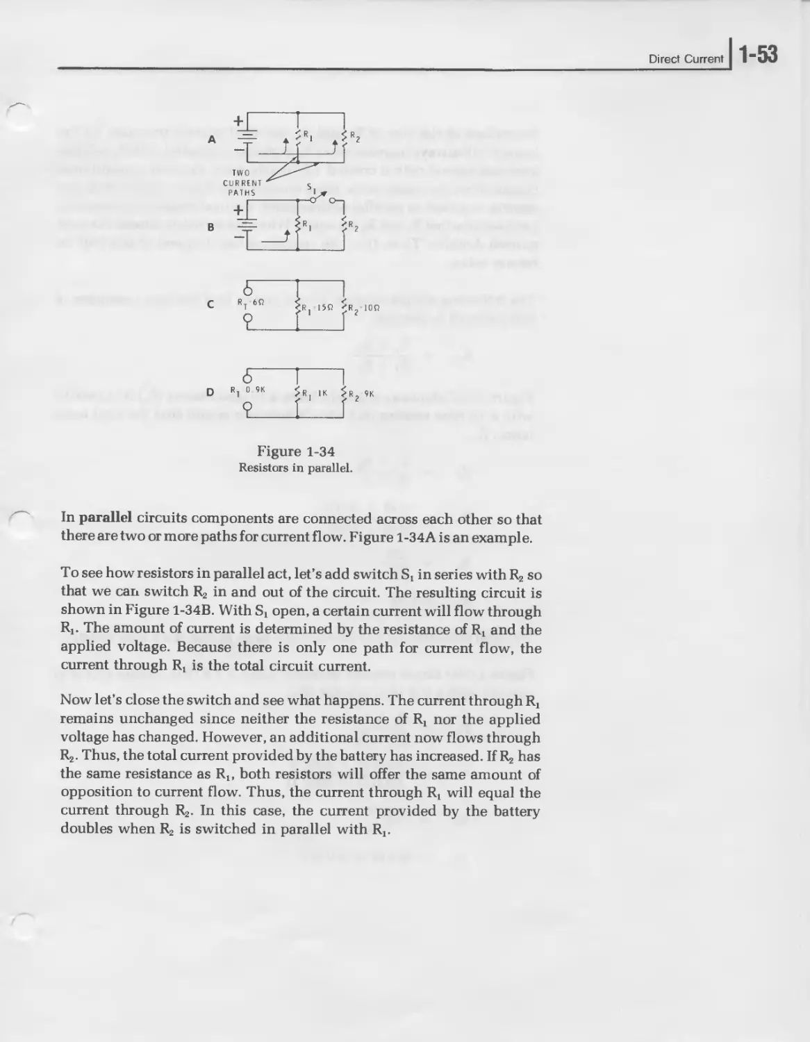


Текст
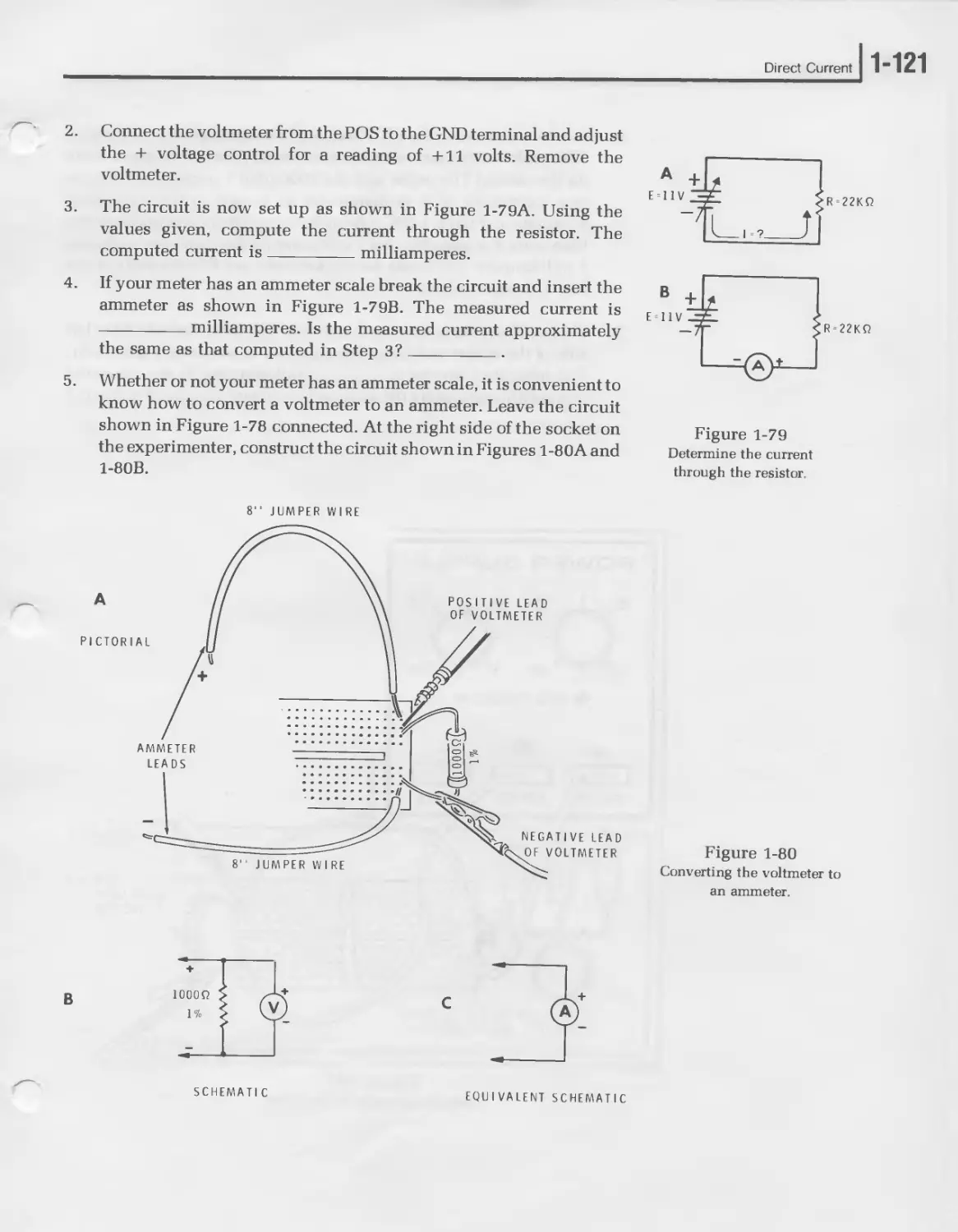
ELECTRONICS
for HOBBYISTS
ELECTRONICS FOR
HOBBYISTS
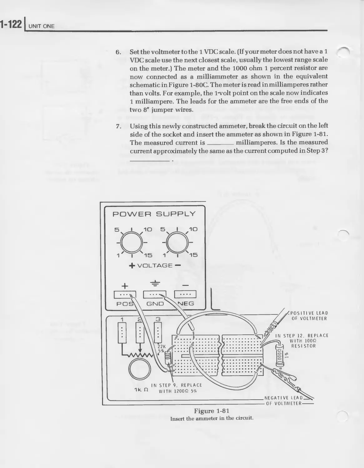
HEATH—
'TgHiTH
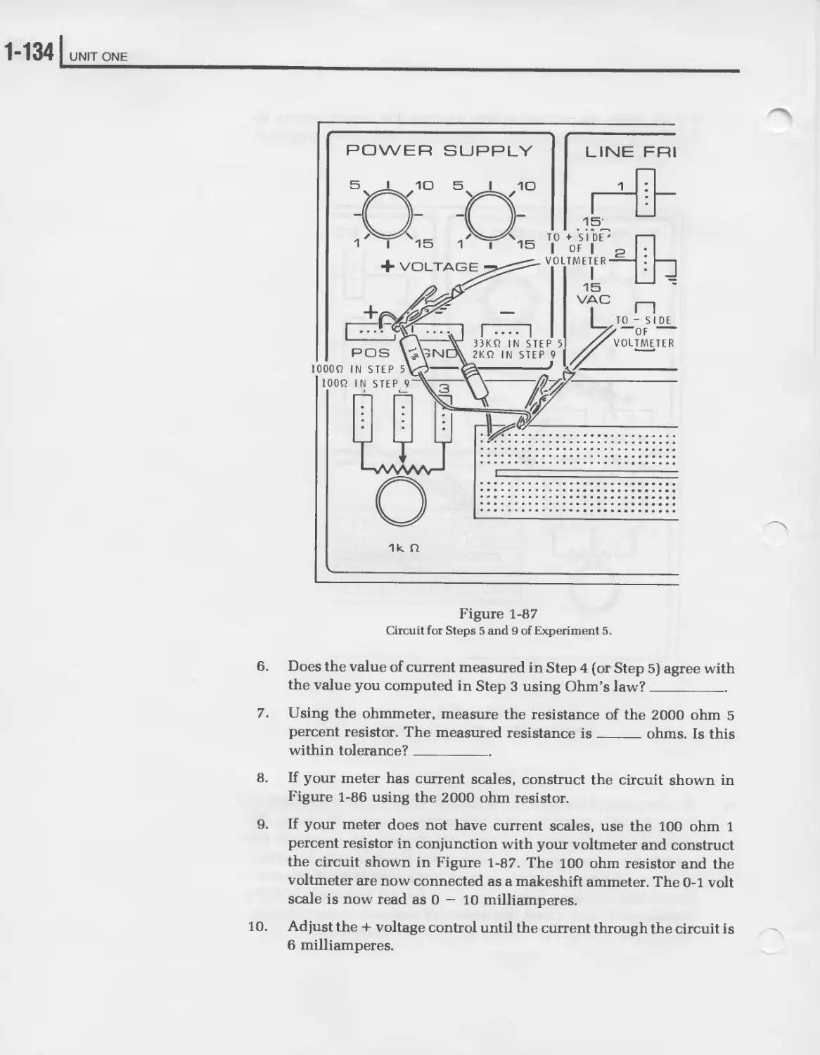
Educational Systems
Model EE-3140
HEATH COMPANY
BENTON HARBOR, MICHIGAN 49022
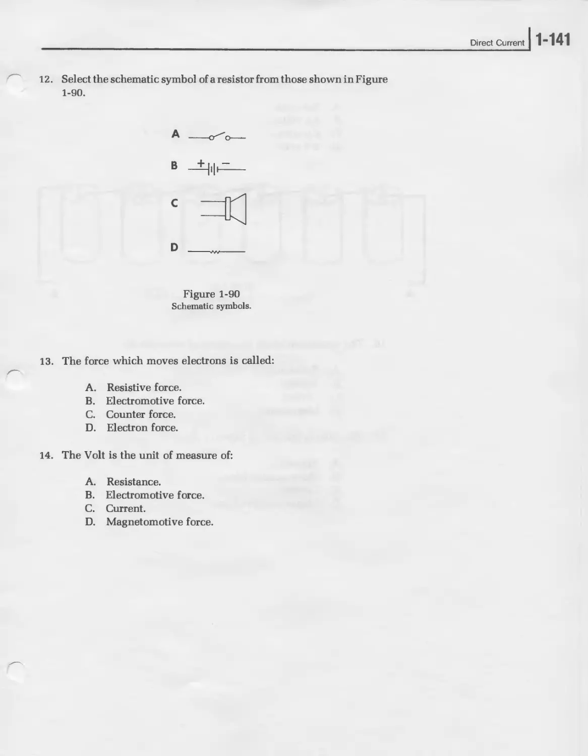
595-2381
Copyright © 1980
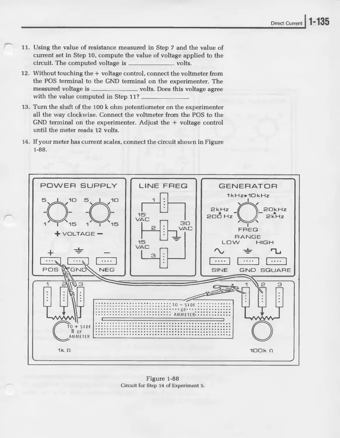
Third Printing — 1982
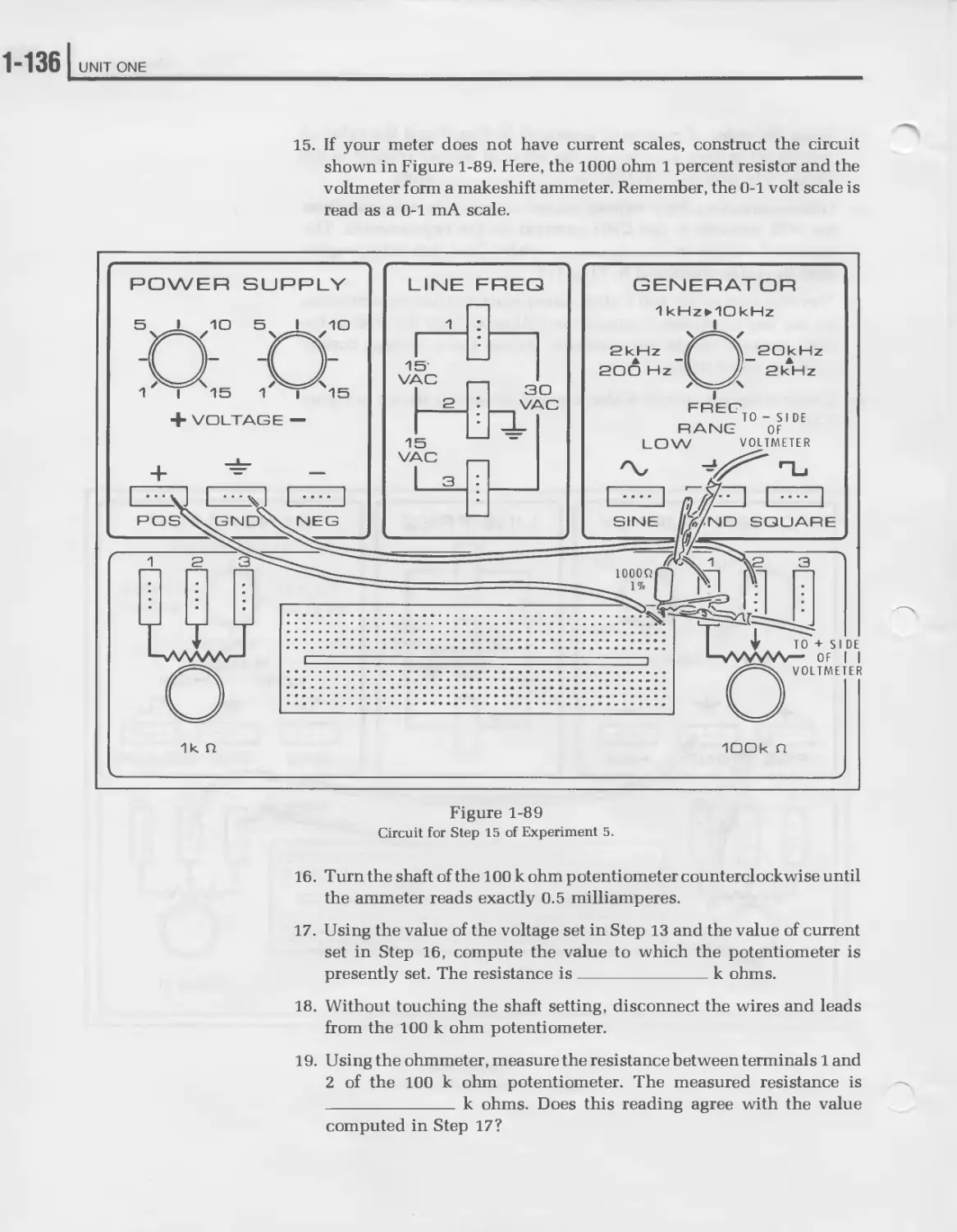
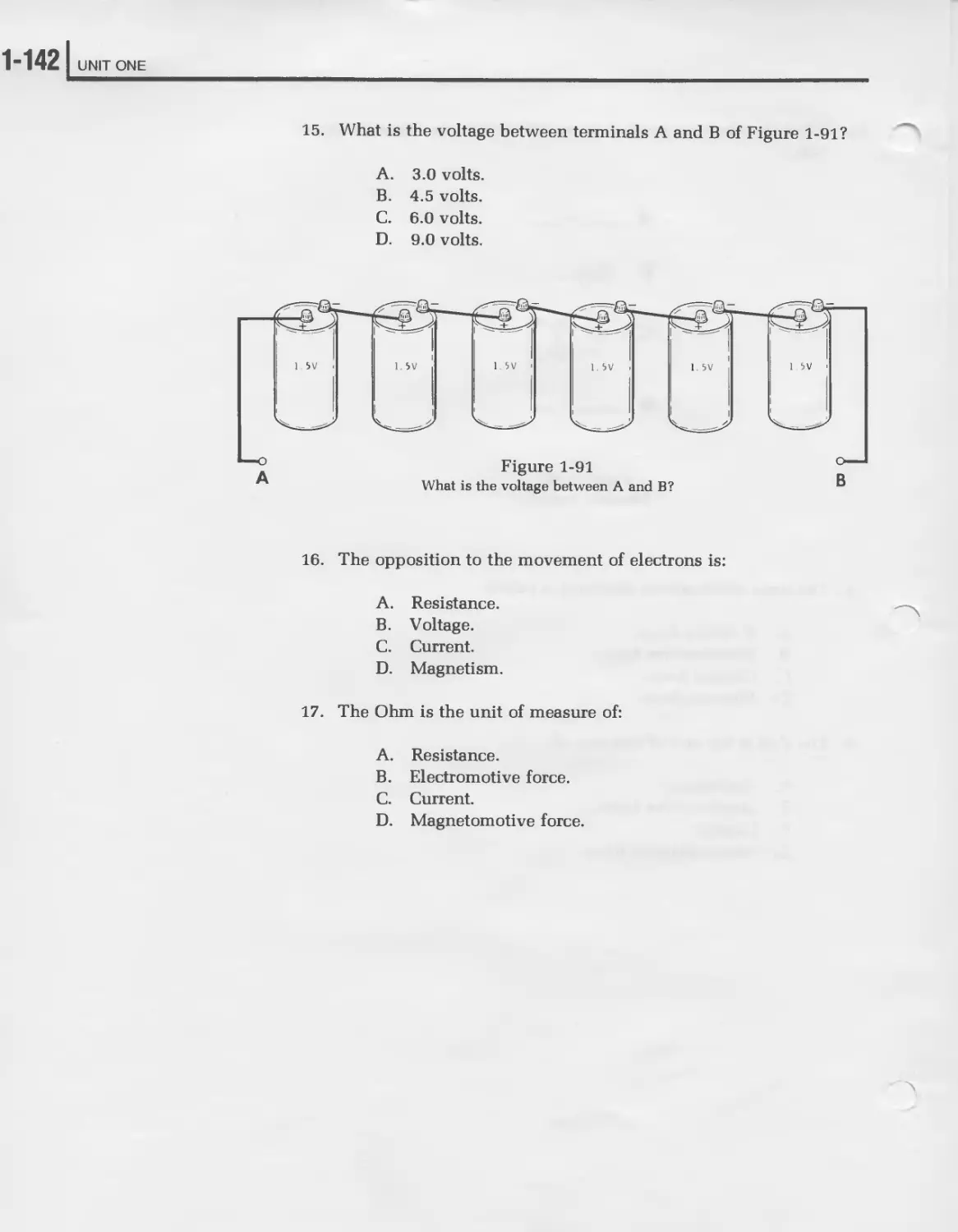
Heath Company
AU Rights Reserved
Printed in the United States of America
2
CONTENTS
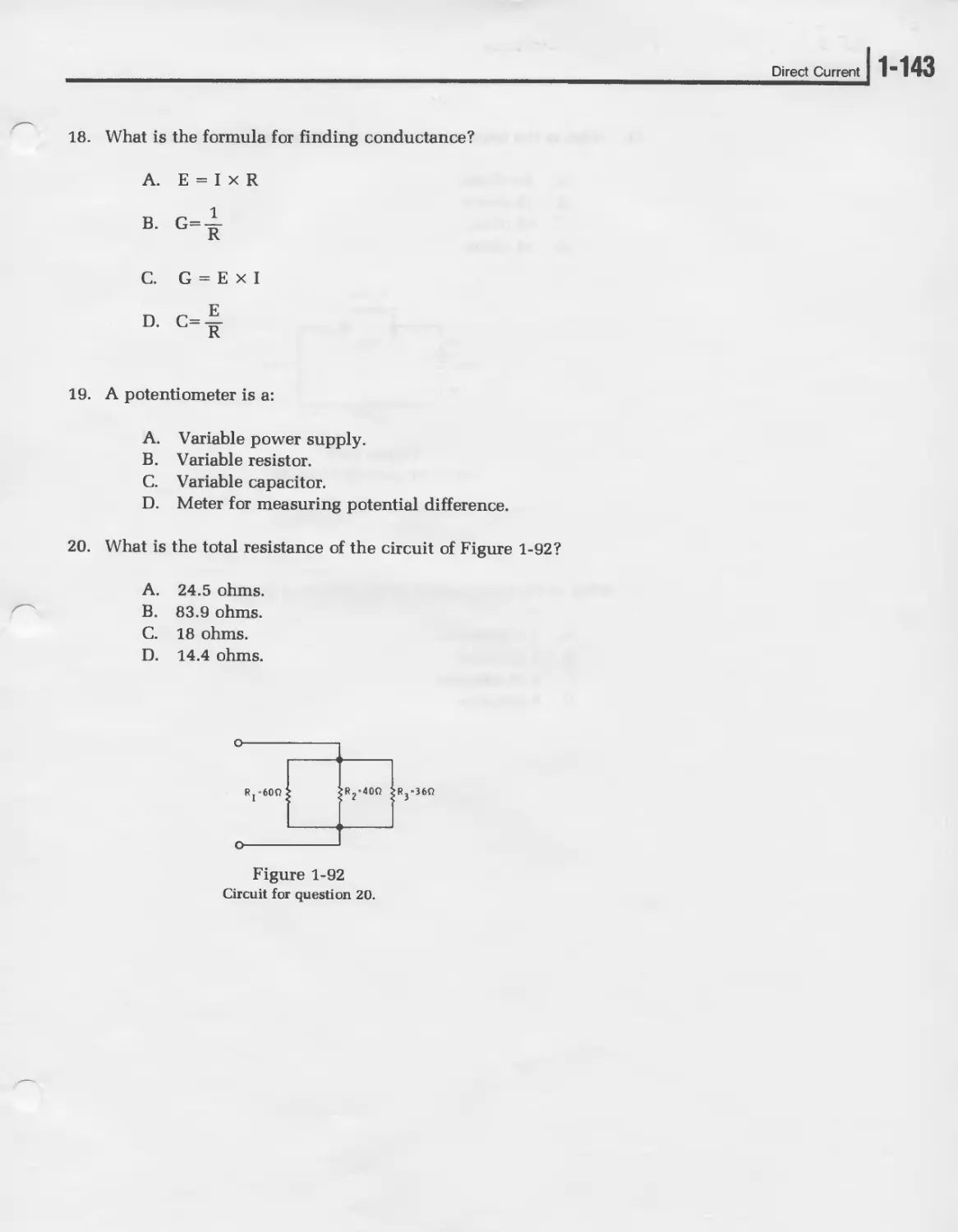
Introduction ..................................... 3
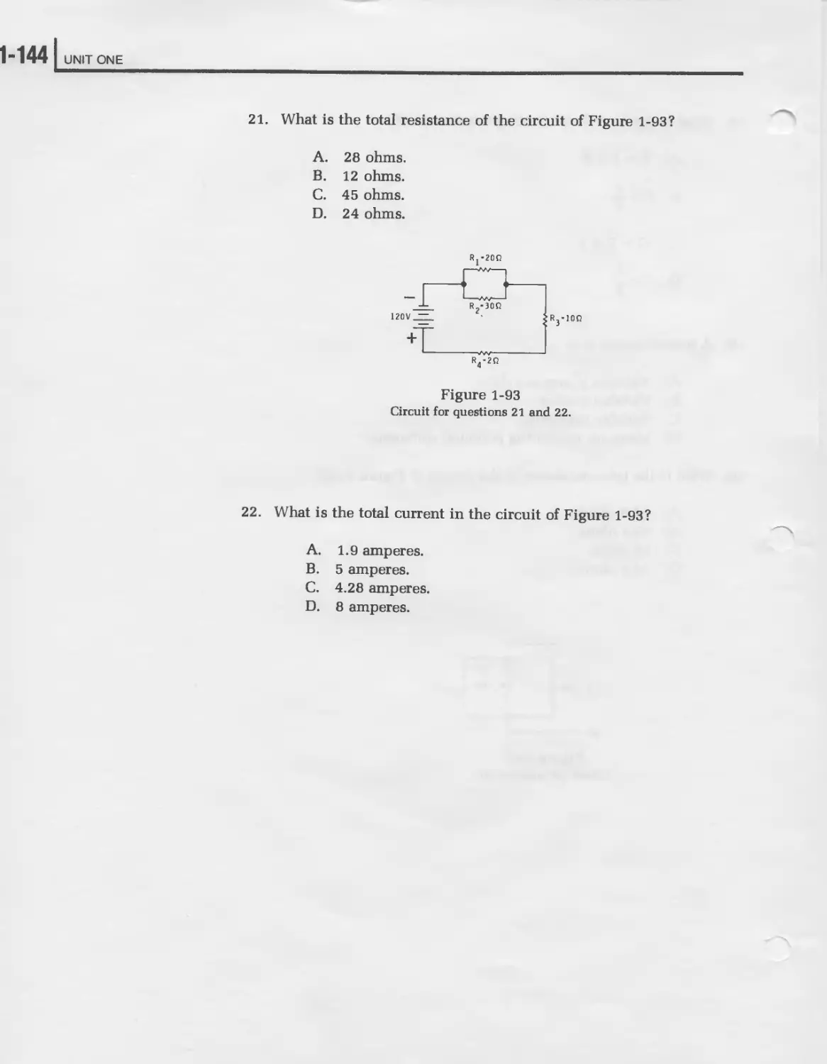
Course Objective.................................. 6
Course Outline.................................... 7
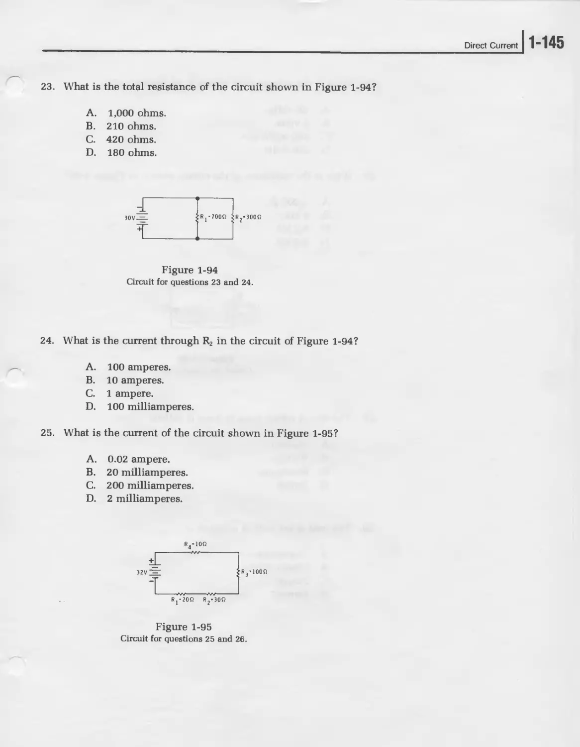
Parts List....................................... 19
UNIT ONE — DIRECT CURRENT ...................... 1-1
UNIT TWO — ALTERNATING CURRENT ................. 2-1
UNIT THREE — ACTIVE DEVICES..................... 3-1
UNIT FOUR — ELECTRONIC CIRCUITS..................4-1
UNIT FIVE — DIGITAL ELECTRONICS................. 5-1
UNIT SIX — DIGITAL COMPUTERS ................... 6-1
UNIT SEVEN — SURVEY OF ELECTRONICS HOBBIES...... 7-1
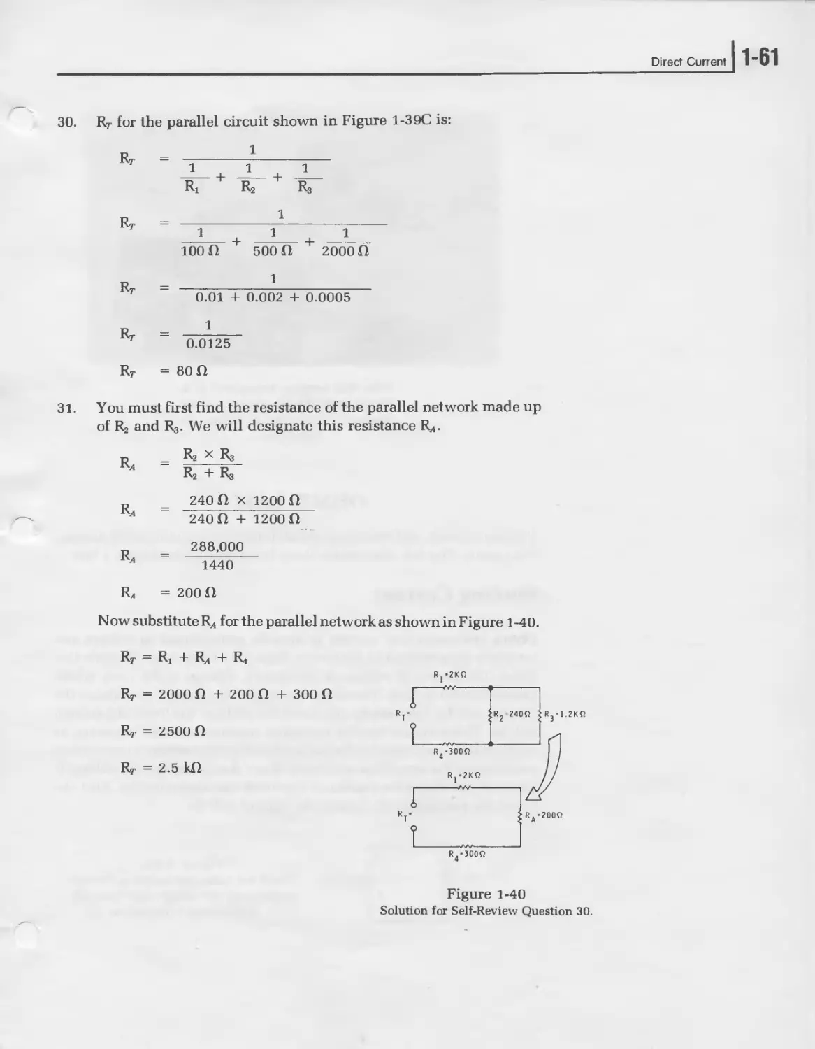
INTRODUCTION
This is Heathkit’s Individual Learning Program, number EE-3140, “Elec-
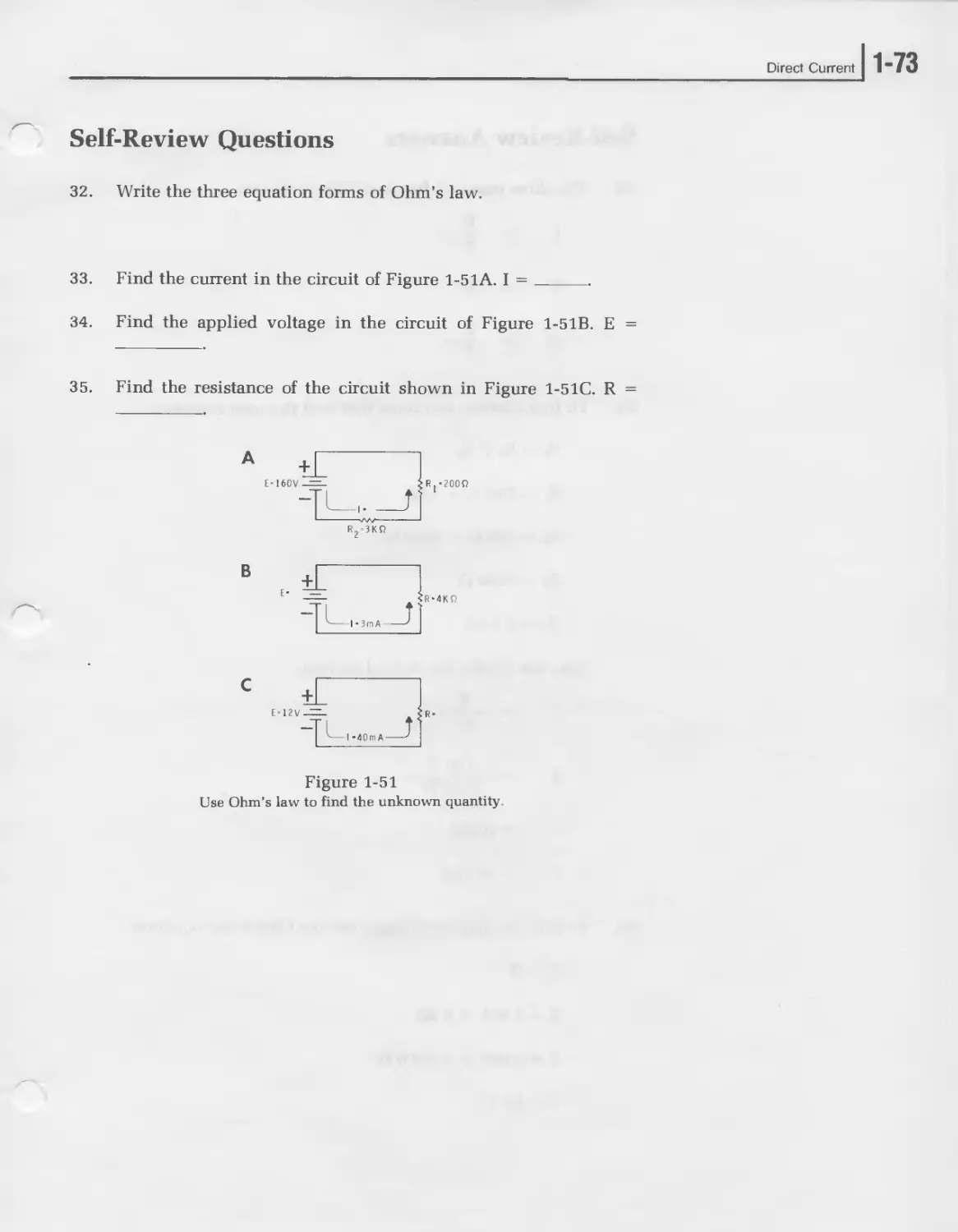
tronics For Hobbyists.” It is designed to give you a thorough foundation
in the basic and intermediate principles of electronics. Starting at the
very beginning, it answers the question: “What is an electron?” This is an
important question because electronics is the science that studies and
controls the behavior of electrons. Therefore, you must be familiar with
the electron and its behavior to fully understand electronics.
As you progress through this learning program, you will examine the
electron’s behavior in direct current (DC) and alternating current (AC)
circuits. You will study diodes, transistors, and integrated circuits. You
will also study power supplies, amplifiers, oscillators, digital elec-
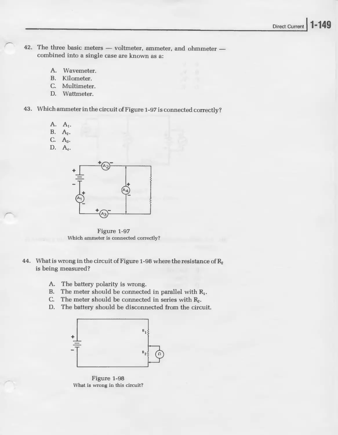
tronics, and digital computers.
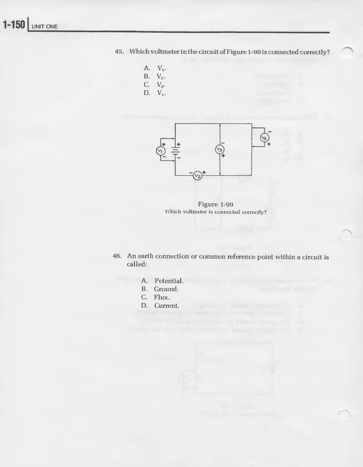
You can get a good idea of the scope of this program by reviewing the
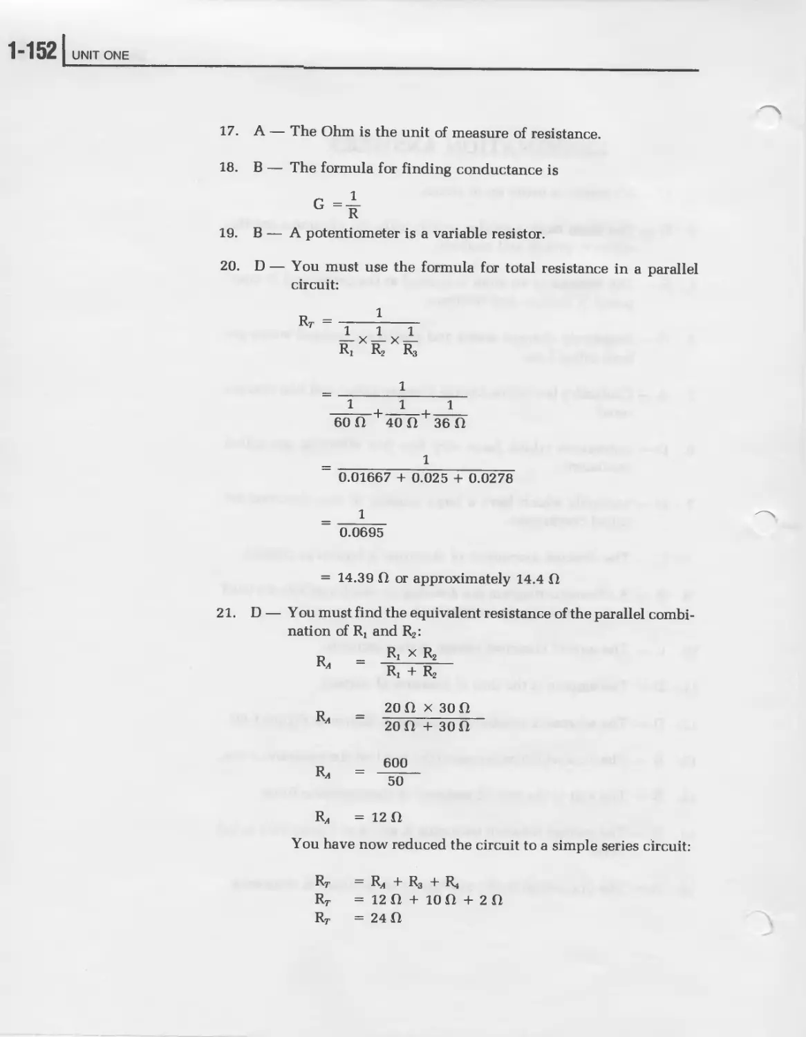
“Course Outline” that follows. As you can see, this is a very comprehen-
sive course with a substantial amount of material. To enliven and enrich
your learning experiences, a total of twenty-six Experiments are in-
cluded. This will reinforce the theory of electronics with practical appli-
cations.
4
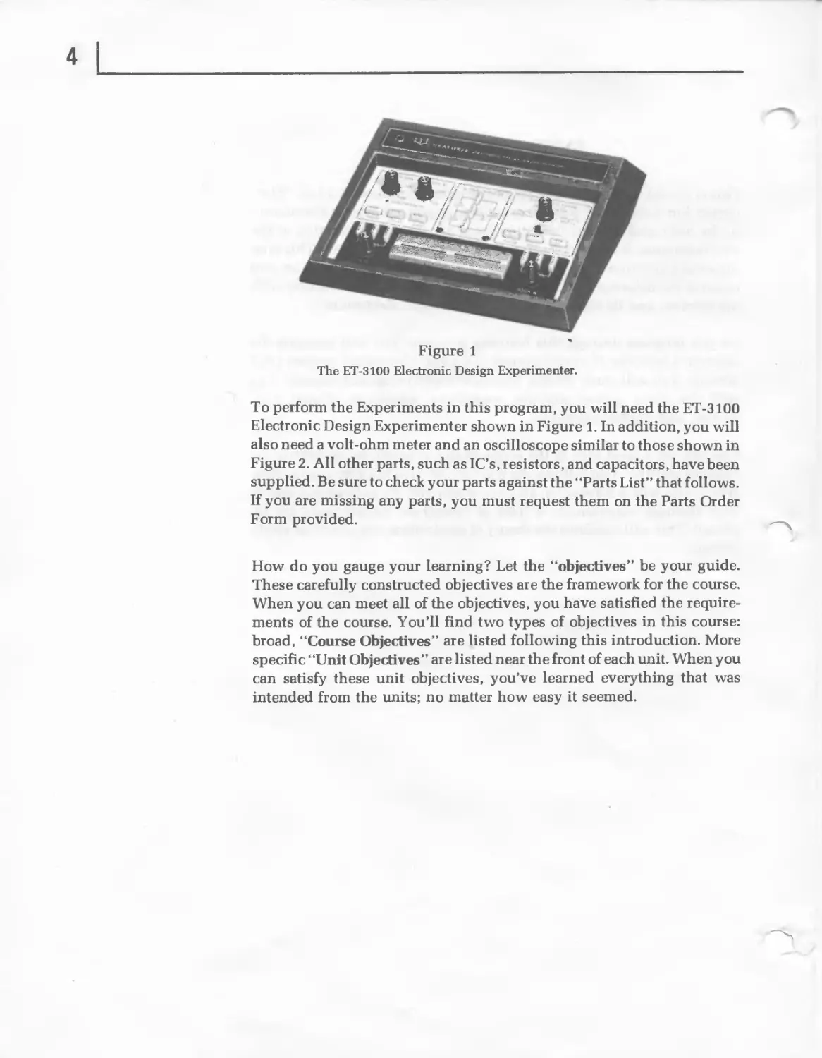
Figure 1
The ET-3100 Electronic Design Experimenter.
To perform the Experiments in this program, you will need the ET-3100
Electronic Design Experimenter shown in Figure 1. In addition, you will
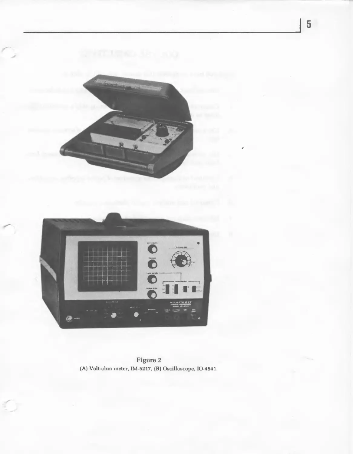
also need a volt-ohm meter and an oscilloscope similar to those shown in
Figure 2. All other parts, such as IC’s, resistors, and capacitors, have been
supplied. Be sure to check your parts against the “Parts List” that follows.
If you are missing any parts, you must request them on the Parts Order
Form provided.
How do you gauge your learning? Let the “objectives” be your guide.
These carefully constructed objectives are the framework for the course.
When you can meet all of the objectives, you have satisfied the require-
ments of the course. You’ll find two types of objectives in this course:
broad, “Course Objectives” are listed following this introduction. More
specific “Unit Objectives” are listed near the front of each unit. When you
can satisfy these unit objectives, you’ve learned everything that was
intended from the units; no matter how easy it seemed.
5
Figure 2
(A) Volt-ohm meter, IM-5217, (B) Oscilloscope, 10-4541.
COURSE OBJECTIVES
When you have completed this course, you will be able to:
1. Discuss basic and intermediate electronics theory and techniques.
2. Construct complex electronic circuits using only a schematic dia-
gram as a guide.
3. Use a multimeter and oscilloscope to measure electronic parame-
ters.
4. Use transistors, diodes, and integrated circuits to construct both
basic and intermediate electronic circuits.
5. Construct and analyze the operation of power supplies, amplifiers,
and oscillators.
6. Construct and analyze digital electronic circuits.
7. Discuss computer concepts and principles.
8. Discuss the more popular electronic hobbies.
COURSE OUTLINE
Unit 1 Direct Current
I. Introduction
II. Unit Objectives
III. Unit Activity Guide
IV. The Basis of Electronics
A. Atoms.
B. Electrons, Protons, and Neutrons.
C. Electrostatics.
D. Coulomb’s Law.
E. The Ion.
F. The Coulomb.
G. Powers of Ten and Scientific Notation.
V. Current
A. Freeing Electrons.
B. Conductors and Insulators.
C. The Battery.
D. Random Drift and Directed Drift.
E. The Electric Circuit.
F. The Ampere.
VI. Voltage
A. Electromotive Force.
B. Potential Difference.
C. Voltage.
D. Battery Connections.
E. Voltage Rises and Voltage Drops.
F. Concept of Ground.
VII. Resistance
A. The Ohm.
B. Resistors.
C. Variable Resistors.
D. Resistor Connections.
E. Conductance.
VIII. Ohm’s Law
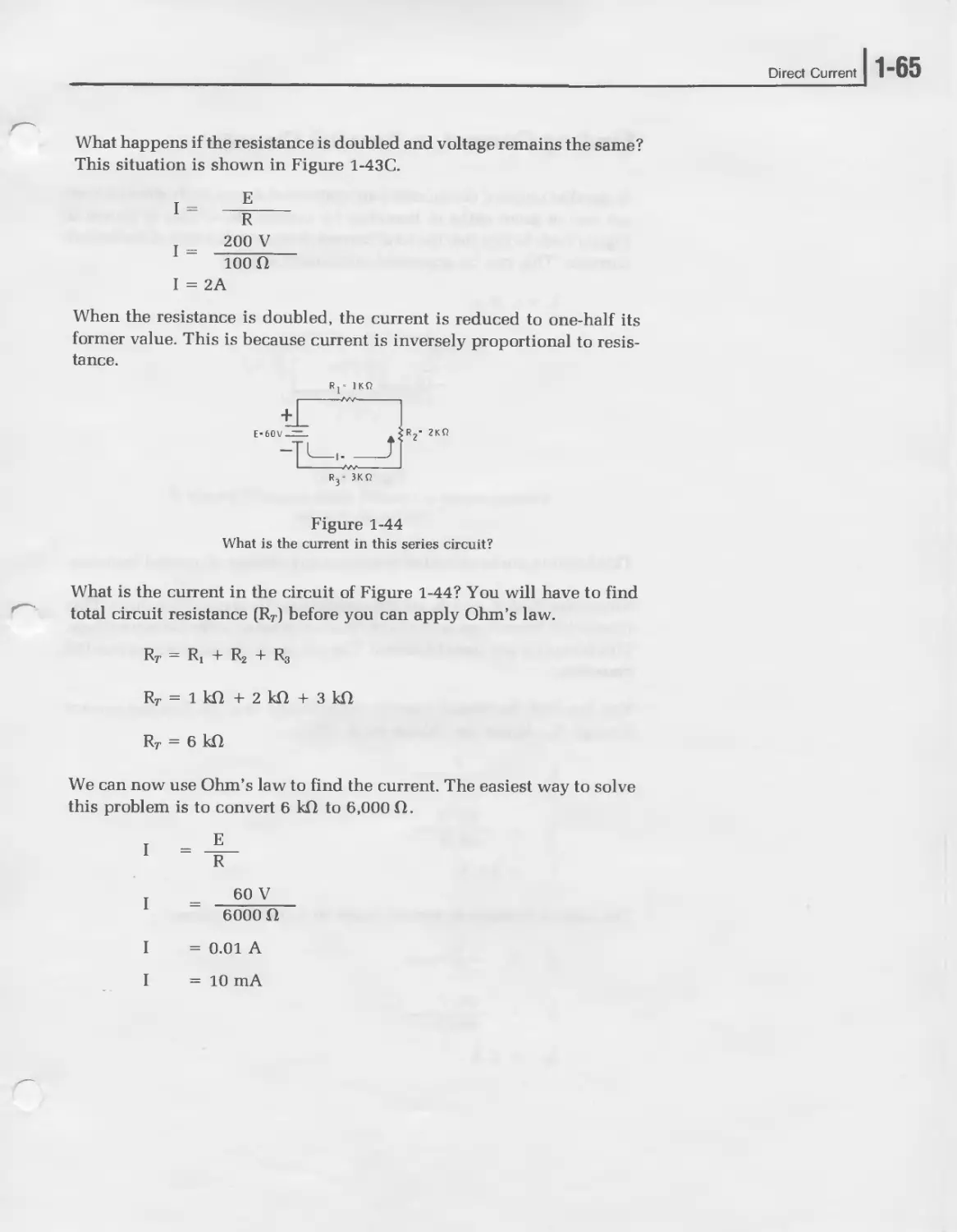
A. Finding Current.
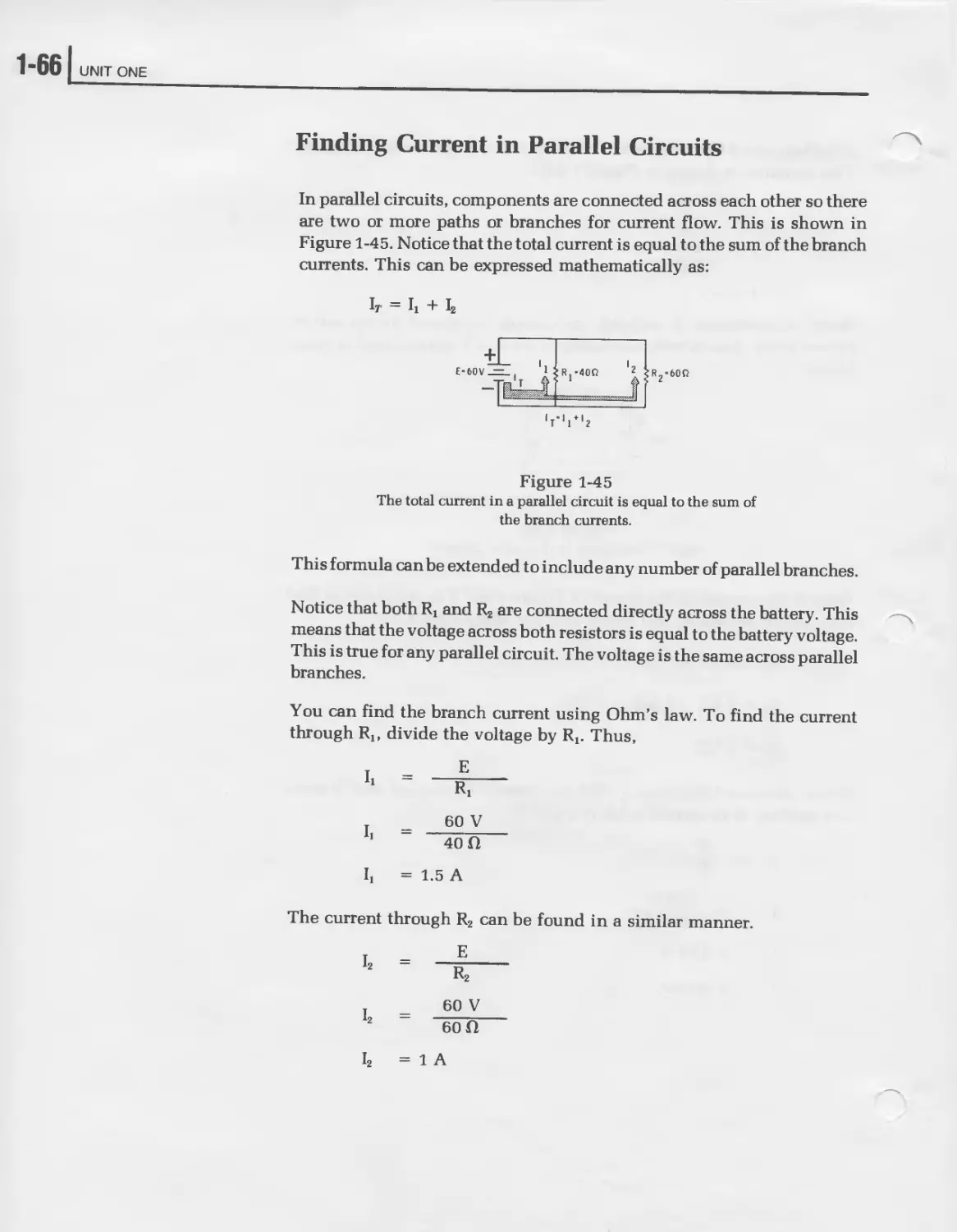
B. Finding Current in Parallel Circuits.
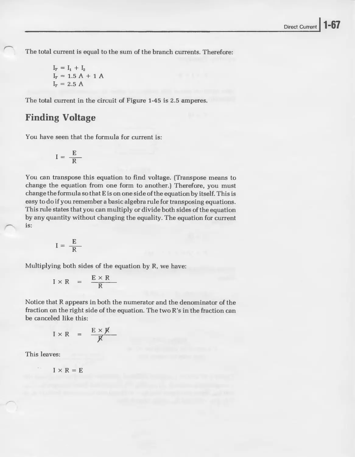
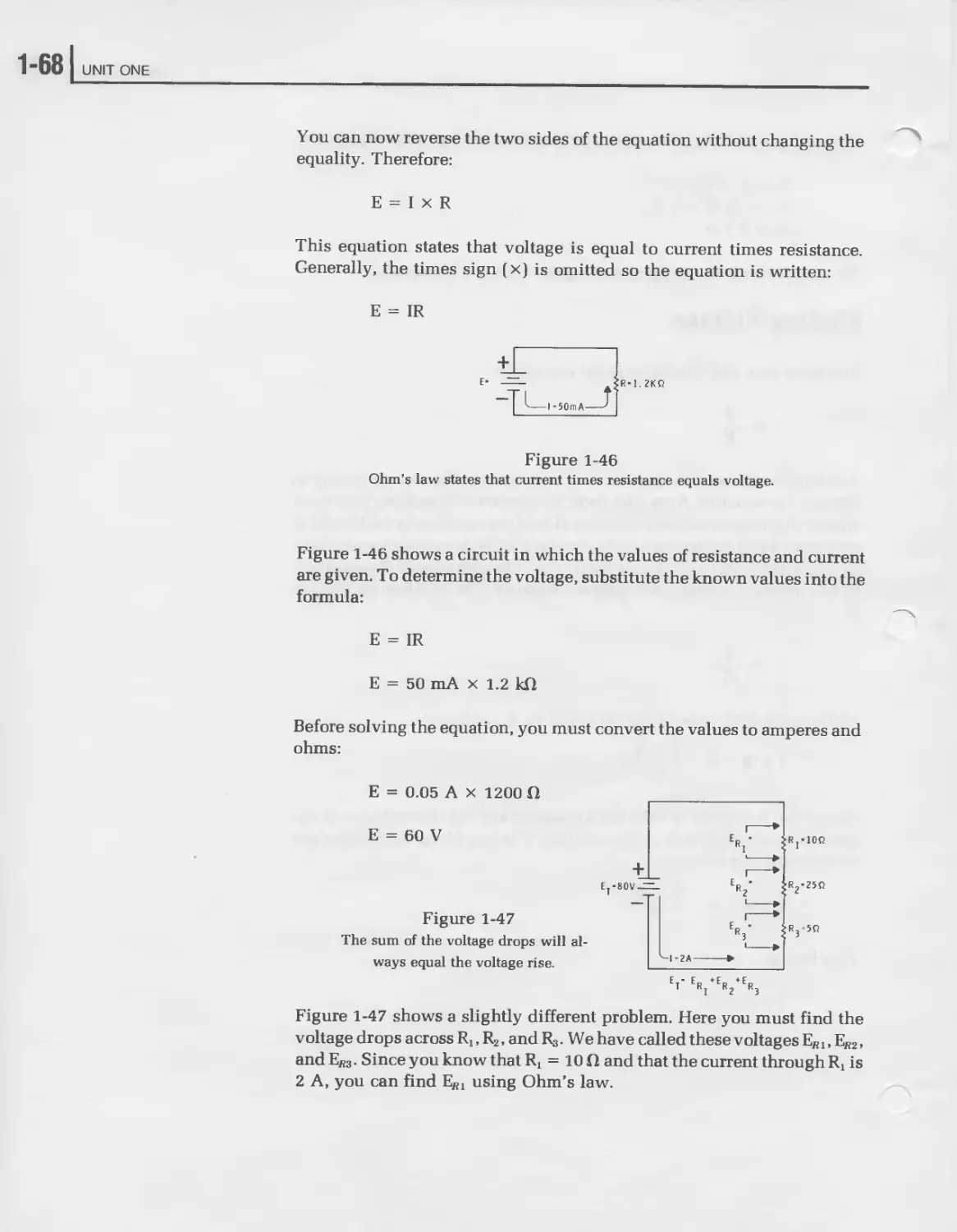
C. Finding Voltage.
D. Finding Resistance.
E. Summary.
8
IX.
X.
XI.
Power
A. The Watt.
B. Power, Current, and Voltage.
C. Power Dissapation in Resistors.
D. The Wheel Diagram.
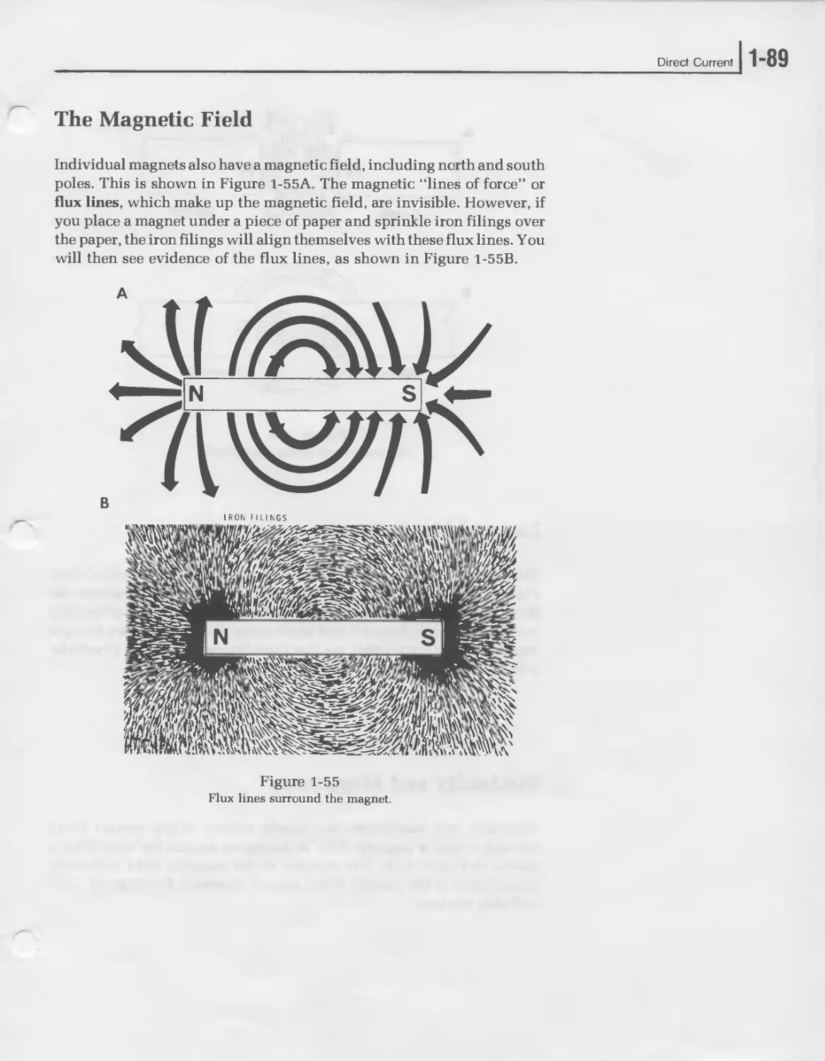
Magnetism
A. The Magnetic Field.
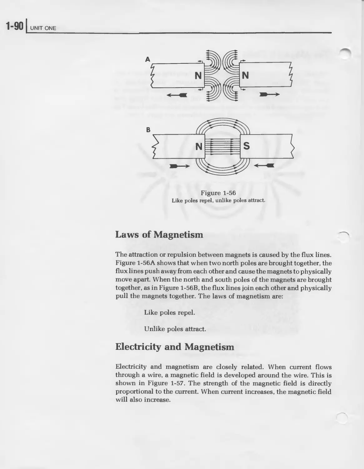
B. Laws of Magnetism.
C. Electricity and Magnetism.
D. Applications of Magnetism.
Meters
A. The Meter Movement.
B. Ammeter.
C. Voltmeter.
D. Ohmmeter.
E. Multimeters.
Experiment 1, Measuring Voltage
Experiment 2, Measuring Current
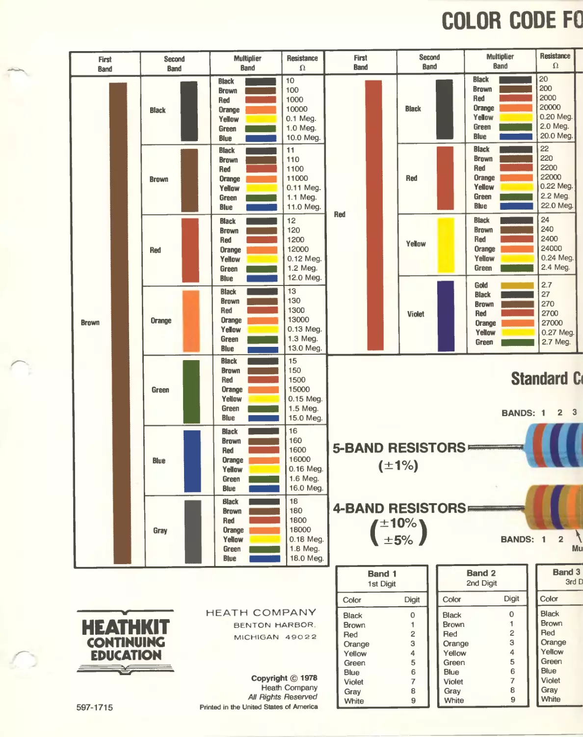
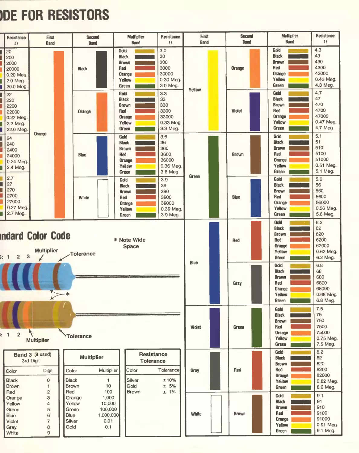
Experiment 3, Resistor Color Code
Experiment 4, Using the Ohmmeter
Experiment 5, Verifying Ohm’s Law
Unit Examination
Examination Answers
9
UNIT 2 ALTERNATING CURRENT
I. Introduction
II. Unit Objectives
III. Unit Activity Guides
IV. What is AC?
A. Generating an Alternating Voltage.
V. Waveform Measurements
A. Voltage and Current Values
B. Frequency
C. Wave Length
D. Phase Angle.
VI. AC Meters
A. Rectifiers.
B. The Complete AC Meter.
C. Using the AC Meter.
VII. Oscilloscopes
A. Oscilloscope Operation.
B. Using the Oscilloscope.
1. Measuring Voltage.
2. Measuring the Period.
3. Measuring Frequency.
VIII. Inductance and Transformers
A. Inductance.
1. Self-inductance.
2. Mutual inductance.
B. Transformers.
IX. Inductors in AC Circuits
A. Inductive Reactance.
B. Inductors in Series and Parallel.
C. Ohm’s Law in Inductive Circuits.
D. Phase Angle in Inductive Circuits.
E. Series RL Circuits.
X. Capacitance
A. Types of Capacitors.
B. Charging and Discharging a Capacitor.
C. Unit of Capacitance.
D. Factors Affecting Capacitance.
E. Parallel — and Series — Connected Capacitors.
F. Capacitive Reactance.
G. Phase Angle in Capacitive Circuits.
H. RC Circuits.
10
XI. RLC Circuits.
A. Series RLC Circuits.
B. Parallel RLC Circuits
C. Series Resonance.
D. Parallel Resonance.
E. Circuit Q.
F. Filters.
1. Bandstop Filter.
2. Bandpass Filter.
3. Low pass Filter.
4. High Pass Filter.
Experiment 1, Measuring AC Voltages
Experiment 2, RC Circuits
Experiment 3, RL Circuits
Experiment 4, Series Resonance
Experiment 5, Parallel Resonance
Experiment 6, LC Filters
Unit Examination
Examination Answers
11
UNIT 3 Active Devices
I. Introduction
II. Unit Objectives
III. Unit Activity Guide
IV. Solid State Diodes
A. Semiconductor Materials.
B. P-N Junctions.
C. Diode Ratings.
D. Zener Diode.
E. Varactor Diode.
V. Transistors
A. Transistor Structure.
B. Transistor Operation.
C. Transistor Amplification.
D. Transistor Circuit Arrangements.
1. Common-Base Circuits.
2. Common-Emitter Circuits.
3. Common-Collector Circuits.
4. Summary.
E. Transistor Ratings.
VI. Field-Effect Transistors.
A. Junction FET.
B. Insulated Gate FET.
C. FET Circuit Arrangements.
1. Common-Source Circuits.
2. Common-Gate Circuits.
3. Common-Drain Circuits.
VII. Optoelectronic Devices
A. Basic Characteristics of Light.
B. Light Sensitive Devices.
1. Photoconductive Cells.
2. Photovoltaic Cells.
3. Photodiodes.
4. Photo Transistors.
C. Light Emitting Devices.
1. LED Operation.
2. LED Construction.
3. LED Applications.
D. Liquid Crystals.
1. LCD Operation.
12
VIII. Integrated Circuits
A. B. C. D. E. The Importance of IC’s. Advantages and Disadvantages. Applications of IC’s. Digital IC’s. Linear IC’s.
Experiment 1, Semiconductor Diode Characteristics
Experiment 2, Zener Diodes
Experiment 3, Transistor Amplifier Configurations
Experiment 4, JFET Amplifier
Experiment 5, LED Characteristics
Unit Examination
Examination Answers
13
UNIT 4 ELECTRONIC CIRCUITS
I. Introduction
II. Unit Objectives
III. Unit Activity Guide
IV. Power Supplies
A. Rectifier Circuits
1. Half-Wave Rectifier.
a. Ripple Frequency.
b. Output Polarity.
2. Full-Wave Rectifier.
3. Bridge Rectifier.
B. Power Supply Filters.
1. Capacitive Filter.
2. The Capacitor’s Effect on the Diodes.
3. Electrolytic Capacitors.
4. PI Filters.
C. Voltage Doublers.
1. Half-Wave Voltage Doubler.
2. Full-wave Voltage Doubler.
D. Voltage Regulation
1. Bleeder Resistor.
2. Zener Voltage Regulator.
3. IC Voltage Regulator.
V. Audio Amplifiers
A. Voltage and Power Amplifiers.
B. Amplifier Gain and the Decibel.
C. Coupling Circuits.
1. Capacitive Coupling.
2. Impedance Coupling.
3. Direct Coupling.
4. Transformer Coupling.
D. Classes of Operation.
E. Amplifier Efficiency.
VI. Operational Amplifiers
A. The Basic Op Amp.
B. The Inverting Amplifier.
C. The Noninverting Amplifier.
D. The Voltage Follower.
VII. Radio Frequency Amplifiers
A. The Tuned Amplifier.
B. Coupling Circuits.
C. RF Power Amplifiers.
1. Flywheel Effect.
D. Tuning an RF Amplifier.
14
VIII. Oscillators
A. Oscillator Requirements.
B. The Armstrong Oscillator.
C.
D.
E.
Hartley Oscillator.
Colpitts Oscillator.
Crystal Oscillators.
Experiment 1, Unregulated Power Supplies
Experiment 2, IC Voltage Regulator
Experiment 3, The Operational Amplifier
Experiment 4, The Practical Tank Circuit
Experiment 5, The Hartley LC Oscillator
Unit Examination
Examination Answers
15
UNIT 5 DIGITAL ELECTRONICS
I. Introduction
II. Unit Objectives
III. Unit Activity Guide
IV. Number Systems
A. Decimal System.
B. Binary Number System.
C. Number System Conversions.
D. Binary Coded Decimal.
V. Logic Elements
A. The Inverter.
B. The AND Gate.
C. The OR Gate.
D. The NAND Gate.
E. The NOR Gate.
F. The Exclusive OR Gate.
VI. Flip-Flops
A. What is a Flip-Flop?
B. The Latch Flip-Flop.
C. D-type Flip-Flop.
D. JK Flip-Flops.
VII. Counters and Shift Registers
A. Binary Counters.
1. Down Counter.
2. Up-Down Counter.
B. BCD Counters.
C. Shift Registers.
VIII. Clocks and One-Shots
A. The 555 Timer.
B. The 555 One-Shot.
C. The 555 Clock.
Experiment 1, NAND and NOR Gates
Experiment 2, Flip-Flops
Experiment 3, The 555 Clock
Experiment 4, The 555 One-Shot
Experiment 5, BCD and Binary Counters
Unit Examination
Examination Answers
16
UNIT 6 DIGITAL COMPUTERS
I. Introduction
II. Unit Objectives
III. Unit Activity Guide
IV. What is a Digital Computer?
A. How Computers are Classified.
1. Minicomputers.
2. Microcomputers.
3. Programmable Calculators.
4. Microprocessors.
V. Digital Computer Organization
and Operation
A. Memory
B. Control Unit
C. Arithmetic — Logic Unit.
D. Input — Output Unit.
E. Digital Computer Operation.
VI. Computer Programming
A. Programming Procedure.
B. Writing Programs.
C. Computer Instructions.
D. A Hypothetical Instruction Set.
E. Example Programs.
VII. Software
A. Subroutines.
B. Utility Programs.
C. Assembler.
D. Compiler.
E. Cross Assemblers and Compilers.
VIII. Microprocessors
A. Types of Microprocessors.
B. Applications of Microprocessors.
C. Where are Microprocessors used?
D. Designing with Microprocessors.
Unit Examination
Examination Answers
17
UNIT 7 SURVEY OF ELECTRONIC HOBBIES
I. Introduction
II. Unit Objectives
III. Unit Activity Guide
IV. Experiments and Construction
A. Construction Projects.
1. Construction Techniques.
2. Parts.
B. Kit Building.
V. Shortwave Listening
A. What’s on the Air?
1. Foreign Broadcasts.
2. Utility Stations.
3. AM Broadcast Band.
4. FM and TV.
5. Public Service Radio.
B. How can I hear these stations?
C. What is a QSL card?
VI. Amateur Radio
A. License Structure.
1. Novice Class.
2. Technician Class.
3. General Class.
4. Advanced and Extra Class.
B. Amateur Radio Activities.
C. Amateur Radio Publications.
VII. Radio Control Models
A. Model Ships.
B. Model Aircraft.
C. R/C Equipment.
D. R/C Publications.
E. R/C Licenses.
VIII. Personal Computing.
A. Hardware and Software.
B. Activities and Applications.
C. Publications.
IX. High Fidelity Audio
A. Audio Equipment.
B. Publications.
Unit Examination
Examination Answers
Final Examination
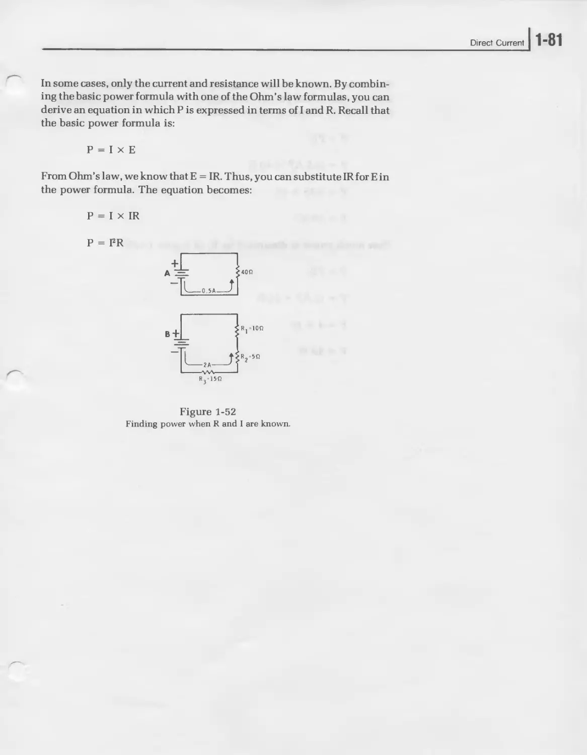
181
19
PARTS LIST
This Parts List contains all of the parts you will need in the Experiments
in this course. The key numbers correspond to the numbers on the parts
illustrated in the column. Some parts are packaged in envelopes. Except
for this initial parts check, keep these parts in their envelopes until they
are called for in an experiment. Two containers are provided so that you
can keep the small parts together.
KEY PART
QTY. DESCRIPTION
No. No.
RESISTORS
1 Envelope of resistors
marked, “R for Exp 3." Set this envelope aside, you will check it in Experiment 3 of Unit 1.
A1 6-1001 1 1000 О (brown-black- black-brown)
A1 6-1000 1 100 О (brown-black- black-black)
A1 6-102-12 1 1000 О (brown-black- red-gold)
A1 6-103-12 1 10 kfl (brown-black- orange-gold)
A1 6-104-12 1 100 kfl (brown-black- yellow-gold)
A1 6-105-12 1 1 MO (brown-black- green-gold)
A1 6-122-12 1 1200 О (brown-red- red-gold)
A1 6-223-12 1 22 kfl (red-red-orange- gold)
A1 6-331-12 3 330 О (orange-orange- brown-gold)
A1 6-472-12 1 4700 О (yellow-violet- red-gold)
A1 6-563-12 1 56 kfl (green-blue- orange-gold)
A1 6-683-12 1 68 kfl (blue-gray- orange-gold)
20
KEY PART QTY. DESCRIPTION
No. No.
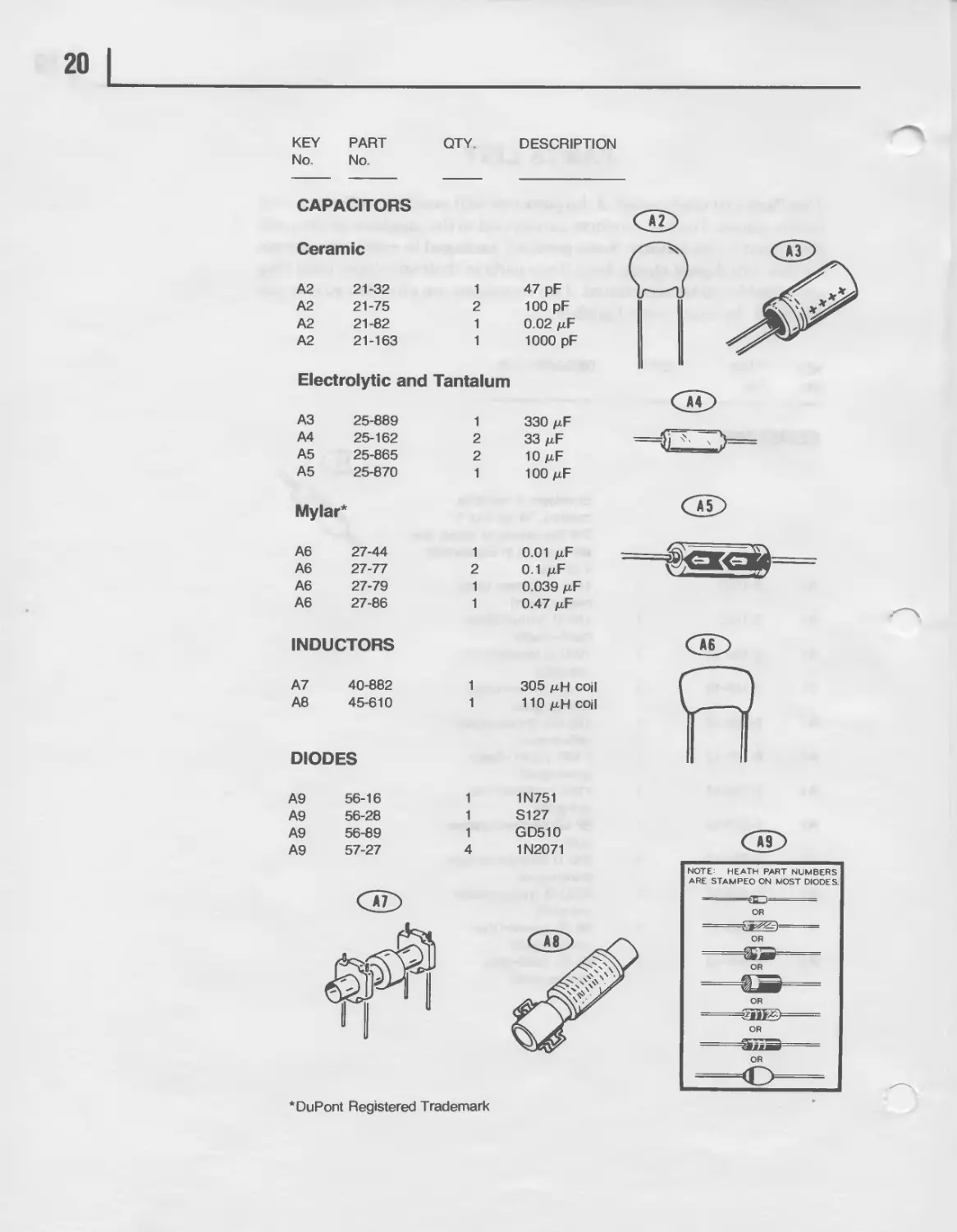
CAPACITORS
Ceramic
A2 21-32 1 47 pF
A2 21-75 2 100 pF
A2 21-82 1 0.02
A2 21-163 1 1000 pF
Electrolytic and Tantalum
A3 25-889 1 330 mF
A4 25-162 2 зз mF
A5 25-865 2 10 mF
A5 25-870 1 wo mF
Mylar*
A6 27-44 1 0.01 mF
A6 27-77 2 0.1 mF
A6 27-79 1 0.039 mF
A6 27-86 1 0.47 mF
INDUCTORS
A7 40-882 1
A8 45-610 1
305 mH coil
110 mH coil
DIODES
A9 56-16
A9 56-28
A9 56-89
A9 57-27
1
1
1
4
1N751
S127
GD510
1N2071
DuPont Registered Trademark
21
KEY PART QTY. DESCRIPTION
No. No.
Bl
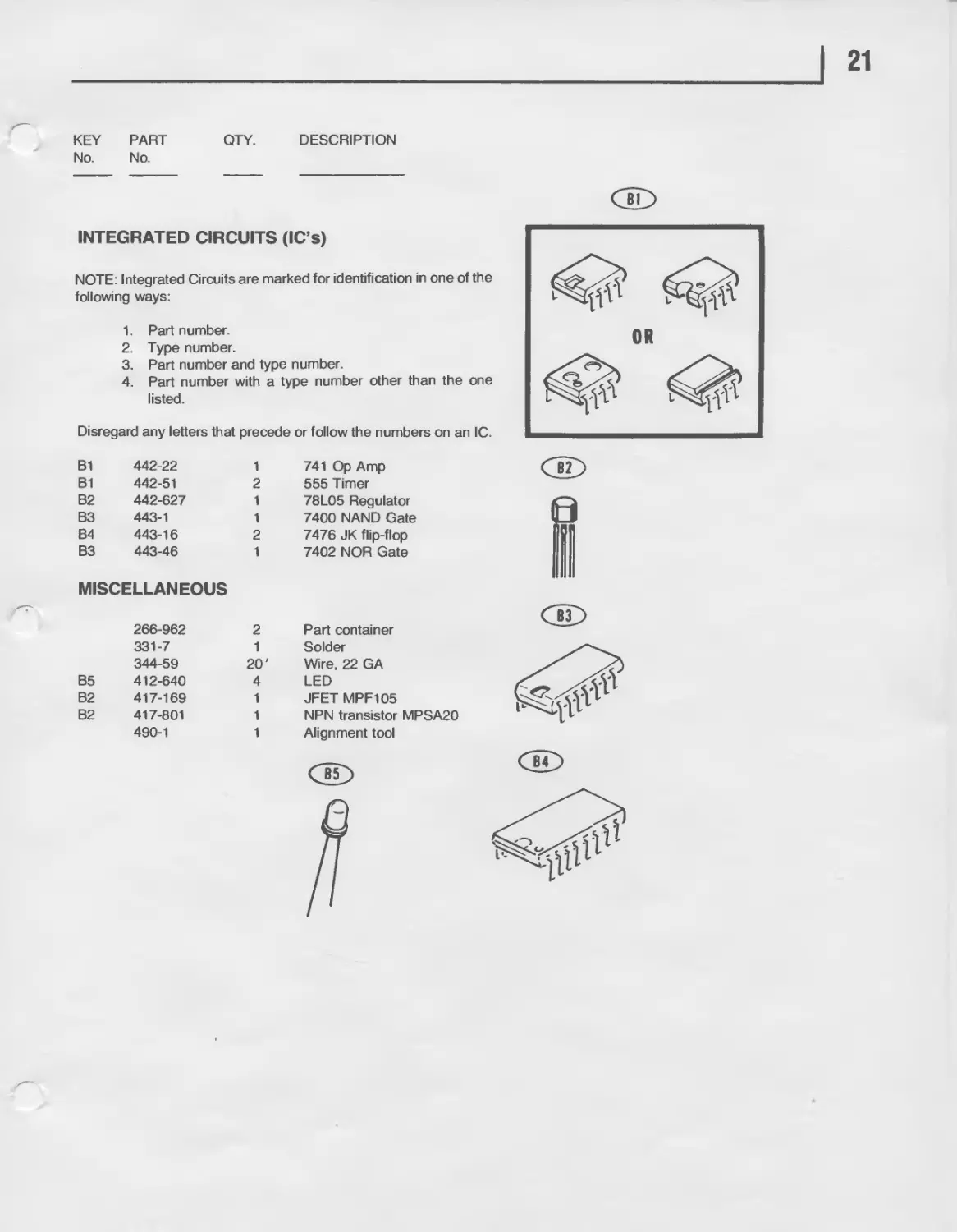
INTEGRATED CIRCUITS (IC’s)
NOTE: Integrated Circuits are marked for identification in one of the
following ways:
1. Part number.
2. Type number.
3. Part number and type number.
4. Part number with a type number other than the one
listed.
Disregard any letters that precede or follow the numbers on an IC.
B1 442-22 1 741 Op Amp
B1 442-51 2 555 Timer
B2 442-627 1 78L05 Regulator
B3 443-1 1 7400 NAND Gate
B4 443-16 2 7476 JK flip-flop
B3 443-46 1 7402 NOR Gate
MISCELLANEOUS
i
266-962 2 Part container
331-7 1 Solder
344-59 20' Wire, 22 GA
B5 412-640 4 LED
B2 417-169 1 JFET MPF105
B2 417-801 1 NPN transistor MPSA20
490-1 1 Alignment tool
Unit 1
DIRECT CURRENT
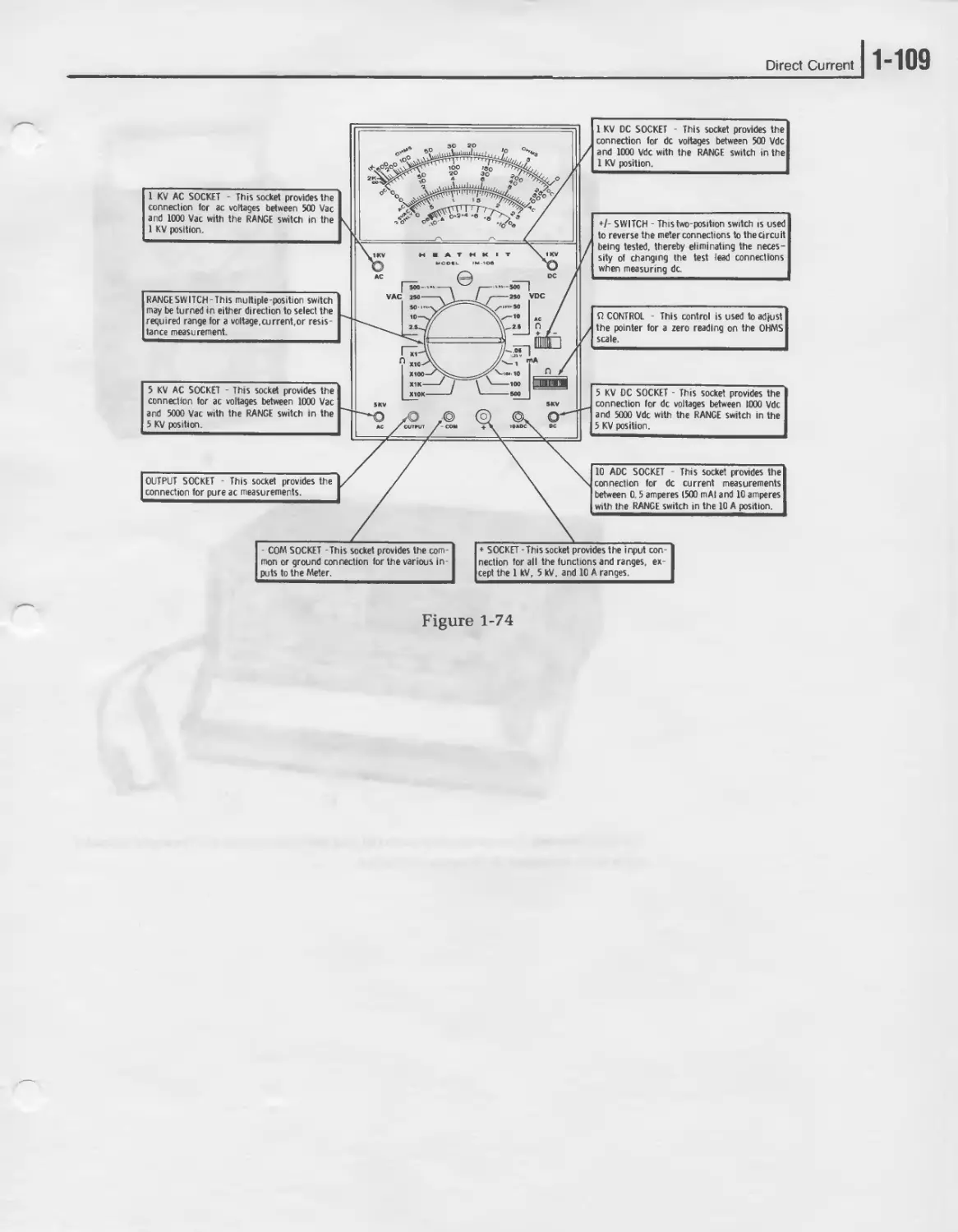
1“2 I UNIT ONE
CONTENTS
Introduction............................................. 1-3
Unit Objectives.......................................... 1-4
Unit Activity Guide...................................... 1-6
The Basis of Electronics................................. 1-8
Current................................................. 1-19
Voltage................................................. 1-33
Resistance ............................................. 1-45
Ohm’s Law .............................................. 1-62
Power................................................... 1-76
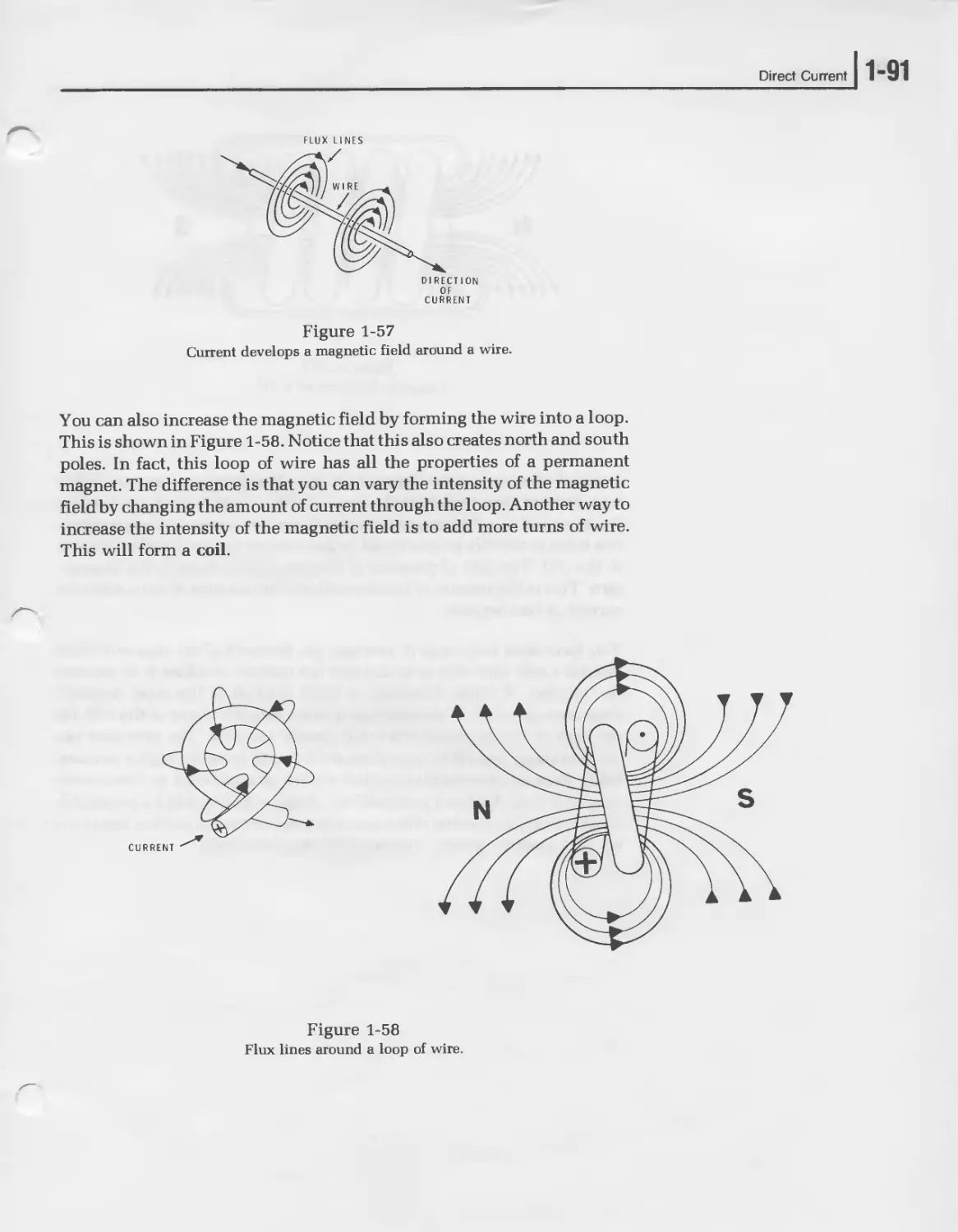
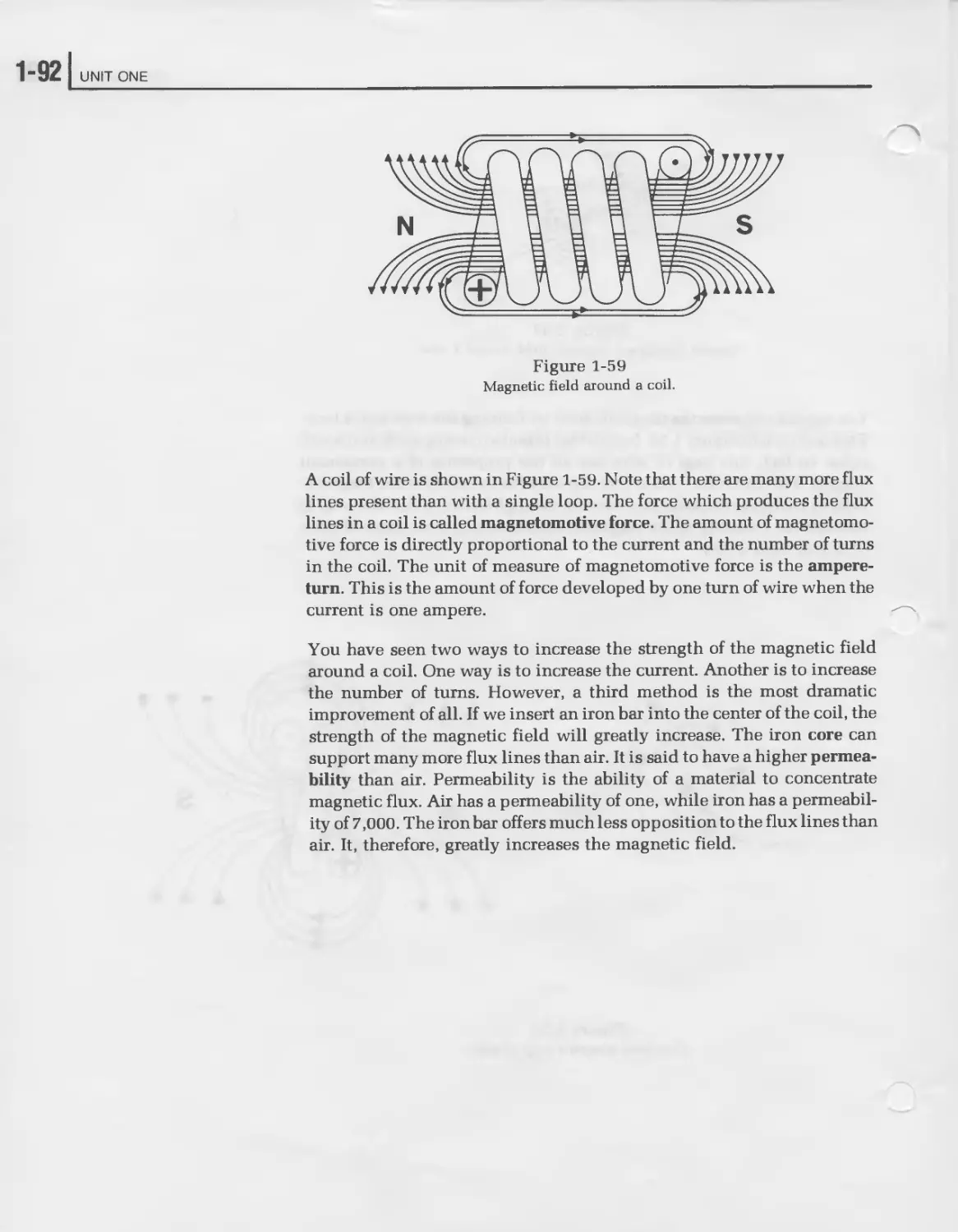
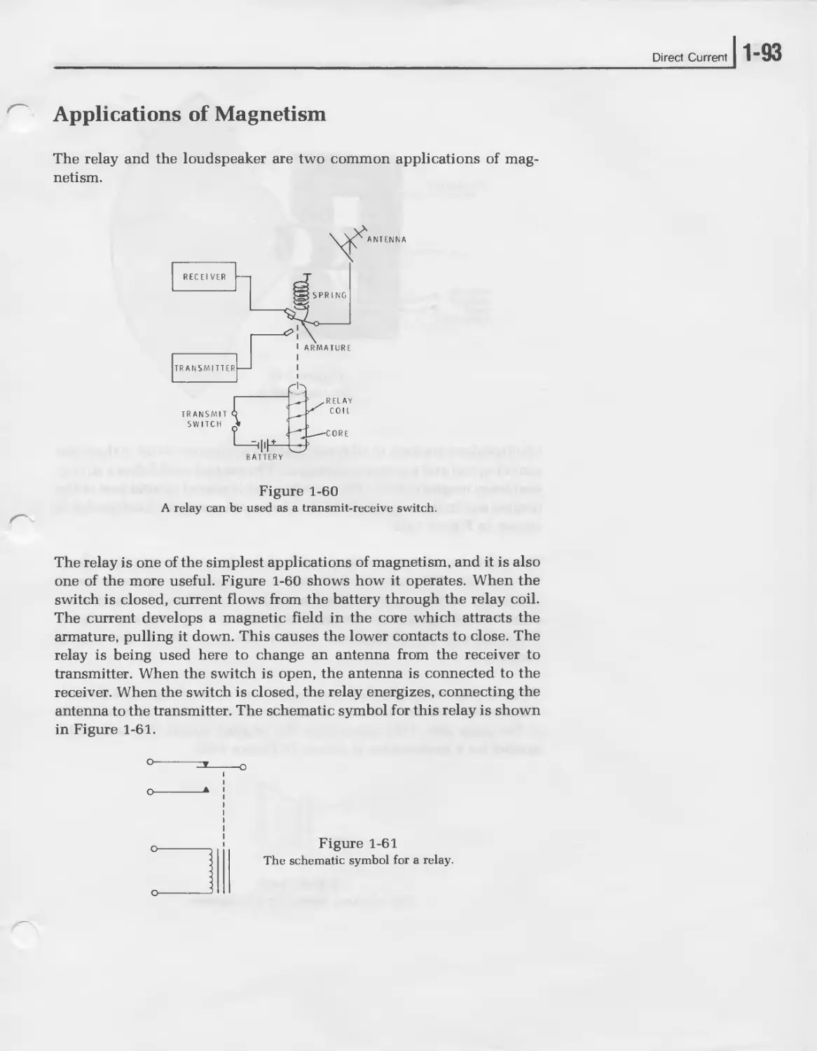
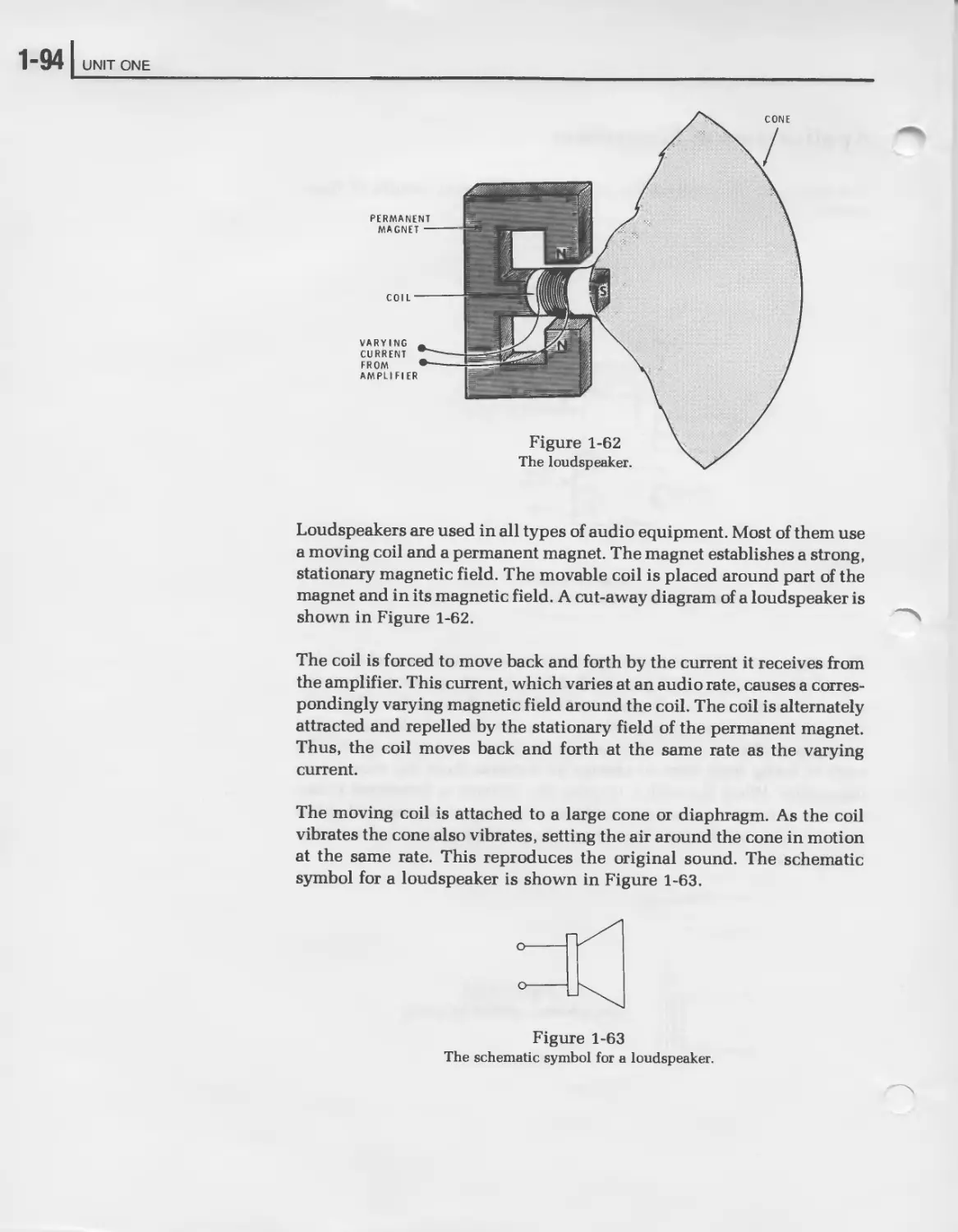
Magnetism............................................... 1-88
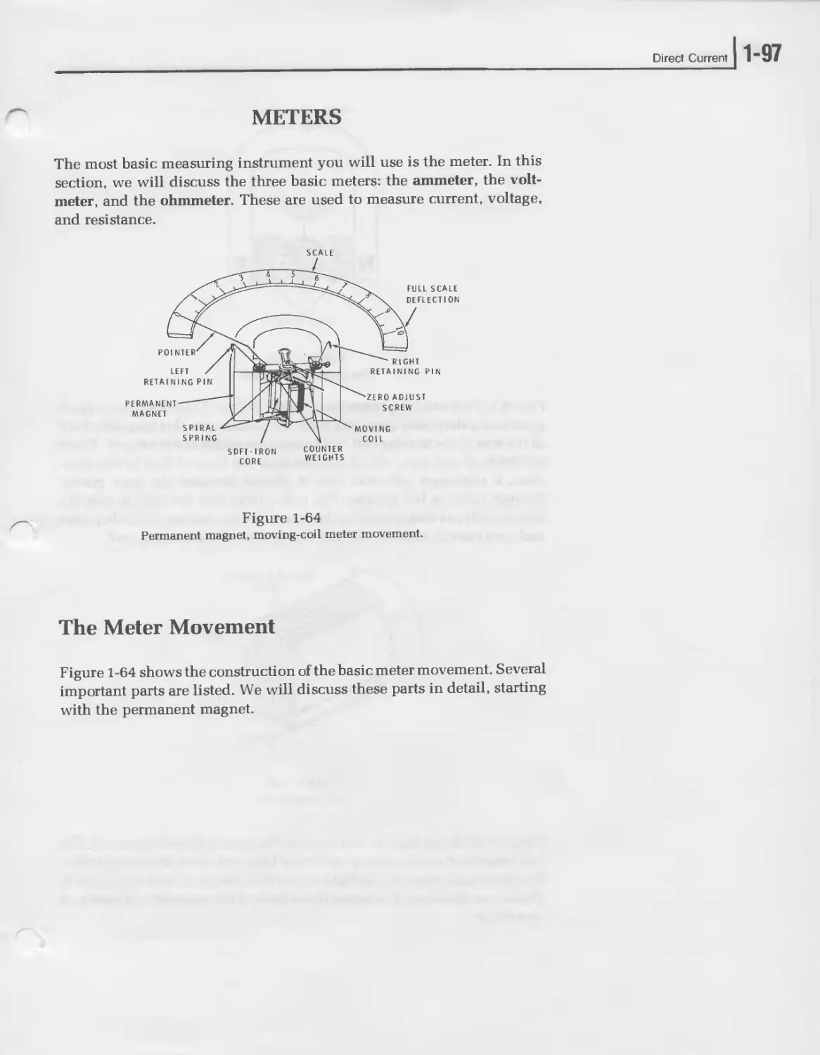
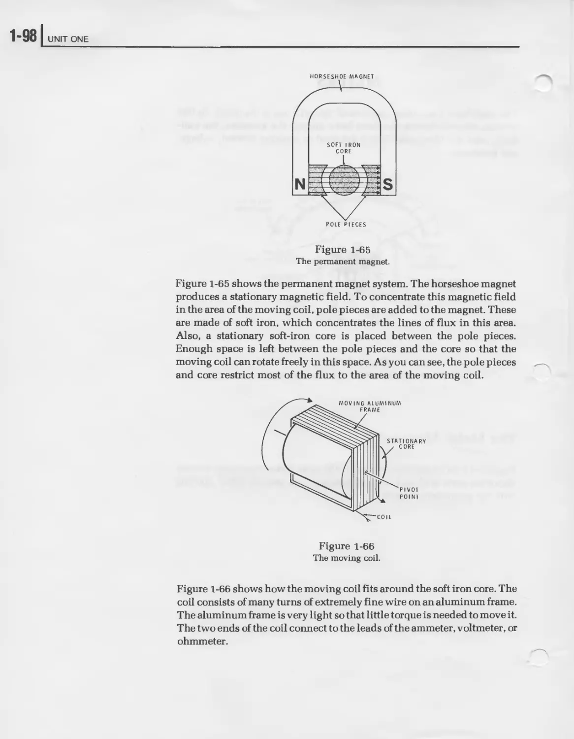
Meters.................................................. 1-97
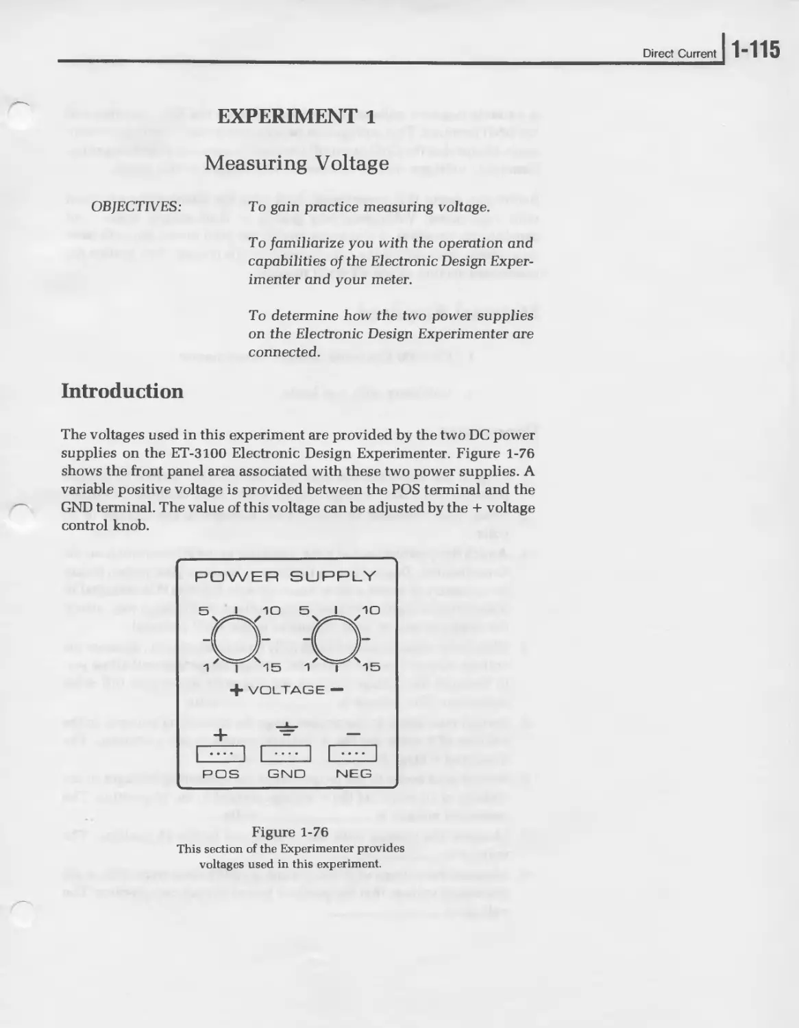
Experiment 1, Measuring Voltage ....................... 1-115
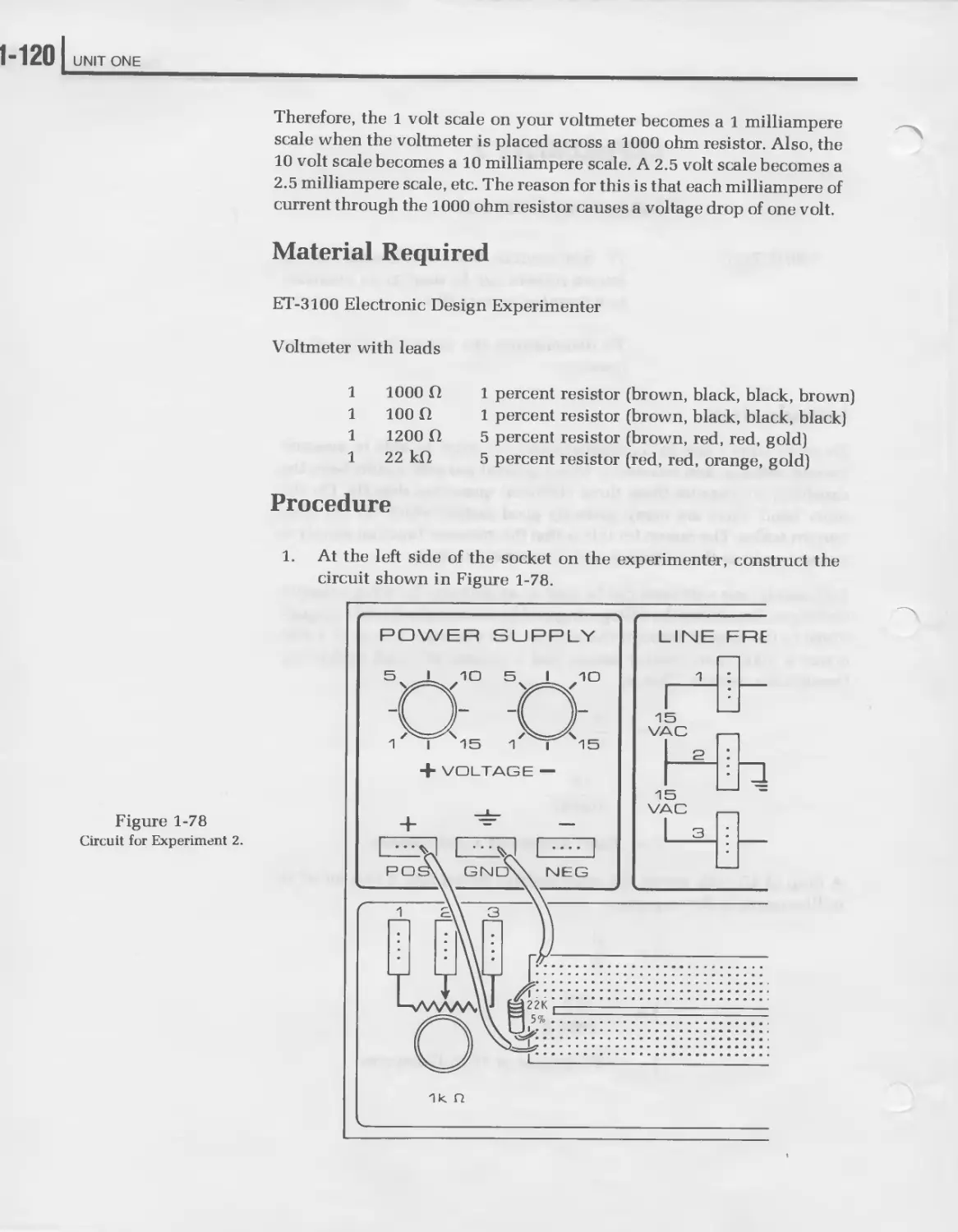
Experiment 2, Measuring Current ....................... 1-119
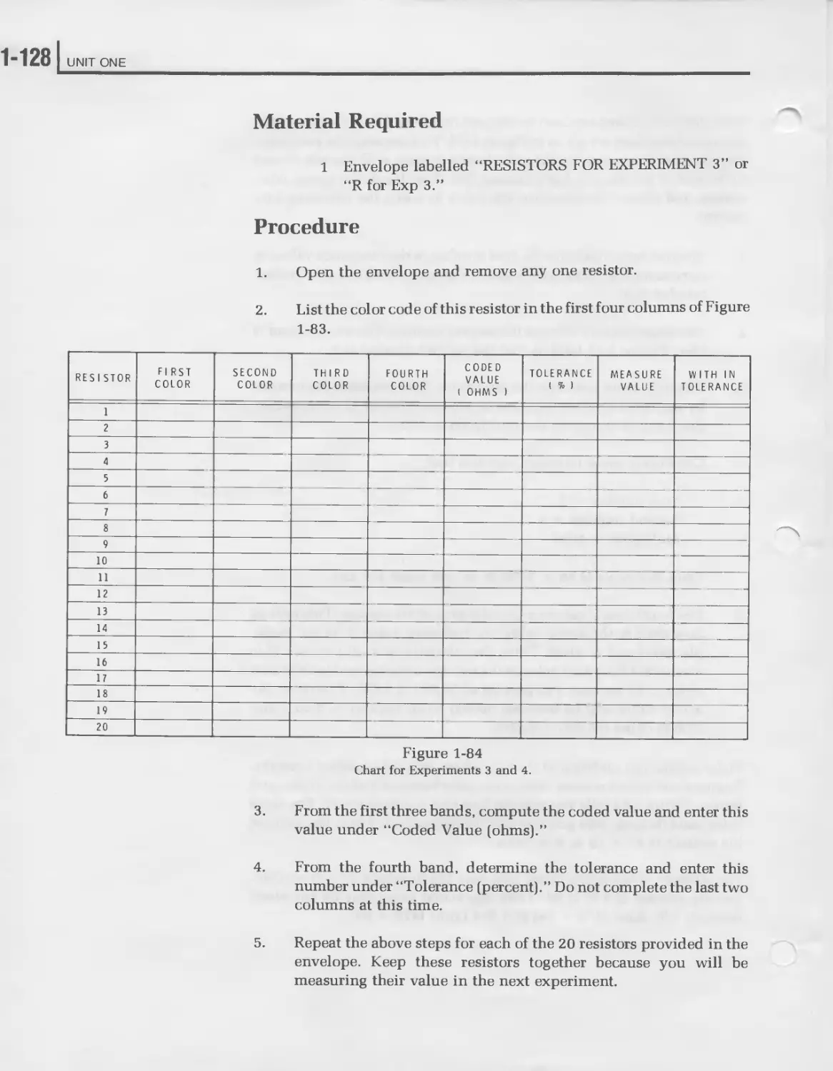
Experiments, Resistor Color Code....................... 1-126
Experiment 4, Using the Ohmmeter ...................... 1-130
Experiment 5, Verifying Ohm’s Law...................... 1-132
Unit Examination ...................................... 1-139
Exam Answers........................................... 1-151
Appendix A
Scientific Notation ............................... 1-157
Appendix В
Resistor Color Code Chart.......................... 1-169
Direct Current
1-3
INTRODUCTION
Electronics is that science which controls the behavior of electrons so
that some useful function is performed. As this definition implies, the
electron is vitally important to electronics. In fact, the word electronics is
derived from the word electron. Electricity comes to our homes and
offices by the movement of electrons through wires. Actually, electric
^current is nothing m ore than the movement of electrons,. Obviously then,
to understand electronics, you must first understand the nature of the
electron. In this unit, you will see what the electron is, how it behaves,
and how you can use it to perform useful jobs. You will also learn how to
measure the flow of electrons.
The “Unit Objectives” listed on the next page state exactly what you are
expected to learn from this unit. Study this list now and refer to it often as
you study the text. The “Unit Activity Guide” follows the “Unit Objec-
tives.” It lists the order in which you should complete this unit. Check off
each activity as you complete it.
1"4 I UNIT ONE
UNIT OBJECTIVES
When you complete this unit, you should be able to:
1. Define: atom, electron, proton, neutron, nucleus, and ion.
2. State the electrical charge associated with the: electron, proton,
neutron, atom, and ion.
3. State Coulomb’s law.
4. Define: insulator, conductor, current flow, schematic diagram,
coulomb, and ampere.
5. Identify the schematic symbols of basic electronic components.
6. Define: electromotive force, potential difference, voltage, and volt.
7. State the effects of connecting batteries in series, parallel, and
series-parallel.
8. Explain the difference between a voltage rise and voltage drop.
9. Define: resistance, ohm, and conductance.
10. Name three types of resistor construction.
11. Define potentiometer.
12. State how the total resistance is affected by connecting resistors in
series, in parallel, and in series-parallel.
13. Write the three equation forms of Ohm’s law.
Direct Current
14. Find current when given voltage and resistance.
15. Find voltage when given current and resistance.
16. Find resistance when given voltage and current.
17. Define power and watt.
18. Write the basic power formula.
19. Find power when given voltage and current.
20. Find voltage when given power and current.
21. Find current when given power and voltage.
22. Find power when given voltage and resistance.
23. Find power when given current and resistance.
24. State the basic law of magnetism.
25. Define magnetomotive force, ampere-turn, and permablility.
26. Name the instruments used to measure current, voltage, and resis-
tance.
27. Demonstrate the correct way to use a ammeter, voltmeter, and
ohmmeter.
28. Define ground.
1“6 I UNIT ONE
UNIT ACTIVITY GUIDE
Completion
Time
| | Read “The Basis of Electronics.” ---------
| | Answer Self-Review Questions 1-6. ---------
| | Read “Current.” ---------
| | Answer Self-Review Questions 7 - 14. ---------
| | Read “Voltage.” ---------
j j Answer Self-Review Questions 15 - 21. ---------
П Read “Resistance.” ---------
П Answer Self-Review Questions 22 - 31. ---------
Г~1 Read “Ohm’s Law.” ---------
Answer Self-Review Questions 32 - 35. ---------
| | Read “Power.” ---------
Direct Current
| | Answer Self-Review Questions 36 - 43. -----------
□ Read “Magnetism.” -----------
□ Answer Self-Review Questions 44 - 47. -----------
□ Read “Meters.” -----------
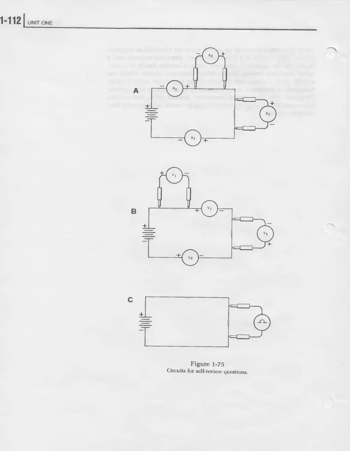
□ Answer Self-Review Questions 48 - 54. -----------
□ Complete Experiment 1. -----------
П Complete Experiment 2. -----------
□ Complete Experiment 3. -----------
□ Complete Experiment 4. -----------
□ Complete Experiment 5. -----------
□ Complete the Unit Examination. -----------
□ Check the Examination Answers. -----------
1-8 I UNIT ONE
THE BASIS OF ELECTRONICS
Electrons are tiny particles which carry the energy to light our homes,
cook our food, operate our electronic devices, and do much of our work.
Therefore, an understanding of the electron is vitally important to an
understanding of electronics. Controlling electrons is what electronics is
all about.
To understand what an electron is, we must investigate the make-up of
matter. Matter is generally described as anything which has weight and
occupies space. Thus, the earth and everything on it is classified as
matter.
Atoms
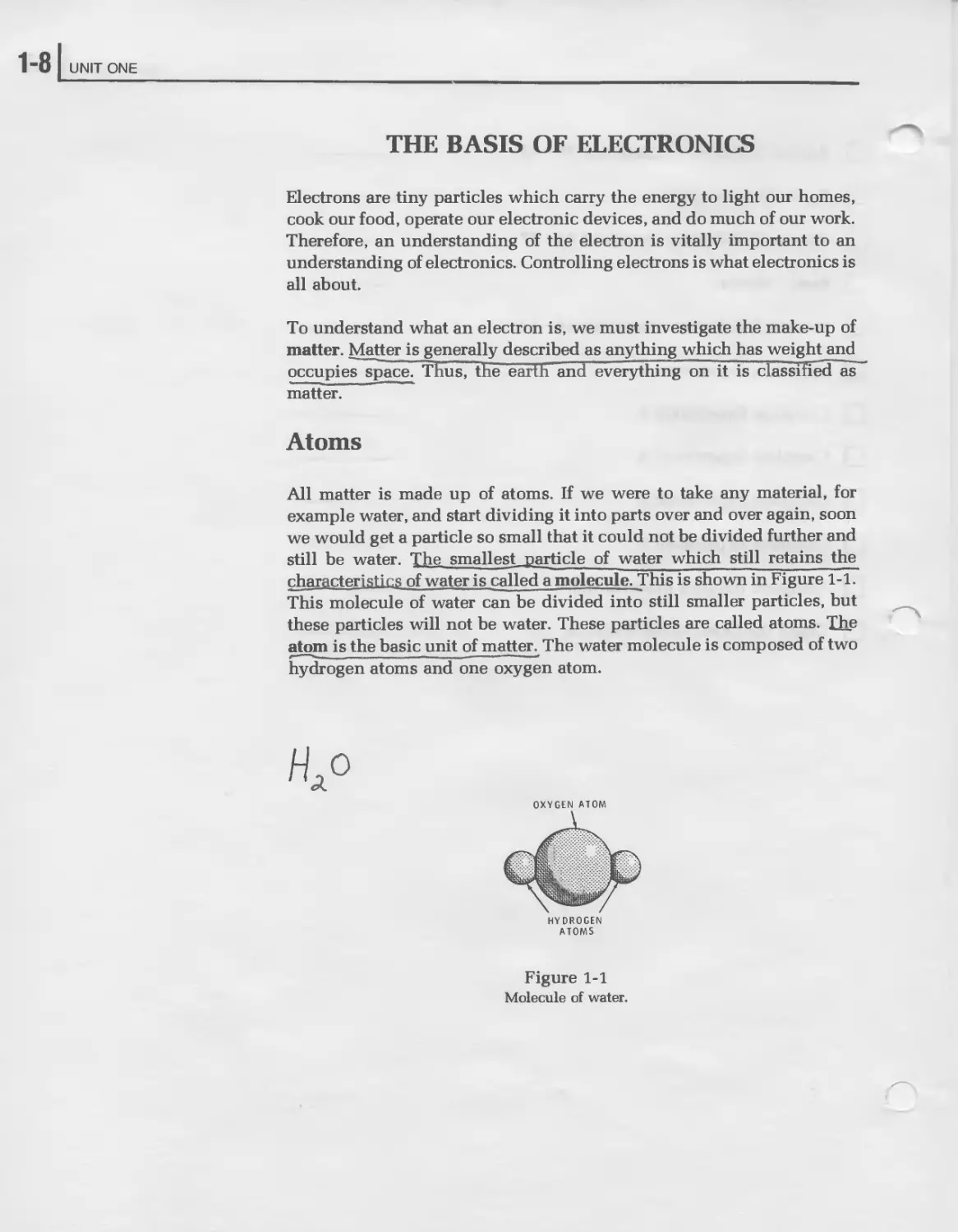
All matter is made up of atoms. If we were to take any material, for
example water, and start dividing it into parts over and over again, soon
we would get a particle so small that it could not be divided further and
still be water. The smallest, particle of water which still retains the
characteristics of water is called a molecule. This is shown in Figure 1-1.
This molecule of water can be divided into still smaller particles, but
these particles will not be water. These particles are called atoms. The
atom is the basic unit of matter. The water molecule is composed of two
hydrogen atoms and one oxygen atom.
OXYGEN ATOM
HYDROGEN
ATOMS
Figure 1-1
Molecule of water.
Direct Current
Electrons, Protons, and Neutrons
Atoms can be further broken down into particles called electrons, pro-
tons, and neutrons. These are the three basic building blocks which make
up all atoms.
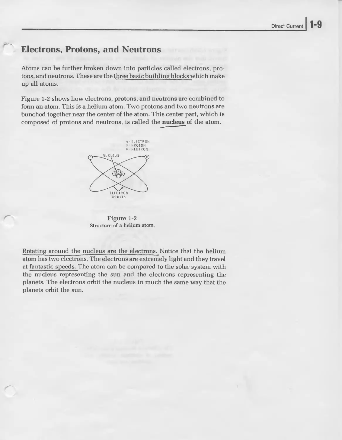
Figure 1-2 shows how electrons, protons, and neutrons are combined to
form an atom. This is a helium atom. Two protons and two neutrons are
bunched together near the center of the atom. This center part, which is
composed of protons and neutrons, is called the nucleus of the atom.
e-ELECTRON
PPROTON
N NEUTRON
ORBITS
Figure 1-2
Structure of a helium atom.
Rotating around the nucleus are the electrons. Notice that the helium
atom has two electrons. The electrons are extremely light and they travel
at fantastic speeds. The atom can be compared to the solar system with
the nucleus representing the sun and the electrons representing the
planets. The electrons orbit the nucleus in much the same way that the
planets orbit the sun.
1-10 UNIT ONE
Figure 1-3 shows the atomic structure of hydrogen, carbon, and copper.
Notice that the number of electrons is always equal to the number of
protons. This is normally true of any atom. When the number of electrons
and protons are equal, the atom is said to be in its normal, balanced, or
neutral state. As you will see later, this state can be upset by an external
force. However, we normally think of the atom as containing equal
numbers of electrons and protons.
HYDROGEN ATOM
(one electron, one proton)
CARBON ATOM
(6 electrons, 6 protons. 6 neutrons)
COPPER
(29 electrons. 29 protons. 35 neutrons)
Figure 1-3
The difference between atoms is the
number of electrons, protons, and
neutrons they have.
Direct Current
1-11
Electrostatics
Electrostatics is the branch of physics dealing with electrical charges at
rest, or static electricity. On the other hand, electronics deals largely with
moving electrical charges. However, before you can fully understand the
action of electrical charges in motion, you must first have some basic
knowledge of their behavior at rest.
We have examined the structure of the atom and discussed some of the
characteristics of the electron, proton, and neutron. However, we have
not yet discussed the most important characteristic of these particles.
This characteristic is their electrical charge. An electrical charge is a
force associated with the electron and the proton. It is this electrical
charge which makes the electron useful in electrical and electronic work.
The electrical charge is difficult to visualize because it is not a thing, like
a molecule or an atom. Rather, it is a force in much the same way that
gravity and magnetism are forces. It is a property which electrons and
protons have that causes these particles to behave in certain ways.
There are two distinct types of electrical charges. Because these two types
of charges have opposite characteristics, they have been given the names
positive and negative. The electrical charge associated with the electron
has been arbitrarily given the name negative. The electrical charge as-
sociated with the proton is considered positive. The neutron has no
electrical charge at all. It is electrically neutral and, therefore, plays no
known role in electricity.
The electron orbits around the nucleus at a fantastic speed. What force
keeps the electron from flying off into space? It is not gravity because the
gravitational force exerted by the nucleus is much too weak. Instead, the
force at work here is caused by the charge on the electron in orbit and the
charge on the proton in the nucleus. The negative charge of the electron is
attracted by the positive charge of the proton. We call this force of
attraction an electrostatic force. To explain this force, science has
adopted the concept of an electrostatic field. Every charged particle is
assumed to be surrounded by an electrostatic field which extends for a
distance outside the particle itself. It is the interaction of these fields
which causes the electron and proton to attract each other.
1-12 UNIT ONE
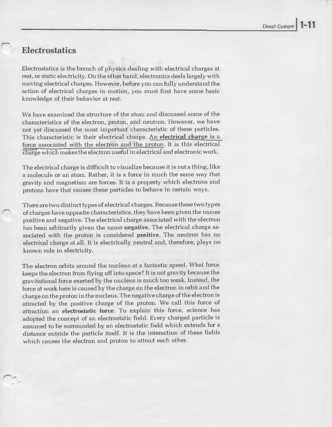
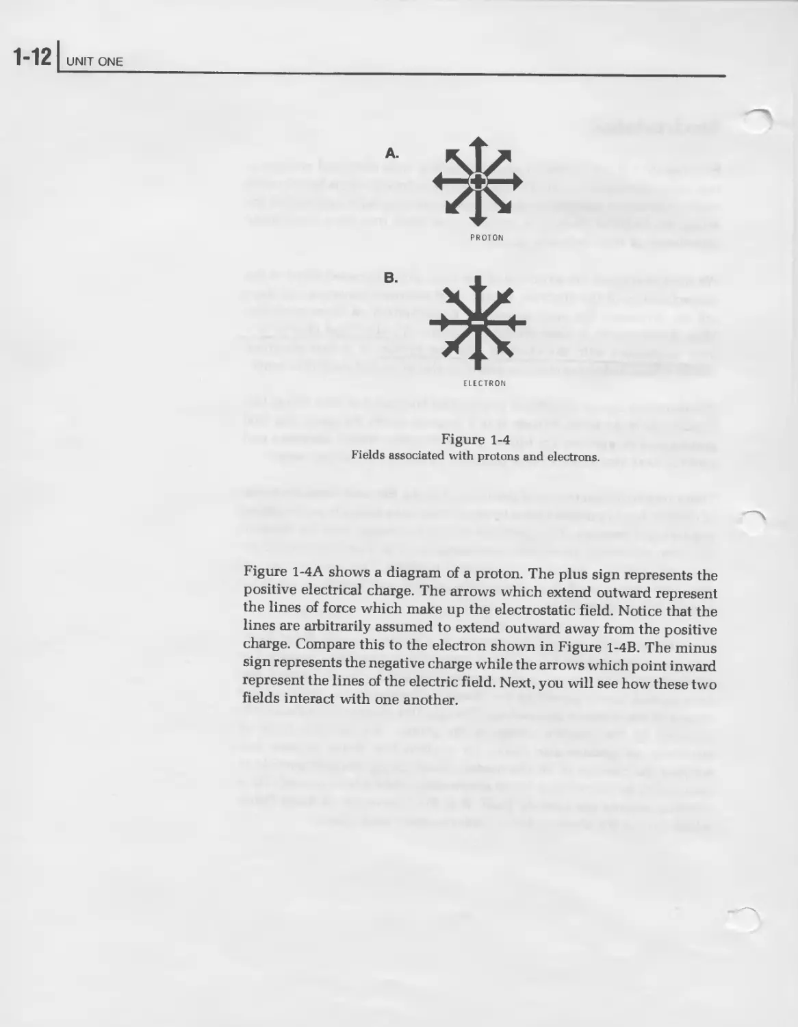
PROTON
В.
ELECTRON
Figure 1-4
Fields associated with protons and electrons.
Figure 1-4A shows a diagram of a proton. The plus sign represents the
positive electrical charge. The arrows which extend outward represent
the lines of force which make up the electrostatic field. Notice that the
lines are arbitrarily assumed to extend outward away from the positive
charge. Compare this to the electron shown in Figure 1-4B. The minus
sign represents the negative charge while the arrows which point inward
represent the lines of the electric field. Next, you will see how these two
fields interact with one another.
Direct Current
] 1-13
Coulomb’s Law
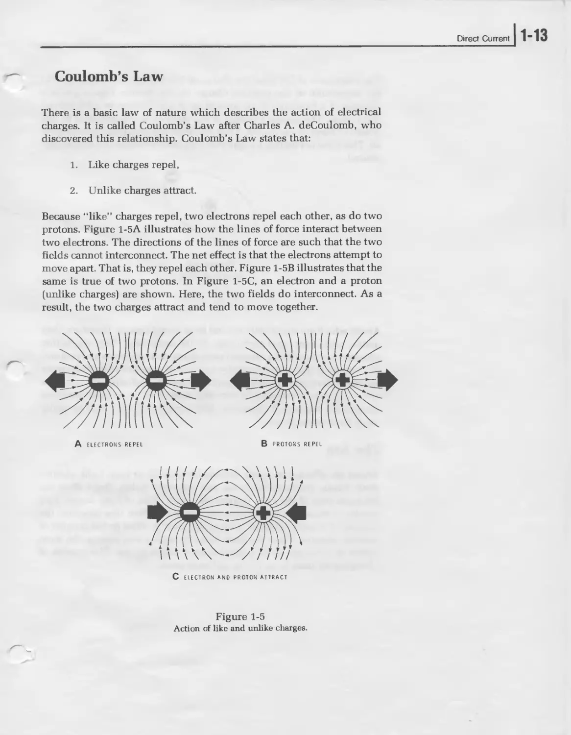
There is a basic law of nature which describes the action of electrical
charges. It is called Coulomb’s Law after Charles A. deCoulomb, who
discovered this relationship. Coulomb’s Law states that:
1. Like charges repel,
2. Unlike charges attract.
Because “like” charges repel, two electrons repel each other, as do two
protons. Figure 1-5A illustrates how the lines of force interact between
two electrons. The directions of the lines of force are such that the two
fields cannot interconnect. The net effect is that the electrons attempt to
move apart. That is, they repel each other. Figure 1-5B illustrates that the
same is true of two protons. In Figure 1-5C, an electron and a proton
(unlike charges) are shown. Here, the two fields do interconnect. As a
result, the two charges attract and tend to move together.
A ELECTRONS REPEL
В PROTONS REPEL
C ELECTRON AND PROTON ATTRACT
Figure 1-5
Action of like and unlike charges.
1“14 UNIT ONE
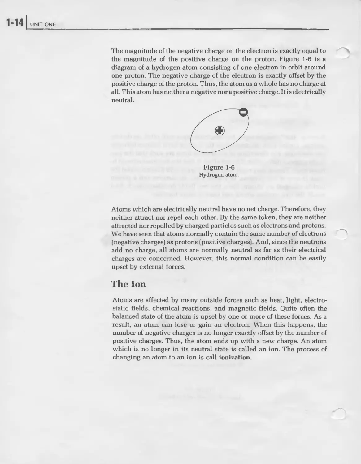
The magnitude of the negative charge on the electron is exactly equal to
the magnitude of the positive charge on the proton. Figure 1-6 is a
diagram of a hydrogen atom consisting of one electron in orbit around
one proton. The negative charge of the electron is exactly offset by the
positive charge of the proton. Thus, the atom as a whole has no charge at
all. This atom has neither a negative nor a positive charge. It is electrically
neutral.
Figure 1-6
Hydrogen atom.
Atoms which are electrically neutral have no net charge. Therefore, they
neither attract nor repel each other. By the same token, they are neither
attracted nor repelled by charged particles such as electrons and protons.
We have seen that atoms normally contain the same number of electrons
(negative charges) as protons (positive charges). And, since the neutrons
add no charge, all atoms are normally neutral as far as their electrical
charges are concerned. However, this normal condition can be easily
upset by external forces.
The Ion
Atoms are affected by many outside forces such as heat, light, electro-
static fields, chemical reactions, and magnetic fields. Quite often the
balanced state of the atom is upset by one or more of these forces. As a
result, an atom can lose or gain an electron. When this happens, the
number of negative charges is no longer exactly offset by the number of
positive charges. Thus, the atom ends up with a new charge. An atom
which is no longer in its neutral state is called an ion. The process of
changing an atom to an ion is call ionization.
Direct Current
1-15
There are both negative and positive ions. Figure 1-7 compares a neutral
atom of carbon with negative and positive ions of carbon. Figure 1-7A
shows the balanced or neutral atom. Notice that the six negative charges
(electrons) are exactly offset by the six positive charges (protons). The
neutrons are ignored in this example since they contribute nothing to the
electrical charge.
Figure 1-7B shows the condition which exists when the carbon atom
loses an electron. There are many forces in nature that can dislodge an
electron and cause it to wander away from the atom. We will discuss this
in more detail later. Notice that the carbon atom now has one more proton
than electrons. Thus, there is one positive charge which is not cancelled
by a corresponding negative charge. Therefore, the atom has a net posi-
tive charge. We call this a positive ion.
Figure 1-7C shows a carbon atom which has picked up a stray electron. In
this case, there is one negative charge which is not offset by a correspond-
ing positive charge. Hence, the atom has a net negative charge. This is
called a negative ion.
Figure 1-7
Carbon atom and ions.
FREE ELECTRON
C NEGATIVE ION CAUSED
BY PICKING-UP A
STRAY ELECTRON
The ion still has all the basic characteristics of carbon because the nu-
cleus of the atom has not been disturbed. Therefore, an atom can give up
or pick up electrons without changing its basic characteristics.
Changing atoms to ions is an easy thing to do and everything you see
around you contains ions as well as atoms. The material around you also
contains a larger number of free or stray electrons. These are electrons
which have escaped from atoms, leaving behind a positive ion. As you
will see later, the electrical characterisitics of different types of material
are determined largely by the number of free electrons and ions within
the material.
1“16 UNIT ONE
The Coulomb
The charge on an object is determined by the number of electrons it loses
or gains. If it loses electrons, the charge is positive. If it gains electrons,
the charge is negative.
The unit of electrical charge is called the coulomb. It is equal to the charge
of 6.25 x Ю18 electrons (6,250,000,000,000,000,000 or 6.25 billion bill-
ion. See “Powers of Ten and Scientific Notation,” below). An object
which has gained 6.25 x 10¹⁸ electrons has a negative charge of one
coulomb. An object which has given up 6.25 x 10¹⁸ electrons has a
positive charge of one coulomb.
Powers of Ten and Scientific Notation
Note above that the number 6,250,000,000,000,000,000 can also be ex-
pressed as 6.25 x Ю18. This number is read “six point two five times ten to
the eighteenth power.” The expression “ten to the eighteenth power”
means that the decimal place in 6.25 should be moved 18 places to the
right in order to convert to the proper number. The theory is that it is
easier to write and remember 6.25 x 10¹⁸ than it is to write and remember
6,250,000,000,000,000,000. This shorthand method of expressing num-
bers is known as powers of ten or scientific notation. It is often used in
electronics to express very large and very small numbers.
Very small numbers are expressed by using negative powers of ten. For
example, 3.2 x 10⁻⁸ is scientific notation for the number 0.000000032.
Here, “ten to the minus eighth power” means “move the decimal place in
3.2 eight places to the left.” To be sure you have the idea, look at the
following examples of both positive and negative powers of ten:
Positive Powers of Ten
7.9 X 104 = 79,000
9.1 x 108 = 910,000,000
1.0 X 1012 = 1,000,000,000,000
Direct Current
Negative Powers of Ten
7.9 X 10 4 = 0.00079
9.1 X ICT8 = 0.000 000 091
1.0 X ICT12 = 0.000 000 000 001
Study these examples until you get the idea of this system of writing
numbers. If you feel you need additional explanation, read “Appendix
A” at the end of this unit. This is a programmed instruction sequence
designed to teach powers of ten and scientific notation in much greater
detail.
Self-Review Questions
1. The------------is the basic unit of matter.
2. The three basic particles which make up all atoms are the
,, and
3. The center of the of the atom, which is composed of protons and
neutrons, is called the___________________
4. State the electrical charge associated with each of the following:
electron__________
proton____________
neutron___________
5. State Coulomb’s law.__________________________________________
6. A normal atom has a charge. However, if an atom loses
an electron, it has a--------charge. If an atom gains an electron
it has a ------------ charge. These charged atoms are called
7. The unit of electrical charge is the
1-18 I UNIT ONE
Self-Review Answers
1. The atom is the basic unit of matter.
2. The three basic particles which make up all atoms are the electron,
proton, and neutron.
3. The center of the atom, which is composed of protons and neut-
rons, is called the nucleus.
4. The electrical charge associated with each of the following is:
electron — negative
proton — positive
neutron — no charge or neutral
5. Coulomb’s law states—Like charges repel, unlike charges attract.
6. A normal atom has a neutral charge. However, if an atom loses an
electron, it has a positive charge. If an atom gains an electron, it has
a negative charge. These charged atoms are called ions.
7. The unit of electrical charge is the coulomb.
Direct Current
] 1-19
CURRENT
In electronics, current is defined as the flow of electrical charge from one
point to another. Electrons have a negative charge. Therefore, if we can
cause electrons to move from one point to another, we will have current.
But before an electron can move from one point to another it must first be
freed from the atom. Therefore, let’s take a closer look at the mechanism
by which electrons are freed from the atom.
Freeing Electrons
You have seen that electrons revolve around the nucleus at very high
speeds. Two forces hold the electron in a precarious balance. The cen-
trifugal force of the electron is exactly offset by the attraction of the
nucleus. This balanced condition can be upset, causing the electron to be
dislodged. But not all electrons can be freed from the atom with the same
ease. Some are dislodged more easily than others. To see why, we must
discuss the concept of orbital shells.
The orbits of the electrons in any atom fall into certain patterns. In all
atoms which have two or more electrons, two of the electrons orbit
relatively close to the nucleus. The area in which these electrons rotate is
called a shell. This shell can support only two electrons. All other elec-
trons must orbit in other shells, further from the nucleus.
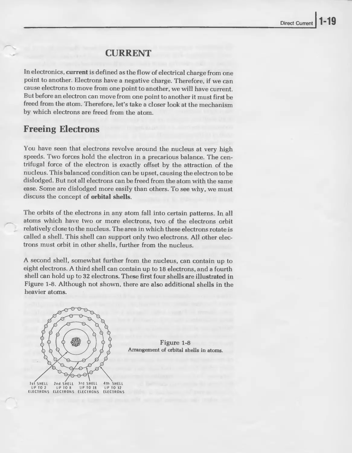
A second shell, somewhat further from the nucleus, can contain up to
eight electrons. A third shell can contain up to 18 electrons, and a fourth
shell can hold up to 32 electrons. These first four shells are illustrated in
Figure 1-8. Although not shown, there are also additional shells in the
heavier atoms.
Figure 1-8
Arrangement of orbital shells in atoms.
1-201 UNIT ONE
Of particular importance to electronics is the outer electron shell of an
atom. Hydrogen and helium atoms have one and two electrons respec-
tively. In this case, the outer shell is the first (and only) shell. With atoms
which have three to ten electrons, the outer shell is the second shell.
Regardless of which shell it happens to be, the outer shell is called the
valence shell. Electrons in this shell are called valence electrons.
Electrons are arranged in such a way that the valence shell never has more
than eight electrons. This may be confusing since we have seen that the
third shell can contain up to 18 electrons. An example shows why both
statements are true. An atom of argon contains 18 electrons — 2 in the first
shell, 8 in the second shell, and 8 in the third shell. It might seem that the
next heavier atom, potassium, would have 9 electrons in its third shell.
However, this would violate the valence rule stated above. Actually, what
happens is that the extra electron is placed in a fourth shell. Thus, the 19
electrons are distributed in this manner: 2 in the first shell, 8 in the
second shell, 8 in the third shell, and 1 in the fourth shell. Notice that the
outer or valence shell becomes the fourth shell rather than the third. Once
the fourth shell is established as the valence shell, the third shell can fill
to its full capacity of 18 electrons.
The valence electrons are extremely important in electronics. These are
the electrons which can be easily freed to perform useful functions. To
see why the valence electrons are more easily freed, let’s consider the
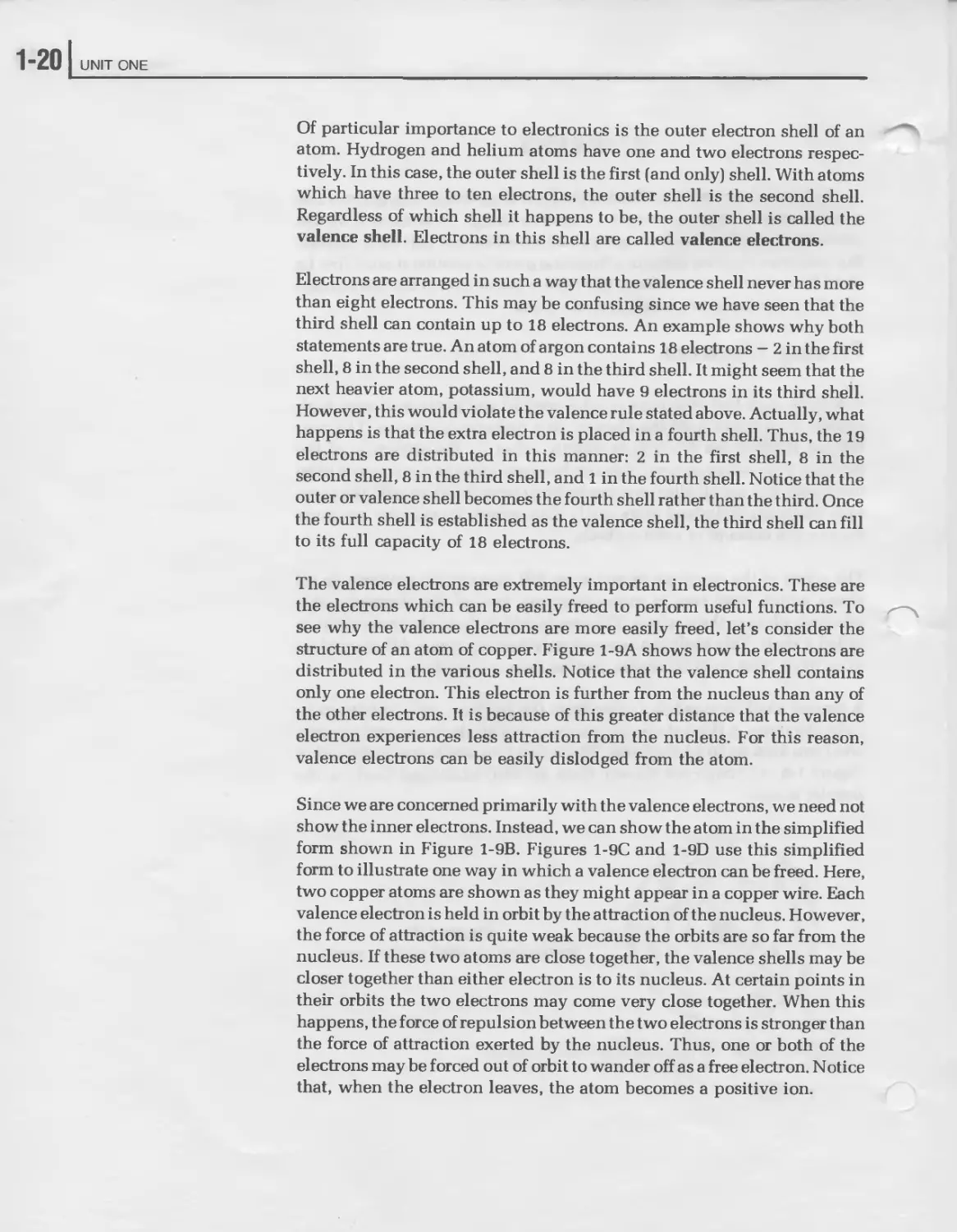
structure of an atom of copper. Figure 1-9A shows how the electrons are
distributed in the various shells. Notice that the valence shell contains
only one electron. This electron is further from the nucleus than any of
the other electrons. It is because of this greater distance that the valence
electron experiences less attraction from the nucleus. For this reason,
valence electrons can be easily dislodged from the atom.
Since we are concerned primarily with the valence electrons, we need not
show the inner electrons. Instead, we can show the atom in the simplified
form shown in Figure 1-9B. Figures 1-9C and 1-9D use this simplified
form to illustrate one way in which a valence electron can be freed. Here,
two copper atoms are shown as they might appear in a copper wire. Each
valence electron is held in orbit by the attraction of the nucleus. However,
the force of attraction is quite weak because the orbits are so far from the
nucleus. If these two atoms are close together, the valence shells may be
closer together than either electron is to its nucleus. At certain points in
their orbits the two electrons may come very close together. When this
happens, the force of repulsion between the two electrons is stronger than
the force of attraction exerted by the nucleus. Thus, one or both of the
electrons may be forced out of orbit to wander off as a free electron. Notice
that, when the electron leaves, the atom becomes a positive ion.
Direct Current
A
Figure 1-9
Freeing an electron from a copper atom.
As the free electron wanders around through the atomic structure, it may
be eventually captured by another positive ion. Or, it may come close
enough to other valence electrons to force them from orbit. The point is
that events like these occur frequently in many types of material. Thus, in
a piece of copper wire containing billions and billions of atoms, there are
bound to be billions of free electrons wandering around the atomic
structure.
1-221 UNIT ONE
Conductors and Insulators
The importance of valence electrons cannot be emphasized too strongly.
The electrical characteristics of a substance depend on the action of the
valence electrons. You have seen that the valence shell can hold up to
eight electrons. Those substances which have their valence shells almost
filled tend to be stable, and strive to fill their valence shell by capturing
free electrons. Therefore, they have very few free electrons wandering
around through their atomic structure. These substances which have
very few free electrons are called insulators. By opposing the production
of free electrons, they resist certain electrical actions. Insulators are
important in electrical and electronics work for this reason. The plastic
material on electrical wires, for example, is an insulator which protects
us from electrical shock.
Materials in which the valence shell is almost empty have the opposite
characteristics. Those with only one or two valence electrons tend to give
up these electrons very easily. Copper, silver, and gold, for example, each
have one valence electron, and valence electrons are very easily dis-
lodged. Consequently, a bar of any one of these will have a very large
number of free electrons. These substances which have a large number of
free electrons are called conductors. Iron, nickel, and aluminum are also
good conductors. Notice that all of these substances are metals. Most
metals are good conductors. Conductors are important because they are
used to carry electrical current from one place to another.
In some substances, like silicon and germanium, the valence shell is half
filled, there are four valence electrons. These substances are called
semiconductors because they are neither good conductors nor good
insulators. Semiconductors are important in electronics because they are
used to make transistors and integrated circuits.
Direct Current
1-23
The Battery
Current flow is the directed movement of free electrons from one place to
another. Thus, to have current flow we must first have free electrons and
positive ions. You have seen how valence electrons can be dislodged
from atoms to form free electrons and positive ions. To perform a useful
function, large numbers of electrons must be freed and concentrated in
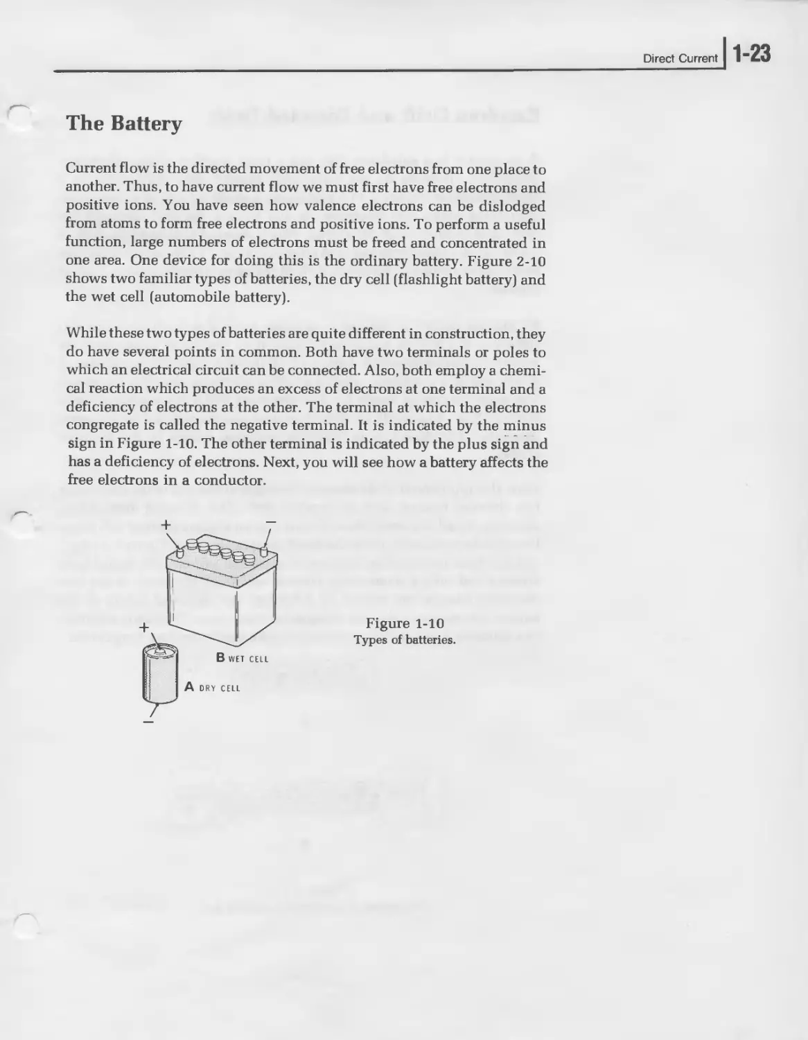
one area. One device for doing this is the ordinary battery. Figure 2-10
shows two familiar types of batteries, the dry cell (flashlight battery) and
the wet cell (automobile battery).
While these two types of batteries are quite different in construction, they
do have several points in common. Both have two terminals or poles to
which an electrical circuit can be connected. Also, both employ a chemi-
cal reaction which produces an excess of electrons at one terminal and a
deficiency of electrons at the other. The terminal at which the electrons
congregate is called the negative terminal. It is indicated by the minus
sign in Figure 1-10. The other terminal is indicated by the plus sign and
has a deficiency of electrons. Next, you will see how a battery affects the
free electrons in a conductor.
Figure 1-10
Types of batteries.
A DRY CELL
1-24 UNIT ONE
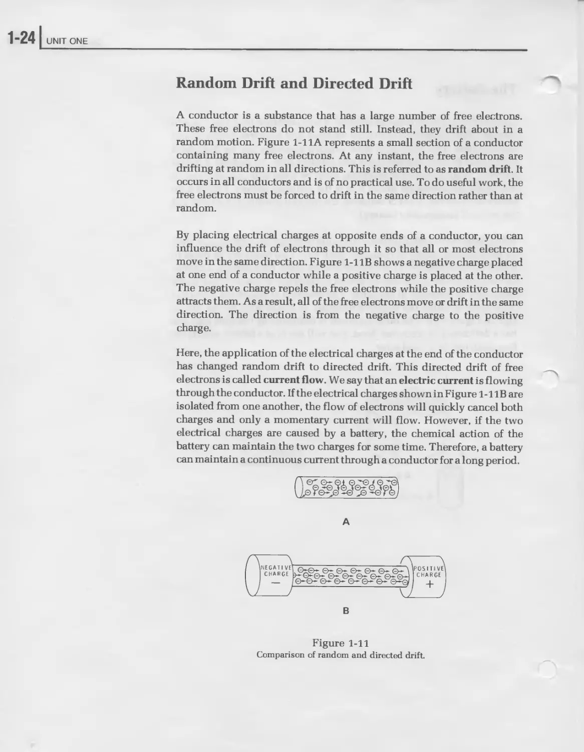
Random Drift and Directed Drift
A conductor is a substance that has a large number of free electrons.
These free electrons do not stand still. Instead, they drift about in a
random motion. Figure 1-11A represents a small section of a conductor
containing many free electrons. At any instant, the free electrons are
drifting at random in all directions. This is referred to as random drift. It
occurs in all conductors and is of no practical use. To do useful work, the
free electrons must be forced to drift in the same direction rather than at
random.
By placing electrical charges at opposite ends of a conductor, you can
influence the drift of electrons through it so that all or most electrons
move in the same direction. Figure 1-1 IB shows a negative charge placed
at one end of a conductor while a positive charge is placed at the other.
The negative charge repels the free electrons while the positive charge
attracts them. As a result, all of the free electrons move or drift in the same
direction. The direction is from the negative charge to the positive
charge.
Here, the application of the electrical charges at the end of the conductor
has changed random drift to directed drift. This directed drift of free
electrons is called current flow. We say that an electric current is flowing
through the conductor. If the electrical charges shown in Figure 1-1 IB are
isolated from one another, the flow of electrons will quickly cancel both
charges and only a momentary current will flow. However, if the two
electrical charges are caused by a battery, the chemical action of the
battery can maintain the two charges for some time. Therefore, a battery
can maintain a continuous current through a conductor for a long period.
в
Figure 1-11
Comparison of random and directed drift.
Direct Current
1-25
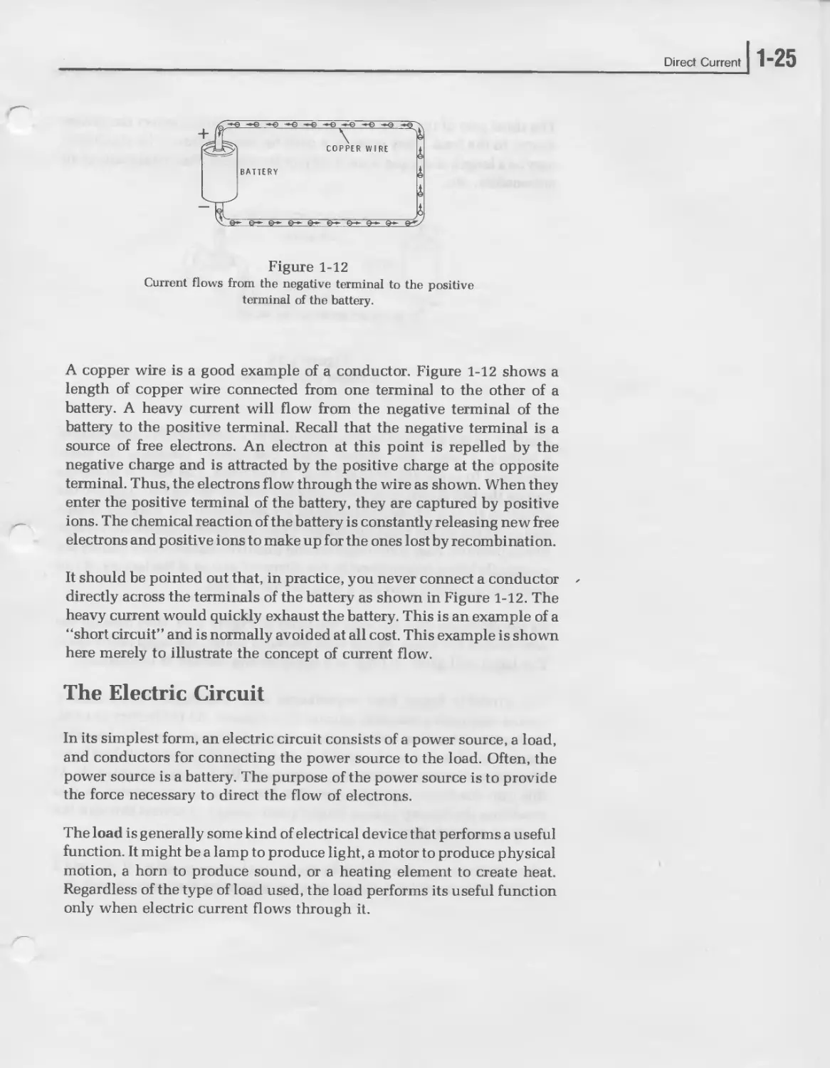
Figure 1-12
Current flows from the negative terminal to the positive
terminal of the battery.
A copper wire is a good example of a conductor. Figure 1-12 shows a
length of copper wire connected from one terminal to the other of a
battery. A heavy current will flow from the negative terminal of the
battery to the positive terminal. Recall that the negative terminal is a
source of free electrons. An electron at this point is repelled by the
negative charge and is attracted by the positive charge at the opposite
terminal. Thus, the electrons flow through the wire as shown. When they
enter the positive terminal of the battery, they are captured by positive
ions. The chemical reaction of the battery is constantly releasing new free
electrons and positive ions to make up for the ones lost by recombination.
It should be pointed out that, in practice, you never connect a conductor -
directly across the terminals of the battery as shown in Figure 1-12. The
heavy current would quickly exhaust the battery. This is an example of a
“short circuit” and is normally avoided at all cost. This example is shown
here merely to illustrate the concept of current flow.
The Electric Circuit
In its simplest form, an electric circuit consists of a power source, a load,
and conductors for connecting the power source to the load. Often, the
power source is a battery. The purpose of the power source is to provide
the force necessary to direct the flow of electrons.
The load is generally some kind of electrical device that performs a useful
function. It might be a lamp to produce light, a motor to produce physical
motion, a horn to produce sound, or a heating element to create heat.
Regardless of the type of load used, the load performs its useful function
only when electric current flows through it.
1“26 UNIT ONE
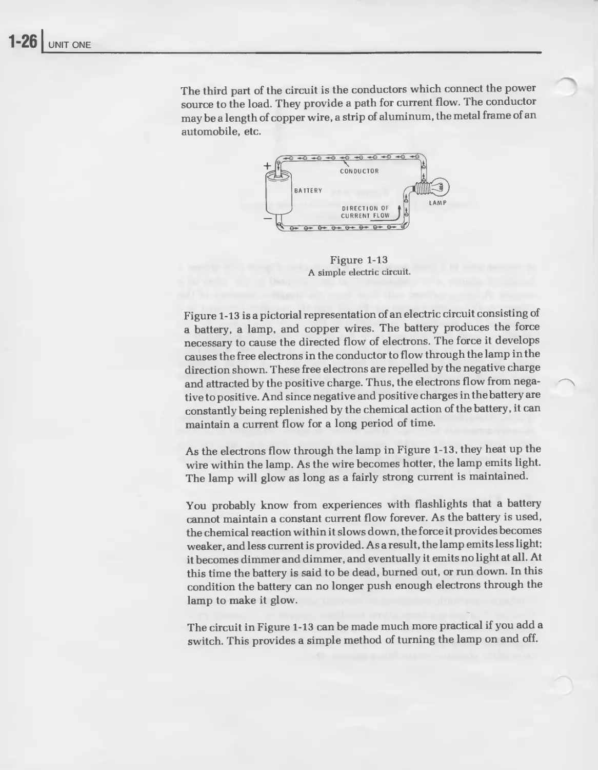
The third part of the circuit is the conductors which connect the power
source to the load. They provide a path for current flow. The conductor
may be a length of copper wire, a strip of aluminum, the metal frame of an
automobile, etc.
Figure 1-13
A simple electric circuit.
Figure 1-13 is a pictorial representation of an electric circuit consisting of
a battery, a lamp, and copper wires. The battery produces the force
necessary to cause the directed flow of electrons. The force it develops
causes the free electrons in the conductor to flow through the lamp in the
direction shown. These free electrons are repelled by the negative charge
and attracted by the positive charge. Thus, the electrons flow from nega-
tive to positive. And since negative and positive charges in the battery are
constantly being replenished by the chemical action of the battery, it can
maintain a current flow for a long period of time.
As the electrons flow through the lamp in Figure 1-13, they heat up the
wire within the lamp. As the wire becomes hotter, the lamp emits light.
The lamp will glow as long as a fairly strong current is maintained.
You probably know from experiences with flashlights that a battery
cannot maintain a constant current flow forever. As the battery is used,
the chemical reaction within it slows down, the force it provides becomes
weaker, and less current is provided. Asa result, the lamp emits less light;
it becomes dimmer and dimmer, and eventually it emits no light at all. At
this time the battery is said to be dead, burned out, or run down. In this
condition the battery can no longer push enough electrons through the
lamp to make it glow.
The circuit in Figure 1-13 can be made much more practical if you add a
switch. This provides a simple method of turning the lamp on and off.
Direct Current
]1-27
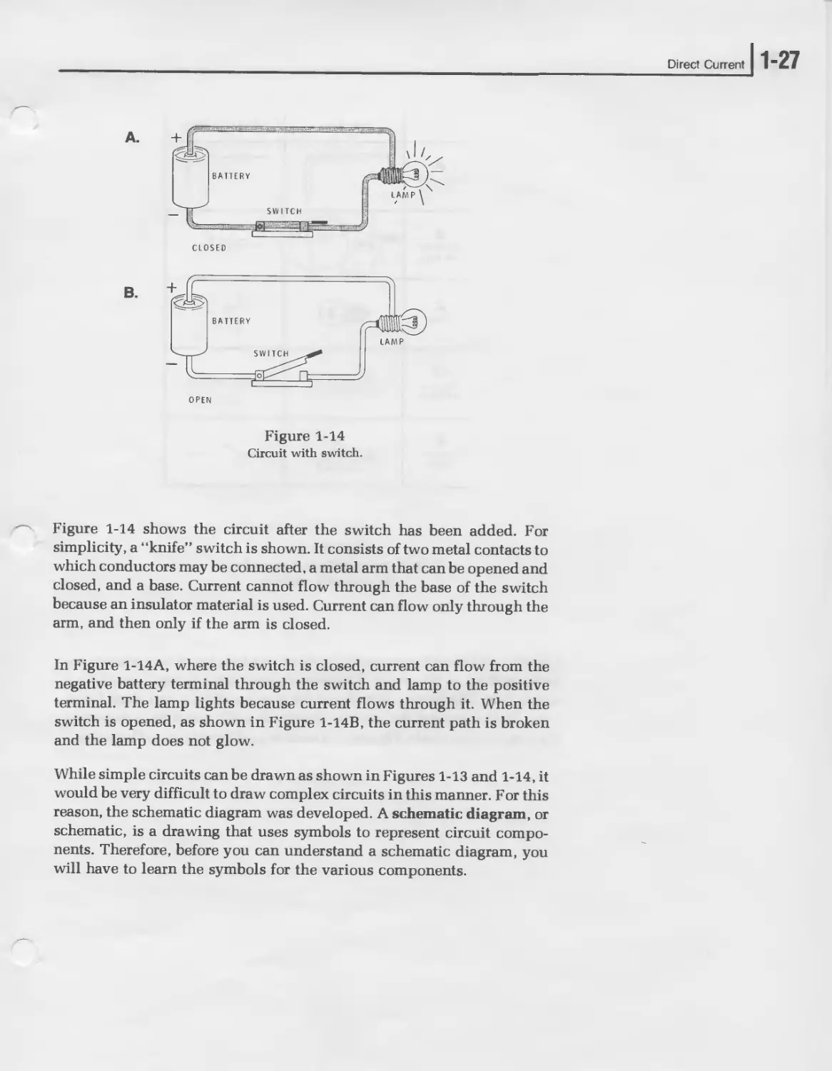
Figure 1-14
Circuit with switch.
Figure 1-14 shows the circuit after the switch has been added. For
simplicity, a “knife” switch is shown. It consists of two metal contacts to
which conductors may be connected, a metal arm that can be opened and
closed, and a base. Current cannot flow through the base of the switch
because an insulator material is used. Current can flow only through the
arm, and then only if the arm is closed.
In Figure 1-14A, where the switch is closed, current can flow from the
negative battery terminal through the switch and lamp to the positive
terminal. The lamp lights because current flows through it. When the
switch is opened, as shown in Figure 1-14B, the current path is broken
and the lamp does not glow.
While simple circuits can be drawn as shown in Figures 1-13 and 1-14, it
would be very difficult to draw complex circuits in this manner. For this
reason, the schematic diagram was developed. A schematic diagram, or
schematic, is a drawing that uses symbols to represent circuit compo-
nents. Therefore, before you can understand a schematic diagram, you
will have to learn the symbols for the various components.
1-281 UNIT ONE
Figure 1-15
Pictorial representations compared with
the schematic symbols.
Figure 1-15 shows the schematic symbols for the circuit components we
have used up to this point. The wire or conductor is represented by a
single line. The battery is replaced by a series of long and short lines.
Long lines represent the positive terminals while short lines represent
the negative terminals. The same symbol is used for all types of batteries.
Direct Current
1-29
SWITCH
(CLOSED)
SWITCH
(OPEN)
Figure 1-16
Schematic diagram of a simple circuit.
Figure 1-16 shows the symbols combined to form schematic diagrams.
Figure 1-16A is the schematic diagram for the pictorial drawing of Figure
1-14A. Figure 1-16B represents Figure 1-14B.
The circuit shown in Figure 1-16 is the schematic diagram of a flashlight.
It could also be a simplified schematic for the headlight system in an
automobile. In fact, it can represent any system which contains a battery,
a lamp, and a switch. If you replace the lamp with a motor, the circuit
becomes that of the starter system in a car. In this case, the switch is
operated by the ignition key. Other circuits which operate in a similar
manner are the doorbell and the automobile horn. In the first case, the bell
is the load while the switch is operated by a pushbutton at the door. In the
second case, the horn is the load while the switch is located on the
steering wheel.
1-301 UNIT ONE
The Ampere
The unit of current is the ampere. The ampere is the rate at which
electrons move past a given point. An ampere is equal to 1 coulomb per
second. That is, if 1 coulomb (6.25 x 10¹⁸ electrons) flows past a given
point in 1 second, then the current is equal to 1 ampere. Coulombs
indicate numbers of electrons; amperes indicate the rate of electron flow
or coulombs per second.
When 6.25 x 10¹⁸ electrons flow through a wire each second, the current
flow is 1 ampere. If twice this number of electrons flows each second, the
current is 2 amperes. This relationship is expressed by the equation:
coulombs
amperes = ------=—
seconds
If 10 coulombs flow past a point in two seconds, then the current flow is 5
amperes.
The name ampere is often shortened to amp and is abbreviated A. Many
times the ampere is too large a unit. In these cases, metric prefixes are
used to denote smaller units. The milliampere (mA) is one thousandth
(.001) of an ampere. The microampere (p,A) is one millionth (.000 001) of
an ampere. In other words, there are 1000 milliamperes or 1,000,000
microamperes in an ampere. In electronics, the letter “I” is used to
represent current. Therefore, in the shorthand of electronics you could
write the statement “the current is 2 amps” as an equation “I = 2A.”
We change from amperes to milliamperes by multiplying by 103 (x 1000).
Thus, 1.7 amperes is equal to 1.7 x 10³ milliamperes. Also, we change
from amperes to microamperes by multiplying by 10® (x 1,000,000).
Therefore, 1.7 amperes is equal to 1.7 x 10⁶ microamperes.
For those who need it, a more detailed explanation of metric prefixes is
given in “Appendix A.”
Direct Current
] 1-31
Self-Review Questions
8. Substances that have very few free electrons are called
9. Substances that have a large number of free electrons are called
10. A directed drift of free electrons is called
11. In an electrical circuit electrons flow from the terminal
of the battery to the terminal.
12. A drawing that uses symbols to represent circuit components is
known as a
13. The schematic symbols for four components are shown in Figure
1-17. Identify each one:
A.
B.
C.
D.
14. The unit of current is the---------------.
Figure 1-17
Identify these symbols.
1-32 UNIT ONE
Self-Review Answers
8. Substances that have very few free electrons are called insulators.
9. Substances that have a large number of free electrons are called
conductors.
10. A directed drift of free electrons is called current flow.
11. In an electrical circuit electrons flow from the negative terminal of
the battery to the positive terminal.
12. A drawing that uses symbols to represent circuit components is
known as a schematic diagram.
13. Figure 1-17 shows the following schematic symbols:
A. Battery,
B. Light bulb,
C. Closed switch,
D. Open switch.
14. The unit of current is the ampere.
Direct Current
1-33
VOLTAGE
You have seen that current will not flow in a circuit unless an external
force is applied. In the circuits discussed in the previous section, the
force was provided by batteries, which change chemical energy to elec-
trical energy by separating negative charges (electrons) from positive
charges (ions). These charges produce the force, or pressure, which
causes electrons to flow and do useful work. This force is given several
different names, discussed below, which are used more or less inter-
changeably.
Electromotive Force
One popular name is electromotive force, which is abbreviated emf. This
name is very descriptive since it literally means a force which moves
electrons. Thus, emf is the force or pressure which sets electrons in
motion. This force is a natural result of Coulomb’s law.
You will recall that Coulomb’s law states that like charges repel while
unlike charges attract. The battery, by chemical action, produces a nega-
tive charge at one terminal and a positive charge at the other. The
negative charge is simply an excess of electrons while the positive charge
is an excess of positive ions. If a closed circuit is connected across the
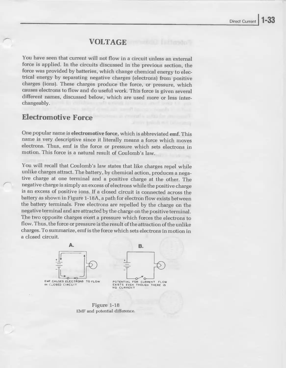
battery as shown in Figure 1-18A, a path for electron flow exists between
the battery terminals. Free electrons are repelled by the charge on the
negative terminal and are attracted by the charge on the positive terminal.
The two opposite charges exert a pressure which forces the electrons to
flow. Thus, the force or pressure is the result of the attraction of the unlike
charges. Tо summarize, emf is the force which sets electrons in motion in
a closed circuit.
EMF CAUSES ELECTRONS TO FLOW
IN CLOSED CIRCUIT
Figure 1-18
EMF and potential difference.
B.
POTENTIAL FOR CURRENT FLOW
EXISTS EVEN THOUGH THERE IS
NO CURRENT
1 ”34 I UNIT ONE
Potential Difference
Another name for this force is potential difference. This name is also very
descriptive. It describes the characteristics of emf in an open circuit. Emf
is the force which causes electrons to move as shown in Figure 1-18A.
However, consider the situation shown in Figure 1-18B. Here, electrons
cannot flow because the switch is open. Nevertheless, the battery still
produces the same pressure or force as before. Thus, the potential for
producing current flow exists even though no current is presently flow-
ing. As used here, potential means the possibility of doing work. If the
switch is closed, current flows, the lamp lights, and useful work is done.
Therefore, whether a battery is connected into a circuit or not, it has the
potential for doing work.
A single unit of charge, such as an electron, also has the potential for
doing work. It can deflect other electrons, which is some small amount of
work. However, it is the difference between two charges which is termed
potential difference. An example is a battery. It has a negative terminal
and a positive terminal. The electrons on the negative terminal are strain-
ing to move toward the positive terminal to equalize the charges. A
potential difference exists between the negative terminal and the positive
terminal of a battery.
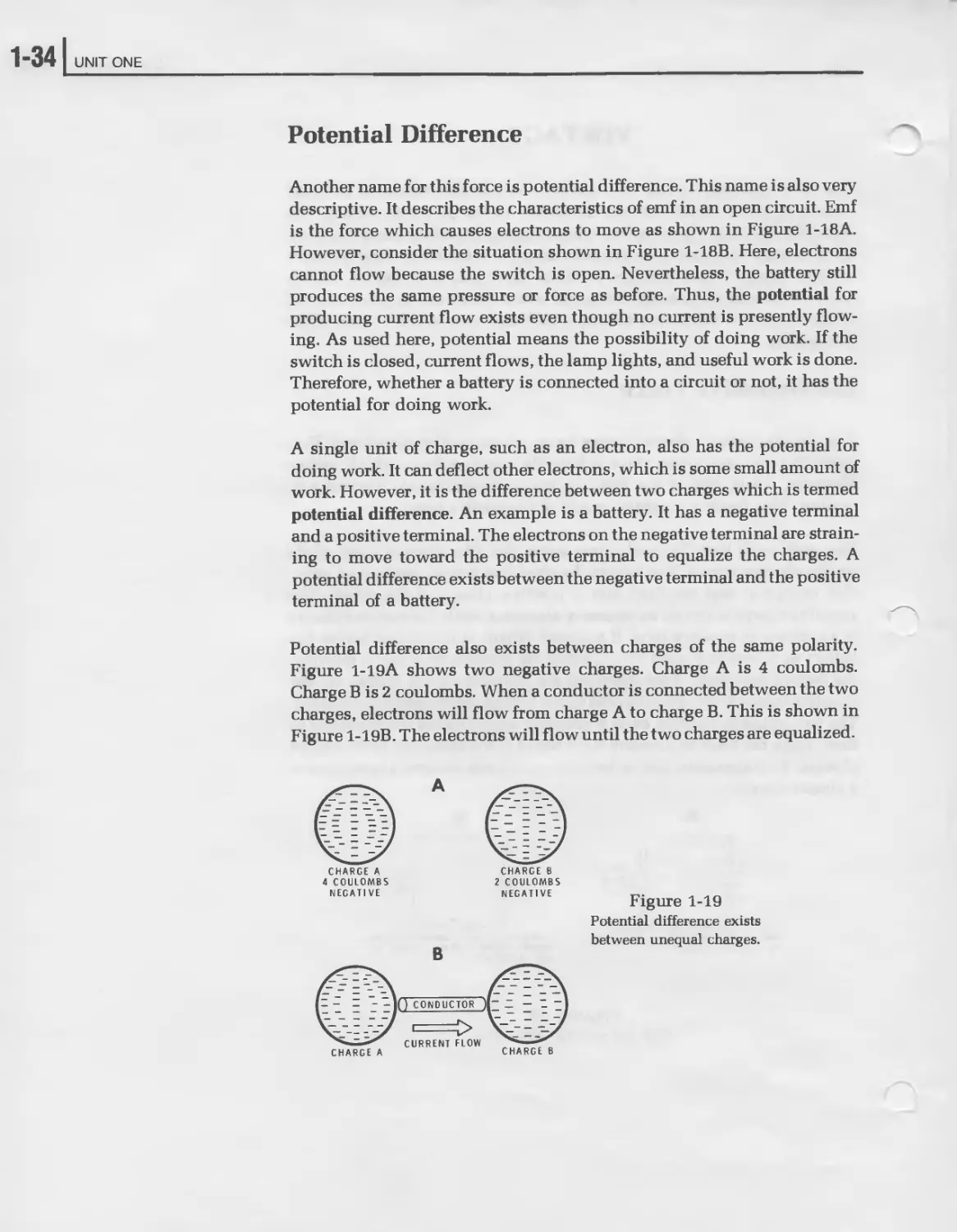
Potential difference also exists between charges of the same polarity.
Figure 1-19A shows two negative charges. Charge A is 4 coulombs.
Charge В is 2 coulombs. When a conductor is connected between the two
charges, electrons will flow from charge A to charge B. This is shown in
Figure 1-19B. The electrons will flowuntil the two charges are equalized.
CHARGE A
4 COULOMBS
NEGATIVE
CHARGE В
2 COULOMBS
NEGATIVE
Figure 1-19
Potential difference exists
between unequal charges.
Direct Current
]l-35
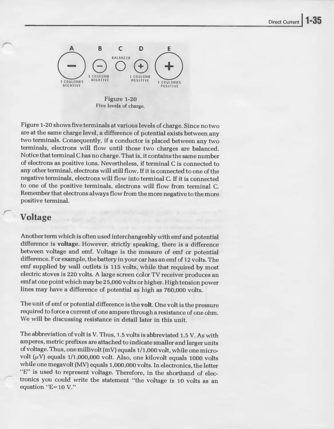
A
3 COULOMBS
NEGATIVE
D
Figure 1-20
Five levels of charge.
3 COULOMBS
POSITIVE
Figure 1-20 shows five terminals at various levels of charge. Since no two
are at the same charge level, a difference of potential exists between any
two terminals. Consequently, if a conductor is placed between any two
terminals, electrons will flow until those two charges are balanced.
Notice that terminal C has no charge. That is, it contains the same number
of electrons as positive ions. Nevertheless, if terminal C is connected to
any other terminal, electrons will still flow. If it is connected to one of the
negative terminals, electrons will flow into terminal C. If it is connected
to one of the positive terminals, electrons will flow from terminal C.
Remember that electrons always flow from the more negative to the more
positive terminal.
Voltage
Another term which is often used interchangeably with emf and potential
difference is voltage. However, strictly speaking, there is a difference
between voltage and emf. Voltage is the measure of emf or potential
difference. For example, the battery in your car has an emf of 12 volts. The
emf supplied by wall outlets is 115 volts, while that required by most
electric stoves is 220 volts. A large screen color TV receiver produces an
emf at one point which may be 2 5,000 volts or higher. High tension power
lines may have a difference of potential as high as 760,000 volts.
The unit of emf or potential difference is the volt. One volt is the pressure
required to force a current of one ampere through a resistance of one ohm.
We will be discussing resistance in detail later in this unit.
The abbreviation of volt is V. Thus, 1.5 volts is abbreviated 1.5 V. As with
amperes, metric prefixes are attached to indicate smaller and larger units
of voltage. Thus, one millivolt (mV) equals 1/1,000 volt, while one micro-
volt (jliV) equals 1/1,000,000 volt. Also, one kilovolt equals 1000 volts
while one megavolt (MV) equals 1,000,000 volts. In electronics, the letter
“E” is used to represent voltage. Therefore, in the shorthand of elec-
tronics you could write the statement “the voltage is 10 volts as an
equation “E=10 V.”
1-361 UNIT ONE
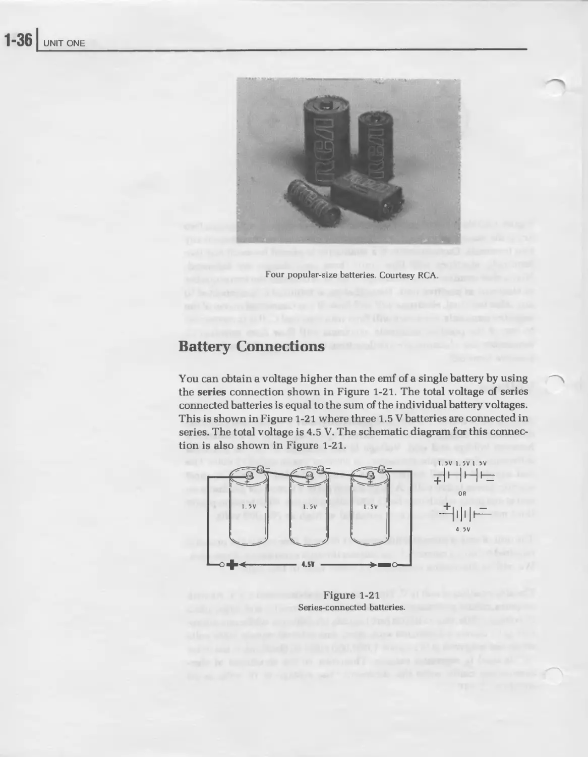
Four popular-size batteries. Courtesy RCA.
Battery Connections
You can obtain a voltage higher than the emf of a single battery by using
the series connection shown in Figure 1-21. The total voltage of series
connected batteries is equal to the sum of the individual battery voltages.
This is shown in Figure 1-21 where three 1.5 V batteries are connected in
series. The total voltage is 4.5 V. The schematic diagram for this connec-
tion is also shown in Figure 1-21.
Figure 1-21
Series-connected batteries.
Direct Current
1-37
While the total voltage increases with the series connection, the current
capacity does not. Since the total circuit current flows through each
battery, the current capacity is the same as a single battery.
You can increase current capacity by connecting several batteries in
parallel. This is shown in Figure 1-22A. In the parallel connection, each
battery can contribute the same amount of current to the load. Therefore,
if we connect three batteries in parallel, the current capacity will be three
times that of a single battery. This is shown in Figure 1-22B. Notice that
while the parallel connection increases the current capacity, the voltage
remains the same.
Figure 1-22
Parallel battery connection.
1-38 UNIT ONE
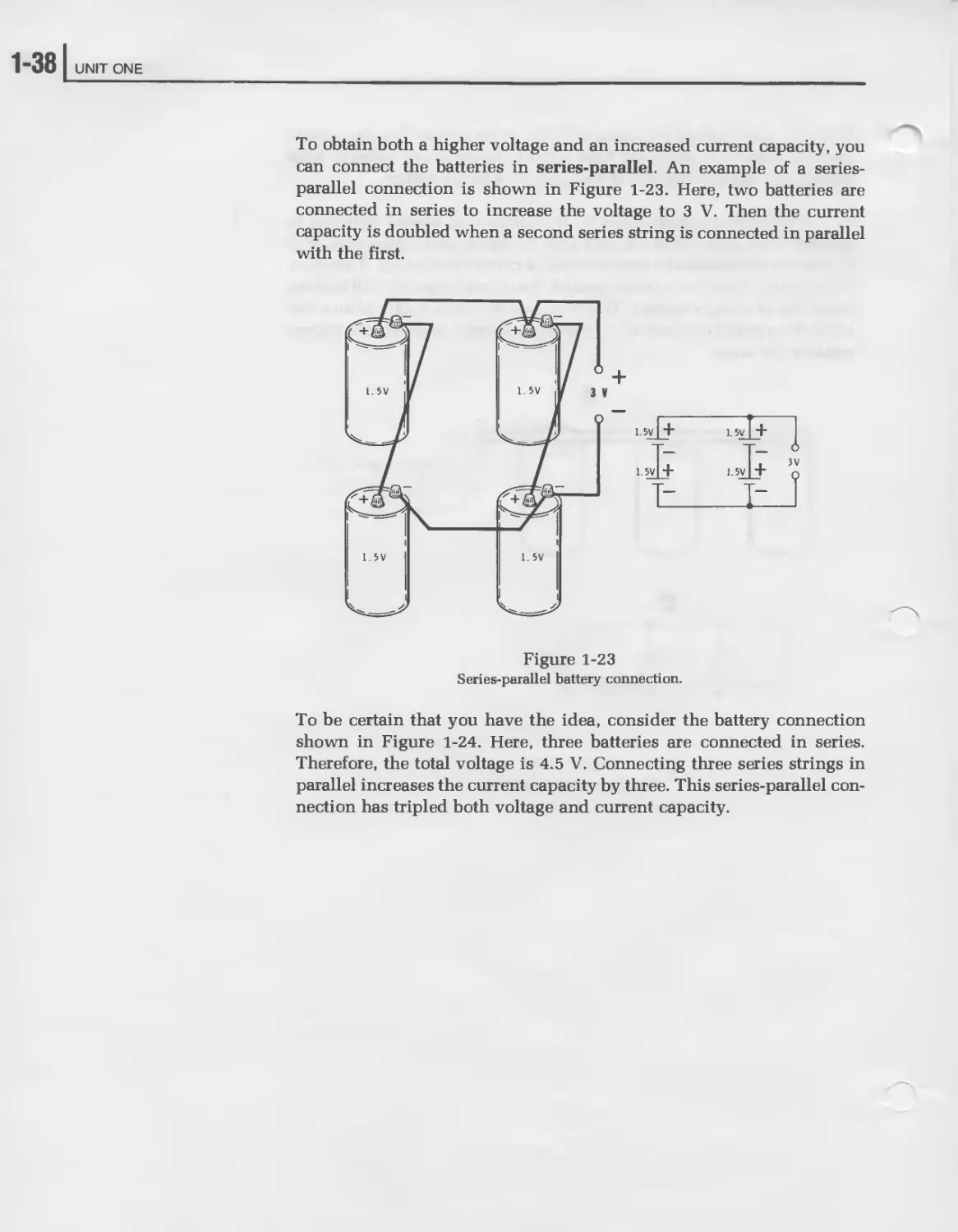
To obtain both a higher voltage and an increased current capacity, you
can connect the batteries in series-parallel. An example of a series-
parallel connection is shown in Figure 1-23. Here, two batteries are
connected in series to increase the voltage to 3 V. Then the current
capacity is doubled when a second series string is connected in parallel
with the first.
Figure 1-23
Series-parallel battery connection.
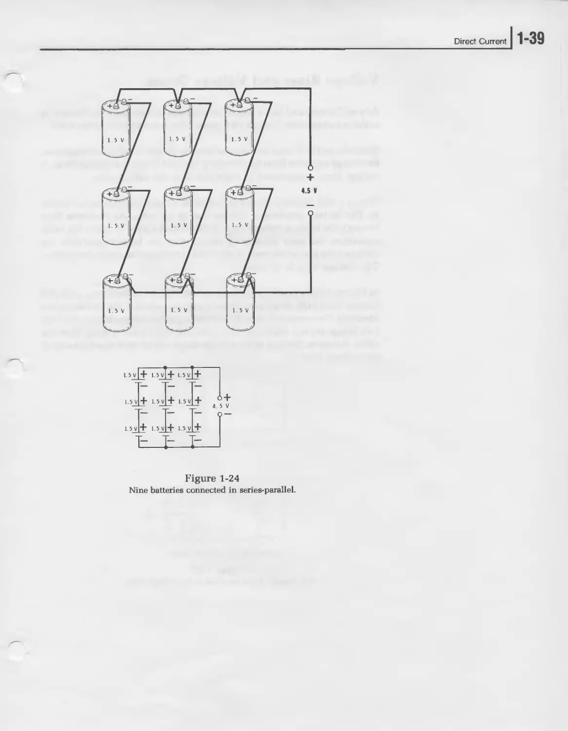
To be certain that you have the idea, consider the battery connection
shown in Figure 1-24. Here, three batteries are connected in series.
Therefore, the total voltage is 4.5 V. Connecting three series strings in
parallel increases the current capacity by three. This series-parallel con-
nection has tripled both voltage and current capacity.
Direct Current
] 1-39
Figure 1-24
Nine batteries connected in series-parallel.
1"40 I UNIT ONE
Voltage Rises and Voltage Drops
Any emf introduced into a circuit by a voltage source, such as a battery, is
called a voltage rise. Thus, a 10 V battery has a voltage rise of ten volts.
Since the emf or energy introduced into the circuit is called a voltage rise,
the energy removed from the circuit by the load is called a voltage drop. A
voltage drop is expressed in volts just as is the voltage rise.
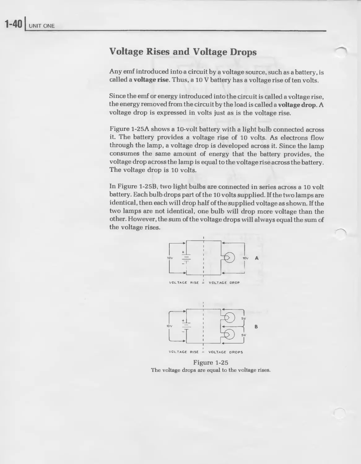
Figure 1-2 5A shows a 10-volt battery with a light bulb connected across
it. The battery provides a voltage rise of 10 volts. As electrons flow
through the lamp, a voltage drop is developed across it. Since the lamp
consumes the same amount of energy that the battery provides, the
voltage drop across the lamp is equal to the voltage rise across the battery.
The voltage drop is 10 volts.
In Figure 1-25B, two light bulbs are connected in series across a 10 volt
battery. Each bulb drops part of the 10 volts supplied. If the two lamps are
identical, then each will drop half of the supplied voltage as shown. If the
two lamps are not identical, one bulb will drop more voltage than the
other. However, the sum of the voltage drops will always equal the sum of
the voltage rises.
VOLTAGE RISE = VOLTAGE DROP
VOLTAGE RISE - VOLTAGE DROPS
Figure 1-25
The voltage drops are equal to the voltage rises.
Direct Current
1-41
Concept of Ground
One of the most important points in the study of electricity and elec-
tronics is the concept of ground. Originally, ground was just what the
name implies — the earth. In fact, in some countries the name earth is
used instead of ground. Earth is considered to have zero potential. Thus,
ground or earth is the reference point to which voltages are most often
compared. Many electrical appliances in your home are grounded. This
is especially true of air conditioning units, electric clothes dryers, and
washing machines. Often this is done by connecting a heavy wire directly
to a cold water pipe which is buried deep in the earth (ground). In other
cases, a third prong on the power plug connects the metal frame to
ground. The purpose of this is to protect the user in case a short circuit
develops in the appliance. It also places the metal parts of different
appliances at the same potential so that you are not shocked by a differece
in potential between two appliances. This type of ground is sometimes
called earth ground.
However, there is a slightly different type of ground used in electronics.
For example, a certain point in a small transistor radio is called ground
although the radio does not connect to earth in any way. This is the
concept of ground with which we will be primarily concerned in this
course. In this case, ground is simply a zero reference point within an
electric circuit. In most larger pieces of electronic equipment the zero
reference point or ground point is the metal frame or chassis on which the
various circuits are constructed. All voltages are measured with respect
to this chassis.
In your automobile, the chassis or metal body of the automobile is consi-
dered ground. If you look closely at the straps leaving the battery you will
see that one cable connects directly to the metal frame of the car. This
point is considered to be ground as is every other point on the metal
frame.
In electronics, ground is important because it allows us to have both
negative and positive voltages. Up to now we have been concerned only
with relative voltages between two points. For example, a 6-volt battery
has an emf between its two terminals of 6 volts. We do not think of this as
4-6 volts or —6 volts but rather simply 6 volts.
However, the concept of ground allows us to express negative and posi-
tive voltages. Remember ground is merely a reference point which is
considered zero or neutral. If we assume that the positive terminal of a
6-volt battery is ground, then the negative terminal is 6 volts more
negative. Thus, the voltage at this terminal with respect to ground is —6
volts.
1-42 UNIT ONE
В
D
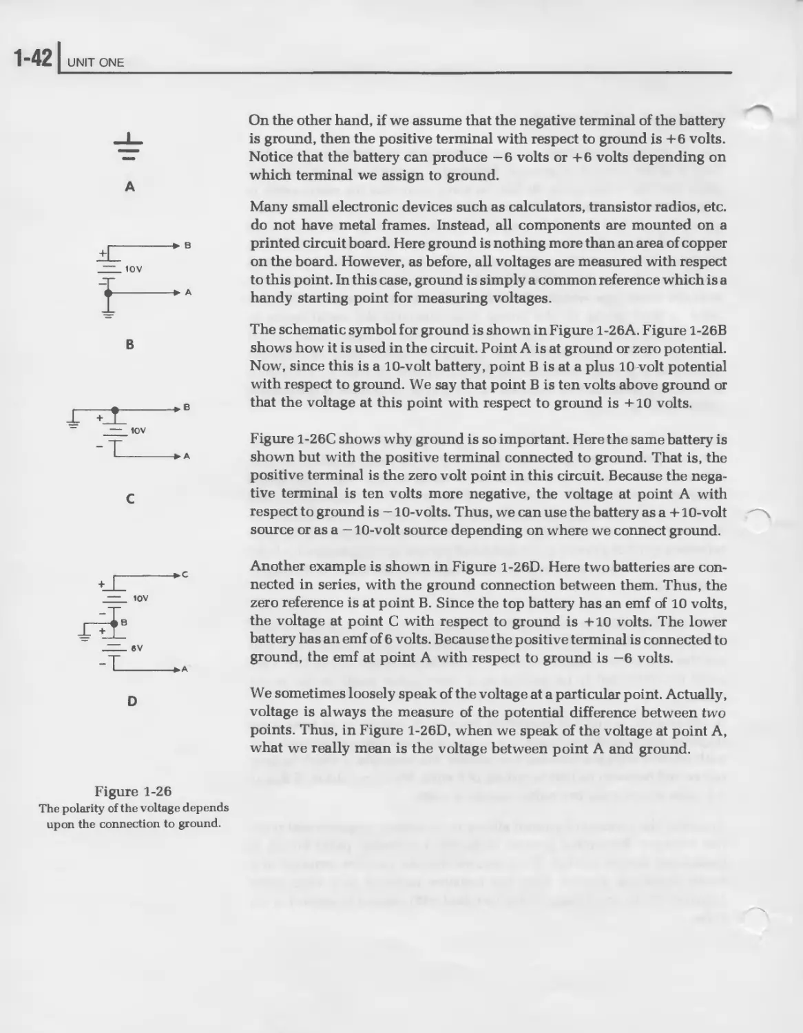
On the other hand, if we assume that the negative terminal of the battery
is ground, then the positive terminal with respect to ground is +6 volts.
Notice that the battery can produce —6 volts or +6 volts depending on
which terminal we assign to ground.
Many small electronic devices such as calculators, transistor radios, etc.
do not have metal frames. Instead, all components are mounted on a
printed circuit board. Here ground is nothing more than an area of copper
on the board. However, as before, all voltages are measured with respect
to this point. In this case, ground is simply a common reference which is a
handy starting point for measuring voltages.
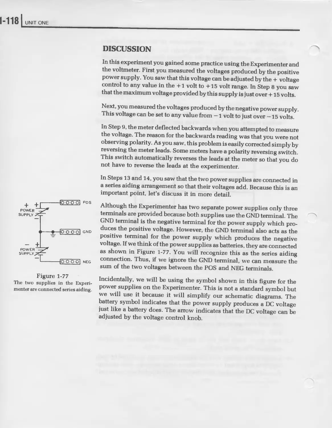
The schematic symbol for ground is shown in Figure 1-26A. Figure 1-26B
shows how it is used in the circuit. Point A is at ground or zero potential.
Now, since this is a 10-volt battery, point В is at a plus 10-volt potential
with respect to ground. We say that point В is ten volts above ground or
that the voltage at this point with respect to ground is +10 volts.
Figure 1-26C shows why ground is so important. Here the same battery is
shown but with the positive terminal connected to ground. That is, the
positive terminal is the zero volt point in this circuit. Because the nega-
tive terminal is ten volts more negative, the voltage at point A with
respect to ground is — 10-volts. Thus, we can use the battery as a + 10-volt
source or as a — 10-volt source depending on where we connect ground.
Another example is shown in Figure 1-26D. Here two batteries are con-
nected in series, with the ground connection between them. Thus, the
zero reference is at point B. Since the top battery has an emf of 10 volts,
the voltage at point C with respect to ground is +10 volts. The lower
battery has an emf of 6 volts. Because the positive terminal is connected to
ground, the emf at point A with respect to ground is —6 volts.
We sometimes loosely speak of the voltage at a particular point. Actually,
voltage is always the measure of the potential difference between two
points. Thus, in Figure 1-26D, when we speak of the voltage at point A,
what we really mean is the voltage between point A and ground.
Figure 1-26
The polarity of the voltage depends
upon the connection to ground.
Direct Current
1-43
Self-Review Questions
15. Define emf___________________________________________________
16. What are two other names for emf?
17. What is the unit of emf?___________________________
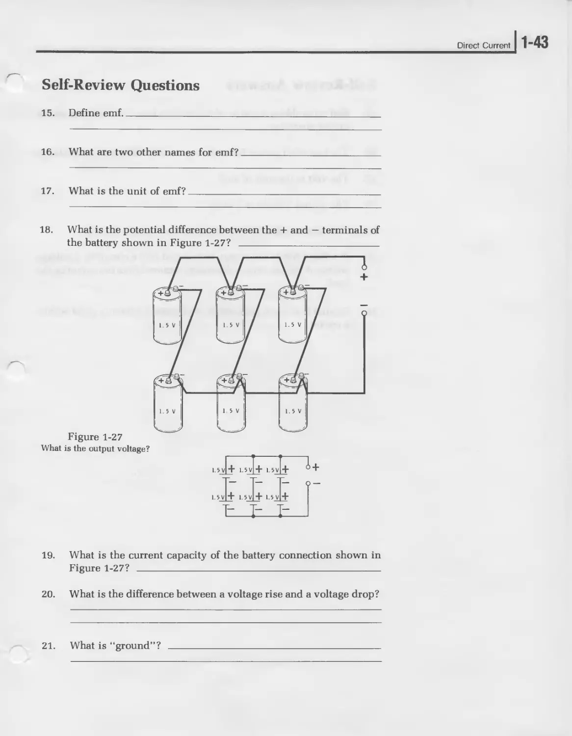
18. What is the potential difference between the + and — terminals of
the battery shown in Figure 1-27?
Figure 1-27
What is the output voltage?
19. What is the current capacity of the battery connection shown in
Figure 1-27? _____________________________________________________
20. What is the difference between a voltage rise and a voltage drop?
21. What is “ground”? ___________________________________________
1-441 UNIT ONE
Self-Review Answers
15. Emf is the abbreviation for electromotive force. It is the force which
moves electrons.
16. The two other names for emf are potential difference and voltage.
17. The volt is the unit of emf.
18. The output voltage is 3 volts.
19. The current capacity is 3 times that of a single battery.
20. A voltage rise is the energy introduced into a circuit by a voltage
source. A voltage drop is the energy removed from the circuit by the
load.
21. Ground is an earth connection or a common reference point within
a circuit.
Direct Current
1-45
RESISTANCE
Resistance is that property which opposes current flow. All materials
have this property to some extent. Some materials, such as glass and
rubber, offer a great deal of opposition to current flow. They allow almost
no current to flow through them. Therefore, they are said to have a very
high resistance. Other materials, such as silver and copper, offer very
little opposition to current flow. Therefore, they have a very low resis-
tance.
The Ohm
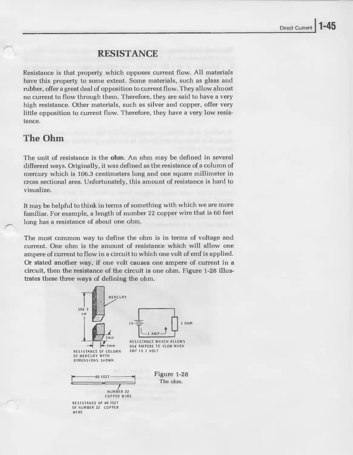
The unit of resistance is the ohm. An ohm may be defined in several
different ways. Originally, it was defined as the resistance of a column of
mercury which is 106.3 centimeters long and one square millimeter in
cross sectional area. Unfortunately, this amount of resistance is hard to
visualize.
It may be helpful to think in terms of something with which we are more
familiar. For example, a length of number 22 copper wire that is 60 feet
long has a resistance of about one ohm.
The most common way to define the ohm is in terms of voltage and
current. One ohm is the amount of resistance which will allow one
ampere of current to flow in a circuit to which one volt of emf is applied.
Or stated another way, if one volt causes one ampere of current in a
circuit, then the resistance of the circuit is one ohm. Figure 1-28 illus-
trates these three ways of defining the ohm.
RESISTANCE OF COLUMN
OF MERCURY WITH
DIMENSIONS SHOWN
RESISTANCE WHICH ALLOWS
ONE AMPERE TO FLOW WHEN
EMF IS 1 VOLT
60 FEET
NUMBER 22
COPPER WIRE
Figure 1-28
The ohm.
RESISTANCE OF 60 FEET
OF NUMBER 22 COPPER
WIRE
1"46 UNIT ONE
The Greek letter omega (fl ) is commonly used to represent ohms. Thus, 1
ohm may be written 1 fl. Also, one thousand ohms may be written as 1000
fl, 1 kilohms, or as 1 kfl. Finally, one million ohms may be written as
1,000,000fl, 1 megohm, or as 1 Mfl. In electronics, the letter R is used to
represent resistance. Thus, in the shorthand of electronics, the statement
“the resistance is ten ohms” may be written as an equation: “R = lOfl.”
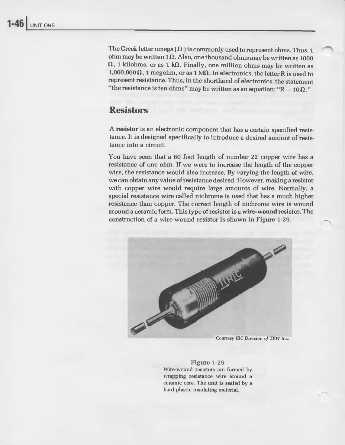
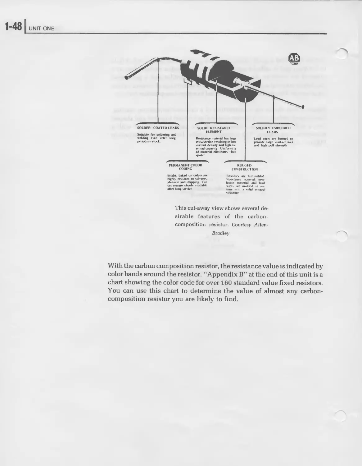
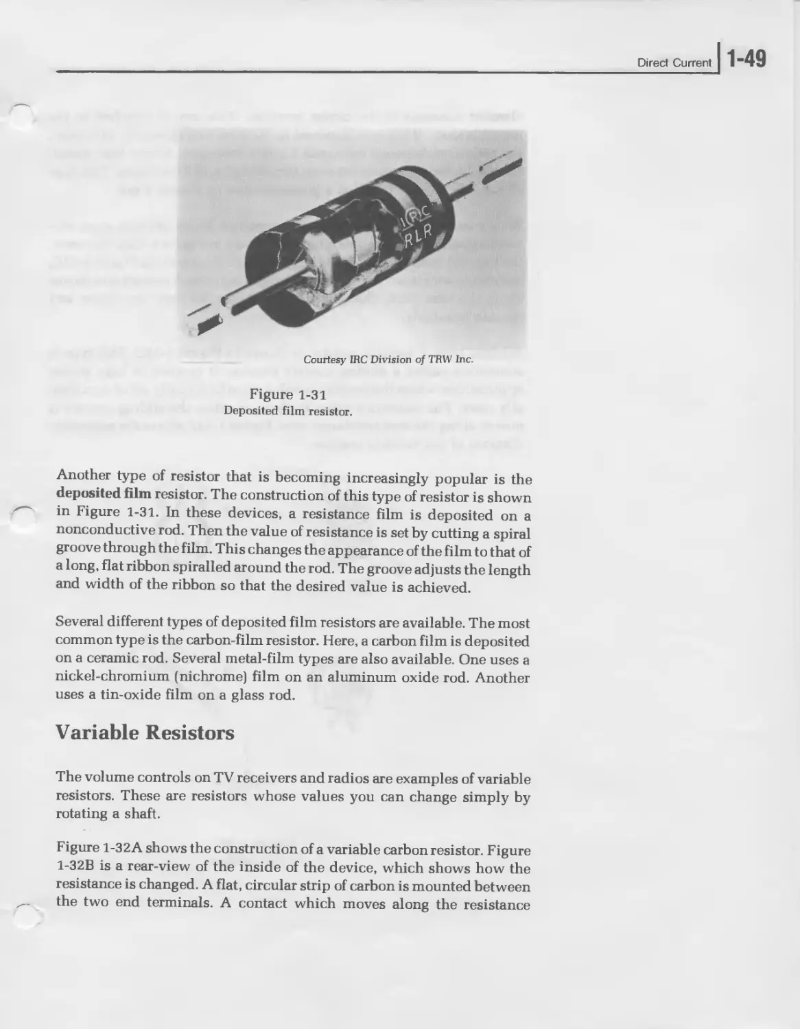
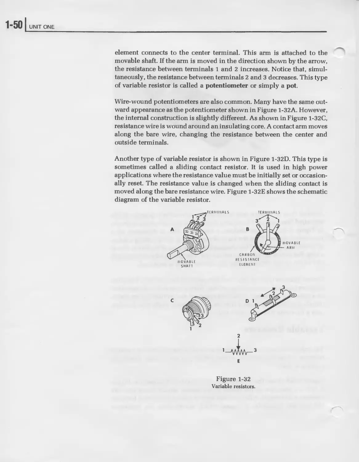
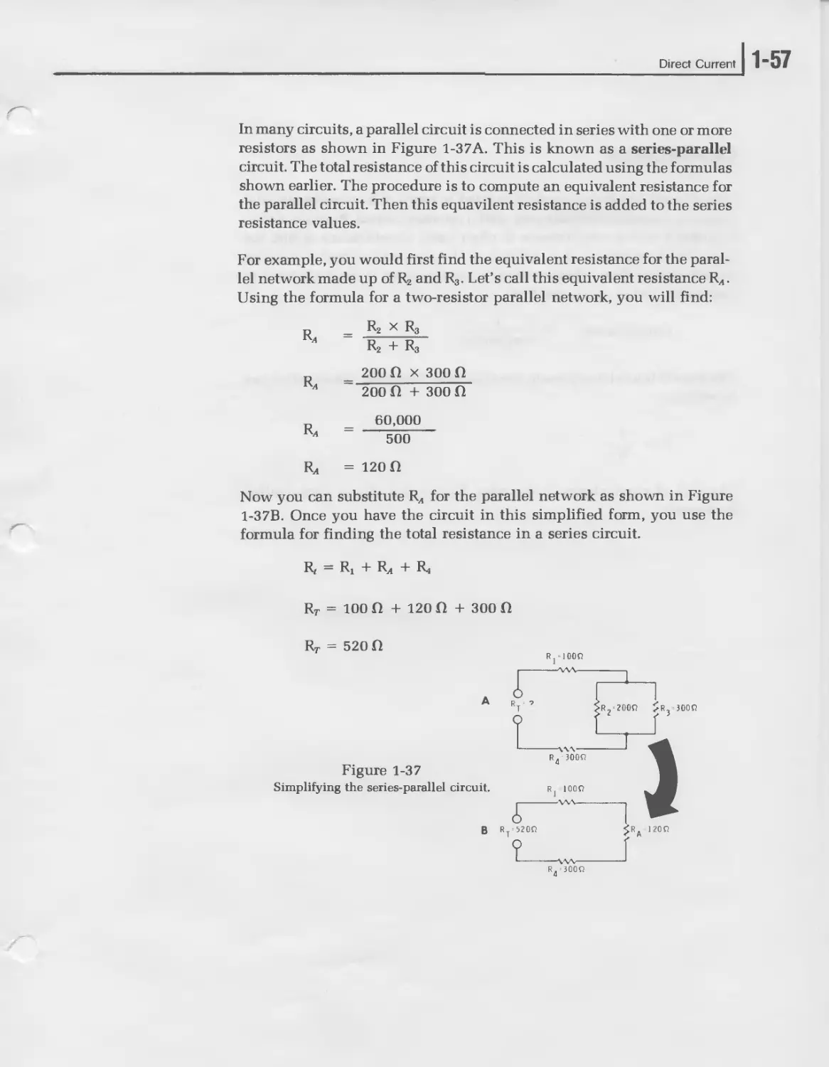
Resistors
A resistor is an electronic component that has a certain specified resis-
tance. It is designed specifically to introduce a desired amount of resis-
tance into a circuit.
You have seen that a 60 foot length of number 22 copper wire has a
resistance of one ohm. If we were to increase the length of the copper
wire, the resistance would also increase. By varying the length of wire,
we can obtain any value of resistance desired. However, making a resistor
with copper wire would require large amounts of wire. Normally, a
special resistance wire called nichrome is used that has a much higher
resistance than copper. The correct length of nichrome wire is wound
around a ceramic form. This type of resistor is a wire-wound resistor. The
construction of a wire-wound resistor is shown in Figure 1-29.
Courtesy IRC Division of TRW Inc
Figure 1-29
Wire-wound resistors are formed by
wrapping resistance wire around a
ceramic core. The unit is sealed by a
hard plastic insulating material.
Direct Current
1-47
Carbon is neither a good conductor nor a good insulator. Instead, it falls
in between and is called a semiconductor. This makes carbon ideal as a
material for resistors. By combining carbon granules and a powdered
insulating material in various proportions, a wide range of resistor values
are possible. This type of resistor is called a carbon-composition resistor.
Figure 1-30A shows the construction of a carbon-composition resistor.
Granules of carbon and a binder material are mixed together and shaped
into a rod. Wire leads are inserted and the package is sealed with a
nonconducting coating. The schematic symbol for a resistor is shown in
Figure 1-30B.
PROTECTIVE
NONCONDUCTING
COATING
CONNECTING WIRE
"VW-
SCHEMATIC SYMBOL
Figure 1-30
Carbon-composition resistor construc-
tion (A) and schematic symbol for a
resistor (B).
1-48 I UNIT ONE
bright, baked on colors are Resistors are hut-molded
highly resistant l<> solvents Resistance material nv.ii
abrasion and chipping (bl- |alloll |)laU.r,a| aBj |raj
ors remain clearly readable w,res arC molded al one
after long service time inlu a solid integral
struct иге
This cut-away view shows several de-
sirable features of the carbon-
composition resistor. Courtesy Allen-
Bradley.
With the carbon composition resistor, the resistance value is indicated by
color bands around the resistor. “Appendix B” at the end of this unit is a
chart showing the color code for over 160 standard value fixed resistors.
You can use this chart to determine the value of almost any carbon-
composition resistor you are likely to find.
Direct Current
1-49
Courtesy IRC Division of TRW Inc.
Figure 1-31
Deposited film resistor.
Another type of resistor that is becoming increasingly popular is the
deposited film resistor. The construction of this type of resistor is shown
in Figure 1-31. In these devices, a resistance film is deposited on a
nonconductive rod. Then the value of resistance is set by cutting a spiral
groove through the film. This changes the appearance of the film to that of
a long, flat ribbon spiralled around the rod. The groove adjusts the length
and width of the ribbon so that the desired value is achieved.
Several different types of deposited film resistors are available. The most
common type is the carbon-film resistor. Here, a carbon film is deposited
on a ceramic rod. Several metal-film types are also available. One uses a
nickel-chromium (nichrome) film on an aluminum oxide rod. Another
uses a tin-oxide film on a glass rod.
Variable Resistors
The volume controls on TV receivers and radios are examples of variable
resistors. These are resistors whose values you can change simply by
rotating a shaft.
Figure 1-32A shows the construction of a variable carbon resistor. Figure
1-32B is a rear-view of the inside of the device, which shows how the
resistance is changed. A flat, circular strip of carbon is mounted between
the two end terminals. A contact which moves along the resistance
1-50 UNIT ONE
element connects to the center terminal. This arm is attached to the
movable shaft. If the arm is moved in the direction shown by the arrow,
the resistance between terminals 1 and 2 increases. Notice that, simul-
taneously, the resistance between terminals 2 and 3 decreases. This type
of variable resistor is called a potentiometer or simply a pot.
Wire-wound potentiometers are also common. Many have the same out-
ward appearance as the potentiometer shown in Figure 1-32A. However,
the internal construction is slightly different. As shown in Figure 1-32C,
resistance wire is wound around an insulating core. A contact arm moves
along the bare wire, changing the resistance between the center and
outside terminals.
Another type of variable resistor is shown in Figure 1-32D. This type is
sometimes called a sliding contact resistor. It is used in high power
applications where the resistance value must be initially set or occasion-
ally reset. The resistance value is changed when the sliding contact is
moved along the bare resistance wire. Figure 1-32E shows the schematic
diagram of the variable resistor.
MOVABLE
SHAFT
2
E
Figure 1-32
Variable resistors.
Direct Current
1-51
Courtesy Allen-Bradley.
Potentiometers are available in a wide
variety of shapes and sizes.
Resistor Connections
Resistors are often connected in series, in parallel, and in series-parallel
combinations. In order to analyze and understand electronic circuits, you
must be able to compute the total resistance of resistor networks.
A series circuit is one in which the components are connected end to end
as shown in Figure 1-33A. Notice that the same current flows through all
components. The current in the circuit must flow through all three
resistors one after the other. Therefore, the total opposition to current
flow is the total of the three resistances.
An example is shown in Figure 1-33B. Here, three resistors are connected
in series. The total resistance is called Ry and is the resistance across the
entire series circuit. You can find RT by adding the individual resistor
values together. That is:
R7 = R] + R2 + R3
RT = 10 ft + 20 ft + 30 ft
RT = 60 ft
1-52 UNIT ONE
These three resistors in series have the same opposition to current flow as
a single 60 ohm resistor.
This example used three resistors. However, the same principle holds
true for any number of series resistors. Thus, in Figure 1-33C, a 1 к ohm
resistor in series with a 5 к ohm resistor has a total resistance of 6 к ohms
or 6000 ohms. The circuit shown in Figure 1-33D uses six resistors. Some
of the values are given in kilohms while others are given in ohms. To
avoid confusion, we can convert all values to ohms, Ri, R3, and R5 are
already expressed in ohms. R2 is equal to 1 к ohms or 1000 ohms. Ri is 1.2
к ohms or 1,200 ohms. And R^ is 3.3 к ohms or 3300 ohms. Thus, you
would find the total resistance (Ry) by adding:
Ry = Rj + R2 + R3 + R4 + R5 + R:
Rr = 500 П + 1000 fl + 750 fl + 1200 fl + 600 fl + 3300 fl
Ry = 7350 Q or 7.35 kQ
A В
R1 + l± ONE " CURRENT PATH s' c R( 1K0 6 RT6KQ R2 5KQ Rj-IOQ \ 1 6 I 1 > R? Rt 600 >R2-20Q J ? I R3 300 D R 5000 R2-1KO $R3-750O Ry 73500 j О SR^l.ZKO ’ X X X xxx ’ Rt 3. 3KQ R=600Q 0 ? Figure 1-33 Resistors in series.
Direct Current
1-53
Figure 1-34
Resistors in parallel.
In parallel circuits components are connected across each other so that
there are two or more paths for current flow. Figure 1-34A is an example.
To see how resistors in parallel act, let’s add switch St in series with R2 so
that we can switch R2 in and out of the circuit. The resulting circuit is
shown in Figure 1-34B. With Sj open, a certain current will flow through
R,. The amount of current is determined by the resistance of R! and the
applied voltage. Because there is only one path for current flow, the
current through R, is the total circuit current.
Now let’s close the switch and see what happens. The current through Ri
remains unchanged since neither the resistance of Rj nor the applied
voltage has changed. However, an additional current now flows through
R2. Thus, the total current provided by the battery has increased. If R2 has
the same resistance as R1; both resistors will offer the same amount of
opposition to current flow. Thus, the current through Ri will equal the
current through R2. In this case, the current provided by the battery
doubles when R2 is switched in parallel with Rv
1-54 I UNIT ONE
Regardless of the size of Ri and R2, the total current provided by the
battery will always increase when R2 is placed in parallel with Rj because
a second current path is created. Obviously, then, the total opposition to
current flow decreases since more current now flows. Thus, when one
resistor is placed in parallel with another, the total resistance decreases.
Let’s assume that Ri and R2 are equal. When the switch is closed, the total
current doubles. Thus, the total resistance has dropped to one half its
former value.
The following simple formula allows you to find the total resistance of
two resistors in parallel:
d _ Ri x R2
T R, + R2
Figure 1-34C shows an example. Here, a 15 ohm resistor (RJ is in parallel
with a 10 ohm resistor (R2). Here’s how you would find the total resis-
R! x R2
Ri + R2
15ft x 10ft
“ 15ft + 10ft
150
25~
= 6ft
The total resistance of this circuit is the same as that of a 6 ohm resistor.
Figure 1-34D shows another example. Неге, a 1 к ohm resistor (RJ is in
parallel with a 9 к ohm resistor (R2).
Ri x R2
Ri + R2
1000ft x 9000ft
1000 ft + 9000 ft
9,000,000
10,000
= 900 ft or 0.9 kft.
tance, Rr.
Rr
Rr
Rr
Rv
Rr
Rr
RT
R
Direct Current
1-55
Figure 1-35
Compute the total resistance.
This formula is normally used when two resistors are in parallel. How-
ever, it can also be used with three or more resistors. For example, Figure
1-35A shows four resistors in parallel. Using the above formula, an
equivalent resistance for Rj and R2 can be found. Then, using the formula
again, an equivalent resistance for Rg and R4 can be found. Finally, the
formula can be applied to the two equivalent resistances so that the total
resistance can be found. However, this method involves using the for-
mula three different times.
There is a better formula to use when more than two resistors are
connected in parallel. The formula is:
RT = ------------------------------------------
1 > 1 1 1 1 1 1 .. 1
“RT + + "RT + X" + ” ’Re-
using this formula for the circuit shown in Figure 1-35A, you can find the
total resistance (RT) as follows:
RT = ------------------------------------------
T 1 1 1 1
100 ft + 100 ft + 400 ft + 400 ft
' .01 + .01 + .0025 + .0025
RT = —----
T .025
RT = 40 ft
Figure 1-35B shows an example using only three resistors. Here’s how
you would find RT.
RT = -------------
111
“RT+ ~RT + "rT
1-561 UNIT ONE
1
i i i
500 ft 500 ft + 250 ft
‘ .002 + .002 + .004
Rr = -—
T .008
Rr = 125ft
Sometimes two or more resistors that have the same value are placed in
parallel. There is a simple rule which covers this situation. When all the
resistors in parallel have the same value, you can find the total resistance
by dividing that value by the number of resistors. For example, Figure
1-36A shows two 20 ohm resistors connected in parallel. Our rule states
that:
_ value of one resistor
T number of resistors in parallel
D _ 20 ft
T ~ 2
R7 = 10ft
Likewise, when three resistors of the same size are connected in parallel,
the total resistance is one third the value of one resistor. Thus, in Figure
1-36B:
„ 330 ft
Ky “ з
Rr = 110ft
In Figure 1-36C:
„ 16 kft
Rr--------4—
R7 = 4 kft
Figure 1-36
When all the resistors have the same
value, R? equals this value divided by the
number of resistors in parallel.
Note that in any parallel circuit the total resistance is always less than the
smallest resistor in the circuit.
Direct Current
1-57
In many circuits, a parallel circuit is connected in series with one or more
resistors as shown in Figure 1-37A. This is known as a series-parallel
circuit. The total resistance of this circuit is calculated using the formulas
shown earlier. The procedure is to compute an equivalent resistance for
the parallel circuit. Then this equavilent resistance is added to the series
resistance values.
Rx
Rx
Rx
R
For example, you would first find the equivalent resistance for the paral-
lel network made up of R2 and R3. Let’s call this equivalent resistance Rx.
Using the formula for a two-resistor parallel network, you will find:
R2 x R3
R2 + R3
200 П x 300 П
200 П + 300 fl
60,000
500
= 120 fl
Now you can substitute Rx for the parallel network as shown in Figure
1-37B. Once you have the circuit in this simplified form, you use the
formula for finding the total resistance in a series circuit.
R, == Rj + Rx + Rj
RT = 100 fl + 120 fl + 300 fl
RT = 520 fl
Figure 1-37
Simplifying the series-parallel circuit.
A
В
Rj-IOOQ
R.=300fi
4
1"58 UNIT ONE
Conductance
Sometimes it is more convenient to think in terms of how well a material
conducts current rather than how well it opposes current. Because of this,
a property called conductance is often used. Conductance is just the
opposite of resistance. It is defined as the ease with which a material
passes current flow. Mathematically, conductance is the reciprocal of
resistance. Stated as an equation:
Conductance
1
resistance
The letter G is used to represent conductance. Therefore, the equation can
be written:
1
R
G =
The unit of conductance is the mho. Notice that this is ohm spelled
backwards.
Direct Current
1-59
Self-Review Questions
22. Define resistance_______________________________________________
23. The unit of resistance is the
24. Define conductance. ____________________________________________
A
25. Name three types of resistor construction. VA
26. Figure 1-38A is the schematic symbol for a_______________ i
1 В
Figure 1-38B is the schematic symbol for a WV
27. A variable resistor is called a Figure 1-38
What do these schematic symbols represent?
28. Find R7 for the series circuit shown in Figure 1-39A.
Ry =____________
29. Find R7 for the parallel circuit shown in Figure 1-39B.
Ry =.
30. Find Ry for the parallel circuit shown in Figure 1-39C.
Ry =______________
31. Find Rr for the series-parallel circuit shown in Figure 1-39D.
Ry =______________
Figure 1-39
R7 for each of these circuits.
1“60 UNIT ONE
Self-Review Answers
22. Resistance is that property which opposes current flow.
23. The unit of resistance is the ohm.
24. Conductance is the ease with which a material passes current flow.
It is the reciprocal of resistance.
25. Three types of resistor construction are wire-wound, carbon-
composition, and deposited-film.
26. Figure 1-38A is the schematic symbol for a resistor.
Figure 1-38B is the schematic symbol for a potentiometer.
27. A variable resistor is called a potentiometer.
28. Ry for the series circuit shown in Figure 1-39A is:
Ry — Rj + R2 + R3
RT = 1 Ю + 200 П + 2.3 Ю
Ry = 1000 П + 200 П + 2300 П
Ry = 3500П
Ry = 3.5 Ю
29. Ry for the parallel circuit shown in Figure 1-39B is:
Ri x R2
Rj + R2
600 П x 400 П
600 n + 400 n
240,000
1,000
Ry =
Ry =
Ry =
Ry = 240 П
Direct Current
1-61
30. Ry for the parallel circuit shown in Figure 1-39C is:
Ry = ------------
111
~RT+ r2 + rT
Ry = ----------------
111
100ft 500 ft + 2000 ft
R = _________2______
T 0.01 + 0.002 + 0.0005
Ry = ------
T 0.0125
Ry = 80ft
31. You must first find the resistance of the parallel network made up
of R2 and R3. We will designate this resistance Кл.
_ _ R2 x R3
A r2 + R3
P _ 240ft X 1200ft
A ~ 240ft + 1200ft
288,000
A ~ 1440
R„ = 200ft
Now substitute R4 for the parallel network as shown in Figure 1-40.
Ry — Rj + Ryi + R,
Ry = 2000 ft + 200 ft + 300 ft
Ry = 2500 ft
Ry = 2.5 kft
Figure 1-40
Solution for Self-Review Question 30.
1-621 UNIT ONE
From this complex transceiver to a
simple flashlight, the operation of all
electronic equipment is based on
Ohm’s law.
OHM’S LAW
Voltage, current, and resistance are all interrelated quantities in an elec-
tric circuit. The law that relates these three quantities is Ohm’s law.
Finding Current
Ohm’s law states that current is directly proportional to voltage and
inversely proportional to resistance. Figure 1-41 will help illustrate this
point. The source of voltage is the battery. Voltage is the force which
causes current to flow. Therefore, the higher the voltage, the higher the
current will be. Conversely, the lower the voltage, the lower the current
will be. This assumes that the resistance remains constant. However, as
we have seen, the current is also determined by the resistance (remember:
resistance is the opposition to current flow). Assuming that the voltage is
constant, the higher the resistance, the lower the current will be. Also, the
lower the resistance, the higher the current will be.
Figure 1-41
Ohm’s law states that current is directly
proportional to voltage and inversely
proportional to resistance.
Direct Current
1-63
Mathematically, Ohm’s law can be expressed like this:
E
R
Where: E = voltage, expressed in volts.
I = current, expressed in amperes.
R = resistance, expressed in ohms.
The equation states that the current in a circuit is equal to the voltage
divided by the resistance. This formula may be used to find current in any
circuit in which the voltage and resistance are known.
Figure 1-42 shows a circuit in which the values of voltage and resistance
are given. Tо determine the current, substitute the known values into the
formula:
10V
I = 2A
Thus, the current in the circuit shown in Figure 1-42 is 2A or 2 amperes.
Figure 1-42
Current is determined by voltage and resistance.
1-64 I UNIT ONE
200 VOLTS
50 OHMS
I-4 AMPERES
400 VOLTS
50 OHMS
1-8 AMPERES
200 VOLTS
100 OHMS
1-2 AMPERES
Figure 1-43
Using Ohm’s law to find current.
Another example is shown in Figure 1-43A. The current inthis circuit is:
-4
z _ 200 V
50 fl
I = 4 A
Figure 1-43B shows what happens when the applied voltage is doubled.
>- -4-
400 V
50 ft
I = 8A
Notice that when the voltage is doubled, the current also doubles. This is
because current is directly proportional to voltage.
Direct Current
1-65
What happens if the resistance is doubled and voltage remains the same?
This situation is shown in Figure 1-43C.
j _ 200 V
100 П
I = 2A
When the resistance is doubled, the current is reduced to one-half its
former value. This is because current is inversely proportional to resis-
tance.
Rj- 1KQ
R3- 3KQ
Figure 1-44
What is the current in this series circuit?
What is the current in the circuit of Figure 1-44? You will have to find
total circuit resistance (Ry) before you can apply Ohm’s law.
Ry = R| + R2 + R3
Ry = 1 kfl + 2 kfl + 3 kfl
Ry = 6 kf)
We can now use Ohm’s law to find the current. The easiest way to solve
this problem is to convert 6 kfl to 6,000 П.
60 V
6000 П
I = 0.01 A
I =10 mA
1-66 UNIT ONE
Finding Current in Parallel Circuits
In parallel circuits, components are connected across each other so there
are two or more paths or branches for current flow. This is shown in
Figure 1-45. Notice that the total current is equal to the sum of the branch
currents. This can be expressed mathematically as:
If — Ii T I2
Figure 1-45
The total current in a parallel circuit is equal to the sum of
the branch currents.
This formula can be extended to include any number of parallel branches.
Notice that both Rt and R2 are connected directly across the battery. This
means that the voltage across both resistors is equal to the battery voltage.
This is true for any parallel circuit. The voltage is the same across parallel
branches.
You can find the branch current using Ohm’s law. To find the current
through R1( divide the voltage by RP Thus,
60 V
h = 1.5 A
The current through R2 can be found in a similar manner.
. _ 60 V
60 ft
I2 = 1 A
Direct Current
1-67
The total current is equal to the sum of the branch currents. Therefore:
IT = Ij + I2
IT = 1.5 A + 1 A
ly = 2.5 A
The total current in the circuit of Figure 1-45 is 2.5 amperes.
Finding Voltage
You have seen that the formula for current is:
You can transpose this equation to find voltage. (Transpose means to
change the equation from one form to another.) Therefore, you must
change the formula so that E is on one side of the equation by itself. This is
easy to do if you remember a basic algebra rule for transposing equations.
This rule states that you can multiply or divide both sides of the equation
by any quantity without changing the equality. The equation for current
is:
Multiplying both sides of the equation by R, we have:
Notice that R appears in both the numerator and the denominator of the
fraction on the right side of the equation. The two R’s in the fraction can
be canceled like this:
,XR -
This leaves:
I x R = E
1-681 UNIT ONE
You can now reverse the two sides of the equation without changing the
equality. Therefore:
E = I x R
This equation states that voltage is equal to current times resistance.
Generally, the times sign (x) is omitted so the equation is written:
E = IR
Figure 1-46
Ohm’s law states that current times resistance equals voltage.
Figure 1-46 shows a circuit in which the values of resistance and current
are given. To determine the voltage, substitute the known values into the
formula:
E = IR
E = 50 mA x 1.2 kft
Before solving the equation, you must convert the values to amperes and
ohms:
Figure 1-47 shows a slightly different problem. Here you must find the
voltage drops across Ri, R2, and R3. We have called these voltages ЕЛ1, ЕД2,
and Едз. Since you know that Rx = 10 fl and that the current through Rx is
2 A, you can find ЕД1 using Ohm’s law.
Direct Current
= I X R,
ЕД1 = 2 A X 10 ft
ЕД1 = 20 V
You can find ЕД2 and Едз the same way:
ЕД2 = I x R2
ЕД2 = 2 A x 25 ft
Ед2 = 50 V
ЕДз = I x R3
Едз = 2 A x 5 ft
Едз = 10 V
In an earlier section you saw that the sum of the voltage drops will always
equal the voltage rise. This can be expressed mathematically for the
circuit of Figure 1-47 as:
Ey = ЕД1 + Ед2 + Едз
Where
Ej- = voltage rise
Ея1-з = voltage drops
We can prove that the sum of the voltage drops equals the voltage rise by
substituting the values of Figure 1-47 into the equation:
Ey = ЕД1 + Ед2 + Едз
Ej- = 20 V + 50 V + 10 V
Ej- = 80 V
The voltage rise is 80 volts and the sum of the voltage drops is 80 volts.
1-70 UNIT ONE
Finding Resistance
You can find the formula for resistance by transposing the current or
voltage formula. For example, the voltage formula is:
E = IR
Dividing both sides by I you get:
E _ IR
I I
The I’s in the fraction on the right cancel:
E = ^R
This leaves:
Reversing the equation, you have the formula for resistance:
This states that resistance is equal to voltage divided by current. Using
this formula, you can find the resistance in any circuit in which the
voltage and current are known.
+j:
F-75V —
l-30mA
Figure 1-48
r- Ohm’s law states that voltage divided by
current equals resistance.
Figure 1-48 shows a circuit in which the voltage and current are known.
Let’s find the resistance.
R =
R =
75 V
30 mA
Direct Current
1-71
You must first convert from milliamperes to amperes before solving the
equation. Therefore:
75 V
0.03 A
R = 2500 ft
R = 2.5 kft
Figure 1-49
What is the resistance of this circuit?
Figure 1-49 shows another example. Solving for R, you find that:
_ 100 V
К — ---—
2 mA
Converting milliamperes to amperes, you have:
100 V
0.002 A
R = 50,000 ft
R = 50 kft
1-72 UNIT ONE
Summary
Ohm’s law may be expressed by three different formulas:
E = IR
A convenient way to remember these three formulas is the Ohm’s law
circle shown in Figure 1-50A. To use this circle, cover the unknown
quantity with your thumb; the desired equation will be the remaining
terms. For example, if the unknown quantity is current, cover the I as
shown in Figure 1-50B. The quantity covered is the left hand side of the
equation. The remaining two symbols represent the right hand side of the
equation. Therefore,
E
R
Figures 1-50C and D show how to find the formulas for resistance and
voltage.
Figure 1-50
The Ohm’s law circle.
Direct Current
1-73
Self-Review Questions
32. Write the three equation forms of Ohm’s law.
33. Find the current in the circuit of Figure 1-51A. I =
34. Find the applied voltage in the circuit of Figure 1-51B. E =
35. Find the resistance of the circuit shown in Figure 1-51C. R =
Figure 1-51
Use Ohm’s law to find the unknown quantity
1-74 UNIT ONE
Self-Review Answers
32. The three equation forms of Ohm’s law are:
E = IR
33. To find current, you must first find the total resistance:
Ry = Rj + R2
Rr = 200 ft + 3 kft
Rr = 200 ft + 3000 ft
Rr = 3200 ft
Rr = 3.2 kft
Now use Ohm’s law to find current:
160 V
3200 ft
I = 0.05A
I =50 mA
34. To find the applied voltage, use the Ohm’s law equation:
E = IR
E = 3 mA x 4 kft
E = 0.003 A x 4000 ft
E = 12 V
Direct Current
1-75
35. Resistance is found by using the Ohm’s law equation.
40 mA
R =
0.04 A
R = 300 fl
1-76 UNIT ONE
POWER
In addition to the three basic electrical quantities (current, voltage, and
resistance), a fourth quantity is also very important. This quantity is
called power. Power is the amount of work done in a specific length of
time.
The Watt
The unit of electrical power is the watt. One watt is equal to the work
done by one volt moving a current of one ampere.
The abbreviation of watt is W. Thus, 4.2 watts is abbreviated 4.2 W. As
with other electrical quantities, metric prefixes are attached to indicate
smaller and larger units of power. Thus, one milliwatt equals 1/1000
watt, while one microwatt equals 1/1,000,000 watt. Also, one kilowatt
equals 1000 watts while one megawatt equals 1,000,000 watts. In elec-
tronics, the letter P is used to represent power. Thus, in the shorthand of
electronics, you could write the statement “the power is 5 watts” as an
equation, "P = 5 W.”
Direct Current
1-77
Power, Current, and Voltage
Power is directly proportional to both current and voltage. Thus, the
formula for power is:
P = IE
where P = power in watts
I = current in amperes
E = voltage in volts
As with Ohm’s law, there are two other useful forms of this equation. The
first expresses voltage in terms of current and power. It is found by
rearranging the equation:
P = IE
Dividing both sides by I, we have:
P _ IE
I I
Canceling the two I’s on the right side:
P _ JE
I X
Reversing the two sides of the equation:
This states that voltage is equal to power divided by current. Another
useful form of the equation is:
See if you can derive this formula from the original power formula. To
summarize, power, voltage, and current are related by the following
formulas:
P = IE
1-78 UNIT ONE
E
I
P
T
p
E
Now, let’s work some sample problems using these formulas.
What is the power dissipated in a circuit in which an emf of 50 volts is
applied and a current of 3.2 amperes flows?
P = IE
P = 3.2 A X 50 V
P = 160 W
How much current flows through a 75-watt light bulb that is connected
across a 120 volt power line?
P
E
75 W
120 V
= 0.625 A
= 625 mA
I
I
I
I
What is the voltage drop across a light bulb that dissipates 60 watts when
the current through the bulb is 0.5 amperes?
P
I
E
60W
0.5A
E
= 120 V
Direct Current 11-79
Power Dissipation in Resistors
In resistors and most other electronic components, power is dissipated in
the form of heat. In some cases, this heat is a desired result, as in the
resistance elements in toasters, heating pads, and electric stoves. But in
most electronic devices the heat produced by resistors represents wasted
power and since electrical power costs money, attempts are generally
made to keep the power lost in resistors at a minimum.
Since resistors dissipate power, there must be some formula for power
which involves resistance. Actually, there are two such formulas. One
expresses power in terms of voltage and resistance. The other expresses
power in terms of current and resistance. Let’s see how these equations
are derived.
1-80 UNIT ONE
First, consider how P can be expressed in terms of E and R. The basic
formula for power is:
P = IxE or P = ExI
However, from Ohm’s law you know that
Thus, you can substitute
E
R
for I in the basic power equation. When you do this, the equation be-
comes:
or,
This formula is used when only the voltage and resistance are known and
you wish to find the power. For example, how much power is dissipated
by a 22 ohm resistor if the voltage drop across the resistor is 5 volts?
P =
(5 V)2
22 ft
P =
25
22
P - 1.136 W
Direct Current 11-81
In some cases, only the current and resistance will be known. By combin-
ing the basic power formula with one of the Ohm’s law formulas, you can
derive an equation in which P is expressed in terms of I and R. Recall that
the basic power formula is:
P = I x E
From Ohm’s law, we know that E = IR. Thus, you can substitute IR for E in
the power formula. The equation becomes:
P = I x IR
P = PR
Figure 1-52
Finding power when R and I are known.
1-821 UNIT ONE
This is the formula you use when only current and resistance are known
and you wish to find power. For example, how much power is dissipated
by the circuit shown in Figure 1-52A?
P = PR
P = (0.5 A)2 x 40 О
P = 0.25 X 40
P = 10 W
How much power is dissipated by Rt in Figure 1-52B?
P = PR!
P = (2 A)2 x 10 О
P = 4 x 10
P = 40 W
Direct Current
]l-83
The Wheel Diagram
There are also a number of other formulas you can derive from the basic
power formula and Ohm’s law.
Figure 1-53 is a wheel diagram that shows all the formulas in an easy-to-
use form. The inner circle contains the four basic units: power, current,
voltage, and resistance. The outer circle contains three formulas for each
quantity. For example, the three formulas for power are:
P = I x E
P = F x R
P
E2
R
Using this diagram, you can quickly find the proper formula for any
problem in which the two quantities are known.
Figure 1-53
Wheel diagram for finding the proper equation for current,
voltage, resistance, and power.
1-84 I UNIT ONE
Self-Review Questions
36. What is power?
37. The unit of electrical power is the .
38. Write the basic power formula.
39. What is the power dissipated when the applied voltage is 800 V and the current is 300 mA? P =
Direct Current 11-85
40. What is the voltage drop across a light bulb that dissipates 75 watts
when the current through the bulb is 250 mA? E = --------------------
41. How much current flows through a 50-watt light bulb which is
connected across a 250-volt power supply? I = -----------------------
42. When an 8 fl resistor has a voltage drop of 10 V, how much power is
dissipated? P = -----------------------------------------------------
43. How much power is dissipated by a 100 fl resistor when 200 mA
flows through it? P - -----------------------------------------------
1-86 I UNIT ONE
Self-Review Answers
36. Power is the amount of work done in a specific length of time.
37. The unit of electrical power is the watt.
38. The basic power formula is:
P = IE
39. P = IE
P = 300 mA x 800 V
P = 0.3 A x 800 V
P = 240 W
40. E = P
I
E = 75 W
250 mA
E = 75 W
0.25 A
E = 300 V
41. I = P
E
I = 50 W
250 V
I = 0.2 A
I = 200 mA
Direct Current
1-87
42. P = E2
R
P = (10 V)2
8ft
P = 100
8
P = 12.5 W
43. P = PR
P = (200 mA)2 X 100 ft
P = (0.2 A)2 X 100 ft
P = 0.04 X 100
P = 4 W
1-881 UNIT ONE
MAGNETISM
NORTH
POLE
Figure 1-54
The Earth’s magnetic field.
Most of us are familiar with the behavior of magnets. We know that they
attract certain metallic materials. We also are aware that a compass works
on the principles of magnetism. The compass needle aligns itself with the
Earth’s magnetic field. This magnetic field is shown in Figure 1-54.
The properties of magnetism are also used in many everyday items, such
as loudspeakers, relays, and electric motors. Even a television set uses
magnetism to help create the picture you see on the screen.
Direct Current
] 1-89
The Magnetic Field
Individual magnets also have a magnetic field, including north and south
poles. This is shown in Figure 1-55A. The magnetic “lines of force” or
flux lines, which make up the magnetic field, are invisible. However, if
you place a magnet under a piece of paper and sprinkle iron filings over
the paper, the iron filings will align themselves with these flux lines. You
will then see evidence of the flux lines, as shown in Figure 1-55B.
Figure 1-55
Flux lines surround the magnet.
1-90 UNIT ONE
Figure 1-56
Like poles repel, unlike poles attract.
Laws of Magnetism
The attraction or repulsion between magnets is caused by the flux lines.
Figure 1-56A shows that when two north poles are brought together, the
flux lines push away from each other and cause the magnets to physically
move apart. When the north and south poles of the magnets are brought
together, as in Figure 1-56B, the flux lines join each other and physically
pull the magnets together. The laws of magnetism are:
Like poles repel.
Unlike poles attract.
Electricity and Magnetism
Electricity and magnetism are closely related. When current flows
through a wire, a magnetic field is developed around the wire. This is
shown in Figure 1-57. The strength of the magnetic field is directly
proportional to the current. When current increases, the magnetic field
will also increase.
Direct Current
] 1-91
Figure 1-57
Current develops a magnetic field around a wire.
You can also increase the magnetic field by forming the wire into a loop.
This is shown in Figure 1-58. Notice that this also creates north and south
poles. In fact, this loop of wire has all the properties of a permanent
magnet. The difference is that you can vary the intensity of the magnetic
field by changing the amount of current through the loop. Another way to
increase the intensity of the magnetic field is to add more turns of wire.
This will form a coil.
Figure 1-58
Flux lines around a loop of wire.
1-921 UNIT ONE
Figure 1-59
Magnetic field around a coil.
A coil of wire is shown in Figure 1-59. Note that there are many more flux
lines present than with a single loop. The force which produces the flux
lines in a coil is called magnetomotive force. The amount of magnetomo-
tive force is directly proportional to the current and the number of turns
in the coil. The unit of measure of magnetomotive force is the ampere-
turn. This is the amount of force developed by one turn of wire when the
current is one ampere.
You have seen two ways to increase the strength of the magnetic field
around a coil. One way is to increase the current. Another is to increase
the number of turns. However, a third method is the most dramatic
improvement of all. If we insert an iron bar into the center of the coil, the
strength of the magnetic field will greatly increase. The iron core can
support many more flux lines than air. It is said to have a higher permea-
bility than air. Permeability is the ability of a material to concentrate
magnetic flux. Air has a permeability of one, while iron has a permeabil-
ity of 7,000. The iron bar offers muchless opposition to the flux lines than
air. It, therefore, greatly increases the magnetic field.
Direct Current
1-93
Applications of Magnetism
The relay and the loudspeaker are two common applications of mag-
netism.
BATTERY
Figure 1-60
A relay can be used as a transmit-receive switch.
The relay is one of the simplest applications of magnetism, and it is also
one of the more useful. Figure 1-60 shows how it operates. When the
switch is closed, current flows from the battery through the relay coil.
The current develops a magnetic field in the core which attracts the
armature, pulling it down. This causes the lower contacts to close. The
relay is being used here to change an antenna from the receiver to
transmitter. When the switch is open, the antenna is connected to the
receiver. When the switch is closed, the relay energizes, connecting the
antenna to the transmitter. The schematic symbol for this relay is shown
in Figure 1-61.
Figure 1-61
The schematic symbol for a relay.
1-941 UNIT ONE
Loudspeakers are used in all types of audio equipment. Most of them use
a moving coil and a permanent magnet. The magnet establishes a strong,
stationary magnetic field. The movable coil is placed around part of the
magnet and in its magnetic field. A cut-away diagram of a loudspeaker is
shown in Figure 1-62.
The coil is forced to move back and forth by the current it receives from
the amplifier. This current, which varies at an audio rate, causes a corres-
pondingly varying magnetic field around the coil. The coil is alternately
attracted and repelled by the stationary field of the permanent magnet.
Thus, the coil moves back and forth at the same rate as the varying
current.
The moving coil is attached to a large cone or diaphragm. As the coil
vibrates the cone also vibrates, setting the air around the cone in motion
at the same rate. This reproduces the original sound. The schematic
symbol for a loudspeaker is shown in Figure 1-63.
Figure 1-63
The schematic symbol for a loudspeaker.
Direct Current
11-95
Self-Review Questions
44. State the basic law of magnetism.
45. The force which produces the flux lines in a coil is called
46. What is the ampere-turn?____________________________________
47. The ability of a material to concentrate magnetic flux is called
1-96 UNIT ONE
Self-Review Answers
44. The basic law of magnetism is: like poles repel, unlike poles attract.
45. The force which produces the flux lines in a coil is called mag-
netomotive force.
46. The ampere-turn is the unit of magnetomotive force.
47. The ability of a material to concentrate magnetic flux is called
permeability.
Direct Current
1-97
METERS
The most basic measuring instrument you will use is the meter. In this
section, we will discuss the three basic meters: the ammeter, the volt-
meter, and the ohmmeter. These are used to measure current, voltage,
and resistance.
SCALE
SOFT-IRON
CORE
COUNTER
WEIGHTS
Figure 1-64
Permanent magnet, moving-coil meter movement.
The Meter Movement
Figure 1-64 shows the construction of the basic meter movement. Several
important parts are listed. We will discuss these parts in detail, starting
with the permanent magnet.
1-98 UNIT ONE
HORSESHOE MAGNET
SOFT IRON
CORE
Figure 1-65
The permanent magnet.
Figure 1-65 shows the permanent magnet system. The horseshoe magnet
produces a stationary magnetic field. To concentrate this magnetic field
in the area of the moving coil, pole pieces are added to the magnet. These
are made of soft iron, which concentrates the lines of flux in this area.
Also, a stationary soft-iron core is placed between the pole pieces.
Enough space is left between the pole pieces and the core so that the
moving coil can rotate freely in this space. As you can see, the pole pieces
and core restrict most of the flux to the area of the moving coil.
MOVING ALUMINUM
FRAME
STATIONARY
y CORE
PIVOT
POINT
Figure 1-66
The moving coil.
Figure 1-66 shows how the moving coil fits around the soft iron core. The
coil consists of many turns of extremely fine wire on an aluminum frame.
The aluminum frame is very light so that little torque is needed to move it.
The two ends of the coil connect to the leads of the ammeter, voltmeter, or
ohmmeter.
Direct Current
1-99
Figure 1-67
The pointer assembly.
Figure 1-67 shows the details of the pointer assembly. The pointer is
attached to the moving coil so that it moves when the coil does. Counter-
weights are often attached to the pointer so that a perfect balance is
achieved. This makes the pointer easier to move and helps the meter read
the same in all positions. A well-balanced meter will read the same
whether held vertically or horizontally. Retaining pins on either side of
the movement limit the distance that the pointer and other rotating parts
can move. Two spiral springs at opposite ends of the moving coil force
the pointer back to the zero position when no current is flowing through
the coil. In most movements, the spiral springs are also used to apply
current to the moving coil. The two ends of the coil connect to the inner
ends of the spiral spring. The outer end of the rear spring is fixed in place.
However, the outer end of the front spring connects to a zero adjust screw.
This allows you to set the pointer to exactly the zero point on the scale
when no current is flowing through the coil.
The moving coil, pointer, and counter weight rotate around a pivot point.
To hold the friction to an absolute minimum, jeweled bearings are used at
this point just as they are in a fine watch.
Now that you have a good idea of how the meter is constructed, we will
discuss how it operates. It is possible to create a motor effect by passing
current through a conductor. The magnetic field set up around the con-
ductor, due to the current flow, will push away from the magnetic field of
the permanent magnet. This will cause the conductor to move if the
magnetic field is strong enough. This is the principle upon which electric
motor operation is based. The meter movement is actually a small motor.
1-1001 UNIT ONE
When current flows through the moving coil, the coil is forced to move,
due to the motor action. When the coil moves, the pointer will move up
scale. The amount of torque produced by this tiny motor is proportional
to the magnitude of the current which flows through the moving coil. The
more current, the greater the torque will be and the further the pointer
will be deflected.
Meter movements come in different shapes, sizes, and sensitivities.
Meter movements are rated by the amount of current required to produce
full-scale deflection. For example, a 50 microampere meter movement
deflects full scale when only 50 microamperes of current flow through it.
The 50 /zA meter movement is one of the most commonly used types of
meter movements. The 100 /zA and 200 /zA movements are also popular.
The d’Arsonval meter movement, which we have been discussing, is
capable of measuring only direct current or DC. When alternating current
or AC is applied to the meter movement, the pointer will attempt to
change its direction of deflection each time the alternating current
changes its direction. If the current changes direction more than a few
times each second, the coil cannot follow the changes. Therefore, the
d’Arsonval meter movement is a “DC only” meter.
Direct Current
1-101
Ammeter
The meter movement discussed in the previous section is basically a
current meter. That is, it deflects when current flows through it. A current
meter is also called an ammeter.
When using an ammeter to measure current, you must place the ammeter
in the circuit in series. That is, you have to break the circuit at the point
where the current is to be measured, and insert the ammeter. You must
also observe polarity, the current must flow through the ammeter from
the negative terminal to the positive terminal. One other precaution you
must take is to be sure that the current to be measured does not exceed the
rating of the ammeter. Failure to observe these precautions could result in
damage to the meter.
Figure 1-68A is a simple series-parallel circuit. To measure total current,
the ammeter would be inserted at Point X. To measure current through R2
or R3, the ammeter would be inserted at Point Y or Z respectively.
Suppose you want to measure the total current. You must first turn off the
power to the circuit to eliminate any shock hazard. The circuit is then
broken at point X. Next, observing the polarity of the ammeter, you would
insert the ammeter in series. When power is applied to the circuit, the
ammeter will indicate total current.
-1021 UNIT ONE
Each meter movement has a certain current rating. This is the current
which will cause full-scale deflection. For example, an inexpensive
meter movement may have a current rating of 1 milliampere. To obtain a
usable reading, the current through the movement cannot be more than 1
mA. By itself, the movement has a single usable range of 0 to 1 mA.
Obviously, the meter would be much more useful if it could measure
currents greater than 1 mA. Fortunately, there is an easy way to convert a
sensitive meter movement to a less sensitive current meter. We do this by
connecting a small value resistor in parallel with the meter movement.
The resistor is called a shunt. Its purpose is to act as a low resistance path
around the movement so that most of the current will flow through the
shunt and only a small current will flow through the movement.
Figure 1-69
Increasing the current range of the ammeter.
Figure 1-69A shows a 1 mA meter movement connected across a low
resistance shunt to form a higher range ammeter. The range will depend
on how much current flows through the shunt. In Figure 1-69B, the
Direct Current
]1-103
current applied to the ammeter is 10 mA. However, only 1 mA of this
flows through the meter movement. The other 9 mA flows through the
shunt. Thus, to convert the 1 mA movement to a 0-10 mA meter, the shunt
must be chosen so that 9/10 of the applied current flows through the
shunt. Once this is done, the full-scale position on the scale indicates 10
mA since this is the amount of current that must be applied before
full-scale deflection is reached.
If the value of the shunt is made smaller, the meter can indicate even
higher values of current. Figure 1-69C shows the requirements necessary
to measure 100 mA. Here 99 mA or 99% of the applied current must go
through the shunt. Thus, the resistance of the shunt must be much
smaller than the resistance of the meter movement.
Voltmeter
The basic meter movement can be used to measure voltage as well as
current. In fact, every meter movement has a certain voltage rating as well
as current rating. This is the voltage which will cause full-scale deflec-
tion. Of course, the voltage rating is determined by the current rating and
the meter resistance. For example, a 50 /xA meter movement which has a
resistance of 2,000 О, deflects full scale when connected across a voltage
of:
E = I x R
E = 50/xA x 2,000 ft
E =0.1 volt
That is, the meter movement alone could be used to measure voltages up
to 0.1 volt. Thus, the meter scale can be calibrated from 0-0.1 volt.
However, if the meter movement is connected across a much higher
voltage such as 10 volts, it may be damaged. Obviously, to be practical,
we must extend the voltage range of the basic meter movement.
We have seen that a 50 /xA, 2000 О meter movement can withstand a
voltage of 0.1 volt without exceeding full scale.
1-104 UNIT ONE
A voltmeter is formed by connecting multiplier
resistor in series with a microammeter.
To extend the range, we must insure that the voltage across the meter
does not exceed 0.1 volt when the meter movement is connected across
higher voltage. We do this by connecting a resistor in series with the
meter movement as shown in Figure 1-70. The resistor is called a multi-
plier because it multiplies the range of the meter movement.
The purpose of the multiplier resistor is to limit the current that flows
through the meter movement. For example, in the voltmeter shown in
Figure 1-70, the current through the meter movement must be limited to
50 /Л.А. Another way to look at it is that the multiplier must drop all the
voltage applied to the voltmeter except the 0.1 volt allowed across the
meter movement. For example, if the range is to be extended to 10 volts,
then the multiplier must drop 10 -0.1 =9.9 volts. This will then mean
that the current within the voltmeter will be 50 pA when 10 volts is
applied across the test probes. Full-scale deflection will occur when 10
volts is applied.
That’s how the voltmeter works, now we’ll discuss how to use it. The test
probes of the voltmeter shown in Figure 1-70 are marked with the sym-
bols + and —. This means that we must also observe polarity when using
the voltmeter, just as we did with the ammeter. The important difference
between the ammeter and the voltmeter is in the method of connection.
Direct Current
1-105
Figure 1-71
Using a voltmeter.
The voltmeter is connected across or in parallel with the voltage to be
measured. This greatly simplifies measurement. We do not need to break
any connections in the circuit or disturb it in any way. We need merely to
exercise care when connecting the meter across the source of voltage to be
measured.
Figure 1-71 shows a simple series circuit. We can measure the voltage of
the battery by connecting the voltmeter across the battery, being careful
to observe the polarity of the battery. The voltage drop across any resistor
can also be measured by placing the voltmeter in parallel with or across
the resistor. Figure 1-71 shows the meter connected to measure the
voltage drop across R2. Note that the polarity must be observed when
connecting the voltmeter.
Usually, you will be using a multi-range voltmeter. This is a voltmeter
which has several values of multiplier resistors and a switch with which
to change the multiplier resistors and thus the full-scale deflection of the
meter. When measuring an unknown voltage, it is always best to set the
voltmeter on its highest range. This will avoid damaging the voltmeter.
Then you can turn the range down until you get a suitable reading on the
meter. Be careful not to switch the range down too far or you may damage
the meter movement.
1-1061 UNIT ONE
Ohmmeter
The basic meter movement can also be used to measure resistance. The
resulting circuit is called an ohmmeter. In its most basic form, the ohm-
meter is nothing more than a meter movement, a battery, and a series
resistance.
METER
MOVEMENT
BATTERY
[^TEST PROBES
^UNKNOWN
RESISTANCE
IRX>
Figure 1-72
The basic ohmmeter.
Figure 1-72 shows the basic circuit of the ohmmeter. An ohmmeter forces
a current to flow through an unknown resistance, then measures the
current. For a given voltage, the current will be determined by the
unknown resistance. That is, the amount of current measured by the
meter is an indication of the unknown resistance. Thus, the scale of the
meter movement can be marked off in ohms.
The purpose of the battery is to force current through the unknown
resistance. The meter movement is used to measure the resulting current.
The test probes have long leads and they simplify the job of connecting
the ohmmeter to the unknown resistor (Rx). Fixed resistor R] limits the
current through the meter to a safe level. Variable resistor R2 is called the
ZERO OHMS adjustment. Its purpose is to compensate for battery aging.
Direct Current
1-107
Figure 1-73
You must “zero” the ohmmeter before using it.
When using an ohmmeter, all voltage sources must be disconnected from
the circuit under test. Never use an ohmmeter on a circuit which has
voltage applied to it. When using the ohmmeter, it is first necessary to
calibrate or “zero” it. This is shown in Figure 1-73A. When you short the
leads of the ohmmeter together, the resistance value being measured is
zero ohms. The meter will deflect to full scale. This is the zero indication
of the meter. At times, you will have to adjust the OHMS ADJUST
potentiometer (R2) until the meter reads full scale. This is known as
calibrating the meter. When the probes are apart and an open circuit
exists, there will be no deflection of the meter, as no current exists in the
circuit. This point on the scale is calibrated as infinite ohms. This is
shown in Figure 1-73B. When measuring other values of resistance, the
meter will deflect to points in between zero and infinite. The meter scale
is calibrated to indicate the value of resistance being measured. The
ohmmeter range may be changed by increasing the battery voltage, and
the value of the series current limiting resistor Rv
1-108 [UNIT ONE
Multimeters
The multimeter or volt-ohm-milliammeter (VOM) is nothing more than
the three basic meters — voltmeter, ammeter, and ohmmeter — combined
into a single case. Cost and convenience are the primary reasons for this.
Using a single movement and a single case costs less than three separate
meters. It is also much simpler and easier to carry a single instrument
than three separate ones.
A popular multimeter is shown in Figure 1-74. This particular instru-
ment has a single switch, which is a combination range and function
switch. This instrument is capable of four functions — DC voltmeter, AC
voltmeter (which is discussed in the next unit), DC ammeter, and ohmme-
ter. The function switch selects the appropriate circuitry inside the meter
and also the desired range by changing the multiplier, shunt, etc. All the
functions work just like the meters previously described.
The common (—) and positive ( + ) jacks are normally used for the meter
probes; however, there are a number of other jacks present which can be
used to extend the range of the instrument beyond those normally
selected by the range switch.
Direct Current
1-109
Figure 1-74
1-110 UNIT ONE
It is not always easy to tell an electrical meter (A) from the electronic type (B). The digital voltmeter
(C) is easily recognized by its numerical readout.
Direct Current 11-111
All of the meters discussed up to this point are classified as electrical
meters. They consist of a meter movement, precision resistors, and a
battery for the ohmmeter. However, there is another family of meters
called electronic meters. These contain electronic circuits which can
amplify small voltages and currents. These meters use vacuum tubes,
transistors or integrated circuits to amplify these voltages and currents.
They may even use a digital (numerical) readout rather than a meter
movement. This is why electronic meters are much more accurate than
electrical meters.
-112 UNIT ONE
Direct Current
1-113
Self-Review Questions
48. An ammeter is used to measure______________
49. Which ammeter is connected properly in the circuit of Figure
1-7 5 A?____________
50. A voltmeter is used to measure____________
51. Which voltmeter is connected properly in the circuit of Figure
1-75B?______________
52. An ohmmeter is used to measure_______________
53. What is wrong with the way the ohmmeter is being used in Figure
1-75C? _______________________________________________
54. What is a multimeter? ________________________________
114 UNIT ONE
Self-Review Answers
48. An ammeter is used to measure current.
49. Ammeter A3 is connected correctly.
50. A voltmeter is used to measure voltage.
51. Voltmeter Vj is connected correctly.
52. An ohmmeter is used to measure resistance.
53. An ohmmeter must never be connected to a circuit which has
voltage applied to it.
54. A multimeter is the three basic meters — voltmeter, ammeter, and
ohmmeter — combined into a single case.
Direct Current
1-115
EXPERIMENT 1
Measuring Voltage
OBJECTIVES:
To gain practice measuring voltage.
To familiarize you with the operation and
capabilities of the Electronic Design Exper-
imenter and your meter.
To determine how the two power supplies
on the Electronic Design Experimenter are
connected.
Introduction
The voltages used in this experiment are provided by the two DC power
supplies on the ET-3100 Electronic Design Experimenter. Figure 1-76
shows the front panel area associated with these two power supplies. A
variable positive voltage is provided between the POS terminal and the
GND terminal. The value of this voltage can be adjusted by the + voltage
control knob.
Figure 1-76
This section of the Experimenter provides
voltages used in this experiment.
116 UNIT ONE
A variable negative voltage is provided between the NEG terminal and
the GND terminal. This voltage can be adjusted by the — voltage control
knob. Notice that the GND (ground) terminal is common to both supplies.
Generally, voltages will be measured with respect to this point.
Before you begin this experiment, read over the instructions provided
with your meter. Voltmeters vary greatly in their ranges, scales, and
capabilities. However, if you know how to use your meter, you will have
no problem completing the experiments in this course. Also review the
operations section of the ET-3100 manual.
Material Required
1 ET-3100 Electronic Design Experimenter
1 Voltmeter with test leads
Procedure
1. Plug in the Experimenter and turn the ON-OFF switch to the ON
position. Turn both voltage control knobs fully counterclockwise.
2. Setup your voltmeter to measure DC voltages in the vicinity of 10
volts.
3. Attach the positive lead of your voltmeter to the POS terminal on the
Experimenter. Depending on the type of leads on your meter, it may
be necessary to insert a short hook-up wire into the POS terminal in
order to make contact for measuring voltage. In the same way, attach
the negative lead of your voltmeter to the GND terminal.
4. With the + voltage control knob fully counterclockwise, measure the
voltage output. Use the lowest DC voltage range that will allow you
to measure the voltage without driving your meter past full scale
deflection. The voltage is volts.
5. Switch your meter to the proper range for measuring voltages in the
vicinity of 5 volts. Set the 4- voltage control to the 5 position. The
measured voltage is volts.
6. Switch your meter to the proper range for measuring voltages in the
vicinity of 10 volts. Set the + voltage control to the 10 position. The
measured voltage is volts.
7. Measure the voltage with the + knob set to the 15 position. The
voltage is_________________
8. Measure the voltage with the + knob set fully clockwise. This is the
maximum voltage that the positive power supply can produce. The
voltage is_________________
Direct Current
1-117
9. Return the + knob on the Experimenter to its counterclockwise
position. Make sure that the — knob is also in its clockwise position.
Remove the positive probe of the voltmeter from the POS terminal.
Attach this probe to the NEG terminal on the Experimenter. The
meter reads____________________________ If you are using a digital meter,
forwards/backwards
consult its operating manual to interpret the reading you obtain.
10. Reverse the position of the two test leads. The meter reads
forwards/backwards
11. Measure the voltage between the NEG and GND terminals with the —
voltage control set to the following positions. Record the measured
voltages in the spaces provided.
— Voltage Control set to: Voltage Measured
1 V
5 V
10 V
15 V
maximum clockwise V
12. Set both voltage control knobs to minimum. Move the meter lead
from the GND terminal to the POS terminal. Set the meter so that it
can read voltages in the vicinity of 35 volts without exceeding full
scale deflection.
13. Turn the — knob and the + knob to their maximum clockwise
positions. The meter reads volts.
14. Compare this voltage with the maximum voltage produced by each
supply in steps 8 and 11. From these voltage readings, what assump-
tion can you make about how the two power supplies are connected?
-118 UNIT ONE
DISCUSSION
In this experiment you gained some practice using the Experimenter and
the voltmeter. First you measured the voltages produced by the positive
power supply. You saw that this voltage can be adjusted by the 4- voltage
control to any value in the +1 volt to 4-15 volt range. In Step 8 you saw
that the maximum voltage provided by this supply is just over 4-15 volts.
Next, you measured the voltages produced by the negative power supply.
This voltage can be set to any value from — 1 volt to just over —15 volts.
In Step 9, the meter deflected backwards when you attempted to measure
the voltage. The reason for the backwards reading was that you were not
observing polarity. As you saw, this problem is easily corrected simply by
reversing the meter leads. Some meters have a polarity reversing switch.
This switch automatically reverses the leads at the meter so that you do
not have to reverse the leads at the experimenter.
In Steps 13 and 14, you saw that the two power supplies are connected in
a series aiding arrangement so that their voltages add. Because this is an
important point, let’s discuss it in more detail.
jo О O O| POS
О о о o| GND
Figure 1-77
The two supplies in the Experi-
menter are connected series aiding.
jo О О О| NEG
Although the Experimenter has two separate power supplies only three
terminals are provided because both supplies use the GND terminal. The
GND terminal is the negative terminal for the power supply which pro-
duces the positive voltage. However, the GND terminal also acts as the
positive terminal for the power supply which produces the negative
voltage. If we think of the power supplies as batteries, they are connected
as shown in Figure 1-77. You will recognize this as the series aiding
connection. Thus, if we ignore the GND terminal, we can measure the
sum of the two voltages between the POS and NEG terminals.
Incidentally, we will be using the symbol shown in this figure for the
power supplies on the Experimenter. This is not a standard symbol but
we will use it because it will simplify our schematic diagrams. The
battery symbol indicates that the power supply produces a DC voltage
just like a battery does. The arrow indicates that the DC voltage can be
adjusted by the voltage control knob.
Direct Current
1-119
EXPERIMENT 2
Measuring Current
OBJECTIVE: To demonstrate that a voltmeter and a
known resistor can be used as an ammeter
to determine current flow.
To demonstrate the characteristics of an
ammeter.
Introduction
To verify Ohm’s law by experimentation, we must be able to measure
current, voltage, and resistance. Many general purpose meters have the
capability to measure these three electrical quantities directly. On the
other hand, there are many perfectly good meters which do not have
current scales. The reason for this is that the ammeter function simply is
not as handy as the voltmeter and ohmmeter function.
Fortunately, any voltmeter can be used as an ammeter by using a simple
technique. Recall that the voltage dropped by a resistor is directly propor-
tional to the current through the resistor. For example, a drop of 1 volt
across a 1000 ohm resistor means that a current of 1 mA is flowing
through the resistor. That is:
E
R
IV
1000П
0.001 ampere or 1 milliampere
A drop of 10 volts across the same resistor means that a current of 10
milliamperes is flowing since:
E
r
10V
1000 П
0.01 ampere or 10 milliamperes
120 UNIT ONE
Therefore, the 1 volt scale on your voltmeter becomes a 1 milliampere
scale when the voltmeter is placed across a 1000 ohm resistor. Also, the
10 volt scale becomes a 10 milliampere scale. A 2.5 volt scale becomes a
2.5 milliampere scale, etc. The reason for this is that each milliampere of
current through the 1000 ohm resistor causes a voltage drop of one volt.
Material Required
ET-3100 Electronic Design Experimenter
Voltmeter with leads
1 1000 fl
1 100 fl
1 1200 fl
1 22 kfl
1 percent resistor (brown, black, black, brown)
1 percent resistor (brown, black, black, black)
5 percent resistor (brown, red, red, gold)
5 percent resistor (red, red, orange, gold)
Procedure
1. At the left side of the socket on the experimenter, construct the
circuit shown in Figure 1-78.
Figure 1-78
Circuit for Experiment 2.
Direct Current
1-121
2. Connect the voltmeter from the POS to the GND terminal and adjust
the + voltage control for a reading of +11 volts. Remove the
voltmeter.
3. The circuit is now set up as shown in Figure 1-79A. Using the
values given, compute the current through the resistor. The
computed current is milliamperes.
4. If your meter has an ammeter scale break the circuit and insert the
ammeter as shown in Figure 1-79B. The measured current is
milliamperes. Is the measured current approximately
the same as that computed in Step 3?.
5. Whether or not your meter has an ammeter scale, it is convenient to
know how to convert a voltmeter to an ammeter. Leave the circuit
shown in Figure 1-78 connected. At the right side of the socket on
the experimenter, construct the circuit shown in Figures 1-80 A and
1-80B.
Figure 1-79
Determine the current
through the resistor.
Figure 1-80
Converting the voltmeter to
an ammeter.
SCHEMATIC
EQUIVALENT SCHEMATIC
1-122 UNIT ONE
6. Set the voltmeter to the 1VDC scale. (If your meter does not have a 1
VDC scale use the next closest scale, usually the lowest range scale
on the meter.) The meter and the 1000 ohm 1 percent resistor are
now connected as a milliammeter as shown in the equivalent
schematic in Figure 1-80C. The meter is read in milliamperes rather
than volts. For example, the 1-volt point on the scale now indicates
1 milliampere. The leads for the ammeter are the free ends of the
two 8" jumper wires.
7. Using this newly constructed ammeter, break the circuit on the left
side of the socket and insert the ammeter as shown in Figure 1-81.
The measured current is milliamperes. Is the measured
current approximately the same as the current computed in Step 3?
OF VOLTMETER----
Figure 1-81
Insert the ammeter in the circuit.
Direct Current
j1-123
Discussion
The voltage is 11 volts while the resistance is 22 к ohms. Thus, the current
computed in Step 3 is:
11 V
22 kft
I = 0.5 mA
The current measured in both Steps 4 and 7 should be approximately 0.5
mA. If your meter has an ammeter scale, the current measured in Step 4 is
probably slightly more accurate than that obtained in Step 7. The reason
for this becomes obvious if we compare Figure 1-82A with Figure 1-82B.
In Figure 1-82A, an actual ammeter is used. Such a meter generally has a
very low resistance. Thus, the resistance of the meter does not signifi-
cantly change the total resistance of the circuit. However, look at the
situation shown in Figure 1-82B. Here the resistor across which the
voltmeter is connected adds 1000 ohms to the total resistance of the
circuit. Thus, the total resistance becomes 22 к ohms plus 1 к ohm or 23 к
ohms. This changes the current to:
Figure 1-82
The ammeter adds resistance to
the circuit, decreasing the cur-
rent.
11 V
23 kft
I = 0.478 milliamperes
This illustrates that the act of measuring the current, changes the current
slightly. The error will be slight as long as the total resistance of the
circuit is quite large compared to the resistance of the ammeter. However,
if the resistance of the meter is a significant portion of the total resistance
in the circuit, the error will become quite large. We can easily demon-
strate this.
1-1241 UNIT ONE
Procedure (Continued)
8. Restore the circuit on the left side of the socket to the condition
shown in Figure 1-78.
9. Replace the 22 к ohm resistor with the 1200 ohm 5 percent resistor.
Calculate the current in the circuit. The calculated current is
____________________milliamperes.
10. Because the current is greater than 1 milliampere, we must switch
our makeshift ammeter to a higher range. Do this by switching the
voltmeter to the 10 VDC scale. The voltmeter and resistor combina-
tion now indicate milliamperes for a full scale
deflection.
11. As you did in Figure 1-81, insert the makeshift ammeter in series
with the 1200 fl resistor and measure the current. The measured
current is milliamperes. Does this reading agree with the
computed current found in Step 9?If not, how do you
account for the error?
12. Replace the 1000 ohm 1 percent resistor with the 100 ohm 1 percent
resistor. With the voltmeter connected across the 100 ohm resistor,
each volt must be caused by milliamperes of cur-
rent through the 100 ohm resistor.
13. Switch the voltmeter back to the 1 volt range. Here a 1 volt reading
indicates milliamperes of current. Thus, the cur-
rent in the circuit is now milliamperes. Is this
measured current approximately the same as the current computed
in Step 9?. Which resistor (the 1000 ohm or the
100 ohm) allowed you to obtain the most accurate current reading?
_____________________Why?
Discussion
The current calculated in Step 9 is:
E
I = —
R
j _ 11 v
1200 fl
I = 9.166 milliamperes
Direct Current
1-125
When we switch the voltmeter to the 10V range this allows the meter and
resistor to indicate currents as high as 10 mA. However, in Step 11 when
the ammeter is placed in series with the 1200 ohm resistor, we find that
the current is only about one-half the computed value. The reason for this
is that the makeshift ammeter adds 1000 ohms to the circuit resistance.
Thus, the resistance becomes 1200 ohms plus 1000 ohms or 2200 ohms.
This reduces the current to:
E
I - —
R
11 V
I = ---------
2200 П
I = 5 mA
The resistance that the ammeter adds to the circuit causes a great error in
the reading.
You can reduce this error by decreasing the resistance of the ammeter. In
Step 12, the 1000 ohm resistor was replaced by a 100 ohm resistor. This
changes the reading of the makeshift ammeter since 10 mA of current is
required in a 100 ohm resistor to produce 1 volt. In Step 13, you measured
the current with the 100 ohm ammeter. This time the measured current
was much closer to the current you computed in Step 9. The reason is that
this new ammeter adds only 100 ohms of resistance to the circuit. Thus,
the total circuit resistance becomes 1200 ohms plus 100 ohms or 1300
ohms. The current is now:
E
I = —
R
11V
I - ------7T-
1300 П
I = 8.46 mA
Notice that an error still exists, but the error with the 100 ohm ammeter is
significantly less than that caused by the 1000 ohm ammeter. In practice,
the lower the resistance of the ammeter, the lower the error will be. The
ideal ammeter would have a resistance of 0. Such a meter would intro-
duce no error at all.
In this experiment you have seen how to convert a voltmeter to a crude
ammeter. You have gained some experience measuring voltage and cur-
rent. Finally, you have seen that the act of measuring a current, changes
the current. This is especially true if the ammeter has a high resistance.
1-1261 UNIT ONE
EXPERIMENT 3
Resistor Color Code
OBJECTIVE: To learn to identify the value of a resistor
from its color code.
Introduction
The most common type of resistor used in electronics is the axial-lead
resistor. Axial-lead simply means that the leads run parallel to the resis-
tor axis as shown in Figure 1-83. The value in ohms of this type of resistor
is indicated by color bands around one end of the resistor. Most resistors
have four bands. The first three indicate the value in ohms while the
fourth indicates the tolerance. If the resistor is manufactured to military
specifications, a fifth band which indicates reliability is used. However,
we will not be concerned with the fifth band in this course.
GREEN BLUE ORANGE SILVER
Figure 1-83
Color code for resistors.
COLOR BAND 1 FIRST NUMBER BAND 2 SECOND NUMBER BAND 3 MULTIPLIER BAND 4 TOLERANCE
BLACK 0 0 1
BROWN 1 1 10
RED 2 2 100
ORANGE 3 3 О^ВЖ'Ш-ооо
YELLOW 4 4 10,000
GREEN ;.< ‘ 5 • 5 100,000
BLUE 6 ОМб.Ж® 1,000,000
VIOLET 7 7 10,000,000
GRAY 8 8 100,000,000
WHITE 9 9 1,000,000,000
GOLD 0.1 ±5%
SILVER 0.01
NONE ± 20%
Direct Current
1-127
With this code, colors are used to indicate numbers. The colors and their
associated numbers are given in Figure 1-83. To determine the resistance
value in ohms, we examine the color bands starting with the one closest
to the end of the resistor. Let’s assume that these bands are green, blue,
orange, and silver. We determine the value by using the following pro-
cedure:
1. The first band indicates the first number in the resistance value. In
our example the first band is green. Figure 1-83 tells us that the first
number is 5.
2. The second band indicates the second number. The second band is
blue. Figure 1-83 tells us that the second number is 6.
3. The third band indicates the multiplier. This indicates the number
by which the first two numbers must be multiplied. In our example,
this band is orange so the multiplier is 1000.
4. Combining these numbers, we find that:
First number = 5
Second number - 6
Multiplier = 1000
Thus, the value is 56 X 1000 or 56,000 ohms (56 kfl).
5. The fourth band indicates the tolerance of the resistor. This tells us
how close to the actual value, the indicated value is. In our exam-
ple, this band is silver. Thus, the tolerance is ± 10 percent. This
means that the actual value of the resistor is guaranteed to be 56,000
ohms ± 10 percent. Ten percent of 56,000 is 5,600. Therefore, the
actual value will be between 50,400 ohms (56,000 — 5,600) and
61,600 ohms (56,000 + 5,600).
To be certain you understand the procedure, let’s take another example.
Suppose you have a resistor with three color bands of yellow, violet, and
brown. Figure 1-83 tells you that the first two numbers are 47. The third
color band (brown) tells you that the multiplier is 10. Thus, the value of
the resistor is 47 x 10 or 470 ohms.
The absence of the fourth band tells that the tolerance is ±20 percent.
Twenty percent of 470 is 94. Thus, the actual value may be anywhere
between 376 ohms (470 — 94) and 564 ohms (470 + 94).
128 UNIT ONE
Material Required
1 Envelope labelled “RESISTORS FOR EXPERIMENT 3” or
“R for Exp 3.”
Procedure
1. Open the envelope and remove any one resistor.
2. List the color code of this resistor in the first four columns of Figure
1-83.
RESISTOR FIRST COLOR SECOND COLOR THIRD COLOR FOURTH COLOR CODED VALUE ( OHMS I TOLERANCE ( % ) MEASURE VALUE WITH IN TOLERANCE
1
2
3
4
5
6
7
8
9
10
11
12
13
14
15
16
17
18
19
20
Figure 1-84
Chart for Experiments 3 and 4.
3. From the first three bands, compute the coded value and enter this
value under “Coded Value (ohms).”
4. From the fourth band, determine the tolerance and enter this
number under “Tolerance (percent).” Do not complete the last two
columns at this time.
5. Repeat the above steps for each of the 20 resistors provided in the
envelope. Keep these resistors together because you will be
measuring their value in the next experiment.
Direct Current
] 1-129
Discussion
The values of the resistors are listed below. Of course, they are not in the
same order as you have them listed. They are all 5% tolerance resistors.
1200 ft 47 ft
22 kft 220 ft
33 kft 10 ft
2000 ft 5.6 kft
470 ft 150 ft
1000 ft 330 ft
4.7 kft 620 ft
100 ft 1.8 kft
10 kft 47 kft
100 kft 4.7 ft
1-1301 UNIT ONE
EXPERIMENT 4
Using the Ohmmeter
OBJECTIVE:
To learn to use the ohmmeter.
Introduction
The device for measuring resistance is called an ohmmeter. Most mul-
tifunction meters contain an ohmmeter as well as a voltmeter. The
characteristics of these meters vary greatly from one to the next. There-
fore, you should carefully study the instructions provided with your
particular instrument. You should become as familiar as possible with
the ohmmeter function of your meter before you attempt this experiment.
There are some basic features which are common to most meter-
movement-type ohmmeters. Since most instruments are of this type, we
can discuss these common features.
Resistance is read in ohms from a nonlinear scale like the top scale shown
in Figure 1-85. Zero ohms is at one end of the scale while infinite ohms is
at the other. The reading shown in Figure 1-85 is 11 ohms.
Figure 1-85
Resistance is read in ohms from the
top scale of this meter.
Direct Current
11-131
Actually, this reading is 11 ohms only if the range switch of the ohmmeter
is on the R x 1 range. Most ohmmeters have a range switch for more
accurate resistance readings over a wide range of resistor values. Ranges
of R x 1, R x 10, R x 100, R x 1000, R x 10,000, R x 100,000, and R x
1,000,000 are common although no one meter is likely to have all these
ranges. In the R x 1000 range, any reading made from the scale would be
multiplied by 1000. Thus, the reading in Figure 1-85 would indicate
11,000 ohms or 11 к ohms.
In many ohmmeters, the scale is reversed with 0 ohms on the right and
infinite ohms on the left. Most ohmmeters have a ZERO OHMS adjust.
The zero adjust must be made anytime you change ranges on the meter.
The adjustment is made by shorting the two test leads of the meter
together and adjusting for exactly a 0-ohm reading on the meter. Many
electronic type ohmmeters also have a full scale or infinite ohms adjust-
ment. So once again you should check with the operating instructions of
your particular meter to see how it should be set up to measure ohms.
One final precaution: NEVER connect the ohmmeter to a circuit which
has power applied. The sensitive meter in the ohmmeter can be burned
out very easily if you connect it across a voltage.
Material Required
20 Assorted resistors used in Experiment 3
1 Ohmmeter with test leads.
Procedure
1. Measure the value of each of the resistors.
2. List the measured value in the column provided in Figure 1-84.
3. Using the coded value and the measured value, determine if each
resistor is within the tolerance range. Indicate yes or no in the
column provided.
Discussion
All of the measured values should fall within the tolerances indicated.
Occasionally, a value may fall outside the tolerance range. However, this
can be due to meter inaccuracies and to difficulties reading the scale.
1-132 UNIT ONE
EXPERIMENT 5
Verifying Ohm’s Law
OBJECTIVE:
To verify Ohm’s law
Introduction
Ohm’s law states that the current in a circuit is directly proportional to
the applied voltage and inversely proportional to the circuit resistance.
There are three forms of Ohm’s law, which are expressed as three for-
mulas:
F F
1= E= IR; and R = -=-
К 1
These formulas are easily verified by experimentation.
Material Required
ET-3100 Electronic Design Experimenter
Volt-ohmmeter with leads
1 — 33 kfl resistor (orange, orange, orange)
1 — 1 kfl 1 percent resistor
1 — 2 kfl resistor (red, black, red)
1 — 100 fl 1 percent resistor
Procedure
1. Using your ohmmeter, measure the resistance of the 33 kilohm
resistor. The measured resistance is к ohms. Is this value
within the 5 percent tolerance? ___________________________
2. Connect your voltmeter from the GND terminal to the POS terminal
on the experimenter. Adjust the + voltage control until the meter
reads +14 volts.
3. According to Ohm’s law, how much current should flow if the
resistor value measured in Step 1 is placed across the voltage set in
Step 2?mA.
Direct Current
1-133
4. If your meter has current scales, connect the circuit shown in
Figure 1-86 and measure the current in the circuit. The current is
milliamperes.
Figure 1-86
Circuit for Steps 4 and 8 of Experiment 5.
5. If your meter does not have a current function, you will have to
convert your voltmeter to a makeshift ammeter by using the
technique discussed in the previous experiment. Construct the
circuit shown in Figure 1-87. Notice that the voltmeter in parallel
with the 1000 ohm 1 percent resistor forms the makeshift ammeter.
Recall that this arrangement converts the 0-1 volt scale to a 0-1
milliampere scale. Using this makeshift ammeter, mesure the cur-
rent in the circuit. The current is milliamperes.
1-134 UNIT ONE
Figure 1-87
Circuit for Steps 5 and 9 of Experiment 5.
6. Does the value of current measured in Step 4 (or Step 5) agree with
the value you computed in Step 3 using Ohm’s law?
7. Using the ohmmeter, measure the resistance of the 2000 ohm 5
percent resistor. The measured resistance is ohms. Is this
within tolerance?
8. If your meter has current scales, construct the circuit shown in
Figure 1-86 using the 2000 ohm resistor.
9. If your meter does not have current scales, use the 100 ohm 1
percent resistor in conjunction with your voltmeter and construct
the circuit shown in Figure 1-87. The 100 ohm resistor and the
voltmeter are now connected as a makeshift ammeter. The 0-1 volt
scale is now read as 0 — 10 milliamperes.
10. Adjust the + voltage control until the current through the circuit is
6 milliamperes.
Direct Current
1-135
11. Using the value of resistance measured in Step 7 and the value of
current set in Step 10, compute the value of voltage applied to the
circuit. The computed voltage is volts.
12. Without touching the + voltage control, connect the voltmeter from
the POS terminal to the GND terminal on the experimenter. The
measured voltage is volts. Does this voltage agree
with the value computed in Step 11?
13. Turn the shaft of the 100 к ohm potentiometer on the experimenter
all the way clockwise. Connect the voltmeter from the POS to the
GND terminal on the experimenter. Adjust the + voltage control
until the meter reads 12 volts.
14. If your meter has current scales, connect the circuit shown in Figure
1-88.
Figure 1-88
Circuit for Step 14 of Experiment 5.
1-1361 UNIT ONE
15. If your meter does not have current scales, construct the circuit
shown in Figure 1-89. Here, the 1000 ohm 1 percent resistor and the
voltmeter form a makeshift ammeter. Remember, the 0-1 volt scale is
read as a 0-1 mA scale.
Figure 1-89
Circuit for Step 15 of Experiment 5.
16. Turn the shaft of the 100 к ohm potentiometer counterclockwise until
the ammeter reads exactly 0.5 milliamperes.
17. Using the value of the voltage set in Step 13 and the value of current
set in Step 16, compute the value to which the potentiometer is
presently set. The resistance is к ohms.
18. Without touching the shaft setting, disconnect the wires and leads
from the 100 к ohm potentiometer.
19. Using the ohmmeter, measure the resistance between terminals 1 and
2 of the 100 к ohm potentiometer. The measured resistance is
к ohms. Does this reading agree with the value
computed in Step 17?
Direct Current
1-137
Discussion
In Steps 1 through 6, you verified Ohm’s law by proving that the actual
current flowing through a circuit agrees with the value computed using
the current equation of Ohm’s law. The resistance value you measured in
Step 1 should by approximately 33 к ohms. In Step 2, you set the voltage
across this resistor to 14 volts. In Step 3, you computed the current:
E
R
14 volts
33 к ohms
= 0.4242 milliamperes.
Your computed value may vary from this value by as much as 5% since
you used the measured value of the resistor. In Step 4 (or Step 5) you
measured the current. Your measured value should be within about 5
percent of the computed value.
In Steps 7 through 12, you verified Ohm’s law in a different way. Here you
measured the resistance (2000 ohms), set the current (6 mA), and com-
puted the voltage (12 volts). You then measured the voltage and verified
that it was very close to the computed value.
In Steps 13 through 19, you verified Ohm’s law in still another way. Here
you set the voltage to 12 volts, set the current to 0.5 mA, and then
computed the value of the resistance:
R =
E
T
12V
0.5 mA
= 24 kfl
Finally, you measured the value of the resistance to verify that the
measured value was the same as the computed value.
In many cases, the computed value will not agree exactly with the
measured value. However, this should not be interpreted as a flaw in
Ohm’s law. Instead, the minor errors are introduced by meter tolerances,
difficulties reading the meter scales exactly, errors introduced by the
makeshift ammeter, etc.
1-1381
UNIT ONE
Direct Current
11-139
UNIT EXAMINATION
The following multiple choice examination is designed to test your
understanding of the material presented in this unit. Read each question
and all of the answers for each question. Select the answer you feel is the
most correct. When you have completed the exam, compare your answers
with the correct ones that follow.
1. All matter is made up of:
A. Dust.
B. Water, fire, air, and earth.
C. Atoms.
D. Five basic substances.
2. The three basic particles which make up all atoms are the:
A. Coulomb, ampere, and electron.
B. Electron, proton, and nucleus.
C. Quark, neutron, and proton.
D. Electron, proton, and neutron.
3. The nucleus of an atom is located at the center and is composed of:
A. Electrons and protons.
B. Protons and neutrons.
C. Coulombs and neutrons.
D. Electrons and neutrons.
4. An ion is:
A. Negatively charged atom.
B. Positively charged atom.
C. Neutral atom.
D. Both A and В are correct.
5. Coulomb’s law states:
A. Unlike charges attract, and like charges repel.
B. Like charges attract and unlike charges repel.
-140 UNIT ONE
6. Substances which have very few free electrons are called:
A. Inductors.
B- Conductors.
C. Coulombs.
D. Insulators.
7. Materials which have a large number of free electrons are called:
A. Inductors.
B. Insulators.
C. Semiconductors.
D. Conductors.
8. The directed movement of electrons is known as:
A. Resistance.
B. Voltage.
C. Current.
D. Magnetism.
9. A schematic diagram is:
A. A pictorial drawing of an electrical circuit.
B. A drawing in which symbols are used to represent circuit
components.
C. A drawing in which pictures are used to represent circuit
components.
D. A pictorial representation of a mechanical apparatus.
10. The unit of electrical charge is the:
A. Ampere.
B. Volt.
C. Coulomb.
D. Newton.
11. The Ampere is the unit of measure of:
A. Conductance.
B. Electromotive force.
C. Magnetomotive force.
D. Current.
Direct Current
1-141
12. Select the schematic symbol of a resistor from those shown in Figure
1-90.
Figure 1-90
Schematic symbols.
13. The force which moves electrons is called:
A. Resistive force.
B. Electromotive force.
C. Counter force.
D. Electron force.
14. The Volt is the unit of measure of:
A. Resistance.
B. Electromotive force.
C. Current.
D. Magnetomotive force.
1-142 UNIT ONE
15. What is the voltage between terminals A and В of Figure 1-91?
A. 3.0 volts.
B. 4.5 volts.
C. 6.0 volts.
D. 9.0 volts.
Figure 1-91
What is the voltage between A and B?
16. The opposition to the movement of electrons is:
A. Resistance.
B. Voltage.
C. Current.
D. Magnetism.
17. The Ohm is the unit of measure of:
A. Resistance.
B. Electromotive force.
C. Current.
D. Magnetomotive force.
Direct Current
1-143
18. What is the formula for finding conductance?
A. E = I x R
B. g=A
C. G = E x I
19. A potentiometer is a:
A. Variable power supply.
B. Variable resistor.
C. Variable capacitor.
D. Meter for measuring potential difference.
20. What is the total resistance of the circuit of Figure 1-92?
A. 24.5 ohms.
B. 83.9 ohms.
C. 18 ohms.
D. 14.4 ohms.
Figure 1-92
Circuit for question 20.
-144 UNIT ONE
21. What is the total resistance of the circuit of Figure 1-93?
A. 28 ohms.
B. 12 ohms.
C. 45 ohms.
D. 24 ohms.
Figure 1-93
Circuit for questions 21 and 22.
22. What is the total current in the circuit of Figure 1-93?
A. 1.9 amperes.
B. 5 amperes.
C. 4.28 amperes.
D. 8 amperes.
Direct Current
1-145
23. What is the total resistance of the circuit shown in Figure 1-94?
A. 1,000 ohms.
B. 210 ohms.
C. 420 ohms.
D. 180 ohms.
Figure 1-94
Circuit for questions 23 and 24.
24. What is the current through R2 in the circuit of Figure 1-94?
A. 100 amperes.
B. 10 amperes.
С. 1 ampere.
D. 100 milliamperes.
25. What is the current of the circuit shown in Figure 1-95?
A. 0.02 ampere.
B. 20 milliamperes.
C. 200 milliamperes.
D. 2 milliamperes.
R.-ЮП
4
Rj-гоя r2«3oq
Figure 1-95
Circuit for questions 25 and 26.
1-146 UNIT ONE
26. What is the voltage drop across R3 of Figure 1-95?
A. 20 volts.
B. 2 volts.
C. 200 millivolts.
D. 200 volts.
27. What is the resistance of the circuit shown in Figure 1-96?
A. 1,000 ft.
B. 4 kft.
C. 3.2 kft
D. 2.5 kft.
Figure 1-96
Circuit for question 27.
28. The rate at which work is done is called:
A. Current.
B. Voltage.
C. Resistance.
D. Power.
29. The watt is the unit of measure of:
A. Resistance.
B. Conductance.
C. Power.
D. Current.
Direct Current
] 1-147
30. If a circuit uses 1200 volts at 800 mA, what is the input power?
A. 1,000 watts.
B. 554 watts.
C. 300 watts.
D. 960 watts.
31. If a resistor dissipates 3 watts when 500 mA flows, what is the
applied voltage?
A. 1.5 volts.
B. 3 volts.
C. 7 volts.
D. 6 volts.
32. If a resistor dissipates 8 watts when 40 volts are applied, what is the
current?
A. 200 mA.
B. 320 mA.
C. 320 A.
D. 40 mA.
33. If an 80 ohm resistor has a voltage drop of 10 volts, how much power
is it dissipating?
A. 8 watt.
B. 1.25 milliwatts.
C. 1.25 watts.
D. 12 watts.
34. If a 100 ohm resistor has 200 mA of current flowing through it, how
much power is it dissipating?
A. 40 watts.
B. 4 watts.
C. 25 watts.
D. 2 watts.
148 UNIT ONE
35. The laws of magnetism state:
A. Like poles attract, unlike poles repel.
B. Unlike poles attract, like poles repel.
36. The force which produces the flux lines in a coil is called:
A. Electromotive force.
B. Magnetomotive force.
C. Positive force.
D. Negative force.
37. The ampere-turn is the unit of measure for:
A. Magnetomotive force.
B. Electromotive force.
C. Centrifugal force.
D. Positive force.
38. The ability of a material to concentrate magnetic flux is called:
A.
B.
C.
D.
Hysteresis.
Inductance,
Permeability.
Resistance.
39. What device is used to measure current?
A. Coulomb meter.
B. Ammeter.
C. Voltmeter.
D. Ohmmeter.
40. What device is used to measure voltage?
A.
B.
C.
D.
Ammeter.
Ohmmeter.
Voltmeter.
Potentiometer.
41. What device is used to measure resistance?
A.
B.
C.
D.
Voltmeter.
Ammeter.
Wavemeter.
Ohmmeter.
Direct Current
]1-149
42. The three basic meters — voltmeter, ammeter, and ohmmeter —
combined into a single case are known as a:
A. Wavemeter.
B. Kilometer.
C. Multimeter.
D. Wattmeter.
43. Which ammeter in the circuit of Figure 1-97 is connected correctly?
A. At.
B. A2.
C. A3.
Which ammeter is connected correctly?
44. What is wrong in the circuit of Figure 1-98 where the resistance of R2
is being measured?
A. The battery polarity is wrong.
B. The meter should be connected in parallel with Rv
C. The meter should be connected in series with R2.
D. The battery should be disconnected from the circuit.
Figure 1-98
What is wrong in this circuit?
1-1501 UNIT ONE
45. Which voltmeter in the circuit of Figure 1-99 is connected correctly?
A.
B.
C.
D.
VP
V2.
V3.
Vp
Which voltmeter is connected correctly?
46. An earth connection or common reference point within a circuit is
called:
A. Potential.
B. Ground.
C. Flux.
D. Current.
Direct Current
EXAMINATION ANSWERS
1. C — All matter is made up of atoms.
2. D — The three basic particles which make up all atoms are the
electron, proton and neutron.
3. В — The nucleus of an atom is located at the center and is com-
posed of protons and neutrons.
4. D — Negatively charged atoms and positively charged atoms are
both called ions.
5. A — Coulomb’s law states: Unlike charges attract and like charges
repel.
6. D — Substances which have very few free electrons are called
insulators.
7. D — Materials which have a large number of free electrons are
called conductors.
8. C — The directed movement of electrons is known as current.
9. В — A schematic diagram is a drawing in which symbols are used
to represent circuit components.
10. C — The unit of electrical charge is the Coulomb.
11. D — The ampere is the unit of measure of current.
12. D — The schematic symbol of a resistor is shown in Figure 1-90.
13. В — The force which moves electrons is called electromotive force.
14. В — The volt is the unit of measure of electromotive force.
15. D — The voltage between terminals A and В of Figure 1-91 is 9.0
volts.
16. A — The opposition to the movement of electrons is resistance.
t
1-152 UNIT ONE
17. A — The Ohm is the unit of measure of resistance.
18. В — The formula for finding conductance is
19. В — A potentiometer is a variable resistor.
20. D — You must use the formula for total resistance in a parallel
circuit:
RT = ----------
111
— x — x —
R-l K-2 R3
1
11 1
60 ft 40 ft + 36 ft
1
0.01667 + 0.025 + 0.0278
1
0.0695
= 14.39 ft or approximately 14.4 ft
21. D — You must find the equivalent resistance of the parallel combi-
nation of Ri and R2:
v _ Ri x R2
A R. + R2
_ 20 ft x 30 ft
A ~ 20 ft + 30 ft
.. - 600
~ “50“
R^ = 12 ft
You have now reduced the circuit to a simple series circuit:
Rt = R< + Rs + Rj
RT = 12 ft + 10 ft + 2 ft
RT = 24 ft
Direct Current
] 1-153
22. В — Using Ohm’s law:
120V
T ~ 24 0
Ir = 5 A
23. В — Use the formula for parallel resistance:
p _ Rj x R2
T Rj + R2
p _ 700 fl X 300 0
T 700 0 + 300 0
_ _ 210,000
T 1,000
Ry = 210 0
24. D — Using Ohm’s law:
30 V
300 О
I
= 0.1 A or 100 mA
1-154 UNIT ONE
25. C — To find the current, you must first find total resistance:
Ry = Rj + R2 + R3 + R4
Rr = 20 fl + 30 fl + 100 fl + 10 fl
RT = 160 fl
You can now use Ohm’s law to find total current:
32 V
IT = 0.2 A or 200 mA
26. A — Use Ohm’s law to find the voltage drop across R3:
Едз = ly X R3
Едз = 200 mA x 100 fl
Едз = 20 V
27. A — Using Ohm’s law:
20 mA
= 20 V
0.02 A
R = 1,000 fl or 1 kfl
28. D — The rate at which work is done is called power.
29. C — The watt is the unit of measure of power
Direct Current
1-155
30. D — Use the formula:
P = I x E
P = 800 mA x 1200 V
P = 0.8 A x 1200 V
P = 960 watts
P
31. D — E = ----j-----
E -- 3 W
500 mA
v 3 W
0.5 A
E = 6 V
32. A — Using the power formula:
8 W
40 V
I = 0.2 A or 200 mA
33. C — You must use the formula:
(10 V)2
80 Л
100
80 fl
P
= 1.25 W
1-1561 UNIT ONE
34. В — P = F X R
P - (200 mA)2 x 100 П
P = (0.2 A)2 x 100 П
P = 0.04 X 100
P = 4 watts
35. В — The laws of magnetism state: Unlike poles attract; like poles
repel.
36. В — The force which produces the flux lines in a coil is called
magnetomotive force.
37. A — The ampere-turn is the unit of measure for magnetomotive
force.
38. C — The ability to concentrate magnetic flux is called permeabil-
ity.
39. В — An ammeter is used to measure current.
40. C — A voltmeter is used to measure voltage.
41. D — An ohmmeter is used to measure resistance.
42. C — The three basic meters — voltmeter, ammeter, and ohmmeter
— combined into a single case are known as a multimeter.
43. В — Meter A2 is connected correctly.
44. D — Power must always be removed from the circuit when you are
using an ohmmeter.
45. A — Voltmeter Vj is connected correctly.
46. В — An earth connection or common reference point within a
circuit is called “ground.”
Direct Current
1-157
APPENDIX A
Scientific Notation
In electronics, it is common to deal with both very large and very small
numbers. An example of a very large number is the speed at which
electricity travels. It travels at the speed of light, which is approximately
1,000,000,000 feet per second or about 300,000,000 meters per second. As
for very small numbers, consider the size and weight of an electron. It is
believed that the electron has a diameter of approximately 0.000 000 000
0022 inch and a weight of about 0.000 000 000 000 000 000 000 000 0009
gram. Sometimes, we perform arithmetic with numbers such as these. To
simplify such arithmetic, a shorthand method has been developed to
express numbers. This shorthand method is called scientific notation.
The following programmed instruction sequence will serve as an intro-
duction to scientific notation. As you read each numbered frame, cover
up the frame below it until you have answered the question. The correct
answer will be at the beginning of the next frame. Be sure to write in each
answer; the act of writing is part of the memory training process.
1. As mentioned above, scientific notation is a shorthand method of
expressing numbers. While any number can be expressed in sci-
entific notation, this technique is particularly helpful in expres-
sing very large and very numbers.
2. (small) Scientific notation is based on a concept called powers of
ten. Thus, in order to understand scientific notation we should
first learn what is meant by powers of---------------------------
3. (ten) In mathematics, a number is raised to a power by multiplying
the number times itself one or more times. Thus, we raise 5 to the
second power by multiplying 5 times itself. That is, 5 to the
second power is 5 x 5 =
4. (25) Also, 5 to the third power is the same as saying 5X5X5 =
1-1581 UNIT ONE_____________________________________________________________
5. (125) Thus, 5 can be raised to any power simply by multiplying it
times itself the required number of times. For example, 5 x 5 x 5 x
5 = 625. Consequently, 5 raised to the power is
equal to 625.
6. (fourth) The above examples use powers of five. However, any
number can be raised to a power by the technique of multiplying it
times itself the required number of times. Thus, the powers of two
would look like this:
2 to the second power equals 2x2 = 4
2 to the third power equals 2 x 2 x 2 = 8
2 to the fourth power equals 2x2x2x2=16
2 to the fifth power equals 2x2x2x2x2=32
2 to the sixth power equals 2x2x2x2x2x2 =
7. (64) In mathematics, the number which is raised to a power is
called the base. If 5 is raised to the third power, 5 is considered the
8. (base) The power to which the number is raised is called the
exponent. If 5 is raised to the third power, then the exponent is 3.
In the same way, if 2 is raised to the sixth power, then 2 is the base
while 6 is the___________________
9. (exponent) There is a shorthand method for writing “2 raised to
the sixth power.” It is:
26
Notice that the exponent is written as a small number at the top
right of the base. Remember this number is the base while this
number is the exponent. | I
26"*-------------------------'
Therefore in the example 34,3 is the while 4 is the
Direct Current
1-159
10. (base, exponent) The number 34 is read “3 raised to the fourth
power.” It is equal to:
3x3x3x3 = 81.
The number 46 is read________________________
11. (4 raised to the sixth power) Scientific notation uses powers of ten.
Several powers of ten are listed below:
102 = 10 x 10 = 100
103 = 10 X 10 X 10 = 1000
104 = 10 x 10 x 10 X 10 = 10,000
105 = 10 x 10 X 10 x 10 x 10 = 100,000
106 = 10 x 10 X 10 X 10 X 10 x 10 =
12. (1,000,000) Multiplication by 10 is extremely easy since all we
have to do is add one zero for each multiplication. Another way to
look at it is that multiplication by ten is the same as moving the
decimal point one place to the right. Thus, we can find the equiva-
lent of 102 by multiplying 10 x 10 = 100; or, simply by adding a 0
after 10 to form 100; or by moving the decimal point one place to
the right to form 10.0. = 100. In any event, 102 is equal to
13. (100) There is a simple procedure for converting a number ex-
pressed as a power of ten to its equivalent number. We simply
write down a 1 and after it write the number of zeros indicated by
the exponent. For example, 106 is equal to 1 with 6 zeros after it. In
the same way 1011 is equal to 1 with zeros after it.
14. (11) This illustrates one of the advantages of power of ten. It is
easier to write and remember IO21 than its equivalent number:
1,000,000,000,000,000,000,000. Try it yourself and see if it isn’t
easier to write 1035 than to write its equivalent number of:
1-160 UNIT ONE
15. (100,000,000,000,000,000,000,000,000,000,000,000). In the above examples, we converted a number expressed in powers of ten to its equivalent number. Now let’s see how we convert in the opposite direction. Remember the number must be expressed using 10 as the base with the appropriate exponent. The exponent is deter- mined simply by counting the zeros which fall on the right side of the 1. Thus, 1,000,000 becomes 106 because there are 6 zeros in the number. In the same way, 10,000,000,000 is expressed as
16. (1010) To be sure you have the right idea, study each of the groups below. Which group contains an error?
Group A Group В Group С
106 = 1,000,000 102 = 100 10» = 1,000,000,000 W V N ООО II II II ООО ООО О О S 107 = 10,000,000 10» = 1,000,000,000 10“ = 10,000,000,000
17. (Group C) There are two special cases of powers of ten which require some additional explanation. The first is 10*. Here the exponent of 10 is 1. If we follow the procedure developed in Frame 13 we find that 10* = 10. That is, we put down a 1 and add the number of zeros indicated by the exponent. Thus 101 =
18. (10) The other special case is 10°. Here the exponent is 0. Once again we follow the procedure outlined in Frame 13. Here again we write down a 1 and add the number of zeros indicated by the exponent. However, since the exponent is 0, we add no zeros. Thus, the equivalent number of 10° is 1. That is 10° =
19. (1) Any base number with an exponent of 1 is equal to the base number. Any base number with an exponent of 0 is equal to 1. Thus, X1 = and X° =
Direct Current
]1-161
20. (X, 1) In the examples given above, the exponents have been
positive numbers. For simplicity the plus sign has been omitted.
Therefore, 102 is the same as 10+2. Also, 10® is the same as
21. (10+6) Positive exponents represent numbers larger than 1. Thus,
numbers such as 102, 107 * * 10 * * * *, and 1015 are greater than 1 and require
exponents.
22. (positive) Numbers smaller than 1 are indicated by negative expo-
nents. Thus, numbers like 0.01,0.0001, and 0.00001 are expressed
as negative powers of ten because these numbers are less than
23. (1) Some of the negative powers of ten are listed below:
10-1 = 0.1
IO-2 = 0.01
IO"3 = 0.001
IO”4 = 0.0001
10"5 * =______________________
24. (0.00001) A brief study of this list will show that this is simply a
continuation of the list shown earlier in frame 11. If the two lists
are combined in a descending order, the result will look like this:
10® = 1,000,000.
105 = 100,000.
10“ = 10,000.
103 = 1,000.
102 = 100.
101 = 10.
10° = 1.
10-1= 0.1
10~2— 0.01
10’3= 0.001
10“4= 0.0001
10~5= ________________
1-162 UNIT ONE
25. (0.00001) We can think of the negative exponent as an indication
of how far the decimal point should be moved to the left to obtain
the equivalent number. Thus, the procedure for converting a nega-
tive power of ten to its equivalent number can be developed. The
procedure is to write down the number 1 and move the decimal
point to the left the number of places indicated by the negative
exponent. For example, 10~4 becomes:
0.0001. or 0.0001
Notice that the —4 exponent indicates that the decimal point
should be moved places to the
26. (4, left) Up to now we have used powers of ten to express only
those numbers which are exact multiples of ten such as 100,1000,
10,000, etc. Obviously, if these were the only numbers which
could be expressed as powers of ten, this method of writing
numbers would be of little use. Actually, any------------------can
be expressed in powers-of-ten notation.
2 7. (number) The technique by which this is done can be shown by an
example. If 1,000,000 can be represented by 106, then 2,000,000
can be represented by 2 x 10®. That is, we express the quantity as a
number multiplied by the appropriate power of ten. As another
example, 2,500,000 = 2.5 X 10®. Also, 3,000,000 =
28. (3 x 10®) In the same way, we can write 5,000 as 5 x io3. Some
other examples are:
200 = 2 X 10²
1500 = 15 X 102
22,000 = 22 X 103
120,000 = 12 X 10“
1,700,000 = 17 X 105
9,000,000 =
Direct Current
1-163
29. (9 х 10®) By the same token, we can convert in the opposite
direction. Thus, 2 x 10⁵ becomes 2 x 100,000 or 200,000. Also, 2.2
X 103 = 2.2 X 1000 = 2,2 00. And, 66 X Ю4 =
30. (660,000) You may have noticed that when we use powers of ten
there are several different ways to write a number. For example,
25,000 can be written as 25 x 103 because 25 x 1000 equals
25,000. However; it can also be written as 2.5 x 10⁴ because 2.5 x
10,000 equals 25,000. It can even be written as 2 50 x 102 since 250
x 100 = 25,000. In the same way, 4.7 x 10⁴, 47 x 103, and 470 x
102 are three different ways of writing the number
31. (47,000) Numbers smaller than one are expressed as negative
powers of ten in much the same way. Thus, .0039 can be expressed
as 3.9 x 10~3, 39 x IO-4, or .39 x 10-2. Also, 6.8 x 10⁻⁵, 68 x 10"®,
and .68 x 10 4 are three different ways of expressing the number
32. (.000068) As you can see there are several different ways in which
a number can be written as a power of ten. Scientific notation is a
way of using powers of ten so that all numbers can be expressed in
a uniform way. To see exactly what scientific notation is, consider
the following examples of numbers written in scientific notation:
6.25 X 1O18
3.7 X 10®
4.0 X 10²
6.8 X 10 4
3.9 X 10®
2.2 X 10⁻¹²
Notice that the numbers range from a very large number to an
extremely small number. And yet, all these numbers are written in
a uniform way. This method of writing numbers is called scien-
tific ______________
1-164 UNIT ONE
. (notation) The rules for writing a number in scientific notation are
quite simple. First, the decimal point is always placed after the
first digit on the left which is not a zero. Therefore, the final
number will appear in this form: 6.25, 7.3, 9.65, 8.31, 2.0 and so
forth. It must never appear in a form such as: .625, 73,96.5, .831 or
20. Thus, there is always one and only one digit on the
side of the decimal point.
34. (left) The second rule involves the sign of the exponent. If the
original number is greater than 1, the exponent must be positive. If
the number is less than 1, the exponent must be negative. Thus,
67,000 requires a positive exponent but 0.00327 requires a
______________________exponent.
. (negative) Finally, the magnitude of the exponent is determined
by the number of places that the decimal point is moved. For
example, 39,000.0 is expressed as 3.9 x 10⁴ because the decimal
point must be moved 4 places in order to have only one digit to the
left of it. Using this rule, 6,700,000,000 is expressed as 6.7 x
36. (109) The number 0.00327 is expressed as 3.27 x 10 3. Here the
decimal point is moved 3 places in order to have one digit which is
not zero to the left of the decimal. Likewise 0.00027 is expressed as
2.7 x_______________________
37. (10 4) To be sure you have the idea look at the groups of numbers
below. Which of the following groups contains a number that is
not expressed properly in scientific notation?
Group A Group В Group C
6.25 X 10¹⁸ 1.11 X 10й 6.9 X IO10
3.75 X 10"9 -3.1 X 10² 3.4 X 10⁷
4.20 X 101 -3.1 X 10⁻² 39.5 X Ю2
7.93 X 10° 2.00 X 10² 6.0 X io4
Direct Current
]1-165
38. (Group C) The number 39.5 x 10² is not written in scientific
notation because there are two digits on the left side of the decimal
point. The minus signs in Group В may have confused you. Al-
though, it has not been mentioned, negative numbers can also be
expressed in scientific notation. Thus, a number like —6,200,000
becomes —6.2 x 10⁶. All the rules previously stated hold true
except that now a sign is placed before the
number.
39. (minus) Small negative numbers are handled in the same way.
Thus —0.0092 becomes —9.2 x 10⁻³. The minus sign before the
number indicates that this is a negative number. The minus sign
before the exponent indicates that this number is less than
40. (1) Listed below are numbers which are converted to scientific
notation. Which one of these groups contains an error?
Group A 2,200 = 2.2 x 10³ 32,000 = 3.2 x 10⁴ 963,000 = 9.63 x 10s 660 = 6.6 x Ю2 Group В 119,000 = 1.19 X10⁵ 1,633,000 = 1.633X Ю6 937,000 = 9.37 X10⁴ 6,800 = 6.8 X10³ Group C 119 = 1.19 X Ю2 93 = 9.3 X 101 7.7 = 7.7 x 10° 131.2 = 1.312 X 10²
41. (Group B) 937,000 converts to 9.37 x 10s and not to 9.37 x 10⁴. Which of the groups below contains an error?
Group A O.OOO37 = 3.7 x 10⁻⁴ 0.312 = 3.12 X 10⁻¹ 0.068 = 6.8 X 10“2 0.0092 = 9.2 X 10³ Group В 0.44 = 4.4 X IO-1 0.0002 = 2.0 X 10~4 0.0798 = 7.98 X IO-2 0.644 = 6.44 X 10~* Group C .37 = 3.7 X IO-1 .0098 = 9.8 X 10 3 .00001 = 1.0 X IO-5 0.0075 = 7.5 X IO-3
1-166 [
UNIT ONE
42. (Group A) The final number in group A requires a negative expo- nent. Which of the groups below contains an error?
Group A 3,700.000 = 3.7 X10⁶ -5,500 = -5.5 X10³ 0.058 = 5.8 X10 2 -0.0034 = -3.4X 10~3 Group В 9440 = 9.44 X 10³ -110 = -1.1 X 10² 0.0062 = 6.2 X IO-4 -0.0123= -1.23 X 10"2 Group C 20 = 2.0 X 101 0.02 = 2.0 X IO-2 -200,000 = -2.0 X 10⁵ -0.000200 = -2.0 X10 4
43. (Group B) 0.0062 is equal to 6.2 x 10⁻³. Match the following: 1. 16 a. 1.6 x 10"3 2. .0016 b. 1.6 x 10⁴ 3. 160,000 c. 1.6 x 10° 4. 1.6 d. 1.6 x 101 5. .016 e. 1.6 x IO-2 6. 16,000 f. 1.6 x 10s
44. (l-d, 2-a, 3-f, 4-c, 5-e,6-b). Another concept that goes hand in hand with powers of ten and scientific notation is metric prefixes. These are prefixes such as mega and kilo which when placed before a word change the meaning of the word. For example, the prefix kilo means thousand. When kilo and meter are combined the word kilometer is formed. This word means 1000 meters. In the same way, the word kilogram means grams.
45. (1,000) Since kilo means 1,000 we can think of it as multiplying any quantity times 1000 or 103. Thus, kilo means 103. Another popular metric prefix is mega. Mega means million. Thus a mega- ton is one million tons or 106 tons. In the same way one million volts is referred to as a volt.
46. (mega) One thousand watts can be called a kilowatt. Also one million watts can be called a
47. (megawatt) A kilowatt is equal to 103 watts while a megawatt is equal to watts.
Direct Current
1-167
48. (IO6) Often it is convenient to convert from one prefix to another.
For example, since a megaton is 106 tons and a kiloton is 103 tons, a
megaton equals 1000 kilotons. And, since a megaton is one
thousand times greater than a kiloton, the kiloton is equal to .001
megaton. Now, consider the quantity 100,000 tons. This is equal
to 100 kilotons or megatons.
49. (0.1) Kilo is often abbreviated k. Thus, 100 kilowatts may be
expressed as 100 к watt. Mega is abbreviated M. Therefore 10
megawatts may be expressed as watts.
5 0. (10M) The quantity 5 к volts is 5 kilovolts or 5000 volts. Also, 5 M
volts is 5 megavolts or volts.
51. (5,000,000) There are also prefixes which have values less than
one. The most used are:
milli which means thousandth (.001) or 10 3, and
micro which means millionth (.000 001) or IO-6.
One thousandth of an ampere is called a milliampere. Also, one
thousandth of a volt is called a
5 2. (millivolt) If a second is divided into one million equal parts each
part is called a microsecond. Also, the millionth part of a volt is
called a_____________________
53. (microvolt) One volt is equal to 1000 millivolts or 1,000,000 mic-
rovolts. Or, 1 volt equals 103 millivolts and 106 microvolts. Ex-
pressed another way, 1 millivolt equals .001 volt while 1 mic-
rovolt equals .000001 volt. Thus, 1 millivolt equals 10 3 volts
while 1 microvolt equals volt.
54. (10~6) Powers of ten allow us to express a quantity using
whichever metric prefix we prefer. For example, we can express
50 millivolts as 50 x 10 3 volts simply by replacing the prefix
milli with its equivalent power of ten. In the same way 50 mic-
rovolts is equal to 50 x volts.
1-168 UNIT ONE
55. (10-6) When writing abbreviation for the prefix milli the letter
small m is used. A small m is used to distinguish it from mega
which used a capital M. Obviously, the abbreviation for micro
cannot also be m. To represent micro the Greek letter pi (pro-
nounced mu) is used. Thus, 10 millivolts is abbreviated 10 m volts
while 10 microvolts is abbreviated 10 pi volts. Remember, m
means 10-3 while pi means
56. (10 6) Match the following: 5
1. M watt a. 10 3 watts
2. к watt b. 10-6 watts
3. m watt c. 500 x 10“3 watts
4. pi watt d. 106 watts
5. .5 watt e. .5k watts
6. 500 watts f. 103 watts
7. 500,000 watts g- .5 M watts
8. .00005 watts h. .05 к watts
9. 50 watts i. 5 m watts
10. .005 watts )• 50 pi watts
5 7. (i-d, 2-f, 3-a, 4-b, 5-c, 6-e, 7-g, 8-j, 9-h, 10-i)
Direct Current
1-169
APPENDIX В
Resistor Color Code Chart
First
Band
Brown
Second Band Multiplier Band Resistance ft
Hack 1 Brown ^HBB Red MB Orange ^HMI Yellow Green ^HBB Blue MM 10 100 1000 10000 0.1 Meg. 1.0 Meg. 10.0 Meg.
Brown 1 ^BBB Brown Red M^BI Orange ^BBB Yellow Green ^HBB Blue MM 11 110 1100 11000 0.11 Meg. 1.1 Meg. 11.0 Meg.
Bad 1 MM Brown MM Red MM Orange BBB Yellow Green ^BBB Blue MM 12 120 1200 12000 0.12 Meg. 1.2 Meg. 12.0 Meg.
Orange ^HBB Brown BHM Red MM Orange BHBI Yelow Green BH Blue 13 130 1300 13000 0.13 Meg. 1.3 Meg. 13.0 Meg.
Green 1 MBH Brown HBI Red МИВ Orange ^BBB Yellow Green ^MH Blue 15 150 1500 15000 0.15 Meg. 1.5 Meg. 15.0 Meg.
Blue 1 Black MM Brown ^HBB Red МИВ Orange ^B^B Yellow Green MBH Blue MBH 16 160 1600 16000 0.16 Meg. 1.6 Meg. 16.0 Meg.
Gray 1 Black I^^M Brown MB Red MBH Orange B^HH Yellow Green HBB Blue MB 18 180 1800 18000 0.18 Meg. 1.8 Meg. 18.0 Meg.
Red
First
Band
COLOR CODE FO
Second Band Multiplier Band Resistance ft
^BB Brown ^HH Red BHM Orange HBBH Yelow Green HHH Blue H^M 20 200 2000 20000 0.20 Meg. 2.0 Meg. 20.0 Meg.
Red HH Brown HHH Red HHH Orange BBH Yellow Green BHBH Blue BHHI 22 220 2200 22000 0.22 Meg. 2.2 Meg 22.0 Meg.
Yelow BBH Brown HHH Red BBB Orange BBH Yellow Green HHH 24 240 2400 24000 0.24 Meg. 2.4 Meg.
Violet Gold BMM BBH Brown BHM Red BHM Orange BBB Yellow Green MBI 2.7 27 270 2700 27000 0.27 Meg. 2.7 Meg.
Standard Ci
BANDS: 1 2 3
Mu
HEATHKIT
CONTINUING
EDUCATION
HEATH COMPANY
BENTON HARBOR
MICHIGAN 49022
597-1715
Copyright © 1978
Heath Company
All Rights Reserved
Printed in the United States of America
Band 1 1 st Digit
Color Digit
Black 0
Brown 1
Red 2
Orange 3
Yellow 4
Green 5
Blue 6
Violet 7
Gray 8
White 9
Band 2 2nd Digit
Color Digit
Black 0
Brown 1
Red 2
Orange 3
Yellow 4
Green 5
Blue 6
Violet 7
Gray 8
White 9
Band 3
3rd D
Color
Black
Brown
Red
Orange
Yellow
Green
Blue
Violet
Gray
White
IDE FOR RESISTORS
Resistance о
L 20 200 2000 20000 0.20 Meg. 2 0 Meg. 20.0 Meg.
22 220 2200 22000 0.22 Meg. 2.2 Meg. 22.0 Meg.
24 240 2400 24000 0.24 Meg. 2.4 Meg.
1 1 1 2.7 27 270 2700 27000 0.27 Meg. 2.7 Meg.
First
Band
ndard Color Code
Second
Band
Multiplier
Band
Resistance
First
Band
Second
Band
Multiplier
Band
Resistance
П
Orange Gold Black Brown Red Orange Yellow Green
Hue Gold Black Brown Red Orange Yellow Green
White Gold Black Brown Red Orange Yellow Green
Gold
Black
Brown
Red
Orange
Yellow
Green
ММНИМ 3.0
30
300
3000
30000
0.30 Meg.
3.0 Meg.
3.3
33
330
3300
33000
0.33 Meg.
3.3 Meg.
3.6
36
360
3600
36000
0.36 Meg.
3.6 Meg.
3.9
39
390
3900
39000
0.39 Meg.
3.9 Meg.
Yellow
♦ Note Wide
Space
Band 3 (if used) 3rd Digit
Color Digit
Black 0
Brown 1
Red 2
Orange 3
Yellow 4
Green 5
Blue 6
Violet 7
Gray 8
White 9
Multiplier
Color Multiplier
Black 1
Brown 10
Red 100
Orange 1,000
Yellow 10,000
Green 100,000
Blue 1,000,000
Silver 0.01
Gold 0.1
Resistance
Tolerance
Color Tolerance
Silver ±10%
Gold ± 5%
Brown ± 1%
White
VmM 1 Gold Black Brown Red Orange Yellow Green
Brown Gold Black Brown Red Orange Yellow Green
Blue 1 Gold Black Brown Red Orange Yellow Green
Brown
Gold
Black
Brown
Red
Orange
Yellow
Green
illillilllBB 4.3
43
430
4300
43000
0.43 Meg.
4.3 Meg.
4.7
47
470
4700
47000
0.47 Meg.
4.7 Meg.
5.1
51
510
5100
51000
0.51 Meg.
5.1 Meg.
5.6
56
560
5600
56000
0.56 Meg.
5.6 Meg.
Gold
Black
Brown
Red
Orange
Yellow
Green
Gold
Black
Brown
Red
Orange
Yellow
Green
Gold
Black
Brown
Red
Orange
Yellow
Green
Gold
Black
Brown
Red
Orange
Yellow
Green
6.2
62
620
6200
62000
0.62 Meg.
6.2 Meg
6^8
68
680
6800
68000
0.68 Meg.
6.8 Meg.
7.5
75
750
7500
75000
0.75 Meg.
7.5 Meg.
8.2
82
820
8200
82000
0.82 Meg.
8.2 Meg.
I
Gold
Black
Brown
Red
Orange
Yellow
Green
9.1
91
910
9100
91000
0.91 Meg.
9.1 Meg.