/


Теги: electronics
Год: 1968


Текст
K4XL's KAMA
This manual is provided FREE OF CHARGE from
the “BoatAnchor Manual Archive” as a service to
the Boatanchor community.
It was uploaded by someone who wanted to help
you repair and maintain your equipment.
If you paid anyone other than BAMA for this manual,
you paid someone who is making a profit from the
free labor of others without asking their permission.
You may pass on copies of this manual to anyone
who needs it. But do it without charge.
Thousands of files are available without charge
from BAMA. Visit us at http://bama.sbc.edu
THE
HQ-200
COMMUNICATIONS RECEIVER
INSTRUCTION AND SERVICE INFORMATION
ESTABLISHED 1910
9001-06-00015
ISSUE 1
NOV., 1968
THE HAMMARLUND MANUFACTURING COMPANY INCORPORATED
73-08 Hammarlund Drive Mars Hill, North Carolina
ADDENDUM
TO
. .COMMUNICATIONS RECEIVER MANUAL
HQ-200, P/N 9001-06-00015, ISSUE 1
Modification to parts list
Page 22,
Was: Cl, A,B,C Variable, Main Tuning 9441-60-40003
Is: Cl, A,B,C Variable, Main Tuning 9441-60-40012
Was: C2, A,B,C,D Variable, Bandspread 9441-60-40007
Is: C2 , A,B,C,D Variable, Bandspread 9441-60-40014
Was: R2 Potentiometer, 10,000 ohms 4735-02-00001
Is: R2 Potentiometer, 10K 4735-01-16002
Add: R7 Potentiometer, 25k Part of R2
Page 23 ,
Was: Knob, 1^2 Diameter 2430-01-00062
Is: Knob, 1.758 Diameter 2430-02-00127
Was: Knob, 7/8 Diameter 2430-01-00060
Is: Knob, .908 Diameter 2430-02-00128
Was: Knob, 11/16 Diameter 2430-02-00061
Is: Knob, .704 Diameter 2430-02-00129
Was: R20 Resistor, 10,000 ohms, 5W 4713-01-00015
Is: R20 Resistor, 15,000 ohms, 5W 4713-01-00017
R F AMP
P/N 9001-15-00005
June, 1970
TABLE OF CONTENTS
TITLE
TITLE
PAGE
1 HQ-200 Specifications Introduction II III 1 4.4 4.5 4.6 4.7 Resistance Measurements IF Alignment RF Alignment Dial calibration 19 19 21 21
1.1 Unpacking 1 5 PARTS LIST 22
1.2 Receiver Connections 1
6 SCHEMATIC DIAGRAM 25
2 OPERATION 4
2.1 General 4
2.2 Operation of controls 4
2.3 Tuning AM Signals g LIST OF ILLUSTRATIONS AND TABLES
2.4 Tuning CW Signals 9
2.5 Tuning SSB signals 10
2.6 Where to Listen 10 FIGURE TITLE PAGE
1-1 Rear connections 2
3 THEORY OF OPERATION 13 1-2 Typical Antenna Installation 2
1-3 Installation of Earth Ground 3
3.1 General 13 1-4 Typical Lightning Arrestor
3.2 RF Amplifier and High Installation 3
Frequency Oscillator 13 2-1 HQ-200 Front view 5
3.3 Mixer and IF Amplifiers 13 2-2 Use of Bandspread Logging
3.4 Q-Multiplier 13 Scale 7
3.5 AVC and "S" Meter 14 3-1 IF Selectivity 15
3.6 Product Detector and BFO 14 4-1 Tube Location 18
3.7 Noise Limiter and Audio 4-2 HQ-200 TOp View 20
Amplifiers 14 4-3 HQ-200 Bottom View 20
3.8 Power Supply 14 6-1 HQ-200 Schematic Diagram 25
4 ALIGNMENT AND SERVICE 16 TABLE TITLE PAGE
4.1 General 16
4.2 Trouble Analysis 16 4-1 Tube Socket Voltages 17
4.3 Voltage Measurements 16 4-2 Tube Socket Resistance 17
HQ-200 SPECIFICATIONS
FREQUENCY RANGE.................. 540 kHz to 30 MHz in four bands.
CALIBRATED BANDSPREAD........... Dial markings every 10 kHz on 80, 40, and 20 meter bands;
every 20 kHz on 15 meter band; every 50 kHz on 10 meter
band. Plus 0-100 arbitrary logging scale.
MAXIMUM AUDIO OUTPUT............. 1.0 Watt (Undistorted)
OUTPUT IMPEDANCE................. 3.2 ohms (EIA standard)
AVC ACTION......................
VARIABLE SELECTIVITY............
SENSITIVITY.....................
Operates on RF and IF stages. Provides fast, smooth action.
One position for high quality broadcast. One position for
Q-Multiplier continuously variable from 100 Hertz to 3 kHz.
AM 2.5 microvolt or less produces 10-1 signal-to-noise
CW/SSB 0.5 microvolt or less produces 10-1 signal-to-noise
ratio
ANTENNA INPUT...................
100 ohms nominal (50-600 ohm)
ANTENNA COMPENSATOR.............
Permits compensation for loading effects of various type
antennas, or balanced transmission line.
BEAT FREQUENCY OSCILLATOR.......
Variable from zero beat to ±2 kHz
POWER SUPPLY....................
117/230V AC, 50-60 Hertz, 50 Watts
"S" METER.......................
calibrated 1 to 9 in steps approximately 6 db. Also includes
db scale above S-9 to + 60 db.
NOISE LIMITER...................
Shunt type which provides better limiting action with mini-
mum effect on modulation.
TUBE COMPLEMENT.................
RF Amplifier 6BZ6
Mixer 6BE6
HF Oscillator 6C4
1st IF Amplifier 6BA6
2nd IF Amplifier 6BA6
Product Detector бВЕб
AM Detector 1N34A
First AF Amplifier
Q-Multiplier
Audio Power Output
Voltage Regulator
Rectifier
Noise Limiter
12AX7 (*5)
12AX7 (*j)
6AQ5
Zener Diode
CER72C (2)
1N541A
FRONT PANEL EQUIPMENT...........
Main Tuning
Bandspread
Sensitivity (RF Gain)
Audio Gain
Antenna (Compensator)
Tuning Range (Selector)
Limiter On-Off Switch Selectivity OFF
"S" Meter LSB-BFO-USB
Q-Multiplier Freq.
AVC-MAN- Switch
OFF-AM- S END- CW/S S В
REAR PANEL EQUIPMENT............
Terminal for speaker connections
Terminal for antenna and ground
connections
Phone Jack
"S" Meter zero
DIMENSIONS......................
17" WIDE, 9" MIGH. 9 1/8" DEEP
Weight: 22 lbs.
Shipping wt.: 26 lbs.
Specifications subject to change without notice.
II
INTRODUCTION
The Hammarlund HQ-200 is /fen all new communications receiver representing Hammarlund's
never-ending search to improve receiver performance. The_JiQ-2Q0 will provide the
discriminating amateur or short wave listener years of top performance with minimum
maintenance. The HQ-200 receiver has a self-contained solid state power supply and
a universal transformer capable of operation from a 117 volt or 230 volt 50/60
Hertz source.
The HQ-200 is a superheterodyne receiver with a frequency coverage continuously
tunable from 540 kHz to 30 MHz with extremely fine control in separation of crowded
signals. A very high signal-to-noise ratio plus the noise limiter circuit, permits
full use of the receiver's excellent sensitivity on the weakest signals. A Q-Mul-
tiplier is provided for varying the selectivity of the receiver while the electrical
bandspread provides accurate tuning in the most crowded portions of the radio spec-
trum.
Electrical bandspread tuning is provided with direct calibration every 10 kHz on
80, 40 and 20 meter bands; every 20 kHz on the 15 meter band and every 50 kHz on
the 10 meter band. in addition, an arbitrary bandspread logging scale is provided
for use throughout the tuning range of the receiver. CB channels are also indicated
on the bandspread logging scale. The main dial is marked to indicate the loca-
tion of the majority of the international short wave stations. The red segments on
the main dial indicate the location of international short wave stations on 60, 49,
41, 31, 25, 19, 16, 13 and 12 meters as well as many more to numerous to mention.
The HQ-200 is equipped with a product detector and a stable beat frequency oscillator
which provides the operator with a continuous range of audio tones when receiving
telegraph code signals, or excellent single-side band reception.
An "S" meter is provided to obtain accurate readings on received phone signals and
to assure "on-the-nose’1 tuning. Fast acting AVC maintains a constant audio level.
The receiver may be used with either speaker or headphones. A send-receive switch
is provided to silence the receiver while transmitting.
The HQ-200 was designed with you in mind. The logical grouping of the large, com-
fortable controls are located to permit the greatest operating ease. The front panel
is clearly marked to permit full attention to the operating at hand.
The Hammarlund HQ-200 Communications Receiver is a unique radio whose concept was
designed with the operator in mind. you will have many hours of pleasure in operat-
ing this truly fine communications instrument.
Ill
SECTION 1
INSTALLATION
1.1 UNPACKING
immediately after receipt of the receiv-
er it should be removed from the ship-
ping carton and visually inspected to
insure that it has not been damaged in
shipment. If it is determined that the
receiver has been damaged in transit the
shipping carton and packing material
should be saved and the transportation
company notified immediately.
AS part of the initial inspection all
of the front panel controls should be
checked to insure their proper mechan-
ical operation. It is advisable to
generally, "look the receiver over"
and verify that nothing has been shaken
loose and that everything appears to be
normal.
single wire outdoor antenna, such as shown
in Figure 1-2 will generally provide en-
tirely satisfactory performance. This
wire may be 50 to 150 feet long.
For best reception, the antenna should
be isolated as much as possible from
neighboring objects and at righ angles
to power lines or busy highways so as to
minimize possible interference pickup.
Optimum performance on a particular
amateur band Or other narrow tuning range
will be obtained by using a tuned half-
wave dipole or folded dipole fed with
300 ohm transmission line or other suit-
able lead-in. as shown in Figure 1-2.
The following items
each receiver:
1. Instruction
part number
quantity 1.
are supplied with
manual. Hammarlund
9001-06-00015.
To tune the one-half wave length dipole,
the following formula for the length of
the antenna mav be used:
Length (feet)
468
Freq. (MHz)
Each half (1/4 wave length) is half the
1.2 RECEIVER CONNECTIONS
length found from the above formula.
If the HQ-200 Receiver is to be used for
receiving only and not as part of a sys-
tem with interconnections to an asso-
ciated transmitter there are only a few
required connections. These connections
are easily accessible at the rear of the
receiver and their design permits per-
manent connections to be made in a neat
manner. Figure 1-1 illustrates the
connections points at the rear of the
rece iver.
A good ground will generally aid in re-
ception and reduce stray line hum. Re-
versal of polarity of power cord plug
may possibly further reduce line hum in
some locations.
To obtain the best results from the
receiver the antenna that most nearly
suits your needs should be selected. The
illustrations shown in Figure 1-2 are typ-
ical antenna installations.
1.2.1 ANTENNA CONNECTION
1.2.2 SPEAKER CONNECTIONS
The HQ-200 is designed to operate with a
single wire or a balanced type antenna.
The front panel antenna trimmer control
permits a good match to most antennae
systems of 50 to 600 ohms.
Connect a 3.2 ohm permanent magnet dynam-
ic speaker (Hammarlund S-100 Speaker) to
the two terminals marked SPKR. on the
rear of the chassis. (Figure 1-1). For
best performance do not place speaker
on top of receiver cabinet.
For general coverage, single wire anten-
nae of 20 to 50 feet length will provide
surprisingly good reception. A long
FIGURE l-l. REAR CONNECTIONS»
FIGURE 1-2.TYPICAL ANTENNA INSTALLATION.
1.2.3 GROUND CONNECTIONS and/or LIGHT-
NING ARRESTOR INSTALLATION
A good external earth ground connection
to the chassis is a must to eliminate
a potential shock hazard. It is pos-
sible that a voltage may exist between
the chassis and ground as a result of
the two power line by-pass capacitors
that are connected across the power line
with the center tap grounded. A method
of connecting a ground is illustrated
in Figure 1-3.
As added protection it is also desirable
to install a lightning arrestor. This
would provide protection for the receiv-
er as well as the operator. Figure 1-4
illustrates two methods of installing
lightning arrestors.
FIGURE 1-3. INSTALLATION
1.2.4 POWER CONNECTIONS
Before inserting the power cable into
a receptacle it should first be deter-
mined that the power source is of the
proper voltage and frequency.
The HQ-200 is designed to be operated
from a standard 110/120 volt, 50/60
Hertz AC supply or, by making internal
changes, from a 220/230 volt, 50/60
Hertz ac supply.
As normally shipped from the factory,
the receiver is wired to be plugged
into a standard 110/120 volt recep-
tacle. For 220/230 volt operation it
will be necessary to remove the unit
from the case and reconnect the power
transformer primary as called for on
the schematic. Also, when changing
from 110 to 220 volts (or vise versa)
be sure to install the proper fuse.
OF EARTH GROUND.
FIGURE 1-4. TYPICAL LIGHTNING ARRESTOR INSTALLATION.
SECTION 2
OPERATION
2.1 GENERAL
With the receiver installed as suggested
in Section 1 it is now ready to receive
transmissions. This section is intended
as an aid to operate the receiver in a
manner that will produce the best aud-
ible signal possible. A brief descrip-
tion of each of the front panel controls
is followed by detailed instructions
for tuning AM, CW and SSB signals.
2.2 OPERATION OF CONTROLS
The index numbers referred to in this
section are taken from Figure 2-1 unless
otherwise noted.
2.2.1 FUNCTION SWITCH (Index #1)
The Function Switch of the receiver has
four positions, "OFF-AM-SEND-CW/SSB".
In the OFF position the switch opens the
line to the power transformer thereby
all power is removed from the receiver.
In the AM position the receiver is
turned "ON" and after an appropriate
warm up time is ready to receive signals.
See detailed instructions below for
tuning AM signals. The SEND position
of the function switch is used when
an associated transmitter is keyed
on for transmissions. When this switch
is placed in the SEND position voltage
is removed from five stages thereby
rendering the receiver inoperative.
The CW/SSB position is used when copy-
ing either of these types of signals.
By placing the switch in the CW/SSB
position the BFO and product detector
are turned ON. See detailed instructions
below for tuning CW or SSB signals. The
receiver is ready for reception when in
either the AM or CW/SSB position. When
in the SEND position it is temporarily
disabled but can be switched to either
AM or CW/SSB and is immediately ready
for reception.
2.2.2 ANTENNA TRIMMER CONTROL (Index #2)
The Antenna Trimmer Control is a single
section air variable capacitor that tunes
the input to the RF amplifier. An approx-
imate setting for this control would be
with the mark on the knob vertical, as
the band or frequency is changed when
tuning the receiver this control should
be peaked. When tuning an AM station
(with AVC-ON) the reading on the S-meter
should be peaked with this control. When
receiving CW or SSB the control will be
peaked to produce the strongest signal
as heard at the speaker. This control
should always be peaked in order for
the receiver to provide the optimum in
sensitivity.
2.2.3 MAIN TUNING CONTROL (Index #3)
The Main Tuning Control tunes the oscil-
lator, RF and antenna sections to the
frequency marked on the main tuning dial
(Index #14). This control tunes the
band selected by the tuning range
switch (Index #6). This control sets
the receiver up for the desired frequen-
cy to be received. The calibration and
use of the dial is explained in Section
2.2.14.
2.2.4 SENSITIVITY CONTROL (Index #4)
The Sensitivity Control manually controls
the gain of the receiver. The gain of
the receiver is at its maximum when this
control is in the maximum clockwise po-
sition. This control functions in two
stages of the receiver. The gain of
the two stages is decreased as the con-
trol is rotated in a counterclockwise
direction.
2.2.5 MAN-AVC SWITCH (Index #5)
This switch selects either manual (MAN)
or automatic volume control (AVC). When
in the MAN position the gain of the
receiver must be manually controlled by
means of the sensitivity control (Index
#4). When placed in the AVC position
the gain of the receiver is automatically
controlled by means of its internal cir-
cuitry. It must be noted that the switch
should only be placed in the AVC position
when the function switch (Index #1) is
FIGURE 2-1. НО 200 FRONT VIEW.
in the AM position. The gain of the
receiver must be manually controlled
when receiving CW or SSB signals, there-
fore; the switch should be in the MAN
postion when receiving these types of
s ignals.
2.2.6 TUNING RANGE SWITCH (Index #6)
The Tuning Range Switch is a five pos-
ition switch that selects the particu-
lar segment of frequencies to be tuned
by the main tuning control (Index #3).
The markings around this control in-
dicate the segment of frequencies for
each of the bands. The 20 BS position
is a special position that permits the
20 meter amateur band to "spread-out"
by the bandspread control (index #9).
The calibration of the 14 kHz section of
the bandspread dial (Index #13) is accu-
rate only when the band selector switch
is in the 20 BS position.
2.2.7 NOISE LIMITER SWITCH (Index #7)
The Noise Limiter control disables the
noise limiter in the OFF position and
will clip noise pulses when placed in
the LIM ON position. The noise limiter
should be left in the OFF position
when not experiencing ignition noise or
some other type of impulse noise. The
limiter should be turned on to minimize
this type of interference. It may be
noted that a slight decrease in audio
will be experienced when turning the
noise limiter on.
2.2.8 AUDIO GAIN CONTROL (Index #8)
The Audio Gain Control governs the lev-
el of audio output from the receiver.
The output from the speaker terminals
and the phone jack are simultaneously
controlled by this control. The out-
put is increased as the control is
rotated in a clockwise direction.
2.2.9 ELECTRICAL BANDSPREAD CONTROL
(Index #9)
The Electrical Bandspread Control will
turn the bandspread dial (Index #13) as
it tunes the amateur bands. This
control functions as a vernier to "spread-
out" a small portion of the band select-
ed by the main tuning control (Index #3).
The use of the bandspread dial and its
calibration are explained in Section
2.2.13.
2.2.10 SELECTIVITY CONTROL (Index #10)
The Selectivity Control governs the pass-
band of the receiver. With the selectiv-
ity control at its extreme counterclock-
wise position (OFF) the selectivity or
passband of the receiver is at its max-
imum. With the selectivity of the receiv-
er at its maximum a greater number of
signals may be heard for a particular
setting of the dials. An example of this
would be to tune thru a particular band
and notice two signals very close togeth-
er on the band. It will be noticed that
by turning the selectivity control clock-
wise, and peaking the Q-Multiplier Freq-
uency Control (Index #11) on the desired
signal of the two, the undesired signal
will decrease as it "falls out" of the
passband of the receiver.
It will be noticed that as the selectiv-
ity control is advanced in a clockwise
direction a point will be reached when
the Q-Multiplier will break into self-
oscillation. This condition will be
noticed as the selectivity control
reaches the end of the portion marked
CW around the selectivity control.
There are three approximate settngs of
the selectivity control that will gener-
ally produce the desired selectivity for
a particular mode of transmission. It
should be noted that generally the selec-
tivity will be in the OFF position for
AM reception. in some cases the selec-
tivity will just be turned on when it is
desirable to reduce the selectivity to
eliminate interfering stations. The
selectivity should be turned on and
advanced into the SSB marking to receive
SSB signals properly. In actuality the
passband required for SSB is one-half
that required for AM thereby the selec-
tivity should be less than that used
when receiving AM signals. When receiv-
ing CW signals the selectivity should be
6
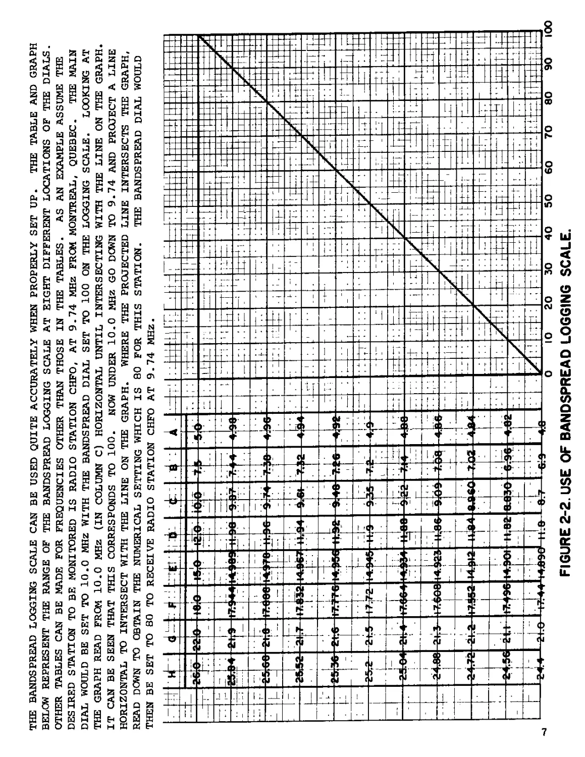
THE BANDSPREAD LOGGING SCALE CAN BE USED QUITE ACCURATELY WHEN PROPERLY SET UP. THE TABLE AND GRAPH
BELOW REPRESENT THE RANGE OF THE BANDSPREAD LOGGING SCALE AT EIGHT DIFFERENT LOCATIONS OF THE DIALS.
OTHER TABLES CAN BE MADE FOR FREQUENCIES OTHER THAN THOSE IN THE TABLES. AS AN EXAMPLE ASSUME THE
DESIRED STATION TO BE MONITORED IS RADIO STATION CHFO, AT 9.74 MHz FROM MONTREAL, QUEBEC. THE MAIN
DIAL WOULD BE SET TO 10.0 MHz WITH THE BANDSPREAD DIAL SET TO 100 ON THE LOGGING SCALE. LOOKING AT
THE GRAPH READ FROM 10.0 MHz (IN COLUMN C) HORIZONTAL UNTIL INTERSECTING WITH THE LINE ON THE GRAPH.
IT CAN BE SEEN THAT THIS CORRESPONDS TO 100. NOW UNDER 10.0 MHZ GO DOWN TO 9.74 AND PROJECT A LINE
HORIZONTAL TO INTERSECT WITH THE LINE ON THE GRAPH. WHERE THE PROJECTED LINE INTERSECTS THE GRAPH,
READ DOWN TO OBTAIN THE NUMERICAL SETTING WHICH IS 80 FOR THIS STATION. THE BANDSPREAD DIAL WOULD
THEN BE SET TO 80 TO RECEIVE RADIO STATION CHFO AT 9.74 MHZ.
FIGURE 2-2. USE OF BANDSPREAD LOGGING SCALE.
advanced even further to decrease the
bandwidth. CW signals require very
little bandwidth and the selectivity
may be decreased almost to the point
where self-oscillation occurs.
It will be noted that a slight loss
of signal strength is apparent when
the selectivity is first turned on.
This is a normal condition and as
the selectivity is advanced clock-
wise the strength will increase
slightly.
2.2.11 FREQUENCY CONTROL, Q-MULTI-
PLIER (Index #11)
The use of the Frequency control was
previously explained in Section
2.2.10. The frequency control and the
selectivity control (Index #10)
make up the Q-Multiplier. The freq-
uency control will have no effect un-
less the selectivity control is advan-
ced past the OFF position. The freq-
uency control should be adjusted for
clarity of signal or for minimum adja-
cent channel interference.
2.2.12 BFO FREQUENCY CONTROL (Index
#12)
The BFO Frequency Control varies the
frequency of the beat frequency oscil-
lator. This control is used when receiv-
ing CW or SSB signals. The beat freq-
uency oscillator is turned on when the
function switch (Index #1) is placed in
the CW/SSB position. When receiving SSB
signals this control should be placed to
one side depending on the type of SSB
to be received. When receiving CW
signals the signal should first be
zeroed using either the main or band-
spread tuning then the BFO control
adjusted to produce the desired beat
note.
2.2.13 ELECTRICAL BANDSPREAD DIAL
(Index #13)
The Electrical Bandspread is a means
of enlarging a portion of the main dial.
A small segment of the main dial can
be "spread-ouf and tuned using the
bandspread dial. The bandspread dial is
calibrated for use on the 10,15,20,40 and
80 meter amateur bands. In addition there
is a logging scale for use on the CB
band or for short wave stations. The
following paragraphs describe the use of
this dial for amateur bands as well as
short wave bands.
When using the bandspread dial on one
of the amateur bands it is first neces-
sary to set the main dial to the proper
frequency. The amateur bands are clearly
marked on the main dial by the block
marked under the frequency for each band
for which the bandspread dial is cali-
brated. As an example assume the desired
band to be the 40 meter band. The band
selector switch (Index #2-6) would be
placed in the 4-10 position and the main
dial control (Index #2-3) rotated until
the hair line is over the mark that indi-
cates the right hand end of the block
that runs from 6.75 to 7.31 MHZ. When the
main dial is set this way it is setting just
past 7.3 MHz (third mark past 7.0 MHz).
The bandspread dial is then rotated from
100 to 0 on the logging scale or from
7.3 to 6.76 which is calibrated for the
40 meter band. This same procedure is
followed for any amateur band. The only
difference being the 20 meter band,
where the band selector switch (Index #2-
6) must be placed in the 20 BS position
for the calibration to be accurate on the
bandspread dial.
The bandspread dial is also very useful
when tuning short wave bands even though
there is no bandspread calibration for
these bands. For an example assume the
desired band to be the 16 meter band
(17.7 MHz -18.1 MHz). The band selector
switch (Index #2-6) will be placed in
the 10-30 position and the main dial
control (Index #2-3) rotated until the
hair line is at the right hand end of
the red block under 18.0 on the main
dial. The bandspread dial can now be
rotated from 100 to 0 on the logging
scale. This will tune from the high
frequency end of the 16 meter band thru the
low frequency end of the band. The use
of the logging scale is realized here.
With the main dial set as above and the
8
bandspread dial rotated down the logging
scale assume the desired shortwave station
is heard when the logging scale indicates
74. This is the reading that would be
remembered or recorded in order to re-
turn to this station with a minimum of
tuning.
The same principals are followed to use
the CB position of the bandspread dial.
The main dial would be set to the right
hand end of the block just under 27.2
MHz and thereby cause the CB band to
appear between 77 and 90 on the logging
scale.
2.2.14 MAIN TONING DIAL (Index #2-14)
The Main Tuning Dial is used to tune
the receiver to the desired frequency
or the desired band of frequencies
when using the bandspread dial. It
must be noted that the calibration of
the main dial is accurate ONLY when
the hair line on the bandspread dial
is over 100 on the logging scale on
that dial. When set this way the freq-
uency is read directly from the main
dial.
The main dial is marked in a manner
that allows the frequency to be eas-
ily located and read off. The amateur
bands (10, 15, 20, 40 and 80 meters)
are blocked off just under the freq-
uencies of these bands. The short-
wave hands are blocked off in red just
under the frequencies for these bands.
Some of the shortwave bands marked are
the 12, 13. 16, 19, 25, 31, 41, 49 and
60 meter bands as well as others.
2.2.15 "S" METER (index #2-15)
The "S" Meter will show a relative
indication of received signal strength.
The meter will function only when the
AVC-MAN switch (Index #2-5) is in the
AVC position and the function switch
(index #2-1) is in the AM position.
The meter is calibrated to +60db over
S-9. Each "S" unit from S-l to S-9
is equal to approximatley 6db. The
meter will be found useful when tuning
AM stations as these stations
may be "peaked-up" using the "S" meter
as an indicator by which to tune.
2.3 TUNING AM SIGNALS
When receiving AM signals the controls
should be set or manipulated as describ-
ed below.
A. Function Switch - AM
B. Sensitivity - maximum clockwise
rotation
C. Audio Gain - to suit operator
D. Bandspread dial - set to 100 on
logging scale (setting of this
dial can be changed later if
desired to tune a band)
E. MAN-AVC Switch - AVC position
Place the tuning range switch to the
position that is desired to receive the
particular frequency and tune the main
dial to that frequency. Peak the station
received on the "S" meter using the main
dial control and the antenna trimmer
control to peak the signal. If impulse
noise is present the noise limiter may
be turned on to limit this noise and
produce a more readable signal. The
selectivity win normally be in the
OFF position when receiving AM signals
to permit a wider bandpass which is
more desirable for AM signals to pro-
duce a signal with higher fidelity. It
is possible to use the selectivity when
receiving AM signals and it may be desir-
able when tuning shortwave bands where
the stations are close together. Turn
the selectivity on but still turned
counterclockwise. This will produce a
more narrow bandwidth thereby elimina-
ting the adjacent station or reducing
it in strength to reduce the interference
caused by it. with the selectivity
switch tuned on the Q-Multiplier freq-
uency control is now effective. This
control may be used to peak the desired
signal or null the undesired signal.
By tuning the control it is seen that
the signal can be peaked up or "tuned-
out" by proper placement of this freq-
uency control.
2.4 TUNING CW SIGNALS
When receiving CW signals the controls
9
should be set or manipulated as describ-
ed below.
A. Function Switch - CW/SSB
B. Audio Gain - maximum clockwise
rotation
C. Sensitivity - to suit operator
D. MAN-AVC - MAN position
E. BFO - Zero "0”
F. Bandspread Dial set to 100 on
logging scale (setting of this
dial can be changed later if
desired)
Place the tuning range switch in the
position desired to tune the particular
frequency and rotate the main dial to the
frequency desired. The tone of the CW
signal should never be set using the
dials. The signal should be "zeroed"
using the dials, then the BFO adjusted
for the desired tone. The antenna
trimmer will be peaked to provide max-
imum signal strength. The noise lim-
iter may be used if conditions are
existing that cause interference. It
will be found highly desirable to narrow
the selectivity of the receiver when
tuning CW signals. This is accomplished
by turning the selectivity on and advan-
cing the control into the CW marking
around the control. The actual setting
will be determined by the amount of
selectivity required for a particular
signal. The Q-Multiplier frequency
control is effective when the selectivty
is turned on and it will be noticed
that the effect of this control is very
pronounced now that the selectivity
control is advanced into the CW portion
of the markings. The peaking effect of
this frequency control will be very
sharp now and the control will be very
useful in peaking the desired signal
or nulling the undesired signal.
2.5 TUNING SSB SIGNALS
When receiving SSB signals the controls
should be set or manipulated as describ-
ed below. It is suggested that
some time be spent in tuning SSB signals
to become familiar with tuning this
particular type of signal.
A. Function Switch - CW/SSB
B. Audio Gain - maximum clockwise
rotation
C. Sensitivity - to suit operator
D. MAN-AVC - MAN position
E. Bandspread Dial - set to 100 on
logging scale (setting of this
dial can be changed later if
desired)
F. BFO - either LSB or USB. This
setting can usually be deter-
mined by the frequency, but
not always. The accepted or
most popular transmission of
single sideband signals inso-
far as the sideband used will
be as follows:
BAND
80 meters
40 meters
20 meters
FREQUENCY
3.8-4.0 MHz
7.2-7.3 MHz
SIDEBAND
lower
28.5-29.7 MHz
upper
upper
upper
A SSB signal may be identified by the
lack of a carrier or beat note when
tuning across the signal. A SSB signal
not properly tuned may sound distorted.
Intelligibility can only be obtained by
proper choice of upper (USB) or lower
(LSB) sideband.
The signal would be found using the
tuning range switcn to select the desir-
ed band of frequencies and tuning the
main dial to the particular frequency.
When located the signal would be peaked
using the antenna trimmer. If impulse
noise is present the noise limiter may
be turned on to eliminate this type
of interference.
The selectivity should be turned on and
advanced until it is in the SSB portion
marked around the control. This will
aid in eliminating adjacent stations and
provide the passband required for good
reception of SSB signals. The frequency
control of the Q-Multiplier may be peak-
ed on the desired signal or set to atten-
uate the undesired signal.
2.6 WHERE TO LISTEN
Where you will want to listen will depend
on your own personal interests. The
following paragraphs are intended to
aid the shortwave listener, the ham.
10
and the persons operating on the citizens
band.
2.6.1 SHORTWAVE LISTENING
if your prime interest is in short
wave listening, you want to find the
stations with a minimum of fuss. It's
simple if you know where and when to lis-
ten.
There are seven bands or areas packed
with stations broadcasting from various
corners of the world. Here you will
hear the voices of London, Paris. Rome,
Moscow, etc.
Experience and practice win soon lead
you to the proper band at the proper
time of day but until you have become
familiar with the routine, here is a
listing that will help you to get start-
ed in the right way.
There are hundreds of broadcast stations
throughout the world operating around
the clock. Foreign broadcast stations
can be heard from about 3,000 kHz up
to 28,000 kHz. For convenience, they
are grouped into "meter bands" or seg-
ments designated by numbers; the 31
meter band covers those frequencies from
9,200 kHz to 9,700 kHz; the 16 meter
band, frequencies from 17,700 kHz to
17.900 kHz, etc.
International short-wave Broadcast Bands
Meters Frequency Range
60....................4750 to 5060 kHz
49....................5950 to 6200 kH2
41....................7100 to 7300 kHz
31....................9200 to 9700 kHz
25...................11700 to 11975 kHz
19...................15100 to 15450 kHz
16...................17700 to 17900 kHz
13...................21450 to 21750 kHz
WHEN TO LISTEN
Short wave Bands-From the U.S.A.
Daybreak to Noon:
16 meters Mainly for stations to the
East
19 meters Mainly for stations to the
Northeast, East or South-
west.
25 meters Mainly for stations to the
Northeast, East or Southwest
49 meters Mainly for stations to the
Northeast, East or Southwest
Noon to Sunset:
16 meters Stations to the East which
fade and are replaced by
those to the South before
sunset
19 meters East and South
25 meters East and South
31 meters Stations to the East
49 meters Inconsistent
Sunset to Midnight:
16 meters Poor
19 meters Poor
25 meters Poor
25 meters Stations from East fade
around midnight. Station
from South usually quite
strong.
31 meters Stations from East fade
around midnight. Station
from South usually quite
strong.
49 meters Stations are strongest
from the East. North-South
reception usually good.
The 13 meter band exhibits much the same
characteristics as the 16 meter band; the
41 meter band follows the 49 meter band
closely.
The above listed conditions apply to the
spring and autumn of the year. During the
winter months evenings, the 41. 49 and 60
meter bands are loaded with short wave
stations; during the summer months, these
same frequencies fade and are replaced by
the higher frequencies for consistent
listening.
For year'round listening, the 31 and 25
meter bands are the ones which produce the
most in the way of stations.
As a general rule, the shorter wavelengths
(higher frequencies) cover the greatest
distances by daylight; the longer wave-
lenghts are more effective during the
evening hours.
Sun spots, which have a direct relationship
to receiving conditions, operate on an 11
year cycle. As the number of sun spots
II
increase, conditions improve on the
higher frequencies particularly and the
13 meter band will enjoy a marked in-
crease in activity from 1968 on.
2.6.2 HAM RADIO
Various segments of the radio spectrum
have been set aside for use by radio
amateurs or "hams" who are licensed to
operate their own radio transmitters.
Communicating across thousands of miles
of land and sea and across international
borders, the chatter of thousands
of hams around the world fills the air
around the clock.
Conversations are often technical in
nature but there is plenty of interesting
"rag-chewing" or general conversation.
Hams often provide emergency communica-
tions in disaster areas using portable and
vehicle mounted equipment.
The ham frequencies you will find on your
Hammarlund receiver are listed below:
Meters Frequency in kHz
160................1800-2000
80...............3500-4000
40...............7000-7300
20...............14000-14350
15...............21000-21450
10...............28000-29700
NOTE: New FCC regulations concerning
suballocations effective Nov. 22,68.
Radio station WWV at Fort Collins,
Colorado and WWVH in Hawaii, broadcast
continuously on the frequencies 2.5 MHZ,
5 MHz, 15 MHz, 20 MHz and 25 MHz.
services provided include time signals
receiver calibration and propagation
forecasts which are of assistance to the
short wave listener.
The chart below indicates the code groups
used for propagation reporting.
Standard Frequency Station and Propa-
gation Reports
Station Frequency in MHz
WWV* 2.5, 5, 10, 15, 20, 25
WWVH* 5, 10, 15
CHU 3.330, 7.335, 14.67
JJY 2.5, 4, 5, 8, 10, 15
Location
WWV - Ft. Collins, Colorado
WWVH - Hawaii
CHU - Ottawa, Canada
JJY - Tokyo, japan
* Propagation Reports Broadcast as Follows:
For North Atlantic Area - WWV, forecast
occurs the last half of every fifth minute.
For North Pacific Area - WWVH, forecast
occurs the last half of every fifth minute.
Code Letter W (.______) = Disturbance Either
in Progress or Expected.
U (..___) = Unstable conditions
N (___.) = No warning
Code letter followed by number which gives
quality of report:
1. (.___ _ _) Impossible
2. (..______) Very poor
3. Poor
4. (...._) Fair to poor
5. (.....) Fair
6. (_....) Fair to Good
7. Good
8. (_____..) Very Good
9. (________.) Excellent
2.6.3 CITIZENS BAND
A recent addition to private communication
is the Citizen Band of frequencies, set
up by the FCC for short range business
and personal communication. It consists
of 23 channels between 26.965 and 27.255
kHz. Your Hammarlund receiver will re-
ceive these channels.
LOCATION OF CITIZENS BAND
Ch. Freq, in kHz. Ch. Freq, in kHz
1 26965 13 27115
2 26975 14 27125
3 26985 15 27135
4 27005 16 27155
5 27015 17 27165
6 27025 18 27175
7 27035 19 27185
8 27055 20 27205
9 27065 21 27215
10 27075 22 27225
11 27085 23 27255
12 27105
12
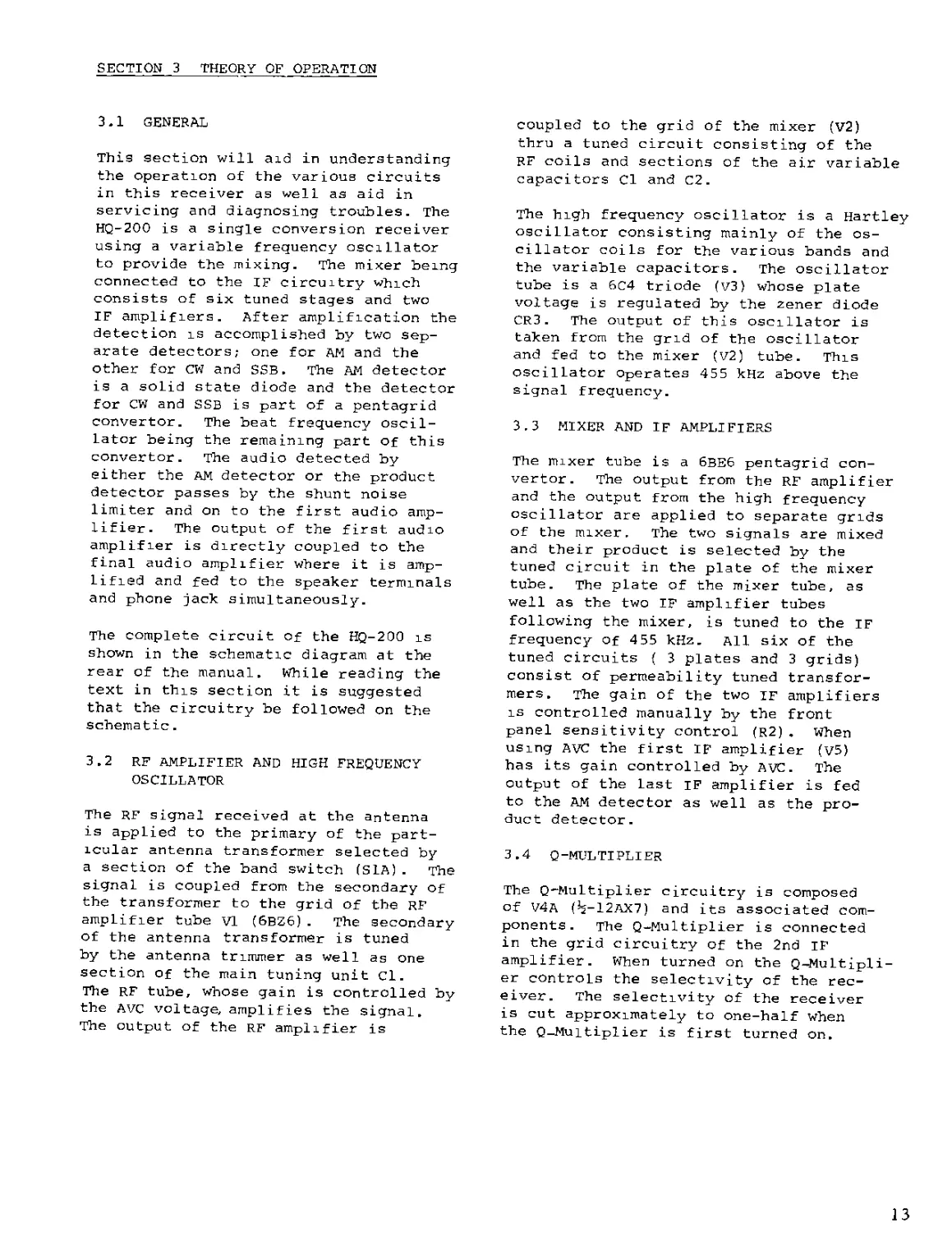
SECTION 3 THEORY OF OPERATION
3.1 GENERAL
This section will aid in understanding
the operation of the various circuits
in this receiver as well as aid in
servicing and diagnosing troubles. The
HQ-200 is a single conversion receiver
using a variable frequency oscillator
to provide the mixing. The mixer being
connected to the IF circuitry which
consists of six tuned stages and two
IF amplifiers. After amplification the
detection is accomplished by two sep-
arate detectors; one for AM and the
other for CW and SSB. The AM detector
is a solid state diode and the detector
for CW and SSB is part of a pentagrid
convertor. The beat frequency oscil-
lator being the remaining part of this
convertor. The audio detected by
either the AM detector or the product
detector passes by the shunt noise
limiter and on to the first audio amp-
lifier. The output of the first audio
amplifier is directly coupled to the
final audio amplifier where it is amp-
lified and fed to the speaker terminals
and phone jack simultaneously.
The complete circuit of the HQ-200 is
shown in the schematic diagram at the
rear of the manual. While reading the
text in this section it is suggested
that the circuitry be followed on the
schematic.
3.2 RF AMPLIFIER AND HIGH FREQUENCY
OSCILLATOR
The RF signal received at the antenna
is applied to the primary of the part-
icular antenna transformer selected by
a section of the band switch (SLA). The
signal is coupled from the secondary of
the transformer to the grid of the RF
amplifier tube VI (6BZ6). The secondary
of the antenna transformer is tuned
by the antenna trimmer as well as one
section of the main tuning unit Cl.
The RF tube, whose gain is controlled by
the AVC voltage, amplifies the signal.
The output of the RF amplifier is
coupled to the grid of the mixer (V2)
thru a tuned circuit consisting of the
RF coils and sections of the air variable
capacitors Cl and C2.
The high frequency oscillator is a Hartley
oscillator consisting mainly of the os-
cillator coils for the various bands and
the variable capacitors. The oscillator
tube is a 6C4 triode (V3) whose plate
voltage is regulated by the zener diode
CR3. The output of this oscillator is
taken from the grid of the oscillator
and fed to the mixer (V2) tube. This
oscillator Operates 455 kHz above the
signal frequency.
3.3 MIXER AND IF AMPLIFIERS
The mixer tube is a 6BE6 pentagrid con-
vertor. The output from the RF amplifier
and the output from the high frequency
oscillator are applied to separate grids
of the mixer. The two signals are mixed
and their product is selected by the
tuned circuit in the plate of the mixer
tube. The plate of the mixer tube, as
well as the two IF amplifier tubes
following the mixer, is tuned to the if
frequency of 455 kHz. All six of the
tuned circuits ( 3 plates and 3 grids)
consist of permeability tuned transfor-
mers. The gain of the two IF amplifiers
is controlled manually by the front
panel sensitivity control (R2). when
using AVC the first IF amplifier (V5)
has its gain controlled by AVC. The
output of the last IF amplifier is fed
to the AM detector as well as the pro-
duct detector.
3.4 Q-MULTIPLIER
The Q-Multiplier circuitry is composed
of V4A (^-12AX7) and its associated com-
ponents. The Q-Multiplier is connected
in the grid circuitry of the 2nd IF
amplifier. When turned on the Q-Multipli-
er controls the selectivity of the rec-
eiver. The selectivity of the receiver
is cut approximately to one-half when
the Q-Muitiplier is first turned on.
13
As the selectivity control (R13) is turn-
ed clockwise the selectivity becomes sharp-
er. This control allows the selectivity
to be varied from approximately 3 kHz
to 100 hertz. The frequency control
will allow the sharp peak, created by
multiplying the Q of l5, to be moved
thru the IF passband of the receiver.
This control will allow the peak to move
±3.5 kHz of the center frequency of 455
kHz.
3.5 AVC AND '-S- METER
The AVC detector is a 1N34a diode (CR4).
The AVC is filtered by part of the chip
Z2. The MAN-AVC switch (S4) controls the
feed of the AVC to the RF amplifier (Vl)
and the 1st IF amplifier (v5). When in
the MAN position the AVC bus is at ground
potential and the RF amplifier and 1st
IF amplifier gain must be manually contro-
lled.
The ''S" meter is in the cathode circuitry
of the two IF amplifiers. The "S" meter
will indicate only when the MAN-AVC
switch is in the AVC position. The cur-
rent through the meter is caused by a
difference of potential existing between
the cathode of the two amplifiers. This
condition exists only when the 1st IF
amplifier has its gain controlled by the
AVC voltage.
3.6 PRODUCT DETECTOR AND BFO
The output from the last IF amplifier is
coupled to the pentagrid convertor tube
used for the product detector and beat
frequency oscillator. This tube (v7-
6BE6) functions as a Hartley oscillator
to perform the function of the BFO
and a product detector to detect CW
and SSB signals. The beat frequency
oscillator is variable 12 kHz from the
center frequency of 455 kHz. This
single stage combines the output of
the last IF and the BFO to produce
their products in its output. The
455 kHz component is filtered and the
audio is passed on to the 1st Audio
amplifier.
3.7 NOISE LIMITER AND AUDIO AMPLIFIERS
The noise limiter consists of a 1N541
diode (CR5) which is connected in a shunt
type configuration. The audio from
either the AM detector or product detec-
tor must pass the noise limiter prior
to reaching the 1st audio amplifier.
The noise limiter switch (S5) places a
shunt across CR5 when in the OFF posi-
tion. When in the ON position the diode
is allowed to clip impulse noise.
There are two audio amplifiers. The
first audio amplifier consists of V4B
which is % of a 12AX7. The output of
the first audio amplifier is filtered
and fed to the final audio amplifier.
The final audio amplifier, V8, is a 6AQ5.
This stage amplifies the audio and
drives the audio output transformer T8
whose secondary is directly coupled to
the audio output terminals and the phone
2ack. The speaker used with the receiv-
er should be 3.2 ohm. if headphones are
used they should be of a low impedance
variety.
3.8 POWER SUPPLY
The power supply consists of the power
transformer (T9), the rectifiers (CR1
and CR2) and the necessary filtering.
The silicon diodes are connected in the
conventional full wave rectifier con-
figuration .
The power transformer has the capability
of allowing the receiver to operate on
either 110 VAC 50/60 Hertz or 220 VAC
50/60 Hertz provided the primary of the
power transformer is programmed properly.
To use the receiver on 110 VAC the prim-
ary should be connected as follows: black
to black/green and black/yellow to black
red, this corresponds to 1 to 2 on TB1
and 3 to 4 on TB1. то use the receiver on
220 VAC the jumpers used for 110 VAC
should be removed and the primary pro-
grammed as follows: black/yellow to black/
green, jumper 2 and 3 together on TB1.
When changing from 110 VAC to 220 VAC
the fuse. Fl, should be changed from
14
1 amp to 0.5 amp.
The power transformer has a separate
winding which supplies the necessary
voltage to operate the pilot lamps and
the necessary filament voltages.
A voltage reading of 45 - 50 volts may
be obtained between the chassis and a
ground as the result of the two power
line by-pass capacitors that are con-
nected across the power line with the
center tap grounded. Since we are
dealing with AC, these capacitors will
look like resistors to a volt meter.
This will also produce a slight shock
if the chassis is not grounded and
one happens to contact a grounded
object, and the chassis or any exposed
part of the receiver. This also will
account for a slight spark, if the
receiver is connected to the power line
and the ground connection is made. For
protection a good ground should always
be employed.
® HQ-200 IF SELECTIVITY WITH SELECTIVITY CONTROL IN ''OFF" POSITION. NOMINAL
6DB BANDWIDTH OF 7.0 kHz.
® HQ-200 IF SELECTIVITY WITH SELECTIVITY CONTROL TURNED "ON" BUT COUNTERCLOCK-
WISE. NOMINAL 6DB BANDWIDTH OF 2.5 kHz.
©HQ-200 IF SELECTIVITY WITH SELECTIVITY TURNED "ON" AND ADVANCED TO CW POSI-
TION. NOMINAL 6DB BANDWIDTH OF 400 Hertz.
FIGURE 3-1. IF SELECTIVITY.
15
SECTION 4 ALIGNMENT AND SERVICE
4.1 GENERAL
This section will provide instructions
for the correct servicing of the HQ-200
Receiver. It includes information on
resistance measurements, voltage meas-
urements, trouble analysis, and align-
ment procedures. It should be noted
that proper tools and test equipment
must be available to undertake the
electrical measurements and alignments.
The accuracy of the test equipment used
will determine the validity of the sig-
nal level measurements and alignment
data. This receiver has been careful-
ly designed, constructed, inspected
and aligned at the factory to provide
a long period of trouble-free use.
Except for an occasional touch up to
compensate for component ageing,
alignment will normally be necessary
only if frequency determining com-
ponents have been replaced. The
enclosure of the receiver has been
designed to allow easy removal for
such maintenance as is required.
4.1.1 ENCLOSURE REMOVAL
To service this receiver, disconnect
from power source and remove all
leadwires attached to terminal con-
nections at rear of chassis apron.
Carefully turn the receiver Up onto
the front panel face on a smooth clean
surface. Remove the two #10 hex machine
screws at the extreme ends of the chassis
apron at the rear of the cabinet. Lift
cabinet straight up and off of chassis.
To reassemble, use reverse procedure.
4.2 TROUBLE ANALYSIS
Many cases of trouble can be traced to
improper adjustments or defective com-
ponents. Troubleshooting this receiver
is simple with the proper procedures
and proper test equipment. In trouble-
shooting the receiver, one must perform
various tests and make certain observa-
tions. Proper interpretation of the re-
sults of these tests will indicate the
problem area. Additional tests in the
problem area will then locate the bad
components or assembly. In the event
of a component failure assume that the
defective part is not the cause of the
trouble but a symptom of a more serious
problem. For example, a burned resistor
may result from a shorted tube or cap-
acitor. Making the measurements out-
lined in Tables 4-1 and 4-2 will aid in
isolating a problem to a particular
stage or component.
An orderly process of elimination cou-
pled with a study of the theory of oper-
ation outlined in Section 3 as well as a
study of the schematic diagram will aid
in isolating trouble. An example of this
would be that the receiver performs all
right on AM but fails to function on CW.
Inspection of the block diagram and sche-
matic will reveal that the only circuit
peculiar to CW reception is V7 and its'
associated components, checking the
voltages and components in this stage
should readily yield the source of dif-
ficulty.
If the receiver is to be returned to the
factory or an authorized service agency
for any reason, a detailed report should
accompany the receiver. A report such as
this will assist in locating the diffi-
culty with a minimum of time and expense.
IT IS REQUIRED BEFORE RETURNING ANY EQUIP-
MENT TO THE FACTORY THAT WRITTEN AUTHOR-
IZATION BE OBTAINED FROM THE FACTORY.
4.3 VOLTAGE MEASUREMENTS
The voltages contained in Table 4-1 are
typical readings and will vary slightly
from unit to unit. The voltage measure-
ments in Table 4-1 were made under the
following conditions;
A. Voltages in Table 4-1 were made
using a VTVM.
B. Audio Gain - Maximum counterclock-
wise
C. Sensitivity - Maximum clockwise
D. Function switch - AM
E. AVC-MAN - MAN
F. LIMITER - OFF
G. Band Selector - 10-30 MHz
H. Selectivity - OFF
16
TABLE 4-1 TUBE SOCKET VOLTAGES
TUBE AND FUNCTION 1 2 3 4 SOCKET PI 5 N NUMBER S 7 8 9
VI RF 6BZ6 - 1.8 6.3AC - 220 110 - - -
V2 MIXER 6BE6 -2.5 1.2 6.3AC - 220 80 - - -
V3 UFO 6C4 115 - 6.3AC - 110 -1 to -9 _ - -
V4 12AX7 Q MULT. 1st A-F 115 - 1.4 - - 200 - 1.5 6.3AC
V5 1st IF 6BA6 - - 6.3AC - 215 115 2.2 20 MIN SENS - -
V6 2nd IF 6BA6 - - 6.3AC - 215 J 1 5 2.2 20 MIN SENS - -
V7 6BE6 BFO Prod. Det. -3 to - BFO ON 5 6.3AC - 145 BFO ON 65 BFO ON -1 to -2 BFO ON - -
V8 6AQ5 AUDIO OUTPUT - 14 6.3AC 240 230 - - -
TABLE 4-2 TUBE SOCKET RESISTANCES
TUBE AND FUNCTION 1 2 3 SOCKE 4 T PIN NU 5 MBERS 6 7 8 9
Vl RF 6BZ6 ЮК, 2.4м ON AVC 180 0 0 . 5 MEG . 5 MEG 0 - -
V2 MIXER 6BE6 22K 180 0 0 . 5 MEG . 5 MEG 0 - -
V3 UFO 6C4 .5 MEG INF 0 0 . 5 MEG 47K 0 - -
V4 12AX7 Q MULT. 1st AF . 5 MEG 2.2 MEG 16K SEL C FF 0 0 . 5 MEG 1MEG 4700 0
V5 1st IF 6BA6 13^, 2.4M ON AVC 0 0 0 . 5 MEG . 5 MEG 180, 10K MIN SENS - -
V6 2nd IF 6BA6 470K 0 0 0 . 5 MEG . 5 MEG 300, 10K MIN SENS - -
V7 6BE6 BFO Prod. Detector 100K 0.5^ о 0 . 5 MEG BFO ON . 5 MEG BFO ON 220K - -
V8 6AQ5 Audio Output 470K 430 0 0 . 5 MEG .5 MEG 470K - -
17
FIGURE 4-1. TUBE LOCATION.
I. No Signal Input
4.4 RESISTANCE MEASUREMENTS
Band selector switch on .54-1.6 MHz
MAN-AVC switch on AVC
SENSITIVITY maximum clockwise
It is probable that resistance neas-
urements will vary somewhat from meter
to meter. On many ohmmeters just chang-
ing the resistance scale will cause a
different reading. The measurements
contained in Table 4-2 were made using
a Simpson 260 VOM with negative lead of
meter connected to receiver chassis.
The following settings were observed for
control settings:
A. Audio Gain- maximum clockwise
B. Sensitivity- maximum clockwise
C. Function Switch- AM
D. AVC-MAN- MAN
E. Limiter- OFF
Г. Band Selector- 10-30 MHz
G. Selectivity- OFF
4.5 IF ALIGNMENT
It should be noted that a non-metallic
alignment tool such as a nylon hex
alignment(General Cement Co. No. 8282
Or equal) tool should be used to align
the receiver.
4.5.1 455 kHz IF ADJUSTMENT
A. Connect the output cable of a 455
kHz unmodulated, signal generator to
the bus lead of the 6BE6 mixer grid.
The frequency accuracy of the generator
may be checked with sufficient precis-
ion by picking up its second harmonic
(910 kHz) in any receiver whose calibr-
tion at 910 kHz has been checked as
correct and then adjusting the generator
frequency.
B. Connect a DC
set for negative
2 of Z2.
vacuum tube voltmeter,
voltage reading to pin
C. Set the receiver controls as follows:
BAND SPREAD dial to 100
Function switch to AM
Main tuning dial to .60 MHz
Noise limiter switch to off
AUDIO GAIN control at minimum
SELECTIVITY control to OFF
D. During alignment, adjust the gener-
ator output to prevent over-loading.
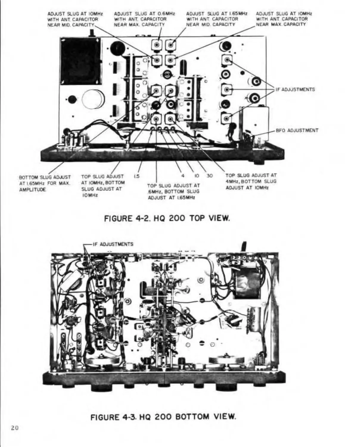
Adjust each of the three IF transformers
for maximum meter reading. Topside
adjustments (Figure 4-1) are second-
aries or grid circuits; bottom of chassis
adjustments (Figure 4-2) are primaries
or plate circuits. The reading on the
voltmeter should be kept below -3.0 volts.
4.5.2 Q-MULTlPLIER ADJUSTMENT
Turn the Q-Multiplier on and adjust the
SELECTIVITY control clockwise to a pos-
ition below the oscillating point, with
its panel bushing nut loosened to permit
the frequency shaft to turn without hind-
rance by the stop, adjust the FREQUENCY
control to obtain a maximum meter indi-
cation. The input signal must be adjust-
ed to a value just sufficient to obtain
a good meter swing. This adjustment is
the center frequency of the pass band.
While the meter is at maximum, turn the
stop lug to a position 180 degrees direct-
ly opposite the stop pin in the freq-
uency shaft. Holding it in this posi-
tion, tighten the bushing in the nut
making sure that the shaft or the stop
lug have not turned by checking the
zero setting.
4.5.3 BFO ADJUSTMENT
Rotate the function switch to the CW/SSB
position and place the MAN-AVC switch in
the MAN position. With the BFO frequency
control on ZERO adjust the slug in L7
for zero beat. The correct setting for
the BFO frequency control capacitor
(C59) is as follows.- with the knob
pointing to LSB the capacitor should be
set for full mesh (maximum capacity),
with the control rotated clockwise to
"O” the capacitor will be at half mesh,
and rotated further until the knob
points to USB where the capacitor will
be fully open (Minimum capacity).
4.5.4 ZERO ADJUST FOR "S" METER
Place the MAN-AVC switch in the AVC
19
FIGURE 4-2. HQ 200 TOP VIEW.
FIGURE 4-3. HQ 200 BOTTOM VIEW.
position. With no signal input, ground
the grid of the mixer (V2-6BE6) pin 7
and zero the "S" meter using R15 to ad-
just the zero reading.
4.6 RF ALIGNMENT
NOTE: Use a non-metallic alignment
tool such as General Cement Co. No. 8282,
or equal.
A. The slugs and trimmers, having been
factory adjusted, should require a min-
imum amount of adjustment for any align-
ment .
B. All RF and oscillator slug adjust-
ments are made from the top of the shield
cans. See Figure 4-1.
C. Connect the unmodulated, signal gener-
ator output cable to the antenna and
ground terminals of the receiver, with
the A terminal adjacent to the G termin-
al jumped together.
D. Set the controls the same as for IF
alignment above.
E. The oscillator adjustment is made
first. The RF is adjusted next to ob-
tain maximum amplitude. The antenna
slugs are adjusted last. A certain
amount of interaction will occur be-
tween the oscillator and RF adjustments,
particularly on the higher frequency
bands. Final adjustment should be ac-
complished by combined or alternate
adjustment of the oscillator and RF for
maximum amplitude.
Figure 4-1 indicates the particular
adjustment for each band of the receiver
and the frequency at which they are to
be adjusted.
There is no RF amplifier adjustment for
the .54 - 1.6 MHz band.
F. Note that the oscillator frequency
in the HQ-200 is always on the high side
of the signal frequency by 455 kHz.
Therefore, it is necessary to make sure
that the oscillator frequency is not
adjusted below the signal frequency
which would be an image response of the
signal.
G. It will be necessary to repeat low
and high end alignment adjustments of
each band since the adjustments are
interdependent. The process should be
repeated until maximum amplitude is
obtained at both alignment frequencies
of each band.
NOTE: The receiver should be warmed
up at least one-half hour before final
oscillator frequency adjustments are
made for the dial calibration check.
4.7 DIAL CALIBRATION
A. Use a crystal calibrator having
100 kHz and 1 MHz output. Set the arb-
itrary band spread dial scale to 100.
Set the function switch to CW/SSB. Set
the BFO Frequency control to ZERO. Set
the SELECTIVITY control to OFF. Set
the MAN-AVC switch to MAN.
B. Check to see that the frequencies at
or near the alignment frequencies are
"on the line". If not, make minor adjust-
ments of the slugs and trimmers (Figure
4-1) to make them correct.
CAUTION
weaker signals will be observed at dial
settings approximately 10 kHz above each
calibration dial marking. These are
image signals from 1 MHz above the
desired signal and may be recognized by
their somewhat weaker strength and may
be further reduced by proper adjustment
of the gain controls. They will, of
course, be more noticeable on the high-
er bands. Keeping the antenna tuned
will help.
21
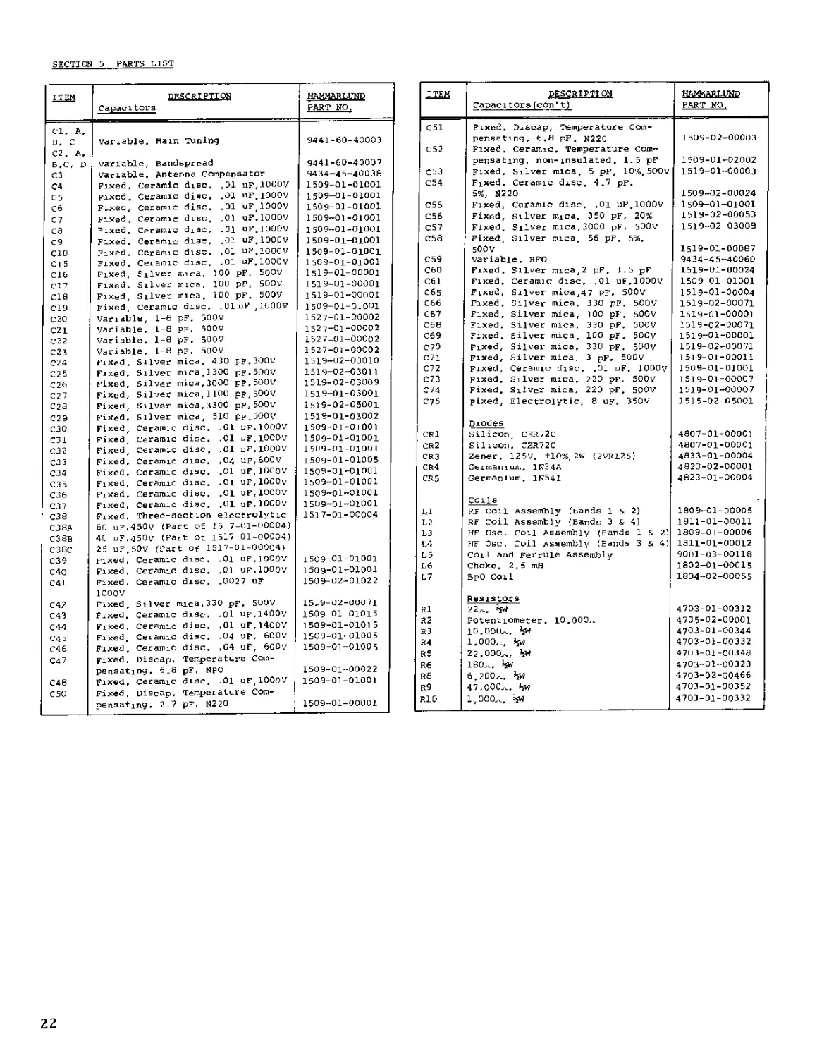
SECTION 5 PARTS LIST
ITEM Capacitors HAMMARLUND PART NO, DESCRIPTION Capacitors(con11) HAMMARLUND PART NO.
Cl. A. C51 Fixed. Discap, Temperature Com-
B. c variable. Main Tuning 9441-60-40003 pensating. 6.8 pF. N220 1509-02-00003
C2, A. C52 Fixed, Ceramic. Temperature Com-
B.C, D variable, Bandspread 9441-60-40007 pensating, non-insulated. 1.5 pF 1509-01-02002
C3 variable. Antenna Compensator 9434-45-40038 C53 Fixed. Silver mica 5 pF, 10% 500V 1519-01-00003
04 Fixed. Ceramic disc. .01 uF.lOOOv 1509-01-01001 C54 Fixed. Ceramic disc. 4.7 pF.
C5 Fixed. Ceramic disc. .01 UF.1000V 1509-01-01001 5%, N220 1509-02-00024
C6 Fixed, Ceramic disc. .01 uF,1000V 1509-01-01001 C55 Fixed, Ceramic disc. .01 uF lOOOv 1509-01-01001
C7 Fixed, Ceramic disc. .01 uF.lOOOV 1509-01-01001 C56 Fixed, Sliver mjca. 350 pF, 20% 1519-02-00053
ca Fixed. Ceramic diac, .01 uF.lOOOV 1509-01-01001 C57 Fixed. Silver mica,3000 pF, 500v 1519-02-03009
C9 Fixed. Ceramic disc. .01 uF.lOOOv 1509-01-01001 CSS Fixed, Silver mica. 56 pF. 5%.
CIO Fixed. Ceramic disc. .01 uF.lOOOV 1509-01-01001 500 V 1519-01-00087
C15 Fixed. Ceramic disc. .01 uF.lOOOV 1509-01-01001 C59 variable. SFO 9434-45-40060
C16 Fixed, Silver mica, 100 pF, 500V 1519-01-00001 C60 Fixed. Silver mica,2 pF. ±.5 pF 1519-01-00024
C17 Fixed. Sliver mica, 100 pF, 500V 1519-01-00001 C61 Fixed. Ceramic disc. .01 uF.lOOOv 1509-01-01001
CIS Fixed Silver mica. 100 pF. 500V 1519-01-00001 C65 Fixed, Sliver mica,47 PF. 500V 1519-01-00004
C19 Fixed ceramic disc. .OluF ,1000V 1509-01-01001 C66 Fixed. Silver mica. 330 pF. 500V 1519-02-00071
C2O variable, 1-8 pF. 500V 1527-01-00002 C67 Fixed. Silver mica, 100 pF. 500V 1519-01-00001
C21 Variable. 1-8 pf. 500V 1527-01-00002 C68 Fixed. Silver mica. 330 pF. 500V 1519-02-00071
C22 Variable. 1-8 pF. 5007 1527 01-00002 C69 Fixed. Silver mica, 100 pF. 500V 1519-01-00001
C23 Variable. 1-8 pF. 5OOV 1527-01-00002 C70 Fixed, Silver mica. 330 pF. 500v 1519-02-00071
C24 Fixed. Silver mica. 430 pF.300V 1519-02-03010 C71 Fixed, Silver mica, 3 pF. 500V 1519-01-00011
C25 Fixed. Sliver mica.1300 pF.500V 1519-02-03011 C72 Fixed, Ceramic disc. .01 uF. JOOOv 1509-01-01001
C26 Fixed. Sliver mica.3000 pF.500V 1519-02-03009 C73 Fixed. Silver mica. 220 pF. 500V 1519-01-00007
C27 Fixed, Silver mica,1100 pp,500v 1519-01-03001 C74 Fixed. Silver mica, 220 pF. 500V 1519-01-00007
Fixed, Silver mica.3300 pF,500V 1519-02-05001 C75 Fixed, Electrolytic, 8 up. 350V 1515-02-05001
C29 Fixed. Silver mica, 510 pf.500v 1519-01-03002
C3O Fixed Ceramic disc. .01 uF.lOOOV 1509-01-01001 Diodes
C31 Fixed Ceramic disc. .01 uF.lOOOV 1509-01-01001 IKl Silicon, CER72C 4807-01-00001
C32 Fixed Ceramic disc. .01 uF.lOOOV 1509 01-01001 CR2 Silicon. CER72C 4807-01-00001
СЗЭ Fixed. Ceramic disc. .04 uF,600V 1509-01-01005 CR3 Zener. 125V. ±10%,2W (2VR1251 4833-01-00004
Fixed. Ceramic disc. .01 uF,1000V 1509-01-01001 CR4 Germanium. 1N34A 4823-02-00001
СЭ5 Fixed. Ceramic disc. .01 uF.lOOOv 1509-01-01001 CR5 Germanium. 1N541 4823-01-00004
C36 Fixed. Ceramic disc. .01 uF.lOOOv 1509-01-01001
C37 Fixed. Ceramic disc. .01 uF.lOOOv 1509-01-01001 Colls
C38 Fixed, Three-section electrolytic 1517-01-00004 1,1 RF coil Assembly (Bands 1 & 2) 1809-01-00005
C38A 60 uF.450v (Part of 1517-01-00004) L2 RF coil Assembly (Bands 3 s 4) 1811-01-00011
C38B 40 uF.450v (Part of 1517-01-00004) L3 HF Osc. coil Assembly (Bands 1 & 2'. 1809-01-00006
C38C 25 uF.SOv (Part of 1517-01-00004) L4 HF Osc. Coil Assembly (Bands 3 & 4( 1811-01-00012
C39 Fixed, Ceramic disc, .01 uF.lOOOv 1509-01-01001 L5 Coil and Ferrule Assembly 9001-03-00118
C40 Fixed. Ceramic disc. .01 UF.lOOOv 1509-01-01001 L6 Choke. 2.5 mH 1802-01-00015
C41 Fixed, Ceramic disc, .0027 UF 1509-02-01022 L7 BpO Coil 1804-02-00055
1000V
C42 Fixed Silver mica.330 pF. 500V 1519-02-00071 Resistors
C43 Fixed. Ceramic disc. .01 up.1400V 1509-01-01015 R1 22л. SsW 4703-01-00312
C44 Fixed. Ceramic disc. .01 uF.1400V 1509-01-01015 R2 Potentiometer. 10.000,. 4735-02-00001
Fixed Ceramic disc. .04 UF. 600V 1509-01—01005 R3 10.000л. 4703-01-00344
Fixed Ceramic disc. .04 uF, 600v 1509-01-01005 R4 1.000л, hw 4703-01-00332
C47 Fixed, Oiscap, Temperature Com- R5 22.000л, 4703-01-00348
pensating. 6.8 pF, NPO 1509-01-00022 R6 | 180л. >}W 4703-01-00323
C48 Fixed. Ceramic disc. .01 uF,1000V 1509-01-01001 R8 6.200л. 4703-02-00466
C5O Fixed, Discap. Temperature Com- ! R9 47,000л. SjW 4703-01-00352
pensating. 2.7 pF. N22O 1509-01-00001 1 RIO 1,000л. hw 4703-01-00332
22
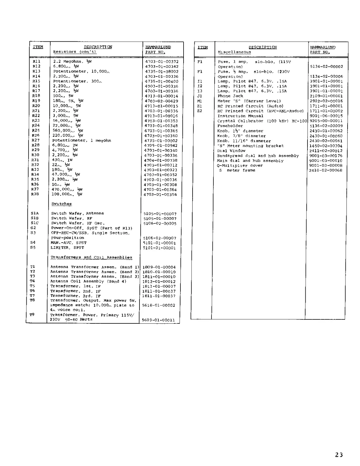
ITEM DESCRIPTION HAMMARLUND
Resistors (con’t) PART NO.
Rll 2.2 Megohms, *$W 4703-01-00372
R12 6,800л, *sW 4703-01-00342
R13 Potentiometer, 10,000л 4735-01-08002
R14 2,200л, *sW 4703-01-00336
R15 Potentiometer, 300,. 4735-01-00400
R16 2,200,., >sW 4703-01-00336
R17 2.200л, 4703-01-00336
R18 500л, 5W 4713-01-00014
R19 180л. 5%. *sW 4703-02-00429
R20 10.000л, 5W 4713-01-00015
R21 2,200л, *sW 4703-01-00336
R22 3,000л, 5W 4713-01-00016
R23 56.000л, 4» 4703-01-00353
R24 22.000л. *jW 4703-01-00348
R25 560,000л. *sW 4703-01-00365
R26 220,000л, *sW 4703-01-00360
R27 Potentiometer, 1 megohm 4735-01-00002
R28 6,800л. 2W 4705-01-00942
r29 4,700л, *5” 4703-01-00340
R30 2.200л, *jw 4703-01-00336
R31 430л. 1W 4704-01-0073B
R32 22л. *sW 4703-01-00312
R33 180л, *sW 4703-01-00323
R34 47,000л. ’sw 4703-01-00352
R35 2,200л, *5W 4703-01-00336
R36 10л, iflt 4703-01-00308
R37 470.000л, *5W 4703-01-00364
R3B 100.000л. *jw 4703-01-00356
Switches
S1A Switch Wafer, Antenna 5105-01-00007
SIB Switch Wafer, RF 5105-01-00007
sic Switch Wafer, HF Osc. 5106-02-00005
•S2 Power-On-Off. SpST (Part of R13)
S3 OFF-REC-CW/SSB, Single Section,
FOur-pOs i tion 5106-02-00007
S4 MAN.-AVC. SPST 5101-01-00001
S5 LIMITER, SPST 5101-01-00001
Transformers and coil Assemblies
T1 Antenna Transformer Assem. (Band 1) 1809-01-00004
T2 Antenna Transformer Assem. (Band 2) 1810-01-00010
T3 Antenna Transformer Assem. (Band 3) 1811-01-00010
T4 Antenna Coil Assembly (Band 4) 1812-01-00012
T5 Transformer, 1st. IF 1811-01-00037
T6 Transformer. 2nd, IF 1811-01-00037
T7 Transformer, 3rd, IF 1811-01-00037
TS Transformer, Output. Max power 5W,
impedance match; 10,000л plate to 5618-01-00002
4. r-ri- 1
T9 Transformer, Power, Primary 115V/
230V 50-60 Hertz 5603-01-00011
ITEM DESCRIPTION Misс cllaneous HAMMARLUND PART NO.
Fl Fl 12 13 JI Ml Z1 22 Fuse, 1 amp, slo-blo, (115V Operation) Fuse, *5 amp, slo-blo, (230v Lamp, Pilot #47, 6.3V, .15A Lamp, Pilot #47, 6.3V, .15A Lamp, Pilot #47, 6.3V. ,15A Phone Jack Meter "S" (Carrier Level) RC Printed Circuit (Audio) RC Printed Circuit (AVC-ANL-Audio) Instruction Manual Crystal calibrator (100 kHz) XC-100 Fuseholder Knob, 1*5" diameter Knob, 7/8" diameter Knob, 11/16" diameter "5” Meter mounting bracket Dial Window Bandspread dial and hub assembly Main dial and bub assembly Q-Multiplier cover S meter frame 5134-02-00002 5134-02-00006 3901-01-00001 3901-01-00001 3901-01-00001 2109-01-00001 2902-02-00016 1711-01-00001 1711-01-00002 9001-06-00015 9205-00-00011 5136-02-00009 2430-01-00062 2430-01-00060 2430-02-00061 1450-02-00304 2411-02-00012 9001-03-00176 9001-03-00010 9001-03-00008 2410-02-00068
23
ANTENNA
| 2ndIF AMP [
C53
C69
100
V6
6BA6
C46
сзе
.OIUF
Ф .04UF
R37
470K
СЗЭ
OIUF
| A M DET |
CR4
IN34A
C7I
3
V4B
1/2 I2AX7
6
2 r
Z I
3
OIUF
| AUDIO AMP~|
V8
6A05
PHONES
JI
250
250
C42__
330-Г
C4I
.0027
UF
6
к
J
RI7
2200
*15.So?
300
IMA
R2
I OK
SENSITIVITY
•R30
•2 2K
Г
4______
2 MEG.
AUDIO
GAIN
R27
I MEG.
R29
4.7K
C38C
5
1,7
R3I
430
IW
T8
30HM
output
— ®
,0N
C*5 7S5
W5®^>-ь
- -
i
100
R26
2 20 К
C56
56
| PROD DET/ BFO |
3
I MEG. I MEG.
C35
•OIUF
AVC _I_cei
CI6 -L
100 T
75K
I20K
.OIUF
Z2
О о C59
i 7 “ 3 2
L7 g-50/
3000
Lc/4 <r3
rALsiooK
N-22O< r.
V7
6BE6
C72
,01
UF
R23 >R24 L6
56K <22K 2.5mH
'ТПЯ'м ।
C55=r
.01
UF ~
C73
220
C74#
220
R22
-7УЧЛ-
30КЛ
5W
C75
8UF
350V “
SEND
IK- RIO
C26
C52
1300
5W
BLK
REO
С, Blk/SRN
GRN
L-'BLK/RED
Rl8
500л
R 26
8e00A.2W
ТВ I CONNECTION
IIOV 182-384
220V 283
3000
C25
RED/YEL
CR2
54 MAN.-i-
s BLK/YEL
CRI
ы RED T9
C40 —L
OIUF "Г
TBI
-O
R20
C22
C23
GRN
REAR
NOTE:
c
AC INPUT
50/60 —
RESISTORS ARE 1/2 W AND VALUE IN OHMS UNLESS OTHERWISE
CAPACITORS ARE IN MICRO-MICRO FARADS UNLESS OTHERWISE
NOTED.
NOTED.
C44
т 01 uf
V3
6C4
R9
47 К
|het osc|
125V
2W
10 К
5W
C3BA:
C3BA;fc C388
60UF 40UF ‘
C60
2
FIGURE 6*1. HQ 200 SCHEMATIC DIAGRAM
25