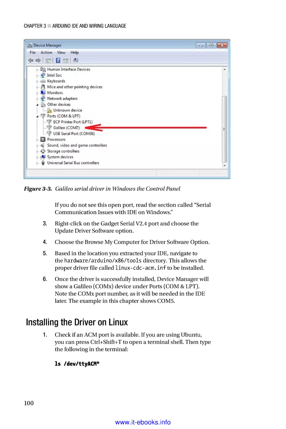
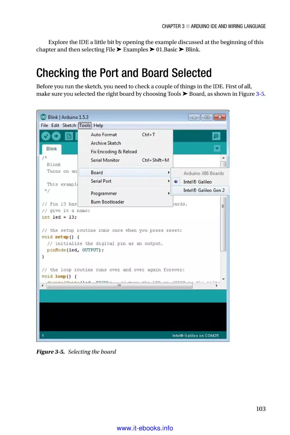
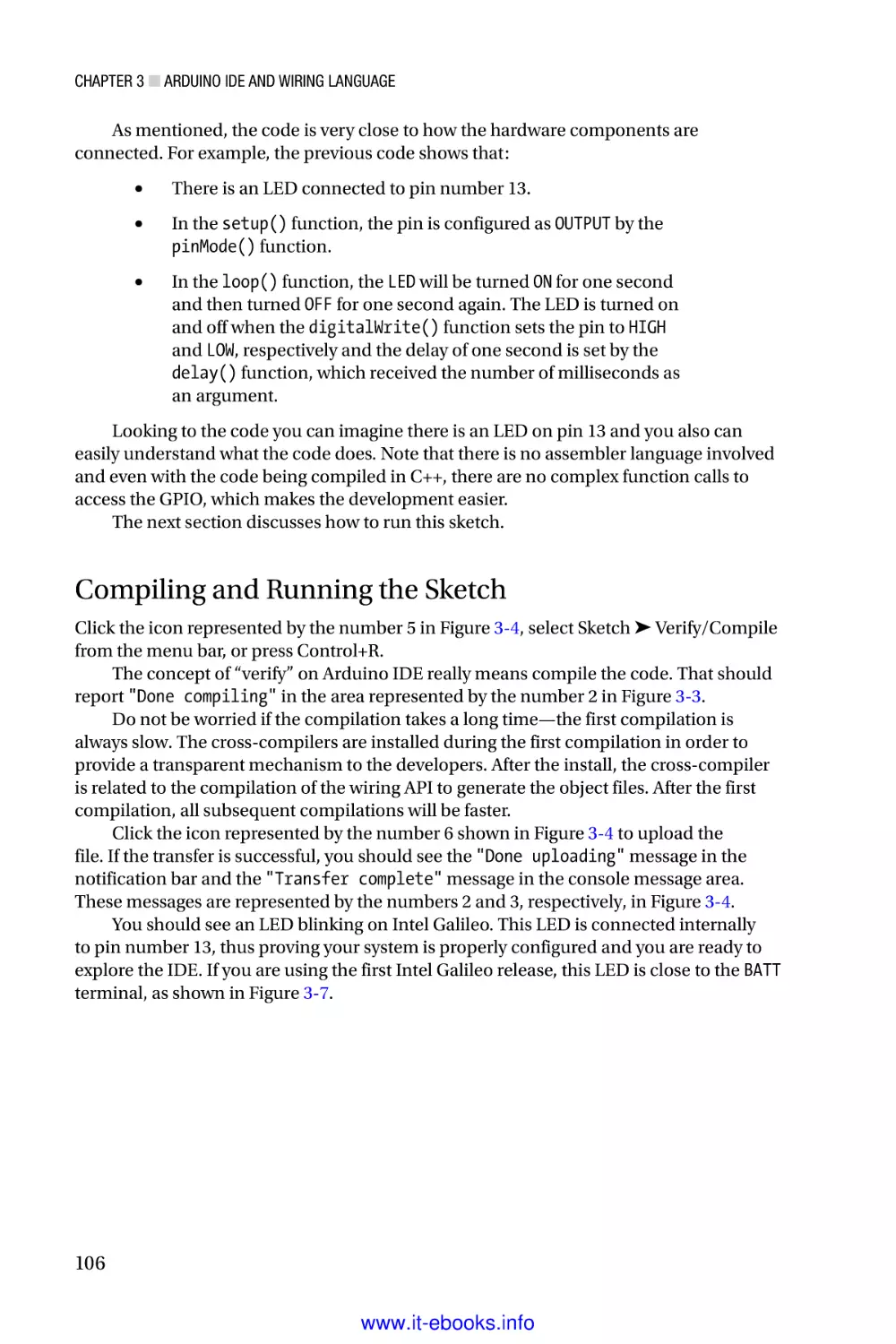
/


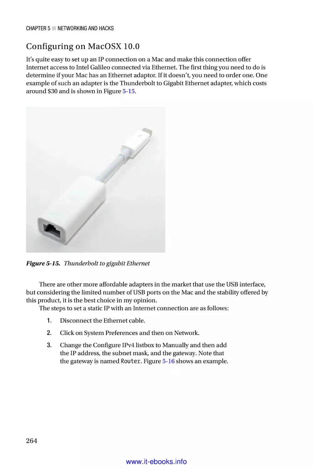

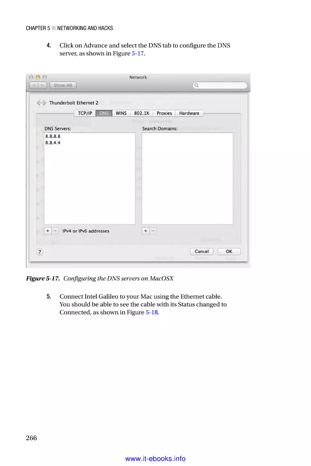


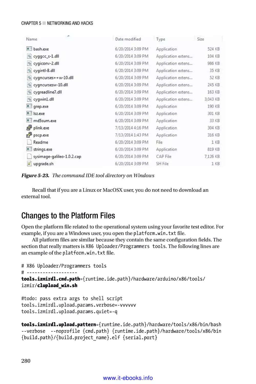


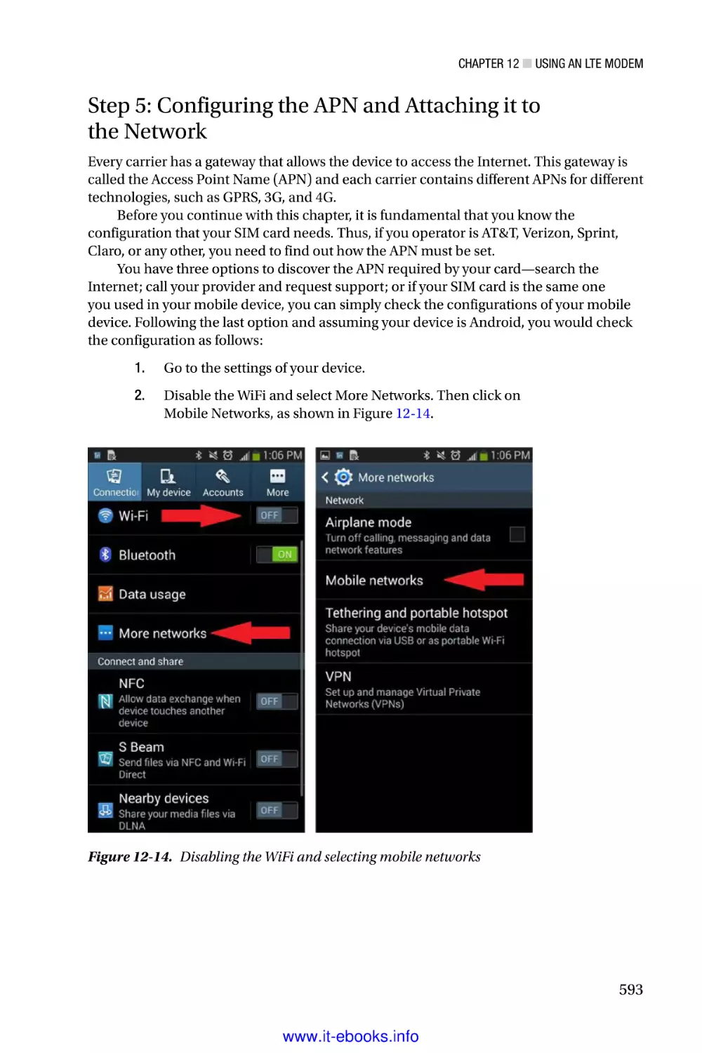


Теги: programming languages programming microelectronics processors friendsoft apress
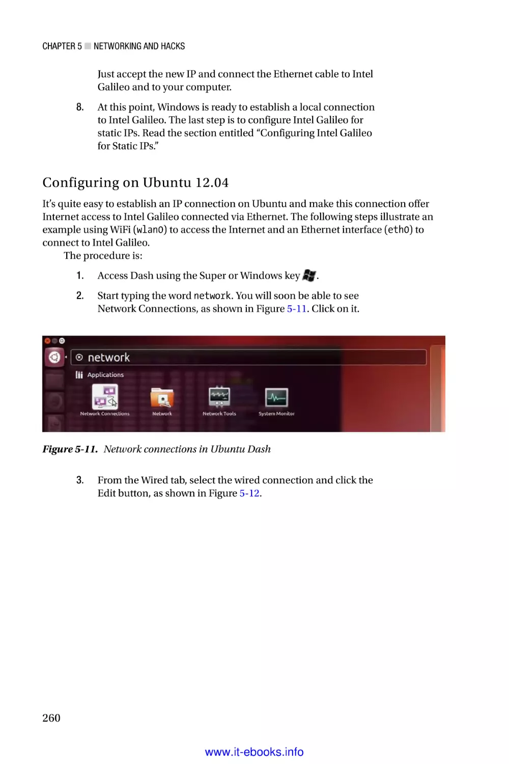
ISBN: 978-1-4302-6839-0


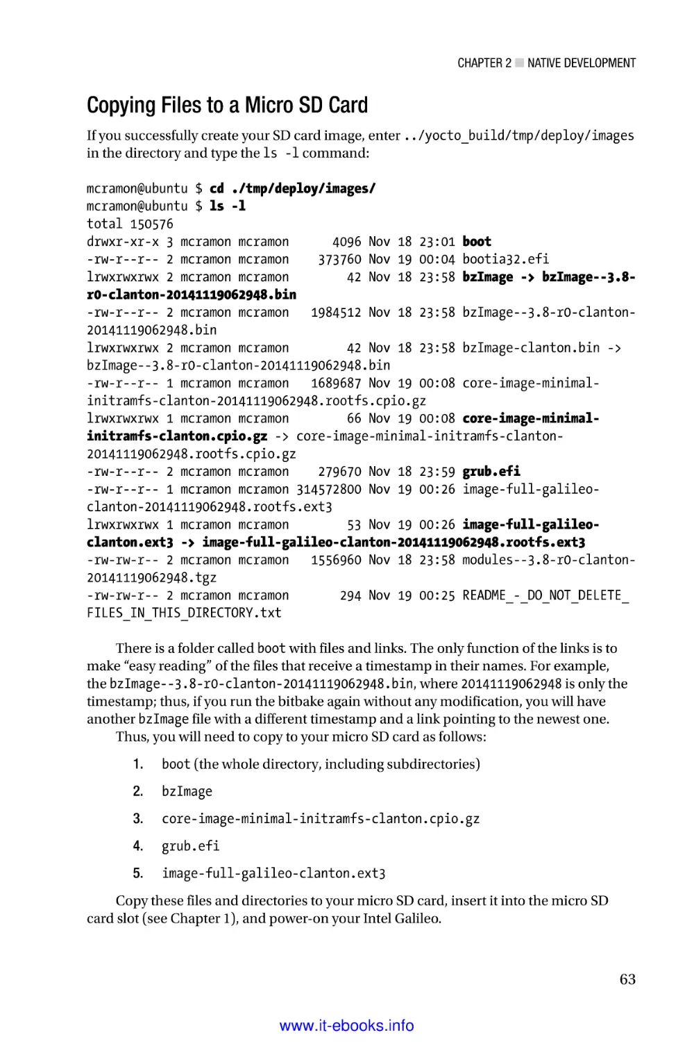
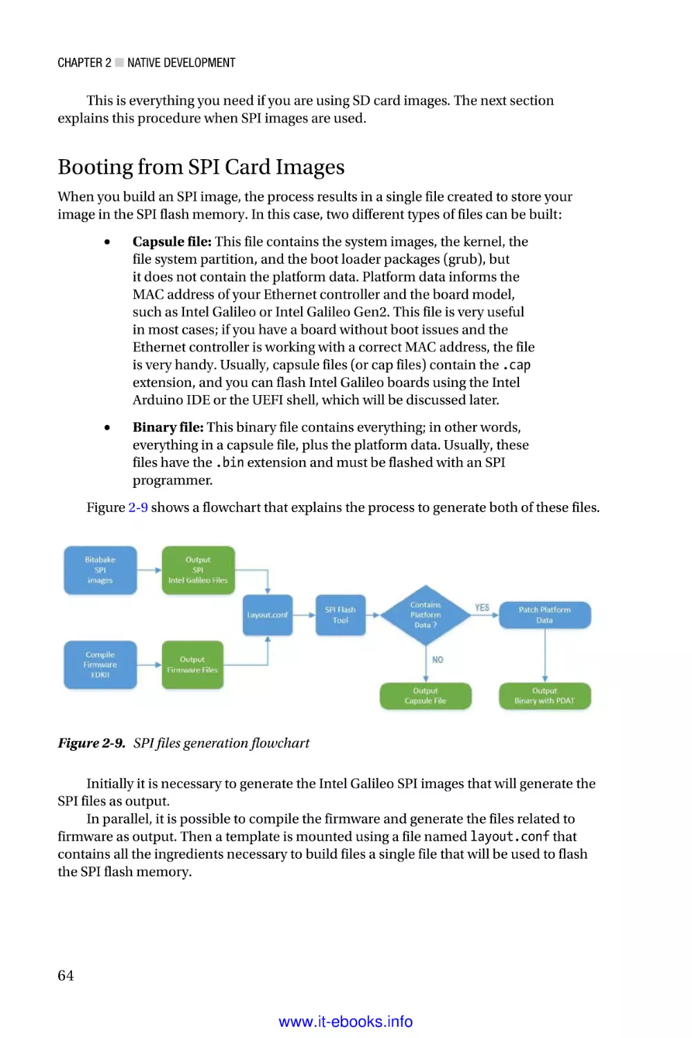
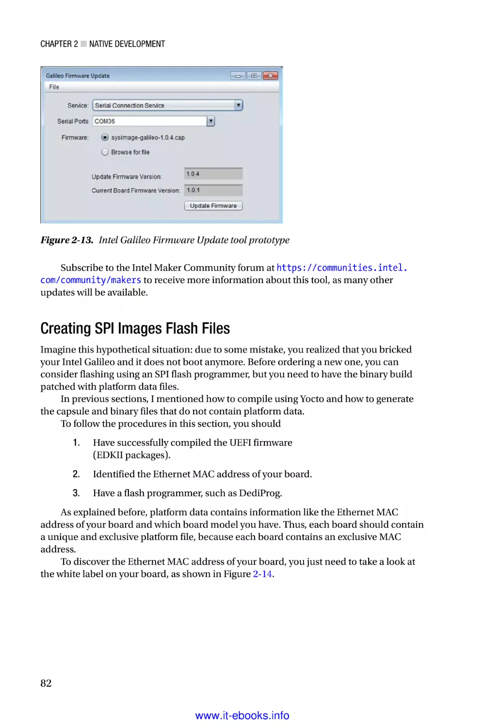
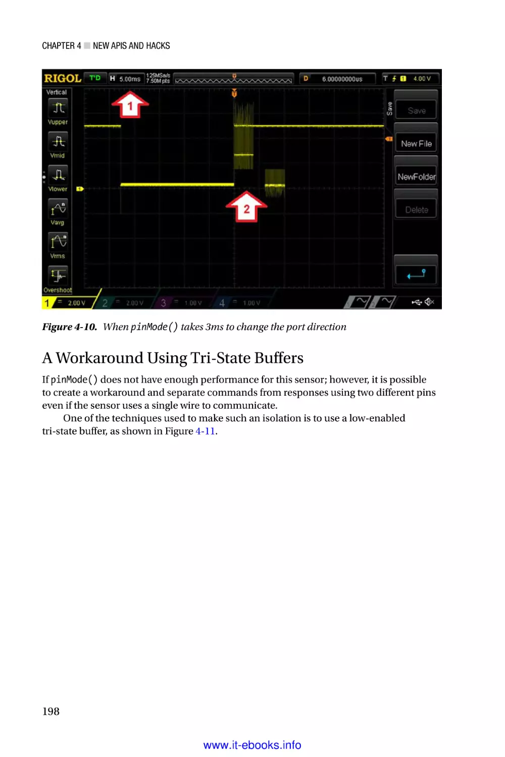
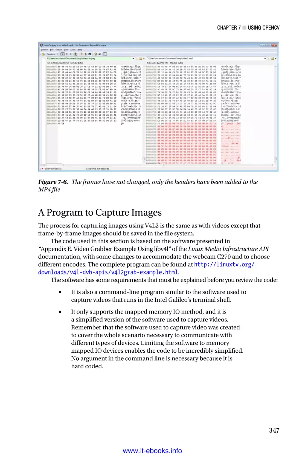
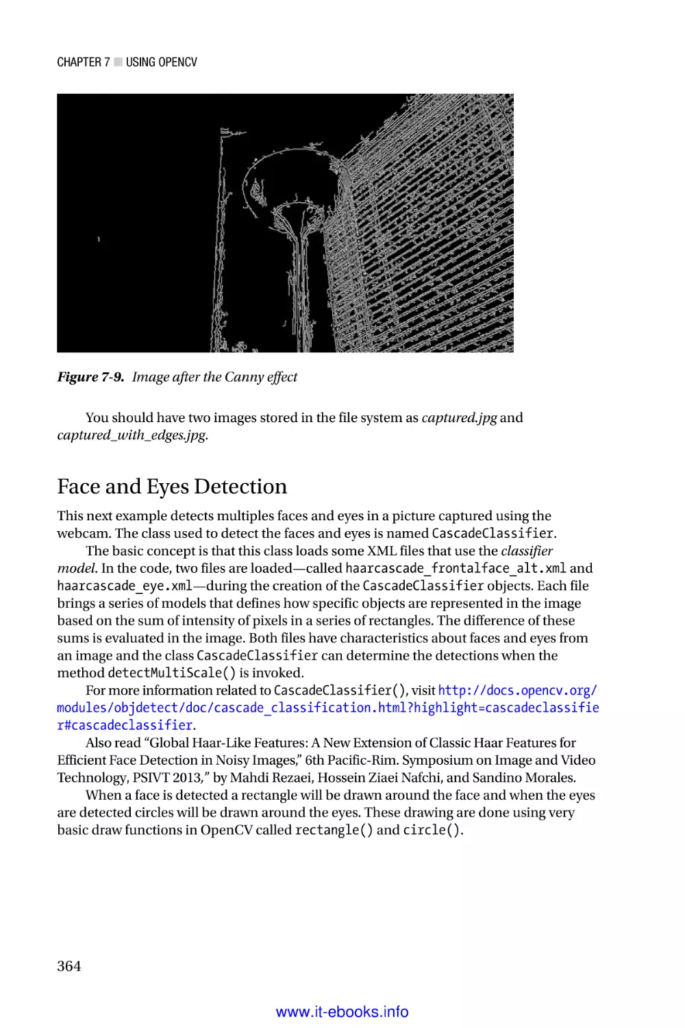
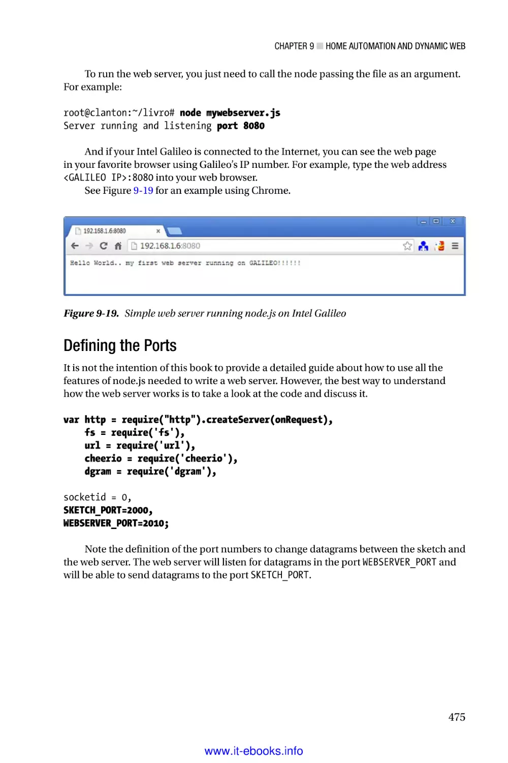
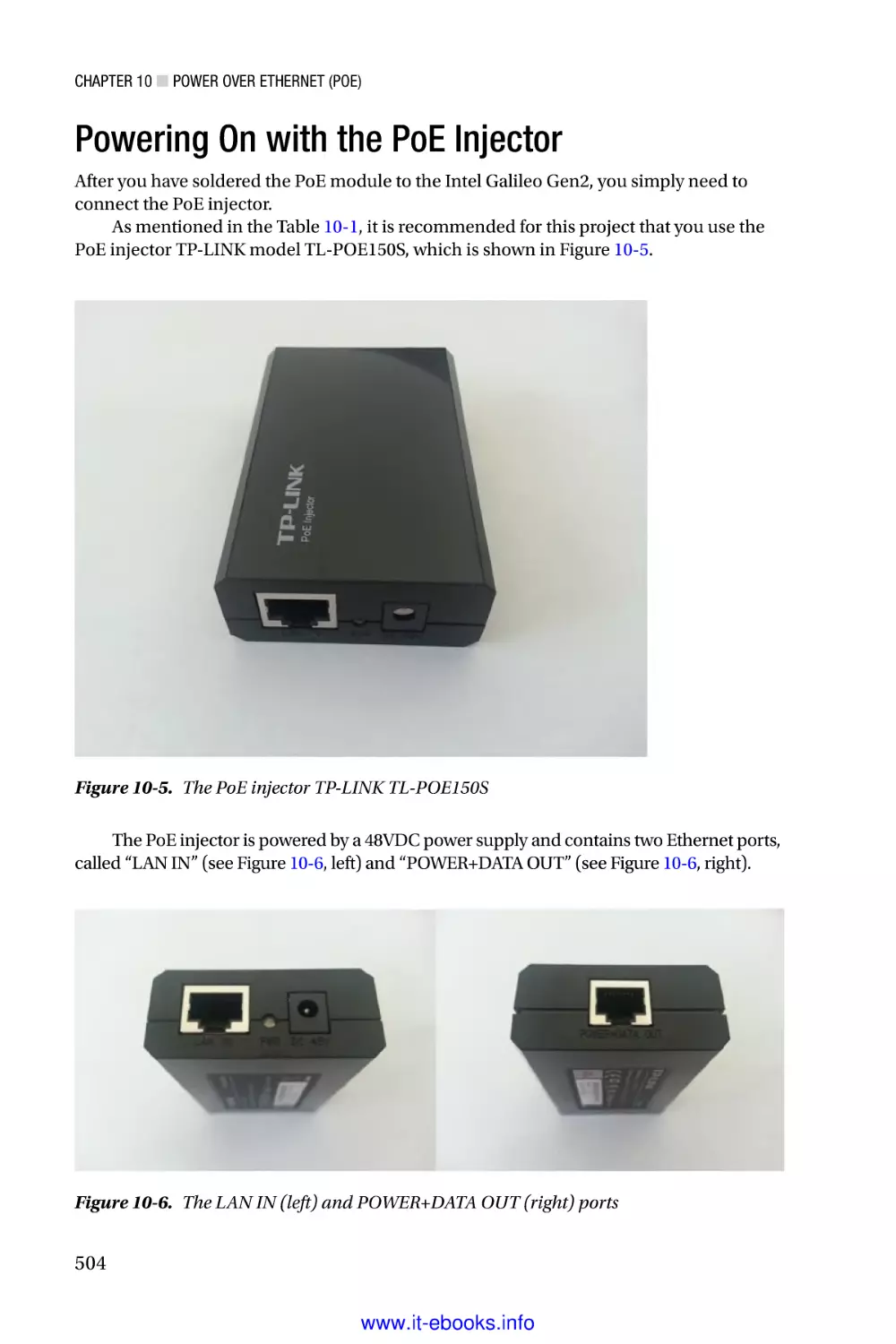
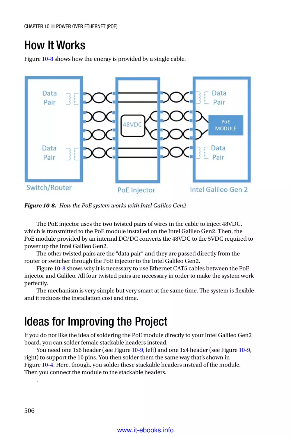
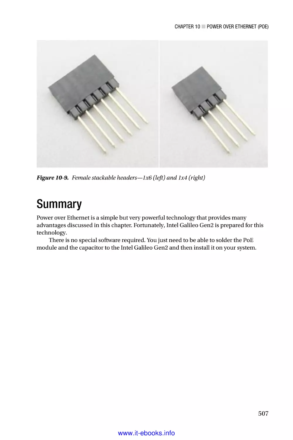
Текст
www.it-ebooks.info
For your convenience Apress has placed some of the front
matter material after the index. Please use the Bookmarks
and Contents at a Glance links to access them.
www.it-ebooks.info
Contents at a Glance
About the Author���������������������������������������������������������������������������� xix
About the Technical Reviewers������������������������������������������������������ xxi
Acknowledgments������������������������������������������������������������������������ xxiii
Introduction������������������������������������������������������������������������������������xxv
■■Chapter 1: Intel Galileo and Intel Galileo Gen 2������������������������������ 1
■■Chapter 2: Native Development���������������������������������������������������� 35
■■Chapter 3: Arduino IDE and Wiring Language������������������������������ 93
■■Chapter 4: New APIs and Hacks������������������������������������������������� 145
■■Chapter 5: Networking and Hacks���������������������������������������������� 217
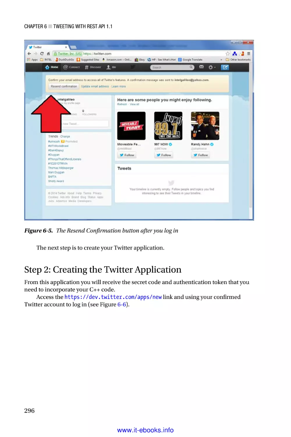
■■Chapter 6: Tweeting with REST API 1.1�������������������������������������� 289
■■Chapter 7: Using OpenCV������������������������������������������������������������ 319
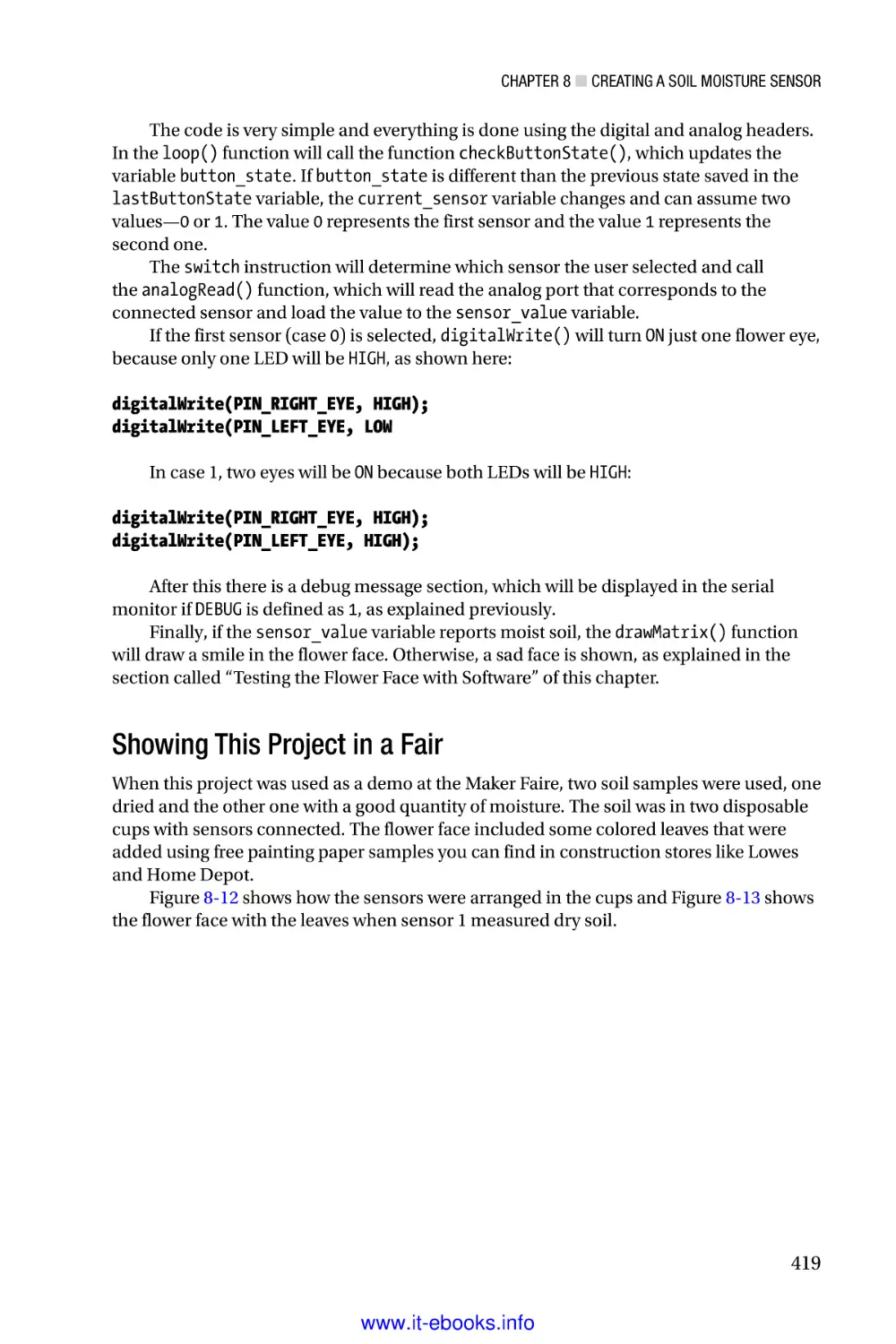
■■Chapter 8: Creating a Soil Moisture Sensor������������������������������� 401
■■Chapter 9: Home Automation and Dynamic Web������������������������ 425
■■Chapter 10: Power over Ethernet (PoE)�������������������������������������� 499
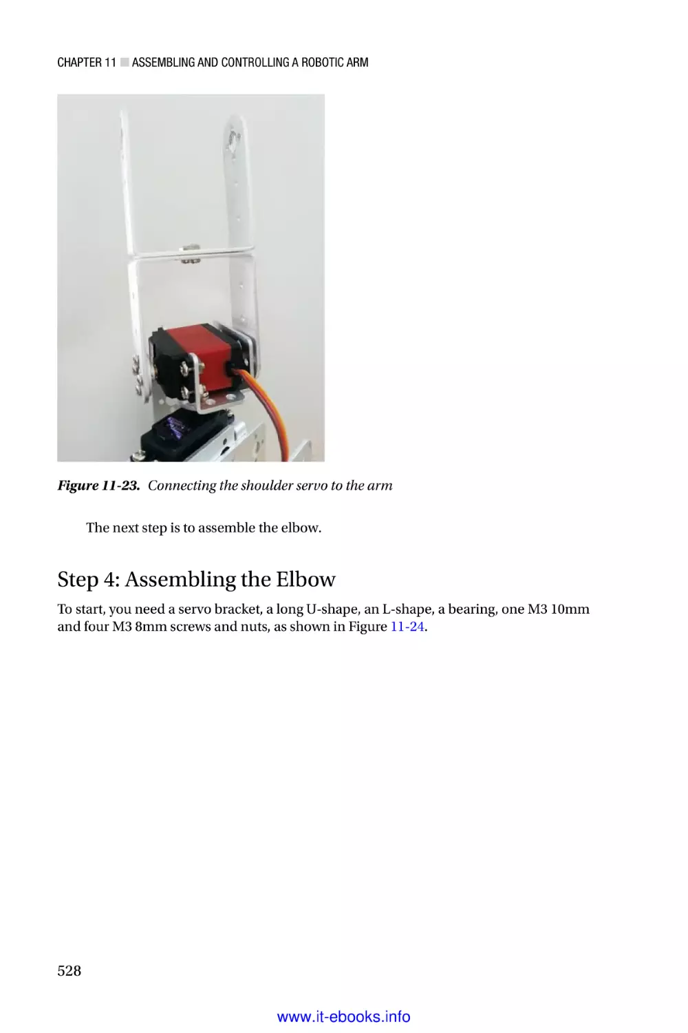
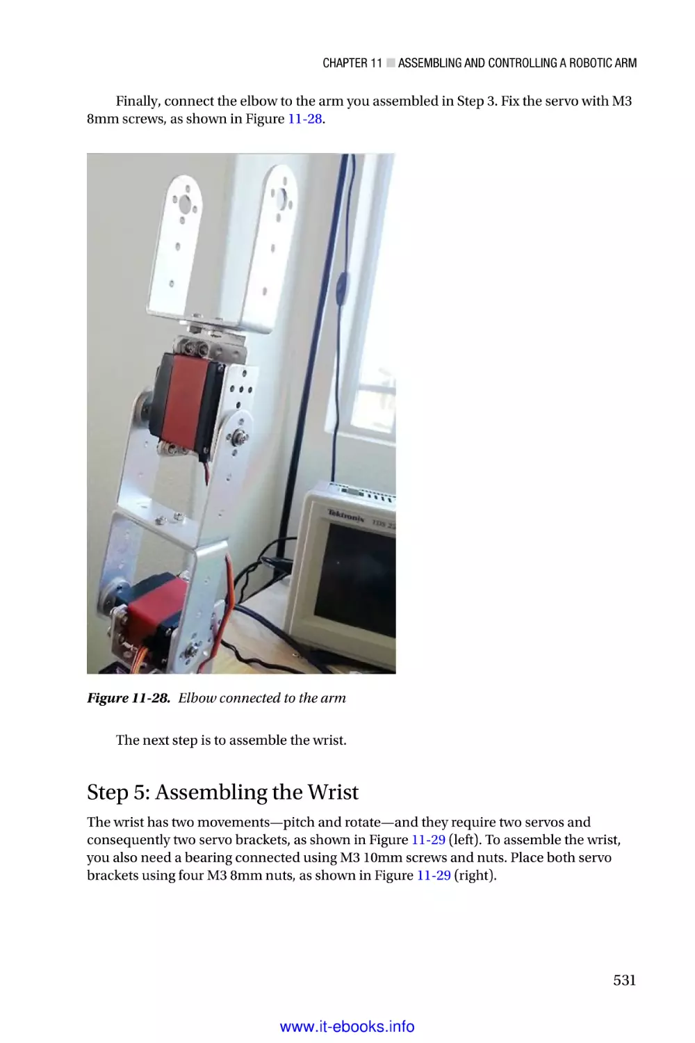
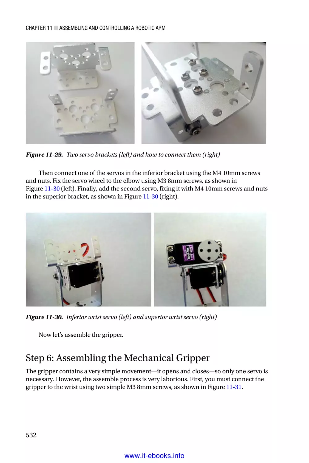
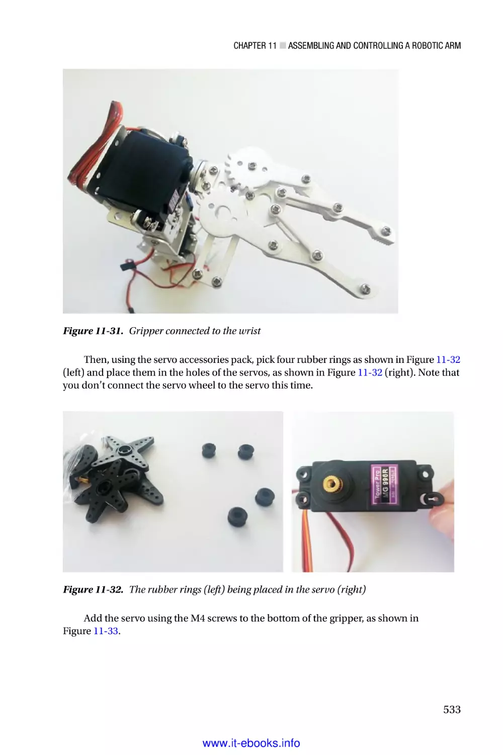
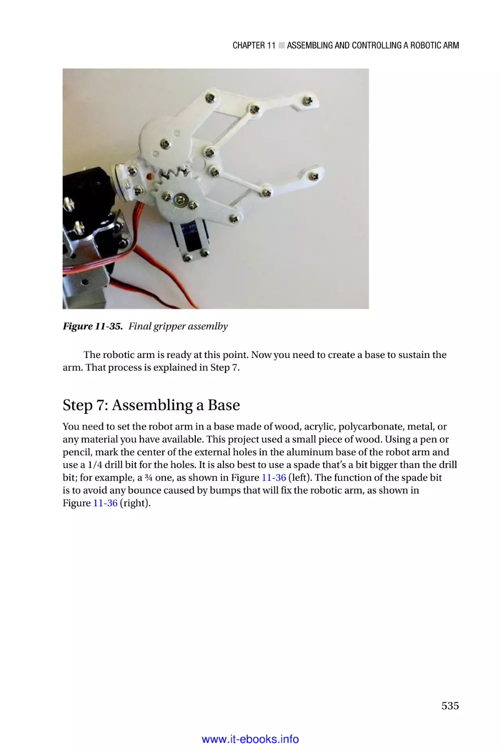
■■Chapter 11: Assembling and Controlling a Robotic Arm������������� 509
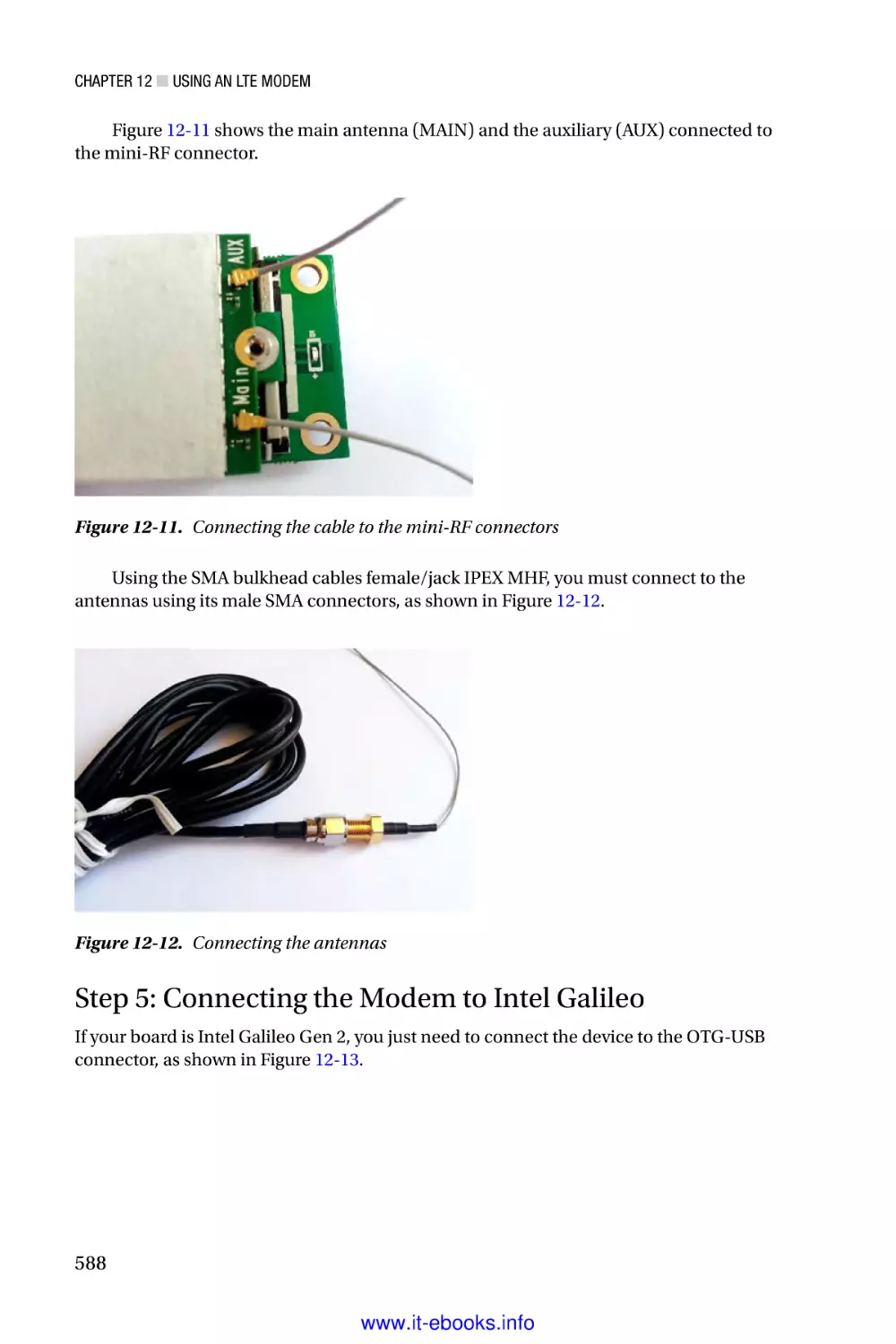
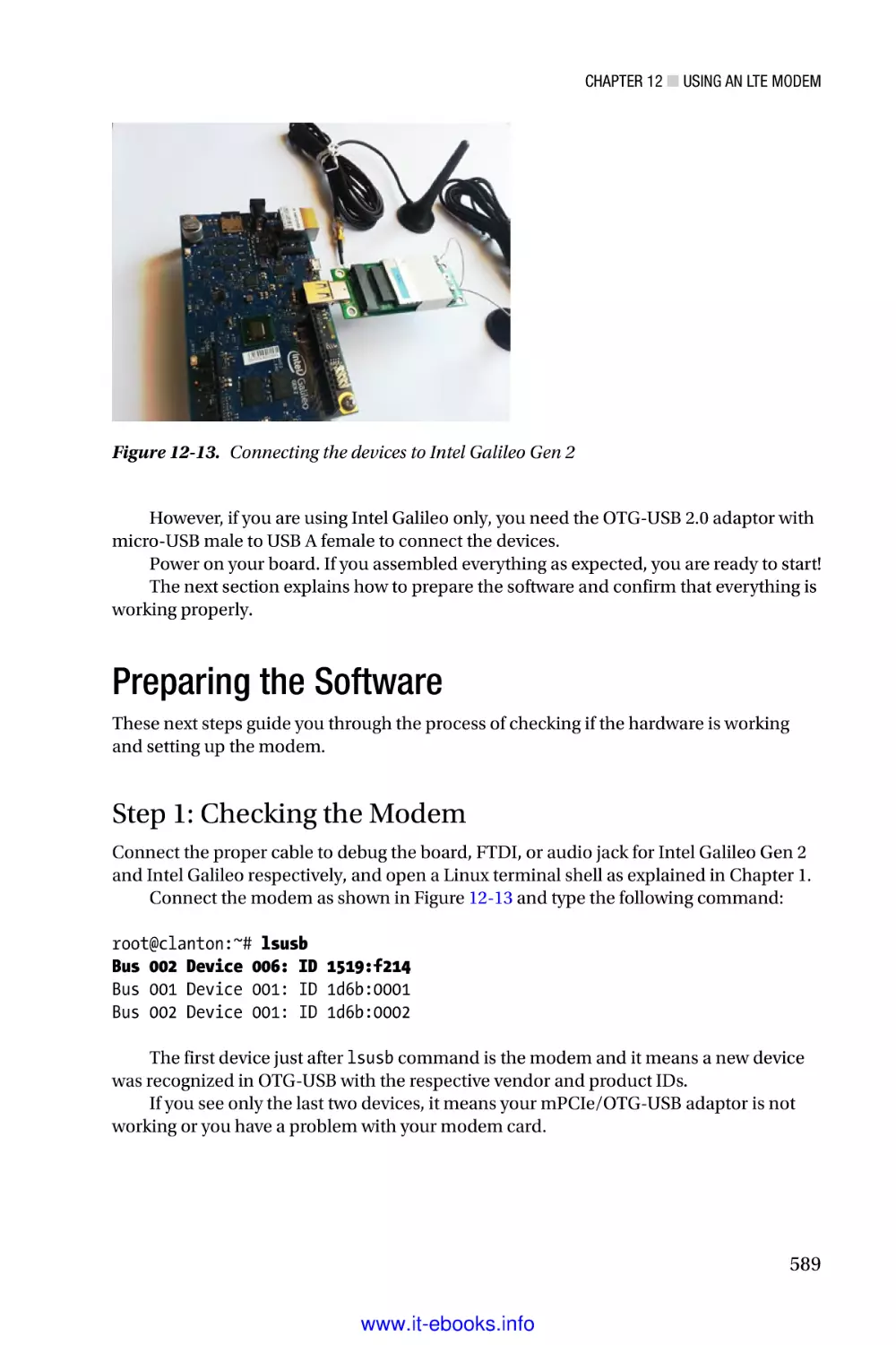
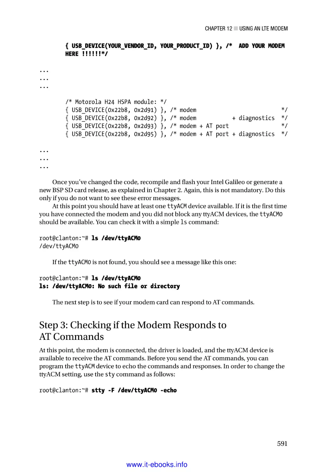
■■Chapter 12: Using an LTE Modem����������������������������������������������� 579
v
www.it-ebooks.info
■ Contents at a Glance
■■Appendix A: Intel Galileo I/O and Muxing����������������������������������� 605
■■Appendix B: Intel Galileo Gen 2 I/O and Muxing������������������������� 611
■■Appendix C: Video Capturing������������������������������������������������������ 617
■■Appendix D: Picture Grabber������������������������������������������������������ 633
Index���������������������������������������������������������������������������������������������� 643
vi
www.it-ebooks.info
Introduction
The Intel Galileo maker development board was announced on October 4, 2013 at the
Rome Maker Fair. It was the first for the Intel Corporation. The board was based on the
Intel Quark SoC X1000 application processor, powered by Linux OS, and compatible with
Arduino reference APIs. The Intel Galileo introduced several extra software and hardware
features that exceeded most other Arduino boards available on the market.
Intel received thousands of feedback comments from makers on Intel’s Maker
forums. Based on this feedback, Intel later unveiled the Intel Galileo Gen 2, a new version
with the same Intel Quark SoC application processor but improved hardware.
This book discusses the hardware and the software for the Intel Galileo and the Intel
Galileo Gen 2, introducing Arduino reference APIs and APIs created especially for Intel
Galileo boards. Practical projects show how to make use of the Linux capabilities and to
aggregate this potential in Arduino sketches.
What Is in this Book?
Chapter 1 discusses the hardware design of the Intel Galileo and the Intel Galileo Gen 2,
as well as the construction of serial and FTDI cables for debugging using Linux terminal
consoles.
Chapter 2 explains how the Yocto build system works and how to generate your
custom SPI and SD card images. It also presents how to compile, install, and use the
toolchains for native applications development, and discusses procedures to recover
bricked Intel Galileo boards.
Chapter 3 shows how to install and use the Arduino IDE, and how to install the
drivers needed in the computer or virtual machine used, running real examples of
interacting sketches with simple circuits. It also brings a practical project that integrates
Python, POSIX calls, and sketches to send an alert when an email is received.
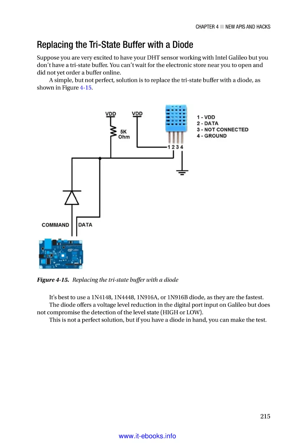
Chapter 4 discusses the new APIs and hacking techniques created especially for the
Intel Galileo and Intel Galileo Gen 2 boards. It contains a broad discussion of clusters
architecture, and how GPIOs are distributed and their respective speed limits. A practical
project demonstrates how to overcome the Intel Galileo’s limitations and how to make
the DHT11 temperature sensor work.
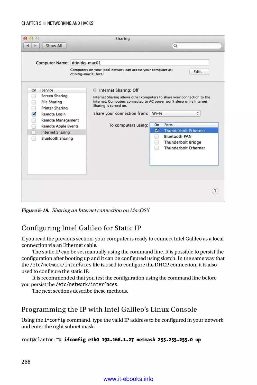
Chapter 5 presents networking APIs and hackings using an Ethernet adapter
and WiFi mPCIe cards. It also explains how to install new WiFi cards and how to share
Internet access between the Intel Galileo and computers. This chapter also explains how
to hack the Arduino IDE to download sketches using network interfaces instead of a USB.
xxv
www.it-ebooks.info
■ Introduction
Chapter 6 offers a practical project on tweeting using Intel Galileo boards with new
OAuth authentication and without intermediary computers or servers. The project uses a
RTC (real-time clock) with external coin batteries and WiFi mPCIe cards.
Chapter 7 shows techniques using V42L and OpenCV libraries, as well as how to
capture images and videos and detect facial expressions and emotions using a webcam.
This chapter also explains how to change the Linux BSD to support eglibc instead uClibc
and to generate the toolchain to compile C/C++ programs. There are also examples of
OpenCV in Python.
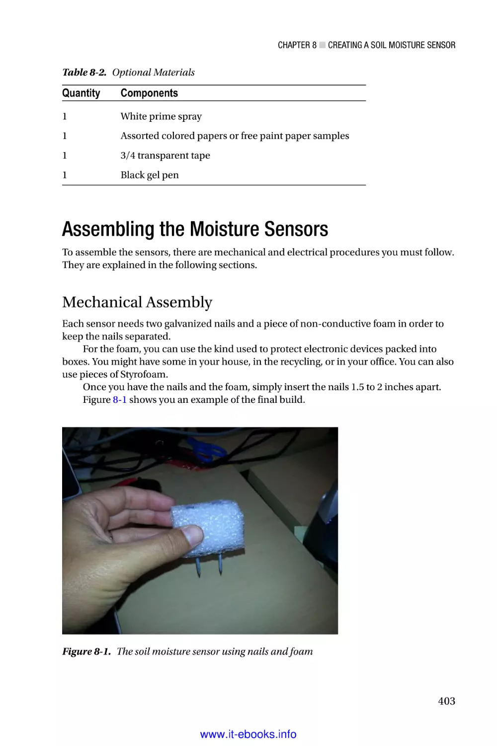
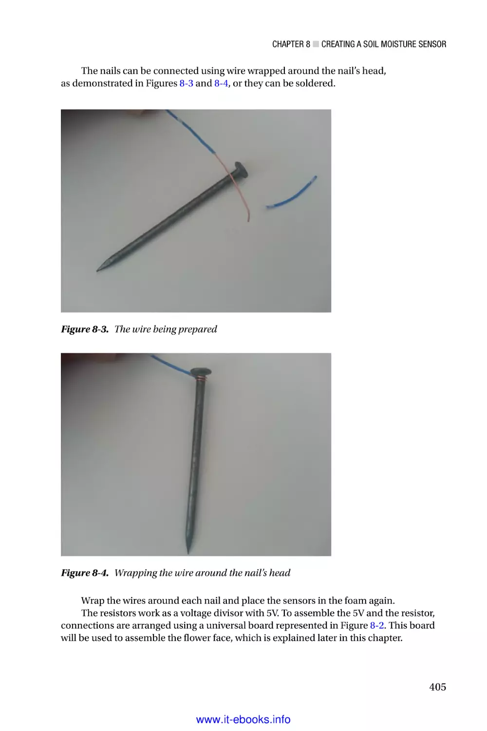
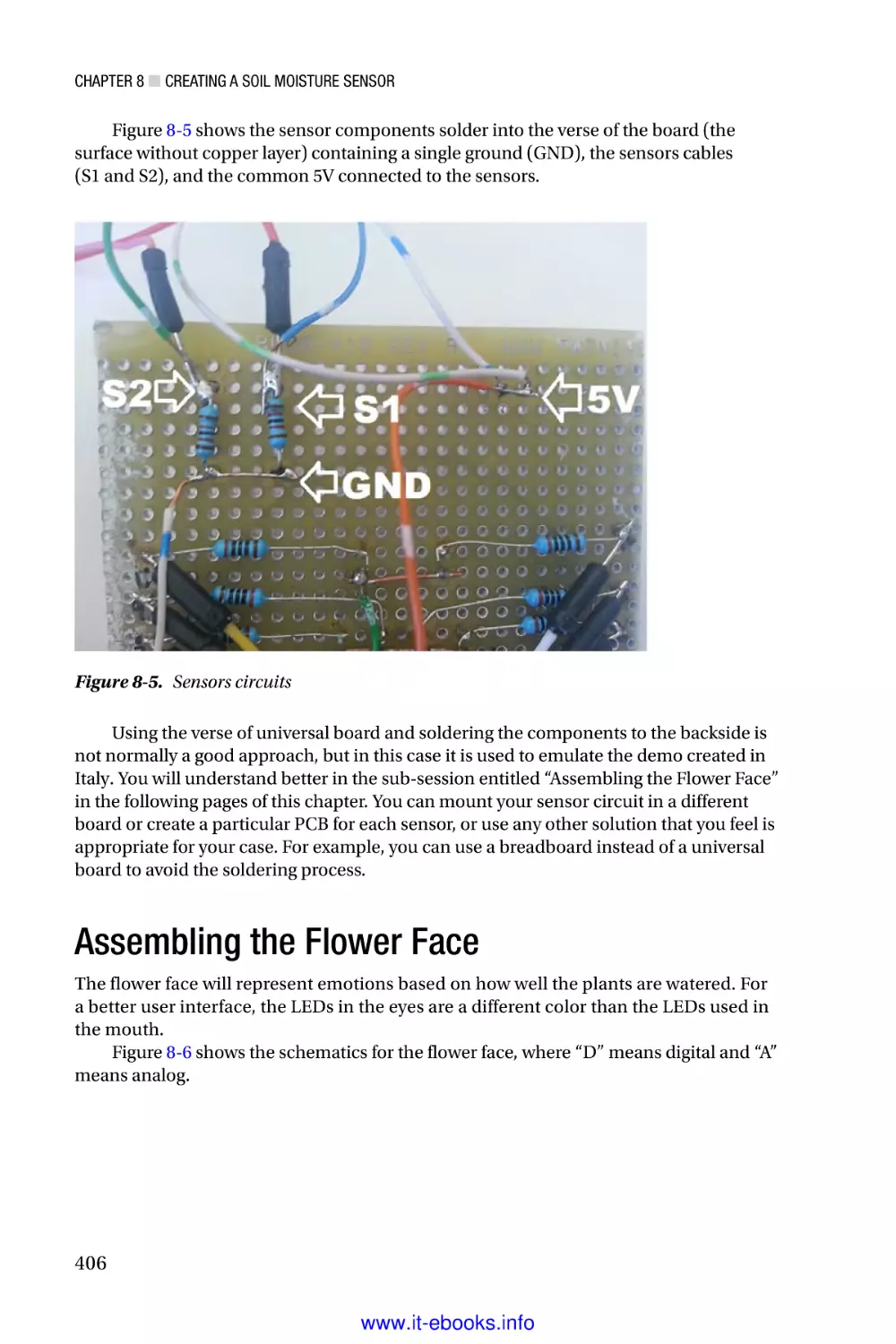
Chapter 8 presents a low-cost project to create moisture sensors based in scrap
materials and galvanized nails.
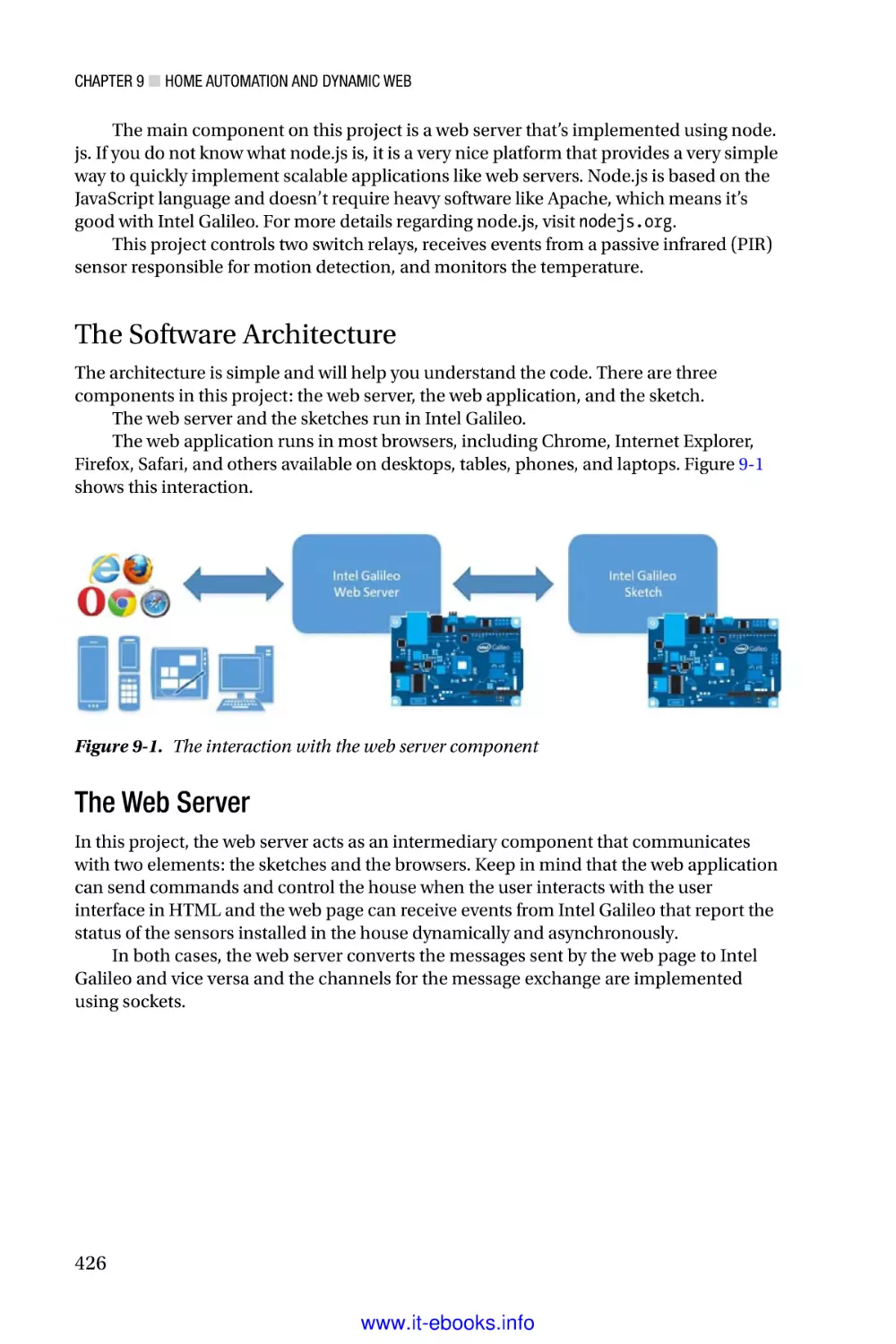
Chapter 9 shows a practical home automation project implementing a web server
using node.js, interacting with multiple sensors for motion and temperature, and using
keypads and switch relays.
Chapter 10 explains how to install and use PoE (Power of Ethernet) modules with
the Intel Galileo Gen 2.
Chapter 11 discusses basic principles in robotics and how to design and control a
robotic arm using analog controllers. It also presents a practical project using a 6 DOF
robotic arm with a mechanical gripper and another one built with ground coffee.
Chapter 12 discusses how to connect a XMM 7160 LTE modem and use data
channels in real networks using Intel Galileo boards.
Chapter 13 is a bonus chapter available online. It presents a practical project
on how to design and build a low-cost robot head with animatronic eyes and
a mouth that expresses emotions. This chapter is available online at
http://www.apress.com/9781430268390, under the Source Code/Downloads tab.
xxvi
www.it-ebooks.info
Chapter 1
Intel Galileo and Intel
Galileo Gen 2
Intel is committed to providing the ultimate processors, boards, and tools to its
community. The first initiative by Intel is the introduction of Intel Galileo and Intel
Galileo Gen 2 boards, which are compatible with the Arduino headers and reference APIs.
They also opened the Intel maker forum and created Intel Arduino IDE.
Intel Galileo boards are open source and open hardware; in other words, all the
source code and hardware schematics are available online, which you can download, use,
and modify.
This chapter describes Intel’s focus on the Galileo boards. With those in your
toolbox, the only other things you need are passion and creativity.
The Beginnings
There are those who believe the social behavior of mankind is directly connected to the
progress of technology.
Walt Disney created his first movie in 1923 in his garage, Steve Jobs and Steve
Wozniak developed the first Apple computer in a garage located at 2066 Crist Drive in Los
Altos, California, Bill Hewlett and Dave Packard founded HP with $500 in a garage, and
the first Harley-Davidson was built in a 10x15-foot wooden garage in 1903. Perhaps the
next greatest invention will be created in someone’s garage.
All of those inventions have a common factor, which is the convergence of different
areas, such as art, mechanics, electronics, and computer science. They involved creativity
and passion.
Inventors are makers, and they have existed since the beginning of time when
our ancestors started creating tools to fish, to hunt, to make fires, and to draw on cave
walls. They created inventions like the wheel and the robot connected to your WiFi that
vacuums your carpet.
All of us are makers because we have all created or developed something to make
our lives easier and faster. Creativity is intrinsic to human nature.
Nowadays, the makers create robots and drones, automate their houses, make devices
to communicate each other, create art that mixes with technology, design and print in 3D
their own objects including musical instruments, and more. Figure 1-1 shows a guitar that
was 3D printed and developed by ODD guitars (http://www.oddguitars.com/).
1
www.it-ebooks.info
Chapter 1 ■ Intel Galileo and Intel Galileo Gen 2
Figure 1-1. A real 3D printed guitar model Atom by ODD guitars
Intel provides new tiny and powerful processors, low power maker boards, and the
tools using the top of technology.
Intel also provides a public Internet forum for makers, not only to support and
answer questions but also to help with personal projects and listen to the community.
They receive valuable feedback that enables them to create a new generation of products
and tools.
Intel Galileo and Intel Galileo Gen 2 are powered by Intel Quark System-on-Chip
(SoC) x1000 at 400MHz, with 512MB SRAM built-in. It runs on an embedded Linux kernel
v3.8 and supports the Arduino reference API and its hardware headers.
The first board, Intel Galileo, was introduced at Maker Fair Rome in October of 2013.
After the feedback received from the maker fair and from others, Intel created the
Intel Galileo Gen 2. It runs on Quark SoC x1000 and has many improvements and features
over the first version, most of which are discussed in this chapter.
About this Book
This book covers the hardware and software in the Intel Galileo and Intel Galileo Gen 2
boards, providing information about how to develop in the Arduino environment, how
to develop natively using regular Linux libraries and the respective cross-compilers, and
how to combine Linux libraries and Arduino code.
This book also explains the Yocto build system, including how to update the board
firmware or generate your own images and prepare your cables for debugging.
If you are not interested in the details about the Linux-native development, you can
jump directly to Chapter 3.
All the projects in this book were planned using affordable parts and materials.
At the end of each project, there is a section entitled, “Ideas for Improving the Project”
that discusses other ideas and covers how to integrate other parts and expand on the
project’s functionalities.
The projects in general are very powerful and include web servers, robot arms,
moisture sensors, LTE modems, and interfacing with different sensors. They all describe
how everything works in a step-by-step manner, as well as how to debug and run
the project.
2
www.it-ebooks.info
Chapter 1 ■ Intel Galileo and Intel Galileo Gen 2
Each project also includes the source code and the schematics, which can be
downloaded from apress.com.
The schematics were created using a tool called DipTrace, which can be downloaded
from http://www.diptrace.com/. This tool is freeware when limited to 300 pins and
two layers; this limitation is more than enough to support the schematics in the book’s
projects.
The schematic files created in DipTrace have the .dch extension. However, when you
open the schematics in the DipTrace tool, you will see there are some male and female
jumper connectors that you don’t see in the figures in this book. The reason for these
connectors is if you decide to use the DipTrace tool to generate your PCB instead of using
the breadboard or a universal board, you will not need to add them by yourself because
they are already present. Thus, you have a clear and easy view of the schematics and you
can have the complete schematic to generate PCBs if you want.
Some projects, like “Home Automation with Node.js,” do not compose a single
project with a single code and schematic but instead make up several micro-projects, like
the integration of keypads, PIR (Passive Infra-Red) sensors, temperature sensors, switch
relays, and a web server that you can use individually. These projects include separate
source code and schematics for each part.
Some of the images in this book were created using an open source tool called
Fritizing. You can download it at http://fritzing.org/home/.
Why Use Intel Galileo Boards?
Depending on the nature of your project, you can get powerful processing and save a lot
of money if you use the regular Arduino boards based on only on microcontrollers.
To get a clear idea why you should use the Intel Galileo boards, assume you need to
develop a project with the following requirements:
•
Save information to the SD card for logging.
•
Connect and transmit the data collected using the Internet.
•
Users must be able to transmit log files and monitor logs files on
demand. So, a web server must be developed.
•
A specific USB peripheral like a webcam will be used and your
Arduino board will be a host. The images captured by this
webcam will be part of the data to be transmitted.
•
The Internet access must be set up using Ethernet or WiFi
connections. You must have the correct time and date for the data
you are logging in the SD card, even when your board reboots and
the system is restored, so a Real Time Clock is needed (RTC).
If you think these requirements are complex, keep in mind that they are common
requirements when you want to create a home automation, build a robot that allows you
to control remotely, build a surveillance system, or monitor your garden soil, for example.
With these requirements in mind, let’s compare the cost of using Intel Galileo boards
versus a regular Arduino Uno.
3
www.it-ebooks.info
Chapter 1 ■ Intel Galileo and Intel Galileo Gen 2
The Software Advantages
The default image of Intel Galileo Flash comes with Linux 3.8 and with libraries in the
user space for integrating the Arduino wiring platform.
Arduino in the context of the Intel Galileo family runs in the Linux kernel user space
and is integrated with IDE, which runs in your personal computer with Windows, Linux
or Mac OSX.
Using Linux, developers can build native applications, install device drivers, create
their own drivers, change the Linux kernel configuration to accommodate new features,
build their own kernel, use the POSIX libraries, and even change and install a new Linux
distribution like Debian.
The details about the Linux-embedded image, kernel customization, and toolchain
are discussed in Chapter 2. The details regarding the Arduino wiring platform is covered
in Chapter 3.
You might wonder why purchase Intel Galileo versus other Arduino boards. The
Linux board that supports the Arduino system comes with a microcontroller that executes
AVR code and runs the Arduino code called sketches. The microcontroller on these
boards is responsible for handling the Arduino headers and only communicates with
Linux OS using bridges. This means developers and students have to use specific classes.
In other words, in such boards, the microcontroller is responsible for running the sketch,
not Linux OS. The communication between the microcontroller and Linux depends on
special mechanisms.
With Intel Galileo boards, the Linux OS is responsible for handling all the digital
and analogic Arduino headers, thereby avoiding special class and bridges. Therefore, the
Arduino code (called sketches) can integrate Arduino APIs with Linux APIs without any
problem.
Another important point is that it’s possible to run more than one sketch at same
time with Intel Galileo. The board with the microcontroller runs only one sketch at a time.
Returning to the idea of this fictitious project, you can use the Linux distribution
in the SD card that comes with node.js for the web server. It has WiFi drivers; you can
count on Python and bash support if you decide to create scripts in your software, you
can use the SD card to store the data until 32GB, and you can easily combine Linux calls
and library API with the regular Arduino wiring platform. Regarding the webcam, you just
need to make sure you have the appropriate driver installed.
The Hardware Advantages
Consider the common built-in components that are present in both boards that would be
used in the fictitious project described in this chapter:
•
Ethernet port
•
USB host connector
•
Micro-SD card capable until 32GB
•
Mini-PCIe connector
•
RTC maintained by coil battery
4
www.it-ebooks.info
Chapter 1 ■ Intel Galileo and Intel Galileo Gen 2
All the requirements for this imaginary project are attended by the Intel Galileo
boards. If you want to connect to the Internet, you can use a simple Ethernet cable. If you
need WiFi you can buy a mini-PCIe Intel Centrino N135 WiFi card, mPCIe card bracket,
and antennas. Table 1-1 shows the average costs of these items.
Table 1-1. Mini-PCIe WiFi Card and Accessories
Description
Cost in U.S. Dollars(*)
Intel Centrino WiFi N135
$8.00
mPCIe card brackets
$5.00
Antennas with connectors
$7.00
Intel Galileo
$55.70
* Cost based on the average price on 3/18/2014 from several sites in the United States.
If you decide to use an Ethernet connection, the only cost is the Intel Galileo board.
Otherwise, if you decide you need a WiFi connection, you have an additional of $20.00 to
the Intel Galileo board, for a total of $75.70.
Now, suppose you want to compare the total cost of your project if you have an
Arduino Uno and decide to buy some shields to meet the project’s requirements.
To reach capabilities similar to Intel Galileo family, the shields listed in Table 1-2 are
necessary.
Table 1-2. Average Cost of the Arduino Shields
Description
Cost in U.S. Dollars(*)
Ethernet
$25.00
SD card/datalogger
$60.00 for 32GB
RTC
$5.00
USB host
$26.00
WiFi
$89.95
Arduino Uno R3
$27.00
* Cost based on the average price on 3/18/2014, from several sites in United States.
The total cost using Arduino Uno with Ethernet only is $143.95 and if you decide to
use Arduino with the WiFi shield it’s $270.95.
As you can evaluate, the same project with Intel Galileo costs $75.70 with WiFi
support versus $270.95 with Arduino Uno R3. This same project with Arduino Uno R3 and
all shields necessary costs 3.58 times more, besides the fact you will not have access to a
powerful Linux-embedded OS, which offers many software resources.
Of course, if your project only requires blinking LEDs, read buttons states, and very
simple things, the Arduino R3 is more affordable.
5
www.it-ebooks.info
Chapter 1 ■ Intel Galileo and Intel Galileo Gen 2
Hardware Overview
Intel Galileo Gen 2 was created to improve on some of the limitations of Intel Galileo.
These details will be explained in the following sections, with an overview on the Quark
SoC X1000 processor, Intel Galileo, and Intel Galileo Gen 2 boards.
The Processor: Intel Quark SoC X1000
Intel Quark SoC X1000 is a 32-bit processor designed for lower power consumption. It’s
x86 compatible with Pentium opcode instructions but implements features like ACPI
(Advanced Configuration and Power Interface) and includes several interfaces that
provide connections with external peripherals. Intel Quark competes directly with ARM
A and M class-based products and is the first Intel initiative to merge into the “Internet of
Things” (IoT) and the wearable market.
Intel Quark SoC X1000 is code-named Clanton and is shown in Figure 1-2.
Figure 1-2. The Quark SoC X1000
Although the package is only 15x15mm, this tiny processor also offers an interface
that allows you to connect to several peripherals, including Bluetooth devices, ZigBee,
SD/SDIO/eMMC cards, I2C devices, and USB2 host and device ports. It also handles
GPIOs interruptible or not by settings, supports temperature ranges that reach industrial,
medical, and military applications (not to mention an internal programmable thermal
sensor), and can run unmodified Linux kernel v3.8+. Figure 1-3 shows the peripherals
supported by Intel Quark SoC.
6
www.it-ebooks.info
Chapter 1 ■ Intel Galileo and Intel Galileo Gen 2
Figure 1-3. Peripheral support of Intel Quark SoC X1000
The following list contains more details regarding the processor:
Processor Core
•
Single Quark CPU core, single thread, 32 bits X86, at 400MHz
Processor UnCore
•
DDR3 memory controller up to 2GB at 800MTS and ECC-On-Chip
•
Embedded 512KB RAM and 16KB cache
•
Supports legacy blocks: PC Compatible: IO ports, PCI, ACPI, and
so on
•
Low-cost 10-pin JTAG
I/O Specifications
•
Two 10/100MB Ethernet MACs
•
Two USB2 host ports (EHCI and OHCI)
•
Two HS UART controllers
•
One SPI port for peripherals
•
One USB2 HS device port
•
One SD/SDIO/EMMC interface
•
One I2C/GPIO controller
•
Sixteen GPIOs with programmable interrupts (edge)
7
www.it-ebooks.info
Chapter 1 ■ Intel Galileo and Intel Galileo Gen 2
Software Support
•
Pentium ISA compatible (.586 opcodes)
•
Standard ICC/GCC/G++ compilers
•
Yocto project based on distribution
•
Open source UEFI EDK II
•
GRUB boot loader support
•
Open OCD debugging support
•
Compliant with PCIe, USB, and ACPI standards
•
Runs Linux kernel v3.8+
Thermals
•
External temperature ranges from -40 to 85 degrees Celsius
•
Internal programmable thermal sensor
Security
•
Supports secure boot technology
•
Supervisory mode execution/protection
•
Secure recovery for UEFI FW
•
Secure remote upgrade with WR IDP 2.0
The next sections explore the Intel Galileo boards in more detail.
Introducing Intel Galileo
Intel Galileo is the first generation and hence has some limitations that are discussed in
this section.
The complete set of documents for Intel Galileo—including the board user guide, the
IO mappings, the release notes, and the BSP guide—can be found at
https://communities.intel.com/community/makers/galileo/documentation/
galileodocuments.
The intention of this section is not to duplicate the information present in the
documents on this link, but to explain in more detail the most important items that you
need to know to start your projects.
If some information is not provided in this chapter, you are encouraged to search the
information you need on this link. If this link does not provide what you need, you can contact
the Intel Makers community at https://communities.intel.com/community/makers.
Take a look the components on the top of the board, as shown in Figure 1-4 and
Table 1-3.
8
www.it-ebooks.info
Chapter 1 ■ Intel Galileo and Intel Galileo Gen 2
Figure 1-4. Top view of Intel Galileo
Table 1-3. Descriptions of the Main Components
Number
Component
Description
1
Ethernet port
10/100 Ethernet connector
2
RS-232 serial port
3-pin 3.5mm jack (this is not audio)
3
RS-232
RS-232 transceiver
4
USB 2.0 client
USB client connector: a fully compliant
USB 2.0 device controller; typically used for
programming
5
USB 2.0 host
USB 2.0 host connector; supports up to 128
USB endpoint devices
6
SPI Flash
8MB Legacy SPI Flash to store the firmware
(or bootloader) and the latest sketch
7
SPI Flash program port
7-pin header for Serial Peripheral Interface
(SPI) programming
Defaults to 4MHz to support Arduino Uno
shields; programmable up to 25MHz
(continued)
9
www.it-ebooks.info
Chapter 1 ■ Intel Galileo and Intel Galileo Gen 2
Table 1-3.
(continued)
Number
Component
Description
8
Arduino headers
Read the section entitled “Arduino Headers
on Intel Galileo”
9
ADC
Analog-to-digital converter
10
Intel Quark SoC X1000
See the section entitled “The Processor Intel
Quark SoC X1000”
11
ICSP
6-pin in-circuit serial programming (ICSP)
header, located appropriately to plug into
existing shields. These pins support SPI
communication using the SPI library
12
256MB DDR3 RAM
256MB DRAM, enabled by the firmware by
default
13
Arduino headers
Read the section entitled “Arduino Headers
on Intel Galileo”
14
JTAG debug port
10-pin standard JTAG header for debugging
15
GPIO expander
GPIO pulse width modulation provided by a
single I2C I/O expander
16
Micro-SD slot
Supports micro-SD card up to 32GB
17
5V DC power
The board is powered via an AC-to-DC
adapter, connected by plugging a 2.1mm
center-positive plug into the board’s power
jack. The recommended output rating of the
power adapter is 5V at up to 3A
18
Voltage regulator
Generates a 3.3 volt supply. Maximum
current draw to the shield is 800mA
19
Eth PHY
Ethernet physical layer transceiver
20
BATT
3.3V battery terminal used to keep the
internal real time clock (RTC); do not power
the device through these terminals
10
www.it-ebooks.info
Chapter 1 ■ Intel Galileo and Intel Galileo Gen 2
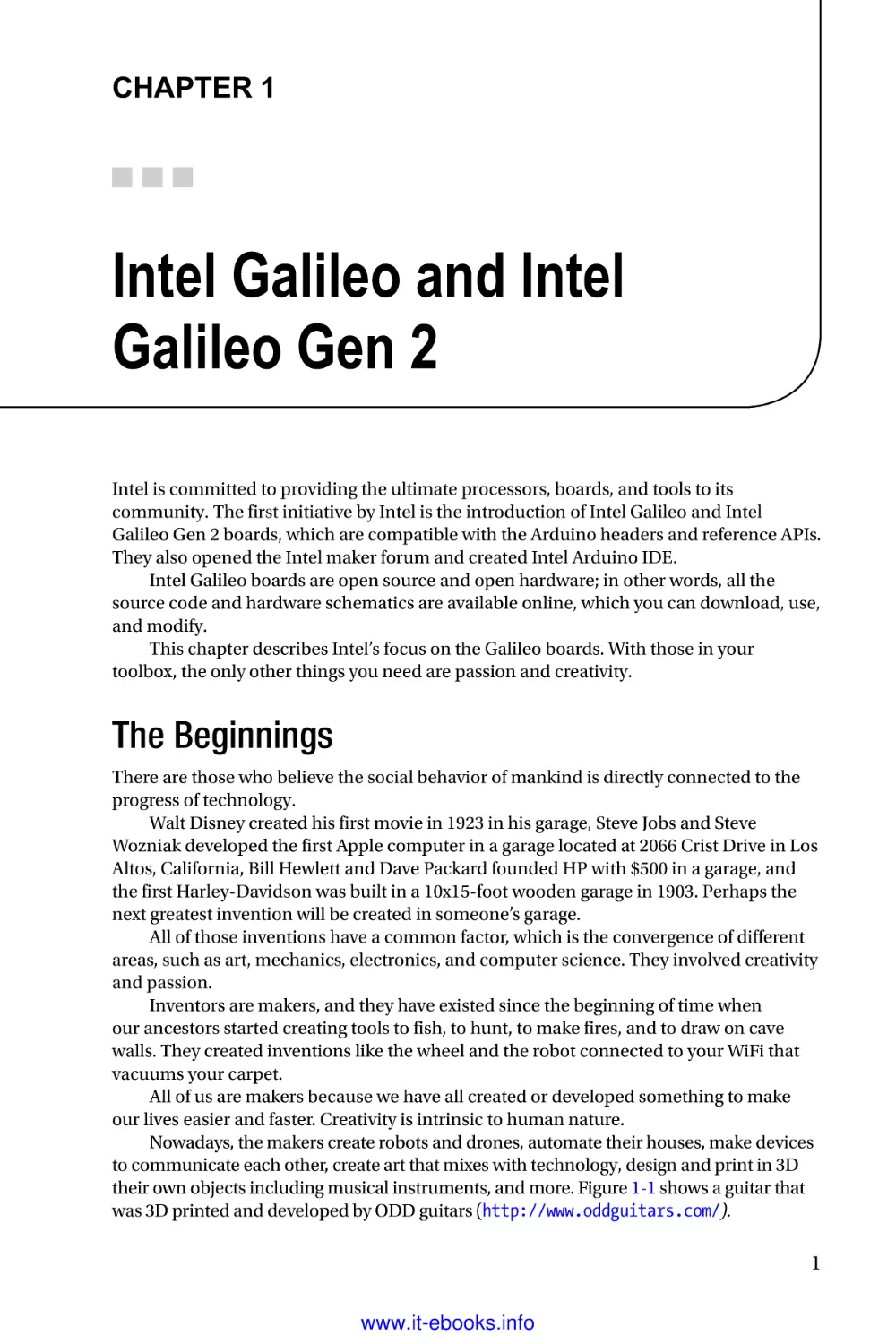
The back view of the board is shown in Figure 1-5.
Figure 1-5. Intel Galileo, bottom view
From Figure 1-5, you can identify the mini-PCIe connector that allows Intel Galileo
to work with full- or half-sized mini-PCIe cards. If you have a half-sized mini-PCIe card,
you need an adapter bracket, which costs around $3.00, as demonstrated in Chapter 5 in
the section entitled “Setting Up the WiFi Mini-PCI-E Card.”
The board dimension is 4.2 inches long and 2.8 inches wide.
Arduino Headers on Intel Galileo
Intel Galileo was the first board developed with Arduino headers compatible to the
Arduino Uno revision 3 called Arduino Interface. You can see it in Figure 1-4. There
are some software functions on the Arduino reference API that are used to manipulate
the digital input and output ports, to generate pulse width modulation (PWM) signals,
to read and write analogic values, to communicate with I2C devices, and to establish
serial interfaces. It is not the scope of this first chapter to provide details about all these
functions. Chapter 3 provides an introduction, but keep in mind that a single pin can be
programmed to assume different functions.
Chapter 3 also contains more details about the pins represented by the bubbles 8
and 13 in Figures 3-10 and 3-11, including how to use these pins with basic functions like
pinMode(), digitalWrite(), digitalRead(), analogRead(), and analogWrite().
11
www.it-ebooks.info
Chapter 1 ■ Intel Galileo and Intel Galileo Gen 2
Fourteen Digital Input/Output Pins (IO2 to IO13, TX, and RX)
Each of the 14 digital pins on Galileo can be used as an input or output. The pins operate
at 3.3V or 5V DC. Each pin can source a maximum of 10mA or sink a maximum of 25mA
and has an internal pull-up resistor (disconnected by default) of 5.6 to 10 KOhms.
Six digital pins can be used as PWM outputs; they are labeled with the tilde (~)
symbol. The pins with this capability are 3, 5, 6, 9, 10, and 11.
The 0 and 1 pins can be programmed for the UART interface, such as RX and TX.
When used as UART, the serial speed is programmable.
Pins 2 and 3 also can be programmed to be used as the UART interface. However,
when they’re used as a serial interface, the Linux serial console will be lost.
There is a speed limitation on I/O ports. Due to the limitation of the sysfs
implementation on Linux kernel v3.8 and the necessity of sending I2C commands to the
Cypress IO expander, there is a delay of 2ms in the ports. This limits the frequency to a
maximum of 230Hz when you set the ports as digital output. However, considering that pin
header 2 and 3 are connected directly to SoC, it is possible to reach 477KHz to 2.93MHz, as
described in Chapter 4 in the section entitled “How to Make Intel Galileo’s I/O Faster.”
I2C Bus Controlled by the SCL and SDA Pins
The I2C or two-wire interface (TWI) can be controlled by A4 or SDA pin and A5 or SCL
pin. Within the Arduino context, the I2C might be programmed easily using the wire
library demonstrated in Chapter 4.
An important observation regarding I2C is that Intel Galileo operates only as a
master device and the internal I2C expander (Cypress IC) runs only in standard
speed (100KHz).
AREF Is Unused
The AD729 A/D is used as internal reference for the analog ports. Thus, external reference
voltage for the analog inputs is not supported and it is not possible to change the upper
end of the analog input range using the AREF pin and the analogReference() function.
Analog Input Pins (A0-A5)
The six analog ports A0 to A5 have a resolution of 12 bits, which counts until 4096. By
default, the analog ports measures from 0V (ground) to 5V.
Power Pins
This bulleted list describes the pins in same order of the headers, from right to left:
•
IOREF: Some shields on the market work with 3.3V or 5V. In order
to select the proper operation voltage level for the Intel Galileo, be
sure to use the jumper tagged IOREF. Note that the jumper on the
left selects 3.3V and the right operation remains set to 5V.
12
www.it-ebooks.info
Chapter 1 ■ Intel Galileo and Intel Galileo Gen 2
•
RESET button/pin: The pin or the Reset button are both used to
reset the Arduino sketch, not the board.
•
3.3V output pin: Provides 3.3V generated by the on-board
regulator with a maximum current drain to the shield of 800mA.
•
5V output pin: This pin outputs 5V from the 5V power supply or
the USB connector. However, it is best to keep the power supply
connected. Maximum current draw to the shield is 800mA.
•
GND (2 pins): Only ground pins.
•
VIN: Instead of using the external and regulated 5V power supply,
you can supply voltage through this pin. However, if this pin is
used, the power supply must also be regulated at 5V. Otherwise, it
might damage the board.
Sink and Source Currents in Outputs
When the pins are set as output, the circuit can provide current (source) or the circuit can
receive current (sink), depending on the device or circuit connected to the ports.
Some developers refer to the source current as the “positive” current and to the sink
as the “negative” current.
Intel Galileo can be used as source or sink, but it is necessary to be aware of the
port’s limitations when used as output.
Each individual pin can provide 10mA as source or 25mA as sink. Combined pins can
have 40mA as source until 200mA but everything depends on how they are combined.
Table 1-4 explains the limits when used as source and sink in different combinations.
Table 1-4. Source and Sink Current Limits as Output
Combination
Source (mA)
Sink (mA)
Each pin
10
25
Digital pins 3, 5, 9, 10, 12, and 13
40
100
Digital pins 0, 1, 2, 4, 5, 6, 7, 8, 11,
and analog pins A0 to A5
40
100
Digital pins 0 to 13 and analog
pins A0 to A5
80
200
13
www.it-ebooks.info
Chapter 1 ■ Intel Galileo and Intel Galileo Gen 2
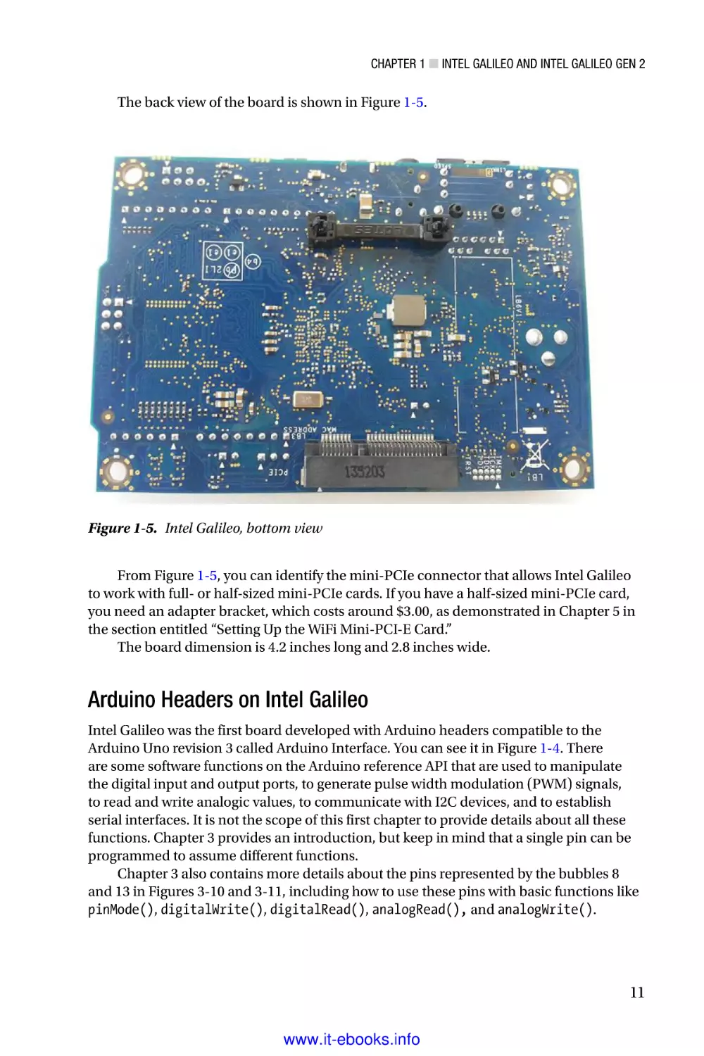
Jumpers and Buttons on Intel Galileo
The board essentially contains three jumpers—IOREF, I2C, and VIN—as shown
in Figure 1-6.
Figure 1-6. Jumpers’ locations and buttons on Intel Galileo
The following sections summarize the functionality of each jumper.
IOREF Jumper
This jumper needs to be changed when your projects use shields that work with 3.3V or 5V.
So, if your shield works with 5V you should connect the jumper in 5V; otherwise, if the shield
works with 3.3V, the jumpers must be set to 3.3V.
It’s important to note that the IOREF jumper does not affect the voltage reference
in the analog input ports. They remain set to 0V (ground) to 5V, regardless of how this
jumper is set.
VIN Jumper
If you keep the VIN jumper, Intel Galileo will receive power from the 5V regulated power
supply connected to the power jack. However, sometimes there are shields that require
more than 5V offered by the power supply. In these cases, it is necessary to remove the
VIN jumper and apply the external and regulated voltage to the VIN headers.
Note that the external power must be regulated and the VIN jumper must be
removed so that you don’t damage your board.
14
www.it-ebooks.info
Chapter 1 ■ Intel Galileo and Intel Galileo Gen 2
I2C Address Jumper
Considering it is possible to connect external I2C slaves as devices to Intel Galileo, this
I2C address jumper was introduced in order to avoid address conflicts between these
external devices and the internal I2C devices (the EEPROM and Cypress GPIO expander).
If you keep J2 connected to pin 1, the one marked with a little white triangle, the
GPIO expander address will be 0100001 and the 7-bit EEPROM address will be 1010001.
If you change the jumper position, the GPIO expander address will be 0100000 and the
EEPROM address will be 1010000.
Reset Button
This button resets the currently running sketch, not Linux itself. You can manually kill the
sketch process and execute it again.
Reboot Button
This button reboots the whole system, including Linux.
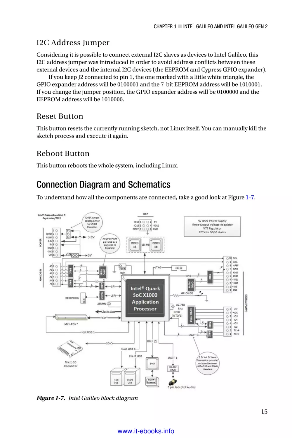
Connection Diagram and Schematics
To understand how all the components are connected, take a good look at Figure 1-7.
Figure 1-7. Intel Galileo block diagram
15
www.it-ebooks.info
Chapter 1 ■ Intel Galileo and Intel Galileo Gen 2
Explanations of Figure 1-7 are detailed here:
•
Although Intel Galileo provides a 3-pin 3.5mm jack, this not used
for audio and in fact causes confusion at first glance, because this
jack is actually used for serial debugging, whereby you can open a
Linux shell. Later in this chapter, you learn how to build your own
cable and access the Linux shell.
•
All pins that support PWM have a tilde (~) in front of their tags.
For example, the pin IO3 has a tilde in front of its name, which
means it supports PWM.
•
The multiplexers (MUX) represented in the diagram are used
because pins might assume different functions. For example, the
pin IO11 might be used as digital input or output or to generate
PWM. The MUX changes the connection of this pin to the
appropriate circuit blocks responsible for each function.
•
Looking at the headers in Figure 1-7, note that IO2 and IO3 are the
only pins connected directly to Intel Quark. All the other IO pins
are connected to the Cypress GPIO expander. This means that
pins IO2 and IO3 are faster and are managed directly by the SoC.
The other IO pins need to be managed through I2C commands
sent to the Cypress GPIO expander, which means they take
more time and reduce performance. Only pins IO2 and IO3 are
interruptible (INT 0 and 1, respectively).
•
There are two micro-USB connectors that work as client and host
interfaces, a 10-pin JTAG connector, a mini-PCIe slot, two DDR3
memory chips of 256MB each, and an SPI interface connected
directly to Intel Quark SoC.
•
The SD card slot uses an SDIO bus connected to Intel Quark and
supports an SD card until 32GB.
•
An interface allows you to update the firmware through the SPI
Flash protocol using a tool called SF100 DediProg. It’s explained
in Chapter 2.
•
Although Intel Quark supports two Ethernet interfaces, only one
is exposed in a RJ45 Ethernet connector.
•
The analog headers are connected to an ADC that uses a highspeed SPI interface.
•
The ICSP (In Circuit Serial Programming) interface is also
supported.
You’ll find the schematics for Intel Galileo in the schematics folder; the file is named
Galileo Schematic.pdf. You can download it from https://communities.intel.com/
docs/DOC-21822.
16
www.it-ebooks.info
Chapter 1 ■ Intel Galileo and Intel Galileo Gen 2
From the schematics, you can check the block diagram represented in Figure 1-7.
You can also check many other details like the bidirectional TXS0108E voltage-level
translators used to convert the header voltage levels, as you can see in Figure 1-8.
Figure 1-8. Bidirectional TXS0108E voltage-level translator
If your intention is to use the board only to connect to external shields and other
peripherals, you do not need to worry about the details in these schematics. The block
diagrams and details explained here cover your needs.
Intel Galileo GPIO Mappings
The GPIO mappings of Intel Galileo can be found in Appendix A.
Introducing Intel Galileo Gen 2
Intel Galileo Gen 2 came about because of the issues identified by the development team
and the feedback received from the makers who contributed to the forums. This is why
your participation in this community is extremely important to Intel. You can access the
Intel maker’s forum at https://communities.intel.com/community/makers.
You can access the complete set of documents for Intel Galileo Gen 2—including the
board user guide, IO mappings, release notes, and the BSP guide—at
https://communities.intel.com/community/makers/galileo/documentation/intelgalileo-gen-2-development-board-documents.
As discussed in the “Intel Galileo” section, the intention of this section is not to
duplicate the information in the documents found on this link, but to explain in more
detail the most important items that you need to know to start your projects.
17
www.it-ebooks.info
Chapter 1 ■ Intel Galileo and Intel Galileo Gen 2
The Intel Quark X1000 SoC was preserved on Intel Galileo Gen 2 as the memory’s
capacity. It also has the same clock frequency, the same analog and power headers
(except for a small improvement in the digital header to allow redirection of UART1 to the
pins IO2 and IO3), and the same I2C and SPI speeds. The next section discusses the new
changes and improvements in detail.
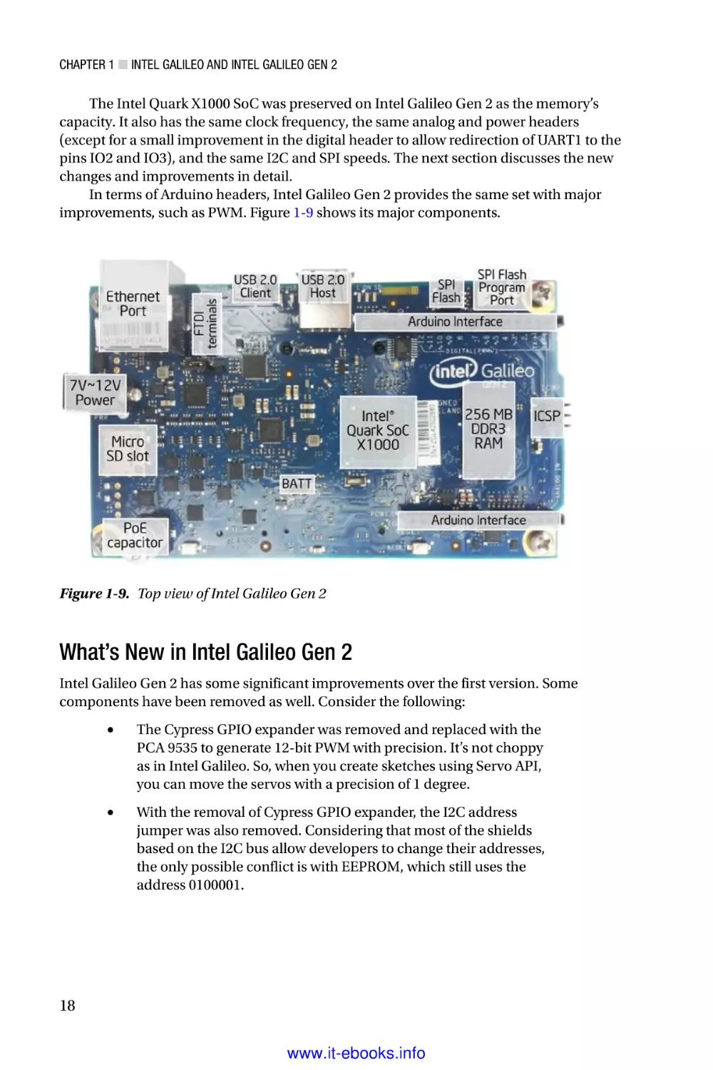
In terms of Arduino headers, Intel Galileo Gen 2 provides the same set with major
improvements, such as PWM. Figure 1-9 shows its major components.
Figure 1-9. Top view of Intel Galileo Gen 2
What’s New in Intel Galileo Gen 2
Intel Galileo Gen 2 has some significant improvements over the first version. Some
components have been removed as well. Consider the following:
•
The Cypress GPIO expander was removed and replaced with the
PCA 9535 to generate 12-bit PWM with precision. It’s not choppy
as in Intel Galileo. So, when you create sketches using Servo API,
you can move the servos with a precision of 1 degree.
•
With the removal of Cypress GPIO expander, the I2C address
jumper was also removed. Considering that most of the shields
based on the I2C bus allow developers to change their addresses,
the only possible conflict is with EEPROM, which still uses the
address 0100001.
18
www.it-ebooks.info
Chapter 1 ■ Intel Galileo and Intel Galileo Gen 2
•
Almost all IO headers are connected directly to Quark SoC,
which means the pins can achieve 2.97MHz. Chapter 4 discusses
the new architecture and all its possible frequencies. With this
new port speed, it’s possible to run shields and sensors that you
couldn’t run using the old version.
•
The board supports the Power over Ethernet (PoE) module, which
wasn’t included in the board. It’s explained in Chapter 10.
•
The client USB connector is still a micro-USB connector but the
host USB has changed to a USB-OTG connector.
•
The power regulator now supports voltage between 7-15V DC.
•
In addition to the IO0 and IO1 pins, which can be used for serial
communication as RX and TX respectively, pins IO2 and IO3
can also communicate serially as RX and TX, respectively. The
problem with using IO2 and IO3 is that the Linux console is lost.
•
The MAX 3232 responsible for converting the RS-232 level to Intel
Quark SoC was also removed. Now it is necessary to use FTDI
cables that are compatible with TTL-232 3.3 V
•
There is no VIN jumper anymore. The VIN is connected directed
to the DC jack, as you can see in Figure 1-10. You can check this in
the schematics discussed in the section.
Figure 1-10. VIN connected directly to power jack DC
•
The board in general is a little bigger compared to Intel Galileo.
It is 4.87 inches long and 2.83 inches wide. The reason it’s bigger
is because some internal voltage regulators on Intel Quark SoC
are not being used anymore, and other external voltage regulators
were added in order to keep Intel Quark SoC cooler.
Figure 1-11 shows the new form factor of Intel Galileo Gen 2 and the new location
of some of the components. Note the buttons have moved and the IOREF jumper is in
a totally different position. Note also the presence of the new OTG-USB connector, the
FTDI terminals, and the capacitor of 47uF, which supports the PoE module.
19
www.it-ebooks.info
Chapter 1 ■ Intel Galileo and Intel Galileo Gen 2
Figure 1-11. The top view of the Intel Galileo Gen 2
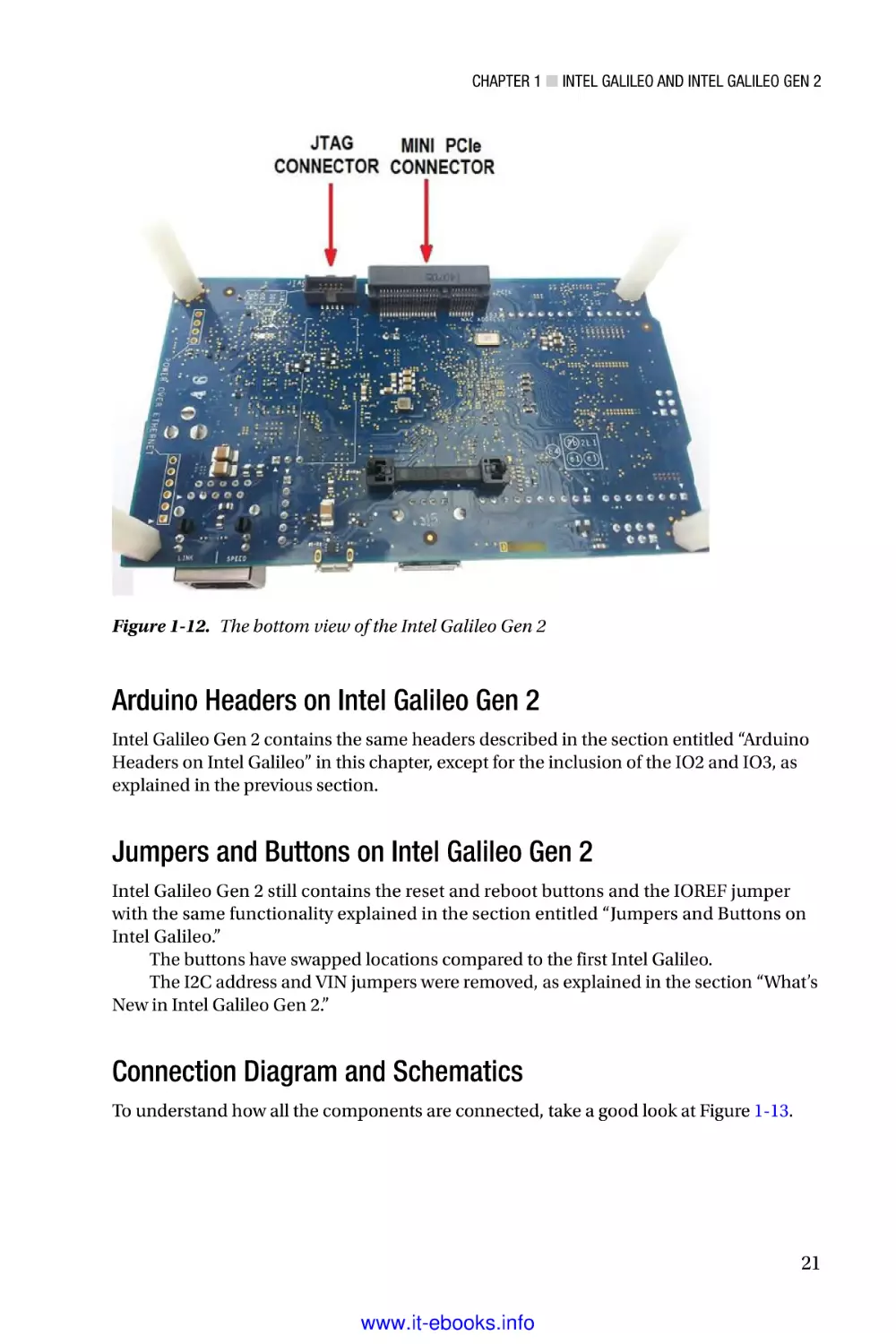
The Intel Galileo Gen 2 preserved the mini-PCIe connector on the bottom, as shown
in Figure 1-12, but the 10-pin JTAG connector was also moved from the top to the bottom
of the board.
20
www.it-ebooks.info
Chapter 1 ■ Intel Galileo and Intel Galileo Gen 2
Figure 1-12. The bottom view of the Intel Galileo Gen 2
Arduino Headers on Intel Galileo Gen 2
Intel Galileo Gen 2 contains the same headers described in the section entitled “Arduino
Headers on Intel Galileo” in this chapter, except for the inclusion of the IO2 and IO3, as
explained in the previous section.
Jumpers and Buttons on Intel Galileo Gen 2
Intel Galileo Gen 2 still contains the reset and reboot buttons and the IOREF jumper
with the same functionality explained in the section entitled “Jumpers and Buttons on
Intel Galileo.”
The buttons have swapped locations compared to the first Intel Galileo.
The I2C address and VIN jumpers were removed, as explained in the section “What’s
New in Intel Galileo Gen 2.”
Connection Diagram and Schematics
To understand how all the components are connected, take a good look at Figure 1-13.
21
www.it-ebooks.info
Chapter 1 ■ Intel Galileo and Intel Galileo Gen 2
Figure 1-13. Intel Galileo Gen 2 block diagram
Consider these issues when you’re looking at Figure 1-13:
•
Intel Galileo Gen 2 provides a terminal with six pins dedicated to
the FTDI cable connection in the TTL level of 3.3V. This terminal
provides access to the Linux console. It replaces the previous
serial audio jack present on Intel Galileo.
•
Like the first Intel Galileo, all pins that support PWM have a tilde
(~) in front of their tags. For example, the pin IO3 has a tilde in
front of its name, which means it supports PWM.
•
The multiplexers (MUX) represented in the diagram are used
because the pins might assume different functions. For example,
the pin IO11 might be used as digital input or output or to
generate PWM, thus the MUX changes the connection of this pin
to the appropriate circuit blocks responsible for each function.
•
The IO header is completely different compared to the first Intel
Galileo. Now, most IO pins are connected directly to Intel Quark
SoC with the exception of IO7 and IO8, which are connected
to the PCA GPIO expander. Consequently, all pins can achieve
2.97MHz except for pins IO7 and IO8, which will achieve the
maximum of 1.8KHz (see Chapter 4 for more details). Note that
pins IO2 and IO3 are the only ones that are interruptible
22
www.it-ebooks.info
Chapter 1 ■ Intel Galileo and Intel Galileo Gen 2
(INT 0 and 1 respectively). Another reason for IO7 and IO8 to be
connected to the GPIO expander is because among the 14 IO pins
on Intel Quark, they are used to reset the mini-PCIe.
•
Note that pins IO2 and IO3 now can be used as serial consoles as
well—IO2 as RX and IO3 as TX. If these pins are used as serial, the
Linux console through the FTDI cable is lost. Read Chapter 4 for
more details.
•
The VIN and I2C address jumpers do not exist anymore.
Many other elements haven’t changed from the first Intel Galileo, such as:
•
There are two micro-USB connectors that work as client and host
interfaces—a 10-pin JTAG connector, a mini-PCIe slot, two DDR3
memory chips of 256MB each, and a SPI interface connected
directly to Intel Quark SoC.
•
The SD card slot uses a SDIO bus connected to Intel Quark and
supports the SD card until 32GB.
•
There is an interface that allows you to update the firmware
through SPI flash protocol using a tool called SF100 DediProg. It’s
explained in Chapter 2.
•
Although Intel Quark supports two Ethernet interfaces only one is
exposed in a RJ45 Ethernet connector.
•
The analog headers are connected to an ADC that uses a high-speed
SPI interface.
•
The ICSP (In Circuit Serial Programming) interface is also supported.
You can find the schematics for Intel Galileo Gen 2 in the schematics folder and the
file is Galileo_Gen2_Schematic.pdf. You can also download them from
https://communities.intel.com/docs/DOC-22895.
Intel Galileo Gen 2 GPIO Mappings
The GPIO mappings of Intel Galileo can be found in the Appendix B.
Preparing Your Cables
Two types of cables are used in this book:
•
A high-speed USB 2.0 male-to-micro USB cable, commonly called
a USB data cable: This cable is used to download, debug, and run
sketches via Intel Arduino IDE. This cable is essential; without it, you
will not be able to run any of the projects in this book. You can use the
same cable on both Intel Galileo and Intel Galileo Gen 2. Figure 1-14
shows this cable. The cost varies between $3.00 and $6.00, depending
on the quality of the cable you order.
23
www.it-ebooks.info
Chapter 1 ■ Intel Galileo and Intel Galileo Gen 2
•
A 3.3V FTDI cable if you have an Intel Galileo Gen 2 or a serial
cable with a stereo jack if you have the first Intel Galileo: As
explained, Intel Galileo and Intel Galileo Gen 2 run embedded
Linux 3.8 on the official releases. You’ll want to access the Linux
console for kernel debugging, to install native applications, to
write Python programs, and so on. Some chapter of this book
utilizes this cable so it is recommended you have it. The details
surrounding these cables are discussed in the sections entitled
“The Serial Cable for Intel Galileo” and “The Serial Cable for Intel
Galileo Gen 2” in this chapter.
There is some confusion between the Arduino serial console, the Arduino serial, and
the Arduino debug terminal. All of these terms are commonly used in the community and
refer to the debug terminal provided by the Arduino IDE. In other words, this is the first
high-speed USB 2.0 A male-to-micro USB cable mentioned earlier.
The next section explains the serial cables you’ll need in order to access the Linux
console after your connection has more than one cable.
The Serial Cable for Intel Galileo
This section is related to the Linux console. In other words, it assumes you have access
to a Linux terminal and can run regular Linux commands directly on your board. In this
case, you’ll use a serial cable with an audio jack adaptor.
This section also explains how to access the serial cable. Gaining access using WiFi
and Ethernet via SSH is explained in Chapter 5.
If your computer contains a RS-232 port, you simply need a serial cable DB9 male
connected to a 3.5mm jack, which costs around $4. If your computer only supports USB,
you need a second cable converter with a RS-232 male connector to USB, which costs
around $9.
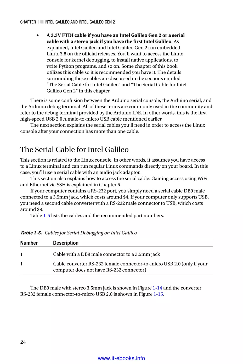
Table 1-5 lists the cables and the recommended part numbers.
Table 1-5. Cables for Serial Debugging on Intel Galileo
Number
Description
1
Cable with a DB9 male connector to a 3.5mm jack
1
Cable converter RS-232 female connector-to-micro USB 2.0 (only if your
computer does not have RS-232 connector)
The DB9 male with stereo 3.5mm jack is shown in Figure 1-14 and the converter
RS-232 female connector-to-micro USB 2.0 is shown in Figure 1-15.
24
www.it-ebooks.info
Chapter 1 ■ Intel Galileo and Intel Galileo Gen 2
Figure 1-14. Cable with a DB9 male connector to a 3.5mm jack
Figure 1-15. Cable converter RS-232 female connector-to-micro USB 2.0
If your computer does not have the RS-232 port, you can also use a single cable
converter with a 3.5mm stereo jack connected to a micro-USB FTDI cable. This cable
costs around $17, but if you order a cable converter RS-232 female connector to
micro-USB and a simple standard stereo audio jack connector (about $1.00), you can
build your own cable with a final cost of $10.
To build your own cable based on a RS-232 to micro-USB converter, remove the
female DB9 connector and replace it with the stereo jack 3.5mm. Follow the connections
shown in Figure 1-16 to do this.
25
www.it-ebooks.info
Chapter 1 ■ Intel Galileo and Intel Galileo Gen 2
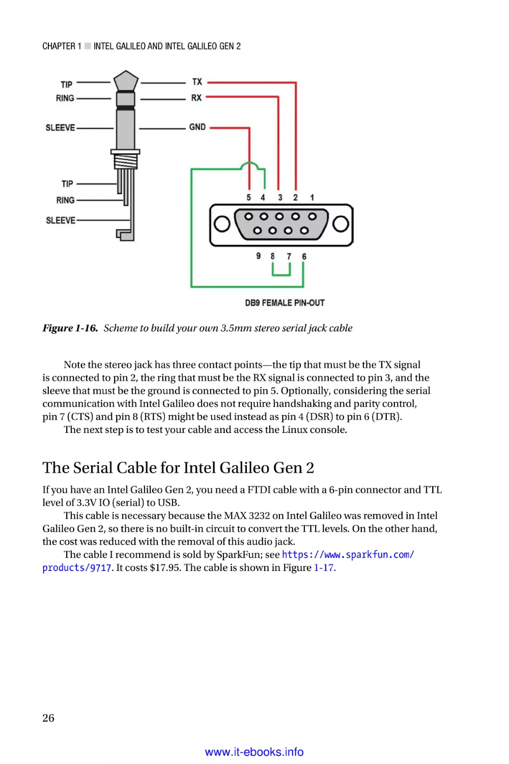
Figure 1-16. Scheme to build your own 3.5mm stereo serial jack cable
Note the stereo jack has three contact points—the tip that must be the TX signal
is connected to pin 2, the ring that must be the RX signal is connected to pin 3, and the
sleeve that must be the ground is connected to pin 5. Optionally, considering the serial
communication with Intel Galileo does not require handshaking and parity control,
pin 7 (CTS) and pin 8 (RTS) might be used instead as pin 4 (DSR) to pin 6 (DTR).
The next step is to test your cable and access the Linux console.
The Serial Cable for Intel Galileo Gen 2
If you have an Intel Galileo Gen 2, you need a FTDI cable with a 6-pin connector and TTL
level of 3.3V IO (serial) to USB.
This cable is necessary because the MAX 3232 on Intel Galileo was removed in Intel
Galileo Gen 2, so there is no built-in circuit to convert the TTL levels. On the other hand,
the cost was reduced with the removal of this audio jack.
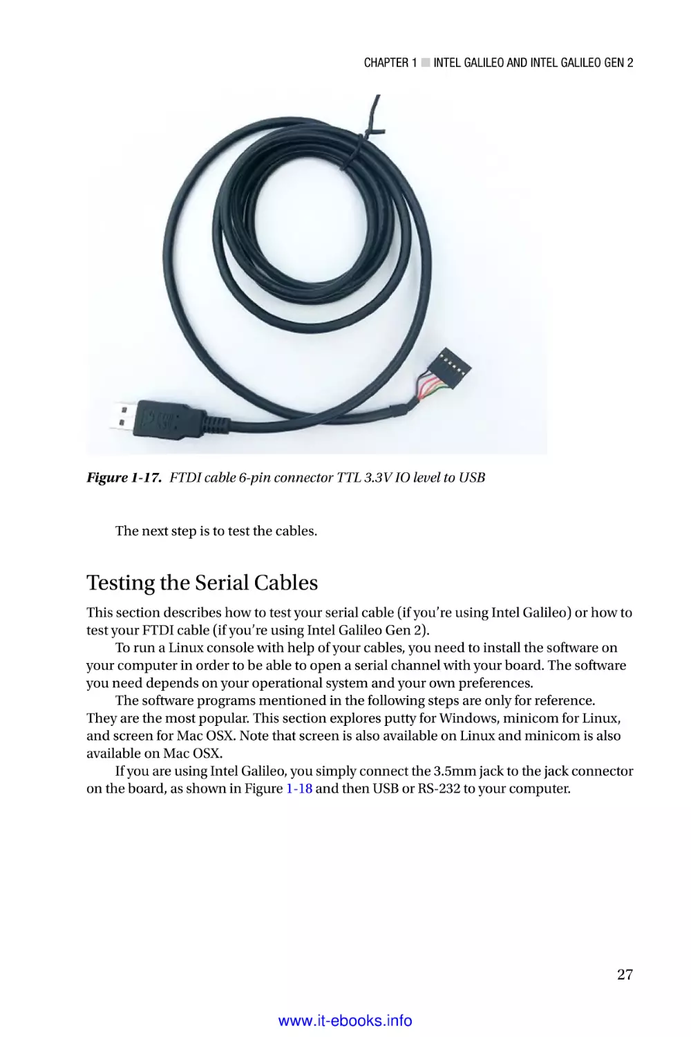
The cable I recommend is sold by SparkFun; see https://www.sparkfun.com/
products/9717. It costs $17.95. The cable is shown in Figure 1-17.
26
www.it-ebooks.info
Chapter 1 ■ Intel Galileo and Intel Galileo Gen 2
Figure 1-17. FTDI cable 6-pin connector TTL 3.3V IO level to USB
The next step is to test the cables.
Testing the Serial Cables
This section describes how to test your serial cable (if you’re using Intel Galileo) or how to
test your FTDI cable (if you’re using Intel Galileo Gen 2).
To run a Linux console with help of your cables, you need to install the software on
your computer in order to be able to open a serial channel with your board. The software
you need depends on your operational system and your own preferences.
The software programs mentioned in the following steps are only for reference.
They are the most popular. This section explores putty for Windows, minicom for Linux,
and screen for Mac OSX. Note that screen is also available on Linux and minicom is also
available on Mac OSX.
If you are using Intel Galileo, you simply connect the 3.5mm jack to the jack connector
on the board, as shown in Figure 1-18 and then USB or RS-232 to your computer.
27
www.it-ebooks.info
Chapter 1 ■ Intel Galileo and Intel Galileo Gen 2
Figure 1-18. Connecting a 3.5mm serial jack cable to Intel Galileo
If your board is Intel Galileo Gen 2, make sure the inline connector connects pin 1
(usually black) to pin 1 of the FTDI connector on the board. This is represented by a little white
triangle shown in Figure 1-19. You’ll connect the other end of the cable to your computer.
Figure 1-19. Connecting the FTDI cable to Intel Galileo Gen 2
28
www.it-ebooks.info
Chapter 1 ■ Intel Galileo and Intel Galileo Gen 2
Windows
The following steps explain how to set up the Linux console on Windows:
1.
After you insert the cable, wait for a few seconds so that the
USB is enumerated. Then open the Windows Device Manager
by choosing Start ➤ Control Panel ➤ Hardware and
Sound ➤ Device Manager. You can also press the Windows
key
and “R” at same time, and then type devmgmt.msc.
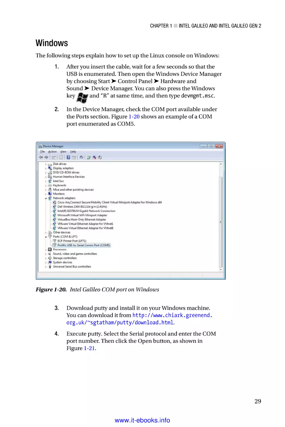
2.
In the Device Manager, check the COM port available under
the Ports section. Figure 1-20 shows an example of a COM
port enumerated as COM5.
Figure 1-20. Intel Galileo COM port on Windows
3.
Download putty and install it on your Windows machine.
You can download it from http://www.chiark.greenend.
org.uk/~sgtatham/putty/download.html.
4.
Execute putty. Select the Serial protocol and enter the COM
port number. Then click the Open button, as shown in
Figure 1-21.
29
www.it-ebooks.info
Chapter 1 ■ Intel Galileo and Intel Galileo Gen 2
Figure 1-21. Configuring putty to open the Linux console
5.
Finally, to access the Linux console, you type username
root and press Enter. You will then have access to the Linux
console, as shown in Figure 1-22.
Figure 1-22. The Linux serial console
30
www.it-ebooks.info
Chapter 1 ■ Intel Galileo and Intel Galileo Gen 2
Ubuntu Linux
The procedure to set up Intel Galileo’s Linux console on a Linux computer is easy. As
mentioned, serial communication on Linux computers is based on the minicom software.
The following steps are necessary to get the Linux console working:
1.
After you insert the cable, wait for a few seconds for the USB
to be enumerated.
2.
Open a Linux terminal. You can press Ctrl+T to do this.
3.
Check the port by typing the command dmesg|grep tty. For
example, Figure 1-23 shows the port enumerated as ttyUSB0.
Figure 1-23. Checking the USB port enumerated on the Ubuntu terminal
4.
Finally, to access the Linux console, you typing the sudo
minicom --device /dev/ttyUSB0 command. The terminal
will open. You need to use the username root.
Mac OSX
The following steps describe how to set up the Linux console on Mac OSX.
1.
After you insert the cable, wait for a few seconds so that the
USB is enumerated.
2.
Open an OSX terminal. You can press z and the spacebar at
same time to open the Spotlight text box. Then type terminal
and press Enter.
3.
In the terminal, check what is the serial port enumerated as
following command:
~$ ls /dev/tty.usb*
/dev/tty.usbserial-A603HVUT
31
www.it-ebooks.info
Chapter 1 ■ Intel Galileo and Intel Galileo Gen 2
4.
Finally, you can access the Linux console by typing
screen /dev/<YOUR SERIAL HERE> 115200 into the terminal.
For example
~$ screen /dev/tty.usbserial-A603HVUT 115200
5.
The console will open. You need to use the username root.
Exploring the Linux Console
Try to run some Linux commands. To check which board you have, you can run the
following command:
root@clanton:~# cd /sys/firmware/board_data/
root@clanton:/sys/firmware/board_data# cat flash_version
0x01000300
As you can see, when this chapter was written, my board was using firmware 1.0.3.
The hexadecimal sequence is decoded as 01.00.03.00, 01.00.03, or 1.0.3, as expected.
A second interesting test is to check your platform name. Run the following
commands if your board is Intel Galileo:
root@clanton:~# cd /sys/devices/platform/Galileo
root@clanton:/sys/devices/platform/Galileo# cat modalias
platform:Galileo
If your board is Intel Galileo Gen 2, the following commands work:
root@clanton:~# cd /sys/devices/platform/GalileoGen2/
root@clanton:/sys/devices/platform/GalileoGen2# cat modalias
platform:GalileoGen2
The releases provided by Intel contain the busybox software utility. It provides about
300 commands that can be executed in the Linux console. If you type busybox and press
Enter, you will be able to see the supported commands.
root@clanton:/sys/devices/platform/GalileoGen2# busybox
BusyBox v1.20.2 (2014-08-22 10:41:19 PDT) multi-call binary.
Copyright (C) 1998-2011 Erik Andersen, Rob Landley, Denys Vlasenko
and others. Licensed under GPLv2.
See source distribution for full notice.
Usage: busybox [function] [arguments]...
or: busybox --list
or: function [arguments]...
32
www.it-ebooks.info
Chapter 1 ■ Intel Galileo and Intel Galileo Gen 2
BusyBox is a multi-call binary that combines many common Unix
utilities into a single executable. Most people will create a
link to busybox for each function they wish to use and BusyBox
will act like whatever it was invoked as.
Currently defined functions:
[, [[, acpid, ar, arp, arping, ash, awk, basename, blkid, blockdev,
bootchartd, brctl, bunzip2, bzcat, cat, chgrp, chmod, chown, chroot,
chrt, clear, cmp, cp, cpio, cttyhack, cut, date, dc, dd, deallocvt,
depmod, df, diff, dirname, dmesg, dnsdomainname, du, dumpkmap, echo,
egrep, env, expr, false, fdisk, fgrep, find, findfs, flock, free, fsck,
fsync, ftpd, ftpget, ftpput, fuser, getty, grep, gunzip, gzip, halt,
hd, head, hexdump, hostname, hwclock, id, ifconfig, ifdown, ifup,
insmod, ionice, iostat, ip, kill, killall, klogd, less, ln, loadkmap,
logger, login, logname, logread, losetup, ls, lsmod, lsof, lspci,
lsusb, md5sum, mdev, mkdir, mkfifo, mknod, mktemp, modprobe, more,
mount, mv, nc, netstat, nice, nohup, nslookup, od, patch, pidof, ping,
ping6, pivot_root, pmap, poweroff, printf, ps, pwd, rdate, readlink,
realpath, reboot, renice, reset, resize, rm, rmdir, rmmod, route,
run-parts, sed, seq, setconsole, setserial, setsid, sh, sleep, sort,
start-stop-daemon, stat, strings, stty, sulogin, switch_root, sync,
sysctl, syslogd, tail, tar, tcpsvd, tee, telnet, telnetd, test, tftp,
time, timeout, top, touch, tr, traceroute, traceroute6, true, tty,
udhcpc, umount, uname, uniq, unzip, uptime, usleep, vconfig, vi, watch,
wc, wget, which, who, whoami, xargs, yes, zcat, zcip
If you need to execute one of these commands, you simply type the desired command.
Testing the Data Cables
The high-speed USB 2.0 male-to-micro USB cable, or simply the data cable, is used to
transfer and debug the sketches. Testing this cable is covered in Chapter 3 because doing
so requires the installation of the IDE.
Summary
This first chapter introduced the importance of the maker community and Intel’s
commitment to them with Intel Quark X1000 SoC.
You were also introduced to the Intel Galileo boards. You learned about the hardware
architecture, the software features, and the advantages of these boards and how powerful
they are.
This chapter is more descriptive than practical, but that’s not the case for the rest of
this book. Enjoy!
33
www.it-ebooks.info
Chapter 2
Native Development
There are projects in this book that require a bit more than the simple usage of Arduino
reference APIs. Especially Chapter 7, where the OpenCV and V4L2 are explained, and
some examples will not run as simple sketches (Arduino programs). In these cases, you
will need to know how to make a new build, how to create the toolchains specifically to
your computer and how to use the cross-compilers to compile native applications.
The build system used to create the Intel Galileo images—the Yocto project—is
very powerful, but it is not as straightforward as a simple make command. There is some
computer preparation that must be done. It is also good to know a little bit about how the
build system works and how to compile the SPI and SD card images for Intel Galileo and
Intel Quark toolchains in order to have the cross-compilers in hand.
This chapter also shows you how to build a very simple native Hello World
application after the installation of the toolchains.
Considering that you will be able to create your own releases, especially the SPI
images, there is some instruction on how to recover your board—in case you make a
mistake and brick your board.
In the end, this chapter brings you some knowledge that will be necessary in the next
chapters. It is not the intention to bring a full understanding of all techniques involved in
a native development, especially debugging.
Introduction to the Yocto Build System
Suppose that you are creating a great product that uses Linux as an embedded operating
system because is open source and free—reducing the product costs, and brings a great
operating system to your users. Does this sound right? The answer is that it depends,
because Linux is an amazing operating system, but “reducing the cost” in an embedded
development could be a really huge nightmare if you do not have good control of the
features required by your product, such as which Linux distribution is able to meet your
requirements with minimal effort to join all the pieces together.
In order to create a custom Linux image and bring exactly the features that you need,
the Yocto project was created to be a flexible and customizable platform for different
hardware architectures and code.
The Yocto project brings a series of tools, methods, and code—allowing you to
choose the CPU that your product targets, the software and hardware components,
and the footprint size—to build a software release based in the Linux operating system.
Among the CPU supported are the Intel Architecture (IA), ARM, PowerPC, and MIPS.
35
www.it-ebooks.info
Chapter 2 ■ Native Development
Besides the product releases, Yocto also allows you to build tools like system
development kits (SDK) and applications to be used with your product. For example, with
Intel Galileo boards, we’ll cover how to build your own toolchain that contains crosscompilers for different operating systems.
Once the Yocto project is established with the configuration and components, when
new components must be added or removed, or even if a new product must be created
based in a legacy one that is supported by Yocto, everything will be easier because your
product is reusable.
The Yocto project is maintained by the Linux Foundation, meaning that your product
will be independent of any vendor or company. Companies like Intel, Dell, Mindspeed,
Wind River, Mentor Graphics, Panasonic, and Texas Instruments, among others,
participate in the Yocto project.
Yocto and this Book
To understand all the details regarding the Yocto project, another book dedicated
exclusively to Yocto would be necessary, because in the same manner that Yocto is
powerful, it is extensive—with a lot of details involved.
In this chapter specifically, some basic concepts regarding Yocto are explained so
that you understand the build process in an Intel Galileo and Intel Quark context.
Instead of executing a bunch of commands to have your builds done without any
idea of what is going on, this section brings a minimal overview about how the build
process works and what the messages on your computer monitor that appear during the
build mean.
If you are interested in understanding Yocto more deeply, it is recommended
that you access the Yocto’s documentation at https://www.yoctoproject.org/
documentation and the manual at http://www.yoctoproject.org/docs/current/
ref-manual/ref-manual.html.
Poky
Poky is the name given to the build system in a Yocto project. Poky depends on a task
executor and scheduler called the bitbake tool.
Bitbake executes all the steps of the build process, based in a group of configuration
files and metadata. Basically, bitbake parses and runs several shell scripts and the Python
code running all the compilations. If you are a regular C/C++ developer, you usually have
dependences of makefiles that were processed having the compilers invoked when you
ran the good old make command. Imagine that you have a complex project with different
software components and you need to run the make for each of them. Bitbake in a Yocto
project context might be considered the “global make command,” but you will definitely
not use any make commands because bitbake will invoke all of them for you.
36
www.it-ebooks.info
Chapter 2 ■ Native Development
The metadata defines which components to build, the components version, and how
to build each of them. The metadata can be broken into three individual parts:
•
Configuration files: Bitbake based in configuration files (.conf)
that holds the global definition of variables, the compilation flags,
where libraries and applications must be placed, the machine
architecture to be used, and so forth.
•
Bitbake classes: The bitbake classes, is also known as bbclasses,
are defined in a file with the .bbclass extension. Mostly, the
heavy things during the build are done with the definitions in
these files, like how the RPM packages are generated, how the
root file system is created, and so forth.
•
Recipes: The recipes are the files with .bb extensions and define
the individual pieces of the software to be built, the packages
that must be included, where and how to obtain source code and
patches, the dependencies, which features and definitions you
want to enable in a source, and others.
Perhaps these definitions sound a little complicated for a build system, but they are
the magic key to making the system flexible, even if it sounds overengineered. However,
in order to better understand how Poky works, and the build system in general, let’s build
an Intel Galileo image and discuss step by step what’s going on during the procedure.
Figure 2-1 was created by a Yocto project team and represents the Yocto build
system flow.
Figure 2-1. The Yocto build system flow
37
www.it-ebooks.info
Chapter 2 ■ Native Development
Figure 2-1 shows how the Yocto build process works. It warrants a few paragraphs to
explain each step.
Along with input files and data, the user (User Configuration), policy (Policy
Configuration), and machine configurations (Machine BSP Configuration) are loaded
and the metadata files are parsed (Metadata .bb + patches).
The build process starts downloading the components from remote repositories,
fetching local packages, HTTPS, web sites, FTP sites, and so on, as shown in the Source
Mirror(s).
Once all the necessary code is fetched to the working area (Source Fetching), the
necessary patches are applied (Path Application) and the configurations are applied
(Configuration/Compile/Autoreconf) based on the information retrieved from the
input files and data.
Then thousands of software code starts to compile and the output files goes to a
staging area (output analysis) until the expected packages are created (.rpm, .deb, or
.ipk). You will use the IPK files in this book.
Some sanity tests are done during the generation of output files (QA tests) until all
the necessary packages are created and fed (package feeds) to generate the final output
images (Image and Application Development SDK).
Note that you will need an Internet connection, because lots of code will be
downloaded to complete the build process.
The Build System Tree at a Glance
In the next section you will learn how to download metafiles and Poky to build Intel
Galileo images and your toolchain. Before building and executing a series of instructions,
it would be interesting to have an overview of how the files are organized in the Poky tree
and the Intel Galileo metafiles.
Figure 2-2 (left) shows the code structure that you will see when you download the
code necessary to build an Intel Galileo and the toolchain.
38
www.it-ebooks.info
Chapter 2 ■ Native Development
Figure 2-2. The Poky and the layers (left) and bitbake tool (right)
As you can see, there is a folder called poky that contains the basic structure of a
Yocto build system. For example, in the poky directory there is a bitbake directory that
contains the bitbake binary tool and other utilities, as shown in Figure 2-2 (right), as
well as some directories starting with meta* prefix. Each meta* directory is, in fact, a layer
containing metadata—in other words, recipes, classes, and configuration files.
On top of the poky directory are other layers, like meta-clanton-bsp, meta-clantondistro, meta-intel, and meta-oe, which, of course, have their respective recipes, classes,
and configuration files, as well as any other metadata.
What defines which layers will in fact be part of compilation is a file called bblayers.conf
in the yocto_build/conf directory shown in Listing 2-1.
39
www.it-ebooks.info
Chapter 2 ■ Native Development
Listing 2-1. bblayers.conf
# LAYER_CONF_VERSION is increased each time build/conf/bblayers.conf
# changes incompatibly
LCONF_VERSION = "6"
BBPATH = "${TOPDIR}"
BBFILES ?= ""
BBLAYERS ?= " \
/home/mcramon/BSP_1.0.4_T/meta-clanton_v1.0.1/poky/meta \
/home/mcramon/BSP_1.0.4_T/meta-clanton_v1.0.1/poky/meta-yocto \
/home/mcramon/BSP_1.0.4_T/meta-clanton_v1.0.1/poky/meta-yocto-bsp \
/home/mcramon/BSP_1.0.4_T/meta-clanton_v1.0.1/meta-intel \
/home/mcramon/BSP_1.0.4_T/meta-clanton_v1.0.1/meta-oe/meta-oe \
/home/mcramon/BSP_1.0.4_T/meta-clanton_v1.0.1/meta-clanton-distro \
/home/mcramon/BSP_1.0.4_T/meta-clanton_v1.0.1/meta-clanton-bsp \
"
It is time to explore the tree a bit more and check out recipe, configuration,
and class files.
An Example of a Recipe (.bb)
Let’s look at a recipe file, choose the valid layers, and search for one. For example, let’s
suppose you chose the meta layer; if you explore this layer a little, you will find very
interesting recipes, like the busybox_1.20.2.bb recipe shown in Figure 2-3(a).
Figure 2-3. Examples of recipe (a), configuration (b), and class files (c)
40
www.it-ebooks.info
Chapter 2 ■ Native Development
Open the busybox recipe and you will see a code structure similar to the one shown
in Listing 2-2.
Listing 2-2. busybox_1.20.2.bb
require busybox.inc
PR = "r7"
SRC_URI = "http://www.busybox.net/downloads/busybox-${PV}.tar.
bz2;name=tarball \
file://B921600.patch \
file://get_header_tar.patch \
file://busybox-appletlib-dependency.patch \
file://run-parts.in.usr-bin.patch \
file://watch.in.usr-bin.patch \
...
...
...
file://inetd"
SRC_URI[tarball.md5sum] = "e025414bc6cd79579cc7a32a45d3ae1c"
SRC_URI[tarball.sha256sum] =
"eb13ff01dae5618ead2ef6f92ba879e9e0390f9583bd545d8789d27cf39b6882"
EXTRA_OEMAKE += "V=1 ARCH=${TARGET_ARCH} CROSS_COMPILE=${TARGET_PREFIX}
SKIP_STRIP=y"
Note that the recipes contain a SRC_URI variable that defines the URLs to download
busybox, and respective md5 and sha256 checksum to make sure that the package
downloaded was the one expected. The EXTRA_OEMAKE only adds compilation flags during
the build.
Each recipe is parsed and the Yocto build process assumes some functions during
the build processing. Some functions are listed next; they can be customized or simply
excluded according to the configurations:
•
do_fetch
•
do_unpack
•
do_patch
•
do_configure
•
do_compile
•
do_install
•
do_package
41
www.it-ebooks.info
Chapter 2 ■ Native Development
Each function is related to the Yocto build flow, as explained earlier, and when you
run the build, you will see these functions displayed on your computer, so you will have
an idea of what the build process stage is for each package.
The whole list of functions that might be executed during the compilation
is specified in Chapter 8 of the Yocto Project Reference Manual at http://www.
yoctoproject.org/docs/1.7/ref-manual/ref-manual.html#ref-tasks.
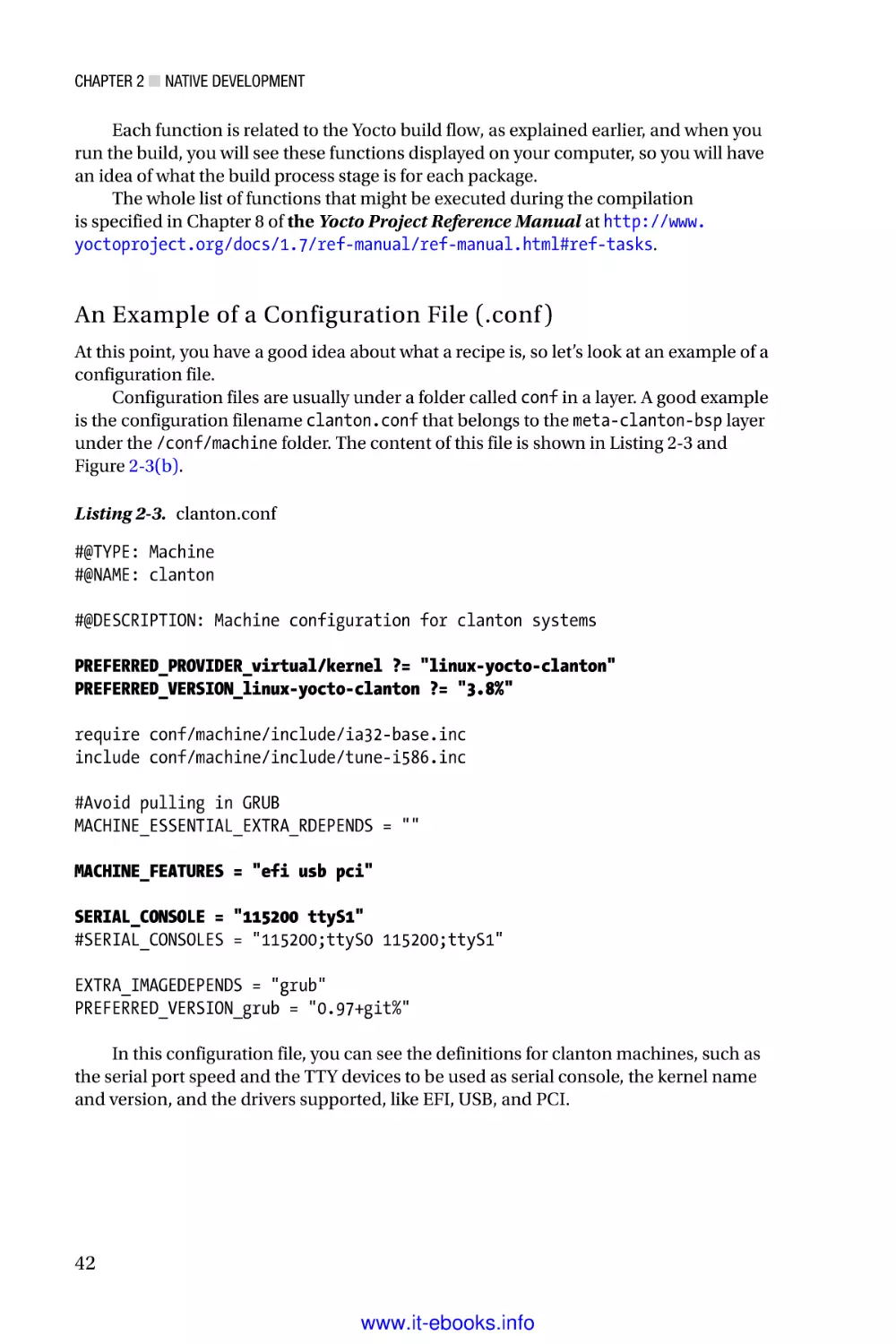
An Example of a Configuration File (.conf )
At this point, you have a good idea about what a recipe is, so let’s look at an example of a
configuration file.
Configuration files are usually under a folder called conf in a layer. A good example
is the configuration filename clanton.conf that belongs to the meta-clanton-bsp layer
under the /conf/machine folder. The content of this file is shown in Listing 2-3 and
Figure 2-3(b).
Listing 2-3. clanton.conf
#@TYPE: Machine
#@NAME: clanton
#@DESCRIPTION: Machine configuration for clanton systems
PREFERRED_PROVIDER_virtual/kernel ?= "linux-yocto-clanton"
PREFERRED_VERSION_linux-yocto-clanton ?= "3.8%"
require conf/machine/include/ia32-base.inc
include conf/machine/include/tune-i586.inc
#Avoid pulling in GRUB
MACHINE_ESSENTIAL_EXTRA_RDEPENDS = ""
MACHINE_FEATURES = "efi usb pci"
SERIAL_CONSOLE = "115200 ttyS1"
#SERIAL_CONSOLES = "115200;ttyS0 115200;ttyS1"
EXTRA_IMAGEDEPENDS = "grub"
PREFERRED_VERSION_grub = "0.97+git%"
In this configuration file, you can see the definitions for clanton machines, such as
the serial port speed and the TTY devices to be used as serial console, the kernel name
and version, and the drivers supported, like EFI, USB, and PCI.
42
www.it-ebooks.info
Chapter 2 ■ Native Development
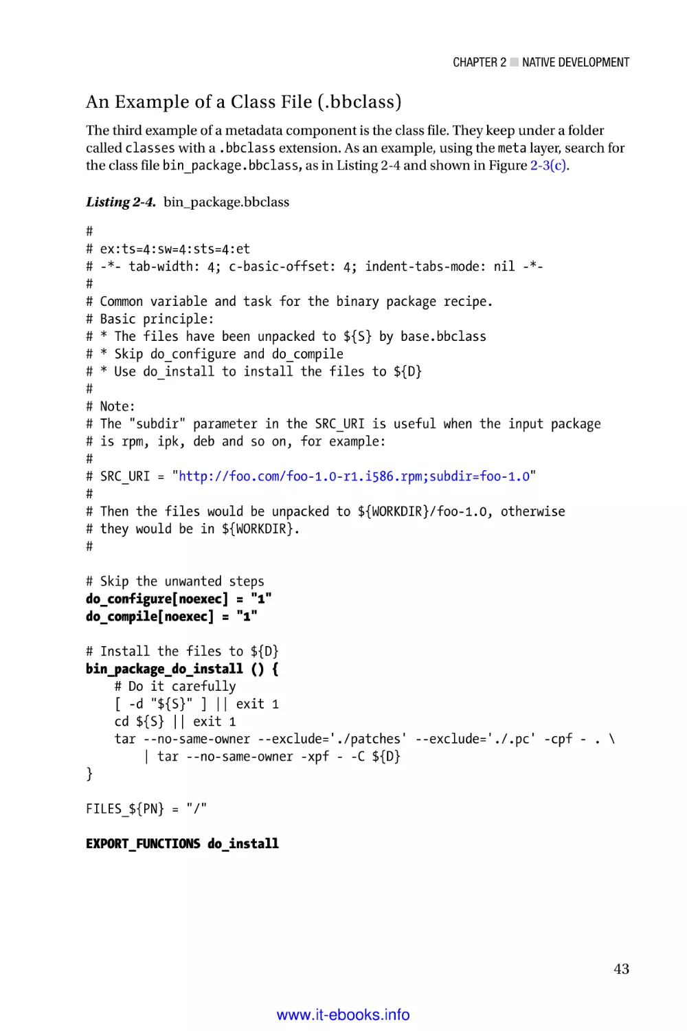
An Example of a Class File (.bbclass)
The third example of a metadata component is the class file. They keep under a folder
called classes with a .bbclass extension. As an example, using the meta layer, search for
the class file bin_package.bbclass, as in Listing 2-4 and shown in Figure 2-3(c).
Listing 2-4. bin_package.bbclass
#
#
#
#
#
#
#
#
#
#
#
#
#
#
#
#
#
#
#
ex:ts=4:sw=4:sts=4:et
-*- tab-width: 4; c-basic-offset: 4; indent-tabs-mode: nil -*Common variable and task for the binary package recipe.
Basic principle:
* The files have been unpacked to ${S} by base.bbclass
* Skip do_configure and do_compile
* Use do_install to install the files to ${D}
Note:
The "subdir" parameter in the SRC_URI is useful when the input package
is rpm, ipk, deb and so on, for example:
SRC_URI = "http://foo.com/foo-1.0-r1.i586.rpm;subdir=foo-1.0"
Then the files would be unpacked to ${WORKDIR}/foo-1.0, otherwise
they would be in ${WORKDIR}.
# Skip the unwanted steps
do_configure[noexec] = "1"
do_compile[noexec] = "1"
# Install the files to ${D}
bin_package_do_install () {
# Do it carefully
[ -d "${S}" ] || exit 1
cd ${S} || exit 1
tar --no-same-owner --exclude='./patches' --exclude='./.pc' -cpf - . \
| tar --no-same-owner -xpf - -C ${D}
}
FILES_${PN} = "/"
EXPORT_FUNCTIONS do_install
43
www.it-ebooks.info
Chapter 2 ■ Native Development
This bbclass file provides information on what must be done for all meta layers
that make usage of binary package recipes, and in this cases skips the configure
(do_configure) and compile (do_compile) procedures indexing noexec to 1, but takes
action during the package installation (do_install).
Creating Your Own Intel Galileo Images
After a small introduction on how the Yocto build system works, it is time to create your
own releases using Poky. It is essential to prepare your computer to run the build system,
because a series of requirements are necessary to make the build system functional.
Preparing Your Computer
The first thing to do is prepare your computer to be able to build. With Yocto, the system
basically runs on Linux, but if you have Windows or Mac OSX, I really recommend that
you install a virtual machine, such as VMWare (http://www.vmware.com) or Oracle
Virtual Box (https://www.virtualbox.org), and install one of the following Linux
distributions:
•
Ubuntu 12.04 (LTS)
•
Ubuntu 13.10
•
Ubuntu 14.04 (LTS)
•
Fedora release 19 (Schrödinger’s Cat)
•
Fedora release 20 (Heisenbug)
•
CentOS release 6.4
•
CentOS release 6.5
•
Debian GNU/Linux 7.0 (Wheezy)
•
Debian GNU/Linux 7.1 (Wheezy)
•
Debian GNU/Linux 7.2 (Wheezy)
•
Debian GNU/Linux 7.3 (Wheezy)
•
Debian GNU/Linux 7.4 (Wheezy)
•
Debian GNU/Linux 7.5 (Wheezy)
•
Debian GNU/Linux 7.6 (Wheezy)
•
openSUSE 12.2
•
openSUSE 12.3
•
openSUSE 13.1
44
www.it-ebooks.info
Chapter 2 ■ Native Development
If you have a recent version of a Linux operating system, but it is not listed in the
previous distribution list, it is recommended to check that this list is not outdated. To check
the most recent distributions supported by Yocto, read the “Supported Linux Distribution”
section in the Yocto Reference Project Manual at http://www.yoctoproject.org/
docs/1.7/ref-manual/ref-manual.html#detailed-supported-distros.
Some people are able to compile successfully on Mac OSX, but there are so many
steps necessary to make this possible that having a virtual machine is the quickest
solution.
This book shows a complete build process using Linux Ubuntu 12.04.04. If you
have a computer or a virtual machine with Ubuntu installed, and you want to check the
version, you can run the following command in a terminal shell:
mcramon@ubuntu:
No LSB modules
Distributor ID:
Description:
Release:
Codename:
~/ $ lsb_release -a
are available.
Ubuntu
Ubuntu 12.04.4 LTS
12.04
precise
The next step requires the installation of some packages used by bitbake during
the build process. The easiest way to install all the dependences is to run the following
command:
mcramon@ubuntu:~/$ sudo apt-get install subversion libcurl4-openssl-dev
uuid-dev autoconf texinfo libssl-dev libtool iasl bitbake diffstat gawk
chrpath openjdk-7-jdk connect-proxy autopoint p7zip-full build-essential
gcc-multilib vim-common gawk wget git-core
There is an important note regarding the IASL that is a compiler used to support
ACPI (Advanced Configuration and Power Interface). When Intel included support to
run Windows on Intel Galileo boards, a new power management configuration was
created, and, consequently, the IASL compiler had to be updated to attend the ACPI 5.0
specification. Thus, when you install the IASL (one of the components) in the previous
command, you need to make sure it supports ACPI revision 5.0 or greater.
If you are using Ubuntu 14, the repositories already point to a version of IASL that
supported ACPI 5.0; however, if you have Ubuntu 12, you will probably have problems,
because the repositories point to the IASL version that only supports ACPI revision 4.0
and will have problems compiling the UEFI packages. So, if you have Ubuntu 12, the
easiest way to install the correct IASL without upgrading your OS or pointing to the
repositories of version 14 is to install from a source with the following commands:
mcramon@ubuntu:~/tools$ sudo apt-get remove iasl
mcramon@ubuntu:~/tools$ sudo apt-get install libbison-dev flex
mcramon@ubuntu:~/tools$ mkdir iasl
mcramon@ubuntu:~/tools$ cd iasl/
mcramon@ubuntu:~/tools/iasl$ git clone git://github.com/acpica/acpica.git
mcramon@ubuntu:~/tools$ cd acpica
mcramon@ubuntu:~/tools/acpica$ make
45
www.it-ebooks.info
Chapter 2 ■ Native Development
After the make command compiles and links everything, the output files will be in the
.../generate/unix/bin folder.
mcramon@ubuntu:~/tools/acpica$ cd ./generate/unix/bin
mcramon@ubuntu:~/tools/iasl/acpica/generate/unix/bin$ ./iasl
Intel ACPI Component Architecture
ASL+ Optimizing Compiler version 20141107-64 [Dec 12 2014]
Copyright (c) 2000 - 2014 Intel Corporation
Supports ACPI Specification Revision 5.1
The previous command gives you an installation of IASL that supports ACPI 5.1 and,
of course, it is enough to meet the requirements of ACPI 5.0 because it points to the latest
release of IASL repositories in https://github.com/acpica/acpica.
Next, just create a link in /usr/bin/iasl pointing to your IASL, compiled manually:
mcramon@ubuntu:~/sudo ln -s <YOUR IASL PATH> /usr/bin/iasl
For example:
mcramon@ubuntu:~/sudo ln -s /home/mcramon/tools/iasl/acpica/generate/unix/
bin/iasl /usr/bin/iasl
After you install all the packages, your machine is able to run the Yocto builds and
you need to follow some steps to create your images, as commented in the next section.
The SPI vs. SD Card Images
The Intel Galileo images are based in Linux 3.8 and there are two possible images
(targets): the SPI image or the SD card image.
The SPI image is an image that fits on Intel Galileo SPI flash memory. It contains the
very basic software, but allows running the sketches (Arduino programs) and contains
some basic utilities, like busybox.
The SD card image must be stored in a micro SD card with a maximum capacity of
32GB and that allows booting Intel Galileo from it. This image contains a powerful variety
of software, such as Python, node.js, and the drivers to support Intel WiFi and Bluetooth
cards, among others.
Both images have the same procedure to build, changing only the target name in the
bitbake command. However, with the SD images, you just need to copy some of the build
output files in the micro SD cards; on the other hand, the SPI images require additional
steps and can be created as capsule files or binary files, which will be discussed later.
The next sections explain how to build Intel Galileo and toolchain images.
46
www.it-ebooks.info
Chapter 2 ■ Native Development
Building Intel Galileo Images
There are some steps that must be followed in order to prepare all the metafiles necessary
to build such images. The instructions shown in this chapter are related to release 1.0.4.
(I can guarantee that the process for 1.0.5 will be simpler because you will not need to
worry about downloading and applying patches manually. So, if you are reading this book
and a release newer than 1.0.4 is available, you will not need to follow all of these steps,
especially the manual application of patches.) The steps are outlined here:
1.
Create a directory where your build will be placed.
mcramon@ubuntu:~/$
2.
mkdir BSP_1.0.4_build
Download the BSP patches. Access the download center
at https://downloadcenter.intel.com/Detail_Desc.
aspx?DwnldID=24355 and read the instructions on how to
compile the BSP. With 1.0.4, there are instructions to access
the GitHub link at https://github.com/01org/GalileoRuntime and download the file https://github.com/01org/
Galileo-Runtime/archive/1.0.4.tar.gz. Next, decompress
the downloaded file:
mcramon@ubuntu:~/$ wget https://github.com/01org/GalileoRuntime/archive/1.0.4.tar.gz
mcramon@ubuntu:~/$ tar -xf Galileo-Runtime-1.0.4.tar.gz
mcramon@ubuntu:~/$ cd Galileo-Runtime-1.0.4
3.
Decompress the patches.
mcramon@ubuntu:~/$ tar -xvf patches_v1.0.4.tar.gz
patches_v1.0.4/
patches_v1.0.4/.DS_Store
patches_v1.0.4/meta-clanton.patches/
patches_v1.0.4/._patch.meta-clanton.sh
patches_v1.0.4/patch.meta-clanton.sh
patches_v1.0.4/._patch.Quark_EDKII.sh
patches_v1.0.4/patch.Quark_EDKII.sh
patches_v1.0.4/._patch.sysimage.sh
patches_v1.0.4/patch.sysimage.sh
patches_v1.0.4/Quark_EDKII.patches/
patches_v1.0.4/sysimage.patches/
patches_v1.0.4/sysimage.patches/.DS_Store
patches_v1.0.4/sysimage.patches/sysimage_v1.0.1+1.0.4.patch
patches_v1.0.4/Quark_EDKII.patches/.DS_Store
patches_v1.0.4/Quark_EDKII.patches/Quark_EDKII_v1.0.2+ACPI_for_
Windows.patch
47
www.it-ebooks.info
Chapter 2 ■ Native Development
patches_v1.0.4/meta-clanton.patches/.DS_Store
patches_v1.0.4/meta-clanton.patches/meta-clanton.post-patch.init.
patch
patches_v1.0.4/meta-clanton.patches/meta-clanton_v1.0.1+quarkinit.patch
patches_v1.0.4/meta-clanton.patches/post-setup.patches/
patches_v1.0.4/meta-clanton.patches/post-setup.patches/.DS_Store
patches_v1.0.4/meta-clanton.patches/post-setup.patches/1.usb_
improv_patch-1.patch
patches_v1.0.4/meta-clanton.patches/post-setup.patches/2.GAL-193clloader-1.patch
patches_v1.0.4/meta-clanton.patches/post-setup.patches/3.GAL-199start_spi_upgrade-1.patch
patches_v1.0.4/meta-clanton.patches/post-setup.patches/4.MAKER222-Sketch_download_unstable-5.patch
patches_v1.0.4/meta-clanton.patches/post-setup.patches/GAL-118USBDeviceResetOnSUSRES-2.patch
patches_v1.0.4/meta-clanton.patches/post-setup.patches/patch.sh
patches_v1.0.4/meta-clanton.patches/post-setup.patches/uart1.0.patch
patches_v1.0.4/meta-clanton.patches/post-setup.patches/uartreverse-8.patch
If you pay attention to the files extracted, you will realize that there are patches for
several different repositories, such as meta-clanton, UEFI firmware, and native BSP code.
The usage of these patches will be discussed according the steps to build the BSP or to
generate the Intel Galileo Images.
4.
Extract the meta-clanton.
At this point you have some tar.gz files extracted in your directory, such as the
directory for SPI flash tools, the firmware based on Intel EDKII, and the sysimage
templates; but what really matters at this point is the meta-clanton directory that must be
decompressed.
mcramon@ubuntu:~/$ tar -zxvf meta-clanton_v1.0.1.tar.gz
Galileo-Runtime-1.0.4/
Galileo-Runtime-1.0.4/Quark_EDKII_v1.0.2.tar.gz
Galileo-Runtime-1.0.4/README.txt
Galileo-Runtime-1.0.4/grub-legacy_5775f32a+v1.0.1.tar.gz
Galileo-Runtime-1.0.4/meta-clanton_v1.0.1.tar.gz
Galileo-Runtime-1.0.4/patches_v1.0.4.tar.gz
Galileo-Runtime-1.0.4/quark_linux_v3.8.7+v1.0.1.tar.gz
Galileo-Runtime-1.0.4/spi-flash-tools_v1.0.1.tar.gz
Alternatively, you can decompress all files, if you want, by running the following
command:
48
www.it-ebooks.info
Chapter 2 ■ Native Development
mcramon@ubuntu:~/$
$file;done
for file in $(ls *.tar.gz); do tar -zxvf
Enter the decompressed meta-clanton directory, and then observe the files and
directories that you have.
mcramon@ubuntu:~/$ cd meta-clanton_v1.0.1/
mcramon@ubuntu:~/$ ls
LICENSE meta-clanton-bsp meta-clanton-distro
setup.sh
README
setup
Note that you have the meta-clanton layer, but the main build processor Poky is not
present and you need to fetch it.
5.
Apply the meta-clanton patches. Return to the previous
directory and run the meta-clanton patches with following
command:
mcramon@ubuntu:~/$ cd ..
mcramon@ubuntu:~/$ ./patches_v1.0.4/patch.meta-clanton.sh
This patch fetches new metafiles and the Poky, and then applies code patches.
Internally, the patch.meta-clanton.sh script calls a second script named setup.sh
that downloads the some new metafiles that are included in the meta-clanton directory.
The new metafiles are meta-intel and meta-oe. Also, two new directories were prepared:
poky and yocto_build. This might take some time, depending on the speed of your
Internet connection.
You can check the new files as follows:
mcramon@ubuntu:~/$ cd meta-clanton_v1.0.1/
mcramon@ubuntu:~/$ ls
LICENSE meta-clanton-bsp meta-clanton-distro meta-intel
meta-oe poky README setup setup.sh yocto_build
At times during the Intel Galileo development, new bugs arise and new fixes
are introduced. The Intel Galileo BSP images lays on Intel Clanton BSP baseline but
the development of two lines run in parallel with some merges of Intel Galileo fixes
sporadically. When new fixes arises before any official Intel Clanton baseline release, then
patches are provided and the Intel Galileo BSP continues independently.
For example, this chapter is based on release 1.0.4, but when you downloaded the
BSP sources, you have notices such as meta-clanton_v1.0.1.tar.gz that mean baseline
1.0.1. In this case, Intel provides patches that must be applied on top of 1.0.1, and once
applied, you have a legitimate source 1.0.4. It is great if there is no patch to be applied,
because the baseline is in sync with previous Intel Galileo fixes.
So, the second action done by patch.meta-clanton.sh is to apply not only code fixes
but also possible recipe files that must be correct; for example, patching a new OpenSSL
code or applying security fixes.
49
www.it-ebooks.info
Chapter 2 ■ Native Development
Intel is doing its best to replace the patches script with efficient .bbappend files
provided as a source, so that you will not need to apply any patches manually.
6.
Set the environment variables. After applying all the
patches, it is necessary to set the environment variables and
Poky directly where the build should start. To do this, run the
following commands:
mcramon@ubuntu:~/$ cd ./meta-clanton_v1.0.1
mcramon@ubuntu:~/$ source poky/oe-init-build-env yocto_build
At the end of this command, your prompt in the terminal shell will be automatically
moved to the yocto_build directory.
7.
Enable the cache and set the number of threads. This step is
just a recommendation. It is not necessary to follow because
you could start your build; however, these changes will enable
the cache and might make your build a little bit faster.
Open the file .../meta-clanton/yocto_build/conf/local.conf with the text
editor of your preference.
The change is the variable BB_NUMBER_THREADS that represents the maximum number
of threads that your bitbake command will be able to handle. My suggestion is to multiply
the numbers of threads on your computer processor by 2; for example, if your computer
supports 8 threads, you can change this number to 16. If you are using a free version
of virtual machines, check the number of core processors that it allows you to set. For
example, the free version of VMware only allows setting a maximum of four cores, and if
each core of your processor holds one single thread, then BB_NUMBER_THREADS could be 8.
BB_NUMBER_THREADS = "12"
Still, in yocto.conf you can make the following changes:
SSTATE_DIR ?= "/tmp/yocto_cache-sstate"
SOURCE_MIRROR_URL ?= "file:///tmp/yocto_cache/"
INHERIT += "own-mirrors"
BB_GENERATE_MIRROR_TARBALLS = "1"
By enabling the cache, if your build is interrupted for some reason, such as a lapse
moment of Internet disconnection, if you re-execute the bitbake command, the build
will not start from scratch because the cache is reused and the code that was previously
downloaded does not need to be downloaded again.
The next step is the compilation itself.
50
www.it-ebooks.info
Chapter 2 ■ Native Development
8.
Compile the images. It is time to execute the build process
using the bitbake tool. At this point, you have two possible
images related to Intel Galileo: the SPI image and the SD card
image. To check the name of each target release, type the
command bitbake -s, which brings all the targets supported
by the current configurations:
mcramon@ubuntu:$ bitbake -s |grep galileo
galileo-target
image-full-galileo
image-spi-galileo
:0.1-r0
:1.0-r0
:1.0-r0
The target image-full-galileo creates the SD card image; image-spi-galileo
creates the SPI image; and galileo-target must be ignored because it is not used
anymore.
Then, using bitbake again, you can run the build process for the target you want to
work. For example, for SPI you just need to run this:
mcramon@ubuntu:$ bitbake image-spi-galileo
All the configurations are checked; the download of the sources, packages, and
patches that compose the software is started; each component is properly set, enabling
and disabling features and software definitions; and finally, everything is compiled and
the images are generated.
During the compilation process, you will be able to see the do_ actions in place of
different recipes, the number of tasks completed and to be completed, and warnings
if the mirrors failed to download the expected code. You do not need to worry about
warnings, because they are an indication that the code failed to be fetched and a different
mirror will be used. You only need to worry if there are errors reported, and in this
case, you need to identify the recipe file and check whether the URL mirrors changed,
which would fix the file, or if you have a generic error like an Internet connection loss or
insufficient space in the device.
Figure 2-4 shows a snapshot of a full image process given after the command
bitbake image-full-galileo is used to create SD card releases. Note that there are 2,924
tasks to be done, but only 190 were executed, which means that this is the beginning
of the compilation. You can also observe some actions in place, such as do_configure,
do_compile, do_patch, and do_unpack, for different recipes.
51
www.it-ebooks.info
Chapter 2 ■ Native Development
Figure 2-4. bitbake output for full image compilation
If the compilation is fine, the next step is to check the output files.
9.
In the end, if everything downloads and is configured,
compiled, and linked, and patches are applied, you should
have the images available in the ...meta-clanton/yocto_
build/tmp/deploy/images directory.
If you created SD card images, you just need to copy the files to your SD card;
otherwise, some additional steps are necessary with SPI images.
The next section explains how to build the toolchain, but if you are excited to test your
release, read the “Booting Intel Galileo with Your Own Images” section in this chapter.
Building and Using the Cross-Compiler Toolchain
It is important to understand how to create the cross-compilers and IPK packages
because some chapters of this book will make use of them, especially in Chapter 7, and, of
course, if you want to create native applications.
The next sections explain how to build the toolchain and how you might generate a
toolchain for different operating systems.
Note that if your intention is only to create images to Intel Galileo boards, then this
section is not mandatory.
Compiling the Toolchain for Different Architectures
If you are a Windows or Mac OSX user, you are probably running the Yocto build using a
virtual machine. At this point, you might be asking if you can create a toolchain for your
native operating system, instead of using virtual machines for everything, including the
toolchain.
52
www.it-ebooks.info
Chapter 2 ■ Native Development
The answer is yes, and it is very simple to create a toolchain for other architectures,
even if you have a Linux machine, because it is one of the proposals of the Yocto build
system.
To make such a change, it is necessary to open the file .../meta-clanton/yocto_
build/conf/local.conf and add the variable SDKMACHINE followed by a string that
describes the machine architecture designed to the SDK build.
SDKMACHINE = "i386-darwin"
BB_NUMBER_THREADS = "12"
PARALLEL_MAKE = "-j 14"
MACHINE = "clanton"
DISTRO ?= "clanton-tiny"
EXTRA_IMAGE_FEATURES = "debug-tweaks"
USER_CLASSES ?= "buildstats image-mklibs image-prelink"
PATCHRESOLVE = "noop"
CONF_VERSION = "1"
Basically, the strings for different operating systems are shown in Table 2-1.
Table 2-1. Machine Architecture Definition
String
Target Architecture
i586
Linux, 32-bit
x86_64
Linux, 64-bit
i386-darwin
OSX
i686-mingw32
Windows, 32- and 64-bit
If the SDKMACHINE is not explicitly declared, then the toolchain will assume the
computer architecture that runs the Yocto build.
You need to use the text editor of your preference, or simply change the machine
using a command line. For example, if you want to specify the target as 32-bit Linux, you
can run the following:
mcramon@ubuntu:~/$ cd meta-clanton_v1.0.1/yocto_build
mcramon@ubuntu:~/$ echo 'SDKMACHINE = "i586"' >> conf/local.conf
The next sections discuss how to build and install the toolchains for different
operating systems.
53
www.it-ebooks.info
Chapter 2 ■ Native Development
Building the Toolchains
The generations of toolchains require the same steps mentioned in the “Building Intel
Galileo Images” section; however, the bitbake command is different and additional layers
must be downloaded.
Note that it is always recommended to check any possible changes in the process—
how the toolchains are generated in case this book becomes outdated. In this case, consult
the Quark BSP Build Guide, which you can access at http://www.intel.com/content/
dam/www/public/us/en/documents/guides/galileo-quark-x1000-bsp-guide.pdf.
The instructions in this section generate the toolchain based on the uclibc library,
because it is the default library set in the metafiles. If you are interested in creating the
toolchains based in eglibc, you need to read Chapter 7, specifically the “Preparing the
BSP Software Image and Toolchain” section.
The generation of toolchains is different for Linux, Windows, and OSX, as you will
read in the following instructions.
Linux
The following is the command to generate the toolchain for 32-bit Linux:
mcramon@ubuntu:~/$
mcramon@ubuntu:~/$
mcramon@ubuntu:~/$
mcramon@ubuntu:~/$
cd ./meta-clanton_v1.0.1
source poky/oe-init-build-env yocto_build
echo 'SDKMACHINE = "i586"' >> conf/local.conf
bitbake meta-toolchain
If you want to generate for 64-bit Linux, you need to change the SDKMACHINE to
x86_64. Alternatively, you can replace the command bitbake meta-toolchain with
bitbake image_full –c populate_sdk and the result will be the same.
OSX
OSX requires you have a legitimate Mac computer with OSX 10.8 or later and with Xcode
5.1.0 or later installed. Initially, using your Mac computer, perform the following steps:
1.
Go to the App Store and install Xcode 5.1.0 or later.
2.
Install the command-line development tools using
Preferences ➤ Downloads and choose command-line tools.
3.
Using the terminal shell, create the file OSX-sdk.zip with
following commands:
$
$
$
$
$
mkdir ~/Desktop/OSX-sdk
cd ~/Desktop/OSX-sdk
ditto `xcrun --sdk macosx10.8 --show-sdk-path` .
cd ..
zip -yr OSX-sdk OSX-sdk
54
www.it-ebooks.info
Chapter 2 ■ Native Development
4.
Copy the OSX-sdk.zip to a directory in your Linux virtual
machine. The following are the commands to create the OSX
toolchain:
mcramon@ubuntu:~/$ cd ./meta-clanton_v1.0.1
mcramon@ubuntu:~/$ sed -i 's|setup/gitsetup.py -c setup/$1.cfg -w
mcramon@ubuntu:~/$ sed -i 's|setup/gitsetup.py -c setup/$1.cfg -w
$1|setup/gitsetup.py -c setup/$1.cfg -w $1 --depth=1|' setup/
gitsetup.py mcramon@ubuntu:~/$ ./setup.sh
mcramon@ubuntu:~/$ git clone git://git.yoctoproject.org/meta-darwin
mcramon@ubuntu:~/$ cd meta-darwin ; git checkout
03b7dd85732838d78e4879332b1cc005dae25754 ; cd ..
mcramon@ubuntu:~/$ (cd poky && patch -p1) < meta-darwin/oecore.patch
mcramon@ubuntu:~/$ mv <YOUR DIRECTORY HERE>/OSX-sdk.zip metadarwin/recipes-devtools/osx-runtime/files darwinpath="$(pwd)/
meta-darwin"
mcramon@ubuntu:~/$ echo 'SDKMACHINE = "i386-darwin"' >> yocto_
build/conf/local.conf
mcramon@ubuntu:~/$ echo "BBLAYERS += \"$darwinpath\"" >> yocto_
build/conf/bblayers.conf
mcramon@ubuntu:~/$ source poky/oe-init-build-env yocto_build
mcramon@ubuntu:~/$ bitbake meta-toolchain
Windows
For Windows, the commands are the same for Windows, 64 or 32 bits; however, a
sequence of two bitbakes is required in addition to the extra metafiles.
mcramon@ubuntu:~/$ sed -i 's|setup/gitsetup.py -c setup/$1.cfg -w $1|setup/
gitsetup.py -c setup/$1.cfg -w $1 --depth=1|' setup/gitsetup.py
mcramon@ubuntu:~/$./setup.sh
mcramon@ubuntu:~/$ git clone -b dylan git://git.yoctoproject.org/meta-mingw
mcramon@ubuntu:~/$ (cd poky && patch -p1) < meta-mingw/oecore.patch
mcramon@ubuntu:~/$ mingwpath="$(pwd)/meta-mingw"
mcramon@ubuntu:~/$ echo 'SDKMACHINE = "i686-mingw32"' >> yocto_build/conf/
local.conf
mcramon@ubuntu:~/$ echo "BBLAYERS += \"$mingwpath\"" >> yocto_build/conf/
bblayers.conf
mcramon@ubuntu:~/$ cd $WORKSPACE/meta-clanton_v1.0.1poky
mcramon@ubuntu:~/$ wget http://git.yoctoproject.org/cgit.cgi/poky/patch/
meta/classes/sstate.bbclass?id=4273aa4287ecd36529f2d752c76ab8d09afc33c3 -O
sstate.bbclass.patch
git am sstate.bbclass.patch
55
www.it-ebooks.info
Chapter 2 ■ Native Development
mcramon@ubuntu:~/$
mcramon@ubuntu:~/$
mcramon@ubuntu:~/$
mcramon@ubuntu:~/$
cd $WORKSPACE/meta-clanton_v1.0.1
source poky/oe-init-build-env yocto_build
bitbake gcc-crosssdk-initial -c cleansstate
bitbake meta-toolchain
The Output Files
The output files will be in the .../meta-clanton_v1.0.1/yocto_build/tmp/deploy/
sdk directory, while the ipk packages will be in the directory .../meta-clanton_v1.0.1/
yocto_build/tmp/deploy/ipk directory.
The output filename depends on whether your computer is 32 or 64 bits, the
architecture that the toolchain is designated for (we will discuss later), and the uclibc or
eglic library that the image is based on. In the end, you will have just a single script file;
however, it is a big file at around 260MB.
For example, if you compile in a 64-bit Linux machine with an Intel processor, the
output filename is clanton-tiny-uclibc-x86_64-i586-toolchain-1.4.2.sh.
The next sections discuss how to install and test the toolchains.
Installing the Cross-Compilers
The installation of the toolchain just requires you to execute the script created and choose
a destination folder, as shown:
mcramon@ubuntu:~/toolchain$ ./clanton-tiny-uclibc-x86_64-i586-toolchain-1.4.2.sh
Enter target directory for SDK (default: /opt/clanton-tiny/1.4.2):
You are about to install the SDK to "/opt/clanton-tiny/1.4.2". Proceed[Y/n]?Y
[sudo] password for mcramon:
Extracting SDK...done
Setting it up...done
SDK has been successfully set up and is ready to be used.
The shell script inflates the toolchain in the directory chosen, and all programs that
make part of the toolchain are promptly accommodated.
The “Creating a Hello World!” section in this chapter brings a practical usage of the
toolchain.
Creating a Hello World!
This section requires you to have built and properly installed the toolchain in your
computer.
If you enter the toolchain directory chosen during the installation, you will notice
many binary files, including the compilers and directories, but initially what matters is a
file that starts with environment-setup-*; for example, in my setup I have the file named
as environment-setup-i586-poky-linux-uclibc.
56
www.it-ebooks.info
Chapter 2 ■ Native Development
This file contains a lot of variables—such as CC, CXX, CPP, AR, and NM—that must be
exported to your computer shell. They are used to compile, link, and archive your native
programs with the toolchain, so primarily you need to make this variable part of the
development environment, sourcing it as follows:
mcramon@ubuntu:/opt/clanton-tiny/1.4.2$ source environment-setup-i586-pokylinux-uclibc
For example, you will be able to compile a problem with $(CC) -c $(CFLAGS)
$(CPPFLAGS) since CC points to the C compilers, CFLAGS to the C compiler flags, and
CPPFLAGS to the C++ compiler flags. If you check some of these variables after sourcing
them, you will see something like this:
mcramon@ubuntu:/opt/clanton-tiny/1.4.2$ echo $CC
i586-poky-linux-uclibc-gcc -m32 -march=i586 --sysroot=/opt/clantontiny/1.4.2/sysroots/i586-poky-linux-uclibc
mcramon@ubuntu:/opt/clanton-tiny/1.4.2$ echo $CFLAGS
-O2 -pipe -g -feliminate-unused-debug-types
mcramon@ubuntu:/opt/clanton-tiny/1.4.2$ echo $CXXFLAGS
-O2 -pipe -g -feliminate-unused-debug-types -fpermissive
Listing 2-5 brings a simple Hello World program written in C, which is present in the
code folder of this chapter.
Listing 2-5. HelloWorld.c
#include <stdio.h>
int main(int argc, char const* argv[])
{
printf("Hello, World! This is Intel Galileo!\n");
return 0;
}
Copy this program to your computer and compile it using the variables you exported.
mcramon@ubuntu:/ ${CC} ${CFLAGS} HelloWorld.c -o HelloWorld
You should have the executable HelloWorld created using the cross-compiler. Just
copy this file to a micro SD card formatted using FAT or FAT32. If you do not know how to
format the micro SD card, read the “Boot from SD Card Image" section of this chapter for
instructions.
Insert the micro SD card on your Intel Galileo and boot the board connecting the
power supply. Also connect the serial cables, as explained in Chapter 1, and open a Linux
terminal shell.
57
www.it-ebooks.info
Chapter 2 ■ Native Development
Then locate the micro SD card mounted to the /media/mmcblk0p1 partition, and
execute the HelloWorld, as shown:
root@clanton:/# cd /media/mmcblk0p1/
root@clanton:/media/mmcblk0p1# ls
HelloWorld
root@clanton:/media/mmcblk0p1# ./HelloWorld
Hello, World! This is Intel Galileo!
If you see the output message, it means that your toolchain is functional and
generating the binaries correctly. There are multiples ways to transfer your executable
to the board, using either WiFi, Ethernet, a pen drive, or a micro SD card. For more
information, read the “Transferring Files Between Intel Galileo and Computers” section in
Chapter 5.
You can also create a simple makefile for this HelloWorld by simply using the
variables exported by the environment-setup-i586-poky-linux-uclibc as a base. For
example, Listing 2-6 shows a makefile for the HelloWorld program.
Listing 2-6. Makefile
SHELL = /bin/bash
TARGET_NAME = i586-poky-linux-uclibc
DIST = clanton-tiny
CC = $(TARGET_NAME)-gcc -m32 -march=i586 --sysroot=/opt/$(DIST)/1.4.2/sysr
oots/$(TARGET_NAME)
CFLAGS = -O2 -pipe -g -feliminate-unused-debug-types
OUTPUT_FILE = HelloWorld
all: target
target: $(patsubst %.c,%.o,$(wildcard *.c))
$(CC) $(CFLAGS) $^ -o $(OUTPUT_FILE)
clean:
rm -f $(TARGET_BIN) *.o $(OUTPUT_FILE)
The makefile created is designated to target i586-poky-linux-uClibc, as stored in
the variable TARGET_NAME and considers the toolchain installed in the /opt/clanton-tiny
directory according the CC variable. So, if you create the toolchain for a different target, or
used a different directory installation, it is necessary to adapt this makefile.
The makefile also brings three commands: clean to clean all the object files and the
output file named as HelloWorld, because it is the value in the OUTPUT_FILE variable; all
and target do the same thing—in other words, compile the C programs, invoking the
compiler pointed by CC and CFLAGS.
To create a HelloWorld, all you need to do is type make.
58
www.it-ebooks.info
Chapter 2 ■ Native Development
mcramon@ubuntu:~/native$ make
i586-poky-linux-uclibc-gcc -m32 -march=i586 --sysroot=/opt/clantontiny/1.4.2/sysroots/i586-poky-linux-uclibc -O2 -pipe -g -feliminate-unuseddebug-types
-c -o HelloWorld.o HelloWorld.c
i586-poky-linux-uclibc-gcc -m32 -march=i586 --sysroot=/opt/clantontiny/1.4.2/sysroots/i586-poky-linux-uclibc -O2 -pipe -g -feliminate-unuseddebug-types HelloWorld.o -o HelloWorld
The next section talks about debugging native applications.
Debugging Native Applications
It is possible to debug native application and kernel modules using GDB, Eclipse,
and JTAG tools. This book focuses on Arduino projects, so all debugging methods are
concentrated in the Intel Arduino IDE, and not in native applications or kernel contexts.
In the scope of this book, it is important to know how build systems work, how to build
and compile native applications, and how to generate the cross-compilers, because these
features will be used in the following chapters, especially when you work with OpenCV
and V4L2 in Chapter 7.
However, if you are interested in learning how to debug native applications, Intel
provides a very good tutorial about how to use Eclipse with Intel Galileo and Intel Edison
in the developer zone. This tutorial can be accessed at https://software.intel.com/
en-us/getting-started-for-c-c-plus-plus-eclipse-galileo-and-edison.
For kernel debugging, GDB, and JTAG enabling using openOCD, it is recommended
that you read the Source Level Debugging using OpenOCD/GDB/Eclipse on Intel Quark
SoC X1000 manual, present in the manuals folder of this chapter, or you can access it at
https://communities.intel.com/docs/DOC-22203.
The next section explains how to make Intel Galileo boot with the images that you
created with poky.
Booting Intel Galileo with Your Own Images
As explained earlier, you have two image targets related to Intel Galileo—the SPI card
image and the SD card image. The procedures to make Intel Galileo boot using these
images differ and must be followed as directed in the following sections.
Booting from SD Card Images
The SD card release only requires that you copy some of the output files to a micro SD
card, insert it in Intel Galileo, and then power-on the board.
Preparing the Micro SD Card
Before copying the files, there are important details to know regarding the format of the
micro SD card, which must be FAT or FAT32 with a single partition.
59
www.it-ebooks.info
Chapter 2 ■ Native Development
First of all, you need to format the SD card in your computer. Nowadays, computers
offer SD card slots; if you insert the micro SD card into a SD card adaptor connected to
the slot, you are able to read, write, or format your micro SD card, as shown in Figure 2-5.
However, if your computer does not provide any kind of access to the micro SD card, then
you will need a micro SD card reader that connects to a USB port. Figure 2-6 shows an
example of an SD card reader in a laptop and a micro SD card reader device.
Figure 2-5. An SD card adaptor to be used with a computer
Figure 2-6. A micro SD card USB adaptor
With a physical connection between the micro SD card and your computer
established, you just need to format the micro SD card according to your OS.
60
www.it-ebooks.info
Chapter 2 ■ Native Development
Windows
If you are a Windows user and you are running a virtual machine with Linux to run Yocto
builds, you might be excited to use the regular format procedure offered by Windows; in
other words, open Explorer, right-click the SD card drive, and select the Format option.
In this case, deselect Quick Format and choose the right partition format, as shown in
Figure 2-7.
Figure 2-7. Formatting the micro SD card on Windows
Mac OSX
Formatting a micro SD card on Mac OSX is quite easy. In Spotlight, type Disk Utility and
run the Disk Utility software. Click the micro SD card in the left panel and then click the
Erase tab. Select the format type in the Format combo box and click the Erase button.
Figure 2-8 shows the Disk Utility options.
61
www.it-ebooks.info
Chapter 2 ■ Native Development
Figure 2-8. The Disk Utility on Mac OSX formatting the micro SD card
Ubuntu
On Ubuntu there are several utilities with a very nice graphical interface that can format
the micro SD card, including GParted (http://gparted.sourceforge.net) and Disk
Utility for Ubuntu (https://apps.ubuntu.com/cat/applications/precise/gnomedisk-utility/). To avoid any new software installation, however, it is possible to format
using simple command-line commands. The steps are as follows:
1.
Open a terminal by pressing Ctrl+Alt+T at same time.
2.
Type the command df to check the partition in your
computer, including the micro SD card mounted. Then
identify the device name that defines the micro SD card; for
example, /dev/sdb1.
3.
Unmount the SD card using the umount command followed by
the device name. For example:
umount /dev/sdb1
4.
Use the MKDOSFS utility to format the card. For example:
mkdosfs -F 32 -v /dev/sdb1
With the micro SD card ready, it is time to copy your image into it.
62
www.it-ebooks.info
Chapter 2 ■ Native Development
Copying Files to a Micro SD Card
If you successfully create your SD card image, enter ../yocto_build/tmp/deploy/images
in the directory and type the ls -l command:
mcramon@ubuntu $ cd ./tmp/deploy/images/
mcramon@ubuntu $ ls -l
total 150576
drwxr-xr-x 3 mcramon mcramon
4096 Nov 18 23:01 boot
-rw-r--r-- 2 mcramon mcramon
373760 Nov 19 00:04 bootia32.efi
lrwxrwxrwx 2 mcramon mcramon
42 Nov 18 23:58 bzImage -> bzImage--3.8r0-clanton-20141119062948.bin
-rw-r--r-- 2 mcramon mcramon
1984512 Nov 18 23:58 bzImage--3.8-r0-clanton20141119062948.bin
lrwxrwxrwx 2 mcramon mcramon
42 Nov 18 23:58 bzImage-clanton.bin ->
bzImage--3.8-r0-clanton-20141119062948.bin
-rw-r--r-- 1 mcramon mcramon
1689687 Nov 19 00:08 core-image-minimalinitramfs-clanton-20141119062948.rootfs.cpio.gz
lrwxrwxrwx 1 mcramon mcramon
66 Nov 19 00:08 core-image-minimalinitramfs-clanton.cpio.gz -> core-image-minimal-initramfs-clanton20141119062948.rootfs.cpio.gz
-rw-r--r-- 2 mcramon mcramon
279670 Nov 18 23:59 grub.efi
-rw-r--r-- 1 mcramon mcramon 314572800 Nov 19 00:26 image-full-galileoclanton-20141119062948.rootfs.ext3
lrwxrwxrwx 1 mcramon mcramon
53 Nov 19 00:26 image-full-galileoclanton.ext3 -> image-full-galileo-clanton-20141119062948.rootfs.ext3
-rw-rw-r-- 2 mcramon mcramon
1556960 Nov 18 23:58 modules--3.8-r0-clanton20141119062948.tgz
-rw-rw-r-- 2 mcramon mcramon
294 Nov 19 00:25 README_-_DO_NOT_DELETE_
FILES_IN_THIS_DIRECTORY.txt
There is a folder called boot with files and links. The only function of the links is to
make “easy reading” of the files that receive a timestamp in their names. For example,
the bzImage--3.8-r0-clanton-20141119062948.bin, where 20141119062948 is only the
timestamp; thus, if you run the bitbake again without any modification, you will have
another bzImage file with a different timestamp and a link pointing to the newest one.
Thus, you will need to copy to your micro SD card as follows:
1.
boot (the whole directory, including subdirectories)
2.
bzImage
3.
core-image-minimal-initramfs-clanton.cpio.gz
4.
grub.efi
5.
image-full-galileo-clanton.ext3
Copy these files and directories to your micro SD card, insert it into the micro SD
card slot (see Chapter 1), and power-on your Intel Galileo.
63
www.it-ebooks.info
Chapter 2 ■ Native Development
This is everything you need if you are using SD card images. The next section
explains this procedure when SPI images are used.
Booting from SPI Card Images
When you build an SPI image, the process results in a single file created to store your
image in the SPI flash memory. In this case, two different types of files can be built:
•
Capsule file: This file contains the system images, the kernel, the
file system partition, and the boot loader packages (grub), but
it does not contain the platform data. Platform data informs the
MAC address of your Ethernet controller and the board model,
such as Intel Galileo or Intel Galileo Gen2. This file is very useful
in most cases; if you have a board without boot issues and the
Ethernet controller is working with a correct MAC address, the file
is very handy. Usually, capsule files (or cap files) contain the .cap
extension, and you can flash Intel Galileo boards using the Intel
Arduino IDE or the UEFI shell, which will be discussed later.
•
Binary file: This binary file contains everything; in other words,
everything in a capsule file, plus the platform data. Usually, these
files have the .bin extension and must be flashed with an SPI
programmer.
Figure 2-9 shows a flowchart that explains the process to generate both of these files.
Figure 2-9. SPI files generation flowchart
Initially it is necessary to generate the Intel Galileo SPI images that will generate the
SPI files as output.
In parallel, it is possible to compile the firmware and generate the files related to
firmware as output. Then a template is mounted using a file named layout.conf that
contains all the ingredients necessary to build files a single file that will be used to flash
the SPI flash memory.
64
www.it-ebooks.info
Chapter 2 ■ Native Development
With layout.conf ready, the SPI flash tool is called to generate capsule and binary
files without platform data. If the intention is to have files without platform data, at this
point the capsule files might be used; otherwise, the platform data must be patched using
a Python script, which will be discussed later. A final binary with all the information is
created.
Creating the Capsule Files Flash Files
When you downloaded the BSP board support package in the step 2 of the “Creating your
Own Intel Galileo Images” section of this chapter, you should have noticed that files in
addition to the meta-clanton data were downloaded, among them files called spi-flashtools_v1.0.1.tar.gz and Quark_EDKII_v1.0.1.tar.gz.
Compiling the UEFI Firmware
To decompress the Linux kernel before your board boots, there is firmware responsible
to initialize the board components, including the Intel Quark SoC. It also assumes other
activities after the boot.
The Intel Galileo provides firmware compliant with UEFI (Unified Extensible
Firmware Interface) standards that consist of boot procedures, runtime services calls, and
data tables used for power management methods like ACPI (Advanced Configuration and
Power Interface).
EDKII means the environment cross-platform for firmware development.
Of course, to understand the UEFI specification and EDKII development process,
it would require a full book dedicated to this subject. In the context of this book, the
concept is limited to how to build the EDKII, which is one of the core elements to have a
functional SPI image.
The next sections discuss how to prepare your environment and how to compile the
firmware.
Preparing the Environment
The following are the dependences to compile the UEFI firmware:
•
Python 2.6 or newer
•
Any GCC and G++ with versions between 4.3 and 4.7
•
Subversion
•
uuid-dev
•
IASL
If you run the command line proposed in the “Preparing Your Computer” section,
you should be fine with these dependences, except Python. Check to see if you have
Python installed on your Linux by running the following command:
65
www.it-ebooks.info
Chapter 2 ■ Native Development
mcramon@ubuntu:~$ dpkg --get-selections | grep -v deinstall|grep -i python
Or you can run this:
mcramon@ubuntu:~$ python --version
Python 2.7.3
If you do not have Python installed, you can install it by following the instructions
at https://www.python.org/downloads/. If you want a quick try using version 2.7.6, you
can run the following commands:
mcramon@ubuntu:~/$ wget https://www.python.org/ftp/python/2.7.6/Python2.7.6.tgz
mcramon@ubuntu:~/$ tar -zxvf Python-2.7.6.tgz
mcramon@ubuntu:~/$ cd Python-2.7.6/
mcramon@ubuntu:~/$ ./configure
mcramon@ubuntu:~/$ make
mcramon@ubuntu:~/$ make install
After this, you are ready to compile the firmware by following the steps presented in
the next section.
Compiling the Firmware
Once you have downloaded the right package, you need to follow these instructions step
by step:
1.
Extract the package. The first thing to do is go back to the
base directory and decompress the file:
mcramon@ubuntu $ tar -xvf Quark_EDKII_v1.0.2.tar.gz
Unfortunately, it is necessary to apply patches manually, but fortunately this can be
done with a single command line:
mcramon@ubuntu $ ./patches_v1.0.4/patch.Quark_EDKII.sh
This patch only fixes some ACPI tables to support Windows, which is not within the
scope of this book, but it is recommended to run this patch anyway to keep your firmware
updated.
2.
Prepare the SVN project. The EDKII is maintained using the
SVN configuration control release tool.
mcramon@ubuntu:~/$
mcramon@ubuntu:~/$
mcramon@ubuntu:~/$
mcramon@ubuntu:~/$
cd Quark_EDKII_v1.0.2/
./svn_setup.py
svn update
export WORKSPACE=$(pwd)
66
www.it-ebooks.info
Chapter 2 ■ Native Development
The first command, ./svn_setup.py, is a Python script that brings a series of code
related to EDKII to your computer. The command svn update makes certain that you
have the latest changes in fetched files. This step might take few minutes, depending on
your Internet connection speed.
3.
Identify the GCC that you have installed. There is a
compilation flag used during the firmware compilation that
depends of the GCC compiler installed on your computer.
To check which version you have, you can type the following
command:
mcramon@ubuntu:~/$ gcc --version
gcc (Ubuntu/Linaro 4.6.3-1ubuntu5) 4.6.3
Copyright (C) 2011 Free Software Foundation, Inc.
This is free software; see the source for copying conditions.
There is NO
warranty; not even for MERCHANTABILITY or FITNESS FOR A
PARTICULAR PURPOSE.
In the example, GCC informed us that the version is 4.6.3, which means that the flag
to be used in the compilation line of EDKII will be the string GCC46.
The GCC and G++ compilers tested at the time that this book was written was
between version 4.3 and 4.7, which means that the flags supported are GCC43, GCC44,
GCC45, GCC46, and GCC47.
The easiest way to keep the right flag during your compilation is to export a variable
in bash with the latest character of the version:
mcramon@ubuntu:~/$ export GCCVERSION=$(gcc -dumpversion | cut -c 3)
mcramon@ubuntu:~/$ echo $GCCVERSION
4
So, for GCC version 4.6.3, the last character, 6, is stored in the variable GCCVERSION; if
the version was 4.7.x, the character 7 would be stored.
4.
Compile the firmware. In the folder that you extracted the
EDKII, you will notice a file called quarkbuild.sh. This file
is a shell script that compiles the firmware for you with the
following options:
quarkbuild.sh [-r32 | -d32 | -clean] [GCC43 | GCC44 | GCC45 |
GCC46 | GCC47]
[PlatformName] [-DSECURE_LD (optional)] [-DTPM_SUPPORT
(optional)]
67
www.it-ebooks.info
Chapter 2 ■ Native Development
These can be defined as follows:
•
-clean: Delete the build files/folders.
•
-d32: Create a DEBUG build.
•
-r32: Create a RELEASE build.
•
GCC4x: GCC flags used for this build.
•
[PlatformName]: Name of the Platform package you want to
build.
•
[-DSECURE_LD]: Create a Secure Lockdown build (optional).
•
[-DTPM_SUPPORT]: Create EDKII build with TPM support
(optional).
■■Note This option has a one-time prerequisite described in CryptoPkg\Library\
OpensslLib\Patch-HOWTO.txt in the EDKII directory that you downloaded and extracted.
So you can type:
mcramon@ubuntu:~/$./quarkbuild.sh -r32 GCC46 QuarkPlatform
Or, if you exported the GCCVERSION variable you can run:
mcramon@ubuntu:~/$./quarkbuild.sh -r32 GCC4$GCCVERSION QuarkPlatform
Several files will be compiled, taking a few minutes to finish.
The files that really matter will be in the output directory at Quark_EDKII_v1.0.2/
Build/QuarkPlatform/RELEASE_GCC46/FV/FlashModules.
mcramon@ubuntu:~/BSP_1.0.4_T/Quark_EDKII_v1.0.2/Build/QuarkPlatform/RELEASE_
GCC46/FV/FlashModules$ l -1
EDKII_BOOTROM_OVERRIDE.Fv
EDKII_BOOT_STAGE1_IMAGE1.Fv
EDKII_BOOT_STAGE1_IMAGE2.Fv
EDKII_BOOT_STAGE2_COMPACT.Fv
EDKII_BOOT_STAGE2.Fv
EDKII_BOOT_STAGE2_RECOVERY.Fv
EDKII_NVRAM.bin
EDKII_RECOVERY_IMAGE1.Fv
Flash-EDKII-missingPDAT.bin
RMU2.bin
RMU.bin
68
www.it-ebooks.info
Chapter 2 ■ Native Development
If you want to see some extra debug messages, especially during the boot, you can
generate the debug releases using the -d32 flag, as follows:
mcramon@ubuntu:~/$./quarkbuild.sh -d32 GCC4$(GCCVERSION) QuarkPlatform
In this case, the output directory is in the DEBUG_GCC4X directory instead of the
RELEASE_GCC4X directory with same files.
5.
Create symbolic links. If you successfully compiled the
firmware, you might have the following output:
mcramon@ubuntu:~/Quark_EDKII_v1.0.2$ cd Build/QuarkPlatform/
mcramon@ubuntu:~/BSP_1.0.4_T/Quark_EDKII_v1.0.2/Build/QuarkPlatform$ ls
DEBUG_GCC46 RELEASE_GCC46
The directories DEBUG_GCC46 and RELEASE_GCC46 are the result of a debug and
release compilation using GCC compiler version 4.6. It is necessary to simplify such
directories using soft links, naming them DEBUG_GCC and RELEASE_GCC only because these
are the names that the system image tools will search for.
mcramon@ubuntu:~/$ ln -s DEBUG_GCC46 DEBUG_GCC
mcramon@ubuntu:~/$ ln -s RELEASE_GCC46 RELEASE_GCC
mcramon@ubuntu:~/$ ls -l
total 8
lrwxrwxrwx 1 mcramon mcramon
11 Nov 21 20:21 DEBUG_GCC -> ../DEBUG_GCC46
lrwxrwxrwx 1 mcramon mcramon
13 Nov 21 20:21 RELEASE_GCC -> ../RELEASE_
GCC46
If you achieve this step, congratulations, you are ready to generate the next step—
creating the capsule files.
Troubleshooting Compiling the Firmware
Some problems can show up during the firmware compilation, but all of them are related
to your environment settings. The following lists the most common errors and explains
how to resolve them.
•
Python does not fetch the code. In this case, the first thing to do
is check whether your Internet connection is working. You can try
to test by opening a web browser or via a command line using a
wget command like this:
mcramon@ubuntu:~/tmp$ wget --spider http://example.com
Spider mode enabled. Check if remote file exists.
--2014-11-21 19:53:29-- http://example.com/
Resolving example.com (example.com)... 93.184.216.119,
2606:2800:220:6d:26bf:1447:1097:aa7
Connecting to example.com (example.com)|93.184.216.119|:80...
connected.
69
www.it-ebooks.info
Chapter 2 ■ Native Development
HTTP request sent, awaiting response... 200 OK
Length: 1270 (1.2K) [text/html]
Remote file exists and could contain further links,
but recursion is disabled -- not retrieving.
If you are behind a proxy, then you need also to configure the subversion proxy
settings, editing the file located in ~/.subversion/servers. Then search for the section
[global] and set your proxy configuration as shown in the following lines:
[global]
http-proxy-host = <YOUR HOST IP>
http-proxy-port = <YOUR PORT NUMBER>
http-proxy-username = <YOUR USER NAME>
http-proxy-password = <YOUR PASSWORD>
•
A GCC compiler not supported. If you have a GCC compiler
that is not supported, you can download and install one of the
versions supported and change the link called gcc in the /usr/
bin directory to point to the old one. For example:
mcramon@ubuntu:~/cd /usr/bin
mcramon@ubuntu:~/sudo ln -s /usr/bin/gcc-4.6 gcc
This file contains a tool that is used to create the cap and binary files based in your
SPI images.
The procedure for the creation is quite simple, as explained next.
Preparing layout.conf
At this point, you need make the other zipped files that you have downloaded but not
used until now. So, move to the base directory and type the following command line to
decompress all of them, if you have not done so yet:
mcramon@ubuntu:~/BSP_1.0.4_T$
mcramon@ubuntu:~/BSP_1.0.4_T$
mcramon@ubuntu:~/BSP_1.0.4_T$
mcramon@ubuntu:~/BSP_1.0.4_T$
tar
tar
tar
tar
-zxvf
-zxvf
-zxvf
-zxvf
spi-flash-tools_v1.0.1.tar.gz
sysimage_v1.0.1.tar.gz
grub-legacy_5775f32a+v1.0.1.tar.gz
quark_linux_v3.8.7+v1.0.1.tar.gz
Then run a script that will create symbolic links, making the folder names much
simpler:
mcramon@ubuntu:~/BSP_1.0.4_T$ ./sysimage_v1.0.1/create_symlinks.sh
See if we can: ln -s ./spi-flash-tools_* spi-flash-tools
Found spi-flash-tools_v1.0.1
+ ln -s spi-flash-tools_v1.0.1 spi-flash-tools
See if we can: ln -s ./Quark_EDKII_* Quark_EDKII
70
www.it-ebooks.info
Chapter 2 ■ Native Development
Found Quark_EDKII_v1.0.2
+ ln -s Quark_EDKII_v1.0.2 Quark_EDKII
See if we can: ln -s ./sysimage_* sysimage
Found sysimage_v1.0.1
+ ln -s sysimage_v1.0.1 sysimage
See if we can: ln -s ./meta-clanton_* meta-clanton
Found meta-clanton_v1.0.1
+ ln -s meta-clanton_v1.0.1 meta-clanton
See if we can: ln -s ./quark_linux_* quark_linux
Found quark_linux_v3.8.7+v1.0.1
+ ln -s quark_linux_v3.8.7+v1.0.1 quark_linux
See if we can: ln -s ./grub-legacy_* grub-legacy
Found grub-legacy_5775f32a+v1.0.1
+ ln -s grub-legacy_5775f32a+v1.0.1 grub-legacy
If this script does not work it is because you are executing from the wrong directory.
Make sure that you are in the base folder where you download all tar.gz files.
As you can see, the script tried to find each component of the BSP source
package and create symbolic links to them using common names. For example, grublegacy_5775f32a+v1.0.1 turns grub-legacy, and the same process is done to the other
directories, as you can see if you type ls -l after the script execution.
mcramon@ubuntu:~/BSP_1.0.4_T$ ls -l
total 5292
-rw-r--r-- 1 mcramon mcramon 2657072 Nov 17
sources_for_intel_quark_v1.0.1.7z
-rw-r--r-- 1 mcramon mcramon
30720 Nov 17
Instructions.1.0.4.tar
lrwxrwxrwx 1 mcramon mcramon
27 Nov 21
legacy_5775f32a+v1.0.1
drwxr-xr-x 2 mcramon mcramon
4096 May 22
legacy_5775f32a+v1.0.1
-rw-rw-r-- 1 mcramon mcramon 192465 May 22
legacy_5775f32a+v1.0.1.tar.gz
lrwxrwxrwx 1 mcramon mcramon
19 Nov 21
clanton_v1.0.1
drwxr-xr-x 9 mcramon mcramon
4096 Nov 18
-rw-rw-r-- 1 mcramon mcramon 517412 May 22
drwxr-xr-x 2 mcramon mcramon
4096 Oct 20
lrwxrwxrwx 1 mcramon mcramon
18 Nov 21
EDKII_v1.0.2
drwxr-x--- 21 mcramon mcramon
4096 Nov 21
drwxrwxr-x 6 mcramon mcramon
4096 Nov 21
externals.repo
-rwxr-xr-x 1 mcramon mcramon 1502762 Nov 21
lrwxrwxrwx 1 mcramon mcramon
25 Nov 21
linux_v3.8.7+v1.0.1
23:11 board_support_package_
22:54 BSP-Patches-and-Build_
20:32 grub-legacy -> grub2014 grub2014 grub20:32 meta-clanton -> meta21:58 meta-clanton_v1.0.1
2014 meta-clanton_v1.0.1.tar.gz
13:31 patches
20:32 Quark_EDKII -> Quark_
18:48 Quark_EDKII_v1.0.2
18:40 Quark_EDKII_v1.0.2-svn_
15:20 quark_edkii_v1.0.2.tar.gz
20:32 quark_linux -> quark_
71
www.it-ebooks.info
Chapter 2 ■ Native Development
drwxr-xr-x 2 mcramon mcramon
-rw-rw-r-- 1 mcramon mcramon
v3.8.7+v1.0.1.tar.gz
-rw-rw-r-- 1 mcramon mcramon
lrwxrwxrwx 1 mcramon mcramon
spi-flash-tools_v1.0.1
drwxr-xr-x 6 mcramon mcramon
-rw-rw-r-- 1 mcramon mcramon
v1.0.1.tar.gz
lrwxrwxrwx 1 mcramon mcramon
sysimage_v1.0.1
drwxr-xr-x 9 mcramon mcramon
-rw-rw-r-- 1 mcramon mcramon
-rw-r--r-- 1 mcramon mcramon
4096 May 22
236544 May 22
2014 quark_linux_v3.8.7+v1.0.1
2014 quark_linux_
480 May 22 2014 sha1sum.txt
22 Nov 21 20:32 spi-flash-tools ->
4096 May 22
219559 May 22
2014 spi-flash-tools_v1.0.1
2014 spi-flash-tools_
15 Nov 21 20:32 sysimage ->
4096 May 22 2014 sysimage_v1.0.1
9876 May 22 2014 sysimage_v1.0.1.tar.gz
2938 Nov 18 22:14 uart-reverse-8.patch
The reason for this “simplification” is related to the sysimage directory bringing a
configuration file that tells the “ingredients”—in other words, the files that will be used to
compose the flash image and the version of the image.
For example, check the directories that you have in the sysimage file:
mcramon@ubuntu:~/BSP_1.0.4_T$ cd sysimage
mcramon@ubuntu:~/BSP_1.0.4_T/sysimage$ ls
total 36
drwxr-xr-x 2 mcramon mcramon 4096 May 22
-rwxr-xr-x 1 mcramon mcramon 2496 May 22
drwxr-xr-x 2 mcramon mcramon 4096 May 22
drwxr-xr-x 2 mcramon mcramon 4096 May 22
-rw-r--r-- 1 mcramon mcramon 1488 May 22
drwxr-xr-x 2 mcramon mcramon 4096 May 22
drwxr-xr-x 2 mcramon mcramon 4096 May 22
drwxr-xr-x 2 mcramon mcramon 4096 May 22
drwxr-xr-x 2 mcramon mcramon 4096 May 22
-l
2014
2014
2014
2014
2014
2014
2014
2014
2014
config
create_symlinks.sh
grub
inf
LICENSE
sysimage.CP-8M-debug
sysimage.CP-8M-debug-secure
sysimage.CP-8M-release
sysimage.CP-8M-release-secure
Note that there are four directories to generate a flash image with 8MB for debug and
release compilation, and for unsecure and secure boots.
In each of these directories, there is a file called layout.conf. This file must be
changed to point to the correct “ingredients” of your build and the right version number.
To make your life easier, there is a script that does the changes in all directories
automatically for you, even if you do not need to change all of them. Running the script
executes the following command in the base directory:
mcramon@ubuntu:~/BSP_1.0.4_T$ ./patches_v1.0.4/patch.sysimage.sh
You might ask which changes this script really makes. Let’s assume one of the
directories—sysimage.CP-8M-debug for example—and open the layout.conf file with
the text editor of you preference before running the patch_sysimage.sh script. layout.
conf is shown in Listing 2-7.
72
www.it-ebooks.info
Chapter 2 ■ Native Development
Listing 2-7. layout.conf
#
#
#
#
#
WARNING: this file is indirectly included in a Makefile where it
defines Make targets and pre-requisites. As a consequence you MUST
run "make clean" BEFORE making changes to it. Failure to do so may
result in the make process being unable to clean files it no longer
has references to.
[main]
size=8388608
type=global
[MFH]
version=0x1
flags=0x0
address=0xfff08000
type=mfh
[Flash Image Version]
type=mfh.version
meta=version
value=0x01000105
[ROM_OVERLAY]
address=0xfffe0000
item_file=../../Quark_EDKII/Build/QuarkPlatform/PLAIN/DEBUG_GCC/FV/
FlashModules/EDKII_BOOTROM_OVERRIDE.Fv
type=some_type
[signed-key-module]
address=0xfffd8000
item_file=config/SvpSignedKeyModule.bin
svn_index=0
type=some_type
in_capsule=no
# On a deployed system, the SVN area holds the last known secure
# version of each signed asset.
# TODO: generate this area by collecting the SVN from the assets
# themselves.
[svn-area]
address=0xfffd0000
item_file=config/SVNArea.bin
type=some_type
73
www.it-ebooks.info
Chapter 2 ■ Native Development
# A capsule upgrade must implement some smart logic to make sure the
# highest Security Version Number always wins (rollback protection)
in_capsule=no
[fixed_recovery_image]
address=0xfff90000
item_file=../../Quark_EDKII/Build/QuarkPlatform/PLAIN/DEBUG_GCC/FV/
FlashModules/EDKII_RECOVERY_IMAGE1.Fv
sign=yes
type=mfh.host_fw_stage1_signed
svn_index=2
# in_capsule=no
[NV_Storage]
address=0xfff30000
item_file=../../Quark_EDKII/Build/QuarkPlatform/PLAIN/DEBUG_GCC/FV/
FlashModules/EDKII_NVRAM.bin
type=some_type
[RMU]
address=0xfff00000
item_file=../../Quark_EDKII/Build/QuarkPlatform/PLAIN/DEBUG_GCC/FV/
FlashModules/RMU.bin
type=none_registered
[boot_stage1_image1]
address=0xffec0000
item_file=../../Quark_EDKII/Build/QuarkPlatform/PLAIN/DEBUG_GCC/FV/
FlashModules/EDKII_BOOT_STAGE1_IMAGE1.Fv
sign=yes
boot_index=0
type=mfh.host_fw_stage1_signed
svn_index=1
[boot_stage1_image2]
address=0xffe80000
item_file=../../Quark_EDKII/Build/QuarkPlatform/PLAIN/DEBUG_GCC/FV/
FlashModules/EDKII_BOOT_STAGE1_IMAGE2.Fv
sign=yes
boot_index=1
type=mfh.host_fw_stage1_signed
svn_index=1
74
www.it-ebooks.info
Chapter 2 ■ Native Development
[boot_stage_2_compact]
address=0xffd00000
item_file=../../Quark_EDKII/Build/QuarkPlatform/PLAIN/DEBUG_GCC/FV/
FlashModules/EDKII_BOOT_STAGE2_COMPACT.Fv
sign=yes
type=mfh.host_fw_stage2_signed
svn_index=3
[Ramdisk]
address=0xffa60000
item_file=../../meta-clanton/yocto_build/tmp/deploy/images/image-spiclanton.cpio.lzma
sign=yes
type=mfh.ramdisk_signed
svn_index=7
[LAYOUT.CONF_DUMP]
address=0xffcff000
type=mfh.build_information
meta=layout
[Kernel]
address=0xff852000
item_file=../../meta-clanton/yocto_build/tmp/deploy/images/bzImage
sign=yes
type=mfh.kernel_signed
svn_index=6
[grub.conf]
address=0xff851000
item_file=grub/grub-spi.conf
sign=yes
type=mfh.bootloader_conf_signed
svn_index=5
[grub]
address=0xff800000
item_file=../../meta-clanton/yocto_build/tmp/deploy/images/grub.efi
sign=yes
fvwrap=yes
guid=B43BD3E1-64D1-4744-9394-D0E1C4DE8C87
type=mfh.bootloader_signed
svn_index=4
75
www.it-ebooks.info
Chapter 2 ■ Native Development
As you can see, this file is has sections like [main], [MFH], [Flash Image Version],
[ROM OVERLAY], and so on. Each section contains data fields with respective values, but
there are two sections that the script changes:
•
[Flash Image Version]: It is recommended that you make a
simple change in the [Flash Image Version] because it brings
version 0x01000105 in the value field. This means that when you
boot your board, the version read will be 01.00.01.05, or simply
1.0.1, because 05 is omitted; and considering that the release of
this example is based on 1.0.4, it is recommended to change to
0x01000400, which means 1.0.4. If you want to see the correct
version number, this change is necessary.
•
[RamDisk]: This section needs to replace the string imagespi-clanton.cpio.lzma with image-spi-galileo-clanton.
cpio.lzma, because if you check the images generated in /
meta-clanton/yocto_build/tmp/deploy/images/, the image
generated is named image-spi-galileo.cpio.lzma. Thus, this
section should be as follows:
[Ramdisk]
address=0xffa60000
item_file=../../meta-clanton/yocto_build/tmp/deploy/images/imagespi-galileo-clanton.cpio.lzma
sign=yes
type=mfh.ramdisk_signed
svn_index=7
In general, the script also adjusts the path filenames, removing all PLAIN directories
and pointing to valid paths.
The sysimage brings the template with the old version because the tool did not
require any changes since 1.0.1, and the template comes with the same version number.
The other sections—like [NVM Storage], [RMU], [boot_stage1_image1], [boot_
stage1_image2], and [boot_stage_2_compact]—search for the EDKII components that
you created in the previous section; but pay attention to DEBUG. This explains why you
created the soft links in the step 5 of the “Steps to Compile the Firmware” section of this
chapter.
The sections [Ramdisk], [LAYOUT.CONF_DUMP], [Kernel], [grub.conf ], and
[grub] try to find the elements that you generated after running the Yocto build, and the
directories that you decompressed and created are simple symbolic links in this section
with the create_symlinks.sh script.
Thus, when you run the patch_sysimage.sh script, the changes mentioned are
automatically done in the layout.conf files of each directory.
76
www.it-ebooks.info
Chapter 2 ■ Native Development
Using the SPI Tool
The SPI tool is on the spi-flash-tool directory that you decompressed. It is used to
create the capsule files and binary files with or without platform data.
In the same directory as your layout.conf file, run the following command:
mcramon@ubuntu:~/$ ../../spi-flash-tools/Makefile
If everything runs OK, you should have generated three new files in the same
directory:
•
Flash-missingPDAT.cap: This is the expected capsule file, absent
of platform data, which you can flash to your Intel Galileo.
•
Flash-missingPDAT.bin: This is a binary file absent of platform
data necessary to generate SPI images, which is discussed in the
“Creating SPI Images with Platform Files” section.
•
FVMAIN.fv: This file is used to recover your board if it does not
boot anymore. This is discussed in the “What to Do If Intel Galileo
Bricks" section of this chapter.
Flashing the Capsule Files
After a long procedure and many hours creating your capsule file, it is time to test it by
flashing the SPI flash memory. In fact, there are three different ways to flash, as discussed
in next sections.
Flashing the Capsule File with the Intel Arduino IDE
This is the easiest way to flash the capsule file with the current software provided at the
time this book was published. You just need to copy the Flash-missingPDAT.cap file in
a specific folder of the IDE, as explained in the “Updating the Firmware with a Different
Firmware” section of Chapter 3. This procedure only requires usage of the regular USB
data cable, which prevents copying the capsule files with a micro SD card or a USB pen
driver.
77
www.it-ebooks.info
Chapter 2 ■ Native Development
Flashing the Capsule File with a Linux Terminal Shell
The procedure described here is exactly the same thing that Intel Arduino IDE does
automatically for you, sending remote commands to Intel Galileo boards. Thus if you do
not want to use the IDE, then the procedure to flash your capsule file is as follows:
1.
Connect the serial cabled to Intel Galileo and open a Linux
terminal, as explained in the “Preparing Your Cables” section
of Chapter 1.
2.
Check which release is being used currently in your board,
checking the content of the file /sys/firmware/board_data/
flash_version. It possible to check using a Linux terminal
shell and typing the following command:
root@clanton:~# cat /sys/firmware/board_data/flash_version
0x01000105
3.
Copy the Flash-missingPDAT.cap that you created in the
previous sections to a micro SD card or a pen driver properly
formatted with FAT or FAT32 in a single partition, as described
in the “Booting from SD Card” section of this chapter.
4.
If your release is 0.7.5 or 0.8.0, run the following command:
# insmod /tmp/0.7.5/efi_capsule_update.ko
Or
# insmod /tmp/0.8.0/efi_capsule_update.ko
5.
If your release is 0.9.0 or 1.0.0, run the following:
# modprobe efi_capsule_update
6.
With newer releases, run the following:
# modprobe sdhci-pci
# modprobe mmc-block
# mkdir /lib/firmware
# cd /media/mmcblk0p1/
# cp Flash-missingPDAT.cap /lib/firmware/Flash-missingPDAT.cap
# echo -n Flash-missingPDAT.cap > /sys/firmware/efi_capsule/
capsule_path
# echo 1 > /sys/firmware/efi_capsule/capsule_update
# reboot
78
www.it-ebooks.info
Chapter 2 ■ Native Development
Make sure that you really ran the command reboot; otherwise, the process to update
the capsule file will not work.
Flashing the Capsule File with a UEFI Shell
The idea on this procedure is to open a UEFI shell as soon the board boots and then
flash your capsule file, but this only works if you have a board with a nonsecure boot;
otherwise, the UEFI shell will be locked and this procedure will not work.
This procedure requires that you have the following:
•
The Flash-missingPDAT.cap file that must be present in the same
directory of your layout.conf.
•
The CapsuleApp.efi file that was generated when you compiled
the EDKII firmware. It must be present in the ./Quark_EDKII/
Build/QuarkPlatform/PLAIN/DEBUG_GCC/FV/Applications/
directory or the ./Quark_EDKII/Build/QuarkPlatform/PLAIN/
RELEASE_GCC/FV/ Applications/ directory, depending whether
you compile using release or debug flags as discussed in the
“Compiling the EDKII Firmware” section of this chapter.
•
You will need serial cables to open the terminal shell, as discussed
in the “Preparing Your Cables” section in Chapter 1. This will
allow you to debug the board using a serial audio jack cable for
Intel Galileo or a FTDI cable for Intel Galileo Gen 2.
•
You need to know how to use some serial terminal software. Read
the “Testing Your Cables” section in Chapter 1 to understand
how to use putty for Windows or minicom for Linux or Mac
OSX. However, you also need to configure the serial software to
recognize special characters from your keyboard. For putty, click
the left panel, Terminal ➤ Keyboard, and select the SCO box
from the Functions and Keys and Keypad tab.
•
Finally, you need a micro SD card or a USB pen driver.
Here is the procedure that must be followed:
1.
Format the micro SD card or the USB pen drive with FAT or
FAT32 in a single partition, as described in the “Booting from
SD Card Images” section of this chapter.
2.
Copy the files CapsuleApp.efi and Flash-missingPDAT.cap
to the micro SD card.
3.
With the board off, keep the serial cable connected and open
the serial terminal software, such as putty or minicom.
4.
Power-on the board connecting the power supply.
5.
As soon you see the image shown in Figure 2-10, press the
F7 function key.
79
www.it-ebooks.info
Chapter 2 ■ Native Development
Figure 2-10. Initial screen just after the boot with the F7 option
6.
In the menu, choose the UEFI Internal Shell option by using
the arrow keys, as shown in Figure 2-11. Press Enter and then
press the ESC key to receive the shell prompt.
Figure 2-11. Selecting the UEFI internal shell
7.
You will see the partition mounted on the board. Usually, a
micro SD card and a pen drive are fs0. Just type fs0: and press
Enter. Check the content of the micro SD card or the USB pen
driver with the command ls, as shown in Figure 2-12.
80
www.it-ebooks.info
Chapter 2 ■ Native Development
Figure 2-12. Selecting the fs0 partition and checking the files
8.
You should be able to see the files you copied to the micro SD
card. In this case. just type the following command to start the
flashing procedure.
fs0:\> CapsuleApp.efi Flash-missingPDAT.cap
CapsuleApp: SecurityAuthenticateImage 0xD504410found.
CapsuleApp: creating capsule descriptors at 0xF0DE510
CapsuleApp: capsule data starts
at 0xD504410 with
size 0x6F6190
CapsuleApp: capsule block/size
0xD504410/0x6F6190
Flashing the Capsule File with the Firmware Update Tool
At the end of 2014, Intel provided a new tool called the Intel Firmware Update tool that
allows you to select the capsule files that come internally in the application, or to browse
your desktop file system to select a custom one. This is a stand-alone application, very
simple to use, and it does not require you to have the Arduino IDE installed.
Figure 2-13 shows this application’s user interface.
81
www.it-ebooks.info
Chapter 2 ■ Native Development
Figure 2-13. Intel Galileo Firmware Update tool prototype
Subscribe to the Intel Maker Community forum at https://communities.intel.
com/community/makers to receive more information about this tool, as many other
updates will be available.
Creating SPI Images Flash Files
Imagine this hypothetical situation: due to some mistake, you realized that you bricked
your Intel Galileo and it does not boot anymore. Before ordering a new one, you can
consider flashing using an SPI flash programmer, but you need to have the binary build
patched with platform data files.
In previous sections, I mentioned how to compile using Yocto and how to generate
the capsule and binary files that do not contain platform data.
To follow the procedures in this section, you should
1.
Have successfully compiled the UEFI firmware
(EDKII packages).
2.
Identified the Ethernet MAC address of your board.
3.
Have a flash programmer, such as DediProg.
As explained before, platform data contains information like the Ethernet MAC
address of your board and which board model you have. Thus, each board should contain
a unique and exclusive platform file, because each board contains an exclusive MAC
address.
To discover the Ethernet MAC address of your board, you just need to take a look at
the white label on your board, as shown in Figure 2-14.
82
www.it-ebooks.info
Chapter 2 ■ Native Development
Figure 2-14. The white label with the exclusive Ethernet MAC address
The tool responsible for generating the binary with platform data is actually a Python
script named platform-data-patch.py in the .../spi-flash-tools/platform-data
directory. The only thing that this script does is patch the binaries with that platform data
configuration file.
In this same directory there is a platform-data template called sample-platform-data.
ini, as shown in Listing 2-8.
Listing 2-8. sample-platform-data.ini
#
#
#
#
#
#
#
Every module contains:
[unique name]
id=decimal integer, data type identifier
desc=string, short description of a data; max 10 characters
data.value=[ABC | CAFEBEBA | xyz abc | /path/to/file ]
data.type=[hex.uint[8/16/32/64] | hex.string | utf8.string | file]
ver=decimal integer, version number; if not specified defaults to 0
83
www.it-ebooks.info
Chapter 2 ■ Native Development
# WARNING: the platform type data.value MUST match the MRC data.value below
[Platform Type]
id=1
desc=PlatformID
data.type=hex.uint16
# ClantonPeak 2, KipsBay 3, CrossHill 4, ClantonHill 5, KipsBay-fabD 6,
GalileoGen2 8
data.value=2
# WARNING: the MRC data.value MUST match the platform type data.value above
[Mrc Params]
id=6
ver=1
desc=MrcParams
data.type=file
data.value=MRC/clantonpeak.v1.bin
#data.value=MRC/kipsbay.v1.bin
#data.value=MRC/crosshill.v1.bin
#data.value=MRC/clantonhill.v1.bin
#data.value=MRC/kipsbay-fabD.v1.bin
#data.value=MRC/GalileoGen2.bin
# If you are developing MRC for a new system you can alternatively
# inline the value like this:
# data.type=hex.string
# data.value=00000000000000010101000300000100010101017C92000010270000102700
00409C000006
# The unique MAC address(es) owned by each device are typically found
# on a sticker. You must find it(them) and change the bogus values
# below.
[MAC address 0]
id=3
desc=1st MAC
data.type=hex.string
data.value=FFFFFFFFFF00
[MAC address 1]
id=4
desc=2nd MAC
data.type=hex.string
data.value=02FFFFFFFF01
Make a copy of this file, saving it using another name—for example,
galileo-platform-data.ini—and open this file in the text editor of your preference.
84
www.it-ebooks.info
Chapter 2 ■ Native Development
As you can observe, this file is divided into sections such as [Platform Type],
[Mrc Params], [MAC address 0], and [MAC address 1]; but what really matters with Intel
Galileo boards are the sections [Platform Type] and [MAC address 0]. On each section
there is a field called data.value= that represents the place you will need to modify the
platform data.
In the section [Platform Type,] there is the following comment:
# ClantonPeak 2, KipsBay 3, CrossHill 4, ClantonHill 5, KipsBay-fabD 6,
GalileoGen2 8
If your board is Intel Galileo Gen 2, the data.value must receive the value 8, and
although the Intel Galileo is not mentioned, the value must be 6 and must be considered
as KipsBay-fabD.
For example, if your board is Intel Galileo Gen 2, the [Platform Type] must be
changed in this way:
[Platform Type]
id=1
desc=PlatformID
data.type=hex.uint16
# ClantonPeak 2, KipsBay 3, CrossHill 4, ClantonHill 5, KipsBay-fabD 6,
GalileoGen2 8
data.value=8
The other section that you need to modify is the [MAC address 0], again changing
the data.value field. For example, suppose your Ethernet MAC address white tag says
MAC:984FEE014C6B; then this section must be changed to the following:
[MAC address 0]
id=3
desc=1st MAC
data.type=hex.string
data.value=984FEE014C6B
Now you need to generate the binary file patching the platform data. First, take a
quick look at the option offered by the platform-data-patch.py script:
mcramon@ubuntu:~/$ ./platform-data-patch.py
Usage: platform-data-patch.py
--help
Options:
--version
show program's version number and exit
-h, --help
show this help message and exit
-i ORIGINAL_IMAGE, --original-image=ORIGINAL_IMAGE
input flash image [default: Flash-missingPDAT.bin]
-p INPUT_FILE, --platform-config=INPUT_FILE
configuration (INI) file [default: platform-data.ini]
85
www.it-ebooks.info
Chapter 2 ■ Native Development
-n MODIFIED_IMAGE, --name=MODIFIED_IMAGE
output flash image [default: Flash+PlatformData.bin]
-u, --undefined-order
By default, items are put in the same order as they
come in the config file. However ordering requires
python 2.7 or above.
The script is very simple: the option -i indicates that the input capsule file, -p, is the
platform-data file; -n is the name of your output file; and -u must be used only if your
version of Python is lower than 2.7. So, before using this script, check which Python
version is installed on your computer by typing python --version on your console to
determine if the -u option must be used or not. If you have a recent version of Python, you
just need to run the script.
In the next example, the output file was named cool_binary.bin and the input files
were the ones created as examples in this chapter.
./platform-data-patch.py -i ../../sysimage/sysimage.CP-8M-debug/FlashmissingPDAT.bin -p galileo-platform-data.ini -n cool_binary.bin
If the script ran smoothly, you should have the output file cool_binary.bin in the
same directory. Next it is time to flash your image using the SPI flash programmer
described in the next section.
If you make mistakes in the [Platform Type], (for example, suppose you specify
that the data.value equals 6, which means Intel Galileo, but flash an Intel Galileo Gen 2
board), during the boot, the firmware will recognize the incompatibility and will ask you
to select the board type, manually displaying a menu that might be seen using the Linux
terminal shell in your board.
Type
Type
Type
Type
Type
Type
'0'
'1'
'2'
'3'
'4'
'5'
for
for
for
for
for
for
'ClantonPeakSVP' [PID 2]
'KipsBay' [PID 3]
'CrossHill' [PID 4]
'ClantonHill' [PID 5]
'Galileo' [PID 6]
'GalileoGen2' [PID 8]
So, if you see this menu, the platform file on your board was not patched, or it was
patched with wrong data.
Flashing Using an SPI Flash Programmer
It is recommended to use the flash programmer called DediProg SF100, which you can
order from http://www.dediprog.com/pd/spi-flash-solution/sf100.
Officially, the DediProg SF100 only works on Windows, but the open source
community has a program called flashrom that supports DediProg SF 100 on Linux and
Mac OSX as well.
86
www.it-ebooks.info
Chapter 2 ■ Native Development
This section will focus on DediProg for Windows, but if you are a Linux or
Mac OSX developer, you can use flashrom with DediProg by downloading from
http://www.flashrom.org/Flashrom and using the following command line:
flashrom -p dediprog -r biosimage.rom
The procedure to use the DediProg SF100 using the GUI interface is as follows:
1.
Connect the DediProg SF100 to Intel Galileo by using the SPI
programmer terminal, as shown in Figure 2-15, but make sure
that Intel Galileo is not connected to any power supply and
that the DediProg SF100 is connected to your computer via a
USB cable. There is no power supply involved in this process,
and the DediProg SF100 uses energy from your USB port. Both
the board, Intel Galileo, and Intel Galileo Gen 2 offer the SPI
flash port, basically in the same position.
Figure 2-15. DediProg SF100 connected to Intel Galileo Gen 2
2.
After running the installer that comes with DediProg SF100, run
the program DediProg Engineering. The first thing that this
program will ask about is the SPI flash memory present in the
board. If you take a quick look in the Intel Galileo schematics
(https://communities.intel.com/docs/DOC-21822), you will
notice that Intel Galileo and Intel Galileo Gen 2 uses the same
type of memory, W25Q64FV, as shown in Figure 2-16. Just
select the write memory and click the OK button.
87
www.it-ebooks.info
Chapter 2 ■ Native Development
Figure 2-16. Selecting the right SPI flash memory and Intel Galileo schematics
3.
Click Configuration and change the Vcc option to Manual.
Select Vcc and 3.5V; this will save a lot of problems due to
flash error. Click the OK button, as shown in Figure 2-17.
Figure 2-17. Configuring the DediProg SF100 to Vcc 3.5V
4.
Click the File option and select the binary with the platform
you have created, as shown in Figure 2-18. Make sure that the
Raw Binary option is selected and then click the OK button.
88
www.it-ebooks.info
Chapter 2 ■ Native Development
Figure 2-18. Selecting the binary file to program
5.
Now it is time to program. Click the Erase option to erase the
SPI flash memory. Then click Prog to program the SPI flash
memory. Finally, click Verify to make sure that your binary was
written correctly in the memory. Figure 2-19 shows the process
of each step. If the verification fails, repeat this step until you
have the SPI flash memory properly programmed. This easily
happens if you did not select the 3.5V mentioned in step 3.
Figure 2-19. Erasing, programming, and verifying steps in DediProg SF100
89
www.it-ebooks.info
Chapter 2 ■ Native Development
What to Do If Intel Galileo Bricks
There are some situations where your Intel Galileo may be bricked:
•
You lost power during the flash.
•
The SPI programmer flashed some part of the memory
incorrectly, corrupting the SPI, and you could not detect the error
because you did not verify.
•
You made a mistake in the layout.conf file.
•
You patched the binaries, declaring a wrong board model in the
platform data. For example, you have an Intel Galileo and you
incorrectly modified the platform data to Intel Galileo Gen 2.
There are two procedures that might help solve this situation after you fixed and
verified, if you did not make any mistakes with the software you created:
1.
Use an SPI flash programmer to reprogram the SPI flash
memory. This procedure was mentioned in the “Flashing
Using an SPI Flash Programmer” section of this chapter.
2.
Use FVMAIN.fv, created with SPI flash tool from the “Using the
SPI Tool” section of this chapter.
The procedure to use in the second case is as follows:
1.
Power-off Intel Galileo, removing the power supply.
2.
Copy FVMAIN.fv to a USB pen drive.
3.
Keep the serial debug cable (FTDI or serial audio) jack
connected and open on a serial software terminal of your
preference. Read the “Preparing Your Own Cables” section in
Chapter 1 if you do not know how do to that.
90
www.it-ebooks.info
Chapter 2 ■ Native Development
4.
Connect the USB pen drive in the USB OTG port on your Intel
Galileo Gen 2. If you are using Intel Galileo, you will need an
adaptor like the one shown in Figure 5-20 of Chapter 5.
Figure 2-20. Resistor to ground to enter the recovery mode
5.
Ground the R2B16 resistor, as shown in Figure 2-20.
6.
Connect the power supply to Intel Galileo.
7.
In the serial shell, a list of platforms will be shown; choose the
Galileo model.
8.
Remove the resistor from ground.
9.
In the serial shell, select the system recovery option. The
system recovery will take around 6 minutes to complete.
These are the two methods that you can try. I wish you sincere good luck with them.
Summary
In this chapter, you received an overview of how the Yocto build system works and how
to generate SD card and SPI releases for Intel Galileo boards, as well as how to generate
the toolchain and IPK packages. You could also tested the cross-compilers present in the
toolchain, creating a simple native program, and then run it on Intel Galileo to test it.
The chapter also explained the differences between capsule and binary files with
platform data, how to build firmware on EDKII repositories, and how to recover your
board if bad firmware was flashed.
91
www.it-ebooks.info
Chapter 3
Arduino IDE and Wiring
Language
This chapter is an introduction to Arduino and its development environment. If you
already have your IDE installed, know how to update the firmware using the IDE,
understand the wiring libraries, know how to communicate with native Linux programs,
and don’t have any problem with your development environment, this chapter is not for
you and you should move to the next one.
Arduino provides a cross-platform integrated development environment (IDE) based
in Java and built to support different Arduino boards. It contains multiple code examples,
a debug serial console, and is open source. With the IDE you can create your programs
called sketches. You can download to Intel Galileo, run the sketches, and debug them
using the serial console that’s integrated with the IDE.
Intel provides a special Arduino IDE release specific for Galileo boards that includes
a firmware update, new APIs, and customization of existing libraries.
This chapter explains how to install Intel Galileo Arduino IDE on Mac, Linux, and
Windows OS, covers the new functionalities added in the IDE, and explains how to solve
any issues when you run the IDE on virtual machines.
This chapter also discusses how the Arduino framework works on top of embedded
Linux OS and includes some basic examples to show how the Arduino libraries can be
used for those who have never used Arduino before.
You’ll also develop a simple project that integrates POSIX calls and a Python script
and create an alarm for unread Gmail emails in your inbox.
A Little Bit of History
You’ll often hear terms like “Arduino wiring language” or “Arduino language” and you
might think Arduino has a special programming language.
In fact, the language used to program the Intel Galileo using the Arduino IDE is
C/C++, so there is no real “wiring language” for Arduino.
93
www.it-ebooks.info
Chapter 3 ■ Arduino IDE and Wiring Language
In 2003, a student named Hernando Barragan created a hardware thesis describing
an IDE and the integration with circuit boards powered by microcontrollers. With
contributions from other researches the concept evolved allowing developers to write just
a few lines of code in order to reproduce simple connections of hardware components.
This allowed interactions such as turning on an LED, receiving events from buttons,
emitting sounds, and so on.
Thus, even if the language used in IDE is C/C++, the IDE can provide APIs that
enable that wiring, and the code is simple and based on how the electronics components
are connected to the circuit.
The Intel Makers Community
If you have questions about Arduino IDE for Intel Galileo, or if you have ideas and
projects to discuss, you can count on the maker community created by Intel at
https://communities.intel.com/community/makers.
There are several forums that discuss the Arduino wiring libraries and project ideas
and one of the best is http://forum.arduino.cc/.
It is very important to be involved with the community, because developers are
always helping each other to solve unexpected problems, providing tutorials, and
discussing great projects.
Installing the Arduino IDE for Intel Galileo
There are two locations where you can download the Arduino IDE for Intel Galileo:
•
The Arduino web site at http://arduino.cc/en/main/software.
You need to search for “Arduino IDE for Intel Galileo” and
click the link provided. You will be redirected to the
Intel web site.
•
The Intel web site at https://communities.intel.com/docs/
DOC-22226.
Choose the best link for you and add the bookmark to your browser so you can easily
update the IDE with subsequent releases.
You need to download the “Getting Started Guide” and the correct IDE according
to the OS installed on your machine. Intel offers versions for Windows, MacOSX, and
32- and 64-bit Linux. It’s best to read the guide before you try to install.
Figure 3-1 shows the link to the “Getting Start Guide.”
94
www.it-ebooks.info
Chapter 3 ■ Arduino IDE and Wiring Language
Figure 3-1. Location of the “Getting Started Guide”
The installation is usually very straightforward:
•
Windows: Just unzip the zip file using 7-zip, preferably to
C:\. Open the folder that’s extracted and execute the
arduino.exe file.
•
Linux 32/64 bits: Extract the tarball zipped file to a new directory
and execute the ./arduino. Use the following command with the
appropriate file name:
tgz file: tar –xvzf <filename>.tgz
•
MacOSX: Drag and drop the file into the /Applications folder
to install the IDE. Launch it by double-clicking Arduino in the
Applications folder.
95
www.it-ebooks.info
Chapter 3 ■ Arduino IDE and Wiring Language
There are different procedures you should check, depending on the OS you’re using,
including if the gadget driver was properly installed, as well as several other details
documented in the “Getting Started Guide” that don’t make sense to reproduce here.
A few things you need to know:
•
Windows: Never use Winzip! You should use the 7-zip tools
(see http://www.7-zip.org/) because the cross-compiler used
for Quark has long path names and several sub-directories.
Winzip cannot handle these path names, which causes errors
during the extraction.
•
When zip fails in Linux: If you are a Linux developer and the
unzip command fails to extract the package, you can install
7-zip with the command sudo apt-get install p7zip-full
for Ubuntu and Debian distributions or you can download the
command-line tool from http://www.7-zip.org/download.html.
Connecting Intel Galileo
There are two important rules regarding the board connection to your computer:
•
Check Figure 3-2 (left) if you have a Intel Galileo Generation 1.
Always connect the 5V power supply (1) before the USB cable on
client port (2) to avoid hardware damages.
•
Check Figure 3-2 (right) if you have a Intel Galileo Generation 2.
Always connect the power supply (1) before the USB cable on
client port (2) to avoid hardware damages. Remember, the Intel
Galileo Gen 2 power supply must be between 7V and 12V DC. You
cannot use 5V DC.
Figure 3-2. Intel Galileo Generation 1 (left) and Intel Galileo Generation 2 (right)
96
www.it-ebooks.info
Chapter 3 ■ Arduino IDE and Wiring Language
•
Always keep the power supply connected to Intel Galileo when
transferring sketches or updating the firmware of your board.
Developers are tempted to use the USB Client Port because it can
boot the board and run the sketches but the 5V power supply is
really recommended to keep connected in all occasions and to
avoid hardware instability.
Wait about 35 seconds and the Gadget Serial driver should be available.
Installing the Drivers and the Arduino IDE
Refer to the “Getting Started Guide” (https://communities.intel.com/docs/DOC-22226)
for the latest instructions on how to install the serial driver and Arduino IDE. For your
convenience, a version of the steps is provided here as well.
Installing the Arduino IDE
For most OSs, the installation process is very simple. For Windows, though, there is a
small detail regarding the installation.
Installing the IDE on Windows
When you download the files for Windows you will see that, according to the version of
IDE you are using, the extension is either .7z or .zip.
Never use the WinZip tool because the toolchain that contains the cross-compiler,
has files with long path names and WinZip is not able to decompress them.
Thus, for Windows it’s better to use a free tool called 7-zip, which you can download
from http://www.7-zip.org. This web site contains the installers for downloading. It
is very simple to install; just follow the recommendations on the site. You then simply
extract the zip file on any directory using the 7-zip tool.
The current “Getting Started” guide (released December 23, 2013) says that it is
necessary to extract the files to C:\, but this is wrong. You are free to install anywhere.
97
www.it-ebooks.info
Chapter 3 ■ Arduino IDE and Wiring Language
Installing the IDE on Linux
To install the IDE on Linux machines, follow the steps:
1.
Open a terminal shell of your preference. If you are using
Ubuntu, you can press Ctrl+Shift+T to open a terminal shell.
2.
In your home directory, extract the package with the
appropriate command:
tar -zxvf arduino-1.5.3-linux32.tar.gz
or
tar -zxvf arduino-1.5.3-linux64.tar.gz
for 32 or 64 bits, respectively.
3.
Some Linux distributions include a package called “modem
manager” that can affect the serial port communication. You
should remove this package from your distribution. If you
are using Ubuntu or Debian, you can remove this package by
typing this command in the terminal shell:
sudo apt-get remove modemmanager
4.
In the same directory where the package was downloaded,
launch the Arduino IDE by executing the following:
./arduino
If you execute the IDE and you can’t select the serial ports (see the section entitled
“Checking the Port and Board Selected”), you did not execute the program with the
appropriate access. If you are using Debian or Ubuntu, you have two ways to resolve the
problem. You can use the following commands:
sudo arduino
or
sudo chmod 755 /dev/ttACM[X]
where [X] is the number of port enumerated in your machine, such as /dev/ttyACM0.
98
www.it-ebooks.info
Chapter 3 ■ Arduino IDE and Wiring Language
Installing the IDE on MacOS
To install the IDE on MacOS, follow these steps:
1.
Download the zip file on the Mac hard drive and unzip it.
2.
Drag and drop the Arduino application into the Applications
folder on your Mac.
Installing the Drivers
The Intel Galileo boards use the gadget serial drivers called “Galileo” only.
The most problematic installation process with this serial gadget driver is in
Windows. If you are a Windows user and you have problems communicating with the
serial interface on your IDE, read the section entitled “Serial Communication Issues with
IDE on Windows.”
The Common Step to Install the Driver
Before starting the driver installation, follow the steps recommended in the section
entitled “Installing the Arduino IDE,” power on your Intel Galileo board, and then
connect the USB cables as described in the “Connecting the Intel Galileo” section. This is
the first and common step with all operation systems. You can then jump to the section
that represents the operation system you are using.
Installing the Driver on Windows
1.
Once the power and USB cables are connected, wait a few
seconds and open the Device Manager by clicking on the
Start menu. Open the Control Panel and then click on System.
Once the System window is open, open the Device Manager.
2.
Look under Ports (COM & LPT). You should see an open port
named “Gadget Serial V2.4” if you using an old release like
0.7.5 or simply “Galileo” in newer releases. Figure 3-3 shows
the serial driver.
99
www.it-ebooks.info
Chapter 3 ■ Arduino IDE and Wiring Language
Figure 3-3. Galileo serial driver in Windows the Control Panel
If you do not see this open port, read the section called “Serial
Communication Issues with IDE on Windows.”
3.
Right-click on the Gadget Serial V2.4 port and choose the
Update Driver Software option.
4.
Choose the Browse My Computer for Driver Software Option.
5.
Based in the location you extracted your IDE, navigate to
the hardware/arduino/x86/tools directory. This allows the
proper driver file called linux-cdc-acm.inf to be installed.
6.
Once the driver is successfully installed, Device Manager will
show a Galileo (COMx) device under Ports (COM & LPT).
Note the COMx port number, as it will be needed in the IDE
later. The example in this chapter shows COM5.
Installing the Driver on Linux
1.
Check if an ACM port is available. If you are using Ubuntu,
you can press Ctrl+Shift+T to open a terminal shell. Then type
the following in the terminal:
ls /dev/ttyACM*
100
www.it-ebooks.info
Chapter 3 ■ Arduino IDE and Wiring Language
2.
You should be able to see at least one serial port like ttyACM0
or any other ttyACM[X], where [X] represents an integer
number. If you cannot see a serial port, follow these steps:
a.
Create a file called /etc/udev/rules.d/50-arduino.rules
and add the following:
KERNEL=="ttyACM[0-9]*", MODE="0666"
b.
Restart the udev service with the following command:
sudo service udev restart
3.
If you are using a virtual machine (VM), you may need to
reboot Linux within the VM.
Installing the Driver on MacOS
Check the System Profiler ➤ USB setting to be sure that Gadget Serial is selected. If you
are installing a new version of the IDE, you may need to re-select this setting.
Understanding the Arduino IDE
Once Intel Galileo is connected to your computer and you have the drivers properly
set up, execute the IDE to access the window shown in Figure 3-4. Table 3-1 provides a
description of each numbered item.
101
www.it-ebooks.info
Chapter 3 ■ Arduino IDE and Wiring Language
Figure 3-4. Arduino IDE graphical interface
Table 3-1. Descriptions of Callouts in Figure 3-4
Number
Description
1
Area code where you develop the code.
2
Notification bar informing you if the code was saved and whether the
compilation was successful.
3
Console message with details of compilation, file transfer messages, and
error messages.
4
Informs the line number of the cursor in the editor.
5
Verify icon: compile the code.
6
Transfer icon: compile the code and transfer to Intel Galileo.
7
Open a new sketch.
8
Open a sketch.
9
Save the edited sketch.
10
Open the serial debug console.
102
www.it-ebooks.info
Chapter 3 ■ Arduino IDE and Wiring Language
Explore the IDE a little bit by opening the example discussed at the beginning of this
chapter and then selecting File ➤ Examples ➤ 01.Basic ➤ Blink.
Checking the Port and Board Selected
Before you run the sketch, you need to check a couple of things in the IDE. First of all,
make sure you selected the right board by choosing Tools ➤ Board, as shown in Figure 3-5.
Figure 3-5. Selecting the board
103
www.it-ebooks.info
Chapter 3 ■ Arduino IDE and Wiring Language
Note that the port name varies according to the operational system:
•
Windows: The ports are named with the COM prefix, followed by
an integer number, such as COM5.
•
Linux: The ports are named with the ttyACM prefix, followed by
an integer number, such as ttyACM0.
•
MacOS: The ports are named with the /dev/cu.usbmodem prefix,
followed by a sequence of numbers and/or alphabetic characters,
such as /dev/cu.usbmodem0001 or /dev/cu.usbmodemfd021.
If you are installing to a MacOS, do not select ports preceded by /dev/tty, because
although these ports have the same nomenclature used on Linux machines, they are not
the right ones.
You also need to check the serial port that communicates with Intel Galileo. Do this
by selecting Tools ➤ Serial Port, as shown in Figure 3-6.
Figure 3-6. Selecting the right serial port
104
www.it-ebooks.info
Chapter 3 ■ Arduino IDE and Wiring Language
What Is a Sketch?
Before you run the first code, you need to know the meaning of the word “sketch” that’s
regularly used in the Arduino development. When you develop code using the Arduino
reference API and its libraries, you’ve created a sketch.
In order to understand how a sketch works, consider the Blink example mentioned
in the previous section.
/*
Blink
Turns on an LED on for one second, then off for one second, repeatedly.
This example code is in the public domain.
*/
// Pin 13 has an LED connected on most Arduino boards.
// give it a name:
int led = 13;
// the setup routine runs once when you press reset:
void setup() {
// initialize the digital pin as an output.
pinMode(led, OUTPUT);
}
// the loop routine runs over and over again forever:
void loop() {
digitalWrite(led, HIGH);
// turn the LED on (HIGH is the voltage level)
delay(1000);
// wait for a second
digitalWrite(led, LOW);
// turn the LED off by making the voltage LOW
delay(1000);
// wait for a second
}
The sketch is composed by two main functions: setup() and loop().
The setup() function is executed one time, and this function establishes the initial
setup of your hardware, including the pin directions, the speed of the serial ports, device
initializations, and so on.
The loop() function is cyclic, which means it works like an infinite loop. It is on this
function that you control your hardware.
105
www.it-ebooks.info
Chapter 3 ■ Arduino IDE and Wiring Language
As mentioned, the code is very close to how the hardware components are
connected. For example, the previous code shows that:
•
There is an LED connected to pin number 13.
•
In the setup() function, the pin is configured as OUTPUT by the
pinMode() function.
•
In the loop() function, the LED will be turned ON for one second
and then turned OFF for one second again. The LED is turned on
and off when the digitalWrite() function sets the pin to HIGH
and LOW, respectively and the delay of one second is set by the
delay() function, which received the number of milliseconds as
an argument.
Looking to the code you can imagine there is an LED on pin 13 and you also can
easily understand what the code does. Note that there is no assembler language involved
and even with the code being compiled in C++, there are no complex function calls to
access the GPIO, which makes the development easier.
The next section discusses how to run this sketch.
Compiling and Running the Sketch
Click the icon represented by the number 5 in Figure 3-4, select Sketch ➤ Verify/Compile
from the menu bar, or press Control+R.
The concept of “verify” on Arduino IDE really means compile the code. That should
report "Done compiling" in the area represented by the number 2 in Figure 3-3.
Do not be worried if the compilation takes a long time—the first compilation is
always slow. The cross-compilers are installed during the first compilation in order to
provide a transparent mechanism to the developers. After the install, the cross-compiler
is related to the compilation of the wiring API to generate the object files. After the first
compilation, all subsequent compilations will be faster.
Click the icon represented by the number 6 shown in Figure 3-4 to upload the
file. If the transfer is successful, you should see the "Done uploading" message in the
notification bar and the "Transfer complete" message in the console message area.
These messages are represented by the numbers 2 and 3, respectively, in Figure 3-4.
You should see an LED blinking on Intel Galileo. This LED is connected internally
to pin number 13, thus proving your system is properly configured and you are ready to
explore the IDE. If you are using the first Intel Galileo release, this LED is close to the BATT
terminal, as shown in Figure 3-7.
106
www.it-ebooks.info
Chapter 3 ■ Arduino IDE and Wiring Language
Figure 3-7. Built-in LED connected to pin 13 on Intel Galileo
The blink example is similar to the “HELLO WORLD!” example you see in other
programming environments, which is used to test if the development environment is
working properly.
Persisted and Not Persisted Sketches
Intel Galileo can boot from SPI flash (SPI releases) or from an SD card. You can download
both releases from the same web page where you downloaded the IDE.
Due to SPI flash part being very small (8MB), SPI flash releases contain only the very
basic features. In order to take advantage of more advanced software, such as Python, WiFi
capability, Node.js, OpenCV, V4L2, and other features, you have to use the SD card release.
The SD card releases contain all those features, plus the capability to persist the
sketches.
If you have plans to keep your sketches after the system reboots, you need to use the
SD card releases. Otherwise, when Intel Galileo reboots, the sketch will not run because it
was not persisted.
Persisted Sketches and Long Time to Start
Intel Galileo is different from other Arduino boards because everything is controlled
by the Quark SoC that runs Linux instead of by a simple microcontroller like the Atmel
processors used in Arduino Uno, Due, Nano, and other boards.
Those microcontrollers do not have an OS, but they access a memory segment and
execute specific opcodes to run the program.
Thus, the persisted sketches on Intel Galileo are executed only when Linux boots, all
modules are loaded, and the user space is ready. This process takes around 50 seconds.
The next section explains how to debug the sketches.
107
www.it-ebooks.info
Chapter 3 ■ Arduino IDE and Wiring Language
Debugging with Serial Console and Serial
Communication
The Arduino reference API contains a serial terminal that’s used to print debug messages
from the sketches. This causes the Arduino boards to transmit messages to your computer
using the Arduino IDE serial console.
The communication occurs using a static class called Serial; however, if you need
to communicate with external devices like XBee shields, you should use the 0 and 1 pins
to connect to such devices. The communication in this case is done by a different object
but with same class methods, called Serial1. Arduino Uno uses the Serial object to
establish communication with the 0 and 1 pins, so if you are porting some sketch code
created for Arduino Uno as the serial interface, you need to change the object from
Serial to Serial1.
There are five Serial object methods used to establish a communication and
transmit messages: begin(), print(), println(), available(), and read().
Serial.begin(int speed)
The speed argument indicates baud rate. The values typically are 300, 600, 1200, 2400,
4800, 9600, 14400, 19200, and 115200.
If you are using the Serial object for debugging messages, this argument is
irrelevant because the communication with Serial object is always 115200 bauds. If you
set it to a different speed like 9600 bauds, the communication will still be 115200.
There is no impact on the development cycle. This was done because most of the
Arduino examples were created for Atmel microcontrollers, and they have the sketches
with the speed set to 9600 bauds by default. Trying to reduce the code changes and make
the developer’s life easier, it is not necessary to change the baud rate to 115200 on each
example provided by IDE.
But with other objects like Serial1, which uses pins 0 and 1, speed really does have
an effect in the communication because this object was created to communicate with
external devices.
Note that this method must be called before any serial method—before you transmit
or receive data, you must call this method.
Serial.print(data)
This method transmits the data argument through the serial port. The data argument
might be a string, an integer, a char, a byte, a long, or any other standard type supported
in the Arduino reference.
Serial.println(data)
This has the same functionality of Serial.print() method except a carrier and return is
added to the end of the data message.
108
www.it-ebooks.info
Chapter 3 ■ Arduino IDE and Wiring Language
Serial.available( )
Informs you if there is any data in the receiver buffer. It returns an integer representing
the quantity of bytes in the receiving buffer that are ready to be read.
Serial.read( )
Reads from the receiver buffer any available data. It’s best to use this method only after
you check for data using the available() method.
The data read might be a simple integer, a single character, an array of characters, a
string, or any serialized object.
The next example shows you how to use such Serial objects and how to invoke the
serial console terminal.
Printing Debug Messages and Using the Serial Console
This section sketches the print messages on the serial console and transmits messages
from IDE to Intel Galileo, as shown in Listing 3-1.
Listing 3-1. serialtest.ino
String inputString = "";
boolean stringComplete = false;
// a string to hold incoming data
// whether the string is complete
void setup() {
// put your setup code here, to run once:
Serial.begin(9600); // does not matter for this object
delay(3000);
}
void loop() {
// transmitting something from Galileo to IDE
Serial.println("Hi there!! type something and press SEND button!!! ");
delay(1000);
// if the developer sent something from IDE to Galileo
while (Serial.available()) {
// get the new byte:
char inChar = (char)Serial.read();
// add it to the inputString:
inputString += inChar;
if (inChar == '\n') {
stringComplete = true;
}
}
109
www.it-ebooks.info
Chapter 3 ■ Arduino IDE and Wiring Language
if (stringComplete == true) {
Serial.print("\nCOOL!! RECEIVED YOUR MESSAGE: ");
Serial.println(inputString);
inputString = "";
stringComplete=false;
}
}
Upload the board with this sketch and access the serial console.
The Serial console can be accessed if you click Tools ➤ Serial Monitor, press
Ctrl+Shift+M, or click the #10 icon highlighted in Figure 3-4.
You’ll then see something similar to Figure 3-8.
Figure 3-8. Arduino IDE serial monitor console
Note in the right-bottom corner there is the baud rate used in the communication
(115200). You can also see the messages being displayed. At the top of the screen, there’s
a text box followed by a Send button. This is used to transmit data from your computer to
the Intel Galileo board.
110
www.it-ebooks.info
Chapter 3 ■ Arduino IDE and Wiring Language
Also in Figure 3-8, considering the code is detecting the newline "\n" character, it is
necessary to change the list box in the right-bottom corner to Both NL & CR. That means
both newline and carriage return characters.
Just type some text using the text box on the left of Send button and press this button
or click the Enter key at the end of your message.
Intel Galileo will receive the message you typed and display it in the serial console
for you. To understand how this “magic” happens, read the next section.
Understanding the serialtest.ino Code
In the setup() function, the serial object is initiated with 9600 bauds by Serial.begin().
This is irrelevant as explained before because the communication is always 115200 bauds
for Serial.
Also in setup(), there is a delay of three seconds to give you time to access the serial
monitor. For Intel Galileo, if you are creating sketches that immediately print something,
it is recommended that you add a small delay; otherwise, you can miss some messages
(Galileo is faster than you).
In the loop() function, there is a message being printed by Serial.println()
followed by Serial.available() that will always return false if you do not type anything
in the text box and press the Send button in the serial console.
If you send a message to the board, the Serial.available() will return true.
Each character of your message will be read by Serial.read() and accumulated in the
variable inputString until the newline character (\n) is encountered (this character is
automatically added when you press the Send button or press Enter).
If the message is completed after it detects the newline feed character, the message
that’s received is transmitted back using Serial.print() in the while loop block
contained by Serial.available().
A message printed by Serial.print() and Serial.println() that asks to the user to
transmit something is added to the end of the loop() function. There is a delay of 1000ms
(1 second) initiated by the delay() function to avoid multiples messages running in the
serial console.
The Arduino Language Reference and APIs
If you read this chapter from the beginning, you are already familiar with some
references, including:
•
Structure: loop() and setup()
•
Digital I/0: pinMode() and digitalWrite()
•
Time: delay()
•
Communication: Serial.begin(), Serial.print(),
Serial.println(), Serial.available(), and Serial.read()
These are only a small part of Arduino reference API. You can find the complete
Arduino reference at http://arduino.cc/en/Reference/HomePage, as shown in Figure 3-9.
111
www.it-ebooks.info
Chapter 3 ■ Arduino IDE and Wiring Language
Figure 3-9. Arduino reference page
Let’s organize the most important and most commonly used functions by category:
Structure, Digital I/O, Analog I/O, and Time.
Remember that there are several functions and data types in the Arduino reference
web page and the functions mentioned on this chapter are just the most common ones.
An entire book could be devoted just to the Arduino reference, which is not the intention
of this book.
Structure
Each sketch has two mandatory functions—setup() and loop(). Even if your sketch
doesn’t need these functions, you should at least keep them empty in your sketch to avoid
compilations. Each of these items is discussed next.
112
www.it-ebooks.info
Chapter 3 ■ Arduino IDE and Wiring Language
setup( )
As mentioned, this function is called just once. It is the first function called during sketch
execution and it is used to set up the pins manually as well as initialize the serial ports
and external devices.
loop( )
This function was also discussed before. This function is called like a infinite loop while
the sketch is executed and is basically responsible for the main state machine of the
hardware.
Digital I/O
The digital I/O are related to pins 0 to 13 in the Intel Galileo headers, as explained in the
section called “Arduino Headers on Intel Galileo” in Chapter 1. The following functions
manage the digital I/Os.
pinMode(int pin, int mode)
This function is normally used in the setup() function and sets the “pin” that means the
pin number to a specific “mode,” which can be INPUT, OUTPUT, or INPUT_PULLUP.
If mode is INPUT, the pin is used as INPUT; for example, to read the state of a button.
If mode is OUTPUT, the pin is used as OUTPUT; for example, to turn on/off an LED.
Note that if mode is set to INPUT_PULLUP and the pullup resistor is around 20k ohms,
that means if you use a pulldown resistor the logic will be inverted. If no pulldown resistor
is used, the reading still will be 1 if you have 5 to 3.3V or 0 if it’s connected to the ground.
digitalWrite(int pin, int state)
This function sets the pin state according to the state argument that’s passed, which can
be HIGH or LOW. It works only if pin was set as OUTPUT by the pinMode() function.
int digitalRead(int pin)
This reads the state of the pin number and returns HIGH or LOW (both are integers).
Analog I/O
The analog I/O are related to pins A0 to A5 in the Intel Galileo headers, as explained in
the section called “Arduino Headers on Intel Galileo” in Chapter 1. Remember that the
AREF is unused on Intel Galileo boards so external references for analog input are not
supported.
The following functions are used to manage the analog I/Os.
113
www.it-ebooks.info
Chapter 3 ■ Arduino IDE and Wiring Language
int analogRead(int pin)
This function reads the analog specified by pin that can assume the values A0 to A5,
according to the six analog ports supported by Intel Galileo. The value returned is an
integer between 0 and 1023 and refers to the scale of 0 to 5V, respectively. Intel Galileo has
12-bit maximum resolution in the ADC. Figure 3-10 shows the analog ports on the Intel
Galileo board.
Figure 3-10. Analog port A0 to A5
analogWrite(int pin, int value)—PWM
This function generates pulse width modulation (PWM) to control servos, create fading
effects on LEDS, control DC motors, and so on.
The pin argument specifies which PIN must generate the PWM with a duty cycle set
by value.
The PINs that can be set to use PWN on Intel Galileo are 3, 5, 6, 9, 10, and 11. You
also can easily identify such pins because there is a small tilde (~) in front of the pins that
support PWM, as shown in Figure 3-11.
114
www.it-ebooks.info
Chapter 3 ■ Arduino IDE and Wiring Language
Figure 3-11. The tilde (~) identifies which pins support PWM
The value must be an integer between 0 and 255, and this range is proportional to
the percentage of 0% to 100% of the duty cycle to be generated. Thus, if the value is 0, the
duty cycle is zero. 127 will generate a PWM with 50% of duty cycle and 255 a duty cycle
with 100%.
This function does not return anything.
Time
The following functions enable you to insert delays into sketch and obtain uptime—the
amount of time the board was booted for.
long millis( )
This function returns the number of milliseconds from the time Intel Galileo was booted.
long micros( )
This function returns the number of microseconds from the time Intel Galileo was
booted.
115
www.it-ebooks.info
Chapter 3 ■ Arduino IDE and Wiring Language
delay(int milliseconds)
Delay pauses sketch execution for the amount of time specified by milliseconds.
delayMicroseconds(int microseconds)
This function pauses the sketch during the time specified in the microseconds argument.
Running Some Examples
The next examples demonstrate the Arduino IDE and the intention is to cover the most
common functions discussed previously. Note the code used in each example and
compare it to the circuit. If you understood the reference functions discussed thus far,
you will realize that it was not necessary to show the example’s schematics because
the reference functions used are simple. Looking just at the code, you can imagine the
circuit and make this circuit interact with the exterior LEDs and buttons. This is the main
purpose of the wiring platform.
Fade Example
Load the example in the IDE by accessing Files ➤ 01.Basics ➤ Fade and checking the
materials list in Table 3-2.
Table 3-2. Materials List for the Fade Example
Number
Description
1
LED
1
220 ohm resistor
1
Breadboard
n
Hook-up wires (assorted)
This example demonstrates using the pinMode() function to set pin 9 to OUTPUT.
It also shows how to generate a PWM to simulate a fading effect. The code varies the duty
cycle applied in a pin port connect to an LED, which changes the intensity of the LED.
116
www.it-ebooks.info
Chapter 3 ■ Arduino IDE and Wiring Language
Fade Materials list
Table 3-2 provides the materials list for this example.
Fade Schematics
Connect the LED’s cathode to the ground and the LED’s anode to the 220 ohm resistor, as
shown in Figure 3-11. The resistor is connected directly to pin 9.
Figure 3-12. Schematic used in the Fade example
117
www.it-ebooks.info
Chapter 3 ■ Arduino IDE and Wiring Language
Fade Code
Listing 3-2 provides the code for the Fade example.
Listing 3-2. Fade.ino
/*
Fade
This example shows how to fade an LED on pin 9
using the analogWrite() function.
This example code is in the public domain.
*/
int led = 9;
int brightness = 0;
int fadeAmount = 5;
// the pin that the LED is attached to
// how bright the LED is
// how many points to fade the LED by
// the setup routine runs once when you press reset:
void setup() {
// declare pin 9 to be an output:
pinMode(led, OUTPUT);
}
// the loop routine runs over and over again forever:
void loop() {
// set the brightness of pin 9:
analogWrite(led, brightness);
// change the brightness for next time through the loop:
brightness = brightness + fadeAmount;
// reverse the
if (brightness
fadeAmount =
}
// wait for 30
delay(30);
direction of the fading at the ends of the fade:
== 0 || brightness == 255) {
-fadeAmount ;
milliseconds to see the dimming effect
}
Running the Fade Sketch
As soon the sketch runs, setup() is executed only once. It sets pin 9 to OUTPUT through the
pinMode() function. In the loop() function, analogWrite() generates a PWM with a duty
cycle of 0 stored in the brightness variable. The duty cycle increases by five, as defined
118
www.it-ebooks.info
Chapter 3 ■ Arduino IDE and Wiring Language
by the variable fadeAmount, until it reaches 255. At this point, the duty cycle reduces by
five again until it reaches 0. The logic then starts increasing the duty cycle again. This
logic will create a PWM varying the duty cycle, causing a diming effect.
There is a 30-millisecond delay to allow you to see the dimming effect; otherwise, the
code would run so fast you would think the LED is only turning ON and OFF.
Button Example
Load the example in the IDE by accessing Files ➤ 02.Digital ➤ Button and checking the
materials needed in Table 3-3.
Table 3-3. Materials List for the Button Example
Number
Description
1
10k ohm resistor
1
Pushbutton or switch
1
Breadboard
n
Hook-up wires (assorted)
This example focuses on how to use the digitalRead() function to read the state of a
working input method. It uses digitalWrite() to turn on an LED. Note that this example
uses an LED on pin 13, which means you do not need to connect an LED to pin 13
because pin 13 is connected to the LED built in to the Intel Galileo, as shown in Figure 3-7.
However, if you connect an LED to pin 13 similar as you connected on pin 2 in the fade
example , you will see two LEDs working at same time you push the button or switch. In
other words, you will see the built-in and the external LED having the same effect. The
10k ohm resistor is used to limit the current and then the button is opened. This prevents
a short circuit between the 5V and the GND in the board.
The pinMode() function is used to set the pins to OUTPUT and INPUT.
Button Materials List
Table 3-3 provides the materials list for this example.
Button Schematics
Use the pushbutton or switch connect to the 10k ohm and pin number 2, as shown in
Figure 3-13.
119
www.it-ebooks.info
Chapter 3 ■ Arduino IDE and Wiring Language
Figure 3-13. Schematic used in the Button example
Button Code
Listing 3-3 provides the code for the Button example.
Listing 3-3. Button.ino
/*
Button
Turns on and off a light emitting diode(LED) connected to digital
pin 13, when pressing a pushbutton attached to pin 2.
120
www.it-ebooks.info
Chapter 3 ■ Arduino IDE and Wiring Language
* LED attached from pin 13 to ground
* pushbutton attached to pin 2 from +5V
* 10K resistor attached to pin 2 from ground
* Note: on most Arduinos there is already an LED on the board
attached to pin 13.
created 2005
by DojoDave <http://www.0j0.org>
modified 30 Aug 2011
by Tom Igoe
This example code is in the public domain.
http://www.arduino.cc/en/Tutorial/Button
*/
// constants won't change. They're used here to
// set pin numbers:
const int buttonPin = 2;
// the number of the pushbutton pin
const int ledPin = 13;
// the number of the LED pin
// variables will change:
int buttonState = 0;
// variable for reading the pushbutton status
void setup() {
// initialize the LED pin as an output:
pinMode(ledPin, OUTPUT);
// initialize the pushbutton pin as an input:
pinMode(buttonPin, INPUT);
}
void loop(){
// read the state of the pushbutton value:
buttonState = digitalRead(buttonPin);
// check if the pushbutton is pressed.
// if it is, the buttonState is HIGH:
if (buttonState == HIGH) {
// turn LED on:
digitalWrite(ledPin, HIGH);
}
else {
// turn LED off:
digitalWrite(ledPin, LOW);
}
}
121
www.it-ebooks.info
Chapter 3 ■ Arduino IDE and Wiring Language
Running the Button Sketch
The setup() function is called once you’ve set pin 13 to OUTPUT and pin 2 to INPUT
through pinMode().
In the loop() function, the variable buttonState receives the current state of the
switch or pushbutton. When you press the button, digitalRead() returns HIGH and
buttonState saves this value and the digitalWrite() function sets pin 13 (LED) to HIGH,
thus turning ON the built-in LED.
Otherwise, if the pushbutton or switch is not pressed, digitalRead() returns LOW
and the buttonState variable saves this value. Then the digitalWrite() function sets
pin 13 (LED) to LOW, turning OFF the built-in LED.
ReadAnalogVoltage Example
Load the example in the IDE by accessing Files ➤ 01.Basics ➤ ReadAnalogVoltage and
checking the materials list in Table 3-4.
Table 3-4. Materials List for ReadAnalogVoltage Example
Number
Description
1
Potentiometer (any!)
1
Breadboard
n
Hook-up wires (assorted)
This example uses the analogRead()function to convert the voltage over a
potentiometer to a digital reading.
This example also uses the Serial object discussed previously to print the value read
in the serial console terminal.
ReadAnalogVoltage Materials List
Table 3-4 provides the materials list for this example.
ReadAnalogVoltage Schematics
Connect the potentiometer only to the 5V and the ground, and then connect the variable
terminal to the A0 port, as shown in Figure 3-14.
122
www.it-ebooks.info
Chapter 3 ■ Arduino IDE and Wiring Language
Figure 3-14. Schematic used in the ReadAnalogVoltage example
The ReadAnalogVoltage Code
Listing 3-4 provides the code for the ReadAnalogVoltage example.
Listing 3-4. ReadAnalogVoltage.ino
/*
ReadAnalogVoltage
Reads an analog input on pin 0, converts it to voltage, and prints the
result to the serial monitor.
Attach the center pin of a potentiometer to pin A0, and the outside pins
to +5V and ground.
123
www.it-ebooks.info
Chapter 3 ■ Arduino IDE and Wiring Language
This example code is in the public domain.
*/
// the setup routine runs once when you press reset:
void setup() {
// initialize serial communication at 9600 bits per second:
Serial.begin(9600);
}
// the loop routine runs over and over again forever:
void loop() {
// read the input on analog pin 0:
int sensorValue = analogRead(A0);
// Convert the analog reading (which goes from 0 - 1023) to a voltage
(0 - 5V):
float voltage = sensorValue * (5.0 / 1023.0);
// print out the value you read:
Serial.println(voltage);
}
Running the ReadAnalogVoltage Sketch
As soon as you run the sketch, press Ctrl+Shift+M to invoke the serial monitor console.
Notice in the loop() function that the analogRead() command reads the analog port A0
and the variable sensor value saves it.
Remember when analogRead() was discussed previously, that the return value
was between 0 and 1023. In this case, 0 means 0V and 1023 means 5V in the port A.
This conversion is being done by the voltage variable that’s printed in the serial console
terminal by Serial.println().
The Debounce Example
Load the example in the IDE by accessing Files ➤ 02.Digital ➤ Debounce. Check the
materials list used in Table 3-3.
This example demonstrates the use of the millis() function to add logic based on
time. It determines whether a button was pressed after a period of time, in order to avoid
interpreting multiples presses. This is called debounce.
The example uses the same material and circuit used in the example button
previously discussed in this chapter.
124
www.it-ebooks.info
Chapter 3 ■ Arduino IDE and Wiring Language
Debounce Materials List
You can use the same material from Table 3-3 from the Button example.
Debounce Schematics
Use the same circuit shown in Figure 3-12 from the Button example.
Debounce Code
Listing 3-5 provides the code for the Debounce example.
Listing 3-5. Debounce.ino
/* Listing 3-5 Debounce.ino.
Debounce
Each time the input pin goes from LOW to HIGH (e.g. because of a pushbutton
press), the output pin is toggled from LOW to HIGH or HIGH to LOW. There's
a minimum delay between toggles to debounce the circuit (i.e. to ignore
noise).
The circuit:
* LED attached from pin 13 to ground
* pushbutton attached from pin 2 to +5V
* 10K resistor attached from pin 2 to ground
* Note: On most Arduino boards, there is already an LED on the board
connected to pin 13, so you don't need any extra components for this
example.
created 21 November 2006
by David A. Mellis
modified 30 Aug 2011
by Limor Fried
modified 28 Dec 2012
by Mike Walters
This example code is in the public domain.
http://www.arduino.cc/en/Tutorial/Debounce
*/
125
www.it-ebooks.info
Chapter 3 ■ Arduino IDE and Wiring Language
// constants won't change. They're used here to
// set pin numbers:
const int buttonPin = 2;
// the number of the pushbutton pin
const int ledPin = 13;
// the number of the LED pin
// Variables will change:
int ledState = HIGH;
int buttonState;
int lastButtonState = LOW
// the current state of the output pin
// the current reading from the input pin
// the previous reading from the input pin
// the following variables are long's because the time, measured in
miliseconds,
// will quickly become a bigger number than can be stored in an int.
long lastDebounceTime = 0 // the last time the output pin was toggled
long debounceDelay = 50;
// the debounce time; increase if the output flickers
void setup() {
pinMode(buttonPin, INPUT);
pinMode(ledPin, OUTPUT);
// set initial LED state
digitalWrite(ledPin, ledState);
}
void loop() {
// read the state of the switch into a local variable:
int reading = digitalRead(buttonPin);
// check to see if you just pressed the button
// (i.e. the input went from LOW to HIGH), and you've waited
// long enough since the last press to ignore any noise:
// If the switch changed, due to noise or pressing:
if (reading != lastButtonState) {
// reset the debouncing timer
lastDebounceTime = millis();
}
if ((millis() - lastDebounceTime) > debounceDelay) {
// whatever the reading is at, it's been there for longer
// than the debounce delay, so take it as the actual current state:
// if the button state has changed:
if (reading != buttonState) {
buttonState = reading;
126
www.it-ebooks.info
Chapter 3 ■ Arduino IDE and Wiring Language
// only toggle the LED if the new button state is HIGH
if (buttonState == HIGH) {
ledState = !ledState;
}
}
}
// set the LED:
digitalWrite(ledPin, ledState);
// save the reading. Next time through the loop,
// it'll be the lastButtonState:
lastButtonState = reading;
}
Running the Debounce Sketch
In this example, the setup() function sets pin 2 to INPUT because the button or switch
should be connected to this pin. Pin 13 (the internal built-in LED) is set to OUTPUT.
The loop() function reads the button state through digitalRead() and the
variable reading assumes the value. If the button state differs from the last read, the
lastDebounceTime variable assumes the current millis(). Then the loop function keeps
running and reading the button states, but when the debounceDelay interval is reached
after the first button pressing, the state is checked again. If the code detects that the user
was still pressing the button, the LED state is changed.
In the next section, you learn how to update the firmware.
Updating the Firmware Using the IDE
Besides the dediprog and the manual procedure to upload the firmware to the board,
which was discussed in the Chapter 2, there is a third option involving IDE and it is much
simpler.
Every time Intel releases a new IDE, it typically comes with a new firmware for Intel
Galileo. It’s recommended that you update it for the bug fixes and the new APIs.
The update process in the IDE is very simple:
1.
Remove the USB cable and 5V power supply.
2.
Remove the SD card or USB stick if you are using one.
3.
Insert the 5V power supply.
4.
Insert the USB cable.
5.
Start the IDE and make sure the Intel Board and serial port
is properly configured, as explained in the section entitled
“Checking the Port and Board Selected” in this chapter.
6.
Select Help ➤ Firmware Update, as shown in Figure 3-15.
127
www.it-ebooks.info
Chapter 3 ■ Arduino IDE and Wiring Language
Figure 3-15. Firmware Update option in the Help menu
7.
A warning dialog will show up to warn you that the 5V power
supply must be connected. See Figure 3-16.
128
www.it-ebooks.info
Chapter 3 ■ Arduino IDE and Wiring Language
Figure 3-16. 5V power supply warning during the firmware update
8.
Another dialog will ask you if you want to update the
firmware. Just click Yes. You’ll then need to wait around six
minutes.
If the firmware version in the Intel Galileo is newer than the IDE, you will be
informed of this. But if you click yes, the firmware will be downgraded, as shown in
Figure 3-17.
Figure 3-17. You do have the option to downgrade
Updating the Firmware with Different Firmware
Sometimes Intel provides new firmware releases before a new IDE release comes out. In
this case, you do not need to wait for a new IDE to upgrade your firmware. Just download
the firmware provided using the same link you used before (https://communities.
intel.com/docs/DOC-22226) and then download the file with the .cap extension to the
following locations:
Windows: .../Arduino<IDE VERSION>/hardware/tools/x86/bin/
Linux: .../Arduino<IDE VERSION>/hardware/tools/
MacOS: Arduino.app/Contents/Resources/Java/hardware/tools/x86/bin/
After you copy the .cap file to one of these locations, make sure you delete or
change the extension of the old .cap file because only one cap file can be present in
this location.
129
www.it-ebooks.info
Chapter 3 ■ Arduino IDE and Wiring Language
Troubleshooting the Drivers
The Arduino IDE is designed to run in different operational systems with different versions.
The operation system can also run on virtual machines like VMware and Virtual Box.
This variety of operation systems, with different versions and configurations, can
impact how the serial driver works. There are some known problems. The intention of
this section is to tell you how to get around those problems.
Serial Communication Issues with IDE on Windows
Sometimes after you plug the serial cable in several times or reboot your computer, the
serial communication fails. This happens sometimes even when the COM port is present
in the device manager and you have selected the right serial port and board in the IDE.
In the IDE console message (see Figure 3-4), the following error might appear:
C:\galileo-arduino-1.5.3/hardware/arduino/x86/tools/izmir/clupload_win.sh:
line 40: /dev/ttyS8: No such file or directory
It means the IDE cannot communicate with Intel Galileo. If you connect the USB
cable to a different port and the problem persists, you need to clean the serial ports in
your computer using following steps:
1.
Start the Command Prompt (cmd.exe). If you are using
Windows 7, you must start the Command Prompt as the
administrator. According to Figure 3-18, click in the Start icon (1)
and type cmd, as shown in the figure (2). Don’t press Enter.
As soon you type cmd, you will see the cmd.exe file available in
Programs, as shown in Figure 3-18 (3).
130
www.it-ebooks.info
Chapter 3 ■ Arduino IDE and Wiring Language
Figure 3-18. Starting the Command Prompt as an administrator on Windows 7
2.
The Command Prompt will be shown. Type the following
commands: set devmgr_show_nonpresent_devices=1 and
start devmgmt.msc. See Figure 3-19.
131
www.it-ebooks.info
Chapter 3 ■ Arduino IDE and Wiring Language
Figure 3-19. Starting the Device Manager via the Command Prompt
3.
The Device Manager will show up. Choose View ➤ Show
Hidden Devices. See Figure 3-20.
Figure 3-20. Enabling the “Show Hidden Devices” option
132
www.it-ebooks.info
Chapter 3 ■ Arduino IDE and Wiring Language
After you enable the option to see the hidden devices, the Ports
(COM & LPT) node will show all the hidden devices as faded
icons, as shown in Figure 3-21.
Figure 3-21. All hidden devices under Ports (COM & LPT) are grayed out
4.
Select the COM port to be uninstalled. Right-click it and select
Uninstall. See Figure 3-22.
133
www.it-ebooks.info
Chapter 3 ■ Arduino IDE and Wiring Language
Figure 3-22. Right-click to uninstall hidden COM ports
5.
In the uninstall dialog, check the Delete the Driver Software
for This Device box to delete the driver. Click the OK button,
as shown in Figure 3-23.
Figure 3-23. Deleting the hidden COM port and driver
134
www.it-ebooks.info
Chapter 3 ■ Arduino IDE and Wiring Language
6.
After deleting all the hidden COM ports, repeat the
installation process mentioned in the “Installing the Drivers”
section of this chapter.
IDE Problems with Virtual Machines and 64-Bit Linux
If you are using the Arduino IDE for Intel Galileo in a virtual machine or in a 64-bit
Linux OS, there are some errors you’ll encounter that aren’t covered in the “Getting
Started Guide.”
These errors are possible to resolve but they require some tricks. The following
sections describe a few of them.
Warning Messages with 64-Bit Linux
If you see a warning message like /ibus/bus is not root, try starting the IDE using
gksudo ./arduino instead of sudo ./arduino. To install the gksudo, use the
sudo apt-get install gksu command.
Problems with VMware
If you installed the IDE into VMware, you might have issues detecting the /dev/ttySx
where x is the port number. There is a bug in VMware if the comm port is automatically
recognized and selected without any manual intervention. If that happens, disconnect
the port as shown in Figure 3-24 and then reconnect it.
Figure 3-24. Option to disconnect serial port
135
www.it-ebooks.info
Chapter 3 ■ Arduino IDE and Wiring Language
Problems with Oracle Virtual Box
If you encounter communication issues, make sure you have the Enable USB 2.0 (EHCI)
Controller enabled by selecting Settings ➤ USB, as shown in Figure 3-25.
Figure 3-25. USB setting for the Orable VM box
Communicating Sketches with Linux Native
Programs
In Chapter 2 you learned how to create a native application and transfer to Linux in your
Intel Galileo board. You might be wondering if you can integrate programs that run in
Linux with sketches.
Before we discuss how the sketches might communicate with Linux-native programs,
it is important that you understand how the sketches work in conjunction with Linux OS.
All wiring libraries were created with the initiative to make Intel Galileo compatible
with the Arduino reference, so they run in the Linux user space. In other words, the
sketches are like any other program.
APIs like shared memory, sockets, signaling libraries, and a vastness of POSIX libraries
can be used to establish communication as any other regular program in Linux OS.
It possible also to call direct programs like Python, curl, OpenSSL, bash scripts, start
services, and so on.
136
www.it-ebooks.info
Chapter 3 ■ Arduino IDE and Wiring Language
The example provided in the next section integrates the unread email alarm with
Python and POSIX. Considering Python is being used you should have an SD card image
because SPI images are very tiny and do not contain additional software like Python.
Additional examples are covered in future chapters.
is.Additionalfuture Project Example: Unread Email Alarm
with Python and POSIX Functions
This project explains how to use regular Linux POSIX APIs to create a timer that
asynchronously calls a function handler every 10 seconds. When this function handler
is executed, it calls a Python script that counts the number of emails unread in a Gmail
account. If the number of emails increased, an LED is ON, which informs you that there is
new email in the inbox.
The connection to Gmail is made using WiFi or an Ethernet cable.
Materials List
Table 3-5 provides the materials list for this example. Table 3-6 provides an optional list.
Table 3-5. Materials List for Fade Example
Number
Description
1
LED
1
220 ohm resistor
1
Breadboard
n
Hook-up wires (assorted)
Table 3-6. Optional Materials
Quantity
Components
1
Intel Centrino Wireless-N 135 or Ethernet cable
2
Dual band antennas 350mm cable 2118060-1 TE Connectivity (only if WiFi)
1
LED
1
220 ohm resistor
n
Hook-up wires (assorted)
1
Breadboard
137
www.it-ebooks.info
Chapter 3 ■ Arduino IDE and Wiring Language
The Schematics
Use the same schematic in Figure 3-12. Note the WiFi card or Ethernet setup, and then
follow the instructions in Chapter 5.
The PythonP Code
The Python script is called emailCounter.py and it accepts two arguments wherein
the first argument is your Gmail’s username or email and the second argument is your
password.
You can execute this script manually to test the terminal serial:
python email.counter <your username or email> <your password>
The Python code is provided in Listing 3-6.
Listing 3-6. gmail.py
# based in the discussion in:
# http://stackoverflow.com/questions/953561/check-unread-count-of-gmailmessages-with-python
# by manoel.c.ramon@intel.com
import imaplib
import sys
obj = imaplib.IMAP4_SSL('imap.gmail.com','993')
obj.login(sys.argv[1],sys.argv[2])
obj.select()
obj.search(None,'UnSeen')
print len(obj.search(None,'UnSeen')[1][0].split())
The sketch code is provided in Listing 3-7.
Listing 3-7. gmailAlarm.ino
#include
#include
#include
#include
<signal.h>
<stdio.h>
<string.h>
<sys/time.h>
// the led
int led = 2;
// the built-in LED
// emails counters
int current_emails_counter = -1;
int last_emails_counter = -1;
138
www.it-ebooks.info
Chapter 3 ■ Arduino IDE and Wiring Language
// add here your credentials
String gmailUserName=""; // email or password
String gmailPassword=""; // your password
String script_name = "python /home/root/emailCounter.py ";
// this function calls a Python script to read the number of emails not read
int processEmailCounter()
{
char cmd_rsp[8];
// This buffer will containg the script response
FILE *fpipe;
String command = script_name;
command += gmailUserName;
command += " ";
command += gmailPassword;
// buffer to be used with popen
char cmd_char[300];
// clear message buffer
memset((void *)cmd_char, sizeof(cmd_char), 0);
// convert the message to char array
command.toCharArray(cmd_char, sizeof(cmd_char), 0);
if ( !(fpipe = (FILE*)popen((char *)cmd_char,"r")) )
{ // If fpipe is NULL
Serial.println("Problems with pipe");
}
else
{
while ( fgets( cmd_rsp, sizeof(cmd_rsp), fpipe)) {}
pclose(fpipe);
// let's print the serial result
Serial.println(cmd_rsp);
return atoi(cmd_rsp);
}
return -1;
}
139
www.it-ebooks.info
Chapter 3 ■ Arduino IDE and Wiring Language
// this is my time handler...
void timerHandler (int signum)
{
current_emails_counter = processEmailCounter();
if (last_emails_counter == -1)
{
last_emails_counter = current_emails_counter;
Serial.println("I am ready to check now... ");
}
if (current_emails_counter != last_emails_counter)
{
// turn on the LED
digitalWrite(led, HIGH);
}
}
int setAlarm ()
{
struct sigaction sa;
struct itimerval timer;
/* Install timer_handler as the signal handler for SIGVTALRM.
memset (&sa, 0, sizeof (sa));
sa.sa_handler = &timerHandler;
sigaction (SIGVTALRM, &sa, NULL);
// Configure the timer to expire after 1 seconds
timer.it_value.tv_sec = 1;
timer.it_value.tv_usec = 0;
// ... and every 10 seconds after that
timer.it_interval.tv_sec = 10;
timer.it_interval.tv_usec = 0;
// Start a virtual timer. Counter while sketch runs
setitimer (ITIMER_VIRTUAL, &timer, NULL);
}
void setup() {
// only a small delay to allow you press CTRL+SHIT+M
// and see the Serial Monitor
delay(3000);
140
www.it-ebooks.info
*/
Chapter 3 ■ Arduino IDE and Wiring Language
// set the alarm
setAlarm();
pinMode(led, OUTPUT);
digitalWrite(led, LOW);
}
void loop() {
// put your main code here, to run repeatedly:
}
Preparing the Project to Run
The first thing to do is transfer the Python script to the Intel Galileo board using FTP, as
described in the Chapter 2, or any other method you prefer. Make sure you transferred
to the correct path because the sketch searches for /home/root/emailCounter.py.
Otherwise, you have to change the sketch code to the path you want.
Make sure that you have the WiFi or Ethernet working properly, as explained in
the Chapter 2. Note that Sketch does not use a client for connection. You can use any
connection since the board has an IP address and Internet connection available.
Before you run the sketch, you need to add your credentials to the beginning of the
code:
// add your credentials here
String gmailUserName=""; // email or password
String gmailPassword=""; // your password
If your Python script is copied to the right path, your Internet connection is working,
and your credentials are in the sketch's code, you are ready to run.
Running the Code
If everything is prepared, run the sketch. As soon it runs, press Ctrl+Shift+M to see the
debug messages in the serial console.
If you are fast enough, you will see the following message:
I am ready to check now...
This means the code read the quantity of emails unread and is waiting for new ones.
Using your browser, open your Gmail and send an email to yourself.
In a maximum of 10 seconds you should see the LED ON.
141
www.it-ebooks.info
Chapter 3 ■ Arduino IDE and Wiring Language
Reviewing the Code
The setup() function has a delay of three seconds in order to allow you to start the
serial console and catch the first debug messages printed by Serial.print() and
Serial.println(). The setup() function also initializes the timer setting by calling the
setAlarm() function. It sets pin 2 to OUTPUT through pinMode() because the LED must be
connected to this pin and then turns off the LED by having digitalWrite() pass LOW.
The setAlarm() function creates a timer using setitimer(), which in turn calls a
function handler called timerHandler() in one second, as soon the sketch runs, and then
every 10 seconds after that. With the regular Arduino reference you could control the
seconds passed in the loop() function using millis(); however, using the POSIX functions
is much easier. The timer that’s created is the ITIMER_VIRTUAL type, which means the
function handler is called only while the sketch is running.
For more information on how setitimer() works, visit this link: http://unixhelp.
ed.ac.uk/CGI/man-cgi?setitimer+2.
When timerHandler() is called, it calls the processEmailCounter() function, which
is responsible for executing the emailCounter.py Python script. This script receives your
credentials and returns the number of unread emails in your Gmail inbox. The sketch
receives the response using the popen() function (ANSI C) and receives the number of
emails in a char array, which is converted to an integer format using atoi().
In sequence, timerHandler() uses two variables called current_emails_counter
and last_emails_counter. They determine if the number of unread email increased
according to the processEmailCounter() function. If there was an increase, the LED
connected to pin 2 is set to HIGH by digitalWire().
The project requires an Internet connection, so it is recommended that you use a
WiFi card or Ethernet cable and set up the board as explained in the Chapter 2.
When the Internet connection is established before the sketch is executed, you can
avoid using WiFi or Ethernet libraries. This is discussed in Chapter 4.
FINAL THOUGHTS ON THIS PROJECT . . .
Check the function loop():
void loop() {
// put your main code here, to run repeatedly:
}
It is empty! Most of the code was developed using Python and POSIX calls provided
by the Linux libraries. Note that a few functions from the Arduino reference were
used: pinMode() and digitalWrite().
You can see how powerful Intel Galileo is and how easy it is to integrate the Arduino
reference APIs into the Linux libraries.
142
www.it-ebooks.info
Chapter 3 ■ Arduino IDE and Wiring Language
Summary
At this point you are able to install and run the Arduino IDE, install the drives in different
operational systems, and load, compile, and download sketches.
You were introduced to the wiring platform concept and to the most common
functions used in the Arduino reference library in order to manage the digital and analog
headers of Intel Galileo. With such headers, you were able to interface with LEDs and
buttons, generate PWM signals, and debug the sketches using serial communication.
At the end of this chapter, you learned how to make the sketches communicate with
the native Linux applications using POSIX functions and how to interface with Python
scripts.
This chapter is very simple but one of most important because it provides basic
concepts that will be used in the remainder of the book.
143
www.it-ebooks.info
Chapter 4
New APIs and Hacks
The challenge when Intel Galileo was designed was to create a board that would
be compatible with Arduino headers and reference language using only the Quark
microprocessor, and to have the same capabilities running Linux and making any needed
bridges with microcontrollers.
The competitor’s boards that run Linux do in fact use microcontrollers to interface
with pin headers and all have decent performance.
Intel Galileo and Intel Galileo Gen 2 do not use a microcontroller, which makes
sketch implementations easier because there is no bridge between the microprocessor
and microcontroller. On other hand, the implementation of Linux drivers and the
Arduino reference API on the Linux userspace context without a microcontroller to
guarantee performance in real-time is a huge challenge.
This chapter describes the new APIs as well as some of the design workarounds
introduced in the first Intel Galileo version. The chapter also discusses some hacks that
you can make if the regular Arduino reference API does not meet the needs of your
project.
Some APIs work exclusively with Intel Galileo, some only with Intel Galileo Gen 2,
and others with both. Thus, each section on APIs hacks includes a note explaining which
version it works with.
Servo API
Servo motors are widely used in robots and devices controlled remotely, such as RC
planes. At the same time, they are confusing because the practice is a little different than
the theory. Let’s take a look at the theory and the practice.
The Theory versus Practice
In theory, the servo rotates between 0 to 180 degrees using PWM pulses that vary between 1
to 2 milliseconds in a period of 20 milliseconds (50Hz) and operating between 4.5 to 6 VDC.
Figure 4-1 shows the servo movement according to the pulses to 0, 90, and 180 degrees.
145
www.it-ebooks.info
Chapter 4 ■ New APIs and Hacks
Figure 4-1. How servos work in theory
With only three wires, the VCC wire is usually red, the ground is usually black,
and the pulse signal wire comes in different colors depending on the manufacterer. It’s
possible to move the servo to a specific position between 0 to 180 degrees.
To exercise the servos and understand how they really work with the new APIs,
connect a servo to an Intel Galileo header. See the materials list in Table 4-1.
146
www.it-ebooks.info
Chapter 4 ■ New APIs and Hacks
Table 4-1. Materials List for Servo Exercises
Number Description
2
Servo Futaba S3003 or equivalent
This servo can be found online for around $7 to $15 US.
Schematic for Servo: One Servo
Connect the VCC to 5V, the ground to a ground, and the pulse to pin 9, as the schematic
shows in Figure 4-2.
Figure 4-2. Connecting the servo to Intel Galileo
147
www.it-ebooks.info
Chapter 4 ■ New APIs and Hacks
With this theory in mind if you decide to buy a servo online, you will see quite a
variety of servos with prices ranging between $5 and $15 US.
Choose a servo, such as the servo Futaba S3003 mentioned in the material list
Table 4-1.
Then write the code shown in Listing 4-1.
Listing 4-1. servotheory.ino
#include <Servo.h>
Servo myservo;
void setup()
{
myservo.attach(9);
}
// attaches the servo on pin 9 to the servo object
void loop()
{
// in theory 0 degrees
myservo.writeMicroseconds(0);
delay(2000);
// in theory 180 degrees
myservo.writeMicroseconds(2000);
delay(2000);
}
The code creates a servo object that’s connected to pin 9 using myservo.attach(9).
The loop sends a pulse of 0 microseconds that in theory means 0 with myservo.
writeMicroseconds(0). After two seconds, it sends a pulse of 2,000 microseconds (2ms)
with myservo.writeMicroseconds(2000), which would in theory move the servo to
180 degrees.
If you are using the Futaba S3003 or equivalent, you will realize the servo doesn’t
move to 180 degrees. It moves to something between 0 and 160 degrees.
Change the code to use the write() method, whereby you can exactly define the
desired angles. See Listing 4-2.
148
www.it-ebooks.info
Chapter 4 ■ New APIs and Hacks
Listing 4-2. servo_write_angles.ino
#include <Servo.h>
Servo myservo;
void setup()
{
myservo.attach(9);
}
// attaches the servo on pin 9 to the servo object
void loop()
{
// move to 0 degrees
myservo.write(0);
delay(2000);
// move to 180 degrees
myservo.write(180);
delay(2000);
}
This servo specifically does not move to 0 degrees with a pulse of 1 millisecond nor
to 180 degrees with a pulse of 2,000 milliseconds. What the IDE is doing differently when
angles are passed to the write() method?
If you run the code in Listing 4-2 you will realize the servo really moves from 0 to 180
degrees without problems.
After you install the IDE, open the file Servo.h in the directory ...\arduino-1.5.3\
hardware\arduino\x86\libraries\Servo. Take a look at the definition of this file:
#define MIN_PULSE_WIDTH
#define MAX_PULSE_WIDTH
544
2400
// the shortest pulse sent to a servo
// the longest pulse sent to a servo
When 0 degrees is specified in the write() method, the servo library uses 544
microseconds (0.544ms) and when 180 degrees is specified, it uses 2400 microseconds
(2.4ms). The servo used in this experiment actually works with these values, not the
theoretical values.
This range between 544 and 2400 microseconds is the most common range that
attends the servos you can buy online. You can also change the maximum and minimum
if you attach the servos specifying the maximum and minimum according to the
specification of the servo. For example, suppose you got a servo where 0 degrees requires
a pulse of 800 microseconds and 180 degrees requires a pulse of 2200 microseconds.
In this case, it is possible to specify boundaries like so:
myservo.attach(9, 800, 2200);
object
// attaches the servo on pin 9 to the servo
149
www.it-ebooks.info
Chapter 4 ■ New APIs and Hacks
But this method only accepts maximum and minimum pulses according to the
range specified by MIN_PULSE_WIDTH and MAX_PULSE_WIDTH (544 and 2400 microseconds,
respectively).
One last observation regarding the write() method. If an angle bigger than 180
degrees is passed to this function, it will be considered microseconds and write() will
behave the same way as the writeMicroseconds() method. For example, both methods
do the same thing:
// move to 180 degrees
myservo.writeMicroseconds(2000);
// the value is > 180, so it means microseconds
myservo.write(2000);
The Mistake with Intel Galileo and Servos
If you’re using the Intel Galileo Gen 2 board, this section is irrelevant because Intel
Galileo Gen 2 uses an expander PCA95555 that works perfectly.
The first Intel Galileo version in the market uses a GPIO expander called CY8C9540A
and manufactured by Cypress. It communicates with Intel Galileo through the I2C
protocol and unfortunately does not offer high enough precision to have a granularity
of 1 degree at a frequency of 50Hz. In other words, the PWM generated by this IC can’t
provide pulses in one-to-one microsecond increments and you can’t move the servo in
one-to-one degree increments in a frequency close to 50Hz.
This expander does not work at 50Hz but does work at 48Hz, which is acceptable for
working with servos because the tolerance of the servos to the frequencies is around 5 to
10 percent (47.5Hz to 55Hz) and that’s acceptable for the domain of 50Hz.
The Cypress CY8C9540A datasheet is in the folder code/datasheets of this chapter in
the file named CY8C95x0A.pdf or you can access it at http://www.cypress.com/?rID=3354.
However, some servos might work in higher frequencies and CY8C9540A offers a
better angular granularity if the frequency is increased. The duty cycle of this expander
is programmed using I2C and only accepts eight bits, which is the source of the problem.
Table 4-2 provides a small sample that explains the issues.
150
www.it-ebooks.info
Chapter 4 ■ New APIs and Hacks
Table 4-2. CY8C9540A Angle Granularity Min Pulse 0.544ms and Max 2.4ms
Angle
Pulse Needed
Duty Cycle Byte @
188Hz [0-255]
Duty Cycle Byte @
48Hz [0-255]
1
0.554311111
26
6
2
0.564622222
27
6
3
0.574933333
27
6
4
0.585244444
28
7
5
0.595555556
28
7
6
0.605866667
29
7
7
0.616177778
29
7
8
0.626488889
30
7
9999
0.636800000
30
7
10
0.647111111
31
7
11
0.657422222
31
7
12
0.667733333
32
8
In the first column of Table 4-2 represents the angle to move, the second column
is the ideal pulse for the respective angle considering the minimum pulse of 544
microseconds and maximum pulse of 2400 microseconds (the standard used by the
Arduino reference implementation). The third and fourth columns represent the byte
necessary to send to the controller to achieve the desired pulse.
As you can see, when the CY8C9540A expander is working at 48Hz the same byte 7
appears to the angles 4 to 11 degrees. If you try to move the servo between 4 and 11
degrees the servo will not move because the byte is the same. When the angle becomes 12
degrees, the byte changes to 8. The servo movements will be choppy and will only move
from 4 to 8 degrees drastically, with horrible precision.
However, if you work with a frequency of 188Hz and move 4 to 11 degrees, the servo
will move a more smoothly because the granularity is better. For example, when the servo
moves from 4 to 6 degrees, it will not move at 5 degrees, because 4 and 5 degrees share the
same byte (28). At 6 degrees, the byte is 29, so the servo moves.
So, when you’re working with servos at 188Hz, it’s still not possible to move in oneto-one degree increments, but the granularity is much better compared to working with
the expander at 48Hz.
Table 4-2 contains just a small angle set from 1 to 12 degrees. In the folder called
code of this chapter, there is a spreadsheet named frequence_versus_resolution.xls
that contains all angles from 0 to 180 and the resolution offered by CY8C9540A.
151
www.it-ebooks.info
Chapter 4 ■ New APIs and Hacks
What Is New in Servo API?
This section is applicable to Intel Galileo only.
In order to attenuate the problem of servo granularity introduced by the expander
CY8C9540A, the software team added an optional argument to the attach() method
and included two new methods in Intel Galileo—set48hz() and set188hz(). Keep in
mind that the frequency control is not independent per servo and once it’s set for one
servo, all the other servos must use the same frequency. Otherwise, the servos will not
work properly.
void Servo::set48hz( )
Forces CY8C9540A to work at 48Hz. As explained, the resolution is very bad and it is
useful only if your application does not require precision.
void Servo::set188hz( )
Forces CY8C9540A to work at 188Hz and offers a resolution of 2 to 2 degrees. It is not
perfect, but for simple robots and RC controllers it is enough. On Intel Galileo, this is
the initial frequency used when a servo is created. Thus, if your servo does not support
188Hz, you can force the attach() method to set 48Hz in the servo initialization to avoid
servo burns.
uint8_t Servo::attach(int16_t pin, bool force48hz = false)
The only difference with this method compared to the traditional Arduino reference servo
API is the inclusion of the argument force48hz. If this argument is set to true, the initial
frequency in the servo will be 48Hz; otherwise the default of 188Hz is assumed.
The other argument, called pin, only specifies the PWM pin to be used to emit the
pulse signals to the servo.
uint8_t Servo::attach(int pin, int min, int max, bool
force48hz = false)
Again, the only difference with this method compared to the traditional Arduino
reference servo API is the inclusion of argument force48hz. If this argument is set to
true, the initial frequency in the servo will be 48Hz; otherwise, the default of 188Hz is
assumed.
The pin argument specifies the PWM pin to be used to emit the pulse signals to the
servo. The and min and max arguments specify the minimum and maximum frequency in
microseconds, respectively.
152
www.it-ebooks.info
Chapter 4 ■ New APIs and Hacks
Schematic for Servo: Two Servos
In order to create some practical tests with these new methods, let’s assemble a circuit
using two servos. Connect both VCC to 5V and both grounds to ground. Connect one
of the servos’ pulse to pin 9 and the another one to pin 3, as the schematic shown in
Figure 4-3 shows.
Figure 4-3. Two servos connected
153
www.it-ebooks.info
Chapter 4 ■ New APIs and Hacks
Testing the New Servo APIs
Listing 4-3 shows a program to be used with the schematics of Figure 4-3.
Listing 4-3. servo_set_freq.ino
#include <Servo.h>
Servo myservo1;
Servo myservo2;
void setup()
{
myservo1.attach(9);
myservo2.attach(3, true);
work at 48hz now
Serial.begin(115200);
}
// attaches the servo to pin 9 at 188 hz
// this must work in 48 hz. All servos will
void loop()
{
myservo1.write(180);
myservo2.write(0);
delay(2000);
myservo1.write(0);
myservo2.write(180);
delay(2000);
myservo1.set188hz();; // all servos will work at 188hz
}
154
www.it-ebooks.info
Chapter 4 ■ New APIs and Hacks
Reviewing servo_set_freq.ino
In the setup() function, two servos are added to the system, one in pin 9 at 188Hz (the
default frequency). The second servo object is created specifying a servo on pin 3 at 48Hz.
However, as soon the myservo2.attach(3, true) method is called, both servos
begin operating at 48Hz.
Then in the loop() function, the first servo moves 180 degrees and the second moves
to 0 degrees. After two seconds, they invert the order to 0 and 180, respectively.
myservo1.write(180);
myservo2.write(0);
delay(2000);
myservo1.write(0);
myservo2.write(180);
delay(2000);
Thus, in the first interaction of loop(), both servos are initially working in 48Hz.
After two seconds, all the servos will be working at 188Hz because one of the servos
selected this frequency with myservo1.set188hz(). The rest of the loop() interactions
the servos will remain in 188Hz.
Challenges with Servos
The biggest challenge when working with servos is the lack of standardization and the
huge variety of servos available in the market, many with different specifications.
For example, there are servo that reach 0 degrees in 1ms and 180 degrees in 2.2ms.
This movement is proportional to the pulse length in one single direction.
However, there are servos limited to 120 degrees, so 1.5ms represents 0 degrees, 1ms
represents -60 degrees, and 2ms represents +60 degrees. These are totally different than
the example in this chapter and the servo API will not have the expected results.
Figure 4-4 represents how these kinds of servos work.
155
www.it-ebooks.info
Chapter 4 ■ New APIs and Hacks
Figure 4-4. Example of a servo with 0 degrees in 1.5ms
This does not mean that the servo API is useless in these cases. You simply need to
understand your servo specifications and use the API to apply the right pulses at the right
time so that the servo moves to the correct angles.
Another common mistake is using servos that do not reach more than 160 degrees.
Such servos have an internal mechanical delimiter that prevents them from moving more
than 160 degrees.
Some developers remove this mechanical delimiter and make a couple of changes
in the servo inputs to make them to have a continuous rotation. In this case, continuous
servos do not control the position but the rotation speed.
Another problem is the Arduino reference API. Intel created the servo API according
to the reference provided by Arduino, but in practical ways some boards have different
behaviors. For example, if you use the Arduino UNO, the initial angle (for most servos) is
156
www.it-ebooks.info
Chapter 4 ■ New APIs and Hacks
90 degrees due to an initial pulse of 1.5ms; however Intel Galileo tries to put your servo
initially in 0 degrees. In both implementations, the reference is respected and there is no
error in terms of implementation because there is no mandatory requirement that says
the initial position must be 0 or 90 degrees.
Serial, Serial1, and Serial2 Objects
This section is applicable to Intel Galileo and Intel Galileo Gen 2.
In Chapter 3, in the section entitled “Debugging with Serial Consoles and Serial
Communication,” you learned a bit about the usage of Serial to print debug messages
from the IDE serial debug console and about the Serial1 object.
In fact Intel Galileo and Intel Galileo Gen 2 count to Serial as any other regular
Arduino board, but also include the new Serial1 and Serial2 objects for serial
communications.
Serial1 uses pin 0 as its RX port and pin 1 as TX for both Intel Galileo and Intel
Galileo Gen 2.
Serial2 uses pin 2 as RX and pin 3 as TX on Intel Galileo Gen 2 and you will use the
audio jack on Intel Galileo.
There is a limitation when using Serial2 and a Linux console shell. If Serial2 is used
in the sketch, the Linux console is lost because the mux are set to redirect the ports used
on Linux console to provide the Serial2 functionality.
The baud rates accepted for such objects are 300, 600, 1200, 2400, 4800, 9600, 14400,
19200, 38400, 57600, 115200, 230400, and 460800.
The usage is very simple and very similar to the regular Serial object used to debug
the sketches. So all methods used to communicate with Serial1 and Serial2 are the same
ones explained in Chapter 3 with the Serial object. This section’s focus is therefore the few
and new details related to Serial1 and Serial2. It includes a simple example for how to use
all three objects in the same sketch.
Testing the Serial, Serial1, and Serial2 Objects
This example was created to run on Intel Galileo Gen 2 due to the simplicity of dealing
with Serial2 in the I/O headers instead of having to prepare a cable exclusively for the
audio jack on Intel Galileo. The idea is to create a sketch that makes a loop between
Serial1 and Serial2 using only two wires. Serial1 will transmit a message that will be read
by Serial2, and then Serial 2 will read the message and send another message to Serial 1.
The process is repeated.
Table 4-3 provides a list of the materials necessary to run this example.
157
www.it-ebooks.info
Chapter 4 ■ New APIs and Hacks
Materials List
Table 4-3. Materials List for the Serial Object Example
Number Description
2
Simple wires for hookup
Schematic for the Serial Example
Figure 4-5 shows how the wires must be hooked up to create a serial loopback.
Figure 4-5. Creating a serial loopback between Serial1 and Serial2
Serial1 RX (pin 0) is connected to Serial2 TX (pin 3) and Serial1 TX (pin 1) is
connected to Serial2 RX (pin 2). This creates a loop between Serial1 and Serial2.
The code for testing is shown in Listing 4-4.
158
www.it-ebooks.info
Chapter 4 ■ New APIs and Hacks
Listing 4-4. all_serials.ino
String inputString = "";
// a string to hold incoming data
void setup() {
// put your setup code here,
Serial.begin(115200);
//
Serial1.begin(115200);
//
Serial2.begin(115200);
//
to run once:
Serial console debugger
PIN 0->RX and 1->TX
PIN 2->RX and 3->TX
}
void loop() {
Serial.println("Transmitting from Serial 1 to Serial 2");
Serial1.println("Intel"); // this will transmitt using PIN 1
inputString="";
// Serial2 will wait for something
while (Serial2.available()) {
// get the new byte:
char inChar = (char)Serial2.read();
// receiving by Serial2 on pin 2
// add it to the inputString:
inputString += inChar;
}
// Serial 2 receive the word "Intel"
// let's send the word "Galileo" back to Serial 1
Serial.print("Message received from Serial 1:");
Serial.println(inputString);
inputString = "";
// transmitting another word to Serial2
Serial.println("Transmitting from Serial 2 to Serial 1");
Serial2.println("Galileo"); // transmitting by Serial2 using pin 3
// Serial1 will wait for something
while (Serial1.available()) {
// get the new byte:
char inChar = (char)Serial1.read();
// receiving by Serial1 using pin 0
159
www.it-ebooks.info
Chapter 4 ■ New APIs and Hacks
// add it to the inputString:
inputString += inChar;
}
Serial.print("Message received from Serial 2:");
Serial.println(inputString);
inputString = "";
delay(2000);
}
Reviewing all_serials.ino
In the setup() function, all three objects are initiated with a 115200 baud rate.
Serial.begin(115200);
Serial1.begin(115200);
Serial2.begin(115200);
// Serial console debugger
// PIN 0->RX and 1->TX
// PIN 2->RX and 3->TX
In the loop() method, the Serial object is used only for debugging purposes. Serial1
object starts transmitting the word "Intel" to Serial2 using the println() method.
Serial1.println("Intel"); // this will transmitt using PIN 1
Then Serial2 receives the message from Serial1 and reads the whole buffer using
the available() method. The available() method will keep returning the number of
bytes available in the buffer and the loop will remain until available() returns zero
bytes (when there are no more bytes to be read). The read() method reads the byte and
casts it to a char byte using the inChar variable. Once the byte is read the number of bytes
reported by the available() method is decreased and the byte is accumulated in the
string buffer called inputString.
// Serial2 will wait for something
while (Serial2.available()) {
// get the new byte:
char inChar = (char)Serial2.read();
// receiving by Serial2 on pin 2
// add it to the inputString:
inputString += inChar;
}
160
www.it-ebooks.info
Chapter 4 ■ New APIs and Hacks
Once Serial2 reads the "Intel" message from Serial1, the word "Galileo" is sent
back to Serial1. Again, the println() method is used for this purpose.
// transmitting another word to Serial 2
...
...
...
Serial2.println("Galileo"); // transmitting by Serial2 using pin 3
After Serial2 sends back the word "Galileo", Serial1 must receive it. The code has
the same logic as was used for Serial2, using the available() and read() methods.
// Serial1 will wait for something
while (Serial1.available()) {
// get the new byte:
char inChar = (char)Serial1.read();
// receiving by Serial1 using pin 0
// add it to the inputString:
inputString += inChar;
}
■■Note To write in the serial port, the println() method is used because it deals with
strings more easily. However, if you’re transmitting raw bytes or integers, you could use the
write() method instead.
As soon as you run the sketch, open the IDE serial console by choosing Tools ➤
Serial Monitor or pressing CTRL+SHIFT+M. You should see something similar to the
following messages in the debug serial console:
Transmitting from Serial 1 to Serial 2
Message received from Serial 1:Intel
Transmitting from Serial 2 to Serial 1
Message received from Serial 2:Galileo
Transmitting from Serial 1 to Serial 2
Message received from Serial 1:Intel
This happens every two seconds due to the delay(2000) command that’s used at the
end of the loop() function.
161
www.it-ebooks.info
Chapter 4 ■ New APIs and Hacks
Improving the I/O Speed
This section is applicable to Intel Galileo and Intel Galileo Gen 2.
In Chapter 3, you learned how to use basic functions like digitalWrite(),
digitalRead(), and pinMode() to manage the I/O header.
If you tried to use the I/O ports when creating a project that requires high-speed
performance, you would probably face some problems due to a latency of the ports
limited to 230Hz with Intel Galileo and or a maximum of 470KHz with Intel Galileo Gen 2
(except pin 7, which achieved 1.8KHz). This happens when the regular Arduino functions
mentioned in the previous paragraph are used.
If you aren’t familiar with this limitation, take a look at Listing 4-5.
Listing 4-5. running_at_230hz_or_max_470KHz.ino
/*
* This program tests the digital port speed
* using regular Arduino functions
*
* Intel Galileo: the max speed is 230Hz
* Intel Galileo Gen 2: the speed is 470KHz to all pins except
*
pin 7, which achieves 1.8KHz
*
*/
int pin = 2; // this is pin header 2
void setup() {
// put your setup code here, to run once:
pinMode(pin, OUTPUT);
}
void loop() {
// put your main code here, to run repeatedly:
int state = LOW;
while(1){
digitalWrite(pin, state);
state =!state;
// if as HIGH it will be LOW and vice-versa
}
}
The setup() function sets pin 2 as OUTPUT. In the loop() function, the variable
"state" is used in an infinite loop. It switches between LOW (0) and HIGH (1) and the
pin state changes according to this variable through digitalWrite().
If you probe an oscilloscope on this pin, the oscilloscope will state a frequency
around 230Hz. Try to change the variable pin to other pins and see if the same frequency
is achieved.
162
www.it-ebooks.info
Chapter 4 ■ New APIs and Hacks
The process of inverting the pins’ state in an infinite loop to generate a square wave
with a certain frequency will be used in the rest of this chapter. Thus, every time the word
“frequency” is used, in all situations this simple algorithm must be considered.
The following factors were responsible for this limitation in the first generation of
Intel Galileo:
•
When the first Intel Galileo was designed with the GPIO expander
CY8C9540A, manufactured by Cypress, some limitations were
introduced. All header ports with the exception of pins 2 and 3
were connected to the GPIO expander, which made the
management of these pins flow only through I2C commands at
100KHz. This limited the port’s speed to 230Hz. Also, the resolution
of 8 bits to set the PWM duty cycle on this GPIO expander
significantly impacted the performance of the servo motors, as
explained in the section entitled “What’s New in the Servo API” in
this chapter.
•
As explained in the beginning of this chapter, Intel Galileo
runs Linux OS. The Arduino API is present in the userspace
context, where the tasks run in a lower priority compared to the
kernel. This makes it more difficult to have precision not only
in terms of GPIOs, but also in terms of timer and interruptions
controls. Also, Intel Galileo does not create bridges between the
processor and the microcontroller. It allows you to run more
than one application (or sketch) in Arduino API instead of only
one instance. Quark can provide an I/O port speed superior to
Arduino Uno if the new API that is discussed later is used.
To improve the I/O performance, some macros were created that allow some Intel
Galileo pins to achieve 2.94MHz. They are discussed in the next section.
The New APIs for I/O
Before you learn about the new API, you need to consider a simple concept about
how the I/O ports are connected. It’s important to understand because there are some
limitations.
On Intel Galileo, there are paths that connected the pins 2 and 3 directly to Quark
SoC, not with the Cypress GPIO expander, and with these connections the pins can get
close to 2.94MHz. With the other pins, there is a software optimization that makes them
achieve 470KHz. 470KHz is a good improvement compared to the weak 230Hz, but it’s
still not enough to make some sensors like the temperature sensor DHT11 work, since
this sensor requires the pins to work in higher frequencies.
When Intel Galileo Gen 2 was designed, all pins were connected directly to Quark
SoC, except for pins 7 and 8, which are shared with a new GPIO expander PCAL9555 that
runs around 357KHz (the kernel stated 400KHz but it is not right) and it is used to reset
the mini PCIe card.
163
www.it-ebooks.info
Chapter 4 ■ New APIs and Hacks
In other words, while Intel Galileo has all pins set to “slow” with exception of pins 2
and 3, Intel Galileo Gen 2 has all pins set to “fast” with the exception of pins 7 and 8.
The original Arduino functions called digitalWrite() and digitalRead() offer
230Hz only and they use sysfs to manage the pins. They manage the pins through a
Linux character driver that accesses the file system and consequently is very slow.
The idea for improving performance is to create an API that allow you to read and
write the pins states and directly access Quark’s port-mapped and memory-mapped I/O.
Accessing these pins directly from these registers significantly reduces latency.
Access to these registers never conflicts with access done by kernel, thus even the
I/O ports being accessed directly through Quark is safe, even in a userspace context.
Memory-Mapped and Port-Mapped I/O
As the developer/maker, you do not need to worry about all the details of the Quark
processor in order to use the new API created to improve the I/O performance.
However, some basic concepts regarding the I/O interface and how the pin headers
are connected to Quark SoC are important to understand in order to make API calls and
obtain the best performance when your software requires more than one pin in high
frequencies.
For example, when you’re using memory-mapped I/O, one single function call can
handle more than one pin; otherwise, if you simply try to make two functions calls and
declare the pins as isolated, the performance will be divided into two.
Memory-Mapped I/O
When the I/O interface is memory-mapped, the I/O states, configurations, and
reading and writing operations are done in the memory context. Thus, the pin
headers connected to the memory-mapped I/O offer the best performance because
it is simple memory access. In the case of Quark SoC X1000, such pins are part
of the south-cluster and the Linux kernel is configured to support UIO (see
http://www.hep.by/gnu/kernel/uio-howto/ for more info).
Port-Mapped I/O
When the I/O interface is port-mapped, the processor needs to execute some instructions
to manage the I/O interface instead of a simple memory access. These I/O offer a slower
interface compared to memory-mapped I/O. In the case of Quark SoC X1000, such pins
are part of the north-cluster.
If you want to understand how Intel Arduino IDE maps the I/O, you must
read sections 19.5.2 and 21.6.5 of the Intel Quark SoC X1000 datasheet at
https://communities.intel.com/docs/DOC-21828 or access a copy of this datasheet
from the code/datasheet folder.
164
www.it-ebooks.info
Chapter 4 ■ New APIs and Hacks
The I/O Distribution
Intel Galileo and Intel Galileo Gen 2 have the I/O distributed according to Table 4-4.
Table 4-4. I/O distrubutions
Pins
Intel Galileo Gen 2
Intel Galileo
0
South-cluster
Expander
1
South-cluster
Expander
2
South-cluster
South-cluster
3
South-cluster
South-cluster
4
North-cluster
Expander
5
North-Cluster
Expander
6
North-Cluster
Expander
7
Expander
Expander
8
Expander
Expander
9
South-cluster
Expander
10
South-cluster
Expander
11
North-cluster
Expander
12
South-cluster
Expander
13
North-cluster
Expander
The rows with “Expander” means that the pin is connected to the GPIO Expander
instead. This provide a direct path to Quark SoC; it’s not possible to improve the
frequency of these pins.
Note that Intel Galileo is the worst case with only pins 2 and 3 available. Intel Galileo
Gen 2 uses all pins except 7 and 8, as explained.
At the moment, this table might not seem to be very useful, but it will be later in this
chapter.
OUTPUT_FAST and INPUT_FAST
Intel created two modes to be used in conjunction with the pinMode() function as the first
attempt to improve the read and writing performance of the pins by abolishing the access
using the regular sysfs. The next sections discusses these two modes and some metrics.
165
www.it-ebooks.info
Chapter 4 ■ New APIs and Hacks
OUTPUT_FAST - 470KHz
It is possible to improve the performance of the digitalWrite() and digitalRead()
functions with a small trick when the pins are configured with pinMode().
In Chapter 3, you learned that pinMode() is used to configure the pin direction using
the OUTPUT and INPUT defines.
However, as you can see in Listing 4-5, the frequency reached was 230KHz, but
replacing OUTPUT with OUTPUT_FAST in the pinMode() function changes the frequency
achieved to 470KHz.
Make this change in Listing 4-6 or simply load running_at_470hz.ino using the IDE.
Listing 4-6. running_at_470KHz.ino
int pin = 2; // this is pin header 2
void setup() {
// put your setup code here, to run once:
pinMode(pin, OUTPUT_FAST);
}
void loop() {
// put your main code here, to run repeatedly:
int state = LOW;
while(1){
digitalWrite(pin, state);
state =!state;
// if as HIGH it will be LOW and vice-versa
}
}
Reviewing the Code
OUTPUT_FAST, when used with digitalWrite(), works only with pins 2 and 3 on Intel
Galileo and all pins on Intel Galileo Gen 2.Recall that pins 7 and 8 reach a maximum of
1.7KHz instead of 470KHz.
INPUT_FAST
In the same manner that OUTPUT_FAST replaces the OUTPUT when the pin is configured
with pinMode(), INPUT_FAST replaces INPUT.
Listing 4-7 compares the performance of digitalRead() using INPUT and
INPUT_FAST.
166
www.it-ebooks.info
Chapter 4 ■ New APIs and Hacks
Listing 4-7. INPUT_FAST_example.ino
/*
This program is only a demonstration of INPUT_FAST
*/
#define MAX_COUNTER 200000
void setup() {
Serial.begin(115200);
pinMode(2, INPUT_FAST);
pinMode(3, INPUT);
// using the pin 2
// using the pin 3
delay(3000); // only to give you time to open the serial debugger terminal
Serial.print("Number of interactions under test:");
Serial.println(MAX_COUNTER);
unsigned long t0,t;
unsigned int counter = 0;
t0 = micros(); // number of microseconds since booted
for (counter = 0; counter < MAX_COUNTER; counter++)
{
digitalRead(2);
// this is the fast reading !!!!
}
t=micros()-t0; // delta time
Serial.print("digitalRead() configured with INPUT_FAST took: ");
Serial.print(t);
Serial.println(" microseconds");
t0 = micros(); // resetting to new initial time
for (counter = 0; counter < MAX_COUNTER; counter++)
{
digitalRead(3);
// this is the lazy reading !!!!
}
t=micros()-t0; // delta time
Serial.print("digitalRead() configured with INPUT took:");
Serial.print(t);
Serial.println(" microseconds");
}
void loop() {
}
167
www.it-ebooks.info
Chapter 4 ■ New APIs and Hacks
Reviewing the Code
The sketch globally defines the maximum number of cycles.
#define MAX_COUNTER 200000
In the setup() function, pinMode() sets pin 2 as INPUT_FAST and pin 3 as INPUT.
This works for Intel Galileo and Intel Galileo Gen 2. A small delay of three seconds was
introduced to give you a chance to open the IDE serial console.
The t0 variable is created and receives the number of microseconds passed since the
board was booted.
t0 = micros(); // number of microseconds since booted
Then a for loop calls the digitalRead() macro, which reads the state of pin 2 during
MAX_COUNTER for the number of interactions (200000).
t0 = micros(); // number microseconds since booted
for (counter = 0; counter < MAX_COUNTER; counter++)
{
digitalRead(2);
// this is the fast reading !!!!
}
When the for loop is finished, the t variable evaluates how many microseconds the
digitalRead() took for pin 2:
t=micros()-t0; // delta time
The same procedure is done using digitalRead() for pin 3, which uses INPUT mode.
Along the program the Serial object is only used to print some debug messages with
the time performance.
If you run this code and check the IDE serial console using Tools ➤ Serial Monitor or
by pressing CTRL+SHIFT+M, you will see output similar to the following.
Using Intel Galileo Gen 2:
Number of interactions under test:200000
digitalRead() configured with INPUT_FAST took: 233937 microseconds
digitalRead() configured with INPUT took:233716 microseconds
Using Intel Galileo Gen:
Number of interactions under test:200000
digitalRead() configured with INPUT_FAST took: 231954 microseconds
digitalRead() configured with INPUT took:437786889 microseconds
168
www.it-ebooks.info
Chapter 4 ■ New APIs and Hacks
As you can see, Intel Galileo took 437786889 microseconds (more than seven
minutes) using INPUT and only 231954 microseconds (0.23 seconds) to read 200.000 times
pin 3 with INPUT_FAST. Thus, INPUT_FAST is 1,888 times faster than INPUT when you are
using Intel Galileo.
On other hand, if your board is Intel Galileo Gen 2, INPUT_FAST and INPUT have
the same performance because they share the same implementation. Therefore, if
digitalRead() is being used to read a port in Intel Galileo Gen 2, it doesn’t matter if
INPUT or INPUT_FAST are used. They are both equally fast.
The Fast I/O Macros
Chapter 3 explained how to select the Intel Galileo and Intel Galileo Gen 2 boards using
the IDE.
When a board is selected in the IDE, a series of files corresponding to the board are
exclusively selected to be part of the sketch compilation. These files bring configurations
specific to the hardware (board) selected, such as the mux scheme, the I/O mappings, the
SPI settings, and how the pins are connected.
Among these files one of most important is variant.h because it determines the I/O
mappings and which pins are connected directly to the Quark SoC.
When you select the Intel Galileo Gen 2 board, the IDE loads the hardware/arduino/
x86/variants/galileo_fab_g/variant.h file and contains the following macros:
#define
#define
#define
#define
#define
#define
#define
#define
#define
#define
#define
#define
GPIO_FAST_IO0
GPIO_FAST_IO1
GPIO_FAST_IO2
GPIO_FAST_IO3
GPIO_FAST_IO4
GPIO_FAST_IO5
GPIO_FAST_IO6
GPIO_FAST_IO9
GPIO_FAST_IO10
GPIO_FAST_IO11
GPIO_FAST_IO12
GPIO_FAST_IO13
GPIO_FAST_ID_QUARK_SC(0x08)
GPIO_FAST_ID_QUARK_SC(0x10)
GPIO_FAST_ID_QUARK_SC(0x20)
GPIO_FAST_ID_QUARK_SC(0x40)
GPIO_FAST_ID_QUARK_NC_RW(0x10)
GPIO_FAST_ID_QUARK_NC_CW(0x01)
GPIO_FAST_ID_QUARK_NC_CW(0x02)
GPIO_FAST_ID_QUARK_NC_RW(0x04)
GPIO_FAST_ID_QUARK_SC(0x04)
GPIO_FAST_ID_QUARK_NC_RW(0x08)
GPIO_FAST_ID_QUARK_SC(0x80)
GPIO_FAST_ID_QUARK_NC_RW(0x20)
When you select the Intel Galileo Gen board, the IDE loads the hardware/arduino/
x86/variants/galileo_fab_d/variant.h file and contains the following macros:
#define GPIO_FAST_IO2
#define GPIO_FAST_IO3
GPIO_FAST_ID_QUARK_SC(0x40)
GPIO_FAST_ID_QUARK_SC(0x80)
When Intel Galileo Gen 2 is selected, the “fast IO” macros exist for all pins except
for pins 7 and 8 because they are not connected directly to Quark. When Intel Galileo
is selected, only pins 2 and 3 use the respective macro because they are the only pins
connected directly to Quark.
169
www.it-ebooks.info
Chapter 4 ■ New APIs and Hacks
If you do not use the right macros, you might see compilation errors. For example,
if your board is Intel Galileo and you try to create a sketch to make pin 4 faster, the
compilation will fail because there is no GPIO_FAST_IO4 available. The same problem
will occur with Intel Galileo Gen 2 if you try to use the GPIO_FAST_IO7 or GPIO_FAST_IO8
macros because they are not defined.
Each macro calls other macros that access the I/O memory mapped through
GPIO_FAST_ID_QUARK_SC, where _SC means south-cluster or through port-mapped registers
with the macro GPGIO_FAST_ID_QUARK_NC_RW macro, where _NC means north-cluster.
These GPIO_FAST_IOx macros (x refers to the pin number) are used to create the I/O
descriptors using 32 bits for each pin. A description is a sequence of bits in memory that
describes the ports directions, the state bitmask, and the reading and writing offset of
each pin. This explains why each pin contains its own descriptor.
The hexadecimal value in the macro is the bitmask in the I/O register that’s used to
represent which bit in the register contains each individual the pin state, HIGH or LOW
(1 and 0) respectively, and this bitmask is called mask in the IDE code.
These descriptions use other information besides the mask, such as if the type of pin
is present in the north-cluster or south cluster and whether the offsets for reading and
writing operation are in the register.
The composition of 32 bits can be verified in the hardware/arduino/x86/cores/
arduino/fast_gpio_common.h file, as shown the code in bold:
// Macros to (de-)construct GPIO_FAST_* register descriptors
#define GPIO_FAST_TYPE_NONE
0x00
#define GPIO_FAST_TYPE_QUARK_SC
0x01
#define GPIO_FAST_TYPE_QUARK_NC
0x02
#define GPIO_FAST_ID(type, rd_reg, wr_reg, mask) \
(0UL | ((type) << 24) | ((rd_reg) << 16) | ((wr_reg) << 8) | (mask))
#define GPIO_FAST_ID_TYPE(id)
(((id) >> 24) & 0xFF)
#define GPIO_FAST_ID_RD_REG(id) (((id) >> 16) & 0xFF)
#define GPIO_FAST_ID_WR_REG(id) (((id) >> 8) & 0xFF)
#define GPIO_FAST_ID_MASK(id)
((id) & 0xFF)
Note the bitmask that defines each pin mask in the descriptor is the last 8 less
significant bits (LSB). This is a detail you need to keep in mind because once a pin is
configured you usually just want to use the mask to locate the pin state in the register.
fastGpioDigitalWrite(GPIO_FAST_IOx, unsigned int value) 652KHz to 684KHz
This macro allows you to write to an I/O port and achieve a frequency between 652KHz to
684KHz.
The first parameter, called GPGIO_FAST_IOx, is a fast I/O macro used to identify the
pin of interest.
The second parameter, called value, is the value of the pin that might be LOW or HIGH.
If Intel Galileo is used, the pinMode() function must receive the OUTPUT_FAST
configuration and only pins 2 and 3 work.
170
www.it-ebooks.info
Chapter 4 ■ New APIs and Hacks
If Intel Galileo Gen 2 is used, the pinMode() function must receive the OUTPUT or
OUTPUT_FAST configuration because, unlike Intel Galileo, they provide the same effect.
And all pins work except for pins 7 and 8, which achieve 684KHz. Pin 13 reaches 657KHz
because it’s also connected to a built-in LED and there is a small loss when triggering
this LED.
Listing 4-8 shows how to reach 687KHz using pin 2.
Listing 4-8. Running_at_684khz.ino
/*
This program makes the I/O speed to achieve 684KHz.
If you are using Intel Galileo: Only pins 2 and 3 work
If you are using Intel Galileo Gen 2: ALL pins work
Note: if you are using Intel Galileo Gen 2 and change
this software to support pin 13, the frequency will be
close to 657KHz and not 687KHz.
*/
void setup() {
// put your setup code here, to run once:
unsigned int pin = 2; // this is pin header 2
pinMode(pin, OUTPUT_FAST);
}
void loop() {
// put your main code here, to run repeatedly:
int state = LOW;
while(1){
fastGpioDigitalWrite(GPIO_FAST_IO2, state);
state =!state;
// if as HIGH it will be LOW and vice versa
}
}
Reviewing 684khz.ino
In the setup() function, the pin variable is created to represent the pin 2 and pinMode()
sets this pin to OUTPUT_FAST. This works for Intel Galileo and Intel Galileo Gen 2.
Then in the loop() function, the state variable is initiated with state LOW which
creates an infinity loop. In this infinity loop, the fastGpioDigitalWrite() macro
identifies the GPGIO_FAST_IO2 macro and the state variable. Finally, the state variable
has its stated inverted on each loop interaction, switching between LOW (0) and HIGH (1).
Try to change the variable pin and the corresponding fast I/O macro used in
fastGpioDigitalWrite() to explore more other pins.
171
www.it-ebooks.info
Chapter 4 ■ New APIs and Hacks
Frequency Reduction with fastGpioDigitalWrite()
The problem with fastGpioDigitalWrite() is the reduction of performance when
fastGpioDigitalWrite() is called multiple times in a single loop cycle.
It does not matter if fastGpioDigitalWrite() is handling different pins; the
maximum frequency is divided by the number of fastGpioDigitalWrite() methods in
one loop interaction.
The code in Listing 4-9 is one example. Considering that fastGpioDigitalWrite()
is called twice, the end frequency will be 340KHz.
Listing 4-9. fastGpioDigitalWrite_340khz_two_pins.ino
/*
This program makes the I/O speed achieve 340KHz.
If you are using Intel Galileo: Only pins 2 and 3 work
If you are using Intel Galileo Gen 2: ALL pins work
*/
void setup() {
// put your setup code here, to run once:
pinMode(2, OUTPUT_FAST);
pinMode(3, OUTPUT_FAST);
}
void loop() {
// put your main code here, to run repeatedly:
int state = LOW;
while(1){
fastGpioDigitalWrite(GPIO_FAST_IO2, state);
fastGpioDigitalWrite(GPIO_FAST_IO3, state);
state =!state;
// if as HIGH it will be LOW and vice versa
}
}
To resolve this problem, a new macro was created called
fastGpioDigitalRegWriteUnsafe(). It’s explained later in this chapter.
int fastGpioDigitalRead(GPIO_FAST_IOx)
This macro allows you to read to an I/O port and achieve much faster performance than
the regular digitalRead().
The GPGIO_FAST_IOx parameter is a fast I/O macro used to identify the pin of interest.
As a result, the macro might return 0 for LOW or any other value representing HIGH,
because the value returned is the current value in the register mask according to the
register offset.
172
www.it-ebooks.info
Chapter 4 ■ New APIs and Hacks
If Intel Galileo is used, the pinMode() function must receive the INPUT_FAST
configuration and only pins 2 and 3 work.
If Intel Galileo Gen 2 is used, the pinMode() function must receive the INPUT or
INPUT_FAST confuguration because, unlike Intel Galileo, they provide the same effect and
all pins work except pins 7 and 8.
Listing 4-10 shows a sketch that compares the performance between digitalRead()
and fastGpioDigitalRead() and detects when a state changes in a pin. If you are
interested only in checking the performance, it is not necessary to assemble any circuit.
In this case, you can just run the sketch. Otherwise, if you want to detect when the pin
state is changed, it is necessary to assemble the same circuit and materials mentioned in
the section entitled “The Button Example” in Chapter 3.
Listing 4-10. fastGpioDigitalRead_example.ino
/*
This program is only a demonstration of fastGpioDigitalRead()
*/
int pin = 2;
#define MAX_COUNTER 200000
void setup() {
Serial.begin(115200);
pinMode(pin, INPUT_FAST);
// using pin 2
delay(3000); // only to give you time to open the serial debugger terminal
Serial.print("Number of interactions under test:");
Serial.println(MAX_COUNTER);
unsigned long t0,t;
unsigned int counter = 0;
t0 = micros(); // number of microseconds since booted
for (counter = 0; counter < MAX_COUNTER; counter++)
{
if (fastGpioDigitalRead(GPIO_FAST_IO2)) // using the fast I/O macro related
// to pin 2
{
// the pin is HIGH
Serial.println("HIGH detected by fastGpioDigitalRead()");
}
}
173
www.it-ebooks.info
Chapter 4 ■ New APIs and Hacks
t=micros()-t0; // delta time
Serial.print("fastGpioDigitalRead() took: ");
Serial.print(t);
Serial.println(" microseconds");
t0 = micros(); // reseting to new initial time
for (counter = 0; counter < MAX_COUNTER; counter++)
{
if (digitalRead(pin)) // using the fast I/O macro related
// to pin 2
{
// the pin is HIGH
Serial.println("HIGH detected by digitalRead()");
}
}
t=micros()-t0; // delta time
Serial.print("digitalRead() took: ");
Serial.print(t);
Serial.println(" microseconds");
}
void loop() {
}
Execute the sketch and open the IDE serial console with Tools ➤ Serial Monitor or by
pressing CTRL+SHIFT+M. In the first test, do not press the button even if you assembled
the recommended circuit. Simply run it and you will be able to see this output in the
serial console:
Number of interactions under test:200000
fastGpioDigitalRead() took: 123207 microseconds
digitalRead() took: 239766 microseconds
The output indicates that the fastGpioDigitalRead() executed 200000 readings
in 123302 microseconds, while digitalRead() took 239766 microseconds for the same
amount of cycles. In other words:
239766/123207 = 1.94
The fastGpioDigitalRead() method was almost twice as fast as the regular
digitalRead() method using the INPUT_FAST mode.
174
www.it-ebooks.info
Chapter 4 ■ New APIs and Hacks
If you assembled the circuit recommended for this test, run the sketch again and
press the button to check in the serial console output. Check if the HIGH state is being
detected by fastGpioDigitalRead() and digitalRead() in INPUT_FAST mode.
Reviewing fastGpioDigitalRead_example.ino
The sketch globally defines a variable to specify pin 2 and to define to the maximum
number of cycles.
int pin = 2;
#define MAX_COUNTER 200000
In the setup() function, pinMode() sets pin 2 to INPUT_FAST, which works for Intel
Galileo and Intel Galileo Gen 2. A delay of three seconds was introduced only to give you
a chance to open the IDE serial console.
The variable t0 is created and receives the number of microseconds passed since the
board was booted.
t0 = micros(); // number microseconds since booted
Then a for loop is created by calling the macro fastGpioDigitalRead(), which
reads the state of pin 2 and passes the fast I/O macro GPIO_FAST_IO2 as the parameter
during MAX_COUNTER number of interactions (200000).
t0 = micros(); // number of microseconds since booted
for (counter = 0; counter < MAX_COUNTER; counter++)
{
if (fastGpioDigitalRead(GPIO_FAST_IO2)) // using the fast I/O macro
related
// to pin 2
{
// the pin is HIGH
Serial.println("HIGH detected by fastGpioDigitalRead()");
}
}
If you assembled the recommended circuit, you still have the option to press the
button and check the detection (HIGH state) because the Serial object prints a message
reporting the HIGH state.
When the for loop is finished, the t variable evaluates how many microseconds the
fastGpioDigitalRead() took and again, using the Serial object, prints the information to
the serial console.
t=micros()-t0; // delta time
175
www.it-ebooks.info
Chapter 4 ■ New APIs and Hacks
The same procedure is done using digitalRead() instead of
fastGpioDigitalRead(), allowing you to compare the performance between both
functions when INPUT_FAST mode is used.
fastGpioDigitalRegSnapshot(GPIO_FAST_IOx)
This macro latches the current register values specified by the macro in the first
parameter, called GPGIO_FAST_IOx. It’s a fast I/O macro used to identify the pin of interest.
An example is shown in Listing 4-11.
Listing 4-11. latch_example.ino
/*
This program is only a demonstration of fastGpioDigitalRegSnapshot()
and the importance of the bitmask fields.
*/
void setup() {
unsigned int latchValue;
Serial.begin(115200);
delay(3000); // only to give you time to open the serial debugger terminal
// latches the current value
latchValue = fastGpioDigitalRegSnapshot(GPIO_FAST_IO3);
// identifies the bit corresponding to pin 3 in the bitmask
unsigned int mask = 0x000000ff & GPIO_FAST_IO3;
if (latchValue & mask)
{
// the register indicated the pin is HIGH
Serial.println("HIGH");
}
else
{
// the register indicated the pin is LOW
Serial.println("LOW");
}
}
void loop() {
}
176
www.it-ebooks.info
Chapter 4 ■ New APIs and Hacks
Reviewing latch_example.ino
The setup() method starts with a delay of three seconds to give you a chance to open the
IDE serial console with Tools ➤ Serial Monitor or with CTRL+SHIFT+M.
Then fastGpioDigitalRegSnapshot() is called to retrieve the I/O latch regarding
pin 3, using the descriptor constructed by the macro GPIO_FAST_IO3.
latchValue = fastGpioDigitalRegSnapshot(GPIO_FAST_IO3);
As explained in the section called “The Fast I/O” in this chapter, a variable called
mask is created by retrieving only the bitmask used an AND operation with 8 fewer
significant bits than the description created for pin 3.
unsigned int mask = 0x000000ff & GPIO_FAST_IO3;
Then the value retrieved by the latchValue variable is compared to the mask variable
to determine whether pin 3 is doing another simple AND operation.
if (latchValue & mask)
This program always prints out LOW because it is the initial state of the pins and the
logic in this case is merely illustrative. This same logic is used in the next section with the
macro fastGpioDigitalRegWriteUnsafe().
The Serial object is only used to debug messages along the code.
fastGpioDigitalRegWriteUnsafe (GPIO_FAST_IOx,
unsigned int value) - 2.94MHz
This macro allows you to write to an I/O port and achieving a frequency up to 2.94MHz.
The first parameter, called GPGIO_FAST_IOx, is a fast I/O macro used to identify the
pin of interest.
The second parameter, called value, corresponds to the descriptors and all current
pin states.
If Intel Galileo is used, the pinMode() function must receive the OUTPUT_FAST
configuration and only pins 2 and 3 work.
If Intel Galileo Gen 2 is used, the pinMode() function must receive the OUTPUT or
OUTPUT_FAST configurations because, unlike Intel Galileo, they provide the same effect.
All the pins work. Pins 7 and 8 can achieve 2.93MHz whereas pin 13 reaches 1.16MHz,
because it’s also connected to a built-in LED and there is a small loss when triggering
this LED.
This function has the word Unsafe on its name because you must preserve the I/O
descriptor and not mess with other I/Os masks when a particular I/O is being used. If you
mess with the description and pin states’ bitmask, unexpected results will be observed in
the pin headers.
The code shown in Listing 4-12 shows how to make pin 2 reach 2.93MHz.
177
www.it-ebooks.info
Chapter 4 ■ New APIs and Hacks
Listing 4-12. running_at_2_93Mh.ino
/*
This program makes the I/O speed achieve 2.93MHz.
If you are using Intel Galileo: Only pins 2 and 3 work
If you are using Intel Galileo Gen 2: ALL pins work
except pins 7 and 8
Note: if you are using Intel Galileo Gen 2 and change
this software to support pin 13, the frequency will be
close to 1.16MHz.
*/
unsigned int latchValue;
unsigned int bmask;
void setup() {
// put your setup code here, to run once:
pinMode(2, OUTPUT_FAST);
// latches the current value
latchValue = fastGpioDigitalRegSnapshot(GPIO_FAST_IO2);
// extract the mask that identifies pin 2 in the
// descriptor
bmask = 0x000000ff & GPIO_FAST_IO2;
}
void loop() {
while(1)
{
if (latchValue & bmask)
{
// state is HIGH
latchValue = GPIO_FAST_IO2 & !bmask;
}
else
{
// state is LOW
latchValue = GPIO_FAST_IO2 | bmask;
}
fastGpioDigitalRegWriteUnsafe (GPIO_FAST_IO2, latchValue);
}
}
178
www.it-ebooks.info
Chapter 4 ■ New APIs and Hacks
Reviewing running_at_2_93Mh.ino
The setup() function configures pin 2 as OUTPUT_FAST for Intel Galileo and Intel Galileo
Gen 2. Then the variable latchValue reads the latest I/O states according to the
GPIO_FAST_IO2 descriptor using fastGpioDigitalRegSnapshot().
pinMode(2, OUTPUT_FAST);
// latches the current value
latchValue = fastGpioDigitalRegSnapshot(GPIO_FAST_IO2);
At the end of setup(), the variable bmask extracts only the I/O bitmask for pin 2,
disregarding the rest of I/O descriptor. Remember this mask occupies only the 8 LSB
among the total of 32 bits that compose the I/O descriptor, as explained in the section
entitled “The Fast I/O Macros” in this chapter.
bmask = 0x000000ff & GPIO_FAST_IO2;
In the loop() function, an infinity while is introduced and latchValue is tested to
check if the state is HIGH.
If the latched value contains the pin bitmask on its 8 LSB, it means the state is
HIGH, because the bit mask will have the bit 1 in the respective pin state; otherwise, the
latchValue state is LOW. This operation can be checked with a simple AND:
if (latchValue & bmask)
If the state is HIGH, it is necessary to change it to LOW. For this, you just need to invert
the bitmask bits and create an AND operation again:
latchValue = GPIO_FAST_IO2 & !bmask;
Otherwise, if the state is LOW, it is necessary to change it to HIGH. For this, you must
add an OR using the bitmask:
latchValue = GPIO_FAST_IO2 | bmask;
Finally, fastGpioDigitalRegWriteUnsafe() is called, informing the fast I/O
descriptor for pin 2 (GPIO_FAST_IO2) and the current value of latchValue to be changed.
An important point—the bitmask bmask" was retrieved and used with the AND and OR
operation, which will preserve the other bits in the I/O descriptor. With this type of logic,
you can handle more than one bit safely.
North-Cluster (1.12MHz) versus South-Cluster (2.93MHz)
The previous example in Listing 4-12 uses pin 2. If you take a look in Table 4-4, you will
realize this pin belongs to the south-cluster.
179
www.it-ebooks.info
Chapter 4 ■ New APIs and Hacks
Based on this table, you can change the code and replace it with a pin that belongs to
the north-cluster, such as pin 4.
With this change, pinMode() must be modified and all GPIO_FAST_IO2 calls must be
replaced with GPIO_FAST_IO4. You could also just open the code running_at_1_12MHz.ino,
which contains these changes.
If you run the sketch again, you will see that pin 4 can achieve only 1.12MHz because
it is a port-mapped I/O. That means it’s slower than the memory-mapped I/O that pin 2
uses.
Keeping the Same Frequency on All Pins
If you create a sketch that works with pins that belong to the same cluster, it’s possible to
keep the same frequency on all of them using fastGpioDigitalRegWriteUnsafe(). This
provides a good alternative to fastGpioDigitalWrite(), which cannot do this.
Listing 4-13 is an example that runs only on Intel Galileo Gen 2 and shows how to
run three pins from the south-cluster, ensuring the speed of 2.93MHz on all of them. You
can run this example in the first board Intel Galileo if you remove the code related to pin
12 from this listing.
Listing 4-13. running_at_2_93Mhz_three_pins.ino
/*
This program makes the I/O speed to achieve 2.93MHz.
If you are using Intel Galileo: Only pins 2 and 3 work
If you are using Intel Galileo Gen 2: ALL pins work
except pins 7 and 8
*/
unsigned
unsigned
unsigned
unsigned
int
int
int
int
latchValue;
bmask_pin2;
bmask_pin3;
bmask_pin12;
void setup() {
// put your setup code here, to run once:
pinMode(2, OUTPUT_FAST);
pinMode(3, OUTPUT_FAST);
pinMode(12, OUTPUT_FAST);
// latches the current value
latchValue = fastGpioDigitalRegSnapshot(GPIO_FAST_IO2);
180
www.it-ebooks.info
Chapter 4 ■ New APIs and Hacks
// retrieving bitmasks from descriptors
bmask_pin2 = 0x000000ff & GPIO_FAST_IO2;
bmask_pin3 = 0x000000ff & GPIO_FAST_IO3;
bmask_pin12 = 0x000000ff & GPIO_FAST_IO12;
//south-cluster
//south-cluster
//south-cluster
}
void loop() {
while(1)
{
if (latchValue & bmask_pin12)
{
// state is HIGH
latchValue = GPIO_FAST_IO2 & !bmask_pin2;
latchValue |= GPIO_FAST_IO3 & !bmask_pin3;
latchValue |= GPIO_FAST_IO12 & !bmask_pin12;
}
else
{
// state is LOW
latchValue = GPIO_FAST_IO2 | bmask_pin2;
latchValue |= GPIO_FAST_IO3 | bmask_pin3;
latchValue |= GPIO_FAST_IO12 | bmask_pin12;
}
// considering all pins in this example belong to the south-cluster
// they share the same register in memory-mapped I/O. Only one
// fastGpioDigitalRegWriteUnsafe() must be called ensuring 2.93MHz
// to ALL pins
fastGpioDigitalRegWriteUnsafe (GPIO_FAST_IO2, latchValue);
}
}
Reviewing running_at_2_93Mhz_three_pins.ino
This code has the same logic as Listing 4-12; the difference is that now there are three pins
(2, 3, and 12) that belong to the same cluster.
In the setup() function, all pins are set to OUTPUT_FAST as expected. The bitmask for
each descriptor is captured and the latchValue latches the current GPGIO_FAST_IO2 state.
The latchValue will contain the state of all pins in the south-cluster because all the pins
share the same register in the memory (memory-mapped I/O) and it does not matter if
the fast macro I/O is used.
181
www.it-ebooks.info
Chapter 4 ■ New APIs and Hacks
In the loop() function, the logic is the same. One of the pin states is checked and the
latchValue changes the state of each pin, inverting the original state.
But the most important point in this code is the fact that only one
fastGpioDigitalRegWriteUnsafe() is called. The explanation is quite simple—all pins
belong to the same cluster and share the same memory registers, so only one call ensures
2.93MHz to all the pins used in the code (pins 2, 3, and 12).
If you change to pins that belong to the north-cluster, the effect will be the same
as explained in the previous section. In other words, the maximum frequency will be
1.12MHz.
When Pins from North-Cluster and South-Cluster Are Used in
Same Sketch
To achieve best performance, it is recommended that you keep using the pins
of same cluster, but in practice this is not always possible. When pins from the
north-cluster and south-cluster must be used in a same sketch, you must call
fastGpioDigitalRegWriteUnsafe() twice in order to configure the I/O pins for both
clusters.
When this situation occurs, the maximum frequency for each pin is not respected
and you’ll get a maximum of 980KHz in this case.
Listing 4-14 shows an example that runs using Intel Galileo Gen 2. It uses two pins
from the south-cluster (pins 2 and 3) and one from the north-cluster (pin 4).
Listing 4-14. mixing_north_and_south_clusters.ino
/*
This program is an example of how to mix pins from the
north-cluster and south-cluster
If you are using Intel Galileo: Only pins 2 and 3 work
If you are using Intel Galileo Gen 2: ALL pins work
except pins 7 and 8
*/
unsigned
unsigned
unsigned
unsigned
int
int
int
int
latchValue;
bmask_pin2;
bmask_pin3;
bmask_pin4;
void setup() {
// put your setup code here, to run once:
pinMode(2, OUTPUT_FAST);
pinMode(3, OUTPUT_FAST);
pinMode(4, OUTPUT_FAST);
// latches the current value
latchValue = fastGpioDigitalRegSnapshot(GPIO_FAST_IO2);
182
www.it-ebooks.info
Chapter 4 ■ New APIs and Hacks
// retrieving bitmasks from descriptors
bmask_pin2 = 0x000000ff & GPIO_FAST_IO2;
bmask_pin3 = 0x000000ff & GPIO_FAST_IO3;
bmask_pin4 = 0x000000ff & GPIO_FAST_IO4;
//south-cluster
//south-cluster
//north-cluster !!!!
}
void loop() {
while(1)
{
if (latchValue & bmask_pin4)
{
// state is HIGH
latchValue = GPIO_FAST_IO2 & !bmask_pin2;
latchValue |= GPIO_FAST_IO3 & !bmask_pin3;
latchValue |= GPIO_FAST_IO4 & !bmask_pin4;
}
else
{
// state is LOW
latchValue = GPIO_FAST_IO2 | bmask_pin2;
latchValue |= GPIO_FAST_IO3 | bmask_pin3;
latchValue |= GPIO_FAST_IO4 | bmask_pin4;
}
// pins from cluster different used, so it is necessary
// to make a couple call using pins from south-cluster and north-cluster
fastGpioDigitalRegWriteUnsafe (GPIO_FAST_IO2, latchValue);
fastGpioDigitalRegWriteUnsafe (GPIO_FAST_IO4, latchValue);
}
}
Reviewing mixing_north_and_south_clusters.ino
The code has the same logic as commented in the Listing 4-12 except that there are two
pins from the south-cluster (pins 2 and 3) and one from the north-cluster.
As explained, this scenario requires two fastGpioDigitalRegWriteUnsafe() calls,
one for each cluster.
If you probe each pin, you can verify that the maximum frequency reached is
980KHz.
183
www.it-ebooks.info
Chapter 4 ■ New APIs and Hacks
When Port Speed Is Not Enough - pinMode( ) Limitations
Until now, you could read methods that help to improve the speed in the digital I/O
headers. Sometimes speed is not enough. There is a limitation when pinMode() is used
to change the pin direction that introduces a three-millisecond delay due to the need to
send the I2C command to set the mux in the boards.
Thus, if you are working with devices that require communication in one single pin
(when a single pin is used to send commands), you need to consider this delay every time
the pin direction is changed.
There are methods for working around this problem, as explained in the section
entitled “Practical Project - DHT Sensor Library with Fast I/O APIs” in this chapter.
The Tone API
This section is applicable to Intel Galileo Gen2 only.
The Tone API is part of the Arduino reference and it was created to generate
square waves in specific frequencies (tones) with a duty cycle close to 50 percent. The
original Arduino reference for the Tone API is discussed at http://arduino.cc/en/
reference/tone.
Due to the latencies in the I/O ports on Intel Galileo, the Tone API cannot work with
pins 2 and 3 when using OUTPUT_FAST and INPUT_FAST because the frequencies required
are not achieved with such modes in other pins. There is no PWM involved.
With Intel Galileo Gen 2, you cannot provide direct connection between Quark SoC
I/O with I/O headers.
So, if you are connecting a speaker or a buzzer and want to use this API, make sure
that pins 7 and 8 are not being used for this purpose.
What’s New in the Tone API?
In the regular Arduino implementation, the Tone API is a blocking call that prevents
the use of more than one tone at the same time. In the implementation created for Intel
Galileo Gen 2, there are blocking and non-blocking calls, which provides more flexibility
to the effect desired when a sketch is created. The next pages discuss these new features.
184
www.it-ebooks.info
Chapter 4 ■ New APIs and Hacks
void tone(unsigned int pin, unsigned int frequency,
unsigned long duration = 0)
The first parameter, called pin, specifies the pin to be used. Note that if you are using this
pin as PWM, the PWM will be disabled automatically.
The second parameter is the frequency in hertz desired.
The third parameter is the duration of the tone in milliseconds to be generated and
it is optional. If it’s not specified in the function call, the default value is 0. In this case,
the tone will be generated continuously until the noTone() function is called. Note when
a duration is not specified, the continuous generation of this tone makes the tone()
function call non-blocking.
With tone() called as a non-blocking call, multiple tones can be generated in
multiples pins. However, the accuracy goes down as the number of tones increases
because each tone called as non-blocking is implemented with POSIX threads called
mutually exclusively.
If the duration parameter is specified, the function will generate the tone until the
duration is attended; the function call in this case is blocking. In these cases, multiples
tones cannot be generated; the accuracy is better when compared to non-blocking calls.
void noTone(uint8_t pin)
This function will stop the generation of the tone in the pin that’s specified as the function
parameter.
A Sample Running Non-Blocking Tone Calls
To run this example, the components listed in Table 4-5 are necessary.
Table 4-5. Materials List for the Non-Blocking Tone Example
Number
Description
2
Resistor 100 Ohms
2
Speaker 8 Ohms
185
www.it-ebooks.info
Chapter 4 ■ New APIs and Hacks
The schematics are represented in Figure 4-6.
Figure 4-6. Two speakers connected to Intel Galileo
186
www.it-ebooks.info
Chapter 4 ■ New APIs and Hacks
Listing 4-15 shows a sketch to be tested.
Listing 4-15. Tone.ino
// some
#define
#define
#define
#define
tones in
NOTE_C4
NOTE_G3
NOTE_A3
NOTE_B3
hertz
262
196
220
247
// melody on pin 0:
int melody_pin0[] = {
NOTE_C4, NOTE_G3,NOTE_G3, NOTE_A3, NOTE_G3,0, NOTE_B3, NOTE_C4};
// melody on pin 1:
int melody_pin1[] = {
NOTE_G3, NOTE_C4,NOTE_G3, NOTE_G3, NOTE_A3,0, NOTE_C4, NOTE_B3};
void setup() {
// iterate over the notes of the melody:
for (int thisNote = 0; thisNote < sizeof(melody_pin0)/sizeof(int);
thisNote++) {
//the duration is not specified to make a non-blocking call.
tone(0, melody_pin0[thisNote]);
tone(1, melody_pin1[thisNote]);
// small delay
delay(500);
// stop the tone playing:
noTone(0);
noTone(1);
}
}
void loop() {
// no need to repeat the melody.
}
When you run the code, you will hear some tones coming out from the speakers
connected to pins 0 and 1 in intervals of 500 milliseconds.
187
www.it-ebooks.info
Chapter 4 ■ New APIs and Hacks
Reviewing Tone.ino
The code starts globally defining the tones C4, G3, A3, and B3 in hertz. The melody_pin0
and melody_pin1 arrays, which contain the sequence of tones to be played, are created
for pins 0 and 1, respectively.
Then in the setup() function, a for loop scans the tone arrays and plays the arrays
on pin 0 and 1 using the tone() function. This is done without defining a duration, which
means the call is non-blocking.
tone(0, melody_pin0[thisNote]);
tone(1, melody_pin1[thisNote]);
A small delay of 500ms is added with the delay() function. It’s used only to allow
the perception of tones in the speakers. Finally the tones are stopped by the noTone()
function call.
// stop the tone playing:
noTone(0);
noTone(1);
If you are interested in testing the tone() function in a blocking scenario, check out
http://arduino.cc/en/Tutorial/tone and run the simple sketch.
The pulseIn API
This section is applicable to Intel Galileo and Intel Galileo Gen2.
The pulseIn() API is used to measure a pulse length in some specified pin.
unsigned long pulseIn(uint8_t pin, uint8_t state,
unsigned long timeout = 1000000)
The first parameter called pin specifies the pin to be used. Note if you are using this pin as
PWM, the PWM will be disabled automatically.
The second parameter is the state. If HIGH is specified, pulseIn() will start timing
when the pin changes from LOW to HIGH, and stop timing when it moves to the LOW state
again. If the state parameter is LOW, the inverse order will be used to measure the pulse
from HIGH to LOW, and LOW to HIGH again.
The third parameter called timeout is in microseconds and is optional. It imposes
the maximum timeout that pulseIn() needs to wait for the pin state transition. If it is not
specified, the default value is 1.000.000 microseconds (1 second).
If pulseIn() measures the pulse length, the length in microseconds is returned.
Otherwise, if some timeout occurred, the value returned is 0.
For example, if you use the following code in your sketch:
duration = pulseIn(3, HIGH);
188
www.it-ebooks.info
Chapter 4 ■ New APIs and Hacks
The pulseIn() method will wait for pin 3 to reach the HIGH state and then start
timing until the state becomes LOW. The pulseIn() function returns the pulse length in
microseconds (duration).
The pulseIn API created for Intel Galileo boards follows the same proposal as the
Arduino reference; see http://arduino.cc/en/Reference/pulseIn. However, it is
crucial to understand its limitations if your sketch intends to use this API.
There is a limitation of the Tone API related to pins that work on Intel Galileo. This
API works only if pins 2 and 3 are used; Intel Galileo Gen 2 works in all pins except 7 and 8.
What’s New with pulseIn()
The implementation created for Intel Galileo boards has as timeout parameter that’s an
unsigned long that occupies 32 bits. It has certain advantages compared to a board with
16 bits because the timeout can be set to measure pulses from 3 microseconds to 2^32
microseconds (71.58 minutes).
The accuracy is around 2 microseconds.
A Sample Running pulseIn()
The idea of this sample is to have a button connection to one of the digital I/O headers
and, using this button, you can generate a pulse. The pulseIn() function will then read
how long the pulse was present.
The pin chosen is pin 2 because it works with Intel Galileo and Intel Galileo Gen 2.
The material and schematics used in this example are the same as explained in the
section entitled “The Button Example” in Chapter 3. This circuit allows you to inject 5V
into pin 2 when the button is pressed; pulseIn() will measure how long the pulse is
generated by the button and will remain in the HIGH state during this time.
Listing 4-16 shows an example of how to use the pulseIn API.
Listing 4-16. pulseIn.ino
int pin = 2;
unsigned long duration;
void setup()
{
Serial.begin(115200);
pinMode(pin, INPUT);
}
void loop()
{
// measuring the pulse lengh during 20 seconds
duration = pulseIn(pin, HIGH,20000000);
Serial.println(duration);
}
189
www.it-ebooks.info
Chapter 4 ■ New APIs and Hacks
Run the sketch and open the IDE serial console by choosing Tools ➤ Serial Monitor
or pressing CTRL+SHIFT+M. Then, try to press the button during intervals of 20 seconds.
The IDE serial console will display 0 if the pulse could not be read; otherwise, the reading
is displayed in microseconds.
Reviewing pulseIn.ino
The code starts globally defining the variable pin, which is used to indicate that pin 2 is
used to receive the pulse event. Another variable duration is used to receive the metric
returned by the pulseIn() function.
In the setup() function, pinMode() is used only to set the pin to the INPUT mode.
The Serial object is initiated for debugging purposes.
In the loop() function, pulseIn() is set to read pin 2 and measure the transition
from LOW to HIGH using 20 seconds as the timeout.
When read with success, the duration variable receives the measurement during a
HIGH state; otherwise, it receives 0. The Serial object prints the results in microseconds.
Hacks
Sometimes there are requirements that the regular Arduino reference API cannot
address. For example, when you need a different PWM frequency and duty cycle than
provided by the regular analogWrite(), or need a servo motor that works with pules out
of regular Arduino reference range, or want to create a single sketch that works in both
Intel Galileo and Intel Galileo Gen 2.
The next sections provide a few hacks that you might find useful.
Hacking the Servo Library
This hack is applicable to Intel Galileo and Intel Galileo Gen 2.
Suppose you acquired a new servo motor and the specification of this servo is a
pulse of 500ms to 0 degrees and 2600ms to 180 degrees. This servo will not work correctly
if you use the Arduino IDE with any changes in the library. This is not specific to Intel
Galileo; the reference implementation of Arduino IDE really uses 544 (MIN_PULSE_WIDTH)
and 2400 (MAX_PULSE_WIDTH) microseconds.
To resolve such a problem, you must change these defines. In the case of the servo
mentioned, the hack would be to change the ...\arduino-1.5.3\hardware\arduino\
x86\libraries\Servo.h file:
#define MIN_PULSE_WIDTH
#define MAX_PULSE_WIDTH
500
2600
// the shortest pulse sent to a servo
// the longest pulse sent to a servo
Then the servo can receive the pulses that attend its specification.
190
www.it-ebooks.info
Chapter 4 ■ New APIs and Hacks
Hacking the GPIO Expander for New PWM Frequencies
This hack is applicable to Intel Galileo only.
The first generation of Intel Galileo uses the expander CY8C9540A from Cypress. It
is a PWM generator that can be commanded using I2C commands and the base PWM
frequency can be changed by changing the clock sources and the divider in the IC.
Before reading this section, it’s best to have the datasheet on hand. The Cypress
CY8C9540A datasheet is in the code/datasheets folder of this chapter in the file named
CY8C95x0A.pdf. You can also access it at http://www.cypress.com/?rID=3354.
In case of Intel Galileo, the CY8C9540A can be reached by I2C commands through
the address 0x20.
Four simple I2C commands must be sent to generate your custom PWM, discussed
in the following sections.
Changing the Frequency
It is necessary to use the divider register 0x2C.
The formula to specify the frequency is:
Freq = Clock Source/Divider
The divider is 8 bits—something from 1 to 255 (0 is not a valid divider).
Selecting the Clock Source
The clock source must be selected using the register 0x29. Check Table 11 in the
datasheet, named “PWM Clock Sources,” for all the available PWM clock sources.
Selecting the Duty Cycle
The duty cycle is set using the command 0x2B and must be represented for 8 bits. It
follows the regular theory, in other words:
Duty cyle = Pulse Width/Period
Setting the Period Register
Sets the period of thePWM counter; only two values are accepted—0 for falling pulse edge
and 255 (0xff ) for rising pulse edge.
191
www.it-ebooks.info
Chapter 4 ■ New APIs and Hacks
Changing the PWM
Suppose you want to generate a PWM with 123Hz, with a minimum duty cycle possible
with a rising edge period.
Looking at the datasheet, the clock source closest to this frequency is 367.6Hz
(see Table 11 of the datasheet). So the divisor that must be used to get close to 123Hz is 3
because 367.6/3 = 122.533Hz.
Thus the clock source register 0x29 is 4 and the divisor 0x2C is 3.
The duty cycle register 0x2b can be set 1 to 255. Dividing the maximum period
of 122.533Hz by 255 gives you the minimum granularity of a duty cycle. In this case
you have:
122.533 hz = 8.16ms
Minimum granularity is: 8.16 / 255 = 32 microseconds
So the minimum duty cycle is 32 microseconds and must be represented by 1 in the
0x2b register. Figure 4-7 shows this logic graphically.
Figure 4-7. Minimum granularity for duty cycle in 255 possibilites
Thus, if a duty cycle of 64 microseconds is desired, the 0x2b register will receive the
value of 2; if the duty cycle desired is 94 microseconds, the value received is 3, and so on.
Knowing all registers that must be used and the respective values that each one must
receive, it is time to create the sketch. The Arduino reference has a library called Wire API
that is created to send I2C commands.
Basically to send an I2C command using Wire API, you use three methods—
beginTransmission(), write(), and endTransmisstion().
192
www.it-ebooks.info
Chapter 4 ■ New APIs and Hacks
The basic sequence to use these commands is as follows:
Wire.beginTransmission(DEVICE_ADRESS_HERE);
Wire.write(BYTE1);
Wire.write(BYTE2);
Wire.write(BYTE3);
...
...
Wire.endTransmission();
It’s simple to create the sketch in order to send such commands using I2C and pin 9.
This process is demonstrated in Listing 4-17.
Listing 4-17. custom_pwm.ino
#include "Wire.h"
int PIN = 9;
void setup()
{
// Set divider to get 122.533Hz freq.
Wire.beginTransmission(0x20);
Wire.write(0x2C);
Wire.write(0x03);
Wire.endTransmission();
// Select PWM source clock
Wire.beginTransmission(0x20);
Wire.write(0x29);
Wire.write(0x04);
Wire.endTransmission();
// Set period register
Wire.beginTransmission(0x20);
Wire.write(0x2a);
Wire.write(0xff);
Wire.endTransmission();
// Duty cycle of 32us @ 122.533hz
Wire.beginTransmission(0x20);
Wire.write(0x2b);
Wire.write(0x01); // 1 is the minimum granularity
Wire.endTransmission();
}
void loop()
{
}
193
www.it-ebooks.info
Chapter 4 ■ New APIs and Hacks
Run the code using the IDE. If you have an oscilloscope, you will be able to see the
PWM on pin 9.
Single Code for Intel Galileo and Intel Galileo Gen 2
This chapter covers some particularities that are supported by Intel Galileo Gen 2 but are
not supported or only partially supported by Intel Galileo.
How do you guarantee compatibility when it is necessary to create a sketch that must
run in these different boards? Or how do you port libraries and ensure they have code
that deals with these particularities?
One way is to use preprocessing by adding a directive that differentiates one board
from other. This directive is present only in Intel Galileo core libraries and is defined as
PLATFORM_ID representing the value 0x06.
Thus, during compilation time it is possible to implement the following checking logic:
#if PLATFORM_ID == 0x06
// this is Intel Galileo
#else
// this is Intel Galileo Gen 2
#endif
It is also possible to check the board used during run-time using the PLATFORM_NAME
directive, which is represented by the string "GalileoGen2" for Intel Galileo Gen 2 and
"Galileo" for Intel Galileo. For example, the following code snippet shows how to check
the board during run-time:
if(PLATFORM_NAME == "GalileoGen2")
{
// this is Intel Galileo Gen 2
...
...
...
} else if (PLATFORM_NAME == "Galileo")
{
// this is Intel Galileo
...
...
...
}
194
www.it-ebooks.info
Chapter 4 ■ New APIs and Hacks
Project: DHT Sensor Library with Fast I/O APIs
The idea is to create a project that provides environmental temperature and humidity
control using sensors called DHT. This project runs on Intel Galileo and Intel Galileo Gen 2.
You’ll do the following with this project:
1.
Introduce a simple project that explores fast I/O APIs.
2.
Provide a workaround to solve the impact caused by
pinMode() when the pin direction changes.
3.
Create a library especially for Intel Galileo to communicate
with DHT sensors.
Materials List
This project requires the materials listed in Table 4-6.
Table 4-6. Materials List for the DHT Sensor Library Project
Number
Description
1
DHT11 sensor
1
1/4W 5K Ohm resistor
1
Low enable tri-state buffer NTE74HC125 or equivalent
The cost of this project is estimated at about $6.00 US, not including the Intel
Galileo board.
The DHT Sensor
The DHT sensor is a humidity and temperature sensor that communicates using one
single wire connected to one of the digital ports on the microcontrollers. This connection
is called a single-wire two-way.
195
www.it-ebooks.info
Chapter 4 ■ New APIs and Hacks
The basic connection of the DHT is shown in Figure 4-8.
Figure 4-8. Connecting DHT11 to Intel Galileo
To communicate with this sensor, you need a simple yet fast protocol, so the fast I/O
API discussed in this chapter will be used. Basically, the protocol sends a command to the
sensor and waits for a response that contains the local temperature and humidity.
Figure 4-9 shows how the protocol works when a command is sent and data is received.
Figure 4-9. DHT11 protocol
Initially Intel Galileo must pull down the digital port at at least 18ms. The sensor’s
interpreter will intepret that as a command and start to transmit the data response after
20 to 40 microseconds.
The sensor pulls down and pulls up the voltage level during 80 microseconds on
each state.
196
www.it-ebooks.info
Chapter 4 ■ New APIs and Hacks
Then the transmission of bits that will report the temperature and humidity starts.
Each bit is composed of a start bit and the bit value in general; in other words, a signal
will tell if the bit value is 0 or 1. The start bit is always identified by a pull down
voltage of 50 microseconds. When the bit is a pull up voltage that remains between
26 to 28 microseconds, the bit value is 0. If the voltage remains at 70 microseconds, the
bit value is 1. It is expected to receive 40 bits that will be used to fill five bytes
(5 bytes = 8 bits * 5 = 40 bits).
These five bits will be parsed as follows:
•
Byte 0 -> Contains the humidity
•
Byte 1 -> Always 0
•
Byte 2 -> Contains the temperature
•
Byte 3 -> Always 0
•
Byte 4 -> The checksum that must match the sum of other four bytes
If you understand how the protocol works, it is time to learn what must be done that
make it work using Intel Galileo’s digital I/O headers.
In a single wire, commands and responses move between the sensor and the Intel
Galileo based on the transition of pin states (high and low) during a specific short period
of time. This protocol is based on the voltage transition in a short period of time. This
is possible because Intel Galileo is supposed to change the port direction all the time.
In other words, when a command must be sent to the sensor, the port I/O is configured
as OUTPUT. The pin state changes during short periods and the sensor detects it,
interpreting as a command.
The next step is to be ready to receive the response. For this, Intel Galileo must
configure to port direction to INPUT. With the command received by the sensor, a
response is sent back to Intel Galileo. It reads the state transition during a short period
of time, thereby converting it to a sequence of bits that will be used to “read” the
sensor’s values.
In case of the DHT sensor, this transition between OUTPUT and INPUT that
sends the commands and receives the responses is done in the order of microseconds
(20 to 40 microseconds). This is impossible to do using pinMode() with Intel Galileo
because it takes around 3 milliseconds (see the section entitled “When Port Speed Is Not
Enough - pinMode() Limitations” in this chapter).
Figure 4-10 shows the catastrophic result with the addition of the DC level while the
pinMode() is still processing the change of pin direction. Pay attention to the numbered
arrows. The number 1 arrow points to the oscilloscope channel that’s set to 5ms per time
division. The number 2 arrow shows how pinMode() takes almost 3ms (less than one
division of 5ms) and applies a DC level in the port.
197
www.it-ebooks.info
Chapter 4 ■ New APIs and Hacks
Figure 4-10. When pinMode() takes 3ms to change the port direction
A Workaround Using Tri-State Buffers
If pinMode() does not have enough performance for this sensor; however, it is possible
to create a workaround and separate commands from responses using two different pins
even if the sensor uses a single wire to communicate.
One of the techniques used to make such an isolation is to use a low-enabled
tri-state buffer, as shown in Figure 4-11.
198
www.it-ebooks.info
Chapter 4 ■ New APIs and Hacks
Figure 4-11. Transforming a one-wire to a two-wires connection
The NTE74HC125 is a low-enabled tri-state buffer that internally contains four gates.
Figure 4-12 shows the gates disposition internally in the NTE74HC125. The letter G is used
to represent the gate, Y is the output, and A is the input. The numbers in front of each
letter represent the gate number. You need only one gate for this project.
199
www.it-ebooks.info
Chapter 4 ■ New APIs and Hacks
Figure 4-12. Top view of the 74HC125 and pin-out disposition
To understand how this is possible, it is necessary to understand some basic
concepts related to tri-state buffers.
The tri-state provides three logic states: LOW (0), HIGH (1), and Z (high impedance),
as shown in Table 4-7.
Table 4-7. Logic Table of a Low-Enabled Tri-State Buffer
INPUT
GATE
OUTPUT
0
0
0
1
0
1
0
1
Z (High impedance)
1
1
Z (High impedance)
In a low-enabled tri-state buffer, the gate enables the input to the output only when
the gate has a low state (0). When the gate is high (1), the output is high impedance, in
other words, it’s floating.
200
www.it-ebooks.info
Chapter 4 ■ New APIs and Hacks
Floating means that the current never will pass over there due to the high
impedance, so the circuit is totally isolated. Figure 4-13 shows a representation of the
low-enabled gate operation in a tri-state buffer.
Figure 4-13. Low-enabled tri-state gate operation
The idea for resolving the pinMode() issue is very simple. As soon as the command
is sent, the gate will be opened, which will isolate the input pin. The current will flow
exclusively to the output pin, which will receives the response.
In that way, it is possible to isolate commands from responses even when the sensor
uses a single wire to communicate and there are not concerns regarding voltage level.
201
www.it-ebooks.info
Chapter 4 ■ New APIs and Hacks
Creating a New Library for DHT11 Sensor
This section explains how to create a functional DHT sensor library for Intel Galileo
boards.
The Problem with Public DHT Libraries
The DHT11 sensors have different free libraries available on the Internet that you can
download to the libraries directory of the IDE and run a sketch example.
Unfortunately, these libraries were mostly created for microcontrollers with a fixed
clock and loop counters used as timing purposes to detect different components in the
DHT11 protocol. For example, at http://playground.arduino.cc/main/DHT11Lib, there
is a library created for DHT11, and in the DHT.cpp file, it is possible to see the following:
// ACKNOWLEDGE or TIMEOUT
unsigned int loopCnt = 10000;
while(digitalRead(pin) == LOW)
if (loopCnt-- == 0) return DHTLIB_ERROR_TIMEOUT;
loopCnt = 10000;
while(digitalRead(pin) == HIGH)
if (loopCnt-- == 0) return DHTLIB_ERROR_TIMEOUT;
This technique never will be precise enough for Intel Galileo. Once the Arduino
libraries run in the Linux userspace context, it will receive a different priority. Fixed clocks
and loop counting are not applicable to Galileo.
The second problem is the lack of performance of pinMode() to switch the pin
direction, as explained.
Designing a New DHT Library
Based on these two problems, a new library was created, as shown in Listings 4-18 and 4-19.
The code of this library is located in the folder code/DHT11_Galileo, which must be
installed in your IDE. The process is simple:
1.
Close all IDEs running.
2.
Move the folder called DHT11_Galileo within the directory
called arduino-1.5.3/libraries of your IDE installation.
3.
Open the IDE again and select Sketch➤Import Library
from the menu. Check if DHT11_Galileo is listed. If it is,
open the sketch called DHT_4_Galileo.ino in the examples
folder of the library. You can also select Files➤Examples➤
DHT11_Galileo➤ DHT11_4_Galileo using the menu. If the
library is not present, check if the library is properly installed
as recommended. You can also learn more about the libraries
installed at http://arduino.cc/en/Guide/Libraries.
202
www.it-ebooks.info
Chapter 4 ■ New APIs and Hacks
Listing 4-18. DHT_4_Galileo.h
#ifndef DHT_4_GALILEO
#define DHT_4_GALILEO
#include <Arduino.h>
#include <stdint.h>
class DHT_4_Galileo
{
public:
// to report ACK status
static const int DHT_ACK_OK = 0;
static const int DHT_ACK_ERROR = -1;
// to report
static const
static const
static const
reading status
int DHT_READ_SUCCESS = 0;
int DHT_READ_TIMEOUT_ERROR = -1;
int DHT_READ_CHECKSUM_ERROR = -2;
int humidity;
int temperature;
/*
* The class constructor must receive the pins
* used as gate/command and the pin to read
* the data from the sensor
*/
DHT_4_Galileo(uint8_t p_gate, uint8_t p_read);
/*
* sendCommand():
* sends the commands and wait for the acknowledgement from the sensor
*
*/
int sendCommand(); // end of send_command()
/*
* read():
* Reads the 40 bits of data, parse the data in
* temperature and humidity
*/
int read ();
203
www.it-ebooks.info
Chapter 4 ■ New APIs and Hacks
private:
int pin_gate;
int pin_read;
/*
* getFastIOMacro(int pin)
* only an utility function to return
* the right macro according to the pin
*/
static int getFastIOMacro(int pin);
}; // end of class
#endif
The idea is to create a very simple class thay sends a command to the sensor
and read its response. That’s exactly what the class DHT_4_Galileo does with the
sendCommand() and read() methods.
Note that the class constructor asks for two pins—p_gate is the pin that is connected
to the gate of one of the tri-state gates (G) of 74HC125 and p_read is for the pin that will
receive the data (Y).
Some constants were created to check if acknowledgement signals were received or
if an error happened during the data readings:
// to report ACK status
static const int DHT_ACK_OK = 0;
static const int DHT_ACK_ERROR = -1;
// to report
static const
static const
static const
reading status
int DHT_READ_SUCCESS = 0;
int DHT_READ_TIMEOUT_ERROR = -1;
int DHT_READ_CHECKSUM_ERROR = -2;
Listing 4-19 shows the DHT_4_Galileo implementation.
Listing 4-19. DHT_4_Galileo.cpp
#include "DHT_4_Galileo.h"
#define DEBUG 1
// change to 0 if you do not want debug messages
/*
* The class constructor must receive the pins
* used as gate/command and the pin to read
* the data from the sensor
*/
204
www.it-ebooks.info
Chapter 4 ■ New APIs and Hacks
DHT_4_Galileo::DHT_4_Galileo(uint8_t p_gate, uint8_t p_read)
{
pin_gate = p_gate;
pin_read = p_read;
pinMode(pin_gate, OUTPUT_FAST);
pinMode(pin_read, INPUT_FAST);
};
/*
* sendCommand():
* sends the commands and wait for the acknowledgement from the sensor
*
*/
int DHT_4_Galileo::sendCommand()
{
// pull down during 18 microseconds.. this is our command!
fastGpioDigitalWrite(getFastIOMacro(pin_gate), LOW);
delay(18);
fastGpioDigitalWrite(getFastIOMacro(pin_gate), HIGH); // High
impedance
delayMicroseconds(40);
// now let's check if some ACK was received
unsigned long t0,ti;
int state = fastGpioDigitalRead(getFastIOMacro(pin_read));
int new_state = state;
boolean ack = false;
t0 = micros(); // number microseconds since booted
while (micros()-t0<80)
{
new_state = fastGpioDigitalRead(getFastIOMacro(pin_read));
if (new_state==0)
{
// cool!!! first ACK received during 80 microseconds
ack = true;
break;
}
}
205
www.it-ebooks.info
Chapter 4 ■ New APIs and Hacks
if (!ack)
{
#if (DEBUG)
Serial.println("problem in FIRST PART OF ACK");
#endif
return DHT_ACK_ERROR;
}
ack=false;
t0 = micros(); // number microseconds since booted
while (micros()-t0 < 80)
{
// waiting for HIGH
new_state = fastGpioDigitalRead(getFastIOMacro(pin_read));
if (new_state!=0)
{
// the second ACK received!!! let's wait for the data!!!
ack = true;
break;
}
}
if (!ack)
{
#if (DEBUG)
Serial.println("problem in SECOND PART ACK");
#endif
return DHT_ACK_ERROR;
}
}
return DHT_ACK_OK;
// end of send_command()
/*
* read():
* Reads the 40 bits of data, parse the data in
* temperature and humidity
*/
int DHT_4_Galileo::read () {
unsigned long t0;
// BUFFER TO RECEIVE
uint8_t bits[5];
uint8_t cnt = 7;
uint8_t idx = 0;
206
www.it-ebooks.info
Chapter 4 ■ New APIs and Hacks
int start_bit[40];
int reading_bit[40];
// cleaning arrays
for (int i=0; i<40; i++)
{
start_bit[i] = 0;
reading_bit[i] = 0;
}
for (int i=0; i<5; i++)
{
bits[i] = 0;
}
// READ OUTPUT - 40 BITS => 5 BYTES or TIMEOUT
for (int i=0; i<40; i++)
{
//start bit
// will stay low for 50us
t0 = micros(); // number microseconds since booted
while(fastGpioDigitalRead(getFastIOMacro(pin_read)) == 0)
{
// using 70 instead 50 us due to the remaining
// state of last ack
if ((micros() - t0) > 70) {
return DHT_READ_TIMEOUT_ERROR;
}
}
start_bit[i] = micros() -t0;
t0 = micros(); // number microseconds since booted
//reading bit
// 26 to 28us -> 0
// up tp 70 us -> 1
//int c = 0;
while( fastGpioDigitalRead(getFastIOMacro(pin_read)) != 0) {
if ((micros() - t0) > 77) {
return DHT_READ_TIMEOUT_ERROR;
}
};
207
www.it-ebooks.info
Chapter 4 ■ New APIs and Hacks
unsigned long delta_time = micros() - t0;
reading_bit[i] = delta_time;
if (delta_time > 50) bits[idx] |= (1 << cnt);
if (cnt == 0)
// next byte?
{
cnt = 7;
// restart at MSB
idx++;
// next byte!
}
else cnt--;
}
// dump
#if (DEBUG)
Serial.println();
for (int i=0; i<40; i++)
{
Serial.print(i);
Serial.print("
");
Serial.print(start_bit[i]);
Serial.print("
");
Serial.print(reading_bit[i]);
Serial.print("
");
if (reading_bit[i] > 40)
Serial.println("1");
else
Serial.println("0");
}
Serial.println();
Serial.println("BYTES PARSED:");
Serial.println("------------");
for (int i=0; i<5; i++)
{
Serial.print(i);
Serial.print(": ");
Serial.println(bits[i]);
}
Serial.println();
#endif
// parsing the bits
humidity
= bits[0];
temperature = bits[2];
uint8_t sum = (bits[0] +
bits[1] + bits[2] +
208
www.it-ebooks.info
bits[3]) & 0xff;
Chapter 4 ■ New APIs and Hacks
if (bits[4] != sum)
{
return DHT_READ_CHECKSUM_ERROR;
} else {
return DHT_READ_SUCCESS;
}
}
/*
* getFastIOMacro(int pin)
* only an utility function to return
* the right macro according to the pin
*/
int DHT_4_Galileo::getFastIOMacro(int pin)
{
int macro;
switch (pin)
{
#if PLATFORM_ID != 0x06
// this is Galileo Gen 2
case 0: macro = GPIO_FAST_IO0;
break;
case 1: macro = GPIO_FAST_IO1;
break;
#endif
case 2: macro = GPIO_FAST_IO2;
break;
case 3: macro = GPIO_FAST_IO3;
break;
#if PLATFORM_ID != 0x06
// this is Galileo Gen 2 - no fast I/O for pins 7 and 8
case 4: macro = GPIO_FAST_IO4;
break;
case 5: macro = GPIO_FAST_IO5;
break;
case 6: macro = GPIO_FAST_IO6;
break;
case 9: macro = GPIO_FAST_IO9;
break;
case 10: macro = GPIO_FAST_IO10;
break;
case 11: macro = GPIO_FAST_IO11;
break;
209
www.it-ebooks.info
Chapter 4 ■ New APIs and Hacks
case 12: macro = GPIO_FAST_IO12;
break;
case 13: macro = GPIO_FAST_IO13;
break;
#endif
default:
macro = 0;
break;
}
return macro;
} // end of getFastIOMacro()
Reviewing the DHT_4_Galileo.cpp Library
The constructor of this class receives the pin connected to the gate and the pin connected
to the data, as explained. In the constructor, the pins are set as INPUT_FAST and OUTPUT_
FAST through the pinMode() function. It defines the possibility for using the new fast I/O
functions.
The second method implemented is sendCommand(). It pulls the pin connected to
the tri-state gate up and down during the 18 milliseconds, which immediately keeps the
acknowledgement waiting. The sensors pull the voltage levels down and up during the
80 microseconds on each state. If the acknowledgement is not received, sendCommand()
reports this by returning DHT_ACK_ERROR; otherwise, DHT_ACK_OK is returned. Note that
this method uses fastGpioDigitalWrite() and fastGpioDigitalRead() fast I/Os. The
static function getFastIOMacro() is used only to convert the regular pin to the specific
fast I/O macros.
Finally, the read() method tries to read the 40 bits transmitted by the sensors
containing the data to be parsed. The fast I/O fastGpioDigitalRead() function reads the
start and data bits. In the first code sequence, the code waits for the start bit:
t0 = micros(); // number microseconds since booted
while(fastGpioDigitalRead(getFastIOMacro(pin_read)) == 0)
{
// using 70 instead 50 us due to the remaining
// state of last ack
if ((micros() - t0) > 70) {
return DHT_READ_TIMEOUT_ERROR;
}
}
start_bit[i] = micros() -t0;
t0 = micros(); // number microseconds since booted
210
www.it-ebooks.info
Chapter 4 ■ New APIs and Hacks
//reading bit
// 26 to 28us -> 0
// up tp 70 us -> 1
while( fastGpioDigitalRead(getFastIOMacro(pin_read)) != 0) {
if ((micros() - t0) > 77) {
return DHT_READ_TIMEOUT_ERROR;
}
};
unsigned long delta_time = micros() - t0;
reading_bit[i] = delta_time;
Note that the reading_bit[] array saves how long each data bit took in
microseconds. Thus to decide if the bit received was a 0 or a 1, you use this simple code:
if (delta_time > 50) bits[idx] |= (1 << cnt);
if (cnt == 0)
// next byte?
{
cnt = 7; // restart at MSB
idx++;
// next byte!
}
else cnt--;
The bits[] array is responsible for saving the five bytes expected from the sensor
after parsing the 40 bits received. The code checks if the time that the bit was received
is bigger than 50us. If it is, it’s considered bit 1; otherwise, it is 0 and each bit is shifted
properly until eight bits are received. When the total of eight bits are received, the index in
the array is incremented and the logic continues by saving the next eight bits in the next
element of bits[] array.
With the bits[] array properly filled, the humidity and temperature classes
members are loaded and the checksum is checked to make sure the data received is
correct:
// parsing the bits
humidity
= bits[0];
temperature = bits[2];
uint8_t sum = (bits[0] +
bits[1] + bits[2] +
bits[3]) & 0xff;
if (bits[4] != sum)
{
return DHT_READ_CHECKSUM_ERROR;
} else {
return DHT_READ_SUCCESS;
}
211
www.it-ebooks.info
Chapter 4 ■ New APIs and Hacks
Creating the Sketch for DHT Sensor
Listing 4-20 shows the sketch itself. Note that the sketch is still simple but now two pins
are defined in the contructor of the DHT_4_Galileo class.
Listing 4-20. DHT11_4_Galileo.ino
#include <DHT_4_Galileo.h>
void setup() {
// put your setup code here, to run once:
Serial.begin(115200);
Serial.println("start......");
delay(3000);
}
void loop() {
// put your main code here, to run repeatedly:
Serial.println("send command..");
Serial.println();
DHT_4_Galileo dht(3, 2);
dht.sendCommand();
int response = dht.read();
if (response == DHT_4_Galileo::DHT_READ_SUCCESS)
{
Serial.println("RESULTS:");
Serial.println("-----------------");
Serial.print("Humidity:");
Serial.print(dht.humidity,1);
Serial.print(",\t");
Serial.print("Temperature (C):");
Serial.println(dht.temperature,1);
}
else
{
Serial.print("there is an error:");
Serial.println(response);
}
delay(5000);
}
With the class, the sketch is very simple. In loop(), a dht object is created using pin 3
as the gate and pin 2 as the data. The methods sendCommand() and read() are used.
212
www.it-ebooks.info
Chapter 4 ■ New APIs and Hacks
Running the Code
As soon you run the sketch, open the IDE serial console by chooseing Tools ➤ Serial
Monitor or pressing the keys CTRL+SHIFT+M.
With the debug enabled, you will be able to see the index of the bit received, the
respective start time, the bit time duration, and whether the bit is considered a 0 or a 1 in
the last column for all 40 bits. You will also see these 40 bits parsed in five bytes and, if the
checksum matches, the humidity and temperature.
0
1
2
3
4
5
6
7
8
9
10
11
12
13
14
15
16
17
18
19
20
21
22
23
24
25
26
27
28
29
30
31
32
33
34
35
36
37
38
39
2
53
54
53
53
54
54
53
54
54
53
53
54
54
53
53
53
54
54
53
53
54
54
53
53
54
54
53
53
54
54
53
53
53
54
53
53
54
54
53
19
23
70
25
22
69
23
69
22
23
24
23
23
23
24
25
23
23
23
71
70
23
23
24
23
23
23
24
23
22
22
26
24
23
70
71
70
70
23
67
0
0
1
0
0
1
0
1
0
0
0
0
0
0
0
0
0
0
0
1
1
0
0
0
0
0
0
0
0
0
0
0
0
0
1
1
1
1
0
1
213
www.it-ebooks.info
Chapter 4 ■ New APIs and Hacks
BYTES PARSED:
-----------0: 37
1: 0
2: 24
3: 0
4: 61
RESULTS:
----------------Humidity:37,
Temperature (C):24
If you probe pins 2 and 3 in the oscilloscope, you will see signals similar to the ones
in Figure 4-14.
Figure 4-14. The correct signals when operating a DHT11 sensor
As you can see in Figure 4-14, the arrow 1 pointing to the signal is the command, the
arrow 2 is pointing to the acknowledgements and the sequence of 40 bits received from
the sensor, and the arrow 3 is the end of transmission with the tension in the pull-up
5K Ohms resistor.
214
www.it-ebooks.info
Chapter 4 ■ New APIs and Hacks
Replacing the Tri-State Buffer with a Diode
Suppose you are very excited to have your DHT sensor working with Intel Galileo but you
don’t have a tri-state buffer. You can’t wait for the electronic store near you to open and
did not yet order a buffer online.
A simple, but not perfect, solution is to replace the tri-state buffer with a diode, as
shown in Figure 4-15.
Figure 4-15. Replacing the tri-state buffer with a diode
It’s best to use a 1N4148, 1N4448, 1N916A, or 1N916B diode, as they are the fastest.
The diode offers a voltage level reduction in the digital port input on Galileo but does
not compromise the detection of the level state (HIGH or LOW).
This is not a perfect solution, but if you have a diode in hand, you can make the test.
215
www.it-ebooks.info
Chapter 4 ■ New APIs and Hacks
Summary
This chapter discussed the new APIs created specially for Intel Galileo boards, including
the differences when the APIs are used on Intel Galileo and Intel Galileo Gen 2, the best
way to optimize the pins’ performance, choosing the right clusters, and what’s new with
tone and pulsein APIs.
You also learned about techniques for hacking the servo API, the GPIO expander
needed to generate different frequencies, and how to create a single sketch that can run in
different Intel Galileo boards.
At the end of this chapter, a real project using temperature and humidity DHT11
sensor was demonstrated.
The information provided in this chapter is essential for making Intel Galileo
communicate with devices that need high-speed performance in the port I/O and
also helps to port libraries created exclusively for Atmel microcontrollers that require
performance not achieved by Intel Galileo when the regular Arduino functions are used.
216
www.it-ebooks.info
Chapter 5
Networking and Hacks
Computers, mobile devices, surveillance systems, robots, cameras, smart TVs,
thermostats, and many other devices can communicate each other using wired or
wireless interfaces.
The scope of such communication can be a simple intranet or external access using
the Internet, making these devices accessible in any part of the world.
Intel Galileo boards are not only an Arduino board micro-controlled but are real
microcomputers operated by Linux OS whose boards contain an Ethernet interface and a
mini-PCIe slot that can receive mini-PCIe cards, including WiFi cards. This combination
of software and hardware enables Intel Galileo to communicate with other devices in
an intranet network or through the Internet using wired or wireless adapters, just like a
regular computer.
This chapter provides information about how to:
•
Install WiFi cards and antennas
•
Add firmware for new WiFi mini-PCIe cards
•
Use the Arduino WiFi API
•
Hack the WiFi API and simplify the sketches
•
Create dynamic and static IPs via an Ethernet adapter
•
Use Internet access shared by your computer via Ethernet
•
Run samples of the Arduino Ethernet API
•
Simplify Ethernet sketches
•
Transfer files between Intel Galileo and other computers
•
Hack the IDE to transfer sketches via TCP/IP
Throughout the chapter, you’ll see several commands using the Linux terminal shell
of Intel Galileo, so keep your serial cables in hand, as described in Chapter 1.
217
www.it-ebooks.info
Chapter 5 ■ Networking and Hacks
WiFi Cards
Intel Galileo and Intel Galileo Gen 2 contain a mini-PCIe slot at the bottom of the board
that allows you to connect WiFi, Bluetooth, video cards, and other modules using the
mini-PCIe form factor.
With the availability of this resource, the cost of integrating a WiFi card to the board
is reduced because the WiFi mini-PCIe cards are usually cheaper than the regular WiFi
shields design for Arduino. However, using a mini-PCIe card does not prevent you from
using a regular Arduino API created specifically for WiFi shields. For example, if you are
using the mini-PCIe slot for a video card but you need a WiFi, you need a WiFi shield.
The only requirement for using WiFi cards in terms of software is the SD image
releases. This is because the SPI releases do not have enough space to hold the Linux WiFi
drivers and the cards’ firmware.
With the Intel Galileo SD releases provided by Intel, the Intel N135 Centrino is
supported by default, but in this chapter you learn how to add other cards using Intel
6236A.
■■Note If your WiFi card is not manufactured by Intel and is not supported by an iwlwifi
driver, this procedure will not work. In this case, it is necessary to search for your driver and
integrate it into the Yocto builds, as explained in Chapter 2.
Setting Up the WiFi Mini-PCIe Card
In addition to the mini-PCIe card, you need the items listed in Table 5-1.
Table 5-1. Materials List for WiFi Exercises
Number
Description
1
Intel WiFi mini-PCIe Intel Centrino model N135 or 6235A
2
Dual-band antennas 350mm cable 2118060-1 TE connectivity
1
Half to full height mini-PCIe card bracket
1
Micro SD card (minimum of 4GB)
218
www.it-ebooks.info
Chapter 5 ■ Networking and Hacks
The procedure for installing these cards on Galileo is quite simple, as explained in
the following steps:
1.
Power off Intel Galileo. Remove the USB and power supply
before starting.
2.
Install the half to full height bracket. Connect the brackets
using the little screws, as shown in Figure 5-1.
Figure 5-1. Connecting the bracket to the WiFi card
219
www.it-ebooks.info
Chapter 5 ■ Networking and Hacks
3.
Connect the dual-band antennas in the card connector
by pressing them down until you feel a small “click” in the
connector. Check Figure 5-2 for reference.
Figure 5-2. Antennas connected to the WiFi card
4.
Insert the WiFi mini-PCIe card at an angle, making sure the
card’s contacts are connected to the slot, as shown in Figure 5-3.
Figure 5-3. Connecting the WiFi card and bracket at an angle
220
www.it-ebooks.info
Chapter 5 ■ Networking and Hacks
5.
Press the bracket down and connect the bracket’s holes to the
slot’s plastic clips until you feel a click. Figure 5-4 shows the
WiFi card properly connected.
Figure 5-4. WiFi card properly installed
6.
Download the BSP SD card image from the Intel Galileo web
site at https://communities.intel.com/docs/DOC-22226.
7.
Transfer the downloaded images to a micro SD card formatted
as FAT32 or FAT and insert the SD card into Intel’s Galileo SD
card slot.
8.
Connect the power supply and then the USB cable (exactly in
this order, as explained in the section entitled “Connecting
Intel Galileo” in Chapter 3.
221
www.it-ebooks.info
Chapter 5 ■ Networking and Hacks
Checking if the WiFi Card Was Recognized
If the card was inserted as expected using a Linux terminal shell, you can type ifconfig
-a or ifconfig wlan0. You’ll see the following output:
root@clanton:~# ifconfig -a
eth0
Link encap:Ethernet HWaddr 98:4F:EE:01:4C:71
UP BROADCAST MULTICAST MTU:1500 Metric:1
RX packets:0 errors:0 dropped:0 overruns:0 frame:0
TX packets:1 errors:0 dropped:0 overruns:0 carrier:0
collisions:0 txqueuelen:1000
RX bytes:0 (0.0 B) TX bytes:322 (322.0 B)
Interrupt:40 Base address:0x8000
lo
Link encap:Local Loopback
inet addr:127.0.0.1 Mask:255.0.0.0
inet6 addr: ::1/128 Scope:Host
UP LOOPBACK RUNNING MTU:65536 Metric:1
RX packets:0 errors:0 dropped:0 overruns:0 frame:0
TX packets:0 errors:0 dropped:0 overruns:0 carrier:0
collisions:0 txqueuelen:0
RX bytes:0 (0.0 B) TX bytes:0 (0.0 B)
wlan0
Link encap:Ethernet HWaddr 0C:D2:92:58:F8:27
BROADCAST MULTICAST MTU:1500 Metric:1
RX packets:0 errors:0 dropped:0 overruns:0 frame:0
TX packets:0 errors:0 dropped:0 overruns:0 carrier:0
collisions:0 txqueuelen:1000
RX bytes:0 (0.0 B) TX bytes:0 (0.0 B)
You should be able to see the wlan0 interface. If this interface is not shown it means
the SD image was not recognized by your card due to missing firmware or improper card
installation. To resolve this problem, read the section entitled “Adding a New WiFi Card"
in this chapter.
If the wlan0 interface is shown, at this point there is no IP associated with
the interface. You need to scan the WiFi routers and use the right credentials and
authentication methods to connect Intel Galileo.
Adding Support to a New WiFi Card
This section is useful only if you have a mini-PCIe WiFi card that hasn’t been recognized.
Otherwise, you can move on to the next section.
If you have a mini-PCIe WiFi card that’s not recognized and you are sure you
connected the card to the mini-PCIe slot correctly, it’s likely that the SD card image
does not contain the firmware required for your card and you need to add it. The other
possibility is that your card is damaged.
222
www.it-ebooks.info
Chapter 5 ■ Networking and Hacks
If your card is fine, you simply need to transfer the WiFi card’s firmware to the
/lib/firmware folder and reboot the system.
For example, if your mini-PCIe WiFi card is Intel, use the following steps to upgrade
your SD image to support the new card:
1.
Access the site
http://wireless.kernel.org/en/users/Drivers/iwlwifi.
2.
On this web site, search for the Firmware section and
download the firmware corresponding to your card. Figure 5-5
shows a list of the newest cards available from the web site.
Figure 5-5. Intel WiFi cards
223
www.it-ebooks.info
Chapter 5 ■ Networking and Hacks
3.
Transfer the file to Intel Galileo. You can transfer using scp or
ftp, or simply copy the file to your SD card or connect a USB
drive to Intel Galileo. Read the section entitled “Transferring
Files Between Intel Galileo and Computers” in this chapter for
the details. You can copy the downloaded file to a temporary
file in your /root/home directory, for example.
4.
Extract the zipped tar file. For example:
root@clanton:~/tmp# tar -zxvf iwlwifi-6000g2b-ucode-18.168.6.1.tgz
iwlwifi-6000g2b-ucode-18.168.6.1/
iwlwifi-6000g2b-ucode-18.168.6.1/iwlwifi-6000g2b-6.ucode
iwlwifi-6000g2b-ucode-18.168.6.1/README.iwlwifi-6000g2b-ucode
iwlwifi-6000g2b-ucode-18.168.6.1/LICENSE.iwlwifi-6000g2b-ucode
5.
The file that you really need has a .ucode extension. Move this
file to the /lib/firmware folder.
mv iwlwifi-6000g2b-6.ucode /lib/firmware/.
6.
Reboot the system using the reboot command.
7.
After the reboot, log in again and check if the wlan0 interface
is available using the ifconfig wlan0 command.
root@clanton:~# ifconfig wlan0
wlan0
Link encap:Ethernet HWaddr C8:F7:33:A4:56:1E
BROADCAST MULTICAST MTU:1500 Metric:1
RX packets:0 errors:0 dropped:0 overruns:0 frame:0
TX packets:0 errors:0 dropped:0 overruns:0 carrier:0
collisions:0 txqueuelen:1000
RX bytes:0 (0.0 B) TX bytes:0 (0.0 B)
Your SD image should now support the new WiFi card without problems.
The WiFi API
If the card and the firmware were properly installed and recognized, it is possible to
create some sketches using the WiFi adapter.
This section provides an introduction to this API by showing a couple of sketches in
several examples present in the IDE. These examples also explain how these sketches can
be optimized to run on Intel Galileo.
There are several examples related to the WiFi API in File ➤ Examples ➤ WiFi in
the IDE. As an introduction, two sketches specifically are discussed—one that scans the
wireless networks and the other that connects to one of the networks using WPA or WEP.
The full reference with details of the WiFi API for Arduino can be found at
http://arduino.cc/en/Reference/WiFi.
224
www.it-ebooks.info
Chapter 5 ■ Networking and Hacks
Scanning the Wireless Networks
The first example scans the wireless networks and checks if your WiFi card is working.
Using the Intel Galileo IDE, open the example by choosing File ➤ Examples ➤
WiFi ➤ ScanNetworks.
Note that this code is not in the code folder of this chapter because this example is
part of your IDE.
Listing 5-1 shows the code related to this scanning example.
Listing 5-1. ScanNetworks.ino
/*
This example prints the WiFi shield's MAC address and
scans for available WiFi networks using the WiFi shield.
Every ten seconds, it scans again. It doesn't actually
connect to any network, so no encryption scheme is specified.
Circuit:
* WiFi shield attached
created 13 July 2010
by dlf (Metodo2 srl)
modified 21 Junn 2012
by Tom Igoe and Jaymes Dec
*/
#include <SPI.h>
#include <WiFi.h>
void setup() {
//Initialize serial and wait for port to open:
Serial.begin(9600);
while (!Serial) {
; // wait for serial port to connect. Needed for Leonardo only
}
// check for the presence of the shield:
if (WiFi.status() == WL_NO_SHIELD) {
Serial.println("WiFi shield not present");
// don't continue:
while(true);
}
String fv = WiFi.firmwareVersion();
if( fv != "1.1.0" )
Serial.println("Please upgrade the firmware");
225
www.it-ebooks.info
Chapter 5 ■ Networking and Hacks
// Print WiFi MAC address:
printMacAddress();
// scan for existing networks:
Serial.println("Scanning available networks...");
listNetworks();
}
void loop() {
delay(10000);
// scan for existing networks:
Serial.println("Scanning available networks...");
listNetworks();
}
void printMacAddress() {
// the MAC address of your WiFi shield
byte mac[6];
// print your MAC address:
WiFi.macAddress(mac);
Serial.print("MAC: ");
Serial.print(mac[5],HEX);
Serial.print(":");
Serial.print(mac[4],HEX);
Serial.print(":");
Serial.print(mac[3],HEX);
Serial.print(":");
Serial.print(mac[2],HEX);
Serial.print(":");
Serial.print(mac[1],HEX);
Serial.print(":");
Serial.println(mac[0],HEX);
}
void listNetworks() {
// scan for nearby networks:
Serial.println("** Scan Networks **");
int numSsid = WiFi.scanNetworks();
if (numSsid == -1)
{
Serial.println("Couldn't get a wifi connection");
while(true);
}
// print the list of networks seen:
Serial.print("number of available networks:");
Serial.println(numSsid);
226
www.it-ebooks.info
Chapter 5 ■ Networking and Hacks
// print the network number and name for each network found:
for (int thisNet = 0; thisNet<numSsid; thisNet++) {
Serial.print(thisNet);
Serial.print(") ");
Serial.print(WiFi.SSID(thisNet));
Serial.print("\tSignal: ");
Serial.print(WiFi.RSSI(thisNet));
Serial.print(" dBm");
Serial.print("\tEncryption: ");
printEncryptionType(WiFi.encryptionType(thisNet));
}
}
void printEncryptionType(int thisType) {
// read the encryption type and print out the name:
switch (thisType) {
case ENC_TYPE_WEP:
Serial.println("WEP");
break;
case ENC_TYPE_TKIP:
Serial.println("WPA");
break;
case ENC_TYPE_CCMP:
Serial.println("WPA2");
break;
case ENC_TYPE_NONE:
Serial.println("None");
break;
case ENC_TYPE_AUTO:
Serial.println("Auto");
break;
}
}
Run the sketch and then open the IDE serial console by choosing Tools ➤ Serial
Monitor or pressing CTRL+SHIFT+M.
In few seconds, you will be able to see your WiFi MAC address as the output, along
with the wireless networks scanned around Intel Galileo with their respective power level
and encryption method. For example:
MAC: 1E:56:A4:33:F7:C8
Scanning available networks...
** Scan Networks **
number of available networks:3
0) 55JW5
Signal: -89 dBm Encryption: None
1) PXDP6
Signal: -79 dBm Encryption: WPA2
2) WDJ36
Signal: -84 dBm Encryption: None
227
www.it-ebooks.info
Chapter 5 ■ Networking and Hacks
Reviewing ScanNetworks.ino
The inclusion of the WiFi.h header gives you access to WiFi classes and functions. There
are some static methods excluded from the sketch regarding object instantiations.
#include <WiFi.h>
Using the WiFi object, the program checks if the WiFi card is in place:
if (WiFi.status() == WL_NO_SHIELD)
If the card is not installed, WL_NO_SHIELD is returned and the program is aborted.
Then next section of the code checks the firmware version:
String fv = WiFi.firmwareVersion();
if( fv != "1.1.0" )
Serial.println("Please upgrade the firmware");
This line checks the firmware version and prints a warning message if the firmware
does not match the latest version.
The sketches prints the MAC address by calling WiFi.macAddress() and passing a
byte array as the reference. This call is done by the local function printMacAddress().
void printMacAddress() {
// the MAC address of your WiFi shield
byte mac[6];
// print your MAC address:
WiFi.macAddress(mac);
Serial.print("MAC: ");
Serial.print(mac[5],HEX);
Serial.print(":");
Serial.print(mac[4],HEX);
Serial.print(":");
Serial.print(mac[3],HEX);
Serial.print(":");
Serial.print(mac[2],HEX);
Serial.print(":");
Serial.print(mac[1],HEX);
Serial.print(":");
Serial.println(mac[0],HEX);
}
The setup() function ends the call to the local function listNetworks(), which is
where the magic happens.
The listNetworks() function calls the method WiFi.scanNetworks(), which returns
the total number of WiFi networks found during scanning. At this moment, an internal
array is created, starting from 0 to the number of wireless networks found minus one.
Each element of this array contains information related to each network scanned.
228
www.it-ebooks.info
Chapter 5 ■ Networking and Hacks
void listNetworks() {
// scan for nearby networks:
Serial.println("** Scan Networks **");
int numSsid = WiFi.scanNetworks();
if (numSsid == -1)
{
Serial.println("Couldn't get a wifi connection");
while(true);
}
...
...
...
}
To retrieve information about each network scanned, the methods WiFi.SSID(),
WiFi.RSSI(), and WiFi.encryptionType() are called and passed to the network index as
references.
The sketch implements a for loop that prints the information about each network
using the methods mentioned with the appropriate index.
void listNetworks() {
...
...
...
// print the network number and name for each network found:
for (int thisNet = 0; thisNet<numSsid; thisNet++) {
Serial.print(thisNet);
Serial.print(") ");
Serial.print(WiFi.SSID(thisNet));
Serial.print("\tSignal: ");
Serial.print(WiFi.RSSI(thisNet));
Serial.print(" dBm");
Serial.print("\tEncryption: ");
printEncryptionType(WiFi.encryptionType(thisNet));
}
}
Note that the method WiFi.encryptionType() returns integers that specify the
encryption used and are parsed properly by the local function printEncryptionType().
229
www.it-ebooks.info
Chapter 5 ■ Networking and Hacks
void printEncryptionType(int thisType) {
// read the encryption type and print out the name:
switch (thisType) {
case ENC_TYPE_WEP:
Serial.println("WEP");
break;
case ENC_TYPE_TKIP:
Serial.println("WPA");
break;
case ENC_TYPE_CCMP:
Serial.println("WPA2");
break;
case ENC_TYPE_NONE:
Serial.println("None");
break;
case ENC_TYPE_AUTO:
Serial.println("Auto");
break;
}
}
If you can list the WiFi networks that are available. The next step is to connect to
some of these networks, as explained in the next sections.
Connecting to the WPA or WEB
Choose a WiFi network you have access to and determine whether the network requires
WPA (WiFi Protected Access) or WEP (Wired Equivalent Privacy). Using the Intel Galileo
IDE, open one of the following examples:
1.
If the WiFi network requests WPA, open the example File ➤
Examples ➤ WiFi ➤ ConnectWithWPA. See Listing 5-2.
2.
If the WiFi network requests WEP, open the example File ➤
Examples ➤ WiFi ➤ ConnectWithWEP. See Listing 5-3.
Listing 5-2. ConnectWithWPA.ino
/*
This example connects to an unencrypted WiFi network.
Then it prints the MAC address of the WiFi shield,
the IP address obtained, and other network details.
Circuit:
* WiFi shield attached
230
www.it-ebooks.info
Chapter 5 ■ Networking and Hacks
created 13 July 2010
by dlf (Metodo2 srl)
modified 31 May 2012
by Tom Igoe
*/
#include <WiFi.h>
char ssid[] = "yournetwork";
char pass[] = "secretPassword";
int status = WL_IDLE_STATUS;
// your network SSID (name)
// your network password
// the WiFi radio's status
void setup() {
//Initialize serial and wait for port to open:
Serial.begin(9600);
while (!Serial) {
; // wait for serial port to connect. Needed for Leonardo only
}
// check for the presence of the shield:
if (WiFi.status() == WL_NO_SHIELD) {
Serial.println("WiFi shield not present");
// don't continue:
while(true);
}
String fv = WiFi.firmwareVersion();
if( fv != "1.1.0" )
Serial.println("Please upgrade the firmware");
// attempt to connect to WiFi network:
while ( status != WL_CONNECTED) {
Serial.print("Attempting to connect to WPA SSID: ");
Serial.println(ssid);
// Connect to WPA/WPA2 network:
status = WiFi.begin(ssid, pass);
// wait 10 seconds for connection:
delay(10000);
}
// you're connected now, so print out the data:
Serial.print("You're connected to the network");
printCurrentNet();
printWifiData();
}
231
www.it-ebooks.info
Chapter 5 ■ Networking and Hacks
void loop() {
// check the network connection once every 10 seconds:
delay(10000);
printCurrentNet();
}
void printWifiData() {
// print your WiFi shield's IP address:
IPAddress ip = WiFi.localIP();
Serial.print("IP Address: ");
Serial.println(ip);
Serial.println(ip);
// print your MAC address:
byte mac[6];
WiFi.macAddress(mac);
Serial.print("MAC address: ");
Serial.print(mac[5],HEX);
Serial.print(":");
Serial.print(mac[4],HEX);
Serial.print(":");
Serial.print(mac[3],HEX);
Serial.print(":");
Serial.print(mac[2],HEX);
Serial.print(":");
Serial.print(mac[1],HEX);
Serial.print(":");
Serial.println(mac[0],HEX);
}
void printCurrentNet() {
// print the SSID of the network you're attached to:
Serial.print("SSID: ");
Serial.println(WiFi.SSID());
// print the MAC address of the router you're attached to:
byte bssid[6];
WiFi.BSSID(bssid);
Serial.print("BSSID: ");
Serial.print(bssid[5],HEX);
Serial.print(":");
Serial.print(bssid[4],HEX);
Serial.print(":");
Serial.print(bssid[3],HEX);
Serial.print(":");
Serial.print(bssid[2],HEX);
232
www.it-ebooks.info
Chapter 5 ■ Networking and Hacks
Serial.print(":");
Serial.print(bssid[1],HEX);
Serial.print(":");
Serial.println(bssid[0],HEX);
// print the received signal strength:
long rssi = WiFi.RSSI();
Serial.print("signal strength (RSSI):");
Serial.println(rssi);
// print the encryption type:
byte encryption = WiFi.encryptionType();
Serial.print("Encryption Type:");
Serial.println(encryption,HEX);
Serial.println();
}
Listing 5-3. ConnectWithWEP.ino
/*
This example connects to a WEP-encrypted WiFi network.
Then it prints the MAC address of the WiFi shield,
the IP address obtained, and other network details.
If you use 40-bit WEP, you need a key that is 10 characters long,
and the characters must be hexadecimal (0-9 or A-F).
e.g. for 40-bit, ABBADEAF01 will work, but ABBADEAF won't work
(too short) and ABBAISDEAF won't work (I and S are not
hexadecimal characters).
For 128-bit, you need a string that is 26 characters long.
D0D0DEADF00DABBADEAFBEADED will work because it's 26 characters,
all in the 0-9, A-F range.
Circuit:
* WiFi shield attached
created 13 July 2010
by dlf (Metodo2 srl)
modified 31 May 2012
by Tom Igoe
*/
#include <WiFi.h>
233
www.it-ebooks.info
Chapter 5 ■ Networking and Hacks
char ssid[] = "yourNetwork";
char key[] = "D0D0DEADF00DABBADEAFBEADED";
int keyIndex = 0;
int status = WL_IDLE_STATUS;
//
//
//
//
your network SSID (name)
your network key
your network key Index number
the WiFi radio's status
void setup() {
//Initialize serial and wait for port to open:
Serial.begin(9600);
while (!Serial) {
; // wait for serial port to connect. Needed for Leonardo only
}
// check for the presence of the shield:
if (WiFi.status() == WL_NO_SHIELD) {
Serial.println("WiFi shield not present");
// don't continue:
while(true);
}
String fv = WiFi.firmwareVersion();
if( fv != "1.1.0" )
Serial.println("Please upgrade the firmware");
// attempt to connect to Wifi network:
while ( status != WL_CONNECTED) {
Serial.print("Attempting to connect to WEP network, SSID: ");
Serial.println(ssid);
status = WiFi.begin(ssid, keyIndex, key);
// wait 10 seconds for connection:
delay(10000);
}
// once you are connected :
Serial.print("You're connected to the network");
printCurrentNet();
printWifiData();
}
void loop() {
// check the network connection once every 10 seconds:
delay(10000);
printCurrentNet();
}
234
www.it-ebooks.info
Chapter 5 ■ Networking and Hacks
void printWifiData() {
// print your WiFi shield's IP address:
IPAddress ip = WiFi.localIP();
Serial.print("IP Address: ");
Serial.println(ip);
Serial.println(ip);
// print your MAC address:
byte mac[6];
WiFi.macAddress(mac);
Serial.print("MAC address: ");
Serial.print(mac[5],HEX);
Serial.print(":");
Serial.print(mac[4],HEX);
Serial.print(":");
Serial.print(mac[3],HEX);
Serial.print(":");
Serial.print(mac[2],HEX);
Serial.print(":");
Serial.print(mac[1],HEX);
Serial.print(":");
Serial.println(mac[0],HEX);
}
void printCurrentNet() {
// print the SSID of the network you're attached to:
Serial.print("SSID: ");
Serial.println(WiFi.SSID());
// print the MAC address of the router you're attached to:
byte bssid[6];
WiFi.BSSID(bssid);
Serial.print("BSSID: ");
Serial.print(bssid[5],HEX);
Serial.print(":");
Serial.print(bssid[4],HEX);
Serial.print(":");
Serial.print(bssid[3],HEX);
Serial.print(":");
Serial.print(bssid[2],HEX);
Serial.print(":");
Serial.print(bssid[1],HEX);
Serial.print(":");
Serial.println(bssid[0],HEX);
235
www.it-ebooks.info
Chapter 5 ■ Networking and Hacks
// print the received signal strength:
long rssi = WiFi.RSSI();
Serial.print("signal strength (RSSI):");
Serial.println(rssi);
// print the encryption type:
byte encryption = WiFi.encryptionType();
Serial.print("Encryption Type:");
Serial.println(encryption,HEX);
Serial.println();
}
Both examples have the same goal, which is to provide access to your WiFi network.
There are minor changes between two programs that will be reviewed later. In order to
make the examples work, it is necessary to provide your credentials. If you are using the
WPA example, the only lines that must be changed are in the beginning of sketch:
#include <WiFi.h>
char ssid[] = "yourNetwork";
char pass[] = "secretPassword";
int status = WL_IDLE_STATUS;
// your network SSID (name)
// your network password
// the Wifi radio's status
If you are using WEP examples, you need to provide the username and the network’s
key and key index. The key should be 10 characters long if WEP uses 40 bits or 26 bits long
if WEP uses 128 bits.
#include <WiFi.h>
char ssid[] = "yourNetwork";
char key[] = "D0D0DEADF00DABBADEAFBEADED";
int keyIndex = 0;
// your network SSID (name)
// your network key
// your network key Index number
Edit these lines with your credentials and run the sketch. As soon as it runs, open the
IDE serial console by using Tools ➤ Serial Monitor or pressing CTRL+SHIFT+M.
After a few seconds, you will see similar messages in your IDE serial console:
Attempting to connect to WPA SSID: S6KFF
You're connected to the networkSSID: S6KFF
BSSID: C6:0:7B:28:7F:0
signal strength (RSSI):-58
Encryption Type:4
236
www.it-ebooks.info
Chapter 5 ■ Networking and Hacks
IP Address: 192.168. 1. 7
192.168. 1. 7
MAC address: 27:F8:58:92:D2:C
SSID: S6KFF
BSSID: C6:0:7B:28:7F:0
signal strength (RSSI):-58
Encryption Type:4
This example used WPA. The network name is S6KFF (my personal one) and the
IP was acquired as expected (192.168.1.7). The MAC address of the WiFi card in the
example is 0x27f85892d20c.
If you have a USB cable attached and a terminal shell opened, in parallel to the Linux
terminal shell, you will see messages like these:
[ 736.741664] wlan0: deauthenticating from 00:7f:28:7b:00:c6 by local
choice (reason=3)
[ 736.762909] cfg80211: Calling CRDA to update world regulatory domain
[ 741.827223] iwlwifi 0000:01:00.0: L1 Disabled; Enabling L0S
[ 741.841249] iwlwifi 0000:01:00.0: Radio type=0x0-0x0-0x0
[ 742.111928] IPv6: ADDRCONF(NETDEV_UP): wlan0: link is not ready
[ 742.598315] wlan0: authenticate with 00:7f:28:7b:00:c6
[ 742.643220] wlan0: send auth to 00:7f:28:7b:00:c6 (try 1/3)
[ 742.650993] wlan0: authenticated
[ 742.660676] wlan0: associate with 00:7f:28:7b:00:c6 (try 1/3)
[ 742.670682] wlan0: RX AssocResp from 00:7f:28:7b:00:c6 (capab=0x431
status=0 aid=1)
[ 742.682587] wlan0: associated
[ 742.685652] IPv6: ADDRCONF(NETDEV_CHANGE): wlan0: link becomes ready
These messages appear while the IP is being acquired with WPA. Note the message
"wlan0: link becomes ready", which indicates that the wlan0 is ready to be used.
If the WiFi router is connected to the Internet, try to ping Intel using the terminal
shell:
root@clanton:~# ping www.intel.com
PING www.intel.com (63.80.4.74): 56 data bytes
64 bytes from 63.80.4.74: seq=0 ttl=60 time=26.506
64 bytes from 63.80.4.74: seq=1 ttl=60 time=26.525
64 bytes from 63.80.4.74: seq=2 ttl=60 time=28.880
64 bytes from 63.80.4.74: seq=3 ttl=60 time=27.931
ms
ms
ms
ms
237
www.it-ebooks.info
Chapter 5 ■ Networking and Hacks
Reviewing ConnectWithWPA.ino and ConnectWithWEP.ino
The code used in the example is very simple and there are minor changes between the
WPA and WEP examples. The whole connection process starts with the setup() function.
Initially, it is necessary to provide the credentials as explained in the previous
section. The program then determines if the card is in place:
if (WiFi.status() == WL_NO_SHIELD)
If the card is not installed, WL_NO_SHIELD is returned and the program is aborted.
Then next section of the code checks the firmware version:
String fv = WiFi.firmwareVersion();
if( fv != "1.1.0" )
Serial.println("Please upgrade the firmware");
This line checks the firmware version and prints a warning message if the firmware
does not match the latest version. Don’t worry about this method because BSP always
returns 1.1.0. This method is useless with Intel Galileo.
The connection is established using the WiFi.begin() call. If you are using the WPA
example, the following code snippet describes the process for connecting:
// attempt to connect to Wifi network:
while ( status != WL_CONNECTED) {
Serial.print("Attempting to connect to WPA SSID: ");
Serial.println(ssid);
// Connect to WPA/WPA2 network:
status = WiFi.begin(ssid, pass);
// wait 10 seconds for connection:
delay(10000);
}
If you are using WEP, this code snippet establishes the connection:
while ( status != WL_CONNECTED) {
Serial.print("Attempting to connect to WEP network, SSID: ");
Serial.println(ssid);
status = WiFi.begin(ssid, keyIndex, key);
// wait 10 seconds for connection:
delay(10000);
}
In both examples, the program will try to connect through the WiFi.begin()
functional call every 10 seconds, which is calculated by delay() function, and will keep
trying in the while loop until the status returned by WiFi.begin() is WL_CONNECTED.
238
www.it-ebooks.info
Chapter 5 ■ Networking and Hacks
The only difference is in the begin() method. For WPA, the user credentials are
passed in WiFi.begin(ssid, pass), whereas with WEP, the keys are used with
WiFi.begin(ssid, keyIndex, key).
The rest of program is identical for both WPA and WEP. The loop() function calls
printCurrentNet(), which prints some info regarding the connection. For example,
WiFi.BSSID() connects the MAC address of the router, WiFi.RSSI() reports the signal
strengths, and WiFi.encryptionType() reports the type of encryption.
Hacking the WiFi Library
This hack is applicable to Intel Galileo and Intel Galileo Gen 2.
If you played with the sketches mentioned in the section “Testing the WiFi MiniPCIe” in this chapter or if you played with any other sketches running other WiFi
examples from the IDE, you should have noticed that every time you run the sketches the
connection to the WiFi routers is redone. This takes time. If you are developing a project
that requires WiFi, this will be considered a huge annoyance for sure.
However, considering that the Intel Galileo boards use Linux as the operating system,
it is possible to set the WiFi connection in the board to be persisted. With a few changes in
the sketches, the development process will become very fast.
In other words, Intel Galileo will try to establish the connection as soon as the board
boots or as soon as the network interfaces restart, without any sketch or native code for it.
With the WiFi connection handled by the Linux kernel, the sketches will not need
to find the SSID. Instead, the sketches will use the connection that’s present, which will
drastically improve the sketch development cycle.
To do this, follow these steps:
1.
Set up your connection using the terminal shell on Linux OS.
2.
Restart the wireless interface.
3.
Perform a small hack in the WiFi library class.
Step 1: Setting Up the WiFi Connection
In the context of Linux for Intel Galileo, the WiFi card is enumerated with the interface
called wlan0. This interface will be mentioned several times in the terminal shell
command lines.
The following sections explain how to create such a setup for the WPA and WEP
connections.
239
www.it-ebooks.info
Chapter 5 ■ Networking and Hacks
Persisted Connection with WPA
You can use the command-line tool wpa_passphrase to generate the PSK (Pre-Shared
Key) for the WPA connection. You pass the network name (SSID) and password for
connecting to this command. It’s then possible to create a configuration file as shown
here:
root@clanton:~# wpa_passphrase YOUR_SSID YOUR_PASSWORD_HERE >
/etc/wpa_supplicant.conf
You can then set Intel Galileo to connect to the WiFi router automatically by editing
the /etc/network/interfaces file. You can edit this file directly in the command shell
using the vi editor.
root@clanton:~# vi /etc/network/interfaces
The auto wlan0 directive is added to the beginning of iface wlan0, as shown here:
# /etc/network/interfaces -- configuration file for ifup(8), ifdown(8)
# The loopback interface
auto lo
iface lo inet loopback
# Wireless interfaces
auto wlan0
iface wlan0 inet dhcp
wireless_mode managed
wireless_essid any
wpa-driver wext
wpa-conf /etc/wpa_supplicant.conf
iface atml0 inet dhcp
# Wired or wireless interfaces
auto eth0
iface eth0 inet dhcp
iface eth1 inet dhcp
# Ethernet/RNDIS gadget (g_ether)
# ... or on host side, usbnet and random hwaddr
iface usb0 inet static
address 192.168.7.2
netmask 255.255.255.0
network 192.168.7.0
gateway 192.168.7.1
# Bluetooth networking
iface bnep0 inet dhcp
240
www.it-ebooks.info
Chapter 5 ■ Networking and Hacks
Note that the WPA searches for the file /etc/wpa_supplicant.conf, which you
created with wpa_passphrase, observing the wpa-conf /etc/wpa_supplicant.conf field.
Persisted Connection with WEP
The WEP procedure is similar to the WPA one.
Edit the /etc/network/interfaces file and add the line auto wlan0 to the top of
iface wlan0, following the same procedure used in the WPA configuration discussed in
the previous section.
It’s necessary to include the SSID and the key to be used as well. See the following
example:
# /etc/network/interfaces -- configuration file for ifup(8), ifdown(8)
# The loopback interface
auto lo
iface lo inet loopback
# Wireless interfaces
auto wlan0
iface wlan0 inet dhcp
wireless_mode managed
wireless-essid your_network_ssid
wireless-key 0123456789ABCDEF0123456789
wpa-driver wext
iface atml0 inet dhcp
# Wired or wireless interfaces
auto eth0
iface eth0 inet dhcp
iface eth1 inet dhcp
# Ethernet/RNDIS gadget (g_ether)
# ... or on host side, usbnet and random hwaddr
iface usb0 inet static
address 192.168.7.2
netmask 255.255.255.0
network 192.168.7.0
gateway 192.168.7.1
# Bluetooth networking
iface bnep0 inet dhcp
241
www.it-ebooks.info
Chapter 5 ■ Networking and Hacks
Step 2: Restart the Wireless Connection
Restart the connection by typing the following command:
root@clanton:~# /etc/init.d/networking restart
If the WiFi router was identified and the connection is accepted, something similar
to the following output will appear:
Running /etc/init.d/networking restart is deprecated because it may not
enable again some interfaces
Reconfiguring network interfaces...
[ 5786.598692] wlan0: deauthenticating from 00:7f:28:7b:00:c6 by local
choice (reason=3)
[ 5786.630939] cfg80211: Calling CRDA to update world regulatory domain
ifdown: interface eth0 not configured
Successfully initialized wpa_sup[ 5786.932111] iwlwifi 0000:01:00.0: L1
Disabled; Enabling L0S
plicant
[ 5786.946981] iwlwifi 0000:01:00.0: Radio type=0x0-0x0-0x0
[ 5787.228184] IPv6: ADDRCONF(NETDEV_UP): wlan0: link is not ready
udhcpc (v1.20.2) started
Sending discover...
[ 5787.881882] wlan0: authenticate with 00:7f:28:7b:00:c6
[ 5787.925896] wlan0: send auth to 00:7f:28:7b:00:c6 (try 1/3)
[ 5787.933589] wlan0: authenticated
[ 5787.940668] wlan0: associate with 00:7f:28:7b:00:c6 (try 1/3)
[ 5787.950731] wlan0: RX AssocResp from 00:7f:28:7b:00:c6 (capab=0x431
status=0 aid=3)
[ 5787.962655] wlan0: associated
[ 5787.965719] IPv6: ADDRCONF(NETDEV_CHANGE): wlan0: link becomes ready
Sending discover...
Sending select for 192.168.1.10...
Lease of 192.168.1.10 obtained, lease time 86400
/etc/udhcpc.d/50default: Adding DNS 192.168.1.1
udhcpc (v1.20.2) started
Sending discover...
Sending discover...
Sending discover...
No lease, failing
In this case, wlan0 is available and the connection to WiFi router is completed,
so the IP is received and the DNS is set with success. If you reboot the board, the WiFi
connection will automatically be re-established.
242
www.it-ebooks.info
Chapter 5 ■ Networking and Hacks
It is possible also to disable and enable the interface using the ifdown and ifup
commands, respectively. Just type the command followed by the "wlan0" string to
specify the wireless interface. See the following examples:
root@clanton:/etc/network# ifdown wlan0
[ 717.113913] wlan0: deauthenticating from 00:7f:28:7b:00:c6 by local
choice (reason=3)
[ 717.150903] cfg80211: Calling CRDA for country: US
root@clanton:/etc/network# ifup wlan0
Successfully initialized wpa_sup[ 722.047319] iwlwifi 0000:01:00.0: L1
Disabled; Enabling L0S
plicant
[ 722.062243] iwlwifi 0000:01:00.0: Radio type=0x0-0x0-0x0
[ 722.347953] IPv6: ADDRCONF(NETDEV_UP): wlan0: link is not ready
udhcpc (v1.20.2) started
Sending discover...
[ 723.026324] wlan0: authenticate with 00:7f:28:7b:00:c6
[ 723.080172] wlan0: send auth to 00:7f:28:7b:00:c6 (try 1/3)
[ 723.087765] wlan0: authenticated
[ 723.100140] wlan0: associate with 00:7f:28:7b:00:c6 (try 1/3)
[ 723.110014] wlan0: RX AssocResp from 00:7f:28:7b:00:c6 (capab=0x431
status=0 aid=3)
[ 723.122344] wlan0: associated
[ 723.125408] IPv6: ADDRCONF(NETDEV_CHANGE): wlan0: link becomes ready
Sending discover...
Sending select for 192.168.1.7...
Lease of 192.168.1.7 obtained, lease time 86400
/etc/udhcpc.d/50default: Adding DNS 192.168.1.1
Step 3: Hacking the WiFi Class
At this point the Intel Galileo WPA or WEP connection process is persisted and functional,
so you need to make a small change in the WiFi class to allow sketch to use this Linux
connection instead of having to pass through the whole process again very quickly.
To understand how this is possible, take a look at the begin() methods implemented
in the WiFi library class. Open the ./hardware/arduino/x86/libraries/WiFi/WiFi.cpp
file and search for the two begin() methods:
int WiFiClass::begin(char* ssid, uint8_t key_idx, const char *key)
{
char cmd[256];
trace_debug("begin ssid=%s,key_idx=%d,key=%s",ssid,key_idx,key);
/*
iwconfig [interface] mode managed key [WEP key]
(128 bit WEP use 26 hex characters, 64 bit WEP uses 10)
*/
243
www.it-ebooks.info
Chapter 5 ■ Networking and Hacks
if(ssid == NULL)
return WL_NO_SSID_AVAIL;
if(key == NULL)
return WL_CONNECT_FAILED;
sprintf(cmd, "iwconfig wlan0 mode managed key %s", key);
system(cmd);
sprintf(cmd, "iwconfig wlan0 essid %s", ssid);
system(cmd);
sprintf(cmd, "ifup %s", ARDUINO_WLAN);
system(cmd);
delay(5000);
_local_ip = getLocalIP();
if(_local_ip._sin.sin_addr.s_addr == 0) {
trace_debug("didnt get an IP address, cant connect");
sprintf(cmd, "ifdown %s", ARDUINO_WLAN);
_status = WL_IDLE_STATUS;
return _status;
}
_subnet = getSubnet();
strcpy(_ssid, ssid);
_status = WL_CONNECTED;
return _status;
}
int WiFiClass::begin(char* ssid, const char *passphrase)
{
char cmd[256];
trace_debug("begin ssid=%s,passphrase=%s",ssid,passphrase);
if(ssid == NULL)
return WL_NO_SSID_AVAIL;
if(passphrase == NULL)
return WL_CONNECT_FAILED;
sprintf(cmd, "iwconfig wlan0 mode managed");
system(cmd);
sprintf(cmd, "iwconfig wlan0 essid %s", ssid);
system(cmd);
sprintf(cmd, "wpa_passphrase %s %s > /etc/wpa_supplicant.conf",
ssid, passphrase);
system(cmd);
sprintf(cmd, "ifup %s", ARDUINO_WLAN);
system(cmd);
delay(5000);
_local_ip = getLocalIP();
if(_local_ip._sin.sin_addr.s_addr == 0) {
trace_debug("didnt get an IP address, cant connect");
sprintf(cmd, "ifdown %s", ARDUINO_WLAN);
_status = WL_IDLE_STATUS;
return _status;
}
244
www.it-ebooks.info
Chapter 5 ■ Networking and Hacks
_subnet = getSubnet();
strcpy(_ssid, ssid);
_status = WL_CONNECTED;
return _status;
}
The first begin() method is used with a WEP connection and the second is with a
WPA connection. If you take a look at the bold code in both methods, the sketches try to
do the same procedure you have done manually, but instead of using the configuration
for wlan0 present in the /etc/network/interfaces. file, the sketches use the iwconfig,
wpa_passphrase, and ifup commands. In other words, the system calls send the
commands to Linux in same way they would be typed into the terminal shell.
The iwconfig command tool sets up the wireless interface. In the begin() method
that’s used for WPA and WEP, the iwconfig wlan0 mode managed and iwconfig wlan0
mode managed key %s commands are used, respectively. These commands set the wlan0
interface to be managed by the access point called mode managed. In other words, the
access point will determine the channel frequency that Intel Galileo might camp. Note
that, in WEP, the key is included at the end of the command line and %s will receive the
char pointer key passed to the begin() method. This makes the key part of the command.
This key might be represented by a 10-hexadecimal string if WEP used encryption with 40
bits or a 26-hexadecimal string if the WEP encryption is 128 bits.
The next usage of iwconfig and is to set the SSID name with iwconfig wlan0 essid %s,
where %s receives the char pointer SSID with the network SSID name.
In the WPA, there is also a wpa_passphrase command being used in the same way it
was used in the “Persisted Connection with WPA” section of this chapter. In this case, it
simply generates a configuration file for the WPA connection.
Both methods call ifup wlan0 (since ARDUINO_WLAN is the string "wlan0") to make
the wlan0 interface available. To make everything worse, there is a five-second delay
implemented by the delay() function on this process.
Finally, the original code in both methods checks if the IP is available through
getLocalIP(). If it is, the status WL_CONNECTED is returned; otherwise, WL_IDLE_STATUS
is used.
When the WiFi connection is manually configured and persisted in Intel Galileo,
the system simply has to determine if there is an IP available for the wlan0 interface once
Linux can handle the connection.
Thus, if you are developing a project that uses WiFi and you want to speed up the
sketch execution by avoiding this process, make the following simple changes to the code:
int WiFiClass::begin(char* ssid, uint8_t key_idx, const char *key)
{
char cmd[256];
local_ip = getLocalIP();
if(_local_ip._sin.sin_addr.s_addr == 0) {
245
www.it-ebooks.info
Chapter 5 ■ Networking and Hacks
trace_debug("begin ssid=%s,key_idx=%d,key=%s",ssid,key_idx,key);
/*
iwconfig [interface] mode managed key [WEP key]
(128 bit WEP use 26 hex characters, 64 bit WEP uses 10)
*/
if(ssid == NULL)
return WL_NO_SSID_AVAIL;
if(key == NULL)
return WL_CONNECT_FAILED;
sprintf(cmd, "iwconfig wlan0 mode managed key %s", key);
system(cmd);
sprintf(cmd, "iwconfig wlan0 essid %s", ssid);
system(cmd);
sprintf(cmd, "ifup %s", ARDUINO_WLAN);
system(cmd);
delay(5000);
_local_ip = getLocalIP();
if(_local_ip._sin.sin_addr.s_addr == 0) {
trace_debug("didnt get an IP address, cant connect");
sprintf(cmd, "ifdown %s", ARDUINO_WLAN);
_status = WL_IDLE_STATUS;
return _status;
}
}
_subnet = getSubnet();
strcpy(_ssid, ssid);
_status = WL_CONNECTED;
return _status;
}
int WiFiClass::begin(char* ssid, const char *passphrase)
{
char cmd[256];
local_ip = getLocalIP();
if(_local_ip._sin.sin_addr.s_addr == 0) {
trace_debug("begin ssid=%s,passphrase=%s",ssid,passphrase);
if(ssid == NULL)
return WL_NO_SSID_AVAIL;
if(passphrase == NULL)
return WL_CONNECT_FAILED;
sprintf(cmd, "iwconfig wlan0 mode managed");
system(cmd);
sprintf(cmd, "iwconfig wlan0 essid %s", ssid);
system(cmd);
sprintf(cmd, "wpa_passphrase %s %s > /etc/wpa_supplicant.
conf",
ssid, passphrase);
246
www.it-ebooks.info
Chapter 5 ■ Networking and Hacks
system(cmd);
sprintf(cmd, "ifup %s", ARDUINO_WLAN);
system(cmd);
delay(5000);
_local_ip = getLocalIP();
if(_local_ip._sin.sin_addr.s_addr == 0) {
trace_debug("didnt get an IP address, cant connect");
sprintf(cmd, "ifdown %s", ARDUINO_WLAN);
_status = WL_IDLE_STATUS;
return _status;
}
}
_subnet = getSubnet();
strcpy(_ssid, ssid);
_status = WL_CONNECTED;
return _status;
}
First off, the code determines whether there is a valid IP for the interface wlan0
through the function getLocalIP(). If there is, the authentication process is avoided.
That means there is no needed to specify the SSID, a password, or the keys in the sketches
once these fields are already configured (as demonstrated in the first step).
You can run the sketches from Listings 5-1 and 5-2 again without changing the SSID,
key, or passwords. The programs will run very fast and work perfectly.
Ethernet API
One advantage to having Intel Galileo boards is the presence of Ethernet connector,
which eliminates the need of an external shield. The Quark SoC supports two Ethernet
interfaces but only one is available on the Intel Galileo boards.
In terms of Ethernet API, Intel Galileo complies with the Arduino reference. There
are several classes implemented on this API: Ethernet, EthernetClient, EthernetUDP,
IPAddress, and Server. For details, visit http://arduino.cc/en/reference/ethernet.
When this API was created, the purpose was to support Ethernet shields and
Ethernet is the primary class used to configure the Ethernet adapter.
For example, to configure the Ethernet interface using the DHCP connection, you
must determine the board MAC address and call the proper begin() method of this class.
The following code snippet shows this process:
#include <Ethernet.h>
byte mac[] = { 0xDE, 0xAD, 0xBE, 0xEF, 0xFE, 0xED };
if (Ethernet.begin(mac) == 0) {
Serial.println("Failed to configure Ethernet using DHCP");
// no point in carrying on, so do nothing forevermore:
for(;;)
;
}
247
www.it-ebooks.info
Chapter 5 ■ Networking and Hacks
The mac[] array must be changed according to the MAC address of your Intel
Galileo. It’s usually shown on a white label on the top of the Ethernet connector or on the
bottom of the board.
What’s New with Ethernet API and Intel Galileo
In the case of Intel Galileo, considering we have a real operational system running with
Quark SoC that supports Ethernet interfaces, the Ethernet class is because the interface
might be configured directly on the Linux context.
This brings a performance improvement, especially when a DHCP connection
is being used. Otherwise, every time the sketch runs, the Ethernet class checks if the
interface is configured. If it’s not, the DHCP negotiation process is restarted, which
takes time.
Nothing blocks you from using the Ethernet class, but in case of Intel Galileo boards,
once the Ethernet interface is already configured on the Linux scope, this class becomes
irrelevant.
It’s also not necessary to hard code the MAC address in the sketches, which makes
your sketches more flexible on different boards.
Ethernet Example: Network Time Protocol (NTP)
The IDE includes several sketches that use the Ethernet API. They can be accessed by
choosing File ➤ Examples ➤ Ethernet.
The examples are from regular Arduino IDE and several sketches have comments
in the code referring to Ethernet as a shield that must be ignored. One sketch example in
particular, TwitterClient, will not work because Twitter changed the API with the OAuth
methods discussed and resolved in Chapter 6.
Among the sketches presented, there is a sketch (choose File ➤ Examples ➤
Ethernet ➤ UdpNtpClient) that implements a simple UDP client that displays the
Network Time Protocol (NTP) in the IDE serial console.
Listing 5-4 shows the source code.
Listing 5-4. WiFiUdpNtpClient.ino
/*
Udp NTP Client
Get the time from a Network Time Protocol (NTP) time server
Demonstrates use of UDP sendPacket and ReceivePacket
For more on NTP time servers and the messages needed to communicate with them,
see http://en.wikipedia.org/wiki/Network_Time_Protocol
Warning: NTP Servers are subject to temporary failure or IP address change.
Plese check
http://tf.nist.gov/tf-cgi/servers.cgi
248
www.it-ebooks.info
Chapter 5 ■ Networking and Hacks
if the time server used in the example didn't work.
created 4 Sep 2010
by Michael Margolis
modified 9 Apr 2012
by Tom Igoe
This code is in the public domain.
*/
#include <SPI.h>
#include <Ethernet.h>
#include <EthernetUdp.h>
// Enter a MAC address for your controller below.
// Newer Ethernet shields have a MAC address printed on a sticker on the shield
byte mac[] = {
0x98, 0x4f, 0xee, 0x01, 0x4c, 0x44 };
unsigned int localPort = 8888;
// local port to listen for UDP packets
IPAddress timeServer(132, 163, 4, 101); // time-a.timefreq.bldrdoc.gov NTP
server
// IPAddress timeServer(132, 163, 4, 102); // time-b.timefreq.bldrdoc.gov
NTP server
// IPAddress timeServer(132, 163, 4, 103); // time-c.timefreq.bldrdoc.gov
NTP server
const int NTP_PACKET_SIZE= 48; // NTP time stamp is in the first 48 bytes of
the message
byte packetBuffer[ NTP_PACKET_SIZE]; //buffer to hold incoming and outgoing
packets
// A UDP instance to let us send and receive packets over UDP
EthernetUDP Udp;
void setup()
{
// Open serial communications and wait for port to open:
Serial.begin(9600);
while (!Serial) {
; // wait for serial port to connect. Needed for Leonardo only
}
249
www.it-ebooks.info
Chapter 5 ■ Networking and Hacks
// start Ethernet and UDP
if (Ethernet.begin(mac) == 0) {
Serial.println("Failed to configure Ethernet using DHCP");
// no point in carrying on, so do nothing forevermore:
for(;;)
;
}
Udp.begin(localPort);
}
void loop()
{
sendNTPpacket(timeServer); // send an NTP packet to a time server
// wait to see if a reply is available
delay(1000);
if ( Udp.parsePacket() ) {
// We've received a packet, read the data from it
Udp.read(packetBuffer,NTP_PACKET_SIZE); // read the packet into the buffer
//the timestamp starts at byte 40 of the received packet and is four bytes,
// or two words, long. First, esxtract the two words:
unsigned long highWord = word(packetBuffer[40], packetBuffer[41]);
unsigned long lowWord = word(packetBuffer[42], packetBuffer[43]);
// combine the four bytes (two words) into a long integer
// this is NTP time (seconds since Jan 1 1900):
unsigned long secsSince1900 = highWord << 16 | lowWord;
Serial.print("Seconds since Jan 1 1900 = " );
Serial.println(secsSince1900);
// now convert NTP time into everyday time:
Serial.print("Unix time = ");
// Unix time starts on Jan 1 1970. In seconds, that's 2208988800:
const unsigned long seventyYears = 2208988800UL;
// subtract seventy years:
unsigned long epoch = secsSince1900 - seventyYears;
// print Unix time:
Serial.println(epoch);
// print the hour, minute and second:
Serial.print("The UTC time is ");
// UTC is the time at Greenwich
Meridian (GMT)
Serial.print((epoch % 86400L) / 3600); // print the hour (86400 equals
secs per day)
250
www.it-ebooks.info
Chapter 5 ■ Networking and Hacks
Serial.print(':');
if ( ((epoch % 3600) / 60) < 10 ) {
// In the first 10 minutes of each hour, we'll want a leading '0'
Serial.print('0');
}
Serial.print((epoch % 3600) / 60); // print the minute (3600 equals
secs per minute)
Serial.print(':');
if ( (epoch % 60) < 10 ) {
// In the first 10 seconds of each minute, we'll want a leading '0'
Serial.print('0');
}
Serial.println(epoch %60); // print the second
}
// wait ten seconds before asking for the time again
delay(10000);
}
// send an NTP request to the time server at the given address
unsigned long sendNTPpacket(IPAddress& address)
{
// set all bytes in the buffer to 0
memset(packetBuffer, 0, NTP_PACKET_SIZE);
// Initialize values needed to form NTP request
// (see URL above for details on the packets)
packetBuffer[0] = 0b11100011;
// LI, Version, Mode
packetBuffer[1] = 0;
// Stratum, or type of clock
packetBuffer[2] = 6;
// Polling Interval
packetBuffer[3] = 0xEC; // Peer Clock Precision
// 8 bytes of zero for Root Delay & Root Dispersion
packetBuffer[12] = 49;
packetBuffer[13] = 0x4E;
packetBuffer[14] = 49;
packetBuffer[15] = 52;
// all NTP fields have been given values, now
// you can send a packet requesting a timestamp:
Udp.beginPacket(address, 123); //NTP requests are to port 123
Udp.write(packetBuffer,NTP_PACKET_SIZE);
Udp.endPacket();
}
Connect your Intel Galileo board using the Ethernet cable to the router in a port that
can establish a DHCP connection, or to a computer that shares the Internet connection.
Change the mac[] array with the MAC address of your Intel Galileo board. Observe
the white tag at the top of the Ethernet connector or at the bottom of your board.
251
www.it-ebooks.info
Chapter 5 ■ Networking and Hacks
With the cable properly connected, run the sketch and open the IDE serial console
by using Tools ➤ Serial Monitor or pressing CTRL+SHIFT+M.
Reviewing WiFiUdpNtpClient.ino
This section simply provides a general explanation as to how the Ethernet API is used.
If you are interested in how NTP works and how to implement a client using UDP,
visit http://www.ietf.org/rfc/rfc958.txt and
http://en.wikipedia.org/wiki/Network_Time_Protocol.
The code initially includes two headers, which are necessary to establish the
Ethernet setting and use the UDP datagrams:
#include <Ethernet.h>
#include <EthernetUdp.h>
The mac[] array defines the MAC address that must match the MAC address of your
board.
The timerServer and Udp instances are created to point to the NTP server and
provide access to UDP datagrams’ functions, respectively:
IPAddress timeServer(132, 163, 4, 101); // time-a.timefreq.bldrdoc.gov NTP
server
// A UDP instance to let us send and receive packets over UDP
EthernetUDP Udp;
In the setup() function, the Ethernet interface is configured with Ethernet object
and the Udp instance is initialized with localport (8888).
unsigned int localPort = 8888;
// local port to listen for UDP packets
...
...
...
// start Ethernet and UDP
if (Ethernet.begin(mac) == 0) {
Serial.println("Failed to configure Ethernet using DHCP");
// no point in carrying on, so do nothing forevermore:
for(;;)
;
}
Udp.begin(localPort);
In the loop() function, the function sendNTPpacket() is called and passes the server
address through the timeServer object. The sendNTPpacket() function is implemented
by the sketch and it is not part of the Ethernet API.
252
www.it-ebooks.info
Chapter 5 ■ Networking and Hacks
In the sendNTPpacket(),Udp sends a datagram to timeServer using port 123 and an
NTP request. Note that the mechanism is similar to how Wire API sends I2C commands.
beginPacket() initiates to the server and port, write() stacks packages to be sent, and
endPacket() transmits the outgoing data. The write() method must always be wrapped
between beginPacket() and endPacket().
// all NTP fields have been given values, now
// you can send a packet requesting a timestamp:
Udp.beginPacket(address, 123); //NTP requests are to port 123
Udp.write(packetBuffer,NTP_PACKET_SIZE);
Udp.endPacket();
After sendNTPpacket() is called, the response is received by the parsePacket()
method of the Udp instance.
Udp.read(packetBuffer,NTP_PACKET_SIZE);
// read the packet into the buffer
The rest of the code parses the response and, using the Serial object, displays the
results every 10 seconds provided by the delay() function at the end of loop() function.
You should see something like this in the output:
Seconds since Jan 1 1900 = 3614060697
Unix time = 1405071897
The UTC time is 9:44:57
Seconds since Jan 1 1900 = 3614060708
Unix time = 1405071908
The UTC time is 9:45:08
Seconds since Jan 1 1900 = 3614060719
Unix time = 1405071919
The UTC time is 9:45:19
Dynamic and Static IP Using Ethernet
This section describes the process for connecting Intel Galileo to a router or computer.
One important point regarding connecting Intel Galileo to a personal computer is that
most people use this kind of connection only to transfer files via scp or ftp, but in this
section, you will learn how to use it for Internet access as well.
The connection to your router or computer depends on the network configuration
you use. Both offer ways to reach the boards and access the Internet and computers.
As mentioned, you can configure the Ethernet interface using Linux and the
Ethernet.begin() method can be removed from the sketches without any problems.
The interface can be configured manually, using the Linux serial console, persisted in the
configuration of the network, or even through sketches.
The Ethernet adapter present in the Intel Galileo boards is identified in Linux as
interface eth0. The next sections explain how to configure the IP on Linux for dynamic
and static connections.
253
www.it-ebooks.info
Chapter 5 ■ Networking and Hacks
However, it is necessary to know how your router is configured in order to
understand the range of IPs used as dynamic IPs, the range for the static IPs, the IP mask,
and the gateway used.
Your routers can be accessed by typing 192.168.1.1 in the address box of a browser.
A password and username are required; the username and password are usually admin.
If that does not work, you can try to reset your router to the default settings (check your
router manual).
From the router settings, you will be able to see which IP range is configured for
DHCP and which range is set for static IPs.
Most routers use the 192.168.1.X range for dynamic IPs, where X is a number above
100 (static IPs use numbers below 100). There are also reserved addresses. For example,
192.168.1.1 is often used to provide the configuration for the web interface and
192.168.1.2 and 192.168.1.15 usually provide the Ethernet connection through a USB if
your router contains a USB port. Again, these addresses depend on your router.
There are thousands of network configurations that affect how your Intel Galileo
must be configured, so this section assumes you have a laptop connected to a router
using WiFi and you have an Ethernet adapter.
Dynamic IP (DHCP)
It is possible to connect Intel Galileo with a dynamic IP to a router or computer, but it
is necessary to create two configurations—one for Intel Galileo and the other for the
computer or router. The next sections explain how to create such configurations.
Configuring Intel Galileo for Dynamic IP
By default, the Intel Galileo software supports dynamic IPs obtained by the DHCP
(Dynamic Host Configuration protocol). You can check this configuration in the
/etc/network/interfaces file in the following lines:
# Wired or wireless interfaces
auto eth0
iface eth0 inet dhcp
iface eth1 inet dhcp
The eth1 is totally irrelevant because Intel Galileo supports only one Ethernet
adapter.
With this configuration set, you simply connect your cable to your router or to a
computer that shares the Internet connection.
You can bring the interface down by using the terminal console and typing
ifdown eth0 and bring it back up by typing ifup eth0.
Testing Intel Galileo with a Router Using DHCP
If /etc/network/interfaces is configured for DHCP as mentioned, you just need to
connect Intel Galileo and your router using the Ethernet cable.
254
www.it-ebooks.info
Chapter 5 ■ Networking and Hacks
If you have a Linux serial console, you might be a message like this when you
connect the cable:
[10737.520194] libphy: stmmac-1:01 - Link is Up - 100/Full
[10737.525495] IPv6: ADDRCONF(NETDEV_CHANGE): eth0: link becomes ready
You can then try to ping your computer IP or ping some valid server on the Internet.
For example:
root@clanton:/etc# ping www.google.com
PING www.google.com (74.125.224.52): 56 data bytes
64 bytes from 74.125.224.52: seq=0 ttl=57 time=17.777 ms
64 bytes from 74.125.224.52: seq=1 ttl=57 time=18.588 ms
Static IPs
Sometimes the router is far from Intel Galileo and extending a cable to your router is
not an option. If your computer is closer and provides an Ethernet port to connect Intel
Galileo, this is a good solution.
You can specify a static IP to Intel Galileo using the local connection in your
computer to transfer files. You can even go a little bit beyond by allowing your computer
to share its Internet connection with Intel Galileo.
If you choose to make your computer share its Internet connection, you need to
determine which adapter will be used to connect to Intel Galileo and identify the adapter
that will share the connection. For example, suppose you have a local connection in
your computer that’s used to connect Intel Galileo via the Ethernet cable and you have
a wireless adapter that connects your computer to a router that gives you access to the
Internet. What you need to do is tell your computer that this wireless adapter will share
the Internet connection with the local connector, which indirectly tells Intel Galileo to use
the Internet as well.
The only problem is that this configuration must be done in your computer and the
process varies according to the operation system. The following sections use the most
common operation systems—Windows 7, Ubuntu 12.04, and MACOSX 10.06—as examples.
Configuring on Windows 7
The configuration on Windows is a little bit odd. You have to change or create a local
connection and configure IPv4 as the static IP. Then, using the adapter that provides the
Internet connection, you tell this adapter that the “local connection” will use its Internet
access. The procedure is as follows:
1.
Access the Control Panel by choosing Control Panel ➤
Network and Internet ➤ Network and Sharing Center.
2.
Click on Change Adapter Settings and right-click on Local
Area Connection. The Local Area Connection Properties will
be shown, as shown in Figure 5-6.
255
www.it-ebooks.info
Chapter 5 ■ Networking and Hacks
Figure 5-6. Local area connection properties
3.
Select Internet Protocol Version 4 (TCP/IPv4) and click the
Properties button. The IPv4 setting will be shown, as shown
in Figure 5-7. Add a valid static IP, subnet mask, and gateway
(usually your router IP).
256
www.it-ebooks.info
Chapter 5 ■ Networking and Hacks
Figure 5-7. IPv4 properties on Windows 7
4.
In this case, IPv4 was set to the Google DNS servers 8.8.8.8
and 8.8.4.4, but you can change this to the servers of your
preference.
5.
The subnet mask must be the same as your router, otherwise
this connection will be out of the common network. If you do
not know the subnet mask your Internet adapter is using, you
can access it using the ipconfig command in the Windows
commands shell. For this, click the Start icon or press the
Windows key
, and then type cmd and press Enter to open
the Windows command shell. In the shell, type ipconfig and
press Enter. Figure 5-8 shows the output of the ipconfig
command on my computer.
257
www.it-ebooks.info
Chapter 5 ■ Networking and Hacks
Figure 5-8. Output of ipconfig
6.
In this case, the adapter that shares the Internet is the Wireless
Lan Adapter and the subnet mask is 255.255.255.0. You
need to determine the right adapter on your computer. If your
intention is to have only a static IP, this is the last step. You can
move on to the section entitled “Configuring Intel Galileo for
Static IP” in this chapter. Otherwise, continue reading!
7.
To share the Internet connection, access your adapters again by
choosing Control Panel ➤ Network and Internet ➤ Network
and Sharing Center and clicking Change Adapter Settings. But
now, right-click in the adapter of your computer that provides
Internet access to you and select Properties. Then click in
the Sharing tab and check the option to share the Internet in
the listbox. Figure 5-9 shows an example that uses a wireless
adapter to access the Internet and a Local Area Connection
for Intel Galileo.
258
www.it-ebooks.info
Chapter 5 ■ Networking and Hacks
Figure 5-9. Sharing the Internet connection
Windows might show you a message saying that some other static IP
will be associated with your local connection. This happens because
Windows reserved some IPs for sharing, as shown in Figure 5-10.
Figure 5-10. Windows provides a specific IP for Internet sharing
259
www.it-ebooks.info
Chapter 5 ■ Networking and Hacks
Just accept the new IP and connect the Ethernet cable to Intel
Galileo and to your computer.
8.
At this point, Windows is ready to establish a local connection
to Intel Galileo. The last step is to configure Intel Galileo for
static IPs. Read the section entitled “Configuring Intel Galileo
for Static IPs.”
Configuring on Ubuntu 12.04
It’s quite easy to establish an IP connection on Ubuntu and make this connection offer
Internet access to Intel Galileo connected via Ethernet. The following steps illustrate an
example using WiFi (wlan0) to access the Internet and an Ethernet interface (eth0) to
connect to Intel Galileo.
The procedure is:
1.
Access Dash using the Super or Windows key
2.
Start typing the word network. You will soon be able to see
Network Connections, as shown in Figure 5-11. Click on it.
.
Figure 5-11. Network connections in Ubuntu Dash
3.
From the Wired tab, select the wired connection and click the
Edit button, as shown in Figure 5-12.
260
www.it-ebooks.info
Chapter 5 ■ Networking and Hacks
Figure 5-12. Selecting the wired connection
4.
At this point, you need to determine whether you want a static
IP only or a static IP with Internet access. If you need Internet
access, go to Step 5. Otherwise, move to Step 7. Ubuntu is a
little bit tricky in how it deals with IPv4 settings.
5.
Change the IPv4 settings as follows: change Method to Shared
to Other Computers and check the Available to All Users
checkbox. Save the changes by clicking Save. Figure 5-13
shows how these settings must be made.
Figure 5-13. IPv4 Settings sharing the Internet
261
www.it-ebooks.info
Chapter 5 ■ Networking and Hacks
You might wonder why you did not specify the IP, subnet
mask, gateway, and all other elements. It is because you will
use a shared Internet, so Ubuntu will update the route table
with the resource that provides the Internet access and a fixed
IP determined by Ubuntu will be provided. The IP provided by
Ubuntu must be the gateway to be used on Intel Galileo. Keep
this information in mind and move to Step 7.
6.
This step is used when you need only a static IP without
Internet access. Change the IPv4 properties by specifying
an IP for your local connection, a subnet mask, a gateway
(usually your router IP, such as 192.168.1.1) and the DNS
servers. Figure 5-14 shows this configuration using the Google
DNS servers 8.8.8.8 and 8.8.4.4.
Figure 5-14. IPv4 properties with static IP only
7.
Power on Intel Galileo and connect to the computer using the
Ethernet cable. In few seconds, the wired connection will be
ready.
262
www.it-ebooks.info
Chapter 5 ■ Networking and Hacks
8.
Open a Linux terminal shell on Ubuntu by pressing
CTRL+ALT+T and typing ifconfig eth0 to check the
configuration that Ubuntu gave to your eth0.
If you selected a shared Internet connection, you probably
will see the static IP that Ubuntu provided. Otherwise you will
see the IP that you configured in Step 6.
mcramon@mcramon-ThinkPad-T520:/media/F42E-D989$ ifconfig eth0
eth0
Link encap:Ethernet HWaddr 3c:97:0e:15:67:91
inet addr:10.42.0.1 Bcast:10.42.0.255 Mask:255.255.255.0
inet6 addr: fe80::3e97:eff:fe15:6791/64 Scope:Link
UP BROADCAST RUNNING MULTICAST MTU:1500 Metric:1
RX packets:38 errors:0 dropped:0 overruns:0 frame:0
TX packets:208 errors:0 dropped:0 overruns:0 carrier:0
collisions:0 txqueuelen:1000
RX bytes:7616 (7.6 KB) TX bytes:36586 (36.5 KB)
Interrupt:20 Memory:f2500000-f2520000
9.
At this point, your Ubuntu is ready to establish a local
connection with Intel Galileo. The last step is to configure
Intel Galileo for a static IP. Read the section “Configuring Intel
Galileo for Static IPs” to learn how to do so.
A Common Problem with Ubuntu and Multiple Adapters
If you are losing your Internet connection on Ubuntu when the Ethernet cable
is connected to Intel Galileo and its properly powered on, it means you have a
masquerading problem with your IP route (MASQ). To fix this issue, open a Ubuntu
command shell and type the following (this code assumes wlan0 is the adapter that gives
you access to the Internet and the local adapter used to connect Intel Galileo is eth0):
sudo -i
echo 1 > /proc/sys/net/ipv4/ip_forward
/sbin/iptables -t nat -A POSTROUTING -o wlan0 -j MASQUERADE
/sbin/iptables -A FORWARD -i wlan0 -o eth0 -m state --state
RELATED,ESTABLISHED -j ACCEPT
/sbin/iptables -A FORWARD -i eth0 -o wlan0 -j ACCEPT
Then remove your Ethernet cable and reconnect. After a few seconds, when the local
connection is re-established, try to ping Intel with the ping www.intel.com command to
test whether your Internet is working.
263
www.it-ebooks.info
Chapter 5 ■ Networking and Hacks
Configuring on MacOSX 10.0
It’s quite easy to set up an IP connection on a Mac and make this connection offer
Internet access to Intel Galileo connected via Ethernet. The first thing you need to do is
determine if your Mac has an Ethernet adaptor. If it doesn’t, you need to order one. One
example of such an adapter is the Thunderbolt to Gigabit Ethernet adapter, which costs
around $30 and is shown in Figure 5-15.
Figure 5-15. Thunderbolt to gigabit Ethernet
There are other more affordable adapters in the market that use the USB interface,
but considering the limited number of USB ports on the Mac and the stability offered by
this product, it is the best choice in my opinion.
The steps to set a static IP with an Internet connection are as follows:
1.
Disconnect the Ethernet cable.
2.
Click on System Preferences and then on Network.
3.
Change the Configure IPv4 listbox to Manually and then add
the IP address, the subnet mask, and the gateway. Note that
the gateway is named Router. Figure 5-16 shows an example.
264
www.it-ebooks.info
Chapter 5 ■ Networking and Hacks
Figure 5-16. Configuring the IP statically on MacOSX
265
www.it-ebooks.info
Chapter 5 ■ Networking and Hacks
4.
Click on Advance and select the DNS tab to configure the DNS
server, as shown in Figure 5-17.
Figure 5-17. Configuring the DNS servers on MacOSX
5.
Connect Intel Galileo to your Mac using the Ethernet cable.
You should be able to see the cable with its Status changed to
Connected, as shown in Figure 5-18.
266
www.it-ebooks.info
Chapter 5 ■ Networking and Hacks
Figure 5-18. Ethernet cable connected and static IP ready
At this point, the setting needed to transfer files between Intel
Galileo and the Mac is ready. If you do not want to share the
Internet connection, you can move to the “Configuring Intel
Galileo for Static IP" section. Otherwise, if you want Internet
access on Intel Galileo through your Mac, continue to Step 6.
6.
It’s easy to share the Internet connection between different
adapters on a Mac. Using the Apple menu, choose System
Preferences and select Internet Sharing. Then select the
adapter that will share the Internet connection and the
adapter that will receive the sharing. For example, Figure 5-19
shows the WiFi adapter on MacOSX sharing the Internet
connection with the Ethernet adaptor, wherein Intel Galileo
is connected.
267
www.it-ebooks.info
Chapter 5 ■ Networking and Hacks
Figure 5-19. Sharing an Internet connection on MacOSX
Configuring Intel Galileo for Static IP
If you read the previous section, your computer is ready to connect Intel Galileo as a local
connection via an Ethernet cable.
The static IP can be set manually using the command line. It is possible to persist the
configuration after booting up and it can be configured using sketch. In the same way that
the /etc/network/interfaces file is used to configure the DHCP connection, it is also
used to configure the static IP.
It is recommended that you test the configuration using the command line before
you persist the /etc/network/interfaces.
The next sections describe these methods.
Programming the IP with Intel Galileo’s Linux Console
Using the ifconfig command, type the valid IP address to be configured in your network
and enter the right subnet mask.
root@clanton:~# ifconfig eth0 192.168.1.27 netmask 255.255.255.0 up
268
www.it-ebooks.info
Chapter 5 ■ Networking and Hacks
Note if you use Ubuntu with a shared Internet, it is necessary to specify a static IP in
the same network group of the IP that’s automatically provided. For example, in Step 8
of the “Ubuntu 12.04” section, the IP was 10.42.0.1, so try to provide an IP close to this,
such as 10.42.0.2.
Try to ping your computer using the static IP that your computer is using. If the ping
fails, see if you need to include the gateway also.
For example, suppose your gateway is 192.168.1.1. Try the following procedure:
1.
Check your route using the route command:
root@clanton:~# route
Kernel IP routing table
Destination
Gateway
192.168.1.0
*
2.
Genmask
255.255.255.0
Flags
U
Metric Ref
0
0
Use Iface
0
eth0
If the gateway is not specified, add a default route to it. Use the
route command again:
root@clanton:~# route add default gw 192.168.1.1 netmask 255.255.255.0
3.
Check if the route was added successfully:
root@clanton:~# route
Kernel IP routing table
Destination
Gateway
default
192.168.1.1
192.168.1.0
*
4.
Genmask
255.255.255.0
255.255.255.0
Flags
UG
U
Metric Ref
0
0
0
0
Use
0
0
Iface
eth0
eth0
Try to ping your computer. Suppose your computer uses the
IP 192.168.1.22 for the local connection:
root@clanton:~# ping 192.168.1.22
PING 192.168.1.22 (192.168.1.22):
64 bytes from 192.168.1.22: seq=0
64 bytes from 192.168.1.22: seq=1
64 bytes from 192.168.1.22: seq=2
56 data
ttl=128
ttl=128
ttl=128
bytes
time=3.018 ms
time=1.795 ms
time=1.879 ms
If you are able to ping your computer, your configuration is fine and you can persist
this configuration in /etc/network/interfaces.
Persisting the Static Configuration
The static IP configuration can be done in the file /etc/network/interfaces.
Using the Linux command console, open this file (you can use vi) and replace the
following lines:
auto eth0
iface eth0 inet dhcp
iface eth1 inet dhcp
269
www.it-ebooks.info
Chapter 5 ■ Networking and Hacks
Replace the IPs with the IP of your interest:
auto eth0
iface eth0 inet static
address 192.168.1.27
netmask 255.255.255.0
gateway 192.168.1.1
You can restart the network configuration using the following command:
root@clanton:~# /etc/init.d/networking restart
Or you can reboot Intel Galileo using the reboot command. Try to ping your
computer or router. If it does not work, try to configure the connection manually,
as explained in the previous section, in order to understand what’s wrong with the
configuration.
Configuring the IP via Sketch
The configuration of IP using sketch it is quite simple. Since Intel Galileo is powered by a
Linux OS, it is possible to use functions that make system calls, for example, system and
popen.
Listing 5-5 shows an example of how to configure the IP statically using system calls.
Listing 5-5. configure_static_ip.ino
void setup() {
// put your setup code here, to run once:
system("ifconfig eth0 192.168.1.28 netmask 255.255.255.0 up");
system("route add default gw 192.168.1.1 netmask 255.255.255.0");
}
void loop() {
// put your main code here, to run repeatedly:
}
This code is so simple that does not need a review section. The system call exactly
the same commands explained in the section "Programming the IP with Intel
Galileo's Linux console".
270
www.it-ebooks.info
Chapter 5 ■ Networking and Hacks
Simplifying the Sketches by Removing the Ethernet
Objects
As mentioned, the Ethernet API was created for Ethernet shields. In Intel Galileo, if the
interface eth0 is configured on a Linux context, the Ethernet object becomes useless.
For example, suppose you have you IP configured on Intel Galileo Linux and your
computer is also sharing the Internet access to Intel Galileo. Then you decide to run the
example in Listing 5-4 and remove or comment out the Ethernet object from the code.
In this case, the setup() function will look like this:
void setup()
{
// Open serial communications and wait for port to open:
Serial.begin(9600);
while (!Serial) {
; // wait for serial port to connect. Needed for Leonardo only
}
/* THIS CODE IS COMMENTED!!! REMOVED FROM THE LOGIC!!!!
Ethernet object is not being used!!!!
// start Ethernet and UDP
if (Ethernet.begin(mac) == 0) {
Serial.println("Failed to configure Ethernet using DHCP");
// no point in carrying on, so do nothing forevermore:
for(;;)
;
}
*/
Udp.begin(localPort);
}
You can compile the example again, and with the Internet working on Intel Galileo,
the example runs without problems. Thus, the Ethernet object is useless when the IP is
already configured on Linux.
The sketch will work not with the Ethernet object.
Transferring Files Between Intel Galileo and
Computers
This section describes how to transfer files between an Intel Galileo board and your
computers through a TCP/IP connection, SD card, or USB pen drive.
If you have an IP configured using the procedures mentioned in this chapter,
you will be able to transfer files using secure copy (scp) or ftp. It doesn’t matter if
271
www.it-ebooks.info
Chapter 5 ■ Networking and Hacks
the adaptor is a mini-PCIe WiFi card or simply an Ethernet cable, you simply need to
provide the IP on Intel Galileo and determine if this IP is achievable on your computer.
If you are using WiFi, check the IP using the Linux terminal shell and typing
ifconfig wlan0. If you are using an Ethernet cable, you can check it by typing
ifconfig eth0. The previous sections in this chapter explain the procedures you need
to follow to have a functional IP using WiFi or Ethernet.
Using ftp
After you set the IP on your Intel Galileo it is necessary to start the ftpd deamon. To use
the ftp with a standard port, type the following command into the Linux terminal shell:
tcpsvd 0 ftp ftpd -w &. For example, suppose you want to establish a static IP and
start the ftp deamon:
root@clanton:~# ifconfig eth0 192.168.1.27 netmask 255.255.255.0 up
root@clanton:~# tcpsvd 0 ftp ftpd -w &
On your computer using a terminal shell, you can use the ftp and pass the Intel
Galileo IP using root as the username:
C:\Users\mcramon>ftp 192.168.1.27
Connected to 192.168.1.27.
220 Operation successful
User (192.168.1.27:(none)): root
230 Operation successful
After this, you can transfer files between your computer and Intel Galileo using the
regular ftp commands. For example, suppose you want to extract a binary file called
a.bin, which is located in /home/root on Intel Galileo:
ftp> bin
200 Operation successful
ftp> get a.bin
200 Operation successful
150 Opening BINARY connection for a.bin (3 bytes)
226 Operation successful
If, for some reason, you want to change the ftp deamon port to something, you just
need to change the standard port (called port in the command) to the specific port you
want. For example, if you want to start the ftpd deamon using the port 1080, but you
already have a ftp deamon running, you can kill the deamon and start a new one by
specifying the new port:
root@clanton:~# kill -9 $(pidof tcpsvd)
root@clanton:~# tcpsvd 0 1080 ftpd -w &
Note that ftp, which represents the standard port number 21, is replaced by 1080.
272
www.it-ebooks.info
Chapter 5 ■ Networking and Hacks
Using scp or pscp
If you are a Linux or MacOSX user, you can transfer files using scp tool.
If you are a Windows user, you can install a free software program called pscp.exe,
which is similar to the scp tool. The installation of pscp.exe on Windows is described in
the section “Tools to Be Used (Needed on Windows Only)” when an example of hacking
involving the IDE is discussed. Follow the procedure to download and copy the pscp.exe
file to your preferable directory.
By default, once you have an IP established on your Intel Galileo and the IP is
reachable by your computer (test it using the ping command), you simply use scp or
pscp. For example, imagine you have a static IP of 192.168.1.27 set on your board and
you want to transfer a file named test.txt to the /home/root directory on your Intel
Galileo. The commands to be used on the Linux command shell are as follows.
•
On Linux or MacOSX:
mcramon@mcramon-ThinkPad-T520:$ scp test.txt root@192.168.1.27:/home/root/.
•
On Windows with pscp.exe installed:
C:\Users\mcramon\tools>pscp -scp test.txt root@192.168.1.27:/home/root/.
test.txt | 0 kB | 0.0 kB/s | ETA: 00:00:00 | 100%
Note that there is a slight difference in the command syntax between pscp and scp.
On Windows, pscp.exe requires that the protocol be specified. That’s why -scp is the first
argument when the tool is invoked.
Using an SD Card
It’s possible to transfer files using an SD card even if you are running an SD image.
Your SD card must be formatted as FAT or FAT32. Accessing the files in the SD card
depends on if you are using an SPI image or an SD card image on Intel Galileo.
SPI Images with SD Card Inserted on Demand
If you are using an SPI image instead of an SD card image, as soon you connect your SD
card, the device will be mounted and it will be accessible from /media/mmcblk0p1.
You can confirm this by typing fdisk -l into the Linux terminal shell:
root@clanton:/media/mmcblk0p1# fdisk -l
Disk /dev/mmcblk0: 3965 MB, 3965190144 bytes
49 heads, 48 sectors/track, 3292 cylinders
Units = cylinders of 2352 * 512 = 1204224 bytes
273
www.it-ebooks.info
Chapter 5 ■ Networking and Hacks
Device Boot
/dev/mmcblk0p1
Start
4
End
3293
Blocks
3868160
Id
b
System
Win95 FAT32
If you enter the /media/mmcblk0p1 folder, the files from your SD card will be there.
For example:
root@clanton:/media# cd /media/mmcblk0p1/
root@clanton:/media/mmcblk0p1# ls
test.txt
SD Card Image
If you are using an SD card image, you can include on the SD card the kernel, sysimage,
grub, and all files needed to make your Intel Galileo boot from the SD card.
In this case, you need to access the /media/realroot folder.
For example, suppose you have a file called HI_I_AM_NEW_FILE.txt in the root of the
SD card that you will use as the SD image. If you access /media/realroot, you will see
something like this:
root@clanton:/ # cd /media/realroot/
root@clanton:/media/realroot# ls
HI_I_AM_NEW_FILE.txt
boot
bzImage
core-image-minimal-initramfs-clanton.cpio.gz
grub.efi
image-full-galileo-clanton.ext3
With all the files accessible, you can copy them to any other folder using the regular
cp command.
Using a USB Pen Drive
If you have an Intel Galileo Gen 2, you can connect a USB pen drive directly to the OTG
USB port. However, if you have the first generation of Intel Galileo, you need to use a
micro USB to USB 2.0 OTG adapter, as shown in Figure 5-20.
274
www.it-ebooks.info
Chapter 5 ■ Networking and Hacks
Figure 5-20. Micro USB to USB 2.0 OTG adapter
If you need such an adapter, do not buy one in an “L” shape because, if you are
using the serial audio jack cable, the adapter will press against the audio jack and might
damage your board.
With the adapter in place, you can connect the USB pen drive and see messages like
these from the Linux terminal shell:
root@clanton:~# [ 3691.870165] usb 2-1: new high-speed USB device number 2
using ehci-pci
[ 3692.043645] scsi0 : usb-storage 2-1:1.0
[ 3693.128613] scsi 0:0:0:0: Direct-Access
Kingston DataTraveler 109
PMAP PQ : 0 ANSI: 0 CCS
[ 3693.171753] sd 0:0:0:0: Attached scsi generic sg0 type 0
[ 3694.815187] sd 0:0:0:0: [sda] 15240576 512-byte logical blocks: (7.80
GB/7.26 GiB)
[ 3694.827134] sd 0:0:0:0: [sda] Write Protect is off
[ 3694.834139] sd 0:0:0:0: [sda] No Caching mode page present
[ 3694.839721] sd 0:0:0:0: [sda] Assuming drive cache: write through
[ 3694.855254] sd 0:0:0:0: [sda] No Caching mode page present
[ 3694.860912] sd 0:0:0:0: [sda] Assuming drive cache: write through
[ 3694.891920] sda: sda1
[ 3694.906548] sd 0:0:0:0: [sda] No Caching mode page present
[ 3694.912207] sd 0:0:0:0: [sda] Assuming drive cache: write through
[ 3694.918365] sd 0:0:0:0: [sda] Attached SCSI removable disk
275
www.it-ebooks.info
Chapter 5 ■ Networking and Hacks
You can also check with fdisk -l, as follows:
root@clanton:/media/realroot# fdisk -l
Disk /dev/mmcblk0: 3965 MB, 3965190144 bytes
49 heads, 48 sectors/track, 3292 cylinders
Units = cylinders of 2352 * 512 = 1204224 bytes
Device Boot
/dev/mmcblk0p1
Start
4
End
3293
Blocks
3868160
Id
b
System
Win95 FAT32
Disk /dev/sda: 7803 MB, 7803174912 bytes
122 heads, 58 sectors/track, 2153 cylinders
Units = cylinders of 7076 * 512 = 3622912 bytes
Device Boot
/dev/sda1 *
Start
2
End
2154
Blocks
7616256
Id
b
System
Win95 FAT32
This code indicates that Intel Galileo recognized your USB pen drive and the content
can be accessed in the /media/sda1 folder. For example:
root@clanton:~# cd /media/sda1/
root@clanton:/media/sda1# ls
NewFile1.jpg
NewFile1.png
NewFile2.jpg
NewFile2.png
NewFile3.png
NewFile4.png
NewFile5.png
NewFile6.png
NewFile7.png
poky-edison-eglibc-i686-edison-image-core2-32-toolchain-1.6
With all the files accessible, you can copy them to any other folder using the regular
cp command.
Hacking the IDE to Improve the Sketch Transfer
Chapter 3 contains a section called “Troubleshoot with Drivers” that describes several
workarounds and procedures for minimizing the problems with the Gadget serial driver,
especially on Windows.
Besides the problem with drivers, Intel Galileo and Intel Galileo Gen 2 use an old
protocol to transfer files called ZMODEM. So the IDE and the Intel Galileo boards talk to
each other over a serial Gadget driver using the ZMODEM protocol.
276
www.it-ebooks.info
Chapter 5 ■ Networking and Hacks
This ZMODEM protocol is managed by two applications: lrz runs in the Intel Galileo
boards and is used to received files with ZMODEM (the “r” on this case stands for “receive”)
and lsz runs in the IDE and is used to send files with the ZMODEM protocol (the “s” stands
for “send”).
These two software protocols are based on command lines and certain problems
might occur during the file transfer. In order to manage the corner cases, an application
called clloader runs like a deamon in the Intel board and manages the lrz tool. The
same process happens on the IDE but there is only a script responsible for sending the file
to the Intel Galileo board and for invoking the lsz.
Figure 5-21 shows a simplified stack of how these software protocols interact with
other using the Gadget serial driver.
Figure 5-21. The regular file transfer mechanism
The problem is, even with the clloader application, the architecture that transfers
the files is still poor because there is no real state machine implemented between the
clloader and the script responsible for transferring from the IDE. When something fails,
the serial hangs. This can force the IDE to close and reboot the computer.
How the Hacked IDE Works
If your Intel Galileo board has an IP that’s reachable from your computer, it is possible
to make some changes to the IDE and program to transfer the files using TCP/IP. This
brings a significant improvement in terms of stability because it reduces significantly the
serials handling during the sketch transfer. The serial objects are still available without
problems.
It does not matter if Intel Galileo is using a WiFi card or an Ethernet cable connected
to the router or computer. If there is an IP available, it is possible to hack the IDE and
improve the file transfer.
Before implementing these changes, you need to understand some details about
how the IDE and Intel Galileo boards work. Take a look at the new mechanism proposed
in Figure 5-22.
277
www.it-ebooks.info
Chapter 5 ■ Networking and Hacks
Figure 5-22. The hacked file transfer mechanism via TCP/IP
Configuring the Sketch Transfer
The next steps explain the changes that must be done to the board and to the IDE.
•
•
Changes to the board:
1.
When clloader receives the sketch transmitted by the
IDE, the sketches are renamed sketch.elf and saved in
the /sketch directory.
2.
The galileo_sketch_reset_script.sh script is located
in /opt/cln/galileo/. It sends a signal to Linux, forcing
sketch.elf to restart.
Changes to the IDE:
1.
The IDE contains some text files with the platform*.txt
moniker for each operational system that contains
information as to which software protocol is responsible
for uploading the sketch to the board, the compiler to be
used and the directives used in the compilation. They are
located in the ...\arduino-1.5.3\hardware\arduino\x86
directory relative to your IDE installation. The files are
as follows:
platform.linux.txt is used with Linux 32 OS bits.
platform.linux64.txt is used with Linux 64 OS bits.
platform.osx.txt is used with MacOSX.
platform.win.txt is used with Windows OS.
Among compilation directives and compilers to be used, these files tell the IDE
which tool or script must be used to upload the files, as well as the pattern (arguments)
passed to this tool.
Thus, when the IDE is started, the file that corresponds to the operational system is
opened and the IDE is properly configured.
When the user asks the IDE to upload the sketch in the board, the scripts in this file
will be responsible for the transfer; they call the lsz tool as explained.
278
www.it-ebooks.info
Chapter 5 ■ Networking and Hacks
Hacking the Transfers
Now that you understood the files you must change in the IDE and what the board does
when the sketches are received, the changes are quite simple. However, it’s necessary to
prepare your desktop with the tools required to make this hack possible.
If you are a MacOSX or Linux user, you do not need to download any tool. If you are a
Windows user, you need to download some free tools.
After you have all the tools you need, you must make changes to the platform files, as
explained next.
Tools to Be Used (Needed for Windows Only)
As you can see in Figure 5-22, the files will be transferred using the SCP protocol. Remote
commands are sent to the boards using ssl.
The SCP protocol can be used with the scp command-line tool on Linux and
MacOSX. Unfortunately, it’s not available on Windows. However, there is a free tool called
pscp.exe that works like the scp command-line tool.
The remote commands are sent using the SSL protocol, which can be used with the
ssl command-line tool on Linux and MacOSX. Again, there is a free tool for Windows
called plink.exe.
Both of these Windows tools can be downloaded from http://www.chiark.
greenend.org.uk/~sgtatham/putty/download.html. You need to place the pscp.exe
and plink.exe files in the ...\ arduino-1.5.3\hardware\tools\x86\bin directory,
relative to your IDE installation directory. Both tools do not require any installation; just
download and move them to the right folder.
This folder is where most external tools are installed for the IDE. Figure 5-23 shows
this directory on a Windows system, with all the other tools including lsz and some
cygwin-related files present.
279
www.it-ebooks.info
Chapter 5 ■ Networking and Hacks
Figure 5-23. The command IDE tool directory on Windows
Recall that if you are a Linux or MacOSX user, you do not need to download an
external tool.
Changes to the Platform Files
Open the platform file related to the operational system using your favorite test editor. For
example, if you are a Windows user, you open the platform.win.txt file.
All platform files are similar because they contain the same configuration fields. The
section that really matters is X86 Uploader/Programmers tools. The following lines are
an example of the platform.win.txt file.
# X86 Uploader/Programmers tools
# ------------------tools.izmirdl.cmd.path={runtime.ide.path}/hardware/arduino/x86/tools/
izmir/clupload_win.sh
#todo: pass extra args to shell script
tools.izmirdl.upload.params.verbose=-vvvvvv
tools.izmirdl.upload.params.quiet=-q
tools.izmirdl.upload.pattern={runtime.ide.path}/hardware/tools/x86/bin/bash
--verbose --noprofile {cmd.path} {runtime.ide.path}/hardware/tools/x86/bin
{build.path}/{build.project_name}.elf {serial.port}
280
www.it-ebooks.info
Chapter 5 ■ Networking and Hacks
The tools.izmirdl.cmd.path field specifies the tool or scripts that will be used to
upload the sketch. In Windows, a script called clupload_win.sh is used.
The tools.izmirdl.upload.pattern field specifies the pattern of command calls.
In other words, it determines the arguments to be passed to the tool specified in tools.
izmirdl.cmd.path and how they must be called.
Basically these two fields are critical for making this hack work.
If you open other platform files, you will see that these fields have minimal changes.
For example, for Linux 64 bits the platform file is platform.linux64.txt, the script used
to upload is clupload_linux.sh (same for Linux 32 bits), and it’s clupload_osx.sh for
MacOSX.
The process for changing the platform files is the same for Linux 64 and 32 bits and
MacOSX. It’s shown in the following lines:
# X86 Uploader/Programmers tools
# ------------------tools.izmirdl.cmd.path="{runtime.ide.path}/hardware/arduino/x86/tools/
izmir/clupload_linux_and_osx_hacked.sh"
tools.izmirdl.upload.params.verbose=-vvvvvv
tools.izmirdl.upload.params.quiet=-q
tools.izmirdl.upload.pattern=/bin/bash --verbose
{build.path}/{build.project_name}.elf
--noprofile {cmd.path}
The script used with Linux and MacOSX is the same (clupload_linux_and_osx_
hacked.sh) and only one argument is used ({build.path}/{build.project_name}.elf),
because there is no needed to indicate the path of an external tool, since ssh and scp are
part of the Linux and MacOSX distributions.
With only one argument used, the script for Linux and MacOSX is simpler than for
Windows:
#!/bin/bash
echo "starting download script"
echo "Args to shell:" $*
# ARG 1: Path of tools used to transfer and send remote commands
# ARG 2: Elf File to download
# ATTENTION: ADD HERE YOU IP
galileo_ip="10.42.0.2"
# cleaning the sketch in /sketch folder
ssh root@$galileo_ip 'rm /sketch/*;kill -9 $(pidof sketch.elf)'
#transfer using scp protocol
scp $1 root@$galileo_ip:/sketch/sketch.elf
281
www.it-ebooks.info
Chapter 5 ■ Networking and Hacks
#giving permission to be executed and reseting to start the sketch
ssh root@$galileo_ip 'chmod a+x /sketch/sketch.elf;/opt/cln/galileo/
galileo_sketch_reset_script.sh'
#END!!
The changes name the platform files. In other words, a new script is created to
transfer the files and the scripts use the respective command-line tools to transfer the
files (scp or pscp.exe) and send remote commands (ssl or plink.exe).
The platform files are available in the code/hacked_platforms_files folder of this
book. However, you need to change to the right IP address presented in the transfer
scripts.
All hacked files can be found in the code/hacked_platforms_files folder of this
chapter, including the platform files and upload scripts for Windows, Linux 32 and 64 bits,
and MacOSX.
Practical Example of a Hack
The following hack uses Windows, which is basically the same as Linux and Mac.
Step 1: Changing the Platform File
The first step is to create a new script to replace the clupload_win.sh file with something
else, such as with clupload_win_hacked.sh.
tools.izmirdl.cmd.path="{runtime.ide.path}/hardware/arduino/x86/tools/
izmir/clupload_win_hacked.sh"
Imagine this script will receive two arguments—the path you have the tools installed
and the sketch’s filename. The instruction you received a couple pages ago was to
download them to the folder.
Changing the pattern field based on this, you have:
tools.izmirdl.upload.pattern={runtime.ide.path}/hardware/tools/x86/bin/bash
--verbose --noprofile {cmd.path} {runtime.ide.path}\hardware\tools\x86\bin
{build.path}/{build.project_name}.elf
Stripping this line, you have:
•
{runtime.ide.path}/hardware/tools/x86/bin/bash: No
changes here. This line is kept because it is the bash that will call
the script.
•
--verbose --noprofile: No changes here either. This line is
kept to keep verbose when bash invokes the script.
282
www.it-ebooks.info
Chapter 5 ■ Networking and Hacks
•
{cmd.path}: No changes. This is the path and script to be called.
Basically, it’s a call to the path and script programmed by
tools.izmirdl.cmd.path.
•
{runtime.ide.path}\hardware\tools\x86\bin: This is the
first parameter in the script and basically is where the tools are
installed (pscp.exe and plink.exe).
•
{build.path}/{build.project_name}.elf: This is the second
parameter in the script and contains the sketch name with the
.elf extension created by the IDE. This is the sketch that will be
transmitted to the board.
If you still don’t understand, basically this line is doing something like the following
pseudo-code:
bash <VERBOSE_OPTIONS> <SCRIPT_NAME> <WHERE_THE_TOOLS_ARE>
<THE_SKETCH_TO_BE_TRANSMITTED>
For Linux and MacOSX, the changes are simple because they assume that the scp
and ssh tools are already on the operational system, so it’s not necessary to specify the
directory of an external tool. For example, the change to Linux 64-bit (file platform_
linux64.txt) is:
# X86 Uploader/Programmers tools
# ------------------tools.izmirdl.cmd.path="{runtime.ide.path}/hardware/arduino/x86/tools/
izmir/clupload_linux_and_osx_hacked.sh"
tools.izmirdl.upload.params.verbose=-vvvvvv
tools.izmirdl.upload.params.quiet=-q
tools.izmirdl.upload.pattern=/bin/bash --verbose
{build.path}/{build.project_name}.elf
--noprofile {cmd.path}
As you can see, only the path to the sketch .elf file is passed to the script that will be
uploaded.
Step 2: Creating the Hacked Script
The script will do exactly what Figure 5-22 shows. Listing 5-6 is an example of the
clupload_win_hacked.sh file created for Windows.
283
www.it-ebooks.info
Chapter 5 ■ Networking and Hacks
Listing 5-6. clupload_win_hacked.sh
#!/bin/sh
echo "starting download script"
echo "Args to shell:" $*
# ARG 1: Path of tools used to transfer and send remote commands
# ARG 2: Elf File to download
# ATTENTION: ADD HERE YOU IP
galileo_ip="192.168.1.27"
# cleaning the sketch in /sketch folder
$1/plink root@$galileo_ip 'rm /sketch/*;kill -9 $(pidof sketch.elf)'
#transfer using scp protocol
$1/pscp -scp $2 root@$galileo_ip:/sketch/sketch.elf
#giving permission to be executed and reseting to start the sketch
$1/plink root@$galileo_ip 'chmod a+x /sketch/sketch.elf;/opt/cln/galileo/
galileo_sketch_reset_script.sh'
#END!!
For Linux and MacOSX, the upload script is simpler because ssh and scp are called
directly. The same script can be used for both operational systems, as you can see in
Listing 5-7.
Listing 5-7. clupload_linux_and_osx_hacked.sh
#!/bin/bash
echo "starting download script"
echo "Args to shell:" $*
# ARG 1: Path of tools used to transfer and send remote commands
# ARG 2: Elf File to download
# ATTENTION: ADD HERE YOU IP
galileo_ip="10.42.0.2"
# cleaning the sketch in /sketch folder
ssh root@$galileo_ip 'rm /sketch/*;kill -9 $(pidof sketch.elf)'
284
www.it-ebooks.info
Chapter 5 ■ Networking and Hacks
#transfer using scp protocol
scp $1 root@$galileo_ip:/sketch/sketch.elf
#giving permission to be executed and reseting to start the sketch
ssh root@$galileo_ip 'chmod a+x /sketch/sketch.elf;/opt/cln/galileo/
galileo_sketch_reset_script.sh'
#END!!
Step 3: Reviewing the Script
As programmed by the pattern field in the platform file, the first parameter is where the transfer
and remote commands tools are installed and the second is the sketch with the full path.
You need to change the galileo_ip variable to your Intel Galileo IP address.
The current sketch is then removed and the sketch process is stopped from the board
through remote commands. The rm command is used to remove the sketch.elf file
and the kill command is used to kill the current sketch.elf process. The process ID is
returned by the pidof command:
# cleaning the sketch in /sketch folder
$1/plink root@$galileo_ip 'rm /sketch/*;kill -9 $(pidof sketch.elf)'
The sketch is then transferred to the board:
#transfer using scp protocol
$1/pscp -scp $2 root@$galileo_ip:/sketch/sketch.elf
Finally, the sketch receives permission to be executed and is restarted:
#giving permission to be executed and reseting to start the sketch
$1/plink root@$galileo_ip 'chmod a+x /sketch/sketch.elf;/opt/cln/galileo/
galileo_sketch_reset_script.sh'
Step 4: Running the Hacked IDE
First of all, if you have an IDE running, close it. The IDE reads the platform file changes
only when they initially run, so do not expect the changes to the platform files and the
new script created to be read dynamically.
Make sure you replace the platform file to the directory ...\arduino-1.5.3\
hardware\arduino\x86.
Also make sure you set your Intel Galileo IP in the script and copy the script to the
right directory. In this example, the script must be moved to the .../arduino-1.5.3\
hardware\arduino\x86\tools\izmir directory.
285
www.it-ebooks.info
Chapter 5 ■ Networking and Hacks
Before you run the IDE, make sure the public keys were informed during an ssh
(or plink.exe for Windows) connection. There is no way to accept the ssh connection
from the IDE since it is necessary to confirm by pressing the Y key on the keyboard. For
Linux and MacOSX, run ssh root@<INTEL GALILEO'S IP>. For Windows, run plink.
exe root@<INTEL GALILEO'S IP>. If you are using Linux or MacOSX, you can modify the
script and add the ssh call:
ssh -o "StrictHostKeyChecking no" root@<INTEL GALILEO'S IP>
With this command, the ssh connection will be accepted without prompting.
Run the IDE and select a sketch from the examples or choose some of your own
sketches. Transfer to the board as you usually do with the IDE.
If everything was okay, you should see the output of bash script execution in the IDE,
as shown in Figure 5-24.
Figure 5-24. The hacked Intel IDE running
Note that each arrow in the figure represents the execution of the hacked script.
286
www.it-ebooks.info
Chapter 5 ■ Networking and Hacks
Summary
This chapter is very important because it explained how to connect Intel Galileo with the
computer and the Internet and increase the possibilities for creating projects that require
external commands. It also explained how to send information to remote computers and
devices, which helps Intel Galileo connect to the world.
You also learned how to use the WiFi and Ethernet API and how these APIs can be
improved. You can simplify their usage with Intel Galileo when a static or dynamic IP is
configured in the board.
This chapter also explained how to transfer files using ftp and scp. You learned
about an alternative for transferring sketches. You can hack the IDE in order to transfer
files using the secure copy protocol instead of using the old z-modem protocol handled
by the clloader application, which is present in the BSP images. This significantly
improves the stability of the IDE and the Intel Galileo boards.
287
www.it-ebooks.info
Chapter 6
Tweeting with REST API 1.1
This chapter explains the procedure involved in posting messages using Twitter with REST
API 1.1 and OAuth authentication directly from Intel Galileo boards, thereby enabling you to
avoid intermediary web services. This chapter also explains how to integrate Linux scripts
with sketch, the advantages of using Linux to post on Twitter, including the commands
involved and the hardware required. It also explains why the examples provided by Intel
Galileo IDE 1.5.3 do not work with Arduino boards.
Project Details
If you tried to post on Twitter using the code in Examples->Ethernet->TwitterClient,
which is offered by IDE 1.5.3, you probably became frustrated. These examples don’t
work with Intel Galileo or on any board compatible with Arduino APIs.
The main reason for the failure is related to the new REST API 1.1. Twitter now
requires a new authentication method and the messages have a new format as well. The old
functions based on API 1.0 do not work anymore, which means thousands of applications
around the world, including the examples in the Arduino IDE, don’t work anymore either.
The authentication is based in OAuth, so the procedure involves processing the sha1
algorithm. There are secret and token codes, encoded in base64, which is special format
required by the API that forces string manipulations. The board must be able to provide
timestamps according to the current real world time, which is independent of time zones
or daylight savings time.
Some developers created web services that bridge between the Arduino boards and
the Twitter servers. These web services compute the sha1, the encodes, and all the string
manipulation, but require the developers to host the service in some server and have a
public IP available. This complication increases the cost of your project and might affect
its performance and stability.
The idea here is to explore the power offered by Linux OS and integrate with sketches,
thereby avoiding a massive quantity of code. This will make the project efficient and simple.
The Linux shell script:
•
Computes the sha1 (secure hash algorithm based on a 160-bit
hash value) and encodes to different bases using openssl.
•
Manipulates the strings using sed and other tools.
•
Posts messages using proper authorization, headers, and message
using curl.
289
www.it-ebooks.info
Chapter 6 ■ Tweeting with REST API 1.1
In the sketch, the code will interact with the script. It will show, in a few lines, its
ability to post to a Twitter account.
Using the Linux capabilities offered by Intel Galileo, in few lines of code and scripting,
you will be able to communicate with the Twitter server. You can therefore avoid a massive
quantity of code and be free of licensing issues, huge code development, and debugging.
However, you must be able to create a Twitter account, get the secret code and token,
understand how the software works, and understand the hardware requirements to make
this project functional.
This chapter describes how to make posts, but if you understand how the
software was created and the concept of Twitter APIs, you can change this software to
accommodate the best API for your project.
Material List
Although you can do everything in this project using just the Ethernet interface already
present on your board, it is recommended that you have the coin battery plugged into the
board to persist the hardware clock (this is explained in more detail later in this chapter).
You can make the connection using the Ethernet, a WiFi, a modem, or any other kind
of interface that gives you access to the Internet. The code and script involved does not
require any special kind of client. This project uses the WiFi listed in Table 6-1.
Table 6-1. Optional Material
Quantity
Components
1
Intel Centrino Wireless-N 135
2
Dual band antennas 350mm cable 2118060-1 TE connectivity
1
3V coin battery
1
Coin battery holder case
2
Wires jumper 10cm long 1/4w female-male
System and Hardware Clock
Maybe you are wondering why I am discussing the system and hardware clock if all you
have to do is simply post on Twitter? One of the key elements for computing the string
base and getting authorization to post on Twitter is a timestamp.
This timestamp must be in sync with the rest of world, in other words, your board
must have a valid and actual time and date. If you type date in the terminal shell as soon
you log in, you will see something like this:
clanton login: root
root@clanton:~# date
Mon Jan 1 00:19:31 UTC 2001
290
www.it-ebooks.info
Chapter 6 ■ Tweeting with REST API 1.1
This date represents the system time in UTC maintained by the kernel software.
To check the hardware clock, use the hwclock command:
root@clanton:~# hwclock
Mon Jan 1 00:19:56 2001
0.000000 seconds
If you try to get the timestamp based on one of these dates, Twitter will not authorize
because they are not synchronized with the real time.
There are several ways to fix the date and time according to the busybox help manual:
date
date [OPTIONS] [+FMT] [TIME]
Display time (using +FMT), or set time
Options:
[-s] TIME
Set time to TIME
-u
Work in UTC (don't convert to local time)
-R
Output RFC-822 compliant date string
-I[SPEC]
Output ISO-8601 compliant date string
SPEC='date' (default) for date only,
'hours', 'minutes', or 'seconds' for date and
time to the indicated precision
-r FILE
Display last modification time of FILE
-d TIME
Display TIME, not 'now'
-D FMT
Use FMT for -d TIME conversion
Recognized TIME formats:
hh:mm[:ss]
[YYYY.]MM.DD-hh:mm[:ss]
YYYY-MM-DD hh:mm[:ss]
[[[[[YY]YY]MM]DD]hh]mm[.ss]
One format not documented here is MMDDhhmmYYYY. Change the date and clock using
your preferable format. The following command uses YYYY-MM-DD hh:mm[:ss]:
root@clanton:~# date 2014.01.08-11:14:20
Wed Jan 8 11:14:20 UTC 2014
To synchronize the hardware clock, you can use the following command:
root@clanton:~# hwclock -w
Check the hardware and system clock again:
root@clanton:~# hwclock
Wed Jan 8 11:19:38 2014 0.000000 seconds
root@clanton:~# date
Wed Jan 8 11:19:42 UTC 2014
291
www.it-ebooks.info
Chapter 6 ■ Tweeting with REST API 1.1
Updating the time clock might be irrelevant because if you decide do not use a coin
battery attached to the BATT pins on Intel Galileo and if your system reboots, the clock will
be reset and you will have the wrong date and clock again (Mon Jan 1 UTC 2001). This will
cause an error if your sketches try to post messages again when they’re restarted.
Several factors might force you to reboot your system, such as high temperatures if
your board is not cooling properly, some instability in the firmware, some new driver or
native application installed, and so on. Thus, it is recommended that you include the coin
battery in your project if you want to run for several hours.
If you are interested in adding a coin battery to your system, read the next section.
Otherwise, jump to the section entitled “Workaround with 1.5V Batteries” later in the
chapter.
Assembling the Coin Battery
Connect two female connectors of the jumper wires to the BATT terminal on the Intel
Galileo board, as shown in Figure 6-1.
Figure 6-1. Battery terminals location
Then weld the other end of jumper cable to the battery holder terminals according to
the polarity provided by your case, as shown in Figure 6-2. Strip the end of the wires and
then weld directly to the battery case’s terminals.
292
www.it-ebooks.info
Chapter 6 ■ Tweeting with REST API 1.1
Figure 6-2. Coin battery 2032 in the case and the polarity
Note that there are different coin battery cases and the polarity in the terminal varies
depending on the model. Insert the coin battery in the case and use a voltmeter to check
the right polarity before you weld the wires.
With the battery in the case and the case properly connected to the BATT terminals,
Intel Galileo will be able to keep the date and time even when the system reboots.
Workaround with 1.5V Batteries
If you want test your project and preserve the hardware clock after the boot but you do
not have a coin battery, it is possible to make a simple workaround using two AA or AAA
batteries connected in a series. These are the same batteries you find in your TV remote
control. Keep in mind that this is a temporary and dirty workaround. Table 6-2 lists the
materials you need.
Table 6-2. Materials for Temporary Battery Workaround
Quantity
Components
2
AA or AAA 1.5 batteries
1
Tape
1
Wire plier or equivalent to strip wires
1
Voltmeter
2
Wires jumper 10cm long 1/4w female-male
293
www.it-ebooks.info
Chapter 6 ■ Tweeting with REST API 1.1
Connect two 1.5 batteries in a series and tape them, strongly pushing one battery
against the other. Using a voltmeter, make sure you have 3V in the battery terminals.
Then connect the two wire jumpers (female connectors) to the BATT terminals, as
shown in Figure 6-1.
You should have something very ugly but temporarily functional, as shown in
Figure 6-3.
Figure 6-3. Temporary workaround to keep hardware clock
Creating a Twitter Application Account
The new Twitter API requires some elements like secret code and tokens. Such elements
are automatically generated when you create an application account. You’ll see how to do
that in the next two sections.
The next steps describe how to create your account and how to avoid a potential bug
in the Twitter server present as of the writing of this chapter.
Step 1: Creating Your Twitter Account
The first thing you need to have is an email. You can create an email account using the
provider of your preference, including Gmail, Yahoo, or any other.
If you already have a Twitter account and you want to use it for your tests, you can
skip to Step 2.
Otherwise, access the https://twitter.com/signup link (see Figure 6-4).
294
www.it-ebooks.info
Chapter 6 ■ Tweeting with REST API 1.1
Figure 6-4. Creating a Twitter account
■■Tip This step looks simple but you need to know a very important tip. After you create
your Twitter account, you will be able to log in and use Twitter normally. However, in parallel
you will receive a confirmation email. If you do not confirm it, in the next step, the Twitter
application will fail.
You might feel lost because in fact you have a Twitter account, but you received a
warning that it’s not valid. As soon you create your Twitter account, check your email
and confirm it. If you did not receive the confirmation email, you will be able to click the
Resend Confirmation button at the top of screen as soon you log in, as indicated by the
arrow in Figure 6-5.
295
www.it-ebooks.info
Chapter 6 ■ Tweeting with REST API 1.1
Figure 6-5. The Resend Confirmation button after you log in
The next step is to create your Twitter application.
Step 2: Creating the Twitter Application
From this application you will receive the secret code and authentication token that you
need to incorporate your C++ code.
Access the https://dev.twitter.com/apps/new link and using your confirmed
Twitter account to log in (see Figure 6-6).
296
www.it-ebooks.info
Chapter 6 ■ Tweeting with REST API 1.1
Figure 6-6. Signing in to create the Twitter application
The next screen will ask for some data related to your application. One of mandatory
details is a website, as shown in Figure 6-7. Because you will not use it, feel free to add any
website, like http://www.intel.com.
297
www.it-ebooks.info
Chapter 6 ■ Tweeting with REST API 1.1
Figure 6-7. Creating an application on Twitter
After you fill all the required data, you will be able to see a screen with the data you
entered. This screen also includes the OAuth settings data such as the consumer secret
string and URL token access. See Figure 6-8.
298
www.it-ebooks.info
Chapter 6 ■ Tweeting with REST API 1.1
Figure 6-8. The Twitter application details page
At the bottom of this page is a button called Create My Access Token. You will need
access tokens in order to make the software work; however, do not click on this button!
You still need to change the access level.
Check on this same page the Access Level in the OAuth settings. Initially, it is
Read-Only but considering you will post messages on Twitter, you need to change this
access level in order to support write operations.
As of January, 2014, Twitter has a bug that’s initiated when you create tokens by
clicking the Create My Access Token button. If you create the tokens with read-only
access, even if you change the access to read/write access and reset the tokens, your
tokens still will have read-only access.
299
www.it-ebooks.info
Chapter 6 ■ Tweeting with REST API 1.1
It took me several hours to figure out why the GET operations were working but the
POST operations were not, even with proper access levels and new access tokens.
As soon you enter the Twitter application details page shown in Figure 6-9, click in
the Settings tab and select the Read, Write, and Access Direct Messages or the Read and
Write option.
Figure 6-9. Changing the Twitter access level
You can choose “Read and Write” or “Read, Write and Access direct messages”.
Then click in the Update this Twitter Application’s Settings button on the bottom of the
page.
Click again in the Details tab and wait a few seconds. Then reload the page by
pressing F5. You will see that the access level was properly changed and you can click in
the Create My Access Token button.
Wait a few seconds and then press the F5 key again. You will be able to see your access
token, secret token, consumer key, and secret consumer key, as shown in Figure 6-10.
300
www.it-ebooks.info
Chapter 6 ■ Tweeting with REST API 1.1
Figure 6-10. Token and consumer keys have been created
Creating a Script to Post Messages on Twitter
Once you have created a Twitter account and the application’s tokens, you can initiate
a creation of your software. The method in this chapter was used to POST messages on
Twitter but you can create a different one if you understand the process. That means
you can create a method to get data, create other types of POST methods, and any other
functions provided by the Twitter API.
Step 1: Identifying the API
First of all, you must identify the structure of the POST API. To do so, follow the steps:
1.
Open the developer console and access
https://dev.twitter.com/console.
2.
For the service, select https://api.twitter.com/1.1.
301
www.it-ebooks.info
Chapter 6 ■ Tweeting with REST API 1.1
3.
For the authentication, select OAuth1. When you’re selecting
this option, the Twitter console will ask you if you authorize
the console to access your application. Only accept by clicking
the Sign In with Twitter option. Your account will pop up in
the Authentication field.
4.
For the Select an API method option, select the API Tweet ->
POST -> /statuses/update.json. This is the method used
in this chapter. It allows you to post messages to your Twitter
account.
5.
In the Status field, you can write a message if you want.
If you set up everything correctly, Figure 6-11 shows what you
should see in your browser.
Figure 6-11. Using the developer console to POST messages
6.
Click the Send button and you should have your status posted
in your Twitter page. You should see the server response
HTTP/1.1 200 OK. See Figure 6-12.
302
www.it-ebooks.info
Chapter 6 ■ Tweeting with REST API 1.1
Figure 6-12. POST response with success
7.
After you send your post, copy the string generated in your
POST to the clipboard. For example:
https://api.twitter.com/1.1/statuses/update.
json?status=HELLO%20THERE%20MY%20FIRST%20
POST&display_coordinates=false
Step 2: Generating the OAuth Signature with
the OAuth Tool
Access your Twitter application again, as shown in Figure 6-8. You will see a tab called
OAuth Tool.
On this tab there is a section called Request Settings. Based on the string captured
previously, you should be able to fill these fields properly.
303
www.it-ebooks.info
Chapter 6 ■ Tweeting with REST API 1.1
Suppose the string you captured is as follows:
https://api.twitter.com/1.1/statuses/update.json?status=HELLO%20THERE%20
MY%20FIRST%20POST&display_coordinates=false
You need to set the following settings:
1.
For the request type, choose POST.
2.
For the request URL, you need to split the string you captured
and include it only until the name API. For example, based on
the string captured in this chapter, the Request URL field is:
https://api.twitter.com/1.1/statuses/update.json
3.
For the API, copy the rest of string after & and post it in this
field. For example, in this example the request query is:
status=HELLO%20THERE%20MY%20FIRST%20POST&display_
coordinates=false
Figure 6-13 graphically shows the steps mentioned.
Figure 6-13. The input data session
4.
Click the See OAuth Signature for this Request button.
If everything was okay, you will be able to see the OAuth signing result in the same
tab. Data such as the signature base string and authorization header help you program
your script and keep the curl command informed to test using the terminal. Figure 6-14
shows the OAuth signing for your reference.
304
www.it-ebooks.info
Chapter 6 ■ Tweeting with REST API 1.1
Figure 6-14. OAuth signing results
Ensure that there a curl command is generated. If you are using Linux or Mac, or if
you have Windows with a Cygwin terminal, try to copy and paste this curl command into a
Terminal shell. You will be able to tweet using this command if you get a HTTP 200OK response.
mcramon@ubuntu:~$ curl --request 'POST' 'https://api.twitter.com/1.1/
statuses/update.json' --data 'display_coordinates=false&status=%2
2HELLO+TEST+2%22' --header 'Authorization: OAuth oauth_consumer_
key="kTTipvgVybC4L65OKGSMMQ", oauth_nonce="690331247b06d8c8de6b39be9b415580",
oauth_signature="XBBsrxFJq%2Bzx67RyOZn9NibKHdU%3D", oauth_signature_
method="HMAC-SHA1", oauth_timestamp="1390173936", oauth_token="2282830086-yz9
n5pcIg9uxRREHjd1rtf4CRqrxRT34z1tkvnZ", oauth_version="1.0"' --verbose
* About to connect() to api.twitter.com port 443 (#0)
*
Trying 199.59.148.20... connected
* Connected to api.twitter.com (199.59.148.20) port 443 (#0)
* successfully set certificate verify locations:
*
CAfile: none
CApath: /etc/ssl/certs
* SSLv3, TLS handshake, Client hello (1):
* SSLv3, TLS handshake, Server hello (2):
* SSLv3, TLS handshake, CERT (11):
* SSLv3, TLS handshake, Server finished (14):
* SSLv3, TLS handshake, Client key exchange (16):
305
www.it-ebooks.info
Chapter 6 ■ Tweeting with REST API 1.1
* SSLv3, TLS change cipher, Client hello (1):
* SSLv3, TLS handshake, Finished (20):
* SSLv3, TLS change cipher, Client hello (1):
* SSLv3, TLS handshake, Finished (20):
* SSL connection using RC4-SHA
* Server certificate:
*
subject: C=US; ST=California; L=San Francisco; O=Twitter, Inc.;
OU=Twitter Security; CN=api.twitter.com
*
start date: 2013-10-10 00:00:00 GMT
*
expire date: 2014-10-10 23:59:59 GMT
*
subjectAltName: api.twitter.com matched
*
issuer: C=US; O=VeriSign, Inc.; OU=VeriSign Trust Network; OU=Terms
of use at https://www.verisign.com/rpa (c)10; CN=VeriSign Class 3 Secure
Server CA - G3
*
SSL certificate verify ok.
> POST /1.1/statuses/update.json HTTP/1.1
> User-Agent: curl/7.19.7 (i486-pc-Linux-gnu) libcurl/7.19.7 OpenSSL/0.9.8k
zlib/1.2.3.3 libidn/1.15
> Host: api.twitter.com
> Accept: */*
> Authorization: OAuth oauth_consumer_key="kTTipvgVybC4L65OKGSMMQ", oauth_no
nce="690331247b06d8c8de6b39be9b415580",
oauth_signature="XBBsrxFJq%2Bzx67RyOZn9NibKHdU%3D",
oauth_signature_method="HMAC-SHA1",
oauth_timestamp="1390173936",
oauth_token="2282830086-yz9n5pcIg9uxRREHjd1rtf4CRqrxRT34z1tkvnZ",
oauth_version="1.0"
> Content-Length: 51
> Content-Type: application/x-www-form-urlencoded
>
< HTTP/1.1 200 OK
< cache-control: no-cache, no-store, must-revalidate, pre-check=0, post-check=0
< content-length: 1866
< content-type: application/json;charset=utf-8
< date: Sun, 19 Jan 2014 23:26:57 GMT
< expires: Tue, 31 Mar 1981 05:00:00 GMT
< last-modified: Sun, 19 Jan 2014 23:26:57 GMT
< pragma: no-cache
< server: tfe
< set-cookie: lang=en
< set-cookie: guest_id=v1%3A139017401726629941; Domain=.twitter.com; Path=/;
Expires=Tue, 19-Jan-2016 23:26:57 UTC
< status: 200 OK
< strict-transport-security: max-age=631138519
< x-access-level: read-write-directmessages
< x-frame-options: SAMEORIGIN
< x-transaction: 093eea24eede2302
< x-xss-protection: 1; mode=block
306
www.it-ebooks.info
Chapter 6 ■ Tweeting with REST API 1.1
<
{"created_at":"Sun Jan 19 23:26:57 +0000 2014","id":425046751838355456,"
id_str":"425046751838355456","text":"\"HELLO TEST 2\"","source":"\u003ca
href=\"http:\/\/www.intel.com\" rel=\"nofollow\"\u003eIntel Galileo Book
Test\u003c\/a\u003e","truncated":false,"in_reply_to_status_id":null,"in_
reply_to_status_id_str":null,"in_reply_to_user_id":null,"in_reply_to_user_
id_str":null,"in_reply_to_screen_name":null,"user":{"id":2282830086,"id_s
tr":"2282830086","name":"intelgalileo","screen_name":"intelgalileo10","l
ocation":"","description":"","url":null,"entities":{"description":{"url
s":[]}},"protected":false,"followers_count":0,"friends_count":0,"listed_
count":0,"created_at":"Thu Jan 09 01:05:45 +0000 2014","favourites_
count":0,"utc_offset":null,"time_zone":null,"geo_enabled":false,"verifie
d":false,"statuses_count":2,"lang":"en","contributors_enabled":false,"is_
translator":false,"profile_background_color":"C0DEED","profile_
background_image_url":"http:\/\/abs.twimg.com\/images\/themes\/theme1\/
bg.png","profile_backgroun* Connection #0 to host api.twitter.com left
intact
* Closing connection #0
* SSLv3, TLS alert, Client hello (1):
d_image_url_https":"https:\/\/abs.twimg.com\/images\/themes\/theme1\/
bg.png","profile_background_tile":false,"profile_image_url":"http:\/\/
abs.twimg.com\/sticky\/default_profile_images\/default_profile_5_normal.
png","profile_image_url_https":"https:\/\/abs.twimg.com\/sticky\/
default_profile_images\/default_profile_5_normal.png","profile_link_
color":"0084B4","profile_sidebar_border_color":"C0DEED","profile_sidebar_
fill_color":"DDEEF6","profile_text_color":"333333","profile_use_background_
image":true,"default_profile":true,"default_profile_image":true,"following":
false,"follow_request_sent":false,"notifications":false},"geo":null,"coordin
ates":null,"place":null,"contributors":null,"retweet_count":0,"favorite_coun
t":0,"entities":{"hashtags":[],"symbols":[],"urls":[],"user_mentions":[]},"f
avorited":false,"retweeted":false,"lang":"en"}mcramon@ubuntu:~$
You might be thinking that you should do the same using your Intel Galileo terminal
shell. If you posted the curl command using your desktop terminal, be sure to change the
text message. Otherwise, Twitter might respond with "duplicate status".
You will see the following error:
* About to connect() to api.twitter.com port 443 (#0)
*
Trying 199.59.149.199...
* Connected to api.twitter.com (199.59.149.199) port 443 (#0)
* error reading ca cert file /etc/ssl/certs/ca-certificates.crt (Error while
reading file.)
* Closing connection 0
curl: (77) Problem with the SSL CA cert (path? access rights?)
307
www.it-ebooks.info
Chapter 6 ■ Tweeting with REST API 1.1
There is no CA certification installed on your Intel Galileo. Twitter requires your code
to trust in G2 and G3 root certificated provided by VeriSign. For more information, check
out https://dev.twitter.com/docs/security/using-ssl.
To follow all the procedures to have the certificates in your Intel Galileo board, you
instead must include the -k option in the curl command generated by the OAuth tool.
This makes the curl command process insecure SSL connections, thereby allowing you
to execute curl and avoid any certificates.
After you install the certificates or use -k in the curl command, you’ll be able to
tweet directly from your Intel Galileo terminal shell.
Step 3: Creating a Script to Post on Twitter with Intel Galileo
If you read the “Important” information provided after you compute the OAuth signing
results as shown in Figure 6-14, you will see the following phrase: "This is only valid
for few minutes...".
It means the curl commands generated by this tool will not work indefinitely
because they are based on the timestamp provided. In few minutes, the Twitter server
will consider the command generated with "time out of bounds". This is the same error
message presented when Intel Galileo uses the wrong time and date.
Therefore, before you run the scripts, make sure you have the date and time of
your Intel Galileo board properly set, as explained in the section entitled “System and
Hardware Clock”.
Once you have a Twitter account and the application’s tokens created, you can
initiate a creation of your software. The method used in this chapter posted messages on
Twitter, but you can create different methods if you understand the process.
Each step presented in the sequence might seem a little “hacking,” but they work and
were developed after reading the documentation on https://dev.twitter.com/docs
and participating in some of the Twitter discussions.
In order to understand the details, take a look Listing 6-1.
Listing 6-1. twitter.sh
#!/bin/bash
#
# POST MESSAGES ON TWITTER
#
# part of this code was based in the discussion:
# https://dev.twitter.com/discussions/14460, info provided by
# https://dev.twitter.com/docs and small hacking observing
# the OAuth Signing Results provied by OAuth tool.
#
debug=1 # set 1 to debug messages
internet_ok=0
# checking for all internet connection except the loopback (lo)
for interface in $(ls /sys/class/net/ | grep -vi lo);
308
www.it-ebooks.info
Chapter 6 ■ Tweeting with REST API 1.1
do
#if there is any, the carrier must be "1"
if [[ $(cat /sys/class/net/$interface/carrier 2>/dev/null) = 1 ]]; then
internet_ok=1;
break;
fi
done
if [ $internet_ok = 0 ]; then
echo "ERROR: No internet connection"
exit 1
fi
consumer_key=$1
consumer_secret=$2
oauth_token=$3
oauth_secret=$4
message=$(echo -n $5|sed -e "s: :+:g"| sed -e s':!:%21:g')
message_special_space_cases=$(echo -n $5|sed -e "s: :%2520:g"|sed -e
"s:!:%2521:g")
#nonce evaluation
timestamp=`date +%s`
nonce=`date +%s%T555555555 | openssl base64 | sed -e s'/[+=/]//g'`
#POST regular format
signature_base_string="POST&https%3A%2F%2Fapi.twitter.
com%2F1.1%2Fstatuses%2Fupdate.json&display_coordinates%3Dfalse%26oauth_
consumer_key%3D${consumer_key}%26oauth_nonce%3D${nonce}%26oauth_signature_
method%3DHMAC-SHA1%26oauth_timestamp%3D${timestamp}%26oauth_token%3D${oauth_
token}%26oauth_version%3D1.0%26status%3D${message_special_space_cases}"
#only add both
signature_key="${consumer_secret}&${oauth_secret}"
#oauth_signature
oauth_signature=`echo -n ${signature_base_string} | openssl dgst -sha1
-binary -hmac ${signature_key} | openssl base64 | sed -e s':+:%2B:' -e
s':\/:%2F:' -e s':=:%3D:'`
#the message header
header="Authorization: OAuth oauth_consumer_key=\"${consumer_key}\",
oauth_nonce=\"${nonce}\", oauth_signature=\"${oauth_signature}\", oauth_
signature_method=\"HMAC-SHA1\", oauth_timestamp=\"${timestamp}\", oauth_
token=\"${oauth_token}\", oauth_version=\"1.0\""
309
www.it-ebooks.info
Chapter 6 ■ Tweeting with REST API 1.1
if [ $debug = 1 ] ; then
echo
echo
echo
echo
echo
-e
-e
-e
-e
-e
"\nmessage:"$message
"\nmessage spaces:"$message_special_space_cases
"\nonce:"$nonce
"\nsignature_base_string:"$signature_base_string
"\noauth_signature:"$oauth_signature
fi
curl --request "POST" "https://api.twitter.com/1.1/statuses/update.json"
--data "display_coordinates=false&status=${message}" --header "${header}" -k
The first part of the script checks if there is an Internet connection available. This
chapter is using a WiFi mPCIe module, but the system could use any other interface like
Ethernet.
Thus, it is necessary to check if there is an Internet connection present, independent
of interface used. The following snippet of bash code is responsible for this task:
internet_ok=0
# checking for all internet connection except the loopback (lo)
for interface in $(ls /sys/class/net/ | grep -vi lo);
do
#if there is any, the carrier must be "1"
if [[ $(cat /sys/class/net/$interface/carrier 2>/dev/null) = 1 ]]; then
internet_ok=1;
break;
fi
done
if [ $internet_ok = 0 ]; then
echo "ERROR: No internet connection"
exit 1
fi
So basically, this code searches all the interface drivers, looking if at least one
interface has a connection available (it checks for the number 1 in the carrier file).
Note the loopback interface lo is not considered. It is eliminated from the search by
grep -vi lo because it is the only loopback interface for the 127.0.0.1 address.
Depending on the kernel version used, when the cat command is used to check
the carrier file, it might return an error like cat: read error: Invalid argument if the
interface is down. In order to make the code reusable in a different Linux kernel version
and patches, if the interface is down and cat returns an error during the reading, the
stdout redirects this error to a null device (/dev/null).
The next part formats the timestamp according to the Twitter server, evaluates the
nonce, changes some specific characters in the text message, assembles the signature base
and signature key, assembles the header, and finally sends the request to the Twitter server.
310
www.it-ebooks.info
Chapter 6 ■ Tweeting with REST API 1.1
The consumer key, consumer secret, OAuth token, and OAuth secret code are passed
as arguments to the script:
consumer_key=$1
consumer_secret=$2
oauth_token=$3
oauth_secret=$4
Some characters used in the text message must be converted. The signature base string
and the messages used in the curl command receive different conversions. Two variables
were created to hold each of them—message and message_special_space_cases.
message=$(echo -n $5|sed -e "s: :+:g"| sed -e s':!:%21:g')
message_special_space_cases=$(echo -n $5|sed -e "s: :%2520:g"|sed -e
"s:!:%2521:g")
If you tweet text messages with space characters, these must be replaced by the +
character in the curl command and by %2520 in the signature base string. Other characters
must be considered as well. For example, the character ! must be replaced by %21 in
the curl command and by %2521 in the signature base string. The character : must be
replaced by %3A and %253A.
You might wonder where you get these conversions. The simple answer is using the
OAuth tool! You can see how each character used in the text messages was replaced in the
signature base string and curl command in Figure 6-14. This script supported alphabetic
characters, spaces, !, and :, covering most common characters used to tweet simple text
messages. However, if you need special characters, you need to change the script as
explained.
To determine how characters are converted, use the OAuth tool and observe how
each character was replaced by comparing the new string to your original text message.
The timestamp must be the number of seconds since 00:00:00 1970-01-01 UTC
and to do this, the command date with the %s argument is used. The OAuth nonce is the
timestamp with hours, minutes, seconds, and nanoseconds. However, in base64 the +, =,
and / characters are removed from the string.
timestamp=`date +%s`
nonce=`date +%s%T555555555 | openssl base64 | sed -e s'/[+=/]//g'`
The signature base string is only a copy of string generated by the OAuth tool.
The next step is the generation of signature_key. This is only a junction of the
consumer secret code with the OAuth secret code. However, this variable is used to
generate the OAuth signature using sha1 algorithm, converting to base64, and replacing
some characters like + with %2B, \ with %2F, and = with %3D.
311
www.it-ebooks.info
Chapter 6 ■ Tweeting with REST API 1.1
signature_key="${consumer_secret}&${oauth_secret}"
#oauth_signature
oauth_signature=`echo -n ${signature_base_string} | openssl dgst -sha1
-binary -hmac ${signature_key} | openssl base64 | sed -e s':+:%2B:' -e
s':\/:%2F:' -e s':=:%3D:'`
At this point you have all the elements you need to assemble the message header
and to assemble the curl command. Note that the curl command used in the script
removed the option called --verbose and added -k so that Intel Galileo didn’t need the
CA certificate to be installed.
#the message header
header="Authorization: OAuth oauth_consumer_key=\"${consumer_key}\",
oauth_nonce=\"${nonce}\", oauth_signature=\"${oauth_signature}\",
oauth_signature_method=\"HMAC-SHA1\", oauth_timestamp=\"${timestamp}\",
oauth_token=\"${oauth_token}\", oauth_version=\"1.0\""
curl --request "POST" "https://api.twitter.com/1.1/statuses/update.json"
--data "display_coordinates=false&status=${message}" --header "${header}" -k
If you have the certificates installed in your board and you want to connect to Twitter
securely, remove the -k option of the curl command from the script.
Step 4: Creating a Sketch that Tweets
Finally, you need to create a sketch that interacts with the script. Take a look Listing 6-2.
Listing 6-2. twitter_sketch.ino
#include
#include
#include
#include
<unistd.h>
<stdio.h>
<stdlib.h>
<sys/wait.h>
char cmd_rsp[256];
/* Add
String
String
String
String
your consumer and OAuth string codes here */
consumer_key="";
consumer_secret="";
oauth_token="";
oauth_secret="";
/* this is the name of the script in the target
you need to push this script to the target before you run this software */
String script_name = ". /home/root/twitter.sh ";
312
www.it-ebooks.info
Chapter 6 ■ Tweeting with REST API 1.1
/* prototype */
boolean post(String message);
void setup() {
Serial.begin(115200);
delay(3000); // just a delay to allow you to see the serial monitor messages
// you can remove this delay
String message="TWEETING!!!";
post(message);
}
void loop() {
delay(100);
}
boolean post(String message)
{
boolean result = true;
String command = script_name;
command += consumer_key;
command += " ";
command += consumer_secret;
command += " ";
command += oauth_token;
command += " ";
command += oauth_secret;
command += " ";
command += "'";
command += message;
command += "'";
// buffer to be used with popen
char cmd_char[1024];
// clear message buffer
memset((void *)cmd_char, sizeof(cmd_char), 0);
313
www.it-ebooks.info
Chapter 6 ■ Tweeting with REST API 1.1
// convert the message to char array
command.toCharArray(cmd_char, sizeof(cmd_char), 0);
Serial.println(cmd_char);
FILE *fpipe;
if ( !(fpipe = (FILE*)popen((char *)cmd_char,"r")) )
{ // If fpipe is NULL
Serial.println("Problems with pipe");
result = false;
}
else
{
while ( fgets( cmd_rsp, sizeof(cmd_rsp), fpipe)) {}
pclose(fpipe);
// checking for errors
if ((strstr(cmd_rsp, "{\"errors\":[{\"message\"") != NULL) ||
(strstr(cmd_rsp, "ERROR: No internet connection") != NULL))
{
Serial.println("OPS!!! ERROR!!");
Serial.println(cmd_rsp);
result = false;
}
else
{
Serial.println("POSTED WITH SUCCESS!");
Serial.println(cmd_rsp);
}
}
return result;
}
The code is pretty simple. You just need to define your consumer key, consumer
secret, OAuth token, and OAuth secret, represented in Figure 6-10, and include them at the
beginning of the code:
/* Add
String
String
String
String
your consumer and OAuth string codes here */
consumer_key="";
consumer_secret="";
oauth_token="";
oauth_secret="";
314
www.it-ebooks.info
Chapter 6 ■ Tweeting with REST API 1.1
Define your text message and call the post() function. Note that the post() function
calls the script using popen(), which is responsible for calling the scripts passing the
consumer, OAuth string codes, and the text message. It opens a pipe between the sketch
and the script, therefore allowing you to read the curl command string responses
using fgets().
The fact curl command returns a string or explains why the system() function was
not called once this system() function returns only integers.
If you want to see the command response as the command executed by the sketch,
you can open the serial console (Ctrl+Shift+M) because you have some debug messages
in the sketch, as shown in Figure 6-15.
Figure 6-15. Debug messages from the serial console after a tweet
Ideas for Improving the Project
This chapter described how to post messages on Twitter and also explained how to create
your Twitter application and successfully communicate with the Twitter server.
The next sections explains how to improve the code presented and include some
ideas for how to integrate this code into other projects.
Flowers and Plants Communicating with
You on a Social Network
One example is to integrate this chapter’s code with the code used in Chapter 8. The idea
is, if each sensor corresponds to a plant and the sensor detects when the plants need
water, each plant can tweet messages asking for water.
You can find the example by searching for soil_moisture_with_twitter.ino.
The integration is very simple. There is a function called should_post_today()
that determines, using regular C functions, whether the day has changed. If the day has
changed, that means the system must tweet for each sensor if the plants need water.
boolean should_post_today(int * day)
{
boolean mustTweet = false;
time_t rawtime;
struct tm *timeinfo;
315
www.it-ebooks.info
Chapter 6 ■ Tweeting with REST API 1.1
time ( &rawtime );
timeinfo = localtime ( &rawtime );
if (old_day[current_sensor] == 0) old_day[current_sensor] = timeinfo->tm_mday;
if (old_day[current_sensor] != timeinfo->tm_mday)
{
old_day[current_sensor] = timeinfo->tm_mday;
mustTweet = true;
}
if (day != NULL) *day = timeinfo->tm_mday;
return mustTweet;
}
The code changes required in the loop() function are also very simple, as you can
see in Listing 6-3.
Listing 6-3. soil_moisture_with_twitter.ino
void loop() {
int day;
// reading the button state
checkButtonState();
if( button_state != lastButtonState)
{
// button pressed
current_sensor++;
if (current_sensor > 1) current_sensor = 0;
}
// reading the sensor
switch (current_sensor)
{
case 0:
sensor_value = analogRead(ANALOG_MOISTURE_SENSOR_1);
// first sensor - one LED ON
digitalWrite(PIN_RIGHT_EYE, HIGH);
digitalWrite(PIN_LEFT_EYE, LOW);
break;
316
www.it-ebooks.info
Chapter 6 ■ Tweeting with REST API 1.1
case 1:
sensor_value = analogRead(ANALOG_MOISTURE_SENSOR_2);
// second sensor - two LEDs ON
digitalWrite(PIN_RIGHT_EYE, HIGH);
digitalWrite(PIN_LEFT_EYE, HIGH);
break;
}
switch (current_sensor)
{
case 0: plant_name = "orquidea";
break;
case 1: plant_name = "sunflower";
break;
default:
Serial.println("There is an error in your logic!");
break;
}
if (DEBUG)
{
Serial.print("current_sensor:");
Serial.println(current_sensor);
Serial.print("
sensor_value:");
Serial.println(sensor_value);
}
if (sensor_value >=SOIL_IS_GOOD)
{
drawMatrix(array_happy_face);
if (should_post_today(&day))
{
char strDay[2];
sprintf(strDay, "%d", day);
message = "This is ";
message += plant_name;
message += " I am ok thanks! Day:";
message += strDay;
post(message);
}
}
317
www.it-ebooks.info
Chapter 6 ■ Tweeting with REST API 1.1
else
{
drawMatrix(array_sad_face);
if (should_post_today(&day))
{
char strDay[2];
sprintf(strDay, "%d", day);
message = "This is ";
message += plant_name;
message += " HEY! I NEED WATER! Day:";
message += strDay;
post(message);
}
}
}
Summary
This chapter walked step-by-step through how to create a Twitter application and how to
integrate with Intel Galileo in order to tweet messages using simple sketches.
It also discussed the integration of bash scripts and how to use the popen instructions
to parse string responses from the web, along with how to avoid using simple and poor
system call instructions. You also read about how RTC (Real Time Clock) works, how to
set up the time, and how to connect a battery coin to your Intel Galileo boards.
318
www.it-ebooks.info
Chapter 7
Using OpenCV
Open source Computer Vision (OpenCV) is a set of cross-platform libraries containing
functions that provide computer vision in real time.
OpenCV is huge framework and there are some basic functions needed to capture
and process videos and images V so that they can communicate with input devices, such
as a webcams. This chapter introduces the basic concepts needed to build powerful
applications with your Intel Galileo board. The project will focus on how to connect a
webcam to Intel Galileo, how the webcam works in Linux, how to capture pictures and
videos, how to change the pictures with OpenCV algorithms, and how to detect and
recognize faces and emotions.
BSP (board support package) SD card images of the Intel Galileo board support
OpenCV and allow projects like the one in this chapter to be developed.
Several programs and tasks will be executed in this project. They are divided into
Video4Linux and OpenCV categories as follows:
1.
Identify the capabilities of webcam with V4L2.
2.
Capture pictures using V4L2.
3.
Capture videos using V4L2.
4.
Capture and process images with OpenCV.
5.
Incorporate edge detection in your pictures with OpenCV.
6.
Incorporate face and eye detection with OpenCV.
7.
Detect emotions with OpenCV.
Note that the V4L2 examples use C and the OpenCV examples are written in C++ and
Python. This is done to illustrate the performance of OpenCV in different languages and
its cross-platform capabilities.
OpenCV Primer
OpenCV was developed by Intel research and is now supported by Willow Garage under
the open source BSD license.
But what is computer vision and what is used for? Computer vision is the ability
to provide methods and algorithms that help computers interpret the environment around
them. Human eyes are able to capture the environment around us stereographically.
319
www.it-ebooks.info
Chapter 7 ■ Using OpenCV
They send the images to our brains, which interpret the images with a sense of depth,
format, and dimension to all the components that compose an image.
For example, when you look at a dog in a park, you can tell how far the dog is from
you, where exactly the dog is, whether you know the dog and his name, the format of the
objects in the park such as sandboxes, trees, and parked cars, if it is going to rain or not,
and so on.
A three-month old baby can identify objects and faces in a process that looks so
natural for human beings.
What about computers? How do we program computers to use the same kind of
analysis and come to the same conclusions when analyzing a simple picture of the park?
Several mathematic models, static data, and machine learned methodologies have
being developed hat allow computers to “see” the world and understand the environment
around them.
Robots use computer vision to assemble cars, recognize people, help patients in
hospitals, and replace astronauts in dangerous missions in the space. In the future they will
be able to replace soldiers in the battlefield, perform surgeries with precision, and more.
The OpenCV libraries offer a powerful infrastructure that enables developers to
create sophisticated computer vision applications, abstracting all mathematic, static,
and machine learning models out of the application context.
It is important to understand how V4L2 works because sometimes OpenCV throws
some “mysterious” messages related to issues with V4L2. If you focus exclusively in
OpenCV, it will be difficult to understand what is going on and how to fix these issues.
These “mysterious” messages are related to V4L2 and not to OpenCV, which can be
confusing.
If you need more details about how the algorithms works, visit the OpenCV
website (opencv.org) and improve your knowledge with books dedicated exclusively to
OpenCV and image processing.
Project Details
This project requires a webcam to serve as Intel Galileo’s “eyes” to capture pictures and
videos and apply algorithms using OpenCV. If you are using Intel Galileo, you will also
need an OTG-USB adapter in order to connect the webcam because, unlike Intel Galileo
Gen2, Intel Galileo does not have an OTG-USB connector.
You’ll need to generate a custom BSP image that contains all the tools and software
packages that will be used. You can also download the BSP image from the code folder
and copy it to the micro SD card, which will save you hours building with Yocto. The
tools and ipks packages used in this chapter require more space than the SPI images can
support, thus a micro SD card is necessary.
To focus directly on the OpenCV examples, it is necessary to understand the
capabilities of your webcam, like the resolution, encodes, and frames per second that are
supported. Understanding these capabilities using V4L2 will prevent you from wasting
hours trying to decipher errors that in fact do not come from OpenCV but from V4L2.
320
www.it-ebooks.info
Chapter 7 ■ Using OpenCV
Materials List
If you are using the Intel Galileo Gen 2, you need a webcam that’s compatible with the
UVC standard. Intel Galileo Gen 2 has an OTG USB connector and you can connect the
camera directly to the board.
Table 7-1 lists this project’s materials. If you are using the Intel Galileo only
(first generation), you need to buy an OTG USB 2.0 adaptor similar to the one shown
in Figure 7-1.
Table 7-1. Materials List
Quantity
Components
1
Webcam Logitech C270
1
OTG-USB 2.0 adaptor with Micro-USB male to USB A Female (only for
Intel Galileo)
1
Micro SD card, 4GB to a maximum of 32GB
Figure 7-1. OTG-USB 2.0 adaptor with micro-USB male to USB A female
The Logitech webcam C270 is the best bet for this project because it is an affordable
camera (US$ 26.00), complies with the USB Video Class (UVC), and works with the
programs presented in this chapter. The Logitech webcam C270 is shown in Figure 7-2.
321
www.it-ebooks.info
Chapter 7 ■ Using OpenCV
Figure 7-2. Logitech webcam C270
Avoid using the OTG-USB adaptor with an L connector due to space constraints with
other connectors in the board.
For more details about UVC, read the next section.
USB Video Class
UVC is a standard that defines how the device streams video and pictures through a USB
port. It uses a driver named uvcvideo, which is supported by the BSP SD card software
releases. In this case, the device is a simple webcam, but there are other types of devices
that support UVC, such as transcoders, video recorders, camcorders, and so on.
If you have a different webcam and you want to use it with this project, just check if
the webcam is UVC compliant on the website http://www.ideasonboard.org/uvc/ and
check the Supported Devices section, as shown in Figure 7-3.
322
www.it-ebooks.info
Chapter 7 ■ Using OpenCV
Figure 7-3. Checking if the webcam supports the UVC standard
This website will tell you if the webcam works with the uvcvideo driver. If it does,
it will be classified as “Device Works” or “Device Works with Issues.”
However, even when the device is classified as working, that does not mean you can
trust that information completely. Developers often end up setting the camera to a lower
resolution or decreasing the frames per second in order to make the code work, even
when the webcam is reported as one that works.
Preparing the BSP Software Image and Toolchain
As mentioned, it is necessary to prepare a custom BSP image and save the deployed files
in a micro SD card in order to run the examples in this chapter. The toolchain is also
necessary to align with eGlibc enabled in the build.
The procedure to create a BSP image and toolchain based on the Yocto project was
discussed in Chapter 2, so if you have not read Chapter 2 yet, now is a good time to do so.
Alternatively, if you do not want to learn how to generate the image you can
download all files into the /code/SDcard folder of this chapter and copy it to your micro
SD card. Doing so will save you hours.
Once you have copied the files to the micro SD card, insert in the micro SD card slot
(review Chapter 1) and boot the board.
323
www.it-ebooks.info
Chapter 7 ■ Using OpenCV
Using eGlibc for Video4Linux Image
The standard BSP SD card release is based on tiny uClibc but there is some problem
with V4L. The solution is to build the full Intel Galileo SD card image based on eGlibc.
To do this, open the file .../meta-clanton-distro/recipes-multimedia/v4l2apps/
v4l-utils_0.8.8.bbappend and comment all three lines using your favorite text editor:
#FILESEXTRAPATHS_prepend := "${THISDIR}/files:"
#SRC_URI += "file://uclibc-enable.patch"
#DEPENDS += "virtual/libiconv"
Increasing the rootfs Size
Some packages related to tools and development libs for OpenCV and V4L will be used,
which means you need to increase the rootfs size.
To do this, edit the .../meta-clanton-distro/recipes-core/image/image-full.bb
file by changing the following lines (see the items in bold):
IMAGE_ROOTFS_SIZE = "507200"
IMAGE_FEATURES += "package-management dev-pkgs"
IMAGE_INSTALL += "autoconf automake binutils binutils-symlinks cpp
cpp-symlinks gcc gcc-symlinks g++ g++-symlinks gettext make libstdc++
libstdc++-dev file coreutils"
In the first line, rootfs (IMAGE_ROOTFS_SIZE) is increased to 5GB. A new image
feature (IMAGE_FEATURES) is enhanced with the integration of the development packages
(dev-pkgs). If IMAGE_INSTALL is added, a series of development tools will be part of the
image (g++, make, and so on).
Disabling GPU Support on OpenCV
The Quark SoC used on Intel Galileo does not contain any GPUs (Graphics Processing
Units). OpenCV can be compiled so that it enables or disables GPU through a definition
called CUDA. For Intel Galileo, GPU must be disabled.
To disable GPU, you need to edit two files: .../meta-oe/meta-oe/recipes-support/
opencv/opencv_2.4.3.bb and .../meta-clanton-distro/recipes-support/opencv/
opencv_2.4.3.bbappend. Make the same changes to both of the lines in EXTRA_OECMAKE
(see the items in bold):
EXTRA_OECMAKE = "-DPYTHON_NUMPY_INCLUDE_DIR:PATH=${STAGING_LIBDIR}/
${PYTHON_DIR}/site-packages/numpy/core/include \
-DBUILD_PYTHON_SUPPORT=ON \
-DWITH_FFMPEG=ON \
-DWITH_CUDA=OFF \
-DBUILD_opencv_gpu=OFF \
-DWITH_GSTREAMER=OFF \
324
www.it-ebooks.info
Chapter 7 ■ Using OpenCV
-DWITH_V4L=ON \
-DWITH_GTK=ON \
-DCMAKE_SKIP_RPATH=ON \
${@bb.utils.contains("TARGET_CC_ARCH", "-msse3",
"-DENABLE_SSE=1 -DENABLE_SSE2=1 -DENABLE_SSE3=1 -DENABLE_SSSE3=1", "", d)} \"
Building the SD Image and Toolchain
You use the same procedure explained in Chapter 2 to build the image here. For your
quick reference, the build process commands are:
cd meta-clanton*
./setup.sh
source poky/oe-init-build-env yocto_build
To build the full SD image, the bitbake is:
bitbake image-full-galileo
To create the toolchain, use this command:
bitbake image-full-galileo -c populate_sdk
Development Library Packages
You might encounter the following message when running OpenCV programs on
Intel Galileo:
error while loading shared libraries: libopencv_gpu.so.2.4: cannot open
shared object file: No such file or directory
If you do, it means some libraries are not properly installed on Intel Galileo. You can
install the packages (the ipk files) individually as well.
The code folder contains a tarball named ipk.tar.gz with all the ipk files needed
for OpenCV and V4L. Copy that file to Intel Galileo and install the libraries using opkg.
To decompress and install the ipk files for OpenCV and V4L, you use the following
command:
root@clanton:#tar -zxvf ipk.tar.gz
root@clanton:#cd ipk
root@clanton:#opkg install libopencv-gpu2.4_2.4.3-r2_i586.ipk
libopencv-stitching2.4_2.4.3-r2_i586.ipk libopencv-ts2.4_2.4.3-r2_i586.ipk
libopencv-videostab2.4_2.4.3-r2_i586.ipk libv4l-dev_0.8.8-r2_i586.ipk
libv4l-dbg_0.8.8-r2_i586
325
www.it-ebooks.info
Chapter 7 ■ Using OpenCV
Connecting the Webcam
After inserting the micro SD card and booting the board, you need to load the uvcvideo
driver and connect your webcam.
Open a terminal shell and type the following command to load the driver:
root@clanton:~# modprobe uvcvideo
[31372.589998] Linux video capture interface: v2.00
[31372.701722] usbcore: registered new interface driver uvcvideo
[31372.707513] USB Video Class driver (1.1.1)
If you cannot load the uvcvideo module driver, it means you have a problem with the
custom BSP image. Review the build process or use the micro SD card files provided with
this chapter.
The driver must be loaded with success. Then, connect your webcam and you should
see messages similar to these:
root@clanton:~# [31372.707513] USB Video Class driver (1.1.1)[31474.420165]
usb 2-1: new high-speed USB device number 3 using ehci-pci
[31474.801403] uvcvideo: Found UVC 1.00 device <unnamed> (046d:0825)
[31474.930869] input: UVC Camera (046d:0825) as /devices/
pci0000:00/0000:00:14.3/usb2/2-1/2-1:1.0/input/input2
The kernel message input:UVC Camera confirms the webcam is in compliance
with UVC.
To determine on which device the camera was installed, type the following command:
root@clanton:~# ls /dev/video*
/dev/video0
In this case the device was properly installed and it is mapped as /dev/video0.
The last number (0 in this case) won’t always be 0. When you connect the webcam the
driver can assign any integer number. For example, if you have a USB host and connect
two cameras, one might be /dev/video0 and the other might be /dev/video1. If you
keep connecting more and more webcams to the USB host, each one is mapped and then
integer will increase, such as /dev/video2, /dev/video3, and so on.
If you have a single webcam currently mapped as /dev/video0 and for some reason
the webcam crashes and was not released properly, the next time you connect, it might
be mapped as /dev/video1.
This information sounds irrelevant, but keep it in your mind because it will be useful
when working with OpenCV later.
326
www.it-ebooks.info
Chapter 7 ■ Using OpenCV
Introduction to Video4Linux
Video4Linux, also called V4L, is a set of API and drivers developed to allow Linux to
communicate with devices that receive and transmit audio and video. With V4L it is
possible to communicate with video cameras, TVs and radio cards, codecs converters,
streaming devices, and remote controllers.
This chapter focuses exclusively on the C270 webcam using the second version of
this API called Video4Linux 2 (V4L2).
V4L2 includes several bug fixes and new API functions that were not covered in the
first release, V4L.
The code samples regarding V4L2 in this chapter come from the official V4L2 website
with minor changes to adapt to the C270 webcam. For more detail regarding the API, visit
http://linuxtv.org/downloads/v4l-dvb-apis.
Before discussing the technical details about how the API works, let’s explore the
C270 webcam using a tool based on V4L2, called v4l2-ctl.
It is important to use your camera with this tool before writing your own code or
using OpenCV. It will help to understand the settings necessary to make this API work.
If you are using a different camera, You will be able to exercise your camera to understand
the adaptations that will be necessary for the code examples in this chapter.
Exploring the Webcam Capabilities with V4L2-CTL
Before you start using OpenCV it is important to understand the following aspects of
your camera:
•
The encode/pixel formats supported
•
The resolutions supported to capture images
•
The resolutions supported to capture video
•
The frames per second (fps) supported in different encode modes
•
The resolutions that really work
If these packages were properly installed you should have a command-line tool
called v4l2-ctl. This tool not only informs the capabilities of your camera but is able to
set/change some properties.
For example, with Logitech C270, you should connect the uvcvideo driver properly.
You can type v4l2-ctl --all to check the current capabilities.
root@clanton:~# v4l2-ctl --all
Driver Info (not using libv4l2):
Driver name
: uvcvideo
Card type
: UVC Camera (046d:0825)
Bus info
: usb-0000:00:14.3-1
Driver version: 3.8.7
327
www.it-ebooks.info
Chapter 7 ■ Using OpenCV
Capabilities : 0x84000001
Video Capture
Streaming
Device Capabilities
Device Caps
: 0x04000001
Video Capture
Streaming
Priority: 2
Video input : 0 (Camera 1: ok)
Format Video Capture:
Width/Height : 640/480
Pixel Format : 'MJPG'
Field
: None
Bytes per Line: 0
Size Image
: 341333
Colorspace
: SRGB
Crop Capability Video Capture:
Bounds
: Left 0, Top 0, Width 640, Height 480
Default
: Left 0, Top 0, Width 640, Height 480
Pixel Aspect: 1/1
Streaming Parameters Video Capture:
Capabilities
: timeperframe
Frames per second: 30.000 (30/1)
Read buffers
: 0
brightness (int) : min=0 max=255 step=1 default=128
value=128
contrast (int) : min=0 max=255 step=1 default=32
value=32
saturation (int) : min=0 max=255 step=1 default=32
value=32
white_balance_temperature_auto (bool) : default=1 value=1
gain (int) : min=0 max=255 step=1 default=64
value=192
power_line_frequency (menu) : min=0 max=2 default=2 value=2
white_balance_temperature (int) : min=0 max=10000 step=10 default=4000
value=1070 flags=inactive
sharpness (int) : min=0 max=255 step=1 default=24
value=24
backlight_compensation (int) : min=0 max=1 step=1 default=0 value=0
exposure_auto (menu) : min=0 max=3 default=3 value=3
exposure_absolute (int) : min=1 max=10000 step=1 default=166
value=667 flags=inactive
exposure_auto_priority (bool) : default=0 value=1
The current encode is set to MJPG, which is a motion JPEG streamer, and the resolution
is 640/480 pixels. The current frame per seconds (fps) is 30 and video cropping is set to the
actual video resolution of 640/480, as informed by Crop Capability Video Capture.
328
www.it-ebooks.info
Chapter 7 ■ Using OpenCV
Even if you are using the same webcam model, you might see different settings.
These are the current settings of my webcam and considering this webcam supports
other resolutions and encodes, yours might use different settings.
Changing and Reading Camera Properties
In the previous command, other properties like brightness, contrast, and saturation
are used. You can change a property using the --set-ctrl argument with v4l2-ctl tool.
Suppose you want to change the contrast attribute from 32 to 40. To do so, type the
following in your terminal:
root@clanton:~# v4l2-ctl --set-ctrl=contrast=40
You can instead use the delimiter =:
root@clanton:~# v4l2-ctl --set-ctrl contrast=40
To read an individual property, use --get-ctrl rather than --all, which lists all the
properties. For example:
root@clanton:~# v4l2-ctl --get-ctrl contrast
contrast: 40
You can also use the -L argument to get the list of controls. See the following example:
root@clanton:~# v4l2-ctl -L
brightness (int)
contrast (int)
saturation (int)
white_balance_temperature_auto (bool)
gain (int)
power_line_frequency (menu)
0
1
2
white_balance_temperature (int)
sharpness (int)
backlight_compensation (int)
: min=0 max=255 step=1 default=128
value=128
: min=0 max=255 step=1 default=32
value=40
: min=0 max=255 step=1 default=32
value=32
: default=1 value=1
: min=0 max=255 step=1 default=64
value=64
: min=0 max=2 default=2 value=2
: Disabled
: 50 Hz
: 60 Hz
: min=0 max=10000 step=10 default=4000
value=4000 flags=inactive
: min=0 max=255 step=1 default=24
value=24
: min=0 max=1 step=1 default=0 value=0
329
www.it-ebooks.info
Chapter 7 ■ Using OpenCV
exposure_auto (menu)
1
3
exposure_absolute (int)
min=0 max=3 default=3 value=3
Manual Mode
Aperture Priority Mode
min=1 max=10000 step=1 default=166
value=166 flags=inactive
exposure_auto_priority (bool) : default=0 value=1
:
:
:
:
Pixel Formats and Resolution
To check the encodes that your webcam supports with v4l2-ctl, use v4l2-ctl --list-formats.
root@clanton:~# v4l2-ctl --list-formats
ioctl: VIDIOC_ENUM_FMT
Index
: 0
Type
: Video Capture
Pixel Format: 'YUYV'
Name
: YUV 4:2:2 (YUYV)
Index
: 1
Type
: Video Capture
Pixel Format: 'MJPG' (compressed)
Name
: MJPEG
As you can see, the webcam supports two types of encodes in this case: YUYV
(index 0) and Motion JPEG (index 1) can both capture video as shown by the field Type.
When the v4l2-ctl --all command was previously executed, the current settings
were pointing to MJPG.
The webcam C270 supports 1280x720 resolution. Use the following command to
change the current 640x480:
root@clanton:~# v4l2-ctl --set-fmt-video width=1920,height=780,pixelformat=0
The resolution needs to be changed to 1920x720 and the pixel format with index 0
represents YUYV, as demonstrated by the byte command --list-formats.
To determine the current pixel format and resolution, you can run the following
command (alternative to --all), which is used before in order to have summarized
information:
root@clanton:~# v4l2-ctl --get-fmt-video
Format Video Capture:
Width/Height : 1280/720
Pixel Format : 'YUYV'
Field
: None
Bytes per Line: 2560
Size Image
: 1843200
Colorspace
: SRGB
330
www.it-ebooks.info
Chapter 7 ■ Using OpenCV
To check all the resolutions supported by the webcam on each encode as the frame
per seconds supported, you must run the v4l2-ctl --list-formats-ext command.
root@clanton:~# v4l2-ctl --list-formats-ext
ioctl: VIDIOC_ENUM_FMT
Index
: 0
Type
: Video Capture
Pixel Format: 'YUYV'
Name
: YUV 4:2:2 (YUYV)
Size: Discrete 640x480
Interval: Discrete 0.033
Interval: Discrete 0.040
Interval: Discrete 0.050
Interval: Discrete 0.067
Interval: Discrete 0.100
Interval: Discrete 0.200
Size: Discrete 160x120
Interval: Discrete 0.033
Interval: Discrete 0.040
Interval: Discrete 0.050
Interval: Discrete 0.067
Interval: Discrete 0.100
Interval: Discrete 0.200
...
...
...
Size: Discrete 1184x656
Interval: Discrete 0.100
Interval: Discrete 0.200
Size: Discrete 1280x720
Interval: Discrete 0.133
Interval: Discrete 0.200
Size: Discrete 1280x960
Interval: Discrete 0.133
Interval: Discrete 0.200
Index
: 1
Type
: Video Capture
Pixel Format: 'MJPG' (compressed)
Name
: MJPEG
Size: Discrete 640x480
Interval: Discrete
Interval: Discrete
Interval: Discrete
Interval: Discrete
Interval: Discrete
Interval: Discrete
0.033
0.040
0.050
0.067
0.100
0.200
s
s
s
s
s
s
(30.000 fps)
(25.000 fps)
(20.000 fps)
(15.000 fps)
(10.000 fps)
(5.000 fps)
s
s
s
s
s
s
(30.000 fps)
(25.000 fps)
(20.000 fps)
(15.000 fps)
(10.000 fps)
(5.000 fps)
s (10.000 fps)
s (5.000 fps)
s (7.500 fps)
s (5.000 fps)
s (7.500 fps)
s (5.000 fps)
s
s
s
s
s
s
(30.000 fps)
(25.000 fps)
(20.000 fps)
(15.000 fps)
(10.000 fps)
(5.000 fps)
331
www.it-ebooks.info
Chapter 7 ■ Using OpenCV
Size: Discrete 160x120
Interval: Discrete
Interval: Discrete
Interval: Discrete
Interval: Discrete
Interval: Discrete
Interval: Discrete
0.033
0.040
0.050
0.067
0.100
0.200
s
s
s
s
s
s
(30.000 fps)
(25.000 fps)
(20.000 fps)
(15.000 fps)
(10.000 fps)
(5.000 fps)
0.033
0.040
0.050
0.067
0.100
0.200
s
s
s
s
s
s
(30.000 fps)
(25.000 fps)
(20.000 fps)
(15.000 fps)
(10.000 fps)
(5.000 fps)
0.033
0.040
0.050
0.067
0.100
0.200
s
s
s
s
s
s
(30.000 fps)
(25.000 fps)
(20.000 fps)
(15.000 fps)
(10.000 fps)
(5.000 fps)
0.033
0.040
0.050
0.067
0.100
0.200
s
s
s
s
s
s
(30.000 fps)
(25.000 fps)
(20.000 fps)
(15.000 fps)
(10.000 fps)
(5.000 fps)
...
...
...
Size: Discrete 1184x656
Interval: Discrete
Interval: Discrete
Interval: Discrete
Interval: Discrete
Interval: Discrete
Interval: Discrete
Size: Discrete 1280x720
Interval: Discrete
Interval: Discrete
Interval: Discrete
Interval: Discrete
Interval: Discrete
Interval: Discrete
Size: Discrete 1280x960
Interval: Discrete
Interval: Discrete
Interval: Discrete
Interval: Discrete
Interval: Discrete
Interval: Discrete
This command provides a long list for webcam C270 with several resolutions
supported for each pixel format. Note that each resolution has a list of frames per second
supported in case you capture video. At a glance, it looks like the table contains the same
resolutions and frames per second, but in fact there are a few differences. For example,
the resolution 1184x656 with pixel format YUYV only supports capturing video in 10 and 5
fps, whereas the same resolution in MJPG supports 30, 25, 20, 15, 10, and 5 fps.
If these kinds of details are unnoticed and the wrong settings are made, the video or
picture capture will fail and cause problems when working with OpenCV.
To change the frames per second using v4l2-ctl, use the set-parm argument. For
example, you can set 30 fps using the following:
root@clanton:~# v4l2-ctl --set-parm=30
Frame rate set to 30.000 fps
332
www.it-ebooks.info
Chapter 7 ■ Using OpenCV
Capturing Videos and Images with libv4l2
The process for capturing video and images using V4L2 is quite similar because it involves
the same IOCTL calls and the same sequence. When the webcam is single-planar that
means one single video frame has a single buffer address as a starting point. Some devices
are multi-planar, which means a single video frame requires more than one start address.
The sequence for capturing the video is quite the same, but the difference is in how
the software saves the frames—individually or as an entire stream.
Copy the images between the kernel and the userspace. Remember that the applications
run in the userspace context There are three I/O operations supported in V4L2 API:
•
Memory mapped buffers (mmap): The buffers are allocated in
the kernel space. The device determines the number of buffers
that can be allocated as the size of the buffers. Usually the
mmap() function and the application must inform this method
using V4L2_MEMORY_MMAP before it queries the buffers. This is the
method used with the webcam C270.
•
Userspace pointers: The buffers are allocated to the userspace
context using the regular malloc() or calloc() functions. In this
case, the V4L2_MEMORY_USERPTR is used to query the buffer.
•
Direct Read/Write: The application in this case can read/write
the buffer directly. Thus, no mapped memory (mmap) or userspace
memory allocation is necessary (malloc/calloc).
In all three methods, the device determines which ones are supported.
You must also set the resolution, the pixel format, and the frames per second.
A Program for Capturing Video
The code used in this section is from “Appendix D: Video Capture Example” of the
Linux Media Infrastructure API documentation at http://linuxtv.org/downloads/
v4l-dvb-apis/capture-example.html (with a few changes to support the C270 motion
JPEG stream).
All communication between the userspace and the kernel driver is made through
IOCTL calls. Therefore, it’s a good idea to have a function to do that.
static int xioctl(int fh, int request, void *arg)
{
int r;
do {
r = ioctl(fh, request, arg);
} while (-1 == r && EINTR == errno);
return r;
}
333
www.it-ebooks.info
Chapter 7 ■ Using OpenCV
This function will be used several times in all IOCTL calls that send IOCTL to the
kernel using the ioctl( ) function.
Figure 7-4 represents the sequence for video and images.
Figure 7-4. Flowchart related to capturing video using V4L2
334
www.it-ebooks.info
Chapter 7 ■ Using OpenCV
Each step in the flowchart is explained with the respective snippet:
1.
Open the device: You use a file descriptor to open the
device. In this case, a string representing the device is used.
The string contains the proper device name in /dev. For
example, the string might be "/dev/video0". The O_NONBLOCK
option prevents the software from remaining blocked when
the buffers are read (this is explained in more detail in the
dequeue process in Step 9).
static void open_device(void)
{
...
...
...
fd = open(dev_name, O_RDWR /* required */ | O_NONBLOCK, 0);
if (-1 == fd) {
fprintf(stderr, "Cannot open '%s': %d, %s\n",
dev_name, errno, strerror(errno));
exit(EXIT_FAILURE);
}
}
2.
Initiate the device: If the device opens properly, you need to
ask the device about its capabilities using VIDIOC_QUERYCAP.
struct v4l2_capability cap;
...
...
...
...
if (-1 == xioctl(fd, VIDIOC_QUERYCAP, &cap)) {
if (EINVAL == errno) {
fprintf(stderr, "%s is no V4L2 device\n",
dev_name);
exit(EXIT_FAILURE);
} else {
errno_exit("VIDIOC_QUERYCAP");
}
}
335
www.it-ebooks.info
Chapter 7 ■ Using OpenCV
3.
Reset any image cropping set: Use VIDIOC_S_CROP set to its
default values. If the devices do not support cropping, you can
ignore the errors because the image will always have the same
resolution.
struct v4l2_crop crop;
struct v4l2_cropcap cropcap;
...
...
...
cropcap.type = V4L2_BUF_TYPE_VIDEO_CAPTURE;
if (0 == xioctl(fd, VIDIOC_CROPCAP, &cropcap)) {
crop.type = V4L2_BUF_TYPE_VIDEO_CAPTURE;
crop.c = cropcap.defrect; /* reset to default */
if (-1 == xioctl(fd, VIDIOC_S_CROP, &crop)) {
switch (errno) {
case EINVAL:
/* Cropping not supported. */
break;
default:
/* Errors ignored. */
break;
}
}
}
4.
Set pixel format and resolution: If VIDIOC_S_FMT is used,
the device will assume the setting passed to IOCTL with the
structure v4l2_format. Otherwise, if VIDIOC_G_FMT is used,
the current programmed settings are used. In this case you
can use the v4l2-ctl tool as explained before. This is the only
part of the code that changed from the original code on the
V4L2 website. The force_format variable, when set to true,
forces the format to motion JPEG stream with 1280x720
resolution. Otherwise, use the current setting of your camera,
which can be changed using the v4ctl tool.
fmt.type = V4L2_BUF_TYPE_VIDEO_CAPTURE;
if (force_format) {
fmt.fmt.pix.width
= 1280;
fmt.fmt.pix.height
= 720;
fmt.fmt.pix.pixelformat = V4L2_PIX_FMT_MJPEG;
fmt.fmt.pix.field
= V4L2_FIELD_NONE;
336
www.it-ebooks.info
Chapter 7 ■ Using OpenCV
if (-1 == xioctl(fd, VIDIOC_S_FMT, &fmt))
errno_exit("VIDIOC_S_FMT");
/* Note VIDIOC_S_FMT may change width and height. */
} else {
/* Preserve original settings as set by v4l2-ctl for example */
if (-1 == xioctl(fd, VIDIOC_G_FMT, &fmt))
errno_exit("VIDIOC_G_FMT");
}
5.
Allocate buffers: With the v4l2_requestbuffers structure
and more precisely using the count field, it is passed to
the device using IOCTL VIDIOC_REQBUFS, which requires a
certain number of buffers to be used by the device to store the
images. In the case of webcam C270, the maximum number of
buffers is five. More than five and the webcam will report
“out of memory” and VIDIOC_REQBUFS will fail. It’s best to set
at least two buffers. If the device accepts the number of buffers
asked, due to the VIDIOC_REQBUFS call, the size of the buffer
is reported. Then you allocate the buffers in the userspace
context to allow the device to fill them. The allocation might
be done using regular functions like calloc() and malloc().
struct v4l2_requestbuffers req;
CLEAR(req);
req.count = 5;
req.type = V4L2_BUF_TYPE_VIDEO_CAPTURE;
req.memory = V4L2_MEMORY_MMAP;
if (-1 == xioctl(fd, VIDIOC_REQBUFS, &req)) {
if (EINVAL == errno) {
fprintf(stderr, "%s does not support "
"memory mapping\n", dev_name);
exit(EXIT_FAILURE);
} else {
errno_exit("VIDIOC_REQBUFS");
}
}
if (req.count < 2) {
fprintf(stderr, "Insufficient buffer memory on %s\n",
dev_name);
exit(EXIT_FAILURE);
}
337
www.it-ebooks.info
Chapter 7 ■ Using OpenCV
buffers = calloc(req.count, sizeof(*buffers));
if (!buffers) {
fprintf(stderr, "Out of memory\n");
exit(EXIT_FAILURE);
}
6.
Query buffers’ statuses and map the memory for each:
For each buffer allocated, it is necessary to query their status
using VIDIOC_QUERYBUF. In response to VIDIOC_QUERYBUF, the
offset of the buffer from the start device as the length of each
buffer is reported. With this information, the function mmap()
must be called to map the virtual memory that will be shared
between the userspace and the device.
for (n_buffers = 0; n_buffers < req.count; ++n_buffers) {
struct v4l2_buffer buf;
CLEAR(buf);
buf.type
buf.memory
buf.index
= V4L2_BUF_TYPE_VIDEO_CAPTURE;
= V4L2_MEMORY_MMAP;
= n_buffers;
if (-1 == xioctl(fd, VIDIOC_QUERYBUF, &buf))
errno_exit("VIDIOC_QUERYBUF");
buffers[n_buffers].length = buf.length;
buffers[n_buffers].start =
mmap(NULL /* start anywhere */,
buf.length,
PROT_READ | PROT_WRITE /* required */,
MAP_SHARED /* recommended */,
fd, buf.m.offset);
if (MAP_FAILED == buffers[n_buffers].start)
errno_exit("mmap");
}
7.
Enqueue the buffers: Considering that the C270 webcam
operated with the mmap method, it is necessary to exchange
each buffer obtained with VIDIOC_REQBUFS, with the driver
using VIDIOC_QBUF. The VIDIOC_QBUF enqueues each buffer.
case IO_METHOD_MMAP:
for (i = 0; i < n_buffers; ++i) {
struct v4l2_buffer buf;
338
www.it-ebooks.info
Chapter 7 ■ Using OpenCV
CLEAR(buf);
buf.type = V4L2_BUF_TYPE_VIDEO_CAPTURE;
buf.memory = V4L2_MEMORY_MMAP;
buf.index = i;
if (-1 == xioctl(fd, VIDIOC_QBUF, &buf))
errno_exit("VIDIOC_QBUF");
}
8.
Start the capture: With all buffers ready, it is necessary to
start the streaming with VIDIOC_STREAMON.
if (-1 == xioctl(fd, VIDIOC_STREAMON, &type))
errno_exit("VIDIOC_STREAMON");
9.
Dequeue the buffers to read the frames: By calling
VIDIOC_DQBUF, the buffers are dequeued and the frames can
be read in case of success. Note that there is no specific order
for the buffers, so as result beside the data, the buffer index is
informed. It is necessary to keep waiting for all the buffers to
be dequeued and a while loop can be implemented for this
purpose. However, to avoid the blocking operation in context
of the userspace, the select() function is used. Note that if
you try to read a specific buffer that’s not available in memory
and if the device was opened with O_NONBLOCK, the error
EAGAIN is thrown during the VIDIOC_DQBUF call. Otherwise it
remains blocked until the buffer is ready.
static void mainloop(void)
{
unsigned int count;
count = frame_count;
while (count-- > 0) {
for (;;) {
fd_set fds;
struct timeval tv;
int r;
FD_ZERO(&fds);
FD_SET(fd, &fds);
/* Timeout. */
tv.tv_sec = 2;
tv.tv_usec = 0;
r = select(fd + 1, &fds, NULL, NULL, &tv);
339
www.it-ebooks.info
Chapter 7 ■ Using OpenCV
if (-1 == r) {
if (EINTR == errno)
continue;
errno_exit("select");
}
if (0 == r) {
fprintf(stderr, "select timeout\n");
exit(EXIT_FAILURE);
}
if (read_frame())
break;
/* EAGAIN - continue select loop. */
}
}
}
...
...
...
static int read_frame(void)
{
struct v4l2_buffer buf;
unsigned int i;
...
...
...
if (-1 == xioctl(fd, VIDIOC_DQBUF, &buf)) {
switch (errno) {
case EAGAIN:
printf("EAGAIN\n");
return 0;
case EIO:
printf("EIO\n");
/* Could ignore EIO, see spec. */
/* fall through */
default:
printf("default\n");
errno_exit("VIDIOC_DQBUF");
}
}
}
340
www.it-ebooks.info
Chapter 7 ■ Using OpenCV
10.
Stop the stream: Simply call VIDIOC_STREAMOFF.
type = V4L2_BUF_TYPE_VIDEO_CAPTURE;
if (-1 == xioctl(fd, VIDIOC_STREAMOFF, &type))
errno_exit("VIDIOC_STREAMOFF");
11.
Free the buffers and unmap the memory: The memory
virtually mapped with mmap() must be unmapped with the
munmap() function and the memory allocated to the buffer
must be freed with the free() function.
static void uninit_device(void)
{
unsigned int i;
switch (io) {
...
...
...
case IO_METHOD_MMAP:
for (i = 0; i < n_buffers; ++i)
if (-1 == munmap(buffers[i].start, buffers[i].length))
errno_exit("munmap");
break;
...
...
...
free(buffers);
}
12.
Close the device: The device file descriptor is closed.
static void close_device(void)
{
if (-1 == close(fd))
errno_exit("close");
fd = -1;
}
The code excerpts used in this section are from “Appendix D: Video Capture
Example” of the Linux Media Infrastructure API documentation at http://linuxtv.org/
downloads/v4l-dvb-apis/capture-example.html (with a few changes to support the
C270 motion JPEG stream). The complete program highlighting the changes is provided
in Appendix C “Video Capturing,” Listing C-1.
341
www.it-ebooks.info
Chapter 7 ■ Using OpenCV
Building and Transferring the Video Capture Program
With the toolchain properly installed on your computer, open a terminal shell and type
the following:
mcramon@ubuntu:~/ $ cd <YOUR BASE TOOLCHAIN PATH>
mcramon@ubuntu:~/xcompiler$ source environment-setup-*
This command will set all the variables of the environment in your system to the
current installation of your toolchain.
To test if it is working, considering the programs created in this book to understand
how V4L is written in C, run the following command in your computer shell:
mcramon@ubuntu:~/xcompiler$ ${CC} --version
i586-poky-linux-gcc (GCC) 4.7.2
Copyright (C) 2012 Free Software Foundation, Inc.
This is free software; see the source for copying conditions. There is NO
warranty; not even for MERCHANTABILITY or FITNESS FOR A PARTICULAR PURPOSE.
The GCC compiler represented by ${CC} was properly set and you are ready to build
the program.
To build the program, you need to run the following:
${CC} -O2 -Wall 'pkg-config --cflags --libs libv4l2'
galileo_video_capture.c -o galileo_video_capture
Note that pkg-config is being used to inform the libv4l2 what will be used in
the compilation.
Now you can transfer the galileo_video_capture program using your favorite
program, as explained in Chapter 5. For example, if you are using an Ethernet cable or a
WiFi card in Intel Galileo and your operation system is Linux/MacOSX, you can use scp.
If your computer is Windows, you can use WinSCP. Here’s an example using scp.
On the Intel Galileo terminal shell, create a direct connection like the following:
root@clanton:~# ifconfig eth0 192.254.1.1 netmask 255.255.255.0 up
Then on your Linux/MacOSX, transfer the file:
mcramon@ubuntu:~/scp galileo_capture root@192.254.1.1:/home/root/.
If you are using a customized BSP image with the development tools present on
your SD card image, it is easier because you can compile directly through Intel Galileo’s
terminal shell. There is no needed to transfer files once the executable is already in the
file system.
342
www.it-ebooks.info
Chapter 7 ■ Using OpenCV
Running the Program and Capturing Videos
The program is executed in the command line and must run using the Intel Galileo
terminal shell. The program accepts some arguments that are used to configure the
capture type and redirect the content capture.
Among the arguments supported, this code supports all three IO methods and the
method to be used during the capture is passed as a simple argument during the program
execution. The arguments are as follows:
•
-m: Memory mapped; used for the C270 webcam
•
-u: Userspace pointers
•
-r: Direct read/write
Another important argument is -f. If this argument is not set, the current camera
settings are used to capture the video. This means you can change them using the
v4l2-ctl tool, as explained.
If -f is used, the capture is forced to use a width of 1280, a height of 720, and the pixel
format that supports the Motion JPEG stream (MJPEG). This is the only change from the
original code, which supports a different format.
You also can define the number of frames you want to be part of your video with the
argument -c. You need to use -c <NUMBER OF FRAMES>.
Finally, the -o argument redirects the content captured to an output that can be
redirected to a file.
With all these arguments in mind, suppose you want to capture a video with 100
frames, force the resolution to 1280X720 using Motion JPEG encode, and create an
output file named video.mjpeg. For this, you can execute the program with the following
arguments using the Intel Galileo terminal shell:
root@clanton:~# ./galileo_video_capture -m -f -c 100 -o > video.mjpeg
............................................................................
........................
Each dot “. ” represents a frame captured in the output.
Now use a different setting using the v4l2-ctl command tool and run the same
command line as before, but omit the -f. Let’s reduce the video resolution.
root@clanton:~# v4l2-ctl --set-fmt-video width=320,height=176,pixelformat=1
Then run the command to accept this configuration, by omitting the -f option.
root@clanton:~# ./galileo_video_capture -m -c 100 -o > video2.mpjpeg
............................................................................
........................
343
www.it-ebooks.info
Chapter 7 ■ Using OpenCV
You will have a new video but with a different resolution.
If your device is not enumerated as /dev/video0, it is necessary to use the
-d </dev/video*> option. For example, suppose your device is enumerated as
/dev/video1. Your command line must then be:
root@clanton:~# ./galileo_video_capture -d /dev/video1 -m
video2.mpjpeg
-c 100 -o >
Converting and Playing Videos
If you read and worked through the previous section, you have two videos collected with
the Motion JPEG encode and with different resolutions. If you transfer these files to your
computer and try to play them you, will have a very sad surprise. They cannot be played
because they are created for streaming, which means some specific headers in the files
are missing.
To include the headers in the files, you must use an external tool. The recommended
tools is ffmpeg, for three reasons:
•
It’s vastly maintained by the open source community
•
It can run directly on Intel Galileo SD image or on your computer
•
It supports different encoders
In case you prefer to run it on your computer, the instructions for downloading and
installing ffmpeg in different operational systems are found at http://www.ffmpeg.org/
download.html. If your computer runs Linux, the easier way is to install it from static
releases present at http://ffmpeg.gusari.org/static/ and then run the following
commands:
mcramon@ubuntu~$:~/$ mkdir ffmpeg;cd ffmpeg
mcramon@ubuntu~$:~/$ wget http://ffmpeg.gusari.org/static/64bit/ffmpeg.
static.64bit.2014-03-02.tar.gz
mcramon@ubuntu:~/$ tar -zxvf ffmpeg.static.64bit.2014-03-02.tar.gz
ffmpeg will be available in the same directory you extracted the files.
On your personal computer or in Intel Galileo, you need to execute ffmpeg to convert
the videos to a “playable” format in most systems. For example, to convert the first and
second videos captured, you can run the following:
mcramon@ubuntu:~/video_samples$ ffmpeg -f mjpeg -i video.mjpeg -c:v copy
video.mp4
ffmpeg version N-63717-g4e3fe65 Copyright (c) 2000-2014 the FFmpeg
developers
built on Jun 3 2014 01:10:16 with gcc 4.4.7 (Ubuntu/Linaro 4.4.7-1ubuntu2)
configuration: --disable-yasm --enable-cross-compile --arch=x86
--target-os=linux
344
www.it-ebooks.info
Chapter 7 ■ Using OpenCV
libavutil
52. 89.100 / 52. 89.100
libavcodec
55. 66.100 / 55. 66.100
libavformat
55. 42.100 / 55. 42.100
libavdevice
55. 13.101 / 55. 13.101
libavfilter
4. 5.100 / 4. 5.100
libswscale
2. 6.100 / 2. 6.100
libswresample
0. 19.100 / 0. 19.100
Input #0, mjpeg, from 'video.mjpeg':
Duration: N/A, bitrate: N/A
Stream #0:0: Video: mjpeg, yuvj422p(pc), 1280x720, 25 fps, 25 tbr,
1200k tbn, 25 tbc
Output #0, mp4, to 'video.mp4':
Metadata:
encoder
: Lavf55.42.100
Stream #0:0: Video: mjpeg (l[0][0][0] / 0x006C), yuvj422p, 1280x720,
q=2-31, 25 fps, 1200k tbn, 1200k tbc
Stream mapping:
Stream #0:0 -> #0:0 (copy)
Press [q] to stop, [?] for help
frame= 100 fps=0.0 q=-1.0 Lsize=
2871kB time=00:00:03.96
bitrate=5939.9kbits/s
video:2870kB audio:0kB subtitle:0kB other streams:0kB global headers:0kB
muxing overhead: 0.041544%
mcramon@ubuntu:~/video_samples$ ffmpeg -f mjpeg -i video2.mjpeg -vcodec
copy video2.mp4
ffmpeg version N-63717-g4e3fe65 Copyright (c) 2000-2014 the FFmpeg
developers
built on Jun 3 2014 01:10:16 with gcc 4.4.7 (Ubuntu/Linaro 4.4.7-1ubuntu2)
configuration: --disable-yasm --enable-cross-compile --arch=x86
--target-os=linux
libavutil
52. 89.100 / 52. 89.100
libavcodec
55. 66.100 / 55. 66.100
libavformat
55. 42.100 / 55. 42.100
libavdevice
55. 13.101 / 55. 13.101
libavfilter
4. 5.100 / 4. 5.100
libswscale
2. 6.100 / 2. 6.100
libswresample
0. 19.100 / 0. 19.100
Input #0, mjpeg, from 'video2.mjpeg':
Duration: N/A, bitrate: N/A
Stream #0:0: Video: mjpeg, yuvj422p(pc), 320x176, 25 fps, 25 tbr,
1200k tbn, 25 tbc
Output #0, mp4, to 'video2.mp4':
Metadata:
encoder
: Lavf55.42.100
Stream #0:0: Video: mjpeg (l[0][0][0] / 0x006C), yuvj422p, 320x176,
q=2-31, 25 fps, 1200k tbn, 1200k tbc
345
www.it-ebooks.info
Chapter 7 ■ Using OpenCV
Stream mapping:
Stream #0:0 -> #0:0 (copy)
Press [q] to stop, [?] for help
frame= 100 fps=0.0 q=-1.0 Lsize=
843kB time=00:00:03.96
bitrate=1743.1kbits/s
video:841kB audio:0kB subtitle:0kB other streams:0kB global headers:0kB
muxing overhead: 0.137993%
Basically, -f indicates that the file is encoded as the Motion JPEG pixel format;
the -i indicates an input file, and -vcodec copy maintains the same encode and quality,
but adds the frames to a MP4 container.
All videos with the extensions of MJPEG and MP4 used in this section are present
in the code/video_samples folder of this chapter. Thus you can exercise this conversion
independently, with or without a webcam.
Videos with MP4 extensions can be played on your computer. If you are using
Ubuntu, you can play them directly using the Movie Player. If you are using Windows or
MacOSX, you can play them with the VLC player or using QuickTime (see Figure 7-5).
Figure 7-5. Videos captured by Intel Galileo reproduced in VLC and Movie Player
By comparing the files before and after the inclusion of headers by ffmpeg, you can
see that the frames in general were maintained in the same content and only the headers
were added to the end of MP4 file and a few bytes in the beginning. Figure 7-6 shows the
header added to the end of the original MJPEG file.
346
www.it-ebooks.info
Chapter 7 ■ Using OpenCV
Figure 7-6. The frames have not changed, only the headers have been added to the
MP4 file
A Program to Capture Images
The process for capturing images using V4L2 is the same as with videos except that
frame-by-frame images should be saved in the file system.
The code used in this section is based on the software presented in
“Appendix E. Video Grabber Example Using libv4l” of the Linux Media Infrastructure API
documentation, with some changes to accommodate the webcam C270 and to choose
different encodes. The complete program can be found at http://linuxtv.org/
downloads/v4l-dvb-apis/v4l2grab-example.html.
The software has some requirements that must be explained before you review the code:
•
It is also a command-line program similar to the software used to
capture videos that runs in the Intel Galileo’s terminal shell.
•
It only supports the mapped memory IO method, and it is
a simplified version of the software used to capture videos.
Remember that the software used to capture video was created
to cover the whole scenario necessary to communicate with
different types of devices. Limiting the software to memory
mapped IO devices enables the code to be incredibly simplified.
No argument in the command line is necessary because it is
hard coded.
347
www.it-ebooks.info
Chapter 7 ■ Using OpenCV
•
It accepts different resolutions related to width and height.
It accepts the -W or --width arguments for the image’s width
and the -H or --height arguments for the image’s height. If the
options are omitted, the default resolution is 1280x720 (width
and height, respectively). If some resolution not supported by
the webcam is defined through these arguments, the closest
resolution is automatically selected. libv4l2 compares the ones
supported by the camera and a warning message is displayed to
the user in the terminal shell.
•
It can select two different encodes, YUYV or RGB24. If the -y or
--yuyv arguments are used, the YUYV encode is used; otherwise
if this argument is omitted, the RGB24 encode is used by default.
•
It is possible to set the number of images that will be stored in the
files using the -c or --count argument, followed by the number
of images desired. If this option is omitted, the number of images
stored in the file system will be 10 by default. The image’s names
will have the prefix out, followed by three decimals formatting the
image order with the extension .ppm. For example, out000.ppm,
out001.ppm, and so on.
You might wonder how it is possible to set the pixel format to RGB24 if it was
demonstrated using v4l2-ctl --list-formats that the webcam C270 only supports
MJPEG and YUYV? Actually, RGB24 is not supported by the webcam C270, but libv4l2
supports to conversion from YUYV to RGB24 and BGR24. In other words, even when you
set the pixel format to RGB24 or BGR24, more precisely V4L2_PIX_FMT_RGB24 and
V4L2_PIX_FMT_BGR24, if your camera does not offer such formats natively, YUYV is
considered and the V4L2 library makes the conversion from YUYV to RGB24 or BGR24
for you.
The following snippet demonstrates the selection of pixel format controlled by the
variable isYUYV.
CLEAR(fmt);
fmt.type = V4L2_BUF_TYPE_VIDEO_CAPTURE;
fmt.fmt.pix.width
= width;
fmt.fmt.pix.height
= height;
if (!isYUYV)
{
printf("Encode RGB24\n");
fmt.fmt.pix.pixelformat = V4L2_PIX_FMT_RGB24;
}
else
{
printf("Encode YUYV\n");
fmt.fmt.pix.pixelformat = V4L2_PIX_FMT_YUYV;
}
348
www.it-ebooks.info
Chapter 7 ■ Using OpenCV
fmt.fmt.pix.field
= V4L2_FIELD_INTERLACED;
xioctl(fd, VIDIOC_S_FMT, &fmt);
if (fmt.fmt.pix.pixelformat != V4L2_PIX_FMT_RGB24 &&
fmt.fmt.pix.pixelformat != V4L2_PIX_FMT_YUYV) {
printf("Libv4l didn't accept RGB24 or YUYV format. Can't
proceed.\n");
exit(EXIT_FAILURE);
}
if ((fmt.fmt.pix.width != width) || (fmt.fmt.pix.height != height))
printf("Warning: driver is sending image at %dx%d\n",
fmt.fmt.pix.width, fmt.fmt.pix.height);
If YUYV or RGB24 is selected, the image will have the same extension, .ppm. The
PPM file extension means “portable pixmap” and consists of a file with an ASCII header
following by a sequence of raw bytes.
A valid example of a PPM header file is:
P6
1280 720 255
The string P6 is called the “magic identifier” and it can be P3 as well. Then the next
line contains the image width and height, represented by 1280 and 720 in this example.
The number 255 is the maximum value of the color component RGB, so it might vary
between 0 to 255. Thus it’s used to delimit the maximum color range in the image.
The following code lines can be used to create the file with fopen() and write this
string sequence in this file using fprintf().
fout = fopen(out_name, "w");
...
...
...
fprintf(fout, "P6\n%d %d 255\n", fmt.fmt.pix.width, fmt.fmt.pix.height);
The maximum color component in the header is retried by the image returned by the
webcam and that’s why it is not part of fprintf() function.
If you selected the RGB24 and the image provided by libv4l2 is already converted
from YUYV to RGB24, you simply need to write the header text for the PPM image and
attach the binary data received when the buffers were “dequeued” through VIDIOC_DQBUF.
xioctl(fd, VIDIOC_STREAMON, &type);
for (i = 0; i < images_count; i++) {
do {
...
...
...
CLEAR(buf);
buf.type = V4L2_BUF_TYPE_VIDEO_CAPTURE;
buf.memory = V4L2_MEMORY_MMAP;
xioctl(fd, VIDIOC_DQBUF, &buf);
349
www.it-ebooks.info
Chapter 7 ■ Using OpenCV
sprintf(out_name, "out%03d.ppm", i);
printf("Creating image: %s\n", out_name);
fout = fopen(out_name, "w");
if (!fout) {
perror("Cannot open image");
exit(EXIT_FAILURE);
}
fprintf(fout, "P6\n%d %d 255\n", fmt.fmt.pix.width,
fmt.fmt.pix.height);
...
...
...
fwrite(buffers[buf.index].start, buf.bytesused, 1, fout);
...
...
...
fclose(fout);
xioctl(fd, VIDIOC_QBUF, &buf);
}
If YUYV is selected, you must convert from YUYV to RGB24 in order to create
the .ppm file.
In the case of webcam C270, the YUYV is 4:2:2, which means 4 bytes per 2 pixels;
or 1 pixel per 2 bytes. RGB24 represents 24 bits per pixel or 3 bytes per pixel. Thus, to
convert YUYV 4:2:2 to RGB24 each 2 bytes (1 pixel) from YUYV 4:2:2 originates to 3 bytes
(pixel) to RGB24.
It means the function that converts the image needs to allocate a buffer because the
resultant image in RGB24 is 1.5 times bigger than the YUYV 4:2:2 image.
So, if in RGB24 each pixel is represented by three bytes, the buffer that will receive
the image allocated must be evaluated. You get the total number of pixels and multiply
that by three bytes each. The following code represents this logic:
// each pixel 3 bytes in RGB 24
int size = fmt.fmt.pix.width * fmt.fmt.pix.height * sizeof(char) * 3;
unsigned char * data = (unsigned char *) malloc(size);
To make this conversion, the code example uses a function extracted from OpenCV,
copied without any changes under Intel licenses. The function is called yuyv_to_rgb24()
and it is from the file cvcap_v4l.cpp. For reference, you can see the whole file at
https://code.ros.org/trac/opencv/browser/trunk/opencv/src/highgui/
cvcap_v4l.cpp?rev=284.
The following snippet makes the conversion function call by passing the image’s
dimensions (fmt.fmt.pix.width and fmt.fmt.pix.height), the initial buffer address
(buffers[buf.index].start) to the current frame returned, and the destination buffer
allocated (data).
350
www.it-ebooks.info
Chapter 7 ■ Using OpenCV
yuyv_to_rgb24(fmt.fmt.pix.width,
fmt.fmt.pix.height,
(unsigned char*)(buffers[buf.index].start),
data);
fwrite(data, size, 1, fout);
free (data);
...
...
...
fclose(fout);
The software is shown in Listing D-1. The portions of the code relevant to this section
are in bold.
The code excerpts used in this section are based on the software presented in
“Appendix E. Video Grabber Example Using libv4l” of the Linux Media Infrastructure API
documentation, with some changes to accommodate the webcam C270 and to choose
different encodes (http://linuxtv.org/downloads/v4l-dvb-apis/v4l2grab-example.html).
The complete program highlighting the changes discussed in this section are provided in
Appendix D “Picture Grabber,” Listing D-1.
Building and Transferring the Picture Grabber
The procedure for building and transferring the file is the same as the one used in the
section “Building and Transferring the Video Capture Program” of this chapter, except for
the command line used to compile the picture grabber program.
Type the following into the command line with the toolchain properly set.
${CC} -O2 -Wall 'pkg-config --cflags --libs libv4l2'
picture_grabber.c -o picture_grabber
Then transfer the file to your Intel Galileo board.
Running the Program and Capturing Images
The program is executed in the command line and can be used with Intel Galileo
terminal shell. The program accepts some arguments explained in the previous section.
The first step is to capture five images in RGB24 format with a resolution of 352x288.
root@clanton:~#
Encode RGB24
Creating image:
Creating image:
Creating image:
Creating image:
Creating image:
./picture_grabber -W 352 -H 288 -c 5
out000.ppm
out001.ppm
out002.ppm
out003.ppm
out004.ppm
351
www.it-ebooks.info
Chapter 7 ■ Using OpenCV
As a result, five images with the prefix out and extension ppm are created. Copy these
images to your computer and open them using an image viewer.
If you try to use a resolution not supported by the webcam, the V4L2 library will
adjust to the closest one supported by the camera and a warning message will appear
informing you of the real resolution used. For example, 300x200 is not supported:
root@clanton:~#
Encode RGB24
Warning: driver
Creating image:
Creating image:
Creating image:
Creating image:
Creating image:
./picture_grabber -W 300 -H 200 -c 5
is sending image at 176x144
out000.ppm
out001.ppm
out002.ppm
out003.ppm
out004.ppm
If you try to run the problem using YUYV encode, just add the -y or --yuyv
argument to it:
root@clanton:~#
Encode YUYV
Creating image:
Creating image:
Creating image:
Creating image:
Creating image:
./picture_grabber -W 352 -H 288 -c 5 -y
out000.ppm
out001.ppm
out002.ppm
out003.ppm
out004.ppm
Working with OpenCV
At this moment you have explored your webcam, you understand how to load the drivers,
adjust the resolutions and other settings on your camera, you are aware of the type of
formats (encodes) that are supported, and you have idea how Video4Linux works.
Now it is time to start exercising some applications created using OpenCV.
As mentioned in the beginning of this chapter, the topic of OpenCV is worthy of a
whole book, and there are several books available with this purpose. The idea here is to
learn what is possible with Intel Galileo and OpenCV, to compare performance between
C++ and Python, and to identify when a problem is related to OpenCV or if it is related to
the wrong settings in Video4Linux.
■■Note The examples demonstrated in this chapter are in C++ and Python. OpenCV also
supports C, which is not explored here. This is because the C++ interface created for OpenCV
is simpler than the C language interface, which requires you to manage memory allocations.
352
www.it-ebooks.info
Chapter 7 ■ Using OpenCV
Building Programs with OpenCV
To build programs that run OpenCV, you must follow the same process you followed
when compiling the program for Video4Linux in the previous sections. In order words,
it is necessary to set the toolchain and run the proper command line.
The procedure is the same as the one outlined in the “Building and Transferring the
Video Capture Program” section of this chapter, except the command line changes a little
bit because the programs are written in C++ instead C, and it is necessary to invoke the
OpenCV libs instead of the V4L2.
For example, to build the program used in the next section listed as Listing 7-1 and
named opencv_capimage.cpp, use the following line:
${CXX} -O2 'pkg-config --cflags --libs opencv' opencv_capimage.cpp -o
opencv_capimage
${CXX} invokes the C++ compiler (g++) of the toolchain and pkg-config invokes the
opencv libs.
Once this compiles, you just transfer the program to Intel Galileo if the toolchain is
not installed directly on your Intel Galileo.
Capturing an Image with OpenCV
Capturing an image using OpenCV is very simple because all the complexity is abstracted
by OpenCV, which uses V4L2 as a baseline.
Figure 7-7 shows the flowchart used to capture images and videos and process
the images.
353
www.it-ebooks.info
Chapter 7 ■ Using OpenCV
Figure 7-7. OpenCV flowchart to capture a frame
354
www.it-ebooks.info
Chapter 7 ■ Using OpenCV
Listing 7-1 shows an example of how to capture an image and store it in the file
system as a JPEG file.
Listing 7-1. opencv_capimage.cpp
#include <opencv2/opencv.hpp>
using namespace cv;
using namespace std;
int main()
{
VideoCapture cap(-1);
//check if the file was opened properly
if(!cap.isOpened())
{
cout << "Webcam could not be opened succesfully" << endl;
exit(-1);
}
else
{
cout << "p n" << endl;
}
int w = 960;
int h = 544;
cap.set(CV_CAP_PROP_FRAME_WIDTH, w);
cap.set(CV_CAP_PROP_FRAME_HEIGHT, h);
Mat frame;
cap >>frame;
imwrite("opencv.jpg", frame);
cap.release();
return 0;
}
Reviewing opencv_capimage.cpp
This first example uses a few objects based in the following classes. VideoCapture is used
to create the capture objects that open and configure the devices, capture images and
videos, and release the devices when they are not in use any more. Mat receives frames
read and works with some algorithms to process the images. It can apply filters, change
colors, and transform the images according to mathematical and statistical algorithms.
In the next example, Mat is used only to read the image. However, in the next couple of
examples, Mat will be used to process images as well.
To understand the code in Listing 7-1, you need a quick overview of each class used.
355
www.it-ebooks.info
Chapter 7 ■ Using OpenCV
VideoCapture:: VideoCapture
The first thing to do is to use the VideoCapture class to create a video capture object and
open the device or some video stored in the files system.
For more information regarding the VideoCapture class, see http://docs.opencv.org/
modules/highgui/doc/reading_and_writing_images_and_video.html.
In the case of the webcam, you will create the object with the parameter -1 in the
constructor, as follows:
VideoCapture cap(-1);
The value -1 means, “open the current device enumerated in the system,” so if
you have the camera enumerated as /dev/video0 or /dev/video1, the webcam will be
opened anyway. Otherwise, if you want to be specific regarding which device to open, you
have to pass to the constructor the index of the enumerated device. For example, to open
the device /dev/video0, you must pass the number 0 to the constructor like this:
VideoCapture cap(0);
If you’re using Intel Galileo and one camera, I recommend you use -1 to avoid
problems with camera enumeration indexes versus the hardcoded number you use in the
constructor.
VideoCapture::isOpened()
You can check if the webcam was opened and initiated with success by invoking the
isOpened() method. It returns a Boolean as true if the webcam was opened and false
if not.
VideoCapture::set(const int prop, int value)
This method sets a property (prop) to a specific value (value). You can set the image’s
width, height, frames per second, and several other properties. In the code example, the
video width and height are set to 960x544:
int w = 960;
int h = 544;
cap.set(CV_CAP_PROP_FRAME_WIDTH, w);
cap.set(CV_CAP_PROP_FRAME_HEIGHT, h);
For more information about the properties supported, visit http://nullege.com/codes/
search/opencv.highgui.CV_CAP_PROP_FPS.
356
www.it-ebooks.info
Chapter 7 ■ Using OpenCV
VideoCapture::read(Mat & image) or operator >> (Mat & image)
This method reads the image from the device. It grabs the image in one single call. The
return is a Mat object that is explained shortly.
This example uses the operator >>:
Mat frame;
cap >>frame;
VideoCapture::release( )
Once the video is captured, if the destructor of the object is not called, you must release
the camera by invoking the release() method.
cap.release();
At a glance, you can see how simple this is, compared to the software used when we
were focusing on Video4Linux.
cv::Mat::Mat
Mat is an awesome class used for matrix operations and it is constantly used in OpenCV
applications. Mat is used to organize images in the format of matrixes responsible for
saving details of each pixel, including color intensity, position in the image, image
dimension, and so on.
The Mat class is organized into two parts—one part contains the image headers with
generic information about the image and the second part contains the sequence of bytes
representing the image.
In the code example, Mat is called only as Mat instead of as cv::Mat because the
namespace was defined in the beginning of the code:
using namespace cv;
Also, in the code example, there is a Mat object created with the simple constructors
available in the class:
Mat frame;
In the next examples, other methods will be used and properly discussed. For now,
keep in mind what the Mat class is for and this simple constructor.
For more details regarding the Mat class, visit http://docs.opencv.org/modules/
core/doc/basic_structures.html#mat-mat. The tutorial maintained by docs.opencv.org
is also recommended at http://docs.opencv.org/doc/tutorials/core/mat_the_
basic_image_container/mat_the_basic_image_container.html.
357
www.it-ebooks.info
Chapter 7 ■ Using OpenCV
cv::imwrite( const string& filename, InputArray img, const
vector<int>& params=vector<int>())
This method saves an image to the file system. In the code example, the file is opencv.jpg,
the input array is intrinsically casted as my Mat class with the object frame, and the
optional vector of the params argument is omitted.
Mat frame;
cap >>frame;
imwrite("opencv.jpg", frame);
In this case, with the omission of the vector of the params argument, the encode used
to capture the image is based on the file extension .jpg. Remember that the camera does
not support capturing images in the JPEG format. It captures streaming in Motion JPEG
but JPEG is not extracted from Motion JPEG because there is segment called DHT that’s
not present in this stream (check out http://www.digitalpreservation.gov/formats/
fdd/fdd000063.shtml). You can extract a series of JPEG images using ffmpeg from a
Motion JPEG streaming file, but they will not be viewable in any image software due to
the DHT segment missing.
In other words, when the file extension is specified and not supported by the
webcam, the OpenCV framework converts the file.
The extensions supported besides JPEG are PNG, PPM, PGM, and PBM.
The docs.opencv.org site maintains a nice tutorial about how to load, modify, and
save an image at http://docs.opencv.org/doc/tutorials/introduction/load_save_
image/load_save_image.html.
Running opencv_capimage.cpp
Compile the code and transfer the file to Intel Galileo. Make sure the uvcvideo driver is
loaded and the webcam is connected to the USB port (read the section called “Connecting
the Webcam” in this chapter). Finally, smile at your webcam and run the software:
root@clanton:~# ./opencv_capimage
VIDIOC_QUERYMENU: Invalid argument
VIDIOC_QUERYMENU: Invalid argument
VIDIOC_QUERYMENU: Invalid argument
VIDIOC_QUERYMENU: Invalid argument
VIDIOC_QUERYMENU: Invalid argument
VIDIOC_QUERYMENU: Invalid argument
VIDIOC_QUERYMENU: Invalid argument
Webcam is OK! I found it!
VIDIOC_QUERYMENU:
VIDIOC_QUERYMENU:
VIDIOC_QUERYMENU:
VIDIOC_QUERYMENU:
Invalid
Invalid
Invalid
Invalid
argument
argument
argument
argument
358
www.it-ebooks.info
Chapter 7 ■ Using OpenCV
VIDIOC_QUERYMENU: Invalid argument
VIDIOC_QUERYMENU: Invalid argument
VIDIOC_QUERYMENU: Invalid argument
You should have a file named opencv.jpg in the same folder. Now, you might asking
what the VIDIOC_QUERYMENU: Invalid argument message mean. Such messages are not
related to OpenCV and there is nothing wrong with the code. It is simply OpenCV using
the Video4Linux framework to understand the capabilities and controls offered by the
webcam. When some control or capability is not offered, V4L informs you with these
warning messages.
If you do not want to see these messages, you can redirect them using a stderr stream
to a null device. For example:
root@clanton:~# ./opencv_capimage 2> /dev/null
Webcam is OK! I found it!
The Same Software Written in Python
You can use Python with OpenCV because the Python Opencv development packages are
part of the BSP SD card images introduced in this chapter.
The program in Listing 7-1 can easily be converted to Python, as demonstrated
by Listing 7-2.
Listing 7-2. opencv_capimage.py
import cv2
import cv
import sys
cap = cv2.VideoCapture(-1)
w, h = 960, 544
cap.set(cv.CV_CAP_PROP_FRAME_WIDTH, w)
cap.set(cv.CV_CAP_PROP_FRAME_HEIGHT, h)
if not cap.isOpened():
print "Webcam could not be opened successfully"
sys.exit(-1)
else:
print "Webcam is OK! I found it!"
ret, frame = cap.read()
cv2.imwrite('pythontest.jpg', frame)
cap.release()
359
www.it-ebooks.info
Chapter 7 ■ Using OpenCV
As you can see, the objects are quite the same. To run the software, transfer to Intel
Galileo board and run the following in the terminal shell:
root@clanton:~# python opencv_capimage.py
Webcam is OK! I found it!
2> /dev/null
However, the examples in this chapter are written in C++. This is because code
written in C++ runs significantly faster than the same code written in Python.
Performance of OpenCV C++ versus OpenCV Python
To check for performance issues, suppose you have the Python program shown in
Listing 7-2 and the C++ program shown in Listing 7-1 properly installed on Intel Galileo.
You can measure performance using the bash terminal with the command date +%s,
which returns the number of seconds passed since 00:00:00 1970-01-01 UTC. Execute the
program and evaluate the time difference.
First, run the Python program with the following command:
root@clanton:~# s=$(date +%s);python opencv_capimage.py; echo $(expr
'date +%s' - $s)
Webcam is OK! I found it!
8
Python took eight seconds to take the picture. Do the same thing with the C++ program:
root@clanton:~# s=$(date +%s);./opencv_capimage 2> /dev/null; echo
$(expr 'date +%s' - $s)
Webcam is OK! I found it!
4
The same program written in C++ took only four seconds. Even the programs
running in the userspace context suffer some time execution variation because it’s not a
real-time system. The OpenCV applications created in C++ are much faster than the same
applications running in Python.
Processing Images
In the previous section, you captured images from the webcam and saved them into
the files system, but no image processing was done. The next examples explore some of
the infinite possibilities of image processing using OpenCV. Some of them use a huge
algorithm in the background and it is not in the scope of this book to discuss the details of
each one. However, references are included for more information.
360
www.it-ebooks.info
Chapter 7 ■ Using OpenCV
Detecting Edges
For the first example of image processing, you’ll learn about how to detect images using
the Canny edge algorithm developed by John F. Canny in 1986.
OpenCV has a function called Canny() that implements such an algorithm. For
details about this algorithm, see http://docs.opencv.org/doc/tutorials/imgproc/
imgtrans/canny_detector/canny_detector.html.
With a few changes to Listing 7-1, the Canny algorithm is shown in Listing 7-3.
Listing 7-3. opencv_capimage_canny.cpp
#include <opencv2/opencv.hpp>
using namespace cv;
using namespace std;
int main()
{
VideoCapture cap(-1);
//check if the file was opened properly
if(!cap.isOpened())
{
cout << "Webcam could not be opened succesfully" << endl;
exit(-1);
}
else
{
cout << "Webcam is OK! I found it!\n" << endl;
}
int w = 960;
int h = 544;
cap.set(CV_CAP_PROP_FRAME_WIDTH, w);
cap.set(CV_CAP_PROP_FRAME_HEIGHT, h);
Mat frame;
cap >>frame;
// converts the image to grayscale
Mat frame_in_gray;
cvtColor(frame, frame_in_gray, CV_BGR2GRAY);
// process the Canny algorithm
cout << "processing image with Canny..." << endl;
int threshold1 = 0;
int threshold2 = 28;
Canny(frame_in_gray, frame_in_gray, threshold1, threshold1);
361
www.it-ebooks.info
Chapter 7 ■ Using OpenCV
// saving the images in the files system
cout << "Saving the images..." << endl;
imwrite("captured.jpg", frame);
imwrite("captured_with_edges.jpg", frame_in_gray);
// release the camera
cap.release();
return 0;
}
Reviewing opencv_capimage_canny.cpp
In this example the following is changed in Listing 7-3:
1.
A new static method called cvtColor() is added.
2.
The Canny() function is used for image processing.
The image originally captured by the camera and the image processed with Canny
algorithm are both stored in the file system as captured.jpg and captured_with_edges.jpg
using the imwrite() function explained previously.
void cv::cvtColor(InputArray src, OutputArray dst,
int code, int dstCn=0)
Converts the image space color to another one. In the following code example:
Mat frame_in_gray;
cvtColor(frame, frame_in_gray, CV_BGR2GRAY);
The input image was the one captured by the webcam and stored in the Mat object
frame. The frame_in_gray object was created to receive the image converted in gray
space color as requested by code CV_BGR2GRAY.
For more detail about the cvtColor() function and color in general,
visit http://docs.opencv.org/modules/imgproc/doc/miscellaneous_
transformations.html#cvtcolor.
void cv::Canny(InputArray image, OutputArray edges,
double threshold1, double threshold2, int apertureSize=3,
bool L2gradient=false)
The Canny function takes the image input array as a source image and transforms the
edges into sharp ones. It stores the output array in edges. The input and output image in
the example is the same object (frame_in_gray); for best effect, a grayscale image is used.
362
www.it-ebooks.info
Chapter 7 ■ Using OpenCV
The apertureSize argument is the size of the Sobel operator used in the algorithm
(see http://en.wikipedia.org/wiki/Sobel_operator for more details) and the code
keeps the default value of 3.
The L2gradient argument is a Boolean; when it’s true, the image gradient
magnitude is used and when it’s false, only the normative equation is considered. This
example used the default value of false.
Two hysteresis thresholds are represented by the arguments threshold1 and
threshold2 and the values 0 and 28 were used, respectively. These values are based on
my experiments with changing these values until I got results I considered good. You can
change these values and check the effects you get.
int threshold1 = 0;
int threshold2 = 28;
Canny(frame_in_gray, frame_in_gray, threshold1, threshold1);
The official documentation about Canvas function is found on this link “http://docs.
opencv.org/modules/imgproc/doc/feature_detection.html?highlight=canny#canny.”
Running opencv_capimage_canny.cpp
Compile the code and transfer the file to Intel Galileo. Make sure the uvcvideo driver
is loaded and the webcam is connected to the USB port (read the section entitled
“Connecting the Webcam” in this chapter). Point your webcam to some object rich in
edges, like the image shown in Figures 7-8 and 7-9.
root@clanton:~# ./opencv_capimage_canny 2> /dev/null
Webcam is OK! I found it!
processing image with Canny...
Saving the images...
Figure 7-8. Original image before the Canny effect
363
www.it-ebooks.info
Chapter 7 ■ Using OpenCV
Figure 7-9. Image after the Canny effect
You should have two images stored in the file system as captured.jpg and
captured_with_edges.jpg.
Face and Eyes Detection
This next example detects multiples faces and eyes in a picture captured using the
webcam. The class used to detect the faces and eyes is named CascadeClassifier.
The basic concept is that this class loads some XML files that use the classifier
model. In the code, two files are loaded—called haarcascade_frontalface_alt.xml and
haarcascade_eye.xml—during the creation of the CascadeClassifier objects. Each file
brings a series of models that defines how specific objects are represented in the image
based on the sum of intensity of pixels in a series of rectangles. The difference of these
sums is evaluated in the image. Both files have characteristics about faces and eyes from
an image and the class CascadeClassifier can determine the detections when the
method detectMultiScale() is invoked.
For more information related to CascadeClassifier(), visit http://docs.opencv.org/
modules/objdetect/doc/cascade_classification.html?highlight=cascadeclassifie
r#cascadeclassifier.
Also read “Global Haar-Like Features: A New Extension of Classic Haar Features for
Efficient Face Detection in Noisy Images,” 6th Pacific-Rim. Symposium on Image and Video
Technology, PSIVT 2013,” by Mahdi Rezaei, Hossein Ziaei Nafchi, and Sandino Morales.
When a face is detected a rectangle will be drawn around the face and when the eyes
are detected circles will be drawn around the eyes. These drawing are done using very
basic draw functions in OpenCV called rectangle() and circle().
364
www.it-ebooks.info
Chapter 7 ■ Using OpenCV
Listing 7-4 shows the code for this example.
Listing 7-4. opencv_face_and_eyes_detection.cpp
#include <opencv2/opencv.hpp>
#include "opencv2/core/core.hpp"
using namespace cv;
using namespace std;
String face_cascade_name = "haarcascade_frontalface_alt.xml";
String eye_cascade_name = "haarcascade_eye.xml";
void faceDetect(Mat img);
CascadeClassifier face_cascade;
CascadeClassifier eyes_cascade;
using namespace cv;
using namespace std;
int main(int argc, const char *argv[])
{
if( !face_cascade.load( face_cascade_name ) )
{
cout << face_cascade_name << " not found!! aborting..." << endl;
exit(-1);
};
if( !eyes_cascade.load( eye_cascade_name ) )
{
cout << eye_cascade_name << " not found!! aborting..." << endl;
exit(-1);
};
// 0 is the ID of the built-in laptop camera, change if you want to use
other camera
VideoCapture cap(-1);
//check if the file was opened properly
if(!cap.isOpened())
{
cout << "Capture could not be opened succesfully" << endl;
return -1;
}
365
www.it-ebooks.info
Chapter 7 ■ Using OpenCV
else
{
cout << "camera is ok\n" << endl;
}
int w = 432;
int h = 240;
cap.set(CV_CAP_PROP_FRAME_WIDTH, w);
cap.set(CV_CAP_PROP_FRAME_HEIGHT, h);
Mat frame;
cap >>frame;
cout << "processing the image...." << endl;
faceDetect(frame);
imwrite("face_and_eyes.jpg", frame);
// release the camera
cap.release();
cout << "done!" << endl;
return 0;
}
void faceDetect(Mat img)
{
std::vector<Rect> faces;
std::vector<Rect> eyes;
bool two_eyes = false;
bool any_eye_detected = false;
//detecting faces
face_cascade.detectMultiScale( img, faces, 1.1, 2, 0|CV_HAAR_SCALE_IMAGE,
Size(30, 30) );
if (faces.size() == 0)
{
cout << "Try again.. I did not dectected any faces..." << endl;
return;
}
// it is possible to face more than one human face in the image
for( size_t i = 0; i < faces.size(); i++ )
{
366
www.it-ebooks.info
Chapter 7 ■ Using OpenCV
// rectangle in the face
rectangle( img, faces[i], Scalar( 255, 100, 0 ), 4, 8, 0 );
Mat frame_gray;
cvtColor( img, frame_gray, CV_BGR2GRAY );
// croping only the face in region defined by faces[i]
std::vector<Rect> eyes;
Mat faceROI = frame_gray( faces[i] );
// In each face, detect eyes
eyes_cascade.detectMultiScale( faceROI, eyes, 1.1, 2, 0
|CV_HAAR_SCALE_IMAGE, Size(30, 30) );
for( size_t j = 0; j < eyes.size(); j++ )
{
Point center( faces[i].x + eyes[j].x + eyes[j].width*0.5,
faces[i].y + eyes[j].y + eyes[j].height*0.5 );
int radius = cvRound( (eyes[j].width + eyes[j].height)*0.25 );
circle( img, center, radius, Scalar( 255, 0, 0 ), 4, 8, 0 );
}
}
}
Reviewing opencv_face_and_eyes_detection.cpp
In this example there are a few new components:
•
Introduction of the CascadeClassifier class.
•
Usage of the Point class
•
The cvRound() function
•
Usage of the rectangle() and circle() functions
•
The Rect class and vectors
The following sections provide an explanation of each item used in the code.
cv::CascadeClassifier::CascadeClassifier( )
Creates the CascadeClassifier object. In the example code, two objects are created, one
to detect the face and the other to detect the eyes.
CascadeClassifier face_cascade;
CascadeClassifier eyes_cascade;
367
www.it-ebooks.info
Chapter 7 ■ Using OpenCV
cv::CascadeClassifier::load(const string & filename)
Loads the file with the classifier to the object. In the code, two classifiers were used, one
to detect the face and the other to detect the eyes.
if( !face_cascade.load( face_cascade_name ) )
{
cout << face_cascade_name << " not found!! aborting..." << endl;
exit(-1);
};
if( !eyes_cascade.load( eye_cascade_name ) )
{
cout << eye_cascade_name << " not found!! aborting..." << endl;
exit(-1);
};
void cv::CascadeClassifier::detectMultiScale(const Mat&
image, vector<Rect>& objects, double scaleFactor=1.1,
int minNeighbors=3, int flags=0, SizeminSize=Size(), Size
maxSize=Size())
The detectMultiScale() method is where the magic happens in terms of detections.
A description of each argument follows:
•
image is the image source.
•
vector<Rect>& objects is a vector of rectangles and is where the
object detects are in the image.
•
scaleFactor is a factor that determine if the image is reduced.
•
minNeighbors determines how many neighbors each candidate
rectangle has. If 0 is passed, there is a risk of other objects in the
image being detected incorrectly, which results in false positives
in the detection. For example, if you have a clock on your wall it
might be detected as a face (a false positive). During my practical
experiments, specifying 2 or 3 is good. More than 3 and there is a
risk of losing true positives and faces not being detected properly.
•
Flags is related to the type of optimization. CV_HAAR_SCALE_IMAGE
tells the algorithm to be in charge of the scaled image. This flags
accepts CV_HAAR_DO_CANNY_PRUNNING, which skips flat regions,
CV_HAAR_FIND_BIGGEST_OBJECT if there is interest in finding the
biggest object in the image, and CV_HAAR_DO_ROUGH_SEARCH, which
must be used only with CV_HAAR_FIND_BIGGEST_OBJECT lile
"0|CV_HAAR_DO_ROUGH_SEARCH |CV_HAAR_FIND_BIGGEST_OBJECT".
368
www.it-ebooks.info
Chapter 7 ■ Using OpenCV
•
SizeminSize defines the minimum object size and objects
smaller than this are ignored. If it’s not defined this argument is
not considered.
•
maxSize defines the maximum object size and objects bigger than
this are ignored. If it’s not defined this argument is not considered.
//detecting faces
face_cascade.detectMultiScale( img, faces, 1.1, 2, 0|CV_HAAR_SCALE_IMAGE,
Size(30, 30) );
...
...
...
//In each face, detect eyes
eyes_cascade.detectMultiScale( faceROI, eyes, 1.1, 2, 0
|CV_HAAR_SCALE_IMAGE, Size(30, 30)
In this code, the scaling factor used is 1.1, minNeighbors is 2 (a kind of hint), the flags
are optimized for performance using CV_HAAR_SCALE_IMAGE, and the minimum size of the
object to detect is 30x30 pixels. No maximum size is defined, so you can put your face very
close to the webcam.
The code detected the faces in the image. For each face that’s detected, a rectangle is
drawn delimiting the region.
// rectangle in the face
rectangle( img, faces[i], Scalar( 255, 100, 0 ), 4, 8, 0 );
The resulting regions containing the faces detected are stored in vector<Rect>
faces. For example, faces[0] is the first face in the picture. If there is more than one
person, you will have face[1], face[2], and so on. The object type Rect means rectangle
so the faces vector is a group of rectangles without graphical objects. They are objects that
store the initial coordinates (upper-left points) in (Rec.x,Rec.y) and the width (Rec.w)
and height (Rec.h) of the rectangle in the object class.
For each region detected, a new image is created with the image content delimited
by the rectangle, which forms a small area. This small area is called the ROI (Region
of Interest). For best performance and to normalize the image in the eye, detection is
converted to grayscale using the cvColor() function.
Mat frame_gray;
cvtColor( img, frame_gray, CV_BGR2GRAY );
// croping only the face in region defined by faces[i]
std::vector<Rect> eyes;
Mat faceROI = frame_gray( faces[i] );
369
www.it-ebooks.info
Chapter 7 ■ Using OpenCV
In this small area that contains only the face, the cascade classifier tries to identify the
eyes. For each eye detected, a circle is drawn. So the while the face uses the whole image to
be detected, the eyes are detected only in the face regions. This optimizes the algorithm.
// In each face, detect eyes
eyes_cascade.detectMultiScale( faceROI, eyes, 1.1, 2, 0
|CV_HAAR_SCALE_IMAGE, Size(30, 30) );
The resultant regions containing the eyes is stored in vector<Rect> eyes.
This process is done with the for loops in this code:
for( size_t i = 0; i < faces.size(); i++ )
{
...
...
...
for( size_t j = 0; j < eyes.size(); j++ )
{
...
...
...
}
}
To draw the circles around the eyes, the Point class was used. It extracts information
from vector<Rect> eyes and stores the exact center of the eyes (the central coordinates):
Point center( faces[i].x + eyes[j].x + eyes[j].width*0.5, faces[i].y +
eyes[j].y + eyes[j].height*0.5 );
int radius = cvRound( (eyes[j].width + eyes[j].height)*0.25 );
circle( img, center, radius, Scalar( 255, 0, 0 ), 4, 8, 0 );
Thus, the Point center object is based on the rectangle’s dimension of the current
face, identified by the center point of the eye and the variable radius. Using the function
cvRound(), it determines the radius to be drawn around the eyes.
With those two information, it is possible to draw a circle using the function
circle().
Figure 7-10 shows this code’s sequence.
370
www.it-ebooks.info
Chapter 7 ■ Using OpenCV
main
detectMultiScale()
for faces
J=0
This is the index of the
eyes counter
i=0
This is the index of the
faces counter
Draw a circle on
each
eye detected
Draw a rectangle on
each face
Create a new image
delimited by the
rectangle area (ROI)
Are there more
eyes in the
current face?
YES
j=j+1
Move to next eye
YES
i=i+1
Move to next face
NO
Are there more
faces in the
current image?
Convert the image
to gray color space
NO
END
detectMultiScale()
for eyes
Figure 7-10. Flowchart for detecting faces and eyes
371
www.it-ebooks.info
Chapter 7 ■ Using OpenCV
Running opencv_face_and_eyes_detection.cpp
Compile the code and transfer the file to Intel Galileo. Make sure the uvcvideo driver was
loaded and the webcam is connected to the USB port (read the section called “Connecting
the Webcam” in this chapter) and copy the haarcascade_frontalface_alt.xml and
haarcascade_eye.xml files to the same location you transferred the executable program.
Stay in front of camera and look in the direction of the lens. Then run the software:
root@clanton:~# ./opencv_face_and_eyes_detection 2> /dev/null
camera is ok
processing the image....
done!
A image named face_and_eyes.jpg is created in the files system wilt all faces and
eyes detected, as shown in Figure 7-11.
Figure 7-11. More than one face and multiples eyes have been detected
Emotions Classification
The methods shown in this section and some of the scripts are based on the work of
Phillip Wagner in article “Gender Classification with OpenCV,” which you can find at
http://docs.opencv.org/trunk/modules/contrib/doc/facerec/tutorial/facerec_
gender_classification.html. Phillip Wagner kindly granted permission for the code
adaptation and the techniques explored, keeping all the code under the BSD licenses as
his original work in this book.
The original code was changed in order to:
•
Run on Intel Galileo and classify emotions instead of genders.
•
Use faces and eyes detection directly from the images captured by
the webcam.
•
Crop the images dynamically based on human anatomy.
372
www.it-ebooks.info
Chapter 7 ■ Using OpenCV
The emotions classifications in this example are divided into three categories:
•
Happy
•
Sad
•
Curious
The idea is that you take pictures with the webcam, and Intel Galileo will try to
describe your emotional state.
You need to create a database with images of you showing each emotional state. This
database will contain images that use specific algorithms explained later. These images
are used as references to allow Intel Galileo to determine your emotions while you look at
the webcam through a model named fisherface.
The database in this chapter is based on my face, but there are instructions for
recreating the database based on your face. If you run the program using this section,
there is a remote chance that it will recognize your emotions (if you are lucky enough to
look like me). Okay, if you look like me, you are not necessarily lucky (ha ha).
Preparing the Desktop
You need to create a database with a few pictures of you. The process for generating this
database is explained in detail in conjunction with some scripts that run in Python.
It’s necessary to have Python installed on your computer, with the pillow and
setuptools modules installed.
Pillow is used to treat images using Python scripts and setuptools is a dependence
that pillow requests. You should install the setuptools module first.
Pillow can be downloaded from https://pypi.python.org/pypi/Pillow and
the setuptools module can be downloaded from https://pypi.python.org/pypi/
setuptools. Both sites include information on how to install these modules on Linux,
Windows, and MacOSX.
You will also need an image editor because it’s necessary to take some pictures of your
face with different emotions and identify the coordinates of the center of each of your eyes.
You can use Paint in Windows, Gimp on Linux/OSX and Windows, or any other software
that allows you to move the mouse cursor in the image and obtain the coordinates.
You can download Gimp from http://www.gimp.org/.
Creating the Database
Follow these steps to create the database:
1.
Obtain the initial images.
2.
Crop the images.
3.
Organize the images in directories.
4.
Create the CSV file.
Let’s look at each step in more detail.
373
www.it-ebooks.info
Chapter 7 ■ Using OpenCV
Obtaining the Initial Images
This example uses three emotions—happy, sad, and surprised. That means the database
must contain at least three pictures of you of each state.
Such pictures must be obtained using your webcam. It doesn’t matter if you obtain
the images with Intel Galileo using the code examples described previously, or if you
connect the webcam to your computer and take the pictures using other software. The
most important thing is to take at least three pictures of each emotion—sad, surprised,
and happy—totalizing nine pictures. I recommend you take these pictures at a resolution
of 1280x1024 or 1280x720. The images will be cropped and reduced and it is important to
maintain the images with good definition after these changes.
In the initial_pictures subfolder of the code folder of this chapter, there are some
pictures of me of each emotion. For each picture the pixel coordinates of the center of my
eyes were taken—see Table 7-2.
Table 7-2. Central Coordinate of Each Eye on Each Emotional State
Picture
Left Eye Center (x,y)
Right Eye Center (x,y)
serious_01.jpg
528, 423
770, 431
serious_02.jpg
522,412
758, 415
serious_03.jpg
518, 423
754, 425
smile_01.jpg
516, 377
753, 379
smile_02.jpg
533, 374
763, 380
smile_03.jpg
518, 379
749, 381
surprised_01.jpg
516,356
754,355
surprised_02.jpg
548, 364
793, 364
surprised_03.jpg
528, 377
770, 378
Be expressive when you take the pictures. Otherwise, it will be more difficult for the
program to guess your emotional states.
Cropping the Images
The next step is to crop the images, removing the ears and hair, and try to generate 20x20
images with only the faces showing. The Python script that was initially created for
gender classification was adapted to emotion classification, as shown in Listing 7-5.
374
www.it-ebooks.info
Chapter 7 ■ Using OpenCV
Listing 7-5. align_faces.py
#!/usr/bin/env python
# Software License Agreement (BSD License)
#
# Copyright (c) 2012, Philipp Wagner
# All rights reserved.
#
# Redistribution and use in source and binary forms, with or without
# modification, are permitted provided that the following conditions
# are met:
#
# * Redistributions of source code must retain the above copyright
#
notice, this list of conditions and the following disclaimer.
# * Redistributions in binary form must reproduce the above
#
copyright notice, this list of conditions and the following
#
disclaimer in the documentation and/or other materials provided
#
with the distribution.
# * Neither the name of the author nor the names of its
#
contributors may be used to endorse or promote products derived
#
from this software without specific prior written permission.
#
# THIS SOFTWARE IS PROVIDED BY THE COPYRIGHT HOLDERS AND CONTRIBUTORS
# "AS IS" AND ANY EXPRESS OR IMPLIED WARRANTIES, INCLUDING, BUT NOT
# LIMITED TO, THE IMPLIED WARRANTIES OF MERCHANTABILITY AND FITNESS
# FOR A PARTICULAR PURPOSE ARE DISCLAIMED. IN NO EVENT SHALL THE
# COPYRIGHT OWNER OR CONTRIBUTORS BE LIABLE FOR ANY DIRECT, INDIRECT,
# INCIDENTAL, SPECIAL, EXEMPLARY, OR CONSEQUENTIAL DAMAGES (INCLUDING,
# BUT NOT LIMITED TO, PROCUREMENT OF SUBSTITUTE GOODS OR SERVICES;
# LOSS OF USE, DATA, OR PROFITS; OR BUSINESS INTERRUPTION) HOWEVER
# CAUSED AND ON ANY THEORY OF LIABILITY, WHETHER IN CONTRACT, STRICT
# LIABILITY, OR TORT (INCLUDING NEGLIGENCE OR OTHERWISE) ARISING IN
# ANY WAY OUT OF THE USE OF THIS SOFTWARE, EVEN IF ADVISED OF THE
# POSSIBILITY OF SUCH DAMAGE.
#
# Manoel Ramon 06/11/2014- changed the code to support images used
#
as example of emotion classification
#
import sys, math, Image
def Distance(p1,p2):
dx = p2[0] - p1[0]
dy = p2[1] - p1[1]
return math.sqrt(dx*dx+dy*dy)
375
www.it-ebooks.info
Chapter 7 ■ Using OpenCV
def ScaleRotateTranslate(image, angle, center = None, new_center = None,
scale = None, resample=Image.BICUBIC):
if (scale is None) and (center is None):
return image.rotate(angle=angle, resample=resample)
nx,ny = x,y = center
sx=sy=1.0
if new_center:
(nx,ny) = new_center
if scale:
(sx,sy) = (scale, scale)
cosine = math.cos(angle)
sine = math.sin(angle)
a = cosine/sx
b = sine/sx
c = x-nx*a-ny*b
d = -sine/sy
e = cosine/sy
f = y-nx*d-ny*e
return image.transform(image.size, Image.AFFINE, (a,b,c,d,e,f),
resample=resample)
def CropFace(image, eye_left=(0,0), eye_right=(0,0), offset_pct=(0.2,0.2),
dest_sz = (70,70)):
# calculate offsets in original image
offset_h = math.floor(float(offset_pct[0])*dest_sz[0])
offset_v = math.floor(float(offset_pct[1])*dest_sz[1])
# get the direction
eye_direction = (eye_right[0] - eye_left[0], eye_right[1] - eye_left[1])
# calc rotation angle in radians
rotation = -math.atan2(float(eye_direction[1]),float(eye_direction[0]))
# distance between them
dist = Distance(eye_left, eye_right)
# calculate the reference eye-width
reference = dest_sz[0] - 2.0*offset_h
# scale factor
scale = float(dist)/float(reference)
# rotate original around the left eye
image = ScaleRotateTranslate(image, center=eye_left, angle=rotation)
# crop the rotated image
crop_xy = (eye_left[0] - scale*offset_h, eye_left[1] - scale*offset_v)
crop_size = (dest_sz[0]*scale, dest_sz[1]*scale)
image = image.crop((int(crop_xy[0]), int(crop_xy[1]),
int(crop_xy[0]+crop_size[0]), int(crop_xy[1]+crop_size[1])))
# resize it
image = image.resize(dest_sz, Image.ANTIALIAS)
return image
376
www.it-ebooks.info
Chapter 7 ■ Using OpenCV
if __name__ == "__main__":
#Serious_01.jpg
#left -> 528, 423
#right -> 770, 431
image = Image.open("serious_01.jpg")
CropFace(image, eye_left=(528,423), eye_right=(770,431),
offset_pct=(0.2,0.2)).save("serious01_20_20_70_70.jpg")
#Serious_02.jpg
#left -> 522,412
#right -> 758, 415
image = Image.open("serious_02.jpg")
CropFace(image, eye_left=(522,412), eye_right=(758,415),
offset_pct=(0.2,0.2)).save("serious02_20_20_70_70.jpg")
#Serious_03.jpg
#left -> 518, 423
#right -> 754, 425
image = Image.open("serious_03.jpg")
CropFace(image, eye_left=(518,423), eye_right=(754,425),
offset_pct=(0.2,0.2)).save("serious03_20_20_70_70.jpg")
#Smile_01.jpg
#left -> 516, 377
#right -> 753, 379
image = Image.open("smile_01.jpg")
CropFace(image, eye_left=(516,377), eye_right=(753,379),
offset_pct=(0.2,0.2)).save("smile01_20_20_70_70.jpg")
#Smile_02.jpg
#left -> 533, 374
#right -> 763, 380
image = Image.open("smile_02.jpg")
CropFace(image, eye_left=(533,374), eye_right=(763,380),
offset_pct=(0.2,0.2)).save("smile02_20_20_70_70.jpg")
#Smile_03.jpg
#left -> 518, 379
#right -> 749, 381
377
www.it-ebooks.info
Chapter 7 ■ Using OpenCV
image = Image.open("smile_03.jpg")
CropFace(image, eye_left=(518,379), eye_right=(749,381),
offset_pct=(0.2,0.2)).save("smile03_20_20_70_70.jpg")
#surprised_01.jpg
#left -> 516,356
#right -> 754,355
image = Image.open("surprised_01.jpg")
CropFace(image, eye_left=(516,356), eye_right=(754,355),
offset_pct=(0.2,0.2)).save("surprised01_20_20_70_70.jpg")
#surprised_02.jpg
#left -> 548, 364
#right -> 793, 364
image = Image.open("surprised_02.jpg")
CropFace(image, eye_left=(548,364), eye_right=(793,364),
offset_pct=(0.2,0.2)).save("surprised02_20_20_70_70.jpg")
#surprised_03.jpg
#left -> 528, 377
#right -> 770, 378
image = Image.open("surprised_03.jpg")
CropFace(image, eye_left=(528,377), eye_right=(770,378),
offset_pct=(0.2,0.2)).save("surprised03_20_20_70_70.jpg")
If you use the same filenames in your pictures, the only thing that you must change
are the coordinates of your eyes for each picture. Then you copy the script into the same
folder your pictures are in and run this in the computer shell:
mcramon@ubuntu:~/tmp/opencv/emotion/mypics$ python align_faces.py
A series of images with the suffix _20_20_70_70 is created:
mcramon@ubuntu:~/tmp/opencv/emotion/mypics$ ls *20*
serious01_20_20_70_70.jpg smile01_20_20_70_70.jpg surprised01_20_20_70_70.jpg
serious02_20_20_70_70.jpg smile02_20_20_70_70.jpg surprised02_20_20_70_70.jpg
serious03_20_20_70_70.jpg smile03_20_20_70_70.jpg surprised03_20_20_70_70.jpg
If you use different filenames and a different number of pictures, you need to change
the script accordingly.
378
www.it-ebooks.info
Chapter 7 ■ Using OpenCV
Do not worry about the details of this code; only keep in mind that this script uses
the pillow module to create an image object that, using the CropFace() function,
crops the image according to the scale reduction. For example, to crop the image file
surprised_02.jpg to a scale of 20% x 20%, the following line of code is necessary:
image = Image.open("surprised_02.jpg")
CropFace(image, eye_left=(548,364), eye_right=(793,364),
offset_pct=(0.2,0.2)).save("surprised02_20_20_70_70.jpg")
As a result, all the images will contain only your face, as shown in Figure 7-12.
Figure 7-12. Emotion pictures cropped
The next step is to transfer these cropped images to Intel Galileo. A quick way to do
that if you are using Linux, MacOSX, or Windows Cygwin and have Intel Galileo with a
valid IP address on your network is to use scp. Run the following in the command line in
the directory containing your images:
mcramon@ubuntu:~/tmp/opencv/emotion/mypics$ for i in $(ls *20*);do scp $i
root@192.254.1.1:/home/root/. ;done
All the images are transferred to the /home/root directory.
Organizing the Images in Directories
With the images transferred to Intel Galileo, organize the images by creating a directory
for each type of emotion and transfer the pictures to the corresponding directory.
For example, use the mkdir command to create the serious, smile, and surprised
379
www.it-ebooks.info
Chapter 7 ■ Using OpenCV
directories. Move each picture with the mv command to the corresponding directory.
The result is something like this:
.
├──
│
│
│
├──
│
│
│
└──
serious
├── serious01_20_20_70_70.jpg
├── serious02_20_20_70_70.jpg
└── serious03_20_20_70_70.jpg
smile
├── smile01_20_20_70_70.jpg
├── smile02_20_20_70_70.jpg
└── smile03_20_20_70_70.jpg
surprised
├── surprised01_20_20_70_70.jpg
├── surprised02_20_20_70_70.jpg
└── surprised03_20_20_70_70.jpg
Creating the CSV File
The last step in creating the database is to create a CSV (comma-separated values) file.
This is a simple text file that describes the exact location of each image and categorizes
each image by emotion based on the directory.
An example of a CV file is shown in Listing 7-6.
Listing 7-6. my_csv.csv
/home/root/emotion/pics/smile/smile01_20_20_70_70.jpg;0
/home/root/emotion/pics/smile/smile02_20_20_70_70.jpg;0
/home/root/emotion/pics/smile/smile03_20_20_70_70.jpg;0
/home/root/emotion/pics/surprised/surprised01_20_20_70_70.jpg;1
/home/root/emotion/pics/surprised/surprised02_20_20_70_70.jpg;1
/home/root/emotion/pics/surprised/surprised03_20_20_70_70.jpg;1
/home/root/emotion/pics/serious/serious01_20_20_70_70.jpg;2
/home/root/emotion/pics/serious/serious02_20_20_70_70.jpg;2
/home/root/emotion/pics/serious/serious03_20_20_70_70.jpg;2
Note that each image is delimited by ; with an index that represents the emotional
state of the picture. In Listing 7-6, 0 represents smiling, 1 represents surprise, and 2
represents seriousness.
The script that helps create CSV files is shown in Listing 7-7.
Listing 7-7. create_csv.py
#!/usr/bin/env python
# Software License Agreement (BSD License)
#
# Copyright (c) 2012, Philipp Wagner
# All rights reserved.
#
380
www.it-ebooks.info
Chapter 7 ■ Using OpenCV
#
#
#
#
#
#
#
#
#
#
#
#
#
#
#
#
#
#
#
#
#
#
#
#
#
#
Redistribution and use in source and binary forms, with or without
modification, are permitted provided that the following conditions
are met:
* Redistributions of source code must retain the above copyright
notice, this list of conditions and the following disclaimer.
* Redistributions in binary form must reproduce the above
copyright notice, this list of conditions and the following
disclaimer in the documentation and/or other materials provided
with the distribution.
* Neither the name of the author nor the names of its
contributors may be used to endorse or promote products derived
from this software without specific prior written permission.
THIS SOFTWARE IS PROVIDED BY THE COPYRIGHT HOLDERS AND CONTRIBUTORS
"AS IS" AND ANY EXPRESS OR IMPLIED WARRANTIES, INCLUDING, BUT NOT
LIMITED TO, THE IMPLIED WARRANTIES OF MERCHANTABILITY AND FITNESS
FOR A PARTICULAR PURPOSE ARE DISCLAIMED. IN NO EVENT SHALL THE
COPYRIGHT OWNER OR CONTRIBUTORS BE LIABLE FOR ANY DIRECT, INDIRECT,
INCIDENTAL, SPECIAL, EXEMPLARY, OR CONSEQUENTIAL DAMAGES (INCLUDING,
BUT NOT LIMITED TO, PROCUREMENT OF SUBSTITUTE GOODS OR SERVICES;
LOSS OF USE, DATA, OR PROFITS; OR BUSINESS INTERRUPTION) HOWEVER
CAUSED AND ON ANY THEORY OF LIABILITY, WHETHER IN CONTRACT, STRICT
LIABILITY, OR TORT (INCLUDING NEGLIGENCE OR OTHERWISE) ARISING IN
ANY WAY OUT OF THE USE OF THIS SOFTWARE, EVEN IF ADVISED OF THE
POSSIBILITY OF SUCH DAMAGE.
import sys
import os.path
# This is a tiny script to help you creating a CSV file from a face
# database with a similar hierarchie:
#
# philipp@mango:~/facerec/data/at$ tree
# .
# |-- README
# |-- s1
# |
|-- 1.pgm
# |
|-- ...
# |
|-- 10.pgm
# |-- s2
# |
|-- 1.pgm
# |
|-- ...
# |
|-- 10.pgm
# ...
381
www.it-ebooks.info
Chapter 7 ■ Using OpenCV
#
#
#
#
#
|-|
|
|
s40
|-- 1.pgm
|-- ...
|-- 10.pgm
if __name__ == "__main__":
if len(sys.argv) != 2:
print "usage: create_csv <base_path>"
sys.exit(1)
BASE_PATH=sys.argv[1]
SEPARATOR=";"
label = 0
for dirname, dirnames, filenames in os.walk(BASE_PATH):
for subdirname in dirnames:
subject_path = os.path.join(dirname, subdirname)
for filename in os.listdir(subject_path):
abs_path = "%s/%s" % (subject_path, filename)
print "%s%s%d" % (abs_path, SEPARATOR, label)
label = label + 1
Transfer this file to Intel Galileo and run the following command line:
python create_csv.py <the ABSOLUTE directory path> > <your file name>
For example:
root@clanton:~/emotion# python create_csv.py $(pwd)/pics/ > my_csv.csv
And check the file:
root@clanton:~/emotion# cat my_csv.csv
/home/root/emotion/pics/smile/smile01_20_20_70_70.jpg;0
/home/root/emotion/pics/smile/smile02_20_20_70_70.jpg;0
/home/root/emotion/pics/smile/smile03_20_20_70_70.jpg;0
/home/root/emotion/pics/surprised/surprised01_20_20_70_70.jpg;1
/home/root/emotion/pics/surprised/surprised02_20_20_70_70.jpg;1
/home/root/emotion/pics/surprised/surprised03_20_20_70_70.jpg;1
/home/root/emotion/pics/serious/serious01_20_20_70_70.jpg;2
/home/root/emotion/pics/serious/serious02_20_20_70_70.jpg;2
/home/root/emotion/pics/serious/serious03_20_20_70_70.jpg;2
382
www.it-ebooks.info
Chapter 7 ■ Using OpenCV
The Code for Emotion Classification
The code for emotion classification uses a class called FaceRecognizer, which is
responsible for reading your models. In other words, it reads the pictures and each state
index in the database and, using a model called fisherface, feeds (or trains) the model
in order to be able to predict emotions.
The code in this section is based on the code presented in Listing 7-7. Listing 7-8
shows the code with the new parts in bold.
Listing 7-8. opencv_emotion_classification.cpp
/*
* Copyright (c) 2011. Philipp Wagner <bytefish[at]gmx[dot]de>.
* Released to public domain under terms of the BSD Simplified license.
*
* Redistribution and use in source and binary forms, with or without
* modification, are permitted provided that the following conditions are met:
*
* Redistributions of source code must retain the above copyright
*
notice, this list of conditions and the following disclaimer.
*
* Redistributions in binary form must reproduce the above copyright
*
notice, this list of conditions and the following disclaimer in the
*
documentation and/or other materials provided with the distribution.
*
* Neither the name of the organization nor the names of its contributors
*
may be used to endorse or promote products derived from this software
*
without specific prior written permission.
*
*
See <http://www.opensource.org/licenses/bsd-license>
*
* Manoel Ramon - 06/15/2014
* manoel.ramon@gmail.com
*
code changed from original facerec_fisherface.cpp
*
added:
*
- adaption to emotions detection instead gender
*
- picture took from the default video device
*
- added face and eyes recognition
*
- crop images based in human anatomy
*
- prediction based in face recognized
*
*/
#include
#include
#include
#include
#include
#include
<opencv2/opencv.hpp>
<stdio.h>
"opencv2/imgproc/imgproc.hpp"
"opencv2/core/core.hpp"
"opencv2/contrib/contrib.hpp"
"opencv2/highgui/highgui.hpp"
383
www.it-ebooks.info
Chapter 7 ■ Using OpenCV
#include <iostream>
#include <fstream>
#include <sstream>
using namespace cv;
using namespace std;
String face_cascade_name = "haarcascade_frontalface_alt.xml";
String eye_cascade_name = "haarcascade_eye.xml";
Mat faceDetect(Mat img);
CascadeClassifier face_cascade;
CascadeClassifier eyes_cascade;
using namespace cv;
using namespace std;
enum EmotionState_t {
SMILE
=0,
// 0
SURPRISED,
// 1
SERIOUS,
// 2
};
static void read_csv(const string& filename, vector<Mat>& images,
vector<int>& labels, char separator = ';') {
std::ifstream file(filename.c_str(), ifstream::in);
if (!file) {
string error_message = "No valid input file was given, please check
the given filename.";
CV_Error(CV_StsBadArg, error_message);
}
string line, path, classlabel;
while (getline(file, line)) {
stringstream liness(line);
getline(liness, path, separator);
getline(liness, classlabel);
if(!path.empty() && !classlabel.empty()) {
images.push_back(imread(path, 0));
labels.push_back(atoi(classlabel.c_str()));
}
}
}
384
www.it-ebooks.info
Chapter 7 ■ Using OpenCV
int main(int argc, const char *argv[])
{
EmotionState_t emotion;
// Check for valid command line arguments, print usage
// if no arguments were given.
if (argc < 2) {
cout << "usage: " << argv[0] << " <csv.ext> <output_folder> " << endl;
exit(1);
}
if( !face_cascade.load( face_cascade_name ) ){ printf("--(!)Error
loading\n"); return -1; };
if( !eyes_cascade.load( eye_cascade_name ) ){ printf("--(!)Error
loading\n"); return -1; };
// 0 is the ID of the built-in laptop camera, change if you want to use
other camera
VideoCapture cap(-1);
//check if the file was opened properly
if(!cap.isOpened())
{
cout << "Capture could not be opened succesfully" << endl;
return -1;
}
else
{
cout << "camera is ok.. Stay 2 ft away from your camera\n" << endl;
}
int w = 432;
int h = 240;
cap.set(CV_CAP_PROP_FRAME_WIDTH, w);
cap.set(CV_CAP_PROP_FRAME_HEIGHT, h);
Mat frame;
cap >>frame;
cout << "processing the image...." << endl;
Mat testSample = faceDetect(frame);
385
www.it-ebooks.info
Chapter 7 ■ Using OpenCV
// Get the path to your CSV.
string fn_csv = string(argv[1]);
// These vectors hold the images and corresponding labels.
vector<Mat> images;
vector<int> labels;
// Read in the data. This can fail if no valid
// input filename is given.
try
{
read_csv(fn_csv, images, labels);
} catch (cv::Exception& e) {
cerr << "Error opening file \"" << fn_csv << "\". Reason: "
<< e.msg << endl;
// nothing more we can do
exit(1);
}
// Quit if there are not enough images for this demo.
if(images.size() <= 1)
{
string error_message = "This demo needs at least 2 images to
work. Please add more images to your data set!";
CV_Error(CV_StsError, error_message);
}
// Get the height from the first image. We'll need this
// later in code to reshape the images to their original
// size:
int height = images[0].rows;
//
//
//
//
//
//
//
//
//
//
//
//
//
//
//
//
//
//
The following lines create an Fisherfaces model for
face recognition and train it with the images and
labels read from the given CSV file.
If you just want to keep 10 Fisherfaces, then call
the factory method like this:
cv::createFisherFaceRecognizer(10);
However it is not useful to discard Fisherfaces! Please
always try to use _all_ available Fisherfaces for
classification.
If you want to create a FaceRecognizer with a
confidence threshold (e.g. 123.0) and use _all_
Fisherfaces, then call it with:
cv::createFisherFaceRecognizer(0, 123.0);
386
www.it-ebooks.info
Chapter 7 ■ Using OpenCV
Ptr<FaceRecognizer> model = createFisherFaceRecognizer();
model->train(images, labels);
// The following line predicts the label of a given
// test image:
int predictedLabel = model->predict(testSample);
// To get the confidence of a prediction call the model with:
//
//
int predictedLabel = -1;
//
double confidence = 0.0;
//
model->predict(testSample, predictedLabel, confidence);
//
string result_message = format("Predicted class = %d", predictedLabel);
cout << result_message << endl;
// giving the result
switch (predictedLabel)
{
case SMILE:
cout << "You are happy!" << endl;
break;
case SURPRISED:
cout << "You are surprised!" << endl;
break;
case SERIOUS:
cout << "You are serious!" << endl;
break;
}
return 0;
cap.release();
return 0;
}
Mat faceDetect(Mat img)
{
std::vector<Rect> faces;
std::vector<Rect> eyes;
bool two_eyes = false;
bool any_eye_detected = false;
387
www.it-ebooks.info
Chapter 7 ■ Using OpenCV
//detecting faces
face_cascade.detectMultiScale( img, faces, 1.1, 2, 0|CV_HAAR_SCALE_IMAGE,
Size(30, 30) );
if (faces.size() == 0)
{
cout << "Try again.. I did not dectected any faces..." << endl;
exit(-1); // abort everything
}
Point p1 = Point(0,0);
for( size_t i = 0; i < faces.size(); i++ )
{
// we cannot draw in the image !!! otherwise will mess with the prediction
// rectangle( img, faces[i], Scalar( 255, 100, 0 ), 4, 8, 0 );
Mat frame_gray;
cvtColor( img, frame_gray, CV_BGR2GRAY );
// croping only the face in region defined by faces[i]
std::vector<Rect> eyes;
Mat faceROI = frame_gray( faces[i] );
//In each face, detect eyes
eyes_cascade.detectMultiScale( faceROI, eyes, 1.1, 3, 0
|CV_HAAR_SCALE_IMAGE, Size(30, 30) );
for( size_t j = 0; j < eyes.size(); j++ )
{
Point center( faces[i].x + eyes[j].x + eyes[j].width*0.5,
faces[i].y + eyes[j].y + eyes[j].height*0.5 );
// we cannot draw in the image !!! otherwise will mess with the
prediction
// int radius = cvRound( (eyes[j].width + eyes[j].height)*0.25 );
// circle( img, center, radius, Scalar( 255, 0, 0 ), 4, 8, 0 );
if (j==0)
{
p1 = center;
any_eye_detected = true;
}
388
www.it-ebooks.info
Chapter 7 ■ Using OpenCV
else
{
two_eyes = true;
}
}
}
cout
cout
cout
cout
cout
cout
cout
<<
<<
<<
<<
<<
<<
<<
"SOME DEBUG" << endl;
"-------------------------" << endl;
"faces detected:" << faces.size() << endl;
"x: " << faces[0].x << endl;
"y: " << faces[0].y << endl;
"w: " << faces[0].width << endl;
"h: " << faces[0].height << endl << endl;
Mat imageInRectangle;
imageInRectangle = img(faces[0]);
Size recFaceSize = imageInRectangle.size();
cout << recFaceSize << endl;
// for debug
imwrite("imageInRectangle.jpg", imageInRectangle);
int rec_w = 0;
int rec_h = faces[0].height * 0.64;
// checking the (x,y) for cropped rectangle
// based in human anatomy
int px = 0;
int py = 2 * 0.125 * faces[0].height;
Mat cropImage;
cout << "faces[0].x:" << faces[0].x << endl;
p1.x = p1.x - faces[0].x;
cout << "p1.x:" << p1.x << endl;
389
www.it-ebooks.info
Chapter 7 ■ Using OpenCV
if (any_eye_detected)
{
if (two_eyes)
{
cout << "two eyes detected" << endl;
// we have detected two eyes
// we have p1 and p2
// left eye
px = p1.x / 1.35;
}
else
{
//
//
//
if
{
only one eye was found.. need to check if the
left or right eye
we have only p1
(p1.x > recFaceSize.width/2)
// right eye
cout << "only right eye detected" << endl;
px = p1.x / 1.75;
}
else
{
// left eye
cout << "only left eye detected" << endl;
px = p1.x / 1.35;
}
}
}
else
{
// no eyes detected but we have a face
px = 25;
py = 25;
rec_w = recFaceSize.width-50;
rec_h = recFaceSize.height-30;
}
rec_w =
cout <<
cout <<
cout <<
cout <<
(faces[0].width "px
:" << px <<
"py
:" << py <<
"rec_w:" << rec_w
"rec_h:" << rec_h
px) * 0.75;
endl;
endl;
<< endl;
<< endl;
390
www.it-ebooks.info
Chapter 7 ■ Using OpenCV
cropImage = imageInRectangle(Rect(px, py, rec_w, rec_h));
Size dstImgSize(70,70); // same image size of db
Mat finalSizeImg;
resize(cropImage, finalSizeImg, dstImgSize);
// for debug
imwrite("onlyface.jpg", finalSizeImg);
cvtColor( finalSizeImg, finalSizeImg, CV_BGR2GRAY );
return finalSizeImg;
}
Reviewing opencv_emotion_classification.cpp
In the beginning of the code, there is an enumerator created to define the emotional state.
Note the value of each element on this enum matches the emotion index in the CSV file.
enum EmotionState_t {
SMILE
=0,
// 0
SURPRISED,
// 1
SERIOUS,
// 2
};
In the main() function, a variable of type EmotionState_t is created and it is
expected to receive the name of the CSV file as an argument.
int main(int argc, const char *argv[])
{
EmotionState_t emotion;
// Check for valid command line arguments, print usage
// if no arguments were given.
if (argc < 2) {
cout << "usage: " << argv[0] << " <csv.ext> <output_folder> " << endl;
exit(1);
}
When the webcam is opened, the picture is collected as before. The faceDetect()
method changes, compared to the faceDetect() method shown earlier:
Mat testSample = faceDetect(frame);
391
www.it-ebooks.info
Chapter 7 ■ Using OpenCV
This new object stored in testSample contains the cropped face. This cropped image
is the same size as the images in the database. This image returned is in grayscale and is
cropped like the images shown in Figure 7-12.
The frame contains an 432x240 image and the testSample image is 70x70. For now,
let’s continue with the main() function. faceDetect() will be discussed in more detail later.
With the image prepared to be analyzed, new components are used to predict the
emotional state:
Ptr<FaceRecognizer> model = createFisherFaceRecognizer();
model->train(images, labels);
// The following line predicts the label of a given
// test image:
int predictedLabel = model->predict(testSample);
class FaceRecognizer : public Algorithm
At a glance, FaceRecognizer looks very simple, but in fact it’s very powerful and complex.
This class allows you to set different algorithms, including your own, to perform different
kinds of image recognitions.
The model used in the code is fisherface and it’s created by the line:
Ptr<FaceRecognizer> model = createFisherFaceRecognizer();
void FaceRecognizer::train(InputArrayOfArrays src,
InputArray labels)
This method trains the model based on your database. The code passes the images and
index (or labels):
model->train(images, labels);
int FaceRecognizer::predict(InputArray src) const = 0
This method predicts the classification index (label) based on the image casted as the
input array src.
For example, if the emotion “happy” is labeled as 0 in the CSV file and the
FaceRecognizer was trained, the prediction will return 0 if the image src is a picture of
you smiling.
This is represented by the following snippet:
int predictedLabel = model->predict(testSample);
...
...
...
392
www.it-ebooks.info
Chapter 7 ■ Using OpenCV
// giving the result
switch (predictedLabel)
{
case SMILE:
cout << "You are happy!" << endl;
break;
case SURPRISED:
cout << "You are surprised!" << endl;
break;
case SERIOUS:
cout << "You are serious!" << endl;
break;
}
If the image returned by faceDetect()is cropped properly and your expression is
similar to the expression in the database, the algorithm will predict accurately.
The faceDetect() method basically does what was done before, as explained in the
flowchart in Figure 7-10. In other words, it detects the face and eyes.
After this example detects the face and eyes, an algorithm containing a few simple
concepts about human anatomy was introduced that crops the image to the face area.
It tries to crop the image captured by the webcam dynamically and do the same thing
that was done manually by the script in Listing 7-7, but instead crop the image exclusively
in the area the face is detected.
To understand how the logic works, see Figure 7-13.
393
www.it-ebooks.info
Chapter 7 ■ Using OpenCV
Figure 7-13. Human anatomy and the variables used to crop the face
Take a look at Figure 7-13 and follow this logic. When a face is recognized the whole
face is typically captured, including the ears, head or hat, part of the neck, and part of
the background image (imageRectangle). However, these elements are not interesting to
the emotion classifier and must be removed (the red arrows area) and only the portion
containing eyes, nose, and mouth are cropped (cropImage).
The cropped image has the initial px and py coordinates with the extensions rec_w
and rec_h, which forms a triangle with perfect dimensions for cropping the area. Such a
rectangle corresponds to the ROI (Region of Interest) area.
To reach the ROI area, the eyes are detected and then the human proportions are
found using the px, px, rec_w, and rec_h values in the image and crop the image.
When the eyes are detected, it is possible to define a point object p1 that corresponds
to the center of the eye. The point object p1 has two members x and y that represent
the distance in pixels to the original image. There are a couple of problems, however.
Sometimes only one eye is detected and the algorithm must determine if it’s the right or
the left. Other times, no eye is detected.
394
www.it-ebooks.info
Chapter 7 ■ Using OpenCV
//detecting faces
face_cascade.detectMultiScale( img, faces, 1.1, 2, 0|CV_HAAR_SCALE_IMAGE,
Size(30, 30) );
Point p1 = Point(0,0);
for( size_t i = 0; i < faces.size(); i++ )
{
...
...
...
//In each face, detect eyes
eyes_cascade.detectMultiScale( faceROI, eyes, 1.1, 3, 0
|CV_HAAR_SCALE_IMAGE, Size(30, 30) );
for( size_t j = 0; j < eyes.size(); j++ )
{
Point center( faces[i].x + eyes[j].x + eyes[j].width*0.5,
faces[i].y + eyes[j].y + eyes[j].height*0.5 );
...
...
...
if (j==0)
{
p1 = center;
any_eye_detected = true;
}
else
{
two_eyes = true;
}
}
}
At the moment, you might have the center of one of the eyes and it is known if one,
two, or none eyes were detected. Now it is necessary to find the px and py coordinates,
as well as the ROI dimensions, rec_w and rec_h.
In human anatomy, the eyes are located at the top of the horizontal red line that
splits the human face in half. If you split the middle horizontal line equally in four parts,
the eyes are separated by each other by half of the largest horizontal proportion and
one-fourth from the laterals.
The nose and mouth are centralized in the middle of the face, with the inferior
proportional divided in five equal parts. The eyebrows are 12.5% above the lines of the
eyes because they are 50%/4 of the superior part of the face.
395
www.it-ebooks.info
Chapter 7 ■ Using OpenCV
If no eye is detected then it is not possible to crop using a simple algorithm. With
these proportions in mind, the following lines were created:
int rec_w = 0;
int rec_h = faces[0].height * 0.64;
// checking the (x,y) for cropped rectangle
// based in human anatomy
int px = 0;
int py = 2 * 0.125 * faces[0].height;
Mat cropImage;
cout << "faces[0].x:" << faces[0].x << endl;
p1.x = p1.x - faces[0].x;
cout << "p1.x:" << p1.x << endl;
if (any_eye_detected)
{
if (two_eyes)
{
cout << "two eyes detected" << endl;
// we have detected two eyes
// we have p1 and p2
// left eye
px = p1.x / 1.35;
}
else
{
//
//
//
if
{
only one eye was found.. need to check if the
left or right eye
we have only p1
(p1.x > recFaceSize.width/2)
// right eye
cout << "only right eye detected" << endl;
px = p1.x / 1.75;
}
else
{
// left eye
cout << "only left eye detected" << endl;
px = p1.x / 1.35;
}
}
}
396
www.it-ebooks.info
Chapter 7 ■ Using OpenCV
else
{
// no eyes detected but we have a face
px = 25;
py = 25;
rec_w = recFaceSize.width-50;
rec_h = recFaceSize.height-30;
}
rec_w =
cout <<
cout <<
cout <<
cout <<
(faces[0].width "px
:" << px <<
"py
:" << py <<
"rec_w:" << rec_w
"rec_h:" << rec_h
px) * 0.75;
endl;
endl;
<< endl;
<< endl;
cropImage = imageInRectangle(Rect(px, py, rec_w, rec_h));
For debugging purposes, the faceDetect() method saves two images in the file system
every time the software runs. One is called onlyface.jpg and it contains the cropped
image. The other is called imageInRectangle.jpg and it contains the detected image.
Mat imageInRectangle;
imageInRectangle = img(faces[0]);
...
...
...
// for debug
imwrite("imageInRectangle.jpg", imageInRectangle);
cropImage = imageInRectangle(Rect(px, py, rec_w, rec_h));
...
...
...
Size dstImgSize(70,70); // same image size of db
Mat finalSizeImg;
resize(cropImage, finalSizeImg, dstImgSize);
Running opencv_emotion_classification.cpp
Compile the code and transfer the file to Intel Galileo. Make sure the uvcvideo driver is
loaded and the webcam is connected to the USB port (read the “Connecting the Webcam”
section in this chapter), and transfer the program to the same location of your CSV file.
Stay in front your camera, preferably two feet away, make some emotional expressions,
and then run the following command:
root@clanton:~/emotion# ./opencv_emotion_classification my_csv.csv 2> /dev/null
camera is ok.. Stay 2 ft away from your camera
397
www.it-ebooks.info
Chapter 7 ■ Using OpenCV
processing the image....
SOME DEBUG
------------------------faces detected:1
x: 172
y: 25
w: 132
h: 132
[132 x 132]
faces[0].x:172
p1.x:-172
px
:25
py
:25
rec_w:80
rec_h:102
Predicted class = 0
You are happy!
The software classifies the image as happy. Extracting the debug images
onlyface.jpg and imageInRectangle.jpg from the file system, it is possible to observe
my expression in the cropped image, shown in Figure 7-14.
Figure 7-14. The happy face is detected and the image is cropped automatically
Note in Figure 7-14 the areas that are cropped out, including the background,
the hair, and the ears.
root@clanton:~/emotion# ./opencv_emotion_classification my_csv.csv 2> /dev/null
camera is ok.. Stay 2 ft away from your camera
processing the image....
SOME DEBUG
------------------------faces detected:1
398
www.it-ebooks.info
Chapter 7 ■ Using OpenCV
x:
y:
w:
h:
178
3
143
143
[143 x 143]
faces[0].x:178
p1.x:43
two eyes detected
px
:31
py
:35
rec_w:84
rec_h:91
Predicted class = 1
You are surprised!
The software classifies this image as surprised. Extracting the debug images
onlyface.jpg and imageInRectangle.jpg from the file system, it observes my expression
and crops the image, as shown in Figure 7-15.
Figure 7-15. The surprised face is detected and the image is cropped automatically
Keep varying the expression and checking the efficiency of the captured images.
Ideas for Improving the Project
At this point you should see the potential that OpenCV and Intel Galileo have. However,
all projects have room for improvement. Let’s discuss some of the ways you can improve
this project.
399
www.it-ebooks.info
Chapter 7 ■ Using OpenCV
Integrating Your Emotions with a Robotic Head
Chapter 13 demonstrated a robotic head that expressed emotion. The idea here is
to integrate the emotion classification in this chapter and make the robot to imitate
emotions. Thus, if you smile the robot will smile; if you are sad, the robot will be sad,
and so on.
Expanding the Classifications
The fisherface model was used to classify emotions but the same technique can be used
to classify gender or recognize your family and friends.
You need to create databases for gender and for the faces of people you know.
An example of gender classification can be found at this link http://docs.opencv.org/
trunk/modules/contrib/doc/facerec/tutorial/facerec_gender_classification.html.
Improving the Emotion Classification Using Large
Databases
There are several databases on the Internet containing thousands of images showing
emotions (some with more than 4,000 faces). To learn about these different database and
download the images, visit http://face-rec.org/databases/.
Improving the Emotion Classification
for Several Faces
On the example of Listing 7-8, I created a database using my own pictures and the
software is prepared to classify only me using the first face detected in the code, in other
words, the object faces[0]. Add more people in the database and improve the code to
classify all faces detected instead only one.
Summary
This chapter explained many principles needed to explore OpenCV: The creation of
SD releases based on eGlibc, the suppression of GPU support in OpenCV development
packages, the generation of the right toolchain to support V4L and OpenCV, the study of
UVC devices, and the exploration of the webcam capabilities using Video4Linux. These
principles serve as a study of OpenCV.
You learned how to capture and process images in OpenCV, including complex tasks
like edge detection with the Canny algorithm, face and eyes detection based on Haar
techniques, and the emotion classification based on the fisherface model.
This is only the beginning in terms of OpenCV and its possibilities. There are several
articles on the Internet and specialized books if you want to explore more features.
400
www.it-ebooks.info
Chapter 8
Creating a Soil Moisture
Sensor
The project in this chapter explains how to use the analog and digital ports of Intel Galileo
to create a very low-cost system that measures the moisture levels in the soil for home
applications. This project was demonstrated in a Maker Faire in October 2013 in Rome,
Italy and the purpose was to create a project with only $4.00, excluding the cost of Intel
Galileo board.
Project Details
To measure moisture in the soil, you simply measure the quantity of water in it. There
are different kinds of sensors available in the market, including neutron moisture gauge
sensors, frequency domain sensors, capacity sensors, and simple electrodes. These are all
used in home applications and each type uses different techniques.
The electrodes are one of the most affordable solutions, and for simple applications
like monitoring the plants in your home, they are good solutions.
The challenge is to create a very affordable system whereby you can use material that
you usually dispose in the trash or have in your garage.
You can build your own electrode sensor using galvanized nails, such as roofing nails
that are used to hold the interlocked concrete tiles.
Considering that the electrodes will be in constant contact with moisture, galvanized
nails are highly recommended to avoid rusting. Rust can cause poor analog readings,
forcing you to adjust the system frequently.
Each sensor consists of two electrodes, in this case, two nails separated by about
two inches. The first electrode receives a voltage and the other one is connected to an
analog port.
Soil has conductive properties that are affected proportionally by the amount of
moisture present. If there is a good quantity of water in the soil, the electrical current
propagation is good; dry soil means the propagation is bad. Of course, other factors affect
soil conductivity, including the degree of salts and nutrients in the soil.
This project is very simple and its purpose is only to indicate whether the soil has
enough water for the houseplants. It doesn’t measure any details about soil type, water
type, or mineral concentrations. This project can be applied to any kind of soil or water.
401
www.it-ebooks.info
Chapter 8 ■ Creating a Soil Moisture Sensor
For practical purposes, this project will follow the same demonstration as performed
at Maker Faire in Italy. The project includes two sensors, so you will be able to monitor
two plants. You will have visual feedback about the sensors’ readings through a group
of LEDs forming a flower face, with eyes and a mouth. The mouth is used to represent
emotions such as happiness and sadness, according to the level of moisture in the soil. In
other words, a “happy face” will tell you if your plant has enough water; when the soil is
dried out, the face will be sad. The eyes indicate which sensor is currently selected. One
eye is related to sensor number 1 and the other eye relates to sensor number 2. You can
switch between the sensors by pressing a push button.
You are free to change this project; for one, you could increase the number of
sensors and use all six possible analog ports (A0 to A5) on the Intel Galileo instead of
only two sensors.
The section called “Ideas for Improving the Project” at the end of the chapter
explains how to increase the number of sensors how to use solenoid and pumps for
automatic irrigation, among other ideas.
Material List
To build this project you need the components listed in Table 8-1.
Table 8-1. Mandatory Components
Quantity
Components
2
Green 5mm LED
8
Red 5mm LED
1
Push button
10
220 ohms 1/4 w
2
12K ohms 1/4 w
4
Galvanized nails
1
Universal board
2
Pieces of foam 3x3 inches
3 ft
Wires (at least 1/4 w)
1
Scissors
The list in Table 8-2 is not mandatory; these materials are used for aesthetic purposes
during the development of the flower face, which is discussed in detail in this chapter.
402
www.it-ebooks.info
Chapter 8 ■ Creating a Soil Moisture Sensor
Table 8-2. Optional Materials
Quantity
Components
1
White prime spray
1
Assorted colored papers or free paint paper samples
1
3/4 transparent tape
1
Black gel pen
Assembling the Moisture Sensors
To assemble the sensors, there are mechanical and electrical procedures you must follow.
They are explained in the following sections.
Mechanical Assembly
Each sensor needs two galvanized nails and a piece of non-conductive foam in order to
keep the nails separated.
For the foam, you can use the kind used to protect electronic devices packed into
boxes. You might have some in your house, in the recycling, or in your office. You can also
use pieces of Styrofoam.
Once you have the nails and the foam, simply insert the nails 1.5 to 2 inches apart.
Figure 8-1 shows you an example of the final build.
Figure 8-1. The soil moisture sensor using nails and foam
403
www.it-ebooks.info
Chapter 8 ■ Creating a Soil Moisture Sensor
Once the nails are inserted into the foam, make sure they can penetrate the soil at
least 1.5 inches. You will not bury the foam; you simply use it to keep the nails separated
and connected to the soil.
If you do not have enough nail area at the bottom, cut the foam or use bigger nails.
Electrical Assembly
The next step is to understand how the nails are connected electrically. Therefore, remove
the nails from the foam and review the image in Figure 8-2.
Figure 8-2. Sensor electric connection
As you can see in Figure 8-2, two nails are necessary to assemble one sensor. One of
the nails is connected directly to the 5V port and other must be connected with the 12K
Ohm resistor to an analog port. In Figure 8-2, sensor 1 is connected to A0 and sensor 2 is
connected to A1.
404
www.it-ebooks.info
Chapter 8 ■ Creating a Soil Moisture Sensor
The nails can be connected using wire wrapped around the nail’s head,
as demonstrated in Figures 8-3 and 8-4, or they can be soldered.
Figure 8-3. The wire being prepared
Figure 8-4. Wrapping the wire around the nail’s head
Wrap the wires around each nail and place the sensors in the foam again.
The resistors work as a voltage divisor with 5V. To assemble the 5V and the resistor,
connections are arranged using a universal board represented in Figure 8-2. This board
will be used to assemble the flower face, which is explained later in this chapter.
405
www.it-ebooks.info
Chapter 8 ■ Creating a Soil Moisture Sensor
Figure 8-5 shows the sensor components solder into the verse of the board (the
surface without copper layer) containing a single ground (GND), the sensors cables
(S1 and S2), and the common 5V connected to the sensors.
Figure 8-5. Sensors circuits
Using the verse of universal board and soldering the components to the backside is
not normally a good approach, but in this case it is used to emulate the demo created in
Italy. You will understand better in the sub-session entitled “Assembling the Flower Face”
in the following pages of this chapter. You can mount your sensor circuit in a different
board or create a particular PCB for each sensor, or use any other solution that you feel is
appropriate for your case. For example, you can use a breadboard instead of a universal
board to avoid the soldering process.
Assembling the Flower Face
The flower face will represent emotions based on how well the plants are watered. For
a better user interface, the LEDs in the eyes are a different color than the LEDs used in
the mouth.
Figure 8-6 shows the schematics for the flower face, where “D” means digital and “A”
means analog.
406
www.it-ebooks.info
Chapter 8 ■ Creating a Soil Moisture Sensor
Figure 8-6. Flower face connection
The D10 and D11 ports are used to control the green LEDs, which inform which
sensor is selected. The other ports D2 to D10 are the red LEDs and they represent the
mouth. They should be aligned horizontally containing four LEDs. The push button B1 is
used to select the sensor.
407
www.it-ebooks.info
Chapter 8 ■ Creating a Soil Moisture Sensor
When this project was demonstrated at the Maker Faire in Italy, it used a universal
board and the resistor was hidden in the back, as demonstrated in the Figure 8-7. It
reserved space in the front of the universal board and around the LEDs in order to glue
some colored paper leaves to emulate a true flower. If the resistors were in the front, it
would not be possible to include these leaves. I painted the area that contains the LEDs
using a white primer spray and added the circle with a black pen.
Figure 8-7. Flower face, front (left) and back (right)
The order of LEDs placed in the board and their respective connections with the
digital ports of Intel Galileo is very important. If they aren’t in proper order, the software
will be a mess and will not be intuitive for other developers.
Figure 8-8 shows how each LED is arranged, with the respective digital headers in
Intel Galileo boards.
408
www.it-ebooks.info
Chapter 8 ■ Creating a Soil Moisture Sensor
Figure 8-8. Physical connection to Intel Galileo ports (front view)
It is recommended that you mark each wire with the corresponding port number to
avoid confusion with connections and to save time. You can do that using regular tape
and paper, as shown in Figure 8-9.
Figure 8-9. Marking the wires with their port numbers
409
www.it-ebooks.info
Chapter 8 ■ Creating a Soil Moisture Sensor
Testing the Flower Face with the Software
After you have built the flower face, it is time to test if the LEDs connections are working,
if they are in the right order, if the button is properly connected and switches the sensor
when pressed, and adjust the button debounce. Using the Intel Galileo IDE, load the code
from Listing 8-1.
Listing 8-1. flower_face_test.ino
// Author: Manoel Carlos Ramon
// email: manoel.c.ramon@intel.com
#define DEBUG
0
/* Pins that define if system is ON */
#define PIN_LEFT_EYE
10
#define PIN_RIGHT_EYE
11
/* Sensor switch button */
#define PIN_SWITCH_SYSTEM
13
void clear();
int current_sensor = 0;
int button_state = 0;
int array_happy_face[2][4] = {{1, 0, 0, 1},
{0, 1, 1, 0}};
/* line 1 */
/* line 0 */
int array_sad_face[2][4]
/* line 1 */
/* line 0 */
/*
= {{0, 1, 1, 0},
{1, 0, 0, 1}};
THE MOUTH - back view
_____________
| __________
| | _______
| | | ______
| | | |
led
led
led
led
O
0
line 1
line 0
O
0
O
0
O
0
^ ^ ^ ^
| | | |__
| | |______
| |________
|____________
led
led
led
led
3
2
1
0
0
1
2
3
=
=
=
=
*/
410
www.it-ebooks.info
=
=
=
pin
pin
pin
pin
pin
pin
pin
pin
5
4
3
2
6
7
8
9
Chapter 8 ■ Creating a Soil Moisture Sensor
int lastButtonState = LOW;
// the previous reading from the input pin
long lastDebounceTime = 0; // the last time the output pin was toggled
long debounceDelay = 500;
// adjust this value if necessary to avoid
flickering
void clear()
{
int pin = 0;
for (pin = 0; pin < 12; pin++)
{
digitalWrite(pin, LOW);
}
}
void drawMatrix(int array[2][4])
{
int line = 0;
int pin = 2;
int c = 0;
int level = LOW;
while (line < 2)
{
digitalWrite(line, LOW);
while (c <= 3)
{
level = array[line][c];
digitalWrite(pin, level);
c++;pin++;
}
c=0;
line++;
delay(10);
}
}
void setup() {
if (DEBUG) Serial.begin(9600);
// put your setup code here, to run once:
int pin = 0;
411
www.it-ebooks.info
Chapter 8 ■ Creating a Soil Moisture Sensor
for (pin = 0; pin < 12; pin++)
{
pinMode(pin, OUTPUT);
delay(10);
}
// switch button
pinMode(PIN_SWITCH_SYSTEM, INPUT);
// turn off all leds
clear();
}
void checkButtonState()
{
// read the state of the switch into a local variable:
int reading = digitalRead(PIN_SWITCH_SYSTEM);
// check to see if you just pressed the button
// (i.e. the input went from LOW to HIGH), and you've waited
// long enough since the last press to ignore any noise:
// If the switch changed, due to noise or pressing:
if (reading != lastButtonState) {
// reset the debouncing timer
lastDebounceTime = millis();
}
if ((millis() - lastDebounceTime) > debounceDelay) {
// whatever the reading is at, it's been there for longer
// if the button state has changed:
if (reading != button_state) {
button_state = reading;
}
}
lastButtonState = reading;
return;
}
412
www.it-ebooks.info
Chapter 8 ■ Creating a Soil Moisture Sensor
void loop() {
// reading the button state
checkButtonState();
if( button_state != lastButtonState)
{
// button pressed
current_sensor++;
if (current_sensor > 1) current_sensor = 0;
}
if (DEBUG) Serial.println(current_sensor);
if (current_sensor == 0)
{
//sensor 1 - only one LED on
digitalWrite(PIN_RIGHT_EYE, HIGH);
digitalWrite(PIN_LEFT_EYE, LOW);
drawMatrix(array_sad_face);
}
else
{
// sensor 2 - two LEDs ON
digitalWrite(PIN_RIGHT_EYE, HIGH);
digitalWrite(PIN_LEFT_EYE, HIGH);
//sad face
drawMatrix(array_happy_face);
}
}
Reviewing the Code
Before you test the circuit, review the code by checking the different functions discussed
in the following sections.
setup( ) function
In the setup() function, you set the ports 2 to 9 (the mouth) and the ports defined
by PIN_LEFT_EYE and PIN_RIGHT_EYE (the eyes) as output because they are the LEDs
connections. PIN_LEFT_EYE and PIN_RIGHT_EYE are defined by the following code:
#define PIN_LEFT_EYE
#define PIN_RIGHT_EYE
10
11
413
www.it-ebooks.info
Chapter 8 ■ Creating a Soil Moisture Sensor
The only port defined as input in the setup() function is the port that determines
which button is connected. Its represented by the definition PIN_SWITCH_SYSTEM with
port 13 by default.
/* Sensor switch button */
#define PIN_SWITCH_SYSTEM
13
loop( ) function
The loop() function checks the button state. If it is different from the previous state, that
means the user pressed the button and the sensor selection must be changed.
Thus, if sensor 1 is the selected sensor, the variable current_sensor is zero (0) and
a sad face will be displayed using the LEDs. Note that only one eye, represented by the
green LED connected to PIN_RIGHT_EYE, is ON, which means that when there is only one
eye ON, it’s sensor 1.
Otherwise, if the user selected sensor 2, a happy face will be displayed and both
“eyes,” represented by the green LEDs, will be ON. In this case, the current_sensor
variable value is one (1).
drawMatrix( ) function
The drawMatrix() function is responsible for drawing the mouth according to the matrix
passed as its argument.
Each expression is defined by a double dimension matrix, represented by the
array_happy_face[][] and array_sad_face[][] integer arrays.
int array_happy_face[2][4] = {{1, 0, 0, 1},
{0, 1, 1, 0}};
/* line 1 */
/* line 0 */
int array_sad_face[2][4]
/* line 1 */
/* line 0 */
= {{0, 1, 1, 0},
{1, 0, 0, 1}};
In the matrixes, the value 1 means the LED must be turned ON and 0 means OFF.
Considering this, you can see that the 1s in array_happy_face[][] form a smiling mouth
and that they form a sad mouth in the array_sad_face[][].
checkButtonState( ) function
The checkButtonState() function is responsible for determining whether the user
pressed the button. For this, the checkButtonState() implements the same logic used by
the debounce example in the IDE (see Examples->02.Digital->Debounce).
In the global scope, the variable called debounceDelay adjusts the button’s debounce
interval. If, during your tests, you think the button is flickering, you can increase this
interval.
long debounceDelay = 500;
flickering
// adjust this value if necessary to avoid
414
www.it-ebooks.info
Chapter 8 ■ Creating a Soil Moisture Sensor
Testing the Flower Face
This test is quite easy and fun. Just make all the connections according to the schematics.
If everything is working okay, the first thing you will see is a sad face with only one eye ON,
as shown in Figure 8-10.
Figure 8-10. The sad face and sensor 1 selected
Then press the button. If the button connection and its debounce interval are
working properly, you will see a happy face with two eyes ON, as shown in Figure 8-11.
415
www.it-ebooks.info
Chapter 8 ■ Creating a Soil Moisture Sensor
Figure 8-11. The happy face and sensor 2 selected
Remember, one eye ON means sensor 1 and two eyes ON means sensor 2.
Running the Project
Now it’s time to run the project. You’ll make a few changes to the code shown in Listing 8-1.
Calibration Procedure
If you tested the flower face and assembled the sensor correctly, the project is ready to
go. You now need to integrate the logic with the sensors in the code and make some final
adjustments.
The final code that joins the flower face and the sensors is called soil_moisture.ino.
Just a few simply changes need to be made to the code.
416
www.it-ebooks.info
Chapter 8 ■ Creating a Soil Moisture Sensor
Defining the Connections
The first change is to define where the sensors are connected and define a variable to set
the initial value.
/* Moisture sensor - Analog Input */
#define ANALOG_MOISTURE_SENSOR_1
#define ANALOG_MOISTURE_SENSOR_2
int sensor_value = 0;
A0
A1
Setting the Boundary Values
The next change is to create a definition that will set a boundary value for when soil is wet
enough. You can initiate your test using good soil; in other words, soil that contains the
quantity of water that you judge good for your plants. The first thing to do is to enable to
debug messages by setting the DEBUG defitition to “1”.
#define DEBUG
1
As soon as you upload the problem using the IDE, you should start the serial monitor
by pressing Ctrl+Shift+M or by selecting Tools ➤ Serial-Monitor, as explained in Chapter
3. You will see a message in the serial terminal that reads “sensor value:” with the
appropriate value. Make sure you are selecting the right sensor during this calibration.
Next, set SOIL_ID_GOOD to the appropriate value. In Listing 8-1, it was set to 350,
which determined if the soil is completely dried out or had enough moisture. The 350
value was tested in three different locations in the United States and in one location in
Italy and worked very well for this demo. However, you should test and determine the
best value for your soil and moisture level.
/* The analog reading boundary when soil is good */
#define SOIL_IS_GOOD
350
The loop function is changed so that it reads the current analog port selected by the
push button, compares the value, and displays the right emotion in the flower face circuit,
as shown in the following excerpt from Listing 8-1.
void loop() {
// reading the button state
checkButtonState();
if( button_state != lastButtonState)
{
// button pressed
current_sensor++;
if (current_sensor > 1) current_sensor = 0;
}
417
www.it-ebooks.info
Chapter 8 ■ Creating a Soil Moisture Sensor
// reading the sensor
switch (current_sensor)
{
case 0:
sensor_value = analogRead(ANALOG_MOISTURE_SENSOR_1);
// first sensor - one LED ON
digitalWrite(PIN_RIGHT_EYE, HIGH);
digitalWrite(PIN_LEFT_EYE, LOW);
break;
case 1:
sensor_value = analogRead(ANALOG_MOISTURE_SENSOR_2);
// second sensor - two LEDs ON
digitalWrite(PIN_RIGHT_EYE, HIGH);
digitalWrite(PIN_LEFT_EYE, HIGH);
break;
}
if (DEBUG)
{
Serial.print("current_sensor:");
Serial.println(current_sensor);
Serial.print("
sensor_value:");
Serial.println(sensor_value);
}
if (sensor_value >=SOIL_IS_GOOD)
{
drawMatrix(array_happy_face);
}
else
{
drawMatrix(array_sad_face);
}
}
418
www.it-ebooks.info
Chapter 8 ■ Creating a Soil Moisture Sensor
The code is very simple and everything is done using the digital and analog headers.
In the loop() function will call the function checkButtonState(), which updates the
variable button_state. If button_state is different than the previous state saved in the
lastButtonState variable, the current_sensor variable changes and can assume two
values—0 or 1. The value 0 represents the first sensor and the value 1 represents the
second one.
The switch instruction will determine which sensor the user selected and call
the analogRead() function, which will read the analog port that corresponds to the
connected sensor and load the value to the sensor_value variable.
If the first sensor (case 0) is selected, digitalWrite() will turn ON just one flower eye,
because only one LED will be HIGH, as shown here:
digitalWrite(PIN_RIGHT_EYE, HIGH);
digitalWrite(PIN_LEFT_EYE, LOW
In case 1, two eyes will be ON because both LEDs will be HIGH:
digitalWrite(PIN_RIGHT_EYE, HIGH);
digitalWrite(PIN_LEFT_EYE, HIGH);
After this there is a debug message section, which will be displayed in the serial
monitor if DEBUG is defined as 1, as explained previously.
Finally, if the sensor_value variable reports moist soil, the drawMatrix() function
will draw a smile in the flower face. Otherwise, a sad face is shown, as explained in the
section called “Testing the Flower Face with Software” of this chapter.
Showing This Project in a Fair
When this project was used as a demo at the Maker Faire, two soil samples were used, one
dried and the other one with a good quantity of moisture. The soil was in two disposable
cups with sensors connected. The flower face included some colored leaves that were
added using free painting paper samples you can find in construction stores like Lowes
and Home Depot.
Figure 8-12 shows how the sensors were arranged in the cups and Figure 8-13 shows
the flower face with the leaves when sensor 1 measured dry soil.
419
www.it-ebooks.info
Chapter 8 ■ Creating a Soil Moisture Sensor
Figure 8-12. The sensors in the cups
Figure 8-13. The flower face with leaves
420
www.it-ebooks.info
Chapter 8 ■ Creating a Soil Moisture Sensor
Ideas for Improving the Project
This project was created knowing that it would be used as a demo in a fair or classroom.
But how could you change the project to attend to your real needs? For example, sprinkler
systems usually irrigate plants periodically, regardless of moisture level, which can
be wasteful. The next sections discuss ideas for adjusting this project to meet real-life
scenarios.
Increasing the Number of Sensors
This project uses only two sensors, but the Intel Galileo pin-out includes six analog ports.
That means you can expand the number of sensors with minimal changes to the software
and hardware.
If you want to have more than two sensors, instead of the flower face, you can build a
simple board with multiple LEDS with each LED representing a sensor. When the LED is
ON, the respective sensor indicates the plant needs water. When the LED is OFF, the soil
has water enough.
Automatic Irrigation
It’s possible to use this project to make an automatic irrigation system, but there are small
differences when you need to irrigate a small plant or a large area.
Such differences are related to what type of device will be used in the irrigation: a
pump or a solenoid valve.
When the quantity of water required is small, such as with indoor plants, you can use
low voltage water pumps that operate between 3V to 9V, and you need a recepticle that
collects water and distributes it to the plants. The recepticle might be a bottle, a bucket, a
basin, or anything that can hold the water to be used by your plants.
When you’re irrigating a large area, you’ll need 12V or 24V solenoid valves that
control the water that comes from a hose or pipe. These values work as a switch on and
switch off. In other words, they either enables or do not enable the water flow.
In both cases, the pumps and solenoid valves work with different voltage levels and
require higher levels of current than your board is able to control. Therefore, it’s better to
isolate the Intel Galileo and use a mechanical or solid state relay.
Figure 8-14 represents a practical circuit using a mechanical relay.
421
www.it-ebooks.info
Chapter 8 ■ Creating a Soil Moisture Sensor
Figure 8-14. Drive relay connected to a pump or solenoid
The circuit shown in Figure 8-14 can be assembled using the material listed
in Table 8-3.
Table 8-3. Optional Materials
Quantity
Components
1
R1: 1K Ohm
1
D1: 1N4001 or 1N4004
1
Q1: 2N2222A or BC548
1
Relay
There are affordable shields with relays available in the market. Figure 8-15 shows
an example of a shield equipped with two relays that operates up to 30 VDC and 10A and
costs less than $4.00 on eBay.
422
www.it-ebooks.info
Chapter 8 ■ Creating a Soil Moisture Sensor
Figure 8-15. Example of an inexpensive shield relay
The outdoor sprinklers in landscapes are equipped with solenoid valves responsible
for activating water flow. Using the circuit shown in Figure 8-14, you can manage your
sprinklers by directly replacing the sprinklers’ timers. Just make sure you are using the
relay and power supply compatible with your sprinklers.
Using Appropriate Wires
It’s possible to find wires that are more appropriate for an outdoor application at any
hardware store. The demo uses simple telephony wires, but it’s better to use wires that
withstand moisture and water, can handle high temperatures, and work underground in
the soil. Usually, they are 16 AWG and are specified as burial wires.
Using a Commercial Sensor
You can replace the galvanized nails with commercial sensors. Many electrode sensors
are very affordable and are more appropriate for this application. They are usually offered
with tine potentiometers, which allow you to make fine adjustments to the analog port
reading. They can be found on eBay for less than $5.00.
Figure 8-16 shows an example of a commercial sensor that can be used with this project.
423
www.it-ebooks.info
Chapter 8 ■ Creating a Soil Moisture Sensor
Figure 8-16. Commercial soil sensor with potentiometer
Tweeting
Tweeting is another way to improve this project. In the Chapter 6, you will learn how to
tweet using Intel Galileo. I will talk again about this project and explain how to make the
plants tweet in order to communicate when they need water.
Summary
This chapter explained how to build a project using parts that you can find in your garage,
recycling, or in a construction store near you.
The next chapters offer resources that can be integrated into this project, like tweeting.
424
www.it-ebooks.info
Chapter 9
Home Automation and
Dynamic Web
This chapter discusses the implementation of a simple home automation system
that transforms Intel Galileo into a web server with a dynamic web application. That
application can be accessed using Internet browsers on personal computers and mobile
phones, including Android and iPhone devices.
The system provides a web page that changes dynamically. It can show a
temperature sensor reading, detect intruders with the PIR sensor, arm and disarm the
system using a flexible keypad, and send commands to control devices in your home, like
turning on and off lamps and TVs.
Each peripheral used in this chapter contains individual test code and schematics,
so even if you are not interested in assembling the whole home automation system, you
can use the four “micro-projects” that describe how to integrate a keypad, a temperature
sensor, switch module relays, and PIR sensors individually.
Project Details
If you read Chapter 3, you will remember that SPI images are very small and do not
contain all device drivers and software packages compared to SD card images. The
sketches are not persisted.
The first requirement of this project is related to the firmware that you must add to
the SD card image. This is because node.js is used to implement a web server running
directly on Intel Galileo and the sketch must persist in the board.
A second requirement of this project is that you need to have Intel Galileo connected
to some network using an Ethernet cable, with a WiFi module or LTE modem like the
XMM7160. To reach Intel Galileo with your browser, you need to know its IP address as
well, which means you need to have the serial cable open to the serial console.
The house in this case might be controlled using a web page that changes
dynamically with new updates. This web page is dynamic because it will automatically be
updated with sensor readings.
But why wasn’t a desktop or mobile phone application created for this project?
The dynamic application using a web page enables the program to run in most devices,
including personal computers, tablets, laptops, and mobile phones.
425
www.it-ebooks.info
Chapter 9 ■ Home Automation and Dynamic Web
The main component on this project is a web server that’s implemented using node.
js. If you do not know what node.js is, it is a very nice platform that provides a very simple
way to quickly implement scalable applications like web servers. Node.js is based on the
JavaScript language and doesn’t require heavy software like Apache, which means it’s
good with Intel Galileo. For more details regarding node.js, visit nodejs.org.
This project controls two switch relays, receives events from a passive infrared (PIR)
sensor responsible for motion detection, and monitors the temperature.
The Software Architecture
The architecture is simple and will help you understand the code. There are three
components in this project: the web server, the web application, and the sketch.
The web server and the sketches run in Intel Galileo.
The web application runs in most browsers, including Chrome, Internet Explorer,
Firefox, Safari, and others available on desktops, tables, phones, and laptops. Figure 9-1
shows this interaction.
Figure 9-1. The interaction with the web server component
The Web Server
In this project, the web server acts as an intermediary component that communicates
with two elements: the sketches and the browsers. Keep in mind that the web application
can send commands and control the house when the user interacts with the user
interface in HTML and the web page can receive events from Intel Galileo that report the
status of the sensors installed in the house dynamically and asynchronously.
In both cases, the web server converts the messages sent by the web page to Intel
Galileo and vice versa and the channels for the message exchange are implemented
using sockets.
426
www.it-ebooks.info
Chapter 9 ■ Home Automation and Dynamic Web
Figure 9-2 illustrates how communication works across all the software components.
Figure 9-2. Communication between the web server, browser, and skecthes
The communication between Intel Galileo sketch and the web server is done using
datagrams (UDP). For this function, the sketches keep a UDP server listening on port
2000 while the web server keeps a UDP server listening on port 2010. The communication
between the web server and the browser uses socket.io, which essentially indicates a TCP
connection.
Thus, when it is necessary to inform the sensors reading, UDP messages are sent by
the sketch to port 2010 received by the web server. The web server is then responsible for
transforming this message to an event transmitted to the browsers connected to the web
server using port 8080. The browser receives the message through socket.io client pieces
and the specific elements of the page are updated dynamically, thus avoiding having to
refresh the whole page.
On the other hand, the user might send commands to control devices to turn on
lamps, TVs, or any other AC device. In this case, the client socket.io in the web application
sends a message to the web server using the socket.io function on port 8080 to the web
server. The web server catches this message and converts it to a UDP message that is
transmitted to port 2000. The UDP server running in the sketch and listening to port 2000
receives the message and interprets it by managing the Arduino’s digital I/O headers in
order to control devices through switch relays.
The web server and the sketch run in the same version of Intel Galileo, so you
might wonder why you have to establish a connection using UDP instead of a simpler
alternative, such as using signals or writing/reading operations in the file system.
Remember that node.js is responsible for ensuring that the web server runs in a different
instance than the sketch. That means the code is platform-dependent. If you decide to
change the web server, the communication layer must be rewritten.
Regarding the communication with the web server and the browser, the choice
regarding can be implemented with a few lines of code. As a result, you have a web page
that changes dynamically and can avoid the annoyance of having to refresh the whole
page like when you use <meta http-equiv="refresh" content="number of seconds"
> in the HTML headers.
427
www.it-ebooks.info
Chapter 9 ■ Home Automation and Dynamic Web
Materials List
This project does not require that much material and the sensors used are very affordable
(see Table 9-1). You can build this system with around US $25 if you use an Ethernet
cable and around US$ 40 if you need to buy the mPCIe WiFi card with the antennas
(besides the Intel Galileo cost).
Table 9-1. Optional Materials
Quantity
Components
1
12-key membrane keypad
2
300 ohm 1/4 W resistor
1
LED green
1
LED red
1
HC-SR501 PIR sensor module
1
YwRobot module, two relays
1
TMP36 temperature sensor
1
0.1 uF ceramic
1
Intel Centrino Wireless-N 135 mPCIe or Ethernet
1
Breadboard (400 points are enough)
N (Several) Dupont wires, female to male, and wire jumpers
In fact, you do not need to buy all the items if you do not want to have specific
features like the movement detection provided by the PIR sensor.
Integrating the Components Individually
The home automation system contains software and hardware components and it is a
good idea to test them individually in order to understand how each component works
and how to write the code that interacts with each one. The next sections help you to
test the keypad, the PIR sensor, the YwRobot relay module, and the TMP36 temperature
sensor, all before you join all the pieces.
Testing the Keypad
The flexible membrane keypad used in this project has 12 keys, operates at 12V, is
76x60x0.8mm, and is very easy to integrate. However, you need only to know how the
connector is mapped to the keys and have a simple way to write the code (see Figure 9-3).
428
www.it-ebooks.info
Chapter 9 ■ Home Automation and Dynamic Web
Figure 9-3. Top view (top) and lateral view (bottom) of the flexible membrane keypad
If you cannot find this keypad easily, you can use any other type, but make sure you
adapt the connections represented in the following sections.
The next sections describe the software functionality, the hardware connections, and
the code that will be integrated with the system in general.
The Keypad Functionality
Before you learn about the connection and code, it is necessary to understand how the
system will work.
Once you boot Intel Galileo, the system will be locked, which means if the PIR sensor
detects movement, an alert will be sent. However, it’s possible to unlock the system by
entering the correct PIN. If the PIN entered matches the secret PIN, the system returns to
the unlocked state and the PIR sensor doesn’t send any alarms.
429
www.it-ebooks.info
Chapter 9 ■ Home Automation and Dynamic Web
If the user enters the same PIN number again, the system is rearmed. In other words,
the same PIN number is used to arm and disarm the system, locking and unlocking the
system respectively.
There is a green LED that’s on when the system is locked and off when the system is
unlocked. It gives the user a visual indication as to whether the system is armed or not.
Every time the user press a key the LED blinks for a small period of time (the
default is 500ms) to confirm the pressing event was recognized by the system. This is
independent of whether the system is locked or not. In order words, the LED blinks even
when it is already on (system is locked) or off (system is unlocked).
The keypad has a ENTER function that’s used when the pound key (#) is pressed and
the user must press this key every time he wants to confirm the PIN number. The star key
(*)resets all the digits pressed and allows the user to re-enter the PIN if some wrong key
was pressed.
The Keypad Connection
The rows 0 to 3 are related to the connector pins 1, 2, 3, and 4, respectively and columns
0 to 2 are related to the connector pins 5, 6, and 7, respectively. These pins must be
connected to the Intel Galileo digital ports and are easily customizable using software.
See Figure 9-4.
Figure 9-4. Keypad disposition of pins and identification of rows and columns
430
www.it-ebooks.info
Chapter 9 ■ Home Automation and Dynamic Web
To test the keypad, an LED is being added. Figure 9-5 shows the keypad schematics.
Figure 9-5. The keypad with an LED connection
Note for this project that the LED is being connected to the digital port 13, which
means the LED is not really necessary because the built-in LED is also connected to pin 13.
It is your choice to use an external LED or not.
Writing and Testing the Keypad Software
This section uses the code from Listing 9-1 (keypad_testcode.ino) contained in the code
folder of this chapter. You also need to download the Keypad library from
http://playground.arduino.cc/Code/Keypad.
431
www.it-ebooks.info
Chapter 9 ■ Home Automation and Dynamic Web
Once the library is downloaded, integrate it with the Intel Galileo IDE as follows:
1.
Locate where the Arduino IDE is installed on your computer
and find the directory called libraries. For example,
c:\arduino-1.5.3-windows\arduino-1.5.3\libraries.
2.
Extract the ZIP file and make sure the library is in the same
level as the other libraries (see Figure 9-6).
Figure 9-6. Installation of the keypad library in the IDE
3.
Open keypad_testcode.ino and run it. Press
CTRL+SHIFT+M to open the serial console debugger.
See Listing 9-1.
Listing 9-1. keypad_testcode.ino
#include <Keypad.h>
enum SYSTEM_STATUS{
LOCKED,
// 0
UNLOCKED,
// 1
};
static SYSTEM_STATUS currentStatus = LOCKED;
const String password = "1968";
String input;
432
www.it-ebooks.info
Chapter 9 ■ Home Automation and Dynamic Web
const byte ledPin = 12;
const byte ROWS = 4; // four rows
const byte COLS = 3; // three columns
char keys[ROWS][COLS] = {
{'1','2','3'},
{'4','5','6'},
{'7','8','9'},
{'*','0','#'}
};
byte rowPins[ROWS] = {5, 4, 3, 2}; // pins on Intel Galielo I/O
byte colPins[COLS] = {8, 7, 6};
// pins on Intel Galielo I/O
Keypad keypad = Keypad( makeKeymap(keys), rowPins, colPins, ROWS, COLS );
void setup(){
Serial.begin(115200);
// in case there is an LED CONNECTED
pinMode(ledPin, OUTPUT);
digitalWrite(ledPin, HIGH);
// The default is system locked..
so, the LED must be HIGH
keypad.addEventListener(handleKey); // this is the listener to handle
the keys
}
void loop(){
// reading the keyboard
char key = keypad.getKey();
// if it’s a valid key
if (key) {
if ((key != '#') && (key != '*'))
{
input += key;
}
Serial.print("key:");
Serial.println(key);
}
}
433
www.it-ebooks.info
Chapter 9 ■ Home Automation and Dynamic Web
// this function is only called when the PIN code
// typed matches the secret PIN code and inverts
// the system logic. It means if the system was LOCKED
// it will be UNLOCKED and vice versa.
void updateLEDStatus() {
if (currentStatus == LOCKED)
{
currentStatus = UNLOCKED;
Serial.println("SYSTEM UNLOCKED");
// turn OFF the LED
digitalWrite(ledPin, LOW);
}
else
{
currentStatus = LOCKED;
Serial.println("SYSTEM LOCKED");
// turn ON the LED
digitalWrite(ledPin, HIGH);
}
}
// this function is responsible to handle
// the keypad events
void handleKey(KeypadEvent key){
switch (keypad.getState())
{
case PRESSED:
digitalWrite(ledPin, !digitalRead(ledPin));
delay(500);
digitalWrite(ledPin, !digitalRead(ledPin));
// this is our ENTER
if (key == '#') {
Serial.println(input);
if (input == password)
{
updateLEDStatus();
}
434
www.it-ebooks.info
Chapter 9 ■ Home Automation and Dynamic Web
input = "";
}
break;
case RELEASED:
// this is our CLEAR
if (key == '*') {
input = "";
}
break;
}
}
Reviewing the Code
The original code sets the secret PIN to 1968, which is the year Intel was founded. Feel
free to change the PIN. To do this, change this line:
const String password = "1968";
The first line of the code calls the Keypad.h file responsible for having the function
calls from the library. The next lines are related to an enumerator and they describe the
two possible states of the system—LOCKED and UNLOCKED.
The next lines determine the keypad design and to which pins in the digital port I/O
the keys must be connected.
const byte ROWS = 4; // four rows
const byte COLS = 3; // three columns
char keys[ROWS][COLS] = {
{'1','2','3'},
{'4','5','6'},
{'7','8','9'},
{'*','0','#'}
};
byte rowPins[ROWS] = {5, 4, 3, 2}; // pins on Intel Galielo I/O
byte colPins[COLS] = {8, 7, 6};
// pins on Intel Galielo I/O
Keypad keypad = Keypad( makeKeymap(keys), rowPins, colPins, ROWS, COLS );
Note the bidimensional array called keys. It describes the keypad design used in this
project and the bytes’ arrays called rowPins and colPins determine how the keypad is
connected to the Intel Galileo digital port I/O.
435
www.it-ebooks.info
Chapter 9 ■ Home Automation and Dynamic Web
If you are using a different keypad with different connections and designs, you need
to change these lines accordingly.
The following line:
Keypad keypad = Keypad( makeKeymap(keys), rowPins, colPins, ROWS, COLS );
Is used only to “join the pieces” of the library. In other words, it is how the software
informs the library of the keypad design and how the keypad’s connector is connected to
the Intel Galileo digital ports.
The setup() function contains a function callback that will be called when a key
event like press, release, and hold is detected.
keypad.addEventListener(handleKey);
In this case, the callback function is named handleKey().
In the function loop(), the keys are read through the function getKey(), as follows.
char key = keypad.getKey();
And still in the function loop(), if the keys are valid and different from # and !,
they are accumulated in the variable called input because the intention is only to store
numeric keys types in this variable.
if (key) {
if ((key != '#') &&
{
input += key;
}
(key != '*'))
Finally, you use the callback function handleKey() when the PRESS and RELEASE
events are detected and some actions are done. For the PRESS event, if the user types #,
this key acts similarly to an ENTER event. The pin sequence accumulated in the variable
input is checked to see if it matches the secret PIN number. If it matches, the system is
UNLOCKED or LOCKED, according to the current state. Recall that the LED is on when
the system is LOCKED and off when it’s UNLOCKED.
switch (keypad.getState())
{
case PRESSED:
// this is our ENTER
if (key == '#') {
...
...
436
www.it-ebooks.info
Chapter 9 ■ Home Automation and Dynamic Web
if (input == password)
{
updateLEDStatus();
}
...
...
For the RELEASE event, if the * key is pressed, the input variable is cleared and the
user is allowed to re-enter the code.
case RELEASED:
// this is our CLEAR
if (key == '*') {
input = "";
}
...
...
Running the Keypad Code
Run the code and press CTRL+SHIFT+M to see the serial console debugger.
You will immediately see the LED on, which means the initial state of the system is
LOCKED. Type some keys and you should see the LED blinking for small period.
If you press # and the PIN typed matches the secret PIN code, then the LED will turn
off and the system will be UNLOCKED.
If you type the secret code again, the system will be rearmed and the LED will turn on.
If you type the key *, all input is cleared.
Figure 9-7 shows the keypad test.
437
www.it-ebooks.info
Chapter 9 ■ Home Automation and Dynamic Web
Figure 9-7. Debugging the keypad functionality
Testing the PIR Sensor
The human sensor passive infrared (PIR) module HC-SR501 is very simple to test. The
purpose of this sensor is to detect movement in an environment. Figure 9-8 shows the PIR
sensor used in this project.
Figure 9-8. PIR sensor
438
www.it-ebooks.info
Chapter 9 ■ Home Automation and Dynamic Web
The module requires some calibration according to your preferences or your needs.
It’s necessary to adjust the maximum distance the sensor must operate and to set how
long the pulse indicating a detection must flash.
The module HC-SR501 does not have encapsulation and consequently it’s not
recommended for outdoor applications.
For more details about this module, check out http://www.mpja.com/
download/31227sc.pdf.
The PIR Sensor Functionality
The module has enough connections for three signals, as demonstrated in Figure 9-9.
Figure 9-9. PIR sensor headers
When a movement is detected, the OUT pin remains HIGH during an interval of 5 to
300 seconds according to the adjustments made in the micro-potentiometer Tx.
The distance in the detection can be set between 2m (6.56ft) and 7m (22.9ft) using the
micro-potentiometer Sx. See Figure 9-9 for details.
439
www.it-ebooks.info
Chapter 9 ■ Home Automation and Dynamic Web
The PIR Sensor Connection
This PIR sensor can receive an input voltage between 5 and 20V. It means the sensor can
use the +5V voltage supplied by Intel Galileo. If your intention is to create a demo or to
understand how it all works, using the +5V provided by the Intel Galileo headers is more
than enough. However, if you plan to use this sensor in your house and need to monitor
a room quite far from Intel Galileo, it’s better to use a 9V battery instead to pass wires all
around your house and avoid the impedance provided by the wires interfere with the
sensor functionality. According to the information related to this sensor, the quiescent
current is lower than 50uA, and that’s okay for a 9V battery.
If you want to connect the sensor directly to Intel Galileo, check out Figure 9-10.
Figure 9-10. PIR sensor connected directly to Intel Galileo
440
www.it-ebooks.info
Chapter 9 ■ Home Automation and Dynamic Web
Otherwise, if you want to use a 9V battery, check out the schematics represented
in Figure 9-11.
Figure 9-11. PIR sensor using a 9V battery as the power supply
Note the sensor is connected to the digital port number 9, which means if you were
previously testing the keypad you can keep the keypad connected. Also, there is an LED
connected to the pin 13, which means you can use the built-in LED to check the sensor
functionality or you can connect an external LED, as used by the keypad test described
earlier in this chapter.
441
www.it-ebooks.info
Chapter 9 ■ Home Automation and Dynamic Web
Writing and Testing the PIR Sensor Software
For this, you’ll use PIR_sensor_testcode.ino from Listing 9-2.
Listing 9-2. PIR_sensor_testcode.ino
//
// For testing Infrared HC-SR501 Pyroelectric Infrared Sensor
//
const byte ledPIRpin = 13;
// LED pin for the LED
const byte sensorPIR_Pin = 9; // input pin
byte pirState = LOW; //
void setup() {
pinMode(ledPIRpin, OUTPUT);
// declare output
pinMode(sensorPIR_Pin, INPUT); // declare input
Serial.begin(115200);
}
void loop(){
if (digitalRead(sensorPIR_Pin) == HIGH) { // input HIGH
digitalWrite(ledPIRpin, HIGH);
// LED ON
if (pirState == LOW)
{
// we have just turned on
Serial.println("OPS!!! Someone here!!! motion DETECTED!");
// We only want to print on the output change, not state
pirState = HIGH;
}
}
else
{
digitalWrite(ledPIRpin, LOW); // turn LED OFF
if (pirState == HIGH){
// we have just turned of
Serial.println("Waiting for next moviment");
// We only want to print on the output change, not state
pirState = LOW;
}
}
}
442
www.it-ebooks.info
Chapter 9 ■ Home Automation and Dynamic Web
The only thing the code does is detect the level changes in pin 9, which is connected
to the sensor header OUT using the digital port. The sketch has a variable called pirState
that starts LOW. When the sensor detects movement, the variable assumes the HIGH
state. Then when the delay expires, the sensor header OUT goes to LOW and the pirState
variable changes the state to LOW, thereby indicating there is no presence.
Run the sketch and press CTRL+SHIFT+M to see the serial debugger. The serial
debugger will print messages when movement is detected.
This is the time to make adjustments! The potentiometers indicated in Figure 9-9
must be changed this way:
1.
Distance Settings (Sx): Turn to the right and distance
(sensitivity) increases; turn to the left and distance decreases.
2.
Time Setting (Tx): Turn to the right and time delay increases;
turn to the left and time reduces.
Remember the limitations: A distance between 2m (6.56ft) and 7m (22.9ft) and a
delay between 5 and 300 seconds.
Testing the YwRobot Relay Module
The two-channel relay module YwRobot used in this chapter is one of the simplest
components to test, but it is necessary to be aware of the limitation of the relays in terms
of amperes and the maximum voltage that can operate when connected to lamps and
other AC devices. Otherwise, your house may end up in flames.
This is the same relay that was mentioned in Chapter 5 as an improvement for the
moisture sensor system to activate and deactivate electric valves.
The YwRobot Relay Module Functionality
In this chapter, the relay module YwRobot can support a maximum of 250V AC and 10A
AC, or 30V DC with 10DC relay. This is enough to support simple lamps.
The input operation is 5V with a TTL level for relays. That means the Intel Arduino
digital ports can be used to operate the module.
443
www.it-ebooks.info
Chapter 9 ■ Home Automation and Dynamic Web
The module used in this project contains two relays, each of which is commanded
according to the schematics shown in Figure 9-12.
Figure 9-12. Relay module command
Each relay in this module contains a simple drive circuit with a PNP 8550 transistor
that operates with 5V DC. When IN1 is LOW, the circuit is active and the relay is switched;
otherwise, when IN1 is HIGH the circuit is off and the relay is inactive.
The module offers some LEDs that help debug because they indicate whether the
module is powered on and indicate whether the relay is active or not, by setting LOW and
HIGH respectively in the IN headers (see Figure 9-13).
Figure 9-13. YwModule LED and headers
444
www.it-ebooks.info
Chapter 9 ■ Home Automation and Dynamic Web
The YwRobot Relay Module Connection with Intel Galileo
The version used in this chapter contains two relays commanded by the header pins
IN1 and IN2. You can buy modules with more relays and the only difference is the
number of “INs” because the module contains unique VCC and GND (ground) headers,
independent of the quantity of relays.
The VCC in the schematics is connected to Intel Galileo 5V. The GND is connected to
the Intel Galileo ground and IN1 is connected to a digital port I/O of your preference.
The driver circuit is active when the module input (IN) is set to LOW and inactive when
it’s set to HIGH.
For this project, the commands IN1 and IN2 are connected to Intel Galileo’s ports 10
and 11, respectively. See Figure 9-14 as a reference.
Figure 9-14. Connecting the module relays to Intel Galileo
445
www.it-ebooks.info
Chapter 9 ■ Home Automation and Dynamic Web
The YwRobot Relay Module Connection with External Lamps
Warning Before connecting your lamps to the AC with the module relay, it’s important
to note that 110 VAC, 127 VAC, and 220 VAC can cause severe personal injury, death, or
substantial property damage.
Make sure the lamp or device you want to command with this project requires a
current and voltage that fits the capability provided by the relay module’s specification
and that all the installation is completed using the proper wires.
The connection of the lamp or device is shown in Figure 9-15.
Figure 9-15. Connecting a lamp to the one relay in AC
When testing your system, it is not necessary to connect the lamps or any other
AC component because the YwRobot module has LEDs that indicate connection, as
explained in Figure 9-13. Therefore, you can consider this connection the last one to be
made in your system.
Writing and Testing the YwRobot Relay Module Software
This section uses the code you can find listed as
Listing 9-3 provides the code for testing the module relay. relaymodule_testcode.
ino is the simplest one in this chapter.
446
www.it-ebooks.info
Chapter 9 ■ Home Automation and Dynamic Web
Listing 9-3. relaymodule_testcode.ino
//
// For testing YwRobot module relay
//
const byte relay1 = 10; // relay 1 command
const byte relay2 = 11; // relay 2 command
void setup() {
pinMode(relay1, OUTPUT); // declare output
pinMode(relay2, OUTPUT); // declare output
Serial.begin(115200);
}
void loop(){
digitalWrite(relay1, LOW); // turn ON
digitalWrite(relay2, HIGH); // turn OFF
delay(5000);
digitalWrite(relay1, HIGH); // turn OFF
digitalWrite(relay2, LOW); // turn ON
delay(5000);
}
As you can see in the code, there is nothing special because the module relay input
IN1 and IN2 are connected to the digital ports 10 and 11 on Intel Galileo.
The loop() function turns on and off the output of relay 1 controlled by IN1 and
relay 2 controlled by IN2 in intervals of five seconds.
If you have the lamps connected to the relays, you will be able to see that when a
lamp is on the other lamp is off and vice versa. If you do not have the lamps connected,
you can see the LED in the YwRobot indicating which relay is active at the moment.
Testing the TMP36 Temperature Sensor
The TMP36 temperature sensor looks like a transistor. It doesn’t require any calibration
and provides an output voltage linearly proportional to the temperature in Celsius.
447
www.it-ebooks.info
Chapter 9 ■ Home Automation and Dynamic Web
The TMP36 Temperature Sensor Functionality
The TMP36 has three pins, a VIN that must be between 2.7 and 5.5V DC, a GND, and a
voltage output (VOUT).
There are different circuits with different precision described in the datasheet at
http://www.analog.com/static/imported-files/data_sheets/TMP35_36_37.
The TMP36 Temperature Sensor Connection with Intel Galileo
Before you start to make a connection, it is very important to note, at the moment this
book is being developed, that the datasheet revision G represents the TMP36 pin showing
the bottom view instead the top.
Several developers claim that the sensor is extremely hot, but in fact it is because the
sensor is connected inverted.
Figure 9-16 shows the bottom view of the sensor.
Figure 9-16. TMP38, bottom view
You need to connect the power to the sensor with 5V, connect the ground, and
choose one of the analog ports to connect to the sensor VOUT. For this project, the analog
port A0 is being used with VOUT and a capacitor with 0.1uF is used between the ground
and the VCC (see Figure 9-17).
448
www.it-ebooks.info
Chapter 9 ■ Home Automation and Dynamic Web
Figure 9-17. The TMP36 connected to Intel Galileo
For more details about this sensor, go to http://www.analog.com/static/
imported-files/data_sheets/TMP35_36_37.pdf.
449
www.it-ebooks.info
Chapter 9 ■ Home Automation and Dynamic Web
Writing and Testing the TMP36 Temperature Sensor Software
The code for testing TMP36 is provided in Listing 9-4.
Listing 9-4. tmp36_testcode.ino
//TMP36 VOUT pin connection
const byte sensorAnalogPin = 0;
/*
* setup() - this function runs once you turn your Arduino on
* We initialize the serial connection with the computer
*/
void setup()
{
Serial.begin(115200);
}
void loop()
{
//getting the voltage reading from the temperature sensor
int reading = analogRead(sensorAnalogPin);
float VOUT = (reading * 5.0)/1024.0;
Serial.print(" volts");
Serial.println(VOUT);
// converting to Celsius according to the datasheet
float tempCelsius = (VOUT - 0.5) * 100 ;
Serial.print(" degrees Celsius:");
Serial.println(tempCelsius);
// converting to Fahrenheit
float tempF = (tempCelsius * 9.0 / 5.0) + 32.0;
Serial.print("degrees Fahrenheit:");
Serial.println(tempF);
delay(1000);
}
450
www.it-ebooks.info
Chapter 9 ■ Home Automation and Dynamic Web
The code converts the real voltage in the output after reading the A0 port:
int reading = analogRead(sensorAnalogPin);
float VOUT = (reading * 5.0)/1024.0;
To convert to Celsius, use this formula:
Temperature Celsius = (VOUT - 0.5V)*100
The code to get the temperature in Celsius is as follows:
// converting to Celsius according the datasheet
float tempCelsius = (VOUT - 0.5) * 100 ;
Creating the Sketch
With all hardware components tested, it is time to create the sketch. The code will be
only a junction of all the test code used to test the peripherals, including only the portion
necessary to communicate with the web server using datagrams (UDP).
Intel Galileo does not require any special Arduino shield to get network connections
and you can set the connection using an Ethernet cable or WiFi card with a mPCIe bus
such as the Intel Centrino wireless N-135 or even using a modem card.
Considering that no shield is used, it is not necessary to use the libraries and write
code for such a connection. This allows you to make the connection with a simple setting
in Intel Galileo, as explained in the Chapter 5.
The sketch will need be able to send and receive datagrams. Linux libraries offer
functions to do that, which means you don’t have to use libraries created specifically for
shields, which aren’t used in this project.
Sending UDP Messages
The following code snippet represents a function responsible for sending the datagram.
Note a socket descriptor socketfd is opened with the parameters SOCK_DGRAM and
IPPROTO_UDP in order to specify the datagram and non-oriented connection.
The port the messages must be sent through is specified by WEBSERVER_UPD_PORT in
the htons() function.
The IP address used to send the message is loopback 127.0.0.1 because the sketch
and the web server run in Intel Galileo, which means the same device is sharing the
same loopback port. You could use the IP provided by the element adapter when the
connection is established but you should change the code all the time or implement
some mechanism to pass this information parameterized.
To send the message, the function sendTo() is used.
451
www.it-ebooks.info
Chapter 9 ■ Home Automation and Dynamic Web
#define WEBSERVER_UDP_PORT 2010 // this port is used to send message events
to Node.js
void sendUDPMessage(String protocol)
{
struct sockaddr_in serv_addr;
int sockfd, i, slen=sizeof(serv_addr);
if ((sockfd = socket(AF_INET, SOCK_DGRAM, IPPROTO_UDP))==-1)
{
printError("socket");
return;
}
bzero(&serv_addr, sizeof(serv_addr));
serv_addr.sin_family = AF_INET;
serv_addr.sin_port = htons(WEBSERVER_UDP_PORT);
// considering the sketch and the web server run into Galileo
// let's use the loopback address
if (inet_aton("127.0.0.1", &serv_addr.sin_addr)==0)
{
printError("inet_aton() failed\n");
close(sockfd);
return;
}
char send_msg[BUFFERSIZE]; // more than enough
memset((void *)send_msg, sizeof(send_msg), 0);
protocol.toCharArray(send_msg, sizeof(send_msg), 0);
if (sendto(sockfd, send_msg, strlen(send_msg), 0, (struct sockaddr
*)&serv_addr, sizeof(serv_addr))==-1)
printError("sendto()");
close(sockfd);
}
Receiving UDP Messages
To receive the datagrams, the socket descriptor is opened in the same way as when
sending UDP messages. However, as soon as the socket is opened, the function bind()
must be called. It specifies the port that will be used to receive messages from the web
server, named SKETCH_UDP_PORT in this case.
452
www.it-ebooks.info
Chapter 9 ■ Home Automation and Dynamic Web
#define SKETCH_UDP_PORT 2000
events from Node.js
// this port is used to receive message
int populateUDPServer(void)
{
if ((sockfd = socket(AF_INET, SOCK_DGRAM, IPPROTO_UDP))==-1)
printError("socket");
else
Serial.println("Server : Socket() successful\n");
bzero(&my_addr, sizeof(my_addr));
my_addr.sin_family = AF_INET;
my_addr.sin_port = htons(SKETCH_UDP_PORT);
my_addr.sin_addr.s_addr = htonl(INADDR_ANY);
if (bind(sockfd, (struct sockaddr* ) &my_addr, sizeof(my_addr))==-1)
printError("bind");
else
Serial.println("Server : bind() successful\n");
memset(msg_buffer, 0, sizeof(msg_buffer));
}
Once the socket descriptor is opened and the bind() function is called, it is possible
to receive the datagrams from the web server by calling the recvfrom() function
periodically. The loop() function is perfect for this.
However, the recvfrom() function is used and is a blocking function. When the web
server isn’t sending messages, the function will block the execution of whole sketch, thus
invalidating the project.
To resolve this issue, another function called select() must be used in conjunction
with recvfrom() in order to implement a timeout in the blocking process. The
recvfrom() function will respect the timeout and allow the program to be executed.
A flag is used to control this process and uses functions like FD_ZERO() for reset and
FD_SET() for binding the flag with the socket descriptor. Such functions must be called
before the select() function.
There is a detail when select() is called regarding the first parameter that must be
the socket descriptor plus one, according to the documentation.
In the next code snippet, the timeout is set to 1,000 microseconds. If no message is
received and the timeout occurs, the sensor’s values are read and sent to the web server
every second so that the web page is constantly updated.
If some message is received, the function FS_ISSET() will state it and the recvfrom()
will be called and the data will be received.
453
www.it-ebooks.info
Chapter 9 ■ Home Automation and Dynamic Web
void loop() {
if (time0 == 0) time0 = millis();
...
...
...
// clear the set ahead of time
FD_ZERO(&readfds);
FD_SET(sockfd, &readfds);
// wait until either socket has data ready to be recvfrom()
(timeout 1000 usecs)
tv.tv_sec = 0;
tv.tv_usec = 1000;
rv = select(sockfd + 1, &readfds, NULL, NULL, &tv);
if(rv==-1)
{
Serial.println("Error in Select!!!");
}
if(rv==0)
{
// TIMEOUT!!!!
if ((millis()-time0) >= 1000)
{
// reached 1 seconds.. let's reads the sensor and
send a message!!!
time0 = millis();
...
...
...
sendUDPMessage(protocol);
}
}
454
www.it-ebooks.info
Chapter 9 ■ Home Automation and Dynamic Web
// checking if the UDP server received some message from the web page
if (FD_ISSET(sockfd, &readfds))
{
if (recvfrom(sockfd, msg_buffer, BUFFERSIZE, 0,
(struct sockaddr*)&cli_addr, &slen)==-1)
printError("recvfrom()");
...
...
...
// let's clear the message buffer
memset(msg_buffer, 0, sizeof(msg_buffer));
}
}
Joining All Code in a Single Sketch
If you tested all the peripherals in this chapter, you should realize that the connection
of the components to the Intel Galileo headers uses different ports. This allows you to
keep all the peripherals connected and test them individually, thus making the hardware
integration very easy.
Listing 9-5 is a simple join of all the test code. It integrates the UDP code for sending
and receiving messages, but also reads the sensors and the system status after using the
keypad to arm and disarm the system. Such readings are done every second. In other
words, when you have the timeouts provided by select() and FD functions, as described.
The code also parses the commands received through the UDP server and changes
the switch relays in the YwRobot module.
Listing 9-5. sketch_client.ino
#include <stdio.h>
// includes for the UDP connections
#include <arpa/inet.h>
#include <netinet/in.h>
#include <sys/types.h>
#include <sys/socket.h>
#include <unistd.h>
#include <stdlib.h>
#include <string.h>
// keypad
#include <Keypad.h>
455
www.it-ebooks.info
Chapter 9 ■ Home Automation and Dynamic Web
// debugging
#define DEBUG 1
// 1 to see the debug messages in the serial
console, or 0 to disable
#define BUFFERSIZE 512
// UDP is limited and must be very
short. 512 bytes is more than enough
#define SKETCH_UDP_PORT 2000
// this port is used to receive message
events from Node.js
#define WEBSERVER_UDP_PORT 2010 // this port is used to send message events
to Node.js
#define SENSOR_READ_INTERVAL 10 // number of seconds to read sensors and
report to website
// for the UDP server
struct sockaddr_in my_addr, cli_addr;
int sockfd, i;
socklen_t slen=sizeof(cli_addr);
char msg_buffer[BUFFERSIZE];
fd_set readfds;
struct timeval tv;
int rv,n;
// pin connections
const byte sensorAnalogPin = 0;
// Keypad
enum SYSTEM_STATUS{
LOCKED,
// 0
UNLOCKED,
// 1
};
static SYSTEM_STATUS currentStatus = LOCKED;
const String password = "1968";
// Intel foundation year..
String input;
const byte ledPin = 12;
const byte ROWS = 4; // four rows
const byte COLS = 3; // three columns
char keys[ROWS][COLS] = {
{'1','2','3'},
{'4','5','6'},
{'7','8','9'},
{'*','0','#'}
};
byte rowPins[ROWS] = {5, 4, 3, 2}; // pins on Intel Galielo I/O
byte colPins[COLS] = {8, 7, 6};
// pins on Intel Galielo I/O
456
www.it-ebooks.info
Chapter 9 ■ Home Automation and Dynamic Web
Keypad keypad = Keypad( makeKeymap(keys), rowPins, colPins, ROWS, COLS );
// PIR sensor
const byte sensorPIR_Pin = 9; // input pin
byte pirState = LOW; //
const byte ledPIRpin = 13;
// Relays
const byte relay1 = 10; // relay 1 command
const byte relay2 = 11; // relay 2 command
// time control
unsigned long time0 = 0;
// this function is only called when some error happens
void printError(char *str)
{
Serial.print("ERROR: ");
Serial.println(str);
}
// this function is reponsible for sending UDP datagrams
void sendUDPMessage(String protocol)
{
struct sockaddr_in serv_addr;
int sockfd, i, slen=sizeof(serv_addr);
if ((sockfd = socket(AF_INET, SOCK_DGRAM, IPPROTO_UDP))==-1)
{
printError("socket");
return;
}
bzero(&serv_addr, sizeof(serv_addr));
serv_addr.sin_family = AF_INET;
serv_addr.sin_port = htons(WEBSERVER_UDP_PORT);
// considering the sketch and the web server run into Galileo
// let's use the loopback address
if (inet_aton("127.0.0.1", &serv_addr.sin_addr)==0)
{
printError("inet_aton() failed\n");
close(sockfd);
return;
}
457
www.it-ebooks.info
Chapter 9 ■ Home Automation and Dynamic Web
char send_msg[BUFFERSIZE]; // more than enough
memset((void *)send_msg, sizeof(send_msg), 0);
protocol.toCharArray(send_msg, sizeof(send_msg), 0);
if (sendto(sockfd, send_msg, strlen(send_msg), 0, (struct sockaddr *)
&serv_addr, sizeof(serv_addr))==-1)
printError("sendto()");
close(sockfd);
}
// this function is responsible to init the UDP datagram server
int populateUDPServer(void)
{
if ((sockfd = socket(AF_INET, SOCK_DGRAM, IPPROTO_UDP))==-1)
printError("socket");
else
if (DEBUG) Serial.println("Server : Socket() successful\n");
bzero(&my_addr, sizeof(my_addr));
my_addr.sin_family = AF_INET;
my_addr.sin_port = htons(SKETCH_UDP_PORT);
my_addr.sin_addr.s_addr = htonl(INADDR_ANY);
if (bind(sockfd, (struct sockaddr* ) &my_addr, sizeof(my_addr))==-1)
printError("bind");
else
if (DEBUG) Serial.println("Server : bind() successful\n");
memset(msg_buffer, 0, sizeof(msg_buffer));
}
// reading the temperature sensor in Celsius
float readTemperatureSensor()
{
// getting the voltage reading from the temperature sensor
int reading = analogRead(sensorAnalogPin);
float VOUT = (reading * 5.0)/1024.0;
if (DEBUG) {
Serial.print(" volts");
Serial.println(VOUT);
}
458
www.it-ebooks.info
Chapter 9 ■ Home Automation and Dynamic Web
// converting to Celsius according to the datasheet
float tempCelsius = (VOUT - 0.5) * 100 ;
if (DEBUG) {
Serial.print(" degrees Celsius:");
Serial.println(tempCelsius);
}
return tempCelsius;
}
// convert celsius to fahrenheit
float convertTempToF(int celsius) {
// converting to Fahrenheit
float tempF = (celsius * 9.0 / 5.0) + 32.0;
if (DEBUG) {
Serial.print("degrees Fahrenheit:");
Serial.println(tempF);
}
return tempF;
}
// update the LED status when the system is armed or disarmed
void updateLEDStatus() {
if (currentStatus == LOCKED)
{
currentStatus = UNLOCKED;
if (DEBUG)
{
Serial.println("SYSTEM UNLOCKED");
}
//turn OFF the LED
digitalWrite(ledPin, LOW);
}
else
{
currentStatus = LOCKED;
if (DEBUG)
{
Serial.println("SYSTEM LOCKED");
}
459
www.it-ebooks.info
Chapter 9 ■ Home Automation and Dynamic Web
// turn ON the LED
digitalWrite(ledPin, HIGH);
}
}
// this is the key handler for the PRESS, RELEASE, and HOLD event
void handleKey(KeypadEvent key){
switch (keypad.getState())
{
case PRESSED: // this is our ENTER
digitalWrite(ledPin, !digitalRead(ledPin));
delay(500);
digitalWrite(ledPin, !digitalRead(ledPin));
if (key == '#') {
if (DEBUG) Serial.println(input);
if (input == password)
{
updateLEDStatus();
}
input = "";
}
break;
case RELEASED: // this is our CLEAR
if (key == '*') {
input = "";
}
break;
}
}
void setup() {
Serial.begin(115200);
delay(3000);
// init variables for UDP server
populateUDPServer();
460
www.it-ebooks.info
Chapter 9 ■ Home Automation and Dynamic Web
// keypad
pinMode(ledPin, OUTPUT);
pinMode(ledPIRpin, OUTPUT);
digitalWrite(ledPin, HIGH);
the LED must be HIGH
digitalWrite(ledPIRpin, LOW);
LED state
// The default is system locked.. so,
// Let's let the PIR sensor change the
keypad.addEventListener(handleKey); // this is the listener to handle the
keys
// relays
pinMode(relay1, OUTPUT); // declare output
pinMode(relay2, OUTPUT); // declare output
digitalWrite(relay1, HIGH);
digitalWrite(relay2, HIGH);
}
void loop() {
if (time0 == 0) time0 = millis();
// checking the keypad
char key = keypad.getKey();
if (key) {
if ((key != '#') && (key != '*'))
{
input += key;
}
if (DEBUG)
{
Serial.print("key:");
Serial.println(key);
}
}
// PIR sensor
if (digitalRead(sensorPIR_Pin) == HIGH) { // input HIGH
digitalWrite(ledPIRpin, HIGH);
// LED ON
461
www.it-ebooks.info
Chapter 9 ■ Home Automation and Dynamic Web
if (pirState == LOW)
{
// we have just turned on
Serial.println("OPS!!! Someone here!!! motion DETECTED!");
// We only want to print on the output change, not state
pirState = HIGH;
}
}
else
{
digitalWrite(ledPIRpin, LOW); // turn LED OFF
if (pirState == HIGH){
// we have just turned off
if (DEBUG) Serial.println("Waiting for next moviment");
// We only want to print on the output change, not state
pirState = LOW;
}
}
// clear the set ahead of time
FD_ZERO(&readfds);
FD_SET(sockfd, &readfds);
// wait until either socket has data ready to be recv()d
(timeout 1000 usecs)
tv.tv_sec = 0;
tv.tv_usec = 1000;
rv = select(sockfd + 1, &readfds, NULL, NULL, &tv);
if(rv==-1)
{
if (DEBUG)
{
Serial.println("Error in Select!!!");
}
}
462
www.it-ebooks.info
Chapter 9 ■ Home Automation and Dynamic Web
if(rv==0)
{
// TIMEOUT!!!!
if ((millis()-time0) >= 1000)
{
// reached 1 seconds let's read the sensor and send a message!!!
time0 = millis();
String protocol = "";
if (pirState == HIGH)
{
protocol += "*INTRUDER!!!*";
}
else
{
protocol += "*NO DETECTION*";
}
// reading the temperature sensor
int tempC = readTemperatureSensor();
int tempF = convertTempToF(tempC);
char msg[20];
memset(msg, 0, sizeof(msg));
sprintf(msg, "%dC - %dF", tempC, tempF);
protocol += "*";
protocol += msg;
// checking the system status
if (currentStatus == LOCKED)
{
protocol += "*ARMED*";
}
else
{
protocol += "*DISARMED*";
}
sendUDPMessage(protocol);
}
}
463
www.it-ebooks.info
Chapter 9 ■ Home Automation and Dynamic Web
// checking if the UDP server received some message from the web page
if (FD_ISSET(sockfd, &readfds))
{
if (recvfrom(sockfd, msg_buffer, BUFFERSIZE, 0,
(struct sockaddr*)&cli_addr, &slen)==-1)
{
printError("recvfrom()");
return; // let's abort the loop
}
if (DEBUG)
{
Serial.println("Received packet from %s:%d\nData:");
Serial.println(inet_ntoa(cli_addr.sin_addr));
Serial.println(msg_buffer);
}
String checkResp = msg_buffer;
if (checkResp.lastIndexOf("L1ON", 0) < 0)
{
// There is no L1ON in the string.. let's switch off the relay
digitalWrite(relay1, HIGH);
if (DEBUG) Serial.println("The lamp 1 is OFF");
}
else
{
// Oops.. let’s switch relay 1 to ON
digitalWrite(relay1, LOW);
if (DEBUG) Serial.println("The lamp 1 is ON");
}
if (checkResp.lastIndexOf("L2ON", 6) < 0)
{
// There is no L2ON in the string.. let's switch off the relay
digitalWrite(relay2, HIGH);
if (DEBUG) Serial.println("The lamp 2 is OFF");
}
464
www.it-ebooks.info
Chapter 9 ■ Home Automation and Dynamic Web
else
{
// Oops.. let switch relay 2 to ON
digitalWrite(relay2, LOW);
if (DEBUG)Serial.println("The lamp 2 is ON");
}
// let's clear the message buffer
memset(msg_buffer, 0, sizeof(msg_buffer));
}
}
Creating Your Own Web Server with node.js
By now you should have tested all the hardware components with the small code
snippets, so it is time to start writing and testing the main component—the web server.
This project uses node.js. As mentioned, node.js tried to simplify the development
of the backend software. Maybe if you program in HTML before you should have played
with JavaScript running in your web pages. If you need something very powerful, you
should have implemented something using Python, Java, Perl scripts in a remote server,
and so on. However, node.js brings the simplicity of JavaScript usage into the context of a
web server in a light and easy implementation.
Updating node.js
Before writing and testing the code, make sure that the node.js is version equal or greater
than 0.10.25. To check this, you can type the following in the terminal shell:
root@clanton:~# node --version
v0.10.25
or
root@clanton:~# node -v
v0.10.25
If you do not have the recommended version, you can update your system in
three ways.
465
www.it-ebooks.info
Chapter 9 ■ Home Automation and Dynamic Web
Option 1: Updating node.js with opkg (recommended)
Edit this file:
root@clanton:~# vi /etc/opkg/base-feeds.conf
And add the following lines:
src/gz all
http://repo.opkg.net/galileo/all
src/gz clanton http://repo.opkg.net/galileo/clanton
src/gz i586
http://repo.opkg.net/galileo/i586
The next step is to update opkg and node.js by typing:
root@clanton:~# opkg update
and then typing:
root@clanton:~# opkg upgrade nodejs --force-overwrite
Option 2: Updating node.js with the Source
It is possible to build node.js directly into Intel Galileo. Suppose you want to install version
0.10.25 (the minimum recommended), which is available at http://nodejs.org/dist/.
You need to add the following:
root@clanton:~# wget http://nodejs.org/dist/v0.10.25/node-v0.10.25.tar.gz
root@clanton:~# tar -zxvf node-v0.10.25.tar.gz
root@clanton:~# cd node*
root@clanton:~#./configure
root@clanton:~# make
root@clanton:~# make install
If the “make” command above fails, you need to install the build tools. For this,
just update the /etc/opkg/base-feeds.conf as done in the “Option 1” and execute the
command “opkg install packagegroup-core-buildessential --force-overwrite”.
Option 3: Updating node.js in the Yocto Build
If you are building your own images and do not want to update node.js through
the prompt shell, you can add a new recipe to your Yocto build and have node.js be
automatically updated.
There is a thread on the Intel community that includes step-by-step instructions
for this process. If you are interested, check out https://communities.intel.com/
thread/48416.
466
www.it-ebooks.info
Chapter 9 ■ Home Automation and Dynamic Web
About the npm
When you install node.js, it comes with some modules installed as dependences.
For example, there is the dgram used for the UDP connection, the fs for file system
operations, the http to provide HTTP server and client functionality, and others.
A module is necessary in a program when it’s explicitly called by the require
instruction, as shown:
var http = require("http").createServer(onRequest),
fs = require('fs'),
url = require('url'),
cheerio = require('cheerio'),
dgram = require('dgram'),
However, not all modules are pre-installed when you install node.js, because the
community is constantly developing new packages to provide new modules. You can install
them according your project’s needs. Before you learn about the packages that will be used
with this project, it is necessary to understand how to install them using the npm tool.
The node.js file has a package manager named npm that allows you to add and
remove external packages and install modules created for node.js.
Most developers think that npm stands for “node package manager,” but this is not
exactly accurate. According to the author, npm is a recursive bacronymic abbreviation for
“npm is not an acronym.” William Shakespeare writes in Romeo and Juliet that “A rose by
any other name would smell as sweet.” Thus, you can call npm a node package manager if
you want, because it works like one.
This project uses npm version 1.3.24. You can check your version with the following
command:
root@clanton:~# npm -v
1.3.24
If you want to update npm, use this command:
root@clanton:~# npm update npm -g
To check the version installed in your system, you need to use the ls, list, or la
arguments, followed by the package name. For example:
root@clanton:~# npm ls socket.io
/home/root
└── socket.io@0.9.16
If the package does not exist, the word empty will be displayed:
root@clanton:~# npm ls idonotknow
/home/root
└── (empty)
467
www.it-ebooks.info
Chapter 9 ■ Home Automation and Dynamic Web
To list all packages and the dependences of each one installed on your system, use
only the argument list:
root@clanton:~# npm list
/home/root
├─┬ cheerio@0.13.1
│ ├─┬ CSSselect@0.4.0
│ │ ├── CSSwhat@0.4.1
│ │ └─┬ domutils@1.3.0
│ │
└── domelementtype@1.1.1
│ ├── entities@0.3.0
│ ├─┬ htmlparser2@3.4.0
│ │ ├── domelementtype@1.1.1
│ │ ├── domhandler@2.2.0
│ │ ├── domutils@1.3.0
│ │ └─┬ readable-stream@1.1.10
│ │
├── core-util-is@1.0.1
│ │
├── debuglog@0.0.2
│ │
└── string_decoder@0.10.25
│ └── underscore@1.5.2
└─┬ socket.io@0.9.16
├── base64id@0.1.0
├── policyfile@0.0.4
├── redis@0.7.3
└─┬ socket.io-client@0.9.16
├─┬ active-x-obfuscator@0.0.1
│ └── zeparser@0.0.5
├── uglify-js@1.2.5
├─┬ ws@0.4.31
│ ├── commander@0.6.1
│ ├── nan@0.3.2
│ ├── options@0.0.5
│ └── tinycolor@0.0.1
└── xmlhttprequest@1.4.2
Before you install any package, first make sure the date and time of your Intel Galileo
is properly set. You can use the command date and pass an argument formatted as
MMDDhhmmYYYY (MM is the month, DD is the day, hh is the hour, mm is the minute, and YYYY is
the year).
For example, the following command sets Intel Galileo to March 15, 2014 at
11:30AM.
root@clanton:~# date 0315113014
468
www.it-ebooks.info
Chapter 9 ■ Home Automation and Dynamic Web
To install a package, use the argument install followed by the package name:
root@clanton:~# npm install socket.io
You can also install a specific version using install with <name>@<version>.
For example:
root@clanton:~#
npm install sax@latest
More information regarding npm can be found at https://www.npmjs.org/doc/
misc/npm-faq.html.
Installing Cheerio
The package named cheerio is a light and fast solution that replaces the jsdom package
and allows you to parse and change HTML elements more easily.
To install cheerio, type the following command in the terminal shell:
root@clanton:~# npm install cheerio
Cheerio will be used to change the elements in the HTML page with the information
sent by sketch. More details regarding cheerio can be found at https://github.com/
MatthewMueller/cheerio.
This project uses the following cheerio version:
root@clanton:~# npm list cheerio
/home/root
└── cheerio@0.13.1
Installing socket.io
The package named socket.io is used in this project to receive data through sockets
between the web server and the web pages. Essentially the connection of socket.io is TCP.
The server implementation will be listening to the connections in the web server and the
client implementation is done in the web page. More details related to socket.io can be
found at https://www.npmjs.org/package/socket.io.
To install the socket.io package, use the following command line:
root@clanton:/# node install socket.io
This project uses the following socket.io version:
root@clanton:~# npm list socket.io
/home/root
└── socket.io@0.9.16
469
www.it-ebooks.info
Chapter 9 ■ Home Automation and Dynamic Web
The Web Page
If node.js is used to write to the web server, this web server must be able to change
dynamically. That means the web page must be defined first.
As mentioned, this web page will be able to control two switch relays (commands),
receive information about the temperature and PIR sensors, and indicate whether the
user armed or disarmed the system using the keypad.
The essential requirements for this page is illustrated in Figure 9-18.
Figure 9-18. Web page design for home automation
470
www.it-ebooks.info
Chapter 9 ■ Home Automation and Dynamic Web
The web page must be dynamic, which means the browser cannot refresh the page
all the time because the sensors will send data every second and if the page is entirely
refreshed the web application will be awful and will block the user interaction to send
commands.
To avoid this problem, the page uses a socket connection to the web server that will
be responsible for binding the socket channels.
This web page will receive information about the sensors and keypad in one message
second by second in order to optimize the communication.
The message received will be very simple. Its fields are delimited by the * character,
and will include the PIR sensor message, the temperatures, and whether the user armed
or disarmed the system using the keypad. Something like the following:
"* INTRUDER * 32C - 89F * UNLOCKED *"
The web application must parse the string received through the socket’s message
and update each HTML element in the page properly.
The elements can be updated as is done with jQuery, accessing the elements using
the $() function with the class name used by each element of web page. For example,
you can check the textarea element:
<p>
Temperature sensor: <textarea class="txtsensor" id="temp" cols="1"
maxlength="10" name="txtsensor" readonly="readonly" style="margin: 2px;
width: 300px; height: 32px;"></textarea></p>
The textarea has a classname called txtsensor. To access this element using
cheerio, you would use the following:
$('p .txtsensor').text('HELLO ADDING A TEXT HERE!!!');
To have all these functionalities, it is possible to create a web page using HTML,
JavaScript, socket.io.js (the client in this case), and jQuery libraries. The HTML code is
shown in Listing 9-6.
471
www.it-ebooks.info
Chapter 9 ■ Home Automation and Dynamic Web
Listing 9-6. home.html
<html>
<head>
<script src="http://ajax.googleapis.com/ajax/libs/jquery/2.1.0/
jquery.min.js"></script>
<script src="/socket.io/socket.io.js"></script>
<script>
var socket = io.connect();
socket.on('server-event-info', function (data) {
console.log(data);
var
var
var
var
rawPIRSensorText = new String();
rawTempText = new String();
rawKeypadText = new String();
len = data.length;
// extracting the sensor frame
var i = data.indexOf("*",1);
// extracting the PIR sensor data
rawPIRSensorText = data.substring(1, i);
// extracting the temp sensor data
var i_old = i;
i = data.indexOf("*",i_old+1);
rawTempText = data.substring(i_old+1, i);
// extracting the keypad sensor data
var i_old = i;
i = data.indexOf("*",i_old+1);
rawKeypadText = data.substring(i_old+1, i);
console.log(rawPIRSensorText);
console.log(rawTempText);
console.log(rawKeypadText)
$('p .txtsensor').text(rawTempText);
$('p .presencesensor').text(rawPIRSensorText);
$('p .systemstatus').text(rawKeypadText);
});
</script>
472
www.it-ebooks.info
Chapter 9 ■ Home Automation and Dynamic Web
</head>
<body bgcolor="#82CAFA">
<form method="post" name="form1" target="_self">
<h1>
Intel Galileo - Home Automation
<img class="img" src="galileo.jpg">
</h1>
<h3>
<hr>
Command Relays and current state:</h3>
<p>
<input checked="checked" class="l1"
name="l1" type="radio" value="0">OFF
<input class="l1" name="l1"
type="radio" value="1">ON Lamp 1</p>
<p>
<input checked="checked" class="l2"
name="l2" type="radio" value="0">OFF
<input class="l2" name="l2"
type="radio" value="1">ON Lamp 2</p>
<p>
<button name="commandButton"
type="submit" value="SET STATE">SET STATE</button></p>
<p>
</p>
<hr>
<h3>
Sensor Readings</h3>
<p>
Temperature sensor: <textarea
class="txtsensor" id="temp" cols="1" maxlength="10" name="txtsensor"
readonly="readonly" style="margin: 2px; width: 300px; height: 32px;">
</textarea></p>
<p>
Presence sensor: <textarea
class="presencesensor" cols="1" id="sensor" maxlength="10"
name="presencesensor" style="margin: 2px; width: 300px; height: 32px;">
</textarea></p>
<p>
System status: <textarea
class="systemstatus" cols="1" id="systemstatus" maxlength="10"
name="systemstatus" style="margin: 2px; width: 300px; height: 32px;">
</textarea></p>
<div>
<hr>
</div>
</form>
</body>
</html>
473
www.it-ebooks.info
Chapter 9 ■ Home Automation and Dynamic Web
Note that each HTML element defines a class ID that will be used for access, similar
to the approach used with jQuery. The cheerios in the web server allow you to access
and change such elements similarly.
The page uses the jQuery library version 2.1.0 and invokes socket.io to implement
the client that will be connected to the web server.
<script src="http://ajax.googleapis.com/ajax/libs/jquery/2.1.0/jquery.min.js">
</script>
<script src="/socket.io/socket.io.js"></script>
The JavaScript parses the string in the socket’s message, separating the elements
with the delimiter * and updating each element in the web page:
$('p .txtsensor').text(rawTempText);
$('p .presencesensor').text(rawPIRSensorText);
$('p .systemstatus').text(rawKeypadText);
Note that the relays can be managed through the radio buttons L1 and L2 and the
web server will be notified. This is accomplished using a regular POST via a submit of the
input button in an HTML form.
<form method="post" name="form1" target="_self">
...
...
...
<button name="commandButton" type="submit" value="SET STATE">SET
STATE</button></p>
The parameter target="_self" prevents a new page tab from being opened in your
browser when the pages refreshes.
Writing the Web Server Code
Now that all the necessary packages are installed, you can write to the web server with a
few lines of code.
For example if you want to develop a web server using node.js you just need the
following lines of code. Suppose you created the file named mywebserver.js provided in
this book:
var http = require('http');
http.createServer(function (req, res) {
res.writeHead(200, {'Content-Type': 'text/plain'});
res.end('Hello World.. my first web server running on GALILEO!!!!!!\n');
}).listen(8080);
console.log('Server running and listening port 8080');
474
www.it-ebooks.info
Chapter 9 ■ Home Automation and Dynamic Web
To run the web server, you just need to call the node passing the file as an argument.
For example:
root@clanton:~/livro# node mywebserver.js
Server running and listening port 8080
And if your Intel Galileo is connected to the Internet, you can see the web page
in your favorite browser using Galileo’s IP number. For example, type the web address
<GALILEO IP>:8080 into your web browser.
See Figure 9-19 for an example using Chrome.
Figure 9-19. Simple web server running node.js on Intel Galileo
Defining the Ports
It is not the intention of this book to provide a detailed guide about how to use all the
features of node.js needed to write a web server. However, the best way to understand
how the web server works is to take a look at the code and discuss it.
var http = require("http").createServer(onRequest),
fs = require('fs'),
url = require('url'),
cheerio = require('cheerio'),
dgram = require('dgram'),
socketid = 0,
SKETCH_PORT=2000,
WEBSERVER_PORT=2010;
Note the definition of the port numbers to change datagrams between the sketch and
the web server. The web server will listen for datagrams in the port WEBSERVER_PORT and
will be able to send datagrams to the port SKETCH_PORT.
475
www.it-ebooks.info
Chapter 9 ■ Home Automation and Dynamic Web
The next step is to read the page and the image used in the HTML page using
cheerio and fs calls.
// reads the html page
var page = fs.readFileSync('home.html').toString()
// reads the image (static)
var img = fs.readFileSync('./galileo.jpg').toString("base64");
// using cheerio to transverse the page
var $ = cheerio.load(page);
$('img').attr('src','data:image/jpg;base64,'+img);
// getting the html string
page = $.html();
The static reading of the web page, in this case home.html, is loaded in the page
variable and parsed by cheerio to be manipulated by the $ variable.
The image used on the page is read statically because the web server will not provide
methods specifically to load images when your browser asks for and changes the HTML
at the same time. With node.js, it’s easier to load statically and then change the properties
of the img element in the HTML page to receive the image converted to base64 using
cheerio, as follows:
"$('img').attr('src','data:image/jpg;base64,'+img)".
Creating the Sockets
It is necessary to create the UDP server using the dgram module and keep listening to the
port defined by WEBSERVER_PORT in order to receive messages from sketch.
//
//
//
UDP server
var server = dgram.createSocket("udp4");
// this 'message' event receives the sketch datagram
server.on("message", function (msg, rinfo) {
udp_msg = msg.toString();
console.log("from " +
rinfo.address + " message:" + udp_msg);
// just bypassing the message sent by the sketch
io.emit("server-event-info", udp_msg);
});
476
www.it-ebooks.info
Chapter 9 ■ Home Automation and Dynamic Web
// this is to bind the socket
server.on("listening", function () {
var address = server.address();
console.log("server listening " +
address.address + ":" + address.port);
});
server.bind(WEBSERVER_PORT);
The UDP server, when it receives a message event from the sketch, simply bypasses
this event to the web page using the socket.io call:
io.emit("server-event-info", udp_msg);
The web page will provide the scripts responsible for parsing the message and
updating the element dynamically in the screen. The socketid is the identification number
received. The web page that connects to the web server and the event that contains the
message to be parsed by the scripts in the web page are called server-event-info.
At this point we have described the code in the web server that handles message
exchanges using datagrams with the sketch and how the web server sends the messages
to web pages using socket.io. However, the web server needs to keep listening and
perform the bind with web page as well. The following code is responsible for this task:
// declaring the socket.io server using the "http"
var io = require('socket.io').listen(http);
// http will listen in port 8080
http.listen(8080);
// TCP socket
io.sockets.on('connection', function (socket) {
socketid =
socket.id;
socket.on('client-event', function (data) {
console.log('just to debug the connection done, ' + data.name);
});
});
Note that socket.io is managed by the variable io, which depends on the HTTP
module provided by the variable http. That variable opens the channel to listen to port
8080. In other words, when the browsers request the pages, that request needs to be sent
through port 8080.
When the connection is establish between the browser and the socket.io server,
the socket.id is saved in the socketid variable in order to allow messages to be repassed
using the emit method.
477
www.it-ebooks.info
Chapter 9 ■ Home Automation and Dynamic Web
Creating the GET and POST Methods
The only thing missing are the GET and POST methods in the web server. The onRequest()
function is responsible for receiving the GET and POST requests.
GET doesn’t do anything special because the web page was already loaded statically.
The GET method simply needs to provide the page, as shown in the following code:
function onRequest(request, response) {
console.log("Request received.");
var url_parts = url.parse(request.url,true);
//
// GET methods
//
if (request.method == 'GET') {
console.log('Request found with GET method');
request.on('data',function(data)
{ response.end(' data event: '+data);
});
if(url_parts.pathname == '/')
// when this message is displayed your browser
// will be able to read the HTML page.
console.log('Showing the home.html');
response.end(page);
}
/
//
//
POST methods
else if (request.method == 'POST') {
...
...
...
}
However, POST is a little bit tricky in this case, because when the user presses the
commandButton on the web page, the form with the radio buttons that specify whether
lamp 1 and lamp 2 are set to on or off is received by the web server.
When this happens, the web server must transform this information from the
form into a message that’s sent to the sketch, which will parse it and change the relays
according to the command sent.
The idea is to send a message with a simple string that indicates the status of each
lamp. "L1" is lamp 1 and "L2" is lamp 2, and “ON” and “OFF” indicate their statuses.
The message also uses the & delimiter character to create a single message.
478
www.it-ebooks.info
Chapter 9 ■ Home Automation and Dynamic Web
For example, the message might be:
"L1ON &L2OFF"
"L1OFF&L2OFF"
"L1OFF&L2ON "
"L1ON &L2ON "
For simplicity in the algorithm, the space characters are used to keep the messages
the same size and make the logic simpler.
The POST starts by saving the form as “chunks” and then the event data is received
and is accumulated by the variable’s body. The “chunks” are used because the page might
not be received as a single data event.
else if (request.method == 'POST') {
// the post we need to parse the L1 and L2
// and assemble a nice message that will be received by
// sketch UDP server
console.log('Request found with POST method');
// handling data received
request.on('data', function (data) {
body = "";
body += data;
console.log('got data:'+data);
});
request.on('end', function () {
...
...
...
}
When the form is received, the event named event is called with the data from the
form. In this case, the states of lamps 1 and 2 are reported per their radio buttons.
The data received is a group element of the HTML element delimited by &. Each
element is followed by the equals character (=).
It’s necessary to extract element by element, observing the delimiter & and extract
the values of each one by the =.
The easiest way do to this is to implement a utility function to parse the data received
in the hash element, wherein the element name is the key and data of each element the
value received.
hash4me = function(data){
var firstSplits = data.split('&'),
finalHash = [];
479
www.it-ebooks.info
Chapter 9 ■ Home Automation and Dynamic Web
// scanning first list
for (i = 0; i < firstSplits.length; i++)
{
var lastSplits = firstSplits[i].split('=');
finalHash[lastSplits[0]] = lastSplits[1];
}
return finalHash;
}
Using the utility function to “hash” the data received and accumulated in the
variable body, it’s possible to identify the value of each element and assemble the
message that will be sent to the sketch. This is being done with the variable message in the
following snippet:
else if (request.method == 'POST') {
...
..
..
var hash = hash4me(body);
if (hash["l1"] == "0") {
...
...
...
// command message
message.write("L1OFF&");
} else if (hash["l1"] == "1") {
console.log("LAMP 1 is ON");
...
...
...
// command message
message.write("L1ON &");
}
The same is done with the l2 element until the message variable is ready to be sent
to the sketch using the datagram, as shown in the following snippet:
// informing sketch about the changes
// this is the message sent from the web server to sketch
server.send(message, 0, message.length, SKETCH_PORT,
"localhost", function(err, bytes) {
480
www.it-ebooks.info
Chapter 9 ■ Home Automation and Dynamic Web
The Final Web Server Code
The final code with all details is shown in Listing 9-7.
Listing 9-7. server.js
var http = require("http").createServer(onRequest),
fs = require('fs'),
url = require('url'),
cheerio = require('cheerio'),
dgram = require('dgram'),
page = "",
body = "",
udp_msg="",
socketid = 0,
SKETCH_PORT=2000,
WEBSERVER_PORT=2010;
// reads the HTML page
var page = fs.readFileSync('home.html').toString()
// reads the image (static)
var img = fs.readFileSync('./galileo.jpg').toString("base64");
// using cheerio to transverse the page
var $ = cheerio.load(page);
$('img').attr('src','data:image/jpg;base64,'+img);
// getting the html string
page = $.html();
//
//
//
UDP server
var server = dgram.createSocket("udp4");
// this 'message' event receives the sketch datagram
server.on("message", function (msg, rinfo) {
udp_msg = msg.toString();
console.log("from " +
rinfo.address + " message:" + udp_msg);
// just bypassing the message sent by the sketch
io.emit("server-event-info", udp_msg);
});
481
www.it-ebooks.info
Chapter 9 ■ Home Automation and Dynamic Web
// this is to bind the socket
server.on("listening", function () {
var address = server.address();
console.log("server listening " +
address.address + ":" + address.port);
});
server.bind(WEBSERVER_PORT);
//
// This function is to hash the response
//
hash4me = function(data){
var firstSplits = data.split('&'),
finalHash = [];
// scanning first list
for (i = 0; i < firstSplits.length; i++)
{
var lastSplits = firstSplits[i].split('=');
finalHash[lastSplits[0]] = lastSplits[1];
}
return finalHash;
}
//
// Checking the GET and POST methods and
// respective responses
//
function onRequest(request, response) {
console.log("Request received.");
var url_parts = url.parse(request.url,true);
//
// GET methods
//
if (request.method == 'GET') {
console.log('Request found with GET method');
request.on('data',function(data)
{ response.end(' data event: '+data);
});
482
www.it-ebooks.info
Chapter 9 ■ Home Automation and Dynamic Web
if(url_parts.pathname == '/')
// when this message is displayed your browser
// will be able to read the HTML page.
console.log('Showing the home.html');
response.end(page);
}
//
//
//
POST methods
else if (request.method == 'POST') {
// the post we need to parse the L1 and L2
// and assemble a nice message that will be received by
// sketch UDP server
console.log('Request found with POST method');
// handling data received
request.on('data', function (data) {
body = "";
body += data;
console.log('got data:'+data);
});
request.on('end', function () {
var message = new Buffer(20);
message.fill(0);
if (body != '') {
var command = "";
// dividing the commands to understand the state of each one
// note in the radio buttons L1 and L2 the parameter "checked"
// must be removed. However, we are removing it twice
because there
// is a bug. Some versions of node.js and cheerio even when you
// remove the item checked="checked", sometimes the tag checked
// remains in the HTML element and the browser becomes confused
//
483
www.it-ebooks.info
Chapter 9 ■ Home Automation and Dynamic Web
// $(the element).attr("checked", null);
// $(the element).removeAttr("checked");
var hash = hash4me(body);
if (hash["l1"] == "0") {
console.log("LAMP 1 is OFF");
$('input[name="l1"][value="0"]').
attr("checked", "checked");
$('input[name="l1"][value="1"]').
attr("checked", null);
$('input[name="l1"][value="1"]').
removeAttr("checked");
// command message
message.write("L1OFF&");
} else if (hash["l1"] == "1") {
console.log("LAMP 1 is ON");
$('input[name="l1"][value="0"]').attr("checked", null);
$('input[name="l1"][value="0"]').
removeAttr("checked");
$('input[name="l1"][value="1"]').
attr("checked", "checked");
// command message
message.write("L1ON &");
}
console.log("len:" + message.toString().length);
if (hash["l2"] == "0") {
console.log("LAMP 2 is OFF");
$('input[name="l2"][value="0"]').
attr("checked", "checked");
$('input[name="l2"][value="1"]').
attr("checked", null);
$('input[name="l2"][value="1"]').removeAttr("checked");
// command message
message.write("L2OFF",
6);
} else if (hash["l2"] == "1") {
console.log("LAMP 2 is ON");
$('input[name="l2"][value="0"]').
attr("checked", null);
$('input[name="l2"][value="0"]').
removeAttr("checked");
$('input[name="l2"][value="1"]').
attr("checked", "checked");
484
www.it-ebooks.info
Chapter 9 ■ Home Automation and Dynamic Web
// command message
message.write("L2ON ",
6);
}
// informing sketch about the changes
// this is the message sent from web
server to sketch
server.send(message, 0, message.length, SKETCH_PORT,
"localhost", function(err, bytes) {
if (err) {
console.
log("Ops... some error sending UDP datagrams:"+err);
throw err;
}
});
body = "";
}
// update the page with the command
response.writeHead(200);
response.end($.html());
});
}
}
// declaring the socket.io server using the "http"
var io = require('socket.io').listen(http);
// http will listen in port 8080
http.listen(8080);
// TCP socket
io.sockets.on('connection', function (socket) {
socketid =
socket.id;
socket.on('client-event', function (data) {
console.log('just to debug the connection done, ' + data.name);
});
});
console.log("Home automation server running...");
485
www.it-ebooks.info
Chapter 9 ■ Home Automation and Dynamic Web
Running the Home Automation System
If all the peripherals tested okay and are connected to the Intel Galileo headers, and the
sketch and web server are ready, the system is ready for testing.
Open a terminal shell and transfer the three files—home.html, galileo.jpg, and
server.js—to a subdirectory in the home directory. In my tests, I created a subfolder
called auto.
Then transfer the files using ftp or ssh, as explained in Chapter 5.
Remember, this project requires that you have Intel Galileo connected to a network
device like WiFi, Ethernet, or an LTE modem. This example uses WiFi with Intel
Centrino N-135.
The first thing to do is check the IP number you set for your device. Using the
terminal shell, type ifconfig eth0 if you are using Ethernet cables, ifconfig wlan0 if
you are using WiFi, or ifconfig to see all adapters:
root@clanton:~/auto# ifconfig wlan0
wlan0
Link encap:Ethernet HWaddr 0C:D2:92:58:F8:27
inet addr:192.168.1.7 Bcast:192.168.1.255 Mask:255.255.255.0
inet6 addr: fe80::ed2:92ff:fe58:f827/64 Scope:Link
UP BROADCAST RUNNING MULTICAST MTU:1500 Metric:1
RX packets:845 errors:0 dropped:0 overruns:0 frame:0
TX packets:13 errors:0 dropped:0 overruns:0 carrier:0
collisions:0 txqueuelen:1000
RX bytes:254690 (248.7 KiB) TX bytes:1857 (1.8 KiB)
Test if the connection is working using a command like ping:
root@clanton:~/auto# ping www.intel.com
PING www.intel.com (63.80.4.74): 56 data bytes
64 bytes from 63.80.4.74: seq=0 ttl=60 time=30.617
64 bytes from 63.80.4.74: seq=1 ttl=60 time=29.061
64 bytes from 63.80.4.74: seq=2 ttl=60 time=28.823
64 bytes from 63.80.4.74: seq=3 ttl=60 time=28.025
ms
ms
ms
ms
With the IP number in hand and the Internet connection working, go to the directory
where you transferred the three files mentioned previously and type node server.js, as
follows:
root@clanton:~/auto# node server.js
info - socket.io started
Home automation server running...
server listening 0.0.0.0:2010
486
www.it-ebooks.info
Chapter 9 ■ Home Automation and Dynamic Web
It takes a few seconds to see the message Home automation server running...,
which means your web server is listening to the ports and can accept connection to the
socket.io and the browser and UDP datagrams exchanges between the web server and the
sketch.
Using a browser of your preference, type the following address in the address bar,
including your IP address:
http://<YOUR IP NUMBER>:8080
In this case, you’d type:
http://192.168.1.7:8080
You can use the browser from your personal computer or mobile phone, including
Android and iPhone versions. This project was tested using Chrome, Internet Explorer 10,
Firefox, Android phones 4.4.1, and iPhones 4 and 5S.
The browser will take a few seconds to connect to this page because the socket.io
is in the “binding process.” Remember that there is static image used in the web page
as well.
If you are under a proxy you might have to set up the proxy in Intel Galileo and make
sure there is no firewall blocking its connection. For example, you can export HTTP
connections using export http=<your proxy>:<your port>.
In few seconds you will be able to see the web page shown in Figure 9-20.
487
www.it-ebooks.info
Chapter 9 ■ Home Automation and Dynamic Web
Figure 9-20. Dynamic web page is working
The PIR and temperature sensors must be working and they must integrate with your
keypad and update the web page dynamically.
The relays must switch according to your command after you press the SET STATE
button.
If you have reached this point in this book, congrats, your system is working!
488
www.it-ebooks.info
Chapter 9 ■ Home Automation and Dynamic Web
Ideas for Improving the Project
The preceding material was developed to give the reader a very basic idea of how
to begin building a sample project, but obviously there is much more you can do to
extend the project in the direction of your particular needs. What follows are several
possibilities to consider.
Power of Ethernet (PoE)
If you are building this project with Intel Galileo generation 2 and using Ethernet to
connect the board to the Internet, be sure to check out Chapter 11. You want to use
energy directly from the Ethernet cable, which is more reliable.
Using express and node.js
You can change the code to support the express web application framework instead of
the regular HTML in the node.js.
If you are building a new web page with more images and more functionalities, it
can be a little harder to implement things using only the regular modules available in the
standard distribution of node.js.
Express has several advantages, including how to deal with static images and not
having to reinvent the wheel.
According to the tests done in this chapter, Intel Galileo was not able to install the
express modules using the node.js 0.8.0, so it’s better to update to version 0.10.25
(as explained in the section called “Updating node.js” in this chapter).
To install express only, type the following in your terminal shell:
npm install express -g
The successful installation creates the following modules:
express@3.4.8 ../node_modules/express
├── methods@0.1.0
├── merge-descriptors@0.0.1
├── range-parser@0.0.4
├── cookie-signature@1.0.1
├── fresh@0.2.0
├── debug@0.7.4
├── buffer-crc32@0.2.1
├── cookie@0.1.0
├── mkdirp@0.3.5
├── commander@1.3.2 (keypress@0.1.0)
├── send@0.1.4 (mime@1.2.11)
For more information about express, check out the link https://www.npmjs.org/
package/express.
489
www.it-ebooks.info
Chapter 9 ■ Home Automation and Dynamic Web
Changing the Web Page and Web Server Without
Experience with the Web
If you are not familiar with jQuery, JavaScript, or the other resources used in web
development, you might have some questions about how to change the web page, add
new elements, and make the cheerio parse the web page so it finds the elements to be
changed or updated.
My recommendation is to install a tool called cheerio REPL available at
https://github.com/kuhnza/cheerio-repl. This tool allow you to parse the web page
while your web server is running and helps you understand how to change the code.
To install cheerio REPL, type the following on the command line:
npm install -g cheerio-repl
After you install cheerio, it should appear in /usr/bin/cheerio. If your web server is
not running, start it manually as you did before but let it run in the background with & and
send the debug messages to a null device so they don’t bother your prompt shell.
root@clanton:~/auto# node server.js > /dev/null &
info - socket.io started
Home automation server running...
server listening 0.0.0.0:2010
Then call the cheerio-repl tool using your IP address or your loopback IP and the
port number. Then you can reach the cheerio prompt as follows:
root@clanton:~/auto# cheerio http://127.0.0.1:8080
Request received.
{}
Request found with GET method
Showing the home.html
cheerio>
If you type $.html() in the prompt, you will see the HTML content of the page, as
follows:
490
www.it-ebooks.info
Chapter 9 ■ Home Automation and Dynamic Web
cheerio> $.html()
'<html>\n
<head>\n\t\t
<script src="http://ajax.googleapis.
com/ajax/libs/jquery/2.1.0/jquery.min.js"></script>\n
<script
src="/socket.io/socket.io.js"></script>\n\t\t\t\t<script>\n
var socket = io.connect();\n
socket.on(\'server-eventinfo\', function (data) {\n
console.log(data);\
n\t\t\t\t\t\t \n\t\t\t\t\t\t
\n\t\t\t\t\t\t \tvar rawPIRSensorText =
new String();\n
var rawTempText = new String(
);\n
var rawKeypadText = new String();\t\n\t
var len = data.length;\n\n
// extracting the
sensor frame\n\t
var i = data.indexOf("*",1);\
n\n
// extracting the PIR sensor data\
n\t
rawPIRSensorText = data.substring(1, i);\n
\n \n
// extracting the temp sensor data\n\t
var i_old = i;\n
i = data.indexOf("*",i_old+1);\
n\t
rawTempText = data.substring(i_old+1, i);\n
\n \n
// extracting the keypad sensor data\
n\t
var i_old = i;\n
i
= data.indexOf("*",i_old+1);\n\t
rawKeypadText =
data.substring(i_old+1, i);\n \n \n
console.
log(rawPIRSensorText);\n
console.log(rawTe
mpText);\n
console.log(rawKeypadText)\n\t\
t\t\t\t\t \n\t\t\t\t\t\t
$(\'p .txtsensor\').text(rawTempText);\n\
t\t\t\t\t\t
$(\'p .presencesensor\').text(rawPIRSensorText);\n\t\t\
t\t\t\t
$(\'p .systemstatus\').text(rawKeypadText);\n\t\t\t\t\t\t
\n
});\n
</script>\n\n
</head>\n
<body bgcolor="#82CAFA">\n
<form method="post" name="form1"
target="_self">\n
\n
<
h1>\n
Intel Galileo - Home
Automation \n\t\t\t\t\t\t\t\t<img class="img" src="data:image/
jpg;base64,/9j/4AAQSkZJRgABAQEAYABgAAD/2wBDAAIBAQIBAQICAgICAgICAwUDAwMDAwY
EBAMFBwYHBwcGBwcICQsJCAgKCAcHCg0KCgsMDAwMBwkODw0MDgsMDAz/2wBDAQICAgMDAwYDAwY
MCAcIDAwMDAwMDAwMDA
The cheerio REPL can parse the content provided by the web server, in this case the
home.html page. For example, suppose you wanted to parse the element used to control
lamp 1, which is named l1 in the HTML:
<p>
<input checked="checked" class="l1" name="l1" type="radio" value="0">OFF
<input class="l1" name="l1" type="radio" value="1">ON Lamp 1</p>
491
www.it-ebooks.info
Chapter 9 ■ Home Automation and Dynamic Web
This radio button can assume two states. You need to type the following into the
cheerio prompt:
cheerio> $('p .l1')
{ '0':
{ type: 'tag',
name: 'input',
attribs:
{ checked: 'checked',
class: 'l1',
name: 'l1',
type: 'radio',
value: '0' },
children: [],
prev:
{ data: '\n
type: 'text',
parent: [Object],
prev: null,
next: [Circular] },
next:
{ data: 'OFF\n
type: 'text',
parent: [Object],
prev: [Circular],
next: [Object] },
parent:
{ type: 'tag',
name: 'p',
attribs: {},
children: [Object],
prev: [Object],
next: [Object],
parent: [Object] } },
'1':
{ type: 'tag',
name: 'input',
attribs:
{ class: 'l1',
name: 'l1',
type: 'radio',
value: '1' },
children: [],
',
',
492
www.it-ebooks.info
Chapter 9 ■ Home Automation and Dynamic Web
prev:
{ data: 'OFF\n
type: 'text',
parent: [Object],
prev: [Object],
next: [Circular] },
next:
{ data: 'ON Lamp 1',
type: 'text',
parent: [Object],
prev: [Circular],
next: null },
parent:
{ type: 'tag',
name: 'p',
attribs: {},
children: [Object],
prev: [Object],
next: [Object],
parent: [Object] } },
length: 2 }
',
You can obtain the same result using the following:
cheerio> $('input[name="l1"]')
In this case, cheerio parsed the whole element given the attributes (attribs) of both
states 0 and 1 as the child and parent object elements as well.
Suppose you want to check a specific attribute, such as checked:
cheerio> $('input[name="l1"][value="0"]').attr("checked")
'checked'
Then you want to remove this attribute:
cheerio> $('input[name="l1"][value="0"]').removeAttr("checked")
{ '0':
{ type: 'tag',
name: 'input',
attribs:
{ '0': 1,
checked: false,
class: 'l1',
name: 'l1',
type: 'radio',
value: '0' },
children: [],
493
www.it-ebooks.info
Chapter 9 ■ Home Automation and Dynamic Web
prev:
{ data: '\n
type: 'text',
parent: [Object],
prev: null,
next: [Circular] },
next:
{ data: 'OFF\n
type: 'text',
parent: [Object],
prev: [Circular],
next: [Object] },
parent:
{ type: 'tag',
name: 'p',
attribs: {},
children: [Object],
prev: [Object],
next: [Object],
parent: [Object] } },
length: 1 }
',
',
The value checked was removed but the attribute checked=false is still there.
To remove that property, you need to set it to null:
cheerio> $('input[name="l1"][value="1"]').attr("checked", null);
{ '0':
{ type: 'tag',
name: 'input',
attribs:
{ '0': 1,
class: 'l1',
name: 'l1',
type: 'radio',
value: '1' },
children: [],
prev:
{ data: 'OFF\n
',
type: 'text',
parent: [Object],
prev: [Object],
next: [Circular] },
next:
{ data: 'ON Lamp 1',
type: 'text',
parent: [Object],
prev: [Circular],
next: null },
494
www.it-ebooks.info
Chapter 9 ■ Home Automation and Dynamic Web
parent:
{ type: 'tag',
name: 'p',
attribs: {},
children: [Object],
prev: [Object],
next: [Object],
parent:
Now check the HTML contents of this element specifically:
cheerio> $.html('p .l1')
'<input 0="1" checked class="l1" name="l1" type="radio" value="0"><input
0="1" class="l1" name="l1" type="radio" value="1">'
The command used to manipulate the HTML content using this tool is the same one
you might use in your code. The difference is that it’s much faster to check if the syntax is
correct instead of starting and reloading the web server or JavaScript all the time.
Creating an Analogic Keypad and Having More I/Os
Available
The keypad uses eight digital port I/Os, which is a lot compared to the 14 digital pins.
If you want to connect more relay and more PIR sensors, the keypad might cause a
problem.
One idea is to use an R-2R resistor ladder and one of the analog ports as the input to
convert analog-to-digital signals when keys or switches are pressed.
The R-2R resistor ladder is a circuit that contains only two types of resistors. One type
value is the double of the other, and they are arranged sequentially (see Figure 9-21).
495
www.it-ebooks.info
Chapter 9 ■ Home Automation and Dynamic Web
Figure 9-21. Analog keypad with R-2R resistor ladder
Each time a key is pressed a different voltage level is applied to input port A1. The
value of resistor R is the double of resistor 2R. You can choose 10K ohm and 20k ohm, for
example.
It’s recommended that you use the resistor with the maximum precision possible, so
try to get a resistor with a tolerance of 1% if you can.
496
www.it-ebooks.info
Chapter 9 ■ Home Automation and Dynamic Web
You need to create a code in the sketch that can read the port A1, test the maximum
and minimum reading of each key, and convert them to a correspondent event. You can
reach such values experimentally pressing the keys and checking the maximum and
minimum reading. You then add your code or resolve the Thevenins theorem for each
condition, following the standard electronic theory.
Adding a Username and Password
The project hasn’t incorporated a username or password, which means anyone could
potentially access your system once they discover the IP.
There are several ways to implement this protection. Due to the simplicity of
the code provided by the framework and the diversity in terms of methods for
authenticating the user, I recommend that you read the passport found at
https://github.com/jaredhanson/passport.
Using the DHT11 Sensor
In this project the TMP36 sensor was used to measure the temperature in the
environment. However, if you are interested in monitoring the humidity instead, you can
use the DHT11 sensor. For more details on how to use this sensor, read the section called
“Project - DHT Sensor Library with Fast I/O APIs” in Chapter 4.
Summary
In this chapter you learned how Intel Galileo communicates with different sensors,
including the integration of sketches with a keypad.
You also learned how to use Linux to create a web server using node.js, which is
different from other Arduino boards based on microcontrollers. Thus, by using a web
client, you can control and monitor the sensor connected to Intel Galileo. This enables
you to control and monitor your house when you’re away.
This project provides very basic functionality in terms of home automation, but it is a
starting point from which you can expand the system and make it more sophisticated.
497
www.it-ebooks.info
Chapter 10
Power over Ethernet (PoE)
The Intel Galileo Board Gen2 can be powered with an Ethernet cable, which means you
don’t need a separate power supply. It requires that you install the Power over Ethernet
(PoE) module that complies with IEEE 802.3af, which you must purchase separately.
Once you install the PoE module on Intel Galileo Gen2, all you need to do to power
the board is connect the Ethernet cable that’s fed by the PoE injector.
Depending on the nature of your project, it might be necessary to install the Intel
Galileo board in difficult-to-access environments, such as from a rooftop. Such access can
mean it’s difficult to install new cables and gain access to a power supply.
In other segments, such as with industrial automation, there are many protocols
used on this environment—including Profibus, ModBus, and many others—that require
specific and expensive equipment to be installed on the network. However, regular LAN
devices are affordable and offer data speed that’s good enough to attend to the industrial
environment. This provides an affordable alternative in the automation control segment.
Other criteria to be considered are mobility and flexibility. It can be important to
provide easier installation options by reducing the concern about cables in general.
The idea is to connect a single cable that provides data and power to your device.
With these constraints and requirements in mind, the goal is to reduce the
complexity of the installation process and increase the mobility of your device around the
network. To meet these concerns, a new standard was created called IEEE 802.3af.
With the IEEE 802.3af PoE, devices can operate up to 15.4W with a minimum of 44VDC
and 350mA. In the real world, however, it is possible to have devices operating at 36VDC.
The first devices to use this technology were IP cameras, VoIP phones, WLAN
routers, and remote POS (point of sales) systems. You can count Intel Galileo Gen2 on
that list as well.
There is no software-specific discussion in this chapter; it is exclusively for Intel
Galileo Gen2 boards because this board has a physical space to install the PoE modules.
If you have one of the first Intel Galileo board releases, this chapter is not applicable.
Following the instructions in this chapter, your Intel Galileo Gen2 will be powered
over an Ethernet cable up to 328ft using a PoE module and will operate normally.
Project Details
In order to set up Intel Galileo Gen2 to be able to receive power over Ethernet, it is necessary
to install a PoE module that does not come with the board. Not everybody will use the
PoE feature, so it doesn’t make sense to increase the cost just to provide this feature.
499
www.it-ebooks.info
Chapter 10 ■ Power over Ethernet (PoE)
You might wonder, if the USB cables provide data and power, why you would have
to use the PoE technology? The answer is very simple—the USB cables are designed
for short distances. They operate at a maximum of 16ft, with only 2.5W, while the PoE
module can reach 328ft.
Intel Galileo Gen2 does not come with the PoE module embedded in the board but
provides an area where you can solder a PoE module if you want to use the board for
this purpose.
The area reserved for the PoE module is one of the factors that contributes to Intel
Galileo Gen2 being a little bit bigger than its first version. Other factors that make the Intel
Galileo Gen2 bigger are explained in more detail in Chapter 1.
The estimated cost is US $38, excluding the cost of Intel Galileo Gen2 board.
Materials List
This project requires the PoE module recommended by Intel, as well as a PoE power
injector, Ethernet cables, and common material for soldering. Table 10-1 list other
materials you’ll use.
Table 10-1. Additional Materials
Quantity
Components
1
PoE module IEEE 802.3af compliant with AG9120-S
1
PoE injector; recommended TP-LINK model TL-POE150S
1
Handle soldering iron
1
Ethernet CAT5 cable with connector RJ-45
N
0.6mm tin lead solder wires
The PoE injector TL-POE150S comes with CAT5 Ethernet cable, but it is generally
too short (around 3ft) to be helpful.
It’s very important that you use CAT5 Ethernet cables because they have four pairs of
twisted cooper wires, which are needed to make the PoE work properly. You need 328ft
of CAT5 cable.
Assembling the PoE Module
This project uses the module model AG9120-S, which is manufactured by Arduino and
works with conventional twisted pair Ethernet cables (CAT5). It complies with the IEEE
802.3af standard.
The module has a DC/DC converter that operates between 36VDC and 57VDC and
supports 15W to the port. It was initially designed to be used with the Arduino Ethernet
shield, but the Intel Galileo Gen2 supports it regardless of any extra shield.
Figure 10-1 shows the front view of the AG9120-S module.
500
www.it-ebooks.info
Chapter 10 ■ Power over Ethernet (PoE)
Figure 10-1. Front view of the Power over Ethernet module AG9120-S
If you flip the Intel Galileo Gen2 board over, you will see a grid of 10 holes, with four
holes on the left and the other six on the right. They are indicated by the “Power Over
Internet” label, as shown in Figure 10-2.
501
www.it-ebooks.info
Chapter 10 ■ Power over Ethernet (PoE)
Figure 10-2. Bottom view of the Intel Galileo board and PoE space
These holes fit perfectly with the PoE AG9120-S module. All you need to do is place
the AG9120-S module over the holes (see Figure 10-3) and solder the pins to the bottom
of your board (see Figure 10-4).
502
www.it-ebooks.info
Chapter 10 ■ Power over Ethernet (PoE)
Figure 10-3. Inserting the PoE module
Figure 10-4. Upper view of the pins to be soldered to the PoE module
503
www.it-ebooks.info
Chapter 10 ■ Power over Ethernet (PoE)
Powering On with the PoE Injector
After you have soldered the PoE module to the Intel Galileo Gen2, you simply need to
connect the PoE injector.
As mentioned in the Table 10-1, it is recommended for this project that you use the
PoE injector TP-LINK model TL-POE150S, which is shown in Figure 10-5.
Figure 10-5. The PoE injector TP-LINK TL-POE150S
The PoE injector is powered by a 48VDC power supply and contains two Ethernet ports,
called “LAN IN” (see Figure 10-6, left) and “POWER+DATA OUT” (see Figure 10-6, right).
Figure 10-6. The LAN IN (left) and POWER+DATA OUT (right) ports
504
www.it-ebooks.info
Chapter 10 ■ Power over Ethernet (PoE)
The POWER+DATA OUT port connects the Ethernet cable to the Intel Galileo Gen2
board. If you are using the recommended PoE injector, it comes with an Ethernet CAT5
UTP cable; however, the cable is short (around 3ft), which means you will probably need
to buy another one or assemble your own. Search the Internet for how to assemble such
an Ethernet cable and you will find several tutorials. This chapter does not teach you how
to assemble your own Ethernet cables.
The LAN IN port is where you connect your switcher or router that accesses the
Internet or intranet. You can also use a regular Ethernet cable to make this connection.
Figure 10-7 shows how the system must be connected to the Intel Galileo Gen2
board.
Figure 10-7. Scheme for PoE connection
505
www.it-ebooks.info
Chapter 10 ■ Power over Ethernet (PoE)
How It Works
Figure 10-8 shows how the energy is provided by a single cable.
Figure 10-8. How the PoE system works with Intel Galileo Gen2
The PoE injector uses the two twisted pairs of wires in the cable to inject 48VDC,
which is transmitted to the PoE module installed on the Intel Galileo Gen2. Then, the
PoE module provided by an internal DC/DC converts the 48VDC to the 5VDC required to
power up the Intel Galileo Gen2.
The other twisted pairs are the “data pair” and they are passed directly from the
router or switcher through the PoE injector to the Intel Galileo Gen2.
Figure 10-8 shows why it is necessary to use Ethernet CAT5 cables between the PoE
injector and Galileo. All four twisted pairs are necessary in order to make the system work
perfectly.
The mechanism is very simple but very smart at the same time. The system is flexible
and it reduces the installation cost and time.
Ideas for Improving the Project
If you do not like the idea of soldering the PoE module directly to your Intel Galileo Gen2
board, you can solder female stackable headers instead.
You need one 1x6 header (see Figure 10-9, left) and one 1x4 header (see Figure 10-9,
right) to support the 10 pins. You then solder them the same way that’s shown in
Figure 10-4. Here, though, you solder these stackable headers instead of the module.
Then you connect the module to the stackable headers.
.
506
www.it-ebooks.info
Chapter 10 ■ Power over Ethernet (PoE)
Figure 10-9. Female stackable headers—1x6 (left) and 1x4 (right)
Summary
Power over Ethernet is a simple but very powerful technology that provides many
advantages discussed in this chapter. Fortunately, Intel Galileo Gen2 is prepared for this
technology.
There is no special software required. You just need to be able to solder the PoE
module and the capacitor to the Intel Galileo Gen2 and then install it on your system.
507
www.it-ebooks.info
Chapter 11
Assembling and Controlling
a Robotic Arm
In 1979, the Robot Institute of America (RIA) classified the robot as a reprogrammable,
multifunctional manipulator designed to move material, parts, tools, and specialized
devices through variable programmed motions for the performance of a variety of tasks.
Not including the word “reprogrammable” mentioned by RIA, the first introduction
of the robot was in 1495 by Leonardo da Vinci, with his medieval robotic knight. This
robot could wave, sit, and move its arms and neck. Of course it was totally mechanic.
A representation of this robot is shown in Figure 11-1 (part of Wikimedia Commons under
“Creative Commons Attribution/Share-Alike License”).
Figure 11-1. Leonardo da Vinci’s robot
509
www.it-ebooks.info
Chapter 11 ■ Assembling and Controlling a Robotic Arm
In 1920, the Czech novelist Karel Capek created a science fiction play called
“Rosumovi Univerzální Roboti” (“Rossum’s Universal Robots”), where humanoid
robots were created to work for humans but then the robots decide to exterminate and
extinguish the humans. The 1984 Arnold Schwarzenegger movie, Terminator, involves a
similar story.
You will not build a full humanoid robot in this chapter but you will learn about
robotic arm principles and design engineering. In the process, you’ll learn how to build a
simple robotic arm.
You will also build a six-channel controller that can be designed using inexpensive
components. You can integrate the arm into the Intel Galileo boards or an Edison
Arduino kit.
An introduction to Robotic Arm Theory
A robot arm has a mechanical structure that alters its form using a group of electric
motors that behave like servo motors, pneumatic, or hydraulic actuators. They attempt to
reproduce movement similar to a human arm.
A common term that’s used when a robot arm is designed is the DOF (degrees of
freedom); it is related to roll, yaw, and pitch. Figure 11-2 shows a representation of these
movements in 3D space.
Figure 11-2. Roll, pitch, and yaw movements in 3D space
510
www.it-ebooks.info
Chapter 11 ■ Assembling and Controlling a Robotic Arm
For example, using you own arm and following Figure 11-2, try to reproduce the
following movements:
•
Shoulder pitch
•
Shoulder roll
•
Arm yaw
•
Elbow pitch
•
Wrist pitch
•
Wrist yaw
•
Wrist roll
Your arm, as it turns out, has seven DOF; the wrist alone has an amazing three DOF.
There are several factors you must consider when constructing a robot arm,
including the maximum load weight, the stall torques of each one of the servos, how
much weight each servo must support related to its position in the arm, and the weight
each frame that constitutes the arm.
In Chapter 4, you learned about servo motors, but not about stall torque, which is an
important concept that you must understand. Stall torque helps determine which servos
you need to use in your robotic arm.
When you order a servo motor, it comes with several items on its specification,
including stall torque. Stall torque is usually measured in ounces per inch or kilograms
per centimeter. To understand what this means, consider Figure 11-3.
Figure 11-3. Units for measuring stall torque
511
www.it-ebooks.info
Chapter 11 ■ Assembling and Controlling a Robotic Arm
In Figure 11-3, the length is represented by L and it’s the measurement of center
of the servo’s shaft to the end of the arm. The letter M represents the quantity of mass
(weight) attached to the end of the arm.
So, when you read that a servo supports a specific amount of Kg/cm or oz/inch,
it means the servo hangs if you apply the weight mentioned in a 1-cm or 1-inch arm.
For example, suppose you have a servo with a stall torque of 100 oz/inch. That means
when you use a 1-inch long arm, the servo will hang if you apply a weight equal to 100oz
(M). In other words, the servo will not be able to rotate or it might rotate backwards.
Torque is force times length, but if you search for different servos on the Internet, you
will realize that vendors only mention the mass, excluding the gravitational acceleration.
A second point to be considered when the vendors provide such numbers is that the
measurement is the worst-case scenario when the arm is holding weight in the horizontal
position. This is explain further in a bit.
By definition, torque must consider the perpendicular length, as shown in Figure 11-4,
and not the arm length as you see in the servo specification. This sometimes causes
confusion.
Figure 11-4. The perpendicular length in determining torque
The formula that defines torque can be expressed as follows:
T=F×L
T=m×g
So you can conclude:
T = F × L = (m × g) × L
Where T means torque, L is the perpendicular length, m is the mass, and g is the
gravitational acceleration. Of course, the force (F) in this case never changes since the
mass is constant and subjected to the same gravitational acceleration.
With this torque formula in mind, note in Figure 11-5 that the worst-case scenario is
when the arm is stretched out horizontally because the perpendicular length is bigger.
512
www.it-ebooks.info
Chapter 11 ■ Assembling and Controlling a Robotic Arm
Figure 11-5. The variation of perpendicular length
Thus you can say the worst-case condition is:
T = F × L3
Now imagine the arm with this perpendicular length and a load, as shown in Figure 11-6.
Figure 11-6. Worst-case perpendicular length with a weight
With a weight identified as A and located L1 from the servo, you can consider
(approximately) that arm weight occupies the center of the mass of L2. The torque must
take into account the two weights (A and F) and the two distances (L1 and L2). The torque
in this scenario is as follows:
T = A × L1 + F × L2
T = A × L1 + F × (L1/2)
However, a robotic arm is a set of servos joined together to create one arm. Consider
the robotic arm in Figure 11-7.
513
www.it-ebooks.info
Chapter 11 ■ Assembling and Controlling a Robotic Arm
Figure 11-7. Several actuators
Suppose you need to evaluate the torque in servo A1. You will have:
T 1 = A2 ´ L3 ´ A3 ´ L1 + F 1 ´ L 4 + F 2 ´ L1
If the weights F1 and F2 are located in the center of the mass, then you can conclude:
L4 =
L3
2
æ L1 ö
ç ÷
L1
2
L2 = L3 + è ø = L3 +
2
4
Replacing the L4 and L2, you have:
T 1 = A2 ´ L3 ´ A3 ´ L1 + F 1 ´
L3
æ L1 ö
+ F 2 ´ ç L3 ÷
2
4 ø
è
It means, if you know the weight of each servo and the length of each part of your
arm, it’s possible to evaluate the torque and determine which servos to use. In this
example, you simply need to know L1, L3, and the weight of the servos and arm parts.
Note that each servo will have a different torque due to its location along the arm.
Another important point that you need to include in your calculation is the
maximum load. For example, suppose the mechanical gripper of your arm is actuator A3
and you know its weight. You simply need to add the load weight to A3’s weight and make
the calculations.
Using an Online Tool to Calculate Your Servos
The web site robotshop.com offers a very nice online tool that helps you calculate the
servos that must be used in your arm. To use this tool, visit http://www.robotshop.com/
blog/en/robot-arm-torque-calculator-9712 and enter the arm and servo data. They
514
www.it-ebooks.info
Chapter 11 ■ Assembling and Controlling a Robotic Arm
use a different notation than presented on this chapter, where L is the arm’s length, M is
the weight in kg of each part of your arm, and A is the weight of your servos. Don’t forget
to include the load max in the gripper servo, as explained previously.
This tool is very simple to use and saves a lot of time and possible mistakes during
your evaluation. Figure 11-8 shows a screenshot of this tool.
Figure 11-8. Web-based robot arm calculator provided by robotshop.com
515
www.it-ebooks.info
Chapter 11 ■ Assembling and Controlling a Robotic Arm
Considerations About This Project
This project is recommended for Intel Galileo Gen 2. There are some issues when it’s
applied using Intel Galileo or Intel Edison Arduino Kit.
As explained in Chapter 4, Intel Galileo does not offer a sufficient PWM signal
resolution in that the PWM signal does not offer a good resolution. That means your arm’s
movements might seem a little choppy due to the lack of precision in the PWM.
A similar issue occurs with the Intel Edison Arduino Kit. It offers only two PWM
channels and this project requires six channels to run the robotic arm. However, if you
own an Intel Edison with the Intel Edison Arduino toolkit, you can use the same sketches
used in this chapter. Instead of using the Servo API you can use the SoftwareServo API.
This API runs in the user space context and brings an emulation of PWM signal in the
digital ports. The good thing is, you can use any digital port to connect your servos;
however, considering it runs in the userspace context, small glitches in the servo might
be observed because processes with higher priority run in the kernel context, which can
impact the userspace performance.
If you decide to use Intel Edison on this project, you need to replace the objects
called “Servo” with “SoftwareServo”. All methods are exactly the same.
This project runs smoothly without any issues in Intel Galileo Gen 2.
The Robotic Arm
Internet sites offer thousands of robot arm kits, instructions for building your own robot
out of wood, 3D printing, scrap materials, and more.
This book uses a low-cost arm kit that has a good quality aluminum form. This kit is
sold by elabpeers, which is located in California.
The arm offers five DOF and comes with a gripper that offers two DOF, totaling seven
DOF. You can order only the mechanical parts or you can include the servos as well.
The whole kit, with servos in place, is shown in Figure 11-9; the equivalent parts of a
human arm are marked.
516
www.it-ebooks.info
Chapter 11 ■ Assembling and Controlling a Robotic Arm
Figure 11-9. Parts of a robotic arm and gripper offering six DOF
The kit includes an arm with:
•
Four U-shaped long brackets
•
Three U-shaped brackets used for the base
•
One mechanical gripper
•
Six metallic servo wheels
•
Four cup bearings
•
Several screws and nuts (more than you need)
If you decide to get the whole kit, it includes:
•
Four servos MG996R that provide a stall torque of 9.4kg/cm
@ 4.8V and 12kg/cm @ 6V
•
Two servos 5521MG with a stall torque of 17,25Kg/cm @ 4.8V and
20.32 Kg/cm @ 6V
•
Three servo extension wire cables
•
Servo accessories packages with rubber rings, horns, and fittings
517
www.it-ebooks.info
Chapter 11 ■ Assembling and Controlling a Robotic Arm
Figure 11-10 shows the whole kit and all its components.
Figure 11-10. Components of the six DOF robotic arm kit
This configuration is enough to keep your servos running smoothly; however, if you
have better servos you can order only the arm body with gripper for $68.
If your budget permits, I recommend replacing the MG996R servo with the
HEXFLY servo.
The MG996R or MG995R servo are considered the worst available in the market.
There are many clones of such servos in the market don’t match the promised
specification. Using these servos to work the base, wrists, and gripper is fine, but the
elbow and shoulder need something better. These servos can’t even handle the weight of
the arm without a load in the gripper.
The other required components for building this arm are listed in Table 11-1.
518
www.it-ebooks.info
Chapter 11 ■ Assembling and Controlling a Robotic Arm
Table 11-1. Materials List for the Robotic Arm
Quantity
Description
1
Robotic arm kit with servos (only if you do not have the servos
recommended; otherwise, order the armor kit).
4
Servo extension wire cables.
1
Piece of wood around 7 x 12 x 0.5 inches (at least).
1
C-clamp if you are using the arm body in a table.
4
M6-30mm hex-head cap screw with nuts and flat washers or equivalent.
3
Dupont jumper cables, male-to-male, or pieces of 1/4 watt wires.
1
Five-inch nose plier.
1
Screwdrivers for M3 and M4 screws.
The piece of wood is used to create a base for the arm body. If you’ll be using this
arm over a table (mostly), it’s best to use a c-clamp in order to hold the arm to the table.
You can find c-clamps for $2.26.
The 1/4 x 2 inch screws with nuts are used to hold the arm body to the piece of wood
and the flat washers are used to help the horizontal equalization of the arm body in
relation to the wood.
■■Note The servos recommended in this chapter work in conjunction with the arm body.
They are fast and strong enough to damage or scratch your table or any other surface,
or even damage your Intel Galileo boards, your hand, or any other element in the reachable
area of action. Make sure you and your Intel Galileo board are far from the robotic arm using
the servo extensions. Use the c-clamp to hold the arm to the surface that sets the arm.
If possible, protect your surface with cardboard, a rubber matt, or any other material.
The next section explains how to assemble the arm and put the servos in place.
Assembling the Robotic Arm
The assembly procedure of this arm takes around two hours when done without error.
The kit has many screws divided in M3 8mm, M3 8mm flat, M3 10mm, and M4 10mm
and it is very important to understand where each screw goes in order to guarantee the
functionality of your arm body.
519
www.it-ebooks.info
Chapter 11 ■ Assembling and Controlling a Robotic Arm
The usage of the screws is summarized as follows:
•
The M3 10mm screws are used in the bearings to connect the
servo that will manipulate the gripper and the wrist.
•
The M4 10mm screws connect the servos with servo brackets, but
if you are using the 5521MG servo then you need to use the M3
10mm screws. If you are using any other servo and M4 10mm is
being difficult, try the M3 10mm screws.
•
The M3 8mm flat screws connect the servo wheel to the
servo only.
•
The M3 8mm rounded screws connect the rest of arm parts—like
the short U-shapes—to each other and the servo to the long
U-shapes.
Figure 11-11 illustrates where the screws are placed. This is explained in more detail
in the following pages.
Figure 11-11. Robot arm screws and where to place them
520
www.it-ebooks.info
Chapter 11 ■ Assembling and Controlling a Robotic Arm
Usually elabpeers sends more screws than necessary, so do not worry about the
quantity of screws.
The following sections describe how to assemble the robotic arm.
Step 1: Preparing the Servos
You must first make sure all the servos are in place exactly 90 degrees. All you need to do is
connect the servos according to Figure 4-2 (Chapter 4). Then run the program in Listing 11-1.
Listing 11-1. prepare_servos.ino
#include <Servo.h>
#define PIN 9
Servo prepareServo;
void setup() {
// Attaching the servo to PIN
prepareServo.attach(PIN);
}
void loop() {
// moves the servo to 90 degrees
prepareServo.write(90);
delay(250);
}
The sketch is very simple and it defines an object called prepareServo as an instance
of the Servo class and attaches to the pin 9 defined by PIN. In the loop, the servo then
moves to 90 degrees. For more details regarding the Servo API, consult Chapter 4.
Using each of the six servos, connect to Intel Galileo and wait for all the servos to be
moved to 90 degrees. This is the reference angle for assembling this arm body.
Connect the aluminum servo wheel to all the servos except the servo that will
be used in the gripper. Try to make the servo wheel align to 90 degrees, as shown in
Figure 11-12.
521
www.it-ebooks.info
Chapter 11 ■ Assembling and Controlling a Robotic Arm
Figure 11-12. Servo wheel placed at 90 degrees
The next step is to assemble the base.
Step 2: Assembling the Base
Join the two U-shape bases using four M3 8mm screws and the respective nuts, as shown
in Figure 11-13.
Figure 11-13. Connecting two U-shapes for the base
522
www.it-ebooks.info
Chapter 11 ■ Assembling and Controlling a Robotic Arm
Fix a third u-shape perpendicular to the other two U-shapes, as shown in Figure 11-14.
Use the M3 screws and nuts to do so.
Figure 11-14. Connecting the third U-shape to form the base
Locate a bearing and a M3 10mm screw. Then insert the screw in the bearing, as
shown in Figure 11-15.
Figure 11-15. Bearings (left); M3 10mm inserted in the bearing (right)
523
www.it-ebooks.info
Chapter 11 ■ Assembling and Controlling a Robotic Arm
Using a servo bracket shape, connect the bearing supported by the screw and fix it
using the proper nut, as shown in Figure 11-16.
Figure 11-16. M3 10mm inserted into the bearing
Next, connect the servo bracket with the bearing to the base assembled using the M3
8mm screws and nuts. See Figure 11-17
Figure 11-17. Servo bracket with the bearing is connected to the base
524
www.it-ebooks.info
Chapter 11 ■ Assembling and Controlling a Robotic Arm
The next step is to set the servo motor and the long U-shape. The long U-shape
will be connected to the bearing and to the servo wheel. You need the parts shown in
Figure 11-18 (left) to complete this step. The way the long U-shape must be connected
is shown in Figure 11-18 (right). This figure is only illustrative so you can see how the
connection is made; the servo must be fixed first.
Figure 11-18. Long U-shape and servo (left) and connection example (right)
Connect the servo using the M4 8mm screws and connect the U-shape by first
placing it in the bearing. Push it to the top of servo wheel, as shown in Figure 11-19.
Figure 11-19. Connecting the long U-shape to the base servo
525
www.it-ebooks.info
Chapter 11 ■ Assembling and Controlling a Robotic Arm
Attach the servo wheel to the servo using a screen M3 8mm flat screw in the center of
the wheel. Your base should be ready.
Assemble another servo bracket by connecting a new bearing with the
corresponding screws, as shown in Figure 11-16. Figure 11-20 shows the elements being
connected. Make sure the screws are not loose.
Figure 11-20. Base mounted with final adjusts being done
The next step is to assemble the shoulder.
Step 3: Assembling the Shoulder
To assemble the shoulder, you need two long U-shapes opposing each other, as shown
in Figure 1-21 (left). Place both shapes as shown in Figure 11-21 (right) using M3 8mm
screws and nuts.
526
www.it-ebooks.info
Chapter 11 ■ Assembling and Controlling a Robotic Arm
Figure 11-21. Two long U-shapes (left) and arm with screws (right)
Connect the servo you chose to be the shoulder to the servo bracket shown in
Figure 11-20. Use M4 screws and place the two long shapes using M3 8mm screws and
nuts, as shown in Figure 11-22.
Figure 11-22. Connecting the shoulder servo and the U-shapes
The shoulder servo and the arm will look similar to Figure 11-23 if you’ve placed
them correctly.
527
www.it-ebooks.info
Chapter 11 ■ Assembling and Controlling a Robotic Arm
Figure 11-23. Connecting the shoulder servo to the arm
The next step is to assemble the elbow.
Step 4: Assembling the Elbow
To start, you need a servo bracket, a long U-shape, an L-shape, a bearing, one M3 10mm
and four M3 8mm screws and nuts, as shown in Figure 11-24.
528
www.it-ebooks.info
Chapter 11 ■ Assembling and Controlling a Robotic Arm
Figure 11-24. Preparing the wrist servo for pitch movement
Place the bearing using M3 10mm screws and the right nut and then connect the
L-shape using the M3 8mm screws and nuts, as shown in Figure 11-25.
Figure 11-25. Connecting the bearing and the L-shape to the servo bracket
529
www.it-ebooks.info
Chapter 11 ■ Assembling and Controlling a Robotic Arm
Then connect the long U-shape to the L-shape, as shown in Figure 11-26.
Figure 11-26. Long U-shape connected to L-shape
Next, connect the servo designated to be the elbow using M4 screws and nuts, as
shown in Figure 11-27.
Figure 11-27. Connecting the elbow servo
530
www.it-ebooks.info
Chapter 11 ■ Assembling and Controlling a Robotic Arm
Finally, connect the elbow to the arm you assembled in Step 3. Fix the servo with M3
8mm screws, as shown in Figure 11-28.
Figure 11-28. Elbow connected to the arm
The next step is to assemble the wrist.
Step 5: Assembling the Wrist
The wrist has two movements—pitch and rotate—and they require two servos and
consequently two servo brackets, as shown in Figure 11-29 (left). To assemble the wrist,
you also need a bearing connected using M3 10mm screws and nuts. Place both servo
brackets using four M3 8mm nuts, as shown in Figure 11-29 (right).
531
www.it-ebooks.info
Chapter 11 ■ Assembling and Controlling a Robotic Arm
Figure 11-29. Two servo brackets (left) and how to connect them (right)
Then connect one of the servos in the inferior bracket using the M4 10mm screws
and nuts. Fix the servo wheel to the elbow using M3 8mm screws, as shown in
Figure 11-30 (left). Finally, add the second servo, fixing it with M4 10mm screws and nuts
in the superior bracket, as shown in Figure 11-30 (right).
Figure 11-30. Inferior wrist servo (left) and superior wrist servo (right)
Now let’s assemble the gripper.
Step 6: Assembling the Mechanical Gripper
The gripper contains a very simple movement—it opens and closes—so only one servo is
necessary. However, the assemble process is very laborious. First, you must connect the
gripper to the wrist using two simple M3 8mm screws, as shown in Figure 11-31.
532
www.it-ebooks.info
Chapter 11 ■ Assembling and Controlling a Robotic Arm
Figure 11-31. Gripper connected to the wrist
Then, using the servo accessories pack, pick four rubber rings as shown in Figure 11-32
(left) and place them in the holes of the servos, as shown in Figure 11-32 (right). Note that
you don’t connect the servo wheel to the servo this time.
Figure 11-32. The rubber rings (left) being placed in the servo (right)
Add the servo using the M4 screws to the bottom of the gripper, as shown in
Figure 11-33.
533
www.it-ebooks.info
Chapter 11 ■ Assembling and Controlling a Robotic Arm
Figure 11-33. Adding the servo to the gripper
Fix a servo wheel to the bottom of the gripper gear, as shown in Figure 11-34 (left),
using two M3 8mm screws, as shown in Figure 11-34 (right).
Figure 11-34. Placing the servo wheel (left) and fixing it to the gripper (right)
Finally, adjust the gripper gears by connecting them to each other. Keep the gripper
opened around 0.8 inches (2 cm) and use the M3 8mm flat screw to place it in the center
of the servo. Figure 11-35 shows the final gripper.
534
www.it-ebooks.info
Chapter 11 ■ Assembling and Controlling a Robotic Arm
Figure 11-35. Final gripper assemlby
The robotic arm is ready at this point. Now you need to create a base to sustain the
arm. That process is explained in Step 7.
Step 7: Assembling a Base
You need to set the robot arm in a base made of wood, acrylic, polycarbonate, metal, or
any material you have available. This project used a small piece of wood. Using a pen or
pencil, mark the center of the external holes in the aluminum base of the robot arm and
use a 1/4 drill bit for the holes. It is also best to use a spade that’s a bit bigger than the drill
bit; for example, a ¾ one, as shown in Figure 11-36 (left). The function of the spade bit
is to avoid any bounce caused by bumps that will fix the robotic arm, as shown in
Figure 11-36 (right).
535
www.it-ebooks.info
Chapter 11 ■ Assembling and Controlling a Robotic Arm
Figure 11-36. The bottom of wooden base (left) and hardware (right)
There is no requirement regarding the type of screws, nuts, or washers you have to
use, so if you have spare screws that can sustain the robotic arm, it’s fine to use what you
have available. This project used M6-30mm hex-head cap screws with corresponding
nuts and washers.
Insert the screws and connect the arm base to the wooden base, as shown in
Figure 11-37. Make sure the screw is not bouncing the base; if it is, you need to use a
smaller screw, add some washers, or cut your screws.
Figure 11-37. Top view of base with screws (left); bottom view with nuts (right)
536
www.it-ebooks.info
Chapter 11 ■ Assembling and Controlling a Robotic Arm
Figure 11-38 shows the robotic arm in the wooden base.
If your base is small, the robotic arm will likely fall during its movement or when
the gripper is holding something. To solve this problem, I fixed the base to my desk
using a c-clamp, as shown in Figure 11-38 (right). Note that I had to use the spade bit to
remove a little bit of the wood. This created a perfect socket for the c-clamp that basically
penetrated the wood and formed a perfect join.
Figure 11-38. The arm in the wooden base (left) and the c-clamp holding the base (right)
You now just have to control the arm, which is explained in the next section.
Controlling the Robotic Arm
At this point you robot arm is ready to be controlled. To make this possible, you must be
able to control the six servos. The board Intel Galileo Gen 2 contains exactly six PWM
ports in the pins identified with a tilde (~), as explained in Chapter 3, Figure 3-10. Thus,
there are enough PWM ports to control the robotic arm. It is possible to write simple
software to make the robotic arm execute pre-programmed movements, but the project
would not be so interesting.
Consider these relevant aspects:
•
Power supply: During my tests I realized the servos can drain
up to 2.2A for a load of 100 grams at 5V. That means Intel Galileo
boards and Edison Arduino toolkit boards do not provide a
current (source) that guarantees the functionality of all servos
since the limit is 80mA.
•
Servos control: The servos must be controlled somehow. You
should have at least five potentiometers and a simple button to
open and close the gripper. If you use joysticks or thumbsticks,
each axis (x and y) could control two servo channels, so three of
them would be enough to control the whole arm.
537
www.it-ebooks.info
Chapter 11 ■ Assembling and Controlling a Robotic Arm
•
Quantity of wires: Each servo requires three wires. including
ground, power, and pulse. Considering there are six servos in the
arm the quantity of wires goes to 18. Besides this, it is necessary
to add wire expanders to guarantee the robotic arm will be far
enough from Intel Galileo or Intel Edison and to avoid damaging
your board. Considering you cannot use an Intel Galileo or
Edison board to power the servos, as explained previously, you
also need to consider more cables related to an external power
supply. If you have a potentiometer or joysticks or thumbsticks to
control the robotic arm, you need at least 15 wires. All these wires
can lead to a considerable mess.
I decided to build a six-channel servo controller set on an universal soldering
board to organize all my cables. I placed the thumbsticks and connector to receive the
external power supply and 5V from Intel Galileo or Intel Edison boards designated to the
thumbsticks. All for around $30.
And a specific API was created in order to use the thumbsticks in two different
modes. This is explained further in subsequent sections.
Building a Servo Control Board
In order to build the servo’s control boards, you can create a very simple board control
and then create a new API, as explained in the next sections.
The Hardware
The servo board control is a very simple design, yet it can control six servos using three
thumbsticks.
Table 11-2 lists the materials necessary to build this board.
538
www.it-ebooks.info
Chapter 11 ■ Assembling and Controlling a Robotic Arm
Table 11-2. Materials List for the Servo Board Controller
Number
Description
3
Thumbsticks SKU 121340 from dealxtream.com or equivalent
3
1K Ohm 1/4W resistors
1
Single-sided prototyping board, 6x3 inches (universal board)
1
Three-pole terminal block
1
470uF electrolytic capacitor
1
Diode 5404 (or three 1N4007 or 1N4004 diodes)
2
40 header pins 2.54mm single row
6
Servo extension cables
1
Power supply 5 or 6 VDC with 3A (minimum)
12
M3 0.5 x 10mm screws with nuts
37
Dupont male-to-female cables
5
Hex or round M3 nylon spacers (standoff ) with screws
1
Soldering iron with lead
Some
AWG23 0.5mm2 or breadboard cables with at least two different colors
(30 inches is enough)
Some
18 AWG 1.5mm2 cables with at least two different colors (11 inches is enough)
It is important to understand the components that make up this board, and they are
explained in the next sections.
The Thumbsticks
The main component in the material list that composes the servos control board is the
thumbstick.
A thumbstick is an analogic stick that offers an analog variation through two internal
potentiometers related to the central position of the stick. Each potentiometer refers to
an axis, so two potentiometers give you x and y references. This kind of control stick offers
much more precision in terms of movement when compared to the old joysticks from
80s, like the ones used on the Atari console system with simple contacts to right, left, up,
and down only. Thumbsticks are used in stick controls like the ones in PlayStation and
Xbox systems. They offer analogic readings that can be transformed into intensity and
movement direction. The thumbstick chosen for this project has a button functionality if
you press the thumbstick tower to down.
539
www.it-ebooks.info
Chapter 11 ■ Assembling and Controlling a Robotic Arm
Interfacing with Intel Galileo or Edison is very simple and uses the analog headers
to read the respective movements and a digital port to detect if the button was pressed.
When you move the thumbstick, the corresponding potentiometer’s value changes, the
ADC on Intel Galileo or Edison reads the voltage of each potentiometer and converts it to
digital. It is possible to identify in which direction and with what intensity the thumbstick
is being moved.
There are different thumbsticks available in the market, including SainSmart, Arrela,
Paralax, Xima, and many others with different prices.
The thumbstick chosen for this project is robust and very affordable, costing only
$2.78 each when you order three on dealxtream (see http://www.dx.com/s/121340).
Figure 11-39 (left) shows a picture of the thumbstick and its terminals, and Figure 11-39
(right) shows its schematics.
Figure 11-39. The thumbstick (left) and its schematics (right)
There are five terminals on this thumbstick—5V, GND, SW (a button click when you
push the tower down), VRx (a variation on the x-axis), and VRy (a variation on the y-axis).
Then only problem with this thumbstick is a pull-up resistor of 10KOhms is
required to enable the button functionality. It must be soldered manually, as shown in
Figure 11-40, because this resistor is not part of the original stick. Some other vendors like
SainSmart do not require this work, but are more expensive.
540
www.it-ebooks.info
Chapter 11 ■ Assembling and Controlling a Robotic Arm
Figure 11-40. Adding the 10KOhm pull-up resitor to the thumbstick
The project works with any thumbstick and you are free to choose your favorite.
The thumbsticks are powered by 5V provided by 5V and GND headers provided by
Intel boards. This separates them from any source of noise that could come from servos,
even when it’s filtered by the diode reducing wrong readings in the ADC.
When there is one thumbstick, the system is very easy and the APIs available on
the Internet can handle it. However, when there are more than one, it is a little bit more
complicated because each time you move one stick you also might affect the reading in
the other stick. This is because the sticks share the same 5V, so the impedances of
each thumbstick is impacted even if a single stick is moved. Figure 11-41 shows the
circuit with three thumbsticks sharing the same power line and ground; imagine you
move the first thumbstick to the left, thereby changing the reading VRx1. All the other
VRxs readings will be affected because the equivalent impedance also changes for each
VRxs and VRys and might cause “ghost” movements in the robot.
541
www.it-ebooks.info
Chapter 11 ■ Assembling and Controlling a Robotic Arm
Figure 11-41. The circuit formed by three thumbsticks sharing 5V
In order to solve this problem, you need to separate the thumbsticks and not power
them using a single 5V source as proposed in Figure 11-42. In this case, the idea is to
power the thumbstick multiplexing the entries TS1, TS2, and TS3 with digital pin on Intel
Galileo or Edison headers. Thus the software changes TS1 to HIGH state by powering
on the thumbstick briefly with 5V, reads the VRx1, VRy1, and SW pins then changes TS1
to LOW state again by disabling the thumbstick. This process repeats with thumbstick 2,
with thumbstick 3, and the returns to thumbstick 1 again. This process is very fast and
you will be able to use all thumbsticks at same time without any interference or “ghost”
movements in the arm. It is the implementation the simple idea of mux using digital
headers.
Figure 11-42. The circuit formed by three independent thumbsticks
The next discussion explains issues related to the external power supply.
542
www.it-ebooks.info
Chapter 11 ■ Assembling and Controlling a Robotic Arm
External Power Supply
The servos used in this project can drain a good amount of current compared to the
80mA offered by the regular headers of Intel Galileo or Intel Edison boards, since they can
drain up to 2.2A.
Thus an external power supply of 5V or 6V and 3A must be included.
Note the thumbsticks also use 5V but at a very low current and are read through
analog ports. Thus to avoid interference from external power supply to the readings of these
thumbsticks, the design selects the 5V provided by Intel Galileo or Intel Edison boards.
Also make sure the external power lines are filtered for any noises that might come
from servo motors. 470uF was enough during the tests.
Circuit Protection
Considering a 5 VDC with a capacity of 3A is used, it is a good idea to protect the circuit to
avoid catastrophic results if you were to invert the polarity.
For this purpose, a simple diode protects the external power line is best. The 1N5404
supports up to 3A. If you do not have a 5404 diode, but you have an 1N4004 or 1N4007
available, you can replace 1N5404 with three diodes in parallel, because each one
supports up to 1A, as shown in Figure 11-43.
Figure 11-43. Replacing the 5404 diode with three 1N4004 or 1N4007 diodes
543
www.it-ebooks.info
Chapter 11 ■ Assembling and Controlling a Robotic Arm
Assembling the Board
Based on the considerations discussed here, a simple idea for the board diagram is shown
in Figure 11-44.
Figure 11-44. Servos board controller diagram
The OUTPUT STICK terminals must be connected to analog headers (A0 to A5) and
the button of each stick must be connected to a digital header.
The THUMBSTICK SELECTION (TS) must be connected to Intel Galileo or Edison
digital headers that will multiplex the thumbsticks to avoid the problem with the
impedances mentioned in previous sections.
The INPUT PWM signal is the PWM signal that will be driven by the PWM header on
Intel Galileo or Edison while the INPUT SERVO terminals connect the servos directly.
The OUTPUT ALTERNATIVE 5V can be used to connect an external peripheral. This
chapter uses this terminal when the you learn about the ground coffee gripper later.
And finally, there is a three-pole terminal block that receives the external power
supply, ground, and 5V provided by Intel Galileo or Edison.
To understand how the servos board controller works, it is also necessary to
understand how this board connects to the external peripherals, in other words, how
it connects with the servos and with Intel Galileo or Edison. Figure 11-45 shows such
connections.
544
www.it-ebooks.info
Chapter 11 ■ Assembling and Controlling a Robotic Arm
Figure 11-45. How the servo board controller connects to the peripherals
You can arrange the components in the prototyping board as shown in Figure 11-46
(top view) and Figure 11-47 (bottom view).
545
www.it-ebooks.info
Chapter 11 ■ Assembling and Controlling a Robotic Arm
Figure 11-46. Top view of the servos board control
Figure 11-47. Bottom view of the servos board control
546
www.it-ebooks.info
Chapter 11 ■ Assembling and Controlling a Robotic Arm
Before you start to build the board, consider these minor mechanical
recommendations:
•
The prototyping board is specified in the material list as
6x3 inches. If you use a small board (even if the thumbsticks fits),
make sure the controllers will have space and the thumbsticks will
not collide with each other when you move their towers. That’s
why there should be a gap of at least 1.2 inches between each
thumbstick.
•
Note in Figure 11-47 that five standoffs were used, four in the
edges and one in the center. The reason for the central one is
that, since you are using this board as a controller, you might rest
your hands on the board. The central standoff will keep the board
from warping given the weight of your hands. digikey.com sells
different types of standoffs; the nylon ones are only around
$0.23 each.
•
Be wise when you arrange the terminals and avoid wires passing
over the board. This can impact the thumbstick’s usability.
Now that your hardware is ready to be tested, you must create the software and
integrate it into a sketch, as explained in the next section.
The Software
Some APIs already provide thumbsticks that are available on the Internet. However, there
are some challenges with these kinds of thumbsticks:
•
There is more than one simple thumbstick to be controlled.
•
The thumbsticks must be calibrated.
•
The code should control the servo limits of each component in
the robotic arm.
•
Considering there are six servos to be controlled, the control must
be easy for the user.
The first challenge was explained in the section entitled, “The Hardware,” which
discussed the digital header being used as a mux to select each thumbstick at a time. It’s
easy to implement in terms of software because every time a function is called to read the
thumbstick state, you simply need to supply 5V to the respective stick, read the state, and
then disable the thumbstick.
547
www.it-ebooks.info
Chapter 11 ■ Assembling and Controlling a Robotic Arm
The second challenge is calibrating the thumbsticks. There is no guarantee that
all the thumbsticks received will have the same impedance and the same mechanical
adjustments to the center position. Therefore, it’s necessary to make the software
understand each thumbstick by identifying the value of the center position and the
boundaries. This ensures proper conversion.
The third challenge is related to how the software programs each thumbstick so that it
respects the mechanical limits that each servo must support. For example, it doesn’t make
sense for the servo that controls the gripper to rotate between 0 to 180 degrees because the
gripper operates with an opening that limits the servo from 70 to 130 degrees. On the other
hand, the servo in the base can work between 0 to 180 degrees without problems.
The final challenge is that the servo must be easily controlled and this is addressed
further on this section.
The next step is to present the API and test it.
An API for Servos Board Control
The API provides a simple interface that allows you to read the state of each thumbstick
by retrieving values that respect the angle limits of the servos controlled by the
thumbstick.
Each thumbstick can control two servos, one in the x-axis and the other in the y-axis.
So, the API must convert the analog reading on the x- and y-axis to the limits that
you specify.
In addition to the limit control, it is also necessary to determine how the analog
headers (VRx and VRy) and button pin connect to Intel Galileo or Edison, and determine
which digital header will select the thumbstick (TS).
It is also interesting to operate the thumbstick in two different modes:
•
Absolute position: The servos will follow the thumbstick
movement. So if you release the thumbstick, the servo will move
to its initial position because the thumbstick automatically moves
to the central position. You need to keep holding the sticks to
move the servos that will follow the same movements.
•
Step in touch: The servos do not follow the stick, but move in the
direction you point the thumbsticks.
Listing 11-2 shows the header file of the API with the methods necessary to
implement such functionalities.
Listing 11-2. Thumbstick.h
/*
This file is part of Thumstick API.
Thumstick API is free software: you can redistribute it and/or modify
it under the terms of the GNU General Public License as published by
the Free Software Foundation, either version 3 of the License, or
(at your option) any later version.
548
www.it-ebooks.info
Chapter 11 ■ Assembling and Controlling a Robotic Arm
Thumstick API is distributed in the hope that it will be useful,
but WITHOUT ANY WARRANTY; without even the implied warranty of
MERCHANTABILITY or FITNESS FOR A PARTICULAR PURPOSE. See the
GNU General Public License for more details.
You should have received a copy of the GNU General Public License
along with Foobar. If not, see <http://www.gnu.org/licenses/>.
by Manoel Carlos Ramon (manoel.ramon@gm ail.com)
Nov 2014
version 1.0
*/
#ifndef _THUMBSTICK_API
#define _THUMBSTICK_API
#include <Arduino.h>
#define
#define
#define
#define
#define
NOT_CALIBRATED
MAX_FLOATING
STEP_X
STEP_Y
NUMBER_OF_SAMPLES
22
10
5
5
25
#define DEBUG 1
class Thumbstick {
private:
int stick_step = 100;
int lastButtonState = HIGH;
long lastDebounceTime = 0;
long debounceDelay = 400;
int
int
int
int
int
int
X_max =
Y_max =
X_min =
Y_min =
centerX
centerY
NOT_CALIBRATED;
NOT_CALIBRATED;
NOT_CALIBRATED;
NOT_CALIBRATED;
= 0;
= 0;
int
int
int
int
pinAnalogX;
pinAnalogY;
pinButton;
pin_select;
// the last time the output pin was toggled
// adjust this value if necessary to avoid
flickering
//
//
//
//
max
max
min
min
X
Y
X
Y
retrieved
retrieved
retrieved
retrieved
during
during
during
during
calibration
calibration
calibration
calibration
549
www.it-ebooks.info
Chapter 11 ■ Assembling and Controlling a Robotic Arm
bool centerCalibrated = false; // informs if the center was calibrated
// 0 and 180 are the default angles values
int servoX_MinAngle = 0;
// the minimum
attached to
int servoX_MaxAngle = 180; // the maximum
attached to
int servoY_MinAngle = 0;
int servoY_MaxAngle = 180;
// the minimum
attached to
// the maximum
attached to
angle supported by servo
axis X
angle supported by servo
axis X
angle supported by servo
axis Y
angle supported by servo
axis Y
// number of samples to estabelish the center during the calibration
int samplesOfrCenterXCounter = NUMBER_OF_SAMPLES, samplesOfrCenterYCounter =
NUMBER_OF_SAMPLES;
int lastAngleX = -1, lastAngleY = -1;
// checks the button state considering the debounce
int checkButtonState();
public:
enum {
ANALOG_RAW,
ABSOLUTE_POSITION,
STEPS_IN_TOUCH,
INVALID_MOVE
} typedef MOVE_T;
//
//
//
//
Only brings the raw values... for testing only
The servos will move according joystick position
The servos moves increases and decreases its angles
Just to mark the invalid boundaries
MOVE_T move_type = ANALOG_RAW;
// initial mode
struct {
int X;
// the current X angle
int Y;
// the current Y angle
int buttonPressed;
// True if thumbstick button is pressed
} typedef JOYSTICK_XY_T;
int
int
int
Xvalue;
Yvalue;
Zvalue;
// current X value read from analog port
// current Y value read from analog port
// current button state
// Contructor
// _pin_select : which digital pin that selects the thumbstick during the
multiplexation
// pinX
: which analog port reads the variation of X axis
550
www.it-ebooks.info
Chapter 11 ■ Assembling and Controlling a Robotic Arm
//
//
//
//
//
//
pinY
_pinButton
minX
maxX
minY
maxY
:
:
:
:
:
:
which analog port
which digital pin
the minimum servo
the maximum servo
the minimum servo
the maximum servo
reads
reads
angle
angle
angle
angle
the variation of Y
the button state
on axis X (default
on axis X (default
on axis Y (default
on axis Y (default
axis
is
is
is
is
0)
180)
0)
180)
Thumbstick(int _pin_select, int pinX, int pinY, int _pinButton, int minX = 0,
int maxX = 180, int minY = 0, int maxY = 180);
// Destructor
~Thumbstick();
// init the pin mode (must be in setup() function)
void initPins();
// Performs the calibration
void calibrate();
// checks if the thumbstick was calibrated
// Returns: TRUE if calibrated or FALSE if it is not.
bool isCalibrated();
// only for debug purposes
void dumpCalibration();
// informs if center was calibrated
bool isCenterCalibrated() { return centerCalibrated; };
// reads the current status of thumbstick
// Parameter:
//
MOVE_T format - the mode of reading
// Returns:
//
JOYSTICK_XY_T - the coordinates and button state
JOYSTICK_XY_T read(MOVE_T format);
};
#endif
The implementation of each method is shown in Listing 11-3.
551
www.it-ebooks.info
Chapter 11 ■ Assembling and Controlling a Robotic Arm
Listing 11-3. Thumbstick.cpp
/*
This file is part of Thumstick API.
Thumstick API is free software: you can redistribute it and/or modify
it under the terms of the GNU General Public License as published by
the Free Software Foundation, either version 3 of the License, or
(at your option) any later version.
Thumstick API is distributed in the hope that it will be useful,
but WITHOUT ANY WARRANTY; without even the implied warranty of
MERCHANTABILITY or FITNESS FOR A PARTICULAR PURPOSE. See the
GNU General Public License for more details.
You should have received a copy of the GNU General Public License
along with Foobar. If not, see <http://www.gnu.org/licenses/>.
by Manoel Carlos Ramon (manoel.ramon@gmail.com)
Nov 2014
version 1.0
*/
#include "Thumbstick.h"
// Contructor
//
_pin_select : which digital pin
multiplexation
// pinX
: which analog port
// pinY
: which analog port
// _pinButton : which digital pin
// minX
: the minimum servo
// maxX
: the maximum servo
// minY
: the minimum servo
// maxY
: the maximum servo
that selects the thumbstick during the
reads
reads
reads
angle
angle
angle
angle
the variation of X
the variation of Y
the button state
on axis X (default
on axis X (default
on axis Y (default
on axis Y (default
Thumbstick::Thumbstick(int _pin_select, int pinX, int pinY,
int _pinButton, int minX, int maxX, int minY, int maxY)
{
pinAnalogX = pinX;
pinAnalogY = pinY;
pinButton = _pinButton;
pin_select = _pin_select;
servoX_MinAngle = minX;
servoX_MaxAngle = maxX;
552
www.it-ebooks.info
axis
axis
is
is
is
is
0)
180)
0)
180)
Chapter 11 ■ Assembling and Controlling a Robotic Arm
servoY_MinAngle = minY;
servoY_MaxAngle = maxY;
}
// Destructor
Thumbstick::~Thumbstick()
{
}
// init the pin mode (must be in setup() function)
void Thumbstick::initPins()
{
pinMode(pinButton, INPUT);
pinMode(pin_select, OUTPUT);
}
// Performs the calibration
void Thumbstick::calibrate()
{
JOYSTICK_XY_T res = this->read(ANALOG_RAW);
//
//
//
if
{
the following logic tries to find the maximum and minimum
values for all axis. Such values will be used to identify
the limits of your thumbstick.
(res.X < X_min)
X_min = res.X;
}
if (res.X > X_max)
{
X_max = res.X;
}
if (res.Y < Y_min)
{
Y_min = res.Y;
}
if (res.Y > Y_max)
{
Y_max = res.Y;
}
// the center of each thumbstick must be found
// considering the center is the first thing that calibration process
search for
553
www.it-ebooks.info
Chapter 11 ■ Assembling and Controlling a Robotic Arm
// then some samples must be aquire until ADC turn stable.
if ((centerX == 0) && (--samplesOfrCenterXCounter ==0))
{
centerX = res.X;
Serial.print("centerX:");
Serial.println(centerX);
}
if ((centerY == 0) && (--samplesOfrCenterYCounter == 0))
{
centerY = res.Y;
Serial.print("centerY:");
Serial.println(centerY);
}
// just to inform the centers were got
if ((centerX !=0) && (centerY !=0))
{
centerCalibrated = true;
}
if ((lastAngleX == -1) && (centerX != 0) && (X_min != NOT_CALIBRATED)
&& (X_max != NOT_CALIBRATED) && (Y_max != NOT_CALIBRATED) &&
(Y_min != NOT_CALIBRATED))
{
lastAngleX = constrain(map(centerX , X_min , X_max ,
servoX_MinAngle, servoX_MaxAngle), servoX_MinAngle, servoX_MaxAngle);
lastAngleY = constrain(map(centerY , Y_min , Y_max ,
servoY_MinAngle, servoY_MaxAngle), servoY_MinAngle, servoY_MaxAngle);
}
}
// checks if the thumbstick was calibrated
// Returns: TRUE if calibrated or FALSE if it is not.
bool Thumbstick::isCalibrated()
{
bool result = false;
if ((X_min != NOT_CALIBRATED) && (X_max != NOT_CALIBRATED) &&
(Y_min != NOT_CALIBRATED) && (Y_max != NOT_CALIBRATED)) {
result = true;
}
return result;
}
554
www.it-ebooks.info
Chapter 11 ■ Assembling and Controlling a Robotic Arm
// only for debug purposes
void Thumbstick::dumpCalibration()
{
if (DEBUG)
{
Serial.print("Xmax:");
Serial.print(X_max);
Serial.print(" Xmin:");
Serial.print(X_min);
Serial.print(" Ymax:");
Serial.print(Y_max);
Serial.print(" Ymin:");
Serial.print(Y_min);
Serial.print(" centerX:");
Serial.print(centerX);
Serial.print(" Angle centerX:");
Serial.print(lastAngleX);
Serial.print(" centerY:");
Serial.print(centerY);
Serial.print(" Angle centerY:");
Serial.println(lastAngleY);
}
}
// checks the button state considering the debounce
int Thumbstick::checkButtonState()
{
// read the state of the switch into a local variable:
int reading = digitalRead(this->pinButton);
// check to see if you just pressed the button
// (i.e. the input went from LOW to HIGH), and you've waited
// long enough since the last press to ignore any noise:
// If the switch changed, due to noise or pressing:
if (reading != lastButtonState) {
// reset the debouncing timer
lastDebounceTime = millis();
}
555
www.it-ebooks.info
Chapter 11 ■ Assembling and Controlling a Robotic Arm
if ((millis() - lastDebounceTime) > debounceDelay) {
// whatever the reading is at, it's been there for longer
// if the button state has changed:
if (reading != Zvalue) {
Zvalue = reading;
}
}
lastButtonState = reading;
return lastButtonState;
}
// reads the current status of thumbstick
// Parameter:
//
MOVE_T format - the mode of reading
// Returns:
//
JOYSTICK_XY_T - the coordinates and button state
Thumbstick::JOYSTICK_XY_T Thumbstick::read(MOVE_T format)
{
int stepX = 0, absoluteX, absoluteY, stepY = 0;
Thumbstick::JOYSTICK_XY_T result = {0,0, false};
// selecting the right thumbstick to provide 5V
digitalWrite(pin_select, HIGH);
delay(5);
result.buttonPressed = false;
if (checkButtonState() == LOW)
{
result.buttonPressed = true;
}
// reading the raw analog values
Xvalue = analogRead(this->pinAnalogX);
Yvalue = analogRead(this->pinAnalogY);
switch (format)
{
case ANALOG_RAW:
// Only brings the raw values of the
joystick potentiometers
result.X = Xvalue;
result.Y = Yvalue;
break;
556
www.it-ebooks.info
Chapter 11 ■ Assembling and Controlling a Robotic Arm
case ABSOLUTE_POSITION:
// The servo will move according joystick
position
result.X = constrain(map(Xvalue , X_min
servoX_MinAngle, servoX_MaxAngle), servoX_MinAngle,
result.Y = constrain(map(Yvalue , Y_min
servoY_MinAngle, servoY_MaxAngle), servoY_MinAngle,
break;
case STEPS_IN_TOUCH:
, X_max ,
servoX_MaxAngle);
, Y_max ,
servoY_MaxAngle);
// The joystick moves increases and
decreases servos coordinates
int x;
int centerx;
x = map(Xvalue , X_min , X_max , 0, 255);
centerx = map(centerX , X_min , X_max , 0, 255);
// checking if the reading is floating
if (abs(x - centerx) > MAX_FLOATING)
{
if (x > centerx) stepX = STEP_X;
if (x < centerx) stepX = -STEP_X;
}
// reading the last angle and adding result.X
int y;
int centery;
y = map(Yvalue , Y_min , Y_max , 0, 255);
centery = map(centerY , Y_min , Y_max , 0, 255);
// checking if the reading is floating
if (abs(y - centery) > MAX_FLOATING)
{
if (y > centery) stepY = STEP_Y;
if (y < centery) stepY = -STEP_Y;
}
if (lastAngleX >= 0)
{
lastAngleX += stepX;
lastAngleX = constrain(lastAngleX, servoX_MinAngle,
servoX_MaxAngle);
result.X = lastAngleX;
}
557
www.it-ebooks.info
Chapter 11 ■ Assembling and Controlling a Robotic Arm
lastAngleY >=0)
{
lastAngleY += stepY;
lastAngleY = constrain(lastAngleY, servoY_MinAngle+1,
servoY_MaxAngle);
result.Y = lastAngleY;
}
break;
default:
if (DEBUG) Serial.println("Wrong mode chosen!");
break;
}
// disable the thumbstick selection
digitalWrite(pin_select, LOW);
return result;
}
Reviewing the Thumbstick API
The API includes a class called Thumbstick that determines how the thumbstick is
connected to Intel Galileo or Edison and the limits of each servo. In other words, how are
the thumbstick’s VRx and VRy terminals connected to the analog headers, how the button
is connected to the digital ports, which pin on Intel Galileo or Edison will select the
thumbstick (TS), and what the limits of the servos controlled by the x- and y-axis are.
A new type called MOVE_T defines the mode the thumbstick must work in; you can
choose between ABSOLUTE_POSITION and STEPS_IN_TOUCH.
Another type called JOYSTICK_XY_T determines the position related to the X and
Y axes and whether the button was pressed (buttonPressed). This type is specifically
returned by the read() method, which receives MOVE_T as an input parameter and
internally makes all the conversions to returns the angles in the correct mode.
Two other important public methods are calibrate(), which performs the
calibration, and isCalibrate(), which checks if the thumbstick was calibrated properly.
The initPins() method must be added to the setup() function of the sketches to
guarantee the digital and analog pins will be configured correctly.
Analyzing the read() method a little bit more, you will realize that the method selects
the thumbstick in the beginning and disables it in the end of the method calling the
digitalWrite() functions. Then it checks the button state by calling a private method
called checkButtonState(), which checks the current button state using a debounce.
It uses the same technique used in the project called “Moisture Sensor” described in
Chapter 8. The rest of the code reads the analog values of x and y using analogRead()
and, according to the mode passed through the variable format, makes the proper
conversion. Remember that analogRead() converts the reading in a value between 0
to 23 (read Chapter 3 for more details), and the ABSOLUTE_POSITION or STEP_IN_TOUCH
mode converts these values to the proper angles on each mode. Of course, the ADC is not
558
www.it-ebooks.info
Chapter 11 ■ Assembling and Controlling a Robotic Arm
perfect. Even with 12 bits and considering you built a decent prototyping board, a small
amount of floating is expected; that tolerance is controlled by MAX_FLOATING.
Thumbstick::JOYSTICK_XY_T Thumbstick::read(MOVE_T format)
{
Thumbstick::JOYSTICK_XY_T result = {0,0, false};
...
...
...
digitalWrite(pin_select, HIGH);
...
if (checkButtonState() == LOW)
{
result.buttonPressed = true;
}
...
// reading the raw analog values
Xvalue = analogRead(this->pinAnalogX);
Yvalue = analogRead(this->pinAnalogY);
switch (format)
{
...
...
...
case ABSOLUTE_POSITION:
joystick position
// The servo will move according
result.X = constrain(map(Xvalue , X_min
servoX_MinAngle, servoX_MaxAngle), servoX_MinAngle,
result.Y = constrain(map(Yvalue , Y_min
servoY_MinAngle, servoY_MaxAngle), servoY_MinAngle,
break;
case STEPS_IN_TOUCH:
, X_max ,
servoX_MaxAngle);
, Y_max ,
servoY_MaxAngle);
// The joystick moves increases and
decreases servos coordinates
int x;
int centerx;
x = map(Xvalue , X_min , X_max , 0, 255);
centerx = map(centerX , X_min , X_max , 0, 255);
559
www.it-ebooks.info
Chapter 11 ■ Assembling and Controlling a Robotic Arm
// checking if the reading is floating
if (abs(x - centerx) > MAX_FLOATING)
{
if (x > centerx) stepX = STEP_X;
if (x < centerx) stepX = -STEP_X;
}
// reading the last angle and adding result.X
int y;
int centery;
y = map(Yvalue , Y_min , Y_max , 0, 255);
centery = map(centerY , Y_min , Y_max , 0, 255);
// checking if the reading is floating
if (abs(y - centery) > MAX_FLOATING)
{
if (y > centery) stepY = STEP_Y;
if (y < centery) stepY = -STEP_Y;
}
...
...
...
lastAngleX += stepX;
lastAngleX = constrain(lastAngleX, servoX_MinAngle,
servoX_MaxAngle);
result.X = lastAngleX;
...
...
...
lastAngleY += stepY;
lastAngleY = constrain(lastAngleY, servoY_MinAngle+1,
servoY_MaxAngle);
result.Y = lastAngleY;
...
...
...
}
// disable the thumbstick selection
digitalWrite(pin_select, LOW);
return result;
}
560
www.it-ebooks.info
Chapter 11 ■ Assembling and Controlling a Robotic Arm
The calibration implemented in the calibrate() method reads the analog values
when each thumbstick is on the central position during some samples controlled by
the samplesOfrCenterXCounter and samplesOfrCenterYCounter variables. The user
usually spins the thumbstick to check the maximum x and y values of each thumbstick.
Such calibration is critical for getting the right result when the read() method is
called. Note all values are initiated with the value defined by NOT_CALIBRATED, which
is 22. The thumbsticks usually start in the center position and the analogic conversion
varies between 0 and 1023. 22 is then too far from the center (average point) of 512 and
mathematically you can conclude that the thumbsticks were not calibrated.
Installing the API
This library code is located in the code/Thumbstick folder and it must be installed in your
IDE. The installation process is simple:
1.
Close any running IDE instances.
2.
Move the Thumbstick folder to the arduino-1.5.3/libraries
directory of your IDE installation.
3.
Open the IDE again and select Sketch ➤ Import Library from
the menu. Check if it is listed as Thumbstick. If it is, open the
RoboticArm.ino sketch in the examples folder of the library
or select Files ➤ Examples ➤ Thumbstick ➤ RoboticArm.
ino using the menu. If the library is not present, check if the
library is properly installed. You can also learn more about
libraries at http://arduino.cc/en/Guide/Libraries.
A Sketch to Control the Robotic Arm
With the API installed and the board built, it’s time to create a sketch to control the arm.
Listing 11-4 shows the sketch for the Intel Galileo boards.
Listing 11-4. RoboticArm.ino
#include <Thumbstick.h>
#include <Servo.h>
#define
#define
#define
#define
#define
#define
PIN_SERVO_BASE
PIN_SERVO_SHOULDER
PIN_SERVO_ELBOW
PIN_SERVO_WRISTX
PIN_SERVO_WRISTY
PIN_SERVO_GRIPPER
3
5
6
9
11
10
561
www.it-ebooks.info
Chapter 11 ■ Assembling and Controlling a Robotic Arm
// Defining the gripper angle limitations
#define GRIPPER_OPENED 90
#define GRIPPER_CLOSED 125
// Declaring the servos in the arm
Servo baseServo;
Servo shoulderServo;
Servo elbowServo;
Servo wristYServo;
Servo wristXServo;
Servo gripper;
// Declaring the sticks with
Thumbstick joystick1(8, A0, A1, 0, 0, 180, 90, 180);
Thumbstick joystick2(12, A2, A3, 1, 0, 180, 0, 180);
Thumbstick joystick3(13, A4, A5, 2);
// Variables used to store the results
Thumbstick::JOYSTICK_XY_T res1;
Thumbstick::JOYSTICK_XY_T res2;
Thumbstick::JOYSTICK_XY_T res3;
void setup()
{
// for debug purposes let's use the serial terminal
Serial.begin(115200);
// init the joystick pins
joystick1.initPins();
joystick2.initPins();
joystick3.initPins();
baseServo.attach(PIN_SERVO_BASE);
shoulderServo.attach(PIN_SERVO_SHOULDER);
elbowServo.attach(PIN_SERVO_ELBOW);
wristYServo.attach(PIN_SERVO_WRISTX);
wristXServo.attach(PIN_SERVO_WRISTY);
gripper.attach(PIN_SERVO_GRIPPER);
//
//
//
//
//
//
joystick 1 - axis -> X
joystick 1 - axis -> y
jostick 2 - axis -> Y
joystick 3 - axis -> X
joystick 3 - axis -> Y
joystick 1, 2 OR 3 - button
// initial position - all servos in 90 degrees and gripper opened
baseServo.write(90);
shoulderServo.write(90);
elbowServo.write(90);
wristYServo.write(90);
wristXServo.write(90);
gripper.write(GRIPPER_OPENED);
562
www.it-ebooks.info
Chapter 11 ■ Assembling and Controlling a Robotic Arm
// a small delay to allow the user to open the serial terminal
delay(3000);
Serial.println("*** Calibrating Joysticks **** ");
Serial.println();
Serial.println("Reading the CENTERS of each control stick");
// let's run the calibration process for 15 seconds (15000 ms)
boolean msgShown = false;
long t = millis();
while (millis()-t < 15000) {
joystick1.calibrate();
joystick2.calibrate();
joystick3.calibrate();
if (joystick1.isCenterCalibrated() &&
joystick2.isCenterCalibrated() &&
joystick3.isCenterCalibrated() &&
msgShown == false)
{
msgShown = true; // only to show the message one single time
Serial.println("Please, start spinning the thumbsticks !!!!");
}
}
if (DEBUG)
{
joystick1.dumpCalibration();
joystick2.dumpCalibration();
joystick3.dumpCalibration();
}
Serial.println("*** Calibration process completed.");
}
void loop()
{
static boolean isGripperOpened = true;
// checking the joysticks calibration
if (joystick1.isCalibrated() == false)
{
Serial.println("ERROR: Joystick 1 not calibrated");
}
563
www.it-ebooks.info
Chapter 11 ■ Assembling and Controlling a Robotic Arm
if (joystick2.isCalibrated() == false)
{
Serial.println("ERROR: Joystick 2 not calibrated");
}
if (joystick3.isCalibrated() == false)
{
Serial.println("ERROR: Joystick 3 not calibrated");
}
// In case some tumbstick is not calibrated the user must be informed
if ((joystick1.isCalibrated() == false) ||
(joystick2.isCalibrated() == false) ||
(joystick3.isCalibrated() == false))
{
// aborting
Serial.println("You need to calibrate the joysticks !!! RESTART the
sketch pressing RESET button!! ");
delay(1000);
return;
}
Thumbstick::MOVE_T move_type = Thumbstick::STEPS_IN_TOUCH;
//let's use this first
//Thumbstick::MOVE_T move_type = Thumbstick::ABSOLUTE_POSITION;
//Thumbstick::MOVE_T move_type = Thumbstick::ANALOG_RAW;
// making the reading of all 3 thumbsticks
res1 = joystick1.read(move_type);
res2 = joystick2.read(move_type);
res3 = joystick3.read(move_type);
if (DEBUG)
{
Serial.print("Joystick1 -> X:");
Serial.print(res1.X);
Serial.print(" Y:");
Serial.print(res1.Y);
Serial.print(" Z:");
Serial.print(res1.buttonPressed);
Serial.print("
Joystick2 -> X:");
Serial.print(res2.X);
564
www.it-ebooks.info
Chapter 11 ■ Assembling and Controlling a Robotic Arm
Serial.print(" Y:");
Serial.print(res2.Y);
Serial.print(" Z:");
Serial.print(res2.buttonPressed);
Serial.print("
Joystick3 -> X:");
Serial.print(res3.X);
Serial.print(" Y:");
Serial.print(res3.Y);
Serial.print(" Z:");
Serial.print(res3.buttonPressed);
Serial.print(" gripper:");
Serial.println(gripper.read());
}
// moving the servos according the responses of each thumbstick
baseServo.write(res1.X);
shoulderServo.write(res1.Y);
elbowServo.write(res2.Y);
wristYServo.write(res3.Y);
wristXServo.write(res3.X);
// in our example the button functionality of all button might be used
// to manipulate the gripper
if ((res1.buttonPressed) || (res2.buttonPressed) || (res3.buttonPressed))
{
if (isGripperOpened)
{
gripper.write(GRIPPER_CLOSED);
isGripperOpened = false;
}
else
{
isGripperOpened = true;
gripper.write(GRIPPER_OPENED);
}
// this small delay is to allow the gripper complete
// it is task before a new movement
delay(600);
}
}
565
www.it-ebooks.info
Chapter 11 ■ Assembling and Controlling a Robotic Arm
Before you run the code and try to control the robotic arm, it is essential that you
read the code review in order to understand how the arm must be controlled.
Reviewing RoboticArm.ino
The code starts by defining the pins that each servo will be connected to, defining the
mechanical limits of the gripper (90 to 125 degrees), and suggesting names for the servo
objects according to their position in the arm.
#define
#define
#define
#define
#define
#define
PIN_SERVO_BASE
PIN_SERVO_SHOULDER
PIN_SERVO_ELBOW
PIN_SERVO_WRISTX
PIN_SERVO_WRISTY
PIN_SERVO_GRIPPER
3
5
6
9
11
10
// Defining the gripper angle limitations
#define GRIPPER_OPENED 90
#define GRIPPER_CLOSED 125
// Declaring the servos in the arm
Servo baseServo;
Servo shoulderServo;
Servo elbowServo;
Servo wristYServo;
Servo wristXServo;
Servo gripper;
Then the thumbsticks objects are created:
// Declaring the sticks with
Thumbstick joystick1(8, A0, A1, 0, 0, 180, 90, 180);
Thumbstick joystick2(12, A2, A3, 1, 0, 180, 0, 180);
Thumbstick joystick3(13, A4, A5, 2);
Note that each object defines the pin that will select it, the analog ports the
thumbstick is connected to, the pin that will receive the button press signals, and the
minimum and maximum angles of servos on the X and Y axes, respectively. If the angles
are not passed in as joystick3 the default values 0 and 180 degrees are used.
In the setup() function, the thumbsticks pins are initiated, the servos are attached
to their respective pins, and the arm is placed at 90 degrees with the gripper opened. No
calibration takes place.
566
www.it-ebooks.info
Chapter 11 ■ Assembling and Controlling a Robotic Arm
// init the joystick pins
joystick1.initPins();
joystick2.initPins();
joystick3.initPins();
baseServo.attach(PIN_SERVO_BASE);
shoulderServo.attach(PIN_SERVO_SHOULDER);
elbowServo.attach(PIN_SERVO_ELBOW);
wristYServo.attach(PIN_SERVO_WRISTX);
wristXServo.attach(PIN_SERVO_WRISTY);
gripper.attach(PIN_SERVO_GRIPPER);
//
//
//
//
//
//
joystick 1 - axis -> X
joystick 1 - axis -> y
jostick 2 - axis -> Y
joystick 3 - axis -> X
joystick 3 - axis -> Y
joystick 1, 2 OR 3 - button
// initial position - all servos in 90 degrees and gripper opened
baseServo.write(90);
shoulderServo.write(90);
elbowServo.write(90);
wristYServo.write(90);
wristXServo.write(90);
gripper.write(GRIPPER_OPENED);
Still in the setup() function, the calibration is invoked in 15 seconds. It means
you have 15 seconds to spin your thumbstick to calibrate them after the center of each
thumbstick is detected.
while (millis()-t < 15000) {
joystick1.calibrate();
joystick2.calibrate();
joystick3.calibrate();
if (joystick1.isCenterCalibrated() &&
joystick2.isCenterCalibrated() &&
joystick3.isCenterCalibrated() &&
msgShown == false)
{
msgShown = true; // only to show the message one single time
Serial.println("Please, start spinning the thumbsticks !!!!");
}
}
The rest of the code is concentrated in the loop() function and it is very simple.
If the calibration was not made for any of thumbsticks, the program aborts and asks you
to reset the sketch. Otherwise, the thumbsticks are read using “step in touch” mode, as
explained previously.
Thumbstick::MOVE_T move_type = Thumbstick::STEPS_IN_TOUCH;
//let's use this first
567
www.it-ebooks.info
Chapter 11 ■ Assembling and Controlling a Robotic Arm
// making the reading of all 3 thumbsticks
res1 = joystick1.read(move_type);
res2 = joystick2.read(move_type);
res3 = joystick3.read(move_type);
The only thing to do is to “ask” the servos to move to the position returned by the
thumbstick readings and check if the button was pressed to open or close the gripper.
// moving the servos according the responses of each thumbstick
baseServo.write(res1.X);
shoulderServo.write(res1.Y);
elbowServo.write(res2.Y);
wristYServo.write(res3.Y);
wristXServo.write(res3.X);
// in our example the button functionality of all button might be used
// to manipulate the gripper
if ((res1.buttonPressed) || (res2.buttonPressed) || (res3.buttonPressed))
{
if (isGripperOpened)
{
gripper.write(GRIPPER_CLOSED);
isGripperOpened = false;
}
else
{
isGripperOpened = true;
gripper.write(GRIPPER_OPENED);
}
// this small delay is to allow the gripper complete
// it is task before a new movement
delay(600);
}
Running RoboticArm.ino
Don’t power the robotic arm. Instead, keep the external power supply disconnected.
You can then test if your thumbsticks are properly connected to Intel Galileo or Edison,
test the calibration, and check the debug messages on the serial monitor.
As soon as you download the sketch, open the serial console by choosing
Tools ➤ Serial Monitor or pressing Ctrl+Shift+M.
568
www.it-ebooks.info
Chapter 11 ■ Assembling and Controlling a Robotic Arm
You will see some messages regarding the calibration of the thumbsticks.
*** Calibrating Joysticks ****
Reading the CENTERS of each control stick
517
509
495
491
478
489
Please, start spinning the thumbsticks !!!!
At this point, spin each of the thumbsticks in all directions. Try to reach the
maximum possible. Recall that you have 15 seconds to spin all the thumbsticks.
If your calibration attempt did not calibrate any of the thumbsticks, you will see error
messages like these:
*** Calibration process completed.
ERROR: Joystick 1 not calibrated
ERROR: Joystick 2 not calibrated
ERROR: Joystick 3 not calibrated
You need to calibrate the joysticks !!! RESTART the sketch pressing RESET
button!!
In this case, download the sketch again or press Reset on Intel Galileo or Edison
Arduino kit to restart the sketch.
If you calibrate successfully, information regarding each thumbstick is displayed in
the serial console. It’s time to check if the angle limits of each servo match the limits you
programmed in when the thumbstick objects were created.
Joystick1 ->
-> X:85 Y:88
Joystick1 ->
-> X:85 Y:88
Joystick1 ->
-> X:85 Y:88
Joystick1 ->
-> X:85 Y:88
Joystick1 ->
-> X:85 Y:88
Joystick1 ->
-> X:85 Y:88
Joystick1 ->
-> X:85 Y:88
Joystick1 ->
-> X:85 Y:88
X:90 Y:177 Z:0
Z:0 gripper:90
X:90 Y:177 Z:0
Z:0 gripper:90
X:90 Y:177 Z:0
Z:0 gripper:90
X:90 Y:177 Z:0
Z:0 gripper:90
X:90 Y:177 Z:0
Z:0 gripper:90
X:90 Y:177 Z:0
Z:0 gripper:90
X:90 Y:177 Z:0
Z:0 gripper:90
X:90 Y:177 Z:0
Z:0 gripper:90
Joystick2 -> X:88 Y:88 Z:0
Joystick3
Joystick2 -> X:88 Y:88 Z:0
Joystick3
Joystick2 -> X:88 Y:88 Z:0
Joystick3
Joystick2 -> X:88 Y:88 Z:0
Joystick3
Joystick2 -> X:88 Y:88 Z:0
Joystick3
Joystick2 -> X:88 Y:88 Z:0
Joystick3
Joystick2 -> X:88 Y:88 Z:0
Joystick3
Joystick2 -> X:88 Y:88 Z:0
Joystick3
569
www.it-ebooks.info
Chapter 11 ■ Assembling and Controlling a Robotic Arm
Play a little bit with the thumbsticks and check how far the angles change and if the
buttons work. If everything is okay, you can power your robotic arm and play with it.
Note if you kept the robotic arm powered while you are calibrating, the arm stands in
90 degrees and then changes to another position when the calibration is successful.
In order to understand this process better, watch the video named
calibrating_the_arm.mp4 in the video folder of this chapter. It shows the calibration
process and the working arm.
A Gripper Based on Coffee and a Balloon
If you play with your arm, you will notice that some small objects, such as coins, small
screwdrivers, and screws, are very difficult to catch using the mechanical gripper that
comes with the kit.
Fortunately for us, in 2010, a publication entitled “Universal Robotic Gripper
Based on the Jamming of Granular Material” by Brown, E., Rodenberg, N., Amend,
J., Mozeika, A., Steltz, E., Zakin, M., Lipson, H., and Jaeger, H., published in Proceedings
of the National Academy of Sciences (PNAS), Vol. 107, no. 44, pp.18809-18814, described a
brilliant solution to this issue. It explains how to create a universal gripper using ground
coffee, a balloon, and a vacuum pump that can crab small objects. If you are interested
in reading the full publication, visit http://creativemachines.cornell.edu/sites/
default/files/PNAS10_Amend.pdf.
Figure 11-48 shows how the process works. First the gripper approaches the object
(1) and then forms over the object (2). The air pump then removes the air, forcing the
ground coffee to hold the object (3). finally, the gripper holds the object (4).
Figure 11-48. How the gripper with ground coffee works
In this chapter, you’ll create a very simple version of this gripper using the materials
in Table 11-3.
570
www.it-ebooks.info
Chapter 11 ■ Assembling and Controlling a Robotic Arm
Table 11-3. Materials List for Ground Coffee Gripper
Number
Description
3
Vacuum pump, 12V 0-16'' Hg
3
12V power supply 2A with switching power supply adapter
1
Relay module shield (one relay is enough)
1
Party balloon at least 24 inches wide
1
Funnel with 10mm or 8mm orifice
1
4 feet 3/8'' (10mm) OD and 1/4'' ID (8mm) clear vinyl house
1
Small piece (2x2 inch) of filter fabric socket (also called drain sleeve)
Some
Around 10 inches of 1/4w wires
Some
Around 10 inches of 1/2w wires of at least two different colors
Regarding the vacuum pump, it’s best to order the ROB-10398 from sparkfun.com.
Check out the product at https://www.sparkfun.com/products/10398.
The 12V power supply used in this project was ordered from Amazon (ASIN
B006NTNGN0). You can check out the product at http://www.amazon.com/
JACKYLED-Switching-Power-Supply-Adapter/dp/B006NTNGN0. It comes with a switching
power supply adapter that makes the connection to the air pump easier.
Make sure the filter can hold the balloon properly; if it’s too big or too small it won’t
provide a good join.
The idea is illustrated in Figure 11-49.
571
www.it-ebooks.info
Chapter 11 ■ Assembling and Controlling a Robotic Arm
Figure 11-49. How to control the gripper based in ground coffee
The relay shield closes its contact, thereby allowing the 12V power supply to turn on
the air pump. The air pump removes the air inside the gripper.
The relay shield needs 5V and you can use the terminal headers tagged as OUTPUT
ALTERNATIVE 5V.
Figure 11-50 shows the air pump connected to the vinyl housing. The relay shield
is already receiving 12V in one of its N.A. terminals. The vinyl house is connected to the
right barb because it is the one that vacuums the air.
572
www.it-ebooks.info
Chapter 11 ■ Assembling and Controlling a Robotic Arm
Figure 11-50. Air pump connected to the relay and vinyl housing
The relay shield used in this project has two relays, but you can use a shield with a
single relay.
The next step is to create the gripper using the funnel, balloon, and coffee.
Preparing the Coffee Gripper
To prepare the gripper, you need to fill about 70% of the balloon with coffee. Use the
funnel to insert the ground coffee, as shown in Figure 11-51.
573
www.it-ebooks.info
Chapter 11 ■ Assembling and Controlling a Robotic Arm
Figure 11-51. Filling the gripper with ground coffee
Then insert the balloon in the funnel and pass its ribbon through the funnel, as
shown in Figure 11-52 (left). You can use a screwdriver or some other object to help to
pass the ribbon.
Put the little piece of filter fabric on the top of the ribbon and insert the vinyl
housing, as shown in Figure 11-52 (right). This filter fabric socket will prevent the ground
coffee from being sucked up by the pump.
574
www.it-ebooks.info
Chapter 11 ■ Assembling and Controlling a Robotic Arm
Figure 11-52. The balloon ribbon (left) and the vinyl filter (right)
If the vinyl housing is not tight enough, you can use a piece of tape to hold it in place.
A Sketch for the Coffee Gripper
Let’s reuse RoboticArm.ino but make a small change to it. You’ll use the first thumbstick
declared as joystick1 to control the coffee gripper. The digital header pin 4 will
command the relay. If you make these changes to Listing 11-3, you’ll get the following:
void setup()
{
...
...
...
pinMode(4, OUTPUT);
}
void loop()
{
static boolean isGripperOpened = true, isCoffeeGripperActive = false;
...
...
...
// in our example the button functionality of all button might be used
// to manipulate the gripper
if ((res2.buttonPressed) || (res3.buttonPressed))
{
if (isGripperOpened)
{
gripper.write(GRIPPER_CLOSED);
isGripperOpened = false;
575
www.it-ebooks.info
Chapter 11 ■ Assembling and Controlling a Robotic Arm
}
else
{
isGripperOpened = true;
gripper.write(GRIPPER_OPENED);
}
// this small delay is to allow the gripper complete
// it is task before a new movement
delay(600);
}
if (res1.buttonPressed)
{
if (isCoffeeGripperActive == true)
{
isCoffeeGripperActive = false;
digitalWrite(4, LOW);
}
else
{
isCoffeeGripperActive = true;
digitalWrite(4, HIGH);
}
}
}
In the setup() function, the digital pin 4 was set to OUTPUT and it is used to command the
relay shield. In the loop() function, a second static variable called isCoffeeGripperActive
determines whether the air pump must be turned on. The second and third thumbsticks
can control the mechanical gripper. On other hand, if the first thumbstick’s button is
pressed, the air pump is turned on due to the relay activation on pin 4. This means the
coffee gripper is working.
In the code directory of this chapter, there is a sketch named
RoboticArmWithCoffeeGripper.ino based on Listing 11-3 with these changes already made.
Running RoboticArmWithCoffeeGripper.ino
You might wonder why the code uses two grippers. If you created your “coffee gripper”
based on the same material mentioned, it will weigh around 100g (0.22 pounds).
Considering the robotic arm was projected to raise objects around 200g (0.44
pounds) or less, it can hold the coffee gripper and catch small objects.
In other words, it is a gripper holding another gripper, which enables you to avoid
new mechanical changes to the system.
Another important point—when you rest the coffee gripper over the object and turn
on the air pump, wait at least four seconds before you move the arm because the air takes
some time to leave the balloon and hold the object.
Figure 11-53 shows the mechanical gripper holding the coffee gripper. It’s holding a
mini screw driver.
576
www.it-ebooks.info
Chapter 11 ■ Assembling and Controlling a Robotic Arm
Figure 11-53. The coffee gripper holding a mini screw driver
Ideas for Improving this Project
There are many things you can do with your arm kit and one of them is create different
manners to control the robotic arm. This chapter introduced a servo board controller, but
you could use a different approach. For example, you could build an exoskeleton using
wood and potentiometers in your joins (shoulder, elbow, and wrists). You could make the
robotic arm reproduce your exact movements. A simple button in you palm could open
and close the gripper.
You also can build your own robotic arm instead of ordering the kit, especially if you
have a 3D printer or a laser cutter. There are several open projects on the Internet that will
allow you to download the project and build the arm. Nothing prevents you from using
the servo board controller to calculate which servos to use.
Summary
This chapter showed you how to create a robotic arm using several Arduino APIs.
You also learned a little bit about the robotic arm theory. You learned how to build
your own robotic arm, evaluate which servos to use, determine the maximum load
supported, and build a board that controls several servos. All this in order to create a
simple human-machine interface.
577
www.it-ebooks.info
Chapter 12
Using an LTE Modem
Chapter 5 discussed how to use WiFi and Ethernet network adaptors to make Intel Galileo
boards to connect to other devices and the Internet.
These adaptors are perfect if you need a stationary project like a board that controls
your house or if you a building a mobile project that’s limited to your WiFi coverage like a
mini-robot that vacuums your floors.
What about building a drone that can fly long distances or a robot that walks around
and monitors your neighborhood?
In these cases, Ethernet and WiFi adaptors are not applicable; you will need an
efficient method to control your project remotely with a good coverage.
One possible solution is to use a modem that interfaces with Intel Galileo boards.
Once the modem is properly configured to work with Intel Galileo and the connection
between modem and carriers is established, the data exchange occurs like any other
network adaptor.
Therefore, this chapter shows:
•
How to physically connect an LTE modem to Intel Galileo.
•
How to make Intel Galileo communicate with and configure the
modem to camp in your preferable carrier provider.
•
How to create a network adaptor in the Linux userspace context
to make the data change possible.
This chapter contains the most expensive project of this book; LTE modems usually
cost more than $100, but the same procedures used for the LTE modem can be used in
3G modems, which are more affordable (in the order of $65). If you have a 3G modem, the
procedures mentioned in this chapter are applicable as well. The only difference is that
you need to know the configuration required by your carrier, like the Access Point Names
(APNs). You also need to have a data plan attributed to the SIM card that will be used in
the modem tests.
This project teaches you how to create the network interface provided by the modem
work and apply it to your project.
The LTE modem used in this chapter is module Intel XMM7160. You can also
use Intel XMM7260 as well as any other LTE modem that is compliant with the 3GPP
specifications. The 3GPP TS 27.007 V12.5.0 (2014-06) specifications are available from
http://www.3gpp.org/DynaReport/27007.htm.
579
www.it-ebooks.info
Chapter 12 ■ Using an LTE Modem
An Introduction to XMM7160 and XMM7260
The XMM 7160 and XMM 7260 modems were the first low-power consumption
LTE modems with hardware and software entirely developed by Intel. Both modems are
LTE (4G), and their differences are explained in Table 12-1.
Table 12-1. Differences between the XMM 7160 and XMM 7260 Modems
Feature
XMM 7160
XMM 7260
Launch year
2013
2014
LTE category
4
6
Peak downlink speed
(downstream)
150 Mbits/s
300 Mbits/s
Supports 2G(GSM/Edge)
Yes
Yes
3G(HSPA+)
Yes
Yes
4G (LTE)
Yes
Yes
Bands supported
Quadband GSM/EDGE
8-band WCDMA
15-band LTE
Quadband GSM/EDGE
8-band WCDMA
21-band LTE
The modems are part of a capsulated module that provides mini-PCIe (mPCIe)
or NGFF bus formats. If your laptop contains a 3G or 2G modem, there is a high
probability of this modem being modular in one of the interfaces mentioned (mPCIe
or NGFF) instead of built in, and you can replace your old 3G modem with a faster and
great 4G modem like Intel XMM7160 or XMM7260. For this, you need to open your
laptop as recommended by the service guide of your manufacturer and replace the
modem manually. Once it’s been replaced, you need to make sure you are using the
right antennas and SIM card, and that the laptop has the Intel modem drivers properly
installed. In this chapter, you learn how to integrate the modem with Intel Galileo boards.
The initial idea of XMM7160 and XMM7260 was to create a reference design modem
that allows other manufacturers like Huawei and Foxconn to create their own modems
based on Intel SoCs. However, there are laptops in the market using the XMM7160 or
XMM7260 as end modems.
This chapter does not require you to use Intel modems; you can use any modem
2G/3G/4G that supports standards AT commands and can communicate using the
cdc-acm interface, which will be explained later.
In summary, the Intel XMM modem was used in this chapter because it is a
reference design and it works as a common model independently of a specific vendor.
The AT commands discussed will work on any modem that uses Intel XMM as reference
or on any modem that’s compliant with 3GPP specifications.
580
www.it-ebooks.info
Chapter 12 ■ Using an LTE Modem
Project Details
The interface used to communicate with modems is typically serial and AT commands
are sent to the modem in order to set up the carrier configuration, search for a network
signal, open the data channel, and establish the connection with other devices.
At the end of this configuration and connection process, the modem will provide a
new interface to the Intel Galileo boards with an IP address, and all communication with
the Internet and other devices is done through this new interface. In other words, the new
IP behaves like any other adaptor, such as WiFi or Ethernet.
This project connects the modem to Intel Galileo using a USB OTG adaptor with a
SIM card slot. The modem antennas are also selected in order to make sure it is possible
to camp in the 4G network. Once the hardware configuration is ready, you must read
the correct device driver in the Linux context in order to allow communication with the
modem using a serial port.
With the modem device driver properly loaded and the serial port ready, a series of
AT commands is sent to the modem in order to configure the modem with the correct
APN, check the SIM card connection, and camp the modem in the network, thereby
opening a data channel.
Finally, a PPP connection is established and an IP number that proves Internet
access is provided.
Materials List
This project requires an LTE modem, a pair of antennas compatible with the modem
and the LTE bands, a SIM card related to your carrier, and more, as listed in Table 12-2.
Table 12-3 lists the optional materials.
Table 12-2. Required Project Materials
Quantity
Components
1
LTE modem card with mPCIe or NGFF bus. Intel XMM 7160 or Intel XMM
7260 is recommended.
1
USB OTG mPCIe or NGFF adaptor with SIM card slot (generic).
1
NGFF to mPCIe or mPCIe to NGFF adaptor (only if the OTG-USB adaptor
contains an incompatible bus with the modem module used; read “The
NGFF/mPCIe Adaptor”).
2
LTE/UMTS antennas with SMA male connector (part number TG.30.8111)
Apex Taoglas or GA-107 Taoglas (part number GA.107.201111).
1
Micro-SIM card with data plan already set (depends on your carrier/plan).
1
OTG-USB 2.0 adaptor with micro-USB male to USB A female, only if your
board is Intel Galileo instead of Intel Galileo Gen 2. This is for physical
connection only because OTG-USB is not supported in this case.
2
SMA bulkhead female/jack to IPEX MHF (part number 071113-04).
1
Serial debugger cable (FTDI if your board is Intel Galileo Gen2 or audio jack
serial if it is Intel Galileo).
581
www.it-ebooks.info
Chapter 12 ■ Using an LTE Modem
Table 12-3. Optional Materials for Incompatible Form Factors
Quantity
Components
1
NGFF to mPCIe or mPCIe to NGFF adaptor if your modem form factor does
not match the connector type provided by the USB-OTG adaptor.
1
Ethernet cable or WiFi mPCIe if you want more than one terminal for
debugging using an SSH connection.
1
Nano-to-micro-SIM card adaptor if your SIM card is not micro-SIM.
1
Scissors and tape or needle-nosed pliers (read “Connecting the Modem
Card”).
You might ask if Intel Galileo boards provide an mPCIe connector, why you simply
do not connect the modem directly to Intel Galileo’s mPCIe bus. Intel Galileo boards
do not provide a built-in interface that allows you to read the SIM card and, without
communication, the SIM card can’t camp the modem in the LTE network.
Thus, the USB-OTG adaptor is necessary. It also must be able to provide a connector
to your modem. Sometimes it is difficult to find this kind of adaptor that matches your
modem. If your OTG-USB connection does not offer the same connection bus of your
modem, you must include a second adaptor in the project in order to connect the modem
to the OTG-USB adaptor.
The following conditions require extra materials:
•
If your OTG USB adaptor with the SIM card slot contains an
incompatible connector with your modem card. You will need a
NGFF to mPCIe or mPCIe to NGFF adaptor.
•
If your OTG USB adaptor contains a SIM card slot that’s
incompatible with your SIM card format. For example, if your
OTG USB adaptor accepts micro-SIM cards, but your SIM card is
nano, you will need a nano-SIM to micro-SIM adaptor.
•
If you want to debug the modem with more than one shell, you
might also need an Ethernet cable or a WiFi mPCIe card to open
several shells using SSH.
Considerations Related to Antennas
There are several affordable antennas in the market; my preferable brand is Taoglas
Limited. These antennas usually cost $10-20 and they are built in different form factors,
including mounted in magnetic mountings that allow you to connect the antennas in any
metallic structure, thereby avoiding holes, screws, or any other kind of apparatus.
This book recommends two LTE/UMTS antennas with an SMA male connector Apex
Taoglas (part number TG.30.8111) or GA-107 Taoglas (part number GA.107.201111).
If you are using an LTE modem, the TG.30.8111 antenna is recommended. Note this
antenna also offers GPS reception. That means if your modem supports a GPS sensor in
the M2M module, you will be able to retrieve your location as well.
582
www.it-ebooks.info
Chapter 12 ■ Using an LTE Modem
The XMM 7160 and XMM 7260 cards have a GPS module, but unfortunately, the AT
commands are confidential and consequently I did not receive authorization to publish
information about them in this book. If you are using a modem that is not LTE,
I recommend the GA.107.201111 antenna, which includes magnetic mounting and
reaches 3.5G camping in the best scenarios in 2.2GHz. It does not mean your LTE modem
will not work with this antenna but the bands that you will camp will not provide the
optimal download streaming.
The datasheets for both antennas are in the datasheet folder of this chapter. You
also can find them at http://taoglas.com/images/product_images/original_images/
TG.30.8111.pdf and http://www.taoglas.com/images/product_images/original_
images/GA.107%20Magnetic%20Telematic%20Cellular%20Penta-band%20Antenna
%20300410.pdf.
The cost of the recommended antennas is $12-16 each, plus shipping.
There are several other decent antennas with different form factors, but make sure
the antennas can camp and get optimal performance.
Preparing the Hardware
This book uses the worst scenario as its example, in other words, it uses a XMM 7160 with
an NGFF bus that’s connected to an OTG-USB adaptor that accepts only mPCIe modems
and a nano-SIM card that must be coupled to a micro-SIM card slot. Thus, a NGFF to
mPCIe adaptor is included in this project and a nano-to-micro-SD card is used as well.
Of course, if your scenario is simpler, you don’t need to follow all these steps.
Step 1: Preparing the SIM Card
The OTG-USB adaptor contains an mPCIe slot, as shown in Figure 12-1 and a micro-SIM
card slot, as shown in Figure 12-2.
Figure 12-1. mPCIe to OTG-USB adaptor, top view
583
www.it-ebooks.info
Chapter 12 ■ Using an LTE Modem
Figure 12-2. mPCIe to OTG-USB adaptor, bottom view
If your SIM card uses a micro-SIM form factor, simply insert your SIM in the bottom
of the mPCIe-OTG adaptor. Otherwise, you need to use a SIM card adaptor to connect the
SIM card to the mPCIe/OTG-USB adaptor. Figure 12-3 shows an example of a micro-SIM
card adaptor used with a nano-SIM card.
Figure 12-3. Nano-to-micro-SIM adaptor (1) and nano-SIM card (2)
Just insert the nano-SIM and make sure the nano-SIM is completely tied and flat
against the surface of the SIM adaptor. Then cut a piece of tape a little bit bigger than
the SIM card adaptor and fasten it over the surface without contacts. Fold the tape into
the borders. Figure 12-4 shows this procedure; note that the nano-SIM’s contacts aren’t
covered by the tape.
584
www.it-ebooks.info
Chapter 12 ■ Using an LTE Modem
Figure 12-4. Inserting the nano-SIM and taping it to the adaptor
Then insert the SIM adaptor to the mPCIe-OTG SIM card’s slot, as shown in
Figure 12-5.
Figure 12-5. Connecting the SIM card
You need to make sure the nano-SIM’s contacts are properly touching the contacts of
the SIM card slot. Otherwise, you will receive errors when trying to read the SIM card.
Step 2: The NGFF/mPCIe Adaptor
If your modem card’s bus is compatible with your mPCIe to OTG-USB adaptor, move to
Step 3. This step is unnecessary if you don’t need to use adaptors. This chapter covers the
worst-case scenario, so the equipment used is a modem card with NGFF format and an
mPCIe to OTG/USB adaptor that forces you to use an NGFF to mPCIe adaptor, as shown
in Figure 12-6.
585
www.it-ebooks.info
Chapter 12 ■ Using an LTE Modem
Figure 12-6. NGFF to mPCIe adaptor (left) and modem card (right)
Connecting both devices, you will have the configuration shown in Figure 12-7.
Figure 12-7. Modem card connected to the NGFF to mPCIe adaptor
Step 3: Adapting the Modem Card
The modem card that’s directly connected to the NGFF to mPCIe adaptor is connected
to the mPCIe to OTG-USB adaptor, as shown in Figure 12-8. The red arrow on this figure
shows the locker mechanism. If your modem is not using a NGFF to mPCIe adaptor, you
will be able to lock the modem to this locker mechanism without any problem.
Figure 12-8. Connecting the modem card to the mPCIe to OTG-USB adaptor
586
www.it-ebooks.info
Chapter 12 ■ Using an LTE Modem
However, if you are using the adaptor as described in the Step 2, there is a good
chance that you will not be able to use the locker because the modem will not fit. In this
case you have two options—remove the locker mechanism using needle-nose pliers and
screw on the NGFF/mPCIe to the mPCIe/OTG-USB adaptor or simply tape the modem
card, as shown in Figure 12-9.
Figure 12-9. Taping the modem card to the mPCIe to USB-OTG adaptor
Step 4: Connecting the Antennas
The modem card is provided by a mini RF connector, more precisely specified as I-Pex
20449-001E. You need to use the SMA bulkhead cables female/jack to IPEX MHF in order
to connect the modem to the antennas.
Figure 12-10 shows the cables and gives you an idea how fragile they are.
Figure 12-10. SMA bulkhead female/jack to IPEX MHF
587
www.it-ebooks.info
Chapter 12 ■ Using an LTE Modem
Figure 12-11 shows the main antenna (MAIN) and the auxiliary (AUX) connected to
the mini-RF connector.
Figure 12-11. Connecting the cable to the mini-RF connectors
Using the SMA bulkhead cables female/jack IPEX MHF, you must connect to the
antennas using its male SMA connectors, as shown in Figure 12-12.
Figure 12-12. Connecting the antennas
Step 5: Connecting the Modem to Intel Galileo
If your board is Intel Galileo Gen 2, you just need to connect the device to the OTG-USB
connector, as shown in Figure 12-13.
588
www.it-ebooks.info
Chapter 12 ■ Using an LTE Modem
Figure 12-13. Connecting the devices to Intel Galileo Gen 2
However, if you are using Intel Galileo only, you need the OTG-USB 2.0 adaptor with
micro-USB male to USB A female to connect the devices.
Power on your board. If you assembled everything as expected, you are ready to start!
The next section explains how to prepare the software and confirm that everything is
working properly.
Preparing the Software
These next steps guide you through the process of checking if the hardware is working
and setting up the modem.
Step 1: Checking the Modem
Connect the proper cable to debug the board, FTDI, or audio jack for Intel Galileo Gen 2
and Intel Galileo respectively, and open a Linux terminal shell as explained in Chapter 1.
Connect the modem as shown in Figure 12-13 and type the following command:
root@clanton:~# lsusb
Bus 002 Device 006: ID 1519:f214
Bus 001 Device 001: ID 1d6b:0001
Bus 002 Device 001: ID 1d6b:0002
The first device just after lsusb command is the modem and it means a new device
was recognized in OTG-USB with the respective vendor and product IDs.
If you see only the last two devices, it means your mPCIe/OTG-USB adaptor is not
working or you have a problem with your modem card.
589
www.it-ebooks.info
Chapter 12 ■ Using an LTE Modem
Step 2: Loading the CDC-ACM Driver
Communication with modem is done using the CDC-ACM serial driver by sending and
receiving responses of AT commands. By default the driver is not loaded during the board
startup and you must therefore load the driver manually using the modprobe command.
Then type the following command:
root@clanton:~# modprobe cdc-acm
If your modem is connected as shown in Figure 12-13, you will see a series of
messages saying the device is not a modem.
[ 135.720822] cdc_acm 2-1:1.2: This device cannot do calls on its own.
It is not a modem.
[ 135.738315] cdc_acm 2-1:1.2: ttyACM0: USB ACM device
[ 135.748033] cdc_acm 2-1:1.4: This device cannot do calls on its own.
It is not a modem.
[ 135.765753] cdc_acm 2-1:1.4: ttyACM1: USB ACM device
[ 135.775111] cdc_acm 2-1:1.6: This device cannot do calls on its own.
It is not a modem.
[ 135.792294] cdc_acm 2-1:1.6: ttyACM2: USB ACM device
[ 135.801241] cdc_acm 2-1:1.8: This device cannot do calls on its own.
It is not a modem.
[ 135.818946] cdc_acm 2-1:1.8: ttyACM3: USB ACM device
[ 135.827775] cdc_acm 2-1:1.10: This device cannot do calls on its own.
It is not a modem.
[ 135.845711] cdc_acm 2-1:1.10: ttyACM4: USB ACM device
[ 135.860799] usbcore: registered new interface driver cdc_acm
[ 135.866545] cdc_acm: USB Abstract Control Model driver for USB modems and
ISD N adapters
Do not worry! Your device is a modem and you will be able to use it as a USB
modem without problems. You can just ignore these messages. If you want to get rid of
such messages, you need to generate your own image after you change the .../linux/
driverusb/class/cdc-acm.c driver code:
/*
* USB driver structure.
*/
static const struct usb_device_id acm_ids[] = {
/* quirky and broken devices */
{ USB_DEVICE(0x0870, 0x0001), /* Metricom GS Modem */
.driver_info = NO_UNION_NORMAL, /* has no union descriptor */
},
...
...
...
590
www.it-ebooks.info
Chapter 12 ■ Using an LTE Modem
{ USB_DEVICE(YOUR_VENDOR_ID, YOUR_PRODUCT_ID) }, /*
HERE !!!!!!*/
ADD YOUR MODEM
...
...
...
/* Motorola H24 HSPA
{ USB_DEVICE(0x22b8,
{ USB_DEVICE(0x22b8,
{ USB_DEVICE(0x22b8,
{ USB_DEVICE(0x22b8,
module:
0x2d91)
0x2d92)
0x2d93)
0x2d95)
*/
},
},
},
},
/*
/*
/*
/*
modem
modem
+ diagnostics
modem + AT port
modem + AT port + diagnostics
*/
*/
*/
*/
...
...
...
Once you’ve changed the code, recompile and flash your Intel Galileo or generate a
new BSP SD card release, as explained in Chapter 2. Again, this is not mandatory. Do this
only if you do not want to see these error messages.
At this point you should have at least one ttyACM device available. If it is the first time
you have connected the modem and you did not block any ttyACM devices, the ttyACM0
should be available. You can check it with a simple ls command:
root@clanton:~# ls /dev/ttyACM0
/dev/ttyACM0
If the ttyACM0 is not found, you should see a message like this one:
root@clanton:~# ls /dev/ttyACM0
ls: /dev/ttyACM0: No such file or directory
The next step is to see if your modem card can respond to AT commands.
Step 3: Checking if the Modem Responds to
AT Commands
At this point, the modem is connected, the driver is loaded, and the ttyACM device is
available to receive the AT commands. Before you send the AT commands, you can
program the ttyACM device to echo the commands and responses. In order to change the
ttyACM setting, use the sty command as follows:
root@clanton:~# stty -F /dev/ttyACM0 -echo
591
www.it-ebooks.info
Chapter 12 ■ Using an LTE Modem
The -F specifies the device to be changed, such as ttyACM0, and the -echo option
enables the echo of input commands with their respective responses as well.
To visualize the behavior of the ttyACM device when an AT command is sent, you
should keep watching the device’s responses. You have two options at this point. If you
have only one cable for debugging using serial, you can keep watching the ttyACM device
in the background. For example:
root@clanton:~# cat /dev/ttyACM0 &
However, if you have an Ethernet cable or a WiFi card, you can open multiple Linux
terminals using SSH, as explained in Chapter 5. This way, you can send the AT command
in one shell and debug the ttyACM responses in the other. For the shell, you observe the
ttyACM responses and do not need to run cat in background:
root@clanton:~# cat /dev/ttyACM0
Then send a simple AT command to the device using an echo command and check if
you receive OK as a response:
root@clanton:~# echo "AT" > /dev/ttyACM0
root@clanton:~# AT
OK
As you can see, once the command is sent, the ttyACM0 replies. In this example,
the modem successfully responded with OK, which means the system is operational and
ready to be configured.
If you do not receive a response, check if you are sending the command to the right
ttyACM device and re-check the hardware.
Step 4: Checking the SIM Card Connection
If you have a nano-SIM and you are using a nano-SIM to micro-SIM adaptor, you need
to check if the nano-SIM is good enough to guarantee that the SIM card’s contacts are
properly contacting the pins of the SIM card slot.
To test if your SIM card responds to your AT commands, you need to send the
following command:
root@clanton:~# AT+CPIN?
+CPIN: READY
OK
If you receive +CPIN:READY followed by OK, your SIM card is fine. If you receive
ERROR, you need to re-check the SIM card; see the section entitled “Preparing the SIM
Card” in this chapter.
592
www.it-ebooks.info
Chapter 12 ■ Using an LTE Modem
Step 5: Configuring the APN and Attaching it to
the Network
Every carrier has a gateway that allows the device to access the Internet. This gateway is
called the Access Point Name (APN) and each carrier contains different APNs for different
technologies, such as GPRS, 3G, and 4G.
Before you continue with this chapter, it is fundamental that you know the
configuration that your SIM card needs. Thus, if you operator is AT&T, Verizon, Sprint,
Claro, or any other, you need to find out how the APN must be set.
You have three options to discover the APN required by your card—search the
Internet; call your provider and request support; or if your SIM card is the same one
you used in your mobile device, you can simply check the configurations of your mobile
device. Following the last option and assuming your device is Android, you would check
the configuration as follows:
1.
Go to the settings of your device.
2.
Disable the WiFi and select More Networks. Then click on
Mobile Networks, as shown in Figure 12-14.
Figure 12-14. Disabling the WiFi and selecting mobile networks
593
www.it-ebooks.info
Chapter 12 ■ Using an LTE Modem
You must disable here because some devices claim to be Android-compatible
but aren’t. In this case, the Google Play application is not available. When WiFi is ON,
the devices camp in a very low band like 2G to reduce the battery consumption. If you
check the APN in this case, an APN for 2G or 3G might be enabled instead of 4G because
the network updates the configuration automatically and it’s transparent to you. The
next step is to select the APN of your carrier provider, check the APN name, provide a
username and password if necessary, and then select the type of IP connection (IPv4
or IPv6) and the MCC and MNC numbers. For example, the red arrows in Figure 12-15
shows the AT&T APN settings in the United States.
Figure 12-15. Disabling the WiFi and selecting mobile networks
As you can see in Figure 12-15, the AT&T 4G data connection requires the
following settings:
•
APN: Phone number
•
Username: Not necessary
•
Password: Not necessary
•
MCC: 310
•
MNC: 410
•
APN protocol: IPv4
594
www.it-ebooks.info
Chapter 12 ■ Using an LTE Modem
You can now configure your modem card. Before you program your modem,
first check if the modem has some APN stored in it. You need to execute the echo
AT+CGDCONT? command as follows:
root@clanton:~# echo "AT+CGDCONT?" > /dev/ttyACM0
+CGDCONT: 1,"IPV4V6","","",0,0
OK
The command returned says there is already an APN set in the modem card. It is
empty. You can add a second one or you can replace this one.
To set the APN, you need to use the CGDCONT AT command, but send the APN name,
the protocol type, and the APN number in the modem card list. Considering there is
only one APN, if you want to include a second one, you just specify the number 2 in the
command and include the second one. If you want to replace the APN already set, just
use the number 1. This example includes a second APN so you can see how a modem
card with several APNs is configured.
When strings are part of the arguments, the command’s syntax can be a bit
confusing. The strings must be between double quotes. For example, the command in
this case will be:
AT+CGDCONT=2,"IP","phone"
Where 2 indicates that you are adding a second APN and preserving the first one,
"IP" is because the protocol is IPv4, and "phone" is the APN name used by AT&T for 4G.
However, considering that you are sending the AT commands using echo in the Linux
terminal, if you type echo without the double quotes, the modem will not understand
the command. If the string requires double quotes, you must also differentiate between
echo's double quotes and the string’s double quotes. To do this, you need to use \".
With this in your mind, the previous command will be:
root@clanton:~# echo "AT+CGDCONT=2,\"IP\",\"phone\"" > /dev/ttyACM0
OK
The OK means the command was accepted and the APN was created. Recheck the list
of APNs running using the AT+CGDCONT? command.
root@clanton:~# echo "AT+CGDCONT?" > /dev/ttyACM0
+CGDCONT: 1,"IPV4V6","","",0,0
+CGDCONT: 2,"IP","phone","0.0.0.0",0,0,0,0,0,0
OK
The APN was added successfully. The next step is to activate PDP in the network
using the following command:
root@clanton:~# echo "AT+CGACT=1,2" > /dev/ttyACM0
OK
595
www.it-ebooks.info
Chapter 12 ■ Using an LTE Modem
The number 1 means “activate” and 2 is the number of the profile index that you
programmed with the AT+CGDCONT command. If you want to deactivate the PDP later, you
can send the same command but use 0 instead of 1 as the first argument.
This command may take a few seconds, so don’t expect an immediate response.
Once the network is activated, it is necessary to inform the MCC (Mobile Country
Code) and MNC (Mobile Network Code), which together informs your network operator
code using the AT+COPS command. The following example shows the AT&T network
operator code in the United States:
root@clanton:~# echo "AT+COPS=1,2,\"310410\"" > /dev/ttyACM0
OK
The last AT command to be sent is AT+CGDATA and it’s responsible for opening the data
stream with the modem to establish a connection with the network. An LTE modem uses
the M-RAW_IP mode; the 1 argument means “attach” as shown in the following example:
root@clanton:~# echo "AT+CGDATA=\"M-RAW_IP\",1" > /dev/ttyACM0
CONNECT
Step 6: Creating an IP Interface with pppd
At this point, your modem card is connected to the network provider and the data stream is
open. It’s time to establish an interface to the modem and acquire a local IP address. The IP
will then be able to connect to the Internet, open sockets, create programs to exchange data
with other devices, and other possibilities, such as the ones you learned about in Chapter 5.
The modem can have an IP in the network NAT but Intel Galileo must be able to
have an IP that links to this connection. One of the solutions is to use the point-to-point
Protocol (PPP) and create a link with the external IP to a local IP on Intel Galileo.
The SPI and BSP images created for Intel Galileo contain an application called pppd
(Point to Point Protocol Daemon) that creates this local IP and establishes the link with
the Internet.
You must first create a configuration file that will be used by pppd. This configuration
file contains relevant information about how to communicate with the modem card.
Transfer the configuration file in the code folder named options-att to your board in the
/etc/ppp/peers directory. Listing 12-1 shows the contents of this file.
Listing 12-1. The options-att Configuration File
ttyACM0
115200
lock
crtscts
passive
novj
defaultroute
noipdefault
usepeerdns
596
www.it-ebooks.info
Chapter 12 ■ Using an LTE Modem
noauth
hide-password
persist
holdoff 10
maxfail 5
debug
connect '/usr/sbin/chat -f /etc/ppp/isp_chat'
Each of these options is explained in the official documentation at
https://ppp.samba.org/pppd.html. They are adapted to Intel Galileo in the
following list:
•
ttyACM0: Uses the serial port called ttyname to communicate
with the peer.
•
115200: A decimal number that’s taken as the desired baud rate
for the serial device. This is the maximum rate for the USB with
Intel Galileo.
•
Lock: Specifies that pppd should create a UUCP-style lock file for
the serial device to ensure exclusive access to the device.
•
Crtscts: Specifies that pppd should set the serial port to use
hardware flow control using the RTS and CTS signals.
•
Passive: Enables the passive option in the LCP (Link Control
Protocol). With this option, pppd will attempt to initiate a
connection. If no reply is received from the peer, pppd will wait
passively for a valid LCP packet from the peer, instead of exiting,
as it would without this option.
•
Novj: Disables Van Jacobson-style TCP/IP header compression in
both the transmit and the receive directions.
•
Defaultroute: Adds a default route to the system routing
tables, using the peer as the gateway, when IPCP negotiation
is successfully completed. This entry is removed when the PPP
connection is broken.
•
Noipdefault: Disables the default behavior when no local IP
address is specified, which is to determine (if possible) the local
IP address from the hostname. With this option, the peer will have
to supply the local IP address during IPCP negotiation (unless it
specified explicitly on the command line or in an options file).
•
Usepeerdns: Asks the peer for up to two DNS server addresses.
The addresses supplied by the peer (if any) are passed to the
/etc/ppp/ip-up script in the DNS1 and DNS2 environment
variables, and the USEPEERDNS environment variable will be set
to 1. In addition, pppd will create an /etc/ppp/resolv.conf file
containing one or two nameserver lines with the address(es)
supplied by the peer.
597
www.it-ebooks.info
Chapter 12 ■ Using an LTE Modem
•
Noauth: Does not require the peer to authenticate itself. This
option is privileged.
•
hide-password: When logging the contents of PAP packets, this
option causes pppd to exclude the password string from the log.
This is the default.
•
Persist: Does not exit after a connection is terminated; instead
tries to reopen the connection. The maxfail option still has an
effect on persistent connections.
•
holdoff n: Specifies how many seconds to wait before re-initiating
the link after it terminates. This option has an effect only when
the persist or demand options are used. The holdoff period is not
applied if the link was terminated because it was idle.
•
maxfail n: Terminates after n consecutive failed connection
attempts. A value of 0 means no limit. The default value is 10 and
you are using 5.
•
Debug: Enables connection-debugging facilities. If this option
is given, pppd will log the contents of all control packets sent
or received in a readable form. The packets are logged through
syslog with facility daemon and level debug. This information
can be directed to a file by setting up /etc/syslog.conf
appropriately.
•
connect “script”: Usually you need to do something to prepare
the link before the PPP protocol can be started; for instance, with
a dial-up modem, commands need to be sent to the modem
to dial the appropriate phone number. This option specifies a
command for pppd to execute (by passing it to a shell) before
attempting to start PPP negotiation. The chat program is often
useful here, as it provides a way to send arbitrary strings to a
modem and respond to received characters.
In this example, the connect option is calling /usr/sbin/chat -f /etc/ppp/isp_
chat. The isp_chat file is available in the code folder of this chapter and you need to copy
this file into the /etc/ppp directory.
This option calls the program chat that receives and sends data through the
userspace and the pppd daemon. The -f option specifies the script that the chat program
must run before connecting.
Listing 12-2 shows the contents of the isp_chat script.
Listing 12-2. The isp_chat Script
'' ATD*99#
TIMEOUT 30
CONNECT
598
www.it-ebooks.info
Chapter 12 ■ Using an LTE Modem
The chat script is a sequence of pairs of strings and expected strings. In general, it
contains what is expected before something that must be sent.
If you use '' nothing is expected as a response and this is the case of the first line of
the isp_chat script. The '' makes a pair with ATD*99## that represents the dial string to
the modem.
In the second line, the script sets a TIMEOUT with the maximum of 30 seconds.
Finally the third line waits for the CONNECT and nothing is sent as a reply.
To get the local IP, it is necessary to run mknod and pppd commands.
root@clanton:~# mknod /dev/ppp c 108 0
The first mknod command is necessary only when you are using the regular Intel Galileo
release and want to create a device that can open a file node to communicate with the
modem using PPP. However, if you recompiled the kernel enabling all options to support
PPP, your customized kernel will have the /dev/ppp device already available and ready to be
used. In the c 108 0 option, the c stands for character file non-buffered, the and 108 and 0
refer to the major and minor numbers, respectively, used to identify the device. It’s the same
methodology used with any regular char driver. Then you call pppd as follows:
root@clanton:~# pppd call options-att debug nodetach
Script /usr/sbin/chat -t3 -f /etc/ppp/isp_chat finished (pid 1486), status
= 0x0
Serial connection established.
using channel 1
Using interface ppp0
Connect: ppp0 <--> /dev/ttyACM0
sent [LCP ConfReq id=0x1 <asyncmap 0x0> <magic 0xbcbf1398> <pcomp> <accomp>]
rcvd [LCP ConfReq id=0x1 <asyncmap 0x0> <magic 0x52181044> <pcomp> <accomp>]
sent [LCP ConfAck id=0x1 <asyncmap 0x0> <magic 0x52181044> <pcomp> <accomp>]
rcvd [LCP ConfAck id=0x1 <asyncmap 0x0> <magic 0xbcbf1398> <pcomp> <accomp>]
kernel does not support PPP filtering
[ 921.149938] PPP Deflate Compression module registered
sent [CCP ConfReq id=0x1 <deflate 15> <deflate(old#) 15>]
sent [IPCP ConfReq id=0x1 <addr 0.0.0.0> <ms-dns1 0.0.0.0> <ms-dns2
0.0.0.0>]
rcvd [LCP ProtRej id=0x2 80 fd 01 01 00 0c 1a 04 78 00 18 04]
Protocol-Reject for 'Compression Control Protocol' (0x80fd) received
sent [IPCP ConfReq id=0x1 <addr 0.0.0.0> <ms-dns1 0.0.0.0> <ms-dns2
0.0.0.0>]
rcvd [IPCP ConfReq id=0x1]
sent [IPCP ConfNak id=0x1 <addr 0.0.0.0>]
rcvd [IPCP ConfNak id=0x1 <addr 10.8.194.5> <ms-dns1 172.26.38.1> <ms-dns2
172.26.38.2>]
sent [IPCP ConfReq id=0x2 <addr 10.8.194.5> <ms-dns1 172.26.38.1> <ms-dns2
172.26.38.2>]
rcvd [IPCP ConfReq id=0x2 <addr 10.8.194.5>]
sent [IPCP ConfAck id=0x2 <addr 10.8.194.5>]
599
www.it-ebooks.info
Chapter 12 ■ Using an LTE Modem
rcvd [IPCP ConfAck id=0x2 <addr 10.8.194.5> <ms-dns1 172.26.38.1> <ms-dns2
172.26.38.2>]
local IP address 10.8.194.5
remote IP address 10.8.194.5
primary DNS address 172.26.38.1
secondary DNS address 172.26.38.2
Script /etc/ppp/ip-up started (pid 1501)
Script /etc/ppp/ip-up finished (pid 1501), status = 0x0
This second pppd command will start the PPP daemon, calling an options-att file
(do not worry, you will learn about this later) in debug mode. nodetach means the pppd
will not detach until you or any other input device asks to kill it. For example, if you press
Ctrl+C, you will kill the daemon.
After a few seconds, the Internet ppp0 will be available with a local IP.
Step 7: Testing the Internet Connection
Everything is in place at this moment—your pppd is running, you have a local IP, and the
modem is camped with the data streaming opened. It’s now time to test your Internet
connection.
Try to ping a server to check if the interface works.
root@clanton:~# ping www.google.com
PING www.google.com (74.125.239.145): 56 data bytes
64 bytes from 74.125.239.145: seq=0 ttl=54 time=49.897 ms
64 bytes from 74.125.239.145: seq=1 ttl=54 time=78.188 ms
64 bytes from 74.125.239.145: seq=2 ttl=54 time=78.101 ms
The command shows that the Internet access is operational and the modem is ready
to exchange data though the internet.
At this point, you are ready to communicate through your modem card. You are
ready to send your robot, your quad-copter, or the mobile project to remote distances and
control it.
You can also use this connection in the home-automation project explained in
Chapter 9.
Testing the Internet Bandwidth
There are several mechanisms for testing your Internet bandwidth, and each mechanism
has its proponents and detractors. It really depends on many variables.
To test bandwidth with Intel Galileo, use a Python script called speedtest-cli.py
that you can download from https://pypi.python.org/pypi/speedtest-cli.
This scripts test your Internet bandwidth using the web site www.speedtest.net.
Python must be available in your Intel Galileo image. In this case, if you are using BSP SD
card images, the regular image contains Python packages.
600
www.it-ebooks.info
Chapter 12 ■ Using an LTE Modem
Basically it tries to reach the best and optimal servers based on your IP location and
executes the download and upload tests.
The procedure is very simple:
1.
Make sure your modem is set and you have a local IP available
according to the procedure described in the section entitled
“Testing the Internet Connection” in this chapter.
2.
Go to https://pypi.python.org/pypi/speedtest-cli and
download the latest Python version.
3.
Extract the contents of the package using tar -zxvf
<package_file_name> if you are using Linux or OSX. Use
Winzip or 7Zip if you are using Windows.
4.
Among the files extracted, there is a file named speedtest_cli.py
that must be transferred to your Intel Galileo. If you do not
know how to transfer files, see Chapter 5 and choose the best
alternative for you.
5.
Simply execute the script using Python:
root@clanton:~/speedtest# python speedtest_cli.py
6.
As a result, this script will show the speed of downloading and
uploading.
Why Aren’t the Download/Upload Bandwidths Optimal?
In real LTE networks, will you never be able to reach the max of 100 Mbps because there
are several factors that interfere with the performance. This includes latency issues,
number of users occupying the data channel of different bands, the quality of the service
provider, and many other variables.
If you are using AT&T in California with an LTE modem and the correct antenna,
you might reach an average download speed of 7 to 12 Mbps and an upload speed of 4 to
7 Mbps.
Ideas for Improving the Project
The following sections discuss a couple of ways to improve this project.
Improving the Chat Script
The AT commands in this chapter are passed manually, and the main reason for this is to
help you to check if your hardware is OK and if the settings allow you to connect to your
carrier network for data connection.
601
www.it-ebooks.info
Chapter 12 ■ Using an LTE Modem
It does not mean that all AT commands must be manually typed, because as you
read in the section entitled, “Creating an IP Interface with pppd,” the isp_chat listed in
Listing 12-2 accepts AT commands.
Once your know all the AT commands with their specific arguments for making your
modem work, you simply need to mode these AT commands to the script.
For example, the AT commands used to set up the AT&T APN in this chapter are as
follows:
AT+CPIN?
+CPIN: READY
OK
AT+CGDCONT=2,"IP","phone"
OK
AT+CGACT=1,2
OK
AT+COPS=1,2,"310410"
OK
AT+CGDATA="M-RAW_IP",1
CONNECT
You simply include the respective AT command in the isp_chat script, as shown in
Listing 12-3.
Listing 12-3. The isp_att_chat Script
OK AT+CPIN?
OK AT+CGDCONT=2,"IP","phone"
OK AT+CGACT=1,2
OK AT+COPS=1,2,"310410"
'' AT+CGDATA="M-RAW_IP",1
TIMEOUT 10
'' ATD*99#
TIMEOUT 30
CONNECT
Then change Listing 12-1 in order to call the isp_att_chat script.
ttyACM0
115200
lock
crtscts
passive
novj
defaultroute
602
www.it-ebooks.info
Chapter 12 ■ Using an LTE Modem
noipdefault
usepeerdns
noauth
hide-password
persist
holdoff 10
maxfail 5
debug
connect '/usr/sbin/chat -f /etc/ppp/isp_att_chat'
Run the pppd command again:
root@clanton:~# pppd call options-att debug nodetach
This way, none of the AT commands have to be invoked from the terminal.
Loading the cdc-acm Driver Automatically
Instead of having to invoke the modprobe cdc-acm manually every time your board
boots, you can load it automatically. The procedure is very simple if you are using BSP
SD card images:
1.
Connect your FDTI cable or serial jack cable and open the
Linux terminal.
2.
Enter the /etc/modules-load.quark directory by typing:
root@clanton:~# cd /etc/modules-load.quark
3.
If your board is Intel Galileo Gen 2, edit the galileo_gen2.conf
file; otherwise, you need to edit galileo.conf if your board
is Intel Galileo. You can edit directly in the Linux terminal
using the vi editor or any other method. These files represent
a configuration file with all the modules that must be loaded
just after the boot.
4.
Insert the cdc-acm line into the configuration file.
pch-udc
g-serial vendor=0x8086 product=0xBABE
stmmac
ehci_hcd
ohci_hcd
ehci-pci
usb_storage
gpio_sch
intel_qrk_gip
gpio-pca953x
603
www.it-ebooks.info
Chapter 12 ■ Using an LTE Modem
pca9685
at24
i2c_dev
spidev
spi-pxa2xx-pci
spi-pxa2xx
industrialio
adc1x8s102
iwlwifi
btusb
usbhid
evdev
sdhci-pci
mmc-block
cdc-acm
5.
Reboot the board by typing reboot and pressing Enter.
If you are using custom SPI images, the procedure is very similar but you need to
change this in the yocto build. In this case the configuration files galileo.conf and
galileo_gen2.conf are present in the directory .../meta-clanton_v1.0.3/metaclanton-bsp/recipes-kernel/quark-init/files. Do the same changes mentioned in
Step 4, rebuild your SPI image, and flash your Intel Galileo with your new custom
SPI image.
After the boot, the cdc-acm drive must be loaded automatically. You can check it by
typing lsmod into the Linux terminal shell.
Summary
This chapter explains a solution based in modem cards for applications that require
large-scale mobility when WiFi coverage is not enough.
It also explains how to connect modem cards to Intel Galileo boards by using
adaptors, how to use the SIM card, what to do when there’s a form factor adaptation, and
how to select and connect the antennas.
In terms of software, this chapter introduced the modem setup using AT commands,
explained how to establish a local IP using the PPP protocol, and covered the scripts and
utilities needed to connect to the Internet.
604
www.it-ebooks.info
Appendix A
Intel Galileo I/O and Muxing
Table A-1 presents the I/O mappings for Intel Galileo. This table is the official
port I/O mapping provided by Intel and also can be found accessing
“https://communities.intel.com/docs/DOC-21920”.
605
www.it-ebooks.info
Source
Cypr
Cypr
SoC (Cypr)
SoC (Cypr)
Cypr
Cypr
Cypr
Cypr
Cypr
Cypr
Cypr
Cypr
Pin
IO0
IO1
IO2
IO3
IO4
IO5
IO6
IO7
IO8
IO9
IO10
IO11
GPIO
51
50
Linux
606
www.it-ebooks.info
GPORT1_BIT1_PWM4
GPORT0_BIT0_PWM7
GPORT0_BIT3_PWM1
GPORT1_BIT2_PWM2
GPORT1_BIT3_PWM0
GPORT1_BIT0_PWM6
GPORT0_BIT1_PWM5
GPORT1_BIT4_PWM6
GPIO<7> (GPORT0_BIT2_PWM3)
25
16
19
26
27
24
17
28
15 (18*)
GPIO<6> (GPORT2_BIT0_PWM6_A3) 14 (32*)
GPORT4_BIT7_PWM0
GPORT4_BIT6_PWM2
Pin
Table A-1. Intel Galileo I/O Mappings
4
7
1
6
5
3
-
N/A
N/A
PWM
Linux
-
-
-
-
-
-
-
-
1
0
-
-
Int
BI
BI
BI
BI
BI
BI
BI
BI
BI
BI
BI
BI
(PWM) SPI1_MOSI
(PWM) SPI1_SS_B
(PWM)
-
-
(PWM)
(PWM)
-
(PWM)
-
UART0_TXD
UART0_RXD
Dir Muxed with
Appendix A ■ Intel Galileo I/O and Muxing
Cypr
Cypr
Cypr
Cypr
Cypr
Cypr
Cypr
Cypr
IO12
IO13
IO14
IO15
IO16
IO17
IO18
IO19
GPORT4_BIT5_PWM4
GPORT4_BIT4_PWM6
GPORT4_BIT3_PWM0
GPORT4_BIT2_PWM2
GPORT4_BIT1_PWM4
GPORT4_BIT0_PWM6
GPORT3_BIT3_PWM1
GPORT3_BIT2_PWM3
49
48
47
46
45
44
39
38
-
-
-
-
-
-
-
-
BI
BI
BI
BI
BI
BI
BI
BI
AD7298:VIN5
AD7298:VIN4
AD7298:VIN3
AD7298:VIN2
AD7298:VIN1
AD7298:VIN0
SPI1_SCK
SPI1_MISO
Appendix A ■ Intel Galileo I/O and Muxing
607
www.it-ebooks.info
Appendix A ■ Intel Galileo I/O and Muxing
Following are acronyms for Table A-1:
•
Cypr: Crypress GPIO Expander
•
BI: Bidirectional
•
I: Input without pull-up off
•
Int: Interruption pins
•
Dir: Direction
Table A-2 presents the Mux Selectors for Intel Galileo.
Table A-2. Intel Galileo Muxing
Mux Selector
0
1
Cypress GPIO pin
Linux
GPIO ID Dir Initial Setup
UART0_RXD
IO0
GPORT3_BIT4_PWM7
40
O
U
UART0_TXD
IO1
GPORT3_BIT5_PWM5
41
O
U
SPI1_SS_B
IO10
GPORT3_BIT6_PWM3
42
O
U
SPI1_MOSI
IO11
GPORT3_BIT7_PWM1
43
O
U
SPI1_MISO
IO12
GPORT5_BIT2_PWM3
54
O
U
SPI1_SCK
IO13
GPORT5_BIT3_PWM1
55
O
U
AD7298:VIN0
IO14
GPORT3_BIT1_PWM5
37
O
LOW
AD7298:VIN1
IO15
GPORT3_BIT0_PWM7
36
O
LOW
AD7298:VIN2
IO16
GPORT0_BIT7_PWM1
23
O
LOW
AD7298:VIN3
IO17
GPORT0_BIT6_PWM3
22
O
LOW
AD7298:VIN4
IO18
GPORT0_BIT5_PWM5
21
O
LOW
AD7298:VIN5
IO19
GPORT0_BIT4_PWM7
20
O
LOW
IO2 via SoC
GPIO<6>
IO2 via Cypress
GPORT2_BIT0_
PWM6
GPORT1_BIT7_PWM0
31
O
U
IO3 via SoC
GPIO<7>
IO3 via Cypress
GPORT0_BIT2_
PWM3
GPORT1_BIT6_PWM2
30
O
U
I2C
(AD7298:VIN4
or IO18) and
(AD7298:VIN5
or IO19)
GPORT1_BIT5_PWM4
29
O
HIGH
608
www.it-ebooks.info
Appendix A ■ Intel Galileo I/O and Muxing
Following are acronyms for Table A-2:
•
O: Output
•
Dir: Direction
•
U: Undefined
The following commands demonstrated some examples how to use the table using
Linux terminal shell:
•
Setting IO7 as GPIO output:
echo
echo
echo
echo
•
-n "27" > /sys/class/gpio/export
-n "out" > /sys/class/gpio/gpio27/direction
0 > /sys/class/gpio/gpio27/value # will set OUTPUT as LOW
1 > /sys/class/gpio/gpio27/value # will set OUTPUT as HIGH
Setting IO7 as GPIO input:
echo -n "27" > /sys/class/gpio/export
echo -n "in" > /sys/class/gpio/gpio27/direction
cat /sys/class/gpio/gpio27/value
609
www.it-ebooks.info
Appendix B
Intel Galileo Gen 2 I/O
and Muxing
Table B-1 provides the I/O mappings and Muxing for Intel Galileo Gen 2. This table was
created by Emutex, one of Intel's partners (see www.emutexlabs.com).
611
www.it-ebooks.info
612
www.it-ebooks.info
gpio0
pwm3
GPIO
PWM
IO5
gpio62
GPIO
gpio6
pwm1
PWM
GPIO
gpio14
GPIO
gpio61
GPIO
ttyS1
gpio13
GPIO
UART1 TX
ttyS1
UART1 RX
gpio12
GPIO
IO4
IO3
IO2
ttyS0
UART0 TX
gpio11
GPIO
IO1
ttyS0
UART0 RX
IO0
Linux
Function
Shield pin
gpio18
gpio36
-
gpio16
-
gpio34
gpio28
gpio32
Shifter
GPIO
Table B-1. Intel Galileo Gen 2 I/O Mappings and Muxing
gpio19
gpio37
gpio17
gpio35
gpio29
gpio33
22K PullUp
GPIO
gpio66(H)
gpio66(L)
-
gpio76(L)
gpio76(L)
gpio76(L)
gpio76(H)
gpio77 (L)
gpio77 (L)
gpio77 (H)
gpio45 (L)
gpio45 (H)
-
-
Pin Mux
1 GPIO
-
-
-
gpio64(L)
gpio64(H)
gpio64(L)
-
-
-
-
-
-
-
-
Pin Mux
2 GPIO
-
R/F/B
R/F/B
R/F/B
-
L/H/R/F
-
R/F/B
L/H/R/F
L/H/R/F
-
L/H/R/F
-
Interrupt
modes
Appendix B ■ Intel Galileo Gen 2 I/O and Muxing
pwm7
PWM
www.it-ebooks.info
IO13
IO12
IO11
IO10
gpio4
GPIO
IO9
gpio7
spidev1.0
GPIO
SPI SCK
spidev1.0
SPI MISO
pwm9
PWM
gpio15
spidev1.0
SPI MOSI
GPIO
gpio5
pwm11
PWM
GPIO
gpio10
GPIO
gpio40
GPIO
IO8
gpio38
pwm5
PWM
GPIO
gpio1
GPIO
IO7
IO6
gpio30
gpio42
gpio24
gpio26
gpio22
-
-
gpio20
gpio31
gpio43
gpio25
gpio27
gpio23
gpio41
gpio39
gpio21
gpio46(H)
gpio46(L)
-
-
gpio44(H)
gpio44(L)
gpio74(H)
gpio74(L)
gpio70(L)
gpio70(L)
-
-
gpio68(H)
gpio68(L)
-
-
-
gpio72(H)
gpio72(L)
gpio72(L)
-
-
-
-
-
-
-
-
(continued)
R/F/B
-
L/H/R/F
-
-
R/F/B
-
L/H/R/F
-
R/F/B
-
-
-
R/F/B
Appendix B ■ Intel Galileo Gen 2 I/O and Muxing
613
614
www.it-ebooks.info
IO19
IO18
IO17
IO16
in_voltage5_raw
i2c-0
ADC A4
I2C SCL
i2c-0
I2C SDA
gpio58
in_voltage4_raw
ADC A4
GPIO
gpio56
in_voltage3_raw
ADC A3
GPIO
gpio54
in_voltage2_raw
ADC A2
GPIO
gpio52
in_voltage1_raw
ADC A1
GPIO
gpio50
GPIO
in_voltage0_raw
ADC A0
IO15
gpio48
GPIO
IO14
Linux
Function
(continued )
Shield pin
Table B-1.
-
-
-
-
-
-
Shifter
GPIO
gpio59
gpio57
gpio55
gpio53
gpio51
gpio49
22K PullUp
GPIO
gpio60(L)
gpio60(H)
gpio60(H)
gpio60(L)
gpio60(H)
gpio60(H)
-
-
-
-
Pin Mux
1 GPIO
-
gpio79(L)
gpio79(H)
-
gpio78(L)
gpio78(H)
-
-
-
-
Pin Mux
2 GPIO
-
-
R/F/B
-
-
R/F/B
-
R/F/B
-
R/F/B
-
R/F/B
-
R/F/B
Interrupt
modes
Appendix B ■ Intel Galileo Gen 2 I/O and Muxing
Appendix B ■ Intel Galileo Gen 2 I/O and Muxing
The follow are acronyms listed in the column “Pin Mux 1 GPIO” and “Pin Mux 2
GPIO” of table B-1 means:
•
L: GPIO configured as OUPUT and level LOW (0)
•
H: GPIO configured as OUTPUT and level HIGH (1)
The following are acronyms listed in the column “Interrupt Modes” of Table B-1:
•
L: low-level
•
H: high-level
•
R: rising-edge
•
F: falling-edge
•
B: both edges
The following commands demonstrated some examples how to use the table using
Linux terminal shell:
•
Setting IO1 as GPIO output:
echo -n "28" > /sys/class/gpio/export
echo -n "29" > /sys/class/gpio/export
echo -n "12" > /sys/class/gpio/export
echo 0 > /sys/class/gpio/gpio28/value
echo 0 > /sys/class/gpio/gpio29/value
echo out > /sys/class/gpio/gpio12/direction
echo 0 > /sys/class/gpio/gpio12/value # will set OUTPUT
as LOW
echo 1 > /sys/class/gpio/gpio12/value # will set OUTPUT
as HIGH
•
Setting IO1 as GPIO input (no pull-up):
echo -n "28" > /sys/class/gpio/export
echo -n "29" > /sys/class/gpio/export
echo -n "12" > /sys/class/gpio/export
echo -n "45" > /sys/class/gpio/export
echo 0 > /sys/class/gpio/gpio45/value
echo 1 > /sys/class/gpio/gpio28/value
echo 0 > /sys/class/gpio/gpio29/value
echo 12 > /sys/class/gpio/export
echo in > /sys/class/gpio/gpio12/direction
cat /sys/class/gpio/gpio12/value
•
Setting IO1 as GPIO input (with pull-up):
echo -n "29" > /sys/class/gpio/export
echo -n "12" > /sys/class/gpio/export
echo 1 > /sys/class/gpio/gpio29/value
cat /sys/class/gpio/gpio12/value
615
www.it-ebooks.info
Appendix C
Video Capturing
Listing C-1 provides the complete code discussed in the “A Program for Capturing Video”
section in Chapter 7. The parts required by webcam C270 are highlighted in bold.
Listing C-1. galileo_video_capture.c
/*
* V4L2 video capture example
*
* This program can be used and distributed without restrictions.
*
*
This program is provided with the V4L2 API
* see http://linuxtv.org/docs.php for more information
*/
#include
#include
#include
#include
<stdio.h>
<stdlib.h>
<string.h>
<assert.h>
#include <getopt.h>
/* getopt_long() */
#include
#include
#include
#include
#include
#include
#include
#include
/* low-level i/o */
<fcntl.h>
<unistd.h>
<errno.h>
<sys/stat.h>
<sys/types.h>
<sys/time.h>
<sys/mman.h>
<sys/ioctl.h>
617
www.it-ebooks.info
Appendix C ■ Video Capturing
#include <linux/videodev2.h>
#define CLEAR(x) memset(&(x), 0, sizeof(x))
enum io_method {
IO_METHOD_READ,
IO_METHOD_MMAP,
IO_METHOD_USERPTR,
};
struct buffer {
void
*start;
size_t length;
};
static
static
static
struct
static
static
static
static
char
enum io_method
int
buffer
unsigned int
int
int
int
*dev_name;
io = IO_METHOD_MMAP;
fd = -1;
*buffers;
n_buffers;
out_buf;
force_format;
frame_count = 70;
static void errno_exit(const char *s)
{
fprintf(stderr, "%s error %d, %s\n", s, errno, strerror(errno));
exit(EXIT_FAILURE);
}
static int xioctl(int fh, int request, void *arg)
{
int r;
do {
r = ioctl(fh, request, arg);
} while (-1 == r && EINTR == errno);
return r;
}
static void process_image(const void *p, int size)
{
// keep saving frame by frame
if (out_buf)
fwrite(p, size, 1, stdout);
618
www.it-ebooks.info
Appendix C ■ Video Capturing
fflush(stderr);
fprintf(stderr, ".");
fflush(stdout);
}
static int read_frame(void)
{
struct v4l2_buffer buf;
unsigned int i;
switch (io) {
case IO_METHOD_READ:
printf("IO_METHOD_READ\n");
if (-1 == read(fd, buffers[0].start, buffers[0].length)) {
switch (errno) {
case EAGAIN:
return 0;
case EIO:
/* Could ignore EIO, see spec. */
/* fall through */
default:
errno_exit("read");
}
}
process_image(buffers[0].start, buffers[0].length);
break;
case IO_METHOD_MMAP:
printf("IO_METHOD_MMAP\n");
CLEAR(buf);
buf.type = V4L2_BUF_TYPE_VIDEO_CAPTURE;
buf.memory = V4L2_MEMORY_MMAP;
if (-1 == xioctl(fd, VIDIOC_DQBUF, &buf)) {
switch (errno) {
case EAGAIN:
printf("EAGAIN\n");
return 0;
619
www.it-ebooks.info
Appendix C ■ Video Capturing
case EIO:
printf("EIO\n");
/* Could ignore EIO, see spec. */
/* fall through */
default:
printf("default\n");
errno_exit("VIDIOC_DQBUF");
}
}
assert(buf.index < n_buffers);
process_image(buffers[buf.index].start, buf.bytesused);
if (-1 == xioctl(fd, VIDIOC_QBUF, &buf))
errno_exit("VIDIOC_QBUF");
break;
case IO_METHOD_USERPTR:
CLEAR(buf);
buf.type = V4L2_BUF_TYPE_VIDEO_CAPTURE;
buf.memory = V4L2_MEMORY_USERPTR;
if (-1 == xioctl(fd, VIDIOC_DQBUF, &buf)) {
switch (errno) {
case EAGAIN:
return 0;
case EIO:
/* Could ignore EIO, see spec. */
/* fall through */
default:
errno_exit("VIDIOC_DQBUF");
}
}
for (i = 0; i < n_buffers; ++i)
if (buf.m.userptr == (unsigned long)buffers[i].start
&& buf.length == buffers[i].length)
break;
620
www.it-ebooks.info
Appendix C ■ Video Capturing
assert(i < n_buffers);
process_image((void *)buf.m.userptr, buf.bytesused);
if (-1 == xioctl(fd, VIDIOC_QBUF, &buf))
errno_exit("VIDIOC_QBUF");
break;
}
return 1;
}
static void mainloop(void)
{
unsigned int count;
count = frame_count;
while (count-- > 0) {
for (;;) {
fd_set fds;
struct timeval tv;
int r;
FD_ZERO(&fds);
FD_SET(fd, &fds);
/* Timeout. */
tv.tv_sec = 2;
tv.tv_usec = 0;
r = select(fd + 1, &fds, NULL, NULL, &tv);
if (-1 == r) {
if (EINTR == errno)
continue;
errno_exit("select");
}
if (0 == r) {
fprintf(stderr, "select timeout\n");
exit(EXIT_FAILURE);
}
621
www.it-ebooks.info
Appendix C ■ Video Capturing
if (read_frame())
break;
/* EAGAIN - continue select loop. */
}
}
}
static void stop_capturing(void)
{
enum v4l2_buf_type type;
switch (io) {
case IO_METHOD_READ:
/* Nothing to do. */
break;
case IO_METHOD_MMAP:
case IO_METHOD_USERPTR:
type = V4L2_BUF_TYPE_VIDEO_CAPTURE;
if (-1 == xioctl(fd, VIDIOC_STREAMOFF, &type))
errno_exit("VIDIOC_STREAMOFF");
break;
}
}
static void start_capturing(void)
{
unsigned int i;
enum v4l2_buf_type type;
switch (io) {
case IO_METHOD_READ:
/* Nothing to do. */
break;
case IO_METHOD_MMAP:
for (i = 0; i < n_buffers; ++i) {
struct v4l2_buffer buf;
CLEAR(buf);
buf.type = V4L2_BUF_TYPE_VIDEO_CAPTURE;
buf.memory = V4L2_MEMORY_MMAP;
buf.index = i;
if (-1 == xioctl(fd, VIDIOC_QBUF, &buf))
errno_exit("VIDIOC_QBUF");
}
622
www.it-ebooks.info
Appendix C ■ Video Capturing
type = V4L2_BUF_TYPE_VIDEO_CAPTURE;
if (-1 == xioctl(fd, VIDIOC_STREAMON, &type))
errno_exit("VIDIOC_STREAMON");
break;
case IO_METHOD_USERPTR:
for (i = 0; i < n_buffers; ++i) {
struct v4l2_buffer buf;
CLEAR(buf);
buf.type = V4L2_BUF_TYPE_VIDEO_CAPTURE;
buf.memory = V4L2_MEMORY_USERPTR;
buf.index = i;
buf.m.userptr = (unsigned long)buffers[i].start;
buf.length = buffers[i].length;
if (-1 == xioctl(fd, VIDIOC_QBUF, &buf))
errno_exit("VIDIOC_QBUF");
}
type = V4L2_BUF_TYPE_VIDEO_CAPTURE;
if (-1 == xioctl(fd, VIDIOC_STREAMON, &type))
errno_exit("VIDIOC_STREAMON");
break;
}
}
static void uninit_device(void)
{
unsigned int i;
switch (io) {
case IO_METHOD_READ:
free(buffers[0].start);
break;
case IO_METHOD_MMAP:
for (i = 0; i < n_buffers; ++i)
if (-1 == munmap(buffers[i].start,
buffers[i].length))
errno_exit("munmap");
break;
623
www.it-ebooks.info
Appendix C ■ Video Capturing
case IO_METHOD_USERPTR:
for (i = 0; i < n_buffers; ++i)
free(buffers[i].start);
break;
}
free(buffers);
}
static void init_read(unsigned int buffer_size)
{
buffers = calloc(1, sizeof(*buffers));
if (!buffers) {
fprintf(stderr, "Out of memory\n");
exit(EXIT_FAILURE);
}
buffers[0].length = buffer_size;
buffers[0].start = malloc(buffer_size);
if (!buffers[0].start) {
fprintf(stderr, "Out of memory\n");
exit(EXIT_FAILURE);
}
}
static void init_mmap(void)
{
struct v4l2_requestbuffers req;
CLEAR(req);
req.count = 5;
req.type = V4L2_BUF_TYPE_VIDEO_CAPTURE;
req.memory = V4L2_MEMORY_MMAP;
if (-1 == xioctl(fd, VIDIOC_REQBUFS, &req)) {
if (EINVAL == errno) {
fprintf(stderr, "%s does not support "
"memory mapping\n", dev_name);
exit(EXIT_FAILURE);
} else {
errno_exit("VIDIOC_REQBUFS");
}
}
624
www.it-ebooks.info
Appendix C ■ Video Capturing
if (req.count < 2) {
fprintf(stderr, "Insufficient buffer memory on %s\n",
dev_name);
exit(EXIT_FAILURE);
}
buffers = calloc(req.count, sizeof(*buffers));
if (!buffers) {
fprintf(stderr, "Out of memory\n");
exit(EXIT_FAILURE);
}
for (n_buffers = 0; n_buffers < req.count; ++n_buffers) {
struct v4l2_buffer buf;
CLEAR(buf);
buf.type
buf.memory
buf.index
= V4L2_BUF_TYPE_VIDEO_CAPTURE;
= V4L2_MEMORY_MMAP;
= n_buffers;
if (-1 == xioctl(fd, VIDIOC_QUERYBUF, &buf))
errno_exit("VIDIOC_QUERYBUF");
buffers[n_buffers].length = buf.length;
buffers[n_buffers].start =
mmap(NULL /* start anywhere */,
buf.length,
PROT_READ | PROT_WRITE /* required */,
MAP_SHARED /* recommended */,
fd, buf.m.offset);
if (MAP_FAILED == buffers[n_buffers].start)
errno_exit("mmap");
}
}
static void init_userp(unsigned int buffer_size)
{
struct v4l2_requestbuffers req;
CLEAR(req);
req.count = 4;
req.type
= V4L2_BUF_TYPE_VIDEO_CAPTURE;
req.memory = V4L2_MEMORY_USERPTR;
625
www.it-ebooks.info
Appendix C ■ Video Capturing
if (-1 == xioctl(fd, VIDIOC_REQBUFS, &req)) {
if (EINVAL == errno) {
fprintf(stderr, "%s does not support "
"user pointer i/o\n", dev_name);
exit(EXIT_FAILURE);
} else {
errno_exit("VIDIOC_REQBUFS");
}
}
buffers = calloc(4, sizeof(*buffers));
if (!buffers) {
fprintf(stderr, "Out of memory\n");
exit(EXIT_FAILURE);
}
for (n_buffers = 0; n_buffers < 4; ++n_buffers) {
buffers[n_buffers].length = buffer_size;
buffers[n_buffers].start = malloc(buffer_size);
if (!buffers[n_buffers].start) {
fprintf(stderr, "Out of memory\n");
exit(EXIT_FAILURE);
}
}
}
static void init_device(void)
{
struct v4l2_capability cap;
struct v4l2_cropcap cropcap;
struct v4l2_crop crop;
struct v4l2_format fmt;
unsigned int min;
if (-1 == xioctl(fd, VIDIOC_QUERYCAP, &cap)) {
if (EINVAL == errno) {
fprintf(stderr, "%s is no V4L2 device\n",
dev_name);
exit(EXIT_FAILURE);
} else {
errno_exit("VIDIOC_QUERYCAP");
}
}
626
www.it-ebooks.info
Appendix C ■ Video Capturing
if (!(cap.capabilities & V4L2_CAP_VIDEO_CAPTURE)) {
fprintf(stderr, "%s is no video capture device\n",
dev_name);
exit(EXIT_FAILURE);
}
switch (io) {
case IO_METHOD_READ:
if (!(cap.capabilities & V4L2_CAP_READWRITE)) {
fprintf(stderr, "%s does not support read i/o\n",
dev_name);
exit(EXIT_FAILURE);
}
break;
case IO_METHOD_MMAP:
case IO_METHOD_USERPTR:
if (!(cap.capabilities & V4L2_CAP_STREAMING)) {
fprintf(stderr, "%s does not support
streaming i/o\n",
dev_name);
exit(EXIT_FAILURE);
}
break;
}
/* Select video input, video standard and tune here. */
CLEAR(cropcap);
cropcap.type = V4L2_BUF_TYPE_VIDEO_CAPTURE;
if (0 == xioctl(fd, VIDIOC_CROPCAP, &cropcap)) {
crop.type = V4L2_BUF_TYPE_VIDEO_CAPTURE;
crop.c = cropcap.defrect; /* reset to default */
if (-1 == xioctl(fd, VIDIOC_S_CROP, &crop)) {
switch (errno) {
case EINVAL:
/* Cropping not supported. */
break;
default:
/* Errors ignored. */
break;
}
}
627
www.it-ebooks.info
Appendix C ■ Video Capturing
} else {
/* Errors ignored. */
}
CLEAR(fmt);
fmt.type = V4L2_BUF_TYPE_VIDEO_CAPTURE;
if (force_format) {
fmt.fmt.pix.width
= 1280;
fmt.fmt.pix.height
= 720;
fmt.fmt.pix.pixelformat = V4L2_PIX_FMT_MJPEG;
fmt.fmt.pix.field
= V4L2_FIELD_NONE;
if (-1 == xioctl(fd, VIDIOC_S_FMT, &fmt))
errno_exit("VIDIOC_S_FMT");
/* Note VIDIOC_S_FMT may change width and height. */
} else {
/* Preserve original settings as set by v4l2-ctl
for example */
if (-1 == xioctl(fd, VIDIOC_G_FMT, &fmt))
errno_exit("VIDIOC_G_FMT");
}
/* Buggy driver paranoia. */
min = fmt.fmt.pix.width * 2;
if (fmt.fmt.pix.bytesperline < min)
fmt.fmt.pix.bytesperline = min;
min = fmt.fmt.pix.bytesperline * fmt.fmt.pix.height;
if (fmt.fmt.pix.sizeimage < min)
fmt.fmt.pix.sizeimage = min;
switch (io) {
case IO_METHOD_READ:
init_read(fmt.fmt.pix.sizeimage);
break;
case IO_METHOD_MMAP:
init_mmap();
break;
case IO_METHOD_USERPTR:
init_userp(fmt.fmt.pix.sizeimage);
break;
}
}
628
www.it-ebooks.info
Appendix C ■ Video Capturing
static void close_device(void)
{
if (-1 == close(fd))
errno_exit("close");
fd = -1;
}
static void open_device(void)
{
struct stat st;
if (-1 == stat(dev_name, &st)) {
fprintf(stderr, "Cannot identify '%s': %d, %s\n",
dev_name, errno, strerror(errno));
exit(EXIT_FAILURE);
}
if (!S_ISCHR(st.st_mode)) {
fprintf(stderr, "%s is no device\n", dev_name);
exit(EXIT_FAILURE);
}
fd = open(dev_name, O_RDWR /* required */ | O_NONBLOCK, 0);
if (-1 == fd) {
fprintf(stderr, "Cannot open '%s': %d, %s\n",
dev_name, errno, strerror(errno));
exit(EXIT_FAILURE);
}
}
static void usage(FILE *fp, int argc, char **argv)
{
fprintf(fp,
"Usage: %s [options]\n\n"
"Version 1.3\n"
"Options:\n"
"-d | --device name Video device name [%s]\n"
"-h | --help
Print this message\n"
"-m | --mmap
Use memory mapped buffers [default]\n"
"-r | --read
Use read() calls\n"
"-u | --userp
Use application allocated buffers\n"
"-o | --output
Outputs stream to stdout\n"
"-f | --format
Force format to 640x480 YUYV\n"
"-c | --count
Number of frames to grab [%i]\n"
"",
argv[0], dev_name, frame_count);
}
629
www.it-ebooks.info
Appendix C ■ Video Capturing
static const char short_options[] = "d:hmruofc:";
static const struct option
long_options[] = {
{ "device", required_argument,
{ "help",
no_argument,
{ "mmap",
no_argument,
{ "read",
no_argument,
{ "userp", no_argument,
{ "output", no_argument,
{ "format", no_argument,
{ "count", required_argument,
{ 0, 0, 0, 0 }
};
NULL,
NULL,
NULL,
NULL,
NULL,
NULL,
NULL,
NULL,
'd'
'h'
'm'
'r'
'u'
'o'
'f'
'c'
},
},
},
},
},
},
},
},
int main(int argc, char **argv)
{
dev_name = "/dev/video0";
for (;;) {
int idx;
int c;
c = getopt_long(argc, argv,
short_options, long_options, &idx);
if (-1 == c)
break;
switch (c) {
case 0: /* getopt_long() flag */
break;
case 'd':
dev_name = optarg;
break;
case 'h':
usage(stdout, argc, argv);
exit(EXIT_SUCCESS);
case 'm':
io = IO_METHOD_MMAP;
break;
case 'r':
io = IO_METHOD_READ;
630
www.it-ebooks.info
Appendix C ■ Video Capturing
break;
case 'u':
io = IO_METHOD_USERPTR;
break;
case 'o':
out_buf++;
break;
case 'f':
force_format++;
break;
case 'c':
errno = 0;
frame_count = strtol(optarg, NULL, 0);
if (errno)
errno_exit(optarg);
break;
default:
usage(stderr, argc, argv);
exit(EXIT_FAILURE);
}
}
open_device();
init_device();
start_capturing();
mainloop();
stop_capturing();
uninit_device();
close_device();
fprintf(stderr, "\n");
return 0;
}
631
www.it-ebooks.info
Appendix D
Picture Grabber
Listing D-1 provides the complete code discussed in the “A Program to Capture Images”
section in Chapter 7. The parts required by webcam C270 are highlighted in bold.
Listing D-1. picture_grabber.c
/* V4L2 video picture grabber
Copyright (C) 2009 Mauro Carvalho Chehab <mchehab@infradead.org>
This program is free software; you can redistribute it and/or modify
it under the terms of the GNU General Public License as published by
the Free Software Foundation version 2 of the License.
This program is distributed in the hope that it will be useful,
but WITHOUT ANY WARRANTY; without even the implied warranty of
MERCHANTABILITY or FITNESS FOR A PARTICULAR PURPOSE. See the
GNU General Public License for more details.
Changed by Manoel Ramon:
- added command line support see usage() function for details.
- added YUYV or RGB pixel format support
- added convertion function from yuyv_to_rgb24() function extracted
from OpenCV, copied without any changes under Intel licenses from the
file cvcap_v4l.cpp.
For reference the whole file can be visualized on this link:
https://code.ros.org/trac/opencv/browser/trunk/opencv/src/highgui/
cvcap_v4l.cpp
*/
#include
#include
#include
#include
#include
#include
<stdio.h>
<stdlib.h>
<string.h>
<fcntl.h>
<errno.h>
<sys/ioctl.h>
633
www.it-ebooks.info
Appendix D ■ Picture Grabber
#include
#include
#include
#include
#include
#include
#include
#include
<sys/types.h>
<sys/time.h>
<sys/mman.h>
<linux/videodev2.h>
<libv4l2.h>
<getopt.h>
<errno.h>
<unistd.h>
/* getopt_long() */
int images_count;
static const char short_options[] = "W:H:yc:d:h";
static const struct option
long_options[] = {
{ "width", required_argument, NULL,
{ "height", required_argument, NULL,
{ "yuyv",
no_argument
, NULL,
{ "count", required_argument, NULL,
{ "device", required_argument, NULL,
{ "help",
no_argument,
NULL,
{ 0, 0, 0, 0 }
};
#define CLEAR(x) memset(&(x), 0, sizeof(x))
'W'
'H'
'y'
'c'
'd'
'h'
},
},
},
},
},
},
static char *dev_name;
/* convert from 4:2:2 YUYV interlaced to RGB24 */
/* based on ccvt_yuyv_bgr32() from camstream */
#define SAT(c) \
if (c & (~255)) { if (c < 0) c = 0; else c = 255; }
static void
yuyv_to_rgb24 (int width, int height, unsigned char *src, unsigned char *dst)
{
unsigned char *s;
unsigned char *d;
int l, c;
int r, g, b, cr, cg, cb, y1, y2;
l = height;
s = src;
d = dst;
634
www.it-ebooks.info
Appendix D ■ Picture Grabber
while (l--) {
c = width >> 1;
while (c--) {
y1 = *s++;
cb = ((*s - 128) * 454) >> 8;
cg = (*s++ - 128) * 88;
y2 = *s++;
cr = ((*s - 128) * 359) >> 8;
cg = (cg + (*s++ - 128) * 183) >> 8;
r = y1 + cr;
b = y1 + cb;
g = y1 - cg;
SAT(r);
SAT(g);
SAT(b);
*d++ = b;
*d++ = g;
*d++ = r;
r = y2 + cr;
b = y2 + cb;
g = y2 - cg;
SAT(r);
SAT(g);
SAT(b);
*d++ = b;
*d++ = g;
*d++ = r;
}
}
}
struct buffer {
void
*start;
size_t length;
};
static void xioctl(int fh, int request, void *arg)
{
int r;
do {
r = v4l2_ioctl(fh, request, arg);
} while (r == -1 && ((errno == EINTR) || (errno == EAGAIN)));
635
www.it-ebooks.info
Appendix D ■ Picture Grabber
if (r == -1) {
fprintf(stderr, "error %d, %s\n", errno, strerror(errno));
exit(EXIT_FAILURE);
}
}
static void usage(FILE *fp, int argc, char **argv)
{
fprintf(fp,
"Usage: %s [options]\n\n"
"Version adapted to Intel Galileo\n"
"Options:\n"
"-d | --device name
Video device name\n"
"-W | --width
Sets image width\n"
"-H | --height
Sets image height\n"
"-y | --yuyv
Sets YUYV encode, if not used the
encode if RGB24\n"
"-c | --count
Sets number of images to be
captured\n"
"-h | --help
Prints this help\n"
"", argv[0]);
}
static void errno_exit(const char *s)
{
fprintf(stderr, "%s error %d, %s\n", s, errno, strerror(errno));
exit(EXIT_FAILURE);
}
int main(int argc, char **argv)
{
struct v4l2_format
struct v4l2_buffer
struct v4l2_requestbuffers
enum v4l2_buf_type
fd_set
struct timeval
int
unsigned int
char
FILE
struct buffer
unsigned char
int
int
fmt;
buf;
req;
type;
fds;
tv;
r, fd = -1;
i, n_buffers;
out_name[256];
*fout;
*buffers;
isYUYV = 0;
width = 1280;
height = 720;
dev_name = "/dev/video0";
images_count = 10;
636
www.it-ebooks.info
Appendix D ■ Picture Grabber
for (;;) {
int idx;
int c;
c = getopt_long(argc, argv,
short_options, long_options, &idx);
if (-1 == c)
break;
switch (c) {
case 0: /* getopt_long() flag */
break;
case 'W':
errno = 0;
width = strtol(optarg, NULL, 0);
if (errno)
errno_exit(optarg);
break;
case 'H':
errno = 0;
height = strtol(optarg, NULL, 0);
if (errno)
errno_exit(optarg);
break;
case 'y':
isYUYV = 1;
break;
case 'c':
errno = 0;
images_count = strtol(optarg, NULL, 0);
if (errno)
errno_exit(optarg);
break;
case 'd':
dev_name = optarg;
break;
case 'h':
usage(stdout, argc, argv);
exit(EXIT_SUCCESS);
637
www.it-ebooks.info
Appendix D ■ Picture Grabber
default:
usage(stderr, argc, argv);
exit(EXIT_FAILURE);
}
}
fd = v4l2_open(dev_name, O_RDWR | O_NONBLOCK, 0);
if (fd < 0) {
perror("Cannot open device");
exit(EXIT_FAILURE);
}
CLEAR(fmt);
fmt.type = V4L2_BUF_TYPE_VIDEO_CAPTURE;
fmt.fmt.pix.width
= width;
fmt.fmt.pix.height
= height;
if (!isYUYV)
{
printf("Encode RGB24\n");
fmt.fmt.pix.pixelformat = V4L2_PIX_FMT_RGB24;
}
else
{
printf("Encode YUYV\n");
fmt.fmt.pix.pixelformat = V4L2_PIX_FMT_YUYV;
}
fmt.fmt.pix.field
= V4L2_FIELD_INTERLACED;
xioctl(fd, VIDIOC_S_FMT, &fmt);
if (fmt.fmt.pix.pixelformat != V4L2_PIX_FMT_RGB24 &&
fmt.fmt.pix.pixelformat != V4L2_PIX_FMT_YUYV) {
printf("Libv4l didn't accept RGB24 or YUYV format. Can't
proceed.\n");
exit(EXIT_FAILURE);
}
if ((fmt.fmt.pix.width != width) || (fmt.fmt.pix.height != height))
printf("Warning: driver is sending image at %dx%d\n",
fmt.fmt.pix.width, fmt.fmt.pix.height);
CLEAR(req);
req.count = 5;
req.type = V4L2_BUF_TYPE_VIDEO_CAPTURE;
req.memory = V4L2_MEMORY_MMAP;
xioctl(fd, VIDIOC_REQBUFS, &req);
638
www.it-ebooks.info
Appendix D ■ Picture Grabber
buffers = calloc(req.count, sizeof(*buffers));
if (!buffers) {
fprintf(stderr, "Out of memory\n");
exit(EXIT_FAILURE);
}
for (n_buffers = 0; n_buffers < req.count; ++n_buffers) {
CLEAR(buf);
buf.type
buf.memory
buf.index
= V4L2_BUF_TYPE_VIDEO_CAPTURE;
= V4L2_MEMORY_MMAP;
= n_buffers;
xioctl(fd, VIDIOC_QUERYBUF, &buf);
buffers[n_buffers].length = buf.length;
buffers[n_buffers].start = v4l2_mmap(NULL, buf.length,
PROT_READ | PROT_WRITE, MAP_SHARED,
fd, buf.m.offset);
if (MAP_FAILED == buffers[n_buffers].start) {
perror("mmap");
exit(EXIT_FAILURE);
}
}
for (i = 0; i < n_buffers; ++i) {
CLEAR(buf);
buf.type = V4L2_BUF_TYPE_VIDEO_CAPTURE;
buf.memory = V4L2_MEMORY_MMAP;
buf.index = i;
xioctl(fd, VIDIOC_QBUF, &buf);
}
type = V4L2_BUF_TYPE_VIDEO_CAPTURE;
xioctl(fd, VIDIOC_STREAMON, &type);
for (i = 0; i < images_count; i++) {
do {
FD_ZERO(&fds);
FD_SET(fd, &fds);
// Timeout.
tv.tv_sec = 2;
tv.tv_usec = 0;
639
www.it-ebooks.info
Appendix D ■ Picture Grabber
r = select(fd + 1, &fds, NULL, NULL, &tv);
} while ((r == -1 && (errno = EINTR)));
if (r == -1) {
perror("select");
return errno;
}
CLEAR(buf);
buf.type = V4L2_BUF_TYPE_VIDEO_CAPTURE;
buf.memory = V4L2_MEMORY_MMAP;
xioctl(fd, VIDIOC_DQBUF, &buf);
sprintf(out_name, "out%03d.ppm", i);
printf("Creating image: %s\n", out_name);
fout = fopen(out_name, "w");
if (!fout) {
perror("Cannot open image");
exit(EXIT_FAILURE);
}
fprintf(fout, "P6\n%d %d 255\n", fmt.fmt.pix.width, fmt.fmt.
pix.height);
if (isYUYV)
{
// each pixel 3 bytes in RGB 24
int size = fmt.fmt.pix.width * fmt.fmt.pix.height *
sizeof(char) * 3;
unsigned char * data = (unsigned char *) malloc(size);
yuyv_to_rgb24(fmt.fmt.pix.width,
fmt.fmt.pix.height,
(unsigned char*)(buffers[buf.index].start),
data);
fwrite(data, size, 1, fout);
free (data);
}
else
{
fwrite(buffers[buf.index].start, buf.bytesused, 1, fout);
}
fclose(fout);
xioctl(fd, VIDIOC_QBUF, &buf);
}
640
www.it-ebooks.info
Appendix D ■ Picture Grabber
type = V4L2_BUF_TYPE_VIDEO_CAPTURE;
xioctl(fd, VIDIOC_STREAMOFF, &type);
for (i = 0; i < n_buffers; ++i)
v4l2_munmap(buffers[i].start, buffers[i].length);
v4l2_close(fd);
return 0;
}
641
www.it-ebooks.info
Index
A
Access Point Name (APN)
AT+CGDATA command, 596
AT+CGDCONT? command, 595
AT+COPS command, 596
AT&T 4G data connection, 594
CGDCONT AT command, 595
configuration, 593
Analogic keypad, 495
Analog I/O
analogWrite–PWM, 114
int analogRead, 114
analogRead() function, 419
API
Arduino reference (see Tone API)
DHT sensor library
bits[] array, 211
bytes value, 197
code implementation, 202
data readings, 204
debugging, 213
definition, 195
DHT_4_Galileo class, 212
DHT11 and DHT.cpp file, 202
fastGpioDigitalRead()
method, 210
fastGpioDigitalWrite()
method, 210
Intel Galileo’s digital
I/O headers, 197
materials list, 195
p_gate, 204
pinMode() function, 197–198, 210
p_read, 204
“read” the sensor’s values, 197
read() method, 204
sendCommand()
method, 204, 210
single-wire two-way, 195
temperature and humidity, 196
tri-state buffers
(see Tri-state buffers)
I/O speed
digitalRead() function, 162, 164
digitalWrite() function, 162, 164
distribution, 165
fastGpioDigitalRead()
method, 173–175
fastGpioDigitalRegSnapshot()
method, 177, 179–180
fastGpioDigitalRegWriteUnsafe
method, 172, 177, 179–182
fastGpioDigitalWrite()
method, 171–172, 180
fast I/O macros, 169
INPUT_FAST, 166
limitations, 163
memory-mapped interface, 164
north- and south-cluster pins, 182
OUTPUT_FAST, 166
pinMode() function, 162
pinMode() method, 184
port-mapped interface, 164
setup() function, 162
pulseIn API
code implementation, 188
digital I/O header, 189
IDE serial console, 190
implementation, 189
limitations, 189
material, 189
pinMode(), 190
PWM, 188
643
www.it-ebooks.info
■ index
API (cont.)
serial ports
code implementation, 158
limitation, 157
materials list, 158
println() method, 160–161
schematic diagram, 158
testing, 157
servo motors (see Servo motors)
Arduino integrated development
environment (Arduino IDE)
board connection, 96
board selection, 103
button
code, 120
materials list, 119
schematics, 119
sketch, 122
debounce
code, 125
materials list, 125
schematics, 125
sketch, 127
driver installation
Linux, 100
MacOS, 101
Windows, 99
drivers troubleshooting, 130
oracle virtual box, 136
serial communication issues, 130
64-bit Linux,
warning messages, 135
VMware problems, 135
fade
code, 118
materials list, 117
schematics, 117
sketch, 118
firmware update process, 127
Getting Start Guide, 94
graphical interface, 102
history, 93
installation process
Linux 32/64 bits, 95
Linux machines, 98
MacOS, 99
MacOSX, 95
Windows, 95, 97
language reference and APIs
analog I/O (see Analog I/O)
digital I/O (see Digital I/O)
loop() function, 113
setup() function, 113
time duration, 115
makers community, 94
port selection, 104
ReadAnalogVoltage
code, 123
materials list, 122
schematics, 122
sketch, 124
serial console, debugging
(see Serial communication)
7-zip tools, 96
Sketch (see Sketch)
sudo apt-get install
p7zip-full command, 96
Arduino reference page, 112
AT+CGDCONT command, 596
attach() method, 152
available() method, 160–161
B
Booting from SD card images
card reader, 60
copying files, 63
Mac OSX, 61
Ubuntu, 62
USB adaptor, 60
Windows, 61
Booting from SPI card images, 64
C
checkButtonState() function, 414, 419
Consumer key, 311
Consumer secret, 311
Cypress CY8C9540A datasheet, 150, 191
D
DC/DC converter, 500
DediProg SF100, 86
delay() function, 106
Digital I/O
digitalWrite, 113
int digitalRead, 113
pinMode, 113
digitalRead() function, 119
digitalWrite() function, 106, 119, 419
drawMatrix() function, 414
644
www.it-ebooks.info
■ Index
E
Edge detection
apertureSize argument, 363
Canny function, 362
cvtColor() function, 362
opencv_capimage_
canny.cpp, 361–363
emailCounter.py script, 138
Emotions classification
database creation, 373
CSV File, 380–382
directory, 379–380
image cropping, 374
pixel coordinates, 374
faceDetect() method, 391
FaceRecognizer code, 383
fisherface model, 383
happy face detection, 398
image cropping, 393–395, 397
image extraction, 398
main() function, 391
opencv_emotion_
classification.cpp, 383–388
original code, 372
prediction method, 392
public algorithm, 392
surprised face detection, 399
testSample image, 392
uvcvideo driver, 397
void FaceRecognizer method, 392
F
Face and eyes detection
CascadeClassifier() object, 364, 367
code’s sequence, 370–371
components, 367
detectMultiScale() method, 368–370
haarcascade_eye.xml code, 364
haarcascade_frontalface_
alt.xml code, 364
opencv_face_and_eyes_detection.
cpp, 365–367, 372
Point center object, 370
rectangle() and circle() functions, 364
fastGpioDigitalRegSnapshot()
method, 177
fastGpioDigitalRegWriteUnsafe()
method, 177, 179
Flashing, capsule files
with Firmware Update Tool, 81
with Linux Terminal Shell, 78
with the Intel Arduino IDE, 77
with UEFI Shell, 79
Flower face test, 410, 415
G
GET and POST methods, 478
Graphics Processing Units (GPUs), 324
Ground coffee gripper
air pump, 572
assembling, 573
control, 572
materials, 571
RoboticArm.ino, 575
RoboticArmWith
CoffeeGripper.ino, 576
working principle, 570
H
Hacks
library, 190
PWM
beginTransmission() method, 192
clock source, 191
custom_pwm.ino, 193
duty cycle, 191
endTransmisstion() method, 192
frequency, 191
implementation, 194
minimum granularity, 192
PLATFORM_NAME directive, 194
register period, 191
write() method, 192
Home automation system
adding username
and password, 497
analogic keypad, 495
cheerio REPL, 490
DHT11 sensor, 497
Ethernet cable, 425
home.html page, 491
LTE modem, 425
materials list, 428
PIR sensor
connection, 440
headers, 439
645
www.it-ebooks.info
■ index
Home automation system (cont.)
9V battery, 441
software writing and testing, 442
PoE, 489
running, 486
SD card image, 425
sketch creation
join all test code, 455
network connections, 451
receiving UDP messages, 452
sending UDP messages, 451
software and hardware components
code review, 435
keypad code run, 437
keypad connection, 430
keypad functionality, 429
keypad software, 431
keypad testing, 428
software architecture
communication, 427
send commands, 427
UDP server listening, 427
web server, 426
TMP36 temperature sensor
connection with Intel Galile, 448
software writing and tresting, 450
voltage output, 448
web server, 426
web server creation
(see Web server creation)
WiFi module, 425
YwRobot relay module
connection with
External Lamps, 446
connection with Intel Galileo, 445
Intel Arduino digital ports, 443
LED and headers, 444
PNP 8550 transistor, 444
software writing and testing, 446
two-channel relay module, 443
I, J, K
IEEE 802.3af.standard, 499
Intel Galileo boards
Arduino headers
analog ports, 12
analogReference() function, 12
I2C/two-wire interface, 12
input/output pins, 12
power, 12–13
source and sink currents, 13
average costs, 5
cables
serial debugging, 24–26
testing, 33
types, 23–24
components, 4, 9, 11
DipTrace tool, 3
Fritizing tool, 3
guitar model, 1–2
I2C address jumper, 15
Intel Galileo Gen 2
block diagram, 22
components, 18
Cypress GPIO expander, 18
elements, 23
FTDI terminals, 19
GPIO mapping, 23
issues, 22–23
JTAG connector, 20–21
jumpers and buttons, 21
MAX 3232, 19
power over ethernet, 19
serial cables, 26–28
user guide, 17
Intel Quark SoC X1000
code-named Clanton, 6
core processor, 7
Pentium opcode, 6
peripheral support, 7
security, 8
software support, 8
specifications, 7
inventors, 1
IOREF jumper, 14
limitations, 8
Maker Fair Rome, 2
mini-PCIe connector, 11
reboot button, 15
requirements, 3
reset button, 15
schematics
block diagram, 15
Intel Quark support, 16
multiplexers, 16
serial debugging, 16
voltage-level translator, 17
sketches, 4
VIN jumper, 14
646
www.it-ebooks.info
■ Index
Windows
busybox software, 32
COM port, 29
configuration, 30
hexadecimal sequence, 32
Mac OSX, 31
Ubuntu terminal, 30–31
Yocto build system, 2
Intel Galileo images
booting (see Booting from
SD card images; Booting
from SPI card images)
capsule files
compiling steps, 66
compiling UEFI firmware, 65
flashing
(see Flashing, capsule files)
preparing environment, 65
preparing layout.conf, 70
troubleshooting, 69
using SPI tool, 77
cross-compiler toolchain
architectures, 52
Hello World program, 57
installation, 56
Linux, 54
OSX, 54
output files, 56
Windows, 55
debugging, 59
metafiles preparation, 47
preparing computer, 44
SPI Images Flash files
(see SPI Images Flash files)
SPI vs. SD card images, 46
testing, 90
L
LAN IN port, 505
Leonardo da Vinci’s robot, 509
linux-cdc-acm.inf, 100
Logitech webcam C270, 321
loop() function, 105, 142, 155
LTE modem
antennas, 582
hardware settings
adapting modem card, 586
antennas connection, 587
Intel Galileo connection, 588
NGFF/mPCIe adaptor, 585
SIM card preparation, 583
internet bandwidth, 600
materials list, 581
project details, 581
project settings
CDC-ACM DRIVER loading, 603
Chat Script, 601
software settings
APN (see Access Point
Name (APN))
CDC-ACM driver, 590
commands and responses, 591
internet connection, 600
IP Interface (see Point to Point
Protocol Daemon (PPPD))
modem checking, 589
options-att configuration, 597–598
SIM card connection, 592
XMM 7160 and XMM 7260 modems,
580
M
Memory mapped buffers
(mmap) function, 333
Modem manager, 98
Motion JPEG encode, 330
myservo2.attach(3, true) method, 155
N
Networking and hacks
Ethernet API
DHCP connection, 247, 254
Ethernet.begin() method, 253
Ethernet class, 248
EthernetClient, 247
Ethernet objects removing, 271
EthernetUDP, 247
IPAddress and Server, 247
mac[] array, 248
NTP, 248
Quark SoC, 247
static IPs (see Static IPs)
WiFiUdpNtpClient.ino review, 252
sketch transfer
clloader application, 277
clupload_linux_
and_osx_hacked.sh, 284
647
www.it-ebooks.info
■ index
Networking and hacks (cont.)
clupload_linux.sh, 281
clupload_osx.sh, 281
clupload_win_hacked.sh, 284
clupload_win.sh, 281
code/hacked_platforms_files, 282
configuration, 278
file transfer mechanism, 277
hacked IDE running, 285
platform file, 282
platform.linux64.txt, 281
platform.win.txt file, 280
SCP protocol, 279
script reviewing, 285
TCP/IP, 277
tools.izmirdl.cmd.path field, 281
tools.izmirdl.upload.
pattern field, 281
ZMODEM protocol, 276
transfer files
ftp deamon, 272
pscp.exe, 273
scp tool, 273
SD card, 273
USB pen drive, 274
WiFi API
ConnectWithWEP.ino, 233
ConnectWithWPA.ino, 230
firmware version, 228
IDE serial console, 236
Linux terminal shell, 237
listNetworks() function, 228
network’s key and key index, 236
printEncryptionType(), 229
printMacAddress(), 228
ScanNetworks.ino, 225
WiFi router, 237
WiFi.begin(), 238
WiFi.encryptionType(), 229
WiFi.SSID(), WiFi.RSSI(), 229
WL_NO_SHIELD, 228
WiFi cards
antennas connection, 220
bracket connection, 219
BSP SD card image, 221
iwlwifi driver, 218
Linux terminal shell, 222
materials, 218
micro SD card, 221
mini-PCIe form factor, 218
SD image, 218
SD image upgradation, 223
WiFi card and
bracket connection, 220
WiFi library
begin() methods, 243, 245
connection restart, 242
getLocalIP(), 245, 247
int WiFiClass, 245–246
iwconfig command tool, 245
WEP connection, 241
wlan0, 239
WPA connection, 240
wpa_passphrase command, 245
Network Time Protocol (NTP), 248
Node package manager (npm), 467
O
OAuth secret, 311
OAuth token, 311
Open source Computer Vision (OpenCV)
BSP image and toolchain
build process, 325
GPUs, 324
rootfs size increment, 324
Video4 Linux, eGlibc, 324
Yocto project, 323
command line, 353
computer vision, definition, 319
C++ vs. Python performance, 352
development library package, 325
device communication, 319
fisherface model, 400
image capture
buffer allocation, 350
file transfer, 351
flowchart, 353–354
fprintf() function, 349
magic identifier, 349
mmap() function, 333
opencv_capimage.cpp, 355, 358
pixel format selection, 348
PPM file extension, 349
read/write application, 333
RGB24 and BGR24, 348
RGB24 format,
352x288 resolution, 351
software, requirements, 347–348
storage, JPEG file, 355
648
www.it-ebooks.info
■ Index
userspace pointers, 333
V4L2, 353
YUYV to RGB24 conversion, 350
yuyv_to_rgb24() function, 350
y/-yuyv argument, 352
image processing
edge detection
(see Edge detection)
emotions
(see Emotions classification)
face and eye
(see Face and eyes detection)
Intel Galileo, 320
libraries, 320
materials list, 321
Python
opencv_capimage.py, 359
performance analysis, 360
robotic head, 400
USB video class (UVC), 322
V4L2, 320
video capture
buffer allocation, 337–338
buffer dequeue, 339–340
buffer enqueues, 338
-c argument, 343
device closed, 341
device initiation, 335
-f argument, 343
ffmpeg installation, video
conversion, 344
force_format variable,
resolution, 336
free() function, 341
image cropping, 336
IOCTL calls, 333
isOpened() method, 356
Mat class, 357
Mat object, 357
mmap() function, 333
MP4 file, 346
munmap() function, 341
-o argument, 343
open the device, 335
params argument, 358
properties, 356
querying process, 338
read/write application, 333
release() method, 357
sequence flowchart, 334
simple argument, 343
streaming process, 339, 341
userspace pointers, 333
VideoCapture class, 356
VIDIOC_G_FMT, 336
webcam capabilities, v4l2-ctl
camera properties, 329
Logitech C270, 327–328
pixel format and resolution, 330
set/change properties, 327
webcam connection, 326
P, Q
pinMode() function, 116, 119, 166
PoE injector TP-LINK TL-POE150S, 504
PoE system, 506
Point to Point Protocol Daemon (PPPD)
isp_chat script, 598
mknod command, 599–600
nodetach, 600
options-att configuration, 596–597
SPI and BSP images, 596
POWER+DATA OUT port, 505
Power of Ethernet (PoE), 489
Power over Ethernet (PoE)
advantages, 499
assembling, 500
connection, 505
goal, 499
LAN IN port, 505
materials, 500
POWER+DATA OUT port, 505
soldering, 506
TP-LINK TL-POE150S injector, 504
pulseIn() method, 188
PythonP Code, 138
R
read() method, 160–161
Real time clock (RTC), 3
Robotic arm
actuators, 514
assembling
connecting U-shaped base, 522
elbow, 528
gripper, 535
preparing servos, 521
screws, 520
649
www.it-ebooks.info
■ index
Robotic arm (cont.)
shoulder, 526
wooden base, 535
wrist, 532
controlling (see Servo control board)
degrees of freedom, 510
materials, 519
online torque calculator, 515
parts and components, 516
perpendicular length, 512–513
stall torque units, 511–512
S
sendCommand() and
read() methods, 204
Serial communication
print messages, 109
Serial.available() function, 109
Serial.begin(int speed), 108
serial monitor console, 110
Serial.print(data) argument, 108
Serial.read(), 109
setup() function, 111
Servo control board
assembling, 544
circuit Protection, 543
external Power Supply, 543
hardware, 538
power supply, 537
quantity of wires, 538
servos control, 537
software, 547
Thumbstick API
challenges, 547
header file, 548
installation, 561
modes, 548
review, 558
RoboticArm.ino, 561
thumbsticks, 542
Servo motors
code implementation, 148
CY8C9540A, 150
loop() function, 155
materials list, 147
MIN_PULSE_WIDTH and MAX_
PULSE_WIDTH methods, 150
myservo2.attach(3, true) method, 155
schematic diagram, 147, 153
setup() function, 155
specifications, 155
testing, 154
theory, 145
uint8_t Servo::attach(int pin,
int min, int max, bool
force48hz = false), 152
uint8_t Servo::attach(int16_t pin,
bool force48hz = false), 152
void Servo::set48hz(), 152
void Servo::set188hz(), 152
write() method, 149
writeMicroseconds() method, 150
setup() function, 105, 142
Sketch
blink, 105
code reviewing, 142
code running, 141
done compiling, 106
“Done uploading” message, 106
hardware components, 106
LED connection, 107
loop() function, 105
persisted and not persisted, 107
POSIX functions
materials list, 137
schematics, 138
Serial.println(data) method, 108
serialtest.ino, 109
setup() function, 105
“Transfer complete” message, 106
verify concept, 106
WiFi/Ethernet, 141
soil_moisture.ino., 416
Soil moisture sensor
appropriate wires, 423
automatic irrigation, 421
calibration procedure
boundary values, 417
connections, 417
flower face, 419
commercial sensor, 423
electrical assembly, 404
electrodes, 401
flower face connection, 406
flower face test, 410, 415
happy face, 402
increasing sensors, 421
materials, 402
mechanical assembly, 403
650
www.it-ebooks.info
Index
review code
checkButtonState() function, 414
drawMatrix() function, 414
loop() function, 414
setup() function, 413
tweeting, 424
SPI Images flash files
binary file, 85
Ethernet MAC address, 82
flashing, 86
sample-platform-data.ini, 83
Static IPs
configuration, 268
MacOSX 10.0
DNS servers, 266
Ethernet cable
connection, 266–267
internet connection
sharing, 267–268
IP configuration, 264–265
Thunderbolt to gigabit
Ethernet adapter, 264
Ubuntu 12.04
IPv4 properties, 262
IPv4 settings, 261
network connections, 260
wired connection, 260
Windows 7
internet connection sharing, 258
ipconfig command, 257
IPv4 properties, 256–257
local area connection
properties, 255–256
new IP, 260
Wireless Lan Adapter, 258
wireless adapter, 255
sudo apt-get install
p7zip-full command, 96
T
Thumbstick API
challenges, 547
RoboticArm.ino
review, 566
running, 568
sketch for Intel Galileo boards, 561
Tone API
implementation, 184
melody_pin0 and
melody_pin1 arrays, 188
non-blocking calls
code implementation, 187
materials list, 185
schematic diagram, 186
OUTPUT_FAST and INPUT_FAST, 184
void noTone, 185
void tone, 185
Tri-state buffers
diode, 215
logic states, 200
low-enabled gate operation, 201
NTE74HC125, 199
74HC125 and pin-out disposition, 200
Twitter application
access level, 300
BATT terminal, 292
coin battery, 293
create my access token, 299
create token and consumer keys, 301
creating account, 294
Linux shell script, 289
POST methods
bash code, 310
cat command, 310
curl command, 308
debug messages, 315
identify API, 301
input data session, 304
message header, 312
mPCIe module, 310
OAuth signing results, 305
OAuth string codes, 314
OAuth tool, 303, 311
popen() function, 315
post() function, 315
request settings, 304
should_post_today(), 315
signature_key, 311
soil_moisture_
with_twitter.ino, 316
system() function, 315
terminal shell, 305
tweet text messages, 311
twitter.sh, 308
twitter_sketch.ino, 312
sha1 algorithm, 289
signing application, 297
system and hardware clock, 290
temporary and
dirty workaround, 293–294
WiFi list, 290
651
www.it-ebooks.info
index
U
mywebserver.js, 474
ports defining, 475
running node.js, 475
sockets creation, 476
node.js updating, 465
npm, 467
socket.io installation, 469
web page
(see Web page)
WiFi mini-PCIe cards, 218
write() method, 148–149
USB-OTG adaptor, 582
uvcvideo module driver, 326
V
Video4Linux (V4L), 327
Video4Linux 2 (V4L2), 327
Virtual machine (VM), 101
W, X
Web page
home automation, 470
home.html, 472
invokes socket, 474
jQuery library version 2.1.0, 474
socket connection, 471
switch relays, 470
temperature and PIR sensors, 470
txtsensor, 471
Web server creation
cheerio installation, 469
code writing
final code, 481
GET and POST methods, 478
Y
Yocto build system
class file, 43
code structure, 38
configuration file, 42
Poky, 36
(see also Intel Galileo images)
recipe file, 40
YUYV encode, 330
Z
ZMODEM protocol, 277
652
www.it-ebooks.info
Intel® Galileo and
Intel® Galileo Gen 2
API Features and Arduino Projects
for Linux Programmers
Manoel Carlos Ramon
www.it-ebooks.info
Intel® Galileo and Intel® Galileo Gen 2: API Features and Arduino Projects for Linux Programmers
Manoel Carlos Ramon
Copyright © 2014 by Apress Media, LLC, all rights reserved
ApressOpen Rights: You have the right to copy, use and distribute this Work in its entirety, electronically without
modification, for non-commercial purposes only. However, you have the additional right to use or alter any source
code in this Work for any commercial or non-commercial purpose which must be accompanied by the licenses in
(2) and (3) below to distribute the source code for instances of greater than 5 lines of code. Licenses (1), (2) and (3)
below and the intervening text must be provided in any use of the text of the Work and fully describes the license
granted herein to the Work.
(1) License for Distribution of the Work: This Work is copyrighted by Apress Media, LLC, all rights reserved. Use
of this Work other than as provided for in this license is prohibited. By exercising any of the rights herein, you are
accepting the terms of this license. You have the non-exclusive right to copy, use and distribute this English language
Work in its entirety, electronically without modification except for those modifications necessary for formatting
on specific devices, for all non-commercial purposes, in all media and formats known now or hereafter. While the
advice and information in this Work are believed to be true and accurate at the date of publication, neither the
authors nor the editors nor the publisher can accept any legal responsibility for any errors or omissions that may be
made. The publisher makes no warranty, express or implied, with respect to the material contained herein.
If your distribution is solely Apress source code or uses Apress source code intact, the following licenses (2) and (3)
must accompany the source code. If your use is an adaptation of the source code provided by Apress in this Work,
then you must use only license (3).
(2) License for Direct Reproduction of Apress Source Code: This source code, from Intel® Galileo and
Intel® Galileo Gen 2: API Features and Arduino Projects for Linux Programmers, ISBN 978-1-4302-6839-0 is
copyrighted by Apress Media, LLC, all rights reserved. Any direct reproduction of this Apress source code is permitted
but must contain this license. The following license must be provided for any use of the source code from this product
of greater than 5 lines wherein the code is adapted or altered from its original Apress form. This Apress code is
presented AS IS and Apress makes no claims to, representations or warrantees as to the function, usability, accuracy
or usefulness of this code.
(3) License for Distribution of Adaptation of Apress Source Code: Portions of the source code provided are
used or adapted from Intel® Galileo and Intel® Galileo Gen 2: API Features and Arduino Projects for Linux
Programmers, ISBN 978-1-4302-6839-0 copyright Apress Media LLC. Any use or reuse of this Apress source code
must contain this License. This Apress code is made available at Apress.com/9781430268390 as is and Apress
makes no claims to, representations or warrantees as to the function, usability, accuracy or usefulness of this code.
ISBN-13 (pbk): 978-1-4302-6839-0
ISBN-13 (electronic): 978-1-4302-6838-3
Trademarked names, logos, and images may appear in this book. Rather than use a trademark symbol with every
occurrence of a trademarked name, logo, or image we use the names, logos, and images only in an editorial fashion
and to the benefit of the trademark owner, with no intention of infringement of the trademark.
The use in this publication of trade names, trademarks, service marks, and similar terms, even if they are not identified
as such, is not to be taken as an expression of opinion as to whether or not they are subject to proprietary rights.
While the advice and information in this book are believed to be true and accurate at the date of publication, neither
the authors nor the editors nor the publisher can accept any legal responsibility for any errors or omissions that may
be made. The publisher makes no warranty, express or implied, with respect to the material contained herein.
Managing Director: Welmoed Spahr
Associate Publisher: Jeffrey Pepper
Lead Editors: Steve Weiss (Apress); Patrick Hauke (Intel)
Coordinating Editor: Melissa Maldonado
Cover Designer: Anna Ishchenko
Distributed to the book trade worldwide by Springer Science+Business Media New York, 233 Spring Street, 6th Floor,
New York, NY 10013. Phone 1-800-SPRINGER, fax (201) 348-4505, e-mail orders-ny@springer-sbm.com, or visit
www.springeronline.com.
For information on translations, please e-mail rights@apress.com, or visit www.apress.com.
www.it-ebooks.info
About ApressOpen
What Is ApressOpen?
•
ApressOpen is an open access book program that publishes
high-quality technical and business information.
•
ApressOpen eBooks are available for global, free,
noncommercial use.
•
ApressOpen eBooks are available in PDF, ePub, and Mobi formats.
•
The user-friendly ApressOpen free eBook license is presented on
the copyright page of this book.
iii
www.it-ebooks.info
This book is dedicated to my children—Mariana, Gabriela, and
Matheus—and my lovely wife Najla, for their patience during several late nights
and working weekends.
www.it-ebooks.info
Contents
About the Author���������������������������������������������������������������������������� xix
About the Technical Reviewers������������������������������������������������������ xxi
Acknowledgments������������������������������������������������������������������������ xxiii
Introduction������������������������������������������������������������������������������������xxv
■■Chapter 1: Intel Galileo and Intel Galileo Gen 2������������������������������ 1
The Beginnings���������������������������������������������������������������������������������������� 1
About this Book��������������������������������������������������������������������������������������� 2
Why Use Intel Galileo Boards?����������������������������������������������������������������� 3
The Software Advantages����������������������������������������������������������������������������������������� 4
The Hardware Advantages���������������������������������������������������������������������������������������� 4
Hardware Overview��������������������������������������������������������������������������������� 6
The Processor: Intel Quark SoC X1000 �������������������������������������������������������������������� 6
Introducing Intel Galileo�������������������������������������������������������������������������������������������� 8
Introducing Intel Galileo Gen 2������������������������������������������������������������������������������� 17
Preparing Your Cables��������������������������������������������������������������������������� 23
The Serial Cable for Intel Galileo���������������������������������������������������������������������������� 24
The Serial Cable for Intel Galileo Gen 2������������������������������������������������������������������ 26
Testing the Serial Cables���������������������������������������������������������������������������������������� 27
Exploring the Linux Console����������������������������������������������������������������������������������� 32
Testing the Data Cables������������������������������������������������������������������������������������������ 33
Summary����������������������������������������������������������������������������������������������� 33
vii
www.it-ebooks.info
■ Contents
■■Chapter 2: Native Development���������������������������������������������������� 35
Introduction to the Yocto Build System������������������������������������������������� 35
Yocto and this Book������������������������������������������������������������������������������������������������ 36
Creating Your Own Intel Galileo Images������������������������������������������������ 44
Preparing Your Computer���������������������������������������������������������������������������������������� 44
The SPI vs. SD Card Images����������������������������������������������������������������������������������� 46
Building Intel Galileo Images���������������������������������������������������������������������������������� 47
Building and Using the Cross-Compiler Toolchain�������������������������������������������������� 52
Creating a Hello World!������������������������������������������������������������������������������������������� 56
Debugging Native Applications������������������������������������������������������������������������������� 59
Booting Intel Galileo with Your Own Images������������������������������������������ 59
Booting from SD Card Images�������������������������������������������������������������������������������� 59
Booting from SPI Card Images�������������������������������������������������������������������������������� 64
What to Do If Intel Galileo Bricks����������������������������������������������������������� 90
Summary����������������������������������������������������������������������������������������������� 91
■■Chapter 3: Arduino IDE and Wiring Language������������������������������ 93
A Little Bit of History����������������������������������������������������������������������������� 93
The Intel Makers Community���������������������������������������������������������������� 94
Installing the Arduino IDE for Intel Galileo��������������������������������������������� 94
Connecting Intel Galileo������������������������������������������������������������������������ 96
Installing the Drivers and the Arduino IDE��������������������������������������������� 97
Installing the Arduino IDE��������������������������������������������������������������������������������������� 97
Installing the IDE on Linux�������������������������������������������������������������������������������������� 98
Installing the Drivers ��������������������������������������������������������������������������������������������� 99
Understanding the Arduino IDE����������������������������������������������������������� 101
Checking the Port and Board Selected������������������������������������������������ 103
viii
www.it-ebooks.info
■ Contents
What Is a Sketch?������������������������������������������������������������������������������� 105
Compiling and Running the Sketch���������������������������������������������������������������������� 106
Persisted and Not Persisted Sketches������������������������������������������������������������������ 107
Persisted Sketches and Long Time to Start���������������������������������������������������������� 107
Debugging with Serial Console and Serial Communication���������������� 108
Serial.begin(int speed)������������������������������������������������������������������������������������������ 108
Serial.print(data) �������������������������������������������������������������������������������������������������� 108
Serial.println(data) ����������������������������������������������������������������������������������������������� 108
Serial.available( )�������������������������������������������������������������������������������������������������� 109
Serial.read( )��������������������������������������������������������������������������������������������������������� 109
Printing Debug Messages and Using the Serial Console�������������������������������������� 109
The Arduino Language Reference and APIs����������������������������������������� 111
Structure��������������������������������������������������������������������������������������������������������������� 112
Digital I/O�������������������������������������������������������������������������������������������������������������� 113
Analog I/O������������������������������������������������������������������������������������������������������������� 113
Time���������������������������������������������������������������������������������������������������������������������� 115
Running Some Examples�������������������������������������������������������������������� 116
Fade Example������������������������������������������������������������������������������������������������������� 116
Button Example���������������������������������������������������������������������������������������������������� 119
ReadAnalogVoltage Example�������������������������������������������������������������������������������� 122
The Debounce Example���������������������������������������������������������������������������������������� 124
Updating the Firmware Using the IDE������������������������������������������������� 127
Updating the Firmware with Different Firmware�������������������������������������������������� 129
Troubleshooting the Drivers���������������������������������������������������������������� 130
Serial Communication Issues with IDE on Windows��������������������������������������������� 130
IDE Problems with Virtual Machines and 64-Bit Linux����������������������������������������� 135
ix
www.it-ebooks.info
■ Contents
Communicating Sketches with Linux Native Programs���������������������� 136
is.Additionalfuture Project Example: Unread Email Alarm with Python
and POSIX Functions�������������������������������������������������������������������������������������������� 137
Summary��������������������������������������������������������������������������������������������� 143
■■Chapter 4: New APIs and Hacks������������������������������������������������� 145
Servo API��������������������������������������������������������������������������������������������� 145
The Theory versus Practice���������������������������������������������������������������������������������� 145
The Mistake with Intel Galileo and Servos����������������������������������������������������������� 150
What Is New in Servo API?����������������������������������������������������������������������������������� 152
Serial, Serial1, and Serial2 Objects����������������������������������������������������� 157
Testing the Serial, Serial1, and Serial2 Objects���������������������������������������������������� 157
Improving the I/O Speed���������������������������������������������������������������������� 162
The New APIs for I/O��������������������������������������������������������������������������������������������� 163
The Tone API���������������������������������������������������������������������������������������� 184
What’s New in the Tone API?�������������������������������������������������������������������������������� 184
The pulseIn API������������������������������������������������������������������������������������ 188
unsigned long pulseIn(uint8_t pin, uint8_t state, unsigned
long timeout = 1000000)�������������������������������������������������������������������������������������� 188
What’s New with pulseIn()������������������������������������������������������������������������������������ 189
A Sample Running pulseIn()��������������������������������������������������������������������������������� 189
Hacks�������������������������������������������������������������������������������������������������� 190
Hacking the Servo Library������������������������������������������������������������������������������������ 190
Hacking the GPIO Expander for New PWM Frequencies��������������������������������������� 191
Single Code for Intel Galileo and Intel Galileo Gen 2��������������������������������������������� 194
Project: DHT Sensor Library with Fast I/O APIs����������������������������������� 195
Materials List�������������������������������������������������������������������������������������������������������� 195
The DHT Sensor���������������������������������������������������������������������������������������������������� 195
x
www.it-ebooks.info
■ Contents
A Workaround Using Tri-State Buffers������������������������������������������������������������������ 198
Creating a New Library for DHT11 Sensor������������������������������������������������������������ 202
Summary��������������������������������������������������������������������������������������������� 216
■■Chapter 5: Networking and Hacks���������������������������������������������� 217
WiFi Cards������������������������������������������������������������������������������������������� 218
Setting Up the WiFi Mini-PCIe Card���������������������������������������������������������������������� 218
Checking if the WiFi Card Was Recognized���������������������������������������������������������� 222
Adding Support to a New WiFi Card���������������������������������������������������������������������� 222
The WiFi API����������������������������������������������������������������������������������������� 224
Scanning the Wireless Networks�������������������������������������������������������������������������� 225
Connecting to the WPA or WEB����������������������������������������������������������������������������� 230
Hacking the WiFi Library��������������������������������������������������������������������� 239
Step 1: Setting Up the WiFi Connection���������������������������������������������������������������� 239
Step 2: Restart the Wireless Connection�������������������������������������������������������������� 242
Step 3: Hacking the WiFi Class����������������������������������������������������������������������������� 243
Ethernet API����������������������������������������������������������������������������������������� 247
What’s New with Ethernet API and Intel Galileo��������������������������������������������������� 248
Ethernet Example: Network Time Protocol (NTP)�������������������������������������������������� 248
Dynamic and Static IP Using Ethernet������������������������������������������������������������������ 253
Simplifying the Sketches by Removing the Ethernet Objects������������������������������� 271
Transferring Files Between Intel Galileo and Computers�������������������� 271
Using ftp��������������������������������������������������������������������������������������������������������������� 272
Using scp or pscp������������������������������������������������������������������������������������������������� 273
Using an SD Card�������������������������������������������������������������������������������������������������� 273
Using a USB Pen Drive������������������������������������������������������������������������������������������ 274
Hacking the IDE to Improve the Sketch Transfer��������������������������������� 276
How the Hacked IDE Works���������������������������������������������������������������������������������� 277
Hacking the Transfers������������������������������������������������������������������������������������������� 279
Summary��������������������������������������������������������������������������������������������� 287
xi
www.it-ebooks.info
■ Contents
■■Chapter 6: Tweeting with REST API 1.1�������������������������������������� 289
Project Details������������������������������������������������������������������������������������� 289
Material List���������������������������������������������������������������������������������������� 290
System and Hardware Clock��������������������������������������������������������������� 290
Assembling the Coin Battery��������������������������������������������������������������� 292
Workaround with 1.5V Batteries��������������������������������������������������������������������������� 293
Creating a Twitter Application Account������������������������������������������������ 294
Step 1: Creating Your Twitter Account������������������������������������������������������������������� 294
Step 2: Creating the Twitter Application��������������������������������������������������������������� 296
Creating a Script to Post Messages on Twitter������������������������������������ 301
Step 1: Identifying the API������������������������������������������������������������������������������������ 301
Step 2: Generating the OAuth Signature with the OAuth Tool������������������������������� 303
Step 3: Creating a Script to Post on Twitter with Intel Galileo������������������������������ 308
Step 4: Creating a Sketch that Tweets������������������������������������������������������������������ 312
Ideas for Improving the Project����������������������������������������������������������� 315
Flowers and Plants Communicating with You on a Social Network��������������������� 315
Summary��������������������������������������������������������������������������������������������� 318
■■Chapter 7: Using OpenCV������������������������������������������������������������ 319
OpenCV Primer������������������������������������������������������������������������������������ 319
Project Details������������������������������������������������������������������������������������� 320
Materials List��������������������������������������������������������������������������������������� 321
USB Video Class���������������������������������������������������������������������������������� 322
Preparing the BSP Software Image and Toolchain������������������������������ 323
Using eGlibc for Video4Linux Image��������������������������������������������������������������������� 324
Increasing the rootfs Size������������������������������������������������������������������������������������� 324
Disabling GPU Support on OpenCV����������������������������������������������������������������������� 324
Building the SD Image and Toolchain������������������������������������������������������������������� 325
xii
www.it-ebooks.info
■ Contents
Development Library Packages����������������������������������������������������������� 325
Connecting the Webcam��������������������������������������������������������������������� 326
Introduction to Video4Linux����������������������������������������������������������������� 327
Exploring the Webcam Capabilities with V4L2-CTL����������������������������� 327
Changing and Reading Camera Properties����������������������������������������������������������� 329
Pixel Formats and Resolution������������������������������������������������������������������������������� 330
Capturing Videos and Images with libv4l2������������������������������������������ 333
A Program for Capturing Video����������������������������������������������������������������������������� 333
A Program to Capture Images������������������������������������������������������������������������������ 347
Working with OpenCV�������������������������������������������������������������������������� 352
Building Programs with OpenCV��������������������������������������������������������������������������� 353
Capturing an Image with OpenCV������������������������������������������������������������������������� 353
The Same Software Written in Python������������������������������������������������������������������ 359
Processing Images����������������������������������������������������������������������������������������������� 360
Detecting Edges���������������������������������������������������������������������������������������������������� 361
Face and Eyes Detection�������������������������������������������������������������������������������������� 364
Emotions Classification���������������������������������������������������������������������������������������� 372
Ideas for Improving the Project����������������������������������������������������������� 399
Integrating Your Emotions with a Robotic Head��������������������������������������������������� 400
Expanding the Classifications������������������������������������������������������������������������������� 400
Improving the Emotion Classification Using Large Databases����������������������������� 400
Improving the Emotion Classification for Several Faces��������������������� 400
Summary��������������������������������������������������������������������������������������������� 400
xiii
www.it-ebooks.info
■ Contents
■■Chapter 8: Creating a Soil Moisture Sensor������������������������������� 401
Project Details������������������������������������������������������������������������������������� 401
Material List���������������������������������������������������������������������������������������� 402
Assembling the Moisture Sensors������������������������������������������������������� 403
Mechanical Assembly������������������������������������������������������������������������������������������� 403
Electrical Assembly���������������������������������������������������������������������������������������������� 404
Assembling the Flower Face��������������������������������������������������������������� 406
Testing the Flower Face with the Software���������������������������������������������������������� 410
Reviewing the Code���������������������������������������������������������������������������������������������� 413
Running the Project����������������������������������������������������������������������������� 416
Calibration Procedure������������������������������������������������������������������������������������������� 416
Ideas for Improving the Project����������������������������������������������������������� 421
Increasing the Number of Sensors����������������������������������������������������������������������� 421
Automatic Irrigation���������������������������������������������������������������������������������������������� 421
Using Appropriate Wires��������������������������������������������������������������������������������������� 423
Using a Commercial Sensor��������������������������������������������������������������������������������� 423
Tweeting��������������������������������������������������������������������������������������������������������������� 424
Summary��������������������������������������������������������������������������������������������� 424
■■Chapter 9: Home Automation and Dynamic Web������������������������ 425
Project Details������������������������������������������������������������������������������������� 425
The Software Architecture������������������������������������������������������������������������������������ 426
Materials List��������������������������������������������������������������������������������������� 428
Integrating the Components Individually��������������������������������������������� 428
Testing the Keypad����������������������������������������������������������������������������������������������� 428
Testing the PIR Sensor������������������������������������������������������������������������������������������ 438
The PIR Sensor Connection���������������������������������������������������������������������������������� 440
Testing the YwRobot Relay Module���������������������������������������������������������������������� 443
Testing the TMP36 Temperature Sensor��������������������������������������������������������������� 447
xiv
www.it-ebooks.info
■ Contents
Creating the Sketch����������������������������������������������������������������������������� 451
Sending UDP Messages���������������������������������������������������������������������������������������� 451
Receiving UDP Messages������������������������������������������������������������������������������������� 452
Joining All Code in a Single Sketch���������������������������������������������������������������������� 455
Creating Your Own Web Server with node.js��������������������������������������� 465
Updating node.js��������������������������������������������������������������������������������������������������� 465
About the npm������������������������������������������������������������������������������������������������������ 467
Installing Cheerio�������������������������������������������������������������������������������������������������� 469
Installing socket.io������������������������������������������������������������������������������������������������ 469
The Web Page������������������������������������������������������������������������������������������������������� 470
Writing the Web Server Code�������������������������������������������������������������������������������� 474
Running the Home Automation System����������������������������������������������� 486
Ideas for Improving the Project����������������������������������������������������������� 489
Power of Ethernet (PoE)���������������������������������������������������������������������������������������� 489
Using express and node.js������������������������������������������������������������������������������������ 489
Changing the Web Page and Web Server Without Experience with the Web�������� 490
Creating an Analogic Keypad and Having More I/Os Available����������������������������� 495
Adding a Username and Password����������������������������������������������������������������������� 497
Using the DHT11 Sensor��������������������������������������������������������������������������������������� 497
Summary��������������������������������������������������������������������������������������������� 497
■■Chapter 10: Power over Ethernet (PoE)�������������������������������������� 499
Project Details������������������������������������������������������������������������������������� 499
Materials List��������������������������������������������������������������������������������������� 500
Assembling the PoE Module���������������������������������������������������������������� 500
Powering On with the PoE Injector������������������������������������������������������ 504
How It Works��������������������������������������������������������������������������������������� 506
Ideas for Improving the Project����������������������������������������������������������� 506
Summary��������������������������������������������������������������������������������������������� 507
xv
www.it-ebooks.info
■ Contents
■■Chapter 11: Assembling and Controlling a Robotic Arm������������� 509
An introduction to Robotic Arm Theory����������������������������������������������� 510
Using an Online Tool to Calculate Your Servos������������������������������������������������������ 514
Considerations About This Project ������������������������������������������������������ 516
The Robotic Arm���������������������������������������������������������������������������������� 516
Assembling the Robotic Arm�������������������������������������������������������������������������������� 519
Step 1: Preparing the Servos�������������������������������������������������������������������������������� 521
Step 2: Assembling the Base�������������������������������������������������������������������������������� 522
Step 3: Assembling the Shoulder�������������������������������������������������������������������������� 526
Step 4: Assembling the Elbow������������������������������������������������������������������������������ 528
Step 5: Assembling the Wrist�������������������������������������������������������������������������������� 531
Step 6: Assembling the Mechanical Gripper��������������������������������������������������������� 532
Step 7: Assembling a Base����������������������������������������������������������������������������������� 535
Controlling the Robotic Arm���������������������������������������������������������������� 537
Building a Servo Control Board����������������������������������������������������������������������������� 538
The Hardware������������������������������������������������������������������������������������������������������� 538
Assembling the Board������������������������������������������������������������������������������������������ 544
The Software�������������������������������������������������������������������������������������������������������� 547
A Gripper Based on Coffee and a Balloon������������������������������������������������������������� 570
Preparing the Coffee Gripper�������������������������������������������������������������������������������� 573
A Sketch for the Coffee Gripper���������������������������������������������������������������������������� 575
Ideas for Improving this Project���������������������������������������������������������� 577
Summary��������������������������������������������������������������������������������������������� 577
■■Chapter 12: Using an LTE Modem����������������������������������������������� 579
An Introduction to XMM7160 and XMM7260��������������������������������������� 580
Project Details������������������������������������������������������������������������������������� 581
Materials List��������������������������������������������������������������������������������������� 581
Considerations Related to Antennas��������������������������������������������������� 582
xvi
www.it-ebooks.info
■ Contents
Preparing the Hardware���������������������������������������������������������������������� 583
Step 1: Preparing the SIM Card���������������������������������������������������������������������������� 583
Step 2: The NGFF/mPCIe Adaptor������������������������������������������������������������������������� 585
Step 3: Adapting the Modem Card������������������������������������������������������������������������ 586
Step 4: Connecting the Antennas�������������������������������������������������������������������������� 587
Step 5: Connecting the Modem to Intel Galileo����������������������������������������������������� 588
Preparing the Software����������������������������������������������������������������������� 589
Step 1: Checking the Modem�������������������������������������������������������������������������������� 589
Step 2: Loading the CDC-ACM Driver�������������������������������������������������������������������� 590
Step 3: Checking if the Modem Responds to AT Commands�������������������������������� 591
Step 4: Checking the SIM Card Connection���������������������������������������������������������� 592
Step 5: Configuring the APN and Attaching it to the Network������������������������������� 593
Step 6: Creating an IP Interface with pppd����������������������������������������������������������� 596
Step 7: Testing the Internet Connection���������������������������������������������������������������� 600
Testing the Internet Bandwidth����������������������������������������������������������� 600
Why Aren’t the Download/Upload Bandwidths Optimal?�������������������������������������� 601
Ideas for Improving the Project����������������������������������������������������������� 601
Improving the Chat Script������������������������������������������������������������������������������������� 601
Loading the cdc-acm Driver Automatically����������������������������������������������������������� 603
Summary��������������������������������������������������������������������������������������������� 604
■■Appendix A: Intel Galileo I/O and Muxing����������������������������������� 605
■■Appendix B: Intel Galileo Gen 2 I/O and Muxing������������������������� 611
■■Appendix C: Video Capturing������������������������������������������������������ 617
■■Appendix D: Picture Grabber������������������������������������������������������ 633
Index���������������������������������������������������������������������������������������������� 643
xvii
www.it-ebooks.info
About the Author
Manoel Carlos Ramon was born in Brazil. He started
learning software programming when he was 11 years
old, using a TK-85—an 8-bit computer based on a
Z80 processor with only 16KB of RAM. His passion for
programming and understanding computers started
with watching Bit & Bytes, a Canadian TV series that
aired on TV Cultura, a Brazilian public TV network.
A few years later, Manoel created his first pirate
FM transmitter that, instead of music, transmitted
programs written in Basic to exchange software saved
on cassette tapes with his friends via radio. He created his first commercial software in
1986, at age 13. This was software for storage control, written in DbaseII and running on a
CP500/M80 computer. He learned and programmed in Z80 Assembler using his first MSX
computer in 1988. Later he bought an IBM PC XT with an Intel 8080 processor, on which
he created the first Brazilian software able to compute with precision the lux intensity of
irregular surfaces based on photometric curves, written in Turbo C.
Manoel earned a BsSc in electric engineering in 1996, graduating with honors. He
has been working in research and development of mobile devices and tablets since
graduation. Manoel contributed to porting the first Java virtual machine fully certified
by Sun Microsystems in Motorola phones. He has also worked with Linux kernel and
device drivers, J2ME, Android NDK/SDK/ADK, audio path, power management, and
modem 2G/3G/4G integration, including the first tablet with an LTE modem released in
South America.
Manoel has worked on several projects in the Americas, Asia, and Europe. He
migrated to the United States in 2011. Manoel is currently part of Intel Corporation’s New
Devices Group, where he is a member of the team responsible for the development of the
Intel Galileo, the Intel Galileo Gen 2, and the Intel Edison Kit for Arduino.
Manoel lives in California with his wife and children. He admires Dr. Steve Mann,
who is considered the real father of wearable computers, and David Rolfe, a notable
Assembler programmer who created classic arcade games in the 1980s.
xix
www.it-ebooks.info
About the Technical
Reviewers
Krzysztof Sywula joined the Intel Corporation in 2010.
He was initially assigned to the LAN Access Division,
which provided him a background in UEFI and the
Ethernet. He joined the Quark Software team in 2012,
where he works on different areas of the chip, gaining
an extensive and deep understanding of the workflows
of low-level components.
Dino Tinitigan graduated from the University of
Nevada Las Vegas (UNLV) with a BS in computer
engineering. He is currently a software engineer for
Intel, working on maker boards like the Galileo and the
Edison. In his spare time he tinkers with robotics, home
automation, and wearables.
xxi
www.it-ebooks.info
Acknowledgments
Many people contributed in different ways along the process of writing this book. I hereby
express my deepest gratitude to them:
The Apress team, who made this book possible, especially Melissa Maldonado, James
Markham, and Steve Weiss.
Patrick Hauke, the Intel Technology Book Program Manager who believed in me and
in the idea of this book.
Dino Tinitigan and Krzysztof Sywula for their excellent contributions on this book as
technical reviewers, and also as part of the Intel Galileo development team.
Jorgen Ostlund and Dan Nguyen for their support with antenna selections for LTE
frequencies and XMM7160 modem information.
Kevin Clarke for his collaboration as tester and developer, going deeply into the
Linux signals issues.
Daniel O’Donovan for his amazing collaboration in developing not only the Arduino
IDE, but also Linux drivers.
Francis Crowe and Srikanth Vasuki for the fantastic job designing, supporting, and
validating the Intel Galileo Gen 2 hardware.
I would especially like to say that I am very thankful to the whole open source
community that works continuously on the Linux operation system and on the Arduino
IDE. Of course, I could not list all names here, but I would like to express my gratitude in a
Linux bash terminal:
cd $LINUX_REPOSITORIES; git log --pretty=format:"%an"|sort -u
cd $ARDUINO_REPOSITORIES; git log --pretty=format:"%an"|sort -u
xxiii
www.it-ebooks.info