/


Автор: Yourdon E. Argila C.
Теги: mathematics higher mathematics computer science object-oriented analysis yourdon press computing series
ISBN: 0-13-305137-4
Год: 1996


Текст
,
I
.
case studies in
.. .
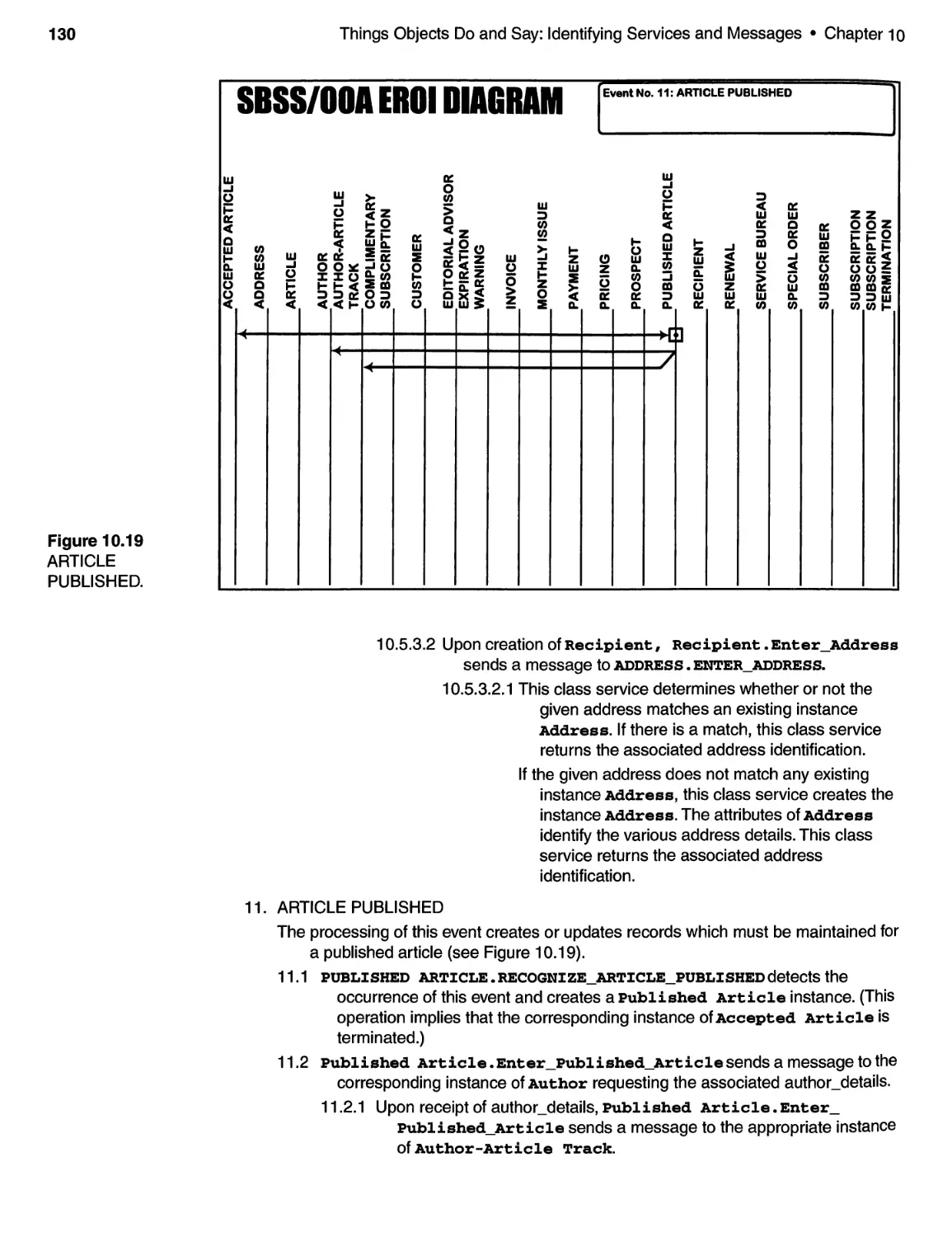
i
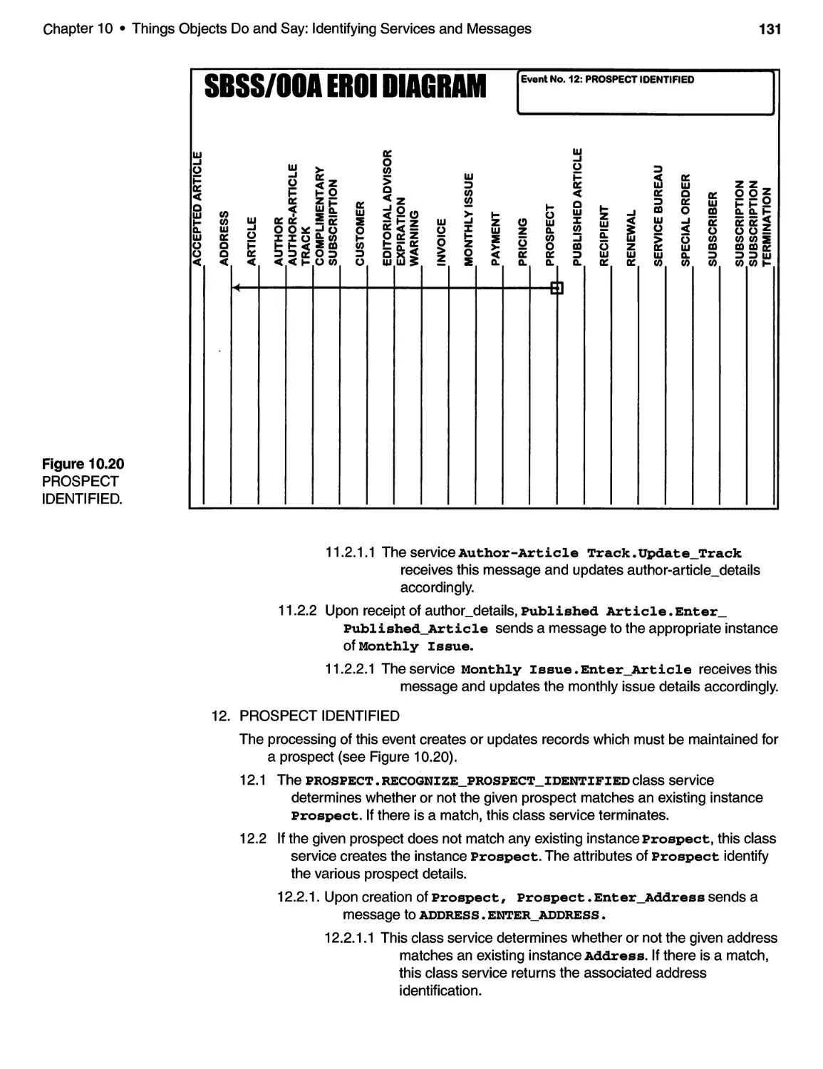
l
r
\
'(
\!
. .
..
. ,
\ "
Edward Your don Carl Argila
YOUR CON PRESS COMPUTING SERIES
,
.
,
ell '.
DISK
INC ..
. .
. .
.
i
..
.
.
..
. .
.
t
, .
.
.
. ..
Object-Oriented Analysis and Design Natatia
CLASS + OBJECT
Attributes
attributes_listed_here
Services
services_listed_here
CLASS + OBJECT represents
non-empty classes. Inner
boundary is the CLASS
BOmWARY Outer boundary
is the mSTNlCE BOUNDARY.
GEllERALIZATION
GEllERALIZATION-SPECIALIZATION
relationships are shown from class
boundary to class boundary.
In this case, the generalization
class has instances
(it is non-empty).
OBJECT
Relationships (or Instance
Connections) are non-directed
lines joining instance boundary to
instance boundary. Multiplicity
and participation designators
(X,Y) are shown.
OBJECT
X,Y
X,Y
\'/HOLE
\'lHOLE-PART relationships may be
interpreted as "strong" instance
relationships. Multiplicity and
participation apply as they would
in ordinary relationships.
Messages are directed lines from
sender to receiver. Normally
messages are from instance
boundary to instance boundary.
However, all of the cases
shown may be allowable
depending on class services.
An unspecified sender or receiver
implies a message "broadcast."
CLASS OULY
CLASS ONLY represents classes which have
no instances. Such classes may also be
referred to as ABSTRACT CLASSES.
GEllERALIZATION
GENERALIZATION-SPECIALIZATION
relationships are shown from class
boundary to class boundary.
In this case, the generalization
class is abstract.
SPECIALIZATION
SPECIALIZATION
GENERALIZATION
X,Y
I
These special cases are permitted.
They imply inheritance of the
relationship or message by the
specialization classes.
SPECIALIZATIOll
\'lHOLE
Variations such as these are
allowed provided the abstract
class is also a generalization
class. The whole-part relation-
ship is then "inherited."
SUBJECTS are boundaries (usually rectangles)
which enclose those objects which are
considered included in the subject.
See Notation and Conventions section on pp. xvii-xviii.
CASE STUDIES IN
OBJECT-ORIENTED
ANALYSIS AND DESIGN
Selected Titles from the
YOURllDN PRESS COMPUTING SERIES
Ed Yourdon, Advisor
ANDREWS AND LEVENTHAL Fusion: Integrating IE, CASE, and JAD
ANDREWS AND STALICK Business Reengineering: The Survival Guide
AUGUST Joint Application Design
BODDIE The Information Asset: Rational DP Funding and Other Radical Notions
BOULDIN Agents of Change: Managing the Introduction of Automated Tools
COAD AND NICOLA Object-Oriented Programming
COAD AND YOURDON Object-Oriented Analysis, 2/E
COAD AND YOURDON Object-Oriented Design
COAD WITH NORTH AND MAYFIELD Object Models: Strategies, Patterns,
and Applications
CONNELL AND SHAFER Object-Oriented Rapid Proto typing
CONNELL AND SHAFER Structured Rapid Proto typing
CONSTANTINE Constantine on Peopleware
CONSTANTINE AND YOURDON Structured Design
CRAWFORD Advancing Business Concepts in a JAD Workshop Setting
DEGRACE AND STAHL The Olduvai Imperative: CASE and the State of Software
Engineering Practice
DEGRACE AND STAHL Wicked Problems, Righteous Solutions
DEMARCO Controlling Software Projects
DEMARCO Structured Analysis and System Specification
EMBLEY, KURTZ, AND WOODFIELD Object-Oriented Systems Analysis
FOURNIER Practical Guide to Structured System Development and Maintenance
GARMUS AND HERRON Measuring the Software Process: A Practical Guide
to Functional Measurements
GLASS Software Conflict: Essays on the Art and Science of Software Engineering
JONES Assessment and Control of Software Risks
KING Project Management Made Simple
LARSON Interactive Software: Tools for Building Interactive User Interfaces
MCMENAMIN AND PALMER Essential System Design
MOSLEY The Handbook of MIS Application Software Testing
PAGE-JONES Practical Guide to Structured Systems Design, 2/E
PINSON Designing Screen Interfaces in C
PUTNAM AND MYERS Measures for Excellence: Reliable Software on Time
within Budget
RIPPS An Implementation Guide to Real-lime Programming
RODGERS ORACLE@: A Database Developer's Guide
RODGERS UNIX@: Database Management Systems
SHLAER AND MELLOR Object Lifecycles: Modeling the World in States
SHLAER AND MELLOR Object-Oriented Systems Analysis: Modeling the World in Data
STARR How to Build Shlaer-Mellor Object Models
THOMSETT Third Wave Project Management
WANG (ed.) Information Technology in Action
WARD System Development Without Pain
WARD AND MELLOR Structured Development for Real-Time Systems
YOURDON Decline and Fall of the American Programmer
YOURDON Managing the Structured Techniques, 4/E
YOURDON Managing the System Life-Cycle, 2/E
YOURDON Modern Structured Analysis
YOURDON Object-Oriented Systems Design
YOURDON Rise and Resurrection of the American Programmer
YOURDON Structured Walkthroughs, 4/E
YOURDON Techniques of Program Structure and Design
YOURDON AND ARGILA Case Studies in Object-Oriented Analysis and Design
YOURDON, WHITEHEAD, THOMANN, OPPEL, AND NEVERMANN Mainstream
Objects: An Analysis and Design Approach for Business
YOURDON INC. YOURDONTM Systems Method: Model-Driven Systems I?evelopment
CASE STUDIES IN
OBJECT-ORIENTED
ANALYSIS AND DESIGN
Edward Yourdon
and
Carl Argila
Who dares to teach must never cease to learn.
John Cotton Dana
=- ,<
YOUR[IDN PRESS
Prentice Hall Building
Upper Saddle River, NJ 07458
Library of Congress Cataloging-in-Publication Data
Yourdon, Edward
Case studies in object-oriented analysis and design / Ed Yourdon.
Carl Argila.
p. em. -- (Yourdon Press computing series)
Includes bibliographical references and index.
ISBN 0-13-305137-4 (alk. paper)
1. Object-oriented programming (Computer science) 2. System
analysis. 3. System design. I. Argila, Carl. II. Title.
III. Series.
QA76.64.Y695 1996
005.1'2--dc20 96-11309
CIP
Acquisitions editor: Paul W. Becker
Editorial assistant: Maureen Diana
Editorial/production supervision/design: Patti Guerrieri
Art director: Gail Cocker-Bogusz
Manufacturing buyer: Alexis R. Heydt
Cover design director: Jerry Votta
Cover designer: Talar Agayasan
@1996 by Prentice Hall PTR
Prentice-Hall, Inc.
A Simon & Schuster Company
Upper Saddle River, NJ 07458
=- .-:. ..!
The publisher offers discounts on this book when ordered in bulk quantities.
For more information, contact: Corporate Sales Department, Prentice Hall PTR,
One Lake Street, Upper Saddle River, NJ 07458, Phone: 800-382-3419, Fax: 201-236-7141,
e-mail: corpsales@prenhall.com
System Architect is a trademark of Popkin Software & Systems. Visual Basic, Microsoft Word,
Windows, and MS-DOS are registered trademarks of Microsoft Corporation. PowerBuilder is a
trademark of the Powersoft Corporation. Delphi is a trademark of Borland International. All
other products are trademarks of their respective companies.
From Famous Quotes. Copyright @ 1994, Infobases, Inc. Reprinted by permission of
Infobases, Inc., Provo, Utah.
All rights reserved. No part of this book may be reproduced, in any form or by any means,
without permission in writing from the publisher.
Printed in the United States of America
10 9 8 7 6 5 4 3
ISBN 0-13-305137-4
Prentice-Hall International (UK) Limited, London
Prentice-Hall of Australia Pty. Limited, Sydney
Prentice-Hall Canada Inc., Toronto
Prentice-Hall Hispanoamericana, S.A., Mexico
Prentice-Hall of India Private Limited, Nezv Delhi
Prentice-Hall of Japan, Inc., Tokyo
Simon & Schuster Asia Pte. Ltd., Singapore
Editora Prentice-Hall do Brasil, Ltda., Rio de Janeiro
To Toni, without whose love and support none of these book projects
would be possible.
Edward Yourdon
To Cecilio,
Carl Argila
(\
J
.;-:.;( ." .....
1-- ,
,
PREFACE
.. .
. . . . . . . . . . . . . . . . . . . . . . . . . . . . . . . . . . . . . . . . . . . . . . . . . . . . . . . . .. "Ill
NOT A TION AND CONVENTIONS .................................. "vii
ACKNOWLEDGMENTS .............................................. "i"
1 INTRODUCTION. . . . . . . . . . . . . . . . . . . . . . . . . . . . . . . . . . . . . . . . . . . . . . . . . 1
1.1 Background: The Philosophy of Software Development. . . . . . . . . . .. 1
1.2 Today's Challenge .. . . . . . . . . . . . . . . . . . . . . . . . . . . . . . . . . . . . . . . . . . . 4
1.3 The Concept of Object-Orientation . . . . . . . . . . . . . . . . . . . . . . . . . . . . . . 5
1.4 Object-Oriented Analysis (OOA) ............................... 6
1.5 Object-Oriented Design (OOD) . . . . . . . . . . . . . . . . . . . . . . . . . . . . . . .. 13
1.6 About This Book ............................................ 17
References for Chapter 1 .......................................... 17
Key Points ...................................................... 17
2 THE CASE STUDIES ............................................. 19
2 .1 Introduction................................................ 19
2.2 The Elevator Control System . . . . . . . . . . . . . . . . . . . . . . . . . . . . . . . . .. 19
2.3 The Small Bytes Subscription System . . . . . . . . . . . . . . . . . . . . . . . . . . . 24
References for Chapter 2 .......................................... 27
Key Points ...................................................... 28
3 FINDING AND KEEPING GOOD OBJECTS ....................... 29
3 .1 Introduction................................................ 29
3.2 Motivation ................................................. 30
3.3 Approach .................................................. 31
3.4 3- View Modeling (3VM) . . . . . . . . . . . . . . . . . . . . . . . . . . . . . . . . . . . . . . 31
vii
viii
Contents
3.5 Linguistic-Based Information Analysis ......................... 33
3.6 Object-Oriented Analysis (OOA) .............................. 35
3.7 Summary................................................... 36
References for Chapter 3 .......................................... 37
Key Points ...................................................... 38
4 CLASS AND OBJECT IDENTIFICATION . . . . . . . . . . . . . . . . . . . . . . . . . .. 39
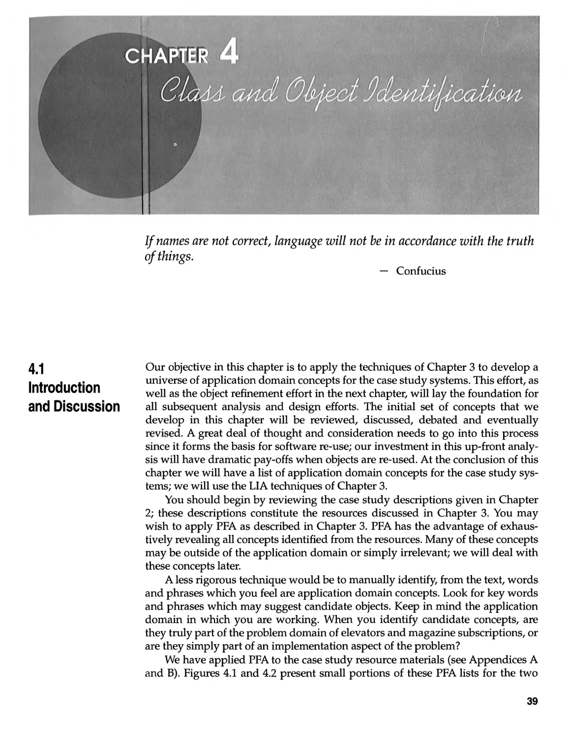
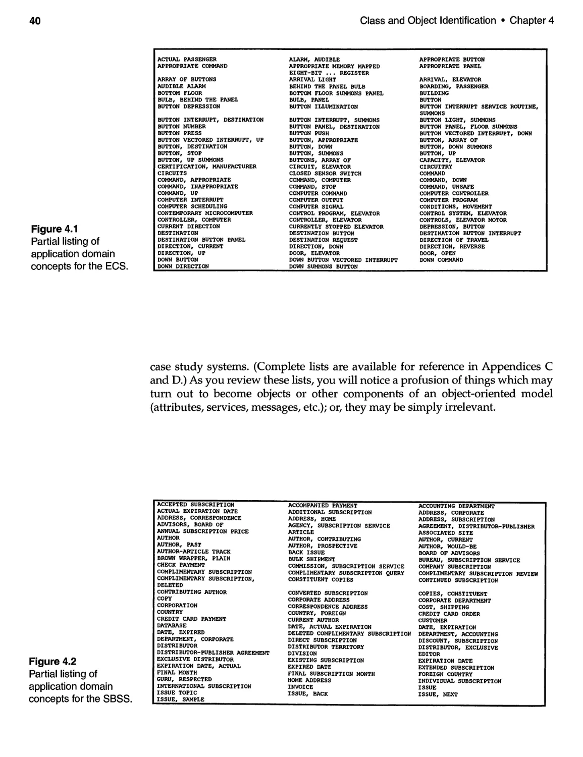
4.1 Introduction and Discussion .................................. 39
4.2 Application Domain Concepts for the
Elevator Control System (ECS) . . . . . . . . . . . . . . . . . . . . . . . . . . . . . . 41
4.3 Application Domain Concepts for the
Small Bytes Subscription System (SBSS) . . . . . . . . . . . . . . . . . . . . . . 42
4.4 Final Comments . . . . . . . . . . . . . . . . . . . . . . . . . . . . . . . . . . . . . . . . . . . . . 43
Key Points ...................................................... 44
5 CLASS AND OBJECT REFINEMENT .............................. 45
5.1 Introduction and Discussion .................................. 45
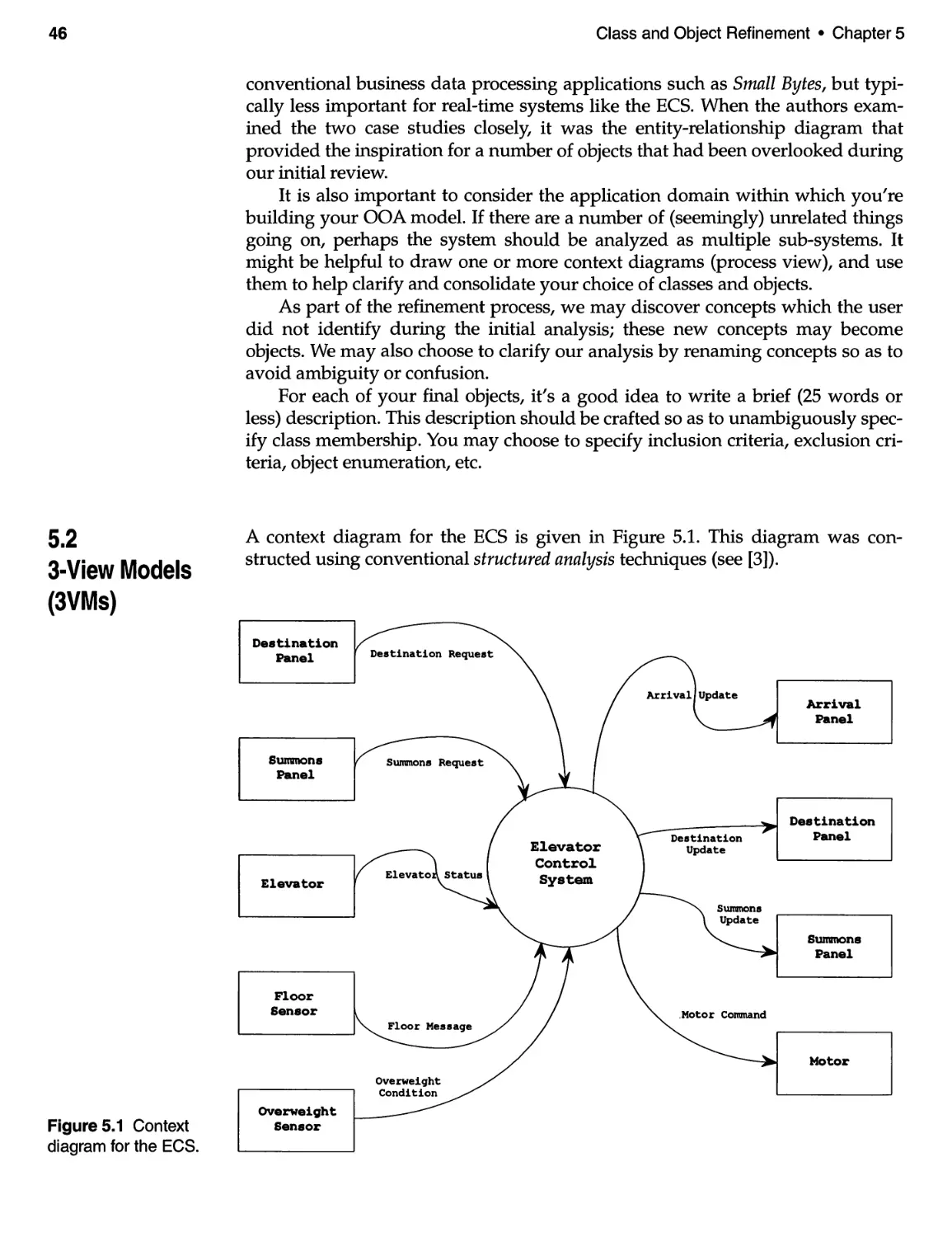
5.2 3- View Models (3VMs) ....................................... 46
5.3 Refinement of Classes and Objects ............................. 55
5.4 Final Comments and Discussion . . . . . . . . . . . . . . . . . . . . . . . . . . . . . . . 64
References for Chapter 5 .......................................... 67
Key Points ...................................................... 67
6 DEALING WITH COMPLEXITY: IDENTIFYING STRUCTURE ....... 69
6.1 Introduction and Discussion .................................. 69
6.2 Structure Layer for the ECS ................................... 70
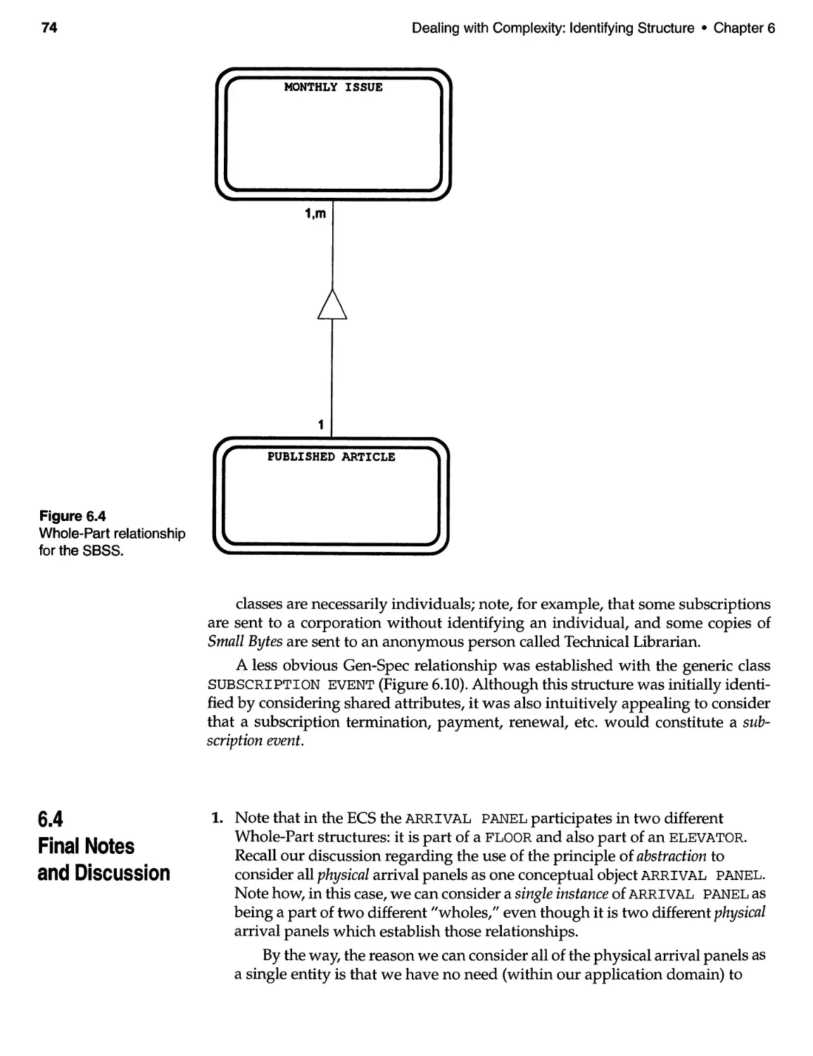
6.3 Structure Layer for the SBSS .................................. 72
6.4 Final Notes and Discussion ................................... 74
Key Points ...................................................... 79
7 DEALING WITH COMPLEXITY: IDENTIFYING SUBJECTS. . . . . . . . .. 81
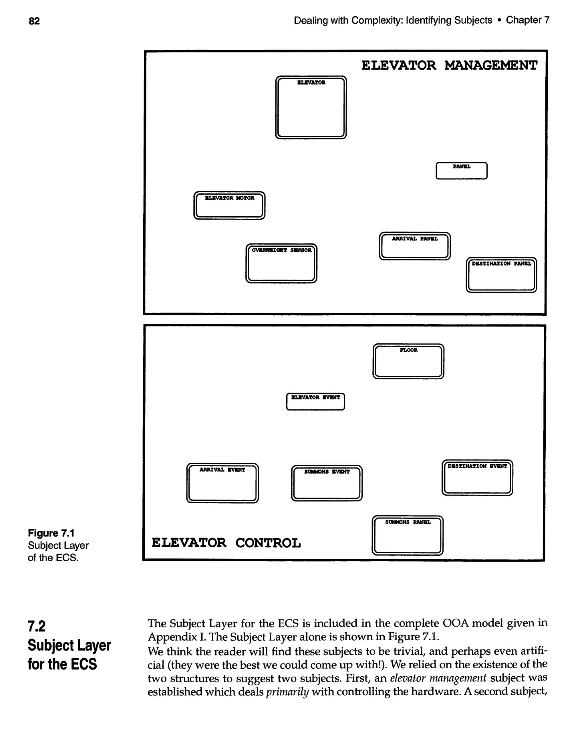
7.1 Introduction and Discussion .................................. 81
7.2 Subject Layer for the ECS . . . . . . . . . . . . . . . . . . . . . . . . . . . . . . . . . . . . . 82
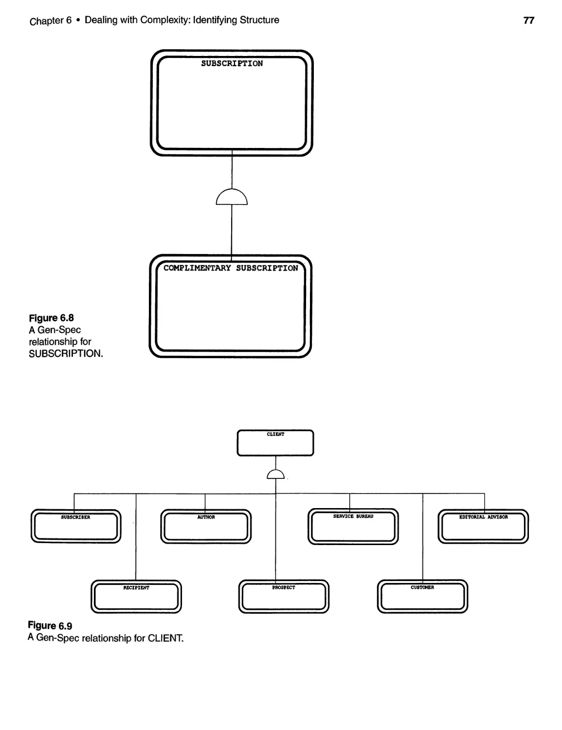
7.3 Subject Layer for the SBSS .................................... 83
7.4 Final Notes and Comments ................................... 84
Key Points ...................................................... 85
8 THINGS OBJECTS REMEMBER: IDENTIFYING ATTRIBUTES ...... 87
8.1 Introduction and Discussion .................................. 87
8.2 Attributes of the ECS . . . . . . . . . . . . . . . . . . . . . . . . . . . . . . . . . . . . . . . . . 89
8.3 Attributes of the SBSS . . . . . . . . . . . . . . . . . . . . . . . . . . . . . . . . . . . . . . . . 90
8.4 Final Comments and Notes ................................... 92
Key Points ...................................................... 93
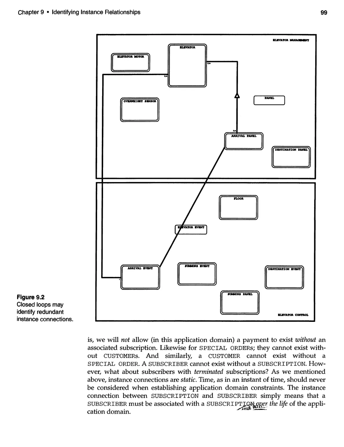
9 IDENTIFYING INSTANCE RELATIONSHIPS. . . . . . . . . . . . . . . . . . . . . . . 95
9.1 Introduction and Discussion .................................. 95
9.2 Instance Connections for the ECS . . . . . . . . . . . . . . . . . . . . . . . . . . . . . . 96
Contents
ix
9.3 Instance Connections for the SBSS ............................. 98
9.4 Final Notes and Comments .................................. 100
Key Points ..................................................... 101
10 THINGS OBJECTS Do AND SAY:
IDENTIFYING SERVICES AND MESSAGES ................... 103
10.1 Introduction and Discussion ................................ 103
10.2 Service Layer for the ECS . . . . . . . . . . . . . . . . . . . . . . . . . . . . . . . . . .. 104
10.3 Service Layer for the SBSS .................................. .116
10.4 Final Notes and Comments ................................. 132
Key Points ..................................................... 133
11 QUALITY ISSUES-COMPLETENESS/CONSISTENCY
OF THE ANALYSIS MODEL ................................. 135
11.1 Introduction and Discussion................................ 135
11.2 The Object-class Layer. . . . . . . . . . . . . . . . . . . . . . . . . . . . . . . . . . . . .. 136
11.3 The Subject Layer. . . . . . . . . . . . . . . . . . . . . . . . . . . . . . . . . . . . . . . . .. 136
11.4 The Structure Layer . . . . . . . . . . . . . . . . . . . . . . . . . . . . . . . . . . . . . . .. 137
11.5 The Attribute Layer . . . . . . . . . . . . . . . . . . . . . . . . . . . . . . . . . . . . . . .. 137
11.6 The Service Layer . . . . . . . . . . . . . . . . . . . . . . . . . . . . . . . . . . . . . . . . .. 138
11.7 Final Notes and Comments ................................. 139
Key Points ..................................................... 139
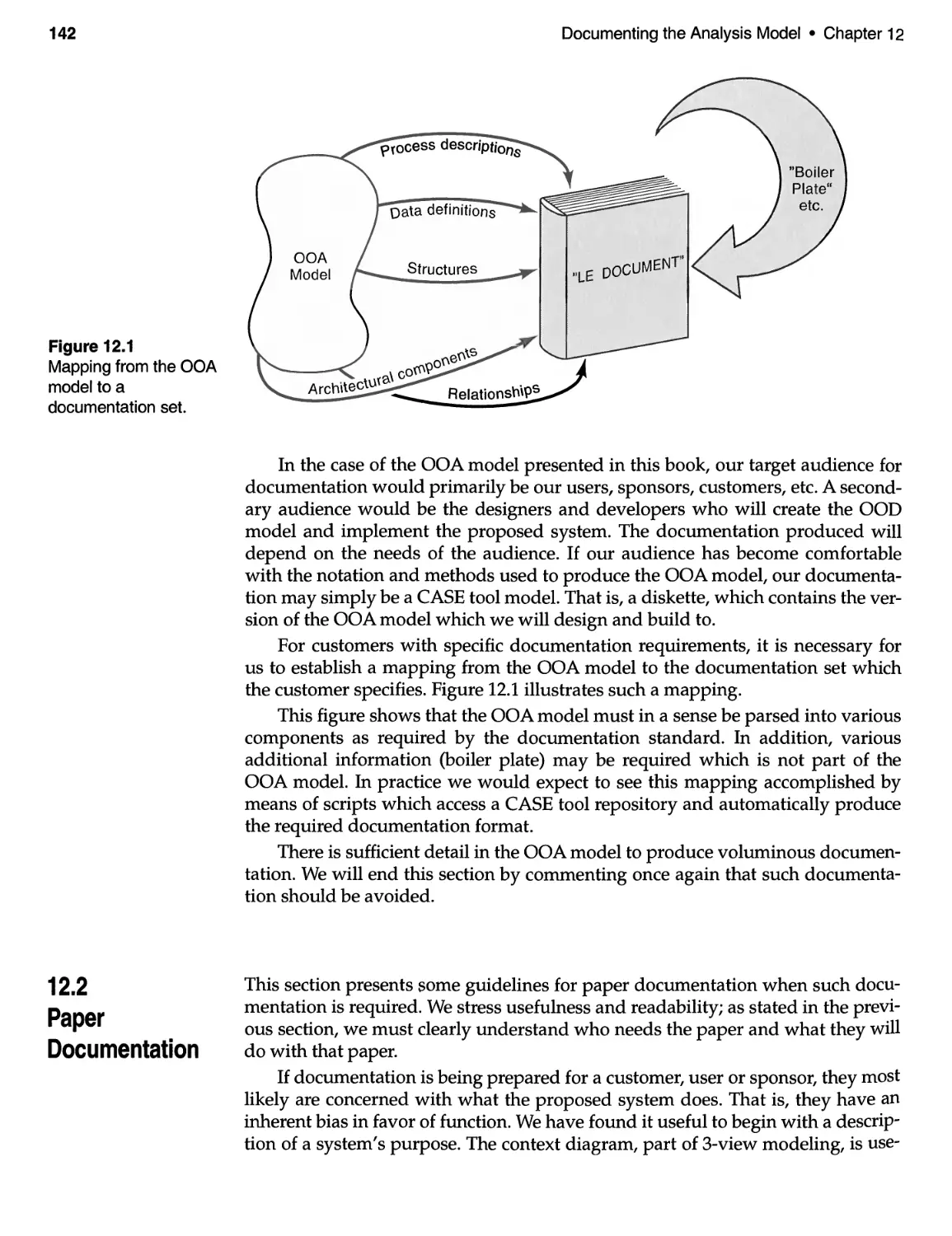
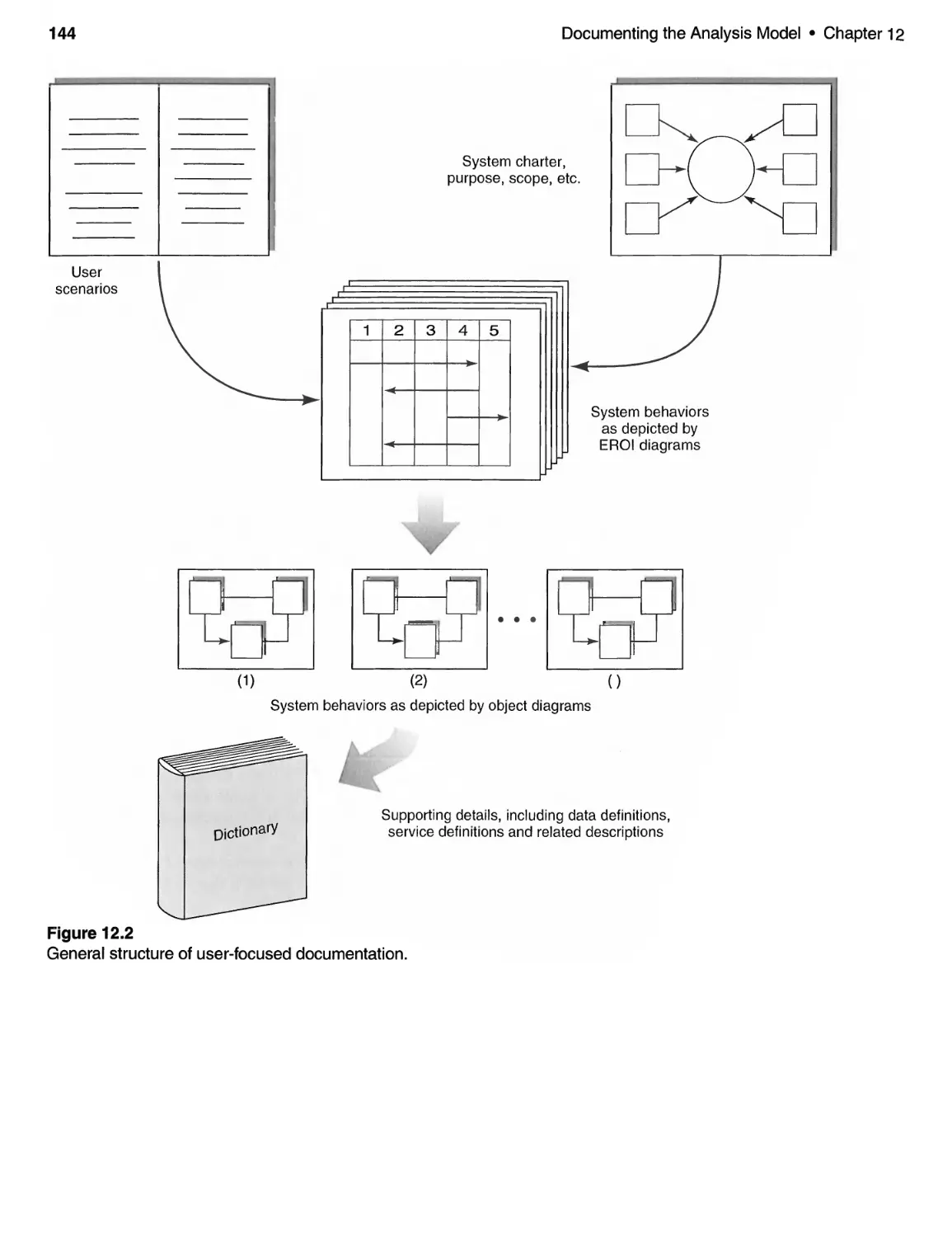
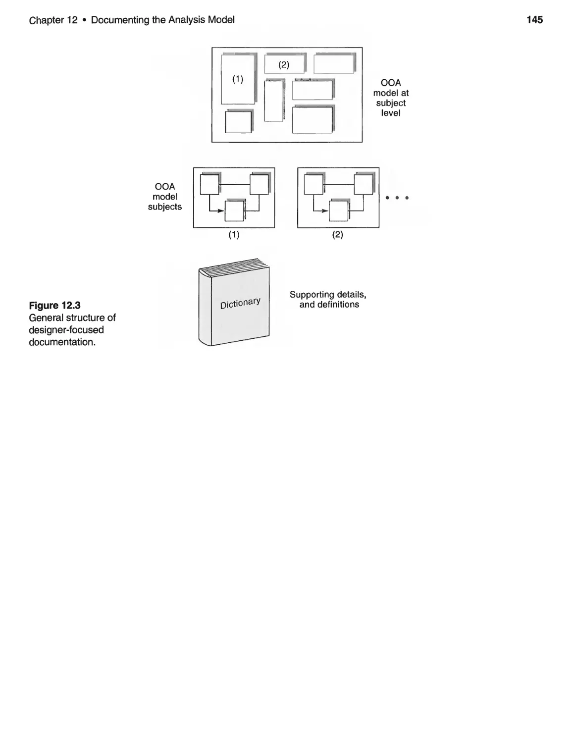
12 DOCUMENTING THE ANALYSIS MODEL ...................... 141
12.1 Introduction and Discussion ................................ 141
12.2 Paper Documentation . . . . . . . . . . . . . . . . . . . . . . . . . . . . . . . . . . . . .. 142
Key Points ..................................................... 143
13 REVIEWING AND REVISING THE ANALYSIS MODEL .......... 147
13.1 Introduction and Discussion ................................ 147
13.2 An OOA Model Review Strategy ............................ 148
Key Points ..................................................... 149
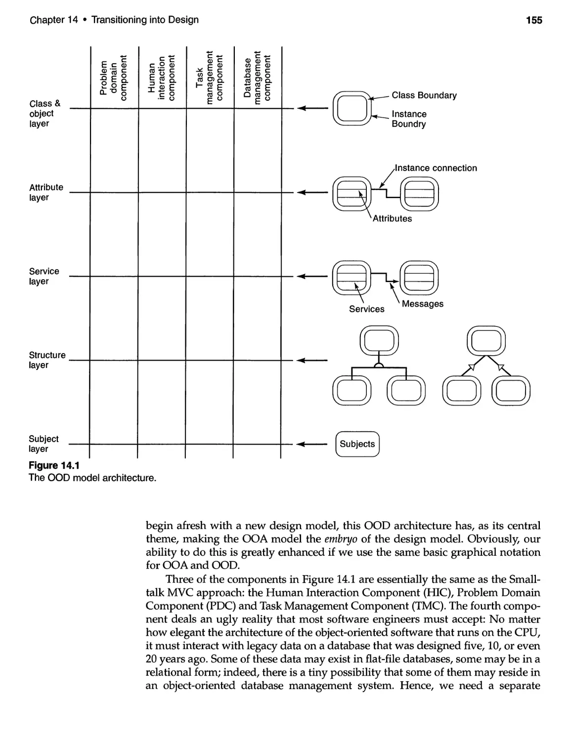
14 TRANSITIONING INTO DESIGN .................. . . . . . . . . . . . .. 151
14.1 Introduction and Discussion ................................ 151
14.2 Design Strategies .......................................... 154
14.3 OOD Issues for the ECS .................................... 156
14.4 OOD Issues for the SBSS . . . . . . . . . . . . . . . . . . . . . . . . . . . . . . . . . . .. 158
Key Points ..................................................... 159
15 PROBLEM DOMAIN ISSUES ................................... 161
15.1 Introduction and Discussion ................................ 161
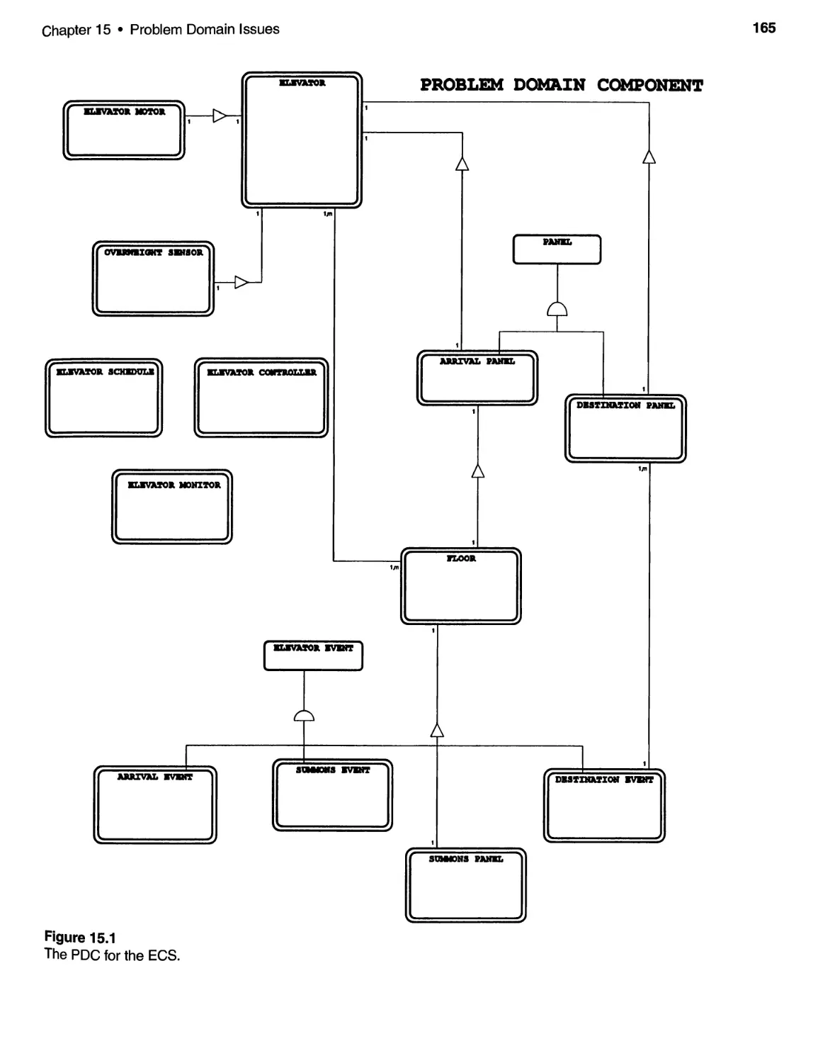
15.2 PDC Considerations for the ECS . . . . . . . . . . . . . . . . . . . . . . . . . . . .. 164
15.3 PDC Considerations for the SBSS ............................ 164
Key Points ..................................................... 166
x Contents
16 SPECIFYING THE HUMAN INTERFACE. . . . . . . . . . . . . . . . . . . . . . . .. 167
16.1 Introduction and Discussion ................................ 167
16.2 The HI C for the ECS ....................................... 168
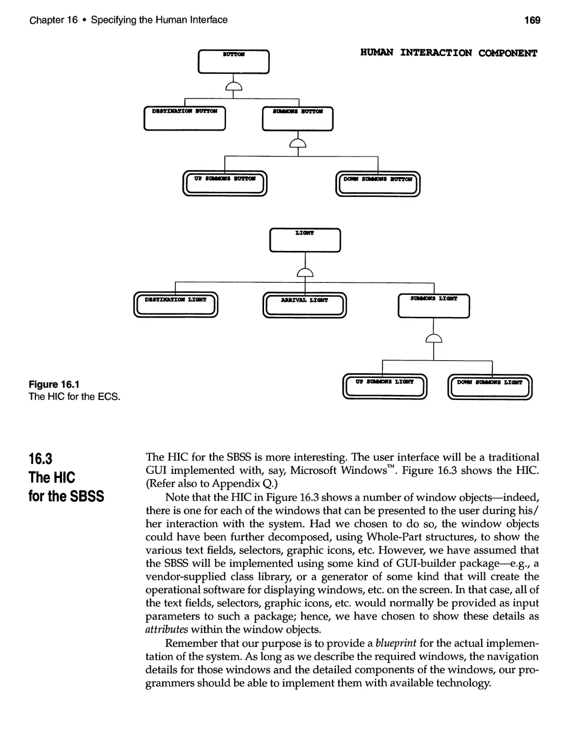
16.3 The HIC for the SBSS . . . . . . . . . . . . . . . . . . . . . . . . . . . . . . . . . . . . . . . 169
16.4 Notes and Final Comments ................................. 171
References for Chapter 16 ..............................0.......... 174
Key Points ..................................................... 175
17 TASK MANAGEMENT ISSUES ................................. 177
17.1 Introduction and Discussion ................................ 177
17.2 Classes and Objects for the ECS ............................. 178
17.3 Notes and Final Comments ................................. 179
Key Po in ts ..................................................... 180
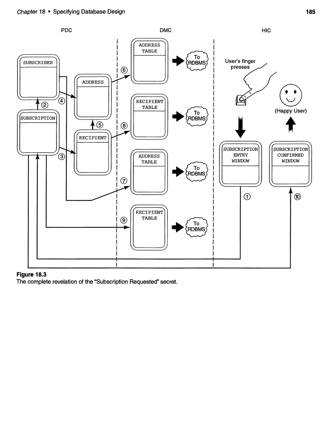
18 SPECIFYING DATABASE DESIGN. . . . . . . . . . . . . . . . . . . . . . . . . . . . .. 181
18.1 Introduction and Discussion ................................ 181
18.2 The DMC for the SBSS ..................................... 182
18.3 Notes and Final Comments ................................. 182
Key Points ..................................................... 184
19 QUALITY ISSUES AT THE DESIGN LEVEL ..................... 187
19.1 Introduction and Discussion ................................ 187
19.2 Quality Issues for the Case Study Systems .................... 190
Referencesfor Chapter 19 . . . . . . . . . . . . . . . . . . . . . . . . . . . . . . . . . . . . . . . .. 191
Key Points ..................................................... 191
20 DOCUMENTING AND REVIEWING THE DESIGN MODEL ...... 193
20.1 Introduction.............................................. 195
20.2 Programming Language Considerations. . . . . . . . . . . . . . . . . . . . .. 195
21 IMPLEMENTATION ISSUES .................................... 195
21.1 An Iterative Software Development Process . . . . . . . . . . . . . . . . . .. 197
21.2 Implementing Object-Oriented Design within
Rapid Application Development (RAD) Environments. . . . . . . . 200
21.3 Testing Object-based Designs ............................... 202
Key Points ..................................................... 203
22 TRANSITIONING TO OBJECT-ORIENTATION-
A TWELVE-STEP PROGRAM ................................ 205
22.1 Introduction and Discussion ................................ 205
References for Chapter 22 ........................................ 210
Key Points ..................................................... 210
Contents
xi
PREFACE TO THE ApPENDICES . . . . . . . . . . . . . . . . . . . . . . . . . . . . . . . . . . . .. 211
A CASE STUDY DESCRIPTION FOR
ELEVATOR CONTROL SYSTEM ............................. 211
A.1 Case Study Description Text. . . . . . . . . . . . . . . . . . . . . . . . . . . . . . . . . .211
B CASE STUDY DESCRIPTION FOR
SMALL BYTES SUBSCRIPTION SYSTEM ..................... 215
B.1 Case Study Description Text ................................. 215
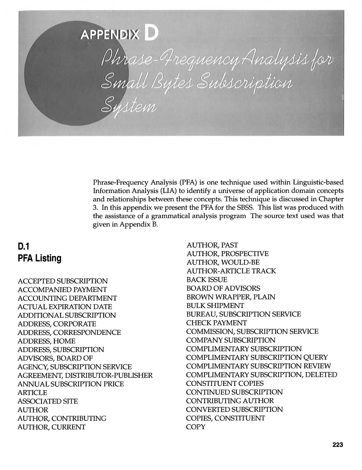
C PHRASE-FREQUENCY ANALYSIS FOR
ELEVATOR CONTROL SYSTEM ............................. 219
C.1 PFA Listing. . . . . . . . . . . . . . . . . . . . . . . . . . . . . . . . . . . . . . . . . . . . . . . . 219
D PHRASE-FREQUENCY ANALYSIS FOR
SMALL BYTES SUBSCRIPTION SYSTEM ..................... 223
D.1 PF A Listing ............................................... 223
E OOA/OOD WORKSHEET FOR
ELEVATOR CONTROL SYSTEM ............................. 227
F OOA/OOD WORKSHEET FOR
SMALL BYTES SUBSCRIPTION SYSTEM ..................... 235
G 3- VIEW MODELS FOR ELEVATOR CONTROL SYSTEM ......... 241
G.1 The Context Diagram . . . . . . . . . . . . . . . . . . . . . . . . . . . . . . . . . . . . . . . 241
G.2 The Entity-Relationship Diagram ............................ 241
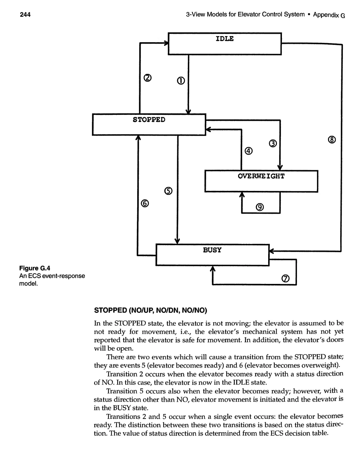
G.3 The Event-Response Model ................................. 243
G.4 The State-Transition Diagram . . . . . . . . . . . . . . . . . . . . . . . . . . . . . . . . 243
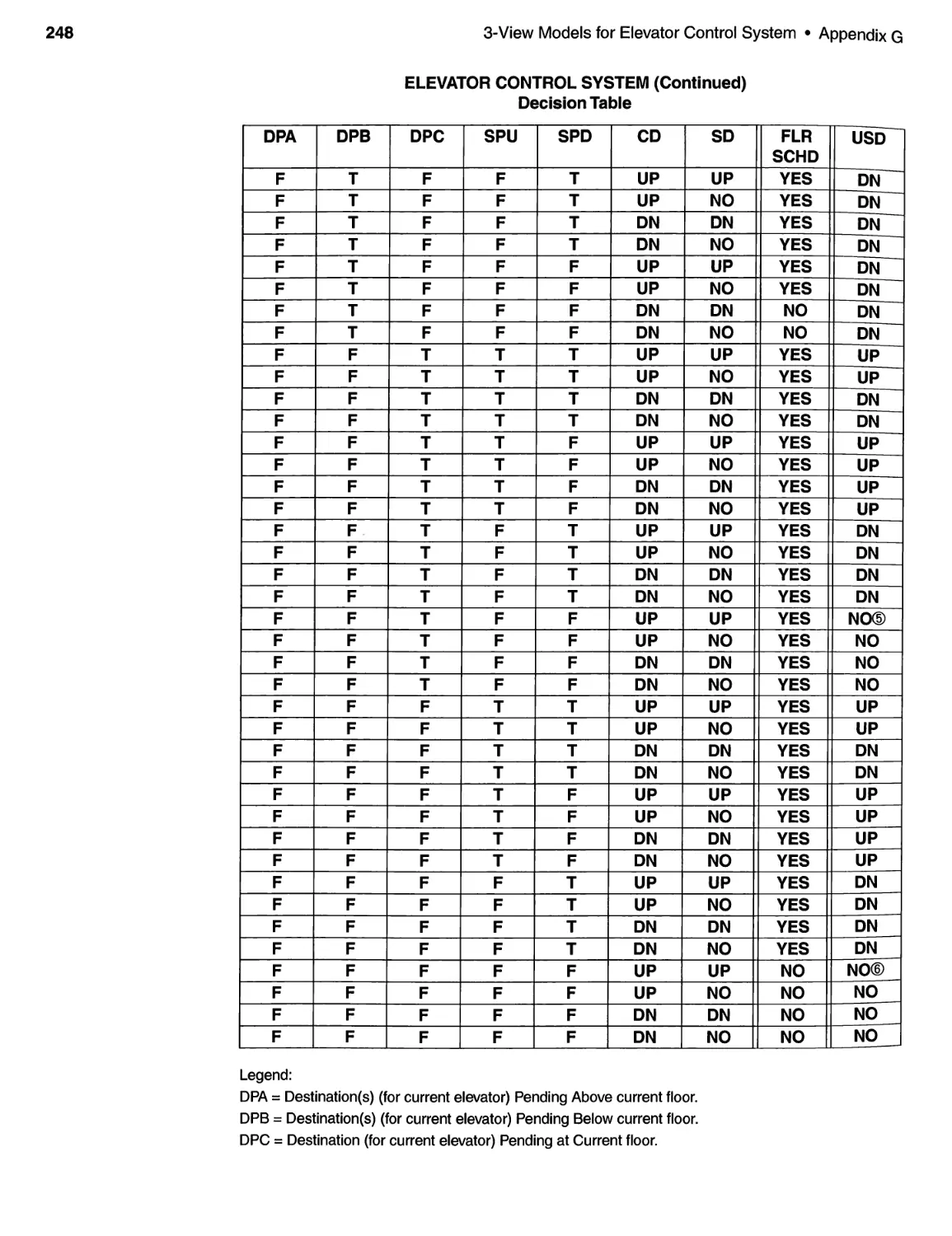
G.5 The Decision Table ......................................... 245
H 3- VIEW MODELS FOR SMALL BYTES SUBSCRIPTION SYSTEM .. 251
H.1 The Context Diagram. . . . . . . . . . . . . . . . . . . . . . . . . . . . . . . . . . . . . . . 251
H.2 The Entity-Relationship Diagram ............................ 251
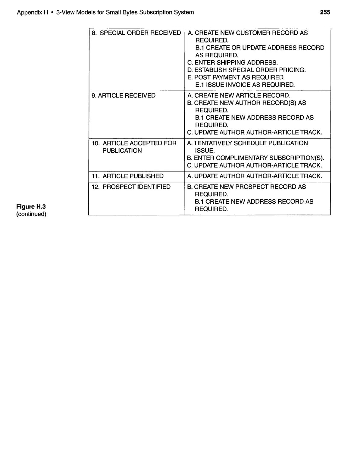
H.3 The Event-Response Model ................................. 252
I OOA MODEL FOR ELEVATOR CONTROL SYSTEM. . . . . . . . . . . . .. 257
1.1 List of ECS OOA Model Components . . . . . . . . . . . . . . . . . . . . . . . . . . 257
1.2 Class Descriptions .......................................... 259
1.3 Attribute Descriptions . . . . . . . . . . . . . . . . . . . . . . . . . . . . . . . . . . . . . . . 260
1.4 Service Definitions .......................................... 262
1.5 Message Definitions . . . . . . . . . . . . . . . . . . . . . . . . . . . . . . . . . . . . . . . . . 269
1.6 Elevator-Scheduling Algorithm . . . . . . . . . . . . . . . . . . . . . . . . . . . . . . . 272
xii
Contents
J OOA MODEL FOR SMALL BYTES SUBSCRIPTION SYSTEM ..... 279
J.l List of SBSS OOA Model Components ......................... 279
J.2 Class Descriptions .......................................... 282
J.3 Attribute Descriptions . . . . . . . . . . . . . . . . . . . . . . . . . . . . . . . . . . . . . . . 285
J.4 Service Definitions .......................................... 290
J.5 Message Definitions . . . . . . . . . . . . . . . . . . . . . . . . . . . . . . . . . . . . . . . . . 296
K EROI DIAGRAM NOTATION. . . . . . . . . . . . . . . . . . . . . . . . . . . . . . . . .. 301
L EROI DIAGRAMS FOR ELEVATOR CONTROL SySTEM......... 305
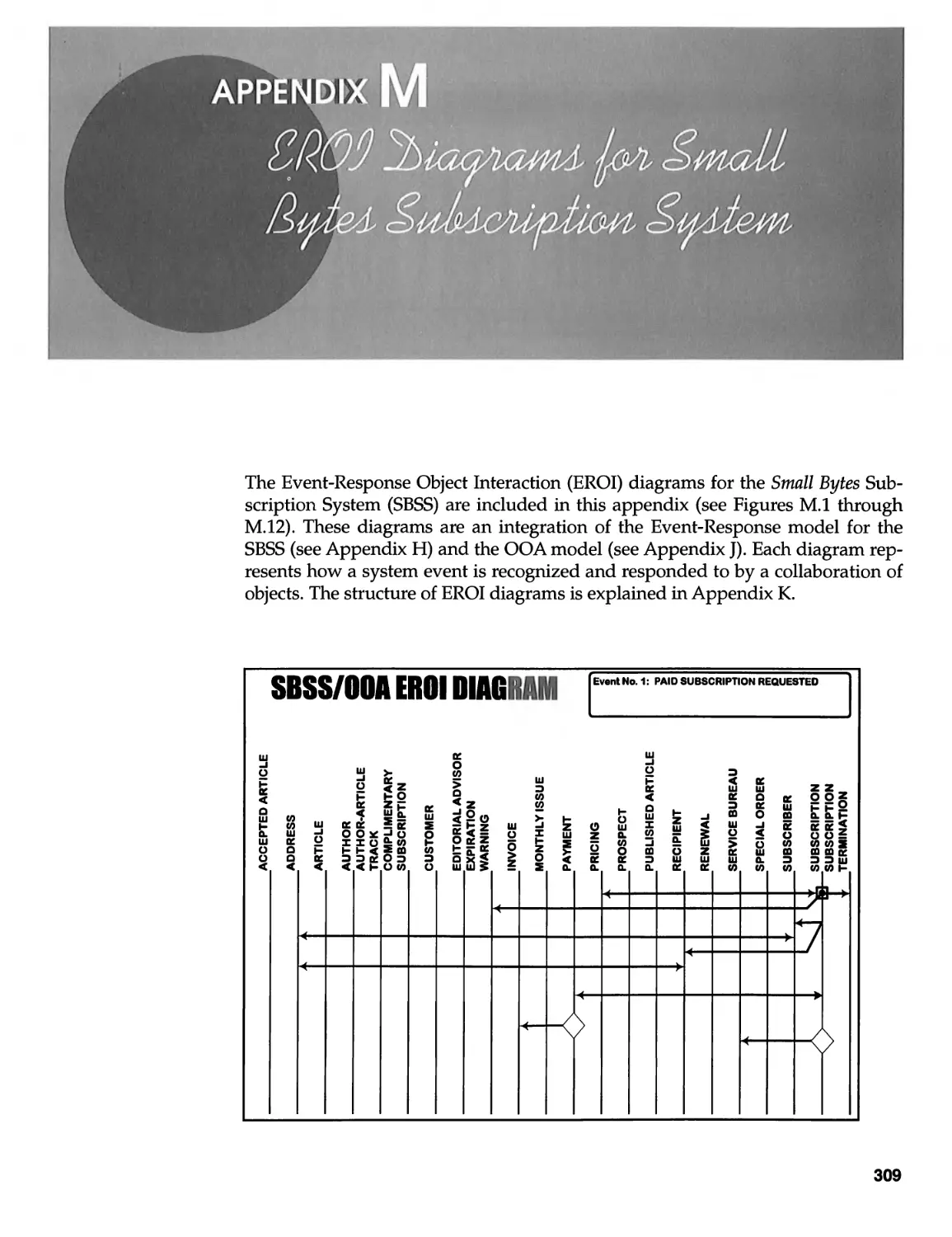
M EROI DIAGRAMS FOR
SMALL BYTES SUBSCRIPTION SYSTEM ..................... 309
N PROBLEM DOMAIN COMPONENT (PDC) FOR
ELEVATOR CONTROL SYSTEM ............................. 317
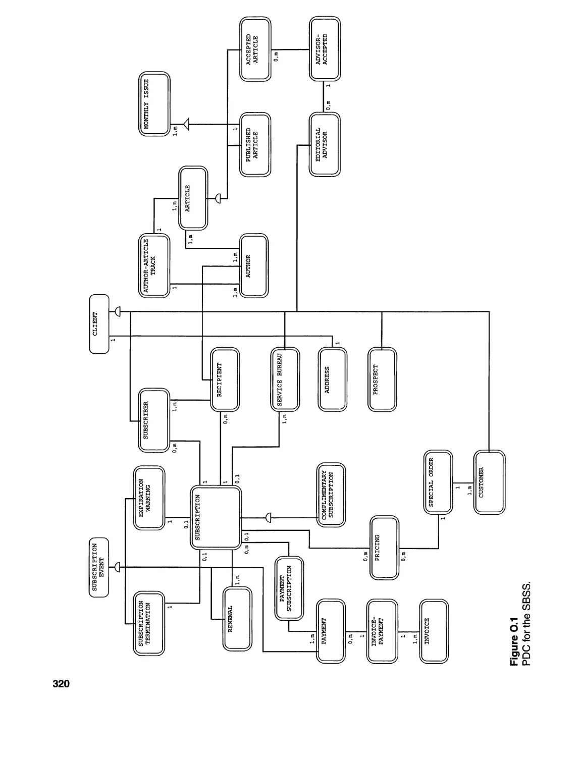
o PROBLEM DOMAIN COMPONENT (PDC) FOR
SMALL BYTES SUBSCRIPTION SYSTEM ..................... 319
P HUMAN INTERACTION COMPONENT (HIC) FOR
ELEVATOR CONTROL SYSTEM ............................. 321
Q HUMAN INTERACTION COMPONENT (HIC) FOR
SMALL BYTES SUBSCRIPTION SYSTEM ..................... 323
R TASK MANAGEMENT COMPONENT (TMC) FOR
ELEVATOR CONTROL SYSTEM ............................. 333
S DATA MANAGEMENT COMPONENT (DMC) FOR
SMALL BYTES SUBSCRIPTION SYSTEM ..................... 335
T PARTIAL LIST OF WORKSHOP GROUPS....................... 337
U CASE STUDIES DISKETTE ..................................... 339
V.1 The ECS Case Study Program. . . . . . . . . . . . . . . . . . . . . . . . . . . . . . . . 339
V.2 The SBSS Case Study Program . . . . . . . . . . . . . . . . . . . . . . . . . . . . . . . 339
IND EX ............................................................. 343
As a graduate student in mathematics, one of the. authors was forced to endure
the presentation of innumerable mathematical theorems. Each theorem was rigor-
ously proved by a learned professor. Each proof was presented as a finished prod-
uct-elegant and beautiful. As a student, however, the author found the proofs
more obscure and confusing than elegant and beautiful!
On one occasion, while presenting a particularly long proof, the professor
became confused and uncertain about the next step. With a somewhat pensive
expression, he walked to a side blackboard, picked up a piece of chalk and began
drawing a figure. He drew circles, arcs, lines and eventually, a look of recognition
flashed across his face. He quickly erased what he had drawn, returned to the
front of the classroom, and proceeded with the proof! But, as you might imagine,
the students were more interested in what the professor had erased than what he
was attempting to prove!
The analysis and design of large, complex software systems are not unlike
mathematical proofs; they are usually presented as finished products. They may
be documented with reams of paper or presented as finished models. Rarely, how-
ever, do software analysts or designers document the anatomy of their analysis or
design. In the past, a savvy software manager could sneak into the offices of his
workers, rummage through their trash cans, and pullout traces of their thinking.
With the advent of CASE tools however, that's harder to do! And, few books on
software analysis and design go deeply into heuristics.
This situation is particularly egregious in the area of object-oriented analysis
and design. Although there are numerous books on the subject (and more corning
out all the time!), few go beyond presenting the terminology, notation and struc-
ture of their own unique models. And, when it comes to the genesis of the pro-
cess-establishing an initial set of objects-guidance is superficial at best. Yet the
wrong choice of objects can have a profound impact on the success of the whole
object-oriented development process. As one C++ instructor recently lamented
about a class, "These guys are just hacking at the object level! They'll never get
any of the object-oriented benefits out of this stuff."
xiii
xiv
Preface
The authors fervently believe that object-oriented analysis and design are real,
with real benefits to be gained. But we also believe, quoting H. L. Mencken, that
"for every complex and difficult problem there is a simple solution. And it is
always wrong." Analyzing and designing large, complex software systems is dif-
ficult. Period. Object-oriented approaches don't make analysis and design easier
than earlier methods. They help us build a better product; they help us improve
productivity-but they're no panacea.
What's missing from the object-oriented analysis and design practitioner's lit-
erature, we feel, is more insight into how object-oriented analysis and design are
done-for real systems. That's what we've tried to present in this book. Although
we present a solution to the case study problems, the nature of the solution is far
less important than how we arrived at it. Our principal contribution, we feel, is in
presenting insight-not technique. Unfortunately, readers seeking the beauty and
elegance of a mathematical proof will have to look elsewhere.
After an introduction to the case study problems, we present a synthesis of
OOA and OOD methods to develop an analysis model and design model. Sepa-
rate chapters are devoted to each of the building blocks of the OOA model (Sub-
ject Layer, Object-Class Layer, Structure Layer, Attribute Layer and Service Layer),
as well as the various components of the OOD model (Problem Domain Compo-
nent, Human Interaction Component, Task Management Component and Data
Management Component). Additional chapters provide some comments on anal-
ysis, design and project management issues.
We have produced object-oriented analysis and design models using the nota-
tion of the Coad and Yourdon technique. Our methodology however, differs signifi-
cantly from the Coad and Yourdon approach. Indeed, we have taken advantage of
components of other object-oriented methodologies-e.g., Ivar Jacobson's Obec-
tOry approach for the discussion of messages between objects-where they pro-
vided useful illuminations. We believe that the principles demonstrated in this
book are applicable to object-oriented analysis and design in general.
We also took advantage of older, more classical structured analysis methodol-
ogies; the entity-relationship diagram and event-response model of both case
studies proved particularly useful for discovering relevant objects, as well as for
providing a deeper understanding of the interactions between objects. Indeed, we
strayed even further afield than structured analysis. For instance, a purely lin-
guistic analysis of the narrative user specifications of the two case studies pro-
vided a very methodical approach for identifying candidate objects for further
investigation.
While object-oriented enthusiasts may have a favorite methodology-e.g.,
Booch, Rumbaugh, Jacobson, Shlaer-Mellor or Coad and Yourdon-we have
found that there is general acceptance of the notion that one might be able to bor-
row ideas and concepts from all of them to attack a problem effectively. On the
other hand, the notion of using the older, structured methodologies may well
offend the purists in the object-oriented camp, who might argue that the same
results could have been achieved without any reference whatsoever to textbooks
written before the dawn of the object-oriented era. For most veteran software
engineers, though, a more pragmatic approach is typically required-especially
when faced with a difficult problem that must be solved within the constraints of
Preface
xv
a tight schedule and budget. From this perspective, it seems foolish to eliminate
useful concepts, tools and techniques that have served us well in the past.
Though time, money and space prevented us from tackling a problem the size
of "Star Wars," we have, nevertheless, selected two very realistic case studies and
applied the principles of object-oriented analysis and design to them. One case
study has a predominant reactive view and should be of interest to readers in the
real-time, embedded systems area. The other case study has a predominant data
view and should be of interest to readers in the MIS community. We decided to
present both case studies in this book; it is interesting and instructive to see how
object-oriented techniques can be applied in such different environments. The
reader should be able to make a personal judgment about the relevance and appli-
cability of object-oriented methods to different environments.
Because they are larger than the typical "tic-tac-toe" game exercises one often
finds in a software engineering textbook, any serious attempt to analyze and
design the case study problems in this book will present some non-trivial difficul-
ties. The authors have used both case studies in numerous seminars and work-
shops during the past few years; we have been constantly amazed by the degree
of intense debate and djscussion they create with our students. We believe that
the case study designs have been developed to the point where these two systems
can be delivered to programmers for implementation. Although we have not dis-
cussed implementation issues, we have created Visual Basic™ prototypes for both
case studies. However, because of the size of the two case studies, we have not
provided fully coded solutions.
Since this is not a book that explains object-oriented principles and theory in
great detail, we have been forced to make some assumptions about you, the
reader. We assume that you are a software engineer with some level of exposure
to both structured analysis methodologies and object-oriented analysis/design
methodologies. However, we assume that your exposure to OOA and OOD has
been limited, at most, to reading one of the popular books in the field, or perhaps
to some limited training in a seminar or workshop. A background like this would
be sufficient for you to work on a "tiny" problem, but probably not adequate to
tackle your first mission-critical object-oriented application at your job. This book
is intended to provide the bridge between that first introduction to OOA and
OOD and a complex real-world application of the theory.
Finally, the authors encourage readers to tell us how this material is being
used, what problems have been encountered and what successes have been
achieved! Our e-mail addresses are below. From time to time, we may post revi-
sions to the materials on our WEB sites, also given below.
Ed Yourdon
New York City
e-mail: yourdon@acm.org
WWW: http://www.acm.org/ -yourdon
Carl Argila
Las Vegas
e-mail: carl@acm.org
WWW: http://www.acm.org/ -aLigra
December, 1995
. . . .. .:.( ..:> --. . ...... .:.:.:.: ..
. -»:"(..... .:.;.:;...: ... ..___... .;.:.:: .::. .... -W a) -"'J'....:-'.' .":..::.:.-:...:.:.;.'.;... .....,...;.:.... «"L . .
\ 4 : r , "k,::. ,,:?' ; ?:/t i f -'7,:' t;:" , .'1 ?! ,! ,' '.: ",
........ ,O< " A'.,. A, ... ,'_ «.<$. . ,.",.;t . '.>A ,"'.{, ., lLA. . ..,. ->.1 '1 ..;$ f.... _.
:::::.:. .)« ..::.' ::.:: :;.
;
Classes are all upper case with space delimiters.
Examples:
ARTICLE
COMPLIMENTARY SUBSCRIPTION
AUTHOR-ARTICLE TRACK
Instances of classes (objects) have initial capitalization with space delimiters.
Examples:
Article
Complimentary Subscription
Author-Article Track
Object attributes are all lower case with underscore delimiters.
Examples:
article_title
complimentary_subscription_id
author-article_date
Class attributes are all upper case with underscore delimiters.
Examples:
TOTAL NUMBER_SUBSCRIPTIONS
PAYMENTS_TO_DATE
:.:!
;.
t
I
::
.
,
;
:j
i
,
xvii
xviii
Notation and Conventions
Object services have initial capitalization with underscore delimiters. Services
are always two or more words (Verb_Noun).
Examples:
Enter_Paid_Subscription
Delete_Complimentary_Subscription
Enter_Article
Class services are all upper case with underscore delimiters. Class services are
always two or more words (VERB_NOUN).
Examples:
CREATE NEW_SUBSCRIPTION
ENTER_PAYMENT
RECEIVE_ARTICLE
Attribute and service names may be "fully qualified" by pre-fixing their names
with the names of their corresponding class or object.
Examples:
Subscription. Enter_Paid_Subscription
SUBSCRIPTION.RECOGNIZE_SUBSCRIPTION_REQUEST
Address.address_details
Subscription Termination.termination_date
See Notation and Conventions chart on the inside front'cover of this text.
I
The authors must first and foremost extend their deepest appreciation and thanks
to Professor Joseph Morrell of the Metropolitan State College of Denver. Dr. Morrell
has been truly unselfish (and at times un-sleeping!) in assisting the authors with the
completion of this manuscript. As the authors schlepped around the world present-
ing their seminars and workshops, it was Dr. Morrell's patience and endurance
which was most responsible for bringing this manuscript to print. Thanks also to
two of Dr. Morrell's colleagues, systems engineers Tamara Gillest and Beth Ross,
for their assistance with the Visual Basic case study implementations and the Sys-
tem ArchitecfM case study models.
The initial version of the Visual Basic case studies was created by Tom
McFarren-a great job which we very much appreciate.
Special thanks to Paul Becker, our editor at Prentice Hall, whose regular tele-
phone calls asking, ".. .so how's the book doing..." helped us not to forget that we
were writing one!
Thanks also to Ron Sherma and Steve Schroer of Popkin Software and Sys-
tems, Inc. for providing the authors with the System Architect product for use with
this project.
Sir Isaac Newton has been quoted as saying, "If I have been able to see farther
than others, it was because I stood on the shoulders of giants." We have had the
most unique opportunity to stand on the shoulders of numerous gial1ts-our fan-
tastic workshop students. Over the past two years, they have endured various
versions and revisions of this material, they have provided insight, they have
been patient, understanding and, most importantly, they have laughed at our
jokes (well, most of the time). A partial list of our workshop groups is included in
Appendix T. Thank you dear friends!
xix
1.1
Background:
The Philosophy
of Software
Development
A" I'
, /
,
There is nothing more difficult to take in hand, more perilous to conduct or
more uncertain in its success, than to take the lead in the introduction of a
new order of things.
- Niccolo Machiavelli
The Prince, Ch. 6
"Philosophy" may seem like an unusual word with which to start off a book of
case studies on software development. However, the authors, whose combined
experience totals well over 1500 fortnights, have witnessed during their careers
dramatic changes in the commonly accepted "philosophy" of building software
systems. When computing began in the 1950's, programs were created using an
ad hoc software development approach; each system was a unique, custom-built
intellectual product. There was no concept of reusability, interchangeability of
parts, or, for that matter, formal design. Although pioneering, these software sys-
tems were difficult to maintain or enhance. And each change to a system pro-
duced a system which was even more difficult to maintain or enhance!
In the 1960's, efforts to produce more maintainable software, in a more pre-
dictable fashion, resulted in the first major change in software development
"philosophy." Ad hoc software development gave way to a more methodical
approach. This approach, commonly referred to as the waterfall approach,
required that a number of formal phases be completed in the process of creating
a software system. Phases such as requirements analysis, high-level design,
detailed design, etc. had to be completed before a subsequent phase could
begin. The completion of each phase was marked by the delivery of one or more
. milestone documents. Hence, the waterfall approach to software development
was frequently characterized by the production of voluminous documentation.
However, despite the more formal approach, large complex software systems
were still being delivered over budget, over schedule and not meeting user
requirements.
(
1
2
Figure 1.1
Model-based
software development.
Introduction · Chapter 1
The 1970's saw another major change in software development "philosophy."
Tom DeMarco, in his seminal book, Structured Analysis and System Specification[1],
introduced the concept of model-based software engineering. Complex software sys-
tems, DeMarco argued, should be built like any large, complex engineering sys-
tem-by first building working paper models of the system before committing
the resources to implement the system. His philosophy was such that users
should be able to "visualize living with the system of the future" before actually
going out and building the damned thing! In the 1970's, this was a radical depar-
ture from simply "hacking out the code" and declaring success if the code gave
some illusion of operating correctly. And, if the code didn't work... well, we didn't
have to worry about that until after the system was deployed-months, if not
years, in the future!
As illustrated in Figure 1.1, this model-based approach is the same as that
taken by architects to specify and design large complex systems, Le., buildings.
Architects build scale models of houses so that users can visualize living with the
system of the future. These models serve as vehicles for communication and
negotiation between users, developers, sponsors, builders, etc.
Virtually all modern software engineering approaches have adopted this
model-based "philosophy." What varies greatly from one software engineering
method to another is the kinds of models that should be built, how they should be
Cb
c::::>
c:::::;")
c:::;:;J
C='
c:>
c:>
.
.
.
I
I
[ rnJ
Blue prints,
diagrams,
inventories,
purchase orders,
etc.
Chapter 1 · Introduction
Figure 1.2
A typical software
development life cycle.
3
built and who should build them. A generic model-based software engineering
life cycle is shown in Figure 1.2. We show various models constructed by different
communities of users for different purposes. A requirements definition model
may be built to capture and negotiate overall system requirements; this model
may be built by representatives from a marketing organization, as well as systems
and software analysts.
An important heuristic concept reflected in most model-based software engi-
neering methods is the principle of Separation of Concerns. This is typically
expressed by constructing an analysis model separate from a design model. Anal-
ysis models (which are a focus of concern in this book) capture software system
requirements which are essential or "logical," as opposed to implementation-
based or "physical" requirements. That is, analysis models describe what a sys-
tem will do, independent of any particular implementation approach or technol-
ogy. On the other hand, design models (also a focus of this book) specify how a
particular system will be built within the context of a given implementation envi-
ronment (platform, network, operating system, database, user interface, etc.)
Analysis models are typically built by those with extensive application domain
knowledge; they may serve as vehicles of communication between customers,
users and developers. Design models, by contrast, are built by those with exten-
sive implementation environment knowledge; they serve as vehicles of communi-
cation between developers, implementers, testers, etc. This principle of Separation
of Concerns is a fundamental driving force behind the approach taken in this book.
Our approach, therefore, "is like other engineering disciplines-it is based
heavily on understanding the problem and establishing requirements by building
--D-O--D-O--t::JL t
t\ \ /
Requirements
definition
model
Design
model
Implementation
model
Analysis
model
\
Users, customers, developers, etc.
4
Introduction · Chapter 1
suitable models of proposed systems. Like other engineering disciplines, we will
build one set of models for the purpose of establishing the essential behavior of a
proposed system and another set of models as blueprints, which specify how to
build the proposed system within a given implementation environment.
1.2
Today's
Challenge
It has become humdrum to talk about the software crisis. Any reader who has
stumbled upon this book knows full well that there has been a software revolution
in our society. Readers know the critical role which software systems play in
numerous applications. Readers know that the software component of delivered
systems may not be the most expensive component, but is usually in series with the
hardware component, Le., if the software doesn't work, the hardware is useless.
What may be less apparent, is the challenge software developers face in deliv-
ering ever larger, ever more complex software systems with a reasonable expecta-
tion of being on budget, on schedule and meeting user requirements and
expectations. To illustrate how difficult this is, Philippe Kahn, founder of Borland
International, presented what he called "Philippe's Law" (see Figure 1.3) in his
keynote address at COMDEX (Las Vegas, 1992). As can be seen from the figure,
the larger the size of a software development team, the less efficient is each mem-
ber of the team. This effect is contrary to one of the basic principles of industrial-
ization. That is, when production processes scale up, each member of the
production team is supposed to become more efficient-not less efficient!
At the very same COMDEX conference, Toshiba Corporation announced its
newest three-inch disk drive product, which had a capacity of 1.2 gigabytes and
could be installed in a laptop or desktop PC. Does any reader doubt that they
could easily fill up a 1.2 gigabyte disk drive with applications?!! Yet, if one
believes Philippe's Law, creating 1.2 gigabytes of application code, with tradi-
tional techniques, would require enormous human resources.
One conclusion from these two observations is that conventional software
development techniques, which depend on humans typing away at code, are
Ln
15K
L _ 15,000
n-
where Ln is the individual
programmer productivity of
each member of an n member
team (LOC/year).
'Z5K
5K
Figure 1.3
Philippe's Law.
1
8
27 n
Chapter 1 · Introduction
1.3
The Concept
of Object-
Orientation
5
inherently flawed. There simply aren't enough people, nor money, to build the
large, complex applications of the future with the techniques of today.
Much of this software might eventually be developed in third world coun-
tries, where labor costs are low. However, if the U.S. is to remain pre-eminent in
this industr}', software development techniques must change-and they must
change dramatically. The authors believe that object-oriented techniques are part
of the solution.
It surely must be difficult for today's young software professionals to appreciate
the dramatic improvements in computer hardware technology since the 1950's. To
make computers do anything seemingly useful in the 1950's and 1960's required
extracting every last "bit" of performance out of the available hardware. Words of
computer memory and clock cycles were counted, tallied and parsimoniously
doled out only when cleverness failed to offer an alternative. Cleverness, how-
ever, led to computer programs which were large, monolithic and intractable.
Sometime during the 1960's, about the time when new transistorized comput-
ers were replacing the water-cooled, vacuum tube behemoths, a new school of
thought began to emerge. These radicals (including the authors) preached that the
large, monolithic computer program, though clearly the most efficient solution to
a problem, was not the best solution. The better computer program, we sermon-
ized, was the computer program which was understandable! Why understandable?
So that such a computer program could actually be maintained and enhanced! In
some organizations, these were radical thoughts!!! The kinds of arguments we
heard were statements like, "Once you've found the best algorithm for computing
Bessel's function, why would you want to change it?!!" As computer technology
spread beyond just the scientific and engineering areas, these arguments became
weaker. For example, the statement that, "Once you've found the best payroll
administration program, why would you want to change it?" isn't very convinc-
ing today.
We radicals preached that modularized computer programs were, though less
efficient, more understandable, extensible and maintainable than large, mono-
lithic computer programs. As the performance of computer hardware advanced,
this approach became more widely accepted within the software engineering
community.
Once everyone agreed that modularized computer programs were better than
monolithic computer programs, software engineers began arguing about how the
modules should be created. One school of thought announced that clearly the best
way to "chunk" modules was by function. "Every module does one and only one
thing. Period." These "functional decompositionists" were challenged head-on by
the "dukes of data." This school of thought preached that, "Every module should
encapsulate one data structure. Period." People involved in real-time systems
development thought that both of the former camps were made up of a bunch of
crackpots. Clearly, said the third group, modules should be chunked by events!
"Every module should recognize and respond to one and only one event. Period."
was this camp's cry.
While these three camps waged war, a fourth school of thought emerged.
Clearl}', they announced, God's way to modularize computer programs is to make,
6
1.4
Object-Oriented
Analysis (OOA)
Introduction · Chapter 1
"Every module correspond to one and only one thing in the real world. Period."
Hummm... that's radically different! Rather than structuring computer programs
in accordance with some analysis approach, the object-oriented campers were
saying that we should structure computer programs in accordance with the prob-
lem to be solved. This is fundamentally appealing! Experience suggests that the
components of a problem domain are perhaps the most stable components of any
software system. (We're told, for example, that the principles of dual-entry book-
keeping haven't changed in the last 300 years, though the implementation tech-
nology has moved from quill pens to PCs.) We have seen in our own experience
that when software systems are enhanced, they usually are enhanced by problem-
domain component. And when systems break, they tend to break by problem-
domain component.
An example of this comes to mind. At the nadir of his career, one of the
authors was associated with avionics software development for an aircraft
project. At one point, the "crisis of the day" was the incorrect wiring of the sole-
noids which controlled the aircraft flight surfaces. The solenoids were wired in
reverse. Hence, when the flight surfaces were commanded to move up, they actu-
ally moved down; when commanded to move down, they moved up. Manage-
ment decided that at this point in the project, too late to re-wire the aircraft, the
problem should be fixed in the flight control software-which turned out to be a
monumental problem. Had the software been developed using object-oriented
techniques, this indeed would have been a trivial fix. The secret of solenoid polar-
ity would have been encapsulated into a single program chunk-an object.
Although the term "object-oriented" is used in a variety of different ways (par-
ticularly in marketing literature!), the term should always suggest an association
between (abstractions of) things in the real world and computer program chunks,
or objects. So what is an object? Informally, an object is an independent, asynchro-
nous, concurrent entity which "knows things" (Le., stores data), "does work" (i.e.,
encapsulates services) and "collaborates with other objects" (by exchanging mes-
sages) to perform the overall functions of the system (being modeled).
It is not our intention to sell object-oriented approaches. However, the reader
may well be wondering at this point: "Why bother?" "Why, exactly, should I care
about objects?" The answer is simple-reuse. Although we have been reusing code
since the dawn of computers, object-oriented techniques allow us to reuse far
more than code. We can reuse requirements, analysis, design, test plans, user
interfaces and architectures. In fact, virtually every component of the software
engineering life cycle can be encapsulated as a reusable object.
In the view of the authors, there are some real advantages to be gained by
object-orientation. We hope that will become apparent as we demonstrate the
application of this approach.
This book illustrates the application of the principles of Object-Oriented Analysis
(OOA) and design. We view the process of analysis, within the context of software
engineering, to be one of establishing fundamental (i.e., essential) system behav-
ior-behavior which must be maintained independently of how the system will
ultimately be built. As discussed above, our approach will be to construct formal
models of a proposed software system (similar to an architect's scale model of a
Chapter 1 · Introduction
7
building) which capture essential system requirements. Insofar as the mechanics
of model building are concerned, we have chosen Coad and Yourdon notation,
which has been documented in detail in [2]. Our techniques, however, are general
and applicable to other forms of OOA as well.
An OOA model depicts the objects representing a particular application
domain together with various structural and communicational relationships. This
will be summarized below and elaborated upon in subsequent chapters. The
OOA model serves two purposes. First, it serves to formalize the "view" of the
real world within which a software system will be built. It establishes the objects
which will serve as the principal organizational structures of that software system
and the various rules or constraints which the real world imposes upon any soft-
ware system built within that application domain.
Secondly, the OOA model establishes how a given set of objects collaborates
to perform the work of the software system being specified. This collaboration is
represented in the model as a collection of message connections which show how
each object communicates with other objects.
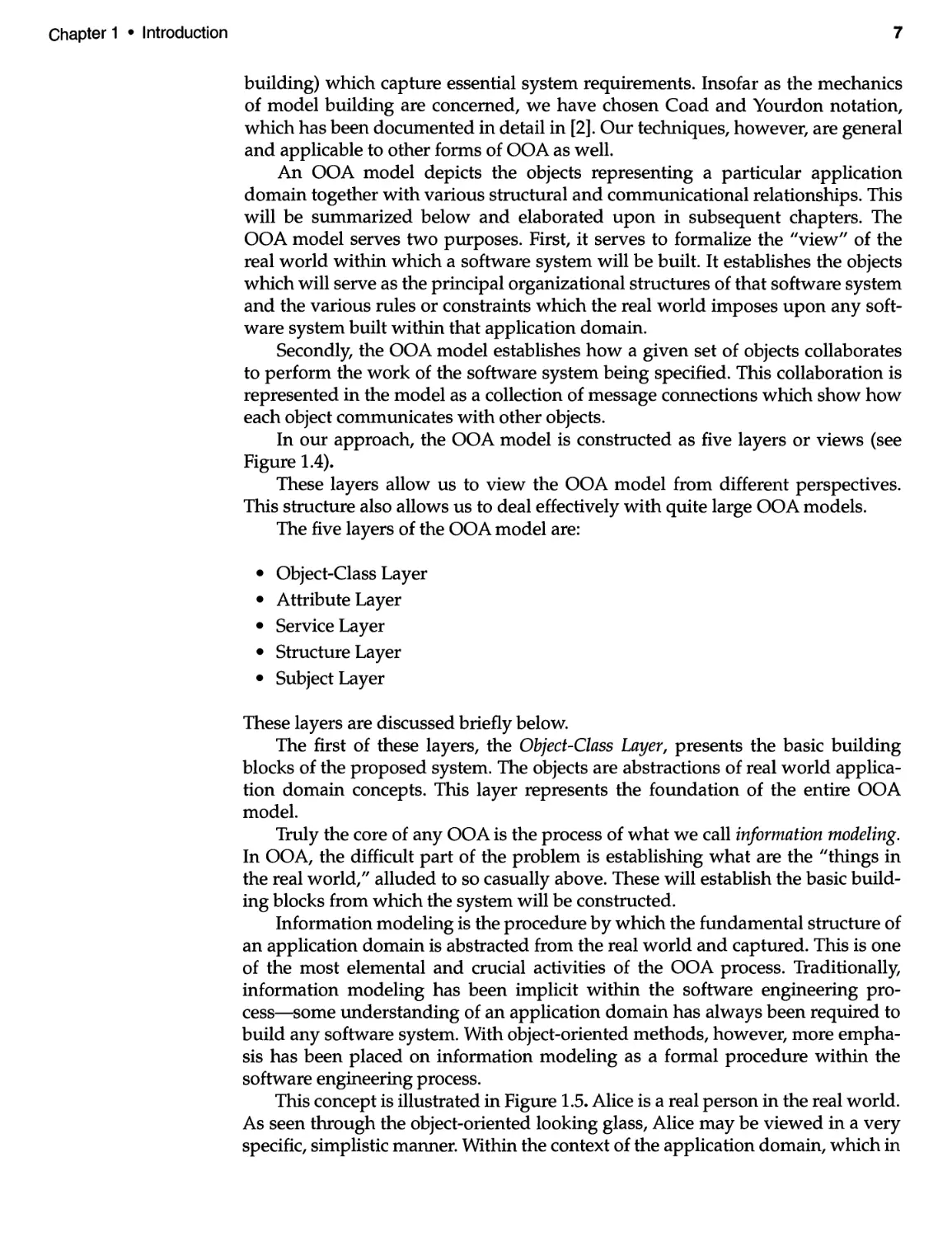
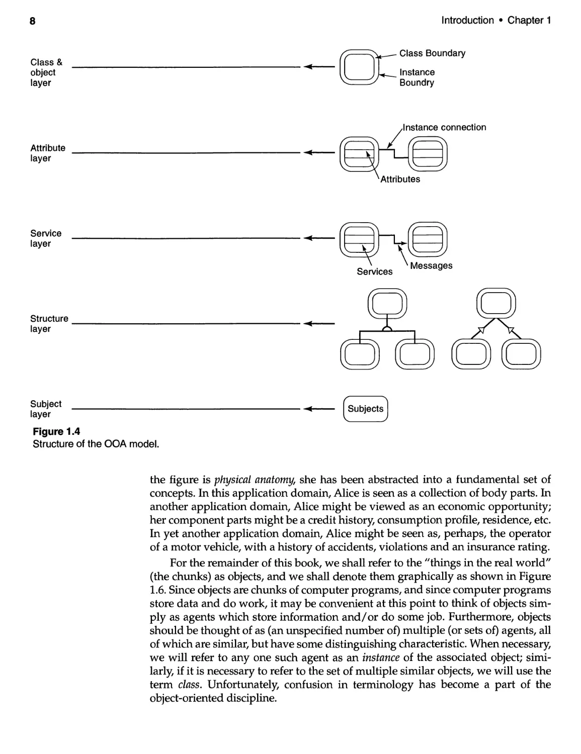
In our approach, the OOA model is constructed as five layers or views (see
Figure 1.4).
These layers allow us to view the OOA model from different perspectives.
This structure also allows us to deal effectively with quite large OOA models.
The five layers of the OOA model are:
· Object-Class Layer
· Attribute Layer
· Service Layer
· Structure Layer
· Subject Layer
These layers are discussed briefly below.
The first of these layers, the Object-Class Layer, presents the basic building
blocks of the proposed system. The objects are abstractions of real world applica-
tion domain concepts. This layer represents the foundation of the entire OOA
model.
Truly the core of any OOA is the process of what we call information modeling.
In OOA, the difficult part of the problem is establishing what are the "things in
the real world," alluded to so casually above. These will establish the basic build-
ing blocks from which the system will be constructed.
Information modeling is the procedure by which the fundamental structure of
an application domain is abstracted from the real world and captured. This is one
of the most elemental and crucial activities of the OOA process. Traditionally,
information modeling has been implicit within the software engineering pro-
cess-some understanding of an application domain has always been required to
build any software system. With object-oriented methods, however, more empha-
sis has been placed on information modeling as a formal procedure within the
software engineering process.
This concept is illustrated in Figure 1.5. Alice is a real person in the real world.
As seen through the object-oriented looking glass, Alice may be viewed in a very
specific, simplistic manner. Within the context of the application domain, which in
8
Introduction · Chapter 1
Class &
object
layer
II(
[: Class Boundary
Instance
Boundry
/Ins tance connection
Q
Attri bute
layer
II(
[:
Service
layer
II(
6
S . \ Messages
ervlces
Structure
layer
II(
Subject
layer
Figure 1.4
Structure of the OOA model.
II(
(SUbjects]
the figure is physicaL anatomy, she has been abstracted into a fundamental set of
concepts. In this application domain, Alice is seen as a collection of body parts. In
another application domain, Alice might be viewed as an economic opportunity;
her component parts might be a credit history, consumption profile, residence, etc.
In yet another application domain, Alice might be seen as, perhaps, the operator
of a motor vehicle, with a history of accidents, violations and an insurance rating.
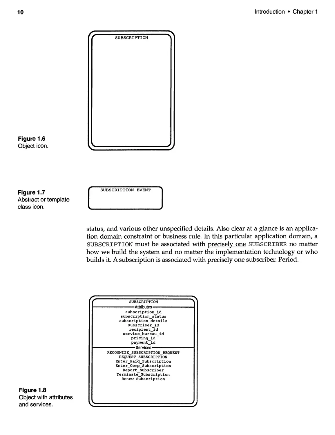
For the remainder of this book, we shall refer to the "things in the real world"
(the chunks) as objects, and we shall denote them graphically as shown in Figure
1.6. Since objects are chunks of computer programs, and since computer programs
store data and do work, it may be convenient at this point to think of objects sim-
ply as agents which store information and/ or do some job. Furthermore, objects
should be thought of as (an unspecified number of) multiple (or sets of) agents, all
of which are similar, but have some distinguishing characteristic. When necessary,
we will refer to anyone such agent as an instance of the associated object; simi-
larly, if it is necessary to refer to the set of multiple similar objects, we will use the
term class. Unfortunately, confusion in terminology has become a part of the
object-oriented discipline.
Chapter 1 · Introduction
Figure 1.5
The object-oriented
looking glass.
9
=
\
h
1\
II
II
If
f(
V
1
I
I
I
I
I
Head
:0,1
I
I
I
Torso
?
.
In Figure 1.6, the outer boundary of the icon is referred to as the instance
boundary; it visually indicates that the object is non-empty. The inner boundary of
the icon is called the class boundary. This notation is useful in that it allows us to
visually distinguish between an entire class (as a whole) or simply members of
that class, Le., objects.
Sometimes it is useful to define objects which will not be implemented as
computer program chunks. We refer to these as template classes or abstract classes
(see Figure 1.7). Template classes may provide a convenient way to consolidate
higher level aggregations, though such aggregations will never be explicitly
implemented.
We refer to those data stored (or encapsulated) by an object as the object's
attributes; the work it does is referred to as its services. In our notation, object
attributes and services may be represented graphically as shown in Figure 1.8.
It is frequently the case that pairs of instances of classes may be constrained,
that is, forced to adhere to some application domain constraint or business rule.
For example, it may be a business rule that when a subscription is deleted, the
associated subscriber must also be deleted. These constraints are referred to as
instance connections. Object attributes, together with instance connections, consti-
tute the Attribute Layer of the OOA model. A portion of an Attribute Layer might
look like the following (Figure 1.9).
At a glance, we can see that in the application domain of the system being
modeled, a SUBSCRIPTION has various attributes or characteristics, such as its
10
Figure 1.6
Object icon.
Figure 1.7
Abstract or template
class icon.
Figure 1.8
Object with attributes
and services.
Introduction · Chapter 1
r,
""'"
SUBSCRIPTION
SUBSCRIPTION EVENT
""""I
status, and various other unspecified details. Also clear at a glance is an applica-
tion domain constraint or business rule. In this particular application domain, a
SUBSCRIPTION must be associated with precisely one SUBSCRIBER no matter
how we build the system and no matter the implementation technology or who
builds it. A subscription is associated with precisely one subscriber. Period.
r,. SUBSCRIPTION " "'"
Attributes
subscription_id
subscription_status
subscription_details
subscriber id
recipien t 3d
service bureau id
pricln9_id -
payrnent_id
Services
RECOGNIZE SUBSCRIPTION REQUEST
REQUEST SUBSCRIPTION
Enter Paid Subscription
Enter=Comp=Subscription
Report_Subscriber
Terminate_Subscription
Renew_Subscription
\..
Chapter 1 · Introduction
11
r;- SUBSCRIPTION """'1'"
Attributes
subscription_id
subscription_status r ""IiI'"
subscription_details r SUBSCRIBER
subscriber id Attributes
recipient_id subscriber id
service bureau id subscriber details
- - address id
pricin9_id
payment_id 1 1 Service
Service
\..""
""
Figure 1.9
Portion of an Attribute Layer.
Object services, together with any message communication between instances
of those objects, constitute the Service Layer of the OOA model. For example, in
Figure 1.10, we observe that both SUBSCRIPTION and SUBSCRIBER perform
work or functions. They also communicate between themselves, that is, they col-
laborate, as shown by the directed arrow.
The message connection shown in Figure 1.10 indicates that one of the services
of SUBSCRIPTION is communicating with one of the services of SUBSCRIBER.
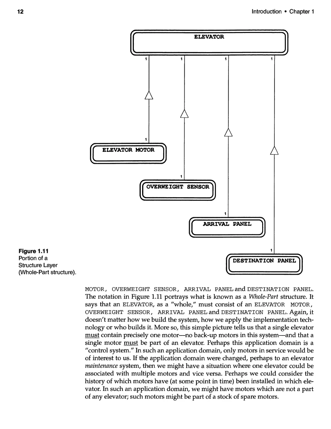
Another layer of the OOA model is the Structure Layer. This layer captures
certain application domain structural relationships. One type of Structure Layer is
shown in Figure 1.11 (another kind of structure will be considered in Chapter 6).
Although this is a different system, within a different application domain, it is
clear at a glance that some kind of relationship exists between an ELEVATOR
Figure 1.10
Portion of a
Service Layer.
r "
SUBSCRIPTION
Attributes
r "","'"
SUBSCRIBER
Attributes
......
SefVice SefVice
RECOGNIZE SUBSCRIPTION ENTER SUBSCRIBER
- - Report_Address
REQUEST Enter_Address
REQUEST_SUBSCRIPTION
Enter_Paid_Subscription
Enter_Comp_Subscription \..
Report_Subscriber
Terminate_Subscription
Renew_Subscription
..
\...
12
Figure 1.11
Portion of a
Structure Layer
(Whole-Part structure).
Introduction · Chapter 1
1 ELEVATOR J
""-
1 1 1 1
1
1 ELEVATOR MOTOR j
.....
1
r ."
( OVERWEIGHT SENSOR )
"-.:
1
( ARRIVAL PANEL 1
""-
1
r """11II
( DESTINATION PANEL )
.....
MOTOR, OVERWEIGHT SENSOR, ARRIVAL PANELandDESTINATION PANEL.
The notation in Figure 1.11 portrays what is known as a Whole-Part structure. It
says that an ELEVATOR, as a "whole," must consist of an ELEVATOR MOTOR,
OVERWEIGHT SENSOR, ARRIVAL PANEL and DESTINATION PANEL. Again, it
doesn't matter how we build the system, how we apply the implementation tech-
nology or who builds it. More so, this simple picture tells us that a single elevator
must contain precisely one motor-no back-up motors in this system-and that a
single motor must be part of an elevator. Perhaps this application domain is a
"control system./I In such an application domain, only motors in service would be
of interest to us. If the application domain were changed, perhaps to an elevator
maintenance system, then we might have a situation where one elevator could be
associated with multiple motors and vice versa. Perhaps we could consider the
history of which motors have (at some point in time) been installed in which ele-
vator. In such an application domain, we might have motors which are not a part
of any elevator; such motors might be part of a stock of spare motors.
Chapter 1 · Introduction
Figure 1.12
Portion of a
Structu re Layer
(Gen-Spec structure).
1.5
Object-Oriented
Design (OOD)
13
ARTICLE
PUBLISHED ARTICLE
ACCEPTED ARTICLE
A second type of structure is the Generalization-Specialization (Gen-Spec) struc-
ture (see Figure 1.12). This type of structure is quite different from the Whole-Part
structure shown above. In this case, we have identified PUBLISHED ARTICLE
and ACCEPTED ARTICLE as specializations of ARTICLE (the generalization). The
Gen-Spec structure exhibits the property of inheritance, that is, attributes or ser-
vices of the generalization class are shared (Le., inherited) by the specialization
classes.
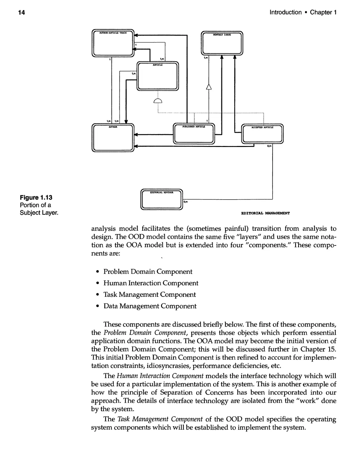
Since OOA models are large, flat structures, the number of objects may
become unwieldy. Objects may be consolidated into subjects; this is accomplished
by enclosing related objects within a subject border. Subjects can be thought of as
sub-models or even sub-systems. The subjects are contained in the Subject Layer.
Figure 1.13 shows a single subject within a Subject Layer. The subject, "editorial
management," includes only those objects which perform system functions asso-
ciated with "editorial management."
At this point, the reader may wish to reference Appendices I and J for exam-
ples of completed OOA models. For convenience, we have summarized OOA
model notation in Figure 1.14.
We stated in the previous section that, within the context of software engineering,
we view the process of analysis to be one of establishing fundamental (Le., essen-
tial) system behavior. By contrast, we view design as the process of specifying the
"blueprints" for construction, that is, the instructions, directions, guidelines, rec-
ommendations, stipulations, qualifications, rules, etc. by which a given software
system should be implemented within a particular environment.
The Object-Oriented Design (OOD) model is constructed as an extension of
the OOA model (see Figure 1.15). Bu lding a design model as an extension of the
14
Introduction · Chapter 1
Figure 1.13
Portion of a
Subject Layer.
AUTHOR-ARTICLE TAACK -
tDnHLY ISSUE
-
1
-
-
1 1,m 1,m , .
ARTICLE
1,m
-
L.. ....... .......-. ................a.......... ............... ...a........... .......................................
1,m 1,m , , ,
AUTHOR PllBLISHED ARTICLE [ ACCEPfED ARTICLE ]
-- -
- -
- . O,m
--
EDITORIAL ADVISOR
O,m
EDITORIAL MANAGEMEN'l'
analysis model facilitates the (sometimes painful) transition from analysis to
design. The OOD model contains the same five "layers" and uses the same nota-
tion as the OOA model but is extended into four "components." These compo-
nents are:
· Problem Domain Component
· Human Interaction Component
· Task Management Component
· Data Management Component
These components are discussed briefly below. The first of these components,
the Problem Domain Component, presents those objects' which perform essential
application domain functions. The OOA model may become the initial version of
the Problem Domain Component; this will be discussed further in Chapter 15.
This initial Problem Domain Component is then refined to account for implemen-
tation constraints, idiosyncrasies, performance deficiencies, etc.
The Human Interaction Component models the interface technology which will
be used for a particular implementation of the system. This is another example of
how the principle of Separation of Concerns has been incorporated into our
approach. The details of interface technology are isolated from the "work" done
by the system.
The Task Management Component of the OOD model specifies the operating
system components which will be established to implement the system.
Chapter 1 · Introduction
C S + OaJ!
AllllbuCes
.ttdbute._li.t.d_h.r.
S.rvlces
..rvic.._li.ted_h.re
CLASS + OBJECT repres.nt.
non- pty cl.s.... Inn.r
boundary I.a the ClASS
IOUH Y Outec bound.ry
is the IHS!AHCE BOUHDAJ\Y.
GEHEAALIIA'nON
GENlRALIIATION-SrEC1ALIIATION
relationships .r. shown fcom cla..
bound.ry to cl..s bound.ry.
ID thi. case, the g.n.c.lization
cl.as ha. in.tancas
lit b non-eII"fItYI.
0 X,Y 0
X,Y
.
Relation.hip. (or In.t.nc.
Connection.' .ra non-dir.cted
lin.. joining in. t.nc. boundary to
in.t.nc. bound.ry. Multiplicity
and participation d..lvn.tors
nc, YI .r. shown.
WHOLB-PART r.lation.hipa y be
int.rpret.d .. -.trong M inst.nca
r.lationships. Multiplicity and
p.rtLcip.tion .pply .s th.y would
In ordin.ry relatlon.hlp..
SEHD!R -- :"'I
MCEIVER
.
-.
. .
"..s.g.. are directed Una. from
..ndar to ncalv.r. Nonully
e..sagae are from instance
bounduy to in.t.Dca boundary.
Howav.r, all of the c....
shown NY be allowable
dap.nding on cl.a. s.rvice.,
o
An unspecified senda. or r.c.iv.r
impliea . s..ge -bro.dcaat.-
Figure 1.14
OOA model notation.
15
CLkSS ONLY
C S ONLY repre.ent. cl...e. Which h.ve
no inst.nce.. Such cl..... NY al.o b.
r.ferred to .. ABSTRACT CLASSES.
GENERALIZATION
GENE IIATIOH-SrEClALIIATION
r.lationahips .re .IIown froa clas.
boundary to cl.as boundary.
In thi. cas., the g.n.r.Uz.tion
cl.ss ia abstr.ct.
srEClALlZATIOH
GEH! IZA'I'IOH
X,Y
TII.s. .paci.l ca.as .te per.1tted.
They iwply inheritance of tha
relationship or ...ga by tha
specializ.tion classes.
SPE.CIALIIATIOH
WKOL!
V.ri.tione such .a the.e .r.
allowed provid.d tha ab.tr.ct
cl..s ia also a 9.neralization
cl..a, 'lh. whole-p.rt r.l.tion-
.hip la than Minharited.-
o
SUBJEC'1'S ar. bound.dea (usudly r.ct.nvl..)
Which enclo.. tho.. obj.cte which ar.
consid.r.d includad in the subject.
16
Class &
object
layer
Attribute
layer
Service
layer
Structure
layer
Subject
layer
Introduction · Chapter 1
..... .....
..... C..... C..... C.....
C OC Q)C Q)Q)C
ECQ) C._ Q) E fnEQ)
Q)'- C ca.....c caQ)c
_ca o E o CJ)Q)0 .c C> 0
.cEa. ::]...a. COC>a. cocaa.
eOE :x:Q)E ....roE cE
a.."C o 'Eo Co Cca O
0 .- 0 ca o EO
E
II(
r Class Boundary
Instance
Boundry
/Ins tance connection
)
II(
II(
S . \ Messages
ervlces
II(
.
( Subjects J
Figure 1.15
Structure of the 000 model.
Finally, the Data Management Component defines those objects required to
interface to the database technology being used. As with the Human Interaction
Component, the Data Management Component is another example of the appli-
cation of the principle of Separation of Concerns; the details of database technol-
ogy are isolated from essential system functions.
The rationale for this approach is technology-independence and therefore
reusability. For example, when a given application system is upgraded from a
GUI interface to, say, a voice-response interface, it should only be necessary to
replace the Human Interaction Component-the remainder of the system should
not be changed. In fact, the remainder of the system should be oblivious to the
change in user interface technology.
Chapter 1 · Introduction
1.6
About This Book
References
for Chapter 1
... Aelf p A
17
Although there are numerous books on the subject of object-oriented analysis and
design, few go beyond presenting terminology, notation and the structure of their
own unique models. And when it comes to the genesis of the process-establish-
ing an initial set of objects-guidance is superficial at best. Yet, it is at this embry-
onic stage that the success or failure of an object-oriented project is established-
though that success or failure may not become apparent until months or years
la ter.
What's missing from the object-oriented analysis and design practitioner's lit-
erature, we feel, is more insight into how object-oriented analysis and design are
done-for real systems. That's what we've tried to present in this book. Our prin-
cipal contribution, we feel, is in presenting insight-not technique.
Charles Dickens once remarked that "I should never have made my success
in my life if I had not bestowed upon the least thing I have ever undertaken, the
same attention and care that I have bestowed upon the greatest." In presenting
these case studies, we have attempted to bestow the greatest attention to even the
least of details-just as would be necessary for real projects.
We hope you will profit from our efforts.
1. Tom DeMarco, Structured Analysis and System Specification (Englewood Cliffs,
NJ: Prentice Hall, 1979).
2. Peter Coad and Edward Yourdon, Object-Oriented Analysis, 2nd edition
(Englewood Cliffs, NJ: Prentice Hall, 1990).
3. Peter Coad and Edward Yourdon, Object-Oriented Design (Englewood Cliffs,
NJ: Prentice Hall, 1991).
The principle of Separation of Concerns distinguishes between essential
requirements and implementation requirements.
A Today's software development techniques can't scale up for the systems of
tomorrow.
A The concept of object-orientation is very different than the traditional top-
down, functional decomposition approach.
A Object-oriented techniques are an enabling technology for full software life
cycle reuse.
A An object is an independent, asynchronous, concurrent entity which knows
things, does work and collaborates with other objects to perform the
functions of a system.
A The Object-Oriented Analysis model has five layers; we use a specific
notation and syntax to represent objects, attributes, services and other object-
oriented concepts.
A The Object-Oriented Design model has four components. It has the same
structure as the OOA model.
2.1
Introduction
2.2
The Elevator
Control System
2.2.1
Specification
of the Problem
! It .,
"
/
--
The path up and down is one and the same.
- Heraclitus
In this chapter, we present a summarized version of a functional specification for
the two case study applications; these will be discussed throughout the remainder
of the book. If either of the case studies were "real-world" projects, the written
specification might be much longer, and the requirements might be much more
detailed. On the other hand, they might not be written at all-especially in the
case of the second application, Small Bytes-and the systems analyst would have
to determine the true user requirements through a combination of questions, dis-
cussion and prototypes.
The text of each case study specification will be used as the basis for a series of
analysis and design models in subsequent chapters; however, we will also discuss
some of the implications and relevant issues of each case study in this chapter.
For the remainder of this book, we shall reference the complete description of
each case study that is included in Appendices A and B.
The general requirement is to design and implement a program to schedule and control
four elevators in a building with 40 floors. The elevators will be used to carry people from
one floor to another in the conventional way.
Efficiency. The program should schedule the elevators efficiently and reasonably. For
example, if someone summons an elevator by pushing the down button on the fourth floor,
the next elevator that reaches the fourth floor traveling down should stop at the fourth floor
to accept the passenger(s). On the other hand, if an elevator has no passengers (no
outstanding destination requests), it should park at the last floor it visited until it is needed
again. An elevator should not reverse its direction of travel until its passengers who want to
19
20
The Case Studies · Chapter 2
travel in its current direction have reached their destinations. (As we will see below, the
program cannot really have information about an elevator's actual passengers; it only
knows about destination button presses for a given elevator. For example, if some
mischievous or sociopathic passenger boards the elevator at the first floor and then
presses the destination buttons for the fourth, fifth, and twentieth floor, the program will
cause the elevator to travel to and stop at the fourth, fifth, and twentieth floors. The
computer and its program have no information about actual passenger boardings and
exits.) An elevator that is filled to capacity should not respond to a new summon request.
(There is an overweight sensor for each elevator. The computer and its program can
interrogate these sensors.)
Destination button: The interior of each elevator is furnished with a panel containing an
array of 40 buttons, one button for each floor, marked with the floor numbers (1 to 40).
These destination buttons can be illuminated by signals sent from the computer to the
panel. When a passenger presses a destination button not already lit, the circuitry behind
the panel sends an interrupt to the computer (there is a separate interrupt for each
elevator). When the computer receives one of these (vectored) interrupts, its program can
read the appropriate memory mapped eight-bit input registers (there is one for each
interrupt, hence one for each elevator) that contains the floor number corresponding to the
destination button that caused the interrupt. Of course, the circuitry behind the panel writes
the floor number into the appropriate memory-mapped input register when it causes the
vectored interrupt. (Since there are 40 floors in this application, only the first six bits of each
input register will be used by the implementation; but the hardware would support a building
with up to 256 floors.)
Destination button lights. As mentioned earlier, the destination buttons can be illuminated
(by bulbs behind the panels). When the interrupt service routine in the program receives a
destination button interrupt, it should send a signal to the appropriate panel to illuminate the
appropriate button. This signal is sent by the program's loading the number of the button
into the appropriate memory-mapped output register (there is one such register for each
elevator). The illumination of a button notifies the passenger(s) that the system has taken
note of his or her request and also prevents further interrupts caused by additional
(impatient?) pressing of the button. When the controller stops an elevator at a floor, it
should send a signal to its destination button panel to turn off the destination button for that
floor.
Floor sensors: There is a floor sensor switch for each floor for each elevator shaft. When an
elevator is within eight inches of a floor, a wheel on the elevator closes the switch for that
floor and sends an interrupt to the computer (there is a separate interrupt for the set of
switches in each elevator shaft). When the computer receives one of these (vectored)
interrupts, its program can read the appropriate memory mapped eight-bit input register
(there is one for each interrupt, hence one for each elevator) that contains the floor number
corresponding to the floor sensor switch that caused the interrupt.
Arrival lights: The interior of each elevator is furnished with a panel containing one
illuminable indicator for each floor number. This panel is located just above the doors. The
purpose of this panel is to tell the passengers in the elevator the number of the floor at
which the elevator is arriving (and at which it may be stopping). The program should
illuminate the indicator for a floor when it arrives at the floor and extinguish the indicator for
a floor when it leaves a floor or arrives at a different floor. This signal is sent by the
program's loading the number of the floor indicator into the appropriate memory-mapped
output register (there is one register for each elevator).
Summons buttons: Each floor of the building is furnished with a panel containing summon
button(s). Each floor except the ground floor (floor 1) and the top floor (floor 40) is furnished
with a panel containing two summon buttons, one marked UP and one marked DOWN. The
ground floor summon panel has only an UP button. The top floor summon panel has only a
DOWN button. Thus, there are 78 summon buttons altogether, 39 UP buttons and 39
Chapter 2 · The Case Studies
21
DOWN buttons. Would-be passengers press these buttons in order to summon an elevator.
(Of course, the would-be passenger cannot summon a particular elevator. The scheduler
decides which elevator should respond to a summon request.) These summon buttons can
be illuminated by signals sent from the computer to the panel. When a passenger presses
a summon button not already lit, the circuitry behind the panel sends a vectored interrupt to
the computer (there is one interrupt for UP buttons and another for DOWN buttons). When
the computer receives one of these two (vectored) interrupts, its program can read the
appropriate memory mapped eight-bit input register that contains the floor number
corresponding to the summon button that caused the interrupt. Of course, the circuitry
behind the panel writes the floor number into the appropriate memory-mapped input
register when it causes the vectored interrupt.
Summon button lights. The summon buttons can be illuminated (by bulbs behind the
panels). When the summon button interrupt service routine in the program receives an UP
or DOWN button vectored interrupt, it should send a signal to the appropriate panel to
illuminate the appropriate button. This signal is sent by the program's loading the number of
the button in the appropriate memory-mapped output register, one for the UP buttons and
one for the DOWN buttons. The illUmination of a button notifies the passenger( s) that the
system has taken note of his or her request and also prevents further interrupts caused by
additional pressing of the button. When the controller stops an elevator at a floor, it should
send a signal to the floor's summon button panel to turn off the appropriate (UP or DOWN)
button for that floor.
Elevator motor controls (Up, Down, Stop;' There is a memory-mapped control word for
each elevator motor. Bit 0 of this word commands the elevator to go up, bit 1 commands the
elevator to dp down, and bit 2 commands the elevator to stop at the floor whose sensor
switch is cl6sed. The elevator mechanism will not obey any inappropriate or unsafe
command. If no floor sensor switch is closed when the computer issues a stop signal, the
elevator mechanism ignores the stop signal until a floor sensor switch is closed. The
computer program does not have to worry about controlling an elevator's doors or stopping
an elevator exactly at a level (home) position at a floor. The elevator manufacturer uses
conventional switches, relays, circuits, and safety interlocks for these purposes so that the
manufacturer can certify the safety of the elevators without regard for the computer
controller. For example, if the computer issues a stop command for an elevator when it is
within eight inches of a floor (so that its floor sensor switch is closed), the conventional,
approved mechanism stops and levels the elevator at that floor, opens and holds its doors
open appropriately, and then closes its door. If the computer issues an up or down
command during this period (while the door is open, for example), the manufacturer's
mechanism ignores the command until its conditions for movement are met. (Therefore, it is
safe for the computer to issue and up or down command while an elevator's door is still
open.) One condition for an elevator's movement is that its stop button not be depressed.
Each elevator's destination button panel contains a stop button. This button does not go to
the computer. Its sole purpose is to hold an elevator at a floor with its door open when the
elevator is currently stopped at a floor. A red emergency stop switch stops and holds the
elevator at the very next floor it reaches irrespective of computer scheduling. The red switch
may also turn on an audible alarm. The red switch is not connected to the computer.
Target machine: The elevator scheduler and controller may be implemented for any
contemporary microcomputer capable of handling this application.
Figure 2.1 illustrates the various components of the elevator control system.
2.2.2
Discussion
of the Problem
Although we will be concerned with the analysis and design of this system from
an object-oriented perspective, we would expect that the behavior of the Elevator
Control System (ECS) will be the same no matter what kind of techniques were
used in its development-object-oriented, structured, ad hoc or otherwise. In fact,
22
The Case Studies · Chapter 2
I 0 0 0 0 0 0 0 0 0 0 I
Arrival
panel
4'
Floor
switch
Summons
I r panel
Summons
button(s) and
light(s)
( shaft)
View from the floor (outside)
(a)
I 0 0 0 0 0 0 0 0 0 o l Arrival
, , panel
4 I
Emergency
stop switch
I . --- I
Stop button
[Q] I Motor I I
Figure 2.1 Overweight
(a) A sketch of a typical sensor
elevator-view from I Wheel
the floor, outside the
elevator.
(b) A sketch of a typical
elevator-view from
inside the elevator.
00
00
00
00
00
00
00
00
00
00 ,
Destination
panel
View from the elevator (inside)
(b)
as we will see in Chapter 5, some non-abject-oriented, traditional structured tech-
niques are quite useful in capturing the required behaviors of the ECS.
Independent of analysis and design techniques, we know, for example, that
elevators have to be "scheduled." That is, when summons or destinations are
requested, or when an elevator moves past a floor, some decisions have to be
made about the control of a particular elevator. As it turns out, there is a related,
but different concept, Le., "dispatching." We use this term to refer to the initiation
Chapter 2 · The Case Studies
23
of activity of a particular elevator. The ECS therefore is primarily concerned with
the scheduling and dispatching of elevators. Our point is that the specification of
how we want the ECS to schedule and dispatch elevators is independent of analy-
sis and design techniques and needs to be understood as a discipline unto itself.
Most readers of this book will not be familiar with elevator scheduling algo-
rithms and the like-neither are the authors. In the course of teaching our work-
shops, however, we have developed some understanding of the behavior of
elevators. Aside from the distinction between scheduling and dispatching, the
reader should be aware of several additional concepts.
First, elevators obviously have directions of movement (up, down or none).
As it turns out, understanding how elevators behave requires identifying a sec-
ond kind of direction, "intended direction," or what we call status direction. An
elevator's status direction may be different from its actual direction. For example,
when an elevator is stopped at a floor, but has pending upward destinations, its
actual direction will be none, but its status direction will be up.
Another concept which is necessary to understanding the behavior of eleva-
tors is that of a scheduled floor. A floor may be "scheduled" with respect to a partic-
ular elevator, if that elevator must stop at that floor, for whatever reason. This
may be the result of pending destinations or an appropriately pending summons
request at the given floor. As it turns out, establishing whether or not a given floor
is a "scheduled floor" for a given elevator, at the point in time at which the eleva-
tor approaches the floor, is the crux of elevator scheduling. And now, the reader
must ponder on the following statement: Establishing whether or not a given
floor is a "scheduled floor" can be accomplished solely on the basis of destina-
tions pending (for that elevator), summons pending (for that floor), the actual
direction of the elevator and the status direction of the elevator.
One final note regarding the behavior of elevators from this generic perspec-
tive. The approach taken above is biased; it is biased in the sense that elevator
scheduling is done independently, for each elevator, at the moment in time when
an elevator reports its approach to a given floor. For lack of a better name, we will
refer to this approach for scheduling elevators as "asynchronous, floor-based
scheduling."
Clearly, the scheduling of elevators could be accomplished on a different
basis, say, every 10 seconds. That is, every 10 seconds the entire system could be
re-examined and elevators re-scheduled accordingly. Or, say, every 100 seconds.
Or perhaps, based on historical data, elevators could be set on their schedules
once every 24 hours (similar to a commuter train). These might all be considered
examples of "synchronous scheduling."
In our workshops, students frequently object to this scheduling bias. They
accuse us of biasing the analysis in favor of one particular implementation-asyn-
chronous, floor-based scheduling. This is not true. The assumption that elevator
scheduling will be asynchronous and floor-based, is simply part of the application
domain, or context within which we study the ECS. By analogy, if we were to
spec'ify an accounts receivable system, there would probably be no objection to
the tacit assumption that we specify the system within the context of commonly
accepted accounting principles and practices.
For the remainder of this book, we will focus on the analysis of the ECS
assuming asynchronous, floor-based scheduling. Readers interested in learning
24
2.3
The Small Bytes
Subscription
System
2.3.1
Specification
of the Problem
The Case Studies · Chapter 2
more about elevator control systems should consult the references at the end of
this chapter. As it happens, this problem is of far broader interest than simply for
elevators (see "The Pure Theory of Elevators," referenced below).
Now, let's start talking about the ECS from an object-oriented perspective.
While there are obviously a number of items in the problem description that
will be identified as objects, and while many of those objects have a number of
interesting data-related characteristics, our attention is drawn to the behavior of
the objects. Our focus is on such issues as: when does an elevator have to go up or
down? How does the summons button communicate with the summons light, and
with what other objects must it communicate? Under what circumstances is it
legal for the elevator motor control to respond to an up or down command?
Within this context, it is also evident that the elevator problem cries out to be
modeled as a number of asynchronous, communicating "things"-whether we
call those things objects or entities or poobahs is less important than the fact that
we want to stay away from a classical, synchronous structured design model in
which a single executive module controls the execution of a number of subordi-
nate modules. By contrast, since the Small Bytes problem described below exhibits
no real-time characteristics, the issue of asynchronous behavior doesn't arise; a
classical transaction-based model would suffice just as well. Note that an IE
approach, which deals with entities, is less appealing than an object-oriented
approach for the elevator problem. A key characteristic of the application is the
communication between various components, which the object-oriented approach
handles naturally with the concept of messages between objects.
There is one other characteristic of the elevator problem description that must
be emphasized: there is a great deal of discussion of implementation technology.
Unlike the Small Bytes problem description below, which is basically technology-
independent, the elevator problem description talks about microprocessors, mem-
ory-mapped input registers, relays, vectored interrupts, interrupt service routines,
sensors, signals and a scheduler. Some of these details may be associated with the
electromechanical environment in which our computer system will be placed;
other details obviously involve the user's assumption about the hardware and
software technology that will be employed to implement the system. An impor-
tant task for the systems analyst-regardless of whether he or she uses an object-
oriented approach or any other methodology-is to eliminate as many of these
irrelevant technology details as possible from the analysis model, to provide a
"perfect technology model" of the essential user requirements.
A small, independent software journal, Small Bytes, has asked you to design a new system
for managing its subscriptions; they have a jury-rigged system today using various
Macintosh-based spreadsheet, word-processing, and flat-file database packages, and it
has gotten completely out of hand. While the concept of managing subscriptions is quite
straightforward, the details are numerous, as will be seen below.
Small Bytes is published on a monthly basis; a typical monthly issue consists of 5-10
articles, each written by one or more authors in the software engineering field. Though the
authors receive no payment for their articles, they do receive a year's free subscription as a
token of appreciation for their efforts; if they already have a subscription, then the expiration
date is extended for a year. Most authors have written only one article during the journal's
five-year history, but a few have written several; management is concerned with keeping
Chapter 2 · The Case Studies
25
track of this information, for it wants to avoid publishing more than one or two articles from
anyone author in a single year.
Small Bytes also has an editorial board of advisors, some of whom may also be authors
from time to time; the editorial board normally serves for a one-year or two-year term, and
they too receive a complimentary subscription to the magazine. The editorial board reviews
submitted articles, and also makes suggestions to Small Bytes's publisher and managing
editor about topics for future issues, and prospective authors who should be contacted to
write articles on those topics. As with most magazines, issues are scheduled and planned
months in advance; hence, the editor is dealing with several issues and its associated
authors simultaneously, as well as receiving numerous unsolicited articles from a variety of
past, current, and would-be authors.
Small Bytes is sold on a subscription basis; most subscriptions are for a one-year period,
but the publisher accepts subscriptions for periods longer than or shorter than a year by
simply pro-rating the annual subscription price. There are only a few thousand subscribers;
most are "corporate" subscribers, but some are individuals who have Small Bytes sent to
their home address in a plain brown wrapper. Most of them are "single-copy" subscribers;
however, it is not uncommon for large companies to order multiple copies, all of which are
sent to the same person. (However, in some cases, the organization is adamant that a
person not be named in the subscription, and that the magazine be sent to a title, such as
"Technical Librarian," instead). Multiple-copy subscriptions typically involve a small discount
from the single-copy price; in addition, various other discounts have been offered from time
to time, though the overwhelming majority of subscriptions are at a standard price. (Note,
however, that the "standard" price is different for North American subscriptions and
international subscriptions, in order to cover the higher cost of shipping overseas.)
There are a few cases of multiple-copy subscriptions where the subscribing organization
asks that the constituent copies be sent to named individuals; of course, it is important to
keep track of the "primary" subscriber from whom payment is received, and to whom any
correspondence should be addressed. Generally, these issues are sent to multiple people
within one "site" (e.g., one division or department, located at a single corporate address);
however, there are a few cases where the multiple copies are sent to individuals in different
sites within the corporation. In any case, the publisher finds it convenient to identify
subscribers within a site, and the various sites associated with an organization.
Most subscriptions are received directly from the subscriber; however, the publication also
deals with a number of agencies, or subscription service bureaus, such as EBSCO, Faxon,
and Readmore. These agencies receive a small commission for the subscriptions they
provide, though this fact is generally kept hidden from the subscriber; it means, though, that
the publisher must keep track of the "retail" price that the subscriber is being charged, as
well as the commission paid to the agency.
In addition, the magazine is distributed in several foreign countries by distributors who have
an quasi-exclusive right to market the magazine in their territory. The distributors receive a
somewhat larger discount for a bulk shipment of magazines (in addition to paying for the
shipping costs, which can be substantial), which they then distribute to their subscribers.
Typically, some "direcf' subscriptions from the distributor's country existed prior to the
distributor-publisher agreement, and Small Bytes continues to supply those subscriptions
directly. In addition, the distributor is supposed to supply the names and addresses of his
own subscribers (in case the distributor goes out of business) to the publisher; in practice,
this has not been done consistently in the past, but the publisher is determined to enforce
this provision when the new system is developed.
As noted earlier, contributing authors and members of the editorial board of advisors
receive a complimentary one-year subscription to the magazine; in addition, the publisher
provides a limited number of additional complimentary subscriptions to respected gurus
and in the field, as well as a few friends and relatives. This list of "comps" is reviewed from
26
The Case Studies · Chapter 2
time to time to see if any should be deleted. Also, the "comp" list is queried periodically in
order to confirm that they still wish to receive their complimentary copy of Small Bytes.
A large percentage of existing subscribers renew their subscription from one year to the
next; the renewal activity is typically the result of renewal notices that the publisher begins
sending several months before the actual expiration. On the final month of a subscription,
the publisher includes a large note with the magazine that says "THIS IS YOUR LAST
COPY." For several months after the subscription has expired, the publisher continues to
send renewal notices. (Note also that the subscription service bureaus make their own
solicitation efforts to their subscribers, in addition to the publisher's direct letters to those
same subscribers.) Renewals sometimes straggle in several months after a subscription
has expirad, so it is vital to maintain the subscription records on the database indefinitely.
Payments for new subscriptions and renewals are normally received by check; the check
may be accompanied with a subscription offer or a renewal notice, but such notices are not
considered "invoices" in the normal sense of the word. In some cases, subscribers ask that
a formal invoice be generated, with a purchase order number, so that it can be submitted to
their accounting department for proper payment. Some subscribers pay by credit card, but
the publisher insists(because its bank insists) that credit card payments be accompanied by
a signature; this means that the credit card orders and renewals are typically sent by fax or
mail.
In addition to full-year subscriptions, the publisher also sells limited numbers of individual
copies of Small Bytes. In most cases, these are "back-issue" orders; they may be paid, as
indicated above, by check, credit card, or invoice. On rare occasions, a customer will order
multiple copies of a back issue, in which case a discount is offered. And on even rarer
occasions, a customer (typically an author, or a vendor whose product was favorably
reviewed in the magazine) will order several thousand copies of an individual article in an
issue, and will ask that it be packaged as a "mini-issue" of the magazine; each of these
special orders is priced separately, depending on volume, etc.
Although there are only a small number of subscribers, the publisher has a large list of
"prospects," which it has accumulated from various sources over the years. Many of these
prospects have asked for sample copies of SmaliBytes; some have received a "trial"
subscription for a few months, but then decided not to "convert" to a paid subscription.
Many others have received various promotional mailings from time to time, including
unsolicited sample copies and/or trial subscriptions. Obviously, all of this information is
useful to the publisher.
2.3.2
Discussion
of the Problem
From the description above, it is evident that the Small Bytes system is a classical
business data processing application; clearly, it is a very different kind of system
than the ECS project described earlier. While the details may seem overwhelming
at first, it is clearly not a mega-project requiring hundreds of people; indeed, we
would expect that such a system could be implemented by one or two people
within a relatively brief period of time.
It is not immediately apparent why such a system must be approached from
an object-oriented perspective. A structured analysis or information engineering
approach, particularly if combined with a CASE tool and/ or a 4GL, might do just
as well. As will become more and more evident in the next several chapters, this
application lends itself to an object-oriented approach, and large productivity
gains might be expected if, for example, the publisher decides to add a new jour-
nal to its list of publications. And while the description in Section 2.3.1 says noth-
ing about the implementation of the system, we can easily imagine that a
graphical user interface will be highly desirable to the user, especially since the
publisher and editor have used Macintosh packages to carry out the business
Chapter 2 · The Case Studies
27
activity up to this point. Thus, it may well turn out that the biggest argument for
adopting an object-oriented approach is not that it improves the analysis phase of
the project, but rather that it facilitates a subsequent object-oriented design and
implementation activity.
Note also that the most dominant characteristic of this application is its data.
Clearly, Small Bytes is not a real-time system; while it will presumably be imple-
mented as an on-line application, and while much of the activity revolves around
a monthly cycle of publication, we don't have to worry about microsecond
response times, concurrency, synchronization and all of the other difficult issues
of real-time systems. Similarly, the processing or number-crunching component of
the system is likely to be fairly trivial; it will involve such things as multiplying
the number of copies times the unit price of the magazine to compute the total
subscription price charged to a customer. This is hardly the stuff that requires
functional decomposition and elaborate structure charts.
On the other hand, the problem description abounds with data descriptions.
There are various items in the problem description that immediately cry out to be
recognized as objects or classes; veteran information engineering practitioners
would recognize the same items as entities. There are clearly relationships
between various items, e.g., between subscribers and their subscriptions, and
there are numerous attributes associated with each item. All of this will be the pri-
mary focus of our analysis activity.
Other applications, such as the elevator problem described above, may have a
different dominant theme. As a result, our strategy for discovering objects, which
we will discuss in Chapter 4, may be quite different from the strategy we would
use on the Small Bytes system.
References
for Chapter 2
1. "Systematic concurrent object-oriented programming," (A simplified
approach to retain distributed and sequential features in object-oriented
application development) (one of eight articles on concurrent object-oriented
programming; special issue), Communications of the ACM, Sept. 1993, v36, n9,
p56(25) .
2. "An entity-life modeling approach to the design of concurrent software
(Computing Practices)," Communications of the ACM, March 1989, v32, n3,
p330(15).
3. " A comparison of techniques for the specification of external system behav-
ior," Communications of the ACM, Sept. 1988, v31, n9, pl098(18).
4. Edward Yourdon, Modern Structured Analysis (Prentice Hall, 1988).
5. "Using material handling in the development of integrated manufacturing,"
Industrial Engineering, March 1992, v24, n3, p43(5).
6. "Entity-life modeling and structured analysis in real-time software design - a
comparison," Communications of the ACM, Dec. 1989, v32, n12, pI458(9).
7. "How Otis Elevator keeps on moving to the top," (Company Profile), PC
Week, March 31, 1987, v4, n13, p45(2).
8. "Object lessons to be learnt," (Related articles on Petroleum Science and
Technology Institute's use of Object Design's Objectstore, object database and
28
The Case Studies · Chapter 2
elevator manufacturer Schindler's use of Hitachi's Object IQ object-oriented
software), Computer Weekly, Jan. 27, 1994, p30(2).
9. "Elevator traffic simulation," (Technical), Simulation, Oct. 1993, v61, n4,
p257(11).
10. "Intelligent elevator dispatching systems," AI Expert, Sept. 1989, v4, n9,
p32(6).
11. Knuth, Donald, The Art of Computer Programming, v3, "One-Tape Sorting,"
pp357-360.
12. Wuffle, A., "The Pure Theory of Elevators," Mathematics Magazine, Jan. 1982,
v5, n1, pp30-37.
... Aelf Po.iYtU A
The "analysis" of a system takes place within an application domain
context-this context is not a bias in the usual sense, but rather a constraint to
which all analyses must conform.
.A System requirements may be determined by subjective factors, such as the
scope and scale of the system as seen by the user. In other words, system
requirements are always established within the context of a user
environment.
Atf
.
/ '
/
, I I
,
I
The formulation of a problem is often more essential than its solution, which
may be merely a matter of mathematical or experimental skill.
- Einstein and Infeld
The Evolution of Physics (1938)
3.1
Introduction
True story. A small European country with a large European social system
installed a new information system. This system replaced an existing legacy sys-
tem which had become enormously expensive to maintain. The system was mas-
sive, tracking and reporting on all of the various government benefits, pensions,
programs, etc. The analysts who were responsible for the specification of the new
system decided to use an object-oriented approach. Their analysis led them to
identify objects with names like citizen, pension, beneficiary and various other
"appropriate" object names.
It was not until some time after the delivery of the system that the failure of
this object-oriented analysis became apparent. As explained by one of the systems
developers, most of the maintenance changes involved changes in so-called "leg-
islative rules." Nowhere, however, was there a legislative rule object-or anything
similar. The secrets of legislative rules were embedded throughout the system.
Therefore, whenever one of these legislative rules changed, it usually required
that very significant system-wide changes be made.
Object-oriented techniques hold the promise of very significantly improving
both the quality and productivity of software development. However, the benefits
of object-orientation can be reaped only if the right set of objects are identified. An
appropriate set of objects, for a given application domain, assures reusability, pro-
motes extensibility and helps to insure the quality and productivity improve-
ments inherent in the object-oriented paradigm. Without a formal method for
establishing what are the objects, software developers risk simply hacking at the
object level.
29
30
Finding and Keeping Good Objects · Chapter 3
In this chapter we introduce a number of practical techniques to help find and
keep good objects. Much of what is presented in this chapter is akin to a chaos
effect for software; that is, identifying small things, at the start of a process, which
can have a big impact in the future. In this chapter we will illustrate these tech-
niques with snippets frcfm the case studies introduced in Chapter 2. More com-
plete application of these techniques will be given in Chapters 4 and 5.
3.2
Motivation
As software engineering practitioners, we are concerned with making things
work. It has been frustrating, therefore, not to find practical, down-to-earth object-
finding techniques; techniques which can be readily applied to real-world prob-
lems. Although there are numerous books on Object-Oriented Analysis (and more
coming out all the time!), few go beyond presenting terminology, notation and the
structure of their own unique models. And when it comes to the genesis of the
process-establishing an initial set of objects-guidance is superficial at best. Yet
the wrong choice of objects can have a profound impact on the success of a
project.
In grappling with this problem, two insights have been revealed. First, objects
"know things" (Le., store data) and objects "do work" (Le., have services). Since
virtually all of the traditional tools of systems analysis are concerned with defin-
ing data or specifying processes, traditional systems analysis tools should, in
some way, be very useful for object-finding.
In particular, we have found three traditional systems analysis tools to be use-
ful: data-flow diagrams (or variants, including context diagrams), entity-relation-
ship diagrams (or variants) and state-transition diagrams (or variants, including
event-response models). These tools capture three different, independent system
views (process, data and control). We refer to the application of these tools to the
software systems analysis process as 3- View Modeling (3VM).
Our second insight deals with the fundamental nature of objects. Clearly
objects are inextricably bound to application domain concepts. To truly find good
objects, we must be able to clearly identify and define application domain con-
cepts. Although understanding the application domain has always been the crux
of software systems analysis, that process has typically been an informal and sub-
jective one.
In attempting to learn more about the human conceptual process, we have
been led from Aristotle to Rand [1]. In software systems analysis, however,
humans deal with concepts primarily by means of natural languages, both writ-
ten and spoken. There is an existing branch of science which deals with the study
of language, Le., linguistics. We investigated, therefore, the use of linguistic tools
and techniques for object-finding.
There have been some efforts in the past to apply some linguistic principles to
software systems analysis (see, for example [2], [3] and [4]). (One CASE product is
based on Nijssen's Information Analysis Model [5].) We refer to the application of
linguistic principles to the software systems analysis process as Linguistic-based
Information Analysis (LIA).
Chapter 3 · Finding and Keeping Good Objects
3.3
Approach
Figure 3.1
Overview of the object-
finding techniques
presented in this
chapter.
3.4
3.View Modeling
(3VM)
31
Figure 3.1 shows the approach which we have taken in applying both 3VM and
LIA to the object-finding process. Both of these techniques will be elaborated
below. At this point, it should be noted in Figure 3.1 that 3VM and LIA are activi-
ties separate and distinct from Object-Oriented Analysis (OOA). (In fact, both of
these techniques are useful for "traditional systems analysis.) It should also be
noted that, although not shown in Figure 3.1, the application of these techniques
is iterative.
Our principal objective in devising this approach has been to reduce, to the
maximum extent practical, the subjective nature of object identification.
DESIGN
PROCESS
USER
DIALOGUE
CLIENT
REPOSITORY
The use of entity-relationship models, data-flow models and state-transition mod-
els is well-known in software systems analysis and will not be discussed in-depth
in this book. We have found the construction of the various 3VMs of a proposed
system useful for object-finding, as discussed below.
Entity-Relationship Models
It is well-known that Entity-Relationship Diagrams (ERDs) are a useful precur-
sor to OOA. The entities strongly suggest objects, and the attributes of those enti-
ties represent data which ultimately must be stored by objects. The relationships
32
Finding and Keeping Good Objects · Chapter 3
between entities may suggest the creation of "associative objects." The so-called
"cardinality" and "conditionality" of relationships may suggest services which
maintain these relationships.
Although the ERD is a very useful object-finding tool, we have found some
inherent problems with its use. First, the identified entities may not be relevant
application domain concepts. This is especially true if the analyst has attempted to
create entities in third normal form. Also, the ERD is not useful for identifying
objects which do not store data; objects which recognize the occurrence of events or
which perform a controlling function, for example, frequently fall into this category.
Data-Flow Models
We have found two forms of data-flow models to be useful object-finding tools.
First, the context diagram establishes an overall system boundary which is use-
ful from a systems analysis perspective. The external entities identified on the con-
text diagram represent the ultimate source or destination of the data flows. As such,
the external entities are object candidates. The context diagram flows represent the
proposed system's inputs and outputs. Any set of objects must therefore account for
how these context diagram flows are received, processed and produced.
When appropriate, a leveled set of data-flow diagrams is produced; this
model represents a functional decomposition of the proposed system into primi-
tive units. These primitive units are referred to as mini-specifications or Primitive-
Process Specifications (PPSs). The PPSs ultimately must correspond to object
methods or services.
State-Transition Models
Two forms of state-transition models have been found to be useful object-finding
tools.
First, the event-response model (or simply an event list) has proved to be a
tremendously useful object-finding tool. This model identifies each happening or
occurrence which the proposed system must recognize and to which the proposed
system must produce a pre-planned response. The event component of this model
helps to identify a set of event-recognizing objects; the response component helps
to identify a set of event-producing objects.
In some very specific cases, it has been useful to create one or more state-tran-
sition diagrams for a proposed system. (These should not be confused with state-
transition diagrams produced at the object level-so called life cycle diagrams.) In
addition to identifying event-recognizing and event-producing objects (as transi-
tion conditions and actions, respectively), such state-transition diagrams help to
identify attributes which maintain state information.
It should be noted that not all 3VM tools are useful for every proposed sys-
tem. For example, an analyst would want to use different tools to model an eleva-
tor control system than an inventory control system.
3VMs for the case study systems are included in Appendices G and H.
Chapter 3 · Finding and Keeping Good Objects
3.5
Linguistic-Based
Information
Analysis
33
We have found the techniques of 3VM to be quite useful for identifying compo-
nents of objects; however, they offer no guidance in specifically identifying the
right set of objects for a proposed system. Judgment, intuition and insight still
rule the object-finding process.
Linguistic-based Information Analysis, on the other hand, offers considerable
guidance in the object-finding process. In addition, LIA also helps to identify
object components and as such, there is some overlap with 3VM.
The goal of LIA is to identify a universe of application domain concepts and
relationships between these concepts. In this chapter we will discuss the two LIA
techniques which have worked well for us; these techniques are Phrase Frequency
Analysis (PFA) and Matrix Analysis (MA).
Both of these techniques require the identification of a resource base or
resource repository. The resource base includes relevant documents, models, soft-
ware, people and whatever other resources contain knowledge of the application
domain or proposed system. If the application domain has a body of reference
materials (text books, practices, procedures, etc.), those materials should be
included in the resource base.
Other information in the resource base may included:
· Transcriptions of interviews
· Formal or informal system specifications
· User's manuals of existing or related systems
· Printed forms
· Logs (for example, system change requests or trouble reports)
All of these resources contain a base of text to which the LIA techniques can
be applied.
The techniques of LIA are usually applied to some subset of the resource base
depending on what view into the application domain or the proposed system the
analyst desires. In general, resources which relate to the application domain will
yield different results than those which relate specifically to the specification of a
proposed system.
Phrase Frequency Analysis involves searching the selected resource text to
identify terms which may represent application domain concepts. Figure 3.2
shows a partial listing of the results of such an analysis on the SBSS textual
description given in Appendix B. (A complete list is included in Appendices C
and D for both case studies.) The creation of a PFA list is primarily an objective
process (in fact, it can be significantly automated). As might be appreciated by
reviewing Figure 3.2, most of the concepts identified might prove to be irrelevant.
We feel that a strong virtue of PFA is the identification of a broad set of application
domain concepts, evaluating them and then deciding which of those are irrele-
vant; this is vastly better than simply overlooking such concepts in the first place.
On the surface, PFA may seem similar to a technique which has been widely
used in data modeling. That is, identifying nouns and verbs as candidate entities
and attributes. However, phrase frequency analysis is quite different. We have
found that noun/verb identification is very subjective. Both in terms of what is a
noun or verb (since words in English can frequently be interpreted as both), as
well as the fact that the perceptions of the analyst usually determine which nouns
34
Figure 3.2
Partial list of application
domain concepts
resulting from Phrase
Frequency Analysis.
Finding and Keeping Good Objects · Chapter 3
accepted subscription
accompanied payment
accounting department
actual expiration date
additional subscription
address, corporate
address, correspondence
address, home
address, subscription
advisors, board of
agency, subscription service
agreement,
distributor-publisher
annual subscription price
article
associated site
author
author, contributing
author, current
author, past
author, prospective
author, would-be
author-article track
back issue
correspondence address
cost, shipping
country
country, foreign
credit card order
credit card payment
current author
customer
database
date, actual expiration
date, expiration
date, expired
deleted complimentary
subscription
department, accounting
department, corporate
direct subscription
discount, subscription
distributor
distributor territory
distributor, exclusive
distributor-publisher
agreement
divi ion
.
.
.
board of advisors
brown wrapper, plain
bulk shipment
bureau, subscription service
check payment
commission, subscription
service
company subscription
complimentary subscription
complimentary subscription
query
complimentary subscription
review
complimentary subscription,
deleted
constituent copies
continued subscription
contributing author
converted subscription
copies, constituent
copy
corporate address
corporate department
corporation
and verbs are found. PFA, on the other hand, identifies concepts rather than
grammatical units. We have found that the creation of a PFA list is not signifi-
cantly influenced by who prepares the list.
A PFA for any significant application domain resource may result in the pro-
duction of a long list of concepts. Many (if not most) of these will be identified as
irrelevant and ultimately discarded. Others will become components of an OOA
model, including objects. We have found it useful to convert the PFA list into an
OOA/OOD worksheet. Figure 3.3 shows a portion of such a worksheet. (Complete
worksheets for both case studies are included in Appendices E and F.) This work-
sheet has been tailored to our version of OOA; it could be adapted, of course, for
any version of OOA.
The OOA/OOD worksheet provides a systematic approach for reviewing a
lengthy PFA list and identifying an initial set of OOA components. It is at this
point where various OOA criteria are applied to the PFA list.
The second LIA technique which we will discuss is Matrix Analysis (MA).
MA is a more sophisticated technique, and is more difficult to perform, than PFA.
Also, MA is usually performed only after an initial object identification.
A portion of a two-dimensional MA for the SBSS is shown in Figure 3.4. The
rows and columns of this matrix represent application domain concepts, which
usually produce an initial set of identified objects. The cells in this matrix repre-
sent associations between the corresponding row and column concepts. Although
an initial matrix could be mechanically constructed from resources, we have
found MA to be most useful as a discussion tool. Analysts review and discuss the
matrix, cell-by-cell, identifying application domain relationships (business rules).
Analysts may also find new objects; objects which may not have been revealed
during the initial PFA.
Clearly, an N-dimensional version of this matrix is possible. In practice, how-
ever, we have only found two-dimensional matrices to be feasible.
Chapter 3 · Finding and Keeping Good Objects
35
OOAIOOD WORKSHEET
Small Bytes Subscription System
ITEM (0) (1) (2) (3) (4) (5) (6) (7) (8) COMMENTS
ACCEPTED SUBSCRIPTION X An attribute of SUBSCRIPTION
ACCOMPANIED PAYMENT X We" do not distinguish between different types
of payments.
ACCOUNTING DEPARTMENT X Outside the application domain of the SBSS.
ACTUAL EXPIRATION DATE X Attribute of SUBSCRIPTION.
ADDITIONAL SUBSCRIPTION X X Possible attribute of SUBSCRIPTION or
possibly suggests a sub-type/super-type
structure.
ANNUAL SUBSCRIPTION PRICE X Attribute of SUBSCRIPTION.
ARYl CLE X
ASSOCIATED SITE X Attribute of SITE.
AUTHOR X ,
AUTHOR-ARTICLE TRACK X
BACK ISSUE X Attribute of SPECIAL ORDER.
BOARD OF ADVISORS X Outside the SBSS application domain.
BULK SHIPMENT X Possible attribute of SUBSCRIPTION?
CHECK PAYMENT X Attribute of PAYMENT.
COMPANY SUBSCRIPTION X Attribute of SUBSCRIPTION.
COMPLIMENTARY SUBSCRIPTION X Attribute of SUBSCRIPTION.
COMPLIMENTARY SUBSCRIPTION QUERY X One of several types of database queries.
COMPLIMENTARY SUBSCRIPTION REVIEW X Possible event-related object-class.
CONSTITUENT COPIES X Too general to be useful.
CONTINUED SUBSCRIPTION X Attribute of SUBSCRIPTION.
CONTRIBUTING AUTHOR X We do not distinguish between different types
of authors.
(0) Not applicable. Possibly irrelevant, outside the context of the system being specified, etc.
(1) Possible object-class.
(2) Possibly part of sub-typelsuper-type structure. Includes Gen-Spec and Whole-Part relationships.
(3) Possibly describes an object-class attribute or instance relationship.
(4) Possibly describes an object service.
(5) Implementation specific. Possible Problem Domain Component item.
(6) Possible Human Interaction Component item.
(7) Possible Task Management Component item.
(8) Possible Data Management Component item.
Figure 3.3
Portion of OOA/OOD worksheet resulting from the application of LIA techniques.
As with PFA, we have found the principal virtue of MA to be its systematic
And Methodical Nature.
3.6
Object-Oriented
Analysis (OOA)
Referring back to Figure 3.1, both 3VM and LIA are precursors to the OOA pro-
cess. It is during OOA that the results of 3VM and LIA are consolidated into an
OOA model. Using the OOAIOOD worksheet as a guide, the various application
domain concepts are examined vis-a.-vis the various components identified by
3VM.
As an illustration of the technique, refer to the partial event list given in Fig-
ure 3.5. Notice that a number of these events are temporal events; for example,
"time to review comp list." We turn to the OOAIOOD worksheet for the SBSS
(Appendix F) and look for an application domain concept associated with this
event. Although there are several possibilities, we select "Complimentary Sub-
36
Finding and Keeping Good Objects · Chapter 3
ARTICLE AUTHOR BOARD COMPLIMENTARY
SUBSCRIPTION
ARTICLE monthly issue
consists of 5-10
ARTICLEs, each
written by one or
more AUTHORs in the
software engineering
field
. . . management is
concerned with
keeping track of
this information,
for it wants to
avoid publishing
more than one or two
ARTICLEs from any
one AUTHOR in a
sinale year
AUTHOR the AUTHORs receive ...they do receive
no payment for their a year's free
ARTICLEs... subscription as a
token of
appreciation for
their efforts; if
they already have a
sUbscription, then
the expiration date
is extended for a
year.
BOARD The editorial BOARD ...and also makes the editorial BOARD
reviews submitted suggestions to Small normally serves for
ARTICLEs. . . Bytes's publisher a one-year or
and managing editor two-year term, and
about...prospective they too receive a
AUTHORs who should COMPLIMENTARY
be contacted... SUBSCRIPTION to the
magazine
...editorial BOARD
of advisors, some of
whom may also be
AUTHORs from time to
time
Figure 3.4
Partial matrix of application domain relationships.
scription Review" as most appropriate. We decide that "Complimentary Sub-
scription Review" will be an SBSS object; it is an example of an event recognizer
object. That is, it is an object which encapsulates the secret of how the time-to-
review event is recognized. It is also an example of an object which is not revealed
through entity-relationship modeling because it stores no data.
From this perspective it becomes apparent that every object must be either an
event recognizer or an event responder. If an object does not either recognize the
occurrence of some event, nor participate in the production of a response to some
event, that object simply does not belong in the system.
It should also be mentioned that this is an iterative process; although 3VM
and LIA are enormously useful in creating an initial OOA model, this model must
still be validated against user requirements. Refinements of this model may well
result in the elimination of existing, or the creation of new, objects.
3.7
Summary
In summary, we have found the combined techniques of 3VM and LIA to be enor-
mously useful as precursors to OOA. We have found that our clients and students
readily grasp and apply these tools; equally important, these tools allow analysts
to initiate OOA in an objective and systematic fashion.
Chapter 3 · Finding and Keeping Good Objects
37
1. P D SUBSCRIPTION REQUESTED A. CREATE NEN SUBSCRIPTION RECORD
B. CREATE NEN SUBSCRIBER RECORD AS REQUIRED
B.l CREATE OR UPDATE ADDRESS RECORD AS
REQUIRED
C. CREATE NEN RECIPIENT RECORD AS REQUIRED
C.l CREATE OR UPDATE ADDRESS RECORD AS
REQUIRED
D. ESTABLISH SUBSCRIPTION PRICING
E. POST PAYMENT AS REQUIRED
E.l ISSUE INVOICE AS REQUIRED
F. NOTIFY SERVICE BUREAU OF SUBSCRIPTION AS
REQUIRED
G. ESTABLISH EXPIRATION DATE FOR SUBSCRIPTION
H. ESTABLISH EXPIRATION WARNING DATE FOR
SUBSCRIPTION
2. COMPLIMENTARY SUBSCRIPTION REQUESTED A. CREATE NEN SUBSCRIPTION RECORD AS REQUIRED
B. CREATE NEN SUBSCRIBER RECORD AS REQUIRED
B.l CREATE OR UPDATE ADDRESS RECORD AS
REQUIRED
C. CREATE NEN RECIPIENT RECORD AS REQUIRED
C.l CREATE OR UPDATE ADDRESS RECORD AS
REQUIRED
3. PAYMENT RECEIVED A. POST PAYMENT AS REQUIRED
B. ISSUE INVOICE AS REQUIRED
4. TIME TO SEND RENEWAL NOTICE A. INITINATE NOTIFICATION SEQUENCE
5. SUBSCRIPTION TERMINATES A. DISCONTINUE SUBSCRIPTION
6. SUBSCRIPTION RENEWED A. CREATE NEN SUBSCRIPTION RECORD
B. UPDATE SUBSCRIBER ADDRESS RECORD AS REQUIRED
C. UPDATE RECIPIENT ADDRESS RECORD AS REQUIRED
D. ESTABLISH RENEWAL PRICING
E. POST PAYMENT AS REQUIRED
E.l ISSUE INVOICE AS REQUIRED
F. NOTIFY SERVICE BUREAU OF SUBSCRIPTION AS
REQUIRED
G. ESTABLISH EXPIRATION DATE FOR SUBSCRIPTION
H. ESTABLISH EXPIRATION WARNING DATE FOR
SUBSCRIPTION
7. TIME TO REVIEW WCOMP" LIST A. TERMINATE COMPLIMENTARY SUBSCRIPTION AS
REQUIRED
8. SPECIAL ORDER RECEIVED A. CREATE NEN CUSTOMER RECORD AS REQUIRED
B.1 CREATE OR UPDATE ADDRESS RECORD AS
REQUIRED
C. ENTER SHIPPING ADDRESS
D. ESTABLISH SPECIAL ORDER PRICING
E. POST PAYMENT AS REQUIRED
E.1 ISSUE INVOICE AS REQUIRED
9. ARTICLE RECEIVED A. CREATE NEN ARTICLE RECORD
B. CREATE NEN AUTHOR RECORD(S) AS REQUIRED
B.l CREATE NEW ADDRESS RECORD AS REQUIRED
C. UPDATE AUTHOR AUTHOR-ARTICLE TRACK
10. ARTICLE ACCEPTED FOR PUBLICATION A. TENTATIVELY SCHEDULE PUBLICATION ISSUE
B. ENTER COMPLIMENTARY SUBSCRIPTION(S)
C. UPDATE AUTHOR AUTHOR-ARTICLE TRACK
11. ARTICLE PUBLISHED A. UPDATE AUTHOR AUTHOR-ARTICLE TRACK
12. PROSPECT IDENTIFIED B. CREATE NEN PROSPECT RECORD AS REQUIRED
B.l CREATE NEN ADDRESS RECORD AS REQUIRED
Figure 3.5
Partial event list for the Small Bytes Subscription System (SBSS).
We will be applying the LIA technique to the two case studies (in Chapter 4).
The 3VM technique will be illustrated in Chapter 5.
References
for Chapter 3
1. Rand, A., Introduction to Objectivist Epistimology, 2nd ed., New American
Library, 1990.
2. Nijssen and Halpin, Conceptual Schema and Relational Database Design (Prentice
Hall, 1989).
38
Finding and Keeping Good Objects · Chapter 3
3. Bird, C., "Modeling gaining ground...," Software Magazine, Jan. 1992, v12, n1,
p67.
4. Barbier, F., "Object-oriented analysis of systems through their dynamical
aspects," Journal of Object-Oriented Programming, May 1992, v5, n2, p45.
5. Taylor, A., "lnfoModeler 1.0," DBMS, July 1994, v7, n8, p30.
6. Yourdon, E., Object-Oriented Systems Development: An Integrated Approach
(Prentice Hall, 1994).
... Kelf PoinU ..
Finding the right objects is difficult-but crucial-if the objects are to be re-
usable.
.. The combination of Linguistic Information Analysis and 3-View Modeling
provides a fairly straight-forward, repeatable process for finding an initial
universe of application domain concepts.
.. The OOA/OOD worksheet provides a mechanism for extracting an initial set
of objects from the universe of application domain concepts.
4.1
Introduction
and Discussion
A"
l
I
"
t'-
/
I
I
.
.
. .
o
If names are not correct, language will not be in accordance with the truth
of things.
- Confucius
Our objective in this chapter is to apply the techniques of Chapter 3 to develop a
universe of application domain concepts for the case study systems. This effort, as
well as the object refinement effort in the next chapter, will lay the foundation for
all subsequent analysis and design efforts. The initial set of concepts that we
develop in this chapter will be reviewed, discussed, debated and eventually
revised. A great deal of thought and consideration needs to go into this process
since it forms the basis for software re-use; our investment in this up-front analy-
sis will have dramatic pay-offs when objects are re-used. At the conclusion of this
chapter we will have a list of application domain concepts for the case study sys-
tems; we will use the LIA techniques of Chapter 3.
You should begin by reviewing the case study descriptions given in Chapter
2; these descriptions constitute the resources discussed in Chapter 3. You may
wish to apply PFA as described in Chapter 3. PFA has the advantage of exhaus-
tively revealing all concepts identified from the resources. Many of these concepts
may be outside of the application domain or simply irrelevant; we will deal with
these concepts later.
A less rigorous technique would be to manually identify, from the text, words
and phrases which you feel are application domain concepts. Look for key words
and phrases which may suggest candidate objects. Keep in mind the application
domain in which you are working. When you identify candidate concepts, are
they truly part of the problem domain of elevators and magazine subscriptions, or
are they simply part of an implementation aspect of the problem?
We have applied PFA to the case study resource materials (see Appendices A
and B). Figures 4.1 and 4.2 present small portions of these PFA lists for the two
39
40
Figure 4.1
Partial listing of
application domain
concepts for the ECS.
Figure 4.2
Partial listing of
application domain
concepts for the SBSS.
Class and Object Identification · Chapter 4
ACTUAL PASSENGER
APPROPRIATE COMMAND
APPROPRIATE BUTTON
APPROPRIATE PANEL
ARRAY OF BUTTONS
AUDIBLE .ALARM
BOTTOM FLOOR
BULB, BEHIND THE PANEL
BUTTON DEPRESSION
BUTTON INTERRUPT, DESTINATION
BUTTON NUMBER
BUTTON PRESS
BUTTON VECTORED INTERRUPT, UP
BUTTON, DESTINATION
BUTTON, STOP
BUTTON, UP SUMMONS
CERTIFICATION, MANUFACTURER
CIRCUITS
COMMAND, APPROPRIATE
COMMAND, INAPPROPRIATE
COMMAND, UP
COMPUTER INTERRUPT
COMPUTER SCHEDULING
CONTEMPORARY MICROCOMPUTER
CONTROLLER, COMPUTER
CURRENT DIRECTION
DESTINATION
DESTINATION BUTTON PANEL
DIRECTION, CURRENT
DIRECTION, UP
DOWN BUTTON
DOWN DIRECTION
ALARM, AUDIBLE
APPROPRIATE MEMORY MAPPED
EIGHT-BIT ... REGISTER
ARRIVAL LIGHT
BEHIND THE PANEL BULB
BOTTOM FLOOR SUMMONS PANEL
BULB, PANEL
BUTTON ILLUMINATION
BUTTON INTERRUPT, SUMMONS
BUTTON PANEL, DESTINATION
BUTTON PUSH
BUTTON, APPROPRIATE
BUTTON, DOWN
BUTTON, SUMMONS
BUTTONS, ARRAY OF
CIRCUIT, ELEVATOR
CLOSED SENSOR SWITCH
COMMAND, COMPUTER
COMMAND, STOP
COMPUTER COMMAND
COMPUTER OUTPUT
COMPUTER SIGNAL
CONTROL PROGRAM, ELEVATOR
CONTROLLER, ELEVATOR
CURRENTLY STOPPED ELEVATOR
DESTINATION BUTTON
DESTINATION REQUEST
DIRECTION, DOWN
DOOR, ELEVATOR
DOWN BUTTON VECTORED INTERRUPT
DOWN SUMMONS BUTTON
ARRIVAL, ELEVATOR
BOARDING, PASSENGER
BUILDING
BUTTON
BUTTON INTERRUPT SERVICE ROUTINE,
SUMMONS
BUTTON LIGHT, SUMMONS
BUTTON PANEL, FLOOR SUMMONS
BUTTON VECTORED INTERRUPT, DOWN
BUTTON, ARRAY OF
BUTTON, DOWN SUMMONS
BUTTON, UP
CAPACITY, ELEVATOR
CIRCUITRY
COMMAND
COMMAND, DOWN
COMMAND, UNSAFE
COMPUTER CONTROLLER
COMPUTER PROGRAM
CONDITIONS, MOVEMENT
CONTROL SYSTEM, ELEVATOR
CONTROLS, ELEVATOR MOTOR
DEPRESSION, BUTTON
DESTINATION BUTTON INTERRUPT
DIRECTION OF TRAVEL
DIRECTION, REVERSE
DOOR, OPEN
DOWN COMMAND
case study systems. (Complete lists are available for reference in Appendices C
and D.) As you review these lists, you will notice a profusion of things which may
turn out to become objects or other components of an object-oriented model
(attributes, services, messages, etc.); or, they may be simply irrelevant.
ACCEPTED SUBSCRIPTION
ACTUAL EXPIRATION DATE
ADDRESS, CORRESPONDENCE
ADVISORS, BOARD OF
ANNUAL SUBSCRIPTION PRICE
AUTHOR
AUTHOR, PAST
AUTHOR-ARTICLE TRACK
BROWN WRAPPER, PLAIN
CHECK PAYMENT
COMPLIMENTARY SUBSCRIPTION
COMPLIMENTARY SUBSCRIPTION,
DELETED
CONTRIBUTING AUTHOR
COPY
CORPORATION
COUNTRY
CREDIT CARD PAYMENT
DATABASE
DATE, EXPIRED
DEPARTMENT, CORPORATE
DISTRIBUTOR
DISTRIBUTOR-PUBLISHER AGREEMENT
EXCLUSIVE DISTRIBUTOR
EXPIRATION DATE, ACTUAL
FINAL MONTH
GURU, RESPECTED
INTERNATIONAL SUBSCRIPTION
ISSUE TOPIC
ISSUE, S.AMPLE
ACCOMPANIED PAYMENT
ADDITIONAL SUBSCRIPTION
ADDRESS, HOME
AGENCY, SUBSCRIPTION SERVICE
ARTICLE
AUTHOR, CONTRIBUTING
AUTHOR, PROSPECTIVE
BACK ISSUE
BULK SHIPMENT
COMMISSION, SUBSCRIPTION SERVICE
COMPLIMENTARY SUBSCRIPTION QUERY
CONSTITUENT COPIES
CONVERTED SUBSCRIPTION
CORPORATE ADDRESS
CORRESPONDENCE ADDRESS
COUNTRY, FOREI GN
CURRENT AUTHOR
DATE, ACTUAL EXPIRATION
DELETED COMPLIMENTARY SUBSCRIPTION
DIRECT SUBSCRIPTION
DISTRIBUTOR TERRITORY
DIVISION
EXISTING SUBSCRIPTION
EXPIRED DATE
FINAL SUBSCRIPTION MONTH
HOME ADDRESS
INVOICE
ISSUE, BACK
ACCOUNTING DEPARTMENT
ADDRESS, CORPORATE
ADDRESS, SUBSCRIPTION
AGREEMENT, DISTRIBUTOR-PUBLISHER
ASSOCIATED SITE
AUTHOR, CURRENT
AUTHOR, WOULD-BE
BOARD OF ADVISORS
BUREAU, SUBSCRIPTION SERVICE
COMPANY SUBSCRIPTION
COMPLIMENTARY SUBSCRIPTION REVIEW
CONTINUED SUBSCRIPTION
COPIES, CONSTITUENT
CORPORATE DEPARTMENT
COST, SHIPPING
CREDIT CARD ORDER
CUSTOMER
DATE, EXPIRATION
DEPARTMENT, ACCOUNTING
DISCOUNT, SUBSCRIPTION
DISTRIBUTOR, EXCLUSIVE
EDITOR
EXPIRATION DATE
EXTENDED SUBSCRIPTION
FOREIGN COUNTRY
INDIVIDUAL SUBSCRIPTION
ISSUE
ISSUE, NEXT
Chapter 4 · Class and Object Identification
4.2
Application
Domain
Concepts for the
Elevator Control
System (ECS)
41
For example, in this application domain, are BUTTON and APPROPRIATE
BUTTON the same thing? In the written specification in Chapter 2, the user makes
reference to both. Is there a subtle difference between them that we need to know
about and that we need to reflect in our analysis model? Better we find out now
rather than after implementing the ECS.
Let's look at the list in more detail. For example, consider everything related
to elevator:
ELEVATOR, ELEVATOR (NO PASSENGERS), ELEVATOR ARRIVAL,
ELEVATOR CAPACITY, ELEVATOR CIRCUIT, ELEVATOR CONTROL
PROGRAM, ELEVATOR CONTROL SYSTEM, ELEVATOR CONTROLLER,
ELEVATOR DOOR, ELEVATOR INTERIOR, ELEVATOR INTERLOCK,
ELEVATOR INTERRUPT, ELEVATOR MANUFACTURER, ELEVATOR
MECHANISM, ELEVATOR MOTOR, ELEVATOR MOTOR CONTROLS,
ELEVATOR MOVEMENT, ELEVATOR NUMBER, ELEVATOR PANEL,
ELEVATOR PARK, ELEVATOR POSITION, ELEVATOR SCHEDULE,
ELEVATOR SCHEDULER, ELEVATOR SHAFT, ELEVATOR STOP,
ELEVATOR TRAVEL, ELEVATOR VISIT, ELEVATOR WHEEL,
CURRENTLY STOPPED ELEVATOR, STOP ELEVATOR
We can eliminate some of these items immediately because they are clearly
related to how the ECS will be implemented rather than what it does. For example,
things like elevator circuit, elevator interrupt and elevator wheel are not essential
aspects of the system we're building. Others in the list are clearly important; they
will become objects, attributes, structures or services. For example, elevator capac-
ity, elevator number and elevator position are probably really important-but then
again, they might simply be attributes of a particular elevator. (e.g., a freight ele-
vator has a different capacity than the passenger elevator, all elevators have a cur-
rent position, etc.)
We might want to consider elevator control system, elevator control program and
elevator controller, all of which are mentioned in the case study description. Are
they the same? Are they simply implementation details? Or, is there some essential
object which must be a part of our system which provides some controlling and
coordination intelligence, separate and distinct from the individual elevators? Or,
is this function satisfied by the elevator scheduler (also mentioned)?
Let's look at another item on this list. For example, many items refer to buttons.
APPROPRIATE BUTTON, ARRAY OF BUTTON, BUTTON, BUTTON
DEPRESSION, BUTTON ILLUMINATION, BUTTON NUMBER, BUTTON
PRESS, BUTTON PUSH, DESTINATION BUTTON, DESTINATION
BUTTON PANEL, DOWN BUTTON, DOWN BUTTON VECTORED
INTERRUPT, DOWN SUMMONS BUTTON, FLOOR SUMMONS BUTTON
PANEL, STOP BUTTON, SUMMONS BUTTON, SUMMONS BUTTON
INTERRUPT, SUMMONS BUTTON LIGHT, UP BUTTON, UP BUTTON
VECTORED INTERRUPT, UP SUMMONS BUTTON
Are all of these distinctions meaningful in the application domain? Or, was
the user just sloppy in the words he/ she used to describe the problem to us? (Is a
press really different than a push?) Which of these are solely of implementation
interest? Is it possible that there might be an object BUTTON which simply has the
42
4.3
Application
Domain
Concepts for the
Small Bytes
Subscription
System (SBSS)
Class and Object Identification · Chapter 4
attributes of up and down? Or, here's something to think about: maybe there isn't
even a BUTTON object! Maybe it will turn out that a BUTTON is an aspect of imple-
mentation technology, in which case, it should be part of the design model, not
the analysis model.
The remaining issues in the list are interesting too. For example, is there any
distinction between passengers and would-be passengers? Well, there might be. In
the ECS of the future, there could be Passive Infrared Detectors (PIRs) located in
each of the floor lobbies. These detectors could provide the system with a rough
estimate of how many people are waiting for an elevator. The ECS would then
know if it should send more than one elevator (or, if it should ignore the request
of a single would-be passenger to service the request of a whole crowd!) You may
ignore this future enhancement for the time being.
For the moment, we'll ignore such future enhancements; but, in the next
chapter, we will consider these issues in more detail to establish a final list of
objects. In addition, we'll consider some perspectives on object discovery that
were discussed in Chapter 3.
As with the ECS, our initial list of words and phrases derived from the Small Bytes
description contains many more items than will eventually be analysis compo-
nents. We made this list as thorough as possible so as not to omit any subtle or
obscure objects, as well as to establish the semantic level used in this application
domain. For example, in this application domain, are SUBSCRIPTION and
ACCEPTED SUBSCRIPTION the same? (Would a subscription ever be rejected?
Even from Bill Gates?) The user makes reference to both. Is there a subtle differ-
ence between them that we need to know about? We'd better find out now rather
than after implementing the SBSS.
Let's look at the list in more detail. First of all, the following is a list of every-
thing related to subscription:
ACCEPTED SUBSCRIPTION, ADDITIONAL SUBSCRIPTION, ANNUAL
SUBSCRIPTION PRICE, COMPANY SUBSCRIPTION, COMPLIMENTARY
SUBSCRIPTION, COMPLIMENTARY SUBSCRIPTION QUERY,
COMPLIMENTARY SUBSCRIPTION REVIEW, CONTINUED
SUBSCRIPTION, CONVERTED SUBSCRIPTION, DELETED
COMPLIMENTARY SUBSCRIPTION, DIRECT SUBSCRIPTION, EXISTING
SUBSCRIPTION, EXTENDED SUBSCRIPTION, FINAL SUBSCRIPTION
MONTH, INDIVIDUAL SUBSCRIPTION, INTERNATIONAL
SUBSCRIPTION, MULTIPLE SUBSCRIPTION, NEW SUBSCRIPTION,
NORTH AMERICAN SUBSCRIPTION, PAID SUBSCRIPTION, RECEIVED
SUBSCRIPTION, STANDARD SUBSCRIPTION PRICE, SUBSCRIPTION,
SUBSCRIPTION ADDRESS, SUBSCRIPTION DISCOUNT, SUBSCRIPTION
NAME, SUBSCRIPTION OFFER, SUBSCRIPTION PERIOD,
SUBSCRIPTION PRICE, SUBSCRIPTION PRICE PRO-RATING,
SUBSCRIPTION RECORD, SUBSCRIPTION RENEWAL, SUBSCRIPTION
SERVICE AGENCY, SUBSCRIPTION SERVICE BUREAU, SUBSCRIPTION
SERVICE COMMISSION, SUBSCRIPTION SHIPPING TITLE,
SUBSCRIPTION TERM, SUBSCRIPTION YEAR, TRIAL SUBSCRIPTION
Chapter 4 · Class and Object Identification
4.4
Final Comments
43
We can eliminate some of these items immediately because they are clearly
redundant. For example, things like subscription service agency and subscription ser-
vice bureau are no doubt the same... or are they?! Others are clearly important, but
will not become objects since they don't satisfy our various criteria. They may,
however, suggest object attributes, structures or services. For example, subscrip-
tion price, subscription address and final subscription month are probably really impor-
tant-but they might simply be attributes of a subscription.
The user talks about COPY, as well as ISSUE. Is a copy just one instance of an
issue? Or, are they the same thing? There are COMPANY SUBSCRIPTIONS-but
CORPORATE ADDRESSes! Is there a fine distinction here to which we should be
sensitive? What makes someone a RESPECTED GURU and why is he/she treated
any differently than just a plain SUBSCRIBER?
Consider the remainder of this list. There are some interesting issues which
arise. For example, note that there are several items such as AUTHOR-ARTICLE
TRACK, RETAIL- PRICE TRACK and PRIMARY-SUBSCRIBER TRACK. How did
they arise? What function do they serve? Should they become objects?
Several points should be apparent at this stage in the development of our OOA
model:
1. Initial identification of OOA model components, including classes-objects,
can be carried out in an orderly fashion. This assumes that the analyst has
access to a reasonably detailed and thorough description of the user's
application domain and/ or requirements. On the other hand, if the user says,
"Ummm...1 think I'd like a general-purpose information retrieval system, but
I'm not at all sure what I mean by that," it will be very difficult to identify
application domain concepts with any confidence. In the absence of any
concrete information from the user, the analyst may have to begin with a
prototype; on the other hand, we don't think it's unreasonable to expect at
least as much information about the problem domain as was provided in the
case study descriptions in Chapter 2.
2. Identifying all of the application domain concepts-even in a tentative
fashion-is a non-trivial process. It's not simply a matter of writing down the
first ten nouns that come to mind; it requires careful study and thought. It has
been our observation, in fact, that simply writing down the first ten nouns
that come to mind is highly biased by who does the writing.
3. A typical user description is likely to be filled with information that is
redundant, ambiguous, confusing and/ or contradictory. We can attempt to
sort things out, using the LIA technique, as discussed in Chapter 3; but
inevitably, we will need to confront the user with a number of concepts that
appear to be highly similar to confirm our tentative decision to consolidate
them into a single object-oriented construct.
4. Even though we may have winnowed our initial list down substantially at
this point, we should not expect that we will have a truly refined list of
objects. Chapter 5 will discuss some techniques that will allow us to refine the
initial candidates to a reasonable subset that can be used as the basis for
44
Class and Object Identification · Chapter 4
subsequent OOA modeling. It is highly likely that analysis components,
including objects and classes, will continue to be refined even further into the
process as we continue to identify attributes, services and other components
of the model.
5. An initial list of application domain concepts provides us with a useful
indication of the scope of a project. For example, it is evident from this initial
analysis that the Small Bytes system does not have the capability for
producing payroll checks. Also it is evident that the ECS does not have a
requirement (or capability) for recording or logging any aspect of its
operational behavior. Documentation specialists often remark, "If it ain't
written down, it don't exist." The OOA analyst would paraphrase this by
saying, "If a requirement don't have an object, then it ain't a requirement."
... A.eIf p .&
We expect user requirements to contain redundant, ambiguous, confusing
and contradictory information-that's why we do analysis!
. We attempt to identify all concepts and let the user decide which mayor may
not be relevant. (It's not the job of the analyst to decide if a "sociopathic
passenger" is or is not important for the user's view of an elevator control
system. )
. The linguistic techniques applied in this chapter provide us with a starting
point for finding objects, but further refinement is necessary.
5.1
Introduction
and Discussion
A a i R
/
.
.
I
The whole of science is nothing more than a refinement of every day
thinking.
- Albert Einstein
In Chapters 3 and 4, we discussed various approaches for identifying an initial list
of candidate objects and other constructs for an OOA model. We will now refine
that list by creating an initial OOA model Object-Class Layer. The final set of
objects will form the basis for all subsequent work in this book.
The PFA lists created in the previous chapter (see Appendices C and D) can be
unwieldy; consequently, we have found it useful to convert these lists into OOAI
OOD worksheets (see Figure 3.3). These worksheets allow each identified applica-
tion domain concept to be allocated to a particular object-oriented model compo-
nent. Worksheets for the two case studies are included in Appendices E and F.
The refinement process involves more than simply reviewing identified appli-
cation domain concepts and allocating them to model components. As discussed
in Chapter 3, we will also use 3- View Modeling (3VM) for finding objects and refin-
ing them. It will become apparent, we believe, that creating one or more 3VM
components is enormously useful for object-finding.
For example, the event-response view identifies happenings or occurrences to
which your system must respond. For each happening or occurrence, which of the
candidate objects recognizes the happening or occurrence, and which of the can-
didate objects produces the systems response? As we pointed out in Chapter 3,
every object must be either an event recognizer or event responder. If an object nei-
ther recognizes the occurrence of some event, nor participates in the production of
a response to some event, the object simply does not belong in the system.
Similarly, it is quite likely that a conventional entity-relationship diagram
(data view) will provide some useful insights. This is particularly valuable for
45
46
5.2
3.View Models
(3VMs)
Figure 5.1 Context
diagram for the ECS.
Class and Object Refinement · Chapter 5
conventional business data processing applications such as Small Bytes, but typi-
cally less important for real-time systems like the ECS. When the authors exam-
ined the two case studies closely, it was the entity-relationship diagram that
provided the inspiration for a number of objects that had been overlooked during
our initial review.
It is also important to consider the application domain within which you're
building your OOA model. If there are a number of (seemingly) unrelated things
going on, perhaps the system should be analyzed as multiple sub-systems. It
might be helpful to draw one or more context diagrams (process view), and use
them to help clarify and consolidate your choice of classes and objects.
As part of the refinement process, we may discover concepts which the user
did not identify during the initial analysis; these new concepts may become
objects. We may also choose to clarify our analysis by renaming concepts so as to
avoid ambiguity or confusion.
For each of your final objects, it's a good idea to write a brief (25 words or
less) description. This description should be crafted so as to unambiguously spec-
ify class membership. You may choose to specify inclusion criteria, exclusion cri-
teria, object enumeration, etc.
A context diagram for the ECS is given in Figure 5.1. This diagram was con-
structed using conventional structured analysis techniques (see [3]).
Destination
Panel
Motor
Destination Request
Arrival
Panel
Summons
Panel
Summons Request
Destination
Update
Destination
Panel
Elevator
Summons
Update
Summons
Panel
Floor
Sensor
.Motor Command
Overweight
Sensor
Chapter 5 · Class and Object Refinement
5.2.1
3-View Models
for the Elevator
Control System (ECS)
Figure 5.2
Entity-relationship
diaaram for the ECS.
47
The context diagram allows us to establish the scope of the ECS indepen-
dently of object-oriented considerations. The external entities on the context dia-
gram strongly suggest objects. The flows on the context diagram suggest inter-
object communication (Le., messages).
When referring to Figure 5.1, many of our students are surprised to find that pas-
senger is not an external entity on the context diagram for the ECS. This is related
to the concept of the semantic level mentioned in Chapter 4. Although passenger
certainly is in the application domain of elevator systems, it is not in the application
domain of elevator control systems. That is, the elevator control system which we
are specifying is oblivious to what the elevator may carry. This refinement of the
scope of the proposed system is a direct result of creating the context diagram.
Again, we must make the point that basic analysis tools (in this case the context
diagram) can be of great value in OOA.
Figure 5.2 presents the data view of the ECS (in the form of an entity-relation-
ship diagram). Not surprisingly, this model is trivial. We would not expect the
ECS to store significant or complex data. We observe that the ECS must store
information about floor arrivals, pending summons and destination requests. Pri-
marily the ECS is reactive and so we would expect the event-response model to be
its most interesting view.
Although we'll discuss this later, it's worth mentioning at this point that FLOOR
is usually an issue when building 3VMs. A great deal of debate centers around
whether or not FLOOR need to be identified in the data model (Figure 5.2). Clearly,
SUM:MONS and DESTINATION represent stored data requirements of the ECS; these
entities on the entity-relationship diagram are consistent with the external entities
SUM:MONS PANEL and DESTINATION PANEL, respectively, on the context diagram.
However, FLOOR is not an equivalent to FLOOR SENSOR. In fact, is it possible to
build an ECS 'lvithout storing FLOOR information? More about this in Section 5.2.
The event-response model for the ECS (see Figure 5.3) identifies all the hap-
penings or occurrences for which the system must have a pre-planned response
and which:
· Occur at a specific point in time
· Are perceivable by the system
JlJ.oor
BJ..vat:or
S\DImOn.
D..tiDation
48
Figure 5.3
Event-response model
for the ECS.
Class and Object Refinement · Chapter 5
1. ELEVATOR SUMMONED A. Summons panel updated.
B. Elevator scheduled in accordance with
elevator schedule policy.
2. DESTINATION REQUESTED A. Destination panel updated.
B. Elevator scheduled in accordance with
elevator schedule policy.
3. ELEVATOR ARRIVES AT A. Arrival panel updated.
SCHEDULED FLOOR B. Destination panel updated.
C. Summons panel updated.
D. Elevator stops at floor.
4. ELEVATOR ARRIVES AT NON- A. Arrival panel updated
SCHEDULED FLOOR
5. ELEVATOR BECOMES READY A. Elevator dispatched in accordance
with elevator schedule policy.
6. ELEVATOR BECOMES A. Elevator dispatching disabled.
OVERWEIGHT
7. ELEVATOR BECOMES NOT- A. Elevator dispatching enabled.
OVERWEIGHT
As anticipated, we have found the event-response model to be of enormous
value in this refinement process. A complete event-response model, in many
respects, fully defines the proposed system. If we account for every event and
every response-we're done! There are, however, three areas which have proven
difficult for our students.
First, to what level of detail should events be specified. Our pat answer to this
is that the "level of detail should be consistent with the 'semantic level' of the
application domain and the user." This rather nebulous statement simply means
that when the user is shown a candidate event, he or she should say, "Yup, that
makes sense!" Related to this issue is that of the complexity of stated events. We
have a useful guideline for this issue. In general, we've found it better to have
non-conditional responses rather than unqualified events. A good example of this
are events 3 and 4 in Figure 5.3. The single event, "Elevator Arrives at Floor,"
could be stated. This, however, would necessitate a conditional response (if floor
is scheduled, then...else...). We find events with non-conditional responses to be
preferable.
The second area of difficulty for our students is the fundamentally subjective
nature of the event-response model. The event-response model represents the
user's view of the world. Like it or not, different users, different worlds, different
event-response models. We like to tease our students with the following question:
Would "Earthquake Occurs" be an event for the ECS? The immediate response is
always "No! Of course not!" But why not? Verify the three criteria for an event.
Does an earthquake occur at a specific point in time? Within the application
domain of elevator control systems, we say yes (even though this may be an
abstraction). Is the ECS capable of detecting the occurrence of the event? Again,
the immediate response is "No." We differ. In fact, if an earthquake occurred, we
would expect that all of the 160 floor sensors would trigger simultaneously. That
simply is not possible in the usual course of operation of the ECS. We will there-
Chapter 5 · Class and Object Refinement
49
Figure 5.4
State-transition
diagram
for the ECS.
... IDLE
(2) CD
,
STOPPED
4 Q) (8)
@
OVERWEIGHT
(S) ,
(6) CID
.., r
BUSY
4
(j)
fore consider the simultaneous triggering of all 160 floor sensors to be an earth-
quake. (Our assumption is that the ECS will have been disabled prior to any
demolition of the building.)
Okay, so why isn't "Earthquake Occurs" an event for the ECS. The reason is
that it fails the third criterion. There is not a pre-planned system response should
the event occur. Clearly, however, a different user might decide that there is a
response-and then "Earthquake Occurs" would be included in the event-
response model.
The third area of difficulty for our students is applying the principle of Separa-
tion of Concerns (Chapter 1) to this context. Note that the ECS event-response
model makes no reference to buttons or lights. We view these as being within the
implementation technology. Could we have elevators without buttons and lights?
Absolutely! Any number of other technologies could be used to interface with an
elevator. So, rather than have an event such as "Summons Button Depressed," we
have "Elevator Summoned." Buttons and lights belong on our OOD model, which
we'll discuss in subsequent chapters.
One final comment about the event-response model. Note event 5 in Figure
5.3, "Elevator Becomes Ready." This event did not appear on the authors' original
50
5.2.2
3-View Models
for the Small Bytes
Subscription System
(SaSS)
Class and Object Refinement · Chapter 5
event-response model. It was not until we had completed the first iteration of our
analysis and design that we recognized the need for this event. The user told us
that the ECS had no way to manage the doors. In particular, it had no way of
knowing that the doors had been secured and the elevator was ready to be
moved. On a real project, we would identify this problem and discuss possible
solutions with the user. In this case, (we assume that) the user agrees and decides
to add an additional interrupt signal-one which informs the ECS that an elevator
has become ready. Clearly the virtue of this process is that we identified the prob-
lem before we built the system!
(We did have one student vociferously insist that the "Elevator becomes
ready" event was really unnecessary. That all the ECS should do is signal to the
elevator motor to start and rely on the elevator mechanisms to assure that the
motor did not actually start until the doors were closed. We argued that this
approach violated the user's stated concern for safety. This alternative approach
also made it more difficult to handle overweight conditions. Nevertheless, the
student was unconvinced.)
We have alluded to other forms or representations of 3VMs which may be
useful in understanding the behavior of a proposed system. In the above section
we used the event-response model to represent a form of the control view. For the
ECS, it is useful to also represent the control view with a state-transition diagram,
such as the one shown in Figure 5.4. Readers who are familiar with state-transi-
tion diagrams may wish to refer to Appendix G for a more detailed description of
this diagram. The usefulness of the state-transition diagram will become more
obvious as we explore the dynamic behavior of the ECS.
Another form of 3VM is the decision table. The decision table is a form of pro-
cess view. For the ECS, it is useful to represent processing associated with the
scheduling and dispatching of elevators in the form of a decision table. Figure 5.5
illustrates a portion of the decision table for the ECS; the complete decision table
is discussed in Appendix G.
The 3VMs for the ECS are included in Appendix G.
A key insight in the analysis of the SBSS is that there are three separate and dis-
tinct activities described by the user. Clearly the principal activity is subscription
management. However, the system also performs editorial management func-
tions. And, the SBSS also performs special orders processing. Viewing the Small
Bytes system as three sub-systems helps to manage the complexity of the system.
Figure 5.6 shows the context diagram for the SBSS.
One issue which frequently comes up when discussing this context diagram
is the monthly issue flow from the SBSS to Recipient. Students frequently suggest
that the system actually produce a monthly issue mailing list or mailing labels.
And that these actually go to a printer or distributor. All this is true. And it's
another good example of the principle of Separation of Concerns discussed in Chap-
ter 1. At the analysis level, we simply don't care how issues get to recipients. The
fundamental (or essential) requirement is that, in fact, issues get to recipients.
Figure 5.7 presents the data view for the SBSS (in the form of an entity-rela-
tionship diagram). Not surprisingly, this model is considerably more complex
Chapter 5 · Class and Object Refinement
Figure 5.5
Partial decision table
for the ECS.
Figure 5.6
Context diagram for the
SBSS.
51
DPA DPB DPC SPU SPD CD SD FLR USD
SCHD
T T T T T UP UP YES UP
T T T T T UP NO YES UP
T T T T T ON ON YES ON
T T T T T ON NO YES ON
T T T T F UP UP YES UP
T T T T F UP NO YES UP
T T T T F ON DN YES ON
T T T T F ON NO YES ON
T T T F T UP UP YES UP
T T T F T UP NO YES UP
T T T F T ON ON YES ON
T T T F T ON NO YES ON
T T T F F UP UP YES UP
T T T F F UP NO YES UP
T T T F F ON ON YES ON
T T T F F ON NO YES ON
T T F T T UP UP YES UP
T T F T T UP NO YES UP
T T F T T ON ON YES ON
User
User
Customer
Subscriber
Customer
Author
Submitted Article
Recipient
Subscriber
Subscription Request I
Payment
Issue Request
Prospect
Distributor
Distributor
Service
Bureau
Service
Bureau
52
"l:'9ioe
auzeau
I:N
. EibeE
1:1
1 :N 1 :N
. E1pt.iOD
1__&
CoIIpl t:azy
8ub 1pt.iOD
a.a.ipieD
I:N
1:1
1:1
Class and Object Refinement · Chapter 5
than the corresponding model for the ECS. We would expect that the SBSS must
store significantly more data.
Glancing at Figure 5.7, it would seem that a number of the identified entities
would be candidate objects. More about this later.
It is not obvious to many of our students that the event-response model for
the SBSS provides useful information. This is probably due to the fact that this
tool has been used primarily by real-time analysts and not typically by MIS ana-
lysts. In fact, we have found the event-response model to be very useful in the
analysis of non-real-time systems.
Figure 5.8 shows the event-response model for the SBSS. A few observations
are in order. First, as with the previous 3VMs, this model was constructed inde-
pendently of any OOA considerations. That is, independent of analysis (or
design, or implementation) techniques, any SBSS must recognize when subscrip-
tions are requested and produce a number of responses as indicated in this model.
ClieD
1:1
-
I:N
i__&
O:IC
CUt:o.N
I'EO
Mri. c
AutboE
O:N 0:1
1 0:1
:N
8pecia1
OrileE
I_.ue
1 :M/O:N
AutboE-
AzU.al.
1fE&Gk
I:N
AzU.a1.
O:N
O:N I'EiaiDg
o :M/O :N
I:N
1'.y.eD
Invoioe
0:1
O:N
Figure 5.7
Entity-relationship diagram for the SBSS.
Chapter 5 · Class and Object Refinement
Figure 5.8
Event-response model
for the SBSS.
53
Secondly, a number of these events are temporal, Le., they represent elapses of
time (for example, time to revielv " comp list"). These events may suggest objects
which are not evident from the other two model views.
Finall}', this model could be extended significantly, if we incorporated trivial
events. Such events might include things such as address change requests, the cre-
ation or deletion of new distributors, etc. We choose to postpone these consider-
ations until the design activity.
1. PAID SUBSCRIPTION
REQUESTED
A. CREATE NEW SUBSCRIPTION RECORD.
B. CREATE NEW SUBSCRIBER RECORD AS
REQUIRED.
B.1 CREATE OR UPDATE ADDRESS
RECORD AS REQUIRED.
C. CREATE NEW RECIPIENT RECORD AS
REQUIRED.
C.1 CREATE OR UPDATE ADDRESS RECORD
AS REQUIRED.
D. ESTABLISH SUBSCRIPTION PRICING.
E. POST PAYMENT AS REQUIRED.
E.1 ISSUE INVOICE AS REQUIRED.
E NOTIFY SERVICE BUREAU OF SUBSCRIPTION
AS REQUIRED.
G. ESTABLISH EXPIRATION DATE FOR
SUBSCRIPTION.
H. ESTABLISH EXPIRATION WARNING DATE FOR
SUBSCRIPTION.
A. CREATE NEW SUBSCRIPTION RECORD AS
REQUIRED.
B. CREATE NEW SUBSCRIBER RECORD AS
REQUIRED.
B.1 CREATE OR UPDATE ADDRESS RECORD
AS REQUIRED.
C. CREATE NEW RECIPIENT RECORD AS
REQUIRED.
C.1 CREATE OR UPDATE ADDRESS RECORD
AS REQUIRED.
A. POST PAYMENT AS REQUIRED.
B. ISSUE INVOICE AS REQUIRED.
A. INITIATE NOTIFICATION SEQUENCE.
2. COMPLIMENTARY
SUBSCRIPTION
REQUESTED
3. PAYMENT RECEIVED
4. TIME TO SEND RENEWAL
NOTICE
5. SUBSCRIP1-ION
TERMINATES
A. DISCONTINUE SUBSCRIPTION.
54
6. SUBSCRIPTION RENEWED
7. TIME TO REVIEW "COMP"
LIST
8. SPECIAL ORDER RECEIVED
9. ARTICLE RECEIVED
1 O. ARTICLE ACCEPTED FOR
PUBLICATION
11. ARTICLE PUBLISHED
12. PROSPECT IDENTIFIED
Figure 5.8 (cont.)
Class and Object Refinement · Chapter 5
A. CREATE NEW SUBSCRIPTION RECORD.
B. UPDATE SUBSCRIBER ADDRESS RECORD
AS REQUIRED.
C. UPDATE RECIPIENT ADDRESS RECORD AS
REQUIRED.
D. ESTABLISH RENEWAL PRICING.
E. POST PAYMENT AS REQUIRED.
E.1 ISSUE INVOICE AS REQUIRED.
E NOTIFY SERVICE BUREAU OF SUBSCRIPTION
AS REQUIRED.
G. ESTABLISH EXPIRATION DATE FOR
SUBSCRIPTION.
H. ESTABLISH EXPIRATION WARNING DATE FOR
SUBSCRIPTION.
A. TERMINATE COMPLIMENTARY
SUBSCRIPTION AS REQUIRED.
A. CREATE NEW CUSTOMER RECORD AS
REQUIRED.
B.1 CREATE OR UPDATE ADDRESS RECORD
AS REQUIRED.
C. ENTER SHIPPING ADDRESS.
D. ESTABLISH SPECIAL ORDER PRICING.
E. POST PAYMENT AS REQUIRED.
E.1 ISSUE INVOICE AS REQUIRED.
A. CREATE NEW ARTICLE RECORD.
B. CREATE NEW AUTHOR RECORD(S) AS
REQUIRED.
B.1 CREATE NEW ADDRESS RECORD AS
REQUIRED.
C. UPDATE AUTHOR AUTHOR-ARTICLE TRACK.
A. TENTATIVELY SCHEDULE PUBLICATION
ISSUE.
B. ENTER COMPLIMENTARY SUBSCRIPTION(S).
C. UPDATE AUTHOR AUTHOR-ARTICLE TRACK.
A. UPDATE AUTHOR AUTHOR-ARTICLE TRACK.
B. CREATE NEW PROSPECT RECORD AS
REQUIRED.
B.1 CREATE NEW ADDRESS RECORD AS
REQUIRED.
The 3VMs for the SBSS are included in Appendix H.
Chapter 5 · Class and Object Refinement
5.3
Refinement of
Classes and
Objects
55
We will now consolidate the various techniques introduced in thus far as we
establish a final selection of objects for the two case study systems.
We will begin with the OOA/OOD worksheets (Appendices E and F); these
worksheets serve as a useful guide. At this point, we will concern ourselves only
with the identification of objects. The 3VMs (Appendices G and H) identify sys-
tem requirements which must be met independently of object considerations. So,
we now review these models vis-a-vis the worksheets. Entities on the entity-rela-
tionship diagram, for example, represent data which are stored by the system. Is
there a corresponding item on the worksheet which, if identified as an object,
could store those data? If so, we will identify that item as an object. This is an iter-
ative process, so we won't worry about getting it perfect our first time through!
Continuing this process, we examine the event-response model. Are there
events which correspond to (or are at least similar to) items on the worksheet. If
so, these can become event-recognizer objects. Similarly evaluate the response
side of the model.
Note again the external entities on the context diagram. Are they related to
items on the worksheet? If so, they may represent objects which serve an external
interface role.
We have not constructed data-flow diagrams for the case study systems. If we
had, we would look at the primitive processes and consider which items on the
worksheet those processes could be identified with.
As an illustration of this process, a portion of the partially completed OOA/
OOD worksheets is shown in Figure 5.9.
It's useful to go through the OOA/OOD worksheet one time, evaluating each
item vis-a-vis the 3VMs, to identify a first set of objects. We may then apply other
criteria to finalize our selection. It's useful at this point to conduct a group meeting.
One activity should be to challenge each candidate object. If you're performing
this activity as part of a team, you may find it useful to have various members of
your group assume the roles of different objects; have them justify their existence
as a distinct object (please, no fisticuffs!). Refine the objects identified above; you
should be able to come to some consensus on most of the candidate objects. Those
which are controversial can be set aside.
For each candidate object ask yourselves these questions: Does each object do
work? Do other objects ask this object to do work? Does each object store informa-
tion? Do other objects ask this object to report on its stored information? Does
each object encapsulate a secret? Does each object have a life cycle that describes
its birth, its various states during its lifetime and its eventual demise? Finally, if
you were to describe this candidate object to an application domain expert, would
he/ she immediately understand its significance? For a given candidate object, not
all of these questions need to be answered in the affirmative, but they can't all be
answered in the negative.
For a moment, stop thinking objects and start thinking systems. Write down a
list of all happenings or occurrences which occur outside the system you are spec-
ifying, which your system recognizes and to which your system must respond. (It
may be useful to create a context diagram for the system you're specifying.) For
each happening or occurrence on this list, which of the candidate objects recog-
nizes the happening or occurrence? Which of the candidate objects produces the
systems response? Are all of the candidate objects accounted for? Do additional
56
Class and Object Refinement · Chapter 5
DDA/DDD WORKSHEET
Elevator Control System
ITEM (0) (1) (2) (3) (4) (5) (6) (1) (8) COMMENTS
ACTUAL 'ASSENGER X We .ell not dlatt,...lah bit..... varlOUl
typea of puaengera (Ktu.l w. IIOUld-bl) for
thla veralon of the les.
APPROPRIATE BUTTON X The we of the MOrel -approprlet.. la not e
technlcel dlatlnctlon In thla application
domain.
APPROPRIATE COMMAND X
APPROPRIATE MEMORY MAPPED EIGHT-liT X
... REGISTER
APPROPRIATE PANEL X
ARRAY OF BUTTONS X Not anlngful by Itaelf. We will only
consider buttons es part of a dealgneted
-panel. -
ARRIVAL LIGHT X Thla will bI Included In an ARRIVAL PANEL
obJect-dess.
AUUBLE ALARM X OUtalde the scope of the ECS.
BEHIND THE PANEL BULB X Ditto.
BOTTOM FLOOR X ProbablY en ettrlbute of fLOOR.
BOTTOM FLOOR SUMMONS PANEL X Probebly en ettrlbute of SUMMON PANEL
BUILDING X OUtside the acope of the ECS.
BUTTON X BUTTON la en aspect of hmf we Interface with
the ECS.
BUTTON DEPRESSION X Too generel to be useful.
BUTTON ILLUMINATION X Like BUTTON , It Is an aspect of how we
Interfece with the ECS.
BUTTON NlJ4BER X Too generel to bI useful.
BUTTON PRESS X Ditto.
(0) Not Ipplicable. Possibly Irrelmnt, IUtsidllhl anteXl If the system being specified, Itc.
n) Possible object-cllss.
(2) Possibly plrt of sub.typelsuplI'.typeltructurl. Includes Gen-Spec Ind Whole.Part relationship..
(3) Possibly describa In object-dUl Ittributl II' instlnce relationship.
(4) Possibly describa In object aMce.
(5) Implementltion specific. Possible Problem Domain COfI1Ionent item.
(6) Possible HumIft Interaction Component item.
(7) Possible T uk Mlnagement COl11Jonent it.....
(8) Possible Dati Mlnlgement Component item.
Figure 5.9 (a)
Partial OOA/OOD worksheet for ECS.
objects need to be created? Are there candidate objects which are neither involved
with the recognition of happenings or occurrences nor with the producing of sys-
tem responses? If so, what purpose do they serve?
Again, suspend object think mentality for a moment and revert back to a sys-
tems think approach. Does your system interface with other persons or systems?
(If not, then save time, trouble and money-don't bother building it!) Have you
identified those objects which mediate these interfaces (refer to the context dia-
gram)? Warning: Don't confuse these objects with objects which implement the
interface (e.g., network objects, CUI objects, etc.)-we'll deal with the latter
objects later!
Challenge each candidate object by role-playing. Eliminate the candidate
object and ask yourself, "So what?" "What piece of my system goes away, doesn't
work, becomes useless, etc. if I throw out this object?" And ultimately ask your-
self, "If this object becomes a re-usable chunk of bits in a box, will it in fact get
reused? Does it serve sufficiently general purposes now and in the future so that it
can become a part of the system I'm building today as well as the systems I plan to
build in the future?"
Chapter 5 · Class and Object Refinement
67
DDA/DDD WORKSHEET
Small Bytes Subscription System
ITEM (0) (1) (2) (3) (4) (5) (6) (1) (8) COMMENTS
ACCEPTED SUBSCRIPTION X An ettrlbute of IUBSCRIPTION
ACCOMPANIED PAYMENT X We do not dl.tl....leh bet..... different typn
of De t..
ACCOUNTING DEPARTMENT X OUt.lde the eppllcetlon domain of the nss.
ACTUAL EXPIRATION DATE X Attribute of SUBSCRIPTION.
ADDITIONAL SUBSCRIPTION X X 'OI.lble ettrlbute of SUBSCRIPTIOM or
poI.lbly .uneet. e u-type'-.r-type
.tructure.
ANNUAL SUBSCRIPTION PRICE X Attribute of SUBSCRIPTION.
ARTI CLE X
ASSOCIATED SITE X Attribute of SITE.
AUTHOR X
AUTHOR-ARTICLE TRACK X
BACK ISSUE X Attribute of SPECIAL ORDER.
BOARD OF ADVISORS X OUtside the SBSS Ippllcetlon domain.
BULK SHIPMENT X Possible ettrlbute of SUBSCRIPTION?
CHECK PAYMENT X Attribute of PAYMENT.
COMPANY SUBSCRIPTION X Attribute of SUBSCRIPTION.
COMPLIMENTARY SUBSCRIPTION X Attribute of SUBSCRIPTION.
COMPLIMENTARY SUBSCRIPTION QUERY X One of severll tYJ)e' of detabe.e QUeries.
COMPLIMENTARY SUBSCRIPTION REVIEW X Possible event-releted ObJect-clls..
CONSTITUENT COPIES X Too lenerel to be useful.
CONTINUED SUBSCRIPTION X Attribute of SUBSCRIPTION.
CONTRIBUTING AUTHOR X We do not dl.tl....lsh between different typn
of author..
(0) Not Ipplicable. Possibly Irrelevant, IUtside the context .f the system beinglpecified, Itc.
(1) Possible object-dass.
(2) Possibly plrt of sub.typelsup..type structurl. Includes ,..-Spec lnet Whole-Part relltionships.
13) Possibly describa In object-dlss Ittribute or instlnce nlltionship.
(4) Possibly describes In object aMce.
(5) ImplelMntltion specifIC. POllible Problem Domtin COIIfORIIrt item.
(6) Possible HUIIW'I Interaction COl11Jonent Item.
(71 Possible T uk Mlnagement Component item..
(8) Possible Dill MIlIIgement COI11JOMlll item.
Figure 6.9 (b)
Partial OOA/OOD worksheet for SBSS.
Document the results of this activity. You may simply list your initial set of
objects (drawing is not required at this time). Each object should be accompanied
by a brief (25 words or less) justification. No further documentation is required at
this time.
Please note that, as this is an iterative process, we might add to and subtract
from this list as new objects become apparent and existing ones are found to be
useless. This is almost certain to happen as we begin identifying detailed
attributes, services and messages associated with each object. This refined list of
object names will usually differ from the list produced in Chapter 4, especially if
we have had a chance to clarify the meaning of application-domain-specific
names with the user. And, if you have been working on your own, the names you
have developed at this point may be different than ours-and perhaps even bet-
ter! However, we hope you'll be able to accept our list as the basis for the model-
ing effort that continues in the subsequent chapters of this book.
58
5.3.1
Final Selection of
Objects for the ECS
Class and Object Refinement · Chapter 5
In this section we present our final set of objects for the ECS.
ARRIVAL EVENT
This object was derived directly from the event-response model. It encapsulates
all of the various services which must be performed when an elevator arrives at a
floor (whether or not it is a scheduled floor). We chose to establish this as an event
object rather than encapsulate these various services into a FLOOR object.
ARRIVAL PANEL
This object is a re-naming of our original ARRIVAL LIGHT. We felt that this is a
better name since it is technology-independent.
DESTINATION EVENT
Again, this object is derived from the event-response model. It encapsulates the
secret of how a destination request is perceived; we also felt that this was a better
name.
DESTINATION PANEL
As discussed above, buttons are clearly part of a (implementation-related) person-
machine interface technology. In fact, some elevators might be operated by robots
(which transmit destination requests), or passive infrared detectors.
Also note that DESTINATION PANEL tells us which elevator to send to that
destination. (Sending elevator 3 to the 10th floor because destination button 10
was pushed in elevator 2 would create problems.)
ELEVATOR
We choose to regard any type of controller object (e.g., ELEVATOR CONTROLLER
or SCHEDULER) as implementation-related-we will incorporate such objects into
our OOD model.
This tends to be an area of intense debate with our students. However, since
we're writing the book, we get the last word! You can have elevator control sys-
tems without centralized controllers or schedulers. Therefore, any centralized
controller or scheduler is not an essential requirement-it is an implementation
issue.
The reader should note carefully what we did not say. We did not say that you
can have an elevator control system without controlling or scheduling. Clearly you
must control and schedule elevators. We simply said that it is not necessary to
have centralized control or scheduling.
At an analysis level, this object encapsulates data required for the manage-
ment and control of elevators and it also encapsulates various services which
report the current status of the elevators.
ELEVATOR MOTOR
ELEVATOR MOTOR is interesting. Although it encapsulates various control ser-
vices, one might argue that those services could just as well be encapsulated
60
Class and Object Refinement · Chapter 5
a FLOOR object. In this version of the ECS, however, elevators negotiate between
themselves as to who should respond to summons or destination requests.
A walkthrough of this version of the ECS caught the authors by surprise.
Under certain, obscure circumstances, the ECS could exhibit a phenomenon called
runaway elevators. That is, an elevator could be dispatched to a summons, for
some reason that summons could be addressed by a different elevator, and the
original elevator would now be moving upwards or downwards-and would
never stop.
Creating a FLOOR object solves the problem of runaway elevators and allows
the dispatching of elevators to be handled in what we believe is a more elegant
fashion.
One final comment on FLOOR. Had the original specification of the system
indicated that some floors were different than other floors, then there would have
been no question about having a FLOOR object. For example, if some floors have
front and back doors, or if some floors have restricted access, then these attributes
would be encapsulated in FLOOR. There would still be the issue, of course, as to
where one would encapsulate the secret of elevator dispatching.
OVERWEIGHT SENSOR
The same argument that we applied to ELEVATOR MOTOR applies here too.
Rather than simply have the ELEVATOR object encapsulate sensor technology
secrets, we choose to establish a separate object.
SUMMONS EVENT
See discussion above for DESTINATION EVENT.
SUMMONS PANEL
See discussion above for DESTINATION PANEL.
Now let's examine some items which did not become objects in our model,
and why they failed our selection criteria:
Building
It's simply outside the application domain of the ECS as stated by the user. If there
were a requirement that the ECS be installed in multiple buildings, perhaps with
different floors or different numbers of elevators, BUILDING would be an appro-
priate place to encapsulate such attributes.
Button (all kinds)
As discussed above, a significant insight into the problem is that buttons are
clearly part of a (implementation-related) person-machine interface technology. In
fact, some elevators are operated by robots (which transmit destination requests),
or passive infrared detectors. BUTTONs belong on our OOD model.
Chapter 5 · Class and Object Refinement
Door
61
DOORs may be a very important component of the application domain of eleva-
tors, but our ECS doesn't know, or care about them. DOORs are managed by the
mechanical systems of the elevator; the elevator simply reports when it becomes
ready.
Elevator Schedule
Although we have decided that an elevator controller would not be an object in
our analysis model, it is certainly plausible that an elevator schedule should be.
Again, however, we argue that an elevator schedule is not an essential component
of elevator control systems. Rather, it is one (very common) technique for imple-
menting those systems.
Floor Sensor
The ARRIVAL EVENT is a non-implementation-specific verSIon of FLOOR
SENSOR.
Light (all kinds)
As with BUTTONs, LIGH'IS are clearly part of an (implementation-related) person-
machine interface technology.
Figure 5.11 shows a diagram of an initial OOA model Object-Class Layer.
[(
J) ((
J)
ARRIVAL EVENT
ARRIVAL PANEL
t
...
1 [(
J)
DESTINATION PANEL
ELEVATOR
[(
J) 1
j
FLOOR
OVERWEIGHT SENSOR
Figure 5.11
Object-Class Layer
for ECS.
((
SUMMONS PANEL
1
....
j
DESTINATION EVENT
t
""-
j
ELEVATOR MOTOR
((
SUMMONS EVENT
62
5.3.2
Final Selection of
Objects for SBSS
Class and Object Refinement · Chapter 5
The following is a list of the SBSS objects we established on the basis of the forego-
ing analysis.
ACCEPTED ARTICLE
This object encapsulates recognition of the article accepted for publication event.
This object also encapsulates relevant article data.
ADDRESS
It is convenient to establish a separate object solely for maintaining addresses
because there are so many different kinds of addresses. It also facilitates having
one large address database which contains subscribers, customers and recipients.
AUTHOR
This object encapsulates relevant author data.
AUTHOR-ARTICLE TRACK
The user specifically mentions tracking author-article information (our PFA
revealed that). The data model interprets this as an associative entity, that is a store
which maintains related data about both authors and articles. It seems reasonable
to create an object which encapsulates those data.
COMPLIMENTARY SUBSCRIPTION
This object encapsulates recognition of the time to review U comp" list event, as well
as any relevant data. Note that we discovered it both from the event list and from
the event-response diagram.
CUSTOMER
Some insight suggests that the SBSS is dealing with three different types of people.
Subscribers order and pay for subscriptions. However, they don't necessarily
receive individual issues of the publication. Recipients (though frequently the same
as subscribers) receive issues of the publication and are a distinct object. Finally, it
is possible that someone is neither a subscriber nor a recipient. (For example, a
vendor who purchases a large number of copies of one single issue. Such persons
constitute a third object: customers.)
This object encapsulates relevant information about customers.
EDITORIAL ADVISOR
This object was discovered by reviewing the entity-relationship diagram, prima-
rily because of the relationships it has: an ADVISOR is granted a complimentary
subscription to Small Bytes.
EXPIRATION WARNING
This object encapsulates recognition of the time to send renewal notice event, as well
as any relevant data.
Chapter 5 · Class and Object Refinement
63
INVOICE
This object encapsulates the various secrets associated with the computing and
processing of invoices.
MONTHLY ISSUE
This object encapsulates recognition of the time to release issue event together with
relevant issue data.
PAYMENT
This object encapsulates recognition of the payment received event, as well as all
relevant payment data.
PRICING
This object encapsulates the various secrets associated with discounts, pricing of
domestic subscriptions, international subscriptions, etc.
PROSPECT
This object represents individuals who are not subscribers, authors or recipients,
etc.-Le., these are people to whom the Small Bytes marketing department expects
to solicit potential subscriptions.
PUBLISHED ARTICLE
This object encapsulates recognition of the article published event.
RECIPIENT
(See discussion of CUSTOMER above.)
RENEWAL
This object encapsulates recognition of the subscription renewed event.
SERVICE BUREAU
The realization that this object plays a distinct role in the system came from the
entity-relationship diagram. The relationships between subscribers, subscriptions
and the service bureau made it evident that SERVICE BUREAU needed to be a dis-
tinct object-class.
SPECIAL ORDER
Encapsulates recognition of the special order received event.
SUBSCRIBER
(See discussion of CUSTOMER above.)
64
5.4
Final Comments
and Discussion
Class and Object Refinement · Chapter 5
SUBSCRIPTION
This object encapsulates recognition of the subscription requested event; it main-
tains stored data related to subscriptions.
SUBSCRIPTION TERMINATION
Encapsulates recognition of the subscription expired event.
Among items which did not become object classes were all various distinc-
tions of subscription; we felt that those distinctions could be accommodated within
the single SUBSCRIPTION object. Whether this was a wise choice remains to be
seen. If the only thing distinguishing various categories of subscriptions is the
value of a status attribute, we will indeed be happy that we chose a single object to
represent subscription. But, if it turns out that the various categories of subscrip-
tions exhibit substantially different behavior and also require different kinds of
attributes-two different kinds of detail which we can't yet evaluate-then we
may need to reconsider.
We also removed DISTRIBUTOR from our list of candidate objects; this
insight came from a careful review of the entity-relationship diagram (Figure 5.7).
While DISTRIBUTOR is obviously a distinct application domain concept, and
implies a unique identity, we concluded that a DISTRIBUTOR has the same char-
acteristics and behavior as any other subscriber who happens to create a multiple-
copy subscription. Note the use of the words "characteristics" and "behavior" in
the previous sentence: an object has "characteristics" that are defined by its
attributes, as well as "behavior" defined by its services and its dynamic interac-
tions with other objects. Thus, our conclusion that a DISTRIBUTOR is just another
form of SUBSCRIBER needs to be verified with the user, and may be subject to
revision when we have a more detailed understanding of its associated attributes
and services.
Finally, Figure 5.12 is our version of the Object-Class Layer for our initial
OOAmodel.
From the objects we have chosen for the two case studies, several interesting com-
ments and observations can be made:
1. The list of objects that we end up with cannot be proven to be absolutely right
or wrong-different analysts might come up with slightly different lists. By
applying the linguistic analysis technique described in Chapter 3, and by
using familiar tools from structured analysis (e.g., 3VMs) we can be
reasonably certain that we have not omitted any major objects. And, we can
be reasonably certain that the objects that we have included in our model
serve a specific purpose. But one of the reasons that we cannot be certain that
there is one, and only one, set of "true" objects for a particular application is
that fundamentally, objects are derived from application domain concepts.
And the identification of application domain concepts is inherently
subjective.
Chapter 5 · Class and Object Refinement
Figure 5.12
Object-Class Layer for
SBSS.
a
J)
1
....
j
ACCEPTED ARTICLE
ADDRESS
oc
D
r( AUTHOR-ARTICLE TRACK j
AUTHOR
a
]
l
....
)
CUSTOMER
EXPIRATION ING
a
]
1
....
)
INVOICE
MONTHLY ISSUE
a
D a
JJ
PRICING
PROSPECT
a
)J
D (t
RECIPIENT
RENE
[
] [
JJ
SPECIAL ORDER
SUBSCRIBER
SUBSCRIPTION TERMINATION
65
[
ARTICLE
COMPLIMENTARY SUBSCRIPTION
1
"'--
EDITORIAL ADVISOR
)
[
PAYMENT
]
l
PUBLISHED ARTICLE
j
a
SERVICE BUREAU
D
a
]
SUBSCRIPTION
2. The user's preferences have an enormous influence on the final choice of
objects in our model. This book is written as a dialogue between analysts,
designers and software engineers who are interested in using object-oriented
techniques to develop an application. The end-user has been treated as a
silent observer, hovering on the sidelines, providing some input from time to
time. But as we all know, the user ultimately pays our salaries, and the user
determines whether or not the model (including the choice of objects) is
acceptable.
Thus, even though the analyst may have decided that an ELEVATOR
CONTROLLER is not an appropriate analysis-level object, the user may insist
66
Class and Object Refinement · Chapter 5
on including it in the model. Users are becoming more and more computer-
literate these days, and some of them may insist on including objects that are
associated with a specific implementation technology with which they are
familiar. We can discourage them from doing so, but we may not be able to
impose our wishes upon them.
3. Our choice of final candidates should not be regarded as final, and we may
continue to make revisions as we extend the analysis model in the next
several chapters. The reason for this is very simple: our decisions have been
based on a relatively superficial understanding of the behavior and attributes
of the various objects. The analyst may have some a priori concept of what a
SUBSCRIPTION object consists of, and the user may have provided some
informal information about the attributes and behavior of some of the objects.
However, there is an enormous amount of additional detail to be filled in;
inevitably, this will cause us to revise the model we have developed thus far.
Thus, the modeling process we are describing in this book should definitely
be considered an iterative or spiral methodology; it is definitely not intended
to be a waterfall methodology, where the candidate objects discovered in this
chapter are frozen without any possibility of subsequent change.
4. Even though our understanding of the objects is far from complete, it is
already evident that some are simple and some are complex. Most of the
objects in the ECS, for example, are almost trivial-it appears, at this stage,
that most will have only one or two attributes, and perhaps one or two
services. Things are not quite as simple in the Small Bytes system-and it is
clear that some objects, such as CUSTOMER and SUBSCRIPTION, may turn out
to be very complex.
Indeed, it is probably already intuitively obvious to the analyst that there
are some abstraction possibilities-e.g., various "sub-classes" of CUSTOMER
that can be identified in order to simplify the overall model. And, it may have
occurred to the reader that words like "author" and "recipient" and
"subscriber" could be regarded as roles that can be carried out by a person. We
will begin to explore these possibilities in the next chapter.
5. We note that all three perspectives of classical structured analysis-process,
data and state-behavior-are valuable in helping discover objects in an OOA
model. We run the risk of overlooking potential objects if we restrict our
perspective to only data, or only state-behavior. For example, if we analyzed
the Small Bytes system from a pure entity-relationship perspective, we
probably would not have identified SUBSCRIPTION-EXPIRATION as an
object. We have found, in practice, that different tools cross-check one another.
6. We will discuss quality issues in Chapter 11; however, at this point we offer a
few comments regarding the mechanics of the Object-Class Layer:
Object names must be appropriate, describing a class and not simply a
function performed by that class or a characteristic of that class. Names must
be unique. Names must be meaningful within the application domain and
must not represent implementation technology. Names should be in a noun or
possibly an adjective-noun form. Names in the noun-verb form should be
avoided. The conjunctions "and" or "or" should not appear in a name. Names
ending in "er" should be closely scrutinized.
Chapter 5 · Class and Object Refinement
67
Objects are clearly described and inclusion/ exclusion criteria are clearly
stated in a non-ambiguous form.
Every object has a clearly stated responsibility. Every object encapsulates
at least one secret which is known only to that object. Objects with only a
single instance should be closely scrutinized.
Objects must be used appropriately. Every object either participates in the
recognition of an event or participates in the production of a response (to an
event). Every object must be either an event recognizer or event responder.
7. Finally, we mention again that one of the virtues of the techniques we have
introduced thus far is in visualizing the system of the future before we build
the system. It might possibly be devastating for the ECS to have ignored the
Elevator becomes ready event or the phenomenon of runaway elevators.
References
for Chapter 5
1. Peter Coad and Edward Yourdon, Object-Oriented Analysis, 2nd edition (Pren-
tice Hall, 1991).
2. Edward Yourdon, Object-Oriented Systems Development: An Integrated Approach
(Prentice Hall, 1994).
3. Edward Yourdon, Modern Structured Analysis (Prentice Hall, 1988).
... Kelf PoinU .&
3-View Models (3VMs) are a set of well-established systems analysis tool that
can help to boot-strap into object-oriented analysis.
. Data flow diagrams, context diagrams and related tools (including mini-
specifications and decision tables) model the process view and are useful for
establishing object services and messages.
. Entity-relationship diagrams model the data view and are useful for
establishing objects and attributes.
. Event-response models and state-transition diagrams model the control view
and are useful for establishing object services and messages.
. OOA/OOD worksheets provide a systematic way to extract an initial set of
objects from a potentially large universe of application domain concepts.
. The object-finding techniques introduced in this chapter provide an initial set
of objects; however, this is still an iterative process and we would expect to
see modifications to this initial set.
6.1
Introduction
and Discussion
," II
t--
,
,
,
I
Some problems are so complex that you have to be highly intelligent and
well informed just to be undecided about them.
- Laurence J. Peter
Peter's Almanac
The Structure Layer identifies relationships between objects which establishes
their composition, as well as inheritance relationships. Since inheritance allows us
to define something once, and then re-use it in different forms, it is important to
identify these structures in our OOA model. The Structure Layer is one of the
mechanisms we use to deal with complexity in the OOA model.
We identify two types of structures: Generalization-Specialization (Gen-Spec)
and Whole-Part. Gen-Spec structures establish inheritance relationships and
Whole-Part structures identify relationships of composition.
Gen-Spec relationships are established when the parent, or generalization
object in the relationship, possesses attributes or characteristics which are shared
by all of its children, or specialization objects. This sharing of attributes between
parent and children is referred to as inheritance.
A point which seems to be confusing for most of our students is that inherit-
ance applies to structure, form or definition, not to value. For example, the fact
that COMPLIMENTARY SUBSCRIPTION is a specialization of SUBSCRIPTION
implies that one or more attributes and/or services are shared, say
subscription_status. This implies that the definition of subscription_
status is shared between COMPLIMENTARY SUBSCRIPTION and SUBSCRIP-
TION. The value of a particular subscription_status, however, is not shared
between the parent and child objects.
Whole-Part relationships are established when the parent object is in some
way composed of a number of child objects. Typically these relationships are
established on the basis of physical composition. Other types of composition are
possible. Although Whole-Part relationships do not exhibit inheritance, as do
69
70
6.2
Structure Layer
for the ECS
Dealing with Complexity: Identifying Structure · Chapter 6
Gen-Spec relationships, they possess the characteristics of multiplicity and partici-
pation. Multiplicity refers to the number of child objects which may compose a
parent. (For example, a car has four tires.) Participation refers to whether or not a
parent or child object must participate in a Whole-Part relationship. (A car must
have four tires, however a tire is not a necessary part of a car.)
Other informal techniques for identifying Whole-Part relationships include
looking carefully at the object names; they frequently suggest Whole-Part rela-
tionships. This is particularly evident in the ECS. Although we haven't discussed
instance connections yet, informally consider how the various objects might be
related to one another. A number of similar relationships from one object to multi-
ple other objects suggests a Gen-Spec relationship.
To establish the multiplicity and participation of Whole-Part relationships try
using the anchor-point method. For example, identify a Whole-Part relationship
between ELEVATOR and ask yourself, "If I have just one instance of ELEVATOR,
how many instances of ELEVATOR MOTOR could I have? Must an instance of
ELEVATOR have an instance of ELEVATOR MOTOR?" Remember, when you ask
yourself these questions you must answer them within the context of the application
domain of the system being specified. For example, elevators probably always
have motors in the application domain of (operational) elevator control systems
but elevators might exist without motors in the application domain of elevator
maintenance systems! Multiplicity and participation are also established on the
basis of static, not dynamic criteria. For example, can (or must) an ELEVATOR be
associated with an ELEVATOR MOTOR, not just at this moment in time, but at all
times. Or, if I look at all instances of the ELEVATOR MOTOR class, how many will
be associated with any single instance of ELEVATOR?
Finally, it should be noted that the identification of structures will almost cer-
tainly reveal the existence of additional objects. In the case of Gen-Spec structures,
it is frequently convenient to identify a parent which is a class with no instances.
Such generic classes or template classes are simply used to consolidate attributes or
services which would otherwise have to be defined multiple times in each of the
child components.
The OOAjOOD worksheets of Appendices E and F can be used to identify
Whole-Part and Gen-Spec relationships. LIA can be applied in a different way. For
example, the existence of a Whole-Part relationship is frequently associated with
the English words "has" and "has a". The existence of a Gen-Spec relationship is
similarly associated with the English words "is" and "is a". Candidate relation-
ships should pass the "is a" or "has a" test; the case study examples below will
illustrate this.
The complete structure layer for the ECS is shown in Appendix I.
We have identified several Gen-Spec and Whole-Part relationships. The most
obvious Whole-Part relationship is that between ELEVATOR and various other
objects (see Figure 6.1). The relationship illustrated is between ELEVATOR and its
various physical components, namely OVERWEIGHT SENSOR, ELEVATOR
MOTOR, ARRIVAL PANEL and DESTINATION PANEL. The multiplicity of each of
these relationships is one-to-one. This is true even for ARRIVAL PANEL. The rea-
son for this is that the arrival panel on each floor is the same as the arrival panel
inside the associated elevator; this is a good example of the principle of abstraction.
Chapter 6 · Dealing with Complexity: Identifying Structure
Figure 6.1
Whole-Part relationship
for the ECS.
71
I ELEVATOR J
"'-
1 1 1 1
1
1 ELEVATOR MOTOR j
\....
1
"'"
( OVERWEIGHT SENSOR )
....
1
( ARRIVAL PANEL 1
....
1
r PANEL J
( DESTINATION
"'- .
A second Whole-Part relationship is shown in Figure 6.2. This relationship is
different than the one shown in Figure 6.1 in that the relationship is established on
the basis of physical association rather than physical containment.
Neither one of the Whole-Part relationships identified above suggests the cre-
ation of a new object for the ECS. However, two new generic classes are estab-
lished on the basis of the Gen-Spec relationships shown in Figure 6.3. In both
cases, generic classes were established which consolidate attributes of their chil-
dren. As a result, we have created a new generalization class, ELEVATOR EVENT,
recognizing (or perhaps anticipating) some commonality between different cate-
gories of events-e.g., they probably all share the attribute floor_number. We sus-
pect that Sill1M:ONS EVENT, ARRIVAL EVENT and DESTINATION EVENT will
all share attributes such as event_time and floor. We have also created a new
generic class, PANEL, to deal with the commonality of ARRIVAL PANELs and
DESTINATION PANELs.
72
Figure 6.2
Whole-Part relationship
for the ECS.
6.3
Structure Layer
for the sass
Dealing with Complexity: Identifying Structure · Chapter 6
[
FLOOR
]
1
1
SUMMONS PANEL
The complete structure layer for the SBSS is shown in Appendix J.
We have identified several Gen-Spec and Whole-Part relationships. The most
obvious Whole-Part relationship is that between MONTHLY ISSUE and
PUBLISHED ARTICLE. The relationship is based on conceptual composition
rather than physical composition. This relationship is shown in Figure 6.4. It is
worth mentioning that a monthly issue in fact has other component parts such as
a front cover, rear cover, book review, table of contents, etc.; these are currently
outside the scope of the system, but they might become relevant in the future-
e.g., if we decide to have invited book reviews, or guest editors who write the
introduction to an issue, in addition to another article.
As previously mentioned, a number of Gen-Spec relationships were identi-
fied for the SBSS. As shown in Figure 6.5, a new class was created: ARTICLE is a
generalization of ACCEPTED ARTICLE and PUBLISHED ARTICLE. We noticed,
of course, the similar names but more importantly, we recognized that these two
objects share common attributes (for example, title) and participate in common
relationships (for example, with AUTHOR). We choose not, however, to consolidate
ACCEPTED ARTICLE and PUBLISHED ARTICLE. Why? What about articles
which are submitted, but neither accepted nor published? Note that we allow
ARTICLE to have instances; these instances represent such articles. (This also
makes it easy to add another specialization of REJECTED ARTICLE, so that we
can keep track of articles that we've rejected in the past and don't want to recon-
sider in the future.)
Figure 6.6 shows a variation of Figure 6.5. In this case, we removed the
instance boundary from ARTICLE, making it a generic class. In this example our
Chapter 6 · Dealing with Complexity: Identifying Structure
Figure 6.3
Gen-Spec relationships
for the ECS.
73
J:LBVA'1'01\ J:VZH'1'
(\
""""II r ."
ARRIVAL J:VZH'1' StM«)NS J:VZH'1' DJ:STINATION J:VJ:H'1'
PANEL
9
ARRIVAL PANEL "
DJ:STINATION PANEL
system does not know about articles which are neither accepted nor published.
We simply don't enter them into the system.
Finally, Figure 6.7 shows the case where PUBLISHED ARTICLE is a special-
ization of ARTICLE. This variation, however, is not acceptable for our system. An
accepted ARTICLE, for example, has a tentati ve-publication_date
attribute, whereas a PUBLISHED ARTICLE has an actua1-publication_date
attribute. We will allow, however, a relationship such as that shown in Figure 6.8.
COMPLIMENTARY SUBSCRIPTION is a valid specialization of SUBSCRIPTION
since all of its attributes and services are inherited by
COMPLIMENTARY SUBSCRIPTION.
As shown in Figure 6.9, an interesting Gen-Spec relationship exists between
CUSTOMER, SUBSCRIBER, RECIPIENT, DISTRIBUTOR, AUTHOR and
ADVISOR. Since all of these objects have an ADDRESS (and some may have multi-
ple addresses), it seemed appropriate to create a new generalization class above
them. We consulted our thesaurus to find an appropriate name to describe this
new generic object, and decided to call it CLIENT. Many of the students in our
classes feel an instinctive need to call this object PERSON-but not all of the sub-
74
Figure 6.4
Whole-Part relationship
for the sass.
6.4
Final Notes
and Discussion
Dealing with Complexity: Identifying Structure · Chapter 6
MONTHLY ISSUE
1,m
1
PUBLISHED ARTICLE
classes are necessarily individuals; note, for example, that some subscriptions
are sent to a corporation without identifying an individual, and some copies of
Small Bytes are sent to an anonymous person called Technical Librarian.
A less obvious Gen-Spec relationship was established with the generic class
SUBSCRIPTION EVENT (Figure 6.10). Although this structure was initially identi-
fied by considering shared attributes, it was also intuitively appealing to consider
that a subscription termination, payment, renewal, etc. would constitute a sub-
scription event.
1. Note that in the ECS the ARRIVAL PANEL participates in two different
Whole-Part structures: it is part of a FLOOR and also part of an ELEVATOR.
Recall our discussion regarding the use of the principle of abstraction to
consider all physical arrival panels as one conceptual object ARRIVAL PANEL.
Note how, in this case, we can consider a single instance of ARRIVAL PANEL as
being a part of two different "wholes," even though it is two different physical
arrival panels which establish those relationships.
By the way, the reason we can consider all of the physical arrival panels as
a single entity is that we have no need (within our application domain) to
Chapter 6 · Dealing with Complexity: Identifying Structure
Figure 6.5
Gen-Spec relationship
for the SBSS.
Figure 6.6
An alternative version of
the ARTICLE Gen-Spec
relationship.
75
r,... ARTICLE ",""
\...'--- --4
(\
rr """ " """
PUBLISHED ARTICLE ACCEPTED ARTICLE
\...""
ARTICLE
!\
'r ",""" ,. "' """
PUBLISHED ARTICLE r ACCEPTED ARTICLE
.... -A..J \........
'-.
76
Figure 6.7
Another variation of the
ARTICLE Gen-Spec
relationship.
Dealing with Complexity: Identifying Structure · Chapter 6
ARTICLE
(\
rr PUBLISHED ARTICLE """
distinguish between physical panels. If it were necessary to distinguish
between the physical arrival panels, say to identify the current floor arrival
panel as being different from all others, then it would be necessary to make
each physical arrival panel a distinct instance of ARRIVAL PANEL.
2. In over two years of presenting object-oriented modeling to groups of
analysts, we have found that the Whole-Part structure seems to be a difficult
concept to grasp. In particular, students frequently confuse Whole-Part
structures with instance connections, which are discussed in Chapter 9. For
novice analysts, we suggest that the Whole-Part structure be used only when
physical composition is implied and is significant within the application
domain. Readers may wish to ignore Whole-Part structures altogether
(substituting instead instance connections)-at least until they have gained
more experience with OOA.
3. We haven't considered issues such as whether someone (a real person) could
simultaneously be an AUTHOR, SUBSCRIBER, RECIPIENT, etc. In fact, an
actual person in the real world could be associated with instances of each of
these various objects. As far as our analysis model is concerned, these entities
are different. Some analysts would like to see an object identified called ROLE.
This is illustrated in Figure 6.11. Although understanding this figure requires
a knowledge of instance connections (covered in Chapter 9), the intended
heuristic should be clear. A CLIENT could take on the ROLEs of AUTHOR,
SUBSCRIBER, etc. We have not done this; it is simply a heuristic which we
have not found useful for novice analysts.
Chapter 6 · Dealing with Complexity: Identifying Structure
77
Figure 6.8
A Gen-Spec
relationship for
SUBSCRIPTION.
rr SUBSCRIPTION "'"
(\
""'COMPLIMENTARY SUBSCRIPTION"
....
-.....
CLIENT
6
I I I I
r r """'" r """'" r ""
SUBSCRIBER AUTHOR SERVICE BUREAU EDITORIAL ADVISOR
\..
1 J "" """'"
RECIPIENT PROSPECT CUSTCl4ER
Figure 6.9
A Gen-Spec relationship for CLIENT.
78
Dealing with Complexity: Identifying Structure · Chapter 6
SUBSCRIPTION EVENT
(\
r "'" t J t r "'"
SUBSCRIPTION TERMINATION RENEWAL PAYMENT J EXPIRATION WARNING
\...:
"'- "'- ..J \...
Figure 6.10
A Gen-Spec relationship for SUBSCRIPTION EVENT.
4. As has been pointed out previously, this is an iterative process. We expect that
our initial identification of structures will reveal new components, which will
alter our view of the problem, which will lead to changes in these structures,
etc.
5. We will discuss quality issues in Chapter 11, however, at this point a few
comments regarding the mechanics of the structure layer are appropriate:
All structures must be meaningful within the application domain.
Whole-Part structures join from instance boundary to instance boundary
except as noted: In the case where the "whole" participant in a Whole-Part
relationship is a generic class, each sub-type of the generic class must
participate as the "whole" in the Whole-Part relationship. In the case where
the "part" participant in a Whole-Part relationship is a generic class, each sub-
( CLIENT j 1 , m IIOLE
O,m
6
I I I I
r .""II r .....
SUBSCRIBER AtmiOR SERVICE BUREAU EDI'roRIAL ADVISOR
"'- "'"
1 J r
RECIPIENT PROSPECT CUSTOHER
\.:
"'-
Figure 6.11
Use of a ROLE class.
Chapter 6 · Dealing with Complexity: Identifying Structure
79
type of the generic class must participate as the "part" in the Whole-Part
relationship.
Every Whole-Part structure must have both multiplicity and participation
designated.
Gen-Spec structures must join from class boundary to class boundary
except as noted: In the case where the "specialization" participant in a Gen-
Spec relationship is itself a generic class, each sub-type of that generic class
must participate as the "specialization" in the Gen-Spec relationship. In the
case where the" generalization" participant in a Gen-Spec relationship is a
specialization of another generic class, each sub-type of the generic class must
participate as the "specialization" in the Gen-Spec relationship.
... Aelf p ... Structures allow us to deal with application domain complexity.
. Generalization-Specialization (Gen-Spec) structures involve inheritance;
inheritance allows us to define an attribute or service once and then to re-use it
in other (specialization) objects.
. Whole-Part structures involve some type of aggregation; they capture an
application domain constraint or business rule.
. In a Gen-Spec structure, it is the definition of attributes or services which are
inherited, not values.
. Whole-Part structures are similar to instance connections (Chapter 9); we use
Whole-Part structures only when aggregation is involved.
7.1
Introduction
and Discussion
1
A
..
7
t--
,
,
I
g
I
,
,
Grasp the s'ubject, the words will follow.
- Cato
One of the characteristics of the structured analysis/design methodology you
may have practiced in the past was that of hierarchical decomposition. This tech-
nique allowed complex functions, data structures, etc. to be decomposed into
manageable chunks. The "7 + 2 Rule" has been widely used as a guideline for
hierarchical decomposition. Unlike structured models, however, most OOA mod-
els are relatively flat, unless the application domain lends itself to substantial use
of Gen-Spec or Whole-Part structures. The complexity of large models may,
instead, be dealt with by establishing a number of subjects. Each subject may be
viewed as a sub-model, or perhaps even a sub-system. In this chapter we discuss
the Subject Layer of the OOA model for both the ECS and SBSS.
Note that the case studies used in this book are sufficiently simple that each
could reasonably be considered a single subject. The Subject Layer developed in
this chapter is thus more for pedagogical benefit than technical necessity.
The concept of a subject tends to be in the eye of the beholder; some analysts
may distinguish subjects on the basis of sub-domains, sub-systems, even organi-
zational (Le., political) or geographical subjects. Any of these criteria will work if
applied consistently. You may find it useful to think of a subject as a Whole-Part
relationship on the application domain. Ask yourself the question: "If I decide
that x should be an application domain, sub-system, or whatever, what are all the
things which must compose x?"
Gen-Spec structures often strongly suggest a subject. However, it is possible that
the components of a Gen-Spec structure may be split between different subjects.
81
82
Figure 7.1
Subject Layer
of the ECS.
7.2
Subject Layer
for the ECS
Dealing with Complexity: Identifying Subjects · Chapter 7
ELEVATOR MANAGEMENT
u.wAtoa
I PAlmI. ]
[ --
[ ARRIVAL PANKL ]
O I I_lOR
DIIS'l'INA'l'ION PANaL
[ I'LOOR ]
I NUWM I
ARRIVAL IIVKN'1' [ -.- ] D81'l'INA'l'ION KV8HT
IOIMONI PANKL
ELEVATOR CONTROL
The Subject Layer for the ECS is included in the complete OOA model given in
Appendix I. The Subject Layer alone is shown in Figure 7.1.
We think the reader will find these subjects to be trivial, and perhaps even artifi-
cial (they were the best we could come up with!). We relied on the existence of the
two structures to suggest two subjects. First, an elevator management subject was
established which deals primarily with controlling the hardware. A second subject,
Chapter 7 · Dealing with Complexity: Identifying Subjects
83
elevator scheduling is concerned with detecting the occurrence of events and sched-
uling the elevators accordingly.
Again, we should point out that for a relatively small model, such as the ECS,
the use of multiple subjects may not be necessary.
The Subject Layer for the SBSS is included in the complete OOA model given in
Appendix J. The Subject Layer alone is shown in Figure 7.2.
We think that the reader will find the subjects identified for the SBSS to be
considerably more meaningful than those identified for the ECS. As discussed in
an earlier chapter, some thinking and insight suggests that there are three distinct
types of activities being performed in the SBSS. Obviously, subscription manage-
ment is the primary function. However, the SBSS also performs editorial manage-
ment functions. Finally, the SBSS performs special orders processing. These three
sub-systems could be the basis to establish three subjects. Gen-Spec relationships
do not, in this case, strongly suggest subjects.
7.3
Subject Layer
for the sass
SUBSCRIPTION EMENT
1 -- 1 ( I
D DD
-
D D
D
D D D
D 0 D
Figure 7.2
Subject Layer for the SBSS.
EDITORIAL EMENT
D
D
D
D
[[ --
(I -- I]
[I -- ]]
D
D
SPECIAL ORDER PROCESSING
84
7.4
Final Notes
and Comments
Dealing with Complexity: Identifying Subjects · Chapter 7
1. For very large and complex models, we can create multiple levels of subjects.
A caution, however: multiple levels of subjects can easily become hierarchical
decomposition-that is, data-flow diagrams drawn with object-oriented
symbols. One hint that you've lapsed into functional decomposition is in
choosing your subject names. Names which express action, Le., verbs, are red
flags. Subject names in the form verb-noun are a dead give-away!
2. Subjects can overlap. For complex models, we would expect to see some
objects (e.g., ADDRESS in the SBSS) to reside in multiple subject areas. We
have chosen to show such objects in only one subject area for our case studies.
3. Subjects may be discovered in either top-down or bottom-up fashion. We
used the former approach for the SBSS. We used the latter approach for the
ECS. That is, for the SBSS, we identified three system functions or
responsibilities, (subscription management, editorial management and
special order processing). We then imposed these on the model as subjects.
For the ECS, we first examined the model and then decided on a reasonable
set of subjects for that model.
4. How would you go about creating an OOA model for a rather complex
system, say, Microsoft Word™? For such a system, the application domain is
large, and the identified system responsibilities are numerous. For a system of
this complexity, it's hard to imagine creating an OOA model without first
establishing some constraints.
One way to approach the problem is to divide and conquer. Divide the
application domain into smaller application domains-then analyze these as
we've done thus far. Thus, each of these sub-domains becomes a subject.
For Microsoft Word, we might consider establishing a collection of subjects
such as: text processing, print management, document management,
drawing, spell checking, style management, etc. Even with a decomposition
such as this, it might be necessary to create additional "nested" subjects. For
example, within text processing, we might create sub-subjects such as font
management, hyphenation, paragraph management, tabulation management,
etc. Note that these subjects may be established even before we have
identified any initial objects.
Clearly in a large model like this, it would be easy to lapse into functional
decomposition. We might avoid this, however, by being conscientious and by
strictly applying OOA principles at the subject level. In addition, after some
.number of subjects are created, we would want to perform an affinity analysis
between subjects so as to identify common objects.
Our advice? Don't attempt Microsoft Word, or a similar large complex
system, as your first OOA project.
5. We will discuss quality issues in Chapter II, however, at this point a few
comments regarding the mechanics of the Subject Layer are appropriate:
If subjects are used, each object should be included within a subject
boundary.
Subjects must be appropriately named. Names must be meaningful
within the application domain and must not represent implementation
technology. Names must be unique. Noun-verb subject names should be
avoided. The conjunctions" and" and "or" should not appear in a name.
Chapter 7 · Dealing with Complexity: Identifying Subjects
85
Subjects may overlap. If t is convention is adopted, it should be applied
consistently. A subject should be independent in the following sense: If a
subject is printed on a single sheet of paper, it should be understandable with
only minimal reference to other parts of the model. Structures should be
included within a single subject. If necessary, a component of a structure may
also be included within an overlapping subject.
.e. Aelf p ... For small OOA models, a Subject Layer may not be necessary.
. A model can be partitioned into subjects in a variety of ways-the subjects
must simply be meaningful to the user.
. Very large OOA models may best be approached by first establishing subjects,
then component objects.
8.1
Introduction
and Discussion
.
A ..
I t'-
,
,
I
,
.
I
God and all the attributes of God are eternal.
- Spinoza
The Attribute Layer of the OOA model incorporates both object attributes, as well
as relationships between objects (instance connections). The object attributes
establish which data are encapsulated in objects; objects can only do work on
those data which they encapsulate. The instance connections, which we will focus
on in Chapter 9, can be thought of as capturing business rules, or application
domain constraints. These connections tell us how an object in one class must be
related to an object in another class. When these object classes are implemented,
these business rules dictate how services (which we will discuss in Chapter 10)
must work to be consistent with our established system policies.
Our objective in this chapter is to use the results of the modeling efforts in
previous chapters to establish a set of attributes for the objects in the ECS and
SBSS.
Our basic strategy is to identify attributes, make modifications to other OOA
model layers to accommodate these attributes, revise objects if necessary, and
then repeat the process.
There are a number of techniques which can be used to identify attributes. If
you've followed our approach and created OOA/OOD worksheets, numerous
identified concepts will represent characteristics of things, stored data require-
ments or have some unique structure (e.g., Social Security number) which cries
out to be an encapsulated attribute. Simply put, check-marks in the appropriate
column-you can sort through these candidate attributes as you look at the
Attribute Layer from other perspectives.
87
88
Things Objects Remember: Identifying Attributes · Chapter 8
If you've created 3VMs as a pre-analysis activity, the data view (usually an
Entity-Relationship Diagram (ERD» is a good starting point. The attributes of an
entity in an ERD represent stored data requirements. These stored data must,
somehow, be represented in our OOA model. It may be that an entity corresponds
to some object. In that case, the entity attributes may simply become object
attributes. It may be that an entity does not correspond to a single object. In that
case, the entity attributes must be allocated to various objects in our OOA model.
Regardless of how this allocation is done, we must be able to account for all
attributes identified in the ERD.
Another approach to identifying attributes is to describe each object. In doing
so, you should be able to identify a set of criteria or characteristics which allows
you to look at anything in the real world and make a yes/no decision-is this
thing IN my class or NOT IN my class. What makes objects in a class belong
together? They share a common set of characteristics which makes them different
from other things which are not in the class, i.e., their attributes. This process may
reveal that an object was, initially, poorly identified.
A dead giveaway that you should re-think an object is when its attributes take
on the value of "not applicable." All attributes of an object must be applicable to
all instance of that class, even if they take on the value of "null." "Not applicable"
is not acceptable.
Our favorite example of this is in the application domain of municipal infor-
mation management. Initially, we might have identified an object of LICENSE
since municipalities issue licenses (see Figure 8.1). The attributes of a license may
be things like: date of issue, fee paid, expiration date, etc. However, our munici-
pality issues several types of licenses, including marriage licenses, dog licenses
and fishing licenses. An attribute of say, expiration date, might not be applicable to
a marriage license. An attribute such as name of spouse might not be applicable to a
dog license. An attribute of date of birth might not be applicable to a fishing
license, etc. Clearly, we should re-think the object LICENSE, perhaps creating a
Gen-Spec structure which specializes LICENSE into MARRIAGE LICENSE,
FISHING LICENSE and DOG LICENSE. A more refined structure is shown in
Figure 8.2.
r LICENSE ""
Attribute
license id
issue date
expiration_date
feeyaid
name_of_spouse
date of birth
Figure 8.1 type_of_breed
An initial object annual allotment
selection. .....
\...
Chapter 8 · Things Objects Remember: Identifying Attributes
Figure 8.2
An object refinement
based on attribute
considerations.
8.2
Attributes
of the ECS
89
LICENSE
Attribute
license id
issue date
feeyaid
(\
PERMANENT LICENSE EXPIRING LICENSE
Attribute
expiration_date
(\ (\
r r r
MARRIAGE LICENSE""'" FISHING LICENSE DOG LICENSE'"
Attributes Attribute -Attributes-
name_of_spouse annual allotment type_of_breed
date of birth
\......... ... ..J
\...
The Attribute Layer for the ECS is included in the complete OOA model given in
Appendix I. We have identified the following object attributes for the ECS.
ARRIVAL EVEN'll arrival - id
arrival - floor
elevator - id
ARRIVAL PANEL arrival-panel_ id
DESTINATION EVENT destination - id
destination - floor
elevator - id
DESTINATION PANEL destination-p anel _ id
destination-pending
90
Things Objects Remember: Identifying Attributes · Chapter 8
ELEVATOR elevator - id
current_direction
current - floor
current - state
status - direction
ELEVATOR EVENT event - id
floor - id
ELEVATOR MOTOR elevator_motor - id
FLOOR floor - id
elevator - id
OVERWEIGHT SENSOR overweight_sensor_ id
overweight_status
PANEL panel_ id
elevator_ id
Sill1M:ONS EVENT sununons - id
sununons_type
sununons - floor
Sill1M:ONS PANEL sununons-panel_ id
sununns-pending_up
sununons-pending_down
8.3
Attributes
of the SBSS
The Attribute Layer for the SBSS is included in the complete OOA model given in
Appendix J. We have identified the following object attributes for the SBSS.
ADDRESS
address_id
address_details
ACCEPTED ARTICLE
ARTICLE
article_id
article_details
author_id
author_details
address_id
author_article_id
author_article_details
address_id
client_id
AUTHOR
AUTHOR-ARTICLE TRACK
CLIENT
COMPLIMENTARY
SUBSCRIPTION REVIEW
Chapter 8 · Things Objects Remember: Identifying Attributes 91
CUSTOMER customer_id
customer_details
address_id
EDITORIAL ADVISOR editorial_advisor_id
EXPIRATION WARNING subscription_id
expiration_warning_id
expiration_warning_date
INVOICE invoice_id
payment_id
invoice_details
MONTHLY ISSUE monthly_issue_id
monthly_details
PAYMENT payment_id
payment_details
PRICING pricing_id
pricing_details
PROSPECT prospect_id
prospect_details
address_id
PUBLISHED ARTICLE
RECIPIENT
recipient_id
subscriber_id
recipient_details
address_id
renewal_id
renewal_date
old_subscription_id
new_subscription_id
service_bureau_id
service_bureau_details
subscription_id
special_order_id
customer_id
special_order_details
payment_id
pricing_id
subscriber_id
address_id
subscriber_details
RENEWAL
SERVICE BUREAU
SPECIAL ORDER
SUBSCRIBER
92
8.4
Final Comments
and Notes
Things Objects Remember: Identifying Attributes · Chapter 8
SUBSCRIPTION
subscription_id
subscriber_id
subscription_details
subscription_status
service_bureau_id
recipient_id
pricing_id
payment_id
subscription_id
subscription_termination_id
termination_date
subscription_id
SUBSCRIPTION EVENT
SUBSCRIPTION
TERMINATION
1. For an OOA model, attributes should represent the application domain
characteristics of their associated objects. Attributes which are specifically
implementation-related should be included in the design model. Examples of
implementation-related attributes would include GUI attributes, presentation
attributes, such as size and format of fields, etc.
Note that for the 5B55, we have frequently identified attributes with the
suffix "_details" (e.g., address_details, subscription_details,
etc.). This simply implies that there will be various details which will be
elaborated on in the design model. We have found this a useful technique
since at the OOA model level, we are focusing on essential requirements. In
other words, we want to understand the basic nature of the system. It is not
important at this stage that an address may ultimately have three lines or four
lines or an international postal code, etc. If our user demands this level of
detail in our OOA model, we will, of course, provide it. It would be best,
however, to omit such details at least in the initial versions of the OOA model.
2. Note that there is a distinction between an attribute and the value(s) which it
may assume. For example, the attribute social_securi ty _number may
assume the value 123-45-6789. Although we are not especially concerned with
attribute values when constructing an analysis model (their format, range of
valid values, etc. is a design issue), considering values of attributes may
suggest a restructuring of the OOA model. For example, if the value of an
object attribute may be " no t valid" or "not defined", that is a sure give-away
that we have done a poor job in defining that object. We should consider
redefining that object as two or more other objects, possibly associated in a
Gen-5pec structure.
3. There is always a good deal of controversy in our workshops concerning the
use of a unique instance identifier in each object; these attributes are usually
suffixed with "_id." The fact is that each instance of a class must be uniquely
identifiable. 50, at least some kind of an "ID" attribute (or attributes) is
implied. These will certainly be specified in the OOD model. Whether or not
you choose to explicitly show them in the OOA model is a convention. Adopt
the convention which makes your user happy-then be consistent.
Chapter 8 · Things Objects Remember: Identifying Attributes
... l:eIf PoinU ·
93
4. Another controversial convention, related to the above, is that of showing the
pointer attribute associated with an instance connection on the diagram (such
as address_id as an attribute of SUBSCRIBER). Once again, such attributes
are redundant in that an instance connection implies their existence. Again,
these will be specified in the OOD model. Whether or not you choose to
explicitly show them in the OOA model is a convention.
5. We will discuss quality issues in Chapter 11; however, at this point, a few
comments regarding the mechanics of the attribute component of the
Attribute Layer are appropriate:
Attributes must be appropriately named, describing characteristics,
qualities or stored data requirements of the associated object. Names must be
meaningful within the application domain and must not represent
implementation technology. Names must be unique within a given object.
Names are usually in the noun or adjective-noun form; verb names should be
avoided. The conjunctions "and" and "or" should not appear in a name.
Each object must have at least one attribute which allows instances of the
object to be uniquely identified.
Classes may have attributes which apply only to the class; such attributes
must be used consistently and apply to the class or all instances of the class.
Such attributes may not apply to a specific instance of the class.
Values of attributes must be well-defined; attributes cannot assume
values of "not-applicable."
The objects which participate in Gen-Spec relationships must inherit
attributes consistent with the Gen-Spec relationship. Specialization objects
cannot inherit attributes which are undefined for that specialization.
Inherited attributes must be meaningful within the application domain.
The definition of an attribute must be unique to that attribute and may
not be shared by any other attribute.
All system-stored data requirements must be accounted for as attributes.
Earlier we characterized objects as "independent, asynchronous, concurrent
entities which know things... Attributes are the mechanism by which objects
"know things."
. All stored data requirements for a proposed system must appear as object
attributes.
Attributes may also be viewed as characteristics of objects.
. There is a distinction between instance attributes and class attributes.
Instance attributes must be applicable and appropriate for each member of a
class. (They cannot take on values of "not-applicable.")
A number of techniques may be used to identify attributes; however, the
identification of attributes is an iterative process.
.
.
.
9.1
Introduction
and Discussion
A"
..
/
.
Marriage must be a relation either of sympathy or of conquest.
- George Eliot
(nee Marian Evans Cross)
The Attribute Layer of the OOA model incorporates both object attributes, as well
as relationships between objects (instance connections). The instance connections
can be thought of as capturing business rules, or application domain constraints.
These connections tell us how an object in one class must be related to an object in
another class. When these object classes are implemented, the business rules dic-
tate how services (which we will discuss in Chapter 10) must work to be consis-
tent with our established system policies.
Our objective in this chapter is to use the results of the modeling efforts in pre-
vious chapters to establish a set of instance connections for the classes and objects
in the ECS and SBSS. An important part of this activity is to define the multiplicity
(1:1, 1:M, M:M) and participation (optional or mandatory) for each instance con-
nection. With the work we did in Chapter 6, we can use the anchor-point technique
to establish multiplicity and participation for each instance connection.
After we have identified the instance connections, we may wish to refine the
objects. For example, many-to-many relationships are permitted in an OOA
model-they express a behavior in the application domain. However, we should
at least consider the possibility of new objects which might be generated if a
many-to-many relationship were eliminated.
Many-to-many instance connections can allvays be decomposed into two one-
to-many instance connections with a third object. Sometimes that new (third)
object is meaningful in the application domain-in that case, we've just found a
new object! In other cases, it is purely artificial and the original many-to-many
relationship should be maintained.
95
96
Identifying Instance Relationships · Chapter 9
In Chapter 3 we introduced two linguistic-based techniques for object identi-
fication: Phrase Frequency Analysis (PFA) and Matrix Analysis (MA). Although
we applied PFA extensively in Chapter 4, we have not yet used MA. We have
found MA to be very useful for identifying relationships between concepts-spe-
cifically objects. Having identified an initial set of objects we may construct a
matrix with all of the identified objects along the column-headers and row-head-
ers. Each entry in this matrix represents a possible constraint (or business rule)
between the associated objects. We may then examine the case study descriptions,
interview the user, etc., to fill in the matrix.
9.2
Instance
Connections
for the ECS
The attribute layer for the ECS is included in the complete OOA model given in
Appendix I. The instance connections alone are shown in Figure 9.1.
The identified instance connections represent fundamental application
domain rules which the ECS must adhere to. Let's examine these in more detail:
1. An instance connection establishes that an ARRIVAL EVENT must be
associated with precisely one ELEVATOR and ELEVATOR may be associated
with zero to multiple ARRIVAL EVENTS. What does this mean? First, an
ARRIVAL EVENT must report the arrival of one specific elevator. In our
application domain, it would not be helpful for an ARRIVAL EVENT to report
the arrival of any elevator without specifying which elevator has arrived. This
instance connection also requires that an ELEVATOR can be associated with
zero to multiple ARRIVAL EVENTS. Multiple, because we would expect that a
single ELEVATOR can arrive more than once (the alternative would be to reset
the ECS after each ELEVATOR arrival); and zero, because we could have an
ELEVATOR which has never arrived-for example, when the ECS is first
executed.
2. A DESTINATION EVENT must be associated with precisely one
DESTINATION PANEL (although DESTINATION PANELs may be associated
with zero to multiple DESTINATION EVENTs). As with the first instance
connection, in our application domain, it would not be helpful if a
DESTINATION EVENT did not report the ELEVATOR reporting the event.
Sending ELEVATOR No.1 to the 5th floor because someone in ELEVATOR No.
2 pressed the 5th floor button, would be unacceptable. As with the first
instance connection, a DESTINATION PANEL can be associated with zero to
multiple DESTINATION EVENTs.
There was a tacit assumption in the previous paragraph that a
DESTINATION PANEL uniquely identifies a specific ELEVATOR. We cannot
just assume that. We do in fact have an instance connection between
ELEVATOR and DESTINATION PANEL. That instance connection is in the
form of a Whole-Part relationship. One ELEVATOR contains precisely one
DESTINATION PANEL. This is a good example of the fact that a Whole-Part
relationship is a strong instance connection.
3. Similar to the above instance connection is the instance connection between
Sill1M:ONS EVENT and SUMM:ONS PANEL. Again, in our application domain we
must be able to associate a SUMM:ONS EVENT with a unique Sill1M:ONS PANEL.
Chapter 9 · Identifying Instance Relationships
Figure 9.1
Instance connections
for the ECS.
97
IIUVA'IOR MM
u..vA'IOR
[ _R_ ]J
0""
'''''
( PAHaL ]
OVUllSI_
IIIMIOR
.ARRIVAL PANKL ]]
D&S
INA
IOH PAMU.
0""
FLOOR
,,,,,
I
( IIUVA'IOR 8Vmft 1 'L
I
8tMaf1 8Vmft
.ARRIVAL 8VIIN'f D&S
IHA
IOH 8V8H't
I
I
ItHtONI PM8L
0""
IIUVA'IOR COH'IROL
(Otherwise, we might send an elevator to the 5th floor when a first floor
summons button was pressed.)
4. Finally, note the many-to-many instance connections between ELEVATOR and
FLOOR. That is, all ELEVATORs are associated with all FLOORs. This is not
quite as trivial as it seems. It says that, for this application domain, there are
no restricted floors. Students frequently misinterpret this relationship as
meaning that all ELEVATORs are associated with all FLOORs at any point in
time. Instance connections are static. Time, as in an instant of time, should
98
Identifying Instance Relationships · Chapter 9
never be considered when establishing application domain constraints. The
many-to-many instance connection between ELEVATOR and FLOOR simply
means that an ELEVATOR can be associated with multiple FLOORs. And that,
over the life of the application domain, a FLOOR can be associated with
multiple ELEVATORs. This application domain constraint is true, it always has
been true and it must be true for the entire future of the ECS.
5. What is not considered an instance connection? Many of our students want to
have establish an instance connection between SUMM:ONS EVENT and
ELEVATOR. Although a many-to-many relationship could be established (as
in 4 above), we have not done so because it is simply irrelevant in the
application domain. A more significant instance connection between
SUMM:ONS EVENT and ELEVATOR would be a one-to-many relationship. This
relationship, however, is not true in our application domain. It suggests that a
SUMMONS EVENT could specify
vhich particular ELEVATOR it wanted. That
might be useful in some hotels where only one of four elevators goes to the
roof-top restaurant. However, it' not relevant in our application domain.
6. We made reference in 5 above that instance connections must be relevant
within the application domain. People with creative imaginations can
establish relationships between any two things in the Universe. However, the
fact that every object in our OOA model is related by virtue of them all being
in the same model, is irrelevant to our application domain.
7. Somewhat related to the idea of relevance is the idea of redundant instance
connections. For example, aren't ARRIVAL EVENT and ARRIVAL PANEL
related? Yes, indeed they are. And that relationship is implied by the fact that
ARRIVAL EVENT is associated with ELEVATOR, which in turn is associated
with ARRIVAL PANEL (remember, a Whole-Part relationship is a strong
instance connection). It is not necessary, therefore, to explicitly show the
instance connection on the OOA model. We may choose, however, to
explicitly show redundant instance connections when they are especially
important, and therefore meaningful, to the user. Or, for that matter, when the
user simply wants to see them.
8. Another possibility, of course, is that redundant instance connections exist-
and we don't recognize them. This is frequently the case in large, complex
models. As shown in Figure 9.2, if we can identify a closed loop (shown with
bold lines), we may have a case where one of the instance connections is
redundant (it depends on the multiplicity and participation of each instance
connection). In this figure we added the (redundant) instance connection
between ARRIVAL EVENT and ARRIVAL PANEL (as discussed in 7). We also
added one of the Whole-Part relationships (see Figure 6.1).
9.3
Instance
Connections
for the SBSS
The Attribute Layer for the SBSS is included in the complete OOA model given in
Appendix J. The instance connections alone are shown in Figure 9.3. The com-
ments in the previous section for the ECS are also relevant for this system.
A number of important business rules are captured on this Attribute Layer. For
- example, all of the various objects which are related to SUBSCRIPTION can exist
only if they are associated with a particular subscription (or subscriptions). That
Chapter 9 · Identifying Instance Relationships
Figure 9.2
Closed loops may
identify redundant
instance connections.
99
R 1AH _.ft
aavA R
-- J]
0""
0""
»ANU.
OVUIISImI'f I..IOR
0,,",
[ DUVAL _ ]
AMlVAL nmrr
I'LOOR
DU'fIHAUOK »AHU.
8WMOHI nmrr
DU'fIMA'fIOK IMIH'f
ItHIONl »ANU.
R COHftOL
is, we will not allow (in this application domain) a payment to exist without an
associated subscription. Likewise for SPECIAL ORDERs; they cannot exist with-
out CUSTOMERs. And similarly, a CUSTOMER cannot exist without a
SPECIAL ORDER. A SUBSCRIBER cannot exist without a SUBSCRIPTION. How-
ever, what about subscribers with terminated subscriptions? As we mentioned
above, instance connections are static. Time, as in an instant of time, should never
be considered when establishing application domain constraints. The instance
connection between SUBSCRIPTION and SUBSCRIBER simply means that a
SUBSCRIBER must be associated with a SUBSCRIP tl ll the life of the appli-
cation domain. ..I\\\\. ------
100
Figure 9.3
Instance connections
for the SBSS.
9.4
Final Notes
and Comments
Identifying Instance Relationships · Chapter 9
-"I" __
I -:'1" I
U
D
D'
-D
[[ -::::- ]]
D
."Cla&. _ _.z.
...
D
D
As you examine the instance connections, you may wish to consider if any
new objects might emerge. (Remember, this is an iterative process.) For example,
how do we deal with subscriptions which go to multiple recipients and recipi-
ents which receive multiple subscriptions? Should we create a new object? Or,
should we simply change our business rules? Similar issues arise when consider-
ing payments and subscriptions (how about an object class called
SUBSCRIPTION PAYMENT), as well as authors and articles.
Consider the inheritance relationship between ARTICLE, ACCEPTED
ARTICLE and PUBLISHED ARTICLE. Based on the object attributes, could multi-
ple inheritance better reflect this relationship?
1. As mentioned above, many-to-many relationships are permitted in an OOA
model because they express a relationship in the application domain. Note
that the existence of a many-to-many instance connection between AUTHOR
and ARTICLE led us to create a new associative entity kind of object called
AUTHOR-ARTICLE-TRACK.
2. We have not yet discussed the Service Layer. It should be noted, however, that
services, or constraints on services, may be suggested by instance
relationships. For example, the requirement that a SUBSCRIPTION always be
associated with a SUBSCRIBER and a RECIPIENT, imposes constraints on the
services which manage instances of SUBSCRIPTION, SUBSCRIBER and
RECIPIENT.
3. We will discuss quality issues in Chapter 11; however, at this point a few
comments regarding the mechanics of the instance connections component of
the Attribute Layer are appropriate:
Chapter 9 · Identifying Instance Relationships
101
Instance relationships must be consistent with and represent application
domain constraints (i.e., business rules). The attributes of objects which
participate in instance relationships must be consistent with those
relationships. (This is equivalent to foreign key relationships in data models.)
All essential instance relationships must be shown on the OOA model.
Only essential instance relationships should be shown on the OOA model.
Redundant instance relationships, or so-called "So what?" instance
relationships (which do not express a business rule or application domain
constraint) should be avoided.
...
eIf p
... Instance connections are part of the Attribute Layer (together with attributes).
. Instance connections are shown only if they are meaningful within the
application domain and capture an application domain constraint, or
business rule.
. Redundant instance connections are usually not shown.
. Many-to-many instance connections are permitted in the OOA model.
. The existence of a many-to-many instance connection may suggest the
existence of a new associative object. Such an object, however, must be
meaningful within the application domain.
10.1
Introduction
and Discussion
A r
..
, / .
,
/ , /
There never was a bad man that had ability for good service.
- Edmund Burke
Thus far, every component of our OOA model has represented some static aspect
of our application domain, e.g., elevators engage in Whole-Part relationships with
their motors, regardless of where the elevators are going or how the motors are
moving-they always have, they do now, and they always will; subscribers are
related to subscriptions, independent of who (or what) the subscriber or subscrip-
tion is-they always have, they do now, and they always will; accounts have bal-
ances regardless of who owns the account or what is the balance-they always
have, they do now, and they always will. However, in this chapter, we will estab-
lish dyna1nic relationships between objects. These are expressed as services per-
formed by objects and messages which flow between objects.
These dynamic relationships establish how the various objects we've identi-
fied collaborate to perform the work of the system. Our deliverable for this chapter
will be the Service Layers of the OOA models of the ECS and SBSS. We will begin
by identifying the set of services which must be encapsulated within each object;
these should be verified for consistency, by comparing the services with the
object's attributes (and vice versa). If we have already identified the object's
attributes (as we did in Chapter 9), then each attribute must be associated with
some service-otherwise the attribute is trapped within the object and can never
be accessed.
Next, we will draw message communication paths between the objects which
are required to orchestrate the behavior of the system. One way to do this is to
interview each object. We ask, "Okay, Mr.jMs. Object.. .how do you get born? And
then, what do you do next? And then?.." This life cycle will suggest a number of
103
104
Things Objects Do and Say: Identifying Services and Messages · Chapter 10
states which the object passes through from birth to death. Each change of state is
associated with the receipt of (and possibly transmission of) a message between
objects. This is a bottom up approach-we begin with objects and work up.
Alternatively, we could conduct this interview process using the event-
response approach discussed in earlier chapters, whereby each happening or
occurrence must be recognized by an object, which must produce messages for
other objects, which must (ultimately) produce responses. From this perspective,
we can ask what services must be performed to receive, process and generate each
message. This is a top-down approach. We begin with system behaviors and work
down into objects.
We have found an enormously useful tool for identifying and documenting
inter-object communication. That is, the Event-Response Object-Interaction (EROI)
diagram, based on fence-post diagrams used in tele-communications. Our exten-
sion to these diagrams is their integration with the event-response model dis-
cussed in Chapter 3. That is, for each event, the EROI diagram shows which object
recognizes the occurrence of the event, which messages are produced, which
other objects receive those messages and which responses are produced. (EROI
diagram notation is given in Appendix K.)
EROI diagrams for the ECS and the SBSS are included in Appendices Land M
and will be discussed below.
10.2
Service Layer
for the ECS
In earlier chapters of this book, we identified the relevant objects for the ECS; this
was based on our tentative conclusions about the characteristics and behavior of
the various objects. However, although the attributes and instance connections
between the objects are helpful and interesting, the heart of the ECS is reflected in
the dynamic behavior between the objects-i.e., by the services and messages.
At first, it seems like a fairly straight-forward task to allocate appropriate ser-
vices (or methods, or functions) to each object in the model. The final result of that
process is presented below, but we want to comment extensively on the thought
process that led to that result. Invariably, when we have observed students in our
workshops looking at this problem, an argument has broken out about the control
aspect of the system: which object is in charge of the overall behavior of the sys-
tem? Students occasionally come to fisticuffs over the issue of whether or not
there must exist a centralized controller object. Actually, there are two key ques-
tions that confront the analyst:
· Which object(s) "remember" pending summons-requests and pending desti-
nation-requests?
· Which object(s) contain the "secret" of the algorithm for dispatching an eleva-
tor to a requested floor?
There may be a tendency to bundle these two issues together, for the dis-
patching of an elevator obviously requires some knowledge of what pending
requests exist. However, there is no a priori reason why this must be the case. The
object responsible for making the dispatching decision could interrogate some
other object, via messages, to ascertain the nature of pending requests. Therefore,
Chapter 10 · Things Objects Do and Say: Identifying Services and Messages
105
whether or not there should be a centralized controller should not be an issue; the
issue is ho v controlling should be accomplished-centralized or not.
We have found that there are four fundamental choices when answering these
questions. For example, regarding the question of how the system should remem-
ber pending requests:
1. Each instance of a FLOOR can remember whether it has a pending destination
request and/ or a pending summons request. There is an intuitive argument
for this, since all requests made by passengers and would-be passengers are
related to a specific floor; also, all of the dispatching decisions are made when
a floor is reached. The whole purpose of the elevator is to travel from one
floor to another; thus, it makes sense to have the floors remember whether
anyone wants them.
2. Each instance of a DESTINATION PANEL (in the elevator) and each instance
of a SUMMONS PANEL (on the floor) can remember appropriate requests.
Indeed, it could be argued that these two objects should remember their
associated requests, since they are required (according to the user's
specification) to display the status of those requests, on a continuous basis, on
the panel lights. Thus, for FLOOR to remember the same information requires
some undesirable redundancy; and, even if we want FLOOR to make the
dispatching decisions (which we'll discuss below), it would be possible for
FLOOR to interrogate the PANEL objects to see if there are pending requests.
Consider now the issue of object responsibility. It could well be argued
that DESTINATION PANEL and SUM:MONS PANEL should remember their
own requests since this is more consistent with the responsibility of those
objects. Clearly this enhances reuse; we could reuse DESTINATION PANEL
and SUMMONS PANEL in applications where there may be no floors at all (for
example, in a Material Movement System). On the other hand, encapsulating
the secret of requests in the same object as the secret of dispatching enhances
FLOOR cohesion (see Chapter 19), making FLOOR more reusable. These
difficult choices are what makes OOA challenging and interesting!
3. Each instance of an ELEVATOR could remember its destination. But, this
"elevator-centric" approach is a disaster; if an elevator were initially
summoned from, say, floor 1 to floor 40, it might need to stop at intermediate
floors along the way to service summons requests that had been entered after
it left floor 1.
It makes sense for an ELEVATOR to at least remember which direction it's
going. Some object has to remember that fact, and it might as well be the
ELEVATOR itself.
4. If a centralized approach is adopted, an elevator scheduler or elevator
controller object could remember all pending requests. We have no object
called ELEVATOR SCHEDULER, hut one could be created, if necessary. It is
tempting to do so, since the user makes a reference to such a controller in the
specification. On the other hand, such an object is not required to make the
elevator system behave in the manner specified by the user, and, it has the
disadvantage of concentrating virtually all of the complexity of the system in
one object (primarily because the decision to remember all pending requests
in a scheduler object usually results in allowing that same object to make all of
106
Things Objects Do and Say: Identifying Services and Messages · Chapter 10
the dispatching decisions). In other words, an elevator scheduler or elevator
controller is not an essential requirement, hence we have decided not to follow
this approach.
We took the position that destination requests and summons requests should
be maintained within the DESTINATION PANEL and SUM:MONS PANEL classes,
respectively. This turns out (after numerous alternatives were explored) to be no
worse than any other alternative.
Similarly, the secret of how to dispatch an elevator could be encapsulated in
three obvious places:
1. As mentioned above, an elevator scheduler could be given the task of
dispatching all elevators. We decided not to use this approach during the
analysis phase of the project, though we can still reserve the option of
introducing such an object in the design model if we decide it would be the
most convenient implementation technology. This is an important
philosophical issue: if we put a scheduler object in the requirements model, it
is almost inevitable that the designer /programmer will feel compelled to
include the same class in the OOD model; by leaving it out of the OOA
model, we give the designer the freedom to choose whatever implementation
approach he/she judges best.
2. Each ELEVATOR could determine its destiny by polling the various floors to
determine which one(s) have outstanding summons and/ or destination
requests. Note that this would require the elevators to communicate with one
another to negotiate the decision as to which elevator would respond to a
given request. While this is a perfectly reasonable approach (and one often
chosen by our students), we have chosen the alternative below.
3. The FLOOR objects can make the dispatching decision by negotiating among
themselves whenever anyone of them learns that an elevator has arrived. We
chose this approach because, after exploring the various alternatives,
allowing floors to control elevators seemed to enhance the reusability of most
classes and also provided the most elegant solution.
Note that this discussion has an enormous impact on the question of whether
FLOOR deserves to exist as a distinct object. As was discussed in Chapter 5, if
FLOOR does no dispatching (e.g., because we have decided to have the elevators
dispatch themselves), and if it has no memory of its pending requests (e.g.,
because we have put that information in other objects, as discussed above), then
FLOOR would contain nothing but a "floor-id" attribute which could just as well
be incorporated as an attribute in the various other objects that deal with floors.
The real justification for the existence of a FLOOR object seems to be our decision
to make it encapsulate the dispatching secret.
To illustrate our strategy for scheduling and dispatching elevators, refer to
Figure 10.1. In this illustration, elevators 1, 2 and 4 are at the first floor; they are
currently not available. Elevator 3 has just arrived at the 37th floor (its direction of
arrival is not important). A single summons request, at floor 32, is pending; no
other summons requests are pending in the building. The following scenario is
Chapter 10 · Things Objects Do and Say: Identifying Services and Messages
Figure 10.1
Strategy for scheduling
and dispatching
elevators.
107
I 40
I 39
I 38
[ID 37 (1) Elevator
) becomes
available
36 I ) (2)
35 I ) (3)
(6)
34 I ) (4)
33 I ) (5)
32
I
I 31 I
.
.
.
initiated at the point in time at which elevator 3 becomes ready (Le., the doors
close and the elevator mechanism reports the "elevator ready" event to the ECS).
(1) Elevator 3 becomes available on floor 37. No summons requests are pending at
that floor. No destination requests are pending for elevator 3. Floor 37 reports the
availability of an elevator to its neighbor (floor 36). ("I have an elevator available,
do you need it?")
(2) Floor 36 checks for summons requests it may have. Since there are none, floor
36 reports the availability of an elevator to its neighbor (floor 35). ("There's an ele-
vator available on 37, do you need it?")
(3), (4) Floors 35 and 34 behave in the same fashion.
(5) Floor 33 also behaves in the same fashion, however when floor 32 receives this
report, it has a summons request pending.
(6) Floor 32 sends a message directly back to floor 37 ("I need your elevator!")
Floor 37, initiates the dispatch of its elevator (in the direction of floor 32) and
reports back to floor 32 that an elevator is on its way. ("0K, you got it!")
In a more general scenario, of course, floor 37 may well have lost its elevator
to other floors, and so the reply to floor 32 might be that the elevator is no longer
available. ("S orry !") Also, if there were no summons requests pending in the
entire building, eventually the availability message would return to floor 37.
(When the availability message gets to floor 1, it is passed on to its neighbor, floor
40.) If the elevator is no longer available, the message is terminated at that time. If
the elevator is still available, the message continues to be passed on (again to floor
36, etc.). If the building were vacant and elevators were idle, availability messages
would simply circulate continuously around the building until a summons or
destination request occurs.
From the discussion above, it is evident that there is more than one solution to
the OOA model for the ECS. There are a number of basic questions that one can
ask when evaluating the alternative approaches:
108
Things Objects Do and Say: Identifying Services and Messages · Chapter 10
· Does it work?
· Is it easy to explain and communicate?
· Does it enhance re-use?
· Will a design based on this analysis be maintainable?
· Is it qualitatively better than alternative approaches?
The question of whether a particular choice of OOA Service Layer works can
be answered, fundamentally, by asking whether the model will behave properly
in all conceivable scenarios. We will discuss this in detail below for the solution
we have chosen, but here is an example of a scenario you might evaluate if you
have chosen a different approach for your OOA model: how does the elevator sys-
tem respond if all four elevators are idle, on the ground floor, when a passenger
pushes the summons button on the 10th floor?
Whether a particular solution is easy to explain and communicate will
depend, to some extent, on the user's ability to understand the metaphor of the
solution explained. From an object-oriented perspective, it is common for the ana-
lyst to anthropomorphize the solution and describe it as if its constituent objects
are living, breathing creatures. An object says, "I am alive. I know things about
myself, and I can do things. And the manner in which I record my knowledge
(state-memory) about myself, and the manner in which I carry out my behavior,
are secrets that I keep (encapsulate) within myself." So, the question you must ask
yourself if you chose our "floor-centric" solution, for example, is whether it
makes sense to articulate the following metaphor to the user: "I am a floor. I know
about the summons commands that passengers have initiated to bring an elevator
to me. I know about the destination requests that passengers within elevators
have initiated. I know how to decide whether an available elevator should be dis-
patched in my direction."
Note that in such discussions, it is important to distinguish between a class
and one or more instances of the class. In the anthropomorphic commentary in the
previous paragraph, for example, is it the FLOOR class or a Floor instance uttering
the soliloquy? In our solution, some of the messages involve individual instances
of objects-e.g., one instance of ELEVATOR might tell one instance of FLOOR that it
has just arrived at that Floor. In other cases, though, it's possible that all
instances might be involved. When dispatching an elevator, for example, eventu-
ally all instances of FLOOR might communicate with one another to decide
whether the elevator should be commanded to move.
To ensure that the user understands and agrees with the approach we have
chosen, it is extremely helpful to have a diagram to walk through. When discuss-
ing services and messages, we typically examine each event in the environment
and trace through a thread of messages to ensure that the system is behaving
properly; an alternative is the use case approach, in which there may be several
interactions (Le., scenarios) between the system and external environment.
All of this could be accomplished using the object diagrams presented in pre-
vious chapters. However, the examination of one scenario or use case typically
involves only a few objects, and the presence of other objects on the diagram can
be distracting during such a discussion. Thus, it would be extremely convenient
to have a CASE tool that would allow us to hide those objects that do not partici-
pate in a scenario, or are not involved in the response to an event. Even better
Chapter 10 · Things Objects Do and Say: Identifying Services and Messages
109
would be a CASE tool that allows us to animate the model to demonstrate how
the system behaves when a specific event occurs. In this book we present the tra-
ditional diagrams on paper. For such discussions, we have found EROI diagrams
to be extremely useful.
The question of whether one solution is qualitatively better than another is
more difficult to evaluate. We will discuss several evaluation criteria in Chapter
19, many of which are based on issues of object inter-connectedness and object
complexity. For now, we might ask a simple question: how much of the model
would have to change if we added a new elevator to the system (or removed one);
what would happen if we added a 41st floor, or if our user wanted the ability to
mark certain floors as being temporarily imavailable?
Our solution to the elevator system is described by the Service Layer given in
Appendix I and the EROI diagram in Appendix L.
1 0.2.1
ECS Walkthrough
This section describes system behavior for each ECS event. For each event, the
EROI diagram is presented together with a textual description of how the system
recognizes the occurrence of that event and how the appropriate responses are pro-
duced. A complete set of EROI diagrams for the ECS may be found in Appendix L.
We implore the reader to walk through several of these events in minute
detail; the reader will be amazed to discover how insight will evolve.
1. ELEVATOR SUMMONED
When this event is recognized, the appropriate summons panel is updated. The
scheduling of the elevator, however, occurs when an elevator actually becomes
"ready." (see Figure 10.2).
1.1 The class service SUMMONS EVENT. RECOGNIZE_SUMMONS_REQUEST detects
the occurrence of a summons button depression.
1.2 This service creates a Swmnons Event. Its attributes are swmnons_id (an
arbitrary identifier), swmnons_floor (the floor at which the summons event
was generated) and swmnons_type ([UPIDOWN]).
1.2.1 The service Swmnons Event. Report_Swmnons_Event sends a uni-
directional message to the Swmnons Panel associated with the
swmnons_floor. The message is: (swmnons_floor, swmnons_
type,CREATE).
1.2.1.1 The Swmnons Panel. Update_Swmnons_Panel receives
this message and updates the summons panel associated
with swmnons_floor to indicate a summons pending. The
appropriate attribute SUMMONS PANEL(swmnons_
floor).swmnons-pending_up or SUMMONS
PAN EL(swmnons_f loor). swmnons-pending_down is
set to TRUE.
1.3 This Swmnons Event is terminated.
2. DESTINATION REQUESTED
When this event is recognized, the appropriate destination panel is updated. The
dispatching of the elevator, however, occurs when the elevator becomes "ready."
(See Figure 10.3).
2.1 The DESTINATION EVENT. RECOGNIZE_DESTINATION_REQUEST service
detects the occurrence of a destination button depression.
110
Things Objects Do and Say: Identifying Services and Messages · Chapter 10
Figure 10.2
ELEVATOR
SUMMONED.
ECS/OOA EROI DIAGRAM Event No. 1: ELEVATOR SUMMONED
or:
... ..J 0
Z W or: UJ
W Z Z ... ..J
... ..J > C w z w
z w W Q. 0 UJ W Z
W Z Z z :Ii ... > C
> C 0 0 :J: W Q.
W Q. i= i= or: or: C) UJ UJ
..J ..J C C w z z
c c z z or: 0 0
> > i= i= c c 0 or: :Ii :Ii
> >
UJ UJ W W 9 w :Ii :Ii
or: or: w W ..J ..J > ::» ::»
c c c c w W &L 0 UJ UJ
r ....
L: r
2.2 A Destination Event is created. Its attributes are destination_id (an
arbitrary identifier), elevator _id (the elevator in which the event was
generated) and destination_floor (the requested destination floor).
2.2.1 The service Destination Event. Report_Dest in at ion_Event
sends a uni-directional message to the Destination Panel
associated with elevator_ide The message is: (elevator_
id, destination_floor,CREATE).
2.2.1.1 The Destination Panel. update_Dest inat ion_Panel
receives this message and updates the destination panel
associated with elevator_id to indicate the pending
destination. The multi-valued attribute DESTINATION
PANEL(eleva tor_id).dest ina t ions-pending
(destination_floor) is set to TRUE.
2.3 This Destination Event is terminated.
3. ELEVATOR ARRIVES AT SCHEDULED FLOOR
When an elevator arrives at any floor, the appropriate Floor must be queried to
determine whether or not that floor is a scheduled floor. The Floor does this by
communicating with the appropriate Destination Panel, Elevator and
Swmnons Panels; these objects encapsulate knowledge of pending destination
and summons requests. In this case there is either a destination request or a
summons request. The appropriate actions are taken to cause the elevator to stop
at the current floor (See Figure 10.4).
Chapter 10 · Things Objects Do and Say: Identifying Services and Messages
111
Figure 10.3
DESTINATION
REQUESTED.
ECS/OOA E 01 DIAO Event No.2: DESTINATION REQUESTED
or:
... -I 0
Z W or: UJ
W Z Z ... -I
... -I > C w z w
z w W Q. 0 UJ W Z
W Z Z z :Ii ... > C
> C 0 0 :J: W Q.
W Q. i= i= or: or: (!) UJ UJ
-I ..J C C w z z
c c z z or: 0 0
> > i= i= c 0 or: :Ii :Ii
0: 0: >
UJ UJ W W 0 w :Ii :Ii
or: or: w W -I -I ..J > ::» ::»
c c c c w W IL 0 UJ UJ
r.: ...
iii ..
3.1 The ARRIVAL EVENT. RECOGNIZE_ARRIVAL_EVENT service detects the
occurrence of an elevator arrival.
3.2 An Arrival Event is created. Its attributes are arri val_id (an arbitrary
identifier), elevator_id (the elevator which generated the arrival event) and
arrival_floor (the floor at which the event was generated).
3.2.1 This Arrival Event . Report_Arrival_Event sends a uni-
directional message to the Arrival Panel associated with
elevator_ide The message is: (arrival_floor).
3.2.1.1 The Arrival Panel. Update_Arrival_Panel receives
this message and updates the arrival panel appropriately.
3.2.2 The Arrival Event. Report_Arri val_Event service sends a
message to the Floor associated with arrival_floor. The
message is: (arri val_id,report_elevator_id,report_
arri val_floor).
3.2.2.1 The Floor.Process_Elevator_Arrival receives this
message. This service may issue a number of messages.
A bi-directional message is sent to the Elevator associated
with report_elevator_id. This message is:
(report_status_direction?,report_current_
direction?).
3.2.2.1.1 The Elevator. Report_Status_Direction of
this instance of Elevator sends a response to this
message indicating the value of the attributes
status_direction and current_direction
112
Figure 10.4
ELEVATOR ARRIVES
AT SCHEDULED
FLOOR.
Things Objects Do and Say: Identifying Services and Messages · Chapter 10
CS/OOA EROI DIAO
Event No.3: ELEVATOR ARRIVES AT SCHEDULED
FLOOR
... -I
Z W
W Z
> C
W Q.
..J ..J
C C
> >
0: 0:
or: or:
c c
... -I
Z W
W Z
> C
W Q.
Z Z
o 0
i= i=
c c
z z
i= i=
UJ UJ
W W
C C
or:
o
UJ
Z
W
UJ
...
:J:
C)
W
or:
w
>
o
-I
W
Z
C
Q.
UJ
Z
o
:Ii
:Ii
::»
UJ
or:
o
...
o
:Ii
or:
o
...
c
>
W
-I
W
...
Z
W
>
W
UJ
Z
o
:Ii
:Ii
::»
UJ
a:
o
...
c
>
W
-I
W
or:
o
o
-I
IL
r... ....
\- ..
,
" ,
....
""'" ,
...
" ,
'\.. ....
/ ,
"'"
--+
by appropriately updating report_status_
direction and report_current_
direction.
3.2.2.2 A bi-directional message is sent to the Destination Panel
associated with report_elevator_id. The message is:
(report_arrival_floo destination-pending_
above? ,dest ina tion-pending_below?)
3.2.2.2.1 The service Report_Dest inat ion_pending of
this instance of Destination_Panel sends a
response by resolving the validity of
destination-pending_aboveas
[TRUEIFALSE] and destination-pending_
below as [TRUEIFALSE] depending on the
destination_pending attributes and the value of
report_current_floor.
3.2.2.3 A bi-directional message is sent to the Swmnons Panel
associated with arrival_floor. The message is:
(report_swmnons-pending_up?,report_swmnons_
pending_down?)
3.2.2.3.1 The Swmnons
panel.Report_swmnons_pendingresponds
appropriately to this message by updating the
parameters with the values of the attributes
swmnons-pending_upandswmnons_
pending_down.
Chapter 10 · Things Objects Do and Say: Identifying Services and Messages
113
The service process_Elevator_Arrival includes an algorithm to determine
whether the elevator should stop and if a summons is being answered at the
arrival floor. The algorithm is based on the reported parameters from the
Elevator, Swmnons_Panel and Destination_Panel instances in response
to the messages from the arrival floor. The algorithm determines the values of
Updated_Current_Direction,Updated_Swmnons_Pending_U
updated_Summons_Pending_Downandupdated_Status_Direction, a nd
honors summons in the committed direction of travel, as well as destinations
pending. It will return appropriate STOP commands at floors 1 and 40. The
algorithm is included in Appendix U.
3.2.3 For this event, either there is a destination pending for this instance of
Floor or there is an appropriate summons. The algorithm updated the
instance of Swmnons_Panel appropriately and sent appropriate
messages to this instance of Elevator to update the attributes
status_direction and current_direction, and the
current_status. The elevator received this message and
responded by sending a message to the instance of Elevator Motor
associated with this Elevator instance. The service Control_
Elevator_Motor of this instance of Elevator_Motor receives
this message and causes the elevator motor to stop. The elevator's
mechanical systems then cause the elevator doors to open. See
Appendix U for details.
3.3 This Arrival Event is terminated.
4. ELEVATOR ARRIVES AT NON-SCHEDULED FLOOR
When an elevator arrives at any floor, the appropriate Floor must be queried to
determine whether or not that floor is a scheduled floor. The Floor does this by
communicating with the appropriate DESTINATION PANEL and Swmnons
Panels; these objects encapsulate knowledge of pending destination and
summons requests. In this case, there are no destination or summons requests
for the current floor, so only the appropriate arrival panel is updated (see
Figure 10.5).
It may be the case that an elevator was dispatched in response to a summons request.
And further, that a competing elevator served that request first. An elevator,
therefore, may be in motion with no floors scheduled. Such a "runaway elevator"
will continue to travel in its current direction until the end of the shaft is
encountered, at which point, the elevator will be stopped and subsequently be
reported as being "ready."
4.1 The ARRIVAL EVENT. RECOGNIZE_ARRIVAL_EVENT service detects the
occurrence of an elevator arrival.
4.2 An Arrival Event is created. Its attributes are arrival_id (an arbitrary
identifier), elevator_id (the elevator which generated the arrival event) and
arrival_floor (the floor at which the event was generated).
4.2.1 This Arrival Event. Report_Arri val_Event sends a uni-
directional message to the Arrival Panel associated with
elevator_id. The message is: (arrival_floor).
4.2.1.1 The Arrival Panel. Update_Arrival_panel receives
this message and updates the arrival panel appropriately.
4.2.2 The Arrival Event. Report_Arri val_Event service sends a
message to the Floor associated with arrival_floor. The
message is: (arri val_id,report_elevator_id,report_
arri val_floor).
114
Figure 10.5
ELEVATOR ARRIVES
AT UNSCHEDULED
FLOOR.
Things Objects Do and Say: Identifying Services and Messages · Chapter 10
ECS/OOA EROI DIAGRAM
Event No.4: ELEVATOR ARRIVES AT UNSCHEDULED
FLOOR
... -I
Z W
W Z
> C
W Q.
..J -I
C C
> >
or: or:
c c
... ..J
Z W
W Z
> C
W Q.
Z Z
o 0
i= i=
c c
z z
i= i=
UJ UJ
W W
C C
or:
o
UJ
Z
W
UJ
...
:J:
C)
W
w
>
o
... -I
Z W
W Z
> C
w Q.
UJ UJ
Z Z
o 0
:Ii :Ii
:Ii :Ii
::» ::»
UJ UJ
a:
o
...
o
:Ii
or:
o
... or:
0
W 0
-I -I
W IL
or:
o
...
c
>
W
-I
W
r. ...
f\ ...
,
...
"" ,
.J ...
"" ,
/
""
4.2.2.1 The Floor. Process_Elevator_Arrival receives this
message. This service may issue a number of messages.
A bi-directional message is sent to the Elevator associated
with report_elevator_id. This message is:
(report_status_direction?,report_current_
direction?).
4.2.2.1.1 The Elevator. Report_Status_Direction of
this instance of Elevator sends a response to this
message indicating the value of the attributes
status_direction and current_direction
by appropriate updating report_status_
direction and report_current_
direction.
4.2.2.2 A bi-directional message is sent to the Destination Panel
associated with report_elevator_id. The message is:
(report_arrival_floo destination-pending_
above?,destination-pending_below?)
4.2.2.2.1 The service Report_Dest inat ion_pending of
this instance of Destination_Panel sends a
response by resolving the validity of
destination-pending_aboveas
[TRUEIFALSE] and destination-pending_
below as [TRUEIFALSE], depending on the
destination-pending attributes and the value
ofreport_current_floo
Chapter 10 · Things Objects Do and Say: Identifying Services and Messages
115
4.2.2.3 A bi-directional message is sent to the Swmnons Panel
associated with arrival_floor. The message is:
(report_swmnons-pending_up?,report_swmnons_
pending_down?)
4.2.2.3.1 The Swmnons Panel. Report_Swmnons_
Pending responds appropriately to this
message by updating the parameters with the
values of the attributes swmnons-pending_up
and swmnons-pending down.
The service Process_Elevator_Arrival includes an algorithm to determine
whether the elevator should stop and if a summons is being answered at the
arrival floor. The algorithm is based on the reported parameters from the
Elevator, Swmnons_Panel and Destination_Panel instances in response
to the messages from the arrival floor. The algorithm determines the values of
Updated_Current_Direction,Updated_Swmnons_Pending_U
Updated_Swmnons_Pending_Downandupdated_Status_Direction, a nd
honors summons in the committed direction of travel, as well as destinations
pending. It will return appropriate STOP commands at floors 1 and 40. The
algorithm is included in Appendix U.
4.2.3 For this event, there is neither a destination pending for this instance of
Floor nor is there an appropriate summons. However, in the event
that the committed direction must be updated, a message is sent to
this instance of Elevator to update the attribute status_
direction. For this event, the elevator will not stop. See Appendix
U for details.
4.3 This Arrival Event is terminated.
5. ELEVATOR BECOMES READY
When an elevator signals that it is "ready" (Le,. its doors are secured and the elevator
is awaiting a control command), it sends a message to the current Floor which
checks the appropriate Destination Panel. Floor then resolves the
appropriate messaging to Elevator. If the determination is that no message is
sent, the FLOOR continuously polls each Elevator by checking its neighbor
iteratively. Either another floor will need an elevator, the current floor will need an
elevator or neither case will apply. In the first case, the Elevator will be
dispatched. In the second case, the Elevator will open its doors. In the third
case, the above process will reiterate (See Figure 10.6).
5.1 The Elevator. Recognize_Elevator_Ready detects the occurrence of the
elevator mechanism becoming ready.
5.1.1 A uni-directional message is sent to the Floor associated with
Elevator. current_floor. The message is:
(report_elevator_id,report_current_floo report_
status_direction,report_current_direction) based on the
values of the corresponding attributes in this instance of Elevator.
The service Process_Elevator_Ready of this instance of Floor receives this
message. This service includes a complex and rigorous algorithm to determine
the dispatch of the elevator. This algorithm is included in Appendix V. The
algorithm services destinations pending appropriately. In the event that no
destinations are pending, it goes through a process of polling neighboring floors to
determine if a summons needs to be answered. The algorithm provides for
updating the Elevator and Swmnons_Panel instances appropriately. In fact, it
116
Figure 10.6
ELEVATOR BECOMES
READY.
10.3
Service Layer
for the sass
Things Objects Do and Say: Identifying Services and Messages · Chapter 10
ECS/OOA EROI DIAO
Event No. 5: ELEVATOR BECOMES READY
or:
... -I 0
Z W or: UJ
W Z Z ... -I
... -I > C 0 w z w
z w w CL. b UJ w Z
W Z Z z :Ii ... > C
> C 0 0 :J: W CL.
W CL. i= or: or: C) UJ UJ
-I -I C 0 0 W z z
c c z z ... ar: 0 0
> > i= C :Ii :Ii
0: > > 0 or:
UJ W W 0 w :Ii :Ii
ar: or: w W -I -I -I > :) :)
C C C Q W W LL 0 UJ UJ
may set parameters to cause the elevator to open its doors to service a delayed
summons. See Appendix V for details.
6. ELEVATOR BECOMES OVERWEIGHT
The processing of this event involves recognizing the event and setting an attribute
appropriately (See Figure 10.7).
6.1 An Overweight Sensor. Recognize_Overweight service detects the
occurrence of an overweight condition.
6.2 The attribute OVERWEIGHT SENSOR(overweight_sensor_
id).overweight_status is set to NOT_OK.
7. ELEVATOR BECOMES NOT-OVERWEIGHT
The processing of this event involves recognizing the event and setting an attribute
appropriately (See Figure 10.8).
7.1 An Overweight Sensor. Recogni ze_Not_Overweight service detects the
occurrence of overweight condition restored.
7.2 The attribute OVERWEIGHT SENSOR(overweight_sensor_
id).overweight_status is set to OK.
Though the SBSS has more events and more object classes than the ECS, the inter-
actions are far simpler. Readers with little interest in the ECS may still wish to
review the comments given in Section 10.1; those comments may prove relevant
and insightful for the SBSS. Our solution to the SBSS is described by the Service
Layer given in Appendix J and the EROI diagram in Appendix M.
Chapter 10 · Things Objects Do and Say: Identifying Services and Messages
Figure 10.7
ELEVATOR BECOMES
OVERWEIGHT.
10.3.1
sass Walkthrough
117
ECS/OOI EROI 0110 Event No.6: ELEVATOR BECOMES OVERWEIGHT
0:
... -I 0
Z W 0: UJ
W Z Z ... -I
... ..J > C 0 w z w
z w W Q. ... UJ W Z
W Z Z Z 0 ... > C
> C 0 0 :Ii :J: W Q.
W Q. t= t= 0: 0: C) UJ UJ
..J ..J C C 0 0 W z z
c c z z ... ... 0: 0 0
> > t= t= c c 0 0: :Ii :Ii
0: 0: > >
UJ UJ W W 9 w :Ii :Ii
0: 0: W W ..J -I > ::» ::»
c c c c w W IL 0 UJ UJ
[
This section describes system behavior for each SBSS event. For each event, the
ERGI diagram is presented together with a textual description of how the system
recognizes the occurrence of that event and how the appropriate responses are
produced. A complete set of ERGI diagrams for the SBSS may be found in
Appendix M.
We implore the reader to walk through several of these events in minute
detail; the reader will be amazed to discover how insight will evolve.
1. PAID SUBSCRIPTION REQUESTED
The processing of this event creates or updates records which must be maintained for
a paid subscription (see Figure 10.9).
1 .1 SUBSCRIPTION. RECOGNIZE_SUBSCRIPTION_REQUEST detects the
occurrence of this event and creates a Subscription instance.
1.2 Subscription. Enter_Paid_Subscription sends a message to the class
service SUBSCRIPTION TERMINATION. CREATE_SUBSCRIPTION_
EXPIRATION
1.2.1 This class service creates the instance Subscription Termination.
The attributes of Subscription Termination identify the
associated subscription and its expiration date.
1.3 Subscription. Enter_Paid_Subscription sends a message to
Pricing. Report_Price of the appropriate Subscription instance.
This service returns the calculated subscription price.
118
Figure 10.8
ELEVATOR
BECOMES
NOT-OVERWEIGHT.
Things Objects Do and Say: Identifying Services and Messages · Chapter 10
ECS/OOA EROI DIAGRAM Event No. 7: ELEVATOR BECOMES NOT-
OVERWEIGHT
0:
... ..J 0
Z W 0: (I)
W Z Z ... ..J
... ..J > C 0 w z w
W Q. ... (I)
Z W 0 W Z
W Z Z z :IE ... > C
> C 0 0 x W Q.
W Q. 0: 0: C) '" (I)
..J ..J 0 w z z
c c z z ... 0: 0 0
> > i= 0 0: :IE :IE
>
(I) W W 0 w :IE :IE
0: 0: W W ..J ..J ..J > :) :)
C C 0 0 W W II. 0 '" (I)
[
1.3.1 Upon receipt of the subscription price, Subscription. Enter_Paid_
Subscription sends a message to PAYMENT. ENTER_PAYME!n
This class service creates an instance of Payment.
1.3.1.1 If an invoice is requested, Payment. Issue_Invoice will
send a message to INVOICE. CREATE_INVOICE.
1.3.1.1.1 This class service will create an instance of
Invoice. The attributes of Invoice identify the
various invoice details.
1.3.2 Upon receipt of the subscription price, Subscription. Enter_
Paid_Subscription may send a message to Service
Bureau.Record_Payment.
1.4 Subscription. Enter_Paid_Subscription sends a message to
EXPIRATION WARNING.CREATE_EXPIRATION_WARNING.
1.4.1 This class service creates the instance Expiration Warning. The
attributes of Expiration warning identify the associated
subscription and its expiration warning date.
1.5 Subscription. Enter_Paid_Subscription sends a message to
SUBSCRIBER. ENTER_SUBSCRIBER
1.5.1 This class service determines whether or not the given subscriber
matches an existing instance Subscriber. If there is a match, that
instance is associated with the given subscription.
If the given subscriber does not match with any existing instance
Subscriber, then this class service creates the instance
Chapter 10 · Things Objects Do and Say: Identifying Services and Messages
Figure 10.9
PAID
SUBSCRIPTION
REQUESTED.
119
SBSS/OOA EROI DIAO Event No.1: PAID SUBSCRIPTION REQUESTED
W 0: W
..J
..J W 0 0
0 > (I) :)
t= ..J a:: Z > w t= C 0:
a:: 0 O C :) a:: w w ZZZ
c i= Cz (I) C 0: C 0: 220
a:: Z- C :) 0: W
C C wt- 0: 2C) t- t- m 0 t-t--
W (I) . :&a. w t- O W Z ..J m a.a.t-
t- (I) W o:a:: _ :& -t-Z w Z C) W :I: W ..J --C
W o:o:Z
a. W ..J OO O o:C- 0 :I: W Z a. (I) Q: 0 C 0 00-
W 0: 0 :1::1:0:&(1) Oa::Z 0 t- :& (3 (I) ::; > (3 (I) (1)(1):&
0 c i= t-t-COm (I) t--o: Z > 0 m (3 Z 0: W m mmo:
0 c 0: :):)a:: :) :) -a. C > 0 C 0: :) W W w a. :) :):)w
C C C CCt-O(l) 0 fall5 Z :& a. a. a. a. 0: 0: (I) (I) (I) (I)(I)t-
.- ...r.
"' '/ . '
.J
"'
.J ... 7
"' ,
"'
"' ,
....
"' ,
.J
"'
Subscriber. The attributes of Subscriber identify the various
subscriber details.
1.5.2 Upon creation of Subscriber, Subscriber. Enter_Address sends
a message to ADDRESS. ENTER_ADDRESS.
1.5.2.1 This class service determines whether or not the given address
matches an existing instance Address. If there is a match,
this class service returns the associated address
identification.
If the given address does not match any existing instance
Address, this class service creates the instance Address.
The attributes of Address identify the various address
details. This class service returns the associated address
identification.
1.6 Subscription. Enter_Paid_Subscription sends a message to
RECIPIENT.ENTER_RECIPIEN
1.6.1 This class service determines whether or not the given recipient matches
an existing instance of Recipient. If there is a match, that instance
is associated with the given subscription.
If the given recipient does not match any existing instance Recipient,
this class service creates the instance Recipient. The attributes of
Recipient identify the various recipient details.
1.6.2 Upon creation of Recipient, Recipient. Enter_Address sends a
message to ADDRESS. ENTER_ADDRESS.
120
Figure 10.10
COMPLIMENTARY
SUBSCRIPTION
REQUESTED.
Things Objects Do and Say: Identifying Services and Messages · Chapter 10
SBSS/OOA EROI DIAGRAM
Event No.2: COMPLIMENTARY SUBSCRIPTION
REQUESTED
W
..J
o
t=
a::
c
c
w
t:
w
o
o
C
0:
o
(I)
:;
C
Cz
2C)
-t-Z
O:C-
Oo:Z
t--a::
-£L C
fall5
W
..J
o
t=
a::
C
c
W
:I:
(I)
::i
m
:)
£L
..J
Z
W
0:
w >
..J a:: z
o O
t= Z-
Wt-
. c£L
0:0:
00 ;:I0
:1::1:0=(1)
t- t- C 0 .. m
:):)a:: :)
CCt-O(l)
:)
C
W
a::
:)
m
W
o
:;
0:
W
(I)
w
:)
'"
:I:
t-
Z
o
:&
0:
W
C
0:
o
..J
C
(3
W
£L
(I)
a::
w
m
o
'"
m
:)
'"
zz
OOZ
--0
t-t-_
£L£Lt-
--C
a::o: Z
00_
(1)(1):&
mma::
:):)w
(I)(I)t-
0:
W
:&
(I)
:)
o
t-
O
W
£L
(I)
o
0:
£L
t-
Z
W
a:
(3
W
0:
(I)
(I)
W
0:
o
o
C
t-
Z
W
:&
>
C
£L
W
..J
o
a::
C
W
o
o
>
z
C)
z
(3
£L
"'
]
.-
"'
...
r
"'
,
.-
'\
...
r
1.6.2.1 This class service determines whether or not the given address
matches an existing instance of Address. If there is a
match, this class service returns the associated address
identification.
If the given address does not match any existing instance
Addres s, this class service creates the instance Address.
The attributes of Address identify the various address
details. This class service returns the associated address
identification.
2. COMPLIMENTARY SUBSCRIPTION REQUESTED
The processing of this event creates or updates records which must be maintained for
a complimentary subscription (see Figure 10.10).
2.1 SUBSCRIPTION. RECOGNIZE_SUBSCRIPTION_REQUEST detects the
occurrence of this event and creates a Subscription instance.
2.2 Subscription. Enter_Comp_Subscription sends a message to
COMPLIMENTARY SUBSCRIPTION.ENTER_COMP_SUBSCRIPTIOH
2.2.1 This class service creates the instance Complimentary
Subscription. The attributes of Complimentary Subscription
identify the associated subscription.
2.3 Subscription. Enter_Comp_Subscription sends a message to
SUBSCRIBER.ENTER_SUBSCRIBE
2.3.1 This class service determines whether or not the given subscriber
matches an existing instance Subscriber. If there is a match, that
instance is associated with the given subscription.
Chapter 10 · Things Objects Do and Say: Identifying Services and Messages
121
If the given subscriber does not match any existing instance
Subscriber, this class service creates the instance Subscriber.
The attributes of Subscriber identify the various subscriber details.
2.3.2 Upon creation of Subscriber, Subscriber. Enter_Address sends
a message to ADDRESS. ENTER_ADDRESS.
2.3.2.1 This class service determines whether or not the given address
matches an existing instance Address. If there is a match,
this class service returns the associated address
identification.
If the given address does not match any existing instance
Address, then this class service creates the instance
Address. The attributes of Address identify the various
address details. This class service returns the associated
address identification.
2.4 Subscription. Enter_Comp_Subscription sends a message to
RECIPIENT.ENTER_RECIPIE
2.4.1 This class service determines whether or not the given recipient matches
an existing instance Recipient. If there is a match, that instance is
associated with the given subscription.
If the given recipient does not match any existing instance Recipient,
this class service creates the instance Recipient. The attributes of
Recipient identify the various recipient details.
2.4.2 Upon creation of Recipient, Recipient. Enter_Address sends a
message to ADDRESS. ENTER_ADDRESS.
2.4.2.1 This class service determines whether or not the given address
matches an existing instance Address. If there is a match,
then this class service returns the associated address
identification.
If the given address does not match with any existing instance
Address, this class service creates the instance Address.
The attributes of Address identify the various address
details. This class service returns the associated address
identification.
3. PAYMENT RECEIVED
The processing of this event updates the appropriate payment record (see Figure
10.11).
3.1 PAYMENT. RECOGNIZE_PAYMENT_RECEIVED detects the occurrence of this
event and creates an instance of Payment.
3.1.1 If an invoice is requested, Payment. Issue_Invoice will send a
message to INVOICE. CREATE_INVOICE.
3.1 .1 .1 This class service will create an instance Invoice. The
attributes of Invoice identify the various invoice details.
4. TIME TO SEND RENEWAL NOTICE
The processing of this event recognizes when a renewal notice must be sent for a
particular subscription; the appropriate information must be secured to issue a
renewal notice (see Figure 10.12).
4.1 Expiration Warning. Recognize_Renewal_Due detects occurrence of
this event and sends a message to Subscription. Report_Subscriber.
122
Things Objects Do and Say: Identifying Services and Messages · Chapter 10
SBSS/OOA EROI DIAO
Event No.3: PAYMENT RECEIVED
W 0: W
-' 0 -'
0 W > (I) 0 :)
-' O:z ::; W C 0:
a:: 0 o c :) a:: w w ZZ
C cz (I) C 0: C 0: OOZ
0: Z- 0: C :) a:: w --0
c c Wt: 2(,1) ... ... m 0 ......-
(I) W W -' m Q.a....
W W 0:0: !i2 :& ... 0 :I: Z W -' i2 --c
... (I) -...Z W Z (,I) W W O:O:Z
Q. W -' OO O 0 O:C- 0 :I: W Z Q. (I) a: 0 c 0
0: 0 Oo:Z ... ::; ::; (3 00_
W :1::1:0:&(1) In 0 :& (3 (I) (I) 00:&
0 c ......C O m "'-0: Z > 0 m (3 Z 0: W m mmo:
-Q.C > 0
0 C 0: :):)0: :) :) fall5 Z c 0: :) W W W Q. :) :):)W
C C C CC...O(l) 0 :& Q. Q. Q. Q. 0: 0: (I) (I) (I) (1)0...
Figure 10.11
PAYMENT
RECEIVED.
4.1.1 Upon receipt of subscriber identification, Expiration
Warning.Recognize_Renewal_Due sends a message to
Subscriber. Report_Address.
4.1.1.1 Upon receipt of the message, Subscriber. Report_
Address sends a message to Address. Report_
Address_Details.
4.1.1.1.1 Upon receipt of the address details, Expiration
warning. Recognize_Renewal_Due issues
the appropriate expiration warning notice.
5. SUBSCRIPTION TERMINATES
The processing of this event involves identifying a subscription as "terminated." All
other records (for subscriber, recipient, etc.) are maintained. The termination of a
subscription applies to both paid and complimentary subscriptions (see Figure
10.13).
5.1 Subscription Te ination.Recognize_Sub_Te ination
detects occurrence of this event and sends a message to
Subscription. Te inate_Subscription for the appropriate
subscription instance.
5.1.1 Upon receipt of this message, Subscription. Te inate_
Subscription sets subscription_status to indicate the
termination of the corresponding subscription.
Chapter 10 · Things Objects Do and Say: Identifying Services and Messages
Figure 10.12
TIME TO SEND
RENEWAL NOTICE.
123
SBSS/IOA 01 DIAo Event No.4: TIME TO SEND RENEWAL NOTICE
W 0: W
..J 0 ..J
0 W > (I) 0 :)
t= ..J O:z :; w t= c 0:
0 :) 0: W W ZZZ
0: t= O 0
c Cz (I) C 0: 0 0: 220
0: Z- :) 0:
0 C w'" 0: ..JOe> ... 0 ... m 0 w ......-
w (I) . :&a. w C- ... 0 W Z ..J m a. a....
t: (I) W 0:0: -i2 :& -...Z w Z e> W :I: W ..J i2 --C
W O:O:Z
W ..J OO O 0 O:C- 0 :I: W Z a. (I) a: 0 C 0 00-
W 0: 0 :1::1:0:&(1) In Oo:Z 0 ... :& (3 (I) ::::i :; (3 (I) (1)(1):&
0 0 t= ......cOm "'-0: Z > 0 m (3 Z 0: W m mmo:
0 0 0: :):)0: :) :) -a. C > 0 C 0: :) W W w a. :) :):)w
C C C c C... 0(1) 0 fall5 Z :& a. a. a. a. 0: 0: (I) (I) (I) (1)(1)'"
r ".J ...
L .. "'
.J
" r
" ,
6. PAID SUBSCRIPTION RENEWED
The processing of this event creates or updates records which must be maintained for
a renewed subscription. A renewed subscription involves the creation of a
subscription instance with a new identifier (see Figure 10.14).
6.1 RENEWAL. RECOGNIZE_SUBSCRIPTION_RENEWED detects the occurrence of
this event and sends a message to the appropriate Subscription instance.
6.2 Subscription. Renew_Subscription sends a message to the class
service SUBSCRIPTION TERMINATION. CREATE_SUBSCRIPTION_
EXPIRATION.
6.2.1 This class service creates the instance Subscription Termination.
The attributes of Subscription Termination identify the
associated subscription and its expiration date.
6.3 Subscription. Renew_Subscription sends a message to
Pricing. Report_Price of the appropriate Subscription instance.
This service returns the calculated subscription price.
6.3.1 Upon receipt of the subscription price, Subscription. Renew_
Subscription sends a message to PAYMENT.ENTER_PAYMEN
This class service creates an instance of Payment.
6.3.1.1 If an invoice is requested, Payment. Issue_Invoice will
send a message to INVOICE. CREATE_INVOICE.
124
Figure 10.13
SUBSCRIPTION
TERMINATES.
Things Objects Do and Say: Identifying Services and Messages · Chapter 10
SBSSI 01 EROI OliO Event No.6: SUBSCRIPTION TERMINATES
W 0: W
..J
..J W 0 0 :)
0 > (I)
t= ..J O:z :; w t= 0:
0 :) 0: W ZZ
0: t= o c (I) C 0: C 0: OOZ
C a:: Z- Cz !!! c :) 0: W --0
C c Wt: 0: 2C) ... ... m 0 m ......-
W (I) D:a: ! W ... 0 W Z ..J £La....
W :& :I: W ..J --C
... (I) -...Z W Z C) W W O:O:Z
£L W ..J OO O 0 O:C- 0 :I: W Z £L (I) a: 0 c 0 00_
W a:: 0 :1::1:0:&(1) t; Oo:Z 0 !z :& (3 (I) ::i :; (3 (I) 0(1):&
0 c t= ......C O m "'-0: > 0 m (3 Z 0: W m mmo:
0 c 0: :):)0: :) :) -£LC > 0 C 0: :) W W W £L :) :):)W
C C C C C... 0(1) 0 fall5 Z :& £L £L £L £L 0: 0: (I) (I) (I) (1)(1)'"
+-1:]
6.3.1.1.1 This class service will create an instance Invoice.
The attributes of Invoice identify the various
invoice details.
6.3.2 Upon receipt of the subscription price, Subscription. Renew_
Subscription may send a message to Service
Bureau. Record_Payment.
6.4 Subscription. Renew_Subscription sends a message to EXPIRATION
WARNING. CREATE_EXPIRATION_WARNING.
6.4.1 This class service creates the instance Expiration Warning. The
attributes of Expiration warning identify the associated
subscription and its expi ration warning date.
7. TIME TO REVIEW "COMP LIST"
The processing of this event creates or updates records involved with renewing or
terminating a complimentary subscription (see Figure 1 0.15).
7.1 COMPLIMENTARY SUBSCRIPTION. RECOGNIZE_TIME_TO_REVIEW detects
the occurrence of this event and sends a message to each Complimentary
Subscription instance.
7.1.1 The instance service Complimentary Subscription. Review_
Comp_Subscription establishes whether or not a complimentary
subscription should be terminated. In the case when a complimentary
subscription should be terminated, this service sends a message to
Subscription. Terminate_Subscription for the appropriate
subscription instance.
Chapter 10 · Things Objects Do and Say: Identifying Services and Messages
125
SBSS/OOI EROI DIIGRAM
Event No.6: PAID SUBSCRIPTION RENEWED
W 0:
..J W 0
0 > '"
t= ..J a:: Z ::;
0
0: t= O c
C 0: Z- Cz
C c Wt: 0: ..JOe>
W (I) 0:0: ! W C-
... (I) W :& -...Z
Q. W ..J OO KO o:C-
W 0: 0 :1::1:0:&(1) Oo:Z
0 c t= ......C O m (I) "'-0:
0 C 0: :):)0: :) :) -Q.C
C C C CC...O(l) 0 fall5
W
o
o
>
Z
W
:)
(I)
:I:
...
Z
o
:&
...
Z
W
:&
>
C
Q.
e>
Z
6
Q.
...
o
W
Q.
(I)
o
0:
Q.
W
..J
o
t=
a::
c
c
W
:I:
(I)
::i
m
:)
Q.
...
Z
W
0:
6
W
0:
..J
Z
W
0:
:)
c
W
0:
:)
m
W
o
>
0:
W
(I)
0:
W
C
0:
o
..J
C
6
W
Q.
(I)
0:
W
m
o
(I)
m
:)
(I)
ZZZ
220
......-
Q.Q....
--c
o:o:z
00_
(1)(1):&
mmo:
:):)w
(1)(1)'"
Figure 10.14
PAID
SUBSCRIPTION
RENEWED.
r. ..
.. ,
.J ....
"' r
"
..J
"'
.6
"-
..J
"'
7.1.1.1 Upon receipt of this message, Subscription. Terminate_
Subscription sets subscription_status to indicate
the termination of the corresponding subscription.
8. SPECIAL ORDER RECEIVED
The processing of this event creates or updates records which must be maintained for
a special order (see Figure 10.16).
8.1 SPECIAL ORDER. RECOGNIZE_SPECIAL_ORDER detects the occurrence of this
event and creates a Special Order instance.
8.2 Special Order. Process_Special_Order sends a message to
Pricing. Report_Price. This service returns the calculated special order
price.
8.2.1 Upon receipt of the special order price, Special Order. Process_
Special_Order sends a message to PAYMENT. ENTER_PAYMENT.
This class service creates an instance of Payment.
8.2.1.1 If an invoice is requested, Payment. Issue_Invoice will
send a message to INVOICE. CREATE_INVOICE.
8.3 Special Order. Process_Special_Order sends a message to
CUSTOMER.ENTER_CUSTOME
8.3.1 This class service determines whether or not the given customer
matches an existing instance Customer. If there is a match, that
instance is associated with the given customer.
126
Figure 10.15
TIME TO REVIEW
"COMP LIST".
Things Objects Do and Say: Identifying Services and Messages · Chapter 1 a
SBSS/OOI EROIIIIGR.
Event No.7: TIME TO REVIEW "COMP LlSr '
W 0: W
..J 0 ..J
0 W > (I) 0 :)
t= ..J O:z > w t= C a::
0
0: t= O c :) 0: W W ZZ
C Cz (I) C 0: C 0: OOZ
a:: z- 0: C :) 0: W --0
C C Wt- QC) t- t- m 0 t-t-_
W (I) . :&a. W t- O W Z ..J m a.a.t-
t- (I) W a::a:: -i2 :& -t-Z W z C) W :I: W W ..J --C
a. W ..J OO O O:C- 0 :I: W Z a. (I) Q: 0 C 0 o:o:z
0: 0 Oa::Z t- ::; > (3 00_
W :1::1:0:&(1) 0 :& (3 (I) (I) Cl)CI):&
0 c t= t-t-cOm (I) t--o: Z > 0 m (3 z 0: W m mmo:
-a. C > 0
0 C 0: :):)0: :) :) fall5 ! C 0: :) W W W a. :) :):)W
C C C CCt-O(l) 0 :& a. a. a. a. 0: 0: (I) CI) (I) Cl)CI)t-
..
r
If the given customer does not match any existing instance Customer,
this class service creates the instance Customer. The attributes of
Customer identify the various customer details.
8.3.2 Upon creation of Customer, Customer. Enter_Address sends a
message to ADDRESS. ENTER_ADDRESS.
8.3.2.1 This class service determines whether or not the given address
matches an existing instance Address. If there is a match,
this class service returns the associated address
identification.
If the given address does not match any existing instance
Address, this class service creates the instance Address.
The attributes of Address identify the various address
details. This class service returns the associated address
identification.
9. ARTICLE RECEIVED
The processing of this event creates or updates records which must be maintained for
a submitted article (see Figure 10.17).
9.1 ARTICLE. RECOGNIZE_ARTICLE_RECEIVED detects the occurrence of this
event and creates an Article instance.
9.2 Article. Enter_New_Article sends a message to AUTHOR. ENTER_
AUTHOR.
9.2.1 This class service determines whether or not the given author matches
an existing instance Author. If there is a match, this class service
returns the associated author identification.
Chapter 10 · Things Objects Do and Say: Identifying Services and Messages
Figure 10.16
SPECIAL ORDER
RECEIVED.
127
SBSS/OOI EIOI 0110 I
Event No.8: SPECIAL ORDER RECEIVED
W
..J
o
t=
a::
c
c
w
t:
w
o
o
c
0:
o
(I)
>
C
Cz
..J 0 ",
C-v
-"'Z
o:C-
Oo:Z
"'-0:
-£L C
fall5
W
..J
o
t=
0:
C
C
W
:I:
(I)
::;
m
:)
£L
..J
Z
W
0:
w >
..J o:z
O
0: Z-
C W'"
. c£L
0:0: !:
OO ;:IO
:I::I:O=:(I)
... ... C 0 .. m
:):)0: :)
CC...O(l)
:)
C
W
0:
:)
m
W
o
>
0:
W
(I)
W
:)
(I)
:I:
...
Z
o
:&
0:
W
C
0:
o
..J
C
6
W
£L
(I)
0:
W
m
o
(I)
m
:)
o
ZZZ
220
......-
£L£L'"
--c
o:o:z
00-
(1)0:&
mmo:
:):)W
(1)(1)'"
0:
W
:&
(I)
:)
o
...
o
W
£L
(I)
o
0:
£L
...
Z
W
Q:
(3
W
0:
(I)
(I)
W
0:
C
C
C
...
Z
W
:&
>
C
£L
W
..J
o
t=
0:
C
C)
Z
6
£L
W
o
o
>
Z
...r.
" _l
" ,
... ...
" r " ,
/
"' "
If the given author does not match any existing instance Author, this
class service creates the instance Author. The attributes of Author
identify the various author details. This class service returns the
associated author identification.
9.2.1.1 Upon creation of Author, Author. Enter_Address sends a
message to ADDRESS. ENTER_ADDRESS.
9.2.1.1.1 This class service determines whether or not the
given address matches an existing instance
Address. If there is a match, this class service
returns the associated address identification.
If the given address does not match any existing
instance Address, this class service creates the
instance Address. The attributes of Address
identify the various address details. This class
service returns the associated address
identification.
9.2.2 Upon receipt of author_id, Article. Enter_New_Article sends
a message to AUTHOR ARTICLE TRACK.
9.2.2.1 The service AUTHOR ARTICLE TRACK. ENTER_AUTHOR_
ARTICLE creates an instance of Author Article Track.
10. ARTICLE ACCEPTED FOR PUBLICATION
The processing of this event creates or updates records which must be maintained for
an accepted article. A complimentary subscription is also processed for the
author(s) of the accepted article (see Figure 10.18).
128
Figure 10.17
ARTICLE RECEIVED.
Things Objects Do and Say: Identifying Services and Messages · Chapter 10
SISS/OOA E OIIIAO Event No.9: ARTICLE RECEIVED
W 0: W
-I 0 -I
0 W > 0 0 :)
t= -I Q:Z > w t= < Q:
0
Q: t= O c :) Q: W W ZZ
< <Z 0 < 0: 0 Q: OOZ
Q: Z- Q: 0 :) Q: W --0
0 < wI- .JO" l- I- 10 0 1-1--
W 0 · :Eo. w <- I- 0 W Z -I 10 0.0.1-
I- 0 W O:Q: -0: :E -I-Z W Z " W :I: W -I 0: --<
w Q:Q:Z
0. W -I OO O 0 0:<_ 0 :I: W Z 0. 0 a: 0 < 0
0 OQ:Z 00_
W Q: :I::I: 0 :E 0 I- 0 I- :E (3 0 ::i > (3 0 00
0 0 t= 1-1-<010 0 I--Q: Z > 0 10 (3 Z 0: W 10 mmQ:
0 0 Q: :):)Q: :) :) -0.< > 0 0:
filt5 Z < Q: :) W W W 0. :) :):)W
< < < «1-00 0 - :E 0. 0. 0. 0. 0: Q: 0 0 0 001-
r.
I,; '
,.
,
""
,
.J ....
..... ,
10.1 ACCEPTED ARTICLE. RECOGNIZE_ARTICLE_ACCEPTED detects the
occurrence of this event and creates an Accepted Article instance. (This
operation implies that the corresponding instance of Article is terminated.)
10.2 Accepted Article. Enter_Accepted_Article sends a message to the
corresponding instance of Author requesting the associated author_details.
10.2.1 Upon receipt of author_details, Accepted Article. Enter_
Accepted_Article, sends a message to the appropriate instance
of Monthly Issue.
10.2.1.1 The service Monthly Issue. Enter_Article receives this
message and updates the issue details accordingly.
10.3 Accepted Article. Enter_Accepted_Article sends a message to
SUBSCRIPTION. REQUEST_SUBSCRIPTION which then creates a
Subscription instance.
10.4 Subscription. Enter_Comp_Subscription sends a message to
COMPLIMENTARY SUBSCRIPTION.ENTER_COMP_SUBSCRIPTION
10.4.1 This class service creates the instance Compl imentary
Subscription. The attributes of Complimentary Subscription
identify the associated subscription.
10.5 Subscription. Enter_Comp_Subscription sends a message to
SUBSCRIBER.ENTER_SUBSCRIBE
10.5.1 This class service determines whether or not the given subscriber
matches an existing instance Subscriber. If there is a match, that
instance is associated with the given subscription.
Chapter 10 · Things Objects Do and Say: Identifying Services and Messages
Figure 10.18
ARTICLE
ACCEPTED FOR
PUBLICATION.
129
SISS/I ERIIDIAO I Event No.1 0: ARTICLE ACCEPTED FOR
PUBLICATION
W a: W
-I 0 -I
0 W > 0 0 :)
t= -I Q:Z > w t= Q:
0
Q: t= O c :) Q: W W ZZZ
<Z 0 Q: 0 Q: 220
Q: z- Q: 0 :) Q: W
0 wI- -I0(!J l- I- m 0 1-1--
W 0 · :&0. W <- I- 0 W Z -I m 0.0.1-
I- 0 W Q:Q: -0: :& -I-Z W Z (!J W % i w -I 0: --
w Q:Q:Z
0. W -I OO O 0 Q: - 0 % W Z 0. 0 ii: 0 < 0
a: 0 OQ:Z I- ::i > 0 00_
w %%0:&0 I- 0 :& 0 0 0 00:&
0 c t= I-I- m 0 I--Q: Z > 0 m 0 Z Q: W m mmQ:
0 c Q: :):)Q:O:) :) -Q. > 0 0: Q: :) W W W 0. :) :):)W
< < 1-00 0 filt5 Z :& 0. 0. 0. 0. Q: Q: 0 0 0 001-
r.
I,; r
..
r
...
r
"' r "'
.. 7
"' ,
"' ,
...
'" r
If the given subscriber does not match any existing instance
Subscriber, this class service creates the instance Subscriber.
The attributes of Subscriber identify various subscriber details.
10.5.2 Upon creation of Subscriber, Subscriber. Enter_Address
sends a message to ADDRESS. ENTER_ADDRESS.
10.5.2.1 This class service determines whether or not the given address
matches an existing instance Address. If there is a match,
this class service returns the associated address
identification.
If the given address does not match any existing instance
Address, this class service creates the instance Address.
The attributes of Address identify the various address
details. This class service returns the associated address
identification.
10.5.3 Subscription. Enter_Comp_Subscription sends a message to
RECIPIENT.ENTER_RECIPIEN
10.5.3.1 This class service determines whether or not the given recipient
matches an existing instance Recipient. If there is a
match, that instance is associated with the given
subscription.
If the given recipient does not match any existing instance
Recipient, this class service creates the instance
Recipient. The attributes of Recipient identify the
various recipient details.
130
Things Objects Do and Say: Identifying Services and Messages · Chapter 10
SBSS/OOA EROI DIAGRAM
Event No. 11: ARTICLE PUBLISHED
W
-I
o
t=
0:
<
C
W 0
I- 0
0. W
W Q:
o 0
o 0
<
W
-I
o
t=
Q:
w >
-I Q:Z
O
ffi t:
Q:a: !
OO =-,O
:J::J:°i(l)
!;!; O
I-O(l)
0:
W
:2
o
I-
o
:)
o
Q:
o
o
:;
o
Z
2"
-I-Z
Q: -
OQ:Z
1--0:
-0.<
fall1
w
o
o
>
Z
-
W
:)
o
%
I-
Z
o
:2
I-
Z
w
:2
>
0.
"
Z
(3
0.
I-
o
W
0.
o
o
Q:
0.
W
-I
o
t=
0:
o
W
%
o
::i
m
:)
0.
:)
< Q: ZZ
W W
Q: 0 Q: OOZ
:) Q: W --0
I- m 0 1-1--
-I m Q.Q.t-
Z i w -I --<
w 0 Q:O:z
A: 0 00_
:; (3 0 (1)0:2
0 Z Q: W m mmo:
w w W 0. :) :):)W
Q: Q: (I) 0 0 00t-
Figure 10.19
ARTICLE
PUBLISHED.
..r
"' , ..
"' /
"'
10.5.3.2 Upon creation of Recipient, Recipient. Enter_Address
sends a message to ADDRESS. ENTER_ADDRESS.
10.5.3.2.1 This class service determines whether or not the
given address matches an existing instance
Address. If there is a match, this class service
returns the associated address identification.
If the given address does not match any existing
instance Address, this class service creates the
instance Address. The attributes of Address
identify the various address details. This class
service returns the associated address
identification.
11. ARTICLE PUBLISHED
The processing of this event creates or updates records which must be maintained for
a published article (see Figure 10.19).
11.1 PUBLISHED ARTICLE. RECOGNI ZE_ARTICLE_PUBLI SHED detects the
occurrence of this event and creates a Published Article instance. (This
operation implies that the corresponding instance of Accepted Article is
terminated.)
11.2 Published Article. Enter_Published_Article sends a message to the
corresponding instance of Author requesting the associated author_details.
11.2.1 Upon receipt of author_details, Published Article. Enter_
Published_Article sends a message to the appropriate instance
of Author-Article Track.
Chapter 10 · Things Objects Do and Say: Identifying Services and Messages
131
SBSS/OOA EROI DIAGRAM
Event No. 12: PROSPECT IDENTIFIED
W Q: W
-I 0 -I
0 W > 0 0 :)
t= -I Q:z > w t= Q:
Q: 0 o 0 :) Q: W W zz
t= Z 0 Q: 0 Q: OOZ
Q: Z- :) Q: --0
0 Wt- a: -IO(!J I- 0 t- m 0 W 1-1--
W en · :Eo. W - I- 0 W Z -I m Q.Q.t-
I- 0 W Q:Q: -0: :E -t-Z W Z (!J W % W -I 0: --
W Q:Q:Z
0. W -I OO O 0 Q: - 0 % W Z 0. 0 ii: 0 0 00-
W Q: 0 %%0:E 0 I- OQ:Z (5 I- :E en ::i > 0 0 00:E
0 0 t= I-t- Om 0 t--Q: Z > 0 0 m 0 Z Q: W m mmQ:
0 0 Q: :):)Q: :) :) -Q. > 0 0: Q: :) W W W 0. :) :):)W
1-00 0 filt5 Z :E 0. 0. 0. 0. Q: Q: 0 0 0 00t-
.J ,...
"'" ....
Figure 10.20
PROSPECT
IDENTIFIED.
11.2.1.1 The service Author-Article Track. Update_Track
receives this message and updates author-article_details
accordingly.
11.2.2 Upon receipt of author_details, Published Article. Enter_
Published_Article sends a message to the appropriate instance
of Monthly Issue.
11.2.2.1 The service Monthly Issue. Enter_Article receives this
message and updates the monthly issue details accordingly.
12. PROSPECT IDENTIFIED
The processing of this event creates or updates records which must be maintained for
a prospect (see Figure 10.20).
12.1 The PROSPECT. RECOGNIZE_PROSPECT_IDENTIFIED class service
determines whether or not the given prospect matches an existing instance
Prospect. If there is a match, this class service terminates.
12.2 If the given prospect does not match any existing instance Prospect, this class
service creates the instance Prospect. The attributes of Prospect identify
the various prospect details.
12.2.1. Upon creation of Prospect, Prospect. Enter_Address sends a
message to ADDRESS. ENTER_ADDRESS.
12.2.1.1 This class service determines whether or not the given address
matches an existing instance Address. If there is a match,
this class service returns the associated address
identification.
132
10.4
Final Notes
and Comments
Things Objects Do and Say: Identifying Services and Messages · Chapter 10
If the given address does not match any existing instance
Address, this class service creates the instance Address.
The attributes of Address identify the various address
details. This class service returns the associated address
identification.
1. This chapter should pull together the various concepts and techniques
introduced thus far. We have now produced OOA models for our case
studies. It should be apparent at this point that these models are not simply a
bunch of diagrams. As discussed in Chapter I, we are striving to build
working paper models. Users should be able to visualize living with the
system of the future before we actually implement that system.
The fact that we are building working paper models should be very
evident from the above walkthroughs. These models have allowed us to
visualize the behavior, in considerable detail, of two non-trivial systems,
without writing a single line of code.
With the models we've created so far, we might consider initiating a
prototyping activity; prototypes would help us identify and resolve analysis
issues before we move on to design. We may, in fact, decide that a prototyping
activity should begin (if it hasn't already) simultaneously with a design activity.
2. We will discuss quality issues in Chapter 11; however, at this point a few
comments regarding the mechanics of the Service Layer are appropriate:
Services should be appropriately named, and represent some work,
function or process associated with the object. Classes may have services
which apply only to the class; such services must be used consistently and
apply to the class or all instances of the class. Such services may not apply to a
specific instance of the class.
Names should be unique within an associated object. Names should be
meaningful within the application domain and should not represent
implementation technology. Names are usually in the verb-noun form; names
not in the verb-noun form should be avoided. The conjunctions "and" and
"or" should not appear in a name.
Each object must have at least one class service-the service which allows
instances of the object to be manipulated. Each object must have at least one
instance service-the service that accesses one or more associated attributes.
Services cannot access attributes which are not encapsulated within the
encapsulating object.
Services should be well-defined, that is they should:
· Have a single entry point
· Not involve concurrent processing
· Produce a single or sequential output
· Be initiated by receipt of a message, or other well-defined event (e.g.,
time-trigger)
· Be specified by brief procedural descriptions which are implementation
language-independent (e.g., using Structured English [2]).
Chapter 10 · Things Objects Do and Say: Identifying Services and Messages
133
The objects which participate in Gen-Spec relationships must inherit
services consistent with the Gen-Spec relationship. Specialization objects
cannot inherit services which are undefined for that specialization.
The services of objects which participate in instance relationships must be
consistent with those relationships. Services apply to instances of objects
except as noted: In the case where a service participates in an instance
relationship with a generic class, then each sub-type of the generic class must
be defined for the service.
Messages are always produced by and received by a service. They must
be used consistently with their associated services. Messages convey
attributes and these attributes must be consistent with the services which
produce and receive the message. That is, all of the inputs and outputs for a
service are consistent with the specification of that service.
Messages are sent from one instance of an object to another instance of
(the same or a different) object except as noted: Services and messages may
apply only to classes but must be used consistently. In the case where the
participant in a message is a generic class, each sub-type of the generic class
must participate in the message.
... Kelf Po.it1M A
Earlier we characterized objects as "independent, asynchronous, concurrent
entities which know things, do work and collaborate..." Services and
messages are the mechanisms by which objects do work and collaborate,
respectively.
.. The Service Layer provides a dynamic view of the system being modeled.
.. The EROI diagram is an integration of the event-response and OOA models.
It is a useful tool to visualize the dynamic behavior of a system.
.. With the Service Layer in place, it should be possible to walkthrough the
behavior of a proposed system demonstrating that the proposed system will
or will not perform in accordance with the user's requirements.
11.1
Introduction
and Discussion
A
1
II
t-.
.
.
I /
All men are liable to error; and most men are, in many points, by passion or
interest, under temptation to it.
- John Locke
Thus far we have not explicitly concerned ourselves with building a good OOA
model. We have concerned ourselves primarily with modeling the requirements for
our two case study systems. In this chapter we will touch upon a few issues related
to how we build good models-independent of what those models may model.
The reader should be sensitive to the distinction between building "the right
model" and building "the model right." The right model refers to capturing the
intended requirements, purposes, spirit, nuances, expectations or 'lvhatever of the
proposed system. If this is achieved, at the completion of the model-building pro-
cess, the user will exclaim in a loud voice, "By God, you've got it!" This concept is
sometimes referred to as the semantic correctness of the model.
The semantic correctness of the OOA model can be established only by evalu-
ating the model against stated requirements and user review. Semantic correct-
ness can be assured by exhibiting the desired behavior of the model. This can be
accomplished by executing the model and verifying that the events on the event-
response model produce the desired responses. As any systems analyst can attest,
semantic correctness tends to be subjective; different individuals may well have
different opinions as to whether or not a model accurately captures requirements
correctly. We will touch upon this further in Chapter 13.
Building "the model right" is quite different than building "the right
modeL" It refers to the completeness and consistency of the OOA model in a
mechanical or logical sense. This concept is sometimes referred to as the syntactic
correctness of the model. In this chapter we will focus only on issues related to
syntactic correctness.
135
136
11.2
The Object-class
Layer
11.3
The Subject
Layer
Quality Issues-Completeness/Consistency of the Analysis Model · Chapter 11
The various correctness criteria are discussed below within the context of the
OOA model; these criteria are applicable however to virtually all OOA methods.
Correctness criteria are identified as:
· Naming conventions
· Style conventions
· Syntax requirements
Naming conventions are accepted standards for the form or format of model
labels, identifiers, designators, etc. Naming conventions facilitate clear communi-
cation and as such can be of enormous value on large object-oriented projects.
Style conventions are also accepted standards for form and format, but
apply to structures, procedures, heuristics, etc. Style conventions apply to mod-
eling techniques. Again, large object-oriented projects demand clear standards
and conventions.
Unlike the conventions noted above, syntax requirements are conditions or
behaviors which are required by the modeling techniques used. Every modeling
technique should have a collection of syntax requirements which establishes the
syntactic correctness of the OOA model built with that technique.
· Naming Conventions : Object names are appropriate, describe a class and are
not simply a function performed by that class or a characteristic of that class.
Names are unique. Names are meaningful within the application domain.
Names do not represent implementation technology. Names should be in a
noun or possibly an adjective-noun form. Names in the noun-verb form
should be avoided. The conjunctions "and" and "or" should not appear in a
name. Names ending in "er" should be closely scrutinized.
· Syntax Requirement : Objects are clearly described and inclusion/ exclusion
criteria are clearly stated and not ambiguous.
· Style Convention : Every object has a clearly stated responsibility. Every object
encapsulates at least one secret which is known only to that object. Objects
with only a single instance should be closely scrutinized.
· Syntax Requirement : Objects and generic classes must be used appropriately.
Every object either participates in the recognition of an event or participates
in the production of a response (to an event). An object must be either an
event recognizer or event responder.
· Style Convention : Every event is recognized by precisely one object. Event
responses are produced by one or more collaborating objects.
· Naming Conventions : Subjects are appropriately named. Names are mean-
ingful within the application domain. Names are unique. Names do not rep-
resent implementation technology. Noun-verb subject names should be
avoided. The conjunctions "and" and "or" should not appear in a name.
· Style Conventions : Subjects may overlap. If this convention is adopted, it
should be applied consistently. A subject should be independent in the fol-
Chapter 11 · Quality Issues-Completeness/Consistency of the Analysis Model
137
lowing sense: If a subject is printed on a single sheet of paper, it should be
understandable with only minimal need to reference other parts of the model.
Structures should be included within a single subject. If necessary, a compo-
nent of a structure may also be included within an overlapping subject.
If subjects are used, each object should be included within a subject boundary.
11.4
The Structure
Layer
· Syntax Requirements : All structures must be meaningful within the applica-
tion domain.
Whole-Part structures join from instance boundary to instance boundary
except as noted below.
· Style Convention : In the case where the "whole" participant in a Whole-Part
relationship is a generic class, each sub-type of the generic class must partici-
pate as the "whole" in the Whole-Part relationship.
In the case where the "part" participant in a Whole-Part relationship is a
generic class, each sub-type of the generic class must participate as the "part"
in the Whole-Part relationship.
· Syntax Requirements : Whole-Part structures must have designated multiplic-
ity and participation.
Gen-Spec structures must join from class boundary to class boundary.
· Style Conventions : In the case where the "specialization" participant in a
Gen-Spec relationship is itself a generic class, each sub-type of that generic
class must participate as the "specialization" in the Gen-Spec relationship.
In the case where the "generalization" participant in a Gen-Spec
relationship is a specialization of another generic class, each sub-type of the
generic class must participate as the "specialization" in the Gen-Spec
relationship.
· Syntax Requirement : The objects which participate in Gen-Spec relationships
must inherit attributes and/ or services consistent with the Gen-Spec relation-
ship. Specialization objects cannot inherit attributes or services which are
undefined for that specialization.
11.5
The Attribute
Layer
· Naming Conventions : Attributes are appropriately named and describe char-
acteristics, qualities or stored data requirements of the associated object.
Names are meaningful within the application domain. Names are unique
within a given object. Names do not represent implementation technology.
Names are usually in the noun or adjective-noun form; verb names should be
avoided. The conjunctions" and" and "or" should not appear in a name.
· Syntax Requirements : Each object must have at least one attribute which
allows instances of the object to be uniquely identified.
Values of attributes must be well-defined; they cannot assume values of
"not-applicable. "
Attributes must be hierarchically defined to the level of primitive data
elements.
138
Quality Issues-Completeness/Consistency of the Analysis Model · Chapter 11
The objects which participate in Gen-Spec relationships must inherit
attributes consistent with the Gen-Spec relationship. Specialization objects
cannot inherit attributes which are undefined for that specialization.
Inherited attributes must be meaningful within the application domain.
The definition of an attribute must be unique to that attribute and may not
be shared by any other attribute.
All data requirements stored by the system must be accounted for as
attributes.
Each attribute must be accessed by at least one service in the encapsulating
object; no attribute may be accessed by a service of another object.
Instance relationships must be consistent with and represent application
domain constraints (Le., business rules).
The attributes of objects which participate in instance relationships must be
consistent with those relationships. (This is equivalent to foreign key
relationships in data models.)
All essential instance relationships must be shown on the OOA model.
· Style Convention : Only essential instance relationships should be shown on
the OOA model. Redundant instance relationships, or so-called "So what?"
instance relationships (which do not express a business rule or application
domain constraint) should be avoided.
· Syntax Requirement : Classes may have attributes which apply only to the
class; such attributes must be used consistently and apply to the class or all
instances of the class. Such attributes may not apply to a specific instance of
the class.
11.6
The Service
Layer
· Naming Conventions : Services are appropriately named and represent some
work, function or process associated with the object. Names are unique
within the associated object. Names are meaningful within the application
domain. Names do not represent implementation technology. Names are usu-
ally in the verb-noun form; names not in the verb-noun form should be
avoided. The conjunctions "and" and "or" should not appear in a name.
· Syntax Requirements : Each object must have at least one class service, that
service which allows instances of the object to be manipulated.
Each object must have at least one instance service, which accesses one or
more associated attributes.
Services must be defined consistently with incoming and outgoing
messages, as well as with attributes of the encapsulating object.
Services cannot access attributes which are not encapsulated within the
encapsulating object.
· Style Convention : Services should be well-defined, that is, they should:
1. Have a single entry point
2. Not involve concurrent processing
3. Produce a single or sequential output
4. Be initiated by the receipt of a message or other well-defined event (e.g.,
time-trigger)
Chapter 11 · Quality Issues-Completeness/Consistency of the Analysis Model
11.7
Final Notes
and Comments
139
5. Be specified by brief procedural descriptions which are implementation
language-independent (e.g., using Structured English [2])
· Syntax Requirements : The objects which participate in Gen-Spec relationships
must inherit services consistent with the Gen-Spec relationship. Specializa-
tion objects cannot inherit services which are undefined for that specializa-
tion.
The services of objects which participate in instance relationships must be
consistent with those relationships.
Services apply to instances of objects except in the case where the service
participates in an instance relationship with a generic class. In this instance,
each sub-type of the generic class must be defined for the service.
Messages are always produced by and received by a service. They must be
used consistently with their associated services.
Messages convey attributes and these attributes must be consistent with
the services which produce and receive the message. That is, all of the inputs
and outputs for a service are consistent with the specification of that service.
Messages are sent from one instance of an object to another instance of (the
same or a different) object except as noted below:
1. Services and messages may apply only to classes, but must be used
consistently.
2. In the case where the participant in a message is a generic class, each sub-
type of the generic class must participate in the message.
Classes may have services which apply only to the class; such services
must be used consistently and apply to the class or all instances of the class.
Such services may not apply to a specific instance of the class.
Although not discussed in this chapter, an additional form of syntactic correctness
can be established at a global level. For example, if a context diagram for a pro-
posed system were created, then all of the context-level data flows would be con-
sistent with the Attribute and Service Layers. That is, all of the data flow
components would be represented as attributes and all of the flows would be rep-
resented as messages. Similar syntactic correctness requirements can be estab-
lished for entity-relationship diagrams and state-transition diagrams.
Readers may wish to use the material presented in this chapter as the basis for
a style manual for OOA projects. Although we do not discuss Computer Aided
Software Engineering (CASE) in this book, the OOA model syntax requirements
presented in this chapter should be incorporated into any good 0-0 CASE tool.
... Aelf PoinU .&
Syntactic correctness (Le., did we build the OOA model "right"?) can be
established solely on the basis of the model construction rules.
. Semantic correctness (Le., did we build the "right" OOA model?) requires
that the OOA model be evaluated against the user's requirements.
. The OOA model must be consistent with other analysis work products, for
example, the EROI diagrams, 3VMs, etc.
12.1
Introduction
and Discussion
AP
it
t-..
.
.
I I
Non multa sed multum.
(It is quality rather than quantity that matters.)
- Lucius Annaeus Seneca
Epistles, 45, 1
Tom DeMarco tells an engaging story about "documentation." When presenting
the concept of "analysis models," Tom talks about how, in the last century, the
British Royal Admiralty office used models of ships as part of the specification
process for new ship designs. Any ship builder who proposed a new ship design
to the government would have to accompany that proposal with a scale model of
the proposed ship. The design would then be reviewed; everyone involve4 in the
operation of the ship, including the captain, boatswain and quartermaster, would
huddle around the model, visualizing how they would perform their jobs on this
"ship of the future." Tom goes on to say that eventually the French caught on to
this idea of modeling. However, the French built their models after the ships were
built, as "documentation." Tom ends his story with the comment, "Is it any won-
der that Britannia ruled the waves?!!"
It is not at all uncommon for the authors to visit consulting clients, ask if they
have any analysis models, and be led to a dusty bookshelf holding volumes of,
say, data flow diagrams. Usually, we learn that these models were created after-
the-fact, as documentation. And worse yet, they are not even consistent with the
current design or implementation. Clearly, the entire software development pro-
cess we introduced in Chapter 1, has been thwarted. The reason for this, of course,
is that such documentation is clearly not useful to people, nor is it beneficial to the
process. Quite naturally, one would expect such documentation to gather dust. So,
when considering documentation, the first question to ask is: Documentation for
whom? And for what purpose? In other words, who needs the paper and what
will they do with that paper.
141
142
Figure 12.1
Mapping from the OOA
model to a
documentation set.
12.2
Paper
Documentation
Documenting the Analysis Model · Chapter 12
ENT"
"LE DOGUM
In the case of the OOA model presented in this book, our target audience for
documentation would primarily be our users, sponsors, customers, etc. A second-
ary audience would be the designers and developers who will create the OOD
model and implement the proposed system. The documentation produced will
depend on the needs of the audience. If our audience has become comfortable
with the notation and methods used to produce the OOA model, our documenta-
tion may simply be a CASE tool model. That is, a diskette, which contains the ver-
sion of the OOA model which we will design and build to.
For customers with specific documentation requirements, it is necessary for
us to establish a mapping from the OOA model to the documentation set which
the customer specifies. Figure 12.1 illustrates such a mapping.
This figure shows that the OOA model must in a sense be parsed into various
components as required by the documentation standard. In addition, various
additional information (boiler plate) may be required which is not part of the
OOA model. In practice we would expect to see this mapping accomplished by
means of scripts which access a CASE tool repository and automatically produce
the required documentation format.
There is sufficient detail in the OOA model to produce voluminous documen-
tation. We will end this section by commenting once again that such documenta-
tion should be avoided.
This section presents some guidelines for paper documentation when such docu-
mentation is required. We stress usefulness and readability; as stated in the previ-
ous section, we must clearly understand who needs the paper and what they will
do with that paper.
If documentation is being prepared for a customer, user or sponsor, they most
likely are concerned with what the proposed system does. That is, they have an
inherent bias in favor of function. We have found it useful to begin with a descrip-
tion of a system's purpose. The context diagram, part of 3-view modeling, is use-
Chapter 12 · Documenting the Analysis Model
143
ful to illustrate the boundaries of the proposed system, as well as what
information will be received and produced by the system.
The above section should be followed by a collection of user scenarios (use
cases), or simply an event-response model (again from 3VM). The documentation
should allow the reader to walkthrough each scenario or event, verifying step-by-
step how an event is recognized and how the associated responses are produced.
The EROI diagrams for the associated scenario or event should be included,
together with the appropriate components of the five-layer OOA model. It is fre-
quently useful to markup copies of the OOA model with annotations showing the
dynamic behavior of the proposed system as the scenario unfolds.
To keep documentation uncluttered, we have found it useful to include
detailed descriptions and definitions of attributes and services in alphabetical
order or to present hierarchical lists in a document appendix.
The general structure of such user-focused documentation is shown in
Figure 12.2.
For the case studies discussed in this book, we would expect that user-
focused documentation would be more useful for the SBSS, than for the ECS.
Certainly, a different structure for documentation would be preferable if the
target audience were software designers. Designers and implementers would
want to see more of the system's structure than the system's behavior. Essentially
the entire five-level OOA model would have to be presented on paper. We have
found it useful to present the OOA model as a collection of subjects. If subjects
can (as they should) be small enough to fit on a single sheet of paper, then a collec-
tion of subjects, with underlying details, provides a useful paper form of the OOA
model. At the start of such a document, an overview of all subjects is essential. In
addition, other documentation, including 3VMs, are useful.
The general structure of such designer-focused documentation is shown in
Figure 12.3.
One interesting variation of designer-focused documentation we have seen
fully documents each class on a single page. That is, each class appears at the cen-
ter of a page, with all of its connections also appearing on that page. Other con-
necting classes or components also appear, usually shown on the periphery of the
page. Clearly this kind of documentation involves a great deal of duplication.
However, for design purposes, a single page reveals the complete specification of
a single class.
For the case studies discussed in this book, we would expect that designer-
focused documentation would be more useful for the ECS than for the SBSS; our
ECS user already knows how an elevator should work!
Appendices I and J contain some examples of paper documentation as pro-
duced by a CASE tool.
... Aelf Po.it1M .&
We build the OOA model so that the user can visualize the system of the
future- not for documentation purposes!!!
. The target audience for the documentation should be identified before
deciding what the form, content and structure of the documentation should be.
. OOA documentation may be user-focused, or designer-focused.
. The best documentation is a CASE tool encyclopedia.
144
Documenting the Analysis Model · Chapter 12
System charter,
purpose, scope, etc.
D- -0
'{J
User
scenarios
1 2 345
System behaviors
as depicted by
EROI diagrams
. . .
(1 )
(2)
System behaviors as depicted by object diagrams
( )
Dictionary
Supporting details, including data definitions,
service definitions and related descriptions
Figure 12.2
General structure of user-focused documentation.
Chapter 12 · Documenting the Analysis Model
DDA
model
subjects
Figure 12.3
General structure of
designer-focused
documentation.
145
0D
(1 )
Dictionary
OOA
model at
subject
level
. . .
(2)
Supporting details,
and definitions
o
13.1
Introduction
and Discussion
A II"
Ii
1
.
/
.
.
I I
One of the greatest creations of the human mind is the art of reviewing books
without having read them.
- G. C. Lichtenberg
Many of our comments regarding the OOA model review process are similar to
comments we made about documentation in the previous chapter. In short, why do
we review models? And, what benefit should be derived from this activity?
The purpose of reviewing the OOA model is to assure that we have correctly
understood and interpreted the user's requirements before we implement the sys-
tem. Most readers of this book are painfully aware of the fact that frequently we
don't become aware of misunderstood or misinterpreted requirements until a sys-
tem is deployed. The cost of correcting misinterpreted requirements after a system
is deployed is enormously greater than the cost would be during the analysis
phase of a project.
Some readers may be familiar with a formal review process where, say, an
OOA model is fully documented, distributed to a number of reviewers and a
meeting is convened to review the document. This is akin to what we discussed in
Chapter 12 as "documentation for the document's sake./I We might consider this a
"review for reviewing's sake./I The authors have sat in meetings where such
reviews consisted of nit-picking at grammar or the quality of illustrations. As
with documentation, model reviews need to be substantive. Unlike documenta-
tion, the review process should be an informal, on-going process that happens
throughout the life of the project.
147
148
13.2
An OOA Model
Review Strategy
Reviewing and Revising the Analysis Model · Chapter 13
Based on our discussion in Chapter II, we have produced a Reviewer's Check-list
(included at the end of this chapter). This check-list presents a number of review
items which will help assure the syntactic correctness of the OOA model, that is,
did we "build the model right." The reader should consider the Reviewer's
Check-list as a starting point; a more elaborate and detailed check-list could be
developed for a specific project. To assure a methodical approach for reviewing,
each model component could be cross-referenced to such a check-list. Conceptu-
ally, this would be equivalent to embedding a check-list into each and every
attribute, service, object, etc. Although this is a tedious process, a CASE tool
would automate and facilitate this kind of tracking. The benefits of this are obvi-
ous. The review process becomes part of the development process. Management
reports could be generated which report not only on the progress of the project,
but on a level of assurance for each model component.
All of the check-lists in the world, however, cannot assure semantic correctness,
that is, did we "build the right model." For semantic correctness we have found it
useful to adopt a review strategy similar to the strategy we adopted in developing
user-focused documentation (see Figure 12.2). That is, validating the behavior of our
model vis-a-vis user-specified scenarios or use cases. This very definitely needs to
be a group activity, although not necessarily conducted in a formal setting.
The event-response model and EROI diagrams provide a natural starting
point for checking semantic correctness. Reviewers can walkthrough each sce-
nario or event, verifying step-by-step how an event is recognized and how the
associated responses are produced. A CASE tool which allows the OOA model to
be animated or even executed makes this an easy process. However, it is useful to
simply mark up copies of the OOA model with annotations showing the dynamic
behavior of the proposed system.
In actual project reviews, we have found it useful to have two video displays:
one showing the OOA model and one showing the EROI diagrams. Events or sce-
narios are walked through, step-by-step, demonstrating the behavior of the OOA
model. For such formal reviews, it is useful to have both a "driver" and a "scribe."
The driver controls the computer equipment, navigating the OOA model and the
EROI diagrams (it is difficult for the presenter to also drive). The scribe has access
to the common CASE tool database; he or she makes interactive modifications to
the OOA model, EROI diagrams or other work products. In this way, all changes
are seen by the reviewers as they are made.
In this chapter we have offered some fairly high-level concepts and sugges-
tions. On actual projects, we would expect project management to take these ideas
and suggestions and transform them into policies and procedures. We know of
many system analysts and software engineers who very much enjoy the technical
aspects of their jobs; however, many of the same people have a strong aversion to
documentation and reviews. This is where good project management is essential.
We have found that it takes more than good people and good intentions to pro-
duce good systems-it also takes good project management. And good project
management is part of an overall project culture which values performance and
quality.
A short anecdote might be appropriate as we close this chapter. Both of the
authors spend a good deal of time traveling around the world presenting training.
One of the authors was setting up for a class in the conference room of a major
Chapter 13 · Reviewing and Revising the Analysis Model
149
telecommunications company ("Company A"). As class was about to begin, it
was discovered that the over-head projector was not working. While the project
manager was checking for burned out bulbs, electrical hook-up problems, etc.,
one of the project team members came over and casually said, "Oh, that extension
cord doesn't work." The project manager tossed the extension cord back into a
drawer and went into another conference room to get a working extension cord.
On several subsequent visits to that same client, the author noticed the same
defective electrical extension cord in the same conference room.
By coincidence, the same author, presenting a class for a small, but growing
company ("Company B"), experienced a similar problem with an electrical exten-
sion cord. On this occasion, however, one of the non-management members of the
class walked to the front of the room, tossed the extension cord into the trash bin,
muttering, "This doesn't work, what's it doing here?" This young man then tele-
phoned the person in charge of audio-visual equipment. He simply said, ".. . He}',
we need an extension cord in the conference room. Can you get one over ASAP?!!"
The differences between Company A and Company B can be summed up in
one word. Culture. The project manager at Company A would not have consid-
ered throwing out a defective extension cord-after all, that was company prop-
erty. And, he would probably not have telephoned the audio-visual department-
he'd prefer to go through channels. What I found most surprising at Company B,
was that the audio-visual person responded to the request for an extension cord,
from someone who clearly was neither a supervisor nor even in his same depart-
ment. At Company B, consciously or unconsciously, employees have been
empowered to assure quality.
There is another aspect of Company B's culture which the author found of
interest-the Friday afternoon review meeting. All project organizations had a
standing meeting on Friday afternoon for reviews. These meetings might be semi-
formal analysis or design reviews, they might be "lessons learned meetings," they
might be "quality circles," etc. Part of Company B's culture was that every Friday
afternoon was allocated for review meetings. All work and appointments were
scheduled around the meetings. Even the personal lives of employees were sched-
uled around the meetings.
... <elf PO-inU .&
In quality organizations, the technical review process is an informal, on-going
activity that occurs throughout the life of a project.
. CASE tool reports are typically the only practical way to establish syntactic
correctness for large systems.
. Semantic corre ctness requires review meetings; the behavior of a system
must be validated against user requirements.
150
Reviewing and Revising the Analysis Model · Chapter 13
OOA MODEL -- REVIEWER'S CHECK-LIST
OOA MODEL Naming Convention Syntax Requirement Style Convention
LAYER
Object-Class o Uniqueness o I nclusion criteria o Responsibility
o Application domain o Event recognizer o Secret encapsulation
o Form o Event responder o Single event-recognizer
Subject o Uniqueness o Overlapping
o Application domain o Independent
o Form o Includes all object-classes
Structure o Uniqueness o Whole-Part, instance-to- O Whole-Part, generic classes
o Application domain instance o Gen-Spec inheritance
o Form o Multiplicity & participation
o Gen-Spec, class-to-class
o Inheritance consistency,
attributes & services
Attribute o Uniqueness o Hierarchical attribute o At least one attribute
o Application domain specification to the primitive o No redundant instance
o Form attribute level relationships
o Consistent with inclusion o No "foreign" access
criteria
DWell-defined
o Inheritance consistency
o Class attribute consistency
o Stored data consistency
o Associated with at least one
encapsulating service
o Instance relationship
consistency
o Attribute consistency with
instance relationship
o Attribute-message
consistency
Service o Uniqueness o Service specification o Each service well-defined
o Application domain consistent with in/out o No "foreign" access
o Form messages and attributes o Process description notation
o Hierarchical message and style
specification to the primitive
parameter level
o At least one class service
o At least one instance service
o Service consistency with
encapsulating attributes
o Inheritance consistency
o Class service consistency
o Stored data consistency
o Instance relationship
consistency
o Service message consistency
14.1
Introduction
and Discussion
" .,
II
1
. .
.
.
.
Life is not a problem to be solved but a reality to be experienced.
- Soren Kierkegaard
After spending the last several chapters discussing the OOA requirements model
for the ECS and SBSS, we are now ready to move into the world of design. With
older methodologies, this was an entirely different world: different notation, dif-
ferent vocabulary, different CASE tools, etc. With object-oriented methodologies,
the boundary between analysis and design is blurred and indistinct; this may
have been accidental in the early days of object-oriented projects, but now it is a
conscious and deliberate feature of the methodology. This is particularly true for
prototyping environments, and where the software engineers have a common
development environment for all of their project activities. If one asks the project
team whether they are doing analysis, design, or programming at any particular
instant in the project, their answer is likely to be, "Yes."
Ever since the first waterfall methodologies were conceived, software engi-
neers have made a distinction between analysis and design. Analysis is concerned
with what the system must do; design is concerned with how the requirements will
be implemented. Analysis, as we have suggested in the previous several chapters,
usually takes place with the assumption that "perfect" technology is available;
design usually takes place with the conscious or unconscious assumption that the
system will be implemented on hardware platform X, under operating system Y,
and with programming language Z.
The situation has become further muddled by the fact that issues that were tra-
ditionally considered pure design in the 1970's and 1980's have now moved into
the area traditionally reserved for analysis. A good example of this is the user-inter-
face component of a system. In olden days, we might show the user a mock-up of
151
152
Transitioning into Design · Chapter 14
report layouts and input screens on a dumb terminal. This approach was pretty
simple; the hard part was figuring out how to make it work with a telecommunica-
tions package like CICS. Now the tables have turned. If one has a GUI-builder
package, implementation may be rather straight-forward; the hard part is figuring
out, with the user, what the windows and graphical icons should look like.
Even with all these problems, it's crucial to think of design and analysis as
distinct activities. They may be overlapped; indeed, they may be taking place at
the same time in a typical project. The detailed sub-activities may have changed,
as has happened with GUls. But there is still a fundamental distinction between
what and how that most software engineers recognize. Indeed, the danger of not
recognizing this distinction is that the analyst or (shudder) the user may begin to
incorporate far too many assumptions and constraints about the implementation
technology into the statement of requirements. Most readers, for example, would
agree that this has been done with the elevator case study discussed in this book.
Another way to think of this is that the OOA model is a "perfect" technology
model. We have assumed, for example, that objects have unlimited storage capac-
it}', that objects can communicate with each other as fast as need be, and that the
real-world is ideal. We have also neglected to consider how the user will ulti-
mately interact with the system we're specifying, how the system will fit onto a
computer platform and other implementation issues. Now it's time to overcome
these assumptions. Imagine, for example, that the project manager is writing a
cover letter for the OOA model as it is being delivered to the designers. What
instructions, constraints, warnings, suggestions, etc. would he/ she include in that
cover letter?
From this perspective, Object-Oriented Design (OOD) consists of three things:
· Notation-so we can communicate our ideas about the design to other mem-
bers of the project team, and to interested outsiders.
· Strategies-so we don't always begin each project as if this is the first time the
human race has ever considered tackling a problem of this kind, and so that
the designs for common domains of problems will begin to fall into familiar
patterns of solutions.
· Goodness criteria-so we can have an objective way of evaluating a design to
see if it should be accepted, rejected or revised.
These are discussed in more detail below.
14.1.1
OOD Notations
Analysis methodologies have been moving toward graphical representations of
user requirements for the past decade, but design methodologies have had this
characteristic for an even longer period of time. Even before structured design
popularized the concept of structure charts in the mid-1970's, software engineers
were using HIPO diagrams, flowcharts, and a variety of other diagramming rep-
resentations. Thus, it should not be a surprise that OOD also uses a graphical
modeling notation.
The question is: What kind of representation do we need, and how different
must it be from the OOA representation we saw in previous chapters? Since
design is more concerned with implementation, it should not surprise us to see
certain OOD methodologies that have representations for tasks, modules, proces-
Chapter 14 · Transitioning into Design
153
sors, queues, and other familiar hardware/ software components. Nevertheless,
most OOD methodologies make a fundamental assumption: OOD notation
should be as close as possible to OOA notation.
14.1.2
OOD Strategies
Given a set of requirements, as documented with an OOA model, how does the
software engineer go about contriving an object-oriented design? Where does he/
she start? What steps does he/ she take? What kind of framework, or architecture,
should he/she expect to end up with?
A highly creative software engineer might answer, "Who cares? Whatever
happens... will happen. Que sera, sera..." And many software engineers are rather
proud of the fact that their design is intrinsically different than the design that
might have been created by another software engineer on the planet. But this is
the attitude of the artist, the craftsman who enjoys hand-crafting the solution to
every problem. One of the objectives of OOD and all other methodologies is to
introduce some consistency and predictability into the software development pro-
cess. We will probably never reach the point where 100 software engineers, given
the same set of requirements, will come up with exactly the same design; but, it
would be nice if their efforts fell into three or four predictable patterns.
In the meantime, we may have a more immediate problem. Some software
engineers come up with no design. They are stymied, and don't know where to
begin. One of the objectives of the design strategies discussed in Section 14.2 is to
remedy this form of "writer's block."
14.1.3
OOD Goodness
Criteria
While some software engineers may find it impossible to derive any design from
an OOA set of requirements, the other extreme is worrisome for many managers:
If 100 designers propose 100 different designs, how do we know which one is
best? Or, if we can't determine "best-ness," how can we avoid those that are
worst? On a more practical basis (assuming that most managers don't have the
luxury of a 100-person design competition for every project!), how can we evalu-
ate the one design proposed by the lone designer on the project? How do we know
if it's any good?
In some organizations, this kind of discussion degenerates into emotional
arguments about efficiency, elegance, flexibility, and so forth. But most software
engineers will agree that there are some well-known practices (or patterns, to use
the term suggested in Section 15.3) that simply don't work. Every time a system
exhibits those patterns, testing and maintenance problems ensue.
Older methodologies, such as structured design, have a well-established set
of design criteria; among these are such well-known concepts as coupling and
cohesion. We will see in Chapter 19 that there are similar guidelines for OOD-and
that some of these guidelines are essentially the same as for older methodologies,
while some have a distinctly unique object-oriented flavor.
14.1.4
Other Issues
What else does the software engineer have to worry about, once he or she leaves
the warm, fuzzy world of analysis? Obviousl}', even the design created by an OOD
methodology is not the final product of a software project. We must translate the
design into some programming language, and then test the resulting code.
154
14.2
Design
Strategies
14.2.1
An OOD Architecture
Transitioning into Design · Chapter 14
This book does not discuss the details of object-oriented programming per se;
however, it is important to realize that the programming language can have a sig-
nificant impact on the design process, as well as the mindset of the designer.
Indeed, even the methodology can be affected. Several commercial forms of OOD
in the marketplace in the early 1990's are evidently influenced by the methodolo-
gist's knowledge of, or preference for, such languages as Ada, Eiffel, C++, Small-
talk, etc. These language influences will be discussed briefly in Chapter 21.
Once a design has been conceived and documented with appropriate notation-
whether on a scrap of paper, or on an elegant CASE tool-what should it look
like? What kind of shape should it display?
For many designers, this is a serious problem. They have difficulty conceptu-
alizing any design for the problem they have been given. In this sense, the notion
of standard architectures is analogous to a cookbook: If you want to bake a choco-
late cake, start with these ingredients and follow these steps... A cookbook
doesn't guarantee success, for it still relies on the experience, judgment and com-
mon sense of the person following the steps (as is evident with such instructions
as "stir until well mixed," "season to taste," etc.), but it's better than flailing
around in the kitchen with no idea of what to do.
This situation is more common than one might think. When software engi-
neers first make the transition from a function-based structured design methodol-
ogy to an OOD approach, they have no familiar landmarks to guide them. As
noted elsewhere in this book, the old-style designer is likely to look at an object
diagram and ask, "Where's the top?" The designer wants to see the control mod-
ule, so that he/ she can trace the architecture by looking for the afferent and effer-
ent legs of the structure chart, etc. In the new world of OOD, what should the
designer be looking for? What sort of shape should he/ she expect to emerge from
his/her design efforts?
Given this need, it is rather surprising that many OOD textbooks pay little atten-
tion to this issue of architecture; much of the discussion seems to be focused on
issues of packaging objects into modules, etc. But, the Small talk community has
developed a simple, but elegant, metaphor for such an architecture known as the
Model-View-Controller architecture, or MVC. Essentially, it suggests that a typical
OOD architecture will have three main components: a group of classes and objects
which model the underlying application itself; a group of classes and objects which
provide a human interface view of those model-related classes; and, a group of
classes and objects which control, or synchronize, the behavior of the others.
Our approach uses a very similar concept, with one additional component; it
is shown in Figure 14.1.
The basic idea of this architecture is simple but crucial. It uses the same
classes and objects that were documented in the OOA model, and then surrounds
them with additional classes and objects to handle the implementation-related
activities of task management, data management and human interaction. Unlike
classical methodologies, where we basically throw out the analysis model and
Chapter 14 · Transitioning into Design
Subject
layer
Figure 14.1
The 000 model architecture.
Class &
object
layer
Attribute
layer
Service
layer
Structu re
layer
155
+oJ +oJ
+oJ c+oJ C+oJ C+oJ
C o C Q)C Q)Q)C
ECQ) C._ Q) E (J)EQ)
Q)'- C co +oJ C coQ)c
_coo EOo (J)Q)o .c 0) 0
.cEo. ::J o. CO 0)0. COco 0.
eOE ::I:Q)E .....coE mcE
a..'C o cO C 0 Qco O
COo
° .- ° E EO
II(
(( Class Boundary
Instance
Boundry
II(
((
/Ins tance connection
..
s
S . \ Messages
ervlces
II(
II(
(SUbjects J
begin afresh with a new design model, this OOD architecture has, as its central
theme, making the OOA model the embryo of the design model. Obviousl)', our
ability to do this is greatly enhanced if we use the same basic graphical notation
for OOA and OOD.
Three of the components in Figure 14.1 are essentially the same as the Small-
talk MVC approach: the Human Interaction Component (HIC), Problem Domain
Component (PDC) and Task Management Component (TMC). The fourth compo-
nent deals an ugly reality that most software engineers must accept: No matter
how elegant the architecture of the object-oriented software that runs on the CPU,
it must interact with legacy data on a database that was designed five, 10, or even
20 years ago. Some of these data may exist in flat-file databases, some may be in a
relational form; indeed, there is a tiny possibility that some of them may reside in
an object-oriented database management system. Hence, we need a separate
156
14.3
OOD Issues for
the ECS
Transitioning into Design · Chapter 14
architectural component-the Data Management Component (DMC)-to trans-
form objects into database records or tables.
With this explanation, the idea of a separate DMC certainly doesn't sound
very radical; similarly, having a separate HIC seems reasonable, because the
human interface is a separate and distinct (and, these days, enormously impor-
tant!) issue. But, there is a crucial consequence of such an approach. It suggests
that the central application-oriented classes and objects in the PDC should not be
aware of the outside world, and should not have to know how to interact with
that world. Without conscious attention to this philosophy, we could end up with
an OOD architecture in which each class and object (a) know how to interact with
the end-user at his/her PC or terminal, and (b) know how to read and write its
permanent data values to and from a disk file. Such an approach would work,
and might run a few microseconds faster than a design built around the architec-
ture of Figure 14.1, but it would be quite vulnerable to changes in the human
interface or database, and it would complicate the internal structure of the classes
and objects which previously only had to be aware of their essential application-
oriented details.
We will examine the HIC in Chapter 16, the TMC in Chapter 17 and the DMC
in Chapter 18.
The strategy for designing the architecture of the ECS basically follows the same
line of reasoning as that laid out above. However, there are a few areas where we
might expect to see some differences between the elevator system and the Small
Bytes system.
It's important, for example, to eliminate the "perfect" technology assumption
of the OOA model. Are there timing and storage requirements which need to be
considered? For example, the ECS must be capable of detecting the arrival of an
elevator at a floor and determining whether or not the elevator should stop at that
floor within the last eight inches of elevator travel! What type of performance con-
straints does this place on the ECS? If we rely solely on the floor sensor detecting
the arrival of an elevator, rough calculations suggest that the elevator would have
to come to a complete stop in about 66ms. This would result in passengers experi-
encing several g's of deceleration when the elevator arrives at a floor. Rather than
deal with a messy clean-up after each elevator arrival, it might be best to imple-
ment a scheduling strategy which allows the ECS to predict when an elevator
should arrive at a floor.
Also, we've ignored sensor technology in the ECS. Do we have to wait for
sensor readings to become stable before we recognize the occurrence of an event?
(Remember, we encapsulated sensor technology as secrets in various objects.) A
good example is the overweight sensor which is just a piece of nicrome wire
bonded to one of the elevator cables. When the cable lengthens and compresses,
the electrical resistance of the wire changes very minutely. The process of detect-
ing an overweight condition actually requires monitoring an electrical current;
before a determination can be made, the current must have been "damped" to a
stable value. Also, the resistance of the wire is very sensitive to ambient tempera-
ture. If the overweight sensor were calibrated during the summer, it would fail to
detect certain overweight conditions in the winter! Should we add a
Chapter 14 · Transitioning into Design
157
THERMOMETER object? Or, should we grossly err on the safe side, so that one cali-
bration is good all year long?
An important issue at the design stage of any project is the system's reliability
and consistency. The elevator's sensors, for example, are dumb sensors; they
could fail without the objects in our OOA model even being aware of it. Perhaps
we could incorporate a polling mechanism which periodically interrogates the
sensors into each object which encapsulates a sensor? Or, perhaps we should
establish some demon objects which monitor the condition of the sensors? Or, we
could be even more sophisticated and monitor the condition of the sensors over
time so as to predict failures!
During the design stage of the ECS project, the following question will inevi-
tably arise: How will the system ultimately be implemented? It seems evident that
we will require multiple asynchronous, communicating tasks; what kinds of con-
straints does that place on our implementation, as well as development, environ-
ment? What about programming language considerations? What if we have
multiple inheritance in our OOA model, but we are programming in a language
that only supports single inheritance?
Another design issue involves initialization and termination activities. Our
"perfect" technology model assumes that the system has always existed in its cur-
rent (operational) state. In fact, there are both initialization and termination activi-
ties which must be performed; these must be specified in the problem domain
(and possibly other) components. For example, suppose our user points out to us
that the entire building and its component elevators are shut down every night,
from midnight to six o'clock in the morning. How does the ECS system start up in
the morning? How does it carry out a graceful shut down, without leaving its pas-
sengers trapped on the 19th floor all night?
Yet another key design issue involves the DMC. What kind of data are sup-
posed to be managed? From our discussion thus far, there seems to be no need for
a database, in the conventional sense of the term, all of the objects in our OOA
model are persistent for the duration of the system's operation, which may be 24
hours a day, 7 days a week, until there is a power failure or some human decision
to shut the system down is made. But, if the system is shut down and then
restarted on a normal, controlled basis, it's hard to imagine why it would have to
remember its previous state. Indeed, the only plausible argument for saving all of
the analysis-based objects onto some form of permanent storage would be the
argument of near-instantaneous backup and recovery in the case of unexpected
power failures. While this is a real issue to think about, we will assume for the
remainder of this book that our user is content with the standard mechanical fail-
safe systems that accompany all elevators, and does not require us to worry about
it in our system.
That leaves the human interface to worry about. How, in fact, will we sum-
mon elevators and command destinations? Will the technology of that interface
impose some special design constraints? Another aspect of this interface is format
and protocol. Is there a protocol in communicating commands to the elevator
mechanism? Maybe a checksum? And what about help facilities, intelligent assis-
tants and wizards, on-line documentation, etc.? From the user's specification, it
appears that the human interface consists entirely of the various lights associated
with summons and destination buttons. No mention has been made of an opera-
158
Transitioning into Design · Chapter 14
tor's control terminal that would enable a supervisory person to monitor the
behavior of the elevators on a multi-color GUI-based PC in the basement of the
building. It would be fun to invent such an interface, but if it wasn't mentioned in
the requirements document, it isn't appropriate for the designers to add it in.
There is one last design issue we should consider-reuse! Indeed, it may have
been the primary argument in favor of using an object-oriented approach in the
first place. In addition to thinking about OOA objects that might be implemented
by purchasing a commercial class library, a good design also tries to ensure that
the objects he/she designs will be potentially useful in future systems-at least,
within the domain of elevator control applications.
"'.
10
From the discussion in this chapter, our first inclination is to begin creating an
OOD architecture base on the one in Figure 14.1 for the Small Bytes system. There
is obviously no real-time flavor to the system, so we don't need the TMC; but
obviously, we do need the HIC and PDC components.
As for the DMC component, our designer would have to get a fundamental
policy decision from the user such as: Can we build an entirely new database for
the subscription system? From the original specification we know that the user
currently has a subscription system based on a relatively simple flat-file database.
The question is whether that database must be maintained, or whether it can be
replaced with something new.
In a situation like this, the most obvious question is: What other systems or
applications use that database? If there are several such legacy applications, and if
they cannot be changed, we are constrained to continue using the existing data-
base-in which case, the DMC component is necessary. If it turns out, for exam-
ple, that the other applications are using a relational database package, it would
now occur to the designer that the SBSS deals with a number of data stores, yet
we have failed to consider normalization issues. Do normalization issues suggest
new objects which are meaningful in our application domain?
On the other hand, if it turns out that the subscription system is the only
application, or if there are other project teams busily rewriting the other applica-
tions in an object-oriented fashion, then it may be possible to replace the flat-file
database with an appropriate OODBMS. There is another issue one must consider
when looking at the database: How difficult or time-consuming will it be to con-
vert the existing database into a new object-oriented format-Le., one that directly
supports inheritance, as well as encapsulation of data and methods? For the Small
Bytes system, it's hard to imagine that this would pose a major problem. Assum-
ing that we can write a translation program (or that the OODBMS has a flexible
import capability), it should not require more than a few hours to convert even
several tens of thousands of records.
And of course, the key assumption here is that a small technical journal is
unlikely to have an overwhelming volume of data; the situation would be entirely
different, for example, if we were building a subscription system for a national
consumer magazine like Time or NelVS'lveek or People. Nevertheless, it's important
to ask the user: Just how "small" is Small Bytes? How many records do we antici-
pate we will have to maintain? And what type of response performance does our
user expect?
14.4
OOD Issues
for the SBSS
Chapter 14 · Transitioning into Design
159
As for the PDC, it's reasonable to assume that little or nothing will have to be
changed. It hardly seems appropriate, for example, to bastardize the design of the
Small Bytes system to save a few microseconds. The OOA model did not rely on
multiple inheritance, so we don't have to worry about that kind of change; and,
since this is apparently the first object-oriented project the organization has built,
it's unlikely that we will find any reusable class hierarchies to take advantage of.
Thus, our conclusion (which we should feel free to amend later on) is that the
original OOA model can be dropped, intact, into the PDC component of the
design architecture.
For the HIC component, we assume that much of the emphasis will be placed on
the design of windows and screens to provide a user-friendly GUI; this is discussed
further in Chapter 16. But, as mentioned in the elevator discussion above, another
aspect of the human interface is format and protocol. What is the format of a new
subscription vs. a renewal subscription vs. a complimentary subscription? And,
what about a help facility, with intelligent assistants and on-line documentation?
For a real-time .system like the ECS, the design issues of reliability and consis-
tency typically involve questions about sensors and physical devices; in a busi-
ness-oriented application like the SBSS, we might be concerned with consistency
issues involving the database. For example, a subscription must always be associ-
ated with precisely one recipient (it's one of our business rules). It's appropriate to
ask whether such consistency will be assured by the services of the individual
objects-or, as an alternative, should we establish new objects whose responsibili-
ties are to assure consistency?
Initialization and termination activities are also relevant for the SBSS, just as
they were for the elevator system. It's highly likely that our user will start running
the SBSS system at the beginning of a work-day, and shut it down at the end of the
day. What kind of initialization and termination activities are required?
Since the SBSS is relatively small, security is probably not an issue. However,
in a larger version it might be necessary to identify a particular user and restrict
access to certain operations.
Finally, as mentioned in the elevator discussion, we should consider the pos-
sibilities of reuse. The issue here is not so much the possibility of using the same
objects in a different subscription system (though that might be possible too), but
rather the possibility of using some of the objects in other business-oriented appli-
cations within the same organization. For example, an ADDRESS object has an
obvious possibility of being reused in other environments. What about a
SUBSCRIBER? What about a CUSTOMER?
... (elf p ..
Transitioning from OOA to OOD requires that implementation constraints
now be placed on the OOA model.
. The OOA model must be enhanced with detailed specifications of
implementation technology and environment.
. The OOD model is akin to construction blueprints. In their most complete
form, they completely specify hOlv a proposed system is to be built with a
particular implementation technology.
160
Transitioning into Design · Chapter 14
. We use a common notation for the OOA and OOD models; this facilitates the
initial transition from analysis to design and helps maintain the OOA model
with the current design and implementation.
. The OOD model has the same five-layer structure as the OOA model but is
partitioned into four components; these components hide implementation
technology from the essential problem domain behavior of the system. This
strategy facilitates reuse and upgrading.
15.1
Introduction
and Discussion
" It
II
15
'J)
, I
You would be surprised at the number of years it took me to see clearly what
some of the problems 'lvere which had to be solved.. . looking back, I think it
'lvas more difficult to see what the problems were than to solve them.
- Charles Darwin
We begin the construction of the OOD model with the Problem Domain Component.
However, as was the case with the OOA model, the various OOD components are
built iteratively rather than sequentially. The OOA model may be considered a core
or nucleus around which design components are attached. All of the various assump-
tions which we made as we created the OOA model must now be overcome. We
begin the OOD model by simply copying over the OOA model and calling it the
Problem Domain Component of the OOD model-we then modify this component
as suggested by the various issues we identified in the previous chapter.
In many cases, the analysis model developed in Chapters 3-13 of this book
can be dropped into the PDC components of the OOD architecture with no fur-
ther changes; indeed, this is one of the most elegant features of the 0-0 analysis
and design methodology. But, there are some circumstances where modifications
are appropriate; some of the more noteworthy circumstances are these:
· Reusable design/programming classes-When a designer examines the class hier-
archies of the OOA model which has initially been placed in the PDC compo-
nent, he/she may see opportunities to take advantage of existing classes and
objects in his/her implementation library. Ideally, this situation would be rec-
ognized during the analysis effort; in practice though, it occurs more fre-
quently during design and implementation. In any case, this would involve
changing the PDC to treat appropriate OOA classes as subclasses of the pre-
existing library classes, and taking full advantage of the ability to inherit pre-
existing attributes and methods within those library classes.
161
162
Problem Domain Issues · Chapter 15
· Grouping domain-related classes together to establish a common protocol-The
designer may wish to gather a number of distinct classes together and treat
them as sub-classes of a newly created superclass which provides a common
protocol for communicating with the DMC, or with other external system
components. Such a grouping approach may also turn out to be useful as a
library management mechanism.
· Accolnmodate available inheritance-If the OOA model relied on the feature of
multiple inheritance, and if the designer knew that the system would eventu-
ally be implemented in a programming language that supported only single
inheritance, it may have been necessary to change the class hierarchies within
the PDC. Typically, this would involve mapping the original multiple inherit-
ance hierarchy into either Whole-Part structures or separate single inheritance
hierarchies with instance connections between them. In extreme cases, it
would involve flattening the original hierarchy, and suffering redundant
duplication of attributes within various classes. However, in most cases, this
problem does not occur because (a) analysts and users often regard multiple
inheritance as too complicated, and simply avoid it, and (b) at the very outset
of a project, everyone typically knows what kind of programming language is
going to be used for implementation, and all of the project activities are based
on that level of inheritance capability.
· Modify the design to improve performance-Performance can be a concern if
there is a great deal of message communication between objects, if the pro-
gramming language implements inheritance inefficiently or for various other
reasons unique to the 0-0 approach. The designer may respond to such per-
formance problems by combining two classes (thus permitting intra-object
communication, rather than inter-object communication), or by violating the
principle of encapsulation through global data areas, etc.
You may wish to consider the implications of implementing classes from a
commercially available off-the-shelf domain-specific class library (e.g., the Smart-
A- Vator Class Library available from Movement Systems and the Pub-fects Class
Library available from Periodically Correct Software).
Consider the implications of implementing your system in a programming
language/ environment that only supports single inheritance. Would this be an
issue for your case study? Similarly, you may wish to include speed/performance
issues or perceived speed/performance improvement (possibly accomplished
through caching interim results).
When factoring in acquired classes (whether the classes are from an outside
vendor, another project or some shareware classes that you downloaded from a
bulletin board system), identify the attributes and services in the OTS (Off-The-
Shelf) class(es) that are not needed (you should strive to minimize this). Add a
Gen-Spec specialization from the OTS class(es) to the PDC class(es).
When accommodating a single inheritance programming language in 000,
you will need to split objects that have multiple inheritance into multiple hierar-
chies with mappings between them. You can use Whole-Part or instance connec-
tions between the hierarchies. Finally, you could flatten a multiple inheritance
hierarchy into a single inheritance hierarchy.
Chapter 15 · Problem Domain Issues
163
Obviously, any of the modifications described above should be viewed as a
trade-off rather than an excuse for unmitigated hacking; efficient performance of
the software is important, for example, but it should be balanced against the
desire to minimize maintenance and testing costs by keeping the PDC as close as
possible to the original OOA model. Before you begin making wholesale changes
to the OOA model for the sake of performance improvements, consider these
points:
· Don't create a performance crisis if there isn't one-Often, the efficiency of the
software is irrelevant, especially if it is running on a powerful CPU and inter-
acting with a single user. Most clock time will probably be spent waiting for
input from the user.
· Don't assume that an OOPL like c++ or Small talk is necessarily going to be ineffi-
cient-While there may be a few degenerate cases where an OOPL is ten times
less efficient than a tightly coded non-OOPL, in most cases, the performance
penalty is likely to be more on the order of 10 percent. In any case, as the older
generation has learned by now, programmers get tired-compilers don't.
· It's easier to make a 'lvorking system efficient than it is to make an efficient system
'lvork- Your first concern should be to build a clean, simple design that can be
implemented and debugged with a minimum of fuss and bother; whatever
performance improvements are necessary at that point will usually involve a
small amount of work. On the other hand, if you begin with the objective of
building the fastest, smallest, most efficient system the world has ever seen,
chances are that it will be so intricate and convoluted that debugging will be a
nightmare. In short, efficiency and performance are so important that you
should save them for last.
· 80% of the overhead in a typical system is concentrated in 20% of the code-In some
cases, this situation is even more extreme. Rather than destroying an elegant
architecture to save overhead every'lvhere, the intelligent thing to do is to find
out 'lvhere the overhead is concentrated, by using a performance profiling
package, and then optimize only that portion.
· Soft'lvare engineers are notoriously poor at anticipating in advance 'lvhere the soft'lvare
overhead 'lvill be concentrated-The best way to optimize is to use some kind of
performance monitoring tools to observe the system as it runs; the nature and
location of the overhead usually turns out to be a surprise, particularly when
a high level language is involved. This is all the more likely when software
engineers use an OOPL for the first time, since its treatment of things like
inheritance, dynamic binding, message-passing, etc. may look deceptively
simple, but may generate a great deal of overhead. Unfortunately, software
engineers tend to think that if a piece of code looks complicated, it will proba-
bly be inefficient; but, there is no correlation between mental complexity and
hardware inefficiency.
· The greatest performance improvelnents come from smarter solutions, not by squeez-
ing out microseconds and bytes of memory-This observation was true long before
0-0 technology came along, and it remains true in the 0-0 world too. As one
of our colleagues observes, "Microefficiency may destroy macroefficiency."
164
15.2
PDC
Considerations
for the ECS
15.3
PDC
Considerations
for the SBSS
Problem Domain Issues · Chapter 15
The reader should refer to Figure 15.1; the complete PDC for the ECS is given in
Appendix N.
First of all, we decided to incorporate a central controller (ELEVATOR
CONTROLLER) to control and coordinate all elevator operations. This controller
works in conjunction with an ELEVATOR SCHEDULE object (recall our earlier dis-
cussion). The elevator performance (not software performance) issues which we
discussed in Chapter 14 led us to believe that a centralized controlling class
would produce the better design.
We have also added an ELEVATOR MONITOR; we felt that it was best to have
a separate object which would perform monitoring functions (performance,
safety, etc.) rather than distribute these functions into various other objects. In our
specification to the implementers, we would ask that this class be hosted on a sep-
arate processor from the main ECS processor. This is a trivial case of a more gen-
eral problem, so-called processor allocation.
Finally, we have enhanced each class with a new service-Self Test. We
require that each class encapsulate the secret of proper operation. When invoked,
Self Test performs the operations necessary to verify proper functioning and
reports these to another class, possibly ELEVATOR MONITOR. It should be noted
that a Sel f Test service is an example of micro-testing, that is, testing at the
object level. We would expect, of course, that the ELEVATOR MONITOR also per-
form macro-testing, that is, testing at the system level.
The reader should refer to Figure 15.2; the complete PDC for the SBSS is given in
Appendix N.
For the SBSS we made several modifications as we transitioned from the
OOA model into the PDC. First, as seen on the diagram, we created an AUDIT
object class. We felt that it was important to have some component which could,
for example, monitor the integrity of the database, possible attempts to enter sub-
scriptions by unauthorized persons, etc. As with the ELEVATOR MONITOR, we
felt that such an entity should be a separate object, rather than distributed to vari-
ous other objects. Unlike the ECS, however, there is no need for such a class to be
hosted on a separate processor.
Recognizing that we will eventually implement the SBSS with a relational
database management system, we eliminated many-to-many (M:M) relationships.
This resulted in the creation of additional object classes.
Finally, we added a help service to most of the SBSS OOD objects; when
invoked, that service might give information about how to enter a subscription
expiration, how to process a payment or whatever. The implementation of a help
facility might take on the form of help windows, cue cards, wizards, tutorials, etc.
We decided, in this case, to distribute this facility; we felt that it would be easier to
keep such a facility up-to-date if its component pieces were maintained inside the
objects to which they belonged.
The issue of adding help services in the PDC always raises a good deal of
debate in our classes. The debate centers around whether help is a problem
domain issue or a human interaction issue. Our position is that the content of a
help facility is a problem domain issue, whereas the presentation of the help facil-
ity is a user interface issue.
Chapter 15 · Problem Domain Issues
165
-..vuo
-..vuoa PROBLEM DOMAIN COMPO
[ -..vuoa I ' -(>-; I
I I
I I""
r .AHU. ]
I I..soa
9
I I
AIUt%'4L .AImL
a ICImDULII -..vuoa COftI.OLLU.
I
D.I IOH .AImL
I
1111
-..vuoa IIOHI!'OR
I
rLOOa
1111
I
r--I
I I
1.....1 ria'!
AIUt%'4L D.I IOH ria'!
I
SUIMOHI .AImL
RENT
Figure 15.1
The PDC for the ECS.
166
Problem Domain Issues · Chapter 15
(--I
:............................Q....................................,
PROBLEM J)()MAIN COMPONENT
i D
D f........._......... -.. .............
D
,
'I I.' "'1 '"
--
I.' , ..................
,................ . !
i ,
D
D
I.'
... I.' i
i
I
6
:.. ..... ........... ................i
i
i . ri - ] J.- --
I I,.
i
I
I
i
i I,.
I .- I
D D'
II"
,
I _111.,._ ] ...
D
.
II"
.,.
10J
'0
.J
-
-.......................................
9
..... .........
D'
D
I,.
..
'./I
.... ....... ...................................... .....,
i
I
i
i
''''' : '''''
D
i............ ....... ...1'........ ...... ..... ..... ............ .......!
i , i
..... ........1
.. ..... .... .............. ........ .... ................ .......... ........... .-11
i
,
, ( -- ]
0........
Figure 15.2
The PDC for the SBSS.
And this provides us with a natural segue into the next chapter which dis-
cusses the Human Interaction Component (HIC).
... J:.eIf p
· The complete, intact OOA model becomes the initial OOD model's PDC.
. We modify the initial PDC to accommodate implementation technology and
constraints. However, we preserve the essential system behavior as captured in
the OOA model.
. Re-usable classes, if used, would be introduced into the PDC.
. Other changes may be made to the PDC for reasons of performance, future re-
use, programming language constraints, normalization, etc.
16.1
Introduction
and Discussion
A
1
. .
..
The most important thing in communication is to hear what isn't being
said.
- Peter F. Drucker
It's lunch time and one of the authors is standing in a check-out line. Hundreds of
office workers, students and tourists crowd one of Hong Kong's busiest super-
markets. The check-out stations are all computerized point-of-sale terminals.
The cashier obviously had never seen the exotic fruits being purchased by one
shopper. She furrowed her brow. On her display screen, she scrolled through doz-
ens of product codes. Because there is no alphabetical order for Chinese charac-
ters, entries on the screen were ordered by number of strokes in the characters.
She frantically scanned the list-first all of the single-stroke characters, then two-
stroke characters, then... But by now people standing in line were shouting at her.
The author does not speak Cantonese, but clearly the impatient shoppers were
not offering her encouragement! She grew more flustered. She finally entered a
seemingly random code into the register. The sale was complete and the shoppers
muttered their approval.
Yet another example of a poor human interface. A typical North American
supermarket check-out station was adapted for the Hong Kong market by simply
replacing English menus with Chinese menus. This might work in Hong Kong.
But it is highly unlikely that this point-of-sale terminal would sell very well to the
millions of markets and shops in mainland China. Now imagine that the point-of-
sale terminal displayed images instead of characters. Perhaps images grouped by
colors or shapes. We can imagine this cashier thinking, "Let's see... these things
are pink, and they're round..." and then spotting a likely picture. Perhaps then
she could touch the screen to enter the selection, without needing a numeric code.
167
168
Specifying the Human Interface · Chapter 16
Perhaps no other activity is as crucial for the successful implementation of a
software system than designing a good user interface. We have learned over the
years that no system, no matter how good, can survive a poor user interface.
In this chapter, we will identify 000 human interface issues for the ECS and
the SBSS. Our objective is to determine what kind of human interface is appropri-
ate for each system and to identify Human Interaction Component (HIC) objects
that will be required to implement that human interface. The HIC in the OOD
model includes the actual displays (e.g., screens, reports), and the data needed for
human-computer interaction.
When developing our OOA model we specifically avoided implementation-
dependent details such as windows and screens. It was our objective to specify
the proposed system independent of implementation technology. The HIC compo-
nent now provides a bridge between system behavior and the implementation
technology of the user interface. In the case of the SBSS, for example, we know
that the user interface will be some kind of CUI. However, suppose that the user
decided to create a voice-response version of the system. Our strategy should
make that adaptation relatively easy. We should only have to replace the CUI HIC
classes with the voice-response HIC classes, and the remainder of the system
would remain unchanged and, in fact, ignorant of the change.
You may want to supplement the 000 HIC with additional models which
show the relationship between various screens and windows. For example, state
transition diagrams are an excellent tool for modeling sequences of interactions
between the user and system, independent of development methodology.
We will elaborate these techniques as we describe the HICs for the two case
study systems.
16.2
The HIC
for the ECS
The HIC for the ECS consists of the various elevator buttons, lights and their
interfaces; there are no screens, windows, or other so-called "conventional" forms
of a user interface for us to design. (See Figure 16.1 and Appendix Q.)
The HIC for the ECS consists of various button and light objects. These
encapsulate the secrets of how button presses are received and light displays are
activated.
For example, we can partially reveal the secret of how a summons request
occurs. In the OOA model, we simply assumed that "when a summons request
occurs.. .," the SUMMONS EVENT object would report that to the SUM:MONS PANEL
object, etc. In fact, the SUM:MONS EVENT object is oblivious to anything until it
receives a message from one of the SUM:MONS BUTTON objects-this message
reports to the SUM:MONS EVENT class that a summons event has occurred. This is
illustrated in Figure 16.2.
The reader may well wonder how the SUM:MONS BUTTON object knows that
the button has been pressed-that's another secret, still to be revealed!
The same strategy applies to, say, the SUMMONS LIGHT. We assumed that how
summons lights were activated or deactivated was a secret encapsulated in the
SUMMONS PANEL object. In fact, the SUM:MONS PANEL must send a message to the
appropriate HIC component class to control the lights. Again, hOlD the light is con-
trolled is a different secret.
Chapter 16 · Specifying the Human Interface
Figure 16.1
The HIC for the ECS.
16.3
The HIC
for the sass
169
.
HUMAN INTERACTION COMPONENT
D.'''DIH% BVftOH
. . IIOftOII
:L%CJII'!
SWMORS L%CIH
The HIC for the SBSS is more interesting. The user interface will be a traditional
CUI implemented with, say, Microsoft Windows™. Figure 16.3 shows the HIC.
(Refer also to Appendix Q.)
Note that the HIC in Figure 16.3 shows a number of window objects-indeed,
there is one for each of the windows that can be presented to the user during his/
her interaction with the system. Had we chosen to do so, the window objects
could have been further decomposed, using Whole-Part structures, to show the
various text fields, selectors, graphic icons, etc. However, we have assumed that
the SBSS will be implemented using some kind of CUI-builder package-e.g., a
vendor-supplied class library, or a generator of some kind that will create the
operational software for displaying windows, etc. on the screen. In that case, all of
the text fields, selectors, graphic icons, etc. would normally be provided as input
parameters to such a package; hence, we have chosen to show these details as
attributes within the window objects.
Remember that our purpose is to provide a blueprint for the actual implemen-
tation of the system. As long as we describe the required windows, the navigation
details for those windows and the detailed components of the windows, our pro-
grammers should be able to implement them with available technology.
170
Specifying the Human Interface · Chapter 16
PDC
HIC
SUMMONS
EVENT
SUMMONS
BUTTON
Button
press
Report
I
I
I
I
I
I
I
I
I
"We have a summons!-
Figure 16.2
Revealing the
"Summons Event"
secret.
""
......
The HIC object model can be supplemented with other tools. For example, a
state transition diagram or a simple menu tree are frequently used to model the
topology of a complex system of menus (in this case CUI windows). We have pre-
pared a single level of a state transition model for the SBSS, as shown in Figure 16.4.
As can be seen, each state becomes a CUI window. Each transition represents the
movement between windows. Associated with each transition is a condition/
action pair. Conditions represent the user interface selection which causes a transi-
tion to occur. The actions represent invocations which occur when transitions occur.
Although the state transition model is useful, we find it cumbersome to use
with the SBSS. Instead, a simple menu tree, as shown in Figure 16.5, provides the
same useful information with less clutter. The menu tree allows the user to visual-
ize how the interface can be navigated.
Since the simple menu tree represents only the essential structure of the HIC,
it is a useful tool for visualizing the global user interface. Understanding, for
example, how many different ways an ADDRESS window or form could be
accessed. We may strive, for example, for a mosque structure for the user interface
(see Figure 16.6). That is, at the higher levels of the interface, we would expect to
see fan-out greater than fan-in. This represents the fact that the user has a number
of selection options at the highest interface level. At the lower levels of the inter-
face, we would expect to see higher "fan-in" than "fan-out." This represents the
fact that a single user interface component (e.g., ADDRESS) is used by multiple
parent components.
Finally, prototyping, or creating other representations of user screens, is an
essential part of designing the HIC. Appendix Q contains a collection of screen
prototypes. A sample is shown in Figure 16.7.
Chapter 16 · Specifying the Human Interface
171
16.4
Notes and
Final Comments
When we present the material in this chapter in our workshops, invariably a good
deal of discussion centers on how to go about designing an HIC for the SBSS, irre-
spective of a specific technology. Here are some of the things we suggest:
1. Remember that cashier in Hong Kong? Culture! You simply must have a very
clear understanding of the user's culture. And we use the word "culture" in a
broader sense than simply meaning language, traditions and customs. Every
organization has its own culture; every community of users has its own
culture. However, the system you build interfaces with a user, and that
interface must be consistent with that user's culture.
Perhaps one of the most exciting adaptations to user culture that we've
seen is the so-called visual metaphor. Rather than changing how users do
business to adapt to a computer interface, the visual metaphor changes the
computer interface to adapt to the user! The usual visual metaphors we see
today are standard forms which serve as user interfaces. For example,
personal computer programs which use on-screen income tax forms or blank-
check forms as the interface medium. One of our clients has developed a very
(( sass '"IINDO;.: 11
II
,,\. n
?
I
I
SUBSCRI?iIO::
I'..ANAGE!-:E::T \"m:DC;";
EDITORIAL
..A!I;"GE:-!E!:T \.:I::DO .;
\.'
II
JI
II
'"
u
1 SUesCRIPTIO:'
!- :AGE!-!E:;T SELECTOR
1 n "'G :;' ; ECTOR
rr SPECIAL ORDER "
'-:II:OO;"J II
'"
"
'"
u
'"
1 1
rl
SUBSCR I PTI O:J
ENTRY '"/11:00;":
11
I
I
r
\.
L
AUtHOR ;.a::oo;":)) (I :.:O::THLY ISSUE \ rr SPECIAL ORDER n
II II ;.;n:D:>;.; II FI ELD
II II II II
U '"
'1
'"
'1
rr "".'nICLE '":WOO;.; n
'"
"I
1
n CUSTO:-!ER I
ENTRY FI ELD II
'"
n
r J AUTHOR E::tRY ))
FIELD II
II
'" II
L
n TOPIC FIELD 11
'"
(I SUBSCRIBER
II FIELD
" II
\.' n
ARTICLE EliTRY
FIELD
'"
1 1
(j RECIPIEr:T 1 1
II FIELD
II
n AUTHOR SELECTOR
"
'"
II
II
" AUtHOR SELECTOR 11
'1
(I PAY1-!E!:T I
II E::TRY \"lIlIoo;"J II
II
rr EXPlRATIO:1
FIELD
"
'" n
(( QUERY )
" II
,,\. JI
n PAYMENT 11
Er:rRY FI ELD
" II
(j CO:-:PLI:-:E::TARY n
II REVIE;"I FIELD J I
'" n
6
1
SUBSCRIPTIO:II \)
ORDER SELECTOR II
"
n
(j SUBSCRIPiIO:: ))
II ADDRESS FI ELD H
'" '1
(j CO:.:PLI:-:E!;T"".' Y n
II SUBSCRIPTIo:I II
'" n
"
'"
PRI:-r';'RY
SUBSCRIBER TAACK
'"
II
U
rr RE:-:EDIAL n
E::TRY \.:moo;": II
'" 'I
(I RETAIL PRICE "
II 'i'RACK II
n SUBSCRIP!'IC:I ))
SELECTIOII II
'"
REGIO::AL
FIELD
11
II
U
'"
u
"
'"
Figure 16.3
The HIC for the SBSS.
172
Specifying the Human Interface · Chapter 16
A
Sub
man
Small bytes
subscription
.... entry menu -
- --
LT+S __ ! J<___ __ ! E __
------ , , --
scription Return to Return to Sp
agement start-up menu ---- start-up menu
, , t
-- ! -- ALT+H
------
Subscription Retu rn to Help Special
management window start-up menu facility order window
Help
window
ALT+S __ !-lif.!. __
----------
Editorial Return to
management start-up menu
,
ALT+D
;Cial ord
Editorial
management window
Figure 16.4
A state transition model for the SBSS HIC.
Subscription
transaction
window
Payment
entry window
Query
window
Subscription
Editorial
management
window
Special
order
window
Address
window
Payment
entry
window
Article
edit/show
window
Address
window
Query show
window (a)
Issue
edit/show
window
Address
window
Query show
window (e)
(1) All windows have an associated help menu
which is not shown.
Figure 16.5
A menu tree for the SBSS HIC.
Chapter 16 · Specifying the Human Interface
173
Figure 16.6
Example of an HIC
mosque structu reo
t
t'
, ,;,
t\ ;t\ t\
t t; t
\;\;\
\t; \t
t t
SUBSCRIPTION MANAGEMENT
Fil .J:Ielp
[ Pending Events
I (None)
I
:mnocr't
111Ii!IllBm_1
Subscription Transaction
11111____1
o New 0 Renew 0 Complimentary
o Convert
llillf 1
Subscription ID: I (New)
D
-;: __.I..___.. 1.- ;:;
11.-
1 {tJA W]
........................................
...........................................,....-...................".......
I
-,
Figure 16.7
Sample prototype screen for the SBSS.
174
Specifying the Human Interface · Chapter 16
impressive real-estate application which uses various government forms as
visual metaphors. Clearly the learning curve for such a user interface is
minimal. After the user learns how to use the mouse, he/she knows how to
use the system!
2. Let user-developed scenarios or use cases, drive the user interface. Without
becoming too elaborate, just watch how the user does his/her job; a good user
interface will always present the user with the next step, or steps, for
performing a particular job. In other words, a good user interface will lead the
user through a job, without forcing the user to do the job in a particular way.
3. If you've done a good job with 1 and 2 above, the rest of the HIC design
process is fairly straight-forward.
Using the tools we introduced in this chapter, both a high-level user
interface and detailed dialogues can be specified. The HIC object can then be
specified to accomplish this design. And finally, a prototyping activity is the
acid test of any HIC design.
4. All of the above might suggest to the reader that HIC design is a sequential
process which occurs only after the OOAmodel has been completed. Not true!
As we discussed in Chapter I, this entire modeling process is iterative. In fact,
we have found it enormously useful-in fact essential-to begin the design of
the HIC at about the same time we begin the OOA model.
We have found that as we develop the HIC for a proposed system, and
allow the user to experiment with it, we realize how poorly we understood
the user's requirements initially! Finding this out during the early months of
a project is imperative if we are to deliver a user-acceptable system on
schedule.
5. And finally, the reader may have noticed that we've almost gotten through an
entire chapter without using the word "reuse" even once! We suspect that
most of our readers will not be designing the HIC class from scratch. In fact,
developers using a variety of so-called visual-development environments
(Delphi™, PowerBuilder n" Visual Basic, etc.) won't even have an HIC. The
design of the user interface may be specified by means of a menu tree or state
transition diagram, together with some prototypes; however, the function of
HIC classes will be performed by the application builder.
References
for Chapter 16
1. The Art of Human-Computer Interface Design, Brenda Laurel (Addison-Wesley,
1990, ISBN 0-201-51797-3).
2. The Design of Everyday Things, Donald Norman (Doubleday, 1988, ISBN 0-385-
26774-6).
3. Designing the User Interface, Ben Shneiderman (2nd ed., Addison-Wesley, 1992,
ISBN 0-201-57286-9).
4. Tog on Interface, Bruce Tognazzini (Addison-Wesley, 1993), American Program-
mer, Oct 1993.
Chapter 16 · Specifying the Human Interface
175
.. . The Human Interaction Component (HIC) isolates user interface technology
..... Kelf p from the rest of the system; this includes screens, reports, modem links,
network interfaces, control panels (e.g., buttons, lights and meters), etc.
. Objects in the HIC encapsulate the secret of many external interfaces;
messages are sent to other components of the 000 model to reveal those
secrets.
. Effective user interfaces are essential for any system to be successful.
. Effective user interfaces require an understanding of the user's culture.
. Application builders obviate the need for an HIC, but not the need for user
interface design.
. Tree diagrams, state-transition diagrams and screen prototypes are all useful
tools which supplement the HIC.
17.1
Introduction
and Discussion
H ' ..
1
I long to accomplish a great and noble task, but it is my chief duty to
accomplish humble tasks as though they were great and noble.
- Attributed to Helen Keller
Another design issue which we must deal with is that of task management. Ulti-
mately each service within each object must be allocated to a computer task, Le.,
an independently scheduleable entity.
In the case of the Small Bytes system, responding to operating system events is
not part of our design (such platform details are handled by the implementation
environment). Therefore, the SBSS would probably be implemented as a single
monolithic computer program. We coul imagine the user running the Small Bytes
application on a PC or workstation on which the operating system could preemp-
tively switch control from Small Bytes to a word processor, to a spreadsheet pro-
gram and then to a background teleprocessing program-but once control was
passed to Small Bytes itself, it's unlikely that we would expect any of its compo-
nent objects to be independently scheduled.
However, in the case of the ECS, there are numerous asynchronous events which
the system must be capable of responding to. And, the description of the ECS in
Chapter 2 makes numerous references to implementation-specific items such as
interrupt service routines, etc. How should all of this be handled in our design?
We introduce in this chapter the Task Management Component (TMC) of the
000 model for the ECS. We will identify any new classes which may need to be
created to deal with concurrency issues, interrupts, scheduling (at the operating
system level) or other platform-specific secrets. As with the HIC, the TMC hides
from the rest of the system the platform-specific secrets. If we decided to port our
ECS to another platform, we would expect that only the TMC classes would have
to be replaced. We would certainly want the essential behavior of the ECS to be
unchanged by moving it to a different platform.
177
178
17.2
Classes and
Objects for
the ECS
Figure 17.1
The TMC for the ECS.
Task Management Issues · Chapter 17
To create the TMC, we look for those platform-specific components which
might be encapsulated into TMC classes; the OOA/OOD worksheet we completed
in Chapter 4 is an excellent starting point. We may also look for task coordination
components, communication dependencies, processor allocation requirements (as,
for example, client-server allocations) or message/thread sequences.
In reviewing the OOA/OOD worksheet for the ECS, it is apparent that the han-
dling of interrupts and accessing of registers is a crucial part of our design
requirement. We have represented these as the collection of classes shown in Fig-
ure 17.1 (see also Appendix R).
It should be noted that there is no OVERWEIGHT INTERRUPT class. Unlike
other events from our event-response model, the overweight event does not have
a corresponding interrupt. Our design, therefore, will have to poll the overweight
sensor to establish the occurrence of the overweight event.
TASK MANAGEMENT COMPONENT
:tH'1'BRRUPT
StHtOHS BU'1"l'ON
\ "'. ;.;. J"-4i
DZSTDIATZON BUTTON
ARRIVAL
ZLEVATOR READY
DGISTBR
Chapter 17 · Task Management Issues
17.3
Notes and
Final Comments
Figure 17.2
The complete revelation
of the "Summons
Event" secret.
179
Recall our discussion in Chapter 16 about partially revealing the secret of a sum-
mons event. We may now completely reveal that secret, at least within the context
of the ECS. (We will talk about a broader context in Chapter 20.) The following
discussion references Figure 17.2.
When a summons button is depressed, outside of the ECS, an interrupt is cre-
ated and, simultaneously, a binary number is deposited into the input register.
There are a total of 78 summons buttons (two at each floor, except the bottom and
top floors, which have only one). Down summons buttons are encoded as odd
numbers, up summons buttons as even. The number zero represents no buttons
currently depressed. Therefore, the input register may contain a binary number
ranging from 00000000, 00000010 through 01001111.
The first inkling the ECS has that a summons button has been depressed is
when the SillfMONS INTERRUPT class wakes up and says "I've got a summons!"
The corresponding SillfMONS INTERRUPT object sends a message to the INPUT
REGISTER object asking for the current value of the input register. Our underly-
ing executive locks the input register's value until it has been read; our interrupt
priorities are such that the value can only be grabbed by the SillfMONS
INTERRUPT object. The SillfMONS INTERRUPT now sends a message to the
SillfMONS BUTTON class telling it, "One of you guys just got pushed!"
To the INPUT REGISTER, a number is a number; one is as good as another.
But, to the SillfMONS BUTTON class, a number means something. The SillfMONS
BUTTON class encapsulates the secret of how register values are mapped to button
numbers. The appropriate SillfMONS BUTTON object is notified, "You just got
pushed, do your thing!" And, now we're back to Figure 16.2. The SillfMONS
BUTTON object sends a message to the SillfMONS EVENT class and the processing
of that event is initiated.
Whew! Clearly all this encapsulation stuff can be a lot of work! In fact, this
overhead is the price we pay for the luxury of being able to change things, in just
one place, and have a good degree of certainty that those changes will not affect
other parts of our system. For example, we may decide to change our button
PDC
TMC
HIC
SUMMONS
EVENT
SUMMONS
BUTTON
\
\
"WE HAVE A
SUMMONSr'
.......
180
Task Management Issues · Chapter 17
numbering scheme. Perhaps some floors now have a third button for calling a
freight elevator. That change would be restricted to a single class, SUMMONS
BUTTON. The rest of the system remains oblivious to that change.
... Aelf PrUnU A
The Task Management Component (TMC) isolates platform technology from
the rest of the system, including operating system or executive interfaces,
tasks, registers, interrupts, memory maps, ports, etc.
.. Objects in the TMC encapsulate the secret of many external interfaces;
messages are sent to other components of the OOD model to reveal those
secrets.
.. A TMC may not be required for systems which have no platform interface
requirements (e.g., our SBSS).
18.1
Introduction
and Discussion
.
AtJ R
.
I
It is a very sad thing that nowadays there is so little useless information.
- Oscar Wilde
The ECS we have described in this book has no database in the conventional
sense. All stored data within the objects will reside in the computer's memory,
and will be lost if the system is powered down. One could certainly imagine a
more elaborate form of elevator control system; however, for our ECS, there is no
Data Management Component (DMC).
The Small Bytes system, on the other hand, clearly does have a need for stored
data. All of the information about subscriptions, subscribers, invoices, etc. must
be stored permanently, even if the computer is shut down at the end of the day.
Depending on the hardware/software platform available to the developer, and
various other considerations, we could imagine storing these data in an object-ori-
ented DBMS in a relational DBMS, or in a simple flat-file scheme.
Although we could have some interesting discussions about the best database
technology for the SBSS project, we will assume in this book that the decision has
already been made-for technical reasons, political reasons or even whimsical
reasons-to use a relational database. In this chapter we will describe a strategy
for developing a Data Management Component (DMC) for the SBSS.
The DMC describes access to and management of persistent data created and
used in other components of the design. The primary reason for having a DMC, as
is true for the other OOD components, is to isolate the particular database man-
agement technology from the OOD PDC. If we decide to change DBMS vendors,
or perhaps move to an OODBMS, we would like to minimize the impact on the
overall design model.
181
182
18.2
The DMC
for the sass
18.3
Notes and
Final Comments
Specifying Database Design · Chapter 18
To develop the DMC, we need to consider what kind of database queries will
be required to support the SBSS; we may decide to establish objects which encap-
sulate the secret (Le., SQL) of how a query is accomplished. It may be necessary to
establish any needed instance connections between the DMC and PDC objects.
Such instance connections would establish constraints between application
domain components and database components.
We will also look for many-to-many instance connections among objects in
the PDC component; to store those objects in a relational database, they will need
to be transformed into one-to-many relationships with an associative object.
Recall that our approach has been to perform this normalization as part of the
PDC. This issue always elicits a great deal of discussion in our workshops.
Clearly, performing any normalization in the PDC biases the PDC for a relational
database implementation. However, creating an associative object in the DMC, for
two PDC objects, requires spanning long distances on a diagram. Mundane as this
may be, it does make the diagrams less readable. From a more aesthetic perspec-
tive, such an associative object in the DMC would encapsulate both problem
domain knowledge and database technology knowledge. We also justify our
approach by saying that it is a design model and as such is always biased toward
a particular implementation. And if, in fact, we will always be implementing our
database with relational technology, why not make life easier and normalize in
the PDC. Clearly, however, the latter justification is no longer realistic. And so, it
may be desirable and pure to perform all normalization in the DMC.
Finally, it may be necessary to re-examine the HIC; are any database queries
required to display or report any screens, fields or reports specified on the HIC? If
so, we will probably need to create a query object in the DMC.
As shown in Figure 18.1, our general strategy is to establish one object for each
relational table which will be created in our database management system. This
object encapsulates the secret of how data (rows) are created, read, written and
deleted. Messages are established between other objects as required to access the
relational tables.
Note how any change of database technology would be confined to the set of
DMC objects. Such changes should have no impact on the PDC objects if the new
database technology were also relational.
1. First of all, the rather straight-forward approach for creating the DMC may be
appealing, but it is certainly not the only approach-and certainly may not be
the best approach. One of our more creative workshop groups in Athens,
Greece devised the strategy shown in Figure 18.2 (thanks to navo <l>ua KL81l
and his BOOt team).
They felt that the DMC objects should simply encapsulate the
characteristics of tables and columns. Rows, which, of course, actually store
data, are then the specializations of both a generic column class and an
associated PDC class. Ultimately all relational table classes are specializations
of the generic table class and associations with a particular set of row
specialization classes.
Chapter 18 · Specifying Database Design
183
r SUBSCRIPTION "",,'"
Attributes
subscription id
subscription status
subscription_C1etails
subscriber id r "'"
recipient.J.d SUBSCRIPTION TABLE
service bureau id Attributes
pricin9_id - "(STORAGE LAY-OUT)"
payment_id Services
Services "(ADD) "
RECOGNIZE SUBSCRIPTION REQUEST
REQUEST SUBSCRIPTION "(DELETE)"
Enter_paid_Subscription -- "(RETRIEVE)"
Enter_Comp_Subscription "(UPDATE)"
Report_Subscriber
Terminate_Subscription ....
Renew_Subscription
"'-
PDC DMC
Figure 18.1
DMC strategy for the SBSS.
TBE.OBJ
SUBSCRIPTION
COL.OBJ
sql.qry
col. name
eoly.type
col. copy
tbe.name
sql.stmnt
SUB. ID
. . .
SUBSCRIPTION
TABLE
Figure 18.2
Another strategy for
creating the DMC.
retrieve
save, update
184
Specifying Database Design · Chapter 18
How would one decide between the strategies depicted in Figures 18.1
and 18.2? One test, of course, is reusability. From that perspective, we believe
the second approach is preferable. However, another test is clarity-if designs
can't be understood, they can't be maintained or enhanced. From that
perspective, certainly the first approach is simpler and more straight-forward.
So which should be selected? Ah! That's where good project management
comes into play!
2. When we discussed the ECS, we talked about revealing the secret of how a
summons event was actually recognized. In Chapter 17, in fact, we
completely revealed that secret to the point where an interrupt occurs from a
summons button. So far, however, we haven't talked about revealing secrets
for the SBSS. We shall do that now.
Consider an event, say, "Subscription Requested." Figure 18.3 illustrates
how that event is ultimately recognized, starting with the click of a mouse
button, or the press of a certain key. This event initially enters the SBSS at the
HIC in the SUBSCRIPTION ENTRY WINDOW class (possibly a Visual Basic
form). A message (CD) is sent to the SUBSCRIPTION class in the PDC. It is this
class which encapsulates the business rules of how a new subscription is to be
processed.
As part of processing a new subscription request, the SUBSCRIPTION
object sends messages @ and <ID to the SUBSCRIBER and RECIPIENT classes,
respectively. (The SUBSCRIPTION object also sends messages to other classes
not shown on Figure 18.3; we tried to keep this figure simple.) In turn, the
SUBSCRIBER and RECIPIENT objects sent messages to the ADDRESS class (@
and <ID, respectively).
All four of the PDC classes shown on Figure 18.3 require access to stored
data. Therefore, all four of these classes have message connections to
corresponding DMC classes (<ID, (f), @ and <ID). Upon receiving these messages,
the various table classes interface with the relational database management
system, which, of course, is outside the SBSS.
Eventually, as directed and determined by the PDC SUBSCRIPTION
class, a new subscription has been created. That accomplishment is reported
back to the user; message @ is sent to the HIC SUBSCRIPTION CONFIRMED
WINDOW class which displays an appropriate message to the elated user.
As we remarked in closing Chapter 17, this simple scenario illustrates
that a great deal of communication and coordination may be required in an
object-based system. Again, that's the price we pay to derive the benefits of
reusability, maintainability, extensibility, etc.
... Aelf PrUnU A
The Data Management Component (DMC) isolates database technology from
the rest of the system, including tables, SQL, various administrative and
backup activities, etc.
.. Objects in the DMC encapsulate the secret of stored data interfaces; messages
are sent to other components of the OOD model to reveal those secrets.
.. A DMC may not be required for systems which have no stored data
requirements (e.g., our ECS).
Chapter 18 · Specifying Database Design
185
PDC DMC HIC
I ADDRESS
I
I TABLE + @
I User's finger
SUBSCRIBER I
I@ presses
I
ADDRESS
I (Q)
I
I RECIPIENT
I TABLE . @
I (Happy User)
SUBSCRIPTION I J t
I@
RECIPIENT I
I
I SUBSCRIPTION SUBSCRIPTION
I ADDRESS ENTRY CONFIRMED
I TABLE + @ WINDOW WINDOW
I
I
lev
I
I CD @)
I
I
I RECIPIENT
I@ TABLE + @
I
I
I
I
I
Figure 18.3
The complete revelation of the "Subscription Requested" secret.
19.1
Introduction
and Discussion
A aD
19
,
.
ai
.
It is quality rather than quantity that matters.
- Lucius Annaeus Seneca
Epistles, 45, 1
Although we have presented only one solution for each of the two case studies in
this book, it should be evident that many others are possible. In many cases, we
have discussed alternatives that we considered and then rejected for one reason or
another. However, an important activity at the end of the design process is an
overall review of the quality of the design.
Criteria for evaluating an object-oriented design are discussed in detail in
other books. We summarize below some of the more relevant evaluation criteria:
· Coupling guidelines-Coupling is a term that was popularized in the mid-
1970's with various structured design guidelines; it refers to the strength of
inter-connections or interdependencies between discrete components in a sys-
tem. As such, it is a bad thing, something to be minimized whenever possible.
For an object-oriented system, we are primarily concerned with the coupling
between classes and objects that are not part of a Gen-Spec or Whole-Part
hierarchy; that coupling takes the form of message connections. Of course, the
very principle of encapsulation is intended to minimize coupling, but we still
look for ways to minimize the number of messages between objects, as well as
minimizing the complexity and content of the messages themselves. Cou-
pling is also created by inheritance in class hierarchies, but this is usually
evaluated in terms of the cohesion guidelines discussed below.
· Cohesion guidelines-Cohesion is also a term popularized by structured
design; it remains relevant in the new world of OOD. Cohesion is a way of
describing the togetherness, or strength of association of elements within a
187
188
Quality Issues at the Design Level · Chapter 19
system component. Low cohesion is a bad thing, and something to be
avoided. In object-oriented designs, we are concerned about cohesion at three
levels: (a) the cohesiveness of individual methods; (b) the cohesiveness of the
data and methods encapsulated within a class and object; and, (c) the cohe-
siveness of an entire class hierarchy. At the microscopic level, method cohe-
sion can be evaluated just as it is with structured design. A method should
carry out one and only one function and it should be possible to accurately
describe its purpose with a simple sentence containing a single verb and a
single object. At the intermediate level, it can be evaluated using the various
guidelines discussed below. At the class hierarchy level, it can be evaluated
by examining the extent to which subclasses override or delete attributes and
methods inherited from their superclasses.
· Focusing on the clarity of the design-Though it must be classified as a soft
guideline, software engineers generally agree that if they can't understand
someone's OOD design, then they won't reuse it-and if they can't reuse it,
it's bad (or, at least, worse than an alternative design that can be reused). Spec-
ified advice in this area includes using a consistent vocabulary for naming
methods and attributes; avoiding excessive numbers of message templates,
avoiding fuzzy class definitions and adhering to existing protocols or behav-
iors of classes.
· Hierarchy and factoring guidelines-Good designs are neither too deep nor too
shallow in terms of their class hierarchies. A medium-sized system with
approximately 100 classes is likely to have class hierarchies with 7+ 2 levels of
Gen-Spec and Whole-Part structures. This may be affected by the program-
ming language, by the use of single inheritance versus multiple inheritance,
etc., but it would be unusual (and probably a manifestation of a bad design)
to see class hierarchies 20 levels deep, or only two levels deep. Excessive lev-
els of subclasses often occur with overly zealous first-time OOD practitioners
who over-factor their design.
· Keeping classes and objects simple-A bad design often has an excessive number
of attributes in the classes; there should be no more than one or two attributes,
on average, for each method, of which 2/3 should be traceable all the way
back to the OOA model. A bad design also tends to have an excessive number
of methods in each class; one typically finds no more than six or seven public
methods per class, in addition to whatever private methods are necessary for
internal housekeeping, etc. (Of course, this can vary substantially, depending
on the nature of the application.) Also, a bad design tends to have excessive
collaboration (Le., coupling) between objects. While it's understandable that
an object may not be able to respond to an external event by itself, it should
not be necessary to interact with more than 7+ 2 other objects to accomplish
something.
· Keeping message protocols simple-Complex message protocols, as noted above,
are a common indication of excessive coupling between classes and objects. If
a message requires more than three parameters, it's an indication of a bad
design. The typical problem is that the class hierarchy has been poorly fac-
tored. Similarly, the existence of computer science jargon in the message pro-
tocol typically means that the class is doing something other than what is in
the problem domain.
Chapter 19 · Quality Issues at the Design Level
189
· Keeping methods simple-With a reasonable high-level language, it should be
possible to write the code for each method in less than a page (which may
require one or two screens on a workstation display monitor); indeed, with a
language like Small talk, it is common to see methods of less than 10 lines of
code. If the method involves a lot of code, look at it more closely. If it contains
IF- THEN-ELSE statements or CASE statements, it's a strong indication that the
method's class has been poorly factored-Le., procedural code is being used to
make decisions that should have been made in the inheritance hierarchy.
· Minimizing the volatility of the design-A bad design will exhibit considerable
volatility during the development phase of the project, as well as during the
ongoing maintenance efforts. Making a small change in one class to fix a bug
or add a new feature may cause a ripple effect throughout many other classes.
It may not be clear what the cause of the volatility is (though it is usually the
result of the coupling problems described above), but it can nevertheless be
used by the project manager as an unbiased assessment of the quality of the
design. With a good configuration management system, the manager should
be able to track the impact analysis associated with a change to an individual
class, and it should be possible to detect a trend line of ever-increasing stabil-
ity as the project inches closer to its deadline.
· Minimizing the overall system size-Small is beautiful; big is ugly. A medium-
sized application should require no more than a few dozen class hierarchies,
each of which may involve a dozen subclasses. If each of the individual
classes has half-a-dozen methods, and if each of those methods involves 10-20
lines of code, the aggregate amount of software is pretty substantial. Unfortu-
nately, there seems to be an attitude among some software engineers which
leads them to think that their prowess and competence will be judged by how
many classes they have managed to invent in their system.
· Emphasizing the ability to "evaluate by scenario"-It should be possible to evalu-
ate the goodness of a design with a role-playing exercise in which the review-
ers act out the behavior of individual classes and objects. Thus, one reviewer
might say to another, "Okay, I'm the XYZ object and I'm sending an 'abc' mes-
sage to you; what are you going to do with it?" If this kind of exercise proves
impossible to conduct, it may indicate that the responsibilities of the various
classes have not been well described, or well thought out.
Using criteria like these, we should examine the 000 designs of the ECS and
SBSS to see if there are areas that can be challenged and improved. For example,
we can look for object collaborations, such as large, complex data structures
which get passed between objects (poor coupling)-or data which are passed fire
brigade fashion through long chains of objects. We cal1 examine object methods
and ask whether some of the objects are encapsulating apples and oranges?
Objects should encapsulate like things-in terms of both methods and the data
within the objects. We can examine inheritance hierarchies and ensure that super-
classes do not depend on sub-classes. We should examine critically any examples
of message communication between sub-classes and super-classes; in most cases,
it will indicate that we have a poor class hierarchy and that a better alternative can
be found. And finally, we can examine the naming conventions in our 000. Are
names consistent with their objects' services and data? If not, why not?
190
19.2
Quality Issues
for the Case
Study Systems
Quality Issues at the Design Level · Chapter 19
The authors are certainly prejudiced, but we find that both of the case study sys-
tems represent fairly good designs-not the best designs possible, but certainly
good designs. And we have seen our students and clients produce equally good,
frequently better, designs on their first object-oriented projects. We believe that
this is neither coincidence nor a result of our teaching styles or techniques. We can
trace many of the qualities of good design to their origins in the analysis model. In
other words, inherently good design results from inherently good analysis.
Can we trace a good design back before the OOA model? The answer is yes.
Although we cannot prove it in a mathematical sense, we believe that the origins
of good design begin with the pre-analysis techniques we introduced in Chapters 3
through 5. For example, looking at our OOA and 000 models, we find that
almost all of our objects are highly cohesive and loosely coupled. Why? Well, we
believe because they emerged from a linguistic-based analysis of application
domain concepts. Might it be that coupling and cohesion, for example, have their
origins in application domain concepts? We think so. Though we are certainly not
experts in linguistics, we speculate that words evolve specifically to encapsulate
concepts-and that multiple words or phrases rarely encapsulate precisely the
same concepts. If they did, simple human usage would have dropped one of them.
(And, as we all know, true synonyms don't exist in human language. Two
words with the same meaning actually have subtle differences or nuances in
meaning, that is, they encapsulate different concepts.)
It's hard to take exception with most of the ECS design. The design seems
fairly clear and straight-forward. Objects have a reasonable number of attributes
and services, and coupling and cohesion seem good. There is an issue, however,
with our decision to create a centralized CONTROLLER cla s and accompanying
SCHEDULE class. This forces some of the services which might be distributed in
other classes to be consolidated into the CONTROLLER class. In fact, that was one of
the reasons we departed from our initial OOA approach; to improve efficiency and
scheduling. Yet clearly, this makes a number of classes less reusable. And certainly,
the CONTROLLER class would only be reusable in an identical kind of system.
But what about our Material Handling System, which also has summons events
and destination requests? Or our Light Rail Scheduling Systeln, which is just a hori-
zontal version of an elevator! At first blush, our CONTROLLER version of the ECS
seems to reduce reusability. This, of course, is a topic for discussion-it results in a
great deal of discussion in our workshops! But these kinds of trade-offs are what
real engineering is all about!
Looking at the SBSS, many of the same comments apply. In general we find the
design to be fairly clear and straight-forward. Objects have a reasonable number of
attributes and services, and coupling and cohesion seem good. But, that
SUBSCRIPTION class does a LOT! This may well be traceable back to our original
LIA; the user uses the word usubscription" in a number of different senses. The
SUBSCRIPTION class may well have taken on a consolidation of those subtly dif-
ferent concepts. It might be profitable to look more closely at how the user talks
about subscriptions. Perhaps it may be possible to partition the SUBSCRIPTION
class into a number of specialization classes. (We shall leave this exercise to the
reader. )
We've attempted, in this chapter, to give the reader a taste of 000 issues. We
hope the reader understands that there are no hard and fast rules for establishing
Chapter 19 · Quality Issues at the Design Level
191
the quality of an 000. There are, however, trade-offs. And, it often takes years of
experience, not to mention some intuition and a bit of luck, to make judicious
choices between differing design alternatives. Nevertheless, as noted above, read-
ers who follow our guidelines for pre-analysis and analysis activities should pro-
duce acceptable designs their very first time!
References
for Chapter 19
1. "Towards a metrics suite for object-oriented design," Chidamber and
Kemerer, Proceedings of oOPS LA, 1991.
2. Technology of 00 Languages and Systelns (TOOLS10), edited by B. Magnuson, B.
Meyer, and J. Perrot (Prentice Hall, 1993).
3. "Timeless Design of Information Systems," Object Magazine, Tom Love, Nov /
Dec 1991.
... f::.eJf p .... Quality design begins with quality analysis.
A In general, quality design is characterized by simplicity, (minimal
components, operations, etc.), clarity and the ability to evaluate by scenario.
A The concepts of coupling and cohesion are applicable in a number of different
ways to object-oriented designs.
A "Smaller" objects tend to be more reusable.
Atl
&I
.
/
.
.
, I
If I let my fingers wander idly over the keys of a typewriter it might happen
that my screed made an intelligible sentence. If an army of monkeys were
strumming on typewriters they might write all the books in the British
Museum.
- Arthur S. Eddington
This chapter shall present some rather brief comments about documentation and
the review process for design models. Most of the comments we made in Chapters
12 and 13 about documenting and reviewing the OOA model are applicable to the
OOD model. One distinct difference is that the target audience for the OOD model
is designers and implementers; we are not creating user-focused documentation.
We have likened design models to blueprints created by architects from
which say, houses, may be constructed. Clearly, blueprints contain an enormously
greater level of detail than do architectural scale models. How much detail? Well,
enough detail so that those building the house know exactly what kind of a house
is to be built. We create design-level documentation for the same reason and to the
same level of detail. The level of detail necessary is such that those implementing
the system know exactly what kind of system is to be built.
Clearly, that level of detail will vary from project to project depending on a
number of factors. The most significant factor may well be who, in fact, are the
implementers. On small projects where the designers and implementers are the
same people, little, if any, design documentation may be required. On the other
hand, if the designers are on one continent and the implementers are on another
continent, enormous levels of details may be required.
Both of the authors have had the opportunity to lecture to software develop-
ment teams in India. These teams are implementing complex software systems for
clients allover the world. The most frequent complaints we heard concerned the
quality and level of detail of design documentation the teams received. Their feel-
ings, in general, were that they received poorly stated and inadequate design
193
194
Documenting and Reviewing the Design Model · Chapter 20
specifications. Interestingly, mis-stated or mis-understood user requirements
were not as much of an issue; they were struggling to simply envision the system
through the design documentation.
As we recommended for analysis-level documentation, we suggest that the
design documentation consist primarily of the CASE tool encyclopedia which
captures the entire 000 model. Obviously, specific projects may have specific
documentation standard requirements. Figure 12.1 applies in this chapter as well
as it did in Chapter 12. We suggest that the 000 model be supplemented with
any type of diagrams, or other specifications, which may be of value in commlmi-
cating the design to the implementers. For example, in the case of the SBSS we
would certainly want to include the user interface screens we developed (Appen-
dix P) as part of the design documentation. For some systems timing diagrams,
algorithm specifications, schematic diagrams, Bode charts, spreadsheets, flow
charts, or perhaps even astrological tables may become part of the design docu-
mentation. Obviously, with the CASE tools of today, it would not be possible to
have all of these various materials stored in the CASE repository. We can, how-
ever, index these materials and have reference links to them within our stored
CASE repository.
As far as reviewing design is concerned, again, we suggest the reader recall
our discussions in Chapter 13. We talked about review processes which are on-
going and a part of the culture of a project organization-as opposed to formal
milestone reviews, which may be more cosmetic than substantive.
If the reader has adopted the approach taken in this book, the concept of
events, scenarios or use cases, will be the driving force behind design reviews. All
design must provide for the recognition of events and the production of the corre-
sponding responses. Clearly there may be designs that are not good (the recogni-
tions and responses are slow, poorly managed, poorly displayed, etc.). But, one
fact cannot be denied-if all of the stated system events and responses are
accounted for in a given design, the system works!
All of this, of course, takes place within an overall development process. We
shall discuss that in the next chapter.
21.1
Introduction
21.2
Programming
Language
Considerations
! IJ
... ,
,
Ever building to the clouds, and never reflecting that the poor narrow basis
cannot sustain the giddy, tottering colLlmn.
- Schiller
In this chapter, we briefly discuss some implementation issues which are unique
or specific to object-based systems. We will avoid discussions of particular pro-
gramming languages and environments-the plethora of books available in those
areas makes that unnecessary.
Over the years, we've noticed a change in the types of students attending our
workshops. Several years ago, we had principally two kinds of students. Those
who weren't sure what objects were all about-and wanted to gain some
insight-and those who were planning to migrate, or actively migrating from
COBOL to C++ (or some such scenario). The latter group typically had more
interest in 0-0 programming languages and frequently equated object-orienta-
tion with a programming language. In other words, a necessary and sufficient
condition to be object-oriented (and thereby gain all those benefits of reuse, etc.)
was to use an 0-0 programming language.
Today, we see a different breed of student; those who have graduated from
the school of hard knocks! Many of our students have already been through a
migration from COBOL to C++, or at least an attempted migration. Many of our
students have failed to see any significant benefits from object technology-some
have had 0-0 disasters!
Object-orientation is more than a programming language. Below are listed
some of the points we try to share with our students:
195
196
Implementation Issues · Chapter 21
1. We talk a lot about reuse. Students frequently assume reuse of code. Yes, true,
but we've been reusing code for at least 30 years. When we say reuse, we're
talking about reuse of business rules, requirements, environments,
documents, architectures, test plans, etc. In fact, all of the work products of
the software engineering life cycle can be reused.
Object-orientation is an enabling technology. It allows us to reuse far more
than just code.
2. You can create object-oriented programs with non-object-oriented
programming languages. After all, for years we created structured programs
with non-structured programming languages. It certainly is more difficult.
And, it would certainly be more consistent with an. object-oriented life cycle
to migrate from 000 into an object-oriented programming language.
However, with standards and discipline, it can be accomplished.
And why would you want to? Well, let's go back to some of our students
who were firing all of the COBOL programmers and hiring a bunch of C++
programmers, half the age of those they replaced. As it turned out, the
COBOL programmers knew more than COBOL. They knew the business.
They understood the business rules. They may have expressed their
knowledge as COBOL, but they knew far more than COBOL.
And what about the millions of lines of legacy code a company may have.
All written in COBOL. It's hard to justify re-writing all of the code in C++.
We can't make any sweeping generalizations; after all, each project
presents a unique situation. Nevertheless, there can be some sound
arguments made for not migrating to an object-oriented programming
language.
One final thought in this vein. For some projects, it may not even be
possible to migrate to an object-oriented programming language. We know of
one organization which is maintaining and enhancing programs for an
obscure, embedded, real-time microprocessor. There simply is not an object-
oriented programming language compiler available; they program in
assembly language. And now, they program in object-oriented assembly
language. That is, they have adopted standards for the assembly language
coding of classes, objects, attributes, services, etc.; and, with standards and
discipline, that can be accomplished.
3. "We write COBOL programs. We write COBOL programs in COBOL and we
write COBOL programs in C++."
That comment comes from one of our clients. His organization was one of
those which migrated, early on, from COBOL to C++. He wouldn't have any
part of that "OOA and 000 stuff." As happened to many such organizations,
his staff learned the syntax of C++, without learning the object-oriented
paradigm. The result? Top-down, functionally decomposed obJects.
An important point to be made here is that C++, being an enormously
flexible language, allows programmers to do whatever they like-including
writing COBOL programs in C++. We would have recommended that our
client first train his programmers in OOA and 000. That is, first learn the
difference between top-down functional decomposition, and middle-out
object collaboration. Another strategy, however, would have been for our
client to have trained his programmers in the Small talk programming
Chapter 21 · Implementation Issues
197
language. Smalltalk?!! Yes! Smalltalk strictly imposes the object-oriented
paradigm; they would have been forced to think about objects. Migrating to
C++ would have been simply a matter of learning the notation and syntax of
that language.
21.3
An Iterative
Software
Development
Process
The focus of this book has been on (object-oriented) analysis and design. How-
ever, any software system analysis and design is performed within the context of
an overall software development process. Some development processes may be
more or less conducive to object techniques; in general, however, a development
process is somewhat independent of development methods or techniques.
We introduced the concept of software development processes in Chapter 1.
At that time, as well as throughout this book, we have referred to the iterative
process. We consider a software development process to be iterative if the various
project phases and work products can be re-done in a controlled and managed
fashion. We have found iterative software development processes to be invaluable
for any large, complex software system.
Figure 21.1 illustrates, at a very general level, an iterative software develop-
ment process which has been tailored specifically for object-oriented develop-
ment. We refer to this process as a thread-based development process. We use this
term for the following reason: The various activities depicted in Figure 21.1 are
not conducted in a waterfall fashion. Each activity is visited and re-visited many
times over during the development process. The mechanism we use to perform
this iteration is what we call a thread. Referring back to the concept of an event, a
thread is the piece-wise implementation of an event.
Referring back to the SBSS, consider a single event, for example, Article
Received. The process depicted in Figure 21.1 would implement that single event
(or some decomposition of that event) completely and independently of all other
system functions. When completed, this thread can actually be demonstrated as a
working piece of the system. We can think of the system being implemented one
thread at a time. There are a number of advantages to such an approach. Problems
such as mis-interpreted requirements and technology shortcomings are identified
very early in the development process.
As the reader can imagine, many details accompany a process such as the one
shown in Figure 21.1. We cannot go into much detail; however, to give the reader
the flavor of an iterative development process, we introduce Figure 21.2. The flow
chart shown in Figure 21.2 describes the activities of a development team as they
work within the iterative development process of Figure 21.1 These activities are
performed within the period of a day.
At the start of the day, a project team meeting is held. The threads to be imple-
mented that day are selected and discussed. The selection is made based on iden-
tified requirements and in accordance with a plan established by the project
manager. It may well be that some of the threads cannot be implemented as
stated; these may be changed, or requirements may be questioned. Ultimately, it
may be the case that user requirements, which cannot be implemented as stated,
are re-negotiated.
Threads which are accepted are distributed to development teams. In the case
shown in Figure 21.1, two development teams exist. One team is responsible for
198
Implementation Issues · Chapter 21
design of the User Interface (VI), the other is responsible for Object-Oriented
Modeling (OOM).
As the teams complete their work, the designs for the thread are passed on to
an implementation team. Since a thread is a small unit of system function, and
since the time from design to implementation is a matter of minutes or hours,
problems can be resolved easily and expeditiously.
At the end of the work day, the threads implemented for that day are
reviewed by the development team. This review consists of working with an
actual version of the system-the version which incorporates the implemented
threads. Some threads may be accepted, others may be sent back for re-work. This
new version of the system is called the daily build.
The next level of work aggregation (not shown on Figure 21.2) is the alpha-
release. The threads implemented for a specified period of time (usually no longer
than four weeks) are delivered as an incomplete version of the final product. It is
these alpha-releases which are sent to selected users, subjected to independent
testing, etc. Feedback generated by these alpha-releases provides more insight
into the system being built.
,,;.
t:.!9
tD'o
..-s
o [J -
'lf Q
. o\ . 'lf
Othe t \ c.:,
manua,\S.
Support includes:
Traceability matrix,
configuration management,
management reports,
metrics, etc.
r::
.
iit
If
{;:-0
0
\
Software
requi re ments
.
Project
library
Product
Figure 21.1
An iterative software development process.
Chapter 21 · Implementation Issues
Initiate
thread
Identify
requirement
Select one
thread
NTER thread
into matrix
Meet with h
development
team
t
Distribute
thread to
teams
t
Distribute
thread to
teams
Create
implementation
Review of
thread
Figure 21.2
Thread-based
implementation flow
chart.
Release
process
199
..I Modify ROM 11
Create OOM
thread
segment
Create
database
implementation
200
21.4
Implementing
Object-Oriented
Design within
Rapid
Application
Development
(RAD)
Environments
Implementation Issues · Chapter 21
Currently the software development industry is being flooded with a variety of
application builders, so-called Rapid Application Development (RAD) environ-
ments. It may well be that readers of this book will be implementing an object-
based system within a RAD environment. How is that any different than a tradi-
tional programming language and development environment? We will say a few
words about how these environments relate to object technology.
Some of the time advantages gained by developing applications with many of
the RAD products is at the expense of reuse and maintainability. The reason for
this is that RAD tools typically do not support the principle of Separation of Con-
cerns discussed in Chapter 1. That is, they may integrate business rules, User
interface technology and database access technology into a single unit (for exam-
ple, the Visual Basic form). This cost of using a RAD tool may well be justified on
the basis of an expeditious system deployment-however, that is a strategic
project management decision.
It is possible and very feasible, however, to still gain enormous benefit from
RAD tools and still adhere to the basic object-oriented paradigm as discussed in
this book. To do so however, requires project standards and developer discipline.
Discipline is required, because in many cases, it is necessary to work against a
particular RAD facility, simply to adhere to object-oriented principles.
Here are some guidelines to follow:
1. Map all Problem Domain Component (PDC) objects into RAD components.
For example, in the case of Visual Basic, each PDC object becomes a . BAS file.
All system logic, therefore, is contained in these components. Reuse of
business rules is easily accomplished by simply reusing that RAD
component, independent of user interface and database issues. We refer to
these components as "RAD Objects."
2. All Human Interaction Component (HIC) objects should be implemented as
RAD screens or forms, that is, there is no RAD equivalent to an HIC. However,
these components may not encapsulate business or database access rules.
Screens or forms may only communicate to the RAD Objects discussed above.
3. All database interface is allowed only through RAD objects.
4. Object services and attributes are simply the programming language
subroutines and variables provided by the RAD tool.
5. Message communication between RAD objects is accomplished by function
or subroutine calls.
6. Instance connections, Whole-Part and Cen-Spec relationships are
implemented as shared variables between RAD objects.
7. So-called bound or data-aware controls violate the above structures, as well
as the encapsulation principles of object-orientation. They can be used,
however, where justified; it is simply unrealistic to ignore the availability of
existing controls. Existing controls are, in fact, a form of reuse.
We've attempted to contrast the typical RAD approach with the approach
above, 0-0 RAD, in Figure 21.3.
Chapter 21 · I mplementation Issues
201
1-1
f.' e Ho'p
SUBSCRIPTION MANAGEMENT
1 . 101
RAD
. av.:.t.
t.! .
fS' - 2/ /;;;$ Tez::u.... I I
Ge Ar.ete 1I:t:1i' I.au.
6'.J1>.cd l_ r a".:do"
G1I . . JIr......t.!fJ .!::o;.. ,.
Orale! OR"""'" OC<q:l1Eentar]' e,;ar:a1nate
S'dt.er FS) t
25", - 2/2/95 .t21.r;aIt.!
III(
..
Itt>tar
FoO'>I
L
t" .ry
!D:;,er Pr .p'e-t:'t.
_ [.x
Database
Business
rules
1-1
f.,'e He'p
SUBSCRIPTION MANAGEMENT
1 . 101
00 RAD
F S. he;.
- 2/ t" h....I1S.1 fi)
t:.!.C1U
er..).U rU"'.l :. .
c...t!p;lof;:1 6nII.C:t.! .c.
Oa!;..t:!: te .ro;.;itl(;&t.J""!a;
Orail! OIl&%Wol OCCJq)lba:>tuy e"ano.inata
E..t6r J
.
.e1 j
..4r..
...
...
...
...
...
...
E=:tcc W-.a.1IUIIct
i!O - 2J J S .rdlutio:\
t.U I'Co.lPt:
c
oJ
--
DMC
objects
LJ
PDC objects
Database
Figure 21.3
Traditional RAD vs.
0-0 RAD.
Business
rules
202
21.5
Testing Object-
based Designs
21.5.1
System-Level Testing
Implementation Issues · Chapter 21
We have touched upon many different areas of software engineering in a book
ostensibly devoted to analysis and design. This book would not be complete,
however, without a few comments on the testing of object-oriented systems.
We have found it useful to distinguish between system-level testing and
object-level testing. We discuss both of these areas below within the context of the
analysis and design techniques presented in this book.
A conventional type of system-level testing is black-box testing, that is, testing
performed on the basis of the system level specifications. This would include
requirements definition models, event-response models and user-interface speci-
fications. Black-box testing involves assuring that all system functions are per-
formed in accordance with these specifications.
We have found the best way to perform this type of testing is by establishing
application domain scenarios (Le., use cases). These scenarios will capture system
behavior from the perspective of the user. One phase of this testing must abso-
lutely involve actual users, preferably in a real-world environment. This may be
done in an on-site environment, e.g., a testing lab. Two type of testers are required
for black-box testing. First, those familiar with the development methodology
(who can read the various diagram types) and users who may only be familiar
with the application user interface.
One of the advantages of black-box testing is that, in general, no special test-
ing environment is required. Testers can use the various pre-releases working
within the usual development environment. It is important, however, to maintain
logs and records of all tests performed.
Another conventional form of system-level testing is clear-box testing, Le.,
testing performed on the basis of internal system structure as defined by the vari-
ous design documents. These would include EROI diagrams, the OOA and OOD
models and GUI design documents. Each event must be verified as recognized by
the specified class from the EROI diagram. The response to the event must be ver-
ified as the collaboration of the classes, also as specified from the EROI diagram.
This verification does not involve testing at the service level; service level testing
is done as a part of object-level testing discussed below. Although all testing is
done in an iterative fashion, in general, clear-box testing is performed after the
associated black-box testing is completed.
Clear-box testing is best performed by persons outside of the project organi-
zation. Skills required for this type of testing include familiarity with the develop-
ment environment and design methodology. Application domain knowledge is
not necessary for this type of testing. It may also be useful for members of one
project team to test the work products of other project teams. Also, the position of
"tester" for such products may be an excellent entry-level job for new employees.
This would afford them the opportunity to learn the various work products and
processes in use at a new company.
The preparation for clear-box testing should be accomplished by an indepen-
dent technical source. A testing environment must be established and software
must allow access to messages, attributes and other software components; this is
similar in concept to a de-bugger. This kind of a test environment should facilitate
the maintenance of logs and records of all tests completed. In fact, these logs and
records may establish some kind of contractual milestone.
Chapter 21 · Implementation Issues
21.5.2
Object-Level Testing
... Aelf p ·
203
Unlike system-level testing, object-level testing is done independently of any par-
ticular application system. Since objects may be reused in a number of different
applications, testing at the object level must be performed within the context of a
general reuse environment. The concepts of black-box and clear-box tests apply at
the object level.
At the object level, black-box testing is accomplishe for each object by means
of an object-level test bed. This test bed allows objects to receive messages and
produced messages can be displayed, captured and analyzed. This testing should
be accomplished by the development team, but does require a special test bed
platform. It is also necessary to be able to "stub" message sources and destina-
tions. Such "stubs" must be capable of producing the various message types with
a frequency and volume representative of actual applications. In addition, every
object has an accompanying user's manual. This user's manual describes the
object independently of any specific application. It forms the basis for the black-
box tests.
Object-level clear-box testing is performed by the development team. This
testing involves the examination of all the services and their component parts to
assure conformance with the service specifications and attribute definitions.
Again, this testing requires use of a specialized test bed platform which allows the
object to be tested in isolation and independently of other objects and the applica-
tion environment.
Object-oriented designs can be implemented with non-O-O programming
languages; this may not be ideal, but there may be compelling reasons to do so.
. Non-object-oriented programs can be implemented in some 0-0
programming languages-this is typically not intentional, but it may rather
be the consequence of programmers not understanding the 0-0 paradigm.
Iterative software development processes are beneficial for large, complex
software development projects. For one reason, an iterative process allows
mis-stated, mis-understood or mis-interpreted user requirements to be
detected early on in the development process.
Rapid Application Development (RAD) environments may require
adaptation to support the OOD model.
. Testing of object-oriented systems must be done at a system level and an
object level. Different kinds of tests and testing strategies apply for these
different levels.
.
.
22.1
Introduction
and Discussion
! R
. .
.
I
,
Good management consists of showing average people how to do the work of
superior people.
- John D. Rockefeller
With the ever-increasing pressure to deliver large, complex software systems on
budget and on schedule, many organizations find themselves scrambling to move
from their current traditional software development methods to object-oriented
methods.
As most of our clients would testify, the truly difficult part of transitioning to
object-orientation is dealing with numerous non-technical factors.
This article presents our 12 steps to get you and your project into object-orien-
tation. We won't promise you that it will be easy, but if you diligently follow these
steps, you can't fail!
Step 1: Accept the Inevitable
Object-orientation is here to stay. Period. There is no doubt in our minds that
object-orientation will be the dominant software development paradigm of, and
for, the foreseeable future. Why? Because there is a potential for very significant
quality and productivity improvements. Vendor support is growing by leaps and
bounds. Early adopters are reporting success. There are serious standards efforts
underway. And some de facto standards are already emerging.
Accepting the inevitable establishes a mind-set which we've found to be a key
success factor. Project staff understands that this is it and there's no turning back.
We sink or swim with objects!
By the way, this doesn't mean that you throw out everything and everyone
from the past. Successful projects build on the past to lead them into the future.
205
206
Transitioning to Object-Orientation A Twelve-Step Program · Chapter 22
Step 2: Understand, Understand, Understand
When introducing any new technology into a business enterprise, that technology
must result in business being done cheaper, faster or better. So understand why
you're transitioning to object-orientation. The reason is reuse! Data assembled by
Capers Jones [1] show that full life cycle reuse yields the highest return on invest-
ment of any software engineering technology (30:1 return after 48 months).
Object-orientation is not necessary for reuse, but it is an enabling technology. As a
pragmatist, reuse is to us, the primary reason for moving into object-orientation.
It's important not just to understand the technology, but also to understand
your motivation for introducing the technology. If your motivations are such that
you're just looking for short-term gain, don't go to object-orientation! You'll be
disappointed. The benefits to be derived from object-orientation won't be seen
until your next project. And maybe not even- until the project after that!
Understand what this paradigm switch is all about. If you've done traditional
top-down functional decomposition in the past, understand that object-orienta-
tion is different-very, very different. You must now think in terms of building
systems from the middle-out, as collaborations of objects. This has a dramatic
effect, not just on how you develop systems, but on how you organize to build
those systems. More about that later.
Understand the concept of an evolutionary vs. revolutionary transition to
object-orientation. Which approach will work best for your organization? For
most of our clients, the whole idea of throwing out everything they've ever done
and starting over is absurd! For some organizations, however, the revolutionary
approach might make sense.
Digging into all of the above will help you to formulate a vision of where you
want to be after you've completed this transition into object-orientation. Now,
write it down. Create a manifesto which presents this vision, clearly, to all mem-
bers of the project. It should be a brief statement (one page or less). It should be
something which people can tack up on the wall of their office.
Step 3: Assess your Assets
Assess your software development process. This doesn't have to be a formal
assessment. Just develop some sense of the maturity level of your project. If you're
an SEI Level One organization, transitioning to object-orientation will be very dif-
ferent than if you were an SEI Level Three organization.
In assessing the software development process, we find it very useful to iden-
tify and distinguish between 'lvork products and artifacts. Work products are usu-
ally deliverable items, sometimes the result of collaborative activities and
presented at specific project milestone dates. (A good example would be project
milestone documents.) Artifacts, on the other hand, may not be deliverable items,
are usually produced by individual staff members and, rather than being pro-
duced on schedule, are simply the result of day-to-day work activities. (For exam-
ple, data flow diagrams, structure charts, module specifications, etc.) Once you
identify what artifacts you build, you can assess how those artifacts can become a
part of your object-oriented process.
You must also assess your peopleware assets. People, of course, are your most
important asset. In studying successful project organizations, Constantine and
Chapter 22 · Transitioning to Object-Orientation A Twelve-Step Program
207
Lockwood found that "only good people, well organized and well managed to
enhance their productivity and the quality of their work, can produce good soft-
ware." Surprise, surprise! What artifacts does each person create? How will that
skill support your object-oriented process. And what about the mavericks-the
techno-cowboys, the prima donnas, and whoever else. How do they fit into the
organiza tion ?
Once you've assessed your assets, again, write it down. Create a transition
plan which identifies your new object-oriented work products, identifies the arti-
facts which everyone must produce to support that set of work products and map
those to your current process.
Step 4: Identify a "Symbioject"
And now the hard part. In our experience, it's foolhardy to introduce any radi-
cally new or different technology into a mission critical project without first com-
pletely understanding all aspects of the technology and its ramifications for the
project, the organization and the people. Pilot projects are excellent vehicles for
learning a new technology but frequently get thrown out after they're done, and
with little technology transfer.
The answer is what we call a "symbioject." A pilot project which has a symbi-
otic relationship with a mission critical project. Usually this turns out to be a com-
ponent of a mission critical project, not on a critical path, which can be
comfortably addressed as a quasi-pilot project. We've found 12 to 18 months to be
the ideal time-frame for such projects.
This approach has the benefit of reducing the risk associated with the intro-
duction of the new technology, while still facilitating the transfer of some of the
new technology into a mainstream project.
Step 5: Establish Meaningful Metrics
A study of the rework cycles of defense and commercial software projects [2]
identifies an interesting project success factor. On successful projects there is a
close correlation between the percent of 1,Vork perceived complete and the percent of
1,Vork really complete. That is, successful projects are well monitored.
The key to good monitoring is what we call "micro-metrics." These are mean-
ingful, artifact-based (not work product-based) measures of progress, qualit)', effi-
ciency, etc. One of our colleagues is a software project manager. He decided that a
good metric to establish is number of compiler invocations per person per unit of time.
As a module is developed and approaches completion, this metric should approach
zero. Modules which do not follow this pattern need more attention. In fact, this
manager became so good at this, that he would monitor compiler invocations dur-
ing the day, offering assistance if he felt that a developer was having problems.
We have found that a few good micro-metrics can make all the difference
between success and failure on a project. Micro-metrics, of course, must be used.
And they must be used in the context for which they were intended.
Step 6: Plan for the Games
Ah, our favorite-politics!!! Every software development project has its share of
politics. However, when transitioning to object-orientation, the games get more
208
Transitioning to Object-Orientation A Twelve-Step Program · Chapter 22
sophisticated and more subtle. Whether or not you want it, hard as you might try
to ignore it, the games will be played. So plan for it. For each game, have an action
plan to turn that game into a project success factor. Here are some of the games
we've identified.
Creative avoidance. ("We can't do this...why... why... we don't have the right
CASE tool. .. the right methodology... the right.. . ") We know this one when we see
it because some kind of a study committee has usually been formed, frequently at
a corporate level. The mission of this committee is to survey and identify that one
"perfect" CASE tool, methodology or whatever. Problem is, that study committee
goes on, and on, and on... And it never seems to come to any conclusion!
A game closely related to creative avoidance is what we call malicious com-
pliance. ("You want objects? I'll give you objects!") This is one of the more insidi-
ous games because the player is actively working for project failure.
Both of these games have the same root cause-fear. Sadly, in our software
development organizations today, both men and women have to be macho. No
one is allowed to say "I'm scared. I'm not sure about this object stuff. And I'm not
sure I'm gonna be able to learn it and be successful at it. I need help. Please."
Creative avoidance and malicious compliance are mechanisms for not having
to deal with this threat. But the games can be turned around. Brief1}', the solution
is to recognize, and stay within, the comfort zones of the players. Avoiders, espe-
cially, are motivated. They can be turned into advocates with good training
(which expands their comfort zone) and mentoring (which gives them that
needed security blanket).
Step 7: Plan for N-Squared
One of Murphy's Laws states that "if two complex computer technologies can
possibly interact, they will interact, and they will do so in the most obscure and
difficult manner possible." Frequently, the project transition to object-orientation
is accompanied by the introduction of other new technologies. These may include
new platforms, operating systems, database management systems, architectures,
networks, programming languages and more!
When adding a new technology, the number of possible interactions between
all of the technologies is not linear. It increases by N-squared. The complexity of
just the interactions becomes so overwhelming that it's hard to focus on doing any-
thing very well. So, keep it simple! We've found that if it is absolutely imperative to
introduce even just two complex new technologies into a project, it's best to intro-
duce them separately. Possibly introduce them on concurrent pilot projects. Then,
integrate them only after both technologies have been thoroughly understood.
Step 8: Jump-Start the Learning Curve
Have you ever known someone who, when traveling to a new cit}', might wander
aimlessly looking for an address-too proud to ask for directions! ("I'm not lost. I
know exactly where I'm at!") We may be suspect because we make our livings
doing training and consulting, but we see no reason to wander aimlessly trying to
move into object-orientation. Successful projects learn from others.
It's not at all uncommon for us to visit a project in trouble, only to find out
that the staff training consisted of buying everyone a copy of some text book!
Chapter 22 · Transitioning to Object-Orientation A Twelve-Step Program
209
Another tact is for one person in an organization to take an object-oriented course,
then go back and teach the rest of the staff. (Imagine trying to learn how to fly an
airplane this way!)
Training and men to ring are, in our view, perhaps the best investments which
management can make to assure a successful transition to object-orientation.
Step 9: Get Help for your First Information Model
Going back to Step 2. Why are you doing this? Reuse! If you move into object-ori-
entation and fail to lay a foundation for future reuse, then you've missed the
whole point!
The concept of reuse may be trivial, but finding a good set of reusable objects
for a given application domain can be difficult. Objects must not just be reusable,
but reuseful. They must form a foundation upon which future systems can be
built. They must encapsulate the rules or secrets of the application domain in a
way which facilitates maintenance, supports extensibility and promotes reuse.
Regardless of the specific flavor of object-orientation which you adopt, they
all involve creating an information model in one form or another. It is this model
which establishes a basic set of objects. Again, our motives may be suspect, but
we strongly recommend getting help on that first information model. The wrong
information model, that is, the wrong set of objects, will not immediately reveal
themselves. They will become apparent in future years as the system is modified
and enhanced.
Step 10: Time-box Your First Project
It's really easy to let your first object-oriented project get out-of-hand. We strongly
recommend time-boxing your first project. The scope or complexity of the project
can be reduced as necessary, but never, never reduce the delivery date! Getting
that first project out on schedule is a real morale booster-it establishes credibility
and creates political capital.
Step 11: Begin a Reuse Library
Have we mentioned yet why we're doing this? Reuse! Although reuse may not
come about until the next project (or the one after that), now is the time to estab-
lish the basic mechanism for reuse within your corporate environment. Keep in
mind that reuse doesn't start with objects! It starts with a corporate commitment
that the next project will re-use objects!
As you look around your organization you may find that your corporate cul-
ture works against reuse. Individual project managers may have to be directed to
reuse. Real motivators must be established to promote reuse. Some examples
include royalty payments to object developers, bonuses to reuse users and special
incentives to project managers. We see organizations in which reuse is a plati-
tude-that won't hack it.
Reuse needs to be measured in some meaningful way. Measuring the portion
of reused analysis, design, tests, code, etc. should be a part of every project's vital
statistics.
210
Transitioning to Object-Orientation A Twelve-Step Program · Chapter 22
Step 12: Conduct a Serious Postpartum/Postmortem
Finally, at the conclusion of the transitioning activity, conduct a serious project
review with all concerned. What went right? What went wrong? And, what
needs to be modified for the next object-oriented project? Here are some things
you may find.
After your first object-oriented project you'll discover that strategic organiza-
tion changes are in order. You'll realize that your organization needs to be split
into two fundamentally different groups. First are the object builders. These are
the guys who fabricate individual objects. They are implementation domain
experts. They don't really care how their objects are used-they thrive on techni-
cal challenge.
Second are the system builders. These guys are application domain experts.
They thrive on understanding the business processes and assembling collabora-
tions of objects to build systems.
You'll appreciate the need for corporate cultural changes which promote,
rather than discourage, reuse. It should become apparent that the mechanisms for
reuse go beyond what anyone project or project manager can establish. To be
truly effective, reuse needs to be coordinated at the corporate level. The need for
reuse standards will become apparent.
Finally, your comfort level with object-orientation will have grown enor-
mously. You'll feel great confidence about your ability to tackle that next object-
oriented project.
Good luck!
References
for Chapter 22
1. Capers Jones, Assessment and Control of Software Risks.
2. American Programmer, May 1993.
I. Aelf p A Object-orientation may not be right for all projects.
.. Don't put mission critical projects at risk.
.. The pay-off from object-orientation won't happen for your first 0-0 project-
and maybe not for your second!
.. Establishing the mechanisms for reuse is just as important as introducing
-object-oriented methods and languages.
.. Understanding your assets, and building a ethnology transfer plan based on
those assets, is crucial for a successful transition into object-oriented
technology.
.. Well chosen pilot projects are important for a successful transition.
.. Project organizations will have to change their structure to accommodate
object-oriented development.
Preface to the
Appendices
A.1
Case Study
Description Text
A.. I
I
I
In the following appendices, we have included most of the work products
involved in the object-oriented analysis and design of the case study systems. We
have assembled this material in an order and style which we hope will allow the
reader to use it as a kind of template for the techniques presented in this book.
In this appendix, we present the user's equivalent of a functional specification for
the ECS. This text will be used as the basis for the object-oriented analysis and
design models created in this book. Line numbers are referenced in the text. See
Chapter 2 for additional discussion of this case study.
The general requirement is to design and implement a program to schedule and control
four elevators in a building with 40 floors. The elevators will be used to carry people from
one floor to another in the conventional way.
Efficiency: The program should schedule the elevators efficiently and reasonably. For
example, if someone summons an elevator by pushing the down button on the fourth floor,
the next elevator that reaches the fourth floor traveling down should stop at the fourth floor
to accept the passenger(s). On the other hand, if an elevator has no passengers (no out-
standing destination requests), it should park at the last floor it visited until it is needed
again. An elevator should not reverse its direction of travel until its passengers who want to
travel in its current direction have reached their destinations. (As we will see below, the pro-
gram cannot really have information about an elevator's actual passengers; it only knows
about destination button presses for a given elevator. For example, if some mischievous or
sociopathic passenger boards the elevator at the first floor and then presses the destination
buttons for the fourth, fifth, and twentieth floor, the program will cause the elevator to travel
to and stop at the fourth, fifth, and twentieth floors. The computer and its program have no
information about actual passenger boardings and exits.) An elevator that is filled to capac-
211
212
Case Study Description for Elevator Control System · Appendix A
ity should not respond to a new summon request. (There is an overweight sensor for each
elevator. The computer and its program can interrogate these sensors.)
Destination button: The interior of each elevator is furnished with a panel containing an
array of 40 buttons, one button for each floor, marked with the floor numbers (1 to 40).
These destination buttons can be illuminated by signals sent from the computer to the
panel. When a passenger presses a destination button not already lit, the circuitry behind
the panel sends an interrupt to the computer (there is a separate interrupt for each eleva-
tor). When the computer receives one of these (vectored) interrupts, its program can read
the appropriate memory mapped eight-bit input registers (there is one for each interrupt,
hence one for each elevator) that contains the floor number corresponding to the destina-
tion button that caused the interrupt. Of course, the circuitry behind the panel writes the
floor number into the appropriate memory-mapped input register when it causes the vec-
tored interrupt. (Since there are 40 floors in this application, only the first six bits of each
input register will be used by the implementation; but the hardware would support a build-
ing with up to 256 floors.)
Destination button lights: As mentioned earlier, the destination buttons can be illumi-
nated (by bulbs behind the panels). When the interrupt service routine in the program
receives a destination button interrupt, it should send a signal to the appropriate panel to
illuminate the appropriate button. This signal is sent by the program's loading the number of
the button into the appropriate memory-mapped output register (there is one such register
for each elevator). The illumination of a button notifies the passenger(s) that the system
has taken note of his or her request and also prevents further interrupts caused by addi-
tional (impatient?) pressing of the button. When the controller stops an elevator at a floor, it
should send a signal to its destination button panel to turn off the destination button for that
floor.
Floor sensors: There is a floor sensor switch for each floor for each elevator shaft.
When an elevator is within eight inches of a floor, a wheel on the elevator closes the switch
for that floor and sends an interrupt to the computer (there is a separate interrupt for the set
of switches in each elevator shaft). When the computer receives one of these (vectored)
interrupts, its program can read the appropriate memory mapped eight-bit input register
(there is one for each interrupt, hence one for each elevator) that contains the floor number
corresponding to the floor sensor switch that caused the interrupt.
Arrival lights: The interior of each elevator is furnished with a panel containing one illu-
minable indicator for each floor number. This panel is located just above the doors. The
purpose of this panel is to tell the passengers in the elevator the number of the floor at
which the elevator is arriving (and at which it may be stopping). The program should illumi-
nate the indicator for a floor when it arrives at the floor and extinguish the indicator for a
floor when it leaves a floor or arrives at a different floor. This signal is sent by the program's
loading the number of the floor indicator into the appropriate memory-mapped output regis-
ter (there is one register for each elevator).
Summons buttons: Each floor of the building is furnished with a panel containing sum-
mon button(s). Each floor except the ground floor (floor 1) and the top floor (floor 40) is fur-
nished with a panel containing two summon buttons, one marked UP and one marked
DOWN. The ground floor summon panel has only an UP button. The top floor summon
panel has only a DOWN button. Thus, there are 78 summon buttons altogether, 39 UP but-
tons and 39 DOWN buttons. Would-be passengers press these buttons in order to summon
an elevator. (Of course, the would-be passenger cannot summon a particular elevator. The
scheduler decides which elevator should respond to a summon request.) These summon
buttons can be illuminated by signals sent from the computer to the panel. When a passen-
ger presses a summon button not already lit, the circuitry behind the panel sends a vec-
tored interrupt to the computer (there is one interrupt for UP buttons and another for DOWN
buttons). When the computer receives one of these two (vectored) interrupts, its program
can read the appropriate memory mapped eight-bit input register that contains the floor
Appendix A · Case Study Description for Elevator Control System
213
number corresponding to the summon button that caused the interrupt. Of course, the cir-
cuitry behind the panel writes the floor number into the appropriate memory-mapped input
register when it causes the vectored interrupt.
Summon button lights: The summon buttons can be illuminated (by bulbs behind the
panels). When the summon button interrupt service routine in the program receives an UP
or DOWN button vectored interrupt, it should send a signal to the appropriate panel to illu-
minate the appropriate button. This signal is sent by the program's loading the number of
the button in the appropriate memory-mapped output register, one for the UP buttons and
one for the DOWN buttons. The illumination of a button notifies the passenger(s) that the
system has taken note of his or her request and also prevents further interrupts caused by
additional pressing of the button. When the controller stops an elevator at a floor, it should
send a signal to the floor's summon button panel to turn off the appropriate (UP or DOWN)
button for that floor.
Elevator motor controls (Up, Down, Stop): There is a memory-mapped control word for
each elevator motor. Bit 0 of this word commands the elevator to go up, bit 1 commands
the elevator to do down, and bit 2 commands the elevator to stop at the floor whose sensor
switch is closed. The elevator mechanism will not obey any inappropriate or unsafe com-
mand. If no floor sensor switch is closed when the computer issues a stop signal, the eleva-
tor mechanism ignores the stop signal until a floor sensor switch is closed. The computer
program does not have to worry about controlling an elevator's doors or stopping an eleva-
tor exactly at a level (home) position at a floor. The elevator manufacturer uses conven-
tional switches, relays, circuits, and safety interlocks for these purposes so that the
manufacturer can certify the safety of the elevators without regard for the computer control-
ler. For example, if the computer issues a stop command for an elevator when it is within
eight inches of a floor (so that its floor sensor switch is closed), the conventional, approved
mechanism stops and levels the elevator at that floor, opens and holds its doors open
appropriately, and then closes its door. If the computer issues an up or down command dur-
ing this period (while the door is open, for example), the manufacturer's mechanism
ignores the command until its conditions for movement are met. (Therefore, it is safe for the
computer to issue and up or down command while an elevator's door is still open.) One
condition for an elevator's movement is that its stop button not be depressed. Each eleva-
tor's destination button panel contains a stop button. This button does not go to the com-
puter. Its sole purpose is to hold an elevator at a floor with its door open when the elevator
is currently stopped at a floor. A red emergency stop switch stops and holds the elevator at
the very next floor it reaches irrespective of computer scheduling. The red switch may also
turn on an audible alarm. The red switch is not connected to the computer.
Target machine: The elevator scheduler and controller may be implemented for any
contemporary microcomputer capable of handling this application.
B.1
Case Study
Description Text
! p.
Ir>'
.
I
,
I
I
In this appendix, we present the user's equivalent of a functional specification for
the SBSS. This text will be used as the basis for the object-oriented analysis and
design models created in this book. Line numbers are referenced in the text. See
Chapter 2 for additional discussion of this case study.
A small, independent software journal, Small Bytes, has asked you to design a new system
for managing its subscriptions; they have a jury-rigged system today using various
Macintosh-based spreadsheet, word-processing, and flat-file database p8;ckages, and it
has gotten completely out of hand. While the concept of managing subscriptions is quite
straightforward, the details are numerous, as will be seen below.
Small Bytes is published on a monthly basis; a typical monthly issue consists of 5-10
articles, each written by one or more authors in the software engineering field. Though the
authors receive no payment for their articles, they do receive a year's free subscription as a
token of appreciation for their efforts; if they already have a subscription, then the expiration
date is extended for a year. Most authors have written only one article during the journal's
five-year history, but a few have written several; management is concerned with keeping
track of this information, for it wants to avoid publishing more than one or two articles from
anyone author in a single year.
Small Bytes also has an editorial board of advisors, some of whom may also be
authors from time to time; the editorial board normally serves for a one-year or two-year
term, and they too receive a complimentary subscription to the magazine. The editorial
board reviews submitted articles, and also makes suggestions to Small Bytes's publisher
and managing editor about topics for future issues, and prospective authors who should be
contacted to write articles on those topics. As with most magazines, issues are scheduled
and planned months in advance; hence, the editor is dealing with several issues and its
associated authors simultaneously, as well as receiving numerous unsolicited articles from
a variety of past, current, and would-be authors.
Small Bytes is sold on a subscription basis; most subscriptions are for a one-year
period, but the publisher accepts subscriptions for periods longer than or shorter than a
year by simply pro-rating the annual subscription price.There are only a few thousand sub-
215
216
Case Study Description for Small Bytes Subscription System · Appendix B
scribers; most are "corporate ll subscribers, but some are individuals who have Small Bytes
sent to their home address in a plain brown wrapper. Most of them are "single-copy" sub-
scribers; however, it is not uncommon for large companies to order multiple copies, all of
which are sent to the same person. (However, in some cases, the organization is adamant
that a person not be named in the subscription, and that the magazine be sent to a title,
such as IITechnical Librarian, II instead). Multiple-copy subscriptions typically involve a small
discount from the single-copy price; in addition, various other discounts have been offered
from time to time, though the overwhelming majority of subscriptions are at a standard
price. (Note, however, that the IIstandard" price is different for North American subscriptions
and international subscriptions, in order to cover the higher cost of shipping overseas.)
There are a few cases of multiple-copy subscriptions where the subscribing organiza-
tion asks that the constituent copies be sent to named individuals; of course, it is important
to keep track of the IIprimary" subscriber from whom payment is received, and to whom any
correspondence should be addressed. Generally, these issues are sent to multiple people
within one "site ll (e.g., one division or department, located at a single corporate address);
however, there are a few cases where the multiple copies are sent to individuals in different
sites within the corporation. In any case, the publisher finds it convenient to identify sub-
scribers within a site, and the various sites associated with an organization.
Most subscriptions are received directly from the subscriber; however, the publication
also deals with a number of agencies, or subscription service bureaus, such as EBSCO,
Faxon, and Readmore. These agencies receive a small commission for the subscriptions
they provide, though this fact is generally kept hidden from the subscriber; it means,
though, that the publisher must keep track of the "retail ll price that the subscriber is being
charged, as well as the commission paid to the agency.
In addition, the magazine is distributed in several foreign countries by distributors who
have an quasi-exclusive right to market the magazine in their territory. The distributors
receive a somewhat larger discount for a bulk shipment of magazines (in addition to paying
for the shipping costs, which can be substantial), which they then distribute to their sub-
scribers. Typically, some "direct ll subscriptions from the distributor's country existed prior to
the distributor-publisher agreement, and Small Bytes continues to supply those subscrip-
tions directly. In addition, the distributor is supposed to supply the names and addresses of
his own subscribers (in case he goes out of business) to the publisher; in practice, this has
not been done consistently in the past, but the publisher is determined to enforce this provi-
sion when the new system is developed.
As noted earlier, contributing authors and members of the editorial board of advisors
receive a complimentary one-year subscription to the magazine; in addition, the publisher
provides a limited number of additional complimentary subscriptions to respected gurus
and in the field, as well as a few friends and relatives. This list of IIcompsll is reviewed from
time to time to see if any should be deleted. Also, the "compll list is queried periodically in
order to confirm that they still wish to receive their complimentary copy of SmaliBytes.
A large percentage of existing subscribers renew their subscription from one year to the
next; the renewal activity is typically the result of renewal notices that the publisher begins
sending several months before the actual expiration. On the final month of a subscription,
the publisher includes a large note with the magazine that says "THIS IS YOUR LAST
COPY:" For several months after the subscription has expired, the publisher continues to
send renewal notices. (Note also that the subscription service bureaus make their own solic-
itation efforts to their subscribers, in addition to the publisher's direct letters to those same
subscribers.) Renewals sometimes straggle in several months after a subscription has
expired, so it is vital to maintain the subscription records on the database indefinitely.
Payments for new subscriptions and renewals are normally received by check; the
check may be" accompanied with a subscription offer or a renewal notice, but such notices
are not considered "invoices" in the normal sense of the word. In some cases, subscribers
ask that a formal invoice be generated, with a purchase order number, so that it can be
Appendix B · Case Study Description for Small Bytes Subscription System
217
submitted to their accounting department for proper payment. Some subscribers pay by
credit card, but the publisher insists(because its bank insists) that credit card payments be
accompanied by a signature; this means that the credit card orders and renewals are typi-
cally sent by fax or mail.
In addition to full-year subscriptions, the publisher also sells limited numbers of individ-
ual copies of Small Bytes. In most cases, these are"back-issue" orders; they may be paid,
as indicated above, by check, credit card, or invoice. On rare occasions, a customer will
order multiple copies of a back issue, in which case a discount is offered. And on even rarer
occasions, a customer (typically an author, or a vendor whose product was favorably
reviewed in the magazine) will order several thousand copies of an individual article in an
issue, and will ask that it be packaged as a"mini-issue" of the magazine; each of these spe-
cial orders is priced separately, depending on volume, etc.
Although there are only a small number of subscribers, the publisher has a large list of
"prospects, II which it has accumulated from various sources over the years. Many of these
prospects have asked for sample copies of SmaliBytes; some have received a "trial ll sub-
scription for a few months, but then decided not to "convertll to a paid subscription. Many
others have received various promotional mailings from time to time, including unsolicited
sample copies and/or trial subscriptions. Obviously, all of this information is useful to the
publisher.
A..
I
A
.
)
Phrase-Frequency Analysis (PFA) is one technique used within Linguistic-based
Information Analysis (LIA) to identify a universe of application domain concepts
and relationships between these concepts. This technique is discussed in Chapter
3. In this appendix we present the PFA for the ECS. This list was produced with
the assistance of a grammatical analysis program. The source text used was that
given in Appendix A.
C.1
PFA Listing
ACTUAL PASSENGER
ALARM, AUDIBLE
APPROPRIATE BUTTON
APPROPRIATE COMMAND
APPROPRIATE MEMORY-MAPPED EIGHT-BIT
... REGISTER
APPROPRIATE PANEL
ARRAY OF BUTTONS
ARRIVAL LIGHT
ARRIVAL, ELEVATOR
AUDIBLE ALARM
BEHIND THE PANEL BULB
BOARDING, PASSENGER
BOTTOM FLOOR
BOTTOM FLOOR SUMMONS PANEL
BUILDING
BULB, BEHIND THE PANEL
BULB, PANEL
BUTTON
BUTTON DEPRESSION
BUTTON ILLUMINATION
BUTTON INTERRUPT SERVICE ROUTINE,
SUMMONS
BUTTON INTERRUPT, DESTINATION
BUTTON INTERRUPT, SUMMONS
BUTTON LIGHT, SUMMONS
BUTTON NUMBER
BUTTON PANEL, DESTINATION
BUTTON PANEL, FLOOR SUMMONS
BUTTON PRESS
BUTTON PUSH
BUTTON VECTORED INTERRUPT, DOWN
BUTTON VECTORED INTERRUPT, UP
BUTTON, APPROPRIATE
BUTTON, ARRAY OF
BUTTON, DESTINATION
BUTTON, DOWN
BUTTON, DOWN SUMMONS
BUTTON, STOP
BUTTON, SUMMONS
219
220
Phrase-Frequency Analysis for Elevator Control System · Appendix C
BUTTON, UP
BUTTON, UP SUMMONS
BUTTONS, ARRAY OF
CAPACITY, ELEVATOR
CERTIFICATION, MANUFACTURER
CIRCUIT, ELEVATOR
CIRCUITRY
CIRCUITS
CLOSED SENSOR SWITCH
COMMAND
COMMAND, APPROPRIATE
COMMAND, COMPUTER
COMMAND, DOWN
COMMAND, INAPPROPRIATE
COMMAND, STOP
COMMAND, UNSAFE
COMMAND, UP
COMPUTER COMMAND
COMPUTER CONTROLLER
COMPUTER INTERRUPT
COMPUTER OUTPUT
COMPUTER PROGRAM
COMPUTER SCHEDULING
COMPUTER SIGNAL
CONDITIONS, MOVEMENT
CONTEMPORARY MICROCOMPUTER
CONTROL PROGRAM, ELEVATOR
CONTROL SYSTEM, ELEVATOR
CONTROLLER, COMPUTER
CONTROLLER, ELEVATOR
CONTROLS, ELEVATOR MOTOR
CURRENT DIRECTION
CURRENTLY STOPPED ELEVATOR
DEPRESSION, BUTTON
DESTINATION
DESTINATION BUTTON
DESTINATION BUTTON INTERRUPT
DESTINATION BUTTON PANEL
DESTINATION REQUEST
DIRECTION OF TRAVEL
DIRECTION, CURRENT
DIRECTION, DOWN
DIRECTION, REVERSE
DIRECTION, UP
DOORS, ELEVATOR
DOORS, OPEN
DOWN BUTTON
DOWN BU1TON VECTORED INTERRUPT
DOWN COMMAND
DOWN DIRECTION
DOWN SUMMONS BUTTON
EFFICIENCY
EIGHT-BIT ... REGISTER, APPROPRIATE
MEMORY-MAPPED
ELEVATOR
ELEVATOR (NO PASSENGERS)
ELEVATOR ARRIVAL
ELEVATOR CAPACITY
ELEVATOR CIRCUIT
ELEVATOR CONTROL PROGRAM
ELEVATOR CONTROL SYSTEM
ELEVATOR CONTROLLER
ELEVATOR DOORS
ELEVATOR INTERIOR
ELEVATOR INTERLOCK
ELEVATOR INTERRUPT
ELEVATOR MANUFACTURER
ELEVATOR MECHANISM
ELEVATOR MOTOR
ELEVATOR MOTOR CONTROLS
ELEVATOR MOVEMENT
ELEVATOR NUMBER
ELEVATOR PANEL
ELEVATOR PARK
ELEVATOR POSITION
ELEVATOR SCHEDULE
ELEVATOR SCHEDULER
ELEVATOR SHAFT
ELEVATOR STOP
ELEVATOR TRAVEL
ELEVATOR VISIT
ELEVATOR WHEEL
ELEVATOR,CURRENTLYSTOPPED
ELEVATOR, STOP
EMERGENCY STOP SWITCH
EXIT, PASSENGER
EXTINGUISHMENT, INDICATOR
FIRST FLOOR
FLOOR
FLOOR (ELEVATOR ARRIVING AT)
FLOOR (SENSOR SWITCH CLOSED)
FLOOR INDICATOR
FLOOR NUMBER
FLOOR SENSOR
FLOOR SENSOR SWITCH
FLOOR SENSOR SWITCH INTERRUPT
Appendix C · Phrase-Frequency Analysis for Elevator Control System
221
FLOOR SUMMONS BUTTON PANEL
FLOOR SUMMONS PANEL
FLOOR SUMMONS PANEL, BOTTOM
FLOOR SUMMONS PANEL, GROUND
FLOOR SUMMONS PANEL, TOP
FLOOR, BOTTOM
FLOOR, FIRST
FLOOR, GROUND
FLOOR, LAST
FLOOR, REACHED
FLOOR, TOP
FLOOR, WITHIN EIGHT INCHES OF
GROUND FLOOR
GROUND FLOOR SUMMONS PANEL
HARDWARE
HOME POSITION
ILLUMINABLE INDICATOR
ILLUMINATION
ILLUMINATION, BUTTON
ILLUMINATION, INDICATOR
INAPPROPRIATE COMMAND
INDICATOR
INDICATOR EXTINGUISHMENT
INDICATOR ILLUMINATION
INDICATOR, FLOOR
INDICATOR, ILLUMINABLE
INPUT REGISTER
INPUT REGISTER, MEMORY-MAPPED
INTERIOR, ELEVATOR
INTERLOCK, ELEVATOR
INTERROGATION, SENSOR
INTERRUPT
INTERRUPT SERVICE ROUTINE
INTERRUPT SERVICE ROUTINE, SUMMONS
BUTTON
INTERRUPT, COMP1;TER
INTERRUPT, DESTINATION BUTTON
INTERRUPT, DOWN BUTTON VECTORED
INTERRUPT, ELEVATOR
INTERRUPT, FLOOR SENSOR SWITCH
INTERRUPT, SUMMONS BUTTON
INTERRUPT, UP BUTTON VECTORED
INTERRUPT, VECTORED
LAST FLOOR
LEVEL POSITION
LIGHT, ARRIVAL
LIGHT, SUMMONS BUTTON
LOADING, PASSENGER
MACHINE, TARGET
MANUFACTURER
MANUFACTURER CERTIFICATION
MANUFACTURER'S MECHANISM
MANUFACTURER, ELEVATOR
MECHANISM, ELEVATOR
MECHANISM, MANUFACTURER'S
MEMORY-MAPPED EIGHT-BIT ... REGISTER,
APPROPRIATE
MEMORY-MAPPED INPUT REGISTER
MEMORY-MAPPED OUTPUT REGISTER
MICROCOMPUTER, CONTEMPORARY
MISCHIEVOUS PASSENGER
MOTOR CONTROLS, ELEVATOR
MOTOR, ELEVATOR
MOVEMENT CONDITIONS
MOVEMENT, ELEVATOR
NOTIFICATION, PASSENGER
NUMBER, BU1TON
NUMBER, ELEVATOR
NUMBER, FLOOR
OPEN DOORS
OPEN SENSOR SWITCH
ORDER, PASSENGER
OUTPUT REGISTER
OUTPUT REGISTER, MEMORY-MAPPED
OUTPUT, COMPUTER
OVERWEIGHT SENSOR
PANEL
PANEL BULB
PANEL, APPROPRIATE
PANEL, BOTTOM FLOOR SUMMONS
PANEL, DESTINATION BUTTON
PANEL, ELEVATOR
PANEL, FLOOR SUMMONS
PANEL, FLOOR SUMMONS BUTTON
PANEL, GROUND FLOOR SUMMONS
PANEL, SUMMONS
PANEL, TOP FLOOR SUMMONS
PARK, ELEVATOR
PASSENGER
PASSENGER BOARDING
PASSENGER EXIT
PASSENGER LOADING
PASSENGER NOTIFICATION
PASSENGER ORDER
PASSENGER REQUEST
PASSENGER SUMMONS
222
Phrase-Frequency Analysis for Elevator Control System · Appendix C
PASSENGER, ACTUAL
PASSENGER, MISCHIEVOUS
PASSENGER, SOCIOPATHIC
PASSENGER, WOULD-BE
PEOPLE
POSITION, ELEVATOR
POSITION, HOME
POSITION, LEVEL
PRESS, BUTTON
PROGRAM, COMPUTER
PROGRAM, ELEVATOR CONTROL
PUSH, BU1TON
REACHED FLOOR
REGISTER, APPROPRIATE MEMORY-MAPPED
EIGHT-BIT ...
REGISTER, INPUT
REGISTER, MEMORY-MAPPED INPUT
REGISTER, MEMORY-MAPPED OUTPUT
REGISTER, OUTPUT
REQUEST, DESTINATION
REQUEST, PASSENGER
REQUEST, SUMMONS
RESPONSE, SUMMONS
REVERSE DIRECTION
ROUTINE, INTERRUPT SERVICE
SCHEDULE, ELEVATOR
SCHEDULER, ELEVATOR
SENSOR INTERROGATION
SENSOR SWITCH INTERRUPT, FLOOR
SENSOR SWITCH, CLOSED
SENSOR SWITCH, FLOOR
SENSOR SWITCH, OPEN
SENSOR, FLOOR
SENSOR, OVERWEIGHT
SERVICE ROUTINE, INTERRUPT
SERVICE ROUTINE, SUMMONS BUTTON
INTERRUPT
SHAFT, ELEVATOR
SIGNAL, COMPUTER
SIGNAL, STOP
SOCIOPATHIC PASSENGER
STOP BUTTON
STOP COMMAND
STOP ELEVATOR
STOP SIGNAL
STOP SWITCH
STOP SWITCH, EMERGENCY
STOP, ELEVATOR
STOP, EMERGENCY SWITCH
SUMMONS BUTTON
SUMMONS BUTTON INTERRUPT
SUMMONS BUTTON INTERRUPT SERVICE
ROUTINE
SUMMONS BUTTON LIGHT
SUMMONS BUTTON PANEL, FLOOR
SUMMONS BUTTON, DOWN
SUMMONS BUTTON, UP
SUMMONS PANEL
SUMMONS PANEL, BOTTOM FLOOR
SUMMONS PANEL, FLOOR
SUMMONS PANEL, GROUND FLOOR
SUMMONS PANEL, TOP FLOOR
SUMMONS REQUEST
SUMMONS RESPONSE
SUMMONS, PASSENGER
SWITCH INTERRUPT, FLOOR SENSOR
SWITCH, CLOSED SENSOR
SWITCH, EMERGENCY STOP
SWITCH, FLOOR SENSOR
SWITCH, OPEN SENSOR
SWITCH, STOP
SYSTEM, ELEVATOR CONTROL
TARGET MACHINE
TOP FLOOR
TOP FLOOR SUMMONS PANEL
TRAVEL, DIRECTION OF
TRAVEL, ELEVATOR
UNSAFE COMMAND
UP
UP BUTTON
UP BUTTON VECTORED INTERRUPT
UP COMMAND
UP DIRECTION
UP SUMMONS BU1TON
VECTORED INTERRUPT
VECTORED INTERRUPT, DOWN BUTTON
VECTORED INTERRUPT, UP BUTTON
VISIT, ELEVATOR
WHEEL, ELEVATOR
WITHIN EIGHT INCHES OF FLOOR
WOULD-BE PASSENGER
! · · I JI D
.
p
.
I
Phrase-Frequency Analysis (PFA) is one technique used within Linguistic-based
Information Analysis (LIA) to identify a universe of application domain concepts
and relationships between these concepts. This technique is discussed in Chapter
3. In this appendix we present the PFA for the SBSS. This list was produced with
the assistance of a grammatical analysis program The source text used was that
given in Appendix B.
D.1
PFA Listing
AUTHOR, PAST
AUTHOR, PROSPECTIVE
AUTHOR, WOULD-BE
AUTHOR-ARTICLE TRACK
BACK ISSUE
BOARD OF ADVISORS
BROWN WRAPPER, PLAIN
BULK SHIPMENT
BUREAU, SUBSCRIPTION SERVICE
CHECK PAYMENT
COMMISSION, SUBSCRIPTION SERVICE
COMPANY SUBSCRIPTION
COMPLIMENTARY SUBSCRIPTION
COMPLIMENTARY SUBSCRIPTION QUERY
COMPLIMENTARY SUBSCRIPTION REVIEW
COMPLIMENTARY SUBSCRIPTION, DELETED
CONSTITUENT COPIES
CONTINUED SUBSCRIPTION
CONTRIBUTING AUTHOR
CONVERTED SUBSCRIPTION
COPIES, CONSTITUENT
COpy
ACCEPTED SUBSCRIPTION
ACCOMPANIED PAYMENT
ACCOUNTING DEPARTMENT
ACTUAL EXPIRATION DATE
ADDITIONAL SUBSCRIPTION
ADDRESS, CORPORATE
ADDRESS, CORRESPONDENCE
ADDRESS, HOME
ADDRESS, SUBSCRIPTION
ADVISORS, BOARD OF
AGENCY, SUBSCRIPTION SERVICE
AGREEMENT, DISTRIBUTOR-PUBLISHER
ANNUAL SUBSCRIPTION PRICE
ARTICLE
ASSOCIATED SITE
AUTHOR
AUTHOR, CONTRIBUTING
AUTHOR, CURRENT
223
224
Phrase-Frequency Analysis for Small Bytes Subscription System · Appendix D
CORPORATE ADDRESS
CORPORATE DEPARTMENT
CORPORATION
CORRESPONDENCE ADDRESS
COST, SHIPPING
COUNTRY
COUNTRY, FOREIGN
CREDIT CARD ORDER
CREDIT CARD PAYMENT
CURRENT AUTHOR
CUSTOMER
DATABASE
DATE, ACTUAL EXPIRATION
DATE, EXPIRATION
DATE, EXPIRED
DELETED COMPLIMENTARY SUBSCRIPTION
DEPARTMENT, ACCOUNTING
DEPARTMENT, CORPORATE
DIRECT SUBSCRIPTION
DISCOUNT, SUBSCRIPTION
DISTRIBUTOR
DISTRIBUTOR TERRITORY
DISTRIBUTOR, EXCLUSIVE
DISTRIBUTOR-PUBLISHER AGREEMENT
DIVISION
EDITOR
EXCLUSIVE DISTRIBUTOR
EXISTING SUBSCRIPTION
EXPIRATION DATE
EXPIRATION DATE, ACTUAL
EXPIRED DATE
EXTENDED SUBSCRIPTION
FINAL MONTH
FINAL SUBSCRIPTION MONTH
FOREIGN COUNTRY
GURU, RESPECTED
HOME ADDRESS
INDIVIDUAL SUBSCRIPTION
INTERNATIONAL SUBSCRIPTION
INVOICE
ISSUE
ISSUE TOPIC
ISSUE, BACK
ISSUE, NEXT
ISSUE, SAMPLE
ISSUE, UNSOLICITED
JOURNAL
MAGAZINE
MAILING, PROMOTIONAL
MAILINGS
MANAGEMENT
MONTH, FINAL
MONTH, FINAL SUBSCRIPTION
MULTIPLE SUBSCRIPTIONS
NAME, SUBSCRIPTION
NEW SUBSCRIPTION
NEXT ISSUE
NORTH AMERICAN SUBSCRIPTION
NOTICE, RENEWAL
OFFER, SUBSCRIPTION
ORDER
ORDER, CREDIT CARD
ORGANIZATION
PAID SUBSCRIPTION
PAST AUTHOR
PAYMENT
PAYMENT, ACCOMPANIED
PAYMENT, CHECK
PAYMENT, CREDIT CARD
PAYMENT, PROPER
PAYMENT, RECEIVED
PEOPLE
PERIOD, SUBSCRIPTION
PERSON
PLAIN BROWN WRAPPER
PRICE PRO-RATING, SUBSCRIPTION
PRICE, ANNUAL SUBSCRIPTION
PRICE, RETAIL
PRICE, STANDARD SUBSCRIPTION
PRICE, SUBSCRIPTION
PRIMARY SUBSCRIBER
PRIMARY-SUBSCRIBER TRACK
PRO-RATING, SUBSCRIPTION PRICE
PROMOTIONAL MAILING
PROPER PAYMENT
PROSPECTIVE AUTHOR
PROSPECTS
PUBLISHER
PURCHASE ORDER
QUERY, COMPLIMENTARY SUBSCRIPTION
RECEIVED PAYMENT
RECEIVED SUBSCRIPTION
RECORD, SUBSCRIPTION
RENEWAL NOTICE
RENEWAL SOLICITATION
RENEWAL, SUBSCRIPTION
Appendix 0 · Phrase-Frequency Analysis for Small Bytes Subscription System
RESPECTED GURU
RETAIL PRICE
RETAIL-PRICE TRACK
REVIEW, COMPLIMENTARY SUBSCRIPTION
SAMPLE ISSUE
SERVICE AGENCY, SUBSCRIPTION
SERVICE BUREAU, SUBSCRIPTION
SERVICE COMMISSION, SUBSCRIPTION
SHIPMENT
SHIPMENT, BULK
SHIPPING COST
SHIPPING TITLE, SUBSCRIPTION
SITE
SITE, ASSOCIATED
SOLICITATION, RENEWAL
STANDARD SUBSCRIPTION PRICE
SUBSCRIBER
SUBSCRIBER, PRIMARY
SUBSCRIPTION
SUBSCRIPTION ADDRESS
SUBSCRIPTION DISCOUNT
SUBSCRIPTION MONTH, FINAL
SUBSCRIPTION NAME
SUBSCRIPTION OFFER
SUBSCRIPTION PERIOD
SUBSCRIPTION PRICE
SUBSCRIPTION PRICE PRO-RATING
SUBSCRIPTION PRICE, ANNUAL
SUBSCRIPTION PRICE, STANDARD
SUBSCRIPTION QUERY, COMPLIMENTARY
SUBSCRIPTION RECORD
SUBSCRIPTION RENEWAL
SUBSCRIPTION REVIEW, COMPLIMENTARY
SUBSCRIPTION SERVICE AGENCY
SUBSCRIPTION SERVICE BUREAU
SUBSCRIPTION SERVICE COMMISSION
SUBSCRIPTION SHIPPING TITLE
SUBSCRIPTION TERM
SUBSCRIPTION YEAR
SUBSCRIPTION, ACCEPTED
SUBSCRIPTION, ADDITIONAL
SUBSCRIPTION, COMPANY
SUBSCRIPTION, COMPLIMENTARY
SUBSCRIPTION, CONTINUED
SUBSCRIPTION, CONVERTED
SUBSCRIPTION, DELETED COMPLIMENTARY
SUBSCRIPTION, DIRECT
SUBSCRIPTION, EXISTING
225
SUBSCRIPTION, EXTENDED
SUBSCRIPTION, INDIVIDUAL
SUBSCRIPTION, INTERNATIONAL
SUBSCRIPTION, MULTIPLE
SUBSCRIPTION, NEW
SUBSCRIPTION, NORTH AMERICAN
SUBSCRIPTION, PAID
SUBSCRIPTION, RECEIVED
SUBSCRIPTION, TRIAL
SYSTEM
TERM, SUBSCRIPTION
TERRITORY, DISTRIBUTOR
TITLE, SUBSCRIPTION SHIPPING
TOPIC, ISSUE
TRACK, AUTHOR-ARTICLE
TRACK, PRIMARY-SUBSCRIBER
TRACK, RETAIL-PRICE
TRIAL SUBSCRIPTION
UNSOLICITED ISSUE
VENDOR
WOULD-BE AUTHOR
WRAPPER, PLAIN BROWN
YEAR, SUBSCRIPTION
A..
I'
E
The OOA/OOD worksheet provides a systematic approach for reviewing a
lengthy PFA list and identifying an initial set of OOA and OOD components.
These techniques are discussed in Chapters 3 and 5. This section contains the
complete OOA/OOD worksheet for the ECS. This sheet was created from the PFA
given in Appendix C.
227
I-
III
III
Z
o
=-
a
o
o
..........
II
o
o
228
E
cu
...
In
>-
en
en
l-
.
u.I
IE
IE
c
u
.......
CD
-
.......
,....
-
.......
CD
-
.......
In
-
;;:
-
.......
,.,
-
.......
N
-
.......
...
-
.......
-=
-
I-
-
I
I-
:I:
"
-
W
...J
0 W
W :z
0. C
IE 0. 0.
D!:
...., ...J en :I:
0 W ::» i z u
I- ! Z I- 0 I-
- I i ...J ! - :;
D!: I- W en ...J !i I-
W I- Z ! w - C en
" i WW :z en en z
z U :ED!: l- I- E C en - a:
W . I- :I: a: 0. a: a: w !i w en
en w w W W ::» " c 8 8 D!: en :I: en
en l- I- l- . I- - ...J W 0. ...J !i w en z
c c c c . C ...J C :I: ...J ...J W ...J a: ::» w
0. - - - - I&. l- I&. I&. " 0 - Z 0. 0. D!: en en
D!: D!: D!: D!: 0 ...J W :z l- I- 0
...J @s @s @s 0. ...J 0 pj pj - ! z :z z ! z - - 0 :z
0 :z 0 0 0 0 0 ::» a w
D: D!: D!: a: C - - - l- I- ...J l- I- l- I- l- I- U en
I- 0. 0. 0. 0. D!: a: 0 :I: l- I- - l- I- l- I- l- I- a: D!: 0 pj
U 0. 0. 0. 0. a: D!: ::» w 0 0 i ::» i ::» => ::» => - - ...J
C C C C C C C C u u u u
-
o
...
c::
o
U
o
...
..
I:
-
....,
Ii
.1::
...
1
c
a
t
a
U
c
'1
a .
cliili
I.t:= .1::.1::
:a.........
e Ii 1 Ii
A..Ecc
cu a a a
=I t f I-
iitaU o
aU U
1 :. lli
. !!:r:r
c c c
-.....
c:IE:IE
.j I oK :!
J!:i!.!
I CIa CIa cu
::a::a::a
- .ft .ft .ft
fooo
_A.. A.. A..
!;il Se
:L
I
a
. .;:::
...
..
..
t::
...
A..
c»
C;
.c
.
1!.e.
-1
it a
'i
1 11
Co!:» ..
IB 8
-a c
i
.E .-
..
ai a
.. cu
...
U,j
i' u
cu .. u
B .
, "' I
ID ...
ca.. fd
i '_'_
:.. - .a .a
::a :'0 a
'D} .:.. c c
B .-
A..'13 iIBIB
, _ .a.a
U U a '6 '5
::a .!!. t:: I IB
J .g II. -a -a
cu:..>->-
::a ::a ::a ::a
:.ft'ft'EI 'EI
a a a a a
ZA.A.A.A.
u
1;
"If
it
aa
c
..
.a
I
u
>-
M
CIa
i5
-
a
CD
...
c
8
cu
i5
cu
-a
.
a
.,,3
c
E
]
s:=N'c;;;r
...., ...., ..... -.-. ........
en
l-
.
u.I
IE
IE
c
u
.......
CD
......
.......
,....
......
.......
CD
......
.......
In
......
--
......
.......
,.,
......
.......
N
......
.......
..
......
.......
-=
......
0.
::»
0. DI:
DI: ! ::» DI:
w DI: W
DI: ...J -
IE is! w w z en
z - DI:
pj W Z C w
u.I ...J - 0. C "
I- DI: " w ....I W ! z
w z ! ! ! en ! w
- ....I 0. - DI: ! c w en
c ...J ::» I ....I U W 5 c en ....I
z 0 DI: :;) ...J - - 0. DI: U i c
I DI: DI: is! DI: C C E 0. ::» ::» i w ! 0.
w 8 w z u 0 DI: -
:I: " w I&. C - en 0 DI:
Z a DI: u - DI: DI: en ! ! ! ! ! 0 ! ! z i z DI:
U - 0. en en C - I u - c
c - - - - - ! w U
DI: DI: DI: DI: DI: DI: DI: ...J DI: Z ! ! !
w w w w w w w c c c c c - => => - w
E Z Z Z Z Z Z Z u c -
is! is! is! is! is! is! is! w w w - - - - - u u
DI: DI: w -
pj pj pj pj pj pj pj ! DI: DI: en en en en en DI: I&. W W W
a a w w w w w - I&. ...J ....I ...J
U U U U U U U U C C C C C C C C C C C W W W W
N
Ii
.1::
i
c:
o
t
o
u
c:
'i
o .
cllili
1.1::.1:: .1::
:a
'- I II
eu 0 0
:; ftt
MOO 0
1f U l
,'fi i
U _ I
!j 5 =r .
a. c: c: c:
lit - - -
c:c::E:E
.J 1 1 J!
J!:i!t-
I
.a .a .a
- .ft .ft 'ft
foaa
_A. A. A.
eSii
It
i
o
.
-
..
...
1::
..
A.
c»
c;
.
-g.e.
-1
it 0
.
Ii-l
Co!:» ...
:B 8
-a c:
-Bi
.E .-
...
.; 0
!I
.a
i'e .
.,3 CD-21
c: ! B .
I Ii
t: a.
';' i . .
_ CD-g-g
1 'fi=
A. liS II :B
.a .a
.!i i os '6 '6
.a '- 1:: I I
. -g I. -a -a
a.eu>->->-
: 1111
ZA.A.A..A.
u
1;
"i
ct:
'11
it
a
c:
..
.a
I
1;;
>-
M
eu
i5
-
o
CD
c:
8
eu
i5
CD
-a
'S
:I
o
e:=fifi
229
en
t-
.
u.I
IE
IE
c
u
.......
ca
......
.......
,....
......
.......
CD
......
.......
I.n
......
.......
.......
,.,
......
.......
N
......
.......
..
......
.......
-=
......
IE I E en
DI: W -I
8 DI: 0
u.I en w DI:
DI: DI: DI:
t- o. en w :J E ! DI:
- -I ! 0. en ! w w
-I -I -I :J U - U Z ...J ...J
- - 0 0 0 - -I C z w a.: - :J :J -I
U a DI: DI: DI: DI: DI: a: I&. C ! ! E w ...J C 0 w ...J
C a: w w w :J ::c w - w W I&. 0. - W
0. DI: ! 8 z U !i z DI: en ::c ::c C 0 en w
- z z z w i i u U ::c ;; ::c
U U C - - - E Z en en en en
! ! ! ! ! ! ! ! ! ! ! ! ! ! ! ! ! ! ! ! ! a: ! ! !
0
w w w w w w w w w w w w w w w w w w w w w w w w W
...J ...J ...J ...J ...J ...J -I ...J -I -I ...J ...J ...J ...J ...J ...J ...J ...J -I -I ...J -I -I -I -I
W W W W W W W W W W W W W W W W W W W W W W W W W
230
M
Ii
.1::
..
Ii
c
f
u
c
'1
o .
cliili
1.1:: .1::.1::
! "ii
o:;lgl
=l fff
uuu
A..c....
&!! 'fi II
on ; a ICD
.....
it.5 fi I;
c:IE:E
.j I 1!1
!I.£ to-
I l ii
f A.. A.. A..
iiieSe
It
1
o
.
.
11
t::
.
A..
c»
c;
.c
.
-g.e.
.1
it 0
'i
Ii 11
Co!:»
II 8
-a c
-Bi
.5 .-
tU 0
!!
.i
fi' .
· 8
! B .
. "' I
iii
i . --
.?: CD
A 0 0
.ft :.- i c
ai1: ·
A..-n iI III
T
.!i i OS '6 '6
'- t:: It I
J .g II. -a -a
a.U>OO>OO>OO
A ::a ::a ::a ::a
='ft'R'ft.ft
:il1fA..1f
c.i
"i
it
a
c
..
I
i
"
cu
i5
-
o
CD
..
c
8
CIa
i5
cu
-a
.
o
c
E
"IS
.I;
S:=NM;r'
..... ..... ..... ..... .......
,--
en
l-
.
u.I
IE
IE
c
u
.......
CD
-
.......
,....
-
.......
CD
-
.......
I.n
-
;;:
-
.......
,.,
-
.......
N
-
.......
...
-
.......
-=
-
- - 0.
C :J
C W DI: ...J ...J
DI: W W W
(,!J W Z Z Z
Z ...J C C Z -
IE - u Z 0. 0. W !
z > - ! c E a
u.I u - z ! en z z -
DI: U Z Z -I i I en DI:
l- ii DI: U U W - c
- c - z ij z w
a - - i c - - u
! ! a a 0. 0 U z !i -
0. Z - DI: >
0 en en ! - w ....I W DI:
DI: ! i i ! )( ...J W
en DI: > en w - w C w - en en
8 w z - en en en ....I - - c;
...J W c !i z z Z ...J ....I - DI: ! ! !
U ....I W en z w w W I&. I&. W en c c @s W 0. 0.
Z I&. - - - z en en en en DI: Z Z DI: ::;) ::;)
w c c - - DI: DI: DI:
(,!J DI: DI: DI: DI: DI: DI: DI: Z z !i !i 0. DI: DI:
DI: en 8 8 8 8 8 8 8 a a c w 0. - - - is! w w
W DI: DI: ....I ....I C C C C
E - ...J ...J ...J ...J ...J ...J ....I ...J ...J ...J DI: DI: C ....I ...J Z Z Z Z Z Z Z
W I&. I&. I&. I&. I&. I&. I&. I&. I&. I&. I&. (,!J (,!J z z - - - - - - - - -
.
Ii
.1::
..
i
I:
o
t
o
u
.S
I
o .
alii
I .1:: .1:: .1::
l ilt
t! !
"'il l
fl
It- Ii
1:1::&:&
.!11!
I
- 1 11
f A. A. A.
eSe
"i
it
t
'-,=
-
11
t::
-
A.
i
'I.e.
-1
it 0
'i
Ii"!
II
II I:
Ii
.5 .-
D
I:
..
.a
Ii
i-
ll»
CD
is
-
o
1:(
a
I:
8
cu
i5
'0
.
II ·
.. · 8
I j'
I 1.tl
. 0
1B ii
1f-q111J
..!! i 't; ] '6
.a .- t:: It
D "I I. -a
!tff i
ZA.A.A.A.
..
-a
.
o
e:::Bfi
231
en
l-
.
u.I
IE
IE
c
u
.......
-
......
.......
,....
......
.......
CD
......
.......
I.n
......
.......
1'1
......
.......
N
......
.......
...
......
.......
-=
......
D:
D: w
W
! en
en -
- I - (,!J
I- (,!J w
IE - W D: !
I D: D:
u.I - -
I&. l- i! en
I- - u z ! z (,!J
- I! w u z (,!J en
D: z a en - - z - en i
w - en :; D: en c - I&. DI: W
! u en c - w Z DI: ! - w 5
.. 0 c c en w - b c
- - - GIll: W w ! en en )( ! w
I- W W W A. en - W ....I Z DI:
- ! ! ! A. u (,!J m ....I
I I en w z ....I DI: DI: DI: DI: DI: DI: DI: DI: I&.
I- Z DI: (,!J => w w w w w w w W
....I U U U . . w z w - (,!J (,!J (,!J (,!J (,!J (,!J (,!J (,!J C
I&. C C C - w 0 en !j z z z z z z z z w W
....I I&. I&. I&. ; ; z E i! ....I ....I W W W W W W W W ....I Z
! I ::;) ::;) u z Z DI: W W en en en en en en en en u
en i z en w w z z en en en en en en en en 0 C
I I! w - a c c c c w W
....I Z E 0 DI:
232
In
.,
J
I-
o
u
.S
I
o .
alii
I .'t:.t:=.t:=
l l!!
I- r I-
M 0 U 0
t ili
:Eli
c :IE::&
.BI1!
J!::c.....a
J
111
f A.. A.. A..
U;-Sr::'&;'
-- ..... -..- .....
:i.
i
o
. .;:::
.
11
t::
.
A..
c»
'0
.c
.
'1.8-
M1
'i
Ii 11
Co!:»
II 21
.. Ii
-ui
.5 .-
.; 0
!j
i! 's
: · 2i
-I .
I.i.i
-"1'1
'Ii!...
1f-u1111
. _ oa.a
.!! i 0'6'6
oa '- t:: I I
.;J 'I I. -a -a
is. iIIII >- >- _ :.0
a,.";--oa
111'1
zlfA..A..A..
u
"i
'=
'11
It
a
..
.a
I
u
>-
lit
CIa
is
-
o
1:(
!!
8
CIa
is
CIa
-a
.
o
,.3
E
"II
.1=
S:=NM;:r'
..... -.-. ..... -.-. .......
en
l-
.
u.I
IE
IE
c
u
.......
CD
......
.......
,....
......
.......
CD
......
.......
I.n
......
.......
..
......
.......
,.,
......
.......
N
......
.......
...
......
.......
-=
......
w
u
-
>
GI:
W 0.
en :;)
GI:
GI:
0. 0. ....I W
IE :J :J W
GI: GI: GI: Z Z
u.I ! w GI: GI: C -
(,!J w W :I: 0.
I- - z (,!J c
- ! w :z z - en w !
8 en - - W ....I W i !
- en en
! ! ! ! en w c
U GI: ! ....I W Z Z U :J
W GI: C w 5 - I w !
GI: W u ! z ....I :I: a z en :I: en >
- - I c U :J :J mGl: m w w u c - en
c z :z: z GI: GI: GI: ! ! z i
- w " :; 8 u I u
w :J ....I - en en en en en en en w
en u w en en i i I i ! I I ....I ....I W GI:
GI: 0 W I&. I&. I&. m :J -
en - 0. 0. 0. @S 0. " c u c
:z 0 0 0 0 s: GI: 0. 0. en
w w :J C 0 0 Z 0. 0. 0. 0. 0. 0.
GI: en en en en en en en en :J :J :J :J :J :J :J
co
Ii
.1::
..
i
c
o
I-
o
u
c
'1
o .
clilii
Ii .1::.1::.1::
l lii
CIa 0 i g
:; II'I
M U
l!c....
u 'fi II
!ji=-=
1".5 I; I;
cc:IE:IE
.J 11 J!
J!£t-
Jiti
I a.. l!
ie5e
It
1
o
'';::
.
--
...
1::
.
a..
c»
c;
.c
.
-a .
Ii .eo
Mi
o
cS" .
, .
Ii--
Co!:» ...
II 8
-a c
-Bi
.s .-
...
.; 0
!s
.a
'j3
CIa · 2i
! B .
''131
111.:...
CL
i .- --
.: :. -= -=
'R i .f Ii I;
a.. '13 iI 1111
, _.a.a
.!i i 0'-'5
"D:a-iBIi
._ 0 a. -a -a
.!! .?:.?:.?:
_.a.a.a.a
: '1 'ft '1 '1
u
"i
I"
a
c
'm
.a
Ii
u
>-
M
U
i5
-
o
u
..
c
8
CIa
i5
CIa
-a
.
Q
.z
c
E
..
.
e:=Bfi
233
en
l-
.
u.I
IE
IE
c
u
.......
CD
......
.......
,....
......
.......
CD
......
.......
I.n
......
'iF
......
.......
,.,
......
.......
N
......
.......
...
......
.......
-=
......
-I
I&.
IE I&.
0
u.I en
I- W D:
- CL z W
:;) U (,!J
D: :z :z
D: - W
W en
en
z z
- (,!J
-
C W W
w m
! z I
- C
Z -I
U ;
:;
234
'"
i
.t::
i
Ii
!
.,
ciili
fi.t:: .t::.t::
"ii
!lio
=alII
BUUU
A..c....
U 'fi I I
1i:r=r
a. c: c: c:
lit - - -
c:c::IE:IE
.J 1 1 J!
J!£t-
I .!!.!!.!!
.a .a .a
- .ft '!I 'R
liIoaaB
.5 A.. A.. A..
iiieSe
i.
i
a
'-,=
..
"!
1::
..
A..
c»
C;
.
-g.e.
-1
it 0
'i
1 11
Co!:»
II 8
-a c:
i
.5 .-
ai a
.
as
U.a
'j3 .
.: CD-21
c: ! B .
E '"13 I
! I. if Ii
>- .H:B":.&'
:is :. C5 a
'!I ti I; II
a..a
A.."13 i1 i ll
cU .:. os. =6
- 1:: I
1=f1.-a-a
"ii.CD>->->-
a.:iS :is :is :is
:'ft '!I'!I'EI
a a a a a
ZA..A..A..A..
u
"i
1
it
-=-
c
..
.a
11
i
"
cu
is
-
a
CD
..
c:
8
CD
i5
CD
-a
.
a
S:=N'M:.ii"
..... ..... -.-. -.-. .......
A..
1)1 ,
,
i)
.
,
The OOA/OOD worksheet provides a systematic approach for reviewing a
lengthy PFA list and identifying an initial set of OOA and OOD components.
These techniques are discussed in Chapters 3 and 5. This section contains the
complete OOA/OOD worksheet for the SBSS. This sheet was created from the
PFA given in Appendix D.
235
I-
III
III
Z
o
=-
a
o
o
..........
CI
o
o
236
E
cu
...
In
>-
en
c::
a
--
...
a.
--
U
In
.a
en
en
cu
m
en
l-
.
I.Y
Ii
Ii
c
u
.......
CD
......
.......
,....
......
.......
CD
......
.......
I.n
......
;;:
......
.......
,.,
......
.......
N
......
.......
...
......
.......
-=
......
W
DI: ;:
w
5 w
DI:
W ! ! !
u - - -
! -
Ii w DI: 0. 0. 0. ! !
! - 0. - - -
I.Y z c ! DI: DI: DI: - -
- W Q 0. ! u u u u !
I- Z E - C - en en en en 0. 0.
- 0. W ! DI: - DI: en w - :I: -
- E DI: U 0. :J fA fA - DI: DI:
&III: C - en 0. w - en 0. u :J U
U C 0. - W DI: 0 en C en
en 0. w c fA &III: - ....I ;: u u
Q &III: U en u z z en DI: DI: &III: fA (,!J
Q - en - w w C C C z
w (,!J 0. ....I Q w f E z -
- z )( c fA w DI: fA z z z W Q Q
Q Z - w ! C I&. - C w w w :J w i w
w w C I en 0 :I: 0. E E E :J
Z ....I - ....I ....I - ! ! - en z - - - - z - DI:
0. a c c u Q ....I ....I ....I - DI: W
w :J - :J - :I: :I: DI: U 0. 0. 0. en >
u u u Q :z en u ....I W ! ! ! 0.
U U U U :z DI: en :J :J C :J :I: 0
C C C C C C C C C u u u u u u u u u
-
-
..
E
en
-
Ii
.1::
i
c
o
I-
o
U
c
'.
o .
cliii
1.1::.1:: .1::
.. .......
.t: l li
CD 0 Ii
i r II"
IUUU
A.. I; ... 1 .. I
. 'fi
!5 ·
'M 5 I' =-
a.c cc
..-- - .
cc::IE:IE
.J 1 1 J!
... 1 -
..a::a:a
- 'R '1 '1
IiIoBoo
.5 A.. A.. A..
Lft'S;:::ii
-- ..... ..... -..-
:i.
i
o
'-,=
-
11
t::
.
A..
c»
c;
..c
.
'I.e.
-1
it a
'i
1 11
c.!J
II 8
-a c:
-&i
.5 .-
ai a
U2:
i! .
: · B
-I '1
ID.:....
a.
i._._
>- - ..a ..a
;s =. a 0
.ft &Ii I; I;
OM..a
A..';illl
, _ ..a..a
.!i i 0'6'6
..a '- t:: I I
J .g II. -a -a
ilcu>->->-
a. :a :a ;s ;s
: 'ft'ft 'R'I
.I If If A.. If
"i
1
It
a
c
..
..a
i
>-
lit
cu
is
-
a
S
c:
8
cu
i5
u
-a
.
a
E
..
.1:
...... ...... ...... ...... .....
e.:=.£::!.tl
en
l-
.
u.I
IE
IE
c
u
.......
CD
......
.......
,....
......
.......
CD
......
.......
I.n
......
;;:
......
.......
,.,
......
.......
N
......
.......
...
......
.......
-=
......
!
-
0. :z
- w
D: E
U W
en w
D:
fA (,!J :I:
IE c
en ;
en D: ! ! !
u.I W D: ! w
:z D: c ! :I: - -
I- w a z en i !
- en E i D: W Z - - - 0. 0.
en w E W D: ....I - - - -
W GI: a E 0. D: m D: D: W D:
D: f w ! c ! - - w is! u U 0. D:
a u 0. ....I D: en en C en -
i w Z :I: 0. U I - Q W D: Z
a ! w c a en ! ! ! c fA fA :I: U e
c GI: D: i m ! c en
w w - u fA c ;
D: W i i i ! (,!J - c fA
i i i w en Q - Z C w :z
en D: z = w - - - - ! en - w c (,!J
w - - w U D: D: D: en :J D: Z ....I ....I -
GI: :z c c D: C W W ;: ....I en - - w c c w
n n n n a w w D: en ....I D: en en en - u - 0. A. Z z !
D: D: a a c w - - - - - c )( )( )( )( )( - -
u u U Q C C C C C C W W W W W W I&. I&. I&.
N
i
.t::
i
Q
I-
a
Co:»
.S
I
a .
Q Ii i i
j.t::.t::.t::
illl
A.i l '"
. . I
is :r
II:L t: I c
..-- . .
ic:IE:IE
. 1 1 a
1 :1 ·
:I--C
-tIt
.fA. A.. A..
e!Se
:i.
=&
Q
.
.
1!
t::
a -
c A.
'15 .,
01:1 C;
.c
.
-a .
if
it a
'i
Ii"!
B
II
J5 .-
..
.. a
"II
I ·
. · 8
f r
III
RB.a ii
A..iiilllIB
.Ii i OS ] 01:1 =6
.a .- 1:: II
.13 -= I. -a
il.:..:..:..
: 11 1 1
;I.fIfA..1f
cJ
1;
"i
it
11
i
"
CIa
is
...
o
11
c
8
.J
CD
-a
'1
a
e::Bfi
237
en
....
.
.....
IE
IE
c
u
......
CD
.......
......
,.....
.......
......
CD
.......
......
1ft
.......
;;-
.......
......
,.,
.......
......
N
.......
......
.......
......
=
.......
! !
-
-
IE ! A. U
A. -
- - ! a!:
..... a!: U
A. U - en a!: CJ
.... - en co W a!: a!: Z
- C¥ co A. ! A. W W -
U - ! A. co co ....I
en a!: - C - - -
co u - z !I a!: a!:
....I en c A. U U
en c co A. U ! - en en
en ! u - - a!: ! !all co ....I
W ....I - a!: W a!: - U c
C¥ ! - z u w en :a:: !
Q w en w w en I co a!: I
Q C w ....I Z CJ E ....I co en :) co -
- Z U C - z W A. - - C z w ! a!: a!:
> a!: W W Z N - CJ - :a:: a!: :z W ....I Z
W - w i i a!: ....I C w Q E en C
Q a i z ....I =- )( ! Q - en a!: - -
z z z en en :) w w ! ! c if c w W ....I a!: a!: a!:
Z - - - - - ., :IE Z Z Z A. A. A. A. A. A. A. A.
238
M
Ii
.1::
-
Ii
I:
a
t
a
U
"I .
clili
1.1::.1:: .1::
"1 .1-
.5:11:1
tU a a a
t r r r
a UUU
D-I:--
d'i I I
!EasD D
111---
1t.5 Ii Ii
I::E:E
.j I -Ii J!
J! .!c!
I tU tU tU
::a::a::a
- 'R 'R 'R
r D- D- D-
!e!eSe
u
-;;
-g
It
:a.
i
a
.
.
..
i
D-
eb
C;
..:
.
-g.e.
-1
fit a
'i
Ii"
II II
-a I:
ii
.5 .-
.; a
.,
iI]
::I '!!
! .. Ii
B '.
as "
Ai.
1._._
..a.a
.a A a a
'11 . l: I: I:
it tI · - -
efi111
.!ii'S=6=6
.a .- 1:: I I
.g "8 II. -a -a
AtU>->->-
A ::a ::a ::a :a
:'I'R'I '1
efD-efef
D
I:
'IJ
.a
I
i
III
tU
'!i
a
.
-
I:
a
u
tU
'!i
tU
"1:1
'!
::I
a
I:
i
..
.
S';::Nc;;'
..... ..... .......
en
....
.
.....
IE
IE
c
u
......
CD
.......
......
,.....
.......
......
CD
.......
......
1ft
.......
;;-
.......
......
,.,
.......
......
N
.......
......
.......
......
=
.......
w
u
-
C¥
A.
IE ! !
..... ! en z
- - en B 8
.... ! - w C¥ w
- A. U A. C¥ w w - u
z - c c - Q en I u.. C¥ -
z C¥ - u.. W
i w u w - :) U Q Z 0 A. A.
Z w E en u u en
w Q co - - G w w w co ! ! ! ! ! ! !
! c ...I U u i
A. 0 0 - - u - - - - - - -
if - en z en Q en w
w W Q Q w A. A. - CJ Q co A. A. A. A. A. A. A.
U U Z en ...I ...I I :z z - - - - - - - -
w w en c U ...I ...I W W - C
W A. A. - z - - w C C ...I f A. Q U U U U U U U U
...I U W W W W A. A. A. W Z en en en en en en en en
co C¥ u u z z en I - - c co co !all co co co co co
C¥ C¥ i! i! w w w w w w w z z - i :) i i
A. A. A. C¥ en en en en en en
i
.t:::
i
t
Co)
'1
o .
cllii
II .t:::.t:::.t:::
"I l ii
et r:
1 000
'I .,"f J
'": .= 1" 1
ilir.
1t.5 1& i
..
.j I -Ii J!
J!£.!
I s.!!.!!
-111
t A-A-A-
eSe
.a
o
.
.
..
t:
.
A-
cb
c;
z:
.
-g.e.
.
it 0
cI' .
. .
Ii"
I I
1 .1
.; 0
.
fij
::I 'e
! · Ii
! B '!
. " I
}.il
.: !=f-=
'R Ii . . .
B..a
A."ill
.!! 11 ';; j .a =6
.a .- t: I
.g -=:. -a
== ..!! , >-
. .a.a .a
_ 'R 'R' 'Ii
o B II 0 0
ZA.A-A.A.
u
-;;
-g
It
Q
'IJ
.a
Ii
u
>-
M
cu
'!i
o
.
-
o
u
.
'!i
cu
-a
'S
::I
o
.;
E
I
e=BH
239
en
....
.
.....
IE
IE
c
u
......
CD
.......
......
,...
.......
......
CD
.......
......
1ft
.......
;;-
.......
......
,.,
.......
......
N
.......
......
.......
......
=
.......
!
'" -
z en
- i en w
u - ...I
Z W
w C¥ -
I CJ i
IE 0 c u
C¥ t:J
..... A. ...I W W W Z
Q U U U -
.... w - - - A. !
- u w > > > A. E C¥ w
- z C¥ C¥ fX - C -
C¥ W W W W W Z W W !
A. en en en en A. en
- - z
! ! ! ! ! ! ! ! !
U Q i
- - - - - - - - - en w
A. A. A. A. A. A. A. A. A. :) - w
- - - - - - - - - en u
C¥ C¥ C¥ E - ! I
U U U U U U U U U W ...I ...I Q
en en en en en en en en en c Q ...I
m m m m !all m en - z ;
i z
en :)
240
an
i
.'t::
I
'.
o .
cliii
Ii .'t:: .'t:: .'t::
-= -si
d: 1 1
tull
CLc- l
.0 I
t '! D
- . !I
Jii.
..
.j 11 l!
J!£t-
1 1 i t
t CLCLCL
ieieSe
ii
-g
It
Q
'IJ
.a
.a.
o
.
.
..
..
Ii
i
WI
cu
'!i
i
CL
.
c;
z:
.
'1.e.
.
fit 0
'i
Ii'!
II
II
.5 .-
o
.
...
o
u
.
'!i
..
'S
o
..
'0
cu
]
"e .
. .. II
! B .
. II
Iii
1._._
..a.a
.a 0 0
'11 &:' c:
Bi.a..
CL-V lll
.!! i '& ] .a =6
.a '_ t:: I
J -= I. -a
ACU
: 1111
ZCLCLCLCL
.,3
i
..
.
S:=Nri;t
.......
o
G.1
The Context
Diagram
G.2
The Entity-
Relationship
Diagram
! .. I
...,
, I
,
$
Chapters 3 and 5 discussed the concept of 3- View Modeling of proposed software
systems. The term "3-View Modeling" refers to the application of data-flow dia-
grams (or variants, including context diagrams), entity-relationship diagrams (or
variants) and state-transition diagrams (or variants, including event-response
models) to the object-finding process. In this appendix we present the application
of 3- View Modeling to the ECS.
A good deal of understanding as to how elevator control systems work, from
a general perspective, is necessary to understand the material in this appendix;
the reader may wish to review Section 2.1.
Finally, it should be mentioned that, with some additional material, this
appendix would represent a fairly thorough structured analysis of the ECS.
Figure G.l shows a context diagram for the ECS. This context diagram is part of
the process view of the ECS. It shows the flow of incoming and outgoing informa-
tion for the ECS, as well as the sources and destinations for these flows.
This context diagram represents only one component of a process view for the
ECS. Other components would be a leveled set of data flow diagrams and primi-
tive process specifications (or various equivalents). We will see another form of a
process view in Section G.5.
Figure G.2 shows an entity-relationship diagram for the ECS. This diagram por-
trays the data view of the ECS, or, in other words, the stored data requirements for
the ECS. Not surprisingly, the diagram is relatively simple-the ECS simply does
not have very complex data storage requirements.
This is the only data view diagram which will be presented for the ECS.
241
242
Figure G.1
ECS context diagram.
Figure G.2
ECS data model.
Destination
Panel
Swmnons
Panel
Elevator
Floor
Sensor
OVerweight
Sensor
SUIIIDODS
3-View Models for Elevator Control System · Appendix G
Destination Request
Arrival
Panel
Swmnons Request
Destination
Update
Destination
Panel
Swmnons
Update
Summons
Panel
Motor Conunand
Motor
1'1002:
Z1.v. 0J:
D.s iDa ioD
Appendix G · 3-View Models for Elevator Control System
G.3
The Event-
Response Model
Figure G.3
An ECS event-response
model.
G.4
The State-
Transition
Diagram
243
Figure G.3 shows an event-response model for the ECS. All external events and
the corresponding system responses are shown.
This event-response model represents only one component of a control view
for the ECS. Another component would be a state-transition diagram, such as that
given in Section G.4.
1. ELEVATOR SUMMONED A. Summons panel updated.
B. Elevator scheduled in accordance with elevator
schedule policy.
2. DESTINATION REQUESTED A. Destination panel updated.
B. Elevator scheduled in accordance with elevator
schedule policy.
3. ELEVATOR ARRIVES AT A. Arrival panel updated.
SCHEDULED FLOOR B. Destination panel updated.
C. Summons panel updated.
D. Elevator stops at floor.
4. ELEVATOR ARRIVES AT A. Arrival panel updated.
NON-SCHEDULED FLOOR
5. ELEVATOR BECOMES A. Elevator dispatched in accordance with elevator
READY schedule policy.
6. ELEVATOR BECOMES A. Elevator dispatching disabled.
OVERWEIGHT
7. ELEVATOR BECOMES NOT- A. Elevator dispatching enabled.
OVERWEIGHT
Figure G.4 shows a state-transition diagram for the ECS. This represents another
form of control view for the ECS. It shows how various events and responses are
related to so-called system states. Referring to Figure G.4, the ECS states are:
BUSY (UP/Up,* UP/NO, DN/DN, DN/NO)
In the BUSY state, the elevator is physically moving. The status direction may be
either NO, or it must be consistent with the elevator's current direction.
There are two events (see event-response model) which will cause a transition
from the BUSY state; they are events 3 and 4, Le., arrival at scheduled or non-
scheduled floors, respectively.
Transition 6 occurs when the elevator arrives at a scheduled floor. The status
direction is updated during this transition. The elevator is now in the STOPPED
state.
Transition 7 occurs when the elevator arrives at a non-scheduled floor. The
status is also updated during this transition; however, the elevator remains in the
BUSY state.
Note that in the case where destination buttons are depressed during the ele-
vator BUSY state, the point at which we may commit to a destination is upon the
next elevator arrival. However, it may be the case, that a given destination will not
be honored.
*(actual direction/status direction)
244
Figure G.4
An ECS event-response
model.
3- View Models for Elevator Control System · Appendix G
IDLE
,
0 (j)
"
STOPPED
J , Q) (8)
@
, ,
OVERWEIGHT
G) \
<ID @
"
BUSY
.,
J\
(j)
STOPPED (NO/UP, NO/DN, NO/NO)
In the STOPPED state, the elevator is not moving; the elevator is assumed to be
not ready for movement, Le., the elevator's mechanical system has not yet
reported that the elevator is safe for movement. In addition, the elevator's doors
will be open.
There are two events which will cause a transition from the STOPPED state;
they are events 5 (elevator becomes ready) and 6 (elevator becomes overweight).
Transition 2 occurs when the elevator becomes ready with a status direction
of NO. In this case, the elevator is now in the IDLE state.
Transition 5 occurs also when the elevator becomes ready; however, with a
status direction other than NO, elevator movement is initiated and the elevator is
in the BUSY state.
Transitions 2 and 5 occur when a single event occurs: the elevator becomes
ready. The distinction between these two transitions is based on the status direc-
tion. The value of status direction is determined from the ECS decision table.
Appendix G · 3- View Models for Elevator Control System
245
Transition 3 occurs when the elevator becomes overweight; the elevator
remains in the OVERWEIGHT state until the overweight condition is reversed.
IDLE (NO/NO)
In the IDLE state, the elevator is not moving and does not intend to move. How-
ever, in this state, the mechanical systems have reported that it is safe to move the
elevator, Le., the doors have been secured and any overweight conditions have
been resolved. It is available for service of either summons requests or destination
requests.
There are two events which will cause a transition from the IDLE state; they
are events 1 (elevator summoned) and 2 (destination requested).
Transition 1 occurs when the elevator is commanded to respond to a sum-
mons request at the elevator's current floor. In this case, the elevator mechanism
opens the elevator doors, and the elevator is in the STOPPED state.
Transition 8 occurs also when the elevator is commanded to respond to a des-
tination request. In this case, movement of the elevator begins and the elevator is
in the BUSY state.
OVERWEIGHT
In the OVERWEIGHT state, the elevator is not moving; the elevator is assumed to
be not ready for movement, Le., the elevator's mechanical system has not yet
reported that the elevator is safe for movement.
Transition 4 occurs when the elevator's overweight condition has been
reversed. This will cause a transition to the STOPPED state; normal elevator con-
trol may then continue.
Transition 9 occurs when the elevator becomes ready. However, since an over-
weight condition exists, the elevator mechanism opens the elevator doors, and the
elevator remains in the OVERWEIGHT state.
G.5
The Decision
Table
The 3VM component presented for the ECS is the decision table. This is a form of
process view which is sometimes used in place of primitive process specifications.
The complete ECS decision table is given below. This decision table establishes
elevator control policy by specifying whether or not, when a given elevator
arrives at a given floor, that floor should be identified as a scheduled floor. This
table also determines what Updated Status Direction (USD) will be established
when a given elevator arrives at a given floor, as a function of the indicated
parameters. Refer to annotations at the end of the table.
Not all possible combinations of parameters may be physically realizable in a
given elevator control system implementation. A specific elevator scheduling algo-
rithm will be introduced in a subsequent appendix. It should also be noted that
the table reflects one particular view of user policy.
246
3- View Models for Elevator Control System · Appendix G
ELEVATOR CONTROL SYSTEM
Decision Table
DPA DPB DPC SPU SPD CD SD FLR USD
SCHD
T T T T T UP UP YESG) UP@
T T T T T UP NO YES UP
T T T T T DN DN YES DN
T T T T T DN NO YES DN
T T T T F UP UP YES UP
T T T T F UP NO YES UP
T T T T F DN DN YES DN
T T T T F DN NO YES DN
T T T F T UP UP YES UP
T T T F T UP NO YES UP
T T T F T DN DN YES DN
T T T F T DN NO YES DN
T T T F F UP UP YES UP
T T T F F UP NO YES UP
T T T F F DN DN YES DN
T T T F F DN NO YES DN
T T F T T UP UP YES UP
T T F T T UP NO YES UP
T T F T T DN DN YES DN
T T F T T DN NO YES DN
T T F T F UP UP YES UP
T T F T F UP NO YES UP
T T F T F DN DN NO DN
T T F T F DN NO NO DN
T T F F T UP UP NO UP
T T F F T UP NO NO UP
T T F F T DN DN YES DN
T T F F T DN NO YES DN
T T F F F UP UP NO UP
T T F F F UP NO NO UP
T T F F F DN DN NO DN
T T F F F DN NO NO DN
T F T T T UP UP YES UP
T F T T T UP NO YES UP
T F T T T DN DN YES U p(ID
T F T T T DN NO YES UP
T F T T F UP UP YES UP
T F T T F UP NO YES UP
T F T T F DN DN YES UP
T F T T F DN NO YES UP
T F T F T UP UP YES UP
T F T F T UP NO YES UP
T F T F T DN DN YES UP
T F T F T DN NO YES UP
Appendix G · 3-View Models for Elevator Control System
247
ELEVATOR CONTROL SYSTEM (Continued)
Decision Table
DPA DPB DPC SPU SPD CD SD FLR USD
SCHD
T F T F F UP UP YES UP
T F T F F UP NO YES UP
T F T F F DN DN YES UP
T F T F F DN NO YES UP
T F F T T UP UP YES UP
T F F T T UP NO YES UP
T F F T T DN DN YES UP
T F F T T DN NO YES UP
T F F T F UP UP YES UP
T F F T F UP NO YES UP
T F F T F DN DN YES UP@)
T F F T F DN NO YES UP
T F F F T UP UP NO UP
T F F F T UP NO NO UP
T F F F T DN DN YES UP
T F F F T DN NO YES UP
T F F F F UP UP NO UP
T F F F F UP NO NO UP
T F F F F DN DN YES UP
T F F F F DN NO YES UP
F T T T T UP UP YES DN
F T T T T UP NO YES DN
F T T T T DN DN YES DN
F T T T T DN NO YES DN
F T T T F UP UP YES DN
F T T T F UP NO YES DN
F T T T F DN DN YES DN
F T T T F DN NO YES DN
F T T F T UP UP YES DN
F T T F T UP NO YES DN
F T T F T DN DN YES DN
F T T F T DN NO YES DN
F T T F F UP UP YES DN
F T T F F UP NO YES DN
F T T F F DN DN YES DN
F T T F F DN NO YES DN
F T F T T UP UP YES DN
F T F T T UP NO YES DN
F T F T T DN DN YES DN
F T F T T DN NO YES DN
F T F T F UP UP YES DN
F T F T F UP NO YES DN
F T F T F DN DN NO DN
F T F T F DN NO NO DN
248
3- View Models for Elevator Control System · Appendix G
ELEVATOR CONTROL SYSTEM (Continued)
Decision Table
DPA DPB DPC SPU SPD CD SD FLR USD
SCHD
F T F F T UP UP YES DN -
F T F F T UP NO YES DN
F T F F T DN DN YES DN
F T F F T DN NO YES DN
F T F F F UP UP YES DN
F T F F F UP NO YES DN
F T F F F DN DN NO DN
F T F F F DN NO NO DN
F F T T T UP UP YES UP
F F T T T UP NO YES UP
F F T T T DN DN YES DN
F F T T T DN NO YES DN
F F T T F UP UP YES UP
F F T T F UP NO YES UP
F F T T F DN DN YES UP
F F T T F DN NO YES UP
F F T F T UP UP YES DN
F F T F T UP NO YES DN
F F T F T DN DN YES DN
F F T F T DN NO YES DN
F F T F F UP UP YES NOCID
F F T F F UP NO YES NO
F F T F F DN DN YES NO
F F T F F DN NO YES NO
F F F T T UP UP YES UP
F F F T T UP NO YES UP
F F F T T DN DN YES DN
F F F T T DN NO YES DN
F F F T F UP UP YES UP
F F F T F UP NO YES UP
F F F T F DN DN YES UP
F F F T F DN NO YES UP
F F F F T UP UP YES DN
F F F F T UP NO YES DN
F F F F T DN DN YES DN
F F F F T DN NO YES DN
F F F F F UP UP NO NOCID
F F F F F UP NO NO NO
F F F F F DN DN NO NO
F F F F F DN NO NO NO
Legend:
DPA = Destination(s) (for current elevator) Pending Above current floor.
DPB = Destination(s) (for current elevator) Pending Below current floor.
DPC = Destination (for current elevator) Pending at Current floor.
Appendix G · 3- View Models for Elevator Control System
249
SPU = Up direction Summons Pending at current floor.
SPD = Down direction Summons Pending at current floor.
CD = Direction of elevator (upon arrival at current floor).
SD = Status Direction (upon arrival at current floor).
FLR SCHD = Current floor is a scheduled floor for given elevator at current floor.
USD = Updated Status Direction (after arrival at current floor).
The Current Direction (CD) of a given elevator ([UPIDNINO]) represents actual, physical movement of
the elevator. The elevator can be moving upwards, downwards or it can be stopped. In this application
domain, when the current direction is NO, the elevator is stopped at a floor, irrespective of the status of
the doors.
The Status Direction (SD) of a given elevator ([UPIDNINO]) indicates that, irrespective of the elevator's
current physical direction, the elevator intends to continue moving in the direction indicated by this
attribute. An example of this would be an elevator stopped at a floor, but intending to move downwards
to continue to scheduled destinations.
The SD (of a given elevator) is always updated upon arrival at a floor. In the decision table above, SD
represents the status direction of a given elevator just prior to arrival at a given floor. The Updated
Status Direction (USD) represents the new status direction upon arrival at the floor.
In the decision table above, the FLR SCHD column indicates whether or not, for the given set of
parameter values, the given floor is a scheduled floor. that is, whether or not the elevator will stop at the
floor.
Notes:
1. Our established policy is that whenever a destination is pending at the current floor (DPC= T), the
floor is considered scheduled, irrespective of any other parameters. Also, the bottom-most and top-
most floors (in this case, 1 and 40, respectively) are always considered as scheduled, irrespective of
any other parameters.
2. Whenever consistent with pending destinations and summons, we update the elevator's status
direction to maintain the elevator's current direction of motion. In the case of a conflict between
pending destinations and pending summons, priority is always given to pending destinations. This
policy is established so as to avoid, as much as possible, elevators stopping at a floor for the sole
purpose of changing direction. In the case of a conflict between pending destinations and pending
summons, priority is always given to pending destinations.
3. In some cases, our policy is that an elevator will stop at a floor and change direction. This is a case
where priority is given to pending destinations.
4. In some few cases, our policy allows for an elevator to stop at a floor and reverse direction so as to
accommodate pending destinations.
5. In some few cases, our policy shows that, after stopping at a floor, an elevator's updated status
direction is set to "NO." A stopped elevator with "NO" as its SD is idle; the status direction eventually
will be updated, depending on system demands.
6. In some few cases, an elevator may arrive at a floor for no apparent reason. That is, the elevator
has no pending destinations nor are there summons requests at the current floors. Our policy is to
allow the elevator to simply pass the given floor. These cases may occur when an idle elevator has
been dispatched for a summons request not at the current floor.
H.1
The Context
Diagram
H.2
The Entity-
Relationsh i p
Diagram
A.. I I
I I
.
I
,
Chapters 3 and 5 discussed the concept of 3- View Modeling of proposed software
systems. The term "3-View Modeling" refers to the application of data-flow dia-
grams (or variants, including context diagrams), entity-relationship diagrams (or
variants) and state-transition diagrams (or variants, including event-response
models) to the object-finding process. In this appendix we present the application
of 3-View Modeling to the SBSS. The reader may wish to review Section 2.2, which
discusses the user's requirements for the SBSS.
Figure H.1 shows a context diagram for the SBSS. This context diagram is part of
the process view of the SBSS. It shows the flow of incoming and outgoing infor-
mation for the SBSS, as well as the sources and destinations for these flows.
This context diagram represents only one component of a process view for the
SBSS. Other components would be a leveled set of data flow diagrams and primi-
tive process specifications (or various equivalents).
Figure H.2 shows an entity-relationship diagram for the SBSS. This diagram por-
trays the data view of the SBSS, or, in other words, the stored data requirements
for the SBSS. Not surprisingly, the diagram is considerably more complex than the
same diagram for the ECS. Obviously, we would expect the SBSS to have more
complex data storage requirements.
251
252
Figure H.1
An SBSS context
diagram.
H.3
The Event-
Response Model
3-View Models for Small Bytes Subscription System · Appendix H
User
User
Customer
Subscriber
Customer
Author
Submitted Axticle
Recipient
Subscriber
Subscription Request I
Payment
Issue Request
Prospect
Distributor
Distributor
Service
Bureau
Service
Bureau
Figure H.3 shows an event-response model for the SBSS. All external events and
their corresponding system responses are shown.
Appendix H · 3-View Models for Small Bytes Subscription System
SeEVioe
Buzeau
I:N
Subaczibez
1:1
I:N I:N
S\1b8CzipUOD
i._a
CoaFlt.eDt:azy
S ZipUOD
-.aipieDt
I:N
I:N
1:1
1:1
Figure H.2
SBSS data model.
Special
Ozdaz
O:N
.ziciDg
.ayz.nt
Client
I:N
i. a
CU
Authoz
1:M/O:N
Aztic1.
O:M/O:N
O:N
IDVOioe
1:1
O:N
I:N
0:1
Authoz-
AzUcl.
-rzack
I:N
O:N
253
.
Adv1I1OZ
.E08peOt
O:N 0:1
0:1
I..,.
254
Figure H.3
SBSS event-response
model.
3- View Models for Small Bytes Subscription System · Appendix H
1. PAID SUBSCRIPTION A. CREATE NEW SUBSCRIPTION RECORD. -
REQUESTED B. CREATE NEW SUBSCRIBER RECORD AS
REQUIRED.
B.1 CREATE OR UPDATE ADDRESS RECORD
AS REQUIRED.
C. CREATE NEW RECIPIENT RECORD AS
REQUIRED.
C.1 CREATE OR UPDATE ADDRESS RECORD
AS REQUIRED.
D. ESTABLISH SUBSCRIPTION PRICING.
E. POST PAYMENT AS REQUIRED.
E.1 ISSUE INVOICE AS REQUIRED.
F. NOTIFY SERVICE BUREAU OF SUBSCRIPTION
AS REQUIRED.
G. ESTABLISH EXPIRATION DATE FOR
SUBSCRIPTION.
H. ESTABLISH EXPIRATION WARNING DATE FOR
SUBSCRIPTION.
2. COMPLIMENTARY S:"CAFATE°f'{JEW SUBSCRIBER RECORD AS
SUBSCRIPTION REQUIRED.
REQUESTED B.1 CREATE OR UPDATE ADDRESS RECORD
AS REQUIRED.
C. CREATE NEW RECIPIENT RECORD AS
REQUIRED.
C.1 CREATE OR UPDATE ADDRESS RECORD
AS REQUIRED.
3. PAYMENT RECEIVED A. POST PAYMENT AS REQUIRED.
B. ISSUE INVOICE AS REQUIRED.
4. TIME TO SEND RENEWAL A. INITIATE NOTIFICATION SEQUENCE.
NOTICE
5. SUBSCRIPTION A. DISCONTINUE SUBSCRIPTION.
TERMINATES
6. SUBSCRIPTION RENEWED A. CREATE NEW SUBSCRIPTION RECORD.
B. UPDATE SUBSCRIBER ADDRESS RECORD AS
REQUIRED.
C. UPDATE RECIPIENT ADDRESS RECORD AS
REQUIRED.
D. ESTABLISH RENEWAL PRICING.
E. POST PAYMENT AS REQUIRED.
E.1 ISSUE INVOICE AS REQUIRED.
F. NOTIFY SERVICE BUREAU OF SUBSCRIPTION
AS REQUIRED.
G. ESTABLISH EXPIRATION DATE FOR
SUBSCRIPTION.
H. ESTABLISH EXPIRATION WARNING DATE FOR
SUBSCRIPTION.
7. TIME TO REVIEW "COMP" A. TERMINATE COMPLIMENTARY SUBSCRIPTION
LIST AS REQUIRED.
Appendix H · 3-View Models for Small Bytes Subscription System
8. SPECIAL ORDER RECEIVED
9. ARTICLE RECEIVED
10. ARTICLE ACCEPTED FOR
PUBLICATION
11. ARTICLE PUBLISHED
12. PROSPECT IDENTIFIED
Figure H.3
( continued)
255
A. CREATE NEW CUSTOMER RECORD AS
REQUIRED.
B.1 CREATE OR UPDATE ADDRESS RECORD
AS REQUIRED.
C. ENTER SHIPPING ADDRESS.
D. ESTABLISH SPECIAL ORDER PRICING.
E. POST PAYMENT AS REQUIRED.
E.1 ISSUE INVOICE AS REQUIRED.
A. CREATE NEW ARTICLE RECORD.
B. CREATE NEW AUTHOR RECORD(S} AS
REQUIRED.
B.1 CREATE NEW ADDRESS RECORD AS
REQUIRED.
C. UPDATE AUTHOR AUTHOR-ARTICLE TRACK.
A. TENTATIVELY SCHEDULE PUBLICATION
ISSUE.
B. ENTER COMPLIMENTARY SUBSCRIPTION(S}.
C. UPDATE AUTHOR AUTHOR-ARTICLE TRACK.
A. UPDATE AUTHOR AUTHOR-ARTICLE TRACK.
B. CREATE NEW PROSPECT RECORD AS
REQUIRED.
B.1 CREATE NEW ADDRESS RECORD AS
REQUIRED.
1.1
List of ECS
OOA Model
Components
A..
. I
I
,
/
This appendix presents the entire ECS OOA model. The complete five-layer object
model diagram is presented at the end of this appendix (see Figure 1.1). Below are
descriptions and definitions of each of the model components. Although the
model is presented in this appendix in documented form, the entire model is con-
tained on the diskette accompanying this book. A CASE tool is required to access
that form of the model.
Section 1.6 of this appendix contains the complete elevator scheduling
algorithm.
This section presents a listing of all of the components (classes, attributes, ser-
vices, etc.) of the OOA model for the ECS. Each component is further described in
a subsequent section of this appendix.
ARRIVAL EVENT
ARRIVAL PANEL
arrival_floor
arrival_id
arrival-panel_id
Control Elevator Motor
Control_Elevator
Control_Elevator_Motor
current_direction
current_floor
current_state
DESTINATION EVENT
DESTINATION PANEL
destination_floor
destination_id
destination-panel_id
destinations-pending
ELEVATOR
ELEVATOR EVENT
Class
Class
Attribute
Attribute
Attribute
Message
Method
Method
Attribute
Attribute
Attribute
Class
Class
Attribute
Attribute
Attribute
Attribute
Class
Class
257
258
OOA Model for Elevator Control System · Appendix I
ELEVATOR MOTOR
elevator_id
elevator_ffiotor_id
event_id
FLOOR
floor_id
id
OVERWEIGHT SENSOR
OVERWEIGHT_SENSOR
overweight_sensor_id
overweight_status
PANEL
panel_id
Poll Neighbor 1
Poll Neighbor 2
Poll_Neighbor
Process Elevator 1
process_Elevator_Arrival
Process_Elevator_Ready
Recognize Destination Request
Recognize Elevator Arrival
Recognize Elevator Ready
Recognize Summons Request
RECOGNIZE_DESTINATION_REQUEST
RECOGNIZE_ELEVATOR_ARRIVAL
Recognize_Elevator_Ready
Recognize_Not_Overweight
Recognize_Overweight
RECOGNIZE_SUMMONS_REQUEST
Report Destination Pending
Report Elevator Status
Report Summons Pending
Report_Arrival_Event
Report_Current_Location
Report_Current_Status
Report_Destination_Event
Report_Destination_Pending
Report_Direction
Report_Overweight_Status
Report_Summons_Event
Report_Summons_Pending
status_direction
SUMMONS EVENT
SUMMONS PANEL
summons_floor
summons_id
summons-panel_id
summons-pending
summons-pending_down
summons-pending_up
summons_type
Update Arrival Panel
Update Summons Panel
Update_Arrival_Panel
Update_Destination_Panel
Update_Direction
Update_Floor_Arrival
Update_Floor_Ready
Update_Summons_Panel
Class
Attribute
Attribute
Attribute
Class
Attribute
Attribute
Class
Message
Attribute
Attribute
Class
Attribute
Message
Message
Method
Message
Method
Method
Message
Message
Message
Message
Method
Method
Method
Method
Method
Method
Message
Message
Message
Method
Method
Method
Method
Method
Method
Method
Method
Method
Attribute
Class
Class
Attribute
Attribute
Attribute
Attribute
Attribute
Attribute
Attribute
Message
Message
Method
Method
Method
Method
Method
Method
Appendix I · OOA Model for Elevator Control System
259
1.2
Class
Descriptions
ARRIVAL EVENT
The purpose of the object-class ARRIVAL EVENT is to recognize the occurrence of
an elevator arrival at a floor. This object-class encapsulates the services required to
respond to arrival events and report these events to other object-classes.
ARRIVAL PANEL
The purpose of the object-class ARRIVAL PANEL is to update the arrival panel
when an elevator arrives at a floor. This object class encapsulates the services
required to respond appropriately to messages from ARRIVAL EVENT.
DESTINATION EVENT
The object-class DESTINATION EVENT recognizes the occurrence of the
"Destination Requested" event and is responsible for reporting that event to other
object-classes.
DESTINATION PANEL
The purpose of the object-class DESTINATION PANEL is to update the
destination panel when a destination is requested and to report pending
destinations. This object-class encapsulates the services required to update the
elevator's destination panel and to report the status of pending destinations. This
object-class also encapsulates attributes which maintain information on pending
destinations.
ELEVATOR
The purpose of the ELEVATOR object-class is to perform elevator controlling and
reporting functions. The ELEVATOR object-class encapsulates various services
which control the elevator movement, report elevator status and recognize when
an elevator becomes ready. Attributes encapsulated within this object-class store
information about the elevator's direction, state and status.
ELEVATOR EVENT
The ELEVATOR EVENT class is a generalization class which encapsulates services
and attributes shared by the various other event recognizer object-classes.
ELEVATOR MOTOR
The purpose of the object-class ELEVATOR MOTOR is to control elevator motors.
This object class encapsulates the services required to respond appropriately to
messages from ELEVATOR.
FLOOR
The purpose of the object-class FLOOR is to manage the dispatch and arrival of
elevators and to maintain information about pending summons. This object-class
encapsulates services which process elevator arrivals and dispatches and which
communicate with other floors to manage elevator dispatching.
260
OOA Model for Elevator Control System · Appendix I
OVERWEIGHT SENSOR
The purpose of the object-class OVERWEIGHT SENSOR is to recognize elevator
overweight conditions and the restoration of safe elevator weight conditions. This
object-class encapsulates the services required to recognize and report on these
conditions. This object-class also encapsulates attributes required to store
information about these conditions.
PANEL
The PANEL class is a generalization class which encapsulates services and
attributes shared by the various other panel object-classes.
SUMMONS EVENT
The purpose of the object-class SU:M:MONS EVENT is to recognize the occurrence of
a "Summons Requested" event. This object-class encapsulates the services
required to recognize and report a "Summons Event."
SUMMONS PANEL
The purpose of the object-class SU:M:MONS PANEL is to update the summons panel
when a summons is requested at a floor and to report pending summons request.
This object-class encapsulates the services to respond appropriately to messages
from SUMMONS EVENT to update the panel and from FLOOR and to provide
information on summons requests.
1.3
Attribute
Descriptions
arrival_floor (ARRIVAL EVENT)
The floor at which the event was generated.
arrival_id (ARRIVAL EVENT)
A unique identifier for an instance of the class ARRIVAL EVENT.
arrival-panel_id (ARRIVAL PANEL)
A unique identifier for an instance of the class ARRIVAL PANEL.
current_direction (ELEVATOR)
Represents the current elevator direction. If the elevator is stopped at a floor,
current_direction represents the direction of the last movement.
current_floor (ELEVATOR)
The floor at which the elevator last arrived.
current_state (ELEVATOR)
Represents current elevator state. Valid values include: bus)', read)', open, etc.
Appendix I · OOA Model for Elevator Control System
261
destination_floor (DESTINATION EVENT)
The floor destination requested by a passenger.
destination_id (DESTINATION EVENT)
A unique identifier for an instance of the class DESTINATION EVENT.
destination-panel_id (DESTINATION PANEL)
A unique identifier for an instance of the class DESTINATION PANEL.
destinations-pending (DESTINATION PANEL)
A multi-valued attribute representing the status of pending destination for the
corresponding floor. Destinations_pending = 1 for true I 0 for false.
elevator_id (ARRIVAL EVENT)
The elevator which generated the arrival event.
elevator_id (DESTINATION EVENT)
The elevator in which the destination event was generated.
elevator_id (ELEVATOR)
A unique identifier for an instance of the class ELEVATOR.
elevator_id (PANEL)
An attribute of the generic class PANEL, inherited by specialization.
elevator_id (FLOOR)
A unique identifier of an instance of Elevator used in messages from an instance
of Floor.
elevator_motor_id (ELEVATOR MOTOR)
A unique identifier of an instance of the class ELEVATOR MOTOR.
event_id (ELEVATOR EVENT)
An attribute of the generic class ELEVATOR EVENT, inherited by specialization.
floor_id (ELEVATOR EVENT)
The unique identifier for an instance of Floor in the generic class ELEVATOR
EVENT.
floor_id (FLOOR)
A unique identifier for an instance of the class FLOOR.
262
OOA Model for Elevator Control System · Appendix I
overweight_sensor_id (OVERWEIGHT SENSOR)
An unique identifier for an instance of the class OVERWEIGHT SENSOR.
overweight_status (OVERWEIGHT SENSOR)
The last reported condition of the overweight sensor.
panel_id (PANEL)
An attribute of the generic class PANEL, inherited by specialization.
status_direction (ELEVATOR)
An attribute used to communicate to an instance of Floor the appropriate
direction for dispatching the elevator.
summons_floor (SUMMONS EVENT)
The floor at which the summons event was generated.
summons_id (SUMMONS EVENT)
A unique identifier for an instance of the class SUMMONS EVENT.
summons-panel_id (SUMMONS PANEL)
A unique identifier for an instance of the class SUMMONS PANEL.
summons-pending_down (SUMMONS PANEL)
Represents the presence (1) or absence (0) of a DOWN summons request.
summons-pending_up (SUMMONS PANEL)
Represents the presence (1) or absence (0) of an UP summons request.
summons_type (SUMMONS EVENT)
Represents the requested summons direction: U DOWN, NONE.
1.4
Service
Definitions
Control_Elevator (ELEVATOR)
This service controls the movement of a given elevator (specified by elevator_id).
1. Upon receipt of the invoc tion message:
1.1 If [UP I DOWN] then:
1.1.1 The attribute
ELEvATOR(elevator_id).current_direction is set to [UP I DOWN].
1.1.2 The attribute ELEVATOR (elevator_id) . current_state is set
to BUSY.
1.2 If STOP then:
Appendix I · OOA Model for Elevator Control System
263
1.2.1 The attribute ELEVATOR (elevator_id) . current_state is set
to STOPPED.
2. Send a uni-directional message to the ELEVATOR MOTOR instance associated
with elevator_ide The message is: (elevator_id,[UP I DOWN I STOP]).
3. This instance of ELEVATOR is suspended until the next invocation message is
received.
Control_Elevator_Motor (ELEVATOR MOTOR)
This service controls the movement of a given elevator motor(specified by
elevator_id).
1. Upon receipt of an invocation message, the required commands are issued to
the interface hardware to cause the elevator motor (specified by
elevator_id) to activate the given command [UP I DOWN I STOP].
2. This service is suspended until the next invocation message is received.
Poll_Neighbor (FLOOR)
This service sends a message to the instance of Floor associated with
neighbor_floor from the Floor associated with current_floor. The
message is: (summons-pending?). The service polls neighboring floors to see if
they need an elevator.
Process_Elevator_Arrival (FLOOR)
This service includes an algorithm to determine whether the elevator should stop
and if a summons is being answered at the arrival floor (see Section 1.6). The
algorithm is based on the reported parameters from the Elevator, Summons
Panel, and Destination Panel instances in response to the messages from
the arrival floor. It returns the values of updated_current_direction,
updated_summons-pending,andupdated_status_directionand
honors the summons in the committed direction of travel, as well as destinations
pending. It will return an appropriate STOP command at floors 1 and 40. This
service performs various control and coordination activities when an elevator
. arrives at a given floor (specified by arrival_floor).
1. Sends a bi-directional message to the Elevator associated with
elevator_ide This message is: (elevator_id, status_direction?).
2. Sends a bi-directional message to the Destination Panel associated with
the elevator_ide The message is: (elevator_id, arrival_floor,
destination-pending (arrival_floor?,destination_
pending_up?, destination-pending_down?).
3. A bi-directional message is sent to the Summons Panel associated with the
arrival_floor. The message is: (arrival_floor, status_
direction, destination-pending_up, destination-pending_
down, summons-pending?).
264
OOA Model for Elevator Control System · Appendix I
4. A uni-directional message may be sent to Elevator associated with
elevator_id. The message is: (elevator_id,STOP).
Process_Elevator_Ready (FLOOR)
This service receives a message that an elevator is ready. This service includes a
complex and rigorous algorithm to determine the dispatch of an elevator (see
Section 1.6). Once received it performs the following operations iteratively:
1. Sends message to Destination Panel associated w / elevator_ide
2. Receives response from Destination Panel and determines if should send a
response to Elevator.
3. May send message to Elevator. In the event that no destinations are pending,
it goes through a process of polling neighboring floors to determine if a
summons needs to be answered.
RECOGNIZE_DESTINATION_REQUEST (DESTINATION EVENT)
This DESTINATION EVENT class service detects the occurrence of a destination
request (destination button depression).
1. An instance of Destination Event is created. Its attributes are
destination_id (an arbitrary identifier), elevator_id (the elevator in
which the event was generated) and destination_floor (the requested
destina tion floor).
2. This instance of Destination Event sends a uni-directional message to the
Destination Panel instance associated with elevator_ide The message
is: (elevator_id, destination_floor,CREATE).
3. This instance of Destination Event is terminated.
RECOGNIZE_ELEVATOR_ARRIVAL (ARRIVAL EVENT)
This ARRIVAL EVENT class service detects the occurrence of an elevator arrival.
1. An instance of Arri val Event is created. Its attributes are: arri val_id
(an arbitary identifier), elevator_id (the elevator which generated the
arrival event) and arrival_floor (the floor at which the event was
generated).
2. This service sends a message to the Floor associated with arrival_floor.
The message is: (arrival_id, elevator_id, arrival_floor).
RECOGNIZE_SUMMONS_REQUEST (SUMMONS EVENT)
This SUMM:ONS EVENT class service detects the occurrence of the Elevator
Summons event by detecting a summons request (summons button depression).
The following occurs:
Appendix I · OOA Model for Elevator Control System
265
1. An instance of Surmnons Event is created. Its attributes are: surmnons id
(an arbitrary identifier), surmnons_floor (the floor at which the summons
event was generated) and surmnons_type ([UP I DOWN]).
2. This instance of Surmnons Event sends a uni-directional message to the
Surmnons Panel instance associated with the surmnons_floor. The
message is: Update Surmnons Panel(surmnons_floor, surmnons_type,
CREATE).
3. This instance of Surmnons Event is terminated.
Recognize_Elevator_Ready (ELEVATOR)
This service recognizes the occurrence of a given Elevator becoming ready
(specified by elevator_id). The overweight status of the Elevator is verified
before the Elevator is indicated in the ready state. Upon invocation:
1. The value of the attribute ELEVATOR (elevator_id) . current_state is
set to NOT_READY.
2. The following operation is performed iteratively until the response is OK:
Send a bi-directional message to OVERWEIGHT SENSOR. This message is:
(elevator_id,?)
3. The value of the attribute ELEVATOR (elevator_id) . current_state is
set to READY.
4. A uni-directional message is sent to the Floor associated with
Elevator. current_floor. The message is: (elevator_id, status_
direction, surmnons-pending).
Recognize_Not_Overweight (OVERWEIGHT SENSOR)
This Overweight Sensor instance service recognizes the occurrence of an
overweight condition being restored for a given Elevator (specified by
elevator_id). Upon invocation:
1. The value of the attribute OVERWEIGHT SENSOR. overweight_status is
set to OK.
2. No further processing is performed by this service.
Recognize_Overweight (OVERWEIGHT SENSOR)
This Overweight Sensor instance service recognizes the occurrence of an
overweight condition for a given elevator (specified by elevator_id). Upon
invocation:
1. The value of the attribute OVERWEIGHT SENSOR. overweight_status is
set to NOT_OK.
2. No further processing is performed by this service.
266
OOA Model for Elevator Control System · Appendix I
Report_Arrival_Event (ARRIVAL EVENT)
This instance service sends a message to the Floor associated with the
arrival_floor. (The message is: arrival_id, report_elevator_id,
report_arrival_flooL)
Report_Current_Location (ELEVATOR)
This service reports the location (floor number) of a given Elevator (specified
by elevator_id). If the elevator is moving between floors, the last floor at
which the elevator arrived is reported.
1. Upon receipt of an invocation message, the value of the attribute
ELEVATOR (elevator_id) . current_floor is returned to the originator
of the message.
2. This instance of Elevator is suspended until the next invocation message is
received.
Report_Current_Status (ELEVATOR)
This service reports the status of a given Elevator (specified by elevator_id).
1. Upon receipt of an invocation message, the value of the attribute
ELEVATOR (elevator_id) . current_state is returned to the originator
of the message.
2. This instance of Elevator is suspended until the next invocation message is
received.
Report_Destination_Event (DESTINATION EVENT)
This Destination Event instance service sends a message to the destination
panel to update the panel display device.
Report_Destination_Pending (DESTINATION PANEL)
This Destination Panel instance service reports the status of a destination
request for a given Elevator (specified by elevator_id) at a given Floor
(specified by arrival_floor).
1. Upon receipt of an invocation message, the value of the attribute
DESTINATION PANEL (elevator_id) .destinations-pending
(arrival_floor) is returned to the originator of the message. This service
resolves the validity of destination-pending_up [TRUE I FALSE] and
destination-pending_down [TRUE I FALSE].
2. This instance of Destination Panel is suspended until the next invocation
message is received.
Report_Direction (ELEVATOR)
This service reports the current direction of travel of a given Elevator (specified
by elevator_id). If the elevator is stopped at a floor, the direction of the last
Appendix I · OOA Model for Elevator Control System
267
movement is reported. Current_direction is returned to the originator of the
message. This service also reports the status direction of a given elevator, and the
status_direction for an Elevator (specified by elevator_id) is returned
to the originator of the message.
Report_Overweight_Status (OVERWEIGHT SENSOR)
This service reports the overweight condition of a given Elevator (specified by
elevator_id).
1. Upon receipt of an invocation message, the value of the attribute
OVERWEIGHT SENSOR (elevator_id) . overweight_status is returned
to the originator of the message.
2. This service is suspended until the next invocation message is received.
Report_Summons_Event (SUMMONS EVENT)
This service responds to messages with updates to the parameters with the values
of the attributes summons-pending_up and summons-pending_down.
Report_Summons_Pending (SUMMONS PANEL)
This service reports the status of a summons request for a given Floor (specified
by arrival_floor). The Summons Panel. Report_Summons_Pending
determines whether the Summons Panel values of status_direction,
destination-pending_up, destination-pending_down associated with
this Floor should be updated as follows:
If the status_direction agrees with the value of either destination_
pending_up or destination-pending_down, and is consistent with either
directions of summons-pending_up or summons-pending_down, that
summons-pending attribute in the Summons Panel will be updated and the
response to summons-pending will be [UP I DOWN] depending on that
attribute. If either the summons-pending_up or summons-pending_down is
not consistent with the value, there is no update to the Summons Panel and the
summons-pending in the message is left at NO.
If the status_direction is not consistent with either destination_
pending_up or destination-pending_down and agrees with either
summons-pending_up or summons-pending_down in the Summons Panel,
that summons-pending attribute in the Summons Panel will be updated and
the response to summons-pending will be [UP I DOWN] depending on that
attribute. Otherwise the summons-pending attribute in the message will be left
at NO.
Update_Arrival_Panel (ARRIVAL PANEL)
This service performs the operations necessary to update an Arri val Panel for
a given Elevator upon arrival of that Elevator at a given Floor.
1. Upon receipt of an invocation message, the required commands are issued to
the interface hardware to cause the Arri val Panel to be updated. A
OOA Model for Elevator Control System · Appendix I
specific panel is identified by the parameter elevator_ide That panel will
be updated to indicate the Floor specified by the parameter arri val_
floor. The indicated Arrival Floor will remain unchanged until a
subsequent command is issued to the interface hardware. Note that at least
one Floor is always indicated on each Arri val Panel.
2. This instance of Arrival Panel is suspended until the next invocation
message is received.
Update_Destination_Panel (DESTXNATXON PANEL)
This DESTINATION PANEL instance service performs the operations necessary to
update a Destination Panel for a given Elevator upon arrival of that
Elevator at a given Floor.
1. Upon receipt of an invocation message, the required commands are issued to
the interface hardware to cause the Destination Panel to be updated. A
specific panel is identified by the parameter elevator_ide That panel will
be updated to indicate the Floor specified by the parameter
destination_floor.
2. If CREATE then:
2.1 The indicator for the specified Floor will be enabled.
2.2 The attribute DESTINATION PANEL (elevator_
id) .destinations-pending (destination_floor) is set to
TRUE.
3. If ARRIVED then:
3.1 The indicator for the specified Floor will be disabled.
3.2 The attribute DESTINATION PANEL elevator_
id) .destinations-pending (destination_floor) is set to
FALSE.
4. This instance of Destination Panel is suspended until the next invocation
message is received.
Update_Direction (ELEVATOR)
This service updates the attributes of current_direction and status_
direction specified by an elevator_ide
Update_Floor_Arrival (ELEVATOR)
This service updates the location (floor number) of a given Elevator (specified
by elevator_id) to the Floor number specified by arrival_floor.
1. Upon receipt of an invocation message, the value of the attribute
ELEVATOR (elevator_id) . current_floor is set to arrival_floor.
2. This instance of Elevator is suspended until the next invocation message is
received.
W
I-
en
>
en
...J
o
II:
I-
Z
o
o
II:
o
tee
>
W
...J
W
I-
Z
w
:E
w
"
«
z
«
:!:
a:
o
>
W
..J
W
f/)
o Q)
8+'"
< :J
:>:e
...
H=
ct
o
-r! H
'{j v 0
-r! U 0
I (1) M
H H 4-1
o -r! I
V'{jV
cO I
:> v (1)
(1) H
M Q)
(1) H ;j
H U
;j
U
,..
o
(1) _ r!
V
cO v
v U U\
CfJ (1) Q)
I_ .
V'O>
C I'"
(1) CfJ Q)
H ;j CJ)
V
;j cO
U v
CfJ
l
,..
r
o
8
ID
+'"
:J
O:e
=
:>ct
H
,..
rg 0 CfJ
(1) -r! ;j M
HO:::VV .g
o I cO 0 0 -r! cO
V H g U) -r! -r! H (1)
cO 0.....:1 I v v H P:::
:>v IVUU I
(1) cO (1) (1) I H
M:>V(1)HHHO
(1) H -r! -r! 0 0
1M (1) H QQ OM
M H;j I IM
o I UV(1) I
H(1) I HV 1(1)
V N U I J.J 0 cO (1) V
-r! l. 0! '{j J.J m
o C J.J 1'-1 (1) 'v
U OI H Orv' 0!cO'"d
o 0 0! I-L< '{j 0!
U 0! (1) 0!
(1) (1) 0:::
0:::P:::
E
o
f
H
o
'{j V
-r! 0
I ::8
H I
o H
V f/) 0
o Q) V
E (.) cO
1'- :>
H t= (1)
o Q) M
VCJ)
cO I
:> M
(1) 0
M H
(1)
o
U
I '{j M
f/) '{j -r!
H Q) -r! I f/) cO
'S I
Z .c M V'- I
< . (1) cO > (1)
= :>Q)V
..", cO (1) CJ) cO
...... 0!M '{j
(1) g
E
,.. --
-
....
,..
-
'{j
-r! CfJ
o I r-i
CJ) H V
Z 0 cO
f/) V
CJ) Q) (1) CfJ f/)
8 'S CfJ Vi
::z:.c I .-
r" .- J.J J-T> >
'-' ... VI ...
H = 01 -r! Q)
ct -r! (1) CJ)
(1) 3
O (1):>
:> 0
o
L
)
,..
J.J CfJ
;j
V 01 J.J
-r! cO
01 (1) J.J
-r! 3 U)
(1) H I
3 (1) V
H :>
(1) 0 01
:> I-r!
o V (1)
I 0 3
(1) Z H
N I (1)
-r! (1) :>
N 0
01 -r! I
o V
U 01 H
(1) 0 0
0::: U 0!
(1) (1)
0:::0:::
I
r
,..
r
,..
M
(1)
'{j
_ , -r! cO
t-t I
I M I I
f/) (1) M
Q) C f/) cO
'S cO -
H .c .- H
. I t= H
>= Q)
ct:>CJ) I
-r! '{j
H (1)
H J.J
cO cO
'{j
0!
'0 tJI
-r!
I -r!
Z M'{j
< (1)
(1)
f/) cO 0!
z 0! lID
O:J I CfJ (.)
H .c .-
8 . 0 0 t=
= -r! -r! Q)
z..",vJ.JCJ)
H ...... cO cO
8
CJ) -r!-r!
V V
Q CfJ CfJ
(1) (1)
'{j'{j
J
01
M
(1) - r!
'{j
cO
(1)
I
I
o
-r! 0
V - r!
cO J.J
cO
-r!
V - r!
CfJ J.J
(1) CfJ
Q (1)
IQ
(1) I
J.J V
cO H
'"d 0
0!0!
(1)
0:::
---
E
o
-
-
--
-
----
-
'"d
f/) '{j - r!
Q) -r! I f/)
° 'S I
° .c H V .-
H . 0 cO t=
=..8:>Q)
ct4-l(1)CJ)
M
(1)
E
,..
f ,'"
M
cO
:>'{j
-r! cO
H (1)
H 0::: H
10
I H ..Q
H 0
o V 01
V cO
cO :> -r!
:> (1) (1)
(1)M Z
M I
1 M
I CfJ M
CfJ CfJ 0
CfJ (1)
(1) U
U 0
o H
H
J
A j
,..
"'"
,..
, E-c
U)
0(1)
8 H :>
z I-L<
rz1 '{j 0 0 Z I I
:> -r!1 M '{j 0
.1\ ...... 4-1 -r! H 0
VI H I I f/) E-c -r!
z 0 H Q) .......v
o :J -.8 0 0 (.) z cO
H :e cO -r! V 'S: H
8 ... J.J cO ... E-c - r!
:$ = -r! cO :> Q) U) V
ct J.J (1)CJ)
H CfJ -r! M Q W
8 (1) V (1) I QI
'{j V
Q '{j H H
Z 0
t? 0!
o (1)
uO:::
I 0:::
-
-
../'1 -
,..
,..
8 E-c
Z Z
Q) f/) '{j '{j
+'" -r!1 -r!1 I
:9 'S:
8 ... (1) 0 ... H
8
U
H
0:::
)
I
E-c
U)
V
0(1)
(1)H
rz1 '{j 0!0 I I
:> ID -r!1 ..8 f/)
+'" CfJ I 4-1 1 0 0
CJ) ,g CfJ ::8
z'- 0 'S:
O= 0 Q)U);j
ct;j E ECJ) IU)
CfJ;j I
,..J N J.J
CJ) CfJ CfJ H H
Z 0
t? 0!
o (1)
uO:::
0:::
I
.....:I
>
H V
0:::
0::: (1)
H :>
'{j0'{j I
-r! 0 -r! g5 M I
1 M If/) E-c cO
M4-IHQ) :>
cO I S . > -r!
:> cOt= H
- :> :> Q) .....:I H
H -r! (1) CJ)
H M I I
cO H (1) I V
cO N H
H 0
Z 0!
t? (1)
00:::
U
0:::
8
Z
f/)
:J
H.c
.
>=
Hct
,..
.J
rr
0!3
'{j ;j 0
H -r! I '"d
M 1011
1-'-1 M 01
f/) (1) -r!
'{j -r! f/)
"5 cO '{j Q)
CJ) .c 0! (1) .
z' I 0! (1) t=
o=CfJ 10!Q)
..", CfJ I CJ)
s......O CfJ
CJ) I i 5
;j
CfJ ;j
CfJ
A E
o
,..
01
M
(1) - r!
'{j
cO
(1)
I
CfJ I
CfJ
o
0
;j
U) ;j
IU)
(1) I
J.J J.J
cO H
'{j 0
0!0!
(1)
P:::
..J
o
a:
I-
z
o
()
a:
o
>
W
..J
W
SUBSCRIPTION MANAGEMENT
S
SUBSCRIPTION EVENT
Attributes
subscription_id
ALL BYTES SU
I
r--------------------L;J--------------------,
I
I
SUBSCRIPTION TERMINATION
Attributes
subscription_termination_id
termination_date
subscription_id
Services
CREATE_SUBSCRIPTION_TERMINATION
Recognize_Sub_Termination
J ,
J ,
1
r - - - - - - - - - - - - --,
, ' 0.1
I
I --
I -
RENEWAL
Attributes
renewal_id
renewal_date
old_subscription_id
new_subscription_id
Services
RECOGNIZE_SUBSCRIPTION_RENEWED
, It 1,m
I
PAYMENT
Attributes
payment_id
payment_details
Services
RECOGNIZE_PAYMENT_RECEIVED
ENTER_PAYMENT
Issue_Invoice
O,m
j ,
, f 1,m
INVOICE
- Attributes -
invoice_id
payment_id
invoice_details
- Services -
CREATE_INVOICE
2
,
1
1
1
1
1
1
1
1
1
: 0,1
. --
-
O,m
QJ.
,
, ,
O,m
PRICING
- Attributes -
pricing_id
pricing_details
- Services -
Report_Price
, O,m I
.
SCRIPTION SYSTE
CLIENT
-Attributes -
client_id
address id
1
()
........
EXPIRATION WARNING
Attributes
expiration_warning_id
expiration_warning_date
subscription_id
Services
CREATE_EX PI RATION_WARNING
Recognize Renewal_Due
1---------------------------
I
SUBSCRIBER
Attributes -
subscriber_id
subscriber_details
address_id
Services -
ENTER_SUBSCRIBER
Report_Address
Enter_Address
, ,
0, I
1,m
j
SUBSCRIPTION
Attributes
subscription_id
subscription_status
subscription_details
subscriber_id
recipient_id
service_bureau_id
pricing_id
payment_id
Services
RECOGNIZE_SUBSCRIPTION_REQUEST
REQUEST_SUBSCRIPTION
Enter_Paid_Subscription
Enter_Comp_Subscription
Report_Subscriber
Terminate_Subscription
Renew_Subscription
1
r------------
1
1
r
1
1,m
RECIPIENT I
I- Attributes -
recipient_id
subscriber_id
recipient_details
address_id
Services -
ENTER_RECIPIENT
Enter_Address
--
-
-
0,1
SERVICE BUREAU
Attributes
service_bureau_id
service_bureau_details
Services
Record_Payment
- - -
1,m
--
-
I
1
1 , ,
()
1
1
1 .. ,
1
ADDRESS
Attributes
address_id
address_details
Services
ENTER_ADDRESS
Report_Address_Details
--
---
--
-
-
__1
-
J ,
A
COMPLIMENTARY SUBSCRIPTION
Services
ENTER_COMP_SUBSCRIPTION
RECOGNI ZE_ TU1E_TO_REVI EW
Review_Comp_Subscription
PROSPECT
Attributes
prospect_id
prospect_details
address_id
Services
RECOGNIZE_PROSPECT_IDENTIFI D
Enter_Address
r----
1
1
1
1
- - - _.. __I
1
..
1
1
1
1
AUTHOR-ARTICLE TRACK
Attributes
author_article_id
author_article_details
Services
ENTER_AUTHOR-ARTICLE
Update_Track
-
-
1_ 1,m
- .
MONTHLY ISSUE
Attributes
monthly_issue_id
monthly_issue_details 0 m
,
Services
Enter_Article
ARTICLE
Attributes
article_id
article_details
Services
RECOGNIZE_ARTICLE_RECEIVED
Enter_New_Article
1 1,m
- - - - - - - - - - - -I
1
,
1
:1,m1,m
O,m
1
1
1
1
________________________J
1
1
1
,
1
1
1
1
: , .
1
1
1
r---------------- J ---------------------------------,
1 1
1
1
1
1
1
1
, It
I
AUTHOR
- Attributes -
author_id
author_details
address_id
- Services -
ENTER_AUTHOR
Enter_Address
--
-
A
------------------------,
: , ,
10.m
I
EDITORIAL ADVISOR
Attributes
editorial_advisor_id
CUSTOMER
- Attributes -
customer_id
customer_details
address_id
- Services -
EN1ER_CUSTONER
Enter_Address
1,m
I
I
I
()
1
L______________,_________
,
, 1
I
PUBLISHED ARTICLE
Services
RECOGNIZE_ARTICLE_PUBLISHED
Enter_Published_Article
SPECIAL ORDER
Attributes
special_order_id
special_order_details
customer_id
payment_id
price_id
Services
RECOGNIZE_SPECIAL_ORDER
Process_Special_Order
1 r 0, 1
1,m
--
EDITORIAL MANAGEMENT-
-----------..,
,
,O,m
....
-
--
ACCEPTED ARTICLE
Services
RECOGNIZE_ARTICLE_ACCEPTED
Enter_Accepted_Article
'
SPECIAL ORDER PROCESSING
-
Appendix I · OOA Model for Elevator Control System
269
Update_Floor_Ready (ELEVATOR)
This service updates the location of a given Elevator (specified by the
elevator_id) in response to the event "Elevator Becomes Ready".
Update_Summons_Panel (SUMMONS PANEL)
This service performs the operations necessary to update a Summons Panel for a
given Floor (specified by summons_floor).
1. Upon receipt of an invocation message, the required commands are issued to
the interface hardware to cause the Summons Panel to be updated. A
specific panel is identified by the parameter summons_f loor. That panel will
be updated to the presence or absence of a summons as indicated by the
parameter [CREATE I ARRIVED]).
2. If CREATE then:
2.1 The indicator for the specified panel will be enabled.
2.2 Depending on the parameter summons_type, the appropriate attribute
SUMMONS PANEL (summons_floor) .summons-pending_upor
SUMMONS PANEL (summons_floor) .summons-pending_downis
set to TRUE.
3. If ARRIVED then:
3.1 The indicator for the specified Floor will be disabled.
3.2 Depending on the parameter summons_type, the appropriate attribute
SUMMONS PANEL (summons_floor) .summons-pending_upor
SUMMONS PANEL (summons_floor) .summons-pending_downis
set to FALSE.
4. This instance of Summons Panel is suspended until the next invocation
message is received.
1.5
Message
Definitions
Control Elevator Motor
The Elevator. Control_Elevator receives this message. This Elevator
sends a uni-directional message to the Elevator Motor associated with
elevator_ide The message is: (elevator_id,STOP). The Elevator
Motor. Control_Elevator_Motor receives this message and causes the
Elevator Motor to stop (elevator_motor_id). The elevator's mechanical
systems then cause the elevator doors to open.
OVERWEXGHT_SENSOR
Elevator. Recognize_Elevator_Ready sends a message to Overweight
Sensor. Report_Overweight_Status to test before the Elevator is
accepted as "ready".
270
OOA Model for Elevator Control System · Appendix I
Poll Neighbor 1
Floor.Poll_Neighbor for the current_floor calculates neighbor_floor
based on the value of status_direction (neighbor_floor=
current_floor + 1 if the status_direction is UP and neighbor_floor =
current_floor -1 if the status_direction is DOWN or NO. If this
calculation results in the value zero, neighbor_floor = 40.) This service sends a
message to the instance of Floor associated with neighbor_floor. The
message is: (neighbor_floor, status_direction, current_floor,
summons-pending?).
Poll Neighbor 2
Floor. Poll_Neighbor sends a message to Floor associated with
current_floor if the the value summons-pending is TRUE or current_
floor equals neighbor_floor, to request that an Elevator be dispatched.
Process Elevator 1
If the destination direction for event "Elevator Becomes Ready" is UP or DOWN,
then Floor. Process_Elevator_Ready sends a uni-directional message to the
Elevator associated with the elevator_ide The message is: (elevator_id,
destination_direction). If the destination_direction is STO the
message is: (elevator_id, STOP).
Recognize Destination Request
This message is sent to the Destination Panel. The message is: (elevator_
id,destination_floo CREATE).TheDestination Panel. Update_
Destination_Panel receives this message and updates the Destination
Panel associated with elevator_id to indicate the pending destination. The
multi-valued attribute DESTINATION PANEL (elevator_id) . destinations_
pending (destination_floor) is set to TRUE.
Recognize Elevator Arrival
The ARRIVAL EVENT service sends a message to the Floor associated with
arri val_f loor. The message is: (arri val_id, eleva tor_id, arri val_
floor). The Floor. Process_Elevator_Arrival service receives this
message and issues a number of messages.
Recognize Elevator Ready
Elevator. Recognize_Elevator_Ready detects occurrence of the elevator
mechanism becoming ready. A uni-directional message is sent to the Floor
associated with Elevator. current_floor. the message is: (elevator_id,
current_direction, status direction).
Recognize Summons Request
A uni-directional message is sent to the Summons Panel. The message is:
(summons_floor, summons_type,CREATE). The Summons Panel. Update_
Appendix I · OOA Model for Elevator Control System
271
Summons_Panel receives this message and updates the Summons Panel associ-
ated with summons_f loor to indicate a summons pending. The appropriate
attribute SUMMONS PANEL (summons_floor) . summons-pending_up or
SUMMONS PANEL (summons_f loor) . summons-pending_down is set to TRUE.
Report Destination Pending
A bi-directional message is sent to the Destination Panel associated with
elevator_ide The message is: (elevator_id, arri val_floor,?), from
Floor.Process_Elevator_Arrival.TheDestination Panel. Report_
Destination_Pending sends a response to this message as [TRUE I FALSE]
indicating the value of the attribute DESTINATION PANEL (elevator_
id) .destinations-pending(arrival_floor).
Report Destination Pending 2
Floor. Process_Elevator_Ready sends a bi-directional message to
Destination Panel. Report_Destination_Pending. (The message is:
report_arrival_floor, destination-pending_up?, destination_
pending_down?)
Report Elevator Status
Floor. Process_Elevator_Arrival sends a bi-directional message to
Elevator associated with elevator_ide This message is: (elevator_id,
status_direction?). Elevator. Report_Direction sends a message
response to this message indicating the value of the attribute
Elevator (elevator_id) . status_direction (UP I DOWN).
Report Summons Pending
If the response to the FLOOR from the Process Elevator Arrival message is
FALSE, a bi-directional message is sent to the Summons Panel associated with
arrival_floor. The message is: (summons_floor,?). The Summons
Panel. Report_Summons_Pending sends a response to this message as
[UP I DOWN I NONE] indicating whether or not a summons is pending for the
given arri val_f loor.
Update Arrival Panel
This event sends a uni-directional message to the Arri val Panel associated
with elevator_ide The message is: (elevator_id, arrival_floor). The
Arri val Panel. Update_Arri val_Panel receives this message and updates
the Arri val Panel appropriately.
Update Summons Panel
Floor. Process_Elevator_Ready sends a uni-directional message to
Summons Panel.Update_Summons_Panel.
272
OOA Model for Elevator Control System · Appendix I
1.6
Elevator-
Scheduling
Algorithm
The elevator-scheduling algorithm presented in this section was developed by
Prof. J. Morrell of the Metropolitan State College of Denver.
1.6.1
Elevator Arrival
Algorithm
The algorithm is initiated at the point when the messages and services to and
from Elevator, Summons Panel, and Destination Panel instances have provided
sufficent parameters to begin the algorithm for arrival. Abbreviations are used for
attributes and parameters in the algorithm for readability. The legend and initial-
ization are as follows:
Start of Algorithm:
RCF = report _arrival_floor (the current_floor as reported by Elevator instance)
RCE = report_elevator_id (the elevator_id as reported by Elevator instance)
RCD = report_current_direction (the current_direction as reported by Elevator instance)
RSD = report_status_direction (the status_direction as reported by Elevator instance)
RSPU = report_summons_pending_up (as reported by the Summons Panel instance)
RSPD = report_summons_pending_down (as reported by the Summons Panel instance)
UCD is a parameter used in communicating with Elevator to update current _direction
SP is a parameter which updated to TRUE if any summons is pending at a Floor instance
DPA = destination_pending_above (as reported by the Destination Panel instance)
DPB =destination_pending_below (similarly)
DPC = destination_pending_current (similarly, all calculated by Report_Destinations_Pending
service)
USPU is a parameter used in updating and communicating the attribute summons_pending_up
USPU, USPD, USD, UCD are, likewise, for the indicated attributes
NONE, NULL, TRUE, FALSE, UP, DOWN are used for "NONE" , "NULL" , etc.
Other initializations are:
USD=RSD
SP=FALSE
UCD=RSPU=USPU=RSPD=USPD=NULL
If DPC = TRUE I STOP if this floor is a destination I
UCD= STOP
Else
If (RCF=1) or (RCF=40) I STOP if this floor is floor 1 or 40 I
UCD=STOP .
If (RSD = NONE)/if there is no commitment to directionl
If (DPA = TRUE and RCD = UP )
or (DPB = TRUE and RCD = DOWN) lif destinations pending consistent with current
d i rectionl
USD=RCD/commit to that directionl
If (RSPU= TRUE and USD = UP)/if summons pending consistent with that directionl
UCD=STOP Istop the elevator and update summons panel I
USPU= FALSE
Else Isimilarly, but direction is DOWNI
If (RSPD = TRUE and USD = DOWN)
UCD=STOP
USPD= FALSE
Else
no updates/no appropriate summons pendingl
Appendix I · OOA Model for Elevator Control System
273
Else /if no destinations in current direction and summons /
If ( RSPU = TRUE and RCD = UP )/ are pending consistent with current direction
(U P)/
USD=RCD/commit to that direction/
USPU = FALSE /update summons panel/
UCD=STOP /stop elevator/
Else
If (RSPD = TRUE and RCD = DOWN )/similarly, but direction is DOWN/
USD = RCD
USPD= FALSE
UCD = STOP
Else/if no destinations or summons consistent with current direction/
If (DPA = TRUE )/if destination pending above/
USD = UP /commit to UP/
IF (RSPU = TRUE )/check for summons pending UP/
USPU = FALSE /updated summons panel/
UCD=STOP /stop elevator/
Else
no updates/no summons panel update, since no summons
pending UP/
Else /similarly, but direction is DOWN/
If (DPB = TRUE)_
USD= DOWN
IF (RSPD = TRUE)
USPD= FALSE
UCD=STOP
Else
no updates
Else /no destinations pending above or below/
If (RSPD = TRUE)/check DOWN summons first (gravity
preference )/
USPD =FALSE /update summons panel/
UCD=STOP /stop elevator/
Else /check UP similarly/
If (RSPU = TRUE)
USPU= FALSE
UCD=STOP
Else
no updates/no reason to stop or commit at this floor/
Else/if there is a commitment to direction and /
If (RSPU = TRUE and RSD = UP)/summons pending consistent with this direction/
UCD=STOP /stop elevator and update summons panel/
USPU= FALSE
Else
If (RSPD = TRUE and RSD = DOWN )/similarly for DOWN/
UCD=STOP
USPD= FALSE
Else
no updates./no stopping for summons at this floor/
If (USPU NOT = RSPU)or(USPD NOT = RSPD)/we answered a summons on current floor/
updated_destinations_pending_up = USPU/set parameters for
communication/updated_destinations_pending_down = USPD
A uni-directional message is sent to the instance of Summons Panel
associated with current floor. The message is:
(updated_su mmons_pending_up, updated_summons_pending_down). The
service Update_Sum mons_Panel will update the instance appropriately
274
OOA Model for Elevator Control System · Appendix I
Else
no updates. /there were no appropriate summons, thus the summons panel will not be
updated/
If (UCD = STOP)or (USD NOT =RSD) /changed commitment to directions must be updated/
The parameters are set and Elevator.Process_Elevator_Ready sends a
uni-directional message to the instance of Elevator associated with
RCE.
updated_current_direction = UCD
updated_status_direction = USD
The message is:
(updated_ cu rrent_ di rection, updated_status_ direction)
The Elevator.Control_Elevator receives this message. This Elevator updates current_direction
and status_direction with the values of updated_current_direction and updated_status_direction,
respectively.
If (UCD = STOP)
This Elevator sends a uni-directional message to the Elevator Motor
associated with elevator_id. The message is: (STOP).
The Elevator Motor.Control_Elevator_Motor receives this message
and causes the elevator motor to stop. The elevator's
mechanical systems then cause the elevator doors to open.
Else
the elevator continues in its current direction.
End of Algorithm
1.6.2
Elevator Ready
Algorithm
The algorithm is initiated at the point when the messages and services to and
from elevator instances provide sufficent parameters to begin the algorithm for
READY. Abbreviations are used for attributes and parameters in the algorithm for
readability. The legend and initialization are as follows:
Start of Algorithm:
RCF = report _arrival_floor (the current_floor as reported by Elevator instance)
RCE = report_elevator_id (the elevator_id as reported by Elevator instance)
RCD = report_current_direction (the current_direction as reported by Elevator instance)
RSD = report_status_direction (the status_direction as reported by Elevator instance)
RSPU will be report_summons_pending_up (when reported by the Summons Panel instance)
RSPD will be report_summons_pending_down (when reported by the Summons Panel instance)
UCD is a parameter used in communicating with Elevator to update current_direction
SP is a parameter which updated to TRUE if any summons is pending at a Floor instance
UNF is the neighbor floor used in the Poll_Neighbor service
NFl is the incrementer (+ 1 or -1) used in the Poll_Neighbor service
USPU is a parameter used in updating and communicating the attribute summons_pending_up
USPU, USPD, USD, UCD are, likewise, for the indicated attributes
NONE, NULL, TRUE, FALSE, UP, DOWN are used for "NONE" , "NULL" , etc.
Other initializations are:
USD=RSD
SP=FALSE
UCD=UN F=NFI=RSPU=USPU=RSPD=USPD=NULL
Appendix I · OOA Model for Elevator Control System
275
The following is a recursive function:
CHECK_READY
/The name of the following function/
A bi-directional message is sent to the Destination Panel associated with
report_elevator_id. The message is:
(report_ cu rrent_floor,destination_pendi ng_above? ,destination_pend ing_below? ,
destination_pending_ cu rrent?)
The service Report_Destination_Pending of this instance of Destination_Panel sends a
response by resolving the validiy of destination_pending_above, destination_pending_below and
destination_pending_current as [TRUEI FALSE] depending on the destination_pending attributes
of this instance and the value of report_current_floor.
Let
DPA = destination_pending_above (as reported by the Destination Panel instance)
DPB =destination_pending_below (similarly)
DPC = destination_pending_current (similarly, all calculated by Report_Destinations_Pending
service)
If (USD=NONE)/if there is no commitment to direction, destinations
are served first!
If (DPB= TRUE)/preference is given to the Force of Gravity/
USD=DOWN/if destinations pending in both directions/
UCD=USD
Else
If (DPA= TRUE)
USD=UP
UCD=USD
Else
If (DPC= TRUE)/destination pending at current floor
possibly a mistake/
UCD=STOP /honor it if and only if no other
destinations are pending/
Else
If (USD=UP)/there is a commitment to UP/
If (DPA= TRUE)/destination pending consistent with status direction/
UCD=USD
Else
If (DPB= TRUE)/destination pending but none in status direction/
USD=DOWN/commit to that direction (serving current destinations)/
UCD=USD
Else
USD=NONE/turn off the commitment, it was invalid/
Else
If (DPB= TRUE)/same scene but commitment is to DOWN/
UCD=USD
Else
If (DPA= TRUE)
USD=UP
UCD=USD
Else
USD=NONE.
If (SP= TRUE/there is a summons pending (this can't be first iteration)/
If (UNF=RCF)/If the summons is from this floor honor it!
If (USD=NONE)/If there are no commitments, commit to the summons/
UCD=STOP/and open the elevator doors/
If (RSPD= TRUE)/go with gravity if summons pending in both directions/
276
OOA Model for Elevator Control System · Appendix I
USD=DOWN
USPD=FALSE/and update the summons panell
Else
USD=UP/answer the up summons if none for downl
USPU=FALSE
Else lif there is a prior commitment!
If (USD=UP) and (RSPU= TRUE)
UCD=STOP/summons pending in direction of commitment!
USPU=FALSE/honor the summons and open the doorsl
Else
If (USD=DOWN) and (RSPD= TRUE)
UCD=STOP/simiiarly but for II DOWN "I
USPD=FALSE
Else
no further updates/no summons appropriate for recognitionl
Else Ithe summons was from another floorl
If (USD=NONE)/and no commitment!
If (UNF<RCF)
UCD=DOWN/answer the summonsl
Else
UCD=U /but make no commitment!
Else
no further updates./a destination pending overides summons from a
neighborl
If (USPU NOT = RSPU)or(USPD NOT = RSPD)/we answered a summons on current floorl
Let
updated_summons_pending_up = USPU
updated_summons_pending_down = USPD
A uni-directional message is sent to the instance of Summons Panel associated with current
floor. The message is: (updated_summons_pending_up,updated_summons_pending_down).
The service Update_Summons_Panel will update the instance appropriately
Else
no updates./there were no appropriate summons, thus the summons panel will not be
updatedl
If (UCD NOT = NULL)/the elevator will go up, down or open its doorsl
Let
updated_current_direction = UCD
updated_status_direction = USD
The Floor. Process_Elevator_Ready sends a uni-directional message to the instance of Elevator
associated with RCE. The message is: (updated_current_direction, updated_status_direction).
The Elevator.Control_Elevator receives this message. This elevator
assigns its attributes current_direction=UCD, status_directon=USD.
If (UCD = UP) or (UCD = DOWN),
The Elevator.Control_Elevator assigns the attribute current_state=BUSY, and sends a uni-
directional message to the elevator motor associated with elevator_id. The message is:
(current_direction).
The Elevator Motor.Control_Elevator_Motor receives this message and
causes the elevator elevator's mechanical system to secure the
elevator and then causes the elevator motor to start.
If (UCD is STOP),
Appendix I · OOA Model for Elevator Control System
277
This Elevator sends a unidirectional message to the Elevator Motor associated with elevator _ide
The message is: (STOP).
The Elevator Motor.Control_Elevator_Motor receives this message and
causes the elevator motor to stop. The elevator's mechanical
systems then cause the elevator doors to open.
Else /UCD is NUll thus there is no command for the elevator to move or open doors/
The service Floor.PolI_Neighbor for the current_floor calculates neighbor_floor as follows:
First it determines the direction to poll:
UNF = RCF
If (RCF>20)
NFI=+ 1
Else
NFI=-1.
and the following recursive function is called:
POll_NEIGHBOR rrhe name of the following function/
UNF = UNF + NFl/the neighbor floor
If (UNF=O)
UNF=40.
If (UNF=41)
UN F= 1.
This service sends a message to the instance of Floor associated with UN The message is:
(report_summons_pending_up?, report_summons_pending_down?)
This instance of Floor sends a bi-directional message to the
associated instance of Summons_Panel. The message is:
(report_summons_pending_up?, report_summons_pending_down?).
The Summons Panel. Report_Summons_Pending responds to this
message by updating the values of report_summmons_pending_up and
report_summons_pending_down with the values of
summons_pending_up and summons_pending_down, respectively.
let
RSPU = report_summons_pending_up
RSPD= report_summons_pending_down
SP is set to TRUE if either RSPU or RSPD is TRUE.
If (SP= TRUE) or (UNF=RCF)
TheFloor. Poll_Neighbor for the instance of Floor associated with
UNF sends a message to the instance of Floor associated with RCF and
the function CHEC_READY above is called.
Else
The Floor. Poll_Neighbor for the instance of Floor associated with
UNF calls the function POll_NEIGHBOR above.
This "RECURSION" continues until UCD changes from NUll
a COUNTER should be put into this algorithm to limit the number of recursions and after the
limit is exceeded, the elevator is sent down (except for floor= 1 )
End of Algorithm
J.1
List of SBSS
OOA Model
Components
A.. ' I
/ I
$
I
,
This appendix presents the entire SBSS OOA model. The complete five-layer object
model diagram is presented in Figure J.l. Below are descriptions and definitions of
each of the model components. Although the model is presented in this appendix
in documented form, the entire model is contained on the diskette accompanying
this book. A CASE tool is required to access that form of the model.
This section presents a listing of all of the components (classes, attributes, ser-
vices, etc.) of the OOA model for the SBSS. Each component is further described
in a subsequent section of this appendix.
ACCEPTED ARTICLE
ADDRESS
address_details
address_id
ARTICLE
article_details
article_id
AUTHOR
AUTHOR-ARTICLE TRACK
author-article_details
author-article_id
author_details
author_id
CLIENT
client_id
COMPLIMENTARY SUBSCRIPTION
CREATE_EXPIRATION_WARNING
CREATE_INVOICE
CREATE_SUBSCRIPTION_EXPIRATION
CREATE_SUBSCRIPTION_TERMINATION
CUSTOMER
Class
Class
Attri bute
Attribute
Class
Attribute
Attribute
Class
Class
Attri bute
Attribute
Attribute
Attribute
Class
Attribute
Class
Method
Method
Method
Method
Class
279
280
OOA Model for Small Bytes Subscription System · Appendix J
customer_details
customer_id
date
EDITORIAL ADVISOR
editorial_advisor_id
Enter Accepted Article 1
Enter Accepted Article 2
Enter Accepted Article 3
Enter Address - Author
Enter Address - Customer
Enter Address - Prospect
Enter Address - Recipient
Enter Address - Subscriber
Enter Comp Subscription
Enter New Article 1
Enter New Article 2
Enter Paid Subscription
Enter Paid Subscription 1
Enter Paid Subscription 2
Enter Paid Subscription 3
Enter Paid Subscription 4
Enter Paid Subscription 6
Enter Paid Subscription 7
Enter Published Article 1
Enter Published Article 2
Enter Published Article 3
Enter_Accepted_Article
ENTER_ADDRESS
Enter_Address
Enter_Article
ENTER_AUTHOR
ENTER_AUTHOR-ARTICLE
ENTER_COMP_SUBSCRIPTION
Enter_Comp_Subscription
ENTER_CUSTOMER
Enter_New_Article
Enter_Paid_Subscription
ENTER_PAYMENT
Enter_Published_Article
ENTER_RECIPIENT
ENTER_SUBSCRIBER
EXPIRATION WARNING
expiration_warning_date
expiration_warning_id
id_number
INVOICE
invoice_details
invoice_id
Issue Invoice
Issue_Invoice
MONTHLY ISSUE
monthly_is sue_details
monthly_issue_id
new_subscription_id
old_subscription_id
PAYMENT
payment_details
payment_id
Attribute
Attribute
Attri bute
Class
Attri bute
Message
Message
Message
Message
Message
Message
Message
Message
Message
Message
Message
Message
Message
Message
Message
Message
Message
Message
Message
Message
Message
Method
Method
Method
Method
Method
Method
Method
Method
Method
Method
Method
Method
Method
Method
Method
Class
Attribute
Attribute
Attri bute
Class
Attribute
Attribute
Message
Method
Class
Attri bute
Attribute
Attribute
Attribute
Class
Attri bute
Attribute
Appendix J · OOA Model for Small Bytes Subscription System
price_id
PRICING
pricing_details
pricing_id
Process Special Order
Process Special Order 2
Process Special Order 4
Process_Special_Order
PROSPECT
prospect_details
prospect_id
PUBLISHED ARTICLE
RECIPIENT
recipient_details
recipient_id
Recognize Renewal Due 1
Recognize Renewal Due 2
Recognize Sub Termination
Recognize Subscription Renewed
RECOGNIZE_ARTICLE_ACCEPTED
RECOGNI ZE_ARTICLE_PUBLI SHED
RECOGNIZE_ARTICLE_RECEIVED
RECOGNIZE_PAYMENT_RECEIVED
RECOGNIZE_PROSPECT_IDENTIFIED
Recognize_Renewal_Due
RECOGNIZE_SPECIAL_ORDER
Recognize_Sub_Termination
RECOGNIZE_SUBSCRIPTION_RENEWED
RECOGNIZE_SUBSCRIPTION_REQUEST
RECOGNIZE_TIME_TO_REVIEW
Record_Payment
Renew Subscription
Renew Subscription 1
Renew Subscription 2
Renew Subscription 3
Renew_Subscription
RENEWAL
renewal_date
renewal_id
Report Address
Report_Address
Report_Address_Details
Report_Price
Report_Subscriber
REQUEST_SUBSCRIPTION
Revi ew_Comp_Subscript ion
Review_Comp_Subscription
SERVICE BUREAU
service_bureau_details
service_bureau_id
SPECIAL ORDER
special_order_details
special_order_id
SUBSCRIBER
subscriber_details
subscriber_id
SUBSCRIPTION
SUBSCRIPTION EVENT
281
Attribute
Class
Attribute
Attribute
Message
Message
Message
Method
Class
Attribute
Attri bute
Class
Class
Attribute
Attribute
Message
Message
Message
Message
Method
Method
Method
Method
Method
Method
Method
Method
Method
Method
Method
Method
Message
Message
Message
Message
Method
Class
Attri bute
Attri bute
Message
Method
Method
Method
Method
Method
Message
Method
Class
Attri bute
Attribute
Class
Attribute
Attribute
Class
Attribute
Attribute
Class
Class
282
OOA Model for Small Bytes Subscription System · Appendix J
SUBSCRIPTION TERMINATION
subscription_details
subscription_id
subscription_status
subscription_termination_id
Terminate_Subscription
termination_date
Update_Track
Class
Attri bute
Attri bute
Attribute
Attribute
Method
Attri bute
Method
J.2
Class
Descriptions
ACCEPTED ARTICLE
The purpose of the object-class ACCEPTED ARTICLE is to recognize when an arti-
cle is accepted for publication and to differentiate between articles of different sta-
tus (submitted, published). A complimentary subscription is also processed for
the author(s) of the accepted article. This object-class encapsulates the following:
recognition of the Article Accepted For Publication event; and services that
respond to this event, and that send messages to AUTHOR, MONTHLY ISSUE,
and SUBSCRIPTION, appropriately.
ADDRESS
The purpose of the object-class ADDRESS is to maintain addresses for a variety of
clients (subscribers, customers, recipients, authors, prospects). This object-class
encapsulates the following: services that respond to messages from AUTHOR,
CUSTOMER, PROSPECT, RECIPIENT, SUBSCRIBER; and, relevant address
da ta.
ARTICLE
The purpose of the object-class ARTICLE is to recognize submitted articles and to
maintain data on the various kinds of articles. This object-class encapsulates the
following: recognition of the Article Received event; services that respond to this
event, and that send messages to AUTHOR and AUTHOR-ARTICLE TRACK, appro-
priately; and, relevant article data.
AUTHOR
The purpose of the object-class AUTHOR is to maintain author data. This object-
class encapsulates the following: services that send messages to ADDRESS appro-
priately and that respond appropriately to messages from ACCEPTED ARTICLE,
ARTICLE, and PUBLISHED ARTICLE, plus relevant author data.
AUTHOR-ARTICLE TRACK
The purpose of the object-class AUTHOR-ARTICLE TRACK is to maintain a rela-
tionship between AUTHOR and ARTICLE. This object-class encapsulates the fol-
lowing: services that respond appropriately to messages from ARTICLE and
PUBLISHED ARTICLE; plus, relevant AUTHOR-ARTICLE TRACK data.
Appendix J · OOA Model for Small Bytes Subscription System
283
CLIENT
The purpose of the class CLIENT is to provide a generalization for CUSTOMERS,
SUBSCRIBERs, RECIPIEN'IS, SERVICE BUREAUS, AUTHORs, and ADVISORS,
and to maintain common data for these specializations. This class encapsulates
relevant client data.
COMPLIMENTARY SUBSCRIPTION
COMPLIMENTARY SUBSCRIPTION is a specialization of SUBSCRIPTION.
CUSTOMER
The purpose of the object-class CUSTOMER is to maintain data on clients that are
neither subscribers nor recipients, such as special order clients or vendors order-
ing a large number of copies of one issue. This object-class encapsulates the fol-
lowing: services that send messages to ADDRESS appropriately and that respond
appropriately to messages from SPECIAL ORDER; plus, relevant CUSTOMER data.
EDITORIAL ADVISOR
The purpose of the object-class EDITORIAL ADVISOR is to maintain data on
members of the editorial board to provide them with complimentary subscrip-
tions. This object-class encapsulates relevant EDITORIAL ADVISOR data.
EXPIRATION WARNING
The purpose of the object-class EXPIRATION WARNING is to recognize when it is
time to send renewal notices. This object-class encapsulates the following: recog-
nition of the Time To Send Renewal Notice event; services that respond to this
event to send messages to SUBSCRIPTION and SUBSCRIBER appropriately, and
respond appropriately to messages from SUBSCRIPTION; and, relevant expira-
tion data.
INVOICE
The purpose of the object-class INVOICE is to maintain data on invoices in the
event that one is required for payment. This object-class encapsulates the follow-
ing: services that respond appropriately to messages from PAYMENT; plus, rele-
vant invoice data.
MONTHLY ISSUE
The purpose of the object-class MONTHLY ISSUE is to maintain relationships
between ARTICLES which appear in an issue. This object-class encapsulates the
following: services that respond appropriately to messages from ACCEPTED
ARTICLE and PUBLISHED ARTICLE; plus, relevant monthly issue data.
PAYMENT
The purpose of the object-class PAYMENT is to recognize when a payment is
received and to maintain data on that payment. This object-class encapsulates the
284
OOA Model for Small Bytes Subscription System · Appendix J
following: recognition of the PAYMENT RECEIVED event; services that respond to
these events, and that send messages to INVOICE appropriately, and that respond
appropriately to messages from SUBSCRIPTION and SPECIAL ORDER; plus, rel-
evant PAYMENT data.
PRICING
The purpose of the object-class PRICING is to calculate prices for a variety of sub-
scription types, such as domestic subscriptions, international subscription, etc.
This object-class encapsulates the following: services that respond appropriately to
messages from SUBSCRIPTION and SPECIAL ORDER; plus, relevant pricing data.
PROSPECT
The purpose of the object-class PROSPECT is to maintain data on clients that are
not subscribers, recipients or authors but have the potential of becoming one. This
object-class encapsulates the following: recognition of the Prospect Identified
event; services that respond to this events and that send messages to ADDRESS,
appropriately; and, relevant prospect data.
PUBLISHED ARTICLE
The purpose of the object-class PUBLISHED ARTICLE is to recognize when an
article is published and to differentiate between articles of different status (submit-
ted, accepted). This object-class encapsulates the following: recognition of the Arti-
cle Published event; services that respond to this event, and that send messages to
AUTHOR and AUTHOR-ARTICLE TRACK and MONTHLY ISSUE, appropriately.
RECIPIENT
The purpose of the object-class RECIPIENT is to maintain data on clients who
receive issues and to maintain data on these clients. This object-class encapsulates
the following: services that send messages to ADDRESS appropriately, and that
respond appropriately to messages from SUBSCRIPTION; and, relevant recipient
data.
RENEWAL
The purpose of the object-class RENEWAL is to recognize when a paid subscription
is renewed and to maintain data on that renewal. This object-class encapsulates
the following: recognition of the Paid Subscription Renewed event; services that
respond to this event, that send messages to SUBSCRIPTION appropriately, and
that respond appropriately to messages from SUBSCRIPTION; plus, relevant
SERVICE BUREAU data.
SERVICE BUREAU
The purpose of the object-class SERVICE BUREAU is to maintain data on sub-
scription service bureaus who receive a commission for the subscriptions they
provide. This object-class encapsulates the following: services that respond appro-
priately to messages from SUBSCRIPTION; and, relevant service bureau data
Appendix J · OOA Model for Small Bytes Subscription System
285
SPECIAL ORDER
The purpose of the object-class SPECIAL ORDER is to recognize requests for spe-
cial orders from customers who may not be subscribers or recipients, such as ven-
dors ordering a large number of copies of one issile, and to maintain data on these
special orders. This object-class encapsulates the following: recognition of the
Special Order Received event; services that respond to this event, and that send
messages to PRICING, CUSTOMER, and PAYMENT appropriately; and, relevant
special order data.
SUBSCRIBER
The purpose of the object-class SUBSCRIBER is to maintain data on clients who
subscribe to monthly issues. Subscribers are not necessarily recipients and may
subscribe for numerous recipients. This object-class encapsulates the following:
services that send messages to ADDRESS appropriately and that respond appro-
priately to messages from EXPIRATION WARNING and SUBSCRIPTION; plus, rel-
evant subscriber data.
SUBSCRIPTION
The purpose of the object-class SUBSCRIPTION is to recognize requests for paid
or complimentary subscriptions and to maintain data on these subscriptions. This
object-class encapsulates the following: recognition of the Paid Subscription
Requested and Complimentary Subscription Requested events; services that
respond to these events, that send messages and that respond appropriately to
messages received from other object-classes; plus, relevant subscription data.
SUBSCRIPTION EVENT
The purpose of the class SUBSCRIPTION EVENT is to provide a generalization
for subscription events, such as subscription termination, payment, renewal and
expiration warnings, and to maintain data shared by these specializations. This
class encapsulates relevant SUBSCRIPTION EVENT data.
SUBSCRIPTION TERMINATION
The purpose of this object-class is to recognize when a subscription terminates
and to maintain data for this termination. This object-class encapsulates the fol-
lowing: recognition of the Subscription Termination event; and, services that
respond to the processing of this event. These services involve identifying a sub-
scription as "terminated." All other records (for SUBSCRIBER, RECIPIENT, etc.)
are maintained. The termination of a subscription applies to both paid and com-
plimentary subscriptions.
J.3
Attribute
Descriptions
address_details (ADDRESS)
Includes address information such as name, street address, postal address, city,
state and zip.
286
OOA Model for Small Bytes Subscription System · Appendix J
address_id (ADDRESS)
Unique identifier for an ADDRESS.
address_id (CLZENT)
Unique identifier for an ADDRESS.
address_id (CUSTOMER)
Unique identifier of an ADDRESS tied to a CUSTOMER.
address_id (PROSPECT)
Unique identifier of an ADDRESS tied to a PROSPECT.
address_id (RECZPIENT)
Unique identifier for an ADDRESS tied to a RECIPIENT.
address_id (SUBSCRIBER)
Unique identifier of an ADDRESS tied to a SUBSCRIBER.
address_id (AUTHOR)
Unique identifier for an ADDRESS tied to an AUTHOR.
article_details (ARTICLE)
Details about an ARTICLE, including the title, date and subject.
article_id (ARTICLE)
Unique identifier for an ARTICLE object.
author-article_details (AUTHOR-ARTICLE TRACK)
Details about an AUTHOR - ARTICLE TRACK, including author name, article name,
date written and article subject.
author-article_id (AUTHOR-ARTICLE TRACK)
Unique identifier for an AUTHOR-ARTICLE TRACK object.
author_details (AUTHOR)
Biographical details about an author, including name, area of expertise, company
affiliation and other personal data.
author_id (AUTHOR)
Unique identifier of an AUTHOR.
Appendix J · OOA Model for Small Bytes Subscription System
287
client_id (CLIENT)
Unique identifier for a CLIENT.
customer_details (CUSTOMER)
Information about a CUSTOMER, including name, company affiliation and history.
customer_id (CUSTOMER)
Unique identifier for a CUSTOMER.
customer_id (SPECIAL ORDER)
Unique identifier of a CUSTOMER who requested a SPECIAL ORDER.
editorial_advisor_id (EDITORIAL ADVISOR)
Unique identifier for an EDITORIAL ADVISOR object.
expiration_warning_date (EXPIRATION WARNING)
Scheduled EXPIRATION WARNING date.
expiration_warning_id (EXPIRATION WARNING)
Unique identifier for an EXPIRATION WARNING object.
invoice_details (INVOICE)
Detailed INVOICE information, including quantity, price, subscription term, due
date and invoice total.
invoice_id (INVOICE)
Unique identifier for an INVOICE.
monthly_issue_details (MONTHLY ISSUE)
Detailed information about the issue contents, including ARTICLE subjects.
monthly_issue_id (MONTHLY ISSUE)
Unique identifier of a MONTHLY ISSUE.
new_subscription_id (RENEWAL)
Unique identifier for a new SUBSCRIPTION.
old_subscription_id (RENEWAL)
Unique identifier to identify an old SUBSCRIPTION which is being renewed.
288
DO A Model for Small Bytes Subscription System · Appendix J
payment_details (PAYMENT)
Payment information, including amount, date, remitter and subject of PAYMENT.
payment_id (INVOICE)
Unique identifier for a PAYMENT which requested an INVOICE.
payment_id (PAYMENT)
Unique identifier for a PAYMENT.
payment_id (SPECIAL ORDER)
Unique identifier for a PAYMENT instance which ties to a SPECIAL ORDER.
payment_id (SUBSCRIPTION)
Unique identifier for a PAYMENT instance which ties to a SUBSCRIPTION.
price_id (SPECIAL ORDER)
Unique identifier for price which ties to a SPECIAL ORDER.
pricing_details (PRICING)
Pricing information, including subscription pricing information and quantity
breaks.
pricing_id (PRICING)
Unique identifier of a PRICING object.
pricing_id (SUBSCRIPTION)
Unique identifier of a PRICING object.
prospect_details (PROSPECT)
Details about a PROS PECT, including name, area of expertise and company affiliation.
prospect_id (PROSPECT)
Unique identifier for a PROSPECT.
recipient_details (RECIPIENT)
Information about a RECIPIENT, including name, company affiliation, quantity
ordered, address information, method of payment and complimentary or paid
arrangement.
recipient_id (RECIPIENT)
Unique identifier of a RECIPIENT.
Appendix J · OOA Model for Small Bytes Subscription System
289
recipient_id (SUBSCRIPTION)
Unique identifier of a RECIPIENT.
renewal_date (RENEWAL)
The date that a SUBSCRIPTION was renewed.
renewal_id (RENEWAL)
Unique identifier for a RENEWAL.
service_bureau_details (SERVICE BUREAU)
Information about a SERVICE BUREAU, including name, address, phone number
and geographical coverage.
service_bureau_id (SERVICE BUREAU)
Unique identifier of a SERVICE BUREAU.
service_bureau_id (SUBSCRIPTION)
Unique identifier of a SERVICE BUREAU.
special_order_details (SPECIAL ORDER)
Information about a SPECIAL ORDER, including recipient, subject, quantity
ordered, pricing, date of order, paper quality and issue number.
special_order_id (SPECIAL ORDER)
Unique identifier for a SPECIAL ORDER.
subscriber_details (SUBSCRIBER)
Information about a SUBSCRIBER, including name, phone number, address,
method of payment, article contributions and account history.
subscriber_id (RECIPIENT)
Unique identifier of a SUBSCRIBER.
subscriber_id (SUBSCRIBER)
Unique identifier of a SUBSCRIBER.
subscriber_id (SUBSCRIPTION)
Unique identifier of a SUBSCRIBER tied to an instance of SUBSCRIPTION.
subscription_details (SUBSCRIPTION)
Details about a SUBSCRIPTION, including date, expiration date, price, recipient
and payment status.
290
OOA Model for Small Bytes Subscription System · Appendix J
subscription_id (SUBSCRIPTION)
Unique identifier for a SUBSCRIPTION.
subscription_id (SUBSCRIPTION EVENT)
Unique identifier for a SUBSCRIPTION.
subscription_id (EXPIRATION WARNING)
Unique identifier for a SUBSCRIPTION.
subscription_id (SUBSCRIPTION TERMINATION)
Unique identifier for a SUBSCRIPTION.
subscription_id (SERVICE BUREAU)
Unique identifier for a SUBSCRIPTION.
subscription_status (SUBSCRIPTION)
The status of a SUBSCRIPTION. Values can be: paid, overdue, canceled, expired
or new.
subscription_te ination_id (SUBSCRIPTION TERMINATION)
Unique identifier for a SUBSCRIPTION TERMINATION.
te ination_date (SUBSCRIPTION TERMINATION)
The date on which a SUBSCRIPTION EXPIRES.
J.4
Service
Definitions
CREATE_EXPIRATION_WARNING (EXPIRATION WARNING)
This service creates the instance Expiration Warning. The attributes of
EXPIRATION WARNING identify the associated subscription and its expiration
warning.
CREATE_INVOICE (INVOICE)
This service will create an instance Invoice. The attributes of INVOICE identify
the various invoice details.
CREATE_SUBSCRIPTION_TERMINATION (SUBSCRIPTION TERMINATION)
This service creates the instance Subscription Termination. The attributes
of SUBSCRIPTION TERMINATION identify the associated SUBSCRIPTION and
its expiration date.
Appendix J · OOA Model for Small Bytes Subscription System
291
ENTER_ADDRESS (ADDRESS)
This service determll1es whether or not the given address matches an existing
instance Address. If there is a match, this class service returns the associated
address identification. If the given address does not match any existing instance
Address, then this class service creates an instance Address. The attributes of
Address identify the various address details. This service returns associated
address identification.
ENTER_AUTHOR (AUTHOR)
This service determines whether or not the given author matches an existing
instance Au thoro If there is a match, this class service returns the associated
author identification. If the given author does not match any existing instance
Author, this class service creates the instance Autho:r:. The attributes of Author
identify the various author details. This class service returns associated author
identification.
ENTER_AUTHOR-ARTICLE (AUTHOR-ARTICLE TRACK)
This service creates an instance of Author- Article Track.
ENTER_COMP_SUBSCRIPTION (COMPLIMENTARY SUBSCRIPTION)
This service creates the instance Complimentary Subscription. The
attributes of Complimentary Subscription identify the associated
SUBSCRI PTION.
ENTER_CUSTOMER (CUSTOMER)
This service determines whether or not the given customer matches an existing
instance Customer. If there is a match, that instance is associated with the given
customer. If the given customer does not match any existing instance Customer,
this class service creates the instance Customer. The attributes of Customer
identify various customer details.
ENTER_PAYMENT (PAYMENT)
This service creates an instance of Payment.
ENTER_RECIPIENT (RECIPIENT)
This service determines whether or not the given recipient matches an existing
instance Recipient. If there is a match, that instance is associated with the given
subscription. If the given recipient does not match any existing instance
Recipient, this class service creates the instance Recipient. The attributes of
Recipient identify various recipient details.
ENTER_SUBSCRIBER (SUBSCRIBER)
This service determines whether or not the given subscriber matches an existing
instance Subscriber. If there is a match, that instance is associated with the
292
OOA Model for Small Bytes Subscription System · Appendix J
given subscription. If the given subscriber does not match any existing instance
Subscriber, this class service creates the instance Subscriber. The attributes
of Subscriber identify various subscriber details.
Enter_Accepted_Article (ACCEPTED ARTICLE)
For the event, Article Accepted For Publication, Accepted Article. Enter_
Accepted_Article sends a message to the corresponding instance of Author
requesting the associated author_details. Upon receipt of author_details,
it sends a message to the appropriate instance of MONTHLY ISSUE.
Enter_Address (AUTHOR)
Upon creation of Author, Author. Enter_Address sends a message to
ADDRESS. ENTER_ADDRESS, to determine whether or not a given address
matches an existing instance of Address.
Enter_Address (CUSTOMER)
This service, upon creation of a Customer, sends a message to ADDRESS. ENTER_
ADDRESS, to determine whether or not a given address matches an existing
instance of Address.
Enter_Address (PROSPECT)
Upon creation of a Prospect, this service sends a message to ADDRESS. ENTER_
ADDRESS, to determine whether or not the given address matches an existing
instance Address.
Enter_Address (RECIPIENT)
Upon creation of an instance of Recipien"t, this service sends a message to
ADDRESS. ENTER_ADDRESS, to determine whether or not the given address
matches an existing instance of Address.
Enter_Address (SUBSCRIBER)
Upon creation of an instance of Subscriber, this service sends a message to
ADDRESS. ENTER_ADDRESS, to determine whether or not a given address
matches an existing instance of Address.
Enter_Article (MONTHLY ISSUE)
This service for MONTHLY ISSUE updates issue details, with such information as
author information.
Enter_Comp_Subscription (SUBSCRIPTION)
This service, SUBSCRIPTION. Enter_Comp_Subscription:
1. Sends a message to COMPLIMENTARY SUBSCRIPTION. ENTER_COMP_
SUBSCRIPTION
2. Sends a message to ADDRESS. ENTER_ADDRESS.
Appendix J · OOA Model for Small Bytes Subscription System
293
3. Upon receipt of the address identification, sends a message to
SUBSCRIBER. ENTER_SUBSCRIBER.
4. Upon receipt of the address identification, sends a message to
RECIPIENT.ENTER_RECIPIEN
Enter_New_Article (ARTICLE)
This service sends a message to AUTHOR. ENTER_AUTHOR. When author_id is
received, it sends a message to AUTHOR - ARTICLE TRACK. ENTER_AUTHOR_
ARTICLE.
Enter_Paid_Subscription (SUBSCRIPTION)
For the event Paid Subscription Requested, SUBSCRIPTION. Enter_Paid_
Subscription:
1. Sends a message to: SUBSCRIPTION TERMINATION. CREATE_
SUBSCRIPTION_EXPIRATION.
2. Sends a message to: PRICING. Report_Price of the appropriate
Subscription instance. This service returns the calculated
subscription-price.
3. Upon receipt of the subscription-price, a message may be sent to
Service Bureau. Record_Payment.
4. A message is sent to EXPIRATION WARNING. CREATE_EXPIRATION_
WARNING.
5. A message is sent to ADDRESS. ENTER_ADDRESS.
6. Upon receipt of the address identification, a message is sent to
SUBSCRIBER. ENTER_SUBSCRIBER.
7. Upon receipt of the address identification, a message is sent to
RECIPIENT.ENTER_RECIPIEN
Enter_Published_Article (PUBLISHED ARTICLE)
This service sends a message to the corresponding instance of Author requesting
the associated author_details. Upon receipt of author_details, a message
is sent to the appropriate instance of Author-Article Track.
Issue_Invoice (PAYMENT)
As required, Payment. Issue_Invoice will send a message to
INVOICE. CREATE_INVOICE to produce a requested invoice.
Process_Special_Order (SPECIAL ORDER)
SPECIAL ORDER. Process_Special_order sends a message to
PRICING. Report_Price to return the calculated special order price.
RECOGNIZE_ARTICLE_ACCEPTED (ACCEPTED ARTICLE)
ACCEPTED ARTICLE. RECOGNIZE_ARTICLE_ACCEPTED detects the occurrence
of the event Article Accepted For Publication and creates anAccepted Article
instance. (The corresponding instance of Article is terminated.)
294
OOA Model for Small Bytes Subscription System · Appendix J
RECOGNIZE_ARTICLE_PUBLISHED (PUBLISHED ARTICLE)
PUBLISHED ARTICLE. RECOGNIZE_ARTICLE_PUBLISHED detects an occurrence
of the event Article Accepted For Publication and creates a Published Article
instance. (The corresponding instance of Accepted Article is terminated.)
RECOGNIZE_ARTICLE_RECEIVED (ARTICLE)
This service detects the occurrence of the event Article Received and creates an
Article instance.
RECOGNIZE_PAYMENT_RECEIVED (PAYMENT)
This service for PAYMENT detects the occurrence of the event Payment Received
and creates an instance of Payment.
RECOGNIZE_PROSPECT_IDENTIFIED (PROSPECT)
This service determines whether or not the given prospect matches an existing
instance Prospect. If there is a match, this class service terminates. If the given
prospect does not match any existing instance Prospect, this class service cre-
ates the instance Prospect. The attributes of Prospect identify the various
prospect details.
RECOGNIZE_SPECIAL_ORDER (SPECIAL ORDER)
This service detects the occurrence of the event Received Special Order and cre-
ates a Special Order instance.
RECOGNIZE_SUBSCRIPTION_RENEWED (RENEWAL)
This service detects the occurrence of the event Paid Subscription Renewed and
sends a message to the appropriate Subscription instance.
RECOGNIZE_SUBSCRIPTION_REQUEST (SUBSCRIPTION)
This service detects the occurrence of the event Paid Subscription Requested and
creates a Subscription instance.
RECOGNIZE_TIME_TO_REVIEW (COMPLIMENTARY SUBSCRIPTION)
This service detects the occurrence of the event Time To Review "Comp List" and
sends a message to the each Complimentary Subscription instance.
REQUEST_SUBSCRIPTION (SUBSCRIPTION)
When this service receives a message from Article. Enter_Accepted_
Article, it will create an instance of Subscription for the event Article
Accepted For Publication.
Appendix J · OOA Model for Small Bytes Subscription System
295
Recognize_Renewal_Due (EXPIRATION WARNING)
Expiration Warning. Recognize_Renewal_Due detects the occurrence of
the event Time To Send Renewal Notice and sends a message to
Subscription. Report_Subscriber. Upon receipt of subscriber identifica-
tion, a message is sent to Subscriber. Report_Address and to
Address. Report_Address_Details. Upon receipt of the address details,
Expiration Warning. Recognize_Renewal_Due issues the appropriate
expiration warning notice. Upon receipt of subscriber identification,
Expira tion Warning. Recognize_Renewal_Due sends a message to
Subscriber. Report_Address. Upon receipt of subscriber identification,
Expiration Warning. Recognize_Renewal_Due sends a message to
Address. Report_Address_Details. Upon receipt of the address details,
Expiration Warning. Recognize_Renewal_Due issues the appropriate
expiration warning notice.
Recognize_Sub_Te ination (SUBSCRIPTION TERMINATION)
This service detects the occurrence of the event Subscription Terminates and
sends a message to Subscription. Terminate_Subscription for the appro-
priate Subscription instance.
Record_Payment (SERVICE BUREAU)
This service records when a payment is received and recognizes that part of it is a
commission. A message may be sent to Service Bureau. Record_Payment by
Subscription.Enter_Paid_SubscriptionorSubscription.Renew_
Subscription.
Renew_Subscription (SUBSCRIPTION)
This service helps create a renewed subscription and will send messages to:
1. SUBSCRIPTION TERMINATION.CREATE_SUBSCRIPTION_EXPIRATION
2. Pricing. Report_Price, which returns the calculated subscription price.
3. Upon receipt of the subscription price, a message is sent to
PAYMENT.ENTER_PAYMEN
4. Upon receipt of the subscription price, a message may be sent to Service
Bureau.Record Payment.
5. A message is also sent to EXPIRATION WARNING. CREATE_EXPIRATION_
WARNING.
Report_Address (SUBSCRIBER)
This service reports to an instance of Expiration Warning address details for
the event Time to Send Renewal Notice.
Report_Address_Details (ADDRESS)
The service Address. Report_Address_Details receives a message from
Subscriber. Report_Address for the event Time to Send Renewal Notice.
296
DDA Model for Small Bytes Subscription System · Appendix J
Report_Price (PRZCZNG)
Upon receipt of the subscription price, this instance service, Pricing. Report
Price, creates an instance of Payment.
Report_Subscriber (SUBSCRZPTZON)
Expiration Warning. Recognize_Renewal_Due sends a message to
Subscription. Report_Subscriber to find the subscriber_id for the
event Time To Send Renewal Notice.
Review_Comp_Subscription (COMPLZMENTARY SUBSCRZPTZON)
This service establishes whether or not a complimentary subscription should be
terminated. In the case when a complimentary subscription should be terminated,
this service sends a message to Subscription. Terminate_Subscription
for the appropriate Subscription instance.
Te inate_Subscription (SUBSCRZPTZON)
This service sets the subscription_status to indicate the termination of the
corresponding subscription for the event Terminate Subscription.
Update_Track (AUTHOR-ARTZCLE TRACK)
This service updates the author_article_details.
J.5
Message
Definitions
Enter Accepted Article 1
For the event Article Accepted For Publication, Accepted Article. Enter_
Accepted_Article sends a message to the corresponding instance of Author,
asking, "What are the associated author_details?"
Enter Accepted Article 2
For the event Article Accepted For Publication, when Accepted
Article. Enter_Accepted_Article receives the author_details, it sends
a message to Monthly Issue. Enter_Article to update the issue details.
Enter Accepted Article 3
For the event Article Accepted For Publication, Accepted Article. Enter
Accepted_Article, sends a message to SUBSCRIPTION. REQUEST_
SUBSCRITPION to create a Subscription instance.
Enter Address - Prospect
Prospect. Enter_Address sends a message to ADDRESS. ENTER_ADDRESS to
ask, "Does an Address instance exist?" and "What is the associated address
identification ?"
Appendix J · DDA Model for Small Bytes Subscription System
297
Enter Address - Author
Author. Enter_Address sends a message to ADDRESS. ENTER_ADDRESS and
asks, "Does an Address instance exist?" and "What is the associated address
identification ?"
Enter Address - Customer
Customer. Enter_Customer sends a message to ADDRESS. ENTER_ENTER for
the event Special Order Received to ask, "Does an Address instance exist?" and
"What is the associated address identification?"
Enter Address - Recipient
Recipient. Enter_Address sends a message to ADDRESS. ENTER_ADDRESS
and asks, "Does an Address instance exist?" and "What is the associated address
identification ?"
Enter Address - Subscriber
Subscriber. Enter_Address sends a message to ADDRESS. ENTER_ADDRESS
and asks, "Does an Address instance exist?" and "What is the associated address
identification ?"
Enter Comp Subscription
Subscription. Enter_Comp_Subscription sends a message to
COMPLIMENTARY SUBSCRIPTION. ENTER_ COMP_SUBSCRIPTIONtocreatean
instance Complimentary Subscription.
Enter New Article 1
FortheeventARTICLE RECEIVED, Article.Enter_New_Articlesendsa
message to AUTHOR. ENTER_ AUTHOR asking, "Does given Author match exist-
ing Author instance?" and "What is the associated author identification?"
Enter New Article 2
FortheeventARTICLE RECEIVED, Article.Enter_New_Articlesendsa
message to AUTHOR-ARTICLE TRACK. ENTER_ AUTHOR_ARTICLE to create an
instance of Author Article Track.
Enter Paid Subscription
When a paid subscription is received, Subscription. Enter_Paid_
Subscription sends a message to PAYMENT. ENTER_PAYMENT to create an
instance of Payment.
Enter Paid Subscription 1
This message is sent from Subscription to SUBSCRIPTION TERMINATION to
create the instance Subscription Termination. The attributes of
298
DDA Model for Small Bytes Subscription System · Appendix J
Subscription Termination identify the associated subscription and its expi-
ration date.
Enter Paid Subscription 2
Subscription. Enter_Paid_Subscription sends a message to
Pricing. Report_Price of the appropriate Subscription instance, which
returns the calculated subscription price.
Enter Paid Subscription 3
Subscription. Enter_Paid_Subscription sends a message to
EXPIRATION_WARNING.CREATE_EXPIRATION_ WARNING to create the
instance Expiration Warning, for the event Paid Subscription Requested. The
attributes of Expiration Warning identify the associated subscription and its
expiration warning date.
Enter Paid Subscription 4
Subscription.Enter_Paid_SubscriptionorSubscription.Renew_
Subscription sends a message to Service Bureau. Record_Payment
whenever a payment is received with a commission going to a Service
Bureau.
Enter Paid Subscription 6
Message sent from Subscriber. Enter_Paid_Subscription or
Subscriber. Enter_Comp_Subscription to SUBSCRIBER. ENTER_
SUBSCRIBER to create an instance of Subscriber, which determines, "Does the
given Subscriber match an existing instance of Subscriber?" If yes, associate
with existing Subscription. If no, create instance Subscriber.
Enter Paid Subscription 7
Message sent from: Recipient. Enter_Paid_Subscription
Recipient.Enter_Comp_SubscriptiontoRECIPIENT.ENTER_
RECIPIENT to create a new instance of Recipient, which determines, "Does
given Recipient match existing instance Recipient?" If yes, associate with
given subscription. If no, create instance Recipient.
Enter Published Article 1
For the event ARTICLE PUBLISHED, Published Article. Enter
Published_Article sends the message, "What are the associated
author_details?" to the corresponding instance of Author.
Enter Published Article 2
For the event ARTICLE PUBLISHED, Published Article. Enter
Published_Article sends a message to Author-Article
Track. UpdateTrack to update author_article_details accordingly.
Appendix J · DDA Model for Small Bytes Subscription System
299
Enter Published Article 3
For the event ARTICLE PUBLISHED, Published Article. Enter
Published_Article sends a message to Monthly_Issue. Enter_Article
to update the monthly issue details.
:Issue :Invoice
Payment. Issue_Invoice sends a message, when requested, to
INVOICE. CREATE_INVOICE to produce a requested invoice.
Process Special Order
Special Order. Process_Special_Order sends a message to
Pricing. Report_Price, which returns the calculated special order price.
Process Special Order 2
Special Order. Process_Special_order sends a message to
PAYMENT. ENTER_PAYMENT to create an instance of Payment.
Process Special Order 4
For the event Special Order Received, Special Order. Process_Special_
Order sends a message to CUSTOMER. ENTER_CUSTOMER to send the address
identification, and ask: Does customer match an existing Customer instance?
Recognize Renewal Due 1
Expiration_Warning. Recognize_Renewal_Due detects the occurrence of
the event Time To Send Renewal Notice and sends a message to
Subscription. Report_SubscribeL
Recognize Renewal Due 2
Upon receipt of subscriber identification, Expiration Warning. Recognize_
Renewal_Due sends a message to Subscriber. Report_Address, for the
event, Time To Send Renewal Address.
Recognize Sub Te ination
After the event Subscription Termination is recognized, Subscription
Termination sends this message to Subscription to determine the appropri-
ate Subscription instance.
Recognize Subscription Renewed
RENEWAL. RECOGNIZE SUBSCRIPTION_RENEWED detects the occurrence of the
Renewal event and notifies the appropriate Subscription instance.
300
DDA Model for Small Bytes Subscription System · Appendix J
Renew Subscription
Subscription. Renew_Subscription sends this message to EXPIRATION_
WARNING. CREATE_EXPlRATION_WARNING to create an instance Expiration
Warning for a renewed subscription, for the event Paid Subscription Renewed.
Renew Subscription 1
Subscription sends a message to SUBSCRIPTION_TERMINATION. CREATE
SUBSCRIPTION_EXPIRATION. This service creates the instance
Subscription Termination. The attributes of Subscription
Termination identify the associated subscription and its expiration date.
Renew Subscription 2
Subscription. Renew_Subscription sends the message, "What is the calcu-
lated subscription price for the Subscription instance?" to Pricing. Report_
Pricing.
Renew Subscription 3
Subscription. Renew_Subscription sends a message to PAYMENT. ENTER_
PAYMENT to create instance of Payment for a renewed subscription.
Report Address
Subscriber. Report Address sends a message to Address. Report_
Address_Details for the event Time To Send Renewal Notice.
Review_Comp_Subscription
Compl imentary Subscription. Review_Comp_Subscription determines
that a complimentary subscription should be terminated, and sends the following
message to Subscription. Terminate_Subscription: "What is the appro-
priate Subscription instance?"
. p.
I)J , K
.
.
,
The Event-Response-Object-Interaction (EROI) diagram is a tool which integrates
event-response analysis with object-oriented concepts. This concept is illustrated
in Figure K.l.
Each event in the event-response model is associated with one EROI diagram.
The EROI diagram consists of a number of vertical lines (fence posts), one for each
object-class in the OOA model. The EROI diagram is constructed as follows:
1. The EROI diagram shows which object-class recognizes the occurrence of the
event. This is designated with a D symbol (refer to Figure K.2).
2. Upon recognition of the event, the designated object-class may produce
messages; these messages may travel from the recognizing object-class (fence
post) to destination object-classes (fence posts).
3. Messages are represented as directed arrows, , or bi-directional arrows,
, when a synchronous response is produced.
The vertical direction on the EROI diagram implies time; that is, messages
drawn below other messages are assumed to occur later in time. Extensions to this
notation are shown in Figure K.2.
Obviously the EROI diagram must be consistent with the corresponding
OOA model; there is a correspondence between messages on the EROI diagram
and messages in the Service Layer of the OOA model. The EROI diagram, how-
ever, portrays the dynamic behavior of the model as a sequence of messages
exchanged between object-classes.
Appendices Land M illustrate EROI diagrams for the two case studies.
301
302
Figure K.1
A conceptual view of
the EROI diagram.
E/R Model
C 'VV'VVV'VV'V'V'
D 'VV'VVV'VV'V'V'
E 'VV'VVV'VV'V'V'
EROI Diagram Notation · Appendix K
OOA Model (service layer)
. . .
1 2 3 4 5 6 7 8
Appendix K · EROI Diagram Notation
303
EROI Diagrams
Objects
Events {
<. .\ Object-to-object message (no reply)
Source Destination
. ..
(With reply)
[!]
Event recognizer object
{ Message order not significant,
messages may be sent simultaneously
<D
.
<D
(?)
<D Always preceeds (?)
@
-I
Figure K.2 yl
ERGI diagram notation. T
{ Messages received in
indeterminate order
(may be simultaneous)
! P
I
L
.
,
I
The Event-Response Object Interaction (EROI) diagrams for the Elevator Control
System (ECS) are included in this appendix (see Figures L.I through L.7). These
diagrams are an integration of the Event-Response model for the ECS (see Appen-
dix G) and the OOA model (see Appendix I). Each diagram represents how a sys-
tem event is recognized and responded to by a collaboration of objects. The
structure of EROI diagrams is explained in Appendix K.
ECI/IIA ERIIIIAGRAM
Event No.1: ELEVATOR SUMMONED
ar:
-' 0
z w ar: CI)
w z z -'
-' > c 0 w z w
W Q. CI)
z w 0 w z
w z z z > c
> c 0 0 % W Q.
W Q. ar: ar: C) CI) CI)
-' -' 0 0 w z z
c c z z ar: 0 0
> >
it: it: > > 0 ar:
CI) w w 9 w
ar: ar: w w -' -' > ::) ::)
c c c c w w u. 0 CI) CI)
a:-+
305
306
EROI Diagrams for Elevator Control System e Appendix L
EeS/IIA EIIIDIAGIAM Event No.2: DESTINATION REQUESTED
a:
.J 0
W en
w z z .J
.J C S w w
W IL 0 en w z
w Z Z Z C
C 0 0 . % IL
IL i i C!) en en
.J 0 0 I z z
!c !c a: 0 0
9 . .
a: W . .
W W ::) ::)
C C Q Q W W en en
.. ..
iii II ,.
EeS/IIA EIIIDIAGIAM
Event No.3: ELEVATOR ARRIVES AT SCHEDULED
FLOOR
.J 0
W en
w z z .J
.J C 0 w w
W IL b en w z
w Z Z Z > C
0 0 . % W IL
C!) en en
.J .J 0 0 m z z
!c !c a: I 0 0
9 . .
W . .
a: w w ::) ::)
C C Q Q W W en en
Appendix L · EROI Diagrams for Elevator Control System
Eel/IIA ERIIIIAGRAI
Eel/IIA ERIIIIAGRAI
307
Event No.4: ELEVATOR ARRIVES AT UNSCHEDULED
FLOOR
w
>
w
c
w
Z
C
IL
C
>
c
w
>
w
Z
o
z
w
Q
a:
o
en
z
w
en
...
:r:
(!)
in
I
w
>
o
w
Z
C
IL
en
z
o
.
.
::)
en
w
Z
C
IL
Z
o
z
w
Q
o
.
o
!C
w
w
en
z
o
.
.
::)
en
o
!C
w
o
o
I&.
..'" ...
i\
...
""" r
-
"""
-
"' r
/
""" "
Event No.6: ELEVATOR BECOMES READY
0
w a: (/)
w Z Z
... > C w w
Z W W IL 0 (/) W Z
w Z Z Z ... C
> C 0 0 :r: IL
W IL (!) en (/)
0 0 in z z
c c z z ... 3: 0 0
> > i= i= 0 . .
> W
(/) (/) W W 0
W W > ::) ::)
C C Q Q W W I&. 0 (/) (/)
308
EROI Diagrams for Elevator Control System · Appendix L
ECI/OOA EROIIIAGRAI Event No.6: ELEVATOR BECOMES OVERWEIGHT
a:
... .J 0
Z W en
w z z .J
... .J > C w w
z w W IL (/) W Z
W Z Z Z ... C
C 0 0 :I: IL
IL C> en (/)
.J .J w z z
c c z z 3: 0 0
> > i= i= 0
ii ii >
(/) (/) W 0 W
W W .J .J .J > ::) ::)
C C Q Q W W I&. 0 en (/)
[
ECI/OOA EROIIIAGRAM
Event No.7: ELEVATOR BECOMES NOT-
OVERWEIGHT
!i .J 0
W en
w z z .J
... .J > C g w w
Z W W IL 0 (/) W Z
W Z Z Z ... > C
> C 0 0 . :I: W IL
W a. 0: C> (/) (/)
.J .J 0 0 w z z
c c z z 3: 0 0
> > i= 0 .
ii! ii >
(/) W 9 w
W W .J .J > ::) ::)
C C Q Q w W I&. 0 en (/)
[
! . .
\ I '
\..
.
,
o
. .
I ,
The Event-Response Object Interaction (EROI) diagrams for the Small Bytes Sub-
scription System (SBSS) are included in this appendix (see Figures M.l through
M.l2). These diagrams are an integration of the Event-Response model for the
SBSS (see Appendix H) and the OOA model (see Appendix J). Each diagram rep-
resents how a system event is recognized and responded to by a collaboration of
objects. The structure of EROI diagrams is explained in Appendix K.
SBSS/IIA ERIIIIAI )
Event No.1: PAID SUBSCRIPTION REQUESTED
W
.J
o
C
Q
w (/)
t: f3
w a:
o Q
o Q
C C
W
.J
o
t=
a:
C
w >
.J a: z
o
a: z-
C wt-
. eQ.
a:a:
oo ::,o
:I::I:O=(/)
t-t-C o m
::)::)a: ::)
CCt-O(/)
a:
o
(/)
:>
Q
a: Cz
w Q(!)
:I -...z
2 a:c-
_ Oa:z
(/) t--a:
5
W
.J
o
w t=
::) a:
(/) C
!l t- Q t-
>: t- 0 w Z
w - z (!) W :I: W
o :I: W Z Q. (/) -
- t-:I (/):J Q.
g o z>oomo
Z _ C a: ::) w
:I Q. Q. Q. Q. a:
::)
C a:
w w
a: Q a:
::) a: w
.J mOm
C w .J
o C 0
> ° (/)
z a: w m
w w Q. ::)
a: CI) (/) (/)
zZz
QQo
......-
Q.Q....
--c
a:a: z
00_
CI)(/).
mma:
::)::)w
(/)CI)'"
..r.
" '/'.. r
"'
.. 7
,
.
"
..
" r
..
.. ,
.....
.....
309
310
EROI Diagrams for Small Bytes Subscription System · Appendix M
SBSS/IIA ERIIIIAI
Event No.2: COMPLIMENTARY SUBSCRIPTION
REQUESTED
W
.J
o
i=
C
o
W
I-
Q.
W
o
o
C
o
(/)
>
o
Cz
.J 0 ,,,
C-v
ii
o z
I--
-Q.c
t53:
W
.J
o
i=
C
o
W
:I:
(/)
:J
CO
::)
Q.
.J
Z
w
w >
.J z
o i!o
z-
1 t:
cii
oo o
:I::I:O (/)
I-I-C o cCO
::)::)0: ::)
CCI-O(/)
::)
C
w
::)
CO
w
o
>
w
(/)
w
::)
(/)
:I:
I-
Z
o
:I
w
c
o
.J
C
o
W
Q.
(/)
w
CO
ii
o
(/)
m
::)
(/)
zz
ooz
--0
I-I-r-
Q.Q.r-
--c
z
00_
(/)(/):1
mm
::)::)w
(/)(/)1-
w
:I
o
l-
(/)
::)
o
I-
o
W
Q.
(/)
o
Q.
I-
Z
w
A:
U
W
0:
I-
Z
w
:I
>
C
Q.
(/)
(/)
w
o
o
C
W
.J
o
i=
C
e>
z
U
ii
Q.
w
o
o
>
!
.,
, ..
..
"' ,
I..
.. Ir
.
"' ,
SBSS/IIA ERIIIIAI
Event No.3: PAYMENT RECEIVED
w W
.J 0 .J
0 W > (/) 0 ::)
i= .J z :; i=
0 O 0 w zZz
C i= Cz C 0 QQo
z- ::) w
0 C w .JOe> I- 0 I- m 0 1-1-_
W W .J m Q.Q.I-
w (/) w !ii :I C- 0 :I: Z W .J ii --C
t: (/) -I-z w (!) w W O::O::z
W .J OO O 0 C- 0 W Z Q. (/) A: 0 C 0 00-
w 0 :I::I:0:1(/) I- o z 0 :I U (/) :J :; U (/) (/)(/).
0 0 1-1-4 0 CO (/) I-- > 0 m U z w m mco
-Q.c > ii
0 0 ::)::) ::) ::) t53: C ::) w w W Q. ::) ::)::)w
C C C CCI-O(/) 0 Q. Q. Q. Q. (/) (/) (/) (/)(/)1-
Appendix M · EROI Diagrams for Small Bytes Subscription System
311
SBSS/IIA ERIIIIAGRAI Event No.4: TIME TO SEND RENEWAL NOTICE
w a: w
W 0 0 ::)
0 > UJ
i= a: Z > w i= a:
0 ::) a: w ZZZ
a: i= O Q UJ C a: Q a:
C a: Z- Cz !Q Q ::) a: w QQO
Q C wlL a: QC!) t- m 0 m t-t--
w UJ a: !a: w 0 w a.a.
w . :I: W a: --C
t- UJ -t-Z W C!) W w a:a: Z
a. w OO O 0 a:C- 0 :I: W Z a. UJ 0: 0 C 0 00_
w a: 0 :I::I:O.UJ t- Oa:Z 0 (j UJ ::::; > 0 UJ UJUJ
0 Q t-t-cOm UJ t--a: 0 m U Z a: w m mma:
0 Q ::)::)a: ::) ::) -a.c > 0 a: a: ::) w w w a. ::) ::)::)w
C C C CCt-OUJ 0 lI13: ! . a. a. a. a. a: a: UJ UJ UJ UJUJt-
[., J
.....
J
... r
..
... ,
SBSS/IIA ERIIIIAGRAI
Event No.6: SUBSCRIPTION TERMINATES
w
o
C
Q
W
IL
w
o
o
C
UJ
UJ
w
a:
Q
Q
C
w
o
i=
a:
C
>
o Z
i= O
a: Z-
C wlL
a: !ii
00 ;l0
:I::I:O=UJ
t- t- C O . m
::)::)a: ::)
CCt-OUJ
a:
w
.
UJ
::)
o
a:
o
UJ
:;
Q
Cz
0 ,,,
C-v
i !
Oa:Z
.--a:
-a.c
t5
w
o
o
>
!
w
::)
UJ
!Q
:I:
o
.
w
a.
C!)
Z
o
ii
a.
t-
O
w
a.
UJ
o
a:
a.
w
o
i=
a:
C
Q
w
:I:
UJ
::::;
m
::)
a.
t-
Z
w
ii:
o
w
a:
Z
w
a:
::)
a:
::)
m
w
o
:;
a:
w
UJ
a:
w
Q
a:
o
C
o
w
a.
UJ
a:
w
m
ii
o
UJ
m
::)
UJ
ZZZ
QQo
t--
a.a.t-
--C
a:a: z
00_
UJUJ
mma:
::)::)w
UJUJt-
r.
..
312
EROI Diagrams for Small Bytes Subscription System · Appendix M
SBSS/IIA ERIIIIAGR
w
-'
o
i=
a:
C
c
w
t:
w
o
o
c
(/)
(/)
w
a:
Q
Q
C
W
.J
o
C
w >
-' a: z
o i!o
i= z-
wt-
, IL
a:a:
00 ;l0
oi
::»::» O::)
cCt-O(/)
a:
w
.
(/)
::»
o
a:
o
(/)
>
Q
Cz
.J 0 ,,,
C-v
-t-z
a:c-
Oa:z
t--a:
-lLc
t53:
w
o
o
>
w
::»
(/)
!!l
:I:
t-
Z
o
Event No.6: PAID SUBSCRIPTION RENEWED
w
:I
>
C
IL
(!)
z
o
IL
t-
O
W
IL
(/)
o
a:
Q.
W
.J
o
C
Q
W
:I:
(/)
::i
m
::»
IL
w
a:
o
w
a:
-'
z
w
a:
::»
a:
::»
m
w
o
>
a:
w
(/)
a:
w
Q
a:
o
.J
C
o
W
IL
(/)
a:
w
m
o
(/)
m
::»
(/)
zz
ooz
--0
t-t-_
1L1Lt-
--c
a:a: z
00_
(/)(/)
mma:
::»::»w
(/)(/)t-
r.
.. ,
'"
,
"
...
. /
'"
'\
SBSS/IIA ERIIIIAGR
w
-'
o
C
Q
W
t-
IL
W
o
o
c
(/)
(/)
w
a:
Q
Q
C
w
-'
o
i=
a:
c
>
u z
i= o
a: z-
1 Wt:
a:a: !!i
OO ;lo
:I::I:O=(/)
t-t-c o .m
::»::»a: ::»
cct-o(/)
a:
w
.
(/)
::»
o
[po
a:
o
(/)
:;
Q
Cz
.J 0 ,,,
C-w
-t-z
a:c-
Oa:z
t--o:
iii ;
w
o
o
>
!
w
::)
(/)
!!l
:I:
o
.
Event No.7: TIME TO REVIEW "COMP Llsr'
w
:I
Q.
(!)
z
o
IL
t-
O
W
IL
(/)
o
a:
Q.
W
.J
o
t=
a:
C
Q
w
:I:
(/)
::i
m
::»
IL
w
a:
o
w
a:
.J
Z
W
a:
::»
C
w
a:
::»
m
w
o
:;
a:
w
(/)
a:
w
Q
a:
o
.J
C
o
W
IL
(/)
a:
w
m
i
o
(/)
m
::»
(/)
zZz
QQo
t-t-_
1L1Lt-
--C
a:a: z
00_
(/)(/):1
mma:
::»::»w
(/)(/)t-
..
,
Appendix M · EROI Diagrams for Small Bytes Subscription System
313
SBSS/IIA ERIIII
Event No.8: SPECIAL ORDER RECEIVED
W
.J
o
C
fiI U)
... U) W
Q. W .J
W a: 0
o Q i=
o Q a:
C C C
>
o $z
i=
O
a: Z-
C wlL
a:
Iii
OO
A'o
:I::I:O=U)
... ... C O
m
::)::)a: ::)
CC"'OU)
a:
w
U)
::)
o
a:
o
U)
>
Q
Cz
.J 0 ,,,
C-v
-"'z
a:c-
Oa:Z
...-a:
-DoC
fillI1;:
w
o
o
>
z
w
::)
U)
!Q
:I:
t-
Z
o
.
...
z
w
.
Q.
e>
z
o
ii
Q.
t-
O
W
Q.
U)
o
a:
Q.
W
.J
o
i=
a:
C
Q
W
:I:
U)
::::;
m
::)
Q.
w
iL
o
w
a:
.J
Z
w
a:
::)
C
w
a:
::)
m
w
o
:>
a:
w
U)
a:
w
c
a:
o
.J
C
(3
W
Q.
U)
a:
w
m
ii
o
U)
m
::)
U)
ZZz
QQo
t-t--
Q.Q....
--C
a:a: z
00-
U)U)
mma:
::)::)w
U)U)'"
-
'l
"' Jr
.J
,
...
, r '" r'
./
'" "
SBSS/IIA ERIIIIAI I Event No.9: ARTICLE RECEIVED
w a: w
.J 0 .J
0 W > U) 0 ::)
.J a: z :> w i=
a:
0 ::) a: w ZZz
i=
O Q
C Cz U) C a: Q a: QQo
a: z- !Q Q ::) a: w
Q C wlL a: .JOe> ...
m 0 t-t--
W U) a:
Iii w C-
t- O W .J m Q.Q....
:I:
W .J ii --C
IL U) -...z w z e> w w a:a: z
w OO
O
a:c- 0 :I: W Z Q. U) iL 0 C 0 00_
w a: :I::I:O
U) Oa:Z 0 t-
(3 U) ::::; :> 0 U) U)U)
0 Q ...t-Com U) ...-a: z
0 m 0 z a: w m mma:
0 c ::)::)a: ::) ::) -Q.c > 0 ii a: ::) w w W Q. ::) ::)::)w
C c CCt-OU) 0 filt5;: ! . Q. Q. Q. Q. a: a: U) U) U) U)U)'"
314
EROI Diagrams for Small Bytes Subscription System · Appendix M
SISSIOOI EROI DIIGRIM
-
r!'l ...
. ,
\' r
,
.. "'
r
7
,
"
"'
W
-I
o
i=
C
o
w
...
A.
W
o
o
C
W
-I
o
i=
C
>
o z
- ...0
... z-
1 wt:
!
00 ='0
Oi
O
cC...OCl)
CI)
CI)
w
o
o
C
w
2
o
...
CI)
o
o
CI)
:;
o
Cz
0C!)
o z
...-
-A.c
fall5
SISSIOOI EROI BIIGR
':
,
, /
,
W
-I
o
i=
C
o en
t!! en
A. w
w
o 0
o 0
C C
W
-I
o
C
>
o $z
i= o
z-
C w'"
. _A.
:!
OO A'O
%%O=en
... ... C 0 .. CD
Cc...OCl)
w
2
CI)
o
a:
o
en
:;
o
Cz
2C!)
-"'z
<-
o z
...-
-A.c
fall5
Event No. 10: ARTICLE ACCEPTED FOR
PUBLICATION
w
o
(5
>
z
w
CI)
!2
%
!Z
o
:E
W
-I
o
i=
C
o
W
%
CI)
::i
CD
A.
-I
i
z
w
CD
W
o
:;
w
CI)
w
o
o
-I
C
o
W
A.
CI)
w
CD
o
en
CD
CI)
zzz
00 0
i=i=,..
A.A.
--C
O:z
00_
Cl)CI)2
CDCD
w
Cl)CI)'"
...
o
W
A.
CI)
o
A.
!Z
w
A:
o
w
...
z
w
C
A.
C!)
z
o
A.
Event No. 11: ARTICLE PUBLISHED
w
o
6
>
w
en
!2
%
!Z
o
2
W
-I
o
i=
C
o
W
%
CI)
::i
CD
A.
zzz
w
0 220
w
!Z CD 0 CD ......-
-I A.A....
i w -I --c
w 0 < 0 z
a: 00_
> 0 en enen2
0 z w CD CDCD
W W W A. w
en CI) en Cl)CI)'"
!Z
w
C
A.
C!)
z
(:)
A.
...
o
W
A.
en
o
A.
Appendix M · EROI Diagrams for Small Bytes Subscription System
315
SBSS/OOA EROIIIAGRAI
Event No. 12: PROSPECT IDENTIFIED
W 0: W
-I 0 -I
0 W > (/) 0 ::)
t= -I O:z :; w i= 0:
0: 0 o Q ::) 0: W zz
i= (/) C 0: Q 0: 00
C 0: z- Cz !l Q ::) 0: w i=i=
Q C wlL 0: -I0C) l- I- m 0
w (/) O:D: Iii w c- I- 0 W Z -I m Q.Q.
l- (/) W -I-z W Z C) W :I: W W -I ii iiii
Q. w -I oo o O:c- 0 :I: W Z Q. (/) ii: 0 c 0 00
W 0: 0 :I::I:O (/) Oo:Z 6 I- :I 0 (/) :J :; 0 (/) (/)(/)
0 c i= I-I-com (/) 1--0: Z > 0 m 0 z 0: w m mm
0 Q 0: ::)::)0: ::) ::) -Q.c > 0 C ii 0: ::) W W W Q. ::) ::)::)
C C C CCI-O(/) 0 t53: ! . Q. Q. Q. Q. 0: 0: (/) (/) (/) (/)(/)
rl-l
"' ..
A.. I
.
, I
,
,
The Problem Domain Component (PDC) for the ECS is shown in Figure N.1. This
OOD model component is described in Chapter 15.
317
318
Figure N.1
PDC for the ECS.
ELEVATOR
SCHEDULE
ELEVATOR
MOTOR
Problem Domain Component (PDC) for Elevator Control System · Appendix N
OVERWEIGHT
SENSOR
ELEVATOR
CONTROLLER
ELEVATOR
MONITOR
ARRIVAL
EVENT
1
ELEVATOR
1
1 , m
ELEVATOR
EVENT
SUMMONS
EVENT
1
1
1 , m
1
ARRIVAL
PANEL
1
1
FLOOR
1
1
SUMMONS
PANEL
PANEL
1 , m
1
DESTINATION
EVENT
, p. I ,0
' I
, I JJ e I
e
. . $
I
The Problem Domain Component (PDC) for the SBSS is shown in Figure 0.1. This
OOD model component is described in Chapter 15.
319
"/'
o 10
..:I 08
8c; (I) PI
- IlI H H
8 e: :>U
0
,.:(
p
00
00
H e:
)-I 0
..:I
::I:
t H
0 0
HO
::I:..:I 00
t1)U - OH
- HH 8:>
..:18
PI
.\.
:..-
..:I KJ-
U
H
e: 8
l
.-t -
..:I
U e:
H
8 0
1 ::I:
8
8
::I:
8
P e:
\,.:(
t -(}
H
..:I
c; -
-I.-. "'\
'" "'\
'----" 8
8 00 U
00
Q:I p..
H 00
"- p.. 0 0
H U
U H p..
00
e: .J
- -
Q:I e:
H e:
0
..... U
00
00
\. e:
0
0
><z 0
I O ..:I 8
0 8 H ,.:( e: 00
z t: H ::>
U U
H
H p..
H Z ..:I U 00 .\
- i 0 p..00
H --
8
p.. 8 00
>< H "
U
0 00
00 a H
L U
E E H E
Z a
0 0 III 0
H 0
88
IlI Z kJ- z
B 0
e: 8 H -
(I) I
r' -
(I) ,.:(U -
'---'" , III 00 "'\
I
Zz i 00
00
HH 8 t
t: ---. I" U
H
HZ 0
H I e: e:
M e: ,.:( H
Q:I 0 Hili
8 .\..
- .J
\. -
-
320
uj
en
CC
en
.... Q)
. .c
0::
CDJ2
...
::so
.2'0
LLa..
, p
I
.,
I
.,
e
I
I
The Human Interaction Component (HIC) for the ECS is shown in Figure P.l.
This OOD model component is described in Chapter 16.
321
322
Figure P.1
HIC for the ECS.
Human Interaction Component (HIC) for Elevator Control System · Appendix P
DE8'fINA'fION 1"!l0N
lunON
HUMAN INTERACTION COMPONENT
SlItHONS I"''I'ON
LIGHT
SlItHONS LIGHT
, p.
I ' ,
.
.,
I
.,
I
.
I
This appendix presents the Human Interaction Component (HIC) for the SBSS. Also
included are a number of diagrams and illustrations as described in Chapter 16.
Figure Q.1 shows the OOD HIC model component. Figure Q.2 shows a tree
diagram which represents the user interface structure or topology. Figure Q.3
shows a state-transition diagram, which documents one user interface transition.
Finally, Figures Q.4 through Q.15 present prototype user interface screens.
323
H -()-
3
CI)
CI)
CI)
324
I
L-
-
'Dt, TT'\.
ta:I .-t
3
O
-
3
ta:I
C1"
ICI) II)
-
-
'r Dt,TT'\
o
8
U
I CI)
- 0
TT" ta:I
-
H
I
ta:lCI
""'--
--
3
H3
1- h
I CI)
I I )
-
I...-
I I
-
-
'r Dt, r r' \
g
ZU
Ota:l
H..:J
t:
U
..
........ I J
-
.IL
o
rr --= T1' LA",
F'r ><
- : I I J
I: I ,* -,
-
I
7_
rr +
3
E .-t
:;:" I...L
U _ - y r':-TT'I
.-t ta:I I
I A.-t o I J
t---- Dt, f;l -
.... U H
fa.
L..CI) I I J
-1-
-
'( 11"\
0
Dt,..:J
E
.-t t
B
-
(Dt. """
ta:I
00
fa.
ta:I
D.
CI)
-
--
I I
-
rr
o
..:J
ta:I
H
fa.
t4-
o
8
-
I
CI)
Cl)3
:
!i!
t
I 1
I
...... I J
-
A .-t
.-t
-
-
-
3 TT
F'r
H
3
Dt,
o
:I:
8
-
-
rr T
><
i9
Dt,ta:I
OH
:I: fa.
I: I J
-
-
-1-
"'"
I-
.-t
1-
H
3
ta:I
..:J ><
U Dt,
I I J 9
...... l ta:Ita:I
_ t3t:
H
8
I I J
-
'r
-
I
I
-
-
'(
1-
I
1
--
T"'" ,
8
U
ta:I
..:J
ta:I
CI)
.-t
:I:
8
I I J
TT'
-
'rDt, T 1'" ,
o
8
M
.-t f;l
- CI)
Dt,
o
:I:
8
-
-
-
rr T 1'"
,
i
o
or
kJ-
I
-
rr T r
HO
=- t1
HH
C1"fa.
I II J
-
r \
I
I
-
rr Tf\
......Dt,
g
H U
t:
Hta:I
Dt,CI)
Ci
O
Cl)Dt,
o
-
I
-
'( r
>0 8
.-t ffi
Hell
Dt,H
C1,,
II)
'(><zrr !
O
I.=.
HDt,
..:JU
CI)
O
UCI)
! I I J
-
'(zoTr
O..:J
Hta:I ,
.-t t:t:
- - HCI)
'" fSt1
><0 Cl)Dt,
O
..:J CI)
.-t mE ...... I
- -
H
..:J H
;:
8Dt,
!'-- )
-
-
-
'(
ta:I
U
H
.-t g;
..:J
H8
ES
ta:I
, \ Dt,
rr\
I J
-
-
-
r( T r 1
o
..:J
Hta:I
_ 2t:
'( T r LAd Dt,
F'n...... I J
HH -
:
Dt,Dt,
'rTr
IIJ z
-
t: H
H 8
f3M
CI)..:J
tI)
I IIJ
-
uj
en
cc
en
d£
CD '-
...J2
:::J
'cnO
i! J:
v
I
e
i
II
I.
I!
;i5
i
-
-
E
C)
as
Q)
+-'
as
..c
+-'
'i
-c
Q)
'0
'0..
Q)
-c
C)
o
(5
C-
O
+-'
Q)
o
C'!
a
CD .5
...
:::J Q)
C')CJ)
i!::::>
325
!
i
I
"
"II
I:;
j
x t
.;
;
..
i
I I
t
x t
I ! " -
Ii : :
I ..
i C
i
E
C>
ils ro
:c
c:
0
iii :; +:i
'00
c:
I
+oJ
I
t I Q)
+oJ
ro
+oJ
! u en
: ro
C ! ! ..c:
+oJ
I .
i "'C
t Q)
+oJ
! ()
III ... '5.
Q)
"'C
c:
0
+:i
'00
c:
& +oJ
I) Q)
()
{g
OQ)
I +oJ
C1) c:
... .-
'-
C)Q)
326 ._ en
LL.::>
Appendix Q · Human Interaction Component (HIC) for Small Bytes Subscription System
327
SMALL BYTES SUBSCRIPTION SYSTEM
..Eile Hel p
Start-Up Menu
Select Function:
liiL'II!lIIBDAD_1
-I Events Pending
1 .lI1lrt__A; 1
O ::::tttWEt::.:
.-...................
........... .........
;. ::::: ::::::- ._..::: :. :-.
::t r t
-:::::::,::::::::,: :::=::.:::.
........ ......
..:.::: : ::::::::::::::::::: ::: -
.-:.:.:.:.::.:.:-:.:.:-:.:.y
I .I
111L _1
. . .
... ...... ......... .... ........
- .. - -..
Figure Q.4
SUBSCRIPTION MANAGEMENT
File Help
I Pending Events
I (None)
I
tD -1
Subscription Transaction
1 .fm Mfi .1
" , -" == -.
.:.:.:-:-:.: .:.:-:.=-:.:-:-:.:.:-:.:-:-:.:.:.:.:.:-:.:.:-:.:.:.:.:.:.:.=-:.:- .w.:.:-:.:v:.:.:.:.:.:.:.:.:-:.:.:-:.:.:.:.:.:.:.:.: :-:.:.:.:-:.:.:.:-:.:.:-:.:.:-:-:.:.:.:.:.:.:.:.:.:
o New 0 Renew 0 Complimentary
o Convert
I mmmmmmmmmmmmmm I
.-
Subscription I D: I (New)
g)
:::: ::::
III&,_J
1 1 _1
..,......m.............
.:':':':.:-:-.':':':':-:':-:':':':':':':':': :.-:.:-:.:. .:.:.:-:.:.:.:.:. .
ir. .
Figure Q.5
Address ID: (New)
Last Name:
Title:
Company:
Address 1:
328
..Eile He lp
Current ID:
New ID:
I Subscriber
I (New)
I Recipient
I (New)
Term:
Start Issue:
Figure Q.6
File H elp
Address 2:
City:
Country:
Phone (B):
Comment:
f .,
t
Figure Q.7
Human Interaction Component (HIC) for Small Bytes Subscription System · Appendix Q
SUBSCRIPTION TRANSACTION
IB'!B--I
IBU
;;;:-::.
.
II. I
Transaction Confirmation
0-
II:c1I!-1
Review Date: I
Terminate: D
Price: I I
m;c ,,)
m !L_..__, ,._ _
.......".....-."."...-.-...._..:.......-.................................:......................--...........-.....,..
ADDRESS
IQ]
I First Name: I
I MI: D
Position: I
State: I
I ZIP: I
Phone (R):
Appendix Q · Human Interaction Component (HIC) for Small Bytes Subscription System
329
.. . . ...
PAYMENT ENTRY
File He lp
Payment ID: I (New)
Amount: I
Form: I
Comments: I
g
I
Status: I
Subscrip tion ID(s):
I (None)
[g]
'.
Figure Q.8
QUERY
°11
File He lp
- Report: Subscription
Name: I (None)
IQI
ZI P: I (None)
g
I mmm m
is.rrdVt_
:":::::::::::::.::::::::::::::::::::::.::::::.:::::::::::::::::::::::::::=:
.........................-.-...-.-.--
Report: Subscriber & Recipient
Subscription ID: I (None)
,.
I_I
Report: Complimentary Subscriptions I_I
Report: Retail Price Tracks "]I]I
Report: Primary Subscribers lii._jl
:
I ."
.:
Figure Q.9
330
Human Interaction Component (HIC) for Small Bytes Subscription System · Appendix Q
'.. I
File He lp
. - ..... ....
EDITORIAL MANAGEMENT
[ Author
ID: I (New)
I
I
1 [ 9L _1 I I J II!I
,..... . .. . .. . ........ ... .........:.. .. - : ...- ... .....,..-_._...._.,. ' :
[ Article I (New)
ID:
[ Issue I (New)
ID:
IQJ I ldiJ.f -1 I !JI'O'i"1!E I
.-- .---'------ :----_.---
x. _:.".. _ . _ _ . .:::" ::::;::"::::;::":::"::::::;:;:;::=:::::::=:::::::-:::::':::::::::":::::;:::: ::::::-::'::::::::::.:::::::::':.:::::::::::. ::.: ::::-::::::::::::'-::;
g l ic f!B1 1 1&111 1
.m --. --------------- : ---------.--
! <:'.'. . .... ... ................ ..'.'..................... .'.... .............,....."
Figure Q.10
Figure Q.11
Appendix Q · Human Interaction Component (HIC) for Small Bytes Subscription System
File He lp
Article ID:
Title:
Author(s):
Status:
Comment:
ARTICLE
fa
... ...... .....
Accept Date:
Issue: I
:.LC. ..................... .......... ...... ..... ..... ......... ...... . ....
Figure Q.12
File He lp
Issue ID:
Topic:
Article(s)
Comment:
""' r
..
: -: i-'"
Figure Q.13
ISSUE
Cover Date:
tEl
331
r
332
File
J
H elp
Customer
Human Interaction Component (HIC) for Small Bytes Subscription System · Appendix Q
SPECIAL ORDER
I;;;]
1 !I?;1iQreT <_' 1
-;-;':-:-:-:-:.."-:':-:.:-.':':':-:.:':':-.':':':.:.':':-:.:-.-:-:.-.:-:-:.".:-:-:.:-:.:-:."."
. --- -"". < .
I
Customer ID: I (New)
Status: I
Order Type
o Bulk 0 Reprint
Issue ID:
Article I D:
..............
Ia
....... ......
.-.-.......
I (None)
I (None)
I :.. ,.. ...... ..... .... .... ... .
Figure Q.14
r
1111L J!.1<11.1 .
l ,gDll!I ma: Q!- 1
. m .wmmmmm..............mm'mm .
... _"." _.__._, ........................ ............. _............ _.._n_.. ............'..
A..
R
A1
(j
I
I
(j,
,
This appendix presents the Task Management Component (TMC) for the ECS.
Figure R.l shows the OOD TMC model component. Refer to Chapter 17 for addi-
tional information about the TMC.
333
334
Figure R.1
The TMC for the ECS.
Task Management Component (TMC) for Elevator Control System · Appendix R
SmetONS BU'l'TON
NG%STZR
XNTZRRUP'1'
ARRIVAL
TASK MANAGEMENT COMPONENT
A p II' ' 5
,
...
,
e $
,
. . $
I
This appendix presents the Data Management Component (DMC) for the
SBSS. Figure S.l shows the OOD DMC model component. Refer to Chapter 18
for additional information about the DMC.
335
Q)
...:I
Q
8
8
...:I
(){)
()H
8 riI
...:I
I
P::;E-t
0
OOQ
H
...:I
Q)
::r:8 ...:I ()
()
E-t
Z
Ot:J ::r:8
CJ) 00
H
00 ...:1...:1
H III{)
t:JH
8
Q)
...:I
...:I
{)...:I
g5p::;
...:I ...:I
8 ()...:I 80
HOO
I 8 QH
p::;{) 8 ::>
P::
0
88 ::r:
8
8
()
...:I
III
oo
0 8
p::;
f5
III...:I
P:: 8 Q) P::
Z ...:I
III 8
H...:I H...:I ...:I
E-t 8
()8 00 00 8
CJ)8 00 00 t:J
III
t:J P:: ()
00 p::;
Q
Q)
...:I
H
z t:
0 8 ...:I
Z H H...:I
0 0 8 lL1JJ 0
HZ ...:I Z HE-t
H...:I 00 8 H p::;
III ()
H t:J H
{)8 P::
8 00 00 p.. oo
:><::3: III
t:J 0
00
uj
(/J
CC
(/J
Q)
Z ..c
0 +"'"
Zz IH 8 () L-
00 8E-t Z H...:I J2
HH Z ...:I ...:I O .....
88 H 8 -0
...:I 8 (I)
HZ III 8 H
P:: H Z oo p.. eo
8 III
8 p::; t:J Q)
III 00 _ ..c
t:J 8 LL.....
00
336
5 Bits Byte
New Delhi
6 Objects - 1 Instance
Calcutta
ACME Inc.
Washington, DC
Acrophobic Freefallers
Southfield, MI
All Stars
San Francisco
Animator
Hong Kong
B'Tween Floors
Toronto
Big Byte
Hong Kong
BOOss
Dallas
BOOt
Athens
! p. I
.
.
Sir Isaac Newton has been quoted as saying, "If I have been able to see farther
than others, it was because I stood on the shoulders of giants./I We have had a
most unique opportunity to stand on the shoulders of numerous giants-our fan-
tastic workshop students. For over two years, they have endured various versions
and revisions of this material, they have provided insight, they have been patient,
understanding and, most importantly, they have laughed at our jokes (well, most
of the time). Thank you to our dear friends!
Brighton
Athens
Byte Management
Chicago
Bytes of Objects
New Delhi
Can-Am Yourdlers
Chicago
Chi tty 2 Bang 2
Bangalore
Cocktail440
Hong Kong
COOlumbus
Toronto
Control Freaks
Bangalore
DARE (Digest And Return
Enlightened)
Bombay
Die Hard 4
Hong Kong
DMDMTMLO (Drag Me, Drop
Me, Treat Me Like an Object)
Southfield, MI
Down Town
Athens
Dr. SOOs
Southfield, MI
Eagles
Hong Kong
EbOOla
Chicago
Elevated
Bangalore
ET _0 2
New Delhi
F3M
Hong Kong
Farside
San Francisco
Final Destination
Bangalore
337
338
FlOOrs
New Delhi
FOOls
Bombay
Free Fall (A Tower of Terror)
Orlando, FL
Gaffe
Bombay
Gagglers
Toronto
Going Oop
Washington, DC
GOOad
Bangalore
Gump
Dallas
Hellevators
Chicago
High Spirits
Chicago
HOOds
Bombay
HOOds
Chicago
Hop Stop ZOOm
New Delhi
Jelo
Toronto
Jumbo
Bombay
L-OO- T
Bangalore
Large Bite
Calcutta
Les Trois Mousquetaires
Toronto
LOOp
Chicago
Loop
Toronto
LOOse Control
Calcutta
Manic Depressives (we have our
Ups and DOWNs)
Washington, DC
MARS
New Delhi
Moody Blues
Toronto
Partial List of Workshop Groups · Appendix T
MOOm POOp
Dallas
MOOt
Orlando, FL
MOOt Points
Washington, DC
MOOzak
San Francisco
Nibblers
Calcutta
NYBBLERS
Washington, DC
02tis
Washington, DC
Objects of Envy
Bombay
OOm
Bombay
OOMC
Chicago
OOPS
Bangalore
Otis-Modus
Southfield, MI
OverByte
San Francisco
Overload ++
Bangalore
Pierre Le Mechanic
Toronto
POOps
Orlando, FL
PUBS
Regina
Raptors
Toronto
SA RE GA MA (Such A Reuse
Gets All My Attention)
Bombay
Shaft, Inc.
Washington, DC
Shiva Consulting
San Francisco
ShOOters
Washington, DC
SITO
Chicago
Skeptics
Washington, DC
SOOul
Bombay
SOS
Washington, DC
SpeedOO
Hong Kong
SpOOf
Dallas
Subobs
Calcutta
SubSis
New Delhi
The 13 th Floor
Washington, DC
Things Asian
San Francisco
Through the Roof (Stop less
Ojbects)
Calcutta
TopClass
Athens
Travelers
Toronto
TrOOps
Calcutta
U-Wait
Regina
UF02IGO
Bangalore
Unstoppable Smarties
Bombay
Up' ers Dn' ers
Dallas
WOOlfe Pack
Regina
World Class
Orlando, FL
WrOOng
Calcutta
YoYo
Bangalore
ZOO
Bombay
ZOOmp
Toronto
U.1
The ECS Case
Study Program
U.2.
The sass Case
Study Program
! .. I' I
U
$
/ .
:hkJkiie
A case study diskette is included with this book. This diskette contains the com-
plete OOA models for the ECS and the SBSS. The case study diskette also contains
executable programs which are the Visual Basic implementations of the two case
studies. The case study implementations can be executed on most PC/Windows
3.X environments. Instructions and additional notes are included on README
text files on the diskette.
The latest versions of case study materials can be downloaded from http:/ /
www.acm.org/....aLigra.
Vpon installation and execution, the ECS case study program should produce a
display similar to that shown in Figure V.I.
The ECS program may be operated in either a manual or automatic mode. In
the latter mode, summons and destination requests will occur randomly and the
ECS will response accordingly.
Vpon installation and execution, the SBSS case study program should produce a
display similar to that shown in Figure V.2.
The SBSS program can be operated in accordance with the user requirements
presented in this book. A Microsoft Access database file is created; this file may be
accessed by other programs.
339
340
Case Studies Diskette · Appendix U
Figure U.1
The ECS screen.
Appendix U · Case Studies Diskette
341
f
::
=:
::
;:
1
I
I
.
I
::
mm
mm
:
I ....,....,'..::'\..........................................v
::.......-.;
......"":==.............,.....................................,......
.:::...............,...............::........,.....................
...........,.........--:::"...::....:.:-::::......
»);:
))))):-))))))
::)))::))»)))));:))»)
)3
»;>::)
»u»
)))))))));))))::))))))))))>
))::)3)::)))))
»)...:::::
II - -
I
:
-
1IIIII r
'1 ll ti
1 1
rilllll'I'III!
IIIII
....WN. ,
w.....w.....,.-"
M$""..........
m
........,..,,,,, ""....
'" ,*....,.....""..*....
r ....,,,
.... """""... 'v...., ....., .. ..." .. ... ,. ...y"\, ,., ... ...y..y.... ..
::
M
i:1
1
t1
t
1
i
i
m
"
$-
'
'
". I ..i
.......
.............. I ..
w.....
*
I..........
...."........w..............
-
J
g
itWo: :
<::
<M
(
r
m
w
m
m
i
m
mm i
::
. I\."'
'" .........., ....... ........." ,...........
N::
....
.
I "
:
m
......
'
»1
m
M
mm
..
...........
*............
...r
......'m.......... ............ .::..'*-'
L t I!!:!I I
M
i
..... ...
'
...... _ .... ...
_ n
&
""t..
...
...
=!
)
t..
1W8
J
)
_ "''''
n
'
'
"'
m
I
_ '..
F
...
t
i.
i.
::
.. ..
u
m:..
.
i
%
lm:.}.
!mm
m:.._mm.
m
.}i
'
-(
mm
!
m&
m
,
i
@
}}
. ..
."
.
I
m
1!
}m
Figure U.2
The SBSS screen.
I
A
Abstract class, introduction to, 9
ACCEPTED ARTICLE (SBSS), 62
Ada, 154
ADDRESS (SBSS), 62
Alpha-release, 198
Analysis model, 3
Anchor-point technique, 95
Application domain concept, 33, 39
Application domain constraint, 9, 95
ARRIVAL EVENT (ECS), 58
Arrival light (ECS), 20
ARRIVAL PANEL (ECS), 58
Article (SBSS), 24
ARTICLE ACCEPTED FOR PUBLICATION
(SBSS event), 127
ARTICLE PUBLISHED (SBSS event), 130
ARTICLE RECEIVED (SBSS event), 126
Artifacts, 206
Associative entity, 100
Associative object, 101, 182
Asynchronous events, 177
Asynchronous, floor-based scheduling (ECS), 23
Attribute Layer, 87, 95
A ttribu te Layer (ECS), 89
Attribute Layer (SBSS), 90
Attribute Layer, introduction to, 9
Attribute, introduction to, 9
Attributes (ECS), 89
Attributes (SBSS), 90
342
Attributes, object, 87
AUTHOR (SBSS), 62
Author (SBSS), 24
AUTHOR-ARTICLE TRACK (SBSS), 62
B
Black-box testing, 202
Bound controls, 200
British Royal Admiralty, office of, 141
Business rules, 9, 95
C
C++, 154, 163, 195
CASE repository, 194
Case study, 19
Children (relationship), 69
Clarity of design, 188
Class boundary, 9
Class hierarchy, 159
Class library, 162
Class, introduction to, 8
Clear-box testing, 202
Client-server allocations, 178
Closed loop, 98
COBOL, 195
Cohesion, 153
Cohesion guidelines, 187
Collaborate, objects, 103
Collaboration, of objects, 7
Commission (SBSS), 25
Index
Communication dependencies, 178
COMPLIMENTARY SUBSCRIPTION (SBSS), 62
Complimentary subscription (SBSS), 25
COMPLIMENTARY SUBSCRIPTION
REQUESTED (SBSS event), 120
Context diagram, 30
Context diagram (ECS), 46
Context diagram (SBSS), 50
Coupling, 153
Coupling guidelines, 187
Creative avoidance, 208
Culture, user's, 171
CUSTOMER (SBSS), 62
D
Daily build, 198
Data aware controls, 200
Data Management Component (DMC), 156
Data Management Component (SBSS), 181
Data Management Component strategy for the
SBSS, 182
Data Management Component, introduction to,
16
Data-flow diagram, 30
Data-Flow Models (application to 3VM), 32
Decision table (ECS), 50
Delphi, 174
DeMarco, Tom, 2
Design components, 161
Design model, 3
Designer-focused documentation, 143
Destination button (ECS), 20
Destination button light (ECS), 20
DESTINATION EVENT (ECS), 58
DESTINATION PANEL (ECS), 58
Destination request (ECS), 19
DESTINATION REQUESTED (ECS event), 109
Dispatching (ECS), 23
Driver, 148
Dynamic relationships between objects, 103
E
EDITORIAL ADVISOR (SBSS), 62
Editorial board of advisors (SBSS), 25
Efficiency, 153
Efficiency (ECS), 19
Eiffel, 154
ELEVATOR (ECS), 58
ELEVATOR ARRIVES AT NON-SCHEDULED
FLOOR (ECS event), 113
ELEVATOR ARRIVES AT SCHEDULED FLOOR
(ECS event), 110
343
ELEVATOR BECOMES NOT-OVERWEIGHT
(ECS event), 116
ELEVATOR BECOMES OVERWEIGHT (ECS
event), 116
ELEVATOR BECOMES READY (ECS event), 115
Elevator Control System (ECS), 19
Elevator controlling scheme, 59
ELEVATOR MOTOR (ECS), 58
Elevator motor (ECS), 21
Elevator motor control (ECS), 21
ELEVATOR SUMMONED (ECS event), 109
Enabling technology, 196
Encapsulation,S
Entity-relationship diagram, 30
Entity-Relationship Diagram (ECS), 47
Entity-Relationship Diagram (SBSS), 50
Entity-Relationship Models (application to
3VM),31
EROI (Event-Response Object-Interaction
diagram), 104
Evaluate by scenario, ability to, 189
Event, 35
Event recognizer (object), 36
Event responder (object), 36
Event, criteria for an, 47
Event-response model, 30
Event-response model (ECS), 47
Event-response model (SBSS), 52
Event-Response Object-Interaction (EROI)
diagram, 104
Event-response view, 45
Executing (a model), 135
EXPIRATION WARNING (SBSS), 62
F
Five-layer model, 7
Flexibility, 153
FLOOR (ECS), 59
Floor (ECS), 19
Floor sensor (ECS), 20
Floor-based scheduling, Asynchronous (ECS), 23
Flowchart, 152
Function, 104
Functional decomposition, 196
Functional specification, 19
G
Generalization, introduction to, 13
Generalization-Specialization (Gen-Spec)
structure, 69
Generalization-Specialization, introduction to,
13
344
Gen-Spec structure, 13
Goodness criteria for design, 152
GUI, 168
H
Hierarchy and factoring guidelines, 188
HIPO diagram, 152
Hong Kong, 167
Human Interaction Component (ECS), 168
Human Interaction Component (HIC), 155, 168
Human Interaction Component (SBSS), 169
Human interaction component, introduction to,
14
I
Implied relationship, 98
India, 193
Information Modeling, 7
Inheritance, 162
Inheritance, introduction to, 13
Input register (ECS), 20
Instance boundary, 9
Instance connection, 87
Instance Connection, introduction to, 9
Instance connections, 95
Instance connections (ECS), 96
Instance connections (SBSS), 98
Inter-object communication, 47
Interrupt (ECS), 20
INVOICE (SBSS), 63
Invoice (SBSS), 26
Iterative software development process, 197
K
Kahn, Philippe, 4
L
Level of detail, documentation, 193
Life cycle, object, 103
Linguistic-based Information Analysis (LIA), 30,
33,39
M
Malicious compliance, 208
Many-to-Many (M:M), 95
Many-to-many instance connections, 182
Mapping, documentation, 142
Matrix Analysis (MA), 33
Menu tree, 170
Messages, 103
Index
Method, 104
Micro-metrics,207
Milestone documents, 1
Mini-issue (SBSS), 26
Model-based software engineering, 2
MONTHLY ISSUE (SBSS), 63
Monthly issue (SBSS), 24
Mosque structure, 170
Multiple inheritance, 162
Multiple-copy subscriptions (SBSS), 25
Murphy's Laws, 208
N
Naming convention, 136
Normalization, 182
Not applicable, value of, 88
Notation, design, 152
Null, value of, 88
o
Object, description of, 6
Object-based designs, testing of, 202
Object-Class Layer (ECS), 61
Object-Class Layer (SBSS), 64
Object-Class Layer, introduction to, 7
Object-level testing, 202
Object-Orientation, 6
Object-Oriented Analysis (OOA), 7
Object-Oriented Analysis model, 7
Object-oriented assembly language, 196
Object-oriented DBMS, 181
Object-Oriented Design (000), 13, 152
Object-Oriented Design model, introduction to,
13
Object-oriented life cycle, 196
Object-oriented looking glass, 7
Object-Oriented Modeling (OOM), 198
Object-oriented programming language, 196
One-to-Many (I:M), 95
OOA/OOD worksheet, 34, 45, 55, 178
OOA/OOD worksheets, completed, 55
000 architecture, 154
000 issues (ECS), 156
000 issues (SBSS), 158
000 strategy, 153
Output register (ECS), 20
Overall system size, 189
OVERWEIGHT SENSOR (ECS), 60
Index
P
PAID SUBSCRIPTION RENEWED (SBSS event),
123
PAID SUBSCRIPTION REQUESTED (SBSS
event),117
Parent (relationship), 69
PAYMENT (SBSS), 63
Payment (SBSS), 26
PAYMENT RECEIVED (SBSS event), 121
"Perfect" technology, 151
Performance, 162
Persistent data, 181
Phases of, software development, 1
Philippe's Law, 4
Phrase Frequency Analysis (PFA), 33, 39
Postpartum/Postmortem, 210
Power Builder, 174
PRICING (SBSS), 63
Problem domain, 39
Problem Domain Component (ECS), 164
Problem Domain Component (PDC), 155, 161
Problem Domain Component (SBSS), 164
Problem Domain Component, introduction to,
14
Processor allocation, 178
PROSPECT (SBSS), 63
Prospect (SBSS), 26
PROSPECT IDENTIFIED (SBSS event), 131
PUBLISHED ARTICLE (SBSS), 63
Q
Quality of design, 187
R
Rapid Application Development (RAD)
environments, 200
Real-time, 158
RECIPIENT (SBSS), 63
Redundant instance connections, 98
Relational table, 182
Relationships between objects, 95
RENEWAL (SBSS), 63
Resource base, 33
Resource repository, See resource base, 33
Response, non-conditional, 48
Reusable design/programming classes, 161
Reviewer's Check-list, 148
Role play, 56
Role, use of, 76
Runaway elevators, 60
345
s
Scenario, 174
Scheduled floor (ECS), 23
Scheduling (ECS), 23
Scribe, 148
Secret, object, 164
Secret, revealing, 168
Secrets, encapsulation of, 36
Semantic correctness, 135
Semantic level, 47
Separation of Concerns, principle of, 3, 49
Service, 103
SERVICE BUREAU (SBSS), 63
Service bureau (SBSS), 25
Service Layer (ECS), 104
Service Layer (SBSS), 116
Service Layer, introduction to, 11
Service, introduction to, 9
Service-level testing, 202
7 :t 2 Rule, 81
Simplicity of design, 188
Single-copy subscription (SBSS), 25
Small Bytes Subscription System (SBSS), 24
Small talk, 154, 163, 196
Software crisis, 4
SPECIAL ORDER (SBSS), 63
SPECIAL ORDER RECEIVED (SBSS event), 125
Specialization, 13
Standard price (SBSS), 25
State transition diagram (for user interface
design), 168
State-transition diagram, 30
State-transition diagram (ECS), 50
State-Transition Models (application to 3VM), 32
Status direction (ECS), 23
Strategies, design, 152
Strategy (scheduling and dispatching elevators),
106,107
Structure layer (ECS), 70
Structure layer (SBSS), 72
Structure Layer, introduction to, 11
Structured Analysis, 46
Structured English, 132
Structured programs, 196
Style convention, 136
Subject, 13
Subject border, 13
Subject Layer (ECS), 82
Subject Layer (SBSS), 83
Subject Layer, introduction to, 13
SUBSCRIBER (SBSS), 63
SUBSCRIPTION (SBSS), 64
Subscription (SBSS), 24
346
Subscription period (SBSS), 25
SUBSCRIPTION TERMINATES (SBSS event),
122
SUBSCRIPTION TERMINATION (SBSS), 64
Summons button (ECS), 20
Summons button light (ECS), 21
SUMMONS EVENT (ECS), 60
Summons event secret, revealing of, 179
SUMMONS PANEL (ECS), 60
Summons request (ECS), 23
Symbioject, 207
Syntactic correctness, 135
Syntax requirement, 136
System views (process, data and control), 30
System-level testing, 202
T
Target audience, 193
Target machine (ECS), 21
Task coordination, 178
Task Management Component (ECS), 177
Task Management Component (TMC), 155, 177
Task Management Component, introduction to,
14
Technical Librarian (SBSS), 25
Template class, 9
Temporal events, 35
Thread, 197
Thread-based development process, 197
Index
3-View Modeling (3VM), 30, 45
TIME TO REVIEW "COMP LIST" (SBSS event),
124
TIME TO SEND RENEWAL NOTICE (SBSS
event), 121
Time-boxing, 209
Toshiba Corporation, 4
Trial subscription (SBSS), 26
U
Use cases, 135, 174
User Interface (UI), 198
User interface topology, 170
User-focused documentation, 143
V
Visual Basic, 174, 200
Visual metaphor, 171
Volatili ty of design, 189
W
Waterfall approach, (for software development),
1
Waterfall methodology, 151
Whole-Part structure, 12, 69
Windows, Microsoft, 169
Work products, 206
LICENSE AGREEMENT AND LIMITED WARRANTY
READ THE FOLLOWING TERMS AND CONDITIONS CAREFULLY BEFORE OPENING
THIS DISK PACKAGE. THIS LEGAL DOCUMENT IS AN AGREEMENT BETWEEN YOU AND
PRENTICE-HALL, INC. (THE "COMPANY"). BY OPENING THIS SEALED DISK PACKAGE, YOU
ARE AGREEING TO BE BOUND BY THESE TERMS AND CONDITIONS. IF YOU DO NOT AGREE
WITH THESE TERMS AND CONDITIONS, DO NOT OPEN THE DISK PACKAGE. PROMPTLY
RETURN THE UNOPENED DISK PACKAGE AND ALL ACCOMPANYING ITEMS TO THE PLACE
YOU OBTAINED THEM FOR A FULL REFUND OF ANY SUMS YOU HAVE PAID.
1. GRANT OF LICENSE: In consideration of your payment of the license fee, which is part of
the price you paid for this product, and your agreement to abide by the terms and conditions of this Agree-
ment, the Company grants to you a nonexclusive right to use and display the copy of the enclosed software
program (hereinafter the "SOFTWARE") on a single computer (Le., with a single CPU) at a single location
so long as you comply with the terms of this Agreement. The Company reserves all rights not expressly
granted to you under this Agreement.
2. OWNERSHIP OF SOFTWARE: You own only the magnetic or physical media (the enclosed
disks) on which the SOFTWARE is recorded or fixed, but the Company retains all the rights, title, and own-
ership to the SOFTWARE recorded on the original disk copy(ies) and all subsequent copies of the SOFT-
WARE, regardless of the fonn or media on which the original or other copies may exist. This license is not a
sale of the original SOFTWARE or any copy to you.
3. COpy RESTRICTIONS: This SOFTWARE and the accompanying printed materials and user
manual (the "Documentation") are the subject of copyright. You may not copy the Documentation or the
SOFTWARE, except that you may make a single copy of the SOFTWARE for backup or archival purposes
only. You may be held legally responsible for any copying or copyright infringement which is caused or
encouraged by your failure to abide by the terms of this restriction.
4. USE RESTRICTIONS: You may not network the SOFTWARE or otherwise use it on more
than one computer or computer terminal at the same time. You may physically transfer the SOFTWARE
from one computer to another provided that the SOFTWARE is used on only one computer at a time. You
may not distribute copies of the SOFTWARE or Documentation to others. You may not reverse engineer,
disassemble, decompile, modify, adapt, translate, or create derivative works based on the SOFTWARE or
the Documentation without the prior written consent of the Company.
5. TRANSFER RESTRICTIONS: The enclosed SOFTWARE is licensed only to you and may
not be transferred to anyone else without the prior written consent of the Company. Any unauthorized trans-
fer of the SOFTWARE shall result in the immediate termination of this Agreement.
6. TERMINATION: This license is effective until tenninated. This license will terminate auto-
matically without notice from the Company and become null and void if you fail to comply with any provi-
sions or limitations of this license. Upon termination, you shall destroy the Documentation and all copies of
the SOFTWARE. All provisions of this Agreement as to warranties, limitation of liability, remedies or dam-
ages, and our ownership rights shall survive termination.
7. MISCELLANEOUS: This Agreement shall be construed in accordance with the laws of the
United States of America and the State of New York and shall benefit the Company, its affiliates, and assign-
ees.
8. LIMITED WARRANTY AND DISCLAIMER OF WARRANTY: The Company warrants
that the SOFTWARE, when properly used in accordance with the Documentation, will operate in substantial
conformity with the description of the SOFTWARE set forth in the Documentation. The Company does not
warrant that the SOFTWARE will meet your requirements or that the operation of the SOFTWARE will be
uninterrupted or error-free. The Company warrants that the media on which the SOFTWARE is delivered
shall be free from defects in materials and workmanship under normal use for a period of thirty (30) days
from the date of your purchase. Your only remedy and the Company's only obligation under these limited
warranties is, at the Company's option, return of the warranted item for a refund of any amounts paid by you
or replacement of the item. Any replacement of SOFTWARE or media under the warranties shall not extend
the original warranty period. The limited warranty set forth above shall not apply to any SOFTWARE which
the Company determines in good faith has been subject to misuse, neglect, improper installation, repair,
alteration, or damage by you. EXCEPT FOR THE EXPRESSED WARRANTIES SET FORTH ABOVE,
THE COMPANY DISCLAIMS ALL WARRANTIES, EXPRESS OR IMPLIED, INCLUDING WITHOUT
LIMITATION, THE IMPLIED WARRANTIES OF MERCHANTABILITY AND FITNESS FOR A PAR-
TICULAR PURPOSE. EXCEPT FOR THE EXPRESS WARRANTY SET FORTH ABOVE, THE COM-
PANY DOES NOT WARRANT, GUARANTEE, OR MAKE ANY REPRESENTATION REGARDING
THE USE OR THE RESULTS OF THE USE OF THE SOFTWARE IN TERMS OF ITS CORRECTNESS,
ACCURACY, RELIABILITY, CURRENTNESS, OR OTHERWISE.
IN NO EVENT, SHALL THE COMPANY OR ITS EMPLOYEES, AGENTS, SUPPLIERS,
OR CONTRACTORS BE LIABLE FOR ANY INCIDENTAL, INDIRECT, SPECIAL, OR CONSEQUEN-
TIAL DAMAGES ARISING OUT OF OR IN CONNECTION WITH THE LICENSE GRANTED UNDER
THIS AGREEMENT, OR FOR LOSS OF USE, LOSS OF DATA, LOSS OF INCOME OR PROFIT, OR
OTHER LOSSES, SUSTAINED AS A RESULT OF INJURY TO ANY PERSON, OR LOSS OF OR
DAMAGE TO PROPERTY, OR CLAIMS OF THIRD PARTIES, EVEN IF THE COMPANY OR AN
AUTHORIZED REPRESENTATIVE OF THE COMPANY HAS BEEN ADVISED OF THE POSSIBIL-
ITY OF SUCH DAMAGES. IN NO EVENT SHALL LIABILITY OF THE COMPANY FOR DAMAGES
WITH RESPECT TO THE SOFTWARE EXCEED THE AMOUNTS ACTUALLY PAID BY YOU, IF
ANY, FOR THE SOFTWARE.
SOME JURISDICTIONS DO NOT ALLOW THE LIMITATION OF IMPLIED WARRAN-
TIES OR LIABILITY FOR INCIDENTAL, INDIRECT, SPECIAL, OR CONSEQUENTIAL DAMAGES,
SO THE ABOVE LIMITATIONS MAY NOT ALWAYS APPLY. THE WARRANTIES IN THIS AGREE-
MENT GIVE YOU SPECIFIC LEGAL RIGHTS AND YOU MAY ALSO HAVE OTHER RIGHTS
WHICH VARY IN ACCORDANCE WITH LOCAL LAW.
ACKNOWLEDGMENT
YOU ACKNOWLEDGE THAT YOU HAVE READ THIS AGREEMENT, UNDERSTAND
IT, AND AGREE TO BE BOUND BY ITS TERMS AND CONDITIONS. YOU ALSO AGREE THAT
THIS AGREEMENT IS THE COMPLETE AND EXCLUSIVE STATEMENT OF THE AGREEMENT
BETWEEN YOU AND THE COMPANY AND SUPERSEDES ALL PROPOSALS OR PRIOR AGREE-
MENTS, ORAL, OR WRITTEN, AND ANY OTHER COMMUNICATIONS BETWEEN YOU AND THE
COMPANY OR ANY REPRESENTATIVE OF THE COMPANY RELATING TO THE SUBJECT MAT-
TER OF THIS AGREEMENT.
Should you have any questions concerning this Agreement or if you wish to contact the Com-
pany for any reason, please contact in writing at the address below or call the at the telephone number pro-
vided.
PTR Customer Service
Prentice Hall PTR
One Lake Street
Upper Saddle River, New Jersey 07458
Telephone: 201-236-7105
COMPUTER PROGRAMMING
Object-Oriented Programming
I
case studies in
DIS
NCLUDED
t
N&
.
t
T..t
-
NT
GN
.
&
Edward Yourdon · Carl Argila
The analysis and design of large, con1plex software syste111s are not unlike lnathematical
proofs; they are presented as finished products They n1ay be docun1ented with rea111S of
paper or presented as finished 1110dels. Rarely, however, do software analysts or designers
docu111e11t the anato111Y of their analysis or design. Case Studies in Object-Oriented
Analysis and Design offers insight into how object-oriented analysis and design are
done-for real syste111s. It goes beyond presenting ter111inology, notation, and 1110del
structure and offers insight on analysis, design, and project lnanage111ent issues.
Case Studies in Object-Oriented Analysis and Design provides the bridge between
the introduction to OONOOD clnd a c0111plex reed-world application of the theolY
Its topics include:
How to Find the Right Objects
Building the Analysis Model
Docu111enting, Revie\\ring, and
Revising the Analysis Model
Transitioning into Design
Building the Design Model
1111plelnentation Issues
Transitioning to Object-Orientation
A hands-on, how-to book written for the practitioner, Case Studies in Object-Oriented
Analysis and Design presents two realistic, in-depth case studies developed froin user
proble111 statelnent through object -otiented analysis, design, and into i111pletnentation.
Techniques are applicable to vittually evelY version of object-otiented analysis dnd design.
Included with the book is a case study diskette containing the case study 1110dels together
with their i111ple111entations. A practical, down-to-eatth introduction to object technology,
this book can also be used as a te111plate for your own object-oriented project.
About the Authors
Edward Yourdon is an independent mandge111ent consultant, author, and the \\ridely
known developer of the "Yourdon Method" of structured systetns analysis and design.
He "is the author of over 100 technical alticles. Currently, Mr. Yourdon is the publisher
of the newsletter The A 111erican PrograJ11Jner and speaks regularly at 111ajor C0111puter
conferences around the world.
Carl A. Argila, Ph.D. an independent software engineering consultant with 1110re
than 30 years' experience, offers training and c011sulting setvices in the areas of
software systelns analysis and design, software develop111ent 111ethodologies, software
project 111anagen1ent, and the application CASE technology. Dr. Argila's 111ajor project
involve111ents have included the Apollo project, The No. 1 ESS Electronic Switching
Syste111, the Trident Sub111drine, the B-2 Aircraft, and others.
YOURDON PRESS
PRENTICE HALL BUILDING
Upper Saddle River, NJ 07458
ISBN 0-13-305137-4
90000
For book alld bookstore illformatloll
http://www.prenhall.com
9 780133 051377