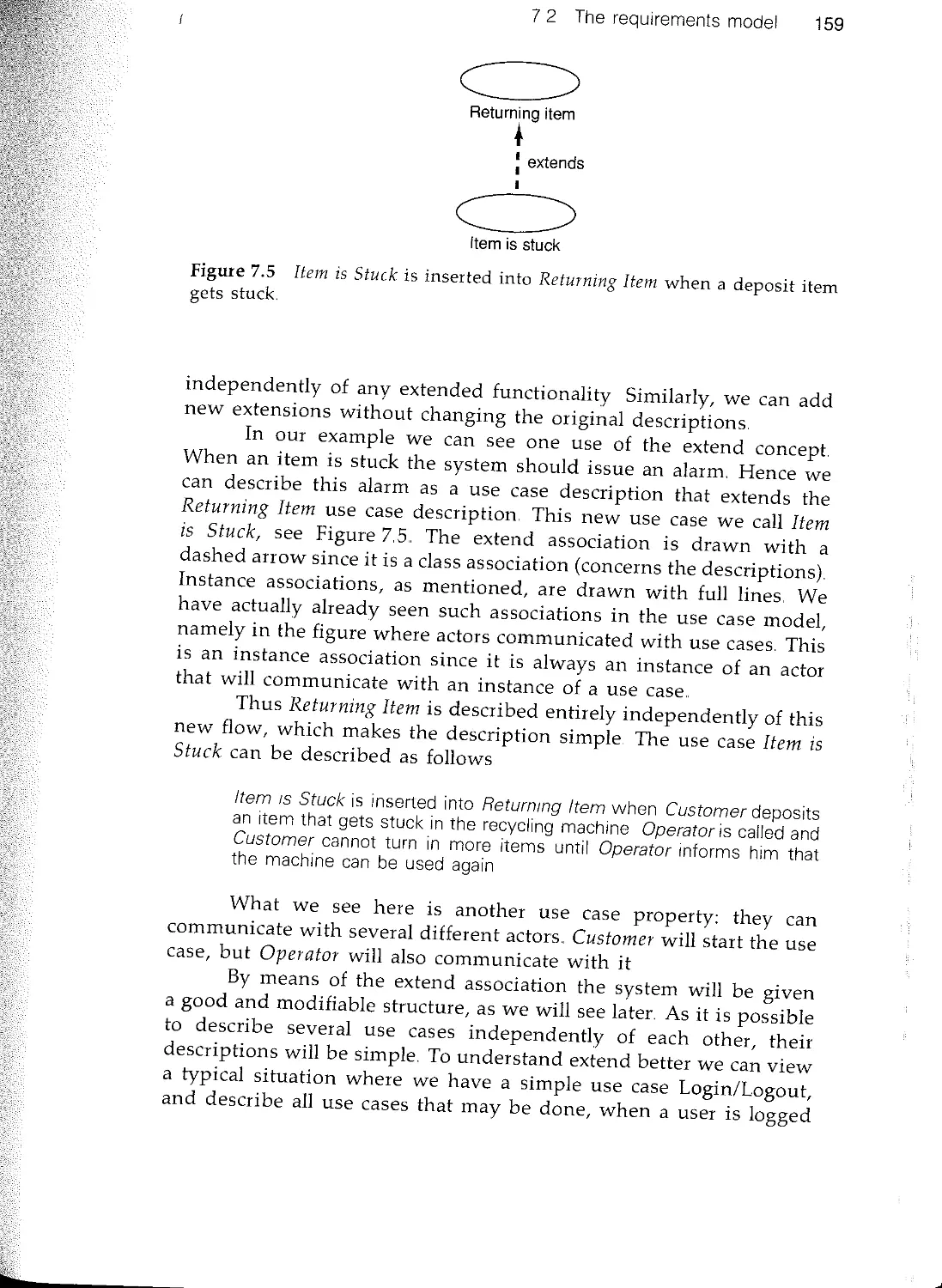
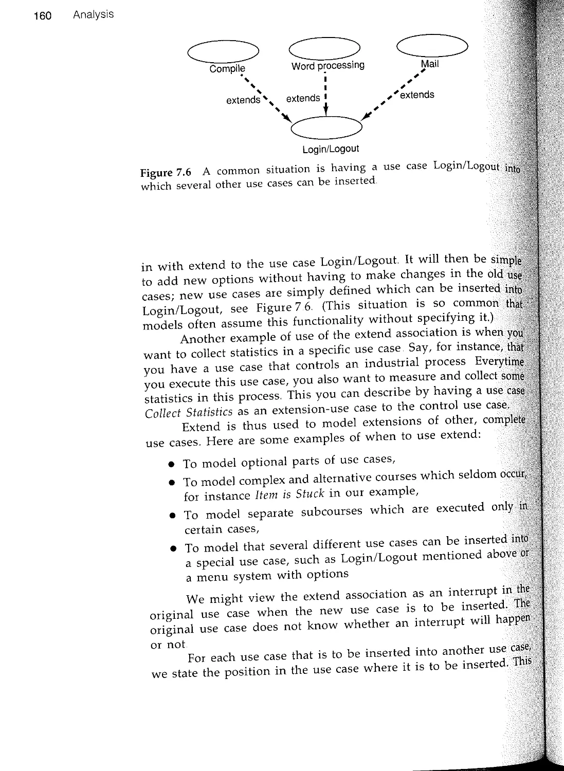
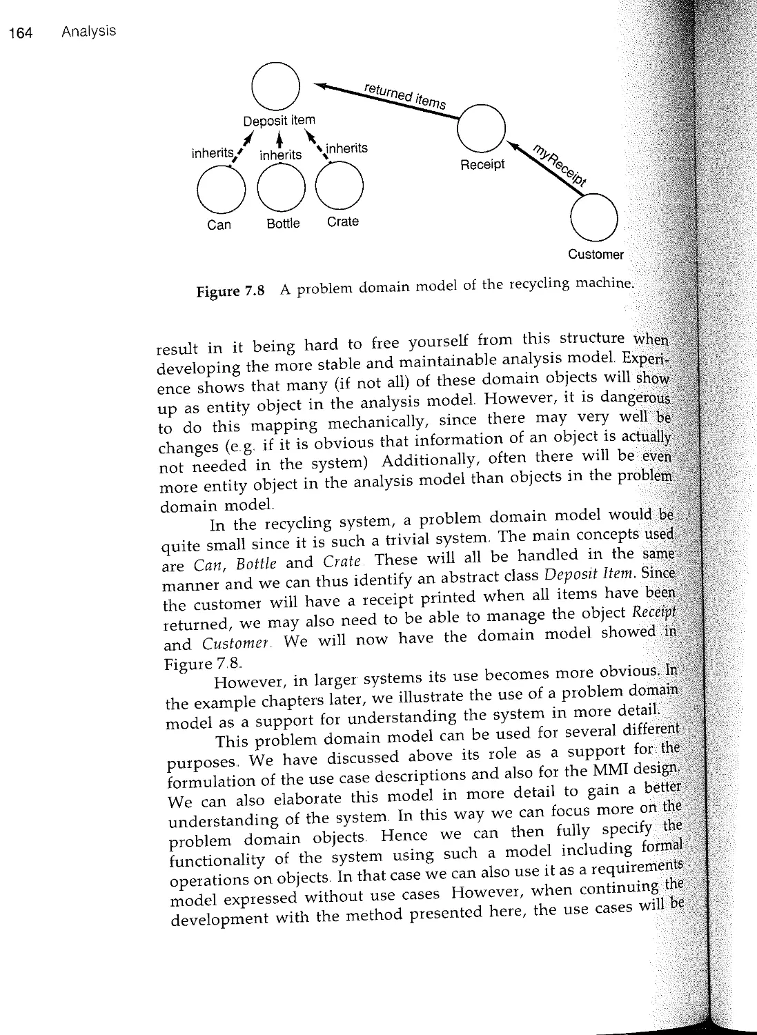
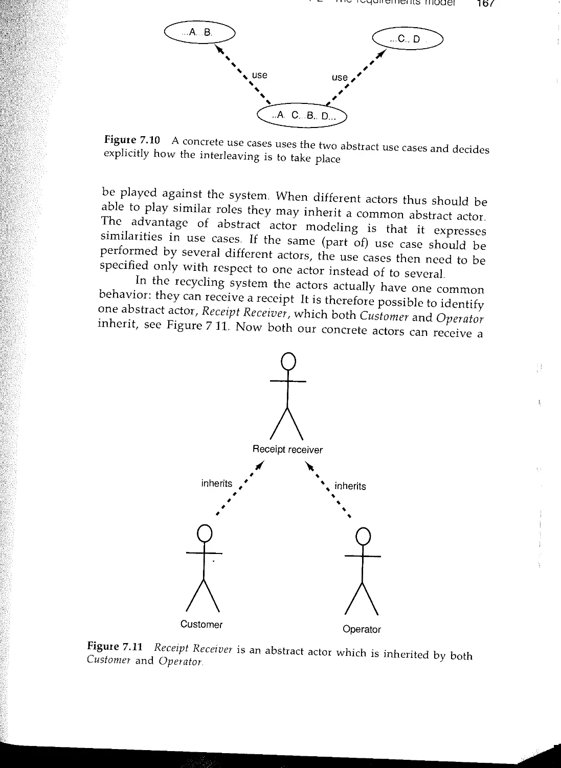
/


Текст
Object-Oriented
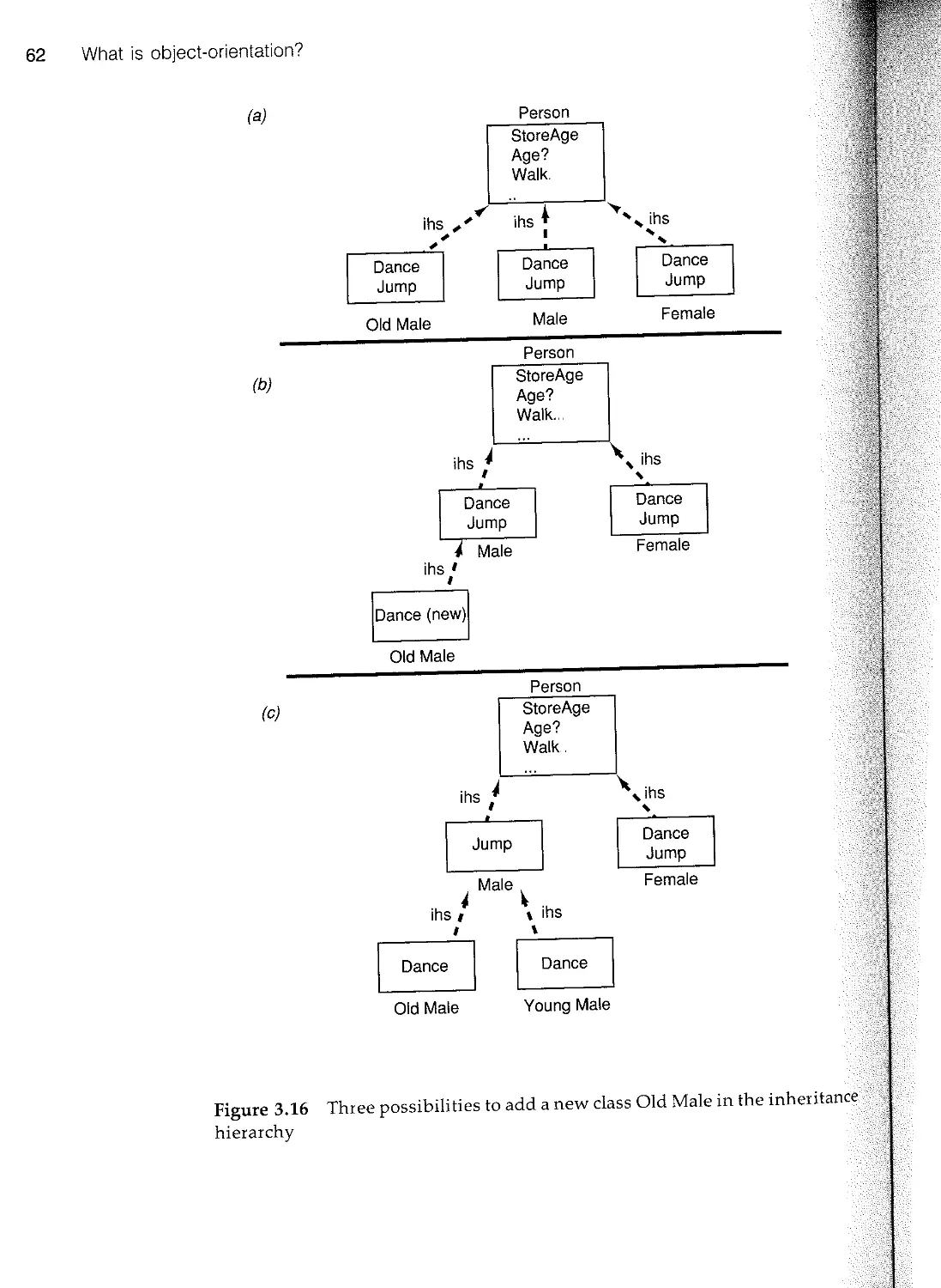
Software Engineering
A Use Case Driven Approach
Ivar Jacobson
Magnus Christerson Patrik Jonsson Gunnar Overgaard
How can software developers, programmers and managers meet the challenges of the 90s and begin
to resolve the software crisis?
This book is based on Objectory which is the first commercially available comprehensive object-oriented
process for developing large-scale industrial systems. Ivar Jacobson developed Objectory as a result
of 20 years of experience building real software-based products. The approach takes a global view of
system development and focuses on minimizing the system's life cycle cost. Objectory is an extensible
industrial process that provides a method for building large industrial systems.
Larry L. Constantine
RODP, Organization & System Consultant
'"
('D
(":')
'"
('D
'='
::3.
==
.;--
1
t::'
'In this book Jacobson establishes a new direction for the future of Software engineering practice. It
is a thorough presentation of ideas and techniques that are both solidly proven and simultaneously at
the leading edge of software engineering methodology.'
'Jacobson is in my opinion one of the foremost methodologists in the field of Software Engineering. . .
I strongly recommend . . . this book. . . not only for software managers and designers but for anyone
who wishes to understand how the next generation of Software Systems should be built.'
Dave Thomas
Object Technology International
Dr Ivar Jacobson has over 20 years experience in the design of large scale real-time systems in the
telecommunications industry. He developed an early object-based design technique, a major portion
of which has evolved into the international standard CCITT/SDL. Ivar Jacobson has extensive industrial
teaching experience and has served on the OOPSLA, ECOOP and TOOLS program committees. He is
founder and Vice President of Technology at Objective Systems in Sweden, which develops and markets
the object-oriented method Objectory.
Magnus Christerson, Patrik Jonsson and Gunnar Overgaard
are actively involved in the development and use of Objectory
at Objective Systems..
ISBN 0-201-54435-0
.
TT
Addison-Wesley Publishing Company
.
.
111111I 90000>
9 780201 544350 II
...... ,...,...... -----
-
Magnus Christerson Patrik Jonsson
Gunnar Overgaard
.
Object-Oriented
Software
Engineering
A Use Case Driven Approach
.
T ADDISON-WESLEY
ACM PRESS
Editor-in-Chief
International Editor
(Europe)
Peter Wegner
Dines Bjorner
Brown University
Technical University
of Denmark
SELECTED TITLES
Object-Oriented Reuse, Concurrency and Distribution Colin
Atkinson
Advances in Database Programming Languages Franqois Bancilhon
and Peter Buneman (Eds)
Software Reusability (Volume 1: Concepts and Models) Ted
Biggerstaff and Alan Perlis (Eds)
Software Reusability (Volume 2: Applications and Experience) Ted
Biggerstaff and Alan Perlis (Eds)
Object-Oriented Concepts, Databases and Applications Won Kim
and Frederick H. Lochovsky (Eds)
Distributed Systems Sape Mullender (Ed)
The Oberon System: User Guide and Programmer's Manual
Martin Reiser
Programming in Oberon: Steps Beyond Pascal and Modula Martin
Reiser and Niklaus Wirth
The Programmer's Apprentice Charles Rich and Richard C Waters
Instrumentation for Future Parallel Computer Systems Margaret
Simmons, Ingrid Bucher and Rebecca Koskela (Eds)
User Interface Design Harold Thimbleby
Project Oberon: The Design of an Operating System and
Compiler Niklaus Wirth and Jurg Gutknecht
n
'd
rn
.
:Object-Oriente
Software
Engineering
A Use Case Driven Approach
.
Ivar Jacobson
Magnus Christerson Patrik Jonsson
Gunnar Overgaard
Objective Systems
.
.
TT
ADDISON-WESLEY
PUBLISHING
COMPANY
Wokingham, England Reading, Massachusetts. Menlo Park, California New York
Don Mills, Ontario. Amsterdam Bonn.. Sydney. Singapore
Tokyo. Madrid San Juan Milan. Paris. Mexico City. Seoul. Taipei
Copyright @ 1992 by the ACM Press, A Division of the Association for Computing
Machinery, Inc (ACM)
All rights reserved No part of this publication may be reproduced, stored in a retrieval
system, or transmitted in any form or by any means, electronic, mechanical,
photocopying, recording or otherwise, without prior written permission of the publisher.
The programs in this book have been included for their instructional value They have
been tested with care but are not guaranteed for any particular purpose The publisher
does not offer any warranties or representations, nor does it accept any liabilities with
respect to the programs
Many of the designations used by manufacturers and sellers to distinguish their products
are claimed as trademarks The publisher has made every attempt to supply trademark
information about manufacturers and their products mentioned in this book A list of the
trademark designations and their owners appears below
Cover designed by Chris Eley
and printed by The Riverside Printing Co (Reading) Ltd
Printed in the United States of America
ISBN 0-201-54435---0
First printed 1992
British Library Cataloguing in Publication Data
A catalogue record for this book is available from the British Library.
Library of Congress Cataloging in Publication Data available
Trademark notice
AdaTM is a trademark of the Ada Joint Program Office, DoD, US Government
CommonView™ is a trademark of Glockenspiel Ltd
Eiffel™ is a trademark of Interactive Software Engineering
HOOD™ is a trademark of HOOD working group
InterView™ is a trademark of Glockenspiel Ltd
KEpM is a trademark of Intellicorp, Inc
LOOPSTM, SMALLTALKTM, SMALLTALK-78™ and SMALLTALK-80™ are
trademarks of Xerox Corporation
MacAppTM, MacintoshTM and Macos™ are trademarks of Apple Computer Inc.
MS-DOSTM and Windows™ are trademarks of Microsoft Corporation
NeWS™ is a trademark of Sun Microsystems Inc.
NewWave™ is trademark of Hewlett-Packard
NeXTStep™is a trademark of NeXT Corp
Objective-CTM is a trademark of Steps tone Corp
ObjectoryTM is a trademark of Objective Systems SF AB
PROLOGTM is a trademark of Expert Systems International
™STM is a trademark of Texas Instruments Inc
UNIXTM is a trademark of AT&T Corporation
X-Windows™ is a trademark of MIT
Foreword
Ivar Jacobson is in my opinion one of the foremost methodologists
in the field of software engineering. I take great pleasure in writing
this, because he is also a close personal friend. He brings a refreshingly
pragmatic point of view to a discipline that often seems be so abstract
and arcane as to be hopelessly remote from the real world of 'blue
collar' programmers. His methodology is based on some really
innovative ideas about modeling the software process, presented
within a tried and proven engineering framework It brings to the
task of analyzing, designing and constructing complex software
intensive products the same disciplined approach that is to be found
in other branches of engineering.
Along with many others I have urged Ivar for some time to publish
his methodology in a textbook, so that it would be accessible to a
larger audience. I believe that the concepts in Objectory, the first
comprehensive object-oriented process for developing large scale
industrial systems, are important and should get wider exposure.
This book represents over 20 years of experience building real
software based products and a great deal of serious thinking about
how such systems should be built. If you have any interest at all in
software you will enjoy reading it.
Objectory stands out as being a truly object-oriented methodology,
in which both the process and the methodology are themselves
represented as objects. While some may find this idea of a reflective
or 'meta' architecture to be rather exotic, it is in fact intensely
practical and absolutely essential. It makes Objectory an extensible
methodology which can be specialized to both the organization and
the application domains. Simply put, Objectory provides a software
process for building not just software, but also other more specialized
software processes.
Another key innovation in Objectory is the concept of use cases,
which has now been proved effective in a number of real-world
projects. Use cases provide the needed linkage between requirements,
v
i
!....
vi Foreword
development, testing and final customer acceptance This idea, which
originated in Ivar's work on the AXE switch, has been generalized
so that it can be applied in application domains as diverse as
command and control and business information systems
Use cases provide a concrete representation of software require-
ments, which allows them to be both formally expressed and
systematically tested Changes in requirements map directly onto
changes in the set of use cases.. In this way Objectory provides a
solid methodological foundation for rapid proto typing and other
forms of incremental software development. Objectory enables
managers to move beyond labour intensive hand assembly of software
systems, and allows them to transform their organizations into
highly automated factories to manufacture software from reusable
components
Many feel that we are in the midst of a software crisis, and I agree..
High quality software has become one of the most sought after
commodities in the modern world We just can't seem to get enough
of it, on time and on budget, to meet the demand This book will
help you overcome the software crisis in your own organization, by
showing you how to make software construction into a reliable and
predictable engineering activity
One of the more profound insights offered by modern software
engineering is that change is inevitable, and that software must be
designed to be flexible and adaptable in the face of changing
requirements Objectory, with its reflective architecture, goes one
step further, and provides an extensible methodology which can itself
adapt to shifts in the business climate or the demands of new
technologies No static text can ever capture all the nuances of such
a dynamic software entity but this one comes very close I strongly
recommend it, not only for software managers and designers, but for
anyone who wishes to understand how the next generation of
software systems should be built
Dave Thomas
Foreword
Ivar Jacobson has taken the time to create a book that is certain to
become essential reading for software developers and their managers
In this book, Jacobson establishes a new direction for the future of
software engineering practice It is a thoughtful and thorough
presentation of ideas and techniques that are both solidly proven
and, simultaneously, at the leading edge of software engineering
methodology.. Jacobson is simply a thinker who has been ahead of
his time in creating usable methods for building better, more reliable
and more reusable large software systems.
Despite the title, this is not 'another book on object-oriented
analysis and design,' nor yet another standard reworking on the
word-of-the-week Once, of course, the word-of-the-week in software
engineering was 'modular,' later it was 'structured,' and now, as
every programmer or software engineer who reads or attends
conferences knows, it is 'object-oriented.'
When the word-of-the-week was still 'structured,' and I wrote the
first edition of Structured Design, the very idea of systematic methods
for software development was radical. Software engineering was in
its infancy, and when I introduced data flow diagrams and structure
charts, few recognized either the need for notation or the benefits of
well-conceived modeling tools for analysis and design.
But things have changed Now, new methodologies are created
over cocktails, and books spin out of word-processors so fast that
revised or 'corrected' editions appear almost before the original has
reached the bookstores. Since nearly everyone now recognizes that
a methodology must be supported by a notation, notations proliferate
A new object-oriented design notation can be churned out over a
weekend so long as the major objective is simply squiggles and icons
with a unique 'look and feel,' and issues of usability and power in
modeling are considered unimportant.
And here we have yet another notation supporting one more
methodology? Not quite..
vii
viii Foreword
It is true that the serious reader will have to surmount both new
terminology and new notation to get to the marrow, but this book
is different It was not conceived and written overnight The
methodology it describes has been in use for years to design and
build numerous software systems, and its notation has evolved slowly
from both manual and CASE-supported application It is not the
work of a writer or consultant with a long booklist, but comes from
a practicing software engineer and leader in software engineering
who has been doing large-scale object-oriented development for
longer than most people even knew that objects existed Throughout
this period, the ideas and methods have been honed by the grindstone
of building software and refined by thoughtful reflection and analysis.
What we have here is an approach to object-oriented analysis and
design that is fundamentally different from most of the highly
and more visible methods that clutter the landscape.. I believe it is
an approach of proven power and even greater promise
The real power of this approach rests not only in the wealth of
experience on which it is based but also in the way in which it starts
from a different point of departure and builds an entirely different
perspective on how to organize software into objects. Jacobson does
not build naive object models derived from simplistic reinterpretations
of data modeling and entity object relationship models.. He starts
from an entirely different premise and set of assumptions uniquely
tailored to creating robust, sophisticated object structures that
the test of time
His approach centers on an analysis of the ways in which a system
is actually used, on the sequences of interactions that comprise the
operational realities of the software being engineered. Although it
fully incorporates the conceptual constructs, the application and
enterprise entities that undergird our thinking about software
systems, it does not force the entire design into this rigid pattern.
The result is a more robust model of an application, leading to
software that is fundamentally more pliant, more accommodating to
extensions and alterations and to collections of component parts that
are, by design, more reusable
At the heart of this method is a brilliantly simple notion: the use
case. A use case, as the reader will learn, is a particular form or
pattern or exemplar of usage, a scenario that begins with some user
of the system initiating some transaction or sequence of interrelated
events By organizing the analysis and design models around user
interaction and actual usage scenarios, the methodology produces
systems that are intrinsically more useable and more adaptable to
changing usage. Equally important, this approach analyzes each use
case into its constituent parts and allocates these systematically to
Foreword ix
software objects in such a way that external behavior and internal
structure and dynamics are kept apart, such that each may be altered
or extended independently of the other This approach recognizes
not one kind of object, but three, which separate interface behavior
from underlying entity objects and keep these independent of the
control and coordination of usage scenarios.
Using this approach, it is possible to construct very large and
complex designs through a series of small and largely independent
analyses of distinct use cases The overall structure of the problem
and its solution emerges, step-by-step and piece-by-piece, from this
localized analysis In principle - and in practice - this methodology
is one whose power increases rather than diminishes with the size
of the system being developed
Use case driven analysis and design is a genuine breakthrough,
but it is also well-grounded in established fundamentals and
connected to proven ideas and traditions in software engineering in
general and object-oriented development in particular. It echoes and
extends the popular model-view-controller paradigm of object-
oriented programming. It is clearly kin to the event-driven analysis
and design approaches of Page-Jones and Weiss, as well as to the
widely practiced event-partitioning methods pioneered by McMena-
min and Palmer.
On this ground, Ivar Jacobson has built a work that is nothing
short of revolutionary. Rich with specific guidelines and accessible
examples, with completely detailed case studies based on real-world
projects, this book will give developers of object-oriented software
material that they can put into practice immediately. It will also
challenge the reader and, I am confident, enrich the practice of our
profession for years to come
Larry L Constantine
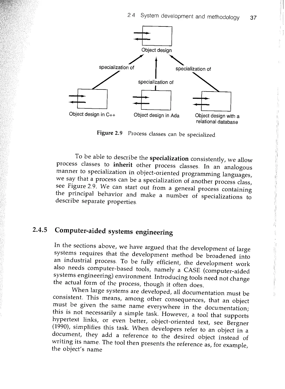
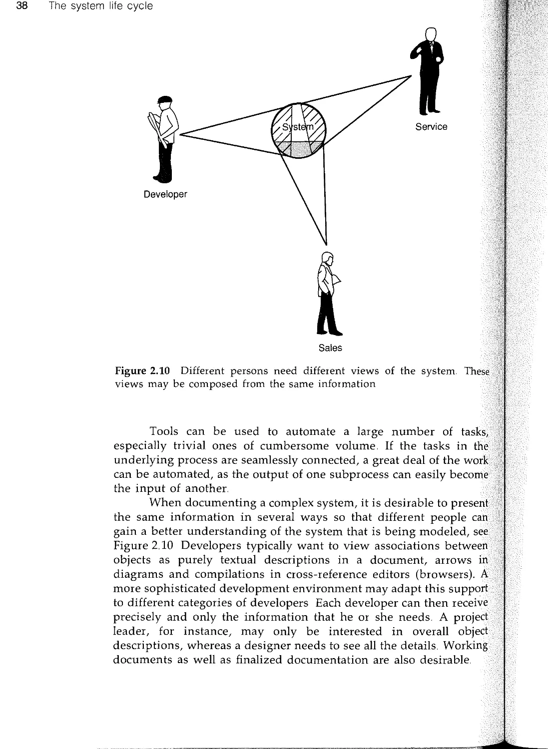
This is a book on industrial system development using
oriented techniques.. It is not a book on object-oriented
We are convinced that the big benefits of object-orientation can
gained only in the consistent use of object-orientation throughout
steps in the development process.. Therefore the emphasis is
on the other parts of development such as analysis, design
testing.
You will benefit from this book if you are a system
seeking ways to improve in your profession. If you are a
with no previous experience in development methods, you will
a robust framework which you can fill with details as you take
in future development projects Since the focus of the text is
development, the book will be convenient to use in
with other texts on object-oriented programming. Many
illustrate the practical application of analysis and design
From this book you will get a thorough understanding of
to use object-orientation as the basic technique throughout
development process. You will learn the benefits of
integration between the different development steps and how the
object-oriented characteristics class, inheritance and encapsulation
used in analysis, construction and testing. With this knowledge
are in a much better position to evaluate and select the way
develop your next data processing system.
Even though object-orientation is the main theme of this book,
is not a panacea for successful system development The change
from craftsmanship to industrialism does not come with the
to a new technique. The change must come on a more
level which also includes the organization of the complete
ment process. Objectory is one example of how this can be done.
This book does not present Objectory What we present is the
fundamental ideas of Objectory and a simplified version of it In this
book we call this simplified method OOSE to distinguish it from
Objectory. To use the process in production you will need the
Preface
Preface xi
complete and detailed process description which, excluding large
examples, amounts to more than 1200 pages.. To introduce the process
in an organization also needs careful planning and dedication.
It is our hope that we have reached our goal with this book, namely
to present a coherent picture of how to use object-orientation in
system development so as to make it accessible to both practitioners
in the field and students with no previous knowledge of system
development. This has been done within a framework where system
development is treated as an industrial activity and consequently
must obey the same requirements as industry in general The
intention is to encourage more widespread use of object-oriented
techniques and to inspire more work on improving the ideas
expounded here. We are convinced that using these techniques will
lead to better systems and a more industrial approach to system
development
Part I: Introduction. The book is divided into three parts The first
part is a background part and covers the following chapters:
(1) System development as an industrial process,
(2) The system life cycle,
(3) What is object-orientation?,
(4) Object-oriented system development,
(5) Object-oriented programming.
This part gives an introduction to system development and summar-
izes the requirements on an industrial process. It also discusses the
system life cycle. The idea of object-orientation is introduced and
how it can be used in system development and during programming
is surveyed.
Part II: Concepts. The second part is the core of the book It covers
the following chapters:
(6) Architecture,
(7) Analysis,
(8) Construction,
(9) Real-time specialization,
(10) Database specialization,
(11) Components,
(12) Testing.
The first chapter in this part introduces the fundamental concepts of
OOSE and explains the reason why these concepts are chosen.. The
xii Preface
following chapter discusses the method of analysis and construction.
Two chapters discusses how the method may be adapted to real-time
systems and database management systems. The components chapter
discusses what components are and how they can be used in the
development process. Testing activities are discussed in a chapter of
their own..
Part III: Applications. The third and last part covers applications
of OOSE and how the introduction of a new development process
may be organized and managed. This part ends with an overview of
other object-oriented methods This part thus looks as follows:
(13) Case study: warehouse management system,
(14) Case study: Telecom,
(15) Managing object oriented software engineering,
(16) Other object-oriented methods.
Appendices. Finally we have two appendices Appendix A
ments on our development of Objectory and Appendix B
the notation used in the book
So, how should you read this book? Of course, to get a
overview, the whole book should be read, including the appendices.
But if you want to read only selected chapters the reading
below could be used..
If you are an experienced object-oriented software engineer,
should be familiar with the basics. You could read the book
suggested in Figure P.L
add to see
real-time
and DBMS
issues
read
6,7,8,13,14
Experienced
with OOSE
Figure P.I
Newcomer to
00 and SE
Preface xiii
read
3,4,6,7,8,12,13
add to see
programming
issues
add to get
survey on
methods
Figure P.2
If you are a newcomer to object-orientation and software engineer-
ing you could read the book as in Figure P2
If you are an experienced software engineer you could read the
book as in Figure P.3.
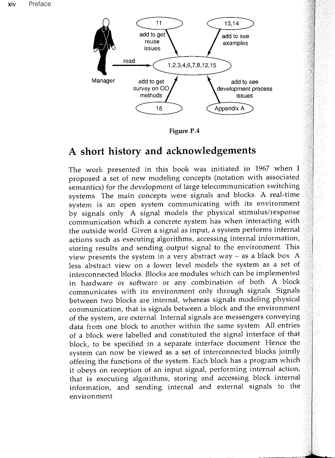
If you are a manager you could read the book as proposed in
Figure PA.
Hence, although the book is not object-oriented, it is written in a
modularized way and can be configured in several different ways.
To build systems in this way is the theme of the book, and the
technique and notation used above is very similar to the technique
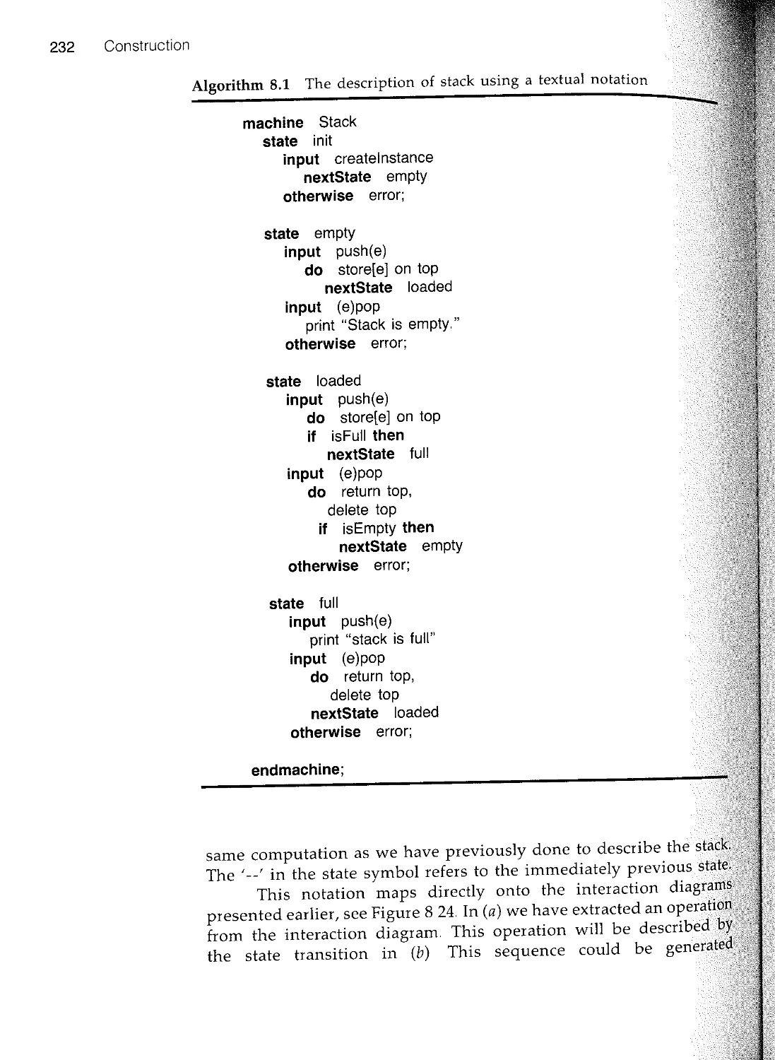
used also in this book.
Experienced
software
engineer
read
add if DB
issues
interesting
1,2,3,4,5,6,7,8,11,12,13,14,16
add to get
manager view
15
Figure P.3
xiv Preface
Manager
read
add to see
development process
issues
Figure PA
A short history and acknowledgements
The work presented in this book was initiated in 1967 when I
proposed a set of new modeling concepts (notation with associated
semantics) for the development of large telecommunication switching
systems The main concepts were signals and blocks. A real-time
system is an open system communicating with its environment
by signals only. A signal models the physical stimulus/response
communication which a concrete system has when interacting with
the outside world Given a signal as input, a system performs internal
actions such as executing algorithms, accessing internal information,
storing results and sending output signal to the environment. This
view presents the system in a very abstract way - as a black box A
less abstract view on a lower level models the system as a set of
interconnected blocks.. Blocks are modules which can be implemented
in hardware or software or any combination of both. A block
communicates with its environment only through signals Signals
between two blocks are internal, whereas signals modeling physical
communication, that is signals between a block and the environment
of the system, are external Internal signals are messengers conveying
data from one block to another within the same system. All entries
of a block were labelled and constituted the signal interface of that
block, to be specified in a separate interface document Hence the
system can now be viewed as a set of interconnected blocks jointly
offering the functions of the system.. Each block has a program which
it obeys on reception of an input signal, performing internal action,
that is executing algorithms, storing and accessing block internal
information, and sending internal and external signals to the
environment
Preface xv
The proposal can be summarized as an attempt to unify long
experience from systems design with the possibilities offered by
dramatically new computer technology. Since the two technologies
were so different, this was not a self-evident method, neither within
Ericsson nor within computer science. There was a rather strong
belief that the two represented unrelated technological universes:
the new one was so different that it would be meaningless and only
a burden to make any attempt to learn from the old one.. However,
the two techniques were joined and a set of modeling concepts
evolved.
The modeling constructs were soon followed by a skeleton of a
new design method, the use of which was first demonstrated in the
development of the AKE system put in service in Rotterdam in 1971,
and more completely demonstrated by the AKE system put in service
in Fredhiill, Sweden, in 1974.. Naturally this experience has guided
subsequent work on the development of the successor to AKE, the
AXE system, which is now in use in more than 80 countries
worldwide The modeling constructs were very important and for the
AXE system a new programming language and a new computer
system were developed in accordance with these early ideas..
Although it is a neighbouring country, the early development of
object-oriented programming and Simula in the 1960s in Norway
was made independently and in parallel with our work. It was not
until 1979 that we 'discovered' object-oriented programming and
then it was in terms of Smalltalk Although object-oriented ideas
have influenced our recent work, basically two separate problems are
being solved: large-scaleness and small-scaleness.
The modeling constructs introduced during the 1960s were further
formalized in research taking place between 1978 and 1985. This
research resulted in a formally described language which offered
support for object-orientation with two types of objects and two
types of communication mechanisms, send/wait and send/no-wait
semantics The language supported concurrency with atomic trans-
actions and with a special semantical construction for the handling
of a course of events similar to the use case construct presented later.
This work, reported in a PhD thesis in 1985, resulted in a number
of new language constructs, initially developed from experience,
being refined and formalized. This was a sound basis from which to
continue, and take a new approach, the development of the method.
The principles of Objectory were developed in 1985-7 Then I further
refined and simplified the ideas, generalized the technique from
telecom applications, extended it with the inheritance concept and
other important constructs like extensions, and joined it with an
analysis technique and also to object-oriented programming.
xvi Preface
Today these concepts have been further refined. The
process, of which this book describes some fundamental ideas, is the
result of work by many individuals, of whom most today work at
Objective Systems SF AB, Sweden. Gunnar Overgaard and
Jonsson did much of the writing of the first process description of
Objectory analysis and design respectively.. Magnus Christerson
much to condense and rewrite the material into the form of
book. They have all contributed to Objectory; especially in
formalization of the Concepts Magnus has also related the ideas
Objectory to other areas as presented in this book Fredrik Lindstrom
has also been involved in the condensation of the material for this
book and in the book project as such. Agneta Jacobson, Bud Lawson,
and Lars Wiktorin have prepared material for some of the chapters
in this book
Marten Gustafsson has substantially contributed to the analysis
part of Objectory. Valuable contributions to Objectory have also been
made by the following people: Sten-Erik Bergner, Per Bjork,
Carlbrand, Hakan Dyrhage, Christian Ehrenborg, Agneta Jacobson,
Sten Jacobson, Fredrik Lindstrom, Lars Lindroos, Benny
Karin Palmkvist, Janne Pettersson, Birgitta Spiridon, Per Sundquist,
Lars Wetterborg and Lars Wiktorin. The following users of Objectory
have also contributed by feeding back experiences and ideas to
enable improvements: Staffan Ehnebom, Per Hedfors, Jorgen Hellberg,
Per Kilgren, Hakan Lidstrom, Christian Meck, Christer Nilsson, Rune
Nilsson, Goran Schefte, Fredrik Stromberg, Karin Villers,
Wallin and Charlotte Wranne. The following persons have done a lot
to support the technology described in this book: Kjell S.. Andersson,
Hans Brandtberg, Ingemar Carlsson, Hakan Dahl, Gunnar M. Eriksson,
Bjorn Gullbrand, Lars Hallmarken, Bo Hedfors, Barbara
Hakan Jansson, Christer Johansson, Ingemar Johnsson, Kurt Katzeff,
Rolf Leidhammar, Jorma Mobrin, Jan-Erik Nordin, Anders Rockstrom,
Kjell Sorme, Goran SundelOf, Per-Olof Thysselius, Ctirad Vrana and
Erik Ornulf. The following people have given me strong personal
inspiration and support: Dines Bj0rner, Tore Bingefors, Larry
stantine, Goran Hemdal, Tom Love, Lars-Olof Noren, Dave Thomas
and Lars-Erik Thorelli. In Sweden we normally do not thank family
and friends in these circumstances, but no one believes that these
types of result can be achieved without an exceptional support from
them.. We are also grateful to the support we have been given from
STU (Swedish National Board on Industrial development now re-
organized to NUTEK) through the IT-4 program which has been part
of the financial support and sponsorship for the writing of this book
Ivar Jacobson
Nybrogatan 45c, 11439 Stockholm, Sweden
Contents
-
Foreword by Dave Thomas
v
Foreword by Larry L. Constantine
Vll
Preface
x
Part I Introduction 1
1 System development as an industrial process 3
1 1 Introduction 3
12 A useful analogy 4
13 System development characteristics 10
14 Summary 21
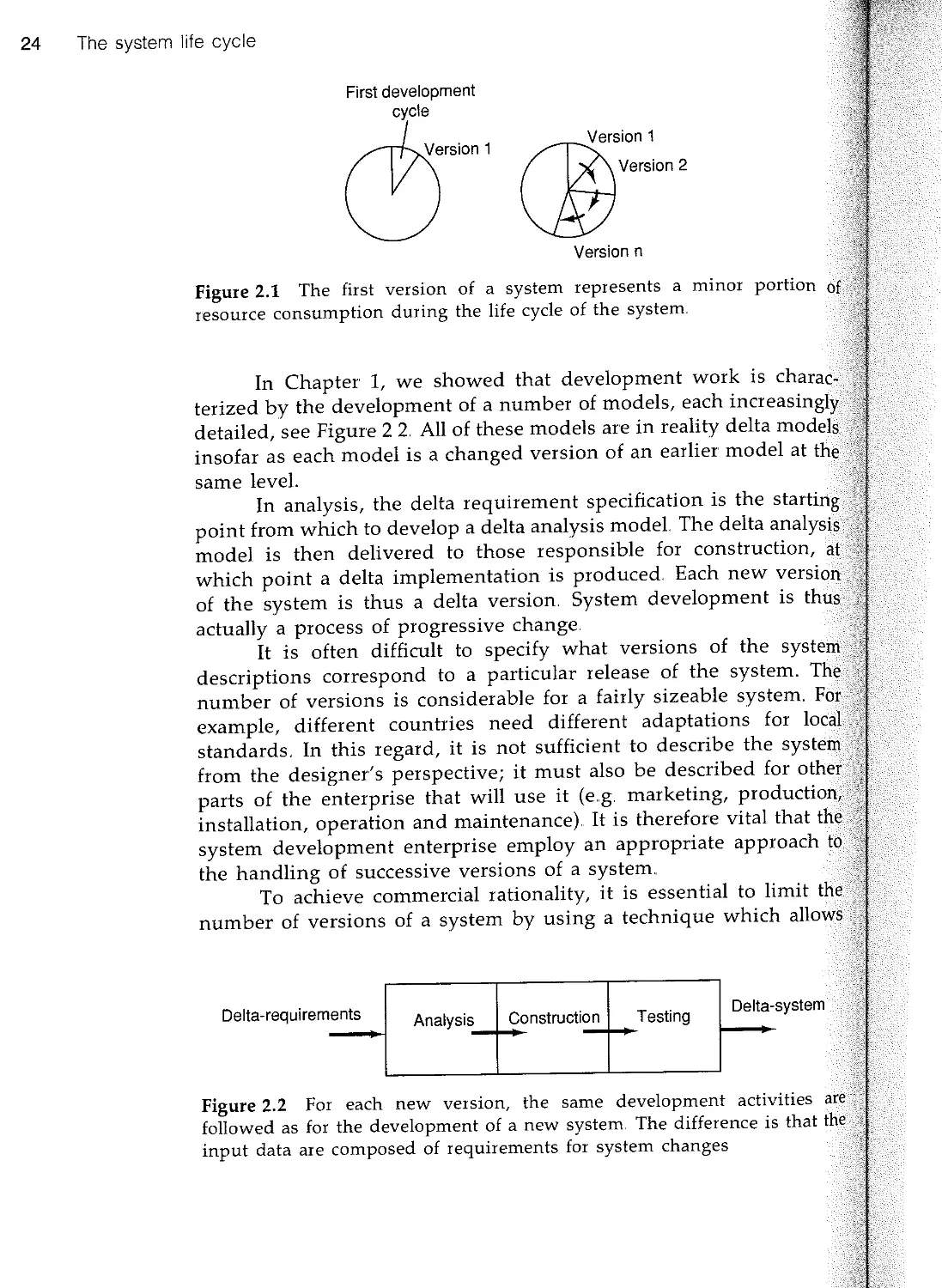
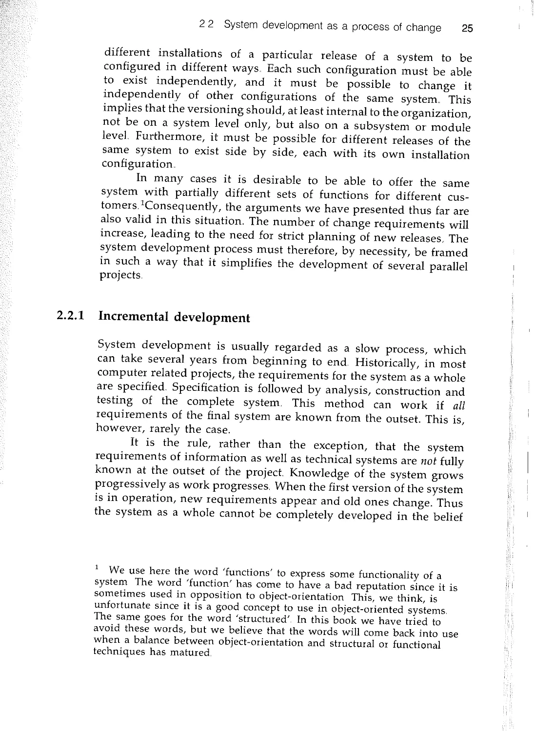
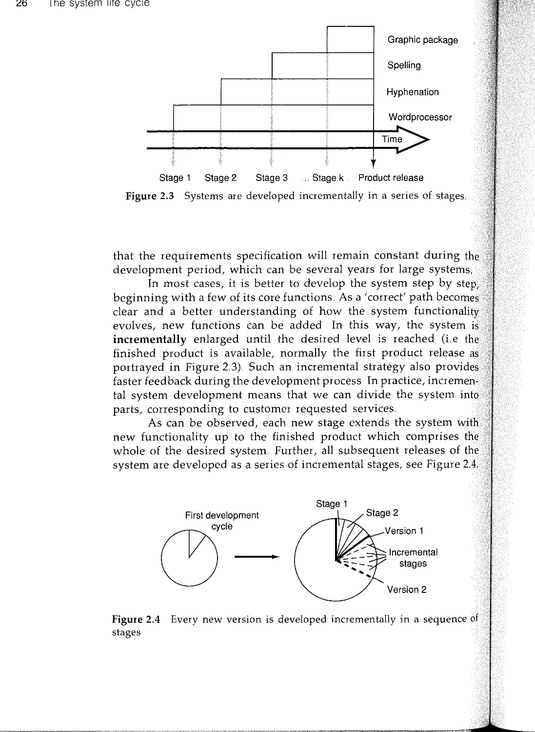
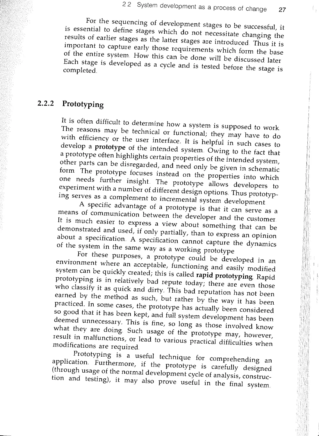
2 The system life cycle 23
2.1 Introduction 23
2.2 System development as a process of change 23
2..3 System development and reuse 28
2.4 System development and methodology 31
2..5 Objectory 39
2..6 Summary 41
3 What is object-orientation? 43
n 3..1 Introduction 43
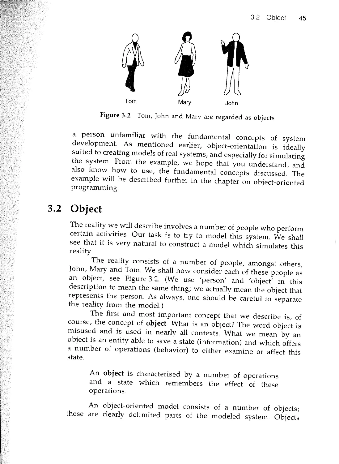
,- 3.2 Object 45
rt 33 Class and instance 50
... 3.4 Polymorphism 56
3.5 Inheritance 57
n 3.6 Summary 69
n
xvii
xviii Contents
4 Object-oriented system development 70
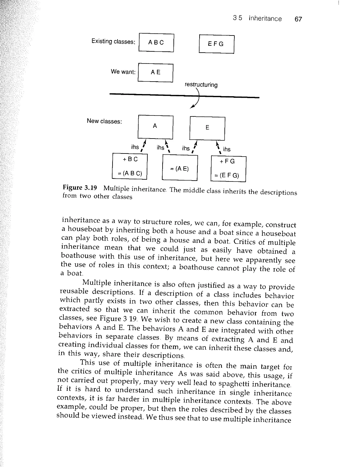
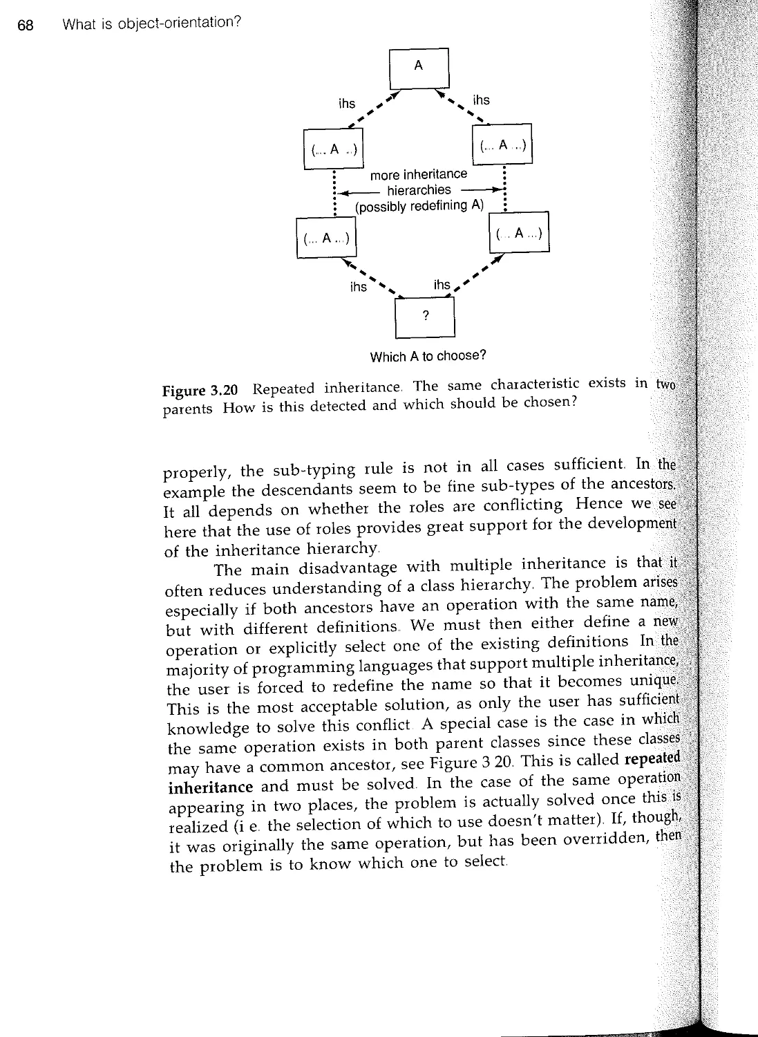
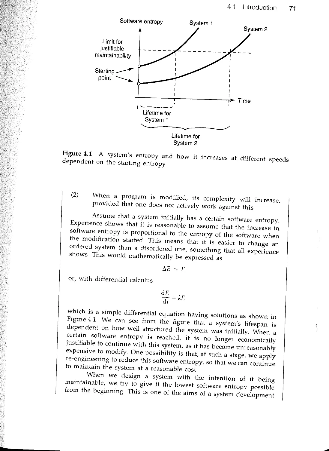
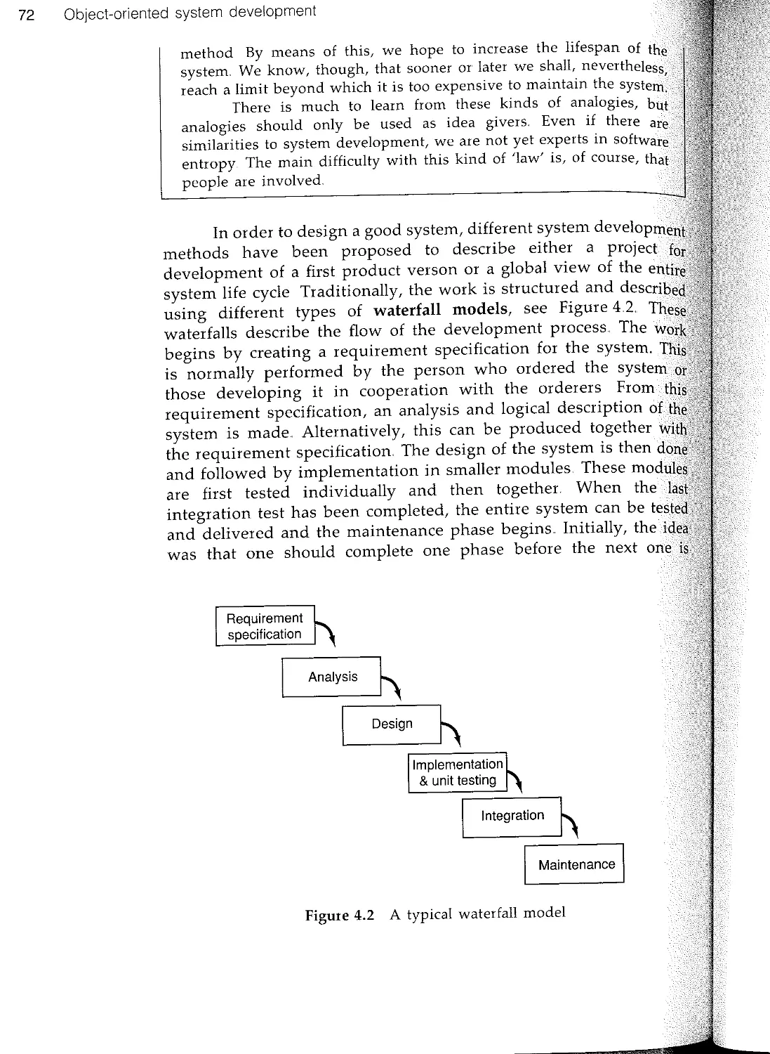
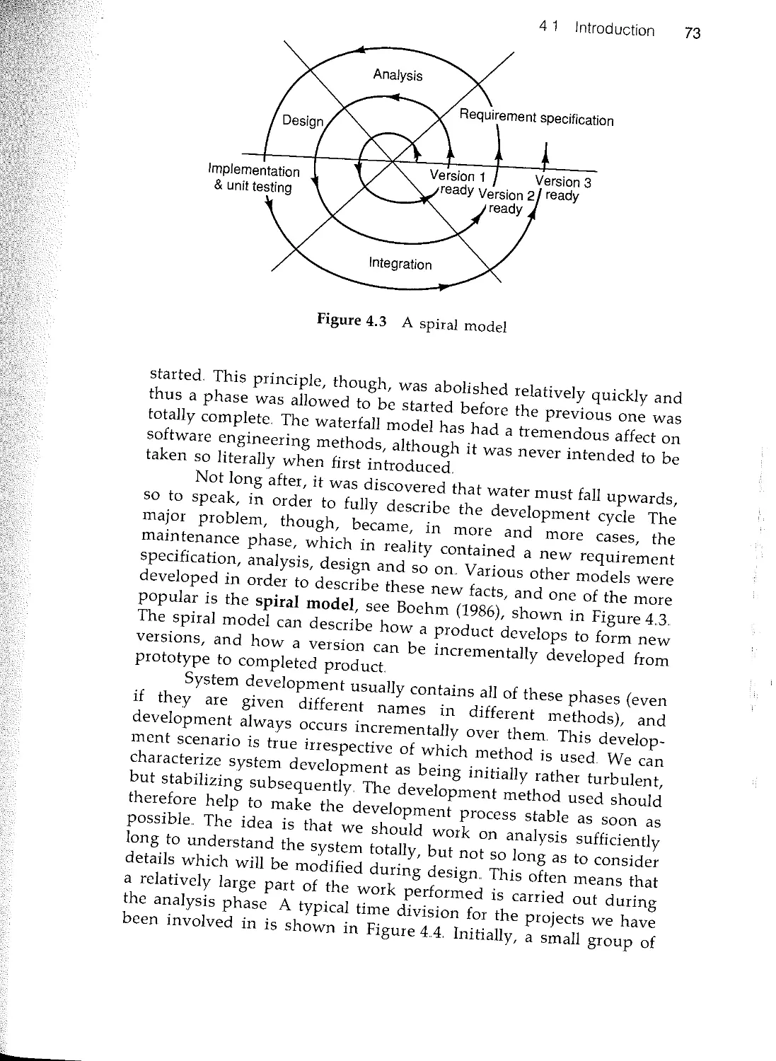
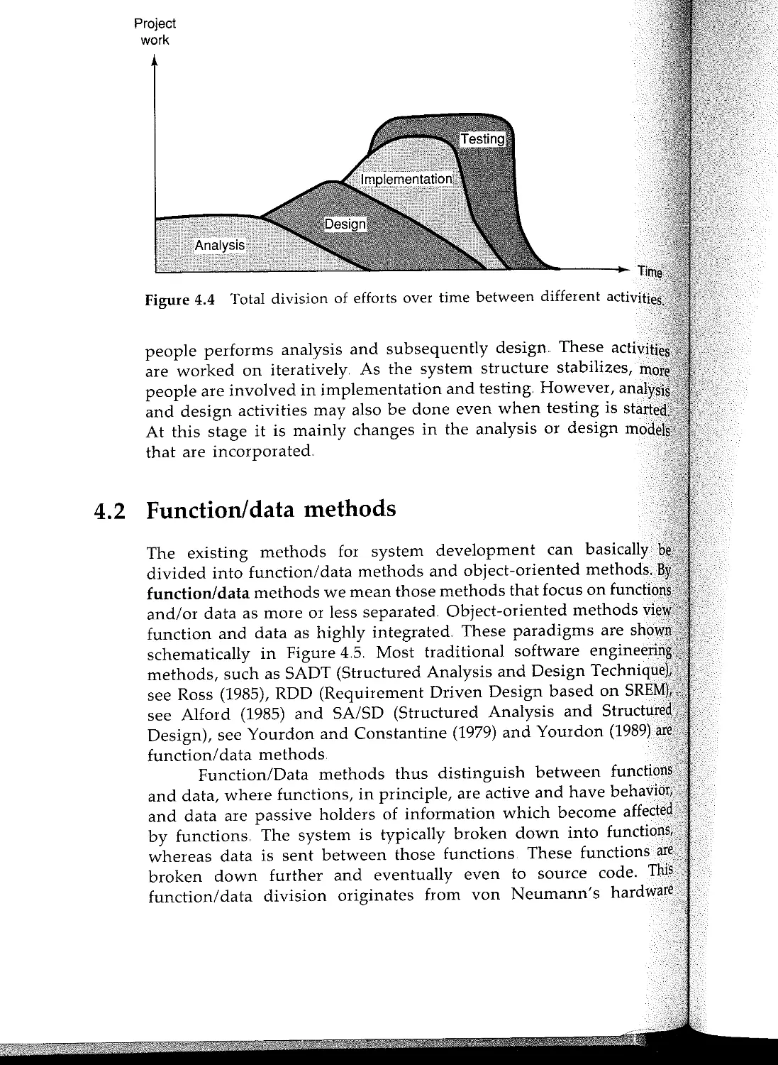
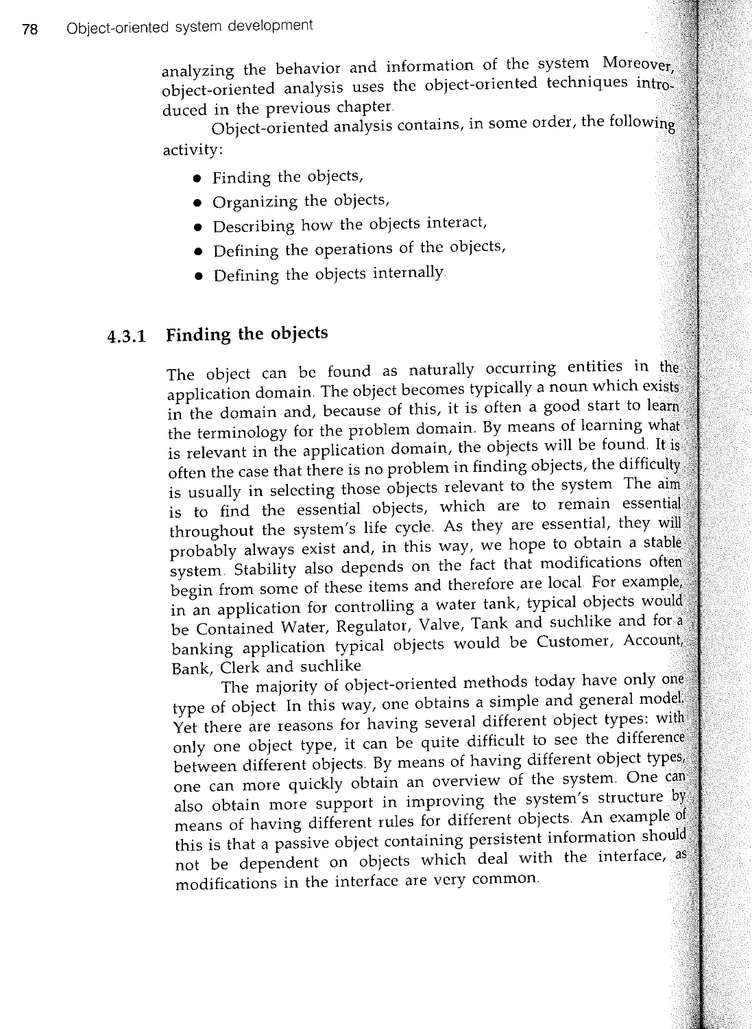
4.1 Introduction
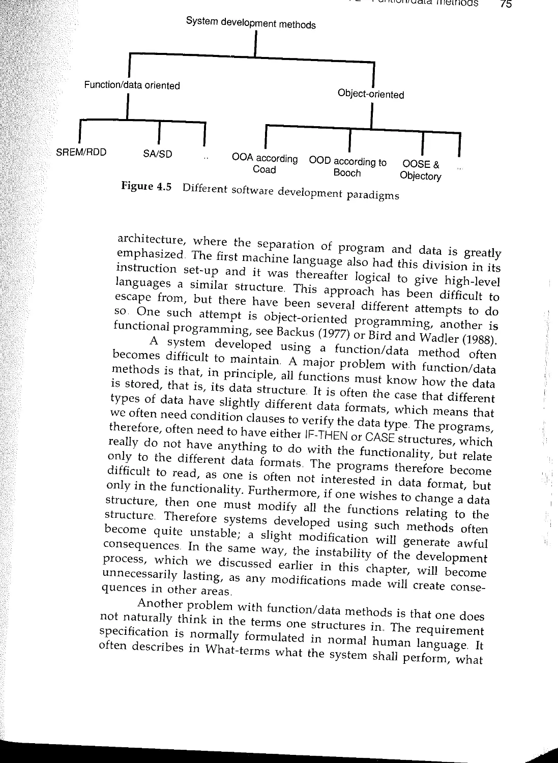
4.2 Function/data methods
4.3 Object-oriented analysis 77
4.4 Object-oriented construction 80
4.5 Object-oriented testing 81
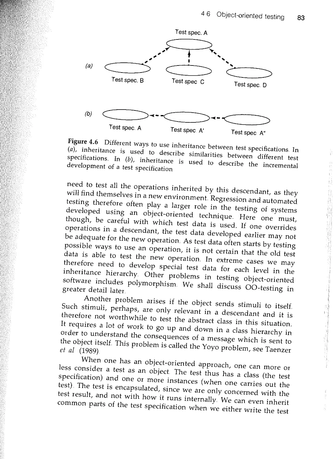
46 Summary 83
5 Object-oriented programming 85
5.1 Introduction
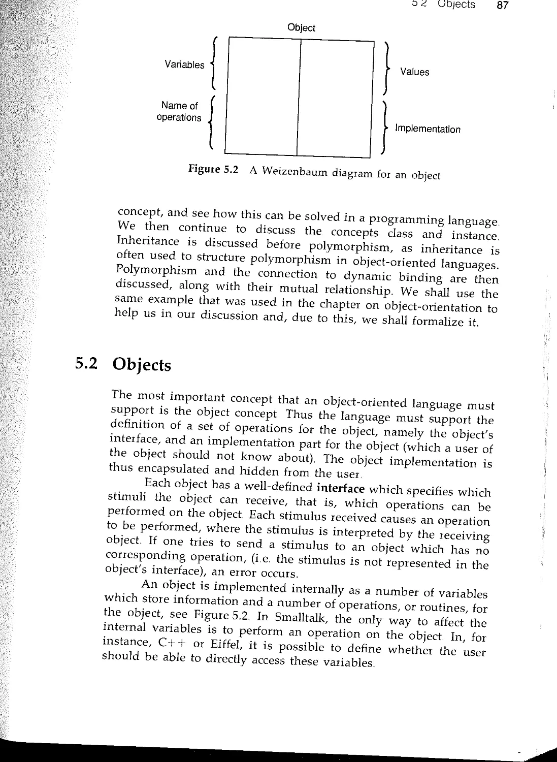
5.2 Objects
53 Classes and instances
5.4 Inheritance
5.5 Polymorphism
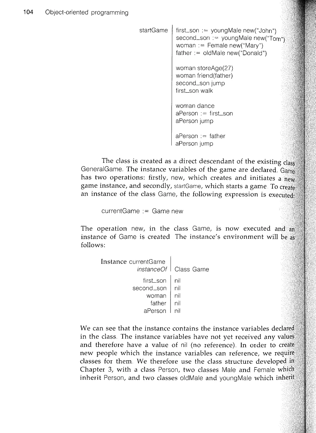
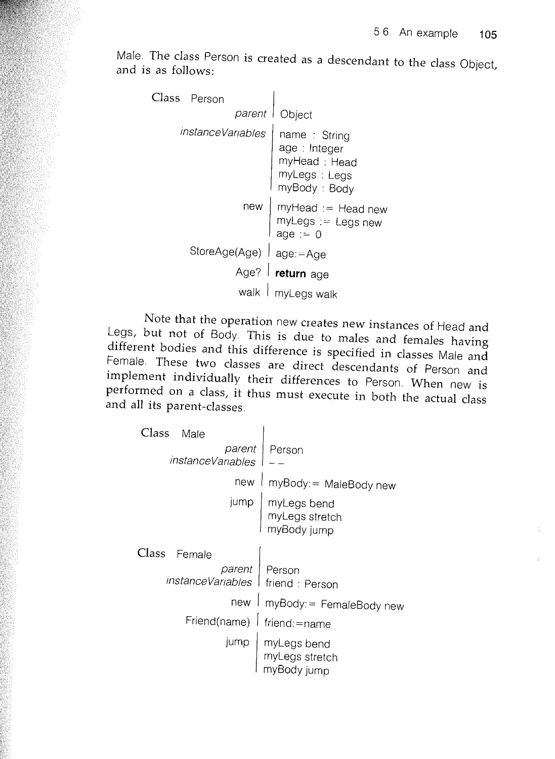
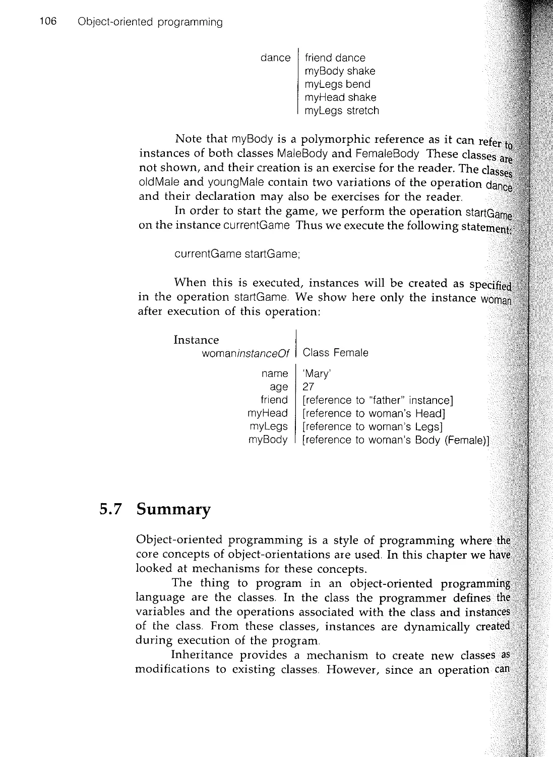
5.6 An example
5.7 Summary
Part II Concepts
6 Architecture
6.1 Introduction
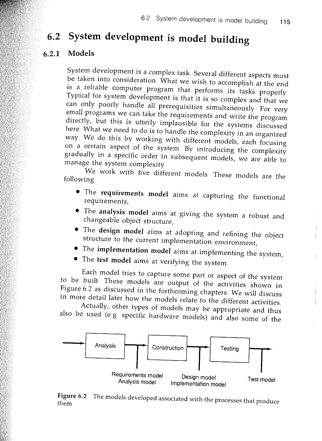
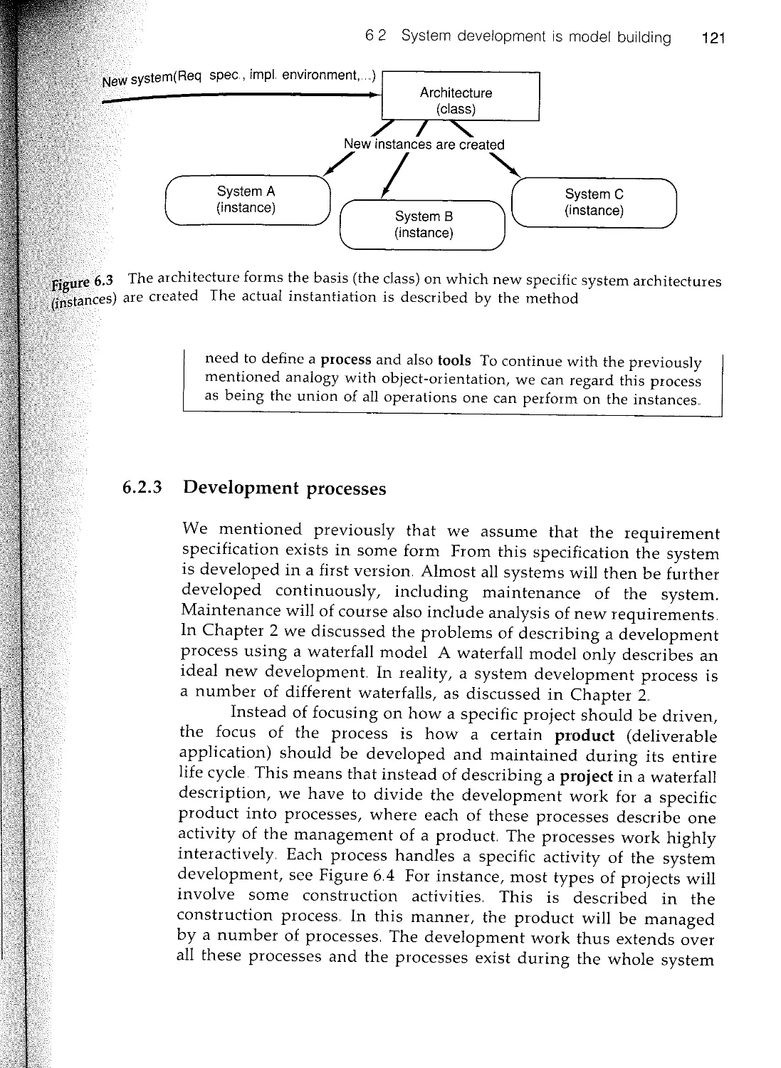
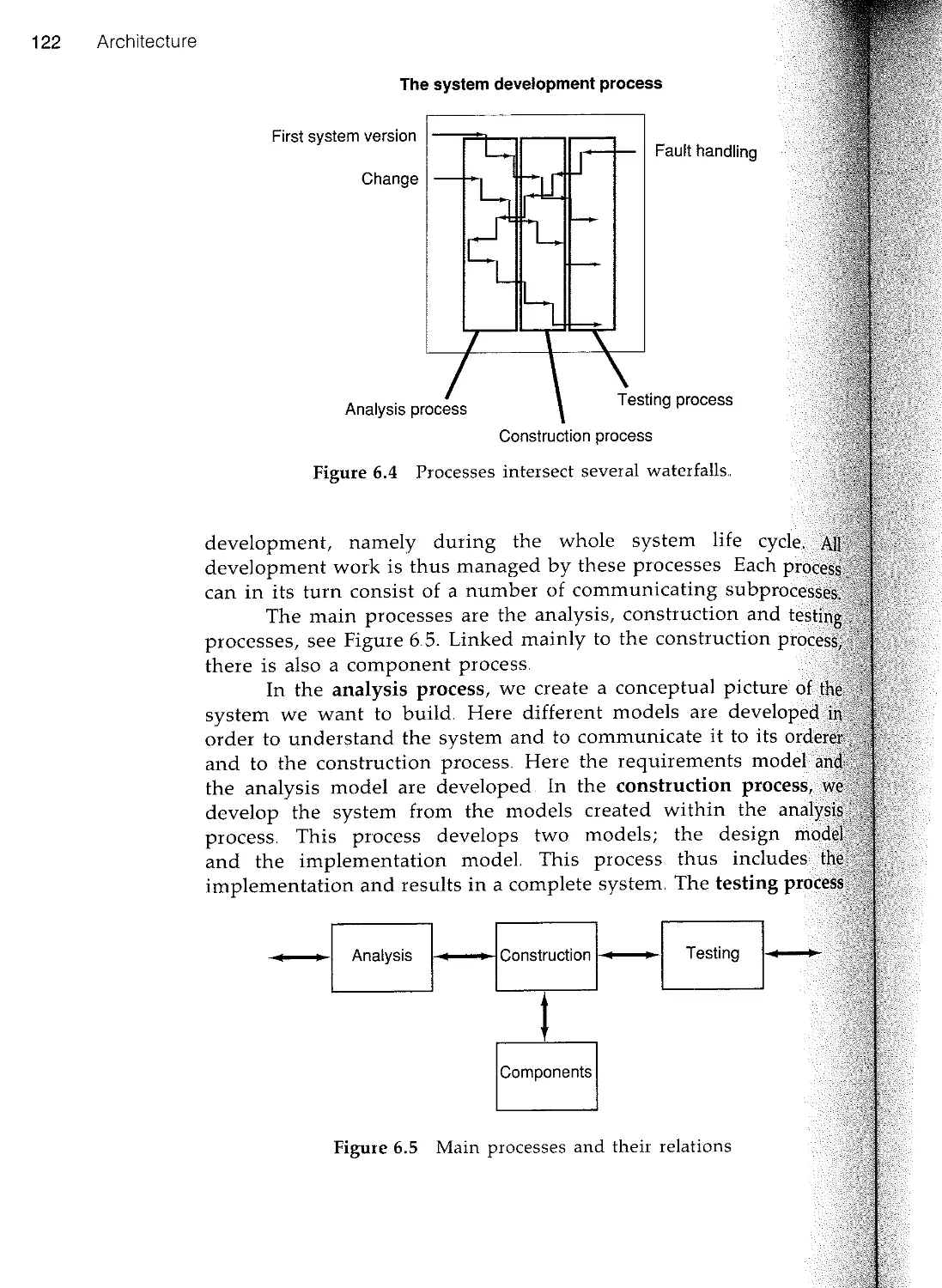
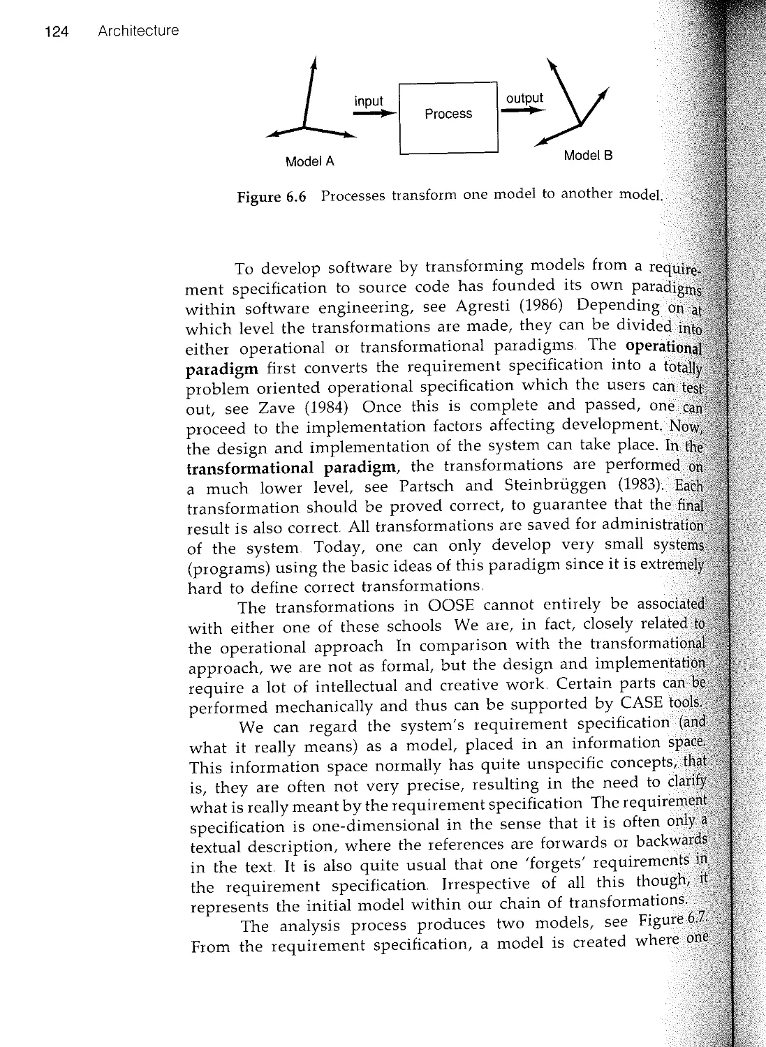
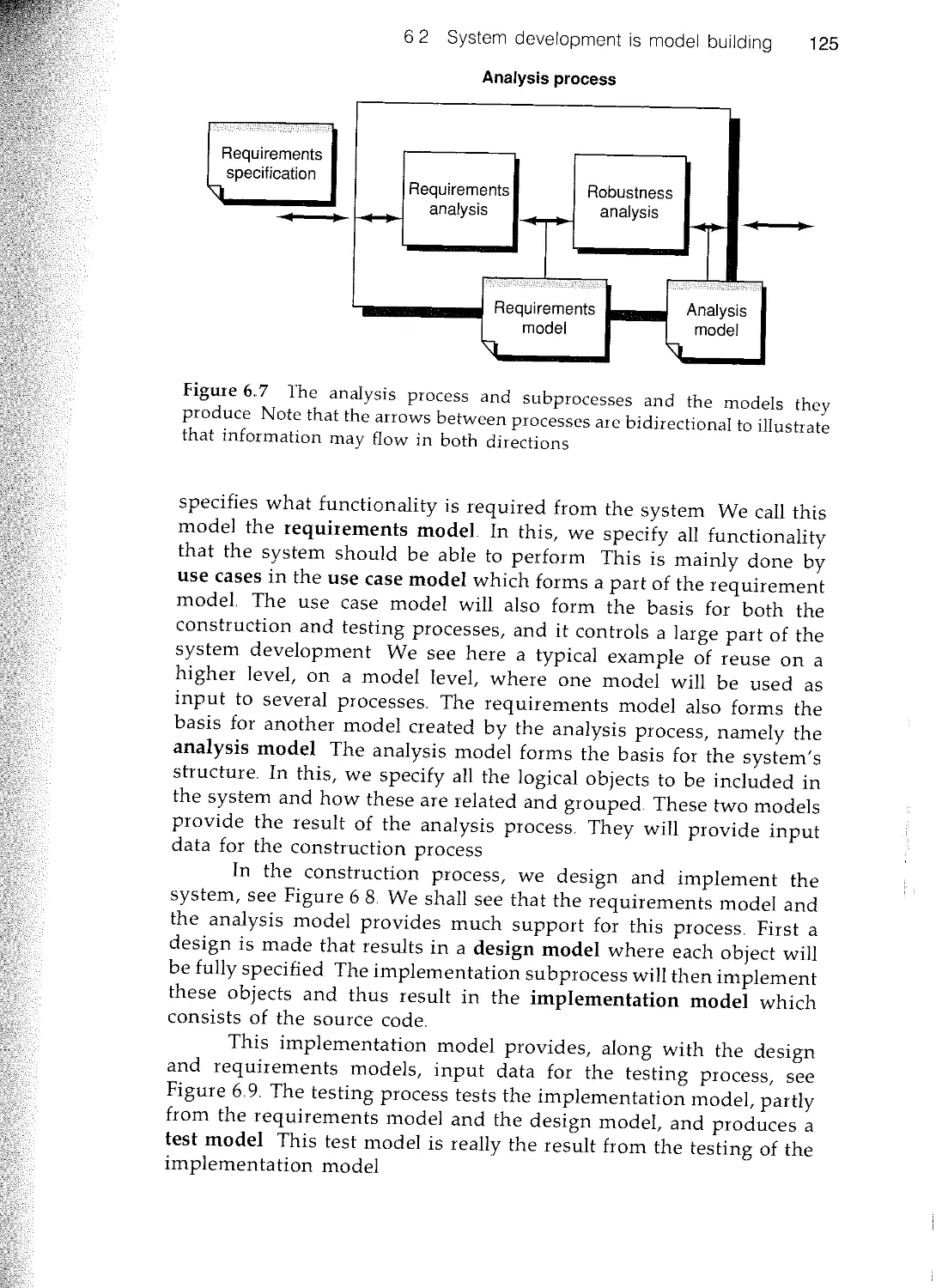
6.2 System development is model building
63 Model architecture
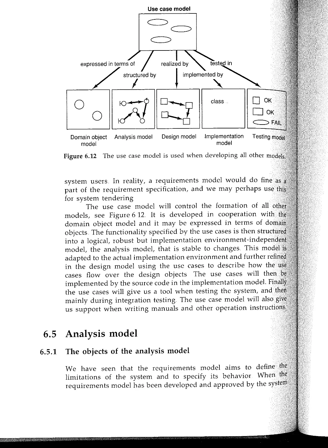
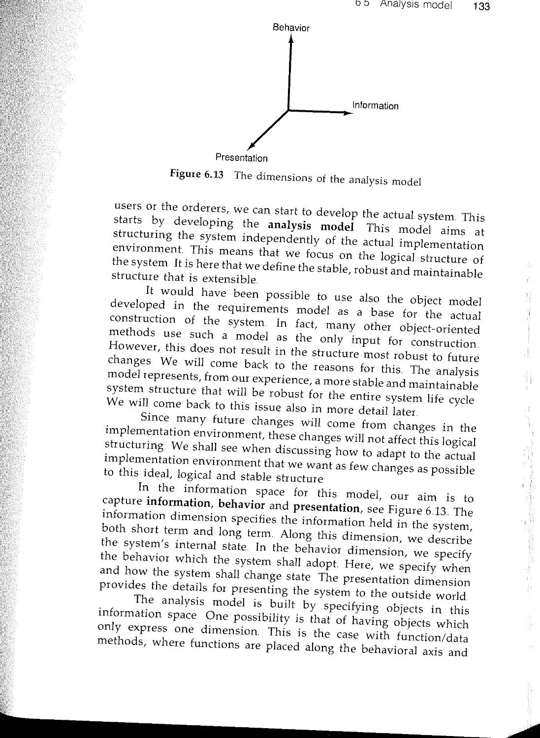
64 Requirements model
65 Analyis model
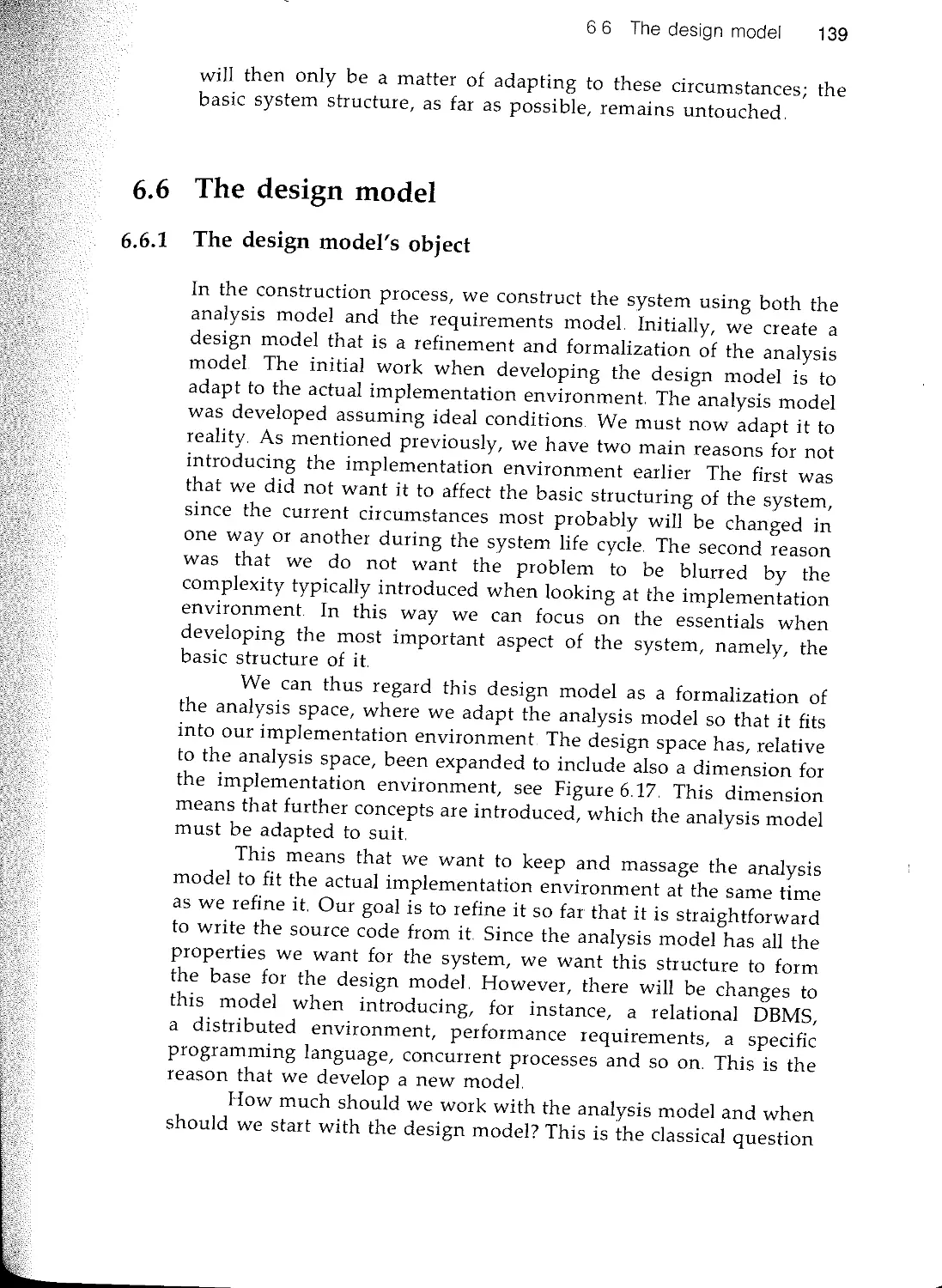
6.6 The design model
6.7 The implementation model
6.8 Test model
6.9 Summary
7 Analysis
7.1 Introduction
7.2 The requirements model
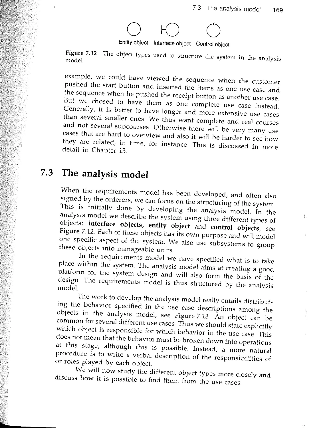
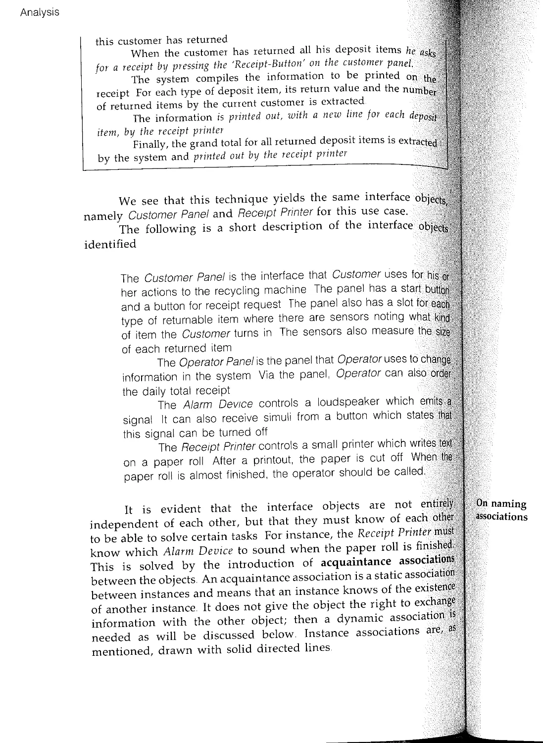
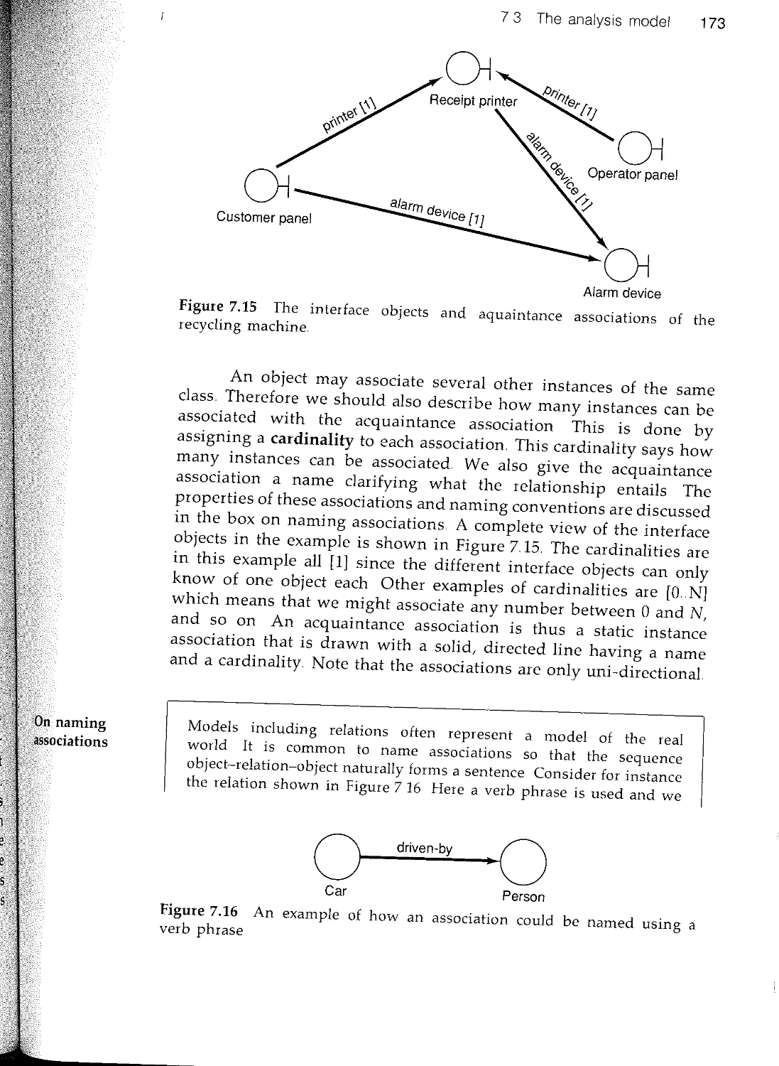
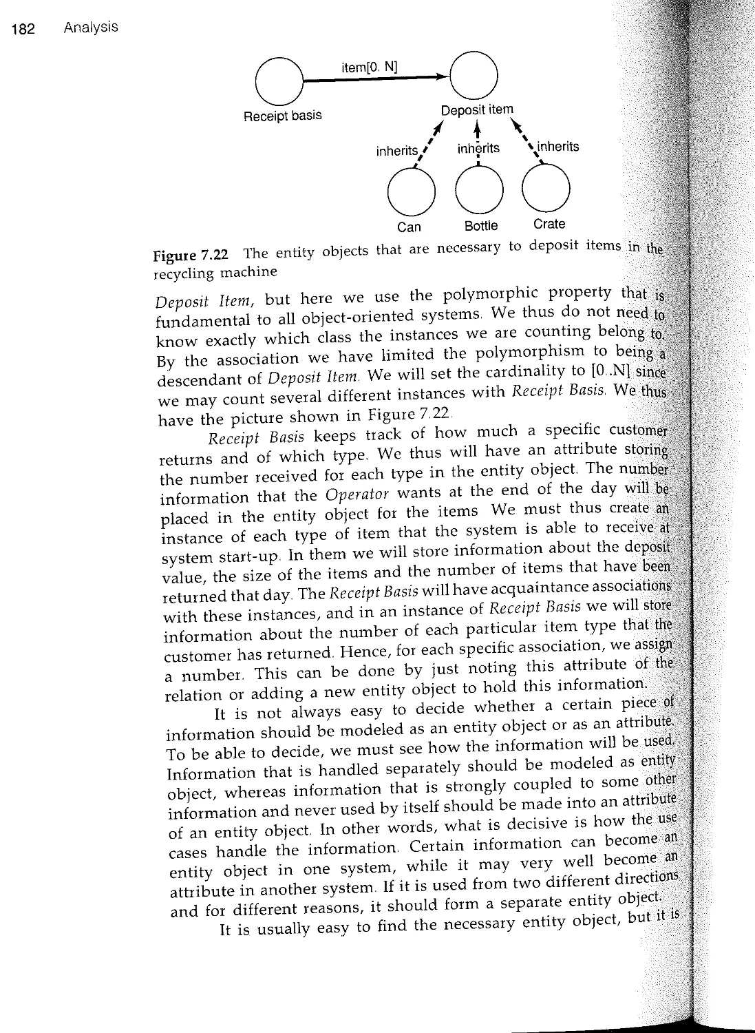
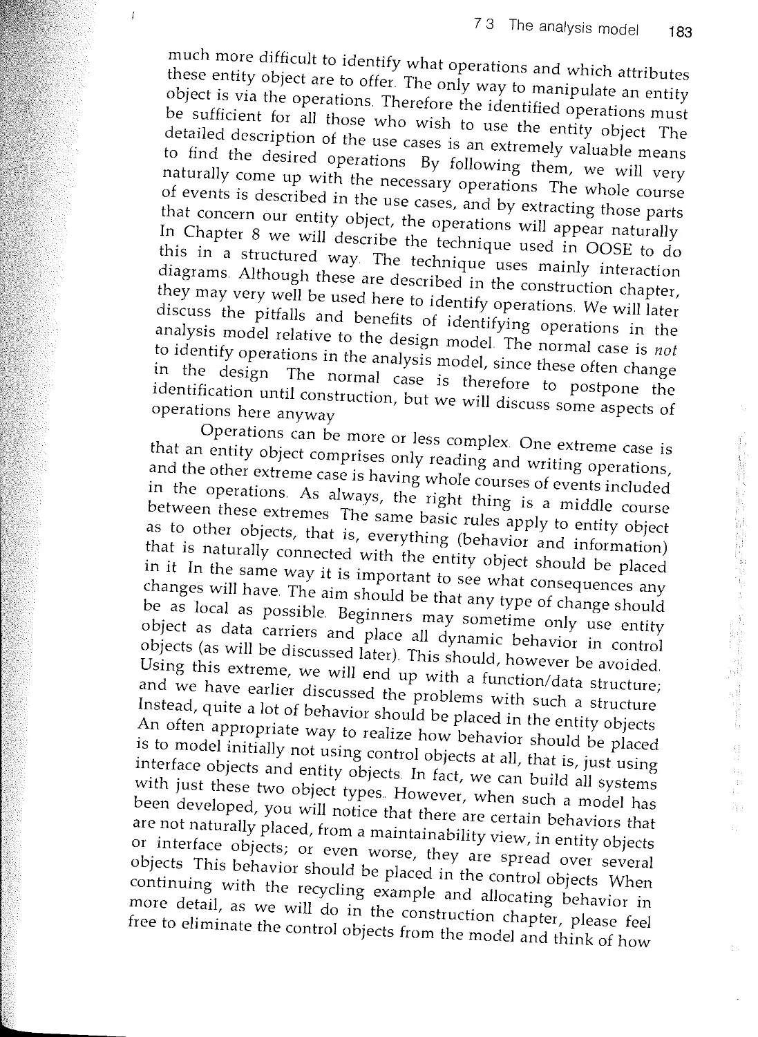
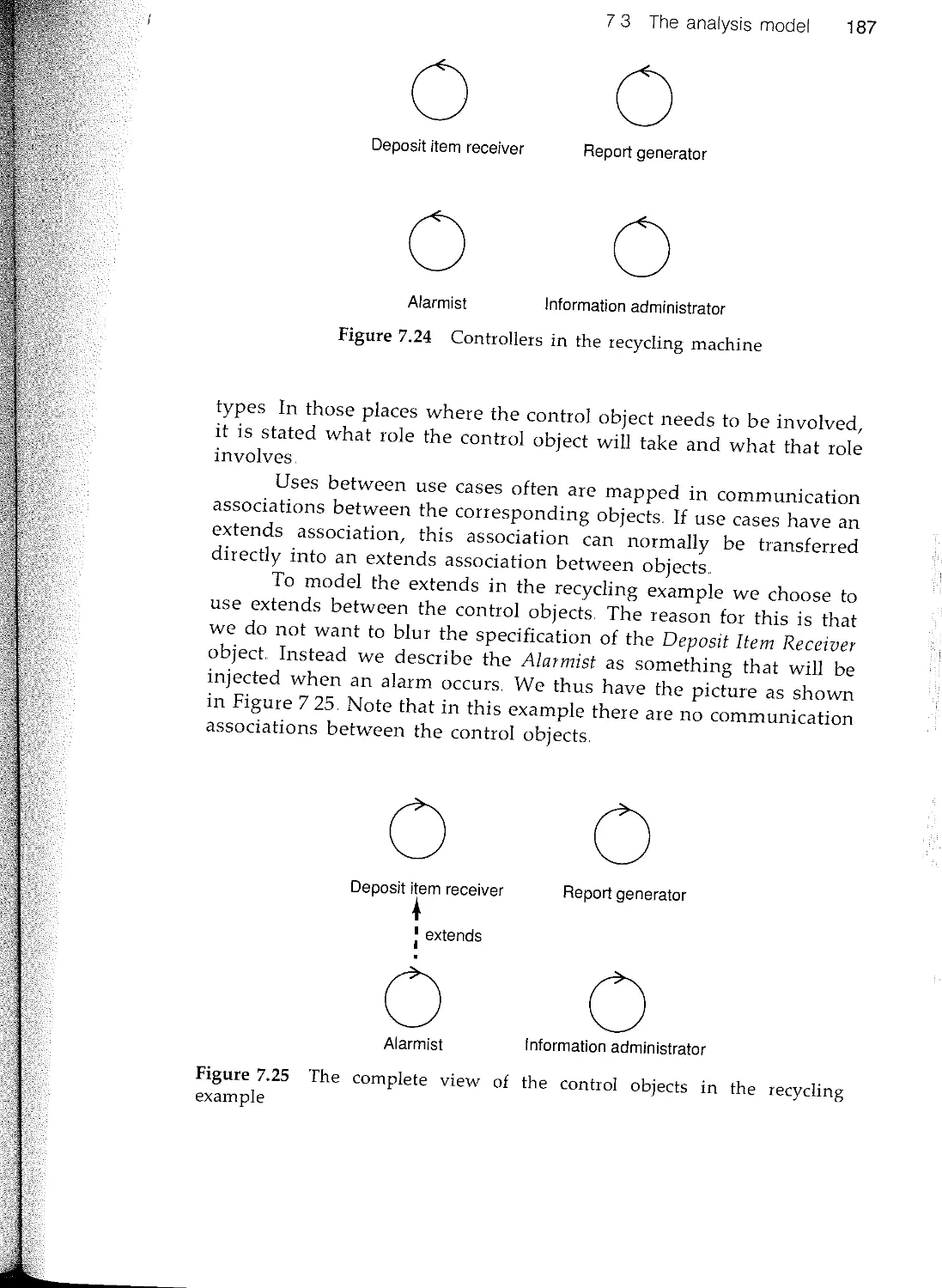
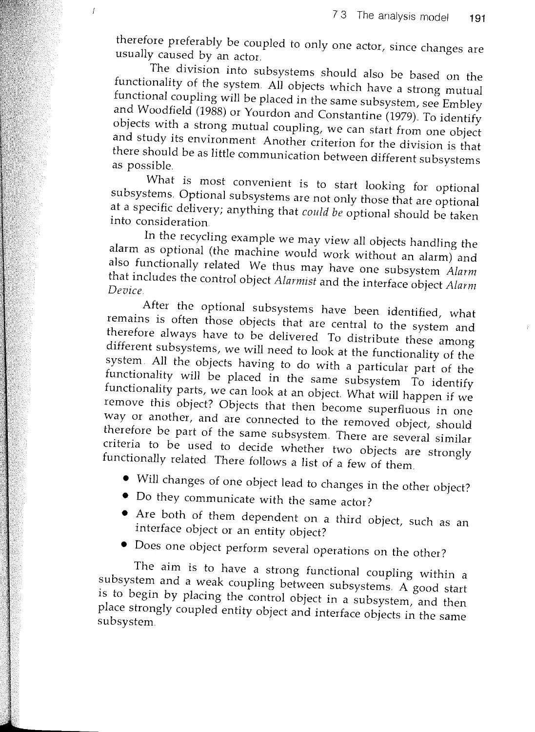
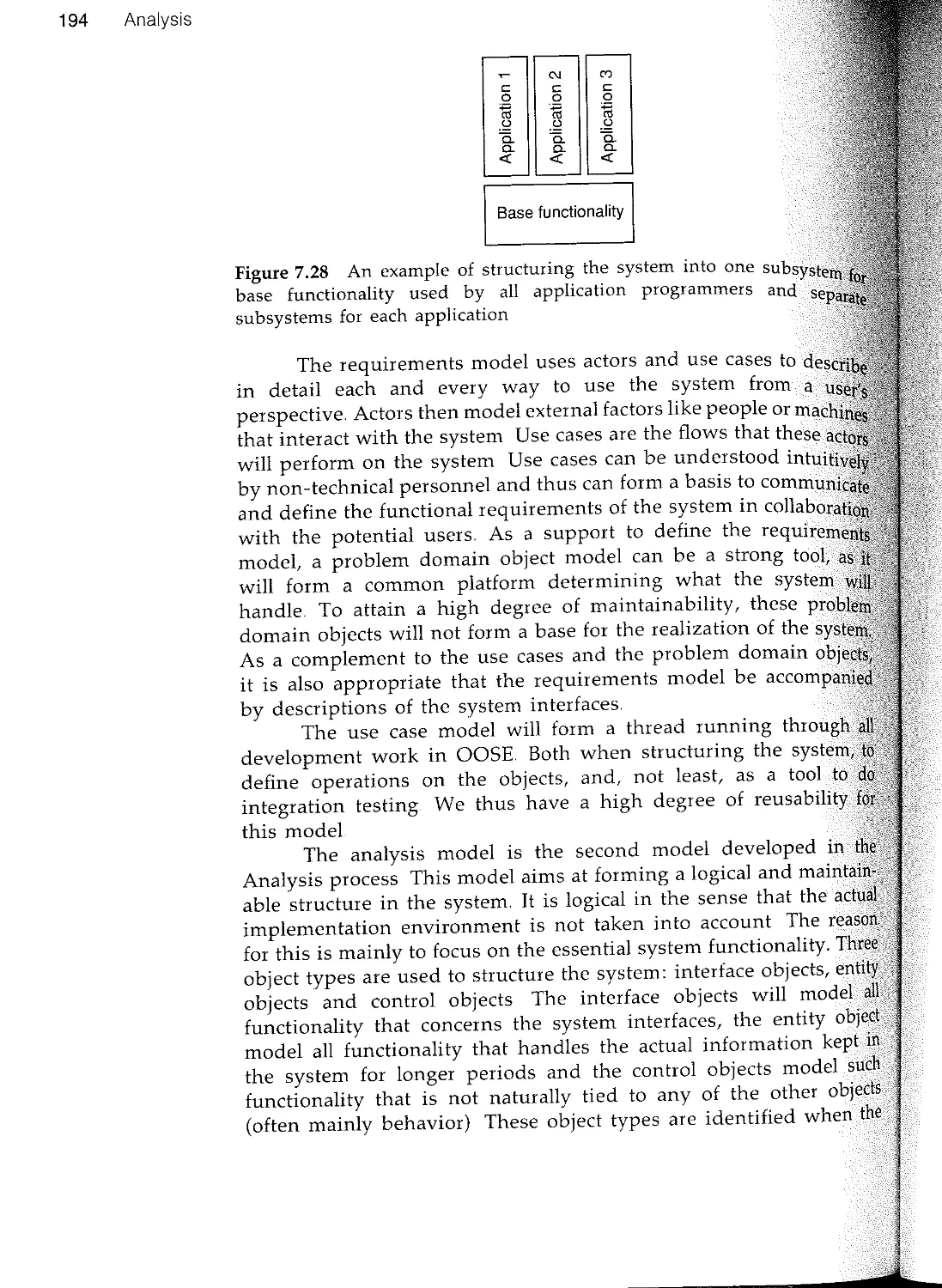
73 The analysis model
7.4 Summary
8 Construction
8 1 Introduction
82 The design model
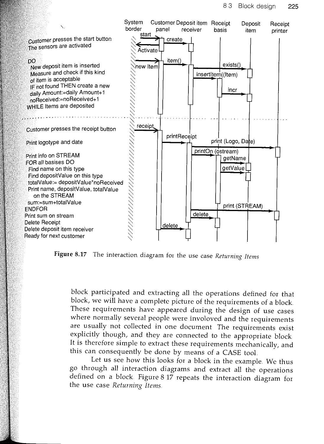
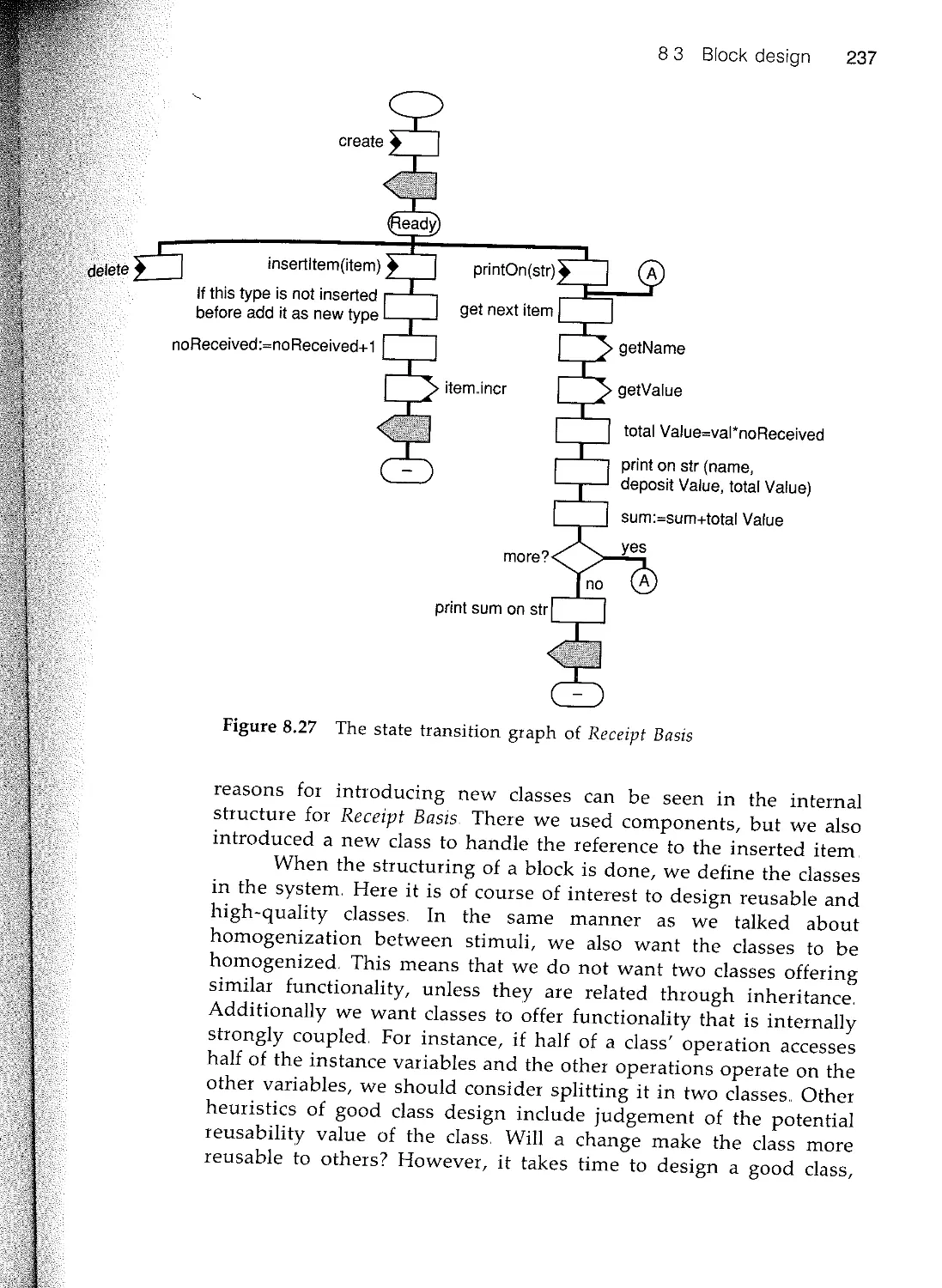
8.3 Block design
8.4 Working with construction 246
8.5 Summary 251
Contents xix
9 Real-time specialization 253
9.1 Introduction 253
9.2 Classification of real-time systems 254
93 Fundamental issues 255
94 Analysis 256
95 Construction 258
9.6 Testing and verification 267
9.7 Summary 267
10 Database specialization 269
101 Introduction 269
102 Relational DBMS 271
103 Object DBMS 280
104 Discussion 282
10.5 Summary 282
11 Components 284
111 Introduction 284
112 What is a component? 289
11.3 Use of components 291
U4 Component management 296
U5 Summary 305
12 Testing 307
121 Introduction 307
12.2 On testing 309
12.3 Unit testing 316
124 Integration testing 325
12.5 Summary 332
Part III Applications 335
13 Case study: warehouse management system 337
13.1 Introduction to the examples 337
13.2 ACME Warehouse Management Inc 337
13.3 The requirement model 339
134 The analysis model 351
13.5 Construction 371
14 Case study: telecom 387
14.1 Introduction 387
142 Telecommunication switching systems 387
References
xx Contents
14.3 The requirements model
14.4 The analysis model
14.5 The design model
14.6 The implementation model
15 Managing object-oriented software engineering
15 1 Introduction
15 2 Project selection and preparation
15.3 Product development organization
15.4 Project organization and management
15.5 Project staffing
156 Software quality assurance
15 7 Software metrics
15..8 Summary
16 Other object-oriented methods
16.1 Introduction
16.2 A summary of object-oriented methods
16..3 Object Oriented Analysis (OOA/Coad- Yourdon)
164 Object Oriented Design (OOD/Booch)
16 5 Hierarchical Object Oriented Design (HOOD)
16.6 Object Modeling Technique (OMT)
16.7 Responsibility Driven Design (RDD)
16.8 Summary
Appendix A On the development of Objectory
A 1 Introduction
A2 Objectory as an activity
A.3 From idea to reality
Appendix B Architecture summary
B.l Associations
B 2 The use case model
B3 Domain object model
BA Analysis model
B.5 Design model
Index
Part I
Introduction
1
1 System development as an
industrial process
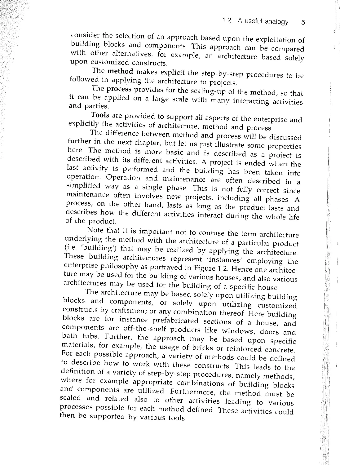
1.1 Introduction
The development of software systems, being a relatively young
industry, has not reached the level of maturity typically found in
more traditional branches of industry. Consequently, products that
are developed based on the usage of software technology often suffer
from a lack of the established practices that are required for their
development and exploitation as commercial products This lack of
experience can be traced to the fact that the emphasis in software
development, thus far, has been placed upon the creative processes
and methods used in the initial development of computer based
systems This emphasis is found in nearly all of the existing software
engineering methods and related tools that have been developed to
assist in the realization of software systems (When we use the word
system we not only include software systems, but also systems where
hardware and software are integrated parts.)
In this book, we shall consider a method which provides, as
do many other methods, support for the creative design of software
products, but which also provides an approach for making software
development a rational industrial process Thus the aim is not just
to produce well engineered software systems, but to make them
viable 'living' products that can be exploited in an industrial
environment
How do we go about providing the software industry with
the methods that enable us to deal with the practicalities of the more
global view of software products? Largely, we must understand what
goes into making 'industrial processes' successful and then apply
this knowledge in an appropriate manner to the software industry
In order to gain the necessary insight, we use an analogy to the
industrial processes of another well established industry The analogy
is quite useful since it illuminates the scope of the general problem,
thus allowing us to understand (draw parallels with) several important
3
The building construction industry is one of the most mature
of industry, having taken advantage of developments since
beginnings of civilized life. Naturally, the advances in this
have accelerated during the 20th century, which can be regarded
a period in which building construction changed largely from a
to refined industrial processes Since we all use buildings and
accustomed to their properties, the selection of building
as an analogy provides a useful common denominator By
examining some, but certainly not all, of the general properties
this industry, we shall be able to understand the need for, as
as the lack of, related properties in the software industry.
We can note that drawing analogies between the
industry and computer related processes is not new Spector
Gifford (1986), via an interview with an experienced bridge
(Gerald Fox), have documented important analogies between
industrial processes of bridge construction and corresponding
puter related processes..
In order to provide rationality in all phases of
construction, it is essential that a well established philosophy (i
point of view) guides the work of all parties in the various
of a building project. The philosophy has its concrete realization in
the form of an 'architecture' and related activities of the enterprise
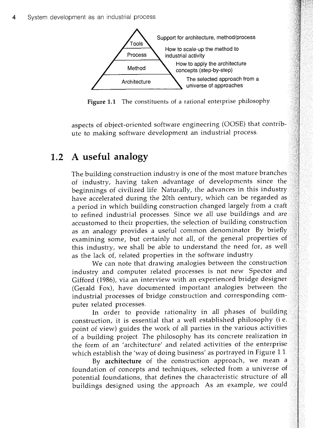
which establish the 'way of doing business' as portrayed in Figure 11
By architecture of the construction approach, we mean a
foundation of concepts and techniques, selected from a universe of
potential foundations, that defines the characteristic structure of all
buildings designed using the approach As an example, we could
4 System development as an industrial process
Architecture
Support for architecture, method/process
How to scale-up the method to
industrial activity
How to apply the architecture
concepts (step-by-step)
The selected approach from a
universe of approaches
Figure 1.1 The constituents of a rational enterprise philosophy.
aspects of object-oriented software engineering (OOSE) that contrib-
ute to making software developmen.t an industrial process
1.2 A useful analogy
1 2 A useful analogy 5
consider the selection of an approach based upon the exploitation of
building blocks and components This approach can be compared
with other alternatives, for example, an architecture based solely
upon customized constructs.
The method makes explicit the step-by-step procedures to be
followed in applying the architecture to projects.
The process provides for the scaling-up of the method, so that
it can be applied on a large scale with many interacting activities
and parties.
TooIs are provided to support all aspects of the enterprise and
explicitly the activities of architecture, method and process
The difference between method and process will be discussed
further in the next chapter, but let us just illustrate some properties
here The method is more basic and is described as a project is
described with its different activities. A project is ended when the
last activity is performed and the building has been taken into
operation. Operation and maintenance are often described in a
simplified way as a single phase This is not fully correct since
maintenance often involves new projects, including all phases. A
process, on the other hand, lasts as long as the product lasts and
describes how the different activities interact during the whole life
of the product
Note that it is important not to confuse the term architecture
underlying the method with the architecture of a particular product
(i e. 'building') that may be realized by applying the architecture..
These building architectures represent 'instances' employing the
enterprise philosophy as portrayed in Figure 1.2. Hence one architec-
ture may be used for the building of various houses, and also various
architectures may be used for the building of a specific house.
The architecture may be based solely upon utilizing building
blocks and components; or solely upon utilizing customized
constructs by craftsmen; or any combination thereof Here building
blocks are for instance prefabricated sections of a house, and
components are off-the-shelf products like windows, doors and
bath tubs. Further, the approach may be based upon specific
materials, for example, the usage of bricks or reinforced concrete.
For each possible approach, a variety of methods could be defined
to describe how to work with these constructs. This leads to the
definition of a variety of step-by-step procedures, namely methods,
where for example appropriate combinations of building blocks
and components are utilized Furthermore, the method must be
scaled and related also to other activities leading to various
processes possible for each method defined. These activities could
then be supported by various tools
6 System development as an industrial process
(a)
Architecture
approach A
(b)
Architecture
approach A
Architecture
approach B
Architecture
approach C
Figure 1.2 In (a) one architecture is used for different building
In (b) we can choose from different architectures for a specific product
We now consider how various activities of building construc-
tion are supported. In fact, the model we have introduced earlier
applied during each activity of building construction as
in Figure 13 The activities are creative design, construction and
term support Of course, to make the transition smoothly
seamlessly between the phases, well defined interfaces are needed
Creative design
Construction
Long term support
Figure 1.3 The constituents of multiple activities of a rational enterprise.
1 2 A useful analogy 7
For each activity, there is a philosophy (point of view and
related concepts) from which a particular architecture, method, process
and tools of the phase are derived Further, to be successful as a
whole, there must exist well defined two-way (seamless) interfaces
between these phases The details of the latter activities are directly
related to factors in the preceding activities and wherever possible
traceability should be applied, enabling us to return to relevant
factors in previous activities when problems arise. We will now look
at each activity in more detail.
1.2.1 Creative design
The transformation from a set of requirements and vague notions of
what is desired, to a structural plan of the building and a plan of
action for its implementation are the creative activities of new
development The requirements for building a house, for example,
are expressed in functional terms (an architectural drawing showing
the place and function of the rooms) as well as in terms of a
construction drawing following specified building standards Building
standards have developed based on a long tradition of what constitutes
a good house (i e. a house that can withstand strong winds, moisture,
wear and tear, etc.) With respect to determining what constitutes
good software, the software industry is maturing, but still has a long
way to go.
In planning for the development of a custom designed house,
the architectural drawings and construction drawings may be the
only basis for examining the building prior to its actual production
In some architectural approaches, a minitiarized scale model of the
house may be constructed However, when a series of houses is to
be developed, where all of the houses have the same basic building
architecture, a scale model, and most often one or more sample
houses (prototypes), are constructed. The prototypes are useful for
potential buyers to evaluate the functionality of the house in terms
of their needs as well as serving as a means of 'debugging' and
improving the basic building architecture.
In creating a modern building, in addition to building standards
and norms, significant attention is given to approaches which exploit
large building blocks based upon sub-assemblies of modules and
components These practices make large scale building construction
economically rational while at the same time insuring quality and
safety in the final product
Creative design thus takes place according to the architectural
approach and follows step-by-step methodes) and process(es) with
8 System development as an industrial process
the assistance of tools used in reducing requirements to a
building project architecture plan, including, when desirable,
creation of prototypes.
1.2.2 Construction
The first activity in construction is to provide implementation
concerning the architectural and constructional plans. That is to
from the more abstract towards a more concrete plan. After
sufficiently concrete plan has evolved, the
(implementation) takes place.. Production is thus the last phase
construction The number of people involved up to the point
production (even for large scale projects) is quite small in
with the number of people involved in actual production
Production is the result of manufacturing the more
construction plans as well as the detailed construction plan..
the production activity may take advantage of any related
and/or prototypes that may have been developed. Here we
differentiate between custom built houses and houses developed
mass production. In the custom built case, the implementation
typically performed by artisans who are specialists in their
field (woodworkers, plumbers, perhaps sculptors, etc.) The
properties of the custom construction are central In the
production case, we find the need to employ people with less
but who can carry out their detailed work in a cost effective
Thus a clear unambiguous method and process by which
construction plans are followed (with the assistance of
tools) are essential ingredients of successful mass production.
Responsibility for large scale building projects is most
placed in the hands of an entrepreneur. The entrepreneur
responsibility for the production according to the building
and construction documentation From this point, the
develops the detailed construction plan as well as the
preparation for production. The entrepreneur, in turn, enlists
services of subcontractors who take responsibility for portions of
total project. In order to use subcontractors effectively, standards
norms and the usage of building blocks and components
vital so that the subcontractors can be relied upon to perform
services properly. Further, we find once again the importance of
method, process and tools which explicitly define and document
procedures to be followed by entrepreneur and subcontractors
1 2 A useful analogy 9
1.2.3 Long-term support
Building construction projects, custom designed or mass produced,
must take account of the fact that the products should exist for many
years Thus the architectural approach of this phase must take account
of 'life-cycle' requirements for maintenance, alteration and extension.
In the software industry, due to inherent flexibility of alteration, the
existence of a philosophy containing an architecture that permits
long term support is absolutely essential
1.2.4 Conclusion
During all activities, from the original product requirements, through
the creative design activities, construction, production and for long
term support; documentation is a vital aspect of rational industrial
activity The documentation must be appropriate ('understandable')
for the various parties having a vested interest in the building
project Documentation must be kept up-to-date following alterations,
variations, experiences and so on, during all phases of the building
project In this area, computer aided tools make a major contribution
to their own branch and to all other industrial branches The software
industry, however, must learn from the traditions of other branches
of industry concerning the information content and management of
appropriate documentation.
The ability to reuse technology that has evolved during
building projects is an essential part of profitability for those involved
in the mass production of housing. Building blocks that have been
identified and exploited must be well documented and understood
so that they can be applied to new projects. In this regard, we can
differentiate between building blocks and components Building
blocks are typically larger units which have evolved during specific
projects (for example, prefabricated walls); whereas standard com-
ponents (for example, windows and doors) may have been used as
parts of the building blocks. The software industry has, during the
1980s, started to realize the importance of components; however, to
a large extent, the maturity associated with identifying and exploiting
useful building blocks has not yet evolved.
From our characterization of the building process being based
upon an architecture, method, process and tools, we can make the
following observations concerning the results of the scaling-up
process from which direct analogies can be drawn with the software
industry.
--
. The process must yield a foreseeable result, irrespective
what individual performed the job,
. The volume of output does not affect the process,
. It must be possible to spread out parts of the process to
man ufactur er sf su bcon tr actors,
. It must be possible to make use of predefined building
and components,
. It must be possible to plan and calculate the process with
precision,
. Persons trained for an operation must perform it in a
manner.
10 System development as an industrial process
1.3 System development characteristics
Having briefly examined some of the characteristics of a
established industrial branch, we can reason better about
development and identify the problems and areas in which
provides new solutions We have, in fact, already identified
aspects of OOSE relating directly to the building construction
As we move on to consider software development, the reader
think from time to time about applying the description of
system development back to the building construction analogy or
drawing analogies to other industrial and commercial activities
bidirectional thinking will be quite useful in gaining a
appreciation of the industrialization of software development
rational' architecture' provided in 005E makes an essential
bution to the long term support, documentation and reuse of
building blocks and components. Further, OOSE places
upon the management of change It is with respect to providing
rational architecture and related method, process and tools
software development that OOSE makes a contribution to the
industry
1.3.1 Part of a larger activity
System development does not take place in isolation It is part of
larger activity, often aimed at developing a product in which
is an integrated part. This is the case in large engineering
industries as well as in commercial enterprises such as
companies or banks In business data processing the product
of the administrative services that the data processing
1 3 System development characteristics 11
Enterprise
I
0:h i :;,i0"", 1
Sales
" .1 Production
,- L
Orders and
requirements
(Change)
requirements
Deliverable
products
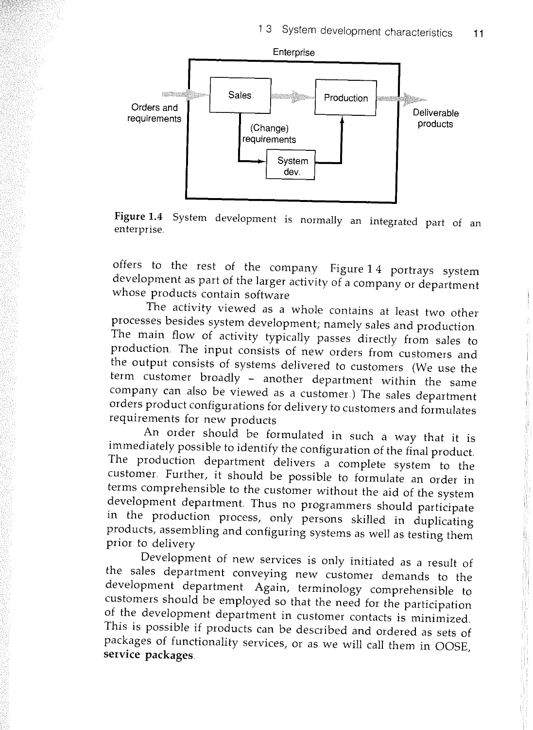
Figure 1.4 System development is normally an integrated part of an
enterprise.
offers to the rest of the company Figure 1 4 portrays system
development as part of the larger activity of a company or department
whose products contain software
The activity viewed as a whole contains at least two other
processes besides system development; namely sales and production
The main flow of activity typically passes directly from sales to
production. The input consists of new orders from customers and
the output consists of systems delivered to customers (We use the
term customer broadly - another department within the same
company can also be viewed as a customer.) The sales department
orders product configurations for delivery to customers and formulates
requirements for new products
An order should be formulated in such a way that it is
immediately possible to identify the configuration of the final product.
The production department delivers a complete system to the
customer. Further, it should be possible to formulate an order in
terms comprehensible to the customer without the aid of the system
development department. Thus no programmers should participate
in the production process, only persons skilled in duplicating
products, assembling and configuring systems as well as testing them
prior to delivery
Development of new services is only initiated as a result of
the sales department conveying new customer demands to the
development department. Again, terminology comprehensible to
customers should be employed so that the need for the participation
of the development department in customer contacts is minimized.
This is possible if products can be described and ordered as sets of
packages of functionality services, or as we will call them in OOSE,
service packages.
In the development department, new software items (i.e
code and/or other documents, for the production of systems)
developed, based on the new product requirements The
department can be informed about the new service packages later.
Thus service packages playa central role in the development phase.
It is in terms of service packages that the staffs of the three
subprocesses (sales, production and development) communicate. In
order to achieve a rational return on investment, service packages
should be designed so that they can be used in a number of different
products It will then be possible to build a large number of
applications from a set of standard service packages.
A customer order corresponds to a product order, specified as
a combination of service packages. The production department
receives the order and assembles the finished product. To do so, they
start from the source code for the service packages and transform the
programs into the object code of a particular machine configuration.
During these processes, it must also be possible to produce all other
forms of documentation that are part of the finished system.
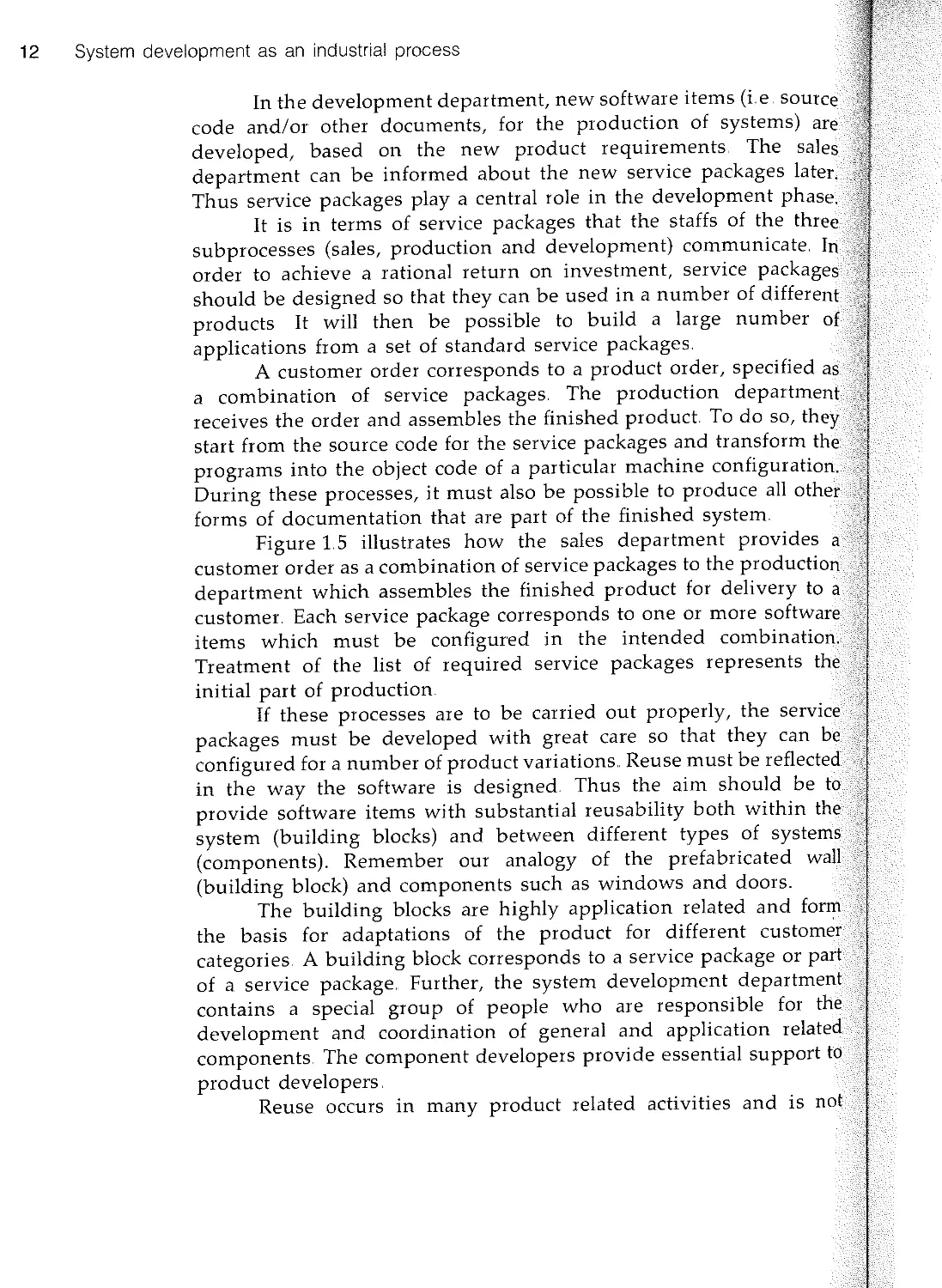
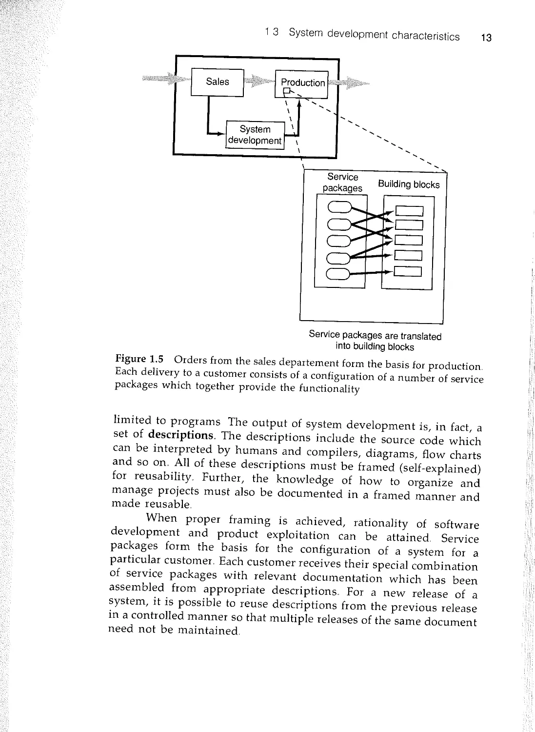
Figure 15 illustrates how the sales department provides a
customer order as a combination of service packages to the production
department which assembles the finished product for delivery to a
customer. Each service package corresponds to one or more softwar
items which must be configured in the intended combination.
Treatment of the list of required service packages represents the.
initial part of production
If these processes are to be carried out properly, the
packages must be developed with great care so that they
configured for a number of product variations Reuse must be
in the way the software is designed Thus the aim should be
provide software items with substantial reusability both within
system (building blocks) and between different types of
(components). Remember our analogy of the prefabricated
(building block) and components such as windows and doors.
The building blocks are highly application related and
the basis for adaptations of the product for different
categories A building block corresponds to a service package or
of a service package.. Further, the system development
contains a special group of people who are responsible for
development and coordination of general and application
components. The component developers provide essential support
product developers
Reuse occurs in many product related activities and is
12 System development as an industrial process
1 3 System development characteristics 13
10GiiiGLli{;;Y
" j
,.,;q,,,,,
....
....
....
........
Building blocks
Service packages are translated
into building blocks
Figure 1.5 Orders from the sales departement form the basis for production
Each delivery to a customer consists of a configuration of a number of service
packages which together provide the functionality
limited to programs The output of system development is, in fact, a
set of descriptions. The descriptions include the source code which
can be interpreted by humans and compilers, diagrams, flow charts
and so on.. All of these descriptions must be framed (self-explained)
for reusability. Further, the knowledge of how to organize and
manage projects must also be documented in a framed manner and
made reusable.
When proper framing is achieved, rationality of software
development and product exploitation can be attained Service
packages form the basis for the configuration of a system for a
particular customer. Each customer receives their special combination
of service packages with relevant documentation which has been
assembled from appropriate descriptions For a new release of a
system, it is possible to reuse descriptions from the previous release
in a controlled manner so that multiple releases of the same document
need not be maintained.
14 System development as an industrial process
New and changed
requirements
System
development
Changed system
Figure 1.6 System development is a process of successive changes of
from new and changed requirements
1.3.2 System development
Let us now concentrate on the subprocess of system
As requirements change, the system changes, see Figure 1.6
changed system actually consists of altered development
(descriptions) to be used for the production process
System development is carried out in a number of steps,
of which constitutes a more detailed and concrete development
earlier activities Thus it can be observed that system
is a gradual transformation of a sequence of models The first
describes the customer's requirements and the last step is the
tested program Between these two end points are a number of
models
System development can be viewed as a process of
model descriptions. This is true of all levels - analysis,
implementation and testing. In this context, the source code is
as a description that can be understood by programmers and also
the production process (a compiler and linker). The
present models of different degrees of detail Early models are
abstract, focusing on external qualities of the system, whereas
models become more detailed and instructional in the sense that
describe how the system is to be built and how it is meant
function.
The aim is to divide the complicated development of a
system into a number of activities and make it possible for
designers to take part at the same time Each partial model is
abstraction of the system which enables the designer to make
necessary decisions at this level in order to move closer to the
model, the tested source code Each modeling step adds more
to the system. Further, each new model is more formal than
previous one. To make the transitions between the different
as simple and faultless as possible, it must be straightforward
relate the model in one activity to the model in the following
We say that two models are seamlessly related to each other if
which were introduced in one model are represented in the
model in a very simple and straightforward manner
1 3 System development characteristics 15
System development
Requirements
Construction
Design Implemen
tation
Testing
Analysis
Figure 1.7 System development can be divided into three activities.
In essence, system development consists of three distinct
phases that follow each other seamlessly - Analysis, Construction
and Testing, see Figure 1.7. In analysis an application-oriented
specification is developed to specify what the system offers its users.
At this early stage, when changes are still relatively inexpensive, the
aim is also to find a good structure for the system, namely a structure
that is robust against change and which is divided into clear,
comprehensible and indivisible units that can be ordered (i e service
packages) This specification, which we call the analysis model,
specifies the functional behavior of the system under practically ideal
circumstances and without regard to a particular implementation
environment In other words, initially we disregard any restrictions
that might exist in implementation artifacts such as the programming
language, the database management system or other surrounding
supporting components It is important, however, to judge whether
the analysis model can actually be realized under the given circum-
stances, for example with regard to performance requirements and/or
development costs.
During construction, the idealized conditions of the analysis
will gradually be replaced by requirements from the chosen implemen-
tation environment In this phase, how the application-oriented
analysis model will be realized with the aid of such components as
system software, database management systems and user interfaces
is defined.. The construction activities constitute design and implemen-
tation The design activities formalize the analysis model in terms of
the implementation environment and specify the identified building
blocks The separate programs (blocks) identified in the design are
then coded (i e implemented)
In testing, the system is checked to make sure that all of
the service packages in the analysis model have been correctly
implemented and that the performance of the system meets require-
ments Testing takes place at several levels, from specific functions
to the system as a whole
These activities look very similar to a waterfall model. In fact,
it is if we are only concerned with a specific project However, our
System
view must raise from the project to the product This change of view
is essential and will be further discussed in the next chapter.
6 System development as an industrial process
1.3.3 The transition from analysis to construction
All development methods divides the development work into different
stages which may vary from project to project. In one project, a
formal analysis model may be required so that different contractors
can be asked for bids; the formal analysis model then guarantees
that the final design and implementation correspond to what was
ordered In another project, however, it may not be obvious how the
implementation environment affects the system requirements. A less
formal analysis model can then be chosen in order to make the
analysis less implementation environment dependent.
At present, formalism during the analysis phase should be
restricted to the syntax and semantics of the static structure of the
system. For this critical phase, no sound, practical, strictly formal
technique have come to our knowledge to satisfactoraly specify th
system's dynamic behavior.. A more practical, descriptive techniqu
is therefore preferable to a mathematical, formal method that is not
yet fully mature. A formal technique is better used later on, especially
during implementation.. Whenever the more formal techniques get
mature, these will probably be preferred..
Even though the boundaries between analysis and construction
may seem vague, there are certain guidelines for what should be
described during analysis and what should be dealt with during
construction, see also McMenamin and Palmer (1984)
. The analysis is independent of the implementation environ
ment Changes in the implementation requirements thus d
not affect the analysis result. Even if an important part of the
system, such as a database management system, is replaced
during implementation, the analysis model is not affected..
. The analysis model is application-oriented. The work is carried.
out in an ideal world; memory, performance and fault-tolerance
requirements are set aside
. The analysis model describes the elements of the application
in application-related concepts such as service packages. Given
this foundation, the structure of the implementation mirrors
the structure of the problem, rather than the other way round.
. The analysis model should not be too elaborate, as some of
this work must be adapted to the chosen implementation
1 3 System development characteristics 17
environment. Such adaptations may be difficult if the analysis
model is too formaL
Given the properties of system development that have been
described, we conclude that one approach to rational system
development is provided by the conceptual framework of OOSE.. This
is a basic theme of the book
1.3.4 Requirements are input to system development
The primary input for the development of a system is a requirements
specification. This will have been developed from facts about the
environment that the system is to serve. For 'technical' applications,
such as tactical command and control systems, process control
systems or telecommunication systems, the role of the system in its
environment is identified, and the requirements of the system are
formulated in terms of the behavior of sensors and actuators. For
'administrative' information systems, such as order-entry systems,
personnel administration systems or reservation systems, the work
usually begins with an analysis of the needs, problems and
development tendencies of the enterprise, see the side box on
enterprise development. Based on this analysis, a new enterprise
model is built where the computer-based information system forms
an important part of the enterprise In fact, the development of a
new and changed enterprise is based on the existing enterprise. This
is fully analogous to changing an existing information system. Thus
the same observations concerning changes which we made concerning
the software system are also valid for the enterprise Although we
here differentiate between technical and administrative systems, we
do not provide a precise definition of either In reality, most systems
include aspects from both areas.
Enterprise development can be viewed as a generalization of system
development Instead of developing a system, a whole enterprise is
developed. In enterprise development, the company is seen from several
different perspectives The aim is to identify the problem areas and
suggest alternative solutions. One result may be to introduce an
information system Enterprise development can be divided into the
phases portrayed in Figure 1. 8.
The current state description is a survey of the framework of
the present enterprise including its aims and problems To begin with,
the functionally different activities within the enterprise are separated,
and an analysis is made to find out how each activity contributes to
Establish
current
state
Enterprise
analysis
Change
analysis
Enterprise
design
Enterprise
V&V
18 System development as an industrial process
Figure 1.8 The different activities of enterprise development
the whole One activity may comprise several parts of the enterprise
that are organized separately
In the enterprise analysis, an ideal (analysis) model is made of
the present enterprise
In the change analysis, a detailed description is made of current
problems and needs, and appropriate changes are suggested This will
result in a changed analysis model.
In the enterprise design, the results from the change analysis
are given a form which can be 'physically' realized, given the practical
conditions of the organization
During enterprise verification and validation, the new enterprise
is verified against the initial intentions and also validated in its new
context
The enterprise design result serves, among other things, as
input data for system development It is then usually given the form
of a requirement specification for the information system which is to
be developed to support personnel with different roles in the enterprise
This requirement specification thus serves as input data for the
development of the supporting information system Moreover, several
aspects of the intended information system which are directly applicable
in the system development have been captured during enterprise
development
For administrative systems, the requirement specification
usually developed in a dialogue between customer and producer.
forms the basis for the decision to order the system. When
requirements of the enterprise are less well known, the
work is preceded by enterprise development (as described
In some cases, the customers are highly experienced and can
the specification during the initial contact with the potential
In other cases, the customer approaches a producer and
assistance in solving his problems The producer must analyse
customer's situation, try to solve the current problems, and
solutions based upon a new technique The result is that
requirements specification is developed. In administrative
development, the work to develop a requirements
constitutes a considerable part of the development activity
often done in cooperation between the user(s) and the
developer(s).
1 3 System development characteristics 19
For technical systems the situation is often somewhat different.
A common situation is that the software is to cooperate with
other machine or software components in an overall system The
requirements of the software system are then given by the interfaces
to the environment (sensors and actuators), where the specification
can be derived from a knowledge of required structure and behavior.
There are cases in which an operational system exists,
developed with another (older) technique which is to be modernized.
In these cases, the existing system documentation functions as a
basis for the development of a requirement specification This field
is often called re-engineering, see Jacobson and Lindstrom (1991)
As will be shown, it is practically impossible (for administrative
and technical systems) to foresee all the requirements of a system
during the introductory specification work In the next chapter we
will consider incremental development to handle the difficulties in
developing a good requirement specification
1.3.5 A system is the output from system development
The output from any system development is a set of descriptions,
often of considerable number They function as a basis for production
in the production department and as a basis for product description
in the sales department.
The most obvious result is the program code which constitutes
the final, executable model of the system. The result also consists of
other related documents which the users need in order to understand
and utilize the system in the appropriate manner. In this context,
the term users covers not only persons, but also the machines that
are in contact with the system in any way. In other words, we include
direct users, such as operators in a process industry, as well as
personnel involved in error detection and normal maintenance, such
as data base administrators In machine cases, the documents provide
interface descriptions to other systems In other words, there are a
number of different users who must all be satisfied by the set of
documents which together constitute the final product.
Document and product are the two basic notions which
together constitute the description of a system The superordinate
entity is the product (i e the system) consisting of a number of
subproducts. All product and subproducts are described in a list of
documents referring to the documents that collectively constitute the
product. Finally, due to reuse, a product may refer to documents in
other products
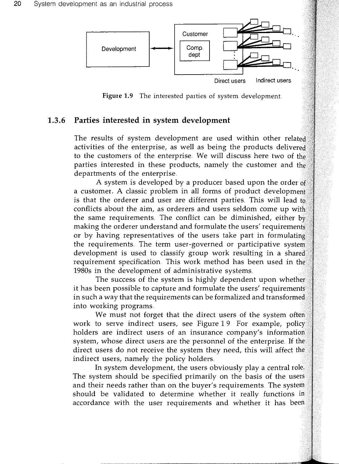
Direct users Indirect users
20 System development as an industrial process
Development
Customer
Figure 1.9 The interested parties of system development.
1.3.6 Parties interested in system development
The results of system development are used within other
activities of the enterprise, as well as being the products delivere
to the customers of the enterprise. We will discuss here two of th
parties interested in these products, namely the customer and th
departments of the enterprise
A system is developed by a producer based upon the order 0
a customer. A classic problem in all forms of product develop men
is that the orderer and user are different parties. This will lead t
conflicts about the aim, as orderers and users seldom come up wit
the same requirements. The conflict can be diminished, either h
making the orderer understand and formulate the users' requirement
or by having representatives of the users take part in formulatin
the requirements. The term user-governed or participative syste
development is used to classify group work resulting in a shared
requirement specification. This work method has been used in the
1980s in the development of administrative systems.
The success of the system is highly dependent upon whethe
it has been possible to capture and formulate the users' requirement
in such a way that the requirements can be formalized and transforme
into working programs.
We must not forget that the direct users of the system often
work to serve indirect users, see Figure 1.9. For example, policy
holders are indirect users of an insurance company's information
system, whose direct users are the personnel of the enterprise. If the
direct users do not receive the system they need, this will affect the
indirect users, namely the policy holders.
In system development, the users obviously playa central role.
The system should be specified primarily on the basis of the users
and their needs rather than on the buyer's requirements The system
should be validated to determine whether it really functions in
accordance with the user requirements and whether it has been
1 4 Summary 21
documented so that it describes the system from the user's perspective
In other words, we need a development process able to capture and
deal with requirements from a user-oriented perspective. Once again,
OOSE provides a new solution to this critical aspect.
The department that develops software products is only one
of the parties having a vested interest in the development of the
system Other departments within the enterprise, such as sales,
production and field service, are parties with an immediate interest
in being able to influence the development process
When the product is an administrative system to be installed
in the enterprise to serve its own personnel, the data processing
department is typically both the developer and the producer The
users are the personnel of the enterprise
Other groups, organizations and people that are also interested
in the development include various managers, accountants, quality
assurance groups, configuraton staff, operators, and suchlike.
1.4 Summary
In this chapter, we have introduced an analogy between the industrial
processes of the well established building construction industry and
the software industry. From this analogy, we have been able to
compare and understand related aspects. In particular we have
introduced the important terms architecture, method, process and
tools and showed how they are related to both branches
Further, we have introduced the major characteristics of
software development. We have identified several important areas
where OOSE provides new solutions to existing problems in the
software industry, in particular, the reuse of all forms of descriptions
that are the result of system development. OOSE can be applied to
the development of technical and administrative systems The result
of enterprise development provides an important input for the
preparation of specification requirements.
The subject of the book has thereby been framed. Finally, it
is important to note that the need for an industrial approach to
sofware development was recognized many years ago by, amongst
others, Doug McIlroy (1976) In a contribution entitled Mass-Produced
Software Components he writes:
'Software production today appears in the scale of
industrialization somewhere below the more backward
construction industries. I think its proper place is
considerably higher, and would like to investigate the
prospects for mass-production techniques in software. [. . .]
My thesis is that the software industry is weakly founded,
in part because of the absence of a software components
subindustry. [ .] A components industry could be
immensely successful.'
22 System development as an industrial process
2 The system life cycle
2.1 Introduction
In this chapter, we take a closer look at several important aspects of
system development which build on the industrial process thinking
described in the introductory chapter. Explicitly, we consider the
process of change in system development, reuse of program code
and documentation and a deeper examination of methodology.
2.2 System development as a process of change
All systems change during their life cycles. This must be borne in
mind when developing systems expected to last longer than the first
version (i.e practically all systems). Most development methods today
focus on new development, see Figure 2.1, treating revision work
only briefly, even though it is known that changes constitute the
main part of the total life cycle cost of most systems An industrial
process should therefore focus on system changes.
A system normally develops through changes in a number of
versions.. New development is, from this point of view, only a special
case - the first version. That is, new development constitutes a change
from nothing into something New development is nonetheless an
important activity It establishes an architectural philosophy and
constitutes the base of the system which must last throughout all
subsequent development A faulty base will have serious conse-
quences for the life cycle of the system
Let us now relate Figure 2.1 to our earlier presentation of a
developing organization being a part of a larger organization Analysis
begins when the sales department sends a requirement specification
to the system development department or, more often, when it sends
a specification of desired changes to an earlier version. We can call
this a delta requirements specification
23
24 The system life cycle
First development
cj CYCle v . 1 (]j verSion 1
erslon
Version 2
Version n
Figure 2.1 The first version of a system represents a minor
resource consumption during the life cycle of the system.
In Chapter 1, we showed that development work is
terized by the development of a number of models, each
detailed, see Figure 2 2. All of these models are in reality delta
insofar as each model is a changed version of an earlier model at
same level.
In analysis, the delta requirement specification is the
point from which to develop a delta analysis model. The delta analysi
model is then delivered to those responsible for construction, a
which point a delta implementation is produced. Each new versio
of the system is thus a delta version System development is th1.l
actually a process of progressive change.
It is often difficult to specify what versions of the syste
descriptions correspond to a particular release of the system.
number of versions is considerable for a fairly sizeable system.
example, different countries need different adaptations for
standards. In this regard, it is not sufficient to describe the
from the designer's perspective; it must also be described for
parts of the enterprise that will use it (e..g. marketing,
installation, operation and maintenance).. It is therefore vital that
system development enterprise employ an appropriate approach
the handling of successive versions of a system.
To achieve commercial rationality, it is essential to limit
number of versions of a system by using a technique which
Delta-requirements
Analysis
Construction
Testing
Figure 2.2 For each new version, the same development activities
followed as for the development of a new system. The difference is that
input data are composed of requirements for system changes
2 2 System development as a process of change 25
different installations of a particular release of a system to be
configured in different ways.. Each such configuration must be able
to exist independently, and it must be possible to change it
independently of other configurations of the same system.. This
implies that the versioning should, at least internal to the organization,
not be on a system level only, but also on a subsystem or module
level. Furthermore, it must be possible for different releases of the
same system to exist side by side, each with its own installation
configuration
In many cases it is desirable to be able to offer the same
system with partially different sets of functions for different cus-
tomers 1 Consequently, the arguments we have presented thus far are
also valid in this situation. The number of change requirements will
increase, leading to the need for strict planning of new releases.. The
system development process must therefore, by necessity, be framed
in such a way that it simplifies the development of several parallel
projects.
2.2.1 Incremental development
System development is usually regarded as a slow process, which
can take several years from beginning to end. Historically, in most
computer related projects, the requirements for the system as a whole
are specified.. Specification is followed by analysis, construction and
testing of the complete system. This method can work if all
requirements of the final system are known from the outset. This is,
however, rarely the case.
It is the rule, rather than the exception, that the system
requirements of information as well as technical systems are not fully
known at the outset of the project Knowledge of the system grows
progressively as work progresses. When the first version of the system
is in operation, new requirements appear and old ones change. Thus
the system as a whole cannot be completely developed in the belief
1 We use here the word 'functions' to express some functionality of a
system The word 'function' has come to have a bad reputation since it is
sometimes used in opposition to object-orientation This, we think, is
unfortunate since it is a good concept to use in object-oriented systems.
The same goes for the word 'structured' In this book we have tried to
avoid these words, but we believe that the words will come back into use
when a balance between object-orientation and structural or functional
techniques has matured.
o I he system lITe cycle
Graphic package
Spelling
Hyphenation
Wordprocessor
Time
Stage 1 Stage 2
Stage 3
Stage k Product release
Figure 2.3 Systems are developed incrementally in a series of stages.
that the requirements specification will remain constant during
development period, which can be several years for large
In most cases, it is better to develop the system step by
beginning with a few of its core functions. As a 'correct' path
clear and a better understanding of how the system
evolves, new functions can be added In this way, the system is
incrementally enlarged until the desired level is reached (i e the
finished product is available, normally the first product release as
portrayed in Figure 2.3). Such an incremental strategy also provide
faster feedback during the development process In practice, incremen
tal system development means that we can divide the system int
parts, corresponding to customer requested services.
As can be observed, each new stage extends the system
new functionality up to the finished product which comprises
whole of the desired system. Further, all subsequent releases of
system are developed as a series of incremental stages, see Figure
Stage 1
First development
CJ'"
Incremental
stages
Figure 2..4 Every new version is developed incrementally in a sequence
stages
2 2 System development as a process of change 27
For the sequencing of development stages to be successful, it
is essential to define stages which do not necessitate changing the
results of earlier stages as the latter stages are introduced. Thus it is
important to capture early those requirements which form the base
of the entire system How this can be done will be discussed later
Each stage is developed as a cycle and is tested before the stage is
completed.
2.2.2 Prototyping
It is often difficult to determine how a system is supposed to work
The reasons may be technical or functional; they may have to do
with efficiency or the user interface.. It is helpful in such cases to
develop a prototype of the intended system. Owing to the fact that
a prototype often highlights certain properties of the intended system,
other parts can be disregarded, and need only be given in schematic
form The prototype focuses instead on the properties into which
one needs further insight. The prototype allows developers to
experiment with a number of different design options Thus prototyp-
ing serves as a complement to incremental system development
A specific advantage of a prototype is that it can serve as a
means of communication between the developer and the customer.
It is much easier to express a view about something that can be
demonstrated and used, if only partially, than to express an opinion
about a specification A specification cannot capture the dynamics
of the system in the same way as a working prototype
For these purposes, a prototype could be developed in an
environment where an acceptable, functioning and easily modified
system can be quickly created; this is called rapid prototyping. Rapid
prototyping is in relatively bad repute today; there are even those
who classify it as quick and dirty. This bad reputation has not been
earned by the method as such, but rather by the way it has been
practiced. In some cases, the prototype has actually been considered
so good that it has been kept, and full system development has been
deemed unnecessary. This is fine, so long as those involved know
what they are doing. Such usage of the prototype may, however,
result in malfunctions, or lead to various practical difficulties when
modifications are required
Prototyping is a useful technique for comprehending an
application Furthermore, if the prototype is carefully designed
(through usage of the normal development cycle of analysis, construc-
tion and testing), it may also prove useful in the final system.
Correctly used, prototyping deserves a far better reputation than
has at the moment.
Finally, we can conclude that prototyping is an
working method, keeping in mind that it differs from incrementa
development in that the aim of prototyping is not to create a product;
but to emphasize and demonstrate certain properties of the intendecl
system.
28 The system life cycle
2.3 System development and reuse
A common desire in all development work is the ability to reuse th
results from earlier development work Reusability has become are
buzzword in software engineering, often promised to be the solutio
of the software crisis, see Cox (1990). Of course, reusability is ve
important, but, relative to other engineering branches, we speak verY
much about reuse. In other branches this is not a very central are
since it is so obvious and is practiced widely. The reason that there
is so much discussion about it in software engineering is that W
have been so unsuccessful in reusing existing parts. Thus our vieW;
of reuse must change into something that is self-evident
The necessity of reusability is of course applicable durin
coding, since it can influence productivity significantly. This is th
usual context when software people talk about reuse. So there is
reason that prevents us having it on the code level, but it is
not the only interesting type of reuse in software engineering.
can give even higher productivity enhancement is reuse in
development phases.. Other parts of the construction phase
benefit when reusing entire designs in several systems.
reuse should also be viewed as natural during analysis and
When developing an engineered product it is desirable to
able to choose between existing units (application modules
components) and develop the system from a set of reusable parts.
the previous chapter we considered how such reuse is exploited
the building construction industry. We would like to develop
in a similar manner.
Reuse should thus occur on several different levels of
larity. A system is assembled from a set of application modules.
module, in turn, is composed of other modules or of
The application modules at the lowest level consist of
only. In other words, system developers must have access to a set
components in order to build application modules. The
are thus the finest level of reuse. It is here that reuse must
However, to increase productivity even more, we also need to
2 3 System development and reuse 29
larger modules. This can be accomplished by reuse in earlier phases
when the system is being structured
Problems with reuse include the finding, understanding and
appropiateness of the thing to be reused. Object-orientation gives a
completely new technique that strongly supports these issues. To be
able to reuse parts already developed in a product is an important
way to decrease significantly the product's life cycle cost As we will
see later, OOSE focuses largely on this when structuring the system.
2.3.1 Components
First of all we need a technique to be able to build really good
components. By components we mean already implemented units
that we use to enhance the programming language constructs. These
are used during programming, corresponding to the components in
the building industry (i. e windows, doors, etc.) They must be
powerful, have simple well-defined interfaces, be simple to find, learn
and use, and have a wide area of application. Moreover, it should
also be possible to build new components with the aid of existing
components
Traditionally, software components have been available in the
form of procedures and functions for numerical and statistical
applications These should be complemented by software components
providing, amongst other functions, the buffers, queues, lists and
trees that are often needed in the programming of algorithms. They
may also provide windows, icons or scroll bars for human user
interfaces. These components often form a good base to start with.
It is not the number of components, but the usefulness of them that
determines the reuse success.
Components are listed in catalogues. For catalogues stored in
computer files there are special tools (browsers), by use of which it
is possible to consider the components more carefully. The catalogues
for electronics components or building construction catalogues
provide useful analogies Let us therefore compare the situation of the
programmer and the electronics designer The electronics designer's
shelves contain catalogues of electronic components from different
firms, whereas the programmer has computer science and software
engineering textbooks on his shelves On the whole, the programmer
must carry his knowledge of standard solutions around in his
head while the electronics designer can find standard solutions in
handbooks.. It may be possible to reuse entire programs, but the
opportunities to reuse parts of standard programs are few with
today's design techniques On the other hand, it is often difficult to
As described in the introductory chapter, a system consists of
program code and a significant number of other related
forming steps on the way from the requirement specification to
30 The system life cycle
design entire programs that are reusable Therefore a programme
often finds it easier to write a new program than to find and lear
an old one and then change it However, these kinds of handbooks
are beginning to appear on the market
There are, of course, a number of macrolibraries, sub-routin
libraries, procedure libraries and so on available for general use
However, with the exception of the libraries for numerical an
statistical computations identified above, they have not proved ver
successful As a rule, today a programmer does not look for read
made routines that can be referred to via a detailed interface He/sh
prefers to build their own routine by using part of an earlier progra
as a model and then making the necessary additions and change
In such situations, the well-defined sub-routine library is less suitabl
It is only in recent years that component libraries have begun to
found on the market. These are still quite simple, supporting mainl
data structures and window management systems, although they at
often very good as a starting point
2.3.2 Changeable applications
An application must be designed so that it permits constant alteration\
The most rational manner of building an application is to joill
changeable application modules, each of which is built using
components. Consider once again the analogy with prefabricated
walls in the building construction industry
The application modules must be framed so that requirements
for changes, in all probability, occur only in one module and onl
rarely in two or more modules Further, modules should be chosen.
so that they can be combined in different configurations for differen.
customers or in different installed systems By partitioning the syste
in this way, modules can be reused for different configurations
one or several systems.
Moreover, the modules should be alterable in a straight
manner without leading to a greater cost than is motivated by
size of the change. Today, a seemingly small change often results
a disproportionately expensive alteration Thus it must be
to bring intuitive costs into agreement with real costs.
2.3.3 Reuse of other descriptions
24 System development and methodology 31
Architecture
Figure 2.5 The foundation of a method is an architecture The method may
then be scaled up into a process, which, when defined, can be supported
by different kinds of tools.
finished system. Apart from these documents, there are various forms
of user-related documentation such as handbooks and educational
material. It should also be possible to reuse these documents
Document reuse early in the development chain may have consider-
ably greater effects than the reuse of application modules at the
source code level
2.4 System development and methodology
When developing large systems, it is important to know how the
different steps of the method cooperate and how they fit into the
development process as a whole This section broadens the discussion
to encompass both the development process and the basic ideas
behind the method, as well as what it is that determines the selection
of an architecture amongst a universe of potential architectures
Finally, we provide a few comments concerning how CASE tools
should be designed to support the development, starting from the
more fundamental properties of the architecture, method and process,
see Jacobson (1991)
Consider the pyramid in Figure 2.5, first introduced in Chapter
1, where it is made clear that a method should be developed from
an architecture Further, from the method, a process, and the
appropriate tools, can be designed
2.4.1 Architecture
A key property of a software system is its internal structure. A good
structure makes the system easy to understand, change, test and
maintain.. Thus properties of the system's architecture determine how
As discussed earlier, a method is a planned procedure by which
specified goal is approached step by step, not to be confused wit
methodology, which is the science of methods. Most work description
for program development are method descriptions They describe;
often in a very abstract manner, how one should think and reaso
in developing a software system. Most methods also indicate the
sequence of steps to be followed. The different steps of a method
can be divided into still more detailed elements, all describing ho
the work is to be carried out assuming a certain underlying basi
architecture A method is based on a preconceived notion of th
architecture of the working system. This means that the descriptio
of the method is formulated in terms of the concepts of the architectur
to be realized.
A basic requirement of a good method is that it simplifies th
development of systems of a particular architecture Thus a gooci
method for object-oriented system development should help us to
identify the appropriate objects. This may seem obvious, but
many methods for object-oriented development actually treat this.
requirement quite superficially. They imply that the objects can easily
be found directly from the activity being modeled It is true thaI
32 The system life cycle
the system must be treated during its lifetime. Using our previotl
building construction analogy, we observe that software systems ca
be compared to houses A stone house and a log house have differe
properties; they are built and maintained differently Unlike a hou
made of cards, however, they are both sound structures Simil
differences are found in software systems. For example, functio
data methods that separate data from functions have proved, in th
long run, to be a house of cards. Small changes in such a system, fo
instance a change in the format of a date, can have significa
consequences Object-oriented systems, on the other hand, a
composed of a number of communicating and well-delimited object
Such systems are easier to develop and understand, as well as beill
simpler to maintain and modify.. Thus we can assert that object
oriented systems have important and desirable architectural propel"
ties.. These architectural properties are extremely important and fo
the basis of the method The architecture thus defines the types
models that can be built and what characteristics each model wi!
have For instance, the following types of models may form
architecture: an analysis model, a design model and an implementatio
model.
2.4.2 Method
2 4 System development and methodology 33
many objects of a system should have real-life counterparts, but they
must also be motivated from the point of view of the architecture of
the system.. Which objects are needed, and how detailed they must
be, depends to a large extent on how the system is intended to be
utilized. It is, for instance, hardly appropriate to include the entire
spare parts information system in the system that supports the sales
department, whereas it is most important to include it in the support
system for the service department
It is usually not difficult to find suitable information-carrying
objects in an enterprise.. However, it is the dynamics describing how
the system is utilized that are difficult to define correctly. Many
people assert that the dynamics need no particular modeling: it
simply constitutes operations on information-carrying objects and
therefore can be included in them. However, systems often exhibit
behaviour that cannot naturally be said to belong to any particular
information-carrying object. For this reason it is better to model
separate dynamic objects
2.4.3 Process
A process is the natural scaling-up of a method.. We described the
relationship of method and process for our building construction
analogy.. To emphasize this essential difference, let us consider one
further analogy. Producing a new chemical substance in the laboratory
differs greatly from producing the same chemical on an industrial
scale in a factory. In the laboratory, the goal is to find a method to
produce the chemical. To make this method appropriate for large-
scale industrial use, a process must be defined. This usually
means changing the working method Nobody would dream of
industrializing the laboratory method by simply building a larger
laboratory with gigantic test tubes and Bunsen burners. Yet this is
often the way system development methods are scaled up for large
projects.
The solution lies in changing the working method so that it
can be scaled up and carried out with great parallelism _ as a process
If the method is developed for use on a large scale from the start,
the growing pains will not be so intense when the work has been
scaled up. It is therefore advantageous to adopt a development
technique for designing large systems from the start
Let us clarify the difference between method descriptions and
process descriptions Methods are typically described in a waterfall
model- a step by step procedure (with various degrees of granularity
in the steps).. This is similar to saying that a method is described as
34 Ihe system lite cycle
Requirements
analysis
Preliminary
design
System test
Figure 2.6 A method is described as a project developing the first
version. The figure illustrates a typical waterfall model
a system development project for one product version.
described as the first development project because a method
normally presented as starting from nothing and resulting in a fi
system version, see Figure 2..6. Note that often maintenance is
activity of its own in a waterfall model However, maintenance al
includes analysis of the requirements, design, testing and so on, a
thus can be described by these other activities..
A development organization not only has projects f
developing the first version, but also several other kinds of projec
like maintenance projects. These other projects include projects f
changing an existing system, tendering projects, error handli
projects and so on. All these different types of projects inclu
activities for analysis, design, testing and so on. Thus the activit
descriptions should be reusable in different kinds of projects in (1
organization ready to develop systems in an industrial manner.
development process defines these activities and can thus offer mot
than one project type. Different activities are combined for differe
project types and the process should offer all the project types .
which its supported organization participates (i.e. new developme
further development, change, error handling, etc), see Figure
The process should thus focus on a specific system and describe
a product is handled during its lifetime.
The process will continue to exist so long as the
system is in operation, whereas a project only exists for a
period of time To summarize, a method is described as the
2 4 System development and methodology 35
The system development process
First system version
Error handling
Figure 2. 7 A development process should describe the activities required
to manage a product over its lifetime These activities are combined to
describe different types of projects
development of a first version of the system, whereas a process is
described as the ideal principle of organization managing the system
during its entire lifetime.
Just as a method can be split up into a number of phases with
underlying steps, a process is composed of a number of interacting
subprocesses, see Figure 2.8.. These subprocesses define the different
activities of the development and must be defined in such a way
that they are clearly delimited, thus enabling each activity to be
performed as independently of other subprocesses as possible. Each
developer is responsible for the work carried out in one or more
subprocesses and thus makes use of the information sent to those
processes Moreover, the developer should also design the objects
that other processes need as the basis of their work The term
software factory has been coined to describe this division into
processes and subprocesses. Each of the subprocesses must be
described in terms of how it works, the input it requires and the
output it produces in the process descriptions
Taking this point of view, the development process itself can
be regarded as a set of communicating objects. Processes are thus a
System development
Changed
requirements
Changed
system
Figure 2.8 System development can be described as a set of interacting
subprocesses, such as analysis, construction, testing and components
The transition from principles to practice requires attention
number of new aspects. A process must be able to express muc
more than what is covered within the underlying method
The process description defines how different subprocess
should cooperate and to what extent they should be carried out i
parallel, that is, how the people involved in the project shoul
cooperate. Each subprocess is independent of the location of othe
subprocesses. Development work can therefore be split up and carrie
out at several locations Another way of expressing this is to sa
that a process description is an enterprise model for the syste
development organization, see Appendix A
When system development is industrialized, the activi
becomes less dependent on individuals A handicraft is extremel
dependent on the craftsmanship of an individual artisan An industri
process has fewer key persons Most work tasks are well defined an
can therefore be moved between different individuals. The whol
process is more resistant to disruption due to the advancement
developers or other personnel changes
If system development is viewed as a process, it become
natural to see development as a process of change All worki
developed relative to the existing system.. This is true both whil
maintaining one version of a system and while developing a ne
version A well-organized process provides version control as well.
It is possible to replace a subprocess with a new subproces
performing an equivalent task This is one way of adapting th
development process to a completely new kind of application, or ()
making a change in the development environment, such as employirt
a new programming language Some subprocesses may be of
type that they cannot be designed in exactly the same way in
types of projects They will have to be replaced by a process
to each specific project Yet this special subprocess must retain
same interfaces to other subprocesses. This requirement is
true for the subprocess responsible for implementing the
objects of the design For example, it will be customized
specific database management system and programming
36 The system life cycle
kind of objects This will be further examined in Appendix
process is thus an application or, if you like, the
of a method In summary, a process presupposes a method
in turn, presupposes a basic architecture
2.4.4 The process expresses more than the method
2 4 System development and methodology 37
=D
Object design
""" ;"';O" I "al;""O" 01
specialization of
U
Object design in C++
Object design in Ada
Object design with a
relational database
Figure 2.9 Process classes can be specialized
To be able to describe the specialization consistently, we allow
process classes to inherit other process classes.. In an analogous
manner to specialization in object-oriented programming languages,
we say that a process can be a specialization of another process class,
see Figure 2.9. We can start out from a general process containing
the principal behavior and make a number of specializations to
describe separate properties.
2.4.5 Computer-aided systems engineering
In the sections above, we have argued that the development of large
systems requires that the development method be broadened into
an industrial process To be fully efficient, the development work
also needs computer-based tools, namely a CASE (computer-aided
systems engineering) environment. Introducing tools need not change
the actual form of the process, though it often does.
When large systems are developed, all documentation must be
consistent. This means, among other consequences, that an object
must be given the same name everywhere in the documentation;
this is not necessarily a simple task. However, a tool that supports
hypertext links, or even better, object-oriented text, see Bergner
(1990), simplifies this task. When developers refer to an object in a
document, they add a reference to the desired object instead of
writing its name. The tool then presents the reference as, for example,
the object's name
38 The system life cycle
Sales
Figure 2.10 Different persons need different views of the system.
views may be composed from the same information
Tools can be used to automate a large number of
especially trivial ones of cumbersome volume. If the tasks in
underlying process are seamlessly connected, a great deal of the
can be automated, as the output of one subprocess can easily
the input of another.
When documenting a complex system, it is desirable to
the same information in several ways so that different people
gain a better understanding of the system that is being modeled,
Figure 2.10 Developers typically want to view associations
objects as purely textual descriptions in a document, arrows
diagrams and compilations in cross-reference editors (browsers).
more sophisticated development environment may adapt this
to different categories of developers Each developer can then
precisely and only the information that he or she needs. A
leader, for instance, may only be interested in overall
descriptions, whereas a designer needs to see all the details.
documents as well as finalized documentation are also desirable.
2 5 Objectory 39
A tool to be used on a large scale must support the process it
is based on. The process can be integrated into the tool as an
extension, for example, by supporting modeling decisions or handling
change proposals.
Computer-aided tools can lead to massive productivity
improvements, but they are only part of a greater whole.. The choice
of a development technique has its roots in the basic philosophy
chosen to govern the overall system structure of the designed systems,
namely the architecture. To this base is then added a method, a
process and, finally, computer-aided tools
2.4.6 Small-scale projects
It seems reasonable that we need a method, a process and tools for
very large projects, but can an appropriate method with good
computer support be sufficient for small projects? In our opinion it
cannot. Coordination around the maintenance activity is necessary
even for quite small projects. Yet projects are often mistakenly deemed
to be so small that they can be handled without very detailed
instructions. In this case, the project members are left to solve
problems as they arise However, ad hoc solutions arrived at beside
the coffee vending machine lead to bad work routines, inferior
systems and project delays. Even so, projects both large and small,
are sometimes carried out without a clear idea of how future
maintenance work is to be carried out..
The conclusion is evident. What is needed is a system
development process that can be packaged and placed into operation
in an arbitrary enterprise. The development process naturally precedes
the product development. Once it has been decided that program
products are to be developed, it becomes natural to choose a reliable
development process which suits software products Only then should
the details of the product itself be considered.. In this book we will
primarily describe a method for system development. It is, however,
important to realize that, like other methods, this method is not
sufficient for successful system development. It needs to be extended
into a complete process
2.5 Objectory
We have now described some important properties that can be
expected of a modern development technique:
· It must support the iterative development of a system over the
entire life cycle,
. The technique has been generalized from
it is now being used in various systems such as
systems, real-time systems, process control systems,
tools and graphic presentation systems.. Furthermore,
technique has been adapted to different programming
ages (for example Ada, C++, Smalltalk or COBOL),
management systems and operating systems, to name
few. It has, moreover, been extended from being
to being object-oriented, see Wegner (1987), as it now
inheritance between classes.
40 The system life cycle
. It should view each iteration as a change to an existing
. It must support the entire chain from changed requiremen
to the functioning system.
Objectory (the Object Factory for Software Development)
such a development technique The framework of Objectory is
design technique, hereafter called design with building bIoc
derived from the Swedish telephone exchange company LM Ericss
and now spread throughout the whole field of telecommunication
This technique is the essential idea behind the CCITT (Commi
Consultatif International Telegraphique et Telephonique) recomme
dation of SDL (the Specification and Description Language), s
CCITT (1988)
With the building block technique, a system is viewed as
number of connected blocks, each block representing a system servic
When all the required system services have been completely specifi
building blocks are designed using a top-down approach keeping
mind the criteria of insuring that the system being developed c
support changes to its functionality and can be adapted to n
technology This latter property is particularly important if
are to have a long lifetime
The building block technique has been employed for
twenty years in the development of large commercial systems. It
been employed in projects involving hundreds of designers,
today more than four thousand designers all over the world are
it. The telecommunications technique has yielded positive
when used in large systems, be they centralized or
In combination with two other techniques, conceptual
ling, see Bubenko and Lindencrona (1984), and
programming (described in the coming chapters), the building
technique has been significantly improved.. This combination
been developed further in Objectory in a number of ways:
2 6 Summary 41
· The technique has been simplified and scaled down for
application to small projects as well as to the large ones for
which it was originally intended.
· The three techniques of design with building blocks, conceptual
modeling and object-oriented programming have been for-
malized and tied together, made unambiguous and interrelated.
· Conceptual modeling has been extended with object-oriented
concepts and the ability to describe dynamic behavior
It is worth noting that the Objectory product itself has been
viewed and described as a system, which made it possible to develop
a new version of Objectory from an earlier version of Objectory.
Thus we can conclude, as described in the introductory chapter, that
the technique can be employed with equal potential during the
enterprise or business modeling phase that often precedes system
development This is further described in Appendix A
2.6 Summary
All larger systems will submit to changes during their life cycles.
This fact must be considered in an industrial process approach to
software engineering System development is actually a process of
progressive change as new and changed requirements will continue
to be imposed on any product
Incremental development offers a way to handle such changing
requirements during development of a specific version. It also
provides a way to speed up the feedback of a development The
complement to incremental development is to do proto typing early.
A prototype normally aims at investigating and highlighting uncertain
properties at an early stage of the system development It is essential,
though, to decide from the beginning the aim of the prototype;
whether it should be incorporated in the product (with maintainability
requirements as a consequence) or not
Reusability has failed in software engineering. Awareness of
this has been commonplace for quite some time. Still, reuse is kept
at a minimum level because of its associated difficulties. To increase
significantly the productivity in software development, reuse must
be a natural ingredient Object-orientation gives us new techniques
that are far better for supporting reuse than are traditional techniques.
Reuse must occur at several different levels. During the coding phase
is the most obvious, but it is also important to reuse previous work
during other phases.
.......
One of the most, if not the most, essential properties of
system is that it must have a stable structure during its lifeti
When defining a system development process, it is therefore import
to have concepts and models that strongly support the developm
of such a structure We call this foundation an architecture HoW
work with these concepts and models in an ideal development
described by a method The method should also support the goal
getting a stable system structure. However, when scaling up a meth
for industrial development of a product covering its entire life cyc
often involving several different types of projects, a method is It
sufficient We call the activities to support this a process The proce
will express more than the method, since it describes the com pie
management of a product over its entire life cycle. To manage sue
an industrial development process, tools must be developed
support the work. The support often consists of different kinds
documentation, although other tools may also be appropriate.
general, as many activities as can be automated should be automat
We have argued that we must change the way that
currently develop systems This change has already begun Importa
ingredients of this work are object-oriented technology, a proce
approach to development work and a well-developed tool box.. In
few decades, system development will have advanced just as has t
building construction industry A large number of components W
be available for reuse at all levels of detail, from small, gene
components to large, application-oriented modules To a large
the development work will correspond to the process model that
have been describing. The basic architecture and foundations of
method, such as object-oriented technology, will have been
and enriched
We have briefly introduced a technique that yields
oriented systems and that is itself object-oriented The rest
book will cover the fundamental ideas of this technique.
orientation provides the basis. In the following chapters, the
will gain a deeper understanding of what object-orientation is
our view of Object-Oriented Software Enginnering, OOSE, and
they can be applied throughout development The reader will
find case studies describing various application areas.
42 The system life cycle
3 What is object-orientation?
3.1 Introduction
This chapter introduces some of the basic concepts of object-oriented
technology. The aim is to introduce the actual idea, not to give strict
and precise definitions.. An introduction of object-orientation in use
both for system development and for programming is found in the
two following chapters..
Object-orientation is a technique for system modelling It offers
a number of concepts which are well suited for this purpose. The
word 'system' is used here with a wide meaning and can be either
a dedicated software system or a system in a wider context, (e.g. an
integrated software and hardware system or an organization).
Using object-orientation as a base, we model the system as a
number of objects that interact. Hence, irrespective of the type of
system being modelled, we regard its contents as a number of objects
which in one way or another are related Our surroundings, for
instance, consist of objects, such as people, trees, cars, towns and
houses which are in some way related to each other. Thus what the
objects model depends on what we wish to represent with our object
model. Another model of our surroundings would, perhaps, consist
of taxation, government and politics as objects. The objects which
we select to be included within our model are, therefore, dependent
on what the object model is to represent.
People regard their environment in terms of objects. Therefore
it is simple to think in the same way when it comes to designing a
model. A model which is designed using an object-oriented technology
is often easy to understand, as it can be directly related with reality..
Thus, with such a design method, only a small semantic gap will
exist between reality and the model, see Figure 3.1
Interest in the object-oriented method has grown rapidly over
the last few years This is mainly due to the fact that it has shown
43
--oiiiii
44 What is object-orientation?
Reality
House
Tree
rr\
1"Tom
Semantic
gap
. .>2
House ,,; ,. val
o
Tom
o
Tree
Model
Figure 3.1 Since objects from reality are directly mapped into objects
model, the semantic gap is minimized
many good qualities Amongst the most prominent qualities
system designed with an object-oriented method are:
. understanding of the system is easier as the semantic
the system and reality is small,
. modifications to the model tend to be local as they often
from an individual item, which is represented by a
object.
In the following sections, we shall introduce the basic
within object-orientation. This introduction is only an
and is independent of both the programming language and
development method used We shall not give any precise
formal concept definitions, but hope to provide you with a
understanding of these concepts. We shall use the concepts
meanings most commonly used within the object-oriented
ment, see Wegner (1987).
We will introduce the concepts by simulating a
example. We have chosen an example easy to understand
3 2 Object 45
Tom
Mary
John
Figure 3.2 Tom, John and Mary are regarded as objects
a person unfamiliar with the fundamental concepts of system
development. As mentioned earlier, object-orientation is ideally
suited to creating models of real systems, and especially for simulating
the system. From the example, we hope that you understand, and
also know how to use, the fundamental concepts discussed. The
example will be described further in the chapter on object-oriented
programming.
3.2 Object
The reality we will describe involves a number of people who perform
certain activities Our task is to try to model this system. We shall
see that it is very natural to construct a model which simulates this
reality.
The reality consists of a number of people, amongst others,
John, Mary and Tom. We shall now consider each of these people as
an object, see Figure 3.2. (We use 'person' and 'object' in this
description to mean the same thing; we actually mean the object that
represents the person. As always, one should be careful to separate
the reality from the model.)
The first and most important concept that we describe is, of
course, the concept of object What is an object? The word object is
misused and is used in nearly all contexts.. What we mean by an
object is an entity able to save a state (information) and which offers
a number of operations (behavior) to either examine or affect this
state.
An object is characterised by a number of operations
and a state which remembers the effect of these
operations
An object-oriented model consists of a number of objects;
these are clearly delimited parts of the modeled system. Objects
Figure 3.3 The object Tom and its operations
Operations
StoreAge
Age?
Walk
Dance
Jump
Tom
usually correspond to real life entity object, such as an invoice,
or a mobile telephone Each object contains individual
(eg.. a car has its registration number).
To each of the objects in the example, we thus
behavior and information that we wish to associate with
corresponding person An example of the information which
perhaps, wish to save for each object is age, address, male/fern
and so on. To access or be able to affect this information, we m
for each object, define a set-up of operations which can affect orre
the saved information We can also define operations which perha
need not affect any internal information, but only perform a behav
(e.g. walk, jump, dance). The only part of the object we can see
its operations, the inside is hidden to us, see Figure 3..3 Note t
from outside, we really see only those operations that exist!
behavior and not how they work We can only see how the differe
objects perform their behavior if we look inside them
Within the information any associations to other objects
also specified, for example an invoice knows which customer
invoice. The model's objects therefore have relations with each oth
For instance, we wish to model that the people shall recognize ea
other. These relations can be of two sorts Firstly, static relatio
namely relations existing over a longer period, which means that t
objects know about each other's existence Secondly, dyna
relations, namely relations by which two objects actually communic
with each other There is an abundance of different static relati()
in connection with semantic modelling, see Peckham and Maryans
(1988). We shall not describe these relations in any more detail,p
content ourselves with calling them static relations The objects ca
thus be composed from other objects, for example Tom can
composed of his head, his arms, his legs and his body, see Figure 3-
By means of this composition, we can structure the object To
in parts. The reason for structuring may depend on many factors.
Figure 3.4 A model of a person can be composed with the objects head,
legs, arms and body.
often depends on a combination of wishing to detailing the object,
increase understanding and wishing to obtain reusable parts.
A similar method of joining different parts together is through
use of partition hierarchies This means that an object can be
constructed from other objects, and those relations are therefore often
called consist of relations The word partition originates from Latin
partitos and means divide. Figure 35 illustrates an example of a
partition hierarchy.
A similar possibility for showing how something is interrelated
is through the use of aggregate. Partition hierarchy and aggregate
are used as synonyms, but there is a difference.. The word aggregate
originates also from Latin (the verb aggregare) and means to join
together, which is the opposite of to partition. As it is difficult to
express this grouping in a single way, a new object and a partition
hierarchy can be used to express the aggregate In a family relationship,
the grouping of Man, Woman and Child establishes the aggregate
Family. Since we cannot represent this triangular relationship, an
object Family is added to express the joining of several objects. This
object thus represents the aggregate, but it is not the aggregate itself
An aggregate is a union of several objects, and the union as such is
often represented by an object of its own.
If we look at the inside of the object, we shall see both its
information structure and how its operations work, see Figure 3.6.
We can also see the information that the object needs to store, the
parts the object consists of and how the behavior for the operations
is defined.
Car
Coachwork Wheels Engine
Figure 3.5 Example of a partition hierarchy. The object Family exists
to link together the other objects When one turns to the whole family,
turns, therefore, to the object Family.
The dynamics in an object-oriented model is created
the dynamic relations, by means of objects sending stimuli to
objects. We denote by the concept stimulus the event when an
communicates with another object In a programming context,
word 'message' is often used instead, but in order to avoid
message-semantic, we use the stimulus concept. Additionally,
word stimulus indicates that it stimulates some behavior to
action and does not necessarily include any message
stimulus, which is received by an object, causes an operation to
performed in the receiving object. This operation can in turn cau
new stimuli to be sent Hence, if we wish an object to perform
behavior, we send a stimulus to this object. For example, if we wi.
Tom to jump, then we send the 'Jump' stimulus to him When To
receives the stimulus, he interprets it and performs what has been
defined for him to do when this stimulus is received. Tom uses his
legs and arms and therefore sends stimuli to his legs and arms, se.e
Figure 3.7
We can also consider more complicated cases. If we want t
object Mary to dance, we send a stimulus 'Dance' to the object Ma
When she receives this, she performs the behavior associated wi
dancing. She, perhaps, will only dance with her friend. She w'
therefore send a stimulus to this friend to start dancing, see Figure 3.8.
All information in an object-oriented system is stored withi
its objects and can only be manipulated when the objects are ordered.
to perform operations. The behavior and information are encapsuIatea.
in the object. The only way to affect the object is to perform operatioIls
on it Objects thus support the concept of information hiding, thO.
is, they hide their internal structure from their surroundings se
Parnas (1972). Everyone of the object's operations perform part
the object's behavior, and can modify information in the object.
order to use an object, we do not need to know how the
behavior or information is represented or implemented
We only need to know which operations it offers.
3 2 Object 49
Tom
Information
Age Behavior
Wife StoreAge.
Friend Age?
Address Jump
... Bend myLeftLeg and
myRightLeg
Parts Stretch myLeftLeg and
myLeftLeg myRightLeg
myRightLeg Lift myRightArm ..
myHead Walk.
myBody Dance.
myRightArm
myLeftArm
Figure 3.6 The inside of object Tom Only the behavior for Jump is shown.
Note that we describe the problem in terms of items or objects
taken from real life and what we wish these objects to perform. We
do not know how John, Tom or Mary perform their tasks or how
they look inside. We have used the concepts object, operation and
encapsulation to understand the problem Encapsulation means that
all that is seen of an object is its interface, namely what operations
we can perform on the object
These important concepts have their roots in abstract data
types, see Aho et al. (1983) An abstract data type is a model
(structure), with a number of operations to affect this model. It is
similar to our definition of an object and, in fact, they are closely
related. Both are abstractions and are defined in terms of what they
perform, not how they perform it They are both generalizations of
something specific, where encapsulation is the central concept One
Jump
2
3
Figure 3.7 Tom jumps as a result of receiving the stimulus Jump
.......
50 What is object-orientation?
Mary
Information
Age
Husband
Friend
Address
Parts
myLeftLeg
myRightLeg
myHead
my Body
myRightArm
myLeftArm
Behavior
Dance
Ask Friend to Dance
Jump
Walk
Jump
Shake myHead
Shake my Body
Bend myRightLeg
Stretch myRightLeg
Figure 3.8 When Mary dances, she wants to have someone else to
with
of the advantages with abstract data types is that they
able to be used independently of their implementation
hiding), which means that even if the implementation is
we should not need to modify how we use the abstract data
Another advantage is, quite simply, the reduced complexity
there being no possibility of becoming involved in their
structure, but only the ability to use them according to
specifications
So far, we have only introduced the object concept.
people using the word 'object-orientation' mean only this,
we have seen, we have actually not come much further than
data types. To be truly object-oriented, we need some
properties and concepts.
3.3 Class and instance
In the system we model, there will be a number of
objects. Some of these objects will have common characteristics
we can group the objects according to these characteristics.
we look at the objects in the example, we notice that all three
have similar behavior and information structure. These objects
the same mold or template.. Such a group represents a class. In
to describe all objects that have similar behavior and
33 Class and instance 51
structure, we can therefore identify and describe a class to represent
these objects.
A class is a definition, a template or a mold to enable the
creation of new objects and is, therefore, a description of the common
characteristics of several objects. The objects comprising a certain
class have this template in common.. As an example we can view this
book. The book you are holding in your hand is an instance of the
book The book description at the publisher represent the class from
where instances can be created..
A class represents a template for several objects and
describes how these objects are structured internally.
Objects of the same class have the same definition both
for their operations and for their information structure.
A class is sometimes called the object's type. However, a type
and a class are actually not the same thing. As we mentioned above,
an abstract data type is defined by a set of operations. A type is
defined by what manipulations you can do with the type. A class is
more than that. You can also look inside a class, for example to see
its information structure. We would therefore rather view the class
as one (of possibly many) specific implementation of a type..
By means of the class concept, we can associate certain
characteristics with a whole group of objects, see Figure 3 9. We can
consider the class as being an abstraction that describes all the common
characteristics of the objects forming part of the class.
In object-oriented systems, each object belongs to a class. An
object that belongs to a certain class is called an instance of that
class. We therefore often use object and instance as synonyms.
An instance is an object created from a class. The class
describes (behavior and information) structure of the
instance, while current state of the instance is defined
by the operations performed on the instance.
We can thus define a class Person, and each object that
represent a person becomes an instance of this class. In our example,
we can describe a class Person, where Tom, John and Mary are
instances of this class, see Figure 3.10..
The behavior of the instance and its information structure are
thus defined by its class. Each instance also has a unique identity.
Several different instances can be created from a certain class, where
each instance is manipulated by the operations defined by the class.
Different instances can be manipulated by different sequences of
John
f t i
Class of persons
1
Person
Figure 3.9 The class person describes what is common to all
operations and, as a result, have different internal states. If
instances had been manipulated in exactly the same way, their
would also have been the same..
Now, we do not need to describe, for each person, how it
appear, as this description is made in one place only, namely
class. The class will therefore contain the information structure
for instance age, and operations to examine or modify this age..
we have created an instance (e..g. John), we need therefore to
John's age in this instance This is achieved by using the
for storing age..
In the same way, we can make all the peoples' arms, legs
heads into classes. Thus we can define an individual class for
arm, body and leg. The class for person can now use these
to construct a person's body, see Figure 3.11
As all people are instances of the same class, they will
similar behavior. If we wish to describe the fact that men and
have different behavior, for example when they dance, we will
to create two classes, one for Male and one for Female John and
are created as instances of the class Male, and Mary as an
of the class Female, see Figure 3.12 We must now, for both
classes, describe their behavior and information structure.
,),) \..,Iass and Instance 53
Class Person
Information Behavior
Age StoreAge ...
Friend Age?
Address Jump
Walk..
Dance..
Parts
myLeftLeg
myRightLeg Create an Instance
myHead Create myLeftLeg
myBody Create myRightLeg
myRightArm Create myHead
myLeftArm Create myBody
..
instance of I
Tom I
1 '0""" 01
\ instance of
John \
Mary
Figure 3.10 Tom, John and Mary are all instances of the class Person.
Why didn't we make John, Mary and Tom into separate classes
instead? This is surely feasible and, if they had different behavior
and/or information structure, we would have had no choice but to
do so. We have simplified things by saying that all men appear in
one way and all women in another. Both these classes have certain
parts in common At the moment, we must repeat these similarities,
but later we shall describe how inheritance can be used to avoid this
duplication of descriptions
What is contained inside the classes Male and Female? In
Figure 3.13, we can see both the information structure and the
operations in each class, and we can see that they have a lot in
common. The operation to create a new instance of a class (ie create
54 What is object-orientation?
Class Head
Class Body
D
Parts:
myLeg from class Leg
myHead from class Head
Class Leg
D
Figure 3.11 Instances of one class can recognize instances of another.
relevant classes are defined in the original class
a new person) creates also legs, arms, head and body for
person.
We also see how we have defined the operation to
differs only slightly, in this example, between the two sexes.
men and women move their bodies, but in slightly different
Class Male
Class Female
Operations:
StoreAge
Jump
Dance
Walk
Operations:
StoreAge
Jump
Dance
Walk
Tom
instance of
instance of
John
Mary
Figure 3.12 Male and Female are separate classes.
Class Female
Information
Age
Husband
Friend
Address
Parts
myLeftLeg
myRightLeg
myHead
my BOdy
myRightArm
myLeftArm
Class Male
Information
Age
Wife
Friend
Address
Parts
myLeftLeg
myRightLeg
myHead
myBody
myRightArm
myLeftArm
3 3 Class and instance 55
Behavior
Jump..
Walk.. .
Dance
Ask Friend to Dance
Jump
Walk
Jump
Shake myHead
Shake myBody
Bend myRightLeg
Stretch myRightLeg
Create an Instance
Behavior
Jump.
Walk..,
Dance
Jump
Shake my Body
Jump
Shake myHead
Jump
Create an Instance
Figure 3.13 The inside of classes Male and Female
Moreover, women will only dance if they have a friend to dance
with.
To summarize, we can consider the class as being the definition
of operations and information structure for objects, and the instance
defining an individual object's state.
Polymorphism means that the sender of a stimulus does
not need to know the receiving instance's class The
receiving instance can belong to an arbitrary class
56 What is object-orientation?
3.4 Polymorphism
Instances, created from classes, will together provide us with
dynamic behavior that we wish to model It is when these instan
start to communicate with each other that the system's behavior
performed An instance may know of other instances to which still1
can be sent If an instance sends a stimulus to another instance, b
does not have to be aware of which class the receiving instal1
belongs to, we say that we have polymorphism Polymorphis
means, at least in object-oriented contexts, that the sending install
does not need to know the receiving instance's class and that
class can be any class
All people have a best friend We can see this in the
structure of the classes Male and Female; both have
a friend. We have not specified any special conditions for this
but we can assume that it is another person A person's friend
therefore, be either of the class Male or Female. We therefore ha
polymorphism in this model, as friend can refer to an instance
several classes Mary's friend is either Tom or John and as these
both associated with the same class, Male, we have no use fort
polymorphism characteristic. However, Tom's friend is either Ma
or John, and as they are from different classes, class Male wilLI\
know with which class the friend will be associated Here,t
reference friend must be polymorphic. Polymorphism thus mea
not only that different instances can be associated, but that th
instances can belong to different classes. It is in the latter case,
with Tom, that we have use of the polymorphic characteristic.
A stimulus can be interpreted in different ways, depend
on the receiver's class It is, therefore, the instance which receivest
stimulus that determines its interpretation, and not the transmitti
instance. Often polymorphism is said to mean that one operati
can be implemented in different ways in different classes. This
actually only a consequence of what is said above and not polymo
phism in itself. (Polymorphism and dynamic binding are also oft
confused Dynamic binding means that, not until the stimulus!
sent, the stimulus is bound to a certain operation in the receiviri
instance's class We shall discuss dynamic binding in more detaiLi.
the chapter on object-oriented programming)
35 Inheritance 57
As we have not specified any conditions on the class, we
should, in theory, be able to associate an instance of any class to
friend. It is therefore possible to associate an arm with friend..
Therefore it is often necessary to restrict the receivers of a stimulus.
If we know, in advance, the receiver's class, then we don't need
polymorphism, but if we allow the receiver to be of varying class,
within limits, we must specify this restriction in the polymorphism
characteristic. Thus, we need to restrict the instances which can be
associated. This is often called limited polymorphism We require
only instances of the classes Male and Female to be friends. This
restriction can be made in different ways. Normally, inheritance
hierarchy is used. We shall soon return to this problem
Polymorphism is a very important characteristic for our models..
It is thus the receiver of a stimulus that determines how a stimulus
shall be interpreted, not the transmitter. The transmitter need only
know that another instance can perform a certain behavior, not which
class the instance belongs to and thus not which operation that
actually performs the behavior.. This is an extremely strong tool for
allowing us to develop flexible systems.. We have, in this way, only
specified what shall occur and not how it shall occur. Through
delegating what shall occur in this way, a flexible and modification
resistant system is obtained If we wish to add an object of a new
class, this modification will affect only the new object, and not those
sending stimuli to it
3.5 Inheritance
When we describe our classes, it is soon noticed that many classes
have common characteristics (behavior and information structure).
For instance, when we compare the classes Male and Female, we see
that they have much similarity to each other. These similarities can
be shared between the classes by extracting them and placing them
in a separate class Person.. In Person, we describe everything that is
common to Male and Female. In this way common characteristics can
be shared by several classes. We collect the common characteristics
into one specific class and let the original classes inherit this class.
Male and Female then inherit Person and we now need only describe
the characteristics that are new to these two classes. We therefore
allow both Male and Female to inherit Person and, in this way,
obtain access to all the characteristics defined there, see Figure 3.14.
Male and Female now contain the same things as before, but their
description has been simplified by means of inheriting Person.
....
Behavior
Jump...
Dance
Behavior
Jump...
Dance
58 What is object-orientation?
Class Person
Information Behavior
Age StoreAge
Wife Age?
Friend Walk..
Address
...
Parts
myLeftLeg
myRightLeg
myHead I I
my Body Create an Instance
myRightArm ...
myLeftArm
""'
I
,
inherits,'
,
,
Class Male
\
inherits
Class Female
Figure 3.14 Classes with inheritance.
If class B inherits class A, then both the operations and
the information structure described in class A will
become part of class B.
By means of inheritance, we can therefore show
between classes and describe these similarities in a class, which
classes can inherit Hence we can reuse common
Inheritance is therefore often promoted as a core idea for
the software industry. However, although inheritance, properly
is a very useful mechanism in many contexts including
35 Inheritance 59
Class A
.
I inherits
I
Class B
Figure 3.15 Class B is a descendant of class A and class A is an ancestor
of class B.
not a pre-requisite for reuse We will come back to this issue in
Chapter 11
Through inheritance, we have also obtained another advantage.
If we want to modify some characteristic in Person, (e.g. how a
person walks), it is sufficient to perform this modification in one
place. Thus, if such a modification is made, both Male and Female
will inherit this new definition of walk Hence inheritance is very
useful for easy modification of models.
We also see from the examples that the descriptions of Male
and Female have been greatly reduced The only information
remaining is that which differs between them. Inheritance is thus
also useful to avoid redundacy, leading to smaller models that are
more easy to understand
The ease of modification does not only occur inside class
descriptions The adding of new classes can be easily done by just
describing changes to existing classes. However, the adding of new
classes may sometimes involve restructuring the inheritance hierarchy.
We shall come back to this issue later.
By means of extracting and sharing common characteristics,
we can generalize classes and place them higher up in an inheritance
hierarchy. In the same way; if we wish to add a new class, we can
find a class that already offers some of the operations and information
structure required for the new class. We can then let the new class
inherit this class and only add anything which is unique for the new
class We then specialize the class
Classes lying below a class in the inheritance hierarchy are
called descendants of the class. Classes lying above are called
ancestors. Sometimes the concepts of sub-classes and super-classes
are used instead, but we prefer descendant and ancestor. The reason
for this is discussed in the side box on super- and sub-classes. Hence,
if class B inherits from class A, then class A becomes class B's
ancestor, see Figure 3.15. Class B is then a descendant of class A.
60 What is object-orientation?
The concepts
super-class and
sub-class
Since inheritance hierarchies may include several classes, we m.
want to emphasize the relation between two classes. If a class direct
inherits from another class, we call it a direct descendant The fi
class is then the direct ancestor of the second class A direct ancest
is sometimes called the parent and a direct descendant is sometin"\
called the child
In this book, inheritance relations are indicated by a das
arrow drawn from the descendant towards the ancestor class We
also write 'inherits' (or shorter, 'ihs') on the arrow to avoid
misunderstandings Note that the direction of the arrow is fromt
descendant towards the ancestor In some other notations the directi
is the opposite The reason that we use this convention is that
descendant should know about its ancestor, but the ancestor sho
not know about its descendant
The inherit association is a class association, that is,
association between classes Class associations are drawn with dash
arrows here Associations between instances are drawn with af
arrow.
Ancestors developed with the main purpose of being inherit
by others are often called abstract classes Most frequently, ins tan
are not created from abstract classes, although it is possible A cl
developed with the main purpose of creating instances of it is can
a concrete class Also, concrete classes may of course be ancestors
other classes
The concepts of super-class and sub-class have varying definitions
instance, super-class is sometimes defined as the class directly
another class and sometimes as all classes above a certain class
class is, in the same way, sometimes defined as the class level
directly under a given class in an inheritance hierarchy and
as all classes lying under a given class When the concepts are used
the right connection, it is usually understood what is meant,
concept confusion is not uncommon - at least for beginners
object-orientation To realize the confusion, those familiar with
can ask the following questions Is the class Object a super-class to
other classes? Which super-class has the class Array? How many
classes have the class Object?
Another problem with the concepts is that the words super
sub have a meaning which does not really agree with how they
understood The concept super is often understood as something
is more capable than anything else In this context, it may mean
the opposite The inheriting class has often been expanded with
characteristics and is therefore often more capable than its
but a descendant may also involve a restriction or specialization of
35 Inheritance 61
ancestor, i.e. a subset It is actually from here that the concept sub
originated, the sub-class instances represent a subset of the super-class
instances.
Bertrand Meyer (1988) has also observed this problem He
proposes that inheritance can be regarded as both an extension and a
specialization (restriction) If we consider the class to be a definition
of operations with an information structure, then inheritance is an
extension If we consider the class to be an implementation of a type,
then inheritance can be used to specialize the type, as the instances
of descendants represent a sub-collection of all instances of the ancestor.
3.5.1 Using inheritance
An inheritance hierarchy can consist of many levels, that is, classes
can be inherited from other classes which, in turn, can be inherited
from new classes, and so on How then should you use the inheritance
to get a good and robust inheritance hierarchy? We will discuss here
some topics from our experience to explain how to get a good
inheritance structure
A class structuring occurs with the help of inheritance
hierarchies. This structuring of classes in an inheritance hierarchy
enables us to work with classes and to define new classes by
specifying the differences between the new ones and the already
existing ones If this expansion becomes extensive, then the inherit-
ance hierarchy may become less suitable and a restructuring may be
necessary.
For instance, what happens if we add two further individuals
to the example, James and Lawrence? They are both men and can
therefore be instances of Male. Such an addition is trivial, but what
if we want to describe them as old men having a few characteristics
differing from those of their younger colleagues? For instance, they
cannot dance in the same way as the younger men. Their dance style
is a little more rigid To describe the older men, we can add a new
class: Old Male. How will this new class be related to the existing
ones? It is clear that the class Old Male has all the characteristics of
the class Person. It also has a lot in common with Male. Basically we
have three relevant possibilities, see Figure 3.16.
(1) Old Male is a descendant of Person and we define the
differences between Old Male and Person;
(2) Old Male inherits Male and we define the differences; we
make, therefore, a redefinition on dance;
...
62 What is object-orientation?
(a)
Person
StoreAge
Age?
Walk,
' h ,
IS,
,
,
ihS.
I
.. ' h
.. I s
..
..
Female
Old Male
Male
(b)
Person
StoreAge
Age?
Walk,
ihs J
I
ihs I
I
Old Male
(e)
Person
StoreAge
Age?
Walk..
ihs J
I
GJ
J Male
ihs I \ ihs
I \
Old Male Young Male
".. ihs
..
Figure 3.16 Three possibilities to add a new class Old Male in the
hierarchy
35 Inheritance 63
(3) We create a further class, Young Male, and define dance even
there. In this way, both Old Male and Young Male can inherit
Male.
Which of these three alternatives should be selected? This will
depend on how the classes are to be used How will further
modifications be handled? What do we really want to model? How
important is a clear understanding? How difficult is it to restructure
the classes? What is the price for restructuring? The best alternative
will depend on how you answer these questions
Ideally, for understanding purposes, we would select the third
alternative: to create a further class, Young Male, extract the similarities
and place these in class Male With this, we now have no redefinition,
and we keep a clear and understandable structure that can be further
developed. The cost has been the work involved in restructuring the
existing class structure and creating the new class
When a new class is to be added, we try to find a suitable
candidate to be the direct ancestor.. As we have seen, some operations
may need to be modified for the inheritance Normally we have four
possibilities to add a new class:
(1) We can go upwards in the inheritance hierarchy to see whether
an ancestor is more suited for inheritance (the characteristics
that we wish to avoid may not exist in the ancestor),
(2) We can describe the class from basics independent of any
other class (i. e without inheritance),
(3) We can restructure the inheritance hierarchy, so that we obtain
a class that suits the inheritance required, see Figure 3.17 for
an example. However this is not always possible..
(4) We can redefine the characteristics that we wish to change.
The first two solutions are trivial and we shall therefore not
discuss them any further. The third solution is the most acceptable,
as it maintains a clean class hierarchy. To restructure in this way,
though, often requires a lot of work, partly due to the work involved
in finding a better structure and partly due to the consequences that
the modification will have on a system designed on the basis of an
already existing class hierarchy.. This solution is usually not as easy
as shown in the figure and thus compromises may need to be made
in order to find where the operations will most suitably be defined..
The fourth solution is often called overriding.. It means that
we redefine some behavior and/or some information structure from
an ancestor Whether overriding should be used, or not, is widely
discussed in the object-oriented community Overriding is both easy
and flexible to use for modifying existing classes, but it can damage
understanding of a class hierarchy, as operations with the same name
64 What is object-orientation?
We want:
I ! ,:e,", I
inherits I \ inherits
I \
becomes (
with A I
restructuring
. inherits new class added
/
wanted
inherits j. ", inherits class
I , /
I =/:: el,l r = (: : FI I
inherits I \ inherits
I \
r-:ol
Figure 3.17 By restructuring an inheritance hierarchy, one can, in
cases, obtain the required classes. The letters in the boxes means
classes has the characteristics represented by these letters which can
relate to behavior or information structure (ABC) means that the
these properties
can have different semantical meanings in different
inheritance chain must then be followed upwards to the place
the operation is defined to find its definition After the
has passed from one class to another, the inherited
can be modified With override, therefore, inheritance is not
Thus the descendant has not inherited all the ancestor's
only some of them have been inherited, while others have
redefined
To understand better how we should use inheritance
proper way we shall review the main purposes of inheritance
35 Inheritance 65
Reuse. The most common reason for using inheritance is that
it simplifies the re-use of code.. Reuse can, in principle, occur in two
different ways in combination with inheritance. The first is that two
classes are found to have similar parts, these parts are extracted and
placed in an abstract class, which they both inherit. This abstract
class represents the common parts of both classes and need not
always be meaningful in itself The other way of reuse is to commence
from a class library. Find a class which has the operations that you
need Inherit this class and make the required modifications
Sub-typing A class can be regarded as an implementation of
a type A class A defines a certain behavior If it is possible to use
one of A's descendants in all the places where class A is used, then
we say that the classes are behaviorally compatible The descendant
represents a sub-type to class A In practice this often means that
the descendant should at least have the same interface as its ancestors.
We can say that the ancestor here represents a subset of the behavior
common to all the descendants Sub-typing normally occurs if the
inheritance performs only an extension, rather than overriding
something already defined in the ancestor. The additions must be
disjunct with the existing classes, and therefore must not create any
restrictions on them. This use of inheritance is tightly coupled to
describing the roIe played by an object; the role is defined by the
operations of the object To think in terms of roles or responsibilities
is often appropriate for modeling object-oriented systems and
provides a good tool.
Specialization If the descendant is modified in such a way
that it is no longer behaviorally compatible with its parent (i e. if
the parent class can no longer be exchanged with the descendant),
the class is said to be specialized Normally, the operations and/or
information structure have been redefined or deleted. A parent class
that has been specialised cannot always be replaced by its descendant
An example of specialization is if a class Adult inherits from another
class Person, see Figure 3.18 The class Adult has a more restricted
age interval than class Person We cannot, therefore, arbitrarily replace
the class Adult with the class Person. Consider the case when one
wishes to enter a person's age of 5 This is not possible for instances
of the class Adult, but is possible for instances of the class Person.
Conceptual This use of inheritance corresponds closely to the
intuitive semantic, 'a dog is a mammal' (i.e in all places where we
use mammal, we can even Use dog, as dog maintains all the
characteristics of mammal)
These different ways of using inheritance are not exclusive or
disjunct in any way. For example, reuse can be a reason for sub-
typing. In order to optimize the use of inheritance and be able to
Age: [18.120]
66 What is object-orientation?
Class Person
Age: [0. ..120]
t . h .
I In ents
Class Adult!
Figure 3.18 Inheritance as specialization The class Person has
to be in the range 0 to 120 years The class Adult restricts this to the
18 to 120 years The class Person is now no longer exchangeable
class Adult, as one cannot specify an age of, for instance, 5 years for
class Adult
recognize both good and bad solutions, more experience
gained and more research done on the use of inheritance
from our experience, focusing on an objects protocol normally
to appropriate inheritance structures This means that
the sub-typing issue at all times will lead to proper
hierachies that are maintainable and robust This usage is also
from a logical perspective. What should be avoided is the
inheritance for reuse of single operations, that is, even if you
only reuse a single operation, you inherit the class anyway.
this may be proper and efficient in prototyping purposes, such
of inheritance often leads to code that is not maintainable or
in the long run We may talk about this type of use as
inheritance
The use of inheritance is discussed by, for example,
and Pugh (1991b), Wegner and Zdonik (1988) and LaLonde,
and Pugh (1986).
3.5.2 Multiple inheritance
When describing a new class, if we wish to use characteristics
two or more existing classes, we can inherit both these
call this multiple inheritance This means that one class can
more than one direct ancestor. The use of multiple inheritance
with overriding, controversial in the 00 community
Multiple inheritance can however be justified if we
inheritance as a way to model roles played by an object If we
3 5 Inheritance 67
Existing classes: [3
We want:
"'J,,"ri"
WW
ihs,' ihs" ihs,' " ihs
8C G FG
= (A E)
= (A 8 C) = (E F G)
New classes:
Figure 3.19 Multiple inheritance. The middle class inherits the descriptions
from two other classes
inheritance as a way to structure roles, we can, for example, construct
a houseboat by inheriting both a house and a boat since a houseboat
can play both roles, of being a house and a boat Critics of multiple
inheritance mean that we could just as easily have obtained a
boathouse with this use of inheritance, but here we apparently see
the use of roles in this context; a boathouse cannot play the role of
a boat
Multiple inheritance is also often justified as a way to provide
reusable descriptions.. If a description of a class includes behavior
which partly exists in two other classes, then this behavior can be
extracted so that we can inherit the common behavior from two
classes, see Figure 3 19. We wish to create a new class containing the
behaviors A and E. The behaviors A and E are integrated with other
behaviors in separate classes.. By means of extracting A and E and
creating individual classes for them, we can inherit these classes and,
in this way, share their descriptions.
This use of multiple inheritance is often the main target for
the critics of multiple inheritance As was said above, this usage, if
not carried out properly, may very well lead to spaghetti inheritance.
If it is hard to understand such inheritance in single inheritance
contexts, it is far harder in multiple inheritance contexts.. The above
example, could be proper, but then the roles described by the classes
should be viewed instead.. We thus see that to use multiple inheritance
Which A to choose?
68 What is object-orientation?
'h, , " 'h,
; ..
; ..
G B
: more inheritance :
:___ hierarchies ---:
8{"""'bl' ,ed,""'"' A{
.... ;;
1h"'tiJ'
Figure 3.20 Repeated inheritance The same characteristic exists
parents How is this detected and which should be chosen?
properly, the sub-typing rule is not in all cases sufficient.
example the descendants seem to be fine sub-types of the
It all depends on whether the roles are conflicting Hence
here that the use of roles provides great support for the
of the inheritance hierarchy.
The main disadvantage with multiple inheritance is
often reduces understanding of a class hierarchy. The problem
especially if both ancestors have an operation with the same
but with different definitions We must then either define a
operation or explicitly select one of the existing definitions
majority of programming languages that support multiple
the user is forced to redefine the name so that it becomes
This is the most acceptable solution, as only the user has
knowledge to solve this conflict A special case is the case in
the same operation exists in both parent classes since these
may have a common ancestor, see Figure 3 20. This is called
inheritance and must be solved In the case of the same
appearing in two places, the problem is actually solved once
realized (i e. the selection of which to use doesn't matter). If,
it was originally the same operation, but has been overridden,
the problem is to know which one to select.
-
3 6 Summary 69
3.6 Summary
Object-orientation is a technique by which to develop models. It
maps very well the way people think about reality.. Therefore
object-oriented models are often easy to understand. Additionally,
modifications are often local since changes often evolve from some
individual item that is modelled..
An object is a representation of some entity with both behavior
and information tied to it Only the operations that can be performed
on the object are seen from the outside of the object Objects are
related and the overall dynamics of the model arises when the objects
start to interact by sending stimuli to each other. However, supporting
objects is not sufficient to be object-oriented
Many objects may be similar. A class describes these similarities
of objects Every object is then an instance of the class and the
behavior and information structure of the instance are defined by its
class. To make the description of classes more flexible, polymorphism
is used. This means that, when defining relations between objects,
one object does not need to know the exact class of the other object
In this way new classes can be introduced without needing to change
other classes.
Classes can be described as changes to existing classes with
inheritance. This makes the definition of new classes easy as only
differences need to be described. However, inheritance is a very
strong tool when properly used, but when improperly used it can
lead to models that are hard to understand and maintain. As single
inheritance is a strong tool, multiple inheriance is a much stronger
tool Improperly used, though, multiple inheritance can be very much
worse than single inheritance.
4 Object-oriented system
development
4.1 Introduction
In order to design large systems, a systematic approach
adopted. There is an abundance of such approaches and all of
are aimed at producing a good system. But what is a good
This question can be answered partly from an external
and partly from an internal viewpoint of the system. The
viewpoint is that of all those who in some way use the system.
want the system to give correct results quickly, to be reliable,e
to learn and use, effective, and so on.. The internal viewpoint ist
of the system developers and those who have to maintain the syst
They want the system to be easy to modify and make additions
easy to understand, contain reusable parts, be easy to test, compaf
with other systems, portable, powerful and easy to manufacture.
The definition of a good system varies though in cert
respects between different applications In some, it is performa
that is important and in others perhaps user-friendliness. It can,
fact, depend on the structure of the system, for instance whethe
is distributed or centralized What is common to all (larger) syste
is that they will need to be modified
The second law of thermodynamics, in principle, states that a
system's disorder cannot be reduced, it can only increase or
remain unchanged A measure of this disorder is entropy. This
also seems plausible for software systems and we can assume that
law is plausible for the systems discussed here; a system's
or entropy, always increases We can call this software entropy.
Within software development, there are similar theories,
Lehman (1985), who suggested a number of laws, where two of
were, basically, as follows:
(1) A program that is used will be modified,
A system's
entropy
70
4 1 Introduction 71
Software entropy
System 1
System 2
Starting ____
poi nt ----....
Limit for
justifiable
maintainability
Time
Lifetime for
System 1
Lifetime for
System 2
Figure 4.1 A system's entropy and how it increases at different speeds
dependent on the starting entropy
(2) When a program is modified, its complexity will increase,
provided that one does not actively work against this
Assume that a system initially has a certain software entropy.
Experience shows that it is reasonable to assume that the increase in
software entropy is proportional to the entropy of the software when
the modification started This means that it is easier to change an
ordered system than a disordered one, something that all experience
shows This would mathematically be expressed as
IE - E
or, with differential calculus
dE
dt = kE
which is a simple differential equation having solutions as shown in
Figure 4 1 We can see from the figure that a system's lifespan is
dependent on how well structured the system was initially. When a
certain software entropy is reached, it is no longer economically
justifiable to continue with this system, as it has become unreasonably
expensive to modify. One possibility is that, at such a stage, we apply
re-engineering to reduce this software entropy, so that we can continue
to maintain the system at a reasonable cost
When we design a system with the intention of it being
maintainable, we try to give it the lowest software entropy possible
from the beginning. This is one of the aims of a system development
.....
Maintenance
72 Object-oriented system development
method By means of this, we hope to increase the lifespan of
system. We know, though, that sooner or later we shall,
reach a limit beyond which it is too expensive to maintain the
There is much to learn from these kinds of analogies,
analogies should only be used as idea givers. Even if there
similarities to system development, we are not yet experts in
entropy. The main difficulty with this kind of 'law' is, of course,
people are involved
In order to design a good system, different system develop11l€
methods have been proposed to describe either a project\<r
development of a first product verson or a global view of the enti
system life cycle Traditionally, the work is structured and describ
using different types of waterfall models, see Figure 4..2.. Tn.
waterfalls describe the flow of the development process.. The w
begins by creating a requirement specification for the system. T
is normally performed by the person who ordered the system
those developing it in cooperation with the orderers Fromt
requirement specification, an analysis and logical description of
system is made. Alternatively, this can be produced together
the requirement specification The design of the system is then
and followed by implementation in smaller modules These
are first tested individually and then together When
integration test has been completed, the entire system can be
and delivered and the maintenance phase begins Initially,
was that one should complete one phase before the next
Requirement
specification
Analysis
Design h
Implementation
& unit testing
Integration h
Figure 4.2 A typical waterfall model
4 1 Introduction 73
Figure 4.3 A spiral model
started. This principle, though, was abolished relatively quickly and
thus a phase was allowed to be started before the previous one was
totally complete The waterfall model has had a tremendous affect on
software engineering methods, although it was never intended to be
taken so literally when first introduced.
Not long after, it was discovered that water must fall upwards,
so to speak, in order to fully describe the development cycle The
major problem, though, became, in more and more cases, the
maintenance phase, which in reality contained a new requirement
specification, analysis, design and so on.. Various other models were
developed in order to describe these new facts, and one of the more
popular is the spiral modeI, see Boehm (1986), shown in Figure 4.3..
The spiral model can describe how a product develops to form new
versions, and how a version can be incrementally developed from
prototype to completed product
System development usually contains all of these phases (even
if they are given different names in different methods), and
development always occurs incrementally over them. This develop-
ment scenario is true irrespective of which method is used. We can
characterize system development as being initially rather turbulent,
but stabilizing subsequently The development method used should
therefore help to make the development process stable as soon as
possible The idea is that we should work on analysis sufficiently
long to understand the system totally, but not so long as to consider
details which will be modified during design.. This often means that
a relatively large part of the work performed is carried out during
the analysis phase A typical time division for the projects we have
been involved in is shown in Figure 44. Initially, a small group of
Project
work
Figure 4.4 Total division of efforts over time between different activit
people performs analysis and subsequently design.. These actiy
are worked on iteratively. As the system structure stabilizes,
people are involved in implementation and testing However, anal
and design activities may also be done even when testing is sta.
At this stage it is mainly changes in the analysis or design m
that are incorporated.
4.2 Function/data methods
The existing methods for system development can basically
divided into function/data methods and object-oriented methods.
function/data methods we mean those methods that focus on functi
and/or data as more or less separated. Object-oriented methods yi
function and data as highly integrated. These paradigms are sh
schematically in Figure 4..5. Most traditional software engineeq
methods, such as SADT (Structured Analysis and Design Techniqll
see Ross (1985), RDD (Requirement Driven Design based on SRE
see Alford (1985) and SA/SD (Structured Analysis and Structllr
Design), see Yourdon and Constantine (1979) and Your don (1989)
function/ data methods
Function/Data methods thus distinguish between functig
and data, where functions, in principle, are active and have beha-vi
and data are passive holders of information which become affec
by functions The system is typically broken down into functio
whereas data is sent between those functions These functions
broken down further and eventually even to source code. T
function/data division originates from von Neumann's hardw
. - , , ,,,v, O1UQlQ 111(jlfloas 75
I
Function/data oriented
"
System development methods
,
I
Object-oriented
r
n
SREM/ROO
SNSO
OOA according 000 according to OOSE &
Coad Booch Objectory
Figure 4.5 Different software development paradigms
architecture, where the separation of program and data is greatly
emphasized The first machine language also had this division in its
instruction set-up and it was thereafter logical to give high-level
languages a similar structure. This approach has been difficult to
escape from, but there have been several different attempts to do
so One such attempt is object-oriented programming, another is
functional programming, see Backus (1977) or Bird and Wadler (1988).
A system developed using a function/data method often
becomes difficult to maintain. A major problem with function/data
methods is that, in principle, all functions must know how the data
is stored, that is, its data structure. It is often the case that different
types of data have slightly different data formats, which means that
we often need condition clauses to verify the data type. The programs,
therefore, often need to have either IF-THEN or CASE structures, which
really do not have anything to do with the functionality, but relate
only to the different data formats. The programs therefore become
difficult to read, as one is often not interested in data format, but
only in the functionality. Furthermore, if one wishes to change a data
structure, then one must modify all the functions relating to the
structure. Therefore systems developed using such methods often
become quite unstable; a slight modification will generate awful
consequences In the same way, the instability of the development
process, which we discussed earlier in this chapter, will become
unnecessarily lasting, as any modifications made will create conse-
quences in other areas
Another problem with function/data methods is that one does
not naturally think in the terms one structures in.. The requirement
specification is normally formulated in normal human language. It
often describes in What-terms what the system shall perform, what
.........
Object from application
Long-lived information structures
Passive object's attribute
Sequences of behavior
Interface with outside world
Functionality
Low
Low
Medi urn
Medi urn
High
High
76 Object-oriented system development
functionality the system shall support and what items should
in the system. This is often reformulated into How-terms for
functional break down when the focus changes In this way
obtain a large semantic gap between the external and internal vie
of the system Note that nothing in the methods explicitly tells y
to change focus, but it is often a consequence when the develop
change focus to the implementation We shall see that, with an obje
oriented method, the system will even be internally structured fr()
the model taken from the requirement specification
This is yet another reason that function/data systems beco
more difficult to modify. Owing to the fact that they are design
around how a certain behavior shall be carried out (this being
common area of modification), modifications often generate maj
consequences. Object-oriented methods structure the system fro
the items which exist in the problem domain This is often a 1118
natural way to describe the system These items are normally \l
stable and change very little The changes which do occur, norma
affect only one or a few such items, which means that the chan
made are usually local in the system. If we wish to have a sta
system, we should consider what has a tendency to change, and tlt
design according to this knowledge. Peter Coad and Ed Yourd
(1991) inspired us to propose the following table:
Table 4.1 Tendency for change in various items
Item Probability
change
However, this topic has not scientifically been investigat
Most object-oriented methods base their structure on the items t
have a low probability of change This can, though, lead
troublesome consequences, as, for example, Constantine
observed We have also noted this and the approach we
later in the book are focused to handle this The aim of our
is to manage all changes in a controlled and preferably local
This especially means that the items with a high
change must be managed by the method as well
4 3 Object-oriented analysis 77
It has been claimed that it is possible to use a function/data
method initiaUy and later, usuaUy in the design or programming
phase, change to an object-oriented point of view. However, this
becomes unnatural as the division of function and data is a central
idea aU the way down to the programming level. To start joining
program and data, at any stage, to design your objects and classes
becomes awkward, as the method is based on separating them. Thus,
before programming commences, a paradigmatic shift will occur,
making it difficult to use aU the object-oriented programming qualities
in full. Object-oriented programming requires a different approach
than that of the function/data development methods.
The shift in approach means that the decision on which object
is fundamental for the system structure is made too late in the
development process A central opinion in connection with object-
oriented programming is that important items from the application
domain will be represented as objects If one uses a strict functional
analysis method in combination with an object-oriented programming
language, the object will not be identified until the design stage, by
people who have not had contact with either the orderer or the final
user. This in turn suggests that the objects will in aU probability not
represent aU the important items from the application domain. Thus
one has reformulated items which the system shaU work with into
How-terms in order to once again reformulate these 'Hows' as objects
We shall now discuss, from an object-oriented point of view, the
different system development phases We assume that there is an
existing requirement specification in some form. This is analyzed with
the aim of finding which objects shall exist in the system. The
object models obtained are designed when we perform design and
implementation FinaUy, we will briefly discuss how testing is
carried out
4.3 Object-oriented analysis
The purpose of object-oriented analysis, as with aU other analysis, is
to obtain an understanding of the application; an understanding
depending only on the system's functional requirements
The difference between object-oriented analysis and function/
data analysis is, as previously mentioned, the means of expression
While function/data analysis methods commence by considering the
system's behavior and/or data regarded separately, object-oriented
analysis combines them and regards them as integrated objects
Object-oriented analysis can be characterized as an iteration between
78 Object-oriented system development
analyzing the behavior and information of the system
object-oriented analysis uses the object-oriented techniques
duced in the previous chapter.
Object-oriented analysis contains, in some order, the
activity:
. Finding the objects,
. Organizing the objects,
. Describing how the objects interact,
. Defining the operations of the objects,
. Defining the objects internally.
4.3.1 Finding the objects
The object can be found as naturally occurring entities in
application domain The object becomes typically a noun which
in the domain and, because of this, it is often a good start to lea
the terminology for the problem domain. By means of learning wh
is relevant in the application domain, the objects will be found. Hi'
often the case that there is no problem in finding objects, the difficul
is usually in selecting those objects relevant to the system The ai
is to find the essential objects, which are to remain essenti
throughout the system's life cycle. As they are essential, they w
probably always exist and, in this way, we hope to obtain a sta
system Stability also depends on the fact that modifications oft
begin from some of these items and therefore are local For ex amp
in an application for controlling a water tank, typical objects wou
be Contained Water, Regulator, Valve, Tank and suchlike and for
banking application typical objects would be Customer, Accoun
Bank, Clerk and suchlike
The majority of object-oriented methods today have only 0
type of object. In this way, one obtains a simple and general mod
Yet there are reasons for having several different object types: wi
only one object type, it can be quite difficult to see the differen
between different objects By means of having different object typ
one can more quickly obtain an overview of the system. One c
also obtain more support in improving the system's structure
means of having different rules for different objects An
this is that a passive object containing persistent information
not be dependent on objects which deal with the interface,
modifications in the interface are very common.
43 Object-oriented analysis 79
Different object types can be organised from different criteria
Some examples are to group them after characteristics, such as
acti ve/passi ve, p hysical! conceptual, tem por ary /permanent/ persistent,
part/whole, generic/specific, private/public, shared/non-shared
4.3.2 Organizing the objects
There are a number of criteria to use for the classification and
organization of objects and classes of objects One classification
originates by considering how similar the classes of objects are to
each other This is normally the basis of inheritance hierarchy; a
class can inherit another class. Another classification can be made by
considering which objects work together with which other objects
or how an object is a part of another; for example a house can be
built of doors and windows A similar classification is to see which
objects are in some way dependent on another and thus having
modification as a basis of grouping and perhaps even structure
according to whole subsystems.
4.3.3 Object interaction
In order to obtain a picture of how the object fits into the system,
we can describe different scenarios or use cases in which the object
takes part and communicates with other objects In this way, we can
fully describe the object's surroundings and what the other objects
expect from our object The object's interface can be decided from
these scenarios We then also consider how certain objects are part
of other objects.
4.3.4 Operations on objects
The object's operations come naturally when we consider an object's
interface. The operations can also be identified directly from the
application, when we consider what can be done with the items we
model They can be primitive (e g create, add, delete) or more
complex such as putting together some report of information from
several objects. If one obtains very complex operations, new objects
can be identified from them. Generally, it is better to avoid objects
that are too complex.
Finally, the object should be defined internally, which inclu
defining the information that each object must hold. Even the nU11l
of instances that can be created of each object is interesting; one
wish to have alternative ways of storing information Some of
attributes can be inherited.
To summarize the above points we can note that all of th
steps are dependent on other steps, and it is typical in a develoPITl
that these steps are worked with iteratively It is important in
analysis phase to concentrate on understanding the problem dom
as the result here will affect the whole of the remaining w6
Experience has shown that objects identified from the applicati
domain are very stable and, after some work has been perfor11le
both work and documentation will revolve around these objects.
We mentioned earlier that one of the advantages with obj t
oriented analysis is that it reduces the semantic distance betw
the domain and the model. This is due to the fact that object-orien
analysis bases the system structure on the human way of looking
reality, namely the objects, classification and hierarchical understa
ing used when people understand their surroundings.. Thus the res
from the object-oriented analysis is easier to understand and th
also easier to maintain than the result from a function/data analysi
Another advantage of object-oriented analysis is that ite
with a low modification probability are naturally identified and i
possible to isolate at an early stage items with a high probability
modification.
We shall see later how OOSE contains all of the ab()
mentioned parts, in a slightly different order.. Several of the issu
discussed here are treated in OOSE in different ways. We sh
postpone the discussion of OOSE analysis until a later chapter.
80 Object-oriented system development
4.3.5 Object implementation
4.4 Object-oriented construction
Object-oriented construction means that the analysis modelii
designed and implemented in source code. This source code/'
executed in the target environment, which often means that the ide
model produced by the analysis model must be molded to fit int
the implementation environment.
Exactly as with all design activities, it is difficult to achieve
good balance between structure and efficiency.. The analysis mod
has provided us with an ideal structure which we shall try to kee
as long as possible It is, as you know, modification resistant. Durin
45 Object-oriented testing 81
the design, though, one must take care to follow all restrictive
demands on the system, (e.g demands of the target environment,
maximum memory usage, reliability and response times) All this
can affect the structure..
The goal is that the objects identified during the analysis
should also be found within the design We call this traceability. We
must therefore have straightforward rules for how to transform the
analysis model into a design model and the programming language.
The objects may be implemented using previously developed
source codes. We call such parts components Such components are
often simpler to create in an object-oriented environment, due to the
integration of functions and data.
Previously, we mentioned that object-oriented programming
demands object-oriented system development as, otherwise, there
will occur a difficult paradigm shift The opposite procedure, to go
from object-oriented analysis to traditional programming, also incurs
a paradigm shift However, this causes less of a problem, as even for
non-object-oriented languages, we can structure the system to be
object-oriented Additionally, we have the possibility of programming
with an object-oriented style, even for other languages, see Jacky and
Kalet (1987) or Linowes (1988) Hence object-orientation is also a style
of programming and not only the name of a programming language
family having language constructs such as inheritance, encapsulation
and polymorphism A paradigm shift will OCcur, but it can be made
relatively smooth. We shall later see that if we have for example a
relational data base, which is typically function/data oriented, we
can incorporate this inside the objects and perform the paradigm
shift locally
Of course, many good techniques have been developed in
function/ data methods, which can also be used in object-oriented
methods. Just because we shift paradigm, we should not forget all
that we have learned. An example of a technique usable within
object-orientation is state diagrams, In the chapter on construction,
we shall see how these can be used to describe an object.
4.5 Object-oriented testing
The testing of a system which has been developed with an object-
oriented method does not differ considerably from the testing of a
system been developed by any other method. In both cases, we verify
the system, namely check that we have correctly designed the system
in accordance with some specifiction This verification should start
as early as possible The program testing begins at the lowest level
with unit testing, and progresses to integration testing, where
units are tested together to see that they interact correctly. Fill
testing of the entire system is done.
Traditionally, integration testing is usually a 'big bang'e
and is very critical during system development It is at this s
that the developed parts are put together and we then see whe
they actually work together. Such a 'big bang' event is, though,
as dramatic in an object-oriented system.
An object-oriented system consists of a number of ob
which communicate with each other.. These objects contain both
and behavior, which makes them larger units than one works
(individual routines) in a traditional system development meth
An object's operations are developed around specific data and
same designers normally develop all operations for an object
nevertheless, the later discussion on inheritance!).. This leads to
testing (i..e. testing on the lowest level) becoming a test of a la
unit than in a traditionally developed system Integration test
however, is carried out at an early stage, since communicatio
essential for the system development. All objects have predefi
interfaces which also contribute to a less dramatic integration
The integration testing continues on higher levels and
more objects are put together incrementally.
However, inheritance between classes can create new
ies with testing. Inheritance means, as you know, that the
defined in one class are inherited by another class and can
executed there. There can therefore arise abstract classes of
will never be instances, but they only contain common parts
other classes.. Is it, therefore, worth testing these abstract
Normally it is worthwhile, since you have then tested an
once instead of testing it several times in all descendants.
one must be aware of how the classes are to be used in order
able to test them properly. Hence an operation in an abstract
may use properties that are changed in the descendants. So
the context of an operation is changed, the operation normally
to be retested in the new context.
Testing of inheritance hierarchies thus requires a more
tive testing method, where one is aware of how the
appear in operation. For instance, as we have pointed out, it
always true that if one has tested an operation higher up
inheritance hierarchy a test is not required lower down. An
can find itself in another (new) environment and may not have
tested in that environment. This means that if we modify an
in an ancestor, we may even need to test this operation
descendants. In the same way, if we add a new descendant, we
82 Object-oriented system development
46 Object-oriented testing 83
Test spec. A
(a)
;
;
;
;
--S
--==>
. ',
,
,
c
-=:::>
Test spec. B
Testspec C
Test spec. 0
(b) C
--:::> -c - <-
-c- <-
Test spec. A
Test spec A'
Testspec AU
Figure 4.6 Different ways to use inheritance between test specifications In
(a), inheritance is used to describe similarities between different test
specifications. In (b), inheritance is used to describe the incremental
development of a test specification
need to test all the operations inherited by this descendant, as they
will find themselves in a new environment Regression and automated
testing therefore often play a larger role in the testing of systems
developed using an object-oriented technique Here one must,
though, be careful with which test data is used. If one overrides
operations in a descendant, the test data developed earlier may not
be adequate for the new operation. As test data often starts by testing
possible ways to use an operation, it is not certain that the old test
data is able to test the new operation In extreme cases we may
therefore need to develop special test data for each level in the
inheritance hierarchy. Other problems in testing object-oriented
software includes polymorphism We shall discuss OO-testing in
greater detail later.
Another problem arises if the object sends stimuli to itself
Such stimuli, perhaps, are only relevant in a descendant and it is
therefore not worthwhile to test the abstract class in this situation.
It requires a lot of work to go up and down in a class hierarchy in
order to understand the consequences of a message which is sent to
the object itself. This problem is called the Yoyo problem, see Taenzer
et al (1989)
When one has an object-oriented approach, one can more or
less consider a test as an object The test thus has a class (the test
specification) and one or more instances (when one carries out the
test) The test is encapsulated, since we are only concerned with the
test result, and not with how it runs internally. We can even inherit
common parts of the test specification when we either write the test
specification or further develop a test, see Figure 4 6.. In the
similar parts of test specifications, such as start up sequences
be reused.. In the latter case a test specification can evolve in diff
versions for different versions of the system.
84 Object-oriented system development
4.6 Summary
The development of qualitative software systems should be d
using some development method. Different methods focus on diff
quality properties. Additionally, different models have been prop
to describe the development, the most common by far being
waterfall model. Most developments however, have an itera
nature..
Traditional methods focus on function and/or data as separa
Such an approach often leads to problems during maintenance s
a function/data structure is quite sensitive to changes.. Object-oriert
methods do not separate functions and data, but view them as
integrated whole.
Object-oriented analysis aims at understanding the systeffl
be developed and building a logical model of the system. This rob
is based on natural objects found in the problem domain. The obje
hold data and have behavior in terms of which the entire syst
behavior can be expressed Since objects in the problem domain
be stable, the overall structure of the system will normally be q
stable. However, changes will of course occur, but since chari
often come from the domain, it is hoped that these changes sh()
be local to as few objects as possible
The design and implementation of the analysis model
straightforward. The aim is to keep the logical structure of the analy
model in the final system. Thus an important characteristic of obj
oriented development is to have built-in traceability. An obj
identified during analysis must be found again in the code sot
the system is durable to easy modifications.
Testing of object-oriented systems does not substantially dif
from testing other kinds of systems. The main differences are th
the integration testing does not come as a 'big bang' event, but
done throughout the development Although inheritance often lea.
to less code, it must not also lead to less testing, quite the opposi
Inheritance hierarchies may lead to a more exhaustive testing where
each inherited operation must be tested in each descendant class
5 Object-oriented
.
programmIng
5.1 Introduction
Object-oriented programming essentially means programming using
objects and the other concepts introduced in Chapter 3.. In this
chapter, we shall describe how the concepts are used in a programming
language and how they can be implemented. This style of program-
ming has been used, until recently, only on a small scale The major
strength of object-oriented programming is that it encourages the
reuse of code and that it is usually easier to understand and maintain
than other types of programming
Defining what is and what is not object-oriented programming
is a difficult task Is it a style of programming or is it language
dependent (one can write pure C programs in C+ + !)? We believe it
to be, essentially, a style of programming; but to optimize the use
of this style of programming, a thorough understanding of the Core
concepts is required. One also requires a lot of knowledge to be able
to use these techniques efficiently. The question of what a good
object-oriented programming style is has been discussed We shall
not enter into this discussion here, but refer to other sources, such
as Rochat (1986), Johnson and Foote (1988) and Lieberherr and
Holland (1989)
We have previously introduced the essential concepts in object-
orientation. An object-oriented language should, at least, support
these concepts, so that the programmer can utilize them to the fullest.
Hence an object-oriented language must support the fOllowing:
· Encapsulated objects,
· The class and instance concepts,
· Inheritance between classes,
· Polymorphism
We shall describe how an object-oriented language operates
by means of lifting its lid and studying its main machinery The aim
85
Variable Value
A 3
B 'atext'
C nil
Figure 5.1 Example of a Weizenbaum diagram
is to provide an understanding of the different parts of an
oriented language. We will not present an exact picture,
content ourselves with providing an outline of the principles.
precise description of the details can be found in any
describes a language, for example Goldberg and Robson
shall not dedicate ourselves to any specific programming
but will mostly refer to an abstract syntax in our examples an
sometimes to an existing language, usually C++, Eiffel or Sm
Different programming languages have sometimes chosen diffe
solutions; we will discuss some of these when they are of
interest. Further reading about the languages that we discuss
can be obtained for Small talk, Goldberg and Robson (1983) or La!...
and Pugh (1990, 1991a); Eiffel, Meyer (1988); C+ +, Lippman (
or Ellis and Stroustrup (1990); Ada, Barnes (1982, 1984) or B
(1987b); Simula, Birtwistle (1979) or Eriksson and Holm (1984);
Objective-C, Cox (1986). Peter Wegner (1987) has made a gener
accepted classification of different programming languages ill
object-based world.. He states in this classification that Ada is obj
based because it supports the object concept, but not thee
concept. Simula, Eiffel, C++, Small talk and Objective-C are exarrip
of object-oriented languages according to his classification sincet
also support the class and inheritance concepts
To enable us to understand how the object appears,
shall use environments and algorithms to understand how t
environments should be interpreted.. Environments are used
within the Lisp world.. An environment describes an object's
and behavior. Environments can be illustrated in several ways,
as by a Weizenbaum diagram, see Weizenbaum (1968), or
frames, see Abelson and Sussman (1985). We shall
environments with diagrams similar to the Weizenbaum
Such diagrams are a description technique in which the
programming language computation can be explained. An
is shown in Figure 5.1. By studying these diagrams, we shall
how the programming language's machinery works.
This chapter's contents follow roughly the contents
chapter on object-orientation We begin by discussing the
::> UbJects 87
Object
Va''''''' {
Name of {
operations
} Va',e,
} 'm,'emeot"',"
Figure 5.2 A Weizenbaum diagram for an object
concept, and see how this can be solved in a programming language.
We then continue to discuss the concepts class and instance.
Inheritance is discussed before polymorphism, as inheritance is
often used to structure polymorphism in object-oriented languages.
Polymorphism and the connection to dynamic binding are then
discussed, along with their mutual relationship.. We shall use the
same example that was used in the chapter on object-orientation to
help us in our discussion and, due to this, we shall formalize it.
5.2 Objects
The most important concept that an object-oriented language must
support is the object concept. Thus the language must support the
definition of a set of operations for the object, namely the object's
interface, and an implementation part for the object (which a user of
the object should not know about) The object implementation is
thus encapsulated and hidden from the user..
Each object has a well-defined interface which specifies which
stimuli the object can receive, that is, which operations can be
performed on the object. Each stimulus received causes an operation
to be performed, where the stimulus is interpreted by the receiving
object. If one tries to send a stimulus to an object which has no
corresponding operation, (i.e. the stimulus is not represented in the
object's interface), an error occurs.
An object is implemented internally as a number of variables
which store information and a number of operations, or routines, for
the object, see Figure 5.2. In Smalltalk, the only way to affect the
internal variables is to perform an operation on the object. In, for
instance, C++ or Eiffel, it is possible to define whether the user
should be able to directly access these variables..
........
In Smalltalk:
In C++:
In Eiffel:
In Ada:
tom jump.
tom->jump(),
tom jump;
jump(tom),
88 Object-oriented programming
Each object is able to receive a specified number
The object interprets this stimulus and performs an
perhaps, directly accesses a variable In Small talk, this
called a message and the operation executed as a result of
a message is called a method To be able to match
operation, they must have the same name. In Eiffel, the
not made explicit, but instead the terminology is that an
performs an operation on another object. If we wanted to
stimulus (e.g. jump) to an object Tom, it may look as follows:
We can see from the above example that the syntax in the
languages reflects the approach adopted by the program
designer In Small talk, C++ and Eiffel, the object Tom is
the operation is performed on tom. However, in Ada it is the
which is central and operates on the object We shall not
how the object is internally structured in this section, but
discuss this when we discuss class and instance, in the next
5.3 Classes and instances
In object-oriented languages, each object is described by a
class is both a module for source code and a type for the
instances The programming language Ada comes close
approach with the package concept, but the package in Ada is
type Inside a package, however, types can be defined with
operations. These types can in turn be used to create objects,
the package's interface may specify the operations that
performed on the object
A class defines the operations that can be performed
instance It also defines the variables of the instance A
associated with a specific instance is often called an instance
These instance variables store the instance's state All
languages have instance variables, even though they may
different name. In Biffel, the variable is called a field
declaration of it is called an attribute, in accordance with
main source of inspiration, Simula. The reason for calling
instance variables, and not just variables, is due to the fact that
languages, such as Smalltalk and, in some senses, C+ +, have
variables which are only associated with the class These are
53 Classes and instances 89
Class
Class {
variables
} Va'""
) 'mp',m'"taHo"
Instance {
variables
Operations i
Instance
instanceOf
how to
create
new
instances
New
Figure 5.3 Class and instance environment. The class contains the names
of operations and their implementation The instance contains the variables
and the values unique to the instance
class variabIes. Additionally, variables could also be local to a specific
operation. These are called temporary variables..
Instances are created from the classes which declare the instance
variables The current values of these variables, though, are stored
in the instances. The operations are thus defined in the class. An
alternative is that they, as with instance variables, should exist in
the instances also. However, this would create much duplication, as
the operations are identical for all instances of a specific class.
Normally, therefore, each instance has a reference, instanceOf, to the
class which contains all the operations, see Figure 53. Thus, by
means of this reference, each instance is linked to its associated class
In such a way, the instances only store information unique to the
individual instance, namely the instance variables, while information
common to all instances, namely operations and (possibly) class
variables, is stored in the class
When an instance is to perform an operation its associated class
selects the required operation and performs it using the instance's
variables. This means that when an operation reads or writes an
instance variable, the current instance's variables are used. The operation
is selected by means of finding an operation that has the same name
as the stimulus (and, possibly, even the correct parameter set-up). The
machinery which interprets a stimulus sent to an instance therefore
operates according to Algorithm 5.1
aPerson Jump
90 Object-oriented programming
Algorithim 5.1 Operation of the machinery to interpret a
Given an instance and a stimulus to the instance:
1 In the environment referred to by instanceOf, i e the
class, the operation corresponding to the stimulus' name is
for
2 Interpret the selected operation using both the stimulus'
and the instance's environment
3 Return any values from the execution of the operation
The algorithm uses the stimulus name to access the required operat"
from within a table in the class. When a stimulus is sent to an obj
an operation is thus performed by applying the algorithm thaf,.!.
both the stimulus and a specified environment
As the instance's environment only consists of informati
unique to itself, and all operations are stored in the instance's d
one must be able to perform the same operations on all instan
The difference is in which environments they are executed. Norm
all operations can access all instance variables The opera
environment is thus the current instance's environment, see Pi
5.4
For an instance to be able to send a stimulus to anot
instance, variable will have to exist to reference the other insta
Figure 55 illustrates an example of how a variable, aPerson, in
instance Mary, refers to another instance, Tom. Thus, in order to
a stimulus Jump to Tom, the instance Mary would need to
the following:
When the instance referred to by aPerson receives this
the algorithm outlined above is performed. Thus Tom interprets
and performs the behavior associated with this operation.
Encapsulation, and the approach from abstract data
mean that there is only one way to affect an object's state,
is through its operations Thus variables can only be directly
by defining an appropriate operation This approach is
Smalltalk, for instance It is recommended, though, that if an
is to read a variable, then the operation should have the same
as the variable In Simula, which is an old language, all
variables are accessible even from outside the object,
variable has been explicitly declared as protected In
compromise between the above two methods has been
5 3 Classes and instances 91
Instance {
variables
Class
Operation 1 implementation
of Operation 1
instanceOf
Execution is made with the current
instance as environment
J Values of inst
variables
Figure 5.4 Different instances execute the same operation, but in different
environments. This means that it is the instance's variables which are used
by the operation.
Class Person
Jump
impl of
Jump
InstanceOf
InstanceOf
aPerson
nil
aPerson
Figure 5.5 The instance variable aPerson refers to the instance Tom (nil
means that nothing is referenced)
92 Object-oriented programming
instance variables are inaccessible, unless the opposite
stated. This means that if we execute the expression:
Age = Aperson myAge,
in, for instance, Eiffel or Simula, we do not really know
operation myAge is performed or if we only read the variable
This is an elegant solution since we could change the
without changing an object's clients.
Some languages also support the notion of class
class operations An example of the information class
contain is how many instances are created from this class..
programming languages do not provide the programmer
possibility to declare and use class variables. This is the case in
for example, where the distinction between the class and the inst
is carefully made The class is viewed as a description, or the prog
text, while instances are viewed as executions of the program
Thus instances are the only thing that exists during run-time,
not classes In Smalltalk, and to a certain extent in Objectiy
classes are regarded as instances of a meta-class, see the box
classes as objects. In C++, the programmer hasn't really the possi
to declare class variables, but can declare an instance
'static', which gives all instances the same value for this
such a way, it can be used as a class variable.
Classes as
objects
Some object-oriented programming languages also view classes a
objects, that is as instances of another class. This is the case in Smalltal
and Objective-C An advantage with this is that it is possible to sen
a stimulus to a class and thus affect all its (existing and not yet created
instances If, for instance, we want all cars manufactured from
be blue, it is easy to express this using class variables and
By means of regarding classes as objects, a more flexible
obtained, allowing classes to be modified during execution
makes it more difficult to understand the classes).
As classes are now referred to as instances, they must
instances of some class This class is often called a meta-class.
class has therefore been supplied with a reference, instanceOf,
refers to this meta-class Figure 5.6 illustrates the use of a
A meta-class contains operations which all classes can
Thus all classes have, at least, the protocol defined by the
For example, the operation 'new' is often defined in the meta-class.
Smalltalk-7S, there is only one meta-class common for all classes,
in Smalltalk-SO, each class has an individual meta-class In this way,
whole shadow hierarchy is found behind the 'real' class hierarchy.
5 3 Classes and instances 93
Metaclass
new "a description of how a new
class is created"
Class
instanceOf
Class {
variables
} Vol,,,
} Implemeolalloo
Name of {
instance
operations
Instance {
variables
Instance
instanceOf
} Val'e'
Figure 5.6 Classes and Meta-classes.
Which class is the meta-class an instance of? In Smalltalk-78,
the problem of this potential limitless chain has been solved by naming
the root class Object as the meta-class' instanceOf In Small talk-80, the
solution is more complicated
Meta-classes are really only a method to implement the class
concept and the underlying system Even if it is possible, the normal
programmer should not use meta-classes The more advanced user can,
by means of modifying the meta-classes, modify the language's syntax
and semantics; but, as mentioned, this is not recommended for the
average programmer
Languages such as Eiffel, C++ and Simula have chosen not to
consider classes as objects In Eiffel, this is a very deliberate choice, as
the class is regarded as implementing a type, while the object is
regarded as an instance of this type The class is static and described
in the program text, while the instance is dynamic and exists
during execution Thus, in Eiffel, the distinction between
and corresponding execution is made fundamental. The aim with
approach is to avoid any misunderstanding and obtain a
distinction between class and instance
94 Object-oriented programming
Normally, operations are only performed on instances,
some languages allow operations to be performed directly on
class. In the same way as with instance and class variables, We
also have instance operations and class operations Class operati
are normally used to operate on class variables or to create
instances. In Small talk, class operations are common, while in Ei
they have been avoided so as to separate clearly the description f
the execution.
However, every programming language has operations
creating new instances This can be seen as a class operation a
operates on the class.. In Smalltalk, this is not significant, but in Elf
it is considered to be an exception The stimulus is often named
(Smalltalk, C+ +, Simula and Objective-C) or Create (Eiffel).
stimulus is sent directly to the class, as there will be no instance;
yet, that can receive it Each class has, therefore, an operah
(corresponding to) new or Create, and when the class receives
stimulus, a new instance is created by allocating storage area for
instance and initiating instance variables (set to default values).
operation also makes sure that one of the instance variabl
instanceOf, refers to the instance's class Figure 5.7 illustrates
Smalltalk/V, Eiffel and by using a Weizenbaum diagram, how clas
are declared with instance variables, how an instance Tom is creat
how aPerson is specified to reference Tom and how Tom is made
Jump.
5.4 Inheritance
Inheritance means that we can develop a new class merely by stati
how it differs from another, already existing class. The new cla
then inherits the existing class.. The main advantage with th.i
approach is that existing classes can be reused to a great extent,Ih.
more general classes are placed higher up in the inheritance hierarch.
whereas the more specialized ones are placed lower down. It is 11
only the classes which have been designed for the current syste
that can be reused, but also those designed earlier, maybe in earli
projects. In Small talk, this is one of the major ideas.. Smalltalk
delivered with an extensive class library and, as such, the progra
54 Inheritance 95
Smalltalk/V Eiffel
(1 ) Object subclass: #Person (1 ) class Person
(2) ins! variable: 'aPerson' (3b) export
Jump,
(3) jump
(2) APerson : Person;
(4) tom : Person new..
(3a) Jump is
(5) aPerson : tom.
(6) aPerson jump (4) Tom : Person. Create;
(5) Aperson: Tom;
(6) Aperson Jump;
Weizenbaum diagram
InstanceOf
(6)
Class Person
"impl of Jump"
new
ins! var:
Aperson can
refer to a
Person
(2)
Instance Mary
InstanceOf
APerson
(5)
nil
APerson
Figure 5.7 (1) declaration of a class, (2) declaration of an instance variable,
(3) declaration of an operation, (4) creation of a new instance (Tom), (5)
assigning an instance variable, (6) rump is sent to Tom. The example shows
SmaIltalk/V, Eiffel and a Weizenbaum diagram The code is not complete
ming is based to a large extent on reusing these classes. Even other
object-oriented languages, such as C++, Eiffel and Objective-C, have
class libraries.
The inheritance mechanism thus simplifies the process of
reuse In traditional programming languages, procedures are the
reuse 'level', but in an object-oriented programming language, the
reuse levels are at classes. A class contains several operations
96 Object-oriented programming
ClassO
parent
nil
Class !
variables
} Val,",
}
Name of !
instance
operations
Class
parent
Class !
variables
Name of !
instance
operations
} Val,e,
} Implemeota'"
Figure 5.8
Environment for inheriting classes
(procedures) and a data structure.. This makes the reuse of
much more powerful feature than the reuse of
inheritance mechanism enables the reuse of whole classes and
hierarchies However, inheritance is not a prerequisite for
shall be discussed in Chapter 11
Inheritance enables modifications to be performed in a
way, as a property common to several classes is implemented
class inherited by these classes If we wish to modify this
we need only modify the corresponding ancestor to
characteristic in all descendants
As a result of an operation being possibly defined in a
higher up in the inheritance hierarchy, the previously
algorithm for operation searching will need to be slightly
If we cannot find the operation in the instance's class, we
proceed to the class' parent, and so on. Thus the class must
reference, parent, to its parent class Figure 5..8 illustrates this.
If the operation does not exist in the environment referre
by parent, then the search is continued upwards in the hierar
until, if necessary, the root class is accessed (The root class
class at the top, ie. the root, of the inheritance hierarchy)..
-
54 Inheritance 97
operation is still not found in the root class, then there is no
interpretation for the received stimulus and an error occurs. Algorithm
5.2 for binding a stimulus to an operation will, therefore, now look
as follows:
Algorithm 5.2 Binding a stimulus to an operation with inheritance
Given an instance environment and a stimulus to the instance
1 In the environment referred to by instanceOf the operation correspond-
ing to the stimulus' name is searched for
2 If the operation is not found, perform Step 1 in the environment
referred to by parent Continue until the operation is found If parent
does not refer to another class, the stimulus is unknown In this case
perform error handling
3 Interpret the corresponding operation using both the stimulus'
parameters and the instance's environment
4 Return any values from the execution of the operation
Inheritance can be used in different ways, as discussed in Chapter
3. Abstract classes can be used to define a common protocol for
several classes The protocol then only provides the operation's
signature, that is which stimuli can be received, while the actual
implementation may exist in the descendants Thus the implemen-
tation can be different for different descendants (see also below on
polymorphism)
Inheritance can, as previously mentioned, be used to reuse an
implementation This type of reuse can sometimes contradict the
intuitive picture one has of inheritance. A typical example is how
the relation between a stack and a double-ended queue (deque)
should be shown Which class should inherit which? If we regard
inheritance as a way to express conceptual relations then neither one
of the solutions will be appropriate A double-ended queue is not a
stack, nor is a stack a double-ended queue The reason for wishing
to inherit in this situation is to reuse code.. The implementation
existing for one can be used for the other As, in this case, it is only
the implementation that is required, it is possible to declare, in a
class stack, an instance variable to reference the deque The operations
push and pop can then use suitable operations on the local deque for
its implementation, see Figure 5.9.
It seems wrong to use inheritance in the above example, as it
contradicts what was discussed as proper use of inheritance in
Chapter 3. As an alternative to inheritance for reusing code,
composition can be used, see Taenzer et al (1989) This means that
we can use classes when we develop new classes, not by inheriting
98 Object-oriented programming
class DEQUE[T] export
add _ at _ front, add _at _ back,
get _at_ front, get_at_ back,
feature
add _ at _front (x: T) is
-- add x at front of deque
do
end -- add_atjront
get_at_ front Tis
-- get element at front of deque
do
end -- get _at _front
class STACK[T) export
push, pop,
feature
store.: DEQUE[T];
max _size INTEGER;
Create (n : INTEGER) is
- Create a stack with depth n
do
store. Create(l,n);
max _size;.=n;
end - Create
push(x. T) is
- Add x on top of stack
do
store add _at _first(x)
end - push
pop: Tis
- get top of stack
do
Result:=store.get _at _front
end - pop
Figure 5.9 How an implementation can be reused without using
Eiffel-like syntax is used.
54 Inheritance 99
them, but by creating instances of them and using these instances,
as in the example above. Thus designing a class with the help of
instances from other classes is another way to obtain the reuse of
code: when we implemented stack, in the above example, we reused
the deque by creating instances of it. It is thus possible to reuse code
by means of two totally different strategies, with inheritance or
through composition, even though they have completely different
characteristics. Both these methods are very powerful and should be
used in programming Lieberman (1986) discusses delegation of
common behavior between objects as a complete alternative to
inheritance.
Partition hierarchies, as discussed in Chapter 3, are very useful
for showing how the system is constructed, and should be used
together with an inheritance hierarchy. These hierarchies enable
classes to be structured in a different way to the inheritance hierarchy.
Partition hierarchies provide a hierarchy between classes, where class
instances can delegate behavior to other instances.
When should we use inheritance hierarchy and when should
we use other hierarchies, such as partition hierarchy? The use of
inheritance was discussed extensively in Chapter 3. We will here
only highlight one simple rule for this decision. We can often view
inheritance as 'is-A' and partition as 'has-A' A dog is a mammal
and a house has a door This simple rule though, is not always
sufficient. In languages which allow us to control which operations,
including inherited operations, are accessible to individual users,
such as C++ and Eiffel, we can specify which operations a user has
access to. In C++, we do this by specifying them as public and in
Eiffel, by placing them in the export clause. However, in Smalltalk,
a user has access to all inherited operations and it is not possible to
specify the protocol used by an object, as this is controlled by the
inheritance hierarchy. We can see that both strategies have advantages
and disadvantages, and so the one selected will depend on a number
of factors, some of which were discussed in Chapter 3. Efficiency
and how the hierarchy is to be used are two other factors affecting
this choice.
The number of inheritance hierarchies in a system varies
between different languages In Smalltalk, there is only one inheritance
hierarchy, and thus one root class Behavior, which is common to all
system classes, is collected and stored in a root class which in
Smalltalk is called Object All classes inherit Object, either directly or
indirectly. Examples of behavior which may be common to instances
of all classes is test for determining which class an instance is
associated with; comparison between instances; copying of instances
The algorithm discussed in the previous section shows clearly 1
the receiving instance is responsible for searching for and find'
the appropriate operation to be executed Polymorphism meanst
the transmitter of a stimulus does not need to know the class of
100 Object-oriented programming
etc As Object does not have any parent class, it is also used forel-f
handling in Smalltalk
In Eiffel, C++ and Simula, there can exist several par
inheritance hierarchies One can thus create different hierarchies
different structures in the system It is therefore possible to cr
new classes without using the existing ones. Both approaches h
their advantages and disadvantages Smalltalk is often used
education in object-oriented programming, as one is forced to Vol
with the inheritance hierarchy. When a new class is to be creat
the class has to be placed somewhere in the inheritance tree.. In\t
way the programmer is forced to think according to the inherita
hierarchy and also to consider which class is to be used as a b
for the new class to be developed. Programmers who have previa
worked in C and begin using C++ may have difficulties both
building inheritance hierarchies and in identifying abstract clas
Therefore C-programmers may initially be educated in Smalltalk
later continue in C++, so that they are forced to learn the use ()
inheritance hierarchy and thus learn to use the inheritance mechafli
in C++ to a greater extent
Encapsulation and inheritance are both essential within obj
oriented programming Irrespective of this though, they are so
what incompatible with each other Encapsulation means that
one using a class should not see its internal representation; btl
we regard a descendant of a class as a user of the class, then the
has complete access to the internal parts of the class This contradicf
is due to the fact that we have three types of user: those who
the class via its interface, those who use the class through inherita
and those who actually implement the class In C+ +, therefore, th
possibilities for encapsulation of operations and data structures
used: 'public' means that all three user types can access the c1
operations, 'protected' means that only the class itself or descenda.
of the class can access the parts of the class, 'private' means that 0
the class itself can access the parts Of course, these three types
combined when a class is developed The problem with inherita
and encapsulation has been discussed by, for example, Snyder (1
and Meyer (1988).
5.5 Polymorphism
5 5 Polymorphism 101
receIvmg instance. The transmitter provides only a request for a
specified event, while the receiver knows how to perform this event.
In this section, we shall discuss both how polymorphism can be
implemented and how it behaves in relation to dynamic binding.
The consequences for both typed and non-typed languages are also
briefly discussed
The linking of the received stimulus to the appropriate
operation to be executed is performed by binding the stimulus to
this operation If this binding occurs during compilation, it is said
to be a static binding. The polymorphic characteristic sometimes
makes it uncertain at compile time, to determine which class an
instance belongs to and thus to decide which operation to perform
This uncertainty will not be clear until execution time, when it must
of course be known. If this binding occurs when the stimulus is
actually sent, that is during run-time, it is said to be dynamic
binding.. Other names for this are late, delayed and virtual binding.
Dynamic binding is flexible, but reduces performance; in principle,
the operation look-up algorithm is now carried out during execution.
This means that each time a stimulus is sent, the algorithm mentioned
in the previous section must be executed. However, in most language
implementations, sophisticated caching strategies or special function
tables are used to minimize this overhead. The advantage with
dynamic binding is the flexible system obtained. This flexibility is
of most use to systems which are regularly modified. By means of
not binding before execution, many of the modifications made wi11
not affect the transmitting object.
Static binding, however, is more secure and efficient. It is
more secure, if we have a typed language, due to errors being noticed
at the time of compilation and not left to cause failures during run-
time It is more efficient due to the operation look-up algorithm
being performed only once during the compilation
Polymorphism often conveys that the receiver of a stimulus
cannot bind the stimulus to an operation before the stimulus is
actually sent in run-time as the class is unknown until then. If we
do not know beforehand (during compilation) which operation is to
be executed on the receipt of a certain stimulus, then we must use
some kind of dynamic binding Dynamic binding is therefore a way
of implementing the polymorphism characteristic
The word polymorphism originates from Greek and means
'many forms' or 'many types' This means that the referenced item
can be of different types. How does this relate to non-typed languages
such as Smalltalk? Is polymorphism useful for non-typed languages?
Yes, it is. The confusion occurs due to one often referring to Small talk
as being a non-typed language. In reality, though, it is the variables
in Smalltalk that lack type, whereas each instance has a
type, namely its class It is thus this type that is referred to
discussing polymorphism in Small talk In Smalltalk, polymorp
is normally not restricted through the use of an inheritance hiera.l'
(see below), as is often the case with strongly typed language .
Smalltalk, the referenced instance can be associated to any class
the system
In strongly typed languages, however, such as Eiffel, SiIX\
and C++, each reference to an instance has a type that specifies
classes to which the reference can refer. When writing the prog
text, the variables are declared and the stimulus to be sent is sped
Both the instance's class and the stimuli to be sent must the
known Consequently, it should be known which operations ar
be executed at the time of compilation and therefore we shoul
able to bind the operation and stimulus statically. Is polymorphi
then useful for strongly typed languages? Yes, but the reason is)
we need not specify exactly with which class the receiving inst
is associated Typically we only specified that the instance shall
associated with class A or some of class A's descendants.
operation can be defined in a descendant and we thus cannot b
before execution, as it is only then known exactly with whichcl
the instance is associated.
Polymorphism can, in fact, be used without having dyna.
binding This is the case if we have declared a variable to a pa
of the instance's class, and the operation to be performed is decla
in this parent class and it is not overridden in any descend
Irrespective of the descendant class with which the instance
associated, the exact operation will be known during compile ti lIl
We can then statically bind the operation to the stimulus. Note th
we have still used polymorphism, as we do not know exactly
which class the actual instance belonged.
An uncertainty arises though, if the operation, in the abo
mentioned case, is redefined in a descendant Can we still statica.
bind the operation? No, since we do not know the actual cl
associated with the instance and thus we do not know the corre
operation In Eiffel, dynamic binding will occur in all situationS. I
C++ and Simula however, the language designer has in this ca
chosen to statically bind the stimulus to the operation known duri
compilation, namely that which applies in the parent class This\i
then regarded as a deliberate choice by the programmer If art
wishes to delay operation binding until execution, the possibili
exists to declare an operation as 'virtual', which means that it can
redeclared in a descendant Then we force the compiler to postpa
the binding to dynaminc binding In Eiffel, the possibility exists on
102 Object-oriented programming
5 6 An example 103
Class Person
virtual Jump
-- not implemented here
Class Male
,
ihs,'
,
,
,
ihs
Class Female
Jump is
-- male implementation here
Jump is
-- female implementation here
Figure 5.10 Example of use of virtual operations.
of declaring an operation in a parent and forcing descendants to
implement it (called deferred) This is used when there is no
implementation in the parent class to force the descendants to
implement the operation. Figure 510 illustrates an example of the
use of virtual operations.
Dynamic binding can also be used without the need for
polymorphism, as in Prolog for example, where a variable can be
bound to an arbitrary term that has no type. Dynamic binding and
polymorphism can thus be used independently of each other, and it
is unfortunate that they are often mixed up in the object-oriented
community.
5.6 An example
We shall here consider how we can use the classes from Chapter 3
to construct a whole game, where people interact with each other.
The people involved are a father with his two sons, a woman and
an anonymous person. We shall begin by looking at the class Game:
Class Game
GeneralGame
firsLson : Male
second_son: Male
woman : Female
father: Male
aPerson : Person
new I "how to create a new game instance"
parent
instance Variables
104 Object-oriented programming
startGame firsLson:= young Male new("John")
second_son := young Male
woman: = Female new("Mary")
father: = old Male new("Donald")
woman storeAge(27)
woman friend(father)
second_son jump
firsLson walk
woman dance
aPerson : = firsLson
aPerson jump
aPerson : = father
aPerson jump
The class is created as a direct descendant of the
GeneralGame. The instance variables of the game are declared..
has two operations: firstly, new, which creates and initiates
game instance, and secondly, startGame, which starts a game To
an instance of the class Game, the following expression is
currentGame := Game new
The operation new, in the class Game, is now executed
instance of Game is created The instance's environment will
follows:
Instance currentGame I
instanceOf Class Game
firsLson nil
second_son nil
woman nil
father nil
aPerson nil
We can see that the instance contains the instance variables
in the class. The instance variables have not yet received any
and therefore have a value of nil (no reference).. In order to
new people which the instance variables can reference, we
classes for them.. We therefore use the class structure
Chapter 3, with a class Person, two classes Male and Female
inherit Person, and two classes old Male and youngMale which
5 6 An example 105
Male. The class Person is created as a descendant to the class Object,
and is as follows:
Class Person I
parent Object
instance Varrables
StoreAge(Age)
Age?
walk
new
name : String
age: Integer
my Head : Head
myLegs : Legs
myBody : Body
myHead : = Head new
myLegs : = Legs new
age := a
age:=Age
return age
myLegs walk
Note that the operation new creates new instances of Head and
Legs, but not of Body. This is due to males and females having
different bodies and this difference is specified in classes Male and
Female. These two classes are direct descendants of Person and
implement individually their differences to Person.. When new is
performed on a class, it thus must execute in both the actual class
and all its parent-classes
Class Male
parent
instance Varrables
Class Female
parent
instance Variables
Person
new
myBody: = MaleBody new
myLegs bend
myLegs stretch
myBody jump
jump
Person
friend : Person
new myBody: = FemaleBody new
Friend(name) I friend:=name
jump myLegs bend
myLegs stretch
myBody jump
name
age
friend
myHead
myLegs
myBody
'Mary'
27
[reference to "father" instance]
[reference to woman's Head]
[reference to woman's Legs]
[reference to woman's Body
106 Object-oriented programming
dance friend dance
my Body shake
myLegs bend
myHead shake
myLegs stretch
Note that myBody is a polymorphic reference as it can
instances of both classes MaleBody and FemaleBody These
not shown, and their creation is an exercise for the reader. The
old Male and young Male contain two variations of the operation
and their declaration may also be exercises for the reader.
In order to start the game, we perform the operation
on the instance currentGame Thus we execute the following
currentGame startGame;
When this is executed, instances will be created as
in the operation startGame We show here only the instance
after execution of this operation:
Instance I
womaninstanceOf Class Female
5.7 Summary
Object-oriented programming is a style of programming
core concepts of object-orientations are used. In this chapter we
looked at mechanisms for these concepts.
The thing to program in an object-oriented
language are the classes. In the class the programmer
variables and the operations associated with the class and
of the class. From these classes, instances are dynamically
during execution of the program.
Inheritance provides a mechanism to create new
modifications to existing classes. However, since an
5 7 Summary 107
be implemented in some ancestor class, an operation look-up
alghorithm must be executed to find the correct operation. Inheritance
is not a prerequisite for reuse.. The construction of a new class can
very well benefit from existing classes without inheriting them.
Polymorphism can be implemented using dynamic binding.
This means that the actual binding of a stimulus to a specific operation
is not done until the stimulus is actually sent during run-time. This
often means that the operation look-up must be done dynamically
during run-time.. However, many language implemetations have
solved this efficiently so that the look-up overhead cost is minimized.
Part II
Concepts
6
6.1
6.1.1
6 Architecture
6.1 Introduction
This chapter discusses the architecture of the pyramid, see Figure 6.1
Here, we wish to provide a reason and motivation for the models
created and the concepts used when working with Object-Oriented
Software Engineering, OOSE. The chapter is relatively abstract, and
thus may be skipped on the first reading. It is intended for someone
who wishes to obtain a deeper understanding of the architecture
layer
6.1.1 System development
In an organization, work is continually modified. One of the ways
we use to carry out these modifications is to develop new systems
Here, we use the concept 'system development' to describe the work
that occurs when we develop computer support to aid an organization.
We wish to emphasize the importance of regarding system develop-
ment as a means for supporting parts of an organization Thus the
system should be seen from the organization's and user's perspective
When a requirement for a system is identified, system
development begins. The requirement and picture of the system
becomes firmly identified. Eventually, one decides to develop the
system and write a requirement specification in some form. In this,
what one wishes to obtain from the system is specified. If the system
is to be developed by someone outside the organization, this
specification is used for quotations and ordering of the system; if
the system is to be developed internally, the specification is used to
plan and control the development process (Often all of this is actually
enterprise modeling which produces a requirement specification (in
one form or another), but since we do not discuss it in this book,
this naive view of it will be sufficient.)
111
112 Architecture
Figure 6.1 This chapter discusses the architecture layer of
From this requirement specification, we develop the
Our wish is to deliver a system with the required quality, and
it as effective as possible When delivery has been made,
important period for the system begins, namely its
will comprise a large amount of maintenance and further
development, and may span some decades This part is
most expensive part in system development, that is, of the
life cycle cost.
One can, of course, debate whether all these activities
to the same system development or are rather several different
but this is not of interest to our discussion here What is of
is that this process goes on for a long time and that
and further development forms a major part of this process.
not unique for development of software systems, but is true
manufacturing industries. What is unique, though, is that
ment of software systems is extremely complex, and that we
this complexity poorly, see Brooks (1987).
OOSE may be used from the time that the
specification exists in some form, and all the way until the
has been in service and has been replaced by another
that is, we include new development, further
maintenance of the system. We have even gone so far as
the main case is further development of a system and
development is only a special case of this, even though it is
important case.
6.1.2 Object-orientation, conceptual modeling and block
As mentioned in Chapter 2, the basis of our approach
from three totally different techniques which have all been
a long time These are object-oriented programming,
modeling and block design
-
6 1 Introduction 113
Object-oriented programming started with Simula, which was
developed at the Norwegan Computing Center during the 1960s. It
was developed initially as an extension of ALGOL to handle
simulation applicatons, see Dahl and Nygaard (1966), but it was soon
discovered by a few groups that it was usable for many other
application areas too However, it was not until the 1980s that
object-oriented programming established itself widely. The real
breakthrough was due to object-oriented programming being very
suitable when developing graphical user interfaces, GUIs. Such
systems are difficult to describe with traditional programming
languages. It is actually only during recent years that it has been
widely noticed that object-orientation is usable in most application
areas. So object-oriented programming has had a quite difficult
childhood, often being rejected. The concepts we have borrowed from
object-oriented programming are mainly the idea of encapsulation,
inheritance and the relationship between classes and instances.
ConceptuaI modeling has been used in several different
contexts since it came to life in the 1970s; examples are analysis of
information management systems and organization theory The aim
is to create models of the system or organization to be analyzed.
Depending on which system and which aspects one wishes to model,
different conceptual models are created. As one normally models a
system where information handling is central, the concept of
conceptual modeling is often used as a synonym for data modeling
and is often used together with discussion of structuring and use of
databases. For more on conceptual modeling, see Hull and King
(1987), Tsichritzis and Lochovsky (1982) or Brodie et al (1984) In
OOSE, we have expanded the technique with object-oriented concepts
and the possibility to express dynamic behavior The models we
develop are used mainly to understand the system and to obtain a
good system architecture These models form the basis for the actual
system design.
The method of bIock design originates from LM Ericsson and
was developed beginning in the 1960s. It is now in widespread use
over the whole telecommunication area, but has also been used in
totally different application areas. The ideas were developed from
considering how one designed hardware This was constructed using
modules with certain functionality being connected together with a
well-defined interface. One should be able to do the same thing with
software; collect together programs and data into modules (blocks)
and describe their mutual communication with signals A new
software approach was however required in an attempt to avoid the
problems that a program error could create: an error could shut down
..........
114 Arch itectu re
the whole system By means of encapsulating program and
these program errors would have less effect By means of wor
with blocks, it was also easier to change and introducen
functionality during operation; a new block is loaded and only
pointer is readdressed to point to the new block Addition
whether certain parts would be developed in software or hard
were not clear. It was thus desirable to be able to change
implementation easily. Now the technique has been generalized
simplified to be usable in several different application areas. I
mainly used during construction Most of the fundamental conc
were present already in the late 1960s and early 1970s Furthenll
the early modeling concepts have been proposed as contributioI1
the development of the CCITT standard, Specification and Descripf'
Language, SDL Concepts like blocks with encapsulation of data
behavior, signals between these blocks, and what we now call ser
packages were present, as well as the interaction diagram techni
already in those days.
These three techniques, which have all been used for al
time, have thus been background technologies for OOSE as descri
in this book Note that this approach was developed long bef
many of the widespread methods used today in object-orien.
development, like Co ad and Your don (1991) or Booch (1991)
explanation of why these have not been background technolog'
The ideas and working methods have been put together and
concepts made unambiguous and related to each other. The res
has shown itself to be a powerful and flexible development metlt
The technique should not be seen as being fully developed, as fur
development occurs continuously. We have also started to genera
the method, so that it can be used in even more areas. The la
domain in which we have started to work is enterprise modeli
Just for interest, we can mention here that we use the method,t
large extent, to develop the method itself, see further details
Appendix A. We thus regard Objectory as a system to be develo
further in new versions.
We shall discuss first in this chapter what we wish to obt
from an architecture for a system development method, pro
and tools and what problems we really want to solve Com
characteristics within all the models are then discussed
every model is thereafter covered in an individual section,
model's object types are briefly presented The discussion in
sections is informal and aims at giving an intuitive
of the architecture
62 System development is model building 115
6.2 System development is model building
6.2.1 Models
System development is a complex task Several different aspects must
be taken into consideration What we wish to accomplish at the end
is a reliable computer program that performs its tasks properly.
Typical for system development is that it is so complex and that we
can only poorly handle all prerequisities simultaneously For very
small programs we can take the requirements and write the program
directly, but this is utterly implausible for the systems discussed
here What we need to do is to handle the complexity in an organized
way. We do this by working with different models, each focusing
on a certain aspect of the system. By introducing the complexity
gradually in a specific order in subsequent models, we are able to
manage the system complexity.
We work with five different models These models are the
following
· The requirements modeI aims at capturing the functional
requirements,
· The analysis modeI aims at giving the system a robust and
changeable object structure,
· The design model aims at adopting and refining the object
structure to the current implementation environment,
· The impIementation model aims at implementing the system,
· The test modeI aims at verifying the system.
Each model tries to capture some part or aspect of the system
to be built These models are output of the activities shown in
Figure 6.2 as discussed in the forthcoming chapters We will discuss
in more detail later how the models relate to the different activities.
Actually, other types of models may be appropriate and thus
also be used (e g. specific hardware models) and also some of the
Analysis
Construction
Testing
Requirements model
Analysis model
Design model
Implementation model
Test model
Figure 6.2 The models developed associated with the processes that produce
them
models can be merged or only be used as working models
However, we have found these models appropriate to work
several different kinds of applications of varying size When
the different activities in subsequent chapters we will also
comments on how this model structure can be modified for
reasons.
The basic idea with these models is to capture right
start all the functional requirements of the system from a
perspective. This is accomplished in the requirements model.
we describe how a potential user will use the system. This mo
often developed in close participation with end users and ordg
When this model becomes stable, the system is structured frb
logical perspective into a structure that is robust and, above
maintainable during the system life cycle. This is done in the an l
model. Here, we assume an ideal implementation environment,
is, we do not take into consideration which DBMSs to use, hard
the current implementation language, whether the system shoul
distributed or not, real time requirements and so on. We have
main reasons for this The first is that it is much easier to work
ideal circumstances to reduce the complexity and thus focus ef
on giving the application a stable, robust and logical struct
The second reason is that of change Since the implemenfa;t
environment will change during the life cycle - imagine whaf
happened with hardware technology in the past ten years - W
not want the current circumstances to affect the system struct
However, the world is not ideal When we have developed
ideal structure, we adopt this maintainable structure with asli
disturbance as possible in the design model The reason for thi
that we want the design model to be maintainable as well. In
model we decide how to integrate, for instance, a relational DB
in the application or how to handle a distributed environm
Whereas the analysis model mostly cannot be implemented strai
forwardly, the design model should be. When all of these decisi
are made and the application further refined and formalized,
impIementation model is gradually developed. This is the actual c
to be composed and/or written. Finally the test model is develo
to support the verification of the system developed This
involves documentation of test specifications and test results
As we see, the system is gradually refined using these
These models should not be viewed as sacred or 'the final
or anything like that Every organization must decide on
models are appropriate for them We have found though, that
models form a thorough base to develop many kinds of
and that it is possible to manage the complexity, as it is
116 Architectu re
62 System development is model building 117
step by step in the models By focusing on the more important
aspects early, a base is laid so that the system structure is modifiable
The relations between these models are of course important
The transitions between the models are seamless By seamless we
mean that we are able to tell, in a foreseeable way, how to get from
objects in one model to objects in another model This is absolutely
crucial for an industrial development process since the result must
be repeatable The method layer will define these transformation
rules.. To be able to maintain the system it is also necessary to have
traceability between the models By this we mean that we are able
to trace objects in one model to objects in another model. Traceability
will in our case actually come as a side effect of the seamless nature
of model transformations.
The models are tightly coupled to the architecture, and our
aim is to find concepts which
. Are simple to learn and use,
. Simplify our understanding of the system,
. Provide us with a changeable model of the system,
. Are sufficiently powerful to express the information which is
required to model the system,
. Are sufficiently defined that different people can communicate
the system in these concepts without being misunderstood.
We will discuss these topics in this chapter. In the box on
expressable information spaces we give a theoretical perspective to
the problems associated with these issues.
This discussion is aimed at giving an intuitive understanding of the
problems with system development We draw an analogy with different
areas in mathematics and computer science It should nevertheless only
be read as ideas, since the basics are not fully expanded Neither have
we handled the terminology very strictly and we make no attempt to
be detailed However, we believe that the analogy can help to improve
your understanding
An information space is a space where information can be
expressed It consists of a certain number of dimensions and, in order
to create models in this space, it uses concepts that have meaning
within this information space Using these concepts, we have the
possibility to create models in this space; the more powerful the
concept, the larger the information space that we can express The
requirement for designing a powerful model is to have concepts
extending over (i e expressing) a large information space Our goal,
118 Architecture
therefore, is to have concepts which span a large and rele
information space.
We can consider the systems we construct as systems tOS()
problems, for example a telephone exchange shall connect togeth
number of subscribers, a banking system shall control the accoullt
the customers, a process control system shall control a critical proe
If a problem can be solved within a finite time, it is called determinis
The problems we shall solve may therefore be placed in the informati
space for deterministic problems (otherwise it is not even w()
trying!) (This information space is often called the set of NP-compl
problems NP is an abreviation for non-deterministic polynomiaFa
means that one can at least determine whether the problem is solva'
in polynomial time) Amongst these deterministic problems existt
most difficult problems that we can hope to solve within aI>T
determined time There are problems that lie outside this space, whi
are thus not certain of a solution within a predetermined time.
example is 'Guess which number I'm thinking of You have onet
This can feel safe so long as we confine our attentiOI1
deterministic problems, and this relates to (nearly) all of the syste
we develop. Now, it has been proved that all deterministic proble
can be solved with a Turing machine A computer has the same po
of expression as a Turing machine, with the exception of not hav'
infinite memory, but that is seldom the critical problem. NOWrt
question is: why do we have such difficulty in building a systerrvt
solve a problem, which has been proved to be solvable? The ans.'\'
is that we do not fully master the complexity Our understanding
too limited What we want from the concepts is, as you now
realize, to manage the complexity of the information space We
unquestionably do this with the concepts a Turing machine offers
infinitely long tape where we can read and write symbols accompani
with a state transition graph). Even if these concepts can express 0
space, they are so primitive to work with that they can hardly helpu
We can compare this with unit vectors in a space or with symbols
count with. If we had only one symbol to count with, we would ha
to print the symbol 1000 times to express the number 1000; if we h
two symbols we can combine these symbols and thus only have
length of 10 symbols (2 10 = 1024) It is therefore not sufficient to hay
concepts able theoretically to express the information space, they mil
also be powerful to work with Another computational tool is lambd
calculus This is just as powerful as a Turing machine, but in ordert
work out for instance 4x5, a whole page of calculations wouldb
required. Owing to this problem, certain reduction rules have bee
added to the lambda calculus, but it is still too complex to work wi
for larger problems
The development of programming languages also aims at solvin
this problems. Initially computers were programmed with very primitiy
languages using ones and zeros to represent the state of some switche
This was at a very low level and the number of errors made increase
exponentially with the size of the programs. Assembly languages we
62 System development is model building 119
developed to represent these ones and zeros in a more human way.
Although this was of great help, it was still too Iowa level for larger
programs Still higher level languages, more readable for humans, were
developed to cope with this increase of complexity for the larger
programs that were developed Compilers were developed to translate
automatically from the high-level language to a lower level machine
language One of the goals for programming language developers is to
develop a satisfiable expressable programming language, often for some
family of applications, and at the same time keep this language as
small and simple as possible. Preferably the language concepts should
be close to the way people think of a problem
The family of object-oriented programming languages is no
exception to this; quite the opposite, they try to follow the way people
think and directly map this onto an executable program. Although this
is a tremendous improvement for software developers, it is still too
low-level to manage the complexity and understanding of the large
systems, the development of which we are discussing in this book
Actually, much of the development of programming languages
has been to increase linearly the level of abstraction of the computers
Starting off with the von Neumann architecture for the first computers,
see von Neumann (1945), where the basic principle was to build the
computer out of five parts; memory, central control, arithmetical unit,
input and output. Computers have since then in most cases been built
in basically this way (often called the von Neumann architecture) The
first programming languages are naturally designed to cope with this
architecture and this forced programmers to think the way computers
do It had control statements that manipulated data in the memory In
the beginning it was necessary, for reasons of efficiency, to think as
computers, but also higher level languages have kept this division of
data and programs However, even worse to understand is that we
have also kept this division at higher level analysis and design, as is
done in function/data methods of software development In object-
oriented languages and methods this tradition is finally broken to
incorporate data and programs, and to encapsulate the data into the
programs We should not blame John von Neumann for us being on
the wrong track for so many years, quite the opposite; he is one of
the greatest mathematicians of our century and has contributed a lot
to the evolution of our field It is the rest of us that lacked the creativity
to realize that programming paradigms should not be developed in the
same way as computer hardware paradigms, but rather as people think
6.2.2 Architecture
System development thus includes the development of different
models of a software system. Our goal is to find a powerful modeling
language, notation, or as we will say, a modeling technique, for each
120 Architecture
An object-
oriented view of
architecture
of these models. Such a set of modeling techniques (one for
model) defines the architecture upon which the system develop
method is based Another, more formal way to express this is
architecture of a method is the denotation of its set of modeling techhi
Here we use the term denotation in the way it is traditionally
in the area of formal semantics for programming languages;
denotation of a language construct is what the construct stands
or the semantics of the construct Intuitively, you may also thih
architecture as the set of all (good) models you can build ll
the method-defined modeling technique. We may thus view
architecture as the class of models that can be built with a eel'
modeling notation.
A modeling technique is normally described by mean
syntax, semantics and pragmatics By syntax we mean how it 1
semantics is what it means, and by pragmatics we mean heuris
and other rules of thumb to use the modeling technique.
The modeling techniques are used to develop models. T
models should be powerful enough to build the systems We.
intersted in developing The techniques should be easy to use
contain a few, but powerful modeling objects to enable easy learh
They should, most of all, help us to handle the complexity
characterizes the systems we build.
To build these models, we require a method to show ush
to work with the modeling techniques in order to develop sysh
The method describes how we, with the aid of the model1
techniques, can create models of different systems The speer
system architecture we then obtain is formulated in terms of
modeling objects used. A specific system's architecture is the ref
the result obtained after applying a method on a system
In order to make a comparison with object-orientation, we can
the architecture as a class For each system we design, we create
instance of this class The specific system architecture is thus
instance of the architecture that the method is based on All
architectures have the same characteristics (modifiable,
etc.), but they can all look different One specific new
development can be seen as sending a Create stimulus to the
class which then applies the development method on the
for a given problem, see Figure 63, and thus creates a new
(system architecture) The development method can thus be seen as
operation (in Smalltalk: method!) on this architecture, where
can be, for instance requirement specification, implementation
ment and so on.
To make this development method usable in larger contexts,
6 2 System development is model building 121
System A
(instance)
System C
(instance)
spec, imp!. environment, .)
System B
(instance)
The architecture forms the basis (the class) on which new specific system architectures
are created The actual instantiation is described by the method
need to define a process and also tools To continue with the previously
mentioned analogy with object-orientation, we can regard this process
as being the union of all operations one can perform on the instances.
6.2.3 Development processes
We mentioned previously that we assume that the requirement
specification exists in some form From this specification the system
is developed in a first version. Almost all systems will then be further
developed continuously, including maintenance of the system.
Maintenance will of course also include analysis of new requirements
In Chapter 2 we discussed the problems of describing a development
process using a waterfall model A waterfall model only describes an
ideal new development. In reality, a system development process is
a number of different waterfalls, as discussed in Chapter 2..
Instead of focusing on how a specific project should be driven,
the focus of the process is how a certain product (deliverable
application) should be developed and maintained during its entire
life cycle This means that instead of describing a project in a waterfall
description, we have to divide the development work for a specific
product into processes, where each of these processes describe one
activity of the management of a product. The processes work highly
interactively. Each process handles a specific activity of the system
development, see Figure 6.4 For instance, most types of projects will
involve some construction activities. This is described in the
construction process.. In this manner, the product will be managed
by a number of processes. The development work thus extends over
all these processes and the processes exist during the whole system
122 Architecture
The system development process
First system version
Fault handling
Change
Testing process
Construction process
Figure 6.4 Processes intersect several waterfalls..
development, namely during the whole system life
development work is thus managed by these processes Each
can in its turn consist of a number of communicating
The main processes are the analysis, construction and
processes, see Figure 6.5. Linked mainly to the construction
there is also a component process.
In the analysis process, we create a conceptual
system we want to build. Here different models are
order to understand the system and to communicate it to its
and to the construction process. Here the requirements
the analysis model are developed In the construction
develop the system from the models created within the
process This process develops two models; the design
and the implementation model. This process thus
implementation and results in a complete system. The testing
,I Aool%;' I
Construction
Components
Figure 6.5 Main processes and their relations
62 System development is model building 123
integrates the system, verifies it and decides whether it should be
passed on for delivery
Apart from these main processes is the component deveIopment
process, which mainly communicates with the construction process
This process develops and maintains components to be used mainly
during construction The components are implemented construction
parts, which can be used in several different applications. The
component process is thus not tied to a specific product, but is a
multiproduct process.
In Chapters 1 and 2, we discussed the concepts of architecture,
method, process and tools. In this chapter, we shall discuss the
architecture forming the basis of the method and process, that is, the
concepts and semantics of each model In the following chapters, we
shall discuss the method layer of each main process in more detail.
Each process has its own chapter The discussion within these
chapters will be confined to the method base from which each process
is built We will also discuss some parts of the processes that are of
special interest although most aspects of the process and tool layer
are omitted in this book
Each process can be supported by tools.. These tools are
essential, especially when the process is used on a large scale. With
the help of these tools, we can automate many work steps and also
obtain an invaluable aid in keeping documentation consistent.
We thus regard a development as communicating processes
This suggests that they are not some set of fixed and complete
procedures able to replace each other mechanically, but quite to the
contrary, they have an intensive communication between each other
and each of them depends highly on the work done in the other
processes. The system development thus iterates over these processes.
This is one of several essential differences between method and
process.
6.2.4 Processes and models
During a development, we create models of the system we are to
design To design these models, we work from a process description
that describes the processes with which we develop the system Each
such process works with models of the system These models are
expressed, or placed, in a certain information space. Each process
takes one or several models and transforms it into other models, see
Figure 66. The final model should be a complete and tested description
of the system This description normally consists of source code and
documentation
124 Architecture
t ;,p", ,,"'"' \ ;
:-...-
Model A Model B
Figure 6.6 Processes transform one model to another model.
To develop software by transforming models from a req
ment specification to source code has founded its own parad
within software engineering, see Agresti (1986) Depending 6
which level the transformations are made, they can be divided
either operational or transformational paradigms The operati
paradigm first converts the requirement specification into a t8t
problem oriented operational specification which the users caI1
out, see Zave (1984) Once this is complete and passed, one
proceed to the implementation factors affecting development.!\!
the design and implementation of the system can take place. lrI
transformational paradigm, the transformations are performe
a much lower level, see Partsch and Steinbruggen (1983).
transformation should be proved correct, to guarantee that the
result is also correct. All transformations are saved for administr
of the system. Today, one can only develop very small sys
(programs) using the basic ideas of this paradigm since it is extre
hard to define correct transformations
The transformations in OOSE cannot entirely be assocl
with either one of these schools We are, in fact, closely relate
the operational approach In comparison with the transformati
approach, we are not as formal, but the design and implementa
require a lot of intellectual and creative work. Certain parts cali
performed mechanically and thus can be supported by CASE t
We can regard the system's requirement specification
what it really means) as a model, placed in an information s
This information space normally has quite unspecific concepts,
is, they are often not very precise, resulting in the need to cl
what is really meant by the requirement specification The require
specification is one-dimensional in the sense that it is often all
textual description, where the references are forwards or backW
in the text. It is also quite usual that one 'forgets' requirement
the requirement specification Irrespective of all this though
represents the initial model within our chain of transformations
The analysis process produces two models, see Figur
From the requirement specification, a model is created where
62 System development is model building 125
Analysis process
'.iii
ments
cation
Requirements Robustness
. .. analysis analysis .
I.'i
Requirements Analysis
model model
..
Figure 6..7 The analysis process and subprocesses and the models they
produce Note that the arrows between processes are bidirectional to illustrate
that information may flow in both directions
specifies what functionality is required from the system We call this
model the requirements model In this, we specify all functionality
that the system should be able to perform This is mainly done by
use cases in the use case model which forms a part of the requirement
model The use case model will also form the basis for both the
construction and testing processes, and it controls a large part of the
system development We see here a typical example of reuse on a
higher level, on a model level, where one model will be used as
input to several processes The requirements model also forms the
basis for another model created by the analysis process, namely the
analysis model The analysis model forms the basis for the system's
structure. In this, we specify all the logical objects to be included in
the system and how these are related and grouped These two models
provide the result of the analysis process. They will provide input
data for the construction process
In the construction process, we design and implement the
system, see Figure 6 8. We shall see that the requirements model and
the analysis model provides much support for this process. First a
design is made that results in a design modeI where each object will
be fully specified The implementation subprocess will then implement
these objects and thus result in the impIementation model which
consists of the source code.
This implementation model provides, along with the design
and requirements models, input data for the testing process, see
Figure 6..9. The testing process tests the implementation model, partly
from the requirements model and the design model, and produces a
test modeI This test model is really the result from the testing of the
implementation model
.
Construction process
126 Architecture
Requirements
model
Design
Implemen-
tation
Analysis
model
Design
model
Figure 6.8 The construction process with its major
models produced.
These transformations of models are not as mechanical
been indicated, quite the opposite, the development of these
is an incremental and creative activity requiring much effort
talented developers. The development work thus flows over
processes which interact with each other The processes thus
a product and exist as long as the product exists For a
project, the issue is to man all or part of these processes
come back to this issue in Chapter 15
Testing proces
Requirements
model
\J
Design
model
...
Implementation
model
Test
model
Figure 6.9 The testing process with its major subprocess
6 3 Model architecture 127
As has been discussed, an extremely important characteristic
that all our models must support, is traceability We must, from one
model, be able to trace an element to an element in another model,
and from this new element, be able to return to the same element
in the first model For example, we wish to be able to trace something
from the test model when a failure is detected, and find the reason
for this failure within the implementation modeL We may further
wish to trace the fault back to the design and analysis models and
also to the requirements model and, perhaps, even to the requirements
specification When we modify a model, we wish to see directly its
effect on the other models This traceability between models can be
difficult to maintain manually during the iterative development work
A CASE tool to maintain this traceability is therefore essential for a
large development project.
Before we review each model in depth, we shaH first discuss
several common characteristics for the objects which we use in the
models.. In the following chapters we will look at how we work with
these models and how they are transformed to new models.
6.3 Model architecture
We have seen that system development is basically concerned with
developing models of the system The work is concerned with both
identifying and describing objects in a certain information space,
and with building models using these objects. Before we look closer
at these models, we discuss the object concept common to all models
The object concept was introduced in Chapter 3. All the models
built during development in OOSE are built using objects With the
help of objects, we will build object modeIs The objects that we
work with in the models all have the properties discussed in Chapter
3
For each model we develop, there exist different types of
objects. By modeling with objects in all models, we gain all the benefits
of object-orientation, namely locality of changes, encapsualtion, reuse
and so on
What, then, is a good object? Much of the work within object-
oriented analysis and design consists of trying to find a good object.
There are several such criteria in various object-oriented methods.
Usually, one claims that the object should have an interpretation in
reality One also says that the objects should be obvious, tangible
things, things that one can focus on. Others say that the objects are
just there for the picking.
The first transformation made is from the requirement
to the requirements model The requirements model consists
. A use case model,
128 Architecture
The methods available today to find objects are based db
on learning and analyzing the terminology in the problem area,
Shlaer and Mellor (1988), Wirfs-Brock et al. (1990), Coad and Your
(1991a,b), Booch (1991) or Rumbaugh et al (1991). (Object-ori Il
methods are discussed in Chapter 16.) By analyzing the terminol
one can extract what seem to be candidates for objects in the syst
When one evaluates how the system needs to handle these obj
one can decide whether the object should be included or left Oll
the model being created
However, a good object does not exist on its own We belt
that the criterias should reflect good object models instead. An 0
can be perfectly right for one model, but totally wrong in anot
This means that an object must be placed in a context to see whe
it is an appropriate object Therefore, what is really of interest
how an object works with other objects and under what conditio
What, then, is a good object model? The most import
criterion is that it should be robust for modifications and help
understanding of the system As we know for certain that all syst
we build will be modified, we must create a robust model struc
Therefore we must analyze how modifications will affect the syste
Our structure should be affected by this analysis After
worked with a mode: for a while, a stable structure will
the system
By working a long time with the early models, we will
a good understanding of the system The development process
therefore be designed so that it results in a sound and robust
as fast as possible This reduces the risk of having to
system structure at a later stage and it should also force us to a
and understandable structure We will see that the first
designed in OOSE is determined totally by the user's
requirements, often resulting in that modifications will be
to simple traceability), as they often depend on how a
perspective gets modified We obtain, in such a way, a user
structure
6.4 Requirements model
6.4.1 Actors and use cases
64 Requirements model 129
Use case
Actor
Figure 6.10 The use case model consists of actors and use cases
· Interface descriptions,
. A problem domain model
The use case model uses actors and use cases, see Figure 6 10.
These concepts are simply an aid to defining what exists outside the
system (actors) and what should be performed by the system (use
cases).
The actors represent what interacts with the system. They
represent everything that needs to exchange information with the
system. Since the actors represent what is outside the system, we do
not describe them in detail Actors are not like other objects in the
respect that their actions are non-deterministic. We differentiate
between actors and users The user is the actual person who uses
the system, whereas an actor represents a certain role that a user can
play. We regard an actor as a class and users as instances of this
class. These instances exist only when the user does something to
the system. The same person can thus appear as instances of several
different actors. For instance, for a system we may have the actors
pilot and clerk Jim Smith is a user who sometimes act as a pilot and
sometimes acts as a clerk; but he performs different use cases
dependent on the roles he plays.
An instance of an actor does a number of different operations
to the system. When a user uses the system, she or he will perform
a behaviorally related sequence of transactions in a dialogue with
the system. We call such a special sequence a use case. An example
of a use case could be to Acknowledge a flight to be performed by
a Pilot. Each use case is a specific way of using the system and every
execution of the use case may be viewed as an instance of the use
case. When a user inputs a stimulus, the use case instance executes
and starts a transaction belonging to the use case. This transaction
consists of different actions to be performed A transaction is finished
when the use case instance again awaits an input stimulus from an
130 Architecture
Pilot
Flight system
c==:>
Confirm booking
Check schedule
Figure 6.11 Example of a use case model The system is bounded by a box.
represented by a person outside the box, while the use cases are represented as
the box.
actor instance The use case instance exists
is operating.
These use case instances follow, as do all
object-oriented system, a specific class. When a use case is
we therefore view this as we instantiate the use case's class.
case class is a description. This description specifies the
of the use case. The set of all use case descriptions
complete functionality of the system. See Figure 6.11 for an
of a use case model.
To view use cases as objects, classes and instances
unnatural to people used to OOP; but let us refer to the
in Chapter 3. There we stated that an object should have
and a state. A use case is a complete flow in the system
such a flow does have a state (how far it has reached, what
of the system is). It also has behavior We may view every
between an actor and the system as the actor invoking new
on a specific use case (e g. 'start use case'). Thus a use case
viewed as an object Let us investigate the class and instance
We see that many flows invoked by an actor have similar
(the same use case).. In this way we can describe this use
view this description as the use case's class Likewise, when
a use case we may view this as we create instances of this
see that use cases fit into all these definitions The purpose
is that we can use all the benefits of object-orientation Vlhen
with these concepts. Another possible way of looking at the
is to view the system as an object and the use cases as
that get invoked on the system, but this is not the way we
chosen If the reader has a hard time viewing use cases as
64 Requirements model 131
it is actually not very crucial when reading this book However, the
reason we do it is to make it easier to be able to work with architecture
matters. We may thus view use cases as transactions with internal
states, having something that represents the course as such which
we can manipulate
Hence the use case model is described by a number of actors
and use cases For the use cases, we make detailed descriptions
When the system is in operation, instances are created from the
descriptions in this model. We wiU later see that these descriptions
are crucial for the identification of the actual objects in the system
6.4.2 Use case driven design
As we design in this way, the system model wiU be use case driven.
When we wish to change the system behavior, we remodel the
appropriate actor and use case. The whole system architecture wi11
be contro11ed from what the users wish to do with the system As
we have traceability through a11 models, we wi11 be able to modify
the system from new requirements We ask the users what they want
to change (which use case) and see directly where these changes
should be made in the other models
Another important characteristic of the requirements model is
that we can discuss with the users and find out their requirements
and preferences This model is easy to understand and formulate
from the user perspective so that we can easily talk to the users and
see if we are building the correct system according to their
requirements Since this is the first model to be developed, we can
thus evaluate whether the users are pleased with what we are about
to design, before we start to build the actual system, see the
operational paradigm of Agresti (1986)
To support the use case model it is often appropriate to develop
also interfaces of the use cases Here a prototype of the user interface
is a perfect tool. In this way we can simulate the use cases for the
users by showing the user the views that she or he wiU see when
executing the use case in the system to be built. Additiona11y, to
communicate with the potential users, and also to get a stable basis
for the descriptions of the use cases, it is often appropriate to sketch
a logical and surveyable domain object modeI of the system. Such
an object model should consist of problem domain objects and serve
as a support for the development of the requirements model. This
approach wiU be further discussed in Chapter 7.
The requirements model can thus be regarded as formulating
the functional requirement specification based on the needs from the
Use case model
c=:>
c=:>
c=:>
expressed in terms of realized by tested in
/' "COt" by ;mPleme""
5I EJ
Domain object Analysis model Design model .Implementation
model model
Figure 6.12 The use case model is used when developing all other
system users In reality, a requirements model would do
part of the requirement specification, and we may perhaps
for system tendering
The use case model will control the formation of
models, see Figure 6 12. It is developed in cooperation
domain object model and it may be expressed in terms of
objects The functionality specified by the use cases is then
into a logical, robust but implementation
model, the analysis model, that is stable to changes. This
adapted to the actual implementation environment and further
in the design model using the use cases to describe how
cases flow over the design objects The use cases will
implemented by the source code in the implementation model.
the use cases will give us a tool when testing the system,
mainly during integration testing. The use case model will
us support when writing manuals and other operation
6.5 Analysis model
6.5.1 The objects of the analysis model
We have seen that the requirements model aims to
limitations of the system and to specify its behavior
requirements model has been developed and approved by the
b 0 Analysis model 133
Behavior
Information
Presentation
Figure 6.13 The dimensions of the analysis model
users or the orderers, we can start to develop the actual system This
starts by developing the analysis model This model aims at
structuring the system independently of the actual implementation
environment. This means that we focus on the logical structure of
the system It is here that we define the stable, robust and maintainable
structure that is extensible.
It would have been possible to use also the object model
developed in the requirements model as a base for the actual
construction of the system In fact, many other object-oriented
methods use such a model as the only input for construction..
However, this does not result in the structure most robust to future
changes We will come back to the reasons for this. The analysis
model represents, from our experience, a more stable and maintainable
system structure that will be robust for the entire system life cycle
We will come back to this issue also in more detail later.
Since many future changes will come from changes in the
implementation environment, these changes will not affect this logical
structuring We shall see when discussing how to adapt to the actual
implementation environment that we want as few changes as possible
to this ideal, logical and stable structure
In the information space for this model, our aim is to
capture information, behavior and presentation, see Figure 6 13.. The
information dimension specifies the information held in the system,
both short term and long term. Along this dimension, we describe
the system's internal state. In the behavior dimension, we specify
the behavior which the system shall adopt. Here, we specify when
and how the system shall change state The presentation dimension
provides the details for presenting the system to the outside world.
The analysis model is built by specifying objects in this
information space. One possibility is that of having objects which
only express one dimension. This is the case with function/data
methods, where functions are placed along the behavioral axis and
........
134 Architecture
o to 0
Entity object Interface object Control object
Figure 6.14 The object types used to structure the system in the
model
data are placed along the information axis. If we design in
we will obtain a system which is sensitive to modification,
must often modify some behavior when we modify the
structure We do not want this situation to arise, so our
should be able to contain both information and behavior, and
the presentation of this if required..
Many object-oriented analysis methods choose to
one object type, which can be placed anywhere within this
We have chosen to use three object types. The simple reason
is to help to get a structure that will be more adaptable to
The object types used in the analysis model are entity
interface objects and control objects, see Figure 6 14. We will
come back to the purposes of these object types. Each of these
types capture at least two of the three dimensions discussed
However, each of them have a certain inclination towards one
dimensions, see Figure 6 15
Hence we have different purposes with the object
entity object models information in the system that should
for a longer time, and should typically survive a use case. All
naturally coupled to this information should also be placed
entity object An example of an entity object is a person with
her associated data and behavior. The interface object models
and information that is dependent on the interface to the
Thus everything concerning any interface of the system is
an interface object. An example of an interface object is the
Behavior
o
o
Presentation
Information
Figure 6.15 The dimensions and object types of the analysis
6 5 Analysis model 135
interface functionality for requesting information about a person The
control objects model functionality that is not naturally tied to any
other object Typically such behavior that consists of operating on
several different entity objects, doing some computations and then
returning the result to an interface object. A typical example of a
control object is calculating taxes using several different factors. This
behavior could be placed on any of the other types of objects (since
they are also able to model behavior), but the actual behavior does
not in fact belong to any specific entity object or interface object.
Then why do these three object types give us a stable system?
The basic assumption is that all systems will change. Therefore
stability will occur in the sense that all changes will be local, that is,
affect (preferably) only one object in the system Let us first consider
what kinds of changes are common to a system. As we mentioned
in Chapter 4, one of the most common changes to a system is changes
of its functionality and its interface. Changes of the interface should
typically affect only interface objects Changes of functionality are
somewhat trickier. Functionality may be placed over all object types:
so how do we achieve locality in these changes? Is it functionality
that is coupled to information held by the system, for instance how
to calculate a person's age, such changes affect the entity object
representing that information Changes of functionality of an interface,
for instance how to receive and collect information of a person,
should affect the corresponding interface object. Changes of interobject
functionality, for instance how to calculate taxes from several different
criteria, should be local to a control object. Typically such functionality
unique to one or a few use cases is placed in a control object.
We thus do not believe that the best (most stable) systems are
built by only using objects that correspond to real-life entities;
something that many other object-oriented analysis and design
techniques claim. When comparing a model developed with one of
these techniques and an analysis model using OOSE, great similarities
will be found with the entity objects in the analysis model and the
objects yielded in other methods. Thus entity objects often represent
a problem domain object, although this is not always necessarily so,
as we will see further on. However, behavior that we place in control
objects will in other methods, be distributed over several other
objects, making it harder to change this behavior.
The reason that we model with these three object types is thus
to have locality in changes of the system Then how do we know
that these are the 'right' object types? This is something you cannot
draw any conclusions on until a system has been changed a number
of times. Our experience comes from the block design technique
metioned earlier. That was an object-based technique where objects
136 Architecture
(there called blocks) typically had counterparts in the problem
The techniques were used in developing telephone
the experience was quite good; it was very modular
easy to introduce most kinds of modifications However,
modifications are unreasonably expensive to introduce For
in the system there was a block called Trunk representing
behavior that should be tied to a trunk (a telephone line bet
exchanges) When the system had been in operation for more
ten years, and thus had undergone several changes, we investi
what had happened to this block Of course, many changes had
made to it to adapt to the new requirements and these changes
local to the block This included also many new operations that
been introduced to the block What we found however, was th
(!) operations had been added that were unique to only one sp
use case The reason for this was that when a new use case
introduced, it was hard to reuse operations since they wer
general enough, so it was easier to add a new operation to ha:
this specific use case However, often operations were reused
was quite easy (cheap) to introduce new use cases (function l
but this was thus not always the case
Thus the actual problem here was that too much spe
functionality had been incorporated in the blocks (entity objet
OOSE) Instead we should model this specific functionality in
control object so that, firstly the (operations of the) entity object
be more reusable in several different use cases, and secondly
specific functionality should be local and not distributed so that
easier to introduce changes in this functionality
Similar observations of object-oriented systems are not
common since very few object-oriented structured systems
undergone changes over several versions Even so, the experi
existing with an object-oriented structure is that in general it is
maintainable than a function/data structure However, there
similar observations on system changes One example is by Scha
berg and Dunsmore (1991), where a system for inventory control
developed with a 'problem domain object' analysis method.
observations were initially that these initial classes were onlyu
as more complex data types and with a not-so-stable structure.
system was refined and further developed, leading to anotherc
structure that was more stable An 'artificial object domain'
reached which did not directly reflect the problem domain,
instead was more stable to changes and more robust The 'artifi
object domain' consisted of three object types very similar to
three object types we use
6 5 Analysis model 137
6.5.2 The requirements model is structured in the analysis model
The analysis model is formed from the use case model Each use case
will be entirely divided into objects of these three types In the
requirements model we specify the entire functionality of the system
This functionality should now be structured to get a robust and
extensible structure. In this way the use cases will be partitioned
into analysis objects, see Figure 6.16. In practice this means that the
functionality specified in the use cases should be allocated to different
objects In this way, each use case will be offered by objects in the
analysis model. An object can of course be common to several use
cases. This is actually desirable since it gives objects that are reusable
in several different use cases, which suggests that they will also be
reusable in future changes of the system. This transformation from
use cases into objects forms one of the most important parts of OOSE
It is now that we form the basis of the system architecture. We shall
here only touch upon the principles for this transformation This
transformation will be discussed in more detail in Chapter 7
Basically, we partition the use case according to the following
principles:
· Those use case functionalities which are directly dependent
on the system's environment are placed in interface objects,
Functionality of
a use case
Interface objects
Entities
Controller
Figure 6..16 The functionality of the use case should be partitioned and
allocated to the objects, thus yielding that the analysis model will offer the
use cases of the system
138 Architecture
. Those functionalities dealing with the storage and
information which are not naturally placed in any
object are placed in the entity object,
. Functionalities specific to one or a few use cases
naturally placed in any of the other objects are placed in
objects
By means of performing this division, we obtain a stru
which helps us to understand the system from a logical view
also one which gives high localization of changes and thus
sensitivity to modifications For instance, changes of an interfa
quite common modification as we have seen, affect only one ob'
the interface object that handles this interface. Changes of data f()1
would affect only the entity object (structure and behavior) w
the change should be introduced
The allocation is quite difficult in practice, and we shall disc
it much more in the analysis and construction chapters. It is W
doing this partition of functionality that we decide upon
robustness and maintainability of the system The basic underl
principle is to get locality in changes
Since it is often hard to draw sharp borders betW'
functionalities in a system, in practice the developers are forc
make many judgements of where to split functionality bet
objects We have seen from real projects that the best develop
often reason in terms of the potential changes to this system.I-f
will these potential changes affect this structure? And from thist
develop a structure that is stable for the most likely changes.
have also seen that this 'speculation of potential changes' rapi
becomes a skill for an experienced developer By giving the devel()
the architecture of OOSE, she or he can use his creativity to dev
stable and robust systems.
As the objects are identified and specified, we also desc
how these objects are related through different types of associati
We shall not, though, discuss these here, but wait until the anal
chapter since it more naturally comes in when working with
objects
The analysis model is now designed directly from the us
requirements, that is, the requirements model This analysis IDO
will now form the basis for the specific system's architect
and we see that no consideration has been made of the act
implementation factors This provides an ideal and sound syst
architecture, as it is the problem which controls the architecture
not the factors of the actual implementation environment. During
design work, we shall take into consideration these points, b l1
6 6 The design model 139
will then only be a matter of adapting to these circumstances; the
basic system structure, as far as possible, remains untouched
6.6 The design model
6.6.1 The design model's object
In the construction process, we construct the system using both the
analysis model and the requirements model Initially, we create a
design model that is a refinement and formalization of the analysis
model. The initial work when developing the design model is to
adapt to the actual implementation environment. The analysis model
was developed assuming ideal conditions. We must now adapt it to
reality As mentioned previously, we have two main reasons for not
introducing the implementation environment earlier The first was
that we did not want it to affect the basic structuring of the system,
since the current circumstances most probably will be changed in
one way or another during the system life cycle The second reason
was that we do not want the problem to be blurred by the
complexity typically introduced when looking at the implementation
environment. In this way we can focus on the essentials when
developing the most important aspect of the system, namely, the
basic structure of it.
We can thus regard this design model as a formalization of
the analysis space, where we adapt the analysis model so that it fits
into our implementation environment. The design space has, relative
to the analysis space, been expanded to include also a dimension for
the implementation environment, see Figure 6.17. This dimension
means that further concepts are introduced, which the analysis model
must be adapted to suit.
This means that we want to keep and massage the analysis
model to fit the actual implementation environment at the same time
as we refine it. Our goal is to refine it so far that it is straightforward
to write the source code from it. Since the analysis model has all the
properties we want for the system, we want this structure to form
the base for the design model However, there will be changes to
this model when introducing, for instance, a relational DBMS,
a distributed environment, performance requirements, a specific
programming language, concurrent processes and so on. This is the
reason that we develop a new model.
How much should we work with the analysis model and when
should we start with the design model? This is the classical question
140 Architecture
Behavior
Implementation
environment
Information
Presentation
Figure 6.17 In the design space, yet another dimension has been
the analysis space to include also the implementation environment
...
Analysis model
.t'"
Design model
.
Refinement
Consequences of implementation
environment starts to show
Figure 6.18 The transition from the analysis model to the design ITl()
should be made when the consequences of the implementation enviromri
start to show.
'When is analysis ready?' There is no uniformly applicable ans
to this question On one hand we want to do as much work in
analysis model as possible, where we can focus on the essenf
but on the other hand we do not want to do so much that we 11
to change it when adapting to the implementation environ11l
What we really want is a continuum of refinement in the mo
where the switch of models will occur where we start to
consequences of the implementation environment, see Figure 6.1
Hence, when the transition from analysis to design should
made must be decided for each specific application If there will
no adaptation problems with the DBMS, distributed environme
real-time requirements, concurrent processes, hardware adapti6
and so on, it is fine to be quite formal in the analysis model Howe
if these circumstances will highly affect the system structure,
transition should be made quite early. The goal is not to redo
work at a later phase that has been done in an earlier phase. In
project using objectory, the development team saw that in oneJ:>
of the application the implementation environment would have v.
little consequence since it would be entirely within one process
one site and with few consequences from the database technolp
used Here the analysis model was refined quite far, includi
operations on the objects and also the parameters of these operatiO
-
66 The design model 141
In another part of the application the consequences were much
greater Here they foresaw consequences from distributed hardware
involving different operating systems, a changeable protocol between
the different nodes (not yet standardized), hard real-time requirements
and so on. This part of the analysis model was developed in a much
more shallow way, postponing important decisions to the design
model
One possibility is to continue working on the analysis
model, and continuing on that model also when incorporating
the implementation environment into it. However, this is not
recommended from a product oriented view. When doing further
development on the product, the analysis model is needed to reason
about when to incorporate the changes, since it has far less complexity
than the design model. In such a way, it is desirable to keep the
ideal analysis model of the system during the entire system life cycle
Likewise, many changes of a system come from changes in the
implementation environment Such changes are then easily incorpor-
ated, since it is the same analysis model that will form the basis of
the new and modified design model. In this way we may thus view
the design model as a specialization of the analysis model for a
specific implementation environment. However, the cost of keeping
the analysis model must be judged for each product.
This also yields the question of when changes in the analysis
model should be made when working with the design model. If a
change of the design model comes from a logical change in the
system, such as that two object should be logically related, then such
changes should also be updated in the analysis model However, if
the change is a consequence of the implementation environment, for
instance that two objects should not communicate directly due to the
process structure chosen for instance, then such changes should not
be incorporated in the analysis model.
The structure which we mainly work with are thus basically
the same as for the analysis model. However, now the view has
changed since this is a step towards implementation We therefore
use the concept of a bIock to describe the intention of how the code
should be produced The blocks are the design objects and they are
drawn as rectangles, as shown in Figure 6 19. One block normally
aims at implementing one analysis object. Here it could be possible
to use different types of blocks as well, if preferable, for instance
interface blocks, entity blocks and control blocks to highlight the
traceability
Important to understand though, is that the blocks are not the
same objects as the analysis objects. We have briefly touched on this
before as we mentioned that it is desirable to keep the ideal analysis
model. Changes will be introduced in the design model, for example
..........
LJ
Block
Figure 6.19 The object type used in design is the block, and it is the
object of the functionality in the analysis model
to split one block into two due to the need to handle, for
loosely coupled process communication Such a split
affect the analysis model and we thus do not want them to
the same model. To highlight the difference we use the
instead of object
Another difference between the analysis and design
that the analysis model should be viewed as a conceptual and 10
model of the system, whereas the design model should take us cl
to the actual source code We can view it as a drawing or ma
the code to be developed This means that we change the vie
the design model into an abstraction of the source code to be w..'
later on Hence the design model should be a drawing of how
source code should be structured, managed and written. Since
want a strong and easy-to-maintain traceability from the anal
model over the design model to the implementation model (so
code), we will try to map the design objects (blocks) to the mo
concept used in the programming language we are implementing
We will discuss this topic in greater depth later.
We thus view the blocks as an abstraction of the ac
implementation of the system The blocks will thus group the so
code. To know how to implement the blocks, we need to refine
design model further. We do this by describing how the block
communicate during execution. To describe the communica
between the blocks we use stimuli. The concept of stimuli
introduced in Chapter 3 A stimulus is sent from one block to ano
to trigger an execution in that block This execution may send
stimuli to other blocks
To describe a sequence of stimuli, we use interaction diagr
In these, we can describe how several blocks communicate by sen
stimuli to each other.. As a base for these interaction diagrams
use the use case model again Thus we describe in detail, for
use case, how and which stimuli will be sent and in what order.
thus describe the use case as a sequence of stimuli sent betwee
blocks. An interaction diagram is shown schematically in Figure
66 The design model 143
Block 1 Block 2 Block 3 Block 4
8,
8 2
83
a2
84
a, a4
85
Figure 6.20 An example of an interaction diagram The diagram shows how
stimuli, sn, are sent between the blocks and invoking activities, a'H in these
blocks
When we have described all sequences, that is, all use cases,
including any alternative flows and error flows, we have described
all external communications between the blocks. From this we have
also received a complete interface description of each block The
notation to describe stimuli should therefore be the one used in the
chosen programming language. The design model thus consists of a
complete description of the blocks with their interfaces.
We mentioned that the blocks should be viewed as abstractions
of the code to be written and that it is desirable that traceability
between blocks and the code is easy. In, for instance, C++, a typical
block wiII be mapped to one file (actually two, hand c-fiIes)
including one or several classes. In Ada it is natural to map a block
to a package. We denote this module concept by the generic term
object module, that is, in C+ + an object module is the class, in Ada
it is a package.. The interfaces of the blocks wiII thus be mapped on
the object module of the particular language, so serving as the
interfaces of these modules (the h-file in C++ and the specification-
part of the Ada package).
One problem in the construction process is that complexity
increases enormously. To master the system development, it is
essential to be able to manage this complexity. Therefore it is
important to have concepts in the information space which allow us
to manage the complex systems that we build
To be able to manage the system more abstractly, we use the
concept of subsystem A subsystem groups several objects Subsystems
may be used in both the analysis model and the design model.
Subsystems may also include other subsystems; the concept is
recursive. In this way we may have a hierarchical structuring of the
----
system to manage its complexity. The highest level we Use i
system leveL The system is the actual application we are WOl"
with. The system also defines the borders of the application We
discuss the subsystem concept in more depth later and we shall
see that subsystems may be used as a help to manage prO
development
144 Architecture
6.6.2 Working with the design model
During the construction work, we proceed from the analysis Il1
For each object in the analysis model, we assign a block in the d
model This transformation occurs totally mechanically and dri
performed by a tool. The transformation is seamless.. Dependil1g
most importantly, the implementation environment, we may n
make a deviation so that this one-to-one relationship ma
modified.. In the design model we thus formalize the analysis Il1
and adapt it so that it fits into the required implement
environment.
When we have created the block structure, we draw intera.
diagrams to show how these blocks communicate. Normally, we
an interaction diagram for every use case. In reality, the use
model will henceforth form the basis even for the constru
process, and we thereby guarantee that the system we constru
exactly what the users want.
In the first part of the construction process we work m
with the blocks. This is often an appropriately detailed level to
with.. However, when maintaining and developing the product fl1
into new versions, it is often appropriate to extract the interfac
a subsystem level, and thus only specify the interfaces bet
subsystems early on, whereas inside each subsystem, the develop
team can work with the blocks. In this way all the teams do not
to know the internal structure of each subsystem. In ChapterS
discuss different techniques to manage this.
6.7 The implementation model
The implementation model consists of the annotated source c
The information space of this model is the one that the program
language uses. Note that we do not require an object-orie
programming language; the technique may be used for any progl'
ming language to obtain an object-oriented structure of the syst
However, an object-oriented programming language is desirables'
all fundamental concepts can easily be mapped on language constr
68 Test model 145
The base for the implementation is the design model. Here
we have specified the interface of each block and also have described
the behavior of what is expected behind this interface. How this
description may look will be discussed in the construction chapter
We stated earlier that it is strongly desirable to have an easy
match between a block and the actual object module (i .e. class,
package, module or whatever the concept would be in the program-
ming language) In many cases we can do a very easy match from
one block to one class in the implementation language When we
have a very smooth implementation envirmonment this is typically
the case. However, in more complex environments this is not always
the case. In one project where Objectory was used, an entity block
ended up using 17 (!) classes in C++ for the implementation.
However, it was a very complex implementation because a relational
DBMS was used The implementation included things like type
conversion, keying, error handling, versioning and suchlike. This is
not a normal case. Typically, one block will map on about 1-5 classes.
In the example chapters later on, we will illustrate some more complex
blocks.
A very powerful implementation tool is the ability to use
components These are fully implemented parts which enable us to
build a system with more powerful concepts (higher abstraction)
than the programming language can offer us. Components can be
regarded as completed building elements which are already placed
in the implementation space and that can be used directly in our
system. Components and how to use them will be discussed in more
detail in Chapter 11
6.8 Test model
The test model is the last model developed in the system development.
It describes, simply stated, the result of the testing. The fundamental
concepts in testing are mainly the test specification and the test
result.
What is tested is initially the lower levels, such as object
modules and blocks. These are tested by the designers Lower
subsystem levels are then tested. The integration test does not come
as a 'big bang', but rather these tests are introduced on varying levels
when integrating larger and larger parts One tool for integration
testing is to use the use case model, to integrate one use case at a
time. This is normally performed by an independent testing group..
The test is thus performed by starting to test the lower levels, in
order later to test the use cases and finally the whole system The
This chapter discussed the underlying architecture of the
method. Here we have defined the concepts and the models that
developed when using OOSE
System development includes many activities during
system life cycle When developing a product, it is essential toJ
on all these activities. When having a life cycle view, one of the
important properties of a system is that the system is maintain
that is, changes can be made to the system at a reasonable cost.
System development is a complex task and by building mo
at different levels of granularity this complexity can be manag
Five different models are developed for a product in OOSE.
transitions between these models are seamless, which means that
model transformation is repeatable between different develop
Another important property is that we should have traceaQ
between the models, that is, we should be able to trace changesf
one object in one model to objects in another model. The transi
between these models are handled by processes These proce
manage a product over its life cycle. Four processes are used; anal)'
construction, testing and components. In all models, objects
handled.
The first model, the requirements model consists of actors
use cases supported by an intuitive domain object model and interf.
descriptions. The actors model something that will interact with
system and a use case specifies a flow that a specific actor inv(J
in the system. The object model gives a conceptuaL easy
understand picture of the system and the interface descripti
146 Architecture
requirements model forms again a powerful tool here; as
each use case, we check that the objects communicate
that particular use case Similarly, we check the user
described in the requirements model. We thus see that the
ments model is verified by the testing process.
We may also view a test as an object just as we view
as objects By doing this we can view the test specification
test's class, and thus we can also inherit common parts or
them from several test specifications, which is valuable when
and thus reusing the specifications In this way we view
execution as an instance of this class The instance thus, quite
has behavior and also a state. The outcome of such an
a test result We thus have test results for all different types
The testing model will be discussed in more deatil in
6.9 Summary
69 Summary 147
describe the system interfaces in detail The requirements model will
thus completely define the functional requirements of the system
from a user's perspective Since the model has a user perspective, it
is easy to communicate with potential users in terms of this modeL
The analysis model is developed from the requirements model.
The aim is to get a logical and robust structure that will be
maintainable during the system life cycle Three object types are
used. Interface objects are used to model functionality that is directly
dependent on the system interfaces The entity objects model
information that the system should manage for a longer time and
behavior tied to this information. Entity objects typically survive a
specific use control case. The objects should model functionality that
is transaction-oriented for a specific use case and that should be kept
together for maintainability purposes Typically, they do not survive
a use case The reason for having these three object types is that a
change should preferably be local to one object only.
The design model refines the analysis models further and takes
into consideration also the current implementation environment. The
blocks describe the intention of how to implement the system. The
ideal analysis model must often be changed due to a complex
implementation environment, even if this is not desirable. However,
the basic system structuring should be kept as far as possible as
defined in the analysis model In the design model, the blocks are
further specified using the use case model to explicitly specify the
interfaces and the communication between the blocks.
The implementation model consists mainly of the source
code written to implement the blocks. Here common, and sound
implementation techniques should be used OOSE does not require
any object-oriented language to be implemented in, although this is
preferable since all the essential concepts exists in these languages..
The testing model is developed when testing the system.
Testing is done on several different levels of granularity. The lower
level objects are tested initially when performing unit testing. The
use case model is used as the primary tool when doing integration
testing.
The aim of the analysis phase is to analyze, specify and
system which is to be built The models developed will
what the system is to do The basis of this modeling is
requirements (expressed in some form) on the system
important to carryon a dialogue with the prospective
users, so that the system that is built is really what is
analysis phase, it will then be possible to build models
make it easier for us to understand the system
The models that are developed during analysis
application oriented, and no consideration is taken of
implementation environment where the system is to be
instance the programming language, DBMSs, distribution or
configuration that should be used This will be our
of analysis; modeling the system with no regard to the
implementation environment, see McMenamin and Palmer
The purpose is to formulate the problem and to build
to solve the problem under ideal conditions As the
entirely problem oriented, and no attention is paid
implementation environment, they are fairly
develop from a functionality viewpoint The models can be
from the application's perspective, with application oriented
Thus it will be possible to discuss the models with the users
system without using implementation terms.
Sooner or later the system will have to be adapted
prevailing conditions, of course. This is done in construction,
all those considerations are taken into account that have
neglected in analysis The fact that little heed is taken
implementation environment will guarantee that the ensuing
architecture will be based on the problem and not on the
7 Analysis
7.1 Introduction
7.1.1 Why an analysis process?
148
Requirement
specification
Analysis
process
CJ
c::> EJ =
o Interfaces
o 0 Use case model
Domain object model
Requirements model
Analysis model
Customers
Figure 7.1 On the basis of the requirement specification, both the require-
ments model and the analysis model are developed in the analysis process
prevailing during the implementation. It will, of course, be impossible
to develop the models entirely without consideration of their
realization; the models and their architecture must be built so that
everything in them can be realized. Another great advantage with
this procedure is that our analysis models will remain intact, if and
when the implementation conditions change. Hence we can use the
same models without changing them even if the implementation
environment changes
7.1.2 What is done in analysis?
Two different models are developed m analysis; the requirements
model and the analysis model. The real base is the requirement
specification and also discussions with the prospective users, see
Figure 7.1. The first model, the requirements model, should above
all make it possible to delimit the system and to define what
functionality should take place within it. For this purpose we develop
a conceptual picture of the system using problem domain objects
and also specific interface descriptions of the system if it is meaningful
Throughout the discussion of the analysis and the
activities, we will show how the different concepts are
practice, by developing a system The system controls a
machine for returnable bottles, cans and crates (used in
hold several bottles). The machine can be used by several
at the same time, and each customer can return all three
items on the same occasion, see Figure 7 2
Since there may be different types and sizes of
cans, the system has to check, for each item, what type
in The system will register how many items each customer
and when the customer asks for a receipt, the system will
what he turned in, the value of the returned items and
return sum that will be paid to the customer
150 Analysis
for this system.. We also describe the system as a
cases that are performed by a number of actors. The actors
the environment of the system, and the use cases are
place within the system.. The use case concept is one of the
concepts of OOSE
The analysis model gives a conceptual
system, consisting of control objects, entity object
objects The purpose of this model is to develop a
extensible structure of the system as a base for construction..
the object types has its own special purpose for this
together they will offer the total functionality that was
the requirements model The analysis model does not
counterpart in other methods, but is unique to OOSE..
since the techniques that we use are orthogonal to the
development, it is possible to add this model to other
well. To manage the development, the analysis model
objects in subsystems.
The analysis model comprises a total functional
of the system we wish to develop, without any
implementation environment In the construction process
construct the system from the analysis model This is when
are made to the implementation language, the database
system, the architecture of the computer system and so on.
design model and the analysis model are both models of
we wish to build, but with various purposes. From an
model we can directly trace to an object in the other model,
versa. We call this traceability
7.1.3 An example system
72 The requirements model 151
Cans Cans Cans
Start eO Starte 0 Starte 0
Receipt e Receipt e Receipt e
Bottles Bottles Bottles
em", D em'" D em'., D
DDD
Figure 7.2 The recycling machine can receive several different types of
returnable items from several customers at the same time.
The system is also used by an operator. The operator wants
to know how many items of each type have been turned in during
the day.. At the end of the day, the operator asks for a printout of
the total number of items that have been turned in to the system on
that particular day. The operator should also be able to change
information in the system, such as the deposit values of the items..
If there is something amiss, for instance if a can gets stuck, or if the
receipt roll is finished, the operator will be called by a special alarm
signal.
This example system is chosen as a case study that is easy to
describe and to understand; it is not intended as an example of a
good recycling machine The system should be viewed as a toy
example and should not be used as a basis for real system modeling..
The descriptions that we give are too simple to be used in system
design; nor should they be used as patterns. The system is small, so
the models will be small; consequently, all the properties of OOSE
will not be fully obvious in this example. Later chapters of the book
contain examples of OOSE used in larger systems, and they will
therefore give a clearer picture of how OOSE is used in larger
developments.
7.2 The requirements model
7.2.1 System development based on user requirements
The requirements model aims at delimiting the system and defining
what functionality the system should offer. This model could function
as a contract between the developer and the orderer of the system
and thus forms the developers view of what the customer wants
To be able to identify what use cases are to be performed
system, we will identify the users of the system. This is
means of actors.. Actors model the prospective users; the
user type or category, and when a user does something he
an occurrence of this type. One person can instantiate (play
of) several different actors Actors thus define roles that
play
152 Analysis
Therefore it is essential that this model should be readable
non-OOSE practitioners.
This model will govern the development of all the other
so this model is the central one throughout the whole
development The requirements model will be structured
analysis model, realized by the design model, implemented
implementation model and tested in the testing modeL Not
the other models be verified againts the requirement model,
other models will actually be developed directly from this
The requirements model will also function as a basis
development of operational instructions and manuals, since
that the system should do is described here from a user's
The requirements model, and especially the use cases, will
unifying thread running through the whole of OOSE
Since the whole system development starts from
users wish to be able to do with the system, we build the
from the users' point of view In this way, it will be easy to
the requirements model with the users, and changes of the
will be simple to make.
The requirements model consists of three parts;
case model, the problem domain object model and user
descriptions The use case model specifies the functionality the
has to offer from a user's perspective and we define what
take place inside the system This model uses actors to
roles the users can play, and use cases to represent what
should be able to do with the system. Each use case is a com
course of events in the system from a user's perspective. If approp
interface descriptions may also be developed These will specif
detail what the user interface will look like when the use
performed To give a conceptual picture and a better
of the system, we use objects that represent occurrences
problem domain This model will serve as a common
all the people involved in the requirements analysis,
well as orderers.
7.2.2 Actors
7 2 The requirements model 153
Recycling machine system
Customer
Operator
Figure 7.3 The recycling machine has two actors: the Customer and the
Operator
The actors model anything that needs information exchange
with the system Actors can model human users, but they can also
model other systems that are going to communicate with the system.
The essential thing is that actors constitute anything that is external
to the system we are to develop.
Thus we will have to make a system delimitation to define
where the limit is between actors and use cases. We will identify an
actor as everything external that is to communicate with the system..
In our example with the recycling machine we can see from
the problem description that we have two actors, namely Customer
and Operator. These were the only ones who should interact with
the system. They interact with the system in different ways: the
Customer turns in bottles and suchlike and receives a receipt from
the machine, while the Operator maintains the machine and takes
out daily reports, see Figure 7.3.
To stress the difference between actor and user, we think of
an actor as a class, that is, a description of a behavior. A user, on
the other hand, can play several roles, that is, serve as many actors.
For instance, think of Brian. He is the operator of the machine, he
normally acts as an instance of the Operator actor. However, sometimes
he deposits his own bottles and cans, and then he acts as an instance
of Customer.
To find actors can entail some work, and all the actors are
seldom found at once. A good starting point is often to check why
the system is to be designed. Who are the actors that the system is
supposed to help? The actors who are going to use the system directly
(maybe in their daily work) we call primary actors. Each one of these
actors will perform one or some of the main tasks of the system. In
our example, Customer is a primary actor, for it is for the customers
that the system is built
As all the important functions of the system are investigated,
more and more primary actors are identified. Beside these primary
actors there are actors supervising and maintaining the system We
After we have defined what is outside our system we can
functionality inside H We do this by specifying use cases.
case is a specific way of using the system by using some part
functionality Each use case constitutes a complete course of
initiated by an actor and it specifies the interaction that takes
between an actor and the system A use case is thus a
sequence of related transactions performed by an actor and the
in a dialogue The collected use cases specify all the existing
of using the system.
To understand use cases we can view their
state transition graphs Each stimulus sent between an actor
system performs a state change in this graph. We can thus
use case as existing in different states The related
mentioned above are thus the transitions in this graph
The reason that we have identified actors initially is that
will be the major tool for finding the use cases Each
perform a number of use cases to the system. By going
actors and defining everything they will be able to do to the
we will define the complete functionality of the system
154 Analysis
call them secondary actors The secondary actors exist only
the primary actors can use the system In our example,
secondary actor, for we would hardly need an operator if
no customers
We make the division into primary and secondary
because we want the system structure to be decided in terms
main functionality. The primary actors will govern the
structure Thus, when identifying use cases, we will also
the primary actors In this way, we can guarantee that the
of the system will be adapted to the most important users
of the system will mainly come from these actors
It is often simple to find actors that model people.
however, more difficult to identify those which are machines,
the use cases are specified, it will be clearer that they are
These actors can of course be both primary and secondary
Normally, we do not view functionality from the
system as actors For instance, a system clock is normally not
as an actor However, nothing stops us from modeling this
actor In some cases, for instance where the underlying
an active role against the application, it is very meaningful to
it as an actor
7.2.3 Use cases
72 The requirements model 155
Like actors, use cases can be instantiated and this is done
every time a user performs a use case in the system. Thus there is
also here a relationship between class and instance. This topic was
discussed in greater depth in Chapter 6
As several use cases can begin in a similar way, it is not
always possible to decide what use case has been instantiated until
it is completed Consider for instance a telephone exchange system.
One actor here is a subscriber, and a typical use case is to make a
local telephone call This use case starts when the subscriber lifts his
telephone Another use case is to order a wake-up calL Both use
cases starts when the subscriber lifts his telephone But when a
subscriber lifts his telephone we do not know which use case he
wants to perform Thus use cases may start in a similar manner and
we may not know which use case was done until it is over. In other
words, the actor does not demand that a use case should be performed;
he only initiates a course of events that will finally result in a complete
use case.
The use cases are identified through the actors. For every
complete course of events initiated by an actor we identify one use
case. By viewing each actor, we decide which use cases this actor is
supposed to perform To identify the use cases, we can read the
requirement specification from an actor's perspective and carryon
discussions with those who will act as actors. It will help to ask a
number of questions, such as:
· What are the main tasks of each actor?
· Will the actor have to read/write/change any of the system
information?
· Will the actor have to inform the system about outside changes?
· Does the actor wish to be informed about unexpected changes?
In the recycling system we can identify a number of use cases.
Let us use the actors as a starting point The Customer is the primary
actor so let us start with her. She should of course be able to return
deposit items. This forms one use case, Returning Item. This use case
should include everything until a receipt is received to be complete.
Are there any more use cases for Customer? When an item is stuck
is an alternative for this use case and we will discuss later how to
handle alternatives. Otherwise, any more use cases are at the moment
not obvious, so let us continue to the Operator The Operator is a
secondary actor He should be able to get a daily report of what
items have been deposited today This will be one use case, call it
Generate Daily Report. He should also be able to modify information
.......
156 Analysis
On the notation
convention
c=::>
Returning item
c=::>
Change item
Customer
Figure 7.4 The first attempt of the use case model for the recycling
in the system, such as each item's deposit value Let us call
case Change Item. A use case is drawn as an ellipse with its
beneath the ellipse, see also the side box on notation We
have the use case model as illustrated in Figure 7.4
The use cases can be summarily described as follows:
Returning Item is started by Customer when he wants to
cans, bottles or crates. With each item that Customer places
recycling machine, the system will increase the received
items from Customer as well as the daily total of this particular
When Customer has turned in all his items, he will press the
button to get a receipt where the returned items have been
as well as a total return sum.
Generate Daily Report is started by Operator when he
to print out information about the returned deposit items of
The system will print out how many of each deposit item type
been received this day, as well as the overall total for the
total number will be reset to zero to start a new daily report.
Change Item is used by Operator to change
the system.. The return value as well as the size of each
item can be changed, and new types of items can be added.
The notations used in figures has the convention of one standard
for each object type and the name of the object beneath the
Additionally, relations are expressed in the figure However, no
information is normally introduced in the figure. Some other
introduce much more information in a figure, such as having
inside the symbols.
We have chosen this notation so as to have a changeable
surveyable picture If we had information inside the symbols,
7 2 The requirements mOdel 157
would need to be extended in size when we add more information
This extension affects the picture and may force us to move the other
objects as well. Hence the picture then depends on how far the details
of the model have evolved Additionally, as we add more and more
information it is very easy to lose the surveyability of the model.
Instead we think of the figure as a graphic view of information
concerning the model in some information bank (database). We
therefore assume a CASE tool to handle this information bank. To add
information to the model, we would just like to point at a specific
object and retrieve some information aspect on this object, such as a
use case's detailed description or operations on an object In this way
there is no need to have different sizes of objects, but rather we can
preserve a view that does not change when we change information
from some other view.
It is not always obvious what functionality should be placed
in a separate use case, and what is only a variant of one and the
same use case The complexity of the use cases is important in this
context We have a number of different ways of expressing variants.
If the differences are small, they can be described as variants of the
same use case, either as just a selection in a use case or as separate
variants of a use case. If the differences are large they should be
described as separate use cases For instance, remember the use case
telephone call. If the person being called does not answer, is that
another use case than if he answers? It will surely be different
behavior In this case we would regard them as variations of the
same use case since they are logically highly correlated.
We have as yet only discussed the identification of use cases.
This is often a very iterative process where several attempts are often
made.. When the picture stabilizes, each use case should be described
in more detail. Then we describe the basic course which is the most
important course giving the best understanding of the use case.
Variants of the basic course and errors that can occur are described
in alternative courses. Normally a use case has only one basic course,
but several alternative courses The descriptions could be made
earlier, but since the requirements model will undergo several changes
initially, too much work should not be done early on, that will be
thrown away.
Thus we will describe each use case in more detail Below is
the flow description of the use case Returning Item:
The course of events starts when the customer presses the 'start-button'
on the customer panel The panel.s built-in sensors are thereby
activated
158 Analysis
The customer can now return deposit items via the
panel The sensors inform the system that an object has been
they also measure the deposit item and return the result to
The system uses the measurement result to determine
of deposit item: can, bottle or crate
The day total for the received deposit item type is
as is the number of returned deposit items of the current type
customer has returned
When the customer has returned all his deposit items
for a receipt by pressing the 'receipt-button' on the customer
The system compiles the information that is to be
the receipt For each type of deposit item, its return value
number of returned items by the current customer is
The information is printed out, with a new line for
item, by the receipt printer
Finally, the grand total for all returned deposit items is
by the system and printed out by the receipt printer
When analyzing and describing the use cases in detail, the
is studied very closely. It is not unusual then that unclear
the requirement specification are revealed in this process
in the requirement specification thus becomes obvious at a
stage.
Since the use cases often focus on a certain
the system, it is possible to analyze the functionalities
incremental way. In this manner we can develop use
different functionality areas initially and later join these
together to form the complete requirements modeL We can
on one problem at a time and analyze it, and later
results together Hence the entire problem must not be
consideration at the same time, but it is possible to take one
a time and thus possibly also do parallel development
Extends
A powerful concept that is used to structure and relate
descriptions is the extend association. Extend relates how
case description may be inserted into, and thus extend,
case description In this way extensions of use cases can be
in a very simple way and, especially, changes and
functionality are more easily made.
The use case where the new functionality should be
must be a complete course in itself Hence this description is
independent of the inserted course. In this way, the
no attention to any courses that can be inserted, and this
is thus avoided We thus describe the first basic use cases
72 The requirements mOdel 159
Returning item
.
: extends
I
Item is stuck
Figure 7.5 Item is Stuck is inserted into Returning Item when a deposit item
gets stuck.
independently of any extended functionality Similarly, we can add
new extensions without changing the original descriptions
In our example we can see one use of the extend concept.
When an item is stuck the system should issue an alarm. Hence we
can describe this alarm as a use case description that extends the
Returning Item use case description This new use case we call Item
is Stuck, see Figure 75 The extend association is drawn with a
dashed arrow since it is a class association (concerns the descriptions).
Instance associations, as mentioned, are drawn with full lines. We
have actually already seen such associations in the use case model,
namely in the figure where actors communicated with use cases. This
is an instance association since it is always an instance of an actor
that will communicate with an instance of a use case..
Thus Returning Item is described entirely independently of this
new flow, which makes the description simple. The use case Item is
Stuck can be described as follows
Item IS Stuck is inserted into Returnmg Item when Customer deposits
an item that gets stuck in the recycling machine Operator is called and
Customer cannot turn in more items until Operator informs him that
the machine can be used again
What we see here is another use case property: they can
communicate with several different actors. Customer will start the use
case, but Operator will also communicate with it
By means of the extend association the system will be given
a good and modifiable structure, as we will see later. As it is possible
to describe several use cases independently of each other, their
descriptions will be simple. To understand extend better we can view
a typical situation where we have a simple use case Login/Logout,
and describe all use cases that may be done, when a user is logged
160 Analysis
c==:>
Compile
"
,
c==:>
Word p ocessing Mail
,
I "
, I ,
"""d",, ,"'e'le"d'
Login/Logout
Figure 7.6 A common situation is having a use case
which several other use cases can be inserted
in with extend to the use case Login/Logout It will then be
to add new options without having to make changes in the
cases; new use cases are simply defined which can be
Login/Logout, see Figure 7.6. (This situation is so
models often assume this functionality without specifying
Another example of use of the extend association is
want to collect statistics in a specific use case Say, for
you have a use case that controls an industrial process
you execute this use case, you also want to measure and
statistics in this process. This you can describe by having a
Collect Statistics as an extension-use case to the control use
Extend is thus used to model extensions of other,
use cases.. Here are some examples of when to use extend:
. To model optional parts of use cases,
. To model complex and alternative courses which seldom
for instance Item is Stuck in our example,
. To model separate sub courses which are executed
certain cases,
. To model that several different use cases can be
a special use case, such as Login/Logout mentioned
a menu system with options
We might view the extend association as an interrupt
original use case when the new use case is to be
original use case does not know whether an interrupt will
or not
For each use case that is to be inserted into another
we state the position in the use case where it is to be
72 The requirements model 161
position is stated as exactly as possible, and is described in the
inserting use case (not in the original use case). The position is
expressed as a reference to a place in the description
What happens when a course is inserted in this way is as
follows. The original use case runs as usual up to the point where
the new use case is to be inserted.. At this point, the new course is
inserted. After the extension is finished, the original course continues
as if nothing happened. When we described Item is Stuck we were
somewhat inaccurate: the use case is not inserted only when an item
gets stuck, but the insertion always takes place. Actually it is always
checked whether an item has got stuck If so, the whole course is
initiated; otherwise the original course Returning Item continues
directly.
7.2.4 Interface descriptions
When describing the use cases and communicating them to potential
users, it is often appropriate to describe the interfaces in more detail.
If it is an MMI (man-machine interface) we can use sketches of what
the user will see on the screen when performing the use case or more
sophisticated simulations using a UIMS (user interface management
system) In this way we can simulate the use cases as they will appear
to the users before even thinking of how to realize them We can
thus liven up the use case descriptions with real computer interaction
by the potential users. Such a technique will eliminate several
possibilities of misunderstandings If it is hardware protocols, we
can refer to different standards These interface descriptions are thus
an essential part of the use case descriptions and should accompany
them.
When designing user interfaces, it is essential to have the
users involved in this development By doing a user interface design
at this early stage, this can be guaranteed Additionally, when
designing user interfaces, it is essential that the interface as such
reflects the user's logical view of the system. The problem domain
model (discussed next) is exactly such a perspective. By using this
model when developing the user interface as a conceptual base to
define concepts and semantics of the system, we can guarantee that
the user interface will be consistent with the user's logical system
perspective This is actually one of the most fundamental principles
of human-interface design; the consistency between the user's
conceptual picture of the system and the system's actual behavior.
It is not only user interfaces that are interesting to specify in
detail at this early stage Since the requirements model may work as
When working with the requirements model it can sometim
elaborate to define the task of the system and especially the sys
delimitation This is typically the case when the requirern
specification exists only in a very vague form Then, a very good
is to start to develop a logical view of the system using prob
domain objects, that is, objects that have a direct counterpa
the application environment and that the system should ha
information about
Such a problem domain model will be a strong support
when specifying the use cases Then, this model will define
concepts that the system should be working with In this way
will have a glossary that can be used to formulate the functiona.
of the use cases In the recycling system we see that we have II
the words 'returnable item', 'can', 'bottle' and 'crate' quite extensi
without really defining them When several people are involve
the specifications of the use cases, such a problem domain ill
can thus be of great value
The major benefit of such a model, though, is that it is ay
good tool with which to communicate about the system Since.<t
users and orderers will recognize all the concepts, the model carl
used when defining what the system will do A technique welt
used when working with such a model is to give the customer ap
and paper and ask him to draw a picture of his view of the syst
By reasoning with him, a quite extensive problem domain ill
will evolve In this way we will also have a common terminol
when reasoning about the use cases, and so lessen the probabi
of misunderstandings between the developer and the potential lIS
Many other object-oriented methods, such as those of Cd
and Yourdon (1991) and Booch (1991), focus entirely on such mod
162 Analysis
a functional requirement specification, it may at this stage als
interesting to define other system interfaces such as communica.t
protocols that should be standardized, for instance Hence t
interface descriptions may also take the form of protocols tOb
systems.
In the recycling machine the interfaces are quite trivial (b
mainly a push-button machine), so we do not go into any detail
the interface description in this example. However, in the case st
chapters later we will discuss this issue more and give example
the development of system interface descriptions, and especially
interfaces, accompaning the requirements model We will
illustrate how the problem domain model will be usedw
developing the user interfaces
7.2.5 Problem domain objects
72 The requirements model 163
Object name
Logical attributes
Static instance associations
Inheritance
Dynamic instance associations
Operations
Refinement of problem
domain objects
Figure 7.7 Suggested possibilities to refine the problem domain objects By
static instance associations we mean associations that are used when an
object should statically know of another object, namely a static reference to
an object Dynamic instance association means such associations where one
object can send stimuli to another object, which implies a dependence on
the other object's protocol
and the heuristics in these methods can very well be used for the
identification of these objects In these methods, this model will also
form a base for the actual implementation, that is, these objects are
directly mapped on classes during implementation However, this is
not the case in OOSE, as discussed in the previous chapter. Our
experience with such an approach tells us differently. Instead we
develop the analysis model that is more robust and maintainable for
future changes, rather than using a problem domain model to serve
as the base for design and implementation.
Then how extensive should a problem domain model actually
be? In Figure 7. 7 we have illustrated different possible degrees of
refinement
Since the main purpose is to form a common base of
understanding to develop the requirements model, and not to entirely
define the system, we believe that the object name and possibly also
the logical attributes and the static instance associations (i e the static
references between these objects) are an appropriate level to stay at.
However, it is of Course possible to do even further refinements of
these objects if it helps understanding and thus specifying the
functionality of the system completely using these objects It is thus
fully possible to express the entire functionality as behavior associated
to these objects, but this will not yield the most robust and extensible
structure for the system. Keep in mind that too much work here may
164 Analysis
o
Deposit item
, h ' I . \, h ' t
'000
Can
Bottle
Crate
Customer
Figure 7.8 A problem domain model of the recycling
result in it being hard to free yourself from this structure
developing the more stable and maintainable analysis model.
ence shows that many (if not all) of these domain objects
up as entity object in the analysis model. However, it is
to do this mapping mechanically, since there may very
changes (eg. if it is obvious that information of an object is
not needed in the system) Additionally, often there will
more entity object in the analysis model than objects in the
domain modeL
In the recycling system, a problem domain model
quite small since it is such a trivial system. The main
are Can, Bottle and Crate These will all be handled in the
manner and we can thus identify an abstract class Deposit Item.
the customer will have a receipt printed when all items have
returned, we may also need to be able to manage the object
and Customer We will now have the domain model
Figure 7. 8.
However, in larger systems its use becomes more
the example chapters later, we illustrate the use of a problem
model as a support for understanding the system in more
This problem domain model can be used for several
purposes We have discussed above its role as a support
formulation of the use case descriptions and also for the MMI
We can also elaborate this model in more detail to gain a
understanding of the system In this way we can focus more
problem domain objects Hence we can then fully
functionality of the system using such a model including
operations on objects In that case we can also use it as a
model expressed without use cases However, when
development with the method presented here, the use cases
72 The requirements model 165
of much more help in the forthcoming work, and therefore it is
recommended to elaborate these in detail instead.
Another use of a problem domain model is when doing
enterprise modeling Then it is essential to capture all the important
and fundamental concepts in one modeL Actually, the extension of
OOSE to include enterprise modeling will deliver such a problem
domain model as output, i.e. input to the system development
process. Accompanying this will be a first version of a requirements
model of the systems required in the enterprise. In such a way the
transition between enterprise modeling and system development can
be done in a seamless way.
This means that a problem domain model, developed with some
technique, will serve as a very solid input to system development. In
some projects we have been involved in, there already existed such
a problem domain modeL Then the idea of the system to be developed
was quite mature, and the development of the requirements model
and the analysis model could be done in a quite straight-forward
manner without too many iterations
7.2.6 Further refinement of the requirements model
The requirements model as described thus far will be sufficient to
specify the functionality of the system However, we can elaborate
this model further not only to enhance reuse, but also to prepare for
the transition to the analysis model. This work is thus not really very
interesting to the orderer of the system.
This refinement is mainly done by identifying similar parts of
the use cases and extracting these similar parts In this way we only
have to describe the similar part once instead of in all use cases
showing this behavior. Any changes to this part will thus automatically
affect all use cases that share this part. Such use cases that we extract,
we call abstract use cases since they will not be instantiated on their
own, but are only meaningful to describe common parts between
other use cases.. The use cases that really will be instantiated we call
concrete use cases.
The descriptions of the abstract use cases are thus used in the
descriptions of the concrete use cases.. This means that when an
instance of a use case follows the description of a concrete use case,
at a certain point it continues to follow the description of the abstract
use case instead. This relationship is thus some kind of inheritance.
However it does not have exactly the same semantics as inheritance
has in an object-oriented programming language. Therefore we give
it a different name. We call this relation a uses-relation Intuitively,
Returning item
Generate daily report
I ,
I ,
uses I , uses
I ,
I '
I '
c:=:>
Figure 7.9 An abstract use case Print has been identified to describe
parts between two other use cases
this is also easier to understand than inheritance as used in
language, since it is not discrete operations that are used, but
sequences Therefore these sequences may have to
interleaved in the concrete use cases. Since it is a
it is drawn as a dashed arrow drawn from the concrete
abstract use case that is to be used
Normally, similar behavior between use cases are
after the use cases have been described. However, in some
is possible to identify them earlier. In the recycling example
that the two use cases Returning Item and Generate Daily
both print out a receipt We can thus identify an abstract
Print that performs this printing, see Figure 7.9.
The reuse between use cases can thus also be multiple
Several parts may have been extracted from a use case
common with other use cases One specific use case can then
these abstract use cases
In use case decomposition, the entire course is always
The course need not be an atomic sequence, although this
the case. However, we may have a situation where the use
be used through interleaving into the concrete use
Figure 7.10 In the left-hand side abstract use case we have a
that consists of the subsequences A and B These sequence
be integrated with subsequences C and D as illustrated in
Abstract use cases can be used by other abstract use
is difficult to state exactly when there is no point in extracting
abstract use cases A good rule of thumb is that when the
separate operations on objects has been reached, you ought to
The effort to find common sequences has then been carried
With some experience, it will soon become easy to discern
the limit should be drawn
A technique to extract abstract use cases is to identify
actors Such an abstract actor typically describes a role that
"'v '''YUIIC;IIIC;lIl::i "IUU8' lof
,
,
,
" use
,
,
, ,
C.B
/
,
,
use, ,
,
,
Figure 7.10 A concrete use cases uses the two abstract use cases and decides
explicitly how the interleaving is to take place
be played against the system When different actors thus should be
able to play similar roles they may inherit a common abstract actor..
The advantage of abstract actor modeling is that it expresses
similarities in use cases. If the same (part of) use case should be
performed by several different actors, the use cases then need to be
specified only with respect to one actor instead of to several.
In the recycling system the actors actually have one common
behavior: they can receive a receipt It is therefore possible to identify
one abstract actor, Receipt Receiver, which both Customer and Operator
inherit, see Figure 711. Now both our concrete actors can receive a
Receipt receiver
"
inherits
#
inherits # #
#
#
#
#
Customer
Operator
Figure 7.11 Receipt Receiver is an abstract actor which is inherited by both
Customer and Operator
As has been pointed out several times, the use case is
running through all OOSE activities when developing all
Our experience with use cases is that they help focus on the
as they constitute a strong tool to define the system
Additionally, since they are logical and straightforward to
also force the development forward as the use cases are
and specified They will also be a strong support when
the subsequent models since these models are based upon
cases. In this way, a disciplined way of working is natural
control the work by the use cases. It is also possible to
work in subsequent models since you know how many
you have and you can predict the time to handle one use
topic is further discussed in Chapter 15
When working with use cases, a common question
complete the use cases should be For instance, in the
168 Analysis
receipt and this needs to be specified only once
Abstract actors can also be used to specify different
in a system. An example of this will be shown in Chapter
The use-association is thus used when two or more
have common behavior. Normally, there is no reason to create
use cases that are used only by one use case. However, in
had this situation with the extend association An extend
may be viewed as an abstract use case since they are
meaningful on their own.
Since the extend and uses between use cases are
associations, you may ask when should uses be chosen
extends and vice versa? In fact, in most cases the choice
obvious, and causes no problems. An important criterion
strongly functionally coupled the use cases are If the
extended is an independent course in itself, and the course
little to do with what it is inserted into, extend should be
If, on the contrary, the courses are strongly functionally
the insertion must take place every time to obtain a complete
use should be chosen There is also a difference in how
found; uses is found through extraction of common
several different use cases, whereas extends is found
courses are introduced, or when there are extensions to an
use case that the user wishes to perform in some specific
can be deceived by this rule, since extend use cases can
common to several use cases
7.2.7 Discussion
7 3 The analysis model 169
o
r()
o
Entity object Interface object Control object
Figure 7.12 The object types used to structure the system in the analysis
model
example, we could have viewed the sequence when the customer
pushed the start button and inserted the items as one use case and
the sequence when he pushed the receipt button as another use case.
But we chosed to have them as one complete use case instead..
Generally, it is better to have longer and more extensive use cases
than several smaller ones. We thus want complete and real courses
and not several subcourses Otherwise there will be very many use
cases that are hard to overview and also it will be harder to see how
they are related, in time, for instance This is discussed in more
detail in Chapter 13.
7.3 The analysis model
When the requirements model has been developed, and often also
signed by the orderers, we can focus on the structuring of the system.
This is initially done by developing the analysis model. In the
analysis model we describe the system using three different types of
objects: interface objects, entity object and control objects, see
Figure 7.12. Each of these objects has its own purpose and will model
one specific aspect of the system. We also use subsystems to group
these objects into manageable units.
In the requirements model we have specified what is to take
place within the system The analysis model aims at creating a good
platform for the system design and will also form the basis of the
design The requirements model is thus structured by the analysis
model.
The work to develop the analysis model really entails distribut-
ing the behavior specified in the use case descriptions among the
objects in the analysis model, see Figure 7.13 An object can be
common for several different use cases. Thus we should state explicitly
which object is responsible for which behavior in the use case This
does not mean that the behavior must be broken down into operations
at this stage, although this is possible Instead, a more natural
procedure is to write a verbal description of the responsibilities of
or roles played by each object.
We will now study the different object types more closely and
discuss how it is possible to find them from the use cases
170 Analysis
Figure 7.13 Each use case is distributed among analysis objects Several use
cases can have objects in common
7.3.1 Interface objects
All functionality specified in the use case descriptions that is
dependent on the system environment is placed in interface
It is through these objects that the actors communicate
system The task of an interface object is to translate the
actions to the system into events in the system, and to translate
events in the system that the actor is interested in into
which is presented to the actor Interface objects can, in other
describe bidirectional communication between the system
users.
Interface objects are quite simple to identify. We have
three strategies Either they are clearly identified from the
interface descriptions accompanying the requirements model,
can start from the actors, or we can read the use case
and extract the functionality that is interface specific Let us
use the second alternative, namely to start from the actors.
Each concrete actor needs its own interface for its
the system. In many cases an actor may need several interface
In the example with the recycling machine, each of the
actors, Customer and Operator, needs its own interface object
system The Customer needs the panel with the push-buttons
slots in which to insert the items and the Operator needs his
to be able to change information in the system and to generate
reports Furthermore, we need an interface object to call the
7 3 The analysis model 171
11
,
,
,
,
,
ihs "
,
,
,
,
,
,
,
,
,
,
,
,
,
.
,
,
,
,
,
\ ihs
,
,
,
,
,
,
,
,
,
,
,
,
"-
./
Receipt receiver
t
Customer panel
Alarm device
Customer
Operator
Figure 7.14 We have four interface objects in the recycling machine:
Customer Panel, Operator Panel, Receipt Printer and Alarm Device.
when an alarm is issued, as well as one to print out a receipt. We
thus have the interface objects as shown in Figure 7.14. Finding an
interface object for an abstract actor, as in this case, does not always
Occur
Let us look at the third strategy, namely to identify interface
objects from the use case description. We have marked the places in
the use case description below where interface functionality are
involved. Note that the use case description has been taken directly
from the requirements model.
The course of events starts when the customer presses the 'Start-Button'
on the customer panel The panel's built-in sensors are thereby activated
The customer can now return deposit items via the customer panel
The sensors inform the system that an object has been inserted, they also
measure the deposit item and return the result to the system.
The system uses the measurement result to determine the type
of deposit item: can, bottle or crate.
The day total for the received deposit item type is incremented,
as is the number of returned deposit items of the current type that
The Customer Panel is the interface that Customer uses
her actions to the recycling machine The panel has a
and a button for receipt request The panel also has a slot
type of returnable item where there are sensors noting
of item the Customer turns in The sensors also measure
of each returned item
The Operator Panel is the panel that Operator uses
information in the system Via the panel, Operator can
the daily total receipt
The Alarm Device controls a loudspeaker which
signal It can also receive simuli from a button which
this signal can be turned off
The Receipt Printer controls a small printer which
on a paper roll After a printout, the paper is cut off
paper roll is almost finished, the operator should be
Analysis
this customer has returned
When the customer has returned all his deposit items
for a receipt by pressing the 'Receipt-Button' on the customer
The system compiles the information to be printed
receipt For each type of deposit item, its return value and the
of returned items by the current customer is extracted
The information is printed out, with a new line for each
item, by the receipt printer
Finally, the grand total for all returned deposit items is
by the system and printed out by the receipt printer
We see that this technique yields the same interface
namely Customer Panel and Receipt Printer for this use case.
The following is a short description of the
identified
It is evident that the interface objects are not
independent of each other, but that they must know of
to be able to solve certain tasks For instance, the Receipt
know which Alarm Device to sound when the paper roll is
This is solved by the introduction of acquaintance
between the objects An acquaintance association is a static
between instances and means that an instance knows of the
of another instance It does not give the object the right to
information with the other object; then a dynamic
needed as will be discussed below Instance associations
mentioned, drawn with solid directed lines
73 The analysis model 173
01
01
Customer panel
Alarm device
Figure 7.15 The interface objects and aquaintance associations of the
recycling machine.
An object may associate several other instances of the same
class. Therefore we should also describe how many instances can be
associated with the acquaintance association This is done by
assigning a cardinality to each association. This cardinality says how
many instances can be associated. We also give the acquaintance
association a name clarifying what the relationship entails The
properties of these associations and naming conventions are discussed
in the box on naming associations. A complete view of the interface
objects in the example is shown in Figure 7.15. The cardinalities are
in this example all [1] since the different interface objects can only
know of one object each Other examples of cardinalities are [O..N]
which means that we might associate any number between 0 and N,
and so on An acquaintance association is thus a static instance
association that is drawn with a solid, directed line having a name
and a cardinality. Note that the associations are only uni-directional.
Models including relations often represent a model of the real
world It is common to name associations so that the sequence
object-relation-object naturally forms a sentence Consider for instance
the relation shown in Figure 7 16 Here a verb phrase is used and we
driven-by
Car
Person
Figure 7.16 An example of how an association could be named using a
verb phrase
174 Analysis
driver
Car
Person
Figure 7.17 An example of how an association could
noun phrase
can read' A Car is driven by a Person' This is very convenient
However, another way of expressing the same relation
express what role another object plays in relation to the first
Then instead a noun phrase should be used as shown in Figure
Here it is harder to read directly a complete sentence, but instead
can use the role played to express the relation 'The object person
the role of a driver to Car'
We see that both of these strategies will be appropriate in
example In the literature, often the first verb phrase strategy is
and it is also often used as an argument of how useful object
is; you can directly read sentences from the model Actually,
not unique for object orientation The same technique is very
used in data modeling, see Barker (1989)
However, we would like to promote the second solution
the noun phrase The reasons for this are as follows
(1) There is a large and fundamental difference between
modeling and object orientation In data modeling you
the model as a flat structure viewed from above In this
is natural to see the relation as a binding between two
The relationship here is often bidirectional In object
however, the view is instead made from an object When
regard this model, you place yourself at an object and then
what references you have to other objects In this way you
to see what roles exists around you Here the
unidirectional This fundamental difference is often hard to
used to for people used to data modeling But object
often models the reality, so think about how the world
you looks As one Objectory user, experienced in data
stated: 'If I'm married to my wife, I want my wife be
to me So why aren't the relations bidirectional?' True, but
if you know about the king of Sweden? Does that mean
he knows about you? Normally not Relations in the real
may be both bidirectional and unidirectional However,
relations always start from the objects In the married
the wife knows about his husband and the husband
about his wife To treat the associations as
thus the more general case
(2) Data modeling is often used in combination with
databases Here the relationship between objects will
7 3 The analysis model 175
explicit, but rather it will be implicitly expressed as foreign keys
and JOINs between tables In an object-oriented implementation
however, the relationship will be made much more explicit
Here the relationship will exist in some way, normally as an
instance variable implemented in some class
If the name of such a variable would be driven-by, or
even worse, has-a, it would be almost impossible to understand
the implementation It is better to have names like driver or
engine instead In this way we increase the traceability between
the models and the actual code (This argument is strongly
related to the first, in being actually a special case of it)
(3) This naming principle will normally give better names, avoiding
names like has-a, consists-of or operated-by Instead, the roles
an object plays are expressed explicitly. These role definitions
may sometimes give rise to subtypes of refered objects Refer
to the example above; the driver may need some additional
information in addition to being a person The driver will then
naturally form a subtype of person This technique will thus
help us to formulate proper inheritance relations as discussed
in Chapter 3
As a consequence of the noun-phrase strategy we will sometimes
end up having the same name for the association as for the referred
object This should not be viewed as something wrong, but quite the
opposite; it is good This is because you have made a proper use of
the object, using it as a role for what it was intended for in the
beginning We thus name the association as a role or as a subtype of
the object associated
To avoid confusion between objects and relationships, we
normally write object names with capital first letter and relationships
with a lower case first letter.
A special type of acquantaince association is the consists-of
association, which is used to express that an object is composed of
other objects. Such a structure where a uniting object has associations
with participating parts is sometimes called an aggregate, as discussed
in Chapter 3 This is common with interface objects.. In a window
system, for instance, we want to express that a window can consist
of buttons, menus, and scroll bars Each such unit can then be
modeled by an interface object of its own The result will be an
interface structure forming a tree. In Customer Panel the buttons and
the sensors can become interface objects of their own, depending on
how we wish to model the customer panel This is illustrated in
Figure 7.18 The interface object Customer Panel we call the centraI
interface object This is also often called a containment hierarchy or
a partition hierarchy as discussed in Chapter 3.
176 Analysis
()1
()1
Can slot
01
01 Crate slot
Bottle slot
Figure 7.18
hierarchy.
interface structure using a
Having identified the interface objects, it will be easy to
an interface in the system If, for instance, we wish to
receipt printer in the recycling machine system for another
changes will concern only this interface object By having
that concerns a specific interface in one object, every change
interface will be local to this object Since changes of
one of the most common changes, it is vital that these be
It soon becomes obvious that there are two different
interfaces to model There are those that are interfaces
systems and there are those that are interfaces to a human
For interface objects which communicate with other
the communication is usually described in terms of
protocols. These interface objects can be of a type that
a standardized protocol, or may be of a type that just
stimuli that are produced internally without any complex
This constitutes another advantage: if the protocol is
these changes will be local to this interface object Actually,
project where we knew that the protocol was to be
modularized the interface object so that changes (in this case
the OSI layers) would be very easy to incorporate. An
problem arises when there are continuous signals from the
world, such as in measurement and/or control systems.
interface object must either sample the input signal or trigger
certain values are passed, since internally in the system, there
discrete communication via stimuli. The interface objects
then translate from continous information to discrete
Quantification problems may then arise and should be taken
The other kind of interface objects are human users.
we often request graphical user interfaces (GUIs) between the
7 3 The analysis model 177
and the user Such interface objects can be complex to model; but
they can be modeled as whole structures of the interface objects as
previously showed Several different techniques exist for good
interface design It is fundamental that the user experiences a logical
and coherent picture of the system. This can be accomplished by
using the problem domain objects as discussed earlier.. By doing
interface design at that early stage and having the prospective users
take an active part, we also guarantee that the interfaces will satisfy
the user needs. In interface intensive applications it is not abnormal
that the user interface will be the major part (up to 80%) of the
entire application When developing interface intensive application,
supporting tools should be used. Such tools include different kinds
of user interface management systems (UIMs), see Hix (1990),
but also different kinds of windowing systems, frameworks and
development environments with predefined parts such as X-Windows,
NeWS, MacApp, NewWave, SmaIItalk, NeXTStep's Interface Builder,
Windows and Presentation Manager. AdditionaIIy, several different
kinds of class libraries, for example, C++, exist that also support the
development of GUls like InterView or Common View. Note, however,
that the use of class libraries is often redundant when UIMS systems
are used.
The purpose of each separate object was discussed in Chapter
6. It became evident that interface objects are suited for presentation,
but that they can also handle information and have behavior. How
much information and behavior should be tied to an interface object
must be decided from case to case. In one extreme, the interface
object only sends on the stimuli it receives from the actor to other
objects in the system, without actively participating itself in the
course of events. In the other extreme case the behavior of the
interface object is very complex, and complex information is tied to
the interface object, and it can function almost independently of
other objects.
How is it possible to decide what behavior in the use case
should be tied to a particular interface object? Generally, it is the
potential changes that should decide this. Any change of functionality
directly coupled to the interface should be local in the interface
object Other changes should not affect the interface objects Experi-
enced users are very ingenious when inventing potential changes.
This is a skill that should be learned and applied in all modeling
activities. Every approach of a model should be viewed in the light
of possible changes of the system.
Thus, to identify which part of the flow in a use case should
be aIIocated to interface objects, we focus on the interactions between
the actors and the use cases. This means that we should look for
units:
178 Analysis
. Which present information to the actor or request
from him,
. The functionality of which is changed if the actor's
is changed,
. Where a course is dependent on a particular interface
We can differentiate between several different strategies of
allocate the functionality, see Hartson and Hix (1989).
(1) Computation dominant control or embedded control
case where we place the controling functionality
the system, that is, in the control objects and the entity
Here the interface objects do not have very much
This structuring can be efficient in execution but
prototype from, since not much functionality is
the interface object As we will see later, we can
overall system sequencing locally anyway, in the
objects, for ease of modifications
(2) Dialogue dominant control is the case where we place
control functionality in the interface objects and these of
model much of the functionality of the system In this cas
do not have many control objects in the model This stra
is easy to do prototypes from, but increases the complexi
the interfaces since different abstraction levels are mixe
example mixing of event detection and global controL
(3) Mixed control places the control on both sides allo
invocation of dialogue from the computational side and
versa This offers more flexibility, but requires more discip
by the programmers to maintain dialogue independence.
(4) Balanced control is the case where we place the control sep
from both the dialogue and the computation The global co
component, which typically is a control object, goy
sequencing among invocations of dialogue and computati
functions.
Which type of control to choose must be decided
application to application OOSE allows modeling of all four t
and actually highlights which strategy was chosen since the an
models will look different for each strategy. In most cases,
OOSE promotes alternative (4); the separation of control
types of functionality The reason for this is to have a high
in future changes of the functionality.
7 3 The analysis model 179
7.3.2 Entity objects
To model the information that the system will handle over a longer
time we use entity objects. Typically such information survives use
cases, so the information should be kept even if the use case has
been completed Besides the information to be handled, we also
allocate the behavior that naturally belongs to this information to the
entity object
The entity object are identified from the use cases, just the
same as the interface objects Most entity object are found early and
are obvious These 'obvious' entity object are often identified in the
problem domain object model. Still others can be harder to find.
Entities usually correspond to some concept in real life, outside the
system, although this is not always the case. It is very easy to model
too many entity object, in the belief that more information is necessary
than is really called for The hard thing is to model only the entity
object actually needed It is therefore essential to work in a structured
way when modeling the entity object. The needs of the use cases
should be the guidelines and only such entity object as can be
motivated from the use case descriptions should be included.
In the example with the recycling machine, we look at what
information must be kept for a longer time. Below is the use case
description, with italics to show where we mention some information
functionali ty:
The course of events starts when the customer presses the 'Start-
Button' on the customer panel The panel's built-in sensors are thereby
activated
The customer can now return deposit items via the customer
panel The sensors inform the system that an object has been inserted,
they also measure the deposit item and return the result to the system
The system uses the measurement result to determine the type
of deposit Item can, bottle or crate
The day total for the received deposit item type IS Incremented,
as is the number of returned deposit Items of the current type that this
customer has returned
When the customer has returned all his deposit items he asks
for a receipt by pressing the 'Receipt-Button' on the customer panel
The system compiles the information that is to be printed on
the receipt For each type of deposit item ItS return value and the
number of returned Items by the current customer are extracted
The information is printed out, with a new line for each deposit
item, by the receipt printer
Finally, the grand total for all returned deposit items is extracted
by the system and printed out by the receipt printer
From this text we can reason as follows. Since we must
remember how many of each type of cans, bottles and crates have
180 Analysis
o
Deposit item
I . \
ihs/ i S \ ihs
000
Can
Bottle
Crate
Figure 7.19 Can, Bottle and Crate have common properties
Deposit Item
been deposited this day, we need something that
information We thus identify the entity objects Can, Bottle
These entity object can also handle their size, deposit
other information that can be tied to these objects These
have common properties and thus could actually be
instances of the same class. However, we want to handle
of the objects a little differently. Cans have a width and a
bottles have a neck width and a bottom width and crates have
length and width However, some properties can be
deposit value, day total) and placed in an abstract entity
common properties which the other entity object will
place in Deposit Item, see Figure 7.19
To store information, objects use attributes To each
object we can thus tie several attributes Each attribute has
which can be of a primitive data type, such as integer or
it can also be of a composite data type which is more
that is especially defined An attribute is described as an
with a name and cardinality indicating the attribute's
Figure 7.20 Note the similarities between this and the
association Actually, attributes and entity object have many
in common and it can sometimes be hard to know when to
entity object and when to use an attribute This will be
further soon. Attributes can be used in all object types to
the information to be stored
Entity Type
Figure 7.20 An attribute of an object
73 The analysis model 181
c=J
ECU
c=J
String
c=J
I
I
inherits I
I
I
I
I
I
CJ
Meters
CJ
Meters
c=J
Meters
CJ
Meters
CJ
Meters
Figure 7.21 Attributes of some of the recycling machine entity objects
The attributes of an entity object develop as the use cases are
analyzed We have already mentioned some of the attributes of the
entity object in the recycling example These are shown in Figure 721
Let us continue analyzing the recycling system We now have
the means to handle the information about the items and also their
daily amount To be able to print out the receipt to a specific customer
when he is through with his deposition, we will need something to
keep track of all the items which he has turned in and that thus
should be printed on the receipt This is actually not information
that will survive the use case, but since it is very essential information
for the system, we model it with entity object anyway. We thus
identify an entity object Receipt Basis Since a specific customer may
insert several different kinds of items, we must keep the information
on how many of each type he has turned in. We have here two
alternatives.. The first is that the Recezpt Basis handles only one specific
type of item and, when several different types are deposited, we
create new instances of Receipt Basis The second alternative is to
have only one instance of the Receipt Basis handling all items, and if
several different types of items are inserted this will be handled
internally to Receipt Basis Since we want to encapsulate as much as
possible, to decrease dependency between the objects, we choose the
second alternative, namely to have only one Receipt Basis for each
customer Receipt Basis thus keeps track of all items the customer
turns in. Since we need to know which type of items we are counting
we will need an aquaintance association between Receipt Basis and
Deposit Item Note that we will actually never count instances of
.....
182 Analysis
item[O. N]
Deposit item
I . \
,
'"(3 (5 cS
Can Bottle Crate
Figure 7.22 The entity objects that are necessary to deposit
recycling machine
Receipt basis
Deposit Item, but here we use the polymorphic property
fundamental to all object-oriented systems We thus do not
know exactly which class the instances we are counting
By the association we have limited the polymorphism to
descendant of Deposit Item We will set the cardinality to
we may count several different instances with Receipt Basis.
have the picture shown in Figure 7.22
Receipt Basis keeps track of how much a specific
returns and of which type. We thus will have an attribute
the number received for each type in the entity object. The
information that the Operator wants at the end of the day
placed in the entity object for the items We must thus
instance of each type of item that the system is able to
system start-up. In them we will store information about the
value, the size of the items and the number of items that
returned that day. The Receipt Basis will have acquaintance
with these instances, and in an instance of Receipt Basis we
information about the number of each particular item type
customer has returned. Hence, for each specific association, we
a number This can be done by just noting this attribute
relation or adding a new entity object to hold this
It is not always easy to decide whether a certain
information should be modeled as an entity object or as an
To be able to decide, we must see how the information will
Information that is handled separately should be modeled as
object, whereas information that is strongly coupled to some
information and never used by itself should be made into an
of an entity object. In other words, what is decisive is how
cases handle the information Certain information can
entity object in one system, while it may very well
attribute in another system. If it is used from two different
and for different reasons, it should form a separate entity
It is usually easy to find the necessary entity object,
73 The analysis model 183
much more difficult to identify what operations and which attributes
these entity object are to offer. The only way to manipulate an entity
object is via the operations. Therefore the identified operations must
be sufficient for all those who wish to use the entity object The
detailed description of the use cases is an extremely valuable means
to find the desired operations By following them, we will very
naturally come up with the necessary operations The whole Course
of events is described in the use cases, and by extracting those parts
that concern our entity object, the operations will appear naturally
In Chapter 8 we will describe the technique used in OOSE to do
this in a structured way. The technique uses mainly interaction
diagrams Although these are described in the construction chapter,
they may very well be used here to identify operations We will later
discuss the pitfalls and benefits of identifying operations in the
analysis model relative to the design model. The normal case is not
to identify operations in the analysis model, since these often change
in the design The normal case is therefore to postpone the
identification until construction, but we will discuss Some aspects of
operations here anyway
Operations can be more or less complex One extreme case is
that an entity object comprises only reading and writing operations,
and the other extreme case is having whole courses of events included
in the operations As always, the right thing is a middle course
between these extremes The same basic rules apply to entity object
as to other objects, that is, everything (behavior and information)
that is naturally connected with the entity object should be placed
in it In the same way it is important to see what consequences any
changes will have. The aim should be that any type of change should
be as local as possible Beginners may sometime only use entity
object as data carriers and place all dynamic behavior in control
objects (as will be discussed later) This should, however be avoided.
Using this extreme, we will end up with a function/data structure;
and we have earlier discussed the problems with such a structure
Instead, quite a lot of behavior should be placed in the entity objects
An often appropriate way to realize how behavior should be placed
is to model initially not using control objects at all, that is, just using
interface objects and entity objects In fact, we can build all systems
with just these two object types.. However, when such a model has
been developed, you will notice that there are certain behaviors that
are not naturally placed, from a maintainability view, in entity objects
or interface objects; or even worse, they are spread over several
objects This behavior should be placed in the control objects When
continuing with the recycling example and allocating behavior in
more detail, as we will do in the construction chapter, please feel
free to eliminate the control objects from the model and think of how
Receipt basis
Deposit item
184 Analysis
Figure 7.23 Receipt Basis increments Deposit Item number when a
has been received
you would place behavior without them.
The following is a list of typical operations that must be
by an entity object:
. Storing and fetching information,
. Courses that must be changed if the entity object is
. Creating and removing the entity object
An operation on an entity object may mean that
object proceeds to another entity object and asks for
about something, see Figure 7..23. This communication
through communication associations A communication
models communication between two objects Through these
ations, an object sends and receives stimuli The
from the object that is to perform the manipulation (i.e.
initiating stimuli), and is directed to the object where the
is to take place. Since it is an instance association, it is
since it is a dynamic, we will not name the association
As the entity objects are modeled, it will be found that
entity objects occur in several use cases. It must then be
whether there should be more than one entity object Even if
cases do not make exactly the same demands on them, the
object may offer operations so that the use cases may use
the way that they wish. It is important not to overuse the
create operations on entity object The operations are, after all,
to be implemented later. The basic rule to follow when
two entity object actually are one and the same is to see
occurrences they represent If it is the same occurrence, there
be only one entity object, otherwise not When it is
entity object should be merged, operations, associations and
should also be integrated. The same functionality that existed
integrated entity objects should be found in the new entity
7.3.3 Control objects
We have now partitioned the flow of the use case into
objects and entity objects.. In some cases all flow has been
7 3 The analysis model 185
objects of these two types In that case no control objects is needed
for that use case. However, in more complex use cases, there often
remains behavior that is not naturally placed in any of these two
object types. Such behavior is placed in controI objects The reason
that such behavior is hard to place in any of the other object types
is that it is behavior that really does not belong to the interface of
the system, neither does it belong to how the information is handled..
One possibility is to spread the behavior, anyway, over these object
types, as suggested by Some methods, but that solution is not ideal
from a changeability perspective A change in such behavior (often
functionality) could then affect several objects and thus be hard
(eApensive) to incorporate; see the discussion on control objects in
Chapter 6
The control objects typically work as glue or cushions to unite
the remaining objects so that they form one use case. They are
typically the most ephemeral of all the object types and usually last
only during the performance of one use case. It is, however, difficult
to strike a balance between what is placed in entity objects, control
objects and interface objects. We will here give some heuristics as to
how to find and specify them
The control objects are normally found directly from the use
cases. In a preliminary draft we will assign one control object for
each concrete and abstract use case Each use case normally involves
interface objects and entity objects. Thus behavior that remains after
the interface objects and entity object have obtained their parts will
be placed in the control objects
Deviations from this first approach can be made for several
reasons. The first is the extreme case when no behavior is left to
model in the use case. A control object need, of course, not be
modeled then. If, on the contrary, there remains behavior of a very
complicated type after the distribution among interfaces and entity
object, the functionality may be divided into several control objects
They should then have limited tasks, and will thus be simpler to
understand and describe If a control object is somehow coupled to
several different actors, this might indicate that the behavior is
different for the actors, and that it should therefore be split up among
several control objects The aim should be to tie only one actor to
each control object, as changes often are caused by behavior of the
actors. The reason for this is that system changes often start from
actors, and, if each control object is dependent on only one actor,
then changes in the system can be isolated.
Typical types of functionality placed in the control objects are
thus transaction-related behavior, or control sequences specific to
one or a few use cases, or functionality to isolate the entity object
186 Analysis
from the interface objects. The control objects are thus the
unite courses of events and thus will carryon
other objects
Let us again look at the use case description to see if
any functionality typical for control objects We have marked
these stages
The course of events starts when the customer presses
Button' on the customer panel The panel's built-in sensors are
activated
The customer can now return deposit items via the
panel The sensors inform the system that an object has been
they also measure the deposit item and return the result to
The system uses the measurement result to determine
of deposit item: can, bottle or crate
The day total for the received deposit item type is
as is the number of returned deposit items of the current type
customer has returned
When the customer has returned all his deposit items
for a receipt by pressing the 'Receipt-Button' on the
The system compiles the Information that IS to be
the receipt For each type of deposit Item its return value
number of returned items by the current customer are
The Information IS printed out, with a new line for each
item, by the receipt printer
Finally, the grand total for all returned deposit items is
by the system and printed out by the receipt printer
This is one concrete use case that inherits an abstract
Print The first option, namely one control object for each
and concrete) use case would have given us two control
The Returning Item is a use case that involves the behavior of
the interface objects and the entity objects together This
a good candidate for a control object The Print use case,
involves the behavior of printing on the line printer: but this
should be naturally tied to the interface object Receipt
thus do not assign a control object for this abstract use
other use cases we have not described in detail here yet,
harder to tell whether or not a control object is needed for
However, as a first approach, we could assign control
for these use cases. Whether this was correct or not will be
the latest during construction, when explicitly defining the
and the stimuli sent between the objects. The control
thus be as in Figure 7 24
The description of a control object is found indirectly
use cases by checking how the use case runs over the other
7 3 The analysis model 187
o 0
Deposit item receiver Report generator
o 0
Alarmist Information administrator
Figure 7.24 ControIJers in the recycling machine
types In those places where the control object needs to be involved,
it is stated what role the control object will take and what that role
involves
Uses between use cases often are mapped in communication
associations between the corresponding objects If use cases have an
extends association, this association can normally be transferred
directly into an extends association between objects.
To model the extends in the recycling example we choose to
use extends between the control objects The reason for this is that
we do not want to blur the specification of the Deposit Item Receiver
object Instead we describe the Alarmist as something that will be
injected when an alarm occurs. We thus have the picture as shown
in Figure 725 Note that in this example there are no communication
associations between the control objects
o 0
Deposit item receiver Report generator
t
I extends
I
o 0
Alarmist Information administrator
Figure 7.25 The complete view of the control objects in the recycling
example
When working with the development of the analysis model,
one is working with one use case at a time Thus, for one
use case, one identifies interface objects, entity objects
objects before continuing with the next use case. However,
analysis objects are orthogonal to the use case in the sense
object may participate in several use cases, this process is
This means that when a set of objects already exist, these
modified to fit also the new use case The goal is to form
a structure as possible, reusing as many objects as possible.
The specification of the object should be made in a
The simplest way of doing this is just to copy the text from
cases and paste it into the object descriptions However,
recommended since the text will then be out of context and
be hard to comprehend It is better to describe each object's
responsibilities bearing in mind those of the other objects.
We have mentioned the use of operations to specify the
This is possible, but it introduces a formalism that the
not be sufficiently stable to handle yet. Changes would
serious consequences Even if operations are used, a
should definitely be avoided When specifying an
tempting to almost use pseudo-code to do the specification,
should be avoided Any changes (and there will be changes!)
very hard to introduce since the specifications will be
When describing behavior, concentrate on what will
how it will happen Generally, in system development the
should come creeping in when the structures grow stable and
be introduced incrementally
A technique to find operations on the objects from
cases will be described in the next chapter This
very well be used, as mentioned, in the analysis model It is,
from our experience too much work to use it in both
design If it is used in analysis, then these operations should
as far as possible in the design model Thus, if you realize
implementation environment will have very little effect
analysis model, you can define operations during analysis;
we recommend doing it during design
When the objects have been identified and described,
we may express how the objects offer the use case; not as
as specifying what stimuli will be sent between the objects,
a more prose-like form Initially, then, we often create a
view of the objects showing how they will be used in the
188 Analysis
7.3.4 Working with the analysis objects
7 3 The analysis model 189
Customer panel
Deposit item receiver
;"mr o -\
Receipt printer
Receipt basis
Deposit item
I t \
, \
;0 (5 6"
Can
Bottle
Crate
Figure 7.26 The objects supporting the use case Returning Item
Let us look at the use case Returning Item. Its VIew IS shown in
Figure 7. 26.
We may also describe the use case in terms of these objects
to show how they will provide the use case. This description will
help you to understand the use case and how it has been distributed
over the objects Here is such a description for the use case Returning
Item.
The use case starts in Customer Panel when Customer presses the
start button Sensors are then activated
Customer can now turn in his returnable items via the Customer
Panel Customer Panel will tell the active object Deposit Item Receiver
that an item has been handed in, as well as the measures of the item
Deposit Item ReceIVer will use the entity objects Can, Bottle
and Crate, together with the measured values from Customer Panel, to
find out what type of item has been received The daily total of the
received object of this type will be enumerated in the object
By means of the entity object Receipt BasIs, Deposit Item
ReceIVer will keep track of how many items of the current type the
customer has turned in so far
After turning in his returnable items. Customer will ask for his
receipt This is done via Customer Panel
Deposit Item Receiver finds the information to be printed on the
receipt A line is printed for each item that has been turned in. stating
the number of each type as well as the return value for this
Finally, the total return value sum is printed on the
information on the receipt is taken from the Receipt Basis
The information is printed on the interface object
which is also told when the printout is completed
190 Analysis
We have seen here that the analysis model will
reflection of what the problem domain looks like This is
to understand The reason is simply to get a more
structure where changes will be local and thus manageable.
do not model reality as it is, as object-orientation often is
but we model the reality as we want to see it and highlight
important in our application
7.3.5 Subsystems
When the analysis objects have been identified, the
contain a large number of objects For a medium sized
typically between 30 and 100 objects have been specified It is
possible to get a clear survey of this number of objects, so the
need to be placed in groups This can be done at one or
levels depending on the size of the system Such groups of
are called subsystems. The system thus consists of a
subsystems which can contain subsystems of themselves.
bottom of such a hierarchy are the analysis objects
thus a way of structuring the system for further
maintenance.
The task of the subsystems is to package the objects
the complexity is reduced The subsystems also work as
units in the organization, for example at development,
sales and delivery. A subsystem can be a compulsory
but it can also be an optional unit
The lowest level of subsystem is to be viewed as change
We call these service packages These should be viewed as
if the customer wants it, he will have the whole of it,
will get nothing When the system is to undergo a minor
this change should concern no more than one such
rather the objects contained in this subsystem This means
most important criterion for this subsystem division is
what the system changes will look like, and then making the
on the basis of this assumption One and the same subsystem
73 The analysis model 191
therefore preferably be coupled to only one actor, since changes are
usually caused by an actor.
The division into subsystems should also be based on the
functionality of the system All objects which have a strong mutual
functional coupling will be placed in the same subsystem, see Embley
and Woodfield (1988) or Yourdon and Constantine (1979) To identify
objects with a strong mutual coupling, we can start from one object
and study its environment Another criterion for the division is that
there should be as little communication between different subsystems
as possible
What is most convenient is to start looking for optional
subsystems Optional subsystems are not only those that are optional
at a specific delivery; anything that could be optional should be taken
into consideration.
In the recycling example we may view all objects handling the
alarm as optional (the machine would work without an alarm) and
also functionally related We thus may have one subsystem Alarm
that includes the control object Alarmist and the interface object Alarm
Device.
After the optional subsystems have been identified, what
remains is often those objects that are central to the system and
therefore always have to be delivered To distribute these among
different subsystems, we will need to look at the functionality of the
system All the objects having to do with a particular part of the
functionality will be placed in the same subsystem To identify
functionality parts, we can look at an object. What will happen if we
remove this object? Objects that then become superfluous in one
way or another, and are connected to the removed object, should
therefore be part of the same subsystem There are several similar
criteria to be used to decide whether two objects are strongly
functionally related. There follows a list of a few of them.
· Will changes of one object lead to changes in the other object?
· Do they communicate with the same actor?
· Are both of them dependent on a third object, such as an
interface object or an entity object?
· Does one object perform several operations on the other?
The aim is to have a strong functional coupling within a
subsystem and a weak coupling between subsystems A good start
is to begin by placing the control object in a subsystem, and then
place strongly coupled entity object and interface objects in the same
subsystem
192 Analysis
Deposit
Alarm
Alan:nist
I
I
extends I
I
o
Customer panel Deposit item receiver
6:0
Receipt basis Deposit item
inherits,l , h t, h ' t
, In ents In ,en s
000
Can Bottle Crate
Figure 7.27 Subsystems in the recycling machine
If it seems very difficult to place a particular
subsystem, it can be placed outside all subsystems This
to the fact that it is completely separate from other
that it has the same functional coupling to two or several
so that it is difficult to choose which one to place it in.
Let us apply these criteria to the recycling example.
already identified the Alarm subsystem The functionality to
all depositing is functionally strongly coupled and thus
placed in one subsystem, Deposit All objects involved
management of the system could be placed in one
Administration The interface object Receipt Printer could be
any of these two subsystems since it is used in both
choose to place it outside the subsystems We thus have the
in Figure 7.27 Any further levels of subsystem are hardly
here; the next level would be the system itself,
We can test some criterion on this division, for
many actors are dependent on a certain subsystem Deposit
dependent on Customer, and Administration is only
Operator Alarm is not related directly to one actor, but
indirectly by both actors. The reason why it was placed as a
74 Summary 193
subsystem was that it constituted a certain functionality part of the
sys tem
When the division into subsystems is made, in some cases it
may also be desirable to modify the analysis objects also. This may
be the case, for instance, when an entity object has separate behavior
that is functionally related to more than one subsystem. If this
behavior is then extracted, it may be easier to place the entity object
in a subsystem
To express how subsystems are related we can assign a
depends On relation between subsystems This relation then means
that objects in one subsystem will use, in some way, objects in
another subsystem. In the example above we see that the Administration
subsystem depends-on the Deposit subsystem since Report Generator
uses Deposit Item. Hence, if we deliver one subsystem, we must also
deliver any subsystem that this subsystem depends on.
The subsystem division in small projects is normally made at
the end of the analysis, when the architecture is clear In larger
projects, however, it often must be done much earlier, in many cases
even before the analysis model has been developed For large projects
there may thus be other criteria for subsystem division, for example:
· Different development groups have different competence or
resources, and it may be desirable to distribute the development
work accordingly (the groups may also be geographically
separated),
· In a distributed environment, a subsystem may be wanted at
each logical node,
· If an existing product can be used in this system, this may be
regarded as a subsystem
In large systems it is often essential to develop the system in
Iayers. Then a subsystem for base functionality is developed
on which applications are built. The applications uses this base
functionality Figure 728 illustrates an example of such an architecture.
7.4 Summary
The analysis process aims at defining and specifying the system to
be built Two models are developed, the requirements model and
the analysis model. Both of these models are logical in the sense
that they do not incorporate any requirements from the actual
implementation environment
194 Analysis
c
o
.5:!
Ci.
a.
<C
C\I
C
o
.
.5:!
Ci.
a.
<C
C')
c
o
.5:!
Ci.
a.
<C
Base functionality
Figure 7.28 An example of structuring the system into one
base functionality used by all application programmers
subsystems for each application
The requirements model uses actors and use cases
in detail each and every way to use the system
perspective Actors then model external factors like people or
that interact with the system Use cases are the flows that
will perform on the system Use cases can be understood
by non-technical personnel and thus can form a basis to
and define the functional requirements of the system in
with the potential users. As a support to define the
model, a problem domain object model can be a strong
will form a common platform determining what the
handle To attain a high degree of maintainability, these
domain objects will not form a base for the realization of the
As a complement to the use cases and the problem domain
it is also appropriate that the requirements model be
by descriptions of the system interfaces
The use case model will form a thread running
development work in OOSE Both when structuring the
define operations on the objects, and, not least, as a
integration testing We thus have a high degree of
this model
The analysis model is the second model developed
Analysis process This model aims at forming a logical and
able structure in the system. It is logical in the sense that the
implementation environment is not taken into account The
for this is mainly to focus on the essential system functionality.
object types are used to structure the system: interface objects,
objects and control objects The interface objects will
functionality that concerns the system interfaces, the entity
model all functionality that handles the actual information
the system for longer periods and the control objects model
functionality that is not naturally tied to any of the other
(often mainly behavior) These object types are identified
7 4 Summary 195
use cases are analyzed and broken down. The objects should
completely offer the functionality of the use cases. To structure the
system in larger units subsystems are used Subsystems group the
objects in the analysis model.
The development of these models forms an iterative process,
as they will undergo many changes before they become stable.
Therefore not too much effort should be put into these models before
they have reached a mature state However, even if it is often wise
to sketch subsequent models when developing models, the early
models must be stable before work starts on the subsequent models.
We build our system in construction, based on the
and the requirements model created during analysis. The
process lasts until the coding is completed and the
have been tested Construction consists of design and
Following the construction process we have the
in which the use cases and the entire system are tested and
This does not mean that you must wait until all parts
constructed before starting the verification of the system,
try to do as much as possible in parallel Additionally,
involves a lot more than only testing code If possible we
start construction before analysis has been completed
What, then, is the purpose of the construction
we not write the source code directly from the analysis
we described the 'objects' in the system and how they are
There are three main reasons for having a construction
(1) The analysis model is not sufficiently formal In
seamlessly change to the source code we must
objects; which operations should be offered,
should the communication between the different
like, which stimuli are sent, and so on?
(2) The actual system must be adopted to the
environment. In analysis we assumed an ideal world
system Luckily enough there is no ideal world, so in
we must make adaptations to the environment in
system is to be implemented This means that we must
transform the analysis model from the analysis space to
with still more dimensions, see Figure 8.1. We must for
8 Construction
8.1 Introduction
8.1.1 Why do we have a construction process?
196
tj 1 Introduction 197
Behavior
Behavior
Implementation
environment
Information
Information
Presentation
Presentation
Analysis space
Design space
Figure 8.1 Construction initially transforms a model in the analysis space
into a model in the design space This is mainly done in the design part of
construction
consider performance requirements, real time requirements
and concurrency, system software, the properties of the program
language, the data base management system to be used, and
so on
(3) We want to validate the analysis results. As Our system is
growing and formalized, we will see how well the analysis
model and the requirements model describe the system. During
construction, we can see at an early stage whether the result
of the analysis will be appropriate for construction If we
discover unclear points in the analysis model or the require-
ments model, we must clarify them, perhaps by returning to
the analysis process
These three reasons may look as though there are deficiencies
in the result of the analysis phase that we must clarify here. This is
an incorrect view since the purpose of analysis is to understand the
system and to give it a good structure. It is consequently important
to understand that the considerations given in construction should
influence our system structure as little as possible; we want to keep
the good properties in the system that the analysis model has focused
on It is the application itself that mainly controls the structure, not
the circumstances when implementing it. We therefore made an
informal and comprehension-oriented analysis where these consider-
ations did not disturb the work
Changes in the system architecture to improve performance
should as a rule be postponed until the system is being (partly) built.
Experience shows that one frequently makes the wrong guesses, at
least in large and complex systems, when it comes to the location of
the bottle necks critical to performance To make correct assessments
regarding necessary performance optimization, in most cases, we
need something to measure Otherwise we will only make more or
--""IiIIIIII
Construction
198 Construction
Requirements
model
Analysis
model
Figure 8.2 The input and output models of construction.
less appropriate guesses. And since we have nothing to 1l1
until the system has been built, we cannot make these optimiz£
at an early stage. One way of avoiding this dilemma is to
simulations of the system in which you simulate the criticalp
Another way is to perform prototyping to get an early opinio
what the system will look like, but this is a risky method sinc
can easily make (too) rough simplifications A prototype always
at highlighting some issue General conclusions on other issue
therefore not be drawn from a prototype that does not highlig
particular issue However, if you know for sure where the perfor
critical parts are, for instance because you have a very good appli
knowledge, optimizations could be done at an early stage.
similar discussion, see Barry (1989).
8.1.2 What is done in the construction phase?
Construction activity produces two models, the design model
the implementation model Construction is thus divided into
phases; design and implementation which each develop a model,
Figure 8..2 The design model is a further refinement and formaliza
of the analysis model where consequences of the implementa
environemnt have been taken into account. The implementa.
model is the actual implementation (code) of the system.
To develop the design model we perform three main ste
(1) Identify the implementation environment This step inch.!
identifying and investigating what consequences
implementation environment will have on the design He
strategic implementation decisions should be made How.
the DBMS be incorporated into the system? What compb
libraries will be used and how? How should processes
process communication be handled? Error handling
garbage collection? And so on. This work aims at dra
82 The design model 199
conclusions on how these circumstances should be handled in
the system. This step can (and should) be done in parallel with
the analysis work so that it is ready when the actual design
starts.
(2) Incorporate these conclusions and develop a first approach to
a design model. Here we use the analysis model as a base and
translate the analysis objects into design objects in the design
model that fits the current implementation environment. From
a project perspective this could be directly incorporated in the
analysis model, but for maintenance purposes and under-
standability this is not recommendable. When doing further
development, the analysis model forms a logical basis for
understanding the system and thus is an essential model to
keep during the entire system life cycle
(3) Describe how the objects interact in each specific use case. Here
the design model is formalized to describe all stimuli sent
between the objects and also to define what each operation
will do to each object The use case model will be of great
help during this work as it will help us to specify each specific
flow in the system in detail. This step gives us the object
interfaces.
The implementation activity then implements each specific
object From the design model we get very detailed specifications of
all objects, including their operations and attributes Various tech-
niques may be used here and we will discuss some of them later.
The programming language and the component library used will of
course be fundamental tools of the implementation
We will now discuss these steps in more detail and make Some
comments on the various techniques used. The recycling example
analyzed in the previous chapter will be used and a design and
implementation will be made for it.
8.2 The design model
8.2.1 Traceability
The design model will further refine the analysis model in light of
the actual implementation environment. Here we will explicitly define
the interfaces of the objects and also the semantics of the operations
Additionally we will decide how different issues such as DBMSs,
programming language features and distribution will be handled..
The design model will be composed of blocks which are the
design objects These will make up the actual structure of the design
200 Construction
model and show how the system is designed
be implemented in the source code
The blocks will abstract the actual
implementation of the blocks may be one specific class in
code, that is, one block is implemented by one class
a block is implemented by several different classes The
therefore a way of abstracting the source code
The module level of the programming language we
the generic term object module, see Constantine (1990) In
oriented language these modules, that the programmer
will be the actual classes When we use a specific
a direct correspondence to a language concept and then
should of course be used, for example class in an 00
package in Ada. Here we will either use the term object
class.
The first attempt at a design model can be made
based on the analysis model. The transformation is
initially each analysis object becomes a block This
rule means that we obtain a clear traceability in the
started modeling the system in the analysis model in
providing a robust structure for the system As each
is traceable to a block, changes introduced in the analysis
be local in the design model and thus also in the source
that the traceability is bidirectional, that is, it also goes
way _ we can trace a class in the source code back to the
and see what gave rise to it.
Traceability is a tremendously important property
development Each major system will be altered during its
Whether the changes emanate from changed
responses to trouble shooting, we will always need to
the changes need be made in the source code
Here we have the great advantage of traceability;
easily find your way in the system even if it has been
major changes It is also important to have a high functional
(i.e. high cohesion) see Your don and Constantine (1979) in
know that changes will not influence large parts of the
In this chapter we will construct the example
previous chapter. This description will be in survey
simplified, but the mode of work should appear clearly
permit a complete construction to be done fairly easily.
along we will introduce new terms and concepts that are
example.
Our analysis model is as shown in Figure 8 3. We
now on concentrate on the use cases Returning Item and Item
8 2 The design model 201
o
Alan:nist
I
I
I
extends I
I
o
Customer panel
Deposit item receiver
6:0
Receipt basis Deposit item
inherits,', h ( h ' t
, In ents III .en s
000
Can Bottle Crate
Figure 8.3 Analysis model of the recycling machine.
and consequently we will focus on the objects that participate in
these use cases..
Based on this analysis model we can now mechanically, and
seamlessly, find the first attempt at a design model. The first attempt
is simply to assign the same model as the analysis model. To
differentiate between the two models, we use another notation and
draw these blocks as rectangles instead of circles, see Figure 84.
The semantics of the design model is somewhat different from
that of the analysis model. The analysis model is developed in logical
terms and is only a conceptual picture of the system to be built
Therefore it is essential to keep and freeze the analysis model for
future maintenance even after the design is finished. The design
model, however, is an abstraction of how the actual system really is
built The first attempt at this model is a direct mapping from the
analysis model Its final structure, however, will reflect how the
implementation environment has affected construction. The goal is
to keep the structure found in the analysis model and not violate it
unnecessary in the design We also want the design to have a logical
and robust structure.
The semantics of the blocks should thus reflect the semantics
of the oqjects existing in the actual system, and likewise, the
associations between the objects should also reflect how the objects
in the system are really related. For example, most programming
languages do not have any way to implement the extends association
-"'"
202 Construction
D D
Air Mm
extend V .
t ReceiP,nter
D "
Customer panel Deposit item receiver D
/ '"
Receipt basis Deposit item
inherits;l , h t, \ h ' t
I In ents In en s
000
Can Bottle Crate
Report generator
Figure 8.4 First attempt to design the structure of the recycling
During design we therefore must decide how this
be implemented and change the design model to reflect this.
if the programming language does not offer any technique to
inheritance, we must reflect on how the inheritance in the
model is really implemented We will discuss these topics
detail later
This is consequently the first idea for a system
We emphasize that this is the first idea because it may be
since we must consider the implementation environment
have to break up or divide blocks because we want to
them on different nodes in our computer system, we may
completely new blocks to encapsulate an existing DBMS.
consider the implementation environment will be discussed
The design model enables us to reduce the complexity
system The blocks are actually an abstraction mechanism
source code By speaking in terms of blocks we can
system on a survey level and understand the architecture
system Through this abstraction mechanism we reduce the
radically, which means that it is easier to build a correct
will avoid errors due to complexity It has been noted, see
(1990), that it is qualitatively better to avoid construction
reducing the complexity at an early stage than to search the
for faults when it is completed and to correct each error The
8 2 The design model 203
variant is (unfortunately) often typical of today's traditional system
development.
8.2.2 The implementation environment
To adapt the design model to the actual implementation environment,
we must first identify the actual technical constraints that the system
should be built under. This identification may (indeed should) be
done early, ideally before the analysis model is developed since it
affects how far the analysis model should be refined.
What do we include in the implementation environment? The
most apparent parts are perhaps the target environment (where the
system should execute during operation), programming language and
existing products that should be used (e g.. DBMSs), but in fact
everything that affects the realization of the system must be included
in this concept We will here discuss some of these aspects in more
detail, but let us first discuss the overall strategy to handle the
implementation environment.
Since one of the more common changes of a system is a change
in the implementation environment, it is preferable to handle this
in the same 'changeable' way as the rest of the system. This implies
that as few objects as possible should be aware of the constraints of
the actual implementation environment Therefore the overall strategy
to handle it should be to have such commitments locally and to
encapsulate them as much as possible. In this way any change of
environment should be local and not have an effect on several objects.
(This is not unique to object-oriented software engineering, but
rather a traditional way of good programming style. However, in the
light of the design model this will be apparent here, and thus we
will have a controlled way of handling it )
So, what is included in the implementation environment? We
will here discuss some topics
To be able to change parts in the target environment, these
parts should be encapsulated in a new block You will thus create
new blocks that represent occurences in the target environment. For
example, if your application will handle files in the operating systems,
you should create a block that interfaces the application's file handling
and the operating systems's file handling as shown in Figure 8.5.
In Figure 8 5, the File Manager block should offer operations
such as Create file to the application objects. This block may then
have different implementations for different configurations of the
system There exist different realizations for this Either an abstract
class that specifies the interface can be defined, which is implemented
204 Construction
Application objects
'6
MS_DOS™
UNIX ™
MacOS ™
Figure 8.5 A special block should be included to encapsulate
properties of the target environment
in descendants for different environments that are
dependent on the platform Or the object can check which
it is running on during run-time and execute the correct
for this environment A third way is to decide this when
is delivered for different configuations In C+ + (or C)
then have several c-files (one for each platform)
same h-file which specifies the interface to the
producing the software it would then be decided which
should be linked into the final product What way is
dependent above all on the programming environment
natural for object-oriented programmers, while the
typically yield CASE-statements in languages where
is not present. The third, which may very well be
the first, is more a choice of how the production and
software should take place
Likewise it is important to investigate whether
environment will execute in a distributed way on different
or in different processes We will discuss this in more
Chapter 9 where we have chosen to discuss operating
processes
Which programming language is used will affect the
We will later discuss how the concepts we use will be
the programming language, but also the more basic
language and its environment are fundamental for the
existence of inheritance, multiple inheritance, typing,
portability are examples of such properties Furthermore,
for handling of errors during run-time must be decided
82 The design model 205
offers the possibility of exceptions and Eiffel assertions C++ does
not have any such mechanisms (in version 2 of the language) It is
essential to decide early on how this strategy should be incorporated
in the design Likewise the memory management strategy must be
decided early Some object-oriented languages have automatic garbage
collection, but in other languages you must as a programmer clean
away instances that are not used anymore yourself Then you must
keep track of all references to these instances
Closely related to the programming language is the use of
components for programming. The use of such component libraries
may also affect the design. One example is the design of the interface
objects Components (or tools) exist to build interfaces, and this will
affect how the design is made. The use of components implies several
new questions, which we will postpone discussion of to Chapter 11
Often existing products are used when developing new
systems Examples of such products are database management systems
(DBMS), user interface management systems (UIMS), network facilities
and other internally or externally developed applications that should
be incorporated in this new system The normal strategy to handle
these products is to introduce new blocks to encapsulate them in the
same manner as was described for the target environment. In Chapter
10 we will discuss in more detail blocks that encapsulate a relational
database.
Products that are used only during developments (mostly
development environments) may also affect the design. Such products
may include compilers, debuggers, preprocessors and other tools..
These may affect how the code is written and configured Other such
implications may come from standards and coding rules.
During construction we must also take into consideration any
requirements for performance or limitations of memory. Such
requirements may also affect the design. One common example is
when databases are used and frequent transactions are too slow.
Then a redesign (or modification) of the database design may be
necessary. Access paths to the database may then be changed or we
may have to introduce new index tables in the database, or change
existing ones, to speed up operations on the database. However, the
principal strategy on these topics should be, as previously mentioned,
to postpone such optimizations until they are needed or you are
absolutely sure that they will be needed. It is far too common that a
good design is ruined for performance optimizations that are only
sub-optimizations Not seldomly the real bottlenecks are missed and
then new optimizations are necessary.
To investigate potential optimization problems early, simul-
ation or prototyping may very well be used before the actual design
is done Then the designers have much a better basis for deter
where the real optimizations should be made. Of course, ext
experience in the application area may also serve to help judge
optimizations should be made at an early stage The messag
is that if you are not sure of the correctness of a perfor'
optimization, then you should not make it until you are sure 0
it should be done
The peopIe and organization involved in the develop
could also affect the design For instance, if the design has
done at different sites, a division of the design work is nec
Different competence areas of the development staff may impl
the design should be done in a specific way. We will not. cl
these issues in this book, but the principal strategy should. b
such factors should not affect the system structure The rea.sd
this is that the circumstances (organizations, staffing, comp
areas) that are in effect today will probably change duril1
system's life cycle To build these circumstances into the syst
not a good idea for the maintenance of the system.
All of these issues should affect the design as little as P9
for maximum robustness The overall principle is that changes
and should occur, but all changes should be justified and docume
also for robustness reasons Principally, we may have to chartg
ideal design model in various ways:
. To introduce new blocks in the design model which doe
have any representation in the analysis model,
. To delete blocks from the design model,
. To change blocks in the design model (splitting andjcf
existing blocks),
. To change the associations between the blocks in thed
model
Normally, adding blocks to handle the environment isa
change Adding blocks for other functionality should normall
be done, since they should be introduced through the analysis J1l
Deleting blocks is more suspicious Why are you deletiri
block? If you have good reasons for it (often implementation rea
it is fine, but if you're actually changing the logical structure
system, such a change should be made in the analysis model fi
it is not, you should view such a change with great reservatio
Splitting and joining blocks are also suspicious changes.
such change will often decrease the robustness of the systerri
should be done with great care For implementation or perfor1I\
206 Construction
82 The design model 207
" 0
b1
I
I
extends I
I
f
0
b2
(a)
o
b1
b2
(b)
Figure 8.6 Behavior bl extends behavior b2 This wi11 normally be
implemented with a stimulus being sent from b2 to bl
reasons it may be justified, but the designer should devote a great
deal of judgement to such changes
Changes of associations are perhaps the most common change
in the design modeL These changes often Come from the implemen-
tation environment. Synchronization and communication between
processes is one example of where the communication between
objects may be changed. Other examples are the actual implementation
of associations. Additionally, we must decide how to implement the
associations For instance, the extends association has no direct
implementation technique in the common programming languages.
We must therefore decide how this association should be implement-
ed
What extends actually means is that a behavior, bl, shall be
inserted into another behavior, b2, see Figure 8..6 We want the
(description of) behavior b2 to be completely independent and
unknowing of behavior bl. Ideally we should want bl itself to take
the initiative and insert itself into b2 However, there is no mechanism
in some ordinary programming languages by which this can be
expressed One solution to this is to have b2 take the initiative by
sending a stimulus to bl. How we do this in the source code will
be described when we implement the blocks. We will therefore have
a communication association from b2 to bl where this stimulus could
be sent
In the example of the recycling machine we have one extends
association. We choose to implement this in the manner described
above. The other associations in the model, however, will not be
changed since they are straightforward to implement.
In the analysis model we have a conceptual picture of the
functionality The extends association has come from the Alarm use
....
208 Construction
D
Alarmist
D
acmd";oe
Reoe;p
D
Report generator
D
Customer panel Deposit item receiver
/ "-
Receipt basis Deposit item
inherits /' . h ., h ' t
, In ents In en s
DOO
Can
Bottle
Crate
Figure 8.7 The refined designed model for the recycling machine.
communication association between Deposit Item Receiver and
case When an alarm is detected during insertion of items,
use case should be inserted The detection is done by
which sends the error stimuli to the system The receiver
Deposit Item Receiver extended with Alarmist It is thus the
that will take part in this use case The communication
should thus be between Deposit Item Receiver and Alarmist
is the way the stimuli will be sent in the design.. We thus
the design model shown in Figure 8.7
Any inheritance associations must also be
cannot implement it in the programming language. Such
can often be designed with a communication association
the blocks This should then reflect that a stimulus is sent upw
through the 'inheritance hierarchy', so called 'call-through' And
possibility is to delete the abstract block and implement
functionality in the concrete block instead In the example we
use C++, which supports inheritance We will come bac
implementation of inheritance in languages that do not suppa
directly.
The implementation environment for the recycling machiri
made very simple. We will run the application in one process 0
(In Chapter 9 we will discuss an implementation using sey
processes.) Additionally, here we will not have a database
persistency (In Chapter 10 we will discuss an implementation us
a relational DBMS.) The programming language will be C++,
8 2 The design model 209
"this will normally not introduce any seams from this refined design
model.
What should be reviewed, however, is how the hardware
interface of the recycling machine should be incorporated in the
application system This interface can be viewed as an existing
product introduced in the system Normally these products would
yield new blocks to encapsulate the product as discussed previously,
but we could also use the block implementing interface objects as
this encapsulating object We will assume that a primitive software
interface does exist to the hardware panel, and we will develop C++
classes that encapsulate this interface.
We should also mention something about the usage of
components At an early stage it is essential to decide upon which
component libraries to use. This is to encourage the use of components
before the actual implementation work is done. When a component
library exists, investigations of this should start to reveal what
functionality it will offer To use a component library effectively, it
is essential to be familiar with the library; this will take Some time
studying the classes and their operations The use of, and especially
finding where to use, components will be discussed more in Chapter
11. We will here assume that we have a class library in C++ for
commmon data structures that can be used, as for instance the NIH
library, see Gorlen et al. (1990) In Chapter 11 we will give some rules
of thumb to find places where components could be used. One of
these rules is to look for acquaintance associations with cardinality
[O..N] This will typically yield a list or array to hold several references
We have this situation in our example, namely between Receipt Basis
and Deposit Item. Deposit Item ReceIVer creates one instance of Receipt
Basis for every new customer The Receipt Basis then holds references
to the different Deposit Items that the customer has turned in and
also to how many of each type. The Receipt Basis will thus be
implemented using such a component We now have the first sketch
of the implementation of the block Receipt BasIs shown in Figure 8.8.
We will come back to the details of this issue when we consider the
implementation of this block
The blocks that we have now identified will correspond to the
modules in which the Source code is included. We will later show
the files for the block Receipt Basis. In this way the blocks become a
manner of grouping the Source code.. These blocks will contain Our
source code and our object modules (classes) Since different customers
may want different configurations, different blocks may be delivered
to different customers.
Before we can implement the blocks we must describe in detail
how they are to communicate with one another. This is done by
210 Construction
,
,
ihs,
,
" Returnedltem
[1]
Insertedltem
Depositltem
Figure 8.8 The first proposal of the classes that implements the
block Classes with a C are ready made components (from the
defining the stimuli to be sent between them When
described the block interfaces completely, we can
seamlessly using the rules that describes how the different
implemented in the relevant programming language as
later.
8.2.3 Interaction diagram
When we have identified the system architecture we
the blocks are to communicate.. This is done by designing
cases which were described in the analysis phase. As
before, the use cases constitute the key to OOSE. They
analysis phase and generate the analysis model; they are
in construction and define the external requirements on the
they will be tested in the testing phase to make sure the
correctly built; and finally, they will be the basis for
the system manual(s).
For each concrete use case we will draw an interaction
The interaction diagram describes how each use case is offen
communicating objects. The diagram shows how the particip
objects realize the use case through their interaction. The intera
takes place as the blocks send stimuli between one another. As
draw the interaction diagrams, we will also define all the sti
including their parameters sent. The main purpose of the use
design is thus to define the protocols of the blocks
With the use case model we have described what takesp
in each use case The analysis model describes which objects
this behavior, and now in the design model we refine the descri
8 2 The design model 211
of the use cases by Showing in the interaction diagram how the
objects behave in every specific use case
The work on identifying the blocks in the design model is
performed rather quickly; at best it is done automatically by means
of a tool On the other hand the design of use cases implies a great
amount of work Here we must define exactly how the participating
objects shall communicate. The descriptions made in analysis, which
are the basis of this work, may now have to be changed which may
yield a change in the system structure. This may then give rise to
proposals for changes in the analysis model or the requirements
model
Since the work on designing the use cases is done early in
construction, we will discover whether the system architecture is
good or whether it should be modified at an early stage when the
inherent resistance against changes is low. This means that the
architecture has a chance to stabilize to a good architecture.. Note
that this is actually a consequence of the work done in the analysis
phase
When we design a use case we start by identifying the blocks
participating in the use case This is easily done by looking at which
blocks offer the use case in the analysis model; the corresponding
blocks will be included in the design This identification is conse-
quently also a completely mechanical process Furthermore, there
may be new blocks introduced during construction (e.g for the
implementation environment) that should also participate in the use
case
The interaction diagram is a type of diagram used for a long
time in the world of telecommunications. There it has the same
function as we are striving for, namely to describe the communication
between different blocks
Each participating block is represented by a column. These
columns are drawn as vertical lines in the diagram The order between
the columns is insignificant and should be selected in the best
manner for clarity. The aim is to obtain a good overview The skeleton
of an interaction diagram is shown in Figure 8.9.
If there will be several instances of a block's classes, we can
draw the instances either as different columns or as one and the
same column depending on which is most legible All behavior of
an object shall be attached to the column representing the actual
block
In the interaction diagram we have drawn a column for the
Deposit Item When the use case is carried out, this object will actually
be Can, Bottle or Crate We have consequently also used polymorphism
in the interaction diagram; this is a very useful technique
2 Construction
Time
System
border
"
Customer Deposit item Receipt
panel receiver basis
Deposit
item
w
Figure 8.9 The skeleton for the interaction diagram for the use case
Item consists of columns for each block that participates, and a
the system border
In almost all the interaction diagrams we also have a
for the surrounding world, namely for what is outside that
to describe. We usually call this column the system
column represents the interface with everything outside the
in the diagram, such as external actors, and consequently
correspond to different interfaces outside the system.
The time axis in the interaction diagram is viewed as
downwards The use case thus starts with the behavior
the beginning of the interaction diagram The time axis
interaction diagram is not linear, but should be regarded as
controlled The distance between two events in the diagram
relation to the real time between these events
At the left edge of the interaction diagram, to the left
system border, we describe the sequences This description is
and consists of structured text or pseudo-code If we use
code, constructs that exists in the current programming
could be used This is to ease our later migration to the
implementation However, it makes us dependent of the
language The text describes what is happening in precisely
of the use case Such a part we call an operation We also
column to which the operation belongs with a rectangle
the operation The textual description consequently belongs
block where the operation takes place and where it shall
implemented, and whose column therefore is marked at the
8 2 The design model 213
"
System
border
presses the start button :\:
sensors are activated
.. . . .:;: . .
New deposit item is inserted
Measure and check if this kind :;:
of item is acceptable
. .. . . . . . . .. . .. . . .. . . . .. :;:. .. .
'R ived:=noReceived+ 1
IF not found THEN create a new
daily Amount:=daily Amount+ 1
WHILE items are deposited :;:
" ..... ..
Customer Deposit item Receipt
panel receiver basis
Deposit
item
""",, "'" < ." """"''''
8.10 Interaction diagram of the recycling machine with operations in the participating
The time axis points straight down Only part of the use case has been included
the operation Between operations we may draw horizontal grid lines
for clarification purposes This technique could also be used for any
other partitioning of the use case. This is shown in Figure 8.10.
Parallel sequences, such as when several processes participate
in a use case, can also be described in the interaction diagram. This
will be further discussed in Chapter 9
8.2.4 Definition of stimuli
The interaction diagrams are controlled by events. A new event gives
rise to a new operation These events are stimuli that are sent from
one object to another and initiate an operation
A stimulus is drawn in the interaction diagram as a horizontal
arrow that starts in the column corresponding to the sending block
and ends in the column corresponding to the receiving block Most
interaction diagrams (and thus use cases) start with a stimulus from
the outside, that is, it is drawn from the system border From the
use case description we can do a use case design. Here is the
decription of the use case Returning Item.
The course of events starts when the customer presses the 'Start-
Button' on the customer panel The panel's built-in sensors are thereby
activated
214 Construction
The customer can now return deposit items via the
panel The sensors inform the system that an object has
they also measure the deposit item and return the result to
The system uses the measurement result to
of deposit item: can, bottle or crate
The day total for the received deposit item type is
as is the number of returned deposit items of the current
customer has returned
When the customer has returned all his deposit
for a receipt by pressing the 'Receipt-Button' on the
The system compiles the information that is to be
the receipt For each type of deposit item its return
number of returned items by the current customer is
The information is printed out, with a new line for
item, by the receipt printer
Finally, the grand total for all returned deposit items is
by the system and printed out by the receipt printer
From this description we can develop an interaction
In this example the interaction diagram will look as
Figure 8..11
The use case starts as the customer presses the start
The block Customer Panel then activates the sensors that are
to our system Now the customer can start feeding in
bottles, empty cans and crates. This is solved by a
statement that is ended when the customer requests a
loop we measure the item and check if it is acceptable.
increment the attribute that knows how many objects the
has fed in of this type, and how many have been fed in
today. Note that the incrementation of the daily number is
to the block Receipt Basis
When the customer is ready he or she presses the
receipt. The Deposit Item Receiver receives a stimulus for
receipt and starts by printing the logo and today's date.
handles over a stream to the Receipt Basis that prints
information on the stream. (A stream is a buffer to store
to be printed) The Receipt Basis puts together the
printed and prints it on the stream Finally, the total sum in
of the customer is printed The stream is sent to Receipt
printing The Receipt Basis is then deleted and the Customer
ready for use again
The interaction diagram for Returning Items is only
the basic course. Naturally, you must consider faults that
for example you may press the start button without
returnable items, but this is not considered here in order
survey presentation
\
presses the start button
are a9tivated
item is inserted
ure and check if this kind
fitem is acceptable
hot found THEN create a new
aily Amount:=daily Amount+ 1
bReceived:=noRecelved+ 1
HILE Items are deposited
stomer presses the receipt button
int info on STREAM
OR all basises DO
Find name on this type
Find depositValue on this type
totaIValue:= depositValue*noReceived
Print name, depositValue, total Value
on the STREAM
um:=sum+totaIValue
NDFOR
rint sum on stream
elete Receipt
elete deposit item receiver
for next customer
82 The design model 215
System Customer Deposit item Receipt
border panel receiver basis
start
Deposit Receipt
item printer
printReceipt
print (Logo. Da e)
rintOn (ostream)
getName
getValue
print (STREAM)
Figure 8.11 Interaction diagram for the use case Returning Item
When working on the design of the use cases you will define
the stimuli that each object should be able to receive. The definition
comprises the name and parameters of each stimulus. To define
stimuli is one of the more critical parts of a development Since
several persons are normally involved in the design of the use cases,
the stimuli to one and the same block will be designed by different
people. What should be striven for is to reuse existing stimuli as
much as possible Then it becomes much easier to design the objects
since the stimuli define the external requirements on each object
When you define the stimuli you should keep the fOllowing in mind
· The reusability increases if we have few parameters Having
few parameters will make it easier to understand and also
increase the probability that the stimuli are similar to one
216 Construction
another A stimulus with many parameters should be
and possibly divided into several stimuli This point
been noticed by Johnson and Foote (1988) who also
other rules for obtaining a reusable design
. Stimuli that invoke similar behavior shall have the
regardless of the parameters they contain or which
are sent to. Hence there is no conflict between duplicate
If stimuli have the same names it is easier to see
similarity between the two stimuli.
. The naming of stimuli shall reflect the distribution of
bilities between blocks To make each object as
as possible is one of the basic principles in all
engineering contexts
. Each stimulus should clearly show the exchange of
that is, the name must be selected carefully. Naming
the most difficult skills in programming and
for this purpose often exist The names indicate an
semantics and consequently the name is extremely
to help understanding and finding for reuse
. Handling and creation of new instances or initiation
processes are performed in the same manner as
stimulus handling
The description of a use cases is normally divided
courses and alternative courses The basic course is the most
(important) sequence in the use case It is always designed
alternative courses constitute all other sequences that the
can take, that is, typically fault handling sequences. When
course has been designed, you continue with the alternative
What is striven for is to describe as many alternative
possible The more alternative sequences we describe,
sequences have been anticipated and hence the more
increased the robustness of the designed system
A stimulus can have different semantics, e..g. be
interprocess or intraprocess communication An intraprocess
is a normal call inside one process. This kind of stimulus we
call a message. A message corresponds to a message in
invoking an operation in Eiffel or C++ That is, it is the
mode of communication in object-oriented languages An
stimulus is a stimulus sent between two processes Such a
we usually call a signal Signals may be either
asynchronous (the execution of the sender continues directly
signal is sent) In Ada, the rendezvous mechanism for
82 The design model 217
.. )
\
Message Signal
Figure 8.12 Different kinds of stimuli may be used in OOSE. Messages are
intra-process and signals are interprocess communication.
between tasks is synchronous, one task must wait for the other task
to finish. In, for instance, CHILL, see CCI1T (1984), a programming
language used in the worlds of telecommunications, signals are
asynchronous; when a signal is sent the sender continues its execution
immediately and does not wait for the receiver The receiver may be
active when the signal arrives and therefore the signal must be
queued at the receiver until processed
Generally, the concepts used in OOSE are generic terms. When
we specialize OOSE to a specific implementation environment we
should use the concepts of the implementation environment. For
instance, when working with Ada, we should talk about rendezvous
mechanisms instead of signals
Messages and signals will be used in this book and will be
drawn differently in the interaction diagram, as shown in Figure 8.12.
Messages are drawn with a closed arrow and signals with an open
arrow.
If necessary, the exact semantics of the stimuli should be
specified from project to project. For instance, different kinds of
synchronizations or time-outs should be specified when necessary
Then again, the chosen operating system or the programming
language's properties should normally be used. We will discuss the
use of signals further in Chapter 9 In this chapter we will assume
that all stimuli are messages
8.2.5 Structure of interaction diagram
Interaction diagrams give the designer a unique possibility of seeing
the entire sequence in a use case at a survey level. The designer can
therefore quickly get a picture of how the sequence progresses over
the objects participating in the use case You can also quickly see
what the structure of the use case looks like. This structure often tells
us a lot about the realization characteristics of the use case Here we
can, in principle, validate the structure of the use case that was
defined in the analysis model. We will now look at a use case that
is designed in two fundamentally different ways
218 Construction
The operator gives a request to
move
Check if the Pallet can be moved
IF NrMoved > MaxMove
THEN check if move is to
checking station
IF checking station
THEN Execute Move
ELSE
ENDIF
ELSE
Move
ENDIF
Transporter Pallet Warehouse
I j
Move Pallet(Pallet,endPo )
How many times have you been moved?
Q I
CheckingStation [endPos]?
Cannot move
:.( - - - - -
Move ok Moved
- - - - -
Figure 8.13 Transport with the transporter controlling the detailed flow.
The use case is based on a real application and is
handle a warehouse with automatic trucks that move
technician only gives an order specifying where the pallet is
and where it should be moved to All loads are placed on
can be moved around automatically in the warehouse.
pallets are moved automatically, the loads must be
intervals, say every tenth move, to make sure that the loads
stable on the pallet. We must therefore keep in mind how
times a specific pallet has been moved We will now design
case to move a pallet. This is done by drawing an interaction
for it. We will look at two different variants for implementing
Figure 8.13 shows the first case. The use case starts
technician sends a stimulus to Transporter. Transporter then asks
how many times it has been moved If it has been
maximum number of permitted times we must check
move shall be made in the warehouse or if the move is to be
to a checking station. If it is to a checking station we can
move, otherwise we must not move the pallet
In this interaction diagram we can see that
handled and controlled by Transporter This object controls the
and operates on the other objects, and then it decides what
8 2 The design model 219
\j
Transporter
Warehouse
Pallet
operator gives a request to
move
" I I
Move Pallet(Pallet,endPos)
I
Can the Pallet be moved?
CheCkingS1ation [endPosJ?
Cannot move
'< - - - - -
v: Moved
:::
Check if the Pallet can be moved
IF NrMoved > MaxMove
THEN check if move is to
checking station
IF checking station
THEN Move
ELSE Move not OK
ENDIF
ELSE
Move
ENDIF
Figure 8.14 A use case design where the load itself knows if it can be moved
This object must therefore contain rules for moving a load. We have
a centralized structure.
In the second design, see Figure 8.14, we have delegated the
decision as to whether the Pallet can be moved or not to Pallet itself.
Transporter now only asks whether the load can be moved or not.
Pallet now checks whether it is permitted to move the load and
whether it shaII be moved to a checking station or not It only replies
yes or no to the Transporter, and then Transporter moves the load if
this is possible
Here we can see that the decisions are decentralized and are
made by the unit knowing the conditions, in our case Pallet
Transporter is only interested in whether the paIIet can be moved or
not, and has now been freed of knowing on which conditions the
load can be moved We have a decentralized structure
The difference between these use cases is actuaIIy fundamental
and it has Come about already in the analysis phase where we have
aIIocated the use cases to the analysis objects. Which of the use case
designs is actuaIIy most sensitive to changes? Let us assume that we
want to move painted bicycles in the warehouse The bikes must not
be moved until they have dried, perhaps for six hours. Then, we
must add a check of attributes that keeps track of whether there is
a painted bike on the paIIet and how long ago it was painted These
220 Construction
Fork - centralized
Stair - decentralized
Figure 8.15 The interaction diagrams show clearly what the
use case looks like. The extreme points are the fork structure and
structure
attributes belong to the bike, but must be checked by
first use case design we must make changes in both
(which must ask Pallet what it contains) and Pallet (where
add new attributes). In the second design we only have
changes in Pallet (where we add the attributes and the
required)
In the interaction diagram, we can see the structure of
cases very clear. The interaction diagram helps us to
decentralized the system is We can distinguish two
of structures for interaction diagrams, see Figure 8 15
The first extreme we call a fork diagram This
characterized by the fact that it is an object acting as a
web and so controls the other objects Much of the behavior
in the controlling object that knows all other objects and
them for direct questions or commands
A fork diagram indicates a centralized structure.
control sequence is placed in one object, often a control
other objects are typically used as information carriers
interface to a user A fork structure often sets great
the designer of the controlling object, since this often
more complex than other objects
The other extreme we call a stair diagram. This
characterized by delegated responsibility The included
know a few of the other objects and know which objects
with a specific behavior. Here we have no 'central' object.
Stair diagrams often indicate a decentralized
each object has a separate task and it only knows the
objects it needs in order to help carrying out this task
82 The design model 221
\
Which of these two types should be chosen? Which is the
best? Often it is claimed that the stair structure is more object-
oriented and thus better The more the responsibilities have been
spread out, the better. However, this is not always true What we
want is to be able to introduce changes easily and also to design
reusable objects and stimuli. Different kinds of changes can of course
occur ..
To handle changes of how a sequence is actually performed,
you should encapsulate the actual sequence and thus obtain a
decentralized structure. If you want to change the actual order of the
operations, it is better to have a centralized stucture, since then such
changes will be local to one object We thus see that both structures
have their benefits What is crucial is whether the operations have a
strong connection to each other. A strong connection exists if the
objects:
· Form a 'consists-of' hierarchy, such as country-state-city,
· form an information hierarchy, such as document-chapter'--
section-paragra ph-char acter,
· represent a fixed temporal relationship, such as advertisement-
or der - in voice-deli very-pa ym en t,
· form a (conceptual) inheritance hierarchy, such as animal-
mammal-cat
We have found the following principal rules:
· A decentralized (stair) control structure is appropriate when:
- The operations have a strong connection (see above),
- The operations will always be performed in the same order,
- You want to abstract or encapsulate behavior.
· A centralized (fork) control structure is appropriate when:
The operations can change order,
- New operations could be inserted.
This also leads to the conclusion that these two structures very
well may be, and indeed should be, combined to yield a stable and
robust structure.
We see here that the orderzng of operations is also a potential
source of changes. We thus cannot only regard behavior or data from
a robustness view but also need to consider ordering The natural
solution for robustness is normally to encapsulate things that can be
changed. Hence we should also be able to encapsulate ordering of
operations That is exactly what is done in the centralized approach,
where we have the ordering of operations defined in only one object
Wait for Error to be fixed
".'" ..., ..",... ",.. "",.,
222 Construction
System Customer Alarmist
border panel
PROBE: In use case Returning Stuck
Item when measuring the Alarm
Deposit Item, the Item is stuck
Start the alarm
Activate Alarm Device
Error Fixed
Turn Alarm off
Back to normal insertion
Figure 8.16 Probe position Alarm for use case Item Stuck in
machine The new behavior is inserted in the probe position
8.2.6 Use cases with extends
One of the most important properties ill the use case model
possibility of extending a use case by means of extends
association will be the extends association also in the analysis
We must also be able to describe this behavior in the
diagrams This is done by means of probes. A probe is a
in a description where an extended behavior can be
description in which there is a possibility that an
behavior shall be added should not show that a behavior
inserted. The reason for this is that the original description
unchanged due to any inserted behavior and therefore
understand You should then not drown in all extensions
We have already discussed the fact that extends must
implemented by a stimulus sent from the object where the
should take place
An extend between two use cases means that when
case is executing, obeying its description, this use case is
to follow also the behavior of the description of the second use
The probe then gives the position in the first use case
extension will take place In the interaction diagram drawn
inserted use case, we must specify the probe as exactly as
Often an extends association is connected with a condition.
condition is also indicated together with the probe description.
we normally give a probe position and the condition The
is a place in the description of an operation in a block, see Figure
8.2.7
82 The design model 223
'\
The description of the Item Stuck use case thus extends the description
of Returning Item. The probe position therefore refers to a place in
the description for Returning Item. During execution, the probe gives
the place where the Item Stuck behavior is inserted.
The use case Item Stuck shall extend Returning Item when an
item is stuck From the description in the interaction diagram we
shall be able to find exactly where the probe is to be inserted We
describe Item Stuck in just the same way as other use cases. The
description of Returning Item has not been affected and hence can be
described independently of Item Stuck
Homogenization
The use cases are normally designed in parallel and by several
designers who can work more or less independently of one another.
This means that stimuli are defined by several different designers
Normally you should agree on the definition rules for stimuli, at least
in the project or for the product, but preferably in the entire
organization We have discussed earlier how stimuli can be handled
uniformly, but despite this there will be stimuli with the same
meaning or purpose but with different definitions. We therefore have
to homogenize all stimuli when the use cases have been designed.
Homogenization can of course also be done as the work goes on
with the design of use cases
Homogenization means that we try to get as few stimuli as
possible, which should be maximally reusable and easy to work with.
What we should strive for is a set of powerful stimuli that can be
reused. Sometimes it may be sufficient to change the name of a
stimulus or to change the parameters, but we may also have to divide
some stimuli or create a completely new set of stimuli. This new set
of stimuli must (of course) have the same power of expression as the
old set, but should consist of as few stimuli as possible
For instance, imagine you have the following set of stimuli
defined on an object Person by different developers:
WhaLis_you r _phon e_number
Where_do_you_live
GeLaddress
G eLadd ress_and_phone_n um ber
These could be homogenized to
GeLaddress
GeLphone_number
When we have designed all the use cases or at least all the
for a specific block, we can design the block(s) Through the
of the use cases we now have a complete description of all
requirements of the block Of course we also have
our analysis model that specifies what each block shall
From these requirements we can now design the block
The actual implementation of the blocks in the
can start when the block interfaces start to stabilize and are
Often we refer to the source code as the implementation
it too is a model with a finer granularity than the design
When the implementation of blocks starts, normally
blocks should be implemented prior to descendant blocks
the recycling machine example, the block Deposit Item
designed prior to Can, Crate and Bottle
Through the use case design, we have implicitly
protocol of each block By taking all interaction diagrams
224 Construction
We have reduced the number of stimuli, but
everything that we got with the first set-up of stimuli. It
decided from time to time on which level the stimuli
defined It is very hard to give any strict rules, but
robustness should be the main criteria
You can compare homogenization with
mathematics, but you should normally not be as strict as
all stimuli to be orthogonal in some information space
is that we also set the requirement that our stimuli must be
To send a stimulus is perhaps very expensive (in some
may be preferable to keep a more complex stimulus than
it into more homogenized stimuli which will always be used
An important criterion in homogenization is consequently
stimuli are to be used The purpose of homogenization is to
for a not-too-complex block design - all operations that
should trigger must be implemented later
In the same manner as we homogenize stimuli, we
review all the use cases to see whether we can find common
that we missed earlier Sub-sequences can perhaps be taken
maybe we will find common parts of use cases not
the analysis phase (typical examples are fault handling in
situations)
8.3 Block design
8.3.1 The block interface
'"
presses the start button
are activated
item is inserted
and check if this kind
is acceptable
found THEN create a new
Amount:=daily Amount+ 1
presses the receipt button
logotype and date
info on STREAM
all basises DO
name on this type
depositValue on this type
depositV alue* noReceived
name, depositValue, totalValue
on the STREAM
sum on stream
Receipt
deposit item receiver
for next customer
83 Block design 225
System Customer Deposit item Receipt
border panel receiver basis
start
Deposit
item
Receipt
printer
:\:
Activate
new Item
.. .
receip
'\
itemO
printReceipt
print (Logo, Da e)
printOn (ostream)
getName
getValue
delete
print (STREAM)
Figure 8.17 The interaction diagram for the use case Returning Items
block participated and extracting all the operations defined for that
block, we will have a complete picture of the requirements of a block
These requirements have appeared during the design of use cases
where normally several people were involoved and the requirements
are usually not collected in one document The requirements exist
explicitly though, and they are connected to the appropriate block
It is therefore simple to extract these requirements mechanically, and
this can consequently be done by means of a CASE tool
Let us see how this looks for a block in the example. We thus
go through all interaction diagrams and extract all the operations
defined on a block Figure 8 17 repeats the interaction diagram for
the use case Returning Items.
226 Construction
From this interaction diagram we can extract the
interface for Deposit Item
existsO
incr
getName
getValue
and the following for Receipt Basis:
insertltem(item)
printOn(ostream)
delete
Hence, from the interaction diagram, we can develop
interface to the blocks. This can be expressd in the
language Below are the header files of the C++ classes
the Receipt Basis block We have used in-line
appropriate. Note that we use the design previously
the components, see Figure 818 The components used are
and Link from file linkedlist h Note that class InvertedItem
supporting the actual implementation
/ / File receiptbasis h
#include (Iinkedlist h>
#include (stream h>
class Insertedltem : public Link
private:
Depositltem *returnedltem;
int total Number;
public:
Insertedltem(Depositltem *di) {returnedltem = di;
totalNumber = 1};
Depositltem *getltemO {return returned Item};
void incrO {totaINumber++;}
int getTotalO {return totaINumber;}
};
class ReceiptBasis {
private:
LinkedList *itemList;
float sum;
public:
ReceiptBasisO {itemList = new LinkedList; sum = Q;}
void insertltem(Depositltem*);
8 3 Block design 227
'--
void
printOn(ostream&);
- ReceiptBasisO {itemList- >removeAIIO;
delete itemList;}
};
By going through all interaction diagrams, we will get the
complete interface to a block We will also have the first description
of the operations from the text in the left margin
Hence, at this stage it is possible to freeze the interface of the
blocks. By freezing the interface of the blocks we can start block
design activities in parallel
In addition to the requirements set by the use case design,
there are also other requirements on the block These requirements
can also be identified from the analysis model where we find for
example which attributes and attribute types the block should have
Other requirements may come from the requirements specification,
for example real time requirements or memory space requirements
In many cases a block will correspond to exactly one class and
its instances. Then it is easy to map the interface of an object in the
design model to a specific class interface in the source code. Other
times, as we have seen, many classes must be used to implement
one block In most cases, the reason is to handle the implementation
environment, but other common cases include the implementation
of attributes, use of components and the separation of common
functionality to abstract classes
To handle the interface of a block we can use concepts from
the programming language as shown above However, the blocks are
also an abstraction and an encapsulation mechanism. Thus we want
to express the interface of a block more explicitly and also be able
to encapsulate it's actual implementation We do this by defining
Public part
Private part
Figure 8.18 The block ReceiptBasis with its public and private classes
228 Construction
On states and
state machines
Receipt basis
ReceiptBasis:
insertltem(item)
printOn(ostream)
delete
Figure 8.19 The block ReceiptBasis and its exported type.
specification is documented in some way clarifying its role to be
public and private object modules The public object
be accessed from the outside of a block and are thus
the block, but the private object modules cannot be
the outside In the example above we will only make the
class public, and encapsulate the details of the blocks's
structure This is illustrated in Figure 8 18
This is thus a way of handling the complexity of
code, to hide internal implementation details However,
technique we must determine early which classes should
and thus take early decisions concerning the internals of
What is actually needed is just to be able to specify an
a role that the block should export. We need then only
on a block that can be implemented in various ways
technique we could define these types as responsibilities and
as disccused by Wirfs-Brock et al (1990). This is
Figure 8 19
8.3.2 Object behavior
As an intermediate level for the internals of the object, before
at the actual implementation, we may use state transition
Their purpose is to provide a simplified description that
understanding of the block without having to go down to
code level, and to provide a description that is less
the selected programming language In these graphs we
which stimuli can be received and what shall happen when a
is received For a discussion on state transition graphs, refer
box
States are actually dependent on what you want to describe and
in that sense relative For our recycling machine we can have
indicating that it is full of bottles, that it is busy or idle, that
8 3 Block design 229
'"
standard height of cans is set to 20 em, and so on We see here that
there is not only one state in the machine but many To be absolutely
correct and complete, a state is the union of all values describing the
present situation With a state we must be able to fully recreate the
present situation We can quickly see that it is impossible to describe
each state since this would mean that we would have to define an
almost infinite number of values If we want to describe a state in a
computer, we must define what each memory cell contains, and this
is impossible in practice in a development
When we describe how our blocks shall work internally, it is
suitable in our case to use state machines, especially to implement
objects that emanate from control objects
In order to continue and to discuss states we differentiate
between internal states and computational states The internal state is
what characterizes all the values of our variables that are important for
our description, as well as variables relating to the application and
variables that are included due to the implementation environment
The computational state describes how far we have come in the
execution, as well as the potential future execution In principle we
only want to describe an object behavior in terms of computational
states It is essential to understand the fact that underlying the
computational states we have internal states that consequently contain
the information we use to move between the computational states The
internal states are also used to describe the state of the object
A computational state transition graph thus describes the class
When a class is instantiated, an instance is created that follows a path
in this graph throughout its lifetime. For a class that can be traced to
a control object, we normally have several states in this graph, whereas
for a class that emanates from an entity object, we usually have only
one computational state The state indicates to some extent the potential
that this object has at that moment We can clearly see which stimuli
the object can receive, and we can also see what will happen in these
cases When the object receives a stimulus, it will follow a path in the
graph and enter another state (that may be the same from which it
started) The path selected is consequently dependent on the received
stimulus, but also on the internal, underlying state.
States and state transitions can be described in many ways.
We will here show some different notations that can be used For
the example we will use a stack A stack is a linear structure to store
elements All insertions and deletions take place at one end An
insertion is performed by a push operation and a deletion is done
by a pop operation. Another name for a stack is a LIFO (last-in-first-
out) list, since the last inserted element is the first to be deleted The
most obvious way is to use ordinary state transition diagrams, see
Sudkamp (1988), often called Mealy machines. In a Mealy machine
230 Construction
push AND NOT full
pop AND NOT empty
Figure 8.20 A state transition graph for describing a
each transition must be well defined by the stimulus
However, this is not plausible in our graphs since it also
on the interval state To make it practical we need to
conditions at the transition edges. This technique is
Figure 8.20
Hence a transition is dependent on the stimuli
on underlying internal state expressed with some condition
be described so as to place the conditions on the edges
nodes, as in Figure 8.21 Not until a certain computation
made can we see which path to take Mealy machines do
this facility to describe a path selection during a state
we have therefore modified the semantics
This description could also be made in textual form as
in Algorithm 8.1 Here each state is represented by a textual
as all computation A similar notation has been described by
and Luqi (1990)
Other techniques can be used to describe the
an object, for instance state tranistion graphs as used in
methods, see Ward and Mellor (1985), the notation used in
Jackson (1983). SDL, the Specification and Description
CCITT (1988) standard used for a long time, is still another
for this notation To describe a specific operation, further
such as data flow diagrams can be used Which technique is
for this description is actually not very important; the
83 Block design 231
'"
pop/error
push/error
Figure 8.21 State transition graph with conditions on the edges.
thing is that it helps you to abstract the actual coding. For our
examples here we will use a notation inspired by SDL, but in
principle any notation could be used Our notation is described In
Figure 8.22.
These symbols are connected to describe the computation of
an object The start symbol indicates where the creation of an object
starts. A state symbol shows a stable state of the object between
different operations. Send message performs an operation on another
object and corresponds to a receive message in the object to be
operated on. To describe the return from such an operation, a return
symbol is used. Sending and Receiving signals are denoted by the
corresponding symbols. The actual computation, not including explicit
communication, is denoted by a Perform task box. The branch symbol
is used to describe alternatives in the execution and the Destroy
object describes where an instance is deleted. The LabeI symbol is
used to make the diagrams easier to read and is often used to describe
loops and the like
Every operation must start beneath a state, or the start symbol,
and end in a (possibly the same) state. This means that after each
state we must have a receive symbol, either a receive message or a
receive signaL The return symbol is only used if we have a return
value. If no return value is explicit the default condition is that a
receive message is ended just before the next state.. Let us look at an
example. In Figure 8.23 we have used this notation to describe the
232 Construction
machine Stack
state init
input createlnstance
nextState empty
otherwise error;
Algorithm 8.1 The description of stack using a textual notation
state empty
input push(e)
do store[e] on top
nextState loaded
input (e) pop
print "Stack is empty"
otherwise error;
state loaded
input push(e)
do store[e] on top
if isFull then
nextState full
input (e)pop
do return top,
delete top
if isEmpty then
nextState empty
otherwise error;
state full
input push(e)
print "stack is full"
input (e) pop
do return top,
delete top
nextState loaded
otherwise error;
endmachine;
same computation as we have previously done to describe
The' --' in the state symbol refers to the immediately
This notation maps directly onto the interaction
presented earlier, see Figure 8 24. In (a) we have extracted an
from the interaction diagram This operation will be
the state transition in (b) This sequence could be
83 Block design 233
'" C) Start symbol
C) State
C> Send message
LJ Receive message
Return from message
C> Send signal
CJ Receive signal
c=J Perform a task
<> Branch
X Destroy object
0 Label
Figure 8.22 The notation used in the state transition graphs in this book
automatically from the interaction diagram However, in the general
case the exact semantics could not be generated Additionally, the
interaction diagram describes one specific path through the graph,
but the graph must describe all paths.. Therefore only path skeletons
can be generated and the developer must relate the paths and states
to each other
In this manner we can describe the classes of all objects in the
system The complete state transition graph for Deposit Item extracted
from this interaction diagram is shown in Figure 8.25
An object that will perform the same operation independent
of state when a certain stimulus is received we call a stimulus-
controlled object The order in which the stimuli are received in the
object is of no significance; it performs the same task every time it
receives the same stimulus. This is the way objects normally act in
object-oriented contexts; the operations can (in principle) be executed
in an optional order. This is sometimes called 'the shopping list
approach' (Meyer 1988) since it reminds us of a shopping list; the
order in which you pick out the items is uninteresting, what is
important is that all the items can be picked out Objects that
implement entity objects are usually stimulus-controlled.
Objects that select operations not only from the stimulus
received, but also from the current state, we call state-controlled
objects. These show a strong temporal relation between the received
stimuli and the stimuli they are prepared to receive.. Objects that
234 Construction
Store(e) on top
Store(e) on top
error
e:=top
delete top
empty?
return(e)
Figure 8.23 The stack described with the notation for a state transition graph used in
implement control objects often have a tendency to be
This, of course, does not mean that they are independent
stimulus received, but they should be regarded as having a
connection between the stimuli they can receive and, above
'\
Deposit
item
INIT
)
incr
incr
daily A
daily Amount:=daily Amount+ 1
(a)
(b)
Figure 8.24 The operation in (a) will yield the state transition described in
(b)
which order they are received. In the same way stimuli-controlled
objects also have an internal state (how otherwise would the
information be represented internaIIy?), but their behavior is con-
trolled more by the stimuli they receive than by the information they
contain. In the recycling example, the Deposit Item Receiver block is
a state-controIIed object. Its state transition graph is shown in
Figure 826. When a stimulus is sent, we have used the common
object-oriented notation for the receiver, for instance RB create means
that create is sent to the block RB (Receipt Basis)
We see that this graph is more complicated. For stimulus-
controIIed objects and for simple state-controIIed objects it is not
necessary to draw a state transition graph since this would be of
little value owing to their simplicity. The benefits of these graphs
increase the more complicated the behavior is. EspeciaIIy in behavior
where the states are important, these graphs will be of great help.
In Chapter 14 we will see the benefits of these graphs for complicated
sequences
getName
Find if there exist an item
with these measures
return(depltem)
return(Name)
Figure 8.25 State transition graph for Deposit Item
236 Construction
new(l,h,w)
RB.delete
printReceipt
Depltem exists(l,h,w)
RP print(Logo,
RB.printOn(str)
RP print(str)
existed?
RB.create
return(not accepted)
return(accepted)
Figure 8.26 The state transition graph of Deposit Item Receiver
We should also describe the state transition graph
Receipt Basis See Figure 8.27 Here we have several task boxes.
boxes represent the computation that is encapsulated in the
8.3.3 Internal block structure
When we have identified these properties of the block, we can
the internal block structure The internal structure of the
will consist of object modules as previously discussed.
implementation language is object-oriented, these object
will in reality become classes in the language, but if we do
classes naturally in the language, then they will be module
the source code We have already discussed the internal
a block
The blocks used in the design model are actually an
mechanism for these object modules Often the block
implemented as only one class, but otherwise we may need a
of classes for each object Generally, there will be more
blocks However, these will often be components, but, for
attribute types that you have defined may also be new classes.
8 3 Block design 237
'--
print on str (name,
deposit Value, total Value)
sum:=sum+total Value
item.incr
insertltem(item)
If this type is not inserted
before add it as new type
noReceived:=noReceived+ 1
pri ntOn (str)
get next item
total Value=val*noReceived
more?
print sum on str
Figure 8.27 The state transition graph of Receipt Basis
reasons for introducing new classes can be seen in the internal
structure for Receipt Basis. There we used components, but we also
introduced a new class to handle the reference to the inserted item
When the structuring of a block is done, we define the classes
in the system. Here it is of course of interest to design reusable and
high-quality classes. In the same manner as we talked about
homogenization between stimuli, we also want the classes to be
homogenized. This means that we do not want two classes offering
similar functionality, unless they are related through inheritance.
Additionally we want classes to offer functionality that is internally
strongly coupled. For instance, if half of a class' operation accesses
half of the instance variables and the other operations operate on the
other variables, we should consider splitting it in two classes.. Other
heuristics of good class design include judgement of the potential
reusability value of the class. Will a change make the class more
reusable to others? However, it takes time to design a good class,
Now that we have described the blocks using state transition
we can seamlessly implement them in the programming
Already today there are systems that automatically translate
238 Construction
and it is not always efficient to develop every class in the syst
be as general as possible A common estimation is that it
something like 5-10 times longer to design a component c1iiS
an ordinary class
The most straightforward way to implement a block's int
is to have one class implementing the entire interface. This i
an appropriate solution. However, there may be times when
better to split the block interface to be implemented by two 6r
classes An example of this is when the block apparently playsse
roles Then there may be reason to separate these rolest
implemented by different classes, although this should not bet
as a rule Another typical example is when you encounter a sitll
in which the actual handling of instances is placed in the sameiB
as the block that represents the instances itself In the recyd
example we have such a case. Think of Deposit Item. This
should receive the stimulus exists, which invokes an operatiOIt
should look among all items to find if there exists an item tha.
the appropriate parameters On the other hand, the block should
receive stimuli like incr, which is sent to one specific instance.
thus have encapsulated the handling of instances and the a.<:
instances in the same block In some object-oriented languages,
C+ + or Smalltalk, you can place behavior as class operations. An
solution is to have one class representing the actual instances
one class that implements the management of these instances.
way to use is more a matter of programming
philosophy, and also of the actual environment
Sometimes one block's functionality will not need
implemented as a class and instances of this class The reason
case is that there is no need for any instance variables A
free operations may then be sufficient This is possible in C+
in some other object-oriented languages it is not. Then they
be placed as class operations
Components are important to use in structuring the
of a block Sometimes components must be adapted in order
used and therefore they may also give rise to new classes that
a shell for the component but, as said before, more about
in a subsequent chapter.
8.3.4 Implementation
8 3 Block design 239
SDL descriptions into source code. Normally, however, we will still
need human beings to make this final transition to source code.
The adaptation to the programming language will be made
according to a specialization of the construction process to the selected
language. The specialization to programming languages will not only
occur in this late phase, but we have seen that during the entire
design process we will be forced to consider how to solve problems
that will appear due to the implementation environment in question
Note that we have maintained traceability from our analysis
model all the way down to the source code When we read the Source
code we can also directly trace what gave rise to it in the analysis
model. This property of a system is very valuable, and when a system
is changed during its life cycle, this property is invaluable for the
engineers who work on the maintenance and development of the
system.
The specialization to the programming language describes how
we translate the terms used in the design into the terms and properties
in the implementation language Although the methods described
here are general and largely independent of the actual language, all
languages will have their specialities during the implementation In
this discussion we will consider programming languages that are
object-oriented We will also discuss differences relative to languages
that are not object-oriented The ideas described in this book can be
used for various languages The techniques are at a higher structuring
level of the system and thus not dependent on particular constructs
in any specific language
Many projects and organizations have coding rules concerning
how the source code should be written. The purpose of these
rules is to obtain a uniform source code that not only facilitates
understanding and reading, but also achieves portability between
different environments. The specialization described here should not
need to influence these rules, but the coding rules should be applied
regardless of this specialization
Let us start by looking at languages that offer classes and inheritance.
Here we include among others C++, Small talk, Simula, Eiffel and
Objective-C These languages have classes, and these classes will
correspond to the object modules that we have designed.
It would be desirable to group these classes in the same
manner as they were grouped earlier, in for example blocks and
subsystems The programming languages usually have no further
terms for this grouping (except for Simula), and here you will have
to use the local standards. Usually you use different files and file
directories for this purpose One block could then correspond to a
file and a subsystem to a directory We have previously seen how
240 Construction
ii->incr();
/ / Ii IS a pointer to the inserted item
one block could be specified in a C+ + file However, in m()cl
environments there exists support for this partitioning
Inheritance between object modules is straightfor'W
mapped onto inheritance between classes in the progral11
language On the other hand, inheritance between blocks d
more complicated Here we want all the functionality in one()
also to be accessible from another This problem could oft ri
solved by direct inheritance between the main classes in the obj
Attributes that have been identified during the analysisp
or that appeared during the design work are usually impleme
as a variable of a specific type If the type has a complex
structure, we often have to make a new class of the attributet
otherwise it could be made of a more primitive type (in, for exa
C+ + a struct). We saw an example of this in the header
we wanted Insertedltem to have one attribute total Number
many of this type the customer had returned:
class Inserted Item : public Link {
private:
Depositltem *returnedltem;
int total Number; / ! here is the attribute of type int
Acquaintance associations are normally implemented in
way as attributes, namely as ordinary instance references or
variables to instances The same could apply for
associations, but these could also be represented by
variables in an operation or by nothing at all if a return
used as an object reference. For these associations we also
handle stimuli Stimuli normally become messages or ordinary
calls Below is shown how the incr stimulus looks in the
Note the possibility here of using virtual (deferred in
subclass responsibility in Smalltalk) operations for classes This
that in the ancestor we only declare that a certain
exist, whereas the implementation is done in a
enables different implementations fm different classes, a
is frequently useful
We see that all concepts are directly translatable to
in the programming language In Table 8.1 we have
Analysis
Table 8.1 Traceability for C+ +
8 3 Block design 241
Design
Source code C++
Analysis object
Behavior in object
Attribute (Class)
Attribute (instance)
Acquaintance ass
Communication ass
Interaction between
objects
Use case
Subsystem
Block
Operation
Attribute (Class)
Attribute (Instance)
Acquaintance ass.
Communication ass
Stimulus
Designed Use Case
Subsystem
L N classes
Member function
Static variables
Instance variable
Instance variable
Reference to a
(member) function
Call to a (member)
function
Sequence of calls
File
traceability for C++ Note that this is one alternative; there may
exist other alternatives in each specific case.
For state-controlled blocks, we often need to keep track of the
current state. The basis is often a description from a state transition
graph One solution is to use CASE or IF statements for this, another
is to use polymorphism, and then the virtual procedure frequently
is very useful. It should be noted here that we do not use CASE
statements to check the type or similar; this should definitely be
solved by using polymorphism instead, but only to implement state
machines.. In, for instance, Smalltalk we could also concatenate the
state with the actual stimuli to find the correct operation. An example
of this is given in Chapter 14
Instantiation is handled in the manner offered by the language..
The instantiation is normally described in the interaction diagrams.
In this context we should also mention that the memory management
must be looked for as previously discussed. In languages such as
Small talk, Simula and Eiffel you normally use automatic garbage
collection, whereas this is done by the user in, for example, C+ +
and Objective-C
Data hiding is an important property used in object-oriented
contexts. All attributes should be made private unless there are
special reasons for the contrary Accessing these variables should be
made by special operations of the form getX This is standard in
Small talk and normally also in Eiffel and C++, but in Simula you
must indicate explicitly that they are hidden
We can consequently see that we maintain the traceability all
the way to the source code by means of these rules Below is the
actual implementation of the member functions specified above
242 Construction
Non-object-
oriented
languages
II File receiptbasis cc
#include 'receiptbasis h'
void ReceiptBasis::insertltem(Depositltem *di) {
if (itemList- >isEmpty()) {
Inserted Item *ii = new Insertedltem(di);
itemList- >addLast(ii);
} else {
int found = 0;
Inserted Item *ii = (Insertedltem*)itemList< <first();
do {
if (ii->getltem() == di) {
ii->incr();
found = 1;
} else
ii = (Insertedltem*)ii-nextLink();
} while (ii && Ifound);
if (!found) {
Inserted Item *ii = new Insertedltem(di);
itemList- >addLast(ii);
}
di->incr();
}
void ReceiptBasis::printOn(ostream &os) {
char *name;
float value;
float totalValue;
Inserted Item *ii = (Insertedltem*)itemList- >first();
do {
name = ii- >getltemO- >getName();
value = ii- >getltem()- >getValueO;
totalValue = value * ii->getTotal();
os « name « value « totalValue «\ 'n';
sum + = totalValue;
ii = (Insertedltem*)ii->nextLink();
} while (ii);
os « sum « 'n';
}
If our language is not object-oriented, we must
fundamental concepts, like inheritance and encapsulation, in
manner Here we will survey some of these properties and
on what differs from what has been said above about
languages
8 3 Block design 243
The most common languages used include object-based langu-
ages such as Ada and Modula-2 and traditional programming
languages such as C, Pascal, Fortran and COBOL Here we will
primarily discuss Ada, but this, together with what has been said
earlier, should be adequate to indicate how to transfer the terms to
other languages The great difference compared with object-oriented
languages lies above all in the inheritance concept
An important term in Ada is the package concept It offers the
possibility to express hiding. In Ada we translate each object module
into a package. Since packages can import other packages (using the
WITH construction) we can also use them here to group blocks and
subsystems
The most difficult problem is how inheritance should be
translated The simplest solution is to get a preprocessor where these
terms have been added to the language. Such preprocessors exist for
Ada(eg ClassicAda),forC(e.g C++),andsoon With this solution
the entire problem is solved, but this is not always possible to do.
Another solution is to simulate inheritance. This can be done
in several ways. The easiest way is simply to import the package
placed above in the 'inheritance hierarchy', encapsulate its type
definition and simulate the inheritance by linking together several
calls This is sometimes called call-through It can cause problems for
long inheritance hierarchies (performance), but it could be a solution
when the inheritance hierarchies are short If you use generic packages
this linkage can be made by using a certain routine as the relevant
(generic) parameter when instantiating the package. In this case
linkage is done during compilation and produces no overhead on
execution. Another way is to use derived types..
One alternative to simulate inheritance is to use the inheritance
hierarchy only as a method of grouping your information and thus
avoid having to write slavishly the Source code according to it The
result will then be that we will not see the inheritance structure in
the source code The abstract blocks will then have no correspondence
in the source code.
Attributes will normally be made into variables, sometimes of
a predefined data type but often as a self-defined type, for example
a composite data structure Class and instance variables can also be
expressed in Ada, but this may be more difficult in other languages.
Acquaintance associations normally become a reference to the
object or a variable of the object's type. Cardinality [1J or [0 .1J can
be expressed with a simple reference Cardinality [MJ or [1 NJ is
expressed by a vector of references or as a dynamic structure (e.g.
list) of references
The explanation why the extends association gives
communication association was given earlier This
associated with a probe which specifies where the sequence
be inserted By a probe we mean a position in a use case
or its accompaning interaction diagram where, when a use
follows this description, another behavior can be inserted
original description must be independent (unknowing) of the
inserted behavior, all of the control structure should be placed
block offering the inserted use case.
244 Construction
Table 8.2 The analysis concepts are treated in the design model
to the source code The example shows this traceability for Ada.
Analysis Design Source code
Analysis object Block Package
Behavior in object Operation Procedure or
Attribute (class) Attribute (class) Variables
package body)
Attribute (instance) Attribute (instance) Variables (part
private type)
Acquaintance ass Acquaintance ass Variable
Communication ass. Communication ass. Existence of
call
Interaction between Stimulus Procedure call or
objects call
Use case Designed use case Sequence of calls
Subsystem Subsystem Package
Stimuli normally give rise to a routine call In Ada
cation associations normally give rise to a variable of the
object's type Instantiation is made in different ways
the nature of the object For example, blocks can be
simply declaring new variables of the relevant type. Note
objects do not survive in the same manner as objects in
oriented languages If you want to instantiate for example
objects, this is normally done with one or several procedure
Also in this case we can see that we maintain the
all the way to the source code Table 8.2 summarizes this
Please note that there may be alternatives in specific cases.
8.3.5 Implementation of probes
8 3 Block design 245
Unfortunately we cannot solve this with today's programming
languages, and so we are forced to deviate from this request. Instead
the probe must be implemented in the block where the sequence
should be inserted. We thus must add one variable to hold a reference
to the inserted functionality and also the stimuli that should be sent
to this object. This is illustrated below:
class CustomerPanel {
public:
void stuck();
void reset();
private:
alarmist myAlarm;
void CustomerPanel: :stuck()
{
myAlarm alarm;
We here assume that an instance of Alarmist (myAlarm) is
created in, for instance, the constructor of the class.
In a more traditional language where we do not have the class
concept, we usually implement the probe with a specific procedure.
In the example this would look something like this:
procedure Receive_ltem(measure: measure_type);
DO
Item: = getltem;
probe-Alarm; \ \ here is the probe_procedure
CASE Item : Item_type OF
Can: newCan(ltem);
Bottle: newBottle(ltem);
Crate: newCrate(ltem);
ENDCASE
WHILE not Receipt;
And the probe procedure would look like this:
procedure probe-Alarm;
BEGIN
IF stuck THEN
BEGIN
alarm;
waiLfor _reset;
END;
END:
246 Construction
In this manner we have hidden what the probe really
a change needs to be made to the inserted sequence, we do
to change the procedure that realizes the Returning Item use
only the probe procedure
Today there is no other way of resolving probes
most common programming languages There are some
however, that similar problems have been solved in some
for example TMS (Doyle 1979) which is implemented in
IntelliCorp Inc, for example.. Another solution can be found
programming language LOOPS, see Stefik et al. (1986). The
is also discussed by Jacobson (1986)
8.4 Working with construction
We have now discussed how the ideal analysis model is
adapted to the implementation environment to reach,
source code level This process is seamless as it will lead
implementation in a straightforward manner We will here
some topics that were briefly mentioned in the previous
As stated several times, our design must be adapted
real environment in which our system works All conditions
implementation emanating from somewhere other than the
phase are called the implementation environment This
comprises the conditions coming from the target environment
form of, for example, existing hardware and
also the requirements that come indirectly from the
environment in the form of the selected programming
its conditions
The implementation environment also includes
that can be traced to the requirement specification in
performance requirements and existing resources Also
such as that the system shall use some other systems are
in the implementation environment This environment is in
everything disregarded in the analysis phase and that now
84 Working with construction 247
looked at. We say that we specialize the construction process to these
different environments Specialization thus means adapting the
Clesign to the relevant implementation environment.
8.4.1 Existing products
A common requirement from the implementation environment is
that the system must use existing products. Even if the limit for
extending the existing product and thus making a further development
is fluctuating, it is still two different problems. In one case the
existing product is the same system, but in an older version, and in
the other we build another (new) system that only makes use of the
existing product because it already exists.
This situation is very similar to that of using completed
components, which will be discussed in a chapter of its own, and
the difference is above all the size and thus complexity of the existing
product. To build with components also differs from this solution;
components are used as powerful units that we combine into objects.
To use an existing product is different; here we must first make an
analysis of the product and adapt our design to it
An assessment must be made as to whether you want to use
an existing product and thus are forced to adapt your design to it,
or whether you will not use the existing product and decide to
develop this functionality yourself. The advantage of the latter is that
you have a homogeneous system that should be easier to maintain
since everything is described in a similar manner, rather than having
two systems that perhaps are described differently and thus look
very different. The advantage of the former is that it requires few
resources since you need not devote resources on developing this
part; the only thing required is to adapt the interfaces between the
two systems. Experience tells us that in the long run it is very
expensive to change fundamentally a system architecture, and this
should therefore be avoided so far as possible. You should use the
same design idea for an entire system, see Lawson (1990).
A common problem is that you want to develop a system that
has not been designed according to an object-oriented method and
this involves great adaptations to the existing system This problem
is difficult and often requires much re-engineering.. See the discussions
on this subject by Dietrich et al. (1989) and by Jacobson and Lindstrom
(1991 )
One of the (most important) criteria when deciding whether
you should use something old or develop something new yourself is
248 Construction
to consider the testing costs It is hoped that an existing
been used earlier and it should therefore already be well
whereas our own system must be tested thoroughly to
number of faults in it. Another important decision is how
know the existing product and how much resources are
get to know it Perhaps some project members have been
in its development and it may therefore be rather easy to
familiar with it. Otherwise it may take a long time, especially
documentation is poor, before you have learned this
how to use it.
8.4.2 Abstractions
When you develop systems on an industrial scale you
time be able to handle the system complexity This is the
issue for abstractions on different levels We have seen how
used the blocks to encapsulate and thus abstract actual
details In this manner we could group several classes in the
system to one block in the design model
The block structure used in the example is
smaller systems, but is by no means satisfiable for larger
Then we must find some way to group these blocks into larger
In a normal system it is not unusual that we have hundreds of
This becomes impossible to handle and assumes a
is hard to manage.
To handle this complexity we use subsystems as
Chapter 7. The subsystems defined in the analysis model
serve as the base also for a division into subsystems in the
model and in the implementation To be flexible for larger
we can have subsystems within subsystems
These subsystems should become the management
organization A subsystem should thus offer a protocol
subsystems. We do this by exporting or making certain
to other subsystems as previously discussed The interface
blocks then will form the interface of the entire subsystem.
The lowest level of the subsystem, service
groups a related functionality This level is then used as a
system configuration. Such subsystem will either be delivered
or not at all. The subsystems are thus indivisible The
can therefore have a functionality that is optional in the
system can thus be delivered with or without certain
This means that the subsystems are atomic units used in, for
discussions with customer and product planning
8 4 Working with construction 249
The work flow illustrated in this chapter can be applied
recursively also to the subsystems Hence it is fully possible to draw
interaction diagrams between subsystems on various levels.. This is
often an appropriate technique when doing further development of
a system. Then you could design a subsystem using only the interfaces
of related subsystems and you only use the blocks or classes that are
made public from these subsystems
In this manner we have a technique to decrease the complexity
on the object level In the same manner there may be times where
you also need to reduce the complexity of the stimuli defined.. In
some of the interaction diagrams presented here we have used this
technique Normally a stimuli would be specified exactly as it will
look in the Source code, but we could, for instance, postpone the
definition of actual parameters and define these later when the
stimulus picture starts to mature. Another way of reducing the
complexity is not to show stimulus interaction encasulated in a block,
such as stimuli sent to components or predefined stimuli in a class
structure. We could also, but with some doubt, abstract the stimuli
to have one abstract stimulus that when implemented will give rise
to many stimuli sent to the same block.
8.4.3 Development is incremental
The picture we have given here is that the process of construction
is straightforward and an easy road to follow. However, this is not
true The development is an incremental process and many iterations
must be done before all stimuli are defined and the interfaces can
be frozen. Further, when implementation is started, changes of the
definitons of stimuli will occur. There you will notice that you must
get a reference to an object as a parameter These iterations will Occur
and there is no point in rejecting them initially What is important
is to find a way of handling them in the project. We will disuss this
topic more in Chapter 16. We will only give some good advice here:
· Start with the construction early, preferably at the same time
as you start working on the analysis model. The first step in
construction is to identify the implementation environment
and this could be done in parallel with analysis so you have
it ready when the actual construction starts
· You have surely noticed that the design model is a refinement
of the analysis model with regard to a certain implementation
environment. When should you do the transition? You could
use the interaction diagrams in the analysis model as well as
We have now described briefly both analysis and
presentation has been an overview to illustrate the central
and the flow of work Among the simplifications we have
can mention:
. Documentation rules have been entirely ignored Real
require such rules In real projects we use document
that specify these rules There are different document
tions for different types of activities
. The discussion only reflects the method; process issues
out. In real development there is of course much
interaction between different parts. This interaction
formalized, as discussed in Appendix A, and the
illustrated in Chapter 15
250 Construction
state transition diagrams If you have done a very
analysis model, the degree of refinement needed may
small, unless the implementation environment will
problems When to do the transition must be
time to time It is important to decide this early,
decision should be based on the result from the
of the implementation environment.
. If you are inexperienced in OOSE, try to take one shot
all the models initially. In this way you will get a
feeling of how the models relate and how output
process will work as input to another By working
manner you will also get some feedback helping
decide when to make the transition from analysis to
Additionally, you will deal with potential problems
you may have to solve before going into construction
strength.
Iterations may thus exist on several different levels of
larity When you work on the design this may give rise to
in the analysis model Still smaller iterations can mean that
inspection meeting you may change something in the
example in which object some functionality shall be placed.
are of course also made on the level where two designers
agree to change the type of a parameter in a stimulus The
level of iteration is probably an individual designer who
makes changes in his or her own classes
8.4.4 Further issues