/


Текст
FN P90 : ARMORERS MANUAL
FNHUSA.COM
THIS DOCUMENT IS THE PROPERTY OF FN HERSTAL S.A.
IT MAY NOT BE USED, REPRODUCED OR DISCLOSED
TO A THIRD PARTY WITHOUT PRIOR FORMAL
CONSENT OF FN HERSTAL S.A.
2001 09 EN
-1 -
Catalog n° 3810084020
NOTES : - The descriptions and illustrations in this maintenance manual may
differ slightly from the present configuration of the product. This would
reflect the constant evolution of the product during its industrial life.
- Data in this manual is technical only and of no contractual value.
TABLE OF CONTENTS
CHAPTER 1 : GENERALITIES
1.1. Introduction.................................................................... 7
1.2. Description............................................................... 7
1.3. Technical data.............................................................8
1.3.1. Dimensions and weight..............................................8
1.3.2. Functional data ...................................................8
1.3.3. Ballistics.........................................................8
1.3.4. Laser characteristics (only P90® LV, P90® UR, P90® TR LV and P90® TR UR).. 9
1.4. Accessories.............................................................. 10
1.5. Abbreviations............................................................ 11
CHAPTER 2 : IDENTIFICATION OF THE PARTS
2.1. How to order parts............................................................ 13
2.2. Parts lists .................................................................. 13
2.2.1. Barrel and optical sight group [ 1 ] (only P90®, P90® LV and P90® UR). 15
Barrel and support group [ 1 ] (only P90® TR, P90® TR LV and
P90®TRUR)........................................................ 19
2.2.2. Frame and trigger group [ 2 ] (only P90® and P90® TR).............23
Frame, trigger and laser group [ 2 ] (only P90® LV, P90® UR, P90® TR LV
and P90® TR UR)...................................................27
2.2.3. Moving parts group [ 3 ]..........................................33
2.2.4. Hammer group [ 4 ]................................................37
2.2.5. Magazine [ 5 ]....................................................41
2001 09 EN
-2-
Catalog n°3810084020
CHAPTER 3 : OPERATING PRINCIPLES
3.1. Introduction..............................................................43
3.2. The "safe mode" / the "initial mode"......................................45
3.3. Semi-automatic firing mode................................................47
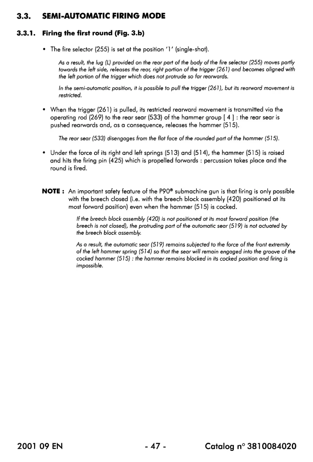
3.3.1. Firing the first round............................................47
3.3.2. Rearward movement of the moving parts............................49
3.3.3. Forward movement of the moving parts..............................51
3.4. Full-automatic firing mode................................................53
3.5. Safety sear (541).........................................................55
3.6. Visible and infra-red laser (only P90® LV, P90® UR, P90® TR LV and P90® TR UR).55
CHAPTER 4 : SAFETY INFORMATION
4.1. Warnings and cautions.....................................................57
4.2. Safety checks.............................................................57
4.3. Tritium light source (714) (only P90®, P90® LV and P90® UR)...............58
4.4. Visible and infra-red laser (only P90® LV, P90® UR, P90® TR LV and P90® TR UR).59
CHAPTER 5 : RECEPTION OF THE GUN
....................................................................................61
CHAPTER 6 : USING THE SUBMACHINE GUN
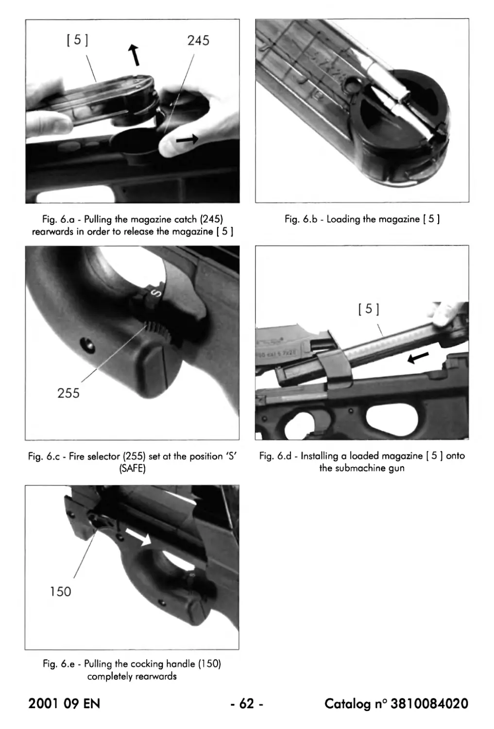
6.1. Loading the magazine [ 5 ] ...............................................63
6.2. Loading and cocking the submachine gun....................................63
6.3. Firing the submachine gun.................................................65
6.4. Unloading the submachine gun..............................................67
6.5. Using the visible or infra-red laser (only P90® LV, P90® UR, P90® TR LV and
P90® TR UR).....................................................................69
6.5.1. Inserting the battery (71 7)......................................69
6.5.2. Setting the laser selector (B4)...................................69
6.5.3. Activating the laser..............................................69
CHAPTER 7 : FIELD STRIPPING
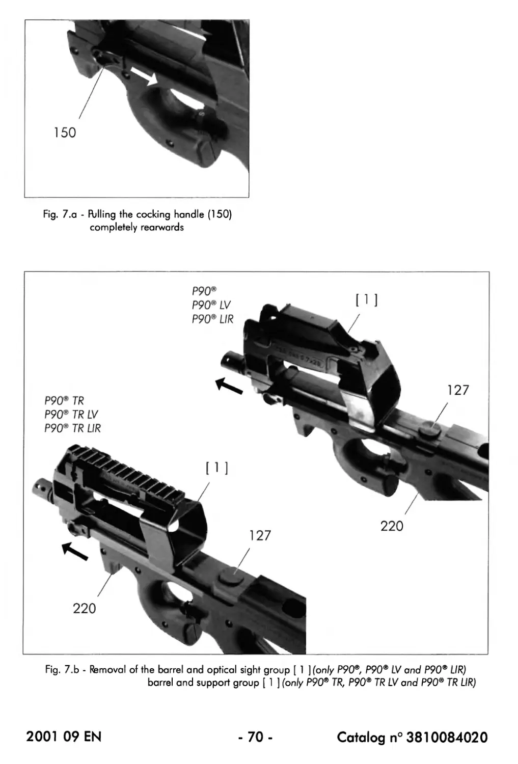
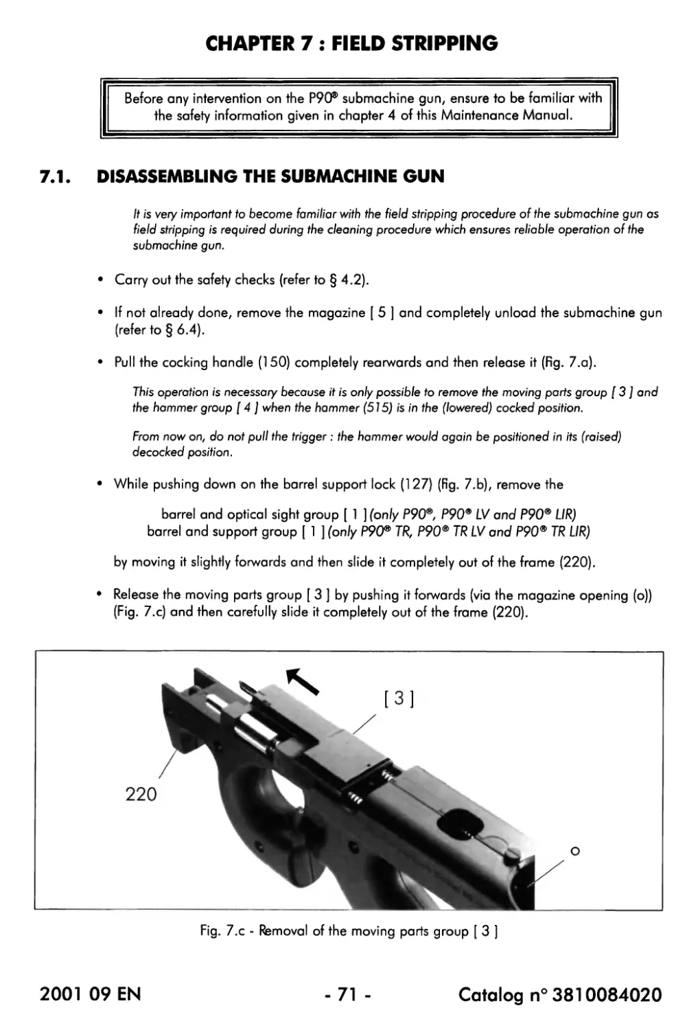
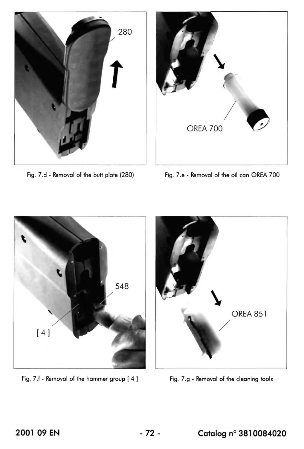
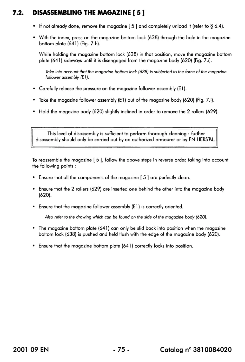
7.1. Disassembling the submachine gun......................................... 71
7.2. Disassembling the magazine [ 5 ]......................................... 75
CHAPTERS : MAINTENANCE
8.1. Lubricant specifications................................................. 76
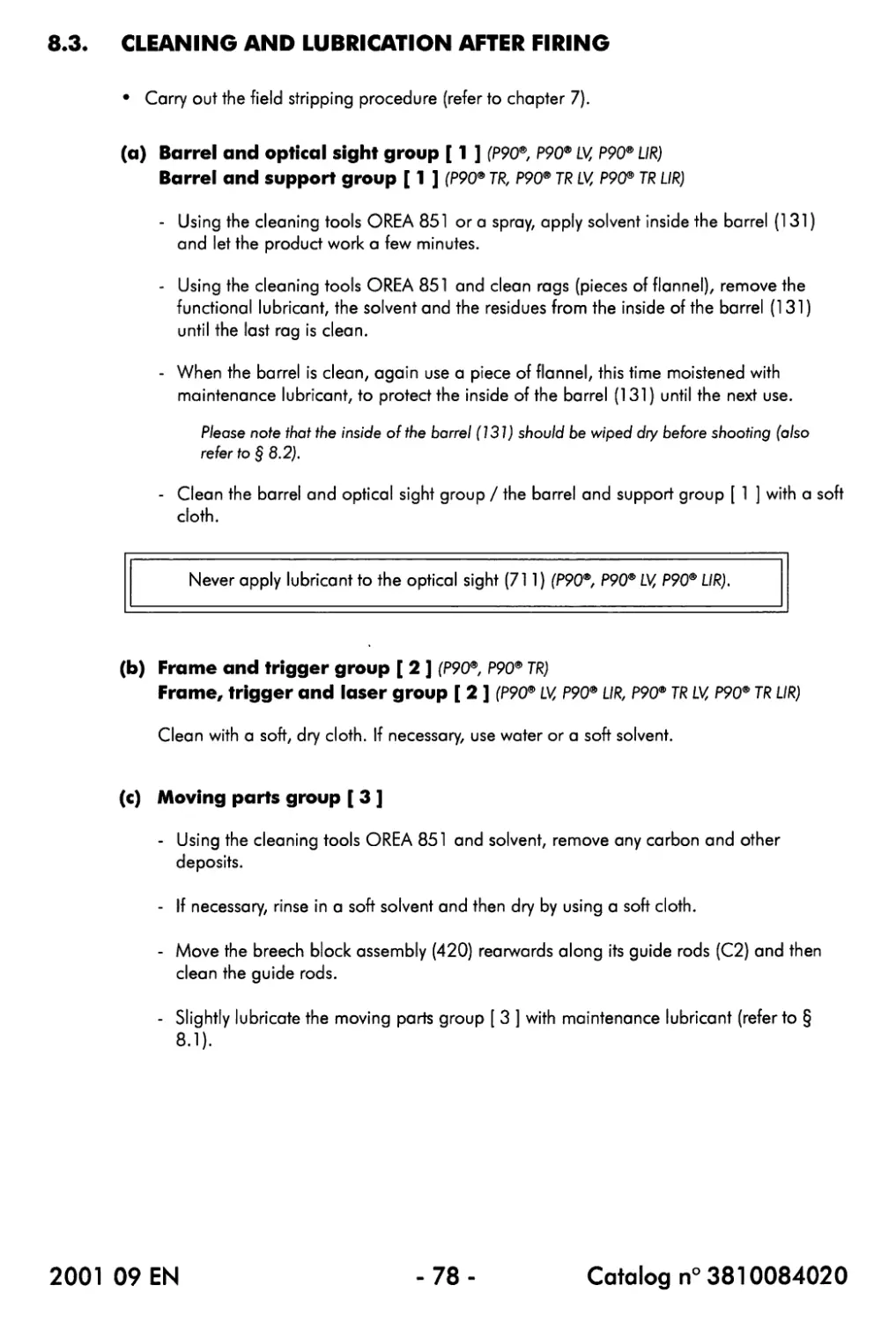
8.2. Cleaning and lubrication before firing................................... 77
8.3. Cleaning and lubrication after firing.....................................78
2001 09 EN
-3-
Catalog n° 3810084020
CHAPTER 9 : DISASSEMBLY AND REASSEMBLY
9.1. Barrel and optical sight group [ 1 ] (only P90®, P90® LV and P90® UR)... 81
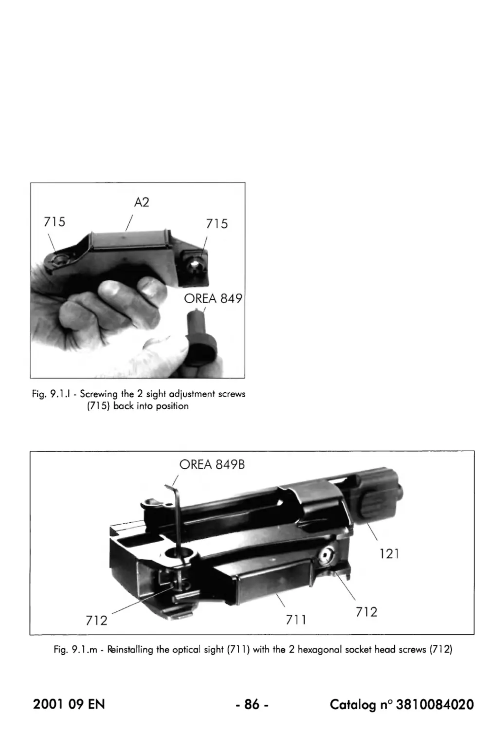
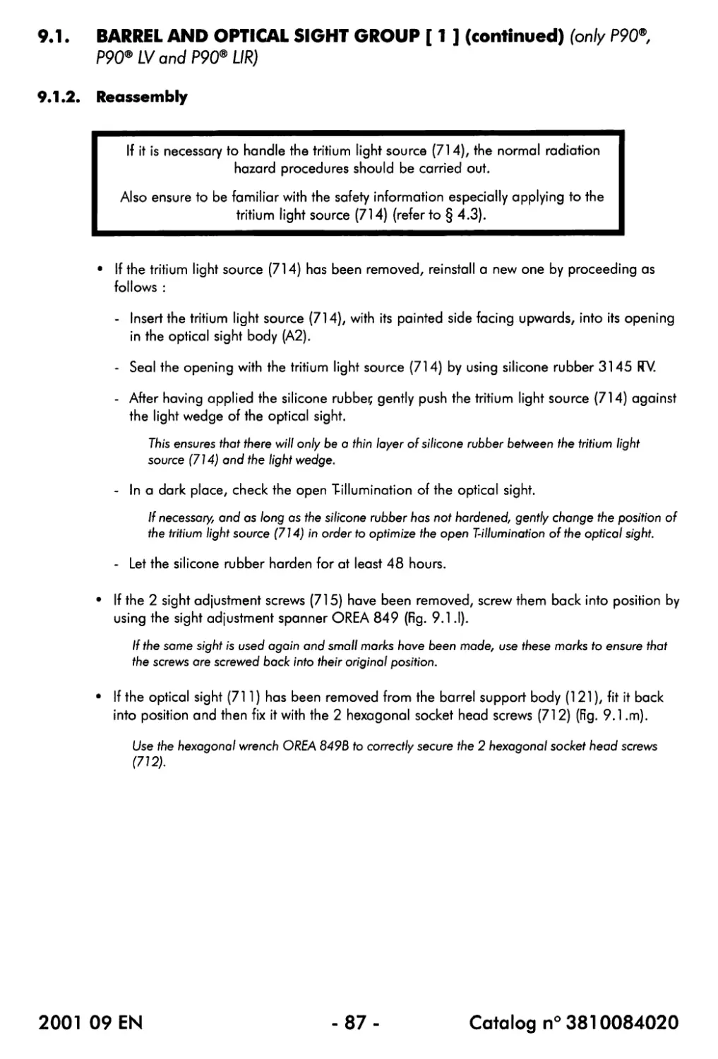
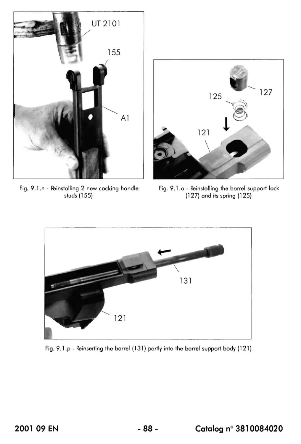
9.1.1. Disassembly......................................................81
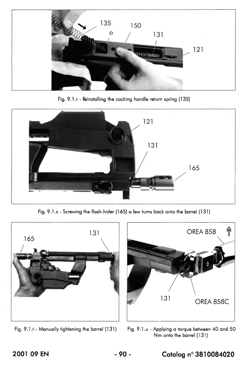
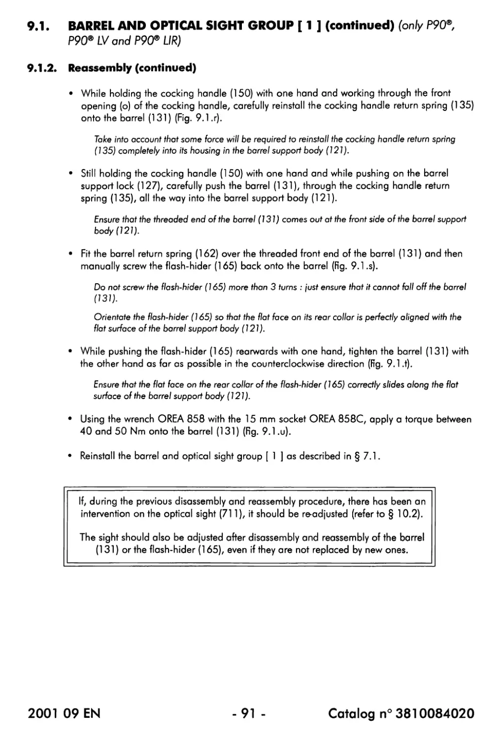
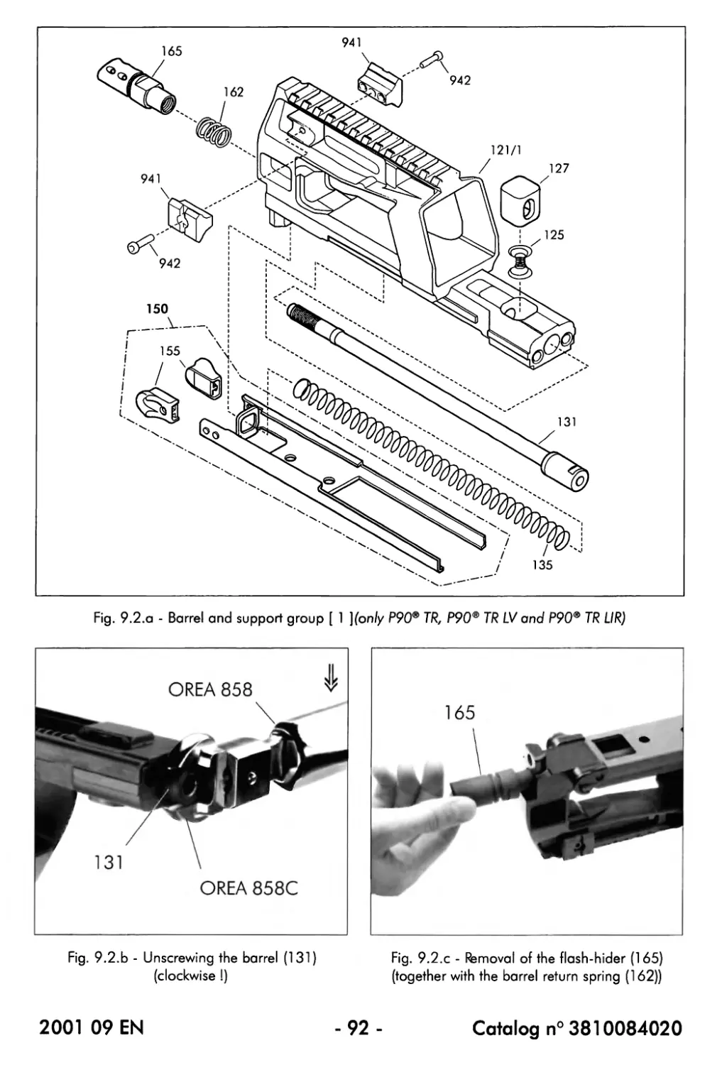
9.1.2. Reassembly.......................................................87
9.2. Barrel and support group [ 1 ] (only P90® TR, P90® TR LV and P90® TR UR).93
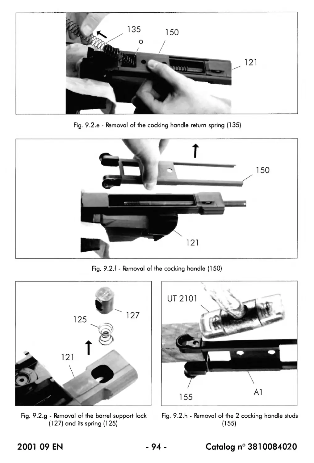
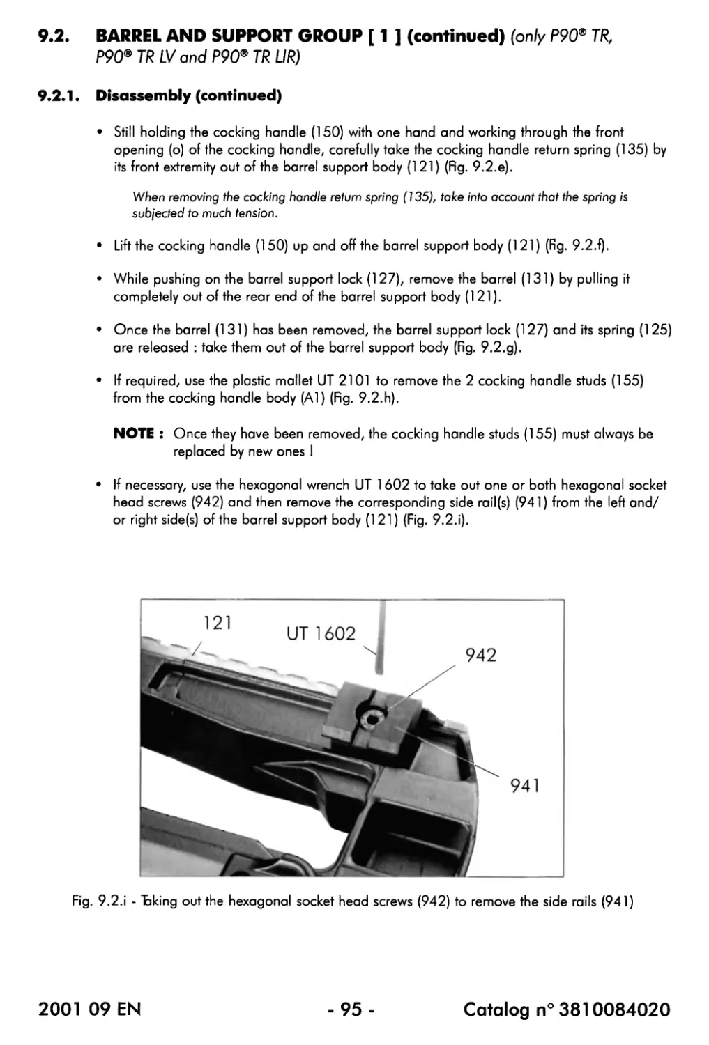
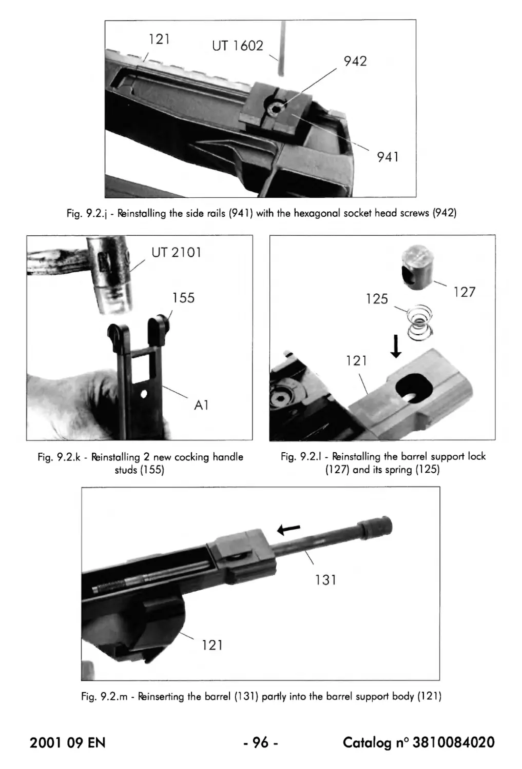
9.2.1. Disassembly......................................................93
9.2.2. Reassembly.......................................................97
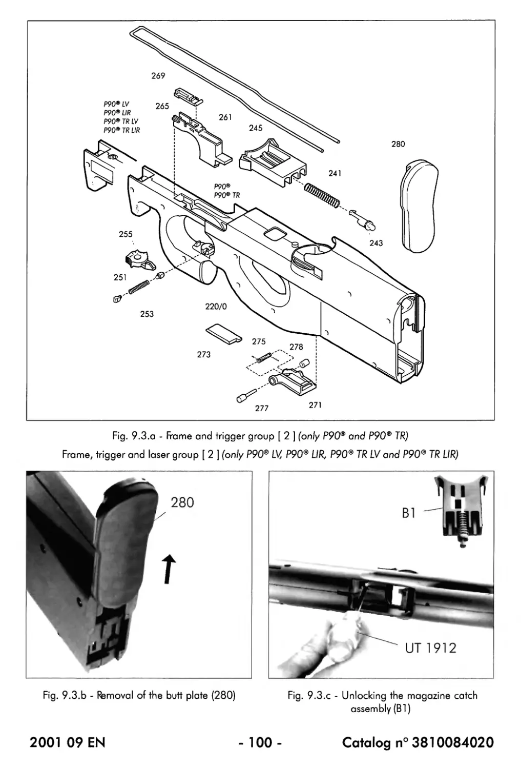
9.3. Frame and trigger group [ 2 ] (only P90® and P90® TR).......... 101
Frame, trigger and laser group [ 2 ] (only P90® LV, P90® LIR, P90® TR LV and
P90®TRLIR)........................................................... 101
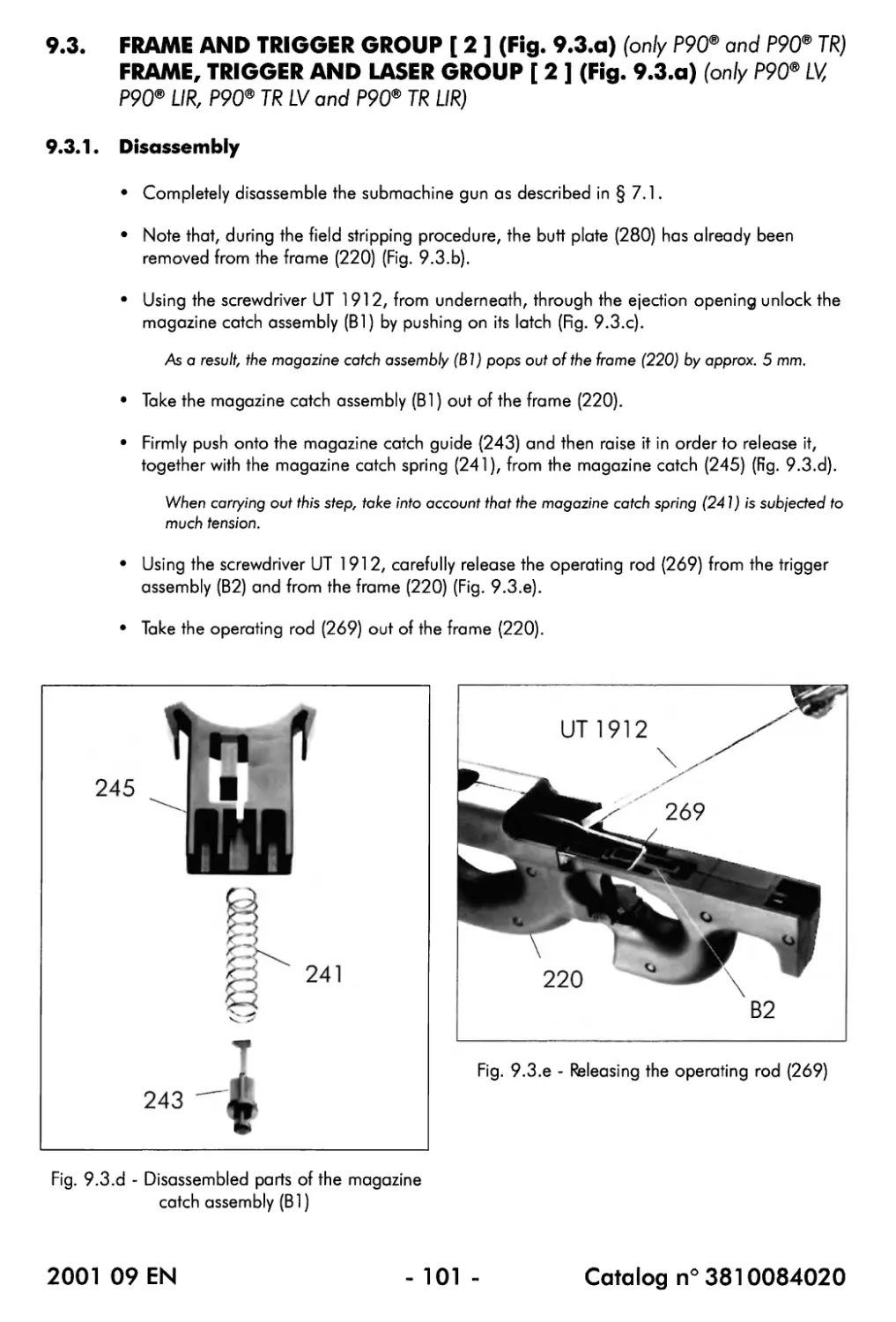
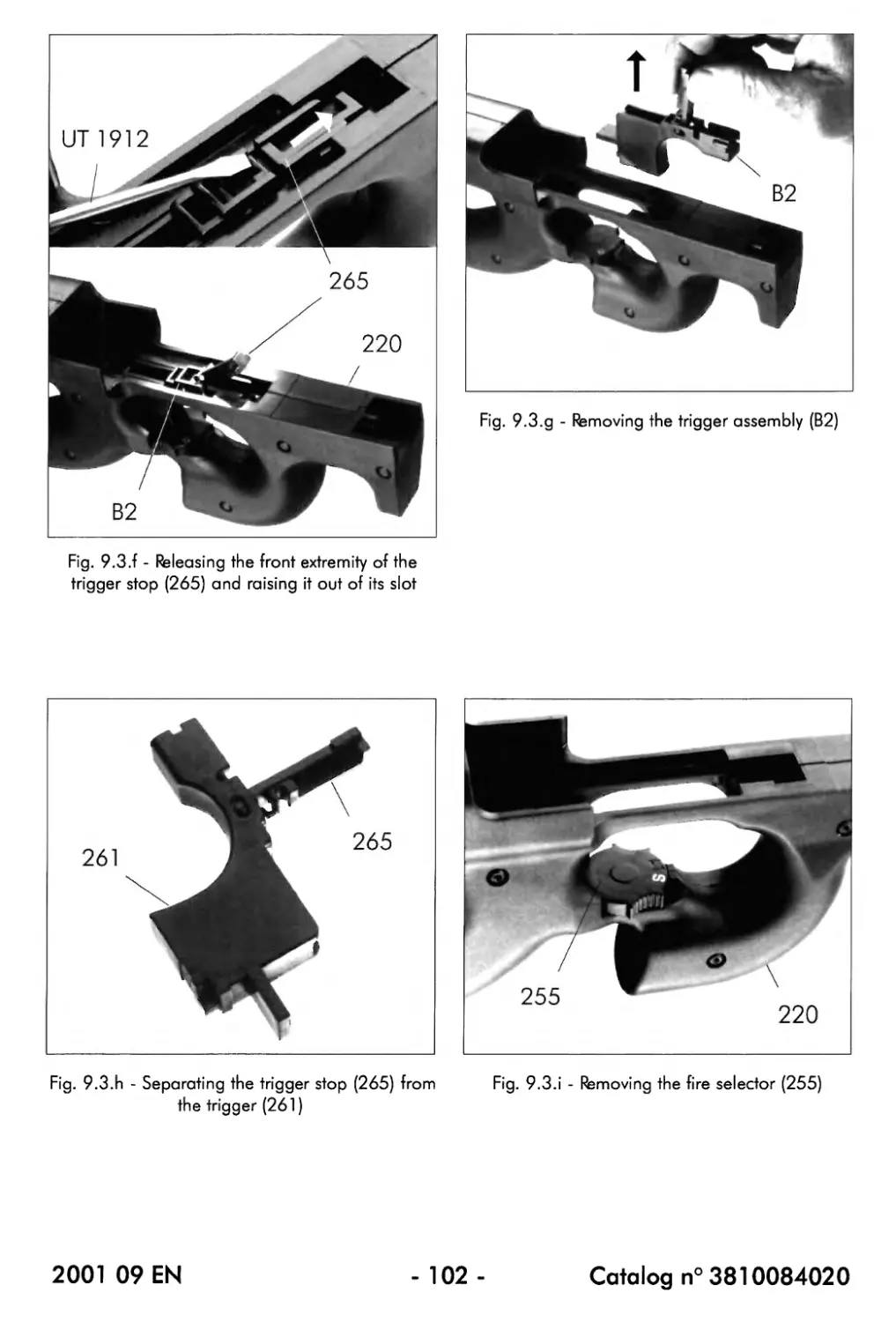
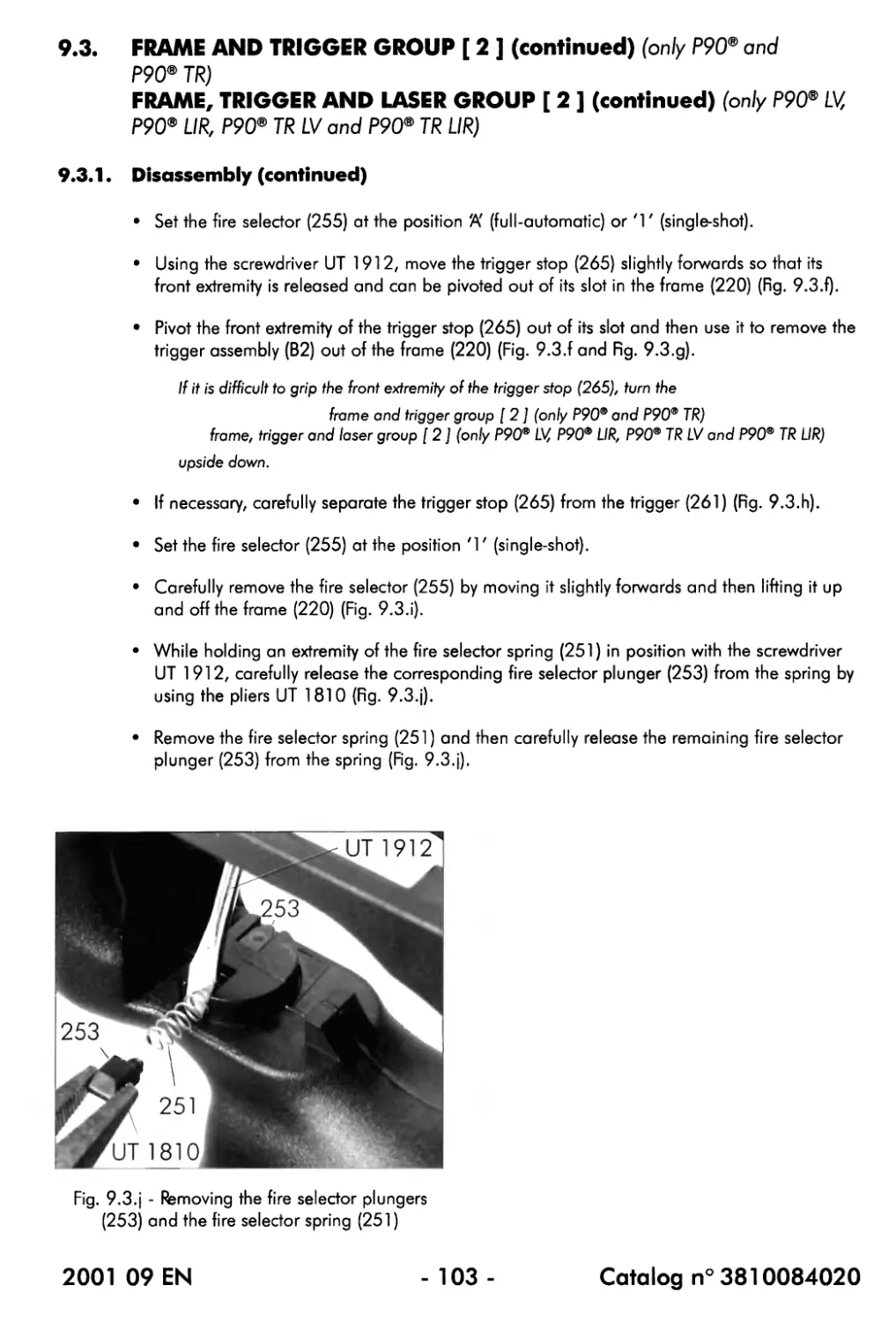
9.3.1. Disassembly.................................................... 101
9.3.2. Disassembly of the frame (220) with integrated laser (only P90® LV,
P90® LIR, P90® TR LV and P90® TR LIR).......................... 107
9.3.3. Reassembly of the frame (220) with integrated laser (only P90® LV,
P90® LIR, P90® TR LV and P90® TR LIR)................................ 107
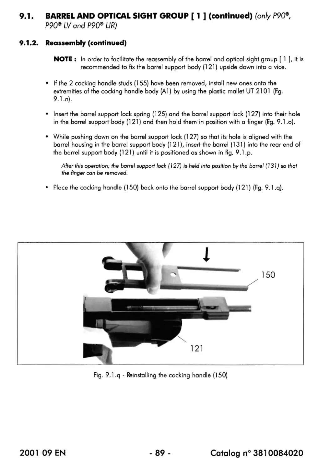
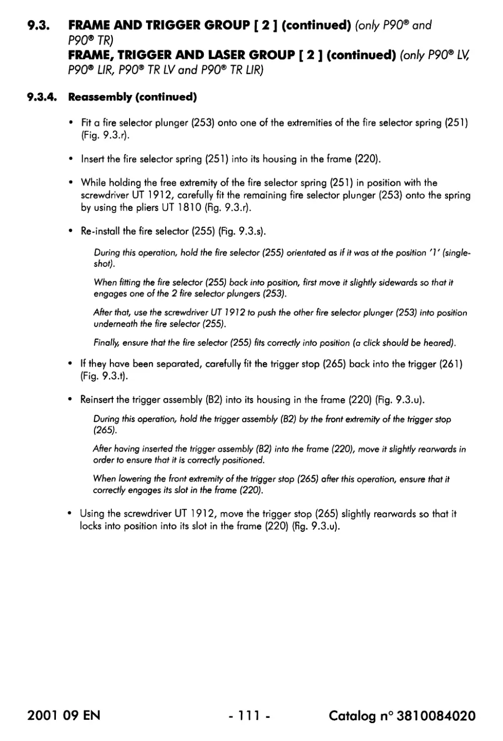
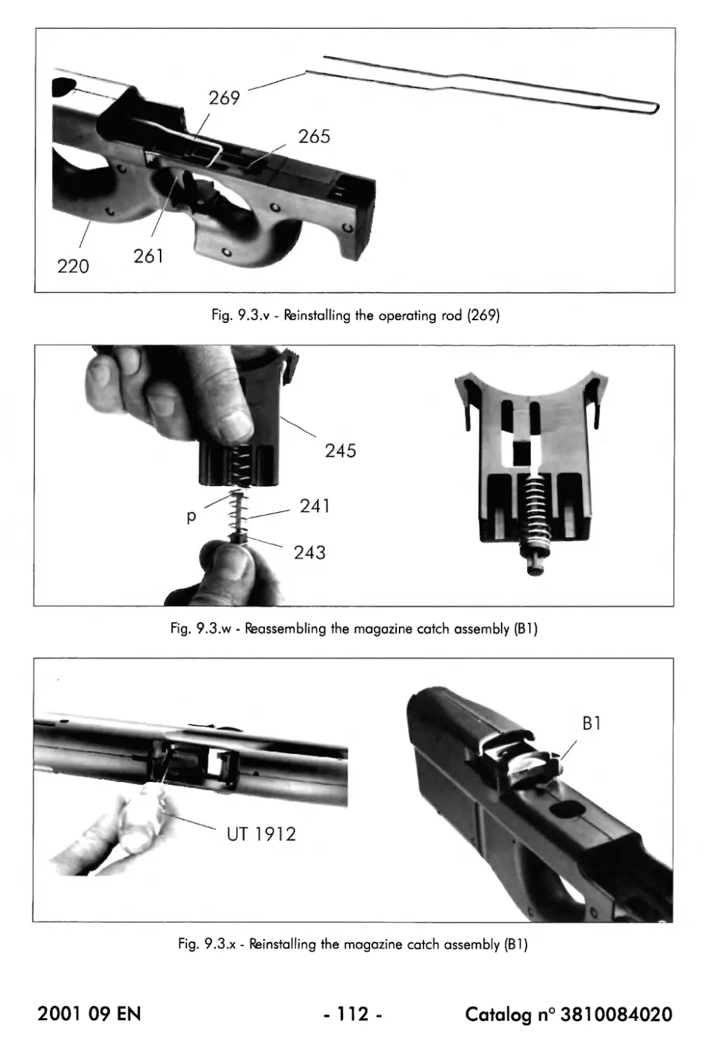
9.3.4. Reassembly..................................................... 109
9.4. Moving parts group [ 3 ]................................................. 115
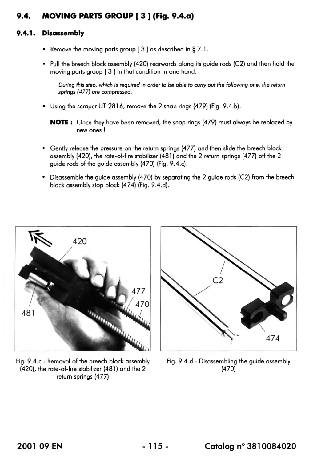
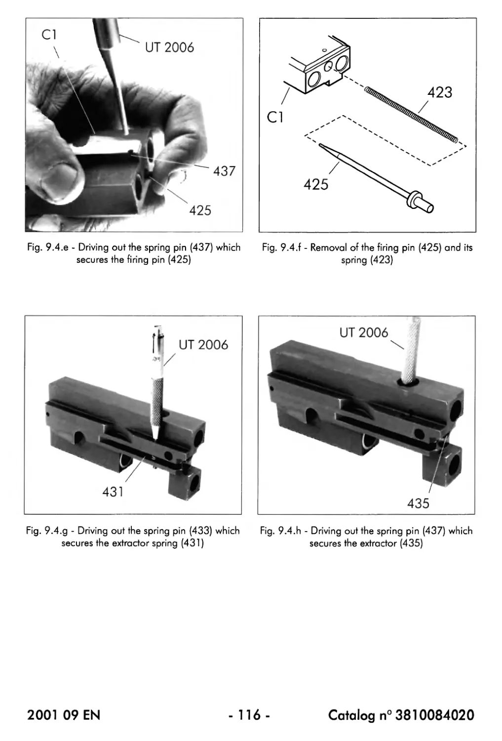
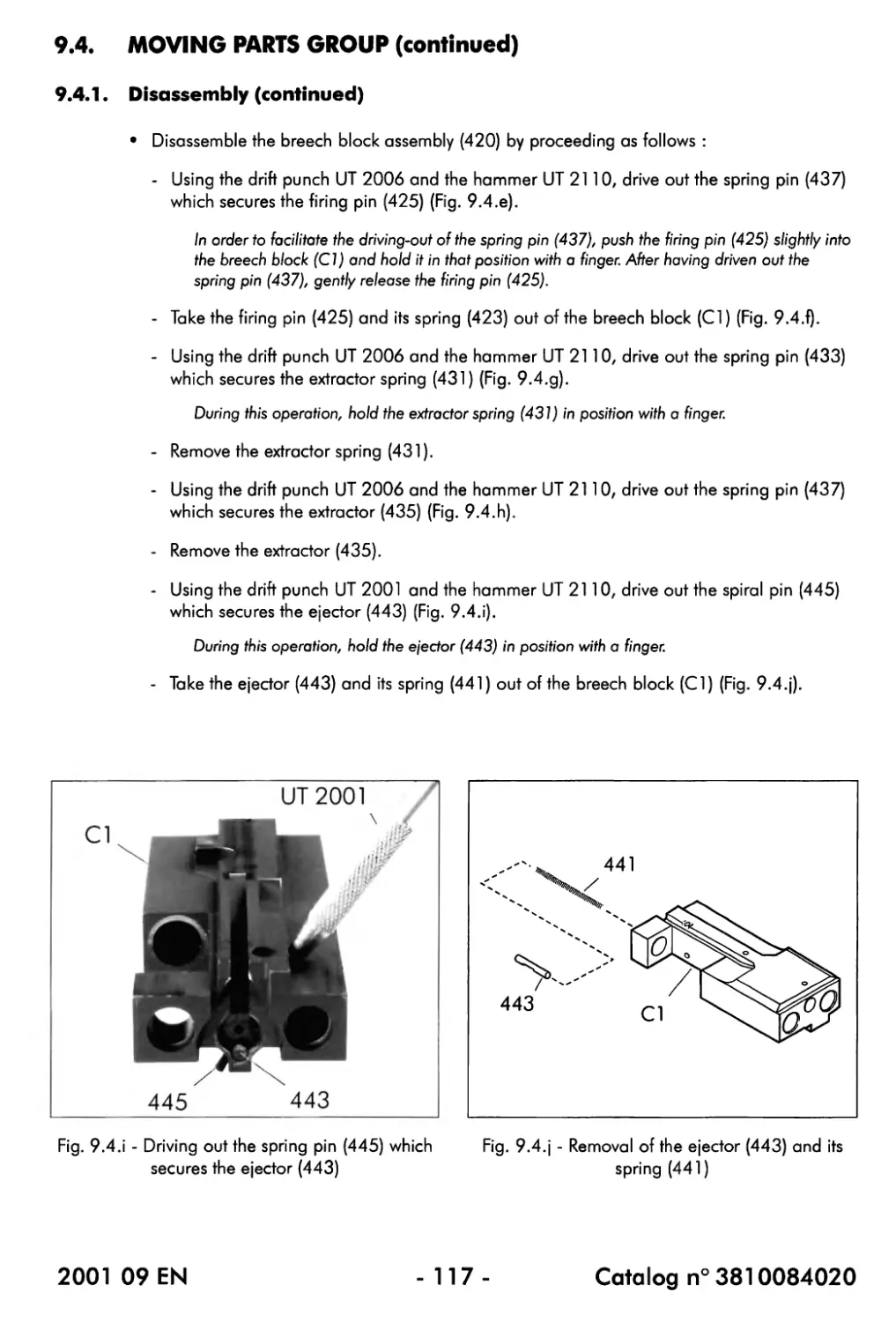
9.4.1. Disassembly.................................................... 115
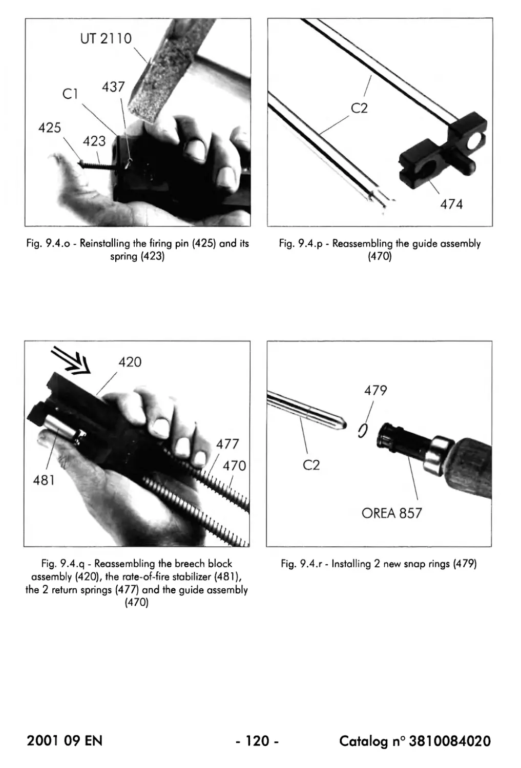
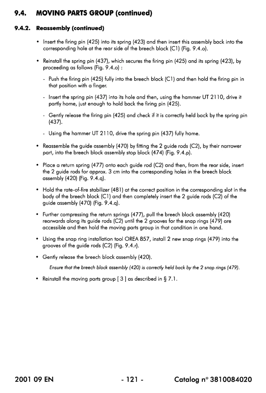
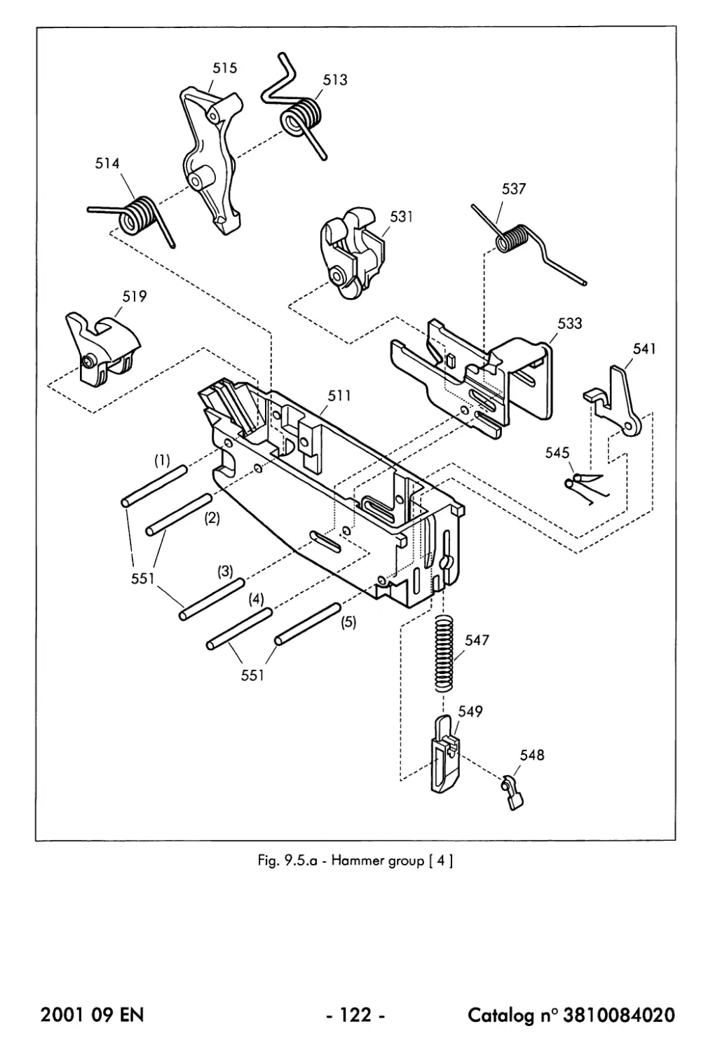
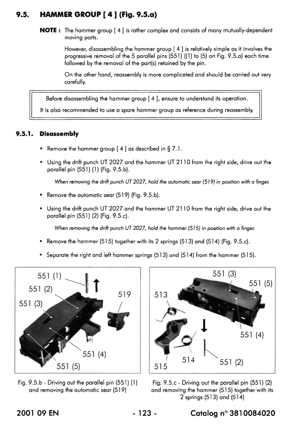
9.4.2. Reassembly....................................................... 119
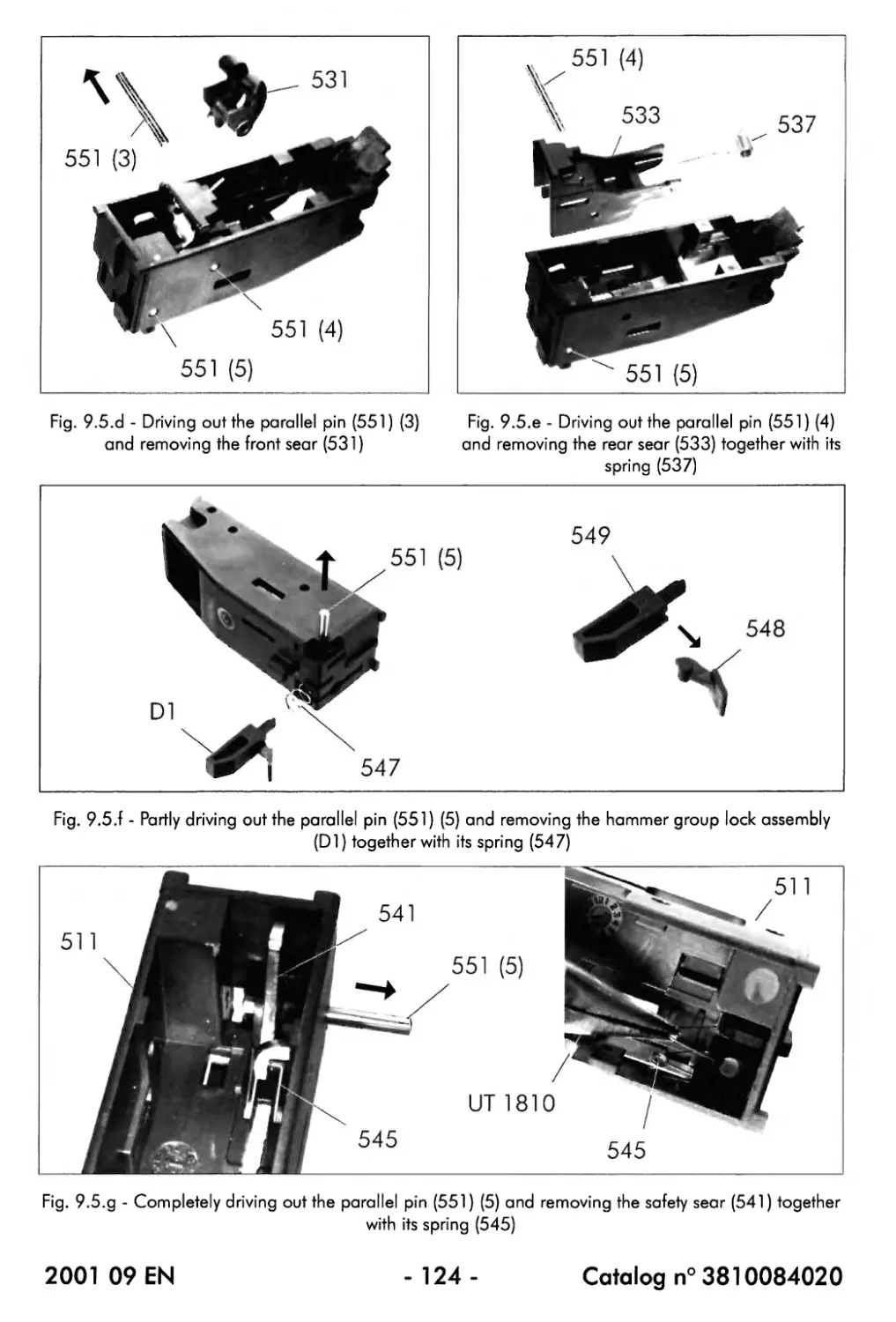
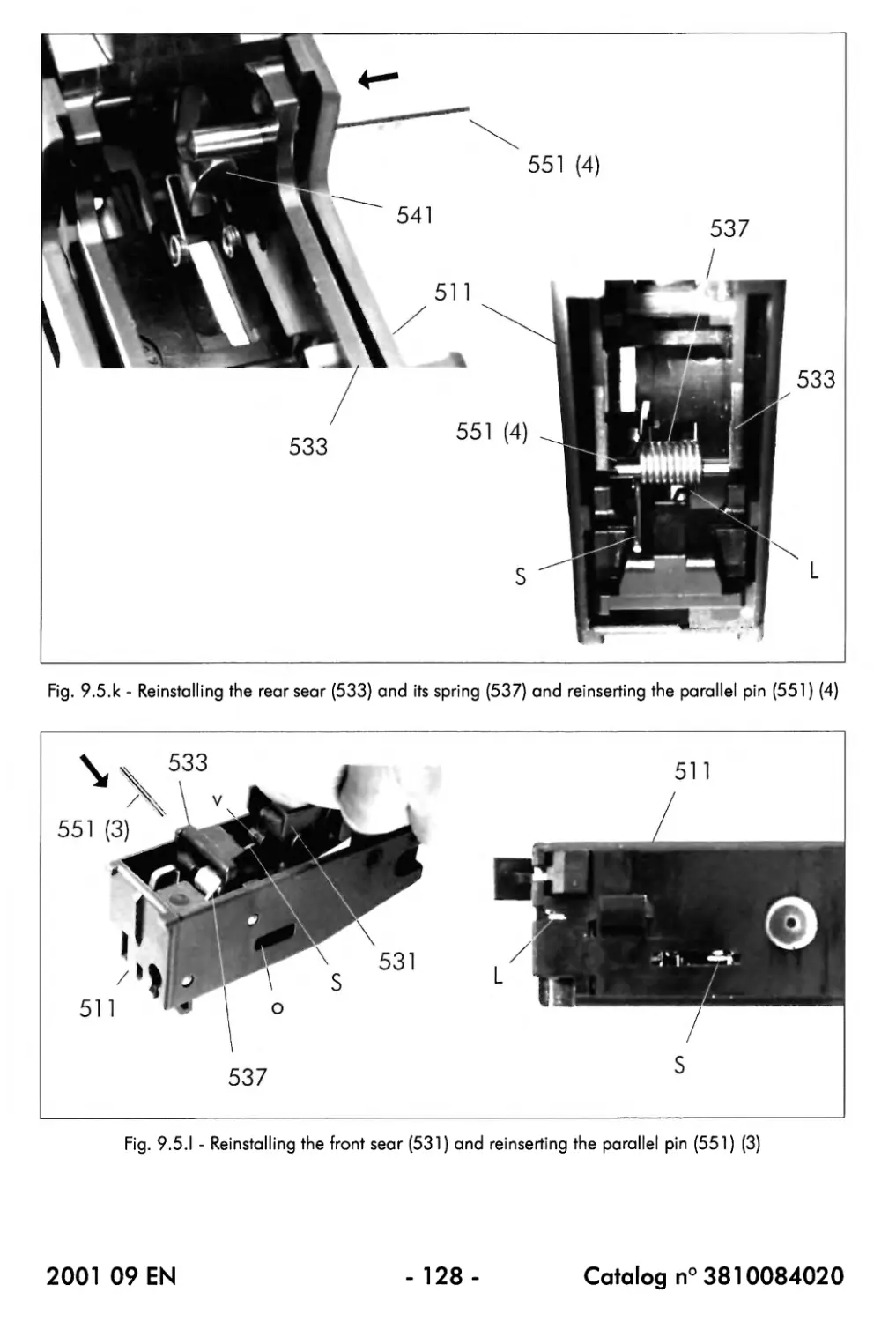
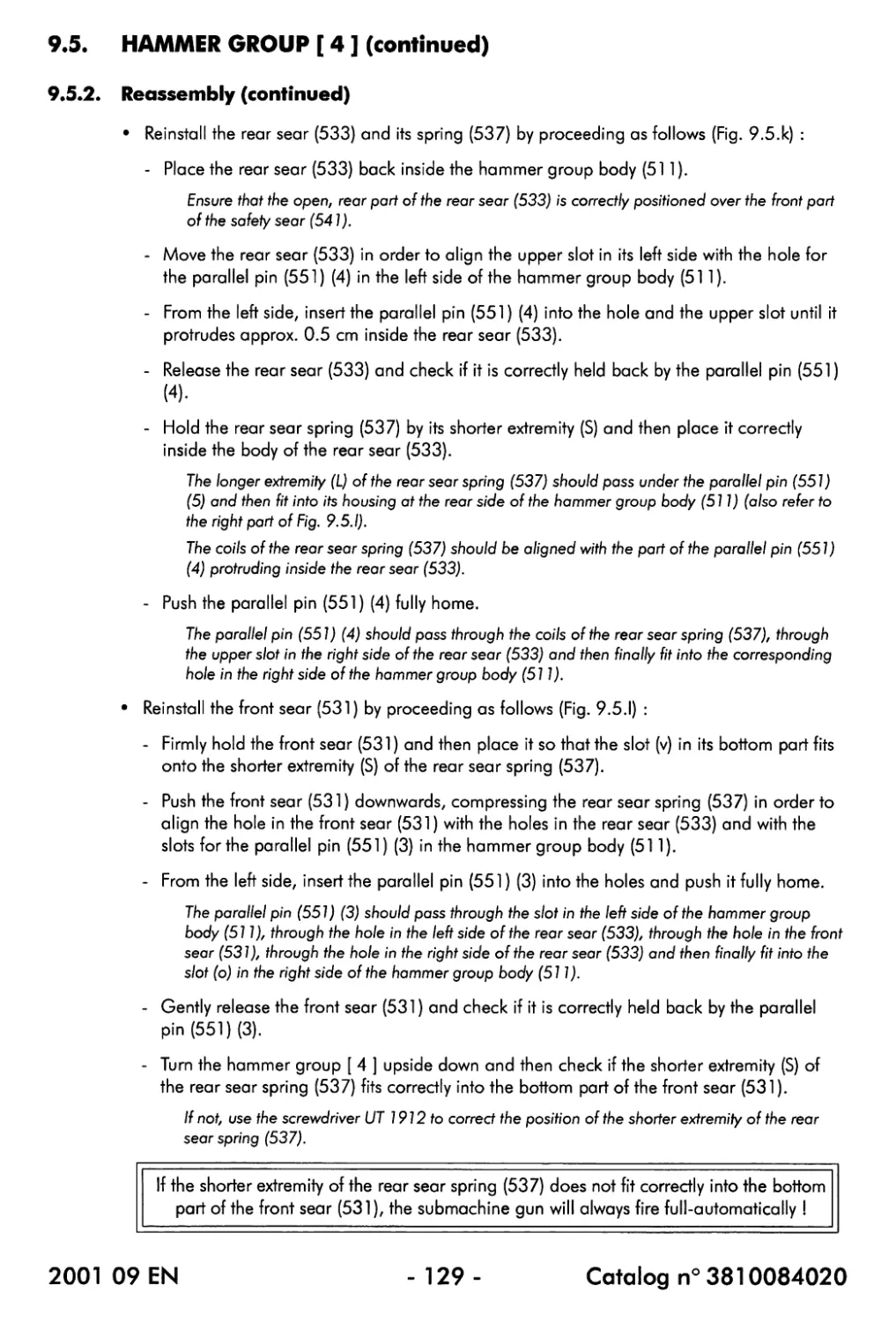
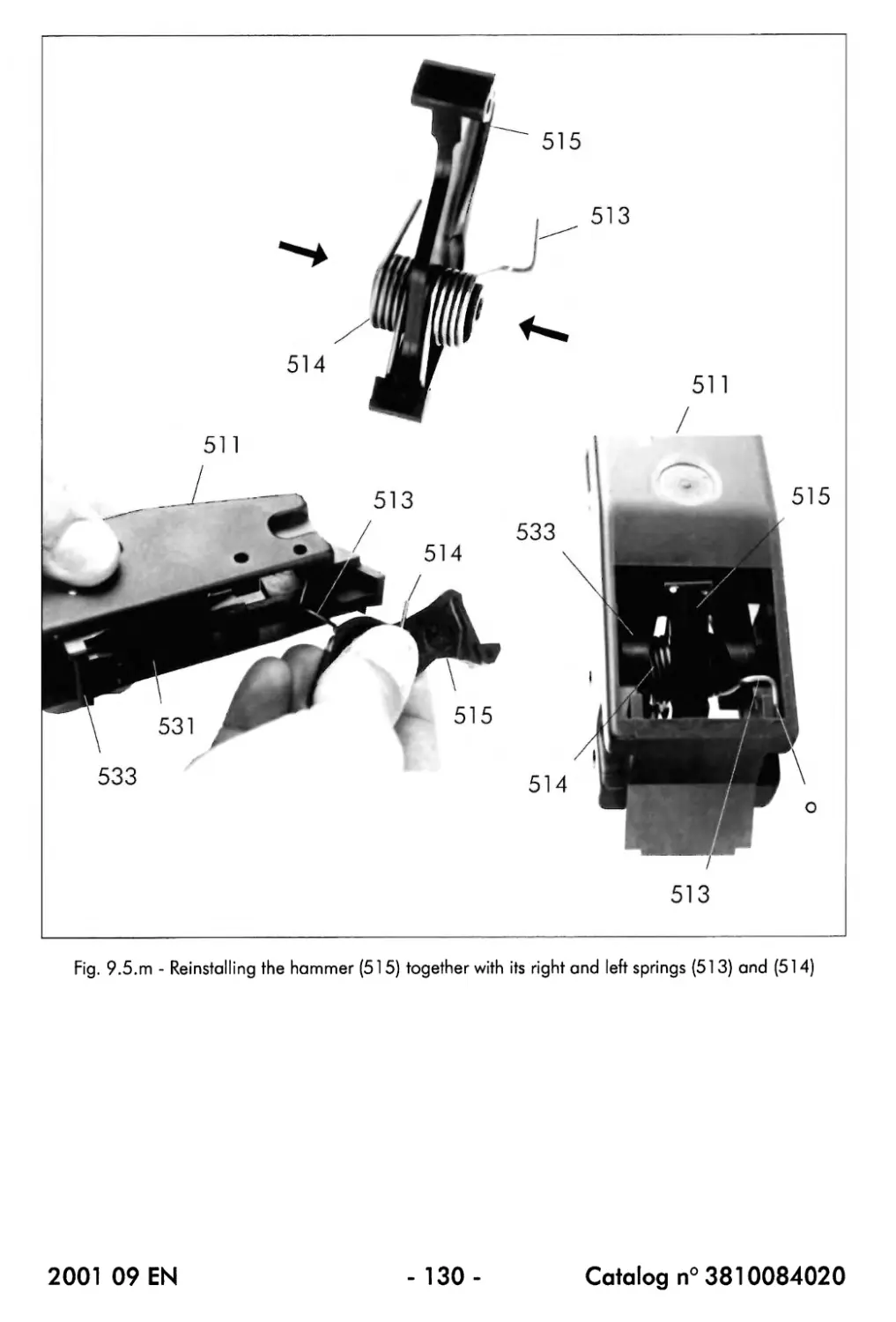
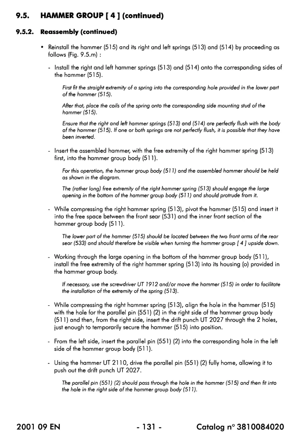
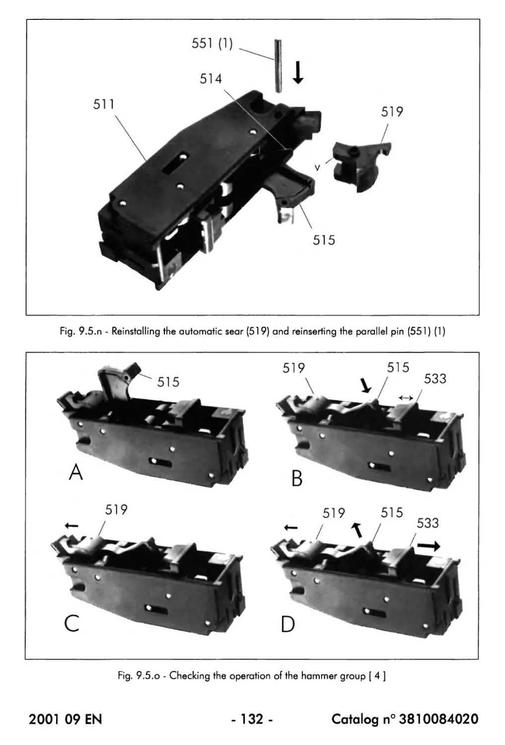
9.5. Hammer group [ 4 ]....................................................... 123
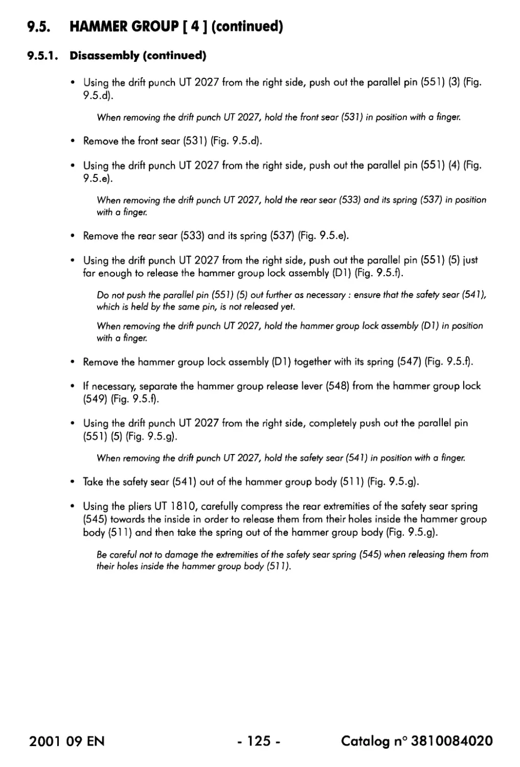
9.5.1. Disassembly.................................................... 123
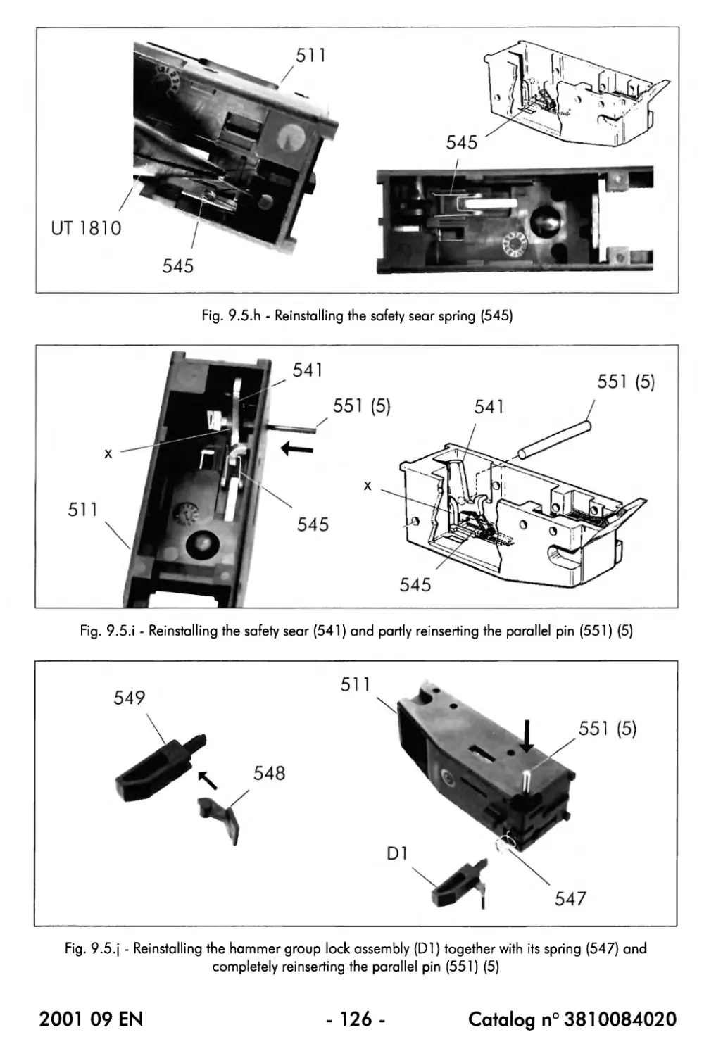
9.5.2. Reassembly..................................................... 127
CHAPTER 10 : INSPECTION AND ADJUSTMENTS
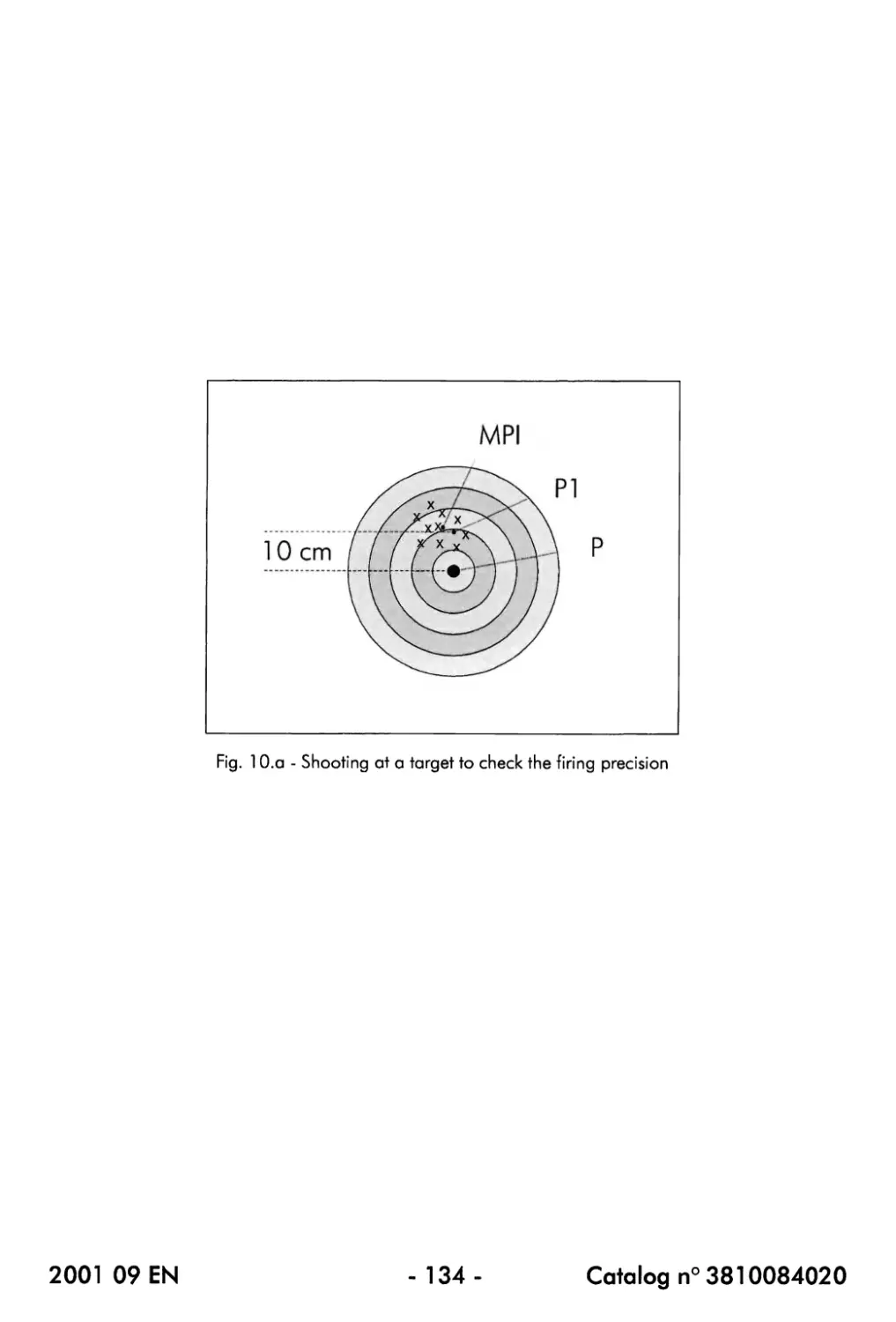
10.1. Checking the firing precision........................................... 135
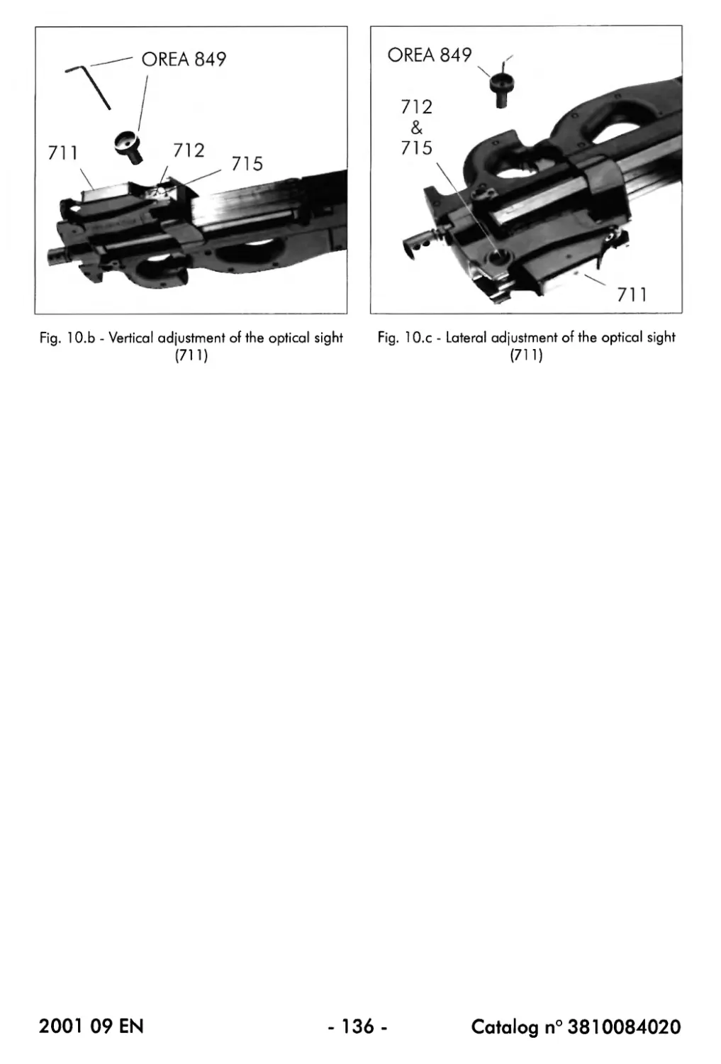
10.2. Adjustment of the optical sight (711) (only P90®, P90® LV and P90® LIR). 137
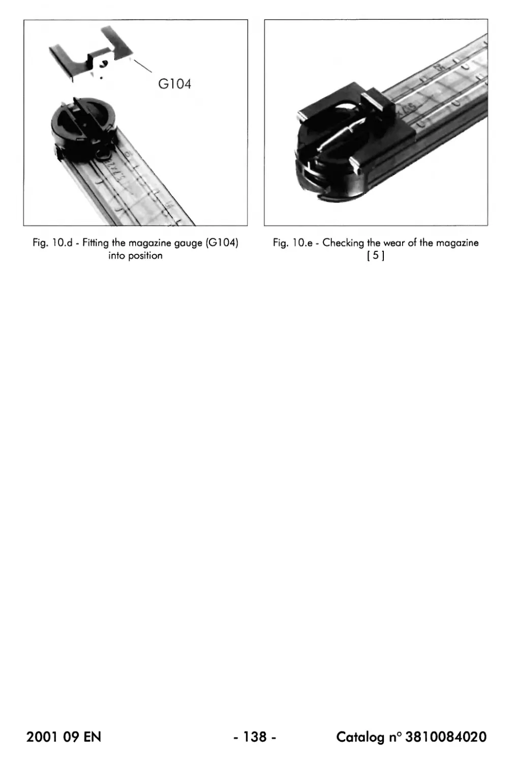
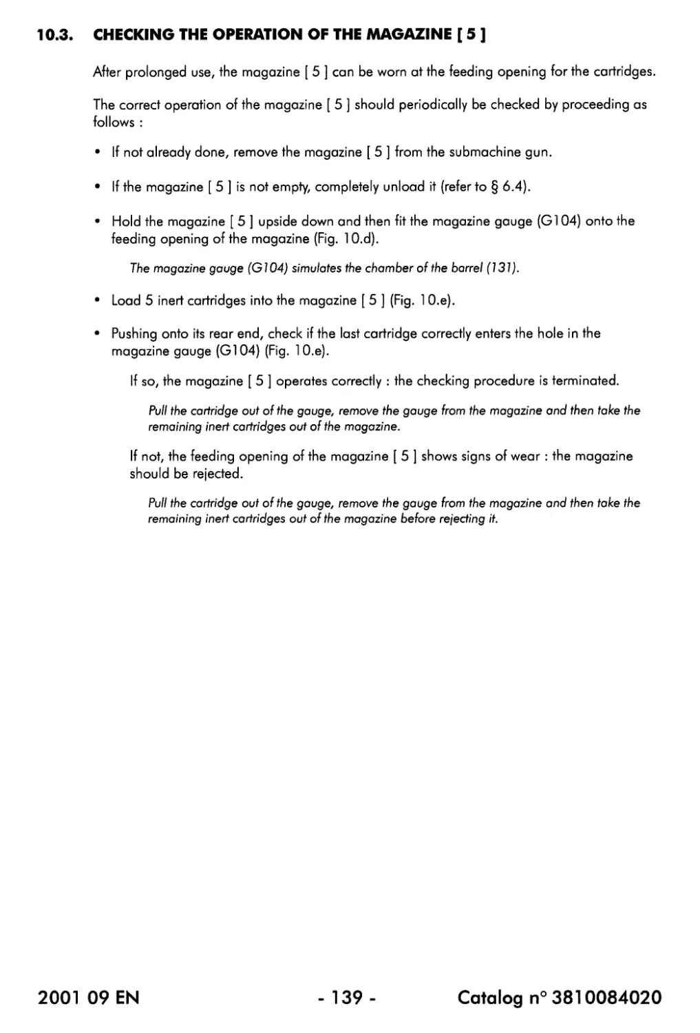
10.3. Checking the operation of the magazine [ 5 ]............................ 139
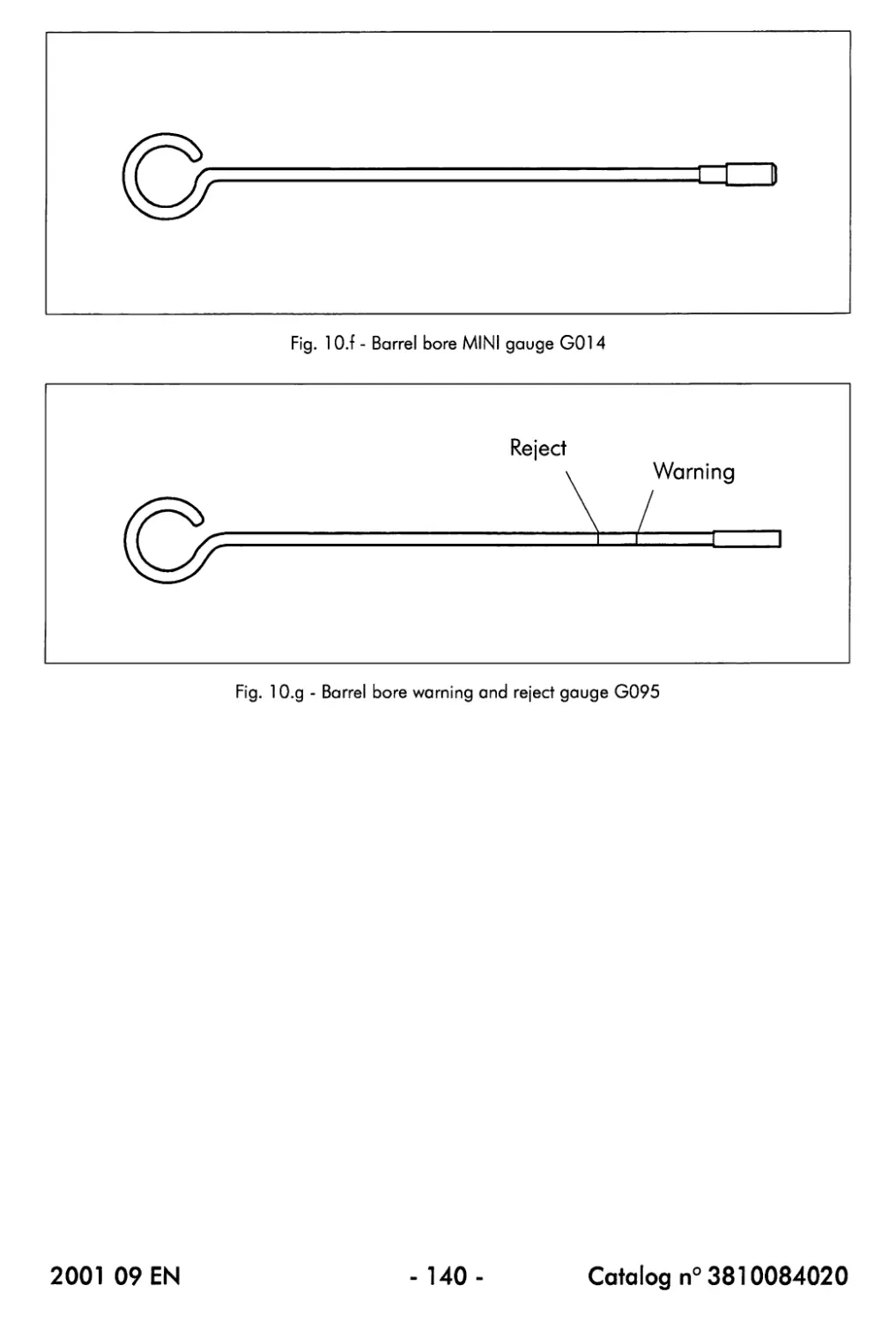
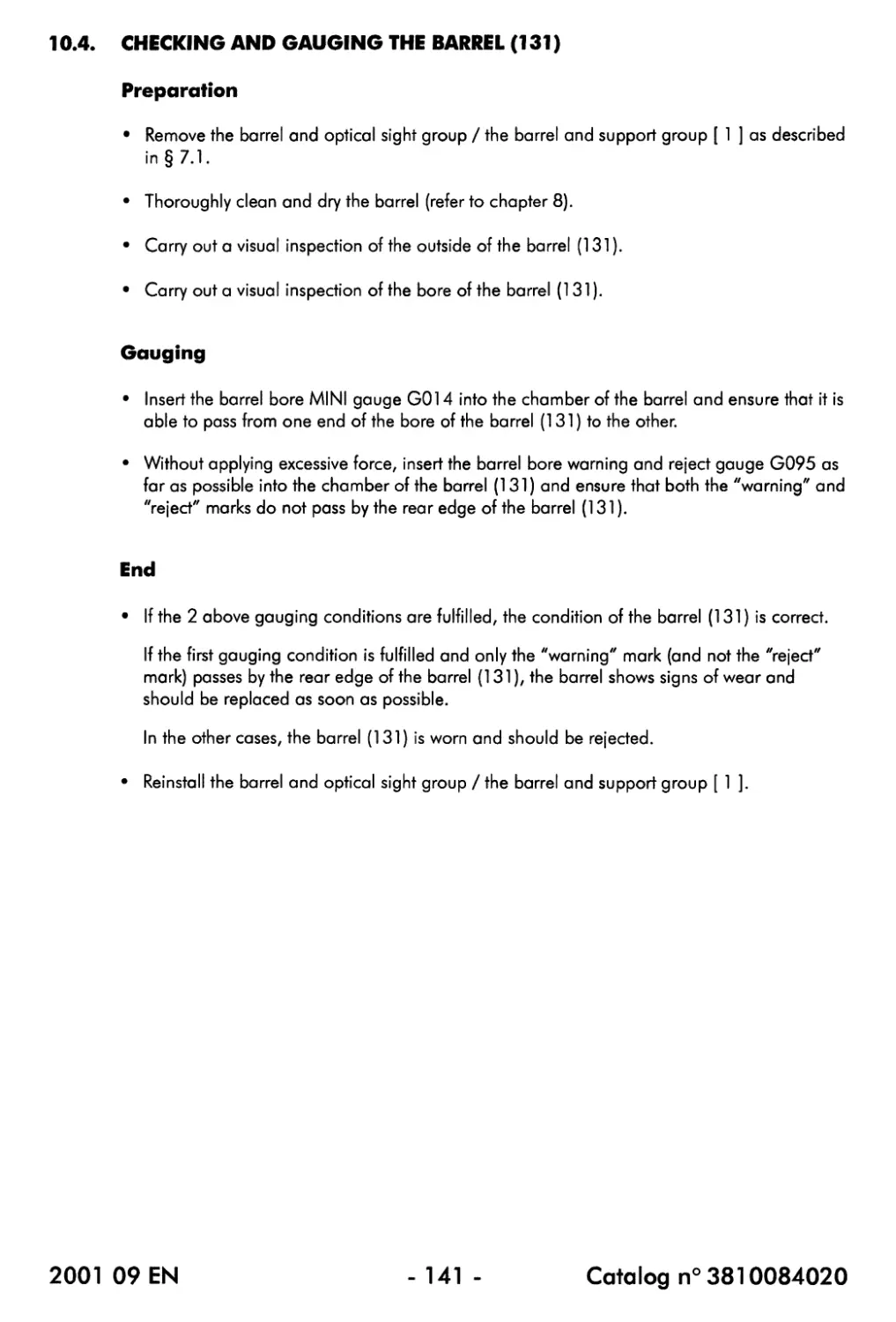
10.4. Checking and gauging the barrel (131)................................. 141
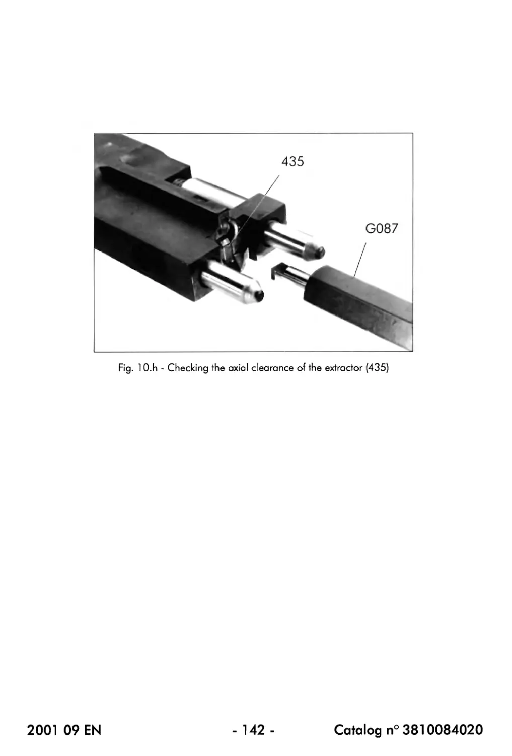
10.5. Checking and gauging the extractor (435) ............................. 143
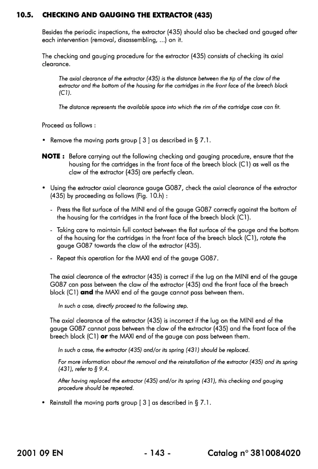
10.6. Checking and gauging the automatic sear (519) ........................ 145
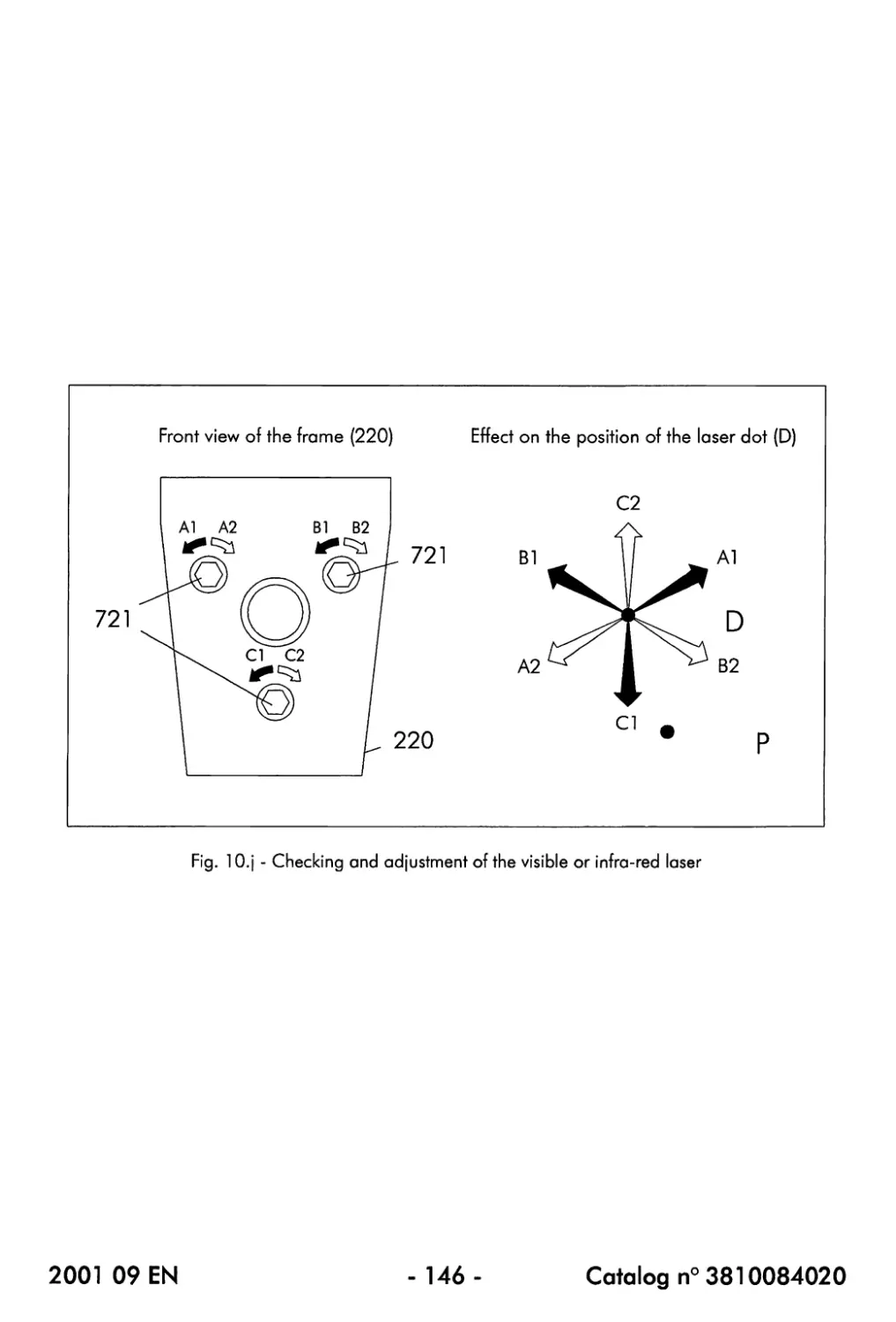
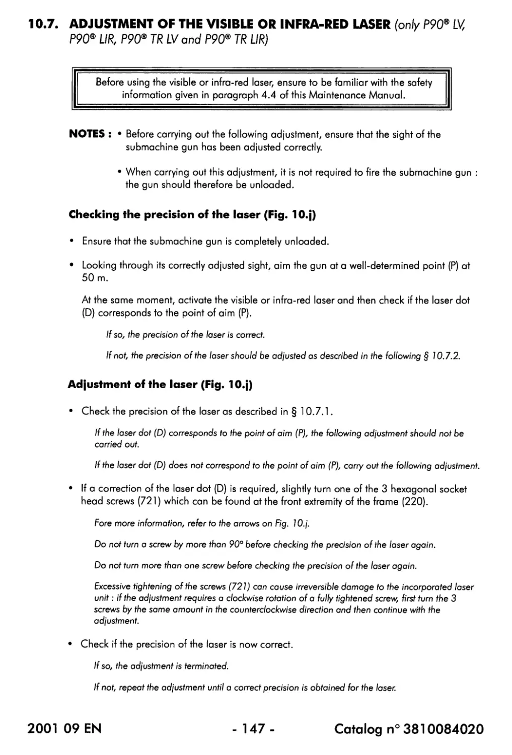
10.7. Adjustment of the visible or infra-red laser (only P90® LV, P90® LIR, P90® TR LV and
P90®TRLIR)................................................................ 147
CHAPTER 11 {TROUBLESHOOTING
11.1. The gun does not fire when the trigger (261) is pulled................ 148
11.2. Typical problems...................................................... 148
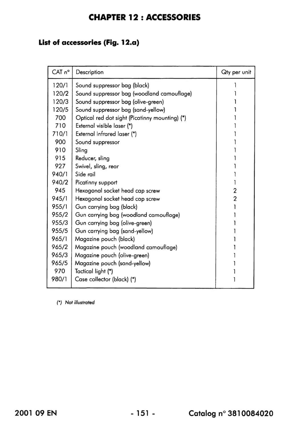
CHAPTER 12 : ACCESSORIES
List of accessories............................................................ 151
2001 09 EN
-4-
Catalog n° 3810084020
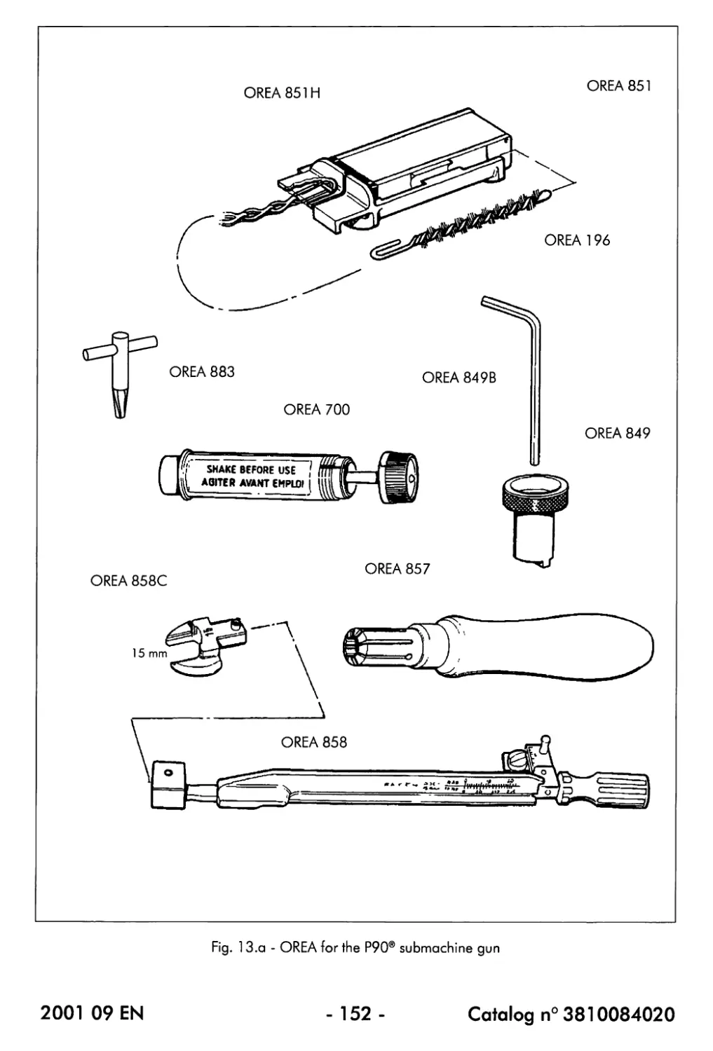
CHAPTER 13 : TOOLS AND GAUGES
13.1. Tools........................................................... 153
13.1.1. ListofOREA.............................................. 153
13.1.2. List of UT...............................................153
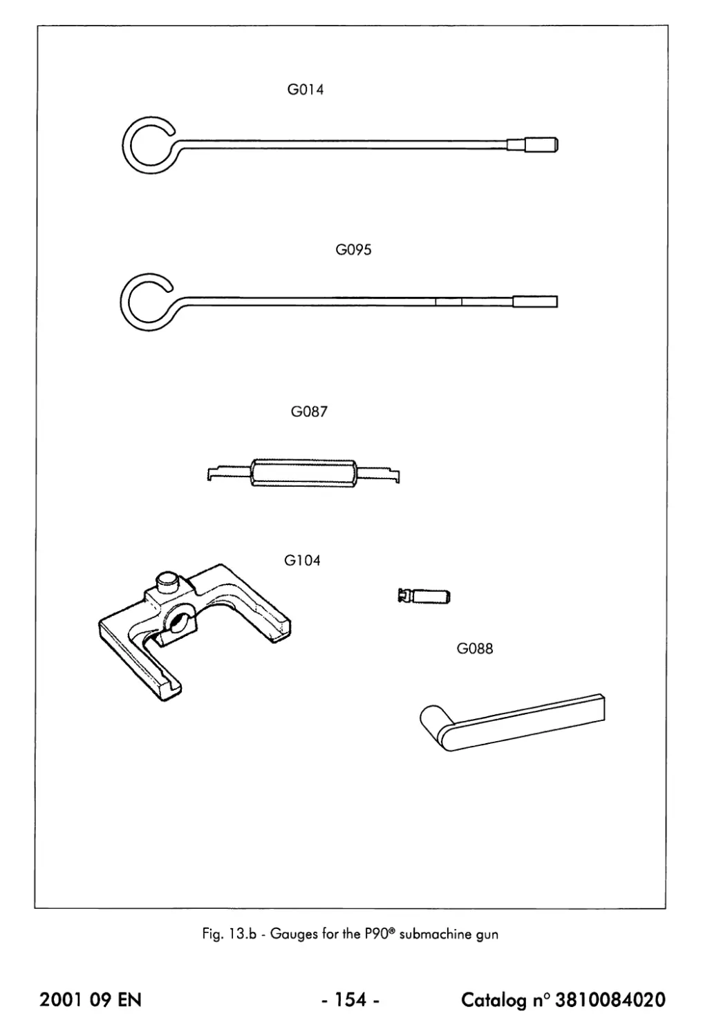
13.2. Gauges.......................................................... 155
CHAPTER 14: NOTES
157
2001 09 EN
-5-
C ata log n° 3810084020
AVOID EXPOSURE
VISIBLE
LASER LIGHT IS
EMITTED FROM
THIS APERTURE
LASER RADIATION AVOID
DIRECTEXPOSURETOBEAM
lO.OmW Maximum Output
Wavelength 635nm-5/+10nm
CLASS ШЬ LASER PRODUCT
AVOID EXPOSURE
INVISIBLE
LASER LIGHT IS
EMITTED FROM
THIS APERTURE
AVOID EXPOSURE
VISIBLE
LASER LIGHT IS
EMITTED FROM
THIS APERTURE
LASER RADIATION AVOID
DIRECTEXPOSURETOBEAM
10.0mW Maximum Output
Wavelength 635nm-5/+10nni
CLASS ШЬ LASER PRODUCT
(с) P90® LV
(d) P90® TR LV
LASER RADIATION AVOID
DIRECTEXPOSURETOBEAM
5.0mW Maximum Output
Wavelength 830nm+/-10nm
CLASS ШЬ LASER PRODUCT
AVOID EXPOSURE
INVISIBLE
LASER LIGHT IS
EMITTED FROM
THIS APERTURE
LASER RADIATION AVOID
DIRECTEXPOSURETOBEAM
5.0mW Maximum Output
Wavelength 830nm+/-10nm
CLASS IUb LASER PRODUCT
(e) P90® UR
(f) P90® TR UR
Fig. 1 - The 6 versions of the P90® submachine gun
2001 09 EN
- 6 - Catalog n° 3810084020
CHAPTER 1 : GENERALITIES
1.1. INTRODUCTION
This manual is intended for the personnel responsible for the maintenance of the P90®
submachine gun.
The purpose of the manual is to familiarise the personnel with the operation and the
maintenance of the gun, to explain the removal, disassembly, repair and/or replacement of the
component parts and to supply the appropriate inspection, gauging and adjustment
procedures.
1.2. DESCRIPTION
The P90® submachine gun is a new-concept, compact, lightweight personal defence weapon
with a capacity of 50 cartridges of 5.7 x 28 mm ammunition and featuring extremely low
recoil.
The P90® is available in 6 versions (Fig. 1) :
P90® P90® LV P90® UR
P90®TR P90®TRLV P90® TR UR
in its standard version, the P90® has been provided with on optical reflex sight with built-in tritium
beta-light source.
P90® LV = P90® + fully integrated visible laser sight
P90® UR = P90® + fully integrated infra-red laser sight
The P90® TR does not have any built-in sight, it has however been provided with 3 Picatinny rails
(1 top rail and 2 side rails) onto which a wide variety of optical sights and accessories can be
mounted.
P90® TR LV = P90® TR 4- fully integrated visible laser sight
P90® TR UR = P90® TR + fully integrated infra-red laser sight
Unless specified differently, all paragraphs of this Maintenance Manual apply to the 6 versions
of the P90®.
2001 09 EN
-7-
C ata log n° 3810084020
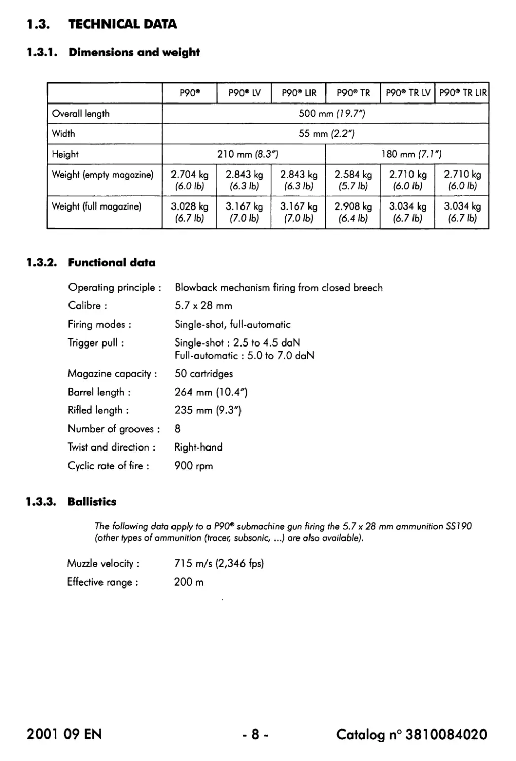
1.3. TECHNICAL DATA
1.3.1 • Dimensions and weight
P90® P90® LV P90* LIR P90® TR P90® TR LV P90® TR LIR
Overall length 500 mm (19.7")
Width 55 mm (2.2")
Height 210 mm (8.3") 180 mm (7.1")
Weight (empty magazine) 2.704 kg (6.0 lb) 2.843 kg (6.3 lb) 2.843 kg (6.3 lb) 2.584 kg (5.7 lb) 2.710 kg (6.0 lb) 2.710 kg (6.0 lb)
Weight (full magazine) 3.028 kg (6.71b) 3.167 kg (7.01b) 3.167 kg (7.0 lb) 2.908 kg (6.4 lb) 3.034 kg (6.7 lb) 3.034 kg (6.71b)
1.3.2. Functional data
Operating principle : Blowback mechanism firing from closed breech
Calibre : 5.7 x 28 mm
Firing modes : Single-shoi, full-automatic
Trigger pull : Single-shot : 2.5 to 4.5 daN
Full-automatic : 5.0 to 7.0 daN
Magazine capacity : 50 cartridges
Barrel length : 264 mm (10.4")
Rifled length : 235 mm (9.3")
Number of grooves : 8
Twist and direction : Right-hand
Cyclic rate of fire : 900 rpm
1.3.3. Ballistics
The following data apply to a P90® submachine gun firing the 5.7 x 28 mm ammunition SSI 90
(other types of ammunition (tracer, subsonic, ...) are also available).
Muzzle velocity : 715 m/s (2Z346 fps)
Effective range : 200 m
2001 09 EN
-8-
Catalog n° 3810084020
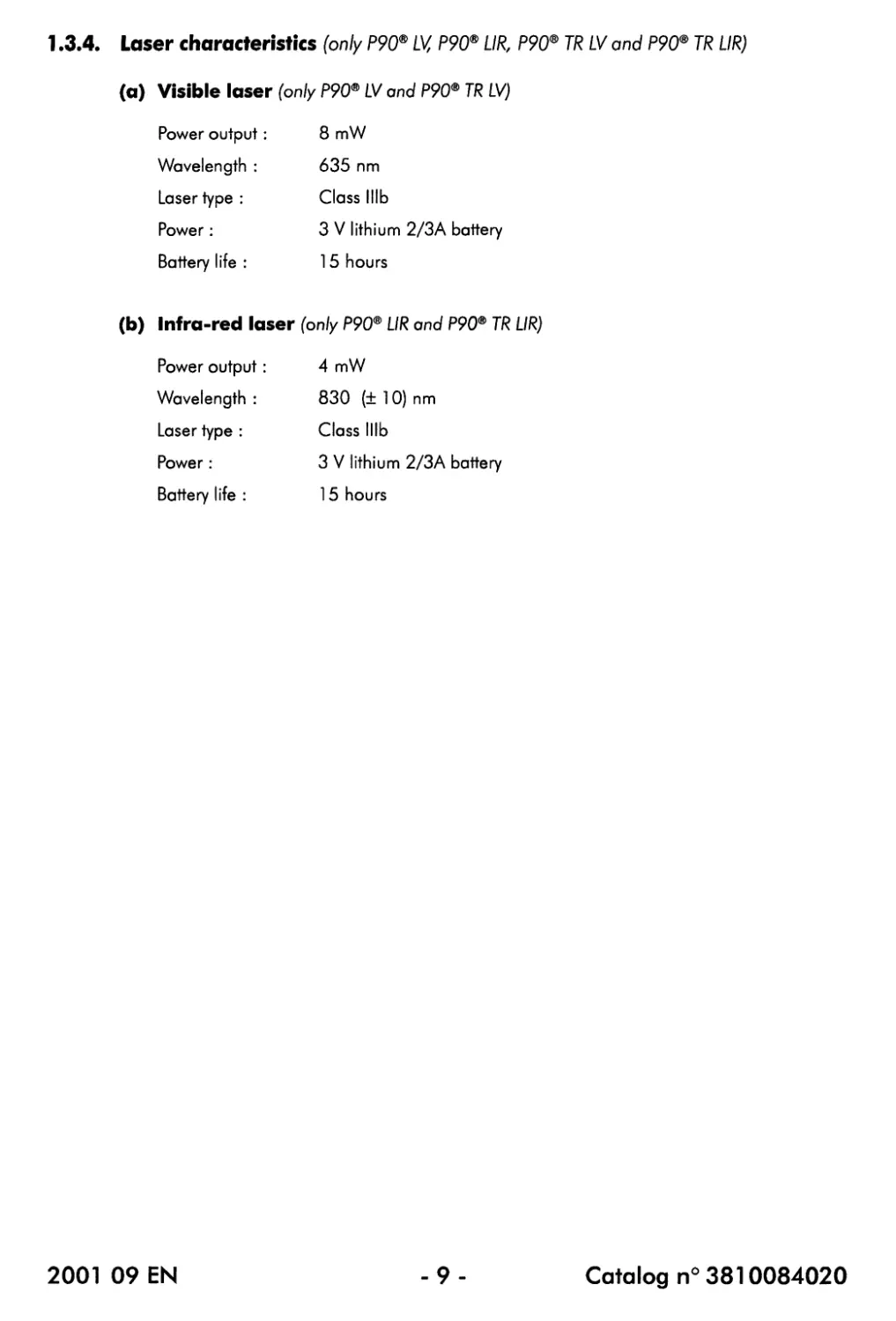
1.3.4. Laser characteristics (only P90® LV, P90® UR, P90® TR LV and P90® TR UR)
(a) Visible laser (only P90® LV and P90® TR LV)
Power output: 8 mW
Wavelength : 635 nm
Laser type : Class lllb
Power: 3 V lithium 2/3A battery
Battery life : 15 hours
(b) Infra-red laser (only P90® UR and P90® TR UR)
Power output: 4 mW
Wavelength : 830 (± 10) nm
Laser type : Class lllb
Power : 3 V lithium 2/3A battery
Battery life : 15 hours
2001 09 EN
-9-
Catalog n° 3810084020
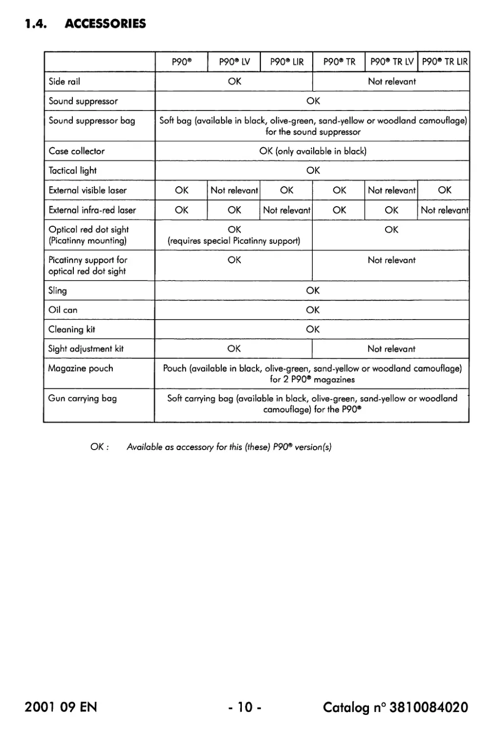
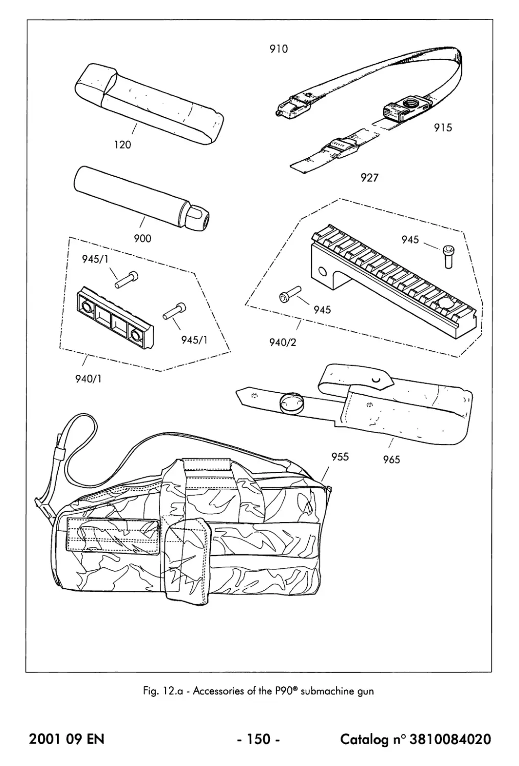
1.4. ACCESSORIES
P90® P90* LV P90* LIR P90® TR P90® TR LV P90® TR LIR
Side rail OK Not relevant
Sound suppressor OK
Sound suppressor bag Soft bag (available in black, olive-green, sand-yellow or woodland camouflage) for the sound suppressor
Case collector OK (only available in black)
Tactical light OK
External visible laser OK Not relevant OK OK Not relevant OK
External infra-red laser OK OK Not relevant OK OK Not relevant
Optical red dot sight (Picatinny mounting) OK (requires special Picatinny support) OK
Picatinny support for optical red dot sight OK Not relevant
Sling OK
Oil can OK
Cleaning kit OK
Sight adjustment kit OK Not relevant
Magazine pouch Pouch (available in black, olive-green, sand-yellow or woodland camouflage) tor 2 P90® magazines
Gun carrying bag Soft carrying bag (available in black, olive-green, sand-yellow or woodland camouflage) for the P90®
OK : Available as accessory for this (these) P90® version (s)
2001 09 EN
- 10-
Catalog n° 3810084020
1.5. ABBREVIATIONS
A: Ampere
CAT n°: cm : Catalog number Centimetres
CN : Codification Number
Fig. : fps : Figure Feet per second
9 kg : lb: UR : LV: m : mm : Grams Kilograms Pounds Infra-red laser Visible laser Metres Millimetres
m/s : Metres/second
mW : nm : Milliwatts Nanometres
OREA: "Outil de Reparation et d'Entretien Armes" (special tool for weapon repair and maintenance)
Qty : Quantity
rpm : Rounds per minute
s : TR: UT : Seconds Triple Rail Universal Tool (commercial tool not considered as a FN Herstal product, but which can be supplied on special request)
V: Volt
2001 09 EN
- 11 -
Catalog n° 3810084020
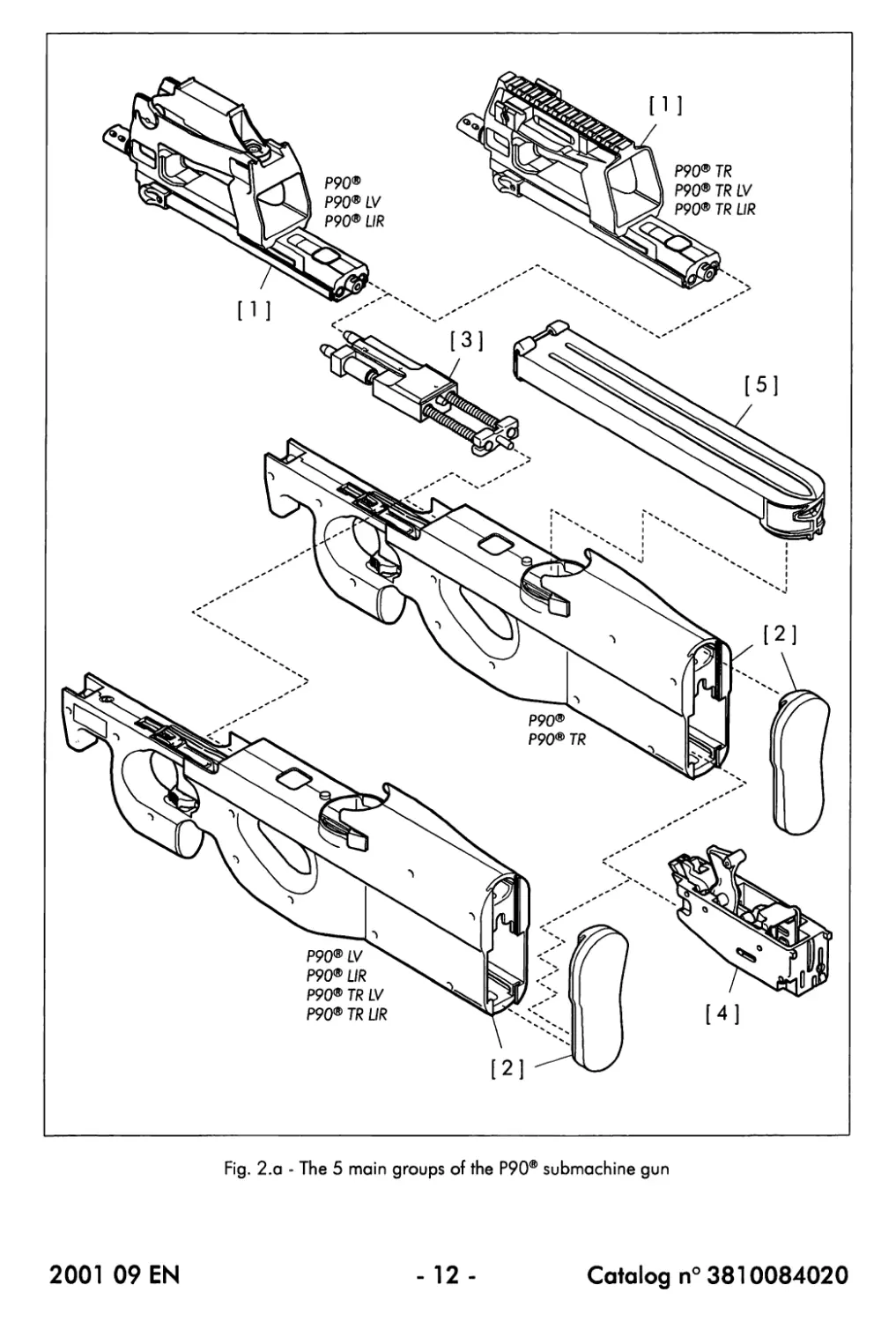
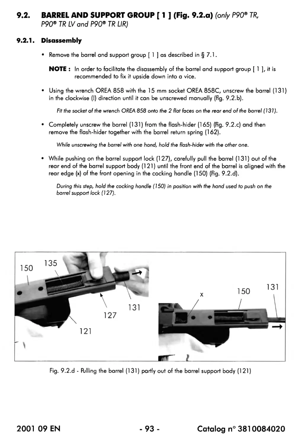
Fig. 2.a - The 5 main groups of the P90® submachine gun
2001 09 EN
- 12 -
Catalog n° 3810084020
CHAPTER 2 : IDENTIFICATION OF THE PARTS
2.1. HOW TO ORDER PARTS
For ordering parts, refer to the 'Catalog of parts and accessories' of the P90® submachine gun.
2.2. PARTS LISTS
The P90® submachine gun is subdivided into 5 groups (Fig. 2.a) :
Group Description Fig- Paragraph
[1 ] Barrel and optical sight group (P90®, P90* LV, P90* LIR) Barrel and support group (P90® TR, P90® TR LV P90® TR UR) 2.b(l) 2.b (2) 2.2.1
[2] Frame and trigger group (P90®, P90® TR) Frame, trigger and laser group (P90* LV, P90* UR, P90® TR LV, P90* TR LIR) 2.c(l) 2.c (2) 2.2.2
13] Moving parts group 2.d 2.2.3
[4] Hammer group 2.e 2.2.4
[5] Magazine 2.f 2.2.5
2001 09 EN
- 13-
Catalog n° 3810084020
712
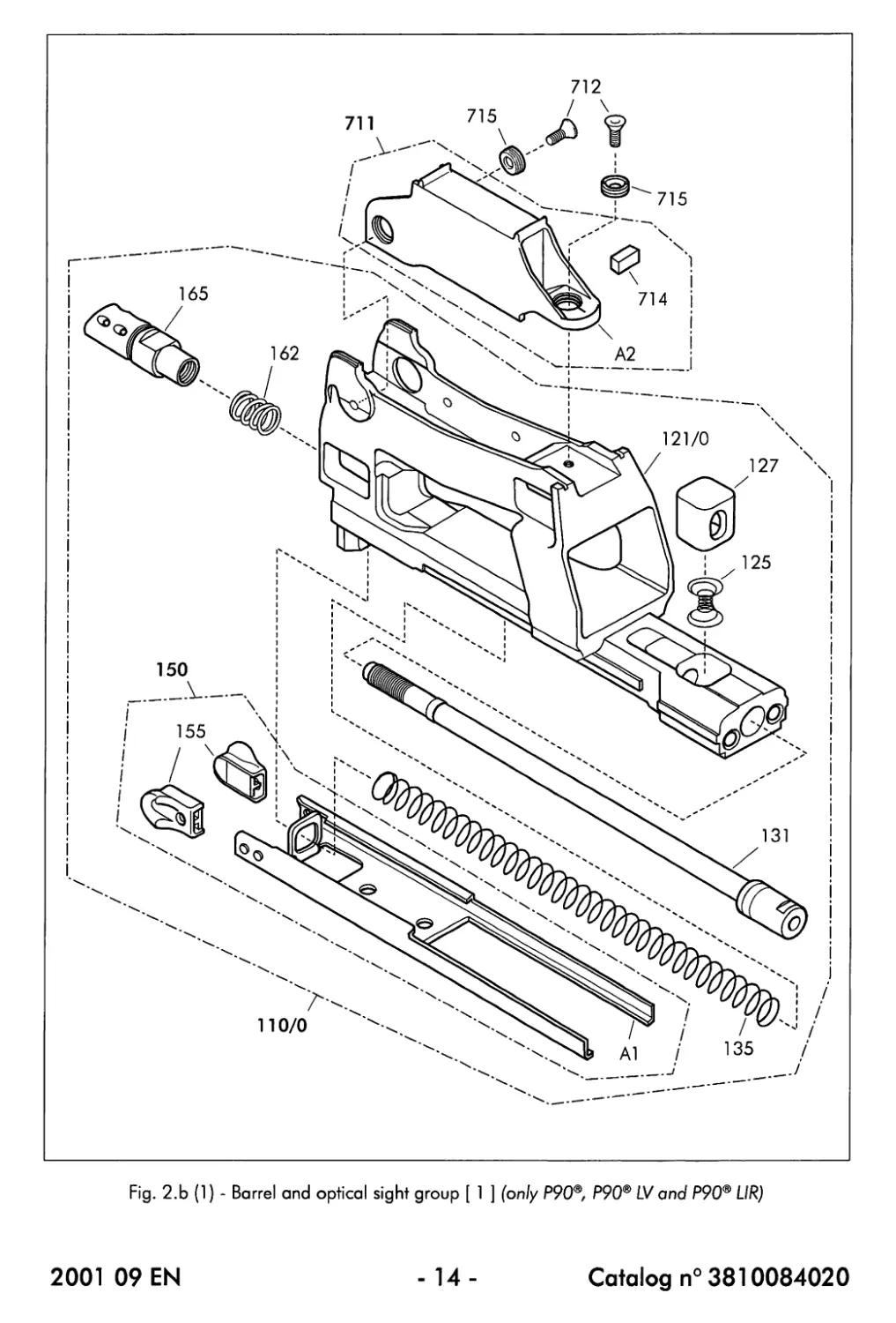
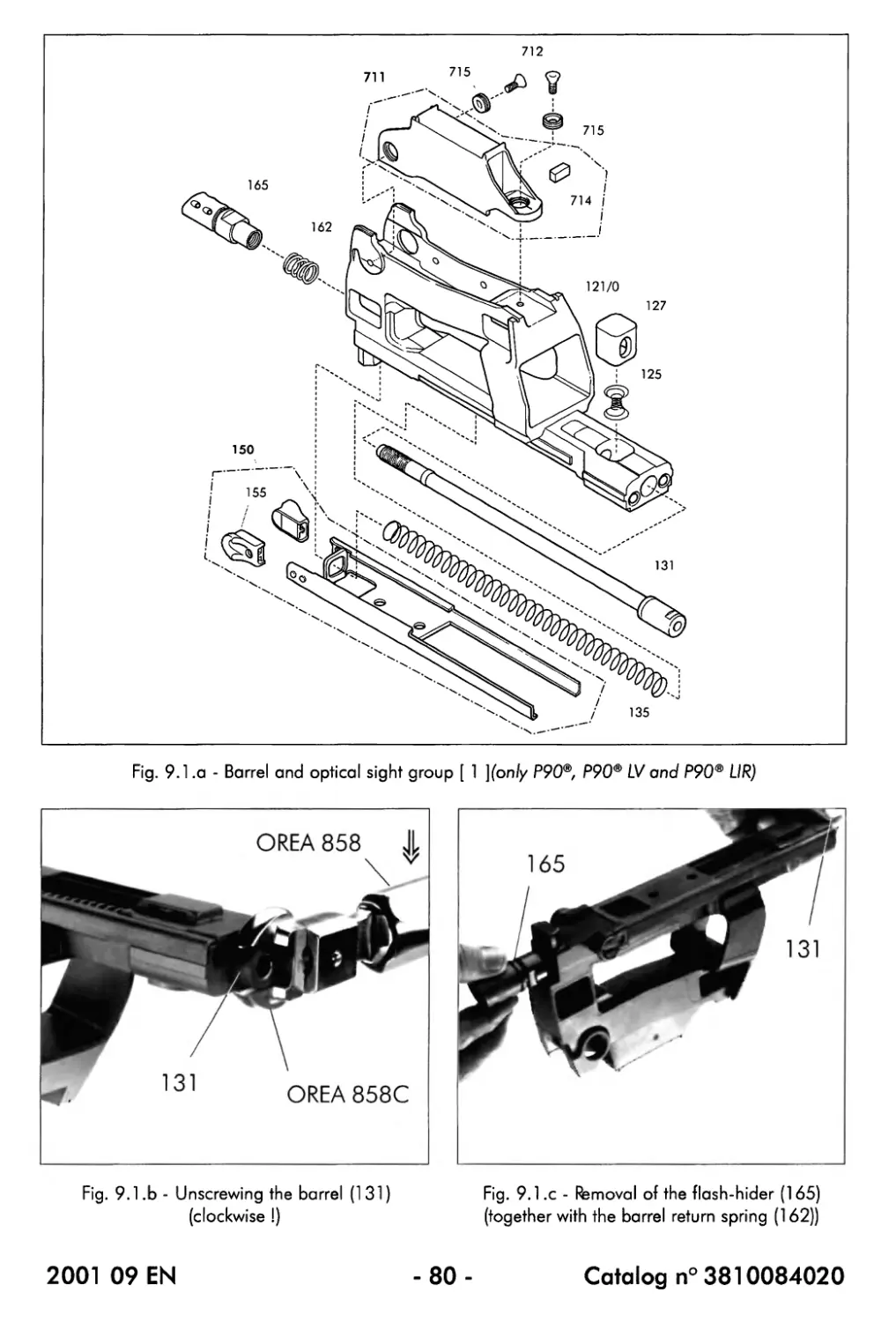
Fig. 2,b (1) - Barrel and optical sight group [ 1 ] (only P90®, P90® LV and P90® UR)
2001 09 EN
- 14-
Catalog n° 3810084020
2.2.1. Barrel and optical sight group [ 1 ] (only P90®, P90® LV and P90® UR)
(a) List of parts (Fig. 2.b (1))
CAT n° Description Qty per unit
110/0 Support and barrel, assembly 1
121/0 Body, support, barrel 1
125 Spring, lock, support, barrel 1
127 Lock, support, barrel 1
131 Barrel (9") 1
135 Spring, return, cocking handle 1
150 Cocking handle 1
155 Stud, cocking handle 2
162 Spring, return, barrel 1
165 Flash-hider 1
711 Reflex optical sight 1
712 Hexagonal socket countersunk head screw 2
714 Tritium light source (*) 1
715 Screw, adjustment, sight 2
(*j Due to the radioactive decay of the tritium, tritium light sources (714) should never be
stored for a long time : it is recommended to order them when they are needed.
The following parts or assemblies cannot be ordered (separately) : a number has however been
attributed in order to facilitate the descriptions throughout this Maintenance Manual:
№ Description Qty per unit
Al Cocking handle body 1
A2 Optical sight body 1
(b) Description
The barrel and optical sight group [ 1 ] fits into position on top of the front part of the
frame (220) and consists of the barrel support body (121) onto or into which the following
assemblies and components have been installed :
- The barrel support lock assembly consisting of the barrel support lock (127) and its
spring (125)
The barrel support lock (127) should be pressed in order to be able to unlock and remove
the barrel and optical sight group [ 1 ] from the frame (220).
On the other hand, the barrel support lock (127) should also be pressed when it is necessary
to slide the barrel (131) out of the barrel support body (121) (after the flash-hider (165) and
the barrel return spring (162) have been removed from the barrel).
2001 09 EN
- 15-
Catalog n° 3810084020
712
Fig. 2.b (1) - Barrel and optical sight group [ 1 ] (only P90®, P90® LV and P90® UR)
2001 09 EN
- 16-
Catalog n° 3810084020
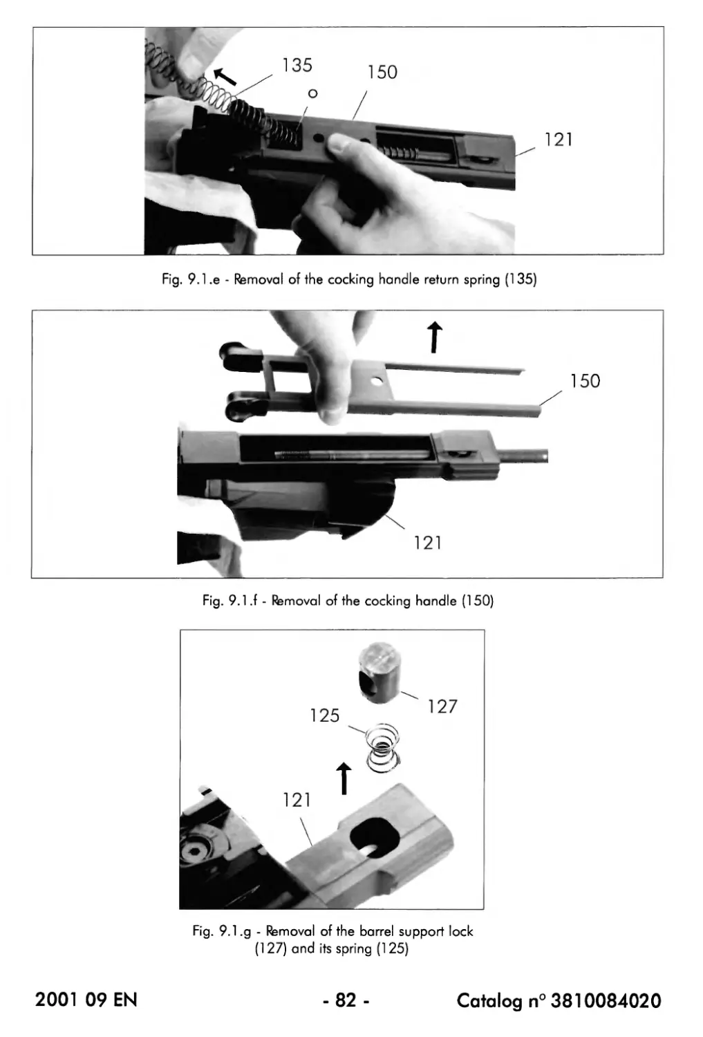
2.2.1. Barrel and optical sight group [ 1 ] (continued) (only P90®, P90® LV and
P90® LIR)
(b) Description (continued)
- The barrel (131), inserted from the rear side into the barrel support body (121), onto
which the barrel return spring (1 62) has been placed and the flash-hider (165) has
been screwed
- The cocking handle (150), consisting of the cocking handle body (Al) provided with
the 2 cocking handle studs (155) and held in a spring-tensioned position by the
cocking handle return spring (135)
When the cocking handle (150) is moved to the rear by using one of its studs (155), it will
move the moving parts rearwards (also refer to § 3.3.2).
When the cocking handle (150) is released in its rear position, it returns towards its front
position by the force of its return spring (135) and by the force of the moving parts which are
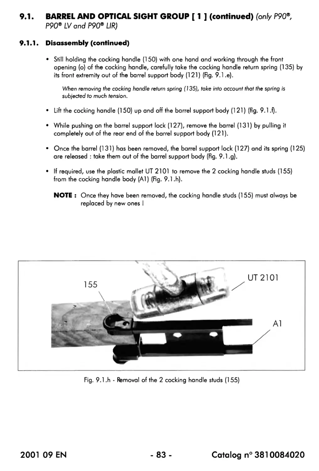
pushed by the return springs (477) (also refer to § 3.3.3).
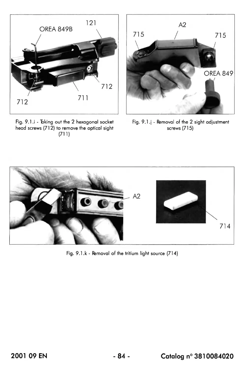
- The optical sight (711), comprising the tritium light source (714) mounted inside the
optical sight body (A2)
The optical sight (711) is adjustable by the 2 sight adjustment screws (715) and fixed into
position onto the barrel support body (121) by means of the 2 hexagonal socket head screws
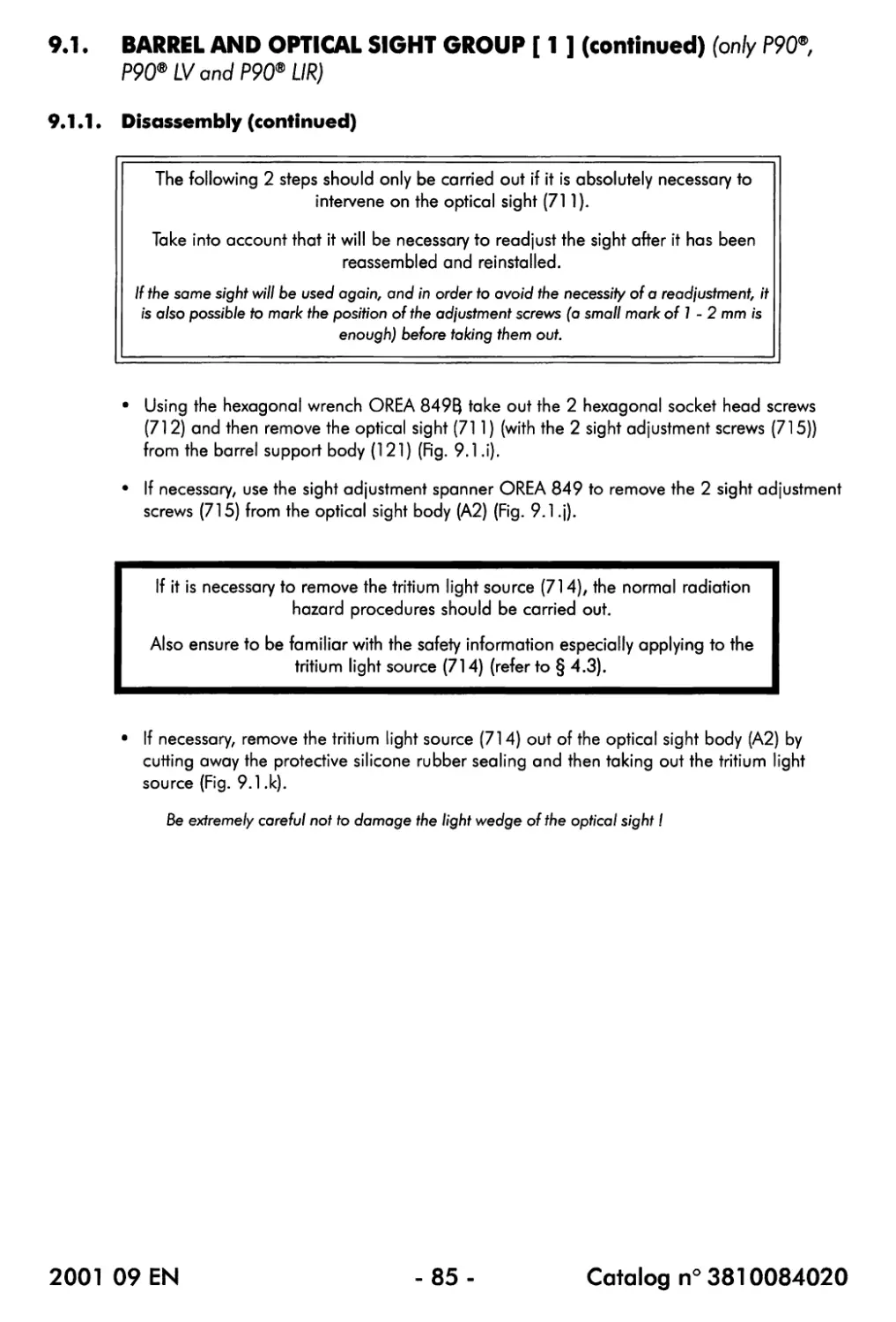
(712).
The 2 hexagonal socket head screws (712) should be correctly tightened as they also secure
the 2 sight adjustment screws (715).
2001 09 EN
- 17-
Catalog n° 3810084020
Fig. 2,b (2) - Barrel and support group [ 1 ] (only P90® TR, P90® TR LVand P90® TR UR)
2001 09 EN
- 18-
Catalog n° 3810084020
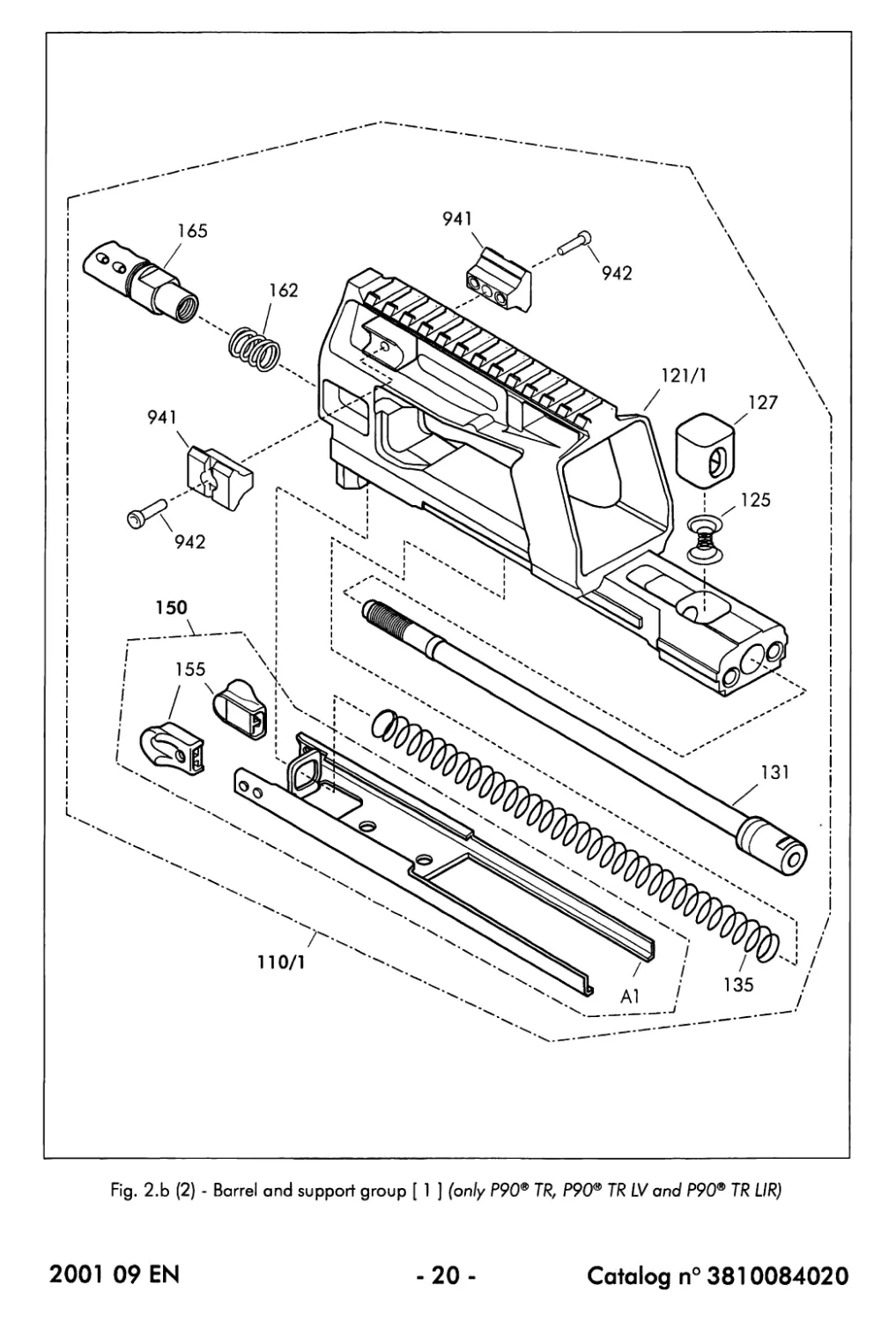
2.2.1. Barrel and support group [ 1 ] (only P90® TR, P90® TR LV and P90® TR UR)
(a) List of parts (Fig. 2.b (2))
CAT n° Description Qty per unit
110/1 Support and barrel, assembly, triple rail 1
121/1 Body, support, barrel, triple rail 1
125 Spring, lock, support, barrel 1
127 Lock, support, barrel 1
131 Barrel (9") 1
135 Spring, return, cocking handle 1
150 Cocking handle 1
155 Stud, cocking handle 2
162 Spring, return, barrel 1
165 Flash-hider 1
941 Side rail 2
942 Hexagonal socket head cap screw 2
The following parts or assemblies cannot be ordered (separately) : a number has however been
attributed in order to facilitate the descriptions throughout this Maintenance Manual:
№ Description Qty per unit
Al Cocking handle body 1
(b) Description
The barrel and support group [ 1 ] fits into position on top of the front part of the frame
(220) and consists of the barrel support body (121) onto or into which the following
assemblies and components have been installed :
- The barrel support lock assembly consisting of the barrel support lock (127) and its
spring (125)
The barrel support lock (127) should be pressed in order to be able to unlock and remove
the barrel and support group [ 1 ] from the frame (220).
On the other hand, the barrel support lock (127) should also be pressed when it is necessary
to slide the barrel (131) out of the barrel support body (121) (after the flash-hider (165) and
the barrel return spring (162) have been removed from the barrel).
- The barrel (131), inserted from the rear side into the barrel support body (121), onto
which the barrel return spring (162) has been placed and the flash-hider (1 65) has
been screwed
2001 09 EN
- 19-
Catalog n° 3810084020
Fig. 2.b (2) - Barrel and support group [ 1 ] (only P90® TR, P90® TR LV and P90® TR LIR)
2001 09 EN
-20-
Catalog n° 3810084020
2*2.1. Barrel and support group [ 1 ] (continued) (only P90® TR, P90® TR LV and
P90® TR UR)
(b) Description (continued)
- The cocking handle (150), consisting of the cocking handle body (Al) provided with
the 2 cocking handle studs (155) and held in a spring-tensioned position by the
cocking handle return spring (135)
When the cocking handle (150) is moved to the rear by using one of its studs (155), it will
move the moving parts rearwards (also refer to § 3,3,2).
When the cocking handle (150) is released in its rear position, it returns towards its front
position by the force of its return spring (135) and by the force of the moving parts which are
pushed by the return springs (477) (also refer to § 3,3.3).
- 2 side rails (941) fixed into position onto the left and right sides of the barrel support
body (121) by means of the 2 hexagonal socket head screws (942)
2001 09 EN
-21 -
Catalog n° 3810084020
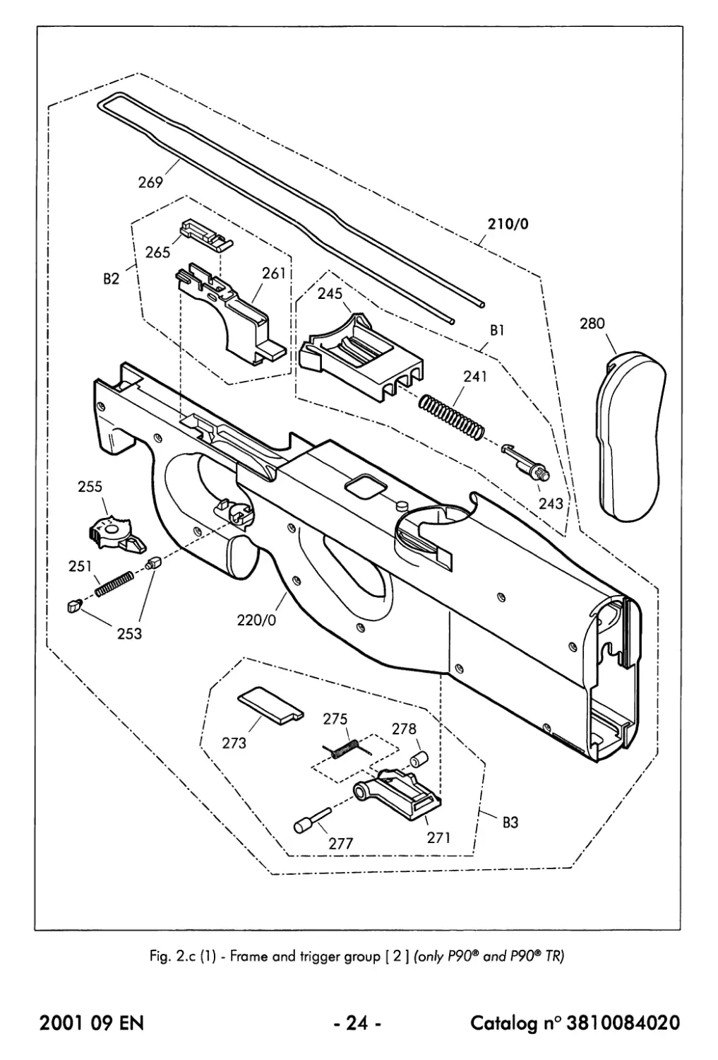
Fig. 2.с (1) - Frame and trigger group [ 2 ] (only P90® and P90® TR)
2001 09 EN
-22 -
Catalog n° 3810084020
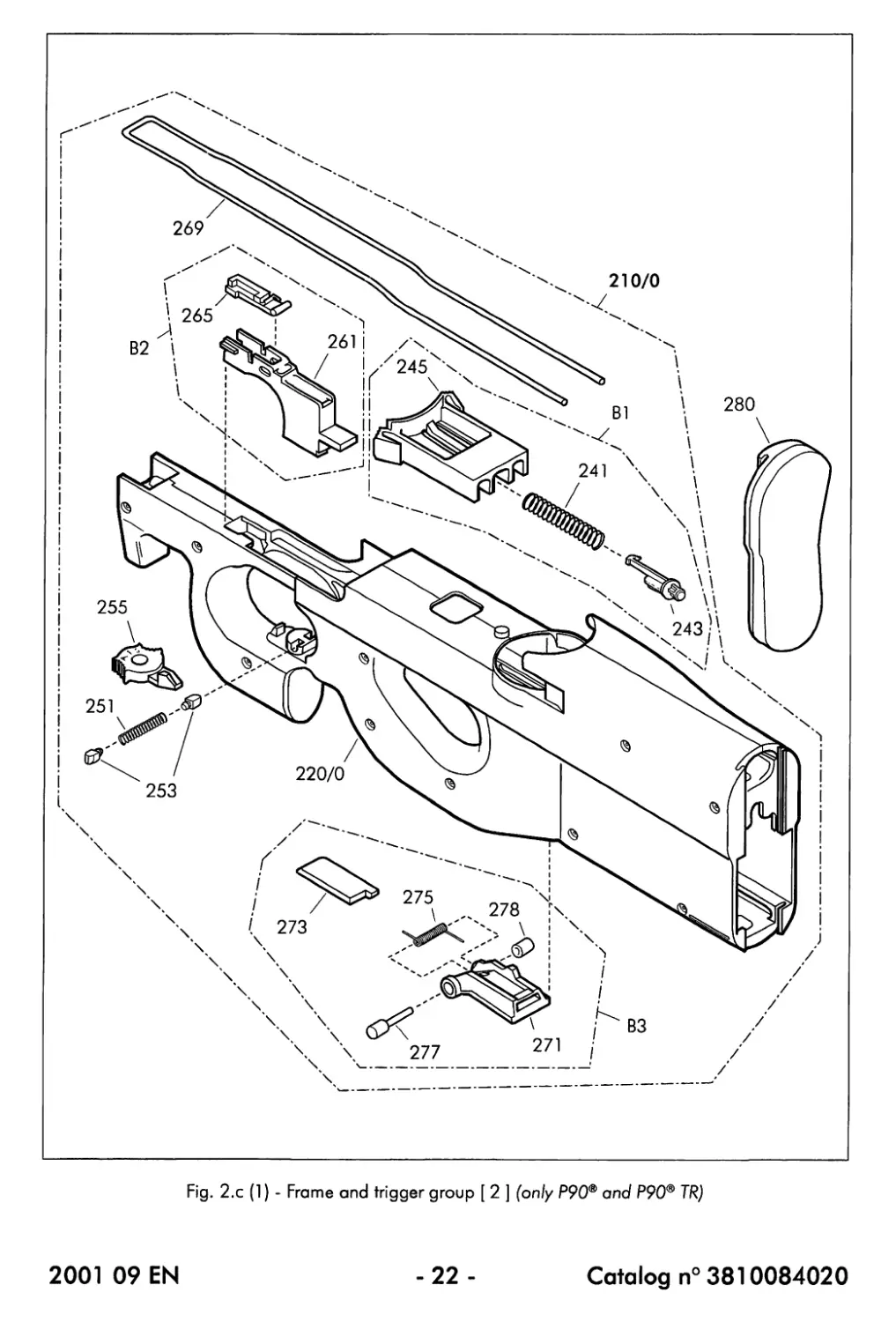
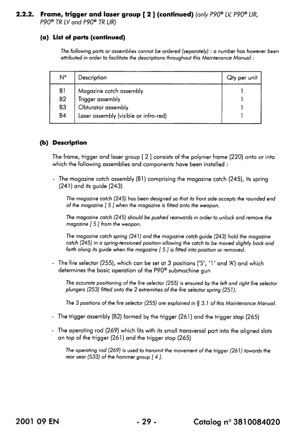
2.2.2. Frame and trigger group [ 2 ] (only P90® and P90® TR)
(a) List of parts (Fig. 2.c (1))
CAT n° Description Qty per unit
210/0 Frame assembly 1
220/0 Frame 1
241 Spring, catch, magazine 1
243 Guide, catch, magazine 1
245 Catch, magazine 1
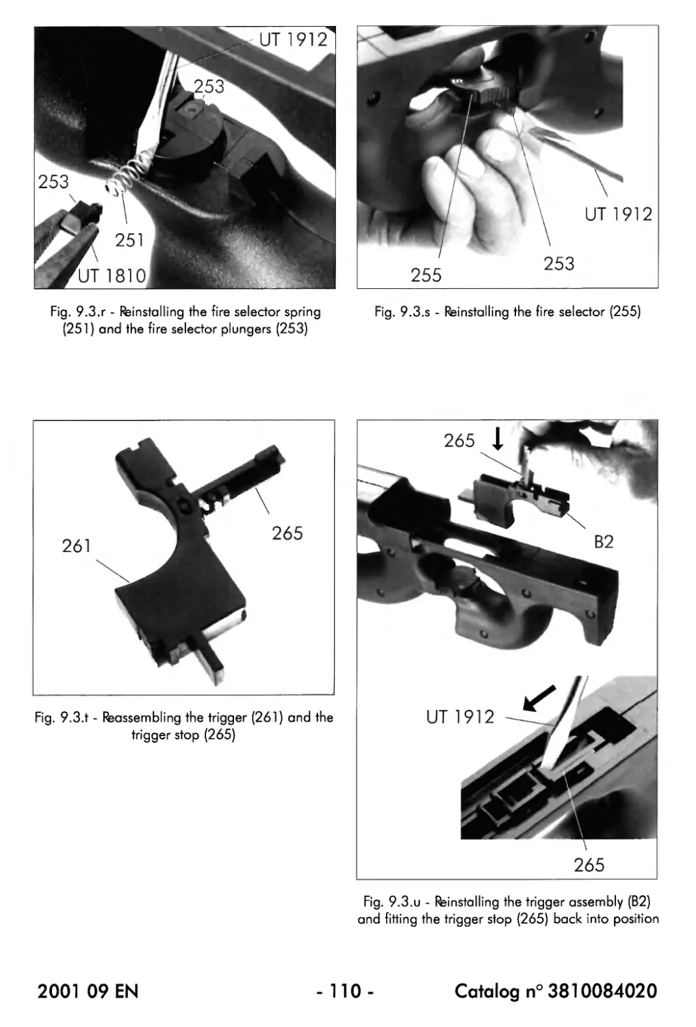
251 Spring, plunger, selector 1
253 Plunger, selector 2
255 Fire selector 1
261 Body, trigger 1
265 Stop, trigger 1
269 Rod, operating 1
271 Body, obturator, ejection opening 1
273 Catch, obturator 1
275 Return spring, obturator 1
277 Stem, axis, obturator 1
278 Bushing, axis, obturator 1
280 Plate, butt assembly 1
The following parts or assemblies cannot be ordered (separately) : a number has however been
attributed in order to facilitate the descriptions throughout this Maintenance Manual:
№ Description Qty per unit
Bl Magazine catch assembly 1
B2 Trigger assembly 1
B3 Obturator assembly 1
(b) Description
The frame and trigger group [ 2 ] consists of the polymer frame (220) onto or into which
the following assemblies and components have been installed :
- The magazine catch assembly (Bl) comprising the magazine catch (245), its spring
(241) and its guide (243)
The magazine catch (245) has been designed so that its front side accepts the rounded end
of the magazine [ 5 ] when the magazine is fitted onto the weapon.
The magazine catch (245) should be pushed rearwards in order to unlock and remove the
magazine [ 5 ] from the weapon.
The magazine catch spring (241) and the magazine catch guide (243) hold the magazine
catch (245) in a spring-tensioned position allowing the catch to be moved slightly back and
forth along its guide when the magazine [ 5 ] is fitted into position or removed.
2001 09 EN
-23-
Catalog n° 3810084020
Fig. 2.с (1) - Frame and trigger group [ 2 ] (only P90® and P90® TR)
2001 09 EN
-24-
Catalog n° 3810084020
2.2.2. Frame and trigger group [ 2 ] (continued) (only P90® and P90® TR)
(b) Description (continued)
- The fire selector (255), which can be set at 3 positions ('S', 'Г and 'A') and which
determines the basic operation of the P90® submachine gun
The accurate positioning of the fire selector (255) is ensured by the left and right fire selector
plungers (253) fitted onto the 2 extremities of the fire selector spring (251).
The 3 positions of the fire selector (255) are explained in §3.1 of this Maintenance Manual.
- The trigger assembly (B2) formed by the trigger (261) and the trigger stop (265)
- The operating rod (269) which fits with its small transversal part into the aligned slots
on top of the trigger (261) and the trigger stop (265)
The operating rod (269) is used to transmit the movement of the trigger (261) towards the
rear sear (533) of the hammer group [ 4 ].
- The obturator assembly (B3) which has been provided to open or close the ejection
opening inside the frame (visible from underneath)
The obturator assembly (B3) is automatically opened by the breech block assembly (420) at
the beginning of the rearward movement of the moving parts (also refer to § 3.3.2).
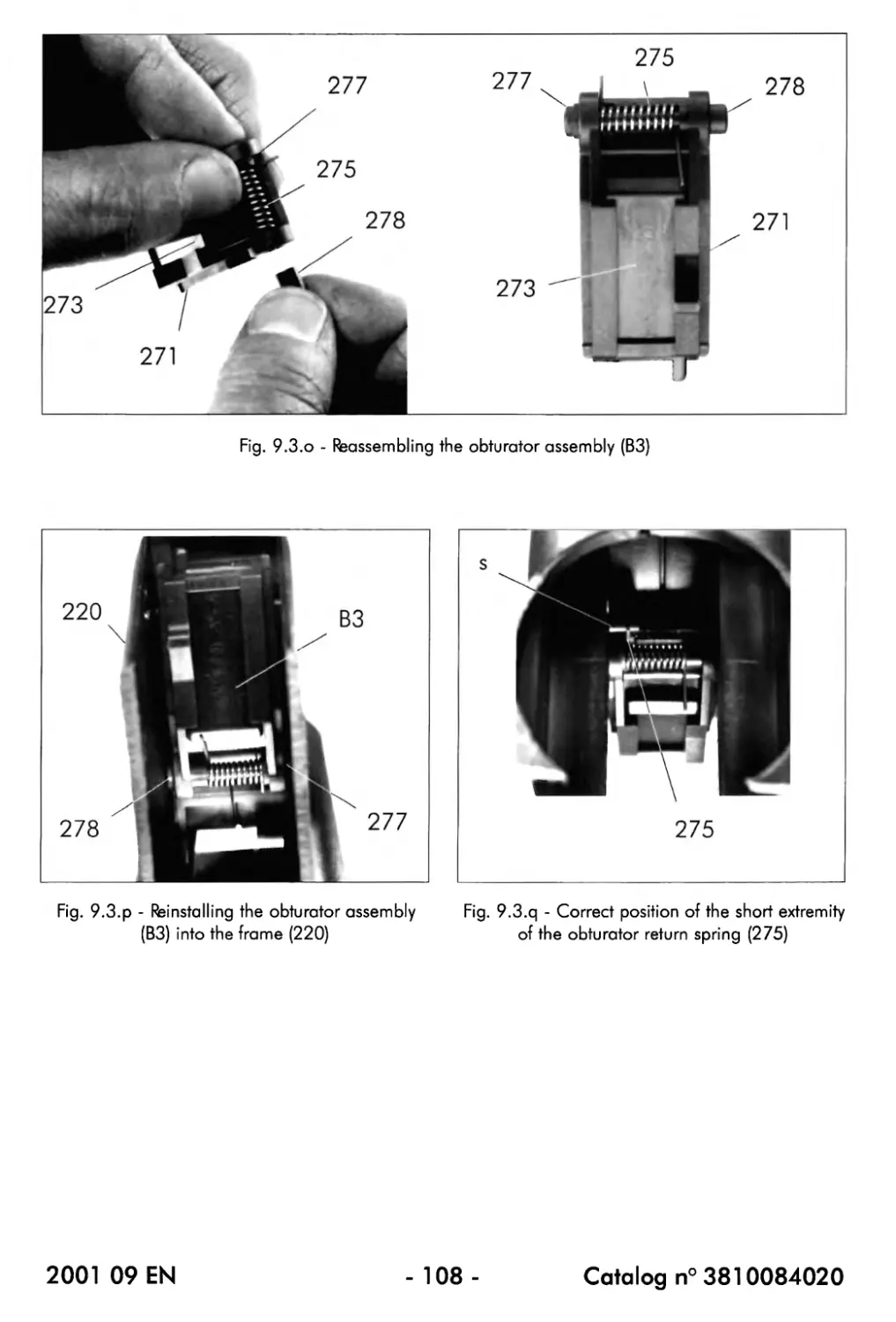
The obturator catch (273), fitted onto the obturator body (271), ensures that the obturator
assembly (B3) remains in the closed position.
When the P90® submachine gun is used in a dirty, sandy, ... environment, the obturator
assembly (B3) can be closed manually. In such a case, a slight closing force is enough : the
obturator catch (273) ensures that the obturator assembly is closed correctly.
Besides ensuring the closing operation, the obturator return spring (275) also holds the
obturator axis (277) and the bushing (278) in a spring-tensioned position : the axis and the
bushing can be pressed inwards in order to enable the obturator assembly (B3) to be inserted
inside the frame (220). Once the obturator assembly (B3) is at the correct position inside the
frame (220), the spring force pushes the axis and the bushing into the corresponding
mounting holes.
- The butt plate (280) which fits onto the rear side of the frame (220)
2001 09 EN
-25-
Catalog n° 3810084020
Fig. 2.c (2) - Frame, trigger and laser group [ 2 ] (only P90® LV, P90® LIR, P90® TR LV and P90® TR LIR)
2001 09 EN
-26-
Catalog n° 3810084020
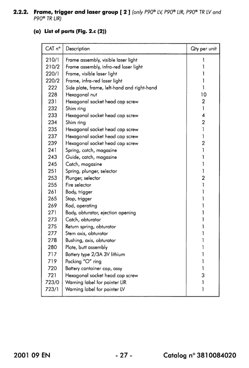
2.2.2. Frame, trigger and laser group [ 2 ] (only P90® LV, P90® UR, P90® TR LV and
P90® TR UR)
(a) List of parts (Fig. 2.c (2))
CAT n° Description Qty per unit
210/1 Frame assembly, visible laser light 1
210/2 Frame assembly, infra-red laser light 1
220/1 Frame, visible laser light 1
220/2 Frame, infra-red laser light 1
222 Side plate, frame, left-hand and right-hand 1
228 Hexagonal nut 10
231 Hexagonal socket head cap screw 2
232 Shim ring 1
233 Hexagonal socket head cap screw 4
234 Shim ring 2
235 Hexagonal socket head cap screw 1
237 Hexagonal socket head cap screw 1
239 Hexagonal socket head cap screw 2
241 Spring, catch, magazine 1
243 Guide, catch, magazine 1
245 Catch, magazine 1
251 Spring, plunger, selector 1
253 Plunger, selector 2
255 Fire selector 1
261 Body, trigger 1
265 Stop, trigger 1
269 Rod, operating 1
271 Body, obturator, ejection opening 1
273 Catch, obturator 1
275 Return spring, obturator 1
TIT Stem axis, obturator 1
278 Bushing, axis, obturator 1
280 Plate, butt assembly 1
717 Battery type 2/3A 3V lithium 1
719 Packing "O" ring 1
720 Battery container cap, assy 1
721 Hexagonal socket head cap screw 3
723/0 Warning label for pointer LIR 1
723/1 Warning label for pointer LV 1
2001 09 EN
-27-
Catalog n° 3810084020
Fig. 2.с (2) - Frame, trigger and laser group [ 2 ] (only P90® LV, P90® UR, P90® TR LV and P90® TR UR)
2001 09 EN
-28-
Catalog n° 3810084020
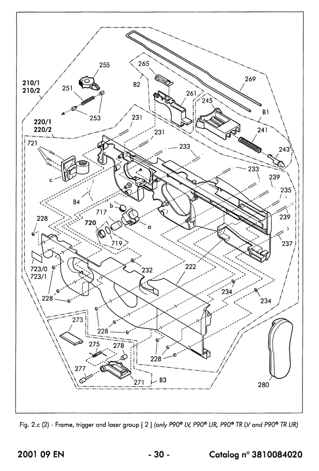
2.2.2. Frame, trigger and laser group [ 2 ] (continued) (only P90® LV, P90® UR,
P90®TRLVand P90®TRLIR)
(a) List of parts (continued)
The following parts or assemblies cannot be ordered (separately) : a number has however been
attributed in order to facilitate the descriptions throughout this Maintenance Manual:
№ Description Qty per unit
Bl Magazine catch assembly 1
B2 Trigger assembly 1
B3 Obturator assembly 1
B4 Laser assembly (visible or infra-red) 1
(b) Description
The frame, trigger and laser group [ 2 ] consists of the polymer frame (220) onto or into
which the following assemblies and components have been installed :
- The magazine catch assembly (Bl) comprising the magazine catch (245), its spring
(241) and its guide (243)
The magazine catch (245) has been designed so that its front side accepts the rounded end
of the magazine [ 5 ] when the magazine is fitted onto the weapon.
The magazine catch (245) should be pushed rearwards in order to unlock and remove the
magazine [ 5 ] from the weapon.
The magazine catch spring (241) and the magazine catch guide (243) hold the magazine
catch (245) in a spring-tensioned position allowing the catch to be moved slightly back and
forth along its guide when the magazine [ 5 ] is fitted into position or removed.
- The fire selector (255), which can be set at 3 positions ('S', '1' and 'A') and which
determines the basic operation of the P90® submachine gun
The accurate positioning of the fire selector (255) is ensured by the left and right fire selector
plungers (253) fitted onto the 2 extremities of the fire selector spring (251).
The 3 positions of the fire selector (255) are explained in §3.1 of this Maintenance Manual.
- The trigger assembly (B2) formed by the trigger (261) and the trigger stop (265)
- The operating rod (269) which fits with its small transversal part into the aligned slots
on top of the trigger (261) and the trigger stop (265)
The operating rod (269) is used to transmit the movement of the trigger (261) towards the
rear sear (533) of the hammer group [ 4 ].
2001 09 EN
-29-
Catalog n° 3810084020
Fig. 2.с (2) - Frame, trigger and laser group [ 2 ] (only P90® LV, P90® UR, P90® TR LV and P90® TR UR)
2001 09 EN
-30-
Catalog n°3810084020
2.2.2. Frame, trigger and laser group [ 2 ] (continued) (only P90® LV, P90® UR,
P90®TRLVand P90® TR UR)
(b) Description (continued)
- The obturator assembly (B3) which has been provided to open or close the ejection
opening inside the frame (visible from underneath)
The obturator assembly (B3) is automatically opened by the breech block assembly (420) at
the beginning of the rearward movement of the moving parts (also refer to § 3.3.2).
The obturator catch (273), fitted onto the obturator body (271), ensures that the obturator
assembly (B3) remains in the closed position.
When the P90® submachine gun is used in a dirty, sandy, ... environment, the obturator
assembly (B3) can be closed manually. In such a case, a slight closing force is enough : the
obturator catch (273) ensures that the obturator assembly is closed correctly.
Besides ensuring the closing operation, the obturator return spring (275) also holds the
obturator axis (277) and the bushing (278) in a spring-tensioned position : the axis and the
bushing can be pressed inwards in order to enable the obturator assembly (B3) to be inserted
inside the frame (220). Once the obturator assembly (83) is at the correct position inside the
frame (220), the spring force pushes the axis and the bushing into the corresponding
mounting holes.
- The butt plate (280) which fits onto the rear side of the frame (220)
The polymer frame (220) is composed of the left and right frame plates (222), holding the
internal, visible or infra-red, laser assembly (B4).
The left and right frame plates (222) are fixed together by 10 hexagonal socket head screws and
10 hexagonal nuts.
The 10 hexagonal socket head screws are not all the same (2 x (231), 4 x (233), 1 x (235), 1 x
(237) and 2 x (239)) and therefore not interchangeable, while the 10 hexagonal nuts (228) are
identical.
Three shim rings have been provided for a correct assembly of the left and right frame plates
(222) : 1 ring (232) (for one of the screws (233)) and 2 rings (234) (for both the screws (235)
and (237)).
The laser assembly (B4), which has been designed to fit into the available space in the
frame (220), consists of the battery holder (a), the "laser ON" button (b) and the laser unit
(c).
The battery holder (a) holds the lithium 3 V type 2/3A battery (717) (which should be inserted
with the side first) and is closed by the battery cap (720) provided with an "O"-ring (719).
The laser unit (c) is fixed into position in the front extremity of the frame (220) by means of the 3
hexagonal socket head screws (721) which are also used to adjust the laser beam.
Depending on the type of the laser (visible or infra-red), an appropriate warning label
(723) has been sticked on the front, left side of the frame (220).
2001 09 EN
- 31 -
Catalog n° 3810084020
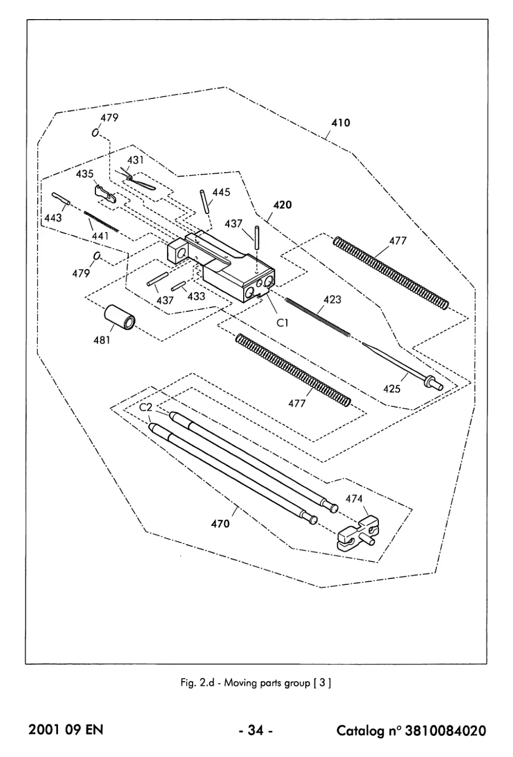
Fig. 2.d - Moving parts group [ 3 ]
2001 09 EN
-32 -
Catalog n° 3810084020
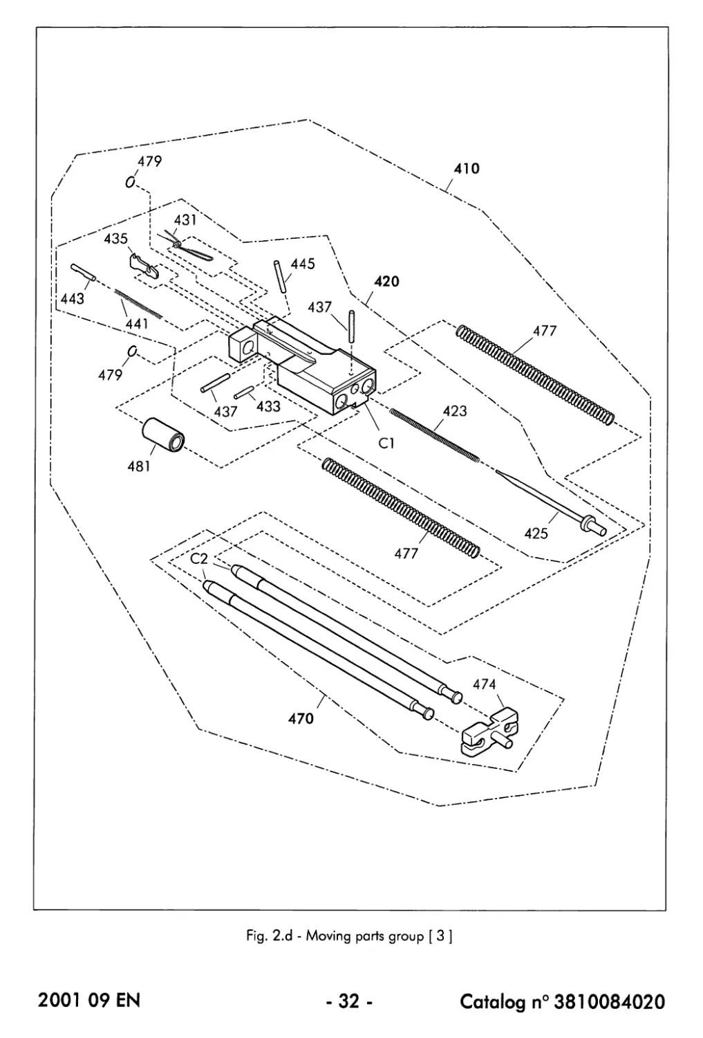
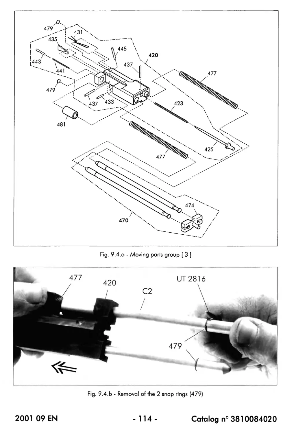
2.2.3. Moving ports group [ 3 ]
(a) List of parts (Fig. 2.d)
CAT n° Description Qty per unit
410 Moving parts assembly 1
420 Breech block assembly 1
423 Spring, firing pin 1
425 Firing pin 1
431 Spring, extractor 1
433 Spring pin, slotted, heavy type 1
435 Extractor 1
437 Spring pin, slotted, heavy type 2
441 Spring, ejector 1
443 Ejector 1
445 Spiral pin, heavy duty 1
470 Guide assembly, breech block assembly 1
474 Stop block, breech block assembly 1
477 Return spring 2
479 Snap ring 2
481 Sta b i 1 i ze r, rate of fi re 1
The following parts or assemblies cannot be ordered (separately) : a number has however been
attributed in order to facilitate the descriptions throughout this Maintenance Manual:
№ Description Qty per unit
Cl Breech block 1
C2 Breech block assembly guide rod 2
(b) Description
The moving parts group [ 3 ], which converts the recoil energy generated when firing a
round into the kinetic energy necessary for the operation of the submachine gun, consists
of the breech block assembly (420) which can slide back and forth along its guide rods
(C2).
When a round is fired, the resulting recoil force causes the breech block assembly (420) to move
rearwards, against the force of the return springs (477).
Once the breech block assembly (420) has reached the breech block assembly stop block
(474), it will be halted and then moved forwards under the force of the return springs (477).
The rate-of-fire stabilizer (481) ensures an even movement of the breech block assembly (420)
along its guide rods (C2).
2001 09 EN
-33-
Catalog n° 3810084020
Fig. 2.d - Moving parts group [ 3 ]
2001 09 EN
-34-
Catalog n° 3810084020
2.2.3. Moving parts group [ 3 ] (continued)
(b) Description (continued)
The breech block assembly (420) is composed of the steel breech block (Cl) onto or into
which the following components have been installed :
- The firing pin (425) and its spring (423) which are held in place by the spring pin (437)
When, during the firing operation, the hammer (515) is released from its cocked position, it
hits the rear extremity of the firing pin (425). The firing pin is then propelled forwards and hits
the primer of the cartridge so that firing takes place.
After firing, the firing pin (425) returns to its initial (rear) position by the force of its spring
(423).
- The extractor spring (431) and the extractor (435) which are respectively held in place
by the spring pin (433) and the spring pin (437)
The extractor (435), which lightly protrudes from the front face of the breech block (Cl), is
held in a spring-tensioned position by its spring (431).
When, during the feeding operation of a cartridge from the magazine [5], the front face of
the breech block (Cl) pushes the cartridge into the chamber, the rim of the cartridge clicks
itself into the extractor (435) (also refer to § 3.3.3).
- The ejector (443) and its spring (441) which are held in place by the spiral pin (445)
As the spiral pin (445) has been installed at an angle, the slot in the ejector (443) is oriented
accordingly.
The ejector (443), which lightly protrudes from the front face of the breech block (Cl), is held
in a spring-tensioned position by its spring (441).
When, during the feeding operation of a cartridge from the magazine [ 5 ], the front face of
the breech block (Cl) pushes the cartridge into the chamber, the ejector (443) is completely
pushed into the breech block. After the firing operation, when the moving parts start their
rearward movement, pressure will be exerted by the ejector (443) on the top rear part of the
cartridge case, causing the case to pivot around the extractor (435) : the case will disengage
from the extractor (435) and leave the weapon through the ejection opening.
The guide assembly (470) consists of the 2 breech block assembly guide rods (C2) fitted,
at the rear side, into the breech block assembly stop block (474).
2001 09 EN
-35-
Catalog n° 3810084020
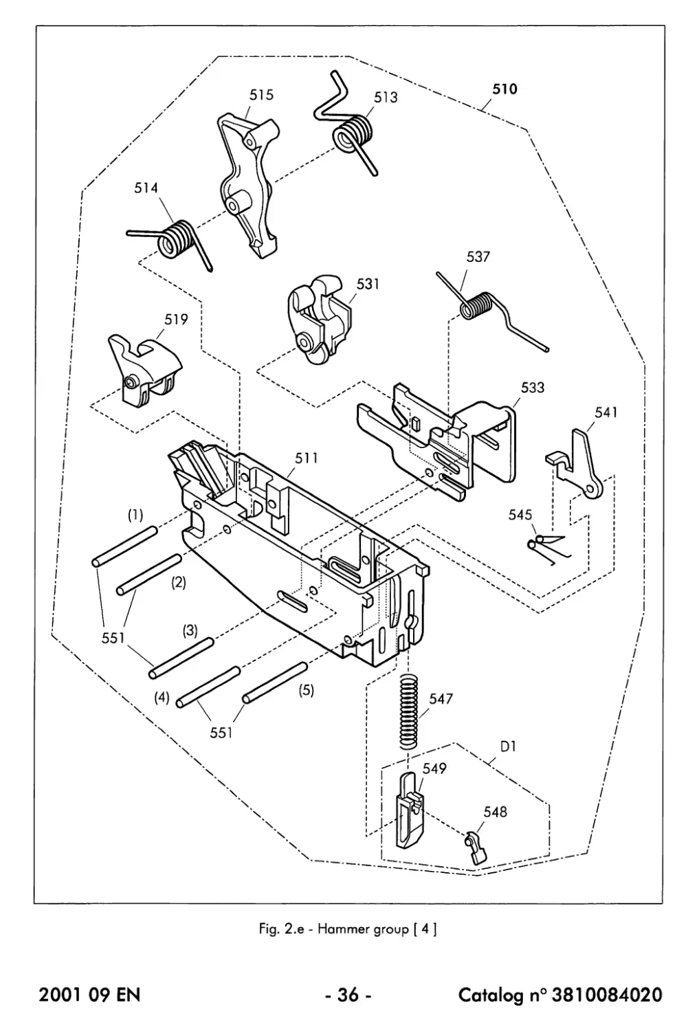
Fig. 2.e - Hammer group [ 4 ]
2001 09 EN
-36-
Catalog n° 3810084020
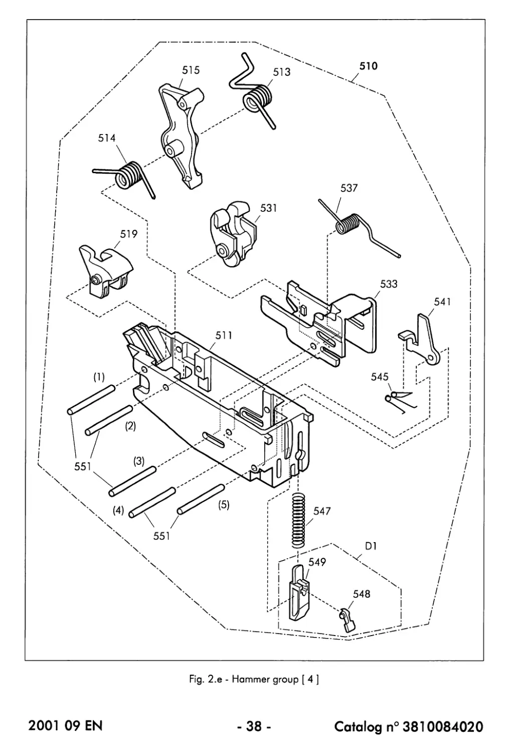
2.2.4. Hammer group [ 4 ]
(a) List of parts (Fig. 2.e)
CAT n° Description Qty per unit
510 Hammer group assembly 1
511 Hammer group body 1
513 Spring, right-hand, hammer 1
514 Spring, left-hand, hammer 1
515 Hammer 1
519 Sear, automatic 1
531 Sear, front 1
533 Sear, rear 1
537 Spring, sear, rear 1
541 Sear, safety 1
545 Spring, sear, safety 1
547 Spring, lock, hammer group 1
548 Lever, release, hammer group 1
549 Lock, hammer group 1
551 Parallel pin 5
The following parts or assemblies cannot be ordered (separately) : a number has however been
attributed in order to facilitate the descriptions throughout this Maintenance Manual:
№ Description Qty per unit
DI Hammer group lock assembly 1
(b) Description
The hammer group [ 4 ]z fitted into the lower rear part of the frame (220), controls the
firing operation of the weapon.
The different components of the hammer group [ 4 ] are held in place in the hammer
group body (511) by means of the 5 parallel pins (551) :
- The parallel pin (551) (1) secures and allows pivoting the automatic sear (519).
The automatic sear (519) is subjected to the force of the front extremity of the left hammer
spring (514) : this spring force pivots the automatic sear (519) towards the hammer (515)
into which a groove has been provided for the engagement of the automatic sear.
The position of the automatic sear (519) is determined by its protruding part which is
actuated by the breech block assembly (420).
2001 09 EN
-37-
Catalog n° 3810084020
Fig. 2.e - Hammer group [ 4 ]
2001 09 EN
-38-
Catalog n°3810084020
2.2.4. Hammer group [ 4 ] (continued)
(b) Description (continued)
- The parallel pin (551) (2) secures and allows pivoting the hammer (515).
The hammer (515) is subjected to the force of the right and left hammer springs (513) and
(514).
The front extremity of the right hammer spring (513) fits into a special housing provided in
the hammer group body (511).
The hammer (515) is pushed into the cocked position by the breech block assembly (420)
during the rearward movement of the moving parts (also refer to § 3.3.2).
The hammer (515) has been designed so that it can be held in its cocked position by the flat
face of its rounded part (for engagement into the rear sear (533) and/or the front sear (531))
or by the groove in the hammer body (for the engagement of the automatic sear (519)).
- The parallel pin (551) (3) secures and allows pivoting the front sear (531) inside the
rear sear (533). The pin also secures the rear sear (533) and allows it moving back
and forth.
Both the front sear (531) and the rear sear (533) are subjected to the force of the rear sear
spring (537) and both sears are designed to engage the flat face of the rounded part of the
hammer (515).
The rear sear (533) is moved by the long extremities of the operating rod (269) which
transmits the movement of the trigger (261) towards the hammer group [ 4 ].
- The parallel pin (551) (4) secures the rear sear spring (537).
The longer extremity of the rear sear spring (537) fits into a special housing provided in the
rear side of the hammer group body (511).
- The parallel pin (551) (5) secures the hammer group lock assembly (DI) which is held
in a spring-tensioned position by its spring (547).
The hammer group lock assembly is used to lock the hammer group [4 ] into position inside
the lower rear part of the frame (220). The assembly consists of the hammer group lock
(549) which fits into a locking hole inside the frame (220) and which can be released from
that hole by raising the hammer group release lever (548).
The parallel pin (551) (5) also secures and allows pivoting the safety sear (541).
The safety sear (541) is subjected to the force of its spring (545) which is fitted into position
on the bottom inside the hammer group body (511).
The functioning of the hammer group [ 4 ] is rather complex but can be understood
by thoroughly reading § 3.3, § 3.4 and § 3.5 of this Maintenance Manual.
2001 09 EN
-39-
Catalog n°3810084020
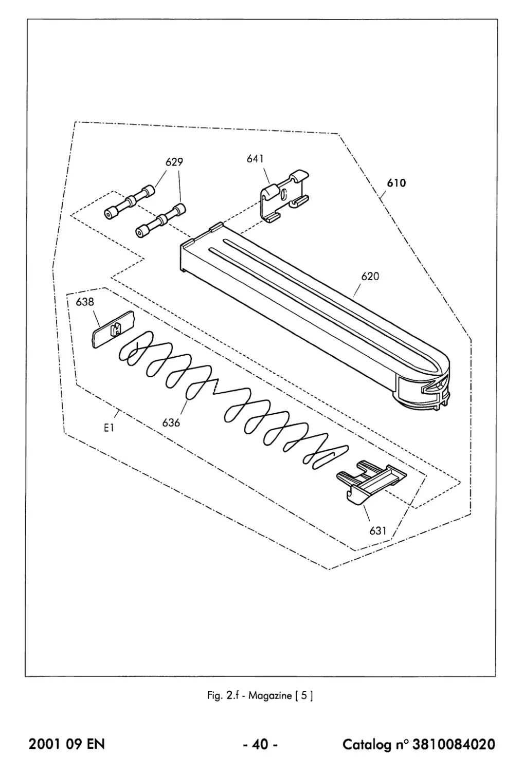
Fig. 2.f - Magazine [ 5 ]
2001 09 EN
-40-
Catalog n° 3810084020
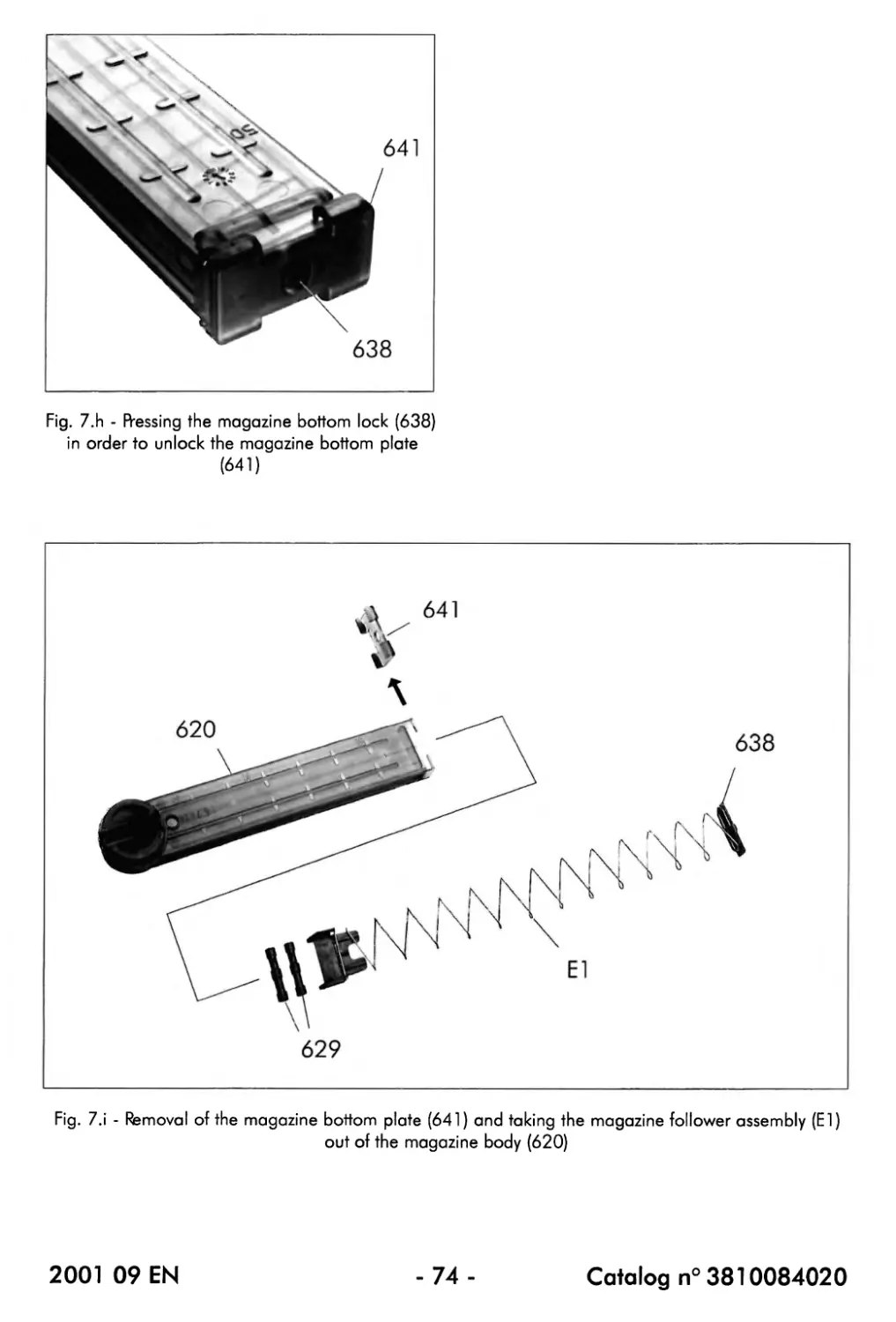
2.2.5. Magazine [ 5 ]
(a) List of parts (Fig. 2.f)
CAT n° Description Qty per unit
610 Magazine assembly 1
620 Case, magazine 1
629 Roller 2
631 Follower, magazine 1
636 Spring, follower, magazine 1
638 Lock, bottom plate, magazine 1
641 Bottom plate, magazine 1
The following parts or assemblies cannot be ordered (separately) : a number has however been
attributed in order to facilitate the descriptions throughout this Maintenance Manual:
№ Description Qty per unit
El Magazine follower assembly 1
(b) Description
The magazine [ 5 ], with a capacity of 50 cartridges, is fitted, with its rounded end towards
the rear side, on top of the frame (220) of the submachine gun, above the barrel (131)
and the moving parts :
- The translucent, polycarbonate magazine case (620) allows you to estimate the
number of cartridges present in the magazine.
The rounded end of the magazine case (620) has been designed so that it is accepted by the
front side of the magazine catch (245).
- The magazine follower assembly (El) pushes the cartridges loaded in the magazine
towards the rear side and supplies the necessary force to push the cartridge against the
lips of the magazine case (620), ready for feeding.
The magazine follower assembly (El) consists of the magazine follower spring (636) onto
which the magazine follower (631) and the magazine bottom lock (638) have been fitted.
- The magazine follower (631), used in combination with the 2 rollers (629), ensures that
the cartridges are correctly moved inside the magazine.
- The magazine bottom plate (641), which is held into position by the magazine bottom
lock (638), can be removed from the magazine case (620) for the disassembly of the
magazine.
2001 09 EN
-41 -
Catalog n° 3810084020
THIS PAGE IS INTENTIONALLY BLANK
2001 09 EN
-42 -
Catalog n° 3810084020
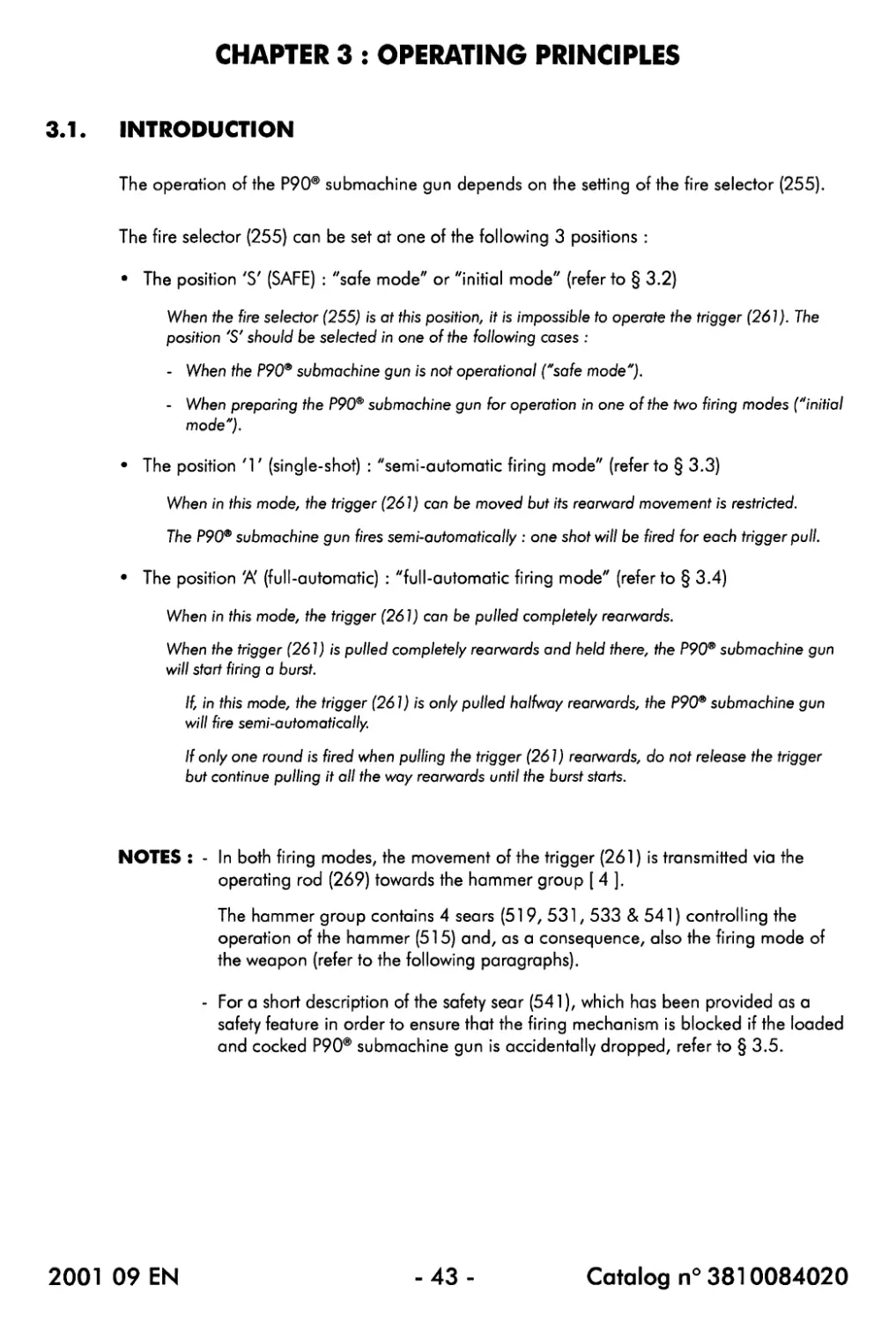
CHAPTER 3 : OPERATING PRINCIPLES
3.1. INTRODUCTION
The operation of the P90® submachine gun depends on the setting of the fire selector (255).
The fire selector (255) can be set at one of the following 3 positions :
• The position 'S' (SAFE) : "sate mode" or "initial mode" (refer to § 3.2)
When the fire selector (255) is at this position, it is impossible to operate the trigger (261). The
position 'S' should be selected in one of the following cases :
- When the P90® submachine gun is not operational ("safe mode").
- When preparing the P90® submachine gun for operation in one of the two firing modes ("initial
mode").
• The position '1' (single-shot) : "semi-automatic firing mode" (refer to § 3.3)
When in this mode, the trigger (261) can be moved but its rearward movement is restricted.
The P90® submachine gun fires semi-automatically : one shot will be fired for each trigger pull.
• The position 'A' (full-automatic) : "full-automatic tiring mode" (refer to § 3.4)
When in this mode, the trigger (261) can be pulled completely rearwards.
When the trigger (261) is pulled completely rearwards and held there, the P90® submachine gun
will start firing a burst.
If, in this mode, the trigger (261) is only pulled halfway rearwards, the P90® submachine gun
will fire semi-automatically.
If only one round is fired when pulling the trigger (261) rearwards, do not release the trigger
but continue pulling it all the way rearwards until the burst starts.
NOTES : - In both tiring modes, the movement of the trigger (261) is transmitted via the
operating rod (269) towards the hammer group [ 4 ].
The hammer group contains 4 sears (519, 531,533 & 541) controlling the
operation of the hammer (515) and, as a consequence, also the firing mode of
the weapon (refer to the following paragraphs).
- For a short description of the safety sear (541), which has been provided as a
safety feature in order to ensure that the firing mechanism is blocked if the loaded
and cocked P90® submachine gun is accidentally dropped, refer to § 3.5.
2001 09 EN
-43 -
Catalog n° 3810084020
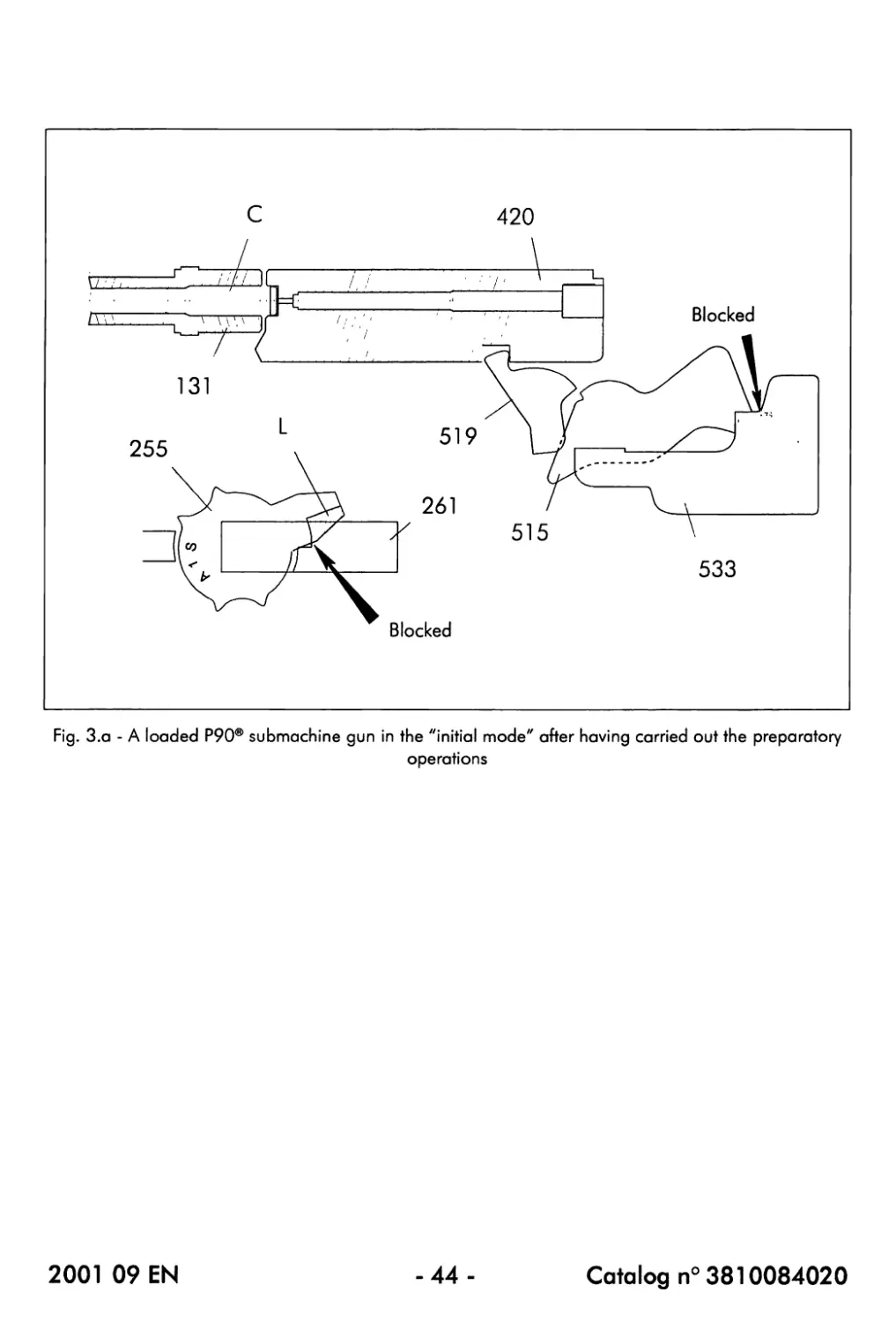
Fig. З.а - A loaded P90® submachine gun in the "initial mode" after having carried out the preparatory
operations
2001 09 EN
-44-
Catalog n° 3810084020
3.2. THE "SAFE MODE" / THE "INITIAL MODE" (Fig. 3.a)
When the fire selector (255) is at the position 'S', it is impossible to operate the trigger (261) :
the lug (L) provided on the rear part of the body of the tire selector is in contact with the rear,
right portion of the trigger so that the trigger is blocked.
There are 2 possibilities :
• The P90® submachine gun is not operational (carried in its carrying bag, stored, ...)
In such a case, it is recommended that the fire selector (255) is at the position 'S'.
• The P90® submachine gun is being prepared for operation in one of the 2 tiring modes
For safety reasons, the fire selector (255) should always be set at the position 'S' when
carrying out the following preparatory operations (the P90® submachine gun is in the so-
called "initial mode") :
- The installation of a loaded magazine [ 5 ] onto the submachine gun
- Cocking the gun by pulling the cocking handle (150) completely rearwards and then
releasing it
When cocking the P90® submachine gun, its hammer (515) will be placed in the cocked
position and the obturator assembly (B3) of the ejection opening will be opened.
If a loaded magazine [ 5 ] has been installed onto the gun, a cartridge will also be fed into the
chamber of the barrel (131).
NOTE : It the P90® submachine gun will not be used immediately after it has been cocked,
the obturator assembly (B3) of the ejection opening can be closed manually.
This is especially useful in order to avoid the penetration of foreign particles inside the
P90® when the weapon is carried in a dirty, sandy, ... environment.
When the obturator assembly (B3) has been closed, it will automatically be reopened by
the following rearward movement of the breech block assembly (420) which will take
place during a next rearward pull of the cocking handle (150) or when the first round is
fired.
Fig. 3.a shows a loaded P90® submachine gun in the "initial mode" after having carried out
the preparatory operations :
- The breech block assembly (420) is positioned at its most forward position and the
cartridge (C) is pushed into the chamber of the barrel (131).
When the breech block assembly (420) is positioned at its most forward position, it is said that
"the breech is closed".
- In its most forward position, the breech block assembly (420) releases the automatic sear
(519) from the hammer (515).
The protruding part of the automatic sear (519) is actuated by the breech block assembly
(420).
- In this mode, the hammer (515) is held in the cocked position by the rear sear (533).
The rear sear (533) engages the flat face of the rounded part of the hammer (515).
2001 09 EN
-45-
Catalog n° 3810084020
2001 09 EN
-46-
Catalog n° 3810084020
3.3. SEMI-AUTOMATIC FIRING MODE
3.3.1. Firing the first round (Fig. 3.b)
• The fire selector (255) is set at the position '1' (single-shot).
As о result the lug (L) provided on the rear pari of the body of the fire selector (255) moves partly
towards the left side, releases the rear, right portion of the trigger (261) and becomes aligned with
the left portion of the trigger which does not protrude so far rearwards.
In the semi-automatic position, it is possible to pull the trigger (261), but its rearward movement is
restricted.
• When the trigger (261) is pulled, its restricted rearward movement is transmitted via the
operating rod (269) to the rear sear (533) of the hammer group [ 4 ] : the rear sear is
pushed rearwards and, as a consequence, releases the hammer (515).
The rear sear (533) disengages from the flat face of the rounded part of the hammer (515).
• Under the force of its right and left springs (513) and (514), the hammer (515) is raised
and hits the firing pin (425) which is propelled forwards : percussion takes place and the
round is fired.
NOTE : An important safety feature of the P90® submachine gun is that tiring is only possible
with the breech closed (i.e. with the breech block assembly (420) positioned at its
most forward position) even when the hammer (515) is cocked.
If the breech block assembly (420) is not positioned at its most forward position (the
breech is not closed), the protruding part of the automatic sear (519) is not actuated by
the breech block assembly.
As a result, the automatic sear (519) remains subjected to the force of the front extremity
of the left hammer spring (514) so that the sear will remain engaged into the groove of the
cocked hammer (515): the hammer remains blocked in its cocked position and firing is
impossible.
2001 09 EN
-47-
Catalog n° 3810084020
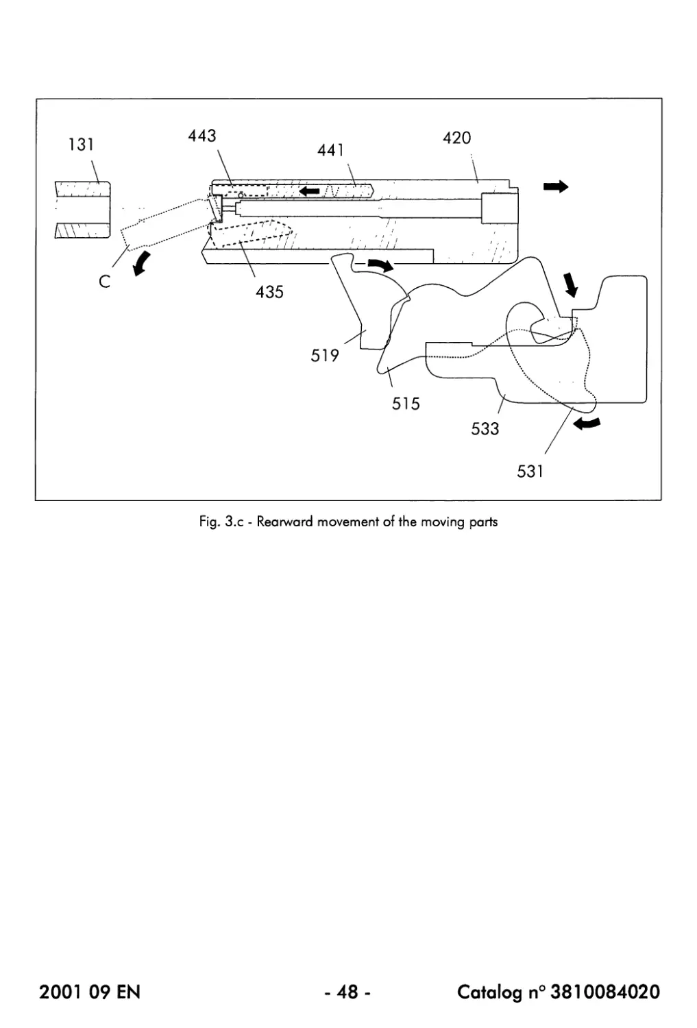
Fig. З.с - Rearward movement of the moving parts
2001 09 EN
-48-
Catalog n° 3810084020
3.3.2. Rearward movement of the moving parts (Fig. 3.c)
When the round is fired, the recoil force of the cartridge case causes the breech block assembly
(420) to be moved rearwards, compressing the return springs (477) and causing the following
operations to take place :
(a) Opening the obturator assembly (B3) of the ejection opening
This operation will only take place if the obturator assembly (B3) has been closed manually.
If the obturator assembly (B3) is closed, it will be reopened automatically by the contact
with the breech block assembly (420) during the rearward movement of the moving parts.
(b) Extraction and ejection of the empty cartridge case
At the beginning of the rearward movement of the moving parts, the extractor (435) still
holds the (empty) cartridge case.
The case is held by its rim which has clicked itself into the extractor (435) during the feeding
operation.
As the rearward movement of the moving parts continues, pressure will be exerted by the
ejector (443) on the top rear part of the cartridge case.
Before the rearward movement of the moving parts, the cartridge was pushed into the chamber
of the barrel (131), causing the ejector (443) to be completely pushed in.
The combined effects of the extractor (435) and the ejector (443) (being held back at its
bottom and being pushed at its top rear part) cause the empty case to pivot around the
extractor (435) : the case will disengage from the extractor (435) and leave the weapon
through the ejection opening.
(c) Recocking the hammer (515)
During its rearward movement, the breech block assembly (420) comes into contact with
the hammer (51 5) and pushes it, against the force of the right and left hammer springs
(513) and (514), rearwards and downwards into the cocked position.
As long as the breech block assembly (420) has not returned towards its most forward position,
the hammer (515) will be held in the cocked position by means of the automatic sear (519)
which engages the groove provided in the hammer body.
If the trigger (261) is kept pressed after the shot, the rear sear (533) is positioned too far
rearwards to be able to hold back the hammer (515) in the cocked position : the hammer will
be held in the cocked position by the front sear (531).
If the trigger (261) is now released, both the front and rear sears (531) and (533) return
towards their initial, forward position. As a result, the front sear (531) releases the hammer
(515) which is caught, and therefore held back in the cocked position, by the rear sear (533).
2001 09 EN
-49-
Catalog n° 3810084020
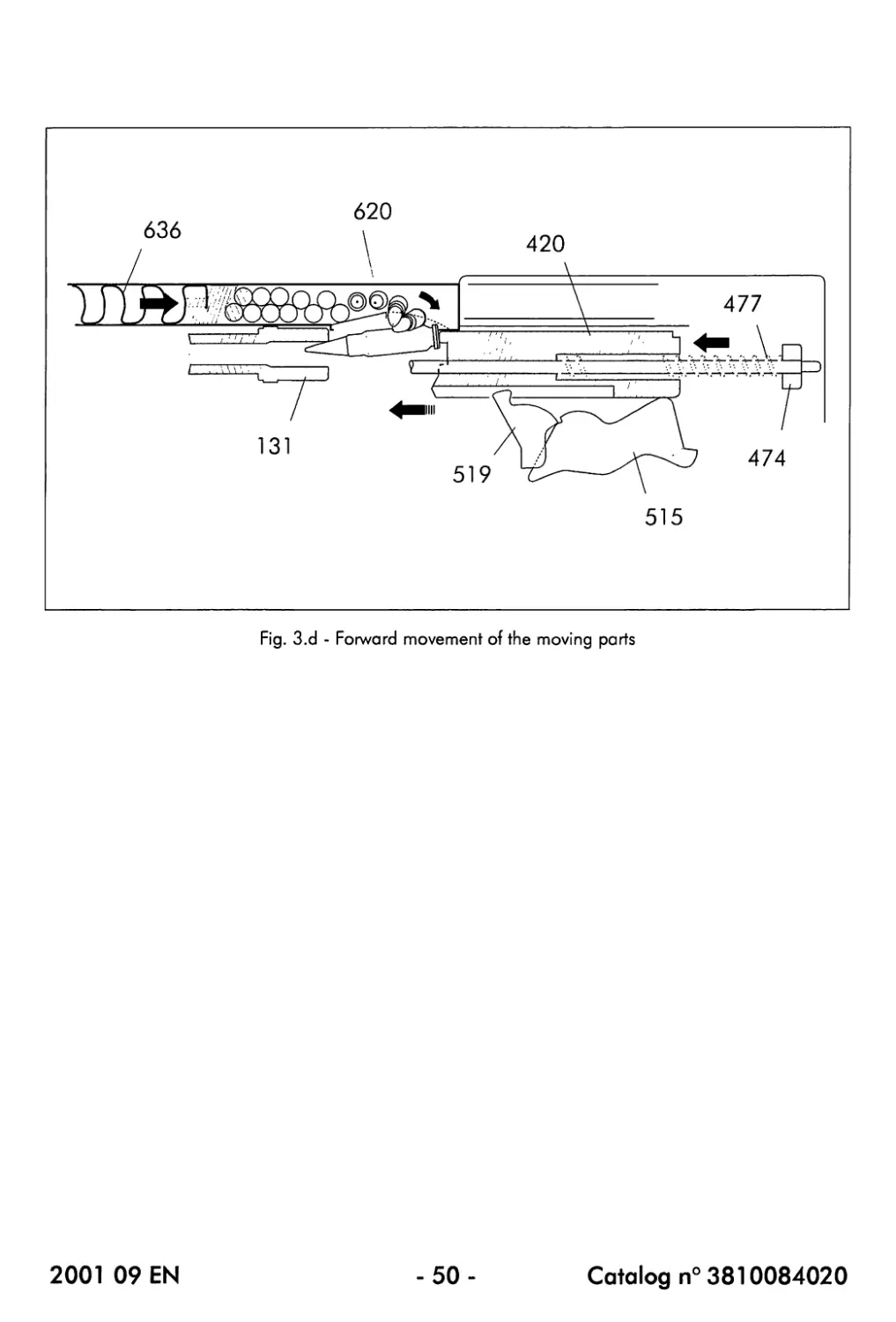
Fig. 3.d - Forward movement of the moving parts
2001 09 EN
-50-
Catalog n° 3810084020
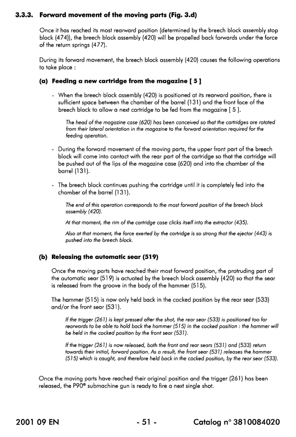
3.3.3. Forward movement of the moving parts (Fig. 3.d)
Once it has reached its most rearward position (determined by the breech block assembly stop
block (474))z the breech block assembly (420) will be propelled back forwards under the force
of the return springs (477).
During its forward movement, the breech block assembly (420) causes the following operations
to take place :
(a) Feeding a new cartridge from the magazine [ 5 ]
- When the breech block assembly (420) is positioned at its rearward position, there is
sufficient space between the chamber of the barrel (131) and the front face of the
breech block to allow a next cartridge to be fed from the magazine [ 5 ].
The head of the magazine case (620) has been conceived so that the cartridges are rotated
from their lateral orientation in the magazine to the forward orientation required for the
feeding operation.
- During the forward movement of the moving parts, the upper front part of the breech
block will come into contact with the rear part of the cartridge so that the cartridge will
be pushed out of the lips of the magazine case (620) and into the chamber of the
barrel (131).
- The breech block continues pushing the cartridge until it is completely fed into the
chamber of the barrel (131).
The end of this operation corresponds to the most forward position of the breech block
assembly (420).
At that moment, the rim of the cartridge case clicks itself into the extractor (435).
Also at that moment, the force exerted by the cartridge is so strong that the ejector (443) is
pushed into the breech block.
(b) Releasing the automatic sear (519)
Once the moving parts have reached their most forward position, the protruding part of
the automatic sear (51 9) is actuated by the breech block assembly (420) so that the sear
is released from the groove in the body of the hammer (515).
The hammer (515) is now only held back in the cocked position by the rear sear (533)
and/or the front sear (531).
If the trigger (261) is kept pressed after the shot, the rear sear (533) is positioned too far
rearwards to be able to hold back the hammer (515) in the cocked position : the hammer will
be held in the cocked position by the front sear (531).
If the trigger (261) is now released, both the front and rear sears (531) and (533) return
towards their initial, forward position. As a result, the front sear (531) releases the hammer
(515) which is caught, and therefore held back in the cocked position, by the rear sear (533).
Once the moving parts have reached their original position and the trigger (261) has been
released, the P90® submachine gun is ready to fire a next single shot.
2001 09 EN
-51 -
Catalog n° 3810084020
2001 09 EN
-52 -
Catalog n° 3810084020
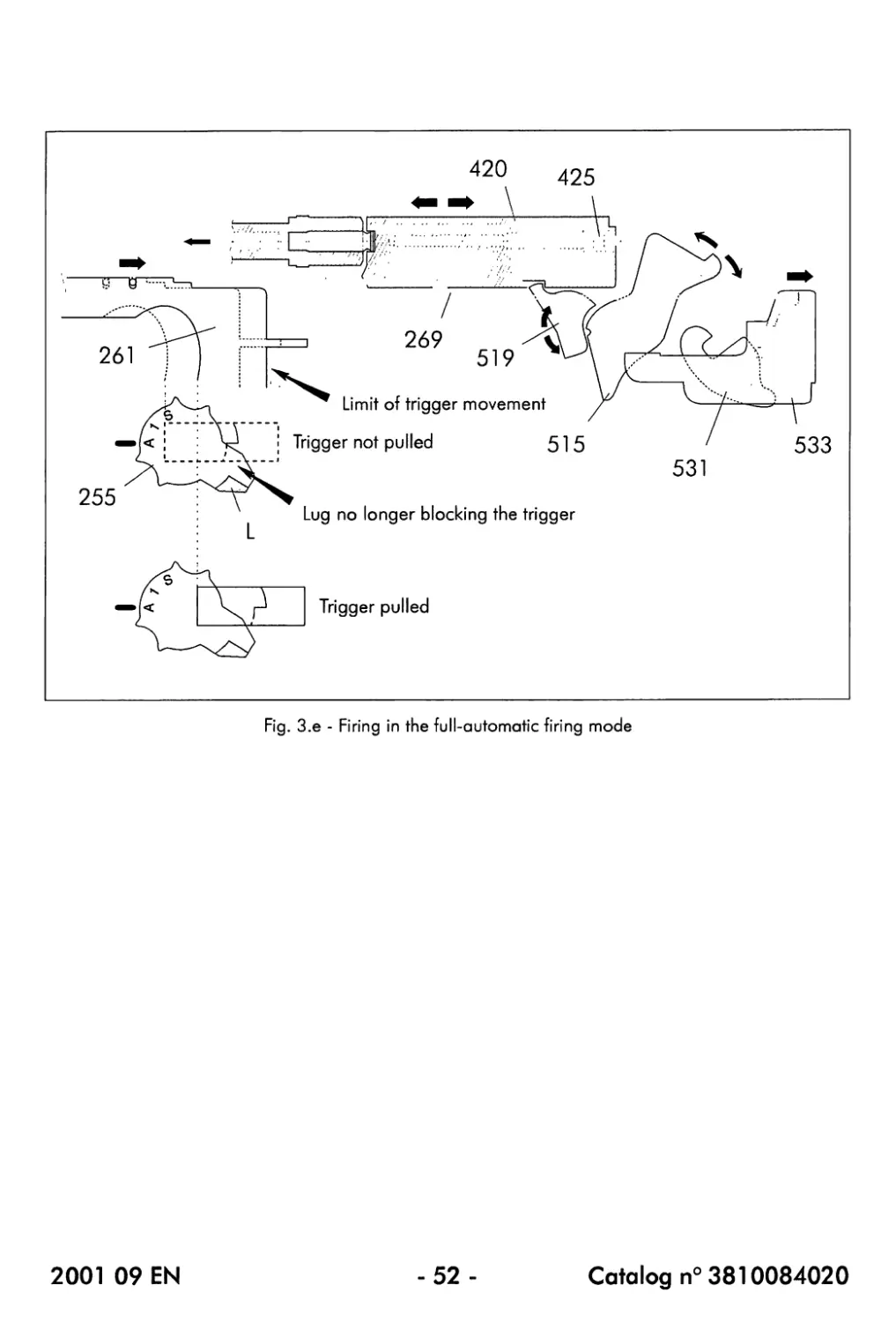
3.4. FULL-AUTOMATIC FIRING MODE
• The fire selector (255) is set at the position 'A' (full-automatic).
As a result, the lug (L) provided on the rear part of the body of the fire selector (255) moves
completely towards the left side, so that it is no longer aligned with any part of the trigger (261).
In the full-automatic position, it is possible to pull the trigger (261) completely rearwards.
• When the trigger (261) is pulled completely rearwards, its movement is transmitted via the
operating rod (269) to the rear sear (533) of the hammer group [ 4 ] : the rear sear is
pushed completely rearwards and, as a consequence, releases the hammer (515).
The rear sear (533) disengages from the flat face of the rounded part of the hammer (515).
When the trigger (261) is pulled completely rearwards, the rear sear (533) moves towards its most
rearward position where it becomes inoperative : the sear is no longer able to reengage the
hammer (515) when the hammer is cocked during the rearward movement of the moving parts.
When the rear sear (533) moves towards its most rearward position, the front sear (531) is
pivoted forwards so that it also becomes inoperative.
• Under the force of its right and left springs (513) and (514), the hammer (515) is raised
and hits the firing pin (425) which is propelled forwards : percussion takes place and the
first round is fired.
♦ During its rearward movement, the breech block assembly (420) comes into contact with
the hammer (515) and pushes it, against the force of the right and left hammer springs
(51 3) and (514), rearwards and downwards into the cocked position.
As long as the breech block assembly (420) has not returned towards its most forward position,
the hammer (515) will be held in the cocked position by means of the automatic sear (519) which
engages the groove provided in the hammer body.
As long as the trigger (261) is held completely rearwards, the rear sear (533) and the front sear
(531) are inoperative (see above) so that the hammer is only held back in its cocked position by
the automatic sear (519).
• Once the moving parts have reached their most forward position, the protruding part of the
automatic sear (51 9) is actuated by the breech block assembly (420) so that the sear is
released from the groove in the hammer body : a new round is fired.
• As long as the trigger (261) is held completely rearwards, the operation of the hammer
(515) is only controlled by the automatic sear (519) and the firing operation is repeated :
the submachine gun fires full-automatically.
The firing will continue as long as the trigger is held fully rearwards and cartridges are present in
the magazine [ 5 ].
NOTE : In the full-automatic tiring mode, single-shot firing is possible by only pulling the
trigger halfway rearwards.
The criterion for full-automatic firing is that the trigger should be pulled so for rearwards
that the rear sear (533) and the front sear (531) become inoperative.
2001 09 EN
-53-
Catalog n° 3810084020
Fig. 3.f - The 3 possible positions of the laser selector (B4)
2001 09 EN
-54-
Catalog n° 3810084020
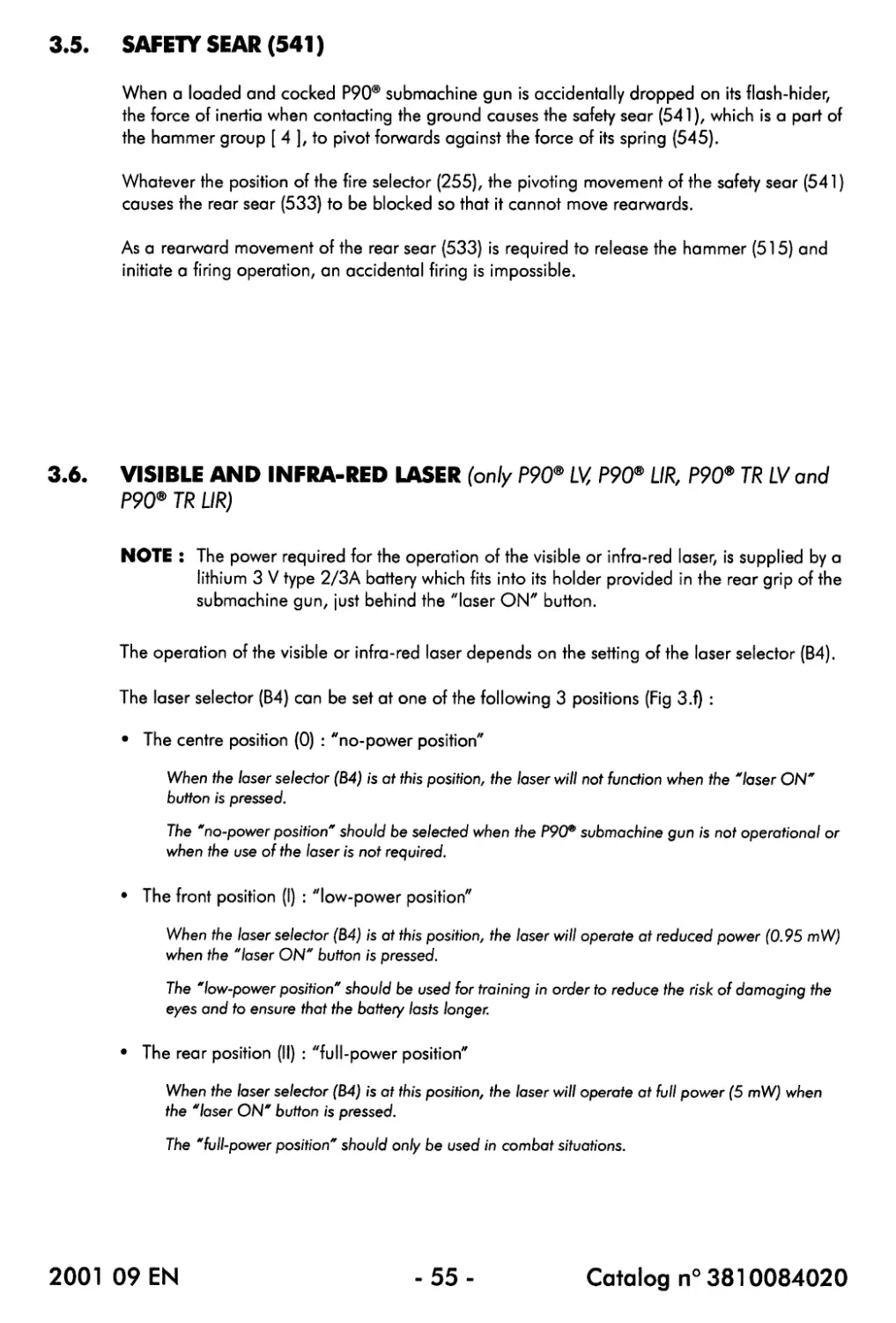
3.5. SAFETY SEAR (541)
When a loaded and cocked P90® submachine gun is accidentally dropped on its flash-hider,
the force of inertia when contacting the ground causes the safety sear (541), which is a part of
the hammer group [ 4 ], to pivot forwards against the force of its spring (545).
Whatever the position of the fire selector (255), the pivoting movement of the safety sear (541)
causes the rear sear (533) to be blocked so that it cannot move rearwards.
As a rearward movement of the rear sear (533) is required to release the hammer (515) and
initiate a firing operation, an accidental firing is impossible.
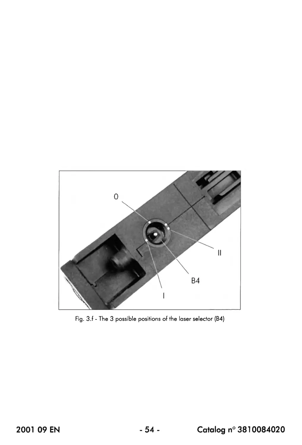
3.6. VISIBLE AND INFRA-RED LASER (only P90® LV, P90® UR, P90® TR LV and
P90® TR LIR)
NOTE : The power required for the operation of the visible or infra-red laser, is supplied by a
lithium 3 V type 2/3A battery which fits into its holder provided in the rear grip of the
submachine gun, just behind the "laser ON" button.
The operation of the visible or infra-red laser depends on the setting of the laser selector (B4).
The laser selector (B4) can be set at one of the following 3 positions (Fig 3.f) :
• The centre position (0) : "no-power position"
When the laser selector (B4) is at this position, the laser will not function when the "laser ON"
button is pressed.
The "no-power position" should be selected when the P90P submachine gun is not operational or
when the use of the laser is not required.
• The front position (I) : "low-power position"
When the laser selector (B4) is at this position, the laser will operate at reduced power (0.95 mW)
when the "laser ON" button is pressed.
The "low-power position" should be used for training in order to reduce the risk of damaging the
eyes and to ensure that the battery lasts longer.
• The rear position (II) : "full-power position"
When the laser selector (B4) is at this position, the laser will operate at full power (5 mW) when
the "laser ON" button is pressed.
The "full-power position" should only be used in combat situations.
2001 09 EN
-55-
Catalog n° 3810084020
Fig. 4.b - Fblling the magazine catch (245)
rearwards in order to release the magazine [ 5 ]
Fig. 4.a - Fire selector (255) set at the position 'S'
(SAFE)
Fig. 4.d - Checking if the chamber is empty
2001 09 EN
-56-
Catalog n° 3810084020
CHAPTER 4 : SAFETY INFORMATION
4.1. WARNINGS AND CAUTIONS
The following instructions should be read before loading and firing the weapon and before any
intervention (disassembly, maintenance, ...) on it:
Й The P90® submachine gun can cause injury or death up to 2000 metres.
Й Always handle the P90® submachine gun, like any other weapon, with extreme care
and with the respect due to a loaded gun, even though you are certain the gun is
unloaded. Never touch the trigger unless you are ready to fire.
Й Never modify parts of the gun. Repairs and disassembly exceeding the basic field
stripping may only be carried out by qualified armourers or by FN HERSTM.
Й If the weapon has been heavily oiled or greased for shipment or storage, clean it
thoroughly and lightly lubricate the metal parts before firing
Й The barrel should be perfectly dry before firing.
Й Never try to clear a barrel obstruction by firing
4.2. SAFETY CHECKS
Carry out the following procedure in order to ensure that the P9CP submachine gun can be
manipulated, stored and/or transported without any risk :
• Set the fire selector (255) at the position 'S' (SAFE) (Fig. 4.a).
• Pull the magazine catch (245) rearwards in order to release the magazine [ 5 ] and then
remove the magazine (Fig. 4.b).
• Pull the cocking handle (150) completely rearwards and hold it in that position (Eg. 4.c).
Please note that, after this operation, the hammer (515) is cocked.
• Through the magazine opening look into the chamber of the submachine gun in order to
ensure that there is no cartridge in the chamber (fig. 4.d).
If there is a cartridge in the chamber, unload the submachine gun as described in § 6.4.
• If the chamber is empty, release the cocking handle (150).
• Ensure that the magazine [ 5 ] is empty.
If the magazine is not empty, unload it as described in § 6.4.
• Fit the empty magazine [ 5 ] back into position.
• Set the fire selector (255) at the position '1' (single-shot).
• Pointing the gun in a safe direction, pull the trigger (261) to decock the hammer (515).
• Set the fire selector (255) at the position 'S' (SAFE).
2001 09 EN - 57 - Catalog n° 3810084020
4.3. TRITIUM LIGHT SOURCE (714) (only P90®, P90® LV and P90® UR)
Ensure to be familiar with the following instructions before any intervention on the optical sight
(711) which contains the tritium light source (714) :
General information concerning the tritium light source (714)
• The tritium light source, incorporated in the optical sight (71 1), consists of a completely
sealed glass capsule internally coated with phosphor and containing the radioactive gas
tritium (hydrogen-3). The tritium has an isotopic purity of at least 94% and emits only В
particles having a maximum energy of 18.4 keV
• The correctly sealed tritium light source presents no external radiation hazard.
• A defective tritium light source cannot be repaired I
Handling the tritium light source (714)
• The optical sight (711) has been designed to withstand normal operational conditions
without any risk of damage to the incorporated tritium light source. It is nevertheless
recommended to handle the sight with care.
• If the tritium light source should be replaced, this replacement should be carried out in a
well-ventilated, NO SMOKING and NO EATING AND DRINKING area.
Storage of spare tritium light sources (714)
Spare tritium light sources should be stored under normal ambient conditions in a well-
ventilated designated storeroom.
Breakage of a tritium light source (714)
• In the event of an (accidental) breakage of a tritium light source, tritium gas might be
released into the atmosphere (where it will be rapidly diffused) or, if the light source is still
assembled in the sight, into the silicone rubber surround.
In any case, any risk of internal radiation of personnel can be minimized by following the
following procedure :
- Inform the other people present in the room.
- Evacuate the room tor at least 15 minutes.
- Fully ventilate the room after returning and then, without touching them directly with the
fingers, put the broken fragments of the tritium light source as well as the surrounding
silicone rubber in a plastic bag The plastic bag should then be disposed of as
radioactive waste.
• In the event of a simultaneous breakage of many tritium light sources, proceed as explained
above but inform the competent local authorities before returning into the room.
Disposal of a tritium light source (714)
Old or defective tritium light sources should be disposed as radioactive waste. Information
about the disposal of this kind of waste can be obtained from the competent local authorities.
2001 09 EN - 58 - Catalog n° 3810084020
4.4. VISIBLE AND INFRA-RED LASER (only P90® LV, P90® LIP, P90® TR LV and
P90® TR UR)
Ensure to be familiar with the following safety instructions before using a Р9(У submachine gun
with incorporated visible or infra-red laser :
• When the laser is at full-power setting, be extremely careful not to expose the eyes, directly
nor indirectly, to the laser beam.
• Even when the laser is at low-power setting, it is strongly recommended not to look directly
into the laser beam, especially when using magnifying optics such as binoculars, ...
THE INFRA-RED LASER BEAM (ONLY P90* UR AND P90® TR UR) IS NOT VISIBLE TO
THE NAKED EYE ! 1
When the eyes are exposed to an infra-red laser beam, there will be no instinctive
reaction to blink or look away BUT serious eye damage can be caused 1
2001 09 EN
-59-
Catalog n° 3810084020
THIS PAGE IS INTENTIONALLY BLANK
2001 09 EN
-60-
Catalog n° 3810084020
CHAPTER 5 : RECEPTION OF THE GUN
Before any intervention on the P90® submachine gunz ensure to be familiar with
the safety information given in chapter 4 of this Maintenance Manual.
• Take the packing case and inspect it for damage.
If the packing case shows traces of deterioration, take note of them (detailed description or photo)
and report it to FN Herstal.
• Open the packing case and check its contents according to the packing list.
If there is a problem, report it to FN Herstal.
• Carry out the field stripping procedure (refer to chapter 7).
If something seems abnormal, report it to FN Herstal.
• Using the cleaning tools OREA 851, clean the bore of the barrel (131) to remove the
existing preservation lubricant.
Remove the preservation lubricant from the moving parts group [ 3 ].
For more detailed cleaning instructions, refer to chapter 8.
• Lubricate the bore of the barrel (131) and the moving parts group [ 3 ] with a maintenance
or functional lubricant.
The other parts of the P90® submachine gun do not require lubrication.
For more detailed lubrication instructions, refer to chapter 8.
• Reassemble the gun.
The P90® submachine gun only requires minimal lubrication.
Excessive lubrication of the weapon will have an unfavourable effect on its
reliability and the longevity of its parts.
Never lubricate components of the magazine [ 5 ].
The presence of a lubricant inside the magazine [ 5 ] could cause malfunctions.
2001 09 EN
-61 -
Catalog n° 3810084020
Fig. 6.b - Loading the magazine [ 5 ]
Fig. 6.a - Pulling the magazine catch (245)
rearwards in order to release the magazine [ 5 ]
Fig. 6.c - Fire selector (255) set at the position ZS'
(SAFE)
Fig. 6.d - Installing a loaded magazine [ 5 ] onto
the submachine gun
Fig. 6.e - Pulling the cocking handle (150)
completely rearwards
2001 09 EN
-62-
Catalog n° 3810084020
CHAPTER 6 : USING THE SUBMACHINE GUN
Before using the P90® submachine gun, ensure to be familiar with the safety
information given in chapter 4 of this Maintenance Manual.
6.1. LOADING THE MAGAZINE [ 5 ]
• If the magazine [ 5 ] to be loaded is still on the gun, pull the magazine catch (245)
rearwards in order to release the magazine and then remove it (Fig. 6.a).
• Load the cartridges, one by one, into the magazine [ 5 ] by proceeding as follows (Fig. 6.b) :
- Hold the magazine [ 5 ] by its rounded end and with its lips facing upwards.
- Place the cartridge with its rear part on the wider part of the lips of the magazine.
Ensure that the bullet points forwards, along the magazine body (620).
- With the thumb, push the cartridge downwards and then rearwards until it locks into
position.
The transparent magazine body (620) allows you to estimate the number of cartridges present
in the magazine [ 5 ] which has a capacity of 50 cartridges.
6.2. LOADING AND COCKING THE SUBMACHINE GUN
It is assumed that the chamber of the submachine gun is empty, that no magazine has been
installed onto the gun and that the gun has not been cocked.
• Set the fire selector (255) at the position 'S' (SAFE) (Fig. 6.c).
• Install a loaded magazine [ 5 ] onto the submachine gun (Fig. 6.d).
In order to ensure that the magazine [ 5 ] correctly locks into position, push firmly on its rear part
(check if the magazine is correctly locked into position by pulling it upwards).
• Pull the cocking handle (150) completely rearwards and then release it (Fig. 6.e).
This causes the hammer (515) to be cocked, the first cartridge to be loaded into the chamber and
the obturator assembly (B3) of the ejection opening to be opened.
NOTE : If the P90® submachine gun will not be used immediately after it has been cocked,
the obturator assembly (B3) of the ejection opening can be closed manually.
This is especially useful in order to avoid the penetration of foreign particles inside the
P90® when the weapon is carried in a dirty, sandy,... environment.
When the obturator assembly (B3) has been closed, it will automatically be reopened by
the following rearward movement of the breech block assembly (420) which will take
place during a next rearward pull of the cocking handle (150) or when the first round is
fired.
2001 09 EN
- 63 - Catalog n° 3810084020
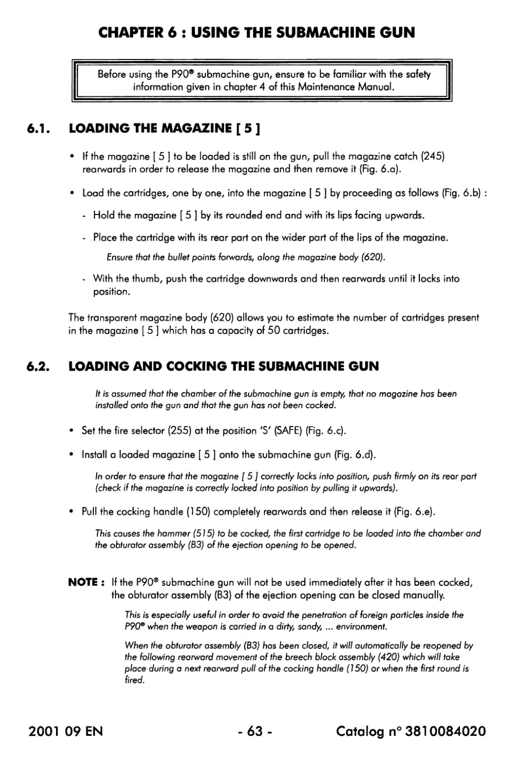
Fig. 6.f - Pulling the trigger (261)
2001 09 EN
-64-
Catalog n° 3810084020
6.3. FIRING THE SUBMACHINE GUN
Ensure that § 8.2. "Cleaning and lubrication before firing" has been carried out.
• If not already done, load the submachine gun as described in § 6.2.
• Set the fire selector (255) at the position '1' (single-shot) or 'A' (full-automatic).
Select '1' for semi-automatic firing (one shot is fired for each trigger pull) or 'A' for full-automatic
firing.
• Aim the submachine gun and then pull the trigger (261).
If semi-automatic (single-shot) firing has been selected, the rearward movement of the trigger is
restricted : one shot will be fired for each trigger pull.
If full-automatic firing has been selected, the trigger should be pulled completely rearwards and
held there : the submachine gun will then start firing a burst.
NOTES : - If, when working in the full-automatic mode, only one round is fired when pulling
the trigger (261) rearwards, do not release the trigger but continue pulling it all
the way rearwards until the burst starts.
- If, when working in the full-automatic mode, the trigger is only pulled halfway
rearwards, the submachine gun will only produce single shots.
2001 09 EN
-65-
Catalog n° 3810084020
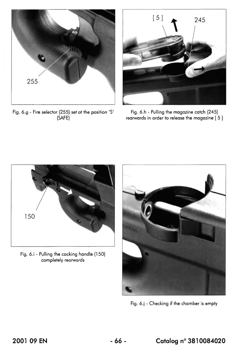
Fig. 6.g - Fire selector (255) set at the position 'S' Fig. 6.h - Pulling the magazine catch (245)
(SAFE) rearwards in order to release the magazine [ 5 ]
Fig. 6.j - Checking if the chamber is empty
2001 09 EN
-66-
Catalog n° 3810084020
6.4. UNLOADING THE SUBMACHINE GUN
• Set the fire selector (255) at the position 'S' (SAFE) (Fig. 6.g).
• Pull the magazine catch (245) rearwards in order to release the magazine [ 5 ] and then
remove the magazine (Fig. 6.h).
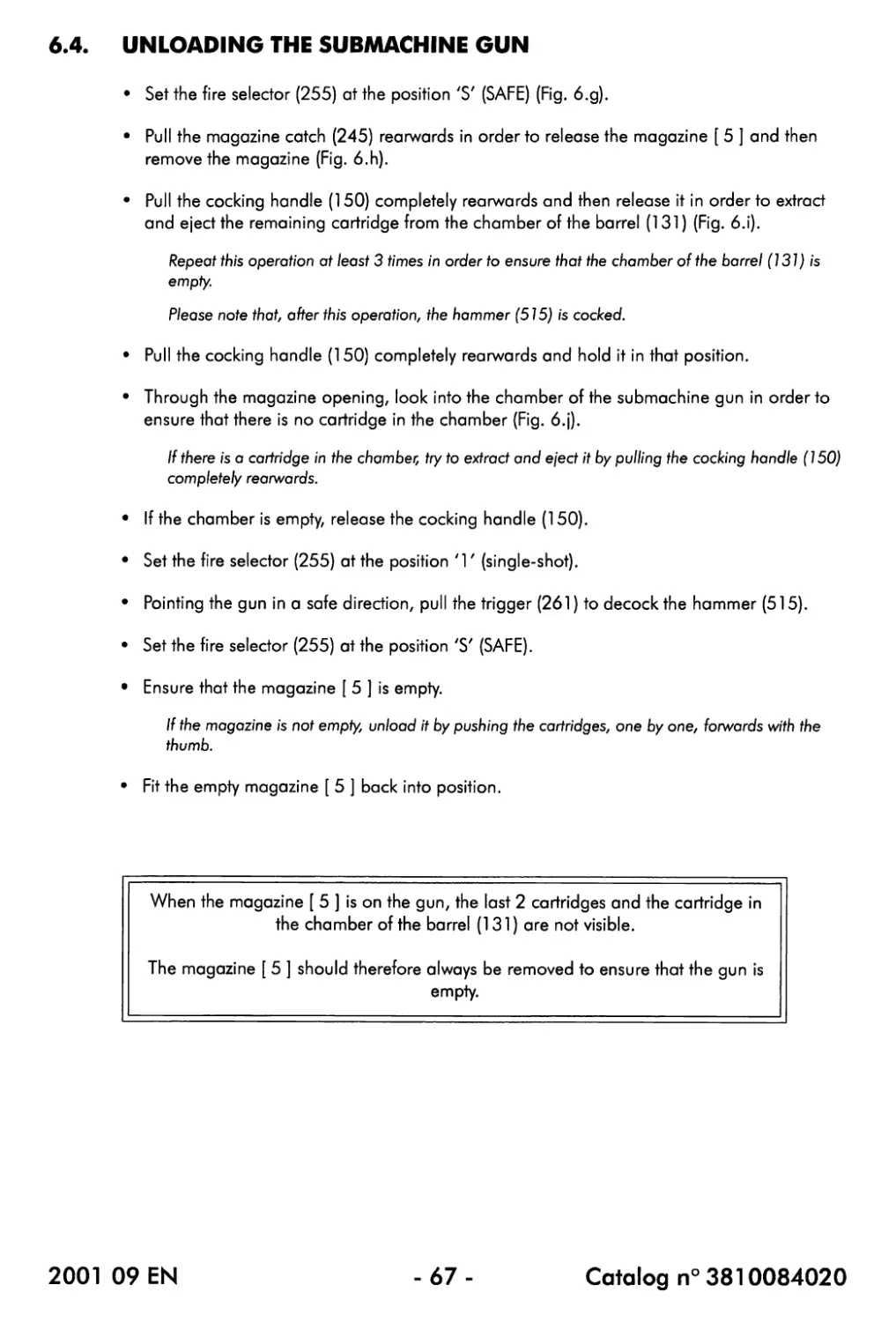
• Pull the cocking handle (150) completely rearwards and then release it in order to extract
and eject the remaining cartridge from the chamber of the barrel (131) (Fig. 6.i).
Repeat this operation at least 3 times in order to ensure that the chamber of the barrel (131) is
empty.
Please note that, after this operation, the hammer (515) is cocked.
• Pull the cocking handle (150) completely rearwards and hold it in that position.
• Through the magazine opening, look into the chamber of the submachine gun in order to
ensure that there is no cartridge in the chamber (Fig. 6.j).
If there is a cartridge in the chamber, try to extract and eject it by pulling the cocking handle (150)
completely rearwards.
• If the chamber is empty, release the cocking handle (150).
• Set the fire selector (255) at the position '1z (single-shot).
• Pointing the gun in a sate direction, pull the trigger (261) to decock the hammer (515).
• Set the tire selector (255) at the position 'S' (SAFE).
• Ensure that the magazine [ 5 ] is empty.
If the magazine is not empty, unload it by pushing the cartridges, one by one, forwards with the
thumb.
• Fit the empty magazine [ 5 ] back into position.
When the magazine [ 5 ] is on the gun, the last 2 cartridges and the cartridge in
the chamber of the barrel (131) are not visible.
The magazine [ 5 ] should therefore always be removed to ensure that the gun is
empty.
2001 09 EN
-67-
Catalog n° 3810084020
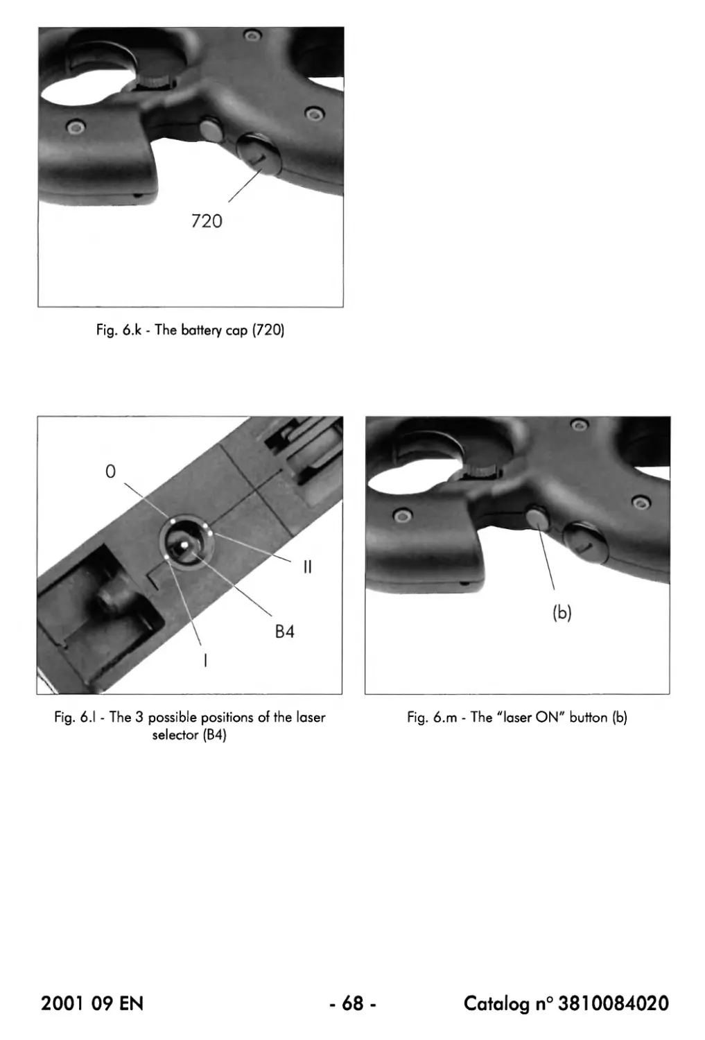
720
Fig. 6.к - The battery cap (720)
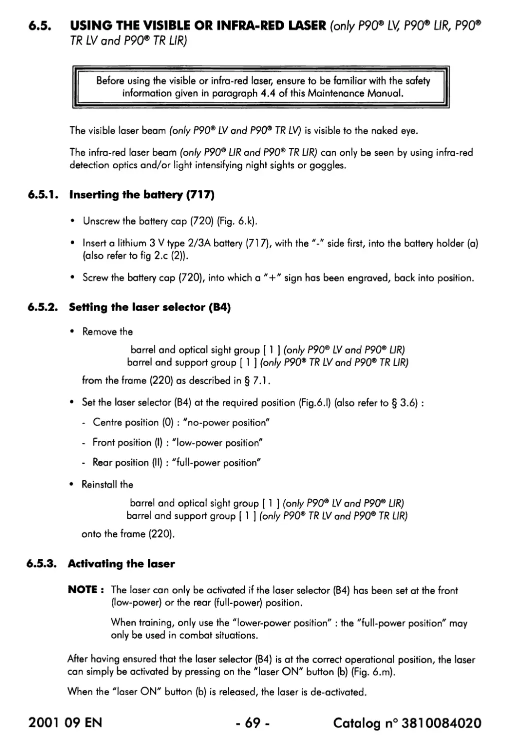
Fig. 6.1 - The 3 possible positions of the laser
selector (B4)
Fig. 6.m - The "laser ON" button (b)
2001 09 EN
-68-
Catalog n° 3810084020
6.5. USING THE VISIBLE OR INFRA-RED LASER (only P90® LV, P90® UR, P90®
TR LV and P90® TR LIR)
Before using the visible or infra-red laser, ensure to be familiar with the safety
information given in paragraph 4.4 of this Maintenance Manual.
The visible laser beam (only P90® LV and P90® TR LV) is visible to the naked eye.
The infra-red laser beam (only P90® LIR and P90® TR LIR) can only be seen by using infra-red
detection optics and/or light intensifying night sights or goggles.
6.5.1. Inserting the battery (717)
• Unscrew the battery cap (720) (Fig. 6.k).
• Insert a lithium 3 V type 2/3A battery (71 7), with the "-" side first, into the battery holder (a)
(also refer to tig 2.c (2)).
• Screw the battery cap (720), into which a "+" sign has been engraved, back into position.
6.5.2. Setting the laser selector (B4)
• Remove the
barrel and optical sight group [ 1 ] (only P90® LV and P90® LIR)
barrel and support group [ 1 ] (only P90® TR LV and P90® TR LIR)
from the frame (220) as described in § 7.1.
• Set the laser selector (B4) at the required position (Fig.6.1) (also refer to § 3.6) :
- Centre position (0) : zzno-power position"
- Front position (I) : "low-power position"
- Rear position (II) : "full-power position"
• Reinstall the
barrel and optical sight group [ 1 ] (only P90® LV and P90® LIR)
barrel and support group [ 1 ] (only P90® TR LV and P90® TR LIR)
onto the frame (220).
6.5.3. Activating the laser
NOTE : The laser can only be activated if the laser selector (B4) has been set at the front
(low-power) or the rear (full-power) position.
When training, only use the "lower-power position" : the "full-power position" may
only be used in combat situations.
After having ensured that the laser selector (B4) is at the correct operational position, the laser
can simply be activated by pressing on the "laser ON" button (b) (Fig. 6.m).
When the "laser ON" button (b) is released, the laser is de-activated.
2001 09 EN - 69 - Catalog n° 3810084020
Fig. 7.a - Fblling the cocking handle (150)
completely rearwards
Fig. 7.b - Removal of the barrel and optical sight group [ 1 ] (only P90®, P90® LV and P90® UR)
barrel and support group [ 1 ] (only P90® TR, P90® TR LV and P90® TR UR)
2001 09 EN
-70-
Catalog n°3810084020
CHAPTER 7 : FIELD STRIPPING
Before any intervention on the P9O5* submachine gun, ensure to be familiar with
the safety information given in chapter 4 of this Maintenance Manual.
7.1. DISASSEMBLING THE SUBMACHINE GUN
It is very important to become familiar with the field stripping procedure of the submachine gun as
field stripping is required during the cleaning procedure which ensures reliable operation of the
submachine gun.
• Carry out the safety checks (refer to § 4.2).
• If not already done, remove the magazine [ 5 ] and completely unload the submachine gun
(refer to § 6.4).
• Pull the cocking handle (150) completely rearwards and then release it (fig. 7.a).
This operation is necessary because it is only possible to remove the moving parts group [ 3 ] and
the hammer group [ 4 ] when the hammer (515) is in the (lowered) cocked position.
From now on, do not pull the trigger : the hammer would again be positioned in its (raised)
decocked position.
• While pushing down on the barrel support lock (127) (Fig. 7.b), remove the
barrel and optical sight group [ 1 ] (only P90®, P90® LV and P90® UR)
barrel and support group [ 1 ] (only P90® TR, P90® TR LV and P90® TR UR)
by moving it slightly forwards and then slide it completely out of the frame (220).
• Release the moving parts group [ 3 ] by pushing it forwards (via the magazine opening (o))
(Fig. 7.c) and then carefully slide it completely out of the frame (220).
Fig. 7.c - Removal of the moving parts group [ 3 ]
2001 09 EN
- 71 -
Catalog n° 3810084020
Fig. 7.d - Removal of the butt plate (280)
Fig. 7.e - Removal of the oil can OREA 700
Fig. 7.f - Removal of the hammer group [ 4 ]
Fig. 7.g - Removal of the cleaning tools
2001 09 EN
- 72 -
Catalog n°3810084020
7.1. DISASSEMBLING THE SUBMACHINE GUN (continued)
• At the rear side, slide the butt plate (280) up and off the frame (220) (Fig. 7.d).
Take info account that, if present, the oil can OREA 700 can fall out of the frame (220).
• If present, take the oil can OREA 700 out of the frame (220) (Rg. 7.e).
If present, the oil can OREA 700 is in the upper rear part of the frame (220).
• While raising the hammer group release lever (548), pull the hammer group [ 4 ] slightly
rearwards in order to release it (Fig. 7.f).
After that, slide the hammer group [ 4 ] completely out of the frame (220).
Note that the hammer group [ 4 ] cannot be removed if the hammer (515) is in the decocked
position. If the trigger has been pulled after the removal of the moving parts [ 3 ], reassemble the
gun, cock the hammer by pulling the cocking handle (150) and then start disassembling again.
• If present, take the cleaning tools out of the frame (220) (Rg. 7.g).
If present, the cleaning tools are inside the frame (220), underneath the hammer group [4].
This level of disassembly is sufficient to perform thorough cleaning : further
disassembly should only be carried out by an authorized armourer or by FN HERS"AL
To reassemble the submachine gun, follow the above steps in reverse ordef taking into account
the following points :
• Ensure that all the components of the submachine gun are perfectly clean.
• Ensure that the different groups of the submachine gun correctly lock into position when
they are reinstalled.
• When reinserting the hammer group [ 4 ] into the frame (220), hold the hammer group
release lever (548) in the raised position.
• When reinstalling the moving parts group [ 3 ], hold it so that the rateof-fire stabilizer
(481) is at the left side.
• When reinserting the
barrel and optical sight group [ 1 ] (only P90®, P90® LV and P90® UR)
barrel and support group [ 1 ] (only P90® TR, P90® TR LV and P90® TR UR)
into the frame (220), press the barrel support lock (127).
• After having reassembled the weapon with an empty magazine, point it in a safe direction
and then pull the trigger (261) in order to decock the hammer (515).
Before carrying out this step, ensure that the magazine and, of course, the chamber are really
empty I
2001 09 EN
-73-
Catalog n° 3810084020
Fig. 7.h - FYessing the magazine bottom lock (638)
in order to unlock the magazine bottom plate
(641)
Fig. 7.i - Removal of the magazine bottom plate (641) and taking the magazine follower assembly (El)
out of the magazine body (620)
2001 09 EN
-74-
Catalog n° 3810084020
7.2. DISASSEMBLING THE MAGAZINE [ 5 ]
• If not already done, remove the magazine [ 5 ] and completely unload it (refer to § 6.4).
• With the index, press on the magazine bottom lock (638) through the hole in the magazine
bottom plate (641) (Fig. 7.h).
While holding the magazine bottom lock (638) in that position, move the magazine bottom
plate (641) sideways until it is disengaged from the magazine body (620) (Fig. 7.i).
Take into account that the magazine bottom lock (638) is subjected to the force of the magazine
follower assembly (El).
• Carefully release the pressure on the magazine follower assembly (El).
• Take the magazine follower assembly (El) out of the magazine body (620) (Fig. 7.i).
• Hold the magazine body (620) slightly inclined in order to remove the 2 rollers (629).
This level of disassembly is sufficient to perform thorough cleaning : further
disassembly should only be carried out by an authorized armourer or by FN HERSTXL
To reassemble the magazine [ 5 ], follow the above steps in reverse order, taking into account
the following points :
• Ensure that all the components of the magazine [ 5 ] are perfectly clean.
• Ensure that the 2 rollers (629) are inserted one behind the other into the magazine body
(620).
• Ensure that the magazine follower assembly (El) is correctly oriented.
Also refer to the drawing which can be found on the side of the magazine body (620).
• The magazine bottom plate (641) can only be slid back into position when the magazine
bottom lock (638) is pushed and held flush with the edge of the magazine body (620).
• Ensure that the magazine bottom plate (641) correctly locks into position.
2001 09 EN
-75-
Catalog n° 3810084020
CHAPTER 8 : MAINTENANCE
Before any intervention on the P90® submachine gunz ensure to be familiar with
the safety information given in chapter 4 of this Maintenance Manual.
The frequency at which the P90® submachine gun should be cleaned and lubricated depends
on the ammunition used, the weather and shooting conditions and other external factors.
When using normal ammunition under normal conditions, it is a good rule to clean and
lubricate the submachine gun after every use or, in case of intensive shooting, after each
2000 rounds : correct maintenance will enhance the longevity of the gun.
NOTE: When using subsonic ammunition, which results in a much quicker soiling of a
weapon, the cleaning frequency should be considerably increased : the condition of
the submachine gun should be followed up all along the shooting sequence.
Before cleaning the P90® submachine gun, ALWAYS ensure that it is unloaded
(refer to § 6.4).
8.1. LUBRICANT SPECIFICATIONS
Lubrication : MIL-L-63460 (NATO S-758 NYCOLUBE 127)
Preservation : MIL-L-63460 (NATO S-758 NYCOLUBE 127)
Never use hydrocarbons, trichlorethylene, ammonia nor teflon-based lubricants :
they could cause damage to the gun !
2001 09 EN
-76-
Catalog n° 3810084020
8.2. CLEANING AND LUBRICATION BEFORE FIRING
The following procedure assumes that the P90® submachine gun has correctly been cleaned and
lubricated the last time it has been used (also refer to §8.3).
If the P90® submachine gun is used for the first time upon purchase, it is assumed that the
procedure described in chapter 5 has been carried out.
• Carry out the field stripping procedure (refer to chapter 7).
• Using the cleaning tools OREA 851 and clean rags (pieces of flannel), remove the
maintenance lubricant from the inside of the barrel (131) until the last rag is clean.
• Dry the inside of the barrel (131).
• Remove the maintenance lubricant from the moving parts group [ 3 ].
• Slightly lubricate the moving parts group [ 3 ] by proceeding as follows :
- Apply 2 drops of functional lubricant to each breech block assembly guide rod (C2), just
behind the breech block assembly (420).
- Move the breech block assembly (420) at least three times back and forth.
- Apply 1 drop of functional lubricant to the ejector (443), to the extractor (435) and to the
holes of the breech block assembly (420).
The other parts of the submachine gun do not require lubrication.
• Reassemble the gun.
The P90® submachine gun only requires minimal lubrication.
Excessive lubrication of the weapon or the presence of a lubricant inside the
magazine [ 5 ] will have an unfavourable effect on the reliability of the weapon and
the longevity of its parts.
Before each shooting sequence, ALWAYS check the barrel (131) for obstructions
and ensure that it is dry and clean.
2001 09 EN
-77-
Catalog n° 3810084020
8.3. CLEANING AND LUBRICATION AFTER FIRING
• Carry out the field stripping procedure (refer to chapter 7).
(a) Barrel and optical sight group [ 1 ] (P90®, P90® LV, P90® UR)
Barrel and support group [ 1 ] (P90® TR, P90® TR LV, P90® TR LIR)
- Using the cleaning tools OREA 851 or a spray, apply solvent inside the barrel (131)
and let the product work a few minutes.
- Using the cleaning tools OREA 851 and clean rags (pieces of flannel), remove the
functional lubricant, the solvent and the residues from the inside of the barrel (131)
until the last rag is clean.
- When the barrel is clean, again use a piece of flannel, this time moistened with
maintenance lubricant, to protect the inside of the barrel (131) until the next use.
Please note that the inside of the barrel (137) should be wiped dry before shooting (also
refer to § 8.2).
- Clean the barrel and optical sight group I the barrel and support group [ 1 ] with a soft
cloth.
Never apply lubricant to the optical sight (711) (P90®, P90® PV, P90® LIR).
(b) Frame and trigger group [ 2 ] (P90®, P90® TR)
Frame, trigger and laser group [ 2 ] (P90® LV, P90® LIR, P90® TR LV, P90® TR LIR)
Clean with a soft, dry cloth. If necessary, use water or a soft solvent.
(c) Moving parts group [ 3 ]
- Using the cleaning tools OREA 851 and solvent, remove any carbon and other
deposits.
- If necessary, rinse in a soft solvent and then dry by using a soft cloth.
- Move the breech block assembly (420) rearwards along its guide rods (C2) and then
clean the guide rods.
- Slightly lubricate the moving parts group [ 3 ] with maintenance lubricant (refer to §
8.1).
2001 09 EN
-78-
Catalog n° 3810084020
(d) Hammer group [ 4 ]
Clean with a soft, dry cloth. If necessary, use water.
(e) Magazine [ 5 ]
Clean with a soft, dry cloth.
If the magazine is very soiled, disassemble it and then clean its parts by using water.
Never use any kind of solvent on the magazine [ 5 ].
Components of the magazine [ 5 ] may never be lubricated : the presence of a
lubricant inside the magazine could cause malfunctions.
• Reassemble the gun.
2001 09 EN
- 79 - Catalog n° 3810084020
712
Fig. 9.1.а - Barrel and optical sight group [ 1 ]fon/y P90®, P90® LV and P90® UR)
Fig. 9.1 .c - Removal of the flash-hider (165)
(together with the barrel return spring (162))
Fig. 9.1 .b - Unscrewing the barrel (131)
(clockwise !)
2001 09 EN
-80-
Catalog n° 3810084020
CHAPTER 9 : DISASSEMBLY AND REASSEMBLY
Before any intervention on the P90® submachine gunz ensure to be familiar with
the safety information given in chapter 4 of this Maintenance Manual.
9.1. BARREL AND OPTICAL SIGHT GROUP [ 1 ] (Fig. 9.1 .a) (only P90*
P90® LVand P90® UR)
9.1.1. Disassembly
• Remove the barrel and optical sight group [ 1 ] as described in § 7.1.
NOTE : In order to facilitate the disassembly of the barrel and optical sight group [ 1 ], it
is recommended to fix it upside down into a vice.
When fixing the barrel and optical sight group [ 1 ] into the vice, use a rag to avoid
scratches.
• Using the wrench OREA 858 with the 15 mm socket OREA 858C, unscrew the barrel (131)
in the clockwise (!) direction until it can be unscrewed manually (fig. 9.1 .b).
Fit the socket of the wrench OREA 858 onto the 2 flat faces on the rear end of the barrel (131).
• Completely unscrew the barrel (131) from the flash-hider (165) (Rg. 9.1 .c) and then
remove the flash-hider together with the barrel return spring (162).
While unscrewing the barrel with one hand, hold the flash-hider with the other one.
• While pushing on the barrel support lock (127), carefully pull the barrel (131) out of the
rear end of the barrel support body (121) until the front end of the barrel is aligned with the
rear edge (x) of the front opening in the cocking handle (150) (fig. 9.1 .d).
During this step, hold the cocking handle (150) in position with the hand used to push on the
barrel support lock (127).
Fig. 9.1 .d - Rjlling the barrel (131) partly out of the barrel support body (121)
2001 09 EN
-81 -
Catalog n° 3810084020
Fig. 9.1 .e - Removal of the cocking handle return spring (135)
Fig. 9.1 .f - Removal of the cocking handle (150)
Fig. 9.1 .g - Removal of the barrel support lock
(127) and its spring (125)
2001 09 EN
-82 -
Catalog n° 3810084020
9.1. BARREL AND OPTICAL SIGHT GROUP [ 1 ] (continued) (only P90®,
P90® LVand P90® UR)
9.1.1. Disassembly (continued)
• Still holding the cocking handle (150) with one hand and working through the front
opening (o) of the cocking handle, carefully take the cocking handle return spring (135) by
its front extremity out of the barrel support body (121) (Fig. 9.1 .e).
When removing the cocking handle return spring (135), take into account that the spring is
subjected to much tension.
• Lift the cocking handle (150) up and off the barrel support body (121) (Fig. 9.1 .f).
• While pushing on the barrel support lock (127), remove the barrel (131) by pulling it
completely out of the rear end of the barrel support body (121).
• Once the barrel (131) has been removed, the barrel support lock (127) and its spring (125)
are released : take them out of the barrel support body (Rg. 9.1 .g).
• If required, use the plastic mallet UT 2101 to remove the 2 cocking handle studs (155)
from the cocking handle body (Al) (Rg. 9.1 .h).
NOTE : Once they have been removed, the cocking handle studs (155) must always be
replaced by new ones 1
Fig. 9.1 .h - Removal of the 2 cocking handle studs (155)
2001 09 EN
- 83 -
Catalog n° 3810084020
Fig. 9.1 .j - Removal of the 2 sight adjustment
screws (715)
Fig. 9.1 .i - bking out the 2 hexagonal socket
head screws (712) to remove the optical sight
(7П)
Fig. 9.1 .k - femoval of the tritium light source (714)
2001 09 EN
-84-
Catalog n° 3810084020
9 Л. BARREL AND OPTICAL SIGHT GROUP [ 1 ] (continued) (only P90®
P90®LVand P90® LIR)
9.1.1 • Disassembly (continued)
The following 2 steps should only be carried out if it is absolutely necessary to
intervene on the optical sight (711).
Take into account that it will be necessary to readjust the sight after it has been
reassembled and reinstalled.
If the same sight will be used again, and in order to avoid the necessity of a readjustment, it
is also possible to mark the position of the adjustment screws (a small mark of 1 - 2 mm is
enough) before taking them out.
• Using the hexagonal wrench OREA 849$ take out the 2 hexagonal socket head screws
(712) and then remove the optical sight (711) (with the 2 sight adjustment screws (715))
from the barrel support body (121) (Fig. 9.1 .i).
• If necessary, use the sight adjustment spanner OREA 849 to remove the 2 sight adjustment
screws (715) from the optical sight body (A2) (Fig. 9.1 .j).
If it is necessary to remove the tritium light source (714), the normal radiation
hazard procedures should be carried out.
Also ensure to be familiar with the safety information especially applying to the
tritium light source (714) (refer to § 4.3).
• If necessary, remove the tritium light source (714) out of the optical sight body (A2) by
cutting away the protective silicone rubber sealing and then taking out the tritium light
source (Fig. 9.1 .k).
Be extremely careful not to damage the light wedge of the optical sight I
2001 09 EN
-85-
Catalog n° 3810084020
Fig. 9.1.1 - Screwing the 2 sight adjustment screws
(71 5) back into position
Fig. 9.1 .m - Reinstalling the optical sight (711) with the 2 hexagonal socket head screws (712)
2001 09 EN
-86-
Catalog n° 3810084020
9 J. BARREL AND OPTICAL SIGHT GROUP [ 1 ] (continued) (only P90®,
P90® LV and P90® UR)
9.1.2. Reassembly
If it is necessary to handle the tritium light source (714), the normal radiation
hazard procedures should be carried out.
Also ensure to be familiar with the safety information especially applying to the
tritium light source (714) (refer to § 4.3).
• If the tritium light source (714) has been removed, reinstall a new one by proceeding as
follows :
- Insert the tritium light source (714), with its painted side facing upwards, into its opening
in the optical sight body (A2).
- Seal the opening with the tritium light source (714) by using silicone rubber 3145 RV
- After having applied the silicone rubbei; gently push the tritium light source (714) against
the light wedge of the optical sight.
This ensures that there will only be a thin layer of silicone rubber between the tritium light
source (7 J 4) and the light wedge.
- In a dark place, check the open ^illumination of the optical sight.
If necessary, and as long as the silicone rubber has not hardened, gently change the position of
the tritium light source (714) in order to optimize the open T-illumination of the optical sight.
- Let the silicone rubber harden for at least 48 hours.
• If the 2 sight adjustment screws (715) have been removed, screw them back into position by
using the sight adjustment spanner OREA 849 (Rg. 9.1.1).
If the same sight is used again and small marks have been made, use these marks to ensure that
the screws ore screwed back into their original position.
• If the optical sight (711) has been removed from the barrel support body (121), fit it back
into position and then fix it with the 2 hexagonal socket head screws (712) (Rg. 9.1 .m).
Use the hexagonal wrench OREA 849B to correctly secure the 2 hexagonal socket head screws
(712).
2001 09 EN
-87-
Catalog n° 3810084020
Fig. 9.1 .n - Reinstalling 2 new cocking handle
studs (155)
Fig. 9.1.0 - Reinstalling the barrel support lock
(127) and its spring (125)
Fig. 9.1 .p - Reinserting the barrel (131) partly into the barrel support body (121)
2001 09 EN
-88-
Catalog n° 3810084020
9.1. BARREL AND OPTICAL SIGHT GROUP [ 1 ] (continued) (only P90®,
P90®LVand P90® LIR)
9.1.2. Reassembly (continued)
NOTE : In order to facilitate the reassembly of the barrel and optical sight group [ 1 ], it is
recommended to fix the barrel support body (121) upside down into a vice.
• If the 2 cocking handle studs (155) have been removed, install new ones onto the
extremities of the cocking handle body (Al) by using the plastic mallet UT 2101 (fig.
9.1.n).
• Insert the barrel support lock spring (125) and the barrel support lock (1 27) into their hole
in the barrel support body (121) and then hold them in position with a finger (Fg. 9.1 .o).
• While pushing down on the barrel support lock (127) so that its hole is aligned with the
barrel housing in the barrel support body (121), insert the barrel (131) into the rear end of
the barrel support body (121) until it is positioned as shown in fig. 9.1 .p.
After this operation, the barrel support lock (127) is held into position by the barrel (131) so that
the finger can be removed.
• Place the cocking handle (150) back onto the barrel support body (121) (fig. 9.1 .q).
Fig. 9.1 .q - Reinstalling the cocking handle (150)
2001 09 EN
-89-
Catalog n° 3810084020
Fig. 9.1 .г - Reinstalling the cocking handle return spring (135)
Fig. 9.1 .s - Screwing the flash-hider (165) a few turns back onto the barrel (131)
Fig. 9.1 .t - Manually tightening the barrel (131)
Fig. 9.1 .u - Applying a torque between 40 and 50
Nm onto the barrel (131)
2001 09 EN
-90-
Catalog n°3810084020
9 J. BARREL AND OPTICAL SIGHT GROUP [ 1 ] (continued) (only P90®,
P90®LVand P90® LIR)
9.1.2. Reassembly (continued)
• While holding the cocking handle (150) with one hand and working through the front
opening (o) of the cocking handle, carefully reinstall the cocking handle return spring (135)
onto the barrel (131) (Fig. 9.1 .r).
Take into account that some force will be required to reinstall the cocking handle return spring
(135) completely into its housing in the barrel support body (121),
• Still holding the cocking handle (150) with one hand and while pushing on the barrel
support lock (127), carefully push the barrel (131), through the cocking handle return
spring (135), all the way into the barrel support body (121).
Ensure that the threaded end of the barrel (131) comes out at the front side of the barrel support
body (121),
• Fit the barrel return spring (162) over the threaded front end of the barrel (131) and then
manually screw the flash-hider (165) back onto the barrel (Rg. 9.1 .s).
Do not screw the flash-hider (165) more than 3 turns : just ensure that it cannot fall off the barrel
(131).
Orientate the flash-hider (165) so that the flat face on its rear collar is perfectly aligned with the
flat surface of the barrel support body (121).
• While pushing the flash-hider (165) rearwards with one hand, tighten the barrel (131) with
the other hand as far as possible in the counterclockwise direction (Rg. 9.1 .t).
Ensure that the flat face on the rear collar of the flash-hider (165) correctly slides along the flat
surface of the barrel support body (121).
• Using the wrench OREA 858 with the 15 mm socket OREA 858C, apply a torque between
40 and 50 Nm onto the barrel (131) (Rg. 9.1 .u).
• Reinstall the barrel and optical sight group [ 1 ] as described in § 7.1.
If, during the previous disassembly and reassembly procedure, there has been an
intervention on the optical sight (711), it should be re-adjusted (refer to § 10.2).
The sight should also be adjusted after disassembly and reassembly of the barrel
(131) or the flash-hider (165), even if they are not replaced by new ones.
2001 09 EN
-91 -
Catalog n° 3810084020
Fig. 9.2.a - Barrel and support group [ 1 ](on/y P90® TR, P90® TR LV and P90® TR LIR)
OREA 858
Fig. 9.2.b - Unscrewing the barrel (131)
(clockwise I)
Fig. 9.2.c - Removal of the flash-hider (165)
(together with the barrel return spring (162))
2001 09 EN
-92-
Catalog n°3810084020
9.2. BARREL AND SUPPORT GROUP [ 1 ] (Fig. 9.2.a) (only P90® TR,
P90®TRLVand P90®TRLIR)
9.2.1 • Disassembly
• Remove the barrel and support group [ 1 ] as described in § 7.1.
NOTE : In order to facilitate the disassembly of the barrel and support group [ 1 ]z it is
recommended to fix it upside down into a vice.
• Using the wrench OREA 858 with the 15 mm socket OREA 858CZ unscrew the barrel (131)
in the clockwise (!) direction until it can be unscrewed manually (fig. 9.2.b).
Fit the socket of the wrench OREA 858 onto the 2 flat faces on the rear end of the barrel (131).
• Completely unscrew the barrel (131) from the flash-hider (165) (Rg. 9.2.c) and then
remove the flash-hider together with the barrel return spring (162).
While unscrewing the barrel with one hand, hold the flash-hider with the other one.
• While pushing on the barrel support lock (127), carefully pull the barrel (131) out of the
rear end of the barrel support body (121) until the front end of the barrel is aligned with the
rear edge (x) of the front opening in the cocking handle (150) (Rg. 9.2.d).
During this step, hold the cocking handle (150) in position with the hand used to push on the
barrel support lock (127).
Fig. 9.2.d - Rjlling the barrel (131) partly out of the barrel support body (1 21)
2001 09 EN
-93-
Catalog n° 3810084020
Fig. 9.2.g - Ramoval of the barrel support lock
(127) and its spring (125)
Fig. 9.2.h - Ramoval of the 2 cocking handle studs
(155)
2001 09 EN
-94-
Catalog n° 3810084020
9.2. BARREL AND SUPPORT GROUP [ 1 ] (continued) (only P90® TR,
P90®TRLVond P9O®TRLIR)
9.2.1 • Disassembly (continued)
• Still holding the cocking handle (150) with one hand and working through the front
opening (o) of the cocking handle, carefully take the cocking handle return spring (135) by
its front extremity out of the barrel support body (121) (Rg. 9.2.e).
When removing the cocking handle return spring (135), take into account that the spring is
subjected to much tension.
• Lift the cocking handle (150) up and off the barrel support body (121) (Rg. 9.2.f).
• While pushing on the barrel support lock (127), remove the barrel (131) by pulling it
completely out of the rear end of the barrel support body (121).
• Once the barrel (131) has been removed, the barrel support lock (127) and its spring (125)
are released : take them out of the barrel support body (Rg. 9.2.g).
• If required, use the plastic mallet UT 2101 to remove the 2 cocking handle studs (155)
from the cocking handle body (Al) (Rg. 9.2.h).
NOTE : Once they have been removed, the cocking handle studs (155) must always be
replaced by new ones 1
• If necessary, use the hexagonal wrench UT 1 602 to take out one or both hexagonal socket
head screws (942) and then remove the corresponding side rail(s) (941) from the left and/
or right side(s) of the barrel support body (121) (Fig. 9.2.i).
Fig. 9.2.i - bking out the hexagonal socket head screws (942) to remove the side rails (941)
2001 09 EN
-95-
Catalog n° 3810084020
Fig. 9.2.j - Reinstalling the side rails (941) with the hexagonal socket head screws (942)
Fig. 9.2.1 - Reinstalling the barrel support lock
(127) and its spring (125)
Fig. 9.2.к - Reinstalling 2 new cocking handle
studs (155)
Fig. 9.2.m - Reinserting the barrel (131) partly into the barrel support body (121)
2001 09 EN
-96-
Caialog n°3810084020
9.2. BARREL AND SUPPORT GROUP [ 1 ] (continued) (only P90® TR,
P90® TRLVand P90®TRLIR)
9.2.2. Reassembly
• If one or both side rails (941) have been removed from the barrel support body (121), fit it
(them) back into position and then fix it (them) with the hexagonal socket head screw(s)
(942) (Fig. 9.2.j).
Use the hexagonal wrench UT 1602 to correctly secure the hexagonal socket head screw(s) (942).
NOTE s In order to facilitate the reassembly of the barrel and support group [ 1 ], it is
recommended to fix the barrel support body (1 21) upside down into a vice.
• If the 2 cocking handle studs (155) have been removed, install new ones onto the
extremities of the cocking handle body (Al) by using the plastic mallet UT 2101 (Rg. 9.2.k).
• Insert the barrel support lock spring (1 25) and the barrel support lock (127) into their hole
in the barrel support body (121) and then hold them in position with a finger (Ifg. 9.2.1).
• While pushing down on the barrel support lock (127) so that its hole is aligned with the
barrel housing in the barrel support body (121), insert the barrel (131) into the rear end of
the barrel support body (121) until it is positioned as shown in Rg. 9.2.m.
After this operation, the barrel support lock (127) is held into position by the barrel (131) so that
the finger can be removed.
• Place the cocking handle (150) back onto the barrel support body (121) (Rg. 9.2.n).
Fig. 9.2.n - Reinstalling the cocking handle (150)
2001 09 EN
-97-
Catalog n° 3810084020
Fig. 9.2.0 - Reinstallation of the cocking handle return spring (135)
Fig. 9.2.p - Screwing the flash-hider (165) a few turns back onto the barrel (131)
Fig. 9.2.q - Manually tightening the barrel (131)
Fig. 9.2.r - Applying a torque between 40 and 50
Nm onto the barrel (131)
2001 09 EN
-98-
Catalog n° 3810084020
9.2. BARREL AND SUPPORT GROUP [ 1 ] (continued) (only P90® TR,
P90®TRLVand P90®TRLIR)
9.2.2. Reassembly (continued)
• While holding the cocking handle (150) with one hand and working through the front
opening (o) of the cocking handle, carefully reinstall the cocking handle return spring (135)
onto the barrel (1 31) (Fig. 9.2.o).
Take into account that some force will be required to reinstall the cocking handle return spring
(135) completely into its housing in the barrel support body (121).
• Still holding the cocking handle (150) with one hand and while pushing on the barrel
support lock (127), carefully push the barrel (131), through the cocking handle return
spring (135), all the way into the barrel support body (121).
Ensure that the threaded end of the barrel (131) comes out at the front side of the barrel support
body (121).
• Fit the barrel return spring (162) over the threaded front end of the barrel (131) and then
manually screw the flash-hider (165) back onto the barrel (Rg. 9.2.p).
Do not screw the flash-hider (165) more than 3 turns : just ensure that it cannot fall off the barrel
(131).
Orientate the flash-hider (165) so that the flat face on its rear collar is perfectly aligned with the
flat surface of the barrel support body (121).
• While pushing the flash-hider (165) rearwards with one hand, tighten the barrel (131) with
the other hand as far as possible in the counterclockwise direction (Rg. 9.2.q).
Ensure that the flat face on the rear collar of the flash-hider (165) correctly slides along the flat
surface of the barrel support body (121).
• Using the wrench OREA 858 with the 15 mm socket OREA 858C, apply a torque between
40 and 50 Nm onto the barrel (131) (Rg. 9.2.r).
• Reinstall the barrel and support group [ 1 ] as described in § 7.1.
2001 09 EN
-99-
Catalog n° 3810084020
Fig. 9.3.a - Frame and trigger group [ 2 ] (only P90® and P90® TR)
Frame, trigger and laser group [ 2 ] (only P90® LV, P90® LIR, P90® TR LV and P90® TR LIR)
Fig. 9.3.b - Removal of the butt plate (280)
Fig. 9.3.C - Unlocking the magazine catch
assembly (Bl)
2001 09 EN
- 100-
Catalog n° 3810084020
9.3. FRAME AND TRIGGER GROUP [ 2 ] (Fig. 9.3.a) (only P90® and P90® TR)
FRAME, TRIGGER AND LASER GROUP [ 2 ] (Fig. 9.3.a) (only P90® LV,
P90® LIR, P90® TR LV and P90® TR UR)
9.3.1. Disassembly
• Completely disassemble the submachine gun as described in § 7.1.
• Note that, during the field stripping procedure, the butt plate (280) has already been
removed from the frame (220) (Fig. 9.3.b).
• Using the screwdriver UT 1912, from underneath, through the ejection opening unlock the
magazine catch assembly (Bl) by pushing on its latch (Rg. 9.3.c).
As a result, the magazine catch assembly (Bl) pops out of the frame (220) by approx. 5 mm.
• Take the magazine catch assembly (Bl) out of the frame (220).
• Firmly push onto the magazine catch guide (243) and then raise it in order to release it,
together with the magazine catch spring (241), from the magazine catch (245) (Rg. 9.3.d).
When carrying out this step, take into account that the magazine catch spring (241) is subjected to
much tension.
• Using the screwdriver UT 1912, carefully release the operating rod (269) from the trigger
assembly (B2) and from the frame (220) (Fig. 9.3.e).
• Take the operating rod (269) out of the frame (220).
Fig. 9.3.d - Disassembled parts of the magazine
catch assembly (Bl)
Fig. 9.3.e - Releasing the operating rod (269)
2001 09 EN
- 101 -
Catalog n° 3810084020
Fig. 9.3.f - Releasing the front extremity of the
trigger stop (265) and raising it out of its slot
Fig. 9.3.g - Removing the trigger assembly (B2)
Fig. 9.3.h - Separating the trigger stop (265) from
the trigger (261)
Fig. 9.3.i - Removing the fire selector (255)
2001 09 EN
- 102 -
Catalog n° 3810084020
9.3. FRAME AND TRIGGER GROUP [ 2 ] (continued) (only P90® and
P90® TR)
FRAME, TRIGGER AND LASER GROUP [ 2 ] (continued) (only P90® LV,
P90® LIR, P90® TR LV and P90® TR LIR)
9.3.1. Disassembly (continued)
• Set the fire selector (255) at the position A' (full-automatic) or 'Г (single-shot).
• Using the screwdriver UT 1912, move the trigger stop (265) slightly forwards so that its
front extremity is released and can be pivoted out of its slot in the frame (220) (Rg. 9.3.f).
• Pivot the front extremity of the trigger stop (265) out of its slot and then use it to remove the
trigger assembly (B2) out of the frame (220) (Fig. 9.3.f and Rg. 9.3.g).
If it is difficult to grip the front extremity of the trigger stop (265), turn the
frame and trigger group [2] (only P90® and P90® TR)
frame, trigger and laser group [ 2 ] (only P90® LV, P90® LIR, P90® TR LV and P90® TR LIR)
upside down.
• If necessary, carefully separate the trigger stop (265) from the trigger (261) (Rg. 9.3.h).
• Set the tire selector (255) at the position '1' (single-shot).
• Carefully remove the fire selector (255) by moving it slightly forwards and then lifting it up
and off the frame (220) (Fig. 9.3.i).
• While holding an extremity of the tire selector spring (251) in position with the screwdriver
UT 1912, carefully release the corresponding fire selector plunger (253) from the spring by
using the pliers UT 1810 (Rg. 9.3.j).
• Remove the tire selector spring (251) and then carefully release the remaining fire selector
plunger (253) from the spring (Rg. 9.3.j).
Fig. 9.3.j - Removing the fire selector plungers
(253) and the fire selector spring (251)
2001 09 EN
- 103 -
Catalog n° 3810084020
Fig. 9.3.к - Removing the obturator assembly (B3) from the inside of the frame (220)
Fig. 9.3.1 - Disassembling the obturator assembly (B3)
2001 09 EN
- 104-
Catalog n° 3810084020
9.3. FRAME AND TRIGGER GROUP [ 2 ] (continued) (only P90® and
P90® TR)
FRAME, TRIGGER AND LASER GROUP [ 2 ] (continued) (only P90® LV,
P90® LIR, P90® TR LV and P90® TR LIR)
9.3.1 • Disassembly (continued)
• Unhook and remove the obturator assembly (B3) from the inside of the frame (220) by
proceeding as follows (Fig. 9.3.k) :
- From underneath, insert a hand into the frame (220) and then carefully grip the obturator
assembly (B3).
- Using the drift punch UT 2006 through the hole provided in the right side of the frame
(220), push on the obturator axis (277) in order to release it from its housing
Do not push too far in order to avoid that inside the frame (220), the obturator axis (277) is
pushed out of the obturator body (271).
- Inside the frame (220), slightly twist the obturator assembly (B3) in order to ensure that
the obturator axis (277) does not engage its housing again.
- Repeat the previous operation at the left side on the bushing (278) in order to completely
release the obturator assembly (B3).
- Take the obturator assembly (B3) out of the frame (220).
• Disassemble the obturator assembly (B3) by proceeding as follows (Fig. 9.3.1) :
- Remove the bushing (278) from the right extremity of the obturator axis (277).
- Holding the obturator return spring (275) with a finger slide the obturator axis (277) out
of the obturator body (271).
- Release and remove the obturator return spring (275).
- Slide the obturator catch (273) off the obturator body (271).
2001 09 EN
- 105 -
Catalog n° 3810084020
Fig. 9.3.m - Disassembled frame (220) with integrated laser
2001 09 EN
-106-
Catalog n° 3810084020
9.3. FRAME AND TRIGGER GROUP [ 2 ] (continued) (only P90® and
P90® TR)
FRAME, TRIGGER AND LASER GROUP [ 2 ] (continued) (only P90® LV
P90® LIR, P90® TR LV and P90® TR UR)
9.3.2. Disassembly of the frame (220) with integrated laser (only P90® LV P90® LIR,
P90®TRLVand P90®TRLIR)
• Disassemble the frame, trigger and laser group [ 2 ] as described in the paragraph 9.3.1.
• At the front extremity of the frame (220), take out the 3 hexagonal socket head screws
(721) which secure the laser unit (c) (Fig. 9.3.m).
• Taking into account that they are not all the same, and therefore not interchangeable, take
out the 10 hexagonal socket head screws (2 x (231), 4 x (233), 1 x (235), 1 x (237) and
2 x (239)) out of the 10 (identical) hexagonal nuts (228) (Fig. 9.3.m).
When carrying out the next step, be careful not to lose the 3 washers (1 x (232) and 2 x (234)).
• Separate the left and right frame plates (222) and then carefully remove the laser assembly
(B4) consisting of the battery holder (a), the "'laser ON" button (b) and the laser unit (c) (Fig.
9.3.m).
9.3.3. Reassembly of the frame (220) with integrated laser (only P90® LV P90® LIR,
P90®TRLVond P90®TRLIR)
• Fit the laser assembly (B4) into position in one of the frame plates (222) (Rg. 9.3.n).
Ensure that the cables of the laser assembly (B4) will not be trapped when reassembling the 2
frame plates (220).
• Reassemble the left and right frame plates (222) (Fig. 9.3.m).
Do not forget to reinstall the 3 washers (1 x (232) and 2 x (234)) while orienting them as shown in
Fig. 9.3.m.
• Screw the 10 hexagonal socket head screws (2 x (231), 4 x (233), 1 x (235), 1 x (237) and
2 x (239)) back into the 10 hexagonal nuts (228) (Rg. 9.3.m).
• At the front extremity of the frame (220), secure the laser unit (c) by using the 3 hexagonal
socket head screws (721) (Fig. 9.3.m).
Do not fully tighten the screws as they will be used for the adjustment of the laser unit (c).
Also take into account that excessive tightening of the screws can cause irreversible damage to the
laser unit (c).
• Proceed to § 9.3.4.
After its reinstallation, the laser unit (c) of the laser assembly (B4) should be
readjusted (refer to § 10.7).
2001 09 EN
- 107-
Catalog n° 3810084020
Fig. 9.3.0 - Reassembling the obturator assembly (B3)
Fig. 9.3.p - Reinstalling the obturator assembly
(B3) into the frame (220)
Fig. 9.3.q - Correct position of the short extremity
of the obturator return spring (275)
2001 09 EN
- 108 -
Catalog n° 3810084020
9.3. FRAME AND TRIGGER GROUP [ 2 ] (continued) (only P90® and
P90® TR)
FRAME, TRIGGER AND LASER GROUP [ 2 ] (continued) (only P90® LV,
P90® LIR, P90® TR LV and P90® TR LIR)
9.3.4. Reassembly
• Reassemble the obturator assembly (B3) by proceeding as follows (Fig. 9.3.o) :
- Fit the obturator catch (273) back onto the obturator body (271).
The obturator catch (273) can only be fitted into position if its protruding part is at the right,
rear side.
Ensure that the obturator catch (273) correctly engages the slot of the obturator body (271).
- Place the obturator return spring (275) at its correct location on the obturator body (271)
and hold it in position with a finger
The obturator return spring (275) should be positioned so that its shorter extremity is at the left
side.
- From the left side, insert the obturator axis (277) into the obturator body (271) and
through the obturator return spring (275).
- From the right side, and through the corresponding right hole of the obturator body
(271), fit the bushing (278) onto the obturator axis (277).
• While pushing the bushing (278) and the obturator axis (277) towards each other in order
to compress the obturator return spring (275), fit the obturator assembly (B3), from
underneath, through the ejection opening inside the frame (220) (Fig. 9.3.p).
• Push the obturator assembly (B3) further upwards until it locks into position.
The bushing (278) and the obturator axis (277) should correctly engage the corresponding holes
in the frame (220) (two clicks should be heared).
• Check if the oburator assembly (B3) is firmly held in place.
• Turn the frame (220) upside down and then, using the screwdriver UT 1912, hook the short
extremity of the obturator return spring (275) onto its support (s) which can be found inside
the frame (220) (Fig. 9.3.q).
2001 09 EN
- 109-
Catalog n° 3810084020
Fig. 9.3.г - Reinstalling the fire selector spring
(251) and the fire selector plungers (253)
Fig. 9.3.s - Reinstalling the fire selector (255)
Fig. 9.3.t - Reassembling the trigger (261) and the
trigger stop (265)
Fig. 9.3.и - Reinstalling the trigger assembly (B2)
and fitting the trigger stop (265) back into position
2001 09 EN
-110-
Catalog n° 3810084020
9.3. FRAME AND TRIGGER GROUP [ 2 ] (continued) (only P90® and
P90® TR)
FRAME, TRIGGER AND LASER GROUP [ 2 ] (continued) (only P90® LV,
P90® LIR, P90® TR LV and P90® TR LIR)
9.3.4. Reassembly (continued)
• Fit a fire selector plunger (253) onto one of the extremities of the fire selector spring (251)
(Fig. 9.3.r).
• Insert the fire selector spring (251) into its housing in the frame (220).
• While holding the free extremity of the fire selector spring (251) in position with the
screwdriver UT 1912Z carefully fit the remaining fire selector plunger (253) onto the spring
by using the pliers UT 1810 (Rg. 9.3.r).
• Re-install the fire selector (255) (Fig. 9.3.s).
During this operation, hold the fire selector (255) orientated as if it was at the position 'Г (single-
shot).
When fitting the fire selector (255) back into position, first move it slightly sidewards so that it
engages one of the 2 fire selector plungers (253).
After that, use the screwdriver UT 1912 to push the other fire selector plunger (253) into position
underneath the fire selector (255).
Finally, ensure that the fire selector (255) fits correctly into position (a click should be beared).
• If they have been separated, carefully fit the trigger stop (265) back into the trigger (261)
(Fig. 9.3.t).
• Reinsert the trigger assembly (B2) into its housing in the frame (220) (Fig. 9.3.u).
During this operation, hold the trigger assembly (B2) by the front extremity of the trigger stop
(265).
After having inserted the trigger assembly (B2) into the frame (220), move it slightly rearwards in
order to ensure that it is correctly positioned.
When lowering the front extremity of the trigger stop (265) after this operation, ensure that it
correctly engages its slot in the frame (220).
• Using the screwdriver UT 1912, move the trigger stop (265) slightly rearwards so that it
locks into position into its slot in the frame (220) (fig. 9.3.u).
2001 09 EN
- Ill -
Catalog n° 3810084020
Fig. 9.3.v - Reinstalling the operating rod (269)
Fig. 9.3.w - Reassembling the magazine catch assembly (Bl)
Fig. 9.3.x - Reinstalling the magazine catch assembly (Bl)
2001 09 EN
-112-
Catalog n° 3810084020
9.3. FRAME AND TRIGGER GROUP [ 2 ] (continued) (only P90® and
P90® TR)
FRAME, TRIGGER AND LASER GROUP [ 2 ] (continued) (only P90® LV,
P90® LIR, P90® TR LV and P90® TR LIR)
9.3.4. Reassembly (continued)
• Reinstall the operating rod (269) by proceeding as follows (Rg. 9.3.v) :
- Insert the operating rod (269), with its 2 extremities first, and oriented as shown in the
right part of the diagram, into the frame (220).
- Ensure that the slot in the trigger stop (265) is correctly aligned with the slot in the trigger
(261) and then fit the small transversal part of the operating rod (269) into them.
- Push down on the long extremities of the operating rod (269) and ensure that they both
fit correctly into position in the corresponding lateral slots inside the frame (220).
• Reassemble the magazine catch assembly (Bl) by proceeding as follows (Fig. 9.3.w) :
- Hold the magazine catch (245) as shown in the diagram.
- Fit the magazine catch spring (241) into its housing in the magazine catch (245) and
hold it back with a finger
- Holding the magazine catch guide (243) with its protruding extremity (p) oriented as
shown in the diagram, insert it into magazine catch spring (241).
- Push hard on the magazine catch guide (243) (against the force of the magazine catch
spring (241)) and then hook it into position on the magazine catch (245).
• Install the magazine catch assembly (Bl), with its opened part facing upwards, back into the
frame (220) (Fig. 9.3.x).
Ensure that the magazine catch assembly (B1) engages correctly : a click should be beared.
If necessary, use the screwdriver UT 1912, from underneath, through the ejection opening, to
press on the latch of the magazine catch assembly (Bl) in order to assist the assembly to engage
properly.
After this operation, check if the magazine catch assembly (Bl) can smoothly move back and
forth.
• Reassemble the submachine gun as described in § 7.1.
During this operation, the butt plate (280) will also be reinstalled.
2001 09 EN
- 113 -
Catalog n° 3810084020
Fig. 9.4.a - Moving ports group [ 3 ]
Fig. 9.4.b - Removal of the 2 snap rings (479)
2001 09 EN
- 114-
Catalog n° 3810084020
9.4. MOVING PARTS GROUP [ 3 ] (Fig. 9.4.a)
9.4.1 • Disassembly
• Remove the moving parts group [ 3 ] as described in § 7.1.
• Pull the breech block assembly (420) rearwards along its guide rods (C2) and then hold the
moving parts group [ 3 ] in that condition in one hand.
During this step, which is required in order to be able to carry out the following one, the return
springs (477) are compressed.
• Using the scraper UT 2816, remove the 2 snap rings (479) (Fig. 9.4.b).
NOTE : Once they have been removed, the snap rings (479) must always be replaced by
new ones 1
• Gently release the pressure on the return springs (477) and then slide the breech block
assembly (420), the rate-of-fire stabilizer (481) and the 2 return springs (477) off the 2
guide rods of the guide assembly (470) (Fig. 9.4.c).
• Disassemble the guide assembly (470) by separating the 2 guide rods (C2) from the breech
block assembly stop block (474) (Fig. 9.4.d).
Fig. 9.4.c - Removal of the breech block assembly
(420), the rate-of-fire stabilizer (481) and the 2
return springs (477)
Fig. 9.4.d - Disassembling the guide assembly
(470)
2001 09 EN
- 115-
Catalog n° 3810084020
Fig. 9.4.e - Driving out the spring pin (437) which
secures the firing pin (425)
Fig. 9.4.f - Removal of the firing pin (425) and its
spring (423)
Fig. 9.4.g - Driving out the spring pin (433) which
secures the extractor spring (431)
Fig. 9.4.h - Driving out the spring pin (437) which
secures the extractor (435)
2001 09 EN
- 116-
Catalog n°3810084020
9.4. MOVING PARTS GROUP (continued)
9.4.1. Disassembly (continued)
• Disassemble the breech block assembly (420) by proceeding as follows :
- Using the drift punch UT 2006 and the hammer UT 2110, drive out the spring pin (437)
which secures the firing pin (425) (Fig. 9.4.e).
In order to facilitate the driving-out of the spring pin (437), push the firing pin (425) slightly into
the breech block (Cl) and hold it in that position with a finger. After having driven out the
spring pin (437), gently release the firing pin (425).
- Take the firing pin (425) and its spring (423) out of the breech block (Cl) (Fig. 9.4.f).
- Using the drift punch UT 2006 and the hammer UT 2110z drive out the spring pin (433)
which secures the extractor spring (431) (Fig. 9.4.g).
During this operation, hold the extractor spring (431) in position with a finger.
- Remove the extractor spring (431).
- Using the drift punch UT 2006 and the hammer UT 2110z drive out the spring pin (437)
which secures the extractor (435) (Fig. 9.4.h).
- Remove the extractor (435).
- Using the drift punch UT 2001 and the hammer UT 2110, drive out the spiral pin (445)
which secures the ejector (443) (Fig. 9.4.i).
During this operation, hold the ejector (443) in position with a finger.
- Take the ejector (443) and its spring (441) out of the breech block (Cl) (Fig. 9.4.j).
Fig. 9.4.j - Removal of the ejector (443) and its
spring (441)
Fig. 9.4.i - Driving out the spring pin (445) which
secures the ejector (443)
2001 09 EN
- 117-
Catalog n° 3810084020
Fig. 9.4.к - Reinserting the ejector (443) (and its
spring (441)) into the breech block (Cl)
Fig. 9.4.1 - Reinstalling the spiral pin (445) which
secures the ejector (443) (and its spring (441))
Fig. 9.4.m - Reinstalling the extractor (435)
Fig. 9.4.n - Reinstalling the extractor spring (431)
2001 09 EN
-118-
Catalog n° 3810084020
9.4. MOVING PARTS GROUP (continued)
9.4.2. Reassembly
• Insert the ejector spring (441) and then the ejector (443) back into their hole at the front
side of the breech block (Cl) (Fig. 9.4.k).
The ejector (443) should be inserted with its smaller end first (pointing towards the rear side).
Ensure that the ejector (443) is oriented so that, when it is pushed into the breech block (Cl), the
slot of the ejector is correctly aligned with the opening (o) for the spiral pin (445).
• Reinstall the spiral pin (445), which secures the ejector (443) and its spring (441), by
proceeding as follows (Fig. 9.4.1) :
- Push the ejector (443) into the breech block (Cl) until its slot is correctly aligned with the
hole for the spiral pin (445) and then insert the drift punch UT 2006 through the hole
and the slot in order to temporarily secure the ejector into position.
- Fit the spiral pin (445) onto the drift punch UT 2005.
- Position the spiral pin (445) against the drift punch UT 2006 and then, using the hammer
UT 211 0, drive the spiral pin fully home, allowing it to push out the drift punch UT 2006.
• Reinstall the extractor (435) by proceeding as follows (Fig. 9.4.m) :
- Insert the extractor (435) into its housing in the breech block (Cl).
- Align the hole in the extractor (435) with the corresponding hole in the breech block (Cl)
and then insert the drift punch UT 2006 through the 2 holes in order to temporarily
secure the extractor (435) into position.
- Fit the spring pin (437) onto the drift punch UT 2005.
- Position the spring pin (437) against the drift punch UT 2006 and then, using the
hammer UT 211 0, drive the spring pin fully home, allowing it to push out the drift punch
UT 2006.
• Reinstall the extractor spring (431) by proceeding as follows (Fig. 9.4.n) :
- Fit the extractor spring (431) onto the extractor (435).
- Align the hole in the extractor spring (431) with the corresponding hole in the breech
block (Cl) and then insert the drift punch UT 2006 through the 2 holes in order to
temporarily secure the extractor spring (431) into position.
- Fit the spring pin (433) onto the drift punch UT 2005.
- Position the spring pin (433) against the drift punch UT 2006 and then, using the
hammer UT 2110, drive the spring pin fully home, allowing it to push out the drift punch
UT 2006.
2001 09 EN
-119-
Catalog n° 3810084020
Fig. 9.4.0 - Reinstalling the firing pin (425) and its
spring (423)
Fig. 9.4.q - Reassembling the breech block
assembly (420), the rate-of-fire stabilizer (481),
the 2 return springs (477) and the guide assembly
(470)
Fig. 9.4.p - Reassembling the guide assembly
(470)
Fig. 9.4.r - Installing 2 new snap rings (479)
2001 09 EN
- 120-
Catalog n° 3810084020
9.4. MOVING PARTS GROUP (continued)
9.4.2. Reassembly (continued)
• Insert the firing pin (425) into its spring (423) and then insert this assembly back into the
corresponding hole at the rear side of the breech block (Cl) (Fig. 9.4.o).
• Reinstall the spring pin (437), which secures the firing pin (425) and its spring (423), by
proceeding as follows (Fig. 9.4.o) :
- Push the firing pin (425) fully into the breech block (Cl) and then hold the firing pin in
that position with a finger.
- Insert the spring pin (437) into its hole and then, using the hammer UT 2110, drive it
partly home, just enough to hold back the firing pin (425).
- Gently release the firing pin (425) and check if it is correctly held back by the spring pin
(437).
- Using the hammer UT 211 0, drive the spring pin (437) fully home.
• Reassemble the guide assembly (470) by fitting the 2 guide rods (C2), by their narrower
part, into the breech block assembly stop block (474) (Fig. 9.4.p).
• Place a return spring (477) onto each guide rod (C2) and then, from the rear side, insert
the 2 guide rods for approx. 3 cm into the corresponding holes in the breech block
assembly (420) (Fig. 9.4.q).
• Hold the rate-of-fire stabilizer (481) at the correct position in the corresponding slot in the
body of the breech block (Cl) and then completely insert the 2 guide rods (C2) of the
guide assembly (470) (Fig. 9.4.q).
• Further compressing the return springs (477), pull the breech block assembly (420)
rearwards along its guide rods (C2) until the 2 grooves for the snap rings (479) are
accessible and then hold the moving parts group in that condition in one hand.
• Using the snap ring installation tool OREA 857, install 2 new snap rings (479) into the
grooves of the guide rods (C2) (Fig. 9.4.r).
• Gently release the breech block assembly (420).
Ensure that the breech block assembly (420) is correctly held back by the 2 snap rings (479).
• Reinstall the moving parts group [ 3 ] as described in § 7.1.
2001 09 EN
- 121 -
Catalog n° 3810084020
Fig. 9.5.a - Hammer group [ 4 ]
2001 09 EN
- 122 -
Catalog n° 3810084020
9.5. HAMMER GROUP [ 4 ] (Fig. 9.5.a)
NOTE : The hammer group [ 4 ] is rather complex and consists of many mutually-dependent
moving parts.
However, disassembling the hammer group [ 4 ] is relatively simple as it involves the
progressive removal of the 5 parallel pins (551) ((1) to (5) on Fig. 9.5.a) each time
followed by the removal of the part(s) retained by the pin.
On the other hand, reassembly is more complicated and should be carried out very
carefully.
Before disassembling the hammer group [ 4 ], ensure to understand its operation.
It is also recommended to use a spare hammer group as reference during reassembly.
9.5.1 • Disassembly
• Remove the hammer group [ 4 ] as described in § 7.1.
• Using the drift punch UT 2027 and the hammer UT 21 10 from the right side, drive out the
parallel pin (551) (1) (Fig. 9.5.b).
When removing the drift punch UT 2027, hold the automatic sear (519) in position with a finger.
• Remove the automatic sear (519) (Fig. 9.5.b).
• Using the drift punch UT 2027 and the hammer UT 211 0 from the right side, drive out the
parallel pin (551) (2) (Fig. 9.5.c).
When removing the drift punch UT 2027, hold the hammer (515) in position with a finger.
• Remove the hammer (515) together with its 2 springs (513) and (514) (Fig. 9.5.c).
• Separate the right and left hammer springs (513) and (514) from the hammer (515).
Fig. 9.5.b - Driving out the parallel pin (551) (1)
and removing the automatic sear (519)
Fig. 9.5.C - Driving out the parallel pin (551) (2)
and removing the hammer (515) together with its
2 springs (513) and (514)
2001 09 EN
- 123 -
Catalog n° 3810084020
Fig. 9.5.d - Driving out the parallel pin (551) (3)
and removing the front sear (531)
Fig. 9.5.e - Driving out the parallel pin (551) (4)
and removing the rear sear (533) together with its
Fig. 9.5.f - Partly driving out the parallel pin (551) (5) and removing the hammer group lock assembly
(DI) together with its spring (547)
Fig. 9.5.g - Completely driving out the parallel pin (551) (5) and removing the safety sear (541) together
with its spring (545)
2001 09 EN
- 124 -
Catalog n° 3810084020
9.5. HAMMER GROUP [ 4 ] (continued)
9.5.1. Disassembly (continued)
• Using the drift punch UT 2027 from the right side, push out the parallel pin (551) (3) (Fig.
9.5.d).
When removing the drift punch UT 2027, hold the front sear (531) in position with a finger.
• Remove the front sear (531) (Fig. 9.5.d).
• Using the drift punch UT 2027 from the right side, push out the parallel pin (551) (4) (Fig.
9.5.e).
When removing the drift punch UT 2027, hold the rear sear (533) and its spring (537) in position
with a finger.
• Remove the rear sear (533) and its spring (537) (Fig. 9.5.e).
• Using the drift punch UT 2027 from the right side, push out the parallel pin (551) (5) just
far enough to release the hammer group lock assembly (DI) (Fig. 9.5.f).
Do not push the parallel pin (551) (5) out further as necessary : ensure that the safety sear (541),
which is held by the same pin, is not released yet.
When removing the drift punch UT 2027, hold the hammer group lock assembly (DI) in position
with a finger.
• Remove the hammer group lock assembly (DI) together with its spring (547) (Fig. 9.5.f).
• If necessary, separate the hammer group release lever (548) from the hammer group lock
(549) (Fig. 9.5.f).
• Using the drift punch UT 2027 from the right side, completely push out the parallel pin
(551) (5) (Fig. 9.5.g).
When removing the drift punch UT 2027, hold the safety sear (541) in position with a finger.
• Take the safety sear (541) out of the hammer group body (511) (Fig. 9.5.g).
• Using the pliers UT 1810, carefully compress the rear extremities of the safety sear spring
(545) towards the inside in order to release them from their holes inside the hammer group
body (511) and then take the spring out of the hammer group body (Fig. 9.5.g).
Be careful not to damage the extremities of the safety sear spring (545) when releasing them from
their holes inside the hammer group body (511).
2001 09 EN
- 125 -
Catalog n° 3810084020
Fig. 9.5.h - Reinstalling the safety sear spring (545)
Fig. 9.5.i - Reinstalling the safety sear (541) and partly reinserting the parallel pin (551) (5)
Fig. 9.5.j - Reinstalling the hammer group lock assembly (DI) together with its spring (547) and
completely reinserting the parallel pin (551) (5)
2001 09 EN
- 126 -
Catalog n° 3810084020
9.5. HAMMER GROUP [ 4 ] (continued)
9.5.2. Reassembly
Reassembling the hammer group [ 4 ] is rather complex and should be carried out
very carefully.
It is recommended to use a spare hammer group as reference during reassembly.
The 5 parallel pins (551) of the hammer group [ 4 ] are identical and can be
interchanged.
• Using the pliers UT 1810, carefully reinstall the safety sear spring (545) into position inside
the hammer group body (511) (Fig. 9.5.h).
Ensure that the safety sear spring (545) is correctly oriented and that its two extremities fit correctly
into the corresponding holes inside the hammer group body (511).
Do not reinstall the safety sear spring (545) upside down I
• Place the safety sear (541) back inside the hammer group body (511) (Fig. 9.5.i).
Ensure that the safety sear (541) is correctly oriented and that its front part is correctly placed onto
the safety sear spring (545).
• Secure the safety sear (541) into position by proceeding as follows (Fig. 9.5.i) :
- Align the hole in the safety sear (541) with the hole for the parallel pin (551) (5) in the
left side of the hammer group body (511).
- From the left side, insert the parallel pin (551) (5) into the 2 holes and then push it further
until it just comes out of the hole in the internal support (x) next to the safety sear (541).
- Check if the safety sear (541) operates correctly on the safety sear spring (545).
• If they have been separated from each other, fit the hammer group release lever (548) back
into the hammer group lock (549) (Fig. 9.5.j).
• Insert the hammer group lock spring (547) and then the hammer group lock assembly (DI)
into their housing in the hammer group body (511) (Fig. 9.5.j).
Ensure that the hammer group lock assembly (D1) is correctly oriented.
• While pushing the hammer group lock assembly (DI) with a finger fully into the hammer
group body (511), push the parallel pin (551) (5) fully home.
After this operation, gently release the hammer group lock assembly (D1) and check if it is
correctly held back by the parallel pin (551) (5).
2001 09 EN
- 127-
Catalog n° 3810084020
Fig. 9.5.к - Reinstalling the rear sear (533) and its spring (537) and reinserting the parallel pin (551) (4)
Fig. 9.5.1 - Reinstalling the front sear (531) and reinserting the parallel pin (551) (3)
2001 09 EN
- 128-
Catalog n° 3810084020
9,5. HAMMER GROUP [ 4 ] (continued)
9.5.2. Reassembly (continued)
• Reinstall the rear sear (533) and its spring (537) by proceeding as follows (Fig. 9.5.k) :
- Place the rear sear (533) back inside the hammer group body (511).
Ensure that the open, rear part of the rear sear (533) is correctly positioned over the front part
of the safety sear (541).
- Move the rear sear (533) in order to align the upper slot in its left side with the hole tor
the parallel pin (551) (4) in the left side of the hammer group body (511).
- From the left side, insert the parallel pin (551) (4) into the hole and the upper slot until it
protrudes approx. 0.5 cm inside the rear sear (533).
- Release the rear sear (533) and check it it is correctly held back by the parallel pin (551)
(4).
- Hold the rear sear spring (537) by its shorter extremity (S) and then place it correctly
inside the body of the rear sear (533).
The longer extremity (L) of the rear sear spring (537) should pass under the parallel pin (551)
(5) and then fit into its housing at the rear side of the hammer group body (511) (also refer to
the right part of Fig. 9.5.1).
The coils of the rear sear spring (537) should be aligned with the part of the parallel pin (551)
(4) protruding inside the rear sear (533).
- Push the parallel pin (551) (4) fully home.
The parallel pin (551) (4) should pass through the coils of the rear sear spring (537), through
the upper slot in the right side of the rear sear (533) and then finally fit into the corresponding
hole in the right side of the hammer group body (511).
• Reinstall the front sear (531) by proceeding as follows (Fig. 9.5.1) :
- Firmly hold the front sear (531) and then place it so that the slot (v) in its bottom part fits
onto the shorter extremity (S) of the rear sear spring (537).
- Push the front sear (531) downwards, compressing the rear sear spring (537) in order to
align the hole in the front sear (531) with the holes in the rear sear (533) and with the
slots for the parallel pin (551) (3) in the hammer group body (511).
- From the left side, insert the parallel pin (551) (3) into the holes and push it fully home.
The parallel pin (551) (3) should pass through the slot in the left side of the hammer group
body (511), through the hole in the left side of the rear sear (533), through the hole in the front
sear (531), through the hole in the right side of the rear sear (533) and then finally fit into the
slot (o) in the right side of the hammer group body (511).
- Gently release the front sear (531) and check if it is correctly held back by the parallel
pin (551) (3).
- Turn the hammer group [ 4 ] upside down and then check if the shorter extremity (S) of
the rear sear spring (537) fits correctly into the bottom part of the front sear (531).
If not, use the screwdriver UT 1912 to correct the position of the shorter extremity of the rear
sear spring (537).
If the shorter extremity of the rear sear spring (537) does not fit correctly into the bottom
part of the front sear (531), the submachine gun will always fire full-automatically I
2001 09 EN
- 129 -
Catalog n° 3810084020
Fig. 9.5.m - Reinstalling the hammer (515) together with its right and left springs (513) and (514)
2001 09 EN
- 130-
Catalog n° 3810084020
9.5. HAMMER GROUP [ 4 ] (continued)
9.5.2. Reassembly (continued)
• Reinstall the hammer (515) and its right and left springs (513) and (514) by proceeding as
follows (Fig. 9.5.m) :
- Install the right and left hammer springs (513) and (514) onto the corresponding sides of
the hammer (515).
First fit the straight extremity of a spring into the corresponding hole provided in the lower part
of the hammer (515).
After that, place the coils of the spring onto the corresponding side mounting stud of the
hammer (515).
Ensure that the right and left hammer springs (513) and (514) are perfectly flush with the body
of the hammer (515). If one or both springs are not perfectly flush, it is possible that they have
been inverted.
- Insert the assembled hammer, with the free extremity of the right hammer spring (513)
first, into the hammer group body (511).
For this operation, the hammer group body (511) and the assembled hammer should be held
as shown in the diagram.
The (rather long) free extremity of the right hammer spring (513) should engage the large
opening in the bottom of the hammer group body (511) and should protrude from it.
- While compressing the right hammer spring (513), pivot the hammer (515) and insert it
into the free space between the front sear (531) and the inner front section of the
hammer group body (511).
The lower part of the hammer (515) should be located between the two front arms of the rear
sear (533) and should therefore be visible when turning the hammer group [ 4 ] upside down.
- Working through the large opening in the bottom of the hammer group body (511),
install the free extremity of the right hammer spring (513) into its housing (o) provided in
the hammer group body.
If necessary, use the screwdriver UT 1912 and/or move the hammer (515) in order to facilitate
the installation of the extremity of the spring (513).
- While compressing the right hammer spring (513), align the hole in the hammer (515)
with the hole for the parallel pin (551) (2) in the right side of the hammer group body
(511) and then, from the right side, insert the drift punch UT 2027 through the 2 holes,
just enough to temporarily secure the hammer (515) into position.
- From the left side, insert the parallel pin (551) (2) into the corresponding hole in the left
side of the hammer group body (511).
- Using the hammer UT 211 0, drive the parallel pin (551) (2) fully home, allowing it to
push out the drift punch UT 2027.
The parallel pin (551) (2) should pass through the hole in the hammer (515) and then fit into
the hole in the right side of the hammer group body (511).
2001 09 EN
- 131 -
Catalog n° 3810084020
Fig. 9.5.n - Reinstalling the automatic sear (519) and reinserting the parallel pin (551) (1)
Fig. 9.5.o - Checking the operation of the hammer group [ 4 ]
2001 09 EN
-132 -
Catalog n° 3810084020
9.5. HAMMER GROUP [ 4 ] (continued)
9.5.2. Reassembly (continued)
• Reinstall the automatic sear (51 9) by proceeding as follows (Fig. 9.5.n) :
- Insert the automatic sear (519) into the free space between the hammer (515) and the
inner front section of the hammer group body (511).
The automatic sear (519) should be oriented so that its protruding part is at the left upper side.
When fitting the automatic sear (519) into the hammer group body (511), the slot (v) in its left
bottom part should fit onto the free extremity of the left hammer spring (514).
- While compressing the left hammer spring (514), align the hole in the automatic sear
(519) with the hole for the parallel pin (551) (1) in the right side of the hammer group
body (511) and then, from the right side, insert the drift punch UT 2001 through the 2
holes, just enough to temporarily secure the automatic sear (519) into position.
- While acting on the drift punch UT 2001 in order to correctly position the hole in the
automatic sear (519), insert, from the left side, the parallel pin (551) (1) into the
corresponding hole in the left side of the hammer group body (511).
- Using the hammer UT 2110, drive the parallel pin (551) (1) fully home, allowing it to
push out the drift punch UT 2001.
The parallel pin should pass through the hole in the automatic sear (519) and then fit into the
hole in the right side of the hammer group body (511).
When carrying out the following checking procedure, be careful not to trap your fingers I
After having reassembled the hammer group [ 4 ] and before reinserting it into the submachine
gun, check if it operates correctly by proceeding as follows (Fig. 9.5.o) :
If one of the following checks does not give the expected result, check if the hammer group [4 ]
has correctly been reassembled.
• Ensure that the hammer (515) is in the decocked position (part A of Fig. 9.5.o) and then
push it into its cocked position (part В of Fig. 9.5.o).
When pushing the hammer (515) into its cocked position, the rear sear (533) will first be moved
rearwards by the rounded part of the hammer.
When the flat face of the rounded part of the hammer (515) reaches the opening in the rear sear
(533), the rear sear is pushed back towards its forward position by the force of its spring so that
the hammer (515) is locked into position.
At the same time, the automatic sear (519) will, under the force of the left hammer spring (514),
engage the notch in the front part of the hammer (515).
• Ensure that the automatic sear (519) can be manually released from the hammer (515)
without the hammer being decocked (part C of Fig. 9.5.o).
• While holding the automatic sear (519) in the released position and being extremely careful
not to trap your fingers, firmly pull the rear sear (533) rearwards and then check if the
hammer (515) decocks correctly (part D of Fig. 9.5.o).
After having checked its operation, reinstall the hammer group [ 4 ] as described in § 7.1.
2001 09 EN
- 133-
Catalog n° 3810084020
Fig. 10.a - Shooting at a target to check the firing precision
2001 09 EN
- 134-
Catalog n° 3810084020
CHAPTER 10 : INSPECTION AND ADJUSTMENTS
Before any intervention on the P90® submachine gun, ensure to be familiar with the
safety information given in chapter 4 of this Maintenance Manual.
Before any inspection or adjustment, ensure that the submachine gun is perfectly clean.
10.1. CHECKING THE FIRING PRECISION (Fig. lO.a)
NOTE : In order to increase the accuracy of the following checking procedure, it is
recommended to secure the gun in a fixing support such as a shooting adjustment
device, a vice, ...
When fixing the gun into the support, be careful not to tighten too hard so that the
movement of the inside moving parts is not hindered and ensure that the fire selector
(255) and the trigger (261) remain easily accessible.
If no fixing support is available, let the gun rest onto an stable surface (e.g. a sandbag),
fire 1 shot more as recommended and eliminate the less accurate impact.
The firing precision should periodically be checked by proceeding as follows :
• Set the fire selector (255) at the position '1' (single-shot).
• Aim the submachine gun at a well-determined point (P) on a safe target located at 50 m.
• Fire 10 single shots.
• At the target, check if the 10 impacts are situated within a square with a side of 20 cm.
If so, directly proceed to the next step.
If not, repeat the shooting procedure at least twice.
If, during these next tries, the 10 impacts are still not situated within a square with a side of
20 cm, this indicates that the barrel (131) of the submachine gun is showing signs of wear :
replace the barrel and then restart this checking procedure.
• At the target, determine the mean point of impact (MPI).
• If the MPI corresponds to the imaginary point (Pl), 10 cm above the point of aim (P), the
firing precision is correct.
Using an imaginary point (Pl) for a range of 50 m is necessary in order to ensure a correct firing
precision at ranges up to 200 m.
If not, the firing precision should be adjusted.
In case of the P90®, P90® LV or P90® LIR with standard optical sight (711), proceed as described
in the following § 10.2.
In the other cases, proceed as described for the optional sight presently installed on the gun.
2001 09 EN
- 135 -
Catalog n° 3810084020
Fig. 10.b - Vertical adjustment of the optical sight
(711)
Fig. lO.c - Lateral adjustment of the optical sight
(711)
2001 09 EN
- 136 -
Catalog n° 3810084020
10.2. ADJUSTMENT OF THE OPTICAL SIGHT (711) (only P90®, P90® LV and P90® UR)
The optical sight (711) should be adjusted after each intervention (removal, disassembling, ...)
on it.
It should also be adjusted if the checking procedure of the previous § 10.1 reveals that, on a
safe target located at 50 m, the mean point of impact (MPI) does not correspond to the
imaginary point (Pl), 1 0 cm above the point of aim (P).
Proceed as follows :
• Check the firing precision of the submachine gun as described in § 10.1.
If the MPI corresponds to the imaginary point (Pl), the following adjustment procedure should not
be carried out.
If the MPI does not correspond to the imaginary point (Pl), carry out the following adjustment
procedure.
• If a vertical correction of the MPI is required, proceed as follows (Fig. 1 O.b) :
- Slightly loosen the hexagonal socket head screw (71 2) located behind the optical sight
(711).
- Turn the corresponding sight adjustment screw (715) in order to correct the vertical
position of the MPI.
In order to raise the MPI, turn the sight adjustment screw in the clockwise direction.
In order to lower the MPI, turn the sight adjustment screw in the counterclockwise direction.
Take into account that each 90° turn of the sight adjustment screw will change the vertical
position of the MPI by 24 cm on a target located at 50 m.
- Retighten the hexagonal socket head screw (712).
• It a lateral (azimuth) correction of the MPI is required, proceed as follows (Fig. 1 O.c) :
- Slightly loosen the hexagonal socket head screw (71 2) located in front of the optical sight
(711).
- Turn the corresponding sight adjustment screw (715) in order to correct the lateral
position of the MPI.
In order to move the MPI towards the left side, turn the sight adjustment screw in the clockwise
direction.
In order to move the MPI towards the right side, turn the sight adjustment screw in the
counterclockwise direction.
Take into account that each 90° turn of the sight adjustment screw will change the lateral
position of the MPI by 24 cm on a target located at 50 m.
- Retighten the hexagonal socket head screw (712).
• Check if the firing precision of the submachine gun is now correct.
If so, the adjustment is terminated.
If not, repeat the adjustment procedure until a correct firing precision is obtained.
2001 09 EN
- 137 -
Catalog n° 3810084020
Fig. 10.e - Checking the wear of the magazine
15]
Fig. lO.d - Fitting the magazine gauge (G104)
into position
2001 09 EN
- 138-
Catalog n° 3810084020
10.3. CHECKING THE OPERATION OF THE MAGAZINE [ 5 ]
After prolonged use, the magazine [ 5 ] can be worn at the feeding opening for the cartridges.
The correct operation of the magazine [ 5 ] should periodically be checked by proceeding as
follows :
• If not already done, remove the magazine [ 5 ] from the submachine gun.
• It the magazine [ 5 ] is not empty, completely unload it (refer to § 6.4).
• Hold the magazine [ 5 ] upside down and then fit the magazine gauge (G104) onto the
feeding opening of the magazine (Fig. lO.d).
The magazine gauge (G104) simulates the chamber of the barrel (131).
• Load 5 inert cartridges into the magazine [ 5 ] (Fig. 1 O.e).
• Pushing onto its rear end, check it the last cartridge correctly enters the hole in the
magazine gauge (G104) (Fig. lO.e).
If so, the magazine [ 5 ] operates correctly : the checking procedure is terminated.
Pull the cartridge out of the gauge, remove the gauge from the magazine and then take the
remaining inert cartridges out of the magazine.
If not, the feeding opening of the magazine [ 5 ] shows signs of wear: the magazine
should be rejected.
Pull the cartridge out of the gauge, remove the gauge from the magazine and then take the
remaining inert cartridges out of the magazine before rejecting it.
2001 09 EN
- 139 -
Catalog n° 3810084020
2001 09 EN
-140-
Catalog n° 3810084020
10.4. CHECKING AND GAUGING THE BARREL (131)
Preparation
• Remove the barrel and optical sight group I the barrel and support group [ 1 ] as described
in §7.1.
• Thoroughly clean and dry the barrel (refer to chapter 8).
• Carry out a visual inspection of the outside of the barrel (131).
• Carry out a visual inspection of the bore of the barrel (131).
Gauging
• Insert the barrel bore MINI gauge G014 into the chamber of the barrel and ensure that it is
able to pass from one end of the bore of the barrel (131) to the other.
• Without applying excessive force, insert the barrel bore warning and reject gauge G095 as
far as possible into the chamber of the barrel (131) and ensure that both the "warning" and
"reject" marks do not pass by the rear edge of the barrel (131).
End
• If the 2 above gauging conditions are fulfilled, the condition of the barrel (131) is correct.
If the first gauging condition is fulfilled and only the "warning" mark (and not the "reject"
mark) passes by the rear edge of the barrel (131), the barrel shows signs of wear and
should be replaced as soon as possible.
In the other cases, the barrel (131) is worn and should be rejected.
• Reinstall the barrel and optical sight group / the barrel and support group [ 1 ].
2001 09 EN
- 141 -
Catalog n° 3810084020
Fig. 1 O.h - Checking the axial clearance of the extractor (435)
2001 09 EN
- 142 -
Catalog n° 3810084020
10.5. CHECKING AND GAUGING THE EXTRACTOR (435)
Besides the periodic inspections, the extractor (435) should also be checked and gauged after
each intervention (removal, disassembling, ...) on it.
The checking and gauging procedure for the extractor (435) consists of checking its axial
clearance.
The axial clearance of the extractor (435) is the distance between the tip of the claw of the
extractor and the bottom of the housing for the cartridges in the front face of the breech block
(Cl).
The distance represents the available space into which the rim of the cartridge case can fit.
Proceed as follows :
• Remove the moving parts group [ 3 ] as described in § 7.1.
NOTE: Before carrying out the following checking and gauging procedure, ensure that the
housing tor the cartridges in the front face of the breech block (Cl) as well as the
claw of the extractor (435) are perfectly clean.
• Using the extractor axial clearance gauge G087, check the axial clearance of the extractor
(435) by proceeding as follows (Fig. 10.h) :
- Press the flat surface of the MINI end of the gauge G087 correctly against the bottom of
the housing for the cartridges in the front face of the breech block (Cl).
- Taking care to maintain full contact between the flat surface of the gauge and the bottom
of the housing for the cartridges in the front face of the breech block (Cl), rotate the
gauge G087 towards the claw of the extractor (435).
- Repeat this operation tor the MAXI end of the gauge G087.
The axial clearance of the extractor (435) is correct if the lug on the MINI end of the gauge
G087 can pass between the claw of the extractor (435) and the front face of the breech
block (Cl) and the MAXI end of the gauge cannot pass between them.
In such a case, directly proceed to the following step.
The axial clearance of the extractor (435) is incorrect it the lug on the MINI end of the
gauge G087 cannot pass between the claw of the extractor (435) and the front face of the
breech block (Cl) or the MAXI end of the gauge can pass between them.
In such a case, the extractor (435) and/or its spring (431) should be replaced.
For more information about the removal and the reinstallation of the extractor (435) and its spring
(431), refer to § 9.4.
After having replaced the extractor (435) and/or its spring (431), this checking and gauging
procedure should be repeated.
• Reinstall the moving parts group [ 3 ] as described in § 7.1.
2001 09 EN
- 143 -
Catalog n° 3810084020
Fig. 10.i - Checking the engagement of the automatic sear (519)
2001 09 EN
- 144-
Catalog n° 3810084020
10.6. CHECKING AND GAUGING THE AUTOMATIC SEAR (519)
Besides the periodic inspections, the automatic sear (519) should also be checked and gauged
after each intervention (removal, disassembling, ...) on the hammer group [ 4 ].
The checking and gauging procedure for the automatic sear (519) consists of checking its
engagement into the groove provided in the body of the hammer (515).
NOTE: Before carrying out the following checking and gauging procedure, ensure that the
automatic sear (519) and the hammer (515) are perfectly clean.
Also ensure that the submachine gun is correctly reassembled.
Proceed as follows (Fig. 10.i) :
• Ensure that the fire selector (255) is at the position 'S' (SAFE).
• If not already done, remove the magazine [ 5 ].
• Pull the cocking handle (150) completely rearwards and hold it in that position.
Please note that, after this operation, the hammer (515) is cocked.
• Using its tool (T), and working through the magazine opening, insert the automatic sear
engagement gauge G088 into the chamber of the barrel (131).
Take into account that the automatic sear engagement gauge G088 should be positioned so that
its rear notch is facing upwards in order to allow the ejector (443) to fit into it.
Ensure that the gauge correctly remains in the chamber of the barrel when removing the tool.
• Slowly release the cocking handle (150).
• Set the tire selector (255) at the position '1' (single-shot).
• Pointing the gun in a safe direction, pull the trigger (261) : the hammer should not be
released.
• Pull the cocking handle (150) completely rearwards and hold it in that position.
• Using its tool (T), take the automatic sear engagement gauge G088 out of the chamber of
the barrel (131).
• Slowly release the cocking handle (150).
The engagement of the automatic sear (519) is correct if the hammer (515) is not released
during the above procedure.
In such a case, the checking and gauging procedure is terminated.
The engagement of the automatic sear (519) is incorrect if the hammer (515) is released
during the above procedure.
In such a case, check the condition of the protruding part of the automatic sear (519) and the
groove provided in the body of the hammer (515). If there is a problem, thoroughly clean or
replace the automatic sear (519) and/or the hammer (515).
2001 09 EN
- 145 -
Catalog n° 3810084020
Effect on the position of the laser dot (D)
Front view of the frame (220)
Fig. 10.j - Checking and adjustment of the visible or infra-red laser
2001 09 EN
- 146 -
Catalog n° 3810084020
10.7. ADJUSTMENT OF THE VISIBLE OR INFRA-RED LASER (only P90® LV,
P90® UR, P90® TR LV and P90® TR LIR)
Before using the visible or infra-red laser, ensure to be familiar with the safety
information given in paragraph 4.4 of this Maintenance Manual.
NOTES : • Before carrying out the following adjustment, ensure that the sight of the
submachine gun has been adjusted correctly.
• When carrying out this adjustment, it is not required to fire the submachine gun :
the gun should therefore be unloaded.
Checking the precision of the laser (Fig. 10.j)
• Ensure that the submachine gun is completely unloaded.
• Looking through its correctly adjusted sight, aim the gun at a well-determined point (P) at
50 m.
At the same moment, activate the visible or infra-red laser and then check if the laser dot
(D) corresponds to the point of aim (P).
If so, the precision of the laser is correct.
If not, the precision of the laser should be adjusted as described in the following § 10.7.2.
Adjustment of the laser (Fig. lO.j)
• Check the precision of the laser as described in § 10.7.1.
If the laser dot (D) corresponds to the point of aim (P), the following adjustment should not be
carried out.
If the laser dot (D) does not correspond to the point of aim (P), carry out the following adjustment.
• If a correction of the laser dot (D) is required, slightly turn one of the 3 hexagonal socket
head screws (721) which can be found at the front extremity of the frame (220).
Fore more information, refer to the arrows on Fig. 10.j.
Do not turn a screw by more than 90° before checking the precision of the laser again.
Do not turn more than one screw before checking the precision of the laser again.
Excessive tightening of the screws (721) can cause irreversible damage to the incorporated laser
unit: if the adjustment requires a clockwise rotation of a fully tightened screw, first turn the 3
screws by the same amount in the counterclockwise direction and then continue with the
adjustment.
• Check if the precision of the laser is now correct.
If so, the adjustment is terminated.
If not, repeat the adjustment until a correct precision is obtained for the laser.
2001 09 EN
- 147-
Catalog n° 3810084020
CHAPTER 11 : TROUBLESHOOTING
Before any intervention on the P90® submachine gun, ensure to be familiar with
the safety information given in chapter 4 of this Maintenance Manual.
11.1. THE GUN DOES NOT FIRE WHEN THE TRIGGER (261) IS PULLED
• Ensure that the fire selector (255) is not at the position 'S' (SAFE).
• Ensure that the gun has been cocked.
• Check if the gun has correctly been reassembled.
• Remove the magazine [ 5 ] and check the magazine feeding opening as well as the
chamber of the barrel (131).
• Ensure that the inside of the gun is not excessively soiled (sand, mud, ...).
• Check if none of the typical problems given in § 1 1.2 has occurred.
If the problem is still not solved, the gun should be restricted for further use and examined by a
qualified armourer.
11.2. TYPICAL PROBLEMS
Problem in the hammer group [ 4 ]
(a) The hammer (515) is not released
• The safety sear (541) is still engaged because the breech block assembly (420) has not
reached its most forward position.
Check if the breech block assembly (420) can move freely.
Check the condition of the return springs (477).
• The trigger (261) is blocked.
Check if the trigger can move freely with the fire selector (255) at the position 'A'.
• Malfunction of the hammer group [ 4 ]
(b) The hammer (515) is released but does not hit the firing pin (425)
The firing pin (425) is broken or has jammed.
2001 09 EN
- 148-
Catalog n° 3810084020
11.2. TYPICAL PROBLEMS (continued)
Problem during the extraction or ejection operations
• Short recoil of the breech block assembly (420)
Check if the breech block assembly (420) can move freely.
Check the condition of the return springs (477).
• The extractor (435) and/or its spring (431) are broken or damaged.
• The ejector (443) and/or its spring (441) are broken or damaged.
Problem during the feeding operation of the cartridge
(a) The cartridge is not pushed out of the magazine [ 5 ]
• Incorrect installation of the magazine [ 5 ]
Push down on the magazine [ 5 ] in order to ensure that it is correctly locked into position.
Check the condition of the magazine catch (245) and its spring (241).
• The cartridges are not pushed inside the magazine [ 5 ]
Check the condition and the reassembly of the magazine [ 5 ].
(b) The cartridge is pushed out off the magazine [ 5 ] but is not fed correctly
The feeding opening of the magazine [ 5 ] is worn.
Check the operation of the magazine [5] (refer to § 10.3).
2001 09 EN
- 149 -
Catalog n° 3810084020
Fig. 12.a - Accessories of the P90® submachine gun
2001 09 EN
- 150-
Catalog n° 3810084020
CHAPTER 12 : ACCESSORIES
List of accessories (Fig. 12.a)
CAT n° Description Qty per unit
120/1 Sound suppressor bag (black) 1
120/2 Sound suppressor bag (woodland camouflage) 1
120/3 Sound suppressor bag (olive-green) 1
120/5 Sound suppressor bag (sand-yellow) 1
700 Optical red dot sight (Picatinny mounting) (*) 1
710 External visible laser (*) 1
710/1 External infrared laser (*) 1
900 Sound suppressor 1
910 Sling 1
915 Reducer, sling 1
927 Swivel, sling, rear 1
940/1 Side rail 1
940/2 Picatinny support 1
945 Hexagonal socket head cap screw 2
945/1 Hexagonal socket head cap screw 2
955/1 Gun carrying bag (black) 1
955/2 Gun carrying bag (woodland camouflage) 1
955/3 Gun carrying bag (olive-green) 1
955/5 Gun carrying bag (sand-yellow) 1
965/1 Magazine pouch (black) 1
965/2 Magazine pouch (woodland camouflage) 1
965/3 Magazine pouch (olive-green) 1
965/5 Magazine pouch (sand-yellow) 1
970 Tactical light (*) 1
980/1 Case collector (black) (*) 1
(*) Not illustrated
2001 09 EN
- 151 -
Catalog n° 3810084020
OREA 858C
OREA 849
Fig. 13.a - OREA for the P90® submachine gun
2001 09 EN
- 152 -
Catalog n° 3810084020
CHAPTER 13 : TOOLS AND GAUGES
13.1. TOOLS
13.1.1. List of OREA (Fig. 13.a)
CAT n° Description
OREA 196 Cleaning brush
OREA 700 Oil can
OREA 849 Sight adjustment spanner
OREA 849B Hexagonal wrench 3 mm
OREA 851 Cleaning tools
OREA 851H Swab barrel
OREA 857 Snap ring outside pliers
OREA 858 Release-type torque wrench
OREA 858C 15 mm socket (modified)
OREA 883 Cleaning tool, flash-hider
13.1.2. List of UT (not illustrated)
CAT n° Description
UT 1602 Hexagonal key 2.5
UT1810 Pliers
UT 1912 Screwdriver 6 x 150
UT 2001 Drift punch, dia. 1.9 x 25
UT 2005 Drift punch, dia. 1.4 x 15
UT 2006 Drift punch, dia. 2.4 x 21
UT 2027 Drift punch, dia. 3.9 x 50
UT2101 Plastic mallet
UT2110 Hammer
UT 2816 Scraper
2001 09 EN
- 153 -
Catalog n° 3810084020
G014
G095
G087
Fig. 13.Ь - Gauges for the P90® submachine gun
2001 09 EN
- 154-
Catalog n°3810084020
13.2. GAUGES (Fig. 13.b)
CAT n° Description
G014 G087 G088 G095 G104 Gauge, bore, MINI Extractor axial protrusion Timing sear maxi Gauge, bore, warning and reject Magazine gauge
2001 09 EN
- 155 -
Catalog n°3810084020
THIS PAGE IS INTENTIONALLY BLANK
2001 09 EN
- 156 -
Catalog n° 3810084020
CHAPTER 14 : NOTES
2001 09 EN
- 157-
Catcilog n° 3810084020
Cg)FNH USA ILLUSTRATION BY DICK KRAMER / P90 SUB-MACHINE GUN