/


Теги: weapons military affairs firearms
Год: 1980

Текст
American 180 Rifle
Instruction Manual
American Arms International, Inc.
E & L MANUFACTURING INC.
4177 RIDDLE BY PASS ROAD
RIDDLE, OR 97469
PHONE 541 874-2137 FAX 541 874-3107
by
RICHARD W. HALL
AMERICAN ARMS INTERNATIONAL, INC.
ARMAMENTS TECHNICIAN
PUBLISHED BY
AMERICAN ARMS INTERNATIONAL, INC.
SALT LAKE CITY, UTAH
1980
PREFACE
WARNING, READ PREFACE COMPLETELY BEFORE USING
WEAPON.
This weapon is a precision instrument which requires proper
handling and maintenance to assure the safety of the user. At the
same time, it is a rugged weapon, fully tested in every conceivable
environment, and if properly maintained, will give many years of
satisfactory service.
Proper and safe handling is required of all weapons. This is
even more important where an automatic weapon is concerned.
Purchasers are presumed to be familiar and experienced with
weapons, nevertheless, ensure that everyone who will handle this
weapon reads and understands this preface and the manual before
attempting to use the weapon.
WARNING: If this firearm is carelessly or improperly handled,
unintentional discharge could result, and could cause injury,
death, or damage to property. This manual gives basic advice on
the proper handling and functioning of the American 180 weapon.
Safety of the firerand others in rangeof the weapon depends upon
mature compliance with the information given in this manual, and
on the adoption and use of accepted safety practices in handling
weapons. CUSTODIAN OF THE WEAPON MUST ENSURE THAT
ALL WHO HANDLE IT ARE FULLY TRAINED IN ACCEPTED GUN
SAFETY PROCEDURES, AND HAVE FAMILIARIZED THEM-
SELVES WITH THE CONTENTS OF THIS MANUAL BEFORE
USE OF THE WEAPON.
WARNING
Keep hands and body free from ejection path and ejection port.
Expended cartridges exit from the weapon at a high rate and at a
high temperature. Firer is advised to wear long sleeve garments
when firing the weapon, and to hold the weapon by the hand grips
provided. Use only high quality ammunition in this weapon. Qual-
ity of ammunition varies and “inexpensive” or poorly made ammu-
nition can cause ammunition malfunction.
NOTICE: American Arms International, Inc. or any of its affiliates
shall not be responsible for injury or death or damage to property
resulting from either intentional or accidental discharge of this
firearm, or from its function when used for purposes or subjected
to treatment for which it was not designed. American Arms Interna-
tional, Inc. will not honor claims involving this firearm which result
from carelessness or improper handling, unauthorized adjustment
or parts replacement, modification of any type, corrosion, neglect,
or the use of ammunition other than original high quality commer-
cially manufactured ammunition in good condition, or any combi-
nation of the above. American Arms International, Inc. will not
honor claims involving this firearm for any reason or cause when
such claims are made by the second or subsequent owner.
This weapon was assembled from quality controlled compo-
nents, tested and inspected by quality control personnel before
leaving the factory. Please read the section of assembly/disassem-
bly instructions before examining the weapon at time of delivery.
We congratulate you on your decision to purchase the Ameri-
can 180 weapon. This weapon represents the finest quality in
firearms and we are proud to produce it.
Charles W. Goff, Jr.
President
CHAPTER 1
4. SIGHTS
Section 1: General
The American 180 Submachine Gun is
an air cooled, blow-back operated,
magazine fed weapon weighing approx-
imately 7.40 pounds with a loaded
177-round.capacity drum magazine.
The exterior surface of the rear portion
of the barrel contains a series of ann u-
lar flanges which serve to dissipate
heat and cool the barrel during firing.
The hand of the firer is protected on
the underside of the barrel by a high-
impact plastic fore grip: A rear grip is
also provided. Sling swivels are att-
ached to the barrel and the rear of the
receiver for attachment of a rifle sling.
By use of a selector pin, the weapon
may befired in eithertheautomaticor
semi-automatic mode.
Section II: Description
1. BARREL
Diameter of bore: .217(5.51)
Number of grooves: 5
Twist in rifling, uniform, one turn
in: 16"
Barrel length: 16" or 9"
2. GUN
Overall length: 36%" with long barrel
Sight radius: 237г"
Weight data:
With Laser-Lok and magazine
(177 rounds): 12.651 lbs.
With loaded magazine (177
rounds): 7.40 lbs.
3. MISCELLANEOUS DATA
Initial velocity: 1255 feet/second’
Chamber pressure: 23,000 PSI
(approximate)
Bullet weight: 40 grains
Rate of fire on automatic: 1800
rounds per minute*
'Varies with brand of ammunition used
Front: fixed blade type
Rear: ramp-type elevation 1/2 minute
of angle windage
Laser-Lok: (Optional) pin-point direct
illumination
5. NOMENCLATURE OF
COMPONENT PARTS
See Figure 1 and list on following
page.
CHAPTER 2
Section): Assembly and Disassembly
1. GENERAL. The submachine gun
will function correctly if it is kept
clean and is properly oiled and
maintained. Thischapterexplains
disassembly, assembly, care and
cleaning, stoppages and imme-
diate action. It is a guide for mech-
anical training and outlines the
procedures to be followed.
2. NOMENCLATURE. The names of
the parts of the submachine gun
(figure 1) should be learned dur-
ing instruction In disassembly and
assembly by referring to the illus-
trations and parts list. Generally,
the parts are named for the job
they do—i.e. the trigger guard
actually guards the trigger from
accidental or unintentional dis-
charge. Adequate cleaning and
oiling can be accomplished with
the weapon broken down into the
following groups: Receiver group,
Barrel group, and Magazine. Some
further disassembly of the maga-
zine is required.
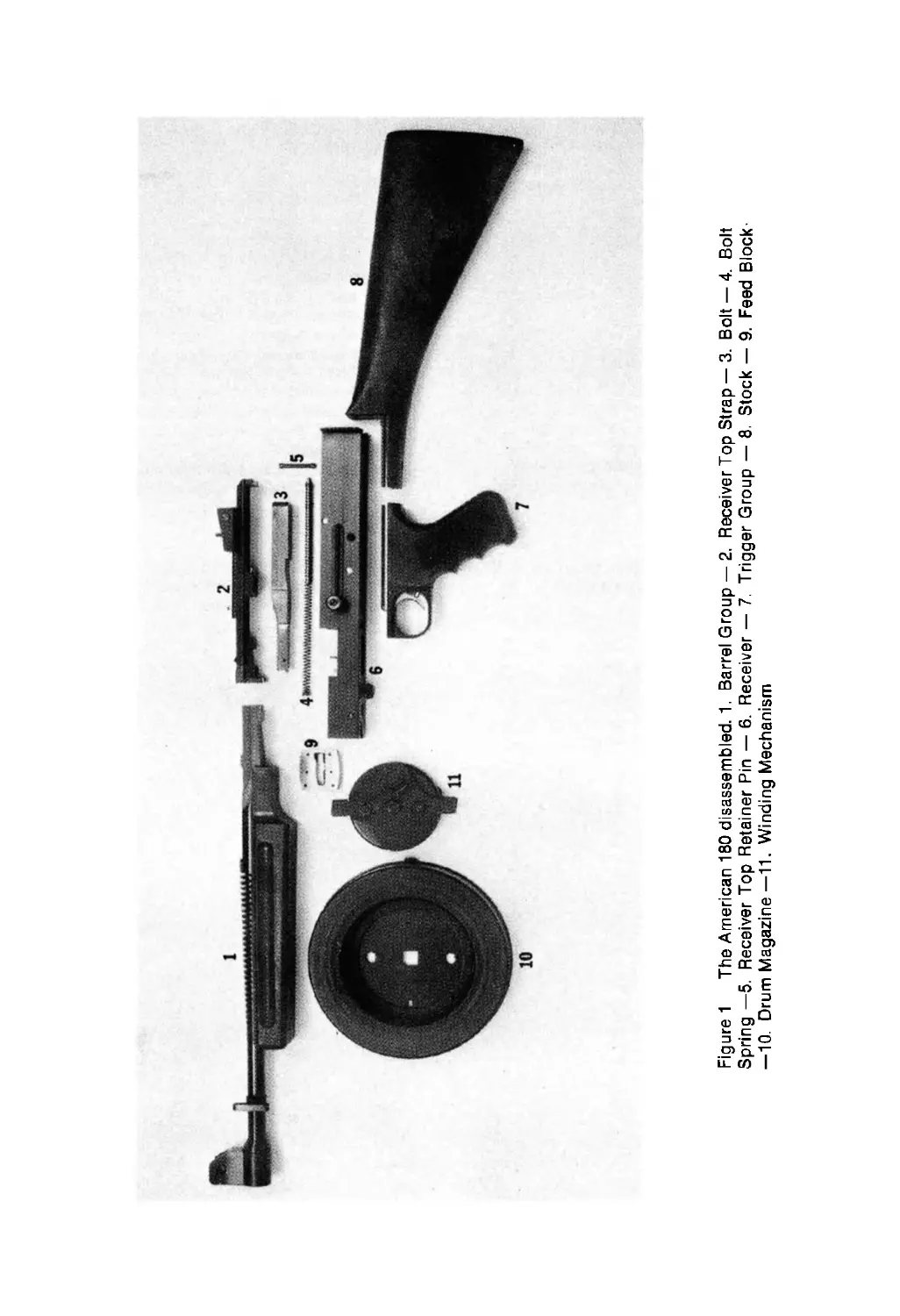
Figure 1 The American 180 disassembled. 1. Barrel Group — 2. Receiver Top Strap — 3. Bolt — 4. Bolt
Spring —5. Receiver Top Retainer Pin — 6. Receiver — 7. Trigger Group — 8. Stock — 9. Feed Block
—10. Drum Magazine—11. Winding Mechanism
3. GUIDES TO FOLLOW IN DIS-
ASSEMBLY AND ASSEMBLY.
These guides should be followed
when disassembling and assem-
bling the American 180:
a. Follow the step-by-step ex-
planation.
b. Do not attempt to disassemble
or assemble the weapon again-
st time.
c. If itis necessarytoapplyforce,
do it carefully so that none of
the parts are damaged.
d. As the weapon is disassembl-
ed, line up the parts in the
order of their removal. This
procedure helps'in assembly
of the weapon, which is done
in reverse order of disassembly.
4. PROCEDURE FOR DIS-
ASSEMBLY.
a. Before disassembling the
American 180, make sure that
the weapon is CLEAR. Pull
back on the magazine catch
(figure 2) and remove the mag-
azine. Inspect the feed block
and chamber to ensure no
ammunition is present in either.
Allow the bolt to go forward by
squeezing on the trigger. (Note:
To pull back [retract] the bolt,
pull back ont he bolt handleto
its rear-most position until it
stops, then manually return it
forward).
b. Detachment of the rear stock
isdone by pushing in on detent
Figure 2
Figure 3
on top of the stock near end of
receiver with your thumb, and
simultaneously pulling off the
stock (figure 3).
c. Removal of barrel is done by
loosening barrel locking screw,
and removing the barrel by
pressing barrel clip and draw-
ing barrel away from the re-
ceiver.
d. Remove feed block by placing
thumb and forefinger on either
side of the feed block and pul-
ling up away from receiver
(figure 4).
e. Removal of cover is done by
firmly holding the receiver with
one hand. With the heel of the
other hand, gentlytapforward
on the rear of the cover. Lift up
Figure 4
Figure 5
on the rear of the cover while
moving slightly forward (fig-
ure 5).
f. Remove the cover retaining
pin from either side of the
receiver (figure 6).
g. Remove the bolt by drawing
back the bolt handlefar enough
to get one finger on the face of
the bolt; by pulling back and
up with this finger the bolt will
leave the receiver (figure 7).
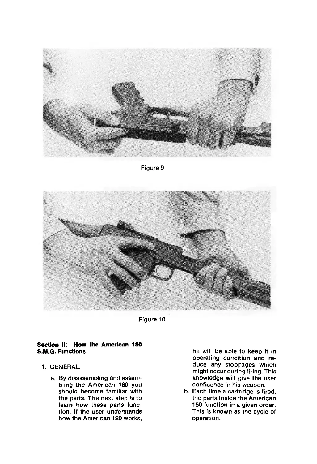
h. Removal of the trigger hous-
ing: depress the stop pin by
inserting a steel punch into the
hole and pressing (figure 8).
Simultaneously, the trigger
housing has to be drawn back
and the sear positioned with
the forefinger so that it does
not interfere with the removal
of the trigger housing (figure
9).
5. ASSEMBLING THE AMERICAN
180. Assembly is done in reverse
order of disassembly
6 OPERATION CHECK. With the
American 180 fully assembled and
unloaded, and the safety rotated
forward into firing position (figure
10) the following operation checks
may be made:
a. Push the selector to the left.
With the trigger released, pull
the bolt handle sharply to the
rear. The bolt should be en-
gaged and held by the sear.
b. Squeeze and maintain press-
ure on the trigger. With the
trigger depressed, the bolt will
go forward. Pull the bolt to the
rear, the sear should again
engage the bolt while the trig-
ger is depressed
c. With the trigger released, pull
the bolt handle to the rear,
cocking the weapon. Push the
selector to the right (automa-
tic) position. The bolt should
not move until the trigger is
squeezed.
d. With the selector in the auto-
matic position, pull the bolt
handle to the rear; hold the
trigger back. The bolt should
move back and forth freely,
not being engaged by the sear
e. Test the safety with the selec-
tor in both the semi-automatic
and the automatic positions.
Figure 8
Figure 6
Figure 7
Figure 9
Figure 10
Section II: How the American 180
S.M.G. Functions
1. GENERAL.
a. By disassembling and assem-
bling the American 180 you
should become familiar with
the parts. The next step is to
learn how these parts func-
tion. If the user understands
how the American 1 SO works,
he will be able to keep it in
operating condition and re-
duce any stoppages which
might occur during firing. This
knowledge will give the user
confidence in his weapon.
b. Each time a cartridge is fired,
the parts inside the American
180 function in a given order.
This is known as the cycle of
operation.
c. The cycle of operation of small
arms is broken down into eight
basic steps. However, in the
American 180, two of these
steps—locking and unlock-
ing—do not occur. The six
basic steps of the cycle of
operation of the American 180
are listed below in the proper
sequence, although more than
one step may be occurring at
the same time.
(1) Feeding—the placing of a
cartridge in the feed block,
in front of the bolt, so it
can be chambered. This
action takes place in the
magazine generally, but
can be accomplished
manually.
(2) Chambering—moving the
cartridge forward until it is
properly seated in the
chamber.
(3) Firing—the striking of the
primer of the cartridge by
the firing pin to ignite the
cartridge.
(4) Extraction—removal of the
empty cartridge case from
the chamber.
(5) Ejection—removal of the
empty cartridge case from
the receiver.
(6) Cocking—retraction of the
bolt far enough so that it
will pick up a new car-
tridge and, as it moves
forward, will have enough
energy to fire the new
cartridge.
2. FUNCTION OF THE AMERICAN
180. As the bolt is moved back to a
cocked position, the driving spring
is compressed, and the sear en-
gages the sear notch of the bolt.
When the trigger is pressed, the
sear releases the bolt, which Is
driven forward by the drive spri ng.
During this forward movement,
the bolt pushes a cartridge from
the feed block into the chamber.
The bolt continues forward and
fires the cartridge. When the car-
tridge is fired the chamber pres-
sure forces the bullet out of the
muzzle of the barrel, At the same
time, this pressure overcomes the
forward movement of the bolt and
starts it to the rear. By the time the
bolt and empty cartridge case
have moved to the rear far enough
to open the rear end of the cham-
ber, the bullet has left the barrel
and the chamber pressure has
decreased. (In the American 180,
the chamber pressure is relatively
low and the bolt is relatively heavy,
thus eliminating the need for the
steps of locking and unlocking.)
Duri ng the rearward movement of
the bolt, the empty cartridge case
is extracted and ejected, the driv-
ing spring is compressed, and the
next round in the magazine moves
into the paws of the feed block.
The rearward movement of the
bolt is stopped by the compressed
driving spring.
3. OPERATION OF THE TRIGGER
AND SEAR.
a. Whenthetriggerispressed.it
rotates around the trigger pin
and forces the sear to rotate
around the sear pin, causing
the sear nose to be moved
down and away from the sear
notch in the bottom of the bolt.
This allows the bolt to move
forward under the action of
the expanding drive spring.
b. Automatic fire—With the sel-
ector pushed to the right (auto-
matic position), if the trigger is
held to the rear, the nose of the
sear cannot engage the sear
notch of the bolt. The bolt will
continue to move forward and
backward, firing the weapon
automatically until the trigger
is released.
c. Semi-automaticfire—With the
selectorpushed to the left (semi-
automatic position), when the
trigger is pulled, the nose of
the sear disengages from the
sear notch on the bottom of
the bolt, allowing the bolt to
move forward. At the same
time under the action of the
sear spring, the sear is moved
back into position to engage
the bolt and hold it to the rear
until pressure is released from
the trigger.
4 FEEDING.
a. When a loaded magazine is
placed on the weapon, the
magazine catch holds the mag-
azine in position. The bottom
cartridge is held by the feed
paws of the feed block through
the action of the magazine
spring and follower. When the
bolt moves forward, it removes
the round from the feed block.
b. When the bolt moves to the
rear and clears the feed block,
the next cartridge is placed in
the feed block by the action of
the magazine spring and foll-
ower.
5. CHAMBERING. The bolt, moving
forward under the action of the
expanding drive spring, pushes
the cartridge out of the feed block.
The bullet ramp of the feed block
aids in aligning the cartridge with
the chamber. As the bolt con-
tinues forward, the cartridge is
pushed into the chamber by the
front of the bolt. The base of the
cartridge protrudes slightly from
the chamber when the cartridge is
fully seated.
6. FIRING. After the cartridge is
chambered, the bolt continues to
move forward. The extractor
springs out underand snaps onto
the rim of the cartridge. At the
same time, the fixed firing pin
strikes the primer of the cartridge,
firing the cartridge. At the instant
of firing the cartridge is enclosed
in the chamber, and the rim of the
cartridge is engaged by the ex-
tractor.
7. EXTRACTION. When the cart-
ridge is fired, the gas pressure
forces the bullet out of the muzzle
and the empty cartridge case out
of the chamber, pushing the bolt
to the rear. The extractor holds
the base of the cartridge case
against the bolt. The bolt con-
tinues moving to the rear, carry-
ing the empty cartridge case with
it. Extraction is completed when
the front of the cartridge case
clears the rear of the chamber. If
the cartridge is not fired, the ex-
tractor will remove it from the
chamber when the bolt is manu-
ally pulled to the rear.
8. EJECTION. As the bolt moves to
the rear, the empty cartridge case
is held by the extractor. When the
front of the cartridge case clears
the rear of the chamber, with the
extractor serving as a pivot point,
the cartridge case is deflected out
of the ejection opening in the bot-
tom of the receiver.
9. COCKING.
a. Semi-automatic—As the bolt
moves to the rear, the drive
spring is compressed, the nose
of the sear will move up. As the
bolt moves forward, the sear
nose will engage in the sear
notch and hold the bolt to the
rear in a cocked position. The
trigger must be released and
pulled to fire again.
b. Automatic—If the trigger has
not been released, the bolt wil I
continue forward and the cycle
of operation will be repeated.
10. OPERATION OF SAFETY. The
American 180 has a positive safety
that blocks the sear when rotated
to the safe position.
Figure 11
Section III: Operations
1. GENERAL. Before firing the
American 180, the firer must know
how to fill the magazine; must
know howto load, fire, and unload
the weapon; and must observe
safety precautions. These points
are covered in this section.
2. TO FILL MAGAZINE.
CAUTION: Before attempting to
fill the magazine, all spring ten-
sion should be released from the
magazine winder mechanism, or.
if the magazine is partially filled,
the magazine winding brake
should be engaged.
a. Press your thumbs upon the
clips of the magazine winding
device and catch it with your
fingers (figure 11).
b. Press the lock on the base and
turn the magazine base until
you can see the filled chamber
through the loading slot of the
base (figure 12). The marking
arrow visible on the magazine
should be positioned below
the narrow protrusion of the
base.
Figure 13
c. Lay the first cartridge in the
slot on the base of the maga-
zine (figure 13). Press the lock
of the magazine and slowly
rotate the magazine base. The
cartridge will go into the mag-
azine without force of any kind.
Repeat this process for 59
rounds.
d. After having loaded 59 rounds,
you have to turn the loading
slot over the full chamber.
(Then you will feel a resist-
ance, called step resistance.)
The loading slot will open once
again with an “empty" cham-
ber, and repeatthe whole pro-
cess. Loading the second and
the third layers is performed
just like the first one.
CAUTION: Do not use force when
inserting rounds. Do not skip a
chamber. It is advisable to always
load full layers of ammunition,
either load 59 rounds, 118 rounds,
orthefull limit of 177 rounds. This
prevents the magazinefrom "drop-
ping" loose rounds when the
magazine is installed or removed.
Note: It is advisable to put the
magazine on a non-slip surface
when loading. The magazine also
can be loaded by means of a spe-
cial loading device.
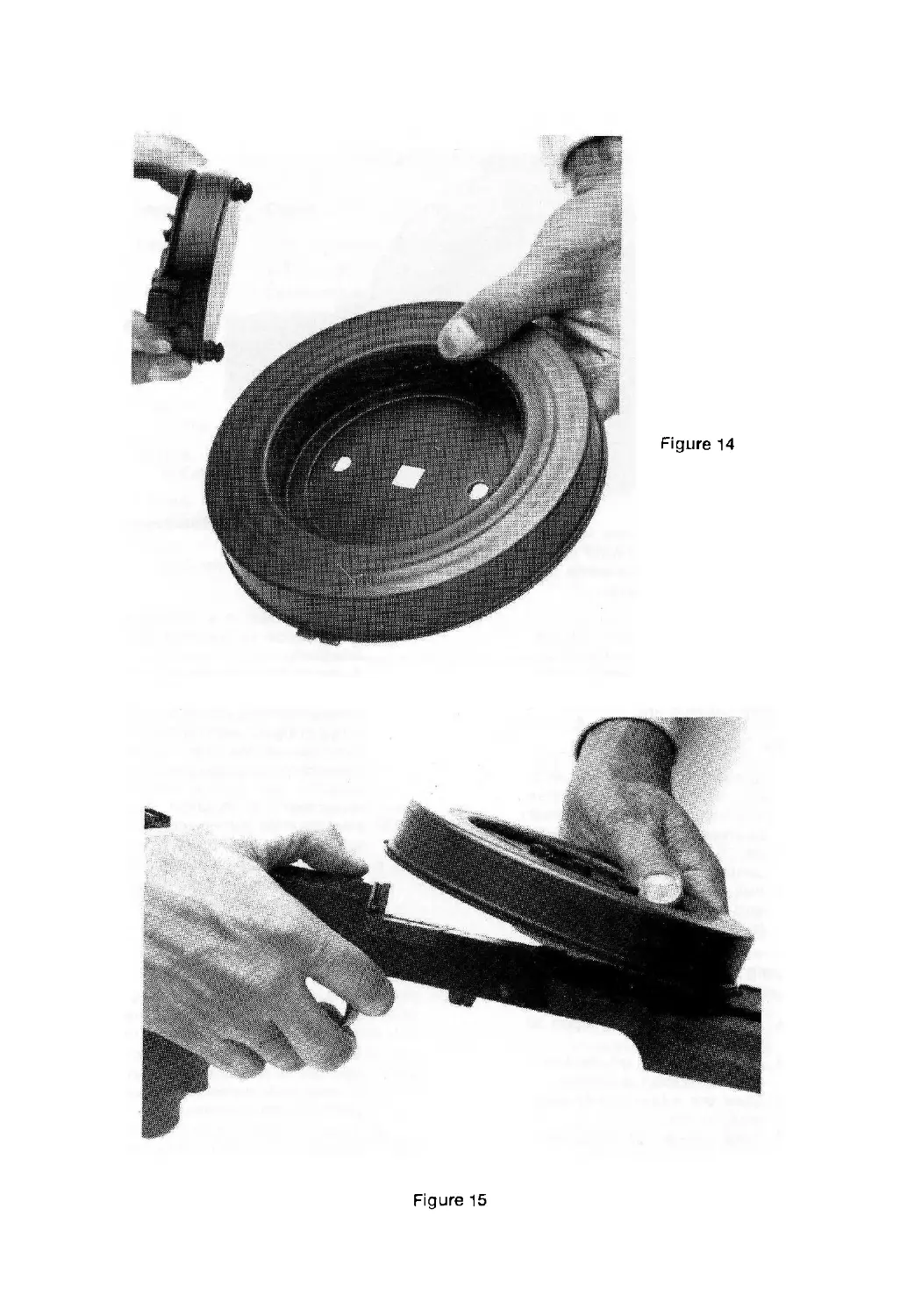
e. Installation of the magazine
winding device isdone by push-
ing the clips of the magazine
winding device into the holes
of the base until they lock in
place (figure 14).
CAUTION: A winding device im-
properly installed may come off
during firing and damage the
spring.
3. TO LOAD THE AMERICAN 180.
a. Insert the wide protrusion of
the magazine base into the
magazine guide of the barrel
and press the narrow protru-
sion tightly until the magazine
snaps into place (figure 15).
Note: Pulling back the magazine
clip with your thumb facilitates
the installation of the magazine.
b. Winding the magazine. Wind
up clockwise until it stops,
about 3 % turns for a full mag-
azine (figure 16) Winding de-
vice stop lever must not be
under tension.
Figure 14
Figure 15
CAUTION: If magazine is only
partially filled, do not wind com-
pletely. Wind only 1% turns for
each (59 rounds) layer.
c. Pull back on the bolt handle
until it stops, and push it for-
ward into its forward most
position. The American 180 is
now ready to fire.
4 UNLOADING
a. In order to remove a partial or
full magazine, the magazine
winding device stop lever must
be placed in the position mark-
ed "F" (outside away from
center).
b. Pull back on magazine clip
and lift off magazine. Inspect
the chamber (look and feel).
5 . SAFETY PRECAUTIONS.
Safety ca nnot be overem phasized
a Never consider a weapon to
be safe.
b. Never playfully or carelessly
point a weapon at anyone.
c. Load the weapon only when
ready to fire.
d Take safety off only when
weapon is raised to fire.
e. Never leave any obstruction in
the muzzle or base.
Section IV: Malfunction, Stoppages
and Immediate Action
1. GENERAL.
a. A malfunction is a failure of
the weapon to function sat-
isfactorily.
b. Astoppageisanyunintentional
interruption in the cycle of
operation. If the American 180
stops firing through notaultor
intention of the firer, or an
attempt to fire is made and the
weapon fails to fire, then a
stoppage has occurred. The
firer must be able to reduce a
stoppage and continue firing.
c. Immediateactionistheprompt
action taken by the firer to
reduce a stoppage without con-
sidering the cause
2. MALFUNCTIONS.
a. Failure to function freely-
sluggish operation of the
American 180 isusuallydueto
excessive friction caused by
dirt, lack of proper lubrication,
burred or dented guide rod or
dented or bent receiver.
b. Uncontrolledautomaticfire(run-
away gun)—uncontrolled auto-
matic fire is fire that continues
after the trigger has been re-
leased . This may be caused by
CAUSE OF STOPPAGES
Stoppage Cause How to Reduce
Failure Dirty or dented magazine Replace magazine
to Feed Weak or broken magazine spring Replace magazine
Deformed ammunition Replace ammunition
Worn or broken magazine catch Replace catch
Failure to Dirty chamber Clean chamber
Chamber Obstruction in chamber Remove
Weak drive spring Replace spring
Failure Defective ammunition Replace ammunition
to Fire- Defective firing pin Replace bolt
Failure Weak driving spring Replace driving spring
to Extract Broken extractor Replace extractor
Failure to Eject Not likely to occur
Failure Worn sear Replace sear
to Cock Worn sear notch Replace bolt
Bent guide rod Replace or straighten rod
Dirt behind cocking knob Clean cocking knob
the following:
(1) Worn sear nose.
(2) Worn sear notch.
(3) Broken sear.
(4) Short recoil.
In case of uncontrolled auto-
maticfire, keepthegun pointed
at the target.
3. STOPPAGES.
a. Stoppages are classified in ac-
cordance with the six steps in.
the cycle of operation. Stop-
pages are usually the result of
faulty ammunition or improper
care of the gun. A knowledge
of how the gun functions will
enable the firer to classify and
correct the stoppage. Listed
below are the causes of stop-
pages which might occur:
(t) Failureto Feed—cartridge
from the magazine is not
positioned in the feed block
in front of the bolt. Most
stoppages of submachine
guns are failure to feed,
caused by defective or dirty
magazines.
(2) Failure to Chamber-
cartridge from the feed
block is not seated in the
chamber.
(3) Failure to Fire—the cart-
ridge is chambered but
does not fire.
(4) Failure to Extract—if the
cartridge fires, the chamber
pressure will usually push
the empty cartridge case
out of the chamber. If the
cartridge case is not com-
pletely removed from the
chamber and the bolt is
retracted, then there is a
failure to extract. This stop-
page seldom occurs.
(5) FailuretoEject—theempty
cartridge case is not e-
jected from the receiver.
(6) Failureto Cock—if the bolt
is retracted and is not held
by the sear, or if during
firing the bolt does not
move to the rear far enough
to clear the cartridge in
the feed block, the wea-
pon has failed to cock.
b. Common stoppages—the two
most common stoppages are:
(1) Failure to Feed—usually
caused by dirty magazine,
or from a magazine which
is not wound properly, or
from a damaged magazine.
(2) Failure to Fire—usually
caused by defective
ammunition.
a. Cause of stoppages—the chart
on the preceding page lists
common causes of various
stoppages.
d. Prevention of stoppages-
periodic inspection and proper
care and cleaning will reduce
the possibility of the American
180 having stoppages.
•4. IMMEDIATE ACTION.
a. As the first step in clearing a
stoppage, pull back on the bolt
handle and return it to its for-
ward most position. Inspect
the chamber from the bottom
of the weapon, through the e-
jection port forthe presence of
jammed ammunition. This is
usually caused by defective
ammunition. Place the maga-
zine winding brake in the “F”
position, remove the magazine
and clear the jammed rounds
manually from the chamber
area. Replace the magazine,
remove the magazine winding
brake, pull the bolt handle to
the rear and return it to the
’closed position and again
attempt to fire.
b. Ifafailuretofireoccurs,again,
move the magazine winding
device to the brake “F" posi-
tion. Remove the magazine and
inspect the weapon in order to
locate and clear the stoppage.
Replace the magazine, move
the winding device lever to the
center and continue to fire.
Section V: Care and Cleaning
1. DEPENDABILITY AND ACC-
URACY. The American 180 will
function under conditions that
would cause some automatic
weapons tofail. However, its con-
tinued dependability and accuracy
depend on its receiving proper
care and cleaning. The chamber
and bore, receiver and moving
parts must be kept clean and very
lightly oiled. The same care must
be given the magazine.
2. THE FREQUENCY OF CLEAN-
ING. The American 180 requires
thorough cleaning after 2000
rounds. For this you can disas-
semble the weapon as described.
Prior to reassembling, all func-
tional parts have to be very lightly
oiled.
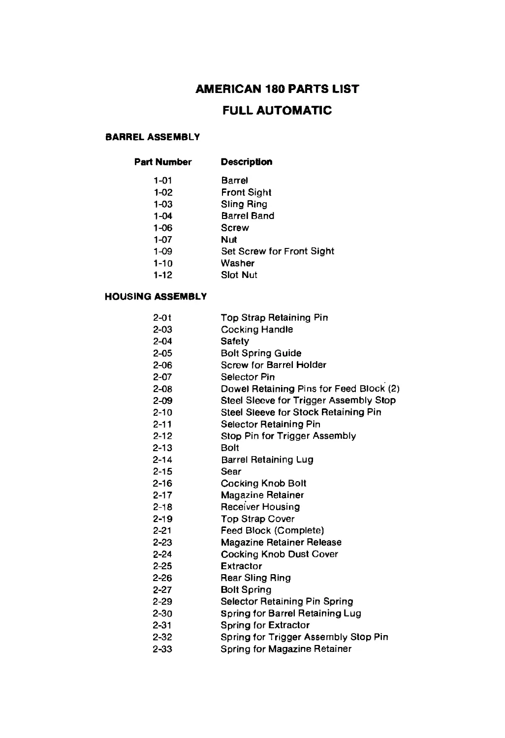
AMERICAN 180 PARTS LIST
FULL AUTOMATIC
BARREL ASSEMBLY
Part Number
Description
1-01 Barrel
1-02 Front Sight
1-03 Sling Ring
1-04 Barrel Band
1-06 Screw
1-07 Nut
1-09 Set Screw for Front Sight
1-10 Washer
1-12 Slot Nut
HOUSING ASSEMBLY
2-01 Top Strap Retaining Pin
2-03 Cocking Handle
2-04 Safety
2-05 Bolt Spring Guide
2-06 Screw for Barrel Holder
2-07 Selector Pin
2-08 Dowel Retaining Pins for Feed Block (2)
2-09 Steel Sleeve for Trigger Assembly Stop
2-10 Steel Sleeve for Stock Retaining Pin
2-11 Selector Retaining Pin
2-12 Stop Pin for Trigger Assembly
2-13 Bolt
2-14 Barrel Retaining Lug
2-15 Sear
2-16 Cocking Knob Bolt
2-17 Magazine Retainer
2-18 Receiver Housing
2-19 Top Strap Cover
2-21 Feed Block (Complete)
2-23 Magazine Retainer Release
2-24 Cocking Knob Dust Cover
2-25 Extractor
2-26 Rear Sling Ring
2-27 Bolt Spring
2-29 Selector Retaining Pin Spring
2-30 Spring for Barrel Retaining Lug
2-31 Spring for Extractor
2-32 Spring for Trigger Assembly Stop Pin
2-33 Spring for Magazine Retainer
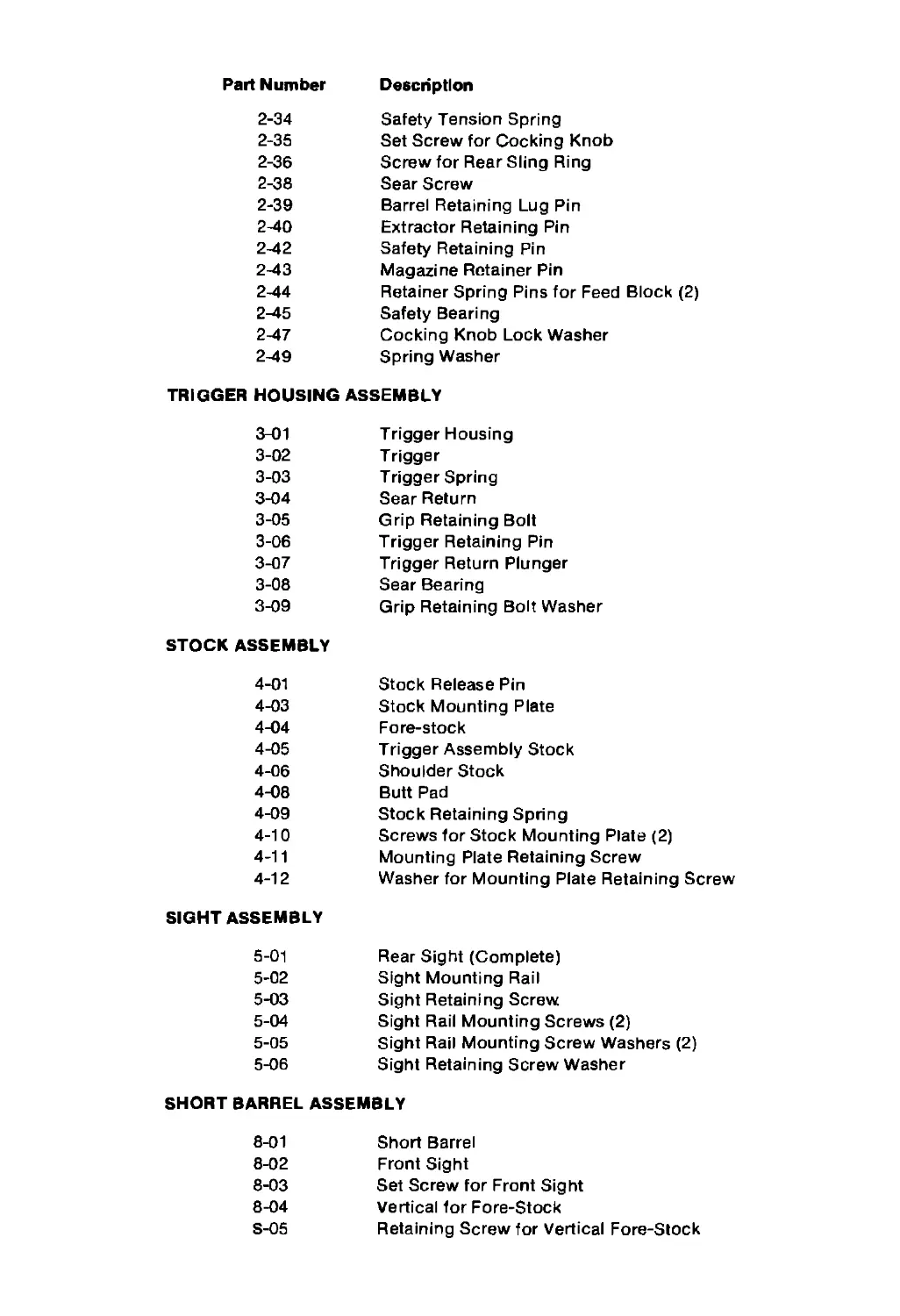
Part Number Description
2-34 2-35 2-36 2-38 2-39 2-40 2-42 2-43 2-44 2-45 2-47 2-49 Safety Tension Spring Set Screw for Cocking Knob Screw for Rear Sling Ring Sear Screw Barrel Retaining Lug Pin Extractor Retaining Pin Safety Retaining Pin Magazine Retainer Pin Retainer Spring Pins for Feed Block (2) Safety Bearing Cocking Knob Lock Washer Spring Washer
TRIGGER HOUSING ASSEMBLY
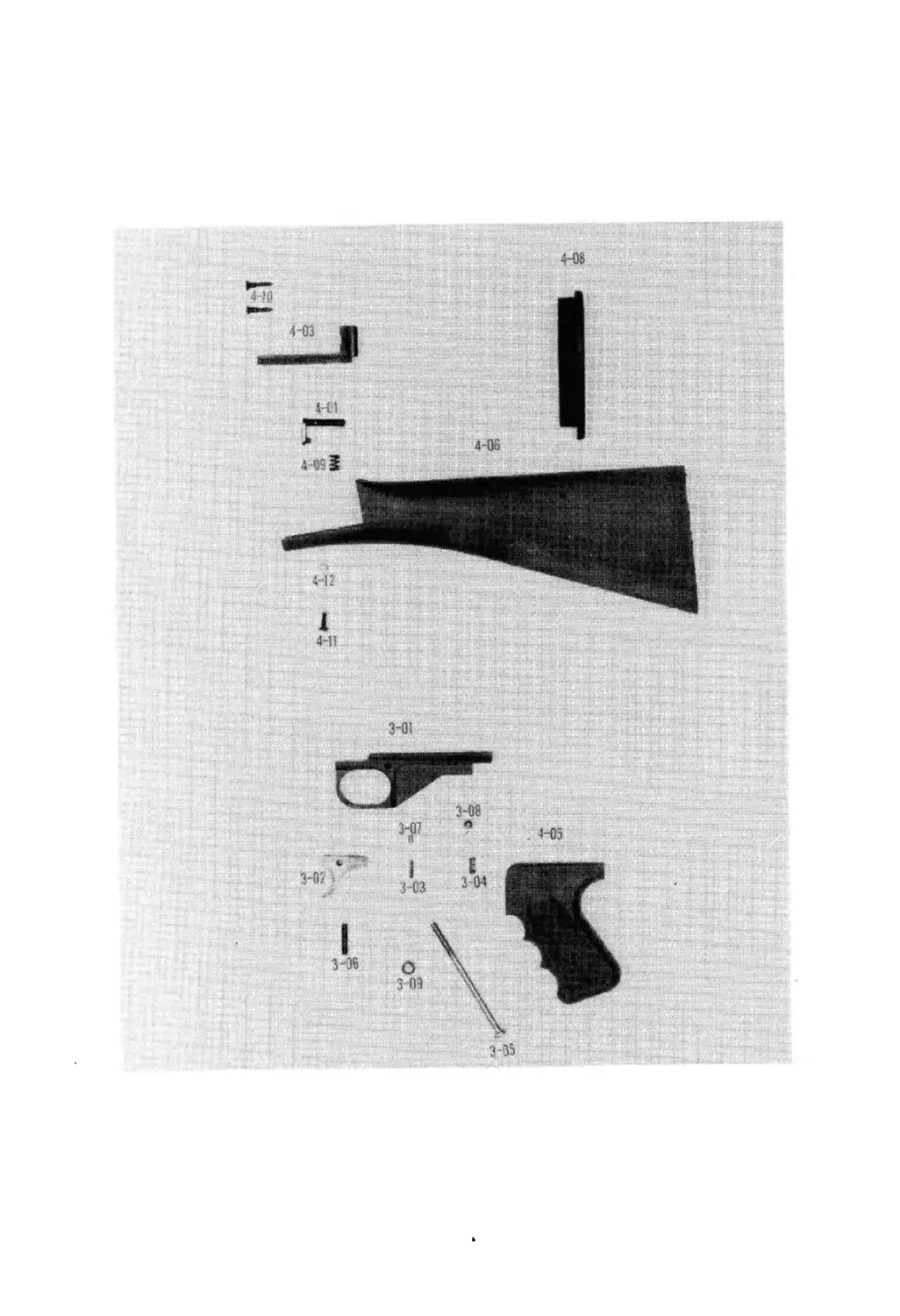
3-01 3-02 3-03 3-04 3-05 3-06 3-07 3-08 3-09 Trigger Housing Trigger Trigger Spring Sear Return Grip Retaining Bolt Trigger Retaining Pin Trigger Return Plunger Sear Bearing Grip Retaining Bolt Washer
STOCK ASSEMBLY
4-01 4-03 4-04 4-05 4-06 4-08 4-09 4-10 4-11 4-12 Stock Release Pin Stock Mounting Plate Fore-stock Trigger Assembly Stock Shoulder Stock Butt Pad Stock Retaining Spring Screws for Stock Mounting Plate (2) Mounting Plate Retaining Screw Washer for Mounting Plate Retaining Screw
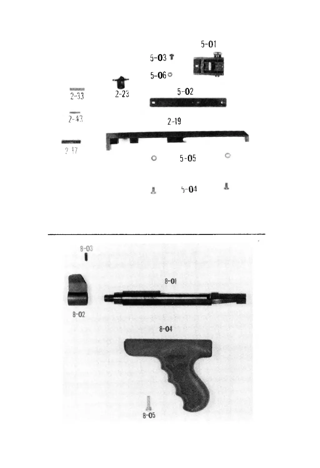
SIGHT ASSEMBLY
5-01 5-02 5-03 5-04 5-05 5-06 Rear Sight (Complete) Sight Mounting Rail Sight Retaining Screw Sight Rail Mounting Screws (2) Sight Rail Mounting Screw Washers (2) Sight Retaining Screw Washer
SHORT BARREL ASSEMBLY
8-01 Short Barrel
8-02 8-03 8-04 S-05 Front Sight Set Screw for Front Sight Vertical for Fore-Stock Retaining Screw for Vertical Fore-Stock
4-08