/


Теги: weapons military affairs


Текст
SIGARMS
Training
Р228 Combat Pistol
Armorers Manual
Р228
ARMORERS MANUAL
The SIGARMS Armorers Manual is intended as a Reference Source to be used in conjunction
with the formal training received from the SIGARMS ACADEMY Armorers School.
STG-Sauer Pistols are accompanied by an Owners Manual which explains and illustrates user
responsibilities and safety precautions. It is recommended that this information be read and
adhered to at all times. Information provided in either manual may change without notification.
This publication is copyrighted, is solely for the use of the registered owner, and may not be
reproduced, copied or distributed in any form without the express written consent of SIGARMS.
P228
TABLE OF CONTENTS
page #
2.0 INTRODUCTION 1-1
1.1 General 1 -1
1.2 Technical Specifications of the SIG-Sauer P228 1 -1
2.0 DESIGN AND COMPONENTS 2-1
2.1 Weapon 2-1
2.1.1 General 2-1
2.1.2 Slide 2-2
2.1.3 Frame 2-3
2.1.4 Magazine 2-4
3.0 HANDLING 3-1
3.1 Loading 3-1
3.2 Reloading 3-1
3.3 Unloading 3-1
3.4 Firing the Pistol 3-1
3.5 Cycle of Operation 3-2
4.0 GENERAL DISASSEMBLY AND ASSEMBLY 4-1
4.1 Disassembly 4-1
4.2 Assembly 4-3
5.0 MAGAZINE - DISASSEMBLY AND ASSEMBLY 5-1
5.1 Disassemby 5-1
5.2 Assembly 5-1
P228
TABLE OF CONTENTS continued
6.0 WEAPON INSPECTION page # 6-1
6.1 General 6-1
6.2 Function Inspection 6-1
6.2.1 Unload and Make the Weapon Safe 6-1
6.2.2 Trigger and Hammer Mechanisms 6-1
6.2.3 Recoil Spring 6-2
6.2.4 Magazine 6-2
6.2.5 Slide Catch Lever 6-3
6.3 Parts Inspection 6-3
6.3.1 General 6-3
6.3.2 Areas of Inspection 6-3
7.0 CLEANING 7-1
7.1 Cleaning the Pistol 7-1
7.1.1 General 7-1
7.1.2 Cleaning Procedures 7-1
7.1.3 Lubrication Specifications 7-1
8.0 WEAPON FUNCTIONS 8-1
8.1 Function of the Trigger Assembly 8-1
8.1.1 Double Action/Single Action Function 8-1
8.1.2 Double Action Only Function 8-2
8.1.3 Disconnector Operation 8-3
8.1.4 Decocking Lever, Safety Intercept Notch and Hammer Reset Spring 8-4
8.1.5 Firing Pin Safety Lock 8-5
P228
TABLE OF CONTENTS continued
8.0 WEAPON FUNCTIONS continued... page #
8.2 Locking and Unlocking 8-6
8.3 Arresting Mechanism (Slide Catch Lever) 8-7
9.0 THE SLIDE - DISASSEMBLY AND ASSEMBLY 9-0
9.1 Removal and Disassembly of the Breechblock 9-1
9.2 Assembly and Installation of the Breechblock 9-1
10.0 THE FRAME - DISASSEMBLY AND ASSEMBLY 10-0
10.1 Locking Insert 10-1
10.1.1 Removal 10-1
10.1.2 Installation 10-1
10.2 Grip Plates, Left and Right 10-2
10.2.1 Removal 10-2
10.2.2 Installation 10-2
10.3 Trigger Assembly 10-3
10.3.1 Disassembly 10-3
10.3.2 Assembly 10-3
10.4 Hammer Assembly 10-4
10.4.1 Disassembly 10-4
10.4.2 Assembly 10-5
10.5 Hammer Stop Assembly 10-7
10.5.1 Removal 1.0-7
10.5.2 Installation 10-7
P228
TABLE OF CONTENTS continued
10.0 THE FRAME - DISASSEMBLY AND ASSEMBLY continued... page#
10.6 Hammer Strut Assembly 10-8
10.6.1 Disassemby 10-8
10.7 10.6.2 Assembly Decocking Lever Assembly 10-8 10-9
10.7.1 Disassembly 10-9
10.7.2 Assembly 10-9
11.0 MAGAZINE CATCH DISASSEMBLY AND ASSEMBLY 11-1
11.1 Disassembly 11-1
11.2 Assembly 11-1
11.3 Reversing the Magazine Catch 11-2
12.0 SIGHT ADJUSTMENT 12-1
12.1 Zeroing the P228 Pistol 12-1
12.2 Sight Specifications 12-2
12.3 Using the Combination Sight Pusher 12-3
12.3.1 Placement of the Pistol in the Sight Pusher 12-4
12.3.2 Moving the Sights 12-4
12.3.3 Changing the Sights 12-4
12.3.4 Centering the Sights 12-5
P228
TA1VLF OF CONTENTS continued
Page #
13.0 TROUBLESHOOTING 13-1
13.1 General 13-1
13.2 Stoppages, Malfunctions and their Corrections 13-1
13.2.1 Feeding 13-1
13.2.2 Extraction and Ejection 13-2
13.2.3 Other 13-3
14.0 PROFILE DRAWING AND PARTS DIAGRAM 14-1
Profile Drawing 14-1
Parts Diagram 14-2
Parts List 14-3
15.0 TOOLS 15-1
15.1 Tools Necessary for Weapon Disassembly 15-1
P228
1.0 INTRODUCTION
1.1 General
The S1G-S AUER P228 combat pistol has been developed to meet the requirements of the
world’s Military and Law Enforcement Agencies. It is manufactured by state of the art
production processes to provide the ultimate in safety, reliability and quality. The P228 is
an excellent close combat weapon that can be placed into action rapidly through the use of
multiple passive safeties; a double-action trigger mechanism; and high visibility, adjust-
able sights.
This mechanically locked, short recoil operated, semiautomatic pistol is self-loading and
will continue to fire with each pull of the trigger until the slide is locked open by the empty
magazine. After firing, the pistol may be easily disassembled for maintenance without the
use of tools and with very little effort.
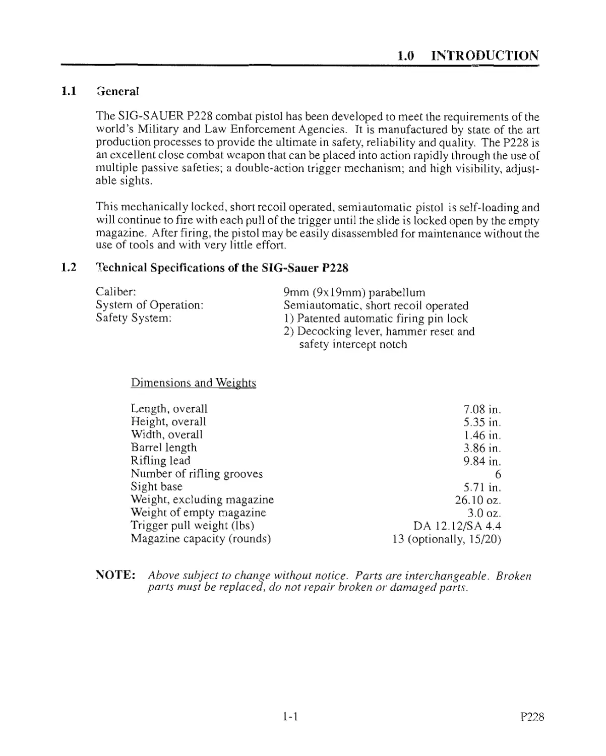
1.2 Technical Specifications of the SIG~Sauer P228
Caliber: 9mm (9x19mm) parabellum
System of Operation: Semiautomatic, short recoil operated
Safety System: 1) Patented automatic firing pin lock 2) Decocking lever, hammer reset and safety intercept notch
Dimensions and Weights
Length, overall
Height, overall
Width, overall
Barrel length
Rifling lead
Number of rifling grooves
Sight base
Weight, excluding magazine
Weight of empty magazine
Trigger pull weight (lbs)
Magazine capacity (rounds)
7.08 in.
5.35 in.
1.46 in.
3.86 in.
9.84 in.
6
5.71 in.
26.10 oz.
3.0 oz.
DA 12.12/SA4.4
13 (optionally, 15/20)
NOTE: Above subject to change without notice. Parts are interchangeable. Broken
parts must be replaced, do not repair broken or damaged parts.
1-1
P.228
1.0 INTRODUCTION
1
29
18
51
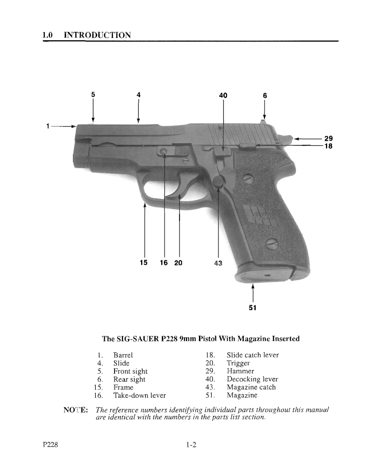
The SIG-SAUER P228 9mm Pistol With Magazine Inserted
1. Barrel 18. Slide catch lever
4. Slide 20. Trigger
5. Front sight 29. Hammer
6. Rear sight 40. Decocking lever
15. Frame 43. Magazine catch
16. Take-down lever 51. Magazine
NOTE: The reference numbers identifying individual parts throughout this manual
are identical with the numbers in. the parts list section.
P228
1-2
2.0 DESIGN AND COMPONENTS
2.1 Weapon
2.1.1 General
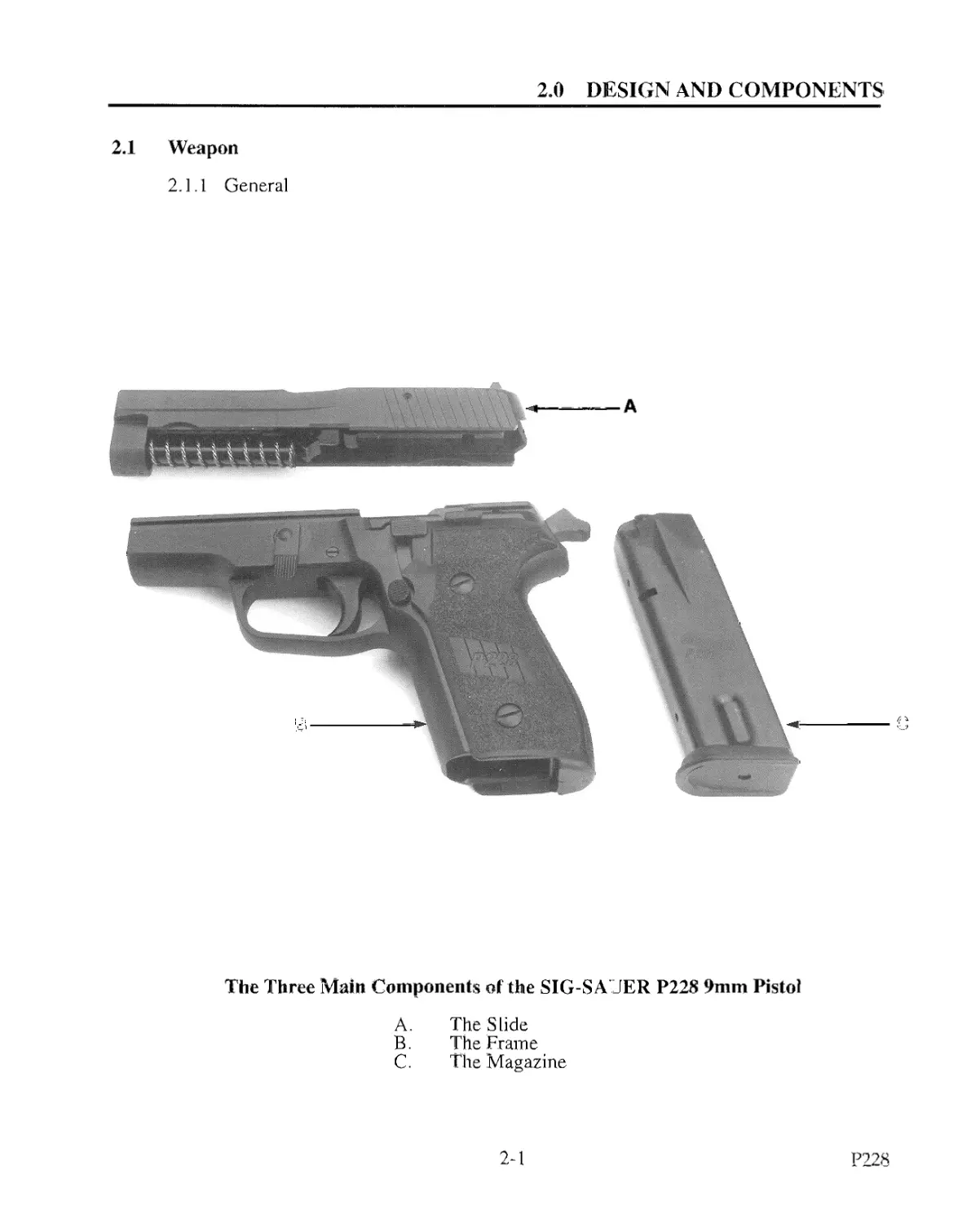
The Three Main Components of the SIG-SA JER P228 9mm Pistol
A. The Slide
В. The Frame
C. The Magazine
2-1
P228
2,0
2.1
DESIGN and components
Weapon (corn’d)
2.1.2 The Slide
5 C 7 8 6
WA/WWWW--
2
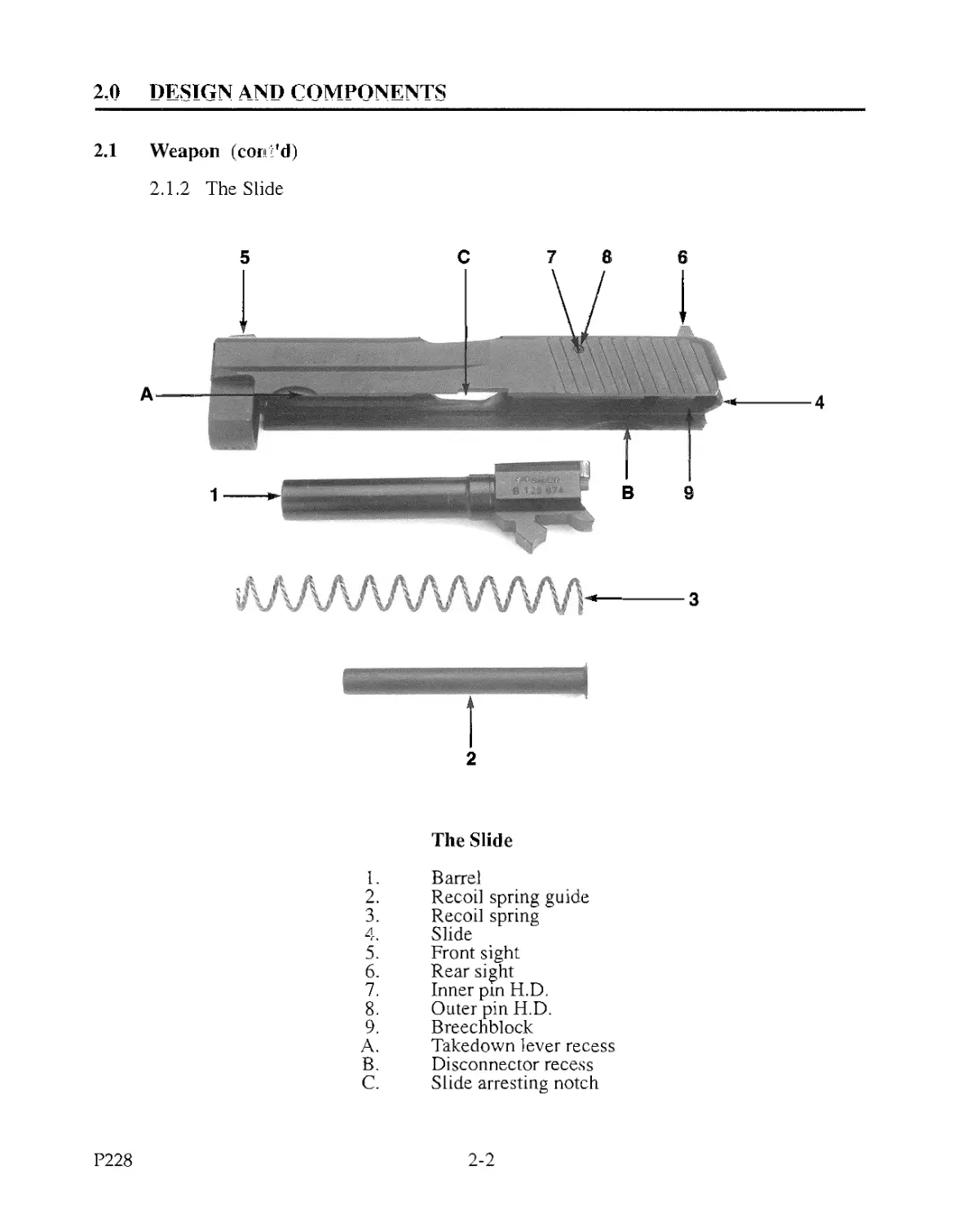
The Slide
I. Barrel
2. Recoil spring guide
3. Recoil spring
4. Slide
5. Front sight
6. Rear sight
7. Inner pin H.D.
8. Outer pin H.D.
9. Breechblock
A. Takedown lever recess
B. Disconnector recess
C. Slide arresting notch
P228
2-2
2.0 DESIGN AND COMPONENTS
2.1 Weapon (cont'd)
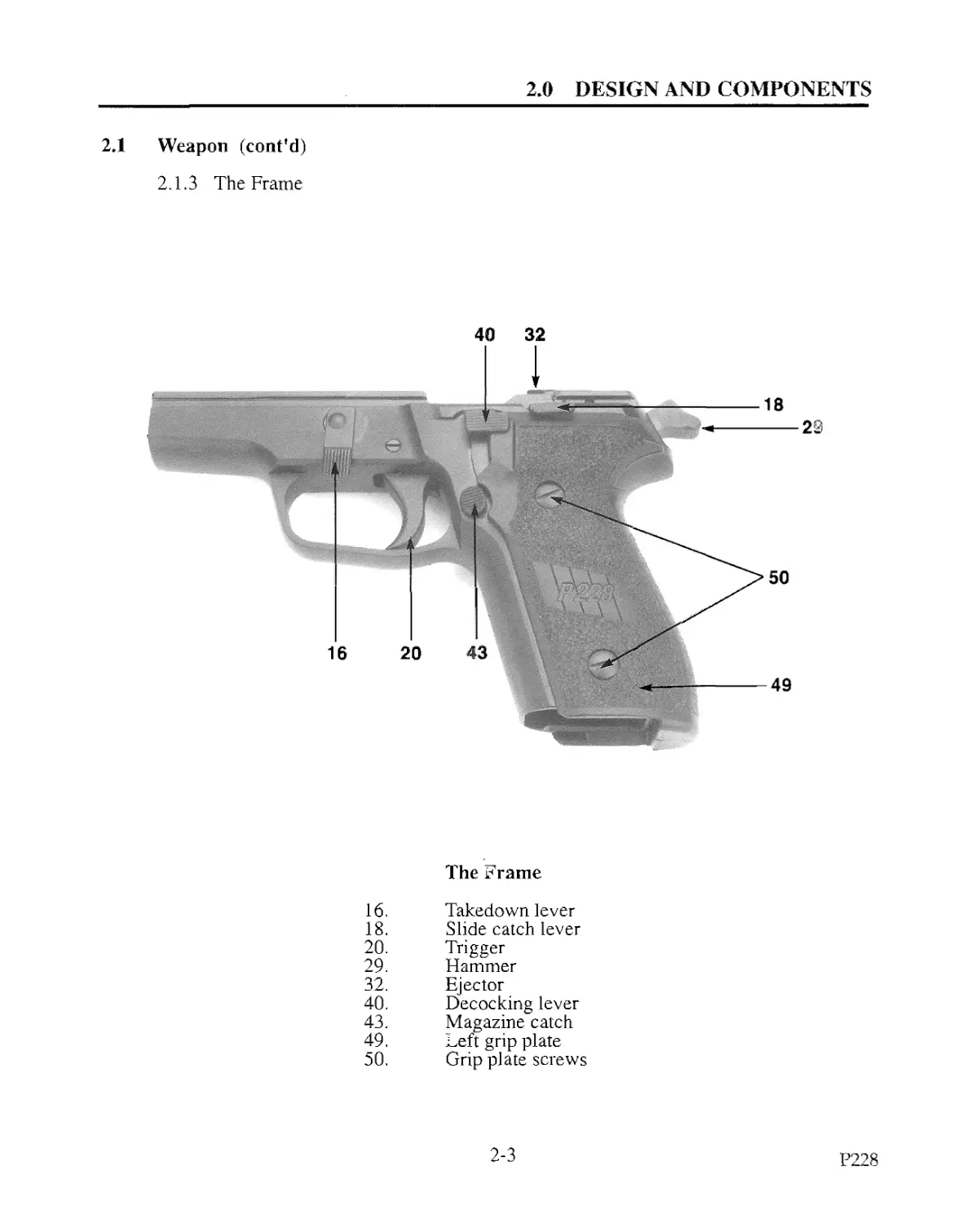
2.1.3 The Frame
40 32
The Frame
16. Takedown lever
18. Slide catch lever
20. Trigger
29. Hammer
32. Ejector
40. Decocking lever
43. Magazine catch
49. Left grip plate
50. Grip plate screws
2-3
P228
2.0 DESIGN AND COMPONENTS
2.1 Weapon (cont'd)
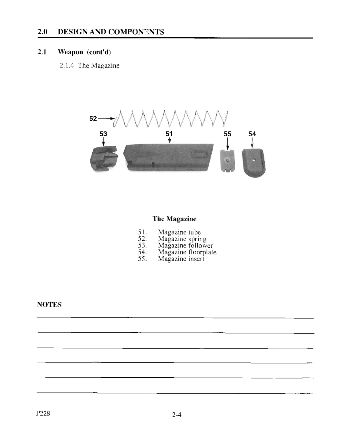
2.1.4 The Magazine
The Magazine
51. Magazine tube
52. Magazine spring
53. Magazine follower
54. Magazine floorplate
55. Magazine insert
NOTES
P228
2-4
3.0 HANDLING
NOTE: The operations described hereafter (loading, reloading, and unloading) are to be
carried out with the trigger finger off of the trigger and the muzzle pointing in a safe
direction. In addition, descriptions of the pistol will be made as if the operator were
pointing it directly away from him, as in firing.
3.1 Loading - Sequence of Opera Jons
1. Trigger finger off of the trigger and muzzle pointing in a safe direction.
2. Insert a full magazine and ensure that it has engaged the magazine catch (check).
3. Pull the slide fully to the rear and release it to chamber the first round from the
magazine.
4. You may either fire the pistol or thumb down the decocking lever (to safely lower the
hammer) and place it in the holster.
3.2 Reloading - Sequence of Operations
1. Trigger finger off of the trigger and muzzle pointing in a safe direction.
2. Depress the magazine catch to remove the empty magazine.
3. Insert a fresh magazine and ensure that it has engaged the magazine catch (check).
4. If the slide is locked back, either pull it to the rear slightly and release it or thumb
down the slide catch lever.
5. You may either fire the pistol or thumb down the decocking lever (to safely lower the
hammer) and place it in the holster.
3.3 Unloading - Sequence of Operations
1. Trigger finger off of the trigger and muzzle pointing in a safe direction.
2. Remove the magazine.
3. Pull the slide to the rear to eject the chambered round, inspect both the chamber
and the magazine well to make sure the pistol is unloaded. Check a second time.
4. Let the slide go forward and thumb down the decocking lever.
3.4 Firing the Pistol - Sequence of Operations
1. Remove the pistol from its holster and assume a shooting position.
2. Pull the trigger to fire (no external safety lever has to be operated).
3. When through firing, remove the trigger finger from the trigger, thumb down the
decocking lever, reload, unload, or place the pistol back in its holster.
3-1
P228
3.0 HANDLING
3.5 Cycle of Operation
In order to understand the functioning of a semiautomatic pistol, the cycle of operation
must be understood.
Feeamg: Placing the round in the path of the slide.
Chambering: Moving the round from the magazine to the chamber.
Locking: Sealing the round in the chamber and locking the breech end of the barrel into the slide.
Firing: Ignition of the primer and firing the round.
Unlocking: Unsealing the breech end of the barrel and unlocking the barrel from the slide.
Extracting: “Pulling” the spent cartridge from the chamber.
Ejecting: “Pushing” the spent cartridge out of the ejection port.
Cocking: Returning the firing mechanism to the cocked position, ready to fire another round.
P228
3-2
4.0 GENERAL DISASSEMBLY AND ASSEMBLY
4.1 Disassembly - Sequence of Operations
1. Unload and check the chamber both visually and physically. Check again!
2. Lock the slide to the rear by inserting an EMPTY magazine and pulling the slide to
the rear until slide is locked back by the slide catch lever, or simply pull the slide to the
rear and push the slide catch lever up into the arresting notch in the slide.
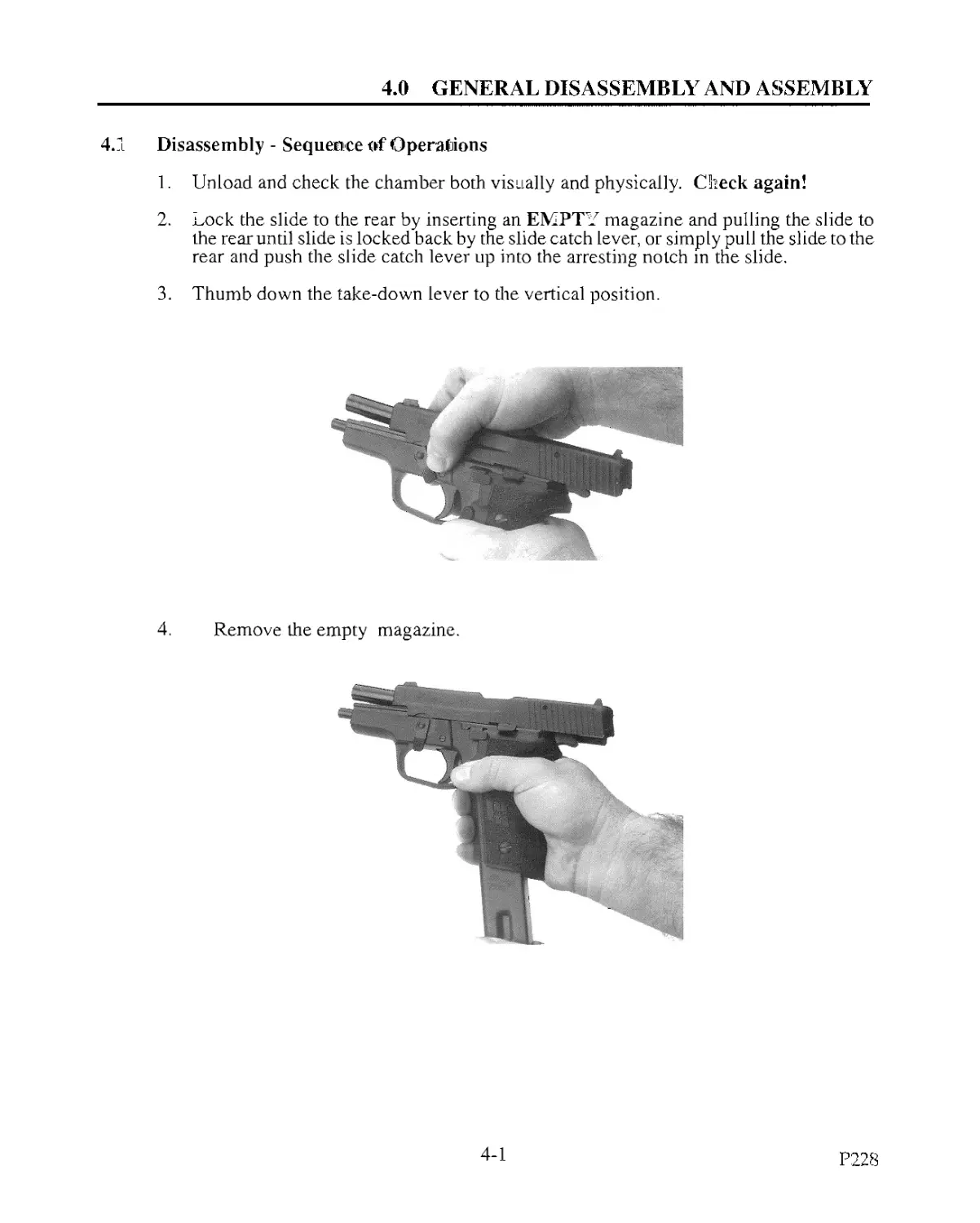
3. Thumb down the take-down lever to the vertical position.
4. Remove the empty magazine.
4-1
P228
4.0 GENERAL DISASSEMBLY AND ASSEMBLY
4.1 Disassembly (cont'd)
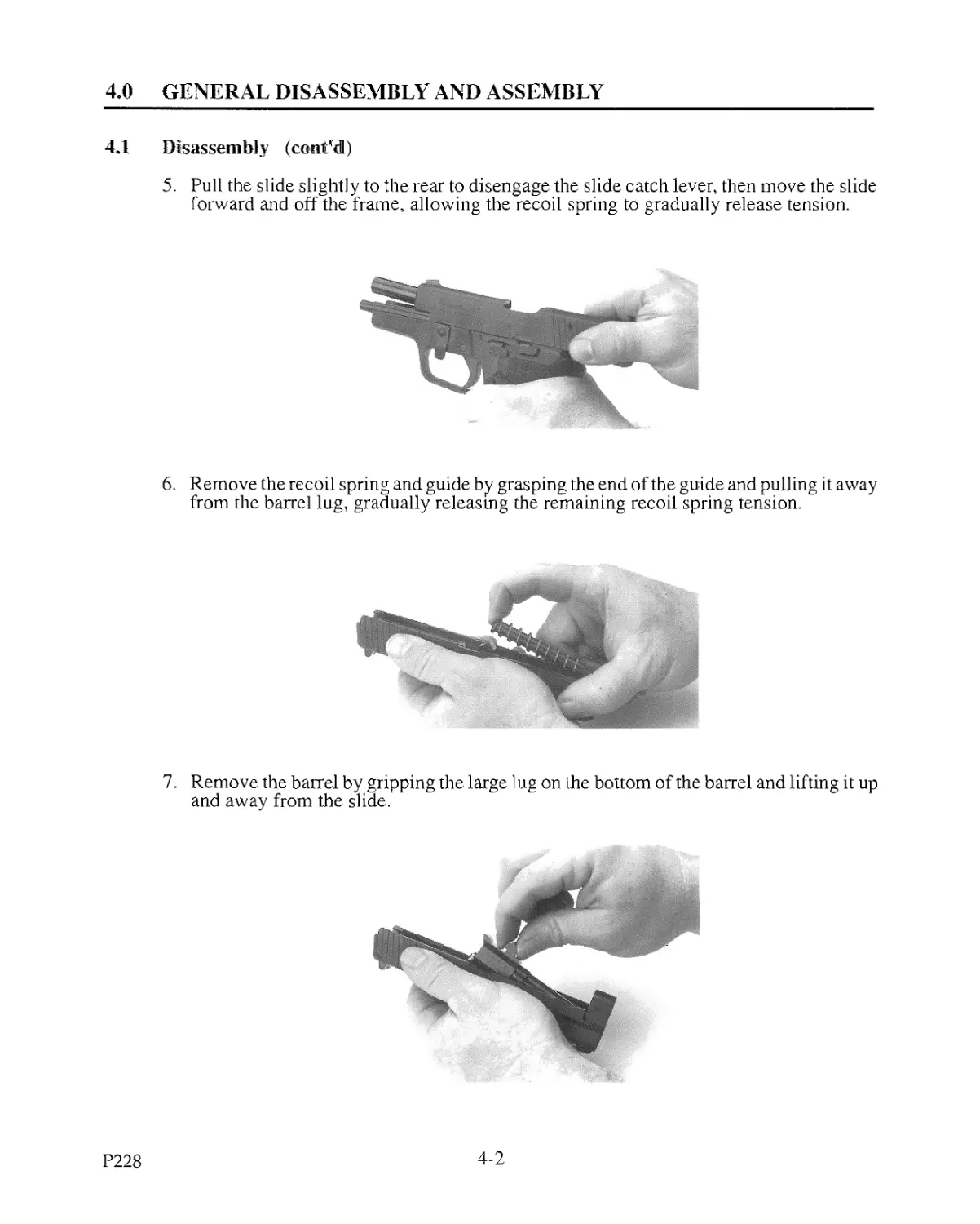
5. Pull the slide slightly to the rear to disengage the slide catch lever, then move the slide
forward and off the frame, allowing the recoil spring to gradually release tension.
6. Remove the recoil spring and guide by grasping the end of the guide and pulling it away
from the barrel lug, gradually releasing the remaining recoil spring tension.
7. Remove the barrel by gripping the large lug on the bottom of the barrel and lifting it up
and away from the slide.
P228
4-2
4.0 GENERAL DI S ASSEMBLY AND ASSEMBLY
4.2 Assembly - Sequence of Operations
1, Hold the slide upside down and insert the barrel, muzzle end first. Then install the recoil
spring and guide (the flared end of the guide is placed in the recess on the front of the
large lug of the barrel).
CAUTION: Ensure the barrel and slide are in the locked position during installation of
the slide onto the frame.
2. Insert an empty magazine into the frame.
3. Install the slide onto the frame and pull it to the rear until the slide catch locks it back
(this will occur automatically with magazine installed).
4. Thumb up the take-down lever and remove magazine.
5. Depress the slide catch lever to release the slide.
6. Thumb down the decocking lever to lower the hammer.
7. CARRY OUT FUNCTION CHECKS See Section 6.0 - WEAPON
INSPECTION
NOTES
4-3
!’22S
5.0 MAGAZINE - DISASSEMBLY AND ASSEMBLY
5,1 Disassembling the Magazine - Sequence of Operations
1. Invert the magazine,
2. Depress the magazine insert with a suitable tool through the opening in the floor plate.
3. Slide the floor plate off the magazine tube, ensuring magazine spring tension is
gradually released.
NOTE: The magazine spring is under great pressure - keep work operation away from the
face.
4. Remove the magazine spring and magazine follower from the magazine tube.
5.2 Assembling the Magazme - Sequence of Operations
1. Place the magazine follower on the magazine spring (raised end of spring under the
front of the magazine follower).
2. Hold magazine tube vertically and insert the magazine follower and magazine spring.
3. invert the magazine, attach magazine insert to the end of the magazine spring,
compress the magazine spring fully into the magazine tube and install the floor plate.
NOTE: Be sure that the insert locks into the floorplate opening.
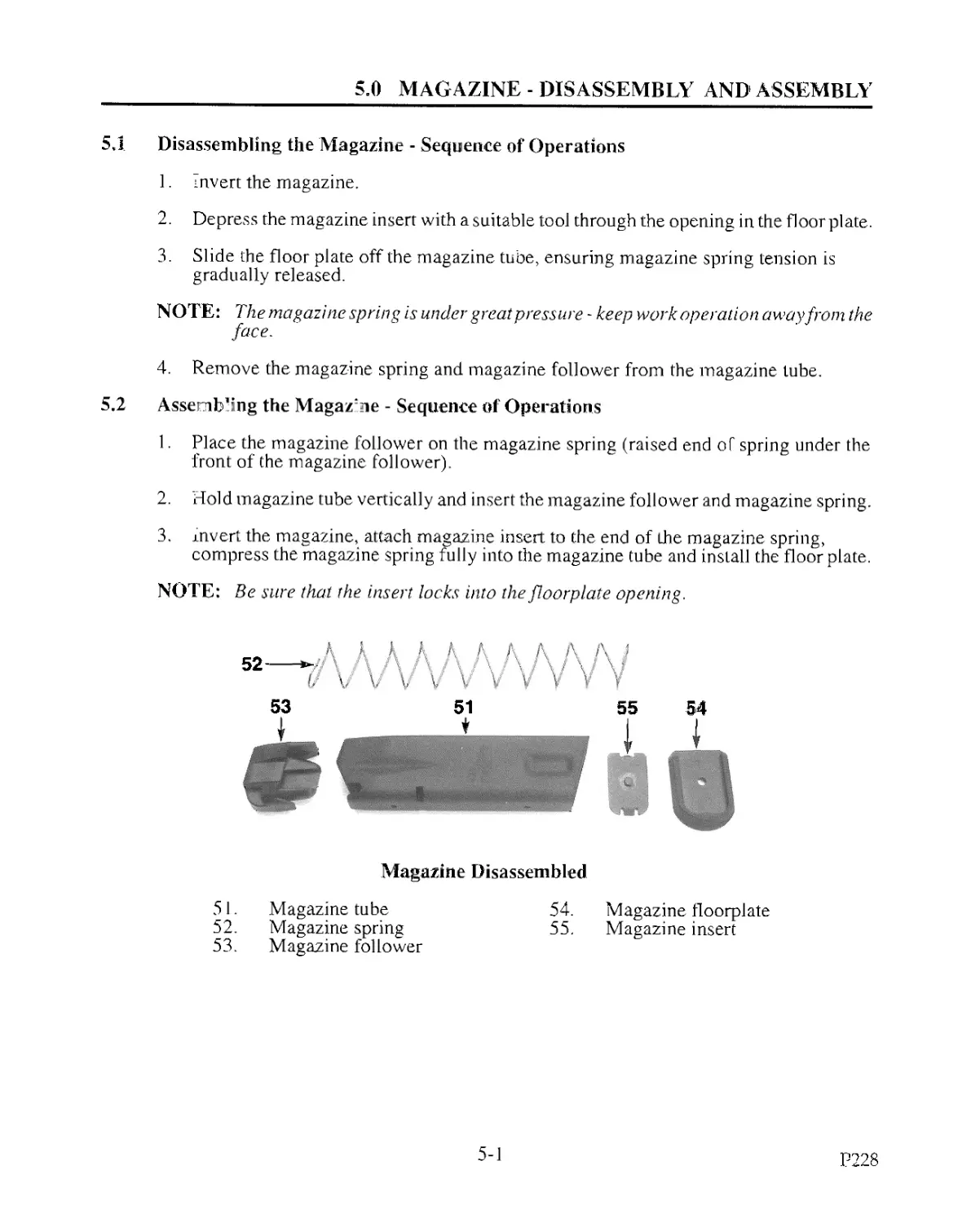
Magazine Disassembled
51. Magazine tube
52. Magazine spring
53. Magazine follower
54. Magazine floorplate
55. Magazine insert
5-1
P228
6.0 WEAPON INSPECTION
6.1 General
The armorer should carry out the following inspections:
1. Function inspection
2. Parts inspection
6.2 Function Inspection
A function check is to be carried out on the assembled weapon:
1, To determine causes of malfunction
2. After repair work
3. Following cleaning and during weapon inspections, as well as after parts inspection
and lubrication
6.2.1 Unload and Make the Weapon Safe
Remove the magazine, pull the slide to the rear to eject the chambered round, inspect both
the chamber and magazine well to be sure the pistol is unloaded. Check a second time. (See
Section 3.3 Unloading Procedures.)
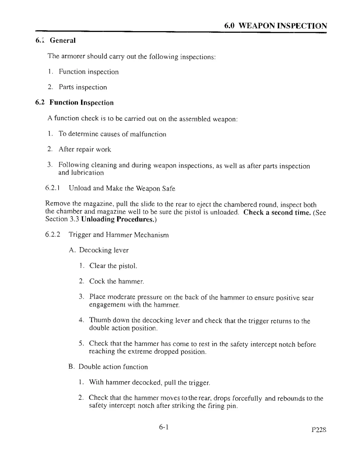
6.2.2 Trigger and Hammer Mechanism
A. Decocking lever
1. Clear the pistol.
2. Cock the hammer.
3. Place moderate pressure on the back of the hammer to ensure positive sear
engagement with the hammer.
4. Thumb down the decocking lever and check that the trigger returns to the
double action position.
5. Check that the hammer has come to rest in the safety intercept notch before
reaching the extreme dropped position.
B. Double action function
1. With hammer decocked, pull the trigger.
2. Check that the hammer moves to the rear, drops forcefully and rebounds to the
safety intercept notch after striking the firing pin.
6-1
P.228
6.0 WEAPON INSPECTION
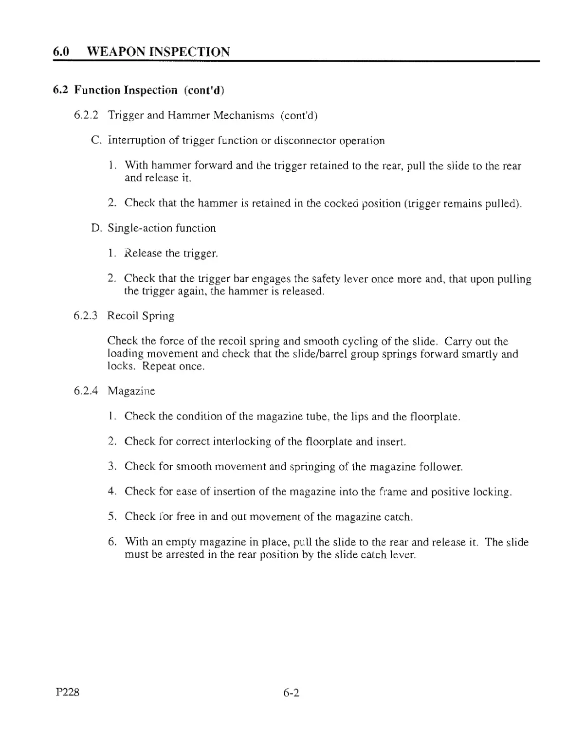
6.2 Function Inspection (cont’d)
6.2.2 Trigger and Hammer Mechanisms (cont’d)
C. Interruption of trigger function or disconnector operation
1. With hammer forward and the trigger retained to the rear, pull the slide to the rear
and release it.
2. Check that the hammer is retained in the cocked position (trigger remains pulled).
D. Single-action function
1. Release the trigger.
2. Check that the trigger bar engages the safety lever once more and, that upon pulling
the trigger again, the hammer is released.
6.2.3 Recoil Spring
Check the force of the recoil spring and smooth cycling of the slide. Carry out the
loading movement and check that the slide/barrel group springs forward smartly and
locks. Repeat once.
6.2.4 Magazine
1. Check the condition of the magazine tube, the lips and the floorplale.
2. Check for correct interlocking of the floorplate and insert.
3. Check for smooth movement and springing of the magazine follower.
4. Check for ease of insertion of the magazine into the frame and positive locking.
5. Check for free in and out movement of the magazine catch.
6. With an empty magazine in place, pull the slide to the rear and release it. The slide
must be arrested in the rear position by the slide catch lever.
P228
6-2
6.0 WEAPON INSPECTION
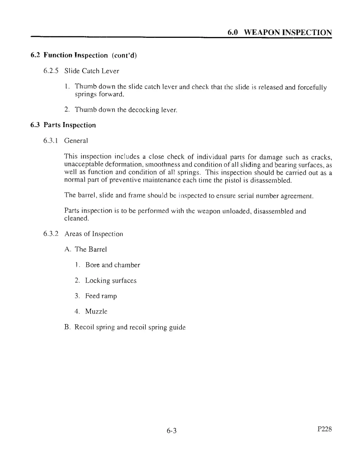
6.2 Function Inspection (cont'd)
6.2.5 Slide Catch Lever
1. Thumb down the slide catch lever and check that the slide is released and forcefully
springs forward.
2. Thumb down the decocking lever.
6.3 Parts Inspection
6.3.1 General
This inspection includes a close check of individual parts for damage such as cracks,
unacceptable deformation, smoothness and condition of all sliding and bearing surfaces, as
well as function and condition of all springs. This inspection should be carried out as a
normal part of preventive maintenance each time the pistol is disassembled.
The barrel, slide and frame should be inspected to ensure serial number agreement.
Parts inspection is to be performed with the weapon unloaded, disassembled and
cleaned.
6.3.2 Areas of Inspection
A. The Barrel
1. Bore and chamber
2. Locking surfaces
3. Feed ramp
4. Muzzle
B. Recoil spring and recoil spring guide
6-3
P228
6.G WEAPON INSPECTION
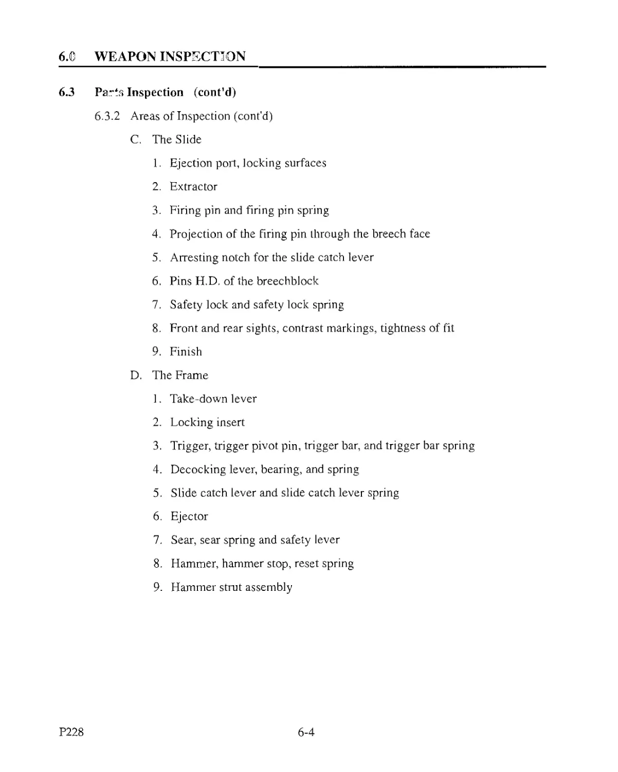
6.3 Parts Inspection (cont’d)
6.3.2 Areas of Inspection (cont’d)
C. The Slide
1. Ejection port, locking surfaces
2. Extractor
3. Firing pin and firing pin spring
4. Projection of the Firing pin through the breech face
5. Arresting notch for the slide catch lever
6. Pins H.D. of the breechblock
7. Safety lock and safety lock spring
8. Front and rear sights, contrast markings, tightness of fit
9. Finish
D. The Frame
1. Take-down lever
2. Locking insert
3. Trigger, trigger pivot pin, trigger bar, and trigger bar spring
4. Decocking lever, bearing, and spring
5. Slide catch lever and slide catch lever spring
6. Ejector
7. Sear, sear spring and safety lever
8. Hammer, hammer stop, reset spring
9. Hammer strut assembly
P228
6-4
6.0 WEAPON INSPECTION
6.3 Parts Inspection (cont'd)
6.3.2 Areas of Inspection (cont'd)
D. The Frame (cont'd)
10. Magazine catch
11. Magazine catch support plate
12. Grip plates, grip plate screws
13. Finish
E. The Magazine
1. Magazine tube and lips
2. Magazine floorplate
3. Magazine insert
4. Magazine spring
5. Magazine follower
6-5
P228
7.0 CLEANING
7.1 Cleaning the Pistol
7.1.1 General
The pistol must be stored in a dry location. Humidity and rapid temperature changes
are detrimental and encourage corrosion. If a pistol is not to be used for some time,
lubricate it well, particularly the bore of the barrel and the exterior surfaces. Clean
the pistol immediately after each use.
7.1.2 Cleaning Procedures
1. Disassemble the pistol after assuring it is UNLOADED.
2. Clean all areas with a cloth treated with a small amount of cleaning solvent.
CAUTION: Some cleaning solvents and treated cloths may be detrimental to the
finish of your weapon. Please read the manufacturers1 warning
labels before using.
3. Cleaning the barrel
CAUTION: Use of a steel brush may be harmful to the smooth barrel surface.
A. To remove all traces of powder residue and bullet fouling from the barrel,
push a wire brush treated with cleaning solvent through the bore at least ten
times, from the chamber end.
B. Dry the barrel using a jag or slotted tip cleaning rod and cloth patches.
C. Continue until the patches inserted into the bore return clean.
4. Reassemble the pistol.
5. Carry out function checks, see (6.2).
6. See lubrication specification (7.1.3).
7.1.3 Lubrication Specifications
DO NOT FIRE THE PISTOL WITHOUT LUBRICATION For user level lu-
brication, place several small drops of oil on both the left and right sides of the frame
rails. Lightly lubricate the interior and exterior of the barrel with emphasis on the
locking surfaces, the muzzle top and bottom, barrel hood where it locks into the
ejection port, and the locking lugs where they engage the locking insert with a light
film of oil. Place several drops of oil on the recoil spring and recoil spring guide.
Lightly lubricate the rib on the bottom of the breechblock along its full length. If
the weapon has been further disassembled, lightly lubricate all moving parts before
reassembly. Assemble the pistol and cycle the slide back and forth several times to
disburse the lubricant evenly. The blued surfaces of the slide should be lightly
treated with a lubricant/preservative to maintain the integrity of the finish. Wipe off
any excess lubrication on the pistol’s exterior. Do not over-lubricate the weapon.
7-1
P228
8.0 WEAPON FUNCTIONS
8.1 Function of the Trigger Assembly
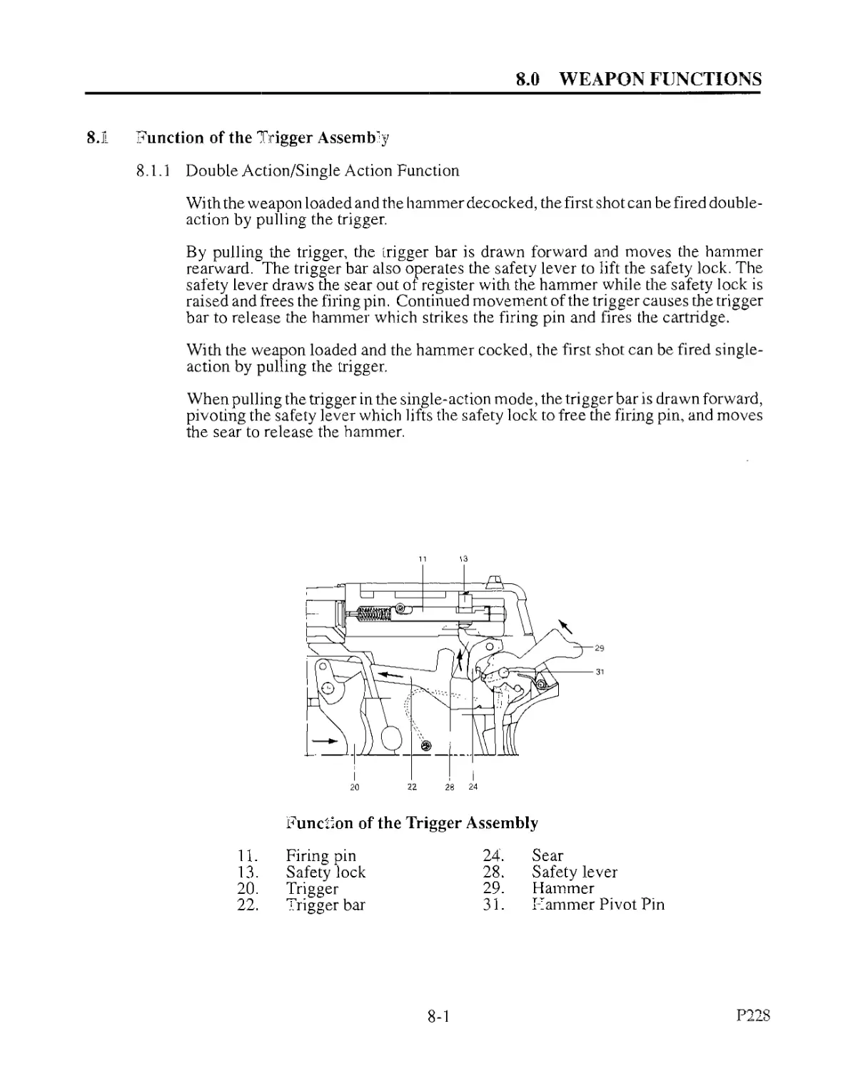
8.1.1 Double Action/Single Action Function
With the weapon loaded and the hammer decocked, the first shot can be fired double-
action by pulling the trigger.
By pulling the trigger, the trigger bar is drawn forward and moves the hammer
rearward. The trigger bar also operates the safety lever to lift the safety lock. The
safety lever draws the sear out of register with the hammer while the safety lock is
raised and frees the firing pin. Continued movement of the trigger causes the trigger
bar to release the hammer which strikes the firing pin and fires the cartridge.
With the weapon loaded and the hammer cocked, the first shot can be fired single-
action by pulling the trigger.
When pulling the trigger in the single-action mode, the trigger bar is drawn forward,
pivoting the safety lever which lifts the safety lock to free the firing pin, and moves
the sear to release the hammer.
Function of the Trigger Assembly
11. Firing pin 24. Sear
13. Safety lock 28. Safety lever
20. Trigger 29. Hammer
22. Trigger bar 31. I’ammer Pivot Pin
8-1
P228
8.0 WEAPON FUNCTIONS
8.1 Function of the Trigger Assembly (cont'd)
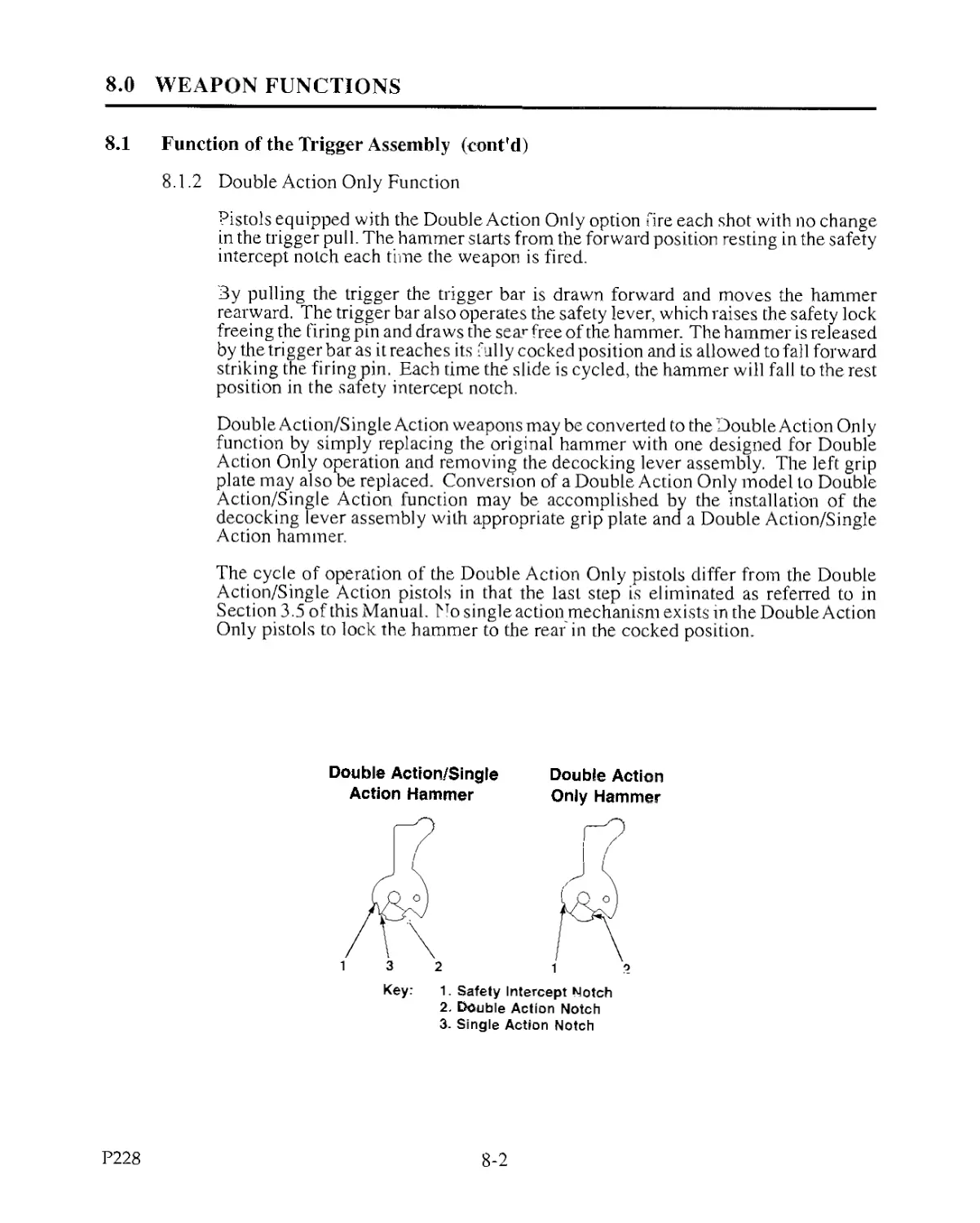
8.1.2 Double Action Only Function
Pistols equipped with the Double Action Only option fire each shot with no change
in the trigger pull. The hammer starts from the forward position resting in the safety
intercept notch each time the weapon is fired.
3y pulling the trigger the trigger bar is drawn forward and moves the hammer
rearward. The trigger bar also operates the safety lever, which raises the safety lock
freeing the firing pin and draws the sear free of the hammer. The hammer is released
by the trigger bar as it reaches its f ully cocked position and is allowed to fall forward
striking the firing pin. Each time the slide is cycled, the hammer will fall to the rest
position in the safety intercept notch.
Double Action/Single Action weapons may be converted to the Double Action Only
function by simply replacing the original hammer with one designed for Double
Action Only operation and removing the decocking lever assembly. The left grip
plate may also be replaced. Conversion of a Double Action Only model to Double
Action/Single Action function may be accomplished by the installation of the
decocking lever assembly with appropriate grip plate and a Double Action/Single
Action hammer.
The cycle of operation of the Double Action Only pistols differ from the Double
Action/Single Action pistols in that the last step is eliminated as referred to in
Section 3.5 of this Manual. No single action mechanism exists in the Double Action
Only pistols to lock the hammer to the rear in the cocked position.
Double Action/Single
Action Hammer
Double Action
Only Hammer
Key: 1. Safety Intercept Notch
2. Double Action Notch
3. Single Action Notch
P228
8-2
8.0 WEAPON FUNCTIONS
8.1 Function of the Trigger Assembly (conf d)
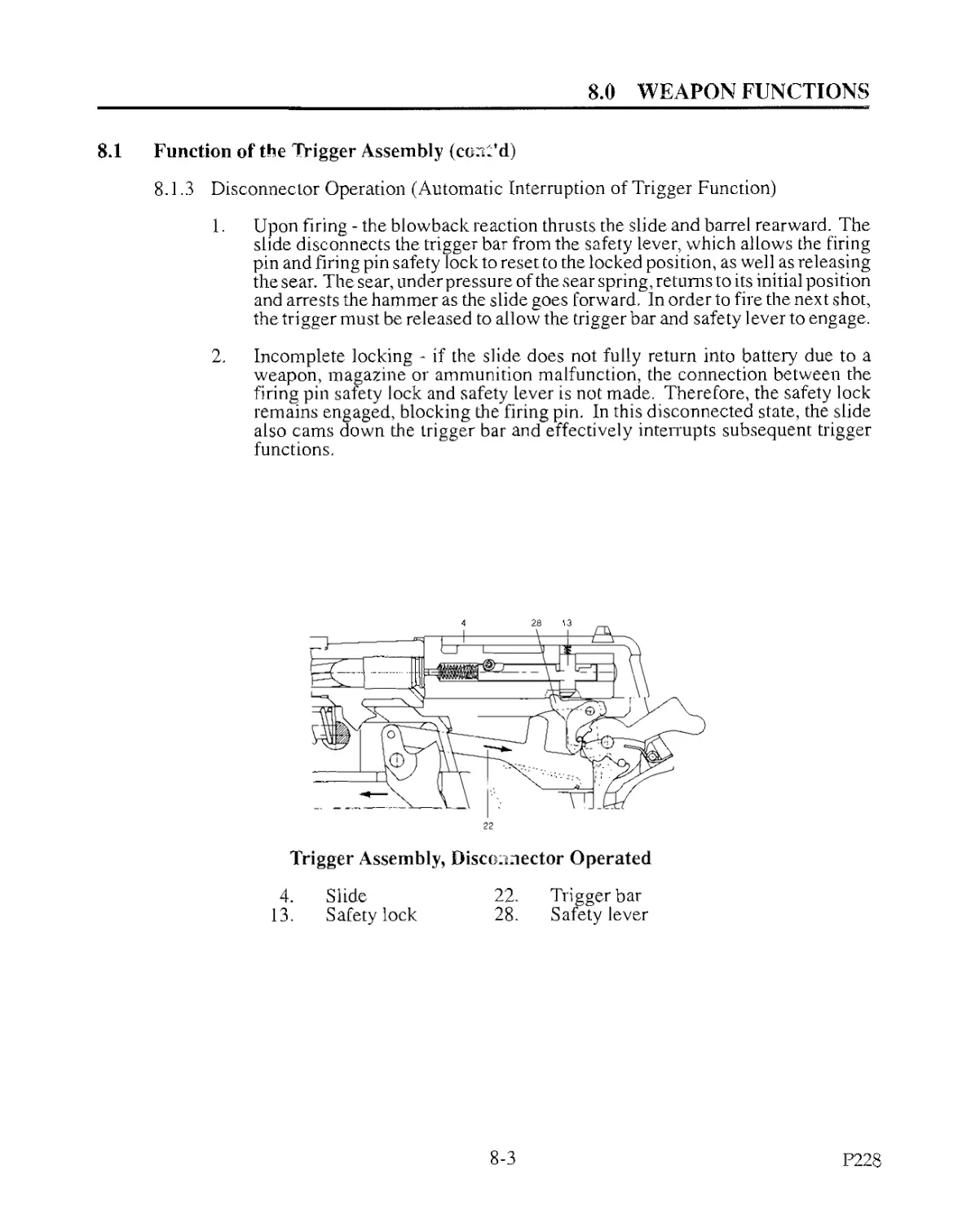
8.1.3 Disconnector Operation (Automatic Interruption of Trigger Function)
1. Upon firing - the blowback reaction thrusts the slide and barrel rearward. The
slide disconnects the trigger bar from the safety lever, which allows the firing
pin and firing pin safety lock to reset to the locked position, as well as releasing
the sear. The sear, under pressure of the sear spring, returns to its initial posi tion
and arrests the hammer as the slide goes forward. In order to fire the next shot,
the trigger must be released to allow the trigger bar and safety lever to engage.
2. Incomplete locking - if the slide does not fully return into battery due to a
weapon, magazine or ammunition malfunction, the connection between the
firing pin safety lock and safety lever is not made. Therefore, the safety lock
remains engaged, blocking the firing pin. In this disconnected state, the slide
also cams down the trigger bar and effectively interrupts subsequent trigger
functions.
Trigger Assembly, Disconnector Operated
4.
13.
Slide
Safety lock
22.
28.
Trigger bar
Safety lever
8-3
P228
8.0 WEAPON FUNCTIONS
8.1 Function of the Trigger Assembly (cont’d)
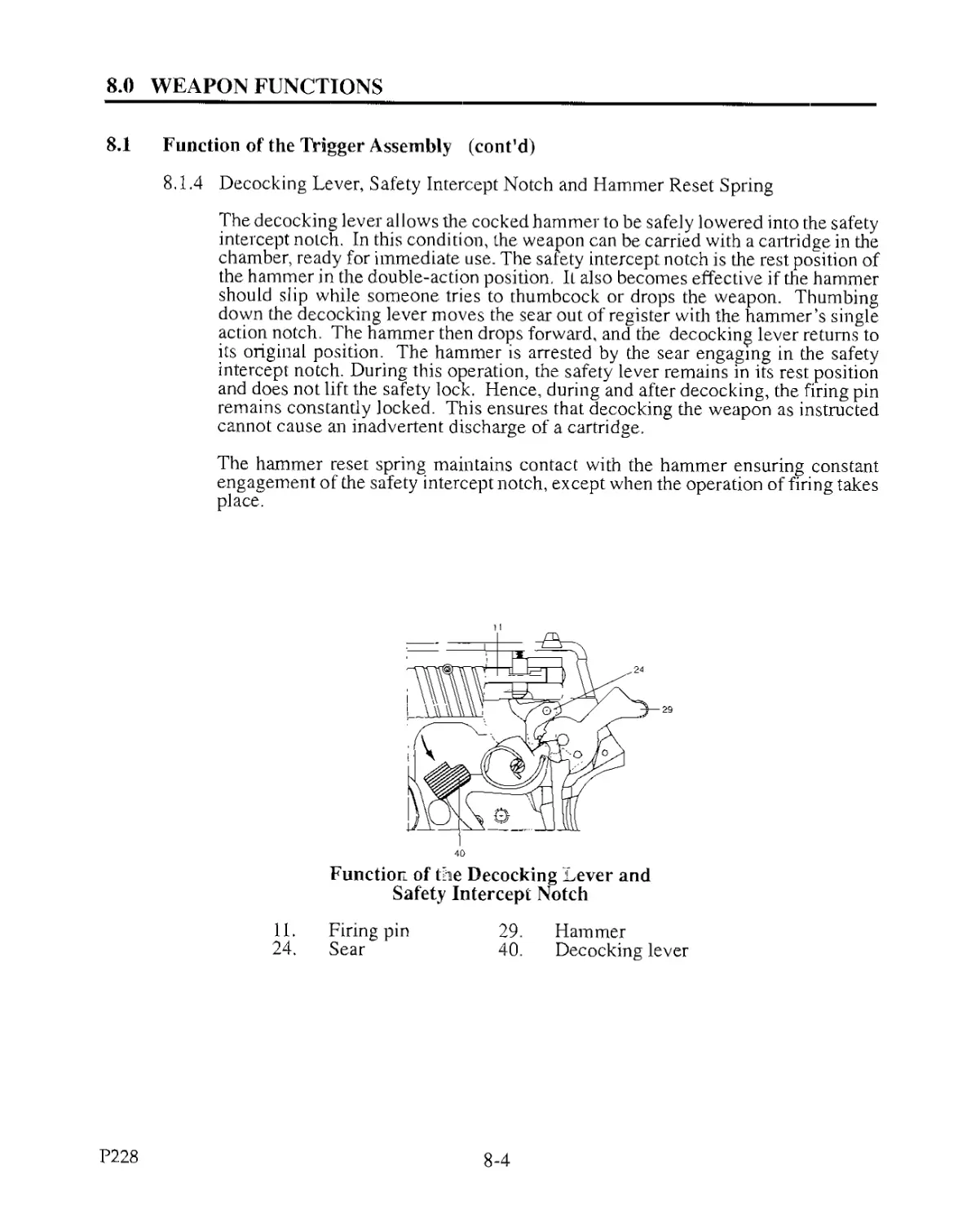
8,1.4 Decocking Lever, Safety Intercept Notch and Hammer Reset Spring
The decocking lever allows the cocked hammer to be safely lowered into the safety
intercept notch. In this condition, the weapon can be carried with a cartridge in the
chamber, ready for immediate use. The safety intercept notch is the rest position of
the hammer in the double-action position. It also becomes effective if the hammer
should slip while someone tries to thumbcock or drops the weapon. Thumbing
down the decocking lever moves the sear out of register with the hammer’s single
action notch. The hammer then drops forward, and the decocking lever returns to
its original position. The hammer is arrested by the sear engaging in the safety
intercept notch. During this operation, the safety lever remains in its rest position
and does not lift the safety lock. Hence, during and after decocking, the firing pin
remains constantly locked. This ensures that decocking the weapon as instructed
cannot cause an inadvertent discharge of a cartridge.
The hammer reset spring maintains contact with the hammer ensuring constant
engagement of the safety intercept notch, except when the operation of firing takes
place.
Function of the Decocking Lever and
Safety Intercept Notch
11. Firing pin 29. Hammer
24. Sear 40. Decocking lever
P228
8-4
8.0 WEAPON FUNCTIONS
8.1 Function of the Trigger Assembly (cont'd)
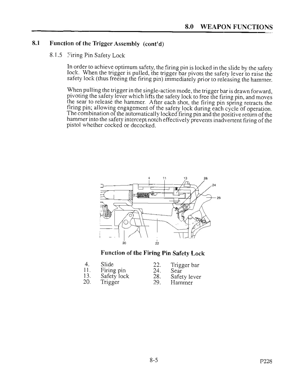
8.1.5 Firing Pin Safety Lock
In order to achieve optimum, safety, the firing pin is locked in the slide by the safety
lock. When the trigger is pulled, the trigger bar pivots the safety lever to raise the
safety lock (thus freeing the firing pin) immediately prior to releasing the hammer.
When pulling the trigger in the single-action mode, the trigger bar is drawn forward,
pivoting the safety lever which lifts the safety lock to free the firing pin, and moves
the sear to release the hammer. After each shot, the firing pin spring retracts the
firing pin; allowing engagement of the safety lock during each cycle of operation.
The combination of the automatically locked firing pin and the positive return of the
hammer into the safety intercept notch effectively prevents inadvertent firing of the
pistol whether cocked or decocked.
Function of the Firing Pin Safety Lock
4.
11.
13.
20.
Slide
Firing pin
Safety lock
Trigger
22.
24.
28.
29.
Trigger bar
Sear
Safety lever
Hammer
8-5
P228
8.0 WEAPON FUNCTIONS
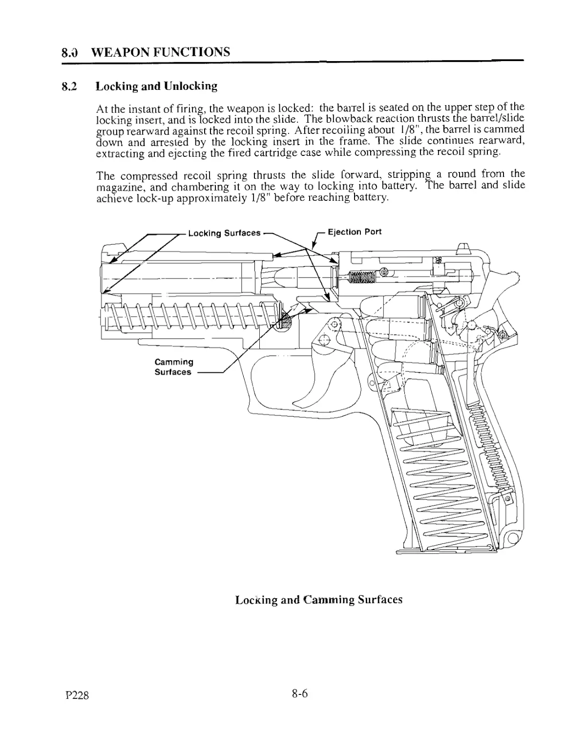
8.2 Locking and Unlocking
At the instant of firing, the weapon is locked: the barrel is seated on the upper step of the
locking insert, and is locked into the slide. The blowback reaction thrusts the banel/slide
group rearward against the recoil spring. After recoiling about 1/8", the barrel is cammed
down and arrested by the locking insert in the frame. The slide continues rearward,
extracting and ejecting the fired cartridge case while compressing the recoil spring.
The compressed recoil spring thrusts the slide forward, stripping a round from the
magazine, and chambering it on the way to locking into battery. The barrel and slide
achieve lock-up approximately 1/8" before reaching battery.
Locking and Camming Surfaces
P228
8-6
8.0 WEAPON FUNCTIONS
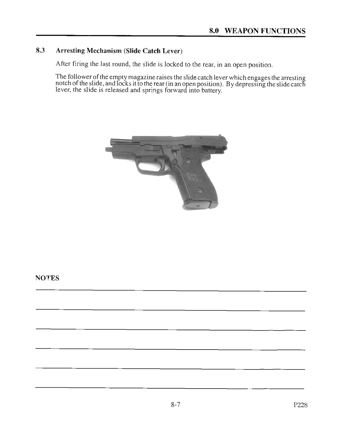
8.3 Arresting Mechanism (Slide Catch Lever)
After firing the last round, the slide is locked to the rear, in an open position.
The follower of the empty magazine raises the slide catch lever which engages the arresting
notch of the slide, and locks it to the rear (in an open position). By depressing the slide eaten
lever, the slide is released and springs forward into battery.
NOTES
8-7
P228
9.0 THE SLIDE - DISASSEMBLY AND ASSEMBLY
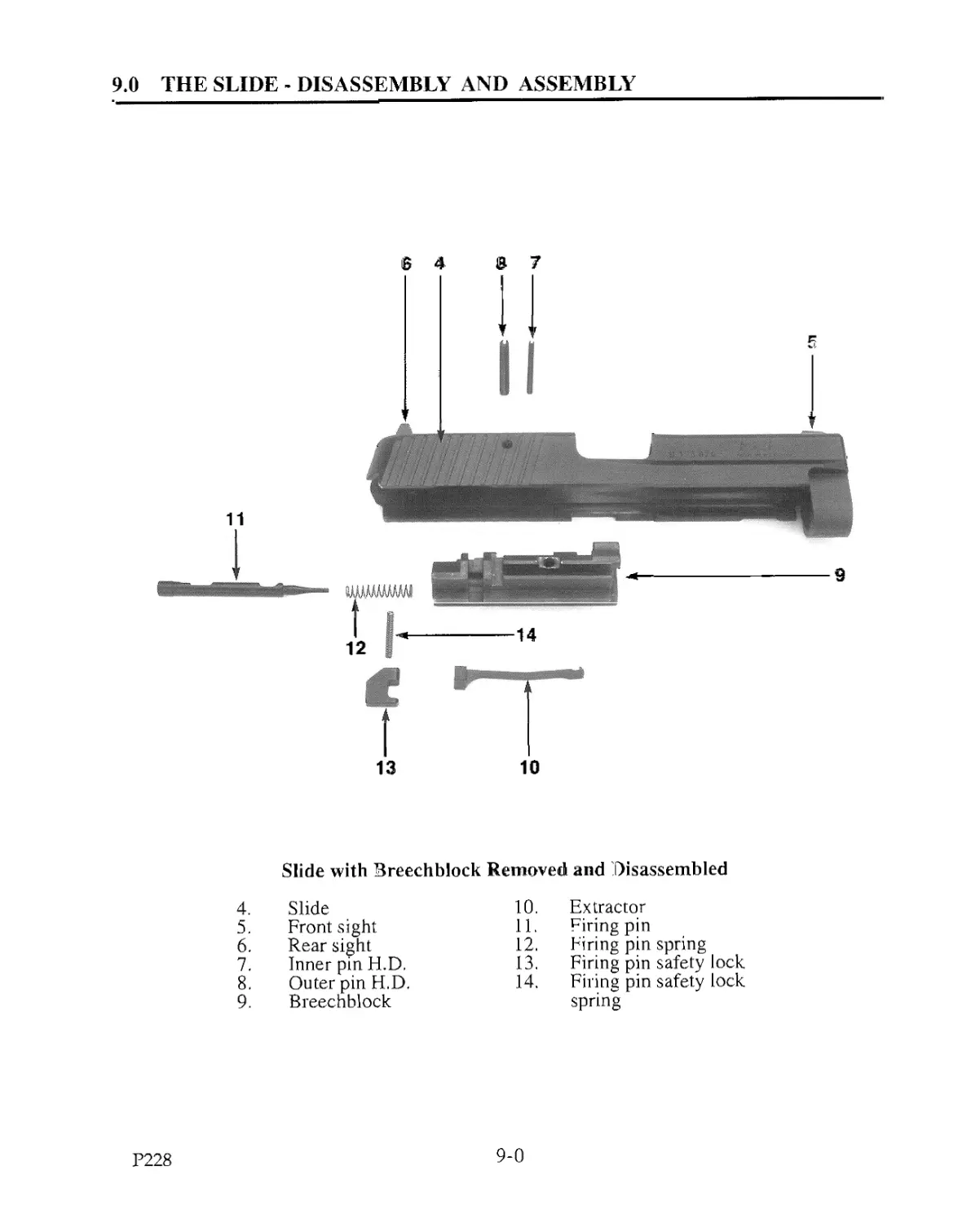
Slide with Breechblock Removed and Disassembled
4. Slide 10. Extractor
5. Front sight 11. Firing pin
6. Rear sight 12. Firing pin spring
7. Inner pin H.D, 13. Firing pin safety lock
8. Outer pin H.D. 14. Firing pin safety lock
9. Breechblock spring
P228
9-0
9.0 THE SLIDE - DISASSEMBLY AND ASSEMBLY
9.1 Removal and Disassembly of the Breechblock
Sequence of Operations
1. Place the slide on a suitable surface.
2. Knock out the inner and outer pins H.D. with a 1/8" roll pin punch.
NOTE: The inner and outer pins H.D. are not reusable and must be replaced
once removed from the slide.
3. Remove the breechblock from the slide.
4. Press the firing pin forward and extract the firing pin safety lock and firing pin safety
lock spring from the side of the breechblock.
5. Remove the firing pin safety lock spring from the firing pin safety lock.
6. Remove the firing pin and firing pin spring from the breechblock.
7. Loosen the extractor at its rear by means of a 1/8 " screwdriver; and, while guiding
the claw, remove it from the breechblock.
8. By simultaneous turning and pulling in a clockwise direction, remove the firing pin
spring from the firing pin. (NO^E: grip tightly where the firing pin spring attaches
to the firing pin.)
9.2 Assembly and Installation oj the Breechblock
Sequence of Operations
1. With narrow end leading, push the firing pin spring onto the firing pin.
2. Insert the extractor parallel from the side until the rear rectangular end is properly
seated.
3. Insert the firing pin into the breechblock bore, with the cut-outs pointing upwards,
towards the top of the breechblock.
4. Push the firing pin forward, insert the firing pin safety lock from the side and seat
it, locking the firing pin into the breechblock.
5. Place the firing pin safety lock spring in the safety lock.
9-1
P228
9.0 THE SLIDE - DISASSEMBLY AND ASSEMBLY
9.2 Assembly and Installation of the Breechblock (cont'd)
Sequence of Operations (cont'd)
6. Start the outer pin H.D. (with the slot at 12 o’clock), into the slide, so that it is flush
with the inside of the slide.
7. While holding the breechblock by its under rib, insert it straight into the slide, ensuring
that it is fully seated.
8. With the thumb and index finger holding the breechblock in place, drive in the outer
pin H.D. until it enters the first half of the breechblock. Depress the firing pin slightly
to allow the outer pin H.D. to pass, and retain it. At this point, start the inner pin
H.D.with its slot positioned opposite that of the outer pin H.D.and drive it flush. Then
continue installation of the inner and outer pins H.D. until they are centered in
the slide.
NOTE: The slot of the outer pin H.D.should point upward at 12 o’ clock and the slot of
the inner pin H.D.should point down at 6 o’ clock.
9. Check to ensure that the firing pin and the firing pin safety lock are functioning safely
and smoothly.
NOTES
P228
9-2
10.0 THE FRAME - DISASSEMBLY AND ASSEMBLY
21
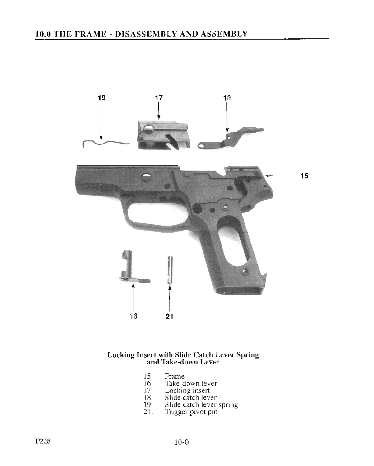
Locking Insert with Slide Catch Lever Spring
and Take-down Lever
15. Frame
16. Take-down lever
17. Locking insert
18. Slide catch lever
19. Slide catch lever spring
21. Trigger pivot pin
P228
10-0
10.0 THE FRAME - DISASSEMBLY AND ASSEMBLY
10.1 Locking Insert
10.1.1 Removal
Sequence of Operations:
1. Remove the slide from the frame.
2. Decock the hammer using the decocking lever.
3. Rotate the take-down lever upwards to the vertical position. While turning
and pulling simultaneously push the take-down lever from the opposite side
of the frame and extract it.
4. Push the locking insert and slide catch lever spring forward, removing them
from the frame.
5. Remove the slide catch lever spring from the locking insert.
10.1.2 Installation
Sequence of Operations:
1. Insert the slide catch lever spring, with its hook in the hole of the locking
insert.
2. Position the d igger pivot pin so that the notches are down and the slot at the
pin's end is horizontal.
3. Insert the locking insert into the frame from the front until the holes for the
take-down lever are aligned.
4. Insert the take-down lever vertically, fully seating it by turning and
simultaneously pushing inward.
NOTE: Trigger and hammer must be forward in the double action position
before removing or installing the locking Insert.
10-1
P228
10.0 THE FRAME - DISASSEMBLY AND ASSEMBLY
10.2 Grip Plates, Left and Right
10.2.1 Removal
Sequence of Operations:
1. Using a proper fitting screwdriver, remove the grip plate screws.
2. Carefully remove the right grip plate and the left grip plate.
10.2.2 Installation
To install, reverse the order used for removal.
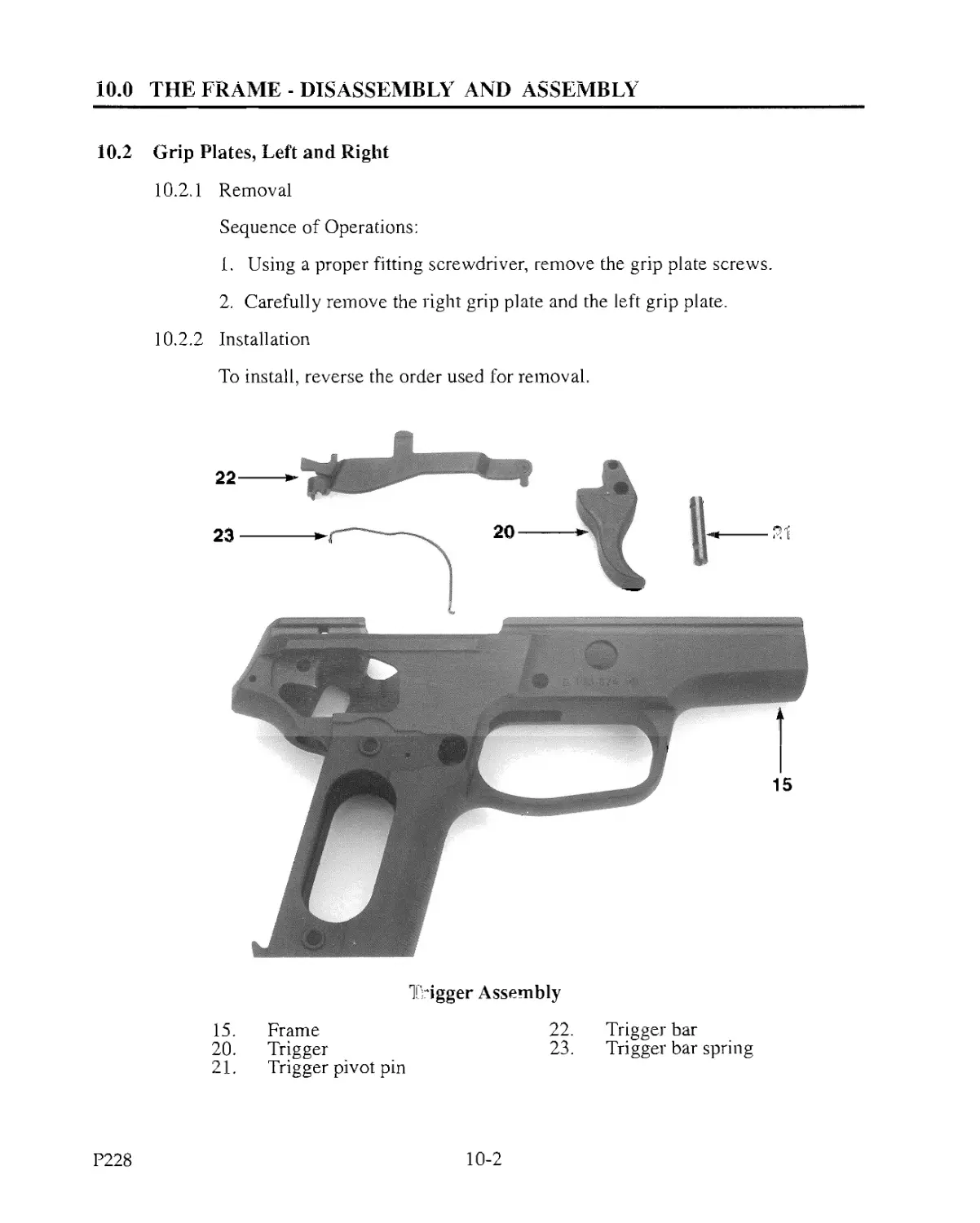
Trigger Assembly
15. Frame
20. Trigger
21. Trigger pivot pin
22. Trigger bar
23. Trigger bar spring
P228
10-2
10.0 THE FRAME - DISASSEMBLY AND ASSEMBLY
10.3 Trigger Assembly
10.3.1 Disassembly
Sequence of Operations:
1. Remove the takedown lever.
2. Remove the locking insert.
3. Remove the right grip plate and the left grip plate.
4. Unhook the trigger bar spring and remove it.
5. Push out the trigger pivot pin from either side.
6. Remove the slide catch lever by lifting it up and out of the frame.
7. Remove the trigger and trigger bar from the frame, diagonally to the front and
upward.
8. Disconnect the trigger bar from the trigger.
10.3.2 Assembly
Sequence of Operations:
1. Connect the trigger bar and the trigger, and place them into the frame.
2. Insert the trigger pivot pin from the right, notches down and the slot
at the end of the pin left and horizontal.
3. Insert the slide catch lever, centering it on the trigger pivot pin.
4. Reinstall the trigger bar spring, making sure that it is properly positioned
on the trigger bar.
5. Install the right grip plate, the left grip plate and the grip plate screws.
6. Install the locking insert and take-down lever.
10-3
P228
10.0 THE FRAME - DISASSEMBLY AND ASSEMBLY
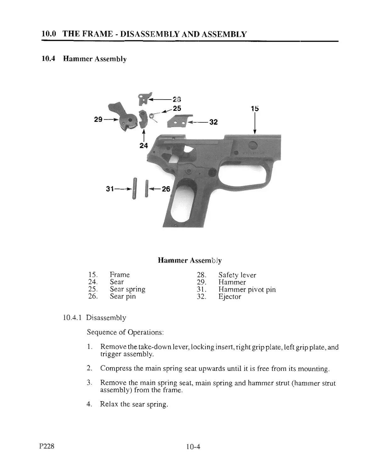
10.4 Hammer Assembly
Hammer Assembly
15. Frame 28. Safety lever
24. Sear 29. Hammer
25. Sear spring 31. Hammer pivot pin
26. Sear pin 32. Ejector
10.4.1 Disassembly
Sequence of Operations:
1. Remove the take-down lever, locking insert, right grip plate, left grip plate, and
trigger assembly.
2. Compress the main spring seat upwards until it is free from its mounting.
3. Remove the main spring seat, main spring and hammer strut (hammer strut
assembly) from the frame.
4. Relax the sear spring.
P228
10-4
10.0 THE FRAME - DISASSEMBLY AND ASSEMBLY
10.4 Hammer Assembly (cont'd)
10.4.1 Disassembly (cont'd)
5. Push out the sear pin.
6. Remove the safety lever, sear and sear spring.
7. Remove the ejector.
8. Push out the hammer pivot pin.
9. Remove the hammer.
10.4.2 Assembly
Sequence of Operations:
1. Install the hammer and hammer pivot pin.
2. Insert the hammer strut assembly through its opening in the frame.
3. Position the hammer strut into the hammer and mount the main spring seat to
the frame.
4. Install the ejector.
5. Insert the sear pin into the frame from the right.
6. Install the safety lever on sear pin.
7. Fit the sear in the frame, maintain its position with the sear pin.
8. Position the sear spring in the sear, center the sear pin in the frame.
9. Tension the sear spring beneath the sear spring pin H.D.
10. Reinstall the trigger assembly, locking insert, take-down lever and grip plates.
10-5
P228
10.0 THE FRAME - DISASSEMBLY AND ASSEMBLY
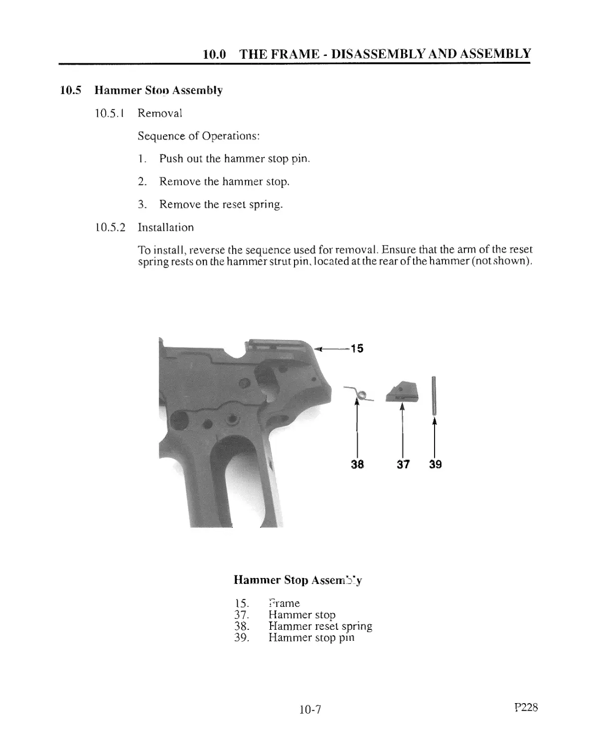
10.5
Hammer Stoo Assembly
10.5.1 Removal
Sequence of Operations:
1. Push out the hammer stop pin.
2. Remove the hammer stop.
3. Remove the reset spring.
10.5.2 Installation
To install, reverse the sequence used for removal. Ensure that the arm of the reset
spring rests on the hammer strut pin, located at the rear of the hammer (not shown).
Hammer Stop Assemb'y
15. Prame
37. Hammer stop
38. Hammer reset spring
39. Hammer stop pin
10-7
P228
10,0 THE FRAME - DISASSEMBLY AND ASSEMBLY
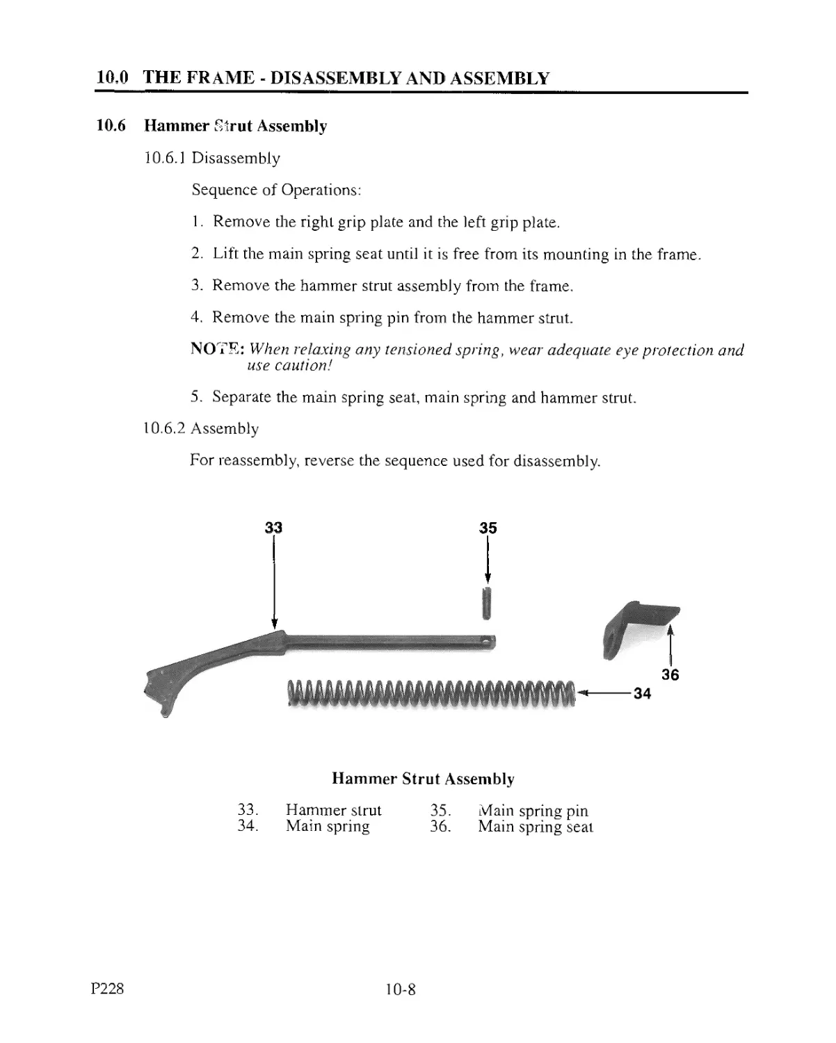
10.6
Hammer Strut Assembly
10.6.1 Disassembly
Sequence of Operations:
1. Remove the right grip plate and the left grip plate.
2. Lift the main spring seat until it is free from its mounting in the frame.
3. Remove the hammer strut assembly from the frame.
4. Remove the main spring pin from the hammer strut.
NOTE: When relaxing any tensioned spring, wear adequate, eye protection and
use caution!
5. Separate the main spring seat, main spring and hammer strut.
10.6.2 Assembly
For reassembly, reverse the sequence used for disassembly.
Hammer Strut Assembly
33. Hammer strut 35. Main spring pin
34. Main spring 36. Main spring seat
P228
10-8
10.0 THE FRAME - DISASSEMBLY AND ASSEMBLY
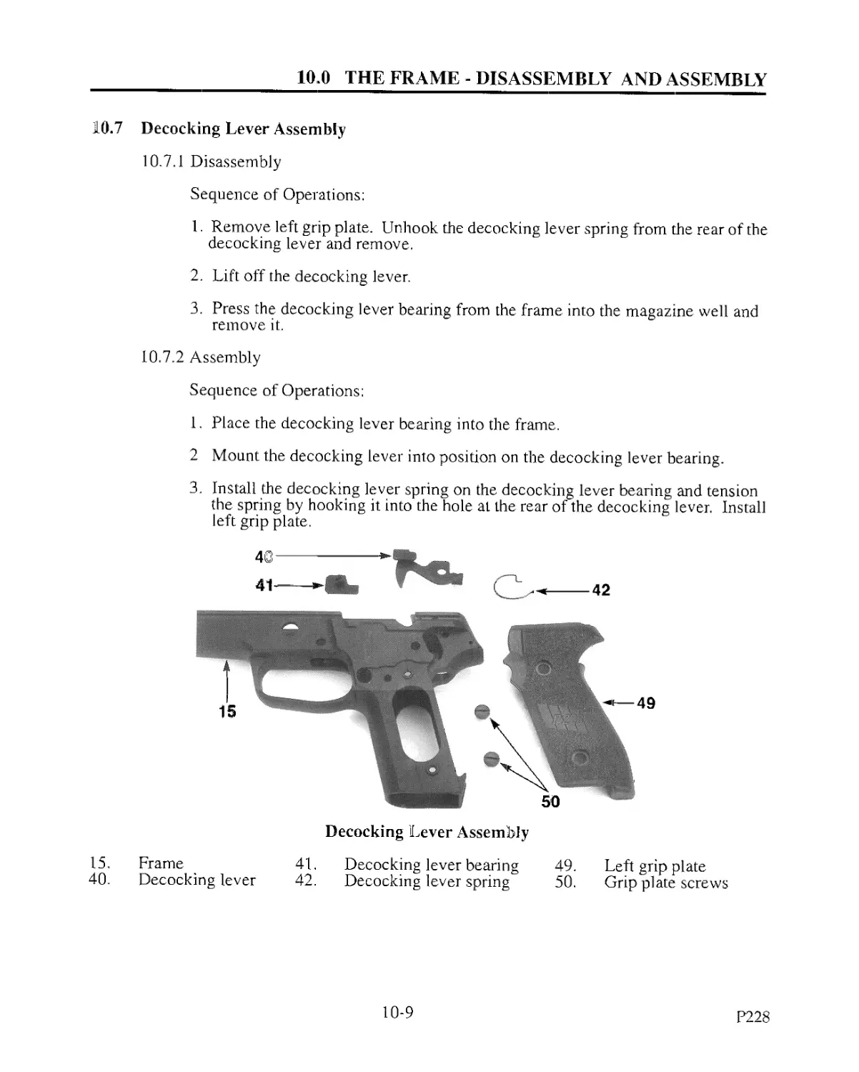
10.7 Decocking Lever Assembly
10.7.1 Disassembly
Sequence of Operations;
1. Remove left grip plate. Unhook the decocking lever spring from the rear of the
decocking lever and remove.
2. Lift off the decocking lever.
3. Press the decocking lever bearing from the frame into the magazine well and
remove it.
10.7.2 Assembly
Sequence of Operations;
1. Place the decocking lever bearing into the frame.
2 Mount the decocking lever into position on the decocking lever bearing.
3. Install the decocking lever spring on the decocking lever bearing and tension
the spring by hooking it into the hole at the rear of the decocking lever. Install
left grip plate.
Decocking Lever Assembly
15. Frame 41. Decocking lever bearing 49. Left grip plate
40. Decocking lever 42. Decocking lever spring 50. Grip plate screws
10-9
P228
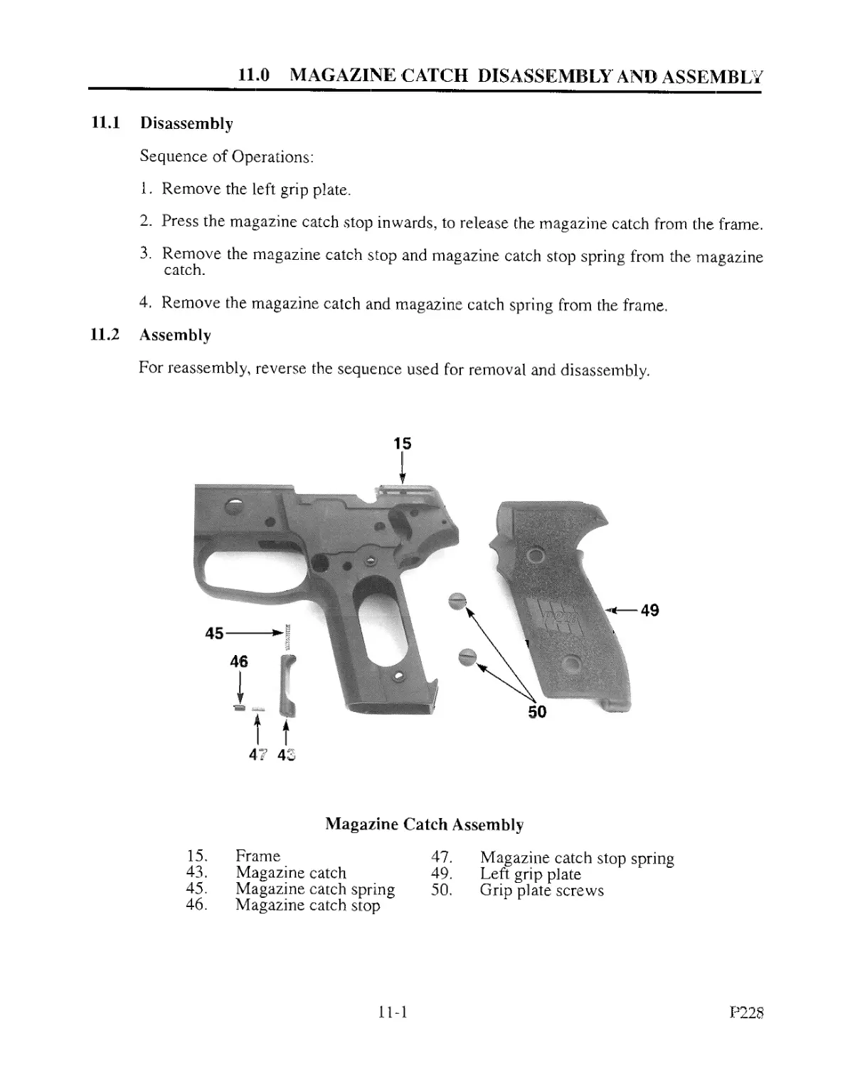
11.0 MAGAZINE CATCH DISASSEMBLY AND ASSEMBLY
11.1
11.2
Disassembly
Sequence of Operations:
1. Remove the left grip plate.
2. Press the magazine catch stop inwards, to release the magazine catch from the frame.
3. Remove the magazine catch stop and magazine catch stop spring from the magazine
catch.
4, Remove the magazine catch and magazine catch spring from the frame.
Assembly
For reassembly, reverse the sequence used for removal and disassembly.
15
Magazine Catch Assembly
15. Frame 47. Magazine catch stop spring
43. Magazine catch 49. Left grip plate
45. Magazine catch spring 50. Grip plate screws
46. Magazine catch stop
11-1
P228
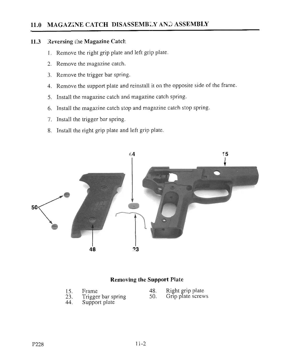
11.0 MAGAZINE CATCH DISASSEMBLY AND ASSEMBLY
11.3 Deversing the Magazine Catch
I. Remove the right grip plate and left grip plate.
2. Remove the magazine catch.
3. Remove the trigger bar spring.
4. Remove the support plate and reinstall it on the opposite side of the frame.
5. Install the magazine catch and magazine catch spring.
6. Install the magazine catch stop and magazine catch stop spring.
7. Install the trigger bar spring.
8. Install the right grip plate and left grip plate.
Removing the Support Plate
15. Frame
23. Trigger bar spring
44. Support plate
48.
50.
Right grip plate
Grip plate screws
P228
11-2
12.0 SIGHT ADJUSTMENT
12.1 Zeroing the P228 Pistol
General Note - No windage or elevation correction should be made until the shooter has
become familiar with the firing characteristics of the weapon.
When zeroing, the target should be at 25 yards and the pistol should be fired from a rested
position using the single-action mode. Sighting should be “point of aim, point of impact.”
1. Windage - A change in windage is accomplished by moving the rear sight either to the
left or right in its dovetail. When doing this, follow the rear sight rule: Move the rear sight
in the direction the group is to go. Moving the rear sight 0.020 inches in the dovetail alters
the point of impact by approximately 3 inches at 25 yards.
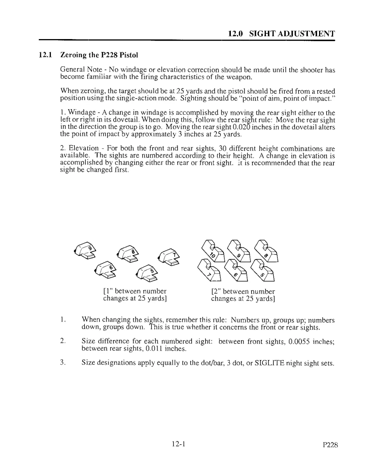
2. Elevation - For both the front and rear sights, 30 different height combinations are
available. The sights are numbered according to their height. A change in elevation is
accomplished by changing either the rear or front sight. It is recommended that the rear
sight be changed first.
[1" between number
changes at 25 yards]
[2" between number
changes at 25 yards]
1. When changing the sights, remember this rule: Numbers up, groups up; numbers
down, groups down. This is true whether it concerns the front or rear sights.
2. Size difference for each numbered sight: between front sights, 0.0055 inches;
between rear sights, 0.011 inches.
3. Size designations apply equally to the dot/bar, 3 dot, or SIGLITE night sight sets.
12-1
P228
12.0 SIGHT ADJUSTMENT
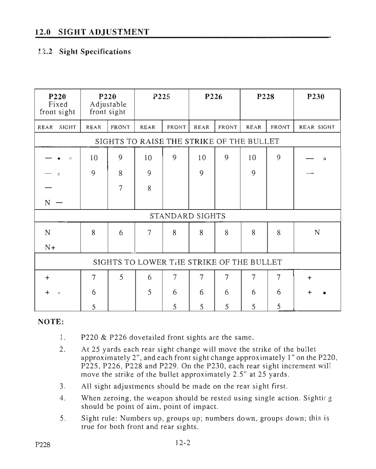
12.2 Sight Specifications
P220 Fixed front sight P220 Adjustable front sight P22S P226 P228 P230
REAR SIGHT REAR FRONT REAR FRONT REAR FRONT REAR FRONT REAR SIGHT
SIGHTS TO RAISE THE STRIKE OF THE BULLET
• o, 10 9 10 9 10 9 10 9 a
c 9 8 9 9 9 —-
— 7 8
N —
STANDARD SIGHTS
N 8 6 7 8 8 8 8 8 N
N+
SIGHTS TO LOWER THE STRIKE OF THE BULLET
+ 7 5 6 7 7 7 7 7 +
+ G 6 5 6 6 6 6 6 + •
5 5 5 5 5 5
NOTE:
1. P220 & P226 dovetailed front sights are the same.
2. At 25 yards each rear sight change will move the strike of the bullet
approximately 2", and each front sight change approximately 1" on the P220,
P225, P226, P228 and P229. On the P230, each rear sight increment will
move the strike of the bullet approximately 2.5" at 25 yards.
3. All sight adjustments should be made on the rear sight first.
4. When zeroing, the weapon should be rested using single action. Sighting
should be point of aim, point of impact.
5. Sight rule: Numbers up, groups up; numbers down, groups down; this is
true for both front and rear sights.
P228
12-2
12.0 SIGHT ADJUSTMENT
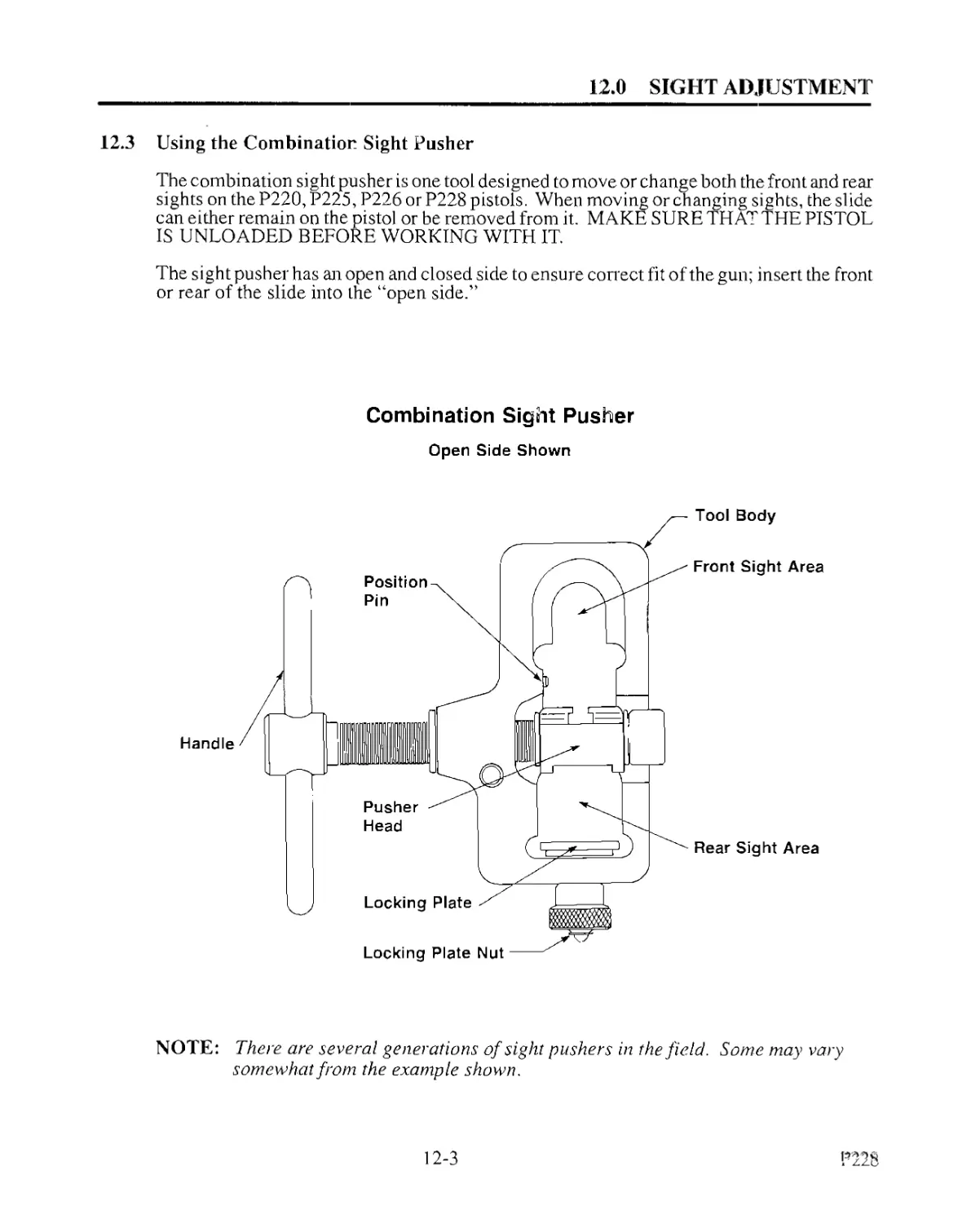
12.3 Using the Combination Sight Pusher
The combination sight pusher is one tool designed to move or change both the front and rear
sights on the P220, P225, P226 or P228 pistols. When moving or changing sights, the slide
can either remain on the pistol or be removed from it. MAKE SURE THAT THE PISTOL
IS UNLOADED BEFORE WORKING WITH IT.
The sight pusher has an open and closed side to ensure correct fit of the gun; insert the front
or rear of the slide into the “open side.”
Combination Sight Pusher
Open Side Shown
NOTE: There are several generations of sight pushers in the field. Some may vary
somewhat from the example shown.
12-3
12.0 SIGHT ADJUSTMENT
12.3 Using the Combination Sight Pusher (coni'd)
12.3.1 Placement of the Pistol in the Sight Pusher
Front Sight: When inserting the front of the slide into the sight pusher, follow
these steps: place the end of the slide into the pusher, center the pusher head
directly over the base of the front sight. Snug the position pin in the sight pusher
against the slide to eliminate movement during the sight adjustment procedure.
Turn the handle to move the pusher head into contact with one side of the sight.
NOTE: The pusher head must be centered over the sight base before
making sight adjustments.
Rear Sight: When inserting the rear of the slide into the pusher, follow these
steps: loosen the locking plate,, insert the slide rails onto the locking plate,
center the rear sight in the pusher head, tighten the locking plate nut.
NOTE: The nut must be finger tight to hold the slide firmly into the tool.
12.3.2 Moving the Sights
To move the sight, rotate the pusher's handle until the pusher head is seated
against the sight, further turning will move the sight for windage adjustments.
12.3.3 Changing the Sights
To change the sights, rotate the pusher's handle to push the sight to the outside of
the pusher (the opposite side from the handle) and off the slide, remove the slide
from the tool and insert the new sight, then put the slide back into the pusher
(making sure to lock it in) and push the new sight into place.
NOTE: Install and remove SIG sights from the left side of the slide, due to
a chamferred edge machined on the right corners of the sight
bases to aid in the ease of sight installation.
P228
12-4
12.0 SIGHT ADJUSTMENT
12.3 Using the Combination Sight Pusher (cont’d)
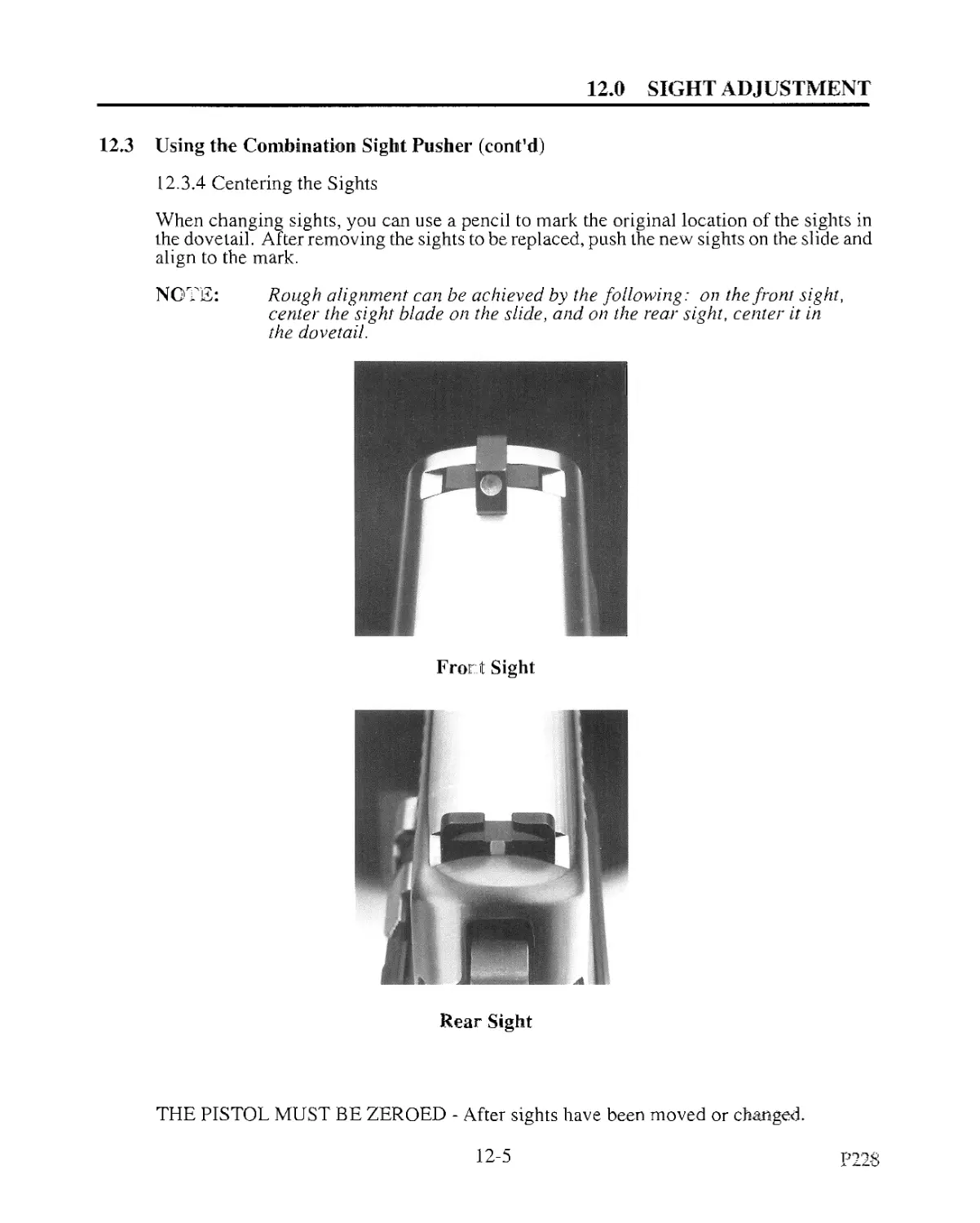
12.3.4 Centering the Sights
When changing sights, you can use a pencil to mark the original location of the sights in
the dovetail. After removing the sights to be replaced, push the new sights on the slide and
align to the mark.
NOTE: Rough alignment can be achieved by the following: on the front sight,
center the sight blade on the slide, and on the rear sight, center it in
the dovetail.
Front Sight
Rear Sight
THE PISTOL MUST BE ZEROED - After sights have been moved or changed.
12-5
P228
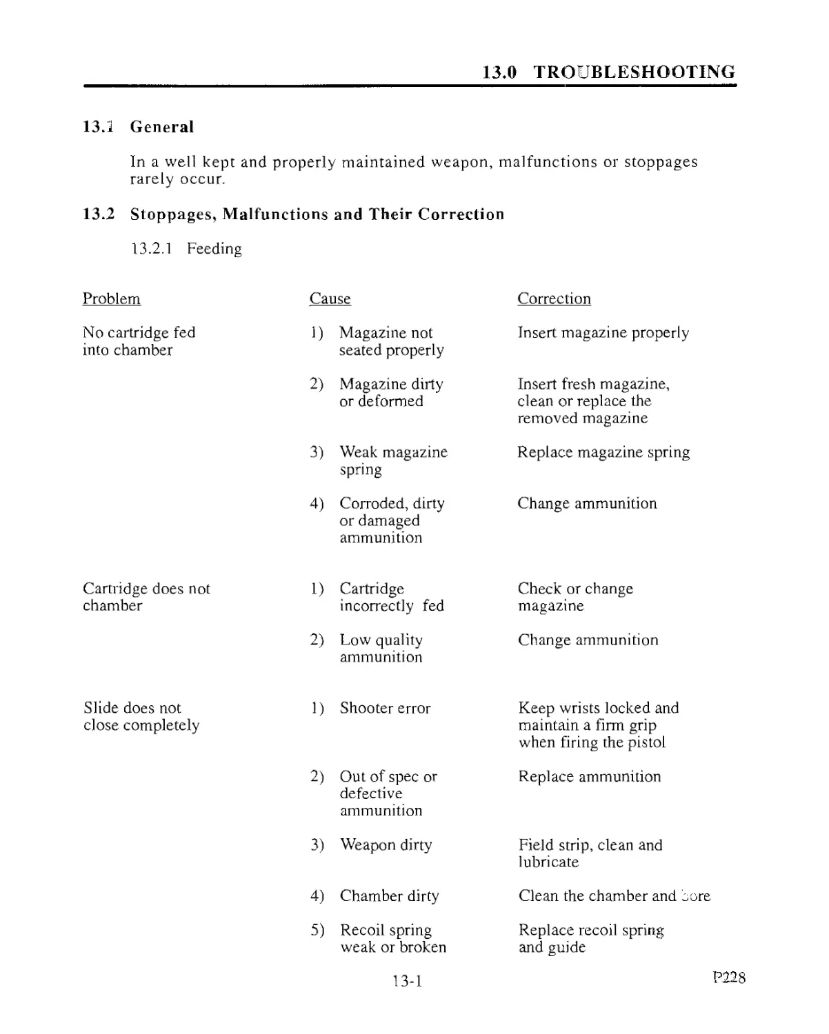
13.0 TROUBLESHOOTING
13.1 General
In a well kept and properly maintained weapon, malfunctions or stoppages
rarely occur.
13.2 Stoppages, Malfunctions and Their Correction
13.2.1 Feeding
Problem
No cartridge fed
into chamber
Cause Correction
1) Magazine not seated properly Insert magazine properly
2) Magazine dirty or deformed Insert fresh magazine, clean or replace the removed magazine
3) Weak magazine spring Replace magazine spring
4) Corroded, dirty or damaged ammunition Change ammunition
Cartridge does not
chamber
1) Cartridge incorrectly fed Check or change magazine
2) Low quality ammunition Change ammunition
Slide does not close completely 1) Shooter error Keep wrists locked and maintain a firm grip when firing the pistol
2) Out of spec or defective ammunition Replace ammunition
3) Weapon dirty Field strip, clean and lubricate
4) Chamber dirty Clean the chamber and core
5) Recoil spring weak or broken Replace recoil spring and guide
13-1
P.228
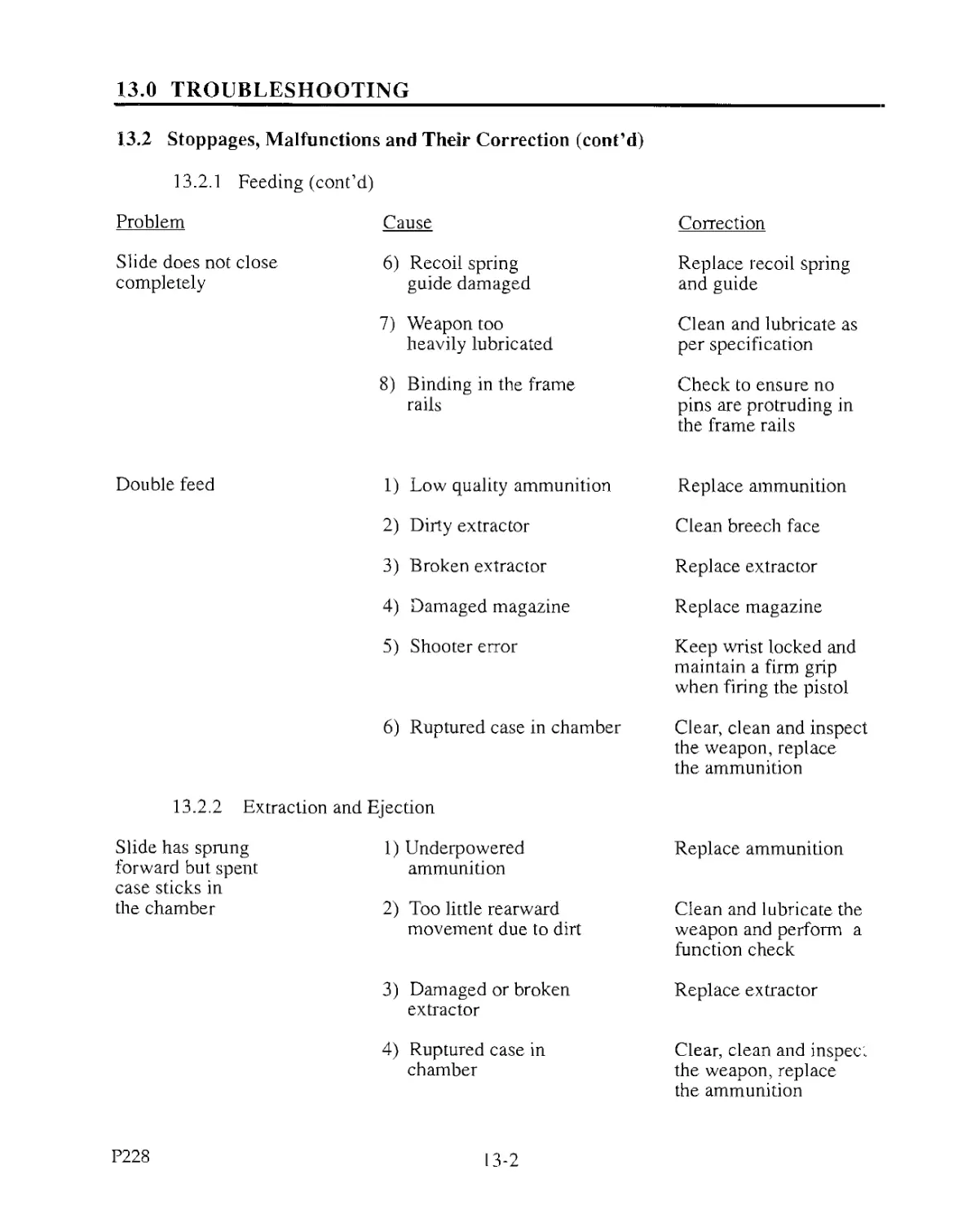
13.0 TROUBLESHOOTING
13.2 Stoppages, Malfunctions and Their Correction (cont’d)
13.2.1 Feeding (cont’d)
Problem Cause Correction
Slide does not close 6) Recoil spring Replace recoil spring
completely guide damaged and guide
7) Weapon too Clean and lubricate as
heavily lubricated per specification
8) Binding in the frame Check to ensure no
rails pins are protruding in
the frame rails
Double feed 1) Low quality ammunition Replace ammunition
2) Dirty extractor Clean breech face
3) Broken extractor Replace extractor
4) Damaged magazine Replace magazine
5) Shooter error Keep wrist locked and maintain a firm grip when firing the pistol
6) Ruptured case in chamber Clear, clean and inspect the weapon, replace the ammunition
13.2.2 Extraction and Ejection
Slide has sprung forward but spent case sticks in 1) Underpowered ammunition Replace ammunition
the chamber 2) Too little rearward movement due to dirt Clean and lubricate the weapon and perform a function check
3) Damaged or broken extractor Replace extractor
4) Ruptured case in chamber Clear, clean and inspect the weapon, replace
the ammunition
P228
13-2
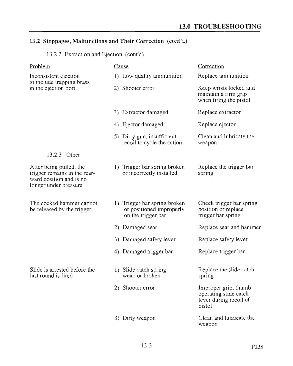
13.0 TROUBLESHOOTING
13.2 Stoppages, Malfunctions and Their Correction (coist’d)
13.2.2 Extraction and Ejection (cont'd)
Problem Cause Correction
Inconsistent ejection to include trapping brass 1) Low quality ammunition Replace ammunition
in the ejection port 13.2.3 Other 2) Shooter error 3) Extractor damaged 4) Ejector damaged 5) Dirty gun, insufficient recoil to cycle the action Keep wrists locked and maintain a firm grip when firing the pistol Replace extractor Replace ejector Clean and lubricate the weapon
After being pulled, the trigger remains in the rear- ward position and is no longer under pressure 1) Trigger bar spring broken or incorrectly installed Replace the trigger bar spring
The cocked hammer cannot be released by the trigger 1) Trigger bar spring broken or positioned improperly on the trigger bar 2) Damaged sear 3) Damaged safety lever 4) Damaged trigger bar Check trigger bar spring position or replace trigger bar spring Replace sear and hammer Replace safety lever Replace trigger bar
Slide is arrested before the last round is fired 1) Slide catch spring weak or broken 2) Shooter error 3) Dirty weapon Replace the slide catch spring Improper grip, thumb operating slide catch lever during recoil of pistol Clean and lubricate the weapon
13-3
1
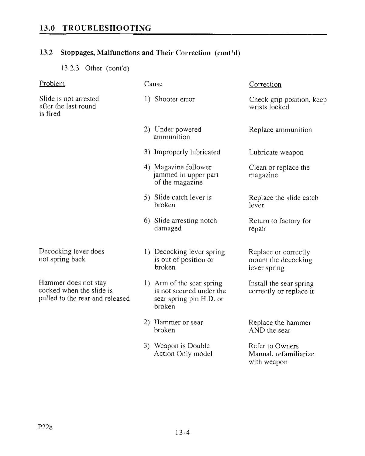
13.0 TROUBLESHOOTING
13.2 Stoppages, Malfunctions and Their Correction (cont’d)
13.2.3 Other (cont’d)
Problem Cause
Slide is not arrested after the last round is fired 1) Shooter error
Correction
Check grip position, keep
wrists locked
Decocking lever does
not spring back
Hammer does not stay
cocked when the slide is
pulled to the rear and released
2) Underpowered
ammunition
3) Improperly lubricated
4) Magazine follower
jammed in upper part
of the magazine
5) Slide catch lever is
broken
6) Slide arresting notch
damaged
Replace ammunition
Lubricate weapon
Clean or replace the
magazine
1) Decocking lever spring
is out of position or
broken
1) Arm of the sear spring
is not secured under the
sear spring pin H.D. or
broken
2) Hammer or sear
broken
3) Weapon is Double
Action Only model
Replace the slide catch
lever
Return to factory for
repair
Replace or correctly
mount the decocking
lever spring
Install the sear spring
correctly or replace it
Replace the hammer
AND the sear
Refer to Owners
Manual, refamiliarize
with weapon
P228
13-4
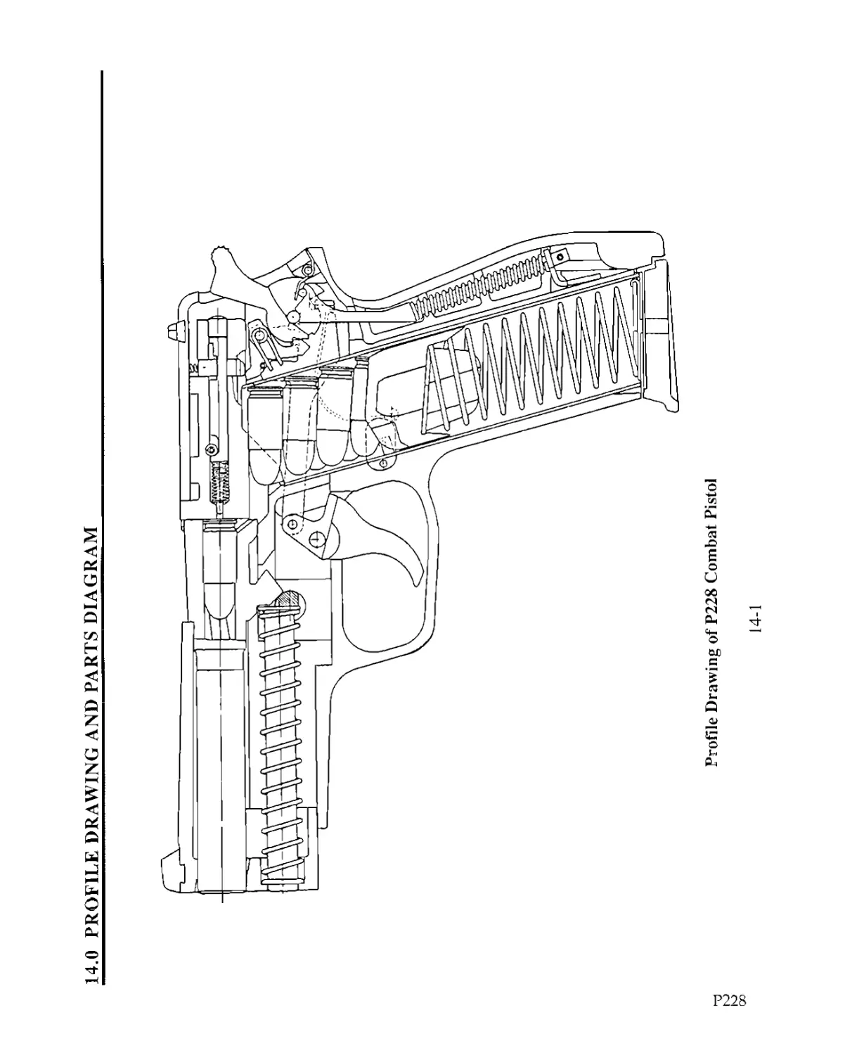
14.0 PROFILE DRAWING AND PARTS DIAGRAM
Р228
Profile Drawing of P228 Combat Pistol
14-1
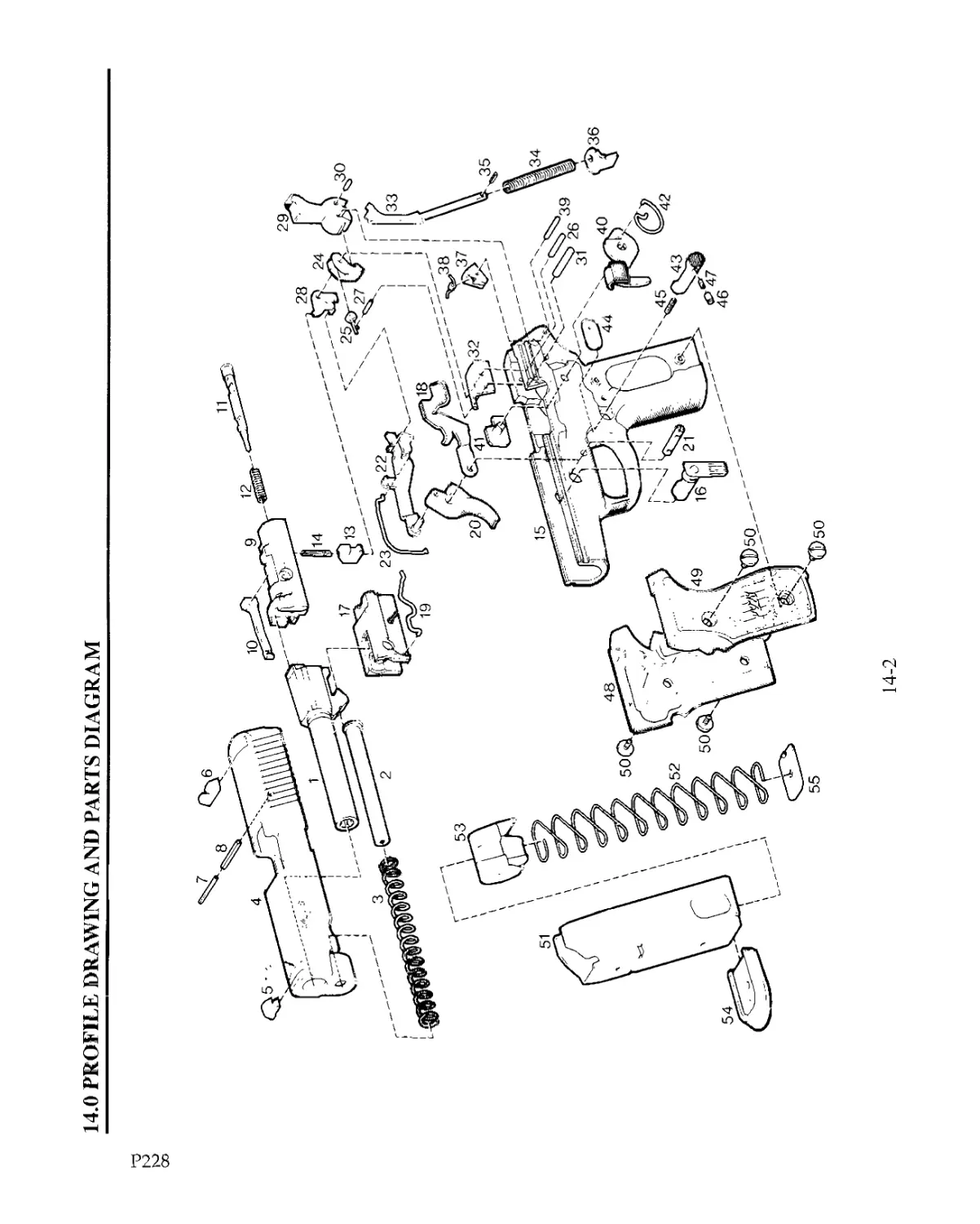
14.0 PROFILE DRAWING AND PARTS DIAGRAM
Р228
14-2
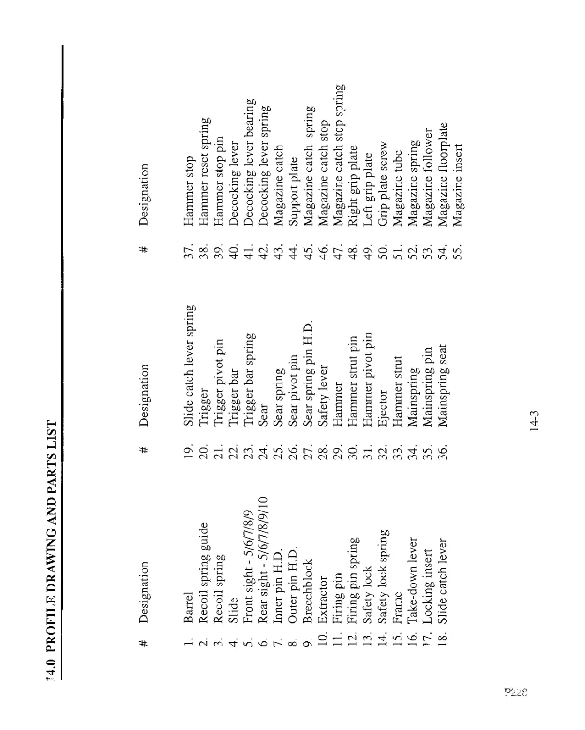
14.0 PROFILE DRAWING AND PARTS LIST
# Designation # Designation # Designation
1. Barre] 19. Slide catch lever spring 37. Hammer stop
2. Recoil spring guide 20. Trigger 38. Hammer reset spring
3. Recoil spring 21. Trigger pivot pin 39. Hammer stop pin
4. Slide 22. Trigger bar 40. Decocking lever
5. Front sight - 5/6/7/8/9 23. Trigger bar spring 41. Decocking lever bearing
6. Rear sight - 5/6/7/8/9/10 24. Sear 42. Decocking lever spring
7. Inner pin H.D. 25. Sear spring 43. Magazine catch
8. Outer pin H.D. 26. Sear pivot pin 44. Support plate
9. Breechblock 27. Sear spring pin H.D. 45. Magazine catch spring
10. Extractor 28. Safety lever 46. Magazine catch stop
11. Firing pin 29. Hammer 47. Magazine catch stop spring
12. Firing pin spring 30. Hammer strut pin 48. Right grip plate
13. Safety lock 31. Hammer pivot pin 49. Left grip plate
14. Safety lock spring 32. Ejector 50. Grip plate screw
15. Frame 33. Hammer strut 51. Magazine tube
16. Take-down lever 34. Mainspring 52. Magazine spring
17. Locking insert 35. Mainspring pin 53. Magazine follower
18. Slide catch lever 36. Mainspring seat 54. Magazine floorplate
55. Magazine insert
14-3
15.0 TOOLS
15.1 Tools Necessary for Weapon Disassembly
(1) Straight Blade Screwdriver suitable for grip plate screw removal
(1) 1/8" Straight Blade Screwdriver
(1) 1/8" Roll Pin Punch
(1) 1/16" Pin Punch
(1) 4 - 8 oz. Hammer
For further assistance after consulting the manual, contact:
SIGARMS, INC.
Corporate Park
Exeter, NH 03833
(603) 772-2302
NOTES:
15-1
P228