/


Теги: weapons military affairs


Текст
|ОСК
PERFECTION
IfmEARM SAFETY"
IS EVERYONE'S BUSINESS
ARMORER’S MANUAL
GLOCK “SAFE ACTION” PISTOLS
THIS ARMORER’S MANUAL WILL BE SUPPLEMENTED
BY TECHNICAL BULLETINS
Information and specifications contained within this manual
may change without notification.
This manual provides basic service and backup information for
certified GLOCK armorers, and is not intended for use otherwise.
fl Certification can only be granted by GLOCK after attending a
GLOCK armorer’s school.
В GLOCK cannot be held responsible for any misinterpretation
of the instructions in this manual that can lead to improper
functioning of the pistol.
В For additional information and service guidelines, contact
GLOCK for your nearest certified field representative.
1
[jgasaa!
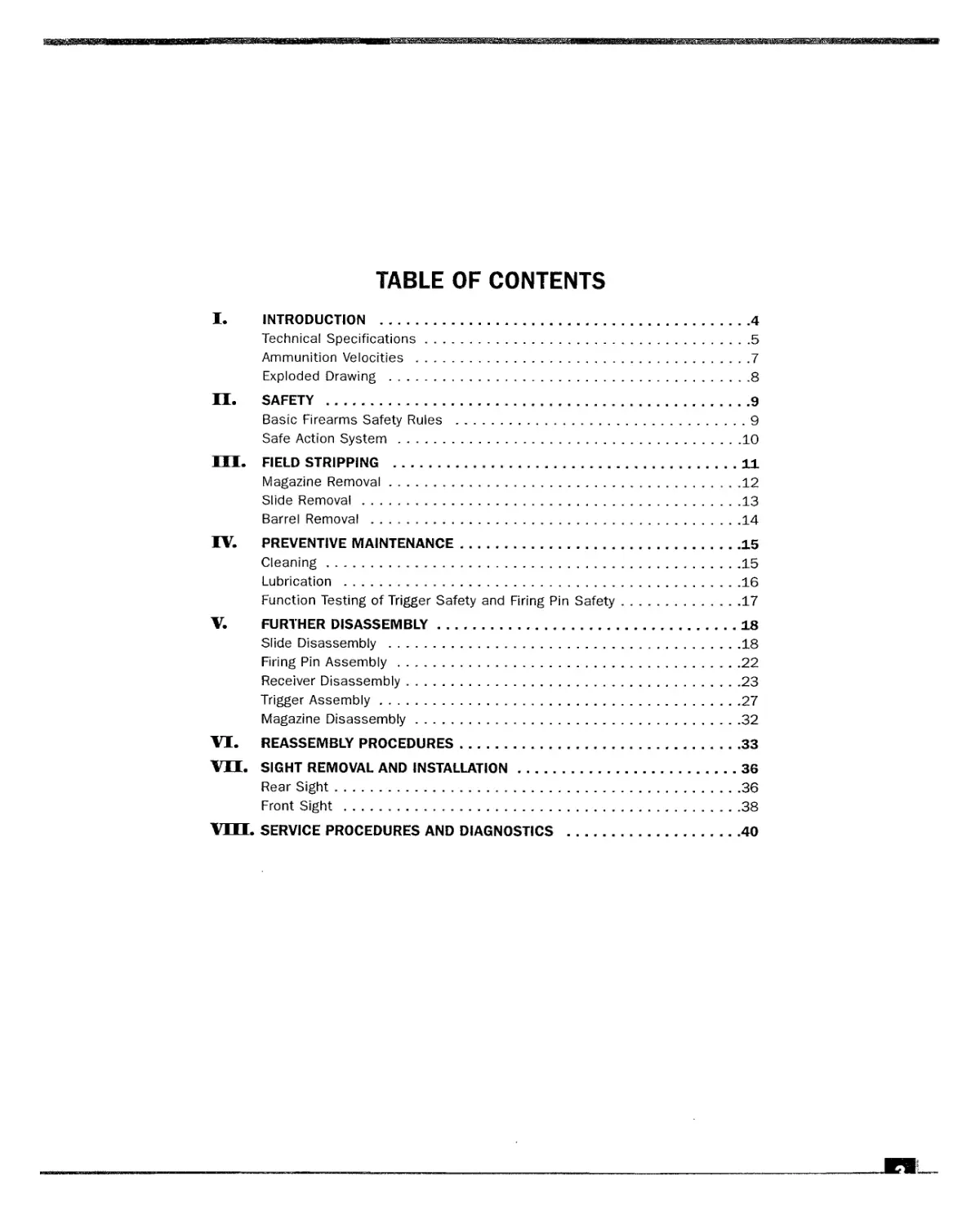
TABLE OF CONTENTS
I. INTRODUCTION ..................................................4
Technical Specifications......................................5
Ammunition Velocities ........................................7
Exploded Drawing .............................................8
II. SAFETY ........................................................9
Basic Firearms Safety Rules ..................................9
Safe Action System ..........................................10
III. FIELD STRIPPING ..............................................11
Magazine Removal.............................................12
Slide Removal ...............................................13
Barrel Removal ..............................................14
IV. PREVENTIVE MAINTENANCE........................................15
Cleaning.....................................................15
Lubrication .................................................16
Function Testing of Trigger Safety and Firing Pin Safety.....17
V. FURTHER DISASSEMBLY...........................................18
Slide Disassembly ...........................................18
Firing Pin Assembly..........................................22
Receiver Disassembly.........................................23
Trigger Assembly.............................................27
Magazine Disassembly.........................................32
VI. REASSEMBLY PROCEDURES.........................................33
vn. SIGHT REMOVAL AND INSTALLATION...............................36
Rear Sight...................................................36
Front Sight .................................................38
VUI. SERVICE PROCEDURES AND DIAGNOSTICS ............................40
I
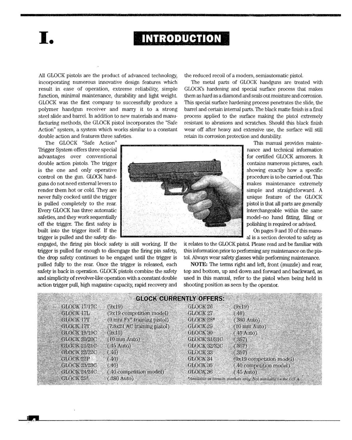
INTRODUCTION
All GLOCK pistols are the product of advanced technology,
incorporating numerous innovative design features which
result in ease of operation, extreme reliability, simple
function, minimal maintenance, durability and light weight.
GLOCK was the first company to successfully produce a
polymer handgun receiver and marry it to a strong
steel slide and barrel. In addition to new materials and manu-
facturing methods, the GLOCK pistol incorporates the “Safe
Action” system, a system which works similar to a constant
double action and features three safeties.
The GLOCK “Safe Action”
Trigger System offers three special
advantages over conventional
double action pistols. The trigger
is the one and only operative
control on the gun. GLOCK hand-
guns do not need external levers to
render them hot or cold. They are
never fully cocked until the trigger
is pulled completely to the rear.
Every GLOCK has three automatic
safeties, and they work sequentially
off the trigger. The first safety is
built into the trigger itself. If the
trigger is pulled and the safety dis-
engaged, the firing pin block safety is still working. If the
trigger is pulled far enough to disengage the firing pin safety,
the drop safety continues to be engaged until the trigger is
pulled fully to the rear. Once the trigger is released, each
safety is back in operation. GLOCK pistols combine the safety
and simplicity of revolver-like operation with a constant double
action trigger pull, high magazine capacity, rapid recovery and
the reduced recoil of a modem, semiautomatic pistol.
The metal parts of GLOCK handguns are treated with
GLOCKs hardening and special surface process that makes
them as hard as a diamond and seals out moisture and corrosion.
This special surface hardening process penetrates the slide, the
barrel and certain internal parts. The black matte finish is a final
process applied to the surface making the pistol extremely
resistant to abrasions and scratches. Should this black finish
wear off after heavy and extensive use, the surface will still
retain its corrosion protection and durability.
This manual provides mainte-
nance and technical information
for certified GLOCK armorers. It
contains numerous pictures, each
showing exactly how a specific
procedure is to be carried out. This
makes maintenance extremely
simple and straightforward. A
unique feature of the GLOCK
pistol is that all parts are generally
interchangeable within the same
model-no hand fitting, filing or
polishing is required or advised.
On pages 9 and 10 of this manu-
al is a section devoted to safety as
it relates to the GLOCK pistol Please read and be familiar with
this information prior to performing any maintenance on the pis-
tol. Always wear safety glasses while performing maintenance.
NOTE: The terms right and left, front (muzzle) and rear,
top and bottom, up and down and forward and backward, as
used in this manual, refer to the pistol when being held in
shooting position as seen by the operator.
GLOCK CURRENTLY OFFERS:
GLOCK 17/170 (9x19) GLOCK 26 (9x19)
GLOCK 17L (9x19 competition model) GLOCK 27 (40)
GLOCK 17T ’ (Oinni l;'x' (raining pistol) GLOCK 28* (.380 Auto)
GLOCK ITT (7.8x21 AC training pistol) GL( )CK29 (10 nun Auto)
GLOCK 19/19C (9x10) GLOCK 30 (.45 Auto)
GLOCK 20/20C (l<i mm Auto) GLOCK31/31C < 357)
GLOCK 21/21C i. 15 Auto) GLOCK 32Z32C (,357)
GLOCK 22/220 (.40) GLOCK 33 (.357)
GLOCK 22P Г40) «.LOCK 3-1 (9x 19 competition m odej)
GLOCK 23/230 (.40) GLOCK 35 (.40 competition morlol)
GLOCK24/24C (.40 competition model)' GLO.CK36 (.45 Auto)
GLOCK 25* (,380 Auto) ★Available in certain markets only Not available in the U.S A. .
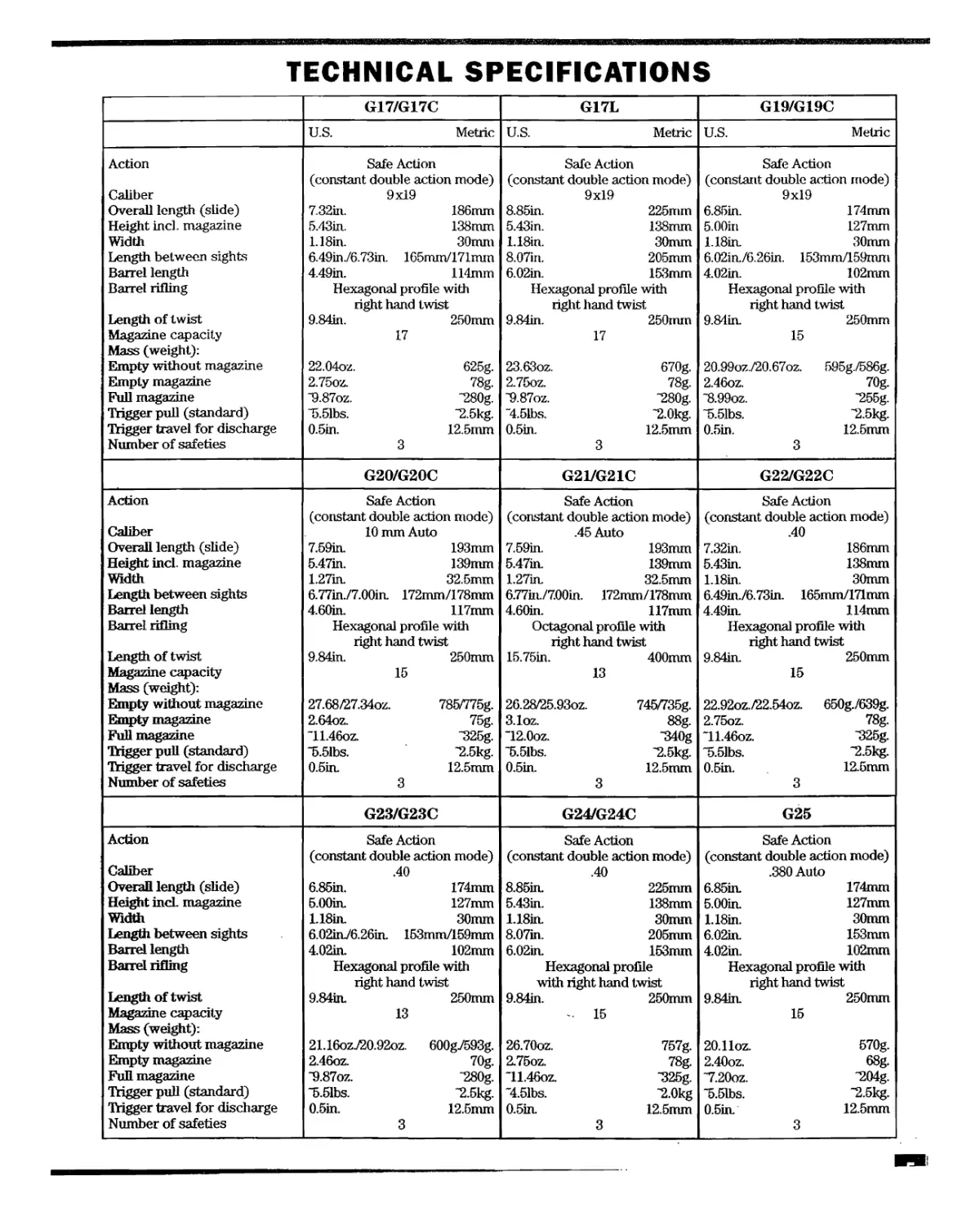
TECHNICAL SPECIFICATIONS
G17/G17C G17L G19/G19C
U.S. Metric U.S. Metric U.S. Metric
Action Caliber Overall length (slide) Height incl. magazine Width Length between sights Barrel length Barrel rifling Length of twist Magazine capacity Mass (weight): Empty without magazine Empty magazine Full magazine Trigger pull (standard) Trigger travel for discharge Number of safeties Safe Action (constant double action mode) 9x19 7.32in. 186mm 5.43in. 138mm 1.18in. 30mm 6.49in./6.73in. 165mm/171mm 4.49in. 114mm Hexagonal profile with right hand twist 9.84in. 250mm 17 22.04oz. 625g. 2.75oz. 78g. "9.87oz. -280g. "5.51bs. "2.5kg. 0.5in. 12.5mm 3 Safe Action (constant double action mode) 9x19 8.85in. 225mm 5.43in. 138mm 1.18in. 30mm 8.07in. 205mm 6.02in. 153mm Hexagonal profile with riglit hand twist 9.84in. 250mm 17 23.63oz. 670g. 2.75oz. 78g. "9.87oz. "280g. “4.51bs. -2.0kg. 0.5in. 12.5mm 3 Safe Action (constant double action mode) 9x19 6.85in. 174mm 5.00in 127mm 1.18in. 30mm 6.02irt/6.26in. 153mm/159mm 4.02in. 102mm Hexagonal profile with right hand twist 9.84in. 250mm 15 20.99oz./20.67oz. 595g./586g. 2.46oz. 70g. -8.99oz. -255g. ~5.51bs. "2.5kg. 0.5in. 12.5mm 3
G20/G20C G2VG21C G22/G22C
Action Caliber Overall length (slide) Height incl. magazine Width Length between sights Barrel length Barrel rifling Length of twist Magazine capacity Mass (weight): Empty without magazine Empty magazine Full magazine Trigger pull (standard) Trigger travel for discharge Number of safeties Safe Action (constant double action mode) 10 mm Auto 7.59in. 193mm 5.47in. 139mm 1.27in. 32.5mm 6.77in./7.00in. 172mm/178mm 4.60in. 117mm Hexagonal profile with riglit hand twist 9.84in. 250mm 15 27.68Z27.34oz. 785/775g. 2.64oz. 75g. ~11.46oz. “325g. ~5.51bs. -2.5kg. 0.5in. 12.5mm 3 Safe Action (constant double action mode) .45 Auto 7.59in. 193mm 5.47in. 139mm 1.27in. 32.5mm 6.77iit/7.00in. 172mm/178mm 4.60in. 117mm Octagonal profile with right hand twist 15.75in. 400mm 13 26.28Z25.93oz. 745/735g. 3.1oz. 88g. "12.0oz. “340g “5.51bs. -2.5kg. 0.5in. 12.5mm 3 Safe Action (constant double action mode) .40 7.32in. 186mm 5.43in. 138mm 1.18in. 30mm 6.49in./6.73in. 165mm/171mm 4.49in. 114mm Hexagonal profile with right hand twist 9.84in. 250mm 15 22.92oz.Z22.54oz. 650g./639g. 2.75oz. 78g. ~11.46oz. -325g. "5.51bs. “2.5kg. 0.5in. 12.5mm 3
G23/G23C G24/G24C G25
Action Caliber Overall length (slide) Height incL magazine Width Length between sights Barrel length Barrel rifling Length of twist Magazine capacity Mass (weight): Empty without magazine Empty magazine Full magazine Trigger pull (standard) Trigger travel for discharge Number of safeties Safe Action (constant double action mode) .40 6.85in. 174mm 5.00in. 127mm 1.18in. 30mm 6.02mV6.26in. 153mm/159mm 4.02in. 102mm Hexagonal profile with right hand twist 9.84in. 250mm 13 21.16oz720.92oz. 600g/593g. 2.46oz. 70g. “9.87oz. "280g. “5.51bs. -2.5kg. 0.5in. 12.5mm 3 Safe Action (constant double action mode) .40 8.85in. 225mm 5.43in. 138mm 1.18irt 30mm 8.07in. 205mm 6.02in. 153mm Hexagonal profile with right hand twist 9.84in. 250mm . 15 26.70oz. 757g. 2.75oz. 78g. ~11.46oz. -325g. ~4.51bs. -2.0kg 0.5in. 12.5mm 3 Safe Action (constant double action mode) .380 Auto 6.85in. 174mm 5.00in. 127mm 1.18in. 30mm 6.02in. 153mm 4.02in. 102mm Hexagonal profile with right hand twist 9.84in. 250mm 15 20.11oz. 570g. 2.40oz. 68g. -7.20oz. “204g. ~5.51bs. -2.5kg. 0.5in. 12.5mm 3
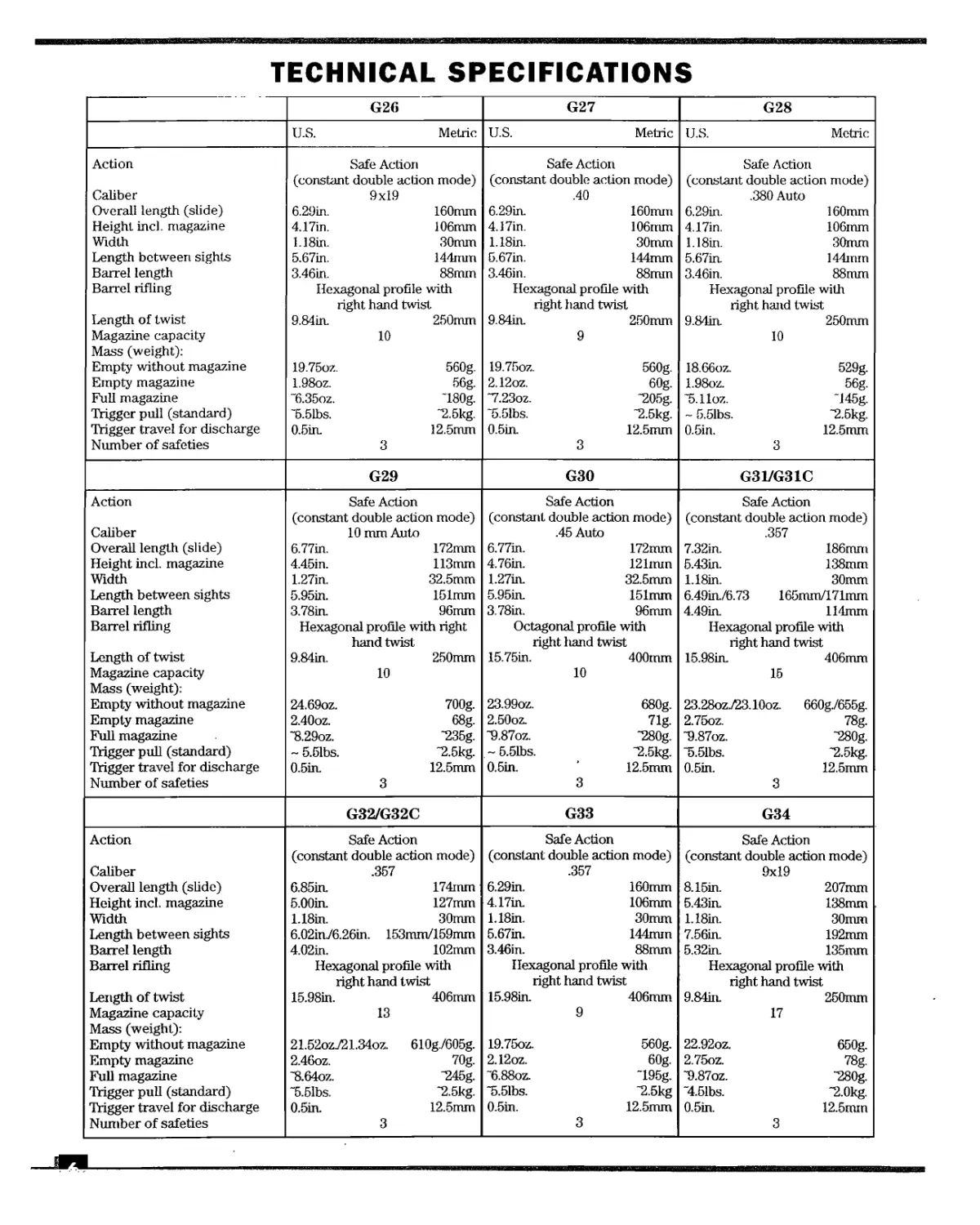
TECHNICAL SPECIFICATIONS
G26 G27 G28
U.S. Metric U.S. Metric U.S. Metric
Action Caliber Overall length (slide) Height incl. magazine Width Length between sights Barrel length Barrel rifling Length of twist Magazine capacity Mass (weight): Empty without magazine Empty magazine Full magazine Trigger pull (standard) Trigger travel for discharge Number of safeties Safe Action (constant double action mode) 9x19 6.29in. 160mm 4.17in. 106mm L18in. 30mm 5.67in. 144mm 3.46in. 88mm Hexagonal profile with right hand twist 9.84in. 250mm 10 19.75oz. 560g. 1.98oz. 56g. ~6.35oz. ~180g. ~5.51bs. “2.5kg. 0.5in. 12.5mm 3 Safe Action (constant double action mode) .40 6.29in. 160mm 4.17in. 106mm 1.18in. 30mm 5.67in. 144mm 3.46in. 88mm Hexagonal profile with right hand twist 9.84in. 250mm 9 19.75oz. 560g. 2.12oz. 60g. “7.23oz. “205g. ~5.51bs. “2.5kg. 0.5in. 12.5mm 3 Safe Action (constant double action mode) .380 Auto 6.29in. 160mm 4.17in. 106mm 1.18in. 30mm 5.67in. 144mm 3.46in. 88mm Hexagonal profile with right hand twist 9.84in. 250mm 10 18.66oz. 529g. 1.98oz. 56g. “5-lloz. ~145g. ~ 5.51bs. 2.5kg. 0.5in. 12.5mm 3
G29 G30 G31/G31C
Action Caliber Overall length (slide) Height incl. magazine Width Length between sights Barrel length Barrel rifling Length of twist Magazine capacity Mass (weight): Empty without magazine Empty magazine Full magazine Trigger pull (standard) Trigger travel for discharge Number of safeties Safe Action (constant double action mode) 10 mm Auto 6.77in. 172mm 4.45in. 113mm 1.27in. 32.5mm 5.95in. 151mm 3.78in. 96mm Hexagonal profile with right hand twist 9.84in. 250mm 10 24.69oz. 700g. 2.40oz. 68g. ~8.29oz. “235g. ~ 5.51bs. “2.5kg. 0.5in. 12.5mm 3 Safe Action (constant double action mode) .45 Auto 6.77in. 172mm 4.76in. 121mm 1.27in. 32.5mm 5.95in. 151mm 3.78in. 96mm Octagonal profile with right hand twist 15.75in. 400mm 10 23.99oz. 680g. 2.50oz. 71g. “9.87oz. “280g. ~5.51bs. "2.5kg. 0.5in. ’ 12.5mm 3 Safe Action (constant double action mode) .357 7.32in. 186mm 5.43in. 138mm 1.18in. 30mm 6.49in./6.73 165mm/171mm 4.49in. 114mm Hexagonal profile with right hand twist 15.98in. 406mm 15 23.28ozj23.10oz. 660g./655g. 2.75oz. 78g. “9.87oz. “280g. "5.51bs. “2.5kg. 0.5in. 12.5mm 3
G32/G32C G33 G34
Action Caliber Overall length (slide) Height incl. magazine Width Length between sights Barrel length Barrel rifling Length of twist Magazine capacity Mass (weight): Empty without magazine Empty magazine Full magazine Trigger pull (standard) Trigger travel for discharge Number of safeties Safe Action (constant double action mode) .357 6.85in. 174mm 5.00in. 127mm 1.18in. 30mm 6.02in76.26in. 153mm/159mm 4.02in. 102mm Hexagonal profile with right hand twist 15.98in. 406mm 13 21.52oz721.34oz. 610g./605g. 2.46oz. 70g. “8.64oz. *245g. "5.51bs. “2.5kg. 0.5in. 12.5mm 3 Safe Action (constant double action mode) .357 6.29in. 160mm 4.17in. 106mm 1.18in. 30mm 5.67in. 144mm 3.46in. 88mm Hexagonal profile with right hand twist 15.98in. 406mm 9 19.75oz. 560g. 2.12oz. 60g. ~6.88oz. ~195g. “5.51bs. “2.5kg 0.5in. 12.5mm 3 Safe Action (constant double action mode) 9x19 8.15in. 207mm 5.43in. 138mm 1.18in. 30mm 7.56in. 192mm 5.32in. 135mm Hexagonal profile with right hand twist 9.84iiL 250mm 17 22.92oz. 650g. 2.75oz. 78g. “9.87oz. -280g. “4.51bs. “2.0kg. 0.5in. 12.5mm 3
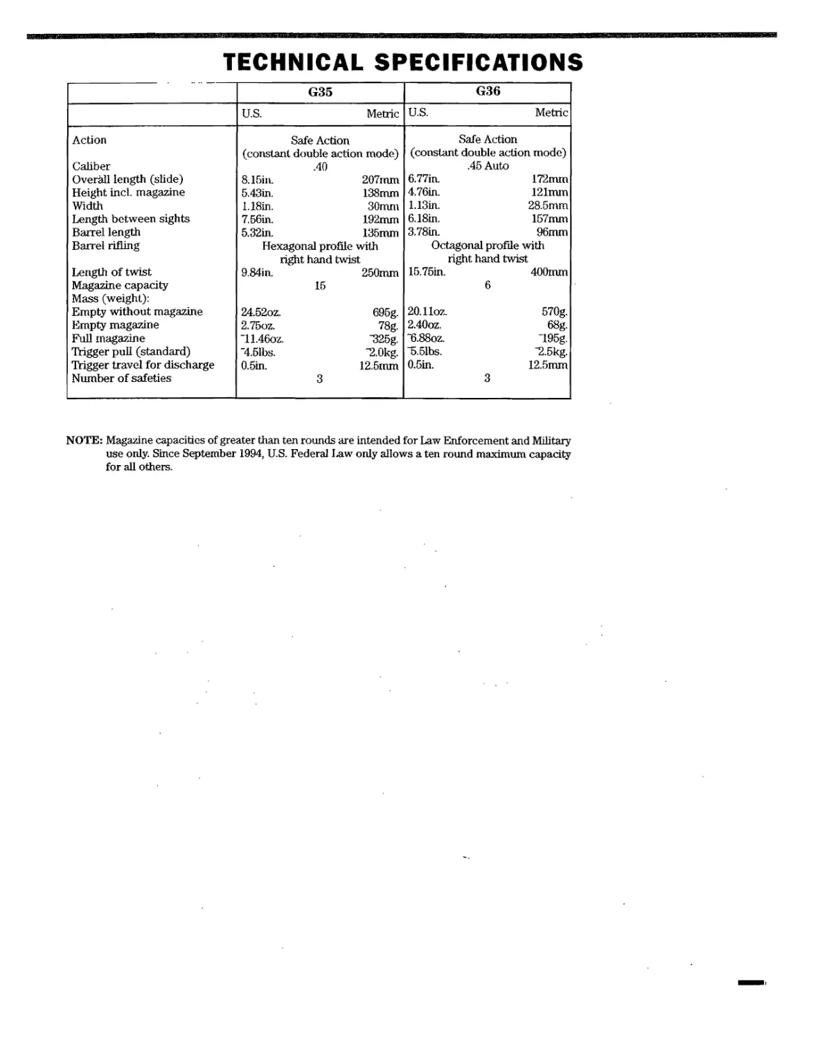
TECHNICAL SPECIFICATIONS
G35 G36
U.S. Metric U.S. Metric
Action Safe Action Safe Action
(constant double action mode) (constant double action mode)
Caliber .40 .45 Auto
Overall length (slide) 8.15in. 207mm 6.77in. 172mm
Height incl. magazine 5.43in. 138mm 4.76in. 121mm
Width 1.18in. 30mm 1.13in. 28.5mm
Length between sights 7.56in. 192mm 6.18in. 157mm
Barrel length 5.32in. 135mm 3.78in. 96mm
Barrel rifling Hexagonal profile with right hand twist Octagonal profile with right hand twist
Length of twist 9.84in. 250mm 15.75in. 400mm
Magazine capacity Mass (weight): 15 6
Empty without magazine 24.52oz. 695g. 20.11oz. 570g.
Empty magazine 2.75oz. 78g. 2.40oz. 68g.
Full magazine "11.46oz. -325g. "6.88oz. -195g.
Trigger pull (standard) ~4.51bs. -2.0kg. ~5.51bs. -2.5kg.
Trigger travel for discharge 0.5in. 12.5inm 0.5in. 12.51ШП
Number of safeties 3 3
NOTE: Magazine capacities of greater than ten rounds are intended for Law Enforcement and Military
use only. Since September 1994, U.S. Federal Law only allows a ten round maximum capacity
for all others.
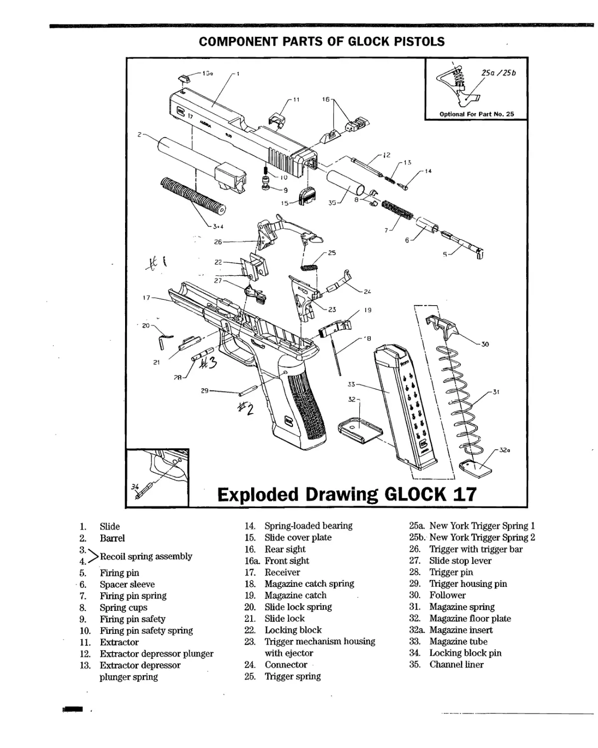
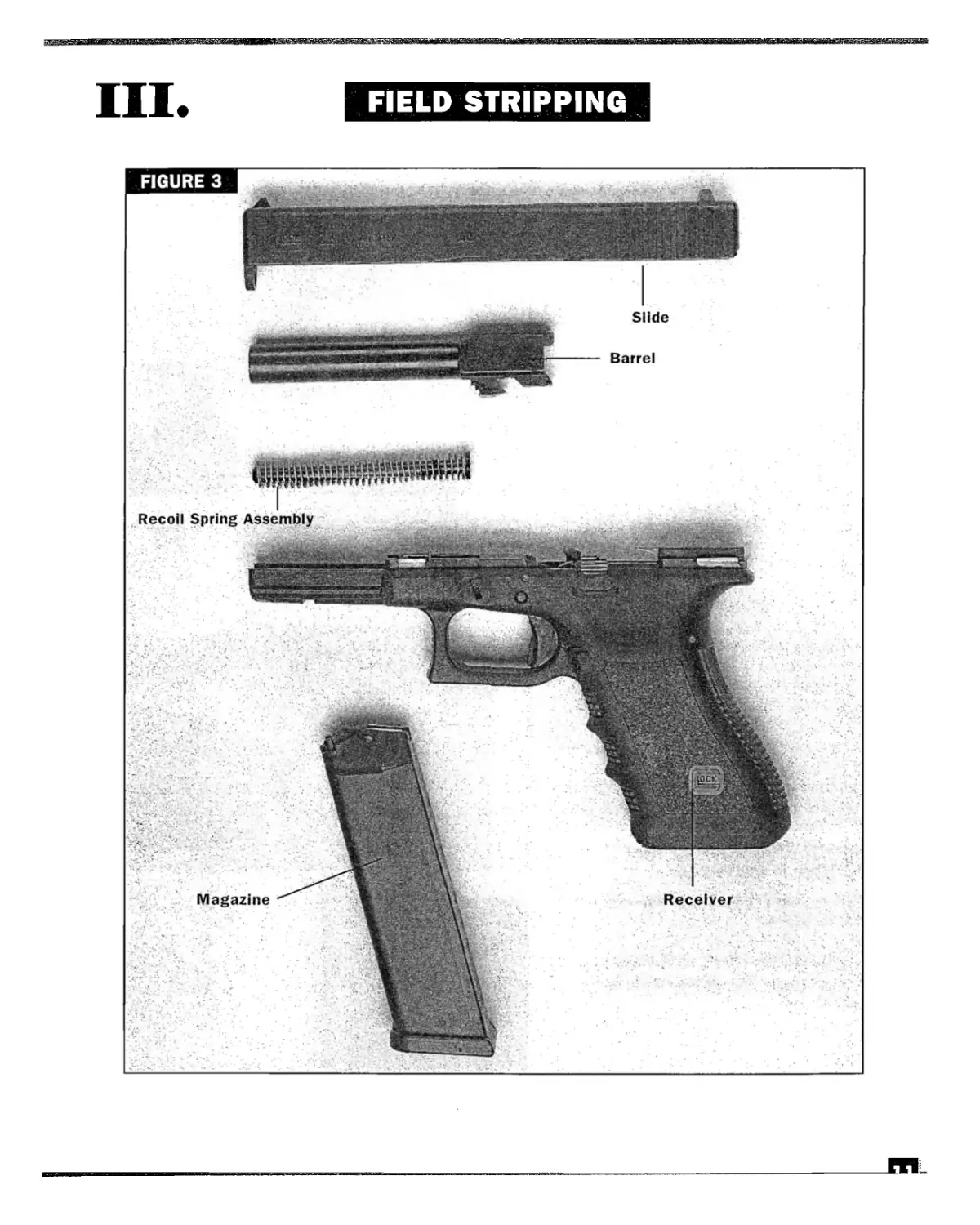
COMPONENT PARTS OF GLOCK PISTOLS
1. Slide 14. Spring-loaded bearing 25a. New York Trigger Spring 1
2. Barrel 15. Slide cover plate 25b. New York Trigger Spring 2
4 Recoil spring assembly 16. Rear sight 16a. Front sight 26. 27. Trigger with trigger bar Slide stop lever
5. Firing pin 17. Receiver 28. Trigger pin
6. Spacer sleeve 18. Magazine catch spring 29. Trigger housing pin
7. Firing pin spring 19. Magazine catch 30. Follower
8. Spring cups 20. Slide lock spring 31. Magazine spring
9. Firing pin safety 21. Slide lock 32. Magazine floor plate
10. Firing pin safety spring 22. Locking block 32a. Magazine insert
11. Extractor 23. Trigger mechanism housing 33. Magazine tube
12. Extractor depressor plunger with ejector 34. Locking block pin
13. Extractor depressor 24. Connector 35. Channel liner
plunger spring 25. Trigger spring
II.
SAFETY
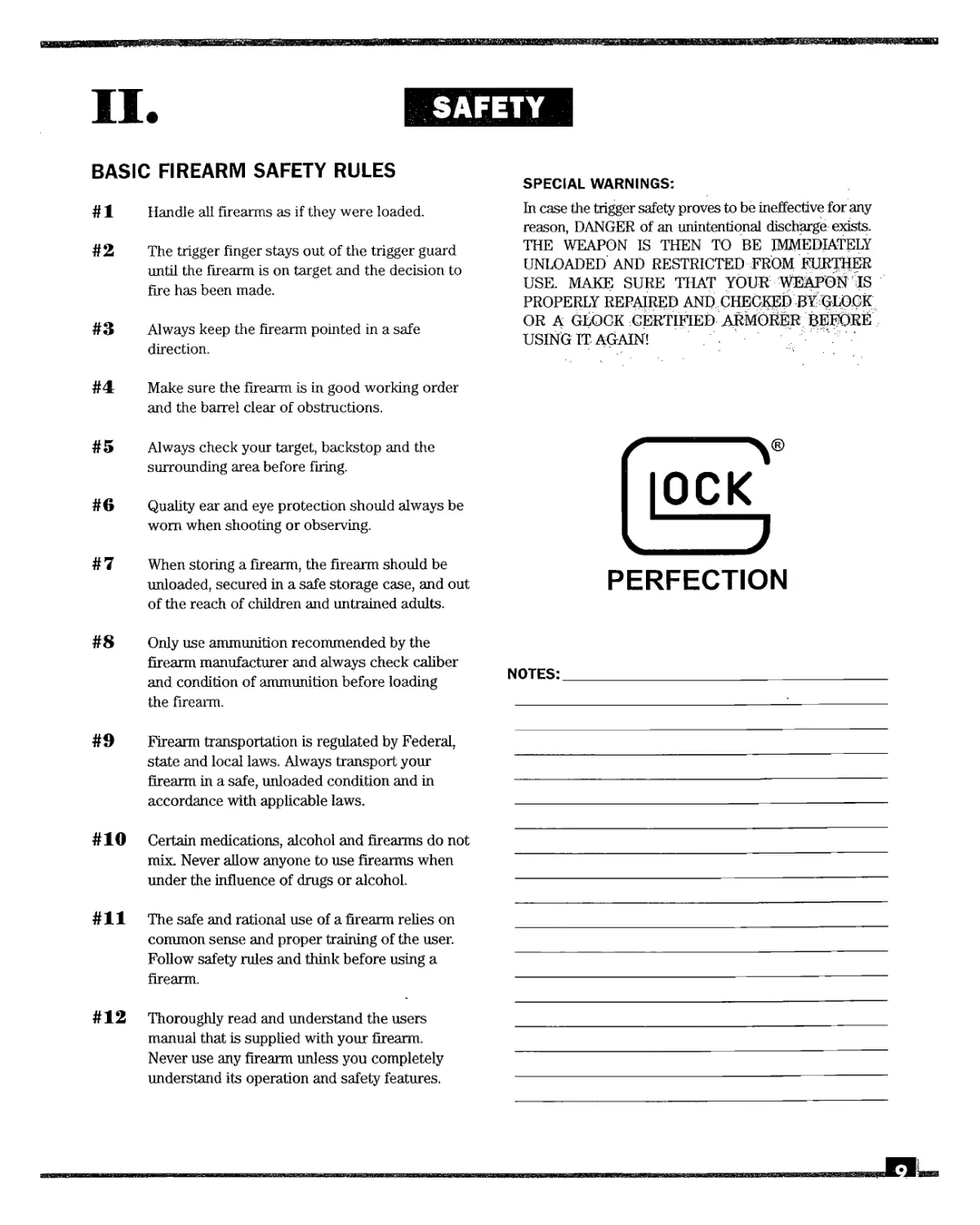
BASIC FIREARM SAFETY RULES
# 1 Handle all firearms as if they were loaded.
# 2 The trigger finger stays out of the trigger guard
until the firearm is on target and the decision to
fire has been made.
# 3 Always keep the firearm pointed in a safe
direction.
# 4 Make sure the firearm is in good working order
and the barrel clear of obstructions.
# 5 Always check your target, backstop and the
surrounding area before firing.
# 6 Quality ear and eye protection should always be
worn when shooting or observing.
# 7 When storing a firearm, the firearm should be
unloaded, secured in a safe storage case, and out
of the reach of children and untrained adults.
# 8 Only use ammunition recommended by the
firearm manufacturer and always check caliber
and condition of ammunition before loading
the firearm.
# 9 Firearm transportation is regulated by Federal,
state and local laws. Always transport your
firearm in a safe, unloaded condition and in
accordance with applicable laws.
# 10 Certain medications, alcohol and firearms do not
mix. Never allow anyone to use firearms when
under the influence of drugs or alcohol.
# 11 The safe and rational use of a firearm relies on
common sense and proper training of the user.
Follow safety rules and think before using a
firearm.
# 12 Thoroughly read and understand the users
manual that is supplied with your firearm.
Never use any firearm unless you completely
understand its operation and safety features.
SPECIAL WARNINGS:
In case the trigger safety proves to be ineffective for any
reason, DANGER of an unintentional discharge exists.
THE WEAPON IS THEN TO BE IMMEDIATELY
UNLOADED AND RESTRICTED FROM FURTHER
USE. MAKE SURE THAT YOUR WEAPONIS
PROPERLY REPAIRED AND CHECKED BYGLOCK
OR A GLOCK CERTIFIED ARMORER BEFORE
USING IT AGAIN! Л " ? 1
|OCK
PERFECTION
NOTES:_____________________________________
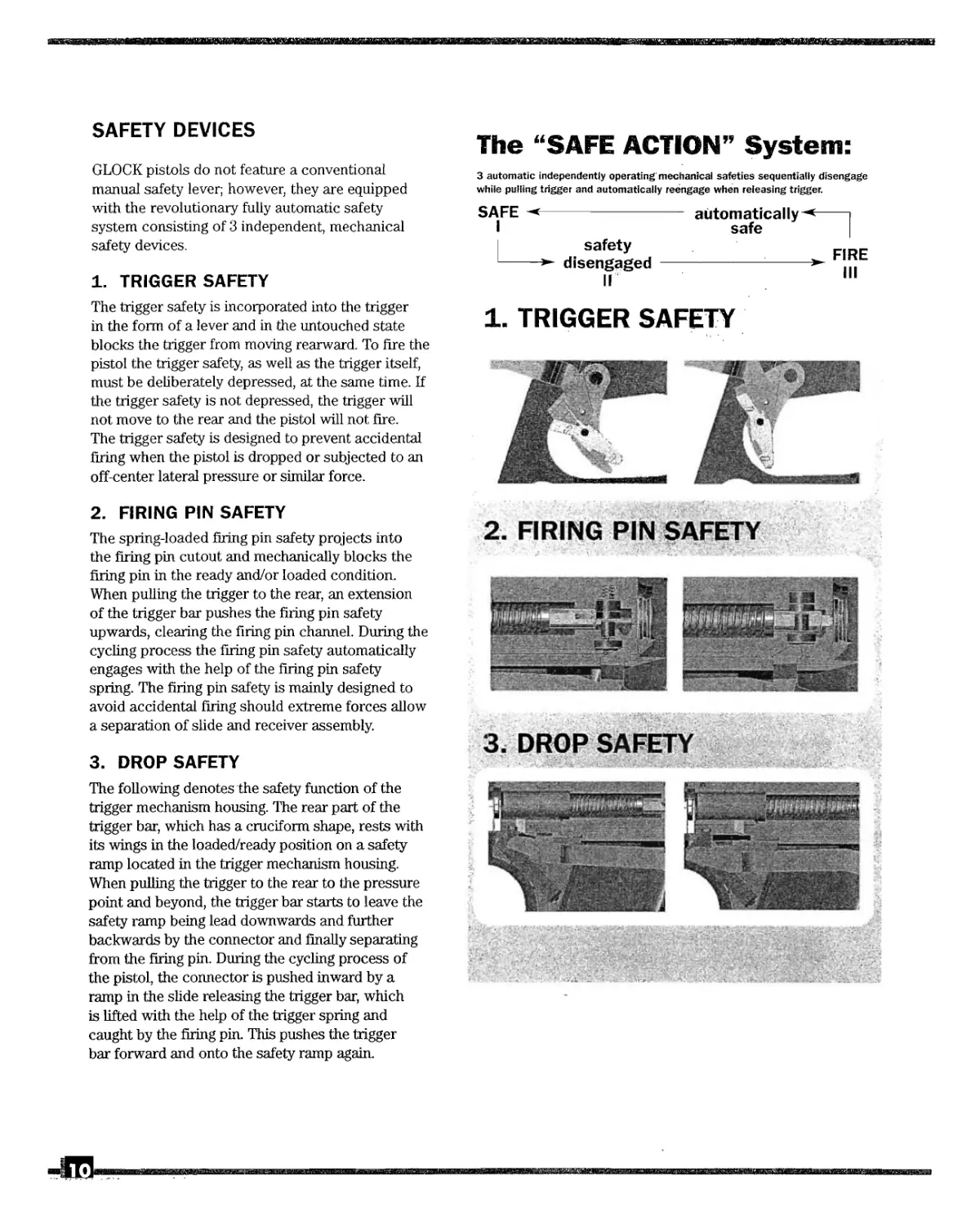
SAFETY DEVICES
GLOCK pistols do not feature a conventional
manual safety lever; however, they are equipped
with the revolutionary fully automatic safety
system consisting of 3 independent, mechanical
safety devices.
1. TRIGGER SAFETY
The trigger safety is incorporated into the trigger
in the form of a lever and in the untouched state
blocks the trigger from moving rearward. To fire the
pistol the trigger safety, as well as the trigger itself,
must be deliberately depressed, at the same time. If
the trigger safety is not depressed, the trigger will
not move to the rear and the pistol will not fire.
The trigger safety is designed to prevent accidental
firing when the pistol is dropped or subjected to an
off-center lateral pressure or similar force.
The “SAFE ACTION” System:
3 automatic independently operating mechanical safeties sequentially disengage
while pulling trigger and automatically reengage when releasing trigger.
SAFE --------------
I
safety
-----disengaged
II
automatically-*----1
safe |
_________ r FIRE
III
1. TRIGGER SAFETY
2. FIRING PIN SAFETY
The spring-loaded firing pin safety projects into
the firing pin cutout and mechanically blocks the
firing pin in the ready and/or loaded condition.
When pulling the trigger to the rear, an extension
of the trigger bar pushes the firing pin safety
upwards, clearing the firing pin channel. During the
cycling process the firing pin safety automatically
engages with the help of the firing pin safety
spring. The firing pin safety is mainly designed to
avoid accidental firing should extreme forces allow
a separation of slide and receiver assembly.
3- DROP SAFETY
The following denotes the safety function of the
trigger mechanism housing. The rear part of the
trigger bar, which has a cruciform shape, rests with
its wings in the loaded/ready position on a safety
ramp located in the trigger mechanism housing.
When pulling the trigger to the rear to the pressure
point and beyond, the trigger bar starts to leave the
safety ramp being lead downwards and further
backwards by the connector and finally separating
from the firing pin. During the cycling process of
the pistol, the connector is pushed inward by a
ramp in the slide releasing the trigger bar, which
is lifted with the help of the trigger spring and
caught by the firing pin. This pushes the trigger
bar forward and onto the safety ramp again.
2. FIRING PIN SAFETY
3. DROP SAFETY
III.
FIELD STRIPPING
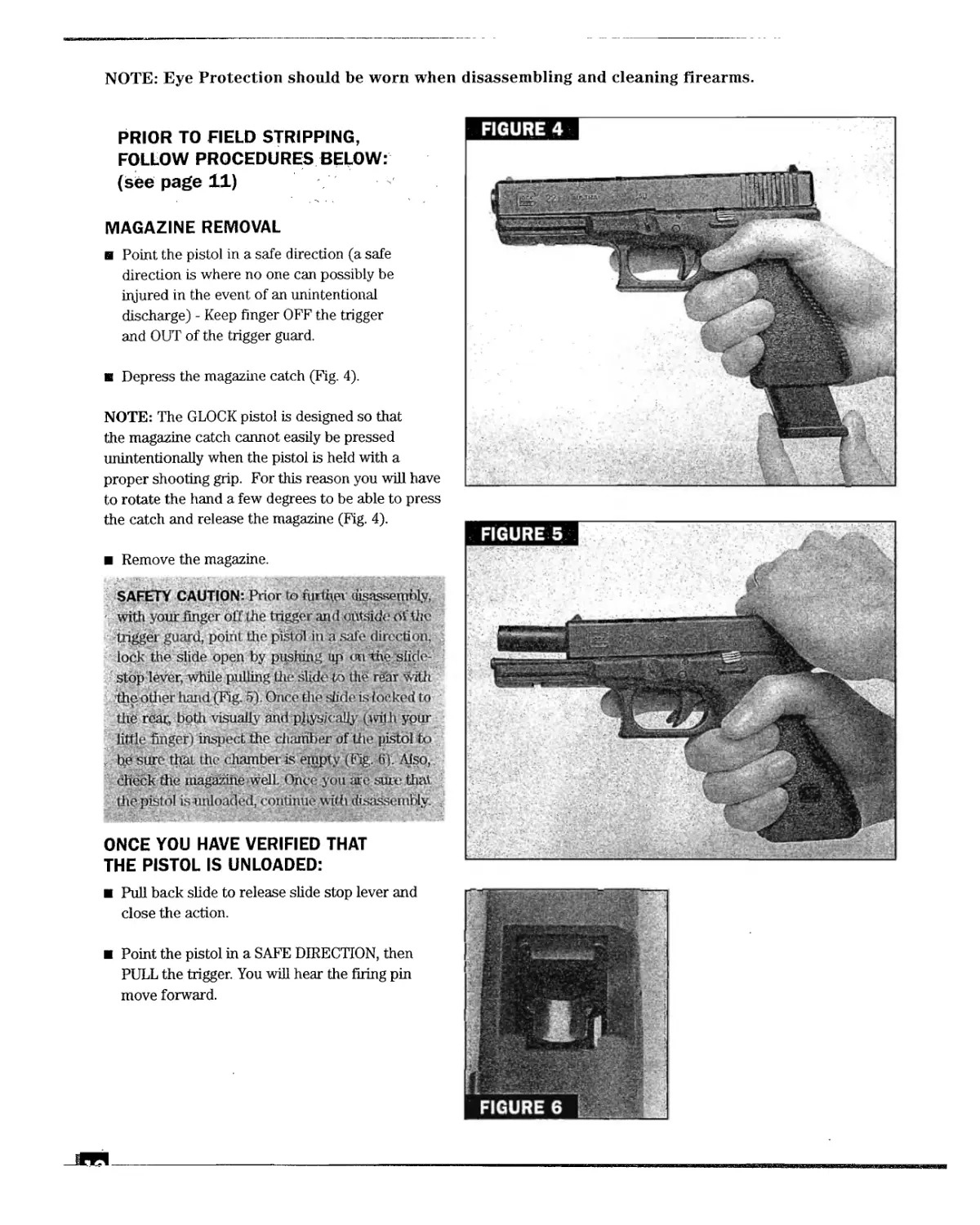
NOTE: Eye Protection should be worn when disassembling and cleaning firearms.
PRIOR TO FIELD STRIPPING,
FOLLOW PROCEDURES BELOW:
(see page 11)
MAGAZINE REMOVAL
в Point the pistol in a safe direction (a safe
direction is where no one can possibly be
injured in the event of an unintentional
discharge) - Keep finger OFF the trigger
and OUT of the trigger guard.
в Depress the magazine catch (Fig. 4).
NOTE: The GLOCK pistol is designed so that
the magazine catch cannot easily be pressed
unintentionally when the pistol is held with a
proper shooting grip. For this reason you will have
to rotate the hand a few degrees to be able to press
the catch and release the magazine (Fig. 4).
в Remove the magazine.
SAFETY CAUTION: Prior to further disassembly,
with your finger off the trigger and of thv
trigger guard, point the pistol in a safe direction,
lock the slide open by pushing up < n the slide-
stop lever, while pulling the slide to th§ rear with
the other hand (Fig. 5). Once the slide is locked to
the rear, both visually and рДуькаЦу (wilh ypur
little finger) inspect the diamber of the pistol to
be sure that the chamber is empty (Fig. 6). Also,
check the magazine well. Once you are sure that
the pistol is unloaded, continue with disassembly.
ONCE YOU HAVE VERIFIED THAT
THE PISTOL IS UNLOADED:
a Pull back slide to release slide stop lever and
close the action.
a Point the pistol in a SAFE DIRECTION, then
PULL the trigger. You will hear the firing pin
move forward.
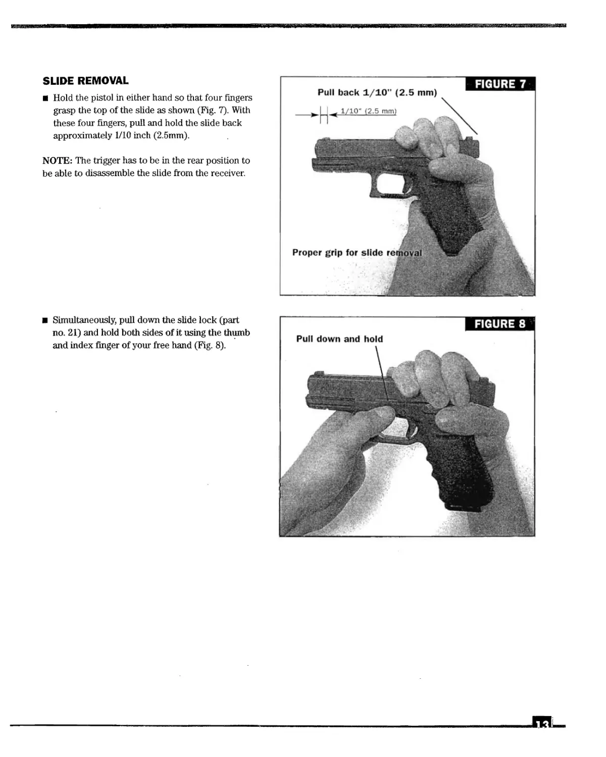
SLIDE REMOVAL
Hold the pistol in either hand so that four fingers
grasp the top of the slide as shown (Fig. 7). With
these four fingers, pull and hold the slide back
approximately 1/10 inch (2.5mm).
NOTE: The trigger has to be in the rear position to
be able to disassemble the slide from the receiver.
Simultaneously, pull down the slide lock (part
no. 21) and hold both sides of it using the thumb
and index finger of your free hand (Fig. 8).
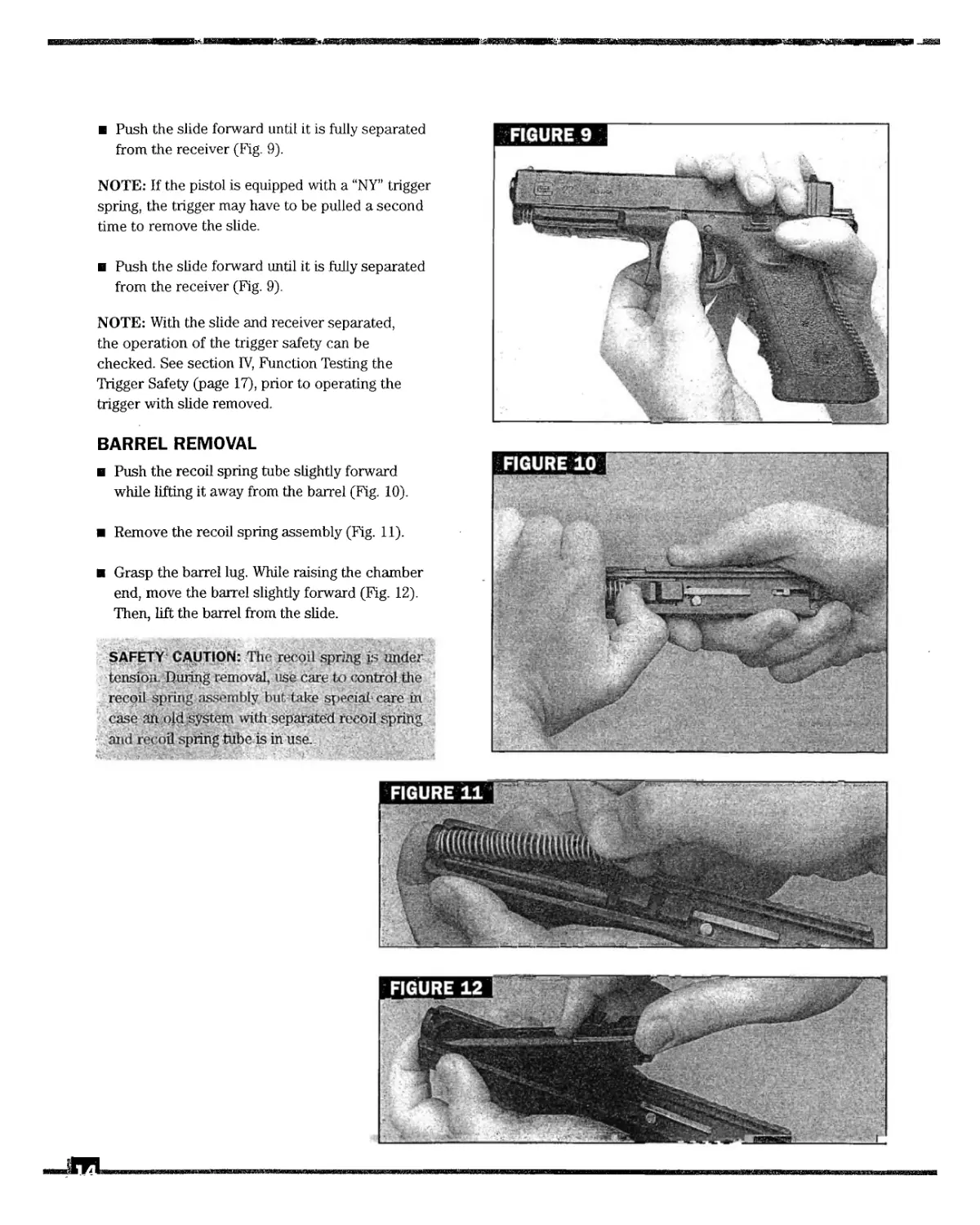
Push the slide forward until it is fully separated
from the receiver (Fig. 9).
NOTE: If the pistol is equipped with a “NY” trigger
spring, the trigger may have to be pulled a second
time to remove the slide.
Push the slide forward until it is fully separated
from the receiver (Fig. 9).
NOTE: With the slide and receiver separated,
the operation of the trigger safety can be
checked. See section IV, Function Testing the
Trigger Safety (page 17), prior to operating the
trigger with slide removed.
BARREL REMOVAL
Push the recoil spring tube slightly forward
while lifting it away from the barrel (Fig. 10).
Remove the recoil spring assembly (Fig. 11).
Grasp the barrel lug. While raising the chamber
end, move the barrel slightly forward (Fig. 12).
Then, lift the barrel from the slide.
SAFETY CAUTION: The recoil spring is under
tension. During removal, use care to control the
recoil spring assembly but take special care in
case ah. ojd system with separated recoil spring
and recoil spring tube is in use.
PREVENTIVE MAINTENANCE
The pistol is now field stripped. Further disassembly is not required for
normal cleaning and maintenance.
NOTE: Refer to page 11-14 for proper method of field stripping the pistol.
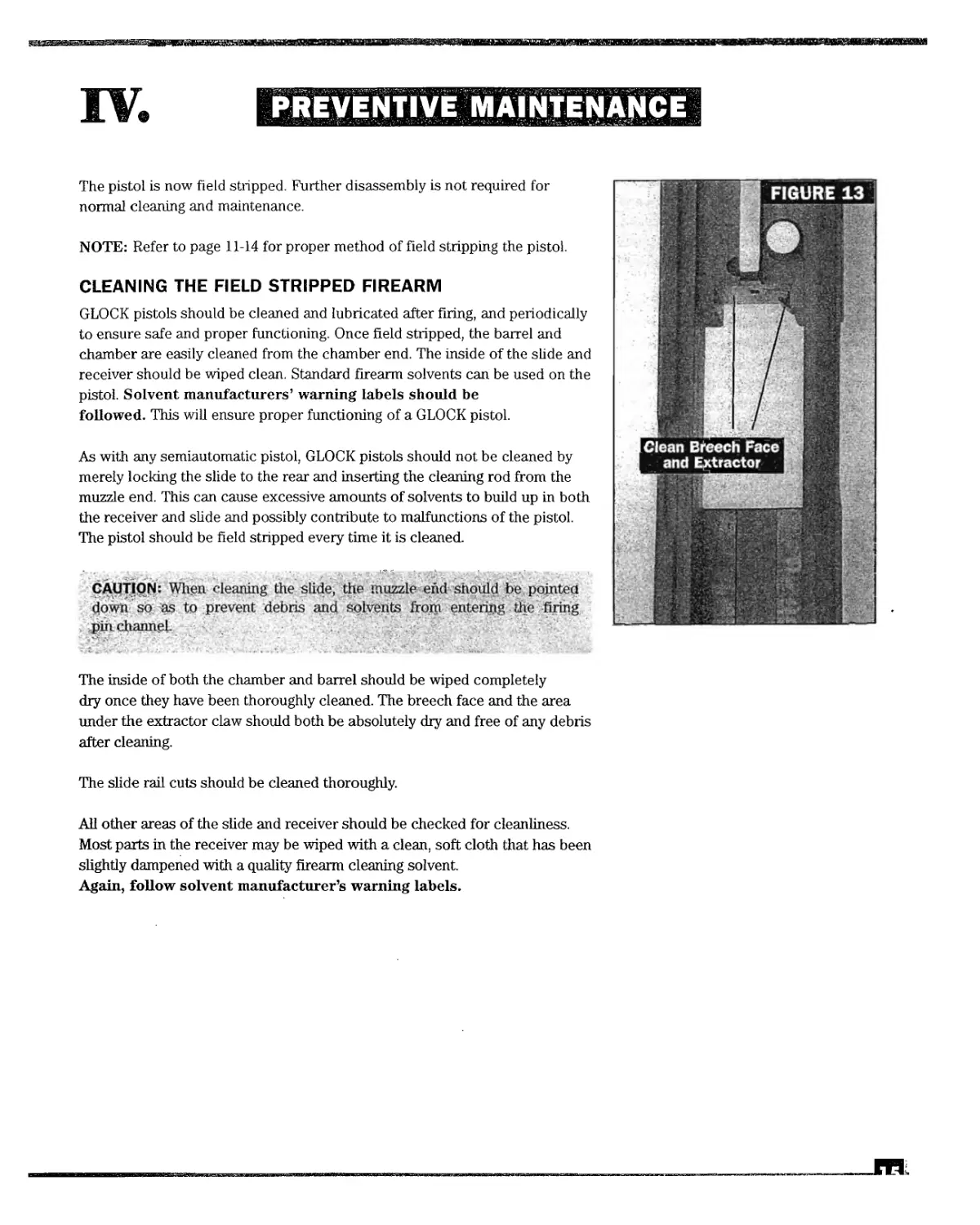
CLEANING THE FIELD STRIPPED FIREARM
GLOCK pistols should be cleaned and lubricated after firing, and periodically
to ensure safe and proper functioning. Once field stripped, the barrel and
chamber are easily cleaned from the chamber end. The inside of the slide and
receiver should be wiped clean. Standard firearm solvents can be used on the
pistol. Solvent manufacturers’ warning labels should be
followed. This will ensure proper functioning of a GLOCK pistol.
As with any semiautomatic pistol, GLOCK pistols should not be cleaned by
merely locking the slide to the rear and inserting the cleaning rod from the
muzzle end. This can cause excessive amounts of solvents to build up in both
the receiver and slide and possibly contribute to malfunctions of the pistol.
The pistol should be field stripped every time it is cleaned.
CAUTION: When cleaning the slide, the muzzle end should be pointed
down so as to prevent debris and solvents from entering die firing
pin channel.
The inside of both the chamber and barrel should be wiped completely
dry once they have been thoroughly cleaned. The breech face and the area
under the extractor claw should both be absolutely dry and free of any debris
after cleaning.
The slide rail cuts should be cleaned thoroughly.
All other areas of the slide and receiver should be checked for cleanliness.
Most parts in the receiver may be wiped with a clean, soft cloth that has been
slightly dampened with a quality firearm cleaning solvent.
Again, follow solvent manufacturer’s warning labels.
LUBRICATING THE
FIELD STRIPPED FIREARM
NOTE: The copper colored substance on the
interior of the pistol is a high-temperature,
factory-applied lubricant for new guns. The
copper colored lubricant should remain, as it
will assure long-term lubrication of the slide.
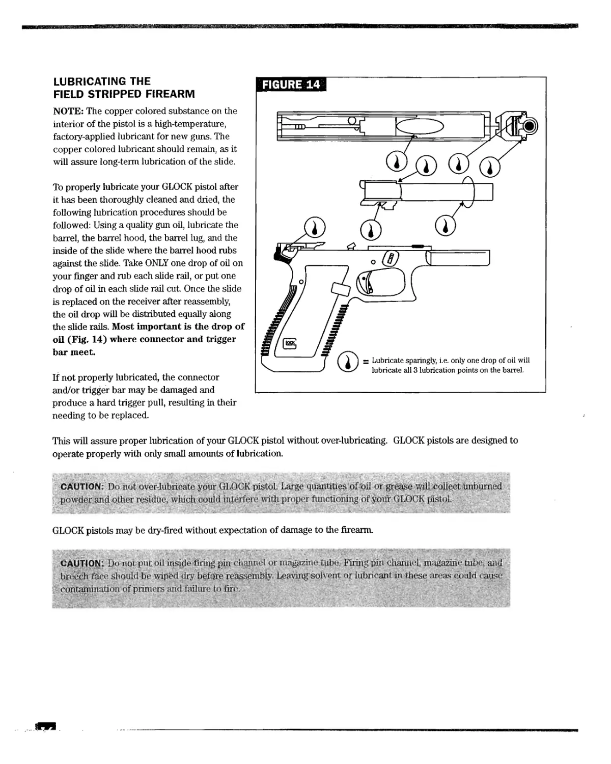
To properly lubricate your GLOCK pistol after
it has been thoroughly cleaned and dried, the
following lubrication procedures should be
followed: Using a quality gun oil, lubricate the
barrel, the barrel hood, the barrel lug, and the
inside of the slide where the barrel hood rubs
against the slide. Take ONLY one drop of oil on
your finger and rub each slide rail, or put one
drop of oil in each slide rail cut. Once the slide
is replaced on the receiver after reassembly,
the oil drop will be distributed equally along
the slide rails. Most important is the drop of
oil (Fig. 14) where connector and trigger
bar meet.
If not properly lubricated, the connector
and/or trigger bar may be damaged and
produce a hard trigger pull, resulting in their
needing to be replaced.
This will assure proper lubrication of your GLOCK pistol without over-lubricating. GLOCK pistols are designed to
operate properly with only small amounts of lubrication.
CAUTION: Do not over-lubrioate your GLOCK pistol. Large quantities of oil or grease WiH collect unbumed
powder and other residue, which could interfere with proper ftmdtiomng of your GLOCK pisiol.
GLOCK pistols may be dry-fired without expectation of damage to the firearm.
CAUTION: Do not put oil inside firing pin channel or magazine tube. Firing pin channel, magazine tube, and
breech face should be wipbd dry before reassembly. Leaving solvent or lubricant in these areas could cause
contahunation of primers and failure to fife.
FUNCTION TESTING (SAFETIES)
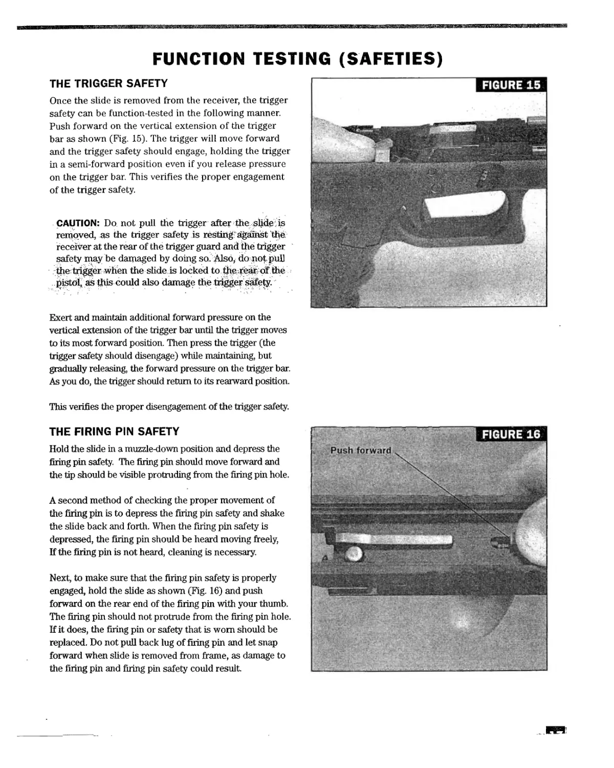
THE TRIGGER SAFETY
Once the slide is removed from the receiver, the trigger
safety can be function-tested in the following manner.
Push forward on the vertical extension of the trigger
bar as shown (Fig. 15). The trigger will move forward
and the trigger safety should engage, holding the trigger
in a semi-forward position even if you release pressure
on the trigger bar. This verifies the proper engagement
of the trigger safety.
CAUTION: Do not pull the trigger after Ше sfid^ is
removed, as the trigger safety is resting against The
receiver at the rear of the trigger guard and the trigger
safety may be damaged by doing so. Also, do not pull
thetri^gdr when the slide is locked to t^^reafeof the
pistof as this could also damage the trigger safety.
Exert and maintain additional forward pressure on the
vertical extension of the trigger bar until the trigger moves
to its most forward position. Then press the trigger (the
trigger safety should disengage) while maintaining, but
gradually releasing, the forward pressure on the trigger bar.
As you do, the trigger should return to its rearward position.
This verifies the proper disengagement of the trigger safety.
THE FIRING PIN SAFETY
Hold the slide in a muzzle-down position and depress the
firing pin safety. The firing pin should move forward and
the tip should be visible protruding from the firing pin hole.
A second method of checking the proper movement of
the firing pin is to depress the firing pin safety and shake
the slide back and forth. When the firing pin safety is
depressed, the firing pin should be heard moving freely,
If the firing pin is not heard, cleaning is necessary.
Next, to make sure that the firing pin safety is properly
engaged, hold the slide as shown (Fig. 16) and push
forward on the rear end of the firing pin with your thumb.
The firing pin should not protrude from the firing pin hole.
If it does, the firing pin or safety that is worn should be
replaced. Do not pull back lug of firing pin and let snap
forward when slide is removed from frame, as damage to
the firing pin and firing pin safety could result.
V.
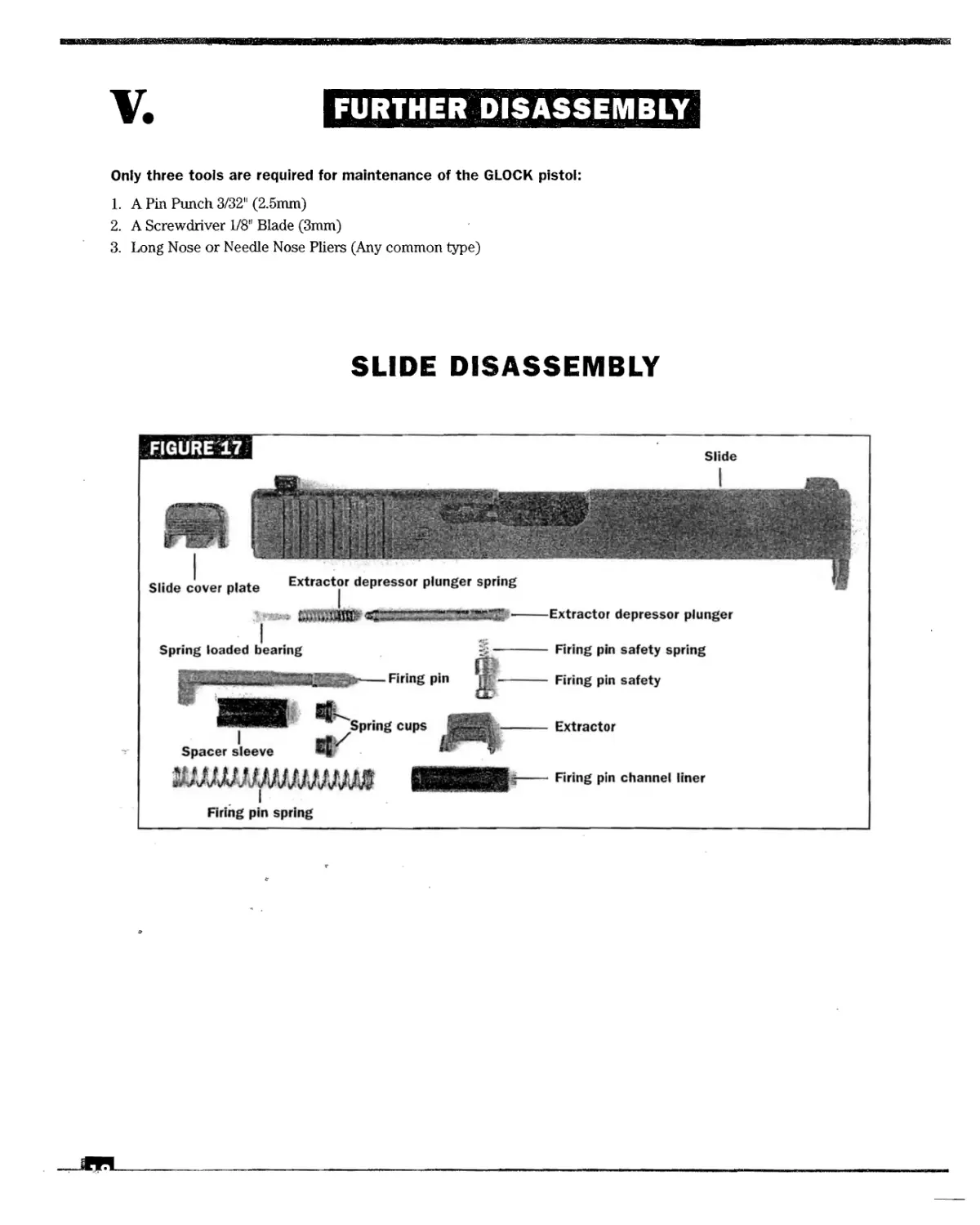
FURTHER DISASSEMBLY
Only three tools are required for maintenance of the GLOCK pistol:
1. A Pin Punch 3/32" (2.5mm)
2. A Screwdriver 1/8" Blade (3mm)
3. Long Nose or Needle Nose Pliers (Any common type)
SLIDE DISASSEMBLY
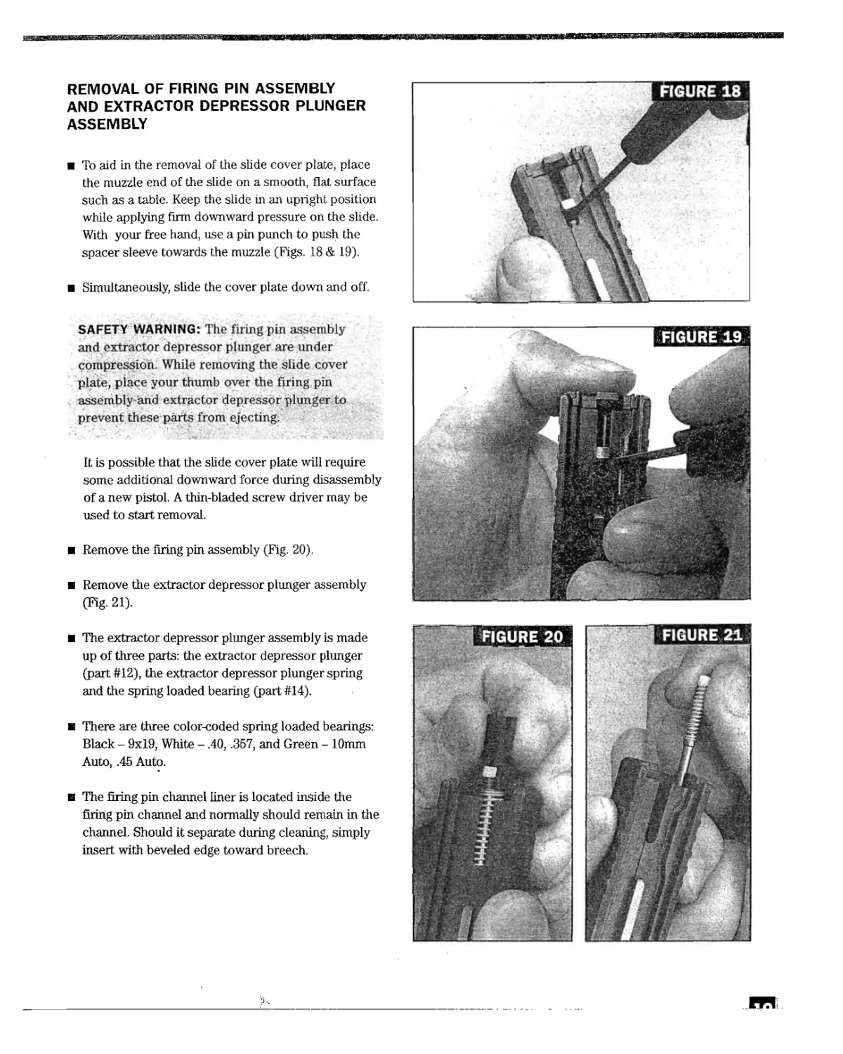
REMOVAL OF FIRING PIN ASSEMBLY
AND EXTRACTOR DEPRESSOR PLUNGER
ASSEMBLY
To aid in the removal of the slide cover plate, place
the muzzle end of the slide on a smooth, flat surface
such as a table. Keep the slide in an upright position
while applying firm downward pressure on the slide.
With your free hand, use a pin punch to push the
spacer sleeve towards the muzzle (Figs. 18 & 19).
Simultaneously, slide the cover plate down and off.
SAFETY WARNING: The firing pin assembly
and extractor depressor plunger are under
compression. While removing the slide cover
plate, place your thumb over the firing pin
assembly and extractor depressor plunger to
prevent these parts from ejecting.
It is possible that the slide cover plate will require
some additional downward force during disassembly
of a new pistol. A thin-bladed screw driver may be
used to start removal.
Remove the firing pin assembly (Fig. 20).
Remove the extractor depressor plunger assembly
(Fig. 21).
The extractor depressor plunger assembly is made
up of three parts: the extractor depressor plunger
(part #12), the extractor depressor plunger spring
and the spring loaded bearing (part #14).
e There are three color-coded spring loaded bearings:
Black - 9x19, White - .40, .357, and Green - 10mm
Auto, .45 Auto.
в The firing pin channel liner is located inside the
firing pin channel and normally should remain in the
channel. Should it separate during cleaning, simply
insert with beveled edge toward breech.
38S3BS
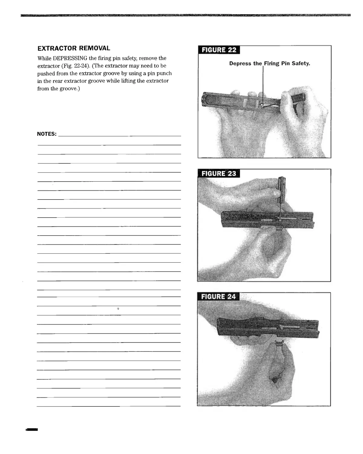
EXTRACTOR REMOVAL
While DEPRESSING the firing pin safety, remove the
extractor (Fig. 22-24). (The extractor may need to be
pushed from the extractor groove by using a pin punch
in the rear extractor groove while lifting the extractor
from the groove.)
NOTES:________________________________________
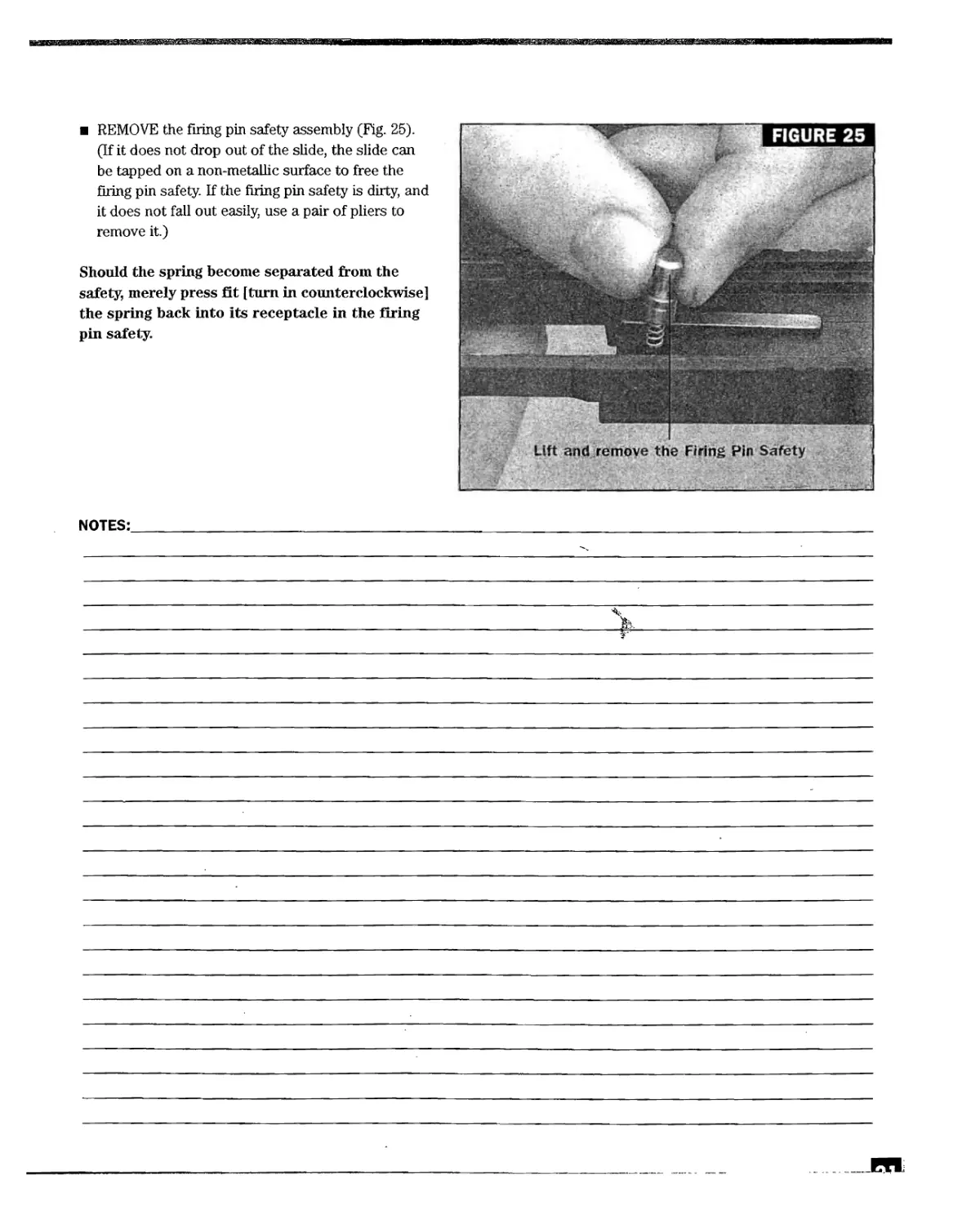
REMOVE the firing pin safety assembly (Fig. 25).
(If it does not drop out of the slide, the slide can
be tapped on a non-metallic surface to free the
firing pin safety. If the firing pin safety is dirty, and
it does not fall out easily, use a pair of pliers to
remove it.)
Should the spring become separated from the
safety, merely press fit [turn in counterclockwise]
the spring back into its receptacle in the firing
pin safety.
NOTES:
FURTHER DISASSEMBLY OF THE FIRING
PIN ASSEMBLY AND THE EXTRACTOR
DEPRESSOR PLUNGER ASSEMBLY
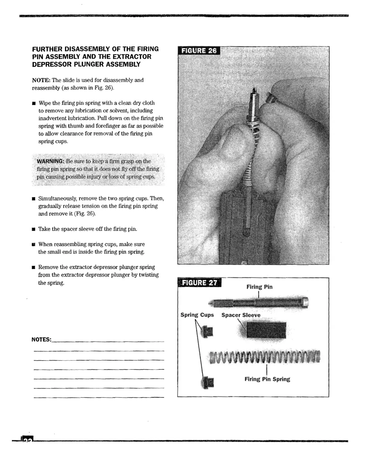
NOTE: The slide is used for disassembly and
reassembly (as shown in Fig. 26).
Wipe the firing pin spring with a clean dry cloth
to remove any lubrication or solvent, including
inadvertent lubrication. Pull down on the firing pin
spring with thumb and forefinger as far as possible
to allow clearance for removal of the firing pin
spring cups.
WARNING: Be sure to keep a firm grasp on the
firing pin spring so that it. does not fly off the firing
pin causing possible injury or loss of spring cups.
Simultaneously, remove the two spring cups. Then,
gradually release tension on the firing pin spring
and remove it (Fig. 26).
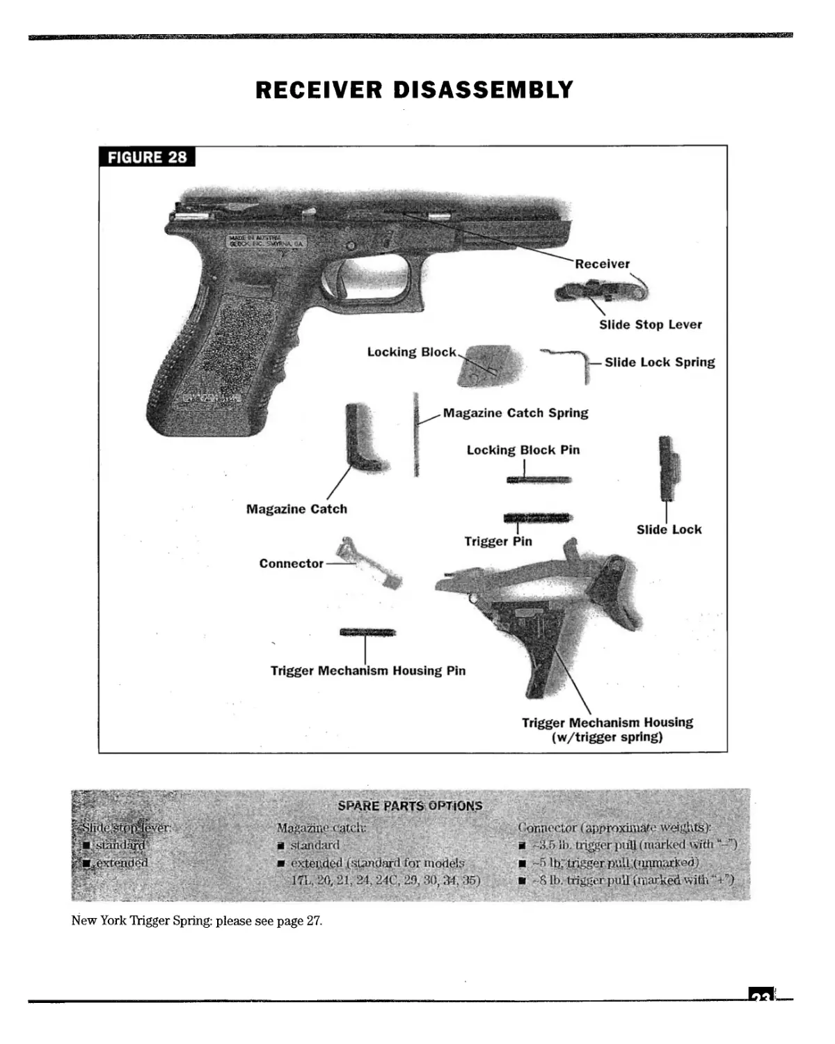
Take the spacer sleeve off the firing pin.
в When reassembling spring cups, make sure
the small end is inside the firing pin spring.
в Remove the extractor depressor plunger spring
from the extractor depressor plunger by twisting
the spring.
NOTES:___________________________________
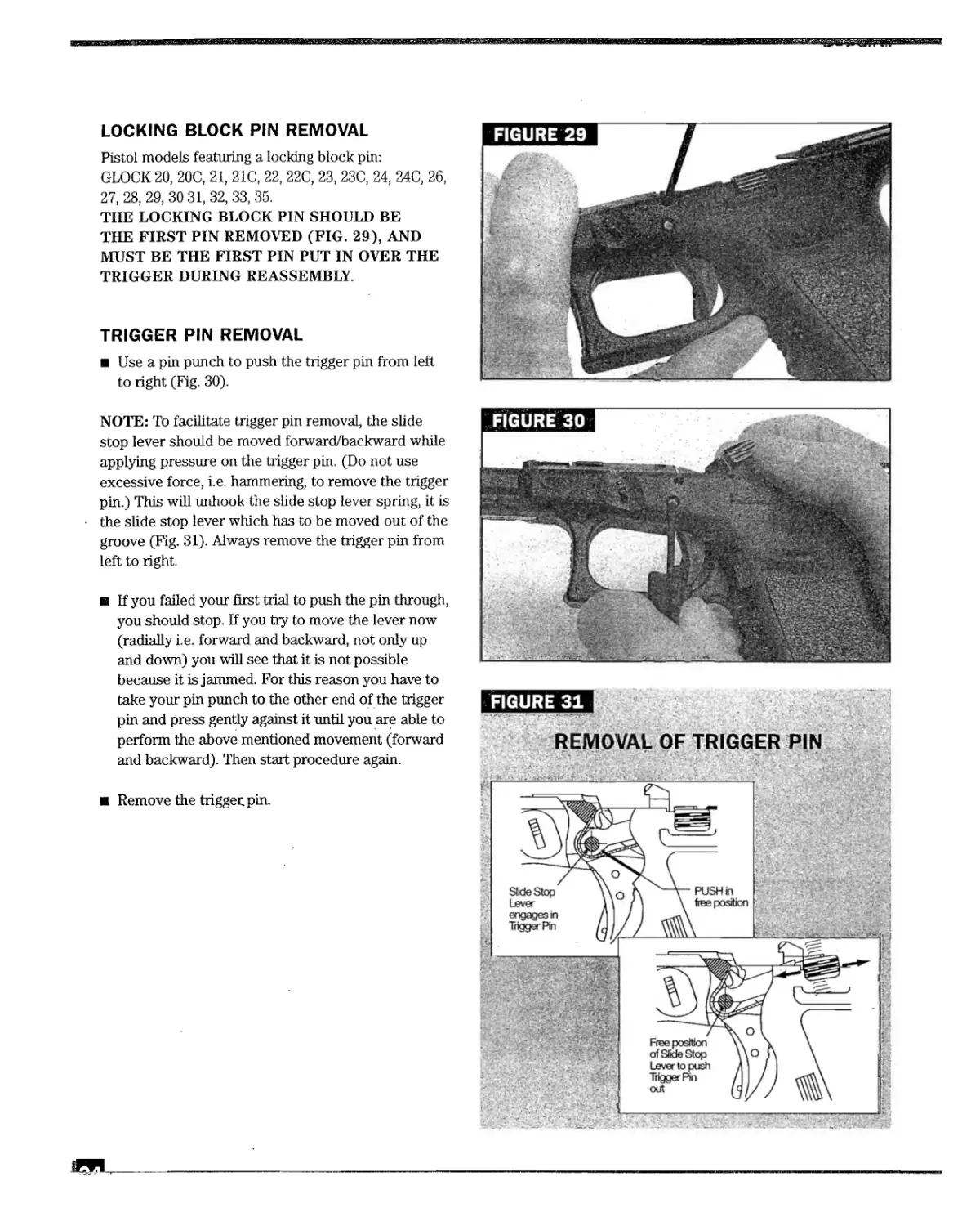
RECEIVER DISASSEMBLY
SPARE PARTS OPTIONS
Magazine eatclv
я standard
<'Mended (standard for models
171.. 20,21,24,240,^30,34,35)
Connector (approximate weights):
я ~3.5 lb. trigger pull (marked wfth “-”)
-4» lb;'.trigger nviU,;(iuunai:ke<i)
-8 lb. trigger pull (marked vvitii “+”)
New York TYigger Spring: please see page 27.
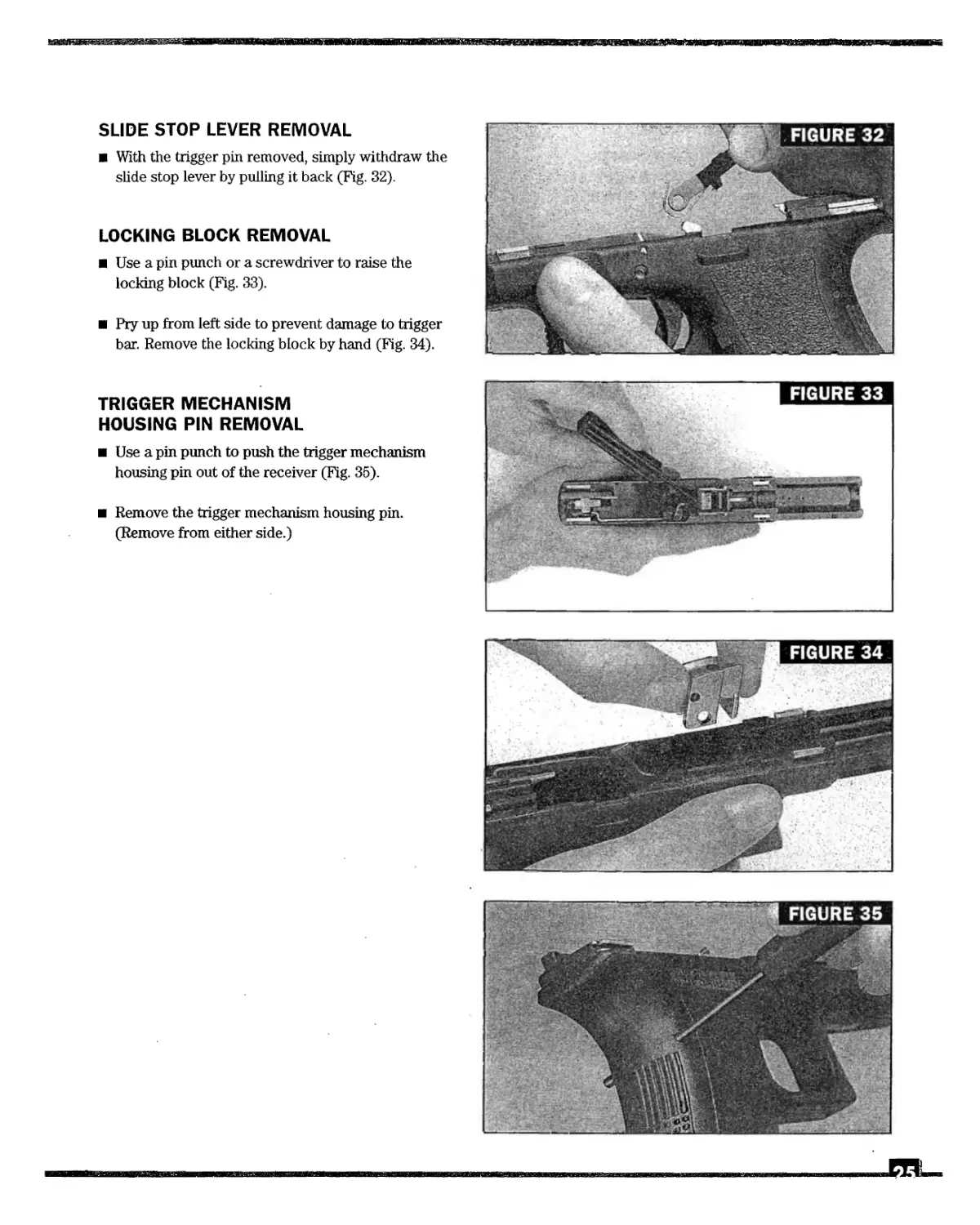
LOCKING BLOCK PIN REMOVAL
Pistol models featuring a locking block pin:
GLOCK 20, 20C, 21, 21C, 22, 22C, 23, 23C, 24, 24C, 26,
27, 28, 29, 30 31, 32, 33, 35.
THE LOCKING BLOCK PIN SHOULD BE
THE FIRST PIN REMOVED (FIG. 29), AND
MUST BE THE FIRST PIN PUT IN OVER THE
TRIGGER DURING REASSEMBLY.
TRIGGER PIN REMOVAL
Use a pin punch to push the trigger pin from left
to right (Fig. 30).
NOTE: To facilitate trigger pin removal, the slide
stop lever should be moved forward/backward while
applying pressure on the trigger pin. (Do not use
excessive force, i.e. hammering, to remove the trigger
pin.) This will unhook the slide stop lever spring, it is
the slide stop lever which has to be moved out of the
groove (Fig. 31). Always remove the trigger pin from
left to right.
и If you failed your first trial to push the pin through,
you should stop. If you try to move the lever now
(radially i.e. forward and backward, not only up
and down) you will see that it is not possible
because it is jammed. For this reason you have to
take your pin punch to the other end of the trigger
pin and press gently against it until you are able to
perform the above mentioned movement (forward
and backward). Then start procedure again.
Remove the trigger; pin.
SLIDE STOP LEVER REMOVAL
With the trigger pin removed, simply withdraw the
slide stop lever by pulling it back (Fig. 32).
LOCKING BLOCK REMOVAL
Use a pin punch or a screwdriver to raise the
locking block (Fig. 33).
Pry up from left side to prevent damage to trigger
bar. Remove the locking block by hand (Fig. 34).
TRIGGER MECHANISM
HOUSING PIN REMOVAL
Use a pin punch to push the trigger mechanism
housing pin out of the receiver (Fig. 35).
Remove the trigger mechanism housing pin.
(Remove from either side.)
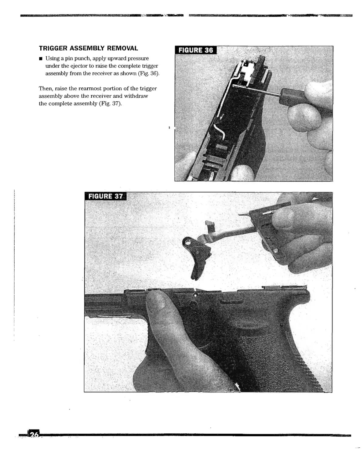
TRIGGER ASSEMBLY REMOVAL
Using a pin punch, apply upward pressure
under the ejector to raise the complete trigger
assembly from the receiver as shown (Fig. 36).
Then, raise the rearmost portion of the trigger
assembly above the receiver and withdraw
the complete assembly (Fig. 37).
FIGURE 36
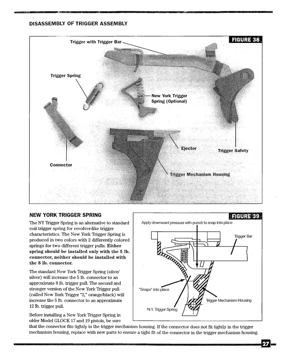
DISASSEMBLY OF TRIGGER ASSEMBLY
FIGURE 39
NEW YORK TRIGGER SPRING
The NY Trigger Spring is an alternative to standard
coil trigger spring for revolver-like trigger
characteristics. The New York Trigger Spring is
produced in two colors with 2 differently colored
springs for two different trigger pulls. Either
spring should be installed only with the 5 lb.
connector, neither should be installed with
the 8 lb. connector.
The standard New York Trigger Spring (olive/
silver) will increase the 5 lb. connector to an
approximate 8 lb. trigger pulL The second and
stronger version of the New York Trigger pull
(called New York Trigger “2,” orange/black) will
increase the 5 lb. connector to an approximate
12 lb. trigger pull
Before installing a New York Trigger Spring in
older Model GLOCK 17 and 19 pistols, be sure
Apply downward pressure with punch to snap into place
that the connector fits tightly in the trigger mechanism housing. If the connector does not fit tightly in the trigger
mechanism housing, replace with new parts to ensure a tight fit of the connector in the trigger mechanism housing.
27
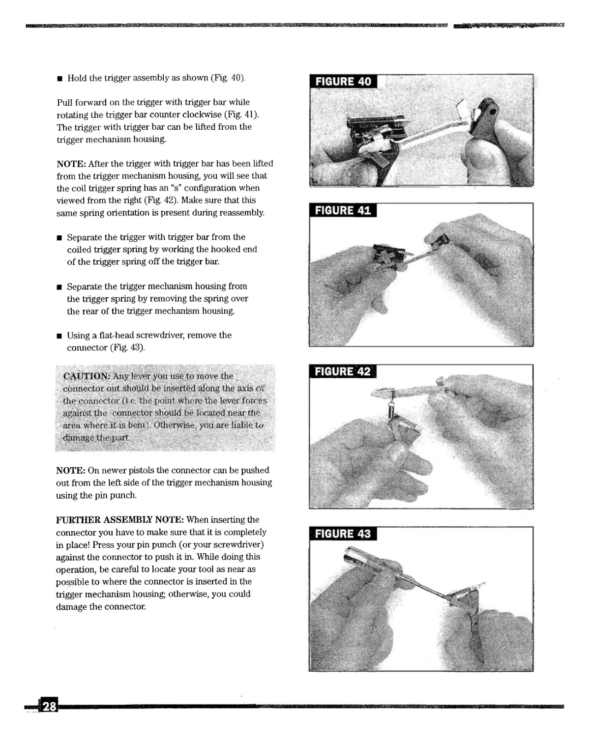
Hold the trigger assembly as shown (Fig. 40).
Pull forward on the trigger with trigger bar while
rotating the trigger bar counter clockwise (Fig. 41).
The trigger with trigger bar can be lifted from the
trigger mechanism housing.
NOTE: After the trigger with trigger bar has been lifted
from the trigger mechanism housing, you will see that
the coil trigger spring has an “s” configuration when
viewed from the right (Fig. 42). Make sure that this
same spring orientation is present during reassembly.
Separate the trigger with trigger bar from the
coiled trigger spring by working the hooked end
of the trigger spring off the trigger bar.
Separate the trigger mechanism housing from
the trigger spring by removing the spring over
the rear of the trigger mechanism housing.
Using a flat-head screwdriver, remove the
connector (Fig. 43).
CAUTION: Any lever you use to move the
connector out should be inserted along the axis oV
the connector (i.c. the point where the lever forces
against the connector should be located near the
area where it is bent). Otherwise, you are liable to
damage the.part.
NOTE: On newer pistols the connector can be pushed
out from the left side of the trigger mechanism housing
using the pin punch.
FURTHER ASSEMBLY NOTE: When inserting the
connector you have to make sure that it is completely
in place! Press your pin punch (or your screwdriver)
against the connector to push it in. While doing this
operation, be careful to locate your tool as near as
possible to where the connector is inserted in the
trigger mechanism housing; otherwise, you could
damage the connector.
FIGURE 40
28
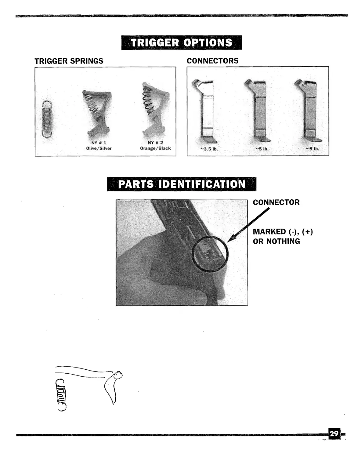
TRIGGER OPTIONS
TRIGGER SPRINGS
CONNECTORS
PARTS IDENTIFICATION
29
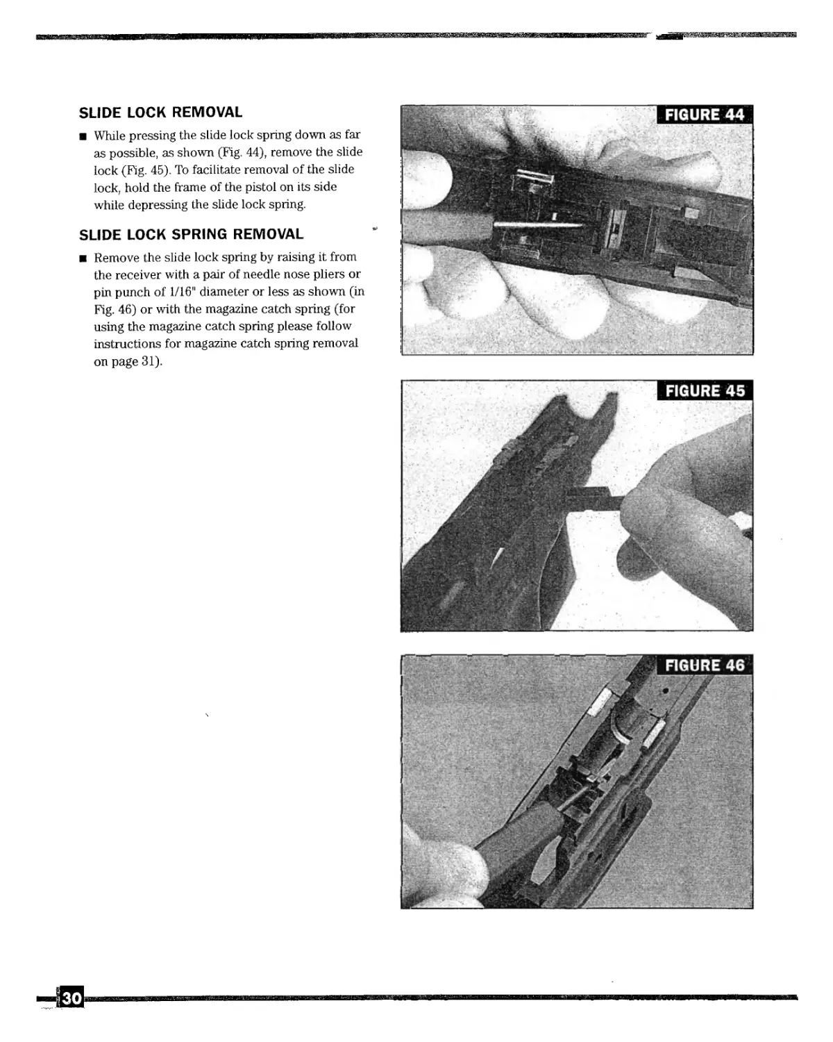
SLIDE LOCK REMOVAL
While pressing the slide lock spring down as far
as possible, as shown (Fig. 44), remove the slide
lock (Fig. 45). To facilitate removal of the slide
lock, hold the frame of the pistol on its side
while depressing the slide lock spring.
SLIDE LOCK SPRING REMOVAL
Remove the slide lock spring by raising it from
the receiver with a pair of needle nose pliers or
pin punch of 1/16" diameter or less as shown (in
Fig. 46) or with the magazine catch spring (for
using the magazine catch spring please follow
instructions for magazine catch spring removal
on page 31).
,30
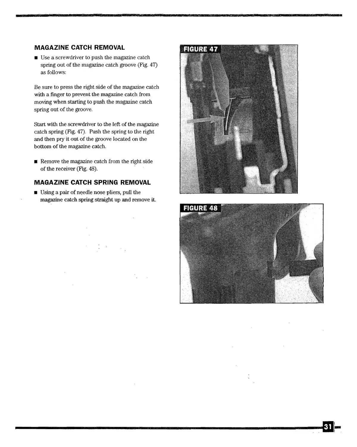
MAGAZINE CATCH REMOVAL
Use a screwdriver to push the magazine catch
spring out of the magazine catch groove (Fig. 47)
as follows:
Be sure to press the right side of the magazine catch
with a finger to prevent the magazine catch from
moving when starting to push the magazine catch
spring out of the groove.
Start with the screwdriver to the left of the magazine
catch spring (Fig. 47). Push the spring to the right
and then pry it out of the groove located on the
bottom of the magazine catch.
Remove the magazine catch from the right side
of the receiver (Fig. 48).
MAGAZINE CATCH SPRING REMOVAL
Using a pair of needle nose pliers, pull the
magazine catch spring straight up and remove it.
li
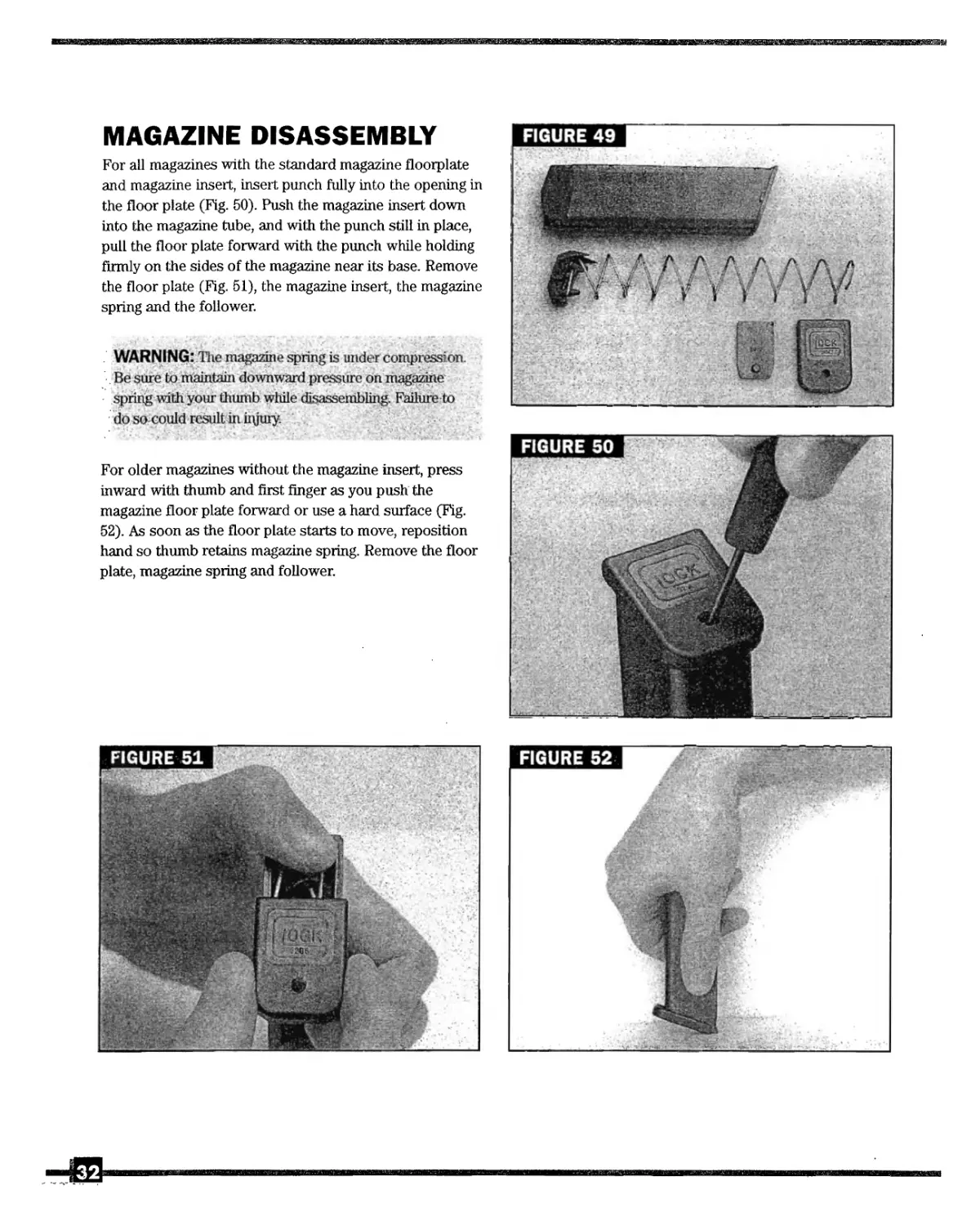
MAGAZINE DISASSEMBLY
For all magazines with the standard magazine floorplate
and magazine insert, insert punch fully into the opening in
the floor plate (Fig. 50). Push the magazine insert down
into the magazine tube, and with the punch still in place,
pull the floor plate forward with the punch while holding
firmly on the sides of the magazine near its base. Remove
the floor plate (Fig. 51), the magazine insert, the magazine
spring and the follower.
WARNING: The magazine spring is under compression.
Be sure to maintain downward pressure on magazine
spring with your thumb while disassembling. Failure to
do so could result in iiyuiy.
For older magazines without the magazine insert, press
inward with thumb and first finger as you push the
magazine floor plate forward or use a hard surface (Fig.
52). As soon as the floor plate starts to move, reposition
hand so thumb retains magazine spring. Remove the floor
plate, magazine spring and follower.
VI.
REASSEMBLY PROCEDURES
As with most firearms, reassembly is
generally carried out in the reverse
order of disassembly. Several specific
suggestions are provided below to
facilitate reassembly.
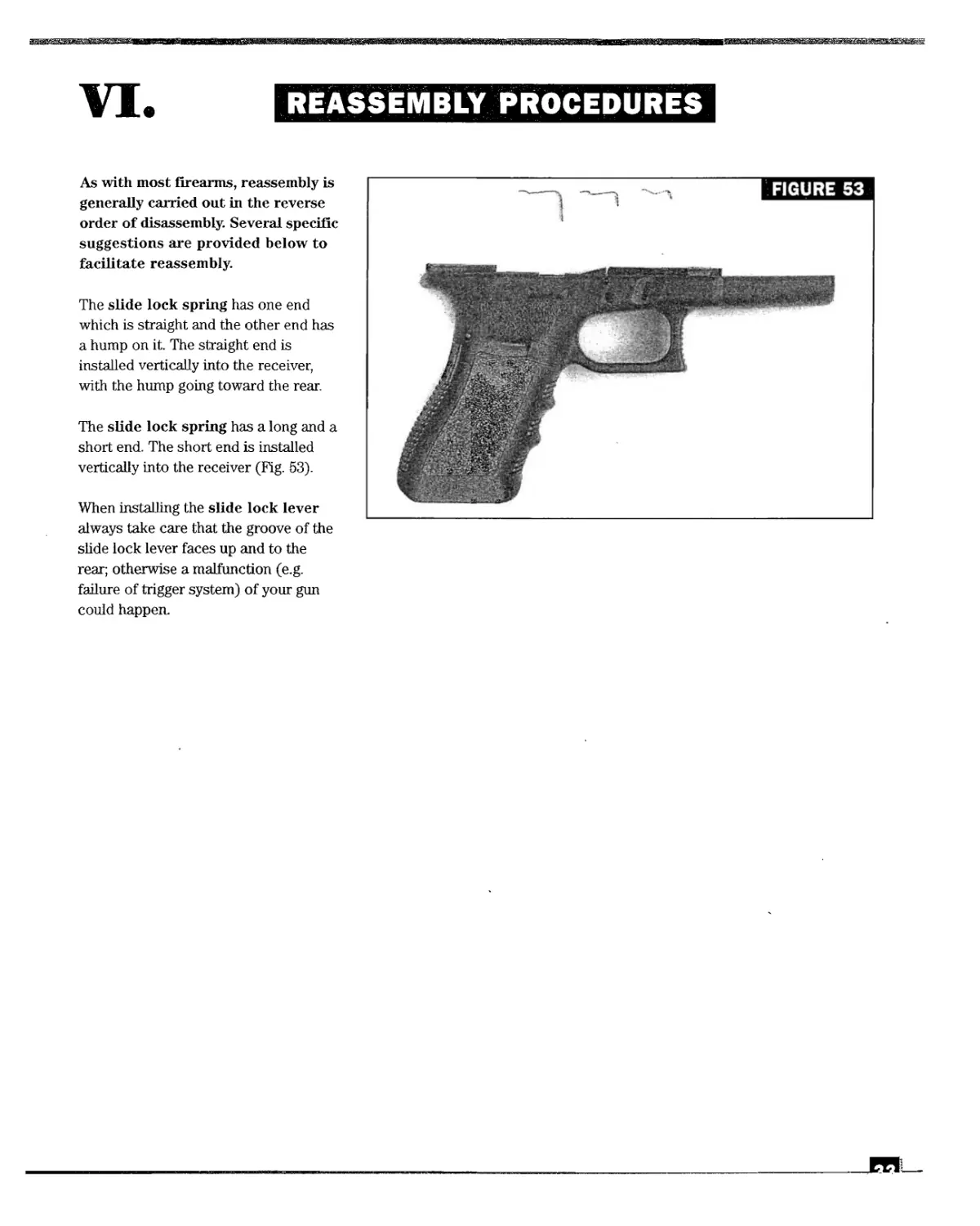
The slide lock spring has one end
which is straight and the other end has
a hump on it. The straight end is
installed vertically into the receiver,
with the hump going toward the rear.
The slide lock spring has a long and a
short end. The short end is installed
vertically into the receiver (Fig. 53).
When installing the slide lock lever
always take care that the groove of the
slide lock lever faces up and to the
rear; otherwise a malfunction (e.g.
failure of trigger system) of your gun
could happen.
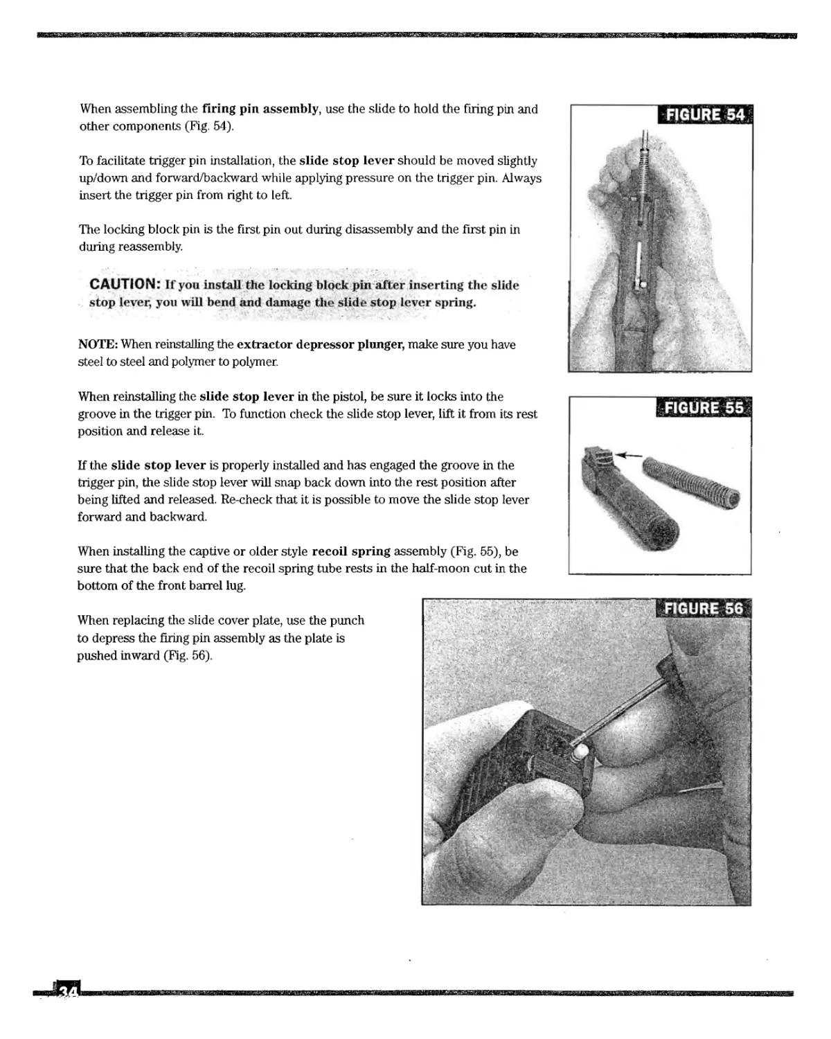
When assembling the firing pin assembly, use the slide to hold the firing pin and
other components (Fig. 54).
To facilitate trigger pin installation, the slide stop lever should be moved slightly
up/down and forward/backward while applying pressure on the trigger pin. Always
insert the trigger pin from right to left.
The locking block pin is the first pin out during disassembly and the first pin in
during reassembly.
CAUTION: If you install the locking block pin after inserting the slide
stop lever, you will bend and damage the slide stop lever spring.
NOTE: When reinstalling the extractor depressor plunger, make sure you have
steel to steel and polymer to polymer.
When reinstalling the slide stop lever in the pistol, be sure it locks into the
groove in the trigger pin. To function check the slide stop lever, lift it from its rest
position and release it.
If the slide stop lever is properly installed and has engaged the groove in the
trigger pin, the slide stop lever will snap back down into the rest position after
being lifted and released. Re-check that it is possible to move the slide stop lever
forward and backward.
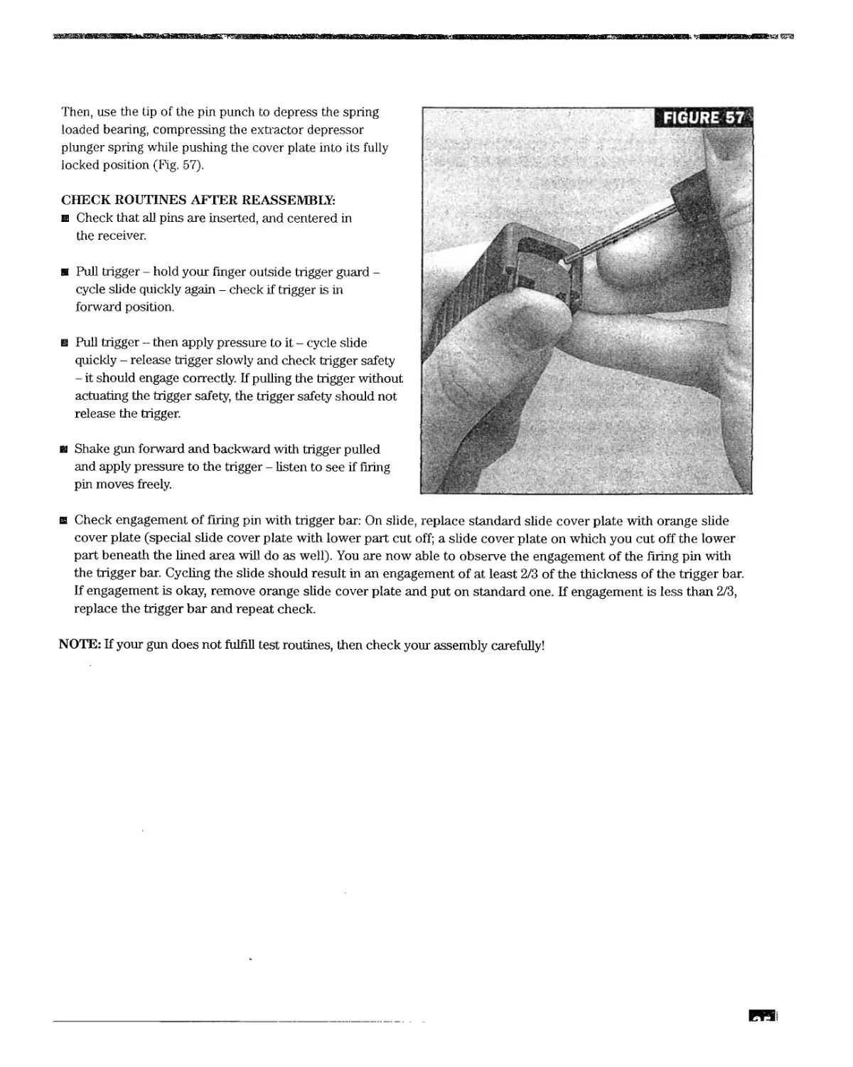
When installing the captive or older style recoil spring assembly (Fig. 55), be
sure that the back end of the recoil spring tube rests in the half-moon cut in the
bottom of the front barrel lug.
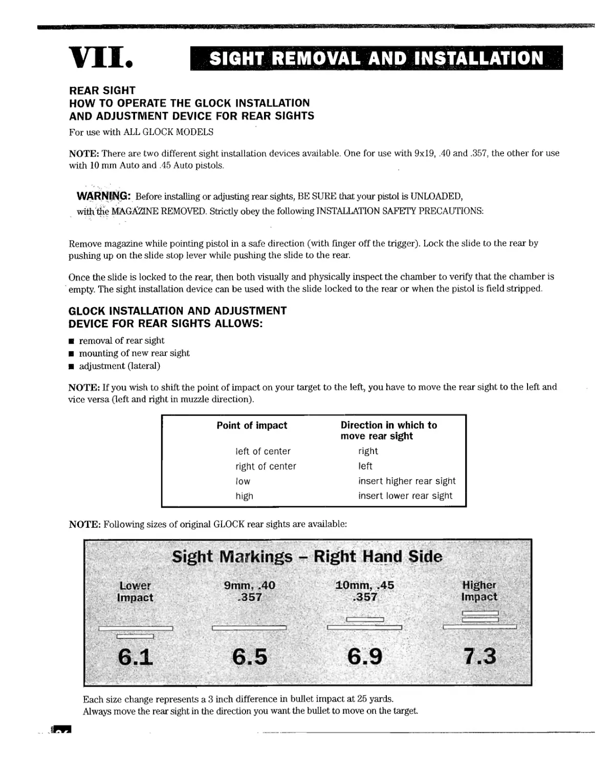
When replacing the slide cover plate, use the punch
to depress the firing pin assembly as the plate is
pushed inward (Fig. 56).
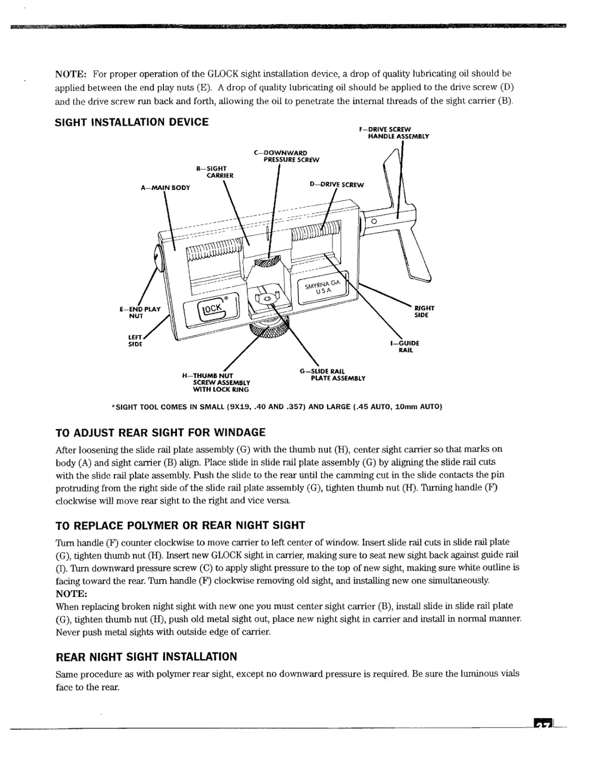
Then, use the tip of the pin punch to depress the spring
loaded bearing, compressing the extractor depressor
plunger spring while pushing the cover plate into its fully
locked position (Fig. 57).
CHECK ROUTINES AFTER REASSEMBLY:
н Check that all pins are inserted, and centered in
the receiver.
s Pull trigger - hold your finger outside trigger guard -
cycle slide quickly again - check if trigger is in
forward position.
e Pull trigger - then apply pressure to it - cycle slide
quickly - release trigger slowly and check trigger safety
- it should engage correctly. If pulling the trigger without
actuating the trigger safety, the trigger safety should not
release the trigger.
в Shake gun forward and backward with trigger pulled
and apply pressure to the trigger - listen to see if firing
pin moves freely.
s Check engagement of firing pin with trigger bar: On slide, replace standard slide cover plate with orange slide
cover plate (special slide cover plate with lower part cut off; a slide cover plate on which you cut off the lower
part beneath the lined area will do as well). You are now able to observe the engagement of the firing pin with
the trigger bar. Cycling the slide should result in an engagement of at least 2/3 of the thickness of the trigger bar.
If engagement is okay, remove orange slide cover plate and put on standard one. If engagement is less than 2/3,
replace the trigger bar and repeat check.
NOTE: If your gun does not fulfill test routines, then check your assembly carefully!
VII.
SIGHT REMOVAL AND INSTALLATION
REAR SIGHT
HOW TO OPERATE THE GLOCK INSTALLATION
AND ADJUSTMENT DEVICE FOR REAR SIGHTS
For use with ALL GLOCK MODELS
NOTE: There are two different sight installation devices available. One for use with 9x19, .40 and .357, the other for use
with 10 mm Auto and .45 Auto pistols.
WARNIlNG- Before installing or adjusting rear sights, BE SURE that your pistol is UNLOADED,
with'tKe MAGAZINE REMOVED. Strictly obey the following INSTALLATION SAFETY PRECAUTIONS:
Remove magazine while pointing pistol in a safe direction (with finger off the trigger). Lock the slide to the rear by
pushing up on the slide stop lever while pushing the slide to the rear.
Once the slide is locked to the rear, then both visually and physically inspect the chamber to verify that the chamber is
empty. The sight installation device can be used with the slide locked to the rear or when the pistol is field stripped.
GLOCK INSTALLATION AND ADJUSTMENT
DEVICE FOR REAR SIGHTS ALLOWS:
removal of rear sight
mounting of new rear sight
adjustment (lateral)
NOTE: If you wish to shift the point of impact on your target to the left, you have to move the rear sight to the left and
vice versa (left and right in muzzle direction).
Point of impact Direction in which to
move rear sight
left of center right
right of center left
low insert higher rear sight
high insert lower rear sight
NOTE: Following sizes of original GLOCK rear sights are available:
Sight Markings - Right Hand Side
Lower 9mm, .40 10mm, .45 Higher
Impact .357 .357 Impact
Each size change represents a 3 inch difference in bullet impact at 25 yards.
Always move the rear sight in the direction you want the bullet to move on the target.
NOTE: For proper operation of the GLOCK sight installation device, a drop of quality lubricating oil should be
applied between the end play nuts (E). A drop of quality lubricating oil should be applied to the drive screw (D)
and the drive screw run back and forth, allowing the oil to penetrate the internal threads of the sight carrier (B).
SIGHT INSTALLATION DEVICE
F—DRIVE SCREW
HANDLE ASSEMBLY
WITH LOCK RING
*SIGHT TOOL COMES IN SMALL (9X19, .40 AND .357) AND LARGE (.45 AUTO, 10mm AUTO)
TO ADJUST REAR SIGHT FOR WINDAGE
After loosening the slide rail plate assembly (G) with the thumb nut (H), center sight carrier so that marks on
body (A) and sight carrier (B) align. Place slide in slide rail plate assembly (G) by aligning the slide rail cuts
with the slide rail plate assembly. Push the slide to the rear until the camming cut in the slide contacts the pin
protruding from the right side of the slide rail plate assembly (G), tighten thumb nut (H). Turning handle (F)
clockwise will move rear sight to the right and vice versa
TO REPLACE POLYMER OR REAR NIGHT SIGHT
Turn handle (F) counter clockwise to move carrier to left center of window. Insert slide rail cuts in slide rail plate
(G), tighten thumb nut (H). Insert new GLOCK sight in carrier, making sure to seat new sight back against guide rail
(I). Turn downward pressure screw (C) to apply slight pressure to the top of new sight, making sure white outline is
facing toward the rear. Turn handle (F) clockwise removing old sight, and installing new one simultaneously.
NOTE:
When replacing broken night sight with new one you must center sight carrier (B), install slide in slide rail plate
(G), tighten thumb nut (H), push old metal sight out, place new night sight in carrier and install in normal manner.
Never push metal sights with outside edge of carrier.
REAR NIGHT SIGHT INSTALLATION
Same procedure as with polymer rear sight, except no downward pressure is required. Be sure the luminous vials
face to the rear.
ВЮИЙЙЙ
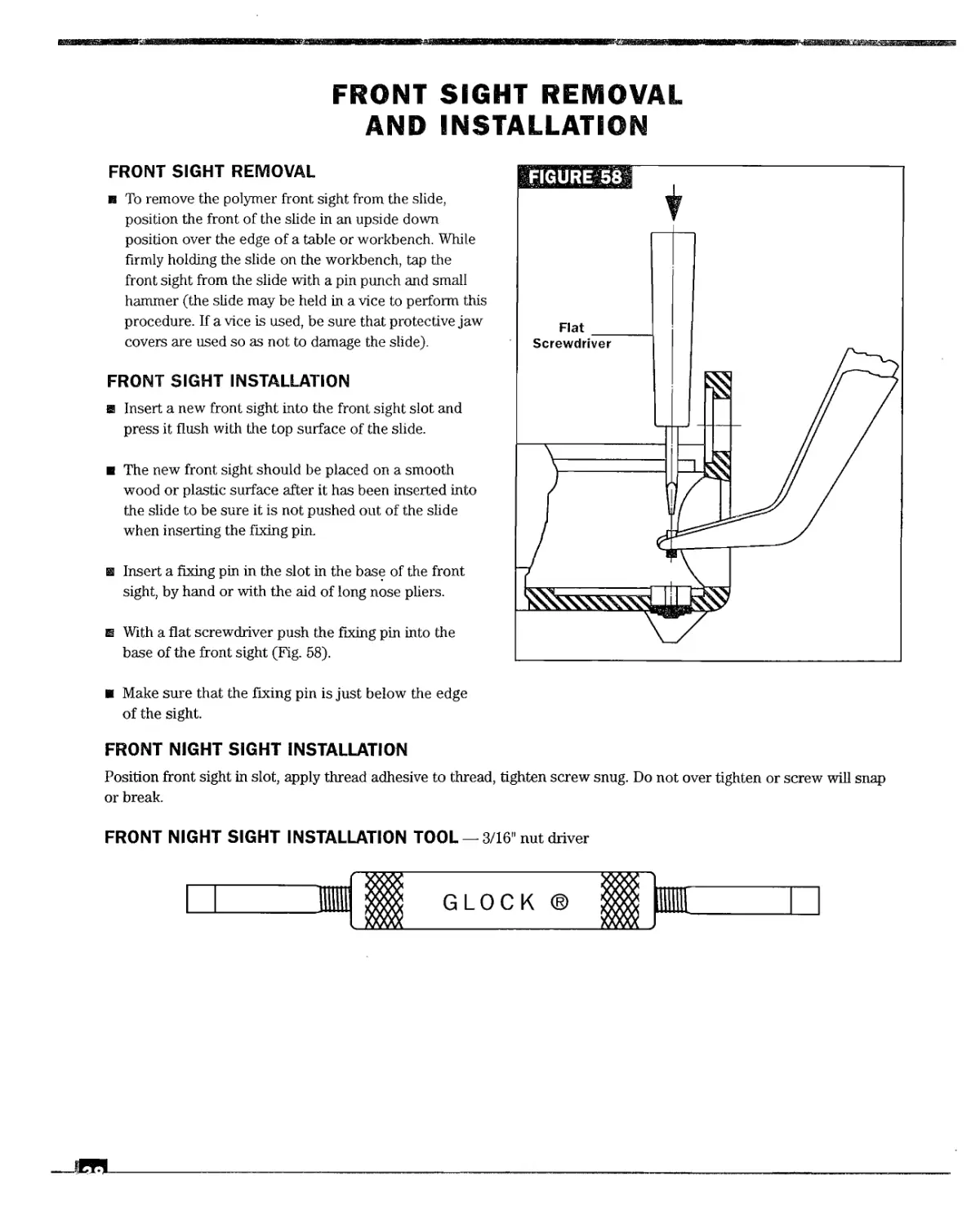
FRONT SIGHT REMOVAL
AND INSTALLATION
FRONT SIGHT REMOVAL
r To remove the polymer front sight from the slide,
position the front of the slide in an upside down
position over the edge of a table or workbench. While
firmly holding the slide on the workbench, tap the
front sight from the slide with a pin punch and small
hammer (the slide may be held in a vice to perform this
procedure. If a vice is used, be sure that protective jaw
covers are used so as not to damage the slide).
FRONT SIGHT INSTALLATION
a Insert a new front sight into the front sight slot and
press it flush with the top surface of the slide.
r The new front sight should be placed on a smooth
wood or plastic surface after it has been inserted into
the slide to be sure it is not pushed out of the slide
when inserting the fixing pin.
a Insert a fixing pin in the slot in the base of the front
sight, by hand or with the aid of long nose pliers.
ш With a flat screwdriver push the fixing pin into the
base of the front sight (Fig. 58).
и Make sure that the fixing pin is just below the edge
of the sight.
FIGURE58
FRONT NIGHT SIGHT INSTALLATION
Position front sight in slot, apply thread adhesive to thread, tighten screw snug. Do not over tighten or screw will snap
or break.
FRONT NIGHT SIGHT INSTALLATION TOOL —3/16 nut driver
GLOCK ®
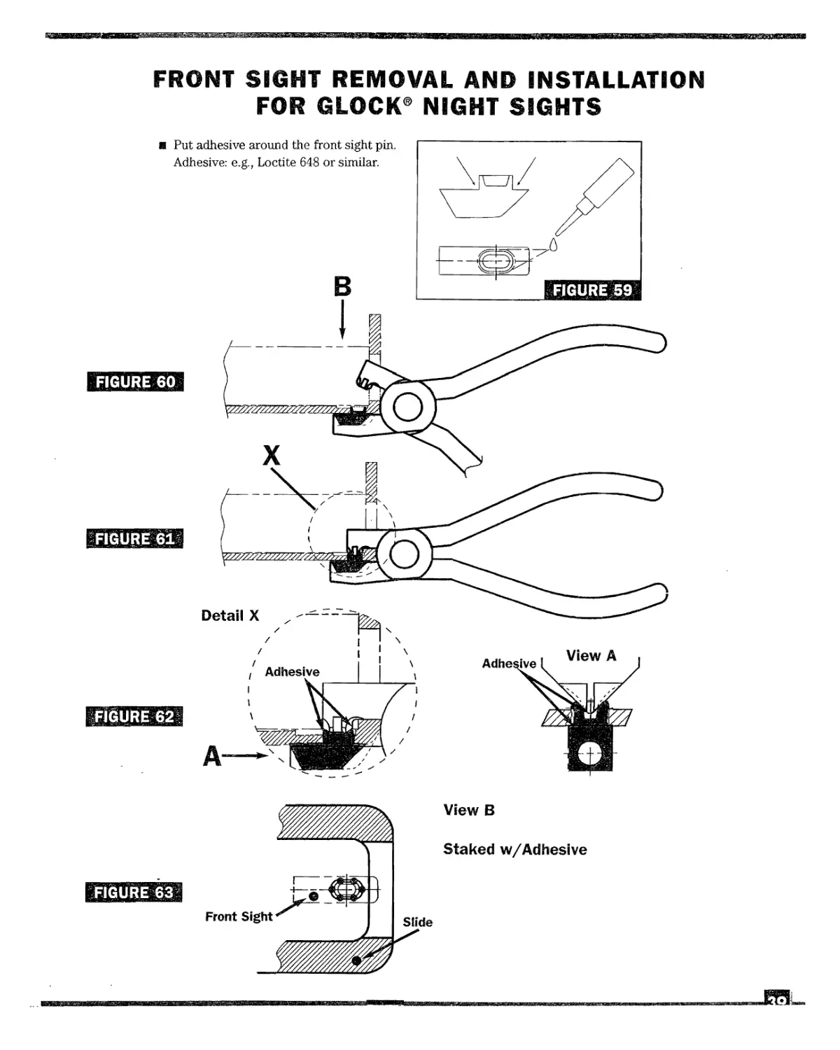
FRONT SIGHT REMOVAL AND INSTALLATION
FOR GLOCK® NIGHT SIGHTS
FIGURE 63
Detail X
FIGURE 62
в Put adhesive around the front sight pin.
Adhesive: e.g., Loctite 648 or similar.
View В
Staked w/Adhesive
Front Sight
Slide
Adhesive
t Adhesive
View A
VIII
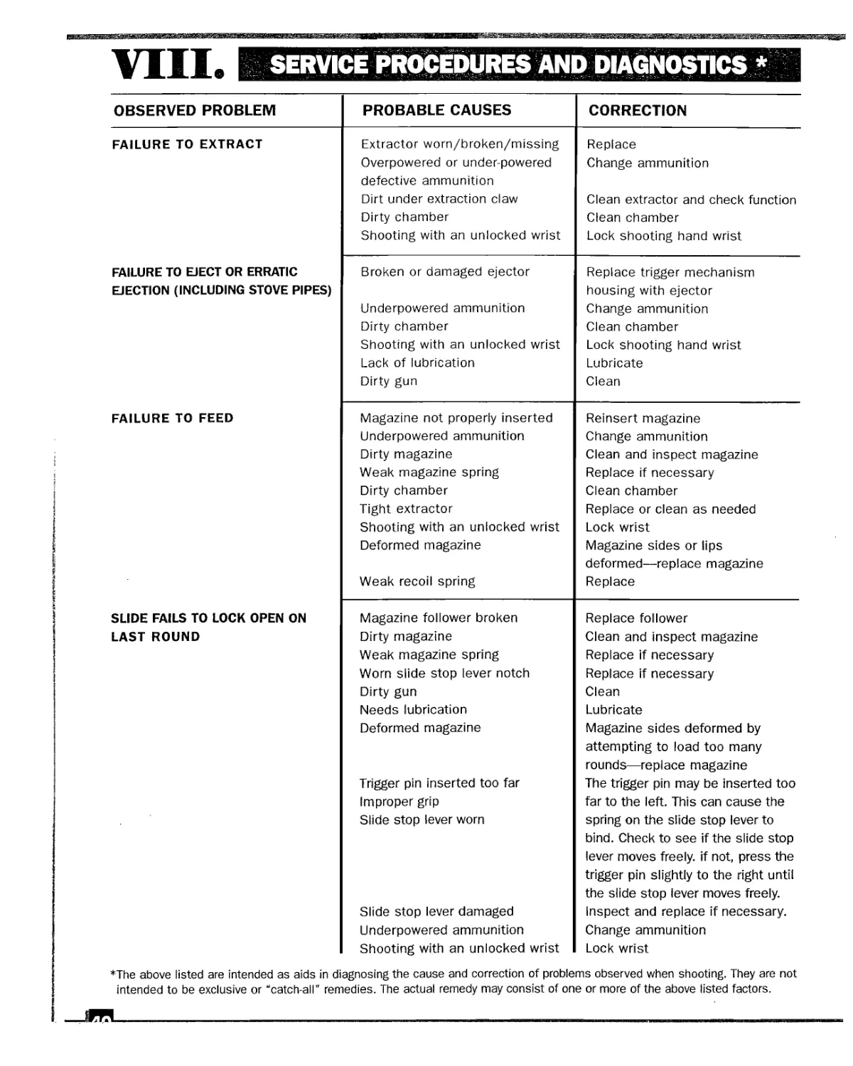
SERVICE PROCEDURES AND DIAGNOSTICS *
OBSERVED PROBLEM PROBABLE CAUSES CORRECTION
FAILURE TO EXTRACT Extractor worn/broken/missing Overpowered or under-powered defective ammunition Dirt under extraction claw Dirty chamber Shooting with an unlocked wrist Replace Change ammunition Clean extractor and check function Clean chamber Lock shooting hand wrist
FAILURE TO EJECT OR ERRATIC EJECTION (INCLUDING STOVE PIPES) Broken or damaged ejector Underpowered ammunition Dirty chamber Shooting with an unlocked wrist Lack of lubrication Dirty gun Replace trigger mechanism housing with ejector Change ammunition Clean chamber Lock shooting hand wrist Lubricate Clean
FAILURE TO FEED Magazine not properly inserted Underpowered ammunition Dirty magazine Weak magazine spring Dirty chamber Tight extractor Shooting with an unlocked wrist Deformed magazine Weak recoil spring Reinsert magazine Change ammunition Clean and inspect magazine Replace if necessary Clean chamber Replace or clean as needed Lock wrist Magazine sides or lips deformed—replace magazine Replace
SLIDE FAILS TO LOCK OPEN ON Magazine follower broken Replace follower
LAST ROUND Dirty magazine Weak magazine spring Worn slide stop lever notch Dirty gun Needs lubrication Deformed magazine Trigger pin inserted too far Improper grip Slide stop lever worn Slide stop lever damaged Underpowered ammunition Shooting with an unlocked wrist Clean and inspect magazine Replace if necessary Replace if necessary Clean Lubricate Magazine sides deformed by attempting to load too many rounds—replace magazine The trigger pin may be inserted too far to the left. This can cause the spring on the slide stop lever to bind. Check to see if the slide stop lever moves freely, if not, press the trigger pin slightly to the right until the slide stop lever moves freely. Inspect and replace if necessary. Change ammunition Lock wrist
*The above listed are intended as aids in diagnosing the cause and correction of problems observed when shooting. They are not
intended to be exclusive orucatch-all" remedies. The actual remedy may consist of one or more of the above listed factors.
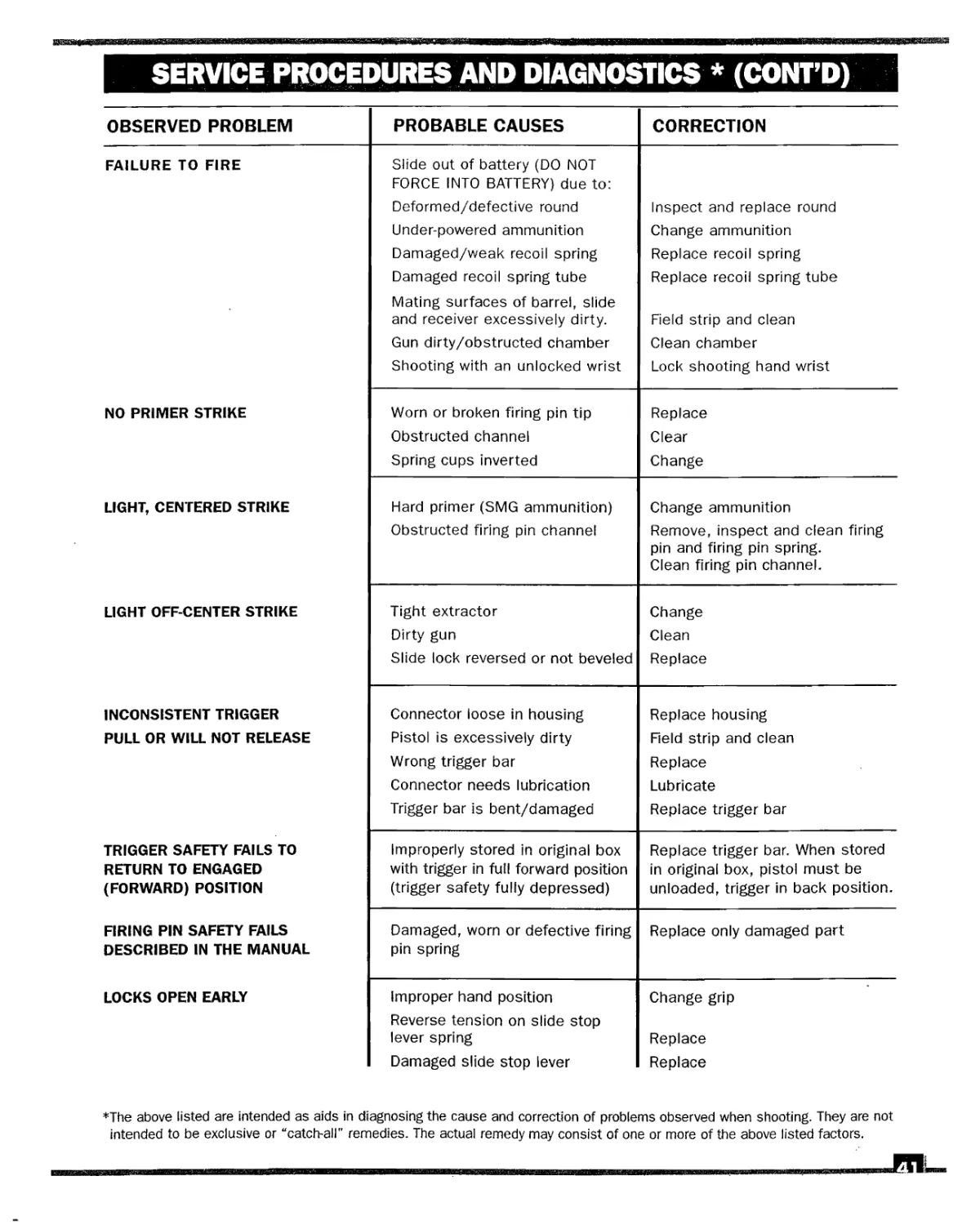
SERVICE PROCEDURES AND DIAGNOSTICS * (CONT’D)
OBSERVED PROBLEM PROBABLE CAUSES CORRECTION
FAILURE TO FIRE Slide out of battery (DO NOT FORCE INTO BATTERY) due to: Deformed/defective round Under-powered ammunition Damaged/weak recoil spring Damaged recoil spring tube Mating surfaces of barrel, slide and receiver excessively dirty. Gun dirty/obstructed chamber Shooting with an unlocked wrist Inspect and replace round Change ammunition Replace recoil spring Replace recoil spring tube Field strip and clean Clean chamber Lock shooting hand wrist
NO PRIMER STRIKE Worn or broken firing pin tip Obstructed channel Spring cups inverted Replace Clear Change
LIGHT, CENTERED STRIKE Hard primer (SMG ammunition) Obstructed firing pin channel Change ammunition Remove, inspect and clean firing pin and firing pin spring. Clean firing pin channel.
LIGHT OFF-CENTER STRIKE Tight extractor Dirty gun Slide lock reversed or not beveled Change Clean Replace
INCONSISTENT TRIGGER Connector loose in housing Replace housing
PULL OR WILL NOT RELEASE Pistol is excessively dirty Wrong trigger bar Connector needs lubrication Trigger bar is bent/damaged Field strip and clean Replace Lubricate Replace trigger bar
TRIGGER SAFETY FAILS TO Improperly stored in original box Replace trigger bar. When stored
RETURN TO ENGAGED with trigger in full forward position in original box, pistol must be
(FORWARD) POSITION (trigger safety fully depressed) unloaded, trigger in back position.
FIRING PIN SAFETY FAILS DESCRIBED IN THE MANUAL Damaged, worn or defective firing pin spring Replace only damaged part
LOCKS OPEN EARLY Improper hand position Reverse tension on slide stop lever spring Damaged slide stop lever Change grip Replace Replace
*The above listed are intended as aids in diagnosing the cause and correction of problems observed when shooting. They are not
intended to be exclusive or “catch-all” remedies. The actual remedy may consist of one or more of the above listed factors.
NOTES
COURSE FORMS
COURSE FORMS
GLOCK CERTIFIED ARMORER POLICY
ON PROFESSIONALISM
GLOCK Certified Armorers have long been known for their professionalism and expertise. The
purpose of certification of GLOCK Armorers is to facilitate the professional handling of
required maintenance of GLOCK pistols. More specifically, it is our intention that only GLOCK
certified Armorers work on GLOCK pistols. It is the belief of GLOCK, Inc. that this policy best
ensures the safety of GLOCK customers and the integrity of GLOCK pistols.
In furtherance of this policy:
1. GLOCK, Inc. encourages you to use the GLOCK logo and “GLOCK Certified Armorer” on
business cards for yourself or your business. However, further use of the GLOCK trademark
and GLOCK logo is not permitted without written authorization from GLOCK, Inc.
2. GLOCK factory parts offered to GLOCK Certified Armorers are to be used for customer
requested maintenance only. GLOCK factory parts are not for re-sale.
GLOCK Certified Armorers who deviate from these standards of professionalism will not
be invited to renew their certification. Any and all licenses previously granted for use of the
trademark and logo will be immediately rescinded upon deviation from this policy.
COURSE FORMS
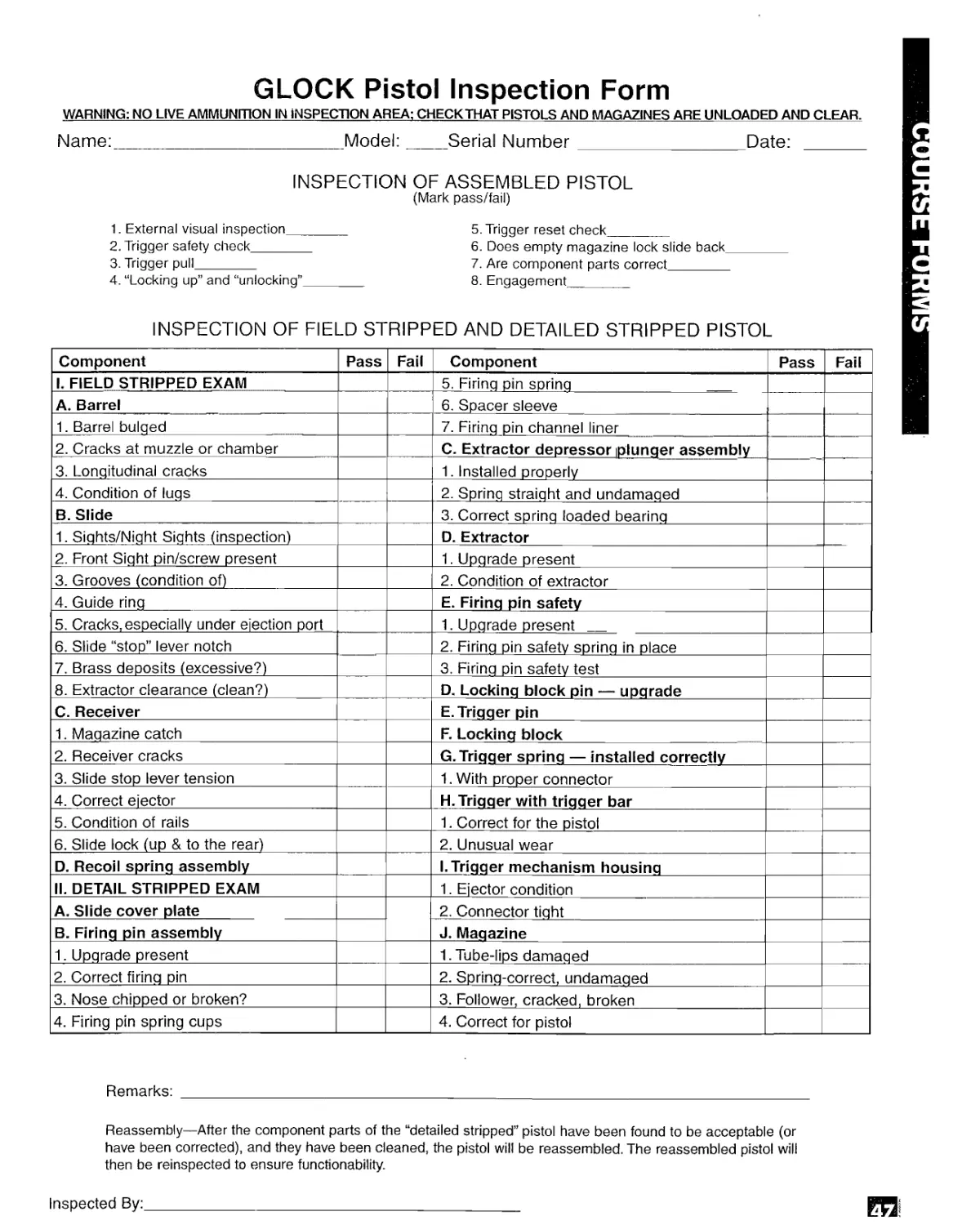
GLOCK Pistol Inspection Form
WARNING: NO LIVE AMMUNITION IN INSPECTION AREA; CHECK THAT PISTOLS AND MAGAZINES ARE UNLOADED AND CLEAR.
Name:Model:Serial Number Date:
INSPECTION OF ASSEMBLED PISTOL
(Mark pass/fail)
1. External visual inspection 5. Trigger reset check
2. Trigger safety check 6. Does empty magazine lock slide back
3. Trigger pull 7. Are component parts correct
4. “Locking up” and “unlocking” 8. Engagement
INSPECTION OF FIELD STRIPPED AMD DETAILED STRIPPED PISTOL
Component Pass Fail Component Pass Fail
1. FIELD STRIPPED EXAM 5. Firing pin spring
A. Barrel 6. Spacer sleeve
1. Barrel bulged 7. Firing pin channel liner
2. Cracks at muzzle or chamber C. Extractor depressor plunger assembly
3. Longitudinal cracks 1. Installed properly
4. Condition of lugs 2. Spring straight and undamaged
B. Slide 3. Correct spring loaded bearing
1. Sights/Night Sights (inspection) D. Extractor
2. Front Sight pin/screw present 1. Upgrade present
3. Grooves (condition of) 2. Condition of extractor
4. Guide ring E. Firing pin safety
5. Cracks, especially under ejection port 1. Upgrade present
6. Slide “stop” lever notch 2. Firing pin safety spring in place
7. Brass deposits (excessive?) 3. Firing pin safety test
8. Extractor clearance (clean?) D. Locking block pin — upgrade
C. Receiver E. Trigger pin
1. Magazine catch F. Locking block
2. Receiver cracks G. Trigger spring — installed correctly
3. Slide stop lever tension 1. With proper connector
4. Correct ejector H. Trigger with trigger bar
5. Condition of rails 1. Correct for the pistol
6. Slide lock (up & to the rear) 2. Unusual wear
D. Recoil spring assembly (.Trigger mechanism housing
II. DETAIL STRIPPED EXAM 1. Ejector condition
A. Slide cover plate 2. Connector tight
B. Firing pin assembly J. Magazine
1. Upgrade present 1. Tube-lips damaged
2. Correct firing pin 2. Spring-correct, undamaged
3. Nose chipped or broken? 3. Follower, cracked, broken
4. Firing pin spring cups 4. Correct for pistol
Remarks:
Reassembly—After the component parts of the “detailed stripped” pistol have been found to be acceptable (or
have been corrected), and they have been cleaned, the pistol will be reassembled. The reassembled pistol will
then be reinspected to ensure functionability.
Inspected By:_________________________________________________
COURSE FORMS
TECHNICAL BULLETINS
TECHNICAL BULLETINS
TECHNICAL BULLETIN
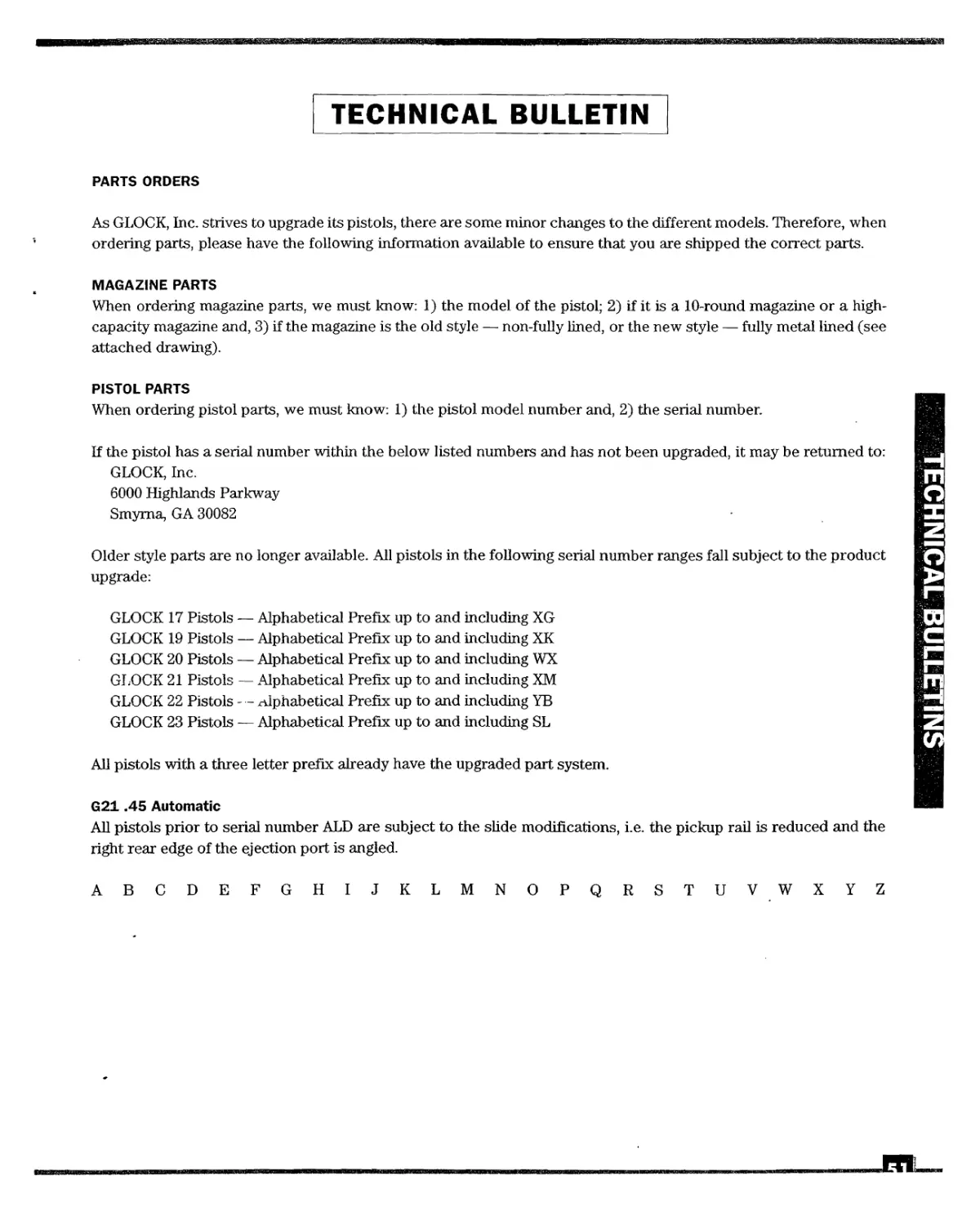
PARTS ORDERS
As GLOCK, Inc. strives to upgrade its pistols, there are some minor changes to the different models. Therefore, when
ordering parts, please have the following information available to ensure that you are shipped the correct parts.
MAGAZINE PARTS
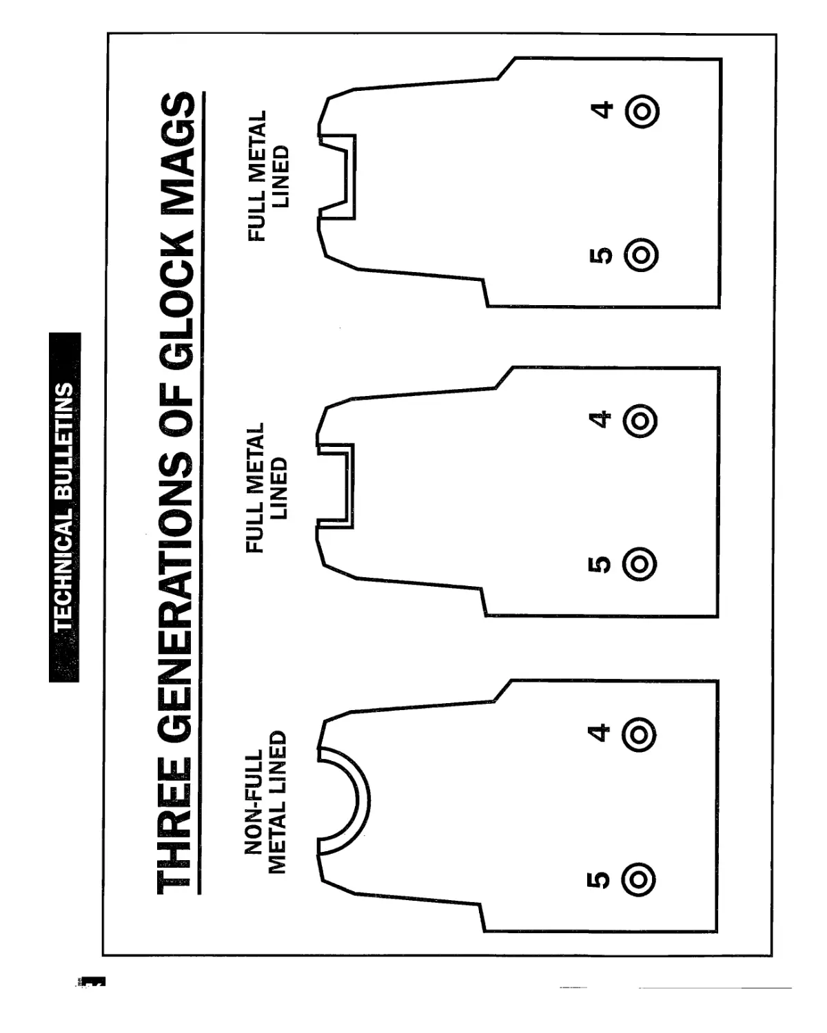
When ordering magazine parts, we must know: 1) the model of the pistol; 2) if it is a 10-round magazine or a high-
capacity magazine and, 3) if the magazine is the old style — non-fully lined, or the new style — fully metal lined (see
attached drawing).
PISTOL PARTS
When ordering pistol parts, we must know: 1) the pistol model number and, 2) the serial number.
If the pistol has a serial number within the below listed numbers and has not been upgraded, it may be returned to:
GLOCK, Inc.
6000 Highlands Parkway
Smyrna, GA 30082
Older style parts are no longer available. All pistols in the following serial number ranges fall subject to the product
upgrade:
GLOCK 17 Pistols — Alphabetical Prefix up to and including XG
GLOCK 19 Pistols — Alphabetical Prefix up to and including XK
GLOCK 20 Pistols — Alphabetical Prefix up to and including WX
GLOCK 21 Pistols — Alphabetical Prefix up to and including XM
GLOCK 22 Pistols - - alphabetical Prefix up to and including YB
GLOCK 23 Pistols — Alphabetical Prefix up to and including SL
All pistols with a three letter prefix already have the upgraded part system.
G21.45 Automatic
All pistols prior to serial number ALD are subject to the slide modifications, i.e. the pickup rail is reduced and the
right rear edge of the ejection port is angled.
TECHNICAL BULLET
ABCDEFGHIJKLMNOPQRSTUVWXYZ
TECHNICAL BULLETIN
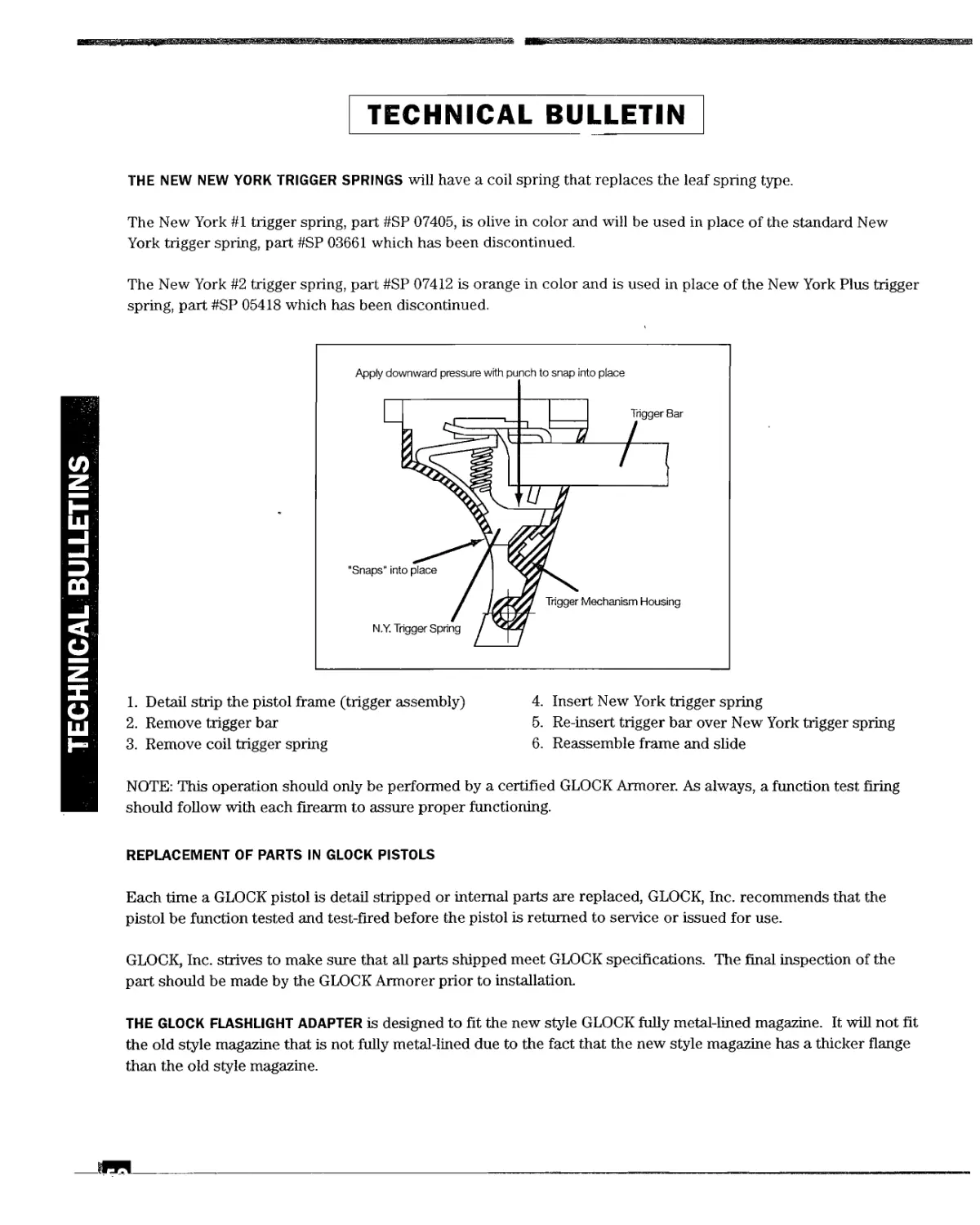
THE NEW NEW YORK TRIGGER SPRINGS will have a coil spring that replaces the leaf spring type.
The New York #1 trigger spring, part #SP 07405, is olive in color and will be used in place of the standard New
York trigger spring, part #SP 03661 which has been discontinued.
The New York #2 trigger spring, part #SP 07412 is orange in color and is used in place of the New York Plus trigger
spring, part #SP 05418 which has been discontinued.
TECHNICAL BULLETINS
1. Detail strip the pistol frame (trigger assembly)
2. Remove trigger bar
3. Remove coil trigger spring
4. Insert New York trigger spring
5. Re-insert trigger bar over New York trigger spring
6. Reassemble frame and slide
NOTE: This operation should only be performed by a certified GLOCK Armorer. As always, a function test firing
should follow with each firearm to assure proper functioning.
REPLACEMENT OF PARTS IN GLOCK PISTOLS
Each time a GLOCK pistol is detail stripped or internal parts are replaced, GLOCK, Inc. recommends that the
pistol be function tested and test-fired before the pistol is returned to service or issued for use.
GLOCK, Inc. strives to make sure that all parts shipped meet GLOCK specifications. The final inspection of the
part should be made by the GLOCK Armorer prior to installation.
THE GLOCK FLASHLIGHT ADAPTER is designed to fit the new style GLOCK fully metal-lined magazine. It will not fit
the old style magazine that is not fully metal-lined due to the fact that the new style magazine has a thicker flange
than the old style magazine.
TECHNICAL BULLETIN
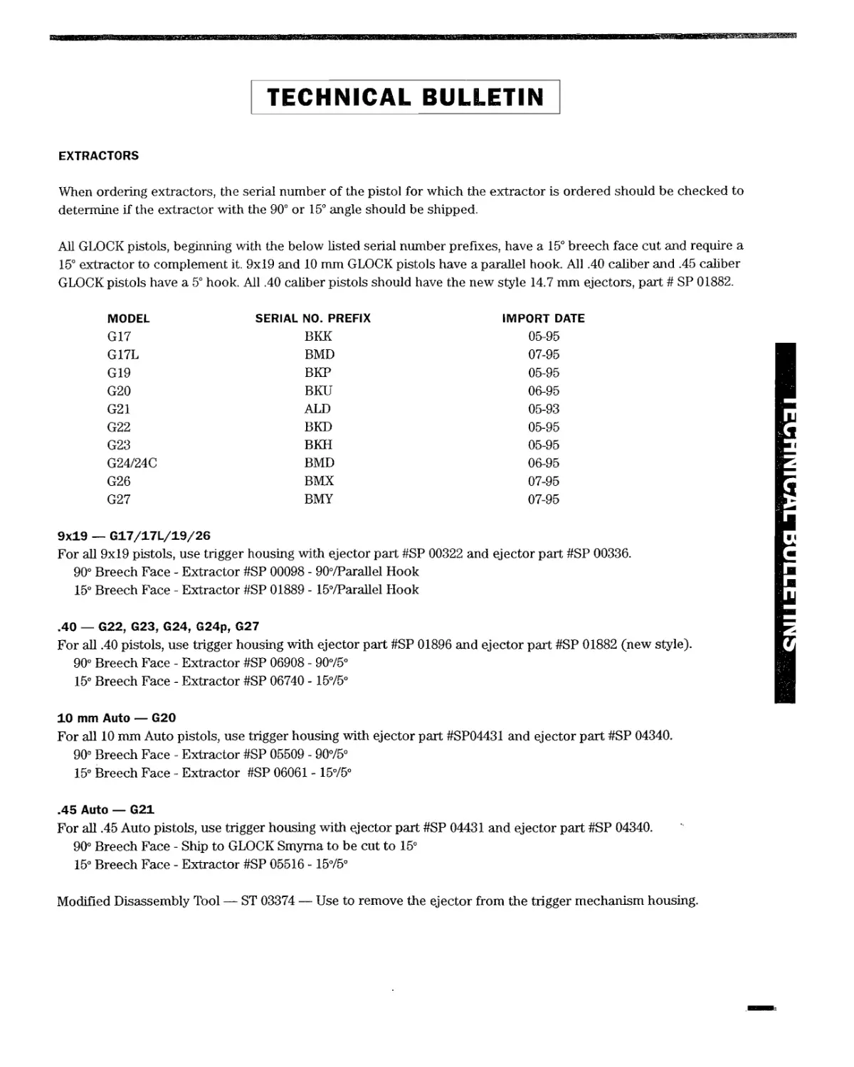
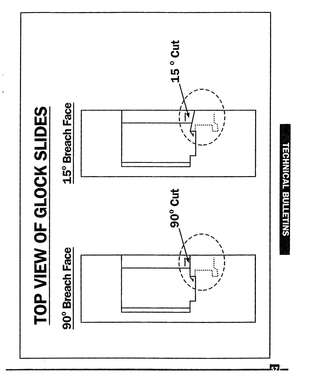
EXTRACTORS
When ordering extractors, the serial number of the pistol for which the extractor is ordered should be checked to
determine if the extractor with the 90° or 15° angle should be shipped.
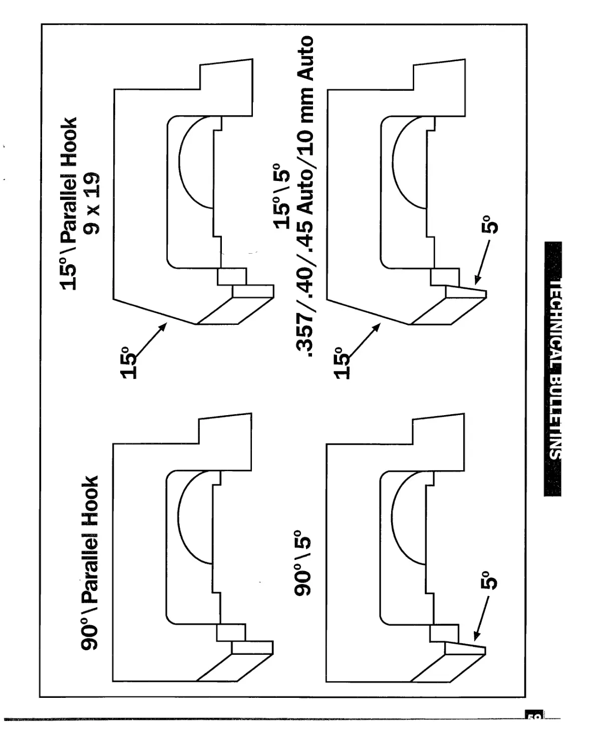
All GLOCK pistols, beginning with the below listed serial number prefixes, have a 15° breech face cut and require a
15° extractor to complement it. 9x19 and 10 mm GLOCK pistols have a parallel hook All .40 caliber and .45 caliber
GLOCK pistols have a 5° hook. All .40 caliber pistols should have the new style 14.7 mm ejectors, part # SP 01882.
MODEL SERIAL NO. PREFIX IMPORT DATE
G17 BKK 05-95
G17L BMD 07-95
G19 BKP 05-95
G20 BKU 06-95
G21 ALD 05-93
G22 BKD 05-95
G23 BKH 05-95
G24/24C BMD 06-95
G26 BMX 07-95
G27 BMY 07-95
9x19 — G17/17L/19/26
For all 9x19 pistols, use trigger housing with ejector part #SP 00322 and ejector part #SP 00336.
90° Breech Face - Extractor #SP 00098 - 90°/Parallel Hook
15° Breech Face - Extractor #SP 01889 - 157Parallel Hook
.40 — G22, G23, G24, G24p, G27
For all .40 pistols, use trigger housing with ejector part #SP 01896 and ejector part #SP 01882 (new style).
90° Breech Face - Extractor #SP 06908 - 9075°
15° Breech Face - Extractor #SP 06740 - 1575°
10 mm Auto — G20
For all 10 mm Auto pistols, use trigger housing with ejector part #SP04431 and ejector part #SP 04340.
90° Breech Face - Extractor #SP 05509 - 9075°
15° Breech Face - Extractor #SP 06061 - 1575°
.45 Auto — G21
For all .45 Auto pistols, use trigger housing with ejector part #SP 04431 and ejector part #SP 04340.
90° Breech Face - Ship to GLOCK Smyrna to be cut to 15°
15° Breech Face - Extractor #SP 05516 -1575°
Modified Disassembly Tool — ST 03374 — Use to remove the ejector from the trigger mechanism housing.
TECHNICAL BULLETIN
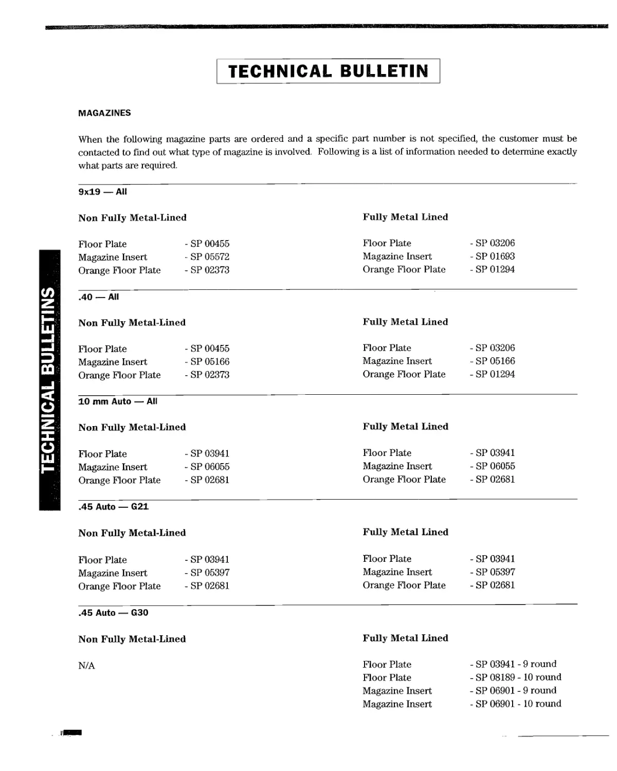
MAGAZINES
When the following magazine parts are ordered and a specific part number is not specified, the customer must be
contacted to find out what type of magazine is involved. Following is a list of information needed to determine exactly
what parts are required.
TECHNICAL BULLETINS
9x19 — All
Non Fully Metal-Lined Floor Plate - SP 00455 Magazine Insert - SP 05572 Orange Floor Plate - SP 02373 Fully Metal Lined
Floor Plate Magazine Insert Orange Floor Plate - SP 03206 - SP 01693 - SP 01294
.40 — All
Non Fully Metal-Lined Fully Metal Lined
Floor Plate - SP 00455 Floor Plate - SP 03206
Magazine Insert - SP 05166 Magazine Insert - SP 05166
Orange Floor Plate - SP 02373 Orange Floor Plate - SP 01294
10 mm Auto — All
Non Fully Metal-Lined Fully Metal Lined
Floor Plate -SP 03941 Floor Plate - SP 03941
Magazine Insert - SP 06055 Magazine Insert - SP 06055
Orange Floor Plate - SP 02681 Orange Floor Plate - SP 02681
.45 Auto — G21
Non Fully Metal-Lined Fully Metal Lined
Floor Plate - SP 03941 Floor Plate - SP 03941
Magazine Insert - SP 05397 Magazine Insert - SP 05397
Orange Floor Plate - SP 02681 Orange Floor Plate - SP 02681
.45 Auto — G30
Non Fully Metal-Lined Fully Metal Lined
N/A Floor Plate - SP 03941 - 9 round
Floor Plate - SP 08189 - 10 round
Magazine Insert - SP 06901 - 9 round
Magazine Insert - SP 06901 -10 round
TECHNICAL BULLETIN
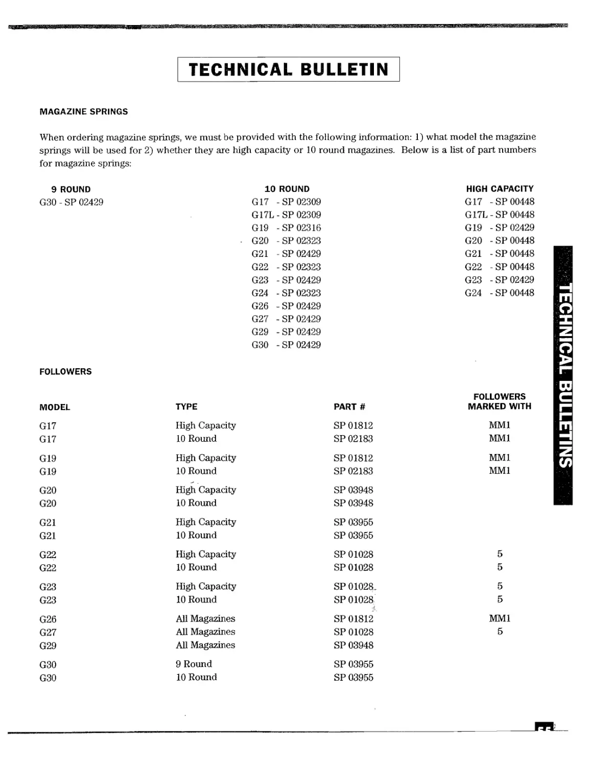
MAGAZINE SPRINGS
When ordering magazine springs, we must be provided with the following information: 1) what model the magazine
springs will be used for 2) whether they are high capacity or 10 round magazines. Below is a list of part numbers
for magazine springs:
9 ROUND 10 ROUND HIGK 1 CAPACITY
G30 - SP 02429 G17 - SP 02309 G17 - SP 00448
G17L - SP 02309 G17L - SP 00448
G19 -SP 02316 G19 - SP 02429
. G20 - SP 02323 G20 - SP 00448
G21 - SP 02429 G21 - SP 00448
G22 - SP 02323 G22 - SP 00448
G23 - SP 02429 G23 - SP 02429
G24 - SP 02323 G24 - SP 00448
G26 - SP 02429
G27 - SP 02429
G29 - SP 02429
G30 - SP 02429
FOLLOWERS
FOLLOWERS
MODEL TYPE PART # MARKED WITH
G17 High Capacity SP 01812 MM1
G17 10 Round SP 02183 MM1
G19 High Capacity SP 01812 MM1
G19 10 Round SP 02183 MM1
G20 High Capacity SP 03948
G20 10 Round SP 03948
G21 High Capacity SP 03955
G21 10 Round SP 03955
G22 High Capacity SP 01028 5
G22 10 Round SP 01028 5
G23 High Capacity SP 01028. 5
G23 10 Round SP 01028 5
G26 All Magazines SP 01812 MM1
G27 All Magazines SP 01028 5
G29 All Magazines SP 03948
G30 9 Round SP 03955
G30 10 Round SP 03955
TECHNICAL BULLETINS
TECHN8CALBULLETINS
THREE GENERATIONS OF GLOCK MAGS
NON-FULL
METAL LINED
FULL METAL
LINED
FULL METAL
LINED
5 4
© ©
5 4
© ©
5 4
© ©
TOP VIEW OF GLOCK SLIDES
SN113ПП8 TVOINHOai
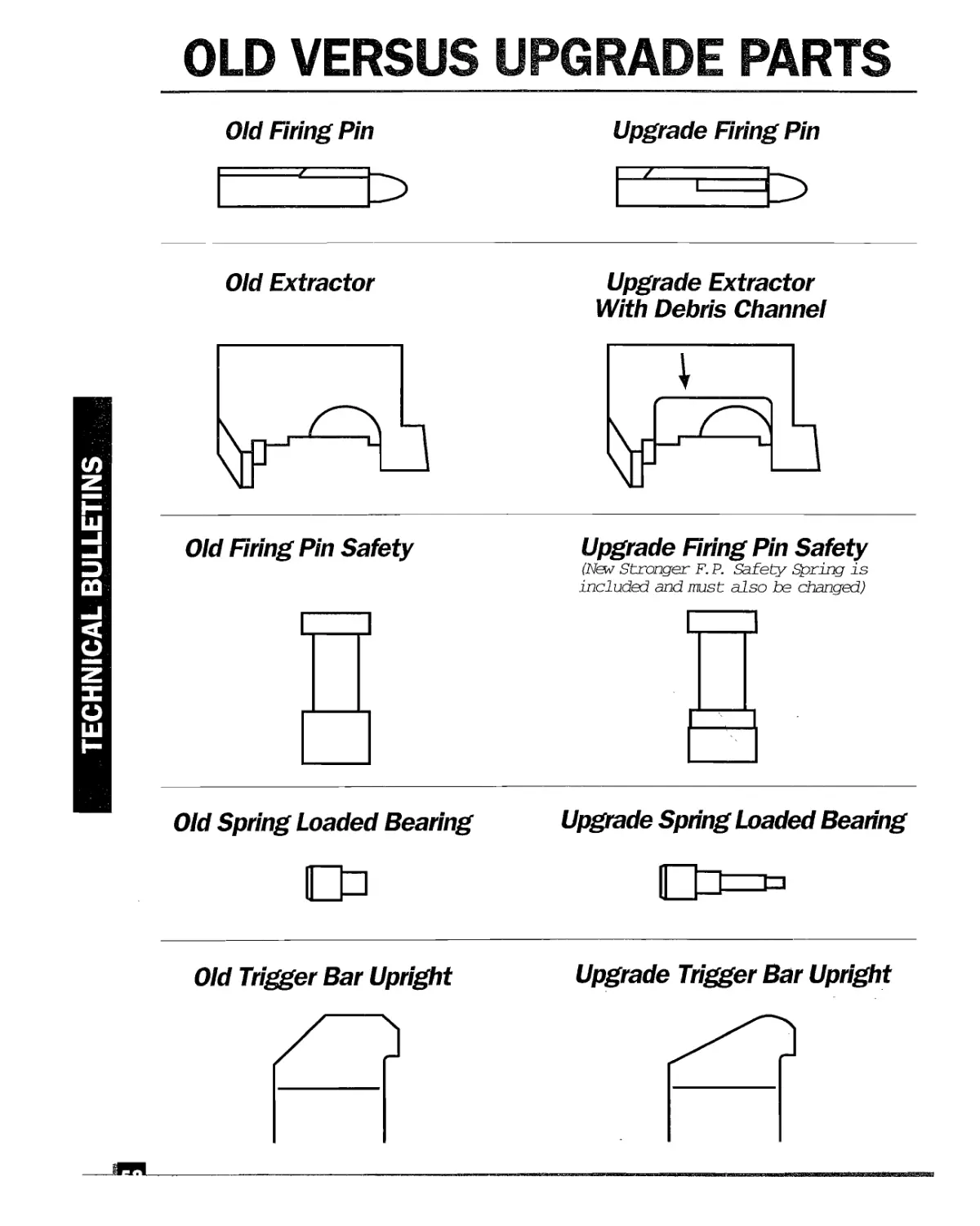
OLD VERSUS UPGRADE PARTS
Old Firing Pin
Upgrade Firing Pin
Old Extractor
Upgrade Extractor
With Debris Channel
TECHNICAL BULLETINS
Old Firing Pin Safety
Upgrade Firing Pin Safety
(New Stronger F. P. Safety Spring is
included and must also be changed)
Old Spring Loaded Bearing
Upgrade Spring Loaded Bearing
Old Trigger Bar Upright
Upgrade Trigger Bar Upright
__яя
TECHNICAL BULLETINS
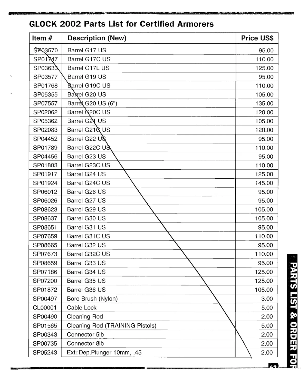
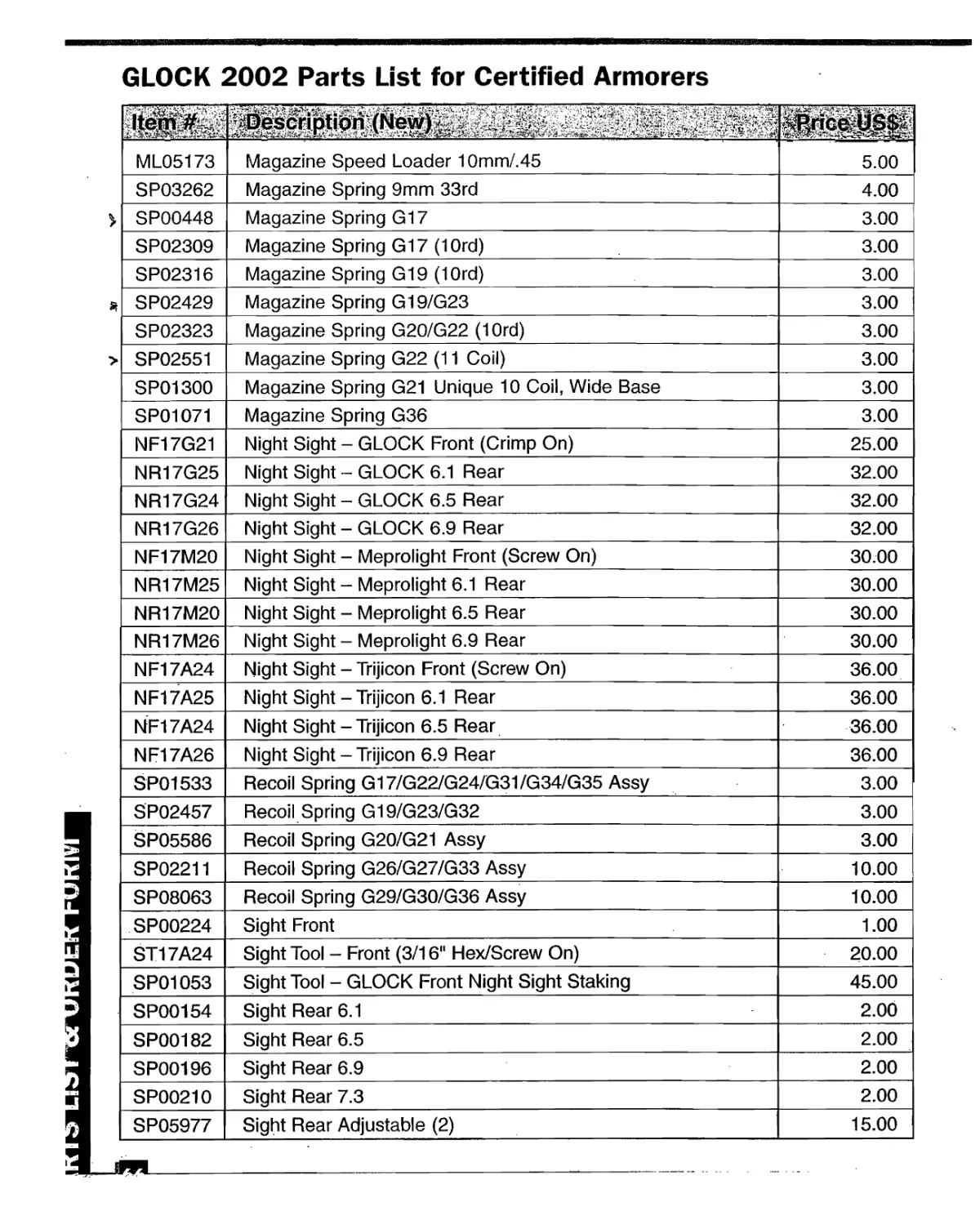
GLOCK 2002 Parts List for Certified Armorers
Item # Description (New) Price USS
SJPQ3570 Barrel G17 US 95.00
SP01M7 Barrel G17C US 110.00
SP0363k Barrel G17L US 125.00
SP03577 \ Barrel G19 US 95.00
SP01768 \arrel G19C US 110.00
SP05355 Ba\el G20 US 105.00
SP07557 Barr\G20 US (6") 135.00
SP02062 Barrel G20C US 120.00
SP05362 Barrel G21 US 105.00
SP02083 Barrel G2l\uS 120.00
SP04452 Barrel G22 u\ 95.00
SP01789 Barrel G22C uk 110.00
SP04456 Barrel G23 US \ 95.00
SP01803 Barrel G23C US \ 110.00
SP01917 Barrel G24 US \ 125.00
SP01924 Barrel G24C US \ 145.00
SP06012 Barrel G26 US \ 95.00
SP06026 Barrel G27 US \ 95.00
SP08623 Barrel G29 US \ 105.00
SP08637 Barrel G30 US \ 105.00
SP08651 Barrel G31 US \ 95.00
SP07659 Barrel G31C US \ 110.00
SP08665 Barrel G32 US \ 95.00
SP07673 Barrel G32C US \ 110.00
SP08659 Barrel G33 US \ 95.00
SP07186 Barrel G34 US \ 125.00
SP07200 Barrel G35 US \ 125.00
SP01872 Barrel G36 US \ 105.00
SP00497 Bore Brush (Nylon) \ 3.00
CL00001 Cable Lock \ 5.00
SP00490 Cleaning Rod \ 2.00
SP01565 Cleaning Rod (TRAINING Pistols) \ 5.00
SP00343 Connector 5lb \ 200
SP00735 Connector 8lb \ 2.00
SP05243 Extr.Dep.Plunger 10mm, .45 \ 2.00
PARTS LIST & ORDER FO
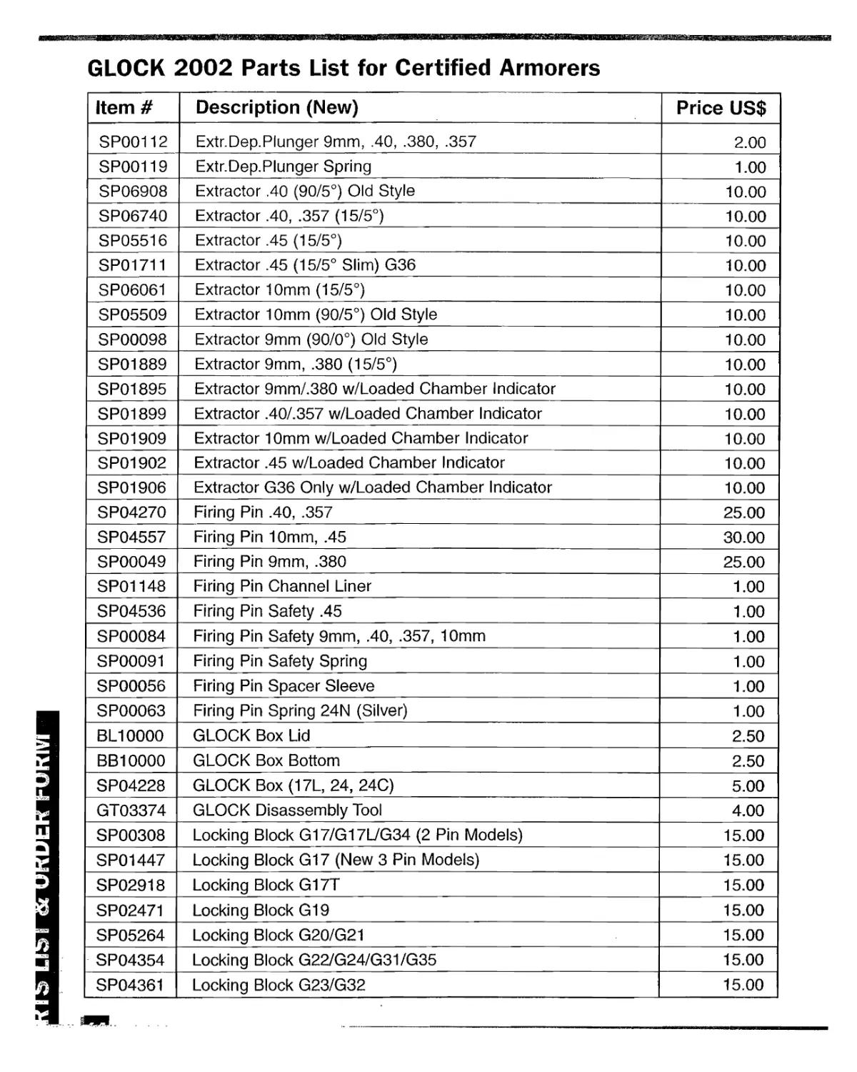
GLOCK 2002 Parts List for Certified Armorers
Item # Description (New) Price US$
SP00112 Extr.Dep.Plunger 9mm, .40, .380, .357 2.00
SP00119 Extr.Dep.Plunger Spring 1.00
SP06908 Extractor .40 (90/5°) Old Style 10.00
SP06740 Extractor .40, .357 (15/5°) 10.00
SP05516 Extractor .45 (15/5°) 10.00
SP01711 Extractor .45 (15/5° Slim) G36 10.00
SP06061 Extractor 10mm (15/5°) 10.00
SP05509 Extractor 10mm (90/5°) Old Style 10.00
SP00098 Extractor 9mm (90/0°) Old Style 10.00
SP01889 Extractor 9mm, .380 (15/5°) 10.00
SP01895 Extractor 9mm/.38O w/Loaded Chamber Indicator 10.00
SP01899 Extractor .40/.357 w/Loaded Chamber Indicator 10.00
SP01909 Extractor 10mm w/Loaded Chamber Indicator 10.00
SP01902 Extractor .45 w/Loaded Chamber Indicator 10.00
SP01906 Extractor G36 Only w/Loaded Chamber Indicator 10.00
SP04270 Firing Pin .40, .357 25.00
SP04557 Firing Pin 10mm, .45 30.00
SP00049 Firing Pin 9mm, .380 25.00
SP01148 Firing Pin Channel Liner 1.00
SP04536 Firing Pin Safety .45 1.00
SP00084 Firing Pin Safety 9mm, .40, .357, 10mm 1.00
SP00091 Firing Pin Safety Spring 1.00
SP00056 Firing Pin Spacer Sleeve 1.00
SP00063 Firing Pin Spring 24N (Silver) 1.00
BL10000 GLOCK Box Lid 2.50
BB10000 GLOCK Box Bottom 2.50
SP04228 GLOCK Box (17L, 24, 24C) 5.00
GT03374 GLOCK Disassembly Tool 4.00
SP00308 Locking Block G17/G17L/G34 (2 Pin Models) 15.00
SP01447 Locking Block G17 (New 3 Pin Models) 15.00
SP02918 Locking Block G17T 15.00
SP02471 Locking Block G19 15.00
SP05264 Locking Block G20/G21 15.00
SP04354 Locking Block G22/G24/G31/G35 15.00
SP04361 Locking Block G23/G32 15.00
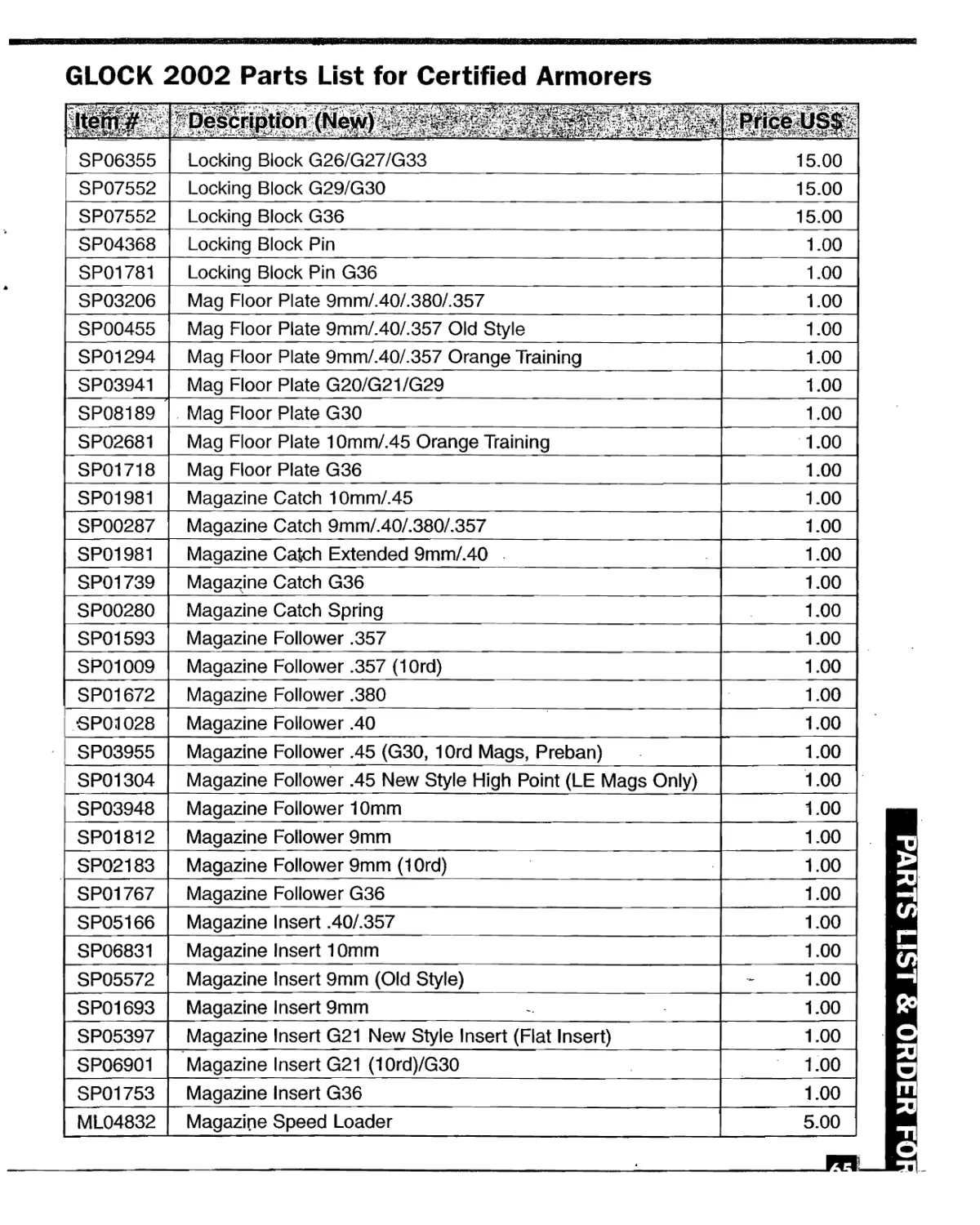
GLOCK 2002 Parts List for Certified Armorers
SP06355 Locking Block G26/G27/G33 15.00
SP07552 Locking Block G29/G30 15.00
SP07552 Locking Block G36 15.00
SP04368 Locking Block Pin 1.00
SP01781 Locking Block Pin G36 1.00
SP03206 Mag Floor Plate 9mm/.40/.380/.357 1.00
SP00455 Mag Floor Plate 9mm/.40/.357 Old Style 1.00
SP01294 Mag Floor Plate 9mm/.40/.357 Orange Training 1.00
SP03941 Mag Floor Plate G20/G21/G29 1.00
SP08189 ' Mag Floor Plate G30 1.00
SP02681 Mag Floor Plate 10mm/.45 Orange Training 1.00
SP01718 Mag Floor Plate G36 1.00
SP01981 Magazine Catch 10mm/.45 1.00
SP00287 Magazine Catch 9mm/.40/.380/.357 1.00
SP01981 Magazine Catch Extended 9mm/.4O 1.00
SP01739 Magazine Catch G36 1.00
SP00280 Magazine Catch Spring 1.00
SP01593 Magazine Follower .357 1.00
SP01009 Magazine Follower .357 (10rd) 1.00
SP01672 Magazine Follower .380 1.00
SP01028 Magazine Follower .40 1.00
SP03955 Magazine Follower .45 (G30, 10rd Mags, Preban) 1.00
SP01304 Magazine Follower .45 New Style High Point (LE Mags Only) 1.00
SP03948 Magazine Follower 10mm 1.00
SP01812 Magazine Follower 9mm 1.00
SP02183 Magazine Follower 9mm (1 Ord) 1.00
SP01767 Magazine Follower G36 1.00
SP05166 Magazine Insert .40/.357 1.00
SP06831 Magazine Insert 10mm 1.00
SP05572 Magazine Insert 9mm (Old Style) 1.00
SP01693 Magazine Insert 9mm 1.00
SP05397 Magazine Insert G21 New Style Insert (Flat Insert) 1.00
SP06901 Magazine Insert G21 (10rd)/G30 1.00
SP01753 Magazine Insert G36 1.00
ML04832 Magazine Speed Loader 5.00
PARTS LIST & ORDER
___________________________________:__________m.
GLOCK 2002 Parts List for Certified Armorers
'"Л-'- /V'’ 'Л ?Л "'V~ swe
ML05173 Magazine Speed Loader 10mm/.45 5.00
SP03262 Magazine Spring 9mm 33rd 4.00
SP00448 Magazine Spring G17 3.00
SP02309 Magazine Spring G17 (1 Ord) 3.00
SP02316 Magazine Spring G19 (1 Ord) 3.00
SP02429 Magazine Spring G19/G23 3.00
SP02323 Magazine Spring G20/G22 (10rd) 3.00
SP02551 Magazine Spring G22 (11 Coil) 3.00
SP01300 Magazine Spring G21 Unique 10 Coil, Wide Base 3.00
SP01071 Magazine Spring G36 3.00
NF17G21 Night Sight - GLOCK Front (Crimp On) 25.00
NR17G25 Night Sight - GLOCK 6.1 Rear 32.00
NR17G24 Night Sight - GLOCK 6.5 Rear 32.00
NR17G26 Night Sight - GLOCK 6.9 Rear 32.00
NF17M20 Night Sight - Meprolight Front (Screw On) 30.00
NR17M25 Night Sight - Meprolight 6.1 Rear 30.00
NR17M20 Night Sight - Meprolight 6.5 Rear 30.00
NR17M26 Night Sight - Meprolight 6.9 Rear 30.00
NF17A24 Night Sight - Trijicon Front (Screw On) 36.00
NF17A25 Night Sight - Trijicon 6.1 Rear 36.00
NF17A24 Night Sight - Trijicon 6.5 Rear 36.00
NF17A26 Night Sight - Trijicon 6.9 Rear 36.00
SP01533 Recoil Spring G17/G22/G24/G31/G34/G35 Assy 3.00
SP02457 Recoil Spring G19/G23/G32 3.00
SP05586 Recoil Spring G20/G21 Assy 3.00
SP02211 Recoil Spring G26/G27/G33 Assy 10.00
SP08063 Recoil Spring G29/G30/G36 Assy 10.00
SP00224 Sight Front 1.00
ST17A24 Sight Tool - Front (3/16" Hex/Screw On) 20.00
SP01053 Sight Tool - GLOCK Front Night Sight Staking 45.00
SP00154 Sight Rear 6.1 2.00
SP00182 Sight Rear 6.5 2.00
SP00196 Sight Rear 6.9 2.00
SP00210 Sight Rear 7.3 2.00
SP05977 Sight Rear Adjustable (2) 15.00
I
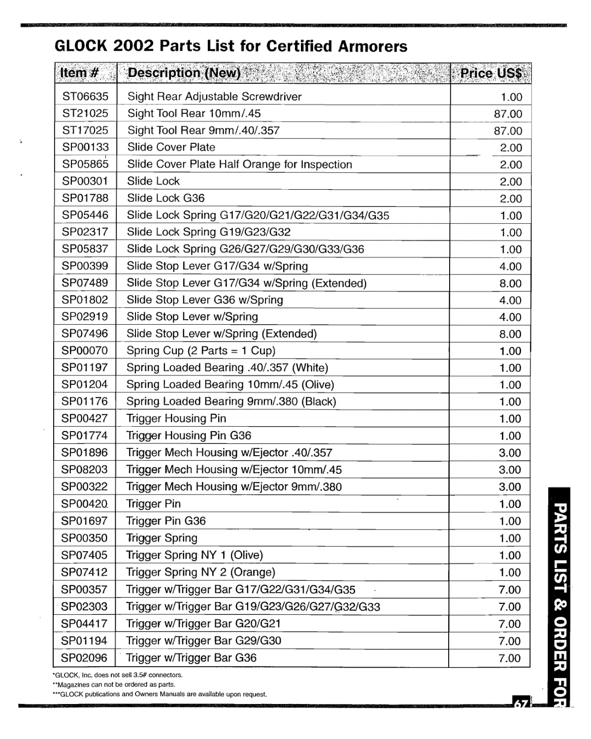
GLOCK 2002 Parts List for Certified Armorers
Item # .. : Rrice US$
ST06635 Sight Rear Adjustable Screwdriver 1.00
ST21025 Sight Tool Rear 10mm/.45 87.00
ST17025 Sight Tool Rear 9mm/.40/.357 87.00
SP00133 Slide Cover Plate 2.00
SP05865 Slide Cover Plate Half Orange for Inspection 2.00
SP00301 Slide Lock 2.00
SP01788 Slide Lock G36 2.00
SP05446 Slide Lock Spring G17/G20/G21/G22/G31/G34/G35 1.00
SP02317 Slide Lock Spring G19/G23/G32 1.00
SP05837 Slide Lock Spring G26/G27/G29/G30/G33/G36 1.00
SP00399 Slide Stop Lever G17/G34 w/Spring 4.00
SP07489 Slide Stop Lever G17/G34 w/Spring (Extended) 8.00
SP01802 Slide Stop Lever G36 w/Spring 4.00
SP02919 Slide Stop Lever w/Spring 4.00
SP07496 Slide Stop Lever w/Spring (Extended) 8.00
SP00070 Spring Cup (2 Parts = 1 Cup) 1.00
SP01197 Spring Loaded Bearing .40/.357 (White) 1.00
SP01204 Spring Loaded Bearing 10mm/.45 (Olive) 1.00
SP01176 Spring Loaded Bearing 9mm/.38O (Black) 1.00
SP00427 Trigger Housing Pin 1.00
SPOt 774 Trigger Housing Pin G36 1.00
SP01896 Trigger Meeh Housing w/Ejector .40/.357 3.00
SP08203 Trigger Meeh Housing w/Ejector 10mm/.45 3.00
SP00322 Trigger Meeh Housing w/Ejector 9mm/.38O 3.00
SP00420. Trigger Pin 1.00
SP01697 Trigger Pin G36 1.00
SP00350 Trigger Spring 1.00
SP07405 Trigger Spring NY 1 (Olive) 1.00
SP07412 Trigger Spring NY 2 (Orange) 1.00
SP00357 Trigger w/Trigger Bar G17/G22/G31/G34/G35 7.00
SP02303 Trigger w/Trigger Bar G19/G23/G26/G27/G32/G33 7.00
SP04417 Trigger w/Trigger Bar G20/G21 7.00
SP01194 Trigger w/Trigger Bar G29/G30 7.00
SP02096 Trigger w/Trigger Bar G36 7.00
*GLOCK, Inc. does not sell 3.5# connectors.
**Magazines can not be ordered as parts.
***GLOCK publications and Owners Manuals are available upon request.
PARTS LIST & ORDER FO
& ORDER FORM
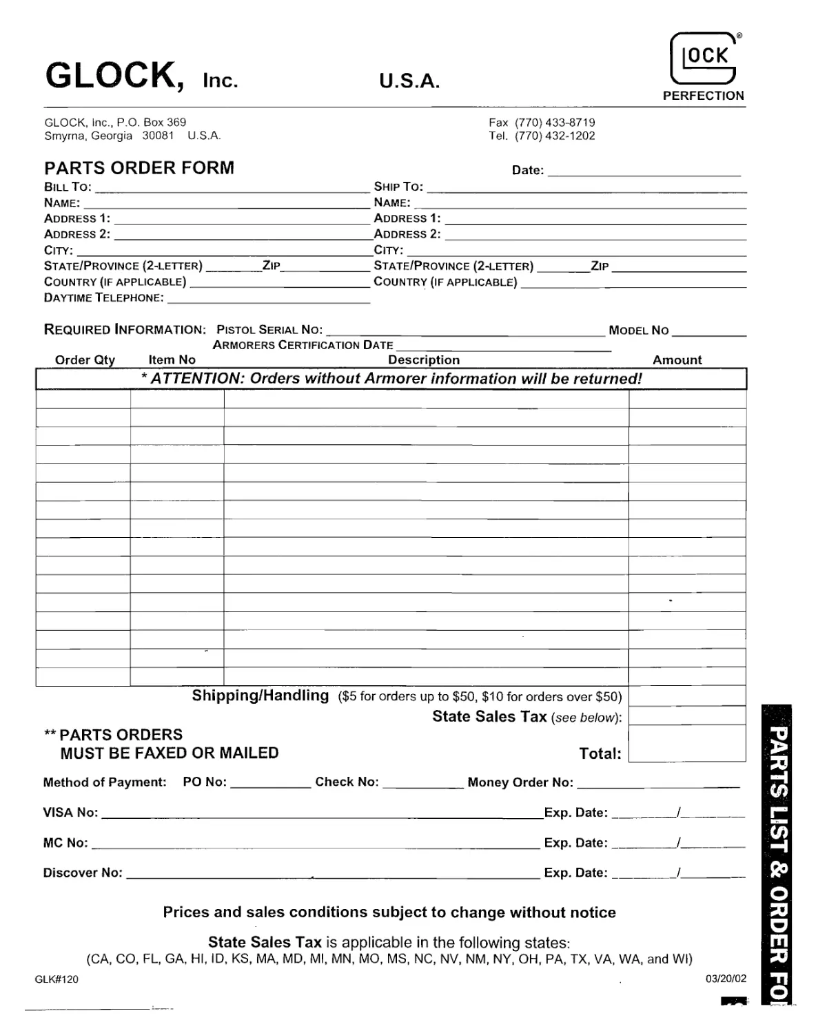
GLOCK, Inc. U.S.A.
PERFECTION
GLOCK, Inc., P.O. Box 369 Smyrna, Georgia 30081 U.S.A. Fax (770)433-8719 Tel. (770)432-1202
PARTS ORDER FORM Date:
Bill To: Ship To:
Name: Name:
Address 1: Address 1:
Address 2: Address 2:
City: City:
State/Province (2-letter)Zip State/Province (2-letter)Zip
Country (if applicable)Country (if applicable)
Daytime Telephone:___________
Required Information; pistol Serial no:model no
Armorers Certification Date____________________________________________________
Order Qty____Item No__________________________Description_________________________Amount_______
★ATTENTION: Orders without Armorer information will be returned!
•
Shipping/Handling ($5 for orders up to $50, $10 for orders over $50) State Sales Tax (see below): ** PARTS ORDERS MUST BE FAXED OR MAILED Total: —
Method of Payment: PO No:Check No:Money Order No:
VISA No: Exp. Date:/
MC No:Exp. Date:I
Discover No:.Exp. Date:/
Prices and sales conditions subject to change without notice
State Sales Tax is applicable in the following states:
(CA, CO, FL, GA, HI, ID, KS, MA, MD, Ml, MN, MO, MS, NC, NV, NM, NY, OH, PA, TX, VA, WA, and Wl)
GLK#120 03/20/02
PR
PARTS LIST & ORDER FO
..П7Т1Ттп-чйМНМ1.1щьшК№11™инкмИми1^^
NOTES
S®jH|s
NOTES
|ОСК
I J
PERFECTION
For Europe, Africa,
Middle East
GLOCK Ges.m.b.H.
Nelkcngasse 3
Л-2232 Deutsch-Wagram, Austria
Tel. (ИЗ) 2247 90 300
Fax. (43) 2247 90 300 312
For USA, Canada
GLOCK, Inc.
6000 Highlands Parkway
Smyrna, GA 30082 USA
Tel. (770) 432-1202
Fax. (770) 433-8719
For Asia, Australia
GLOCK (H.K.) Ltd.
Unit 3102, China Merchants Tower,
Shun Tak Centre
168-200 Connaught Road Central
Hong Kong
Tel. (852) 2375-3858
Fax. (852) 2654-7089
For Latin America,
Central America,
Caribbean
GLOCK America N.V.
Plaza Independencia 831, Office 802
CP 11100 Montevideo
Uruguay
Tel. (598-2) 902 22 27, 902 22 28, 902 22 29
Fax. (598-2) 902 22 30
www.GLOCK.com
l® । GLOCK and the GIjOCK “G" and Iho Pistol
Appearance are Trademarks Registered
£ in the U.S. Patent and Trademark Office.
For further information on GLOCK products please contact your local dealer or the GLOCK office that serves your area.