/


Теги: instructions instruction manual machines
Год: 2012


Текст
TECHNICAL INSTRUCTIONS
MP - 1 H
МОТШБШТОРЯЯ
www.motolab.ru
*2012*
SOClETE GENEVOISE D’INSTRUMENTS DE PHYSIQUE
GENEVE - SUISSE
Vertrag Nr. 64/81060-136
Trans. Nr. 93203
м
- 1 н
No 1601...
The specifications and illustrations correspond to the production prevailing at the time of issue. Rights are reserved with
regard to modifications and improvements, without any obligation to carry them out to machines and accessories already sold.
All rights of property are reserved on these texts and illustrations which must not be copied, reproduced or communicated
to a third party, without the written agreement of the Society Genevoise d'Instruments de Physique.
PRINTED IN SWITZERLAND
NDS 1162-1122
TECHNICAL INSTRUCTIONS FOR MP-1H
Table of contents
Drawing Page
Part I: Characteristics of the machine 5
Purpose and accuracy 6
Main characteristics - 7
Overall dimensions 201661 9
General view 10511 10
General view 10512 11
Identification of the reference numbers 12
Part II: Installation, lubrication, up keep 15
1. Installation 16
Opening of packing case 16
Lifting the machine 6172 17
Foundation 514115 18
Cleansing 19
Sketch for dowelling the nut holding tube 508383 20
Unlocking 6173 21
Unlocking of table and slide 22
Placing the counterweight 22
Installation sketch 300655 23
2. Lubrication 24
Lubrication of the V-way 6176-6179 25
3. Up keep 26
-.5
Part III: Description of the machine 29
Machine elements 30
Bed 30
Slide and worktable 30
Photo of the fan-device 10509 31
Column and vertical slide 30
Boring head 32
Spotting tool 32
Height of the spotting tool 32
Boring spindle 33
2 -
Drawing
Depth measuring device 33
Sketch of boring spindle nose 520150 34
Speed gear box 35
Optical equipment 35
Sketchs showing location of transversal 520147 36
and longitudinal lamps 520146 37
Sketch of centering templet 508387 38
Changing the bulbs 39
Remark: duration of bulb life 40
Zero setting 40
Coordinate settings < 40
Viewing microscope 41
Lighting of the viewing microscope 41
Use 41
Precision 42
Replacement of tube 42
Electrical equipment 42
Motors 42
Electrical installation diagram (Europe) 89002 9 43
" " " (U.S.A.) 890027 44
Main switch-board controlling 46
Main switch-board 10510 45
Fuses 46
Contactors 46
Outlet sockets 46
Connecting auto-transformer 47
Connecting to the mains 47
Switch board 47
Part IV; The accessories 49
Accessories 50
Regular equipment 50
Additional equipment 50
Description of the main accessories 51
Clamping socket for holding spring collets 51
Spring collets 51
Boring tool holder 1/64 to 9/16" 51
Boring tool holder 5/8 to 13/16" 53
Boring tool holder 3/4 to 1" 53
Sketch showing sharpening of the cutting tool 508389 55
Sharpening the cutters 56
Illuminated glass table 56
Scribing tool 56
- ъ -
Drawing Page
Additional optical sighting device 56
Locating dial indicator 1-3 57
Reference square 57
Lamp for the illumination of work 57
Twist drills 57
End mills 58
Taper shanks 58
Part V: Hints of the practical use of the machine 61
Information and advices 62
Layout of drawings 62
Clamping large workpieces 64
Clamping light or very small pieces 68
Recommended cutting speeds 69
Machining bored holes 70
Boring holes through oblique surfaces 70.
Boring holes from .1 to .6" 70
Boring very small holes 71
Preparation of the workpiece to be drilled 71
Machining 72
Drilling 72
How to choose the drilling tool 72
Boring 72
Boring tools 72
Some advices 74
Standard temperature 75
to
- 5 -
Part I
CHARACTERISTICS OF THE MACHINE
- б -
PURPOSE AND ACCURACY
The No 1H Jig Boring Machine is designed for handling small work, such as is
required in the watchmaking industry, in the manufacturing of small apparatus and
in fine mechanics. The accuracy of .00008" (2 p.m) guaranteed for the settings of
the work-table permits to satisfy all requirements met with in that field. The
three tools mostly used, viz. the boring spindle, the spotting tool and the loca-
ting microscope can be set successively on the same point of the workpiece by
simply operating a handwheel. This permits to spot a point, to check its posi-
tion and to drill the hole without any loss of time. Furthermore, readings, made
on screens instead of eyepieces, are highly accurate and so easy that the fati-
gue of the operator's eye is considerably lessened. The operator is normally
seated.
The most sensitive feed of the quill permits to drill holes from about .01"
(0,2 mm) in diameter up to 1/2" (12 mm) in steel. The tool holders permit holes
from .02" (0,4 mm) up to 1" (25 mm) in diameter to be bored. The spindle being
very rigid, it is possible to mill without fear of wear of the traversing screws
which serve exclusively for displacing the table and not for performing measure-
ments. The optical device is of such accuracy that the machine constitutes a high
precision measuring machine.
- 7 -
MAIN CHARACTERISTICS
English units inch Me trie units mm
Measuring range
Table nominal longitudinal travel 8 200
Table nominal transverse travel 8 200
Guaranteed accuracy for table settings .00008 0.002
Work table
Length 16 400
Width 10 250
Width of T-slots 3/8 10
Number of slots 5 5
Distance between axes of clamping slots 2 1/16 53
10-H7
Boring spindle
Internal Morse taper
External taper
Nominal quill travel
Distance from table top to boring head:
maximum
minimum
Spindle speeds (7)
Hand feed
Motor power
No 1
SIP special
2 1/8 55
16 1/4 415
6 150
from 560 to 5000 rpm.
0,2/0,27 h.p.
- 8 -
Required space
Maximum height
Maximum width
Length
Weights
Net, without accessories and
without packing case
Gross, with packing case
76 1/2 in. 1940
41 1/4 in. 1050
50 in. 1264
i I В
2100 lbs 950 kg
3000 lbs 1350 kg
К СТ иЛАБОРАТОРИЯ
www.motolab.ru
*2012*
1050 mm -41 ><in
1940mm-76^ein.
1680mm-661/ein.
990mm.-39in.
201661
ббз
705/7
ЮЗ-)?
- 12 -
IDENTIFICATION OF THE REFERENCE NUMBERS
1
11
12
121
1211
1212
121?
1214
1215
13
131
132
133
14
141
1411
142
143
144
15
151
1511
'2
21
211
212
22
23
231
24
25
26
261
27
271
272
273
274
275
276
277
28
281
282
Bed
V-shaped slots for three-point support
Cover of the main switch board
Controlling switch board
Main cut-off switch
Illumination cut off
Motor switch
General signal lamp
Illuminating signal lamp
Slide locking lever
Vertical motion handwheel
Transverse zero setting
Transverse auxiliary scale
Protecting strip of the V-way
Strip fixing screw
Plug of V-way
Fixation cover of the strips
Cover screw
Fixation of strip
Ventilating device
Filter
Cover screw
Transversal slide
V-way
Flat-way
Releasing roller
Tube for transverse nut
Handwheel for transverse motion
Knob for transverse fine setting
Handwheel for longitudinal motion
Table locking lever
Transverse index
Setting knob of transverse index
Optical housing
Screen for transverse settings
Screen for longitudinal settings
Transverse micrometer drum
Longitudinal micrometer drum
Longitudinal index
Setting knob of longitudinal index
Fixation screw of longitudinal bulb
Housing of transversal lamp
Cover for case 28
Fixation screw of transversal bulb
- 13 -
29 Bulb
291 Bulb holding socket
292 Nut
293 Pin plug
3 Work table
31 V-way
311 Flat way
32 Longitudinal zero setting knob
321 Cover of the zero setting knob
33 Longitudinal auxiliary scale
34 Screw holding the work table on its nut
341 Locking of the holding screw
35 Front holding bar
351 Screw of holding bar
36 Rear holding bar
4 Column
41 Cover
42 Counterweight
421 Chain
4211 Removable connecting link
422 Bracket of the chain pulleys
423 Small suspension rod of the vertical slide
43 Outlet-socket for the work lamp
431 6 V outlet-socket
44 Cover on counterweight assembling holes
45 Vertical index
46 Identification plate
5 Vertical slide
51 Locking lever
511 Clamp pace
52 Vertical scale
53 Handwheel for boring head traverse
531 Boring head abutments
6 Boring head
61 Speed gear box
611 Motor
612 Change speed lever
613 Tool clamping knob
615 Boring spindle locking lever
- 14 -
616 617 62 621 622 63 631 632 64 65 651 652 66 661 662 663 Quill locking lever Boring spindle Quill control lever Handwheel for boring feed Handwheel engaging knob Depth measurement indicator Bracket Bracket locking knob Boring head locking lever Spotting tool Control lever of spotting tool Weight lifting button Microscope body Lamp cover Lamp screw Snap cover fitting
7 71 72 73 Centering template Bulb locking screw Adjusting screw Slots
8 81 82 821 822 823 824 825 826 83 84 85 86 Main switch board Supply current terminals Fuses Boring head motor fuses Ventilating motor fuses Transformer fuses Contactor fuses Illuminating device fuses Test lamp fuses Boring head motor contactor Ventilating motor contactor Transformer Connecting auto-transformer
- 15 -
Part II
INSTALLATION, LUBRICATION, UP KEEP
- 16 -
INSTALLATION AND LUBRICATION
1. INSTALLATION
Opening of packing case
Remove first the roof of the case, and. then the walls specified "open here".
The case contains the counterweight for the vertical slide, the case or the ca-
ses containing the accessories as well as a parcel containing a hand pump and
some screws intended for closing the holes uncovered by dismantling the locking
parts during the transportation.The machine is anchored to the bottom of the ca-
se by means of stays the removing of which presents no difficulties.
For lifting up the machine, pass a rope through the three lifting buckles
keeping both rope ends straddled by a wooden beam for preventing the levers of
the slide from being damaged (see photo No 6172).
Putting down the machine
To obtain full benefit of the high inherent accuracy of the No 1H, it must
be installed in a room fulfilling the following conditions:
a) Temperature controlled to 68° F (20° C)
b) Free from vibration
c) No dust
d) Suitable illumination
This room can be located at any floor level provided it is protected against
vibration; however, ground floor is always preferable. The windows must be of the
double-panel type and provided with curtains or blinds for protecting the machine
as well as the workpiece to be machined from receiving direct sunlight. In fact,
any local heating causes unequal expansion which renders the accuracy of the ma-
chine quite illusory. For the same reason the room radiators must be provided
with protecting screens preventing direct radiations.
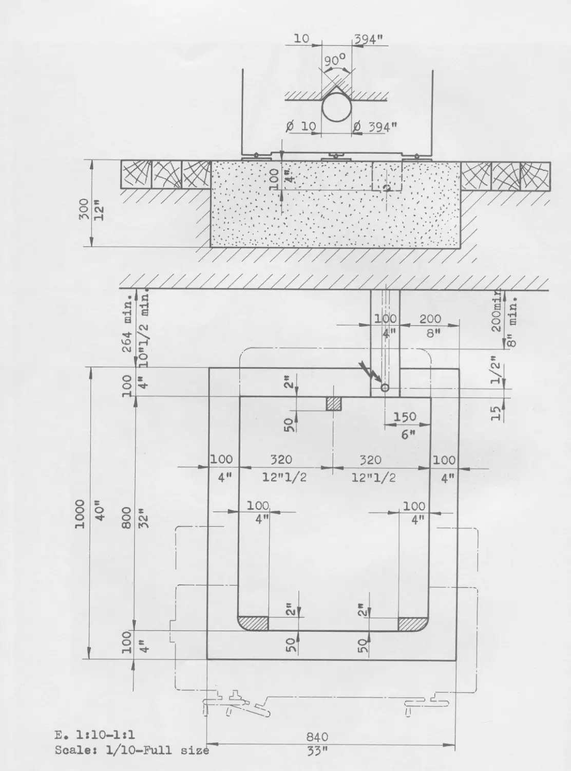
A concrete foundation block must be provided when the machine is installed
at the ground floor (drawing 514115)•
The bed must rest on three points constituted by steel plates of about
4x4 in. and ?/8 in. thick (10x10x1 cm). On each of them a steel cylinder of
3/8" dia. and 2 5/16" in length (10 mm dia. and 60 mm in length) is placed
and located on the V-grooves 11 foreseen at the lower part of the bed.
6772
1000 300
- 19 -
Although it is not necessary absolutely to have the work table set perfectly
level, it is however advisable to correctly level the machine. By doing so, round
workpieces will not toll and fall down on the floor. To this aim, introduce sheet
steel pieces of convenient thickness between the plates and the cylinders. After
having gauged them, complete levelling by grinding or milling a flat of the re-
quired dimension under the two opposite cylinders. It is unadvisable and even
dangerous to run cement underneath the bed, as it may subjected to deformations
when drying and thus subject the machine to detrimental strains.
Cleansing
Remove completely the anti-rust grease coating all non-painted surfaces.
For doingy/this, use,a white rag soaked with paraffine and squeezed nearly dry.
Where the anti-rust grease sticks more tenaciously, insist on rubbing it away
as, in spite of its denomination, this so-called grease has no lubricating pro-
perty.
Avoid the use of alcohol, petrol or of proprietoiy mixtures, which may con-
tain solvents prejudiciable to the paint-work. After this cleansing, coat the
non-painted surfaces with a light film of lubricating oil.
Note: Should the machine have exceptionnally been left in its packing case for
over three months, it is then necessary to remove all oil from the ways
and from the roller races.
For doing this, lift the work-table and then the slide, remove the rol-
lers and their respective cages and clean the surfaces with paraffine.
Remove every trace of dried oil or grease and repolish carefully any sur-
faces showing a slight oxydation. Using a clean oily rag.
For lifting the work-table, untighten firstly the screws 351 and let the
bar lean on the slide. The rear bar 36 can be removed without any difficulty.
Displace the work-table to its right-hand end position. Untighten slightly the
screw 341 and completely the screw 34. This permits to push the table approxi-
mately 1 9/16" (4 cm) more to its right. In this position the work-table is
released from its locking device and can be lifted. For lifting the slide, dis-
mantle the strip 14 by unscrewing at the front side the screws 141 and the plug
of the Vee 1411, and then the screws 143 at the rear, which fasten the cover
142. Having removed this cover, the fixation 144 can be dismantled and the strip
is thus released. Place the slide at the utmost end of its front travel. Remove
the three screws and the two dowels fixing the tube 22 of the traverse nut to
the column (drawing 508383). Pull the slide approximately 1 9/16" (4 cm) forward
to release it from its locking device. It can now be lifted.
The re-assembling is performed in the reverse sequence.
3 vis Мб
506363
6Г73
- 22 -
Unlocking of the work-table and of the slide
When working, the front way 311 of the work-table and the left-hand way of
the slide 211 roll on rollers. During transportation these rollers have been
relieved. This is done by introducing steel setting pieces which lift the ta-
ble from .005" up to .01" (0,1 up to 0,2 mm). Moreover, various clamps painted
in red immobilize these components with respect to each other on the bed (pho-
to No 6173) •
Dismantle the clamps A and В fixing the slide 2 and remove the bolt 0. Af-
ter this, remove both setting pieces D, lowering gently and taking care not to
let the slide drop on its roller, because even a dropping of .005" up to .01"
(0,1 up to 0,2 mm) may damage the roller ways. Proceed afterwards with the sa-
me precautions for removing the clamps E and the setting pieces F of the table-
work 3.
When the clamps E and the setting pieces F are removed from the table, the
latter can be moved on its guideways. One notices that the handwheel 24 has a
large backlash. This is done on purpose for transportation. In order to reduce
this backlash, proceed as follows:
- Move the table 1 to 1 1/2 in. (2 to 3 cm) from its centre position to the
left.
- Unscrew slightly the small screw 341.
- Screw without locking the screw 34.
- Lock it by means of the small screw 341.
The holes left as a result of the dismantling of the lifting buckles and
the locking clamps can be closed by means of screws supplied for this purpose.
Putting the counterweight in place
First remove the cover 41 of the column and the bracket 422 of the chain
pulleys: remove also both small covers 44 protecting the holes located about
in the middle of the column. The counterweight 42 which weighs 133 lbs
(60 kg) must be lowered inside the column by means of a small rope until its
hole is located opposite to both holes of the column. Pass through these three
holes an iron bar of about 3/4" (20 mm) dia. and let the counterweight rest
on it without drawing away the small rope. Put in place the pulley bracket,
pass the chain 421 according to sketch 300655 and fasten its end by means of
the removable connecting link 4211. Let now the counterweight go down up to
the chain extremity by sustaining it by means of the small rope and by remo-
ving the iron bar. Take.the small rope away and put again the cover 41 on
the column. The vertical slide 5 cam now work and the setting piece G which
supported it during the transportation can be removed. Close the holes of the
setting piece by means of the headless screws supplied to this purpose.
4211 422 41
500655
24
2. LUBRICATION
1 . Oil and grease to be used
1.1. General lubrication by means of the hand lubricating pump
Oil s TONNA 27 of Shell
Viscosity 11,2° E at 68° F (20° C)
" 3,1° E at 122° F (50° C)
1.2. Housing of the vertical leadscrew, fine settings, locking
devices
Grease s Marfak О of Caltex Oil
1.3. Ball bearings of the motors and of the gear-box, ball
and roller bearings of the spindle, optical micrometers
Grease s Premium 2 of Caltex Oil
2 . Use and frequency
TONNA 27
2.1. Once a month give one pump shot in each nipple.
2.2. To lubricate the mechanism of the transversal displace-
ment of the boring head put it in the boring position
against the right hand abutment. Lubricate this nipple
once a week with one pump shot.
2.3. The lubrication of the spotting tool sleeves must be
made once a week by spreading a very thin film of oil,
with a clean rag, on the part of the spotting tool which
projects out of the head at the top and at the bottom.
2.4. The V-way 21 of the transversal slide must be lubricated
once every six months (photo No 6176). To do this, push
the slide fully to the rear, unscrew 141 which fasten the
strip 14 to the V. Pour about 2 cu.in (30 cm3) in the Vee.
This oil will flow in the front lubricating cup. Replace
the strip 14 in position and displace the slide fully
forward. Dismantle the cover 142 of the strip by unscrew-
ing the screws 143. The fixation 144 is the accessible;
dismantle it and lift the strip. Pour also 2 cu.in.
(30 cm3) oil in this portion of the Vee; it will run in
the rear lubricating cup. Replace the strip in position
and displace the slide once at least over its whole
travel.
26
MAREAK О
2.5. The lubrication of the housing of the vertical leadscrew,
fine settings, locking device should be done every three
years.
PREMIUM 2
2.6. The lubrication of the ball bearings of the spindle and
ventilator's motors should be done every three years.
The spindle motor must be greased by one of our service-
men.
2.7. The lubrication of the
of the spindle must be
every three years.
optical micrometers and bearings
made by one of our servicemen
3. NOTE
To ensure a good lubrication of the ways of the table and
transversal slide, one must displace them to and fro over
their whole travel once a day.
3. UPKEEP
In addition to periodical lubrication as per instructions con-
tained in preceding chapter, the machine will require the
following care in order to be kept in good condition.
External surface of the machine
Remove once a week the chips and the dirt by means of a brush or
a rag.
Do not use air pressure! (see remark in page 35). After com-
pletion of cleansing, slightly grease the non-painted surfaces
with an oily rag.
Internal mechanisms
These do not require particular upkeep, except the lubrication
already specified.
Optical elements
All the optical devices are fully enclosed so that the only
periodical cleaning to be done comprise the following parts;
a) The glass windows on the viewing screens, using a dry rag.
b) The eyepiece of the spindle head microscope and the pro-
tecting glass under the spindle head, through which the
light rays pass when the spotting tool is retracted.
- 27 -
These last two surfaces are to be cleaned by rubbing them gently with a
clean rag or some cotton-wool on which a few drops of rectified paraffine oil
have been poured.
Never use deer skin which carries dust and abrasive particles which will
scratch the glass.
Filter of the electro-ventilator
The inlet pipe of the ventilator 15 (page 31) is provided with a filter
151 made of oiled paper. A decrease of the air supply, which can be detected
by placing the hand before the outlet openings of the spindle motor, reveals
that the filter is stuffed and must be changed. This is made by opening the
cover 12 and removing the eight screws 1511. Remove the lattice cover and the
filter 151.
- 29 -
Part III
DESCRIPTION OF THE MACHINE
- 30 -
MACHINE ELEMENTS
Bed
The bed is of completely closed design, strongly ribbed and very rigid. An
aluminium cover 12 which projects at the rear side contains the electrical equip-
ment as well as the two-step fan device.
Slide and work-table
The slide moves along the bed, being guided by a V-shaped way at the right-
hand and by a flat way at its left-hand side. In the V-way plain surfaces are in
contact, whereas on the flat way rolls a roller. The V-way guarantees the maximum
straightness of the movement; however, as the friction attains a rather high va-
lue, it is relieved of a part of its weight by means of a sprung roller, the pres-
sure of which is adjusted at its optimum value.
The work-table moves along the slide, guided by a plain V-way at the rear,
and by a roller guide-way at the front. Its relatively light weight makes a re-
lieving roller unnecessary.
The transversal traversing screw is controlled by handwheel; at the right
it is fixed to the slide, whereas its nut is fastened to the column at the end
of the tube 22. The longitudinal screw is controlled by the handwheel at the left;
it is also fastened to the slide and its nut travels along with the work-table.
The controlling handwheels are provided with slow motion knobs for fine set-
tings which facilitate the accurate positioning of the table.
The locking of the slide on the bed and of the work-table on the slide is
obtained by means of an eccentric acting on fixed jaws clamping a sheet-steel
plate affixed to the movable element. The right-hand lever (13) locks the car-
riage slide whereas the left-hand lever (25) locks the work-table.
After each setting in co-ordinates, lock first the slide, and then the
work-table.
Column and vertical slide
The column 4, rigidly assembled to the bed, is provided with guiding ways
on which the vertical slide 5 moves. The latter is suspended on the chain 421
provided with the counterweight 42 which weighs only half the weight to be ba-
lanced. The chain is attached on two oblique connecting rods 423 in such a way
that the reversing torque, which tends to upset the overhanging slide, is
transformed into an equally distributed pressure along the ways.
- 32 -
The vertical displacement is controlled by the handwheel 1J1 located below
on the left; it is determined by means of the auxiliary scale 52. This figure is
useful to determine the position of the vertical slide in order to locate the
focussing position of the microscope for the workpiece being machined. The clam-
ping action is obtained by means of the jaw 511 with grip on the column, it is
controlled by the lever 51•
Boring head
The boring head contains three tools, viz. the boring spindle 617, the spot-
ting tool 65 and the locating microscope 66 which may all three be brought exac-
tly on the same point of the workpiece. The axis of the three tools are parallel
to each other and situated within the same vertical plane. The boring head can
be traversed transversally and can occupy two positions: in the first, the spin-
dle is in working position, in the second the spotting tool and the locating mi-
croscope are both ready for use. For this purpose, the microscope is provided with
a tiltable portion which is withdrawn inside when the spotting tool is lowered and
which regains its working position as soon as the spotting tool is raised.
The boring head travel is limited by the abutments 531, the value of which
is precisely equal to the distance between the axes of the boring spindle and the
spotting tool. The pressure against the abutments is maintained constant by means
of a spring loaded by the controlling handwheel 53. The accurate repetition of
both positions is thus guaranteed. A clamping device acting on a sheet iron plate
and controlled by the handle 64 locks the boring head in either position.
Spotting tool
The up- and downward movement of the spotting tool is controlled by the le-
ver 651. The spotting tool being set in place, a blow is imparted by a weight (652),
the falling height of which is indicated by a graduated scale, thus permitting to
vary the diameter of the impression.
When the wear of tool point occurs, it is necessary to re-grind it. The point
is a taper the included angle of which is 90°. For dismantling it, unscrew the
point by means of a fork spanner З/В" (10 mm). It is then possible to remove it
from below. The grinding operation must be performed by supporting the cylindri-
cal portion of 3/16” (6 mm) dia. adjacent to the conical portion, into a fixed
steady. For re-assembling the spotting tool, screw it thoroughly into its re-
cess, however without forcing it too much.
Height of the spotting tool
When the locating microscope is focused on the top surface of a workpiece,
the tip of the spotting tool have to be at .008" to .02" (0,2 to 0,5 mm) from
this surface. After some re-grindings of the tip this distance will be too great.
To correct this distance, proceed as follows:
- 33 -
1) Traverse the head in the position giving in the microscope an absolute sharp
image of the top surface of a workpiece.
2) Lower the spotting tool and measure the distance between the top surface of
the workpiece and the tip, raise the spotting tool.
3) Loose the screw placed in-the front of the control lever of the spotting tool
(651) on photograph 10512.
4) Go beyond the maximum travel and notice the position of the control lever in
the moment where the rack is disengaged.
5) Remove the splitted'steel ring acting as lowest travel abutment. Reduce its
thickness to obtain the normal distance, as specified here over.
6) Re-assemble the sleeve of the spotting tool on the head, place the control
lever in the position noted under 4, lower the spotting tool, tighten the
screw in front of the boss of the control lever.
r
In no case the setting of the locating microscope must be modified because
it will produce a change in the magnification and, consequently, the distances
measured by means of the graduation of the reticule will no more be correct.
Boring spindle
The boring spindle runs in special ball and roller bearings of high accura-
cy. It is bored No 1 Morse ta^er and provided with a special external taper to
accomodate some of the tool holders, etc. (sketch 52.0150).
The boring spindle is adjusted in a carefully balanced quill, controlled by
the lever 62 the motion of which is slightly reduced by appropriate gearing in
order to insure the necessary sensitivity for the drilling of small holes. The
small handwheel 621 for fine feed is provided with a friction clutch engaged by
means of the knob 622. The lever 161 permits to lock the quill during milling
operations, whereas the lever 615 permits of locking the spindle when clamping
or releasing the tools by means of knob 613 which operates only when the quill
is fully raised. Avoid clamping the draw-in bar very strongly, as the Morse taper
tightens itself when the tool is subjected to a sufficient load.
Depth measuring device
This device permits to limit the depth of the holes bored to an exact value
determined by a gauge block the height of which is equal to the depth of the hole
to be machined.
The device comprises a dial indicator 63 fixed to the quill and a flat sup-
port 631 adjustable vertically for accommodating the gauge blocks.
520150
- 35 -
For drilling a hole of a given depth 1, bring the tip of the tool into con-
tact with the workpiece to be machined. Lower the support 631 so as to permit
the required gauge block to be placed , lift the support until the feeler of the
dial indicator contacts the gauge block and its hand indicates 0. Then, clamp
the knob 632.
Remove the gauge block and drill or bore the hole until the feeler contacts
the support 631 and the hand on the dial indicates 0. The hole is then exactly-
drilled or bored to the required depth 1.
Speed gear box
The speed gear box 61 is located between the motor 611 and the boring head
6. It is driven by a two-speed three-phase motor. The set of gears gives 4 com-
binations, so that the available spindle speeds are the following:
motor speed 1500 r.p.m. spindle speeds 360 - 535 - 1070 - 1600
motor speed 3000 r.p.m. spindle speeds 720 - 1070 - 2140 - 3000
viz. 7 different spindle speeds.
The shifting gear of the gear box is controlled by the lever 612.
Optical equipment
The standard scales built into the table are made of glass, the thermal ex-
pansion coefficient of which is very close to that of steel.
The transverse scale is fixed to the bed, parallel to the V-way. It is sighted
by an objective fixed to the slide which throws the image of the graduation lines
of the scale onto the right-hand projection screen, visible behind the window 271.
The longitudinal scale is located underneath the work-table and being soli-
dly attached, moves with it. The objective which sights it, is mounted on the
slide and throws the image of the graduation lines of the scale onto the left-
hand projection screen, visible behind the window 272.
All the optical components are mounted in dust and shock-proof housings.
Nevertheless, the machine must not be cleansed by means of compressed air, lest
the pressure might cause fine dust particles to enter the housings.
The necessary light for the projection is supplied by 6 V. - 1,45 A., 6052M
Philips lamps. The lamp of the transversal optical system is located within the
housing 28, on the right, at the rear of the slide, sketch 520147, whereas the
lamp of the longitudinal system is located within the optical housing 27 in front
of the slide (sketch 520146). The centering of the filament of the bulbs in the
axis of the optical system is of prime importance (see following chapter, rechan-
ging the bulb).
293
520147
293
277
292
520146
73
503337
- 39 -
The projection screens carry six double lines represented 1/20 of an inch di-
vided into 5 parts (viz. 1 mm divided into ten parts). The graduated lines of the
standard scales are projected on the screens at such a magnification that when the
double line 0 of the screen is centered on the image of a scale line, the image of
the next line is centered in the double line 10 of the screen. When traversing the
slide or the table, the image of the line of the corresponding standard scale mo-
ves on the screen. When it has travelled from one to the next double line of the
screen, the displacement effected is equal to 0.01 inch or 0,1 mm. By keeping the
screen steady, it is only possible to displace the table or the slide by incre-
ments of .01 inch or 0,1 mm. This is the reason why the screens are adjustable
and controlled by a micrometer screw the drum 273 or 274 of which is divided into
100 parts. One turn of the micrometer drum corresponds to a screen displacement
equal to the distance between two consecutive double lines.
Thus the .01 inch (or 0,1 mm) length is divided into 100 parts. Consequently,
one graduation of the micrometer drum represents .0001 inch or 0,001 mm.
Outside auxiliary scales graduated into .05 in. (or 1 mm) are used in con-
junction with adjustable index marks for approximate settings.
Changing the bulbs
The projection bulb for longitudinal readings can be removed by slightly un-
tightening the screw 277. It then falls by its own weight in one's hand placed un-
der the housing 27. It is now only necessary to disconnect the pin-plug 293*
The bulb for transverse readings is accessible by removing the housing 28
held by four screws. Disconnect the pin-plugs 293 > unscrew the screw 282 and push
then the upwards from below. The lamp comes out and can be grasped with the other
hand. The bulbs have threaded socket. In order to avoid short-circuits, the bulbs
must only be removed after having cut off the current by operating the switch 1212
of the illuminating devices.
For putting a new bulb in place, proceed as follows (sketch 508387):
1. Screw the bulb into the socket 291»
2. Introduce the socket into the centering templet 7.
?• Maintain it by tightening the screw 71 which must enter the slot.
4. Untighten slightly the nut 292 so as to be able to place the filaments as shown
by sketch 508387 and push the bulb by operating the screws 72 until the filament
is located at the intersection of the axis defined by the slots 73-
5. Tighten nut 292.
6. Remove the socket from the templet and place it again in the machine by con-
necting the pin-plug.
7. Light the lamps.
- 40 -
8. Determine the height giving a good illumination of the screens by letting the
lamp-holder socket slide vertically in its recess. This position being found,
tighten the screws 277 or 282.
REMARK : The duration of life of the bulbs is a function in which the ratio
nominal tension
actual tension
intervenes at the 14th power. The life of a over-run
lamp is considerably shortened. For this reason, the main switch board
of the electrical equipment is provided with adjustable resistors which
permit to maintain the tension of 6 V. constant in spite of a possible
variation of ± 15 % of the net tension. The normal duration of use of
the No 6052M Philips bulb is about 2'000 hours.
Zero setting
With a view to make readings easier, it is advantageous to choose a full num-
ber of in. (or centimetres) as starting point and to set the table and the slide
to zero. The setting to zero can be performed after the boring spindle has been
centered on the origin of the coordinates and when
the drums of the micrometers read 0,
the image of a line of the standard scales is centered within the double
line 0 on the screen,
the index marks of the auxiliary scales are set to a full number of inches
or mm at choice.
In order to obtain this result, the standard scales can be displaced by means
of the knurled knobs 132 and 32.
The index marks on the auxiliary scales can be displaced by means of the
knurled knobs 261 and 276.
Coordinate settings
The machine being set to zero, the setting of the prescribed coordinate va-
lue is performed as follows:
- Set the micrometer drum of the screen to the prescribed figure.
- Displace the table or the slide, using the auxiliary scale, until the required
number coincides with the index. Complete the setting by using the slow motion
knob and looking at the projection screen to centre the image of the scale li-
ne in the double line of the screen according to the figure prescribed. Set-
ting to be obtained: 6.8279 in. (173,429 mm).
- 41 -
Example: Set the drum on 79 (on 29)•
Move the table until the index of the auxiliaiy scale is on 6.8
(on 173).
Complete the movement by letting the image of the line coincides with
the double stroke 2 (4) •
Viewing microscope
The viewing or locating microscope built into the boring head is illumina-
ted by а б V. - 0,5 A. lamp accessible from the rear of the protecting cover 661.
The centering of the filament of this bulb within the optical axis of the micros-
cope is not very important and any 6 V. - 0,5 A. bulb screwed onto its socket
is generally sufficiently well centered.
The microscope is provided with a double cross-line reticle and with con-
centric circles graduated in thousandth of inches or 0,1 mm.
Lighting of the viewing microscope
The illumination built into the boring head is suitable for the observation
of perfectly polished pieces, such as the optical centering plug of the dividing
table, reference square, etc.
For workpieces with non-polished surfaces, but on the contrary diffusing sur-
faces, the external illumination must be used.
It consists of a fluorescent ring-shaped tube mounted on a polished reflec-
tor. It is fixed under the boring head in a taped hole foreseen for this purpose.
This illumination is fed by plugging in the wire into the upper outlet socket.
The cooling is made by plugging in the plastic tube into the snap cover fitting
663 which is on the left hand side of the boring head.
Use
The central switch 1212 of the electrical switch-board presents three posi-
tions of work.
In the zero position, nothing is switched on. In the first position, it lights
up the built-in illumination allowing the observation of polished workpieces, op-
tical centering plug of the dividing table, reference square. In the second posi-
tion, it lights up the fluorescent tube which enables the observation of other
parts.
- 42 -
Precision
Although of low power, the fluorescent tube releases a certain quantity of
heat. If one wants to work with the maximum precision by avoiding any expansion
of the boring head, it is advisable to light up the tube only during the time ne-
cessary for observation.
Replacement of tube
This tube has a very long life and its replacement is very rare. To replace
a worn out tube, first remove the accessory from the machine. Then remove the
sheet metal cover fixed by three chamfer-head screws. The electrical connections
are then visible, dismantle the connection between the tube and the binding
screw. Remove the large screw which fixes the reflector to the body of the ac-
cessory. Take out the reflector, remove the tube and replace it by the new one.
Reassemble the accessoiy carrying out the above operations in reverse order.
Electrical equipment
The machine is supplied with complete electric equipment ready to be con-
nected to the supply net. As it is neither provided with safety fuses nor with
section switch, it is important to provide fuses or an accross the line switch.
This for safety's sake and to prevent any possible accident which may occur to
the electrician who might have to handle any part of the electrical equipment of
the machine. Drawing 890026 represents the general wiring diagram of the electri-
cal equipment of the machine. The electrical consumption is as follows:
Three-phase tension V
Current A
208 4,8
220 4,5
240 4,2
380 2,6
400 2,5
420 2,4
440 2,3
550 1,8
Motors
The machine is equipped with two three-phase asynchronous motors.
Spindle head motor characteristics:
Power 0,2/0,27 HP
Speed under load 1400/2800 r.p.m.
Pan-motor characteristics:
Power 0,2 HP
Speed under load 2800 r.p.m.
ELEMENTARY DIAGRAM
WIRING DIAGRAM
F 1 — FUSES PROTECTING THE SPINDLE MOTOR .
F 2— — --------„------VENTILATOR MOTOR.
F 3------------„------«—TRANSFORMER T2 .
F 4 — _„-------„------„—CONTROL CIRCUITS.
F 5 — —„-------„------«—ILLUMINATION CIRCUITS.
F6 — —_________„—SIGNAL LAMPS .
F 7 — — „-------------„-FLUORESCENT LAMP LB .
T 1 — MAIN AUTOTRANSFORMER .
MP-1H
I V — MOTOR SWITCH .
I E — ILLUMINATION CUT-OFF.
M1 — SPINDLE MOTOR .
М2— VENTILATOR MOTOR
CB— CONTACTOR FOR SPINDLE MOTOR .
R1 — RESISTOR FOR L3 .
R2— -----------«--L4-L5-L6
R3----------------L7.
T 2— TRANSFORMER SUPPLYING CURRENT TO CONTROL CIRCUITS .
T 3 —-----------------„--------K----„-FLUORESCENT LAMP.
P 1 — SOCKET FOR WORKPIECE ILLUMINATION .
P2—-----------„—CIRCULAR DIVIDING TABLE.
R4 — RESISTOR FOR CIRCULAR DIVIDING TABLE LAMP.
R5-------*---- ADJUSTING THE THERMIC COMPENSATION.
R6—-----------FOR THERMIC COMPENSATION.
L1 — MAIN SIGNAL LAMP.
P 3 —----•----„—FLUORESCENT LAMP L 8 . L 2 — SIGNAL LAMP OF ILLUMINATING .
FL — SLIDING BRUSH SUPPLYING CURRENT TO THE LAMP OF LONGITUDINAL SCREEN. (_ 3 — LAMP ILLUMINATING THE MICROSCOPE FIELD.
FT — ------------------------„------„-----„--„_TRANSVERSAI--------. L 4 — — --------„-------.— LONGITUDINAL —
C — CONNECTING TERMINALS OF THE FLUORESCENT LAMP L8 . -MICROMETER DRUM.
SCV-OVERLOAD TRIPPING CONTACTS OF VENTILATOR CONTACTOR.
S°b----------------------------„-SPINDLE CONTACTOR.
I G — MAIN CUT-OFF SWITCH .
CV— CONTACTOR FOR VENTILATOR MOTOR.
L5— LAMP ILLUMINATING THE TRANSVERSAL MICROMETER DRUM
L6--------------„--------„—SCREEN FOR LONGITUDINAL SETTINGS.
L7-------------„„____________„_____„__TRANSVERSAL SETTINGS.
L8— fluorescent tube illuminating the spotting tool.
SOCIETE GENEVOISE D'lNSTRUMENTS DE PHYSIQUE
GENEVA-SWITZERLAND
890031
LI o—J—Л.
ELEMENTARY DIAGRAM
WIRING DIAGRAM
F 1 — FUSES PROTECTING THE SPINDLE MOTOR .
F 2— .------—VENTILATOR MOTOR.
F 3---------- -------—TRANSFORMER T2 .
F 4 — —________.______—CONTROL CIRCUITS
F 5 — —________-______—ILLUMINATION CIRCUITS.
F 6 — _______.—SIGNAL LAMPS .
F7 — — --____________.-FLUORESCENT LAMP L8 .
T 1 — MAIN AUTOTRANSFORMER .
T 2 — TRANSFORMER SUPPLYING CURRENT TO CONTROL CIRCUITS .
T 3 — ---------------—2------------— FLUORESCENT LAMP.
P 1 — SOCKET FOR WORKPIECE ILLUMINATION .
P2 —_________—CIRCULAR DIVIDING TABLE
MP-1H
I V — MOTOR SWITCH .
I E — ILLUMINATION CUT-OFF
M1 — SPINDLE MOTOR .
М2— VENTILATOR MOTOR
CB- CONTACTOR FOR SPINDLE MOTOR
R1 — RESISTOR FOR L3 .
R2— ---------- L4-L5-L6
R3----------------L7.
R4— RESISTOR FOR CIRCULAR DIVIDING TABLE LAMP
R5— —---------ADJUSTING THE THERMIC COMPENSATION.
R6------------FOR THERMIC COMPENSATION.
L1 — MAIN SIGNAL LAMP.
P 3 —--------.—FLUORESCENT LAMP L 8 L 2 — SIGNAL LAMP OF ILLUMINATING .
FL — SLIDING BRUSH SUPPLYING CURRENT TO THE LAMP OF LONGITUDINAL SCREEN, L 3 — LAMP ILLUMINATING THE MICROSCOPE FIELD.
FT — ~----------------«-------------•>.—н-.---TRANSVERSAI---------. L 4 — -----------------. — LONGITUDINAL -
-MICROMETER DRUM.
L5— LAMP ILLUMINATING THE TRANSVERSAL MICROMETER DRUM
L6------.-----------------SCREEN FOR LONGITUDINAL SETTINGS
L7------.--------------..___._____._TRANSVERSAL SETTINGS.
L8— FLUORESCENT TUBE ILLUMINATING THE SPOTTING TOOL.
C — CONNECTING TERMINALS OF THE FLUORESCENT LAMP L8 .
SCV- OVERLOAD TRIPPING CONTACTS OF VENTILATOR CONTACTOR.
SCb-----------------------------— SPINDLE CONTACTOR
I G — MAIN CUT-OFF SWITCH .
CV — CONTACTOR FOR VENTILATOR MOTOR.
SOCIETE GENEVOISE DINSTRUMENTS DE PHYSIQUE
GENEVA-SWITZERLAND
89OO27a
821
822 823 83
84 85
- 46 -
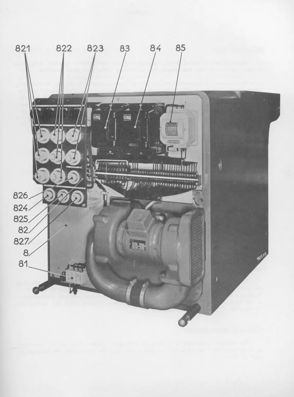
Main switch board
The main switch board 8 which groups most of the electric devices is mounted
at the rear of the bed underneath the protecting cover 12 (photo No 10510).
The machine is connected to the net by the terminals 81. Higher on the left,
there are twelve fuses. Above the fuses are mounted the adjustable resistors for
the illumination intensity. At the upper part, in the middle, there is a contac-
tor 83 for the spindle head motor and on the right the contactor 84 for the fan-
motor. On the right the transformer 85 feeds the coils of the contactors and of
the illumination devices.
Fuses
Following fuses are to be used:
Spindle head motor, 3 fuses ............... 2A DII type
Ventilator motor, 3 fuses ............... 2A DII type
Transformer, 2 fuses .................... 2A DII type
Contactor, 1 fuse ....................... 1A DI type
Lighting, 1 fuse .......................... 6A DI type
Working lamp, signal lamp, 1 fuse ....... 1A DI type
Lighting spiotting tool, 1 fuse ............. 1A DI type
Contactors
The tension of the machine being always 380 V., the contactors are adjusted
on: spindle head motor 0,57 A., fan-motor 0,42 A.
Outlet socket
There are three outlet sockets on the left hand side of the column: the high
one serves to feed the fluorescent tube and corresponds to the fuse 1A marked
"lighting spotting tool". The middle one feeds the working lamp and corresponds
to the fuse marked "signal". The low one feeds the dividing table and corresponds
to the fuse 6A marked "lighting".
Connecting autotransformer
The machine connected to a mains of different tension than 380 V., possesses
an autotransformer 86 connected in such a way that the tension of the machine al-
ways is 380 V.
- 47 -
Connecting to the mains
The terminal 81 enables the connection to the three-phase supply mains. The
small terminal which is next to it allows the possibility of connecting the fluo-
rescent tube to a single phase supply mains of 110 or 220 V. without using the
transformer 85. The change of connection from one to the other is obtained by mo-
ving a connecting strip on the terminal plate situated behind the fuses (see
diagram 890026).
The special transformer of the fluorescent tube possesses a primary winding
with two entries 110 or 220 V. If the parted supply is chosen, the tension of
the mains must evidently correspond to one or the other of these primary tensions
and the connections made accordingly.
Controlling switch board
The inclined desk-shaped panel at the front of the bed bears the controlling
switch board 121 fitted with:
the main cut-off switch 1211
the cut-off switch 1212 for the illuminating devices
the switch 1213 for the spindle head motor
two signal lamps constituted by EM 769/6 bulbs.
The right-hand one (1214) lights up when the main switch is closed. The left-
hand one (1215) lights up with the illumination devices.
- 49 -
Part IV
THE ACCESSORIES
- 50 -
ACCESSORIES
Regular equipment
(Generally supplied with the machine)
1 illumination attachment with fluorescent tube for observing non-polished
work-pieces,
1 clamping socket for holding spring collets,
7 spring collets 3/64" - 1/16" - 5/64" - 3/32" - 1/8" - 9/64" - 5/32" -
(1 - 1,5 - 2 - 2,5 - 3 - 3,5 - 4 mm dia.)
1 drill chuck, capacity 5/16" (8 mm),
1 adjustable boring tool holder L0e-l/64" to 9/16" (0,4 - 15 mm) with
9 cutters.
Moreover, the following tools and spare parts are supplied:
1 bulb centering templet,
1 set of servicing spanners,
1 hand lubricating pump,
Spare bulls and spare fuses.
Additional equipment
High precision optical circular dividing table, type Rotoptic-1, with settings
on projection screen.
Illuminated glass table.
Proving bar.
Adjustable boring tool holder Ll-5/8" to 13/16" (15/20 mm).
Adjustable boring tool holder L0e-3/4" to 1" (19/25 mm).
Scribing tool.
Locating dial indicator.
Reference square for use with the boring head microscope.
Additional optical device for observing simultaneously the workpiece and the
tool in the viewing microscope.
Precision spring collets with diameters from .008 in. to 5/32" (0,2 to 4 mm)
by increments of 1/64" (0,1 mm).
with cylindrical shaft or with No 1 Morse taper
Twist drills
End mills
- 51 -
DESCRIPTION OF THE MAIN ACCESSORIES
Clamping socket for spring collets
This accessory permits to hold with satisfaction the concentricity of the
flat drills ranging from .008" to .15" (0,2 to 4 mm) dia. It has a No 1 Morse
taper shank and is clamped in the spindle taper by means of the draw-bar. The
collet is held in the socket by an external nut tightened by means of a special
wrench.
Spring collets
Are used with the above mentioned socket. They are of the F-206 type, from
Messrs. Schaublin, Delemont (Switzerland) and can be obtained either from them
or from us; their concentricity, as required by us, is within .0002" (0,005 mm).
Boring tool holder L0e-l/64" to 9/16" (0,4/15 mm)
This tool holder specially designed for the No 1H machine fits on the ex-
ternal spindle taper. Being of cylindrical form and concentric with the rotation
axis, it is well balanced and shows no tendency to vibrate, even at the highest
speeds.
The boring cutter is advanced by rotating the graduated ring 9» Two succes-
sive graduation lines correspond to an increase in diameter of .0002" (0,005 mm).
The total travel of each cutter is of about .125 in. (3,2 mm). The normal set
of 9 cutters permits to bore all diameters ranging from 1/64" to 9/16" (0,4 to
15 mm) dia. These cutters are marked as follows:
Identification Number and shape Boring capacity Boring depth for machining
in. mm in. mm
96) high speed 1/64 - .275 (0,4 - 0,7) .08 2 steel, cast, iron,
95 steel .0275 - .04 (0,7 - 1,0) .10 2,5 light alloys
94 cutters, to .04 - .06 (1,0 - 1,5) .135 3,5
93 be used with .06 - .08 (1,5 - 2,0 2,5) .175 4,5
92 intermediary .08 - .10 (2,0 - .235 6
91) sleeve .10 - .125 (2,5 - 3,0) .315 8
184' • carbide tip- .125 - .24 (3 - 6 ) • 47 12 cast iron
183 ped boring .24 - .40 (6 - 10 ) .79 20
182 । cutters .40 - 9/16 (10 - 15 ) 1.18 30
- 52 -
Identification
Number and shape Boring capacity Boring depth for machining
in. mm in. mm
188) carbide tip- .125 - .24 ( 3 - 6 ) .47 12 cast iron
187 ped counter- .24 - .40 (6-10) •79 20
186 sinking cut- .40 - 9Л6 (10 - 15) 1.18 30
ters
284) HSS .125 - .24 (3-6) .47 12 steel
283 boring .24 - .40 (6-10) .79 20
282) cutters .40 - 9/16 (10 - 15) 1.18 30
288) HSS .125 - .24 (3-6) .47 12 steel
287 countersin- .24 - .40 (6-10) .79 20
286; king cutters .40 - 9/16 (10 - 15) 1.18 30
784) carbide tip- .125 - .24 (3-6) .47 12 steel
783 ped boring .24 - .40 (6-10) .79 20
782; cutters .40 - 9/16 (10 - 15) 1.18 30
788) carbide tip- ,il25 -.24 (3-6) .47 12 steel
787 ped counter- .24 - .40 (6-10) .79 20
786 sinking cut- .40 - 9/16 (10 - 15) 1.18 30
ters
384) HSS .125 - .24 (3-6) .47 12 light alloys
383 ' boring .24 - .40 (6-10) .79 20
382 1 cutters .40 - 9/16 (10 - 15) 1.18 30
388 HSS .125 - .24 (3-6) .47 12 light alloys
387 » countersin- .24 - .40 (6-10) .79 20
386 king cutters .40 - 9/16 (10 - 15) 1.18 30
684 ) carbide tip- .125 - .24 (3-6) .47 12
683 ) ped boring ;24 - .40 (6-10) .79 20
682 ) cutters .40 - 9/16 (10 - 15) 1.18 30
688 ) carbide tip- .125 - .24 (3-6) .47 12 light alloys
687 ) ped counter- .24 - .40 (6-10) .79 20
686 ) sinking cut- .40 - 9/16 (10 - 15) 1.18 30
) ters
53 -
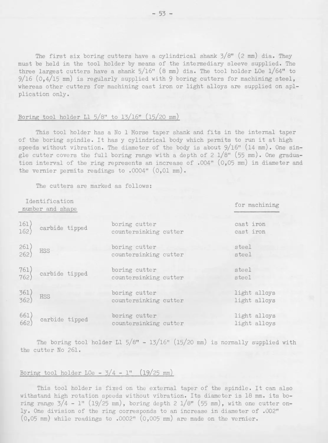
The first six boring cutters have a cylindrical shank 3/8" (2 mm) dia. They
must be held in the tool holder by means of the intermediary sleeve supplied. The
three largest cutters have a shank 5/16" (8 mm) dia. The tool holder LOe 1/64" to
9/16 (0,4/15 mm) is regularly supplied with 9 boring cutters for machining steel,
whereas other cutters for machining cast iron or light alloys are supplied on apl-
plication only.
Boring tool holder LI 5/8" to 13/16" (15/20 mm)
This tool holder has a No 1 Morse taper shank and fits in the internal taper
of the boring spindle. It has у cylindrical body which permits to run it at high
speeds without vibration. The diameter of the body is about 9/16" (14 mm). One sin-
gle cutter covers the full boring range with a depth of 2 1/8" (55 mm). One gradua-
tion interval of the ring represents an increase of .004" (0,05 mm) in diameter and
the vernier permits readings to .0004" (0,01 mm).
The cutters are marked as follows:
Identification
number and shape
for machining
161) 162) carbide tipped boring cutter c ounte rs inking cutter cast : cast : iron iron
261) 262, HSS boring cutter countersinking cutter steel steel
761) 762, carbide tipped boring cutter counters!nking cutter steel steel
361' 362) . HSS boring cutter countersinking cutter light light alloys alloys
661' 662, i carbide tipped boring cutter countersinking cutter light light alloys alloys
The boring tool holder LI 5/8" - lj/16" (15/20 mm) is normally supplied with
the cutter No 261.
Boring tool holder LOe - 3/4 - 1"
(19/25 mm)
This tool holder is fixed on the external taper of the spindle. It can also
withstand high rotation speeds without vibration. Its diameter is 18 mm. its bo-
ring range 3/4 - 1" (19/25 mm), boring depth 2 1/8" (55 mm), with one cutter on-
ly. One division of the ring corresponds to an increase in diameter of .002"
(0,05 mm) while readings to .0002" (0,005 mm) are made on the vernier.
- 54 -
The cutters for this tool are designated as follows:
Identification
number and shape
for machining
151, 152; . carbide tipped boring cutter countersinking cutter cast iron cast iron
251; HSS boring cutter steel
252; countersinking cutter steel
751; 752' carbide tipped goring cutter countersinking cutter steel steel
351; HSS boring cutter light alloys
352' countersinking cutter light alloys
651) carbide tipped boring cutter light alloys
652; countersinking cutter light alloys
The boring tool holder L0e-3/4" - 1" (19/25 mm) is normally supplied with the
cutter No 251.
Remark concerning the tool holders types Ll-5/б" to 13/16" (15 to 20 mm) and
L0e-3/4"-1" (19/25 mm)
For removing the cutters, rotate the graduated ring fully in increasing direc-
tion. A stop retains it when the cutter is released. It is then possible to take
the cutter out with the fingers. To replace the cutter, keep the graduated ring in
position mentioned above, introduce the cutter in its recess and push it inside so
that it is engaged, then revolve the graduated ring in the reverse direction.
When rotating the ring to remove the cutter, observe great care to see that
the ring does not hit the internal stop too heavily as otherwise it may seize.
Nevertheless, should this occur, it suffices to exert a sufficient effort
on the knurled ring. To this end, hold the knurled ring of the tool in a split
bush held in a grinding carrier and exert the necessary rotational effort on the
carrier.
Always keep a cutter mounted in the tool holder so as to prevent the ingress
of chips or dirt into the rectangular recess of the cutter. It would be otherwise
difficult to remove them, especially if the chips are magnetised.
508369
- 56 -
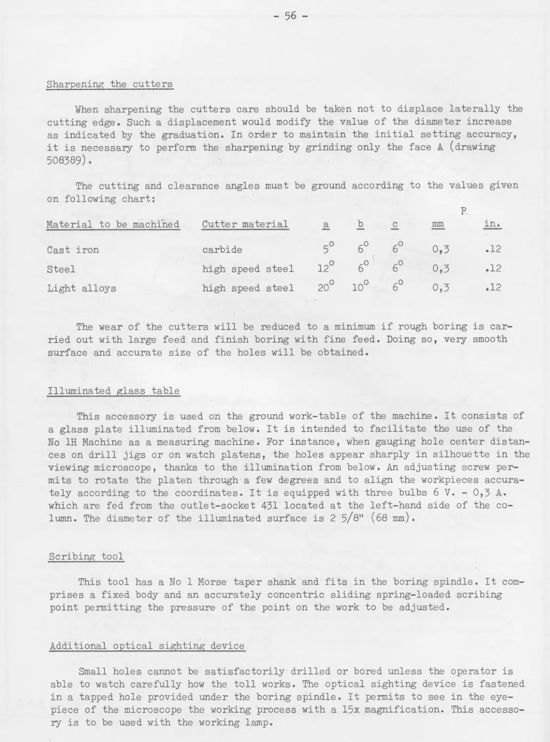
Sharpening the cutters
When sharpening the cutters care should be taken not to displace laterally the
cutting edge. Such a displacement would modify the value of the diameter increase
as indicated by the graduation. In order to maintain the initial setting accuracy,
it is necessary to perform the sharpening by grinding only the face A (drawing
508389).
The cutting and clearance angles must be ground according to the values given
on following chart:
P.
Material to be machined Cutter material a b c mm in.
Cast iron carbide 5° 6° 1 6° 0,3 .12
Steel high speed steel 12° 6° 6° 0,3 .12
Light alloys high speed steel 20° 10° 6° 0,3 .12
The wear of the cutters will be reduced to a minimum if rough boring is car-
ried out with large feed and finish boring with fine feed. Doing so, very smooth
surface and accurate size of the holes will be obtained.
Illuminated glass table
This accessory is used on the ground work-table of the machine. It consists of
a glass plate illuminated from below; It is intended to facilitate the use of the
No 1H Machine as a measuring machine. For instance, when gauging hole center distan-
ces on drill jigs or on watch platens, the holes appear sharply in silhouette in the
viewing microscope, thanks to the illumination from below. An adjusting screw per-
mits to rotate the platen through a few degrees and to align the workpieces accura-
tely according to the coordinates. It is equipped with three bulbs 6 V. - 0,3 A.
which are fed from the outlet-socket 431 located at the left-hand side of the co-
lumn. The diameter of the illuminated surface is 2 5/8" (68 mm).
Scribing tool
This tool has a No 1 Morse taper shank and fits in the boring spindle. It com-
prises a fixed body and an accurately concentric sliding spring-loaded scribing
point permitting the pressure of the point on the work to be adjusted.
Additional optical sighting device
Small holes cannot be satisfactorily drilled or bored unless the operator is
able to watch carefully how the toll works. The optical sighting device is fastened
in a tapped hole provided under the boring spindle. It permits to see in the eye-
piece of the microscope the working process with a 15x magnification. This accesso-
ry is to be used with the working lamp.
- 57 -
Locating dial indicator 1-3
This accessory is mounted on No 1 Morse taper shank. It is used to center the
spindle over a hole or a cylinder. It is also used to align work on the table.
It is normally equipped with a dial reading to .0001" (0,002 mm).
For centering holes of a diameter less than 1/4" (6 mm) into which the feeler
cannot be introduced, insert an appropriate plug in the hole and centre by applying
the feeler on the external diameter of the plug.
It is also possible to use the boring head microscope, the field diameter of
which is .228" (5,8 mm). In case the diameter of the hole is larger than the dia-
meter of the microscope field, opposite points on the periphery must be sighted,
taking the mean value of the readings.
Reference square
This accessory is to be used with the viewing microscope. The image of the
rectilinear edge of a workpiece is often not sharp enough to permit correct sight-
ing with the viewing microscope.
In this case, the reference square is placed against the vertical face of the
workpiece. It is provided with a highly polished circular surface on which a very
fine line is traced, which lies exactly in the plane of the inner surface of the
vertical leg.
Avoid rubbing this polished surface (for cleansing purposes, e.g.). Although
it is very hard, it may be scratched and this would necessitate a new polishing and
tracing of a new reference line on it.
For making sure that the reference square contacts correctly the vertical face
during the sighting with the microscope, press it gently with the finger.
Lamp for the illumination of work
This lamp permits to illuminate the workpiece being machined. It proves neces-
saiy when viewing the progress of work through the microscope used in conjunction
with the additional optical device. It must be equipped with a 6 V. 15 W. bulb and
is fed by the outlet-socket 43 located at the left-hand side of the column.
Twist drills
The SIP high speed precision twist drills permit to rough drill undersize the
holes which have to be finished by means of the end mills or with the tool holder
LOe-1/64" to 9/16" (0,4/15 mm).
- 58 -
These drills are only available for a limited number of diameters.
Twist drills with straight shank;
dia. in.: .080 - .110 - .135 - .140 - .170 - .185 - .205 - .235 - .250 - .300
dia. mm : 2,0 - 2,5 - 3,0 - 3,5 - 4,0 - 4,5 - 5,0 - 5,5 - 6,5 - 7,5
Twist drills with No 1 Morse taper:
dia. in.: .170 - .185 - .205 - .235 - .250 - .300 - .360 - .420 - .480 - .540 -
.605
dia. mm : 4,5 - 5,0 - 5,5 - 6,5 - 7,5 - 8,5 - 9,5 - 10,5 - 11,5 - 12,5 - 13,5 -
14,5 - 15,5
SIP end mills reamers
These end mills reamers are provided to finish bore the roughed out holes which
are drilled .01 to .015 in. (0,3 to 0,5 mm) smaller than the finished size. They are
made of special steel; they cut only on the end teeth. They can be re-sharpened wi-
thout any prejudicial effect on the concentricity of their cutting edge.
Their diameters are in keeping with the limits ISA-H7, CNM-H7, DIN-B and VSM-T2
and insure the correct adjustment of the drilling bushes machined acoording to li-
mits ISA-n6, CMN-N6, DIN-179 or VSM-K2.
The end mills reamers fitted with No 1 Morse taper show, thanks to their inte-
gral rigid taper, have an excellent concentricity and guarantee accurate work. The
following end mills reamers can be used with the No 1H Machine:
Nominal dia. in.: .10 - 1/8 - .15 - 5/32 - з/16 - .20 - 7/32 - 1/4 - .30 - 5/16 -
3/8 - .40 - 7/16 - 1/2 - 9/16
Nominal dia. mm: 2,5-3-3,5-4-4,5-5-5,5-6-7-8-9-10-11-
12 - 13 - 14 - 15
Taper shanks
It is absolutely necessary that the taper shanks of the various tools and ac-
cessories with No 1 Morse taper or special internal taper, should be absolutely ac-
curate. This is the most important condition to ensure precision work and absolute
concentricity of the holes.
Imperfect tapers may even injure the taper of the boring spindle, in spite of
its high standard of hardness.
- 59 -
Unfortunately, the Morse tapers of tools offered generally on the market lack
accuracy. We point out that all the SIP tools are provided with taper shanks sub-
jected to most severe inspection using high precision measuring equipment. We can
thus guarantee the limits given in sketch 520150.
The tool tapers should be handled with utmost care so as to avoid to damage
them. Even very small foreign particles, such a lint, dust, hardened grease or
rust, prevent the correct fit of the tools or the accessory in the spindle. Should
a burr be formed on the taper, smooth the surface by means of an extra fine honing
stone.
In case a Morse taper seems to fit in correctly, check the tool and the spin-
dle taper by means of precision gauges. Remember that the gauge may be inaccurate,
since they are subject to wear as any other mechanical part and, for this reason,
may cause troubles. Use Prussian blue for performing this checking, the usual yel-
low ochre having too coarse grains for this particular use. Remember that Prussian
blue is subject to rather rapid alterations, the contents of a tube left open beco-
ming useless after 2 or 3 weeks.
МО TO ЛАБОРАТОРИЯ
www.motolab.ru
*2012*
- 61 -
Part V
HINTS ON THE PRACTICAL USE OF THE MACHINE
- 62 -
INFORMATION AND ADVICES
The following pages are intended for the drawing office and operators of the
MP-1H jig boring machine with the purpose of helping to increase the output and the
accuracy of the work and reducing to a minimum the wear of the machine.
Laying-out of drawings
It would be a mistake to compell the
operator of this machine to carry out
additions or subtractions. The machine
is idle during this time.
Drawings judiciously established viz.
with figures giving directly the reading
to be taken on the coarse setting sca-
les and on the micrometer drums, will
substantially speed up work and reduce
errors.
Generally speaking, a common starting
point for all figures should be used,
arranging them as on the accompanying
examples.
Drawing
Work-piece
- 63 -
This arrangement simplifies very much the lay-out of the drawings.
Should a large number of holes be drilled on the same workpiece, then number
them. Instead of figuring the holes directly on the drawing, record their diame-
ters as well as their coordinates in a chart as shown below.
Hole No Coordinate X Coordinate У Diameter Observation
1 94,750 8,000 3 - M7
2 83,500 17,125 10 t0,02
3 41,000 12,750 4 - H6
4 17,505 22,502 5 - H7
5 62,750 22,502 6 - M7
6 93,500 34,750 5 +0,02
7 41,000 34,750 4 - M7
8 17,133 41,115 5 - H6
9 62,755 41,115 6 - H7
In the preceding chart the vacant column of x and of у are intended to enable
the operator to record the actual starting point and subsequent settings.
- 64 -
Adopting the scheme here under, the risk of errors (confusion of coordinates or
omission of drilling operations) is reduced to a minimum
Clamping large workpieces
When carrying out high precision work, it is quite indispensable to so fasten
workpieces that any deformation deriving from the clamping device is obviated.
Very often, holes to be drilled or bored are open holes. In this case, it is
necessary to use supporting blocks of a certain thickness so as not to damage the
machine table. Note that, even if this should not be the case, it is advisable to
proceed as suggested above to avoid clamping stresses whose effect is otherwise
difficult to eliminate.
Although all clamping systems adopted in the workshops can be used, we however
recommend more especially the one illustrated on this page, experience having proved
- 65 -
5/32
that it is most suitable for the kind of work to be performed in this machine.
Still, it is quite a classic clamping arrangement.
The studs and the special head-nuts which should slide within T-slots of the
table are to be machined to dimensions given on this page.
Clamps should be as robust and rigid as possible because their elasticity ren-
ders the alignment of workpieces very difficult and tends to alter their position
during clamping.
- 66 -
These clamps are to be used in connection with the supporting blocks mentioned
below (they can be made of cast iron, steel or even hard wood).
Supporting steel parallels are made of hardened ground steel.
It is most convenient to have available sets of 2 or 4 pieces of exactly the
same thickness (ground simultaneously).
- 67 -
Very often a locating-key provided at the bottom part of these steel parallels
will prove very useful for true positioning according to table T-slots.
Cylindrical supporting blocks will sometimes prove useful for fixing workpie-
ces which would otherwise be difficult to be fastened.
The figures on following page show some sizes we recommend to grind by batches
of 6 with exactly the same length.
The following types of clamps will prove most suitable.
- 68 -
Clamping light or very small pieces
These pieces which are not intended to support important cutting pressures can
be fastened by clamps of very light design.
It is therefore unnecessary to use hexagonal nuts or other mechanical parts to
be tightened by means of wrenches: knurled heads generally suffice.
The sketches on this page show two clamping devices of this kind.
- 69 -
Recommended cutting speeds
In order to secure the highest efficiency, whether with respect to final accu-
racy, tool life or quality of finish, it is essential to employ a correct cutting
speed which depends on the type of tool in use, the material machined and the ma-
chining operation to be performed.
Machining operation Cutting speeds in feet/minute
Soft steel Hard steel Cast iron Light alloy Brass
Drilling with twist drills 90 55 80 150 120
Boring with end mills 17 13 17 33 33
Boring with single point HSS tools Roughing out 60 50 — 250 200
Finishing 80 65 — 500 250
Boring with carbide tipped single points tools — — a.— 220 280 ж ж —
ROTATIONAL SPEEDS FOR HIGH SPEED TWIST DRILLS
for a frequency of 50 cycles
Dia. of hole in. Soft steel Cast iron Hard steel Light alloy Brass
.020 3000 3000 3000 3000 3000
.040 3000 3000 3000 3000 3000
.060 3000 3000 3000 3000 3000
.080 3000 3000 2140 3000 3000
.100 3000 3000 2140 3000 3000
.120 3000 2140 1500 3000 3000
.140 2140 2140 1500 3000 3000
.160 2140 2140 1070 3000 3000
.180 1500 1500 1070 3000 3000
.200 1500 1500 720 3000 2140
.225 1500 1500 720 3000 2140
.250 1500 1070 720 3000 2140
.275 1070 1070 720 3000 1500
.300 1070 1070 720 2140 1500
- 70 -
All cutting speeds given in the chart are intended as a general indication on-
ly. In some cases, the figures should be determined by actual test, especially for
very small holes.
For convenience' sake, a speed chart is given in the preceding page.
Machining bored holes
These holes can be bored with one of the tool holders delivered with the ma-
chine. The initial drilling is performed with a twist drill. The definite diame-
ter is obtained by removing stock by an appropriate number of cuts.
Use preferably for opening the holes precision twist drills with rigorously
concentric shanks. It is rather difficult to true out-of-round holes or holes which
are not correctly located. Eliminate these troubles from the very beginning. Whene-
ver possible, never start work using a rough-cast hole.
Boring holes through oblique surfaces
This presents some difficulties because a
twist drill will not easily enter into a sur-
face which does not lie square to it.
The difficulty is overcome by using a cen-
tering drill, such as used for the centres of
pieces to be machined on a lathe (see figure
close-by).
The drilling is then continued with an or-
dinary twist drill, finish boring being perfor-
med by means of an end mill or a tool holder.
Boring holes from .1" to .6" dia.
A method combining accuracy with rapidity consists in drilling a hole 1/64" to
1/32" smaller than the nominal diameter to be obtained and to finish it with a SIP
end mill or a boring tool holder. End mills, made of special carbon steel, permit
to finish a hole in a single operation. They are not available for all possible dia-
meters so that adjustable boring tool holders are necessary.
- 71 -
End mills are used without coolant when machining cast iron. For machining steel,
we recommend the use of colza seed oil or of a mixture of colza or lard oil and kero-
zene in equal parts, this mixture being less soiling for the machine. For aluminium,
use kerozene.
Boring large sized holes
The method to be used is the same, but holes should be finished exclusively with
single point tools; there is no end mill larger than dia. 9/16".
Boring very small holes (from 1/64" to .1" dia.)
Small end mills cannot be used, owing to their too great fragility. After having
rough-drilled the hole slightly undersize (about .004 in.), the hole is finish bored,
taking into account the following recommendations:
For avoiding the deviation of these very small drills, spot the centre sufficien-
tly strongly (at least .01" dia.). Use the spotting tool supplied with the machine.
This spotting tool should be lowered gently on the workpiece for producing the
impression of the required size (in any case larger than the drill diameter).
It is surrounded by a big burr which it is necessary to first remove.
The rough drilling will be carried out:
- by means of a twist drill when machining steel and aluminium;
- by means of a straight-fluted or a flat drill for non-ferrous metals.
The finish drilling can be made:
- by means of a twist drill in steel and aluminium;
- by means of a straight-fluted - not spade drill - in non-ferrous metals.
The gun boring drill suits the need as well for finish drilling in steel or
non-ferrous metals.
All these drills are to be held in concentric collets and not in the three-jaw
chuck which is not sufficiently concentric.
Preparation of the workpiece to be drilled
The resting face of the workpiece must be accurately machined. The face to be
drilled must be smooth in order to eliminate any possible deviation of the tool as
it contacts with the surface.
- 72 -
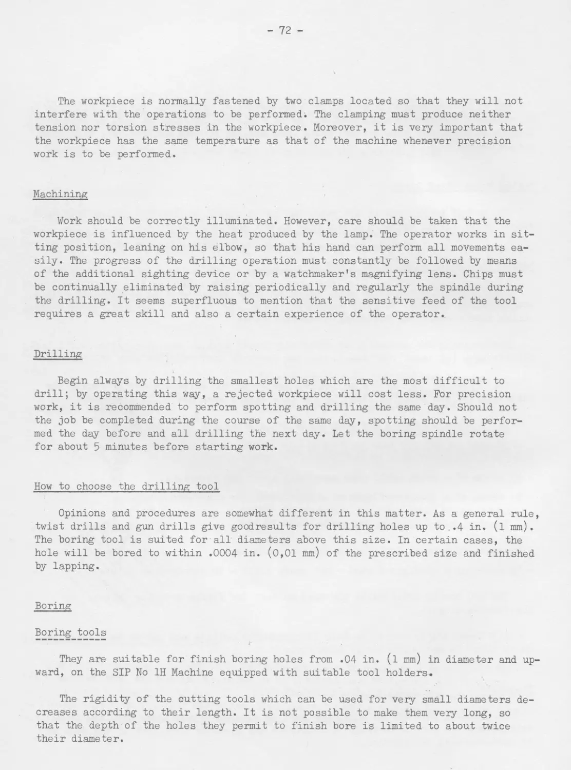
The workpiece is normally fastened by two clamps located so that they will not
interfere with the operations to be performed. The clamping must produce neither
tension nor torsion stresses in the workpiece. Moreover, it is very important that
the workpiece has the same temperature as that of the machine whenever precision
work is to be performed.
Machining
Work should be correctly illuminated. However, care should be taken that the
workpiece is influenced by the heat produced by the lamp. The operator works in sit-
ting position, leaning on his elbow, so that his hand can perform all movements ea-
sily. The progress of the drilling operation must constantly be followed by means
of the additional sighting device or by a watchmaker's magnifying lens. Chips must
be continually eliminated by raising periodically and regularly the spindle during
the drilling. It seems superfluous to mention that the sensitive feed of the tool
requires a great skill and also a certain experience of the operator.
Drilling
Begin always by drilling the smallest holes which are the most difficult to
drill; by operating this way, a rejected workpiece will cost less. For precision
work, it is recommended to perform spotting and drilling the same day. Should not
the job be completed during the course of the same day, spotting should be perfor-
med the day before and all drilling the next day. Let the boring spindle rotate
for about 5 minutes before starting work.
How to choose the drilling tool
Opinions and procedures are somewhat different in this matter. As a general rule,
twist drills and gun drills give goodresults for drilling holes up to .4 in. (1 mm).
The boring tool is suited for all diameters above this size. In certain cases, the
hole will be bored to within .0004 in. (0,01 mm) of the prescribed size and finished
by lapping.
Boring
Boring tools
They are suitable for finish boring holes from .04 in. (1 mm) in diameter and up-
ward, on the SIP No 1H Machine equipped with suitable tool holders.
The rigidity of the cutting tools which can be used for very small diameters de-
creases according to their length. It is not possible to make them very long, so
that the depth of the holes they permit to finish bore is limited to about twice
their diameter.
- 73 -
Begin to centre the tool so that it penetrates freely within the rough-drilled
hole. This is done by using the observation microscope and requires a certain skill.
Adjust progressively the tool until it begins to cut. From that moment, cuts from
.01" to .02" are to be taken. The boring tool being, of course, somewhat flexible it
cannot remove the full stock in a single cut. It is therefore necessary to repeat
the operation several times.
The progress of the work can be checked by means of standard plugs calibrated
in increments of .0005" dia. These small plugs permit to ascertain at what moment
the tool begins to enlarge the hole, to follow the work and to interrupt it at the
right moment.
For boring very deep holes, start as indicated above and continue using a gun
barrel drill which is guided in the already bored portion. This drill must have an
absolutely accurate diameter.
During the drilling and boring operation, put a drop of fine oil on the drill
or on the boring tool.
Working in medium-hard steel (about 215 Brinell) is easiest. Holes are bored more
accurately in steel than in brass. The depth of the holes to be machined should be
reduced to a strict minimum.
- 74 -
SOME ADVICES
The No 1H Jig Boring Machine should be installed in a room free from dust. Take
great care of the machine. The measuring device,.the ways, etc., should always be
kept as clean as possible. Remove chips after each job before starting the next one.
Avoid temperature variations, otherwise accurate work is quite impossible. Some
parts of the machine are rather large and, therefore, follow the variations of the
room temperature after only several hours. The workpiece to be machined being gene-
rally lighter follow temperature changes more rapidly.
It is, of course, quite impossible to perform precision work if both machine
and workpiece do not have the same temperature. The latter should be as far as pos-
sible at 68° F especially when workpieces are not of steel or cast iron (viz. :
bronze, aluminium, etc.), the thermal expansion coefficient of these metals being
different.
Use the machine as much as possible. In case you have no jigs to manufacture,
use it for the direct machining of pieces. It is of extremely strong and rigid de-
sign and can be used as a production machine-tool.
In order to spare the operator's time, prepare special drawings which will al-
ways quickly pay for themselves.
The No 1H Jig Boring Machine permits of machining jigs larger than its actual
capacity. In that case, jigs should"be-composed of plates assembled by reference
dowels and machined individually. It is only necessary to clamp and re-set them se-
veral times.
Do not forget to regularly lubricate the machine using the prescribed lubri-
cants .
Keep the tools and spanners in good order and do not let them lie about anywhe-
re. Place them on the supports provided to that purpose.
Do not clamp exclusively all workpieces on the centre part of the worktable. Use
successively the whole table surface in order to distribute the natural wear of the
machine uniformly.
Never use tools with faulty or damaged shanks. Do not damage tapers in letting
them fall. Put them in a wooden tool-block or within their wooden case immediately
after use.
The wooden blocks should be soaked with paraffine wax. Untreated wood is never
chemically neutral and may corrode the surface of the shanks.
- 75 -
Remember that a workpiece is subjected to a temperature increase and deformations
during its machining. It is therefore absolutely necessary to take special care when
highest accuracy is required. Let the workpieces lie several hours close to the machi-
ne so that they should take the same temperature.
Provide wooden protecting covers for the parts of the worktable which are not ac-
tually used. You will prevent damaging its surface, should inadvertently a tool or a
spanner fall on it.
The accessories supplied in special cases are precision measuring instruments. Ta-
ke care of them accordingly.
STANDARD TEMPERATURE
As a well known fact, all metals expand by heat and the same piece measured accu-
rately at different temperatures will therefore show different lengths.
The "standard temperature" of a machine is the temperature at which the measuring
components will show their nominal length exactly.
It is now easy to understand why the knowledge of this temperature is of capital
importance.
- 76 -
Suppose we have a steel bar exactly 1 foot long at the standard temperature of
68° Fahrenheit. This means that the bar will have exactly a length of 12 in. at
68° F. At a lower temperature, the bar will somewhat shrink and be "shorter", whe-
reas at a higher temperature it will expand and be "longer".
This example shows why it is not possible to obtain the same dimensions on a
given object, even when measured with absolutely accurate measuring instruments
which are, however, calibrated at a "different" standard temperature. Plants desi-
rous to perform precision work are therefore compelled to choose a well defined
standard temperature.
In Europe, America and Japan 68° F is now generally chosen as standard tempe-
rature. Since January 1st 1932 Great Britain has also officially adopted this tem-
perature. Thus 68° F is now a World Standard Temperature and, unless otherwise sta-
ted, all machines made by the Societe Genevoise d'Instruments de Physique are cali-
brated for this temperature.
Pieces machined on SIP Jig Borers must consequently be checked with measuring
devices (micrometers, gauge blocks, etc.) calibrated at 68° F. If their standard
temperature is different, it is necessaiy to correct the measurements accordingly.
The thermic expansion coefficient of cast iron or common steel is nearly .0000115,
this means that these materials expand .000076 in. per foot and per degree Fahren-
heit.
We strongly insist upon these fundamental facts because it has already happened
that customers put forth unjustified claims concerning the accuracy of our machines.
They merely neglected to take into account that the workpieces machined on our ma-
chine were gauged by means of instruments calibrated at 62° F for example. They ne-
cessarily ascertained a difference of about .00045 in. per foot and attributed this
fact to a lack of accuracy, whereas it was only due to the difference of both stan-
dard temperatures.
-o-o-o-o-o-o-o-o-o-
May 1964.
МОТСЛАБШШйк
www.motolab.ru
*2012*