/


Текст
O
A
.
.:) -1.J-
W r-\f LEHRMITTEL
-
...
II1I1
tlO
r
L'
+L£
o
+15
6 8
-"'\
10 -4. 1
'.
- -12 : r.::
3 -5', !f
-28 -14 rl
-
-16 -6 +12
-34 -17 -1 1
'
I
.
'...,
..
.
1';
J
r.
'or
."..
1.
S, "..;'t....
.;.I:; ,
#>..
t
1..
. :<i. ........,...
.\ .,,
;:q.- .",-
,...
,
.f
echanical and eta I
Trades Handbook
Europa-No 1910X
ISBN 978-3-8085-1913-4
9 !8JJJlll s1 tJ
EUROPA-TECHNICAL BOOK SERIES
for the Metalworking Trades
Ulrich Fischer
Roland Gomeringer
Max Heinzler
Roland Kilgus
Friedrich Naher
Stefan Oesterle
Heinz Paetzold
Andreas Stephan
Mechanical and
Metal Trades
Handbook
2nd English edition
Europa-No.: 1910X
VERLAG EUROPA LEHRMITTEL . Nourney, Vollmer GmbH & Co. KG
Dusselberger StraBe 23 . 42781 Haan-Gruiten . Germany
Original title:
Tabellenbuch Metall, 44th edition, 2008
Authors:
Ulrich Fischer
Roland Gomeringer
Max Heinzler
Roland Kilgus
Friedrich Naher
Stefan Oesterle
Heinz Paetzold
Andreas Stephan
Dipl.-Ing. (FH)
Dipl. -Gwl.
Dipl.-Ing. (FH)
Dipl. -Gwl.
Dipl.-Ing. (FH)
Dipl.-Ing.
Dipl.-Ing. (FH)
Dipl.-Ing. (FH)
Reutlingen
Me Bstetten
Wangen im Aligau
Neckartenzlingen
Balingen
Amtzell
Muhlacker
Kressbronn
Editor:
Ulrich Fischer, Reutlingen
Graphic design:
Design office of Verlag Europa-Lehrmittel, Leinfelden-Echterdingen, Germany
The publisher and its affiliates have taken care to collect the information given in this book to the best of their ability.
However, no responsibility is accepted by the publisher or any of its affiliates regarding its content or any statement
herein or omission there from which may result in any loss or damage to any party using the data shown above.
Warranty claims against the authors or the publisher are excluded.
Most recent editions of standards and other regulations govern their use.
They can be ordered from Beuth Verlag GmbH, Burggrafenstr. 6, 10787 Berlin, Germany.
The content of the chapter "Program structure of CNC machines according to PAL" (page 386 to 400) complies with
the publications of the PAL PrOfungs- und Lehrmittelentwicklungsstelle (Institute for the development of training and
testing material) of the IHK Region Stuttgart (Chamber of Commerce and Industry of the Stuttgart region).
English edition: Mechanical and Metal Trades Handbook
2nd edition, 2010
654321
All printings of this edition may be used concurrently in the classroom since they are unchanged, except for some
corrections to typographical errors and slight changes in standards.
ISBN 13 978-3-8085-1913-4
Cover design includes a photograph from TESA/Brown & Sharpe, Renens, Switzerland
All rights reserved. This publication is protected under copyright law. Any use other than those permitted by law
must be approved in writing by the publisher.
@ 2010 by Verlag Europa-Lehrmittel, Nourney, Vollmer GmbH & Co. KG, 42781 Haan-Gruiten, Germany
http://www.europa-Iehrmittel.de
Translation: Techni-Translate, 72667 Schlaitdorf, Germany; www.techni-translate.com
Eva Schwarz, 76879 Ottersheim, Germany; www.technische-uebersetzungen-eva-schwarz.de
Typesetting: YeliowHand GbR, 73257 Kongen, Germany; www.yellowhand.de
Printed by: Media Print Informationstechnologie, 0-33100, Paderborn, Germany
3
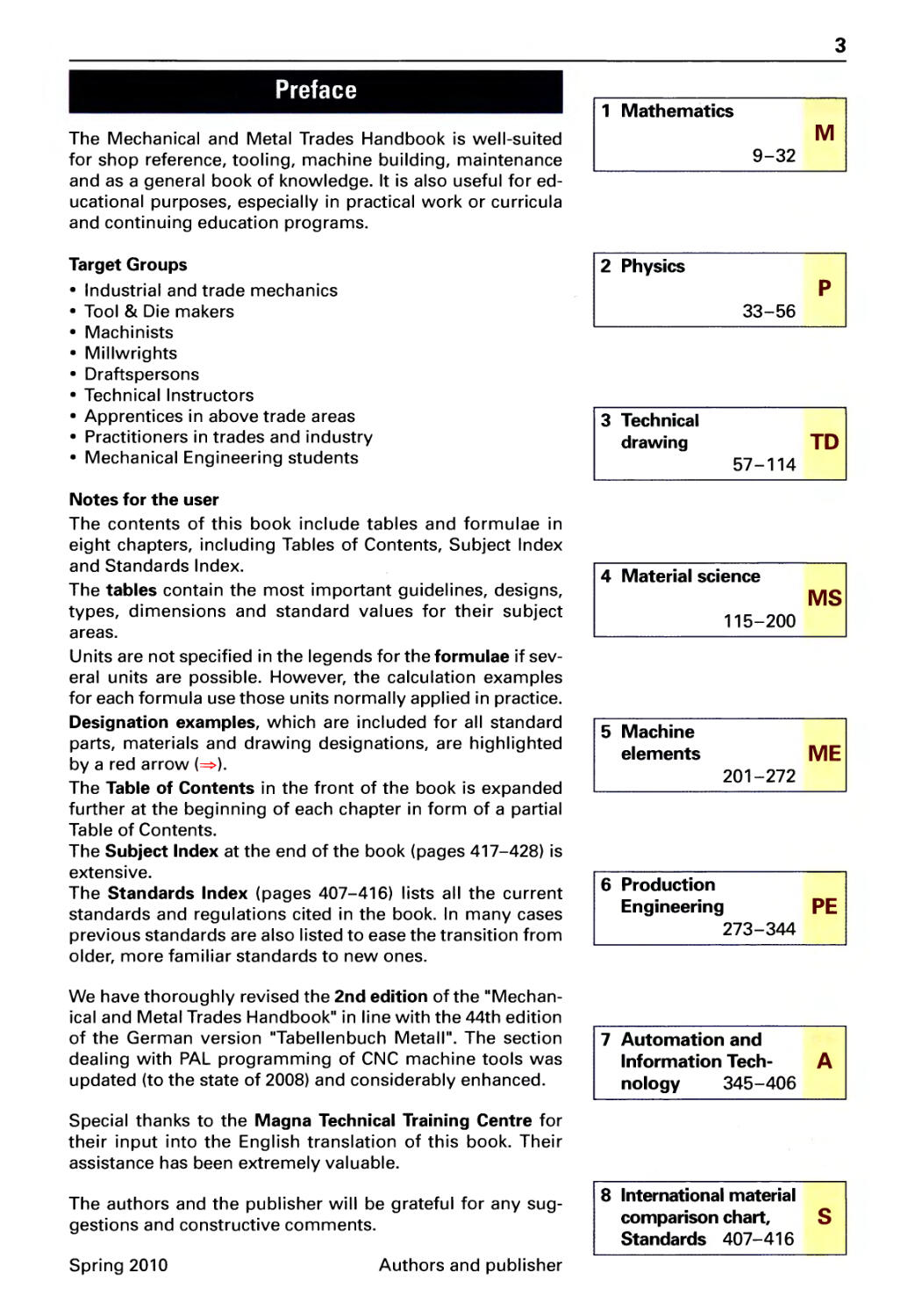
Preface
1 Mathematics
The Mechanical and Metal Trades Handbook is well-suited M
for shop reference, tooling, machine building, maintenance 9-32
and as a general book of knowledge. It is also useful for ed-
ucational purposes, especially in practical work or curricula
and continuing education programs.
Target Groups 1 2 Physics 1
· Industrial and trade mechanics P
· Tool & Die makers 33-56
· Machinists
· Millwrights
· Draftspersons
· Technical Instructors
· Apprentices in above trade areas 3 Technical
· Practitioners in trades and industry drawing TD
· Mechanical Engineering students 57-114
Notes for the user
The contents of this book include tables and formulae in
eight chapters, including Tables of Contents, Subject Index
and Standards Index. 4 Material science
The tables contain the most important guidelines, designs, MS
types, dimensions and standard values for their subject 115-200
areas.
Units are not specified in the legends for the formulae if sev-
eral units are possible. However, the calculation examples
for each formula use those units normally applied in practice.
Designation examples, which are included for all standard 5 Machine
parts, materials and drawing designations, are highlighted elements ME
by a red arrow (
). 201-272
The Table of Contents in the front of the book is expanded
further at the beginning of each chapter in form of a partial
Table of Contents.
The Subject Index at the end of the book (pages 417-428) is
extensive. 6 Production
The Standards Index (pages 407-416) lists all the current
standards and regulations cited in the book. In many cases Engineering PE
previous standards are also listed to ease the transition from 273-344
older, more familiar standards to new ones.
We have thoroughly revised the 2nd edition of the "Mechan-
ical and Metal Trades Handbook" in line with the 44th edition
of the German version "Tabellenbuch Metall". The section 7 Automation and
dealing with PAL programming of CNC machine tools was Information Tech- A
updated (to the state of 2008) and considerably enhanced. nology 345-406
Special thanks to the Magna Technical Training Centre for
their input into the English translation of this book. Their
assistance has been extremely valuable.
The authors and the publisher will be grateful for any sug- 8 International material
gestions and constructive comments. comparison chart, S
Standards 407-416
Spring 2010
Authors and publisher
4
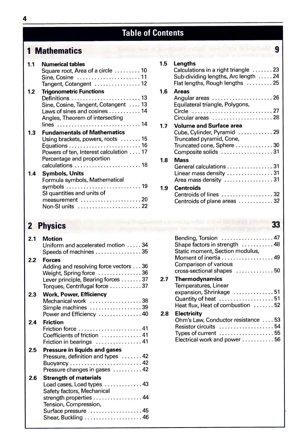
Table of Contents
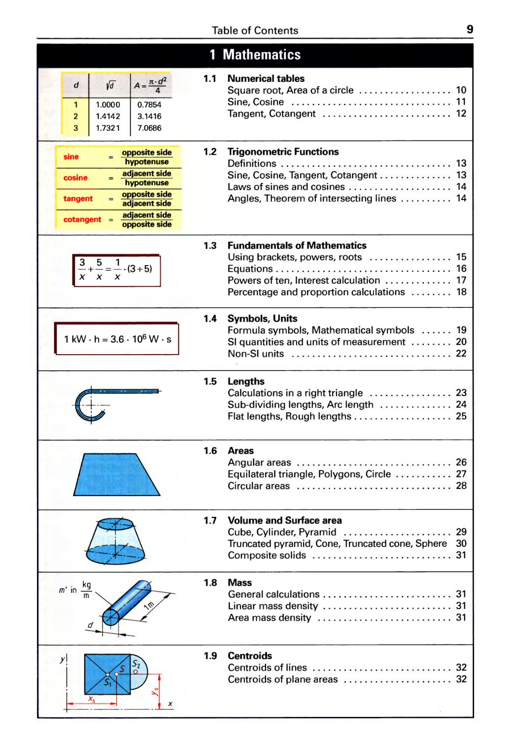
1 Mathematics
1.1 Numerical tables
Square root, Area of a circle. . . . . . . . . 10
Sine, Cosine ...................... 11
Tangent, Cotangent ................ 12
1.2 Trigonometric Functions
Definitions . . . . . . . . . . . . . . . . . . . . . . . . 13
Sine, Cosine, Tangent, Cotangent .... 13
Laws of sines and cosines........... 14
Angles, Theorem of intersecting
Ii n es ............................. 14
1.3 Fundamentals of Mathematics
Using brackets, powers, roots ....... 15
Equations. . . . . . . . . . . . . . . . . . . . . . . . . 16
Powers of ten, Interest calculation. . . . 17
Percentage and proportion
calculations . . . . . . . . . . . . . . . . . . . . . . . 18
1.4 Symbols, Units
Formula symbols, Mathematical
symbols . . . . . . . . . . . . . . . . . . . . . . . . . . 19
SI quantities and units of
measurement .............. ...... .20
Non-SI units ...................... 22
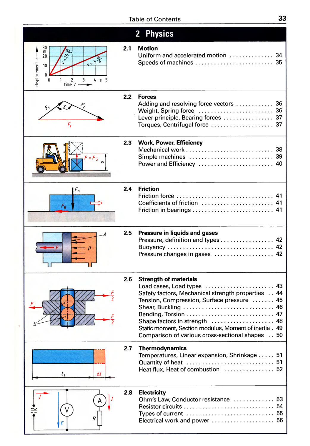
2 Physics
2.1 Motion
Uniform and accelerated motion .... . 34
Speeds of machines. . . . . . . . . . . . . . . .35
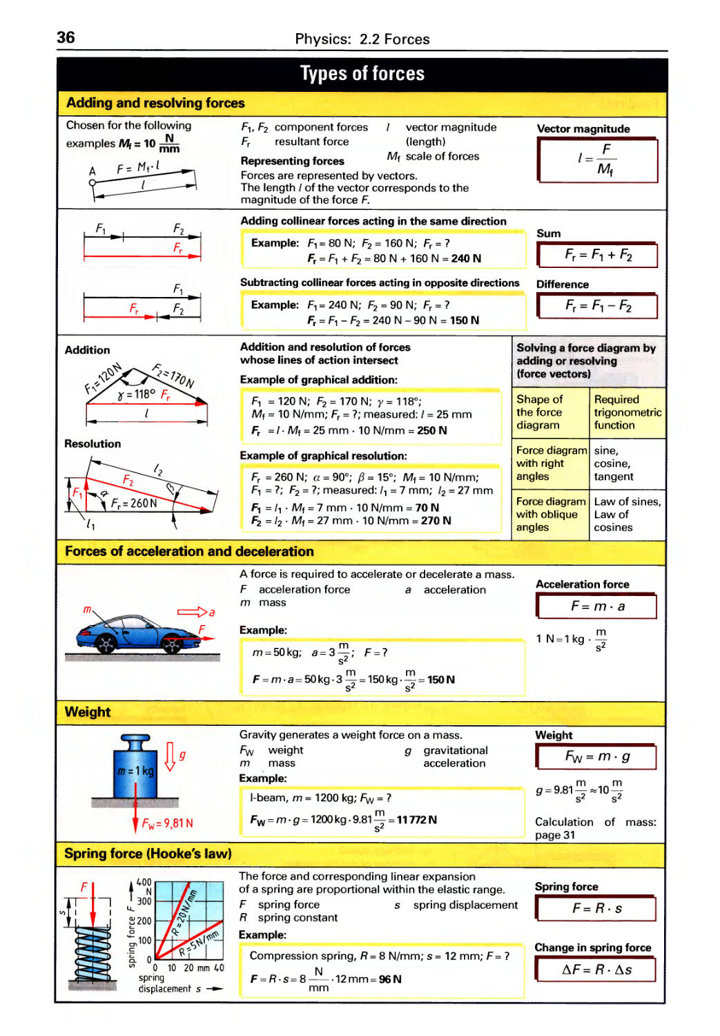
2.2 Forces
Adding and resolving force vectors. . . 36
Weight, Spring force ............... 36
Lever principle, Bearing forces. . . . . . . 37
T orq ues, Centrifugal force . . . . . . . . . . . 37
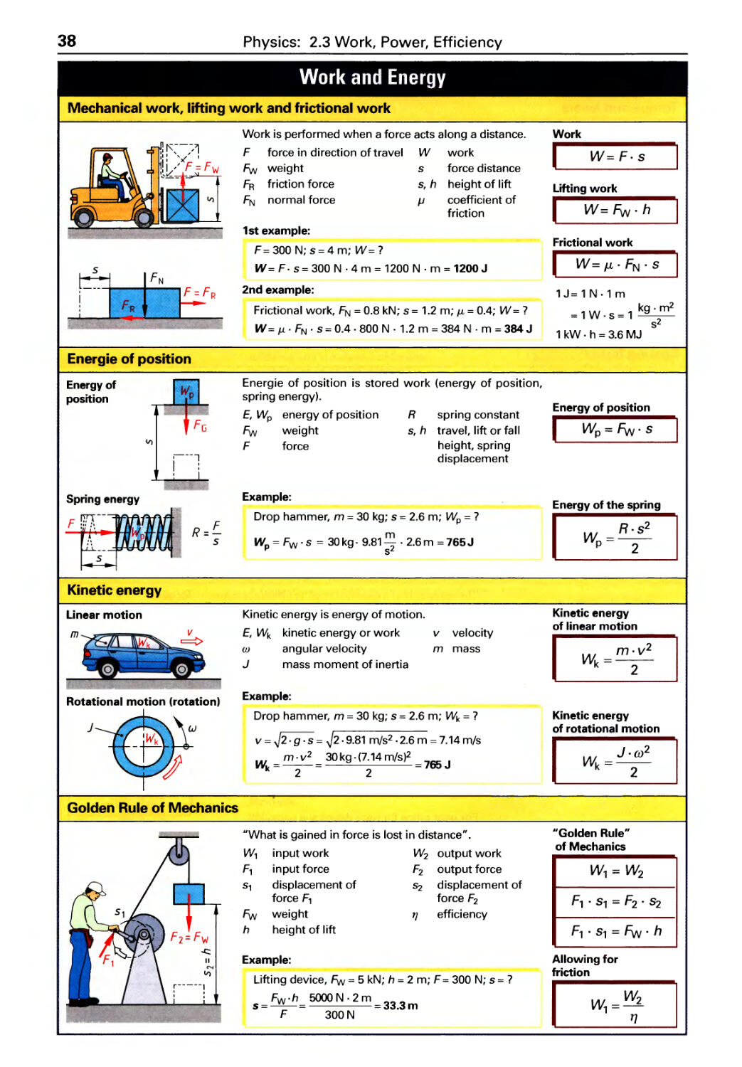
2.3 Work, Power, Efficiency
Mechanical work .................. 38
Simple machines .................. 39
Power and Efficiency ............... 40
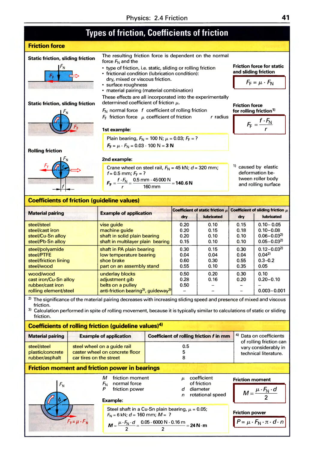
2.4 Friction
Friction force . . . . . . . . . . . . . . . . . . . . . . 41
Coefficients of friction .............. 41
Friction in bearings ................ 41
2.5 Pressure in liquids and gases
Pressure, definition and types ....... 42
Buoyancy. . . . . . . . . . . . . . . . . . . . . . . . . 42
Pressure changes in gases ..........42
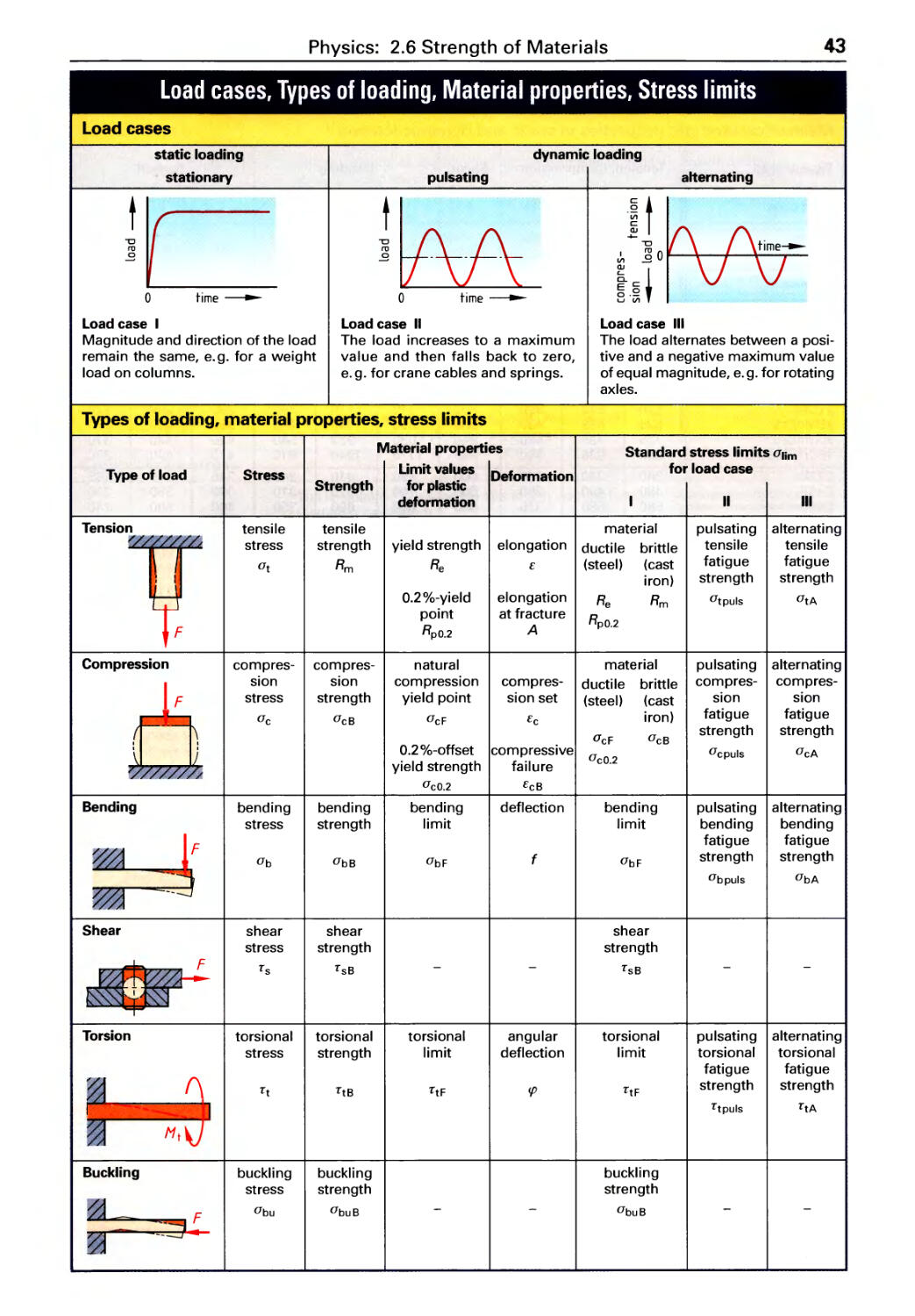
2.6 Strength of materials
Load cases, Load types .............43
Safety factors, Mechanical
strength properties. . . . . . . . . . . . . . . . . 44
Tension, Compression,
Surface pressure .................. 45
Shear, Buckling . . . . . . . . . . . . . . . . . . . . 46
9
1.5 Lengths
Calculations in a right triangle ....... 23
Sub-dividing lengths, Arc length ..... 24
Flat lengths, Rough lengths ......... 25
1.6 Areas
Angular areas ..................... 26
Equilateral triangle, Polygons,
Circle ............................ 27
Circular areas ..................... 28
1.7 Volume and Surface area
Cube, Cylinder, Pyramid ............ 29
Truncated pyramid, Cone,
Truncated cone, Sphere. . . . . . . . . . . . . 30
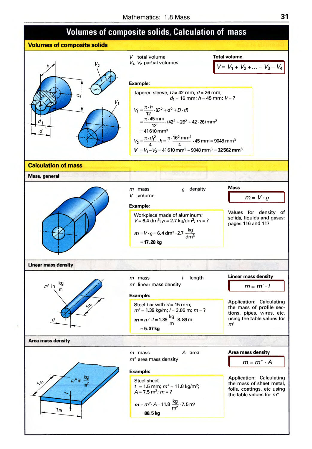
Composite solids .................. 31
1.8 Mass
General calculations. . . . . . . . . . . . . . . . 31
Linear mass density . . . . . . . . . . . . . . . . 31
Area mass density ................. 31
1.9 Centroids
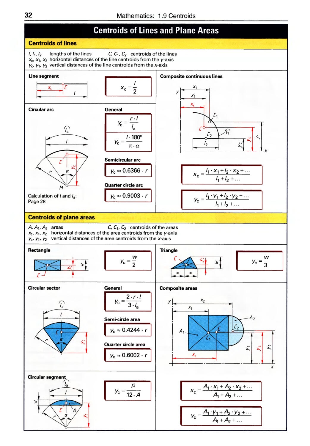
Centroids of lines .................. 32
Centroids of plane areas ............ 32
33
Bending, Torsion .................. 47
Shape factors in strength ........... 48
Static moment, Section modulus,
Moment of inertia. . . . . . . . . . . . . . . . . . 49
Comparison of various
cross-sectional shapes ............. 50
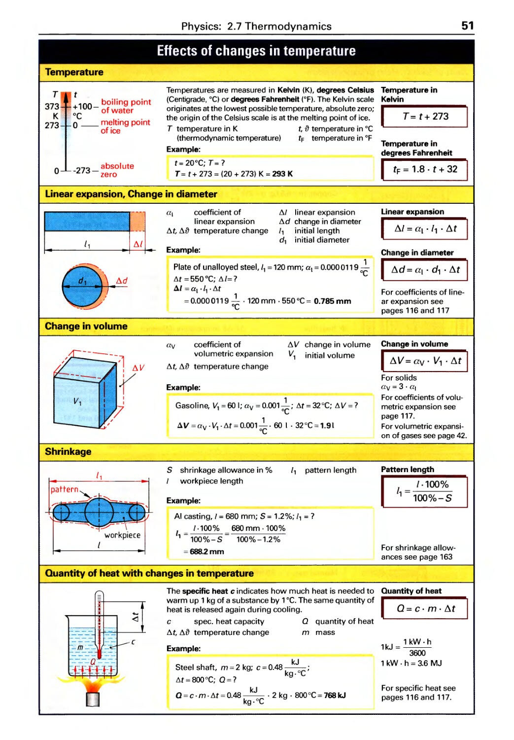
2.7 Thermodynamics
Temperatures, Linear
expansion, Shrinkage .............. 51
Quantity of heat ...................51
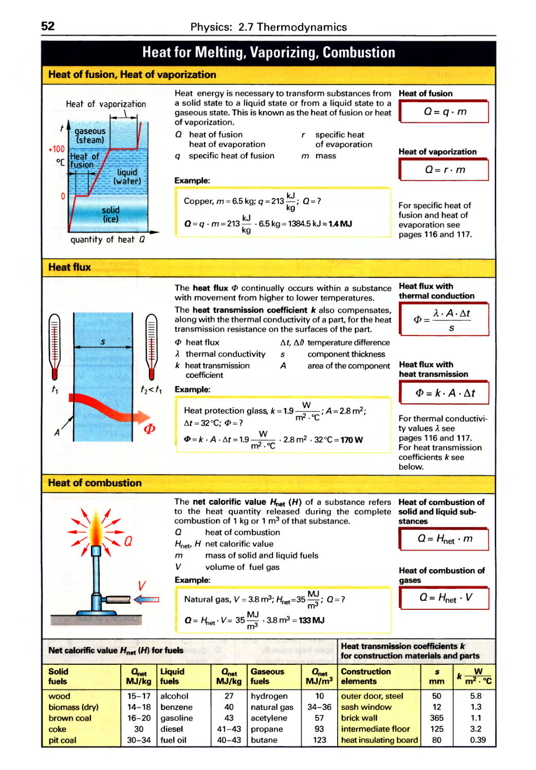
Heat flux, Heat of combustion ....... 52
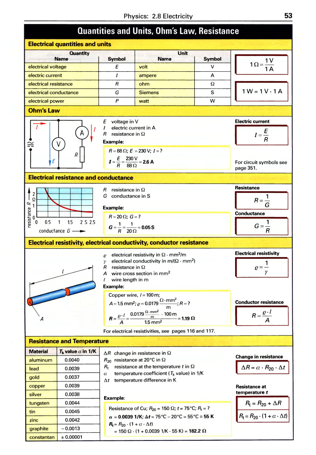
2.8 Electricity
Ohm's Law, Conductor resistance .... 53
Resistor circuits ................... 54
Types of current ................... 55
Electrical work and power. . . . . . . . . . . 56
Table of Contents
5
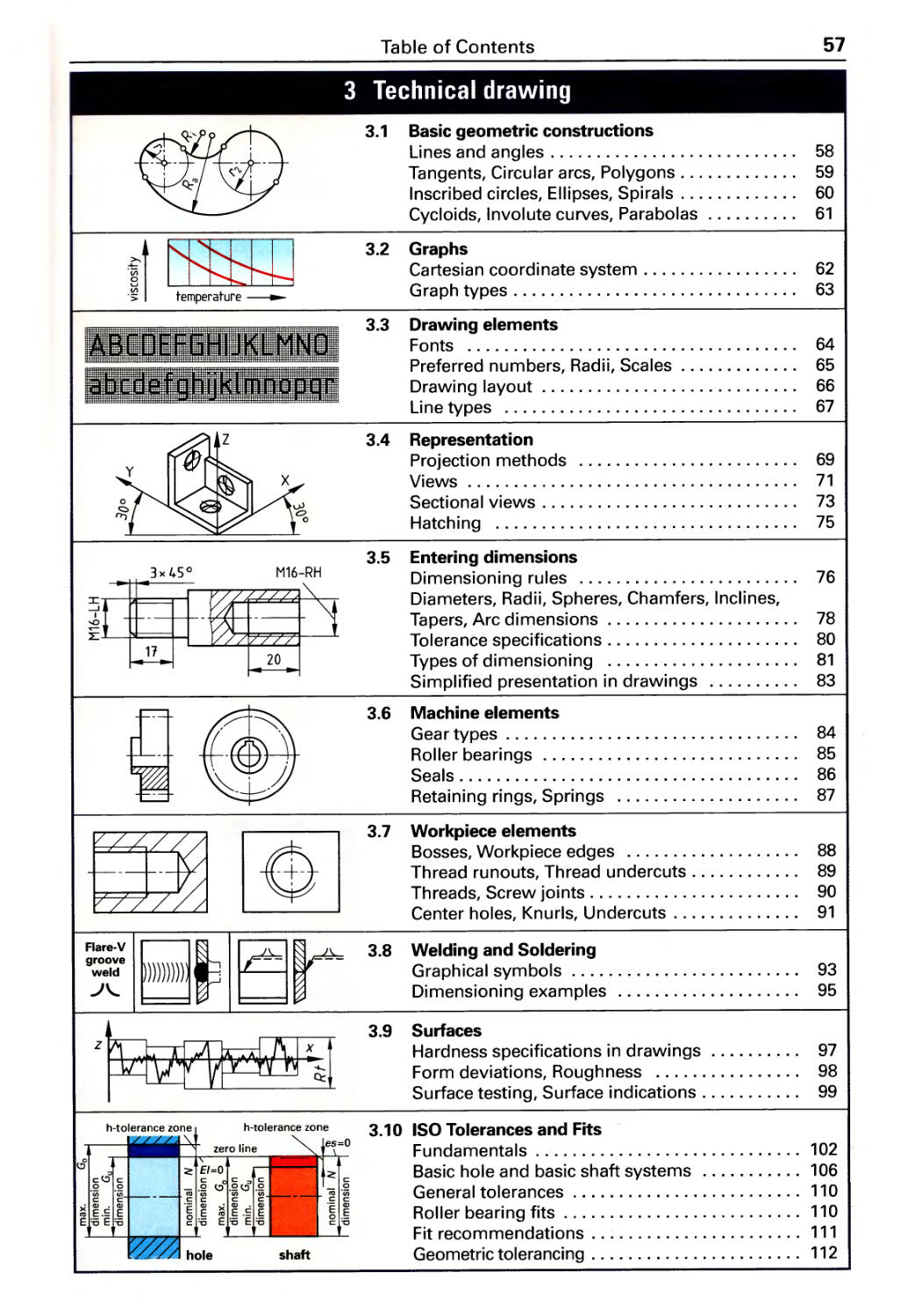
3 Technical drawing
3.1 Basic geometric constructions
Lines and angles. . . . . . . . . . . . . . . . . . . 58
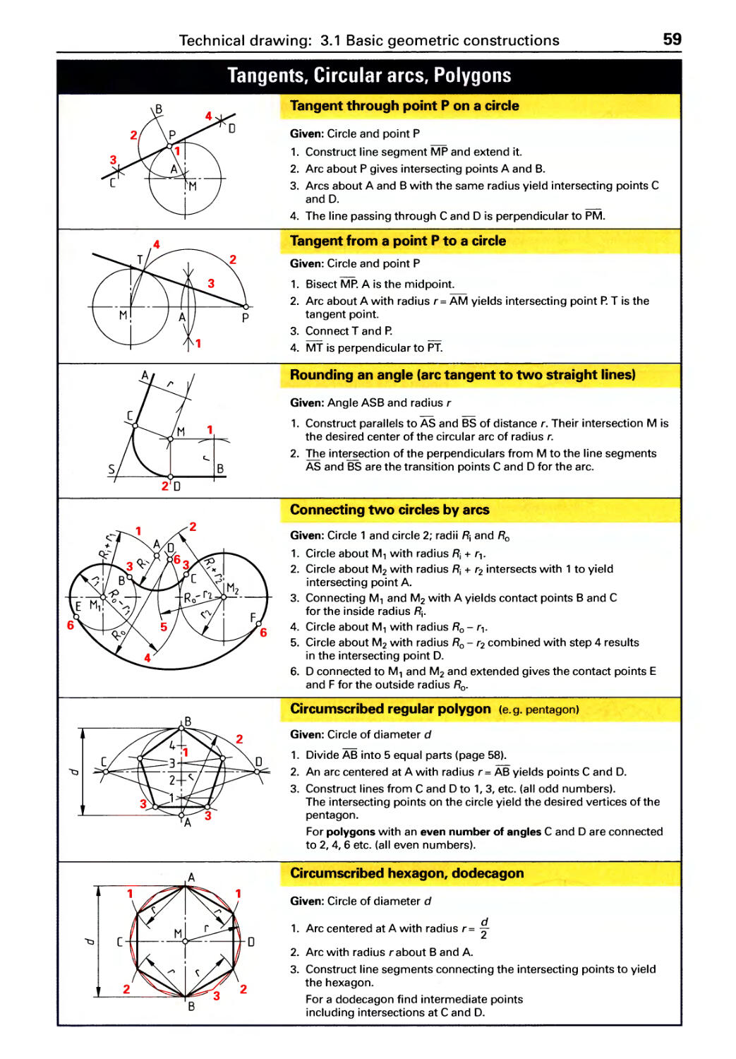
Tangents, Circular arcs, Polygons .... 59
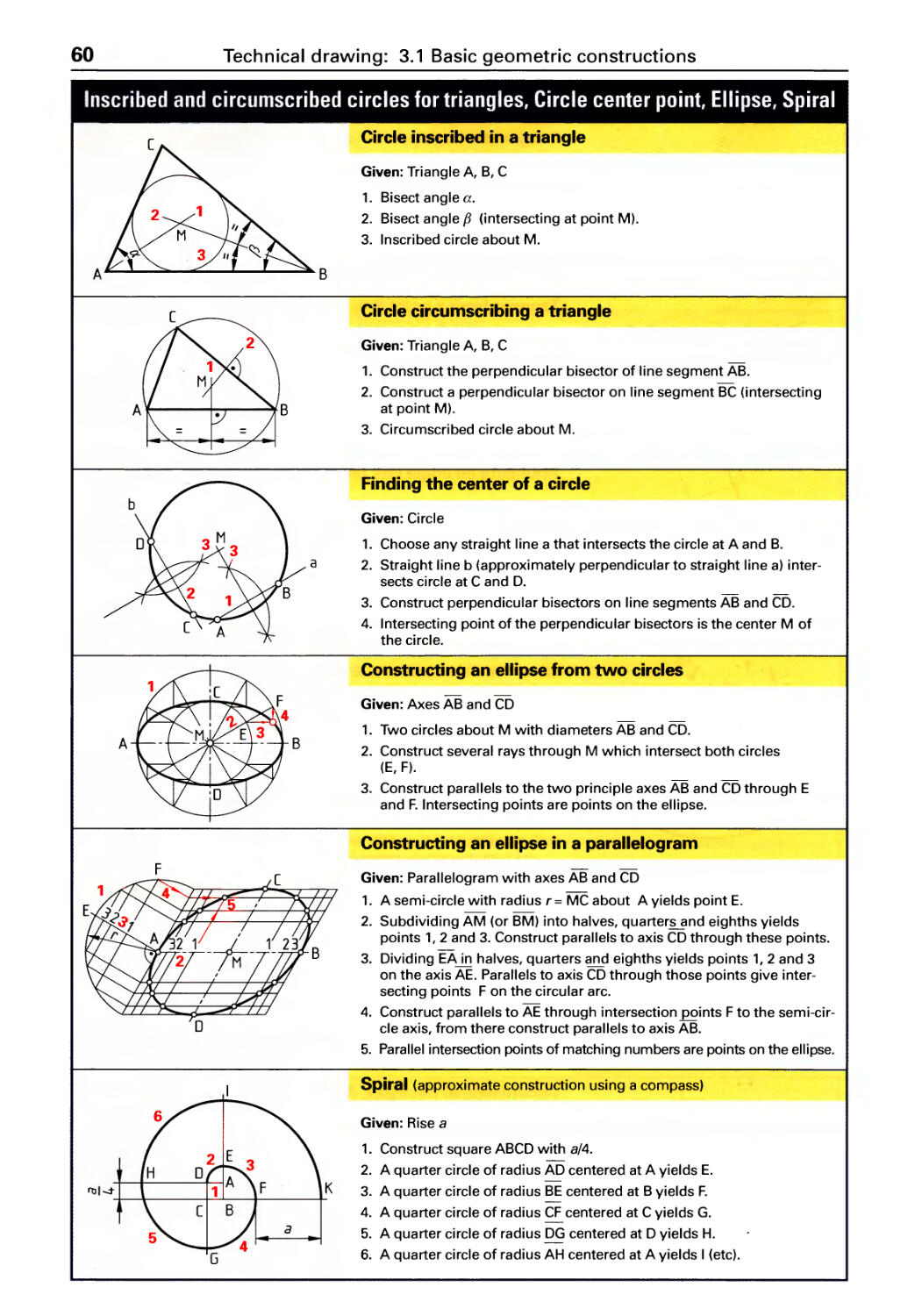
Inscribed circles, Ellipses, Spirals. . . . . 60
Cycloids, Involute curves, Parabolas . . 61
3.2 Graphs
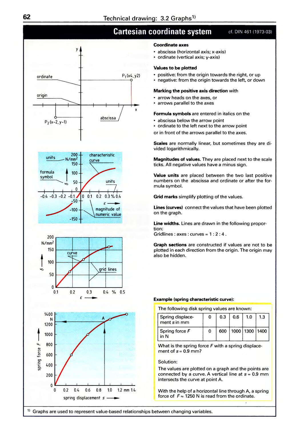
Cartesian coordinate system ........62
G ra ph types . . . . . . . . . . . . . . . . . . . . . . . 63
3.3 Drawing elements
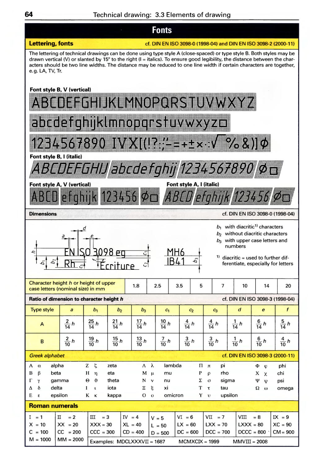
Fonts ............................ 64
Preferred numbers, Radii, Scales. . . . . 65
Drawing layout . . . . . . . . . . . . . . . . . . . . 66
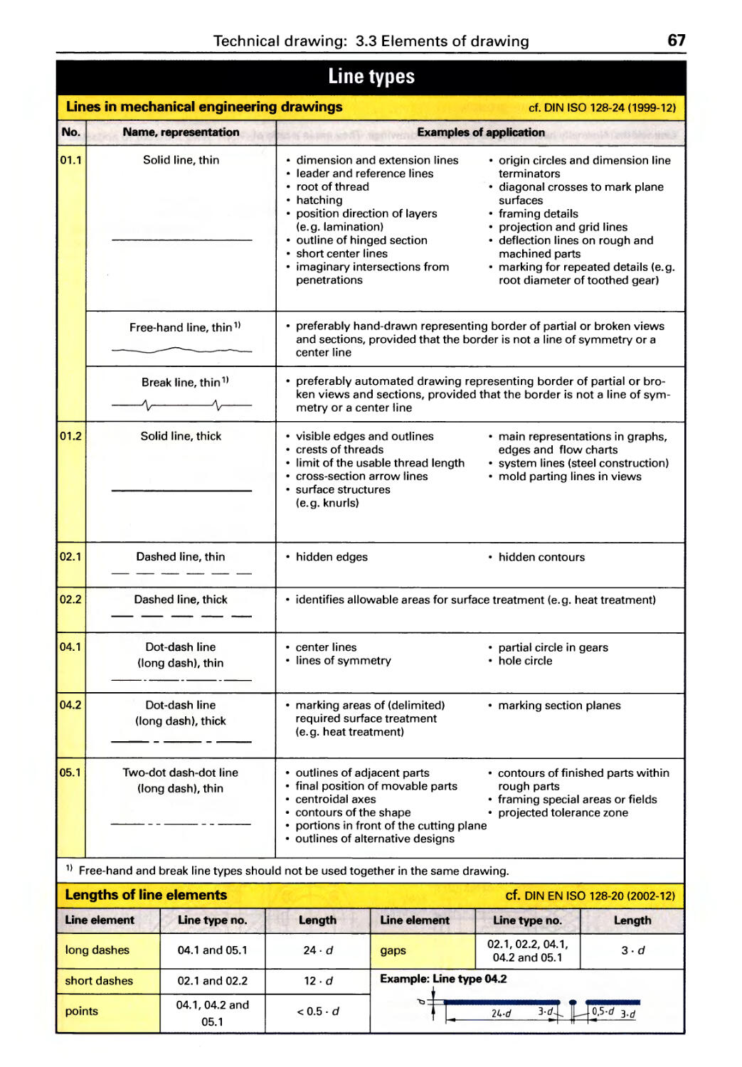
Li ne types ........................ 67
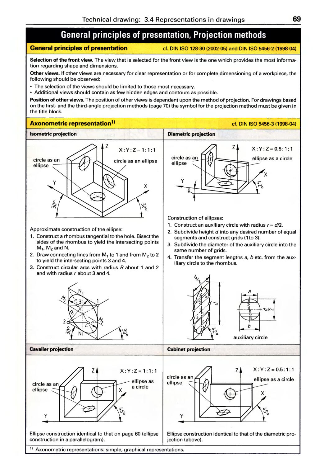
3.4 Representation
Projection methods ................ 69
Views ............................ 71
Sectional views. . . . . . . . . . . . . . . . . . . . 73
Hatching ......................... 75
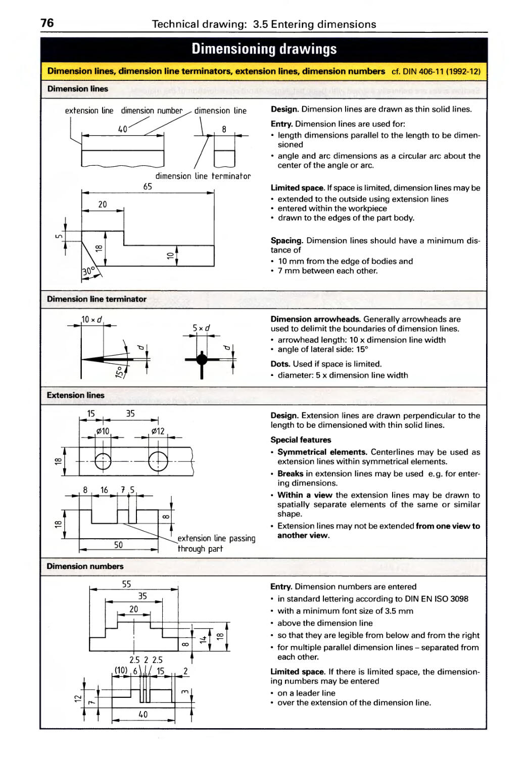
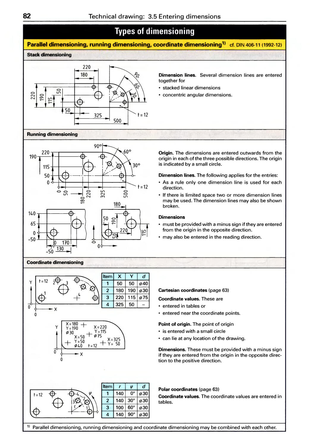
3.5 Entering dimensions
Dimensioning rules ................ 76
Diameters, Radii, Spheres, Chamfers,
Inclines, Tapers, Arc dimensions. . . . . 78
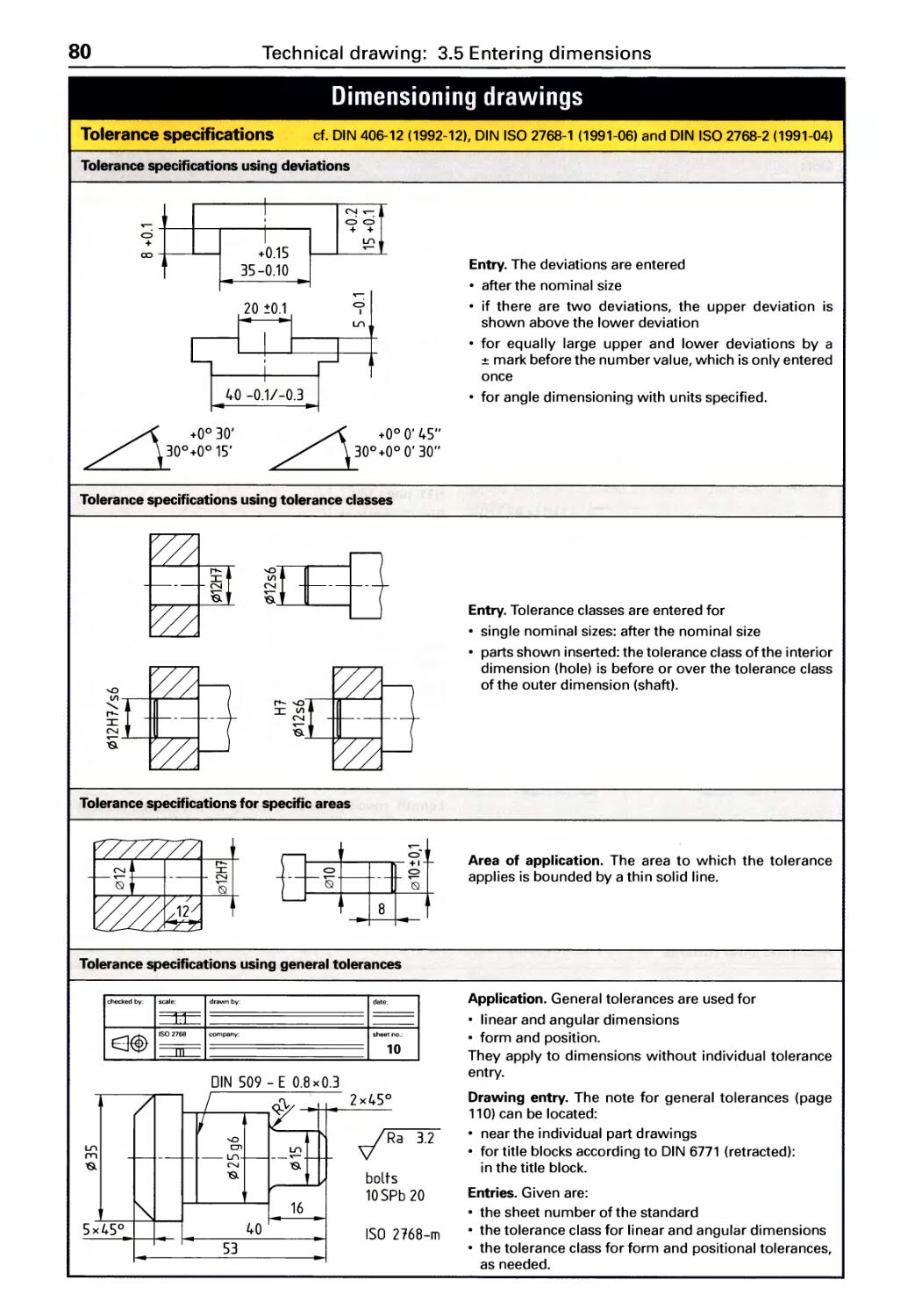
Tolerance specifications ............ 80
Types of dimensioning ............. 81
Simplified presentation in drawings .. 83
4 Materials science
4.1
Materials
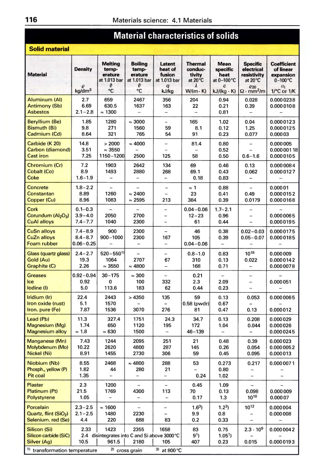
Material characteristics of solids .... 116
Material characteristics of liquids
and gases ....................... 117
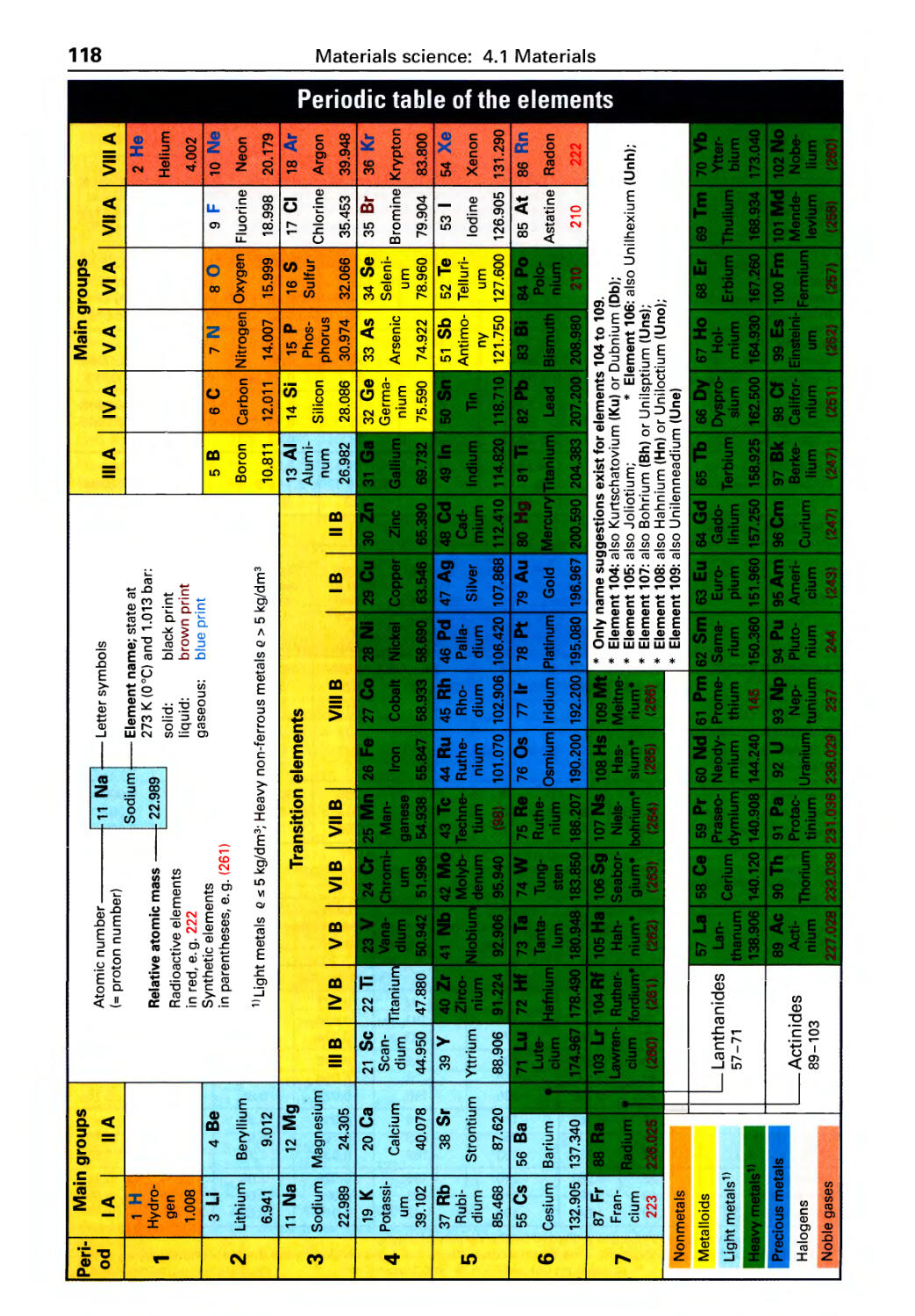
Periodic table of the elements ...... 118
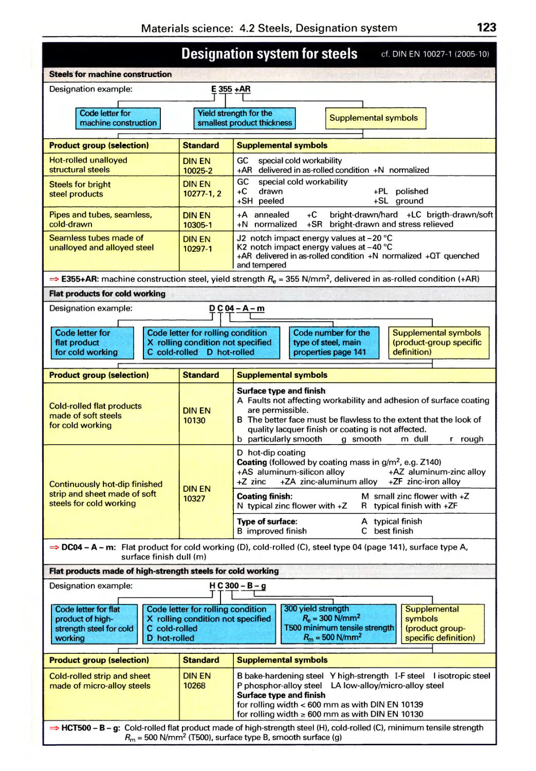
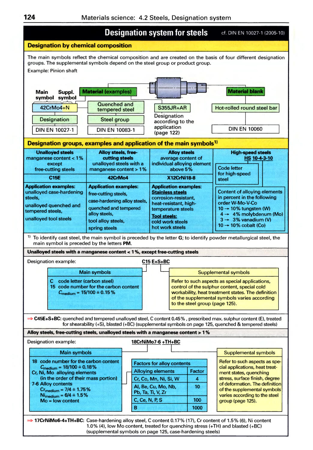
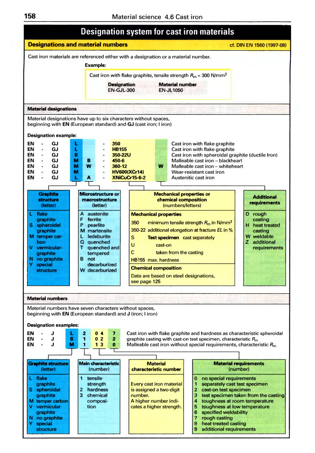
Designation system for steels
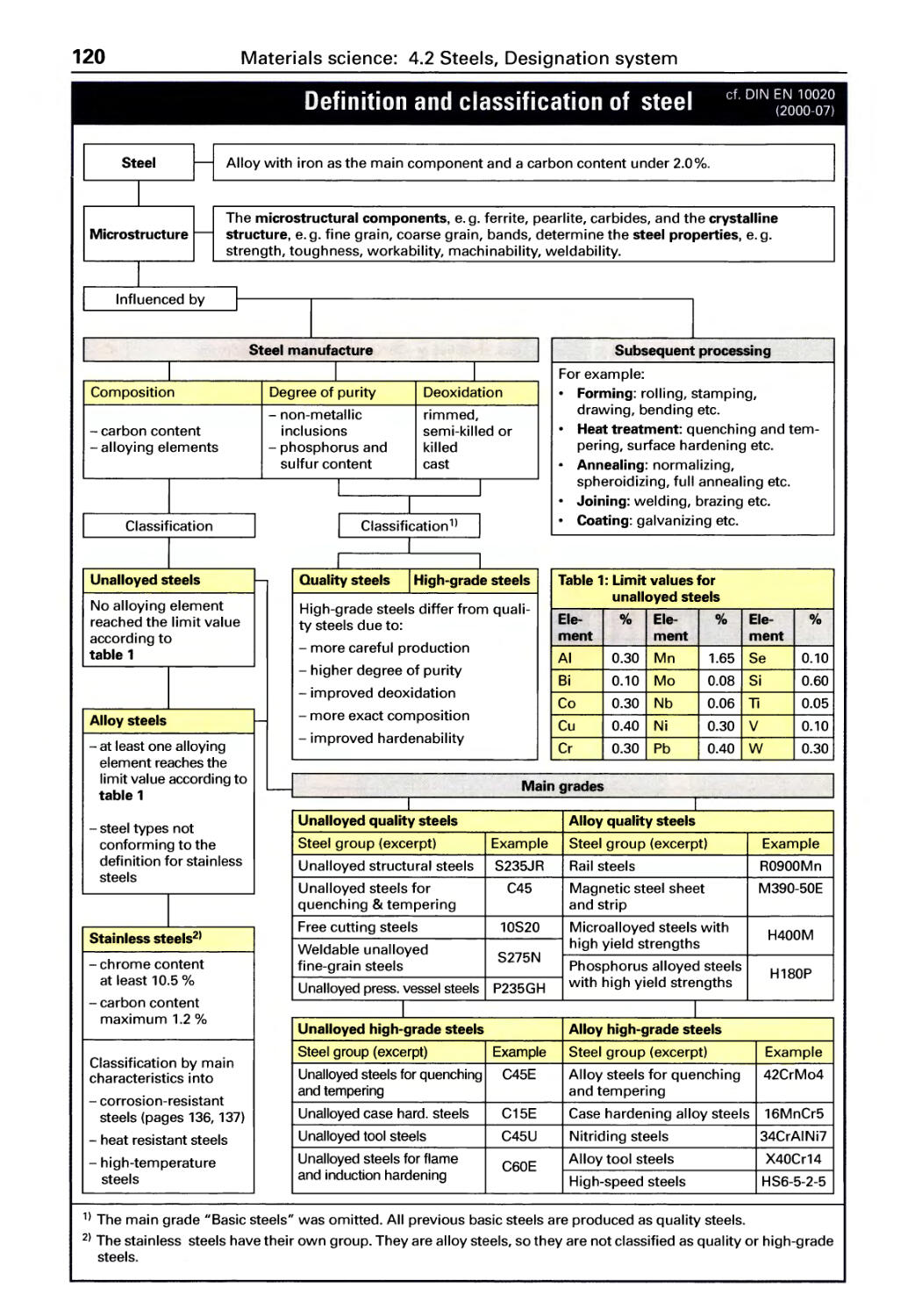
Definition and classification of steel . 120
Material codes, Designation ........ 121
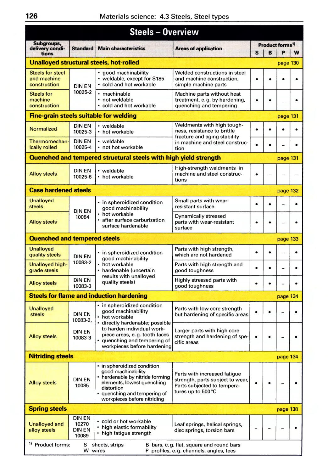
Steel types, Overview. . . . . . . . . . . 126
Structural steels .................. 128
Case hardened, quenched and tem-
pered, nitrided, free cutting steels ... 132
Tool steels ....................... 135
Stainless steels, Spring steels ...... 136
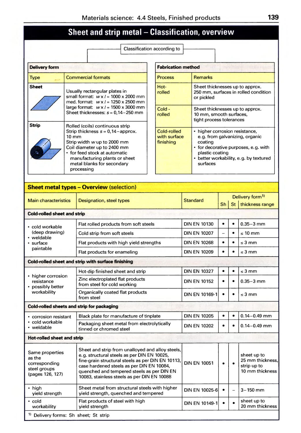
Finished steel products
Sheet, strip, pipes. . . . . . . . . . . . . . . . . 139
Profi I es . . . . . . . . . . . . . . . . . . . . . . . . . . 143
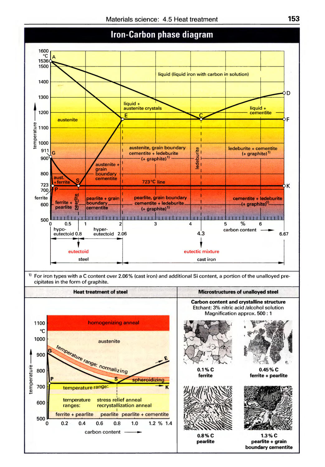
Heat treatment
Iron-Carbon phase diagram ........ 153
Processes................ ........154
Cast iron materials
Designation, Material codes ... . . . . . 158
Classification. . . . . . . . . . . . . . . . . . . . . 159
Cast iron ........................ 160
Malleable cast iron, Cast steel ...... 161
4.2
4.3
4.4
4.5
4.6
57
3.6 Machine elements
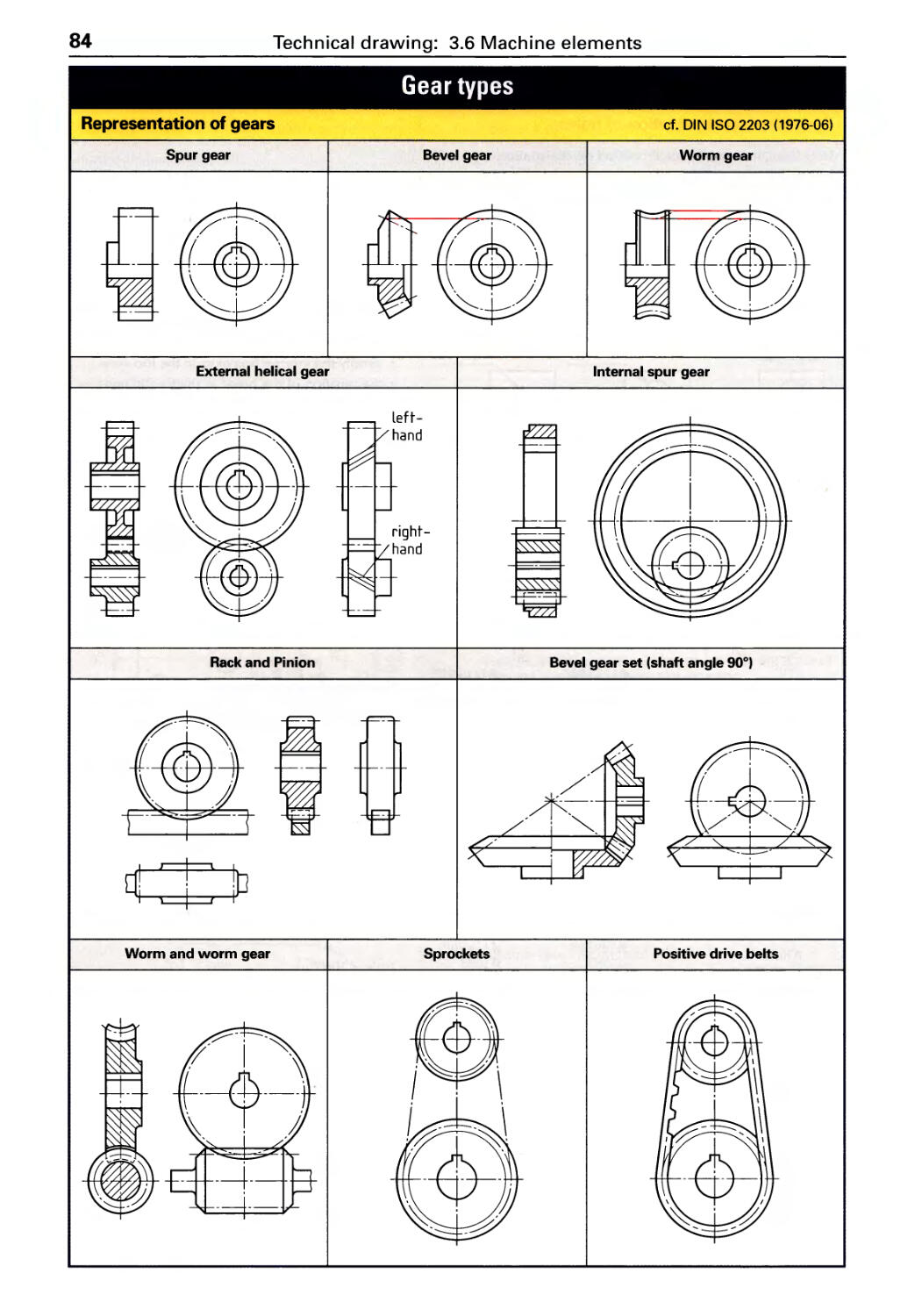
Gear types . . . . . . . . . . . . . . . . . . . . . . . . 84
Roller bearings .................... 85
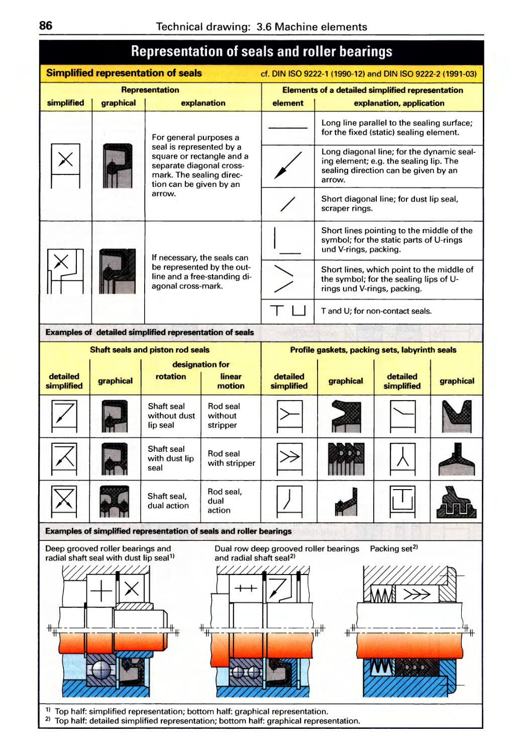
Seals. . . . . . . . . . . . . . . . . . . . . . . . . . . . . 86
Retaining rings, Springs ............ 87 .
3.7 Workpiece elements
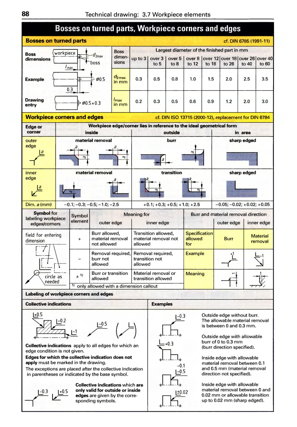
Bosses, Workpiece edges ........... 88
Thread runouts, Thread undercuts ...89
Threads, Screw joints .............. 90
Center holes, Knurls, Undercuts. . . . . .91
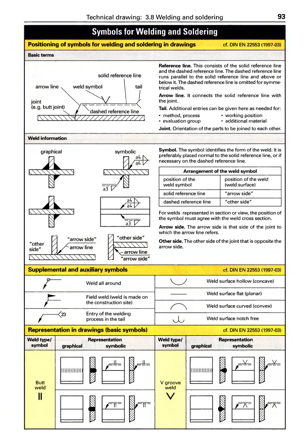
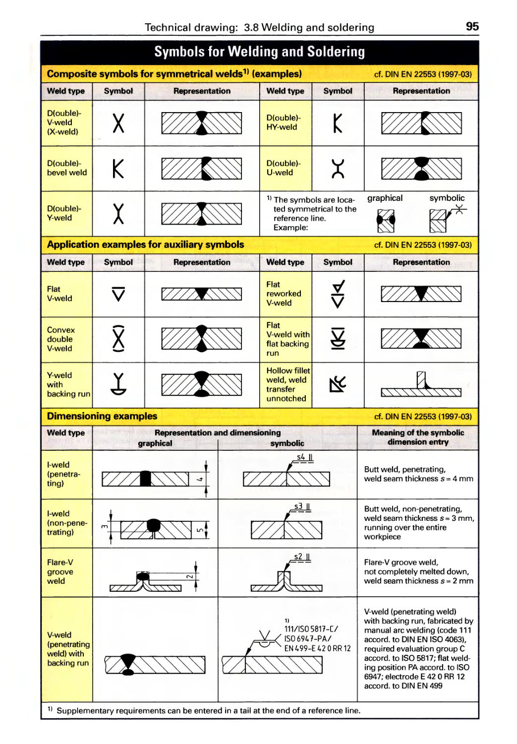
3.8 Welding and Soldering
Graphical symbols . . . . . . . . . . . . . . . . . 93
Dimensioning examples ............ 95
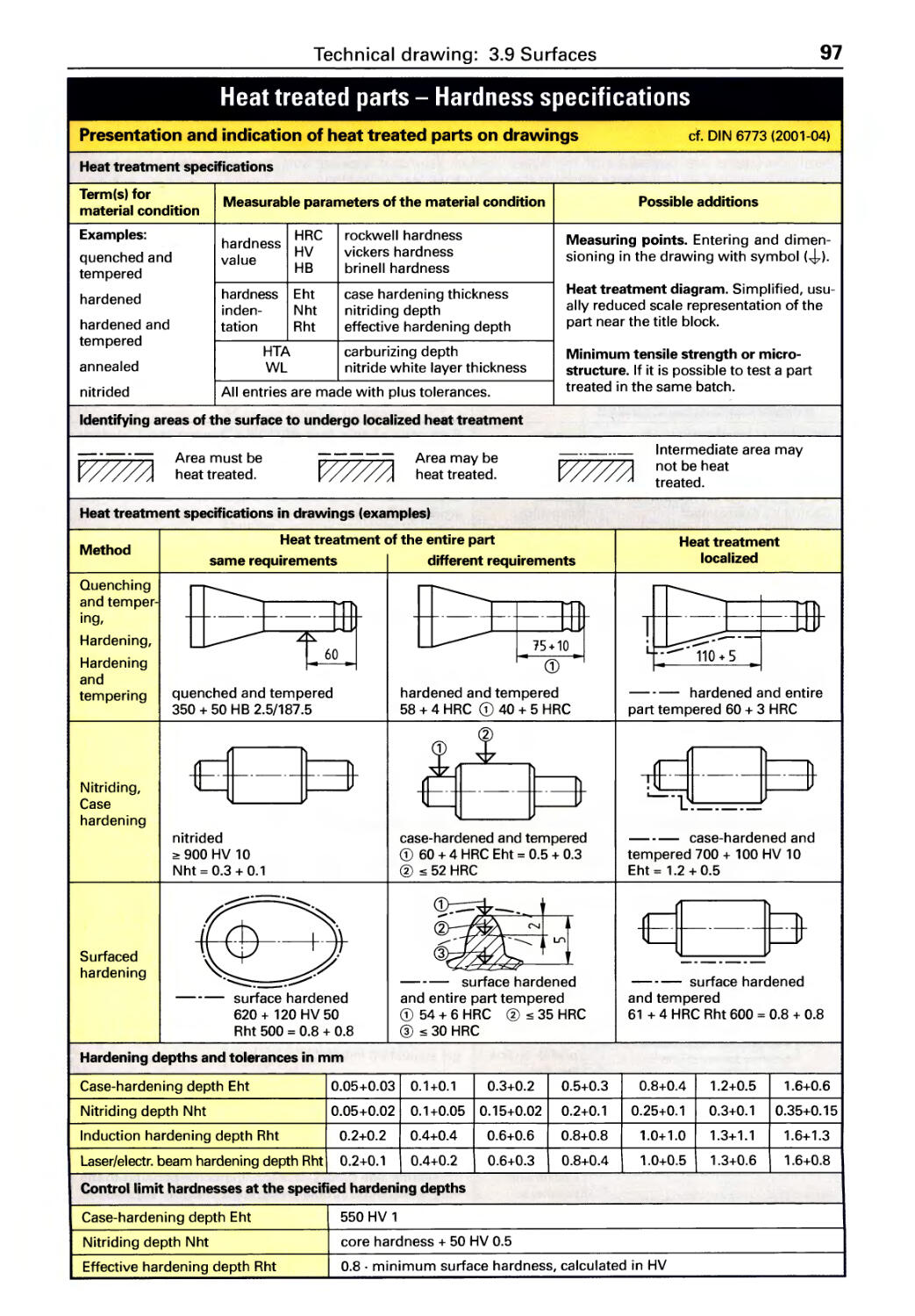
3.9 Surfaces
Hardness specifications in drawings . . 97
Form deviations, Roughness ........ 98
Surface testing, Surface indications .. 99
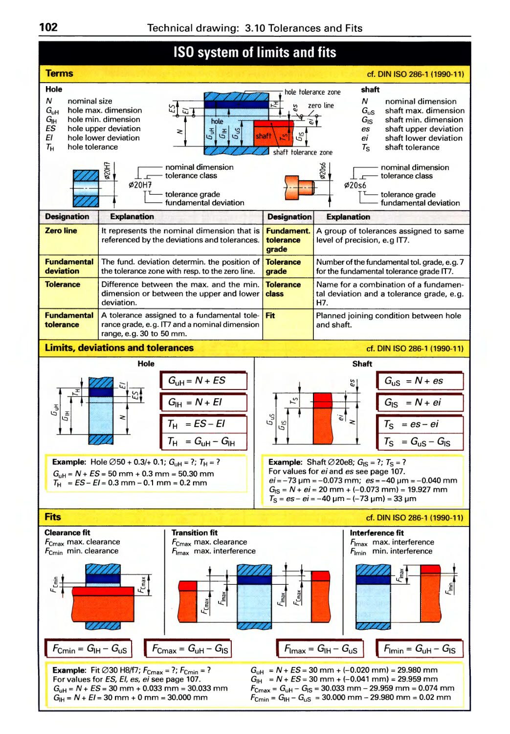
3.10 ISO Tolerances and Fits
Fundamentals. . . . . . . . . . . . . . . . . . . . 102
Basic hole and basic shaft systems .. 106
General Tolerances, Roller
bearing fits ..................... .110
Fit recommendations ............. .111
Geometric tolerancing ............ .112
GD & T (Geometric
Dimensioning & Tolerancing) ...... .113
115
4.7
Foundry technology
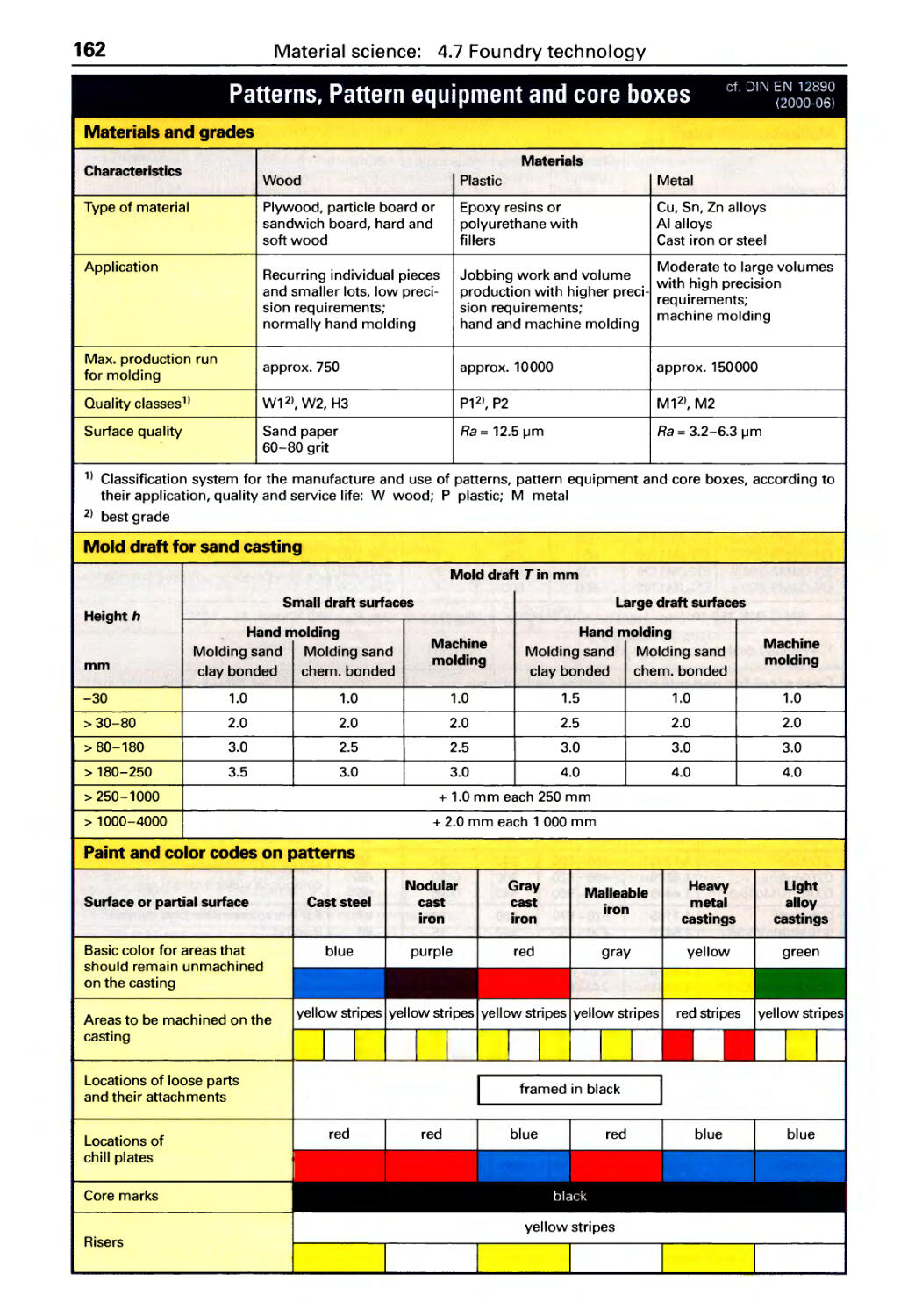
Patterns, Pattern equipment . . . . . . . . 162
Shrinkage allowances,
Dimensional tolerances. . . . . . . . . . . . 163
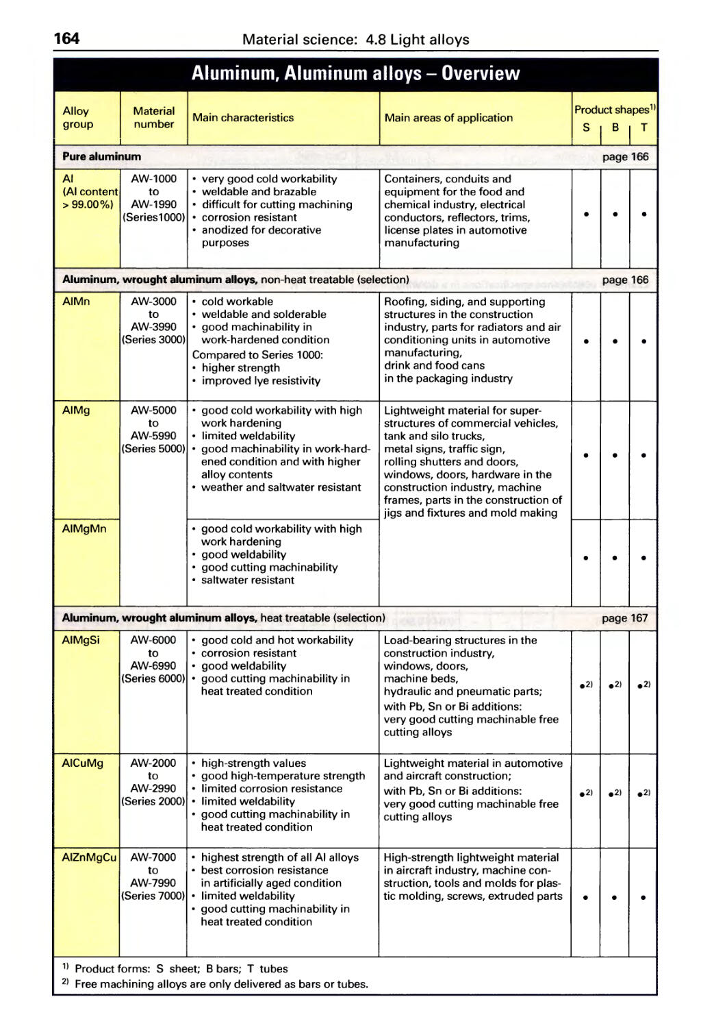
Light alloys, Overview of AI alloys . . 164
Wrought aluminum alloys ......... 166
Aluminum casting alloys. . . . . . . . . . . 168
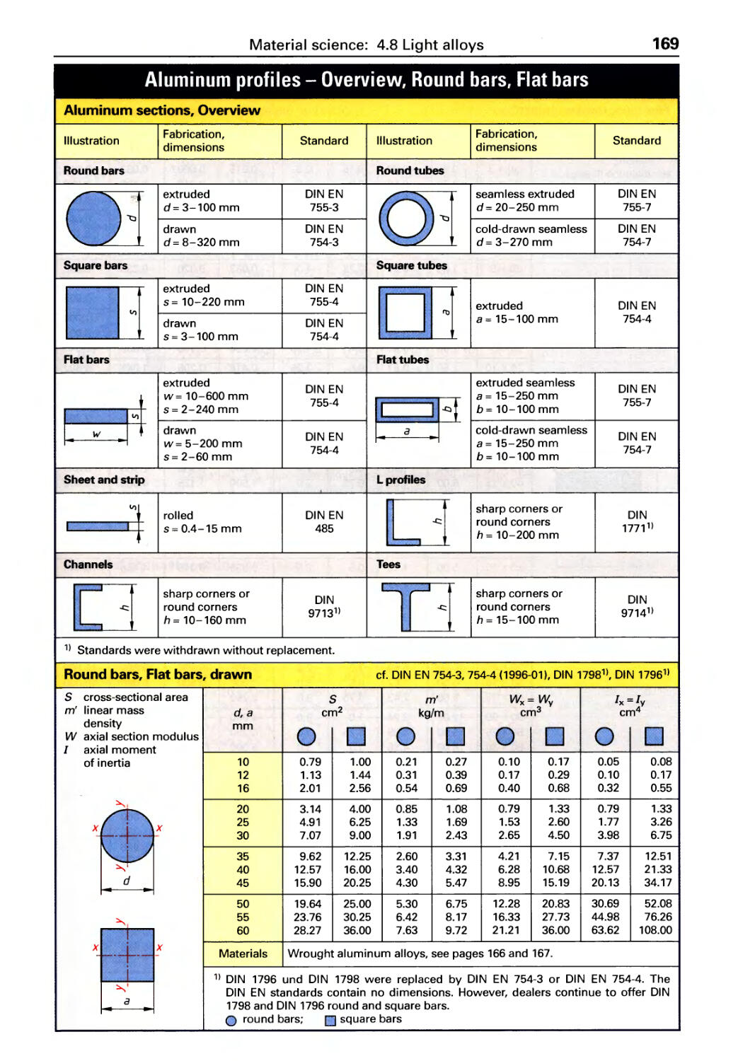
AI u m i n u m p rofi I es . . . . . . . . . . . . . . . . 169
Magnesium and titanium alloys. . . . . 172
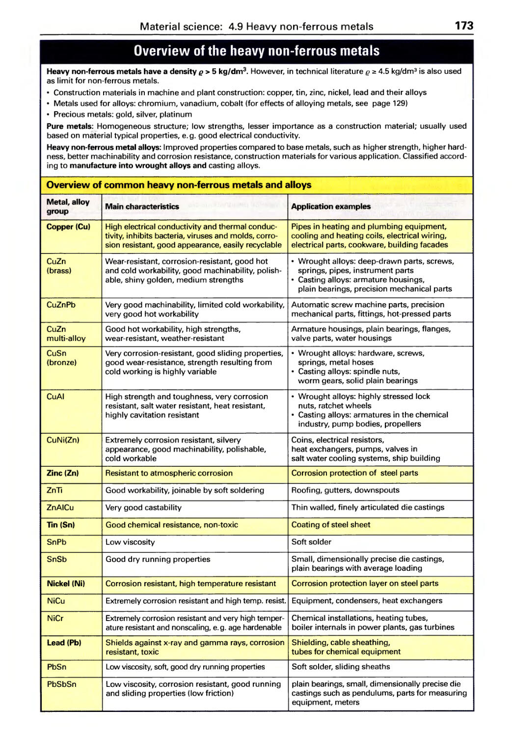
Heavy non-ferrous metals,
Overview . . . . . . . . . . . . . . . . . . . . . . . . 173
Designation system ............... 174
Copper alloys .................... 175
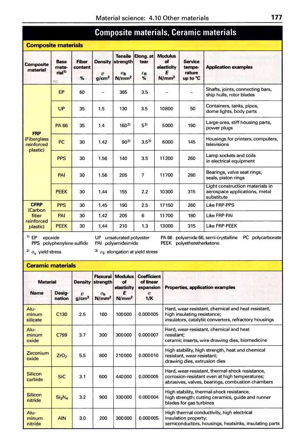
Other metallic materials
Composite materials,
Ceramic materials ................ 177
Sintered metals .................. 178
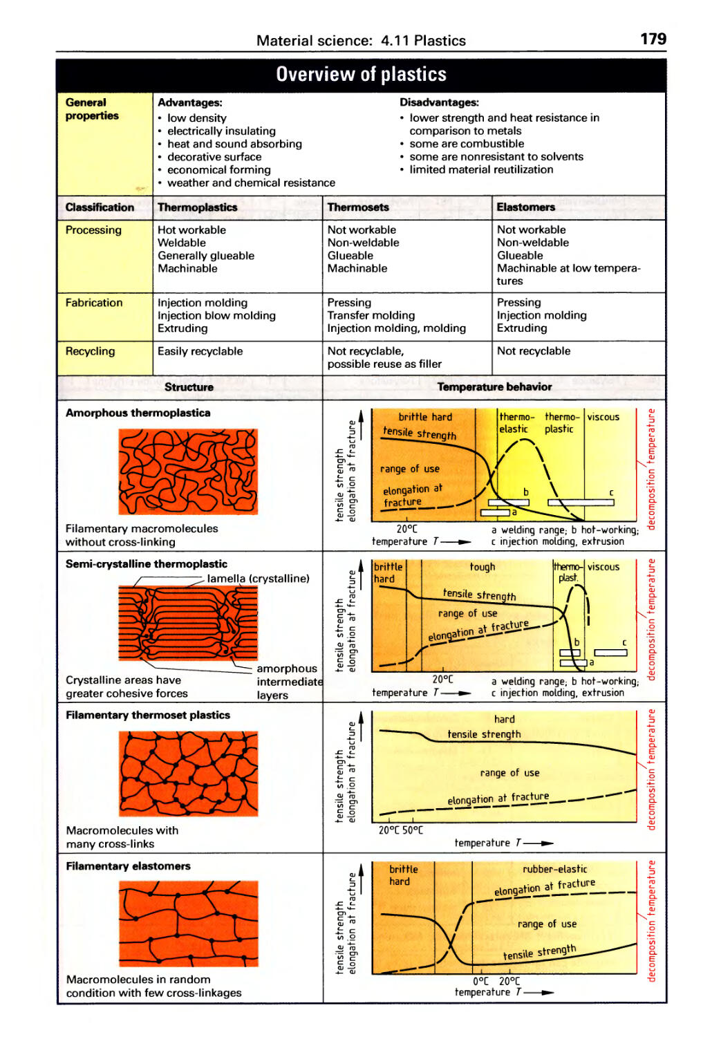
Plastics, Dve rvi ew . . . . . . . . . . . . . . 179
Thermoplastics . . . . . . . . . . . . . . . . . . . 182
Thermoset plastics, Elastomers. . . . . 184
Plastics processing. . . . . . . . . . . . . . . . 186
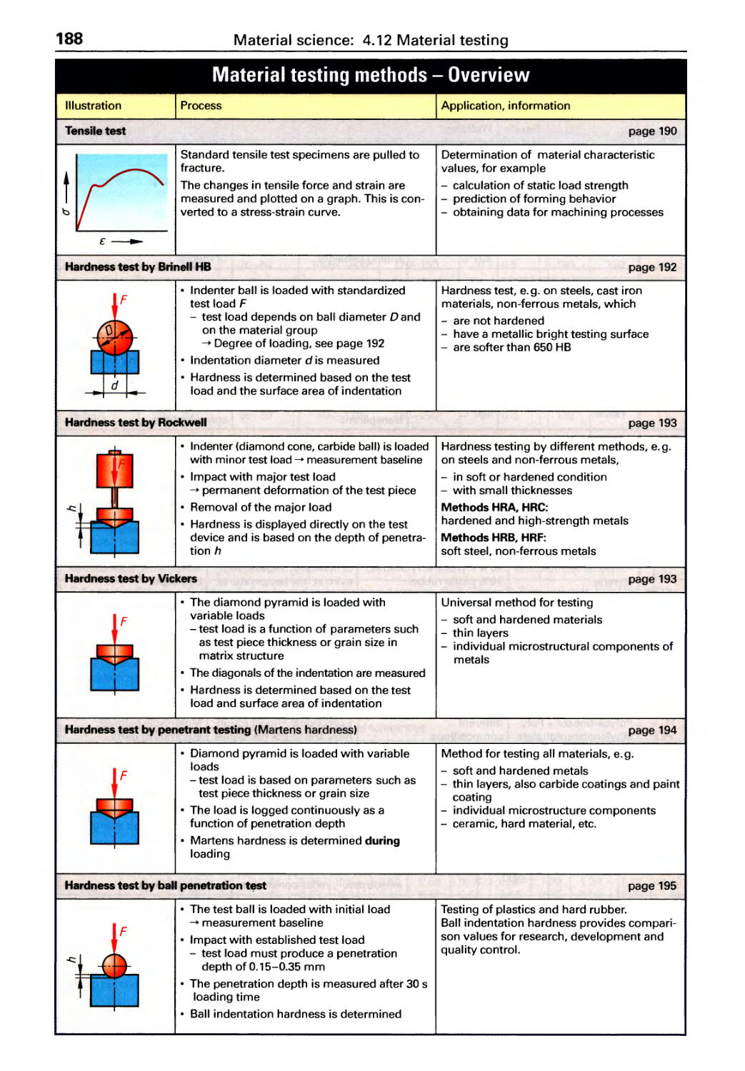
Material testing methods,
Dve rvi ew .................... 188
Tensile testing ....................190
Hardness test .................... 192
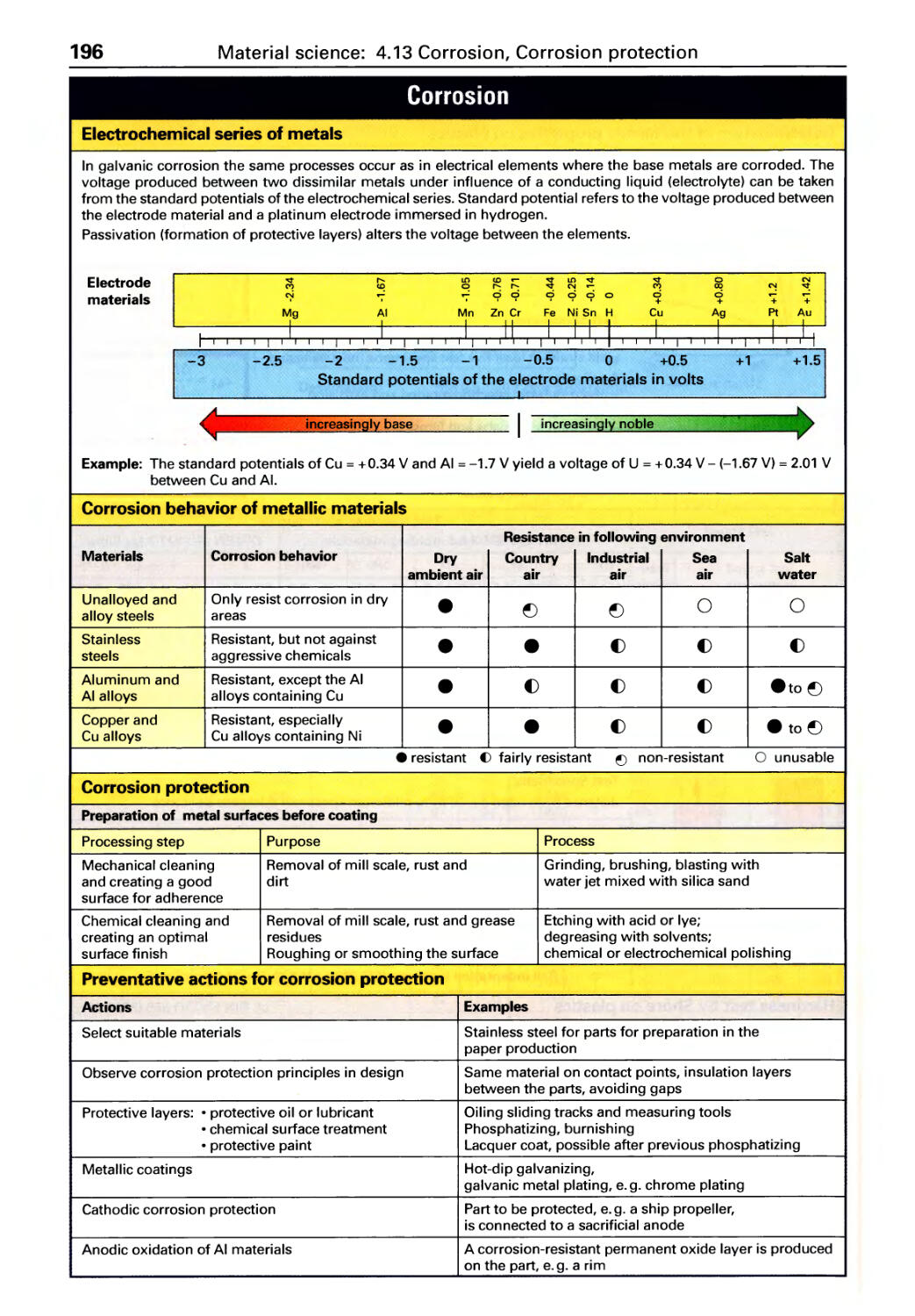
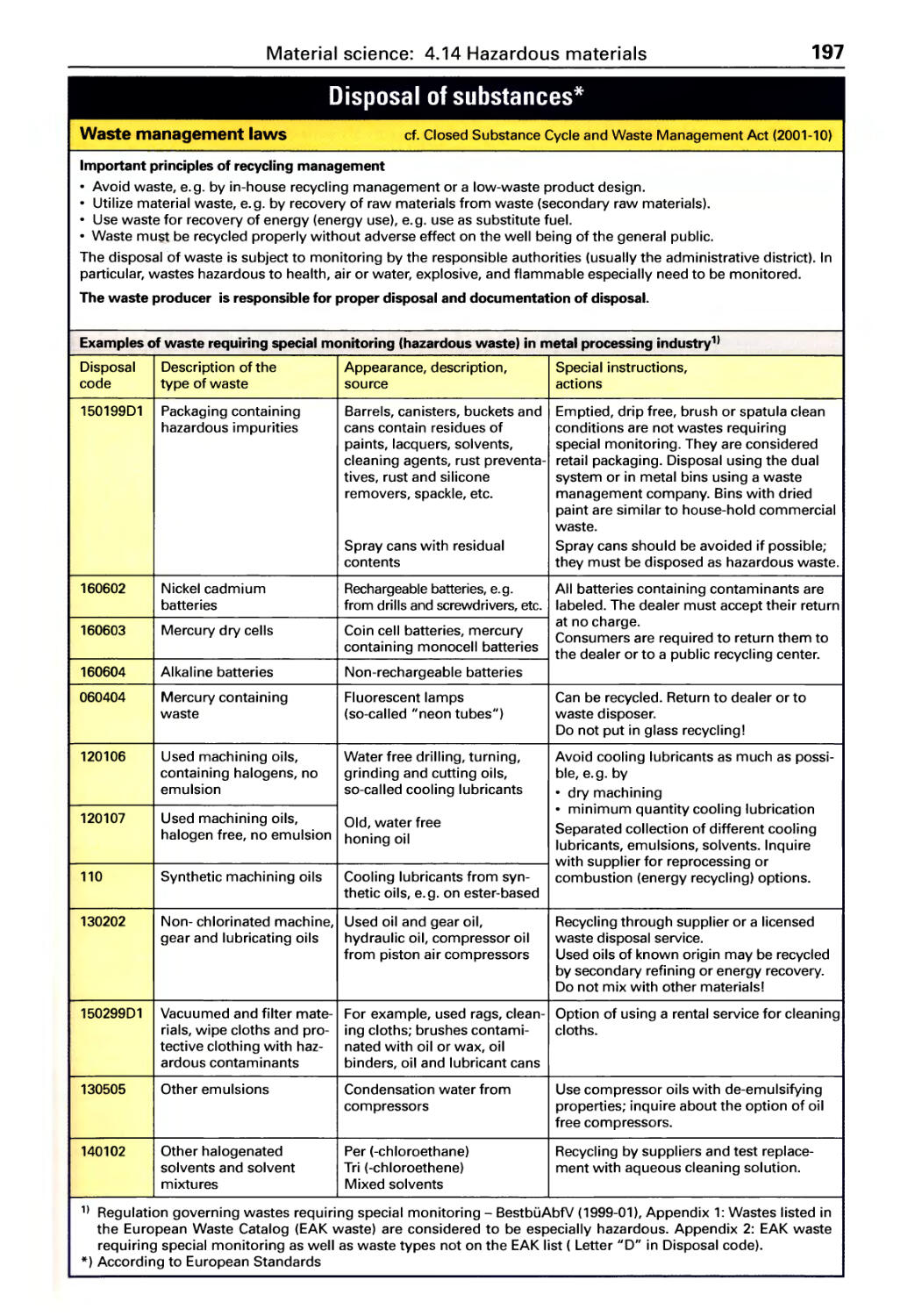
Corrosion, Corrosion protection .. 196
Hazardous materials . . . . . . . . . . . . 197
4.8
4.9
4.10
4.11
4.12
4.13
4.14
6
Table of Contents
5 Machine elements
5.1 Threads (overview) ............. 202
Metric ISO th reads . . . . . . . . . . . . . . . . 204
Whitworth threads, Pipe threads .... 206
Trapezoidal and buttress threads . . . . 207
Th read tolerances. . . . . . . . . . . . . . . . . 208
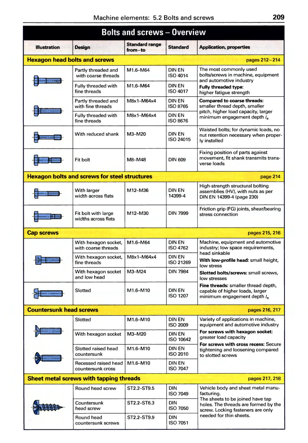
5.2 Bolts and screws (overview) ..... 209
Designations, strength. . . . . . . . . . . . . 210
Hexagon head bolts & screws. . .. ..212
Other bolts & screws .. . . . . . . . . . . . . 215
Screw joint calculations. . . . . . . . . . . . 221
Locking fasteners . . . . . . . . . . . . . . . . . 222
Widths across flats, Bolt and
screw drive systems .............. 223
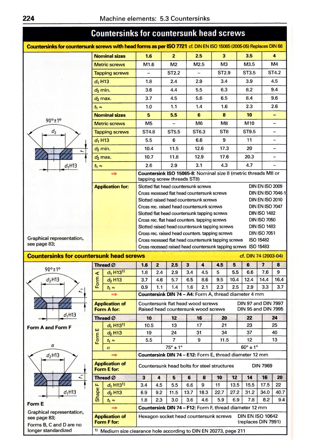
5.3 Countersinks.................. 224
Countersinks for countersunk
head screws ..................... 224
Counterbores for cap screws ....... 225
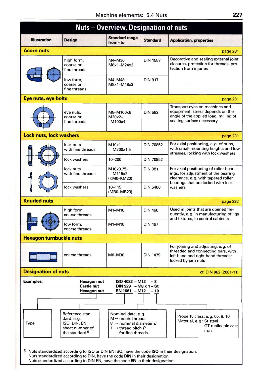
5.4 Nuts (overview) . . . . . . . . . . . . . . . . 226
Designations, Strength ............ 227
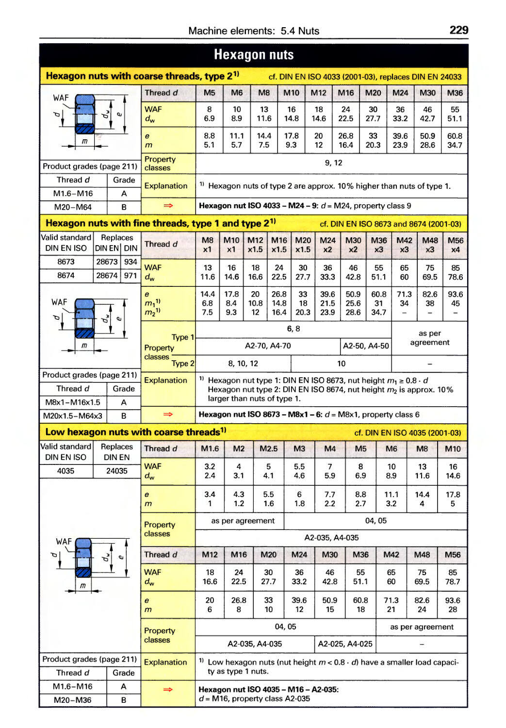
Hexagon nuts .................... 228
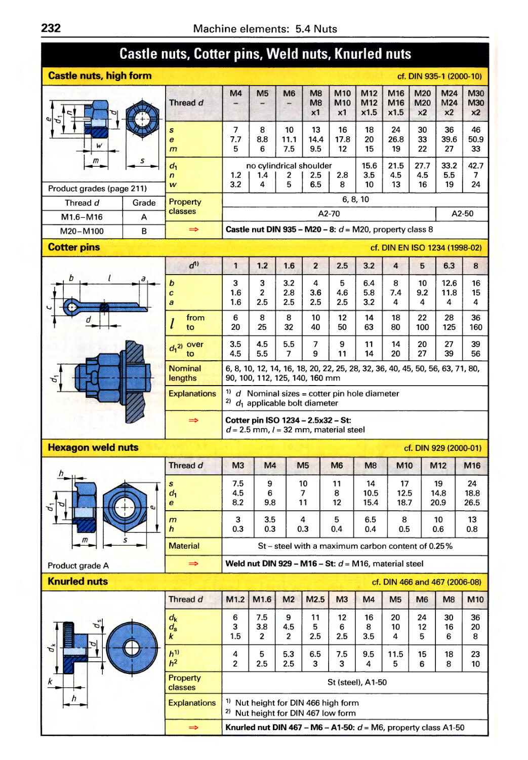
Other nuts ....................... 231
5.5 Washers (overview) ............ 233
Flat washers ..................... 234
HV, Clevis pin, Conical spring washers . 235
5.6 Pins and clevis pins (overview) ... 236
Dowel pins, Taper pins, Spring pins . 237
6 Production Engineering
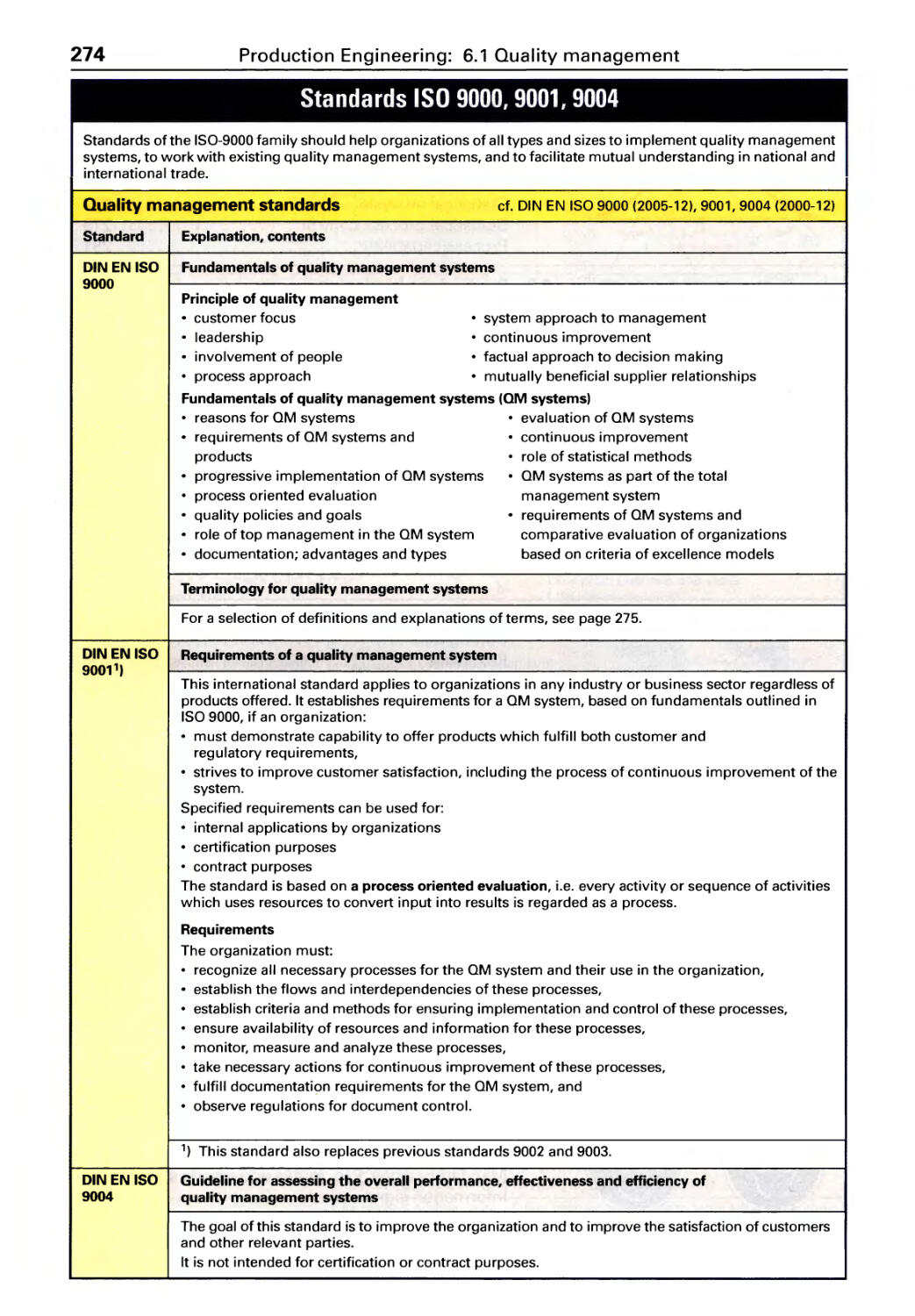
6.1 Quality management
Standards, Terminology ........... 274
Quality planning, Quality testing .... 276
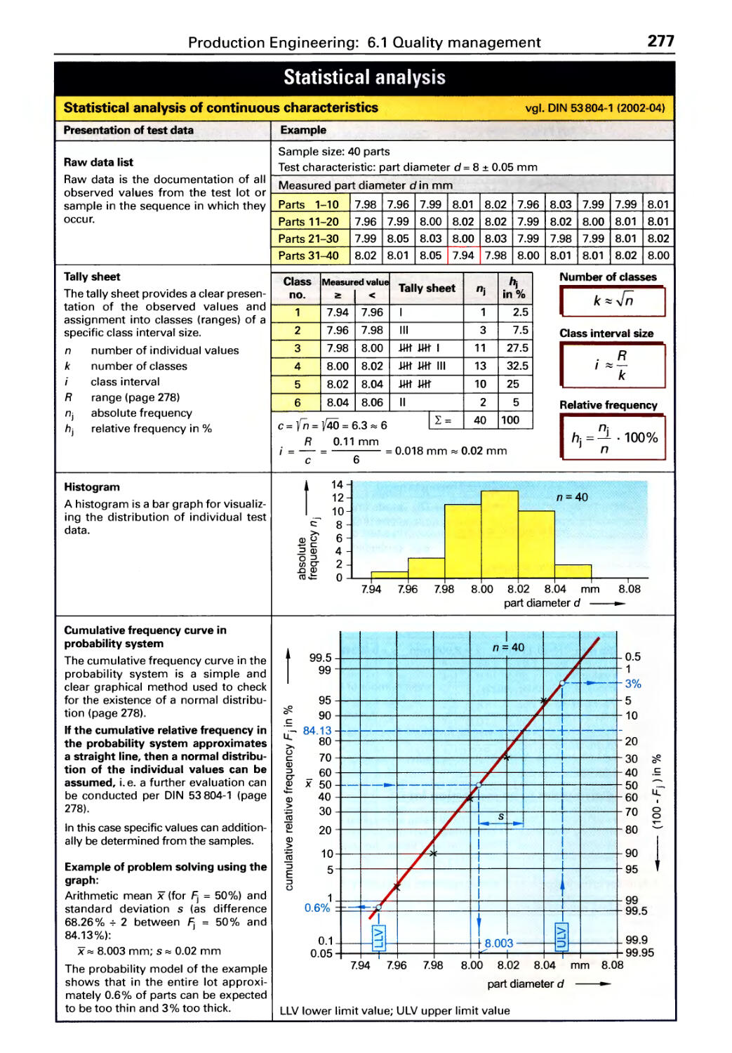
Statistical analysis ................ 277
Statistical process control . . . . . . . . . . 279
Process capability. . . . . . . . . . . . . . . . . 281
6.2 Production planning
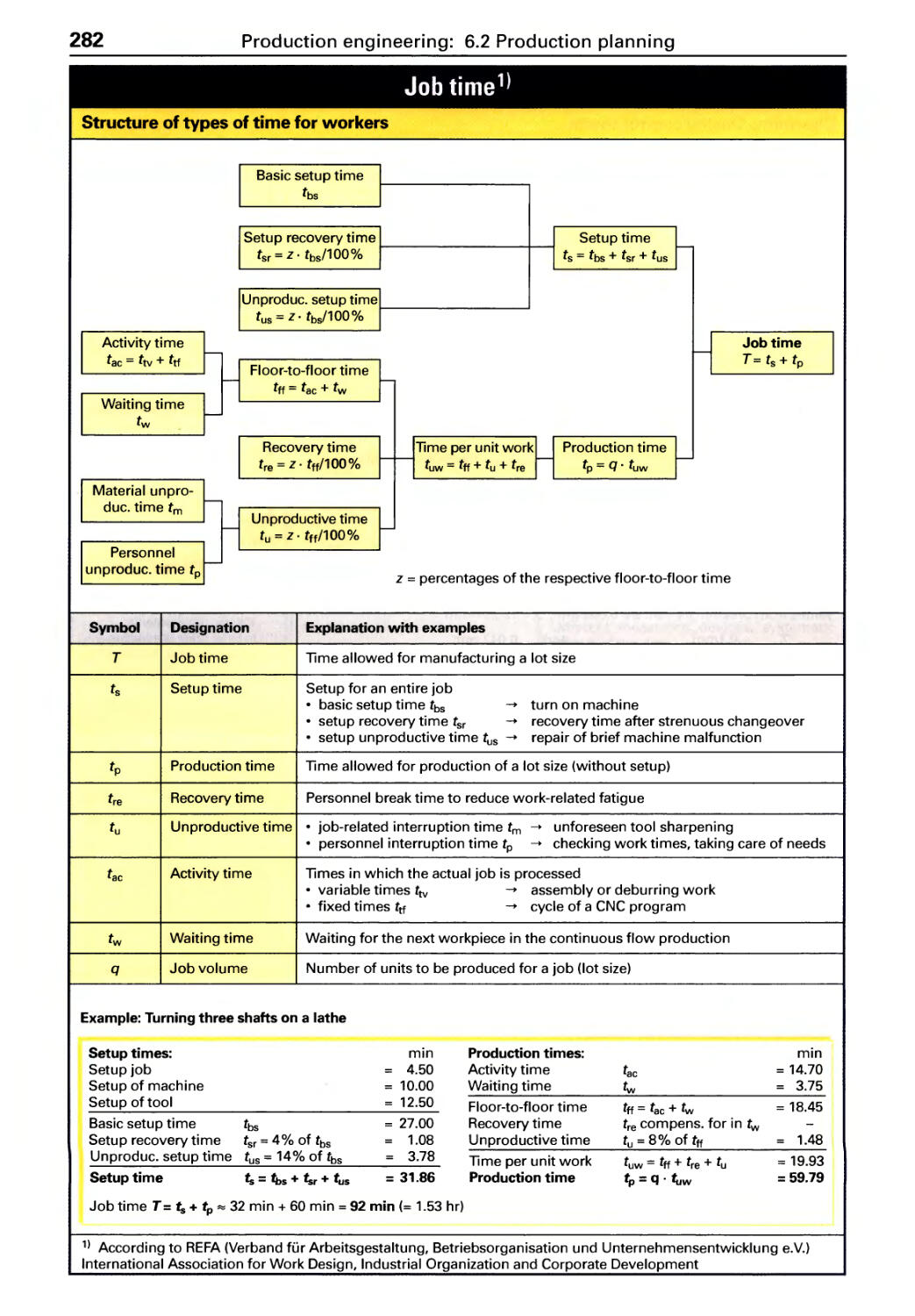
Time accounting according to REFA . 282
Cost accou nti ng .................. 284
Machine hourly rates. . . . . . . . . . . . . . 285
6.3 Machining processes
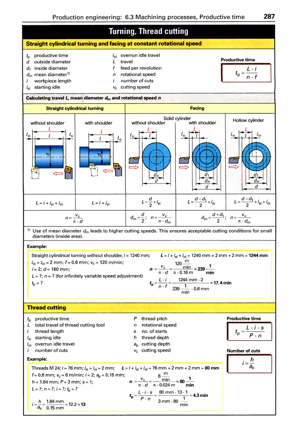
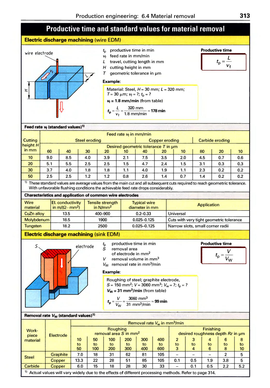
Productive time .................. 287
Machining coolants ............... 292
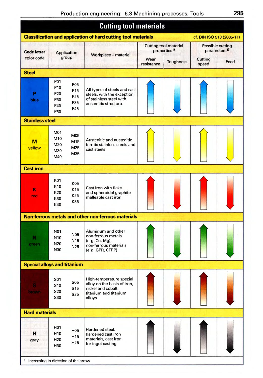
Cutting tool materials, Inserts,
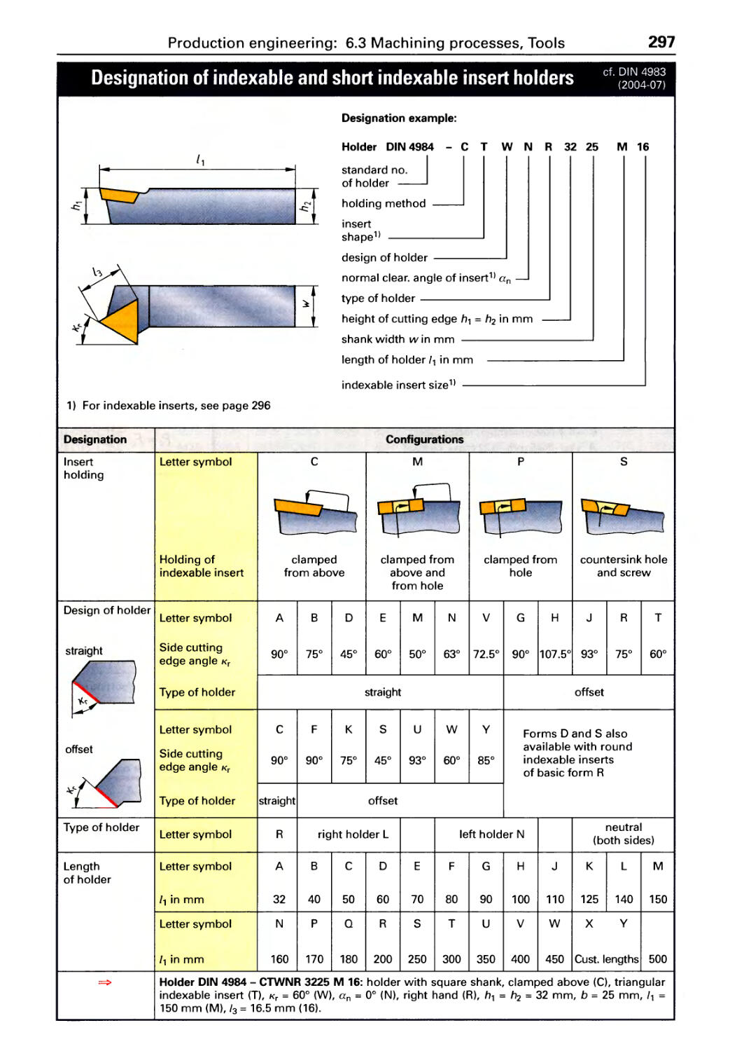
Tool holders ..................... 294
Forces and power. . . . . . . . . . . . . . . . . 298
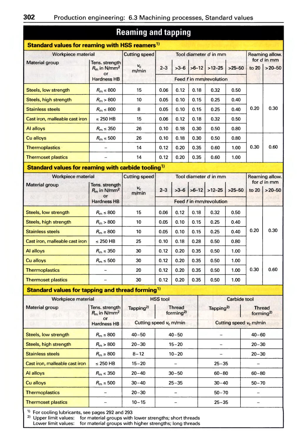
Cutting data: Drilling, Reaming,
Turn i n g . . . . . . . . . . . . . . . . . . . . . . . . . . 301
Cutting data: Taper turning .. . . . . . . . 304
Cutting data: Milling. . . . . . . . . . . . . . . 305
Indexing. . . . . . . . . . . . . . . . . . . . . . . . . 307
Cutting data: Grinding and honing .. 308
6.4 Material removal
Cutting data...................... 313
Processes . . . . . . . . . . . . . . . . . . . . . . . . 314
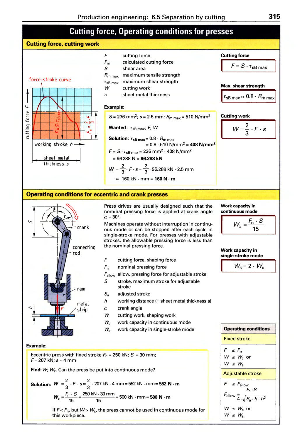
6.5 Separation by cutting
Cutting forces.. . . . ... .. . .. ..... . .315
201
Grooved pins, Grooved drive studs,
Clevis pins . . . . . . . . . . . . . . . . . . . . . . . 238
5.7 Shaft-hub connections
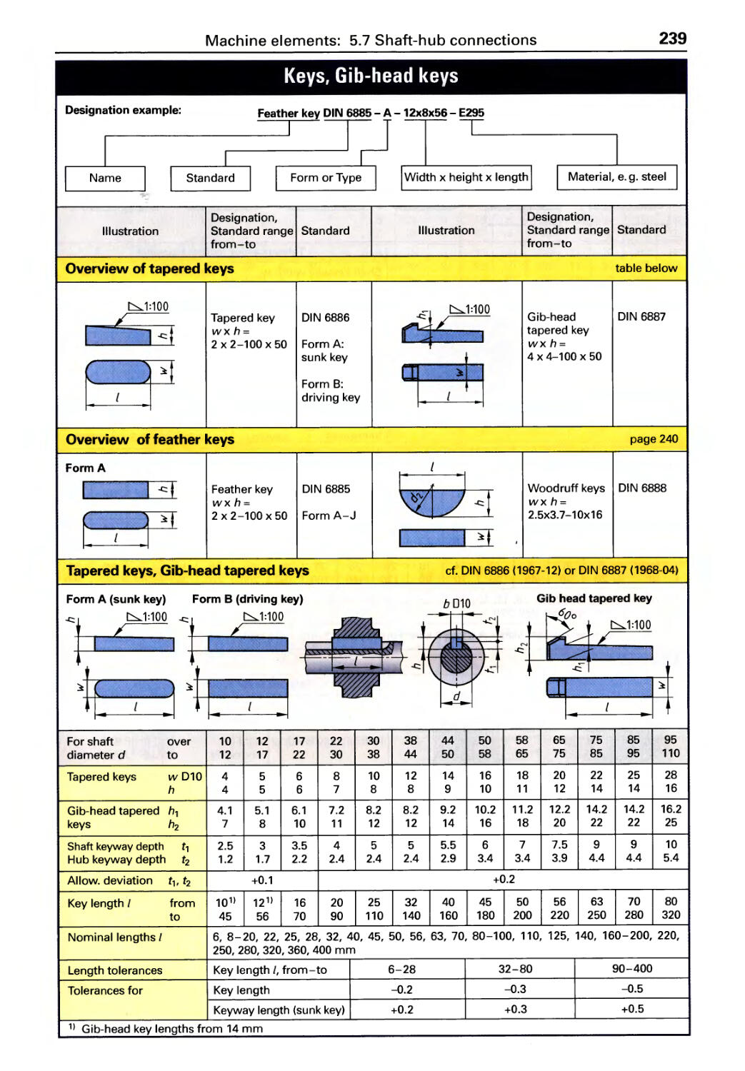
Tapered and feather keys .......... 239
Parallel and woodruff keys ......... 240
Splined shafts, Blind rivets ......... 241
Tool tapers. . . . . . . . . . . . . . . . . . . . . . . 242
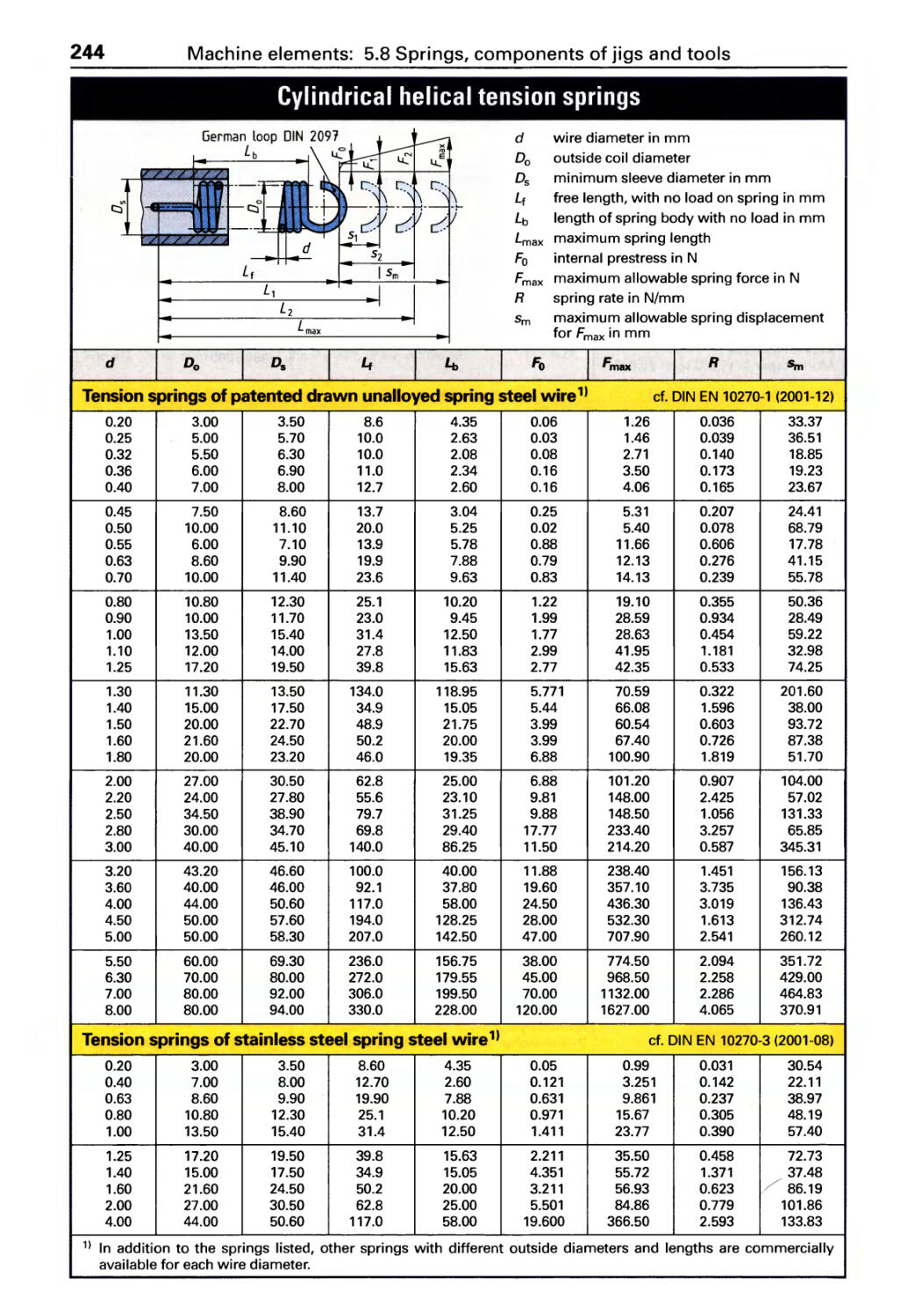
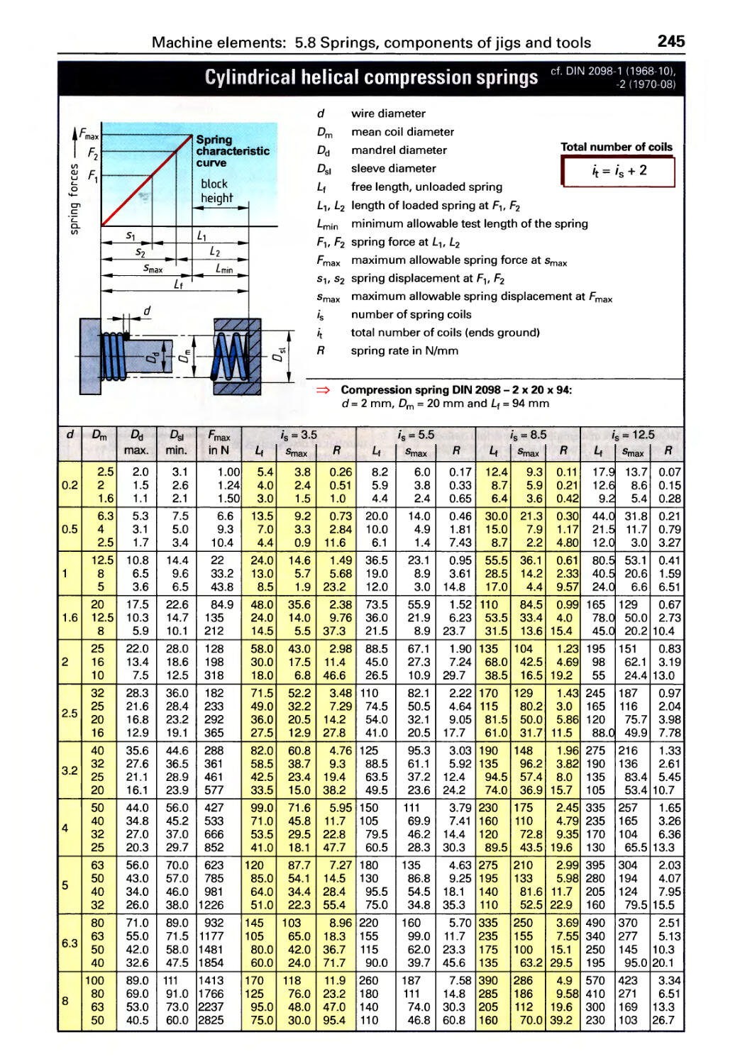
5.8 Springs, components of jigs
and tools
Springs ......................... 244
Drill bushings .................... 247
Standard stamping parts. . . . . . . . . . . 251
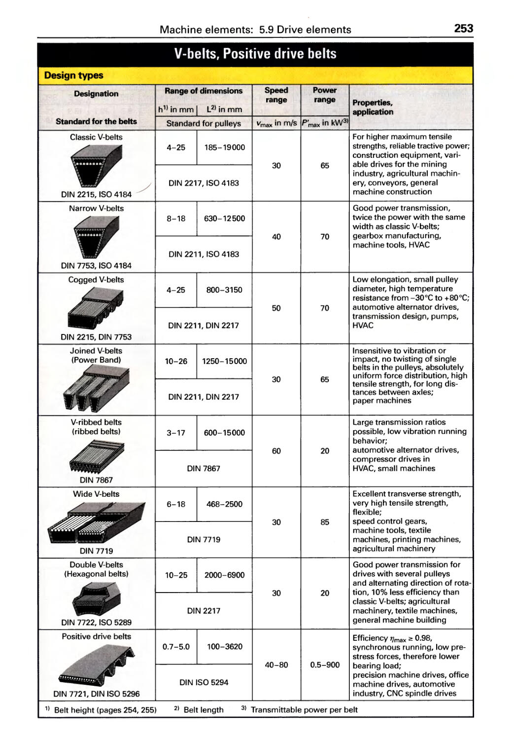
5.9 Drive elements
Belts . . . . . . . . . . . . . . . . . . . . . . . . . . . . 253
Gears ........................... 256
Transmission ratios ............... 259
Speed graph ..................... 260
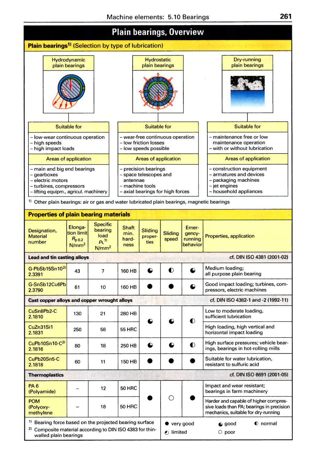
5.10 Bearings
Plain bearings (overview) .......... 261
Plain bearing bushings ............ 262
Antifriction bearings (overview) . . . . . 263
Types of roller bearings. . . . . . . . . . . . 265
Retaining rings ................... 269
Sealing elements ................. 270
Lubricating oils . . . . . . . . . . . . . . . . . . . 271
Lubricating greases ............... 272
273
Shearing ........................316
Location of punch holder shank. . . . . 317
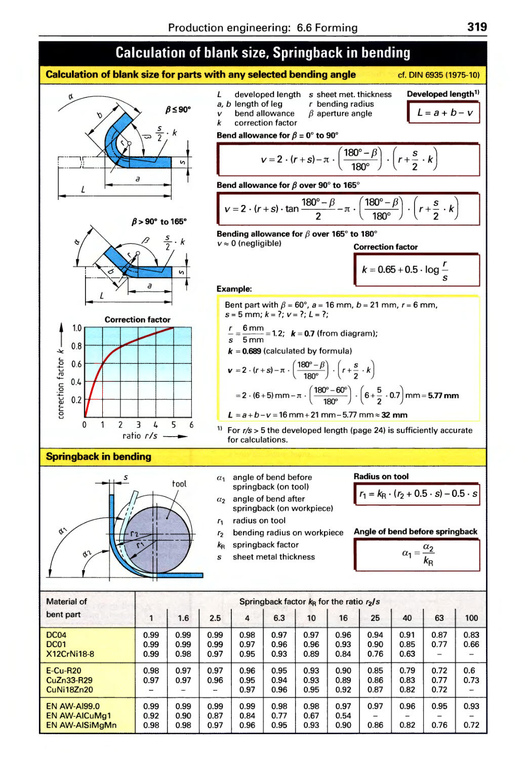
6.6 Forming
Bending ......................... 318
Deep drawing .................... 320
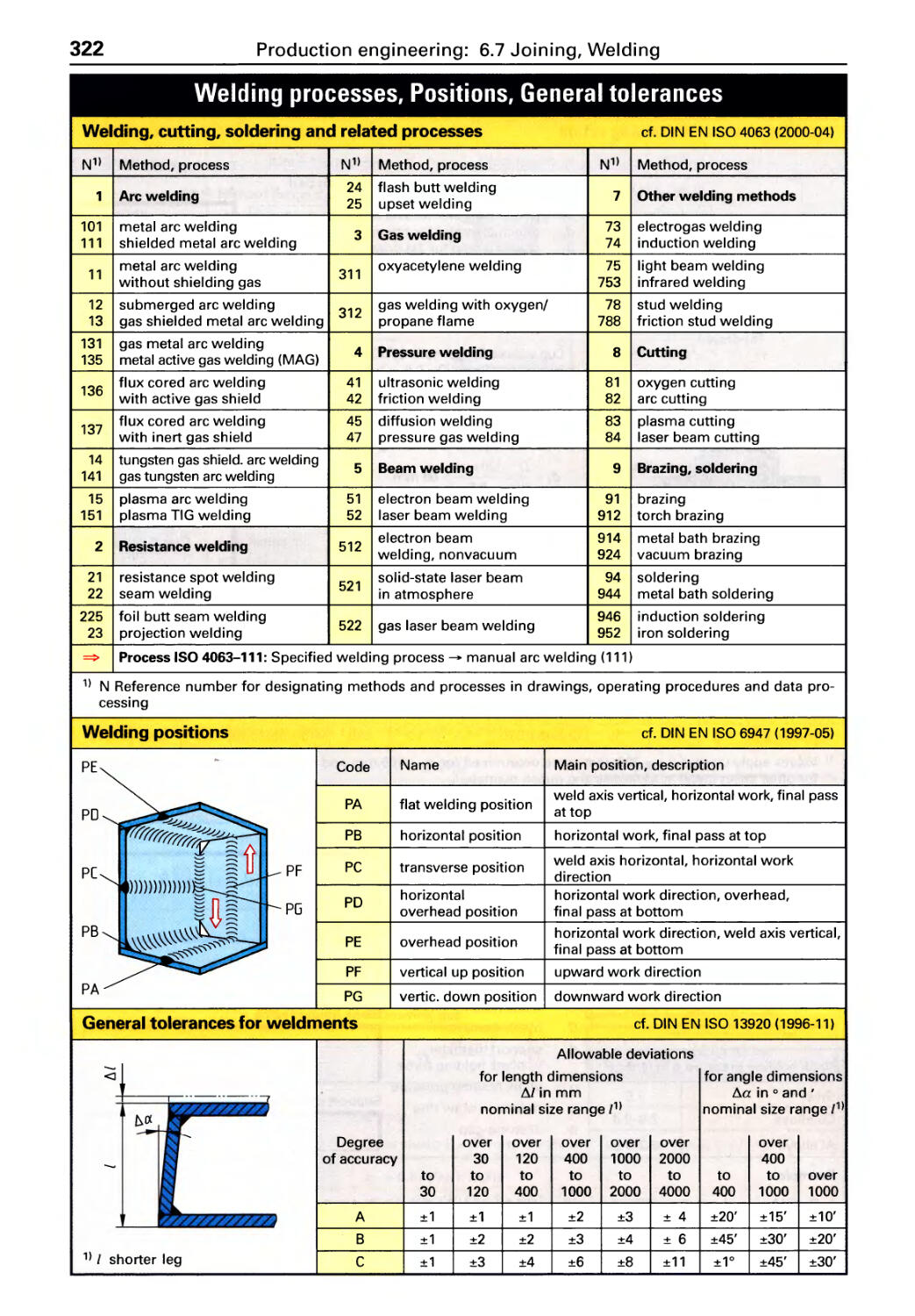
6.7 Joining
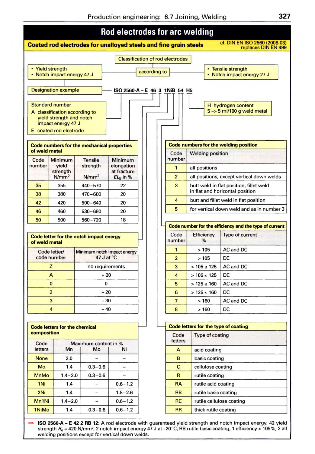
Welding processes. . . . . . . . . . . . . . . . 322
Weld preparation ................. 323
Gas welding ..................... 324
Gas shielded metal arc welding . . . . . 325
Arc welding . . . . . . . . . . . . . . . . . . . . . . 327
Thermal cutting .................. 329
Identification of gas cylinders. . . . . . . 331
Soldering and brazing ............. 333
Adhesive bonding ................ 336
6.8 Workplace safety and environmental
protection
Prohibitive signs. . . . . . . . . . . . . . . . . . 338
Warning signs. . . . . . . . . . . . . . . . . . . . 339
Mandatory signs,
Escape routes and rescue signs . . . . . 340
Information signs . . . . . . . . . . . . . . . . . 341
Danger symbols. . . . . . . . . . . . . . . . . .342
Identification of pipe lines. . . . . . . . . . 343
Sound and noise ................. 344
Table of Contents
7
345
7 Automation and Information Technology
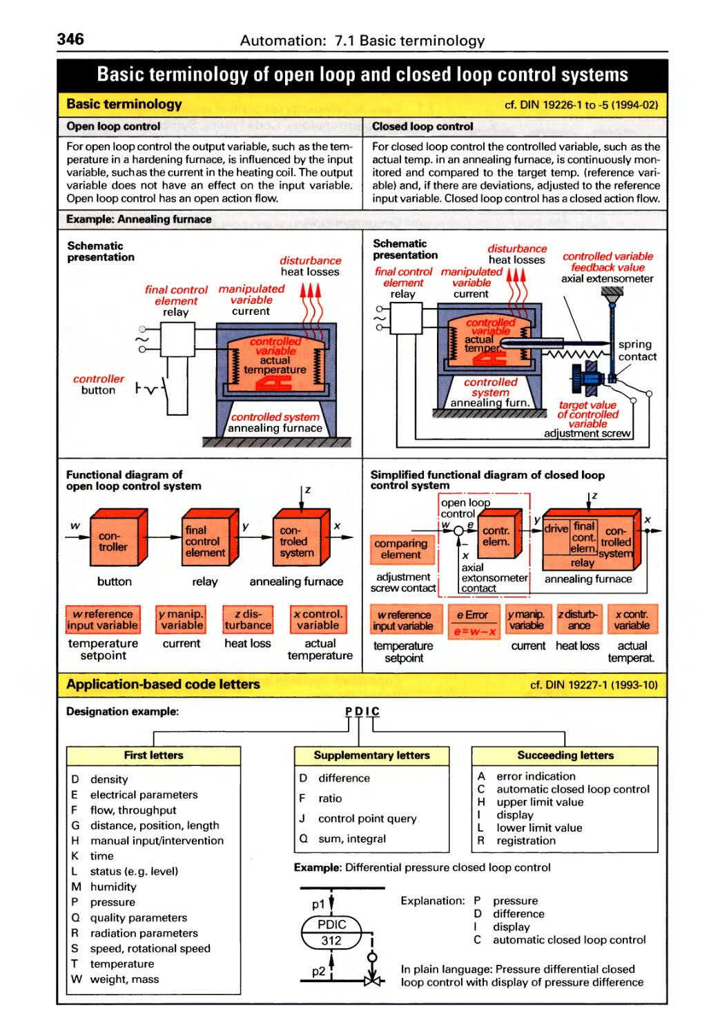
7.1 Basic terminology for control
engineering
Basic terminology, Code letters,
Symbols ........................ 346
Analog controllers. . . . . . . . . . . . . . .. 348
Discontinuous and digital controllers. . 349
Binary logic . . . . . . . . . . . . . . . . . . . . . . 350
7.2 Electrical circuits
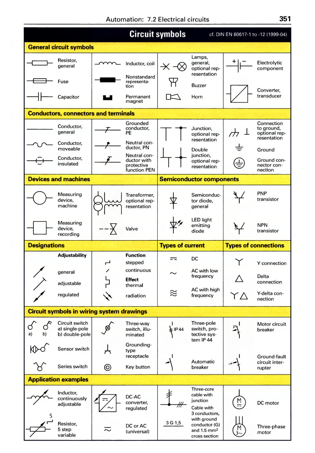
Circuit symbols. . . . . . . . . . . . . . . . . . . 351
Designations in circuit diagrams .... 353
Circuit diagrams . . . . . . . . . . . . . . . . . . 354
Sensors ......................... 355
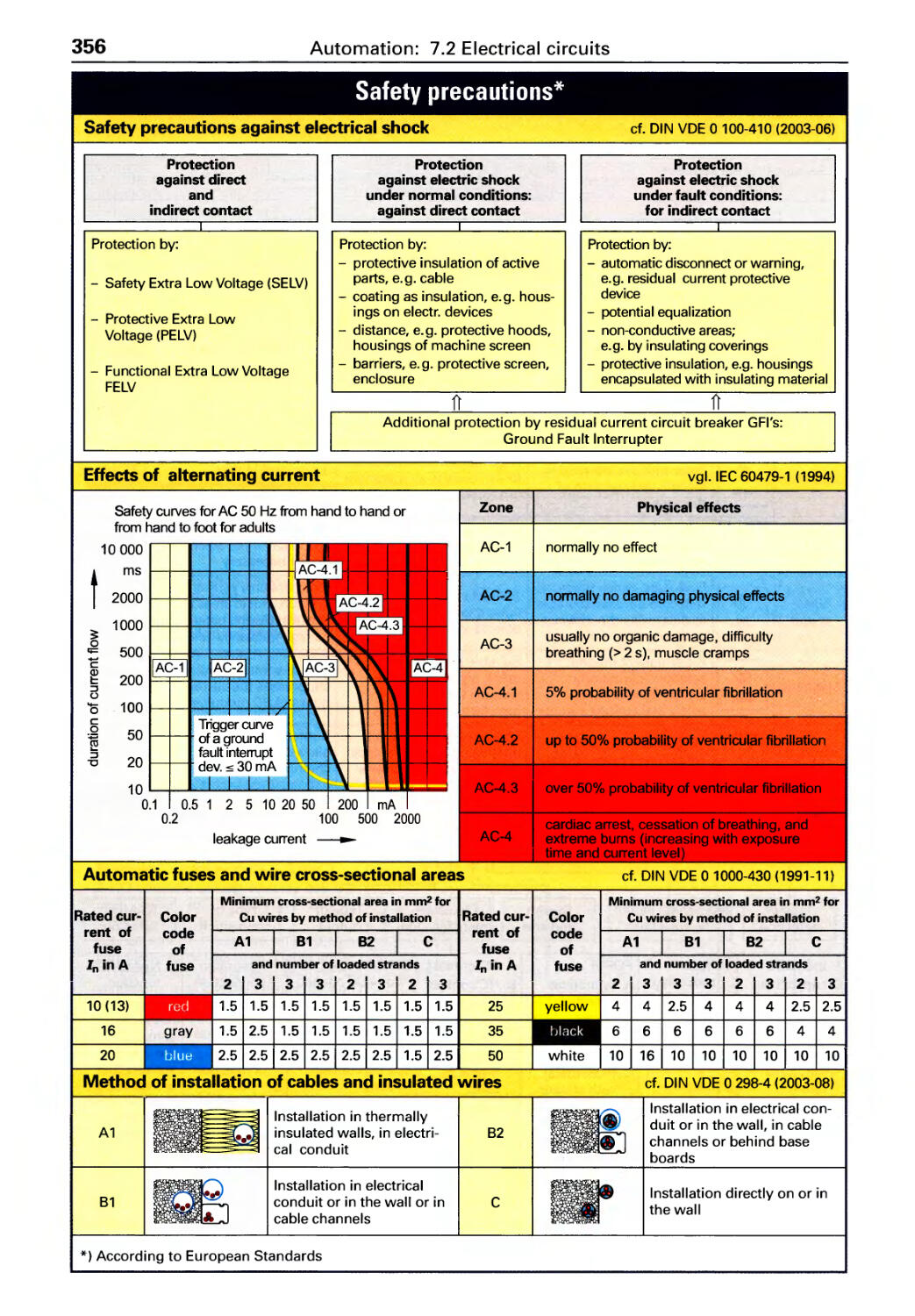
Protective precautions. . . . . . . . . . . . . 356
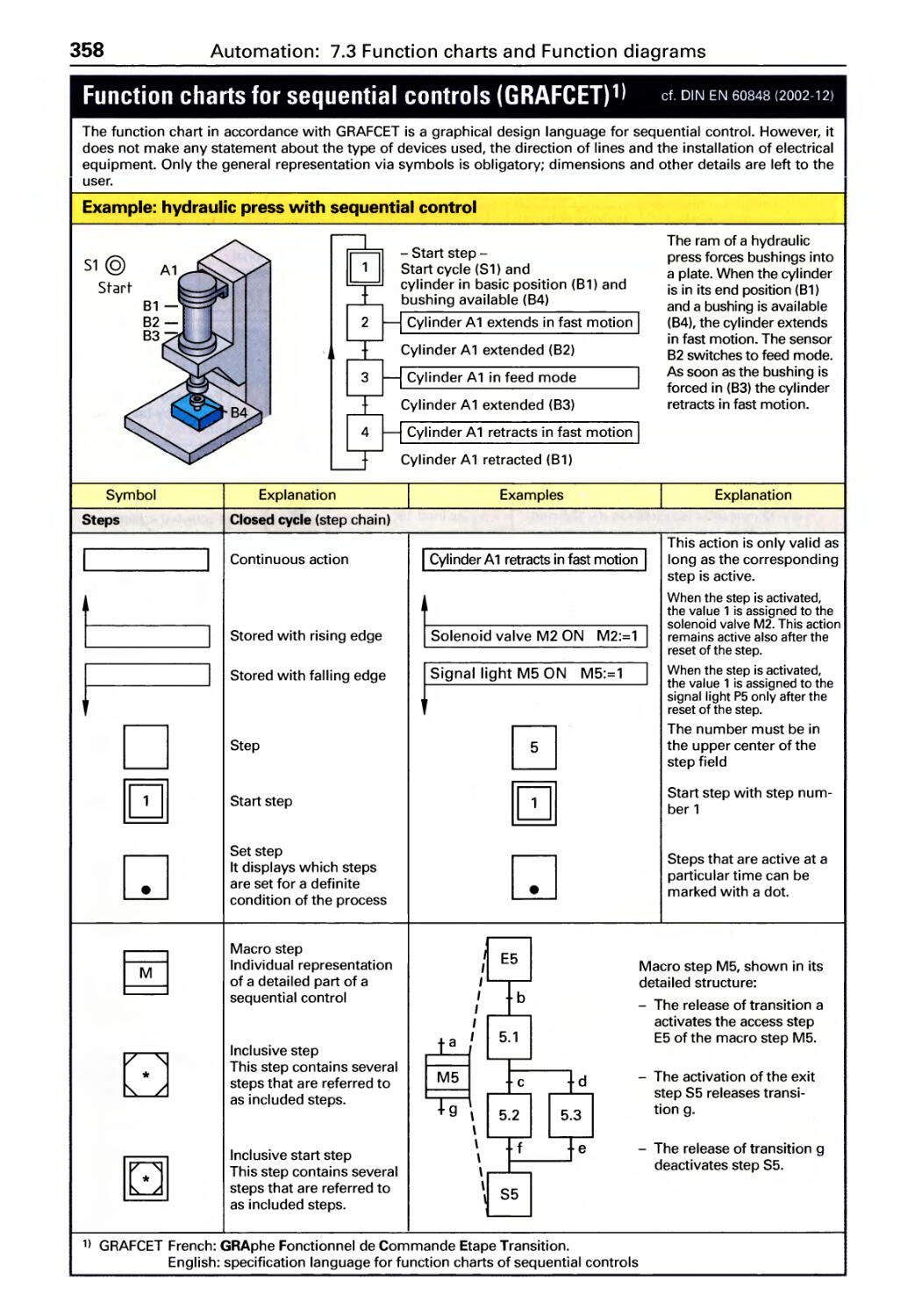
7.3 Function charts and function diagrams
Function charts . . . . . . . . . . . . . . . . . . . 358
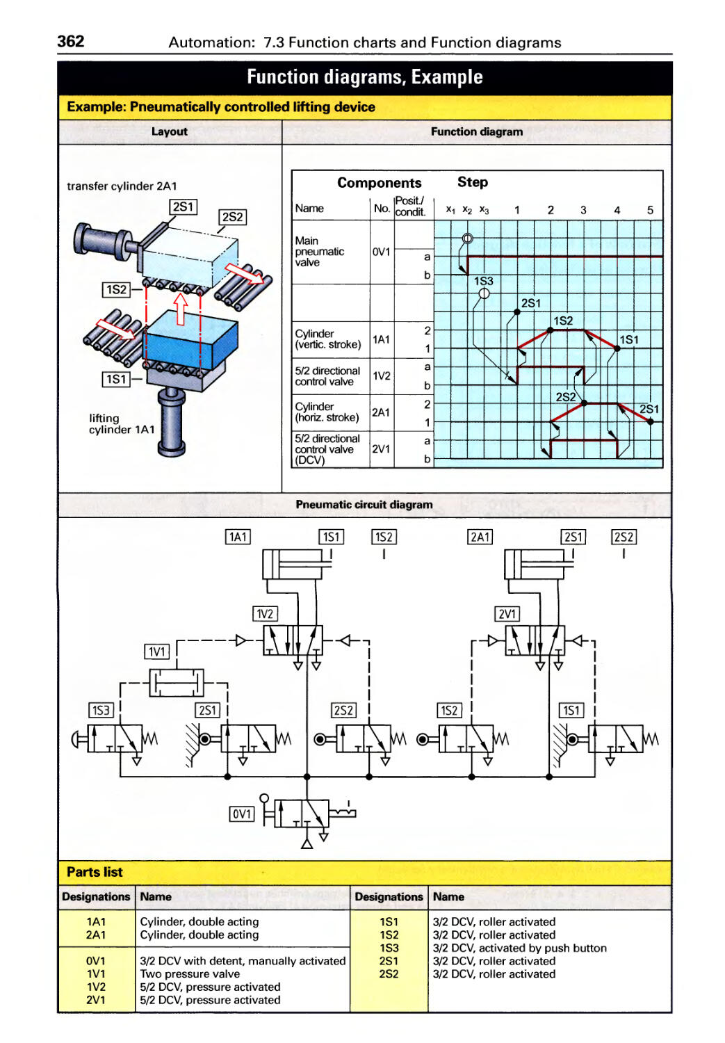
Function diagrams . . . . . . . . . . . . . . . . 361
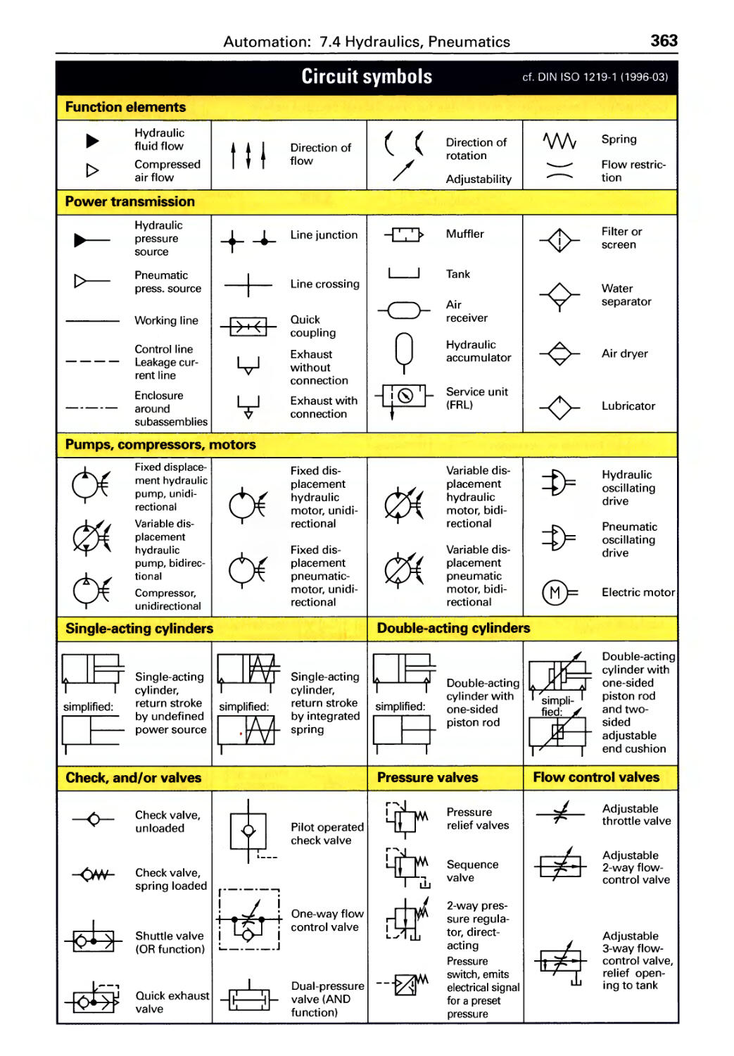
7.4 Pneumatics and hydraulics
Circuit symbols. . . . . . . . . . . . . . . . . . . 363
Layout of circuit diagrams ......... 365
Controllers . . . . . . . . . . . . . . . . . . . . . . . 366
Hydraulic fluids. . . . . . . . . . . . . . . . . . . 368
Pneumatic cylinders. . . . . . . . . . . . . . . 369
Forces,Speeds,Povver ....... ... ..370
Precision steel tube ............... 372
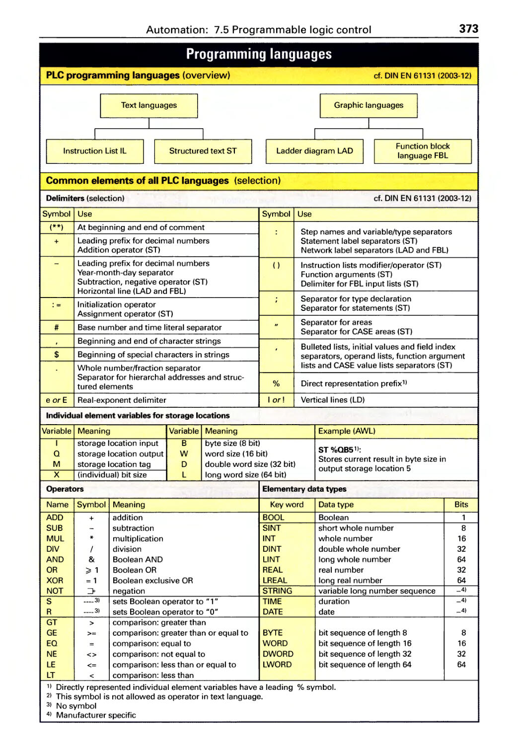
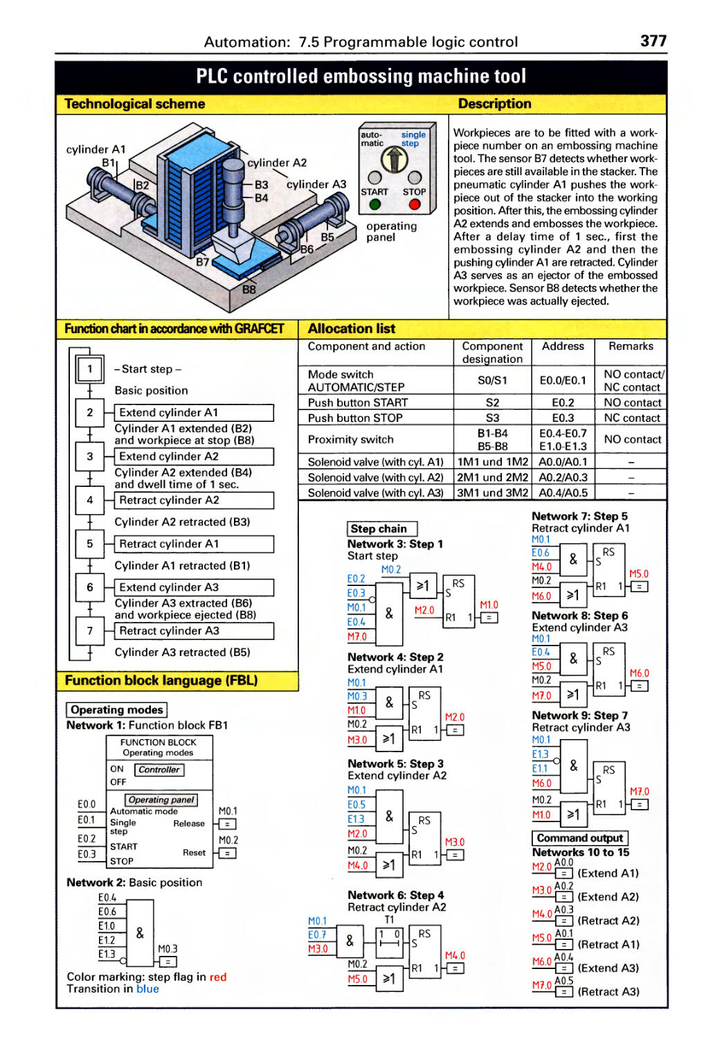
7.5 Programmable logic control
PLC programming languages. . . . . . . 373
Ladder diagram (LD) .............. 374
Function block language (FBL) . . . . . . 374
8 Material chart, Standards
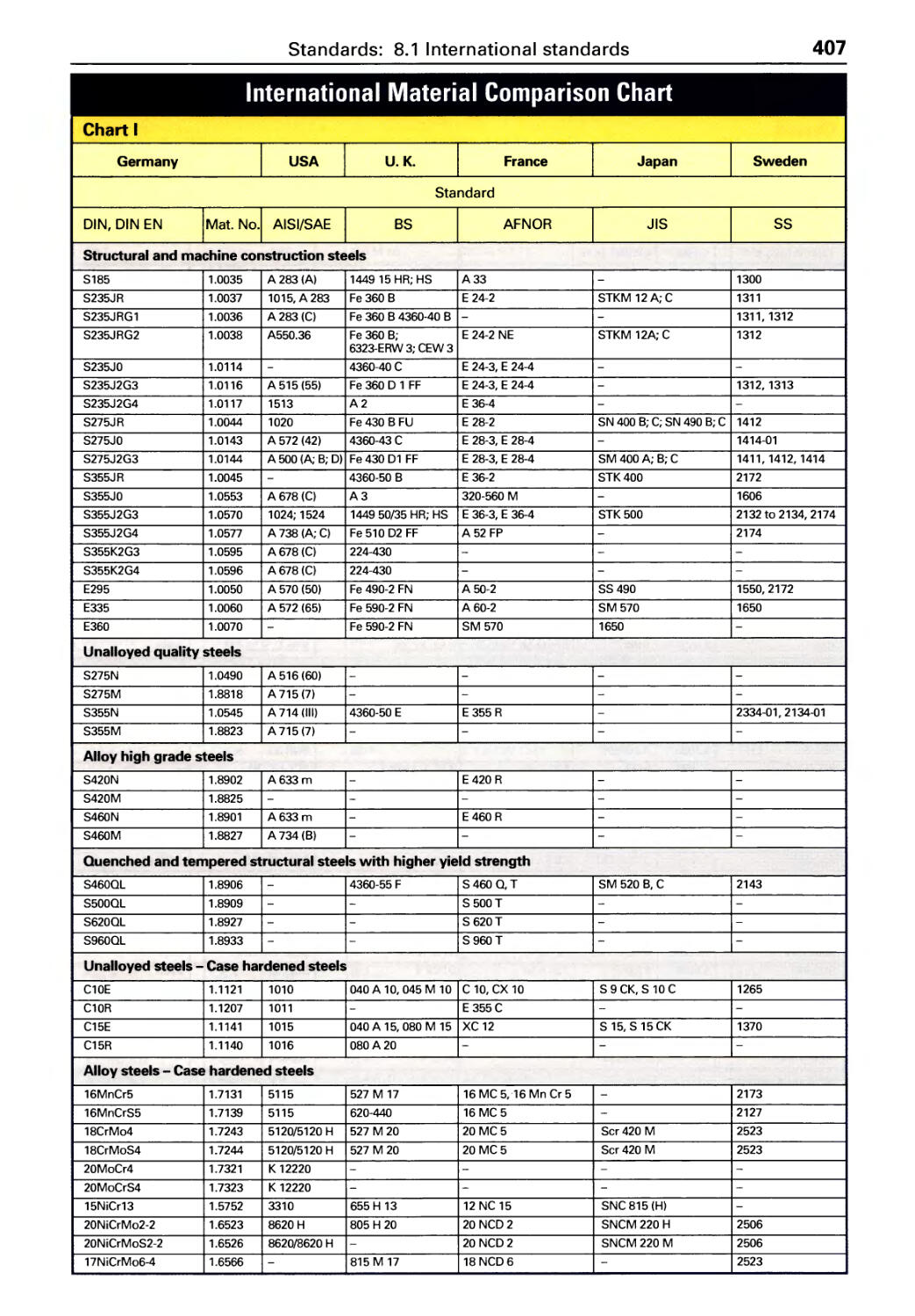
8.1 International material
comparison chart .............. 407
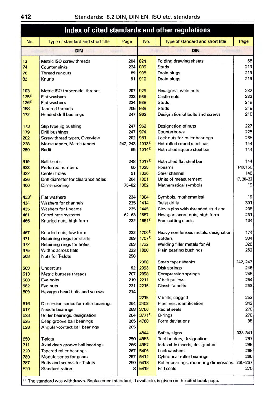
8.2 DIN, DIN EN, ISO etc. standards .. 412
Subject index
Structured text (ST) ............... 374
Instruction list ................... 375
Simple functions ................. 376
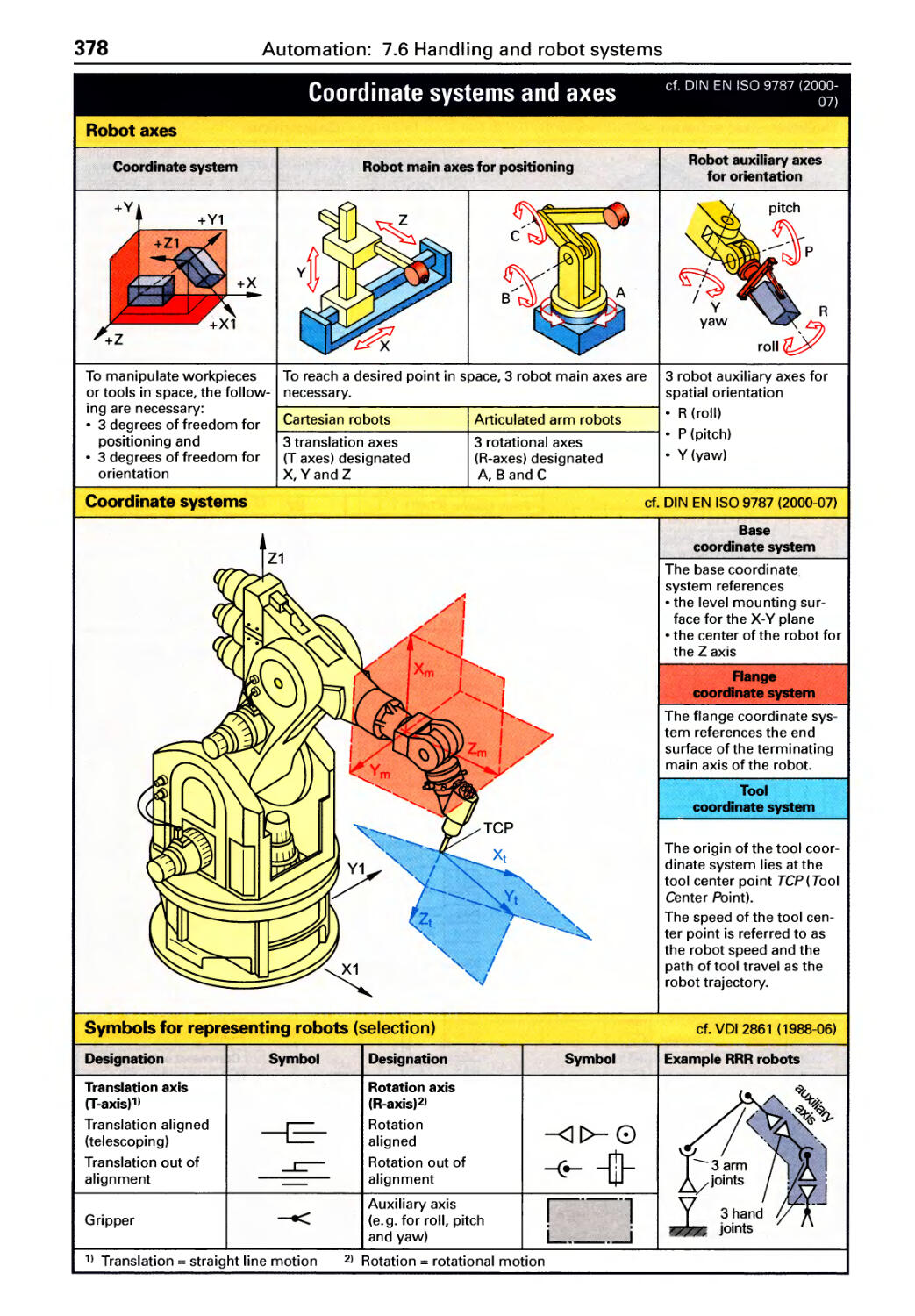
7.6 Handling and robot systems
Coordinate systems and axes. . . . . . . 378
Robot designs. . . . . . . . . . . . . . . . . . . . 379
Grippers, job safety ............... 380
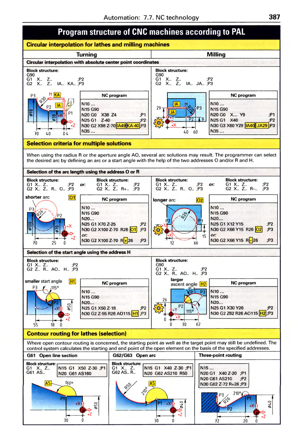
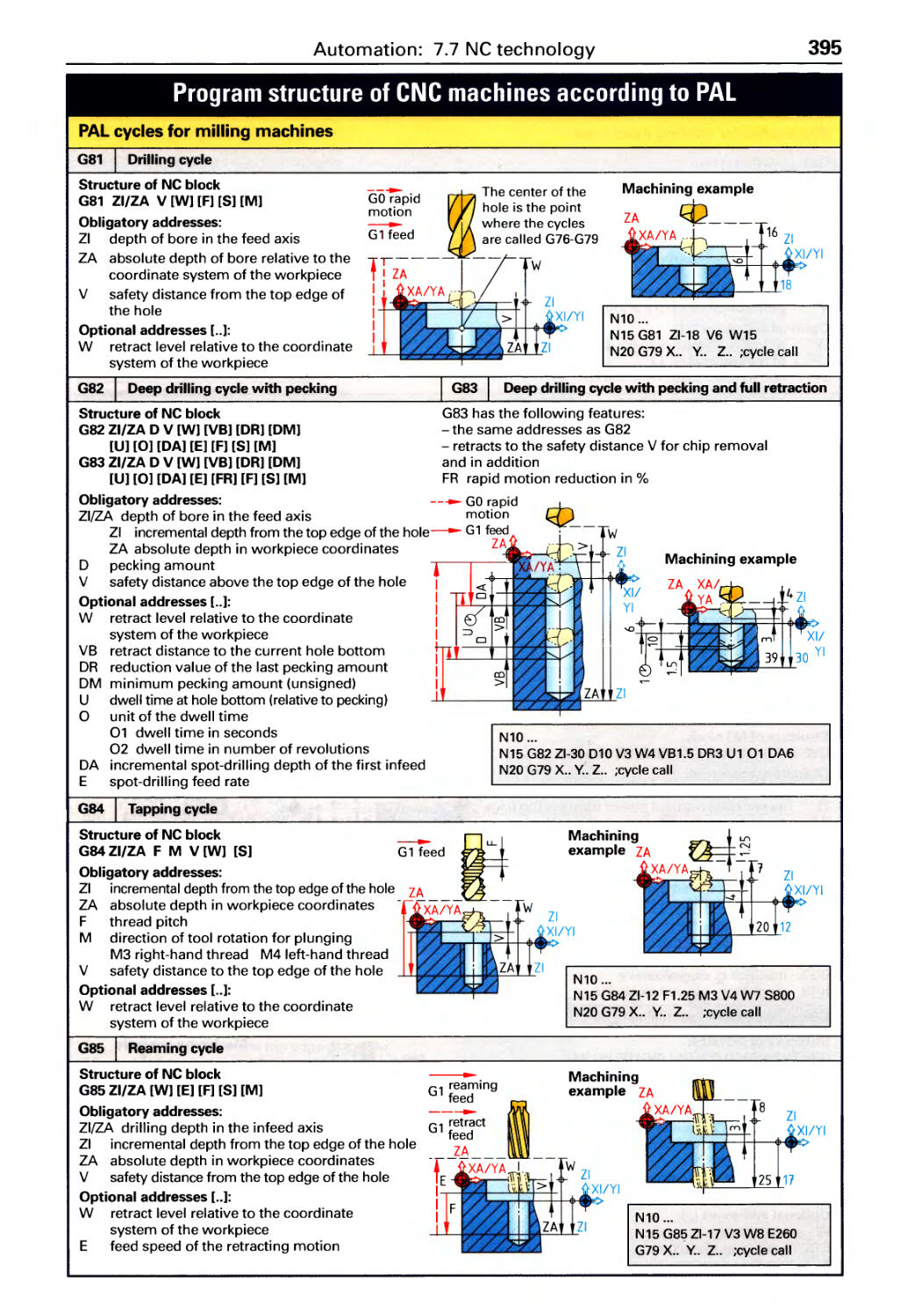
7.7 Numerical Control (NC) technology
Coordinate systems . . . . . . . . . . . . . . . 381
Program structure according to DIN. .382
Tool offset and Cutter compensation. 383
Machining motions as per DIN . . . . . . . 384
Machining motions as per PAL
(German association) . . . . . . . . . . . . . . 386
PAL programming system for turning . 388
PAL programming system for milling . 392
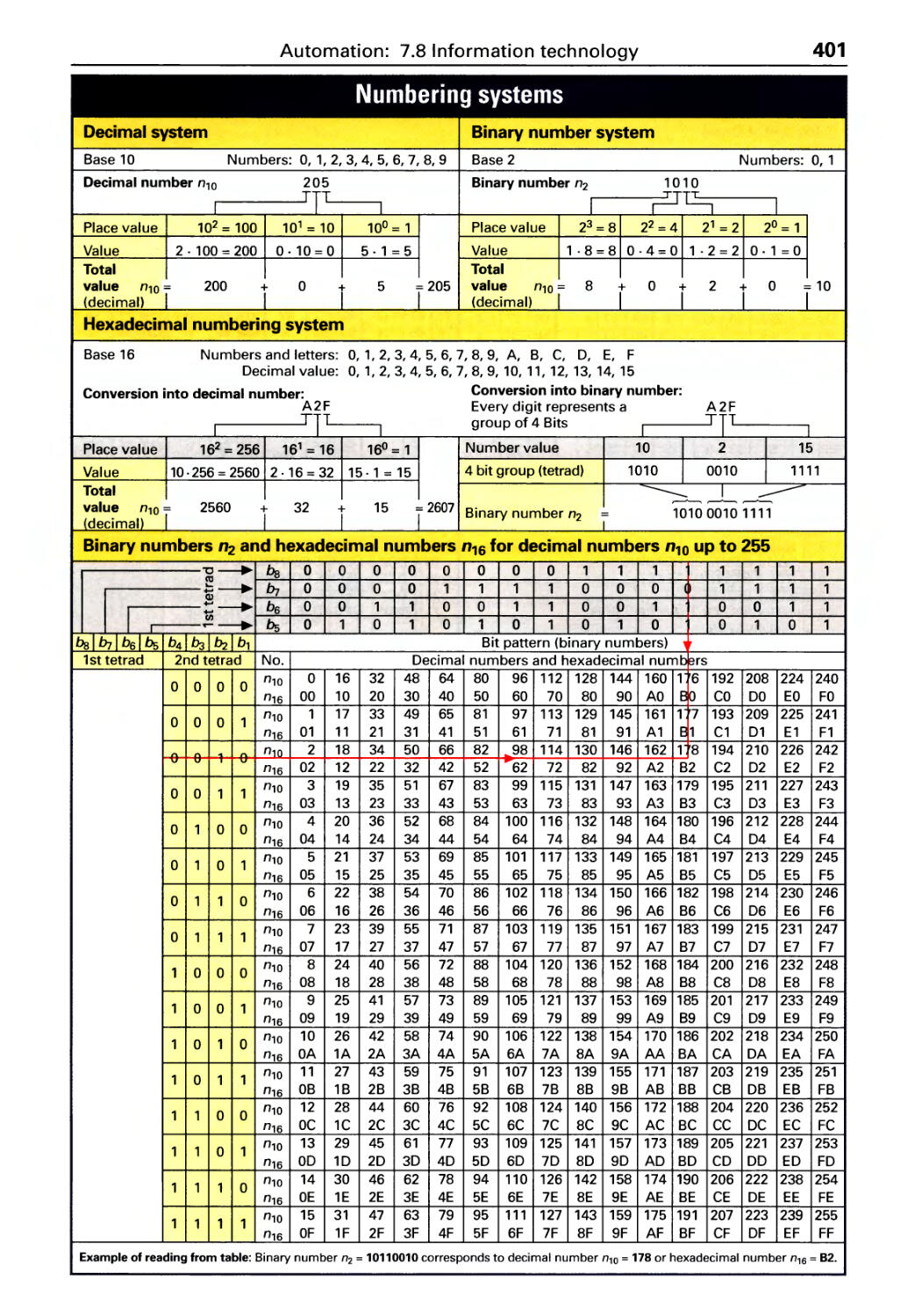
7.8 Information technology
Numbering systems. . . . . . . . . . . . . . .401
ASCII code . . . . . . . . . . . . . . . . . . . . . . . 402
Program flovv chart, Structograms .. 403
WORD- and EXEL commands ...... 405
407
417
8
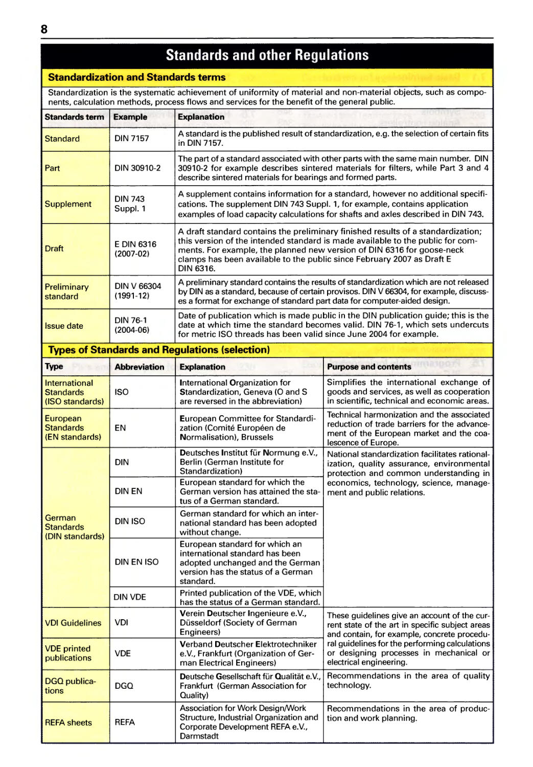
Standards and other Regulations
Standardization and Standards terms
Standardization is the systematic achievement of uniformity of material and non-material objects, such as compo-
nents, calculation methods, process flows and services for the benefit of the general public.
Standards term Example Explanation
Standard DIN 7157 A standard is the published result of standardization, e.g. the selection of certain fits
in DIN 7157.
The part of a standard associated with other parts with the same main number. DIN
Part DIN 30910-2 30910-2 for example describes sintered materials for filters, while Part 3 and 4
describe sintered materials for bearings and formed parts.
DIN 743 A supplement contains information for a standard, however no additional specifi-
Supplement Suppl. 1 cations. The supplement DIN 743 Suppl. 1, for example, contains application
examples of load capacity calculations for shafts and axles described in DIN 743.
A draft standard contains the preliminary finished results of a standardization;
E DIN 6316 this version of the intended standard is made available to the public for com-
Draft (2007-02) ments. For example, the planned new version of DIN 6316 for goose-neck
clamps has been available to the public since February 2007 as Draft E
DIN 6316.
Preliminary DIN V 66304 A preliminary standard contains the results of standardization which are not released
standard ( 1991- 12) by DIN as a standard, because of certain provisos. DIN V 66304, for example, discuss-
es a format for exchange of standard part data for computer-aided design.
DIN 76-1 Date of publication which is made public in the DIN publication guide; this is the
Issue date (2004-06) date at which time the standard becomes valid. DIN 76-1, which sets undercuts
for metric ISO threads has been valid since June 2004 for example.
Types of Standards and Regulations (selection)
Type Abbreviation Explanation Purpose and contents
International International Organization for Simplifies the international exchange of
Standards ISO Standardization, Geneva (0 and S goods and services, as well as cooperation
(ISO standards) are reversed in the abbreviation) in scientific, technical and economic areas.
European European Committee for Standardi- Technical harmonization and the associated
Standards EN zation (Comite Europeen de reduction of trade barriers for the advance-
(EN standards) Normalisation), Brussels ment of the European market and the coa-
lescence of Europe.
Deutsches Institut fUr Normung e.V., National standardization facilitates rational-
DIN Berlin (German Institute for ization, quality assurance, environmental
Standardization) protection and common understanding in
European standard for which the economics, technology, science, manage-
DIN EN German version has attained the sta- ment and public relations.
tus of a German standard.
German German standard for which an inter-
Standards DIN ISO national standard has been adopted
(DIN standards) without change.
European standard for which an
international standard has been
DIN EN ISO adopted unchanged and the German
version has the status of a German
standard.
DIN VDE Printed publication of the VDE, which
has the status of a German standard.
Verein Deutscher Ingenieure e.V., These guidelines give an account of the cur-
VDI Guidelines VDI Dusseldorf (Society of German rent state of the art in specific subject areas
Engineers) and contain, for example, concrete procedu-
VDE pri nted Verband Deutscher Elektrotechniker ral guidelines for the performing calculations
VDE e.V., Frankfurt (Organization of Ger- or designing processes in mechanical or
publications man Electrical Engineers) electrical engineering.
DGQ publica- Deutsche Gesellschaft fUr Qualiti=it e.V., Recommendations in the area of quality
DGQ Frankfurt (German Association for technology.
tions Quality)
Association for Work Design/Work Recommendations in the area of produc-
REFA sheets REFA Structure, Industrial Organization and tion and work planning.
Corporate Development REFA e.V.,
Darmstadt
Table of Contents
9
1 Mathematics
d fd 1f,.d 2
A=-
4
1 1.0000 0.7854
2 1.4142 3.1416
3 1.7321 7.0686
sine opposite side
hypotenuse
cosine adjacent side
hypotenuse
tangent opposite side
adjacent side
cotangent adjacent side
opposite side
3 5 1
-+- = -. (3+5)
X X X
1 1 kW . h = 3.6 . 10 6 W . s I 1.4
1.5
(fj - ----+-
/ \ 1.6
1.7
,. kg
m In-
m
Y!
I
x
1.1 Numerical tables
Sq u a re root, Area of a ci rei e .................. 1 0
Sine, Cosine ............................... 11
Tangent, Cotangent ......................... 12
1.2 Trigonometric Functions
Defi nit ion s . . . . . . . . . . . . . . . . . . . . . . . . . . . . . . . .. 13
Sine, Cosine, Tangent, Cotangent. . . . . . . . . . . . .. 13
Laws of sines and cosines. . . . . . . . . . . . . . . . . . .. 14
Angles, Theorem of intersecting lines . . . . . . . . .. 14
1.3 Fundamentals of Mathematics
Usi ng brackets, powers, roots ................ 15
Equations. . . . . . . . . . . . . . . . . . . . . . . . . . . . . . . . .. 16
Powers often, Interest calculation. . . . . . . . . . . .. 17
Percentage and proportion calculations ........ 18
Symbols, Units
Formula symbols, Mathematical symbols ...... 19
SI quantities and units of measurement ........ 20
Non-SI units ............................... 22
Lengths
Calculations in a right triangle ................ 23
Sub-dividing lengths, Arc length .............. 24
Flat lengths, Rough lengths. . . . . . . . . . . . . . . . . .. 25
Areas
Angular areas .............................. 26
Equilateral triangle, Polygons, Cirele . . . . . . . . . .. 27
Circular areas .............................. 28
Volume and Surface area
Cube, Cylinder, Pyramid ..................... 29
Truncated pyramid, Cone, Truncated cone, Sphere 30
Composite solids ........................... 31
1.8 Mass
General calculations. . . . . . . . . . . . . . . . . . . . . . . .. 31
Linear mass density . . . . . . . . . . . . . . . . . . . . . . . .. 31
Area mass density .......................... 31
1.9 Centroids
Centroids of lines ........................... 32
Centroids of plane areas ..................... 32
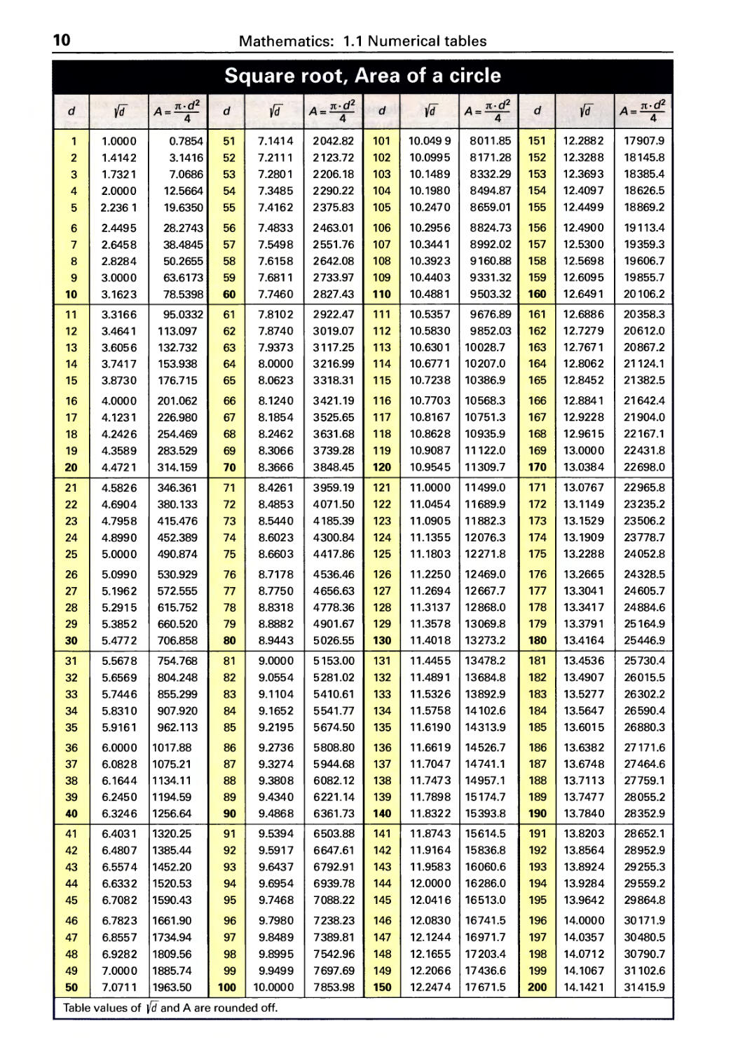
10
Mathematics: 1.1 Numerical tables
Square root, Area of a circle
d fd A = n. d 2 d Vi A = n. d 2 d fd A = n.d 2 d fd A- n.d 2
4 4 4 - 4
1 1.0000 0.7854 51 7.1414 2042.82 101 10.0499 8011.85 151 12.2882 17907.9
2 1.4142 3.1416 52 7.2111 2123.72 102 10.0995 8171.28 152 12.3288 18145.8
3 1.732 1 7.0686 53 7.2801 2206.18 103 10.1489 8332.29 153 12.3693 18385.4
4 2.0000 12.5664 54 7.3485 2290.22 104 10.1980 8494.87 154 12.4097 18626.5
5 2.236 1 19.6350 55 7.4162 2375.83 105 10.2470 8659.01 155 12.4499 18869.2
6 2.4495 28.2743 56 7.4833 2463.01 106 10.2956 8824.73 156 12.4900 19113.4
7 2.6458 38.4845 57 7.5498 2551.76 107 10.344 1 8992.02 157 12.5300 19359.3
8 2.8284 50.2655 58 7.6158 2642.08 108 10.3923 9160.88 158 12.5698 19606.7
9 3.0000 63.6173 59 7.6811 2733.97 109 10.4403 9331.32 159 12.6095 19855.7
10 3.1623 78.5398 60 7.7460 2827.43 110 10.4881 9503.32 160 12.6491 20106.2
11 3.3166 95.0332 61 7.8102 2922.47 111 10.5357 9676.89 161 12.6886 20358.3
12 3.464 1 113.097 62 7.8740 3019.07 112 10.5830 9852.03 162 12.7279 20612.0
13 3.6056 132.732 63 7.9373 3117.25 113 10.6301 10028.7 163 12.7671 20867.2
14 3.7417 153.938 64 8.0000 3216.99 114 10.6771 10207.0 164 12.8062 21124.1
15 3.8730 176.715 65 8.0623 3318.31 115 10.7238 10386.9 165 12.8452 21382.5
16 4.0000 201.062 66 8.1240 3421.19 116 10.7703 10568.3 166 12.8841 21642.4
17 4.123 1 226.980 67 8.1854 3525.65 117 10.8167 10751.3 167 12.9228 21904.0
18 4.2426 254.469 68 8.2462 3631.68 118 10.8628 10935.9 168 12.9615 22167.1
19 4.3589 283.529 69 8.3066 3739.28 119 10.9087 11122.0 169 13.0000 22431.8
20 4.4721 314.159 70 8.3666 3848.45 120 10.9545 11309.7 170 13.0384 22698.0
21 4.5826 346.361 71 8.4261 3959.19 121 11.0000 11499.0 171 13.0767 22965.8
22 4.6904 380.133 72 8.4853 4071.50 122 11.0454 11689.9 172 13.1149 23235.2
23 4.7958 415.476 73 8.5440 4 185.39 123 11.0905 11 882.3 173 13.1529 23506.2
24 4.8990 452.389 74 8.6023 4300.84 124 11.1355 12076.3 174 13.1909 23778.7
25 5.0000 490.874 75 8.6603 4417.86 125 11.1803 12271.8 175 13.2288 24052.8
26 5.0990 530.929 76 8.7178 4536.46 126 11.2250 12469.0 176 13.2665 24328.5
27 5.1962 572.555 77 8.7750 4656.63 127 11.2694 12667.7 177 13.3041 24605.7
28 5.2915 615.752 78 8.831 8 4778.36 128 11.3137 12868.0 178 13.3417 24884.6
29 5.3852 660.520 79 8.8882 4901.67 129 11.3578 13069.8 179 13.3791 25164.9
30 5.4772 706.858 80 8.9443 5026.55 130 11.4018 13273.2 180 13.4164 25446.9
31 5.5678 754.768 81 9.0000 5153.00 131 11.4455 13478.2 181 13.4536 25730.4
32 5.6569 804.248 82 9.0554 5281.02 132 11.489 1 13684.8 182 13.4907 26015.5
33 5.7446 855.299 83 9.1104 5410.61 133 11.5326 13892.9 183 13.5277 26302.2
34 5.831 0 907.920 84 9.1652 5541.77 134 11.5758 14102.6 184 13.5647 26590.4
35 5.9161 962.113 85 9.2195 5674.50 135 11.6190 14313.9 185 13.6015 26880.3
36 6.0000 1017.88 86 9.2736 5808.80 136 11.6619 14526.7 186 13.6382 27171.6
37 6.0828 1075.21 87 9.3274 5944.68 137 11.7047 14741.1 187 13.6748 27464.6
38 6.1644 1134. 11 88 9.3808 6082.12 138 11.7473 14957.1 188 13.7113 27759.1
39 6.2450 1194.59 89 9.4340 6221.14 139 11.7898 15174.7 189 13.7477 28055.2
40 6.3246 1256.64 90 9.4868 6361.73 140 11.8322 15393.8 190 13.7840 28352.9
41 6.403 1 1320.25 91 9.5394 6503.88 141 11.8743 15614.5 191 13.8203 28652.1
42 6.4807 1385.44 92 9.5917 6647.61 142 11.9164 15836.8 192 13.8564 28952.9
43 6.5574 1452.20 93 9.6437 6792.91 143 11.9583 16060.6 193 13.8924 29255.3
44 6.6332 1520.53 94 9.6954 6939.78 144 12.0000 16286.0 194 13.9284 29559.2
45 6.7082 1590.43 95 9.7468 7088.22 145 12.0416 16513.0 195 13.9642 29864.8
46 6.7823 1661.90 96 9.7980 7238.23 146 12.0830 16741.5 196 14.0000 30171.9
47 6.8557 1734.94 97 9.8489 7389.81 147 12.1244 16971.7 197 14.0357 30480.5
48 6.9282 1809.56 98 9.8995 7542.96 148 12.1655 17203.4 198 14.0712 30790.7
49 7.0000 1885.74 99 9.9499 7697.69 149 12.2066 17436.6 199 14.1067 31102.6
50 7.0711 1963.50 100 10.0000 7853.98 150 12.2474 17671.5 200 14.1421 31415.9
Table values of {d and A are rounded off.
Mathematics: 1.1 Numerical tables
11
Values of Sine and Cosine Trigonometric Functions
de-
sine 0° to 45°
de-
sine 45° to 90°
grees minutes - grees minutes
-
0' 15' 30' 45' 60' 0' 15' 30' 45' 60'
0° 0.0000 0.0044 0.0087 0.0131 0.0175 89° 45° 0.7071 0.7102 0.7133 0.7163 0.7193 44°
1° 0.0175 0.0218 0.0262 0.0305 0.0349 88° 46° 0.7193 0.7224 0.7254 0.7284 0.7314 43°
2° 0.0349 0.0393 0.0436 0.0480 0.0523 87° 47° 0.7314 0.7343 0.7373 0.7402 0.7431 42°
3° 0.0523 0.0567 0.0610 0.0654 0.0698 86° 48° 0.7431 0.7461 0.7490 0.7518 0.7547 41°
4° 0.0698 0.0741 0.0785 0.0828 0.0872 85° 49° 0.7547 0.7576 0.7604 0.7632 0.7660 40°
5° 0.0872 0.0915 0.0958 0.1002 0.1045 84° 50° 0.7660 0.7688 0.7716 0.7744 0.7771 39°
6° 0.1045 0.1089 O. 1132 0.1175 0.1219 83° 51° 0.7771 0.7799 0.7826 0.7853 0.7880 38°
7° 0.1219 0.1262 0.1305 0.1349 0.1392 82° 52° 0.7880 0.7907 0.7934 0.7960 0.7986 37°
8° 0.1392 0.1435 0.1478 0.1521 0.1564 81° 53° 0.7986 0.8013 0.8039 0.8064 0.8090 36°
9° 0.1564 0.1607 0.1650 0.1693 0.1736 80° 54° 0.8090 0.8116 0.8141 0.8166 0.8192 35°
10° 0.1736 O. 1779 0.1822 0.1865 0.1908 79° 55° 0.8192 0.8216 0.8241 0.8266 0.8290 34°
11° 0.1908 0.1951 O. 1994 0.2036 0.2079 78° .... 56° 0.8290 0.8315 0.8339 0.8363 0.8387 33°
12° 0.2079 0.2122 0.2164 0.2207 0.2250 77° 57° 0.8387 0.8410 0.8434 0.8457 0.8480 32°
13° 0.2250 0.2292 0.2334 0.2377 0.2419 76° 58° 0.8480 0.8504 0.8526 0.8549 0.8572 31°
14° 0.2419 0.2462 0.2504 0.2546 0.2588 75° 59° 0.8572 0.8594 0.8616 0.8638 0.8660 30°
15° 0.2588 0.2630 0.2672 0.2714 0.2756 74° 60° 0.8660 0.8682 0.8704 0.8725 0.8746 29°
16° 0.2756 0.2798 0.2840 0.2882 0.2924 73° 61° 0.8746 0.8767 0.8788 0.8809 0.8829 28°
17° 0.2924 0.2965 0.3007 0.3049 0.3090 72° 62° 0.8829 0.8850 0.8870 0.8890 0.8910 27°
18° 0.3090 0.3132 0.3173 0.3214 0.3256 71° 63° 0.8910 0.8930 0.8949 0.8969 0.8988 26°
19° 0.3256 0.3297 0.3338 0.3379 0.3420 70° 64° 0.8988 0.9007 0.9026 0.9045 0.9063 25°
20° 0.3420 0.3461 0.3502 0.3543 0.3584 69° 65° 0.9063 0.9081 0.9100 0.9118 0.9135 24°
21° 0.3584 0.3624 0.3665 0.3706 0.3746 68° 66° 0.9135 0.9153 0.9171 0.9188 0.9205 23°
22° 0.3746 0.3786 0.3827 0.3867 0.3907 67° 67° 0.9205 0.9222 0.9239 0.9255 0.9272 22°
23° 0.3907 0.3947 0.3987 0.4027 0.4067 66° 68° 0.9272 0.9288 0.9304 0.9320 0.9336 21°
24° 0.4067 0.4107 0.4147 0.4187 0.4226 65° 69° 0.9336 0.9351 0.9367 0.9382 0.9397 20°
25° 0.4226 0.4266 0.4305 0.4344 0.4384 64° 70° 0.9397 0.9412 0.9426 0.9441 0.9455 19°
26° 0.4384 0.4423 0.4462 0.4501 0.4540 63° 71° 0.9455 0.9469 0.9483 0.9497 0.9511 18°
27° 0.4540 0.4579 0.4617 0.4656 0.4695 62° 72° 0.9511 0.9524 0.9537 0.9550 0.9563 17°
28° 0.4695 0.4733 0.4772 0.4810 0.4848 61° 73° 0.9563 0.9576 0.9588 0.9600 0.9613 16°
29° 0.4848 0.4886 0.4924 0.4962 0.5000 60° 74° 0.9613 0.9625 0.9636 0.9648 0.9659 15°
30° 0.5000 0.5038 0.5075 0.5113 0.5150 59° 75° 0.9659 0.9670 0.9681 0.9692 0.9703 14°
31° 0.5150 0.5188 0.5225 0.5262 0.5299 58° 76° 0.9703 0.9713 0.9724 0.9734 0.9744 13°
32° 0.5299 0.5336 0.5373 0.5410 0.5446 57° 77° 0.9744 0.9753 0.9763 0.9772 0.9781 12°
33° 0.5446 0.5483 0.5519 0.5556 0.5592 56° 78° 0.9781 0.9790 0.9799 0.9808 0.9816 11°
34° 0.5592 0.5628 0.5664 0.5700 0.5736 55° 79° 0.9816 0.9825 0.9833 0.9840 0.9848 10°
35° 0.5736 0.5771 0.5807 0.5842 0.5878 54° 80° 0.9848 0.9856 0.9863 0.9870 0.9877 9°
36° 0.5878 0.5913 0.5948 0.5983 0.6018 53° 81° 0.9877 0.9884 0.9890 0.9897 0.9903 8°
37° 0.6018 0.6053 0.6088 0.6122 0.6157 52° 82° 0.9903 0.9909 0.9914 0.9920 0.9925 7°
38° 0.6157 0.6191 0.6225 0.6259 0.6293 51° 83° 0.9925 0.9931 0.9936 0.9941 0.9945 6°
39° 0.6293 0.6327 0.6361 0.6394 0.6428 50° 84° 0.9945 0.9950 0.9954 0.9958 0.9962 5°
40° 0.6428 0.6461 0.6494 0.6528 0.6561 49° 85° 0.9962 0.9966 0.9969 0.9973 0.9976 4°
41° 0.6561 0.6593 0.6626 0.6659 0.6691 48° 86° 0.9976 0.9979 0.9981 0.9984 0.9986 3°
42° 0.6691 0.6724 0.6756 0.6788 0.6820 47° 87° 0.9986 0.9988 0.9990 0.9992 0.9994 2°
43° 0.6820 0.6852 0.6884 0.6915 0.6947 46° 88° 0.9994 0.9995 0.9997 0.9998 0.99985 1°
44° 0.6947 0.6978 0.7009 0.7040 0.7071 45° 89° 0.99985 0.99991 0.99996 0.99999 1.0000 0°
60' 45' 30' 15' 0' t 60' 45' 30' 15' 0' t
c minutes de- l( minutes de-
cosine 45° to 90° 9 rees cosine 0° to 45° grees
Table values of the trigonometric functions are rounded off to four decimal places.
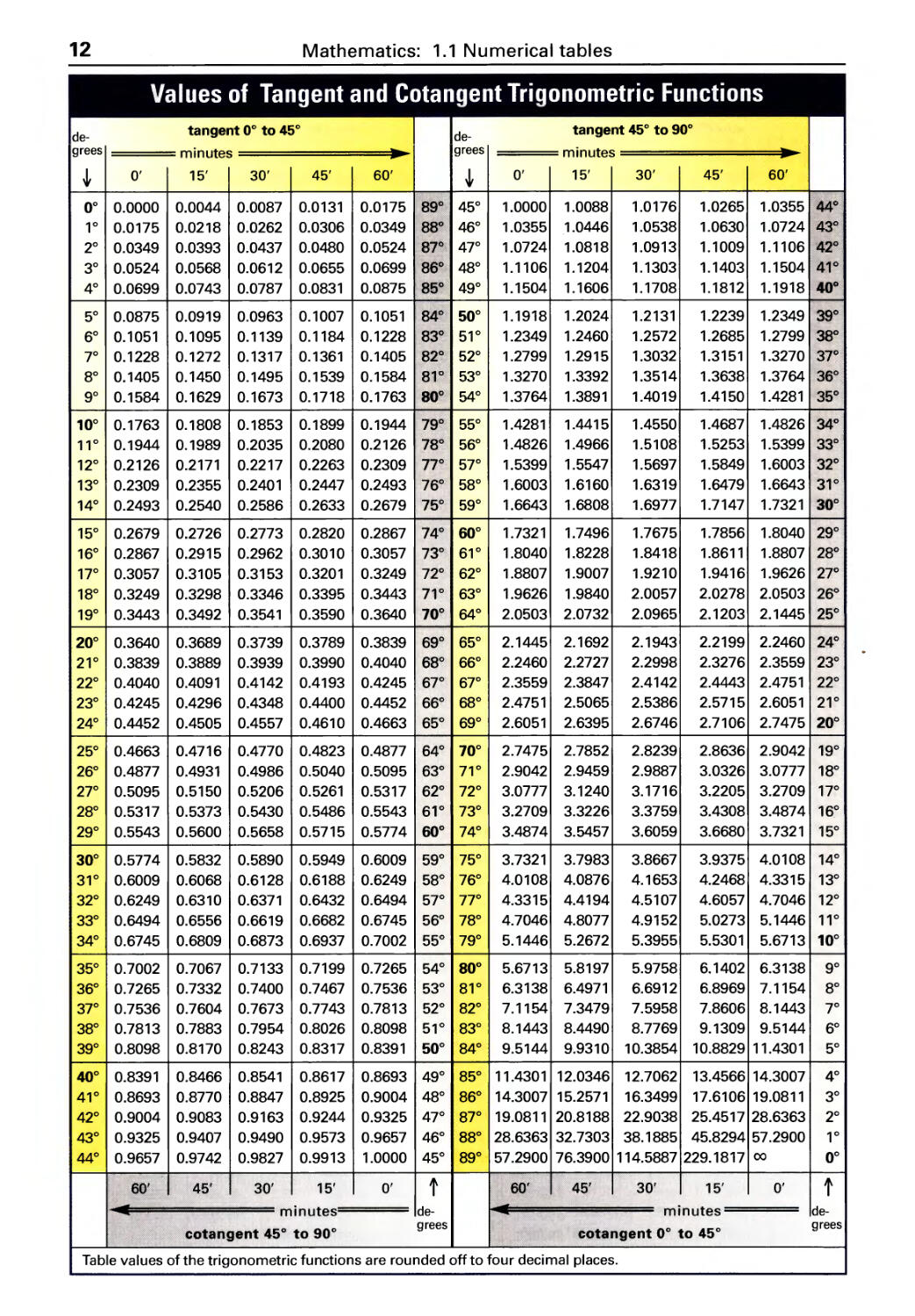
12
Mathematics: 1.1 Numerical tables
Values of Tangent and Cotangent Trigonometric Functions
de-
tangent 0° to 45°
de-
tangent 45° to 90°
grees minutes . grees minutes .
0' 15' 30' 45' 60' 0' 15' 30' 45' 60'
0° 0.0000 0.0044 0.0087 0.0131 0.0175 89° 45° 1.0000 1.0088 1.0176 1.0265 1.0355 44°
1° 0.0175 0.0218 0.0262 0.0306 0.0349 88° 46° 1.0355 1.0446 1.0538 1.0630 1.0724 43°
2° 0.0349 0.0393 0.0437 0.0480 0.0524 87° 47° 1.0724 1.0818 1.0913 1.1009 1 . 11 06 42°
3° 0.0524 0.0568 0.0612 0.0655 0.0699 86° 48° 1. 11 06 1. 1204 1. 1303 1. 1403 1. 1504 41°
4° 0.0699 0.0743 0.0787 0.0831 0.0875 85° 49° 1. 1504 1. 1606 1. 1708 1.1812 1.1918 40°
5° 0.0875 0.0919 0.0963 0.1007 0.1051 84° 50° 1.1918 1.2024 1.2131 1.2239 1.2349 39°
6° 0.1051 0.1095 O. 1139 0.1184 O. 1228 83° 51° 1.2349 1.2460 1.2572 1.2685 1.2799 38°
7° 0.1228 0.1272 0.1317 O. 1361 0.1405 82° 52° 1.2799 1.2915 1.3032 1.3151 1.3270 37°
8° 0.1405 0.1450 0.1495 O. 1539 0.1584 81° 53° 1.3270 1.3392 1.3514 1.3638 1.3764 36°
9° 0.1584 0.1629 O. 1673 0.1718 0.1763 80° 54° 1.3764 1.3891 1.4019 1.4150 1.4281 35°
10° 0.1763 0.1808 0.1853 0.1899 0.1944 79° 55° 1.4281 1.4415 1.4550 1.4687 1.4826 34°
11° 0.1944 0.1989 0.2035 0.2080 0.2126 78° 56° 1.4826 1.4966 1.5108 1.5253 1.5399 33°
12° 0.2126 0.2171 0.2217 0.2263 0.2309 77° 57° 1.5399 1.5547 1.5697 1.5849 1.6003 32°
13° 0.2309 0.2355 0.2401 0.2447 0.2493 76° 58° 1.6003 1.6160 1.6319 1.6479 1.6643 31°
14° 0.2493 0.2540 0.2586 0.2633 0.2679 75° 59° 1.6643 1.6808 1.6977 1.7147 1.7321 30°
15° 0.2679 0.2726 0.2773 0.2820 0.2867 74° 60° 1.7321 1.7496 1.7675 1.7856 1.8040 29°
16° 0.2867 0.2915 0.2962 0.3010 0.3057 73° 61° 1.8040 1.8228 1.8418 1.8611 1.8807 28°
17° 0.3057 0.3105 0.3153 0.3201 0.3249 72° 62° 1.8807 1.9007 1.9210 1.9416 1.9626 27°
18° 0.3249 0.3298 0.3346 0.3395 0.3443 71° 63° 1.9626 1.9840 2.0057 2.0278 2.0503 26°
19° 0.3443 0.3492 0.3541 0.3590 0.3640 70° 64° 2.0503 2.0732 2.0965 2.1203 2.1445 25°
20° 0.3640 0.3689 0.3739 0.3789 0.3839 69° 65° 2.1445 2.1692 2.1943 2.2199 2.2460 24°
21° 0.3839 0.3889 0.3939 0.3990 0.4040 68° 66° 2.2460 2.2727 2.2998 2.3276 2.3559 23°
22° 0.4040 0.4091 0.4142 0.4193 0.4245 67° 67° 2.3559 2.3847 2.4142 2.4443 2.4751 22°
23° 0.4245 0.4296 0.4348 0.4400 0.4452 66° 68° 2.4751 2.5065 2.5386 2.5715 2.6051 21°
24° 0.4452 0.4505 0.4557 0.4610 0.4663 65° 69° 2.6051 2.6395 2.6746 2.7106 2.7475 20°
25° 0.4663 0.4716 0.4770 0.4823 0.4877 64° 70° 2.7475 2.7852 2.8239 2.8636 2.9042 19°
26° 0.4877 0.4931 0.4986 0.5040 0.5095 63° 71° 2.9042 2.9459 2.9887 3.0326 3.0777 18°
27° 0.5095 0.5150 0.5206 0.5261 0.5317 62° 72° 3.0777 3.1240 3.1716 3.2205 3.2709 17°
28° 0.5317 0.5373 0.5430 0.5486 0.5543 61° 73° 3.2709 3.3226 3.3759 3.4308 3.4874 16°
29° 0.5543 0.5600 0.5658 0.5715 0.5774 60° 74° 3.4874 3.5457 3.6059 3.6680 3.7321 15°
30° 0.5774 0.5832 0.5890 0.5949 0.6009 59° 75° 3.7321 3.7983 3.8667 3.9375 4.0108 14°
31° 0.6009 0.6068 0.6128 0.6188 0.6249 58° 76° 4.0108 4.0876 4.1653 4.2468 4.3315 13°
32° 0.6249 0.6310 0.6371 0.6432 0.6494 57° 77° 4.3315 4.4194 4.5107 4.6057 4.7046 12°
33° 0.6494 0.6556 0.6619 0.6682 0.6745 56° 78° 4.7046 4.8077 4.9152 5.0273 5.1446 11°
34° 0.6745 0.6809 0.6873 0.6937 0.7002 55° 79° 5.1446 5.2672 5.3955 5.5301 5.6713 10°
35° 0.7002 0.7067 0.7133 0.7199 0.7265 54° 80° 5.6713 5.8197 5.9758 6.1402 6.3138 9°
36° 0.7265 0.7332 0.7400 0.7467 0.7536 53° 81° 6.3138 6.4971 6.6912 6.8969 7. 1154 8°
37° 0.7536 0.7604 0.7673 0.7743 0.7813 52° 82° 7.1154 7.3479 7.5958 7.8606 8.1443 7°
38° 0.7813 0.7883 0.7954 0.8026 0.8098 51° 83° 8.1443 8.4490 8.7769 9.1309 9.5144 6°
39° 0.8098 0.8170 0.8243 0.8317 0.8391 50° 84° 9.5144 9.9310 10.3854 10.8829 11.4301 5°
40° 0.8391 0.8466 0.8541 0.8617 0.8693 49° 85° 11.4301 12.0346 12.7062 13.4566 14.3007 4°
41° 0.8693 0.8770 0.8847 0.8925 0.9004 48° 86° 14.3007 15.2571 16.3499 17.6106 19.0811 3°
42° 0.9004 0.9083 0.9163 0.9244 0.9325 47° 87° 19.0811 20.8188 22.9038 25.4517 28.6363 2°
43° 0.9325 0.9407 0.9490 0.9573 0.9657 46° 88° 28.6363 32.7303 38.1885 45.8294 57.2900 1°
44° 0.9657 0.9742 0.9827 0.9913 1.0000 45° 89° 57.2900 76.3900 114.5887 229.1817 00 0°
60 1 45' 30' 15' 0' t 60' 45' 30' 15' 0' t
II minutes de- -- minutes
... de-
cotangent 45° to 90° grees cotangent 0° to 45° grees
Table values of the trigonometric functions are rounded off to four decimal places.
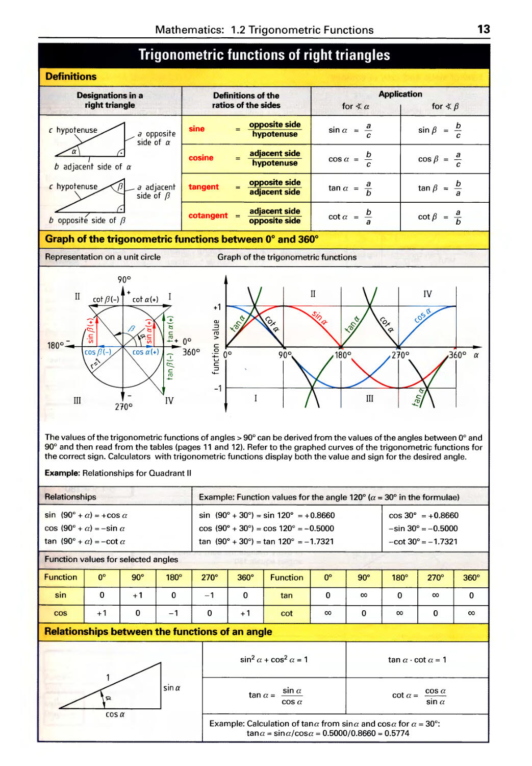
Mathematics: 1.2 Trigonometric Functions
13
Trigonometric functions of right triangles
Definitions
Designations in a Definitions of the Application
right triangle ratios of the sides for a for fJ
sine opposite side sin a a sin fJ b
a opposite hypotenuse = - =
c c
side of a
cosine adjacent side b cos fJ a
hypotenuse cosa -
b adjacent side of a c c
a adjacent tangent opposite side tan a a tan f3 b
adjacent side b -
side of f3 a
cotangent = adjacent side cot a b cot fJ a
b opposite side a b
Graph of the trigonometric functions between 0 0 and 360 0
Representation on a unit circle
Graph of the trigonometric functions
90 0
-1
IV
II
+
cot a(+)
+1
180 0
0 0
360 0
QJ
..3
ro
>
c
00
u
C
:::J
4-
360 0 a
III
210 0
IV
The values of the trigonometric functions of angles> 90° can be derived from the values of the angles between 0° and
90° and then read from the tables (pages 11 and 12). Refer to the graphed curves of the trigonometric functions for
the correct sign. Calculators with trigonometric functions display both the value and sign for the desired angle.
Example: Relationships for Quadrant II
Relationships
Example: Function values for the angle 120° (a = 30° in the formulae)
sin (90° + a) = +cos a
cos (90° + a) = -sin a
tan (90° + a) = -cot a
sin (90° + 30°) = sin 120 0 = +0.8660
cos (90 0 + 30°) = cos 120° = -0.5000
tan (90 0 + 30°) = tan 120° = -1.7321
cos 30 0 = + 0.8660
-sin 30° = -0.5000
-cot 30° = -1.7321
Function values for selected angles
Function 0° 90 0 180° 270 0 360 0 Function 0° 90 0 180° 270° 360°
sin 0 +1 0 -1 0 tan 0 00 0 00 0
cos +1 0 -1 0 +1 cot 00 0 00 0 00
Relationships between the functions of an angle
Sina
sin 2 a + cos 2 a = 1
ta n a . cot a = 1
tan a =
sin a
cosa
cot a = cos a
sin a
cas a
Example: Calculation of tana from sina and cosa for a = 30°:
tana = sina/cosa = 0.5000/0.8660 = 0.5774
14
Mathematics: 1.2 Trigonometric Functions
Trigonometric functions of oblique triangles, Angles, Theorem of intersecting lines
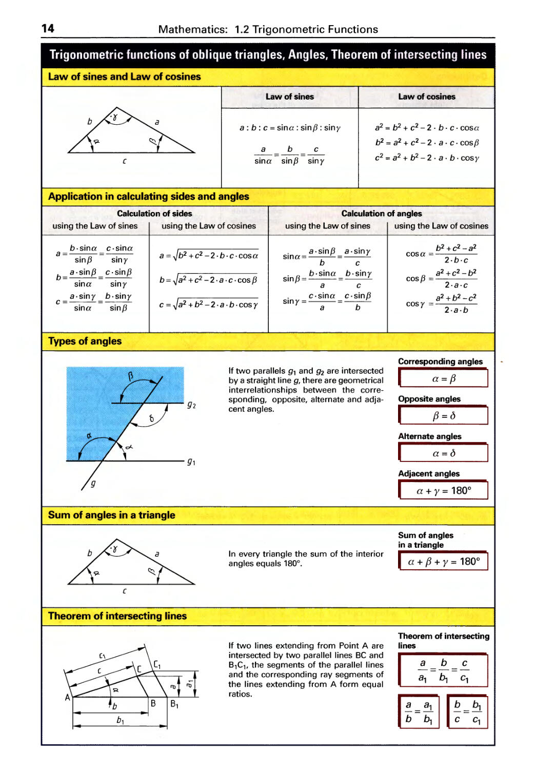
Law of sines and Law of cosines
Law of sines
a : b: c = sina : sinf3 : siny
a b c
- -
---
- -
sina sin{3 siny
[
Application in calculating sides and angles
Law of cosines
a 2 = b 2 + c 2 - 2 . b . c . cos a
b 2 = a 2 + c 2 - 2 . a . c. cos f3
c 2 = a 2 + b 2 - 2 . a . b . cos y
Calculation of sides
using the Law of sines using the Law of cosines
Calculation of angles
using the Law of sines using the Law of cosines
b.sina c.sina
a=
sin{3 siny
b= a.sin{3 = c.sin{3
sina siny
a.siny b.siny
c=
sina sin{3
. a. sin{3
sma=
b
. {3 b.sina
sm =
a
. c.sina
smy=
a.siny
c
b.siny
c
c. sin{3
b
a = b 2 + c 2 - 2 . b . c . cos a
b = a 2 + c 2 - 2 . a . c . cos {3
c = a 2 + b 2 - 2 . a . b . cos y
a
Types of angles
If two parallels 9, and 92 are intersected
by a straight line 9, there are geometrical
interrelationships between the corre-
sponding, opposite, alternate and adja-
cent angles.
g2
g1
Sum of angles in a triangle
In every triangle the sum of the interior
angles equals 180°.
[
Theorem of intersecting lines
If two lines extending from Point A are
intersected by two parallel lines BC and
B,C" the segments of the parallel lines
and the corresponding ray segments of
the lines extending from A form equal
ratios.
I'tJ
b 1
b 2 + c 2 - a 2
cos a =
2.b.c
a 2 +c 2 -b 2
cos {3 =
2.a.c
a 2 + b 2 - c 2
cos Y = 2 . a . b
Corresponding angles
I a={3 I
Opposite angles
I {3=o
Alternate angles
I a=o
Adjacent angles
I a + y = 180 0
Sum of angles
in a triangle
I a + {3 + y = 180 0
Theorem of intersecting
lines
1
8 b c
8, b, c,
1:=:; 11:=: I
Mathematics: 1.3 Fundamentals
15
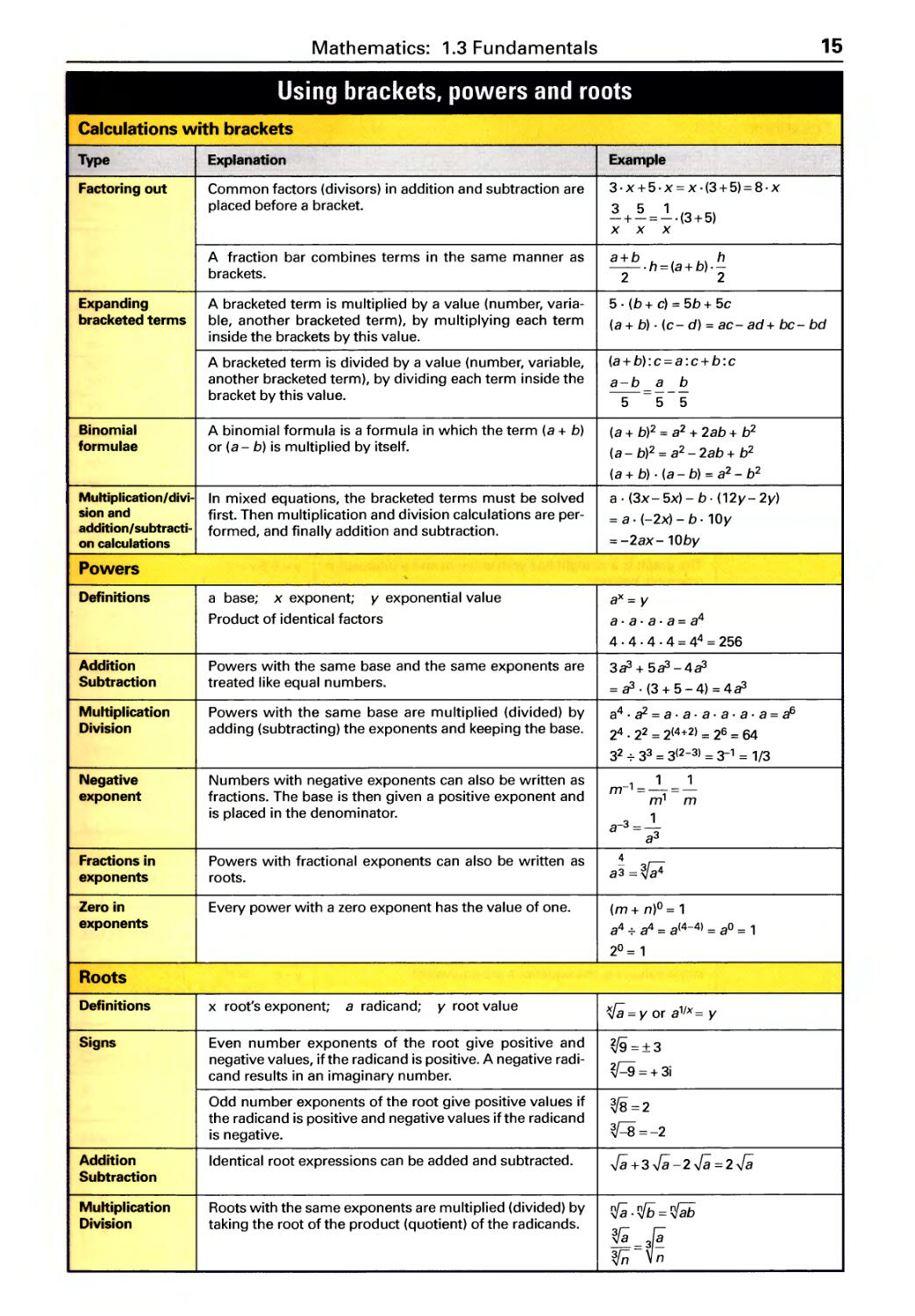
Using brackets, powers and roots
Calculations with brackets
Type Explanation Example
Factoring out Common factors (divisors) in addition and subtraction are 3. x+5.x = x .(3+5)= 8.x
placed before a bracket. 351
-+-=-.(3+5)
x x x
A fraction bar combines terms in the same manner as a+b h
brackets. -.h=(a+b).-
2 2
Expanding A bracketed term is multiplied by a value (number, varia- 5 . (b + e) = 5b + 5e
bracketed terms ble, another bracketed term), by multiplying each term (a + b) . (e - d) = ae - ad + be - bd
inside the brackets by this value.
A bracketed term is divided by a value (number, variable, (a + b) : e = a : e + b : e
another bracketed term), by dividing each term inside the a-b a b
bracket by this value. - = ---
5 5 5
Binomial A binomial formula is a formula in which the term (a + b) (a + b)2 = a 2 + 2ab + b 2
formulae or (a - b) is multiplied by itself. (a - b)2 = a 2 - 2ab + b 2
(a + b) . (a - b) = a 2 - b 2
Multiplicationl divi- In mixed equations, the bracketed terms must be solved a . (3x- 5x) - b. (12y- 2y)
sion and first. Then multiplication and division calculations are per- = a. (-2x) - b. 10y
addition/subtracti- formed, and finally addition and subtraction.
on calculations = -2ax- 10by
Powers
Definitions a base; x exponent; y exponential value aX = y
Product of identical factors a.a.a.a=a 4
4 . 4 . 4 . 4 = 4 4 = 256
Addition Powers with the same base and the same exponents are 383 + 583 - 483
Subtraction treated like equal numbers. = 83 . (3 + 5 - 4) = 483
Multiplication Powers with the same base are multiplied (divided) by a 4 . a2 = a . a . a . a . a . a = a 6
Division adding (subtracting) the exponents and keeping the base. 2 4 . 2 2 = 2(4+2) = 2 6 = 64
3 2 73 3 = 3(2-3) = , = 1/3
Negative Numbers with negative exponents can also be written as 1 1
m-'=-=-
exponent fractions. The base is then given a positive exponent and m' m
is placed in the denominator. 1
a- 3 = -
a 3
Fractions in Powers with fractional exponents can also be written as 4
exponents roots. a3=
Zero in Every power with a zero exponent has the value of one. (m + n)o = 1
exponents a 4 7 a 4 = a(4-4) = a O = 1
2° = 1
Roots
Definitions x root's exponent; a radicand; y root value l{/8 = y or a '/x = y
Signs Even number exponents of the root give positive and =:13
negative values, if the radicand is positive. A negative radi- =+3i
cand results in an imaginary number.
Odd number exponents of the root give positive values if =2
the radicand is positive and negative values if the radicand =-2
is negative.
Addition Identical root expressions can be added and subtracted. .]; +3.]; -2.]; =2.];
Subtraction
Multiplication Roots with the same exponents are multiplied (divided) by rf8.it; =i8b
Division taking the root of the product (quotient) of the radicands. =
n
16
Mathematics: 1.3 Fundamentals
Types of equations, Rules of transformation
Equations
Type
Variable
equation
Compatible units
equation
Single variable
equation
Function
equation
linear
function
y= mx+b
Explanation
Equivalent terms (formula terms of equal value) form rela-
tionships between variables (see also, Rules of transfor-
mation).
Immediate conversion of units and constants to an SI unit
in the result.
Only used in special cases, e. g. if engineering parameters
are specified or for simplification.
Calculation of the value of a variable.
Assigned function equation: y is a function of x with x as
the independent variable; y as the dependent variable.
The number pair (x, y) of a value table form the graph of
the function in the (x,y) coordinate system.
Constant function
The graph is a line parallel to the x-axis.
Proportional function
The graph is a straight line through the origin.
Linear function
The graph is a straight line with slope m and y intercept b
(example below).
Quadratic function
Every quadratic function graphs as a parabola
(example below).
3 - f- example:
t y=O.5x+1
2 -r- ./
1 l/' m=O.5
I b , =1
I I I I
,- -2 -1 1 2 3
-1-r- x
quadratic
function
y=x 2
Rules of transformation
Example
v=n.d.n
(a+ b)2 = a2 + 2ab+ b 2
p = M. n . P in kW if
9550 ' ,
n in 1/min and M in Nm
x+3=8
x=8-3=5
y = f (x)
H-- real numbers
y = f (x) = b
y = f (x) = mx
y=2x
y = f (x) = mx + b
y= 0.5x+ 1
y = f (x) = x 2
y= a2x2 + a,x+ ao
\li 3 - example:
y=0.5.x 2
2-
1 -
I I L I
I I
1 2
I
I
3
I I
-2 -1
-1 -
x
Equations are usually transformed to obtain an equation in which the unknown variable stands alone on the left side
of the equation.
Addition
Subtraction
Multiplication
Division
Powers
Roots
The same number can be added or subtracted from both
sides.
In the equations x + 5 = 15 and x + 5 - 5 = 15 - 5, x has the
same value, i.e. the equations are equivalent.
It is possible to multiply or divide each side of the equation
by the same number.
The expressions on both sides of the equations can be
raised to the same exponential power.
The root of the expressions on both sides of the equation
can be taken using the same root exponent.
x+5 =15 1-5
x+5-5 = 15-5
x=10
y-c =d I+c
y-c+c =d+c
y=d+c
a.x=b I+a
a.x b
a a
b
x -
a
.[; = a + b 1 0 2
(.[;)2 = (a + b)2
x =a 2 +2ab+b 2
x 2 = a + b I f
(.[;)2 = a + b
x = T. a + b
Mathematics: 1.3 Fundamentals
17
Decimal multiples and factors of units, Interest calculation
Decimal multiples and factors of units ct. DIN 1301-1 (2002-10)
Mathematics SI units
Power of Name Multiplication factor Prefix Examples
ten Name Character Unit Meaning
10'8 quintillion 1 000 000 000 000 000 000 exa E Em 10'8 meters
10'5 quadrillion 1 000 000 000 000 000 peta P Pm 10'5 meters
10'2 tri llion 1 000 000 000 000 tera T TV 10'2 volts
10 9 billion 1 000 000 000 giga G GW 10 9 watts
10 6 million 1 000 000 mega M MW 10 6 watts
10 3 thousand 1000 kilo k kN 10 3 newtons
10 2 hundred 100 hecto h hi 10 2 liters
10' ten 10 deca da dam 10' meters
10° one 1 - - m 10° meter
10-' tenth 0.1 deci d dm 10-' meters
10- 2 hundredth 0.01 centi c cm 10- 2 meters
10- 3 thousandth 0.001 milli m mV 10- 3 volts
1 O-{) millionth 0.000 001 micro IJ.. IJ..A 1 O-{) ampere
10- 9 billionth 0.000 000 001 nano n nm 10- 9 meters
10-'2 trillionth 0.000000000001 pico p pF 10-'2 farad
10-'5 quadrillionth 0.000000000000001 femto f fF 10-'5 farads
10-'8 quintillionth 0.000000000000000001 atto a am 10-'8 meters
values Numbers greater than 1 are expressed with positive exponents and num-
<1 f >1 bers less than 1 are expressed with negative exponents.
... -
1 1 1
-- - 1 Examples: 4300 = 4.3 . 1000 = 4.3 . 10 3
1000 100 10 10 100 1000 14638 = 1.4638. 10 4
"'1 I I f I I I- 0.07 = 1 0 = 7 . 10- 2
10- 3 10- 2 10- 1 10 0 10 1 10 2 10 3
Simple interest
P principle I interest
A amount accumulated r interest rate per year
t time in days,
interest period
Interest
1 st example:
P.r. t
1=
100% . 360
0/.
P = $2800.00; r = 6 ; t= '/2 a; I = ?
a
0/.
$2800.00. 6 . 0.5a
I = a $84.00
100%
1 interest year (1 a) = 360 days (360 d)
360 d = 12 months
1 interest month = 30 days
2nd example:
P = $4800.00; r =5.1 ; t = 5Od; I =?
a
%
$ 4800.00.5.1_ .50 d
I = a $34.00
100%. 360
a
Compound interest calculation for one-time payment
P principle
A amount accumulated
I interest
r interest rate per year
n time
q compounding factor
Amount accumulated
I A = p. qn I
Example:
P = $8000.00; n = 7 years; r = 6.5%; A = ?
= 1 + 6.5% = 1.065
q 100%
A = p. qn = $ 8000.00.1.065 7 = $ 8000.00.1.553986
= $ 12431.89
Compounding factor
I q = 1 + 1 % I
18
Mathematics: 1.3 Fundamentals
Percentage calculation, Proportion calculations
Percentage calculation
The percentage rate gives the fraction of the base value in hundredths.
The base value is the value from which the percentage is to be calculated.
The percent value is the amount representing the percentage of the base value.
Pr percentage rate, in percent Pv percent value Bv base value.
Percent value
R = Bv. F:-
v 100%
1st example:
Workpiece rough part weight 250 kg (base value); material loss 2%
(percentage rate); material loss in kg = ? (percent value)
P. = Bv . r:: = 250 kg . 2 % 5 kg
v 100% 100%
Percentage rate
P. = Pv . 100 %
r B
v
2nd example:
Rough weight of a casting 150 kg; weight after machining 126 kg;
weight percent rate (%) of material loss?
P. = .100% = 150 kg-126 kg .100% = 16%
r Bv 150 kg
Proportion calculations
Three steps for calculating direct proportional ratios
Example:
60 elbow pipes weigh 330 kg. What is the weight of
35 elbow pipes?
1st step: I Known data 1 60 elbow pipes weigh 330 kg.
2nd step: I Calculate the unit weight by dividing
1 elbow pipe weighs 33 ok9
3rd step: I Calculate the total by multiplying
1 80
60
100 200 kg 300
weight
40
c::
:::J 20
35 elbow pipes weigh
330 . 35 = 192.5 kg
Three steps for calculating inverse proportional ratios
Example:
It takes 3 workers 170 hours to process one order. How many
hours do 12 workers need to process the same order?
Known data l it takes 3 workers 170 hours
2nd step: I Calculate the unit time by multiplying
It takes 1 worker 3. 170 hrs
3rd step: I Calculate the total by dividing
It takes12 workers 3. 1 hrs= 42.5 hrs
1 2 0
150
VI
100
a
..c. 50
o
o 2
4 6 8 10 12 14
workers
Using the three steps for calculating direct and inverse proportions
Example:
660 workpieces are manufactu-
red by 5 machines in 24 days.
1 st application of 3 steps:
5 machines produce 660 workpieces in 24 days
1 machine produces 660 workpieces in 24 .5 days
9 machines produce 660 workpieces in 24.5 days
9
How much time does it take for
9 machines to produce
312 workpieces of the same
type?
2nd application of 3 steps:
9 machines produce 660 workpieces in 24. 5 days
9
9 machines produce 1 workpiece in 92: 650 days
9 machines produce 312 workpieces in
24 . 5 . 312 = 6.3 days
9.660
Mathematics: 1.4 Symbols, Units
19
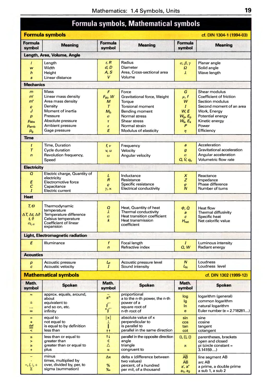
Formula symbols, Mathematical symbols
Formula symbols ct. DIN 1304-1 (1994-03)
Formula Meaning Formula Meaning Formula Meaning
symbol symbol symbol
Length, Area, Volume, Angle ., ,
I Length r,R Radius a, fJ, y Planar angle
w Width d,D Diameter Q Solid angle
h Height A,S Area, Cross-sectional area A Wave length
s Linear distance V Volume
Mechanics
m Mass F Force G Shear modulus
m' Linear mass density Fw,W Gravitational force, Weight jl,f Coefficient of friction
m" Area mass density M Torque W Section modulus
{! Density T Torsional moment I Second moment of an area
J Moment of inertia Mb Bending moment E Work, Energy
P Pressure a Normal stress W p , Ep Potential energy
Pabs Absolute pressure T Shear stress W k , Ek Kinetic energy
Pamb Ambient pressure E Normal strain P Power
Pg Gage pressure E Modulus of elasticity 'f} Efficiency
lime
t Time, Duration f,v Frequency a Acceleration
T Cycle duration v,u Velocity 9 Gravitational acceleration
n Revolution frequency, w Angular velocity a Angular acceleration
Speed Q, l% qv Volumetric flow rate
Electricity
Q Electric charge, Quantity of L Inductance X Reactance
electricity R Resistance Z Impedance
E Electromotive force
C Capacitance {! Specific resistance cp Phase difference
I Electric current y, x Electrical conductivity N Number of turns
Heat
T,B Thermodynamic Q Heat, Quantity of heat f/>,Q Heat flow
temperature A Thermal conductivity a Thermal diffusivity
T, t, {) Temperature difference a Heat transition coefficient c Specific heat
t, {) Celsius temperature k Heat transmission Hnet Net calorific value
al,a Coefficient of linear coefficient
expansion
Light, Electromagnetic radiation
E Illuminance f Focal length I Luminous intensity
n Refractive index Q, W Radiant energy
Acoustics
P Acoustic pressure L p Acoustic pressure level N Loudness
c Acoustic velocity I Sound intensity LN Loudness level
Mathematical symbols ct. DIN 1302 (1999-12)
Math. Spoken Math. Spoken Math. Spoken
symbol symbol symbol
"'" approx. equals, around, - proportional log logarithm (general)
about an a to the n-th power, the n-th
- equivalent to y power of a Ig common logarithm
. .. and so on, etc. square root of In natural logarithm
00 infinity ny n-th root of e Euler number (e = 2.718281...)
= equal to Ixl absolute value of x sin sine
'*' not equal to --L perpendicular to cos cosi ne
def is equal to by definition II is parallel to tan tangent
< less than tt parallel in the same direction cot cotangent
:S less than or equal to H parallel in the opposite direction (),[J,{} parentheses, brackets
> greater than angle open and closed
2: greater than or equal to triangle 3t pi (circle constant =
+ plus - congruent to 3.14159.. .)
- minus x delta x (difference between AB line segment AB
times, multiplied by two values) AB arc AB
-, I, :, ..;- over, divided by, per, to % percent, of a hundred a', a" a prime, a double prime
L sigma (summation) %0 per mil, of a thousand a" a2 a sub 1, a sub 2
20
Mathematics: 1.4 Symbols, Units
SI quantities and units of measurement
SP) Base quantities and base units cf. DIN 1301-1 (2002-10), -2 (1978-02), -3 (1979-10)
.......
Base Electric Thermo- Amount of Luminous
quantity Length Mass lime current dynamic substance intensity
temperature
Base mete r kilo- second kelvin mole candela
units gram ampere
Unit kg A K mol cd
symbol m s ') The units for measurement are defined in the International System of Units SI (Systeme International d'Unites). It
is based on the seven basic units (SI units), from which other units are derived.
Base quantities, derived quantities and their units
Quantity Unit Relationship Remarks
Symbol Name I Symbol Examples of application
Length, Area, Volume, Angle
Length I meter m 1m = 10 dm = 100 cm 1 inch = 25.4 mm
= 1000 mm In aviation and nautical applications
1mm = 1000 m the following applies:
1km = 1000 m 1 international nautical mile = 1852 m
Area A,S square meter m 2 1 m 2 = 10000 cm 2 Symbol S only for cross-sectional
= 1000000 mm 2 areas .
are a 1 a = 100 m 2
hecta re ha 1 ha = 100 a = 10000 m 2 Are and hectare only for land
100 ha = 1 km 2
Volume V cubic meter m 3 1 m 3 = 1000 dm 3
= 1000000cm 3
liter 1, L 11 = 1 L = 1 dm 3 = 10 dl = Mostly for fluids and gases
0.001 m 3
1 ml = 1 cm 3
Plane a,{3,y... radian rad 1 rad = 1 m/m = 57.2957... ° 1 rad is the angle formed by the inter-
angle = 180 0 /n section of a circle around the center of
(angle) degrees ° 1° = 1 0 rad = 60' 1 m radius with an arc of 1 m length.
In technical calculations instead of
minutes , l' = 1°/60 = 60" a = 33° 17' 27.6", better use is a =
33.291°.
seconds " 1" = 1'/60 = 1°/3600
Solid angle Q steradian sr 1 sr = 1 m 2 /m 2 An object whose extension measures
1 rad in one direction and perpendicu-
larly to this also 1 rad, covers a solid
angle of 1 sr.
..........
Mechanics
Mass m kilogram kg 1 kg = 1000 g Mass in the sense of a scale result or a
gram g 1 g = 1000 mg weight is a quantity of the type of mass
(unit kg).
megagram Mg
metric ton t 1 metric t = 1000 kg = 1 Mg
0.2 g = 1 ct Mass for precious stones in carat (ct).
Linear mass m' kilogram kg/m 1 kg/m = 1 g/m m For calculating the mass of bars, pro-
density per meter files, pipes.
Area mass m" kilogram kg/m 2 1 kg/m 2 = 0.1 g/cm 2 To calculate the mass of sheet metal.
density per square
meter
Density {! kilogram kg/m 3 1000 kg/m 3 = 1 metric t/m 3 The density is a quantity independent
per cubic = 1 kg/dm 3 of location.
meter = 1 g/cm 3
= 1 g/ml
= 1 mg/mm 3
Mathematics: 1.4 Symbols, Units
21
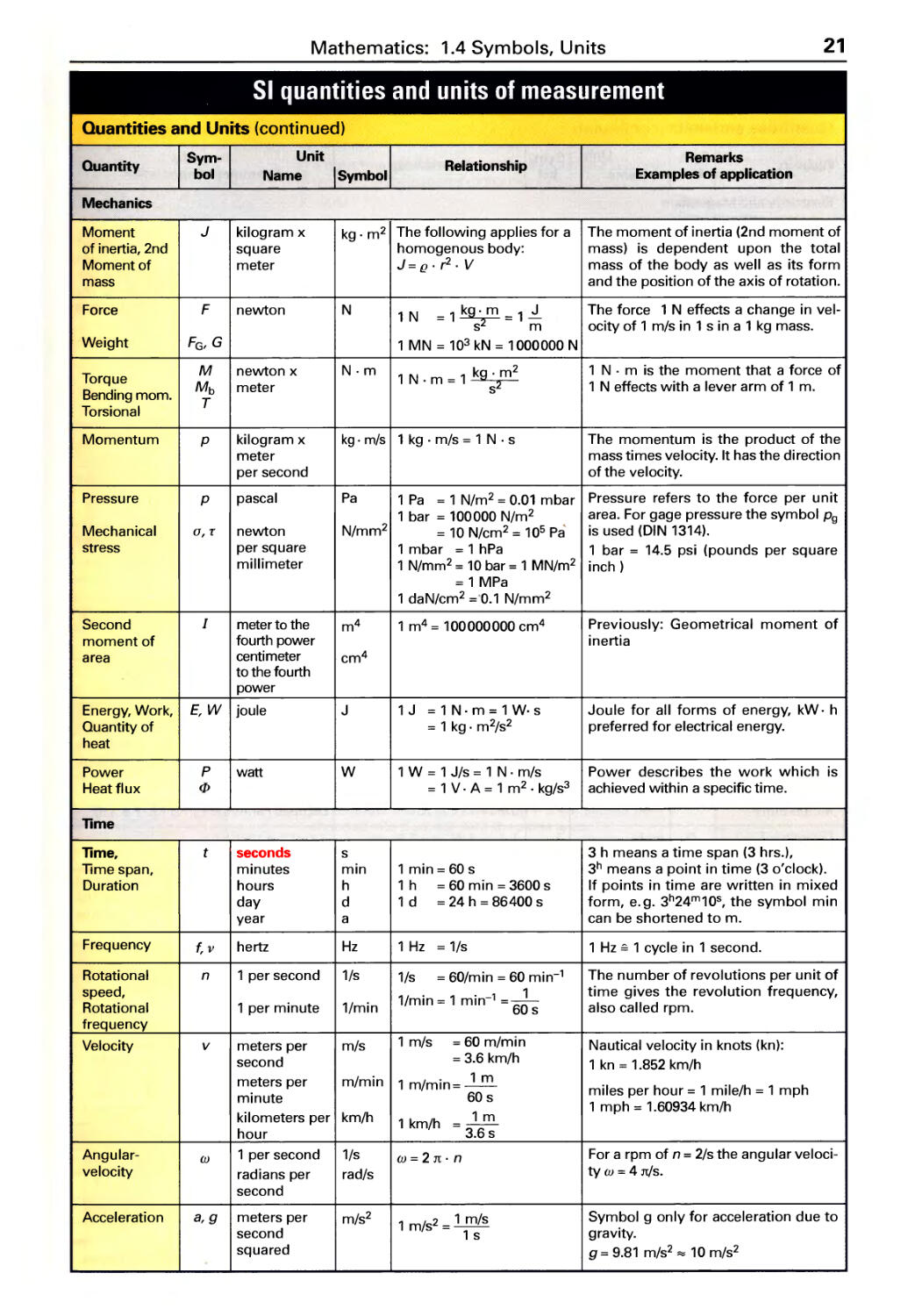
SI quantities and units of measurement
Quantities and Units (continued)
Quantity Sym- Unit Relationship Remarks
bol Name I Symbol Examples of application
Mechanics
Moment J kilogram x kg. m 2 The following applies for a The moment of inertia (2nd moment of
of inertia, 2nd square homogenous body: mass) is dependent upon the total
Moment of meter J=g.r 2 .V mass of the body as well as its form
mass and the position of the axis of rotation.
Force F newton N 1 N =1 =1 The force 1 N effects a change in vel-
s m ocityof 1 m/s in 1 s in a 1 kg mass.
Weight F G , G 1 M N = 10 3 kN = 1 000000 N
Torque M newton x N.m 1 N - 1 k g . m 2 1 N . m is the moment that a force of
Bending mom. Mb meter . m - s 2 1 N effects with a lever arm of 1 m.
Torsional T
Momentum P kilogram x kg . m/s 1 kg . m/s = 1 N . s The momentum is the product of the
meter mass times velocity. It has the direction
per second of the velocity.
Pressure P pascal Pa 1 Pa = 1 N/m 2 = 0.01 mbar Pressure refers to the force per unit
1 bar = 100000 N/m 2 area. For gage pressure the symbol Pg
Mechanical G, T newton N/mm 2 = 10 N/cm 2 = 10 5 Pa" is used (DIN 1314).
stress per square 1 mbar = 1 hPa 1 bar = 14.5 psi (pounds per square
millimeter 1 N/mm 2 = 10 bar = 1 MN/m 2 inch)
= 1 MPa
1 daN/cm 2 = 0.1 N/mm 2
Second I meter to the m 4 1 m 4 = 100000000 cm 4 Previously: Geometrical moment of
moment of fourth power inertia
area centi meter cm 4
to the fourth
power
Energy, Work, E, W joule J 1 J = 1 N. m = 1 W. s Joule for all forms of energy, kW. h
Quantity of = 1 kg. m 2 /s 2 preferred for electrical energy.
heat
Power P watt W 1 W = 1 J/s = 1 N . m/s Power describes the work which is
Heat flux cp = 1 V . A = 1 m 2 . kg/s 3 achieved within a specific time.
lime
lime, t seconds s 3 h means a time span (3 hrs.),
Time span, minutes min 1 min = 60 s 3 h means a point in time (3 o'clock).
Duration hours h 1 h = 60 m i n = 3600 s If points in time are written in mixed
day d 1 d = 24 h = 86400 s form, e.g. 3 h 24 m 10 s , the symbol min
year a can be shortened to m.
Frequency f,v hertz Hz 1 Hz = 1/s 1 Hz';' 1 cycle in 1 second.
Rotational n 1 per second 1/s 1/s = 60/min = 60 min-' The number of revolutions per unit of
speed, 1/min = 1 min-' =-L time gives the revolution frequency,
Rotational 1 per minute 1/min 60 s also called rpm.
frequency
Velocity v meters per m/s 1 m/s = 60 m/min Nautical velocity in knots (kn):
second = 3.6 km/h 1 kn = 1.852 km/h
meters per m/min 1 /. 1 m
m mln=- miles per hour = 1 mile/h = 1 mph
minute 60 s
kilometers per km/h 1m 1 mph = 1.60934 km/h
hour 1 km/h = 3.6s
Angular- (J) 1 per second 1/s (J)=2n.n For a rpm of n = 2/s the angular veloci-
velocity radians per rad/s ty (J) = 4 n/s.
second
Acceleration a, 9 meters per m/s 2 1 m/s 2 = 1 m/s Symbol g only for acceleration due to
second 1 s gravity.
squared 9 = 9.81 m/s 2 ::::: 10 m/s 2
22
Mathematics: 1.4 Symbols, Units
SI quantities and units of measurement
Quantities and units (continued)
Quantity Sym- Unit Sym- Relationship Remarks
bol Name bol Examples of application
Electricity and Magnetism
Electric current I ampere A The movement of an electrical charge is
Electromotive E volt V 1 V = 1 W/1 A = 1 J/C
force called current. The electromotive force
Electrical R ohm Q 1 Q = 1 V/1 A is equal to the potential difference bet-
resistance ween two points in an electric field. The
Electrical G siemens S 1 S = 1 Al1 V = 1/Q reciprocal of the electrical resistance is
conductance called the electrical conductivity.
Specific ohm x Q.m 10-6 Q. m = 1 Q. mm 2 /m 1 . Q.mm 2
{! {! = - In
resistance meter x m
Conductivity siemens S/m 1 . m
y, x x=- In
per meter {! Q.mm 2
Frequency f hertz Hz 1 Hz = 1/s Frequency of public electric utility:
1000 Hz = 1 kHz EU 50 Hz, USA/Canada 60 Hz
Electrical energy W joule J 1 J =1W.s=1N.m In atomic and nuclear physics the unit
1 kW . h = 3.6 MJ eV (electron volt) is used.
1 W. h = 3.6 kJ
Phase cp - - for alternating current: The angle between current and voltage
difference P in inductive or capacitive load.
coscp = -
V.I
Elect. field strength E volts per meter Vim
Elect. charge Q coulomb C 1 C = 1 A. 1 s; 1 A . h = 3.6 kC E= F c= Q Q =1. t
Elect. capacitance C farad F 1 F =1 CN Q' V'
inductance L henry H 1 H = 1 V . s/A
Power P watt W 1 W = 1 J/s = 1 N . m/s In electrical power engineering:
Effective power = 1 V.A Apparent power S in V. A
Thermodynamics and Heat transfer
Thermo- T,B kelvin K OK = -273.15°C Kelvin (K) and degrees Celsius (OC) are
dynamic used for temperatures and tempera-
temperature t, i} degrees °C O°C = 273.15 K ture differences.
Celsius Celsius O°C = 32°F t = T - To; To = 273.15 K
temperature O°F = -17.77 °C degrees Fahrenheit (OF): 1.8 of = 1°C
Quantity of Q joule J 1 J =1W.s=1N.m 1 kcal :So 4.1868 kJ
heat 1 kW . h = 3600000 J = 3.6 MJ
Net calorific joule per J/kg 1 MJ/kg = 1 000000 J/kg Thermal energy released per kg fuel
value Hnet kilogram minus the heat of vaporization of the
Joule per J/m 3 1 MJ/m 3 = 1000000 J/m 3 water vapor contained in the exhaust
cubic meter gases.
Non-SI units
Length Area Volume Mass Energy, Power
1 inch = 25.4 mm 1 sq.i n = 6.452 cm 2 1 cu.in = 16.39 cm 3 1 oz = 28.35 g 1 PSh = 0.735 kWh
1 foot = 0.3048 m 1 sq. ft = 9.29 dm 2 1 cU.ft = 28.32 dm 3 11b = 453.6 g 1 PS = 735 W
1 ya rd = 0.9144 m 1 sq.yd = 0.8361 m 2 1 cu.yd = 764.6 dm 3 1 metric t = 1000 kg 1 kcal = 4186.8 Ws
1 nautical 1 US gallon = 3.785 dm 3 1 short ton = 907.2 kg 1 kcal = 1.166 Wh
mile = 1.852 km Pressure 1 Imp. gallon = 4.536 dm 3 1 ca rat = 0.2 g 1 kpm/s = 9.807 W
1 mile = 1.609 km 1 bar = 14.5 psi 1 barrel = 158.8 dm 3 1 Btu = 1055 Ws
1 hp = 745.7 W
Prefixes of decimal factors and multiples
Prefix pico nano micro milli centi deci deca hecto kilo mega giga tera
Prefix symbol p n m c d da h k M G T
Power of ten 10-'2 10- 9 10- 6 10- 3 10- 2 10-' 10' 10 2 10 3 10 6 10 9 10'2
- Factor Multiple -
- -
1 mm = 10- 3 m = 1/1000 m, 1 km = 1000 m, 1 kg = 1000 g, 1 GB (Gigabyte) = 1000000000 bytes
Mathematics: 1.5 Lengths
23
Calculations in a right triangle
The Pythagorean Theorem
c 2
11
4\)
PT .
L :j
I
r-
!J)
.
P1
x
z
;-
I
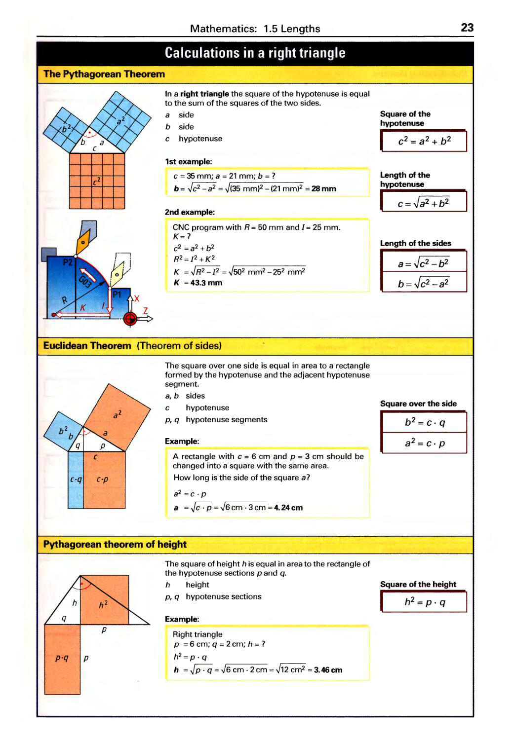
In a right triangle the square of the hypotenuse is equal
to the sum of the squares of the two sides.
a side
b side
c hypotenuse
1 st example:
c = 35 mm; a = 21 mm; b = ?
b = .Jc 2 - a 2 = .J (35 mm)2 - (21 mm)2 = 28 mm
2nd example:
CNC program with R = 50 mm and] = 25 mm.
K=?
c 2 =a 2 +b 2
R2 = ]2 + K2
K = .J R2 - ]2 = .J 50 2 mm 2 - 25 2 mm 2
K =43.3mm
Euclidean Theorem (Theorem of sides)
c.q
c.p
The square over one side is equal in area to a rectangle
formed by the hypotenuse and the adjacent hypotenuse
segment.
a, b sides
c hypotenuse
p, q hypotenuse segments
Example:
A rectangle with c = 6 cm and p = 3 cm should be
changed into a square with the same area.
How long is the side of the square a?
a 2 = c . p
a = = -J 6cm.3cm=4.24cm
Pythagorean theorem of height
p
p.q
p
The square of height h is equal in area to the rectangle of
the hypotenuse sections p and q.
h height
p, q hypotenuse sections
Example:
Right triangle
p = 6 cm; q = 2 cm; h = ?
h 2 = P . q
h = = -J 6 cm. 2cm = .J 12 cm 2 =3.46cm
Square of the
hypotenuse
I C 2 = a 2 + b 2
Length of the
r e: : 2 + b 2
Length of the sides
a = .J C 2 - b 2
b = .J c 2 -a 2
Square over the side
I
b 2 = c. q
a 2 = c. p
Square of the height
I h 2 = P . q
24
Mathematics: 1.5 Lengths
Division of lengths, Arc length, Composite length
Sub-dividing lengths
Edge distance = spacing
p
p
p
p
Edge distance ;e spacing
p p p p
Subdividing into pieces
Ir
Is 5
5
Arc length
Example: Torsion spring
(
Composite length
1 2
t:::I ""t:JE ""t:J
I total length
p spaci ng
n number of holes
Example:
1=2 m; n = 24 holes; p = 7
I 2000 mm
p=-= 80mm
n + 1 24 + 1
I total length
p spacing
n number of holes
a, b edge distances
Example:
1=1950 mm; a = 100 mm; b = 50 mm;
n = 25 holes; p = 7
1-(a + b) 1950 mm - 150 mm
p= 75mm
n -1 25 - 1
bar length 5 saw cutting width
z number of pieces Ir remaining length
Is piece length
Example:
I = 6000mm; Is= 230 mm; 5 = 1.2 mm; z = 7; Ir = 7
I 6000 mm .
z =-= 25. 95=25 pieces
Is +5 230 mm + 1.2 mm
lr = 1- z. (Is + 5) = 6000 mm-25. (230 mm + 1.2 mm)
=220mm
la arc length
r radius
a angle at center
d diameter
Example:
r = 36 mm; a = 120°; la = 7
1t . r . a 1t .36 mm . 120°
1 - 75. 36 mm
a-180° 1800
o outside diameter
d m mean diameter
I" 12 section lengths
a angle at center
d inside diameter
t thickness
L composite length
1 1
Example (composite length, picture left):
0= 360 mm; t= 5 mm; a = 270°; 12 = 70 mm;
d m = 7; L = 7
d m = 0 - t = 360mm-5mm = 355mm
1t. d . a
L = I, + 1 2 = m + 1 2
360
1t . 355 mm . 270° 70 906 45
= + mm = . mm
360°
Spacing
I
I
p=-
n+1
Spacing
I p = 1- (8 + b)
. n-1
Number of pieces
I
I
z=-
Is + S
Remaining length
I I, = I - z . (Is + 5)
Arc length
I='Jt.(.a
a 180 0
'Jt.d.a
I =
a 360 0
Composite length
I L = I, + 1 2 + ...
Mathematics: 1.5 Lengths
25
Effective length, Spring wire length, Rough length
Effective lengths
d m
D
Circular ring sector
d m
D
Spring wire length
o outside diameter
d inside diameter
d m mean diameter
t th ickness
/ effective length
a angle at center
Example (circular ring sector):
0= 36 mm; t= 4 mm; a = 240°; d m =?; 1 =?
dm=O-t =36 mm-4mm=32 mm
J[ . d . a J[ . 32 mm .240°
I = m 67.02mm
360° 360°
Example: Compression spring / effective length of the helix
Om mean coil diameter
i number of active coils
Dm
Example:
Om = 16 mm; i = 8.5; 1 = ?
I = Jt . Om . i + 2 . Jt . Om
= Jt . 16 mm . 8.5 + 2 . Jt . 16 mm = 528 mm
Rough length of forged parts and pressed parts
/
scaling loss
12
When forming without scaling loss the volume of the rough
part is the same as the volume of the finished part. If there
is scaling loss or burr formation, this is compensated by a
factor that is applied to the volume of the finished piece.
Va volume of the rough part
V e volume of the finished part
q addition factor for scaling loss or loss due to burrs
A, cross-sectional area of the rough part
A 2 cross-sectional area of the finished part
/, initial length of the addition
1 2 length of the solid forged part
Example:
A cylindrical peg d = 24 mm and 12 = 60 mm is pressed
onto a flat steel workpiece 50 x 30 mm. The scaling
loss is 10 %. What is the initial length I, of the forged
addition?
Va = V e . (1 + q)
A, .1, = A 2 . 1 2 , (1 + q)
I _ A 2 . 1 2 , (1+q)
1 -
A,
:IT . (24 mm)2 .60 mm . (1 + 0.1)
20mm
4 . 50 mm . 30 mm
Effective length
of a circular ring
I I = :it . d m
Effective length of a
circular ring sector
I n.d .a
1= m
360 0
Mean diameter
d m = D - t
d m = d+ t
Effective length
of the helix
1 = n . Dm . i +
2 . n . Dm
1 = n . Dm . (i + 2)
Volume without sca-
ling loss
I Va = V e
Volume with scaling
loss
Va = V e + q. V e
Va = V e . (1 + q)
A, . I, = A 2 . /2 . (1 + q)
26
Mathematics: 1.6 Areas
Angular areas
Square
Rhombus (lozenge)
Rectangle
/"
/'
/"
Rhomboid (parallelogram)
Trapezoid
Triangle
A area
length of side
Example:
d length of diagonal
1= 14 mm; A = 7; d = 7
A = 1 2 = (14 mm)2 = 196 mm 2
d = fi . I = fi . 14 mm = 19.8 mm
A area
I length of side
w width
Example:
I = 9 mm; w = 8.5 mm; A = 7
A = I . w = 9 mm . 8.5 mm = 76.5 mm 2
A area
I length
w width
d length of diagonal
Example:
1=12mm;w=11 mm;A=7;d=7
A =1. w=12 mm. 11 mm=132mm 2
d = .J12 + w 2 = ,J( 12 mm)2 + (11 mm)2 = .J 265 mm 2
=16.28 mm
A area
I length
Example:
w width
1= 36 mm; w= 15 mm; A = 7
A = I. w= 36 mm .15 mm = 540 mm 2
A a rea
I, longer length
12 shorter length
Example:
1m average length
w width
I, = 23 mm; 12 = 20 mm; w= 17 mm; A = 7
A = I, + 1 2 . W = 23 mm + 20 mm . 17 mm
2 2
= 365. 5 mm 2
A area
length of side
Example:
w width
I, = 62 mm; w= 29 mm; A = 7
A = I, . w = 62 mm . 29 mm 899 mm 2
2 2
Area
I A = /2
Length of diagonal
I d=Y2./
Area
I A=/.w
I .
Area
I A=/.w
Length of diagonal
I d= .J P+w2
Area
I A=/.w
Area
I
A = I, + 1 2 . W
2
Average length
I
1 = I, + 1 2
m 2
Area
I
I. w
A=-
2
Mathematics: 1.6 Areas
27
Triangle, Polygon, Circle
Equilateral triangle
,
D
Regular polygons
A a rea
d diameter of inscribed circle
[ length of side
h height
o diameter of circumscribed
ci rcl e
Example:
[ = 42 mm; A = 7;
A = ! . J3 .[2 = ! . J3 . (42 mm)2
4 4
= 763.9 mm 2
. A a rea
[ length of side
o diameter of circumscribed
circle
d diameter of inscribed circle
n no. of vertices
a angle at center
(3 vertex angle
Diameter of
circumscribed circle Area
I 0 = . .[ = 2 . d II A = . .[2
Diameter of
inscribed circle Triangle height
I d= . .[= II
h=!.J3.l
2
Diameter of
inscribed circle
I d= DL[2
Diameter of
circumscribed circle
I 0 = d2 + [2
Area
II
n./.d
A=
4
Length of side
. ( 1800 )
l=D.sln n
Example:
Hexagon with 0 = 80 mm; [ = 7; d = 7; A = 7
. ( 1800 ) . ( 1800 )
1 = 0 . Sin -----;:;- = 80 mm . Sin 6 = 40 mm
d = 02 _[2 = 6400 mm 2 -1600 mm 2 = 69.282 mm
n .[ . d 6. 40 mm . 69.282 mm
A =-= 4156.92 mm 2
4 4
Calculation of regular polygon using table values
No of
ertices n
Area A ""
Diameter of
circumscribed circle D ""
Angle at center
I
Corner angle
I f:i = 180 0 - a
360 0
a=-
n
Diameter of
inscribed circle d ""
Length of side I ""
3 0.325 . 0 2 1.299 . d 2 0.433 . [2 1 . 154 . [ 2.000. d 0.578 . [ 0.500 . 0 0.867 . 0 1.732. d
4 0.500 . 0 2 1.000. d 2 1.000. [2 1.414. [ 1.414. d 1.000 . [ 0.707 . 0 0.707.0 1.000. d
5 0.595 . 0 2 0.908. d 2 1.721 . [2 1.702 . [ 1.236. d 1.376.[ 0.809 . 0 0.588 . 0 0.727. d
6 0.649 . 0 2 0.866 . d 2 2.598 . [2 2.000 . [ 1.155 . d 1.732 . [ 0.866 . 0 0.500 . 0 0.577 . d
8 0.707 . 0 2 0.829 . d 2 4.828 . [2 2.614. [ 1.082 . d 2.414.[ 0.924 . 0 0.383 . 0 0.414. d
10 0.735 . 0 2 0.812. d 2 7.694. [2 3.236 . [ 1.052 . d 3.078 . [ 0.951 . 0 0.309 . 0 0.325 . d
12 0.750.0 2 0.804 . d 2 11. 196 . [2 3.864 . [ 1.035. d 3.732 . [ 0.966.0 0.259 . 0 0.268 . d
Example: Octagon with [ = 20 mm A = 7; 0 = 7
A 4.828 . [2 = 4.828 . (20 mm)2 = 1931.2 mm 2 ; o 2.614. [ = 2.614 . 20 mm = 52.28 mm
Circle
A a rea
d diameter
C circumference
Example:
d = 60 mm; A = 7; C = 7
Jt . d 2 Jt. (60 mm)2
A =-= 2827 mm 2
4 4
C = Jt.d = Jt.60 mm= 188.5mm
Area
I
:Tt . d 2
A=-
4
Circumference
I C=n.d
28
Mathematics: 1.6 Areas
Circular sector, Circular segment, Circular ring, Ellipse
Circular sector
f\
La
d
Circular segment
Circular segment with a :5180°
L
'i'
a
d
Circular ring
w
d m
Ellipse
"'t:J
D
A area
d diameter
fa arc length
chord length
f radius
a angle at center
Example:
d = 48 mm; a = 110°; fa = 7; A = 7
1t. f . a 1t. 24 mm .110°
1--- 46.1mm
a-180° - 1800
A= fa .f = 46.1 mm.24mm 553mm 2
2 2
A area
d diameter
fa arc length
f chord length
Example:
w width of segment
f radius
a angle at center
f= 30 mm; a = 120°; f = 7; w= 7; A = 7
2 . a 2 30 . 120 0 5 96
I = .r,sln-=' mm,sln-= 1. mm
2 2
I a 51.96 mm 120 0
w=-.tan-= .tan-=14.999mm=15 mm
2 4 2 4
A = ;r. d 2 . a I . (r - w)
4 360 0 2
;r. (60 mm)2 120 0 51.96 mm . (30 mm - 15 mm)
4 360 0 2
= 552.8 mm 2
Radius
I
W 1 2
r=-+-
2 8.w
Arc length
II
n.r.a
1 =
a 1800
A a rea
o outside diameter
d inside diameter
Example:
0= 160 mm; d= 125 mm; A = 7
A = . (0 2 - d 2 ) = . (160 2 mm 2 -125 2 mm 2 )
4 4
= 7834 mm 2
d m mean
diameter
w width
d diameter
C Circumference
A area
o length
Example:
0= 65 mm; d = 20 mm; A = 7
1t . 0 . d 1t . 65 mm . 20 mm
A= =
4 4
= 1021 mm 2
Area
n.d 2 a
A=-.-
4 360°
A = la . r
2
Chord length
I
Arc length
I
1 = 2 . r . sin a
2
n.r.a
1 =
a 1800
Area
A = n . d 2 . 1 . (r - w)
4 360° 2
1 . r - 1 . (r - w)
A= a
2
Chord length
1 = 2 . r . sin a
2
1 = 2 . w. (2 . r - w)
Height of segment
1 a
w=-.tan-
2 4
w=r- rL
Area
A=n.d .w
m
n
A = - . (0 2 - d 2 )
4
Area
I
Circumference
I
n.O.d
A=
4
O+d
C=n.-
2
Mathematics: 1.7 Volume and Surface area
29
Cube, Square prism, Cylinder, Hollow cylinder, Pyramid
Cube
Square prism
Cylinder
Hollow cylinder
...c:::
Pyramid
V volume
As surface area
length of side
Example:
/ = 20 mm; V=?; As =?
V = /3 = (20 mm)3 = 8000 mm 3
As = 6.1 2 = 6. (20 mm)2 = 2400 mm 2
V volume
As surface area
1 length of side
Example:
1=6cm;w=3cm;h=2cm;V=?
V = 1 . w. h = 6 cm . 3 cm . 2 cm = 36 cm 3
h height
w width
V volume d diameter
As surface area h height
Ac cylindrical surface area
Example:
d = 14 mm; h = 25 mm; V = ?
V = It . d 2 . h
4
It. (14 mm)2
= .25 mm
4
= 3848 mm 3
V volume
As surface area
0, d diameter
h height
Example:
0= 42 mm; d= 20 mm; h = 80 mm;
V=?
V = It . h . (02 _ d 2 )
4
It.80 mm (42 2 2 20 2 2 )
= . mm - mm
4
= 85 703 mm 3
V volume
h height
hs slant height
1 length of base
/, edge length
w width of base
Example:
1 = 16 m m; w = 21 mm; h = 45 m m; V = ?
/. w . h 16 mm . 21 mm . 45 mm
V=-=
3 3
= 5040 mm 3
Volume
I V = 1 3
Surface area
I As = 6 . 1 2
Volume
I V=I.w.h
Surface area
I As = 2 . (I . w + I . h + w. hI
Volume
I
1t . d 2
V=-.h
4
Surface area
I A s =n.d.h+2. n.t I
Cylindrical surface area
I A,,=n.d.h
Volume
I V = n h . (0 2 - d 2 )
Surface area
As = J't . (0 + d) . [i. (0 - d) + h ]
Volume
I
Edge length
I I, = h + :2
Slant height
I
[. w. h
V=
3
R 2
h = h 2 +-
s 4
30
Mathematics: 1.7 Volume and Surface area
Truncated pyramid, Cone, Truncated cone, Sphere, Spherical segment
Truncated pyramid
Cone
..c::
Truncated cone
d
..c::
Sphere
d
Spherical segment
..c::
\ ,
\ I I
, I '
'---+_/
d
V volume
/" /2 lengths of
base
Example:
/, = 40 mm; /2 = 22 mm; w, = 28 mm;
W2 = 15 mm; h = 50 mm; V = ?
V = !2 . (A, + + A, . )
3
= 50mm .(1120+330+ 1120.330)mm2
3
= 34299 mm 3
A, area of base
surface
A 2 top surface
hs slant height
h height
W" W2 widths
V volume h
Ac conical surface area hs
d diameter
height
slant height
Example:
d= 52 mm; h= 110 mm; V=?
Jt . d 2 h
V=-.-
4 3
Jt . (52 mm)2 110 mm
4 3
= 77870 mm 3
V volume d
Ac conical surface area
o diameter h
of base hs
Example:
0= 100 mm; d= 62 mm; h = 80 mm; V=?
Jt.h
V =-.(0 2 +d 2 +O.d)
12
= Jt. 80 mm . (1002 + 622 + 100.62) mm 2
12
= 419800 mm 3
diameter
of top
height
slant height
V volume d diameter of sphere
As surface area
Example:
d = 9 mm; V = ?
Jt.d 3 Jt.(9mm)3
V=-. 3S2mm 3
6 6
V volume d
AI lateral surface area h
As surface area
Example:
d= 8 mm; h = 6 mm; V=?
V =rr.h 2 .(%- )
= rr . 6 2 mm 2 . ( 8 m _ 6 m )
= 226 mm 3
diameter of sphere
height
Volume
I V= .(A+ + J A. ) I
Slant height
2
hs = h 2 + C' : /, )
Volume
I
Conical surface area
I
Slant height
I
n.d 2 h
V=-.-
4 3
n.d.h
A = s
c 2
2
h = _+h2
s 4
Volume
:n;.h
V =-.(0 2 +d 2 +0 .d)
12
Conical surface area
I n.h
A = .(D+d)
c 2
Slant height
I hs = h2 +( D;d )2
Volume
I
Surface area
I
n.d 3
V=-
6
As = n . d 2
Volume
I V=n.h 2 . (%- )
Surface area
I As = n . h . (2 . d - h) I
lateral surface area
A=n.d.h
Mathematics: 1.8 Mass
31
Volumes of composite solids, Calculation of mass
Volumes of composite solids
V 2
., ' I
- -
Calculation of mass
Mass, general
,/
Linear mass density
,/'
Area mass density
V total volume
V" V 2 partial volumes
Total volume
I V = V, + V 2 +... - V 3 - V 4 !
Example:
Tapered sleeve; 0 = 42 mm; d = 26 mm;
d, = 16 mm; h = 45 mm; V = ?
Jt.h
V, = - . (0 2 + d 2 + 0 . d)
12
Jt.45mm
= .(42 2 +26 2 +42.26)mm 2
12
= 41610 mm 3
\I. - Jt . dl h _ Jt .16 2 mm 2 45 - 9048 3
2 - 4 . - 4 . mm - mm
V = V,- V 2 = 41610 mm 3 -9048 mm 3 = 32562 mm 3
m mass
V volume
{} density
Mass
I m= V. e
Example:
Workpiece made of aluminum;
V = 6.4 dm 3 ; {} = 2.7 kg/dm 3 ; m = ?
V 3 kg
m= .{}=6.4dm .2.7 _ 3
dm
Values for density of
solids, liquids and gases:
pages 116 and 117
= 17.28 kg
m mass / length
m' linear mass density
Linear mass density
I m = m' . I
Example:
Steel bar with d = 15 mm;
m' = 1.39 kg/m; / = 3.86 m; m =?
m =m'./=1.39 kg .3.86m
m
Appl ication: Ca Icu lati ng
the mass of profile sec-
tions, pipes, wires, etc.
using the table values for
m'
= 5. 37 kg
m mass A area
m" area mass density
Area mass density
I m = m" . A
Example:
Steel sheet
t = 1.5 mm; m" = 11.8 kg/m 2 ;
A = 7.5 m 2 ; m = ?
Application: Calculating
the mass of sheet metal,
foils, coatings, etc using
the table values for m"
" A 8 kg 2
m=m. =11. 2.7.5m
m
= 88. 5 kg
32
Mathematics: 1.9 Centroids
Centroids of Lines and Plane Areas
Centroids of lines
I, I" 1 2 lengths of the lines C, C" C 2 centroids of the lines
xc' x" X2 horizontal distances of the line centroids from the v-axis
Vc, v" V2 vertical distances of the line centroids from the x-axis
Line segment
J: x( .r e .1
Circular arc
'f\
a
Calculation of 1 and la:
Page 28
Centroids of plane areas
I
Composite continuous lines
/
X =-
c 2
y
X1
X2
x(
General
, ./
Yc=i
a
x
I
! /2
+--------
/.180°
Y c =
Jt.a
Semicircular arc
I Yc '" 0.6366 . r I
/1 . X 1 + /2 . X 2 + .. .
X =
c /1 + /2 + . ..
Quarter circle arc
I Yc '" 0.9003 . r I
/, . Y1 + /2 . Y2 +...
y; =
c /, + /2 +...
A, A" A 2 areas C, C" C 2 centroids of the areas
Xc, x" X2 horizontal distances of the area centroids from the v-axis
Vc, V" V2 vertical distances of the area centroids from the x-axis
Rectangle I
1?r8
Circular sector
'/'
a
Circular segment
1;:
w
Yc="2
Triangle
[,
w
YC=3
I
General
I 2.,./
Yc=
Composite areas
y X2
X1
Semi-circle area
I Yc '" 0.4244 . r I
A 2
A 1
Quarter circle area
I Yc '" 0.6002 . r I
u ('.I
X(
x
I
I
/3
Y c = 12 . A
A, .X1 +A 2 .X2 +...
X =
c A,+A 2 +...
A 1 . Y1 + A 2 . Y2 +...
y; =
c A,+A 2 +...
Table of Contents
33
2 Physics
t
20
-I-
10
E
QJ
w
rc
-a.
.
"'t:)
2 3 4 s 5
time t
Fr
'Q\
F=FG
VI
j FN
L F R T
A
5
l,
l
I
"'-J
E
2.1 Motion
Uniform and accelerated motion .............. 34
Speeds of machines. . . . . . . . . . . . . . . . . . . . . . . .. 35
2.2 Forces
Adding and resolving force vectors . . . . . . . . . . .. 36
Weight, Spring force ........................ 36
Lever principle, Bearing forces . . . . . . . . . . . . . . .. 37
Torques, Centrifugal force . . . . . . . . . . . . . . . . . . .. 37
2.3 Work, Power, Efficiency
Mechanical work. . . . . . . . . . . . . . . . . . . . . . . . . . .. 38
Simple machines ........................... 39
Power and Efficiency ........................ 40
2.4 Friction
Friction force . . . . . . . . . . . . . . . . . . . . . . . . . . . . . .. 41
Coefficients of friction ....................... 41
Friction in bearings. . . . . . . . . . . . . . . . . . . . . . . . .. 41
2.5 Pressure in liquids and gases
Pressure, definition and types. . . . . . . . . . . . . . . .. 42
Buoyancy. . . . . . . . . . . . . . . . . . . . . . . . . . . . . . . . .. 42
Pressure changes in gases ................... 42
2.6 Strength of materials
Load cases, Load types ...................... 43
Safety factors, Mechanical strength properties .. 44
Tension, Compression, Surface pressure ....... 45
Shear, Buckling . . . . . . . . . . . . . . . . . . . . . . . . . . . .. 46
Bending, Torsion. . . . . . . . . . . . . . . . . . . . . . . . . . .. 47
Shape factors in strength .................... 48
Static moment, Section modulus, Moment of inertia. 49
Comparison of various cross-sectional shapes .. 50
2.7 Thermodynamics
Temperatures, Linear expansion, Shrinkage. . . .. 51
Quantity of heat ............................ 51
Heat flux, Heat of combustion ................ 52
!l
2.8 Electricity
Ohm's Law, Conductor resistance ............. 53
Resistor ci rcu its . . . . . . . . . . . . . . . . . . . . . . . . . . . .. 54
Types of current ............................ 55
Electrical work and power . . . . . . . . . . . . . . . . . . .. 56
34
Physics: 2.1 Motion
Uniform motion and uniformly accelerated motion
Uniform motion
Linear motion
Displacement-time diagram
30
t m
20
VI
4-
10
E
QJ
u
00
"t:J
2 3
4 s 5
time t
Circular motion
p
Uniformly accelerated motion
Linear accelerated motion
Velocity-time diagram
t
:::. 4
>....
4-
'w
2
>
1 2 3 4 s 5
time t
Displacement-time diagram
t 12
m
8
VI
4-
C
QJ
E 4
QJ
u
Cl.
I/)
"t:J 00 1 2 3 4 s 5
time t
v velocity
t time
s displacement
Example:
v = 48 km/h; s = 12 m; t = ?
. km 48000 m
Conversion: 48 - =
h 3600 s
s 12m
t = - = = 0.9 s
v 13.33 m/s
13.33 m
s
v circumferential velocity,
cutting speed
w angular velocity
n rotational speed
r radius
d diameter
Example:
Pulley, d = 250 mm; n = 1400 min-';
v=?;w=?
Conversion: n = 1400 min-' = 1400 = 23.33 s-,
60s
m
v = Jt . d . n = Jt . 0.25 m . 23.33 s-, = 18.3 -
s
Cd = 2 . Jt . n = 2 . Jt .23.33 s-, = 146.6 S-1
For a cutting speed of a circumferential velocity
see page 35.
The increase in velocity per second is called accel-
eration; and a decrease is deceleration. Free fall is
uniformly accelerated motion on which gravitational
acceleration 9 is acting.
v terminal velocity (acceleration),
or initial velocity (deceleration)
s displacement t time
a acceleration 9 gravitational
acceleration
1 t example:
Object, free fall from s = 3 m; v = ?
m
a =g= 9.81-
S2
v = .J 2 . a . s = 2. 9.81 m/s 2 .3 m = 7.7 m
s
2nd example:
Vehicle, v = 80 km/h; a = 7 m/s 2 ;
Braking distance s = ?
. km 80000m m
Conversion: v = 80 - = = 22.22-
h 3600s s
v = .J 2 . a . s
v 2 (22.22 m/s)2
s --- 35.3m
- 2 . a - 2. 7 m/s 2
Velocity
I
s
v=-
(
1 m = 60 = 3.6 km
s min h
1 km = 16.667
h min
m
= 0.2778 -
s
Circumferential
velocity
v=n.d.n
v= OJ. r
Angular
velocity
I w=2.Jt.n
=min-'=
min 60 s
The following applies
to acceleration from
rest or deceleration to
rest:
Terminal or initial
velocity
v= a. (
v = .J 2 . a . s
Displacement due to
acceleration'
deceleration
1
s=-.v.(
2
1
s = - . a . (2
2
v 2
s=-
2.a
Physics: 2.1 Motion
35
Speeds of machines
Feed rate
Turning
f\n
- - - F . =
n J;J :/l __
(j tv ' C.
" Z
- - - -;:7- - \:!7 --';-
',: ..' ./')
Fz
Vf
r=::>
Screw
dri _ I
:u - n Threa d le
with pitch P
Rack and
pinion
z
Vf feed rate
n rotational speed
f feed
ft feed per cutting edge
N number of cutting edges, or
number of teeth on the pinion
p th read pitch
p pitch of rack and pinion
1 st example:
Cylindrical milling cutter, Z = 8; ft = 0.2 mm;
n = 45/min; Vf = ?
1 mm
v f = n . . N = 45 ----:- . 0.2 mm . 8 = 72 ---=-
mln mm
2nd example:
Feed drive with threaded spindle,
p= 5 mm; n = 112/min; Vf = ?
1 mm
vf = n. P = 112 ----:-.5 mm = 560---=-
mln mm
3rd example:
Feed of rack and pinion,
n = 80/min; d= 75 mm; vf =?
1
v f = Jt . d . n = Jt . 75 mm . 80 ----:-
mln
= 18850 mm = 18.85
min min
Cutting speed, Circumferential velocity
Cutting speed
't';)
/
__. I:
<-:- 'Ii
, ;[ .
Circumferential
velocity
Average speed of crank mechanism
vt
E
::J
E"'C
,- QJ
X QJ
rtJe..
E V1
QJ
C'I
rtJ"'C
L QJ
QJ QJ
;:; 5} :::.rTJ
s
V c cutting speed
v circumferential velocity
d diameter
n rotational speed
Example:
Turning, n = 1200/min; d = 35 mm; V c = ?
1
V c = Jt. d. n= Jt. 0.035 m .1200----:-
mln
m
= 132-
min
va average speed
n number of double strokes
s stroke length
Example:
Power hacksaw,
s = 280 mm; n = 45/min; Va = ?
1
va = 2 . s . n = 2 . 0.28 m .45 ----:-
nn nnln
= 25.2-
min
Feed rate
for drilling, turning
I vf=n.f
Feed rate
for milling
I vf=n.ft.N
Feed rate
for screw drive
I Vf=n.P
Feed rate for
rack and pinion
vf=n.N.p
vf=n.d.n
Cutting speed
I
\I. =n.d.n
c
Circumferential
velocity
I v=n.d.n
Average speed
va = 2 . s . n
36
Physics: 2.2 Forces
1
Types of forces
Adding and resolving forces
Chosen for the following
N
examples M, = 10 mm
I F1 .. I
Addition
F 2
Fr : I
F 1
Fr .. I .. F 2 "I
"'),, f\:j < J o
(, 4'
, '\ (f = 118 0 Fr
,
Resolution
F" F 2 component forces
Fr resultant force
vector magnitude
(length)
M f scale of forces
Representing forces
Forces are represented by vectors.
The length / of the vector corresponds to the
magnitude of the force F.
Adding collinear forces acting in the same direction
Example: F, = 80 N; F 2 = 160 N; Fr = 7
Fr = F, + F 2 = 80 N + 160 N = 240 N
Subtracting collinear forces acting in opposite directions
Example: F, = 240 N; F 2 = 90 N; Fr = 7
Fr = F, - F 2 = 240 N - 90 N = 150 N
Addition and resolution of forces
whose lines of action intersect
Example of graphical addition:
F, = 120 N; F 2 = 170 N; y = 118°;
M f = 10 N/mm; Fr = 7; measured: / = 25 mm
Fr = / . M f = 25 mm . 10 N/mm = 250 N
Example of graphical resolution:
Fr = 260 N; a = 90°; f3 = 15°; M f = 10 N/mm;
F, = 7; F 2 = 7; measured: /, = 7 mm; /2 = 27 mm
F, = /, . M f = 7 mm. 10 N/mm = 70 N
F 2 = /2' M f = 27 mm .10 N/mm = 270 N
Forces of acceleration and deceleration
a
. ) -
Weight
m = 1kg 9
Fw= 9,81 N
A force is required to accelerate or decelerate a mass.
F acceleration force a acceleration
m mass
Example:
m
m = 50 kg; a = 3 2" ; F = 7
s
m m
F = m . a = 50 kg. 3 - = 150 kg. - = 150 N
S2 S2
Gravity generates a weight force on a mass.
Fw weight 9 gravitational
m mass acceleration
Example:
I-beam, m = 1200 kg; Fw = 7
m
Fw=m.g= 1200kg.9.812"=11772N
s
Spring force (Hooke's law)
F
t 40
300
ll...
e:: 200
L-
o
';100
c:
. 0
VI 0 10 20 mm 40
spring
displacement s
The force and corresponding linear expansion
of a spring are proportional within the elastic range.
F spring force s spring displacement
R spring constant
Example:
Compression spring, R = 8 N/mm; s = 12 mm; F = 7
N
F=R.s= 8-.12mm=96N
mm
Vector magnitude
I
l=
M f
Sum
I Fr = F, + F 2
Difference
I Fr = F, - F 2
Solving a force diagram by
adding or resolving
(force vectors)
Shape of
the force
diagram
Required
trigonometric
function
Force diagram sine,
with right cosine,
angles tangent
Force diagram Law of sines,
with oblique Law of
angles cosines
Acceleration force
I F=m.a
m
1 N = 1 kg . -
s2
Weight
I Fw=m.g
m m
g=9.81- 10-
S2 S2
Calculation of mass:
page 31
Spring force
I F=R.s
Change in spring force
I':..F = R . I':..s I
Physics: 2.2 Forces
37
Torque, Levers, Centrifugal force
Torque and levers
Single-ended lever
'1
F 1
F 2 H,
Two-ended lever
r J: ' /'
'2
'2
Example of bearing forces
,
F 1
F B
'1
F 2 '2
A
F J F 2 rt F ,
Torque in gear drives
Ji
Z1
Z2
d 1
d 2
Centrifugal force
The effective lever arm is the right angle distance
between the fulcrum and the line of application of
the force. For disk shaped rotating parts the lever
arm corresponds to the radius r.
M moment F force
/ effective lever arm
IMI sum of all counter-clockwise moments
IM r sum of all clockwise moments
Example:
N l
Angle lever, F, = 30 N; /, = 0.15 m; /2 = 0.45 m;
F 2 =?
F 2 = F, ./, = 30 N . 0.15 m 10 N
/2 0.45 m
B
A bearing point is treated as a fulcrum in calculating
bearing forces.
FA, F B bearing forces
F" F 2 forces
Example:
Overhead travelling crane, F, = 40 kN; F 2 = 15
kN; /, = 6 m; /2 = 8 m; / = 12 m; FA = ?
Solution: B is selected as fulcrum point; the
bearing force FA is assumed on a single-
ended lever.
F = F, ./, + F 2 . /2 40 kN . 6 m + 15 kN . 8 m = 30 kN
A / 12 m
/, I" /2 effective
lever arms
Moment
I M=F.I
Lever principle
I IM[ = IM,
Lever principle with
only 2 applied forces
I F,. I, = F 2 . 1 2
Lever principle
I IM[ = IM,
Bearing force at A
F - F, . l1 + F 2 . l2. . .
A-
l
FA + F B = F 1 + F 2 ...
The lever arm of a gear is half of its reference diame- Torques
ter d. Different torques result if two engaging gears
do not have the same number of teeth.
Driving gear Driven gear
I), tangential force 1)2 tangential force
M, torque M 2 torque
d, reference diameter d 2 reference diameter
z, number of teeth Z2 number of teeth
n, rotational speed n2 rotational speed
gear ratio
Example:
Gears, i = 12; M, = 60 N . m; M 2 = ?
M 2 = i . M, = 12 . 60 N . m = 720 N . m
For gear ratios for gear drives see page 259.
Centrifugal force Fe when a mass is made to move
along a curvilinear path, e. g. a circle.
Fe centrifugal force w angular velocity
m mass v circumferential velocity
r radius
Example:
Turbine blade, m = 160 g; v= 80 m/s;
d = 400 mm; Fe = ?
F. = m. v 2 = 0.16 kg. (80 m/s)2 = 5120 kg. m = 5120 N
e r 0.2 m s2
M - 111 . d 1
1-
2
M - 112 . d 2
2-
2
M 2 = i . M 1
M 2 Z2
M 1 Z1
M 2 n1
M 1 n2
Centrifugal force
Fe = m . r. W 2
m.v 2
Fe=
r
38
Physics: 2.3 Work, Power, Efficiency
Work and Energy
Mechanical work, lifting work and frictional work
5
FN
Energie of position
Energy of
position
FG
VI
,-Ul
I :
Spring energy
R= F
5
5
Kinetic energy
Linear motion
m
v
w"
o
o
Rotational motion (rotation)
J
Golden Rule of Mechanics
VI
Work is performed when a force acts along a distance.
F force in direction of travel W work
Fw weight 5 force distance
FR friction force 5, h height of lift
FN normal force Jl coefficient of
friction
1 st example:
F = 300 N; 5 = 4 m; W = ?
W = F. 5 = 300 N . 4 m = 1200 N . m = 1200 J
2nd example:
Frictional work, FN = 0.8 kN; 5 = 1.2 m; JL = 0.4; W = ?
W = J.l . FN . 5 = 0.4 . 800 N . 1.2 m = 384 N . m = 384 J
Energie of position is stored work (energy of position,
spring energy).
E, W p energy of position
Fw weight
F force
R spring constant
5, h travel, lift or fall
height, spring
displacement
Example:
Drop hammer, m = 30 kg; 5 = 2.6 m; W p = ?
m
W p = Fw . 5 = 30 kg. 9.81 2 . 2.6 m = 765 J
s
Kinetic energy is energy of motion.
E, W k kinetic energy or work
w angular velocity
J mass moment of inertia
v velocity
m mass
Example:
Drop hammer, m = 30 kg; 5 = 2.6 m; W k = ?
v = 2 . g . 5 = 2 . 9.81 m/s 2 .2.6 m = 7.14 m/s
W k = m.v 2 = 30kg.(7.14m/s)2 765J
2 2
"What is gained in force is lost in distance".
W, input work W 2 output work
F, input force F 2 output force
5, displacement of 52 displacement of
fu e fu e
Fw weight 1] efficiency
h height of lift
Example:
Lifting device, Fw = 5 kN; h = 2 m; F = 300 N; 5 = ?
s= Fw. h = 5000 N . 2m 33.3m
F 300 N
Work
I W=F.s
Lifting work
I W=Fw.h
Frictional work
I W=/L.FN.s
1 J= 1 N. 1 m
kg. m 2
=1W.s=1
s2
1 kW . h = 3.6 MJ
Energy of position
I Wp=Fw's
Energy of the spring
I
R.5 2
W p =-
2
Kinetic energy
of linear motion
I
m.v 2
W k =
2
Kinetic energy
of rotational motion
I
J.m 2
W k =-
2
"Golden Rule"
of Mechanics
W 1 =W 2
F, . 51 = F 2 . 52
F 1 . 51 = Fw . h
Allowing for
friction
I
W _ W2
1-
1]
Physics: 2.3 Work, Power, Efficiency
39
Simple machines
Fixed pulley 1) Movable pulley 1 )
I F 1 = Fw I Fw
V) F,=-
2
I ...c::
51 = h II I
N
V) 51 = 2 . h
...c::
II I I
N W 2 =Fw.h W 2 =Fw.h
V) F 2 = Fw
Block and tackle 1 ) Inclined plane 1)
n no. of load-bearing a angle of inclination
ropes, pulleys
I Fw I F 1 . 51 = Fw . h
F,=-
n
I ...c:: I F 1 =Fw.sina
51 = n . h II
N
V)
... ...
I W 2 =Fw.h I W 2 =Fw.h
Wedge 1 ) Bolt 1 )
f3 angle of inclination p thread pitch
tan f3 incline I lever arm
I For 1 full turn
F 1 . 51 = F 2 . h I F 1 . 2 . :n: . I = F 2 . P I
F 1
04- I
F. ---.fL I 51 = 2 . :n: . I
2 - tanf3
N I 52 = 51 . tan/3 I W 1 = F 1 . 2 . :n: . /
V)
S1 I W 2 = F 2 . h I W 2 =F 2 .P
Hoisting winch 1 ) Gear winch 1 )
I crank length I crank length
d d drum d d drum
diameter diameter
nD number of turns F1t gear
of the drum .... ratio
I Fw.d I Fw.d
F,.l=- F,./.i=-
2 2
I h=:n:.d.no I . z2
/=-
...c:: ...c:: z1
II F 2 = Fw II F 2 = Fw
N I N I
V) uJ W 2 =Fw.h V) uJ W 2 =Fw.h
,) The formulae apply to a hypothetical frictionless condition, wherein the output work W, is equal to the input work
W 2 .
40
Physics: 2.3 Work, Power, Efficiency
- Power and Efficiency
Power in linear motion
t
v
F
Power in circular motion
1£
n
t1
F
r
V
Efficiency
input
power
PM1 = P1
output
power
PG2 = P2
motor
gear-
box
ry1 ry2
y
ry = ry1. ry2
Efficiencies rJ (approximate values)
Brown coal power station 0.32
Coal power station 0.41
Natural gas power station 0.50
Gas turbine 0.38
Steam turbine (high pressure) 0.45
Water turbine 0.85
Cogeneration 0.75
Power is work per unit time.
P power
W work
v velocity
1 st example:
Forklift, F = 15 kN; v= 25 m/min; P= 7
25m N.m
P= F. v= 15000N.-= 6250-= 6250 W =6.25 kW
60s s
s displacement in
the force direction
t time
2nd example:
Crane lifts a machine. m = 1.2 t; s = 2.5 m;
t = 4.5 s; P = 7
Fw = m. 9 = 1200 kg. 9.81 m/s 2 = 11772 N
P = Fvv . s . 11772 N . 2.5 m 6540 W = 6.5 kW
t 4.5s
For power in pumps and cylinders see page 371.
Power
p= W
t
p= F.s
t
p= F. V
1 W =1
s
N.m
=1-
s
1 kW =1.36 PS
P power
M torque
F tangential force
v velocity
s displacement in the force direction Power
t time
n rotational speed
w angular velocity
p= F. V
Example:
Belt drive, F= 1.2 kN; d= 200 mm; n = 2800/min; P= 7
P=F.j(.d.n
2800 kN . m
=1.2kN.j(. 0.2 m. -= 35.2-= 35.2 kW
60s s
Numerical equation:
Enter M in N . m, n in 1/min
Result P in kW
For cutting power in machine tools see pages 299 and 300.
Efficiency refers to the ratio of power or work output to the
power or work input.
P, input power
W, input work
rJ total efficiency
P 2 output power
W 2 output work
rJ" rJ2 partial efficiencies
Example:
Belt drive, P, = 4 kW; P 2 = 3 kW; rJ, = 85%; rJ = 7; 1]2 = 7
P 2 3 kW . 1] 0.75
71=-= -=0.75, 712 = -=-= 0.88
P, 4 kW 1], 0.85
Gasoline engine 0.27
Automobile diesel engine (partial load) 0.24
Automobile diesel engine (full load) 0.40
Large diesel engine (partial load) 0.33
Large diesel engine (full load) 0.55
Three phase AC motor 0.85
Machine tools 0.75
P=F.Jt.d.n
P= M. 2 . Jt . n
P=M.w
or:
Power
I
M.n
P=-
9550
Efficiency
P 2
1}=-
P,
W 2
1}=-
Lt\I,
Total efficiency
1 17 = 171 . 172 . 173 ...
Screw thread
Pinion gear
Worm gear, ; = 40
Friction drive
Chain drive
Wide V-belt drive
Hydrostatic transmission
0.30
0.97
0.65
0.80
0.90
0.85
0.75
Physics: 2.4 Friction
41
Types of friction, Coefficients of friction
Friction force
Static friction, sliding friction
Static friction, sliding friction
i1j
-
Rolling friction
FF {
\:.1 rj
f
The resulting friction force is dependent on the normal
force FN and the
· type of friction, Le. static, sliding or rolling friction
· frictional condition (lubrication condition):
dry, mixed or viscous friction.
· surface roughness
· material pairing (material combination)
These effects are all incorporated into the experimentally
determined coefficient of friction JL.
FN normal force f coefficient of rolling friction
FF friction force JL coefficient of friction r radius
1 st example:
Plain bearing, FN = 100 N; JL = 0.03; FF = ?
= JL . FN = 0.03 . 100 N = 3 N
2nd example:
Crane wheel on steel rail, FN = 45 kN; d = 320 mm;
f = 0.5 mm; FF = ?
_ f.F N _0.5mm.45000N 140.6N
F - r - 160 mm
Coefficients of friction (guideline values)
Material pairing
Friction force for static
and sliding friction
I FF=IL'
Friction force
for rolling friction 1)
I
f .F N
FF=-
r
1) caused by elastic
deformation be-
tween roller body
and rolling surface
Example of application
Coefficient of static friction p. Coefficient of sliding friction p.
dry lubricated dry lubricated
steel/steel vise guide 0.20 0.10 0.15 0.10- 0.05
steel/cast iron machine guide 0.20 0.15 0.18 0.10-0.08
steel/Cu-Sn alloy shaft in solid plain bearing 0.20 0.10 0.10 0.06-0.03 2 )
steel/Pb-Sn alloy shaft in multilayer plain bearing 0.15 0.10 0.10 0.05-0.03 2 )
steel/polyamide shaft in PA plain bearing 0.30 0.15 0.30 0.12-0.03 2 )
steel/PTFE low temperature bearing 0.04 0.04 0.04 0.04 2 )
steel/friction lining shoe brake 0.60 0.30 0.55 0.3-0.2
steel/wood part on an assembly stand 0.55 0.10 0.35 0.05
wood/wood underlay blocks 0.50 0.20 0.30 0.10
cast iron/Cu-Sn alloy adjustment gib 0.28 0.16 0.20 0.20-0.10
rubber/cast iron belts on a pulley 0.50 - --
rolling element/steel anti-friction bearing 3 ), guid eway 3) - - - 0.003-0.001
2) The significance of the material pairing decreases with increasing sliding speed and presence of mixed and viscous
friction.
3) Calculation performed in spite of rolling movement, because it is typically similar to calculations of static or sliding
friction.
Material pairing
Coefficients of rolling friction (guideline values)4)
steel/steel
plastic/concrete
rubber/asphalt
steel wheel on a guide rail
caster wheel on concrete floor
car tires on the street
Coefficient of rolling friction fin mm 4) Data on coefficients
of rolling friction can
0.5 vary considerably in
5 technical literature.
8
Example of application
Friction moment and friction power in bearings
FN
G:
,,,- 1 1
-
FF:::'J.1.FN
M friction moment
FN normal force
P friction power
JL coefficient
of friction
d diameter
n rotational speed
Example:
Steel shaft in a Cu-Sn plain bearing, JL = 0.05;
FN = 6 kN; d = 160 mm; M = ?
M= JL.FN.d 0.05.6000 N. 0.16 m = 24N.m
2 2
Friction moment
I M= IL.;.d I
Friction power
I p= IL' FN":n:. d. n I
42
Physics: 2.5 Pressure in liquids and gases
Types of pressure
Pressure
A
F
-----,
P pressure
F force
A area
p
Example:
F=2MN;piston0 d= 400 mm; P=?
P= = 2000000N =1591 = 159.1 bar
A 11:. (40 cm)2 cm 2
4
Gage pressure, air pressure, absolute pressure
For calculations on hydraulics and pneumatics see page 370.
Pressure
I
F
P=-
A
Units of pressure
N
1 Pa = 1 2 = 0. ססoo 1 bar
m
N N
1 bar =10-=0.1-
cm 2 mm 2
1 mbar= 100 Pa= 1 hPa
Pe gage pressure (excedens, excess) Gage pressure
Q) Pamb air pressure (ambient, surroundings) I
1/1 2 +1 Q. Pabs absolute pressure Pe = Pabs - Pamb
..c
co Q)
Q.
:J The gage pressure is
Q) Q) en
bar bar positive, if Pabs > Pamb and
:J 0> en
en co
en o>c. negative, if Pabs < Pamb (vacuum)
Q) air Pamb = 1.013 bar 1 bar
0
c.
Q) ch pressure Example: (standard air pressure)
- Q)Q)
:J . c.. Pamb
0 COQ)Q) Car tires, Pe = 2.2 bar; Pamb = 1 bar; Pabs = ?
en C)C)
..c Q) co :J Pabs = Pe + Pamb = 2.2 bar + 1 bar = 3.2 bar
co 0 -1 c: C) en
vacuum
Hydrostatic pressure, buoyancy
t Fs
Pressure changes in gases
Compression
condition 1 condition 2
P abs 2
V 2 T 2
P abs 1
V 1 T 1
Boyle's Law
5
bar
t :
2
QJ
c-
::J
VI
VI
QJ
c-
a..
1
o
o
1 2 3 dm 3 5
volume V
Pe hydrostatic pressure,
inherent pressure
{! density of the liquid
9 gravitational acceleration
Fs buoyant force
V displaced volume
h depth of liquid
...c::
Example:
What is the pressure in a water depth of 10 m?
m kg
P = 9 . {! . h = 9.81- . 1000 - . 10 m
e S2 m3
=98100 =98100Pa 1 bar
m.s
Condition 1
Pabs' absolute pressure
V, volume
T, absolute
temperature
Condition 2
Pabs2 absolute pressure
V 2 volume
T 2 absolute
temperature
Example:
A compressor aspirates V, = 30 m 3 of air at
Pabs' = 1 bar and t, = 15°C and compresses
it to V 2 = 3.5 m 3 and t2 = 150°C.
What is the pressure Pabs2?
Calculation of absolute temperatures (page 51):
T, = t, + 273 = (15 + 273) K = 288 K
T 2 = t2 + 273 = (150 + 273) K = 423 K
Pabs' . . T 2
Pabs2 = T \/.
". 2
1 bar. 30 m 3 . 423 K
288 K . 3.5 m 3 = 12.6 bar
Hydrostatic pressure
I Pe=g'e. h
Buoyant force
I FB=g.e. V
m m
g=9.81 10-
S2 S2
For density values, see page 117.
Ideal gas law
Pabs1 . V; P a bs2 . V 2
11 T 2
Special cases:
constant temperature
I Pabs' . V, = Pabs2 . V2 1
constant volume
P a bs1
11
P a bs2
T 2
constant pressure
I
V 1
11
V 2
T 2
Physics: 2.6 Strength of Materials
43
Load cases, Types of loading, Material properties, Stress limits
1
Load cases
static loading
stationary
dynamic loading
pulsating
alternating
t (
"'tJ
ro
E
o
time
o time
i t
- f\ f\time
LEO V V
o. I
Win'
t
]AA
Load case I
Magnitude and direction of the load
remain the same, e.g. for a weight
load on columns.
Load case II
The load increases to a maximum
value and then falls back to zero,
e. g. for crane cables and springs.
Load case III
The load alternates between a posi-
tive and a negative maximum value
of equal magnitude, e. g. for rotating
axles.
Types of loading, material properties, stress limits
Material properties Standard stress limits alim
Type of load Stress Limit values Deformation for load case
Strength for plastic
deformation I II III
Tension tensile tensile material pulsating alternating
///////h stress strength yield strength elongation ductile brittle tensile tensi Ie
\ ( at Rm Re E (steel) (cast fatigue fatigue
8 iron) strength strength
0.2 %-yield elongation Re Rm at puis atA
point at fractu re R pO . 2
,F R pO . 2 A
Compression compres- compres- natural material pulsating alternating
IF sion sion compression compres- ductile brittle com pres- compres-
stress strength yield point sion set (steel) (cast sion sion
a c acB acF Ec iron) fatigue fatigue
acF acB strength strength
D
I I 0.2%-offset compressive acpul s acA
yield strength failure a c O.2
a c O.2 EcB
Bending bending bending bending deflection bending pulsating alternating
stress strength limit limit bending bending
lF fatigue fatigue
ab abB abF f abF strength strength
-: ;j Gb puis GbA
Shear shear shear shear
stress strength strength
1's 1'sB - - 1'sB - -
Torsion torsional torsional torsional angular torsional pulsating alternating
stress strength limit deflection limit torsional torsional
fatigue fatigue
f\ 1't 1'tB 1'tF cp TtF strength strength
1'tpuls 1'tA
Mt
Buckling buckling buckling buckling
stress strength strength
Gbu GbuB - - GbuB - -
__:j F
= -- .
44
Physics: 2.6 Strength of Materials
Mechanical strength properties, Allowable stresses, Safety factors
Mechanical strength properties in static and dynamic loading 1 )
Type of load Tension, Compression Shear Bending Torsion
Load case I II III I I II III I II III
Stress Re, R pO . 2 at puis atA
limitalim GcF, a c O.2 a c puis acA isB abF abpuls abA itF it puis itA
Material Stress limit Glim in N/mm 2
S235 235 235 150 290 330 290 170 140 140 120
S275 275 275 180 340 380 350 200 160 160 140
E295 295 295 210 390 410 410 240 170 170 150
E335 335 335 250 470 470 470 280 190 190 160
E360 365 365 300 550 510 510 330 210 210 190
C15 440 440 330 600 610 610 370 250 250 210
17Cr3 510 510 390 800 710 670 390 290 290 220
16MnCr5 635 635 430 880 890 740 440 360 360 270
20MnCr5 735 735 480 940 1030 920 540 420 420 310
18CrNiM07-6 835 835 550 960 1170 1040 610 470 470 350
C22E 340 340 220 400 490 410 240 245 245 165
C45E 490 490 280 560 700 520 310 350 350 210
C60E 580 580 325 680 800 600 350 400 480 240
46Cr2 650 630 370 720 910 670 390 455 455 270
41 Cr4 800 710 410 800 1120 750 440 560 510 330
50CrM04 900 760 450 880 1260 820 480 630 560 330
30CrNiM08 1050 870 510 1000 1470 930 550 735 640 375
GS-38 200 200 160 300 260 260 150 115 115 90
GS-45 230 230 185 360 300 300 180 135 135 105
GS-52 260 260 210 420 340 340 210 150 150 120
GS-60 300 300 240 480 390 390 240 175 175 140
EN-GJS-400 250 240 140 400 350 345 220 200 195 115
EN-GJS-500 300 270 155 500 420 380 240 240 225 130
EN-GJS-600 360 330 190 600 500 470 270 290 275 160
EN-GJS-700 400 355 205 700 560 520 300 320 305 175
,) Values were determined using cylindrical samples having d 16 mm with polished surface. They apply to struc-
tural steels in normalized condition; case hardened steels for achieving core strength after case hardening and
grain refinement; heat treatable steels in tempered condition.
The compression strength of cast iron with flake graphite is GcB 4 . Rm.
Values according to DIN 18800 are to be used for structural steelwork.
Allowable stress for (pre-)sizing of machine parts
For safety reasons parts may only be loaded with a portion of the stress limit Glim which will
lead to permanent deformation, fracture or fatigue fracture.
Gallow allowable stress Glim stress limit depending on
v safety factor (table below) type of loading and load case
Allowable stress
Example: (preliminary design)
What is the allowable tensile stress at allow for a hexagonal bolt ISO 4017 - M12 x 50- O"lim
10.9, if a safety factor of 1.5 is required with static loading? O"allow=-
V
R N N. Glim 900 N/mm 2 N
Glim = e = 10 .9 . 10 = 900 , u t allow= - = =600-
mm mm' v 1.5 mm 2
For mechanical strength properties for bolts see page 211.
Safety factors v for (pre-)sizing machine parts
Load case I (static) II and III (dynamic)
Type of material ductile materials, brittle materials, ductile materials, brittle materials,
e.g. steel e.g. cast iron e.g. steel e. g. cast iron
Safety factor v 1.2-1.8 2.0-4.0 3-4') 3-6')
') The high margins of safety in part sizing relative to the stress limits are intended to compensate for yet unknown
strength-reducing effects due to part shape (for shape-related strength factors see page 48).
Physics: 2.6 Strength of Materials
45
Tensile stress, Compressive stress, Surface pressure
Tensile stress
F
5
F
Gt= -
5
F
Compressive stress
F
5
F
G c =-
5
F
Surface pressure
A = f.e
Re yield strength
Rm tensile strength
v safety facto r
Fallow allowable tensile force Allowable tensile force
I Fallow = at,allow . 5 I
The calculation of allowable stress only applies to static
loading (Load case I).
at tensile stress
F tensile force
5 cross-sectional area
at,allow allowable tensile stress
Example:
Round bar steel, at,allow = 130 N/mm 2
(S235JR, v = 1.8); Fallow = 13.7 kN; d=?
5 = Fallow = 13700 N = 105 mm2
at, allow 130 N/mm 2
c = 12 mm (according to table, page 10)
for
steel
for
cast
iron
For mechanical strength properties Re and Rm see pages 130
to 138. For calculation of elastic elongation see page 190.
The calculation of allowable stress only applies to static
loading (Load case I).
acF compression yield point
a c compressive stress
aC,allow allowable compo stress
v safety factor
F compressive force
Fallow allowable compo force
5 cross-sectional area
Rm tensile strength
Example:
Rack made of EN-GJL-300; 5 = 2800 mm 2 ;
v = 2.5; Fallow = ?
4.R
Fallow=ac,allow.5 = .5
= 4. 300N/mm 2 .2800 mm 2 =13440ooN
2.5
for
steel
for
cast
iron
For mechanical strength properties see page 44 and pages '60-'6'
F force
p surface pressure
A contact surface,
projected area
Example:
Two metal sheets, each 8 mm thick, are joined with a
bolt DIN 1445-10h11 x 16 x 30. How great a force may
be applied given a maximum allowable surface pres-
sure of 280 N/mm 2 ?
N
F=p.A=280-. 8mm .10mm
mm 2
= 22400 N
Allowable surface pressure for joints with pins and bolts
made of steel (standard values)
Assembly type
Load case
Component material
S235 100 70
E295 105 75
cast steel 85 60
cast iron 70 50
CuSn, CuZn alloy 40 30
AICuMg alloy 65 45
For reference values for allowable s ecific bearin
Tensile stress
I
F
O"t =-
S
Allowable tensile stress
Re
O"t, allow = -
V
Rm
O"t,allow =-
V
Compressive stress
I
F
(J:=-
c S
Allowable
compressive force
Fallow = ac,allow . 5 1
Allowable
compressive stress
O"cF
O"c,allow =-
V
4.R
m
O"C allow
, V
Surface pressure
I
F
p=-
A
25
25
25
30
30
15
e 261.
10
10
10
15
15
10
46
Physics: 2.6 Strength of Materials
Shear and buckling stress
Shear stress
F
F
single-
shear
double-
shear
Cutting of materials
F
d
V)
I.
-@1 :n /s
I'
[=n.d . V)
The loaded cross-section must not shear.
Ts shear stress Fallow allowable shear force
T s, allow allowable shear stress S cross-sectional area
T s B shear strength v safety factor
Example:
Dowel pin 0 6 mm, single-shear loaded,
E 295, v = 3; Fallow = ?
_ TsB _ 390 N/mm 2 130
's,allow - V - 3 mm 2
11: . d 2 11: . (6 mm)2
S =-= =28.3mm 2
4 4
N
Fallow = S . Ts allow = 28.3 rrm 2 .130 _ 2 = 3679 N
, mm
For mechanical strength properties TsB and safety factors see page 44.
The loaded cross-section must be sheared.
TsB max max. shear strength S shear area
Rm max max. tensile strength F cutting force
Example:
Punching a 3 mm thick steel sheet S235JR;
d = 16 mm; F = ?
Rmmax = 470 N/mm 2 (Table page 130)
TsBmax 0.8. Rmmax = 0.8.470 N/mm 2 = 376 N/mm 2
S = 11:' d. 5 = 11:.16 mm . 3 mm = 150.8 mm 2
F = S. TsBmax = 150.8 mm 2 . 376 N/mm 2 = 56701 N
= 56.7 kN
For mechanical strength properties Rm max for steel, see pages '30 to '38
Buckling stress (Euler columns)
Load case and free buckling
lengths (Euler columns)
Load case
I
F
II
FJ
IV
F
III
F
free buckling lengths
Ibu=2.ll bu =llbu=0.1.ll bu =0.5.1
Calculation for buckling of Euler columns applies only to
thin (profile) parts and within the elastic range of the
workpiece.
Fbu,allow allowable buckling force E Modulus of elasticity
I length / Moment of inertia
lbu free buckling length
v safety factor (in machine construction 3-10)
Example:
Beam IPB200, 1= 3.5 m; clamped at both ends;
v = 10; Fbuallow = ?; E = 210000 N/mm 2 = 21 . 10 6 N/cm 2
(table below); I') = 2000 cm 4
2 E I 11:2 .21.106 .2000cm 4
F - 11:. . cm 2
bu,allow - l u' v (0.5. 350 cm)2 . 10
= 1.35. 10 6 N = 1.35 MN
') for moments of inertia of an area (2nd moment), see pages
49 and 146-151. Special calculation methods are stipulated
for structural steel according to DIN 18800 and DIN 4114.
Shear stress
I
F
, =-
s S
Allowable
shear stress
's8
's,allow =-
v
Allowable shear force
I Fallow = $ . r s, allow I
Maximum
shear strength
I rsBmax'" 0.8. Rmmax l
Cutting force
I F=$.rsBmax
Allowable buckling
force
Jt2. E. I
Fbu, allow = f 2
bu . V
Modulus of elasticity E in kN/mm 2
steel EN-GJL- EN-GJL- EN-GJS- GS-38 EN-GJMW- CuZn40 AI alloy 1i alloy
150 300 400 350-4
196-216 80-90 110-140 170-185 210 170 80-100 60-80 112-130
Physics: 2.6 Strength of Materials
47
Bending and torsional stress
Bending load cases in beams
Beam loaded with a concentrated load Beam with a uniformly distributed load
fixed at one end I fixed at one end I
Mb = F . f F .f
F = F' . I M b =-
, . 2
I I I I 1 F'
I I
F f= F .f3 f= F .f3
3.E.] 8.E.]
supported at both ends I supported at both ends I
F .f F = F'. I F .f
= = M b =- M b =-
4 F' 8
HiiHi
F I I
f= F .f3 f= 5 . F . f3
48.E.] I T 384.E.]
Bending stress
F
fixed at both ends
=
=
Tensile and compressive stresses occur in a member
during bending. The maximum stress is calculated in
boundary areas of the member; they may not exceed
the allowable bending stress.
Gb bending stress F bending force
Mb bending moment f deflection
W axial section modulus
Example:
Beam IPE-240, W = 324 cm 3 (page 149); clamped at
one end; concentrated load F = 25 kN; I = 2.6 m; Gb = ?
u = Mb = 25000 N. 260cm =20061 =200
b W 324 cm 3 cm 2 mm 2
I
fixed at both ends
Bending stress
I
Mb
Gb = -
W
Allowable bending
stress Gb allow
from page 44
I
F .f
M b =-
12
F .f
M b =-
8
F = F' . I
I F .[3 I
f=384.E.]
E Modulus of elasticity; values: page 46 I 2nd moment of inertia; formulae: page 49; values: pages 146 to 151.
F' Distributed load (load per unit length, e.g. N/cm) I Length of distributed load
Torsional stress
F .f3
f=
192 . E . ]
Mt torsional moment Tt torsional stress
W p polar section modulus
Example:
Shaft, d= 32 mm; Mt = 420 N . m; Tt =?
W = 1t . d 3 = 1t. (32 mm)3 = 6434 mm 3
p 16 16
_ Mt _ 420000N. mm N
rt - W p - 6434 mm3 65.3 mm 2
For polar section moduli see pages 49 and 151
Torsional stress
I
Mt
't=-
W p
Allowable torsional-
stress Ttallow from page
44 or page 48
48
Physics: 2.6 Strength of Materials
Shape factors in strength
Shape-related strength and allowable stress for dynamic loading
Shape-related strength is the fatigue strength of the cross-section of a dynamically loa-
ded member with an additional allowance for the strength reducing effects of the com-
ponent's shape. Important factors include
· the shape of the component (presence of stress concentration)
· machining quality (surface roughness)
· stock dimensions (member thickness).
When compensating for the required safety factor this yields the allowable stress nee-
ded to verify the strength of a member which is dynamically loaded.
as shape-related strength b, surface condition factor
alim stress limit of the unnotched b 2 size factor
cross-section, e. g. aba or rtpuls (page 44) f3k stress concentration factor
VF safety factor for fatigue fracture a(r)allow allowable stress
Example:
Rotating axle, E335, transverse hole, surface roughness Rz = 25 J..Im,
rough part diameter d = 50 mm, safety factor VF = 1.7; as = 7; aallow = 7
abW = 280 N/mm 2 (page 44); b,= Q8 (Rm = 570 N/mm 2 , diagram below);
= 0.8 (diagram below); f3k = 1.7 (table below)
Us = abW . . 280 N/mm 2 .0.8 . 0.8 105 N/mm 2
f3k 1.7
uall ow = as/vF = 105 N/mm 2 /1.7 = 62 N/mm 2
Stress concentration and stress concentration factors f3k for steel
Example: Stress distribution
for tensile loading
F.
engineering
stress in
unnotched part
f
7
!! UH t
/5
t: '- t
, '\, (:)
-
F'
stress
concentration in
notched part
Shape-related strength
(dynamic loading)
_ (J'lim . b, . b 2
us -
f3k
' I ' . b, . b 2
'r _ 1m
"S -
f3k
Allowable stress
(dynamic loading)
(J'S
(J'allow =-
vF
'S
'allow =-
vF
VF for steel::::: 1.7
Unnotched cross-sections have an uninterrupted distribution of forces and there-
fore a uniform stress distribution. Changes in cross-sections lead to concentrations
of lines of force where stresses are concentrated. The ensuing reduction of strength
is primarily influenced by the notch shape, but also by the notch sensitivity of the
material.
Notch shape Material Stress concentration factor f3k
bending torsion
Shaft with shoulder S 185- E335 1.5-2.0 1.3-1.8
Shaft with semicircular notch S185-E335 1.5-2.2 1.3-1.8
Shaft with retaining ring groove S185-E335 2.5-3.0 2.5-3.0
S185-E335 1.9-1.9 1.5-1.6
Key way in shaft C45E+QT 1.9-2.1 1.6-1.7
50CrM04+QT 2.1-2.3 1.7-1.8
Woodruff key way in shaft S185-E335 2.0-3.0 2.0-3.0
Spline shaft S185-E335 - 1.6-1.8
Shaft interface to snug fit hub S185-E335 2.0 1.5
Shaft or axle with transverse S185-E335 1.4-1.7 1.4-1.8
through hole
Flat bar with hole S185-E335 1.3-1.5 tensile loading
1.6-1.8
Surface condition factor b 1 and size factor for steel
! 1.0
T .........___
0 . 9 .......... .........
0 8 ...... ........-
-t . r",....... -- ::::: ........
ro 0 1 ............ -- ... ............
4-. , __ ........
5 ,__ SCat r--. .........
0.6 ,",, fI'Q
c: 0 5 'IJ) I'Q//
.
0.4 400 600 800 1000 1200 1400
L..
tensile stength Rm in N/mm 2
\ "tension, compression
"
f' b nding/torsion
1.6
t 1.0
0.9
QJ E
4 ::1.
4- c:
10 s'
2 5 VI 0:::
40
c:
-100'E
L.. ..s:::.
QJ I:J)
-I- :::J
QJ 0
"'0 L..
0.6
o
25 50 15 100 125 150 mm 200
stock diameter d
c-....
...t::I
5 0.8
-I-
U
ro
4-
QJ 0.1
N
VI
Physics: 2.6 Strength of Materials
49
Moments of area and Polar section moduli 1 )
Sh
f h
Bending and Buckling
Torsion
ape 0 t e Area moment of Axial section Polar section
cross-section inertia I modulus W modulus W p
ffi n.d 4 n.d 3 n.d 3
1=- w=- W =-
64 32 p 16
'"[ [ 1= n . (0 4 - d 4 ) w= n . (0 4 - d 4 ) w- n . (0 4 - d 4 )
64 32.0 p- 16.0
d
I
t I ) 1 = 0.05 . l)4 - 0.083 d . 0 3 W = 0.1 . 0 3 - 0.17 d. [J2 W p = 0.2 . 0 3 - 0.34 d . 0 2
t
I
D
-
I,", W p = 0.2 . d 3
-ct- "'t:J 1= 0.003. (0+ d)4 W= 0.012. (0 + d)3
:.J
I
I
1 = 0.003 . (0 + d)4 W= 0.012. (0 + d)3 W p = 0.024. (0 + d)3
,
also applies for more keys
z h 3
'\. w=-
X - -- x...c:: h 4 x 6 W p = 0.208 . h 3
'\. I =1 =- J2.h 3
x z 12
h z w=-
z 12
.Yo 5.J3 '5 4 5'5 3 5.J3.d 3
'! Ix = Iy = w--- W p = 0.188.53
x- -+-- ,... x "'t:J 144 x- 48 - 128
'-J/ 5.J3.d 4 5 . 53 5 . d 3
Ix = Iy = W ----
yl 256 y - 24. J3 - 64 W p = 0.123. d 3
5
.Y.
! w.h 3 w.h2 W p = 1] . w . h
--t-- 1=- w=-
x- I-X ...c:: x 12 x 6
i h.w 3 h.w 2 Values for 1]
y' 1=- W =- see table below
w y 12 y 6
.Y.
I
+- ::t:: B.H3- w .h 3 w= B.H3 -w. h 3
x- ,...x ...c:: I =
x 6.H
; x 12 t . (H + h) . (B + w)
I w-
y' H .B3-h.w 3 H .B3 -h.w 3 p- 2
""- I = w=
w y 12 y 6.B
---
B
') 2nd moments of inertia and axial section moduli for profiles see pages 146 to 151.
Auxiliary value 1] for polar section moduli of rectangular cross-sections
h/w 1 1.5 2 3 4 6 8 10 00
1] 0.208 0.231 0.246 0.267 0.282 0.299 0.307 0.313 0.333
50
Physics: 2.6 Strength of Materials
Comparison of various cross-sectional shapes
Cross-section Linear Section moduli or static moments for type of loading
mass density Bending Buckling Torsion
Shape Standard m' W x W y Imin W p
designation kg/m factor 1 ) cm 3 factor 1 ) cm 3 factor 1) cm 3 factor 1 ) cm 3 factor 1 )
x$x round bar
EN 10060- 61.7 1.00 98 1.00 98 1.00 491 1.00 196 1.00
100
Y
x@x square bar
EN 10059- 78.5 1.27 167 1.70 167 1.70 833 1.70 208 1.06
100
Y
x x pipe
EN 10220- 16.8 0.27 55 0.56 55 0.56 313 0.64 110 0.56
114.3 x 6.3
xW x hollow
structural
section 18.3 0.30 67.8 0.69 67.8 0.69 339 0.69 110 0.56
EN 10210-2
Y 100 x 100 x 6.3
xGx hollow
structural
section 16.1 0.26 59 0.60 38.6 0.39 116 0.24 77 0.39
EN 10210-2
Y 120 x 60 x 6.3
x{j}x flat bar
EN 10058- 39.3 0.64 83 0.85 41.7 0.43 104 0.21 - -
100 x 50
y
x'x T-section
EN 10055- 16.4 0.27 24.6 0.25 17.7 0.18 88.3 0.18 - -
T100
Y
x-(t- x U-Channel
section 10.6 0.17 41.2 0.42 8.5 0.08 29.3 0.06
EN 1026- - -
U100
Y
x -1- x I-beam section
DIN 1025- 8.3 0.13 34.2 0.35 4.9 0.05 12.2 0.02 - -
1100
Y
x:J:x I-beam section
DIN 1025- 20.4 0.33 89.9 0.92 33.5 0.34 167 0.34 - -
1PB100
Y
') Factor referenced to round bar EN 10060-100 (cross-section in first row of table)
Physics: 2.7 Thermodynamics
51
Temperature
T
373
K
273
t
+ 100 _ boiling point
0C of water
o _ melting point
of ice
o
-273 _ absolute
zero
Effects of changes in temperature
Temperatures are measured in Kelvin (K), degrees Celsius
(Centigrade, °C) or degrees Fahrenheit (OF). The Kelvin scale
originates at the lowest possible temperature, absolute zero;
the origin of the Celsius scale is at the melting point of ice.
T temperature in K t, {J temperature in °C
(thermodynamic temperature) tF temperature in OF
Example:
t = 20°C; T = ?
T = t + 273 = (20 + 273) K = 293 K
Linear expansion, Change in diameter
I. 1 1 Jl
t!,.d
Change in volume
----
-1 v
r
Shrinkage
al coefficient of
linear expansion
t, l!1{J temperature change
I linear expansion
d change in diameter
I, initial length
d, initial diameter
Example:
1
Plate of unalloyed steel, I, = 120 mm; at = 0.0000119 0c
t = 550 DC; /=?
Al = at .1, . t
1
=0.0000119- . 120mm .550°C= O.785mm
°C
av coefficient of
volumetric expansion
t, l!1{J temperature change
V change in volume
V, initial volume
Example:
Gasoline, V, = 60 I; av = 0.001 o ; t = 32°C; V =?
AV = av . V, . t = 0.001 o . 60 I . 32°C = 1.91
5 shrinkage allowance in %
1 workpiece length
I, pattern length
Example:
AI casting, 1 = 680 mm; 5 = 1.2%; /, = ?
1 _ 1.100% 680 mm .100%
1 - 100%-5 100%-1.2%
= 688.2mm
Quantity of heat with changes in temperature
%
'I'
1:
.....
<]
J:
%
:r
[
.-: m =-.-- -
o
The specific heat c indicates how much heat is needed to
warm up 1 kg of a substance by 1°C. The same quantity of
heat is released again during cooling.
c spec. heat capacity Q quantity of heat
t, {J temperature change m mass
Example:
kJ
Steel shaft, m = 2 kg; c = 0.48 -;
k .oC
t = 800 DC; Q = ? g
a=c.m. t=O.48 . 2 kg. 800°C = 768kJ
kg.oC
Temperature in
Kelvin
I T = t + 273
Temperature in
degrees Fahrenheit
I tF = 1.8 . t + 32
Linear expansion
I I'll = at . I, . M
Change in diameter
I l'1d = at . d, . M
For coefficients of line-
ar expansion see
pages 116 and 117
Change in volume
1 1'1 V = av . V, . M I
For solids
av = 3 . at
For coefficients of volu-
metric expansion see
page 117.
For volumetric expansi-
on of gases see page 42.
Pattern length
I _ I .100%
1 -100%-5
For shrinkage allow-
ances see page 163
Quantity of heat
1 Q=c.m.M
1 kJ = 1 kW . h
3600
1 kW . h = 3.6 MJ
For specific heat see
pages 116 and 117.
52
Physics: 2.7 Thermodynamics
1 Heat for Melting, Vaporizing, Combustion
Heat of fusion, Heat of vaporization
Heat of vaporization
\
f
I
gaseous
(steam)
+100
Heat of -:::-= -::--::-==
O( fuslon-= -=-::-=-=-::
- - --: liquid :
. := = a!
- f=-:.------
o - --------
I soLid
(ice)
quantity of heat Q
Heat flux
A
-
-
5
)'
1 1
A/
' 2 < ' 1
Heat of combustion
c\,Q
=
1 0
,
v
{
r
'It.
Heat energy is necessary to transform substances from
a solid state to a liquid state or from a liquid state to a
gaseous state. This is known as the heat of fusion or heat
of vaporization.
Q heat of fusion
heat of evaporation
q specific heat of fusion
r specific heat
of evaporation
m mass
Example:
-
kJ
Copper, m = 6.5 kg; q =213 -; Q=?
kg
kJ
O=q. m=213- .6.5 kg=1384.5 kJ 1.4MJ
kg
Heat of fusion
I Q=q.m
Heat of vaporization
Q= r. m
For specific heat of
fusion and heat of
evaporation see
pages 116 and 117.
Heat flux with
thermal conduction
I A . A . t
(]>=
s
Heat flux with
heat transmission
I C/J=k.A.M
For thermal conductivi-
ty values A see
pages 116 and 117.
For heat transmission
coefficients k see
below.
Heat of combustion of
solid and liquid sub-
stances
I Q = Hnet . m I
Heat of combustion of
gases
I Q = Hnet . V I
Net calorific value Hnet (H) for fuels Heat transmission coefficients k
for construction materials and parts
Solid °net Liquid Onet Gaseous Onet Construction 5 k W
fuels MJ/kg fuels MJ/kg fuels MJ/m 3 elements mm m 2 . °C
wood 15-17 alcohol 27 hydrogen 10 outer door, steel 50 5.8
biomass (dry) 14-18 benzene 40 natural gas 34-36 sash window 12 1.3
brown coal 16-20 gasoline 43 acetylene 57 brick wall 365 1.1
coke 30 diesel 41-43 propane 93 intermediate floor 125 3.2
pit coa I 30-34 fuel oil 40-43 butane 123 heat insulating board 80 0.39
A
The heat flux tP continually occurs within a substance
with movement from higher to lower temperatures.
The heat transmission coefficient k also compensates,
along with the thermal conductivity of a part, for the heat
transmission resistance on the surfaces of the part.
tP heat flux t, iJ temperature difference
A thermal conductivity s component thickness
k heat transmission A area of the component
coefficient
Example:
I Heat protection glass, k = 1.9 2 ; A = 2.8 m 2 ;
m .oc
t = 32°C; tP = ?
tlJ = k . A . t = 1.9 . 2.8 m 2 . 32°C = 170 W
m 2 .oC
,
tP
The net calorific value Hoet (H) of a substance refers
to the heat quantity released during the complete
combustion of 1 kg or 1 m 3 of that substance.
Q heat of combustion
Hnet, H net calorific value
m mass of solid and liquid fuels
V volume of fuel gas
Example:
MJ
Natural gas, V = 3.8 m 3 ; Hnet=35 3; Q =?
m
MJ
0= Hnet" V= 35 3 .3.8 m 3 = 133MJ
m
Physics: 2.8 Electricity
53
Quantities and Units, Ohm's Law, Resistance
Electrical quantities and units
Quantity Unit I
Name Symbol Name Symbol 1Q= 1V I
electrical voltage E volt V
1A
electric current I ampere A
electrical resistance R ohm Q I I
electrical conductance G Siemens S 1W=1V.1A
electrical power P watt W
Ohm's Law
CP l E voltage in V Electric current
I I electric current in A I I
R resistance in Q 1= E
""-.J V Example: R
--
t R = 88 0.; E = 230 V; I = ?
R
E 1= E = 230 V =2.6A For circuit symbols see
R 880. page 351.
Electrical resistance and conductance
h \ R resistance in Q Resistance
G conductance in S I R= I
Q::1 "- G
QJ "" ......... Example:
u
c:: - Conductance
O R = 20 0.; G = ?
. 0 0.5 1 1.5 2 S 2.5 1 1 I G= I
L G=-=-=O.05S
conductance U R 200. R
Electrical resistivity, electrical conductivity, conductor resistance
e electrical resistivity in Q . mm 2 /m Electrical resistivity
y electrical conductivity in m/(Q . mm 2 ) I 1 I
R resistance in Q {2=-
A wire cross section in mm 2 r
I wire length in m
Example:
Copper wire, 1 = 100 m;
o..mm 2 Conductor resistance
A = 1.5 mm 2 ; e = 0.0179 ; R = ?
m I I
e. l 0.0179 Q . mm2 .100m (2.f
A m 1.190 R=-
R--- A
- - 1.5 mm 2
A
For electrical resistivities, see pages 116 and 117.
Resistance and Temperature
Material Tk value a in 1/K 6.R change in resistance in Q
aluminum 0.0040 R 20 resistance at 20°C in Q Change in resistance
I /). R = a . R 20 . M I
lead 0.0039 Rt resistance at the temperature t in Q
a temperature coefficient (T k value) in 1/K
gold 0.0037 6.t temperature difference in K
copper 0.0039 Resistance at
silver 0.0038 temperature t
Example:
tungsten 0.0044 Rt = R 20 + l1R
tin 0.0045 Resistance of Cu; R 20 = 150 Q; t= 75°C; Rt = ?
zinc 0.0042 a = O.00391/K; t= 75°C - 20°C = 55°C 55 K Rt = R 20 . (1 + a . l1t)
graphite - 0.0013 Rt = R 20 . (1 + a . 6. t)
= 150 Q . (1 + 0.0039 1/K. 55 K) = 182.20
constantan :t 0.00001
54
Physics: 2.8 Electricity
Current density, Resistor circuits
Current density in wires
+ 10 allowable current densit
.....A
6
L
34
u
. 2
L
00
QJ
2 3 4 mm 2 6
conductor (cross-sectional) area A
Voltage drop in wires
Rline
Series resistor circuit
I
..
R 1
E,
""-.J
R 2
E E 2 12
Parallel resistor circuit
I
.
I,
""-.J
R 1
R 2
E E 1
E 2
J current density in Almm 2
/ electric current in A
A conductor cross section in mm 2
Example:
.. A = 2.5 mm 2 ; / = 4 A; J = ?
J=!..-= 4A =1.6
A 2.5 mm 2 mm 2
Ed voltage drop in wire in V
E voltage at terminal in V
Ec voltage across load in V
/ electric current in A
R 1ine resistance for feed or
return line in Q
I,
R total resistance, equivalent resistance in Q
/ total current in A
E total voltage in V
R" R 2 individual resistances in Q
I" /2 partial current in A
E" E 2 voltage drop across R, & R 2 in V
Example:
R, = 10 0; R 2 = 20 0; E = 12 V; R =?; / =?;
E,= ?; E 2 = ?
R = R, + R 2 = 100 + 20 0 = 30 0
1 = E = 12 V = 0.4 A
R 300
E 1 = R, . / = 100.0.4 A = 4 V
E 2 = R 2 ./ = 200.0.4A = 8V
I)
R total resistance, equivalent resistance in Q
/ total current in A
E total voltage in V
R" R 2 individual resistances in Q
I" /2 partial current in A
E" E 2 voltage drop across R, & R 2 in V
Example:
R, =150; R 2 =300; E =12V; R =?; /=?;
/, =?; /2 = ?
R = R,.R2 = 150.300 100
R, +R 2 150+300
1 = E = 12V =1.2A
R 100
1 = E, = 12 V = 0.8 A'
1 R, 15 0 '
1 = E 2 = 12 V = 0.4 A
2 R 2 300
') Use this formula if there are only two parallel
resistors in the circuit.
Current density
I
J=
A
Voltage drop
I Ed = 2 . 1 . R 1ine
Voltage at load
I Ec = E - Ed
Total resistance
I R = R 1 + R 2 +...
Total voltage
I E = E 1 + E 2 +...
Total current
I 1=1 1 =1 2 =",
Voltage drops
I
E 2
R 1
R 2
Total resistance
1 1 1
-=-+-+...
R R, R 2
R1) = R 1 . R 2
R, + R 2
Total voltage
I E = E 1 = E 2 =...
Total current
I 1 = 1 1 + 1 2 +...
Partial currents
I
!l = R 2
1 2 R 1
Physics: 2.8 Electricity
55
Types of current
Direct current (DC; symbol -), DC voltage
i l
f
! I
f
Direct current flows in one direction only and main-
tains a constant level of current. The voltage is also
constant.
I electric current in A
E voltage in V
t time in s
Alternating current (AC); symbol -), AC voltage
Cycle duration and Frequency
t t
l.L..J......
H
While the voltage is continuously changing in a sinu-
soidal pattern, the free electrons are also continuous-
ly alternating their direction of flow.
f frequency in 1/s, Hz
T period in s
ill angular frequency in 1/s
I electric current in A
E voltage in V
t time in s
Example:
Frequency 50 Hz; T =?
1
T=-=O.02s
50 1
s
Maximum value and effective value of current and voltage
t t
l.L..J......
f
Three-phase current
t
l.L..J
T (360°)
Imax maximum value of the electric current in A
leff effective value of the electric current in A
Emax maximum value of the voltage in V
E eff effective value of the voltage in V (voltage
that produces the same power as an identical
DC voltage across an ohmic resistor).
I electric current in A
E voltage in V
t time in s
Example:
E eff = 230 V; Emax = ?
Emax = f2 . 230 V = 325 V
Three-phase current is created from three
AC voltages each offset by 120°.
E voltage in V
T period in s
L 1 phase 1
L2 phase 2
L3 phase 3
Eeff effective voltage between phase wire and
neutra I wi re = 230 V
E eff effective voltage between two phase wires
= 400 V
Electric current
I I = constant
Voltage
I E = constant
Cycle duration
I
T=.!
(
Frequency
I
(=
T
Angular frequency
w=2.Jt.(
2.Jt
0)=-
T
1 Hertz = 1 Hz = 1/s =
1 period per second
Maximum value of the
electric current
I Imax = fi . leff
Maximum value of the
voltage
I Emax = fi . Eeff I
Maximum value of the
voltage
I Emax = fi . E eff I
56
Physics: 2.8 Electricity
. Electrical Work and Power, Transformers
Electrical work
....... n II n ,.......
I I
I NO I I
W electrical work in kW . h
P electrical power in W
t time (power-on time) in h
Example:
Hot plate, P= 1.8 kW; t= 3 h;
W = ? in kW . hand MJ
w = p. t = 1.8 kW . 3 h = 5.4 kW . h = 19.44 MJ
Electrical work
I W= p. t
1 kW . h = 3.6 MJ
= 3600000 W. s
Direct or alternating current
Electrical power with direct current and alternating or three-phase current with non-reactive load')
1
E
R
Three-phase current
...- N ,..,.,
-..J -..J -..J
R 1
J
,E
R 2
R3
P electrical power in W
E voltage (phase-to-phase voltage) in V
1 electric current in A
R resistance in Q
1 st example:
Light bulb, E =6V; 1=5A;P =?; R=?
P = E . 1 = 6 V. 5A = 30 W
R = E = 6 V = 1.2 n
1 5A
2nd example:
Annealing furnace, three-phase current,
E =400V;P =12kW;I=?
1 = = 12000W =17.3A
J3.E J3.400V
Power with direct
or alternating current
p= £. I
p = /2 . R
£2
p=-
R
Power with
three-phase current
I P=¥3.E.I
,) Le. only with heating devices (ohmic resistors)
Electrical power with alternating and three-phase current with reactive load component 1 2 )
Alternating current
-..J Z I
t E
Three-phase current
...- N ,..,.,
-..J -..J -..J
J
Transformers
Input
side
(primary coil)
Output
side
(secondary
coil)
1 2
I,
P electrical power output in W
E voltage (phase-to-phase voltage) in V
1 electric current in A
coscp power factor
Example:
Three-phase motor, E = 400 V; 1 = 2 A;
coscp = 0.85; P = ?
P = Y3' E. I. coscp = Y3' 400 V. 2 A. 0.85
= 1178 W 1.2 kW
2) L e. in electric motors and generators
N" N 2 number of turns
E" E 2 voltages in V
1,,1 2 current level in A
Example:
N, = 2875; N 2 = 100; E, = 230 V; I, = 0.25 A; E 2 =?; 1 2 =?
E - E, . N 2 _ 230 V .100 8 V
2 - N, - 2875
_ I, . N, _ 0.25 A . 2875 _ 7 2 A
1 2 - - - .
N 2 100
Electric power output
with alternating current
I P = E . I . cos <P I
Electric power output
with three-phase current
I P = ¥3 . E. I. cos <p I
Voltages
I
£,
£2
N,
N 2
Electric current
I
!i
/2
N 2
N 1
Table of Contents
57
3.7
e
Flare-V ))))))))). r= 3.8
groove
weld
J\...
3.9
it LfIHIJ
" I temperature
3x 45°
M16-RH
I
--I
I
'-D
..-
L
11
z
""-
Q:::
x
o
(,:J
zero line
h-tolerance zone
es 0
C(,:J c
o 0
'Ci) 'Ci)
c C
xQ).Q)
10 E. E
E'OE'C
2 £/=0
C C::J C
- .£1 .£1 (,:J .£1
10 CI) CI) CI)
C C C C
"E E E . E
g'C E'C E'C
hole
shaft
3 Technical drawing
3.1 Basic geometric constructions
Lines and angles. . . . . . . . . . . . . . . . . . . . . . . . . .. 58
Tangents, Circular arcs, Polygons. . . . . . . . . . . .. 59
Inscribed circles, Ellipses, Spirals. . . . . . . . . . . .. 60
Cycloids, Involute curves, Parabolas .......... 61
3.2 Graphs
Cartesian coordinate system. . . . . . . . . . . . . . . .. 62
Graph types. . . . . . . . . . . . . . . . . . . . . . . . . . . . . .. 63
3.3 Drawing elements
Fonts .................................... 64
Preferred numbers, Radii, Scales . . . . . . . . . . . .. 65
Drawing layout ............................ 66
Li ne types ................................ 67
3.4 Representation
Projection methods ........................ 69
Vi ews .................................... 71
Sectional views. . . . . . . . . . . . . . . . . . . . . . . . . . .. 73
H atc hi n g ................................. 75
3.5 Entering dimensions
Dimensioning rules ........................ 76
Diameters, Radii, Spheres, Chamfers, Inclines,
Tapers, Arc dimensions ..................... 78
Tolerance specifications. . . . . . . . . . . . . . . . . . . .. 80
Types of dimensioning ..................... 81
Simplified presentation in drawings .......... 83
3.6 Machine elements
Gea r types . . . . . . . . . . . . . . . . . . . . . . . . . . . . . . .. 84
Roller bearings ............................ 85
Sea Is . . . . . . . . . . . . . . . . . . . . . . . . . . . . . . . . . . . .. 86
R eta i n i n g ri n g s, S p ri n g s .................... 87
Workpiece elements
Bosses, Workpiece edges ................... 88
Thread runouts, Thread undercuts. . . . . . . . . . .. 89
Threads, Screw joints. . . . . . . . . . . . . . . . . . . . . .. 90
Center holes, Knurls, Undercuts. . . . . . . . . . . . .. 91
Welding and Soldering
Graphical symbols ......................... 93
Dimensioning examples .................... 95
Surfaces
Hardness specifications in drawings .......... 97
Form deviations, Roughness ................ 98
Surface testing, Surface indications. . . . . . . . . .. 99
2 C
_ 0
10 'Ci)
C C
"E E
o "_
c"'C
3.10 ISO Tolerances and Fits
Fun dam e nta Is. . . . . . . . . . . . . . . . . . . . . . . . . . . .. 1 02
Basic hole and basic shaft systems ........... 106
General tolerances ......................... 110
Roller bearing fits.......................... 110
Fit recommendations. . . . . . . . . . . . . . . . . . . . . .. 111
Geometric tolerancing . . . . . . . . . . . . . . . . . . . . . .. 112
58
Technical drawing: 3.1 Basic geometric constructions
line segments, Perpendiculars and Angles
g' 1.
3 2.
3.
4.
A [ B
A
4
1
9
9
A
3
Parallels to a line
Given: Line segment AB and point P on the desired parallel line g'
Arc with radius, about A results in intersecting point C.
Arc with radius, about P.
Arc with radius, about C results in intersecting point D.
Connecting line segment PO is parallel line g' to AB .
Bisecting a line
B
Given: Line segment AB
1. Arc 1 with radius ,about A;'> AB .
2. Arc 2 with equal radius, about B.
3. The line connecting the intersecting poi nts is the perpendicular
bisector or the bisector of line segment AB.
Dropping a perpendicular
Given: Straight line g and point P
1. Any arc 1 about P results in intersecting point A and B.
2. Arc 2 with radius, about A; ,> t AB .
3. Arc 3 with equal radius, about B (intersecting point C).
4. The line joining intersecting point C with P is the desired perpendicular.
Constructing a vertical line at point P
Given: Straight line g and point P
1. Arc 1 about P with any radius, results in intersecting point A.
2. Arc 2 with same radius, about point A results in intersecting point B.
3. Arc 3 with equal radius, about B.
4. Construct a line from A to B and extend it (to intersecting point C).
5. Construct a line from point C to point P to obtain the vertical at P.
Bisecting an angle
Given: Angle a
1. Any arc 1 about S yields intersecting points A and B.
2. Arc 2 with radius, about A; , > t AB.
3. Arc 3 with equal radius, about B results in intersecting point C.
4. The line joining intersecting point C with S is the desired
B bisected angle.
2
3
4
A
Dividing a line
Given: Line AB should be divided into 5 equal parts.
1. Construct a ray from A at any desired angle.
2. Mark 5 equal lengths with a compass on the ray from A.
3. Construct a line from point 5' to B.
4. Construct parallels to 5' B through the other division po(nts 1'-4'.
Technical drawing: 3.1 Basic geometric constructions
59
Tangents, Circular arcs, Polygons
1
Co..
B
"'t:J
A
"'t:J
[
o
B
Tangent through point P on a circle
Given: Circle and point P
1. Construct line segment MP and extend it.
2. Arc about P gives intersecting points A and B.
3. Arcs about A and B with the same radius yield intersecting points C
and D.
4. The line passing through C and D is perpendicular to PM.
Tangent from a point P to a circle
Given: Circle and point P
1. Bisect MP. A is the midpoint.
2. Arc about A with radius, = AM yields intersecting point P. T is the
tangent point.
3. Connect T and P.
4. MT is perpendicular to PT.
Rounding an angle (arc tangent to two straight lines)
Given: Angle ASB and radius,
1. Construct parallels to AS and BS of distance ,. Their intersection M is
the desired center of the circular arc of radius ,.
2. The int erse ction of the perpendiculars from M to the line segments
AS and BS are the transition points C and D for the arc.
Connecting two circles by arcs
Given: Circle 1 and circle 2; radii R j and Ro
1. Circle about M, with radius R j + ',.
2. Circle about M 2 with radius R j + '2 intersects with 1 to yield
intersecting point A.
3. Connecting M, and M 2 with A yields contact points Band C
for the inside radius R i .
4. Circle about M, with radius Ro - ',.
5. Circle about M 2 with radius Ro - '2 combined with step 4 results
in the intersecting point D.
6. D connected to M, and M 2 and extended gives the contact points E
and F for the outside radius Ro.
Circumscribed regular polygon (e. g. pentagon)
Given: Circle of diameter d
1. Divide AB into 5 equal parts (page 58).
2. An arc centered at A with radius, = AB yields points C and D.
3. Construct lines from C and D to 1,3, etc. (all odd numbers).
The intersecting points on the circle yield the desired vertices of the
pentagon.
For polygons with an even number of angles C and D are connected
to 2, 4, 6 etc. (all even numbers).
Circumscribed hexagon, dodecagon
Given: Circle of diameter d
1. Arc centered at A with radius,= g
2. Arc with radius, about Band A.
3. Construct line segments connecting the intersecting points to yield
the hexagon.
For a dodecagon find intermediate points
including intersections at C and D.
60
Technical drawing: 3.1 Basic geometric constructions
Inscribed and circumscribed circles for triangles, Circle center point, Ellipse, Spiral
A
A
B
A
B
I'tJ l....;t
G
Circle inscribed in a triangle
Given: Triangle A, B, C
1. Bisect angle a.
2. Bisect angle {3 (intersecting at point M).
3. Inscribed circle about M.
B
Circle circumscribing a triangle
Given: Triangle A, B, C
1. Construct the perpendicular bisector of line segment AB.
2. Construct a perpendicular bisector on line segment BC (intersecting
at point M).
3. Circumscribed circle about M.
Finding the center of a circle
Given: Circle
1. Choose any straight line a that intersects the circle at A and B.
a 2. Straight line b (approximately perpendicular to straight line a) inter-
sects circle at C and D.
- -
3. Construct perpendicular bisectors on line segments AB and CD.
4. Intersecting point of the perpendicular bisectors is the center M of
the circle.
Constructing an ellipse from two circles
Given: Axes AB and CD
1. Two circles about M with diameters AB and CD.
2. Construct several rays through M which intersect both circles
(E, F).
- -
3. Construct parallels to the two principle axes AB and CD through E
and F. Intersecting points are points on the ellipse.
Constructing an ellipse in a parallelogram
Given: Parallelogram with axes AB and CD
1. A semi-circle with radius r = MC about A yields point E.
- -
2. Subdividing AM (or BM) into halves, quarter nd eighths yields
points 1, 2 and 3. Construct parallels to axis CD through these points.
3. Dividing E A in halves, quarters and eighths yields points 1,2 and 3
on the axis AE. Parallels to axis CD through those points give inter-
secting points F on the circular arc.
4. Construct parallels to AE through intersection points F to the semi-cir-
cle axis, from there construct parallels to axis AB.
5. Parallel intersection points of matching numbers are points on the ellipse.
Spiral (approximate construction using a compass)
Given: Rise a
K
1. Construct square ABCD with a/4.
2. A quarter circle of radius AD centered at A yields E.
3. A quarter circle of radius BE centered at B yields F.
4. A quarter circle of radius CF centered at C yields G.
5. A quarter circle of radius DG centered at D yields H.
6. A quarter circle of radius AH centered at A yields I (etc).
Technical drawing: 3.1 Basic geometric constructions
61
Cycloid, Involute, Parabola, Hyperbola, Helix
auxiliary
circle 5
intersection point of
auxiliary circle 5 with
parallel Line 5
6
9
o
4 2
2
3
92
M
Cycloid
Given: Rolling circle of radius r
1. Subdivide the pitch circle into any number of equal sized parts, e.g. 12.
2. Divide the base line ( extent of the pitch circle = Jt . d) into equal parts,
in this case 12.
3. Vertical lines from segment points 1-12 on the base line to the ex-
tended vertical center line of the rolling circle yield the midpoints
M,-M'2'
4. Construct auxiliary circles about the midpoints M,-M'2 with radius r.
5. The intersecting points of these auxiliary circles with the parallels
through the points on the rolling circle having the same numbers give
the points of the cycloid.
I
Involute
12
Given: Circle
1. Subdivide the circle into any desired number of equal sized parts,
e.g. 12.
2. Construct tangents to the circle at each section.
3. Mark off the length of the developed circumference on each tangent
from its contact poi nt.
4. The curve through the endpoints forms the involute.
Parabola
Given: Orthogonal parabola axes and parabola point P
1. Parallel g to vertical axis through point P gives P'.
2. Divide distance OP' on the horizontal axis into any desired number of
parts (e. g. 5) and construct parallels to the vertical axis.
3. Subdivide distance PP' into the same number of segments and connect
to origin at O.
4. Intersecting points of the lines with the matching number yield points
on the parabola.
Hyperbola
Given: Orthogonal asymptotes through M and point P on the hyperbola.
1. Construct lines g, and g2 parallel to the asymptotes through point P on
the hyperbola.
2. Construct any desired number of rays from M.
3. Construct lines through the intersections of the rays with g, and g2
91 parallel to the asymptotes.
4. Intersecting points of the parallel lines (P" P 2 , ...) are points on the
hyperbola.
Heliocoidalline (Helix)
Given: Circle of diameter d and pitch P
1. Divide semicircle into equal sections, e. g. 6.
2. Divide the pitch P into twice the number of equal segments, e.g. 12.
3. Extend the same number of horizontal and vertical lines to intersec-
tion. The intersecting points yield points on the heliocoidalline.
62
Technical drawing: 3.2 Graphs 1)
Cartesian coordinate system cf. DIN 461 (1973-03)
ordinate
orlgm
P 2 (x-2, y-1)
y
Coordinate axes
· abscissa (horizontal axis; x-axis)
· ordinate (vertical axis; y-axis)
P, (x4, y2)
Values to be plotted
· positive: from the origin towards the right, or up
· negative: from the origin towards the left, or down
Marking the positive axis direction with
· arrow heads on the axes, or
· arrows parallel to the axes
x
Formula symbols are entered in italics on the
· abscissa below the arrow point
· ordinate to the left next to the arrow point
or in front of the arrows parallel to the axes.
Scales are normally linear, but sometimes they are di-
vided logarithmically.
200
units __ N/mm 2
150
formula 100
symbol I
.............. "C 50
o
-0.4 -0.3 -0.2 -0.1
-50
oo
-150
200
N/mm 2
150
f 100
"C
50
0.2 0.3 0.4 % 0.5
E
1400
N
1200
f 1000
I.L... 800
OJ
u
'- 600
0
......
C"I
C
'C:: 400
c...
VI
200
0.2 0.4 0.6 0.8 1.0 1.2 mm 1.4
spring displacement s
characteristic
curve
Magnitudes of values. They are placed next to the scale
ticks. All negative values have a minus sign.
lines (curves) connect the values that have been plotted
on the graph.
Value units are placed between the two last positive
numbers on the abscissa and ordinate or after the for-
mula symbol.
Grid marks simplify plotting of the values.
E
magnitude of
numeric value
line widths. Lines are drawn in the following propor-
tion:
Gridlines: axes: curves = 1 : 2 : 4 .
Graph sections are constructed if values are not to be
plotted in each direction from the origin. The origin may
also be hidden.
Example (spring characteristic curve):
The following disk spring values are known:
Spring displace-
ment sin mm
o
0.3 0.6 1.0 1.3
Spring force F
in N
o 600 1000 1300 1400
What is the spring force F with a spring displace-
ment of s= 0.9 mm?
Solution:
The values are plotted on a graph and the points are
connected by a curve. A vertical line at s = 0.9 mm
intersects the curve at point A.
With the help of a horizontal line through A, a spring
force of F 1250 N is read from the ordinate.
1) Graphs are used to represent value-based relationships between changing variables.
Technical drawing: 3.2 Graphs
63
Polar coordinate systems, Area graphs
Cartesian coordinate system (continued)
1600
t Nlmm'
-
C'I
I::
QJ
c....
-
VI
1200
1000
800
600
400
200
o
100 200 300 400 O( 600
temperature
Polar coordinate system
90°
180°
210°
90°
180°
210°
Area graphs
4
I:: 3
VI I::
2
ro=-=
VI E 1
+tp
0°
(360°)
0°
(360°)
2005 2006 2001 2008
(u
5%
5%
Sn
ct. DIN 461 (1973-03)
Graphs with multiple curves
When measured values are highly scattered, a different special
symbol is used for each curve, e.g: 0, x, D
Marking the curves
· when the same type of line is used, by using the names or
formula symbols of the variables or by using different colors
for the curves
· by different types of lines
cf. DIN 461 (1973-03)
Polar coordinate systems have a 360° division.
Origin (pole). Intersection of horizontal and vertical axis.
Angle layout. The angle 0° is assigned to the horizontal axis to
the right of the origin.
Angle position. Positive angles are plotted counter-clockwise.
Radius. The radius corresponds to the magnitude of the value to
be plotted. Concentric circles may be drawn about the origin to
simplify plotting of the values.
Example:
Using a measuring machine, the roundness of a turned bush-
ing is checked to see if it lies within the required tolerance.
The out-of-roundness found was probably caused by clamp-
ing the bushing forcefully in the chuck.
Bar graphs
In bar graphs the quantities to be represented are drawn as hori-
zontal or vertical columns of equal width.
Pie charts
Percent values are normally represented by pie charts. In these
the circumference of a circular area corresponds to 100%
(= 360°).
Central angle. The percentage xto be plotted determines the cor-
responding central angle:
360°. x%
a=
100%
Example:
What is the central angle for the percentage of lead in the
alloy CuPb15Sn8?
Solution:
360°.15%
a = 54°
100%
64
Technical drawing: 3.3 Elements of drawing
Fonts
Lettering, fonts
ct. DIN EN ISO 3098-0 (1998-04) and DIN EN ISO 3098-2 (2000-11)
The lettering of technical drawings can be done using type style A (close-spaced) or type style B. Both styles may be
drawn vertical (V) or slanted by 15° to the right (I = italics). To ensure good legibility, the distance between the char-
acters should be two line widths. The distance may be reduced to one line width if certain characters are together,
e. g. LA, TV, Tr.
Font style B, V (vertical)
Dimensions
ct. DIN EN ISO 3098-0 (1998-04)
...c::
I...J
b 1 with diacritic 1) characters
b 2 without diacritic characters
b:3 with upper case letters and
numbers
d
.Q"
C'J
I...J
1) diacritic = used to further dif-
ferentiate, especially for letters
Character height h or height of upper 1.8 2.5 3.5 5 7 10 14 20
case letters (nominal size) in mm
Ratio of dimension to character height h ct. DIN EN ISO 3098-3 (1998-04)
Type style a b 1 b 2 b:3 C1 C2 C3 d e f
A 2 25 h h ITh 1Qh 4 4 1 6 5
U h 14 14 14 14 U h 14 h U h U h 14 h
B 2 h h h 7 3 3 1 6 4
W h 10 10 10 W h W h W h W h W h W h
Greek alphabet ct. DIN EN ISO 3098-3 (2000-11)
A a alpha Z zeta A "- lambda n Jt pi <1> <p phi
B 13 beta H 11 eta M !-! mu p p rho X X chi
r y gamma e t} theta N v nu 0 sigma \P tV psi
/1 {} delta I iota - 1; xi T "[ tau Q (JJ omega
E E epsilon K K kappa 0 0 omicron y u upsilon
Roman numerals
I = 1 II =2 III =3 IV = 4 V = 5 VI = 6 VII =7 VIII =8 IX = 9
X = 10 XX = 20 XXX = 30 XL = 40 L = 50 LX = 60 LXX = 70 LXXX = 80 XC = 90
C = 100 CC = 200 CCC = 300 CD = 400 D = 500 DC = 600 DCC = 700 DCCC = 800 . CM = 900
M = 1000 MM = 2000 Examples: MDCLXXXVII = 1687 MCMXCIX = 1999 M MVIII = 2008
Technical drawing: 3.3 Elements of drawing
65
Preferred numbers, Radii, Scales
Preferred numbers and series of preferred numbers') ct. DIN 323-1 (1974-08)
R5 R 10 R20 R40 R5 R10 R20 R40
1.00 1.00 1.00 1.00 4.00 4.00 4.00 4.00
1.06 4.25
1.12 1.12 4.50 4.50
1.18 4.75
1.25 1.25 1.25 5.00 5.00 5.00
1.32 5.30
1.40 1.40 5.60 5.60
1.50 6.00
1.60 1.60 1.60 1.60 6.30 6.30 6.30 6.30
1.70 6.70
1.80 1.80 7.10 7.10
1.90 7.50
2.00 2.00 2.00 8.00 8.00 8.00
2.12 8.50
2.24 2.24 9.00 9.00
2.36 9.50
2.50 2.50 2.50 2.50 10.00 10.00 10.00 10.00
2.65 Series Multiplier
2.80 2.80 5
R5 q5 = V10 1.6
3.00
10
3.15 3.15 3.15 R 10 q10 = V10 1.25
3.35 20
R 20 Q20 = V10 1.12
3.55 3.55
40
3.75 R40 Q40 = V10 1.06
Radii ct. DIN 250 (2002-04)
0.2 0.3 0.4 0.5 0.6 0.8
1 1.2 1.6 2 2.5 3 4 5 6 8
10 12 16 18 20 22 25 28 32 36 40 45 50 56 63 70 80 90
100 110 125 140 160 180 200 Values shown in bold font in the table are preferred values.
Scale factors 2 ) ct. DIN ISO 5455 (1979-12)
Actual size Reduction factors Enlargement factors
1 : 1 1 : 2 1 : 20 1 : 200 1 : 2000 2: 1 5: 1 10: 1
1 : 5 1 : 50 1 : 500 1 : 5000 20: 1 50: 1
1 : 10 1 : 100 1 : 1000 1 : 10000
1) Preferred numbers, e.g. for length dimensions and radii. Their usage prevents arbitrary graduations. In the series
of preferred numbers (base series R 5 to R 40), each number of the series is obtained by multiplying the previous
number by a constant multiplier for that series. Series 5 (R 5) is preferred over R 10, R 10 over R 20 and R 20 over
R 40. The numbers of each series can be multiplied by 10, 100, 1000, etc. or divided by 10, 100, 1000, etc.
2) For special applications the given enlargement and reduction factors can be expanded by multiplying by whole
multiples of 10.
66
Technical drawing: 3.3 Elements of drawing
Drawing layout
Paper sizes (ISO) ct. DIN EN ISO 5457 (1999-07) and DIN EN ISO 216 (2002-03)
Format AO A1 A2 A3 A4 A5 A6
Format 841 x 1189 594 x 841 420 x 594 297 x 420 210 x 297 148 x 210 105 x 148
dimensions 1) in mm
Drawing area 821 x 1159 574 x 811 400 x 564 277 x 390 180 x 277 - -
dimensions in mm
1) The height: width aspect ratio of the drawing papers are 1 : f2 (= 1 : 1.414).
Folding for DIN A4 format ct. DIN 824 (1981-03)
C) I I 42oVw 1st fold: Fold right side (190 mm wide)
c: "tJ1"tJ
c: o a - tt-.. toward the back.
_I a
co en "tJ - 0'-
E o c: I t) ('.J 2nd fold: Fold the remainder of the sheet
IDa Nlr- e:;] so that the edge of the 1st fold is
-
"'" 20 mm from the left edge of the
20 190 paper.
title block
105, ./ 4th fold A2 420 x 594 1 st fold: Fold the left side (210 mm wide)
!;:-- 2nd fold towards the right.
/\ I title block 2nd fold: Fold a triangle of 297 mm height
4 -
/ \.- l by 105 mm width towards the
Itt-.. left.
o II (5 0
I - 0'- 0 3rd fold: Fold the right side (192 mm wide)
o I , "E d ('.J
__ I M \ towards the back.
\] 4th fold: Fold the folded packet of 297 mm
210 11 t fold 192 height toward the back.
,
Title block ct. DIN EN ISO 7200 (2004-05), Replacement for DIN 6771-1
The width of the title block is 180 mm. The sizes of the individual data fields (field widths and heights) are no longer
stipulated, in contrast to the previous standard. The table at the bottom of this page has examples of possible field sizes.
Example of a title block:
Resp. dept. Technical reference Created by Approved by
AB 131 11 Susan Miller 12 Kristin Brown 13 John Davis 14 15
Type of document Document status
Assembly drawing 9 released 10
John Smith [o
Title, additional title
'2 _____ A225-03300-012 4
Circular saw shafY 3 Changes Release date L. Sheet
complete with bearing 5 6 7 8
A 2008-01-15 de 1/3
Drawing specific callouts, such as scale, projection symbol, tolerances and surface specifications should be indicated
on the drawing outside of the title block.
Data fields in the title block
Field Field name Max. no. of Field name Field size (mm)
no. characters required optional width height
1 Owner of the drawing not specified yes - 69 27
2 Title (drawing name) 25 yes - 60 18
3 Additional title 25 - yes 60
4 Drawing number 16 yes - 51
5 Change symbol (drawing version) 2 - yes 7
6 Issue date of the drawing 10 yes - 25
7 Language identifier (de = German) 4 - yes 10
8 Page number and number of pages 4 - yes 9
9 Type of document 30 yes - 60
9
10 Document status 20 - yes 51
11 Responsible department 10 - yes 26
12 Technical reference 20 - yes 43
13 Drawing originator 20 yes - 44
14 Authorizing person 20 yes - 43
15 Classification/key words not specified - yes 24
Technical drawing: 3.3 Elements of drawing 67
Line types
I
No.
Lines in mechanical engineering drawings ct. DIN ISO 128-24 (1999-12)
01.1
01.2
02.1
02.2
04.1
04.2
05.1
Name, representation
Solid line, thin
Free-hand line, thin 1)
---
Break line, thin 1)
Solid line, thick
Dashed line, thin
- ---- -
Dashed line, thick
- - - - -
Dot-dash line
(long dash), thin
Dot-dash line
(long dash), thick
Two-dot dash-dot line
(long dash), thin
Examples of application
· dimension and extension lines
· leader and reference lines
· root of thread
· hatching
· position direction of layers
(e. g. lamination)
· outline of hinged section
· short center lines
· imaginary intersections from
penetrations
· origin circles and dimension line
terminators
· diagonal crosses to mark plane
surfaces
· framing details
· projection and grid lines
· deflection lines on rough and
machined parts
· marking for repeated details (e.g.
root diameter of toothed gear)
· preferably hand-drawn representing border of partial or broken views
and sections, provided that the border is not a line of symmetry or a
center line
· preferably automated drawing representing border of partial or bro-
ken views and sections, provided that the border is not a line of sym-
metry or a center line
· visible edges and outlines
· crests of threads
· limit of the usable thread length
· cross-section arrow lines
· surface structures
(e.g. knurls)
· hidden edges
· main representations in graphs,
edges and flow charts
· system lines (steel construction)
· mold parting lines in views
· hidden contours
· identifies allowable areas for surface treatment (e. g. heat treatment)
· center lines
· lines of symmetry
· marking areas of (delimited)
required surface treatment
(e. g. heat treatment)
· outlines of adjacent parts
· final position of movable parts
· centroidal axes
· contours of the shape
· portions in front of the cutting plane
· outlines of alternative designs
· partial circle in gears
· hole circle
· marking section planes
· contours of finished parts within
rough parts
· framing special areas or fields
· projected tolerance zone
1) Free-hand and break line types should not be used together in the same drawing.
Lengths of line elements
Line element
Line type no.
long dashes
04.1 and 05.1
short dashes
points
02.1 and 02.2
04.1,04.2 and
05.1
Length
Line element
24. d
gaps
cf. DIN EN ISO 128-20 (2002-12)
Line type no.
Length
02.1, 02.2, 04.1,
04.2 and 05.1
3.d
Exam P : +, : Lin e type 04.2
24.d
.
12. d
<0.5. d
3' ill ,5.d 3.d
68
Technical drawing: 3.3 Elements of drawing
Line types
line thicknesses and line groups
ct. DIN ISO 128-24 (1999-12)
line widths. Normally two line types are used in drawings. They are in a ratio of 1: 2.
line groups. The line groups are ordered in a ratio of 1: fi ( 1 : 1.4).
Selection. Line thicknesses and line groups are selected corresponding to the type and size of drawing, as well as to
the drawing scale and the requirements of microfilming and/or method of reproduction.
line group
Associated line thicknesses (dimension in mm) for
Thick lines Thin lines Dimension and tolerance
callouts, graphical symbols
0.25
0.25
0.13
0.35
0.35
0.18
0.5
0.5
0.25
0.7
0.7
0.35
1
0.5
1.4
1.4
0.7
2
2
Examples of lines in technical drawings
end position of the
moving part (05.1)
line of symmetry
(04.1)
0.18
0.25
0.35
0.5
0.7
1
1.4
ct. DIN ISO 128-24 (1999-12)
dimension line (01.1)
extension
line (01.1)
hatching
line (01.1)
center line
(04.1)
border
lines (01.1)
Imaginary
intersections
(01.1)
contour
of an adjacent part
(05.1)
short center line (01.1)
surface structure
(knurl)
(01.2)
Z frame of
detail (011)
fully
hardened
visible contours
(01.2)
hole circle
- - I (04.1)
hidden - eSignation
contour (02.1) of (heat) treatment (04.2)
identification of
section plane (04.2)
visible contours
(01.2)
A-A
line of symmetry (04.1)
border line (01.1)
edge in front of section plane (05.1)
Technical drawing: 3.4 Representations in drawings
69
General principles of presentation, Projection methods
General principles of presentation
cf. DIN ISO 128-30 (2002-05) and DIN ISO 5456-2 (1998-04)
Selection of the front view. The view that is selected for the front view is the one which provides the most informa-
tion regarding shape and dimensions.
Other views. If other views are necessary for clear representation or for complete dimensioning of a workpiece, the
following should be observed:
· The selection of the views should be limited to those most necessary.
· Additional views should contain as few hidden edges and contours as possible.
Position of other views. The position of other views is dependent upon the method of projection. For drawings based
on the first- and the third-angle projection methods (page 70) the symbol for the projection method must be given in
the title block.
Axonometric representation 1 )
Isometric projection
z
X:Y:Z=1:1:1
Approximate construction of the ellipse:
1. Construct a rhombus tangential to the hole. Bisect the
sides of the rhombus to yield the intersecting points
M 1 , M 2 and N.
2. Draw connecting lines from M 1 to 1 and from M 2 to 2
to yield the intersecting points 3 and 4.
3. Construct circular arcs with radius R about 1 and 2
and with radius r about 3 and 4.
2
Cavalier projection
X:Y:Z=1:1:1
ellipse as
a circle
y
Ellipse construction identical to that on page 60 (ellipse
construction in a parallelogram).
ct. DIN ISO 5456-3 (1998-04)
Diametric projection
X : Y : Z = 0,5: 1 : 1
ellipse as a circle
y
o
r-
Construction of ellipses:
1. Construct an auxiliary circle with radius r = d/2.
2. Subdivide height d into any desired number of equal
segments and construct grids (Ho 3).
3. Subdivide the diameter of the auxiliary circle into the
same number of grids.
4. Transfer the segment lengths a, b etc. from the aux-
iliary circle to the rhombus.
"'t::J
"'t::JIN
b
auxiliary circle
Cabinet projection
X : Y : Z = 0.5: 1 : 1
ellipse as a circle
y
Ellipse construction identical to that of the diametric pro-
jection (above).
1) Axonometric representations: simple, graphical representations.
70
Technical drawing: 3.4 Representations in drawings
cf. DIN ISO 128-30 (2002-05)
and DIN ISO 5456-2 (1998-04)
Projection methods
Arrow projection method
At
T F [ g] t B 11
B
( E T E
Marking the direction of observation:
· with arrow lines and upper case letters
Marking the views:
· with upper case letters
Locations of the views:
· any location with respect to front view
Layout of upper case letters:
· above the views
· vertical in reading direction
· above or to the right of the arrow
lines
First-angle projection
B-1 1 Locations with respect to front view F:
T top view below F
LS view from right of F
the left side
RS view from left of F
RS F LS R the right side
B bottom view above F
R rear view left or right
of F
t;gJ Symbol E3@
Third-angle projection 1)
t;gJ Locations with respect to front view F:
T top view above F
LS view from left of F
the left side
RS view from right of F
LS F RS R the right side
B bottom view below F
R rear view left or right
of F
Symbol
<!)E3
Symbols for projection methods
Symbol 2 ) for Symbol for first-angle projection
first-angle projection third-angle projection
r- B -11
E3@
E3
Application in
English speaking countries,
e. g. USA/Canada
...c::
::t::
H
3.d
h font height in mm (page 64)
H=2h
d = 0.1 h
Germany and most
European countries
1) Second-angle projection is not provided.
2) The symbol for projection method is included in the drawing layout (page 66).
Technical drawing: 3.4 Representations in drawings
71
Partial views
[j
1= --- j-
I
A 30°
T\
M
t
I J
- -
Q1J L l Q
Q1J / l Q Q
B D
Adjacent parts
Simplified penetrations
Broken views
o
Lf'\
'&
r----:
-- housing
Views
cf. DIN ISO 128-30
and -34 (2002-05)
Application. Partial views are used to avoid unfavorable
projections or shortened representations.
Position. The partial view is shown in the direction of the
arrow or rotated. The angle of rotation must be given.
Boundary. This is identified with a break line.
Application. It is sufficient to represent just a portion of
the whole workpiece, for example if space is limited.
Marking. With two short parallel solid lines through the
line of symmetry on the outside of the view.
Application. If the representation is clear, a partial view is
sufficient instead of a full view.
Representation. The partial view (third-angle projection)
is connected with the main view by a thin dot-dash line.
Application. Adjacent parts are drawn if it aids in under-
standing the drawing.
Representation. This is done with thin two-dot dash-dot
lines. Sectioned adjacent parts are not hatched.
Application. If the drawing remains clearly understanda-
ble, rounded penetrating lines may be replaced by
straight lines.
Representation. Rounded penetrating lines are drawn
with thick solid lines for grooves in shafts and penetrat-
ing holes whose diameters significantly differ.
Implied penetrating lines of imaginary intersections and
rounded edges are drawn with thin solid lines at the
location at which the (circumferential) edge would have
been with a sharp edged transition. The thin solid lines
do not contact the outline.
Application. To save space only the important areas of
long workpieces need to be represented.
Representation. The boundary of the remaining parts is
shown by free-hand lines or break lines. The parts must
be drawn close to each other.
72
Technical drawing: 3.4 Representations in drawings
Views cf. DIN ISO 128-30
and -34 (2002-05)
Repeating geometrical elements
8 x rb10
-
-+-
---0:/-
\
#1 2 (=60)
Parts at a larger scale (details)
z
fi?
Z (10:1)
Minimal inclines
Moving parts
Surface structures
.--::.-=
.....
.....
..;
tp
Application. For geometric elements which repeat regu-
larly, the individual element only needs to be drawn
once.
Representation. For geometric elements which are not
drawn,
· the positions of symmetrical geometric elements are
shown with thin dot-dash lines.
· asymmetrical geometric elements of the area in which
they are found are drawn with thin solid lines.
The number of repeated elements must be given in the
dimensioning.
Application. Partial areas of a workpiece which can not
be clearly represented may be drawn at a larger scale.
Representation. The partial area is framed with a thin
solid line or encircled and marked with a capital letter.
The partial area is represented in an enlarged detail view
and is identified with the same capital letter. The en-
larged scale is additionally given.
Application. Minimal inclines on slopes, cones or pyra-
mids which cannot be shown clearly, do not have to be
drawn in the corresponding projection.
Representation. The edge representing the projection of
the smaller dimension is drawn with a thick solid line.
Application. Depicting alternative positions and limits of
movement of parts in assembly drawings.
Representation. Parts in alternate positions and limits of
movement are drawn with two-dot dash-dot lines.
Representation. Structures such as knurls and emboss-
ing are represented with thick solid lines. Partial repre-
sentation of the structure is preferable.
Technical drawing: 3.4 Representations in drawings
73
S · I . cf. DIN ISO 128-40,
ectlona views -44 and -50 (2002-05)
Section types
view
r-
_= _:rJ
--
L
half section
Definitions
A .
..---- section
line
.
A
B
.
-$-
B
Hatching of sections
full section
'& '&
partial section
A-A
B-B
Section. The interior of a workpiece can be shown with
a section. The front part of the workpiece, which hides
the view to the interior, is perceived to be cut out.
In a section it is possible to represent:
· the cutting plane and additional workpiece outlines
lying behind the cutting plane or
· only the cutting plane.
Full section. The full section shows the conceptualized
workpiece sectioned in a plane.
Half section. In a symmetrical workpiece one half is
represented as a view, the other half as a section.
Partial section. A partial section shows only part of the
workpiece in section.
Cutting plane. The cutting plane is the imaginary plane
with which the workpiece is sectioned. Complicated
workpieces can also be represented in two or more cut-
ting planes.
Cross-section area. It is formed by the theoretical sec-
tioning of the workpiece. The cross-section area is
marked with hatch lines (see below and page 75).
Section line. It marks the position of the cutting plane;
for two or more cutting planes it marks the cutting path.
The section line is drawn with a thick dot-dash line.
For two or more cutting planes the path of the section
line is emphasized on the ends of the corresponding
plane using short thick solid lines.
Marking the section line. It is done with the same upper
case letters. Arrows drawn with thick solid lines indicate
the direction for viewing the cutting plane.
Marking the section. The sectional view is marked with
the same upper case reference letters as the section
lines.
Hatching. The hatching is drawn with parallel solid lines,
preferably at an angle of 45° to the centerline or to the
main outlines. The hatching is interrupted for lettering.
Hatching is used for
individual parts - all hatch lines for cross-section areas
should be in the same direction and at the same spa-
cing.
parts adjacent to each other - hatch lines for the dif-
ferent parts should be in different directions or at dif-
ferent spacing.
large cross-section areas - hatching preferably only
near boundaries or edges.
74
Technical drawing: 3.4 Representations in drawings
S t - I -ct. DIN ISO 128-40,
ec lona views -44 and -50 (2002-05)
Special sections
r
-f
/
.
J
-- -w
.
*
Parts that are not sectioned
Notes on drawing
edge on the
center line
Profile sections. They may be
· drawn rotated in a view (revolved section).
The contour lines of the section are represented with
thin solid lines and are drawn within the interior of the
part.
· taken out of a view (removed section).
The section must be connected with the view by a thin
dot-dash line.
Sections with intersecting planes. If two planes inter-
sect, one cutting plane may be rotated in the projection
plane.
Details of rotated parts. Uniformly arranged details out-
side of the cross-section area, e.g. holes, may be rotated
in the cutting plane.
Outlines and edges. Contours and edges lying behind
the cutting plane are only drawn if they add clarity to the
drawing.
Not sectioned in the lengthwise direction:
· parts that are not hollow, e. g. screws, bolts, pins,
shafts
· areas of an individual part which should protrude from
the base body, e. g. ribs.
Tool edges
· Circumferential edges. Edges exposed by sectioning
must be represented.
· Hidden edges. In sections the hidden edges are not
represented.
· Edges on the center line. If an edge falls on a center-
line by sectioning, it is represented.
Half-sections in symmetrical workpieces
Section halves of symmetrical workpieces are preferably
drawn in relation to the center line,
· below, with horizontal center lines
· to the right, for vertical center lines.
Technical drawing: 3.4 Representations in drawings
75
Hatching, Systems for entering dimensions
Hatching
cf. DIN ISO 128-50 (2002-05)
Section areas are generally marked with basic hatching without consideration of the material.
Parts whose material should be emphasized can be identified using specific section lining.
Basic hatching (without considering the material)
I
Gases
----1----- 1
Igggggggg.
0 o _<? j
.
Solids
-4 £j
I
Natural materials
___---1_____
I
Metals
-------- j
Ferrous
meta Is
Non-ferrous
metals
I
Plastics
r:-?,q
Z
carbon steel
!ff/
£2
light alloys
- - -
thermoplastics
[]]_[!J
wood
- ;)/ /// /;) 1
/// _ (// .1J
glass
W
alloyed steel
heavy metals
thermoset plastics
W$/J.
-
cast iron
ceramic
Systems for entering dimensions
20:!: 0.2
35:!: 0.02
{2}12 d9
20:!: 0.2
35:!: 0.02
{2}12 H8
55:!: 0.01
20:!: 0.01
{2}12 H8
+0.01
14 -0.02
+0.04
41 -0.01
{2}12 H8
elastomers, rubber
I
Liquids
-- --'- - ---,
t=---. _ _I
1=--
L-__ __ __
--:.=.:- --- 1
--
,--
-- -- -
water
1 -------- 1
L_______ j
oil
--------=-4
Lo 0 o o
L- _<?- <? _-0_ ::1
grease
t-=-: - --- - ---
i:::::":"_ - _- _- j
fuel
ct. DIN 406-10 (1992-12)
The dimensioning and tolerancing of workpieces can be
based on
· function,
· manufacturing or
· testing.
Several systems of dimensioning may be used within a
single drawing.
Dimensioning based on function
Characteristic. Selection, entry and tolerancing of the
dimensions is done according to design requirements.
Dimensioning based on fabrication
Characteristic. Dimensions which are necessary for
fabrication are calculated from functional dimensions.
Dimensioning based on testing
Characteristic. Dimensions and tolerances are entered
in the drawing according to the planned testing.
76
Technical drawing: 3.5 Entering dimensions
Dimensioning drawings
Dimension lines
Dimension lines, dimension line terminators, extension lines, dimension numbers cf. DIN 406-11 (1992-12)
extension line dimension number
40/
dimension line
8
dimension line terminator
65
20
I.f"I
o
..---
Dimension line terminator
10 x d
"'t:J
5xd
=ti
o
Extension lines
15 35
{2}10
{2}12
ex::>
..---
8 16 1 5
ex::>
ex::>
..---
extension line passing
through part
50
Dimension numbers
55
ex::>
..---
ex::>
2.5 2 2.5
(10) 6 15 2
f"T'1
N
..--- .......
40
Design. Dimension lines are drawn as thin solid lines.
Entry. Dimension lines are used for:
· length dimensions parallel to the length to be dimen-
sioned
· angle and arc dimensions as a circular arc about the
center of the angle or arc.
Limited space. If space is limited, dimension lines may be
· extended to the outside using extension lines
· entered within the workpiece
· drawn to the edges of the part body.
Spacing. Dimension lines should have a minimum dis-
tance of
· 10 mm from the edge of bodies and
· 7 mm between each other.
Dimension arrowheads. Generally arrowheads are
used to delimit the boundaries of dimension lines.
· arrowhead length: 10 x dimension line width
· angle of lateral side: 15°
Dots. Used if space is limited.
· diameter: 5 x dimension line width
Design. Extension lines are drawn perpendicular to the
length to be dimensioned with thin solid lines.
Special features
· Symmetrical elements. Centerlines may be used as
extension lines within symmetrical elements.
· Breaks in extension lines may be used e. g. for enter-
ing dimensions.
· Within a view the extension lines may be drawn to
spatially separate elements of the same or similar
shape.
· Extension lines may not be extended from one view to
another view.
Entry. Dimension numbers are entered
· in standard lettering according to DIN EN ISO 3098
· with a minimum font size of 3.5 mm
· above the dimension line
· so that they are legible from below and from the right
· for multiple parallel dimension lines - separated from
each other.
Limited space. If there is limited space, the dimension-
ing numbers may be entered
· on a leader line
· over the extension of the dimension line.
Technical drawing: 3.5 Entering dimensions
77
Dimensioning drawings
Dimensioning rules, leader and reference lines, angle dimensions,
square and width across flats
Dimensioning rules
6
-.0
..---
1,5
ex::>
N
m
__ -.0
..---
50
10
(15) 10 15 1 8 15
t=5
o
..---
leader and reference lines
leader line
2
5 5
WAF24
f/>4
Angular dimensions
Square, width across flats
019
WAF11
[fWAF11
ct. DIN 406-11 (1992-12) and
DIN ISO 128-22 (1999-11)
Entering dimensions
· Each dimension is only entered once. If two elements
have identical dimensions but different shapes, they
must be dimensioned separately.
· If multiple views are drawn, the dimensions should be
entered where the shape of the workpiece is best
recognized.
· Symmetrical workpieces. The position of the center
line is not dimensioned.
Chained dimensions. Series of chained dimensions
should be avoided. If chained dimensions are required
for reasons related to manufacturing, one dimension of
the chain must be in parentheses.
Flat workpieces. For flat workpieces that are only drawn
in one view, the thickness dimension may be entered
with the reference letter t
· in the view or
· near the view.
leader lines. Leader lines are drawn as thin solid lines.
They end
· with an arrowhead, if they point to solid body edges
or holes.
· with a dot, if they point to a surface.
· without marking, if they point to other lines.
Reference lines. Reference lines are drawn in the read-
ing direction with thin solid lines. They may be connec-
ted to leader lines.
Extension lines. The extension lines point toward the
vertex of the angle.
Dimension numbers. Normally these are entered tan-
gentially to the dimensioning line so that their lower
edge points to the vertex of the angle if they are above
the horizontal center line and with their upper edge if
they are below it.
Square
Symbol. For square shaped elements the symbol is set
in front of the dimensioning number. The size of the
symbol corresponds to the size of the small letters.
Dimensioning. Square shapes should preferably be
dimensioned in the view in which their shape is recog-
nizable. Only the length of one side of the square should
be entered.
Width across flats
Symbol. For widths across flats the upper case letters
WAF are placed in front of the dimensioning number, if
the width between flats cannot be dimensioned.
78
Technical drawing: 3.5 Entering dimensions
Dimensioning drawings
Diameter, radius, sphere
Diameters, radii, spheres, chamfers, inclines, tapers, arc dimensions
ct. DIN 406-11 (1992-12)
...:t -.0
-.0 l.f')
'&CX)L
m
r3
Chamfers, countersinks
2 x 45°
..---
Q
2 x 45°
3
+
°
l.f')
...:t
x
...:t
0.6 x 45°
2x45°
0.6 x 45°
Inclines, tapers
30%
1: 10
Arc dimensions
,,32 32
QO
Diameter
Symbol. For all diameters the symbol 0 is placed befo-
re the dimension number. Its overall height corresponds
to the height of the dimensioning number.
Limited space. In the case of limited space the dimen-
sion references the workpiece feature from the outside.
Radius
Symbol. For radii the lower case letter r is placed before
the dimensioning number.
Dimension lines. Dimension lines should be drawn
· from the center of the radius or
· from the direction of the midpoint.
Sphere
Symbol. For spherical shape workpiece features the
capital letter S is placed before the diameter or radius
symbol.
45° chamfers and countersinks of 90° can be simply
dimensioned by indicating the angle and the chamfer
width. Both drawn and undrawn chamfers may be
dimensioned using an extension line.
Other chamfer angles. For chamfers with an angle de-
viating from 45° the
· angle and the chamfer width or
· the angle and the chamfer diameter
are to be entered.
Incline
Symbol. The symbol is entered before the dimen-
sion numbers.
Orientation of the symbol. The symbol is oriented so that
its incline matches the incline of the workpiece. Preferably
the symbol is connected to the inclined surface with a
reference line or a leader line.
Taper
Symbol. The symbol C>- is entered before the dimen-
sion numbers on a reference line.
Orientation of the symbol. The orientation of the symbol
must match the direction of the workpiece taper. The
reference line of the symbol is connected to the outline
of the taper with a leader line.
Symbol. The symbol" is entered before the dimen-
sion numbers. For manual drawing the arc may be
labeled with a similar symbol over the dimension num-
ber.
Technical drawing: 3.5 Entering dimensions
79
Dimensioning drawings
Slots, threads, patterns
Slots
10P9
10N9
N
a
+
Lf)
32h9
32H1
32h9
closed slot
open slot
open slot
0-- 0--
:z:
(T1 a
'G. ..-
h = 5+0.2 10 N9 x 5+0.2
Pt \6; i.3 tL
-- .
36+0.3
1.3 HB x 21 h11
1.1 H13 x 23 H11
Threads
3 x 45 0
M16-RH
:::c
--.J
I
....0
..-
L:
11
20
Radial and linear patterns
10
20 x 16 (= 320)
16
(10)
o,
'\..
'-!!
o
-...;j-
>c
LJ')
340
8 6
12
8x12(=96)
ct. DIN 406-11 (1992-12) and DIN ISO 6410-1 (1993-12)
Slot depth. The slot depth is measured
· from the slot side for closed slots
· from the opposing side for open slots.
Simplified dimensioning. For slots represented only in
the top view, the slot depth is dimensioned
· with the letter h or
· in combination with the slot width.
With slots for retaining rings the slot depth may also be
entered in combination with the slot width.
Limit deviations for tolerance classes JS9, N9, P9 and
H 11: page 109
Slot dimensions
· for wedges see page 239
· for fitted keys see page 240
· for retaining rings see page 269
Code designation. Code designators are used for stand-
ard threads.
Left hand threads. Left hand threads are marked with
LH. If both left hand and right hand threads are found on
a workpiece, the right hand threads get the addition RH.
Multiple screw threads. For multiple screw threads the
pitch and the spacing are entered behind the nominal
diameter.
Length specifications. These give the usable thread
length. The depth of the basic hole (page 211) is normal-
ly not dimensioned.
Chamfers. Chamfers on threads are only dimensioned if
their diameters do not correspond to the thread core or
the thread outside diameter.
Identical design elements. The following data is given
for spacing of identical design elements having the
same distance or angle between them
· the number of elements
· the distance between the elements
· the overall length or overall angle (in parentheses).
80
Technical drawing: 3.5 Entering dimensions
Dimensioning drawings
Tolerance specifications
Tolerance specifications using deviations
ct. DIN 406-12 (1992-12), DIN ISO 2768-1 (1991-06) and DIN ISO 2768-2 (1991-04)
.....--
a
+
c::o
+0.15
35 -0.10
<'!'"""':
00
+ +
Lf)
.....--
a
1
Lf)
_ +0 0 30'
00+00 15'
40 -0.1/ -OJ
_ +0 0 0' 45"
00+00 0' 30"
Tolerance specifications using tolerance classes
....0
VI
.........
.......
::r:
N
G
IE8
....... ....0
::r: VI
N
G
Tolerance specifications for specific areas
.....--
0-
+1
o
a
o
8
Tolerance specifications using general tolerances
checked by: scale: drawn by:
EJ@) ISO 2768 company:
=m:::=
date:
sheet no.:
10
2 X 45 0
Lf)
(T1
'G.
....0
D1 Lf)
- Lf) --.....--
('o,J 'G.
'G.
" Ra 3.2
bolts
105Pb 20
5 X 45 0
16
40
150 2168-m
53
Entry. The deviations are entered
· after the nominal size
· if there are two deviations, the upper deviation is
shown above the lower deviation
· for equally large upper and lower deviations by a
j: mark before the number value, which is only entered
once
· for angle dimensioning with units specified.
Entry. Tolerance classes are entered for
· single nominal sizes: after the nominal size
· parts shown inserted: the tolerance class of the interior
dimension (hole) is before or over the tolerance class
of the outer dimension (shaft).
Area of application. The area to which the tolerance
applies is bounded by a thin solid line.
Application. General tolerances are used for
· linear and angular dimensions
· form and position.
They apply to dimensions without individual tolerance
entry.
Drawing entry. The note for general tolerances (page
110) can be located:
near the individual part drawings
· for title blocks according to DIN 6771 (retracted):
in the title block.
Entries. Given are:
· the sheet number of the standard
· the tolerance class for linear and angular dimensions
· the tolerance class for form and positional tolerances,
as needed.
Technical drawing: 3.5 Entering dimensions
81
Dimensioning in drawings
Dimensions
Types of dimensioning
10 -- basic dimension
60
5 x 45°
c::o
Special dimensions
auxiliary
-l dimension
I
I
30
[35]
rough dimension
10
t=2
25
20
( 42 -0.1 )
{ZS10H1
ct. DIN 406-10 and -11 (1992-12)
Basic Dimensions. The basic dimensions of a workpiece
are the
· total length
· total width
· total height.
Shape dimensions. Shape dimensions establish, e. g. the
· dimensions of slots
· dimensions of shoulders.
Positional dimensions. These are used to specify the
location of
· holes
· slots
· elongated holes, etc.
Rough dimensions
Function. Rough dimensions might be used to give
information about, for example, the dimensions of cast
or forged workpieces before machining.
Labeling. Rough dimensions are put in brackets.
Auxiliary dimensions
Function. Auxiliary dimensions give additional in-
formation. They are not necessary to geometrically defi-
ne the workpiece.
Labeling. Auxiliary dimensions are
· put in parentheses
· entered without tolerances.
Dimensions not drawn to scale
Labeling. Dimensions not drawn to scale might be used
for drawing changes, for example, and they are marked
by underlining.
Prohibited are underlined dimensions in computer aided
(CAD) drawings.
Control dimensions
Function. It should be noted that these dimensions are
especially checked by the purchaser. If necessary a 100%
check will be performed.
Labeling. Control dimensions are set in frames with
rounded ends.
Theoretically precise dimensions
Function. These dimensions give the geometrically ideal
(theoretically precise) position of the shape of a design
feature.
Labeling. The dimensions are placed in a frame without
tolerance specifications and correspond with geometric
tolerancing.
82
Technical drawing: 3.5 Entering dimensions
Types of dimensioning
Stack dimensioning
Parallel dimensioning, running dimensioning, coordinate dimensioning 1) ct. DIN 406-11 (1992-12)
220
180
a
N a
N
...--
325
500
Running dimensioning
220
190C
11 = .
50
o
t =12
a a
Lf)
Lf)
N
(T1
a
a
Lf)
140
65
o
-50
a
Coordinate dimensioning
Item X y d
Y t=12 1 50 50 040
2 180 190 030
3 220 115 075
0 4 325 50
.. X
0
Y X=180 +
Y=190 X=220
{l}30 + Y=115
X-50 {l}15
Y: 50 X = 325
+ {l}40 t=12 + Y= 50
0 · X
0
Item r tp d
t=12 1 140 0° 030
2 140 30° 030
3 100 60° 030
4 140 90° 030
Dimension lines. Several dimension lines are entered
together for
· stacked linear dimensions
· concentric angular dimensions.
Origin. The dimensions are entered outwards from the
origin in each of the three possible directions. The origin
is indicated by a small circle.
Dimension lines. The following applies for the entries:
· As a rule only one dimension line is used for each
direction.
· If there is limited space two or more dimension lines
may be used. The dimension lines may also be shown
broken.
Dimensions
· must be provided with a minus sign if they are entered
from the origin in the opposite direction.
· may also be entered in the reading direction.
Cartesian coordinates (page 63)
Coordinate values. These are
· entered in tables or
· entered near the coordinate points.
Point of origin. The point of origin
· is entered with a small circle
· can lie at any location of the drawing.
Dimensions. These must be provided with a minus sign
if they are entered from the origin in the opposite direc-
tion to the positive direction.
Polar coordinates (page 63)
Coordinate values. The coordinate values are entered in
tables.
1) Parallel dimensioning, running dimensioning and coordinate dimensioning may be combined with each other.
Technical drawing: 3.5 Entering dimensions
83
Simplified presentation in drawings
Simplified representation of holes
Hole base, line widths for simplified representation
Full scale represen-
tation, full scale
dimensioning
{ZS10
-.j-
...--
{ZS10 x 14U
{Jj
Full scale repre-
sentation, simpli-
fied dimensioning
Simplified repre-
sentation, simpli-
fied dimensioning
{ZS10 x 14U {ZS10 x 14U
rn
{ZS10 x 14U {ZS10 x 14U
00- 1 /I
Stepped holes, countersinks and chamfers, internal threads
{ZS 11 x6.5U {ZS 11 x6.5U
{ZS 6.6 {ZS 6.6
rn
iJ
90° {ZS 12.4x900 {ZS 12.4x90°
{ZS 6.6 {ZS 6.6
I.J!
-.Q
M10
Examples
{ZS10H1
{ZS 11x6.5U
{ZS 6.6
[iJ
M10x15/20
M10x15/20
°
Lf)
-.j-
x
...--
{zs12x90° {zs12x90°
{ZS10H1 {ZS10H1
mrn
M10-LHx12
M10-LHx12
rT1
c::>
{zs8x0.3
{zs8x90°
{zs4.3
{zs8x0.3
{zs8x900
{zs4.3
ctJ
cf. DIN 6780 (2000-10)
Hole base
The shape of the hole base is given by a symbol
if necessary.
The symbol U for example means a flat hole
base (cylindrical end bore).
Line widths
For holes depicted in simplified form, the posi-
tions of holes should be drawn as:
· simply the intersecting axes in the top view
· the position of the holes in thick solid lines in
parallel axis representation.
Stepped holes
For holes with two or more steps the dimensions
are written under each other. Here the largest
diameter is written on the first line.
Countersinks and chamfers
For countersinks and hole chamfers the largest
countersink diameter and the countersink angle
are given.
Internal threads
The thread length and the hole depth are sepa-
rated by a slash. Holes without depth specifica-
tion are drilled through.
Hole 0 10H7
Through hole
Chamfer 1 x 45°
Left hand thread M10
Thread length 12 mm
Drilled through core hole
Cylindrical countersink 08
Bore depth 0.3 mm
Through hole 04.3 with
cone shaped counterbore 90°
Countersink diameter 08
84
Technical drawing: 3.6 Machine elements
Gear types
Representation of gears
Spur gear
External helical gear
Rack and Pinion
X
Worm and worm gear
Bevel gear
ct. DIN ISO 2203 (1976-06)
Worm gear
Internal spur gear
Bevel gear set (shaft angle 90°)
Sprockets
Positive drive belts
Technical drawing: 3.6 Machine elements
85
Roller bearings
Representation of roller bearings ct. DIN ISO 8826-1 (1990-12) and DIN ISO 8826-2 (1995-10)
Representation Elements of a detailed simplified representation
simplified graphical explanation element explanation, application
Long, straight line; for representing
EJ For general purposes a the axis of the roller bearing elements for
roller bearing is repre- bearings that cannot be adjusted.
sented as square or rec- Long, curved line; for representing the axis
tangular with a free-stand-
ing upright cross. of the roller bearing elements for bearings
that can be adjusted (self-aligning bearing).
B I Short straight line; used to represent the
If necessary, the roller position and number of rows of roller
bearing can be repre- bearing elements.
sented by its outline Circle; for the representation of roller bear-
and a free-standing 0
upright cross. ing elements (balls, roller, needle rollers)
which are drawn perpendicular to their axis.
Examples of detailed simplified representation of roller bearings
Representation of single-row roller bearings Representation of double row roller bearings
detailed graphical designation detailed graphical designation
simplified simplified
F=l Radial-deep Radial-deep
groove ball groove ball
bearings, bearings,
cylindrical roller cylindrical roller
bearings bearings
1! Radial spherical H EiEi Spherical roller
roller bearing bearing, radial-
(barrel-shaped spherical
bearing) roller bearing
f21 Angular-contact Fl
ball bearing, Angular-contact
tapered roller ball bearings
bearing
II U Needle bearing, 19 Lj Needle bearing,
needle roller needle roller
assembly assembly
lmm Axial-deep grooved M Axial-deep grooved
ball bearing, ball bearing,
axial-roller bearing dual action
rq 1m 1'+ +'1 ImJ1 Axial-deep grooved
Axial-spherical ball bearing with
roller bearing spherical seating,
dual action
Combined ball bearings Representation perpendicular to the rolling element axis
II Combined .-L
radial-needle I
bearing with 'm\
angular-contact Roller bearing with
ball bearing L{ -+--+j-<- any desired type of
roller element
M 1_ Combined shape (balls,
\ ' rollers, needles)
"-I axial-ball bearing '''--' /
with radial needle - '
bearing --r
86
Technical drawing: 3.6 Machine elements
Representation of seals and roller bearings
Simplified representation of seals
ct. DIN ISO 9222-1 (1990-12) and DIN ISO 9222-2 (1991-03)
simplified
Representation
graphical explanation
Elements of a detailed simplified representation
element explanation, application
For general purposes a
seal is represented by a
square or rectangle and a
separate diagonal cross-
mark. The sealing direc-
tion can be given by an
arrow.
/
:
/
If necessary, the seals can
be represented by the out-
line and a free-standing di-
agonal cross-mark.
'"
/
TU
Examples of detailed simplified representation of seals
Shaft seals and piston rod seals
Long line parallel to the sealing surface;
for the fixed (static) sealing element.
Long diagonal line; for the dynamic seal-
ing element; e.g. the sealing lip. The
sealing direction can be given by an
arrow.
Short diagonal line; for dust lip seal,
scraper rings.
Short lines pointing to the middle of the
symbol; for the static parts of U-rings
und V-rings, packing.
Short lines, which point to the middle of
the symbol; for the sealing lips of U-
rings und V-rings, packing.
T and U; for non-contact seals.
Profile gaskets, packing sets, labyrinth seals
detailed
simplified
designation for
rotation linear detailed
motion simplified
Shaft seal Rod seal EJ
without dust without
lip seal stripper
Shaft seal Rod seal EJ
with dust lip with stripper
seal
Shaft seal, Rod seal, 0
dual action dual
action
graphical
.,is> ,
",<-
.ft ,, $)<. ;'.#.$
- " JI..
' +
\."4
:
;> &- ,, :,.
Examples of simplified representation of seals and roller bearings
graphical
detailed
simplified
graphical
G
UJ
t : t.+,+: :
. : :!: :
::. '.' .,
.. .: .. ,
.: ; : };
Deep grooved roller bearings and
radial shaft seal with dust lip seal1)
Dual row deep grooved roller bearings Packing set 2 )
and radial shaft seal 2 )
H-
---------1t-
---------
1) Top half: simplified representation; bottom half: graphical representation.
2) Top half: detailed simplified representation; bottom half: graphical representation.
Technical drawing: 3.6 Machine elements
87
Representation of retaining rings, Slots for retaining rings,
Springs, Splines and serrations
Representation of retaining rings and slots for retaining rings
Representation
Assembly dimension
t n
Retaining i
rings for C'I
shafts ""tJ""tJ
(page 269) mHB
Retaining
rings for
holes
(page 269)
reference plane
for dimensioning 1)
a = roller bearing
width + retaining
ring width
reference plane
for dimensioning 1)
-; t
Deviations
Deviations for d 2 :
upper deviation: 0 (zero)
lower deviation: negative
Deviations for a:
upper deviation: positive
lower deviation: 0 (zero)
Deviations for d 2 :
upper deviation: positive
lower deviation: 0 (zero)
Deviations for a:
upper deviation: positive
lower deviation: 0 (zero)
1) For functional reasons the reference plane for the dimensioning of slots is the locating face of the part to be secured.
Representation of springs
Name
Cylindrical
helical com-
pression
spring (round
wire)
Representation
view section
. ' rET
m
Symbol
Name
Cylindrical
helical ten-
sion spring
1 Cyl i n d rica I
Cylindrical helical com-
helical ten- ! I i pression
sion spring W spring (square
wire)
Disk spring
(simple)
Disk spring as-
sembly (disks
layered in the
same direction)
.
---.
.....
- --
Disk spring
assembly
(disks layered
in alternating
directions)
--
...'::= :s- ,
Representation of splines and serrations
Shaft
Splines or
spline hubs
with straight
flanks.
Symbol: n
Toothed shafts
or toothed
hubs with
involute
splines or
serrations.
Symbol: ./\.
tiJ
Hub
cf. DIN ISO 2162-1 (1994-08)
Representation
view section
e e
T T
mffi
. . I .
.==: -
- -
--
--
::=
-
--
Symbol
Joint
ct. DIN ISO 6413 (1990-03)
0)]= . . JL... ... . .. .. ....
.
gr <:-: JL.. @ .. P - ... ... :. ' . .
-- . .. - ..
- .
. ....".
- . .
.. .
.. -. ,
. .
=> Splines ISO 14-6 x 26 f7 x 30: Spline profile with straight flanks according to ISO 14, number of
splines N = 6, inner diameter d = 26f7, outer diameter 0 = 30 (page 241)
88
Technical drawing: 3.7 Workpiece elements
Bosses on turned parts, Workpiece corners and edges
Bosses on turned parts
Boss (workpiece ..-- d
dimensions r------ ::: =- 2max
.....boss
I max
Example
(
+------- I-
- 0.5
OJ
to 0 {lJ05 x OJ
Workpiece corners and edges
Drawing
entry
ct. DIN 6785 (1991-11)
Boss Largest diameter of the finished part in mm
dimen- up to 3 over 3 over 5 over 8 over 12 over 18 over 26 over40
sions to 5 t08 to 12 to 18 to 26 to 40 to 60
d 2 max 0.3 0.5 0.8 1.0 1.5 2.0 2.5 3.5
inmm
Lmax 0.2 0.3 0.5 0.6 0.9 1.2 2.0 3.0
inmm
ct. DIN ISO 13715 (2000-12), replacement for DIN 6784
Edge or
corner
Workpiece edge/corner lies in reference to the ideal geometrical form
inside outside in area
outer
edge
material removal
--(
inner
edge
material removal
a':I
Dim. a (mm)
-0.1; -0.3; -0.5; -1.0; - 2.5
burr
-4i
transition
sharp edged
sharp edged
iL
+0.1; +0.3; +0.5; +1.0; +2.5
-0.05; -0.02; +0.02; +0.05
Symbol for Symbol Meaning for Burr and material removal direction
labeling workpiece element outer edge inner edge outer edge inner edge
edges/corners
field for entering Burr allowed, Transition allowed, Specification Material
dimension + material removal material removal not allowed Burr removal
CT-L not allowed allowed for
Removal required, Removal required, Example +1 L-1
- burr not transition not L SJ
r- allowed allowed --r
L..-- _ _ Burr or transition Material removal or Meaning -f4 1
circle as :t 1) allowed transition allowed J
needed
1) only allowed with a dimension callout
Labeling of workpiece corners and edges
Collective indications
b:Q.5
[7;l L:9.2
¥------
.5
(/=)
Collective indications apply to all edges for which an
edge condition is not given.
Edges for which the collective indication does not
apply must be marked in the drawing.
The exceptions are placed after the collective indication
in parentheses or indicated by the base symbol.
L:9.3 .5
I
Collective indications which are
only valid for outside or inside
edges are given by the corre-
sponding symbols.
Examples
J
lli
L+OJ
1h
-0.1
l::9.5
n=s:-
l!9. 02
Ih
Outside edge without burr.
The allowable material removal
is between 0 and 0.3 mm.
Outside edge with allowable
burr of 0 to 0.3 mm
(burr direction specified).
Inside edge with allowable
material removal between 0.1
and 0.5 mm (material removal
direction not specified).
Inside edge with allowable
material removal between 0 and
0.02 mm or allowable transition
up to 0.02 mm (sharp edged).
Technical drawing: 3.7 Workpiece elements
89
Thread runouts, Thread undercuts
Thread runouts for metric ISO threads
Pitch ISO
1) standard
thread
External thread
I
-+-- _ _ _ _ _ I- "t:J
I "&
X1; X2
I
f --- -
a1; a2; a3
Internal thread
-- -----
I-L--- -
e1; e2; e3
0.2
0.25
0.3
0.35
0.4
0.45
0.5
0.6
0.7
0.75
0.8
1
P
d
Thread runout 2 )
X1 81
max. max.
0.5 0.6
0.6 0.75
0.75 0.9
0.9 1.05
1 1.2
1.1 1.35
1.25 1.5
1.5 1.8
1.75 2.1
1.9 2.25
2 2.4
2.5 3
e1
1.3
1.5
1.8
2.1
2.3
2.6
2.8
3.4
3.8
4
4.2
5.1
Pitch
1)
1.25
1.5
1.75
2
2.5
3
3.5
4
4.5
5
5.5
6
ISO
standard
thread
P
d
ct. DIN 76-1 (2004-06)
Thread runout 2 )
x, 81
max. max.
e1
M1
M1.6
M2
M2.5
M3
M4
M5
M6
Screw thread undercuts for metric ISO threads
Pitch ISO
1) standard
th read
External thread
form A and form B
... ---,
I Z
----/
-+----+---- ---I-
I
I
.....__..J
92
91 Z
rA 30° min
\ v-l/ I
C'I LJ "t:J
"t:J "&
-
Internal thread
form C and form D
7/
_X V____
V/7////
x
(/7/7\
' ,
"t:JC'I 9 1
"&
92
30° min.
M8 3.2 3.75 6.2
M10 3.8 4.5 7.3
M 12 4.3 5.25 8.3
M16 5 6 9.3
M20 6.3 7.5 11.2
M24 7.5 9 13.1
M30 9 10.5 15.2
M36 10 12 16.8
M42 11 13.5 18.4
M48 12.5 15 20.8
M56 14 16.5 22.4
M64 15 18 24
1) For fine threads the dimension of the thread runout is chosen according to the
pitch P.
2) As a rule; applies if no other entries are given.
If a shorter thread runout is necessary, this applies:
x2 0.5 . x,; 82 0.67 . 8,; e2 0.625 . e1
If a longer thread runout is necessary, this applies:
83 1.3 . 8,; 83 1.6 . e,
0.2
0.25
0.3
0.35
0.4
0.45
0.5
0.6
0.7
0.75
0.8
1
1.25
1.5
1.75
2
2.5
3
3.5
4
4.5
5
5.5
6
P
d
External threads
Form A2) Form B3)
g, g2 g, g2
min. max. min. max.
r
d g
h13
d-0.3
d-0.4
d-0.5
d-0.6
d-0.7
d-0.7
d-0.8
d-1
d-1.1
d-1.2
d-1.3
d-1.6
d-2
d-2.3
d-2.6
d-3
d-3.6
d-4.4
d-5
d-5.7
d-6.4
d-7
d-7.7
d-8.3
0.45
0.55
0.6
0.7
0.8
1
1.1
1.2
1.5
1.6
1.7
2.1
2.7
3.2
3.9
4.5
5.6
6.7
7.7
9
10.5
11.5
12.5
14
0.7 0.25
0.9 0.25
1.05 0.3
1.2 0.4
1.4 0.5
1.6 0.5
1.75 0.5
2.1 0.6
2.45 0.8
2.6 0.9
2.8 0.9
3.5 1.1
4.4 1.5
5.2 1.8
6.1 2.1
7 2.5
3.2
3.7
4.7
5
5.5
6.5
7.5
8
8.7
10.5
12
14
16
17.5
19
21
DIN 76-C: Screw thread undercut shape C
0.5
0.6
0.75
0.9
1
1.1
1.25
1.5
1.75
1.9
2
2.5
3.2
3.8
4.3
5
6.3
7.5
9
10
11
12.5
14
15
d g
H13
d+ 0.1
d+ 0.1
d+ 0.1
d+0.2
d+0.2
d+0.2
d+0.3
d+0.3
d+0.3
d+0.3
d+ 0.3
d+ 0.5
d+0.5
d+0.5
d+0.5
d+0.5
ct. DIN 76-1 (2004-06)
Internal threads
Form C2) Form D3)
g1 g2 g1 g2
min. max. min. max.
0.8
1
1.2
1.4
1.6
1.8
2
2.4
2.8
3
3.2
4
5
6
7
8
1.2 0.5 0.9
1.4 0.6 1
1.6 0.75 1.25
1.9 0.9 1.4
M1
M1.6
M2
M2.5
M3
M4
M5
M6
M8
M10
M12
M16
M20
M24
M30
M36
M42
M48
M56
M64
0.1
0.12
0.16
0.16
0.2
0.2
0.2
0.4
0.4
0.4
0.4
0.6
0.6
0.8
1
1
1.2
1.6
1.6
2
2
2.5
3.2
3.2
d + 0.5 10
d + 0.5 12
d + 0.5 14
d + 0.5 16
d + 0.5 18
d + 0.5 20
d + 0.5 22
d + 0.5 24
2.2 1
2.4 1.1
2.7 1.25
3.3 1.5
3.8 1.75
4 1.9
4.2 2
5.2 2.5
6.7 3.2
7.8 3.8
9.1 4.3
10.3 5
13 6.3
15.2 7.5
17.7 9
20 10
1.6
1.7
2
2.4
2.75
2.9
3
3.7
4.9
5.6
6.4
7.3
9.3
10.7
12.7
14
23
26
28
30
11 16
12.5 18.5
14 20
15 21
') For fine thread screws the dimension of the thread undercut is chosen according
to the pitch P.
2) as a rule; always applies if no other entries are made
3) Only in cases where a shorter thread undercut is required.
90
Technical drawing: 3.7 Workpiece elements
Representation of threads and screw joints
Representation of threads
Internal thread
ct. DIN ISO 6410-1 (1993-12)
if'
\(t)-
........--:p
_ / +
////J-:: lYJ
b e,
61J
lYJ
Bolt thread
e, accord. to DIN 76-1. Thread runout is normally not shown.
Bolts in internal thread
$ -+- - --- -- -I- $ +-
\ , / '
:--.....
b
Thread undercut
graphical
\
---. DIN 16-0
-U--L£-
//
DIN 167/V 7 / /A
symbolic
I DlN / 16-D
- I J---+
////"
DIN 16-A A/ / / /
Representation of screw joints
I
..c::b.
$
7 17
i
/
Pipe threads and pipe screw joints
""-" "" /A
----e--f -
1""- ""- ""'" " " 'i '"
.
Hexagonal bolt and nut
detailed
e s
---L.....--. I
I II II I
- -P' "u> Q,j,' I N
2 L 0 ,f'....I i ...c:
1 j 0 I
d d £
i I
! I
i
I t\ I
i .£
....I ;
I J I
I I
h 1 bolt head hight -+-
?1:' h 2 nut height {, ; ,
-1 -$- }+ h3 washer thickness ----$---
e diagonal between corners
, s width across flats \1 I')
d thread nominal (ZS --r-
I I
e
simplified
II
I
I I
I
:
!
I
II
I
I
h, 0.1. d
h 2 0.8. d
h3 0.2. d
e 2.d
s 0.81 . e
Screw joint with Screw joint with Screw joint with Screw joint
cap screw hexagonal screw countersunk head screw with stud
I FI=9
I /ir [ I J
VJI i I
! V Zl 2
t8$
I I I I
Technical drawing: 3.7 Workpiece elements
91
Center holes, Knurls
Center holes ct. DIN 332-1 (1986-04)
form R form A Nominal sizes
I !0;2 - !W Form d, 1 1.25 1.6 2 2.5 3.15 4 5 6.3 8
+- - ---tV I- -- v : --f-- d 2 2.12 2.65 3.35 4.25 5.3 6.7 8.5 10.6 13.2 17
I. : - : tmin 1.9 2.3 2.9 3.7 4.6 5.8 7.4 9.2 11.4 14.7
/"t:J
f min "t:J f min R
a 3 4 5 6 7 9 11 14 18 22
a a tmin 1.9 2.3 2.9 3.7 4.6 5.9 7.4 9.2 11.5 14.8
A
a 3 4 5 6 7 9 11 14 18 22
form B tmin 2.2 2.7 3.4 4.3 5.4 6.8 8.6 10.8 12.9 16.4
I l' a 3.5 4.5 5.5 6.6 8.3 10 12.7 15.6 20 25
J : (//b-::"'EEl 0 B
b 0.3 0.4 0.5 0.6 0.8 0.9 1.2 1.6 1.4 1.6
-4-+tH-- .,;'
) : l ij/) ;J ..- d 3 3.15 4 5 6.3 8 10 12.5 16 18 22.4
( l\b
tmin 1.9 2.3 2.9 3.7 4.6 5.9 7.4 9.2 11.5 14.8
f min
7 a 3.5 4.5 5.5 6.6 8.3 10 12.7 15.6 20 25
form C C b 0.4 0.6 0.7 0.9 0.9 1.1 1.7 1.7 2.3 3
) d 4 4.5 5.3 6.3 7.5 9 11.2 14 18 22.4 28
! /[ d 5 5 6 7.1 8.5 10 12.5 16 20 25 31.5
: '£/'
I I N ...j- IJ"\ 0 0
I I "t:J "t:J "t:J C> C>
) : I%Z: R: curved bearing surface, without protective countersink
J AJj A: straight bearing surface, without protective countersink
f mm b Form B: straight bearing surface, conical protective countersink
c: straight bearing surface, truncated conical protective counter-
a sink
Drawing callout for center holes ct. DIN ISO 6411 (1997-11)
A center hole is A center hole is allowed A center hole may not be present
required on the finished part on the finished part on the finished part
-a lSO 6411-A4/B.5 +- ___ 1 150 6411-A4/B.5 ISO 6411-A4/B.5
< ISO 6411 - A4/8.5: center hole ISO 6411: a center hole is required on the finished part.
Form and dimensions of the center hole according to DIN 332: form A; d, = 4 mm; d 2 = 8.5 mm.
Knurls ct. DIN 82 (1973-01)
Letter Representati on Name Point Initial
- symbol shape diameter d 2
15" "" -rg Knurls with
I RAA axially parallel - d 2 = d, - 0.5 . t
0
grooves
RBR 300 Right-hand - d 2 = d, - 0.5 . t
d 1 nominal diameter knurl
d 2 initial diameter
f spacing 300
Standard spacing values RBL Left-hand knurl - d 2 = d, - 0.5 . t
t: 0.5; 0.6; 0.8; 1.0; 1.2; 1.6 mm o
RGE Left-hand/right- raised d 2 = d, - 0.67 . t
Drawing entry (example):
RGV hand knurls recessed d 2 = d, - 0.33 . t
DIN 82-RGE 0.8
J RKE fit Axial and cir- raised d 2 = d, - 0.67 . t
cumferential
RKV knurl recessed d 2 = d, - 0.33 . t
DIN 82-RGE 0.8: Left-hand/right-hand knurls, raised points, t = 0.8 mm
92
Technical drawing: 3.7 Workpiece elements
Undercuts
Undercuts 1) ct. DIN 509 (2006-12)
form E form F form G form H
for cylindrical surface to for shoulders and cylindrical for small transition for planar and cylindrical surfaces
be further machined surfaces to be further machined (for low loading) to be further machined
f Z2 Z2 Z2
t 2 : f f t 2 00 0
, O- I . ou - o f fo
;- f' - ..+._ - rl-" &0
I\j r
r .... ....--1
\---- ..- ..
, - .
....:-
-
Z" Z2 = machining allowances
Undercut DIN 509 - E 0.8 x 0.3: form E, radius r= 0.8 mm, undercut depth t1 = 0.3 mm
Undercut dimensions and countersink dimensions
Correlation to diameter d 1 3 ) Minimum dimension a for counter
Form r 2 ) 0.1 t, t2 f 9 for workpieces with sink on the opposing piece 4 )
Series Series + 0.1 +0.05 + 0.2 normal increased Undercut Form
1 2 0 0 0 loading fatigue strength r x t, E F G H
- RO.2 0.1 0.1 1 (0.9) > 0 1.6-03 - 0.2 x 0.1 0.2 0 - -
RO.4 - 0.2 0.1 2 (1.1) > 0 3-0 18 - 0.4 x 0.2 0.3 0 - -
- RO.6 0.2 0.1 2 (1.4) > 0 10-0 18 - 0.6x 0.2 0.5 0.15 - -
- RO.6 0.3 0.2 2.5 (2.1 ) > 0 18- 0 80 - 0.6 x 0.3 0.4 0 - -
RO.8 - 0.3 0.2 2.5 (2.3) >018-080 - 0.8 x 0.3 0.6 0.05 - -
E - R1 0.2 0.1 2.5 (1.8) - > 0 18- 0 50 1.0 x 0.2 0.9 0.45 - -
and
F - R1 0.4 0.3 4 (3.2) >080 - 1.0 x 0.4 0.7 0 - -
R1.2 - 0.2 0.1 2.5 (2) - > 0 18- 0 50 1.2 x 0.2 1.1 0.6 - -
R1.2 - 0.4 0.3 4 (3.4) >080 - 1.2 x 0.4 0.9 0.1 - -
R1.6 - 0.3 0.2 4 (3.1 ) - > 0 50- 0 80 1.6 x 0.3 1.4 0.6 - -
R2.5 - 0.4 0.3 5 (4.8) - > 0 80-0 125 2.5 x 0.4 2.2 1.0 - -
R4 - 0.5 0.3 7 (6.4) - > 0 125 4.0 x 0.5 3.6 2.1 - -
G RO.4 - 0.2 0.2 (0.9) (1.1) > 0 3-0 18 - 0.4x 0.2 - - 0 -
RO.8 - 0.3 0.05 (2.0) (1.1) > 0 18- 0 80 - 0.8 x 0.3 - - - 0.35
H
R1.2 - 0.3 0.05 (2.4) ( 1.5) - > 0 18-050 1.2 x 0.3 - - - 0.65
4) Countersink dimension a on
1) All forms of undercut apply to both shafts and holes. opposing piece
2) Undercuts with Series 1 radii are preferred. -A I('.J
3) The correlation to the diameter area does not apply with curved shoulders and 1B t .-+"
thin walled parts. For workpieces with differing diameters it may be advisable
to design all undercuts for all diameters in the same form and size.
V d 2 = d, + a
Drawing entry for undercuts
Normally undercuts are represented in drawings as a simplified entry with the designator. However they can also be
completely drawn and dimensioned.
Example: Shaft with undercut DIN 509 - F1.2 x 0.2 Example: Hole with undercut- DIN 509 - E1.2 x 0.2
simplified entry simplified entry
DIN 509-F 1.2 x 0.2 t-E DIN 509-E1.2.0.2
t - B 0.1+0.05 2.5+0.2
.
...--
o y C>
--- complete entry +
X ('.J
complete entry tI rI: // 6
// ...--
Bf9 1.2 o C>
+
('.J R1.2
ci
/// . 2.5+0.21
/I I
Technical drawing: 3.8 Welding and soldering 93
Symbols for Welding and Soldering
Basic terms
Positioning of symbols for welding and soldering in drawings ct. DIN EN 22553 (1997-03)
solid reference line
Weld information
graphical
a3 V
"arrow side"
"arrow side"
Supplemental and auxiliary symbols
I
r ZJ
Weld all around
Field weld (weld is made on
the construction site)
Entry of the welding
process in the tail
Representation in drawings (basic symbols)
Weld typel
symbol
Representation
graphical symbolic
Butt
weld
))))))1)))))) I Ej r
II
BI Ejt=
Reference line. This consists of the solid reference line
and the dashed reference line. The dashed reference line
runs parallel to the solid reference line and above or
below it. The dashed reference line is omitted for symme-
trical welds.
Arrow line. It connects the solid reference line with
the joint.
Tail. Additional entries can be given here as needed for:
· method, process · working position
· evaluation group · additional material
Joint. Orientation of the parts to be joined to each other.
Symbol. The symbol identifies the form of the weld. It is
preferably placed normal to the solid reference line, or if
necessary on the dashed reference line.
Arrangement of the weld symbol
position of the position of the weld
weld symbol (weld surface)
solid reference line
dashed reference line
"arrow side"
"other side"
For welds represented in section or view, the position of
the symbol must agree with the weld cross section.
Arrow side. The arrow side is that side of the joint to
which the arrow line refers.
Other side. The other side of the joint that is opposite the
arrow side.
ct. DIN EN 22553 (1997-03)
'---/
Weld surface hollow (concave)
Weld surface flat (planar)
f\
Weld surface curved (convex)
Weld surface notch free
ct. DIN EN 22553 (1997-03)
Weld typel
symbol
Representation
graphical symbolic
V groove
weld
))))1)))))))) I Ej r
v
BIEjt=
94
Technical drawing: 3.8 Welding and soldering
Symbols for Welding and Soldering
Representation in drawings (basic symbols) ct. DIN EN 22553 (1997-03)
Weld typel Representation Weld type I Representation
symbol graphical symbolic symbol graphical symbolic
Flare-V r I Ejr
groove B --
weld )))))))))))
: ))))))))))))
J\.. Bevel
groove weld
f r V 81 h
Plug
welding
n
Frontal 8 r V-butt I Ejt=
flush weld weld
))))))))))))
III Y
Steep- r= HY-weld I
flanked weld
))))))))) ))))))))))))
U r
Build-up @r U-groove I t=
weld
weld ))))))))))))
rv-\ Y
Fold weld ' B r- J-groove I)))})))I)))II) I Ejt=
weld
II
o
Weld all
around
Spot weld
Line weld
@:
Fillet weld
Field weld
with 3 mm
seam
thickness
Surface weld
-
-
-m-
Technical drawing: 3.8 Welding and soldering 95
Symbols for Welding and Soldering
Weld type
Composite symbols for symmetrical welds 1) (examples) ct. DIN EN 22553 (1997-03)
Representation
D(ouble)-
V-weld
(X-weld)
D(ouble)-
bevel weld
D(ouble)-
Y-weld
Symbol
Representation
Weld type
x
W
D(ouble)-
HY-weld
K
D(ouble)-
U-weld
Symbol
K
x
W
x
W
1) The symbols are loca- graphical
ted symmetrical to the
reference line.
Example:
symbolic
r
Application examples for auxiliary symbols
Weld type Symbol Representation Weld type
Flat - Flat
V-weld V V// reworked
V-weld
Convex ....... W Flat
X V-weld with
double flat backi ng
V-weld
...... run
Y-weld W Hollow fillet
with weld, weld
backing run transfer
unnotched
Dimensioning examples
Weld type
I-weld
(penetra-
ting)
Representation and dimensioning
graphical symbolic
j/ / / LA""
/// :\
v/// "'" N f
I-weld f-r
: ne- '" tt
Flare-V
groove
weld
V-weld
(penetrating
weld) with
backing run
Symbol
y
V
-
g
-
1)
111/1505811-[/
ISO 6941-PA/
EN 499-E 42 0 RR 12
'\
1) Supplementary requirements can be entered in a tail at the end of a reference line.
ct. DIN EN 22553 (1997-03)
Representation
v/
W
I.. " " " " " " " 'i
ct. DIN EN 22553 (1997-03)
Meaning of the symbolic
dimension entry
Butt weld, penetrating,
weld seam thickness s = 4 mm
Butt weld, non-penetrating,
weld seam thickness s = 3 mm,
running over the entire
workpiece
Flare-V groove weld,
not completely melted down,
weld seam thickness s = 2 mm
V-weld (penetrating weld)
with backing run, fabricated by
manual arc welding (code 111
accord. to DIN EN ISO 4063),
required evaluation group C
accord. to ISO 5817; flat weld-
ing position PA accord. to ISO
6947; electrode E 42 0 RR 12
accord. to DIN EN 499
96
Technical drawing: 3.8 Welding and soldering
Symbols for Welding and Soldering,
Representation of adhesive, folded and pressed joints
Weld type
Dimensioning examples (continued)
Fillet weld
(contin-
uous)
Fillet weld
(inter-
rupted)
Double
fillet weld
(inter-
rupted)
Double
fillet weld
(inter-
rupted,
staggered)
Representation and dimensioning
graphical symbolic
?l
"'
"" "" '" "" "" "'J
30
----
,))))) I)))))'
20 20
\
(10)
I)))))) ))))))) ))))))
,))))) IJ))))) I)))))
30 10 30 10 30
25 20 30 20
I))))' I))))'
I )) )); )))) ))))).
20 30 20 30 20
vl
-
.
-
a5 2X20(10)
a4",3x30(10)
1 a4V3x30(10)
25
z5 '" 2 x 207(30)
/ z5 V3 x20L(30)
V
Symbolic representation of adhesive, folded and
pressed joints (examples)
Type of
joint
Adhesive
bonded-
seams
Weld type!
symbol
Meaning!
drawing entry
Weld type!
symbol
Surface
seam')
4
./
Type of
joint
20
-1-, t
5 x20=
o
Folded
seam
Folded
seam
-
-
I i
e
Stant
seam 1 )
Pressed
seam
Pressed
seam
//
I I
LS
1) The adhesive media is not shown for adhesive seams.
Meaning of the symbolic
dimension entry
Fillet weld,
weld leg thickness a = 3 mm
(height of the isosceles trian-
gle)
Fillet weld,
weld leg thickness z= 4 mm
(side length of the isosceles
triangle)
Fillet weld (interrupted),
weld leg thickness a = 5 mm;
2 single welds each with
1= 20 mm length;
weld spacing e = 10 mm,
end distance v= 30 mm
Double fillet weld
(interrupted, symmetrical),
weld leg thickness a = 4 mm;
single weld length 1= 30 mm,
weld spacing e = 10 mm,
without end distance
Double fillet weld
(interrupted, staggered),
weld leg thickness z = 5 mm;
single weld length 1= 20 mm,
weld spacing e = 30 mm,
end distance v = 25 mm
ct. DIN EN ISO 15785 (2002-12)
Meaning!
drawing entry
Vt
6X1@ ' ''''-
V I
5
k'( <'(
5 x 4 l....l
I -$---
Technical drawing: 3.9 Surfaces
97
Heat treated parts - Hardness specifications
Presentation and indication of heat treated parts on drawings ct. DIN 6773 (2001-04)
Heat treatment specifications
Term(s) for Measurable parameters of the material condition Possible additions
material condition
Examples: hardness HRC rockwell hardness Measuring points. Entering and dimen-
quenched and value HV vickers hardness sioning in the drawing with symbol ( ).
tempered HB brinell hardness
hardened hardness Eht case hardening thickness Heat treatment diagram. Simplified, usu-
inden- Nht nitriding depth ally reduced scale representation of the
hardened and tation Rht effective hardening depth part near the title block.
tempered HTA carburizing depth
Minimum tensile strength or micro-
annealed WL nitride white layer thickness structure. If it is possible to test a part
nitrided All entries are made with plus tolerances. treated in the same batch.
Identifying areas of the surface to undergo localized heat treatment
----- Area must be ----- Area may be -..--....- Intermediate area may
V//// V//// t7/////1 not be heat
heat treated. heat treated. treated.
Heat treatment specifications in drawings (examples)
Method Heat treatment of the entire part Heat treatment
same requirements different requirements localized
Quenching - r---..-. - r---..-. -----
and temper- -------1-------- 1 r -------1--- rl r ----t-- - - tH}-
ing, - J L - -- LJL T
Hardening, - t 60 - ---
15 + 10 i. I- - .---
Hardening CD --- 110 + 5
I
and
tempering quenched and tempered hardened and tempered --- hardened and entire
350 + 50 HB 2.5/187.5 58 + 4 HRC CD 40 + 5 HRC part tempered 60 + 3 HRC
Et --- t3 % 11 --- p
Nitriding, l----- -4
Case L______
hardening
nitrided case-hardened and tempered - - - case-hardened and
900 HV 10 CD 60 + 4 HRC Eht = 0.5 + 0.3 tempered 700 + 100 HV 10
Nht = 0.3 + 0.1 @ 52 HRC Eht = 1.2 + 0.5
.-. -- £t- --- -P
/ . - .B:V\
---t- 2 r \ ('.J
l.J"'\
Surfaced
. . . -------
hardening . ._. --- surface hardened --- surface hardened
--- surface hardened and entire part tempered and tempered
620 + 120 HV 50 CD 54 + 6 HRC @ 35 HRC 61 + 4 HRC Rht 600 = 0.8 + 0.8
Rht 500 = 0.8 + 0.8 @) 30 HRC
Hardening depths and tolerances in mm
Case-hardening depth Eht 0.05+0.03 0.1+0.1 0.3+0.2 0.5+0.3 0.8+0.4 1.2+0.5 1.6+0.6
Nitriding depth Nht 0.05+0.02 0.1+0.05 0.15+0.02 0.2+0.1 0.25+0.1 0.3+0.1 0.35+0.15
Induction hardening depth Rht 0.2+0.2 0.4+0.4 0.6+0.6 0.8+0.8 1.0+ 1.0 1.3+ 1.1 1.6+ 1.3
Laser/electr. beam hardening depth Rht 0.2+0.1 0.4+0.2 0.6+0.3 0.8+0.4 1.0+0.5 1.3+0.6 1.6+0.8
Control limit hardnesses at the specified hardening depths
Case-hardening depth Eht 550 HV 1
Nitriding depth Nht core hardness + 50 HV 0.5
Effective hardening depth Rht 0.8 . minimum surface hardness, calculated in HV
98
Technical drawing: 3.9 Surfaces
Form deviations and roughness parameters
Form deviations ct. DIN 4760 (1982-06)
Form deviations are deviations of the actual surface (surfaces ascertainable by measurement) from the
geometrically ideal surface, whose standard shape is defined by the drawing.
Degrees of form deviation (Profile sec- Examples Possible causes
tion repres. with vertical exaggeration)
1 st degree: form deviation deviation in Deflection of the workpiece or the machine during fabrica-
# ///////7I stra ig htness, tion of the part, malfunction or wear in the guides of the
roundness machine tool.
2nd degree: waviness waves Vibrations of the machine, runout or shape deviation of a
/;@ milling machine during fabrication of the part.
3rd degree: roughness grooves Geometry of the cutting tool, feed or depth of cut of the
tool during fabrication of the part.
4th degree: roughness scoring, Sequence of chip formation (e. g. tearing chip), surface
W / scales, deformation due to blasting during fabrication of the part.
bumps
5th and 6th degree: roughness matrix Crystallization cycles, matrix changes due to welding or hot
Cannot be represented structure, working, changes due to chemical effects, e.g. corrosion,
as a simple profile section lattice structu re etching.
Surface texture profiles and parameters ct. DIN EN ISO 4287 (1998-10) and DIN EN ISO 4288 (1998-04)
Surface profile Parameters Explanations
Primary profile (act. profile, P profile) Total height of The primary profile represents the foundation for calculat-
Z X-Qt the profile Pt ing the parameters of the primary profile and forms the
basis for the waviness and roughness profiles.
The total height of the profile Pt is the sum of the height of
the highest profile peak Zp and the depth of the lowest pro-
file trough Zvwithin the evaluation length In.
Waviness profile (W-profile) Total height of The waviness profile is obtained by low-pass filtering, i. e. by
Z the profile Wt suppressing the short wavelength components of the profile.
x " f The total height of the profile Wt is the sum of the height of
the highest profile peak Zp and the depth of the lowest pro-
file trough Zvwithin the evaluation length In.
Roughness profile (R-profile) Total height of The roughness profile is obtained by high-pass filtering, i. e. by
the profile Rt suppressing the long wavelength components of the profile.
z :-T d.l', The total height of the profile Rt is the sum of the height of
LV f/ I:..JV rv - the highest profile peak Zp and the depth of the lowest pro-
x file trough Zvwithin the evaluation length In.
- Q:::
I r ::::.. Rp,Rv Height of the highest profile peak Zp, depth of the lowest
--.-:-- In=5.lr profile trough Zvwithin the single evaluation length lro
m Highest peak The highest peak of the profile Rz is the sum of the height
z
1- of the profile of the highest profile peak Zp and the depth of the lowest
- - l )\ -
.J , ..J \ I'\j R Z 1) profile trough Zvwithin the single evaluation length Ir.
) \ XI1J Q:::
Q::: Arithmetic The arithmetic mean of the profile ordinates Ra is the
::::.. II::::" '"
N mean of the arithmetic mean of all ordinate values Z(x) within the sin-
Ir Rv = ZV3 profile ordina- gle evaluation length Ir.
material tes Ra 1)
z x
1\ II ratio Material ratio The material ratio of the profile expressed as a percentage,
t n J I .a A II &rJ " 1\........... curve- of the profile Rmr, is the ratio of the sum of the contributing material
I\'III'II\l ifili , " ............
IIv"n V II 504 Rmr lengths at a specified section height to the total evaluation
v v II length In.
In P R . 0lc 100
mr In ° Center line The center line (x-axis) x is the line corresponding to the
Z(x) height of the profile at any posi- (x-axis) x long wavelength profile component which is suppressed
tion x; ordinate value by profile filtering.
In evaluation length 1) For parameters defined over a single evaluation length, the arithmetic mean of 5 single
I r single evaluation length evaluation lengths to DIN EN ISO 4288 is used for determining the parameters.
Technical drawing: 3.9 Surfaces
99
Surface testing, Surface indications
Measuring sections for roughness ct. DIN EN ISO 4288 (1998-04)
Periodic Non-periodic Li m it Single / Periodic Non-periodic Limit Single /
profiles profiles wave- total profiles profiles wave- total
(e.g. turning (e.g. grinding and length evaluation (e. g. turning (e. g. grinding and length evaluation
profiles) lapping profiles) length profiles) lapping profiles) length
Groove width Rz Ra I r, In groove width Rz Ra Ir, In
RSm mm m m m mm RSm mm m m m mm
> 0.01-0.04 up to 0.1 up to 0.02 0.08 0.08/0.4 > 0.13-0.4 > 0.5-10 > 0.1-2 0.8 0.8/4
> 0.04-0.13 > 0.1-0.5 > 0.02-0.1 0.25 0.25/1.25 > 0.4-1.3 > 10-50 > 2-10 2.5 2.5/12.5
Symbol
Indication of surface finish
Meaning
v
r
Examples
Symbol
RZ 10
yl Ra 3.5
Rzmax 0.5
All manufacturing processes
are allowed.
Material removal specified, e. g.
turning, milling.
(
a
e\7d b
ct. DIN EN ISO 1302 (2002-06)
Additional marks
a surface parameter 1 ) with
numerical value in m, trans-
fer characteristic 2 )/individual
evaluation length in mm
b secondary surface finish
requirement (as described
for a)
c manufacturing process
d symbol for the required
groove direction
(table page 100)
e machining deviation in mm
Meaning
· material removal machining
· Ra = 8 m (upper limit)
· standard transfer
characteristic 3 )
· standard evaluation length 4 )
· "16% rule"S)
· applies all around the contour
· material removal machining
· manufacturing process
grinding
· Ra = 1.6 m (upper limit)
· Ra = 0.8 m (lower limit)
· for both Ra values:
" 16% rule"S)
· transfer characteristic
each 0.008 to 4 m m
· standard evaluation length 4 )
· machining deviation 0.5 mm
· surface grooves vertical
1) surface parameter, e. g. Rz, consists of the profile (here the roughness profile R) and the parameters (here: z).
2) transfer characteristic: wavelength range between the short wavelength filter As and the long wavelength filter
Ac. The wavelength of the long wavelength filter corresponds to the single evaluation length Ir. If no transfer char-
acteristic is entered, then the standard transfer characteristic applies 3 ).
3) standard transfer characteristic: the limit wavelength for measurement of the roughness parameters is dependent
upon the roughness profile and is taken from tables.
4) standard evaluation length In = 5 X single evaluation length Ir.
S) "'6% rule": only 16% of all measured values may exceed the chosen parameter.
6) "max. rule" ("highest value rule"): no measured value may exceed the specified highest value.
Material removal not allowed
or the surface remains in de-
livered condition.
All surfaces around the contour
must have the same surface-
finish.
Meaning
Symbol
· material removing machining
not allowed
· Rz = 10 m (upper limit)
· standard transfer
cha racte ristic 3 )
· standard evaluation length 4 )
· "16% rule"S)
./ Ra a
· Machining can be done as
desired
· standard transfer
characteristic 3 )
· Ra = 3.5 m (upper limit)
· standard evaluation length 4 )
· "16% rule"S)
· material removal machining
· Rz = 0.5 m (upper limit)
· standard transfer
cha racte ristic 3 )
· standard evaluation length 4 )
· "max. rule"6)
ground
j O.008-4/Ra 1.6
0.5\7..l0.008-4/Ra 0.8
100 Technical drawing: 3.9 Surfaces
Surface finish symbols
Indication of surface finish ct. DIN EN ISO 1302 (2002-06)
Symbols for groove direction
Repre-
sentation
of groove
direction
g c£
I- m . e Ed
Symbol 1- X M C R P
Groove parallel perpen- crossed multi- approxi- approxi- non-grooved
direction to the dicular to in two directional mately con- mately surface, non-
projection the projec- angular centric to radial to directional or
plane tion plane directions the center the center troughs
Sizes of the symbols
Letter height h in mm
- 2.5 3.5 5 7 10 14 20
d 0.25 0.35 0.5 0.7 1.0 1.4 2.0
::t:
H 1 3.5 5 7 10 14 20 28
H 2 8 11 15 21 30 42 60
Layout of symbols in drawings
..--
(T1
Rz 12
Ra 3
Ra 1.6
N
0:::
Rz 10
Legibility
from below or from the right
Layout
directly on the surface or with reference and
leader lines
Examples of drawing entries
A-A
JZ v/ RZ 10
=
Rz 6.5 vfY v/ RZ 3.1
=
(yI)
Technical drawing: 3.9 Surfaces
101
Roughness of surfaces
Recommended assignment of roughness values to ISO tolerance specifications 1)
Nominal size Recommended
range values of ISO tolerance grade
from-to Rzand Ra
mm J..Im 5 6 7 8 9 10 11
1-6 Rz 2.5 4 6.3 6.3 10 16 25
Ra 0.4 0.8 0.8 1.6 1.6 3.2 6.3
6-10 Rz 2.5 4 6.3 10 16 25 40
Ra 0.4 0.8 0.8 1.6 3.2 6.3 12.5
10-18 Rz 4 4 6.3 10 16 25 40
Ra 0.8 0.8 0.8 1.6 3.2 6.3 12.5
18-80 Rz 4 6.3 10 16 16 40 63
Ra 0.8 0.8 1.6 3.2 3.2 6.3 12.5
80- 250 Rz 6.3 10 16 25 25 40 63
Ra 0.8 1.6 1.6 3.2 3.2 6.3 12.5
250-500 Rz 6.3 10 16 25 40 63 100
Ra 0.8 1.6 1.6 3.2 6.3 12.5 25
Achievable roughness of surfaces 1 )
" Rz in J..Im for type of manufacturing Ra in J..Im for type of manufacturing
Manufacturing process fine normal rough fine normal roug h
min. from-to max. min. from-to max.
C) Casting: Die casting 4 10-100 160 - 0.8-30 -
c:
E Permanent mold casting 10 25-160 250 - 3.2-50 -
0
- Sand casting 25 63-250 1000 - 12.5-50 -
co Sintering: Sinter smooth - 2.5-10 - - 0.4-1.6 -
E
;t Calibrated smooth - 1.6-7 - - 0.3-0.8 -
Extrusion 4 25-100 400 0.8 3.2-12.5 25
C) Closed-die forming 10 63-400 1000 0.8 2.5-12.5 25
c:
E Rod extrusion 4 25-100 400 0.8 3.2-12.5 25
'-
0 Deep drawing sheet metal 0.4 4-10 16 0.2 1-3.2 6.3
u..
Rolling: Burnishing 0.1 0.5-6.3 10 0.025 0.06-1.6 2
Material Wire EDM 0.8 2.8-10 16 0.1 0.4-1 3.2
removal: Diesinking 1.5 5-10 31 0.2 0.45 6.3
Cutting Oxyacetylene cutting 16 40-100 1000 3.2 8-16 50
operations: Laser cutting - 10-100 - - 1-10 -
Plasma cutting - 6-280 - - 1-10 -
Shearing - 10-63 - - 1.6-12.5 -
(J) Water jet cutting 4 16-100 400 1.6 6.3-25 50
c: Machining Drilling: Drilling in solid 16 40-160 250 1.6 6.3-12.5 25
0
. operations:
ctI Boring 0.1 2.5-25 40 0.05 0.4-3.2 12.5
'-
Q.)
c.. Countersinking 6.3 10-25 40 0.8 1.6-6.3 12.5
0
C) Routing 0.4 4-10 25 0.2 0.8-2 6.3
c:
'f Turning: Longitudinal turning 1 4-63 250 0.2 0.8-12.5 50
:J
U Facing 2.5 10-63 250 0.4 1.6-12.5 50
Milling: Peripheral, face milling 1.6 10-63 160 0.4 1.6-12.5 25
Honing: Super finishing 0.04 0.1-1 2.5 0.006 0.02-0.17 0.34
Long-stroke honing 0.04 1-11 15 0.006 0.13-0.65 1.6
Lapping 0.04 0.25-1.6 10 0.006 0.025-0.2 0.21
Polishing - 0.04-0.25 0.4 - 0.005-0.035 0.05
Grinding 0.1 1.6-4 25 0.012 0.2-0.8 6.3
1) Roughness values, as long as they are not contained in DIN 4766-1 (cancelled) are according to specifications of the industry.
Read-out example: fine finishing ---!!;;>- rough finishing
reaming (for surface R Z min = 0.4 - conventio\al finishing R Z max = 25
characteristic Rz)
102
Technical drawing: 3.10 Tolerances and Fits
ISO system of limits and fits
Terms
Hole
N
G uH
G 1H
ES
EI
T H
nominal size
hole max. dimension
hole min. dimension
hole upper deviation
hole lower deviation
hole tolerance
hole tolerance zone
ct. DIN ISO 286-1 (1990-11)
shaft
N
Gus
GIS
es
ei
Ts
nominal dimension
shaft max. dimension
shaft min. dimension
shaft upper deviation
shaft lower deviation
shaft tolerance
m
r---- nominal dimension
...L ....c-- tolerance class
9520H1
TT tolerance grade
fundamental deviation
r---- nominal dimension
...L....c-- tolerance class
9520s6
TT tolerance grade
fundamental deviation
Designation
Zero line
Explanation
It represents the nominal dimension that is
referenced by the deviations and tolerances.
Designation
Fundament.
tolerance
grade
Tolerance
grade
Tolerance
class
Explanation
A group of tolerances assigned to same
level of precision, e.g IT7.
The fund. deviation determin. the position of
the tolerance zone with resp. to the zero line.
Difference between the max. and the min.
dimension or between the upper and lower
deviation.
Fundamental A tolerance assigned to a fundamental tole- Fit
tolerance rance grade, e. g. 1T7 and a nominal dimension
range, e.g. 30 to 50 mm.
Fundamental
deviation
Tolerance
Number ofthe fundamental to!. grade, e.g. 7
for the fundamental tolerance grade 1T7.
Name for a combination of a fundamen-
tal deviation and a tolerance grade, e. g.
H7.
Planned joining condition between hole
and shaft.
Limits, deviations and tolerances
Hole
ct. DIN ISO 286-1 (1990-11)
Shaft
I G uH = N + ES I Gus = N + es
I
G IH = N + EI GIS = N + ei
:r:
:::J +
l::J :r: V1
l5" :::J "Q:j
T H = ES - EI l::J V1 Ts = es - el
l5"
T H = G uH - G IH Ts = GuS - GIS
Example: Hole 050 + 0.3/+ 0.1; G uH = 7; T H = 7
G uH = N + ES = 50 mm + 0.3 mm = 50.30 mm
T H = ES - EI = 0.3 mm - 0.1 mm = 0.2 mm
Example: Shaft 020e8; GIS = 7; Ts = 7
For values for ei and es see page 107.
ei=-73 J..Im =-0.073 mm; es=-40 J..Im =-0.040 mm
GIS = N + ei = 20 mm + (-0.073 mm) = 19.927 mm
Ts = es- ei = -40 J..Im - (-73 J..Im) = 33 J..Im
Fits
cf. DIN ISO 286-1 (1990-11)
Clearance fit
Fcmax max. clearance
F Cmin min. clearance
Transition fit
Fcmax max. clearance
Fimax max. interference
Interference fit
Fimax max. interference
Fimin min. interference
} j f
+-
PI J
X
ttI
- E
L.C
., II
lu//J
c:
"E
U
I FCmin = G 1H - GuS I I FCmax = G uH - GIS I
Example: Fit 030 H8/f7; Fcmax = 7; F Cmin = 7
For values for ES, EI, es, ei see page 107.
G uH = N + ES = 30 mm + 0.033 mm = 30.033 mm
G IH = N + EI = 30 mm + 0 mm = 30.000 mm
Flmax = G 1H - GuS I ' Fimin = G uH - GIS
G uH = N + ES = 30 mm + (-0.020 mm) = 29.980 mm
G IH = N + ES = 30 mm + (-0.041 mm) = 29.959 mm
Fcmax = G uH - GIS = 30.033 mm - 29.959 mm = 0.074 mm
F Cmin = G IH - Gus = 30.000 mm - 29.980 mm = 0.02 mm
Technical drawing: 3.10 Tolerances and Fits
103
ISO system of limits and fits
Fit systems ct DIN ISO 286-1 (1990-11)
Fit system: basic hole system (all hole dimensions have the fundamental deviation H)
Examples for nominal dimension 25,
Fundamental deviations for shafts tolerance grade 7
LJ
u zc
_ UUZb +40 - 125561
11 m - 25n6
+ H hole j k m n P U uUr.J9 Z za
+20 - R M
IlU[JlJ s t U v / zero line +10 -
0 0
d nL,- -10 -
c f 9 h JS -20 - 1 25f1 1
ro
- bD c: -30 -
I" clearance 'E QJ -40 -
transition interference 0 N clearance transition interference
c: VI
a fits fits fits fit fit fit
n
Fit system: basic shaft system (all shaft dimensions have the fundamental deviation h)
Fundamental allowances for holes Examples for nominal dimension 25,
LJ tolerance grade 6
A +50 - [25FSI
Uu 11 m -
+ +30 -
B (UUu G H JS +20 -
o E UI hn / zero line +10 -
0 0
nnnnn UVXy -10 -
h-shaft J K M N P R . nnnn Z -20 - 25N1
- I ro S - n ZA -30 - 1 2551 1
c: nZB
"E QJ -40 -
0 N interference n n
c: VI -50 - clearance
clearance transition transition interference
fits fits fits fit fit fit
Fundamental tolerances , ct. DIN ISO 286-1 (1990-11)
Nominal Fundamental tolerance grade
dimension IT1 IIT2 IIT3 IIT4 IIT5 IIT6 IIT7 IIT8 I IT9 IIT10 IIT11 IIT1211T1311T1411T1511T1611T1711T18
range Fundamental tolerances
over-to
mm J.Jm mm
up to 3 0.8 1.2 2 3 4 6 10 14 25 40 60 0.1 0.14 0.25 0.4 0.6 1 1.4
3-6 1 1.5 2.5 4 5 8 12 18 30 48 75 0.12 0.18 0.3 0.48 0.75 1.2 1.8
6-10 1 1.5 2.5 4 6 9 15 22 36 58 90 0.15 0.22 0.36 0.58 0.9 1.5 2.2
10-18 1.2 2 3 5 8 11 18 27 43 70 110 0.18 0.27 0.43 0.7 1.1 1.8 2.7
18-30 1.5 2.5 4 6 9 13 21 33 52 84 130 0.21 0.33 0.52 0.84 1.3 2.1 3.3
30-50 1.5 2.5 4 7 11 16 25 39 62 100 160 0.25 0.39 0.62 1 1.6 2.5 3.9
50-80 2 3 5 8 13 19 30 46 74 120 190 0.3 0.46 0.74 1.2 1.9 3 4.6
80-120 2.5 4 6 10 15 22 35 54 87 140 220 0.35 0.54 0.87 1.4 2.2 3.5 5.4
120-180 3.5 5 8 12 18 25 40 63 100 160 250 0.4 0.63 1 1.6 2.5 4 6.3
180-250 4.5 7 10 14 20 29 46 72 115 185 290 0.46 0.72 1.15 1.85 2.9 4.6 7.2
250-315 6 8 12 16 23 32 52 81 130 210 320 0.52 0.81 1.3 2.1 3.2 5.2 8.1
315-400 7 9 13 18 25 36 57 89 140 230 360 0.57 0.89 1.4 2.3 3.6 5.7 8.9
400-500 8 10 15 20 27 40 63 97 155 250 400 0.63 0.97 1.55 2.5 4 6.3 9.7
500-630 9 11 16 22 32 44 70 110 175 280 440 0.7 1.1 1.75 2.8 4.4 7 11
630-800 10 13 18 25 36 50 80 125 200 320 500 0.8 1.25 2 3.2 5 8 12.5
800-1000 11 15 21 28 40 56 90 140 230 360 560 0.9 1.4 2.3 3.6 5.6 9 14
1000-1250 13 18 24 33 47 66 105 165 260 420 660 1.05 1.65 2.6 4.2 6.6 10.5 16.5
1250-1600 15 21 29 39 55 78 125 195 310 500 780 1.25 1.95 3.1 5 7.8 12.5 19.5
1600-2000 18 25 35 46 65 92 150 230 370 600 920 1.5 2.3 3.7 6 9.2 15 23
2000-2500 22 30 41 55 78 110 175 280 440 700 1100 1.75 2.8 4.4 7 11 17.5 28
2500-3150 26 36 50 68 96 135 210 330 540 860 1350 2.1 3.3 5.4 8.6 13.5 21 33
The limit deviations of the tolerance grade for the fundamental deviations h, js, Hand JS can be derived from the
fundamental tolerances: h: es = 0; ei = - IT js: es = + IT/2; ei = - IT/2 H: ES= + IT; EI= 0 JS: ES = + IT/2; EI = - IT/2
104
Technical drawing: 3.10 Tolerances and fits
ISO fits
Fundamental deviations for shafts (selection) cf DIN ISO 286-1 (1990-11)
Fundamental d f h j k
deviations a c e g m n p r s
Fundamental IT9 ITS IT5 IT5 IT3 IT3 IT1 IT5 IT3 IT3 IT3
tolerance to to to to to to to to to to to IT3 to IT10
grade IT13 IT12 IT13 IT10 IT10 IT10 IT18 ITS IT13 IT9 IT9
Table IT4 over
applies to all fundamental tolerance grades IT7 to 1T7 all fundamental tolerance grades
1T7
Nominal
dimension Upper deviation es in J..Im Lower deviation ei in J..Im
over-to mm
up to 3 -270 -60 -20 -14 -6 -2 0 -4 0 0 +2 +4 +6 +10 +14
3-6 -70 -30 -20 -10 -4 0 -4 +1 0 +4 +8 +12 +15 +19
6-10 -280 -80 -40 -25 -13 -5 0 -5 +1 0 +6 +10 +15 +19 +23
10-18 -290 -95 -50 -32 -16 -6 0 -6 +1 0 +7 +12 +18 +23 +28
18 - 30 -300 -110 -65 -40 -20 -7 0 -8 +2 0 +8 +15 +22 +28 +35
30-40 -310 -120
-80 -50 -25 -9 0 -10 +2 0 +9 +17 +26 +34 +43
40-50 -320 -130
50- 65 -340 -140 +41 +53
-100 -60 -30 -10 0 -12 +2 0 +11 +20 +32
65-80 -360 -150 +43 +59
80-100 -380 -170 +51 +71
-120 -72 -36 -12 0 -15 +3 0 +13 +23 +37
100-120 -410 -180 +54 +79
120-140 -460 -200 +63 +92
140-160 -520 -210 -145 -85 -43 -14 0 -18 +3 0 +15 +27 +43 +65 +100
160-180 -580 -230 +68 +108
180-200 -660 -240 +77 +122
200-225 -740 -260 -170 -100 -50 -15 0 -21 +4 0 +17 +31 +50 +80 +130
225-250 -820 -280 +84 +140
250-280 -920 -300 +94 +158
-190 -110 -56 -17 0 -26 +4 0 +20 +34 +56
280-315 -1050 -330 +98 +170
315-355 -1200 -360 +108 +190
-210 -125 -62 -18 0 -28 +4 0 +21 +37 +62
355-400 -1350 -400 +114 +208
400-450 -1500 -440 +126 +232
-230 -135 -68 -20 0 -32 +5 0 +23 +40 +68
450-500 -1650 -480 +132 +252
Calculation of limit deviations
Limit deviations for fundamental tolerance grades given in the table row "Table applies to" (above and page 105) can
be calculated using tables on this page and page 105 and the formulas below. The values necessary for the funda-
mental tolerances IT are found in the table on page 103.
Formulas
· for shaft deviations Example 1: Shaft {outside dimension} Example 2: Hole (inside dimension)
o 40g5; es == ?; ei == ? 0100K6; ES= 7; EI= 7
I ei = es - IT I es (table above) = -9 J..Im ES (table page 105) = -3 J..Im + /).
IT5 (table page 103) = 11 J..Im (Value /). for fundamental tolerance grade
I es = ei + IT I ei= es-IT =-9 J..Im -11 J..Im =-20 J..Im IT6 acc. to table, bottom of page 105: 7 J..Im)
ES = -3 J..Im + 7 J..Im = 4 J..Im
IT6 (table page 103) = 22 J..Im
EI= ES-IT = 4 J..Im - 22 J..Im = -18 J..Im
. for hole deviations /' zero line ES /' zero line
I I 40 eSt 100
EI= ES-IT IT tolerance IT
ei I tolerance I {fundamental EI zone for hole {fundamental
I I zone for shaft tolerance tolerance
ES = EI + IT tolerance n tolerance n
Technical drawing: 3.10 Tolerances and fits
105
ISO fits
Fundamental deviations for holes (selection)1) ct. DIN ISO 286-1 (1990-11)
Fundamental A C D E F G H J K M N P, R, P R S
deviations S
Fundamental IT9 ITS IT6 IT5 IT3 IT3 IT1 IT6 IT3 IT3 IT3
tolerance to to to to to to to to to to to IT3 to IT10
grade IT13 IT13 IT13 IT10 IT10 IT10 IT18 ITS IT10 IT10 IT11
Table all fundamental tolerance grades ITS IT3 to ITS to IT 8 to IT10
applies to 1T7
Nominal
dimension Lower deviation EI in J..Im Upper deviation ES in J..Im
over-to; mm
up to 3 +60 +20 +14 +6 +2 0 +6 0 -2 -4 -6 -10 -14
+270
3-6 +70 +30 +20 +10 +4 0 +10 -1+ -4+ -8+ Q.) -12 -15 -19
"'C
6-10 +280 +80 +40 +25 +13 +5 0 +12 -1+ -6+ -10 + ro -15 -19 -23
L-
C)
10-18 +290 +95 +50 +32 +16 +6 0 +15 -1+ -7+ -12 + Q.) -18 -23 -28
(.)
c
18-30 +300 +110 +65 +40 +20 +7 0 +20 -2 + -8+ -15 + ro -22 -28 -35
L-
Q.)
30-40 +310 +120 0
+-'
+80 +50 +25 +9 0 +24 -2 + -9+ -17 + - -26 -34 -43
40-50 +320 +130 ro
+-'
c
Q.)
50-65 +340 +140 E -41 -53
+100 +60 +30 +10 0 +28 -2 + -11 + - 20 + ro -32
65-80 +360 +150 "'C -43 -59
c
80-100 +380 +170 .2<1 -51 -71
CJ)CJ)
+120 +72 +36 +12 0 +34 -3+ -13 + -23 + ro :J -37
100-120 +410 +180 Q.)e.. -54 -79
E
120-140 +460 +200 roO -63 -92
CJ)'r"""
Q.)t:
140-160 +520 +210 +145 +85 +43 +14 0 +41 -3+ -15 + - 27 + '50 -43 -65 -100
+-'
160-180 +580 +230 ci500 -68 -108
lUt:
CJ)
180-200 +660 +240 c -77 -122
0
'';:;
0 ro -50 -80 -130
200-225 +740 +260 +170 +100 +50 +15 +47 -4+ -17 + -31 + 'S;
Q.)
225-250 +820 +280 "'C -84 -140
L-
Q.)
c..
250-280 +920 +300 c.. -94 -158
+190 +110 +56 +17 0 +55 -4+ - 20 + -34 + :J -56
Q.)
280-315 +1050 +330 -98 -170
+-'
L-
315-355 +1200 +360 0 -108 -190
-
+210 +125 +62 +18 0 +60 -4+ -21 + -37 + CJ) -62
Q.)
355 - 400 +1350 +400 :J -114 -208
ro
400-450 +1500 +440 > -126 -232
+230 +135 +68 +20 0 .+66 -5+ -23 + -40 + -68
450-500 +1650 +480 -132 -252
Values for A 1) in m
Nominal dimension over-to in mm
Fundamental 3 6 10 18 30 50 80 120 180 250 315 400
tolerance to to to to to to to to to to to to
grade 6 10 18 30 50 80 120 180 250 315 400 500
IT3 1 1 1 1.5 1.5 2 2 3 3 4 4 5
IT4 1.5 1.5 2 2 3 3 4 4 4 4 5 5
IT5 1 2 3 3 4 5 5 6 6 7 7 7
IT6 3 3 3 4 5 6 7 7 9 9 11 13
IT7 4 6 7 8 9 11 13 15 17 20 21 23
ITS 6 7 9 12 14 16 19 23 26 29 32 34
1) For examples of calculations see page 104.
106
Technical drawing: 3.10 Tolerances and fits
ISO fits
Basic hole system ct. DIN ISO 286-2 (1990-11)
Limit deviations in J..Im for tolerance classes 1)
Nominal for for shafts for for shafts
dimension hole Paired with an hole Paired with an H7 hole
range H6 hole results in a results in a
over-to clearance, transition, interference clearance transition interference
mm ""Hr fit Hf fit fit fit
..:: :=..1 h5 j5 k6 n5 r5 --oOIIII f7 g6 h6 j6 k6 m6 n6 r6 s6
up to 3 +6 0 :t2 +6 +8 +14 +10 -6 -2 0 +4 +6 +8 +10 +16 +20
0 -4 0 +4 +10 0 -16 -8 -6 -2 0 +2 +4 +10 +14
3-6 +8 0 +3 +9 +13 +20 +12 -10 -4 0 +6 +9 +12 +16 +23 +27
0 -5 -2 +1 +8 +15 0 -22 -12 -8 -2 +1 +4 + 8 +15 +19
6-10 +9 0 +4 +10 +16 +25 +15 -13 -5 0 +7 +10 +15 +19 +28 +32
0 -6 -2 +1 +10 +19 0 -28 -14 -9 -2 +1 +6 +10 +19 +23
10-14
+11 0 +5 +12 +20 +31 +18 -16 -6 0 +8 +12 +18 +23 +34 +39
14-18 0 -8 -3 +1 +12 +23 0 -34 -17 -11 -3 +1 +7 +12 +23 +28
18 - 24 0 +24 +37 -20 +48
+13 +5 +15 +21 -7 0 +9 +15 +21 +28 +41
24-30 0 -9 -4 +2 +15 +28 0 -41 -20 -13 -4 +2 +8 +15 +28 +35
30-40 +16 0 +6 +18 +28 +45 +33 +50 +59
+25 -25 -9 0 +11 +18 +25
40-50 0 -11 -5 +2 +17 +34 0 -50 -25 -16 -5 +2 +9 +17 +34 +43
50-65 +54 +60 +72
+19 0 +6 +21 +33 +41 +30 -30 -10 0 +12 +21 +30 +39 +41 +53
65-80 0 -13 -7 +2 +20 +56 0 -60 -29 -19 -7 +2 +11 +20 +62 +78
+43 +43 +59
80-100 +66 +73 +93
+22 0 +6 +25 +38 +51 +35 -36 -12 0 +13 +25 +35 +45 +51 +71
100-120 0 -15 -9 +3 +23 +69 0 -71 -34 -22 -9 +3 +13 +23 +76 +101
+54 +54 +79
120-140 +81 +88 +117
+63 +63 +92
140-160 +25 0 +7 +28 +45 +83 +40 -43 -14 0 +14 +28 +40 +52 +90 +125
0 -18 -11 +3 +27 +65 0 -83 -39 -25 -11 +3 +15 +27 +65 +100
160-180 +86 +93 +133
+68 +68 +108
180-200 +97 +106 +151
+77 +77 +122
200-225 +29 0 +7 +33 +51 +100 +46 -50 -15 0 +16 +33 +46 +60 +109 +159
0 -20 -13 +4 +31 +80 0 -96 -44 -29 -13 +4 +17 +31 +80 +130
225-250 +104 +113 +169
+84 +84 +140
250-280 +117 +126 +190
+32 0 +7 +36 +57 +94 +52 -56 -17 0 +16 +36 +52 +66 +94 +158
280-315 0 -23 -16 +4 +34 +121 0 -108 -49 -32 -16 +4 +20 +34 +130 +202
+98 +98 +170
315-355 +133 +144 +226
+36 0 +7 +40 +62 +108 +57 -62 -18 0 +18 +40 +57 +73 +108 +190
355-400 0 -25 -18 +4 +37 +139 0 -119 -54 -36 -18 +4 +21 +37 +150 +244
+114 +114 +208
400-450 +153 +166 +272
+40 0 +7 +45 +67 +126 +63 -68 -20 0 +20 +45 +63 +80 +126 +232
450- 500 0 -27 -20 +5 +40 +159 0 -131 -60 -40 -20 +5 +23 +40 +172 +292
+132 +132 +252
1) The tolerance classes in bold print correspond to row 1 in DIN 7157; their use is preferable.
Technical drawing: 3.10 Tolerances and fits
107
ISO fits
Basic hole system ct. DIN ISO 286-2 (1990-11)
Limit deviations in J..Im for tolerance classes 1)
Nominal for for shafts for for shafts
dimension hole Paired with an H8 hole hole Paired with an H 11 hole
range results in a results in a
over-to ..
clearance interference clearance
mm "'Hi fit fit 'H1f fit
d9 e8 f7 h9 u8 2 ) x8 2 ) ' :.. a11 c11 d9 d11 h9 h11
up to 3 +14 -20 -14 -6 0 +32 +34 +60 -270 -60 -20 -20 0 0
0 -45 -28 -16 -25 +18 +20 0 -330 -120 -45 -80 -25 -60
3-6 +18 -30 -20 -10 0 +41 +46 +75 -270 -70 -30 -30 0 0
0 -60 -38 -22 -30 +23 +28 0 -345 -145 -60 -105 -30 -75
6-10 +22 -40 -25 -13 0 +50 +56 +90 -280 -80 -40 -40 0 0
0 -76 -47 -28 -36 +28 +34 0 -370 -170 -76 -130 -36 -90
10-14 +67
+27 -50 -32 -16 0 +60 +40 +110 -290 -95 -50 -50 0 0
14-18 0 -93 -59 -34 -43 +33 +72 0 -400 -205 -93 -160 -43 -110
+45
18-24 +74 +87
+33 -65 -40 -20 0 +41 +54 +130 -300 -110 -65 -65 0 0
24-30 0 -117 -73 -41 -52 +81 +97 0 -430 -240 -117 -195 -52 -130
+48 +64
30-40 +99 +119 -310 -120
+39 -80 -50 -25 0 +60 +80 +160 -470 -280 -80 -80 0 0
40- 50 0 -142 -89 -50 -62 +109 +136 0 -320 -130 -142 -240 -62 -160
+70 +97 -480 -290
50-65 +133 +168 -340 -140
+46 -100 -60 -30 0 +87 +122 +190 -530 -330 -100 -100 0 0
65-80 0 -174 -106 -60 -74 +148 +192 0 -360 -150 -174 -290 -74 -190
+102 +146 -550 -340
80-100 +178 +232 -380 -170
+54 -120 -72 -36 0 +124 +178 +220 -600 -390 -120 -120 0 0
100-120 0 -207 -126 -71 -87 +198 +264 0 -410 -180 -207 -340 -87 -220
+144 +210 -630 -400
120-140 +233 +311 -460 -200
+170 +248 -710 -450
140-160 +63 -145 -85 -43 0 +253 +343 +250 -520 -210 -145 -145 0 0
0 -245 -148 -83 -100 +190 +280 0 -770 -460 -245 -395 -100 -250
160-180 +273 +373 -580 -230
+210 +310 -830 -480
180-200 +308 +422 -660 -240
+236 +350 -950 -530
200-225 +72 -170 -100 -50 0 +330 +457 +290 -740 -260 -170 -170 0 0
0 -285 -172 -96 -115 +258 +385 0 -1030 -550 -285 -460 -115 -290
225- 250 +356 +497 -820 -280
+284 +425 -1110 -570
250-280 +396 +556 -920 -300
+81 -190 -110 -56 0 +315 +475 +320 -1240 -620 -190 -190 0 0
280-315 0 -320 -191 -108 -130 +431 +606 0 -1050 -330 -320 -510 -130 -320
+350 +525 -1370 -650
315-355 +479 +679 -1200 -360
+89 -210 -125 -62 0 +390 +590 +360 -1560 -720 -210 -210 0 0
355-400 0 -350 -214 -119 -140 +524 +749 0 -1350 -400 -350 -570 -140 -360
+435 +660 -1710 -760
400-450 +587 +837 -1500 -440
+97 -230 -135 -68 0 +490 +740 +400 -1900 -840 -230 -230 0 0
450-500 0 -385 -232 -131 -155 +637 +917 0 -1650 -480 -385 -630 -155 -400
+540 +820 -2050 -880
1) The tolerance classes in bold print correspond to row 1 in DIN 7157; their use is preferable.
2) DIN 7157 recommends: nominal dimensions up to 24 mm: H8/x8; nominal dimensions over 24 mm: H8/u8.
108
Technical drawing: 3.10 Tolerances and fits
ISO fits
Basic shaft system ct. DIN ISO 286-2 (1990-11)
Limit deviations in J..Im for tolerance classes 1)
Nominal for for holes for for holes
dimension shafts Paired with an h5 shafts Paired with an h6 shaft
range shaft results in a results in a
over-to clear- transition interference clearance transition interference
mm P'"'h5 ance fit fit ". h6 fit fit fit
fit
H6 J6 M6 N6 P6 ....-: F8 G7 H7 J7 K7 M7 N7 R7 57
up to 3 0 +6 +2 -2 -4 -6 0 +20 +12 +10 +4 0 -2 -4 -10 -14
-4 0 -4 -8 -10 -12 -6 +6 +2 0 -6 -10 -12 -14 -20 -24
3-6 0 +8 +5 -1 -5 -9 0 +28 +16 +12 +6 +3 0 -4 -11 -15
-5 0 -3 -9 -13 -17 -8 +10 +4 0 -6 -9 -12 -16 -23 -27
6-10 0 +9 +5 -3 -7 -12 0 +35 +20 +15 +8 +5 0 -4 -13 -17
-6 0 -4 -12 -16 -21 -9 +13 +5 0 -7 -10 -15 -19 -28 -32
10-18 0 +11 +6 -4 -9 -15 0 +43 +24 +18 +10 +6 0 -5 -16 -21
-8 0 -5 -15 -20 -26 -11 +16 +6 0 -8 -12 -18 -23 -34 -39
18 - 30 0 +13 +8 -4 -11 -18 0 +53 +28 +21 +12 +6 0 -7 -20 -27
-9 0 -5 -17 -24 -31 -13 +20 +7 0 -9 -15 -21 -28 -41 -48
30 -40
0 +16 +10 -4 -12 -21 0 +64 +34 +25 +14 +7 0 -8 -25 -34
40 - 50 -11 0 -6 -20 -28 -37 -16 +25 +9 0 -11 -18 -25 -33 -50 -59
50 -65 -30 -42
0 +19 +13 -5 -14 -26 0 +76 +40 +30 +18 +9 0 -9 -60 -72
65 -80 -13 0 -6 -24 -33 -45 -19 +30 +10 0 -12 -21 -30 -39 -32 -48
-62 -78
80 -100 -38 -58
0 +22 +16 -6 -16 -30 0 +90 +47 +35 +22 +10 0 -10 -73 -93
100 -120 -15 0 -6 -28 -38 -52 -22 +36 +12 0 -13 -25 -35 -45 -41 -66
-76 -101
120-140 -48 -77
-88 -117
140-160 0 +25 +18 -8 -20 -36 0 +106 +54 +40 +26 +12 0 -12 -50 -85
-18 0 -7 -33 -45 -61 -25 +43 +14 0 -14 -28 -40 -52 -90 -125
160-180 -53 -93
-93 -133
180-200 -60 -105
-106 -151
200 -225 0 +29 +22 -8 -22 -41 0 +122 +61 +46 +30 +13 0 -14 -63 -113
-20 0 -7 -37 -51 -70 -29 +50 +15 0 -16 -33 -46 -60 -109 -159
225 - 250 -67 -123
-113 -169
250 - 280 -74 -138
0 +32 +25 -9 -25 -47 0 +137 +69 +52 +36 +16 0 -14 -126 -190
280 -315 -23 0 -7 -41 -57 -79 -32 +56 +17 0 -16 -36 -52 -66 -78 -150
-130 -202
315 -355 -87 -169
0 +36 +29 -10 -26 -51 0 +151 +75 +57 +39 +17 0 -16 -144 -226
355 -400 -25 0 -7 -46 -62 -87 -36 +62 +18 0 -18 -40 -57 -73 -93 -187
-150 -244
400 -450 -103 -209
0 +40 +33 -10 -27 -55 0 +165 +83 +63 +43 +18 0 -17 -166 -272
450-500 -27 0 -7 -50 -67 -95 -40 +68 +20 0 -20 -45 -63 -80 -109 -229
-172 -292
1) The tolerance classes in bold print correspond to row 1 in DIN 7157; their use is preferable.
Technical drawing: 3.10 Tolerances and fits
109
ISO fits
Basic shaft system ct. DIN ISO 286-2 (1990-11)
Limit deviations in m for tolerance classes 1)
Nominal for for holes for for holes
dimension shafts Pairing with an h9 shaft shafts Pairing with an
range results in a h11 shaft results in a
over-to
mm ".. h9 clearance fit transition fit 'h1f clearance fit
C11 D10 E9 F8 H8 J9/JS9 2 ) N9 3 ) P9 :4 A11 C11 D10 H11
bis 3 0 +120 +60 +39 +20 +14 + 12,5 -4 -6 0 +330 +120 +60 +60
-25 +60 +20 +14 +06 0 - 12,5 -29 -31 -60 +270 +60 +20 0
3-6 0 +145 +78 +50 +28 +18 +15 0 -12 0 +345 +145 +78 +75
-30 +70 +30 +20 +10 0 -15 -30 -42 -75 +270 +70 +30 0
6-10 0 +170 +98 +61 +35 +22 +18 0 -15 0 +370 +170 +98 +90
-36 +80 +40 +25 +13 0 -18 -36 -51 -90 +280 +80 +40 0
10-18 0 +205 +120 +75 +43 +27 + 21,5 0 -18 0 +400 +205 +120 + 110
-43 +95 +50 +32 +16 0 -21,5 -43 -61 -110 +290 +95 +50 0
18-30 0 +240 +149 +92 +53 +33 +26 0 -22 0 +430 +240 +149 +130
-52 + 110 +65 +40 +20 0 -26 -52 -74 -130 +300 + 110 +65 0
30-40 +280 +470 +280
0 +120 +180 + 112 +64 +39 +31 0 -26 0 +310 +120 +180 +160
40-50 -62 +290 +80 +50 +25 0 -31 -62 -88 -160 +480 +290 +80 0
+130 +320 +130
50-65 +330 +530 +330
0 +140 +220 +134 +76 +46 +37 0 -32 0 +340 +140 +220 +190
65-80 -74 +340 +100 +60 +30 0 -37 -74 -106 -190 +550 +340 +100 0
+150 +360 +150
80-100 +390 +600 +390
0 +170 +260 +159 +90 +54 +43,5 0 -37 0 +380 +170 +260 +220
100-120 -87 +400 +120 +72 +36 0 -43,5 -87 -124 -220 +630 +400 +120 0
+180 +410 +180
120-140 +450 + 710 +450
+200 +460 +200
140-160 0 +460 +305 +185 +106 +63 +50 0 -43 0 +770 +460 +305 +250
-100 +210 +145 +85 +43 0 -50 -100 -143 -250 +520 +210 +145 0
160-180 +480 +820 +480
+230 +580 +230
180-200 +530 +950 +530
+240 +660 +240
200-225 0 +550 +355 +215 +122 +72 + 57,5 0 -50 0 + 1030 +550 +355 +290
-115 +260 +170 +100 +50 0 -57,5 -115 -165 -290 +740 +260 +170 0
225-250 +570 + 1110 +570
+280 +820 +280
250-280 +620 + 1240 +620
0 +300 +400 +240 +137 +81 +65 0 -56 0 +920 +300 +400 +320
280-315 -130 +650 +190 + 110 +56 0 -65 -130 -186 -320 + 1370 +650 +190 0
+330 + 1050 +330
315-355 +720 + 1560 +720
0 +360 +440 +265 + 151 +89 +70 0 -62 0 + 1200 +360 +440 +360
355-400 -140 +760 +210 +125 +62 0 -70 -140 -202 -360 +1710 +760 +210 0
+400 + 1350 +400
400-450 +840 +1900 +840
0 +440 +480 +290 +165 +97 + 77,5 0 -68 0 + 1500 +440 +480 +400
450-500 -155 +880 +230 +135 +68 0 - 77,5 -155 -223 -400 + 2050 +880 +230 0
+480 +1650 +480
1) The tolerance classes in bold print correspond to row 1 in DIN 7157; their use is preferable.
2) The tolerance zones J9/JS9, J10/JS10 etc. are all identical in size and are symmetrical to the zero line.
3) Tolerance class N9 may not be used for nominal dimensions:s 1mm.
110
Technical drawing: 3.10 Tolerances and Fits
General tolerances, Roller bearing fits
General tolerances 1 ) for linear and angular dimensions ct. DIN ISO 2768-1 (1991-06)
Linear dimensions
Tolerance Limit deviations in mm for nominal dimension ranges
class
0.5 over 3 over 6 over 30 over 120 over 400 over 1000 over 2000
to 3 to 6 to 30 to 120 to 400 to 1000 to 2000 to 4000
f (fine) I 0.05 I 0.05 IO.1 IO.15 I 0.2 I 0.3 IO.5 -
m (medium) IO.1 IO.1 IO.2 I 0.3 I 0.5 I 0.8 I1.2 I2
c (coarse) I 0.2 I 0.3 I 0.5 I 0.8 I1.2 I2 I3 I4
v (very coarse) - I 0.5 I 1 I1.5 I 2.5 I4 I6 I8
Radii and chamfers Angular dimensions
Tolerance Limit deviations in mm for Limit deviations in degrees and minutes
class nominal dimension ranges for nominal dimension ranges (shorter angle leg)
0.5 over 3 6 to 10 over 10 over 50 over 120 400
to 3 to 6 to 50 to 120 to 400
f (fine) :t 0.2 :t 0.5 :t1 :t 1° :t 0° 30' :t 0° 20' :to° 10' :t 0° 5'
m (medium)
c (coarse) :to.4 :t 1 :t2 :t 1° 30' :t 1° :t 0° 30' :t 0° 15' :t 0° 10'
v (very coarse) :t 3° :t 2° :t 1° :t 0° 30' :t 0° 20'
General tolerances 1 ) for form and position ct. DIN ISO 2768-2 (1991-04)
Tolerances in mm for
Tolerance straightness and flatness perpendicularity symmetry run
class nominal dimension ranges in mm nominal dim. ranges in mm nominal dim. ranges in mm
(shorter angle leg) (shorter feature)
over over over over over over over over over over over
up to 10 30 100 300 1000 upto 100 300 1000 up to 100 300 1000
10 to to to to to 100 to to to 100 to to to
30 100 300 1000 3000 300 1000 3000 300 1000 3000
H 0.02 0.05 0.1 0.2 0.3 0.4 0.2 0.3 0.4 0.5 0.5 0.1
K 0.05 0.1 0.2 0.4 0.6 0.8 0.4 0.6 0.8 1 0.6 0.8 1 0.2
L 0.1 0.2 0.4 0.8 1.2 1.6 0.6 1 1.5 2 0.6 1 1.5 2 0.5
1) General tolerances apply to dimensions without individual tolerance entry. Drawing entry page 80.
Tolerances for the installation of roller bearings ct. DIN 5425-1 (1984-11)
Radial bearing
Inner ring (shaft) Outer ring (housing)
Load Fundamental deviations Load Fundamental deviations
Fit Load for shafts 1 ) with Fit Load for housings 1 ) with
case ball bearing roller bearing case ball bearing I roller bearing
circum- transition low h,k k, m i
ferential
if or clearance arbitrarily
interference medium j, k, m k, m, n, p fit J, H, G, F
fit allowed large
required high m, n n, p, r
point load circum- transition low J K
ferential
. clearance arbitrarily Ii or inter-
fit j, h, g, f ference medi um K, M M, N
allowed large fit
required high - N,P
Thrust bearing
Shaft washer (shaft) Housing plate (housing)
Load type Bearing construction Fundamental deviat. Fundamental deviations
Load case for shafts 1) Load case for housing 1)
angular contact ball circumfer. j, k, m point H,J
Combined bearing load load
radial/axial load spherical roller bearing point j circumfer. K, M
tapered roller bearing load load
Pure axial load ball bearing - h, j, k - H,G,E
roller beari ng
1) Fundamental tolerance grades: for shafts typically IT6, for bores typically IT7. If the smoothness and accuracy of
running must satisfy increased requirements, also smaller tolerance grades are specified.
Technical drawing: 3.10 Tolerances and fits
111
I
Fit recommendations, possible fits
Fit recommendations 1 ) ct. DIN 7157 (1966-01)
From row 1 C11/h9, D10/h9, E9/h9, F8/h9, H8/f7, F8/h6, H7/f7, H8/h9, H7/h6, H7/n6, H7/r6, H8/x8 or u8
From row 2 C11/h11, D10/h11, H8/d9, H8/e8, H7/g6, G7/h6, H11/h9, H7/j6, H7/k6, H7/s6
Possible fits (examples) ct. DIN 7157 (1966-01)
Basic hole 2 ) Characteristic/application examples Basic shaft2)
Clearance fits
O Loose running fit r010- I
H8/d9 Clearance allows for loose fit of mating parts. D10/h9
UD (i. e. spacer sleeves on shafts) 0 I h9 I
o tR81 Free running fit (Medium running fit): Sufficient clearance is ffiJ
H8/e8 allowed for ease of assembly. E9/h9
m:J (i. e. collar on shaft) 0 [ h9 J
o rFI8l Close running fit: Clearance allows for parts to be easily assem- r Fe I
H8/0 bled by hand while maintaining location accuracy. F8/h9 0
1 (i. e. plain bearing of shaft) Lh ]
o IFi1l Sliding fit - free: Clearance allows accurate location and free [ill
H7/0 movement, including turning. F8/hG
[J[J 0 1 h6 I
(i. e. piston valves in cylinders)
o t H1 I Sliding fit - constrained: Clearance allows better locational []I]
H7/g6 accuracy while still allowing sliding or turning movement. G7/h6 0 L--J
g6 (i. e. transmission gear on shaft) h6
o rmn Minimal clearance fit: Allows locational accuracy and hand o rH8l
H8/h9 force assembly without being a snug fit. H8/h9
I h9 I (i. e. spacer sleeves) [ h9 I
o rRTl Locational clearance fit: Allows snug fit of stationary parts that o [:Ilfl
L--J H7/hG may be assembled by hand force. H7/hG L-..J
h6 (i. e. punch in punch holder) h6
Transition fits
O Locational transition fit - clearance: For accurate location allo-
H7/j6 wing more clearance than interference.
j6 (i. e. gears on shafts)
not specified
n6 Locational transition fit - interference: For accurate location
n:rn H7/nG where interference is permissible.
o .. (i. e. drill bushing in jigs)
Interference fits
c::J Locational interference fit: For rigidity and alignment/accurate
o I H1 I r6 H7/rG location without special bore requirements.
(i. e. bushings in housings)
c=J Medium drive fit: For ordinary steel parts or shrink fits of light
o rH1l s6 H7/s6 sections. Tightest fit possible for cast iron.
(i. e. plain bearing bushings)
not specified
[Y[] Force fit: For parts fitting that can withstand high mechanical
H8/u8 pressing force or shrink fitting.
o r HB I (i. e. wheel on axle)
Extreme force fit: For parts that can only be assembled by stret-
H8/x8 ching or shrinking.
o I He I (i. e. turbine blade on shaft)
1) Deviations from these fit recommendations should only be made in exceptional cases, e.g. installation of roller bearings.
2) The fits in bold print are tolerance combinations according to row 1. Their use is preferred.
112
Technical drawing: 3.10 Tolerances and fits
Geometric tolerancing
Tolerances of geometry, orientation, location and run-out
Structure of tolerance specifications
Datum
· Identification
· Datum is the
datum letterbox
datum letter
datum line
datum base
center plane
ct. DIN EN ISO 1101 (2006-02)
Toleranced element
feature control frame
datu m letter
tolerance value
datum line
with datum
arrow
· Identification
toleranced
element
· The tolerance applies to the
axis
surface
line
Datum
Indications in drawings of datum specifications and toleranced elements
Common datum
Simple datum
Example
$E---
A
Datum in feature
control frame Individual datum letter
Examples
The axis of the hole
must run perpendicular
(tolerance value 0.04 mm)
to the datum surface.
Indication in drawings
Geometric
characteristic
symbols
45f1
The center plane of the slot
must run symmetrically
to the center plane of the
exterior surface (tolerance
value 0.1 mm).
Representation
in drawing
(examples)
Geometric tolerances
oEr
itLt
Straight-
ness
C7
Flat-
ness
c5
surface
Multiple datum
(two or three elements)
Datu m letters sepa rated
with hyphens
Order of datum letters
according to their importance
A
At all points across width b, the surface curve
must lie between two parallel lines spaced t =
0.1 mm apart
The cylindrical surface
SZS 24g6 must run true to the
axis SZS 20k6 and the flat
surface must be planar
(tolerance value 0.05 mm).
Explanation
The toleranced axis of the shaft must lie within a
cylinder with diameter t = 0.04 mm.
D
The toleranced surface must be located between
two parallel planes spaced apart a distance of
t= 0.03 mm.
('.J
o
+
-.j-
SZS25h6
The slot must lie symmet-
rical (tolerance value
0.06 mm) and parallel
(tolerance value 0.02 mm)
to the axis SZS 25h6.
cf. DIN ISO 1101 (1985-03)
Tolerance zone
.
,
'
Technical drawing: 3.10 Tolerances and fits
113
Geometric dimensioning and tolerancing GD & T
Indications in drawings (continued)
Symbol and
toleranced
property
Representation
in drawing
Tolerances of form (continued)
ct. DIN EN ISO 1101 (2006-02)
Explanation
Tolerance zone
0 Circu- ; The cone's circumferential line must lie between (A- i t
larity two concentric circles spaced apart at a distance
of t = 0.08 mm in each point of the cone length I. ! everycone
;,/ cross section
/:J Cylin- @) The shell surface of the cylinder must lie between
two coaxial cylinders, which are spaced apart at
dricity a radial distance of t = 0.1 mm.
b The profile line must lie between two enveloping
Profi Ie Q lines, whose gap is bounded by circles of diame- >
f\ of ter t = 0.05 mm in each point of the workpiece
thickness b.
line The centers of these circles lie on a geometrically //
ideal line. <5 . .
Sf/Jf
Profi Ie The surface of the sphere must lie between two
of enveloping surfaces, whose gap t = 0.3 mm is
created by spheres. The centers of these
surface spheres lie on the geometrically ideal surface.
Orientation tolerances
II
L
Paral-
lelism
Per-
pen-
dic-
ularity
Ang u-
larity
tw
B
The hole's centerline must lie between two
parallel planes spaced apart at a distance of
t = 0.01 mm. The planes are parallel to datum
line A and datum plane B and in line with the
defined direction (vertical in this case).
The hole's centerline must lie within a cylinder
of diameter t = 0.03 mm. The centerline of this
cylinder is parallel to datum line (axis) A.
The hole's centerline must lie within a cylinder
of diameter t = 0.1 mm that is perpendicular to
datum plane A.
The plane surface must lie between two planes
perpendicular to datum line A that are spaced
apart at a distance of t = 0.03 mm.
The hole's centerline must lie within a cylinder
of diameter t = 0.1 mm. The centerline of the
cylinder is parallel to datum plane B and inclined
at a theoretically exact angle of a = 45° with refe-
rence to datum plane A.
The inclined plane must lie between two parallel
planes spaced at a distance of t = 0.15 mm that
are inclined at a theoretically exact angle of
a = 75° with reference to datum line A.
-""'
-6- _--
......------",
--
:::-- -=--- - - - l'
'" datum '.
" ---I--
datum plane B
If
\
\
\ .
<:'-- - ::->
..../ - --
datum /"'-...----
plane A
jJ ,
T-- j!---
datum t
lineA
114
Technical drawing: 3.10 Tolerances and fits
Geometric dimensioning and tolerancing GD & T
Indications in drawings (continued)
Symbol and
toleranced
property
Representation
in drawing
Tolerances of location
-$-
Posi-
tion
Concen-
tricity
@
Coaxi-
ality
Sym-
metry
Runout tolerances
LJ
Radial
circular
runout
I
Axial
circular
runout
Total
radial
runout
Total
axial
runout
ct. DIN EN ISO 1101 (2006-02)
Explanation
The hole's centerline must lie within a cylinder
of diameter t = 0.05 mm. The cylinder's centerline
must coincide with the theoretically exact loca-
tion of the hole's centerline in regard to the
datum planes A, Band C.
The surface must lie between two parallel
planes spaced apart at a distance of t = 0.1 mm
that are symmetrical to the theoretically exact
location of the toleranced surface in regard to
datum plane A and datum line B.
The center of the hole must lie in a circle of dia-
meter t= 0.1 mm that is concentric to the datum
point A in the cross section.
The centerline of all diameters must lie within a
cylinder of diameter t = 0.05 mm. The centerline
of this cylinder must coincide with the common
datum axis A- B.
The midplane of the slot must lie between two
parallel planes spaced apart at a distance of
t = 0.05 mm that are located symmetrical to
datum plane A.
In every cross section, the circumferential line
must be perpendicular to the common datum line
A-B between two concentric circles in the same
plane having a radial distance of t = 0.1 mm.
In every cross section, the 120 0 circumferential
line must be perpendicular to datum line A and
lie between two concentric circles in the same
plane that have a radial distance of t = 0.1 mm.
In every diameter, the circumferential line must
lie in the plane surface between two circles that
have a radial distance of t = 0.04 mm. The cen-
terline of each diameter must coincide with
datum line A.
The shell surface must lie between two coaxial
cylinders having a radial distance of t = 0.03 mm.
The centerlines of these cylinders must coincide
with the common datum line A-B.
The plane surface must lie between two parallel
planes spaced apart at a distance of t = 0.1 mm
that are perpendicular to datum line A.
Tolerance zone
datum datum
plane A {ZS t, plane B
r.',-y / "
X '""" ' I
datum' .' :
plane ..x,
C t?,
datum
f /2 ( '- line B
ay - "
[' I""
.\/ f/2 - '
1/ _
", 2 0 . "
" datum --I
plane A
dmum
point A --J<t:t
I'..' f
..' . ,'"
every . atum
cross section -J n_eB
- a
r"
datum I
lineA
every diameter
Table of Contents
115
4 Materials science
4.1 Materials
Material characteristics of solids ............. 116
Material characteristics of liquids and gases ... 117
Periodic table of the elements ............... 118
Designation system for steels
Definition and classification of steel. . . . . . . . . .. 120
Material codes, Designation ................. 121
Steel types, Overview ...................... 126
Structural steels ........................... 128
Case hardened, quenched and tempered,
nitrided, free cutting steels .................. 132
Tool steels ................................ 135
Stainless steels, Spring steels. . . . . . . . . . . . . . .. 136
Finished steel products
Sheet, strip, pipes . . . . . . . . . . . . . . . . . . . . . . . . .. 139
Profi I es . . . . . . . . . . . . . . . . . . . . . . . . . . . . . . . . . .. 143
Heat treatment
Iron-Carbon phase diagram ................. 153
Processes . . . . . . . . . . . . . . . . . . . . . . . . . . . . . . . .. 154
Tungsten (W)
Zinc (Zn)
Tin (Sn)
19.27
7.13
7.29
3390
419.5
231.9
4.2
Unalloyed Alloy Stainless
steels steels steels
4.3
I S235 II 16MnCrS II C60E
I 31CrM012 I I Cf45 II 35S20
I 6OWCrV8 II X12Cr13 II 38Si7
4.4
/
:f 4.5
-= ...:'"'I- :
4.6 Cast iron materials
Designation, Material codes ................. 158
Classification . . . . . . . . . . . . . . . . . . . . . . . . . . . . .. 159
Ca st i ro n ................................. 160
Malleable cast iron, Cast steel. . . . . . . . . . . . . . .. 161
4.7 Foundry technology
Patterns, Pattern equipment ................. 162
Shrinkage allowances, Dimensional tolerances. 163
iI
"' ..,
r., . , T
(';,) : . :. I ",
.'\ \. -:".
l t . '*
\: It III' .. """
(I' \ ,
· .. i;<.
, ;,
y
(1'
I - -'.
, \
\
'\ \
\
\
I ,"
'"
.
\
'-\
\
....
.,
.
4.8 Light alloys, Overview of AI alloys. . . . . . . . . . .. 164
Wrought aluminum alloys. . . . . . . . . . . . . . . . . .. 166
Aluminum casting alloys. . . . . . . . . . . . . . . . . . .. 168
Aluminum profiles ......................... 169
Magnesium and titanium alloys. . . . . . . . . . . . .. 172
4.9 Heavy non-ferrous metals, Overview ......... 173
Designation system ........................ 174
Copper alloys ............................. 175
4.10 Other metallic materials
Composite materials, Ceramic materials ...... 177
Sintered metals. . . . . . . . . . . . . . . . . . . . . . . . . . .. 178
....... . ._a.
-<:>--
4.11
Plastics, Overview .........................
Thermoplastics . . . . . . . . . . . . . . . . . . . . . . . . . . . .
Thermoset plastics, Elastomers ..............
Plastics processing . . . . . . . . . . . . . . . . . . . . . . . . .
Material testing methods, Overview. . . . . . . . . .
Tensile testing . . . . . . . . . . . . . . . . . . . . . . . . . . . . .
Hardness test .............................
179
182
184
186
188
190
192
. r
;.
!:-
- -
. ';/j ::t ;};:-::: , \S ,:. ,
4.12
4.13 Corrosion, Corrosion protection ............. 196
4.14 Hazardous materials ....................... 197
116
Materials science: 4.1 Materials
Material characteristics of solids
Solid material
Melting Boiling Latent Thermal Mean Specific Coefficient
Density temp- temp- heat of conduc- specific electrical of linear
Material erature erature fusion tivity heat resistivity expansion
at 1.013 bar at 1.013 bar at 1.013 bar at 20°C at 0-100°C at 20°C 0-100°C
f2 it it q A C f220 at
kg/dm 3 °C °C kJ/kg W/(m. K) kJ/(kg . K) Q . mm 2 /m 1/ o C or 1/K
Aluminum (AI) 2.7 659 2467 356 204 0.94 0.028 0.0000238
Antimony (Sb) 6.69 630.5 1637 163 22 0.21 0.39 0.0000108
Asbestos 2.1-2.8 1300 - - - 0.81 - -
Beryllium (Be) 1.85 1280 3000 - 165 1.02 0.04 0.0000123
Bismuth (Bi) 9.8 271 1560 59 8.1 0.12 1.25 0.0000125
Cadmium (Cd) 8.64 321 765 54 91 0.23 0.077 0.00003
Carbide (K 20) 14.8 > 2000 4000 - 81.4 0.80 - 0.000005
Carbon (diamond) 3.51 3550 - - - 0.52 - 0.00000118
Cast iron 7.25 1150-1200 2500 125 58 0.50 0.6-1.6 0.0000105
Chromium (Cr) 7.2 1903 2642 134 69 0.46 0.13 0.0000084
Cobalt (Co) 8.9 1493 2880 268 69.1 0.43 0.062 0.0000127
Coke 1.6-1.9 - - - 0.18 0.83 - -
Concrete 1.8-2.2 - - - 1 0.88 - 0.00001
Constantan 8.89 1260 2400 - 23 0.41 0.49 0.0000152
Copper (Cu) 8.96 1083 2595 213 384 0.39 0.0179 0.0000168
Cork 0.1- 0.3 - - - 0.04-0.06 1.7-2.1 - -
Corundum (AI 2 0 3 ) 3.9-4.0 2050 2700 - 12 - 23 0.96 - 0.0000065
CuAI alloys 7.4-7.7 1040 2300 - 61 0.44 - 0.0000195
CuSn alloys 7.4-8.9 900 2300 - 46 0.38 0.02 - 0.03 0.0000175
CuZn alloys 8.4-8.7 900-1000 2300 167 105 0.39 0.05 - 0.07 0.0000185
Foam rubber 0.06-0.25 - - - 0.04-0.06 - - -
Glass (quartz glass) 2.4-2.7 520-550') - - 0.8-1.0 0.83 10'8 0.000009
Gold (Au) 19.3 1064 2707 67 310 0.13 0.022 0.0000142
Graphite (C) 2.26 3550 4800 - 168 0.71 - 0.0000078
Greases 0.92 - 0.94 30-175 300 - 0.21 - - -
Ice 0.92 0 100 332 2.3 2.09 - 0.000051
Iodine (I) 5.0 113.6 183 62 0.44 0.23 - -
Iridium (lr) 22.4 2443 > 4350 135 59 0.13 0.053 0.0000065
Iron oxide (rust) 5.1 1570 - - 0.58 (pwdr) 0.67 - -
Iron. pure (Fe) 7.87 1536 3070 276 81 0.47 0.13 0.000012
Lead (Pb) 11.3 327.4 1751 24.3 34.7 0.13 0.208 0.000029
Magnesium (Mg) 1.74 650 1120 195 172 1.04 0.044 0.000026
Magnesium alloy 1.8 630 1500 - 46 -139 - - 0.0000245
Manganese (Mn) 7.43 1244 2095 251 21 0.48 0.39 0.000023
Molybdenum (Mo) 10.22 2620 4800 287 145 0.26 0.054 0.0000052
Nickel (Ni) 8.91 1455 2730 306 59 0.45 0.095 0.000013
Niobium (Nb) 8.55 2468 4800 288 53 0.273 0.217 0.000007 1
Phosph., yellow (P) 1.82 44 280 21 - 0.80 - -
Pit coa I 1.35 - - - 0.24 1.02 - -
Plaster 2.3 1200 - - 0.45 1.09 - -
Platinum (Pt) 21.5 1769 4300 113 70 0.13 0.098 0.000009
Polystyrene 1.05 - - - 0.17 1.3 10'0 0.00007
Porcelain 2.3-2.5 1600 - - 1.6 3 ) 1.2 3 ) 10'2 0.000004
Quartz, flint (Si0 2 ) 2.1-2.5 1480 2230 - 9.9 0.8 - 0.000008
Selenium. red (Se) 4.4 220 688 83 0.2 0.33 - -
Silicon (Si) 2.33 1423 2355 1658 83 0.75 2.3 . 10 9 0.0000042
Silicon carbide (SiC) 2.4 disintegrates into C and Si above 3000°C 9') 1.05') - -
Silver (Ag) 10.5 I 961.5 I 2180 I 105 407 0.23 0.015 0.0000193
,) transformation temperature 2) cross grain 3) at 800°C
Materials science: 4.1 Materials
117
Material characteristics of solid, liquid and gaseous materials
Solid materials (continued)
... Melting Boiling Latent Thermal- Mean Specific Coefficient
Density temp- temp- heat of conduc- specific electrical of linear
Material erature erature fusion tivity heat resistivity expansion
at 1.013 bar at 1.013 bar at 1.013 bar at 20°C at 0-100°C at 20°C o -100°C
",....... f2 it it q A C f220 at
kg/dm 3 °C °C kJ/kg W/(m. K) kJ/(kg . K) Q . mm 2 /m 1rC or 1/K
Sodium (Na) 0.97 97.8 890 113 126 1.3 0.04 0.000071
Steel, unalloyed 7.85 ::::: 1500 2500 205 48 - 58 0.49 0.14-0.18 0.0000119
Steel, alloyed 7.9 ::::: 1500 - - 14 0.51 0.7 0.0000161
Sulfur (S) 2.07 113 344.6 49 0.2 0.70 - -
Tantalum (Ta) 16.6 2996 5400 172 54 0.14 0.124 0.0000065
Tin (Sn) 7.29 231.9 2687 59 65.7 0.24 0.114 0.000023
Titanium (Ti) 4.5 1670 3280 88 15.5 0.47 0.42 0.0000082
Tungsten (W) 19.27 3390 5500 54 130 0.13 0.055 0.0000045
Uranium (U) 19.1 1133 ::::: 3800 356 28 0.12 - -
Vanadium (V) 6.12 1890 ::::: 3380 343 31.4 0.50 0.2 -
Wood (air dried) 0.20-0.72 - - - 0.06-0.17 2.1-2.9 - ::::: 0.00004 2
Zinc (Zn) 7.13 419.5 907 101 113 0.4 0.06 0.000029
Liquid materials
Freezing
Ignition or melting Boiling Latent Thermal- Specific Coefficient
Density temp- tempera- temp- heat of conduc- heat of volume
Material erature ture erature vapori- tivity expansion
at 20°C at 1.013 bar at 1.013 bar zation 2 ) at 20°C at 20 °C
f2 it it it r A c av
kg/dm 3 °C °C °C kJ/kg W/(m. K) kJ/(kg . K) 1/ o C or 1/K
Alcohol 95 % 0.81 520 -114 78 854 0.17 2.43 0.0011
Diesel fuel 0.81-0.85 220 -30 150-360 628 0.15 2.05 0.00096
Ethyl ether (C2H5)20 0.71 170 -116 35 377 0.13 2.28 0.0016
Fuel oil EL ::::: 0.83 220 -10 > 175 628 0.14 2.07 0.00096
Gasoline 0.72-0.75 220 -30- -50 25-210 419 0.13 2.02 0.0011
Machine oil 0.91 400 -20 > 300 - 0.13 2.09 0.00093
Mercury (Hg) 13.5 - -39 357 285 10 0.14 0.00018
Petroleum 0.76-0.86 550 -70 > 150 314 0.13 2.16 0.001
Water, distilled 1.00 3 ) - 0 100 2256 0.60 4.18 0.00018
1) above 1000°C 2) at boiling temperature and 0.013 bar 3) at 4°C
Gaseous materials
Density Specific Melting Boiling Thermal Coefficient Specific
at O°C and gravity 1) temperature temperature conductivity of thermal heat
Material 1.013 bar at 1.013 bar at 1.013 bar at 20°C conduc- at 20°C and 1,013 bar
f2 f2/f2L it it A tivit y 2) C 3) I £;,4)
p
kg/m 3 °C °C W/(m. K) A/AA kJ/(kg . K)
Acetylene (C 2 H 2 ) 1.17 0.905 -84 -82 0.021 0.81 1.64 1.33
Air 1.293 1.0 -220 -191 0.026 1.00 1.005 0.716
Ammonia (NH 3 ) 0.77 0.596 -78 -33 0.024 0.92 2.06 1.56
Butane (C 4 H 10 ) 2.70 2.088 -135 -0.5 0.016 0.62 - -
Carbon diox. (CO 2 ) 1.98 1.531 - 57 5 ) -78 0.016 0.62 0.82 0.63
Carbon monox. (CO) 1.25 0.967 -205 -190 0.025 0.96 1.05 0.75
Freon (CF 2 CI 2 ) 5.51 4.261 -140 -30 0.010 0.39 - -
Hydrogen (H 2 ) 0.09 0.07 -259 -253 0.180 6.92 14.24 10.10
Methane (CH 4 ) 0.72 0.557 -183 -162 0.033 1.27 2.19 1.68
Nitrogen (N 2 ) 1.25 0.967 -210 -196 0.026 1.00 1.04 0.74
Oxygen (0 2 ) 1.43 1.106 -219 -183 0.026 1.00 0.91 0.65
Propane (C 3 H 8 ) 2.00 1.547 -190 -43 0.018 0.69 - -
1) Specific gravity = density of a gas f2 divided by the density of air f2A'
2) Coefficient of thermal conductivity = the thermal conductivity A of a gas divided by the thermal conductivity AA of air.
3) at constant pressure 4) at constant volume 5) at 5.3 bar
118
Materials science: 4.1 Materials
«
:>
«
:;
a.«
g :>
...
en
c
"i «
:?i >
«
>
«
co
-.0
COM
Q)-
roq
1;)-
00 Q;'-g
"0 Eco
.o E G
o
E
Q5 E
.!?
....J WN
I I
ca
Z
-
-
L::"
Q)
.o
E
E :J
:J c:
c: c:
u 0
'E e
oc.
..!!.
a.«
o
...
en
c
ca
:E
CD
:r:
E
::3
Q)
:I:
N CD
02
o
o::i 0
-
N
-
_ c:
C:'L: -
'L: c..!::
c.c:c..
tj Q)
COO:J
- -
.0 .0 .0
en
:J
-c
=:JOO
o C" co
00 = 0)
E 0)
:J
"0 N
o N
en
I
en 00
en -
co 53 O)
E E 53 Q)
. E N E uj
Q)N Q) Q)
o Q) ID
1a . u -5
Q) t) Q)';::; c:
> co ,Q)Q)
+:i .Q -5 ro
co"O c:c.
.!:: .!::
« :r: 53 ;.:j
> 0) q M
:J: -
.
"i: "C
CD 0
0..
w-
LL.
0)
o
00
c:
o
Q)
Z
Q)
c:
'L:
o
::3
u.
c:
Q)
0)
>
x
o
Periodic table of the elements
0) ...
«
ci 00
N -
C3
0)
cx:) r---
- -
O)U)
m
aD (0:5
_ -en
c: ...
o 0)
en (0
« M M
M ...
'L: m
.2 aD 1.0
<5 M M
c: 0 CD
o 0 X
Q. 00
M v
00 It)
Q)
c:
E
o
Q)
v
o -
0)
cri
r---
c:
o
c:
Q)
X
c
a:
- (0
00
(0 CD. 0 CD' 8 0
U)53E F E a..Q
N - Q3 :J cx:) N - :J r--- or::t 0._
M Men r--- I.O con.. c:
r---
c: 00 en
b 0..00 0 ' 2 «
o 0 1.0 L:. 0 ""!
-D..-E.
2
(J
(0
m
1.0
CD
m
v
g :: en
-e q _
co N '"
U - -
Q)
c:
"0
.2
1.0
<
cO 1.0
00
.5:2
c:
Q)
00
<
.c6 ii
U).
- c: N
1.0« _
c:
o
.5:2
en
(0 CDroEO C
CJE:JmU) F !:
cx:) Q) . - aD 0
N <.9 c: r--- an
c:
o
o
Q)
« 'EEm
ci M.2 cri_
- -« N ('t)
-
(0
E
:J N
-
N
-
E
:J
L:.
-
N
M
E
"0
-
0)
1.0
/I.
QI
co
-
Q)
E
00
:J
o
Q)
-
c.
o
c:
>
>
co
Q)
:J:
r,'
E
"0
-
0)
1.0
VI
QI
00
co
-
Q)
E
-
L:.
0)
.- ca
or::tZ
0)
cO -
-
Ie
m N
m
en
....
c
CD
E
CD
1i)
C
o
+:
"C;;
c
ca
m
:>
m
:>
m
:>
o
M
:s
CJ
0')
N
z
00
N
o
CJ
......
N
CD
U.
(0
N
C , Q)oo
:Ei
I
.. .- (0
CJgEm
v ::3'-:
NQ an
E
::3
c:
m
-
F
o"O'E :r:
CJ"C::3v
Lri co._ N
(0 UE::
E
co
C)
.5 E
r--- ::3
m =g
(.)
c:
N
Q) (0 en
or::t." Q)
Q. an
Q. M
8 (O en
0.0
r:::a.
0:) N
:: 00
I=
ot:i .-
.- 00
.-
00 :s
«
r'
o 0)
_ r---
O"O' E joI
0') 0...!2 v g"
(0 -:J.
0:) (0 m.- (0 00
an vn.."C r-.
.c'E .!::
0') a: ::3 0)
cx:) an II: =c N r---
an v r---
Q)
(J
z
-
co
.0
o
U
c:
o
.=
d>ER o en
ex) a:£:J q
::2 3 'c
E
L:.::3
M (J.-
or::t -
O.Q E
>::3
1IIII:::(5C:
NIII:::Q)
v.c::::"C
E
::3
15
o
Z
m
>
cbEN.a
C:::3 Z
M co.- ci
N:;>"C an :;
I: !
- N _
m c.E >
. 0)
- r::ien"C v M
E
en :J
:E .
c:
0)
co
E
:J
=c
o
en
1.0 ca
(J
o::i 0
N N
c:
o
"C
m
II:
Q)
c:
.;::;
co
-
00
«
L:.
-
:J
E
en
m
"C
co
"C
(5
C)
E
::3
c:
+:0
co
ii:
E
:J
"C
-i:
E
:J
'e
en
o
" , a: CD d> E
. £::3
I an:J.- cO
r--- II: C
o ::> 0
>
an or::t 1;)
0') r--- .-
N
N
N
:c
c
2
E
:J
X
Q)
L:.
c:
:::>
.;..:
.gro
-:0.. .,
'WI - CD .,-
O ° E 0Ci)'°
- _cc
o. .... :::> :::>
0:) .... c: c - -
o g.gQ) E EE
N - 0 :J .::!
en .!! .;::; -
o .... wc.u
o c 0 oo..Q-
N Q) - * 'c Q)
r' E c::::> c
o Q) _ :::> :::>
N Q)E aaE'
M"':J -
00 .E'> :c £ .::!
1;) 0 ., --g
2» .;: ro E E E Q)
N Q) -£. :J.::! 2
en 00 (5'L: c: Q)
c t:: .- L:. L:.
an .2:J"O 0 co c:
ci 1;) """') Q) :J: :::>
o Q)ooooo
N cnoooooooooo
cnro ro ro ro ro
r--- ::::J..........
(0 en or::t Lt) r-. 00 en
0) Q)0oooo
cO E -----
0) co....................
- c;;;;;
o EEEEE
0 00 c Q) Q) Q) Q) Q)
aD Owwwww
0)
-
o
-
N
* * * * * *
8 cb *
11III::: S E
N 0').-::3
.i: -
o rn
:r: 0E-
ci 00 co ::3
0) 0 J: 'en -
- .-
rn *
Z en E,
- ::3
r---.9l' C
ozL:.
- ..8
en *
U).8 Er
(0 m ::3
o Q) .- .
_ en C)
I E :! 1: E
. C::::JO anm:::J
N M F co - 00 0 J: --
0') r--- _ _ C
o "' E v
OONO N;;I;
00 ::3
N.C :;;
E
:J
..S:?
co
u
00 ...
bU)
ci 00
V M
E
:::J
:E
m
:I:
0.... ,*
a:
:e
- -a:.e
E
:J
:ScbE;e E
0) ...I - :::J"'"
cx:) _:J._ M;:.
00 ..... -I (J . 0 m (J
.- ---I
E
:J
.;::;
c:
o
-
en
o
N
(0 ca
r'm
00
,
m ' E
0) 19 :J cri :J._ ari
N -J:. M MII:"C 00
M
In
(0
Lt)
E
:J
'L:
co
Q)
E
:J
'C;;
Q)
u
CD
o ca
a:
r'
E
::3
=c
m
a:
. C.EM
CO:JN
U:: '(3 N
-
r-...
.o E 0d>
Q)::3 0 Z.o
o t:: -- M N 0._
......>..0 z-
E
....
0')
(0
E
.2
:;
L:.
....
E
:::J
15
w
or::t "0 d> E
(W') "C ...
0') .r: C .:
00 _Q»
E
N u. . E -
r' g
(0
- - .f
...
w
m
.
o E o rn'c
...' (W') W '- Q) E
"'o:::J
r--- J:.e Cb 0) ::3
CD _ O)ijj
>6 E 0
Cc.::J g u
(0 U)._ N 00 - "-
(O 0 en c:
r:. JJE
Lt) :e ex) r--- CD.
(0 O')m-
6EgIE E
"C ::3 C"o! CJ .
CO.- ...... -
<.9 a
6 E I E.t E
W :::J «Q):::J
,.,.. :::J.- - E .-
US W 0. « (J
EcbEfQ :S'E
U) E ..-, o...s ::3
m. 2 ci :J __
t:t (f) ... 0: c:
Ed>E
a. E ::3
0'-
_ L:.
(00.-
a. . E
Z .
(W')zC:
0') .a
"0 >E ::)
Z"C::3 N
f6 'E
...6E
0.. m - 0)
O')coE
anQ: .-
o
N
-
-
E
::3
'c
co
...
::>
cabE
o..,S::3
0'-
_ c:
0)0.'';;
E
:::J
.
00 Q)
an U
.c E
.... 'E
o 0
0')
. E
'0::3
0') « .-
00 C
CD
CJ
ca . E
...I c: ::3 0')
r--- cx:)
an £
en
Q)
"'C
C
co
.!:-
.....r---
CI
cor---
....JI.O
en
Q)
M
CO
.
(,)0)
«00
-
-
00
..- "!
00 E 00
19"0 Q) E 00 c: co
Q) '0 E ::3 Q) 0)
E o 0)(1)
g tm.
z :J: D.. :J: Z
Materials science: 4.1 Materials
119
Chemicals used in metal technology, molecular groups, pH value
Important chemicals used in metal technology
Technical Chemical Formula Properties Use
designation designation
Acetone Acetone (CH 3 bCO Colorless, combustible, lightly Solvent for paint,
(propanone) volatile liquid acetylene and plastics
Acetylene . Acetylene, C 2 H 2 Highly reactive, colorless Fuel for welding,
Ethane gas, highly explosive source material for plastics
Aqueous Various -COO- Various water soluble Solvent, cleaning agent;
cleaner surfactants - OS0 3- substances emulsifying and thickening
-SO:r agent
Carbonic acid Carbon dioxide CO 2 Water soluble, non-combustible Shielding gas for MAG
gas, solidifies at - 78°C welding, dry ice
as refrigerant
Carbon Carbon CCI 4 Colorless, non-combustible Solvent for fats, oils and
tetrachloride tetrachloride liquid, harmful to health paint
Cleaning Organic C n H 2n + 2 Colorless, sometimes lightly Solvent for fats and oils,
agent solvent combustible liquids cleaning agent
Copper vitriol Copper su Ifate CUS04 Blue, water soluble crystal, Electroplating baths, pest
moderately toxic control, for scribing
Corundum Aluminum oxide AI 2 0 3 Very hard colorless crystal, Grinding and polishing agent,
melting point 2050 °c oxide ceramic materials
Ethyl alcohol Ethyl alcohol, C 2 H 5 OH Colorless, lightly combustible Solvent, cleaning agent,
denatu red liquid, boiling point 78°C for heating purposes, fuel additive
Hydrochloric Hydrochloric HCI Colorless, pungent smelling, Etching and pickling of metals,
acid acid strong acid manufacture of chemicals
Nitric acid Nitric acid HN0 3 Very strong acid, dissolves met- Etching and pickling of metals,
als (except precious metals) manufacture of chemicals
Soda Sodium Na2C03 Colorless crystal, slightly water Degreasing and cleaning
carbonate soluble, basic baths, water softening
Spirits of Ammonium NH 4 0H Colorless, pungent smelling Cleaning agent (fat solvent),
ammonia hydroxide liquid, weak lye neutralization of acids
Sulfuric acid Sulfuric acid H 2 SO 4 Colorless, oily, odorless Pickling of metals, electroplating
liquid, strong acid baths, storage batteries
Table salt Sodium chloride NaCI Colorless, crystalline salt, Condiment, for freezing mixtures,
slightly water soluble for chlorine extraction
Frequently occurring molecular groups
Molecular group Description Example
Designation Formula Designation Formula
Carbide =C Carbon compounds; to some extent very hard Silicon carbide SiC
Carbonate =C0 3 Compounds of carbonic acid, addition of heat Calcium carbonate CaC0 3
yields CO 2
Chloride -CI Salts of the hydrochloric acids; usu. dissolve readily in water Sodium chloride NaCI
Hydroxide -OH Hydroxides are produced from metal oxides and water; Calcium hydroxide Ca(OHb
behave as basics
Nitrate -N0 3 Salts of the nitric acids; usu. dissolve readily in water Potassium nitrate KN0 3
Nitride =N Nitrogen compounds; some of them are very hard Silicone nitride SiN
Oxide =0 Oxygen compounds; most commonly occurring Aluminum oxide AI 2 0 3
molecular group on earth
Sulfate = S0 4 Salts of the sulfuric acids; usu. dissolve readily in water Copper sulfate CUS04
Sulfide =S Sulfur compounds; important ores, chip breaker Iron(ll) sulfide FeS
in free cutting steels
pH value
Type of aqueous < increasingly acidic I neu- I increasingly basic >
solution tral
pH value 0 1 2 3 4 5 6 7 8 9 10 11 12 13 14
Concentration 10 0 10-' 10- 2 10- 3 10-4 10- 5 10- 6 10- 7 10-8 10- 9 10-'0 10-" 10-'2 10-'3 10-'4
H+ in mol/l
120
Materials science: 4.2 Steels, Designation system
Definition and classification of steel
cf. DIN EN 10020
(2000-07)
Steel Alloy with iron as the main component and a carbon content under 2.00/0.
I
The microstructural components, e. g. ferrite, pearlite, carbides, and the crystalline
Microstructure f-- structure, e. g. fine grain, coarse grain, bands, determine the steel properties, e. g.
strength, toughness, workability, machinability, weldability.
I
Influenced by I
I I I
Steel manufacture Subsequent processing
I I For example:
Composition Degree of purity Deoxidation . Forming: rolling, stamping,
- non-metallic rimmed, drawing, bending etc.
- carbon content inclusions semi-killed or . Heat treatment: quenching and tem-
- alloying elements - phosphorus and killed pering, surface hardening etc.
su Ifu r content cast . Annealing: normalizing,
I I spheroidizing, full annealing etc.
I . Joining: welding, brazing etc.
Classification I Classification 1) I . Coating: galvanizing etc.
I
I I
Unalloyed steels t-- Quality steels I High-grade steels Table 1: Limit values for
No alloying element High-grade steels differ from quali- unalloyed steels
reached the limit value ty steels due to: Ele- 0/0 Ele- 0/0 Ele- 0/0
according to ment ment ment
table 1 - more careful production AI 0.30 Mn 1.65 Se 0.10
- higher degree of purity Bi 0.10 Mo 0.08 Si 0.60
- improved deoxidation Co 0.30 Nb 0.06 Ti 0.05
Alloy steels t-- - more exact composition Cu 0.40 Ni 0.30 V 0.10
- at least one alloying - improved hardenability Cr 0.30 Pb 0.40 W 0.30
element reaches the
limit value according to y Main grades
table 1 I I
- steel types not Unalloyed quality steels Alloy quality steels
conforming to the Steel g rou p (excerpt) Example Steel group (excerpt) Example
definition for stainless Unalloyed structural steels S235J R Rail steels R0900Mn
steels
Unalloyed steels for C45 Magnetic steel sheet M390-50E
quenching & tempering and strip
Stainless steels 2 ) Free cutting steels 10S20 Microalloyed steels with H400M
Weldable unalloyed high yield strengths
- chrome content fine-grain steels S275N Phosphorus alloyed steels
H180P
at least 10.5 0/0 Unalloyed press. vessel steels P235GH with high yield strengths
- carbon content I I
maximum 1.2 % Unalloyed high-grade steels Alloy high-grade steels
Classification by main Steel group (excerpt) Example Steel group (excerpt) Example
characteristics into Unalloyed steels for quenching C45E Alloy steels for quenching 42CrM04
- corrosion-resistant and tempering and tempering
steels (pages 136, 137) Unalloyed case hard. steels C15E Case hardening alloy steels 16MnCr5
- heat resistant steels Unalloyed tool steels C45U Nitriding steels 34CrAINi7
- high-temperature Unalloyed steels for flame C60E Alloy tool steels X40Cr14
steels and induction hardening High-speed steels HS6-5-2-5
1) The main grade "Basic steels" was omitted. All previous basic steels are produced as quality steels.
2) The stainless steels have their own group. They are alloy steels, so they are not classified as quality or high-grade
steels.
Materials science: 4.2 Steels, Designation system
121
Designation of steels using material numbers
Material numbers
ct. DIN EN 10027-2 (1992-09), replaces DIN 17007')
Steel designations (page 122) or material numbers are used to identify and differentiate steels.
Designation
Material number
(with additional symbol +N)
Designation of
steel (examples):
42CrM04+N
or
1.7225+N
The material numbers consist of a 6-character number (five numeric characters and a decimal point). They are bet-
ter suited for data processing than designations.
Material number I Supplemental symbol
I If the material number is insufficient
I I I I to clearly describe the steel, the supple-
----- ----.. mental symbol of the designation is
I
I
Example: 1 . 72 25 _ _ _J added (page 125).
I I Steel type number
Material main group Steel group Each steel within a steel group receives
1 -. Steel number its own type nu m ber.
I
I I
Unalloyed steels Alloy steels
I I
Steel Steel
group Steel groups2) group Steel g rou ps
number number
Quality steels Quality steels
01,91 General structural steels, Rm < 500 N/mm 2 08,98 Steels with special physical
02,92 Other structural steels not specified for properties
heat treatment with 09,99 Steels for various areas of application
Rm < 500 N/mm 2
03,93 Steels with C < 0.12 % or High-grade steels
Rm < 400 N/m m 2 20- 28 Alloy tool steels
04,94 Steels with 0.12 % C < 0.25 % or 32 High-speed steels with cobalt
400 N/mm 2 Rm < 500 N/mm 2 33 High-speed steels without cobalt
05,95 Steels with 0.25 % C < 0.55 % or 35 Roller bearing steels
500 N/mm 2 Rm < 700 N/mm 2
06,96 Steels with C 2: 0.55% or 36,37 Steels with special magnetic
Rm 2: 700 N/m m 2 properties
07,97 Steels with high phosphorus and 38,39 Steels with special physical
sulfur content properties
40-45 Stainless steels
High-grade steels Nickel alloys, chemical resistant,
10 Steels with special physical high-temperature
properties 47,48 Heat resistant steels
11 Structural, machine and vessel steels 49 High-temperature materials
with C < 0.5%
50- 84 Structural, machine and vessel
12 Machine steels with C 2: 0.5% steels with various alloy
13 Structural, machine and vessel steels combinations
with special requirements 85 Nitriding steels
15-18 Unalloyed tool steels 87-89 High-strength weldable steels
') The material numbers remained unchanged with the conversion from DIN 17007 to DIN EN 10027-2.
2) C carbon, Rm tensile strength
Values for tensile strength Rm and for carbon content C are mean values.
122
Materials science: 4.2 Steels, Designation system
Designation system for steels cf. DIN EN 10027-1 (2005-10)
Designation by application
The codes for steels are composed of main and supplemental symbols. Main symbols reflect the application or
chemical composition. Supplemental symbols depend on to the steel or product group.
Example: Pinion shaft
tI -
I II r "11
II
I Material (examples) I -- II - LJ I Matenal blank I
Main Suppl.
-
symbol symbol .----J I - I
... I
I S355JR+AR Unalloyed structural steel I 42CrMo4+N I I Hot-rolled round steel bar I
I Desig nation I I Steel group Designation I
according to the
I DIN EN 10027-1 I I DIN EN 10025-2 chemical com- I DIN EN 10060 I
position (page 124)
Main symbols for the designation by application
Application Main symbol') Application Main symboP)
Steels for steel construction S 235 2 ) Prestressing steels V 1770 3 )
Steels for machine construction E 360 2 ) Flat rolled products for cold working D X52 4 )
Steels for pressure vessel construction P 265 2 ) Rail steels R 260 5 )
Steels for pipes and tubes L 360 2 ) Flat products of high-strength steels H C4006)
Concrete reinforcing steels B 500 2 ) Magnetic steel, sheet and strip M 400-50 7 )
Packaging steel, sheet and strip T S550 2 ) To identify cast steel, the main symbol is preceded by the letter G.
,) The main symbol is composed of the code letter and 6) As-rolled condition C, D, X and minimum yield
a number and may include an additional letter. strength Re or as-rolled condition CT, DT, XT and
2) Yield strength Re for the smallest product thickness minimum tensile strength Rm
3) Nominal value for minimum tensile strength Rm 7) Maximum magnetic hysteresis loss in W/kg x 100
4) As-rolled condition C, D, X followed by two symbols and nominal thickness x 100 separated by a hyphen
5) Minimum hardness in accordance with Brinell HBW
Steels for steel construction
Designation example: S 235 JR+N
T I I
I
I Code letter for I I Yield strength Re for I I Supplemental symbols I
steel construction smallest product thickness
Product group (selection) Standard Supplemental symbols
Hot-rolled unalloyed DIN EN Notch impact energy in J at °C C special cold workability
structural steels 10025-2 JR j 27 I 20° I J2 I 27 1-20° +AR delivered in as-rolled condition
JO I 27 I 0° I K2 I 40 1-20° +N normalized
Normalized/normalizing rolled, DIN EN N normalized or normalizing rolled, notch impact energy values
grain-refined structural steels 10025-3 at -20°C.
suitable for welding NL like N, but notch impact energy values at -50°C
Thermomechanically rolled struc- DIN EN M thermomechanically rolled, notch impact energy values
tural steels suitable for welding 10025-4 at -20°C
ML like M, but with notch impact energy values at -50°C
Hot-rolled structural steels with DIN EN Q quenched and tempered, notch impact energy values at -20°C
higher yield strength in the 10025-6 QL quenched and tempered, notch impact energy values at -40°C
quenched and tempered state QL 1 quenched and tempered, notch impact energy values at -60°C
Steels for bright DIN EN C special cold workability
steel products 10277-1,2 +C drawn +PL polished
+SH peeled +SL ground
Hot-rolled hollow sections of DIN EN JR, JO, J2 and K2 as with DIN EN 10025-2
unalloyed structural steels and 10210-1 N, NL as with DIN EN 10025-3
grain-refined structural steels H hollow section
S235JR+N: Steel-construction steel Re = 235 N/mm 2 , notch impact energy 27 J at -20°C, normalized (+N)
Materials science: 4.2 Steels, Designation system
123
Designation system for steels
cf. DIN EN 10027-1 (2005-10)
S I f h"
tee s or mac me construction
Designation example: T
I I
I Code letter for I I Yield strength for the I I Supplemental symbols I
machine construction smallest product thickness
I
I
Product group (selection) Standard Supplemental symbols
Hot-rolled unalloyed DIN EN GC special cold workability
structural steels 10025-2 +AR delivered in as-rolled condition +N normalized
Steels for bright DIN EN GC special cold workability
steel products 10277-1,2 +C drawn +PL polished
+SH peeled +SL ground
Pipes and tubes, seamless, DIN EN +A annealed +C bright-drawn/hard +LC brigth-drawn/soft
cold-drawn 10305-1 +N normalized +SR bright-drawn and stress relieved
Seamless tubes made of DIN EN J2 notch impact energy values at -20°C
unalloyed and alloyed steel 10297-1 K2 notch impact energy values at -40°C
+AR delivered in as-rolled condition +N normalized +QT quenched
and tempered
=:> E355+AR: machine construction steel, yield strength Re = 355 N/mm 2 , delivered in as-rolled condition (+AR)
Flat products for cold working
Designation example: DC04-A-m
I T II I I I
Code letter for Code letter for rolling condition Code number for the Supplemental symbols
flat product X rolling condition not specified type of steel, main (product-group specific
for cold working ecoid-roiled D hot-rolled properties page 141 definition)
I
I
Product group (selection) Standard Supplemental symbols
Surface type and finish
Cold-rolled flat products A Faults not affecting workability and adhesion of surface coating
DIN EN are permissible.
made of soft steels 10130 B The better face must be flawless to the extent that the look of
for cold working quality lacquer finish or coating is not affected.
b particularly smooth g smooth m dull r rough
D hot-dip coating
Coating (followed by coating mass in g/m 2 , e.g. Z140)
+AS aluminum-silicon alloy +AZ aluminum-zinc alloy
Continuously hot-dip finished +Z zinc +ZA zinc-aluminum alloy +ZF zinc-iron alloy
DIN EN
strip and sheet made of soft 10327 Coating finish: M small zinc flower with +Z
steels for cold working N typical zinc flower with +Z R typical finish with +ZF
Type of surface: A typical finish
B improved finish C best finish
=:> DC04 - A - m: Flat product for cold working (D), cold-rolled (C), steel type 04 (page 141), surface type A,
surface finish dull (m)
Flat products made of high-strength steels for cold working
Designation example: H C 300 - B -
I TTT I I
Code letter for flat Code letter for rolling condition 300 yield strength Supplemental
product of high- X rolling condition not specified Re = 300 N/mm 2 symbols
strength steel for cold C cold-rolled T500 minimum tensile strength (product group-
working D hot-rolled Rm = 500 N/mm 2 specific definition)
I
I I
Product group (selection) Standard Supplemental symbols
Cold-rolled strip and sheet DIN EN B bake-hardening steel Y high-strength I -F steel I isotropic steel
made of micro-alloy steels 10268 P phosphor-alloy steel LA low-alloy/micro-alloy steel
Surface type and finish
for rolling width < 600 mm as with DIN EN 10139
for rolling width 600 mm as with DIN EN 10130
=:> HCT500 - B - g: Cold-rolled flat product made of high-strength steel (H), cold-rolled (C), minimum tensile strength
Rm = 500 N/mm 2 (T500), surface type B, smooth surface (g)
124
Materials science: 4.2 Steels, Designation system
Designation system for steels ct. DIN EN 10027-1 (2005-10)
Designation by chemical composition
The main symbols reflect the chemical composition and are created on the basis of four different designation
groups. The supplemental symbols depend on the steel group or product group.
Example: Pinion shaft
II '--"-
I I !If ..
-- - n
Main Suppl. I Material (examples) I LJ I Material blank I
-
symbol sy bo I I
Quenched and I I
I 42CrMo4+N tempered steel I S355J R+AR I Hot-rolled round steel bar
I Designation I
I Designation I I Steel group I
according to the
I DIN EN 10027-1 I I DIN EN 10083-1 I application DIN EN 10060
(page 122) Designation groups, examples and application of the main symbols 1)
Unalloyed steels Alloy steels, free- Alloy steels High-speed steels
manganese content < 1 % cutting steels average content of HS 10-4-3-10
except unalloyed steels with a individual alloying element -r
free-cutting steels manganese content> 1 % above 50/0 Code letter
C15E 42CrM04 X12CrNi18-8 for high-speed
steel
Application examples: Application examples: Application examples:
unalloyed case-hardening free-cutting steels, Stainl e ss steels Content of alloying elements
steels, case-hardening alloy steels, corrosion-resistant, in percent in the following
unalloyed quenched and heat-resistant, high- order W-Mo-V-Co
tempered steels, quenched and tempered temperature steels 10 - 10% tungsten (W)
alloy steels, Tool st eels: 4 - 4% molybdenum (Mo)
unalloyed tool steels tool alloy steels, cold work steels 3 - 3% vanadium (V)
spring steels hot work steels 10 - 10% cobalt (Co)
,) To identify cast steel, the main symbol is preceded by the letter G; to identify powder metallurgical steel, the
main symbol is preceded by the letters PM.
Unalloyed steels with a manganese content < 1 %, except free-cutting steels
Designation example: C15 E+S+BC
J L
Main symbols Supplemental symbols
C code letter (carbon steel) Refer to such aspects as special applications,
15 code number for the carbon content control of the sulphur content, special cold
Cmedium = 15/100 == 0.15 0/0 workability, heat treatment states. The definition
of the supplemental symbols varies according
to the steel group (page 125).
=:> C45E+S+BC: quenched and tempered unalloyed steel, C content 0.45 % , prescribed max. sulphur content (E), treated
for shearability (+S), blasted (+BC) (supplemental symbols on page 125, quenched & tempered steels)
Alloy steels, free-cutting steels, unalloyed steels with a manganese content> 1 %
Designation example: 18CrNiM07-6 + TH+BC
Main symbols I I Supplemental symbols
18 code number for the carbon content Factors for alloy contents Refer to such aspects as spe-
Cmedium = 18/100 == 0.18% Alloying elements Factor cial applications, heat treat-
Cr, Ni, Mo alloying elements J ment states, quenching
(in the order of their mass portion) Cr, Co, Mn, Ni, Si, W 4 stress, surface finish, degree
7-6 Alloy contents AI, Be, Cu, Mo, Nb, 10 of deformation. The definition
Crmedium = 7/4 == 1.75% Pb, Ta, Ti, V, Zr of the supplemental symbols
Nimedium = 6/4 == 1.50/0 varies according to the steel
Mo = low content C, Ce, N, S 100 group (page 125).
B 1000
=:> 17CrNiM06-4+ TH+BC: Case-hardening alloy steel, C content 0.17% (17), Cr content of 1.5% (6), Ni content
1.0% (4), low Mo content, treated for quenching stress (+TH) and blasted (+BC)
(supplemental symbols on page 125, case-hardening steels)
Materials science: 4.2 Steels, Designation system
125
Designation system for steels ct. DIN EN 10027-1 (2005-10)
Steel groupl
product group (selection)
Standard
Hot-worked case-
hardening steels
DIN EN
10084
Hot-worked quenched
and tempered steels
DIN EN
10083- 1
10083- 2
Hot-worked free-
cutting steels
DIN EN
10087
Bright steel products made of DIN EN
case-hardening steel, quenched & 10277-1
tempered steel, free-cutting steel 10277,3..5
Seamless steel tubes made of
case-hardening steels and
quenched & tempered steels
DIN EN
10297-1
Supplemental symbols
E prescribed maximum sulphur content
R prescribed sulphur content range
+H normal hardenability +HH restricted hardness tolerance, upper range
+HL restricted hardness tolerance, lower range
Treatment conditions:
+A soft-annealed +S treated for shearability
+FP treated for ferrite-pearlite microstructure and quenching stress
+U untreated + TH treated for quenching stress
Surface finish:
+BC blasted +HW hot worked +PI pickled
E, R as with care-hardening steels as per DIN EN 10084 (above)
Treatment conditions
+A soft-annealed +H normal hardenability +N normalized
+HL restricted hardness tolerance, lower range
+HH restricted hardness tolerance, upper range
+QT quenched and tempered +S treated for shearability +U untreated
Surface finish:
+BC blasted +HW hot-worked +P pickled
+RM hot-worked and pre-machined
Under normal conditions, no supplemental symbols provided (in
special cases for direct quenching types: +QT quenched and tempered)
+C cold-drawn
+SL ground
+SH peeled
+PL polished
+A soft-annealed +AR as rolled +N normalized
+FP treated for ferrite-pearlite microstructure and quenching stress
+QT quenched & tempered + TH treated for quenching stress
16MnCr5+A: Case-hardening alloy steel, C content 0.16% (16), Mn content 1.25% (5), low Cr content, soft-annealed (+A)
Alloy steels, the content of at least one alloying element is above 5% (without high-speed steels)
Designation example:
. Main symbols
X4CrNi18-12 +2D
J L
Supplemental symbols
X code letter for the designation group
4 code number for medium carbon content
Cmedium = 4/100 = 0.04%
Cr, Ni main alloying elements (Cr > Ni)
18-12 alloy contents in %
chromium = 18%, nickel = 12%
Specification of heat treatment conditions, the
rolling condition, the type of execution, the
surface finish.
The definition of the supplemental symbols
varies according to the product group.
I
Steel groupl
product group (selection)
Standard
Hot-rolled corrosion-resistant
sheets and strips
DIN EN
10088- 2
Cold-rolled corrosion-resistant
sheets and strips
DIN EN
10088-2
I
I
Supplemental symbols (selection)
Treatment condition Type of execution/surface finish
+A annealed
+QT quenched &
tempered
+QT650 quenched &
tempered to
Rm = 650 N/mm 2
+AT solution annealed
+P precipitation
hardened
+P1300
precipitation
hardened to
Rm = 1300 N/mm 2
+SR stress relieved
annealed
+ 1 hot-rolled products
1 U not heat-treated, not descaled
1C heat treated, not descaled
1 E heat treated, mechanically descaled
1 D heat treated, pickled, smooth
1 G ground
+2 cold-rolled products
2C, E, D, G as with hot-rolled products
2B like D but cold-rolled in addition
2R bright-annealed
2Q hardened and tempered, scale-free
2H strain-hardened (with different
hardness stages), bright surface
X2CrNi18-9+AT+2D: Alloy steel, C content 0.02% (2), Cr content 18%, Ni content 9%, solution annealed (+AT),
cold-rolled (+2), hot-treated, pickled, smooth surface (D)
126
Materials science: 4.3 Steels, Steel types
Steels - Overview
Subgroups, Product forms 1)
delivery condi.. Standard Main characteristics Areas of application S I B I p I W
tions
Unalloyed structural steels, hot-rolled page 130
Steels for steel · good machinability Welded constructions in steel
and machine · weldable, except for S185 and machine construction, . . . .
construction DIN EN · cold and hot workable simple machine parts
Steels for 10025-2 · machinable Machine parts without heat
machine · not weldable treatment, e. g. by hardening, . . - .
construction · cold and hot workable quenching and tempering
Fine-grain steels suitable for welding page 131
Normalized DIN EN · weldable Weldments with high tough-
10025-3 · hot workable ness, resistance to brittle . . . .
fracture and aging stability
Thermomechan DIN EN · weldable in machine and steel construc-
ically rolled 10025-4 not hot workable . . - .
. tion
Quenched and tempered structural steels with high yield strength page 131
DIN EN · weldable High-strength weldments in
Alloy steels 10025-6 · hot workable machine and steel construc- . - - -
tions
Case hardened steels page 132
Unalloyed · in spheroidized condition Small parts with wear- . . .
steels resistant surface -
DIN EN good machinability
10084 · hot workable Dynamically stressed
Alloy steels · after surface carburization parts with wear-resistant . . .
-
surface hardenable su rface
Quenched and tempered steels page 133
Unalloyed · in spheroidized condition Parts with high strength, . . .
quality steels which are not hardened -
DIN EN good machinability
Unalloyed high- 10083- 2 · hot workable Parts with high strength and
grade steels · hardenable (uncertain good toughness . . - .
DIN EN results with unalloyed Highly stressed parts with
Alloy steels 10083-3 quality steels) good toughness . . - .
Steels for flame and induction hardening page 134
Unalloyed · in spheroidized condition Parts with low core strength
steels DIN EN good machinability but hardening of specific areas . . - .
· hot workable
10083-2, · directly hardenable; possible
DIN EN to harden individual work- Larger parts with high core
Alloy steels 10083-3 piece areas, e. g. tooth faces strength and hardening of spe- . . - .
· quenching and tempering of cific areas
workpieces before hardening
Nitriding steels page 134
· in spheroidized condition
good machinability Parts with increased fatigue
DIN EN · hardenable by nitride forming strength, parts subject to wear,
Alloy steels 10085 elements, lowest quenching Parts subjected to tempera- . . - .
distortion
· quenching and tempering of tures up to 500°C
workpieces before nitriding
Spring steels page 138
DIN EN · cold or hot workable
Unalloyed and 10270 Leaf springs, helical springs,
alloy steels DIN EN · high elastic formability disc springs, torsion bars - - - .
10089 · high fatigue strength
') Product forms: S sheets, strips B bars, e. g. flat, square and round bars
W wires P profiles, e. g. channels, angles, tees
Materials science: 4.3 Steels, Steel types
127
Steels - Overview
u groups, Product forms 1)
delivery condi- Standard Main characteristics Areas of application SiB I p I W
tions
Free cutting steels page 134
Non-heat- DIN EN Mass produced turned parts
treatable ste_els 10087 with low strength require- - . - .
· optimal machinability ments
(short chipping)
Free cutting DIN EN · non-weldable Like unalloyed case hardened
case hardened 10087 · might not respond uniformly steels; - . - .
steels to heat treatment with case better machinability
Free cutting hardening or quench Like unalloyed quenched and
DIN EN and tempering tempered steels; better
quenched and 10087 machinability, less fatigue - . - .
tempered steels strength
Tool steels page 135
· in spheroidized condition
Cold work good machinability Low stressed tools for cutting
steels, DIN EN · non-cutting cold and hot- and non-cutting forming at
ISO 4957 workable operating temperatures up to . . . .
unalloyed · full hardening up to max. 200°C
10 mm diameter
· in spheroidized condition
machinable Highly stressed tools for cut-
Cold work · hot workable
steels, DIN EN · larger case hardening depth, ting and non-cutting forming
ISO 4957 at operating temperatures . . - .
alloy higher strength, more wear- over 200°C
resistant than unalloyed cold
work steels
· in spheroidized condition
Hot work DIN EN machinable Tools for non-cutting
steels ISO 4957 · hot workable forming at operating . . - .
· hardens over the entire tem peratu res over 200°C
cross section
· in spheroidized condition Cutting materials for cutting
machinable
High-speed DIN EN · hot workable tools, operating temperatures
steels ISO 4957 up to 600°C, . . - .
· hardens over the
entire cross section highly stressed forming tools
Corrosion resistant steels pages 136, 137
DIN EN · machinable Low stressed rust-free parts;
Ferritic 10088-2, · good cold-workable parts with high resistance to
steels DIN EN · weldable chlorine induced stress, . . . .
· heat treatment does not
10088-3 increase strength corrosion cracking
DIN EN · machinable Non-rusting parts with high
Austenitic 10088-2, · very good cold workability corrosion resistance,
steels DIN EN · weldable widest application range of all . . . .
· no increase in strength
10088-3 through heat treatment stainless steels
· machinable
DIN EN · in spheroidized condition Highly stressed non-rusting
Martensitic 10088-2, cold-workable
steels DIN EN · with low carbon content parts, which can also be . . . .
10088-3 weldable quenched and tempered
· heat treatable
') Product forms: S sheets, strip B bars, e. g. flat, square and round bars
W wires P profiles, e. g. channels, angles, tees
S b
128
Materials science: 4.3 Steels, Steel types
Selecting structural steels by application
I Unalloyed steels I
I I
Heat treatment, e. g. hardening or Heat treatment intended
quenching and tempering not intended (page 129)
Selection by Main characteristics are determined by
application
I I I
Example: unalloyed structural steels Composition Purity grade Deoxi-
(page 130) · carbon (C) · manganese (Mn) . phosphorus (P) dation
· silicon (Si) · copper (Cu) · sulphur (S)
Minimum Type of steel, maximum values in % . nitrogen (N)
maximum values in %
requirements designation I I I I I
C Mn Si Cu P S N DO')
· strength S185 not specified not specified -
· strength E295, E335, not specified 0.045 0.045 0.014 FN
· toughness E360
· strength S235J R 0.17 1.40 -
· toughness S275J R 0.21 1.50 - 0.35 0.035 0.035 0.012 FN
· weldability S355JR 0.24 1.60 0.55
S235JO 0.17 1.40 -
· strength 0.55 0.030 0.030 0.012 FN
S275JO 0.18 1.50 -
· higher toughness
· weldability S355JO 0.20 1.60 0.55 0.012 FN
0.55 0.030 0.030
S450J02) 0.20 1.70 0.55 0.025 FF
S235J2 0.17 1.40 -
· strength 0.55 0.025 0.025 0.012 FF
S275J2 0,18 1,50 -
· highest toughness
· weldability S355J2 0.20 1.60 0.55
0.55 0.025 0.025 - FF
S355K2 0.20 1.60 0.55
More steel groups, e. g. I
I
· cold-rolled flat products · pressure vessel steels · concrete reinforcing steels
of high-strength steels · packaging steel sheet and strip · prestressing steels
· flat products for cold working · steels for pipes and tubes · magnetic steel sheet
I Required properties are not achieved I
I I
I For selection according to chemical composition, see page 129 I
,) DO type of deoxidation: FN semi-killed steel; FF killed steel with nitrogen binding elements
2) Additional alloying elements: niobium 0.06% max.; vanadium 0.15% max.; titanium 0.06% max.
Materials science: 4.3 Steels, Steel types
129
Selecting structural steels by chemical composition
I Unalloyed steels
I
I page 128
I yes I I Heat treatment provided, no
I I e. g. hardening or quench and tempering
I
I or
Selection according to carbon content Main properties are determined by
I I
Composition Purity grade Deoxi-
Minimum Steel group Desig- · carbon (C) · manganese (Mn) · phosphorus (P) dation
requirements nation . silicon (Si) · sulfur (S) D02)
· other alloying elements (L)
I I I Cin% Mnin% Siin% L') in % Pmax in % Smax in % DO
Case hardened C10 0.10 0.45 - FN
steels 3 ) -
· heat C15 0.15 0.45 - FN
0.40 0.045 0.045 -
treatment Quenched and C35 0.35 0.65 FN
tempered steels 0.63 -
C60 0.60 0.75 FN
I I I
Case hardened C10E 0.10 0.45 - FN
· heat steels -
treatment C15E 0.15 0.45 - FN
with proven 0.40 0.035 0.035 -
Quenched and C35E 0.35 0.65 FN
values tempered steels 0.63 -
C60E 0.60 0.75 FN
I I Further requirements
I
') L Maximum percentage (Cr + Mo + Ni)
2) DO Type of deoxidation: FN semi-killed cast I Alloy steels
3) The steels C10 and C15 are no longer included in the standard
case hardened steels DIN EN 10084. However, they are still
available from specialty dealers.
Effect of alloying elements (selection)
Properties influenced Alloying elements
by alloying elements Cr Ni AI W V Co Mo Si Mn S P
Tensile strength . . - . . . . . . - .
Yield strength . . - . . . . . . - .
Impact toughness 0 - 0 - . 0 . 0 - 0 0
Wear-resistance . 0 - . . . . 0 0 - -
Hot workability 0 . 0 0 . 0 . 0 . 0 -
Cold workability - - - 0 - 0 0 0 0 0 0
Machinability - 0 - 0 - - 0 0 0 . .
High-temperature strength . . - . . . . . - - -
Corrosion resistance . - - - . - - - - 0 -
Hardening temperature . - - . . - . . 0 - -
Hardenability, temperability . . - . . . . . . - -
Nitridability . - . . . - . 0 . - -
Weldability 0 0 . - . - 0 - 0 0 0
. increase o decrease - no significant effect
Example: Gears, case hardened, rough parts drop forged, reliable heat treatment is required
Wanted: Suitable steels
Solution: Heat treatment (case hardening) provided -+ case hardened steel, C:s 0.2 %
The properties of unalloyed quality and high-grade steels are insufficient -+ alloy steels
Increase of hot workability: Mn, V; increase of hardenability: Cr, Ni
Steel selection: 16MnCr5, 20MnCr5, 15NiCr13 (page 132)
130
Materials science: 4.3 Steels, Steel types
Unalloyed structural steels
Unalloyed structural steels, hot-rolled ct. DIN EN 10025-2 (2005-04), replaces DIN EN 10025
Steel type Notch Yield strength Re Elonga-
impact Tensile in N/mm 2 for tion
Material DO') energy strength product thickness in mm at frac- Properties,
R 2) ture application
Designation number m
at KV N/mm 2 $161 > 161 > 40 I > 63 A3)
°C J :s 40 :s 63 :s 80 %
Structural and machine construction steels
S185 1.0035 - - - 290-510 185 175 175 175 18 Non-weldable, simple
steel constructions
S235J R 1.0038 FN 20
S235JO 1.0114 FN 0 27 360-510 235 225 215 215 26 Basic machine parts,
S235J2 1.0117 FF -20 weldments in steel and
machine construction;
S275JR 1.0044 FN 20 levers, bolts, axles,
S275JO 1.0143 FN 0 27 410-560 275 265 255 245 23 shafts
S275J2 1.0145 FF -20
S355JR 1.0045 FN 20
S355JO 1.0553 FN 0 27 470-630 355 345 335 325 22 Highly stressed weld-
S355J2 1.0577 FF -20 ments in steel, crane
S355K2 1.0596 FF -20 40 470-630 355 345 335 325 22 and bridge construction
S450JO 1.0590 FF 0 27 550-720 450 430 410 390 17
Steels for machine construction
E295 1.0050 FN 470-610 295 285 275 265 20 Axles, shafts,
- - bolts
E335 1.0060 FN - - 570-710 335 325 315 305 16 Wear parts;
pinion gears, worms,
E360 1.0070 FN - - 670-830 360 355 345 335 11 spindles
') DO Type of deoxidation: - manufacturer's option; FF ki lied cast steel.
FN semi-killed cast steel;
2) Values apply to product thicknesses from 3 mm to 100 mm.
3) Values apply to product thicknesses from 3 mm to 40 mm and longitudinal test pieces with Lo = 5.65 . (page 190)
The steel types listed in the table are unalloyed quality steels acc. to DIN EN 10020 (page 120)
Technical properties
Weldability Hot workability
Steels of grade groups JR - JO - J2- K2 are weldable The steels are hot workable. Only products which are
using all processes. ordered and delivered in normalized (+N) or normalizing
Increased strength and product thickness also increase rolled (+N) condition must meet the requirements of the
the risk of cold cracks. above table. The treatment condition must be specified
Steels S185, E295, E335 and E360 are not weldable, at the time of ordering.
because the chemical composition is not specified. Example: S235JO+N or 1.0114+N
Cold workability
The additional Cor GC symbol is appended to the designation of a steel type suitable for cold working (edge fold-
ing, roll forming, cold-drawing), and these types are also assigned their own material number.
Steel types for cold working
Material Suitable for') Material Suitable for') Material Suitable for')
Designation number Designation number Designation nu m ber
F R C F R C F R C
S235J RC 1.0122 S275JRC 1.0128 S355JOC 1.0554
S235JOC 1.0115 . . . S275JOC 1.0140 . . . S355J2C 1.0579 . . .
S235J2C 1.0119 S275J2C 1.0142 S355K2C 1.0594
E295GC 1.0533 - - . E335GC 1.0543 - - . E360GC 1.0633 - - .
') Forming process: F edge folding: R roll forming: C cold drawing: · well-suited - unsuitable
Materials science: 4.3 Steels, Steel types
131
Weldable fine-grain and quenched & tempered structural steels
Weldable fine-grained structural steels (selection) ct. DIN EN 10025-3 and DIN EN 10025-4 (2005-04),
replaces DIN EN 10113
Notch impact Yield strength Re Elonga-
Steel type energy KV2) in J at Tensile in N/mm 2 for tion
DC') temperatures in °C strength nominal thicknesses at frac- Properties,
Material Rm inmm ture application
Designation number +20 I 0 1- 20 N/mm 2 16 > 16 >40 A
40 63 %
Unalloyed quality steels
S275N 1.0490 N 55 47 40 370-510 275 265 255 24
S275M 1.8818 M 370-530 High toughness,
S355N 1.0545 N brittle fracture and
55 47 40 470-630 355 345 335 22 aging resistant;
S355M 1.8823 M weldments in machin-
Alloy high-grade steels ery, crane and bridge
construction, automo-
S420N 1.8902 N 55 47 40 520 - 680 420 400 390 19 tive manufacturing,
S420M 1.8825 M conveyors
S460N 1.8901 N 55 47 40 550-720 460 440 430 17
S460M 1.8827 M 540-720
') DC Delivery condition: N normalized/normalizing rolled M thermomechanically rolled
2) Values apply to V-notch longitudinal test pieces.
Assignment of steels: DIN EN 10025-3 S275N, S355N, S420N, S460N
DIN EN 10025-4 S275M, S355M, S420M, S460M
Technical properties
Weldability Hot workability Cold workability
The steels are weldable. Increased strength Only steels S275N, S355N, Cold-bending or edge folding is guaran-
and product thickness also increase the S420N and S480N are hot teed for nominal thicknesses up to
risk of cold cracks. workable. 16 mm, if cold-workability is specified
in the order.
Quenched and tempered struc. steels with higher yield strength (selection) ct. DIN EN 10025-6 (2005-02),
replaces DIN EN 10137-2
Notch impact energy Yield strength Re Elonga-
Steel type KV in J at Tensile in N/mm 2 for tion
temperatures in °C strength nominal thicknesses at frac- Properties,
Desig- Material Rm inmm ture application
nation ,) number 0 -20 -40 N/mm 2 >3 > 50 > 100 A
50 100 150 %
S460Q 1.8908 40 30 - 550 - 720 460 440 400 17
S460QL 1.8906 50 40 30 High toughness, high
S500Q 1.8924 40 30 - resistance to brittle
S500QL 1.8909 50 40 30 590-770 500 480 440 17 fracture and aging
stability;
S620Q 1.8914 40 30 - 700-890 620 580 560 15 highly stressed weld-
S620QL 1.8927 50 40 30 ments in machinery,
S890Q 1.8940 40 30 crane and bridge
- 940-1100 890 830 11 construction, auto-
S890QL -
1.8983 50 40 30 motive manufac-
S960Q 1.8941 40 30 - 980 -1150 960 10 turing, conveyors
S960QL - -
1.8933 50 40 30
') Q quenched and tempered; QL quenched and tempered, guaranteed minimum values for notched bar
impact values to -40°C
Technical properties
Weldability Hot workability Cold workability
The steels are not weldable without limitations. The steels are hot workable up Cold-bending or edge folding
Professional planning of the welding parameters to the temperature limit for is guaranteed for nominal
is required. Increased strength and product thick- stress relief annealing. thicknesses up to 16 mm, if
ness also increase the risk of cold cracks. cold-workability is specified
in the order.
132
Materials science: 4.3 Steels, Steel types
Case hardened steels, unalloyed and alloy
Case hardened steels (selection) ct. DIN EN 10084 (2008-06)
Steel type Core properties after Harden-
Hardness HB in case hardening 3 ) ing
Material delivery condition 2 ) Tensile Yield Elong. method Properties,
4) applications
Designation ') number strength strength at fractu re
+A +FP Rm Re A D Is
N/mm 2 N/mm 2 %
Unalloyed case hardened steels
C10E 1.1121 131 90-125 49 - 640 295 16 . . Small parts with average
C10R 1. 1207 stress;
levers, pegs, bolts,
C15E 1.1141 143 103-140 590 - 780 355 . . rollers, spindles, pressed
C15R 1. 1140 - and stamped parts
Alloy case hardened steels
17Cr3 1.7016 174 700-900 450 11 . .
-
17CrS3 1.7014
28Cr4 1.7030 217 156-207 700 . .
28CrS4 1.7036 - -
16MnCr5 1.7131 207 140-187 780-1080 590 10
16MnCrS5 1.7139 780-1080 590 10 0 .
16NiCr4 1.5714 Parts subject to
217 156-207 900 - - - . alternating stresses,
16NiCrS4 1.5715 e. g. in gearbox;
18CrM04 1.7243 gears, bevel and ring
207 140-187 900 - - 0 . gears, driving pinions,
18CrMoS4 1.7244 shafts, propellershafts
20MoCr3 1.7320 217 145-185 900 .
- - -
20MoCrS3 1.7319
20MoCr4 1.7321 207 140-187 880-1180 590 10 .
20MoCrS4 1.7323 -
17CrNi6-6 1.5918 229 156-207 1100 - - - .
22CrMoS3-3 1.7333 217 152-201 - - - 0 .
15NiCr13 1.5752 229 166-207 920-1230 785 10 - .
10NiCr5-4 1.5805 192 137 -187 900 - - - . Parts subject to highly
alternating stresses,
20NiCrM02-2 1.6523 212 149-194 780-1080 590 10 . . e. g. in gearbox;
20NiCrMoS2-2 1.6526 gears, bevel and
ring gears,
17NiCrM06-4 1.6566 149-201 1000 - - driving pinion,
17NiCrMoS6-4 1.6569 229 149-201 1000 - - - . shafts, propellershafts
20NiCrMoS6-4 1.6571 154-207 1100 - -
20MnCr5 1.7147 217 152-201 980-1270 685 8 0 .
20MnCrS5 1.7149 Parts subject to larger
dimensions;
18NiCr5-4 1 .581 0 223 156-207 1100 - - - . pinion shafts, gears,
14NiCrM013-4 1.6657 241 166-217 1030-1390 - 10 - . ring gears
18CrNiM07-6 1.6587 229 159-207 1060-1320 785 8 - .
,) Steel types with added sulfur, e. g. 16MnCrS5, have an improved machinability.
2) Delivery condition: +A spheroidized; + FP treated for ferrite-pearlite microstructure and hardness range
3) Strength values are valid for test pieces with 30 mm nominal diameter.
4) Hardening methods:
D Direct hardening: The workpieces are quenched directly from the carburizing temperature.
S Simple hardening: After carburizing the workpieces are usually left to cool at room temper-
ature. For hardening they are reheated.
· well-suited o conditionally suitable - unsuitable
For heat treatment of case hardened steels, see page 155
Materials science: 4.3 Steels, Steel types
133
Ouenched and tempered steels, unalloyed and alloy
Quenched and tempered steels (selection) ct. DIN EN 10083-2 and DIN EN 10083-3
Steel type Strength values for rolled diameter d in mm
Tensile strength Yield strength Elongation at
Material T') Rm in N/mm 2 Re in N/mm 2 fractu re Properties,
Designation number ELin% applications
> 16 I >40 > 16 I > 40 > 161 > 40
'" :5; 40 :5; 1 00 :5; 40 s 100 :5; 40 :5; 100
Unalloyed quenched and tempered steels 2 ) ct. DIN EN 10083-2 (2006-10)
+N 410 410 210 210 25 25
C22E 1.1151
+QT 470-620 - 290 - 22 -
C35 1.0501 +N 520 520 270 270 19 19
C35E 1.1181 +QT 600- 750 550 - 700 380 320 19 20
C45 1.0503 +N 580 580 305 305 16 16 Parts subject to lower
stresses and small
C45E 1.1191 +QT 650- 800 630 - 780 430 370 16 17 quench and temper-
C55 1.0535 +N 640 640 330 330 12 12 ing diameters;
screws, bolts, axles,
C55E 1.1203 +QT 750 - 900 700-850 490 420 14 15 shafts, gears
C60 1.0601 +N 670 670 340 340 11 11
C60E 1.1221 +QT 800-950 750-900 520 450 13 14
+N 600 600 310 310 18 18
28M n6 1.1170
+QT 700-850 650 -800 490 440 15 16
Alloy quenched and tempered steels cf. DIN EN 10083-3 (2007-01)
38Cr2 1.7003 +QT 700 - 850 600-750 450 350 15 17
46Cr2 1.7006 800- 950 650 - 800 550 400 14 15 Parts subject to high-
er stresses and larger
34Cr4 1.7033 +QT 800-950 700-850 590 460 14 15 quenched and temp-
37Cr4 1.7034 850-1000 750-900 630 510 13 14 ered diameters;
drive shafts, worms,
25CrM04 1.7218 +QT 800 - 950 700 - 850 600 450 14 15 gears
25CrMoS4 1.7213
41 Cr4 1.7035 +QT 900-1100 800 - 950 660 560 12 14
41 CrS4 1.7039
34CrM04 1.7220 Parts subject to high
+QT 900-1100 800-950 650 550 12 14 stresses and larger
34CrMoS4 1.7226 quenched and tem-
42CrM04 1.7225 pered diameters;
42CrMoS4 1.7227 +QT 1000 -1200 900-1100 750 650 11 12 shafts, gears, larger
forged parts
50CrM04 1.7228 +QT 1000-1200 900-1100 780 700 10 12
51CrV4 1.8159 800
30NiCrM016-6 1.6747 +QT 1080-1230 1080-1230 880 880 10 10 Parts subject to high-
34CrNiM06 1.6582 1100-1300 1000-1200 900 900 11 est stresses and large
36NiCrM016 1.6773 quenched and tem-
30CrNiM08 1.6580 +QT 1250-1450 1100-1300 1050 900 9 10 pered diameters
20MnB5 1.5530 +QT 750- 900 - 600 - 15 -
30MnB5 1.5531 800- 950 - 650 - 13 -
27MnCrB5-2 1.7182 +QT 900 - 1150 800-1000 750 700 14 15
39MnCrB6-2 1.7189 1050-1250 1000-1200 850 800 12 12
') T treatment condition: +N normalized; +QT quenched and tempered
For unalloyed quenched and tempered steels the treatment conditions +N and +QT also apply to the quality and
high-grade steels, for example for C45 and C45E.
2) Unalloyed quenched and tempered steels C35, C45, C55 and C60 are quality steels, steels C22E, C35E, C45E, C55E
and C60E are produced as high-grade steels.
For heat treatment of quenched and tempered steels, see page 156
134
Materials science: 4.3 Steels, Steel types
Nitriding steels, Steels for flame and induction hardening, Free cutting steels
Nitriding steels (selection) cf. DIN EN 10085 (2001-07), replaces DIN 17211
Steel type Spher- Tensile Yield Elongation
Material oidized strength' ) strength') at fractu re') Properties,
Designation number hardness Rm Re EL applications
HB N/mm 2 N/mm 2 %
31CrM012 1.8515 248 980-1180 785 11 Wear parts up to 250 mm thickness
31CrMoV9 1.8519 248 1000-1200 800 10 Wear parts up to 100 mm thickness
34CrAIM05-10 1.8507 248 800-1000 600 14 Wear parts up to 80 mm thickness
40CrAIM07-10 1.8509 248 900-1100 720 13 High-temperature wear parts up to 500°C
34CrAINi7-10 1.8550 248 850-1050 650 12 Large parts; piston rods, spindles
') Strength values: The values for tensile strength Rm, yield strength Re and elongation at fracture EL apply to mate-
rial thicknesses from 40 to 100 mm in the quenched and tempered condition.
For heat treatment of nitriding steels, see page 157
Steels for flame and induction hardening (selection) ct. DIN EN 100831)
Steel type Spher- Tensile Yield strength Re Elon-
oidized strength 2 ) in N/mm 2 for nominal gation at Properties,
Material hardness T2) Rm thicknesses in mm fractu re applications
Designation number HB N/mm 2 16 > 16 > 40 EL
40 100 %
C45E' ) 1.1191 207 +QT 650 -800 490 430 370 16
C60E') 1. 1221 241 800-950 580 520 450 13 Wear parts with high
37Cr4 1.7034 850-1000 750 630 510 14 core strength and good
46Cr2 1.7006 255 +QT 800-950 650 550 400 13 toughness; crank shafts,
drive shafts, cam shafts,
41 Cr4 1.7035 255 +QT 900-1100 800 660 560 12 worms, gears
42CrM04 1.7225 1000-1200 900 750 650 11
,) The previous standard DIN 17212 was withdrawn without replacement. For flame and induction hardenable steels,
see quenched and tempered steels DIN EN 10083-3 (page 133). For unalloyed high-quality steels acc. to DIN EN
10083-2, hardness results are only assured if the steels are ordered with austenite grain size:so 5.
2) T treatment condition: +QT quenched and tempered
For heat treatment of steels for flame and induction hardening, see page 156
Free cutting steels (selection) ct. DIN EN 10087 (1999-01)
Steel type For product thicknesses from 16 to 40 mm
Tensile Yield Elongation Properties,
Material T2) Hardness strength strength at fractu re applications
Designation ,) nu mber HB Rm Re EL
N/mm 2 N/mm 2 %
11 SMn30 1.0715 +U 112-169 380-570 · Steels unsuitable for heat
- -
11SMnPb30 1.0718 treatment
11SMn37 1.0736 +U 112-169 380-570 Small parts subject to low
11SMnPb37 - - stress; levers, pegs
1.0737
10S20 1.0721 +U 107-156 360-530 · Case hardened steels
10SPb20 1.0722 - -
Wear-resistant small parts;
15SMn13 1.0725 +U 128-178 430- 600 - - shafts, bolts, pins
35S20 1.0726 +U 154-201 520-680 - -
35SPb20 1.0756 +QT - 600- 750 380 16 · Quenched and tempered
44SMn28 1.0762 +U 187-238 630- 800 - - steels
44SMnPb28 1.0763 +QT - 700 - 850 420 16 Larger parts subject to higher
stress;
46S20 1.0727 +U 175-225 590-760 - - spindles, shafts, gears
46SPb20 1.0757 +QT - 650 - 800 430 13
,) Steel types with lead additives, e. g. 11 SMnPb30, have better machinability.
2) T treatment condition: +U untreated; +QT quenched and tempered
All free cutting steels are unalloyed quality steels. It is not possible to guarantee a uniform response to case
hardening or quench and tempering. For heat treatment of free cutting steels, see page 157
Materials science: 4.3 Steels, Steel types
135
Cold work steels, Hot work steels, High-speed steels
Tool steels (selection) cf DIN EN ISO 4957 (2001-02), replaces DIN 17350
Steel type
I Material
Designation number
Cold work steels, unalloyed
Hardness Hardening Tempering
HB') temperature QM2) temperat.
ma °C °C
C45U
1.1730
C70U
1.1520
C80U
1.1525
C105U
1.1545
Cold work steels, alloy
21 MnCr5
1.2162
60WCrV8
1.2550
90MnCrV8
1.2842
102Cr6
1.2067
X38CrMo 16
1.2316
40CrMnNiM08-6-4 1.2738
45NiCrM016
1.2767
X153CrMoV12
1.2379
X210CrW12
1.2436
Hot work steels
55NiCrMoV7
1.2714
X37CrMoV5-1
1.2343
32CrMoV12-28
1.2365
X38CrMoV5-3
1.2367
High-speed steels
HS6-5-2C
1.3343
HS6-5-2-5
1.3243
HS 1 0-4-3-1 0
1.3207
190
190
190
213
215
230
220
230
250
235
260
250
255
250
235
230
235
250
270
270
800 - 830
790-820
780-810
770 - 800
810-840
880 - 930
790-820
820-850
1000-1040
840-870
840-870
O,A
1020-1050 0, A
950-980 0, A
840-870
1020-1050 O,A
1020-1050 O,A
1030-1080 0, A
1190-1230 0, A
1210-1250 0, A
1210-1250 0, A
o
180-300
o
180-300
W
180-300
W
180-300
o
150-180
o
180-300
o
150-250
o
100-180
o
650 - 700
Application examples, properties
Non-hardened mounted parts for tools,
screwdrivers, chisels, knives
Centering pins, small dies, vise jaws, trim-
ming press
Dies with flat cavities, chisels,
cold extruding dies, knives
Simple cutting tools, coining dies,
scribers, piercing plugs, twist drills
Complex case hardened press forms for
plastics; easily polished
Cutters for steel sheet from 6 to 15 mm, cold
punching dies, chisels, center punches
Cutting dies, stamps, plastic stamping
molds, reamers, measuring tools
Drills, milling cutters, reamers, small cutting
dies, turning centers for lathes
Tools for processing chemically aggressive
thermoplastics
o
180-220 Plastic molds of all types
160-250
180-250
180-250
o
400- 650
Twist drills, reamers, milling cutters, thread
cutters, circular saw blades
Highly stressed twist drills, milling cutters,
roughing tools with high toughness
Lathe tools for automatic machining,
high cutting capacity
HS2-9-2 1.3348 250 1190-1230 0, A 540-580 MiII ng C h utters, twist drills and thread cutters, high
cutting ardness, high-temp. strength, toughness
,) Deliv.ery c?ndition: annealed 2) QM Quenching medium; W water; 0 oil; A air
For designations of tool steels, see page 125; for heat treatment of tool steels, see page 155
550-650
500-670
600 - 700
540 - 560
550-570
550-570
Bending and embossing tools, shearing
blades for thick material
Cutting tools sensitive to breaking, milling
cutters, broaching tools, shearing blades
High-performance cutting tools,
broaching tools, stamping tools
Plastic molds, small and medium sized dies,
hot shearing blades
Die casting molds for light alloys,
extrusion tools
Die casting molds for heavy non-ferrous
metals, extrusion tools for all metals
High-quality dies, highly stressed
tools for manufacture of screws
136
Materials science: 4.3 Steels, Steel types
Stainless steels
Corrosion-resistant steels (selection) ct. DIN EN 10088-2 and 10088-3 (2005-09)
Steel type Tensile Yield Elonga-
D') DC2) Thickness strength strength tion at Properties,
Material d fractu re
Designation number mm Rm R pQ ,2 EL applications
SiB N/mm 2 N/mm 2 %
Austenitic steels
. C ::s; 8 600-950 250 40 Springs for temperatures
X10CrNi18-8 1.4310 up to 300°C, automotive
. - ::s; 40 500-750 195 40 manufacturing
. C ::s; 8 520 - 700 220
P 75 500 - 650 200 45 Household containers,
X2CrNi18-9 1.4307 . ::s;
chemical and food industry
. - ::s; 160 500 - 700 175 45
. C ::s; 8 520 - 700 220 Equipment and parts
45
X2CrNiN19-11 1.4306 . P ::s; 75 500 - 700 200 exposed to organic and
. ::s; 160 460-680 180 45 fruit acids
-
. C ::s; 8 550-750 290 Equipment for the dairy
40
X2CrNi18-10 1.4311 . P ::s; 75 540-750 270 and brewery industry,
. - ::s; 160 550-760 270 40 pressure vessels
. C ::s; 8 540- 750 230 45 Deep-drawn parts in the
X5CrNi18-10 1.4301 . P ::s; 75 210 food industry, easily pol-
::s; 160 500-700 190 45 ished
. -
. P ::s; 75 500-700 190 35 Parts in the food and dairy
X8CrNiS18-9 1.4305 industry
. - ::s; 160 500-750 190 35
. C ::s; 8 520-720 220 40 Consumer goods used in
X6CrN iTi 18-1 0 1.4541 . P ::s; 75 500 - 700 200 the household, parts in the
. - ::s; 160 500-700 190 40 photo industry
. C ::s; 8 500 - 650 220 45 Chemical industry;
X4CrNi18-12 1.4303
. - ::s; 160 500 - 700 190 45 bolts, nuts
. C ::s; 8 530 - 680 240 40 Parts in the paint, oil and
X5CrNiM017-12-2 1.4401 . P ::s; 75 520 - 670 220 45 textile industry
. - ::s; 160 500 - 700 200 40
. C ::s; 8 540-690 240 Parts in the textile,
40
X6CrNiMoTi17-12-2 1.4571 . P ::s; 75 520-670 220 synthetic resin and rubber
. - ::s; 160 500 - 700 200 40 industry
. C ::s; 8 550 - 700 240 40 Parts with improved
X2CrNiM018-14-3 1.4435 . P ::s; 75 520-670 220 45 chemical resistance for the
. - ::s; 160 500 - 700 200 40 pulp industry
. C ::s; 8 580 - 780 300 35 Pressure vessels with
X2CrNiMoN17-13-3 1.4429 . P ::s; 75 280 40 increased chemical resist-
::s; 160 580 - 800 280 35 ance
. -
. C ::s; 8 580 - 780 290 35 Resistant to chlorine
X2CrNiMoN17-13-5 1.4439 . P ::s; 75 270 40 and higher tempera-
. - ::s; 160 580 - 800 280 35 tures; chemical industry
. C ::s; 8 530 - 730 240 Resistant to phosphoric,
35
. P ::s; 75 520 - 720 220 sulfuric and hydrochloric
X1 NiCrMoCu25-20-5 1.4539
. - ::s; 160 700-800 200 35 acids;
chemical industry
, ) D Delivery forms: S sheet, strip; B bars, profile
2) DC Delivery condition: C cold-rolled strip; P hot-rolled sheet
Materials science: 4.3 Steels, Steel types
137
Stainless steels
Corrosion-resistant steels (continued) ct. DIN EN 10088-2 and 10088-3 (2005-09)
Steel type Tensile Yield Elonga-
D1) DC2) Th ickness strength strength tion at Properties,
Material d fractu re
Designation number mm Rm R pQ ,2 EL applications
SiB N/mm 2 N/mm 2 %
Ferritic steels
. C ::s; 8 450 - 650 280 20
X2CrNi12 1.4003 P ::s; 25 250 18 Automotive and container
manufacturing, conveyors
. - ::s; 100 450 - 600 260 20
. C ::s; 8 400 - 600 240 Resistant to water and
19
X6Cr13 1.4000 . P ::s; 25 220 steam; household
. - ::s; 25 400 - 630 230 20 equipment, fittings
. C ::s; 8 450 - 600 260 Good cold workability,
20
X6Cr17 1.4016 . P ::s; 25 240 able to be polished;
. - ::s; 100 400 - 630 240 20 flatware, bumpers
X2CrTi 12 1 .4512 . C ::s; 8 450 - 650 280 23 Catalytic converters
. C ::s; 8 450 - 630 260 18 Automotive manufac-
X6CrM017-1 1.4113
. - ::s; 100 440 - 660 280 18 turing; trim, hub caps
X3CrTi17 1.451 0 . C ::s; 8 450 - 600 260 20 Welded parts in
food industry
X2CrMoTi18-2 1.4521 . C ::s; 8 420-640 300 Bolts, nuts,
20
. P ::s; 12 420 - 620 280 heaters
') D Delivery forms: S sheet, strip; B bars, profile
2) MF Mill finish: C cold-rolled strip; P hot-rolled sheet
Martensitic steels
Steel type Thick- Tensile Yield Elonga-
D') DC2) H3) tional
Mat. ness strength strength fractu re Properties,
Designation d Rm R pQ ,2 EL applications
no. N/mm 2 N/mm 2
S B mm %
. C ::s; 8 A ::s; 600 - 20
X12Cr13 1.4006 . P ::s; 75 QT650 650 - 850 450 12 Resistant to water
and steam, food industry
. - ::s; 160 QT650 650 - 850 450 15
. C ::s; 8 A ::s; 700 - 15 Axles, shafts,
X20Cr13 1.4021 . P ::s; 75 QT750 750-950 550 10 pump parts,
. - ::s; 160 QT800 800-950 600 12 propellers
. C ::s; 8 A ::s; 740 - 15 Bolts, nuts, springs,
X30Cr13 1.4028 . P ::s; 75 QT800 800-1000 600 10 piston rods
. - ::s; 160 QT850 850-1000 650 10
X46Cr13 1.4034 . C ::s; 8 A ::s;780 245 12 Hardenable; table knives
. - ::s; 160 QT800 850-1000 650 10 and machine knives
X39CrM017-1 1.4122 . C ::s; 8 A ::s;900 280 12 Shafts, spindles,
. - ::s; 60 QT900 900-1100 800 11 a rmatu res up to 600°C
. P ::s; 75 QT900 900-1100 800 11 High toughness;
X3CrNiM013-4 1 .4313 . - A ::s; 1100 320 - pumps, turbine wheels,
- reactor construction
. ::s; 160 QT900 900-1100 800 12
') D Delivery forms: S sheet, strip; B bars, profile
2) DC Delivery condition: C cold-rolled strip; P hot-rolled sheet
3) H Heat treatment condition: A solution annealed; QT750 -+ quenched and tempered to minimum tensile strength
Rm = 750 N/mm 2
138
Materials science: 4.3 Steels, Steel types
Spring steel
Steel wire for springs, patented drawn cf. DIN EN 10270-1 (2001-12), replaces DIN 17223
Wire Minimum tensile strength Rm in N/mm 2 for the nominal diameter d in mm
type 0.5 0.8 1.0 1.5 2.0 2.5 3.0 3.4 4.0 4.5 5.0 6.0 8.0 10.0 15.0 20.0
SL - - 1720 1600 1510 1460 1410 1370 1320 1290 1260 1210 1120 1060 - -
SM 2200 2050 1980 1850 1740 1690 1630 1590 1530 1500 1460 1400 1310 1240 1110 1020
SH 2480 2310 2330 2090 1970 1900 1840 1790 1740 1690 1660 1590 1490 1410 1270 1160
DM 2200 2050 1980 1850 1740 1690 1630 1590 1530 1500 1460 1400 1310 1240 1110 1020
DH 2480 2310 2230 2090 1970 1900 1840 1790 1740 1690 1660 1590 1490 1410 1270 1160
Wire diameter d in mm (selection)
all 0.30 - 0.32 - 0.34 - 0.36 - 0.38 - 0.40 - 0.43 - 0.48 - 0.50 - 0.53 - 0.56 - 0.60 - 0.63 - 0.65 - 0.70 -
types, 0.75 - 0.80 - 0.90 - 1.00 - 1.10 - 1.20 - 1.25 - 1.30 - 1.40 - 1.50 - 1.60 - 1.70 - 1.80 - 1.90 - 2.00 -
except 2.10 - 2.25 - 2.40 - 2.50 - 2.60 - 2.80 - 3.00 - 3.20 - 3.40 - 3.60 - 3.80 - 4.00 - 4.25 - 4.50 - 4.75 -
SL ,) 5.00 - 5.30 - 5.60 - 6.00 - 6.30 - 6.50 - 7.00 - 7.50 - 8.00 - 8.50 - 9.00 - 9.50 - 10.00
,) Wire type SL is only supplied in diameters d = 1 to 10 mm.
Operating conditions, applications
Wire Suitable for springs with: Applications
type
SL Low static loading Tension springs,
SM Moderate static or, less often, dynamic loading compression springs,
SH High static or low dynamic loading torsion springs in equipment and
machine construction,
DM Moderate dynamic loading wire type DH is also suitable
DH High static or average dynamic loading for shaped springs.
Wire coatings, delivery forms
Desig- Wire Letter Wire Delivery forms
nation surfaces symbol surfaces
ph phosphatize Z with zinc coating · in coils or on spools
cu copper coated ZA with zinc/aluminum coating · straightened rods in bundles
Spring wire EN 10270-1 DM 3,4 ph: Spring type DM, d = 3,4 mm, phosphatized surface (ph)
Hot-rolled steels for quenched and tempered springs cf. DIN EN 10089 (2003-04), replaces DIN 17221
Steel type Hot- Spher- In quenched and tem ered
rolled oidized condition (+QT)'
Desig- Material +A Tensile Yield Elongation Properties, applications
strength strength at fractu re
nation number Hardness Hardness Rm R pQ ,2 EL
HB HB N/mm 2 N/mm 2 %
38Si7 1.5023 240 217 1300-1600 1150 8 Spring screw locks
46Si7 1.5024 270 248 1400-1700 1250 7 Leaf springs, helical springs
55Cr3 1.7176 > 310 248 1400-1700 1250 3 Larger tension and compression springs
54SiCr6 1.7102 310 248 1450-1750 1300 6 Spring wire
61SiCr7 1.7108 310 248 1550-1850 1400 5.5 Leaf springs, helical springs
51CrV4 1.8159 > 310 248 1400-1700 1200 6 Highly stressed springs
Explanation ') Strength values apply to test pieces with d = 10 mm diameter.
Round bar EN 10089 - 20 x 8000 - 51CrV4+A: Bar diameter d = 20 mm, bar length 1= 8000 mm,
steel type 51CrV4, delivery condition spheroidized (+A)
Wire diameter din mm (selection) Delivery forms
5.0 - 5.5 - 6.0 - 6.5 - 7.0 - 7.5 - 8.0 - 8.5 - 9.0 - 9.5 - 10.0 - 10.5 - 11.0- · directional rods
11.5 - 12.0 - 19.0 - 19.5 - 20.0 - 21.0 - 22.0 - 23.0 - 27.0 - 28.0 - 29.0 - 30.0 · wire coils
Materials science: 4.4 Steels, Finished products
139
Sheet and strip metal - Classification, overview
Classification according to
I
Delivery form Fabrication method
Type Commercial formats Process Remarks
Sheet Hot- Sheet thicknesses up to approx.
Usually rectangular plates in rolled 250 mm, surfaces in rolled condition
// small format: wx I = 1000 x 2000 mm or pickled
med. format: w x I = 1250 x 2500 mm
large format: wx I = 1500 x 3000 mm Cold - Sheet thicknesses up to approx.
Sheet thicknesses: s = 0,14-250 mm rolled 10 mm, smooth surfaces,
tight process tolerances
Strip Rolled (coils) continuous strip
Strip thickness s = 0,14-approx. Cold-rolled · higher corrosion resistance,
10 mm with surface e. g. from galvanizing, organic
/ Strip width w up to 2000 mm finishing coati ng
, Coil diameter up to 2400 mm · for decorative purposes, e. g. with
- · for feed stock at automatic plastic coating
manufacturing plants or sheet · better workability, e. g. by textured
metal blanks for secondary su rfaces
processing
Sheet metal types - Overview (selection)
Main characteristics Designation, steel types Standard Delivery form')
Sh I St I thickness range
Cold-rolled sheet and strip
Flat rolled products from soft steels DIN EN 10130 . . 0.35-3 mm
· cold workable
(deep drawing) Cold strip from soft steels DIN EN 10207 - . s 10 mm
· weldable
· su rface Flat products with high yield strengths DIN EN 10268 . . s 3 mm
paintable Flat products for enameling DIN EN 10209 . . s3mm
Cold-rolled sheet and strip with surface finishing
Hot-dip finished sheet and strip DIN EN 10327 . . s 3 mm
· higher corrosion Zinc electroplated flat products
resistance DIN EN 10152 . . 0.35-3 mm
· possibly better from steel for cold working
workability Organically coated flat products DIN EN 10169-1 . . s3mm
from steel
Cold-rolled sheets and strip for packaging
· corrosion resistant Black plate for manufacture of tinplate DIN EN 10205 . . 0.14-0.49 mm
· cold workable Packaging sheet metal from electrolytically
· weldable DIN EN 10202 . . 0.14-0.49 mm
tinned or chromed steel
Hot-rolled sheet and strip
Same properties Sheet and strip from unalloyed and alloy steels,
as the e. g. structural steels as per DIN EN 10025, sheet up to
correspondi ng fine-grain structural steels as per DIN EN 10113, DIN EN 10051 25 m m th ickness,
case hardened steels as per DIN EN 10084, . . strip up to
steel groups quenched and tempered steels as per DIN EN 10m m th ickness
(pages 126, 127) 10083, stainless steels as per DIN EN 10088
· high Sheet metal from structural steels with higher DIN EN 10025-6 . - 3-150 mm
yield strength yield strength, quenched and tempered
· cold Flat products of steel with high DIN EN 10149-1 . . sheet up to
workability yield strength 20 mm thickness
') Delivery forms: Sh sheet; St strip
140
Materials science: 4.4 Steels, Finished products
Cold-rolled sheet and strip for cold working
Cold-rolled strip and sheet from soft steels ct. DIN EN 10130 (2007-02)
Steel type Tensile Yield Elongation Lack
Material Type of strength strength at fractu re of flow- Properties,
Designation number su rface Rm Re EL lines') Application
N/mm 2 N/mm 2 %
DC01 1.0330 A 270-410 140 28 -
B 280 3 months
A 140 Cold workable, e. g. by
DC03 1.0347 270-370 34 6 months deep drawing, weldable,
B 240 surface paintable;
A 140 worked sheet parts
DC04 1.0338 B 270-350 210 38 6 months in automotive,
general machine and
DC05 1.0312 A 270 - 330 140 40 6 months equipment manufac-
B 180 turing, in the construction
industry
DC06 1.0873 A 270-350 120 38 unlimited
B 180 time
Delivery forms Sheet thicknesses: 0.25 - 0.35 - 0.4 - 0.5 - 0.6 - 0.7 - 0.8 - 0.9 - 1.0 - 1.2 - 1.5 - 2.0 - 2.5 - 3.0 mm
(standard Metal sheet dimensions: 1000 x 2000 mm, 1250 x 2500 mm, 1500 x 3000 mm, 2000 x 6000 mm
values) strip (coils) up to approx. 2000 mm wide
Explanation ') In subsequent non-cutting processes, e. g. deep drawing, no flow lines appear within the given time
period. The time period begins at the agreed upon delivery date.
Type of surface Surface finish
Designation Description of the surface Designation Finish Average roughness Ra
Defects, e. g. pores, scoring, may not influ- b very smooth Ras 0.4 m
A ence the workability and the adhesion of sur-
face coatings. g smooth Ras 0.9 m
One side of the sheet must be free of defects matt 0.6 m < Ras 1.9 m
B so that its surface finish will not influence m
quality painting. r rough Ra>1.6 m
Sheet EN 10130 - DC06 - B - g: Sheet metal from DC06 material, surface type B, smooth surface
Cold-rolled strip and sheet ct. DIN EN 10268 (2006-10)
of high yield steels (selection)
Steel type Tensile Yield Elongation
Desig- Material strength strength at fractu re Properties,
nation number Rm Re EL Application
N/mm 2 N/mm 2 %
HC180Y 1.0922 340 -400 180-230 36 Cold workability at high mechanical strength,
HC220Y 1.0925 350- 420 220-270 34 sophisticated deep-drawn parts
HC260Y 1.0928 380 - 440 260-320 32
HC180B 1.0395 300-360 180-230 34 Good cold workability, increase of the yield strength
HC220B 1.0396 320 - 400 220-270 32 through heat treatment after the shaping process;
HC300B 1.0444 400-480 300- 360 26 exterior parts of the vehicle body
HC180P 1.0342 280-360 180-230 34 Good cold workability, high impact resistance and
HC260P 1.0417 360-440 280-320 29 fatigue strength;
HC300P 1.0448 400-480 300- 360 26 parts of the body skin, deep-drawn parts
HC260LA 1.0480 350- 430 260-330 26 Good weldability and limited cold workability,
HC380LA 1.0550 440- 560 380-480 19 good impact resistance and fatigue strength;
HC420LA 1.0556 470-590 420-520 17 reinforcing parts of the vehicle body
Forms of Forms of delivery see DIN EN 10130 (table on top)
delivery, Surface finishes: The products are available with the surface finish types A and B in accordance with
su rface DIN EN 10130. For LA types, e. g. HC380LA, only surface finish type A is available.
finishes For rolling width> 600 mm, the surface finishes also comply with DIN EN 10130.
Sheet metal EN 10628 - HC380LA - A - m: Sheet metal of material HC380LA, surface finish A, matt (m)
Materials science: 4.4 Steels, Finished products
141
Cold-rolled and hot-rolled sheet
Hot-dip galvanized strip and sheet ct. DIN EN 10327 (2004-09)
from soft steels for cold working replaces DIN EN 10142
Steel type Guarantee Tensile Yield Elongation Lack
Material for strength strength strength at fracture of flow Cold working
Designation number values ') Rm Re EL lines 2 ) grade
_. . N/mm 2 N/mm 2 %
DX51D+Z 1.0226+Z 8 days 270 - 500 22 1 month machine seamed
DX51 D+ZF 1.0226+ZF -
quality
DX52D+Z 1.0350+Z 8 days 270 - 420 140-300 26 1 month drawing grade
DX52D+ZF 1.0350+ZF
DX53D+Z 1.0355+Z 6 months 270 - 380 140-260 30 6 months deep drawing grade
DX53D+ZF 1.0355+ZF
DX54D+Z 1.0306+Z 6 months 260 - 350 120-220 36 6 months extra deep
DX54D+ZF 1.0306+ZF 34 drawing grade
DX56D+Z 1.0322+Z 6 months 270 - 350 120-180 39 6 months special deep
DX56D+ZF 1.0322+ZF 37 drawing grade
Delivery forms Sheet th icknesses: 0.25 - 0.35 - 0.4 - 0.5 - 0.6 - 0.7 - 0.8 - 0.9 - 1.0 - 1.2 - 1.5 - 2.0 - 2.5 - 3.0 m m
(standard Metal sheet dimensions: 1000 x 2000 mm, 1250 x 2500 mm, 1500 x 3000 mm, 2000 x 6000 mm
values) strip (coils) up to approx. 2000 mm wide
Explanation ,) Values for tensile strength Rm, yield strength Re and elongation at fracture EL are only
guaranteed within the given time period. The time period begins at the agreed upon delivery date.
2) In subsequent working, e. g. deep drawing, no flow lines appear within a given period. The time
period begins at the agreed upon delivery date.
Composition, properties and structures of the coating
Designation Composition, properties Designation Structure
Coatings of pure zinc, shiny flower pat- N Zinc flowers in different sizes
+Z terned surface, protection against atmo- Small zinc flowers, often not visible.
spheric corrosion M
Abrasion resistant coating of a zinc-iron Uniform matt gray surface
+ZF alloy, uniform matt gray surface, corrosion R (texture information only combined with
resistant like +Z coating +ZF)
Type of surface
Designation Meaning
A No surface defects are allowed, e. g. dots, stripes
8 Improved surface compared to A
C Best surface, high-quality painting must be assured on one side of the sheet
Sheet EN 10142 - DX53D+ZF100-R-B: Sheet of DX53D material, coating of
iron-zinc alloy with 100 g/m 2 , uniform matt gray (R) and improved (8) surface
Hot-rolled sheet and strip ct. DIN EN 10051 (1997-11)
Hot-rolled sheet and strip according to DIN EN 10051 are manufactured
from steels of various material groups, for example:
Steel group, designation Standard Page
Structural steels DIN EN 10025 130 Properties and
Materials Case hardened steels DIN EN 10084 132 applications of the
Quenched and tempered steels DIN EN 10083 133 steels are given on
the pages for the
Weldable fine-grain steels DIN EN 10113 131 individual steel.
Heat-treatable structural steels, high yield strength DIN EN 10137 131
Stainless steels DIN EN 10088 136
Pressure vessel steels DIN EN 10028 -
Delivery forms Sheet thicknesses: 0.5 -1.0 -1.5 - 2.0 - 2.5 - 3.0 - 3.5 - 4.0 - 4.5 - 5.0 - 6.0 - 8.0 - 10.0 -12.0 -15.0-
(standard values) 18.0 - 20.0 - 25.0 mm. Sheet and strip dimensions see DIN EN 10142.
Sheet EN 10051 - 2,0 x 1200 x 2500: Sheet thickness 2,0 mm, sheet dimensions 1200 x 2500 mm
Steel EN 10083-1 - 34Cr4: Carbon quenched and tempered steel 34Cr4
142
Materials science: 4.4 Steels, Finished products
Tubes for machine construction, Precision steel tube
Seamless tube for machine construction {selection} ct. DIN EN 10297-1 (2003-06)
d outside diameter dxs S m' W x Ix dxs S m' W x Ix
5 wall thickness cm 2 kg/m cm 3 cm 4 cm 2 kg/m cm 3 cm 4
S cross-sectional area
m' linear mass density 26.9 x 2.3 1.78 1.40 1.01 1.36 54 x 5.0 7.70 6.04 8.64 23.34
W x axial section 26.9 x 2.6 1.98 1.55 1.10 1.48 54 x 8.0 11.56 9.07 11.67 31.50
modulus 26.9 x 3.2 2.38 1.87 1.27 1.70 54 x 10.0 13.82 10.85 13.03 35.18
Ix axial geometrical 35 x 2.6 2.65 2.08 2.00 3.50 60.3 x 8 13.14 10.31 15.25 45.99
moment of inertia 35 x 4.0 3.90 3.06 2.72 4.76 60.3 x 10 15.80 12.40 17.23 51.95
35 x 6.3 5.68 4.46 3.50 6.13 60.3 x 12.5 18.77 14.73 19.00 57.28
40x4 4.52 3.55 3.71 7.42 70x8 15.58 12.23 21.75 76.12
40 x 5 5.50 4.32 4.30 8.59 70 x 12.5 22.58 17.73 27.92 97.73
40 x8 8.04 6.31 5.47 10.94 70 x 16 27.14 21.30 30.75 107.6
.-L..
x- ffi; _x 44.5 x 4 5.09 4.00 4.74 10.54 82.5 x 8 18.72 14.70 31.85 131.4
44.5 x 5 6.20 4.87 5.53 12.29 82.5 x 12.5 27.49 21.58 42.12 173.7
44.5 x 8 9.17 7.20 7.20 16.01 82.5 x 20 39.27 30.83 51.24 211.4
51 x 5 7.23 5.68 7.58 19.34 88.9 x 10 24.79 19.46 44.09 196.0
51 x 8 10.81 8.49 10.13 25.84 88.9 x 16 36.64 28.76 57.40 255.2
51 x 10 12.88 10.11 11.25 28.68 88.9 x 20 43.29 33.98 62.66 278.6
-+- Steel group Steel type, examples Annealing condition')
5
d Machine construction unalloyed E235,E275,E315 +AR or +N
Material, steels alloy E355K2,E420J2 +N
annealing Quenched and unalloyed C22E,C45E,C60E +N or +QT
condition tempered steels alloy 41 Cr4, 42CrM04 +QT
Case hard. steel, unall., alloy C10E, C15E, 16MnCr5 +A or +N
Properties and applications of steels, see pages 126 and 127.
Precision steel tube, cold-drawn seamless {selection} ct. DIN EN 10305-1 (2003-02)
d outside diameter dxs S m' W x Ix dxs S m' W x Ix
5 wall thickness cm 2 kg/m cm 3 cm 4 cm 2 kg/m cm 3 cm 4
S cross-sectional area
m' linear mass density 10 x 1 0.28 0.22 0.06 0.03 35 x 3 3.02 2.37 2.23 3.89
W x axial section 10 x 1.5 0.40 0.31 0.07 0.04 35 x 5 4.71 3.70 3.11 5.45
modulus 10 x 2 0.50 0.39 0.09 0.04 35 x 8 5.53 4.34 2.53 3.79
Ix axial geometrical 12 x 1 0.35 0.27 0.09 0.05 40 x4 4.52 3.55 3.71 7.42
moment of inertia 12 x 1.5 0.49 0.38 0.12 0.07 40 x 5 5.50 4.32 4.30 8.59
12 x 2 0.63 0.49 0.14 0.08 40 x8 8.04 6.31 5.47 10.94
15 x 2 0.82 0.64 0.24 0.18 50 x 5 7.07 5.55 7.25 18.11
15 x 2.5 0.98 0.77 0.27 0.20 50 x8 10.56 8.29 9.65 24.12
15 x 3 1.13 0.89 0.29 0.22 50 x 10 12.57 9.87 10.68 26.70
20 x 2.5 1.37 1.08 0.54 0.54 60 x 5 8.64 6.78 10.98 32.94
x- ffi- _x 20 x 4 2.01 1.58 0.68 0.68 60 x 8 13.07 10.26 15.07 45.22
20 x 5 2.36 1.85 0.74 0.74 60 x 10 15.71 12.33 17.02 51.05
25 x 2.5 1.77 1.39 0.91 1.13 70 x 5 10.21 8.01 15.50 54.24
25 x 5 3.14 2.46 1.34 1.67 70 x 10 18.85 14.80 24.91 87.18
25 x 6 3.58 2.81 1.42 1.78 70 x 12 21.87 17.17 27.39 95.88
\, - Y 30 x 3 2.54 1.99 1.56 2.35 80 x 8 18.10 14.21 29.68 118.7
-+- 30 x 5 3.93 3.08 2.13 3.19 80 x 10 21.99 17.26 34.36 137.4
5 30 x 6 4.52 3.55 2.31 3.46 80 x 16 32.17 25.25 43.75 175.0
d Steel group Surfaces Annealing condition')
Materials, Unalloyed structural Tubes with smooth interior +C or
surface, steels, free cutti ng and exterior surfaces, +A or +N
annealing steels, quenched and surface roughness
condition tempered steels Ra:5 0,4 m
Properties and applications of steels, see pages 126 and 127.
Explanation ,) +A spheroidized; +AR condition after hot working;
+C cold-rolled; +N normalized; +QT quenched and tempered
Materials science: 4.4 Steels, Finished products
143
Hot-rolled steel profiles
Cross-section Designation, Standard, Cross-section Designation, Standard,
dimensions page dimensions page
Round steel bar DIN EN TI Z profile steel DIN
"--/ 10060 1027
d= 8-200 page 144 h = 30-200
d
Square steel bar DIN EN ro Equal leg DIN EN
10059 steel angle 10056- 1
a = 8-120 page 144 1 a = 20-250 page 148
a a I
B Unequal leg
Flat steel bar DIN EN ro steel angle DIN EN
10058 10056-1
b x s = 10 x 5 to 150 x 60 page 144 ax b= page 147
b I 30 x 20 to 200 x 150
0 Square DIN EN TI Narrow I-beam
ro tube I series DIN
10210-2 1025-1
a = 40-400 page 151 h = 80 - 160
a
-
Rectangular I] Medium width I-beam
ro tubes DIN EN IPE series DIN
10210-2 1025-5
-- ax b= page 151 page 149
2- 50 x 25 to 500 x 300 h = 80-600
os Circular tube TI Wide I-beam DIN
DIN EN IPB series')
Dxs= 10210-1 1025-2
21.3 x 2.3 to 1219 x 25 h = 100-1000 page 150
D
13 Equal leg TI Wide I-beam
DIN EN light duty DIN
tee 10055 IPBI series') 1025-3
b = h = 30 -140 page 146 page 149
h = 100-1000
I3 Wide I-beam
.c:: Steel channel DIN reinforced design DIN
1026-1 I PBv series') 1025-4
h = 30-400 page 146 page 150
2-J h = 100-1000
') according to EURONORM 53-62: IPB = HE to B, IPBl = HE to A, IPBv = HE to M
144
Materials science: 4.4 Steels, Finished products
Steel bar, hot-rolled
Hot-rolled round steel bar ct. DIN EN 10060 (2004-02), replaces for DIN 1013-1
g Material: Unalloyed structural steel according to DIN EN 10025 or quenched and
tempered steel according to DIN EN 10083
Type of delivery: Manufactured lengths (M) 3 m < 13 m, normal lengths (F) :5 13 m ::t 100 mm,
precision lengths (E) < 6 m ::t 25 mm, 6 m < 13 m ::t 50 mm
Diameter d 10 - 12 - 13 - 14 - 15 - 16 - 18 - 19 - 20 - 22 - 24 - 25 - 26 - 27 - 28 - 30 - 32 - 35 - 36 - 38 - 40 -
inmm 42 - 45 - 48 - 50 - 52 - 55 - 60 - 63 - 65 - 70 - 73 - 75 - 80 - 85 - 90 - 95 - 100 - 105 - 110 - 115 -
120 - 125 - 130 -135 -140 - 145 - 150 - 155 - 160 - 165 - 170 - 175 - 180 - 190 - 200 - 220 - 250
Diameter d Limit Diameter d Limit Diameter d Limit Diameter d Limit
inmm deviations inmm deviations inmm deviations inmm deviations
inmm inmm inmm inmm
10-15 ::t 0.4 36-50 ::t 0.8 105-120 ::t 1.5 220 ::t 3.0
16 - 25 ::t 0.5 52 - 80 ::t 1.0 125-160 ::t 2.0
250 ::t 4.0
26-35 ::t 0.6 85 -100 ::t 1.3 165-200 ::t 2.5
==> Round bar EN 10060 - 40 x 6000 F steel EN 10025-S235JR: Hot-rolled round steel bar,
d = 40 mm, normal length 6000 mm, made of S235JR
Hot-rolled square steel bar ct. DIN EN 10059 (2004-02), replaces DIN 1014-1
Material: Unalloyed structural steel according to DIN EN 10025
Type of delivery: Manufactured lengths (M) 3 m < 13 m, normal lengths (F) :5 13 m ::t 100 mm,
precision lengths (E) < 6 m ::t 25 mm, 6 m < 13 m ::t 50 mm
Length of side a 8 - 10 - 12 - 13 - 14 - 15 - 16 - 18 - 20 - 22 - 24 - 25 - 26 - 28 - 30 - 32 - 35 - 40 - 45 - 50 - 55 -
inmm 60 - 65 - 70 - 75 - 80 - 90 - 100 - 110 - 120 - 130 - 140 - 150
Length of side a Limit Length of side a Limit Length of side a Limit Length of side a Limit
deviations deviations deviations deviations
inmm inmm inmm inmm inmm inmm inmm inmm
8-14 ::t 0.4 26-35 ::t 0.6 55 - 90 ::t 1.0 110-120 ::t 1.5
15-25 ::t 0.5 40 - 50 ::t 0.8 100 :t 1.3 130-150 ::t 1.8
==> Square bar EN 10059 - 60 x 6000 F steel EN 10025-S235JR: Hot-rolled square steel bar,
a = 2.36 in, normal length 6000 mm, made of S235JR
Hot-rolled flat steel bar ct. DIN EN 10058 (2004-02), replaces DIN 1017-1
Eft Material: Unalloyed structural steel according to DIN EN 10025
Type of delivery: Manufactured lengths (M) 3 m < 13 m, normal lengths (F) :5 13 m ::t 100 mm,
precision length (E) < 6 m ::t 25 mm, 6 m < 13 m ::t 50 mm
Nominal width w 10 - 12 - 15 - 16 - 20 - 25 - 30 - 35 - 40 - 45 - 50 - 60 - 70 - 80 - 90 - 100 - 120 - 150
inmm
Nominal thick- 5 - 6 - 8 - 10 - 12 - 15 - 20 - 25 - 30 - 35 - 40 - 50 - 60 - 80
ness sin mm
Allowable deviations to nominal width w
Nominal width w Limit deviations Nominal width w Limit deviations Nominal width w Limit deviations
inmm inmm inmm inmm inmm inmm
10-40 ::t 0.75 85 -100 ::t 1.5
150 ::t 2.5
45 -80 ::t 1.0 120 ::t 2.0
Allowable deviations to nominal thickness 5
Nominal thick- Limit deviations Nominal thick- Limit deviations Nominal thick- Limit deviations
ness sin mm inmm ness sin mm inmm ness sin mm inmm
5-20 ::t 0.5 25-40 ::t 1.0 50 -80 ::t 1.5
==> Flat steel bar EN 10058 - 20 x 5 x 6000 F steel EN 10025-S235JR: Hot-rolled flat steel bar,
b = 20 mm, S = 5 mm, normal length 6000 mm, made of S235JR
Materials science: 4.4 Steels, Finished products
145
Steel bars, bright
Common dimensions of bright steel bars {selection}
Designation Nominal dimensions
Flat steel bar Width w, height h in mm
w h w h w h w h w h w h
t 5 2-3 12 2-10 18 2-12 28 2-20 45 2-32 70 4-40
6 2-4 14 2-10 20 2-16 32 2-25 50 2-32 80 5-25
8 2-6 15 2-12 22 2-12 36 2-20 56 3-32 90 5-25
w 10 2-8 16 2-12 25 2-20 40 2-32 63 3-40 100 5-25
Nominal thicknesses h in mm: 2 - 2.5 - 3 - 4- 5- 6 - 8 -10 -12 -15-16- 20- 25- 30- 32 - 35-40
Square steel bar Side length a in mm
g 4 6 9 12 16 22 36 50 80
4.5 7 10 13 18 25 40 63 100
5 8 11 14 20 28 45 70
Hexagonal bar steel Side length s in mm
g 2 4 7 12 17 27 41 65
2.5 4.5 8 13 19 30 46 70 90
3 5 9 14 21 32 50 75 95
3.2 5.5 10 15 22 36 55 80 100
3.5 6 11 16 24 38 60 85
round steel bar Diameter d in mm
2.5 6.5 11 19 27 38 58 90 160
@ 3 7 12 20 28 40 60 100 180
3.5 7.5 13 21 29 42 63 110 200
4 8 14 22 30 45 65 120
4.5 8.5 15 23 32 48 70 125
5 9 16 24 34 50 75 130
5.5 9.5 17 25 35 52 80 140
6 10 18 26 36 55 85 150
common delivered diameters 1 mm to 13 mm > 13 mm to 25 mm > 25 mm to 50 mm
polished round steel bar common diameter gradation 0.5mm
1mm 5mm
Delivery conditions ct. DIN EN 10278 (1999-12)
Code +C +SH +SL +PL
Finished condition cold drawn peeled ground polished
Round EN 10278 - 20 h9 x mill length 6000 EN 10277-3 - 44SMn28+C - Class 3: Round bright steel bar, d= 20 mm,
Tolerance class h9, mill length 6000 mm, free cutting steel 44SMn28, cold drawn, surface quality class 3
Material groups and assigned delivery conditions ct. DIN EN 10277-1 to -5 (1999-10)
Material groups Delivery conditions')
+SH +C +C +QT +QT +C +A +SH +A+C +FP +SH +FP +C
Steels for general engineering use . .
Free cutting steels . .
Free cutting case hardened steels . .
Free cutting quenched and temp. steels . . . .
Unalloyed case hardened steels . . . .
Case hardened alloy steels . . . .
Unalloyed quenched and tempered steels . . . .
Quenched and tempered alloy steels . . . .
,) Explanation pages 124 and 125
Length types and length limit deviations ct. DIN EN 10278 (1999-12)
Length type Length in mm Limit deviations in mm Order information
Manufactured length 3000 - 9000 ::t 500 length
Mill length 3000 - 6000 0/+200 e. g. mill length 6000
Precision length up to 9000 by agreement, but min. ::t 5 length and limit deviation
146
Materials science: 4.4 Steels, Finished products
Structural Tee, Steel channel
Equal leg Tee, hot-rolled cf DIN EN 10055 (1995-12)
b S cross-sectional area W axial section modulus
I second moment of inertia m' linear mass density
W1 d 1
..;
' x Material: Unalloyed structural steel DIN EN 10025, e. g. S235JR
""- <1J
j" l..i- /') Delivery type: Lengths to order with a usual limit deviation of
b' .......,"' .7 '" ::t 100 mm or a reduced limit deviation ::t 50 mm,
x-- _ -" . 1:7'2% - --- r-X
-- 4- ::t 25 mm, ::t 10 mm
, - "'--
° "" I I I I
,IN N 5 S
.L ' ,- ,= S '1 =-
2
Distance
Desig- Dimensions of the For the bending axis Tracing dimension
x axis x-x v-v accord. to DIN 997
nation inmm
S m' ex Ix W x Iv W V W1 W2 d 1
T b=h s=t cm 2 kg/m cm cm 4 cm 3 cm 4 cm 3 mm mm mm
30 30 4 2.26 1.77 0.85 1.72 0.80 0.87 0.58 17 17 4.3
35 35 4.5 2.97 2.33 0.99 3.10 1.23 1.04 0.90 19 19 4.3
40 40 5 3.77 2.96 1.12 5.28 1.84 2.58 1.29 21 22 6.4
50 50 6 5.66 4.44 1.39 12.1 3.36 6.06 2.42 30 30 6.4
60 60 7 7.94 6.23 1.66 23.8 5.48 12.2 4.07 34 35 8.4
70 70 8 10.6 8.23 1.94 44.4 8.79 22.1 6.32 38 40 11
80 80 9 13.6 10.7 2.22 73.7 12.8 37.0 9.25 45 45 11
100 100 11 20.9 16.4 2.74 179 24.6 88.3 17.7 60 60 13
120 120 13 29.6 23.2 3.28 366 42.0 179 29.7 70 70 17
140 140 15 39.9 31.3 3.80 660 64.7 330 47.2 80 75 21
=> Tee profile EN 10055 - T50 - S235JR: Structural steel tee, h = 50 mm, from S235JR
Steel channel, hot-rolled ct. DIN 1026-1 (2000-03)
;I b S cross-sectional area W axial section modulus
,2 I second moment of inertia m' linear mass density
II I
I DU-I
5 1:7'80/0- 1-,- Material: Unalloyed structural steel DIN EN 10025, e. g. S235JO
, x- II .£ Delivery type: Manufactured lengths 3 m to 15 m; normal lengths up to 15 m
,----- x
. " ::t 50 mm; slope angle at h 300 mm: 8 %; h > 300 mm: 5 %
/
,
e y I I d 1 I I I I I I
I t
W1 '1 = t '2 :::::::- '3 0,3 . t
b 2
Distance For the bending axis Tracing
Desig- Dimensions to the dimensions
nation inmm V axis x-x v-v DIN 997
S m' e y Ix W x Iv w1 d 1
U h b s t h 1 cm 2 kg/m cm cm 4 cm 3 cm 4 cm'!3 mm mm
30 x 15 30 15 4 4.5 12 2.21 1.74 0.52 2.53 1.69 0.38 0.39 10 4.3
30 30 33 5 7 10 5.44 4.27 1.31 6.39 4.26 5.33 2.68 20 8.4
40 x 20 40 20 5 5.5 18 3.66 2.87 0.67 7.58 3.97 1.14 0.86 11 6.4
40 40 35 5 7 11 6.21 4.87 1.33 14.1 7.05 6.68 3.08 20 8.4
50 x 25 50 25 5 6 25 4.92 3.86 0.81 16.8 6.73 2.49 1.48 16 8.4
50 50 38 5 7 20 7.12 5.59 1.37 26.4 10.6 9.12 3.75 20 11
60 60 30 6 6 35 6.46 5.07 0.91 31.6 10.5 4.51 2.16 18 8.4
80 80 45 6 8 46 11.0 8.64 1.45 106 26.5 19.4 6.36 25 13
100 100 50 6 8.5 64 13.5 10.6 1.55 206 41.2 29.3 8.49 30 13
120 120 55 7 9 82 17.0 13.4 1.60 364 60.7 43.2 11.1 30 17
160 160 65 7.5 10.5 115 24.0 18.8 1.84 925 116 85.3 18.3 35 21
200 200 75 8.5 11.5 151 32.2 25.3 2.01 1 910 191 148 27.0 40 23
260 260 90 10 14 200 48.3 37.9 2.36 4820 371 317 47.7 50 25
300 300 100 10 16 232 58.8 46.2 2.70 8030 535 495 67.8 55 28
350 350 100 14 17.5 276 77.3 60.6 2.40 12 840 734 570 75.0 58 28
400 400 110 14 18 324 91.5 71.8 2.65 20 350 1020 846 102 60 28
=> Channel DIN 1026 - U100 - S235JO: Steel channel, h = 100 mm, from S235JO
Materials science: 4.4 Steels, Finished products
147
Steel angle
Unequal leg steel angle, hot-rolled (selection) ct. DIN EN 10056-1 (1998-10)
t S cross-sectional area W axial section modulus
I second moment of inertia m' linear mass density
-f-
...- Material: Unalloyed structural steel DIN EN 10025-2, e. g. S235JO
ttJ
:r . ! Delivery type: From 30 x 20 x 3 to 200 x 150 x 15, in manufactured lengths
I 2: 6 m < 12 m, normal lengths 2: 6 m < 12 m ::t 100 mm
::r l -A---x
I . I I I I I
e y ! t
W3 '1 t '2 -
2
b
Desig- Dimen- Distances For the bending axis Tracing dimension
nation sions to axes x-x y- y accord. to DIN 997
inmm S m' ex e y Ix W x Iy w1 w2 w3 d 1
L a b t cm 2 kg/m cm cm cm 4 cm 3 cm 4 cm'!3 mm mm mm mm
30 x 20 x 3 30 20 3 1.43 1.12 0.99 0.50 1.25 0.62 0.44 0.29 17 - 12 8.4
30 x 20 x 4 30 20 4 1.86 1.46 1.03 0.54 1.59 0.81 0.55 0.38 17 - 12 8.4
40 x 20 x 4 40 20 4 2.26 1.77 1.47 0.48 3.59 1.42 0.60 0.39 22 - 12 11
40 x 25 x 4 40 25 4 2.46 1.93 1.36 0.62 3.89 1.47 1.16 0.69 22 - 15 11
45 x 30 x 4 45 30 4 2.87 2.25 1.48 0.74 5.78 1.91 2.05 0.91 25 - 17 13
50 x 30 x 5 50 30 5 3.78 2.96 1.73 0.74 9.36 2.86 2.51 1.11 30 - 17 13
60 x 30 x 5 60 30 5 4.28 3.36 2.17 0.68 15.6 4.07 2.63 1.14 35 - 17 17
60 x 40 x 5 60 40 5 4.79 3.76 1.96 0.97 17.2 4.25 6.11 2.02 35 - 22 17
60 x 40 x 6 60 40 6 5.68 4.46 2.00 1.01 20.1 5.03 7.12 2.38 35 - 22 17
65 x 50 x 5 65 50 5 5.54 4.35 1.99 1.25 23.2 5.14 11.9 3.19 35 - 30 21
70 x 50 x 6 70 50 6 6.89 5.41 2.23 1.25 33.4 7.01 14.2 3.78 40 - 30 21
75 x 50 x 6 75 50 6 7.19 5.65 2.44 1.21 40.5 8.01 14.4 3.81 40 - 30 21
75x 50 x 8 75 50 8 9.41 7.39 2.52 1.29 52.0 10.4 18.4 4.95 40 - 30 23
80 x 40 x 6 80 40 6 6.89 5.41 2.85 0.88 44.9 8.73 7.59 2.44 45 - 22 23
80 x 40 x 8 80 40 8 9.01 7.07 2.94 0.96 57.6 11.4 9.61 3.16 45 - 22 23
80 x 60 x 7 80 60 7 9.38 7.36 2.51 1.52 59.0 10.7 28.4 6.34 45 - 35 23
100 x 50 x 6 100 50 6 8.71 6.84 3.51 1.05 89.9 13.8 15.4 3.89 55 - 30 25
100 x 50 x 8 100 50 8 11.4 8.97 3.60 1.13 116 18.2 19.7 5.08 55 - 30 25
100 x 65 x 7 100 65 7 11.2 8.77 3.23 1.51 113 16.6 37.6 7.53 55 - 35 25
100 x 65 x 8 100 65 8 12.7 9.94 3.27 1.55 127 18.9 42.2 8.54 55 - 35 25
100 x 65 x 10 100 65 10 15.6 12.3 3.36 1.63 154 23.2 51.0 10.5 55 - 35 25
100 x 75 x 8 100 75 8 13.5 10.6 3.10 1.87 133 19.3 64.1 11.4 55 - 40 25
100 x 75 x 10 100 75 10 16.6 13.0 3.19 1.95 162 23.8 77.6 14.0 55 - 40 25
100 x 75 x 12 100 75 12 19.7 15.4 3.27 2.03 189 28.0 90.2 16.5 55 - 40 25
120 x 80 x 8 120 80 8 15.5 12.2 3.83 1.87 226 27.6 80.8 13.2 50 80 45 25
120 x 80 x 10 120 80 10 19.1 15.0 3.92 1.95 276 34.1 98.1 16.2 50 80 45 25
120 x 80 x 12 120 80 12 22.7 17.8 4.00 2.03 323 40.4 114 19.1 50 80 45 25
125 x 75 x 8 125 75 8 15.5 12.2 4.14 1.68 247 29.6 67.6 11.6 50 - 40 25
125 x 75 x 10 125 75 10 19.1 15.0 4.23 1.76 302 36.5 82.1 14.3 50 - 40 25
125 x 75 x 12 125 75 12 22.7 17.8 4.31 1.84 354 43.2 95.5 16.9 50 - 40 25
135 x 65 x 8 135 65 8 15.5 12.2 4.78 1.34 291 33.4 45.2 8.75 50 - 35 25
135 x 65 x 10 135 65 10 19.1 15.0 4.88 1.42 356 41.3 54.7 10.8 50 - 35 25
150 x 75 x 9 150 75 9 19.6 15.4 5.26 1.57 455 46.7 77.9 13.1 60 105 40 28
150 x 75 x 10 150 75 10 21.7 17.0 5.30 1.61 501 51.6 85.6 14.5 60 105 40 28
150 x 75 x 12 150 75 12 25.7 20.2 5.40 1.69 588 61.3 99.6 17.1 60 105 40 28
150 x 75 x 15 150 75 15 31.7 24.8 5.52 1.81 713 75.2 119 21.0 60 105 40 28
150 x 90 x 12 150 90 12 27.5 21.6 5.08 2.12 627 63.3 171 24.8 60 105 50 28
150 x 90 x 15 150 90 15 33.9 26.6 5.21 2.23 761 77.7 205 30.4 60 105 50 28
150 x 100 x 10 150 100 10 24.2 19.0 4.81 2.34 553 54.2 199 25.9 60 105 55 28
150 x 100 x 12 150 100 12 28.7 22.5 4.89 2.42 651 64.4 233 30.7 60 105 55 28
200 x 100 x 10 200 100 10 29.2 23.0 6.93 2.01 1220 93.2 210 26.3 65 150 55 28
200 x 100 x 15 200 100 15 43.0 33.8 7.16 2.22 1758 137 299 38.5 65 150 55 28
LEN 10056-1 - 65 x 50 x 5 - S235JO: Unequal leg steel angle, a = 65 mm, b = 50 mm,
t = 5 mm, from S235JO
148
Materials science: 4.4 Steels, Finished products
Steel angle
Equal leg steel angle, hot-rolled (selection) ct. DIN EN 10056-1 (1998-10)
t
5 cross-sectional area W axial section modulus
: I second moment of inertia m' linear mass density
I
I1:J x-- n --+--x Material: Unalloyed structural steel DIN EN 10025-2, e. g. S235JO
:r __ -'"t:J Delivery type: From 20 x 20 x 3 to 200 x 250 x 35, in manufactured lengths
C1J f'A I A
'/ Ii 6 m < 12 m, normal lengths 6 m < 12 m ::t 100 mm
. . . . .
W1 I I I I I I
e I i t
W2 r1 t r2 -
2
a
Distances For the bending axis Tracing dimension
Desig- Dimensions to x- x and y- y accord. to DIN 997
nation inmm axes
5 m' e Ix = Iy Wx=W y w1 w2 d 1
L a t cm 2 kg 1m cm cm 4 cm 3 mm mm mm
20 x 20 x 3 20 3 1.12 0.882 0.598 0.39 0.28 12 - 4.3
25 x 25 x 3 25 3 1.42 1.12 0.723 0.80 0.45 15 - 6.4
25 x 25 x 4 25 4 1.85 1.45 0.762 1.02 0.59 15 - 6.5
30x 30 x 3 30 3 1.74 1.36 0.835 1.40 0.65 17 - 8.4
30 x 30 x 4 30 4 2.27 1.78 0.878 1.80 0.85 17 - 8.4
35 x 35 x 4 35 4 2.67 2.09 1.00 2.95 1.18 18 - 11
40x 40 x 4 40 4 3.08 2.42 1.12 4.47 1.55 22 - 11
40 x 40 x 5 40 5 3.79 2.97 1.16 5.43 1.91 22 - 11
45 x 45 x 4.5 45 4.5 3.90 3.06 1.25 7.14 2.20 25 - 13
50 x 50 x 4 50 4 3.89 3.06 1.36 8.97 2.46 30 - 13
50 x 50 x 5 50 5 4.80 3.77 1.40 11.0 3.05 30 - 13
50 x 50 x 6 50 6 5.69 4.47 1.45 12.8 3.61 30 - 13
60x 60x 5 60 5 5.82 4.57 1.64 19.4 4.45 35 - 17
60 x 60x 6 60 6 6.91 5.42 1.69 22.8 5.29 35 - 17
60 x 60 x 8 60 8 9.03 7.09 1.77 29.2 6.89 35 - 17
65 x 65 x 7 65 7 8.70 6.83 1.85 33.4 7.18 35 - 21
70 x 70 x 6 70 6 8.13 6.38 1.93 36.9 7.27 40 - 21
70x 70 x 7 70 7 9.40 7.38 1.97 42.3 8.41 40 - 21
75 x 75 x 6 75 6 8.73 6.85 2.05 45.8 8.41 40 - 23
75 x 75 x 8 75 8 11.4 8.99 2.14 59.1 11.0 40 - 23
80 x 80 x 8 80 8 12.3 9.63 2.26 72.2 12.6 45 - 23
80 x 80 x 10 80 10 15.1 11.9 2.34 87.5 15.4 45 - 23
90x 90 x 7 90 7 12.2 9.61 2.45 92.6 14.1 50 - 25
90 x 90 x 8 90 8 13.9 10.9 2.50 104 16.1 50 - 25
90 x 90 x 9 90 9 15.5 12.2 2.54 116 17.9 50 - 25
90 x 90 x 10 90 10 17.1 13.4 2.58 127 19.8 50 - 25
100 x 100 x 8 100 8 15.5 12.2 2.74 145 19.9 55 - 25
100 x 100 x 10 100 10 19.2 15.0 2.82 177 24.6 55 - 25
100 x 100 x 12 100 12 22.7 17.8 2.90 207 29.1 55 - 25
120 x 120 x 10 120 10 23.2 18.2 3.31 313 36.0 50 80 25
120 x 120 x 12 120 12 27.5 21.6 3.40 368 42.7 50 80 25
130 x 130 x 12 130 12 30.0 23.6 3.64 472 50.4 50 90 25
150 x 150 x 10 150 10 29.3 23.0 4.03 624 56.9 60 105 28
150 x 150 x 12 150 12 34.8 27.3 4.12 737 67.7 60 105 28
150 x 150 x 15 150 15 43.0 33.8 4.25 898 83.5 60 105 28
160 x 160 x 15 160 15 46.1 36.2 4.49 1100 95.6 60 115 28
180 x 180 x 18 180 18 61.9 48.6 5.10 1870 145 65 135 28
200 x 200 x 16 200 16 61.8 48.5 5.52 2340 162 65 150 28
200 x 200 x 20 200 20 76.3 59.9 5.68 2850 199 65 150 28
200 x 200 x 24 200 24 90.6 71.1 5.84 3330 235 70 150 28
250 x 250 x 28 250 28 133 104 7.24 7700 433 75 150 28
LEN 10056-1-70 x 70 x 7 - S235JO: Equal leg steel angle, a = 70 mm, t = 7 mm,
from S235JO
Materials science: 4.4 Steels, Finished products
149
Medium width and wide I-beams
I
Medium width I-beams (lPE), hot-rolled (selection) ct. DIN 1025-5 (1994-03)
w,
d, ----
I I S cross-sectional area W axial section modulus
II I second moment of inertia m' linear mass density
. ...I
1 I
5 Material: Unalloyed structural steel DIN EN 10025-2, e.g. S235JR
..c::: x--- ----x
I;: Delivery type: Standard lengths, 8 m to 16 m:t 50 mm with h < 300 mm,
8m to 18m:t50mmwith h 300mm
-r.T
I I
.......
b
Desig- For the bending axis Tracing dimension
nation Dimensions in mm x-x y- y accord. to DIN 997
S m' Ix W x Iy Wv- w, d,
IPE h b s t r cm 2 kg/m cm 4 cm 3 cm 4 cm 3 mm mm
100 100 55 4.1 5.7 7 10.3 8.1 171 34.2 15.9 5.8 30 8.4
120 120 64 4.4 6.3 7 13.2 10.4 318 53.0 27.7 8.7 36 8.4
140 140 73 4.7 6.9 7 16.4 12.9 541 77.3 44.9 12.3 40 11
160 160 82 5.0 7.4 9 20.1 15.8 869 109 68.3 16.7 44 13
180 180 91 5.3 8.0 9 23.9 18.8 1320 146 101 22.2 50 13
200 200 100 5.6 8.5 12 28.5 22.4 1940 194 142 28.5 56 13
240 240 120 6.2 9.8 15 39.1 30.7 3890 324 284 47.3 68 17
270 270 135 6.6 10.2 15 45.9 36.1 5790 429 420 62.2 72 21
300 300 150 7.1 10.7 15 53.8 42.2 8360 557 604 80.5 80 23
360 360 170 8.0 12.7 18 72.7 57.1 16270 904 1040 123 90 25
400 400 180 8.6 13.5 21 84.5 66.3 23130 1160 1320 146 96 28
500 500 200 10.2 16.0 21 116 90.7 48200 1930 2140 214 110 28
600 600 220 12.0 19.0 24 156 122 92080 3070 3390 308 120 28
==:> I-profile DIN 1025 - S235JR -IPE 300: Medium width I-beams with parallel flange surfaces,
h = 300 mm, from S235JR
Wide I-beams light duty UPEl), hot-rolled (selection) ct. DIN 1025-2 (1994-3)
I W1 I S cross-sectional area W axial section modulus
I :...... I I second moment of inertia m' linear mass density
I . I ! 1'1
I d 1 1
5 , Material: Unalloyed structural steel DIN EN 10025-2, e.g. S235JR
..c:: x- ---x Delivery type: Standard lengths, 8 m to 16 m :t 50 mm with h < 300 mm
. .... I
/11 I
I . I I' r 3.s
::':"w2 I W 31
1 b 1 1
Desig- For the bending axis Tracing dimension
nation Dimensions in mm x-x y- y accord. to DIN 997
S m' Ix W x Iy W
IPSI h b s t cm 2 kg/m cm 4 cm 3 cm 4 cm w, w2 w3 d,
100 96 100 5 8 21.2 16.7 349 72.8 134 26.8 56 - - 13
120 114 120 5 8 25.3 19.9 606 106 231 38.5 66 - - 17
140 133 140 5.5 8.5 31.4 24.7 1030 155 389 55.6 76 - - 21
160 152 160 6 9 38.8 30.4 1670 220 616 76.9 86 - - 23
180 171 180 6 9.5 45.3 35.5 2510 294 925 103 100 - - 25
200 190 200 6.5 10 53.8 42.3 3690 389 1340 134 110 - - 25
240 230 240 7.5 12 76.8 60.3 7760 675 2770 231 - 94 35 25
280 270 280 8 13 97.3 76.4 13670 1010 4760 340 - 110 45 25
320 310 300 9 15.5 124.0 97.6 22930 1480 6990 466 - 120 45 28
400 390 300 11 19 159.0 125.0 45070 2310 8560 571 - 120 45 28
500 490 300 12 23 198.0 155.0 86970 3550 10370 691 - 120 45 28
600 590 300 13 25 226.0 178.0 141200 4790 11270 751 - 120 45 28
800 790 300 15 28 286.0 224.0 303400 7680 12640 843 - 130 40 28
==:> I-profile DIN 1025 - S235JR -IPB1320: Wide I-beams light duty from S235JR
Designation according to EURONORM 53-62: HE 320 A
150
Materials science: 4.4 Steels, Finished products
Wide I-beams
Wide I-beams (lPB), hot-rolled (selection) ct. DIN 1025-2 (1995-11)
I W1 , S cross-sectional area W axial selection modulus
I second moment of inertia m' linear mass density
I I. I I I . I I
d 1 1 I
I 5 Material: unalloyed structural steel DIN EN 10025-2, e. g. S235JR
..c::: x-- --x
,d 1 , ,/ Delivery type: standard lengths, 8 m to 16 m :t 50 mm at h < 300 mm,
I I I I 8 m to 18 m:t 50 mm at h 300 mm
I . I I . I .
W2 W3 I r1 2 . s I
b
Desig- For the bending axis Tracing dimension
nation Dimensions in mm x-x y- y according to DIN 997
S m' Ix W x Iy Wv. W, w2 w3 d,
IPB h b s t cm 2 kg/m cm 4 cm 3 cm 4 cm 3 mm mm mm mm
100 100 100 6 10 26.0 20.4 450 89.9 167 33.5 56 - - 13
120 120 120 6.5 11 34.0 26.7 864 144 318 52.9 66 - - 17
140 140 140 7 12 43.0 33.7 1510 216 550 78.5 76 - - 21
160 160 160 8 13 54.3 42.6 2490 311 889 111 86 - - 23
180 180 180 8.5 14 65.3 51.2 3830 426 1360 151 100 - - 25
200 200 200 9 15 78.1 61.3 5700 570 2000 200 110 - - 25
240 240 240 10 17 106 83.2 11260 938 3920 327 - 96 35 25
280 280 280 10.5 18 131 103 19270 1380 6590 471 - 110 45 25
320 320 300 11.5 20.5 161 127 30820 1930 9240 616 - 120 45 28
400 400 300 13.5 24 198 155 57680 2880 10820 721 - 120 45 28
500 500 300 14.5 28 239 187 107200 4290 12620 842 - 120 45 28
600 600 300 15.5 30 270 212 171000 5700 13530 902 - 120 45 28
800 800 300 17.5 33 334 262 359100 8980 14900 994 - 130 40 28
::::::> I-profile DIN 1025 - S235JR - IPB 240: Wide I-beam with parallel flange faces, h = 240 mm, made of S235JR,
designation according to EURONORM 53-62: HE 240 B
Wide I-beams, reinforced version (lPBv) hot-rolled (selection) ct. DIN 1025-4 (1994-03)
I w, I S cross-sectional area W axial selection modulus
I I
I I. r J : I I second moment of inertia m' linear mass density
I 1£1,1
s Material: unalloyed structural steel DIN EN 10025-2, e. g. S235JR
..c:: x-- ---x
![} Delivery type: standard lengths, 8 m to 16 m :t 50 mm at h < 300 mm,
, I I 8 m to 16 m :t 50 mm at h 300 mm
I . I I ; I i
I ::.... W2 w31 I I
I b I , r s
Desig- For the bending axis Tracing dimension
nation Dimensions in mm x-x y- y according
S m' Ix W x Iy Wv. to DIN 997 in mm
IPBv h b s t cm 2 kg/m cm 4 cm 3 cm 4 cm 3 w, W2 W3 d,
100 120 106 12 20 53.2 41.8 1140 190 399 75.3 60 - - 13
120 140 126 12.5 21 66.4 52.1 2020 283 703 112 68 - - 17
140 160 146 13 22 80.5 63.2 3290 411 1140 157 76 - - 21
160 180 166 14 23 97.1 76.2 5100 568 1760 212 86 - - 23
180 200 186 14.5 24 113 88.9 7480 748 2580 277 100 - - 25
200 220 206 15 25 131 103 10640 967 3650 354 110 - - 25
240 270 248 18 32 200 157 24290 1800 8150 657 - 100 35 25
280 310 288 18.5 33 240 189 39550 2550 13160 914 - 116 45 25
320 359 309 21 40 312 245 68130 3800 19710 1280 - 126 47 28
400 432 307 21 40 319 250 104100 4820 19340 1260 - 126 47 28
500 524 306 21 40 344 270 161900 6180 19150 1250 - 130 45 28
600 620 305 21 40 364 285 237400 7660 18280 1240 - 130 45 28
800 814 303 21 40 404 317 442600 10870 18630 1230 - 132 42 28
::::::> I-profile DIN 1025 - S235JR - IPBv 400: Wide I-beam, reinforced version, made of S235JR, designation
according to EURONORM 53-62: HE 400 M
Materials science: 4.4 Steels, Finished products
151
Tubes
Material: Unalloyed structural steel DIN EN 10025
Delivery type: DIN EN 10210-2
f t d I th 4 t 16 fI
! manu ac ure eng s mo m, pro I e
--+-- dimensions a x a = 20 x 20 to 400 x 400
x- -x I"tJ x- -+-- I-X DIN EN 10219-2
5 . I"tJ manufactured lengths 4 m to 16 m, profile
I 5 I
I ..) dimensions a x a = 20 x 20 to 400 x 400
I \. DIN EN 10210 and DIN EN 10219 also contain circular tubes,
I along with square and rectangular tubes.
a b
Hot worked square and rectangular tubes cf. DIN EN 10210-2 (1997-11)
Nominal Linear Area moments and section moduli
dimension Wall mass den- Cross for the bending axes for torsion
axa thickness sity section x-x y- y
axb s m' S Ix W x Iy Wy- Ip W R
mm mm kg/m cm 2 cm 4 cm 3 cm 4 cm 3 cm 4 cm 3
40x40 3.0 3.41 4.34 9.78 4.89 9.78 4.89 15.7 7.10
4.0 4.39 5.59 11.8 5.91 11.8 5.91 19.5 8.54
50 x 50 2.5 3.68 4.68 17.5 6.99 17.5 6.99 27.5 10.2
3.0 4.35 5.54 20.2 8.08 20.2 8.08 32.1 11.8
3.0 5.29 6.74 36.2 12.1 36.2 12.1 56.9 17.7
60 x 60 4.0 6.90 8.79 45.4 15.1 45.4 15.1 72.5 22.0
5.0 8.42 10.7 53.3 17.8 53.3 17.8 86.4 25.7
50 x 30 3.0 3.41 4.34 13.6 5.43 5.94 3.96 13.5 6.51
4.0 4.39 5.59 16.5 6.60 7.08 4.72 16.6 7.77
60 x 40 3.0 4.35 5.54 26.5 8.82 13.9 6.95 29.2 11.2
4.0 5.64 7.19 32.8 10.9 17.0 8.52 36.7 13.7
4.0 6.90 8.79 68.2 17.1 22.2 11.1 55.2 18.9
80 x 40 5.0 8.42 10.7 80.3 20.1 25.7 12.9 65.1 21.9
6.0 9.87 12.6 90.5 22.6 28.5 14.2 73.4 24.2
100 x 50 4.0 8.78 11.2 140 27.9 46.2 18.5 113 31.4
5.0 10.8 13.7 167 33.3 54.3 21.7 135 36.9
::::::> Tube DIN EN 10210 - 60 x 60 x 5 - S355JO: Square tube, a = 60 mm, S = 5 mm,
made of S355JO
Cold worked, welded, square and rectangular tubes ct. DIN EN 10219-2 (1997-11)
Nominal Linear Area moments and section moduli
dimension Wall mass den- Cross for the bending axes for torsion
axa thickness sity section x-x y- y
axb S m' S Ix W x Iy Wy- Ip W R
mm mm kg/m cm 2 cm 4 cm 3 cm 4 cm 3 cm 4 cm 3
2.0 1.68 2.14 2.72 1.81 2.72 1.81 4.54 2.75
30 x 30 2.5 2.03 2.59 3.16 2.10 3.16 2.10 5.40 3.20
3.0 2.36 3.01 3.50 2.34 3.50 2.34 6.15 3.58
2.0 2.31 2.94 6.94 3.47 6.94 3.47 11.3 5.23
40x40 2.5 2.82 3.59 8.22 4.11 8.22 4.11 13.6 6.21
3.0 3.30 4.21 9.32 4.66 9.32 4.66 15.8 7.07
4.0 4.20 5.35 11.1 5.54 11.1 5.54 19.4 8.48
3.0 7.07 9.01 87.8 22.0 87.8 22.0 140 33.0
80 x 80 4.0 9.22 11.7 111 27.8 111 27.8 180 41.8
5.0 11.3 14.4 131 32.9 131 32.9 218 49.7
2.0 1.68 2.14 4.05 2.02 1.34 1.34 3.45 2.36
40 x 20 2.5 2.03 2.59 4.69 2.35 1.54 1.54 4.06 2.72
3.0 2.36 3.01 5.21 2.60 1.68 1.68 4.57 3.00
3.0 4.25 5.41 25.4 8.46 13.4 6.72 29.3 11.2
60 x 40 4.0 5.45 6.95 31.0 10.3 16.3 8.14 36.7 13.7
5.0 6.56 8.36 35.3 11.8 18.4 9.21 42.8 15.6
3.0 5.19 6.61 52.3 13.1 17.6 8.78 43.9 15.3
80 x 40 4.0 6.71 8.55 64.8 16.2 21.5 10.7 55.2 18.8
5.0 8.13 10.4 75.1 18.8 24.6 12.3 65.0 21.7
3.0 6.13 7.81 92.3 18.5 21.7 10.8 59.0 19.4
100 x 40 4.0 7.97 10.1 116 23.1 26.7 13.3 74.5 24.0
5.0 9.70 12.4 136 27.1 30.8 15.4 87.9 27.9
::::::> Tube DIN EN 10219 - 60 x 40 x 4 - S355JO: Rectangular tube, a = 60 mm, b = 40 mm,
S = 4 mm, made of S355JO
152
Materials science: 4.4 Steels, Finished products
Linear mass density and area mass density
Linear mass densit y 1) (Table values for steel with density e = 7.85 kg/dm 3 )
d diameter m' linear mass density a length of side SW widths across flats
Steel wire Round steel bar
d m' d m' d m' d m' d m' d m'
mm kgl1 000 m mm kg/1000 m mm kg/1000 m mm kg/m mm kg/m mm kg/m
0.10 0.062 0.55 1.87 1.1 7.46 3 0.055 18 2.00 60 22.2
0.16 0.158 0.60 2.22 1.2 8.88 4 0.099 20 2.47 70 30.2
0.20 0.247 0.65 2.60 1.3 10.4 5 0.154 25 3.85 80 39.5
0.25 0.385 0.70 3.02 1.4 12.1 6 0.222 30 5.55 100 61.7
0.30 0.555 0.75 3.47 1.5 13.9 8 0.395 35 7.55 120 88.8
0.35 0.755 0.80 3.95 1.6 15.8 10 0.617 40 9.86 140 121
0.40 0.986 0.85 4.45 1.7 17.8 12 0.888 45 12.5 150 139
0.45 1.25 0.90 4.99 1.8 20.0 15 1.39 50 15.4 160 158
0.50 1.54 1.0 6.17 2.0 24.7 16 1.58 55 18.7 200 247
Flat steel bar Hexagonal steel bar
a m' a m' a m' SW m' SW m' SW m'
mm kg/m mm kg/m mm kg/m mm kg/m mm kg/m mm kg/m
6 0.283 20 3.14 40 12.6 6 0.245 20 2.72 40 10.9
8 0.502 22 3.80 50 19.6 8 0.435 22 3.29 50 17.0
10 0.785 25 4.91 60 28.3 10 0.680 25 4.25 60 24.5
12 1.13 28 6.15 70 38.5 12 0.979 28 5.33 70 33.3
14 1.54 30 7.07 80 50.2 14 1.33 30 6.12 80 43.5
16 2.01 32 8.04 90 63.6 16 1.74 32 6.96 90 55.1
18 2.54 35 9.62 100 78.5 18 2.20 35 8.33 100 68.0
Linear mass density of special profiles
Profile Page Profile Page
Tee EN 10055 146 Tubes EN 10210-2 151
Angles, equal legs EN 10056-1 148 Tubes EN 10219-2 151
Angles, unequal legs EN 10056-1 147 Aluminum round bars DIN 1798 169
Steel channel DIN 1026-1 146 Aluminum square bars DIN 1796 169
I-beams IPE DI N 1025-5 149 Aluminum flat bars DIN 1769 170
I-beams IPB DIN 1025-2 149 Aluminum round tube DIN 1795 171
I-beams, narrow DIN 1025-1 150 Aluminum channel DIN 9713 171
Area mass densit y 1) (Table values for steel with density e = 7.85 kg/dm 3 )
Sheet
s sheet thickness m" area mass density
s m" s m" s m" s m" s m" s m"
mm kg/m 2 mm kg/m 2 mm kg/m 2 mm kg/m 2 mm kg/m 2 mm kg/m 2
0.35 2.75 0.70 5.50 1.2 9.42 3.0 23.6 4.75 37.3 10.0 78.5
0.40 3.14 0.80 6.28 1.5 11.8 3.5 27.5 5.0 39.3 12.0 94.2
0.50 3.93 0.90 7.07 2.0 15.7 4.0 31.4 6.0 47.1 14.0 110
0.60 4.71 1.0 7.85 2.5 19.6 4.5 35.3 8.0 62.8 15.0 118
') Table values can be calculated for a different material by taking a ratio of its density to the density of steel
(7,85 kg/dm 3 ).
Example: Sheet metal with s = 4.0 mm of AIMg3Mn (density 2.66 kg/dm 3 ). From the table: m" = 31.4 kg/m 2 for steel.
AIMg 3 Mn: m" = 31.4 kg/m 2 . 2.66 kg/dm 3 n.85 kg/dm 3 = 10.64 kg/m 2
Materials science: 4.5 Heat treatment
153
Iron-Carbon phase diagram
A
liquid (liquid iron with carbon in solution)
1400
1300
t 1200
austenite
Q)
1100
+-'
Q)
c.
E 1000
Q)
+-' 911
900
austenite, grain boundary
cementite + ledeburite
(+ graphite)')
I
I
Q)I
.EI
:J
..c
Q)
-gl
-,
I
I
723°C line
pearlite, grain boundary
cementite + ledeburite
(+ graphite}')
500
o 0.5
hypo-
eutectoid 0.8
hyper-
eutectoid 2.06
4.3
,
eutectoid
steel
eutectic mixture
cast iron
D
liquid +
cementite
F
ledeburite + cementite
(+ graphite) 1)
K
6.67
,) For iron types with a C content over 2.06% (cast iron) and additional Si content, a portion of the unalloyed pre-
cipitates in the form of graphite.
Heat treatment of steel
Microstructures of unalloyed steel
Carbon content and crystalline structure
Etchant: 3% nitric acid /alcohol solution
Magnification approx. 500 : 1
1100
°C
1000
.......
t G
900
Q)
.... 800
:J
+-'
C'C
....
Q)
Co
E 700
Q)
+-'
600
500
0
homogenizing anneal
austenite
0.1 % C
ferrite
P!(/ 'ill\
..
f. : 4 . '- .....
; :' .:,\ , ...:'"
r_ I\': ., .. "".
' " \\ ':
temperature
ranges:
ferrite + pearlite
I
I
I
stress r lief anneal
recrystallization anneal
I
pearlite pearlite + cementite
0.2
1.0
1.2 % 1.4
0.6
0.4
0.8
carbon content ..
0.8 % C
pearlite
t , ,v,.. .' '0' "
J! '. !j;.:
IA "J.,r:oo. (" ..
\ "o'"<;;
; .
0.45 % C
ferrite + pearlite
l i ;- i{; ' '::(" / ' (,II ' :;o.)!
.:) 1J"lj (I. ! Y h '\ Ii i ..
'"'" 'J//' .If i) ' \ " I . 1\'
l. -... 1/'l/i' 1 1 "'J ;J " ) .
D ... 'E'. iIJ ) 1 \ Z I{!"', I'
. _ -" . ?,.,. ;7
i( , . U
« . :. ,' t, ?:If
'f 'I. " w.."I.'-'
. . .: :tIt ' I <
.. .,, . . . ""'"
'" . c.. l -:. 11
1.3 % C
pearlite + grain
boundary cementite
154
Materials science: 4.5 Heat treatment
Normalizing
a g.
Spheroidizing
a g
Stress relief anneal
t t
c::::>
1/1 anneali g
Hardening
t
QJ
L.
It)
L.
QJ
Q.
E
time
Quenching and tempering
t
QJ
L.
It)
L.
QJ
Q.
E
time
Case hardening
t
carburizing hardening
QJ
L.
It)
L.
QJ
Q.
E
time
Nitriding
t
annealing
QJ
L.
It)
L.
QJ
Q.
E
time
· Heat and hold at annealing temperature
- structural transformation (austenite)
· Controlled cooling to room temperature
- fine-grained normal structure
· Heat to annealing temperature, hold at tem-
perature or cycle anneal
- spheroidizing of the cementite
· Cool down to room temperature
· Heat and hold at annealing temperature
(below structure transition)
- stress relief by plastic
deformation of the workpieces
· Cool down to room temperature
· Heat and hold at hardening temperature
- structural transformation (austenite)
· Quench in oil, water, air
- brittle hard, fine structure (martensite)
· Temper - transformation of martensite,
higher toughness, working hardness
· Heat and hold at hardening temperature
- structural transformation (austenite)
· Quench in oil, water, air
- hard, brittle, fine-grain structure (marten-
site), for larger sized parts fine
core structure (bainite)
· Temper at higher temperatures than for
hardening
- martensite reduction, fine structure, high
strength with good toughness
· Carburize machined workpieces on the
surface layer
· Cool to room temperature
- normal structure (ferrite, pearlite,
carbides)
· Harden (for procedure see hardening)
- surface hardening: heat to surface
hardening temperature
core hardening: heat to hardening
temperature of the core area
Anneal usually finish-machined workpieces
in nitrogen-producing atmospheres
- formation of hard, wear-resistant and
temperature-resistant nitrides
· Cool in still air or in
nitrogen stream
To normalize coarse grain structures
in rolled, cast, welded and forged
products
To improve cold workability, machin-
ability and hardenability;
can be used for all steels
To reduce internal stresses in welded,
cast and forged parts;
can be used for all steels
For parts subject to wear stress, e. g.
tools, springs, guideways, press
forms;
steels suitable for heat treatment with
C > 0,3%, e.g.
C70U, 102Cr6, C45E, HS6-5-2C,
X38CrMoV5-3
Usually used for dynamically loaded
workpieces with high strength and
good toughness, e.g. shafts, gears,
screws;
quenched and tempered steels,
see page 133,
nitriding steels, see page 134,
steels for flame and induction
hardening, see page 134,
steels for heat-treatable springs,
see page 138
For workpieces with wear-resistant
surfaces, high fatigue strength and
good core strength, e. g. gears, shafts,
bolts;
surface hardening: high wear-resist-
ance, low core strength
core hardening: high core strength,
hard brittle surface;
case hardened steels, see page 133,
free cutting steels, see page 134
For workpieces with wear-resistant
surfaces, high fatigue strength and
good temperature-resistance, e.g.
valves, piston rods, spindles;
nitriding steels, see page 134
') For annealing and tempering temperatures, quenching media and attainable hardness values, see pages 155 to 157.
Materials science: 4.5 Heat treatment
155
Tool steels, Case hardened steels
Heat treatment of unalloyed cold work steels ct. DIN EN ISO 4957 (2001-02)
Steel type Spheroidizing Hardening Surface hardness
in HRC
Material Hot Tempe- Hardness Tempera- Cooling Case Full after after
Designation number working rature HB ture medium harden. harden. hard- tempering 2 ) at
temperature depth ') up to 0 ening 100 200 300
°C °C max. °C mm mm °C °C °C
C45U 1.1730 1000-800 680-710 207 800-820 water 3.5 15 58 58 54 48
C70U 1.1520 183 790-810 3.0 10 64 63 60 53
C80U 1.1525 1050-800 192 780 - 800 64 64 60 54
C90U 1.1535 1050-800 680-710 207 770-790 water 3.0 10 64 64 61 54
C 1 05U 1 . 1545 1000-800 212 770 - 790 65 64 62 56
') For diameters of 30 mm.
2) The tempering temperature is set according to the application and the desired working hardness. The steels are
normally delivered spheroidized.
Heat treatment of alloy cold work steels, ct. DIN EN ISO 4957 (2001-02)
hot work steels and high-speed steels
Steel type Hot Spheroidizing Hardening Surface hardness in HRC
Material working tempe- Hardn. tempe- cooling after after tempering 2 ) at
Designation number temperature rature HB rature ,) medium harden- 200 300 400 500 550
°C °C max. °C ing °C °C °C °C °C
105V 1.2834 1050 -850 710-750 212 780 - 800 water 68 64 56 48 40 36
X153CrMoV12 1.2379 800- 850 255 1010-1030 air 63 61 59 58 58 56
X210CrW12 1.2436 800- 840 255 96- 980 64 62 60 58 56 52
90MnCrV8 1.2842 1050-850 680- 720 229 780 - 800 oil 65 62 56 50 42 40
102Cr6 1.2067 710-750 223 830 - 850 65 62 57 50 43 40
60WCrV8 1.2550 1050-850 710-750 229 900 - 920 oil 62 60 58 53 48 46
X37CrMoV5-1 1.2343 1100-900 750-800 229 1010-1030 53 52 52 53 54 52
HS6-5-2C 1.3343 269 1200-1220 oil, 64 62 62 62 65 65
HS 1 0-4-3-1 0 1.3207 1100-900 770-840 302 1220-1240 hot 66 61 61 62 66 67
HS2-9-1-8 1.3247 277 1180-1200 bath, air 66 62 62 61 68 69
') The austenitizing time is the holding time at hardening temperature, which is approx. 25 min for cold work steels
and approx. 3 min. for high-speed steels. Heating is performed in stages.
2) High-speed steels are tempered at least twice at 540-570°C. Holding time at this temperature is at least 60 min.
Heat treatment of case hardened steels cf. DIN EN 10084 (2008-06)
Steel type') Hardening End quench test
Material Carburizing Core harden. Surf. harden. Temper- Quench- Hardness HRC at distance of:
Designation number temperature temperature temperature ing ing Temp.
°C °C °C °C medium °C max. 2 ) 3mm 5mm 7mm
C10E 1.1121 880 - 920 water - - - - -
C15E 1.1141 - - - - -
17Cr3 1.7016 880 47 44 40 33
16M nCr5 1.7131 870 47 46 44 41
860 -900
20MnCr5 1.7147 880 - 980 780-820 150-200 870 49 49 48 46
20MoCr4 1.7321 910 49 47 44 41
oil
17CrNi6-6 1.5918 830-870 870 47 47 46 45
15NiCr13 1.5752 840 - 880 880 48 48 48 47
20NiCrM02-2 1.6523 860 -900 920 49 48 45 42
18CrNiM07-6 1.6587 830-870 860 48 48 48 48
') The same values apply to steels with controlled sulfur content, e. g. C10R, 20MnCrS5.
2) For steels with normal hardenability (+H) at a distance of 1.5 mm from the end face.
156 Materials science: 4.5 Heat treatment
Ouenched and tempered steels
Heat treatment of unalloyed quenched and tempered steels cf. DIN EN 10083-2 (2006-10)')
Steel types 2 ) End quench test Quenching and tempering
Normaliz- Hardness HRC at
Designation Material ing hardening depth in mm 3 ) Hardening 4 ) Quenching medium Tempering 5 )
number °C °C 1 3 5 °C °C
C22E 1.1151 880-940 - - - - 860-900 water 550-660
C35E') 1.1181 860-920 870 48-58 33-55 22-49 840-880
C40E 1. 1186 850-910 870 51-60 35- 59 25-53 830-870 water or oil 550- 660
C45E' ) 1.1191 840-900 850 55-62 37-61 28-57 820-860
C50E' ) 1.1206 830-890 850 56-63 44-61 31-58 810-850
C55E' ) 1.1203 825-885 830 58-65 47 -63 33-60 810-850 oil or water 550-660
C60E 1.1221 820-880 830 60-67 50- 65 35-62 810-850
28Mn6 1.1170 850-890 850 45-54 42 - 53 37-51 840-880 water or oil 540-680
Heat treatment of quenched and tempered alloy steels (selection) ct. DIN EN 10083-3 (2007-01)')
Steel types 2 ) End quench test Quenching and tempering
Surface Hardness HRC at
Designation Material hardness 6 ) hardening depth in mm 3 ) Hardening 4 ) Quenching medium Tempering 5 )
number HRC °C 1.5 5 15 °C °C
38Cr2 1.7003 - 850 51- 59 37 - 54 -35 830-870 oil or water 540-680
46Cr2') 1.7006 54 54- 63 40- 59 22-39 820-860 oil or water
34Cr4 1.7033 - 49-57 45-56 27 -44 830-870 water or oil
37Cr4') 1.7034 51 850 51- 59 48-58 31-48 825-865 oil or water 540-680
41Cr4') 1.7035 53 53-61 50-60 32 - 52 820-860 oil or water
25CrM04 1.7218 - 44-52 40- 51 27-41 840-900 water or oil
34CrM04 1.7220 - 850 49-57 48-57 34-52 830-890 oil or water 540-680
42CrM04') 1.7225 53 53-61 52-61 37 - 58 820-880 oil or water
50CrM04') 1.7228 58 58-65 57-64 48-62 820-870 oil
51 CrV4 1.8159 - 850 57 -65 56-64 48-62 820-870 oil 540-680
39NiCrM03 1.6510 - 52-60 50-59 43- 56 820-850 oil or water
34CrNiM06 1.6582 - 50- 58 50-58 48-57 830-860 oil or water 540- 660
30CrNiM08 1.6580 - 850 48-56 48- 56 46-55 830-860 oil or water 540-660
36NiCrM016 1.6773 - 50-57 48-56 47-55 865-885 air or oil 550-650
38MnB5 1.5532 - 850 52-60 50- 59 31-47 840-880 water/oil 400-600
33MnCrB5-2 1.7185 - 880 48-57 47- 57 41-54 860-900 oil 400- 600
,) DIN 17212 "Steels for flame and induction hardening" was withdrawn without replacement. More information about
steels for flame and induction hardening on page 133 and 134 in the section "Quenched and tempered steels".
2) Identical values apply to the high-grade steels C35 to C60 and steels with controlled sulphur content, such as C35R.
3) Hardenability requirements: +H normal hardenability
4) The lower temperature range applies to quenching in water, the higher range to quenching in oil.
5) The tempering time is 60 minutes minimum.
6) Minimum surface hardness of the steel after flame or induction hardening.
Hardenability and hardening depth of quenched and tempered steels (scatter bands)
70
70 51CrV4+HH
Z;Z;; 51CrV4+HL
60 ( 1( //00«0
50 ..... A X X X x x x xX
t'....""" xx x xx
,"",'\ . ,"", x x x
40 -...
30 -
20 0 5 10 15 20 25 30 35 40 45 50
t 70
L.J 60 1"-
50 1 /A
. 40 I
1/1 '/[,\
30 VV'\.
'77
.L; 20 0 5 10 15 20 25 30
C35E
37Cr4+HH
37Cr4+ HL
60
50 SZ>
40 _
X7f 77
30
20 0 5 10 15 20 25 30 35
hardening depth
Materials science: 4.5 Heat treatment
157
Nitriding steels, Free cutting steels, Aluminum alloys
Heat treatment of nitriding steels ct. DIN EN 10085 (2001-01)
Steel type Heat treatment before nitriding Nitriding treatment')
Quenching and tempering
Material Spheroid. Hardening Tempering Gas Nitrocar-
Designation number temperature Tempera- Quenching tempera- nitriding burizing Hardness 5 )
tu re 2 ) medium ture 3 )4)
.. °C °C °C °C °C HV1
24CrMo 13-6 1.8516 650- 700 870-970 -
31CrM012 1.8515 650- 700 870-930 800
32CrAIM07-10 1.8505 650- 750 870-930 -
31CrMoV9 1.8519 680-720 870-930 oil or 800
33CrMoV12-9 1.8522 680-720 870-970 580-700 500 - 600 570-650 -
34CrAINi7-10 1.8550 650-700 870 - 930 water 950
41CrAIM07-10 1.8509 650- 750 870-930 950
40CrMoV13-9 1.8523 680 - 720 870-970 -
34CrAIM05-10 1.8507 650-750 870-930 950
,) The nitriding time is a function of the desired nitriding hardness depth.
2) Austenitizing time at least 0.5 hours.
3) Tempering time at least 1 hour.
4) The tempering temperature should not be less than 50°C above the nitriding temperature.
5) Hardness of the nitrided surface.
Heat treatment of free cutting steels ct. DIN EN 10087 (1999-01)
Free cutting case hardened steels
Steel type Carburizing Core hardening Surface harden. Quenching Tempering
Material temperature temperature temperature medium ') temperatu re 2 )
Designation number °C °C °C °C
10S20 1.0721 water, oil,
10SPb20 1.0722 880- 980 880-920 780 - 820 150-200
15SMn13 1.0725 emulsion
Free cutting quenched and tempered steels
Steel type Hardness Quenching Quench. and Quenched and tempered 3 )
Material
Designation number temperature medium ,) temp. temperat. Re Rm A
°C °C N/mm 2 N/mm 2 %
35S20 1.0726 860 - 890 430 630- 780 15
35SPb20 1.0756 water
36SMn14 1.0764 850- 880 or oil 460 14
36SMnPb14 1.0765 540 - 680
38SMn28 1.0760 850-880 460 700-850 15
38SMnPb28 1.0761
44SMn28 1.0762 oil or
44SMnPb28 1.0763 840-870 water 480 16
46S20 1.0757 490 12
,) The choice of quenching medium depends on the shape of the workpiece. 2) Tempering time at least 1 hour.
3) Values apply to diameters 10 < d 16.
Hardening of aluminum alloys
Alloy EN AW- Solution Artificial aging Natural Age hardened
Material Type of age annealing temperature holding aging time Rm A
Designation hardening 2 ) temperature time
number °C °C h days N/mm 2 %
AI Cu4MgSi 2017 T4 500 5-8 390 12
AI Cu4SiMg 2014 T6 - 420 8
AI MgSi 6060 T4 525 100-300 8-24 5-8 130 15
AI MgSi 1 MgMn 6082 T6 - 280 6
AI Zn4,5Mg 1 7020 T6 - 210 12
AI Zn5,5MgCu 7075 T6 470 545 8
-
AI Si7Mg') 42000' ) T6 525 4 250 1
') Aluminum casting alloy EN AC-AI Si7Mg or EN AC 42000.
2) T4 solution annealed and naturally aged; T6 solution annealed and artificially aged.
158
Material science 4.6 Cast iron
Designation system for cast iron materials
Designations and material numbers
cf. DIN EN 1560 (1997-08)
Cast iron materials are referenced either with a designation or a material number.
Example:
Cast iron with flake graphite, tensile strength Rm = 300 N/mm 2
Material designations
Designation
EN-GJL-300
Material number
EN-Jl1050
Material designations have up to six characters without spaces,
beginning with EN (European standard) and GJ (cast iron; I iron)
Designation example:
EN - GJ
EN - GJ
EN - GJ
EN - GJ
EN - GJ
EN - GJ
EN - GJ
I
Graphite
structure
( letter)
l flake
graphite
S spheroidal
graphite
M temper car-
bon
V vermicular-
graphite
N no graphite
y special
structu re
Material numbers
L - 350
L - HB155
S - 350-22U
M B - 450-6
M W - 360-12
M - HV600(XCr14)
L A - XNiCuCr15-6-2
-,- I
Microstructure or
macrostructure
( letter)
A austenite
F ferrite
P pearlite
M martensite
L ledeburite
Q quenched
T quenched and
tempered
8 not
decarburized
W decarburized
Cast iron with flake graphite
Cast iron with flake graphite
Cast iron with spheroidal graphite (ductile Iron)
Malleable cast iron - blackheart
W Malleable cast iron - whiteheart
Wear-resistant cast iron
Austenitic cast iron
-,-
Mechanical properties or
chemical composition
(numbers/letters)
Mechanical properties
350 minimum tensile strength Rm in N/mm 2
350-22 additional elongation at fracture EL in %
S Test specimen cast separately
U cast-on
C taken from the casting
HB155 max. hardness
Chemical composition
Data are based on steel designations,
see page 125
I
Additional
requirements
D rough
casting
H heat treated
casting
W weldable
Z additional
requirements
Material numbers have seven characters without spaces,
beginning with EN (European standard) and J (iron; I iron)
Designation examples:
EN - J L 2 o 4 7
EN - J S 1 o 2 2
EN - J M 1 1 3 0
I TL,T--r
Graphite structure Main characteristic
(letter) (number)
l flake 1 tensile
graphite strength
S spheroidal 2 hardness
graphite 3 chemical
M temper carbon composi-
V vermicular tion
graphite
N no graphite
y special
structu re
Cast iron with flake graphite and hardness as characteristic spheroidal
graphite casting with cast-on test specimen, characteristic Rm
Malleable cast iron without special requirements, characteristic Rm
I
Material
characteristic number
I
Material requirements
(number)
o no special requirements
1 separately cast test specimen
2 cast-on test specimen
3 test specimen taken from the casting
4 toughness at room temperature
5 toughness at low temperature
6 specified weldability
7 rough casting
8 heat treated casting
9 additional requirements
Every cast iron material
is assigned a two-digit
number.
A higher number indi-
cates a higher strength.
Material science 4.6 Cast iron
159
Classification of Cast Iron Materials
Type
Tensile
Standard Examples/ strength Properties
material number Rm
Application examples
I I I N/mm I I
Cast iron
with flake DIN EN EN-GJL-150 100 Very good castability, For complex workpieces
graphite (gray 1561 (GG-15)1) to good compression strength, with many contours;
iron) EN-JL 1020 450 damping capacity, very versatile in its applica-
emergency running tions.
properties, and good Machine frames,
corrosion resistance gear housings
with spheroidal DIN EN EN-GJS-400 350 Very good castability, Wear stressed
graphite 1563 (GGG-40)') to high strength even with workpieces;
EN-JS1030 900 dynamic loading, clutch parts, fittings,
surface hardenable engine/motor construction
with vermicular ISO ISO 300 Very good castability, high Automotive parts,
graphite 16112 16112/JV/300 to strength without expensive engine/motor construction,
500 alloying additions gear housings
bainitic DIN EN EN-GJS-800-8 800 Heat treatment and con- Highly stressed parts, e. g.
cast iron 1564 EN-JS 1100 to trolled cooling produce bai- wheel hubs, gear rings, ADI
1400 nite and austenite for high castings 2 )
strength and good tough-
ness
wear-resistant DIN EN EN-GJN-HV350 > 1000 Wear-resistant due to Wear-resistant cast iron,
casti ngs, 12513 EN-JN2019 martensite and carbides, e. g. dressing rolls,
white cast iron also alloyed with Cr and Ni dredging shovels,
impellers for pumps
Malleable cast iron
deca rbu rized DIN EN E N-GJ MW-350 270 Decarburization of the sur- True to shape, thin-walled,
(whiteheart) 1562 (GTW-35)') to face by tempering. High impact-loaded parts;
EN-JM1010 570 strength and toughness, levers, brake drums
ductile
not DIN EN EN-GJMB-450 300 Cluster graphite in entire True to shape, thick walled,
decarburized 1562 (GTS-45)') to cross-section due to mal- impact stressed parts;
(blackheart) EN-JM1140 800 leablizing. High strength levers, universal joint yokes
and toughness in larger
wall thickness
Cast steel
for general DIN EN GE240 380 Unalloyed and low alloy Minimum mechanical values
use 10293 3 ) 1.0446 to cast steel for general use from -10°C to 300°C
600
with improved DIN EN G20Mn5 430 Lower carbon content with Welded assembly construction,
weldability 10293 4 ) 1.6220 to manganese and microalloy fine-grain structural steels with
650 larger wall thickness
quenched and DIN EN G30CrMoV6-4 500 Fine quenched and tem- Chains,
tempered 10293 5 ) 1.7725 to pered structure with high plating
cast steel 1250 toughness
for pressure DIN EN G P280G H 420 Types with high strength Pressure vessels for hot or
vessels 10213 1.0625 to and toughness at low and cold media, high tempera-
960 high temperatures ture resistant and tough at
low temperatures; rustproof
stainless DIN EN GX6CrNi26-7 450 Resistant to chemical attack Pump impellers in acids,
10283 1.4347 to and corrosion duplex steel
1100
heat-resistant DIN EN GX25CrN iSi 18-9 400 to Resistant to scaling gases Turbine parts,
10295 1.4825 550 furnace grates
,) previous designation 2) ADI-+ Austempered Ductile Iron
3) Replaces DIN 1681 4) Replaces DI N 17182 5) Replaces DIN 17205
2
160
Material science: 4.6 Cast iron
Cast iron with flake graphite, Cast iron with spheroidal graphite
Cast iron with flake graphite (gray iron) ct. DIN EN 1561 (1997-08)
Tensile strength Rm as identifying characteristic Hardness HB as identifying characteristic
Type Wall Tensile strength Type Wall Brinell
Designation Material thickness Rm Designation Material thickness hardness
number mm N/mm 2 number mm HB30
EN-GJL-100 EN-JL 1010 5-40 100-200 EN-GJL-HB155 EN-JL2010 40 - 80 max. 155
EN-GJL-150 EN-JL 1020 2.5-300 150-250 EN-GJL-HB175 EN-JL2020 40- 80 100-175
EN-GJL-200 EN-JL1030 2.5-300 200- 300 EN-GJL-HB195 E N-J L2030 40-80 120-195
EN-GJL-250 EN-JL 1040 5-300 250-350 EN-GJL-HB215 EN-JL2040 40-80 145-215
EN-GJL-300 EN-JL 1050 10- 300 300 - 400 EN-GJL-HB235 EN-JL2050 40-80 165-235
EN-GJL-350 EN-JL 1060 10 - 300 350-450 EN-GJL-HB255 EN-JL2060 40- 80 185-255
EN-GJL-100: Cast iron with flake graphite (gray EN-GJL-HB215: Cast iron with flake graphite (gray
iron), minimum tensile strength Rm = 100 N/mm 2 iron), maximum Brinell hardness = 215 HB
Properties
Good castability and machinability, vibration damping, corrosion resistance, high compression strength,
good sliding properties.
Application examples
Machine frames, bearing housings, plain bearings, pressure-resistant parts, turbine housings.
Hardness as characteristic property provides information on the machinability.
Cast iron with spheroidal (nodular) graphite ct. DIN EN 1563 (2005-10)
Tensile strength Rm as identifying characteristic
Type Tensile Yield Elongation
Designation Material strength strength EL Properties,
Rm R pO . 2 application examples
number N/mm 2 N/mm 2 %
EN-GJS-350-22-LT') EN-JS1015 350 220 22
E N-GJS-350-22-RT2) EN-JS1014 350 220 22
E N-GJS-350-22 EN-JS1010 350 220 22 Good machinability,
EN-GJS-400-18-LT') EN-JS1025 400 250 18 low wear resistance;
EN-GJS-400-18-RT2) EN-JS1024 400 250 18 housings
EN-GJS-400-18 EN-JS1020 400 250 18
EN-GJS-400-15 EN-JS1030 400 250 15
EN-GJS-450-10 EN-JS1040 450 310 10 Good machinability,
EN-GJS-500-7 EN-JS1050 500 320 7 average wear resistance;
EN-GJS-600-3 EN-JS1060 600 370 3 fittings, press frames
EN-GJS-700-2 EN-JS1070 700 420 2 Good surface hardness;
EN-GJS-800-2 EN-JS1080 800 480 2 gears, steering and clutch parts,
E N-GJS-900-2 EN-JS1090 900 600 2 chains
,) LT for low temperatures 2) RT for room temperature
EN-GJS-400-18: Cast iron with spheroidal (nodular) graphite, minimum tensile strength Rm = 400 N/mm 2 ;
elongation at fracture EL = 18%
Hardness HB as identifying characteristic
Type Tensile Yield Brinell
Designation Material strength strength hardness Properties,
Rm R pO . 2 application examples
number N/mm 2 N/mm 2 HB
EN-GJS-HB130 EN-JS2010 350 220 < 160
EN-GJS-HB150 EN-JS2020 400 250 130-175
EN-GJS-HB155 EN-JS2030 400 250 135-180
EN-GJS-HB185 EN-JS2040 450 310 160-210 By specifying hardness values the pur-
EN-GJS-HB200 EN-JS2050 500 320 170-230 chaser can better adapt process para-
EN-GJS-HB230 EN-JS2060 600 370 190-270 meters to machining of the cast parts.
Applications as above.
EN-GJS-HB265 EN-JS2070 700 420 225 - 305
EN-GJS-HB300 EN-JS2080 800 480 245-335
EN-GJS-HB330 EN-JS2090 900 600 270 - 360
EN-GJS-HB130: Cast iron with spheroidal (nodular) graphite, Brinell hardness HB 130, maximum hardness
Material science: 4.6 Cast iron
161
Malleable cast iron, Cast steel
Malleable cast iron 1) ct. DIN EN 1562 (2006-08)
Type Tensile Yield Elongation Brinell
strength strength at fracture hardness Properties,
Designation Material Rm R pO . 2 EL application examples
number N/mm 2 N/mm 2 % HB
Decarburizing annealed malleable cast iron (whiteheart malleable cast iron)
EN-GJ MW-350-4 EN-JM1010 350 - 4 230 All types have good castability and
EN-GJ MW-400-5 EN-JM1030 400 220 5 220 good machinability.
EN-GJMW-450-7 EN-JM1040 450 260 7 250 Workpieces with low wall thickness,
EN-GJMW-550-4 EN-JM1050 550 340 4 250 e. g. levers, chain links
EN-GJMW-360-12 EN-JM1020 360 190 12 200 Especially well suited for welding.
EN-GJMW-350-4: Whiteheart malleable cast iron, Rm = 350 N/mm 2 , EL = 4%
Non-decarburizing annealed malleable iron (blackheart malleable cast iron)
EN-GJMB-300-6 EN-JM1110 300 - 6 -150 High pressure tightness
EN-GJMB-350-10 EN-JM1130 350 200 10 -150
E N-GJ M B-450-6 EN-JM1140 450 270 6 150-200
E N-GJ M B-500-5 EN-JM 1150 500 300 5 165-215 All types have good castability and
E N-GJ M B-550-4 EN-JM1160 550 340 4 180-230 good machinability.
E N-GJ M B-600-3 EN-JM1170 600 390 3 195-245 Workpieces with high wall thickness,
e. g. housings, universal joint yokes
EN-GJMB-650-2 EN-JM1180 650 430 2 210-260 pistons
EN-GJMB-700-2 EN-JM1190 700 530 2 240-290
EN-GJMB-800-1 EN-JM1200 800 600 1 270- 320
EN-GJMB-350-10: Non-decarburizing annealed malleable cast iron, Rm = 350 N/mm 2 , EL = 10%
,) Previous designations: page 159
Cast steel for general applications (selection) ct. DIN EN 10293 (2005-06)1)
Tensile Yield Elongation Notch
Type strength strength impact Properties,
energy application examples
Designation Material Rm R pO . 2 EL Kv
number N/mm 2 N/mm 2 % J
GE200 2 ) 1.0420 380 - 530 200 25 27 For workpieces with average
GE240 2 ) 1.0445 450- 600 240 22 31 dynamic loading;
GE300 2 ) 1,0558 600 - 750 300 15 27 wheel spiders, levers
G17Mn5 3 ) 1.1131 450 - 600 240 24 70 Improved weldability;
G20M n5 2 ) 1.6220 480- 620 300 20 60
GX4CrNiM016-5-1 3 ) 1.4405 760- 960 540 15 60 composite welded structures
G28M n6 2 ) 1. 1165 520- 670 260 18 27 For workpieces with high dynamic
G10MnMoV6-3 3 ) 1.5410 600- 750 500 18 60 loading;
G34CrM04 3 ) 1.7230 620- 770 480 10 35 shafts
G32NiCrM08-5-4 3 ) 1.6570 850-1000 700 16 50 For corrosion-protected workpieces
GX23CrMoV12-1 3 ) 1.4931 740-880 540 15 27 with high dynamic loading
,) DIN 17182 "Steel cast types with improved weldability and toughness" was withdrawn without replacement.
2) normalized 3) quenched and tempered
Cast steel for pressure vessels (selection) ct. DIN EN 10213 (2004-03)
Type Tensile Yield Elongation Notch
strength ') strength' ) at fracture impact Properties,
Designation Material Rm R pO . 2 EL energy Kv application examples
number N/mm 2 N/mm 2 % J
G P240GH 1.0619 420 240 22 27
G17CrM05-5 1.7357 490 315 20 27 For high and low temperatures, e. g.
steam turbines, super heated steam
GX8CrNi12 1.4107 540 355 18 45 armatures, also corrosion resistant
GX4CrNiM016-5-1 1.4405 760 540 15 60
') Values for a wall thickness up to 40 mm
162
Material science: 4.7 Foundry technology
Patterns, Pattern equipment and core boxes cf. DIN EN 12890
(2000-06)
Materials and grades
Characteristics Materials
Wood Plastic Metal
Type of material Plywood, particle board or Epoxy resins or Cu, Sn, Zn alloys
sandwich board, hard and polyurethane with AI alloys
soft wood fillers Cast iron or steel
Application Recurring individual pieces Jobbing work and volume Moderate to large volumes
and smaller lots, low preci- production with higher preci- with high precision
sion requirements; sion requirements; requirements;
normally hand molding hand and machine molding machine molding
Max. production run approx. 750 approx. 10000 approx. 150000
for molding
Quality classes') W1 2 ), W2, H3 P1 2 ), P2 M1 2 ), M2
Surface quality Sand paper Ra = 12.5 m Ra = 3.2-6.3 m
60-80 grit
') Classification system for the manufacture and use of patterns, pattern equipment and core boxes, according to
their application, quality and service life: W wood; P plastic; M metal
2) best grade
Mold draft for sand casting
Mold draft Tin mm
Small draft surfaces Large draft surfaces
Height h
Hand molding Machine Hand molding Machine
Molding sand Molding sand molding Molding sand Molding sand molding
mm clay bonded chem. bonded clay bonded chem. bonded
-30 1.0 1.0 1.0 1.5 1.0 1.0
> 30-80 2.0 2.0 2.0 2.5 2.0 2.0
> 80-180 3.0 2.5 2.5 3.0 3.0 3.0
> 180-250 3.5 3.0 3.0 4.0 4.0 4.0
> 250-1000 + 1.0 mm each 250 mm
> 1000-4000 + 2.0 mm each 1 000 mm
Paint and color codes on patterns
Surface or partial surface
Basic color for areas that
should remain unmachined
on the casting
Areas to be machined on the
casting
Locations of loose parts
and their attachments
Locations of
chill plates
Core marks
Risers
Nodular Gray Malleable Heavy Light
Cast steel cast cast iron metal alloy
iron iron castings castings
blue purple red gray yellow green
yellow stripes yellow stripes t yellow stripes yellow stripes red stri pes yellow stripes
t I .......... . ..
I framed in black I
red red blue red blue blue
black
yellow stripes
Material science: 4.7 Foundry technology
163
Shrinkage allowances, Dimensional tolerances, Molding and casting methods
Shrinkage allowances cf. DIN EN 12890 (2000-06)
Cast iron Shrinkage Other casting materials Shrinkage
allowance in 0/0 allowance in %
with flake graphite 1.0 Cast steel 2.0
with spheroidal graphite, annealed 0.5 Austenitic manganese cast steel 2.3
with spheroidal graphite, not annealed 1.2 AI, Mg, CuZn alloys 1.2
austenitic 2.5 CuSnZn, Zn alloys 1.3
malleable cast iron, decarburizing anneal 1.6 CuSn alloys 1.5
malleable cast iron, no decarburizing anneal 0.5 Cu 1.9
Dimensional tolerances and machining allowances, RMA ct. DIN ISO 8062 (1998-08)
Examples of tolerance specifications in a drawing: R rough casting - nominal dimension
- - F dimension after finishing
1. ISO 8062-CT12-RMA6 (H) CT casting tolerance grade
Tolerance grade 12, material allowance 6 mm T total casting tolerance
2. Individual tolerances and machining allowances are given RMA material allowance for machining
directly after a dimension. I R = F + 2 . RMA + T/2 I
Casting tolerances
Nominal Total casting tolerance Tin mm
dimensions for casting tolerance grade CT
inmm 1 2 3 4 5 6 7 8 9 10 11 12 13 14 15 16
-10 0.09 0.13 0.18 0.26 0.36 0.52 0.74 1.0 1.5 2.0 2.8 4.2 - - - -
> 10-16 0.10 0.14 0.20 0.28 0.38 0.54 0.78 1.1 1.6 2.2 3.0 4.4 - - - -
> 16- 25 0.11 0.15 0.22 0.30 0.42 0.58 0.82 1.2 1.7 2.4 3.2 4.6 6 8 10 12
> 25-40 0.12 0.17 0.24 0.32 0.46 0.64 0.9 1.3 1.8 2.6 3.6 5 7 9 11 14
> 40-63 0.13 0.18 0.26 0.36 0.50 0.70 1.0 1.4 2.0 2.8 4.0 5.6 8 10 12 16
> 63-100 0.14 0.20 0.28 0.40 0.56 0.78 1.1 1.6 2.2 3.2 4.4 6 9 11 14 18
> 100-160 0.15 0.22 0.30 0.44 0.62 0.88 1.2 1.8 2.5 3.6 5 7 10 12 16 20
> 160-250 - 0.24 0.34 0.50 0.70 1.0 1.4 2.0 2.8 4.0 5.6 8 11 14 18 22
> 250-400 - - 0.40 0.56 0.78 1.1 1.6 2.2 3.2 4.4 6.2 9 12 16 20 25
> 400-630 - - - 0.64 0.90 1.2 1.8 2.6 3.6 5 7 10 14 18 22 28
> 630-1000 - - - - 1.0 1.4 2.0 2.8 4 6 8 11 16 20 25 32
Molding and casting methods
Advantages and Relative dimen- Achievable
Method Application Casting material sional accuracy 1) roughness Ra
disadvantages in mm/mm in Jim
Hand large castings, all sizes, expensive, GJL, GJS, GS,
molding small lots low dimensional GJM, AI and 0.00-0.10 40-320
accuracy Cu alloys
Machine small to medium dimensionally accurate, GJL, GJS, GS, 0.00-0.06 20-160
molding sized parts, volume good surface GJM, AI alloys
Vacuum medium to large dimensionally accurate, GJL, GJS, GS,
molding parts, volumes good surface, GJM, AI and 0.00-0.08 40-160
high investment costs Cu alloys
Shell small parts, dimensionally accurate, GJL, GS, 0.00-0.06 20-160
molding large volumes high mold costs AI and Cu alloys
Investment small parts, complex parts, GS, AI alloys 0.00-0.04 10-80
casting large volumes high mold costs
Die casting small to medium dimensionally accurate hot chamber:
sized parts, even with thin walls, Zn, Pb, Sn, Mg 0.00-0.04 10-40
large volumes fine-grain structure, cold chamber:
high investment costs Cu, AI
') The ratio of largest relative deviation to the nominal dimension is called the relative dimensional accuracy.
164
Material science: 4.8 Light alloys
Aluminum, Aluminum alloys - Overview
Alloy
group
Material
number
Main characteristics
Main areas of application
Product shapes')
S B T
I I I I I I
Pure aluminum page 166
AI AW-1000 · very good cold workability Containers, conduits and
(AI content to · weldable and brazable equipment for the food and
> 99.00%) AW-1990 · difficult for cutting machining chemical industry, electrical
(Series1000) · corrosion resistant conductors, reflectors, trims, . . .
· anodized for decorative license plates in automotive
purposes manufacturing
Aluminum, wrought aluminum alloys, non-heat treatable (selection) page 166
AIMn AW-3000 · cold workable Roofing, siding, and supporting
to · weldable and solderable structures in the construction
AW-3990 · good machinability in industry, parts for radiators and air
(Series 3000) work-hardened condition conditioning units in automotive . . .
Compared to Series 1000: manufacturing,
· higher strength drink and food cans
· improved lye resistivity in the packaging industry
AIMg AW-5000 · good cold workability with high Lightweight material for super-
to work hardening structures of commercial vehicles,
AW-5990 · limited weldability tank and silo trucks,
(Series 5000) · good machinability in work-hard- metal signs, traffic sign, . . .
ened condition and with higher rolling shutters and doors,
alloy contents windows, doors, hardware in the
· weather and saltwater resistant construction industry, machine
frames, parts in the construction of
jigs and fixtures and mold making
AIMgMn · good cold workability with high
work hardening
· good weldability . . .
· good cutting machinability
· saltwater resistant
Aluminum, wrought aluminum alloys, heat treatable (selection) page 167
AIMgSi AW-6000 · good cold and hot workability Load-bearing structures in the
to · corrosion resistant construction industry,
AW-6990 · good weldability windows, doors,
(Series 6000) · good cutting machinability in mach i ne beds, .2) .2) .2)
heat treated condition hydraulic and pneumatic parts;
with Pb, Sn or Bi additions:
very good cutting machinable free
cutting alloys
AICuMg AW-2000 · high-strength values Lightweight material in automotive
to · good high-temperature strength and aircraft construction;
AW-2990 · limited corrosion resistance with Pb, Sn or Bi additions: .2) .2) .2)
(Series 2000) · limited weldability very good cutting machinable free
· good cutting machinability in cutting alloys
heat treated condition
AIZnMgCu AW-7000 · highest strength of all AI alloys High-strength lightweight material
to · best corrosion resistance in aircraft industry, machine con-
AW-7990 in artificially aged condition struction, tools and molds for plas-
(Series 7000) · limited weldability tic molding, screws, extruded parts . . .
· good cutting machinability in
heat treated condition
, ) Product forms: S sheet; B bars; T tubes
2) Free machining alloys are only delivered as bars or tubes.
Material science: 4.8 Light alloys
165
Aluminum, wrought aluminum alloys: Designations and material numbers
Designations for aluminum and wrought aluminum alloys ct. DIN EN 573-2 (1994-12)
The designations apply to wrought products, e. g. sheet, bars, tubes, wires and for wrought parts.
Designation examples: EN AW - AI 99,98
EN AW - AI M 1SiCu - H111
T
I
EN European standard Chemical composition, purity
AW Aluminum wrought products AI 99.98 -+ pure aluminum, degree of purity 99,98% AI
Mg 1 SiCu -+ 1 % Mg, low percentage of Si and Cu
Material condition (excerpt) ct. DIN EN 515 (1993-12)
Condition Symbol Meaning of the symbol Meaning of the
material conditions
manufac- Wrought products are manufactured without specifying mechanical Wrought products
tu red F limits, e. g. tensile strength, yield strength, elongation at fracture without secondary
condition operations
spher- 0 Spheroidizing can be replaced by hot working To restore worka
oidized 01 Solution annealed, cooled slowly to room temperature bility after cold
02 Thermomechanically formed, highest workability working
Work H12 Work hardened with the following hardness grades: To assure guaran-
hardened to H12 H14 H16 H18 teed mechanical
H18 '/4 hard '/2 hard 3/ 4 hard 4/4 hard values,
H111 Annealed with subsequent slight work hardening e. g. tensile strength
H112 Slight work hardening yield strength
Heat T1 Solution annealed, stress relieved and naturally age hardened, not redressed To increase in ten-
treated T2 Quenched like T1, cold worked and naturally aged sile strength, yield
T3 Solution heat treated, cold worked and naturally age hardened strength and hard-
T3510 Solution annealed, stress relieved and naturally aged ness, reduction of
T3511 Like T3510, redressed to hold the limit deviations the cold workability
T4 Solution annealed, naturally age hardened
T4510 Solution annealed, stress relieved and naturally age hardened, not redressed
T6 Solution annealed, artificially aged
T6510 Solution annealed, stress relieved and artificially aged, not redressed
T8 Solution annealed, cold worked, artificially aged
T9 Solution annealed, artificially aged, cold worked
Material numbers for aluminum and wrought aluminum alloys ct. DIN EN 573-1 (1994-12)
Material numbers apply to wrought products, e. g. sheet, bars, tubes, wires and for wrought parts.
Designation examples: EN AW - 10 T
EN AW - 5154
"- -
I I
EN European standard Indicates that country-specific limits deviate
AW Aluminum wrought products from the original alloy.
I
Alloy groups Alloy modifications Type number
Number Group Number Group Within an alloy group, e. g.
0 -+ Original alloy AIMgSi, each type is assigned
1 pure AI 5 AIMg 1-9 -+ Alloys that deviate its own number.
2 AICu 6 AIMgSi from the original alloy
3 AIMn 7 AIZn
4 AISi 8 other
166
Material science: 4.8 Light alloys
Aluminum, wrought aluminum alloys
I
Aluminum and wrought aluminum alloys, ct. DIN EN 485-2 (2004-09),
non-heat treatable (selection) DIN EN 754-2, 755-2 (2008-06)
Designation Delivery Th ickness/ Tensile Yield Elong. at
(material- forms 2 ) DC3) Material diameter strength strength fracture Applications,
number) 1) condition 4 ) Rm R pO . 2 EL Examples
R S mm N/mm 2 N/mm 2 %
AI 99.5 p F, H112 :s 200 60 20 25 Equipment manufacturing,
( 1050A) . - z 0, H111 :s 80 60-95 - 25 pressure vessels,
z H14 :s 40 100-135 70 6 signs,
packaging,
0,5-1,4 65-95 20 22 trim
- . w 0, H 111 1,5-2,9 65-95 20 26
3,0-5,9 65-95 20 29
AI Mn1 . - p F, H112 :s 200 95 35 25 Equipment manufacturing,
(3103) z 0, H 111 :s 60 95-130 35 25 extruded parts,
z H14 :s 10 130-165 110 6 vehicle superstructures,
heat exchangers
0.5-1.4 90 -130 35 19
- . w 0, H 111 1.5-2.9 90-130 35 21
3.0-5.9 90 -130 35 24
AI Mn1Cu . - p F, H112 :s 200 95 35 25 Roofing,
(3003) z 0, H 111 :s 80 95-130 35 25 facades,
z H14 :s 40 130-165 110 6 load-bearing structures
in metal working
0.5-1.4 95-135 35 17
- . w 0, H111 1.5-2.9 95-135 35 20
3.0- 5.9 95-135 35 23
AI Mg1 . - p F, H112 :s 200 100 40 18 Roofing,
(5005) z 0, H111 :s 80 100-145 40 18 facades,
z H14 :s 40 140 110 6 windows, doors,
hardware
0.5-1.49 100-145 35 19
- . w 0, H111 1.5-2.9 100-145 35 20
3.0-5.9 100-145 35 22
AI Mg2MnO.3 p F, H112 :s 200 160 60 16 Equipment and devices for
(5251 ) . - z 0, H111 :s 80 150-200 60 17 the food industry
z H14 :s 30 200-240 160 5
0.5-1.4 160-200 60 14
- . w 0, H111 1.5-2.9 160-200 60 16
3.0-5.9 160-200 60 18
AIMg3 . - p F, H112 :s 150 180 80 14 Equipment manufacturing,
(5754) z 0, H111 :s 80 180-250 80 16 aircraft industry,
z H14 :s 25 240 - 290 180 4 body parts,
mold making
0.5-1.4 190-240 80 14
- . w 0, H111 1.5-2.9 190-240 80 16
3.0-5.9 190-240 80 18
AIMg5 . - p F, H112 :s 200 250 110 14 Optical equipment,
(5019 ) z 0, H111 :s 80 250 - 320 110 16 packaging
z H14 :s 40 270-350 180 8
AI Mg3Mn . - p F, H112 :s 200 200 85 10 Container construction,
(5454) 0, H111 200-275 85 18 including pressure vessels,
conduits,
0.5-1.4 215-275 85 13 tank and silo trucks
- . w 0, H111 1.5-2.9 215-275 85 15
3.0-5.9 215-275 85 17
AI Mg4.5MnO.7 . - p F, H111 :s 200 270 110 12 Mold making and
(5083) z 0, H 111 :s 80 270- 350 110 16 construction of jigs and fix-
z H12 :s 30 280 200 6 tures, machine frames
, ) For simplification all designations and material numbers are written without the addition "EN AW-".
2) Delivery forms: R round bar; S sheet, strip
3) DC Delivery condition: p extruded; z drawn; w cold-rolled
4) Material condition, see page 165
Material science: 4.8 Light alloys
167
Wrought aluminum alloys
Wrought aluminum alloys, cf. DIN EN 485-2 (2004-09),
heat treatable (selection) DIN EN 754-2, 755-2 (2008-06)
Designation Delivery Th ickness/ Tensile Yield Elong. at
forms 2 ) Material strength strength fracture Application,
(material- DC3) condition 4 ) diameter Rm R pO . 2 EL Examples
number) 1) R S mm N/mm 2 N/mm 2 %
.....
AI Cu4PbMgMn p T4, T4510 :s 80 370 250 8 Free cutting alloys,
(2007) . - z T3 :s 30 370 240 7 also good machinability
z T3 30 - 80 340 220 6 at high machining
AI Cu4PbMg :s 80 370 250 8 outputs, e. g. for
p T4, T4510 turned parts, milled parts
(2030) . - z T3 :s 30 370 240 7
z T3 30-80 340 220 6
AI MgSiPb p T5, T6510 :s 150 310 260 8
(6012) . - z T3 :s 80 200 100 10
z T6 :s 80 310 260 8
AI Cu4SiMg . - p 0, H111 :s 200 :s 250 :s 135 12 Parts in hydraulic,
(2014) z T3 :s 80 380 290 8 pneumatic,
z T4 :s 80 380 220 12 automotive and aircraft
manufacturing,
0.5-1.4 :s 220 :s 140 12 load-bearing structures in
- . w 0 1.5-2.9 :s 220 :s 140 13 metal manufacturing
3.0-5.9 :s 220 :s 140 16
AI Cu4Mg1 P 0, H111 :s 200 :s 250 :s 150 12 Parts in automotive and
(2024) . - z T3 10-80 425 290 9 aircraft manufacturing,
z T6 :s 80 425 315 5 load-bearing structures in
metal working
0.5-1.4 :s 220 :s 140 12
- . w 0 1.5-2.9 :s 220 :s 140 13
3.0-5.9 :s 220 :s 140 13
AI MgSi . - p T4 :s 150 :s 120 :s 60 16 Windows, doors, vehicle
(6060 ) z T4 :s 80 130 65 15 superstructures, machine
z T6 :s 80 215 160 12 beds, optical equipment
AI Si1MgMn . - p 0, H111 :s 200 :s 160 :s 110 14 Hardware, parts in mold
(6082 ) z T4 :s 80 205 110 14 making and manufacturing
z T6 :s 80 310 255 10 of jigs and fixtures,
machine beds, equipment
0.5-1.4 :s 150 :s 85 14 in the food industry
- . w 0 1.5-2.9 :s 150 :s 85 16
3.0-5.9 :s 150 :s 85 18
AI Zn4.5Mg 1 . - P T6 :s 50 350 290 10 Parts in automotive and air-
(7020) z T6 :s 80 350 280 10 craft manufacturing,
machine beds,
0.5-1.4 :s 220 :s 140 12 superstructures of rail cars
- . w 0 1.5-2.9 :s 220 :s 140 13
3.0-5.9 :s 220 :s 140 15
AI Zn5Mg3Cu . - p T6, T6510 :s 80 490 420 7 Parts in hydraulic,
(7022) z T6 :s 80 460 380 8 pneumatic and aircraft
manufacturing,
3.0 - 12 450 370 8 screws
- . w T6 12.5-24 450 370 8
25-50 450 370 7
AI Zn5.5MgCu . - p 0,H111 :s 200 :s 275 :s 165 10 Parts in automotive
(7075) z T6 :s 80 540 485 7 and aircraft manufacturing,
z T73 :s 80 455 385 10 mold making and
manufacturing of jigs and
0.4-0.75 275 145 10 fixtures, screws
- . w 0 0.8-1.45 275 145 10
1.5-2.9 275 145 10
, ) For simplification all designations and material numbers are written without the addition "EN AW-".
2) Delivery forms: R round bar; S sheet, strip
3) DC Delivery condition: p extruded; z drawn; w cold-rolled
4) Material condition, see page 165
168
Material science: 4.8 Light alloys
Aluminum casting alloys
Designation of aluminum castings cf. DIN EN 1780-1...3 (2003-01), DIN EN 1706 (1998-06)
Aluminum castings are identified by designations or material numbers.
Designation Designation Material number
examples: EN AC - AI Mg5KF EN AC - 51300KF
I I
I I I
EN European standard K -+ casting method K -+ casting method
AC Aluminum casting F -+ material condition F -+ material condition
(table below) (table below)
I I
Chemical composition Alloy groups Type number
Example Alloy percentage No. Group No. Group
Within one alloy group each
AIMg5 5%Mg 21 AICu 46 AISi9Cu type has its own number.
AISi6Cu 6% Si, additions of Cu 41 AISiMgTi 47 AISi(Cu)
AICu4MgTi 4 % Cu, additions of 42 AISi7Mg 51 AIMg
Mg and Ti 44 AISi 71 AIZnMg
Casting method Material condition
Letter Casti ng method Letter Meaning
F Casting condition, without subsequent processing
S Sand casting 0 Spheroidized
K Permanent mold T1 Controlled cooling after pouring, naturally aged
casti ng
D Die casti ng T4 Solution annealed and naturally aged
L Investment casting T5 Controlled cooling after pouring, artificially aged
T6 Solution annealed and artificially aged
Aluminum casting alloys ct. DIN EN 1706 (1998-06)
Strength values in casting condition (F)
Designation Hardn. Tensile Yield Elongation Properties 4 )
(material- C2) M3) strength strength at fractu re
number) 1) HB Rm R pO ,2 EL
N/mm 2 N/mm 2 % C P M Application
AC-AIMg3 S F 50 140 70 3 . Corrosion resistant,
- - polish able,
(AC-51 000) K F 50 150 70 5
anodized for decorative
AC-AIMg5 S F 55 160 90 3 . purposes; fittings,
- -
(AC-51300) K F 60 180 100 4 household appliances,
AC-AIMg5(Si) S F 60 160 100 3 ship building,
- - . chemical industry
(AC-51400) K F 65 180 110 3
AC-AISi12 S F 50 150 70 4 Resistant to weather
(AC-441 00) K F 55 170 80 5 . . 0 influences, for complex,
L F 60 160 80 1 thin-walled and pressure-
AC-AISi7Mg S T6 75 220 180 2 tight parts;
pump and motor housings,
(AC-42000) K T6 90 260 220 1 0 . 0 cylinder heads, parts in air-
L T6 75 240 190 1 craft manufacturing
AC-AISi12(Cu) S F 50 150 80 1 . .
-
(AC-47000) K F 55 170 90 2
AC-AICu4Ti S T6 95 300 200 3 Highest strength values,
(AC-21100) K T6 95 330 220 7 - - . vibration and high temp.
resistance; simple castings
') For simplification all designations and material numbers are written without "EN",
e. g. AC-AIMg3 instead of EN AC-AIMg3 or AC-51000 instead of EN AC-51000.
2) C casting method (table above) 3) M material condition (table above)
4) C castability, P pressure tightness, M machinability; · very good, 0 good, - conditionally good
Material science: 4.8 Light alloys
169
Aluminum profiles - Overview, Round bars, Flat bars
Aluminum sections, Overview
Illustration Fabrication, Standard Illustration Fabrication, Standard
dimensions dimensions
Round bars Round tubes
CI[ extruded DIN EN crr seamless extruded DIN EN
d= 3-100 mm 755-3 d = 20-250 mm 755-7
drawn DIN EN cold-drawn seamless DIN EN
d = 8-320 mm 754-3 d= 3-270 mm 754-7
Square bars Square tubes
[I[ extruded DIN EN DTI
s = 10-220 mm 755-4 extruded DIN EN
drawn DIN EN a = 15-100 mm 754-4
s = 3-100 mm 754-4
Flat bars Flat tubes
extruded DIN EN extruded seamless DIN EN
B4 w= 10-600 mm 755-4 83 a = 15-250 mm 755-7
s = 2-240 mm b = 10-100 mm
drawn DIN EN cold-drawn seamless DIN EN
w= 5-200 mm a = 15-250 mm
s= 2-60 mm 754-4 b= 10-100 mm 754-7
Sheet and strip L profiles
rolled DIN EN [] sharp corners or DIN
s= 0.4-15 mm 485 round corners 1771' )
h = 10-200 mm
Channels Tees
D sharp corners or DIN II] sharp corners or DIN
round corners 9713') round corners 9714')
h = 10-160 mm h = 15-100 mm
') Standards were withdrawn without replacement.
Round bars, Flat bars, drawn ct. DIN EN 754-3, 754-4 (1996-01), DIN 1798 1 ), DIN 1796')
S cross-sectional area S m' W x = W y Ix = Iy
m' linear mass d, a cm 2 kg/m cm 3 cm 4
density mm 0 D 0 D 0 D 0 D
W axial section modulus
I axial moment
of inertia 10 0.79 1.00 0.21 0.27 0.10 0.17 0.05 0.08
12 1.13 1.44 0.31 0.39 0.17 0.29 0.10 0.17
16 2.01 2.56 0.54 0.69 0.40 0.68 0.32 0.55
20 3.14 4.00 0.85 1.08 0.79 1.33 0.79 1.33
x x 25 4.91 6.25 1.33 1.69 1.53 2.60 1.77 3.26
--+-- 30 7.07 9.00 1.91 2.43 2.65 4.50 3.98 6.75
W 35 9.62 12.25 2.60 3.31 4.21 7.15 7.37 12.51
40 12.57 16.00 3.40 4.32 6.28 10.68 12.57 21.33
d 45 15.90 20.25 4.30 5.47 8.95 15.19 20.13 34.17
50 19.64 25.00 5.30 6.75 12.28 20.83 30.69 52.08
55 23.76 30.25 6.42 8.17 16.33 27.73 44.98 76.26
I 60 28.27 36.00 7.63 9.72 21.21 36.00 63.62 108.00
--+-- x Materials Wrought aluminum alloys, see pages 166 and 167.
i ,) DIN 1796 und DIN 1798 were replaced by DIN EN 754-3 or DIN EN 754-4. The
::.....' DIN EN standards contain no dimensions. However, dealers continue to offer DIN
a 1798 and DIN 1796 round and square bars.
o round bars; D square bars
170
Material science: 4.8 Light alloys
Flat bars from aluminum alloys
Flat bars, drawn (selection) ct. DIN EN 754-5 (1996-01), replaces DIN 1769')
S cross-sectional area wxh 5 m' ex e y W x Ix W y Iy
m' linear mass mm cm 2 kg/m cm cm cm 3 cm 4 cm 3 cm 4
density 10 x 3 0.30 0.08 0.15 0.5 0.015 0.0007 0.033 0.016
e distance to edge
W axial section modulus 10 x 6 0.60 0.16 0.3 0.5 0.060 0.018 0.100 0.050
I axial moment 10 x 8 0.80 0.22 0.4 0.5 0.106 0.042 0.133 0.066
of inertia 15 x 3 0.45 0.12 0.15 0.75 0.022 0.003 0.112 0.084
15 x 5 0.75 0.24 0.25 0.75 0.090 0.027 0.225 0.168
15 x 8 1.20 0.32 0.4 0.75 0.230 0.064 0.300 0.225
20 x 5 1.00 0.27 0.25 1.0 0.083 0.020 0.333 0.333
20 x 8 1.60 0.43 0.4 1.0 0.213 0.085 0.533 0.533
20 x 10 2.00 0.54 0.5 1.0 0.333 0.166 0.666 0.666
20 x 15 3.00 0.81 0.75 1.0 0.750 0.562 1.000 1.000
25 x 5 1.25 0.34 0.25 1.25 0.104 0.026 0.520 0.651
25 x 8 2.00 0.54 0.4 1.25 0.266 0.106 0.833 1.041
25 x 10 2.50 0.67 0.5 1.25 0.416 0.208 1.041 1.302
25 x 15 3.75 1.01 0.75 1.25 0.937 0.703 1.562 1.953
25 x 20 5.00 1.35 1.0 1.25 1.666 1.666 2.083 2.604
30 x 10 3.00 0.81 0.5 1.5 0.500 0.250 1.500 2.250
30 x 15 4.50 1.22 0.75 1.5 1.125 0.843 2.250 3.375
30 x 20 6.00 1.62 1.0 1.5 2.000 2.000 3.000 4.500
:::..... 40 x 10 4.00 1.08 0.5 2.0 0.666 0.333 2.666 5.333
! 40 x 15 6.00 1.62 0.75 2.0 1.500 1.125 4.000 8.000
x --+-- x
...c:: - 40 x 20 8.00 2.16 1.0 2.0 2.666 2.666 5.333 10.666
>< .
<lI
40 x 25 10.00 2.70 1.25 2.0 4.166 5.208 6.666 13.333
::..... 40 x 30 12.00 3.24 1.5 2.0 6.000 9.000 8.000 16.000
e y 40 x 35 14.00 3.78 1.75 2.0 8.166 14.291 9.333 18.666
w
50 x 10 5.00 1.35 0.5 2.5 0.833 0.416 4.166 10.416
50 x 15 7.50 2.03 0.75 2.5 1.875 1.406 6.250 15.625
50 x 20 10.00 2.70 1.0 2.5 3.333 3.333 8.333 20.833
50 x 25 12.50 3.37 1.25 2.5 5.208 6.510 10.416 26.041
50 x 30 15.00 4.05 1.5 2.5 7.500 11.250 12.500 31.250
50 x 35 17.50 4.73 1.75 2.5 10.208 17.864 14.583 36.458
50 x 40 20.00 5.40 2.0 2.5 13.333 26.666 16.666 41.668
60 x 10 6.00 1.62 0.5 3.0 1.000 0.500 6.000 18.000
60 x 15 9.00 2.43 0.75 3.0 2.250 1.687 9.000 27.000
60 x 20 12.00 3.24 1.0 3.0 4.000 4.000 12.000 36.000
60 x 25 15.00 4.05 1.25 3.0 6.250 7.812 15.000 45.000
60 x 30 18.00 4.86 1.5 3.0 9.000 13.500 18.000 54.000
60 x 35 21.00 5.67 1.75 3.0 12.250 21.437 21.000 63.000
60 x 40 24.00 6.48 2.0 3.0 16.000 32.000 24.000 72.000
80 x 10 8.00 2.16 0.5 4.0 1.333 0.666 10.666 42.666
80 x 15 12.00 3.24 0.75 4.0 3.000 2.250 16.000 64.000
80 x 20 16.00 4.52 1.0 4.0 5.433 5.333 21.333 85.333
80 x 25 20.00 5.40 1.25 4.0 8.333 10.416 26.666 106.66
80 x 30 24.00 6.48 1.5 4.0 12.000 18.000 32.000 128.00
80 x 35 28.00 7.56 1.75 4.0 16.333 28.583 37.333 149.33
80 x 40 32.00 8.64 2.0 4.0 21.333 42.666 42.666 170.66
100 x 20 20.00 5.40 1.0 5.0 6.666 3.666 33.333 166.66
Edge radii r 100 x 30 30.00 8.10 1.5 5.0 15.000 22.500 50.000 250.00
h r max 100 x 40 40.00 10.8 2.0 5.0 26.666 53.333 66.666 333.33
mm mm Material Wrought aluminum alloys, see pages 166 and 167.
s 10 0.6
> 10- 30 1.0 ') DIN EN 754-5 contains no dimensions. Specialized dealers still offer flat bars in dimen-
sions according to DIN 1769.
> 30- 60 2.0
Material science: 4.8 Light alloys
171
Round tubes, Channels from aluminum alloys
Round tubes, cold-drawn seamless (selection) ct. DIN EN 754-7 (1998-10), replaces DIN 17951)
d outside diameter dXs S m' W x Ix dXs S m' W x Ix
S wall thickness mm cm 2 kg/m cm 3 cm 4 mm cm 2 kg/m cm 3 cm 4
5 cross-sectional
area 10 x 1 0.281 0.076 0.058 0.029 35 x 3 3.016 0.814 2.225 3.894
m' linear mass 10 x 1.5 0.401 0.108 0.075 0.037 35 x 5 4.712 1.272 3.114 5.449
density ,. 10 x 2 0.503 0.136 0.085 0.043 35 x 10 7.854 2.121 4.067 7.118
W axial section
modulus 12 x 1 0.346 0.093 0.088 0.053 40 x 3 3.487 0.942 3.003 6.007
I axial moment 12 x 1.5 0.495 0.134 0.116 0.070 40 x 5 5.498 1.484 4.295 8.590
of inertia 12 x 2 0.628 0.170 0.136 0.082 40 x 10 9.425 2.545 5.890 11.781
16 x 1 0.471 0.127 0.133 0.133 50 x 3 4.430 1.196 4.912 12.281
16 x 2 0.880 0.238 0.220 0.220 50 x 5 7.069 1.909 7.245 18.113
16 x 3 1.225 0.331 0.273 0.273 50 x 10 12.566 3.393 10.681 26.704
-W x 20 x 1.5 0.872 0.235 0.375 0.375 55 x 3 4.901 1.323 6.044 16.201
20 x 3 1.602 0.433 0.597 0.597 55 x 5 7.854 2.110 9.014 24.789
x 20 x 5 2.356 0.636 0.736 0.736 55 x 10 14.137 3.817 13.655 37.552
25 x 2 1.445 0.390 0.770 0.963 60 x 5 8.639 2.333 10.979 32.938
\ I 25 x 3 2.073 0.560 1.022 1.278 60 x 10 15.708 4.241 17.017 51.051
25 x 5 3.142 0.848 1.335 1.669 60 x 16 22.117 4.890 20.200 60.600
5 30 x 2 1.759 0.475 1.155 1.733 70 x 5 10.210 2.757 15.498 54.242
30 x 4 3.267 0.882 1.884 2.826 70 x 10 18.850 5.089 24.908 87.179
d 30 x 6 4.524 1.220 2.307 3.461 70 x 16 27.143 7.331 30.750 107.62
Material e. g. aluminum alloys, non-heat treatable, see page 166
aluminum alloys, heat-treatable, see page 167
,) DIN EN 754-7 contains no dimensions. Specialized dealers still offer round tubes in dimen-
sions according to DIN 1795.
Extruded channel sections (selection) ct. DIN 9713 (1981-09)1)
w width hxwxsxt 5 m' ex ey W x Ix W y Iy
h height mm cm 2 kg/m cm cm cm 3 cm 4 cm 3 cm 4
5 cross-sectional
area 20 x 20 x 3 x 3 1.62 0.437 1.00 0.780 0.945 0.945 0.805 0.628
m' linear mass 30 x 30 x 3 x 3 2.52 0.687 1.50 1.10 2.43 3.64 2.06 2.29
density 35 x 35 x 3 x 3 2.97 0.802 1.75 1.28 3.44 6.02 2.91 3.73
W axial section
modulus 40 x 15 x 3 x 3 1.92 0.518 2.0 0.431 2.04 4.07 0.810 0.349
I axial moment 40 x 20 x 3 x 3 2.25 0.608 2.0 0.610 2.59 5.17 1.30 0.795
of inertia 40 x 30 x 3 x 3 2.85 0.770 2.0 3.62 7.24 2.49 2.49 2.52
40 x 30 x 4 x 4 3.71 1.00 2.0 1.05 4.49 8.97 3.03 3.17
e y I' -&.- 40 x 40 x 4 x 4 4.51 1.22 2.0 1.49 5.80 11.6 4.80 7.12
I 40 x 40 x 5 x 5 5.57 1.50 2.0 1.52 6.80 13.6 5.64 8.59
I
50 x 30 x 3 x 3 3.15 0.851 2.5 0.929 4.88 12.2 2.91 2.70
5 50 x 30 x 4 x 4 4.91 1.33 2.5 1.38 7.83 19.6 5.65 7.80
-+--x...c:: 50 x 40 x 5 x 5 6.07 1.64 2.5 1.42 9.32 23.3 6.54 9.26
x--
I " 60 x 30 x 4 x 4 4.51 1.22 3.0 0.896 7.90 23.7 4.12 3.69
x v 7 60 x 40 x 4 x 4 5.31 1.43 3.0 1.29 10.1 30.3 6.35 8.20
C1J
60 x 40 x 5 x 5 6.57 1.77 3.0 1.33 12.0 36.0 7.47 9.94
I
I 80 x 40 x 6 x 6 8.95 2.42 4.0 1.22 20.6 82.4 10.6 20.6
::.....
w 80 x 45 x 6 x 8 11.2 3.02 4.0 1.57 27.1 108 13.9 21.8
100 x 40 x 6 x 6 10.1 2.74 5.0 1.11 28.3 142 12.5 13.8
Rounded edges " and '2 100 x 50 x 6 x 9 14.1 3.80 5.0 1.72 43.4 217 19.9 34.3
120 x 55 x 7 x 9 17.2 4.64 6.0 1.74 61.9 295 28.2 49.1
t r, r2 140 x 60 x 4 x 6 12.35 3.35 7.0 1.83 56.4 350 24.7 45.2
mm mm mm
3,4 2.5 0.4 Materials AIMgSiO.5; AIMgSi1; AIZn4.5Mg1
5,6 4 0.6 ,) DIN 9713 was withdrawn without replacement. Specialized dealers still offer channels
8,9 6 0.6 according to this standard.
172
Material science: 4.8 Light alloys
Magnesium alloys, Titanium, Titanium alloys
Wrought magnesium alloys (selection) cf. DIN 9715 (1982-08)
Delivery Bar dia- Tensile Yield Elong. at
Designation Material- form 1) M2) meter strength strength fracture Properties,
number Rm RpO,2 EL application
B T D mm N/mm 2 N/mm 2 %
MgMn2 3.3520 F20 s80 200 145 15 Corrosion resistant,
. . . weldable, cold workable;
MgAI3Zn 3.5312 F24 s80 240 155 10 cladding, containers
MgAI6Zn 3.5612 . . . F27 s80 270 195 10 Higher strength, limited weld-
ability; lightweight material
MgAI8Zn 3.5812 . . . F29 s80 290 205 10 in automotive, machine and
F31 s80 310 215 6 aircraft manufacturing
,) Delivery forms: B bars, e. g. round bars; T tubes; D stamped part
2) M material condition F20 - Rm = 10.20 = 200 N/mm 2
Magnesium casting alloys (selection) ct. DIN EN 1753 (1997-08)
Mate- Tensile Yield Elong. at
Designation 1) Material- M2) rial- Hardness strength strength fractu re Properties,
number') condi- HB Rm RpO,2 EL application
tion 3 ) N/mm 2 N/mm 2 %
S F 50- 65 160 90 2 Very good castability,
T6 50- 65 240 90 8 dynamically loadable,
MCMgAI8Zn 1 MC21110 K F 50-65 160 90 2 weldable;
K T4 50- 65 160 90 8 gear and motor
D F 60- 85 200 - 250 140-160 s7 housings
.
S F 55- 70 160 90 6 High-strength,
T6 60-90 240 150 2 good sliding properties,
MCMgAI9Zn 1 MC21120 weldable;
K F 55- 70 160 110 2 automotive and aircraft
K T6 60-90 240 150 2 manufacturing,
D F 65-85 200-260 140-170 1-6 armatures
MCMgAI6Mn MC21230 D F 55- 70 190-250 120-150 4-14 Fatigue resistant, dynam-
MCMgAI7Mn MC21240 D F 60- 75 200-260 130-160 3-10 ically loadable, high tem-
perature resistant, gear
MCMgAI4Si MC21320 D F 55- 80 200- 250 120-150 3-12 and motor housings
') For simplification, designations and material numbers are written without the "EN-" prefix,
e.g. MCMgAIBZn1 instead of EN-MCMgAI8Zn1.
2) M casting method: S sand casting; K permanent mold casting; D die casting
3) Material condition, see designation of aluminum casting alloys, page 168
"Titanium, titanium alloys (selection) ct. DIN 17860 (1990-11)
Delivery Sheet Hard- Tensile- Yield Elong. at
Designation Material- form ') thickness strength strength fractu re Properties,
number ness Rm RpO,2 EL application
s HB
S B T mm N/mm 2 N/mm 2 %
1i1 3.7025 120 290-410 180 30
1i2 3.7035 . . . 0.4-35 150 390- 540 250 22 Weldable, solderable,
1i3 3.7055 170 460- 590 320 18 glueable, machinable,
cold and hot workable,
1i 1 Pd 3.7225 . . . 0.4-35 120 290-410 180 30 fatigue resistant,
1i2Pd 3.7235 150 390 - 540 250 22 corrosion resistant;
weight saving designs
1iA16V6Sn2 3.7175 . . . <6 320 1070 1000 10 in machine construction,
6-50 320 1000 950 8 electrical engineering,
precision engineering,
1iA16V4 3.7165 . . . <6 310 920 870 8 optics and medical tech-
6 -100 310 900 830 8 nology, chemical indus-
1iA14M04Sn2 3.7185 6-65 350 1050 1050 9 try, food industry, air-
. . . craft manufacturing
,) Delivery forms: S sheet and strip; B bars, e. g. round bars; T tubes
Material science: 4.9 Heavy non-ferrous metals
173
Overview of the heavy non-ferrous metals
Heavy non-ferrous metals have a density e > 5 kg/dm 3 . However, in technical literature {J 4.5 kg/dm 3 is also used
as limit for non-ferrous metals.
· Construction materials in machine and plant construction: copper, tin, zinc, nickel, lead and their alloys
· Metals used for alloys: chromium, vanadium, cobalt (for effects of alloying metals, see page 129)
· Precious metals: gold, silver, platinum
Pure metals: Homogeneous structure; low strengths, lesser importance as a construction material; usually used
based on material typical properties, e. g. good electrical conductivity.
Heavy non-ferrous metal alloys: Improved properties compared to base metals, such as higher strength, higher hard-
ness, better machinability and corrosion resistance, construction materials for various application. Classified accord-
ing to manufacture into wrought alloys and casting alloys.
Overview of common heavy non-ferrous metals and alloys
Metal, alloy Main characteristics Application examples
group
Copper (Cu) High electrical conductivity and thermal conduc- Pipes in heating and plumbing equipment,
tivity, inhibits bacteria, viruses and molds, corro- cooling and heating coils, electrical wiring,
sion resistant, good appearance, easily recyclable electrical parts, cookware, building facades
CuZn Wear-resistant, corrosion-resistant, good hot · Wrought alloys: deep-drawn parts, screws,
( brass) and cold workability, good machinability, polish- springs, pipes, instrument parts
able, shiny golden, medium strengths · Casting alloys: armature housings,
plain bearings, precision mechanical parts
CuZnPb Very good machinability, limited cold workability, Automatic screw machine parts, precision
very good hot workability mechanical parts, fittings, hot-pressed parts
CuZn Good hot workability, high strengths, Armature housings, plain bearings, flanges,
multi-alloy wear-resistant, weather-resistant valve parts, water housings
CuSn Very corrosion-resistant, good sliding properties, · Wrought alloys: hardware, screws,
(bronze) good wear-resistance, strength resulting from springs, metal hoses
cold working is highly variable · Casting alloys: spindle nuts,
worm gears, solid plain bearings
CuAI High strength and toughness, very corrosion · Wrought alloys: highly stressed lock
resistant, salt water resistant, heat resistant, nuts, ratchet wheels
highly cavitation resistant · Casting alloys: armatures in the chemical
industry, pump bodies, propellers
CuNi(Zn) Extremely corrosion resistant, silvery Coins, electrical resistors,
appearance, good machinability, polishable, heat exchangers, pumps, valves in
cold workable salt water cooling systems, ship building
Zinc (Zn) Resistant to atmospheric corrosion Corrosion protection of steel parts
ZnTi Good workability, joinable by soft soldering Roofing, gutters, downspouts
ZnAICu Very good castability Thin walled, finely articulated die castings
lin (Sn) Good chemical resistance, non-toxic Coating of steel sheet
SnPb Low viscosity Soft solder
SnSb Good dry running properties Small, dimensionally precise die castings,
plain bearings with average loading
Nickel (Ni) Corrosion resistant, high temperature resistant Corrosion protection layer on steel parts
NiCu Extremely corrosion resistant and high temp. resist. Equipment, condensers, heat exchangers
NiCr Extremely corrosion resistant and very high temper- Chemical installations, heating tubes,
ature resistant and nonscaling, e. g. age hardenable boiler internals in power plants, gas turbines
lead (Pb) Shields against x-ray and gamma rays, corrosion Shielding, cable sheathing,
resistant, toxic tubes for chemical equipment
PbSn Low viscosity, soft, good dry running properties Soft solder, sliding sheaths
PbSbSn Low viscosity, corrosion resistant, good running plain bearings, small, dimensionally precise die
and sliding properties (low friction) castings such as pendulums, parts for measuring
equipment, meters
174
Material science: 4.9 Heavy non-ferrous metals
Designation of heavy non-ferrous metals
Designation system (excerpt) ct. DIN 1700 (1954-07)1)
Example: NiCu30Fe F45 I Special properties
GD - Sn80Sb
Manufacture, application T I F45 minimum tensile strength
Rm = 10 . 45 N/mm 2
E Electrical material Chemical composition = 450 N/mm 2
G Sand casting a age hardened
GC Continuous casting Example Comment g annealed
GD Die casting N iCu30Fe N i-Cu alloy, h hard
GK Permanent mold casting 30% Cu, trace iron ka naturally aged
GZ Centrifugal casting ku cold worked
L Solder Sn80Sb Sn-Sb alloy, 80% Sn, ta partially age hardened
S Welding filler alloys approx. 20% Sb wa artificially aged
,) The standard has been withdrawn. However the material designations are wu hot worked
zh drawn hard
still used in individual standards.
Designation system for copper alloys cf. DIN EN 1982 (2008-08) and 1173 (2008-08)
Examples: CuZn31Si - R620
CuZn38Pb2
CuSn11Pb2 - C - GS Casting method
I T T GS Sand casting GM Permanent mold casting
GZ Centrifugal casting GC Continuous casting
Chemical composition GP Die casti ng
Example Meaning - Product form
CuZn31Si Cu alloy, 31 % Zn, trace Si C Material in the form of castings
CuZn38Pb2 Cu alloy 38% Zn, 2% Pb B Material in ingot form
CuSn11Pb2 Cu alloy 11 % Sn, 2% Pb Wrought alloys (without code letter)
Material condition (selection)
Example Meaning Example Meaning
A007 Elongation at fracture EL = 7 % Y450 Yield strength Rp = 450 N/mm 2
D Drawn, without specified M Manufactured condition, without specified
mechanical properties mechanical properties
H160 Vickers hardness HV = 160 R620 Minimum tensile strength Rm = 620 N/mm 2
Material numbers for copper and copper alloys ct. DIN EN 1412 (1995-12)
Example: CW024A
I C Copper material I T - - T
C Cast material Number between 000 and 999 without
B Material in ingots - specified meaning (sequential number)
W Wrought material
Code letters for material groups
Letter Material group Letter Material group
Aor B Copper H Copper-nickel alloys
CorD Copper alloys, percentage of the J Copper-zinc alloys
alloying element < 5 % K Copper-tin alloys
E or F Copper alloys, percentage of the Lor M Copper-zinc binary alloys
alloying elements 5 % Nor P Copper-zinc-Iead alloys
G Copper-aluminum alloys R or S Copper-zinc multi-alloys
Material numbers for castings of zinc alloys ct. DIN EN 12844 (1999-01)
Example: Z P 04 1 0
T --
I Z Zinc alloy I
Content of the next higher
Ip Casting I
I alloying element
I I o = next higher alloying
I AI content II CU content I element < 1 %
04 4% aluminum 1 1 % copper
Material science: 4.9 Heavy non-ferrous metals
175
Copper alloys
Wrought copper alloys
Designation, Bars Tensile Yield Elong. at
Material C 2 ) D3) Hardness strength strength fracture Properties,
number 1 ) HB Rm '\>0,2 EL application examples
mm N/mm 2 N/mm 2 %
Copper-zinc alloys cf. DIN EN 12163 (1998-04)
R310 4-80 - 310 120 27 Very good cold workability, good
CuZn28 R460 4-10 - 460 420 - hot workability, machinable,
(CW504L) H085 4-80 85-115 - - - very easily polished;
H145 4-10 145 - - - instrument parts, bushings
R310 2-80 - 310 120 30 Very good cold workability, good
CuZn37 R440 2-10 - 440 400 - hot workability, machinable,
(CW508L) H070 4-80 70-100 - - - very easily polished; deep-drawn
H140 4-10 140 - - - parts, screws, springs, press rollers
CuZn40 R340 2-80 - 340 260 25 Very good hot workability,
(CW509L) H080 80 - - - machinable; rivets, screws
Copper-zinc alloys (multi-alloys) ct. DIN EN 12163 (1998-04)
R460 5-40 - 460 250 22 Good cold workability; hot workable,
CuZn31Si R530 5-14 - 530 330 12 machinable, good sliding properties;
(CW708R) H115 5-40 115-145 - - - sliding parts, bearing bushings,
H140 5-14 140 - - - guides
R490 5-40 - 490 210 18 Good hot workability, cold
CuZn38Mn1AI R550 5-14 - 550 280 10 workable, machinable, sliding
(CW716R) H120 5-40 120-150 - - - properties, weather resistant;
H150 5-14 150 - - - sliding elements, guides
R460 5-40 - 460 270 20 Good hot workability, cold workable,
CuZn40M n2Fe 1 R540 5-14 - 540 320 8 machinable, average strength,
weather resistant;
(CW723R) H110 5-40 110-140 - - - equipment manufacturing,
H150 5-14 150 - - - architecture
Copper-zinc-Iead alloys ct. DIN EN 12164 (2000-09)
CuZn36Pb3 R340 40-80 90 340 160 20 Excellent machinability, limited cold
(CW603N) R550 2-4 150 550 450 - workability; automatic lathe parts
CuZn38Pb2 R360 40-80 90 360 150 25 Excellent machinability, good cold and
(CW608N) R550 2-6 150 550 420 - hot workability; screw machine parts
CuZn40Pb2 R360 40-80 90 360 150 20 Excellent machinability, good hot
(CW617N) R550 2-4 150 550 420 - workability; stamping blanks, gears
Copper-tin alloys ct. DIN EN 12163 (1998-04)
R340 2-60 - 340 230 45 High chemical resistance,
CuSn6 R550 2-6 - 550 500 - good strength;
(CW452K) H085 2-60 85-115 - - - springs, metal hoses, pipes and
H180 2-6 180 - - - bushings for suspension bodies
R390 2-60 - 390 260 45 High chemical resistance,
CuSn8 R620 2-6 - 620 550 - high-strength, good sliding
(CW453K) H090 2-60 90-120 - - - properties; plain bearings, rolled bear-
H185 2-6 185 - - - ing bushings, contact springs
R390 2-60 - 390 260 45 Excellent sliding properties, high
CuSn8P R620 2-6 - 620 550 - wear-resistance, endurance strength;
(CW459K) H090 2-60 90-120 - - - highly stressed plain bearings in auto-
H185 2-6 185 - - - motive and machine manufacturing
') Material numbers according to DIN EN 1412, see page 174.
2) C Material condition according to DIN EN 1173, see page 174. In manufactured condition M all alloys can be deliv-
ered up to diameter 0 = 80 mm.
3) 0 Diameter for round bars, width across flats for square bars and hexagonal bars, thickness for flat bars.
176
Material science: 4.9 Heavy non-ferrous metals
Copper and refined zinc alloys
Designation,
Material
number' )
c 2 )
Bars
D3)
mm
Tensile Yield Elong. at
Hardness strength strength fracture Properties,
HB Rm R pO . 2 EL application examples
I I I I N/mm 2 I N/mm 2 I % I
Copper-aluminum alloys ct. DIN EN 12163 (1998-04)
R590 10-80 - 590 330 12 Corrosion-resistant, wear-resistant,
CuAI10Fe3Mn2 R690 10-50 - 690 510 6 fatigue-resistant, high-temperature
(CW306G) H140 10-80 140-180 - - - resistant; screws, shafts, gears, worm
H170 10- 50 170 - - - gears, valve seats
R680 10-80 - 680 480 10 Corrosion resistant, wear-resistant,
CuAI10Ni5Fe4 R740 - 740 530 8 nonscaling, fatigue resistant, high tem-
(CW307G) H170 10- 80 170-210 - - - perature resistant; capacitor bases,
H200 200 - - - control parts for hydraulics
Copper-nickel-zinc alloys ct. DIN EN 12163 (1998-04)
R380 2-50 - 380 270 38 Extremely good cold workability,
CuNi12Zn24 R640 2-4 - 640 550 - machinable, easily polished;
(CW430J) H090 2-50 90-130 - - - deep-drawn parts, flatware, applied
H190 2-4 190 - - - arts, architecture, spring contacts
R400 2-50 - 400 280 35 Good cold workability, machinable,
CuNi18Zn20 R650 2-4 - 650 580 - non-tarnishing, easily polished;
(CW409J) H100 2-50 100-140 - - - membranes, spring contacts,
H200 2-4 200 - - - flatware
') Material numbers according to DIN EN 1412, see page 174. 2) C Material condition according to DIN EN 1173, see page 174
3) D Diameter for round bars, width across flats for flat bars and hexagonal bars, thickness for flat bars.
Cast copper alloys cf. DIN EN 1982 (1998-12)
Tensile Yield strength Elong. at
Designation, strength fracture Hardness
Material number') Rm Rpo,2 A HB Properties, application
N/mm 2 N/mm 2 %
CuZn 15As-C 160 70 20 45 Excellent soft and hard solderability,
(CC760S) salt water resistant; flanges
CuZn32Pb2-C 180 70 12 45 Good machinability, resistant to indus-
(CC750S) trial water up to 90°C; armatures
CuZn25AI5Mn4Fe-C 750 450 8 180 Very high strength and hardness,
(CC762S) good machinability; plain bearings
CuSn 12-C 260 140 7 80 High wear-resistance;
(CC483K) spindle nuts, worm gears
CuSn11Pb2-C 240 130 5 80 Wear-resistant, good dry running
(CC482K) properties; plain bearings
CuAI10Fe2-C 500 180 18 100 Mechanically stressed parts;
(CC331 G) levers, housings, bevel gears
CuAI10Ni3Fe2-C 500 180 18 130 Corrosion stressed parts;
(CC332G) armatures, propellers
CuAI1 OFe5N i5-C 600 250 13 140 Strength and corrosion
(CC333G) stressed parts; pumps
1) Material numbers according to DIN EN 1412, see page 174. More cast Cu alloys for plain bearings, see page 261.
Strength values apply to separately sand-cast test specimens.
High-grade cast zinc alloys ct. DIN EN 12844 (1999-01)
ZP3 (ZP0400) 280 200 10 83 Very good castability; preferred alloys
ZP5 (ZP0410) 330 250 5 92 for die castings
ZP2 (ZP0430) 335 270 5 102 Good castability; very good
ZP8 (ZP0810) 370 220 8 100 machinability, universally applicable
ZP12 (ZP1110) 400 300 5 100 Injection, blow, and deep-draw molds
ZP27 (ZP2720) 425 300 2.5 120 for plastics, sheet metal working tools
Material science: 4.10 Other materials
177
Composite materials, Ceramic materials
Composite materials
Tensile Elong. at Modulus
Composite Base Fiber Density strength tear of Service
material mate- content elasticity tempe- Application examples
rial') (! ao fR E rature
% g/cm 3 N/mm 2 % N/mm 2 up to °C
EP 60 - 365 3.5 - - Shafts, joints, connecting bars,
ship hulls, rotor blades
UP 35 1.5 130 3.5 10800 50 Containers, tanks, pipes,
dome lights, body parts
PA66 35 1.4 160 2 ) 53) 5000 190 Large-area, stiff housing parts,
power plugs
FRP
(Fiberglass PC 30 1.42 90 2 ) 3.5 3 ) 6000 145 Housings for printers, computers,
reinforced televisions
plastic)
PPS 30 1.56 140 3.5 11 200 260 Lamp sockets and coils
in electrical equipment
PAl 30 1.56 205 7 11700 280 Bearings, valve seat rings,
seals, piston rings
Light construction materials in
PEEK 30 1.44 155 2.2 10300 315 aerospace applications, metal
substitute
CFRP PPS 30 1.45 190 2.5 17150 260 Like FRP-PPS
(Carbon
fiber PAl 30 1.42 205 6 11 700 180 Like FRP-PAI
reinforced
plastic) PEEK 30 1.44 210 1.3 13000 315 Like FRP-PEEK
,) EP epoxide UP unsaturated polyester PA66 polyamide 66, semi-crystalline PC polycarbonate
PPS polyphenylene sulfide PAl polyamideimide PEEK polyetheretherketone
2) a y yield stress 3) ES elongation at yield stress
Ceramic materials
Flexural Modulus Coefficient
Material Density strength of of linear
elasticity expansion Properties, application examples
Name Desig- (! ab E a
nation g/cm 3 N/mm 2 N/mm 2 1/K
Alu- Hard, wear-resistant, chemical and heat resistant,
minum C130 2.5 160 100000 0.000005 high insulating resistance;
silicate insulators, catalytic converters, refractory housings
Alu- Hard, wear-resistant, chemical and heat
minum C799 3.7 300 300000 0.000007 resistant;
oxide ceramic inserts, wire drawing dies, biomedicine
Zirconium High stability, high strength, heat and chemical
oxide Zr02 5.5 800 210000 0.000010 resistant, wear-resistant;
drawing dies, extrusion dies
Silicon Hard, wear-resistant, thermal-shock resistance,
carbide SiC 3.1 600 440000 0.000005 corrosion-resistant even at high temperatures;
abrasives, valves, bearings, combustion chambers
Silicon High stability, thermal-shock resistance,
nitride Si 3 N 4 3.2 900 330000 0.000004 high strength; cutting ceramics, guide and runner
blades for gas turbines
Alu- High thermal conductivity, high electrical
minum AIN 3.0 200 300000 0.000005 insulation property;
nitride semiconductors, housings, heatsinks, insulating parts
178
Material science: 4.10 Other materials
Sintered metals
Designation system for sintered metals cf. DIN 30910-1 (1990-10)
Designation example: Sint - A 1 0 sintered smooth
I Sintered metal I J -" 2. 2nd number for further differentiation
I without systematics
I
Code letters for material class 1. 1st number for chemical composition
Code letter Volume ratio Area of application Number Chemical composition
Rxin% mass fraction in %
AF <73 Filter 0 Sintered iron, sint. steel, Cu < 1 % with or without C
A 75 :t 2.5 plain bearings 1 Sintered steel, 1 % to 5 % Cu, with or without C
2 Sintered steel, Cu > 5 %, with or without C
plain bearings 3 Sintered steel, with or without Cu or C, other
B 80 :t 2.5 Formed parts with
sliding properties alloying elements < 6%, e. g. Ni
C 85 :t 2.5 plain bearing, formed parts 4 Sintered steel, with or without Cu or C, other
D 90 :t 2.5 Formed parts alloying elements> 6%, e. g. Ni, Cr
5 Sintered alloys, Cu > 60%, e. g. sintered CuSn
E 94:t 1.5 Formed parts 6 Sintered nonferrous heavy metals, except for no. 5
F >95.5 Sintered forged 7 Sintered light alloys, e. g. sintered aluminum
formed parts 8,9 Reserved numbers
Treatment condition
Treatment condition of the material Treatment condition of the surface
· sintered · steam treated · sintered smooth · machined
· calibrated · sintered forged · calibrated smooth · su rface treated
· heat treated · isostatically pressed · sized and coined smooth
Sintered metals (selection, soft magnetic sintered metals not included) ct. DIN 30910-2-6 (1990-10)
Designa- Hardness Tensile strength Chemical composition Properties,
tion HB min Rm N/mm 2 application examples
Sint-AF 40 - 80- 200 Sintered steel, Cr 16-19%, Ni 10-14% Filter parts for gas and
Sint-AF 50 - 40-160 Sintered bronze, Sn 9-11 %, rem. Cu liquid filters
Sint-A 00 >25 >60 Sintered iron, C < 0.3 %, Cu < 1 % Bearing materials with
Sint-A 20 >40 > 150 Sintered steel, C < 0.3 %, Cu 15-25 % exceptionally large pore vol-
ume for the best emergency
Sint-A 50 >25 >70 Sintered bronze, C < 0.2 % , Sn 9-1 %, rem. Cu running properties; bearing
Sint-A 51 >18 >60 Sintered bronze, C 0.2-2%, Sn 9-11 %, rem. Cu liners, bearing bushings
Sint-B 00 >30 >80 Sintered iron, C < 0.3 %, Cu < 1 % Plain bearings with very
Sint-B 10 >40 > 150 Sintered steel, C < 0.3%, Cu 1-5% good dry running properties,
Sint-B 50 >30 >90 Sintered bronze, C < 0.2%, Sn 9-11 %, rem. Cu low stressed formed parts
Sint-C 00 >45 > 150 Sintered iron, C < 0.3 % , Cu < 1 % Plain bearings, formed parts
Sint-C 10 >60 >200 Sintered steel, C < 0.3 %, Cu 1 -1,5 % with average stress with
Sint-C 40 >100 >300 Sintered steel, Cr 16-19%, Ni 10-14%, Mo 2% good sliding properties; auto
Sint-C 50 >35 > 140 Sintered bronze, C < 0.2 % , Sn 9-11 %, rem. Cu parts, levers, clutch parts
Sint-D 00 >50 >250 Sintered iron, C < 0.3 %, Cu < 1 % Formed parts for higher
Sint-D 10 >80 >300 Sintered steel, C < 0.3%, Cu 1-5% stresses; wear-resistant
Sint-D 30 > 110 >550 Sintered steel, C < 0.3%, Cu 1-5%, Ni 1-5% pump parts, gears, some are
Sint-D 40 >100 >450 Sintered steel, Cr 16-19%, Ni 10-14%, Mo 2% corrosion-resistant
Sint-E 00 >60 >200 Sintered iron, C < 0.3 %, Cu < 1 % Formed parts for precision
Sint-E 10 > 100 >350 Sintered steel, C < 0.3%, Cu 1-5% engineering, for household
appliances, for the electrical
Sint-E 73 >55 >200 Sintered aluminum Cu 4-6% industry
Sint-F 00 >140 >600 Sinter forged steel, containing C and Mn Sealing rings, flanges for
Sint-F 31 >180 >770 Sinter forged steel, containing C, Ni, Mn, Mo muffler systems
Material science: 4.11 Plastics
179
Overview of plastics
General
properties
Classification
Processing
Fabrication
Recycling
Advantages:
· low density
· electrically insulating
· heat and sound absorbing
· decorative su rface
· economical forming
· weather and chemical resistance
Thermoplastics
Hot workable
Weldable
Generally glueable
Machinable
Injection molding
Injection blow molding
Extruding
Easily recyclable
Structure
Amorphous thermoplastica
Filamentary macromolecules
without cross-linking
Semi-crystalline thermoplastic
lamella (crystalline)
Crystalline areas have
greater cohesive forces
C amorphous
intermediat
layers
Filamentary thermoset plastics
Macromolecules with
many cross-links
Filamentary elastomers
Macromolecules in random
condition with few cross-linkages
Thermosets
Disadvantages:
· lower strength and heat resistance in
comparison to metals
· some are combustible
· some are nonresistant to solvents
· limited material reutilization
Elastomers
Not workable
Non-weldable
Glueable
Machinable
Not workable
Non-weldable
Glueable
Machinable at low tempera-
tures
Pressing
Transfer molding
Injection molding, molding
Not recyclable,
possible reuse as filler
Temperature behavior
t
u
ro
..c. c....
- ....
0'1_
ro
c.... c::
t; .2
-
QJ ro
=-= 0'1
VI c::
c:: 0
QJ --'
- QJ
t
u
ro
..c. c....
- ....
0'1_
ro
c.... c::
- 0
VI._
-
QJ ro
==CTa
VI c::
c:: 0
QJ --'
- QJ
t
u
ro
..c. c....
- ....
0'1_
ro
c.... c::
t;o
:.;::
QJ ro
=-=CTa
VI c::
c:: 0
QJ --'
- QJ
t
ro
..c. c....
- ....
0'1_
ro
l:c::
VI.2
+-
QJ ro
CTa
VI c::
c:: 0
QJ --'
+- QJ
Pressing
Injection molding
Extruding
Not recyclable
brittle hard
tensile strength
thermo- thermo-
elastic plastic
/
\
\
\
VISCOUS
range of use
elongation at
fracture
----
c::
o
:.;::
'Vi
o
Cl.
E
o
u
QJ
a welding range; b hot-working; "U
c injection molding, extrusion
20 0 (
temperature T
brittle
hard
tough
tensite stren
range of use
t ion at tra
elon __--
--
20 0 (
temperature T
VI
o
Cl.
E
o
u
QJ
a welding range; b hot-working; "U
c injection molding, extrusion
c
c:=J
a
hard
tensile strength
range of use
elongation at _-----
----
----
20 0 ( SOO(
temperature T
brittle
hard
rubber-elastic
tion at fracture
elong a ----
---
--
--
range of use
OO( 20 0 (
temperature T
QJ
c....
:J
-
ro
c....
QJ
Cl.
E
2
c
QJ
c....
:J
-
ro
c....
QJ
Cl.
E
QJ
-
c::
.2
+-
QJ
c....
:J
+-
ro
c....
QJ
Cl.
E
QJ
+-
c::
o
:.;::
'Vi
o
Cl.
E
o
u
QJ
"U
QJ
c....
:J
+-
ro
c....
QJ
Cl.
E
2
VI
o
Cl.
E
o
u
QJ
"U
180
Material science:. 4.11 Plastics
Basic polymers, fillers and reinforcing materials
Designations for basic polymers ct. DIN EN ISO 1043-1 (2002-06)
Desig- Meaning Type ' ) Desig- Meaning Type ' ) Desig- Meaning Type'
nation nation nation
ABS Acrylonitrile PAK Polyacrylate T PTFE Po Iytetrafl u 0 roethyl e ne T
butadiene styrene T PAN Polyacrylonitrile T PUR Polyurethane 0
AMMA Acrylon itri le-methyl- PB Polybutene T PVAC Polyvinyl acetate T
methacrylate T PBT Polybutylene terephthalate T PVB Polyvinyl butyral T
ASA Acrylonitri le-styrene-acrylate T PC Polycarbonate T PVC Polyvinyl chloride T
CA Cellulose acetate T PCTFE Polychlorotrifluoroethylene T PVDC Polyvinylidene chloride T
CAB Cellulose acetate butyrate T PE Polyethylene T PVF Polyvinyl fluoride T
CF Cresol-formaldehyde D PET Polyethyle neterephtha late T PVFM Polyvinyl formaldehyde T
CMC Carboxymethyl cellulose MNM PF Phenol formaldehyde D PVK Poly-N-vinylcarbazole T
CN Cellulose nitrate MNM PIB Polyisobutene T SAN Styre ne-ac rylon itri I e T
CP Cellulose propionate T PMMA Polymethylmethacrylate T SB Styrene-butadiene T
EC Ethyl cellulose MNM POM Polyoxymethylene; T SI Silicone D
EP Epoxide D Polyformaldehyde SMS Styrene-a-m ethylstyre ne T
EVAC Ethylene-vinyl acetate E PP Polypropylene T UF Urea-formaldehyde D
MF Melamine formaldehyde D PS Polystyrene T UP Unsaturated polyester D
PA Polyamide T PSU Polysulfone T VCE Vinyl chloride-ethylene T
,) MNM modified natural materials; E elastomers; D thermoset plastics; T thermoplastics
Code letters for designation of special properties ct. DIN EN ISO 1043-1 (2002-06)
CL'I Special CL'I Special CL'I Special CL') Special
properties properties properties properties
B block, brominated F flexible; liquid N normal; novolak T temperature
C chlorinated; crystalline H high; homo 0 oriented U ultra; no plasticizers
D density I impact tough P plasticized V very
E foamed; l linear, low R raised; resol; hard W weight
elastomer M moderate, molecular S saturated; sulphonated X cross-linked, cross-linkable
==> PVC-P: Polyvinylchloride, plasticized; PE-LLD: Linear Polyethylene low density
,) code letter
Code letters and abbreviations for fillers and reinforcing materials ct. DIN EN ISO 1043-2 (2002-04)
Abbreviation for material')
Desig- Material Desig- Material Desig- Material Desig- Material
nation nation nation nation
B Boron G Glass P Mica T Talc
C Carbon K Calcium carbonate Q Silicate W Wood
D Aluminum trihydrate L Cellulose R Aramid X not specified
E Clay M Mineral, metal 2 ) S Synthetic materials Z other
Abbreviations for shape and structure
Desig- Shape, structure Desig- Shape, structure Desig- Shape, structure Desig- Shape, structure
nation nation nation nation
B pearls, balls, G ground stock N nonwoven (thin) VV veneer
beads H whiskers P paper W woven
C chips, shavings K knitwear R roving X not specified
D powder L laminates S peelings, flakes Y yarn
F fibers M matted, thick T spun yarn, cord Z other
==> GF: glass fiber; CH: carbon whisker; MD: mineral powder
') The materials can be further designated, e. g. by its chemical symbol or another symbol from relevant inter-
national standards.
2) For metals (M) the type of metal must be specified by the chemical symbol.
Material science: 4.11 Plastics
181
Identification, Distinguishing characteristics
Methods for identifying plastics
Floating test Solubility in Visual test Behavior when
Solution density Plastics Appearance of the specimen is
in g/cm 3 floating solvents transparent cloudy heated
0.9-1.0 PB, PE, PIB, PP Thermosets and CA, CAB, Cp, ABS, ASA, · Thermopl. soften and melt
1.0-1.2 ABS, ASA, CAB, Cp, PTFE are not solu- Ep, PC, PS, PA, PE, · Thermosets and elastomers
PA, PC, PMMA, ble. PMMA, PVC, POM, pp, decompose without soften-
PS, SAN, SB Other thermo- SAN PTFE ing
1.2-1.5 CA, PBT, PET, plastics are soluble Touch Burning test
POM, PSU, PUR in certain solvents;
e.g. PS is soluble in Waxy to the touch: · flame color
1.5-1.8 Organically filled benzene or ace- PE, PTFE, POM, PP · fire behavior
molding material tone. · soot formation
1.8- 2.2 PTFE · odor of the smoke
Distinguishing characteristics of plastics
Desig- Density Burning behavior Other characteristics
nation 1 ) g/cm 3
ABS 1.05 Yellow flame, soots strongly, smells like Tough elastic, is not dissolved by carbon
coal gas tetrachloride, sounds dull
CA 1.31 Yellow, sputtering flame, drips, smells like Pleasant to the touch, sounds dull
distilled vinegar and burnt paper
CAB 1.19 Yellow, sputtering flame, drips burning, Sounds dull
smells like rancid butter
MF 1.50 Very flammable, chars with white Very brittle, rattling sound
edges, smells like ammonia (compare to UF)
PA 1.10 Blue flame with yellow edges, drips Tough elastic, not brittle, sounds dull
in fibers, smells like burnt horn
PC 1.20 Yellow flame, goes out after flame is Tough hard, not brittle, rattling sound
removed, soots, smells like phenol
Light flame with blue core, drips off burning, Wax like surface, can be scratched with the
PE 0.92 odor like paraffin, smoke hardly fingernail, not brittle, working
visible (compare with PP) temperature> 230°C
PF 1.40 Very flammable, yellow flame, chars, Very brittle, rattling sound
smells like phenol and burnt wood
PMMA 1.18 Luminous flame, fruity odor, Clear when uncolored, sounds dull
crackles, drips
POM 1.42 Bluish flame, drips, smells like Not brittle, rattling sound
formaldehyde
Light flame with blue core, drips off burning, Cannot mark with fingernail,
PP 0.91 odor like paraffin, smoke hardly
visible (compare with PE) not brittle
PS 1.05 Yellow flame, soots strongly, smells sweet Brittle, sounds like tinny metal, is dissolved
like coal gas, drips off burning by carbon tetrachloride among others
PTFE 2.20 Nonflammable, strong odor when red hot Waxy surface
1.26 Polyurethane, rubber elastic
PUR Yellow flame, very strong odor
0.05 Polyurethane foam
PVC-U 1.38 Very flammable, extinguishes after the flame Rattling sound (U = hard)
is removed, smells like hydrochloric acid, chars
PVC-P 1.20-1.35 Can be more flammable than PVC-U, depending Rubbery flexible, no sound (P = soft)
on plasticizer, smells like hydrochloric acid, chars
SAN 1.08 Yellow flame, soots strongly, smells Tough elastic, is not dissolved by carbon
like coal gas, drips off burning tetrachloride
SB 1.05 Yellow flame, soots strongly, smells like Not as brittle as PS, is dissolved by
coal gas and rubber, drips off burning carbon tetrachloride among other things
UF 1.50 Very flammable, chars with white Very brittle, rattling sound
edges, smells like ammonia (compare to MF)
UP 2.00 Luminous flame, chars, soots, smells Very brittle, rattling sound
like styrene, glass fiber residue
,) Compare to page 180
182
Material science: 4.11 Plastics
Thermoplastics (selection)
Working
Abbrev- Density Tensile- Impact temperature,
iation Designation Trade name strength 1) toughness long-term 2t Application examples
g/cm 3 N/mm 2 mJ/mm 2 °C
Acrylon itri le- Terluran, 80- Telephone housings,
ABS butadiene-styrene Novodur 1.05 35-56 n.f. 3 ) 85-100 instrument panels,
surf boards
PA6 Polyamide 6 Durethan, 1.14 43 n.f. 3 ) 80-100 Gears,
Maranyl, plain bearings,
Resistane, screws,
PA66 Polyamide 66 Ultramid, 1.14 57 21 4 ) 80-100 cables,
Rilsan housings
Polyethylene, Battery cases,
PE-HD 0.96 20-30 n.f. 3 ) 80-100 fuel containers,
high density Hostalen, garbage cans,
Lupolen, pipes,
Polyethylene, Vestolen A cable insulation
PE-LD low density 0.92 8-10 n.f. 3 ) 60-80 films,
bottles
Plexiglas, Optical lenses,
PMMA Polymethyl- Degalan, 1.18 70-76 18 70-100 warning lights,
methacrylate Lucryl dials,
lighted letters
Delrin, Gears,
POM Polyoxy- Hostaform, 1.42 50-70 100 95 plain bearings,
methylene; Ultraform valve bodies,
housing parts
Hostalen pp, Heating ducts,
Novolen, washing machine
PP Polypropylene Procom, 0.91 21-37 n.f. 3 ) 100-110 parts,
Vestolen P fittings,
pump housings
Styropor, Packaging material,
PS Polystyrene Polystyrol, 1.05 40-65 13-20 55-85 flatware,
Vestyron film cartridges,
insulating boards
Hostaflon, Maintenance free
PTFE Polytetrafluor- Teflon, 2.20 15-35 n.f. 3 ) 280 bearings,
ethylen Fluon piston rings,
seals, pumps
Polyvinylchloride, 1.20 Hoses,
PVC-P plasticized Hostalit, -1.35 20-29 2 4 ) 60-80 seals,
Vinoflex, cable sheathing,
Vestolit,
Polyvinylchloride Vinnolit, pipes,
PVC-U no plasticizers Solvic 1.38 35-60 n.f. 3 ) <60 fittings,
containers
Styrene- Luran, Graduated dials,
SAN acrylnitrile Vestyron, 1.08 78 23-25 85 battery housings,
copolymer Lustran headlight housings
Styrene- Television housings,
SB butadiene Vestyron, 1.05 22-50 40 - 55-75 packaging material,
copolymer Styrolux n. f. 3 ) clothes hangers,
distribution boxes
') Values depend on temperature and test speed.
2) Duration of temperature application has a significant effect.
3) n. f. no fracture of the specimen
4) Impact toughness
Material science: 4.11 Plastics
183
Designation of thermoplastic molding materials
Polyethylene PE ct. DIN EN ISO 1872-1 (1999-10)
Polypropylene PP ct. DIN EN ISO 1873-1 (1995-12)
Designation system
Name Standard I Data block I I Data block ] I Data block I I Data block I I Data block I
block: number block 1 2 3 4 51)
Example: "
Thermoplastic ISO 1873 - PP-R EL 06-16-003 2) ISO 8773
, , "
Data block 1
In data block 1 the molding material is designated by its abbreviation PE or PP after the hyphen.
For polypropylene the additional information follows: PP-H homopolymers of the propylene, PP-B thermoplastic,
impact tough PP (so-called block-copolymer); PP-R thermoplastic, static copolymers of the propylene.
Data block 2
Intended applications and/or Important properties, additives and coloring
processing methods for PE and PP for PE and PP
Sym- Position 1 Sym- Position 1 Sym- Positions 2 to 8 Sym- Positions 2 to 8
bol bol bol bol
B Blow molding L Monofilam. extrusion A Process stabilizer L Light stabilizer
C Calendering M Injection molding B Anti-blocking agent N Natural colors
E Extrusion Q Stamping C Artificial color P Impact tough
F Extrusion (films) R Rotomolding D Powder R Mold release agent
C General use S Powder sintered E Blowing agent S Sliding and lubricating agent
H Coating X Unspecified F Fire extinguisher T Increased transparency
K Cable insulation Y Fiber production 3 ) C Pellets X Cross-linkable
H Thermal aging stabilizer Y Increased electr. conductivity
Z Static inhibitor
Data block 3
Density of PE in kg/m 3 Modulus of elasticity Melting mass flow rate in g/10 min
for PP in MPa (N/mm 2 )
Sym- Sym- Conditions for PE Sym- for PP and PE
bol above-to bol above-to Temp. Load bol above-to
in °C in kg
00 -901 02 -400 E 190 0.325 000 -0.1
03 901-906 06 400-800 D 190 2.16 001 0.1-0.2
08 906-911 10 800-1200 T 190 5.00 003 0.2-0.4
13 911-916 16 1200-2000 G 190 21.6 006 0.4-0.8
18 916-921 28 2000-3500 012 0.8-1.5
23 921-925 40 3500 022 1.5-3.0
27 925-930 Impact toughness for PP in kJ/m 2 0,45 3.0-6.0
33 930-936 02 -3 - 090 6-12
40 936-942 05 3-6 200 12-25
400 25-50
45 942-948 09 6-12 700 50
50 948-954 15 12-20
-
57 954-960 25 20-30
62 960 35 30
Data block 4 for PE and PP
Position 1: Symbol for filler/reinforcer grade Position 2: Symbol for physical form
Symbol Material Symbol Material Symbol Form Symbol Form
B Boron S Synthetic, B Pearls, balls S Lamina
C Carbon organic D Powder Flakes
G Glass T Talcum F Fiber X Not specified
K Chalk W Wood G Ground stock Z Other
L Cellulose X Not specified H Whiskers
M Mineral, metal Z Other
Position 3: Mass percentage of the filler material
=> Thermoplastic ISO 1873-PP-H, M 40-02-045, TD40: Polypropylene molding material, homopolymer,
fabricated by injection molding, modulus of elasticity 3500 MPa; Impact toughness 3 kJ/m 2 , melting mass
flow rate 4.5 g/10 min, filler 40% talcum powder
') Data block 5 optional - entry of additional requirements 2) 2 commas - data block missing 3) on Iy for PP
184
Material science: 4.11 Plastics
Thermoset molding materials, laminated material
Designation and properties of thermoset plastic molding materials
Type Type flexural Impact Water
DIN 7708-2 ISO 14526 Resin Filler strength 1 ) toughness 1) absorption
(old stan- cf.
dard) page 180 N/mm 2 kJ/m 2 mg
Pourable phenolic plastic molding materials (PF PMC) ct. DIN EN ISO 14526-3 (2000-08)
31 PF (WD30+ 30% wood flour Q: 40 Q: 4.5 :s 100
MD20) 20% mineral flour M: 50 M: 5.0
51 PF(LF20+ 20% cellulose fibers Q: 40 Q: 4.5 :s 150
MD25) 25% mineral flour M: 50 M: 5.0
84 PF (SC20+ 20% synthetic chips Q: 35 Q: 5.5 :s 150
LF15) Phenolic 15% cellulose fibers M: 45 M: 6.5
74 PF (SS40 (formalde- 40% (to 50%) flaky Q: 30 Q: 7.0 :s 200
to SS50) hyde)-resin organ. synthesis product M: 45 M: 9.0
13 PF(PF40 (PF) 40% (to 60%) Q: 30 Q: 2.5 :s 30
to PF60) mica fi bers M: 40 M: 3.5
83 PF(LF20+ 20% cellulose fibers Q: 35 Q: 5.5 :s 150
MD25) 25% mineral fibers M: 45 M: 6.0
12 PF (GF20+ 20% fiber glass Q: 50 Q: 6.0 :s 30
GG30) 30% glass grist M: 60 M: 7.0
==> PMC ISO 14526 - PF(WD30+MD20), M: Pourable molding compound (PMC), phenolic (formaldehyde)
resin (PF), approx. 30% of wood flour (WD30), approx. 20% of mineral flour (MD20); recommended
machining process: injection molding (M)')
Urea formaldehyde molding materials (UF PMC) and ct. DIN EN ISO 14527-3 (2000-08)
urea/melamine formaldehyde molding materials (UF/MF-PMC) (UF/MF-PMC)
131.5 UF(LD10+ 20% cellulose powder Q: 45 Q: 5.0 :s 150
MD30),X,E2) Urea 30% mineral flour M: 55 M: 7.5
UF(LD10+ (formal- 20% cellulose fibers Q: 45 Q: 5.0
131 dehyde) :s 150
MD30) resin 30% mineral flour M: 55 M: 7.5
130 UF(WD30+ (UF) 30% wood flour Q: 35 Q: 4.5 :s 200
MD20) 20% mineral flour M: 40 M: 5.0
- UF/MF U rea/me- 20% cellulose fibers - Q: 6.5 :s 100
(LF20+S10) lamine 10% organic M:-
(formalde- synthesis product
hyde) resin
==> PMC ISO 14527 - UF(LD20+MD20), M: Pourable molding compound (PMC), urea formaldehyde resin
(UF), approx. 20% of cellulose powder (LD20), approx. 20% of mineral flour (MD20); recommended
machining process: injection molding (M)')
laminated materials 3 ) cf. DIN EN 60893 (2004-12)
Resin types Types of reinforcing materials
Type of resin Designation Abbreviation Designation
EP Epoxy resin CC Cotton fabric
MF Melamine (formaldehyde) resin CP Cellulose paper
PF Phenolic (formaldehyde) resin CR Combined reinforcing material
UP Unsaturated polyester resin GC Glass fiber fabric
SI Silicone resin GM Fiber glass mat
PI Polyimide resin WV Wood veneer
Nominal
thicknesses 0.4; 0.5; 0.6; 0.8; 1.0; 1.2; 1.5; 2; 2.5; 3; 4; 5; 6; 8; 10; 12; 14; 16; 20; 25; 30; 35; 40; 45; 50; 60; 70; 80; 90; 100
tinmm
==> Board lec 60893 - 3 - 4 - PF CP 201, 10 x 500 x 1000: Board made of phenolic (formaldehyde) resin/cellulose
paper (PF CP 201) according to IEC standard 4 ) 60893-3-4 with t= 10 mm, w= 500 mm, 1= 1000 mm.
') Q = compression molding compound; M = injection molding compound
2) X = machining process not specified; A = free of ammonia; E = specific electric properties
3) Applications: insulators for electrical equipment, for instance, or bearing liners, rollers and gears for machine construction
4) IEC = International Electrotechnical Commission (international standard)
Material science: 4.11 Plastics
185
Elastomers, Foam materials
Elastomers (rubber)
Abbre- Tensile Elong: at Working
via- Designation Density strength 2 ) fracture temperature Properties,
tion 1) % °C application examples
g/cm 3 N/mm 2
BR Butadiene 0.94 2 (18) 450 -60 to +90 High abrasion resistance;
rubber tires, belts, V-belts
CO Epichlorhydrin 1.27 5(15) 250 -30 to +120 Vibration damping, oil and gasoline
rubber -1.36 -10 to + 120 resistant; seals, heat
resistant dampers
CR Chloroprene 1.25 11 (25) 400 -30to+110 Oil and acid resistant, very flammable,
ru bbe r seals, hoses, V-belts
CSM Ch lorosu Ifonated 1.25 18 (20) 300 -30 to + 120 Aging and weather resistant, oil resistant;
polyethylene insulating material, molded goods, films
EPDM Ethylene- Good electrical insulator, not resistant
propylene rubber 0.86 4 (25) 500 -50 to +120 against oil and gasoline; seals, profiles,
bumpers, cold water hoses
FKM Fluoro rubber Abrasion resistant, best thermal resistance;
1.85 2 (15) 450 -10 to + 190 aerospace and automotive industries;
rotary shaft seals, O-rings
IIR Isobutene- Weather and ozone resistant;
Isoprene 0.93 5 (21) 600 -30 to + 120 cable insulation, automotive hoses
rubber
IR Isoprene 0.93 1 (24) 500 -60 to +60 Low resistance to oil, high strength;
rubber truck tires, spring elements
NBR Acrylon itrile- Abrasion resistant, oil and gasoline resistant,
butadiene 1.00 6 (25) 450 - 20 to + 110 electr. conductors, O-rings, hydraulic hoses,
rubber rotary shaft seals, axial seal
NR Natural rubber 0.93 22 (27) 600 -60 to +70 Low resistance to oil, high strength;
Isoprene rubber truck tires, spring elements
PUR Polyurethane 1.25 20 (30) 450 -30 to +100 Elastic, wear-resistant; timing belts,
rubber seals, couplings
SIR Styrene-Isoprene Good electr. insulator, water repellant
rubber 1.25 1 (8) 250 -80 to + 180 O-rings, spark plug caps, cylinder
head and joint sealing
SBR Styrene-Butadiene 0.94 5 (25) 500 -30 to +80 Low resistance to oil and gasoline;
rubber tires, hoses, cable sheathing
,) cf. DIN ISO 1629 (1992-03) 2) Value in parentheses = with additive or filler reinforced elastomer
Foam materials ct. DIN 7726 (1982-05)
Foam materials consist of open cells, closed cells or a mixture of closed and open cells.
Their raw density is lower than that of the structural substance. A distinction is made between hard, medium hard,
soft, elastic, soft elastic and integral foam material.
Stiffness, Raw material base of the Density Max. working Thermal Water absorp-
hardness foam material Cell structure kg/m 3 temperature conductivity tion in 7 days
°C1) W/(K. m) Vol.-%
Polystyrene 15 - 30 75 (100) 0.035 2-3
Polyvi nylch loride Predominantly 50 -130 60 (80) 0.038 <1
closed
Polyethersulfone cell 45-55 180 (210) 0.05 15
Hard
Polyurethane 20 -100 80 (150) 0.021 1-4
Phenolic resin 40 -100 130 (250) 0.025 7-10
Urea-formaldehyde resin Open cell 5-15 90 (100) 0.03 20
Polyethylene Predominantly 25-40 up to 100 0.036 1-2
Medium- Polyvi nylch loride closed 50- 70 -60 to +50 0.036 1-4
hard Melamine resin cell 10.5-11.5 up to 150 0.033 approx. 1
to soft-
elastic Polyurethane polyester type Open cell 20-45 -40 to + 100 0.045
-
Polyurethane polyether type
') Long-term working temperature, short-term in parentheses
186
Material science: 4.11 Plastics
Plastics processing
Injection molding and extrusion
Injection molding Tolerance group1) for
Abbre- temperature in °C Injection pres- Extrusion Shrinkage Gen- Dimensions
viation sure process in % eral with
Substance Mold in bar temperature tole- deviations
in °C rances Series 1 2 ) Series 2 2
PE 160-300 20-70 500 190-230 1.5-3.5 150 140 130
PP 170-300 20-100 1200 235-270 0.8-2 3 ) 150 140 130
PVC, hard 170-210 4 ) 30-60 1000-1800 170-190 0.2-0.5 130 120 110
PVC, soft 170-200 4 ) 20-60 300 150-200 1-2.5 - - -
PS 180-250 30-60 - 180-220 0.3-0.7 130 120 110
SB 180-250 20-70 - 180-220 0.4-0.7 130 120 110
SAN 200-260 40-80 - 180-200 0.5-0.6 130 120 110
ABS 200-240 40-85 800-1800 180-220 0.4-0.7 130 120 110
PMMA 200-250 50-90 400-1200 180-250 0.3-0.8 130 120 110
PA 210-290 80-120 700-1200 230-275 1-2 130 120 110
POM 180-230 4 ) 50-120 800-1700 180-220 1-3.5 140 130 120
PC 280-320 4 ) 80-120 >800 240-290 0.7-0.8 130 120 110
PF5) 90-110 4 ) 170-190 800-2500 - 0.5-1.5 3 ) 140 130 120
MF6) 95-110 4 ) 160-180 1500-2500 - 0.6-1.7 3 ) 130 120 110
UF5) 95-110 150-160 1500-2500 - 0.4-0.6 140 130 120
') See table below 2) Series 1: Can be maintained without special effort, Series 2: Requires high finishing effort
3) Transverse and longitudinal shrinkage may differ 4) With screw injection molding machine
5) With organic filler material 6) With inorganic filler material
Tolerances for plastic molded parts ct. DIN 16901 (1982-11)
Tolerance Nominal dimension range over - up to in mm
group Code-
from table letter 1) 0-1 1-3 3-6 6-10 10-15 15-22 22-30 30-40 40-53 53-70 70-90 90- 120-
above 120 160
General tolerances
150 A :!:0.23 :!:0.25 :!:0.27 :!:0.30 :!:0.34 :!:0.38 :!:0.43 :!:0.49 :!:0.57 :!:0.68 :!:0.81 :!:0.97 :!: 1.20
B :!:0.13 :!:0.15 :!:0.17 :!:0.20 :!:0.24 :!:0.28 :!:0.33 :!:0.39 :!:0.47 :!:0.58 :!:0.71 :!:0.87 :!:1.10
140 A :!:0.20 :!:0.21 :!:0.22 :!:0.24 :!:0.27 :!:0.30 :!:0.34 :!:0.38 :!:0.43 :!:0.50 :!:0.60 :!:0.70 :!:0.85
B :!:0.10 :!:0.11 :!:0.12 :!:0.14 :!:0.17 :!:0.20 :!:0.24 :!:0.28 :!:0.33 :!:0.40 :!:0.50 :!:0.60 :!:0.75
130 A :!:0.18 :!:0.19 :!:0.20 :!:0.21 :!:0.23 :!:0.25 :!:0.27 :!:0.30 :!:0.34 :!:0.38 :!:0.44 :!:0.51 :!:0.60
B :!:0.08 :!:0.09 :!:O. 1 0 :!:0.11 :!:0.13 :!:0.15 :!:0.17 :!:0.20 :!:0.24 :!:0.28 :!:0.34 :!:0.41 :!:0.50
Tolerances for dimensions with deviations
140 A 0.40 0.42 0.44 0.48 0.54 0.60 0.68 0.76 0.86 1.00 1.20 1.40 1.70
B 0.20 0.22 0.24 0.28 0.34 0.40 0.48 0.56 0.66 0.80 1.00 1.20 1.50
130 A 0.36 0.38 0.40 0.42 0.46 0.50 0.54 0.60 0.68 0.76 0.88 1.02 1.20
B 0.16 0.18 0.20 0.22 0.26 0.30 0.34 0.40 0.48 0.56 0.68 0.82 1.00
120 A 0.32 0.34 0.36 0.38 0.40 0.42 0.46 0.50 0.54 0.60 0.68 0.78 0.90
B 0.12 0.14 0.16 0.18 0.20 0.22 0.26 0.30 0.34 0.40 0.48 0.58 0.70
110 A 0.18 0.20 0.22 0.24 0.26 0.28 0.30 0.32 0.36 0.40 0.44 0.50 0.58
B 0.08 0.10 0.12 0.14 0.16 0.18 0.20 0.22 0.26 0.30 0.34 0.40 0.48
1) A For dimensions which do not depend on mold dimensions; B For dimensions which depend on mold dimensions
Material science: 4.11 Plastics
187
High-temperature plastics, Polyblends, Reinforcing fibers
High-temperature plastics
Abbre- Tensile Working
viation Designation strength temperature Special properties Application examples
N/mm 2 from to
Polytetra- -20 to 260°C, High-temperature strength Bearings, seals, coatings, high-
PTFE fluoretylene 10 short-term to and chemical resistance, low frequency cable, chemical
trade name 300°C strength, hardness and equipment
"Teflon" coefficient of friction
Polyether- -65 to 250°C, High-temperature strength Bearings, gears, seals, air and
PEEK 97 short-term to and chemical resistance, good space travel (instead
etherketone 300°C sliding behavior of metals)
Polyphenylen- -200 to 220°C, High strength, hardness, stiff- Pump housings,
PPS sulfide 70 short-term to ness, high chemical, weather bearing bushings, space travel,
260°C and radiation resistance nuclear power stations
-40 to 150°C, High strength, hardness, stiff- Microwave dishes, spools,
PSU Polysulfone 140-240 short-term to ness, high chemical and radia- circuit boards, oil level indica-
200°C tion resistance, clear tors, needle bearing cages
Polyimide -240 to 360°C, High strength in large Jet engines, aircraft noses,
PI trade name 75-100 short-term to temperature range, piston rings, valve seats, seals,
"Vespel" 400°C radiation resistant, dark, non- electronic connection
transparent components
Polyblends
Polyblends (also known as "blends") are mixtures of different thermoplastics. The special properties of these copoly-
mers result from numerous possible combinations of the properties of the original materials.
Abbre- Designation Components Special Application examples
viation properties
SIB Styrene/butadiene 90 % polystyrene, Brittle hard, at low tempe- Stacking boxes, fan
10% butadiene rubber ratures not impact tough housings, radio housings
ABS Acrylon itrile/butadiene/ 90% styrene-acrylonitrile, Brittle hard, impact tough Telephones, dash-boards,
styrene 10% nitrile rubber even at low temperatures hub caps
various compositions; High hardness, high cold Radiator grill, computer
PPE + Polyphenylenether + impact toughness to parts, medical equipment,
PS Polystyrene possibly can be reinforced -40°C, physiologically solar panels,
with 30% glass fiber harmless trims
Polycarbonate + High strength, hardness, Instrument panels,
PC+ various toughness, dimensional fenders, office machine
ABS Acrylnitrile/Butadiene/ compositions stability under heat, housings, lamp housings
Styrene impact tough, shock-proof in motor vehicles
PC+ Polycarbonate + Poly- different Exceptional impact tough- Motorcycle helmets,
PET ethyleneterephtha late compositions ness and shock resistance automotive parts
Reinforcing fibers
Designa- Density Tensile Elongation
tion kg/dm 3 strength at fracture Special properties Application examples
N/mm 2 %
Glass fiber 2.52 3400 4.5 Isotropic'), good strength, high- Body parts, aircraft manufac-
GF temp. strength, inexpensive turing, sailboats
Aramide 3400 Lightest reinforcing fiber, Highly stressed light parts,
fibers 1.45 - 3800 2.0-4.0 ductile, fracture tough, strongly crash helmets,
AF3) an isotropic'), radar-penetrable bulletproof vests
Carbon 1750 Extremely anisotropic '), high- Parts for racing cars, sails for
fiber 1.6-2.0 - 5000 2 ) 0.35-2.1 2 ) strength, light, corrosion resist- raci ng yachts,
CF ant, good electr. conductor aerospace applications
Thermosets (e.g. UP and EP resins) and thermoplastics with high working temperatures (e.g. PSU, PPE, PPS, PEEK,
PI) are used as embedding materials (so-called matrix).
,) Isotropic = the same material properties in all directions; anisotropic = material properties in the direction of the
fibers are different from those transverse to fibers
2) Depends significantly on the fiber defect sites occurring during the manufacturing process
3) Trade name "Kevlar"
188
Material science: 4.12 Material testing
Tensile test
t
b
E
Standard tensile test specimens are pulled to
fracture.
The changes in tensile force and strain are
measured and plotted on a graph. This is con-
verted to a stress-strain curve.
Hardness test by Brinell HB
F
o
I
,
d
· Indenter ball is loaded with standardized
test load F
- test load depends on ball diameter D and
on the material group
---. Degree of loading, see page 192
· Indentation diameter d is measured
· Hardness is determined based on the test
load and the surface area of indentation
Hardness test by Rockwell
..c:
· Indenter (diamond cone, carbide ball) is loaded
with minor test load ---. measurement baseline
· Impact with major test load
---. permanent deformation of the test piece
· Removal of the major load
· Hardness is displayed directly on the test
device and is based on the depth of penetra-
tion h
Hardness test by Vickers
F
· The diamond pyramid is loaded with
variable loads
- test load is a function of parameters such
as test piece thickness or grain size in
matrix structu re
· The diagonals of the indentation are measured
· Hardness is determined based on the test
load and surface area of indentation
Hardness test by penetrant testing (Martens hardness)
· Diamond pyramid is loaded with variable
loads
- test load is based on parameters such as
test piece thickness or grain size
· The load is logged continuously as a
function of penetration depth
· Martens hardness is determined during
loading
F
Hardness test by ball penetration test
· The test ball is loaded with initial load
---. measurement baseline
F
..c:
· Impact with established test load
- test load must produce a penetration
depth of 0.15-0.35 mm
· The penetration depth is measured after 30 s
loading time
· Ball indentation hardness is determined
page 190
Determination of material characteristic
values, for example
- calculation of static load strength
- prediction of forming behavior
- obtaining data for machining processes
page 192
Hardness test, e.g. on steels, cast iron
materials, non-ferrous metals, which
- are not hardened
- have a metallic bright testing surface
- are softer than 650 HB
page 193
Hardness testing by different methods, e. g.
on steels and non-ferrous metals,
- in soft or hardened condition
- with small thicknesses
Methods HRA, HRC:
hardened and high-strength metals
Methods HRB, HRF:
soft steel, non-ferrous metals
page 193
Universal method for testing
- soft and hardened materials
- thin layers
- individual microstructural components of
metals
page 194
Method for testing all materials, e. g.
- soft and hardened metals
- thin layers, also carbide coatings and paint
coating
- individual microstructure components
- ceramic, hard material, etc.
page 195
Testing of plastics and hard rubber.
Ball indentation hardness provides compari-
son values for research, development and
quality control.
Material science: 4.12 Material testing
189
Hardness test by Shore
Shear test
F
F
· The testing device (durometer) is pressed on
the test piece with contact pressure F
· The spring loaded indenter penetrates
into the test piece
· Working time 15 s
· The shore hardness is displ. directly on the device
· Cylindrical specimens are loaded in standard-
ized equipment until fractured due to shearing
· Breaking strength is determined from the
maximum shearing force and cross-sectional
area of the test specimen
Notched-bar impact bending test
Erichsen cupping test
Fatigue test
t
b
n
Ultrasonic testing
wtm
Metallography
1
· Notched test specimens are subjected to
bending load by pendulum impact and are
fractu red
· Notch impact toughness = energy required
to deform and fracture the test specimen
· Sheet metal clamped on all sides is
deformed until crack formation by a ball
· The deformation depth until crack propaga-
tion is a measure of deep drawing capability
· Cylindrical specimens with polished surface
are alternately loaded with constant mean
stress am and variable alternating stress
amplitude aA, until fracture. The graphical
representation of the series of tests yields
the Wohler (S-N) curve
· A transducer sends ultrasonic signals
through the workpiece. The waves are
reflected by the front wall, the back wall and
by defects of a certain size
· The screen of the testing device displays the
echoes
· The test frequency determines the detectable
defect size which is limited by the grain size
of the test specimen
Etching metallographic test specimens (microsec-
tions) develops the microstructure which can then
be observed under the metallographic microscope.
Specimen preparation:
Removal -+ avoid structural transformation
Embedding -+ sharp edged microsections
Grinding -+ removal of layers of deformation
Polishing -+ high surface quality
Etching -+ structural development
page 195
Control of plastics (elastomers).
It is hardly possible to derive any relation-
ships to other material properties from the
shore hardness.
page 191
Used to determine the shear strength TsB, e. g.
- for strength calculations of shear loaded
parts, e.g. pins
- to predict cutting forces in forming
page 191
- To test metallic materials for behavior after
impact bending loads
- To monitor heat treatment results, e.g.
with quenching and tempering
- To test the temperature behavior of steels
page 191
- For testing of sheet metal and strip for
their deep drawing capability
- Evaluation of the sheet surface for
changes during cold working
Used to determine material properties with
dynamic loading, e. g.
- fatigue strength, fatigue endurance and
fatigue strength under alternating stresses
- endurance limit
- Nondestructive testing of parts, e. g. for
cracks, cavities, gas holes, inclusions, lack
of fusion, differences in microstructure
- To determine the type of defect, the size
and the location of the defect
- To measure wall and layer thicknesses
- To check the crystalline structure
- To monitor heat treatments, forming and
joining processes
- To determine grain distribution and
grain size
- Defect testi ng
190
Material science: 4.12 Material testing
Tensile test, Tensile test specimens
Tensile test
Stress-strain diagram
with distinct yield point,
e. g. for soft steel
I N Rm
:z E R
E e
.
t
-
en
,
,
,
,
,
,
,
,
,
EL
strain E in %
Stress-strain diagram
without distinct yield point,
e. g. for quenched and
tempered steel
Rm
R p02
I N E I .S
:z , -...
E I -
I
I ';0
'-
-
I CI)
1- , -
I.!;E I '!y..c
I."t: " ;:0 .!;!1
i .S ---1- '-
! 1t1_
i , C1..CI)
0.2 EL
strain E in %
c:
;:0
I:i::
I "S
I QJ
l..c
I-
I 0 QJ
,-g
t
-
en
Tensile test specimens
Shape A
RZ 6.3
fOI
- -- . --- :
; I Lo=5.d o I -
"', L I
(
Lt
"15""
- "'--
-
I
I
EL elongation at fracture 50 initial cross section
F tensile force of the test specimen
Fm maximum force 5u smallest test
Fe force at yield specimen cross
strength limit section after fracture
F pO . 2 force at yield E normal strain
strength limit Z reduction of area at
at 0.2% strain offset fractu re
La initial gage length G z tensile stress
Lu gage length Rm tensile strength
after fractu re Re yield strength
do initial diameter of R pO . 2 yield strength at
the test specimen 0.2 % strain offset
V s yield strength ratio
Tensile test specimens
Normally, round proportional bars with an initial gage
length of La = 5 . do are used.
Unmachined specimens are allowed with
- uniform cross sections, e. g. for specimens of sheet
metal, profiles, wires
- cast test specimens, e. g. of cast iron materials or
non-ferrous casting alloys
Elongation at fracture EL
If tensile test specimens are used that contract during
the test, the initial gage length La has an effect on the
elongation at fracture EL.
Smaller initial gage length Lo - greater elongation at
fracture EL
Yield strength ratio: V s = Re (R pO . 2 )/R m
It provides information about the heat treatment con-
dition of the steels:
normalized V s :::::; 0.5-0.7
quenched & tempered V s :::::; 0.7-0.95
ct. DIN EN 10002-1 (2001-12)
Tensile stress
I F I
a =-
z So
Tensile strength
I R _ Fm I
m-
So
Yield strength
I Fe I
R=-
e S
0
Yield strength at
0.2 % strain offset
I F. I
R _ pO.2
pO.2 - S
0
Normal strain
I L- I
. E= .100%
Elongation at fracture
I EL= l.u .100% I
Reduction of area at fraction
z = So -Su .1000/0
So
Round tensile test specimens with smooth cylindrical ends, shapes A and B
ct. DIN 50125 (2004-01)
do 4 5 6 8 10 12 14 Shapes, application
La 20 25 30 40 50 60 70 Shape A: Machined test spe-
Lc 24 30 36 48 60 72 84 cimens for clamping in the
Shape A d, 5 6 8 10 12 15 17 tensioning wedge
Lt 65 80 95 115 140 160 185 Shape B: Machined test spe-
cimens with threaded heads
Shape B d, M6 M8 M10 M12 M16 M18 M20 produce more precise mea-
Lt 40 50 60 75 90 110 125 surement of the elongation
Tensile test specimens, other shapes
3 4 5 6 7 8 10 Shapes, application
8 10 10 20 22 25 25 Flat specimens with heads
30 35 40 60 70 80 90 for tensioning wedges,
12 15 15 27 29 33 33 tensile test specimens of
38 45 50 80 90 105 115 strips, sheets, flat bars and
115 135 140 210 230 260 270 profiles
Machined round test specimens with shouldered ends
Machined round test specimens with conical ends
Unmachined sections of round bars
a
Shape E b
Shape E La
a So B
I ) " 7 Lc
Lt
CQ .Q, / Shape C
Shape D
r!+ : !j Shape F
Shape G
I Lt I Shape H
=>
Unmachined sections of flat bar steel and profiles
Flat specimens for testing sheets with thicknesses between 0.1 and 3 mm
Tensile test specimen DIN 50125 - A10x50: Shape A, do = 10 mm, Lo = 50 mm
Material science: 4.12 Material testing
191
Shear test, Notched bar impact bending test, Cupping test
Shear test
hardened Fm
bushings
G. So
//>X V
,,
I .... '/ !/ I""'" !L c>
I) IJ "'t:J
/%", /
So 00,
I
I
t=:m
Charpy impact test
pendulum
i ( test
.. spe(lme
.c:: .:\3' _ l ' F
,+;-I
I J
Test specimen cross section
-V 1rn1 -'"
. ..c:::
lw W b
'q
urr uNotC Jii
Erichsen cupping test
test \i men D 1ie
\ Lt.: Y-2
( & -;T
, -rl
F
F
sheet metal
holder
punch
ct. DIN 50141 (2008-07), withdrawn
Fm maximum shear force
do initial diameter of
the test specimen
I specimen length
So initial cross section
of the test specimen
TsB shear strength
Shear strength
I Fm
T as = 2 . So
The test is carried out on tensile test machines with
standardized shear devices.
Shear test specimens
do 3 4 5 6 8 10 12 16
Limit -0.020 -0.020 -0.030 - 0.030 -0.040 -0.013 -0.016 -0.016
deviations -0.370 -0.370 -0.390 -0.345 - 0.370 -0.186 -0.193 -0.193
I 50 50 50 50 50 110 110 110
ct. DIN EN 10045 (1991-04)
KU Notch impact energy in J, measured on a test specimen with U-notch
KV Notch impact energy in J, measured on a test specimen with V-notch
Test specimen
The test specimen must be completely machined. Fabrication of the test material
should alter the material's microstructure as little as possible. No notch should be
visible with the naked eye at the notch root which runs parallel to the notch axis.
Notch impact test specimens
Designation
Notch Test dimension in mm or degree (0)
shape I 'w h b h k r a
U 55 40 10 10 5 1.0 -
V 55 40 10 10 8 0.25 45°
U 55 40 10 10 7 1.0 -
Normal test specimen
Normal test specimen
DVM test specimen')
Explanation
1) Deutscher Verband fur Materialprufung
(German Association for Material Testing)
KU = 115 J: Normal test specimen with U-notch, Notch
impact energy 115 J, work capacity of the
pendulum impact tester 300 J
KV150 = 85 J: Normal test specimen with V-notch, Notch
impact energy 85 J, work capacity of the pen-
dulum impact tester 150 J
cf. DIN EN ISO 20482 (2003-12), replacement for DIN 50101 and 50102
IE Erichsen cupping depth value in mm D hole diameter of the die
F sheet metal holding force in kN d ball diameter of the punch
I length of the test sheet t thickness of the test sheet
w width of the test sheet
Test specimens
The test specimens must be flat and not have any burrs. Before clamping, the
sheets are to be lightly greased over with a graphite lubricant.
Tools and test specimen dimensions
Abbre-
viation
Tool dimensions Test specimen dimensions
D d F I w t Application
mm mm kN mm mm mm
27 20 10 90 90 0.2-2 Standard test
40 20 10 90 90 2-3 Tests on
21 15 10 55 - 90 0.2-2 thicker or
w narrower
11 8 10 b 30- 55 0.1-1 strips
IE
IE 40
IE 2 ,
IE"
IE = 12 mm: Erichsen cupping depth = 12 mm, standard test
192
Material science: 4.12 Material testing
Hardness test by Brinell
Hardness test by Brinell cf. DI N EN ISO 6506-1 (2006-03)
D F test load in N Impression diameter
I I
IF D ball diameter in mm
d diameter of the impression in mm d= d, + d 2
..c::: A d" d 2 individual measurement values ofthe 2
impression diameter in mm
j h depth of impression in mm
V) minimum thickness of the test specimen
s Brinell hardness
I I inmm
a a distance from edge in mm 0.204 . F
Test conditions HBW= Jt . 0 . (0 - 0 2 - d 2 )
r '" N Impression diameter
-I- ""t:J 0.24 . D d 0.6 . D
I\...
Minimum test specimen thickness s 8 . h
d, Distance from edge a 3. d
Test specimen surface: metallic bright
Designation examples: 180 HBW 2.5/62.5
600 HBW 1 / 30 / 25
I I -- -- T
I I I
Hardness value Indenter Ball Test force F Impact time
diameter
Brinell hardness 180 W carbide ball 2.5mm 62.5 . 9.80665 N = 612.9 N Unspecified: 10 to 15 s
Brinell hardness 600 1mm 30 . 9.80665 N = 294.2 N Value entry: 25s
Degree of loading, ball diameter, test loads and test materials
Degree of Test load Fin N Test range Brinell
loading with ball diameter D1) in mm hardness
0.102. F/D2 1 2.5 5 10 Materials HBW
Steel, nickel and titanium alloys 650
30 294.2 1839 7355 29420 Cast iron 140
Copper, copper alloys > 200
15 - - - 14710 Light metal, light metal alloys >35
Cast iron <140
10 98.07 612.9 2452 9807 Light metal, light metal alloys > 35
Copper, copper alloys 35 - 200
5 49.03 306.5 1226 4903 Copper, copper alloys < 35
Light metals, light metal alloys 35-80
2.5 24.52 153.2 612.9 2452 Light metals, light metal alloys < 35
1 9.807 61.29 245.2 980.7 Lead, tin -
') Small ball diameters for fine-grained materials, thin specimens or hardness tests in the outer layer. For hardness tests
on cast iron, the ball diameter D must be 2.5 mm. Hardness values are only comparable if the tests were carried out
with the same degree of loading.
Minimum thickness s of the specimens
Ball diameter Minimum thickness sin mm for impression diameter d1) in mm
Dinmm 0.25 0.35 0.5 0.6 0.8 1.0 1.2 1.3 1.5 2.0 2.4 3.0 3.5 I 4.0 I 4.5 I 5.0 I 5.5 I 6.0
1 0.13 0.25 0.54 0.8 'If Example: D = 2.5 mm, d = 1.2 mm
2 0.23 0.37 0.67 1.07 1 6 - minimum specimen thickness
2.5 - n ')Q n I: n O . ')3 1.46 2.0 s= 1.23 mm
- v._v v. vv v.__
5 0.58 0.69 0.92 1.67 2.45 4.0
10 1.17 1.84 2.53 3.34 4.28 5.36 6.59 8.0
') Table fields without thickness indicated lie outside of the test range 0.24 . D d 0.6 . D
Material science: 4.12 Material testing
193
Hardness test by Rockwell, Hardness test by Vickers
Hardness test by Rockwell ct. DIN EN ISO 6508-1 (2006-03)
Hardness test Fa minor load in N Rockwell hardness HRA, HRC
1 st step 2nd step 3rd step F, major load in N HRA, HRC = 100 _ h
ri, Jl r+, h permanent indentation depth
! i inmm 0.002 mm
I s test specimen thickness
tFf a distance from edge
a I Iii Test conditions Rockwell hardness HRB, HRF
I
F Surface of specimen is ground to HRS, HRF = 130 _ h
............. 'F" FA Ra = 0.8-1.6 m. The machining of the
j' T specimen must not result in any 0.002 mm
V) I changes to the microstructure.
Distance from edge a 1 mm
/ Designation examples:
reference plane for measurement
65 HRC
100 , 70 HRBW
T ---y-
90 I I
\
f Hardness value Test method
80
\ - 65 HRC Rockwell hardness - C, HRBW Rockwell hardness - B,
10 - 70 test with diamond cone test with carbide ball
V1 \1J \
V1 60
w y \
c \ Test method, applications (selection)
""t:J
c.... 50
ru r ,
..c
\. Method Indenter Fa F, Measurement Application
oJ 40 in N in N range from - to
3 \ \
Hardened steel,
w 30 HRA Diamond cone, 98 490.3 20-88 HRA
0
c.... , high-strength
20 \ HRC cone angle 120 0 98 1373 20- 70 HRC metals
0 0.5 1 1.5 2 mm 3 HRB Carbide ball (W) 98 882.6 20-100 HRB
minimum test Soft steel,
specimen thickness HRF 1.5785 mm 98 490.3 60-100 HRF non-ferrous metals
Hardness test by Vickers ct. DIN EN ISO 6507-1 (2006-03)
F test load in N Diagonal of the impression
F d diagonal of the indentation in mm I I
136° s test specimen thickness d = d, + d 2
a distance from edge 2
'\..
Test conditions
II Surface of specimen is ground to Vickers hardness
Ra = 0.4-0.8 m. The machining of I F I
the specimen must not result in any HV = 0.1891 . d 2
changes to the microstructure.
ro Distance from edge a 2.5 . d
Designation examples:
540 HV 1 I 20
650 HV 5
I T T I
Hardness value Test load F Working time
r ooo \ \\ Vickers hardn. 540 1 . 9.80665 N = 9.807 N Value entry 20s
1000 Vickers hardn. 650 5 . 9.80665 N = 49.03 N Unspecified: 10 to 15 s
> 500>- 1z-
I :\-;-> Test conditions and applied loads for the Vickers hardness test
0c;?,
250 \\ Test condition HV100 HV50 HV30 HV20 HV10 HV5
100 Test load in N 980.7 490.3 294.2 196.1 98.07 49.03
ru
.c 0.01 0.025 0.1 0.25 1 2.5 10
min. test specimen thickness Test condition HV3 HV2 HV1 HVO.5 HVO.3 HVO.2
Test load in N 29.42 19.61 9.807 4.903 2.942 1.961
194
Material science: 4.12 Material testing
Martens hardness, Conversion of hardness values
Martens hardness by penetrant testing cf. DIN EN ISO 14577 (2003-05)
indenter 136° F test load in N
test h depth of penetration in mm
specime I,J ) s specimen thickness in mm
Test specimen surface Martens hardness
1 r' H I Average roughness Ra at F I F I
Test characteristics HM=
FT]A Material 26.43 . h 2
0.1 N 2N 100 N
Aluminum 0.13 0.55 4.00
Steel 0.08 0.30 2.20
h h max Carbide 0.03 0.10 0.80
Designation: T T 1211 1 20. = 5700 N/mm 2
I I I I
Test method Test load F Test duration Application of load Martens hardn. value
Martens hardness 0.5 N 20s within 20 s 5700 N/mm 2
Test range Conditions Applications
Macro range 2 N :5 F :5 30 kN Universal hardness test, e. g. for all metals,
Micro range F < 2 N or H > 0.2 m plastics, carbides, ceramic materials;
micro and nano ranges: thin layer measurement,
Nano range h :5 0.2 m microstructure components
Conversion tables for hardness values and tensile strength 1) ct. DIN EN ISO 18265 (2004-02)
Tensile Vickers Brinell Rockwell hardness Tensile Vickers Brinell Rockwell hard-
strength hardness hardness strength hardness hardness ness
Rm HV HB30 HRC HRA HRB2) HRF2) Rm HV HB30
N/mm 2 (F t;: 98 N) N/mm 2 (F t;: 98 N) HRC HRA
255 80 76 - - - - 1155 360 342 37 69
285 90 86 - - 48 83 1220 380 361 39 70
320 100 95 - - 56 87 1290 400 380 41 71
350 110 105 - - 62 91 1350 420 399 43 72
385 120 114 - - 67 94 1420 440 418 45 73
415 130 124 - - 71 96 1485 460 437 46 74
450 140 133 - - 75 99 1555 480 456 48 75
480 150 143 - - 79 (101) 1595 490 466 48 75
510 160 152 - - 82 (104) 1665 510 485 50 76
545 170 162 - - 85 (106) 1740 530 504 51 76
575 180 171 - - 87 (107) 1810 550 523 52 77
610 190 181 - - 90 ( 1 09) 1880 570 542 54 78
640 200 190 - - 92 (110) 1955 590 561 55 78
675 210 199 - - 94 (111) 2030 610 580 56 79
705 220 209 - - 95 ( 112) 2105 630 599 57 80
740 230 219 - - 97 (113) 2180 650 618 58 80
770 240 228 20 61 98 ( 114) - 670 - 59 81
800 250 238 22 62 100 (115) - 690 - 60 81
835 260 247 24 62 (101) - - 720 - 61 82
865 270 257 26 63 (102) - - 760 - 63 83
900 280 266 27 64 (104) - - 800 - 64 83
930 290 276 29 65 ( 1 05) - - 840 - 65 84
965 300 285 30 65 - - - 880 - 66 85
1030 320 304 32 66 - - - 920 - 68 85
1095 340 323 34 68 - - - 940 - 68 86
,) Applies to unalloyed and low alloy steels and cast steel. Special tables of this standard are to be used for
quenched and tempered, cold worked and high-speed steels, as well as for various carbide types. Considerable
deviations are to be expected for high-alloyed and/or work-hardened steels.
2) The values in parentheses lie outside of the measurement range.
Material science: 4.12 Material testing
195
Testing of plastics: Tensile properties, Hardness testing
Determination of the tensile properties on plastics ct. DIN EN ISO 527-1 (1996-04)
Typical stress-strain FM maximum force Lo gage length Tensile strength
curves Fy yield stress So initial cross section I FM I
LFM change in length with aM tensile strength (J'M = -
aM1 / brittle maximum load So
t aM2 ay yield strength
aY2 I - ./ /). L Fy change in length with EM maximum elongation Yield strength
1/ r ductile yield strength fy yield strain I I
0 Fy
aM3 (J'y = -
QJ I ........ ithfut So
c.... Test Specimens
-
VI Y
yield point For each property, e. g. tensile strength, yield strength, Maximum elongation
EM' EY2 EM2 EM3 yield strain, at least five test specimens must be tested. - LFM 100
strain E Application EM --. 0
- thermoplastic injection molded and extrusion LO
Test specimens molding materials
I Lo I ...(':} - thermoplastic slabs and films Yield strain
I I - thermoset molding materials Ey = LFY .100%
- -+- - -,H-- -I----_+_ - thermoset slabs
so/II h ----.... - fiber reinforced composite materials, thermoplastic LO
II and thermoset plastic
Test speed Test specimen according to
DIN EN ISO 527-2 for molding materials DIN EN ISO 527-3 for films
Test speed Toler- Type 1A 1B 5A 5B 2 4 5
in mm/min ance Lo mm 50 ::t 0.5 50 ::t 0.5 20 ::t 0.5 10 ::t 0.2 50 ::t 0.5 50 ::t 0.5 25 ::t 0.25
1 2 5 10 ::t 20% h mm 4 ::t 0.2 4 ::t 0.2 2 1 :s 1 :s 1 :s 1
20 50 100 200 ::t 1 0% b mm 10::tO.2 10 ::t 0.2 4 ::t 0.1 2 ::t 0.1 10-25 25.4 ::t 0.1 6 ::t 0.4
=> Tensile test ISO 527-2/1A/50: Tensile test according to ISO 527-2; specimen type 1A; test speed 50 mm/min
Hardness test on plastics ct. DIN EN ISO 2039-1 (2003-06)
Ball indentation test Fo preload 9.8 N h depth of penetration s specimen thickness
Fm test load a distance from edge
I Fm Test Specimens
I
I distance from edge a 10 mm, minimum specimen thickness s 4 mm
I
L' Test load Ball indentation hardness H in N/mm 2 for indentation depth h in mm
Q Fmin N 0.16 0.18 0.20 0.22 0.24 0.26 0.28 0.30 0.32 0.34
..c::: 49 22 19 16 15 13 12 11 10 9 9
I I \. J 132 59 51 44 39 35 32 30 27 25 24
, V)
T est ecimen 358 160 137 120 106 96 87 80 74 68 64
-
--
a 961 430 370 320 290 260 234 214 198 184 171
Ball indentation hardness ISO 2039-1 H 132: H = 31 N/mm 2 at Fm = 132 N
=>
Hardness test by Shore on plastics cf. DIN EN ISO 868 (2003-06)
,F Test FA contact pressure in N h depth of penetration s specimen thickness
imen F test load a distance from edge
..c::: Test Specimens
I J Distance from edge a 9 mm, minimum specimen thickness s 4 mm
V) I
a Test conditions for the Shore A and Shore D methods
Indenters for Test Fmax FA Application
S (; _I: Shore D method in N in N
'" A 7.30 10 if Shore hardness with Type D is < 20
o 'S. D 40.05 50 if Shore hardness with Type A is > 90
Lf"I
rr'I -
=> 85 Shore A: Hardness value 85; test method Shore A
196
Material science: 4.13 Corrosion, Corrosion protection
Corrosion
Electrochemical series of metals
In galvanic corrosion the same processes occur as in electrical elements where the base metals are corroded. The
voltage produced between two dissimilar metals under influence of a conducting liquid (electrolyte) can be taken
from the standard potentials of the electrochemical series. Standard potential refers to the voltage produced between
the electrode material and a platinum electrode immersed in hydrogen.
Passivation (formation of protective layers) alters the voltage between the elements.
Electrode '<t ,.... It) to .... '<t It) '<t '<t 0 N
M t'! C! ,.... ,.... '<t N .... M 00 C"!
materials 9 9 9 9 9 0 ci ci '+
+ + +
g AI Mn Zn Cr Fe NiSn H Cu g Pt Au
I I I I I I I I I I I
I I I II I I I I I I I I I
I I I I I I I I I I I I I I I I I I I I I I I I I I I I I I I I I I I I I I I I
-3 -2.5 -2 -1.5 -1 -0.5 0 +0.5 +1 +1.5
Standard potentials of the electrode materials in volts
I
< increasin g l y base I increasin .1 noble -- 0 --
Example: The standard potentials of Cu = +0.34 V and AI = -1.7 V yield a voltage of U = +0.34 V - (-1.67 V) = 2.01 V
between Cu and AI.
Corrosion behavior of metallic materials
Resistance in following environment
Materials Corrosion behavior Dry Country Industrial Sea Salt
ambient air air air air water
Unalloyed and Only resist corrosion in dry . 0 0
alloy steels areas
Stainless Resistant, but not against . . () () ()
steels aggressive chemicals
Aluminum and Resistant, except the AI . () () () .to
AI alloys alloys containing Cu
Copper and Resistant, especially . . () () .to
Cu alloys Cu alloys containing Ni
. resistant () fairly resistant non-resistant o unusable
Corrosion protection
Preparation of metal surfaces before coating
Processing step Purpose Process
Mechanical cleaning Removal of mill scale, rust and Grinding, brushing, blasting with
and creating a good dirt water jet mixed with silica sand
surface for adherence
Chemical cleaning and Removal of mill scale, rust and grease Etching with acid or lye;
creating an optimal residues degreasing with solvents;
surface finish Roughing or smoothing the surface chemical or electrochemical polishing
Preventative actions for corrosion protection
Actions Examples
Select suitable materials Stainless steel for parts for preparation in the
paper production
Observe corrosion protection principles in design Same material on contact points, insulation layers
between the parts, avoiding gaps
Protective layers: · protective oil or lubricant Oiling sliding tracks and measuring tools
· chemical surface treatment Phosphatizing, burnishing
· protective paint Lacquer coat, possible after previous phosphatizing
Metallic coatings Hot-dip galvanizing,
galvanic metal plating, e. g. chrome plating
Cathodic corrosion protection Part to be protected, e. g. a ship propeller,
is connected to a sacrificial anode
Anodic oxidation of AI materials A corrosion-resistant permanent oxide layer is produced
on the part, e. g. a rim
Material science: 4.14 Hazardous materials
197
Disposal of substances*
Waste management laws
cf. Closed Substance Cycle and Waste Management Act (2001-10)
Important principles of recycling management
· Avoid waste, e. g. by in-house recycling management or a low-waste product design.
· Utilize material waste, e. g. by recovery of raw materials from waste (secondary raw materials).
· Use waste for recovery of energy (energy use), e.g. use as substitute fuel.
· Waste must be recycled properly without adverse effect on the well being of the general public.
The disposal of waste is subject to monitoring by the responsible authorities (usually the administrative district). In
particular, wastes hazardous to health, air or water, explosive, and flammable especially need to be monitored.
The waste producer is responsible for proper disposal and documentation of disposal.
Examples of waste requiring special monitoring (hazardous waste) in metal processing industry1)
Disposal Description of the Appearance, description, Special instructions,
code type of waste source actions
150199D1 Packaging containing Barrels, canisters, buckets and Emptied, drip free, brush or spatula clean
hazardous impurities cans contain residues of conditions are not wastes requiring
paints, lacquers, solvents, special monitoring. They are considered
cleaning agents, rust preventa- retail packaging. Disposal using the dual
tives, rust and silicone system or in metal bins using a waste
removers, spackle, etc. management company. Bins with dried
paint are similar to house-hold commercial
waste.
Spray cans with residual Spray cans should be avoided if possible;
contents they must be disposed as hazardous waste.
160602 Nickel cadmium Rechargeable batteries, e.g. All batteries containing contaminants are
batteries from drills and screwdrivers, etc. labeled. The dealer must accept their return
160603 Mercury dry cells Coin cell batteries, mercury at no charge.
Consumers are required to return them to
containing monocell batteries the dealer or to a public recycling center.
160604 Alkaline batteries Non-rechargeable batteries
060404 Mercury containing Fluorescent lamps Can be recycled. Return to dealer or to
waste (so-called "neon tubes") waste disposer.
Do not put in glass recycling!
120106 Used machining oils, Water free drilling, turning, Avoid cooling lubricants as much as possi-
containing halogens, no grinding and cutting oils, ble, e. g. by
emulsion so-called cooling lubricants · dry machining
120107 Used machining oils, · minimum quantity cooling lubrication
Old, water free Separated collection of different cooling
halogen free, no emulsion honing oil lubricants, emulsions, solvents. Inquire
with supplier for reprocessing or
110 Synthetic machining oils Cooling lubricants from syn- combustion (energy recycling) options.
thetic oils, e. g. on ester-based
130202 Non- chlorinated machine, Used oil and gear oil, Recycling through supplier or a licensed
gear and lubricating oils hydraulic oil, compressor oil waste disposal service.
from piston air compressors Used oils of known origin may be recycled
by secondary refining or energy recovery.
Do not mix with other materials!
150299D1 Vacuumed and filter mate- For example, used rags, clean- Option of using a rental service for cleaning
rials, wipe cloths and pro- ing cloths; brushes contami- cloths.
tective clothing with haz- nated with oil or wax, oil
ardous contaminants binders, oil and lubricant cans
130505 Other emulsions Condensation water from Use compressor oils with de-emulsifying
compressors properties; inquire about the option of oil
free compressors.
140102 Other halogenated Per (-chloroethane) Recycling by suppliers and test replace-
solvents and solvent Tri (-chloroethene) ment with aqueous cleaning solution.
mixtures Mixed solvents
,) Regulation governing wastes requiring special monitoring - BestbuAbN (1999-01), Appendix 1: Wastes listed in
the European Waste Catalog (EAK waste) are considered to be especially hazardous. Appendix 2: EAK waste
requiring special monitoring as well as waste types not on the EAK list ( Letter "D" in Disposal code).
*) According to European Standards
198
Material science: 4.14 Hazardous materials
Hazardous materials and material characteristics of hazardous gases
Identification and handling of hazardous materials ct. EC Directive R 67/548/EEC')
Substance Identification 2 ) Substance Identification 2 )
Symbol R-ph rases S-phrases Symbol R-phrases S-phrases
Acetone F, Xi 11; 36; 66; 67 9; 16; 26 Tetrachlor- Xn;N 40; 51/53 23; 36/37;
ethane ("Per") 61
Acetylene F+ 5; 6; 12 (2); 9; 16; 33 Kerosine T 45 53;45
Acrylonitrile F,T,N 45; 11; 23/24; 9; 16;45; Phenol T;C 23/24/25; 34; 24/25; 26;
25; 37/38; 41; 53; 61 48/20/21/22; 28; 36/37;
43; 51/53 68 39;45
Ammonia C;N 34;50 26; 36/37/39; Phosphoric acid C 34 23;45
61
Arsenic T;N 23/25; 50/53 20/21; 28; 45; Propane F+ 12 9; 16
60;61
Asbestos T 45; 48/23 53;45 Mercury T;N 23; 33; 50/53 7;45;60;61
Gasoline T 45;65 53;45 Hydrochloric acid C 34;37 26;45
Benzene F; T 45; 46; 11; 53;45 Oxygen 0 8 17
36/38; 48/23/
24/25; 65
Lead T;N 61; 20/22; 33; 53;45;60;61 Lubricating grease T 45 53;45
compounds 62; 50/53
Chromium T;N 49; 43; 50/53 53; 45; 60; 61 Lubricating oil T 45 53;45
compounds
Hydrofluoric acid T+;C 26/27/28; 7/9; 26; Sulphoric acid C 35 26;30;45
(HF) 35 36/37; 45
Ceramic T 49;38 53;45 Styrene Xn 10; 20; 36/38 23
mineral fibers
Carbon F+;T 61; 12; 23; 53;45 Turpentine, oil Xn; N 10; 20/21; 36/37; 46;
monoxide 48/23 36/38; 43; 61;62
51/53; 65
Fiber glass Xn 38;40 35/37 Trich lorethylene T 45; 36/38; 53;45;61
(Tri) 52/53; 67
Nicotine T+;N 25; 27; 51/53 36/37; 45; 61 Hydrogen F+ 12 9; 16;33
') As per Art. 1a of the Regulation on Hazardous Materials applicable in Germany since 31 October 2005
2) Cf. R-phrases on page 199, S-phrases on page 200, Safety signs on page 342; the slash (/) between the number indi-
cates a combination of R-phrases or S-phrases.
Material characteristics of hazardous gases
Density Ignition Lower I Upper
Gas ratio to air temperature ignition limit Additional information
vol.-% gas in air
Acetylene 0.91 305°C 1.5 82 With a pressure Pe > 2 bar self-disintegration
and explosion
Argon 1.38 incombustible - - Loss of breath; danger of suffocation
Butane 2.11 365°C 1.5 8.5 Narcotic effect; suffocating effect
Carbon dioxide 1.53 incombustible - - Liquid CO 2 and dry ice lead to serious frost byte
Carbon monoxide 0.97 605°C 12.5 74 Potent blood poison; damage to vision,
lungs, liver, kidneys and hearing
Spontaneous combustion with high escaping
Hydrogen 0.07 570°C 4 75.6 speeds; forms explosive mixtures with air, O 2
and CI
Nitrogen 0.97 incombustible - - Lose of breath in enclosed spaces; danger of
suffocation
Oxygen 1.1 incombustible - - Greases and oils react with oxygen explosively;
fire-promoting gas
Propane 1.55 470°C 2.1 9.5 Loss of breath; liquid propane causes damage
to skin and eyes
Material science: 4.14 Hazardous materials
199
Hazardous substances, R-phrases*
Hazardous substances adversely affect the safety and health of humans and endanger the environment. They must
be specially labeled (see page 342). The following R Phrases') are standard phrases and point out the special risks
when handling a hazardous substance. Special safety data sheets for each hazardous substance contain further
extensive information.
R-Phrases: Notes on special risks ct. RL 67/548/EWG2) (2004-04)
R-Phrases 3 ) Meaning R-Phrases 3 ) Meaning
R 1 Explosive when dry R34 Causes burns
R2 Risk of explosion by shock, friction, R35 Causes severe burns
fire, or other sources of ignition R36 Irritating to the eyes
R3 Extreme risk of explosion by shock, friction, R37 Irritating to respiratory system
fire, or other sources of ignition
R4 Forms very sensitive explosive metallic R38 Irritating to the skin
compounds R39 Danger of very serious irreversible effects
R5 Heating may cause an explosion R40 Limited evidence of a carcinogenic effect
R6 Explosive with or without contact with air R 41 Risk of serious damage to eyes
R7 May cause fire R42 May cause sensitization by inhalation
R8 Contact with combustible material may R43 May cause sensitization by skin contact
cause fire R44 Risk of explosion if heated under confinement
R 10 Flammable R45 May cause cancer
R 11 Highly flammable R46 May cause heritable genetic damage
R 12 Extremely flammable R48 Danger of serious damage to health by
R 13 Extremely flammable liquid gas prolonged exposure
R49 May cause cancer by inhalation
R 14 Reacts violently with water R 50 Very toxic to aquatic organisms
R 15 Contact with water liberates extremely R 51 Toxic to aquatic organisms
flammable gases
R 16 Explosive when mixed with R 52 Harmful to aquatic organisms
oxidizing substances R 53 May cause long-term adverse effects
R 17 Spontaneously flammable in air in the aquatic environment
R 54 Toxic to flora (plants)
R 18 In use, may form flammable/explosive
vapor-air mixture R 55 Toxic to fauna (animals)
R 19 May form explosive peroxides R 56 Toxic to soil organisms
R 20 Harmful by inhalation R 57 Toxic to bees
R 21 Harmful in contact with skin R 58 May cause long-term adverse effects
in the environment
R 22 Harmful if swallowed R 59 Dangerous to the ozone layer
R23 Toxic by inhalation R60 May impair fertility
R 24 Toxic in contact with skin
R 25 Toxic if swallowed R 61 May cause harm to the unborn child
R 62 Possible risk of impaired fertility
R 26 Very toxic by inhalation
R27 Very toxic in contact with skin R63 Possible risk of harm to the unborn child
R 28 Very toxic if swallowed
R 29 Contact with water liberates toxic R 64 May cause harm to breastfed babies
gases
R30 Can become highly flammable in use R65 Harmful: May cause lung damage if
swallowed
R 31 Contact with acids liberates toxic gases R66 Repeated exposure may cause skin dryness
R32 Contact with acids liberates very toxic or cracking
gases R67 Vapors may cause drowsiness
R33 Danger of cumulative effects and dizziness
R 68 Possible irreversible damage
') R = Risk 2) EU-Directive, Appendix III
3) Combinations of the risk phrases are possible; e. g. R 23/24: Toxic by inhalation and in contact with skin
*) According to European Standards
200
Material science: 4.14 Hazardous materials
Hazardous substances, S-Phrases*
I
The following standardized recommended safety measures (S phrases)1) are to be followed while handling hazardous
substances and preparations. By complying with them dangers can be avoided or reduced.
S (safety) phrases: Recommended Safety Measures
S phrase 3 )
S 1
S2
S3
S4
S5
S6
S7
S8
S9
S 12
S 13
S14
S15
S 16
S 17
S 18
S20
S21
S22
S23
S24
S25
S26
S27
S28
S29
S30
S33
S35
S36
S37
S38
Meaning
Keep locked up
Keep out of the reach of children
Keep in a cool place
Keep away from living quarters
Keep contents under... (appropriate liquid to
be specified by the manufacturer)
Keep contents under ... (appropriate linert gas
to be specified by the manufacturer)
Keep container tightly closed
Keep container dry
Keep container in a well-ventilated place
Do not keep the container sealed
Keep away from food, drink and animal
feeding stuffs
Keep away from... (incompatible materials
to be indicated by the manufacturer)
Keep away from heat
Keep away from sources of ignition - no smoking
Keep away from combustible materials
Handle and open container with care
When using do not eat or drink
When using do not smoke
Do not breathe dust
Do not breathe gas/fumes/vapor/spray
(appropriate wording to be specified by the
manufacturer)
Avoid contact with skin
Avoid contact with eyes
In case of contact with eyes, rinse immediately
with plenty of water and seek medical advice
Take off immediately all contaminated
clothing
After contact with skin, wash immediately with
plenty of ... (to be specified by the manufacturer)
Do not empty into drains
Never add water to this product
Take precautionary measures against
static discharges
This material and its container must be
disposed of in a safe way
Wear suitable protective clothing
Wear suitable gloves
S phrase 3 )
S39
S40
S 41
S42
S43
S45
S46
S47
S48
S49
S50
S 51
S52
S53
S56
S57
S59
S60
S 61
S62
S63
ct. RL 67/548/EWG2) (2004-04)
Meaning
Wear eye/face protection
To clean the floor and all objects contam. by this
material, use ... (to be specif. by the manufacturer)
In case of fire and/or explosions do not breathe
fumes
During fumigation/spraying wear suitable
respiratory equipment (appropriate
wording to be specified by the manufacturer)
In case of fire, use ... (indicate in the space
the precise type of fire-fighting equipment
if water increases risk, add: 'Never use water')
In case of accident or if you feel unwell,
seek medical advice immediately
(show the label where possible)
If swallowed, seek medical advice immediately
and show this container or label
Keep at temperature not exceeding ... °C
(To be specified by the manufacturer)
Keep wet with... (appropriate material
to be specified by the manufacturer)
Keep only in the original container
Do not mix with ... (to be specified
by the manufacturer)
Use only in well-ventilated areas
Not recommended for interior use on large
surface areas
Avoid exposures 4 ), obtain special
instructions before use
Dispose of this material and its container
at hazardous or special waste collection point
Use appropriate container to avoid 5 )
environmental contamination
Refer to manufacturer/supplier for information
on recovery/recycling
This material and its container must be
disposed of as hazardous waste
Avoid release to the environment.
Refer to special instructions/safety data sheets
If swallowed, do not induce vomiting:
seek medical advice immediately
and show this container or label
In case of accident by inhalation: move victim to
fresh air and keep at rest
In case of insufficient ventilation,
wear suitable respiratory equipment
,) S = safety 2) EU- Directive, Appendix IV
3) Combinations of the S phrases are possible; e. g. S 20/21: when using do not eat, drink or smoke.
4) i. e. do not expose yourself to this hazard 5) Contamination, infestation
*) According to European Standards
S64
If swallowed, rinse mouth with water (only if the
person is conscious)
Table of Contents
201
5 Machine elements
e$
(SSJ
it ------- -[t
I
c
I
)
__ _iW3_
----=mJ
5.1 Threads {overview} . . . . . . . . . . . . . . . . . . . . . . . .. 202
Metric ISO th reads ......................... 204
Whitworth threads, Pipe threads ............. 206
Trapezoidal and buttress threads ............. 207
Thread tolerances. . . . . . . . . . . . . . . . . . . . . . . . .. 208
5.2 Bolts and screws {overview} . . . . . . . . . . . . . . . .. 209
Designations, strength. . . . . . . . . . . . . . . . . . . . .. 210
Hexagon head bolts & screws ............... 212
Other bolts & screws ....................... 215
Screw joint calculations. . . . . . . . . . . . . . . . . . . .. 221
Locking fasteners .......................... 222
Widths across flats, Bolt and screw drive systems 223
5.3 Countersinks.............................. 224
Countersinks for countersunk head screws .... 224
Counterbores for cap screws ................ 225
5.4 Nuts {overview} ........................... 226
Designations, Strength ..................... 227
Hexagon nuts ............................. 228
Oth ern uts ................................ 231
5.5 Washers {overview} ........................ 233
Flat washers .............................. 234
HV, Clevis pin, Conical spring washers .......... 235
5.6 Pins and clevis pins {overview} . . . . . . . . . . . . . .. 236
Dowel pins, Taper pins, Spring pins .......... 237
Grooved pins, Grooved drive studs, Clevis pins. 238
5.7 Shaft-hub connections
Tapered and feather keys. . . . . . . . . . . . . . . . . . .. 239
Parallel and woodruff keys .................. 240
Splined shafts, Blind rivets .................. 241
Tool tapers. . . . . . . . . . . . . . . . . . . . . . . . . . . . . . .. 242
5.8 Springs, components of jigs and tools
Spri ngs .................................. .244
Dri II bush i ngs ............................. 247
Standard stamping parts. . . . . . . . . . . . . . . . . . .. 251
5.9 Drive elements
Belts . . . . . . . . . . . . . . . . . . . . . . . . . . . . . . . . . . . .. 253
Gea rs .................................... 256
Transmission ratios ........................ 259
Speed graph .............................. 260
5.10 Bearings
Plain bearings {overview} ................... 261
Plain bearing bushings ..................... 262
Antifriction bearings {overview} . . . . . . . . . . . . .. 263
Types of roller bearings . . . . . . . . . . . . . . . . . . . .. 265
Retaining rings ............................ 269
Sealing elements .......................... 270
Lubricating oils. . . . . . . . . . . . . . . . . . . . . . . . . . .. 271
Lu bricati ng greases ........................ 272
202
Machine elements: 5.1 Threads
Types of threads, Overview
ct. DIN 202 (1999-11)
Right-hand threads, single-start
Thread Code Designation
name Thread profile letter example Nominal sizes Application
DIN 14-M 08 0.3 to 0.9 mm Clocks, precision
mechanisms
Metric threads DIN 13-M 30 1 to 68 m m General purpose
ISO threads (coarse thread)
M DIN 13-M 20 x 1 1 to 1000 mm General purpose
(fine thread)
Metric threads with DIN 2510-M 36 12 to 180 mm Bolts/screws with
large clearance anti-fatigue shank
Me ric straight DIN 158-M 30 x 2 6 to 60 mm Drain plugs and
internal threads grease nipples
60°
Metric 1:16 Drain plugs and
taper M DIN 158-M 30 x 2 keg 6t060mm
external threads - - grease nipples
Pipe threads, " 5-5-0 " DIN ISO 228-G1'h (internal) Does not seal on
straight . G DIN ISO 228-G'/2A (external) '/8 to 6 inches thread
, \'! r
Parallel DIN 2999-Rp '12 '/'6 to 6 inch
pipe threads Rp Pipe threads,
(internal threads) DIN 3858-Rp '/8 '/8 to 1'12 inch seals on thread;
for threaded pipe,
Taper fJft: DIN 2999- R '/2 '/'6 to 6 inches fittings, screwed
pipe threads R pipe joints
(external threads) DIN 3858- R '/8-1 '/8 to 1'12 inches
Metric ISO General purpose as
trapezoidal Tr DIN 103- Tr 40 x 7 8 to 300 mm motion screw
th reads threads
General purpose as
Buttress threads S DIN 513-S 48 x 8 10 to 640 mm motion screw
threads
- DIN 405- Rd 40 x '/6 8 to 200 mm General purpose
Knuckle threads Rd Knuckle threads with
DI N 20400- Rd 40 x 5 10 to 300 mm large thread overlap
Tapping screw For tapping
ST ISO 1478-ST 3,5 1.5 to 9.5 mm
threads 60° screws
, '\
Designation of left-hand and multiple start threads ct. DIN ISO 965-1 (1999-11)
Type of thread Explanation Code designation (examples)
Left-hand threads The code designation "LH" is placed after the complete M 30 - LH
thread designation (LH = Left-Hand). Tr 40 x 7-LH
Multiple start The lead Ph and the pitch Pfollow the code designation M 16 x Ph 3 P 1 ,5 or
right-hand thread and the thread diameter. M 16 x Ph 3 P 1,5 (double-start)
Multiple start left- "LH" is placed after the thread designation of the multi- M 14 x Ph 6 P 2-LH or
hand thread pie start.') M 14 x Ph 6 P 2 (triple-start)-LH
') For parts which have right-hand and left-hand threads, "RH" (Right-Hand) is placed after the thread designation of
the right-hand thread and "LH" (Left-Hand) after the left-hand thread. The number of starts for multiple-starts is
found by: no. of starts = lead Phi pitch P.
Machine elements: 5.1 Threads
203
Thread standards of various countries (selection)1)
Thread name Thread profile Code Thread designation Country2)
Example Meaning
Unified National UNC '/4-20 UNC-2A ISO-U NC-thread ARG, AUS,
Coarse Thread with '/4 inch CAN, GBR,
nominal diameter, IND, JPN,
20 threads/inch, NOR, PAK,
-- Class 2A SWE
and others
Unified National Fine UNF '/4-28 UNC-3A ISO-UNF threads ARG, AUS,
Th read with '/4 inch CAN, GBR,
internal thread nominal diameter, IND, JPN,
28 threads/inch, NOR, PAK,
Class 3A SWE
and others
Unified National UNEF '/4-32 UNEF - 3A ISO-UNEF thread ARG, AUS,
Extra Fi ne with '/4 inch CAN,IND,
Thread nominal diameter, NOR, PAK,
external thread 32 threads/inch, SWE
Class 3A and others
p
Unified National UNS '/4-27 UNS UNS threads with ARG, AUS,
Special Thread, '/4 inch nominal CAN, NZL,
special diameter/lead diameter, USA
combinations 27 threads/inch
Straight Pipe NPSM '/2-14 NPSM NPSM threads USA, CAN
Threads for with '/2 inch
Mechanical Joints nominal diameter,
14 threads/inch
American Standard
Taper Pipe Thread
NPT
3/ 8 -18 NPT
NPT thread
with 3/ 8 inch
nominal diameter,
18 threads/inch
BRA, CAN,
FRA,USA
and others
taper
internal thread
American Taper Pipe
Thread, Fuel
American truncated
trapezoidal threads
h = 0.3 . P
NPTF '/2-14 NPTF NPTF threads BRA, CAN,
(dryseal) with '/2 inch USA
nominal diameter,
taper 14 threads/inch,
external thread (dry sealing)
internal thread Acme 1 3 / 4 -4 Acme - 2G Acme threads AUS, CAN,
p/ with 1 3 / 4 inch GBR, NZL,
nominal diameter USA
4 threads/inch,
Class 2G
Stub '/2-20 Stub Stub Acme threads CAN, USA
Acme Acme with '/2 inch
nominal diameter,
20 threads/inch
external thread
American trapezoidal
threads
h = 0.5 . P
') ct. Kaufmann, Manfred: "Wegweiser zu den Gewindenormen verschiedener Lander"
DIN, Beuth-Verlag
2) Three-letter codes for countries, ct. DIN EN ISO 3166-1 (2008-06)
203 a
Machine elements: 5.1 Threads
Imperial Threads
Imperial Threads for general purposes
internal thread p Major diameter d =0
CD
\/ / J :t: Pitch P
/ /1 J / / / / / / Depth of external thread h3 = 0.6134 . P
,/\/// V/I'!V//////ll Depth of internal thread H, = 0.5413. P
N
Q :t: ":£ Radius at root R = 0.1443. P
IN h - '/:l( """ m Basic pitch 0 d 2 = O 2 = d - 0.6495 . P
II N "V/ -c: J Minor 0 of external thread d 3 = d - 1.1904 . P
::r:: :t:
....:t .. "'" 1\1" Minor 0 of internal thread 0, = d-1.0825. P
. :t: ,"'
-'--- - - , \ ' , , , ::e, 1<"""'<"""'1 ", -,5' ..:> Tap hole drill 0 = d-P
Thread angle 60 0 = . (d 2 ; d 3 r
c5' external thread "t::J Stress area S
c5
Basic sizes for Unified National Coarse Threads (UNC) ANSI/ASME B1.1 (1989)
Minor Thread depth
No. Threads Major Pitch External Internal External Internal Stress
size per inch diameter Pitch diameter threads threads threads threads Radius area S Drill bit for tap hole
or inches 0 P ch.= d:3 0, H, R inch 2 Drill size Decimal
inches inches inches inches inches inches inches inches equival.
6 32 0.1380 0.0313 0.1177 0.1008 0.1042 0.01920 0.01691 0.0045 0.0093 #36 0.1065
8 32 0.1640 0.0313 0.1437 0.1268 0.1302 0.01920 0.01691 0.0045 0.0142 #29 0.1360
10 24 0.1900 0.0417 0.1629 0.1404 0.1449 0.02558 0.02255 0.0060 0.0179 #25 0.1495
12 24 0.2160 0.0417 0.1889 0.1664 0.1709 0.02558 0.02255 0.0060 0.0246 #16 0.1770
1/4 20 0.2500 0.0500 0.2175 0.1905 0.1959 0.03067 0.02706 0.0072 0.0324 #7 0.2010
5/16 18 0.3125 0.0556 0.2764 0.2464 0.2524 0.03411 0.03007 0.0080 0.0532 F 0.2579
3/8 16 0.3750 0.0625 0.3344 0.3006 0.3073 0.03834 0.03383 0.0090 0.0786 5/16 0.3125
7/16 14 0.4375 0.0714 0.3911 0.3525 0.3602 0.04380 0.03866 0.0103 0.1078 U 0.3680
1/2 13 0.5000 0.0769 0.4500 0.4084 0.4167 0.04717 0.04164 0.0111 0.1438 27/64 0.4219
9/16 12 0.5625 0.0833 0.5084 0.4633 0.4723 0.05110 0.04511 0.0120 0.1842 31/64 0.4843
5/8 11 0.6250 0.0909 0.5660 0.5168 0.5266 0.05576 0.04921 0.0131 0.2288 17132 0.5313
3/4 10 0.7500 0.1000 0.6851 0.6310 0.6418 0.06134 0.05413 0.0144 0.3382 21132 0.6562
7/8 9 0.8750 0.1111 0.8028 0.7427 0.7547 0.06815 0.06014 0.0160 0.4666 49/64 0.7656
1 8 1.0000 0.1250 0.9188 0.8512 0.8647 0.07668 0.06766 0.0180 0.6120 7/8 0.8750
11/8 7 1.1250 0.1429 1.0322 0.9549 0.9704 0.08765 0.07732 0.0206 0.7713 63164 0.9844
11/4 7 1.2500 0.1429 1.1572 1.0799 1.0954 0.08765 0.07732 0.0206 0.9781 1 7/64 1.1093
13/8 6 1.3750 0.1667 1.2668 1.1766 1.1946 0.10225 0.09021 0.0241 1.1664 1 7/32 1.2187
11/2 6 1.5000 0.1667 1.3918 1.3016 1.3196 0.10225 0.09021 0.0241 1.4179 1 11132 1.3437
13/4 5 1.7500 0.2000 1.6201 1.5119 1.5335 0.12268 0.10825 0.0289 1.9171 1 9/16 1.5625
2 4.5 2.0000 0.2222 1.8557 1.7355 1.7594 0.13630 0.12028 0.0321 2.5207 1 25132 1.7812
Basic sizes for Unified National Fine Threads (UNF) ANSI/ASME B1.1 (1989)
Minor Thread depth
No. Threads Major Pitch External Internal External Internal Stress
size per inch diameter Pitch diameter threads threads threads threads Radius area S Drill bit for tap hole
or inches 0 P ch.= d:3 D, H, R inch 2 Drill size Decimal
inches inches inches inches inches inches inches inches equival.
6 40 0.1380 0.0250 0.1218 0.1082 0.1109 0.0153 0.01353 0.0036 0.0103 #33 0.1130
8 36 0.1640 0.0278 0.1460 0.1309 0.1339 0.0170 0.01504 0.0040 0.0149 #29 0.1360
10 32 0.1900 0.0313 0.1697 0.1528 0.1562 0.0192 0.01691 0.0045 0.0203 #21 0.1590
12 28 0.2160 0.0357 0.1928 0.1735 0.1773 0.0219 0.01933 0.0052 0.0262 #14 0.1820
1/4 28 0.2500 0.0357 0.2268 0.2075 0.2113 0.0219 0.01933 0.0052 0.0368 I 0.2720
5/16 24 0.3125 0.0417 0.2854 0.2629 0.2674 0.0256 0.02255 0.0060 0.0587 I 0.2720
3/8 24 0.3750 0.0417 0.3479 0.3254 0.3299 0.0256 0.02255 0.0060 0.0886 Q 0.3320
7/16 20 0.4375 0.0500 0.4050 0.3780 0.3834 0.0307 0.02706 0.0072 0.1198 25/64 0.3906
1/2 20 0.5000 0.0500 0.4675 0.4405 0.4459 0.0307 0.02706 0.0072 0.1612 29/64 0.4531
9/16 18 0.5625 0.0556 0.5264 0.4964 0.5024 0.0341 0.03007 0.0080 0.2046 33/64 0.5156
518 18 0.6250 0.0556 0.5889 0.5589 0.5649 0.0341 0.03007 0.0080 0.2578 37/64 0.5781
3/4 16 0.7500 0.0625 0.7094 0.6756 0.6823 0.0383 0.03383 0.0090 0.3754 11/16 0.6875
7/8 14 0.8750 0.0714 0.8286 0.7900 0.7977 0.0438 0.03866 0.0103 0.5127 13/16 0.8125
1 12 1.0000 0.0833 0.9459 0.9008 0.9098 0.0511 0.04511 0.0120 0.6674 59/64 0.9219
11/8 12 1.1250 0.0833 1.0709 1.0258 1.0348 0.0511 0.04511 0.0120 0.8607 1 3/64 1.0469
1 1/4 12 1.2500 0.0833 1.1959 1.1508 1.1598 0.0511 0.04511 0.0120 1.0785 1 11/64 1.1719
13/8 12 1.3750 0.0833 1.3209 1.2758 1.2848 0.0511 0.04511 0.0120 1.3208 1 19/64 1.2968
11/2 12 1.5000 0.0833 1.4459 1.4008 1.4098 0.0511 0.04511 0.0120 1.5877 1 27/64 1.4219
Machine elements: 5.1 Threads
203 b
Imperial Threads
Basic sizes National Pipe Taper (NPT)
p
ANSI/ASME B1.20.1-1983 (R 1992)
internal
thread 0_038 P
" I
,
01: 60 , .£
1 -" ,
external 0 .... .
thread <>t
axi of t rea _ aper _ 1: 16 ____
Q..
co
N
I'T1
<::>
6
Thread depth h3 = 0.8 . P
Hight H= 0.865. P
Q..
co
N
I'T1
A <::>
6
I:
L 2
outside
diameter
of pipe
L 1
"I
-I
. ,
Usuable Depth of
Threads Outside Pitch Gauge length of external Drill bit for tap hole
No. size diam. of pipe Pitch diameter length ext. thread thread Drill size I Decimal
D p ch.= L, L 2 =8P equival.
all dimensions in inches
1/16 27 0.3125 0.03704 0.28120 0.1598 0.2611 0.02963 C 0.2420
1/8 27 0.4050 0.03704 0.37360 0.1613 0.2639 0.02963 Q 0.3320
1/4 18 0.5400 0.05556 0.49163 0.2275 0.4018 0.04444 7/16 0.4380
3/8 18 0.6750 0.05556 0.62701 0.2398 0.0478 0.04444 9/16 0.5620
1/2 14 0.0625 0.07143 0.77843 0.3199 0.5337 0.05714 45/64 0.7030
3/4 14 1.0500 0.07143 0.98887 0.3391 0.5457 0.05714 29/32 0.9060
1 11 1/2 1.3150 0.08696 1.23863 0.3997 0.6828 0.06957 1 9/64 1.1410
1 1/4 11 1/2 1.6600 0.08696 1.58338 0.4197 0.7068 0.06957 1 31/64 1.484
1 1/2 11 1/2 1.9000 0.08696 1.82234 0.4197 0.7235 0.06957 1 23/32 1.7190
2 11 1/2 2.3750 0.08696 2.29627 0.4354 0.7565 0.06957 2 3/16 2.1880
2 1/2 8 2.8750 0.12500 2.76215 0.6825 1.1375 0.10000 2 39/64 2.6090
Basic sizes American National Standard General Purp. Acme Screw Thread ANSI/ASME B1.5-1988 (R 1994)
//p///0 er ( a c up to 10 tpi = 0.020
2 d a c over 10 tpi = 0.010
, 70 R, 0.06. P
R 2 0.12. P
Y / / Minor {2} external threads d 3 = d - (P + 2 . a c )
j,',",y.f.; '/J....'N V' Major {2} internal threads 0 4 = d + 2 . a c
'€,r-...' - R\ ' <- Minor {2} internal threads 0, = d - P
, , '.p ' : Pitch {2} d 2 = O 2 = d - 0.5 . P
' : ..;t Thread depth h3 = H4 = 0.5 . P + a c
I!Ii, a , t:J
Width of flat w = 0.370. P- 0.259. a c
Minor diameter
Threads Nominal diameter Pitch Pitch diameter External thread I Internal thread Thread depth
No. size per inch d P ch.= d:3 D, =H4
all dimensions in inches
3/8 12 0.3750 0.0833 0.3333 0.2717 0.2917 0.0517
7/16 12 0.4375 0.0833 0.3958 0.3342 0.3542 0.0517
1/2 10 0.5000 0.1000 0.4500 0.3600 0.4000 0.0700
5/8 8 0.6250 0.1250 0.5625 0.4600 0.5000 0.0825
3/4 6 0.7500 0.1667 0.6667 0.5433 0.5833 0.1033
7/8 6 0.8750 0.1667 0.7917 0.6683 0.7083 0.1033
1 5 1.0000 0.2000 0.9000 0.7600 0.8000 0.1200
1 1/8 5 1.1250 0.2000 1.0250 0.8850 0.9250 0.1200
1 1/4 5 1.2500 0.2000 1.1500 1.0100 1.0500 0.1200
13/8 4 1.3750 0.2500 1.2500 1.0850 1.1250 0.1450
1 1/2 4 1.5000 0.2500 1.3750 1.2100 1.2500 0.1450
13/4 4 1.7500 0.2500 1.6250 1.4600 1.5000 0.1450
2 4 2.0000 0.2500 1.8750 1.7100 1.7500 0.1450
2 1/4 3 2.2500 0.3333 2.0833 1.8767 1.9167 0.1867
2 1/2 3 2.5000 0.3333 2.3333 2.1267 2.1667 0.1867
23/4 3 2.7500 0.3333 2.5833 2.3767 2.4167 0.1867
3 2 3.0000 0.5000 2.7500 2.4600 2.5000 0.2700
31/2 2 3.5000 0.5000 3.2500 2.9600 3.0000 0.2700
4 2 4.0000 0.5000 3.7500 3.4600 3.5000 0.2700
41/2 2 4.5000 0.5000 4.2500 3.9600 4.0000 0.2700
5 2 5.0000 0.5000 4.7500 4.4600 4.5000 0.2700
204
Machine elements: 5.1 Threads
Metric threads and fine threads
Metric ISO threads for general purpose application, basic profiles ct. DIN 13-19 (1999-11)
internal thread p CD Major diameter d =0
/ / :t: Pitch P
/ /1 f r ,. , I' , f Depth of external thread h3 = 0.6134. P
/'e/// //JP:V//////i
N ; Depth of internal thread H, = 0.5413. P
Q.. ::r:: ":£ Radius at root R = 0.1443. P
IN ---- . /'; tm Basic pitch 0 d 2 = O 2 = d - 0.6495 . P
II N ' V'/ @"'" "..,- -C: J Minor 0 of external thread d 3 = d-1.2269 . P
::r:: :t: :t: ,," Minor 0 of internal thread 0, = d- 1.0825. P
---- '\1>-_1"" ..- ,;' Tap hole drill 0 = d-P
Thread angle 60° . ( ; d3t
c5 external thread 1::1 Stress area S
cS
Basic sizes for coarse threads Series 1') (dimensions in mm) ct. DIN 13-1 (1999-11)
Thread- Minor 0 Thread depth Drill bit Hexago-
designa- Pitch Pitch 0 external internal external internal Rounded Stress o for nal width
tion threads threads threads threads root area S tap across
d=O P = d3 0, h3 H, R mm 2 hole 2) flats 3 )
M1 0.25 0.84 0.69 0.73 0.15 0.14 0.04 0.46 0.75 -
M 1.2 0.25 1.04 0.89 0.93 0.15 0.14 0.04 0.73 0.95 -
M 1.6 0.35 1.38 1.17 1.22 0.22 0.19 0.05 1.27 1.25 3.2
M2 0.4 1.74 1.51 1.57 0.25 0.22 0.06 2.07 1.6 4
M2.5 0.45 2.21 1.95 2.01 0.28 0.24 0.07 3.39 2.05 5
M3 0.5 2.68 2.39 2.46 0.31 0.27 0.07 5.03 2.5 5.5
M4 0.7 3.55 3.14 3.24 0.43 0.38 0.10 8.78 3.3 7
M5 0.8 4.48 4.02 4.13 0.49 0.43 0.12 14.2 4.2 8
M6 1 5.35 4.77 4.92 0.61 0.54 0.14 20.1 5.0 10
M8 1.25 7.19 6.47 6.65 0.77 0.68 0.18 36.6 6.8 13
M 10 1.5 9.03 8.16 8.38 0.92 0.81 0.22 58.0 8.5 16
M 12 1.75 10.86 9.85 10.11 1.07 0.95 0.25 84.3 10.2 18
M 16 2 14.70 13.55 13.84 1.23 1.08 0.29 157 14 24
M20 2.5 18.38 16.93 17.29 1.53 1.35 0.36 245 17.5 30
M24 3 22.05 20.32 20.75 1.84 1.62 0.43 353 21 36
M30 3.5 27.73 25.71 26.21 2.15 1.89 0.51 561 26.5 46
M36 4 33.40 31.09 31.67 2.45 2.17 0.58 817 32 55
M42 4.5 39.08 36.48 37.13 2.76 2.44 0.65 1121 37.5 65
M48 5 44.75 41.87 42.59 3.07 2.71 0.72 1473 43 75
M56 5.5 52.43 49.25 50.05 3.37 2.98 0.79 2030 50.5 85
M64 6 60.10 56.64 57.51 3.68 3.25 0.87 2676 58 95
Basic sizes for fine threads (dimensions in mm) ct. DIN 13-2 -10 (1999-11)
Thread Pitch 0 Minor 0 Thread Pitch 0 Minor 0 Thread Pitch 0 Minor 0
designation ext.th. into tho designation ext. tho int.th. designation ext. tho into tho
dx P = d 3 0, dxP = d 3 0, dxP = d 3 0,
M 2 x 0.25 1.84 1.69 1.73 M 10 x 0.25 9.84 9.69 9.73 M 24 x 2 22.70 21.55 21.84
M 3 x 0.25 2.84 2.69 2.73 M 10 x 0.5 9.68 9.39 9.46 M 30 x 1.5 29.03 28.16 28.38
M 4 x 0.2 3.87 3.76 3.78 M 10 x 1 9.35 8.77 8.92 M 30 x 2 28.70 27.55 27.84
M 4 x 0.35 3.77 3.57 3.62 M 12 x 0.35 11.77 11.57 11.62 M 36 x 1.5 35.03 34.16 34.38
M 5 x 0.25 4.84 4.69 4.73 M 12 x 0.5 11.68 11.39 11.46 M 36 x 2 34.70 33.55 33.84
M 5 x 0.5 4.68 4.39 4.46 M 12 x 1 11.35 10.77 10.92 M 42 x 1.5 41.03 40.16 40.38
M 6 x 0.25 5.84 5.69 5.73 M 16 x 0.5 15.68 15.39 15.46 M 42 x 2 40.70 39.55 39.84
M 6 x 0.5 5.68 5.39 5.46 M 16 x 1 15.35 14.77 14.92 M 48 x 1.5 47.03 46.16 46.38
M 6 x 0.75 5.51 5.08 5.19 M 16 x 1.5 15.03 14.16 14.38 M48x2 46.70 45.55 45.84
M 8 x 0.25 7.84 7.69 7.73 M 20 x 1 19.35 18.77 18.92 M 56 x 1.5 55.03 54.16 54.38
M 8 x 0.5 7.68 7.39 7.46 M 20 x 1.5 19.03 18.16 18.38 M 56 x 2 54.70 53.55 53.84
M 8 x 1 7.35 6.77 6.92 M 24 x 1.5 23.03 22.16 22.38 M64x2 62.70 61.55 61.84
') Series 2 and Series 3 also have intermediate sizes (e. g. M7, M9, M 14).
2) ct. DIN 336 (2003-07) 3) ct. DIN ISO 272 (1979-10)
Machine elements: 5.1 Threads
205
Metric taper threads
Metric taper external and mating cf DIN 158-1 (1997-06)
internal straight screw threads (standard design)1)
p \ C
. Thread dimensions of
1 ::t: I CD 1 I I I " external threads
;;-: J. _ -W-lt- Pitch 0 d 2 = d - 0.650 . P
C'I I I I _C'I
,"G £A" \ -I. '"t:J '"t:J
l'\. Minor 0 d 3 = d - 1.23 . P
-- '" ''-J..''''1... )£
7'" ;0.. '-I" / , Height H, = 0.866 . P
- , t I Clpo, 30° / Thread depth h3 = 0.613 . P
::t:1'" H T _C'I I'--. 1"--" reference
2 '"t:J - a Root radius R = 0.144. P
.;;.,;' reference .Jj "" "tJ plane
'"t:J plane <>t .. b I"-- inspection
inspection r---
thread axis -+ plane /, plane
------ - ---- r---.:--
Thread dimensions Dimensions in reference plane Dimensions in inspection plane
Thread Thread Thread Dis- Thread dimensions Dis- Thread dimensions
designation length depth tance stance
dxP I, h:i max. a d = 0 2 ) = D.z3) b d' d'2 d'3
M 5 keg 5 0.52 2 5 4.48 4.02 2.8 5.05 4.5 4.07
M 6 keg 6 5.35 4.77 6.06 5.4 4.84
M 8 x 1 keg 8 7.35 6.77 8.06 7.4 6.84
M 10 x 1 keg 5.5 0.66 2.5 10 9.35 8.77 3.5 10.06 9.4 8.84
M 12 x 1 keg 12 11.35 10.77 12.06 11.4 10.84
M 10 x 1.25 keg 10 9.19 8.47 10.13 9.3 8.59
M 12 x 1.25 keg 7 0.82 3 12 11.19 10.47 5 12.13 11.3 10.59
M 12 x 1.5 keg 12 11.03 10.16 12.19 11.2 10.35
M 14 x 1.5 keg 14 13.03 12.16 14.19 13.2 12.35
M 16 x 1.5 keg 16 15.03 14.16 16.19 15.2 14.35
M 18 x 1.5 keg 8.5 0.98 3.5 18 17.03 16.16 6.5 18.19 17.2 16.35
M 20 x 1.5 keg 20 19.03 18.16 20.19 19.2 18.35
M 22 x 1.5 keg 22 21.03 20.16 22.19 21.2 20.35
M 24 x 1.5 keg 24 23.03 22.16 24.19 23.2 22.35
M 26 x 1.5 keg 26 25.03 24.16 26.19 25.2 24.35
M 30 x 1.5 keg 30 29.03 28.16 30.19 29.2 28.35
M 36 x 1.5 keg 36 35.03 34.16 36.22 35.2 34.38
M 38 x 1.5 keg 38 37.03 36.16 38.22 37.2 36.38
M 42 x 1.5 keg 10.5 1.01 4.5 42 41.03 40.16 8 42.22 41.2 40.38
M 45 x 1.5 keg 45 44.03 43.16 45.22 44.2 43.38
M 48 x 1.5 keg 48 47.03 46.16 48.22 47.2 46.38
M 52 x 1.5 keg 52 51.03 50.16 52.22 51.2 50.38
M 27 x 2 keg 27 25.70 24.55 27.25 25.9 24.80
M 30 x 2 keg 12 1.32 5 30 28.70 27.55 9 30.25 28.9 27.80
M 33 x 2 keg 33 31.70 30.55 33.25 31.9 30.80
M 36 x 2 keg 36 34.70 33.55 36.25 34.9 33.80
M 39 x 2 keg 39 37.70 36.55 39.25 37.9 36.80
M 42 x 2 keg 42 40.70 39.55 42.25 40.9 39.80
M 45 x 2 keg 13 1.34 6 45 43.70 42.55 10 45.25 43.9 42.80
M 48 x 2 keg 48 46.70 45.55 48.25 46.9 45.80
M 52 x 2 keg 52 50.70 49.55 52.25 50.9 49.80
M 56 x 2 keg 56 54.70 53.55 56.25 54.9 53.80
M 60 x 2 keg 60 58.70 57.55 60.25 58.9 57.80
=> Threads DIN 158 - M 30 x 2 keg: Metric taper external threads, d= 30 mm, P= 2 mm,
standard design
') For self-sealing joints (e. g. Drain plugs, grease nipples). For larger nominal diameters it is recommended to use
a joint compound to seal in the threads.
2) 0 Basic major diameter of internal thread 3) O 2 Basic pitch diameter of internal thread
206
Machine elements: 5.1 Threads
Whitworth threads, Pipe threads
Whitworth threads
(not standardized)
...... ::r::
...c:
"t::J
N
"t::J
"t::J
external thread
Major diameter
Minor diameter
d = 0
d, = 0, = d - 1.28 . P
= d - 2 . t,
d 2 = O 2 = d - 0.640 . P
N 25.4 mm
P =
:
Pitch diameter
Threads/inch
Pitch
Thread depth
Radius
Thread angle
N
h, = H, = 0.640 . P
R = 0.137. P
55 0
Thread Dimensions in mm for external and internal threads Thread Dimensions in mm for external and internal threads
desig- Major Minor Pitch Threads Thread Core desig- Major Minor Pitch Threads Thread Core
nation 0 0 0 per depth cross nation 0 0 0 per depth section
d = inch h,=H, section d d,=D, = inch h,=H, mm 2
d=D d,=D, N mm 2 d=D N
'/ 4 " 6.35 4.72 5.54 20 0.81 17.5 1'/ 4 " 31.75 27.10 29.43 7 2.32 577
5/'6" 7.94 6.13 7.03 18 0.90 29.5 1'/2" 38.10 32.68 35.39 6 2.71 839
3/8" 9.53 7.49 8.51 16 1.02 44.1 1 3 /4" 44.45 37.95 41.20 5 3.25 1131
'/2" 12.70 9.99 11.35 12 1.36 78.4 2" 50.80 43.57 47.19 4.5 3.61 1491
5/ 8 " 15.88 12.92 14.40 11 1.48 131 2'/4" 57.15 49.02 53.09 4 4.07 1886
3/ 4 " 19.05 15.80 17.42 10 1.63 196 2'/2" 63.50 55.37 59.44 4 4.07 2408
7/ 8 " 22.23 18.61 20.42 9 1.81 272 3" 76.20 66.91 72.56 3.5 4.65 3516
1" 25.40 21.34 23.37 8 2.03 358 3'/2" 88.90 78.89 83.89 3.25 5.00 4888
Pipe threads
Pipe threads DIN ISO 228-1
for joints not sealed by threads;
straight internal and external threads
ct. DIN ISO 228-1 (2003-05), DIN EN 10226-1 (2004-10)
Pipe threads DIN EN 10226-1
sealed by threads;
straight internal threads, taper external threads
internal-
thread
......
...c:
"t::J N
"t::J
"t::J
N
external thread
straight
internal thread
cf. American Taper Standard-Pipe Threads NPT: page 203
Thread designation Major Pitch Minor Pitch Threads Profile Usable
DIN ISO 228-1 DIN EN10226-1 diameter diameter diameter per height length of
inch external
External and External Internal threads
internal threads threads threads d=D = d,=D, P N h=h,=H,
G'/'6 R'/'6 Rp '/'6 7.723 7.142 6.561 0.907 28 0.581 6.5
G'/8 R'/8 Rp '/8 9.728 9.147 8.566 0.907 28 0.581 6.5
G'14 R'/4 Rp'/ 4 13.157 12.301 11.445 1.337 19 0.856 9.7
G3/ 8 R3/ 8 R p 3/ 8 16.662 15.806 14.950 1.337 19 0.856 10.1
G'/2 R'/2 Rp'/2 20.995 19.793 18.631 1.814 14 1.162 13.2
G 3 / 4 R3/ 4 R p 3/ 4 26.441 25.279 24.117 1.814 14 1.162 14.5
G1 R1 Rp1 33.249 31.770 30.291 2.309 11 1.479 16.8
G1'/4 R 1'1 4 Rp1'/4 41.910 40.431 38.952 2.309 11 1.479 19.1
G1'/2 R1'/2 Rp1'/2 47.803 46.324 44.845 2.309 11 1.479 19.1
G2 R2 Rp2 59.614 58.135 56.656 2.309 11 1.479 23.4
G2'/2 R2'/2 Rp2'/2 75.184 73.705 72.226 2.309 11 1.479 26.7
G3 R3 Rp3 87.884 86.405 84.926 2.309 11 1.479 29.8
G4 R4 Rp4 113.030 111.551 110.072 2.309 11 1.479 35.8
G5 R5 Rp5 138.430 136.951 135.472 2.309 11 1.479 40.1
G6 R6 Rp6 163.830 162.351 160.872 2.309 11 1.479 40.1
Machine elements: 5.1 Threads
207
Trapezoidal and buttress threads
Metric ISO trapezoidal screw threads
V/// p // / i ternal-0
30 h hread »
, {.wY:(/ 2
v /-/
-- 1(Lb :9
'.c:, " j "
'
'm 0.." "",. tI, " C:)
.e mal thread C:)
Dimension
For pitch P in mm
2-5 6-12
0.25 0.5
0.125 0.25
0.25 0.5
14-44
1
0.5
1
Be
R,
R 2
1.5
0.15
0.075
0.15
Thread dimensions in mm
Nominal diameter
Single start pitch
and multiple start lead
Multiple start pitch
No. of threads
Minor 0 external threads
Major 0 internal threads
Minor 0 internal threads
Pitch 0
Thread depth
Thread overlap
Crest clearance
Radius
Width of flat
Thread angle
cf. DIN 103-1 (1977-04)
d
P
Ph
n = Ph:P
d 3 = d - (P + 2 . Be)
0 4 = d + 2 . Be
0, = d- P
d 2 = = d - 0.5 . P
h3 = H4 = 0.5 . P + Be
H, = 0,5. P
Be
R, and R 2
w= 0.366. P- 0.54. Be
30°
Thread dimensions in mm
Thread Minor 0 Thread Minor 0
designation Major Thread Width designation
d x P Pitch 0 ext. tho into tho 0 depth of flat d x P Pitch 0 ext. tho lint. tho
= D.z d.J 0 1 D4 h:i = w = D.z 0,
Tr 10 x 2 9 7.5 8
Tr 12 x 3 10.5 8.5 9
Tr16x 4 14 11.5 12
Tr 20 x 4 18 15.5 16
Tr 24 x 5 21.5 18.5 19
Tr 28 x 5 25.5 22.5 23
Tr 32 x 6 29 25 26
Tr 36 x 3 34.5 32.5 33
Tr 36 x 6 33 29 30
Tr 36 x 10 31 25 26
Metric buttress threads
1.25
1.75
2.25
2.25
2.75
2.75
3.5
2.0
3.5
5.5
0.60
0.96
1.33
1.33
1.70
1.70
1.93
0.83
1.93
3.39
10.5
12.5
16.5
20.5
24.5
28.5
33
36.5
37
37
internal thread
,w .
m -- !f /.
tS
external thread
Externalthreads Internal threads
Thread Minor Thread Minor Thread Pitch
designation 0 depth 0 depth 0
dxP d.J h:i 0, H,
S 12 x 3
S 16 x 4
S 20 x 4
S 24 x 5
S 28 x 5
S 32 x 6
S 36 x 6
S40x7
2.25
3.00
3.00
3.75
3.75
4.50
4.50
5.25
9.75
13.00
17.00
20.25
24.25
27.50
31.50
34.75
6.79
9.06
13.06
15.32
19.32
21.58
25.59
27.85
2.60
3.47
3.47
4.34
4.34
5.21
5.21
6.07
7.5
10.0
14.0
16.5
20.5
23.0
27.0
29.5
Tr 40 x 7
Tr 44 x 7
Tr 48 x 8
Tr 52 x 8
Tr 60 x 9
Tr 70 x 10
T r 80 x 10
Tr 90 x 12
T r 100 x 12
Tr 140 x 14
32
36
39
43
50
59
69
77
87
124
36.5
40.5
44
48
55.5
65
75
84
94
133
Nominal thread size
Pitch
Minor 0 external threads
Minor 0 internal threads
Pitch 0 external threads
Pitch 0 internal threads
Axial clearance
External thread depth
Internal thread depth
Radius
Crest width on major 0
Thread angle
External threads
Thread Minor Thread
designation 0 depth
dxP d.J h:i
S 44x 7
S 48x 8
S 52 x 8
S 60x 9
S 70 x 10
S 80 x 10
S 90 x 12
S 100 x 12
31.85
34. 12
38.11
44.38
52.64
62.64
69.17
79.17
6.07
6.94
6.94
7.81
8.68
8.68
10.41
10.41
Major Thread Width
o depth of flat
D4 h:i = H4 W
41 4 2.29
45 4 2.29
49 4.5 2.66
53 4.5 2.66
61 5 3.02
71 5.5 3.39
81 5.5 3.39
91 6.5 4.12
101 6.5 4.12
142 8 4.58
ct. DIN 513 (1985-04)
d =0
P
d 3 = d - 1.736 . P
0, = d - 1.5 . P
d 2 = d-0.75. P
= d- 0.75. P+ 3.176. B
B = 0.1 . ff
h3 = 0.8678 . P
H, = 0.75 . P
R = 0.124 . P
w = 0.264 . P
33°
33
37
40
44
51
60
70
78
88
126
Internal threads
Minor Thread
o depth
0, H,
33.5
36
40
46.5
55
65
72
82
5.25
6.00
6.00
6.75
7.50
7.50
9.00
9.00
Pitch
o
38.75
42.00
46.00
53.25
62.50
72.50
81.00
91.00
208
Machine elements: 5.1 Threads
Thread tolerances
Tolerance classes for metric ISO threads cf. DIN ISO 965-1 (1999-11)
Screw thread tolerances are to ensure the function Thread tolerance Internal threads External threads
and interchangeability of internal and external pitch and minor pitch and major
threads. They are dependent on the diameter toler- Applies to diameters diameters
ances set in this standard and on the precision of
the pitch and the thread angle. Labeled by upper case letters lower case letters
The tolerance class (fine, medium and coarse) is
also dependent on the surface finish of the Tolerance class 5H 6g
threads. Thick electroplated protective coatings (example)
require more clearance (e. g. Tolerance Class 6G) Tolerance grade
than bright or phosphatized surfaces (Tolerance (size of tolerance) 5 6
Class 5H).
Tolerance zone H g
(position of zero line)
Designation examples Explanations
M 12 x 1 - 5g 6g External fine threads, nominal 0 12 mm, pitch 1 mm; 5g - Tolerance class for pitch 0;
6g -+ Tolerance class for major 0
M 12 - 6g External coarse threads, nominal 0 12 mm; 6g -+ Tolerance class for pitch and major 0
M24 - 6G/6e Thread fit for coarse threads, nominal 024 mm, 6G -+ Tolerance class of the internal
threads, 6e -+ Tolerance class of the external threads
M16 Tolerance class medium 6H/6g applies to threads without tolerance indication
Tolerance Class 6H/6g p - P
is assigned to the & A
"medium" (general --, -F' y ---
purpose) tolerance -->----1 rl _ '---
class and "normal" I '\ -
engagement length in 'YJx L-
...
DIN ISO 965-1 (see OJ x OJ )(
"!::! c:: c:: N )( c:: 10 c:: x
"_ ro.- ro IV c::
table below). VI E VI "e E °e "Vi E "e E "e "e ro
c: C'I C'I c-... c-... m IT'I E
ro C:J C:J OJ C:J C:J C:J ro "tJ "tJ "tJ "tJ "tJ "tJ
C:J c: "& "& o "& "& "& "tJ c: "& "& "& "& "& "&
"& "E c.... c.... "t:J c.... "& "E c.... c.... c.... c....
0 0 0 X £ £ . 0 £ £ 0 0 0 0
c: c: c: lJ lJ c: lJ lJ c: c: Oro "--.
ro - - ro - - ro
"E "E E '(i '(i E '(i "(i 'E 'E E E
Internal threads, tolerance zone location H External threads, tolerance zone location g
limits for external and internal threads (selection) ct. DIN ISO 965-2 (1999-11)
Internal threads - Tolerance class 6H External threads - Tolerance class 6g
Th reads Major Pitch 0 Minor 0 D, Major 0 d Pitch 0 d 2 Minor 0 ') d 3
0D
min. min. max. min. max. max. min. max. min. max. min.
M3 3.0 2.675 2.775 2.459 2.599 2.980 2.874 2.655 2.580 2.367 2.273
M4 4.0 3.545 3.663 3.242 3.422 3.978 3.838 3.523 3.433 3.119 3.002
M5 5.0 4.480 4.605 4.134 4.334 4.976 4.826 4.456 4.361 3.995 3.869
M6 6.0 5.350 5.500 4.917 5.135 5.974 5.794 5.324 5.212 4.747 4.596
M8 8.0 7.188 7.348 6.647 6.912 7.972 7.760 7.160 7.042 6.438 6.272
M8 x 1 8.0 7.350 7.500 6.917 7.153 7.974 7.794 7.324 7.212 6.747 6.596
M10 10.0 9.026 9.206 8.376 8.676 9.968 9.732 8.994 8.862 8.128 7.938
M10 x 1 10.0 9.350 9.500 8.917 9.153 9.974 9.794 9.324 9.212 8.747 8.596
M12 12.0 10.863 11.063 10.106 10.441 11.966 11.701 10.829 10.679 9.819 9.602
M12 x 1.5 12.0 11.026 11.216 10.376 10.676 11.968 11.732 10.994 10.854 10.128 9.930
M16 16.0 14.701 14.913 13.385 14.210 15.962 15.682 14.663 14.503 13.508 13.271
M16 x 1.5 16.0 15.026 15.216 14.376 14.676 15.968 15.732 14.994 14.854 14.128 13.930
M20 20.0 18.376 18.600 17.294 17.744 19.958 19.623 18.334 18. 164 16.891 16.625
M20 x 1.5 20.0 19.026 19.216 18.376 18.676 19.968 19.732 18.994 18.854 18.128 18.930
M24 24.0 22.051 22.316 20.752 21.252 23.952 23.577 22.003 21.803 20.271 19.955
M24 x 2 24.0 22.701 22.925 21.835 22.210 23.962 23.682 22.663 22.493 21.508 21.261
M30 30.0 27.727 28.007 26.211 26.771 29.947 29.522 27.674 27.462 25.653 25.306
M30 x 2 30.0 28.701 28.925 27.835 28.210 29.962 29.682 28.663 28.493 27.508 27.261
M36 36.0 33.402 33.702 31.670 32.270 35.940 35.465 33.342 33.118 31.033 30.655
M36 x 3 36.0 34.051 34.316 32.752 33.252 35.952 35.577 34.003 33.803 32.271 31.955
,) cf. DIN 13-20 (2000-08) and DIN 13-21 (2005-08)
Machine elements: 5.2 Bolts and screws
209
Bolts and screws - Overview
Illustration Design Standard range Standard Application, properties
from-to
Hexagon head bolts and screws pages 212-214
Partly threaded and M 1.6-M64 DIN EN The most commonly used
{f+ - --i- with coarse threads ISO 4014 bolts/screws in machine, equipment
and automotive industry
Fully threaded with M1.6-M64 DIN EN Fully threaded type:
fine threads ISO 4017 higher fatigue strength
Partly threaded and M8x1-M64x4 DIN EN Compared to coarse threads:
ft- - -+ with fi ne th reads ISO 8765 smaller thread depth, smaller
Fully threaded with M8x1-M64x4 DIN EN pitch, higher load capacity, larger
minimum engagement depth Ie
fine threads ISO 8676
--t3 Waisted bolts; for dynamic loads, no
With reduced shank M3-M20 DIN EN nut retention necessary when proper-
ISO 24015 Iy installed
{lEJs Fixing position of parts against
Fit bolt M8-M48 DIN 609 movement, fit shank transmits trans-
verse loads
Hexagon bolts and screws for steel structures page 214
DIN EN High-strength structural bolting
- With larger M 12-M36 assemblies (HV), with nuts as per
width across flats 14399-4 DIN EN 14399-4 (page 230)
DIN 7999 Friction grip (FG) joints, shear/bearing
Fit bolt with large M12-M30 stress connection
widths across flats
Cap screws pages 215,216
With hexagon socket, M1.6-M64 DIN EN Machine, equipment and automotive
with coarse threads ISO 4762 industry; low space requirements,
head sinkable
With hexagon socket, M8x1-M64x4 DIN EN With low-profile head: small height,
fine threads ISO 21269 low stress
With hexagon socket M3-M24 DIN 7984 Slotted bolts/screws: small screws,
and low head low stresses
Fine threads: smaller thread depth,
-81---+ Slotted M1.6-M10 DIN EN capable of higher loads, larger
ISO 1207 minimum engagement depth Ie
Countersunk head screws pages 216, 217
Slotted M1.6-M10 DIN EN Variety of applications in machine,
- ISO 2009 equipment and automotive industry
With hexagon socket M3-M20 DIN EN For screws with hexagon socket:
ISO 10642 greater load capacity
For screws with cross recess: Secu re
Slotted raised head M1.6-M10 DIN EN tightening and loosening compared
- -t countersunk ISO 2010 to slotted screws
Recessed raised head M1.6-M10 DIN EN
countersunk cross ISO 7047
Sheet metal screws with tapping threads pages 217, 218
Round head screw ST2.2-ST9.5 DIN Vehicle body and sheet metal manu-
ISO 7049 factu ri ng.
Countersunk ST2.2-ST6.3 DIN The sheets to be joined have tap
holes. The threads are formed by the
head screw ISO 7050 screw. Locking fasteners are only
Round head ST2.2-ST9.9 DIN needed for thin sheets.
countersunk screws ISO 7051
210
Machine elements: 5.2 Bolts and screws
Bolts and screws - Overview, Designation of bolts and screws
Illustration Design Standard range Standard Application, properties
from-to
Drilling screws with tapping threads
Flat head with ST2.2-ST6.3 DIN EN Vehicle body and sheet metal
cross recess ISO 15481 manufacturing
Round head counter- ST2.2-ST6.3 DIN EN drilling screws bore the tap hole
while being screwed in and form the
sunk with cross/recess ISO 15483 th reads.
Studs page 219
Ie:::::: 2. d M4-M24 DIN 835 For aluminum alloys
Ie Ie :::::: 1.25 . d M4-M48 DIN 939 For cast iron materials
Ie:::::: 1 . d M4-M48 DIN 938 For steel
Set screws page 220
With dog point M1.6-M12 DIN EN Compression loadable screws
- and slotted 27435 for securing position of parts,
With dog point M 1.6-M24 DIN EN ISO e.g. levers, bearing bushings, hubs
and hex socket 4028 Set screws are not suitable for power
With cone point DIN EN transmission of torques, e. g. for join-
. y and slotted M1.6-M12 27434 ing shafts to hubs.
With cone point M 1.6-M24 DIN EN ISO
and hex socket 4027
With flat point M1.6-M12 DIN EN
t- --- --B- and slotted 24766
With flat point M 1.6-M24 DIN EN ISO
and hex socket 4026
Drain plugs page 219
00 Gearbox manufacturing; Fill, overflow
Heavy type with M 1 Ox 1- DI N 908 and drain screws for gear oil; milling
hexagon socket or M52x1.5 DIN 910 of seating surface necessary
hexagon head
Thread forming screws page 218
For low loading in malleable
@--S- Various head forms M2-M10 DIN 7500-1 materials, e. g. S235, DC01-DC04,
e. g. hexagon, non-ferrous metals; use without
cheese head locking fastener
Eye bolts page 219
t Transport eyes on machines and
equipment; stress depends on the
With coarse threads M8-M100x6 DI N 580 angle of the applied load, milling of
seati ng su rface necessa ry
Designation of bolts and screws ct. DIN 962 (2001-11)
Examples: Hex screw ISO 4017 - M12 x 80 - A2-70
Drain plug DIN 910 -M24x 1.5 -St
Cap screws ISO 4762 - M10 x 55 - 8.8
I I -r-
I
I
I
Reference standard, Nominal data, e. g. Property class, e. g. 8.8, 10.9,
Type e. g. ISO, DIN, EN; M - metric screw thread A2-70, A4-70
Sheet number of 12 - nominal diameter d Material, e. g. St steel,
the standard 1) 80 - shank length I CuZn copper-zinc-alloy
') Bolts and screws standardized according to ISO, DIN EN or DIN EN ISO have the abbreviation ISO in their desig-
nation. Bolts and screws standardized according to DIN have the abbreviation DIN in their designation.
Machine elements: 5.2 Bolts and screws
211
Property classes, -Product grades, Clearance holes, Minimum engagement depth
Property classes of screws and bolts ct. DIN EN ISO 898-1 (1999-11), DIN EN ISO 3506-1 (1998-03)
Examples: Unalloyed and alloy steels Stainless steels
DIN EN ISO 898-1 DIN EN ISO 3506-1
9.8 A 2 - 70
T r TI T I
Tensile strength Rm Yield strength fie Steel microstr. Steel group Tensile strength Rm
Rm = 9.100 N/mm 2 Re = 9.8.10 N/mm 2 A austenitic 2 alloyed with Cr, Ni Rm = 70 . 10 N/mm 2
= 900 N/m m 2 = 720 N/mm 2 F ferritic 4 alloyed with Cr, Ni, Mo = 700 N/mm 2
Property classes and material properties
Property classes for bolts and screws made of
$ Material property unalloyed and alloyed steels stainless steels')
.-i. 5.8 6.8 8.8 9.8 10.9 12.9 A2-50 A4-50 A2-70
Tens. strength Rm in N/mm 2 500 600 800 900 1000 1200 500 500 700
($ Yield strength Re in N/mm 2 400 480 640 720 900 1080 210 210 450
Elong. at fracture EL in % 10 8 12 10 9 8 20 20 13
,) Material properties apply to threads s M20.
Product grades for bolts and nuts ct. DIN EN ISO 4759-1 (2001-04)
r-----1u t I A Product Tole- Explanation, application
grade rances
A fine
.I--+---t B medium Dimensional, form and positional tolerances for bolts and nuts
-- with ISO threads are specified in tolerance grades A, B, C.
,,--I I C coa rse
Clearance holes for bolts ct. DIN EN 20273 (1992-02)
I Th read Clearance hole d h ') Thread Clearance hole d h 1) Th read Clearance hole d h ')
!l Series Series Series
d h d fine med. coarse d fine med. coa rse d fine med. coarse
I M1 1.1 1.2 1.3 M5 5.3 5.5 5.8 M24 25 26 28
M1.2 1.3 1.4 1.5 M6 6.4 6.6 7 M30 31 33 35
I I I M1.6 1.7 1.8 2 M8 8.4 9 10 M36 37 39 42
M2 2.2 2.4 2.6 M10 10.5 11 12 M42 43 45 48
r---!] M2.5 2.7 2.9 3.1 M12 13 13.5 14.5 M48 50 52 56
"'-.1
M3 3.2 3.4 3.6 M16 17 17.5 18.5 M56 58 62 66
I M4 4.3 4.5 4.8 M20 21 22 24 M64 66 70 74
d ,) Tolerance grades for d h ; fine series: H12, medium series: H13, coarse series: H14
Minimum engagement depth in blind hole
Minimum engagement depth Ie 1)
Area of application for coarse threads and property class
3.6, 4.6 4.8-6.8 8.8 10.9
r r T 1 Rm s 400 N/mm 2 0.8. d 1.2. d
- -
I Struc. Rm = 400-600 N/mm 2 0.8. d 1.2. d 1.2. d -
steel Rm > 600-800 N/mm 2 0.8. d 1.2. d 1.2. d 1.2. d
' Rm > 800 N/mm 2 0.8. d 1.2. d 1.0. d 1.0. d
-...ClJ ! Cast iron materials 1.3. d
1.5. d 1.5. d -
I Copper alloys 1.3. d 1.3. d - -
Aluminum casting alloys 1.6. d 2.2. d - -
AI alloys, age-hardened 0.8. d 1.2. d 1.6. d -
AI alloys, not age-hardened 1.2. d 1.6. d - -
x 3 . P (thread pitch)
e, according to DIN 76, Plastics 2.5. d - -
see page 89 ,) Engagement depth for fine threads Ie = 1.25. Engagement depth for coarse threads
212
Machine elements: 5.2 Bolts and screws
Hexagon head bolts
Hexagon head bolt with shank and coarse threads cf DIN EN ISO 4014 (2001-03)
Valid standard Replaces Thread d M1.6 M2 M2.5 M3 M4 M5 M6 M8 M10
DIN EN ISO DIN EN DIN
WAF 3.2 4 5 5.5 7 8 10 13 16
4014 24014 931 k 1.1 1.4 1.7 2 2.8 3.5 4 5.3 6.4
d w 2.3 3.1 4.1 4.6 5.9 6.9 8.9 11.6 14.6
e 3.4 4.3 5.5 6 7.7 8.8 11.1 14.4 17.8
b 9 10 11 12 14 16 18 22 26
I from 12 16 16 20 25 25 30 40 45
to 16 20 25 30 40 50 60 80 100
- .-- "1:J
-I- Property
<1J -I-- -- I- ----ll- classes 5.6,8.8,9.8, 10.9, A2-70, A4-70
r... -I-
/ -t? b Thread d M12 M16 M20 M24 M30 M36 M42 M48 M56
WAF k ,
WAF 18 24 30 36 46 55 65 75 85
k 7.5 10 12.5 15 18.7 22.5 26 30 35
d w 16.6 22 27.7 33.3 42.8 51.1 60 69.5 78.7
e 20 26.2 33 39.6 50.9 60.8 71.3 82.6 93.6
b') 30 38 46 54 66 - - - -
,) for I < 125 mm b 2 ) - 44 52 60 72 84 96 108 -
2) for I = 125-200 mm b 3 ) - - - 73 85 97 109 121 137
3) for I > 200 mm I from 50 65 80 90 110 140 160 180 220
to 120 160 200 240 300 360 440 500 500
Product grades (page 211) Property 5.6, 8.8, 9.8, 10.9 as per
Threads d I in mm Grade classes A2-70, A4-70 A2-50, A4-50 agreement
s M12 all A Nominal 12,16,20,25,30,35-60,65,70,80,90-140,150,160,
I s 150 A lengths I 180, 200-460, 480, 500 mm
M16-M24
I 160 B Hexagon head bolt ISO 4014 - M10 x 60 - 8.8:
M30 all B d = M 1 0, 1= 60 mm, property class 8.8
Hexagon head bolts with coarse threads, fully threaded ct. DIN EN ISO 4017 (2001-03)
Valid standard Replaces Thread d M1.6 M2 M2.5 M3 M4 M5 M6 M8 M10
DIN EN ISO DIN EN DIN
WAF 3.2 4 5 5.5 7 8 10 13 16
4017 24017 933 k 1.1 1.4 1.7 2 2.8 3.5 4 5.3 6.4
d w 2.3 3.1 4.1 4.6 5.9 6.9 8.9 11.6 14.6
e 3.4 4.3 5.5 6 7.7 8.8 11.1 14.4 17.8
I from 2 4 5 6 8 10 12 16 20
to 16 20 25 30 40 50 60 80 100
"1:J
-I- Property
<1J I ---+- classes 5.6,8.8,9.8, 10.9, A2-70, A4-70
I
r.? ---I-
/ -t? Thread d M12 M16 M20 M24 M30 M36 M42 M48 M56
WAF k , WAF 18 24 30 36 46 55 65 75 85
k 7.5 10 12.5 15 18.7 22.5 26 30 35
d w 16.6 22 27.7 33.3 42.8 51.1 60 69.5 78.7
e 20 26.2 33 39.6 50.9 60.8 71.3 82.6 93.6
I from 25 30 40 50 60 70 80 100 110
to 120 200 200 200 200 200 200 200 200
Product grades (page 211) Property 5.6, 8.8, 9.8, 10.9
as per
Threads d I in mm Grade classes A2-70, A4-70 A2-50, A4-50 agreement
s M12 all A Nominal 2,3,4,5,6,8,10,12,16,20,25,30,35-60,65,70,80,
I :s 150 A lengths I 90-140, 150, 160, 180, 200 mm
M16-M24
I 160 B Hexagon head bolt ISO 4017 - M8 x 40 - A4-50:
M30 all B d = M8, I = 40 mm, property class A4-50
Machine elements: 5.2 Bolts and screws
213
Hexagon head bolts
Hexagon head bolt with shank and fine threads ct. DIN EN ISO 8765 (2001-03)
Valid standard Replaces Thread d M8 M10 M12 M16 M20 M24 M30 M36 M42 M48 M56
DIN EN ISO DIN EN DIN x1 x1 x1.5 x1.5 x1.5 x2 x2 x3 x3 x3 x4
8765 28765 960 WAF 13 16 18 24 30 36 46 55 65 75 85
k 5.3 6.4 7.5 10 12.5 15 18.7 22.5 26 30 35
.....
d w 11.6 14.6 16.6 22.5 28.2 33.6 42.8 51.1 60 69.5 78.7
- r-- ...-- "1:J e 14.4 17.8 20 26.2 33 39.6 50.9 60.8 71.3 82.6 93.6
-f-
<1J -- -- I- ----t b') 22 26 30 38 46 54 66 - - - -
... -f- b 2 ) - - - 44 52 60 72 84 96 108 -
/ -t? b b 3 ) 73 85 97 109 121 137
- - - - -
WAF k ,
I from 40 45 50 65 80 100 120 140 160 200 220
to 80 100 120 160 200 240 300 360 440 480 500
Nominal 40,45,50,55,60,65,70,80,90-140,150,160,180,200,
Product grades (page 211) lengths / 220-460,480, 500 mm
Threads d / in mm Grade Property d s M24x2: 5.6, 8.8, 10.9, A2-70, A4-70 d M42x3: as per
s M12x1.5 all A classes d = M30x2-M36x2: 5.6,8.8, 10.9, A2-50, A4-50 agreement
M16x1.5- s 150 A Explanations ') for/<125mm 2) for / = 125-200 mm 3) for / > 200 m m
M24x2 > 150 B Hexagon head bolt ISO 8765-M20 x 1.5 x 120 - 5.6:
M30x2 all B d = M20 x 1.5, / = 120 mm, property class 5.6
Hexagon head bolts with fine threads, fully threaded ct. DIN EN ISO 8676 (2001-03)
Valid standard Replaces Thread d M8 M10 M12 M16 M20 M24 M30 M36 M42 M48 M56
DIN EN ISO DIN EN DIN x1 x1 x1.5 x1.5 x1.5 x2 x2 x3 x3 x3 x4
8676 28676 961 WAF 13 16 18 24 30 36 46 55 65 75 85
k 5.3 6.4 7.5 10 12.5 15 18.7 22.5 26 30 35
d w 11.6 14.6 16.6 22.5 28.2 33.6 42.8 51.1 60 69.5 78.7
"1:J e 14.4 17.8 20 26.2 33 39.6 50.9 60.8 71.3 82.6 93.6
-r--_ --
<1J I --t- I from 16 20 25 35 40 40 40 40 90 100 120
I
... -c- to 80 100 120 160 200 200 200 200 420 480 500
/ -t? Nominal 16,20,25,30,35-60,65,70,80,90-140,150,160,180,200,
WAF k , lengths / 220-460,480,500 mm
Property d s M24x2: 5.6,8.8, 10.9, A2-70, A4-70 d M42x3: as per
classes d = M30x2 - M36x2: 5.6, 8.8, 10.9, A2-50, A4-50 agreement
Product grades according to Hexagon head bolt ISO 8676 - M8 x 1,5 x 55 - 8.8:
DIN EN ISO 8765 d = M8 x 1.5, / = 55 mm, property class 8.8
Hex head bolt with reduced shank ct. DIN EN 24015 (1991-12)
Thread d M3 M4 M5 M6 M8 M10 M12 M16 M20
WAF 5.5 7 8 10 13 16 18 24 30
WAF k 2 2.8 3.5 4 5.3 6.4 7.5 10 12.5
d w 4.4 5.7 6.7 8.7 11.4 14.4 16.4 22 27.7
4
-c- "1:J d s 2.6 3.5 4.4 5.3 7.1 8.9 10.7 14.5 18.2
r--
- ---i ---t e 6 7.5 8.7 10.9 14.2 17.6 19.9 26.2 33
<1J t--- -
-'- '-- L-- b') 12 14 16 18 22 26 30 38 46
b b 2 ) - - - - 28 32 36 44 52
----
k , I from 20 20 25 25 30 40 45 55 65
to 30 40 50 60 80 100 120 150 150
Nominal 20,25,30-65,70,75,80,90, 100-130, 140, 150mm
lengths /
Property 5.8, 6.8, 8.8, A2-70
classes
Product grades (page 211) Explanations ') for / s 120 mm 2) for / > 125 mm
Threads d / in mm Grade Hexagon head bolt ISO 4015 - M8 x 45 - 8.8:
sM20 all B d = M8, / = 45 mm, property class 8.8
214
Machine elements: 5.2 Bolts and screws
Hexagon head bolts
Hexagon head fit bolts with long thread ct. DIN 609 (1995-02)
M8 M10 M12 M16 M20 M24 M30 M36 M42 M48
Thread d M8 M10 M12 M16 M20 M24 M30 M36 M42 M48
x1 x1 x1.5 x1.5 x1.5 x2 x2 x3 x3 x3
WAF 13 16 18 24 30 36 46 55 65 75
k 5.3 6.4 7.5 10 12.5 15 19 22 26 30
WAF
-- "'t:J1I'I d s k6 9 11 13 17 21 25 32 38 44 50
"'t:J e 14.4 17.8 19.9 26.2 33 39.6 50.9 60.8 71.3 82.6
......
<1J -E:::r- -- ---It ----.+- b') 14.5 17.5 20.5 25 28.5 - - - - -
- b 2 ) 16.5 19.5 22.5 27 30.5 36.5 43 49 56 63
-- -
b b 3 ) - - - 32 35.5 41.5 48 54 61 68
k ,
I from 25 30 32 38 45 55 65 70 80 85
to 80 100 120 150 150 150 200 200 200 200
Nominal 25,28,30,32,35,38,40,42,45,48,50,55,60-150, 160-200mm
lengths I
Property 8.8 as per
classes A2-70 A2-50 agreement
Product grades (page 211)
dinmm I in mm Grade Explanations ,) for I s 150 mm 2) for I = 50-150 mm 3) for I > 150 mm
s 10 all A =:> Fit bolt DIN 609 - M16 x 1.5 x 125 - A2-70:
12 all B d = M16 x 1.5, 1= 125 mm, property class A2-70
Hexagon head bolts with large width across flats ct. DIN EN 14399-4 (2006-06),
for high-strength structural bolting assemblies (HV) replaces DIN 6914
Thread d M12 M16 M20 M22 M24 M27 M30 M36
WAF 22 27 32 36 41 46 50 60
k 8 10 13 14 15 17 19 23
WAF d w 20.1 24.9 29.5 33.3 38 42.8 46.6 55.9
-t? "'t:J e 23.9 29.6 35 39.6 45.2 50.9 55.4 66.4
-..... b min 23 28 33 34 39 41 44 52
<1J - --- f- --
-I- I from 35 40 45 50 60 70 75 85
b to 95 130 155 165 195 200 200 200
k , Nominal 35,40,45,50,55,60,65,70-175, 180, 185, 190, 195, 200 mm
lengths I
Property class, 10.9
su rface normal -> with thin oil film, hot-galvanized -> code: tZn
=:> Hexagon head bolt EN 14399-4 - M12 x 65 - 10.9 - HV - tZn:
Product grade C d = M12, 1= 65 mm, property class 10.9, for high-strength bolting
assemblies, with hot-galvanized surface
Hexagon fit bolts with large width across flats cf. DIN 7999 (1983-12)
Thread d M12 M16 M20 M22 M24 M27 M30
WAF 21 27 34 36 41 46 50
k 8 10 13 14 15 17 19
WAF d w 19 25 32 34 39 43.5 47.5
-t? "'t:J1I'I d s b11 13 17 21 23 25 28 31
"'t:J
...---..... e 22.8 29.6 37.3 39.6 45.2 50.9 55.4
<1J - t--- f-- --1t f-----f - b 18.5 22 26 28 29.5 32.5 35
I--
L...-.-I- I from 40 45 50 55 55 60 65
b to 120 160 180 200 200 200 200
k ,
Nominal 40,45,50,55,60,65-180, 185, 190, 195,200mm
lengths I
Property All bolts: property class 10.9
classes
=:> Hexagon head bolt DIN 7999 - M24 x 165:
Product grade C d = M24, 1= 165 mm, property class 10.9
Machine elements: 5.2 Bolts and screws
215
Hexagon socket head cap screws
Hexagon socket head cap screws with coarse threads cf. DIN EN ISO 4762 (2004-06)
Valid standard Replaces Thread d M1.6 M2 M2.5 M3 M4 M5 M6 M8 M10
DIN EN ISO DIN
4762 912 WAF 1.5 1.5 2 2.5 3 4 5 6 8
k 1.6 2 2.5 3 4 5 6 8 10
d k 3 3.8 4.5 5.5 7 8.5 10 13 16
.,.,..
b - 16 17 18 20 22 24 28 32
for / - 20 25 25 30 30 35 40 45
/, 1.1 1.2 1.4 1.5 2.1 2.4 3 3.8 4.5
for / s 16 s 16 s 20 s 20 s 25 s 25 s30 s 35 s40
I from 2.5 3 4 5 6 8 10 12 16
to 16 20 25 30 40 50 60 80 100
Property by agreement 8.8, 10.9, 12.9
classes Stainless steels A2-70, A4-70
WAF
I "1:J Thread d M12 M16 M20 M24 M30 M36 M42 M48 M56
"15 i-t. - ------1-
_:Y WAF 10 14 17 19 22 27 32 36 41
, 1 b k 12 16 20 24 30 36 42 48 56
dk 18 24 30 36 45 54 63 72 84
k ,
b 36 44 52 60 72 84 96 108 124
for / 55 65 80 90 110 120 140 160 180
/, 5.3 6 7.5 9 10.5 12 13.5 15 16.5
for / s 50 s 60 s 70 s80 s 100 s 110 s 130 s 150 s 160
I from 20 25 30 40 45 45 60 70 80
to 120 160 200 200 200 200 300 300 300
Property 8.8, 10.9, 12.9 as per
classes A2-70, A4-70 A2-50, A4-50 agreement
Nominal 2.5,3,4,5,6,8,10, 12, 16,20,25,30-65, 70, 80-150, 160,
Product grades (page 211) lengths / 180,200,220,240,260,280,300mrn
Thread d Grade =:> Cap screw ISO 4762 - M10 x 55 - 10.9:
M1.6-M56 A d = M10, / = 55 mm, property class 10.9
Hexagon socket head cap screws, low head cf. DIN 7984 (2002-12)
Thread d M3 M4 M5 M6 M8 M10 M12 M16 M20 M24
WAF 2 2.5 3 4 5 7 8 12 14 17
k 2 2.8 3.5 4 5 6 7 9 11 13
d k 5.5 7 8.5 10 13 16 18 24 30 36
WAF
-t "1:J b 12 14 16 18 22 26 30 38 44 46
----1 for / 20 25 30 30 35 40 50 60 70 90
"1:J :::1'
-- - , , b /, 1.5 2.1 2.4 3 3.8 4.5 5.3 6 7.5 9
for / s 16 s20 s25 s 25 s30 s35 s45 s50 s60 s80
k ,
I from 5 6 8 10 12 16 20 30 40 50
to 20 25 30 40 80 100 80 80 100 100
Nominal 5,6,8, 10,12, 16,20,25,30,35,40,45,50,60,70,80,90,100mm
lengths /
Property 8.8, A2-70, A4-70
Product grades (page 211) classes
Th read d Grade =:> Cap screw DIN 7984 - M12 x 50 - A2-70:
M3-M24 A d= M12, / = 50 mm, property class A2-70
216
Machine elements: 5.2 Bolts and screws
Cap screws, Countersunk head screws
Hexagon socket head cap screws with fine threads cf. DIN EN ISO 21269 (2004-06)
Thread d M8 M10 M12 M16 M20 M24 M30 M36 M42 M48 M56
x1 x1 x1.5 x1.5 x1.5 x2 x2 x3 x3 3x x4
WAF 6 8 10 14 17 19 22 27 32 36 41
k 8 10 12 16 20 24 30 36 42 48 56
d k 13 16 18 24 30 36 45 54 63 72 84
b 28 32 36 44 52 60 72 84 96 108 124
WAF for / 40 45 55 65 80 90 110 120 140 160 180
I '"t::J /, 3 3 4.5 4.5 4.5 6 6 9 9 9 9
_l-i+ .....-----fr- for / s 35 s40 s50 s60 s70 s70 s100 s110 s130 s150 s160
::Y --,
I from 12 20 20 25 30 40 45 55 60 70 80
1 1 b to 80 100 120 160 200 200 200 200 300 300 300
k 1 Nominal 12,16,20,25,30,35,40,45,50,55,60,65,70,80,90,100,110,
lengths / 120,130,140,150, 160, 180,200, 220, 240, 260, 280, 300 mrn
Property 8.8, 10.9, 12.9 as per
classes A2-70, A4-70 ' ) ag reement
Explanation ') Property classes A2-50, A4-50 (stainless steels)
=:> Cap screw ISO 21269 - M20 x 1,5 x 120 -10.9:
Product grade A (page 211) d = M20x1.5, / = 120 mm, property class 10.9
Slotted cheese head screws ct. DIN EN ISO 1207 (1994-10)
Thread d M1.6 M2 M2.5 M3 M4 M5 M6 M8 M10
d k 3 3.8 4.5 5.5 7 8.5 10 13 16
k 1.1 1.4 1.8 2 2.6 3.3 3.9 5 6
1t- '"t::J n 0.4 0.5 0.6 0.8 1.2 1.2 1.6 2 2.5
t 0.5 0.6 0.7 0.9 1.1 1.3 1.6 2 2.4
----- -
I from 2 3 3 4 5 6 8 10 12
to 16 20 25 30 40 50 60 80 80
f b b for / < 45 mm -+ threads near to head
k 1 for / 45 mm -+ b = 38 m m
Nominal 2,3,4,5,6,8, 10, 12, 16, 20,25-45, 50,60,70,80 mrn
lengths /
Property 4.8, 5.8, A2-50, A4-50
classes
Product grade A (page 211) =:> Cheese head screw ISO 1207 - M6 x 25 - 5.8:
d = M6, / = 25 mm, property class 5.8
Hexagon socket head countersunk screws cf. DIN EN ISO 10642 (2004-06), replaces DIN 7991
Th read d M3 M4 M5 M6 M8 M10 M12 M16 M20
WAF 2 2.5 3 4 5 6 8 10 12
d k 5.5 7.5 9.4 11.3 15.2 19.2 23.1 29 36
k k 1.9 2.5 3.1 3.7 5 6.2 7.4 8.8 10.2
WAF b 18 20 22 24 28 32 36 44 52
for / 30 30 35 40 50 55 65 80 100
"- / '"t::J
( /, 1.5 2.1 2.4 3 3.8 4.5 5.3 6 7.5
- --- ---- -
for / s 25 s25 s30 s 35 s45 s 50 s 60 s 70 s90
V V I, b I from 8 8 8 8 10 12 20 30 35
1 to 30 40 50 60 80 100 100 100 100
Property 8.8, 10.9, 12.9
classes
Nominal 8,10,12,16,20,25,30,35,40,45,50,55,60,65, 70,80,90, 100mm
lengths /
=:> Countersunk head screw ISO 10642 - M5 x 30 - 8.8:
Product grade A (page 211) d = M5, / = 30 mm, property class 8.8
Machine elements: 5.2 Bolts and screws
217
Countersunk head screws, Raised head countersunk screws, Tapping screws
Slotted raised head countersunk screws ct. DIN EN ISO 2010 (1994-10)
Raised head countersunk screws with cross recess ct. DIN EN ISO 7047 (1994-10)
Thread d M1.6 M2 M2.5 M3 M4 M5 M6 M8 M10
:>-.- k
I -, d k 3 3.8 4.7 5.5 8.4 9.3 11.3 15.8 18.3
L '\ k 1 1.2 1.5 1.7 2.7 2.7 3.3 4.7 5
0
-t5 0 -- -"'t:J
0- r n 0.4 0.5 0.6 0.8 1.2 1.2 1.6 2 2.5
" 1 b f 0.4 0.5 0.6 0.7 1.0 1.2 1.4 2 2.3
fY I t 0.6 0.8 1.0 1.2 1.6 2.0 2.4 3.2 3.8
C1) 0 1 2 3 4
_ k I from 2.5 3 4 5 6 8 8 10 12
to 16 20 25 30 40 50 60 80 80
0
-t5 0 - --- -"'t:J
0- b for 1 < 45 mm - b I; for 1 45 mm - b = 38 mm
% b
;'yv
I Property DIN EN ISO 2010: 4.8, 5.8, A2-50, A2-70
classes DIN EN ISO 7047: 4.8, A2-50, A2-70
a cross recess @- Nominal
'0. forms _. lengths 1 2.5,3,4, 5, 6, 8, 10, 12, 16, 20, 25-45, 50,60, 70, 80 mm
HZ. Explanation ,) C cross recess size, forms Hand Z
Product grade A (page 211) Countersunk head screw ISO 7047 - M3 x 20 - 4.8 - H:
d = M3, 1 = 20 mm, property class 5.8, cross recess form H
Slotted flat head countersunk screws ct. DIN EN ISO 2009 (1994-10)
Flat head countersunk screws with cross recess ct. DIN EN ISO 7046-1 (1994-10)
Thread d M1.6 M2 M2.5 M3 M4 M5 M6 M8 M10
j::.k d k 3 3.8 4.7 5.5 8.4 9.3 11.3 15.8 18.3
k 1 1.2 1.5 1.7 2.7 2.7 3.3 4.7 5
( '\.. 0.4 0.5 0.6 0.8 1.2 1.2 1.6 2 2.5
...><: n
"'t:J t --- f-"'t:J t 0.5 0.6 0.8 0.9 1.3 1.4 1.6 2.3 2.6
Yt b
V I C') 0 1 2 3 4
I from 2.5 3 4 5 6 8 8 10 12
to 16 20 25 30 40 50 60 80 80
b for 1 < 45 m m - b I; for 1 45 m m - b = 38 m m
-- Property DIN EN ISO 2009: 4.8, 5.8, A2-50, A2-70
-c; - : -;;-+
classes DIN EN ISO 7046-1: 4.8, A2-50, A2-70
Nominal 2.5,3,4, 5, 6, 8, 10, 12, 16, 20, 25-45, 50,60, 70, 80 mm
I lengths 1
Explanation ,) C cross recess size, forms Hand Z (DIN EN 2010)
Product grade A (page 211) Countersunk head screw ISO 7046-1 - M5 x 40 - 4.8 - H:
d = M3, 1 = 40 mm, property class 4.8, cross recess form H
Flat head countersunk tapping screws ct. DIN EN ISO 7050 (1990-08)
Raised head countersunk tapping screws ct. DIN EN ISO 7051 (1990-08)
DIN EN ISO 7050, Thread d ST2.2 ST2.9 ST3.5 ST4.2 ST4.8 ST5.5 ST6.3
/ '" - - - - - Form F
( d k 3.8 5.5 7.3 8.4 9.3 10.3 11.3
-": .111
"'t:J " I. k 1.1 1.7 2.4 2.6 2.8 3 3.2
------
\ f 0.5 0.7 0.8 1.0 1.2 1.3 1.4
Y k from 4.5 6.5 9.5 9.5 9.5 13 13
I I to 16 19 25 32 32 38 38
DIN EN ISO 7051, C') 0 1 2 3
I J _____FormC
-": ( Nominal 4.5,6.5,9.5, 13, 16, 19,22,25,32,38 mm
"'t:J I::I - i\\ . \t> lengths 1
\ /'- - - - - Forms Form C with cone point, form F with dog point
/ k
f I Explanation ,) C cross recess size, forms Hand Z (DIN EN 2010)
Tapping screw ISO 7050 - ST 4.8 x 32 - F - Z:
Product grade A (page 211) d = ST4.8, 1 = 32 mm, form F, cross recess form Z
218
Machine elements: 5.2 Bolts and screws
Tapping screws, Thread forming screws
Pan head tapping screws ct. DIN ISO 7049 (1990-08)
Thread d ST2.2 ST2.9 ST3.5 ST4.2 ST 4.8 ST5.5 ST6.3
d k 4 5.6 7 8 9.5 11 13
k 1.6 2.4 2.6 3.1 3.7 4 4.6
£ I from 4.5 6.5 9.5 9.5 9.5 13 13
A .... .... .... to 16 19 25 32 32 38 38
...><: - d '" \ \\\ \\ \\\ \\\""'"-
"'t:J - " \\\ \\\ "f,,\ \\uv-
"" .... .... '" '" C') 0 1 2 3
k I Nominal 4.5,6.5,9.5, 13, 16, 19, 22, 25, 32, 38 mm
lengths I
Forms Form C with cone point, form F with dog point
Explanation ,) C cross recess size, forms Hand Z (DIN EN 2010)
Product grade A (page 211) =::> Tapping screw ISO 7049 - ST2.9 x 13 - C - H:
d = ST2.9, 1= 13 mm, form C, cross recess form H
Tap hole diameter for tapping screws (selection)
Sheet metal Tap hole diameter d for tapping screw threads'
thickness
sinmm ST2.2 ST2.9 ST3.5 ST4.2 ST4.8 ST5.5 ST6.3
from-to
"'t:J 0-0.5 1.6 2.2 2.6 - - - -
\\\\ \'\\"'I 0.6-0.8 1.7 2.3 2.7 3.2 3.7 - -
. \, \"\\ \\'\ . I - f---- 0.9-1.1 1.8 2.4 2.8 3.2 3.7 4.2 4.9
- V 5 1.2-1.4 1.8 2.4 2.8 3.3 3.9 4.3 4.9
/ 1.5-1.7 - 2.5 2.9 3.5 3.9 4.5 5.0
1.8-2.0 - 2.6 3.0 3.5 4.0 4.6 5.2
2.0-2.5 - - 3.0 3.5 4.0 4.6 5.3
,) Holes bored or punched in 2.6-3.0 - - 3.0 3.8 4.1 4.7 5.3
steel or copper alloy sheet 3.1-3.5 - - - 3.9 4.3 5.0 5.8
Thread forming screws ct. DIN 7500-1 (2007-03)
Form Thread M2 M2.5 M3 M4 M5 M6 M8 M10
Form DE: hexagon head bolt d
WAF WAF 4 5 5,5 7 8 10 13 16
l. k 1.4 1.7 2 2.8 3.5 4 5.3 6.4
! - \ T
...:.j t-- - ---Mf- "'t:J DE d k 2.3 3.1 4.1 4.6 6 6.9 11.6 14.6
.1. e 3.4 4.3 5.5 6 7.7 11.1 14.4 17.8
k I
I from 3 4 4 6 8 8 10 12
to 16 20 25 30 40 50 60 80
Form EE: hexagon socket head WAF 1.5 2 2.5 3 4 5 6 8
cap bolt
WAF k 2 2.5 3 4 5 6 8 10
t - - EE d k 3.8 4.5 5.5 7 8.5 10 13 16
I from 3 4 4 6 8 8 10 12
to 16 20 25 30 40 50 60 80
d k 3.8 4.7 5.5 8.4 9.3 11.3 15.8 18.3
k 1.2 1.5 1.7 2.7 2.7 3.3 4.7 5
Form NE: raised countersunk f 0.4 0.5 1 1.2 1.4 1.4 2 2.3
head bolt with cross NE I from
recess 4 5 6 8 10 10 12 20
k to 16 20 25 30 40 50 60 80
i\ C1) 0 1 2 3 4
...><: - ,...t-----r -"'t:J Nominal
"'t:J
;; lengths I 3,4,5,6,8, 10, 12, 16,20,25,30-50, 55,60,70,80 mm
f I Explanation ') C cross recess size, forms Hand Z (DIN EN 2010)
=::> Screw DIN 7500 - DE - M8 x 25 - St: DE Hex head, d = M8,
Product grade A (page 211) 1= 25 mm (material: case hardened and tempered steel)
Machine elements: 5.2 Bolts and screws
219
Studs, Eye bolts, Drain plugs
Studs ct. DIN 835,938,939 (1995-02)
M3 M4 M5 M6 M8 M10 M12 M16 M20 M24
Thread d M8 M10 M12 M16 M20 M24
""t::::J ""t::::J x1 x1.25 x1.25 x1.5 x1.5 x2
BE - I -----i bfor 1<125 12 14 16 18 22 26 30 38 46 54
I < 125 18 20 22 24 28 32 36 44 52 60
b
DIN 835 - 8 10 12 16 20 24 32 40 48
e I e DIN 938 3 4 5 6 8 10 12 16 20 24
DIN 939 - 5 6.5 7.5 10 12 15 20 25 30
I from 20 20 25 25 30 35 40 50 60 70
Product grade A (page 211) to 30 40 50 60 80 100 120 170 200 200
Application Property 5.6, 8.8, 10.9
classes
DIN For screwing into Nominal
835 Aluminum alloys lengths I 20,25,30-75,80,90-180, 190,200mm
938 Steel =::> Stud ISO 939 - M10 x 65 - 8.8:
939 Cast iron d = M10, 1= 65 mm, property class 8.8
Eye bolts ct. DIN 580 (2003-08)
d, Thread d M8 M10 M12 M16 M20 M24 M30 M36 M42 M48 M56
d 2 h 18 22.5 26 30.5 35 45 55 65 75 85 95
i----+-
I r\ d, 36 45 54 63 72 90 108 126 144 166 184
___ I d 2 20 25 30 35 40 50 60 70 80 90 100
.J..L ...c:.::
I d 3 20 25 30 35 40 50 65 75 85 100 110
pt d e- I 13 17 20.5 27 30 36 45 54 63 68 78
l F
d] Materials Case hardened steel C15E, A2, A3, A4, A5
loading So Carrying capacity in t for loading direction
directions Vertical 0.23 0.34 0.70 1.20 3.20 6.30
0.14 1.80 4.60 8.60 11.5
under 45 0 0.10 0.17 0.24 0.50 0.86 1.29 2.30 3.30 4.50 6.10 8.20
vertical under 45 0
(single line) (double line) =::> Eye bolt DIN 580 - M20 - C15E: d = M20, material C15E
Hexagon head Drain plugs ct. DIN 910 (1992-01)
WAF Thread d M10 M12 M16 M20 M24 M30 M36 M42 M48 M52
I x1 x1.5 x1.5 x1.5 x1.5 x1.5 x1.5 x1.5 x1.5 x1.5
J d, 14 17 21 25 29 36 42 49 55 60
>-- I 17 21 21 26 27 30 32 33 33 33
i 8 12 12 14 14 16 16 16 16 16
"6 QJ -- - - -- ""t::::J
C 3 3 3 4 4 4 4 5 5 5
>-- WAF 10 13 17 19 22 24 27 30 30 30
e 10.9 14.2 18.7 20.9 23.9 26.1 29.6 33 33 33
[ I Materials St steel, AI AI-alloy, CuZn copper-zinc-alloy
I =::> Screw plug DIN 910 - M24 x 1.5 - St:
d = M24 x 1.5, material: steel
Hexagon socket Drain plugs ct. DIN 908 (1992-01)
Thread d M10 M12 M16 M20 M24 M30 M36 M42 M48 M52
t: - 11 x1 x1.5 x1.5 x1.5 x1.5 x1.5 x1.5 x1.5 x1.5 x1.5
d, 14 17 21 25 29 36 42 49 55 60
"6 QJ ,---, I 11 15 15 18 18 20 21 21 21 21
J c 3 3 3 4 4 4 5 5 5 5
WAF 5 6 8 10 12 17 19 22 24 24
I t 5 7 7.5 7.5 7.5 9 10.5 10.5 10.5 10.5
[ I e 5.7 6.9 9.2 11.4 13.7 19.4 21.7 25.2 27.4 27.4
I
t Materials St steel, AI AI-alloy, CuZn copper-zinc-alloy
I
I =::> Screw plug DIN 908 - M20 x 1.5 - CuZn:
d = M24 x 1.5, material: copper-zinc-alloy
220
Machine elements: 5.2 Bolts and screws
I
Set screws
Slotted set screws
with cone point
c:: A
"tJTk! -_ L ::-"
1.=f- r 0.: \ /'--
t , Y
with dog point
{t - jfJ
with flat point
A
{ ---- -- --t;
c:: t, Y
Product grade A (page 211)
Valid standard Replaces
Th read d
Z.q
WM
Z
ON
ZLt)
WM
Z
_f'.
ON
M1.2 M1.6 M2 M2.5 M3
ct. DIN EN 27434,27435,24766 (all 1992-10)
d, 0.1 0.2 0.2 0.3 0.3
n 0.2 0.3 0.3 0.4 0.4
t 0.5 0.7 0.8 1 1.1
I from 2
to 6
d,
z
n -
t -
I from -
to -
d,
Zc.o n
Wc.o t
o N I from 2
to 6
Property
classes
Nominal
lengths I
DIN EN 27434 DIN 553
DIN EN 27435 DIN 417
DIN EN 24766 DIN 551
Set screws with hexagon socket
with cone point
--
_ "'t:J
"'t:J 1: -< ; 4- -..t-.:
E .-.=-' VA 0- \ L/c--
-+j- Y
t ,
SW
with dog point
"'t:J
* -
with flat point
A
"'t:J t (6.i --- I-
0-
f
.'/ t , Y
sw
Product grade A (page 211)
Valid standard Replaces
DIN EN ISO 4026
DIN EN ISO 4027
DIN EN ISO 4028
DIN 913
DIN 914
DIN 915
Th read d
Z
we
z
-0
o(/)
Z
we
Z
-0
o(/)
Z
we
z
-0
o(/)
Property
classes
Nominal
lengths I
2 3 3 4
8 10 12 16
0.8 1 1.5 2 2.5
1.1 1.3 1.5 1.8 2.3
0.3 0.3 0.4 0.4
0.7 0.8 1 1.1
2.5 3 4 5
8 10 12 16
0.6 0.8 1 1.5 2
0.2 0.3 0.3 0.4 0.4
0.5 0.7 0.8 1 1.1
2
8
2
10
2.5
12
3
16
M4
0.4
0.6
1.4
6
25
0.6
1.4
6
20
2.5
0.6
1.4
4
20
M5
0.5
0.8
1.6
8
30
3.5
2.8
0.8
1.6
8
25
3.5
0.8
1.6
5
25
45H, A1-12H, A2-21H, A3-21H, A4-21H, A5-21H
M6
1.5
1
2
M8 M10 M12
2 2.5 3.6
1.2 1.6 2
2.5 3 3
5
35
4.3
3.3
1
2
8
30
4
1
2
6
30
2,2.5,3,4, 5, 6, 8, 10, 12, 16,20,25, 30-50, 55, 60 mm
10 12 16
40 55 60
5.5
4.3
1.2
2.5
10
40
5.5
1.2
2.5
8
40
7
5.3
8.5
6.3
1.6
3
2
3
12
50
16
60
7
1.6
3
8.5
2
3.6
10
50
12
60
Set screw ISO 7434 - M6 x 25 - 14H:
d = M6, 1= 25 mm, property class 14H
cf. DIN EN ISO 4026, 4027, 4028 (2004-05)
M2 M2.5 M3 M4 M5 M6 M8 M10 M12 M16 M20
=::>
d, 0.5 0.7 0.8 1 1.3
WAF 0.9 1.3 1.5 2 2.5
e 1 1.5 1.7 2.3 2.9
t 0.8 1.2 1.2 1.5 2
I from 2
to 10
d, 1
z 1.3
WAF 0.9
e 1
t 0.8
I from 2.5
to 10
d, 1
WAF 0.9
e 1
t 0.8
I from 2
to 10
2.5
12
3
16
4
20
5
25
1.5
3
3.4
2
6
30
4
3.3
3
3.4
2
8
30
4
3
3.4
2
6
30
2
4
4.6
3
8
40
5.5
4.3
4
4.6
3
8
40
5.5
4
4.6
3
8
40
45H, A1-12H, A2-21H, A3-21H, A4-21H, A5-21H
1.5
1.5
1.3
1.5
1.2
3
12
2 2.5 3.5
1.8 2.3 2.8
1.5 2 2.5
1.7 2.3 2.9
1.2 1.5 2
456
16 20 25
2.5
5
5.7
4
10
50
7
5.3
5
5.7
4
20
50
7
5
5.7
4
10
50
2,2.5,3,4,5,6,8,10, 12, 16, 20,25, 30-50, 60 mm
1.5
1.3
2 2.5 3.5
1.5 2 2.5
1.7 2.3 2.9
1.2 1.5 2
345
16 20 25
3
6
6.9
4.8
12
60
8.5
6.3
6
6.9
4.8
12
60
8.5
6
6.9
4.8
12
60
=::>
Set screw ISO 4026 - M6 x 25 - A5-21 H:
d = M6, 1= 25 mm, A5 stainless steel, property class 21 H
1.5
1.2
2.5
12
4
8
5
10
9.1
6.4
16
60
11.4
8
20
60
12
8.4
8
15
10.4
10
9.1
6.4
16
60
11.4
8
20
60
12
8
15
10
9.2
6.4
16
60
11.4
8
20
60
Machine elements: 5.2 Bolts and screws
221
Screw joint calculations
Joint diagram Preselection of shank bolts 1 )
F p preload Load Applied force per bolt Fa 2 ) in kN
, Fa applied force · static 6.3
I 2.5 4 10 16 25 40 63
Fp J lJ... It! F c joint clamp · dynamic 1.6 2.5 4 6.3 10 16 25 40
force
t lJ...1II 5.8, 6.8 M5 M6 M8 M10 M12 M16 M20 M24
F s total bolt load >
ten 8.8 M5 M6 M8 M8 M10 M16 M20 M24
lJ... - Q)en
1--- c.ro
\ f s bolt extension 0- 10.9 M4 M5 M6 M8 M10 M12 M16 M20
u
I a..
fj j int compres- 12.9 M4 M5 M5 M8 M8 M10 M12 M16
slon ,) It is necessary to check the values of the selected bolts in accordance
fs f. 111-
J with VDI Guideline 2230 for instance.
2) For waisted bolts select next higher applied force level.
Preload and tightening torques
Shank bolts Waisted bolts
Preload Tightening torque Preload Tightening torque
Thread F3) A ,) Fp in kN Mt in N. m A 2) Fp in kN Mt in N . m
s w
in Overall coefficient of friction Jl4) in Total coefficient of friction Jl4)
mm 2 mm 2
0.08 0.12 0.14 0.08 0.12 0.14 0.08 0.12 0.14 0.08 0.12 0.14
8.8 18.6 17.2 16.5 17.9 23.1 25.3 12.9 11.8 11.2 13.6 17.6 19.2
M8 10.9 36.6 27.1 25.2 24.2 26.2 34 37.2 26.6 19 17.3 16.4 20 25.8 28.2
12.9 31.9 29.5 28.3 30.7 39.6 43.6 22.2 20.2 19.2 23.4 30.2 33
8.8 20.3 18.8 18.1 18.8 24.8 27.3 14.6 13.4 12.7 13.6 17.6 19.2
M8x1 10.9 39.2 29.7 27.7 26.6 27.7 36.4 40.1 29.2 21.5 19.6 18.7 20 25.8 28.2
12.9 34.8 32.4 31.1 32.4 42.6 47.1 25.1 23 21.9 23.4 30.2 33
8.8 29.5 27.3 26.2 36 46 51 20.7 18.9 17.9 25 32 35
M10 10.9 58.0 43.3 40.2 38.5 53 68 75 42.4 30.4 27.7 26.4 37 47 51
12.9 50.7 47 45 61 80 88 35.6 32.4 30.8 43 55 60
8.8 31.5 29.4 28.3 37 49 54 22.7 20.9 19.9 27 35 38
M10x1.25 10.9 61.2 46.5 43.2 41.5 55 72 80 45.6 33.5 30.6 29.2 40 51 56
12.9 54.4 50.6 48.6 64 84 93 39.2 35.9 34.4 46 60 65
8.8 43 39.9 38.3 61 80 87 30.3 27.6 26.3 43 55 60
M12 10.9 84.3 63 58.5 56.2 90 117 128 61.7 44.6 40.6 38.6 63 81 88
12.9 73.9 68.5 65.8 105 137 150 52.1 47.7 45.2 74 95 103
8.8 48.2 45 43.2 65 87 96 35 32.6 31 48 63 69
M12x1.5 10.9 88.1 70.8 66 63.5 96 128 141 65.8 52 47.8 45.7 71 93 102
12.9 82.7 72.3 74.3 112 150 165 61 56 53.4 83 108 119
8.8 81 75.3 72.4 147 194 214 58.4 53.4 51 106 137 150
M16 10.9 157 119 111 106 216 285 314 117 85.8 78.5 74.8 156 202 221
12.9 140 130 124 253 333 367 100 91.8 87.5 182 236 258
8.8 88 82.2 79.2 154 207 229 65.5 60.2 57.4 115 151 166
M16x1.5 10.9 167 129 121 116 227 304 336 128 96.2 88.4 84.5 169 222 244
12.9 151 141 136 265 355 394 113 104 99 197 260 285
8.8 131 121 117 297 391 430 92 86 82 215 278 304
M20 10.9 245 186 173 166 423 557 615 182 134 123 117 306 395 432
12.9 218 202 194 495 653 720 157 144 137 358 462 505
8.8 149 138 134 320 433 482 113 104 100 242 322 355
M20x1.5 10.9 272 212 200 190 455 618 685 210 160 148 142 345 460 508
12.9 247 231 225 533 721 802 188 173 166 402 540 594
8.8 188 175 168 512 675 743 136 124 118 370 480 523
M24 10.9 353 268 250 238 730 960 1060 262 193 177 168 527 682 745
12.9 313 291 280 855 1125 1240 225 207 196 617 800 871
8.8 210 196 189 545 735 816 158 145 139 410 543 600
M24x2 10.9 384 300 280 268 776 1046 1160 295 224 207 198 582 775 852
12.9 350 327 315 908 1224 1360 263 242 230 682 905 998
During assembly, the bolts are under tensile and torsional stress. The tightening torque Mt utilizes approx. 90% ofthe
yield strength of the bolt material.
') As stress area 4) Jl = 0.08: bolt MoS 2 lubricated
2) Aw waist cross section Jl = 0.12: bolt lightly oiled
3) F property class of bolt Jl = 0.14: bolt secured with microencapsulated plastic
222
Machine elements: 5.2 Bolts and screws
locking fasteners
100
%-
90 '"
locking edge rings, bolts/screws with
80 teeth under the head, microencapsulated -
adhesives, liquid adhesive: optimal
70 unscrewina lac k
t \ '-
60
-g N OCk washers, castle nuts, lock wire:
o 50 captive fasteners or small unscrewing -
e locks (polyamide coatings)
c.
40
"...............
30
...... t :spring lock washer, spring washer,
20 - tooth lock washer, counter nut:
inefficient lock elements
10\ \
o
o 1000 2000 3000 4000 5000
load cycles
Vibration test DIN 65151 performed on various locking
elements
The locking behavior of screw joints under transverse
loading on the bolt is tested
ISO 4014-M10.
A locking fastener is generally not necessary for screw
joints which are sufficiently dimensioned and securely
mounted. The clamping forces prevent the slipping of
the screwed parts or loosening of the bolts and nuts. In
practice a loss of clamping force can still occur due to
the following causes:
· Loosening of the screw joint caused by high surface
contact pressures which initiate plastic deformation
(so-called settling) and reduce the preload of the
screw joint.
Remedy: As little seperation as possible, minimal sur-
face roughness, use of high-strength bolts (large pre-
load).
· Unscrewing of the screw joint: For joints dynamical-
ly loaded transverse to the bolt axis a fully self-actuat-
ed unscrewing can occur.
This is remedied with locking elements. These are
divided into three groups based on their effective-
ness.
Ineffective locking elements (e. g. spring lock washers
and tooth lock washers).
Captive fasteners, which allow a partial unscrewing,
but prevent the screw joint from coming completely
apart.
Threadlocking (e. g. glue or corrugated head screws).
The preload remains approximately constant. The nut
or bolt cannot loosen by itself (best method of lock-
ing).
Overview of locking fasteners
Joint Locking element Standard Type, property
Loaded spring lock washer withdrawn ineffective
together, spring washer withd rawn ineffective
spring loaded tooth lock washer withdrawn ineffective
serrated lock washer withdrawn ineffective
I nterlocki ng lock washer withdrawn captive fastener
castle nut with cotter pin DIN 935-1+2 captive fastener
lock wire - captive fastener
Force-fit ja m nut - ineffective, loosening possible
(gripping)
bolts and nuts DIN 267-28 captive fastener or slight
with gripping ISO 2320 anti-rotation lock
polyamide coating
Blocking bolts with teeth - anti-rotation lock, not suitable for
(force-fit and under the head hardened parts
interlocking) detent edged ring - anti-rotation lock, not suitable for
detent washer hardened parts
self-locking pair - anti-rotation lock
of washers
Bonded microencapsulated adhesives DIN 267-27 anti-rotation lock, sealing joint;
in threads temperature range -50°C to 150°C
liquid adhesive - anti-rotation lock
Machine elements: 5.2 Bolts and screws
223
Width across flats, Types of bolt and screw drives
Width across flats for bolts, screws, valves and fittings ct. DIN 475-1 (1984-01)
- " Width across Length of diagonal Width across Length of diagonal
flats (WAF) Two Square Hexa- flats (WAF) Two Sq ua re Hexa- Octa-
Nominal size flats gonal Nominal size flats gonal gonal
s d 8, 82 S d 8, 82 8J
3.2 3.7 4.5 3.5 21 24 29.7 23.4 22.7
5 3.5 4 4.9 3.8 22 25 31.1 24.5 23.8
4 4.5 5.7 4.4 23 26 32.5 25.6 24.9
m 4.5 5 6.4 4.9 24 28 33.9 26.8 26.0
5 6 7.1 5.5 25 29 35.5 27.9 27.0
5.5 7 7.8 6.0 26 31 36.8 29.0 28.1
.. .. 8.5 32
6 7 6.6 27 38.2 30.1 29.1
81 = 1.4142. s 7 8 9.9 7.7 28 33 39.6 31.3 30.2
s = 0.7071 . 81 8 9 11.3 8.8 30 35 42.4 33.5 32.5
9 10 12.7 9.9 32 38 45.3 35.7 34.6
- clli, 10 12 14.1 11.1 34 40 48.0 37.7 36.7
11 13 15.6 12.1 36 42 50.9 40.0 39.0
\ I 12 17.0 13.3 41 48 58.0
"V 14 45.6 44.4
13 15 18.4 14.4 46 52 65.1 51.3 49.8
5
14 16 19.8 15.5 50 58 70.7 55.8 54.1
82 = 1.1547' S 15 17 21.2 16.6 55 65 77.8 61.3 59.5
S = 0.8660 . 82 16 18 22.6 17.8 60 70 84.8 67.0 64.9
17 19 24.0 18.9 65 75 91.9 72.6 70.3
18 21 25.4 20.0 70 82 99.0 78.3 75.7
19 22 26.9 21.1 75 88 106 83.9 81.2
---
20 23 28.3 22.2 80 92 113 89.6 86.6
=> DIN 475 - WAF 16: Width across flats with nominal size s = 16 mm
5
Table values as per DIN 475 apply to finished stamped wrought products, bolts,
83 = 1.0824 . S screws, nuts and fittings. Diagonal lengths calculated by the formula e2 = 1.1547 . s
S = 0.9239 . 83 are larger than the table values, since they are based on the sharp-edged hexagon.
Calculation of regular polygons, page 27.
Screw drive systems
Type Properties
$
hexagonal head
@)
hexagon socket
(f)
tamper resistant
hexagon drive
slotted
High torque transmission, no axial
force required, relatively economical,
identical tool for bolt and nut, many
variations, tool relatively large
Like hexagon head except the torque
transmission is slightly less, requires
less space for tool than with hexagon
head
Safety screw, can only be loosened
with a special tool, especially well-
suited as protection against damage
and theft, yet has good torque trans-
mission
Inexpensive and popular, but it is diffi-
cult to center the tool, low torque
transmission, high contact pressure
on the loaded driving flats
Type
$
internal
torx drive
e
external
torx drive
1$l
w
tamper resistant
torx drive
$
cross recess
Pozidriv
Properties
Higher torque transmission than with
hexagon head
Very good torque transmission, little
space required for tool
Safety screw, can only be loosened
with a special tool, especially well-
suited as protection against damage
and theft, yet has good torque trans-
mission
Higher torque than with slotted bolts
& screws, better tool centering, lower
contact pressure, available without
diagonal notches and also with cross
recess Phillips form H
224
Machine elements: 5.3 Countersinks
Countersinks for countersunk head screws
Countersinks for countersunk screws with head forms as per ISO 7721 d. DIN EN ISO 15065 (2005-05) Replaces DIN 66
Nominal sizes 1.6 2 2.5 3 3.5 4
Metric screws M1.6 M2 M2.5 M3 M3.5 M4
Tapping screws - ST2.2 - ST2.9 ST3.5 ST4.2
d, H 13 1.8 2.4 2.9 3.4 3.9 4.5
d 2 min. 3.6 4.4 5.5 6.3 8.2 9.4
d 2 max. 3.7 4.5 5.6 6.5 8.4 9.6
t, 1.0 1.1 1.4 1.6 2.3 2.6
Nominal sizes 5 5.5 6 8 10 -
90 o !1° Metric screws M5 M6 M8 M10
<J V - -
d 2 Tapping screws ST4.8 ST5.5 ST6.3 ST8 ST9.5 -
d, H 13 5.5 6 6.6 9 11 -
I d 2 min. 10.4 11.5 12.6 17.3 20
I /// -
.......
i //// d 2 max. 10.7 11.8 12.9 17.6 20.3 -
I
d,H13 t, 2.6 2.9 3.1 4.3 4.7 -
=::> Countersink ISO 15065-8: Nominal size 8 (metric threads M8 or
tapping screw threads ST8)
Application for: Slotted flat head countersunk screws DIN EN ISO 2009
Cross recessed flat head countersunk screws DIN EN ISO 7046-1
Slotted raised head countersunk screws DIN EN ISO 2010
Cross rec. raised head countersunk screws DIN EN ISO 7047
Slotted flat head countersunk tapping screws DIN ISO 1482
Cross rec. flat head counters. tapping screws DIN ISO 7050
Slotted raised head countersunk tapping screws DIN ISO 1483
Cross rec. raised head counters. tapping screws DIN ISO 7051
Graphical representation, Cross recessed flat head countersunk tapping screws ISO 15482
see page 83; Cross recessed raised head countersunk tapping screws ISO 15483
Countersinks for countersunk head screws ct. DIN 74 (2003-04)
Thread 0 1.6 2 2.5 3 4 4.5 5 6 7 8
90 o !1° d, H13') 1.8 2.4 2.9 3.4 4.5 5 5.5 6.6 7.6 9
<J d2 13 V <
E d 2 H13 3.7 4.6 5.7 6.5 8.6 9.5 10.4 12.4 14.4 16.4
0 2.3 3.3 3.7
u. t, 0.9 1.1 1.4 1.6 2.1 2.5 2.9
=::> Countersink DIN 74 - A4: Form A, thread diameter 4 mm
I /// Application of Countersunk flat head wood screws DIN 97 and DIN 7997
i / / /.1,
I Form A for: Raised head countersunk wood screws DIN 95 and DIN 7995
d, H13 Thread 0 10 12 16 20 22 24
Form A and Form F d 1 H13 1 ) 10.5 13 17 21 23 25
w
E d 2 H13 19 24 31 34 37 40
5.5 7 9 11.5 12 13
0 t1
u.
a a 75° :t: 1 0 60° :t: 1 °
\Jd2 13v =::> Countersink DIN 74 - E12: Form E, thread diameter 12 mm
Application of Countersunk head bolts for steel structures DIN 7969
Form E for:
I /7/ ....... Thread 0 3 4 5 6 8 10 12 14 16 20
i
I ///.. u. d 1 H13 1 ) 3.4 4.5 5.5 6.6 9 11 13.5 15.5 17.5 22
I Q)
d, H13 C. d 2 H13 6.9 9.2 11.5 13.7 18.3 22.7 27.2 31.2 34.0 40.7
ctI
- ..c:
en t1 1.8 2.3 3.0 3.6 4.6 5.9 6.9 7.8 8.2 9.4
Form E
=::> Countersink DIN 74 - F12: Form F, thread diameter 12 mm
Graphical representation, Application of DIN EN ISO 10642
see page 83; Hexagon socket head countersunk screws
Forms B, C and D are no Form F for: (replaces DIN 7991)
longer standardized ') Medium size clearance hole according to DIN EN 20273, page 211
Machine elements: 5.3 Counterbores
225
Counterbores for cap screws and Hexagon head bolts
Counterbores for cap screws cf. DIN 974-1 (1991-05)
d 3 4 5 6 8 10 12 16 20 24 27 30 36
d h H13') 3.4 4.5 5.5 6.6 9 11 13.5 17.5 22 26 30 33 39
Series 1 6.5 8 10 11 15 18 20 26 33 40 46 50 58
Series 2 7 9 11 13 18 24 - - - - - - -
M Series 3 6.5 8 10 11 15 18 20 26 33 40 46 50 58
-
I
-c Series 4 7 9 11 13 16 20 24 30 36 43 46 54 63
Series 5 9 10 13 15 18 24 26 33 40 48 54 61 69
d, H13 Series 6 8 10 13 15 20 24 33 43 48 58 63 73 -
ISO 1207 2.4 3.0 3.7 4.3 5.6 6.6 - - - - - - -
I JX N
% I ..... ISO 4762 3.4 4.4 5.4 6.4 8.6 10.6 12.6 16.6 20.6 24.8 - 31.0 37.0
DI N 7984 2.4 3.2 3.9 4.4 5.4 6.4 7.6 9.6 11.6 13.8 - - -
OJ I
I =:> DIN 974 provides no code designations for counterbores.
d h H13 Series Cap screws without washer components
1 Screws (bolts) ISO 1207, ISO 4762, DIN 6912, DIN 7984
VX= / Ra 3.2 2 Screws (bolts) ISO 1580, DIN 7985
Cap screws and the following washer components:
3 Screws (bolts) ISO 1207, ISO 4762, DIN 7984 with spring lock washers DIN 7980 3 )
4 Washers DIN EN ISO 7092 Tooth lock washers DIN 6797 3 )
Spring washers DIN 137 Form A3) Serrated lock washers DI N 6798 3 )
Spring lock washers DIN 128 + DIN 6905 3 ) Serrated lock washers DIN 6907 3 )
5 Washers DIN EN ISO 7090 Spring washers DIN 137 Form B3)
Washers DIN 6902 Form A3) Spring washers DIN 6904 3 )
6 Conical spring washers DIN 6796
Graphical represen- ') Clearance hole according to DIN EN 20273, series medium, page 211
tation, see page 83; 2) For screws/bolts without washer components 3) Standards withdrawn
Counterbore for hexagon bolts/screws and hexagon nuts ct. DIN 974-2 (1991-05)
d 1 H13 d 4 5 6 8 10 12 14 16 20 24 27 30 33 36 42
Width across flats 7 8 10 13 16 18 21 24 30 36 41 46 50 55 65
I \fX d h H13 4.5 5.5 6.6 9 11 13.5 15.5 17.5 22 26 30 33 36 39 45
I /'
/ Series 1 13 15 18 24 28 33 36 40 46 58 61 73 76 82 98
i M
-
I Series 2 15 18 20 26 33 36 43 46 54 73 76 82 89 93 107
, d h H13 -c
Series 3 10 11 13 18 22 26 30 33 40 48 54 61 69 73 82
VX = / Ra .... Hex bolt 3.3 4.1 4.6 6.1 7.2 8.3 9.6 10.8 13.3 16.0 18.2 20.1 22.4 23.9 27.4
3.2 .....
=:> DIN 974 provides no code designations for counterbores.
/ RZ 25 Series 1: For socket wrench DIN 659, DIN 896, DIN 3112 or socket DIN 3124
or Series 2: For box wrench DIN 838, DIN 897 or socket DIN 3129
Graphical represen- Series 3: For recesses in tight space conditions (not suitable for conical spring washers)
tation, see page 83; ,) For hexagon bolts/screws ISO 4014, ISO 4017, ISO 8765, ISO 8676 without washer components
Calculation of counterbore depth for flush mounting (for DIN 974-1 and DIN 974-2)
Determining the allowance Z
washer bolt/screw Thread over 1 over 1.4 over 6 over 20 over 27
, j", head
d k nominal 0 d to 1.4 to 6 to 20 to 27 to 100
I Allowance Z 0.2 0.4 0.6 0.8 1.0
'-1 !- t%r t counterbore depth
II
" I I /. k max maximum height of the screw/bolt head
% Counterbore depth 1)
I h max maximum height of the washer component I I
Z allowance based on thread nominal diameter t= k max + h max + Z
k max (see table)
d
I 1 H1 I ') If values k max and h max are unavailable,
values k and h can be used as approximations.
226
Machine elements: 5.4 Nuts
Nuts - Overview
Illustration Design l Standard range Standard Applications, properties
from-to
Hexagon nuts, type 1 page 228
with coarse threads M1.6-M64 DIN EN ISO Most commonly used nuts, used with
{J $ 4032 bolts up to equal property class
Fine threads: greater transmitted
with fi ne th reads M8x1-M64x4 DIN EN ISO force than for coarse threads
8673
Hexagon nuts, type 2 page 229
with coarse threads M5-M36 DIN EN ISO Nut height m is approx. 10% higher
4033 than nuts of type 1, used with bolts
up to equal property class
with fine threads M8x1-M36x3 DIN EN ISO Fine threads: greater transmitted
8674 force than for coarse threads
Low hexagon nuts pages 229, 230
U $ with coarse threads M 1.6-M64 DIN EN ISO Use with low installation heights and
4035 low stresses
with fine threads M8x1-M64x4 DIN EN ISO Fine threads: higher transmission of
force than coarse threads
8675
Prevailing torque hexagon nuts with locking insert page 230
with coarse threads M3-M36 DIN EN ISO Self-locking nuts with full loading
7040 capacity and non-metallic insert, up
to operating temperatures of 120°C
. with fine threads M8x1-M36x3 DIN EN ISO Fine threads: greater transmitted
10512 force than for coarse threads
with coarse threads M5-M36 DIN EN ISO Self-locking all-metal nuts with full
7719 loading capacity
with fine threads M8x1-M36x3 DIN EN ISO Fine threads: greater transmitted
10513 force than for coarse threads
Hexagon nuts, other forms pages 230, 232
$ with large M12-M36 DIN EN Metal construction: high-strength
width across flats, 14399-4 custom preloaded joints (HV), with
coarse threads hexagon head bolts DIN EN 14999-4
(page 214)
tj $ Might be used with large clearance
with flange, M5-M20 DIN EN 1661 holes or to reduce contact pressure
coarse threads
. Used in sheet metal structures; nuts
weld nuts, M3-M 16 DIN 929 are usually joined to metal sheets by
-
coarse threads M8x1-M16x1.5 projection welding
Castle nuts, cotter pins page 232
high form, M4-M 1 00 DI N 935 Might be used for axial fixing of
coarse or M8x1-M100x4 bearings, hubs in safety joints (steer-
. fine threads ing area of vehicles)
- Locking with cotter pin and trans-
low form, M6-M48 DI N 979 verse hole in the bolt. At full
coarse or M8x1-M48x3 load of the bolt, the cotter pin is
fine threads sheared off above property class 8.8.
.... cotter pins 0.6x12-20x280 DIN EN ISO
., 1234
Machine elements: 5.4 Nuts
227
Nuts - Overview, Designation of nuts
Illustration Design Standard range Standard Application, properties
from -to
Acorn nuts page 231
high form, M4-M36 DIN 1587 Decorative and sealing external joint
coarse or M8x1-M24x2 closures, protection for threads, pro-
($ fine threads tection from injuries
-
low form, M4-M48 DIN 917
coarse or M8x1-M48x3
fine threads
Eye nuts, eye bolts page 231
«W Transport eyes on machines and
eye nuts, M8-M 100x6 DIN 582 equipment; stress depends on the
coarse or M20x2- angle of the applied load, milling of
fine threads M 100x4 seating surface necessary
Lock nuts, lock washers page 231
1-$ lock nuts M10x1- DI N 70852 For axial positioning, e. g. of hubs,
with fine threads M200x1.5 with small mounting heights and low
stresses, locking with lock washers
lock washers 10-200 DIN 70952
lock nuts M10xO.75- DIN 981 For axial positioning of roller bear-
t-$ with fine threads M 115x2 ings, for adjustment of the bearing
(KMO-KM23) clearance, e. g. with tapered roller
bearings that are locked with lock
lock washers 10-115 DIN 5406 washers
(MBO-MB23)
Knurled nuts page 232
high form, M1-M10 DIN 466 Used in joints that are opened fre-
@ coa rse th reads quently, e. g. in manufacturing of jigs
and fixtures, in control cabinets
-
low form, M 1-M 10 DI N 467
coarse threads
Hexagon turnbuckle nuts
For joining and adjusting, e. g. of
threaded and connecting bars, with
1- - II: coa rse th reads M6-M30 DIN 1479 left-hand and right-hand threads;
I
--- locked by jam nuts
-
Designation of nuts ct. DIN 962 (2001-11)
Examples: Hexagon nut ISO 4032 - M12 -8
Castle nut DIN 929 - M8 x 1 - St
Hexagon nut EN 1661 - M12 -10
I I T
I
I I
Reference stan- Nominal data, e. g. Property class, e. g. 05,8, 10
dard, e. g. M -+ metric threads
Type ISO, DIN, EN; 8 -+ nominal diameter d Material, e. g.: St steel
sheet number of 1 -+ th read pitch P GT malleable cast
the standard') for fine threads iron
') Nuts standardized according to ISO or DIN EN ISO, have the code ISO in their designation.
Nuts standardized according to DIN, have the code DIN in their designation.
Nuts standardized according to DIN EN, have the code EN in their designation.
228
Machine elements: 5.4 Nuts
Property classes, hexagon nuts with coarse threads
Property classes of nuts cf. DIN EN 20898-2 (1994-02),
DIN EN ISO 3506-2 (1998-03)
Examples: Unalloyed and alloy steels Stainless steels
DIN EN 29898-2 DIN EN ISO 3506-2
nut height m 0.8 . d: 8 nut height m 0.8 . d: A 2 - 70
nut height m < 0.8 . d: T nut height m < 0.8 . d: A 4 - 035
T --
I r
Code Steel microstructure Steel group Code
8 property class A austenitic 1 free machining alloys 70 proof stress = 70 . 10 N/m m 2
04 low nuts, test F ferritic 2 alloyed with Cr, Ni 035 low nut,
load = 4 . 100 N/mm 2 4 alloyed with Cr, Ni, Mo proof stress = 35.10 N/mm 2
Allowable combinations of nuts and bolts ct. DIN EN 20898-2 (1994-02)
Nuts Property class Usable bolts up to property class
of the nut Unalloyed and alloy steels Stainless steels
ft 4.8 5.8 6.8 I 8.8 9.8 10.9 12.9 A2-50 I A2-70 I A4-50 I A4-70
- --m 4
5 allowable combinations
'- 6 of property classes for nuts
8 and bolts
'"" V 9
10
12
2-7 A2-50
- --+-- A2-70
A4-50
'-I A4-70
04, 05, Property classes for low nuts. The nuts are designed for smaller load
A2-025, capacity. Bolts and nuts of the same material group, e. g. stainless steel,
Bolts A4-025 can be combined with each other.
Hexagon nuts with coarse threads, Type 1) cf. DIN EN ISO 4032 (2001-03)
Valid standard Replaces Th read d M1.6 M2 M2.5 M3 M4 M5 M6 M8 M10
DIN EN ISO DIN EN DIN
WAF 3.2 4 5 5.5 7 8 10 13 16
4032 24032 934 d w 2.4 3.1 4.1 4.6 5.9 6.9 8.9 11.6 14.6
e 3.4 4.3 5.5 6 7.7 8.8 11.1 14.4 17.8
m 1.3 1.6 2 2.4 3.2 4.7 5.2 6.8 8.4
WAF -- Property as per agreement 6, 8, 10
'-
t - 0 <1.J classes A2-70, A4-70
V/A -- Th read d M12 M16 M20 M24 M30 M36 M42 M48 M56
m
WAF 18 24 30 36 46 55 65 75 85
d w 16.6 22.5 27.7 33.3 42.8 51.1 60 69.5 78.7
e 20 26.8 33 39.6 50.9 60.8 71.3 82.6 93.6
m 10.8 14.8 18 21.5 25.6 31 34 38 45
Property 6, 8, 10 as per agreement
Product grades (page 211) classes A2-70, A4-70 A2-50, A4-50
-
Thread d Grade
M1.6-M16 A Explanation ') Type 1: Nut height m 0.8 . d
M20-M64 B ==> Hexagon nut ISO 4032 - M10 -10: d = M10 property class 10
Machine elements: 5.4 Nuts
229
Hexagon nuts
Hexagon nuts with coarse threads, type 21) ct. DIN EN ISO 4033 (2001-03), replaces DIN EN 24033
WAF Thread d M5 M6 M8 M10 M12 M16 M20 M24 M30 M36
--
'" WAF 8 10 13 16 18 24 30 36 46 55
io-- - --. -t? cu d w 6.9 8.9 11.6 14.8 14.6 22.5 27.7 33.2 42.7 51.1
I
V// --
e 8.8 11.1 14.4 17.8 20 26.8 33 39.6 50.9 60.8
m m 5.1 5.7 7.5 9.3 12 16.4 20.3 23.9 28.6 34.7
Property 9, 12
Product grades (page 211) classes
Th read d Grade Explanation ,) Hexagon nuts of type 2 are approx. 10% higher than nuts of type 1.
M1.6-M16 A
M20-M64 B Hexagon nut ISO 4033 - M24 - 9: d = M24, property class 9
Hexagon nuts with fine threads, type 1 and type 21) ct. DIN EN ISO 8673 and 8674 (2001-03)
Valid standard Replaces M8 M10 M12 M16 M20 M24 M30 M36 M42 M48 M56
DIN EN ISO DIN EN DIN Thread d x1 x1 x1.5 x1.5 x1.5 x2 x2 x3 x3 x3 x4
8673 28673 934 WAF 24 30 36 55 65 75 85
13 16 18 46
8674 28674 971 d w 11.6 14.6 16.6 22.5 27.7 33.3 42.8 51.1 60 69.5 78.6
e 14.4 17.8 20 26.8 33 39.6 50.9 60.8 71.3 82.6 93.6
WAF f--- r- m,') 6.8 8.4 10.8 14.8 18 21.5 25.6 31 34 38 45
.'-- m2') 7.5 9.3 12 16.4 20.3 23.9 28.6 34.7 - - -
+ - --..... cu
6,8
V//: ---- "- Type 1 as per
m Property A2-70, A4-70 A2-50, A4-50 agreement
classes
Type 2 8, 10, 12 10 -
Product grades (page 211) Explanation ,) Hexagon nut type 1: DIN EN ISO 8673, nut height m, 0.8 . d
Thread d Grade Hexagon nut type 2: DIN EN ISO 8674, nut height m2 is approx. 10%
M8x1-M16x1.5 A larger than nuts of type 1.
M20x1.5- M64x3 B Hexagon nut ISO 8673 - M8x1 - 6: d = M8x1, property class 6
Low hexagon nuts with coarse threads 1 ) ct. DIN EN ISO 4035 (2001-03)
Valid standard Replaces Thread d M1.6 M2 M2.5 M3 M4 M5 M6 M8 M10
DIN EN ISO DIN EN
4035 24035 WAF 3.2 4 5 5.5 7 8 10 13 16
d w 2.4 3.1 4.1 4.6 5.9 6.9 8.9 11.6 14.6
e 3.4 4.3 5.5 6 7.7 8.8 11.1 14.4 17.8
m 1 1.2 1.6 1.8 2.2 2.7 3.2 4 5
Property as per agreement 04,05
classes A2-035, A4-035
WAF
'" + '-- r Thread d M12 M16 M20 M24 M30 M36 M42 M48 M56
tJ cu
V..I: WAF 18 24 30 36 46 55 65 75 85
d w 16.6 22.5 27.7 33.2 42.8 51.1 60 69.5 78.7
m
e 20 26.8 33 39.6 50.9 60.8 71.3 82.6 93.6
m 6 8 10 12 15 18 21 24 28
Property 04,05 as per agreement
classes A2-035, A4-035 A2-025, A4-025 -
Product grades (page 211) Explanation ,) Low hexagon nuts (nut height m < 0.8 . d) have a smaller load capaci-
Th read d Grade ty as type 1 nuts.
M1.6-M16 A Hexagon nut ISO 4035 - M16 - A2-035:
M20-M36 B d = M 16, property class A2-035
230
Machine elements: 5.4 Nuts
Hexagon nuts
Low hexagon nuts with fine threads 1 ) ct. DIN EN ISO 8675 (2001-03)
Valid standard Replaces Thread d M8 M10 M12 M16 M20 M24 M30 M36 M42 M48 M56
DIN EN ISO DIN EN x1 x1 x1.5 x1.5 x1.5 x2 x2 x3 x3 x4 x4
8675 28675 WAF 13 16 18 24 30 36 46 55 65 75 85
d w 11.6 14.6 16.6 22.5 27.7 33.3 42.8 51.1 60 69.5 76.7
WAF
"1:J . '- e 14.4 17.8 20 26.8 33 39.6 50.9 60.8 71.3 82.6 93.6
........-.., 3 <l.J 4 5 6 8 10 12 15 18 21 24 28
"l::J m
a.....J
V/.: Property 04,05 as per
m classes A2-035, A4-035 2) agreement
Product grades (page 211) Explanations ') Low hexagon nuts (nut height m < 0.8 . d) have a smaller load capacity
of type 1 nuts (page 229).
Th read d Grade 2) Property classes for stainless steels: A2-025, A4-025
M8x1-M16x1.5 A Hexagon nut ISO 8675 - M20x1.5 - A2-035:
M20x1.5-M64x3 B d = M20x1.5, property class A2-035
Hexagon nuts with insert, type 1 1 ) cf. DIN EN ISO 7040 and 10512 (2001-03)
Valid standard Replaces M4 M5 M6 M8 M10 M12 M16 M20 M24 M30 M36
DIN EN ISO DIN EN DIN Thread d - - - M8 M10 M12 M16 M20 M24 M30 M36
7040 x1 x1 x1.5 x1.5 x1.5 x2 x2 x3
27040 982 WAF 8 10 13 16 18 24 30
10512 7 36 46 55
d w 5.9 8.9 8.9 11.6 14.6 16.6 22.5 27.7 33.3 42.8 51.1
WAF e 7.7 8.8 11.1 14.4 17.8 20 26.8 33 39.6 50.9 60.8
"1:J "- --
f- h 6 6.8 8 9.5 11.9 14.9 19.1 22.8 27.1 32.6 38.9
1....---. 3 <l.J 2.9 4.4 4.9 6.4 8 10.4 14.1 16.9 20.2 24.3 29.4
-11 "l::J m
Property cl. for DIN EN ISO 7040: 5,8, 10 for DIN EN ISO 10512: 6, 8, 10
h m Explanation ,) Hexagon nuts type 1 (nut height m 0.8 . d)
DIN EN ISO 7040: Nuts with coarse threads
DIN EN ISO 10512: Nuts with fine threads
Product grades see
DIN EN ISO 4032 Hexagon nut ISO 7040 - M16-10: d = M10, property class 10
Hexagon nuts with large width across flats 1) ct. DIN EN 14399-4 (2006-06), replaces DIN 6915
Thread d M12 M16 M20 M22 M24 M27 M30 M36
WAF WAF 22 27 32 36 41 46 50 60
'- d w 20.1 24.9 29.5 33.3 38 42.8 46.6 55.9
'f.-. '
"l::J + - r-l - 3 <l.J e 23.9 29.6 35 39.6 45.2 50.9 55.4 66.4
"l::J
m 10 13 16 18 20 22 24 29
/ Property cI., 10
m surface normal-> lightly oiled, hot-galvanized -> code: tZn
Explanation ,) for high-strength structural bolting assemblies (HV) in metal construction. Used
in combination with hexagon head bolts as per DIN EN 14399-4 (page 214).
Hexagon nut DIN EN 14399-4 - M16 -10 - HV: d = M24, property class 10,
Product grade B high-strength preloaded
Hexagon nuts with flange ct. DIN EN 1661 (1998-02)
Thread d M5 M6 M8 M10 M12 M16 M20
WAF
i t;- WAF 8 10 13 16 18 24 30
.-- 3 "l::JU d w 9.8 12.2 15.8 19.6 23.8 31.9 39.9
<l.J "l::J
de 11.8 14.2 17.9 21.8 26 34.5 42.8
I W j 8.8 11.1 14.4 17.8 20 26.8 33
I e
m m 5 6 8 10 12 16 20
Property 8,10,A2-70
Product grades see classes
DIN EN ISO 4032 Hexagon nut EN 1661 - M16-8: d = M16, property class 8
Machine elements: 5.4 Nuts
231
Hexagon acorn nuts, Lock nuts, Eye nuts
Hexagon acorn nuts, high form ct. DIN 1587 (2000-10)
M4 M5 M6 M8 M10 M12 M16 M20 M24
w;:'tJ Th read d - - - M8 M10 M12 M16 M20 M24
x1 x1 x1.5 x1.5 x2 x2
1 f WAF 7 8 10 13 16 18 24 30 36
"l::J d, 6.5 7.5 9.5 12.5 15 17 23 28 34
""t5" - I <I.J m 3.2 4 5 6.5 8 10 13 16 19
r
e 7.7 8.8 11.1 14.4 17.8 20 26.8 33.5 40
h 8 10 12 15 18 22 28 34 42
t 5.3 7.2 7.8 10.7 13.3 16.3 20.6 25.6 30.5
92 9 2 . P (P thread pitch) Thread undercut DIN 76-D
Property 6, A 1-50
classes
Product grade A or B
by choice of manufacturer ==> Acorn nut DIN 1587 - M20 - 6: d = M20, property class 6
Lock nuts ct. DIN 70852 (1989-03)
Thread d M12 M16 M20 M24 M30 M35 M40 M48 M55 M60 M65
x1.5 x1.5 x1.5 x1.5 x1.5 x1.5 x1.5 x1.5 x1.5 x1.5 x1.5
,....
I d, 22 28 32 38 44 50 56 65 75 80 85
'" - 1l < - & d 2 18 23 27 32 38 43 49 57 67 71 76
"l::J
m 6 6 6 7 7 8 8 8 8 9 9
V..:::::r:; w 4.5 5.5 5.5 6.5 6.5 7 7 8 8 11 11
- I 1.8 2.3 2.3 2.8 2.8 3.3 3.3 3.8 3.8 4.3 4.3
t
......
m w
Material St (steel)
==> Lock nut DIN 70852 - M16x1.5 - St: d = M16x1.5, material steel
Lock washers ct. DIN 70952 (1976-05)
a w d 12 16 20 24 30 35 40 48 55 60 65
I I
I i d, 24 29 35 40 48 53 59 67 79 83 88
I t 0.75 1 1 1 1.2 1.2 1.2 1.2 1.2 1.5 1.5
- I- ""t5"
W.? a 3 3 4 4 5 5 5 5 6 6 6
'---"- w 4 5 5 6 7 7 8 8 10 10 10
t d w, C11 4 5 5 6 7 7 8 8 10 10 10
t, 1.2 1.2 1.2 1.2 1.5 1.5 1.5 1.5 1.5 2 2
hub I Material St (steel sheet)
keyway ==> Lock washer DIN 70952-16 - St: d = 16 mm, material steel
Eye nuts cf. DIN 582 (2003-08)
d 1 Thread d M8 M10 M12 M16 M20 M24 M30 M36 M42 M48 M56
d 2 h 18 22.5 26 30.5 35 45 55 65 75 85 95
l.:+: d, 36 45 54 63 72 90 108 126 144 166 184
. \ d 2 20 25 30 35 40 50 60 70 80 90 100
" I ) ...c:::
TY I "IT d 3 20 25 30 35 40 50 65 75 85 100 110
I
d Load capacity') in t for direction of load application
1 F
Vertical 0.14 0.23 0.34 0.70 1.20 1.80 3.20 4.60 6.30 8.60 11.5
loading So I under 45° 0.10 0.17 0.24 0.50 0.86 1.29 2.30 3.30 4.50 6.10 8.20
directions ' ,
Materials Case hardened steel C15, A2, A3, A4, A5
vertical under 45 0 Explanation 1) The values include a safety factor v = 6, based on the ultimate load.
(single line) (double line) ==> Eye nut DIN 582 - M36 - C15E: d = M36x3, material C15E
232
Machine elements: 5.4 Nuts
Castle nuts, Cotter pins, Weld nuts, Knurled nuts
Castle nuts, high form
I
I P\----1 ,.,. I r7't.,
c:: { . "l::J J t II.
<I.J : _ --:;j - .. f- - - + -F f-
::;L--1
:
m
w
s
Product grades (page 211)
Thread d Grade
M1.6-M16 A
M20-M100 B
Cotter pins
at ;
"'6""
-
I---
1--__ L-
L----
-
Hexagon weld nuts
h I
r
'" '"h
u
m
I
I
5
Product grade A
Knurled nuts
I d k
- "l::JLn r i d s
-.; B- 1 '" - -$-+ :,1
L i h 2
-- --,--
k
h
Thread d
d,
n
w
Property
classes
d')
from
to
d 2) over
, to
Nominal
lengths
Explanations
Thread d
5
d,
e
m
h
Material
Thread d
Property
classes
1.2 n 1 0 in l dri al S l h02 de l r 2.8 56
3.2 4 5 6.5 8 10
6, 8, 10
A2-70
Castle nut DIN 935 - M20 - 8: d = M20, property class 8
M4
M5
M6
M8 M10 M12
M8 M10 M12
x1 x1 x1.5
M8
14
10.5
15.4
6.5
0.4
cf DIN 935-1 (2000-10)
M16 M20 M24 M30
M16 M20 M24 M30
x1.5 x2 x2 x2
24 30
26.8 33
19 22
21.5 27.7
4.5 4.5
13 16
36 46
39.6 50.9
27 33
33.2 42.7
5.5 7
19 24
7
7.7
5
8
8.8
6
13 16 18
14.4 17.8 20
9.5 12 15
A2-50
ct. DIN EN ISO 1234 (1998-02)
4
6.3
8
10
11.1
7.5
1
1.2
2.5 3.2
5
3 3 3.2
1.6 2 2.8
1.6 2.5 2.5
688
20 25 32
3.5 4.5 5.5
4.5 5.5 7
4 5
3.6 4.6
2.5 2.5
10 12
40 50
7 9
9 11
6.4 8 10 12.6 16
5.8 7.4 9.2 11.8 15
3.2 4 4 4 4
14 18 22 28 36
63 80 100 125 160
11 14 20 27 39
14 20 27 39 56
6,8,10,12,14,16, 18,20,22,25,28,32,36,40,45,50,56,63,71,80,
90, 100,112, 125, 140, 160mm
,) d Nominal sizes = cotter pin hole diameter
2) d, applicable bolt diameter
ct. DIN 929 (2000-01)
M10
M12
M16
1.6
2
Cotter pin ISO 1234 - 2.5x32 - St:
d = 2.5 mm, 1=32 mm, material steel
M3
M4
M5
M6
17
12.5
18.7
8
0.5
24
18.8
26.5
13
0.8
7.5
4.5
8.2
3
0.3
10
7
11
4
0.3
9
6
9.8
3.5
0.3
11
8
12
5
0.4
19
14.8
20.9
10
0.6
St - steel with a maximum carbon content of 0.25%
Weld nut DIN 929 - M16 - St: d = M16, material steel
ct. DIN 466 and 467 (2006-08)
M1.2 M1.6 M2 M2.5 M3 M4 M5 M6 M8 M10
6 7.5 9
3 3.8 4.5
1.5 2 2
11 12 16 20 24
5 6 8 10 12
2.5 2.5 3.5 4 5
30
16
6
36
20
8
23
10
4 5 5.3
2 2.5 2.5
6.5 7.5 9.5 11.5 15
33456
18
8
Explanations ,) Nut height for DIN 466 high form
2) Nut height for DIN 467 low form
Knurled nut DIN 467 - M6 - A 1-50: d = M6, property class A 1-50
St (steel), A 1-50
Machine elements: 5.5 Washers
233
Flat washers, Overview
Designation example:
Washer ISO 7090 - 8 - 300 HV - A2 1 )
I
I I I I
I Name I Standard I Nominal size Hardness Material
(Thread nominal 0) grade
') Stainless steel, steel group A2
Overview
Design Design
Illustration Standard range M') Standard Illustration Standard range M') Standard
from-to from-to
Flat washers Steel, DIN EN Flat washers Steel DIN EN
with chamfer stainless ISO with chamfer, 14399-6
Product grade A2) steel 7090 for HV bolts
M5-M64 M 12-M30
table below .... "'" f..'J page 235
Flat washers Steel, DIN EN ' -I-d Washers, square, Steel DIN 434
small series stainless ISO m for channels and DIN 435
Product grade A2) steel 7092 I beams
M1.6-M36 M8-M27
page 234 page 235
t Flat washers Steel DIN EN Plain washers for Steel DIN EN
normal series ISO clevis pins 28738
Product grade C2) 7091 Product grade A2)
M 1.6-M64 d= 3-100 mm
page 234 page 235
Washers for steel Steel DIN Conical spring Spring DIN
structu res 7989-1 washers for steel 6796
.01 Product grade screw joints
A2), C2) d= 2-30 mm
---.-- M10-M30
page 234 page 235
, ) Material is steel with corresponding hardness grade (e. g. 200 HV; 300 HV); other materials as agreed upon.
2) Product grades are differentiated by tolerance and by manufacturing process.
Flat washers with chamfer, normal series ct. DIN EN ISO 7090 (2000-11), replaces for DIN 125-1+2
For threads M5 M6 M8 M10 M12 M16 M20
h Nominal size 5 6 8 10 12 16 20
h h d, min.') 5.3 6.4 8.4 10.5 13.0 17.0 21.0
4 2 d 2 max.') 10.0 12.0 16.0 20.0 24.0 30.0 37.0
)v h') 1 1.6 1.6 2 2.5 3 3
For threads M24 M30 M36 M42 M48 M56 M64
30° to 45° N Nominal size 24 30 36 42 48 56 64
- - "l::J "l::J
d, min.') 25.0 31.0 37.0 45.0 52.0 62.0 70.0
d 2 max.') 44.0 56.0 66.0 78.0 92.0 105.0 115.0
h') 4 4 5 8 8 10 10
Hardness grade 200 HV suitable for: Material 2 ) Steel Stainless steel
· Hexagon bolts and nuts of proper- Type - - A2, A4, F1, C1, C4 (ISO 3506)3)
ty classes :s 8.8 or :s 8 (nut) 300 HV
· Hexagon bolts and nuts made of Hardness grade 200 HV (quenched and 200 HV
stainless steel tempered)
Hardness grade 300 HV suitable for: Washer ISO 7090-20-200 HV: Nominal size (= thread nomi-
· Hexagon bolts and nuts of proper- nal 0) = 20 mm, hardness grade 200 HV, steel
ty classes :s 10.9 or :s 10 (nut) ,) These are all nominal dimensions
2) Non-ferrous metals and other materials as per agreement
3) Compare to paqe 211
234
Machine elements: 5.5 Washers
Flat washers, Washers for steel structures
Flat washers small series
ct DIN EN ISO 7092 (2000-11) replaces DIN 433-1+2
, ,
For threads M1.6 M2 M2.5 M3 M4 M5 M6 M8
Nominal size 1.6 2 2.5 3 4 5 6 8
d, min.') 1.7 2.2 2.7 3.2 4.3 5.3 6.4 8.4
d 2 max.') 3.5 4.5 5 6 8 9 11 15
h
h max 0.35 0.35 0.55 0.55 0.55 1.1 1.8 1.8
For threads M10 M12 M14 2 ) M16 M20 M24 M30 M36
N Nominal size 10 12 14 16 20 24 30 36
f-- I- "l::J "l::J
d, min.') 10.5 13.0 15.0 17.0 21.0 25.0 31.0 37.0
d 2 max.') 18.0 20.0 24.0 28.0 34.0 39.0 50.0 60.0
h max 1.8 2.2 2.7 2.7 3.3 4.3 4.3 5.6
Material 3 ) Steel Stainless steel
Hardness grade 200 HV suitable for: Type - - A2, A4, F1, C1, C4 (ISO 3506)4)
· Cap screws with property classes 300 HV
:s 8.8 or of stainless steel Hardness grade 200 HV (quenched 200 HV
· Cap screws with hexagon socket and tempered)
and property classes => Washer ISO 7092-8-200 HV-A2: Nominal size
:s 8.8 or of stainless steel (= thread nominal 0) = 8 mm, small series,
Hardness grade 300 HV suitable for: hardness grade 200 HV, of stainless steel A2
· Cap screws with hexagon socket
and property classes ,) These are all nominal dimensions
:s 10.9 2) Avoid this size if at all possible
3) Non-ferrous metals and other materials as per agreement
4) Compare to page 211
Flat washers, normal series ct. DIN EN ISO 7091 (2000-11), replaces DIN 126
For threads M2 M3 M4 M5 M6 M8 M10 M12
Nominal size 2 3 4 5 6 8 10 12
hi d, min.') 2.4 3.4 4.5 5.5 6.6 9.0 11.0 13.5
d 2 max.') 5.0 7.0 9.0 10.0 12.0 16.0 20.0 24.0
- h') 0.3 0.5 0.8 1.0 1.6 1.6 2 2.5
- l- N For threads M16 M20 M24 M30 M36 M42 M48 M64
"l::J "l::J
Nominal size 16 20 24 30 36 42 48 64
3 d, min.') 17.5 22.0 26.0 33.0 39.0 45.0 52.0 70.0
d 2 max.') 30.0 37.0 44.0 56.0 66.0 78.0 92.0 115.0
Hardness grade 100 HV suitable for: h') 3 3 4 4 5 8 8 10
· Hexagon bolts/screws, product => Washer ISO 7091-12-100 HV: Nominal size
grade C, with property classes :s 6.8 (= thread nominal 0), d = 12 mm, hardness grade 100 HV
· Hexagon nuts, product grade C,
with property classes :s 6 ') These are all nominal dimensions
Washers for steel structures ct. DIN 7989-1 and DIN 7989-2 (2000-04)
For threads 1) M10 M12 M16 M20 M24 M27 M30
iTl1 d, min. 11.0 13.5 17.5 22.0 26.0 30.0 33.0
d 2 max. 20.0 24.0 30.0 37.0 44.0 50.0 56.0
=> Washer DIN 7989-16-C-100 HV: Thread nominal 0
d = 16 mm, product grade C, hardness grade 100
Suitable for bolts according to DIN Versions: Product grade C (stamped version) thickness h = (8 :t 1.2) mm
7968, DIN 7969, DIN 7990 joined Product grade A (turned version) thickness h = (8 :t 1) mm
with nuts according to ISO 4032 and
ISO 4034. ') Nominal dimensions
Machine elements: 5.5 Washers
235
Washers for HV bolts, Channels and I beams, Clevis pins, Conical spring washers
Flat washers with chamfer for HV screw joints ct. DIN EN 14399-6 (2006-06)
Identification k o For threads M12 M16 M20 M22 M24 M27 M30
H 45° d, min. 13 17 21 23 25 28 31
' d 2 max. 24 30 37 39 44 50 56
\ - I - h - - h 3 4 4 4 4 5 5
n 450 Washer DIN EN 14399-6 - 20: Nominal size d = 20 mm (the
nominal size d corresponds to thread diameter)
Sign of the facturer h
Material: steel, quenched and tempered to 300 HV-370 HV.
Square, tapered washers for channels and I beams ct. DIN 434 (2000-04), DIN 435 (2000-01)
channel washer I -beam washer For threads M8 M10 M12 M16 M20 M22 M24
DIN 434 DI N 435 d, min.') 9 11 13.5 17.5 22 24 26
- ...l - -
l ...c::: ...c::: a 22 22 26 32 40 44 56
""'J 8%:!:0.5% I
""'J 14%:!: 0.5%/ b 22 22 30 36 44 50 56
I . h DIN 434 3.8 3.8 4.9 5.8 7 8 8.5
r I
ftJ -EF) _"'t::J ftJ -Et-) :l::J h DIN 435 4.6 4.6 6.2 7.5 9.2 10 10.8
i i I-Washer DIN 435-13.5: Nominal sizes d, = 13.5 mm
I I Material: Steel, hardness 100 HV 10 to 250 HV 10
b b
- ') Nominal diameter
Washers for clevis pins, product grade A 1) cf. DIN EN 28738 (1992-10)
d 1 min. 2 ) 3 4 5 6 8 10 12
"! d 2 max. 6 8 10 12 15 18 20
m 1.6 2.5
h 0.8 1 2 3
ro d 1 min. 2 )
0::: 14 16 18 20 22 24 27
d 2 max. 22 24 28 30 34 37 39
h 3 4 5
.h d 1 min. 2 ) 30 36 40 50 60 80 100
I d 2 max. 44 50 56 66 78 98 120
h 5 6 8 10 12
Washer ISO 8738-14-160 HV: d, min. = 14 mm,
'" hardness grade 160 HV
-f-- "'t::J "'t::J
Material: Steel, hardness 160 to 250 HV
Application: For clevis pins according to ISO 2340 and ISO 2341 (page 238),
used only on the cotter pin end. ') Product grades are differentiated by
tolerance and manufacturing process 2) nominal dimensions
Conical spring washers for screw joints cf. DIN 6796 (1987-10)
For threads M2 M3 M4 M5 M6 M8 M10
d, H 14 2.2 3.2 4.3 5.3 6.4 8.4 10.5
d 2 h 14 5 7 9 11 14 18 23
- s hmax. 0.6 0.85 1.3 1.55 2 2.6 3.2
- 0.4 0.6 1 1.2 1.5 2 2.5
s
I
For threads M12 M16 M20 M22 M24 M27 M30
d, H 14 13 17 21 23 25 28 31
'" d 2 h 14 29 39 45 49 56 60 70
"'t::J - - "'t::J
hmax. 3.95 5.25 6.4 7.05 7.75 8.35 9.2
s 3 4 5 5.5 6 6.5 7
Conical spring washer DIN 6796-10-FSt: for threads M10,
of spring steel
h Material: Spring steel (FSt) according to DIN 267-26
Application: Conical spring washers should counteract loosening of the
screw joints. This does not apply to alternating transverse loads. Its applica-
tion is therefore limited to predominantly axially loaded, short bolts/screws
of property classes 8.8 to 10.9.
236
Machine elements: 5.6 Pins and clevis pins
Pins and clevis pins, Overview
Designation example: Taper pin ISO 2339 - A - 10x40 - St
I I I TT I
I I
I Name I I Standard I I Form or Type') I Nominal 0 x nominal length I I Material I
e.g. St = steel
Pins with DIN-EN main numbers are designated with ISO numbers. Stainless steels:
ISO number = DIN-EN number - 20000; example: DIN EN 22338 = ISO 2338 A 1 = austenitic
,) if available C1 = martensitic
Designation, Stan- Designation, Stan-
Illustration Standard range dard Illustration Standard range dard
from -to from - to
Pins
Dowel pin, DIN Taper pin DIN EN
t -- -- =fI not ha rdened EN ISO -G--------( d, = 0.6-50 mm 22339
d= 1-50 mm 2338
0 \ 1:50
<r-
1) tolerance m6 or h8 .....,
"l::J -
t-- --1lt Dowel pin, DIN , Spring pin DIN
hardened EN ISO "1 r . (clamping EN ISO
d= 0.8-20 mm 8734 -- - --a- sleeves), 8752
.1 slotted DIN
, d, = 1-50 mm EN ISO
- 13337
Grooved pins, grooved drive studs
Straight grooved DIN Tapered grooved DIN
tw Ej pin with chamfer EN ISO pin EN ISO
d, = 1.5-25 mm 8740 , d, = 1.5-25 mm 8744
"l::J , ""1
,
--
Half length DIN Half length taper DIN
reversed taper EN ISO grooved pin EN ISO
-- 1 grooved pin 8741 - . d, = 1.2-25 mm 8745
"l::J J d, = 1.5-25 mm "l::J 1
, ,
-
Center grooved DIN Round head DIN
- pin, EN ISO @ grooved pin EN ISO
J-- --i grooved '/3 the 8742 d, = 1.4-20 mm 8746
"l::J length "l::J
, d, = 1.2-25 mm
Center grooved DIN Grooved pin with DIN
pin, with long EN ISO '" countersunk head EN ISO
-i---- -- - - grooves 8743 I I r d, = 1.4-20 mm 8747
"l::J - -- "l::J
d, = 1.2-25 mm I I -L
V I
, I , -
Clevis pins
Clevis pins with- DIN EN Form A , Clevis pins with DIN EN
Form A out head, 22340 - head, 22341
-tf-- - - - --f form A without -------f form A without
cotter pin hole, - cotter pin hole,
......- form B with form B with
......- d = 3-100 mm l <r- d = 3-100 mm
l ..r:: - <r-
"l::J ..c.
..- - "l::J
Machine elements: 5.6 Pins and clevis pins
237
Dowel, Taper and spring pins
Dowel pins of unhardened steel d. DIN EN ISO 2338 (1998-02)
and austenitic stainless steel
d m6/h8 2 ) 0.6 0.8 1 1.2 1.5 2 2.5 3 4 5
I from 2 2 4 4 4 6 6 8 8 10
;- to 6 8 10 12 16 20 24 30 40 50
--- --f
t--.:. d m6/h8 2 ) 6 8 10 12 16 20 25 30 40 50
I from 12 14 18 22 26 35 50 60 80 95
I cx)
..s:::. to 60 80 95 140 180 200 200 200 200 200
........
..0
1) E Nominal 2, 3, 4, 5, 6, 8, 10, 12, 14, 16, 18, 20, 22, 24, 26, 28, 30, 32, 35,
- "'t:J lengths I 40-95,100,120,140,160, 180,200mm.
=> Dowel pin ISO 2338 - 6 m6 x 30 - St: d = 6 mm,
,) Radius and hollow allowed at tolerance class m6, 1= 30 mm, of steel
end of pin 2) Available in tolerance classes m6 and h8
Dowel pins, hardened ct. DIN EN ISO 8734 (1998-03)
dm6 1 1.5 2 2.5 3 4 5 6 8 10 12 16 20
j--------f ..0 I from 3 4 5 6 8 10 12 14 18 22 26 40 50
t----- E to 10 16 20 24 30 40 50 60 80 100
"'t:J
t I Nominal 3,4,5,6,8,10,12,14,16,18,20,22,24,26,28,30,32,35,40,
lengths I 45,50,55,60,65,70,75,80,85,90,95,100mm
0 1)
- Materials · Steel: Type A pin fully hardened, type B case hardened
· Stainless steel type C1
') Radius and hollow allowed on => Dowel pin ISO 8734 - 6 x 30 - C1: d = 6 mm, 1= 30 mm,
end of pin of stainless steel of type C1
Taper pin, unhardened ct. DIN EN 22339 (1992-10)
0tt ,. <]l50 dh10 1 2 3 4 5 6 8 10 12 16 20 25 30
I from 6 10 12 14 18 22 22 26 32 40 I 45 I 50 I 55
to 10 35 45 55 60 90 120 160 180 200
_____-;-_ n j Nominal 2, 3, 4, 5, 6, 8, 10, 12, 14, 16, 18, 20, 22, 24, 26, 28, 30, 32, 35, 40,
lengths I 45-95, 100, 120-180,200 mm
Type A ground, Ra = 0.8 m; => Taper pin ISO 2339 - A -10x40 - St: Type A, d =10 mm,
Type B turned, Ra = 3.2 m I = 40 mm, of steel
Spring pins (clamping sleeves), slotted, heavy duty cf. DIN EN ISO 8752 (1998-03)
Spring pins (clamping sleeves), slotted, light duty cf. DIN EN ISO 13337 (1998-02)
Nominal 0 cia 2 2.5 3 4 5 6 8 10 12
d, max. 2.4 2.9 3.5 4.6 5.6 6.7 8.8 10.8 12.8
s ISO 8752 0.4 0.5 0.6 0.8 1 1.2 1.5 2 2.5
s ISO 13337 0.2 0.25 0.3 0.5 0.5 0.75 0.75 1 1
1) I from 4 4 4 4 5 10 10 10 10
1. l' A to 20 30 40 50 80 100 120 160 180
"'6" -f-- - - - -- Nominal 0 cia 14 16 20 25 30 35 40 45 50
\J T...... d, max. 14.8 16.8 20.9 25.9 30.9 35.9 40.9 45.9 50.9
I s ISO 8752 3 3 4 5 6 7 7.5 8.5 9.5
s ISO 13337 1.5 1.5 2 2 2.5 3.5 4 4 5
I from 10 14 20
to 200 200 200
A Nominal 4, 5, 6, 8, 10, 12, 14, 16, 18, 20, 22, 24, 26, 28, 30, 32, 35, 40,
lengths I 45-95,100,120,140,160, 180, 200 mm
Materials · Steel: Hardened and tempered 420 HV 30-520 HV 30
· Stainless steel: Type A or type C
Application The diameter of the location hole (tolerance class H 12) must
have the same nominal diameter d, as the mating pin. After
installing the pin in the smallest receiving hole, the slot
,) Only one chamfer is allowed for should not be completely closed.
spring pins with nominal diame- => Spring pin ISO 8752 - 6 x 30 - St: d, = 6 mm, I = 30 mm,
ter d, 10 mm. of steel
238
Machine elements: 5.6 Pins and clevis pins
Grooved pins, Grooved drive studs, Clevis pins
Grooved pins, grooved drive studs cf. DIN EN ISO 8740-8747 (1998-03)
Full length straight d, 1.5 2 2.5 3 4 5 6 8 10 12 16 20 25
grooved pin with "'6 I from 8 8 10 10 10 14 14 14 14 18 22 26 26
chamfer l
ISO 8740 to 20 30 30 40 60 60 80 100 100 100 100 100 100
1/2 length rever e- i -1 I from 8 8 8 8 10 10 12 14 18 26 26 26 26
taper grooved pm l to 20 30 30 40 60 60 80 100 160 200 200 200 200
ISO 8741
113-1/.2 length 1: - =:: -j I from 8 12 12 12 18 18 22 26 32 40 45 45 45
center grooved pins l to 20 30 30 40 60 60 80 100 160 200 200 200 200
ISO 8742+8743
Tapered groove pin 1 J I from 8 8 8 8 8 8 10 12 14 14 24 26 26
ISO 8744 l to 20 30 30 40 60 60 80 100 120 120 120 120 120
Full length taper ti-j I from 8 8 8 8 10 10 10 14 14 18 26 26 26
grooved pins 20 30 30 40 60 60 80 100 200 200 200 200 200
ISO 8745 to
Grooved pins d , 1.4 1.6 2 2.5 3 4 5 6 8 10 12 16 20
with round head I from 3 3 3 3 4 6 8 10 16 20
ISO 8746 5 12 25
to 6 8 10 12 16 20 25 30 40 40 40 40 40
I from 3 3 4 4 5 6 8 8 10 12 16 20 25
tIFt to 6 8 10 12 16 20 25 30 40 40 40 40 40
Grooved pins with
countersunk head Nominal Pins: 8, 10-30,32,35,40-100, 120, 140-180,200mm
ISO 8747 lengths I Studs: 3,4, 5, 6, 8, 10, 12, 16, 20, 25, 30, 35, 40 mm
=> Grooved pin ISO 8740 - 6 x 50 - St: d, = 6 mm, I = 50 mm, of steel
Clevis pins with and without head ct. DIN EN 22340,22341 (1992-10)
Clevis pins without head ISO 2340 d h11 3 4 5 6 8 10 12 14 16 18 20 22 24
d, H13 0.8 1 1.2 1.6 2 3.2 3.2 4 4 5 5 5 6.3
"'t) ----H-f f-"'t:J
le le d k h14 5 6 8 10 14 18 20 22 25 28 30 33 36
l k jS14 1 1 1.6 2 3 4 4 4 4.5 5 5 5.5 6
Clevis pins with head ISO 2341 Ie 1.6 2.2 2.9 3.2 3.5 4.5 5.5 6 6 7 8 8 9
"'6' I from 6 8 10 12 16 20 24 28 30 35 40 45 50
,. to 30 40 50 60 80 100 120 140 160 180 200 200 200
"'t:J -
I L
"'t:J Ile Nominal 6,8,10-30,32,35,40-95,100,120, 140-180,200mm
I
k l lengths I
Form A without cotter pin hole => Clevis pin ISO 2340 - B - 20 x 100 - St: Form B, d = 20 mm,
Form B with cotter pin hole 1= 100 mm, of free-cutting steel
Clevis pins with head and threaded stud end cf. DIN 1445 (1977-02)
d, h11 8 10 12 14 16 18 20 24 30 40 50
b min 11 14 17 20 20 20 25 29 36 42 49
t 1 m d 2 M6 M8 M10 M12 M12 M12 M16 M20 M24 M30 M36
"'t5" - [--I -6'
---' d 3 h14 14 18 20 22 25 28 30 36 44 55 66
I
k l1 1 ) b k js14 3 4 4 4 4.5 5 5 6 8 8 9
-
l2 S 11 13 17 19 22 24 27 32 36 50 60
Nominal 16,20,25,30,35-125, 130, 140, 150-190,200mm
lengths 1 2
=> Clevis pin DIN 1445 -12h11 x 30 x 50 - St: d, = 12 mm, toler-
') gripping length ance class h11, I, = 30 mm, 1 2 = 50 mm, of 9SMnPb28 (St)
Machine elements: 5.7 Shaft-hub connections
239
Designation examp e:
I
I Name I I
11:
Illustration
Keys, Gib-head keys
Feather key DIN 6885 - A - 12x8x56 - E295
I T
Form or Type I IWidth x height x length I
I
Standard I
Designation,
Standard range Standard
from-to
Overview of tapered keys
t:::...1:1 00
"
I
6j3
Tapered key
wxh=
2 x 2 -100 x 50
DI N 6886
Form A:
sunk key
Form B:
driving key
Overview of feather keys
Form A
I
f
G
}
.
Feather key DIN 6885
wxh=
2 x 2-100 x 50 Form A-J
Tapered keys, Gib-head tapered keys
I
I Material, e. g. steel I
Designation,
Illustration Standard range Standard
from-to
table below
/ t:::...1:1 0 0 Gib-head DIN 6887
I tapered key
wxh=
4 x 4-100 x 50
page 240
L
Woodruff keys DI N 6888
wxh=
2.5x3.7-10x16
I G ,
ct. DIN 6886 (1967-12) or DIN 6887 (1968-04)
Form A (sunk key)
....c::: t:::...1:100
. /'
I
Ea
Form B (driving key) b 010
....c::: t:::...1:100 - '"
/' rT//////7 /'" r--...
/,A \
I-- '-r-r If r--r j
t-r---, -<: \ V.::
t1=d L
Gib head tapered key
600
b...1:100
N /
-<: I
For shaft over 10 12 17 22 30 38 44 50 58 65 75 85 95
diameter d to 12 17 22 30 38 44 50 58 65 75 85 95 110
Tapered keys wD10 4 5 6 8 10 12 14 16 18 20 22 25 28
h 4 5 6 7 8 8 9 10 11 12 14 14 16
Gib-head tapered h, 4.1 5.1 6.1 7.2 8.2 8.2 9.2 10.2 11.2 12.2 14.2 14.2 16.2
keys h 2 7 8 10 11 12 12 14 16 18 20 22 22 25
Shaft keyway depth t, 2.5 3 3.5 4 5 5 5.5 6 7 7.5 9 9 10
Hub keyway depth t2 1.2 1.7 2.2 2.4 2.4 2.4 2.9 3.4 3.4 3.9 4.4 4.4 5.4
Allow. deviation t" t 2 +0.1 +0.2
Key length I from 101) 12') 16 20 25 32 40 45 50 56 63 70 80
to 45 56 70 90 110 140 160 180 200 220 250 280 320
Nominal lengths I 6,8-20,22,25,28,32,40,45,50,56,63,70,80-100, 110, 125, 140, 160-200,220,
250, 280,320,360,400 mm
Length tolerances Key length I, from-to 6-28 32 - 80 90-400
Tolerances for Key length -0.2 -0.3 -0.5
Keyway length (sunk key) +0.2 +0.3 +0.5
') Gib-head key lengths from 14 mm
240
Machine elements: 5.7 Shaft-hub connections
Feather keys, Woodruff keys
Feather keys (high form)
cf. DIN 6885-1 (1968-08)
Form A
Form B
Form C
Form D
Form E
Form F
I O I O
g C $ ) I
$
I C$
$) 1 $
$ 1
Tolerances for feather keyways
Shaft keyway width w tight fit P9
Tt- normal fit N9
J- - '-
I Hub keyway width w tight fit P9
t' 1".7 / /1/ /..1
normal fit JS 9
....c:::
",,,............... '-I d\ Allow. deviation for d, :s 22 :s130 >130
-I--- - - - - --l-
t Shaft keyway depth t, +0.1 +0.2 +0.3
Hub keyway depth t 2 +0.1 +0.2 +0.3
V////////I Alilow. deviation for length I 6-28 32 - 80 90 - 400
'- /
Length key -0.2 -0.3 -0.5
for
tolerances keyway +0.2 +0.3 +0.5
d, over 6 8 10 12 17 22 30 38 44 50 58 65 75 85 95 110
to 8 10 12 17 22 30 38 44 50 58 65 75 85 95 110 130
w 2 3 4 5 6 8 10 12 14 16 18 20 22 25 28 32
h 2 3 4 5 6 7 8 8 9 10 11 12 14 14 16 18
t, 1.2 1.8 2.5 3 3.5 4 5 5 5.5 6 7 7.5 9 9 10 11
t 2 1 1.4 1.8 2.3 2.8 3.3 3.3 3.3 3.8 4.3 4.4 4.9 5.4 5.4 6.4 7.4
I from 6 6 8 10 14 18 20 28 36 45 50 56 63 70 80 90
to 20 36 45 56 70 90 110 140 160 180 200 220 250 280 320 360
Nominal 6,8,10,12,14,16, 1a 20, 22,25, 2a32,36,4 45, 50,5 63,70,80,90,100, 110, 12 140, 160, 180,
lengths I 200, 220, 250, 280, 320mm
==:> Feather key DIN 6885 - A -12 x 8 x 56: Form A, b = 12 mm, h = 8 mm, 1= 56 mm
Woodruff keys ct. DIN 6888 (1956-08)
t Tolerances for Woodruff keyways
w
tr/ Shaft keyway width w tight fit P 9 (P 8) 1)
- normal fit N 9 (N 8)')
"// r7
r-.J ///
""- '/ Hub keyway width w tight fit P 9 (P 8)')
....c:::
, , normal fit J 9 (J 8) 1)
-.
----- Allow. devia. for w :s5 5 6 6 8 10
and h :s 7.5 > 7.5 :s9 >9 - -
" Shaft keyway depth t, +0.1 +0.2 +0.1 +0.2 +0.2 +0.2
Hub keyway depth t2 +0.1 +0.1 +0.1 +0.1 +0.1 +0.2
d, over 8 10 12 17 22 30
to 10 12 17 22 30 38
w h9 2.5 3 4 5 6 8 10
h h12 3.7 3.7 5 6.5 5 6.5 7.5 6.5 7.5 9 7.5 9 11 9 11 13 11 13 16
d 2 10 10 13 16 13 16 19 16 19 22 19 22 28 22 28 32 28 32 45
t, 2.9 2.5 3.8 5.3 3.5 5 6 4.5 5.5 7 5.1 6.6 8.6 6.2 8.2 10.2 7.8 9.8 12.8
t2 1 1.4 1.7 2.2 2.6 3 3.4
l 9.7 9.7 12.7 15.7 12.7 15.7 18.6 15.7 18.6 21.6 18.6 21.6 27.4 21.6 27.4 31.4 27.4 31.4 43.1
==:> Woodruij key DIN 6888 - 6 x 9: w = 6 mm, h = 9 mm
,) Tolerance class for broached keyways
Machine elements: 5.7 Shaft-hub connections
241
Splined shaft joints and blind rivets
Splined shaft joints with straight flanks and internal centering ct. DIN ISO 14 (1986-12)
Hub -fr- Light Medium Light Medium
series series series series
d N1) D B N') D B d N1) D B N') D B
11 - - - 6 14 3 42 8 46 8 8 48 8
I 13 - - - 6 16 3.5 46 8 50 9 8 54 9
L - 16 6 20 4 52 8 58 10 8 60 10
- - - - -
18 - - - 6 22 5 56 8 62 10 8 65 10
I 21 6 25 5 62 8 68 12 8 72 12
- - -
23 6 26 6 6 28 6 72 10 78 12 10 82 12
26 6 30 6 6 32 6 82 10 88 12 10 92 12
B 28 6 32 7 6 34 7 92 10 98 14 10 102 14
Shaft -I I- 32 8 36 6 8 38 6 102 10 108 16 10 112 16
36 8 40 7 8 42 7 112 10 120 18 10 125 18
Tolerance classes for the hub Tolerance classes for the shaft
I Not heat Heat Type of fit
C;:) - treated treated Dimen. Sliding Transition Press fit
dimensions dimensions fit fit
B D d B D d B d10 f9 h10
D a11 a11 a11
Internal I H9 H10 H7 H11 H10 H7
centering d f7 g7 h7
I ==:> Shaft (or hub) DIN ISO 14 - 6 x 23 x 26: N = 6, d = 23 mm, D = 26 mm
') N number of splines
Open end blind rivets with break mandrel and flat head ct. DIN EN ISO 15977 (2003-04)
Open end blind rivets with break mandrel and countersunk head ct. DIN EN ISO 15978 (2003-08)
Blind rivet with flat head Rivet 0 d (Nominal size) 3 4 5 6 1 )
rt>d h Head 0 d k max. 6.3 8.4 10.5 12.6
I
' ...'\f\: Head height k 1.3 1.7 2.1 2.5
rt>d a.
l'.:' "- Rivet mandrel 0 d m max. 2 2.45 2.95 3.4
"\. t\ C'I
C\ I;kI
I r::s Rivet hole 0 d h , min. 3.1 4.1 5.1 6.1
..(;) .,, 6.2
-.. i max. 3.2 4.2 5.2
r///// V////J Fitting length b lmax + 3.5 lmax + 4 1m ax + 4.5 I max + 5
11 1 1 rt>d k
rt>d I I I Shaft length I Recommended grip range
m min.
max.
4 5 0.5-1.5') - - -
broken jf formed 6 7 2.0-3.5 1-3') 1.5-2.5') -
mandrel ,"IIi, head 1.5-3.5' )
original nZ 8 9 3.5-5.0 2-5 2.5-4.0 2-3
head 3-5')
set rivet joint 10 11 5-7 5.0-6.5 4-6 3-5
Blind rivet with countersunk 12 13 7-9 6.5-8.5 6-8 5-7
head rt>d h 16 17 9-13 8.5-12.5 8-12 7-11
I
'" ,," 20 21 13-17 12.5-16.5 12-15 11-15
l'.:' rt>d I\: a.
"-
"\. t\ C'I 25 26 17-22 16.5-21.0 15-20 15-20
C\
..(;) I r::s 30 31 - - 20-25 20-25
-.. i . ""Y
I. '////J Property L (low) and H (high) are differentiated by the minimum shear
I I f/Jd k classes and minimum tensile forces of the rivet.
rt>d I I Materials 2 )
m Rivet body of aluminum alloy (AlA)
..... Rivet mandrel of steel (Sf)
==:> Blind rivet ISO 15977 - 4 x 12 - AIA/St -l: Blind rivet with flat
broken . formed head; d = 4 mm, 1= 12 mm, rivet body of aluminum alloy, rivet
- ,\' head mandrel of steel, property class L (low)
m n rel t
original 9 H ,) Only for flat head rivets ISO 15977
head set rivet joint 2) Other standardized material combinations for rivet body/mandrel include:
St/St; AlA/AlA; A2/A2; Cu/St; NiCu/St etc.
242
Machine elements: 5.7 Shaft-hub connections
Metric tapers, Morse tapers, Steep tapers
Morse tapers and metric tapers ct. DIN 228-1 (1987-05)
Form A: Taper shank with tightening thread Form B: Taper shank with tang
\/Rz 2.5 ....""- I JRz 25 ....""-
" "-' &J ! "'""--- ---,
-6' -H- H- ---- -- ---+- -t----- ---------- --- - - ----1
'"--'- lev,
L""'- " "- ""''''' lev, ''''-.. "\ ''''-..
,----.
/1 a /2 a
Form C: Taper sleeve for taper shanks with draw-in threads Form D: Taper sleeve for taper shanks with tang
z z
-- - --- r--
v/////////// 1//////////-//
-6"1- - --4 ----1\ Rz 2.5 I -6" &'; / L A II I t
- - --}- --- Rz 2.5
I /"7 ,,/
/ / / / / /0/ /./ / /c__" '////////////
/4 /ev/ I /4 /ev/
/3 /3
The Forms AK, BK CK and DK each have a feed for cooling lubricants.
Type of Taper shank Taper shank Taper
CD
N Taper
taper en cia dt 1 , 1 2 d& H11 13 14 z1t ex
a ratio 2
Metric 4 4 4.1 2.9 - - 23 2 - 3 25 20 0.5
taper 1 : 20 1.432°
(ME) 6 6 6.2 4.4 - - 32 3 - 4.6 34 28 0.5
0 9.045 9.2 6.4 - 6.1 50 3 56.5 6.7 52 45 1 1 : 19.212 1.491 °
1 12.065 12.2 9.4 M6 9 53.5 3.5 62 9.7 56 47 1 1 : 20.047 1.429°
Morse 2 17.780 18.0 14.6 M10 14 64 5 75 14.9 67 58 1 1 : 20.020 1.431°
ta pe r 3 23.825 24.1 19.8 M12 19.1 81 5 94 20.2 84 72 1 1 : 19.922 1.438°
(MT) 4 31.267 31.6 25.9 M16 25.2 102.5 6.5 117.5 26.5 107 92 1 1 : 19.254 1.488°
5 44.399 44.7 37.6 M20 36.5 129.5 6.5 149.5 38.2 135 118 1 1 : 19.002 1.507°
6 63.348 63.8 53.9 M24 52.4 182 8 210 54.8 188 164 1 1 : 19.180 1.493°
80 80 80.4 70.2 M30 69 196 8 220 71.5 202 170 1.5
Metric 100 100 100.5 88.4 M36 87 232 10 260 90 240 200 1.5
taper 120 120 120.6 106.6 M36 105 268 12 300 108.5 276 230 1.5 1 : 20 1.432°
(MT) 160 160 160.8 143 M48 141 340 16 380 145.5 350 290 2
200 200 201.0 179.4 M48 177 412 20 460 182.5 424 350 2
==:> Taper shank DIN 228 - ME - B 80 AT6: Metric taper shank, Form B, Size 80,
Taper angle tolerance quality AT6
,) Control dimension d 1 may lie a maximum distance z in front of the taper sleeve.
Steep taper shanks for tools and chucks form A ct. DIN 2080-1 (1978-12)
No. d, d 2 a10 d 3 d 4 - 0.4 /, a 1:: 0.2 bH12
7:24 ,/,R 25 -. 30 31.75 17.4 M12 50 68.4 1.6 16.1
Zc::.- 40 44.45 25.3 M16 63 93.4 1.6 16.1
" ..., , Ot>
7 ./ I - }t 50 69.85 39.6 M24 97.5 126.8 3.2 25.7
-H -6'H--f>1---- t - i -
rz: I f 60 107.95 60.2 M30 156 206.8 3.2 25.7
- - j 70 165.1 92 M36 230 296 4 32.4
Y'
" io-.i I 80 254 140 M48 350 469 6 40.5
/1 a L
==:> Steep taper shank DIN 2080 - A 40 AT4: Form A,
No. 40, Taper angle tolerance quality AT4
Machine elements: 5.7 Shaft-hub connections
243
Tool holding fixtures
Tool holding fixtures join the tool with the spindle of the machine tool. They transmit the torque and are responsible
for precise concentric running.
Type of design
Metric taper (ME) and Morse taper (MT)
Function, advantages (+) and disadvantages (-) Application, sizes
cf. DIN 228-1 and -2 (1987-05)
machine tool spindle
Metric taper 1 : 20;
Morse taper 1: 19.002 to 1: 20.047
Steep taper shank (SK)
"V contact
surface
machine
tool
spindle
Torque transmission:
· force-fit over the taper surface
+ reduction sleeves fit different taper
diameters
- not suitable for automatic tool change
Clamping device for conven-
tional drilling and milling.
Taper shank numbers:
· ME 4; 6
· MT 0; 1; 2; 3; 4; 5; 6
· ME 80; 100; 120; (140); 160;
(180); 200
ct. DIN 2080-1 (1978-12) and -2 (1979-09) and DIN 69871-1 (1995-10)
Torque transmission:
· grooves on taper edge produce interlock.
The steep taper is not meant for transmis-
sion of forces, it only centers the tool.
Axial locking is achieved by the thread or
the ring groove.
+ DIN 69871-1 suitable for automatic tool
change
- high weight, therefore less suited for
quick tool change with high axial repeat-
ing clamping accuracy and for high revo-
lution speeds
Fastening in the machine spindle:
Form A: with draw-in bar
Form B: by front fastener
Taper 7: 24 (1 : 3.429) according to
DI N 254
Hollow taper shanks (designation HSK)
driver
machine tool spindle
"Vcontact surface
Taper 1 : 9.98
Shrinkage chucks
holding
shank
available with HSK or steep taper
"&
ro
c:
'E
o
c:
Torque transmission:
· force-fit using the taper and contact sur-
faces
· drive slots on shaft end produce interlock.
+ low weight, therefore
+ high static and dynamic
rigidity
+ high repeated clamping accuracy (3 J..Im)
+ high rotational speeds
- more expensive than steep taper
Torque transmission like HSK.
Clamping the tool by quick, inductive heat-
ing (approx. 340°C) of the holding shank in
the shrinkage chuck. A shrinkage joint is
formed by the oversize of the tool (approx.
3- 7 J..Im) after the joining and cooling.
+ transmission of high torques
+ high radial rigidity
+ higher cutting values possible
+ shorter machining times
+ good runout
+ greater running smoothness
+ better surface quality
+ reliable tool changes
- relatively expensive
- additional induction and cooling devices
required
Use with CNC machine tools,
especially machining centers;
less suited for high-speed cut-
ting (HSC)
Steep taper numbers:
· DIN 2080-1 (form A): 30; 40;
45;50;55;60;65;70;75;80
· DIN 69871-1:30;40;45;50;60
ct. DIN 69893-1 and -2 (2003-05)
Safer use with high-speed cut-
ting
Nominal sizes: d, = 32; 40; 50;
63; 80; 100; 125; 160 mm
Form A: with shoulder and
clamping keyway for automatic
tool change
Form C: only manual change is
possible
Universally applicable in
machine tools with steep taper
or hollow shank tool holders;
suitable for tools with cylindri-
cal shank of HSS or carbide.
Shank diameters: 6; 8; 10; 12;
14; 16; 18; 20; 25 mm
244
Machine elements: 5.8 Springs, components of jigs and tools
C;:)V1
d
Cylindrical helical tension springs
German loop DIN 2091
Lb
)(
li...
f-1 t -
, a
--C;:)
I
-Ii:: t: - ___n__
////
Do
L f
L,
L 2
Lmax
Ds
c-. c-. c-.
- L>i- _ l
I J/. j ) j
- S,
d s
2
- ISm
I
I
L,
4,
d wire diameter in mm
Do outside coil diameter
Ds minimum sleeve diameter In mm
L f free length, with no load on spring in mm
Lb length of spring body with no load in mm
Lmax maximum spring length
Fo internal prestress in N
Fmax maximum allowable spring force in N
R spring rate in N/mm
sm maximum allowable spring displacement
for Fmax in mm
Fo
Tension springs of patented drawn unalloyed spring steel wire 1)
Fmax
ct. DIN EN 10270-1 (2001-12)
Sm
0.20
0.25
0.32
0.36
0.40
0.45
0.50
0.55
0.63
0.70
0.80
0.90
1.00
1.10
1.25
1.30
1.40
1.50
1.60
1.80
2.00
2.20
2.50
2.80
3.00
3.20
3.60
4.00
4.50
5.00
5.50
6.30
7.00
8.00
3.00
5.00
5.50
6.00
7.00
7.50
10.00
6.00
8.60
10.00
10.80
10.00
13.50
12.00
17.20
11.30
15.00
20.00
21.60
20.00
27.00
24.00
34.50
30.00
40.00
43.20
40.00
44.00
50.00
50.00
60.00
70.00
80.00
80.00
3.50
5.70
6.30
6.90
8.00
8.60
11.10
7.10
9.90
11.40
12.30
11.70
15.40
14.00
19.50
13.50
17.50
22.70
24.50
23.20
30.50
27.80
38.90
34.70
45.10
46.60
46.00
50.60
57.60
58.30
69.30
80.00
92.00
94.00
8.6
10.0
10.0
11.0
12.7
13.7
20.0
13.9
19.9
23.6
25.1
23.0
31.4
27.8
39.8
134.0
34.9
48.9
50.2
46.0
62.8
55.6
79.7
69.8
140.0
100.0
92.1
117.0
194.0
207.0
236.0
272.0
306.0
330.0
4.35
2.63
2.08
2.34
2.60
3.04
5.25
5.78
7.88
9.63
10.20
9.45
12.50
11.83
15.63
118.95
15.05
21.75
20.00
19.35
25.00
23.10
31.25
29.40
86.25
40.00
37.80
58.00
128.25
142.50
156.75
179.55
199.50
228.00
0.06
0.03
0.08
0.16
0.16
0.25
0.02
0.88
0.79
0.83
1.22
1.99
1.77
2.99
2.77
5.771
5.44
3.99
3.99
6.88
6.88
9.81
9.88
17.77
11.50
11.88
19.60
24.50
28.00
47.00
38.00
45.00
70.00
120.00
Tension springs of stainless steel spring steel wire 1)
0.20 3.00 3.50 8.60 4.35
0.40 7.00 8.00 12.70 2.60
0.63 8.60 9.90 19.90 7.88
0.80 10.80 12.30 25.1 10.20
1.00 13.50 15.40 31.4 12.50
1.25 17.20 19.50 39.8 15.63
1.40 15.00 17.50 34.9 15.05
1.60 21.60 24.50 50.2 20.00
2.00 27.00 30.50 62.8 25.00
4.00 44.00 50.60 117.0 58.00
0.05
0.121
0.631
0.971
1.411
2.211
4.351
3.211
5.501
19.600
1.26
1.46
2.71
3.50
4.06
5.31
5.40
11.66
12.13
14.13
19.10
28.59
28.63
41.95
42.35
70.59
66.08
60.54
67.40
100.90
101.20
148.00
148.50
233.40
214.20
238.40
357.10
436.30
532.30
707.90
774.50
968.50
1132.00
1627.00
R
0.036
0.039
0.140
0.173
0.165
0.207
0.078
0.606
0.276
0.239
0.355
0.934
0.454
1.181
0.533
0.322
1.596
0.603
0.726
1.819
0.907
2.425
1.056
3.257
0.587
1.451
3.735
3.019
1.613
2.541
2.094
2.258
2.286
4.065
33.37
36.51
18.85
19.23
23.67
24.41
68. 79
17.78
41.15
55.78
50.36
28.49
59.22
32.98
74.25
201.60
38.00
93.72
87.38
51.70
104.00
57.02
131.33
65.85
345.31
156.13
90.38
136.43
312.74
260.12
351.72
429.00
464.83
370.91
cf. DIN EN 10270-3 (2001-08)
0.99 0.031 30.54
3.251 0.142 22.11
9.861 0.237 38.97
15.67 0.305 48.19
23.77 0.390 57.40
35.50 0.458 72.73
55.72 1.371 37.48
56.93 0.623 /' 86.19
84.86 0.779 101.86
366.50 2.593 133.83
,) In addition to the springs listed, other springs with different outside diameters and lengths are commercially
available for each wire diameter.
Machine elements: 5.8 Springs, components of jigs and tools
245
Cylindrical helical compression springs
cf. DIN 2098-1 (1968-10),
-2 (1970-08)
r max
Spring
d wire diameter
Om mean coil diameter
F 2 , characteristic Od mandrel diameter Tota number 0 co. s
/
I/) curve Osl sleeve diameter I it = is + 2 I
OJ F 1
u /
"- block L f free length, unloaded spring
0
height
C'I L" L 2 length of loaded spring at F" F 2
c::
"- L min minimum allowable test length of the spring
a.
I/) 5, L1
- F" F 2 spring force at L" L 2
52 L2 Fmax maximum allowable spring force at smax
Lmin -
5max
Lf S" S2 spring displacement at F" F 2
- smax maximum allowable spring displacement at Fmax
I d is number of spring coils
J // /
- ", it total number of coils (ends ground)
H 1 1 / In R spring rate in N/mm
,r / I::::)
/
--...........--- J
----- /0,,/ / => Compression spring DIN 2098 - 2 x 20 x 94:
d = 2 mm, Om = 20 mm and L f = 94 mm
d Dm Dd Osl Fmax is = 3.5 is = 5.5 is = 8.5 is = 12.5
max. min. in N L f Smax R L f Smax R L f Smax R L f smax R
2.5 2.0 3.1 1.00 5.4 3.8 0.26 8.2 6.0 0.17 12.4 9.3 0.11 17.9 13.7 0.07
0.2 2 1.5 2.6 1.24 4.0 2.4 0.51 5.9 3.8 0.33 8.7 5.9 0.21 12.6 8.6 0.15
1.6 1.1 2.1 1.50 3.0 1.5 1.0 4.4 2.4 0.65 6.4 3.6 0.42 9.2 5.4 0.28
6.3 5.3 7.5 6.6 13.5 9.2 0.73 20.0 14.0 0.46 30.0 21.3 0.30 44.0 31.8 0.21
0.5 4 3.1 5.0 9.3 7.0 3.3 2.84 10.0 4.9 1.81 15.0 7.9 1.17 21.5 11.7 0.79
2.5 1.7 3.4 10.4 4.4 0.9 11.6 6.1 1.4 7.43 8.7 2.2 4.80 12.0 3.0 3.27
12.5 10.8 14.4 22 24.0 14.6 1.49 36.5 23.1 0.95 55.5 36.1 0.61 80.5 53.1 0.41
1 8 6.5 9.6 33.2 13.0 5.7 5.68 19.0 8.9 3.61 28.5 14.2 2.33 40.5 20.6 1.59
5 3.6 6.5 43.8 8.5 1.9 23.2 12.0 3.0 14.8 17.0 4.4 9.57 24.0 6.6 6.51
20 17.5 22.6 84.9 48.0 35.6 2.38 73.5 55.9 1.52 110 84.5 0.99 165 129 0.67
1.6 12.5 10.3 14.7 135 24.0 14.0 9.76 36.0 21.9 6.23 53.5 33.4 4.0 78.0 50.0 2.73
8 5.9 10.1 212 14.5 5.5 37.3 21.5 8.9 23.7 31.5 13.6 15.4 45.0 20.2 10.4
25 22.0 28.0 128 58.0 43.0 2.98 88.5 67.1 1.90 135 104 1.23 195 151 0.83
2 16 13.4 18.6 198 30.0 17.5 11.4 45.0 27.3 7.24 68.0 42.5 4.69 98 62.1 3.19
10 7.5 12.5 318 18.0 6.8 46.6 26.5 10.9 29.7 38.5 16.5 19.2 55 24.4 13.0
32 28.3 36.0 182 71.5 52.2 3.48 110 82.1 2.22 170 129 1.43 245 187 0.97
2.5 25 21.6 28.4 233 49.0 32.2 7.29 74.5 50.5 4.64 115 80.2 3.0 165 116 2.04
20 16.8 23.2 292 36.0 20.5 14.2 54.0 32.1 9.05 81.5 50.0 5.86 120 75.7 3.98
16 12.9 19.1 365 27.5 12.9 27.8 41.0 20.5 17.7 61.0 31.7 11.5 88.0 49.9 7.78
40 35.6 44.6 288 82.0 60.8 4.76 125 95.3 3.03 190 148 1.96 275 216 1.33
3.2 32 27.6 36.5 361 58.5 38.7 9.3 88.5 61.1 5.92 135 96.2 3.82 190 136 2.61
25 21.1 28.9 461 42.5 23.4 19.4 63.5 37.2 12.4 94.5 57.4 8.0 135 83.4 5.45
20 16.1 23.9 577 33.5 15.0 38.2 49.5 23.6 24.2 74.0 36.9 15.7 105 53.4 10.7
50 44.0 56.0 427 99.0 71.6 5.95 150 111 3.79 230 175 2.45 335 257 1.65
4 40 34.8 45.2 533 71.0 45.8 11.7 105 69.9 7.41 160 110 4.79 235 165 3.26
32 27.0 37.0 666 53.5 29.5 22.8 79.5 46.2 14.4 120 72.8 9.35 170 104 6.36
25 20.3 29.7 852 41.0 18.1 47.7 60.5 28.3 30.3 89.5 43.5 19.6 130 65.5 13.3
63 56.0 70.0 623 120 87.7 7.27 180 135 4.63 275 210 2.99 395 304 2.03
5 50 43.0 57.0 785 85.0 54.1 14.5 130 86.8 9.25 195 133 5.98 280 194 4.07
40 34.0 46.0 981 64.0 34.4 28.4 95.5 54.5 18.1 140 81.6 11.7 205 124 7.95
32 26.0 38.0 1226 51.0 22.3 55.4 75.0 34.8 35.3 110 52.5 22.9 160 79.5 15.5
80 71.0 89.0 932 145 103 8.96 220 160 5.70 335 250 3.69 490 370 2.51
6.3 63 55.0 71.5 1177 105 65.0 18.3 155 99.0 11.7 235 155 7.55 340 277 5.13
50 42.0 58.0 1481 80.0 42.0 36.7 115 62.0 23.3 175 100 15.1 250 145 10.3
40 32.6 47.5 1854 60.0 24.0 71.7 90.0 39.7 45.6 135 63.2 29.5 195 95.0 20.1
100 89.0 111 1413 170 118 11.9 260 187 7.58 390 286 4.9 570 423 3.34
8 80 69.0 91.0 1766 125 76.0 23.2 180 111 14.8 285 186 9.58 410 271 6.51
63 53.0 73.0 2237 95.0 48.0 47.0 140 74.0 30.3 205 112 19.6 300 169 13.3
50 40.5 60.0 2825 75.0 30.0 95.4 110 46.8 60.8 160 70.0 39.2 230 103 26.7
f .1
246
Machine elements: 5.8 Springs, components of jigs and tools
Disc springs
cf. DIN 2093 (2006-03)
- t thickness of the single
I
a disc spring
-to I Spring
. ho spring height (theoretic
without contact surface: spring displacement to flat Spring force deflection
Groups 1 & 2 position) I Ftotal = FII Stotal = i. 5 1
3 } (b) (d) 10 overall height of the
t . -- unloaded single spring Spring length
-- s spring deflection of a single I y, = i . 10 I
-
lJ... 2 /" (c) spri ng
QJ
u (a) . Statal spring deflection of stack of
c.... /
0 disc springs
..... Parallel stack
c:n1 ,,- --- F load generated by a single
c:: - : -
c.... disc spring
Cl.
V) Ftatal total load generated by stack
of disc springs Spring
1 2 3 4 Spring force deflection
Spring deflection 5 .. Lo length of unloaded spring I l10tal = n. F II Stotal = 5 I
Spring force graph for various disc spring stack
combinations: (a) single spring; n number of disc springs in
(b) parallel stack of 3 single springs: 3 times force; parallel stack Spring length
(c) series stack of 4 single springs: 4-fold deflection; i number of disc springs in I I
(d) series stack of 3 parallel stacks with 2 single Lo = 10 + (n - 1) . t
springs each: 3-fold deflection, 2-fold force series stack
3) Series A: hard springs Series B: medium hard springs Series C: soft springs
Group De OJ De/t 18; holt 0.4 De/t 28; holt 0.75 De/t 40; holt 1.3
h12 H12 t 10 Fin s2) t 10 Fin s2) t Lo Fin s2)
kN1) kN') kN')
E 8 4.2 0.4 0.6 0.21 0.15 0.3 0.55 0.12 0.19 0.2 0.45 0.04 0.19
E 10 5.2 0.5 0.75 0.33 0.19 0.4 0.7 0.21 0.23 0.25 0.55 0.06 0.23
LO:J 14 7.2 0.8 1.1 0.81 0.23 0.5 0.9 0.28 0.30 0.35 0.8 0.12 0.34
NCI)
. - 16 8.2 0.9 1.25 1.00 0.26 0.6 1.05 0.41 0.34 0.4 0.9 0.16 0.38
roo 0
v19
.....c:
.. 0 20 10.2 1.1 1.55 1.53 0.34 0.8 1.35 0.75 0.41 0.5 1.15 0.25 0.49
-0
. - 25 12.2 0.9 1.6 0.87 0.53 0.7 1.6 0.60 0.68
c.:J - - - -
::::J 0
O.c: 28 14.2 - - - - 1.0 1.8 1.11 0.60 0.8 1.8 0.80 0.75
...-
C) .- 40 20.4 1 2.3 1.02 0.98
- - - - - - - -
25 12.2 1.5 2.05 2.91 0.41 - - - - - - - -
28 14.2 1.5 2.15 2.85 0.49 - - - - - - - -
40 20.4 2.2 3.15 6.54 0.68 1.5 2.6 2.62 0.86 - - - -
45 22.4 2.5 4.1 7.72 0.75 1.7 3.0 3.66 0.98 1.25 2.85 1.89 1.20
E (1)
E 50 25.4 3 4.3 12.0 0.83 2 3.4 4.76 1.05 1.25 2.85 1.55 1.20
co't: 56 28.5 3 4.9 11.4 0.98 2 3.6 4.44 1.20 1.5 3.45 2.62 1.46
I :J
LOCI) 63 31 3.5 5.6 15.0 1.05 2.5 4.2 7.18 1.31 1.8 4.15 4.24 1.76
Nt)
19 71 36 4 6.7 20.5 1.20 2.5 4.5 6.73 1.50 2 4.6 5.14 1.95
II c:
.....0
.. 0 80 41 5 7 33.7 1.28 3 5.3 10.5 1.73 2.25 5.2 6.61 2.21
N-
c.:J 90 46 5 8.2 31.4 1.50 3.5 6 14.2 1.88 2.5 5.7 7.68 2.40
::::J 0
o£ 100 51 6 8.5 48.0 1.65 3.5 6.3 13.1 2.10 2.7 6.2 8.61 2.63
... .-
C)
125 64 - - - - 5 8.5 30.0 2.63 3.5 8 15.4 3.38
140 72 - - - - 5 9 27.9 3.00 3.8 8.7 17.2 3.68
160 82 - - - - 6 10.5 41.1 3.38 4.3 9.9 21.8 4.20
180 92 - - - - 6 11.1 37.5 3.83 4.8 11 26.4 4.65
=> Disc spring DIN 2093 - A 16: Series A, outside diameter De = 16 mm /
,) Spring force F of a single disc with spring deflection s 0.75 . ho
2) S 0,75 . ho
3) Size 3: t> 6-14 mm, with contact surface, De = 125,140,160, 180,200,225,250 mm
Single spring
De
H
I ho '" 10 - t I
FfJ
De outside diameter
inside diameter
Series stack
Machine elements: 5.8 Springs, components of jigs and tools
247
Drill bushings
Press-fit drill bushings ct. DIN 179 (1992-11); Standard sheet withdrawn
Form A Form B d F7 over 1 1.8 2.6 3.3 4 5 6 8 10 12 15 18 22 26
d 2 ' to 1.8 2.6 3.3 4 5 6 8 10 12 15 18 22 26 30
w-r short 6 8 10 12 16 20 25
I /, medium 9 12 16 20 28 36 45
I -... I long - 16 20 25 36 45 56
I /' I
......... d 2 n6 4 5 6 7 8 10 12 15 18 22 26 30 35 42
,
Rz 4 , , 1 1 1.5 2 3
( ) Drill bushing DIN 179 - A 18 x 16: Form A, d, = 18 mm,
Hardness 780 + 80 HV 10 /, = 16 mm
Headed press-fit drill bushings cf. DIN 172 (1992-11); Standard sheet withdrawn
Form A Form B d F7 over 1 1.8 2.6 3.3 4 5 6 8 10 12 15 18 22 26
I d 3 I ' to 1.8 2.6 3.3 4 5 6 8 10 12 15 18 22 26 30
I {' , I short 6 8 10 12 16 20 25
_:> ,. I V,.J .
I \JRZ 63 I /, medium 9 12 16 20 28 36 45
-... -h I long - 16 20 25 36 45 56
/ /> I
/ "- d 2 n6 4 5 6 7 8 10 12 15 18 22 26 30 35 42
I /.
I d 3 7 8 9 10 11 13 15 18 22 26 30 34 39 46
d 1
d 2 V= vfRZ4 /2 2 2.5 3 4 5
, 1 1 1.5 2 3
y! Rz 25 (y1RZ4 y!R z 6.3) Drill bushing DIN 172 - A 22 x 36: Form A, d, = 22 mm,
Hardness 780 + 80 HV 10 /, = 36 m m
Slip type jig bushings cf. DIN 173-1 (1992-11); Standard sheet withdrawn
Form K Quick-change bushings for d F7 over 4 6 8 10 12 15 18 22 26 30 35 42 48
right hand cutting tools ' to 6 8 10 12 15 18 22 26 30 35 42 48 55
Form L Removable bushings d 2 m6 10 12 15 18 22 26 30 35 42 48 55 62 70
(dimensions same as form K) short 12 17 20 25 30 35
t /, medium 20 28 36 45 56 67
;\ "tf long 25 36 45 56 67 78
I- +-. v:- d3 6.5 8.5 10.5 12.5 15.5 19 23 27 31 36 43 50 57
-:::!
t ,»y- I ' d 4 18 22 26 30 34 39 46 52 59 66 74 82 90
-... d 5 15 18 22 26 30 35 42 46 53 60 68 76 84
\ I.,V IVRz 6.3 d s H7 2.5 3 5 6 8
V'
JRZ4)/ !!l.. /2 8 10 12 16
d 2 65° 60° 50° 35° 30° 25°
a
d s 1.5 2
13 1
I 14 4.25 6 7 9 8
r:' 15 3 4 5.5 7
I medium 8 12 16 20 26 32
/s long 13 20 25 31 37 43
r2 ../ t 4 5 6 7 8 9 10 12 14
e1 " 2 3 3.5
'2 7 8.5 10.5 12.5
yIRZ25 (vfRZ4 vfRZTI) e, 13 16.5 18 20 23.5 26 29.5 32.5 36 41.5 45.5 49 53
Hardness 780 + 80 HV 10 Drill bushing DIN 173 - K 15 x 22 x 36: Form K,
d, = 15 mm, d 2 = 22 mm, /, = 36 mm
248
Machine elements: 5.8 Springs, components of jigs and tools
I
Grub screws, Thrust pads, Ball knobs
Grub screws with thrust point
Form S (M6 to M20)
A 9
f 'f
'"
...--
..c.
N
"'tJ
- --------
. . l + l3
l, 2
Application examples as clamping screws
with star knob') with knurled with wing nut
DIN 6335 nut DIN 315
M6 to M20 DIN 6303 M6 to M10
M6 to M10
1". 4 .1
d s I e I
d1 l Zl d 0
I I
d,
I ...:t
-...
Thrust pads
Form S with snap ring
d 3
d 2
I
_ snap ring
V
/
// I "'"
1/ . I - ,//
,
.£
JRZ 25
1
(vfiZ2s)
EHT (450 HV 1) 0.3 + 0.2mm,
surface hardness 550 + 100 HV 10
I
d,
1-
thrust points
Ball knobs
Form C
with threads
I
J II'> -<::
- I VBA
X/ /'l
Form L
with clamping sleeve
&
o ....-.v
.r/ " ..c:::
W
I
d s
Sl/>d,
I
Sl/>d,
Form M
with conical hole
Form E
with threaded bushing
VA ..c:::
i
'" 0.5 0 I
.....:0..., -- d 6
d 2 I
m
14 :;;1.
..c:::
Sl/>d,
Other forms no longer standardized.
cf. DIN 6332 (2003-04)
d, M6 M8 M10 M12 M16
d 2 4.8 6 8 8 12
d 3 4 5.4 7.2 7.2 11
r 3 5 6 6 9
1 2 6 7.5 9 10 12
13 2.5 3 4.5 4.5 5
d 4 32 40 50 63 80
24 30 36 - -
e 33 39 51 65 73
I, 30 50 40 60 60 80 60 80 100 80 100 125
14 20 40 27 47 44 64 40 60 80 - - -
15 22 42 30 50 48 68 - - - - - -
Grub screw DIN 6332 - S M 12 x 60: Form S with
threads d, = M12, I, = 60 mm
') or scallop knob DIN 6336 M6 to M16
cf. DIN 6311 (2002-06)
d, d:i h, t, Snap ring Grub screw
H12 DIN 7993 DIN 6332
12 4.6 10 7 4 - M6
16 6.1 12 9 5 - M8
20 8.1 15 11 6 8 M10
25 8.1 18 13 7 8 M12
32 12.1 22 15 7.5 12 M16
40 15.6 28 16 8 16 M20
Thrust pad DIN 6311 - S 40: Form S, d, = 40 mm,
with inserted snap ring
cf. DIN 319 (2002-04)
d, 16 20 25 32 40 50
d 2 M4 M5 M6 M8 M10 M12
t, 7 9 11 14.5 18 21
t3 6 7.5 9 12 15 18
4 5 6 8 10 8 10 12 10 12 16 12 16 20
t5 11 13 16 15 15 15 20 20 20 23 23 20 23 28
d s 4 5 6 8 - 8 10 - 10 12 - 12 16 -
ts 9 12 15 15 - 15 15 - 20 20 - 22 22 -
h 15 18 22.5 29 37 46
Ball knob DIN 319 - E 25 PF: Form E, d, = 25 mm,
of phenolic molding compound PF (thermoset plasticl-
Material: Ball knob of phenolic molding compound PF (ther-
moset plastic); threaded bushing of steel (St) by
choice of manufacturer; other materials by agree-
ment.
Color: black
Machine elements: 5.8 Springs, components of jigs and tools
249
Knobs, Locating and seating pins
Star knobs
Form A Form B
...L
e!1 .£ ! N
I m ! .J::::
I .J::::
d 2 d 4 H1
"-
Form E
I
d, N
""I 3__ .J::::
I; I
I d s
Form C Form K
cr rv
l £ t': ;:: .
1, ...
I
d 4 H1 d s
Fluted knobs
Form A Form E
1
Ci n- .£ / N
I 1/ / ..J::::
I m
.J:::: it' /
d 2 I d 4 ..1 t
Form L
I
.... C ; I
,.-
-f J I
1--/ l ... J
t
d 4 I -...
I
J..
I
cf DIN 6335 (1996-01)
d 1 d 4 c4i h 1 t1
32 12 18 6 M6 21 20 10 12
40 14 21 8 M8 26 25 14 15
50 18 25 10 M10 34 32 20 18
63 20 32 12 M12 42 40 25 22
80 25 40 16 M16 52 50 30 28
100') 32 48 20 M20 65 60 38 36
Form Description
AtoE Metal knobs
A rough part of metal
B with through bore d 4
C with blind bore d 4
D with through threaded bore d 5
E with blind threaded bore d 5
K2) of molding mat. (plastic) with threaded bushing d 5 (of metal)
L2) of molding material (plastic) with threaded pin (of metal)
Star knob DIN 6335 - A 50 AL: Form A, d, = 50 mm,
of aluminum
') This size is not available in molding material.
2) Sometimes with insignificant other dimensions; material like
fluted knobs DIN 6336
cf. DIN 6336 (1996-01)
d 1 d 4 h 1 t1 1
32 12 M6 21 20 10 12 20 30
40 14 M8 26 25 13 15 20 30
50 18 M10 34 32 17 18 25 30
63 20 M12 42 40 21 22 30 40
80 25 M16 52 50 25 28 30 40
Fluted knob DIN 6336 - L 40 x 30: Form L (molding
material) d, = 40 mm, / = 30 mm
Forms A to E (metal knobs) as well as K and L (knobs of molding
material) correspond to star knobs DIN 6335.
Materials: Cast iron, aluminum, molding compounds (PF 31 N
RAL 9005 DIN 7708-2)
Locating and seating pins ct. DIN 6321 (2002-10)
Form A Form B Form C d 1 1 1 11 b 1) 12 13 14 t
Seating Locating Locating g6 Form A Form Band C n6
pin pin pin h9 short long
cylindrical truncated
6 5 7 12 1 4 6 1.2 4
d 1 A d 1 d 1
0 8 - 16 1.6
115 I
I t -= V'r 10 6 10 6 9 1.6 6 0.02
18 2.5
! ..-- +-= I I -... 12 -
T -+- -7- 16 8 13 22 3.5 8 12 2 8
m . N
-... -...
I 20 - 0.04
"-So. d d 2 15 25 5 12 18 2.5 9
I --?- 25 10
d
2 10 tl A I Clevis pins DIN 6321 - C 20 x 25: Form C, d, = 20 mm, /, = 25 mm
hardened 53 + 6 HRC ') Appropriate bore tolerance: H7
250
Machine elements: 5.8 Springs, components of jigs and tools
T-slots and accessories, Spherical washers, Conical seats
T-slots and nuts for T-slots
n/\ a
l-
I
y' IT .£
:
I . r I
i
I
I G
- f-<IJ
b I
I
e
,) Tolerance class H8 for pilot T-slots and
clamping slots; H12 for clamping slots
Bolts for T-slots
! ;nf-ttJI---t
-- b -£
e2 1= lt A k l 'S.
e2 e,
SO
M12X12: _ --- --t
M12x 14 and h
up: a>d, 1 '»
Loose slot tenons
Form A Form B
b 1 > b 2 b 1 = b 2
T t
b 2 W .£
b 2
[[I b I'
3 I I Other
I -..... OB ' I dimensions
and indi-
cations
I -..... like form A
hardened, hardness 650 + 100 HV10
Form C
b 1 < b 2
b 1
I
I
b 2 :
I
I
m
Spherical washers and conical seats
Spherical washer
Conical seat
120 0
-
d s
. 900
'\<0.£
-«;
d,
d 3
-Z'
H
Form C
Form D
d 4 = d 3
I
I
I
.£
I
I
d 2
d 4
Form G
d 4 > d 3
ct DIN 650 (1989-10) and 508 (2002-06)
Width a 8 10 12 14 18 22 28 36 42
Deviation from a -0.3/-0.5 - 0.3/- 0.6 -0.4/-0.7
b 14.5 16 19 23 30 37 46 56 68
Deviation from b 1.5/0 +2/0 +3/0 +4/0
c 7 7 8 9 12 16 20 25 32
Deviation from c +1/0 +2/0 +3/0
h m x. 18 21 25 28 36 45 56 71 85
min. 15 17 20 23 30 38 48 61 74
Thread d M6 M8 M10 M12 M16 M20 M24 M30 M36
e 13 15 18 22 28 35 44 54 65
h, 10 12 14 16 20 28 36 44 52
k 6 6 7 8 10 14 18 22 26
Deviation from k 0/-0.5 0/-1
Nut DIN 508 - M10 x 12: d = M10, a = 12 mm
ct. DIN 787 (2005-02)
d, M8 M10 M12 M16 M20 M24 M30
a 8 10 12 14 18 22 28 36
b from 22 30 35 45 55 70 80
to 50 60 120 150 190 240 300
e, 13 15 18 22 28 35 44 54
h, 12 14 16 20 24 32 41 50
k 6 6 7 8 10 14 18 22
Nominal 25,32,40,50,63,80,100,125,160,200,250,315,400,
lengths I 500 mm
Bolt DIN 787 - M10 x 10 x 100 - 8.8: d, = M10,
a = 10 mm, 1= 100 mm, property class 8.8
vgl. DIN 6323 (2003-08)
b, h6
Form
h,
h 2
b 2 h6
6
8
10
12
12
14
18
22
28
36
42
b:3
h3
h4
1
12
A
3.6
20
12
B
28.6
9
20
5.5
5
A
5.5
32
14
20
9
12
16
19
50.5
61.5
76.5
90.5
c
7
18
24
30
36
40
50
Slot tenon DIN 6323 - C 20 x 28:
Form C, b, = 20 mm, = 28 mm
ct. DIN 6319 (2001-10)
d,
d 2 d 3
R
Sphere
d 4
Form
D G
12 17
17 24
21 30
24 36
30 44
36 50
h 2
h3
Form
D G
2.8 4
3.5 5
4.2 5
5 6
6.2 7
7.5 8
d 5
H13
6.4
8.4
10.5
13
17
21
H13
7.1 12
9.6 17
12 21
14.2 24
19 30
23.2 36
2.3
3.2
4
4.6
5.3
6.3
11
14.5
18.5
20
26
31
9
12
15
17
22
27
Spherical washer DIN 6319 - C 17: Form C, d, = 17 mm
Machine elements: 5.8 Springs, components of jigs and tools
251
Punch holder shanks, Punches, Machined plates
Punch holder shanks form A 1) ct. DIN ISO 10242-1 and -2 (2000-03)
..
Form A d 1 f9 d 2 d 3 1 1 1 2 13 14 Is WAF
d 1 20 15 M16 x 1.5 40 2 12 58 4 17
30 0 o M16 x 1.5
A N 25 20 45 2.5 16 68 6 21
-... M20 x 1.5
I
I M20 x 1.5
WAF I. _ d 2 ?fo 32 25 M24 x 1.5 56 3 16 79 6 27
IJ
1 -...
=t>kJ ---.I.. ...:t M24 x 1.5
-...
m 40 32 M27 x 2 70 4 26 93 12 36
-...
I I.J"\ M30 x 2
-...
I 1V\ 0 50 42 M30 x 2 80 5 26 108 12 41
I J
d 3 Punch holder shanks ISO 10242-1 A - 40 x M30 x 2: Form A,
d, = 40 mm, d 3 = M30 x 2
thread undercut DIN 16-A ') Form C with mounting flange instead of screw threads
Round punch Form D1) ct. DIN 9861-1 (1992-07)
d,h6 Gradua- I 0/+0.5 Material Hardness
I from-to tion Shank Head
f 60 0
I
I W 0.5-0.95 0.05 WS2)
71 80 -
I 1.0-2.9 0.1 62 :t 2 HRC 45:t 5 HRC
1 HWS3)
-... r -L 3.0-6.4 0.1
I I 71 80 100
T I 6.5-20 0.5 HSS4) 64 :t 2 HRC 50:t 5 HRC
I I
I -+- Punch DIN 9861 D - 5.6 x 71 HWS: Form D, d, = 5.6 mm,
1= 71 mm, of high-alloyed cold-work steel
I
I ') Form DA with allowable enlargement below the head
d 1 h6 I
2) WS alloyed cold-work steel
3) HWS high-alloyed cold-work steels
d 2 (1.1-1.8) . d 1 (depending on 0 d 1 ) 4) HSS high-speed steels
Machined plates for press tools cf. DIN ISO 6753-1 (2006-09)
and for fixtures
11# 10,01/100IA I Plate thickness t for plate dimension w
80 I 100 I 125 I 160 200 250 315 400 500 630
d Ra 3,2 160 20,25,32 - - - - - -
200 - 25,32,40 - - - - -
-i...
\d Ra 250 - - 25,32,40 - - - -
3,2 315 - - - 32,40,50 - - -
400 32,40,50
- - - - - -
500 - - - - - 32,40,50 -
630 32,40,50,63
- - - - - -
=:> Machined plate ISO 6753-1 1 - 315 x 200 x 32: Fabricated by flame
l cutting (1), 1= 315 mm, w= 200 mm, t= 32 mm
Limit deviations for Limit deviations
Code Fabrication method length 1 and width w for thickness t
( ) (ws 630 mm)
1 Flame cutting +4 :t2
Beam cutting +1
Note: These surface roughness
values only apply to milled 2 Milling +0.4 +0.5
edges. +0.2 +0.3
252
Machine elements: 5.8 Springs, components of jigs and tools
Pillar die sets
Pillar die sets with rectangular working
surface forms C and CG1) ct. DIN 9812 (1981-12)
d
d 2
1 I I l
d 3 I
L1j d*d 2 ro
, I '
a1 : .
- l --- r
8,-X b 1 C, d:J e 1
80 x 63 50 30 80 19 M20 x 1.5 125 160
100 x 63 145
100 x 80 50 30 80 25 M20 x 1.5 155 160
160 x 80 215
125 x 100 50 40 90 25 M24 x 1.5 180 170
250 x 100 32 315 180
160 x 125 56 40 90 32 M24 x 1.5 225 180
315 x 125 380
200 x 160 56 50 100 32 M30 x 2 265 200
315 x 160 63 40 395 220
250 x 200 63 50 100 40 M30 x 2 330 220
315 x 250 395
Center pillar die set DIN 9812 - C 100 x 80:
Form C, 8, x b, = 100 mm x 80 mm
') Form C without threads; form CG with threads d 3
Pillar die sets with centrally positioned
pillars and thick pillar guide plate, form DF
cf. DIN 9816 (1981-12)
I
e
I
I
::0
I v
I I
'/ d 2
I d *d 2 !
I I I
II) I
r = I
!l_l
I I t
: 1 G
1_ + I
T I
r I
(fm.
\. \!' r I £'
'-:::::::::: +
"I
I
d 1
80
100
125
160
200
"
16
'2
10
'3
36
19
C1
80
85
90
100
110
e
125
155
180
225
265
50
50
25
18
11
40
56
32
23
11
45
Pillar die set DIN 9816 - DF 100 GG: Form DF,
d, = 100 mm, cast iron slide guide
Pillar die sets with circular working surface
forms D and DG2) ct. DIN 9812 (1981-12)
I I I
fZL t T d2
I
:t I I d 3 l
__ I 1__-
--1- 1 d * d 2 I" -...
I ,
I I I
G r I I I
I I
I I I
I
e I
/"" . I d,
d, c, d:J e 1
50 40 25 65 16 M16 x 1.5 80 125
63 95 140
80 19 125
100 50 30 80 25 M20 x 1.5 155 160
125 25 180
160 225 180
180 56 40 90 32 M24 x 1.5 245 180
200 265 190
250 56 50 100 40 M30 x 2 330 200
315 63 395 220
Pillar die set DIN 9812 - D 160: Form D,
d= 160 mm
2) Form D without threads; form DG with threads d 3
Pillar die sets with diagonal
pillars, forms C and CG3)
ct. DIN 9819 (1981-12)
I I I
t . ,. I y
I I I I d J I i 1
---t:! d*d 21 d 2 :.-- -...
I I
; I: ;
I I I
. / ,
'/
I a2
- --. ---I--
al,
I
1/ /1
\.. / I e,
C"
N N ......
-C:!QJ-C:!
1
170
180
190
220
240
81 X b, 8;2 c, e, B2 1
80 x 63 135 180 19 75 103
125 x 80 215 30 80 25 128 160
125 x 100 190 235 50 40 90 25 120 148 170
250 x 100 325 255 245 158
160 x 125 235 56 40 90 32 155 180
315 x 125 390 280 310 183
Pillar die set DIN 9819 - C 160 x 80 GG:
Form C, 8, = 160 mm, b, = 80 mm, cast iron
3) Form C without threads; form CG with threads d 3
Machine elements: 5.9 Drive elements
253
V-belts, Positive drive belts
Design types
Designation
Standard for the belts
Classic V-belts
\::::::-::7'
\' /1
, J'
'\ I j
$ # /
DIN 2; ;: ISO 4184
Narrow V-belts
\ :::::::::7!
\ ?l
" ,t
\ t7-:
===:
DI N 7753, ISO 4184
Cogged V-belts
"'f'
______:IT
DIN 2215, DIN 7753
Joined V-belts
(Power Band)
./
V-ribbed belts
(ribbed belts)
(( k- o
VHJl$.J \/ \'}V;.v}v" ,-
DI N 7867
Wide V-belts
."
...&;=======,.:: ==== - !if'
'\' <C':/
\ L-...:-_-_-_-_"",- === ===-l./.''''
DIN 7719
Double V-belts
(Hexagonal belts)
'.;;:-.;--" .=-..;...:;'"..::-;:. \
,. \
\ ::: : : :::!'
DIN 7722, ISO 5289
Positive drive belts
DIN 7721, DIN ISO 5296
') Belt height (pages 254, 255)
Range of dimensions Speed Power
range range Properties,
h 1 ) in mm L2) in mm application
Standard for pulleys v max in m/s P'max in kW3)
For higher maximum tensile
4-25 185-19000 strengths, reliable tractive power;
construction equipment, vari-
30 65 able drives for the mining
industry, agricultural machin-
DIN 2217, ISO 4183 ery, conveyors, general
machine construction
Good power transmission,
8-18 630-12500 twice the power with the same
width as classic V-belts;
40 70 gearbox manufacturing,
machine tools, HVAC
DIN 2211, ISO 4183
4-25 800-3150
Low elongation, small pulley
diameter, high temperature
resistance from -30°C to +80°C;
automotive alternator drives,
transmission design, pumps,
HVAC
50
70
DIN 2211, DIN 2217
10-26
1250-15000
Insensitive to vibration or
impact, no twisting of single
belts in the pulleys, absolutely
uniform force distribution, high
tensile strength, for long dis-
tances between axles;
paper machines
30
65
DIN 2211, DIN 2217
3-17 600-15000
Large transmission ratios
possible, low vibration running
behavior;
automotive alternator drives,
compressor drives in
HVAC, small machines
60
20
DIN 7867
6-18 468-2500
Excellent transverse strength,
very high tensile strength,
flexible;
speed control gears,
machine tools, textile
machines, printing machines,
agricultural machinery
Good power transmission for
drives with several pulleys
and alternating direction of rota-
tion, 10% less efficiency than
classic V-belts; agricultural
machinery, textile machines,
general machine building
30
85
DIN 7719
10-25 2000-6900
30
20
DIN 2217
0.7-5.0
Efficiency 1Jmax 0.98,
synchronous running, low pre-
stress forces, therefore lower
0.5-900 bearing load;
precision machine drives, office
machine drives, automotive
industry, CNC spindle drives
3) Transmittable power per belt
100-3620
40-80
DIN ISO 5294
2) Belt length
254
Machine elements: 5.9 Drive elements
Narrow V-belts
Narrow V-belts Narrow V-belt Designations Narrow V-belts,
pulley V-belt pulleys
DIN 7753-1 (1988-01) DIN 2211-1 (1984-03) Belt profile (ISO designation codes) SPZ SPA SPB SPC
w, W u upper belt width 9.7 12.7 16.3 22
W u we effective width 8.5 11 14 19
we
We h belt height 8 10 13 18
3 I...J, 7- hw distance 2 2.8 3.5 4.8
..c:: -- , -L- f-
III N a . -i... d min minimum allowable effective 0
f ..c:: [;. I J) 63 90 140 224
. ;;"11' W, upper groove width 9.7 12.7 16.3 22
rt"'/VA' .
"t:::Jrc 'Y."'yf' c distance from effective 0 to outer 0 2 2.8 3.5 4.8
t minimum allowable groove depth 11 13.8 17.5 23.8
Effective diameter I de = d a - 2 . c I e groove spacing for multi-groove 12 15 19 25.5
pulleys
=:> Narrow V-belt DIN 7753 - XPZ 710: f groove spacing from outer edge 8 10 12.5 17
Narrow V-belt, cogged profile, 34 0 for effective 0 up to 80 118 190 315
reference length 710 mm a
38 0 for effective 0 over 80 118 190 315
(L Angle factor c, 1 1.02 1.05 1.08 1.12 1.16 1.22 1.28 1.37 1.47
Wrap angle f3 180 0 170 0 160 0 150 0 140 0 130 0 120 0 110 0 100 0 90 0
Service factor 1:2
Daily operating time in hours Driven machines (examples)
up to 10 from 10 to 16 over 16
1.0 1.1 1.2 Centrifugal pumps, fans, conveyor belts for light material
1.1 1.2 1.3 Machine tools, presses, sheet metal shearers, printing machines
1.2 1.3 1.4 Grinding gears, piston pumps, textile and paper machines
1.3 1.4 1.5 Stone crushers, mixers, winches, cranes, excavators
Efficiency values for narrow V-belts ct. DIN 7753-2 (1976-04)
Belt profile SPZ SPA SPB SPC
smaller 63 100 180 90 160 250 140 250 400 224 400 630
pulley d min
smaller Power rating Prated in kW per belt
pulley ns
400 0.35 0.79 1.71 0.75 2.)4 3.62 1.92 4.86 8.64 5.19 12.56 21.42
700 0.54 1.28 2.81 1.17 3.30 5.88 3.02 7.84 13.82 8.13 19.79 32.37
n o ... r:: ... An @ 7.60 3.83 10.04 17.39 10.19 24.52 37.37
..,. '"''V . '"' '"' 'V. '"''"' . .'V
1450 0.93 2.36 5.19 2.02 6.01 10.53 5.19 13.66 22.02 13.22 29.46 31.74
2000 1.17 3.05 6.63 2.49 7.60 12.85 6.31 16.19 22.07 14.58 25.81 -
2800 1.45 3.90 8.20 3.00 9.24 14.13 7.15 16.44 9.37 11.89 - -
Profile selection for narrow V-belts
250 I I · I I 'I I . 1 I I .
t 200 J ' I L )W.&l +-
1600 ' -A J <:) £.
. I " I - J &r-;
E 1250 -r- . .. -/( rv )r-- f- I-
./il! l._ ;fl)..;ff- "bi _. v
c 1000 - ..--,J ".4 \)
.- 800 I ,. I I .4 ry
r:::.V1 " I 4 t' I 'btf {(j
LJ 630 . J '0 f-
/ !J ," I i f I I
500 ." II .4 I r-
400 If' j, f i . I
belt pr?file J ' I I ' I ,
- 315 I ,I If # I "
250 SPZ.-J- -SPA / SPB, _, SPC-
'- 200 I V If I J III J i I I
2.5 4 6.3 10 16 25 40 63 100 160 250
calculated power P'L2 in kW
P power to be transmitted
Prated power rating per belt
N number of belts
c, angle factor
C2 service factor Number of belts
N = P . C1 . C2
ated
Example:
Transmission parameters P= 12 kWwith c, = 1.12;
c2 = 1.4; d min = 160 mm, ns = 950 1/min; f3s = 1, N= 1
1. p. C2 = 12 kW . 1.4 = 16.8 kW
2. From the diagram ns = 950 1/min and
p. C2 = 16.8 kW - profile SPA
3. F:-ated = 4.27 kW from the table
N = P . c, . C2 = 12 kW . 1.12 . 1.4
4. 4.4
F:.ated 4.27 kW ·
5. Selected: N = 5 belts
Machine elements: 5.9 Drive elements
255
Positive drive belts
Positive drive belts (timing belts)
Tooth spacing
Single-sided
20 0 20 0
--It
I 1 li/ J '"
, Vf J ..c: t ..c::
P I
I I
Double-sided
*"
"" t ' WI l \ ..c:
..c:: --s--' s r J
1- _ '"
..c: t \ I IV' \. ..c::
"' OO /
Non-standardized tooth fonns
VV \.J-J
HT profile
LAHN profile
Timing belt pulleys
Pulley groove dimensions
15 0 ---'--
r
\t=- -
en ,- !
.s:: / I
25 0
:U ro
C>
"t:J"t:J
Effective diameter
I d=d o +2.a
,) Form SE for 20 grooves
2) Form N for> 20 grooves
Pully dimensions
Wf
I - · I
with pulley flange
W'f
,- -,
without pulley flange
ct. DIN 7721-1 (1989-06)
Positive drive belt width
Code p
T2.5 2.5
T5 5
T10 10
Tooth size Nominal
thickness
s ht r hs
1.5 0.7 0.2 1.3
2.7 1.2 0.4 2.2
5.3 2.5 0.6 4.5
6
16
W
4 6 10
10 16 25
25 32 50
Effective No. of teeth for
length' ) T10
1010 101
1080 108
1150 115
1210 121
1250 125
1320 132
1390 139
1460 146
1560 156
1610 161
1780 178
1880 188
1960 196
2250 225
Effective
length ')
120
150
160
200
245
270
285
305
330
390
420
455
480
500
No. of teeth for Effective No. of teeth for
T2.5 T5 length ,) T5 T10
48 - 530 - 53
- 30 560 112 56
64 - 610 122 61
80 40 630 126 63
98 49 660 - 66
- 54 700 - 70
114 - 720 144 72
- 61 780 156 78
132 66 840 168 84
- 78 880 - 88
168 84 900 180 -
- 91 920 184 92
192 96 960 - 96
200 100 990 198 -
=> Belt DIN 7721- 6 T2.5 x 480: w= 6 mm, spacing p = 2.5 mm,
effective length = 480 mm, single-sided
The code letter D is added for double-sided positive drive belts.
') Effective lengths from 100-3620 mm, in custom-made products up to
25000 mm
ct. DIN 7721-2 (1989-06)
Pulley Pulley outer 0 Pulley Pulley outer 0 Pulley Pulley outer 0
do for do for do for
groove T2.5 T5 T10 groove T2.5 T5 T10 groove T2.5 T5 T10
10 7.4 15.0 - 17 13.0 26.2 52.2 32 24.9 50.1 100.0
11 8.2 16.6 - 18 13.8 27.8 55.4 36 28.1 56.4 112.7
12 9.0 18.2 36.3 19 14.6 29.4 58.6 40 31.3 62.8 125.4
13 9.8 19.8 39.5 20 15.4 31.0 61.8 48 37.7 75.5 150.9
14 10.6 21.4 42.7 22 17.0 34.1 68.2 60 47.2 94.6 189.1
15 11.4 23.0 45.9 25 19.3 38.9 77.7 72 56.8 113.7 227.3
16 12.2 24.6 49.1 28 21.7 43.7 87.2 84 66.3 132.9 265.5
Code
Pulley groove dimensions
Groove width w, Groove height hg
Form SE1) Form N2) Form SE') Form N2)
28
T2.5
T5
T10
0.6
1
2
0.75
1.25
2.6
1.75
2.96
6.02
1.83
3.32
6.57
1
1.95
3.4
Letter symbols
Pulley width
with flange Wf without flange Wf
Belt width w
T2.5
4
6
10
6
10
16
25
16
25
32
50
5.5 8
7.5 10
11.5 14
7.5 10
11.5 14
17.5 20
26.5 29
18 21
27 30
34 37
52 55
T5
T10
256
Machine elements: 5.9 Drive elements
Straight-toothed spur gears
Unmodified spur gears with straight teeth
f'lJ
m module N, N" N 2 no. of teeth
p pitch d, d" d 2 pitch
c clearance diameter
h whole depth do, do" d o2 outside
ha addendum diameter
hd dedendum dr, d r " d r2 root
diameter
a center distance
Example:
External spur gear,
m = 2 mm; N = 32; c = 0.167 . m; d = ?; do = ?; h = ?
d= m. N= 2 mm. 32 = 64 mm
do = d + 2 . m = 64 mm + 2 . 2 mm = 68 mm
h = 2 . m + C = 2 . 2 mm + 0.167 . 2 mm = 4.33 mm
N 2
0;
N,
External teeth
Number of teeth
I
d d -2. m
N=-= 0
m m
Outside diameter
I do: d+2. m: m. (N+2) I
Root diameter
I
d r = d - 2 . (m + c)
Center distance
d 1 + d 2 m. (N,+N 2 )
a - -
- -
2 2
External and internal teeth
Module
I p d
m=-=-
Jt N
I p=rr.m
I d= m. N
c = 0.1 . m to 0.3 . m
often c = 0.167 . m
I ha= m
I hd = m + c
I h=2.m+c
Pitch
Pitch diameter
Clearance
Addendum
Dedendum
Whole depth
Internal teeth
Number of teeth
I
N = !!..- = do + 2 . m
m m
Outside diameter
I do : d + 2 . m: m . (N + 2) I
Root diameter
I
d r = d - 2 . (m + c)
Center distance
I a = d 2 ; d, = m . ( 2 - N,) I
Example:
Internal spur gear, m = 1.5 mm; N = 80;
c = 0.167. m; d =?; do = ?; h = ?
d = m . N = 1.5 mm . 80 = 120 mm
do = d- 2. m = 120 mm - 2.1.5 mm = 111 mm
h = 2. m + c= 2.1.5 mm + 0.167.1.5 mm = 3.25 mm
Machine elements: 5.9 Drive elements
257
Helical gears, Module series for spur gears
Unmodified helical gears
iJ
;;
\
N 1 '(--
, '- -
\: '"
---
I'tJ
- N
\ -
+-
I::l
loo-
N.--
2 ___
In helical gears the teeth run in a screw-like pattern on
the cylindrical wheel body. The tools for manufactur-
ing spur gears and helical gears conform to the real
pitch module.
In the case of parallel shafts the two gears have the
same helix angle, but opposite direction of rotation,
i. e., one gear has a right-hand helix and the other a
left-hand helix ({3, = -{32)'
Example:
Helical gear, N= 32; m r = 1.5 mm;
{3 = 19.5°; c = 0.167 . m; mt = 7; do = 7; d = 7; h = 7
m r 1.5 mm
m = - = =1.591mm
t cos f3 cos 19. 5°
do = d + 2 . m r = 50.9 mm + 2 . 1.5 mm = 53.9 mm
d = mt' N = 1.591 mm .32 = 50.9 mm
h = 2. m r + c= 2.1.5 mm + 0.167.1.5 mm
= 3.25 mm
transverse module
real pitch module
transverse pitch
real pitch
helix angle (normally {3 = 8° to 25°)
no. of teeth
pitch diameter
outside diameter
center distance
mt
m r
Pt
Pr
{3
N, N" N 2
d, d" d 2
do
a
Transverse module
Transverse pitch
Pitch diameter
Number of teeth
Real pitch module
Real pitch
Outside diameter
Center distance
I
m r Pt
m - -
t - casf3 ---;-
Pr Jt . m r
P---
t - casf3 - casf3
I I
I I
I I
I p, = Jt . m, = Pt . COS f3 I
I I
I I
N.m
d = mt. N = r
casf3
d Jt.d
N ----
- -
mt Pt
m r = Pr = mt . cas f3
Jt
d =d+2.m
o r
d, + d 2
a=
2
Calculations of whole depth, addendum, dedendum, clear-
ance and root diameter are the same as those for spur
gears with straight teeth (page 256). In the formulae the
module m is replaced by the real pitch module m r .
Module series for spur gears (Series I) cf. DIN 780-1 (1977-05)
Module 0.2 0.25 0.3 0.4 0.5 0.6 0.7 0.8 0.9 1.0 1.25
Pitch 0.628 0.785 0.943 1.257 1.571 1.885 2.199 2.513 2.827 3.142 3.927
Module 1.5 2.0 2.5 3.0 4.0 5.0 6.0 8.0 10.0 12.0 16.0
Pitch 4.712 6.283 7.854 9.425 12.566 15.708 18.850 25.132 31.416 37.699 50.265
Classification of a tool set of 8 module side milling cutters (up to m = 9 mm)1)
Cutter no. 1 2 3 4 5 6 7 8
No. of teeth 12-13 14-16 17-20 21-25 26 - 34 35 - 54 55-134 135 to toothed rack
,) The manufacture of gears with side milling cutters is not an involute process. Only an approximate involute form
of the tooth flank is produced. Therefore this manufacturing process is only suitable for secondary gears. For gears
with m> 9 mm a tool set with 15 module side milling cutters is used.
258
Machine elements: 5.9 Drive elements
Bevel gears, Worm drive
Unmodified bevel gears with straight teeth
-J
In addition to the dimensions given on the outside
edges, the dimensions in the centers and inner edges
of gear teeth are also important for manufacturing.
Example:
Bevel gear drive, m = 2 mm; N, = 30; N 2 = 120;
2 = 90°. Calculate the dimensions for turning the
driving bevel gear.
N 30
tan8 = --.J = - = 0.2500' 8 ' = 14.04°
, N 2 120 '
d, = m. N, = 2 mm . 30 = 60 mm
d o1 = d, + 2 . m . cos 8,
= 60 mm+2. 2 mm. cos 14.04°= 63.88 mm
_ N,+ 2 . cos8, 30 + 2 . cos 14.04° _ 0 267
tany 1 - - .
N 2 -2 . sin8, 120-2. sin 14.04°
y, = 14.95°
Worm drive
-J
-1
,_/
N 1 (no. of teeth)
Example:
Worm drive m = 2.5 mm; N, = 2; d, = 40 mm;
N 2 = 40; do' = ?; d 2 = ?; d t = ?; rt = ?; a = ?
do,=d, +2. m=40 mm+2. 2.5 mm = 45 mm
d 2 = m . N 2 = 2.5 mm . 40 = 100 mm
d 02 =d 2 +2. m=100 mm+2. 2.5 mm= 105 mm
d t -:::;d02 +m=105 mm+2.5 mm = 107.5 mm
= d' _m= 40 mm 2.5 mm = 17.5 mm
It 2 2
a d, +d 2 = 40 mm+100 mm
2 2
= 70 mm
m module N, N" N 2 no. of teetf'
d, d" d 2 pitch diameter (), c5" c5 2 pitch angle
do, do" d o2 outside diameter y" Y2 tip angle
2 shaft angle (normally 90°)
Pitch and whole depth narrow to the cone point, so that at
every point of the tooth width a bevel gear has another
module, outside diameter, etc. The outermost module cor-
responds to the standard module.
Pitch diameter I d= m. N
Outside diameter I do = d + 2 . m . cos 0
N, +2 . cos8,
lip angle gear 1 tany, =
N 2 -2 . sin8,
N 2 +2 . cos8 2
lip angle gear 2 tan y 2 =
N,-2 . sin8 2
I d 1 N, 1
Pitch angle gear 1 tan8, =- =- =-
d 2 N 2 i
Pitch angle gear 2 I tan 8 2 = d 2 = N 2 = i
d, N,
Shaft angle I L = 01 + 02
Whole depth, addendum, clearance, etc. are calculated like
spur gears with straight teeth (page 256).
m module
d, d" d 2 pitch diameter
do, do" d o2 outside diameter
rt throat radius
N" N 2 no. of teeth
Pn lead
Px, P (axial) pitch
d t tip 0
Worm
Pitch diameter
d, = nominal size
Axial pitch - worm
px=Jt.m
do' = d 1 + 2 . m
Pn = Px . N, = Jt . m . N,
Outside diameter
Lead
Worm gear
Pitch diameter
d 2 = m . N 2
Pitch
p=Jt.m
d 02 = d 2 + 2 . m
d t d 02 + m
d
'1: =--1-m
2
Outside diameter
lip diameter
Throat radius
Clearance, whole depth, addendum, dedendum and center
distance like spur gears (page 256).
Mach i ne elements: 5.9 Drive elements
259
Transmission ratios
Gear drives
Smgle gear ratio
driving driven
Multiple gear ratio
Belt drives
Single gear ratio
I
-
I
driving ,
driven
Multiple gear ratio
'2
driving
Worm drives
driven
i{
\. n2
driving
n,
N" N 3 , N 5 ... no. of teeth ] driving Drive formula
n" n3, n5 ... speeds gears I n1 . N, = n2 . N 2
N 2 , N 4 , N s ... no. of teeth ] driven
n2, n4, ns ... speeds gears
n- initial speed Gear ratio
I
nf final speed . N 2 n, ni
; total gear ratio 1=-=-=-
N 1 n2 nf
;" ;2, ;3'" individual gear ratios
Example:
; = 0.4; n, = 180/min; N 2 = 24; n2 = 7; N, = 7
_ n, _ 180/min _ 450/ .
n2 --- - mm
; 0.4
N, = n2 . N 2 = 450/min . 24 60
n, 180/min
Torque for gears, page 37
d" d 3 , d 5 ... diameters')
n" n3, n5 . .. speeds
d 2 , d 4 , d s ... diameters 1)
n2, n4, ns ... speeds
nj initial speed
final speed
; total gear ratio
;" ;2, ;3'" individual gear ratios
v, v" V2 circumferential velocity
] driving
pulleys
]
driven
pulleys
Example:
n, = 600/min; n2 = 400/min;
d, = 240 mm; ; = 7; d 2 = 7
; = = 6OO/min = 1,5 = 1,5
n2 4OO/min 1
d 2 = n, . d, = 6OO/min . 240 mm = 360 mm
n2 4OO/min
,) For V-belts (page 254) calculate with the
effective diameter de; for positive drive
belts (page 255) calculate with the number
of teeth on the pulley.
N, no. of teeth (no. of threads) of the worm
n, speed of the worm
N 2 no. of teeth of the worm gear
n2 speed of the worm gear
gear ratio
Example:
; = 25; n, = 1500/min; N, = 3; n2 = 7
n, 1500/m i n 60/m. . n
n 2 =j= 25
Total gear ratio
. N 2 . N 4 . N 6 .. .
1=
N, . N 3 . N 5 ...
. . . .
1 = I, . '2 . '3, ...
Velocity
I V = v, = v2
Drive formula
I n,. d, = n2 .
Gear ratio
. d 2 n1 ni
1=-=-=-
d, n2 nf
Total gear ratio
. d 2 . d 4 . d 6 ...
1=
d, . d 3 . d 5 ...
. . . .
1 = " . '2 . '3 ...
Drive formula
I n,. N, = n2 . N 2
Gear ratio
I
. n1 N 2
1=-=-
n2 N 1
260
Machine elements: 5.9 Drive elements
Speed graph
The speed n of a machine tool from the workpiece or tool diameter d and the select-
ed cutting speed V c can be determined
· on a computer/calculator using the formula, or
· graphically using the speed graph.
Speed graphs have the speeds under load which can be set on the machine.
These are stepped geometrically. For infinitely variable drives the calculated speed
can be set precisely.
S peed
I
V c
n=-
n.d
Speed graph with logarithmically scaled coordinates
800
m/min
600
500
400
300
220
200
180
160
140
120
100
90
t 80
10
u 60
50
QJ
40
c:n
c:
4- 30
4-
:::J
u
20
18
16
14
12
10
9
8
1
6
5
4
3
> Vc !'. ,, !'. S)
'O <::- Vc '\:5 '\.<0 '\.'\,: '-> ,'vi v 0.'\:5 '\''\
<-)
Vc
V ,/v V V / V / V / # ,/
/ 1/ '/ / V / / / / /
/ / /
V / /' V v /' v V / 'f" / /
/ / / / / /
V / v / / / / !/ / :v / /
/ / / / V / / / / , / / /
V V V V i/ / '/ / V I V / /
/ / / / /' / / / / 4 " / / / /
/
/ / / V V ,// 1/ ,/ / A V / / ,// /
V / V V / V / , / , :/ 1/ / / /
/ / ,/
I I / I , "7 ,/ I V / / / / / ,
/ V / / / ,/ ,/ / / / / / / / / /
1/ / ./ / ,/v V )' / V / / / ' V V / V
V V V / / / / / / / / / / / V / /
/ ,/V / / / / V / / / / ,// / / V / / /
,/
/ V / ./V V V V / / , , / V V / / /
/ V / / / / / / ./ /
/ / 1/ / / / / ./ / / / / / / / / / /
/ / / / V V / / / / / v / / / ./ 1/ / / /
/ 1/ / / / / / / / / 1/ / / / / / / V / /
V / / v/ V / / v / / v / V / / V / / /v
/ / /
/ V / / / V ,/ V IV / V V / / / / ./ / /
!/ , , V / / / / / / / / ,/ V / / ,
/ / / , / / / / ./ / / / / / / / / / /
v / / V V V / ,/' / / / / / / / / V / / V
, / / V / / , / / 1/ / / / / V / V / /
/ / / ,/
/ V .// / / ./V / / / / / / V / / / V / / /v
./ ,/
V V / / / / V V / / / / / / / / // V / v V
/ ,/ / / / /
v V / / / V V /,/ / / / /:/ / V V / :/ // / / V
V / / / / / / 1/ /
/ ./ V , / / / / / ,/ / / / / / / / V / /
/ IV V / V / V / / / ,/ ./ / V / / ' 1/ / / V
/ / / / / / / / / / / / / / V / / V / /
,/
V / V / v V V / / V / / / V V / / / / / ,/V
/ / 1/ /
V / / / :/ / V ,// / V / / / v v/ , / V / /
/ / / / ,/ /
/ / V v / / v / / ,/ / / / / 1/ / / / /
V / / / / / / v / / / / V / / / / !/ /
/ / / / / / V / / / / / / / V / / V
I I I , , , , , ,/ , , , I I
,/ V I I I I I / V V , v v
/ / / V" / / :/ 1/ // / / / / V v , / /
/ / / / / ,/
/ / V v / / V" / / ,/ ./ / ./ / . / /
/ / V / / / / / / / / / / / / /
/ / V / / / / v / / / V" / / / / V
/ ,// V / // , / / / ,/V V / / V /
/ / ,/
4 5 6 1 8 9 10
15 20
30 40 50 60 80 100 150 200 mm 300 400
diameter d
m
Example: d = 100 mm; v c = 220 ----=-; n = ?
mm
m
v 220 ----=- 1 1 ·
Calculation: n = = mm = 700.3 -; read from the speed graph above: n 700-
1t . d Jt. 0.1 m min min
h
'\,:
'\.
Vc
'"
'\. f
o.
c:::
'\' "'0
QJ
QJ
'o c..
VI
ro
c:
.
h.4-
ro
4-
0
'\.<0 '-
'\.y.
'\.
'\.
.
Machine elements: 5.10 Bearings
261
Plain bearings, Overview
Plain bearings 1) {Selection by type of lubrication}
Hydrodynamic Hydrostatic Dry-running
plain bearings plain bearings plain bearings
"
,"- & # . . . . .' : ". ..:
.... . .:.... ..
'\. (.: .. .': -,p .
1\
I I I
Suitable tor Suitable for Suitable for
- low-wear continuous operation - wear-free continuous operation - maintenance free or low
- high speeds - low friction losses maintenance operation
- high impact loads - low speeds possible - with or without lubrication
Areas of application Areas of application Areas of application
- main and big end bearings - precision bearings - construction equipment
- gearboxes - space telescopes and - armatures and devices
- electric motors antennae - packaging machines
- turbines, compressors - machine tools - jet engines
- lifting equipm., agricul. machinery - axial bearings for high forces - household appliances
1) Other plain bearings: air or gas and water lubricated plain bearings, magnetic bearings
Properties of plain bearing materials
Elonga- Specific Shaft Emer-
Designation, tion limit bearing min. Sliding Sliding gency-
Material R pO . 2 load hard- proper- speed running Properties, application
number PL 1 ) ties
N/mm 2 N/mm 2 ness behavior
Lead and tin casting alloys ct. DIN ISO 4381 (2001-02)
G-PbSb 15Sn 1 0 2 ) 43 7 160 H B () Medium loading;
2.3391 all purpose plain bearing
G-SnSb 12Cu6Pb 61 10 160 HB . . Good impact loading; turbines, com-
2.3790 pressors, electric machines
Cast copper alloys and copper wrought alloys ct. DIN ISO 4382-1 and -2 (1992-11)
CuSn8Pb2-C 130 21 280 HB Low to moderate loading,
2.1810 sufficient lubrication
()
CuZn31Si1 250 58 55 HRC High loading, high vertical and
2.1831 horizontal impact loading
Cu Pb 1 OSn 1 0-C2) 80 18 250 HB () High surface pressures; vehicle bear-
2.1816 ings, bearings in hot-rolling mills
CuPb20Sn5-C 60 11 150 HB . . . Suitable for water lubrication,
2.1818 resistant to sulfuric acid
Thermoplastics ct. DIN ISO 6691 (2001-05)
PA6 12 50 HRC Impact and wear resistant;
(Polyamide) - bearings in farm machinery
POM . 0 . Harder and capable of higher compres-
(Polyoxy- - 18 50 HRC sive loads than PA; bearings in precision
methylene mechanics, suitable for dry-running
1) Bearing force based on the projected bearing surface . very good good () normal
2) Composite material according to DIN ISO 4383 for thin- limited o poor
walled plain bearings
262
Machine elements: 5.10 Bearings
Plain bearing bushings
Bushings made of copper alloys
cf DIN ISO 4379 (1995-10)
Form C Form F v Form C Form F Lengths
/////// '/ / / / Series 1 Series 2
d 1 b,
;::- ;::- 16 20 3 10
-.Q -.Q -.Q -.Q ...- 10 12 14 16 12 14 1 - -
...-
V1 - ----- _W V1 W - ----- -0 12 14 16 18 14 16 1 18 22 3 10 15 20
-b -b ,....,
"t:J 15 17 19 21 17 19 1 21 27 3 10 15 20
18 20 22 24 20 22 1 24 30 3 12 20 30
////// 'l//// 20 23 24 26 23 26 1.5 26 32 3 15 20 30
b 1 js13 all b 2 s13 /. 22 25 26 28 25 28 1.5 28 34 3 15 20 30
chamfers 45° b 1 js13 I 25 28 30 32 28 31 1.5 32 38 4 20 30 40
1) Force fitting produces 30 34 36 38 34 38 2 38 44 4 20 30 40
tolerance class H8 35 39 41 45 39 43 2 45 50 5 30 40 50
Recommended tolerance classes for mounting dimensions 40 44 48 50 44 48 2 50 58 5 30 40 60
Location hole H7 Diameter range d 1 : 6-200
Shaft e7 or g7 (depending on => Bushing ISO 4379 - F22 x 25 x 30 - CuSn8P: Form F,
application) d 1 = 22 mm, d 2 = 25 mm, b 1 = 30 mm, of CuSn8P
Bushings made of sintered metal ct. DIN 1850-3 (1998-07)
Form J Form V Form J Form V Lengths
d, Rmax b,
////// ///// 10 16 14 16 22 2 0.6 8 10 16
12 18 16 18 24 3 0.6 8 12 20
-.Q ....... -.Q ....... f'T1 15 21 19 21 27 3 0.6 10 15 25
t- ---- -l.:J t- l.:J - ----- ...-
- V1 18 24 22 24 30 3 0.6 12 18 30
-b N '---'
"t:J 20 26 25 26 32 3 0.6 15 20 25
22 28 27 28 34 3 0.6 15 20 25
'//////.1 V/////(,s 25 32 30 32 39 3.5 0.8 20 25 30
l /. 30 38 35 38 46 4 0.8 20 25 30
b 1 js13 b 2 js13 I 35 45 41 45 55 5 0.8 25 35 40
. I 40 50 46 50 60 5 0.8 30 40 50
b 1 Js13
all chamfers 45° Diameter range d 1 : 1-60
Recommended tolerance classes for mounting dimensions => Bushing DIN 1850 - V18 x 24 x 18 - Sint-B50:
Location hole H7 d 1 = 18 mm, d 2 = 24 mm, b 1 = 18 mm,
Shaft - sintered bronze Sint-B50
Bushings made of thermosets and thermoplastics cf. DIN 1850-5 and -6 (1998-07)
Thermoset plastics d, Rmax Lengths
b,
Form P Form R 10 16 20 3 0.3 6 10 -
'fr7 12 18 22 3 0.5 10 15 20
////.1 //// / 15 21 27 3 0.5 10 15 20
f'T1 18 24 30 3 0.5 12 20 30
-b '----- -b - ---- ...- 20 26 32 3 0.5 15 20 30
-0
22 28 34 3 0.5 15 20 30
25 32 38 4 0.5 20 30 40
/1/// 1//// 30 38 44 4 0.5 20 30 40
. LL
b 1 js13 b 2 Js13 I 35 45 50 5 0.8 30 40 50
all chamfers 45° b 1 js13 I Diameter range d 1 for thermosets: 3-250,
for thermoplastics: 6-200
Thermoplastics Limit deviations and d, of tolerance classes A and B for
bushings made of thermoplastics
Form S Form T
Tolerance class
30 )y.. 30° Fabrication resulting after
//v/ from 10 15 20 28 35 42 method
"' r f'T1 14 18 25 32 40 55 force fitting tit
N . ...- to
"t:J r---- - - -b f---- -0
A +0.21 +0.2 +0.4 +0.6 +0.69 +0.90 injection D12
\. +0.07 0 +0.1 +0.2 +0.23 +0.30 molded
7'- .L..L .f. L .I Tolerance class zb11 machined C11
)1:30° «.; I b 2 h13 B
b 1 h13 b 1 h13 Additional codes for bushings made of thermoset plastics
Circular grooves on y Assembly bevel 15° (inst. of 45 J
Recommended tolerance classes for mounting dimensions W outer diameter d 2 Z Undercut instead of
Thermosets Thermoplastics radius R
Location hole H7 H7 => Bushing DIN 1850 - S20 A20 - PA 6: Form S; d, :=
Shaft h7 h9 20 mm, tolerance cl. A, b 1 = 20 mm, polyamide 6
Other stand. designs: Wrapped bushings DIN 1494, internal tension bushings DIN 1498, external tension bushings DIN 1499
Machine elements: 5.10 Bearings
263
Antifriction bearings, Overview
Roller bearings {selection}
I For rotation I
I
I
I
I Radial I
." load
I Antifriction bearings
I
I
Axial and radial
load
I
I I
I Ball bearing I Roller bearingl
I I
Deep groove ball Cylindrical roller
bearings DIN 625 bearings DIN 5412
I I
I Ball bearing I IRolier bearing
I I
Angular ball Tapered roller
bearings DIN 628 bearings DIN 720
,
A
,
R
t
& "' :;;"--""
-. -- .. - .
........:.-.........
.." .
t
g
Self-aligning ball Needle bearings
bearing DIN 630 DIN 617
ngular contact ball Cylindrical roller
bearings DIN 628 bearings DIN 5412
t
-It
. ' ,._ ..- ..".-.....-... .. R... . . . . . .
"'."..,:.--,;-',,' .,.
;-::j':5. - . .:;:' ':" ..:. - -. - ..:: --,,
B
Properties of roller bearings
For linear I
movement I I
I Linear bearings
I
I Axial I
load
I
I
I Ball bearing I
I
Axial-deep groove
ball bear. DIN 711
I
IRolier bearing I
I
Axial-cyl. roller
bear. DIN 722
+
Four-point contact Spherical roller
bearings DIN 628 bearings DIN 728
--
Bearing design 1) Inside 0 Radial Axial High High Quiet Application
d loading loading speed loads running
Ball bearings ' ..,.,.
Deep groove ball 1.5-600 () . () . Universal bearings in machine and
bearings automotive manufacturing
Self-aligning ball 5 -120 Compensation with misalignment
bearings
Angular contact ball 10-170 .2) 3) Only used in pairs, large forces,
bearings single-row automotive manufacturing
Angular contact ball 10-110 () Large forces, automotive manufacturing,
bearings double-row with limited space requirements
Axial deep groove 8 - 360 0 () () Acceptance of very high axial forces,
ball bearings drill spindles, tail stock centers
Four-point contact 20-240 () Very tight spaces, spindle bearing layouts,
bearings gear and roller bearing assemblies
Roller bearings
Cylindrical roller 17 -240 . 0 . () Acceptance of very large radial forces,
bearings (form N) roller bearing assemblies, transmissions
Cylindrical roller 15-240 . () Like Form N, with flanged wheel
bearings (form NUP) additional acceptance of axial forces
Needle bearings 90 - 360 . 0 . () High carrying capacity with tight
mounting space
Tapered roller 15 - 360 . . ()2) .3) Usually mounted in pairs, wheel bearings
bearings in automobiles, spindle bearings
Axial cylindrical 15 - 600 0 . 0 Stiff bearing requiring minimal axial
roller bearings space, high friction
Spherical 60-1060 . 0 Angular displacement thrust bearings,
roller bearings thrust bearings in cranes
1 ) For all radial bearings the prefix "radial" is omitted. Suitability levels:
2) Reduced suitability with paired mounting . very good good t) normal
3) Mounted in pairs limited o not suitable
264
Machine elements: 5.10 Bearings
Antifriction bearings, Designation
Designation of antifriction bearings ct. DIN 623-1 (1993-05)
Example: Tapered roller bearings DIN 720 - S 30208 P2
I I I I iTT I I
I Name I I Standard I I Prefix symbol I I Basic numbers I I Suffix symbol
I I I
I
Prefix symbols Suffix symbols (selection)
K cage with roller elements K bearing with tapered bore
L free ring Z bearing with shield on one side
R ring with roller set 2Z bearing with shield on both sides
S stainless steel E reinforced design
RS bearing with seal on one side
2RS bearing with seal on both sides
P2 highest precision: dimensional, form and
running
Example of basic numbers: 3 0 2 08
T T T T
I I
I Bearing series 302 I
I I
I Width series 0 I I Diameter series 2 I
I I
Bearing type 3 I I Dimension series 02 I Bore code 08
I
Bearing type Design Bore- Bore 0 Bore Bore 0
0 Angular contact ball bear., double row code d code d
1 Self-aligning ball bearing 00 10 12 60
2 Barrel and spherical roller bearings 01 12 13 65
3 Tapered roller bearings 02 15 14 70
4 Deep groove ball bear., double row 03 17 15 75
5 Axial deep groove ball bearings 04 20 16 80
6 Deep groove ball bear., single row 05 25 17 85
7 Angular contact ball bear., single row 06 30 18 90
8 Axial cylindrical roller bearings 07 35 19 95
NA Needle bearings 08 40 20 100
QJ Four-point contact bearing 09 45 21 105
N, NJ, NJp, NN, 10 50 22 110
NNU, NU, NUP Cylindrical roller bearings 11 55 23 115
Dimension series (selection) cf. DIN 616 (1994-06)
Explanation Structure of the dimension series Example: Tapered roller bearings 1)
The dimension plans in DIN 616 width series dim en- Dimension series 02
contain diameter series in ..
which each nominal diameter 0 1 sion Bore Bore
of a bearing bore d (= shaft f 3 13 7' code 0 0 B
diameter) is assigned a number 03 d
2
of: 02 12V 07 35 72 17
· outside diameters and o - 0] 1<f
· width series (for radial 08 40 80 18
09 45 . 85 19
bearings) or diameter _____" ",t _ ____
· height series (for axial series 10 50 90 20
bearings). 1) other dimensions, see page 267
Machine elements: 5.10 Bearings
265
Ball bearings
Deep groove ball bearings {selection} ct. DIN 625-1 (1989-04)
Bearing series 60 Bearing series 62 Bearing series 63
d D W r h Basic D W r h Basic D W r h Basic
max min number max min number max min number
10 26 8 0.3 1 6000 30 9 0.6 2.1 6200 35 11 0.6 2.1 6300
12 28 8 0.3 1 6001 32 10 0.6 2.1 6201 37 12 1 2.8 6301
15 32 9 0.3 1 6002 35 11 0.6 2.1 6202 42 13 1 2.8 6302
- ----- "t:J (:) 17 35 10 0.3 1 6003 40 12 0.6 2.1 6203 47 14 1 2.8 6303
20 42 12 0.6 1.6 6004 47 14 1 2 6204 52 15 1 3.5 6304
25 47 12 0.6 1.6 6005 52 15 1 2 6205 62 17 1 3.5 6305
- 30 55 13 1 2.3 6006 62 16 1 2 6206 72 19 1 3.5 6306
35 62 14 1 2.3 6007 72 17 1 2 6207 80 21 1.5 4.5 6307
40 68 15 1 2.3 6008 80 18 1 3.5 6208 90 23 1.5 4.5 6308
45 75 16 1 2.3 6009 85 19 1 3.5 6209 100 25 1.5 4.5 6309
W 50 80 16 1 2.3 6010 90 20 1 3.5 6210 110 27 2 5.5 6310
55 90 18 1 3 6011 100 21 1.5 4.5 6211 120 29 2 5.5 6311
d from 1.5 to 600 mm 60 95 18 1 3 6012 110 22 1.5 4.5 6212 130 31 2.1 6 6312
65 100 18 1 3 6013 120 23 1.5 4.5 6213 140 33 2.1 6 6313
Mounting dimensions 70 110 20 1 3 6014 125 24 1.5 4.5 6214 150 35 2.1 6 6314
according to DIN 5418: 75 115 20 1 3 6015 130 25 2 5.5 6215 160 37 2.1 6 6315
80 125 22 1 3 6016 140 26 2 5.5 6216 170 39 2.5 7 6316
85 130 22 1.5 3.5 6017 150 28 2.1 6 6217 180 41 2.5 7 6317
- ' .J:::
90 140 24 1.5 3.5 6018 160 30 2.1 6 6218 190 43 2.5 7 6318
95 145 24 1.5 3.5 6019 170 32 2.1 6 6219 200 45 2.5 7 6319
/.. .J::: 100 150 24 1.5 3.5 6020 180 34 2.1 6 6220 215 47 2.5 7 6320
/\ =:» Deep groove ball bearing DIN 625 - 6208 - 2Z - P2: Deep groove ball bearing (bear-
\' ing type 6), width series 0 1 ), diameter series 2, bore code 08 (d= 8.5 mm = 40 mm),
_ _ _ ----L.. design with 2 shields, bearing with highest precision (tolerance class 2)
Angular contact ball bearings {selection} ct. DIN 628-1 (1993-12)
Bearing series 72 Bearing series 73 Bearing ser. 33 (double row)
, cx__ d D W h Basic D W h Basic D W h Basic
,;( -- r r r
/// max min number2) max min number2) max min number3)
- - 15 35 11 0.6 2.1 7202B 42 13 1 2.8 7302B 42 19 1 2.8 3302
17 40 12 0.6 2.1 7203B 47 14 1 2.8 7303B 47 22.2 1 2.8 3303
V}7; /. 20 47 14 1 2.8 7204B 52 15 1 3.5 7304B 52 22.2 1 3.5 3304
25 52 15 1 2.8 7205B 62 17 1 3.5 7305B 62 25.4 1 3.5 3305
30 62 16 1 2.8 7206B 72 19 1 3.5 7306B 72 30.2 1 3.5 3306
-r.------ "t:J (:) 35 72 17 1 3.5 7207B 80 21 1.5 4.5 7307B 80 34.9 1.5 4.5 3307
40 80 18 1 3.5 7208B 90 23 1.5 4.5 7308B 90 36.5 1.5 4.5 3308
V/$ 45 85 19 1 3.5 7209B 100 25 1.5 4.5 7309B 100 39.7 1.5 4.5 3309
50 90 20 1 3.5 7210B 110 27 2 5.5 7310B 110 44.4 2 5.5 3310
55 100 21 1.5 4.5 7211B 120 29 2 5.5 7311B 120 49.2 2 5.5 3311
- / /;; 60 110 22 1.5 4.5 7212B 130 31 2.1 6 7312B 130 54 2.1 6 3312
W 65 120 23 1.5 4.5 7213B 140 33 2.1 6 7313B 140 58.7 2.1 6 3313
70 125 24 1.5 4.5 7214B 150 35 2.1 6 7314B 150 63.5 2.1 6 3314
dfrom 10 to 170 mm 75 130 25 1.5 4.5 7215B 160 37 2.1 6 7315B 160 68.3 2.1 6 3315
80 140 26 2 5.5 7216B 170 39 2.1 6 7316B 170 68.3 2.1 6 3316
Mounting dimensions 85 150 28 2 5.5 7217B 180 41 2.5 7 7317 B 180 73 2.5 7 3317
according to DIN 5418: 90 160 30 2 5.5 7218B 190 43 2.5 7 7318B 190 73 2.5 7 3318
,""", """,,, ""'" ""'" ""'" 95 170 32 2.1 6 7219B 200 45 2.5 7 7319B 200 77.8 2.5 7 3319
- / 100 180 34 2.1 6 7220B 215 47 2.5 7 7320B 215 82.6 2.5 7 3320
=:» Angular contact ball bearing DIN 628 - 730gB: Angular contact ball bearing
// I (Bearing type 7), width series 0 1 ), diameter series 3, bore code 09 (bore diameter
d = 9 . 5 mm = 45 mm), contact angle a = 40° (B)
1) In the designations for deep groove and angular contact ball bearings the 0 for the
I width series is sometimes omitted according to DIN 623-1.
--- ---'- 2) Contact angle a = 40° 3) Contact angle not standardized
266
Machine elements: 5.10 Bearings
Ball bearings, Roller bearings
Axial deep groove ball bearings {selection} cf. DIN 711 (1988-02)
d Bearing series 512 Bearing series 513
I d D, D T r h Basic D T r h Basic
V I £1 max min number max min number
I+-}- I iiI '- 25 27 47 15 0.6 6 51205 52 18 1 7 51305
I m 30 32 52 16 0.6 6 51206 60 21 1 8 51306
I 35 37 62 18 1 7 51207 68 24 1 9 51307
I
I
D 1 40 42 68 19 1 7 51208 78 26 1 10 51308
D 45 47 73 20 1 7 51209 85 28 1 10 51309
50 52 78 22 1 7 51210 95 31 1 12 51310
dfrom 8 to 360 mm
Mounting dimensions according to DIN 5418: 55 57 90 25 1 9 51211 105 35 1 13 51311
h 60 62 95 26 1 9 51212 110 35 1 13 51312
I 1 65 67 100 27 1 9 51213 115 36 1 13 51313
Y T
jj ! L1 70 72 105 27 1 9 51214 125 40 1 14 51314
75 77 110 27 1 9 51215 135 44 1.5 15 51315
I I 80 82 115 28 1 9 51216 140 44 1.5 15 51316
IW
\1 i '" '\' =:» Axial deep groove ball bearing DIN 711 - 51210: Axial-deep
groove ball bearing of the bearing series 512 with bearing
I I type 5, width series 1, diameter series 2 and bore code 10
Cylindrical roller bearings {selection} ct. DIN 5412-1 (2005-08)
Bearing series Bearing series
Form N Form NU N2, NU2, NJ2, NUP2 N3, NU3, NJ3, NUP3 Bore
fj d D W r, h, r2 D W r, h, r2 code
//
rt-- max min max min max min max min
- - .- f- 17 40 12 0.6 2.1 0.3 1.2 47 14 1 2.8 1 2.8 03
t?
20 47 14 1 2.8 0.6 2.1 52 15 1.1 3.5 1 2.8 04
25 52 15 1 2.8 0.6 2.1 62 17 1.1 3.5 1 2.8 05
Form NJ
e 30 62 16 1 2.8 0.6 2.1 72 19 1.1 3.5 1 2.8 06
----- I- "t:J (:) 35 72 17 1 3.5 0.6 2.1 80 21 1.5 4.5 1 2.8 07
40 80 18 1 3.5 1 3.5 90 23 1.5 4.5 2 5.5 08
45 85 19 1 3.5 1 3.5 100 25 1.5 4.5 2 5.5 09
- 50 90 20 1 3.5 1 3.5 110 27 2 5.5 2 5.5 10
Form NUP 55 100 21 1.5 4.5 1 3.5 120 29 2 5.5 2 5.5 11
{fj 60 110 22 1.5 4.5 1.5 4.5 130 31 2.1 6 2 5.5 12
77/
65 120 23 1.5 4.5 1.5 4.5 140 33 2.1 6 2 5.5 13
W 70 125 24 1.5 4.5 1.5 4.5 150 35 2.1 6 2 5.5 14
dfrom 15 to 500 mm 75 130 25 1.5 4.5 1.5 4.5 160 37 2.1 6 2 5.5 15
80 140 26 2 5.5 2 5.5 170 39 2.1 6 2 5.5 16
85 150 28 2 5.5 2 5.5 180 41 3 7 3 7 17
Mounting dimensions according to DIN 5418: 90 160 30 2 5.5 2 5.5 190 43 3 7 3 7 18
Form N Form NU 95 170 32 2.1 6 2.1 6 200 45 3 7 3 7 19
100 180 34 2.1 6 2.1 6 215 47 3 7 3 7 20
unflanged with fixed flange 105 - - - - - - 225 49 3 7 3 7 21
," j" " " " ,,,L,,,, 110 200 38 2.1 6 2.1 6 240 50 3 7 3 7 22
120 215 40 2.1 6 2.1 6 260 55 3 7 3 7 24
V//L =:» Cylindrical roller bearing DIN 5412 - NUP 312 E: Cylindrical
N -- - - '" --=1- .£ roller bearing of bearing series NUP3 with bearing type NUp,
.J::: .J:::
:r; width series 0, diameter series 3 and bore code 12, reinforced
I I///// \ desig n
I '0 "_____1 The normal design of the dimension series 02, 22, 03 and 23 were
deleted from the standard with no replacement and then
...l...-- _ _ _ _ ---L.. replaced with the reinforced design (suffix symbol E).
Machine elements: 5.10 Bearings
267
Roller bearings
Tapered roller bearings (selection)
cf DIN 720 (1979-02) and DIN 5418 (1993-02)
Bearing series 302
Dimensions Mounting dimension
d D W C T d 1 d a db Da c a Cb 'as 'bs Basic
max min min max min min min max max no.
20 47 14 12 15.25 33.2 27 26 40 41 43 2 3 1 1 30204
25 52 15 13 16.25 37.4 31 31 44 46 48 2 2 1 1 30205
30 62 16 14 17.25 44.6 37 36 53 56 57 2 3 1 1 30206
35 72 17 15 18.15 51.8 44 42 62 65 67 3 3 1.5 1.5 30207
40 80 18 16 19.75 57.5 49 47 69 73 74 3 3.5 1.5 1.5 30208
45 85 19 16 20.75 63 54 52 74 78 80 3 4.5 1.5 1.5 30209
C:::I - ----- - "'t) .
50 90 20 17 21.75 67.9 58 57 79 83 85 3 4.5 1.5 1.5 30210
55 100 21 18 22.75 74.6 64 64 88 91 94 4 4.5 2 1.5 30211
W 60 110 22 19 23.75 81.5 70 69 96 101 103 4 4.5 2 1.5 30212
65 120 23 20 24.75 89 77 74 106 111 113 4 4.5 2 1.5 30213
70 125 24 21 26.25 93.9 81 79 110 116 118 4 5 2 1.5 30214
75 130 25 22 27.25 99.2 86 84 115 121 124 4 5 2 1.5 30215
( 80 140 26 22 28.25 105 91 90 124 130 132 4 6 2.5 2 30216
85 150 28 24 30.5 112 97 95 132 140 141 5 6.5 2.5 2 30217
, 90 160 30 26 32.5 118 103 100 140 150 150 5 6.5 2.5 2 30218
95 170 32 27 34.5 126 110 107 149 158 159 5 7.5 3 2.5 30219
[ 100 180 34 29 37 133 116 112 157 168 168 5 8 3 2.5 30220
105 190 36 30 39 141 122 117 165 178 177 6 9 3 2.5 30221
T 110 200 38 32 41 148 129 122 174 188 187 6 9 3 2.5 30222
120 215 40 34 43.5 161 140 132 187 203 201 6 9.5 3 2.5 30224
Bearing series 303
Mounting dimensions Dimensions Mounting dimension
according to DIN 5418: d a db Da c a Cb 'as 'bs Basic
d D W C T d 1
cage max min min max min min min max max no.
, ; 20 52 15 13 16.25 34.3 28 27 44 45 47 2 3 1.5 1.5 30304
25 62 17 15 18.25 41.5 34 32 54 55 57 2 3 1.5 1.5 30305
30 72 19 16 20.75 44.8 40 37 62 65 66 3 4.5 1.5 1.5 30306
35 80 21 18 22.75 54.5 45 44 70 71 74 3 4.5 2 1.5 30307
> - 40 90 23 20 25.25 62.5 52 49 77 81 82 3 5 2 1.5 30308
45 100 25 22 27.25 70.1 59 54 86 91 92 3 5 2 1.5 30309
50 110 27 23 29.25 77.2 65 60 95 100 102 4 6 2.5 2 30310
- 55 120 29 25 31.5 84 71 65 104 110 111 4 6.5 2.5 2 30311
i:"t' /' '.J
..... /"' 60 130 31 26 33.5 91.9 77 72 112 118 120 5 7.5 3 2.5 30312
( '
65 140 33 28 36 98.6 83 77 122 128 130 5 8 3 2.5 30313
70 150 35 30 38 105 89 82 120 138 140 5 8 3 2.5 30314
75 160 37 31 40 112 95 87 139 148 149 5 9 3 2.5 30315
( 80 170 39 33 42.5 120 102 92 148 158 159 5 9.5 3 2.5 30316
---- --- - -'-- -
C:::I rtJ "'t)rtJ "'t) .c .c C:::I 85 180 41 34 44.5 126 107 99 156 166 167 6 10.5 4 3 30317
"'t) C:::I
90 190 43 36 46.5 132 113 104 165 176 176 6 10.5 4 3 30318
95 200 45 38 49.5 139 118 109 172 186 184 6 11.5 4 3 30319
100 215 47 39 51.5 148 127 114 184 201 197 6 12.5 4 3 30320
In the case of tapered roller bear- 105 225 49 41 53.5 155 132 119 193 211 206 7 12.5 4 3 30321
ings the cage projects beyond the 110 240 50 42 54.5 165 141 124 206 226 220 8 12.5 4 3 30322
lateral face of the outer ring. 120 260 55 46 59.5 178 152 134 221 246 237 8 13.5 4 3 30324
The mounting dimensions of DIN
5418 must be maintained so that Tapered roller bearing DIN 720 - 30212: Tapered roller bearing of bearing
the cage does not rub against =>
other parts. series 302 with bearing type 3, width series 0, diameter series 2, bore code 12
268 Machine elements: 5.10 Bearings
Needle bearings, Lock nuts, Lock washers
Needle bearings (selection) ct. DIN 617 (1993-04)
""'"
E:a:::a:::<:]
,""""
,,,.>'"
>,. :a:::IE;:]
"'t:J lJ..
----- - lJ.. t::::! - ---- - t::::!
.'-
tIiI-- -....
,,"","",""" !II-- --IIi!
-
W [
Mounting dimensions
according to DIN 5418:
/
fit-----m
7///////.
'<
(
"""'--- _ _ _ _ _-----L.
d
20
25
30
35
40
45
50
55
60
65
70
75
D
37
42
47
55
62
68
72
80
85
90
100
105
F
25
28
30
42
48
52
58
63
68
72
80
85
r
max
h
min
Bearing series NA49 Bearing series NA69
0.3
0.3
0.3
0.6
0.6
0.6
0.6
1
1
1
1
1
1
1
1
1.6
1.6
1.6
1.6
2.3
2.3
2.3
2.3
2.3
w
Basic
number
w
Basic
number
NA6904
NA6905
NA6906
NA6907
NA6908
NA6909
NA6910
NA6911
NA6912
NA6913
NA6914
NA6915
Needle bearing DIN 617 - NA4909: NA6907 and up:
Needle bearing of bearing series NA49 with bear- double row
ing type NA, width series 4, diameter series 9,
bore code 09
=>
Lock nuts for antifriction bearings (selection)
,.-
fai
.-
- - "'tJ
P"!IO't
"--
h ....'\.'\.'-. """"'"
Mounting example: __ J]""" .Jl
///h
- --- '-----........
d 1 from M10 to M200
Lock washers (selection)
d, [11
tab
<?9 r
l]/ I \2
!#
7
)
N
- r "'tJ
s
Mounting dimensions
00
W I +
I
A 1")0.,.
to;W/A.
r///. 'A ///A
I
d 1 from 10 to 200 mm
M10 x 0.75
M12 x 1
M15 x 1
M17 x 1
M20 x 1
M25 x 1.5
M30 x 1.5
M35 x 1.5
M40 x 1.5
M45 x 1.5
M50 x 1.5
M55 x 2
10
12
15
17
20
25
30
35
40
45
50
55
=>
d 1
=>
d,
18
22
25
28
32
38
45
52
58
65
70
75
h
Code
17
17
17
20
22
22
22
25
25
25
30
30
NA4904
NA4905
NA4906
NA4907
NA4908
NA4909
NA491 0
NA4911
NA4912
NA4913
NA4914
NA4915
30
30
30
36
40
40
40
45
45
45
54
54
ct. DIN 981 (1993-02)
Code
KM12
KM13
KM14
KM15
KM16
KM17
KM18
KM19
KM20
KM21
KM22
KM23
Lock nut DIN 981 - KM6: Lock nut of d 1 = M30 x 1.5
w
s H11 t
4
4
5
5
6
7
7
8
9
10
11
11
KMO
KM1
KM2
KM3
KM4
KM5
KM6
KM7
KM8
KM9
KM10
KM11
d 1
h
21 1 4
25 1 4
28 1 5
32 1 5
36 1 5
42 1.2 6
49 1.2 6 4
57 1.2 7 4
62 1.2 7 4
69 1.2 7 4
74 1.2 7 4
81 1.5 9 4
Code
2
2
2
2
2
3
MBO
MB1
MB2
MB3
MB4
MB5
MB6
MB7
MB8
MB9
MB10
MB11
M60 x 2
M65 x 2
M70 x 2
M75 x 2
M80 x 2
M85 x 2
M90 x 2
M95 x 2
M100 x 2
M105 x 2
M110 x 2
M115 x 2
80 11
85 12
92 12
98 13
105 15
110 16
120 16
125 17
130 18
140 18
145 19
150 19
ct. DIN 5406 (1993-02)
d 1
w
s H11 t
60
65
70
75
80
85
86 1.5 9 4
92 1.5 9 4
98 1.5 9 5
104 1.5 9 5
112 1.7 11 5
119 1.7 11 5
90 126 1.7 11 5
95 133 1.7 11 5
100 142 1.7 14 6
105 145 1.7 14 6
11 0 154 1.7 14 6
115 159 2 14 6
Lock washer DIN 5406 - MB6: Lock washer of
d 1 = 30 m m
Code
MB12
MB13
MB14
MB15
MB16
MB17
MB18
MB19
MB20
MB21
MB22
MB23
Machine elements: 5.10 Bearings
269
Internal and external retai'ning rings, Circlips
Retaining rings in standard design 1) {selection}
For shafts (external) ct. DIN 471 (1981-09) For bores (internal) ct. DIN 472 (1981-09)
mounting .-t. external mounting I internal t'"//... '/ ';
space , I.........'" groove space groove
-,' " 01..' -..
-' -- --- - - _ ; i - - -
"YJ
- ' - i....-.
v//.'/
d 4 5 m n d 3 5 m n
Nomi- Ring Slot Nomi- Ring Slot
nal size d 4 nal size da
d, s w m n d, s w m n
mm ::::: H13 min mm ::::: H13 min
10 1 9.3 17 1.8 9.6 1.1 0.6 10 1 10.8 3.3 1.4 10.4 1.1 0.6
12 1 11 19 1.8 11.5 1.1 0.8 12 1 13 4.9 1.7 12.5 1.1 0.8
15 1 13.8 22.6 2.2 14.3 1.1 1.1 15 1 16.2 7.2 2 15.7 1.1 1.1
18 1.2 16.5 26.2 2.4 17 1.3 1.5 18 1 19.5 9.4 2.2 19 1.1 1.5
20 1.2 18.5 28.4 2.6 19 1.3 1.5 20 1 21.5 11.2 2.3 21 1.1 1.5
22 1.2 20.5 30.8 2.8 21 1.3 1.5 22 1 23.5 13.2 2.5 23 1.1 1.5
25 1.2 23.2 34.2 3 23.9 1.3 1.7 25 1.2 26.9 15.5 2.7 26.2 1.3 1.8
28 1.5 25.9 37.9 3.2 26.6 1.6 2.1 28 1.2 30.1 17.9 2.9 29.4 1.3 2.1
30 1.5 27.9 40.5 3.5 28.6 1.6 2.1 30 1.2 32.1 19.9 3 31.4 1.3 2.1
32 1.5 29.6 43 3.6 30.3 1.6 2.6 32 1.2 34.4 20.6 3.2 33.7 1.3 2.6
35 1.5 32.2 46.8 3.9 33 1.6 3 35 1.5 37.8 23.6 3.4 37 1.6 3
38 1.75 35.2 50.2 4.2 36 1.85 3 38 1.5 40.8 26.4 3.7 40 1.6 3
40 1.75 36.5 52.6 4.4 37.5 1.85 3.8 40 1.75 43.5 27.8 3.9 42.5 1.85 3.8
42 1.75 38.5 55.7 4.5 39.5 1.85 3.8 42 1.75 45.5 29.6 4.1 44.5 1.85 3.8
45 1.75 41.5 59.1 4.7 42.5 1.85 3.8 45 1.75 48.5 32 4.3 47.5 1.85 3.8
48 1.75 44.5 62.5 5 45.5 1.85 3.8 48 1.75 51.5 34.5 4.5 50.5 1.85 3.8
50 2.0 45.8 64.5 5.1 47.0 2.15 4.5 50 2.0 54.2 36.3 4.6 53.0 2.15 4.5
60 2.0 55.8 75.6 5.8 57.0 2.15 4.5 60 2.0 64.2 44.7 5.4 63.0 2.15 4.5
65 2.5 60.8 81.4 6.3 62.0 2.65 4.5 65 2.5 69.2 49.0 5.8 68.0 2.65 4.5
70 2.5 65.5 87 6.6 67.0 2.65 4.5 72 2.5 76.5 55.6 6.4 75.0 2.65 4.5
75 2.5 70.5 92.7 7.0 72.0 2.65 4.5 75 2.5 79.5 58.6 6.6 78.0 2.65 4.5
80 2.5 74.5 98.1 7.4 76.5 2.65 5.3 80 2.5 85.5 62.1 7.0 83.5 2.65 5.3
90 3.0 84.5 108.5 8.2 86.5 3.15 5.3 90 3.0 95.5 71.9 7.6 93.5 3.15 5.3
100 3.0 94.5 120.2 9 96.5 3.15 5.3 100 3.0 105.5 80.6 8.4 103.5 3.15 5.3
Retaining ring DIN 471 - 40 x 1.75: Retaining ring DIN 472 - 80 x 2.5:
d 1 = 40 mm, s= 1.75 mm d 1 = 80 mm, s= 2.5 mm
Tolerance classes for Tolerance classes for
d 1 in mm 3-10 12-22 24-100 d 1 in mm 8-22 24-100 100-300
d 2 h10 h11 h12 d 2 H11 H12 H13
1) Standard design: d 1 from 3-300 mm; heavy duty design: d 1 from 15-100 mm
Circlips {selection} ct. DIN 6799 (1981-09)
relaxed loaded Circlips Shaft
i d 2 d 3 d 1 n
h11 loaded a s from-to m min
-/ II
6 12.3 5.26 0.7 7- 9 0.74 + 0.05 1.2
'- lJ 7 14.3 5.84 0.9 8-11 0.94 0 1.5
a 5 d 2 8 16.3 6.52 1 9-12 1.05 1.8
-- -- ---=-- -
d 3 9 18.8 7.63 1.1 10-14 1.15 2
Mounting _. 10 20.4 8.32 1.2 11-15 1.25 2
dimensions: I 12 23.4 10.45 1.3 13-18 1.35 + 0.08 2.5
0 -
HffD 15 29.4 12.61 1.5 16 - 24 1.55 3
19 37.6 15.92 1.75 20-31 1.80 3.5
24 44.6 21.88 2 25-38 2.05 4
Circlip DIN 6799 - 15: d 2 = 15 m m
d 2 from 0.8 to 30 mm
270
Machine elements: 5.10 Bearings
Sealing elements
Radial seals (selection) ct. DIN 3760 (1996-09)
Form A Form AS d, w d, w d, w
I- w -I
22 26 40 52 65 72
10 7 8.5 28 7 25.5 50 8 46.5
r ..... - -. ,; 25 - 47 - 68 -
, f ""'''' .
!
L! ; 12 22 30 40 47 70 80
. '
.. . ... , I: 7 10 30 8 27.5 55 8 51
..+. . :+:.':. +. 25 - 42 52 72 -
..-....
N 1 J l
"'tJ 14 24 30 7 12 45 52 75 85
32 8 29 60 8 56
26 35 47 - 80 -
15 7 13
- - 30 - 47 52 8 32 65 85 90 10 61
35
Mounting dimensions: 16 30 35 7 14 50 55 70 90 95 10 66
non-rotating 8 35
b + O.3 mm 18 30 35 7 16 38 55 62 75 95 100 10 70.5
v= 0.85 . b min 30 40 52 62 8 37 80 100 110 10 75.5
20 7 18 40
with 10° to 20 I 35 - 55 - 85 110 120 12 80.5
RaD.2 to 8 38.5
150 to O; a) J 35 47 42 55 62 90 110 120 12 85.5
RaD.8 22 7 19.5
or 40 - 60 65 8 41.5 95 120 125 12 90.5
Rz1 bis RzS 45
35 47 62 - 120 130
ex:> I m 25 7 22.5 8 44.5 100 12 94.5
:r: ( 40 52 48 62 125
"'tJ -#- "- - - - I..ft- - -
a) = edges rounded => RWDR DIN 3760 - A25 x 40 x 7 - NB: Radial seal (RWDR) of
d, from 6 to 500 mm form A with d 1 = 25 mm, d 2 = 40 mm and w = 7 mm,
elastomer part of Nitrile-Butadiene rubber (NBR)
Felt rings (selection) ct. DIN 5419 (1959-09)
Mounting dimensions: Dimensions Mounting dim. Dimensions Mounting dim.
-- --
d 1 d 2 W d 3 d 4 f d 1 d 2 W d 3 d 4 f
20 30 4 21 31 3 60 76 6.5 61.5 77 5
( 25 37 5 26 38 4 65 81 6.5 66.5 82 5
...- __ 14° __ ('oJ ('oJ 30 42 5 31 43 4 70 88 7.5 71.5 89 6
N ...- ...- ...-
- -- "'tJ "'tJ ..c:: -I-- - -r---:: ---t :r: :r: 35 47 5 36 48 4 75 93 7.5 76.5 94 6
"'tJ m ..j"
I "'tJ "'tJ 40 52 5 41 53 4 80 99 7.5 81.5 99 6
) ( 45 57 5 46 58 4 85 103 7.5 86.5 104 6
g 50 66 6.5 51 67 5 90 110 9.5 92 111 7
f H13 55 71 6.5 56 72 5 100 124 10 102 125 8
d, from 17 to 180 mm => Felt ring DIN 5419 M5-40: Felt ring of d 1 = 40 mm, felt hardn. M5
O-rings DIN 3771 (withdrawn)
d 2 d, d, d, d,
externally sealing 5 18 56 85
0° to 5 1----. ...- 6 20 58 90
_ c...C'vj 0 8 1.8 25 2.65 3.55 60 95
+
"' ..c::: 9 28 63
100
"'tJ ---f- :; '- 10 30 67 3.55 5.3 103 3.55 5.3
_0_ 14 40 69 106
- -- - ---
15 45 71 109
w+0.25 16 1.8 2.65 50 3.55 5.3 75 112
d, from 1.8 to 670 mm, 17 53 80 115
d 2 from 1.8 to 7 mm Mounting dimensions for static loading
axially sealing internally sealing internally & extern. sealing axially sealing
h+0.1 Lf') 0° to 5°
('oJ /'> /'\-...... d 2 '1 '2 internal external
0 w w h
'" + :::::..!
h h
, T/\. f\. " " " , ,]
'lh I
:--.' I 1.8 2.4 1.4 1.3 2.6 1.3
lL__ 0.3 0.2
- 2.65 3.6 2.1 1.95 3.8 2
f--
r 2
. w+0.25 3.55 4.8 2.85 2.65 5 2.75
" y ---- ... 0.6 0.2
5.3 7.1 4.3 4.15 7.3 4.25
Machine elements: 5.10 Bearings
271
lubricating oils
Designation of lubricating oils ct. DIN 51502 (1990-08)
Designation using code letters Designation using symbols
PGLP 220
T--T IT] BE
I . 100 220
Code letters Additional code ISO viscosity Mineral oil based Silicon based
for lubricating oils letters grade lubricating oil lubricating oil
=> Lubricating oil DIN 51517 - CL 100: Circulating mineral oil based lubricating oil (C), increased corrosion and
aging resistance (L), ISO viscosity grade VG 100 (100)
=> Lubricating oil DIN 51517 - PGLP 220: Polyglycol oil (PG), increased corrosion and aging resistance (L),
increased wear protection (P), ISO viscosity grade VG 220 (220)
Types of lubrication oils cf. DIN 51502 (1990-08)
Code letters Type of lubricant and properties Standard Application
Mineral oils
AN Normal lubricating oils without DIN 51501 Once-through and circulating
additives lubrication at oil temperatures up to 50°C
B Bitumen containing lubricating oils DIN 51513 Manual, continuous flow and oil bath lubrica-
with high adhesion tions, mainly for open lubrication points
C Circulating lubricating oil, without DIN 51517 Plain bearings, antifriction bearings, gears
additives
CG Sliding track oil with active ingredients DI N 8659 In mixed friction operations for slideways and
for reducing wear T2 guideways, and for worm gears
Synthetic liquids
E Ester oils with especially low - Bearings with widely varying
change in viscosity temperatures
PG Polyglycol oils with high aging - Bearings with frequent mixed friction
resistance conditions
SI Silicon oils with high aging - Bearings with very high and low
resistance temperatures, very water repellant
Additional code letters ct. DI N 51502 (1990-08)
Additional Application and explanation
code letters
E For lubricants that are mixed with water, e. g. cooling lubricant SE
F For lubricants with solid lubricant additive, e. g. graphite, molybdenum sulfide
L For lubricants with active ingredients to improve corrosion protection and/or aging
resistance
P For lubricants with active ingredients for reducing friction and wear in
mixed friction areas and/or to increase the load capacity
ISO viscosity grade for liquid industrial lubricants ct. DIN 51519 (1998-08)
Viscosity Kinetic viscosity Viscosity Kinetic viscosity Viscosity Kinetic viscosity
in mm 2 /s at in mm 2 /s at in mm 2 /s at
grade 20°C 40°C 50°C grade 20°C 40°C 50°C grade 20°C 40°C 50°C
ISO VG 2 3.3 2.2 1.3 ISO VG 22 - 22 15 ISO VG 220 - 220 130
ISO VG 3 5 3.2 2.7 ISO VG 32 - 32 20 ISO VG 320 - 320 180
ISO VG 5 8 4.6 3.7 ISO VG 46 - 46 30 ISO VG 460 - 460 250
ISO VG 7 13 6.8 5.2 ISO VG 68 - 68 40 ISO VG 680 - 680 360
ISO VG 10 21 10 7 ISO VG 100 - 100 60 ISO VG 1000 - 1000 510
ISO VG 15 34 15 11 ISO VG 150 - 150 90 ISO VG 1500 - 1500 740
272
Machine elements: 5.10 Bearings
Lubricating grease, Solid lubricants ct. DIN 51502 (1990-08)
Designation of lubricating greases
Designation by code letters Designation by symbols
K SI 3 R -10 K
TT iT K
51 3R
I I
Code letter for Additional Code for 3N -20 1
Additional Additional
lubricating code letters viscosity or letters code Mineral oil based Silicon based
grease consistency lubricating grease lubricating grease
=> Lubricating grease DIN 51517 - K3N -20: Lubricating grease for antifriction and plain bearings (K) based on
mineral oil (NLGI grade 3) (3), upper working temperature + 140°C (N), lower working temperature -20°C (-20)
=> Lubricating grease DIN 51517 - K513R -10: Silicon based lubricating grease for antifriction and plain bearings
(K) (SI), NLGI-grade 3 (3), upper working temperature + 180°C (R), lower working temperature -10°C (-10)
Lubricating greases
Code letters Application' additives Code letters Application
K General: antifriction bearings, plain bearing, G Closed gears
sliding surfaces
KP Like K, but with additives for OG Open gears
reducing friction (adhesive lubricant without bitumen)
KF Like K, but with solid lubricant M For plain bearings and seals
additives (low requirements)
Consistency 1) classification for lubricating greases
NLGI- Worked penetration 2 ) NLGI- Worked penetration 2 ) NLGI- Worked penetration 2 )
grade 3 ) grade 3 ) grade 3 )
000 445-475 (very soft) 1 310-340 4 175-205
00 400-430 2 265-295 5 130-160
0 355-385 3 220-250 6 85-115 (very firm)
1 ) Code for the viscoelasticity
2) Measure of the penetration depth of a standardized test ball in the kneaded (worked) grease
3) National Lubrication Grease Institute (NLGI)
Additional letters for lubricating greases
Add it. Upper working Addit. Upper working Addit. Upper working
letter 1 ) temperature Grade 2) letter 1 ) temperature Grade 2) letter 1 ) temperature Grade 2)
°c °C °C
C +60 o or 1 G +100 o or 1 N +140
D +60 2 or 3 H +100 2 or 3 P +160
R +180 as per
E +80 o or 1 K +120 o or 1 S +200 agree-
T +220 ment
F +80 2 or 3 M +120 2 or 3 U +220
1) The number value for the lower working temperature can be appended to the additional code letters;
e.g. -20 for -20°C
2) Grades for behavior when subjected to water, ct. DIN 51807-1:
0: no change; 1: small change; 2: moderate change; 3: large change
Solid lubricants
Lubricant Code Working Application
temperature
Graphite C -18 to +450 °C As powder or paste and as an additive to lubricating oils and
lubricating greases, not in oxygen, nitrogen and vacuums
Molybdenum MoS 2 -180 to +400 °C As mineral oil-free paste, sliding lacquer or additive to lubricating oils sulfide
and lubricating greases, suitable for very high surface pressures
Polytetra- PTFE -250 to +260 °C As powder in sliding lacquer and synthetic lubricating greases and as
fluorethylene bearing material, very low coefficient of sliding friction J1 = 0.04 to 0.09
Table of Contents
273
6 Production Engineering
X mln
_ 5 X + 5 X max
Material overhead
in percent of material direct
costs, e.g. purchasing costs,
warehousing costs, etc.
Q
Wear safety
glasses
Wear hard
hat
6.1 Quality management
Standards, Terminology .................... 274
Quality planning, Quality testing ............. 276
Statistica I a na lysis ......................... 277
Statistical process control ................... 279
Process capability. . . . . . . . . . . . . . . . . . . . . . . . .. 281
6.2 Production planning
Time accounting according to REFA . . . . . . . . .. 282
Cost accounting ........................... 284
Machine hourly rates . . . . . . . . . . . . . . . . . . . . . .. 285
6.3 Machining processes
Prod uctive ti me . . . . . . . . . . . . . . . . . . . . . . . . . . .. 287
Machining coolants ........................ 292
Cutting tool materials, Inserts, Tool holders .... 294
Forces and power. . . . . . . . . . . . . . . . . . . . . . . . .. 298
Cutting data: Drilling, Reaming, Turning ....... 301
Cutting data: Taper turning .................. 304
Cutting data: Milling. . . . . . . . . . . . . . . . . . . . . . .. 305
I ndexi ng . . . . . . . . . . . . . . . . . . . . . . . . . . . . . . . . .. 307
Cutting data: Grinding and honing. . . . . . . . . . .. 308
6.4 Material removal
Cutting data . . . . . . . . . . . . . . . . . . . . . . . . . . . . . .. 313
Processes . . . . . . . . . . . . . . . . . . . . . . . . . . . . . . . .. 314
6.5 Separation by cutting
Cutting forces ............................. 315
Shea ri n g ................................. 316
Location of punch holder shank. . . . . . . . . . . . .. 317
6.6 Forming
Bend i ng .................................. 318
Deep drawing ............................. 320
6.7 Joining
Welding processes . . . . . . . . . . . . . . . . . . . . . . . .. 322
Weld preparation .......................... 323
Gas welding .............................. 324
Gas shielded metal arc welding .............. 325
Arc welding . . . . . . . . . . . . . . . . . . . . . . . . . . . . . .. 327
Thermal cutting ........................... 329
Identification of gas cylinders . . . . . . . . . . . . . . .. 331
Soldering and brazing ...................... 333
Adhesive bonding ......................... 336
6.8 Workplace safety and environmental protection
Prohibitive signs. . . . . . . . . . . . . . . . . . . . . . . . . .. 338
Warning signs. . . . . . . . . . . . . . . . . . . . . . . . . . . .. 339
Mandatory signs, Esc. routes and rescue signs . 340
Information signs .... . . . . . . . . . . . . . . . . . . . . .. 341
Danger symbols ........................... 342
Identification of pipe lines . . . . . . . . . . . . . . . . . .. 343
Sound and noise. . . . . . . . . . . . . . . . . . . . . . . . . .. 344
274
Production Engineering: 6.1 Quality management
Standards ISO 9000, 9001, 9004
Standards of the ISO-9000 family should help organizations of all types and sizes to implement quality management
systems, to work with existing quality management systems, and to facilitate mutual understanding in national and
international trade
Quality management standards
ct. DIN EN ISO 9000 (2005-12), 9001, 9004 (2000-12)
Standard Explanation, contents
DIN EN ISO Fundamentals of quality management systems
9000
Principle of quality management
· customer focus · system approach to management
· leadership · continuous improvement
· involvement of people · factual approach to decision making
· process approach · mutually beneficial supplier relationships
Fundamentals of quality management systems (QM systems)
· reasons for QM systems · evaluation of QM systems
· requirements of QM systems and · continuous improvement
products · role of statistical methods
· progressive implementation of QM systems · QM systems as part of the total
· process oriented evaluation management system
· quality policies and goals · requirements of QM systems and
· role of top management in the QM system comparative evaluation of organizations
· documentation; advantages and types based on criteria of excellence models
Terminology for quality management systems
For a selection of definitions and explanations of terms, see page 275.
DIN EN ISO Requirements of a quality management system
9001' )
This international standard applies to organizations in any industry or business sector regardless of
products offered. It establishes requirements for a QM system, based on fundamentals outlined in
ISO 9000, if an organization:
· must demonstrate capability to offer products which fulfill both customer and
regulatory requirements,
· strives to improve customer satisfaction, including the process of continuous improvement of the
system.
Specified requirements can be used for:
· internal applications by organizations
· certification purposes
· contract purposes
The standard is based on a process oriented evaluation, i.e. every activity or sequence of activities
which uses resources to convert input into results is regarded as a process.
Requirements
The organization must:
· recognize all necessary processes for the QM system and their use in the organization,
· establish the flows and interdependencies of these processes,
· establish criteria and methods for ensuring implementation and control of these processes,
· ensure availability of resources and information for these processes,
· monitor, measure and analyze these processes,
· take necessary actions for continuous improvement of these processes,
· fulfill documentation requirements for the QM system, and
· observe regulations for document control.
1) This standard also replaces previous standards 9002 and 9003.
DIN EN ISO
9004
Guideline for assessing the overall performance, effectiveness and efficiency of
quality management systems
The goal of this standard is to improve the organization and to improve the satisfaction of customers
and other relevant parties.
It is not intended for certification or contract purposes.
Production Engineering: 6.1 Quality management
275
Extent to which the characteristics of a product fulfill the requirements for that product.
Specified or mandatory demands for characteristics of a unit, e.g. nominal values, toler-
ances, functional capability or safety.
Customer's perception of degree to which its requirements have been fulfilled.
Suitability of an organization, system or process to provide a product that fulfills that prod-
uct's quality requirements.
Characteristic and conformity related terms
Quality-related terms
Quality
Requirement
Customer satisfaction
Capability
Quality characteristic
Conformity
Defect
Rework
Identifying attribute of a product or process, which is utilized in assessing quality based on
the specified quality requirements.
· Quantitative (variable) characteristics:
discrete characteristics (whole numbers), i.e. number of holes, piece count
continuous characteristics (measured values), e.g. length, position, mass
· Qualitative characteristics:
ordinal characteristics (with ranking), e.g. light blue - blue - dark blue
nominal characteristics (without ranking), e.g. good - bad, blue - yellow
Identifying attribute of a product, a process or system relating to a requirement.
Fulfilling a specified requirement, e.g. a dimensional tolerance.
Not fulfilling a specified requirement, e.g. not conforming to a required dimensional
tolerance or surface quality.
Action taken on a defective product so that it fulfills requirements.
Process
Process and product related terms
Mutually interactive resources and activities which convert inputs into results. Some exam-
ples of resources are personnel, finances, facilities and manufacturing methods.
Defined manner in which an activity or process is performed. In written form also referred
to as process instructions.
Result of a process, e.g. part, assembly, service, processed item, knowledge, concept, doc-
ument, contract, pollutant.
Terms related to organization
Method
Product
Organization
Customer
Supplier
Group of persons and facilities with a matrix of responsibilities, authorities and relation-
ships.
Organization or person which receives a product from a supplier.
Organization or person which provides a product to a customer.
Terms relating to management
Quality
management system
Quality
management
Quality planning
Quality control
Quality assurance
Quality
improvement
Quality manual
Organization and organizational structures, methods and processes of an operation required
to put a quality management into practice.
All coordinated activities for managing and controlling the quality-related aspects of an
organization by:
· establishing a quality policy · quality control
· setting quality goals · quality assurance
· quality planning · quality improvement
Activities directed toward establishing quality goals and required implementation process-
es, as well as associated resources for attaining quality goals.
Work activities and techniques to continually fulfill requirements despite unavoidable vari-
ations in quality. Consists primarily of process monitoring and elimination of weak points.
Performing and generating required documentation for all activities relating to the QM sys-
tem, with the goal of creating an atmosphere of trust, both in-house and with the customer,
that quality requirements will be fulfilled.
Actions taken throughout the organization to increase product quality.
Document describing the quality policy, quality goals and quality management system of an
organization.
276
Production Engineering: 6.1 Quality management
Quality planning, Quality control, Quality testing
Quality planning
Rule-of-ten (for costs)
f 100- 1 st phase 2nd phase 3rd phase Costs required to eliminate defects or costs resulting
from defects increase by about a factor of 10 from
phase to phase in the product life cycle.
0')
c: Example: A tolerance error on a single part can be
1:5 Trend in defect costs
10- r corrected during the design phase with negligible
0 increase of costs. If the defect is first noticed in pro-
0
coo duction, much larger costs result. If the defect leads
00 0 1- to problems in assembly or has an adverse impact
1i5JE
00> on the functionality of the finished product or even
0'0 0.1
product planning process planning testing leads to a recall, enormous costs are incurred.
and development and production and customer
Quality control
Quality control circle Factors causing variance in quality
Factor Examples
human environment Human qualification, motivation,
ma\e testing degree of utilization
1\ \ good parts Machine machine rigidity, positioning
raw parts product accuracy, wear condition
11 fI U (/ If' Material deviations, material properties,
h material variations
material method Method work steps, production process,
management test conditions
t + Surroundings temperature, vibrations,
Actions taken Quality Actions taken (environment) light, noise, dust
on process inspection "'" on product Management poor quality goals or policies
-.. ,-
Measurability measurement inaccuracy
Quality testing ct. DIN 55350-17 (1988-08)
Concepts Explanations
Quality testing Determine to what extent a unit meets specified quality requirements.
Test plan Define and describe the type and scope of testing, e. g. measuring and monitoring devices,
Test instructions frequency of testing, test personnel, testing location.
Complete testing Testing of a unit for all specified quality characteristics, e. g. complete inspection of a
single workpiece regarding all requirements.
100% testing Testing of all units within a test lot, e. g. visual inspection of all delivered parts.
Statistical testing Quality testing with the aid of statistical methods, e. g. evaluation of a large quantity
(sampling test) of parts by analyzing a number of sampled parts.
Test lot All of the units being tested, e. g. a production of 5000 identical workpieces.
(sampling test)
Sample One or more units which are taken from the population or a subset of the population,
e. g. 50 parts from a daily production of 400 parts.
Probability (Probability of defect)
Probability of a defective part within a defined total number of parts.
p probability in % m total number of parts
n number of defective parts
Example: Probability
In a crate there are m = 400 parts, where n = 10 parts have a dimensional defect. I p =!!... . 100% I
What is the probability P of obtaining a defective part when taking one part out
of the crate? m
n 10
Probability p= - .100% = - . 100% = 2.5%
m 400
Production Engineering: 6.1 Quality management
277
Statistical analysis
Statistical analysis of continuous characteristics
vgl. DIN 53804-1 (2002-04)
Presentation of test data Example
Sample size: 40 parts
Raw data list Test characteristic: part diameter d = 8 :f: 0.05 mm
Raw data is the documentation of all Measured part diameter din mm
observed values from the test lot or
sample in the sequence in which they Parts 1-10 7.98 7.96 7.99 8.01 8.02 7.96 8.03 7.99 7.99 8.01
occu r. Parts 11-20 7.96 7.99 8.00 8.02 8.02 7.99 8.02 8.00 8.01 8.01
Parts 21-30 7.99 8.05 8.03 8.00 8.03 7.99 7.98 7.99 8.01 8.02
Parts 31-40 8.02 8.01 8.05 7.94 7.98 8.00 8.01 8.01 8.02 8.00
Tally sheet Class Measured value hj Number of classes
The tally sheet provides a clear presen- Tally sheet n. in % I k j";", I
no. < J
tation of the observed values and
assignment into classes (ranges) of a 1 7.94 7.96 I 1 2.5
specific class interval size. 2 7.96 7.98 III 3 7.5 Class interval size
n number of individual values 3 7.98 8.00 J.Ht J.Ht I 11 27.5 I R I
k number of classes 4 8.00 8.02 J.Ht J.Ht III 13 32.5 I -
i class interval J.Ht J.Ht 10 25 k
5 8.02 8.04
R range (page 278) 6 8.04 8.06 II 2 5 Relative frequency
n- absolute frequency
J c = rn = V40 = 6.3 6 I L = 40 100
h- relative frequency in % n.
J h= .100%
R 0.11 mm
1=- = = 0.018 mm 0.02 mm J n
c 6
Histogram
A histogram is a bar graph for visualiz-
ing the distribution of individual test
data.
Cumulative frequency curve in
probability system
The cumulative frequency curve in the
probability system is a simple and
clear graphical method used to check
for the existence of a normal distribu-
tion (page 278).
If the cumulative relative frequency in
the probability system approximates
a straight line, then a normal distribu-
tion of the individual values can be
assumed, i. e. a further evaluation can
be conducted per DIN 53804-1 (page
278).
In this case specific values can addition-
ally be determined from the samples.
Example of problem solving using the
graph:
Arithmetic mean x (for Fj = 50%) and
standard deviation s (as difference
68.26% 2 between Fj = 50% and
84.13%):
x 8.003 mm; s 0.02 mm
The probability model of the example
shows that in the entire lot approxi-
mately 0.6% of parts can be expected
to be too thin and 3 % too thick.
f
14 -
12 -
10-
8-
6-
4 -
2 -
o
n=40
t::
>-
Q)U
--c:
:JQ)
(5:J
000-
.QQ)
rn-=
I
I
8.02 8.04 m
part diameter d
..
I
I
7.94
I
I
7.96
I
8.08
7.98
8.00
f
I
n=40
1/ 0.5
1
rf- ____-f- 3%
. 5
90 10
c: / I
- 84.13-f--------------- --+----
>- 80 , 20
70 / 30
5- 60 / 40
x 50 - --- ---- I 50
';i; 40 / I 60
30 / s 70
ID !
L.. 20 , I 80
!!
10 / ! :
: )f i
0.6% -- -1f
'1
:?j
L--'J
I
99.5
99
-;:1:!.
o
.
u..-
a
a
T"""
-
J
t
90
95
99
99.5
0.1
0.05
t
18.003
/'
I I
8.00 8.02
I
L=>J
I
8.04
mm
99.9
99.95
8.08
7.94
7.98
7.96
part diameter d ..
LLV lower limit value; ULV upper limit value
278
Production Engineering: 6.1 Quality management
Gaussian distribution
t
x
0)
-3a -2a -a +a +2a +3a
f1
characteristic value x _
Normal distribution in sampling
t
>
()
c:
CD
::J
0-
CD
-
Xmin
I"
X max
-I
x
cha acteristic value x
When evaluating several samples:
m
number of samples
mean of multiple sample means
=
x
Normal distribution
Continuous data values often exhibit a characteristic in their distribu-
tion which is approximated mathematically by the Gaussian
normal distribution model. For an infinite number of individual val-
ues the probability density of a normal distribution yields the typical
bell curve. This symmetrical and continuous distribution curve is
clearly described by the following parameters:
The mean plies on the curve maximum and identifies the position of
the distribution.
The standard deviation a is a measure of the variations, i.e. how val-
ues deviate from the mean.
1) Carl Friedrich GauB (1777-1855), German mathematician
ct. DIN 53804-1 (2002-04) or DGQ 16-31 (1990)
n number of individual values
(sample size)
xi value of measurable properties,
e.g. individual value
X max largest measurement value
Xmin smallest measurement value
x arithmetic mean
x median value 1), middle value of
measured values arranged in
order of magnitude
5 standard deviation
R range
D mode (measurement value
occurring most frequently
in a test series)
g(x) probability density
R mean of multiple sample ranges
5 mean of standard deviations
Example: Evaluation of sample values from page 277:
x = 8.00225 mm R = 0.11 mm x = 8.005 mm 5 = 0.02348 mm D = 7.99 mm
1) Median value for
odd number of individual values:
even number of individual values:
e.g. x1; x2; x3; X4; x5: e.g. X1; x2; X3; x4; x5; x6:
x = X3 X = (X3 + X4) /2
2) Many pocket calculators have special functions for calculating the mean and
standard deviation.
Repeated occurrences of identical measurement values can be represented by a
suitable factor.
Normal distribution in an inspection lot
Arithmetic
mean 2 )
I x=X,+X2;...+X n I
Standard deviation 2 )
I . 5 = L:(Xi - x)2
. n-1
Range
R=Xmax-Xmin
Mean of sample ranges
I R= R, +R 2 :...+Rm I
Mean of sample means
I X = x, + X 2 :... + X m I
Mean of standard
deviations
I 5 = 5, +52 :..+5m
Parameters of the population are estimated using a sampling method based on characteristic values from the sam-
ple (confirmatory statistics). To differentiate sampling characteristics clearly from parameters of the population,
other designations are used. These estimated values are distinguished from the calculated process values for a
100% inspection (descriptive statistics) by adding a 1\ mark.
Characteristic values and designations in quality testing
Sampling test (confirmatory statistics)
Sample Population
Number of measured values n Number of measured values m. n
Arithmetic mean x Estimated process meant.
Standard deviation 5
100 % inspection
(descriptive statistics)
Number of measured values N
Process mean f1
Estimated process standard
deviation (calculator U n -1)
Process standard deviation a
(calculator un)
279
Production Engineering: 6.1 Quality management
Statistical process control
Quality control charts
Acceptance control charts
Process control charts
Acceptance control charts are used to monitor a process
in reference to set specification limits (limit values).
Control limits are calculated as tolerance limits for the
location of the process mean and a tolerance range for
process variance.
Process control charts are used for monitoring a
process for changes compared to a target value or a
previous process value. The intervention and warning
limits are determined by the process estimated value of
a population or a preliminary run.
Process control charts for quantitative characteristics (Shewhart-control charts)1)
Control limits
Raw data chart
Example: 5 individual values for each sample
The raw data chart is a docu-
mentation of all measure-
ment values by entering directly
on the chart. tt assumes a n a p-
proximate normal distribu-
tion process and is relatively
complex because of the
number of entries.
characteristic mean
(mean of the characteris-
tic, target value, ideal
value)
upper warning limit
lower warning limit
upper control limit
lower control limit
upper specification limit
lower specification limit
x
5.06
5.04
5.02
5.00
4.98
4.96
4.94
USL
UCL
- - - - - - k.- - - UWL
d ,
--..::: --.H..----- - - X
J
-..., - - .:.. ..., . - - - - - LWL
, LCL
LSL
en
CD
:J
co
>
'E
E
:J
en
co
CD
UWL
LWL
UCL
LCL
USL
LSL
Sample
n umber
2
3 4 5 ...
1
Median value range chart (x-R-chart)
These charts are used to clearly represent production
dispersion without requiring much calculation. They are
suitable for manual control chart management.
Mean standard deviation chart (x-s-chart)
These charts are used to show the trend of the mean
and exhibit greater sensitivity than x-R-charts. They
require computer-aided control chart management.
Example:
Example:
Inspect. characteristic: Control dimension: ,
diameter 5:t0.05
Sample size Control interval
n = 5 60 mi n
E x1 4.98 4.96 5.03 4.97
x2 4.97 4.99 5.01 4.96
E E x3 4.99 5.03 5.02 5.01
COCO
CD > X4 5.01 4.99 4.99 4.99
x5 5.01 5.00 4.98 5.02
LX 24.96 24.97 25.03 24.95
x 4.99 4.99 5.01 4.99
R 0.04 0.07 0.05 0.06
5.04 I
ro > :J E E 5.02 I : :
I
c: c: 5.00 - --+-- -- ,""""- -- X
CO.- I I
:c 1>( 4.98 I LSL
CD
4.96 LCL
0.08 I I : UCL
CD E 0.06 : -' .......... J..,..... 1JWL
C) E - - ---"' --f--- X
c: 0.04 : : : LWL
co c:
a: Ct: 0.02 : : : LCL
o I
Sample no. 1 2 3
Time 6 00 7 00 8 00
r
Inspect. characteristic:
diameter
Sample size:
n=5
Control dimension:
5:t0.05
Control interval!:
60 min
x1 4.98 4.96 5.03 4.97
x2 4.97 4.99 5.01 4.96
E
E x3 4.99 5.03 5.02 5.01
x4 5.01 4.99 4.99 4.99
x5 5.01 5.00 4.98 5.02
x 4.992 4.994 5.006 4.990
s 0.018 0.025 0.021 0.025 .
5.02 : ; : UCL ,
5.01 : : : UWL
I " _
5.00 - --t-- :7'i-- , --x
499- I I ___ LWL
. I : I
4.98 : ; I LCL
0.026 "UCL
I '- : I
0.024 : I '-i ;, UWL
0.022 'I ;'
- --fr-- _ L_-_--x
0.020 I ; ; ;
0.018 ": : : LWL J
0.016 : : : LCL IJj,
Sample no. 1 2 3 4 r
Ti me 6 00 7 00 8 00 9 00 '
.
E
CD en
(1)
:J:J
en-
COCO
(1»
\
\
UCL
UWL
en
(1)
E
E
c:c:
CO'-
(1)1>(
CI)
"Ec:
coo
-c',;:
c:co
co'-
+-->
(/)(1)
-c
l
4
9 00
1) Walter Andrew Shewhart (1891-1967), American scientist
280
Production Engineering: 6.1 Quality management
Process trend, Acceptance sampling and plan
Process trends
Process trend
(e.g. from an ii trace)
:::
i J\ UCL
m_-_ \: - I - - - x
,.... V LCL
-....- UCL
¥ '\. /
L: - - - -x
LCL
UCL
'
\ -- --- x
\
LCL
UCL
Jk ",6 -
"Y""Y v-v- v." ..- x
LCL
4> UCL
-- - N - x
,.. LCL
Designation' observations
Natural run
2/3 of all values lie in the range
:t standard deviation s and all val-
ues lie within the control limits.
Exceeding the control limits
The values are outside of the con-
trollimits.
RUN (sequential)
7 or more sequential values lie on
one side of the mean line.
Trend
7 or more sequential values show
an increasing or decreasing trend.
Middle Third
At least 15 consecutive values lie
within :t standard deviation s.
Cyclical
The values cross the mean line
periodically.
Acceptance sampling (attribute sampling)
Possible causes - Actions
The process is under control and can con-
tinue without interruption.
Over-adjusted machine, different material,
damaged or worn equipment
- Stop process and 100% inspect parts
since the last sampling
Tool wear, other material charge, new tool,
new personnel
- Tightened observation of the process
Wear on tool, equipment or measuring de-
vices, operator fatigue
- Stop process to determine reasons for
adjustment
Improved production, better supervision,
corrected test results
- Determine how the process was
improved or check the test results
Different measuring devices, systematic
spread of the data
- Examine manufacturing process for
influences
ct. DIN ISO 2859-1 (2004-01)
An attribute inspection is an acceptance sampling inspection in which the acceptability of the inspection lot is deter-
mined based on defective units or defects in individual sampling.
The percentage of nonconforming units or the number of defects per hundred units of the lot identifies the quali-
ty level. The acceptable quality level is the quality level defined for continuously presented lots; it is a quality level
that is specified by the customer in most cases. The associated sampling instructions are summarized in control
tables.
Acceptance sampling plan for single sampling inspection as the normal inspection
(excerpt from a control table)
Lot size Acceptable quality level AQL (preferred values)
0.04 0.065 0.10 0.15 0.25 0.40 0.65 1.0 1.5 2.5
2- 8
9- 15 8 0 5 0
16- 25 13 0 8 0 5 0
26- 50 20 0 13 0 8 0 5 0
51- 90 50 0 32 0 20 0 13 0 8 0 20 1
91- 150 80 0 50 0 32 0 20 0 13 0 32 1 20 1
151- 280 125 0 80 0 50 0 32 0 20 0 50 1 32 1 32 2
281- 500 200 0 125 0 80 0 50 0 32 0 80 1 50 1 50 2 50 3
501-1200 315 0 200 0 125 0 80 0 50 0 125 1 80 1 80 2 80 3 80 5
Explanation: Use first sampling instruction of this column. If the sample size is greater than or equal to
50 2 the batch size: Carry out a 100% inspection.
Second number: Acceptance number = number of the accepted delivered defective units
First number: Sample size = number of units to be tested
Production Engineering: 6.1 Quality management
281
Process and machine capability, Duality control charts
During an evaluation of the quality-related capability of a process through capabili-
ty characteristics (capability indices), differentiation must be made between short-
term capability (machine capability) and long-term capability (process capability).
Machine capability is an evaluation of the
machine, i.e. whether there is sufficient probability
that it can produce within specified limits given its
normal fluctuations.
Capability, Quality control charts
tolerance T'? 10 s
6crit I S
JI -
LLV x ULV
charcteristic value -
LLV
ULV
lower limit value
upper limit value
arithmetic mean
standard deviation
x
S
Machine capability index
T
C =-
m 6. s
c _ L\krit
mk - 3 . s
If C m 1.67 and C mk 1.67, this means that
99.99994% (range :t 5 s) of the quality charac-
teristics lie within the limits and the mean xlies
at least an amount of 5 s away from the tolerance
limits.
Requirement 1) e. g.
C m 1.67 and C mk 1.67.
Process capability index
bocrit smallest interval between
mean and a tolerance limit
Cm, C mk machine capability index
T
Cp=
6.0'
C _ L\crit
pk - 3 . a-
Process capability is an assessment of the manufacturing process, i.e. whether
there is sufficient probability that it can fulfill specified requirements given its
normal fluctuations.
/\
a estimated standard deviation
C p , C pk process capability index
Requirement 1) e. g.
C p 1.33 and C pk 1.33
Example:
Examination of machine capability for production dimension 80 :t 0.05;
Values from preliminary run: s = 0.009 mm; x = 79.997 mm
C = = 0,1mm
m 6. s 6 . 0.009 mm
1) Customer or contract
specific requirements;
in large scale production,
e.g. automotive industry,
tendency to higher require-
ments, e.g. C m 2.0.
852 C - 6crit _ 0.047 mm 74
1. ; mk - 3. s - 3.0.009 mm 1.
The machine capability is below requirements.
Defect chart
Quality control charts for qualitative characteristics
Defect charts record the defective
units, the defect types and their fre-
quency in a sampling.
Example of reading from the graph
for F3:
n = 9 . 50 = 450
"Ii.
defects in % = -1 . 100%
n
3
=- .100%=0.66%
450
Pareto 1) diagram
The Pareto diagram classifies crite-
ria (e. g. defects) according to type
and frequency and is therefore an
important aid in analyzing criteria
and establishing priorities.
Example for F2:
Percentage of total defects
= 14 . 100 % = 40 %
35
1) Pareto - Italian sociologist
cf. DGO 16-33 (1990); DGO 11-19 (1994)
Example:
Part: Cover Sample size n = 50 I Test interval: 60 min '"
Iii
Defect type Frequency of defect ;. "I i j % Perc. of total '"
J
Paint damage F1 1 1 2 0.44 I
Dents F2 1 2 2 1 2 2 2 2 14 3.11 I
Corrosion F3 1 1 1 3 0.66 j
Burr F4 1 1 0.22 I
CrackinQs F5 1 1 0.22 I
Angle error F6 2 3 1 3 1 2 12 2.66 I
Bent F7 1 1 0.22 I
Threads missing F8 1 1 0.22 I
Defects per sample 4 6 3 3 3 5 4 3 4 35
Sample no. 1 2 3 4 5 6 7 8 9
'.
Example:
f 100 I I I I I I I I
%
60
ii : 1/1' I I I I I I
F2 F6 F3 F1 F4 F7 F8 F5
defect types ·
Example of graphic representation: Dents (F2) and angle error
(F6) together make up approx. 74 % of the total errors.
282
Production engineering: 6.2 Production planning
Job time 1)
Structure of types of time for workers
Basic setup time
tbs
Setup recovery time Setup time -
t sr = z, tbs/1OO% t s = tbs + t sr + t us
Unproduc. setup time
t us = z. tbs/1OO%
Activity time Job time
-
t ac = ttv + ttf Floor-to-floor time T = t s + t p
- tff = t ac + t w r--
Waiting time .......-
t w
Recovery time lime per unit work Production time
t re = z. tff/1OO% f-- - t uw = tff + t u + t re - t p = q. t uw -
Material unpro-
duc. time t m
Unproductive time
- t u = z. tff/1OO% f--
Personnel
unproduc. time t p
Z = percentages of the respective floor-to-floor time
Symbol Designation Explanation with examples
T Job time Time allowed for manufacturing a lot size
t s Setup time Setup for an entire job
· basic setup time tbs - turn on machine
· setup recovery time t sr - recovery time after strenuous changeover
· setup unproductive time t us - repair of brief machine malfunction
t p Production time Time allowed for production of a lot size (without setup)
t re Recovery time Personnel break time to reduce work-related fatigue
t u Unproductive time · job-related interruption time t m - unforeseen tool sharpening
· personnel interruption time t p - checking work times, taking care of needs
t ac Activity time Times in which the actual job is processed
· variable times ttv - assembly or deburring work
· fixed times ttf - cycle of a CNC program
t w Waiting time Waiting for the next workpiece in the continuous flow production
q Job volume Number of units to be produced for a job (lot size)
Example: Turning three shafts on a lathe
Setup times: min Production times: min
Setup job = 4.50 Activity time t ac = 14.70
Setup of machine = 10.00 Waiting time t w = 3.75
Setup of tool = 12.50 Floor-to-floor time tff = t ac + t w = 18.45
Basic setup time tbs = 27.00 Recovery time t re com pens. for in t w -
Setup recovery time t sr = 4% of tbs = 1.08 Unproductive time t u = 8 % of tff = 1.48
Unproduc. setup time t us = 14% of tbs = 3.78 Time per unit work t uw = tff + t re + t u = 19.93
Setup time fs = t"s + fsr + t us = 31.86 Production time tp=q.t uw = 59.79
Job time T = fs + t p 32 min + 60 min = 92 min (= 1.53 hr)
1) According to REFA (Verband fur Arbeitsgestaltung, Betriebsorganisation und Unternehmensentwicklung e.V.)
International Association for Work Design, Industrial Organization and Corporate Development
Production engineering: 6.2 Production planning
283
Utilization time 1)
Structure of the types of times for production resources (PR)
PR
basic setup time
tbsP PR
- setup time I--
PR tsP = tbsP + tusp
unproduc. setup time
tusp = z, tbsP/100%
Main
productive time -
t mp = ttv + ttf Utilization
PR r-- time
- floor-to-floor time - TUtp = tsp + tpP
Aux. tffP = t mp + tap + tid PR time PR pro-
productive time - - per unit work - duction time I--
tap = t av + tat PR tuwP = tffP + tuP tpP = q. tuwP
unproductive time -
tuP = z. tffP/100%
Idle time
tid -
Z = percentage rate of the respective floor-to-floor time
Symbol Designation Explanation with examples
TUtp Utilization time Time allowed for utilization of a production resource for manufacturing
a lot size
tsp Production resource Setup of production resource for completing an entire job
setup time · PR basic setup time tbsP --+ clamping equipment on a machine
· unproductive setup time tusp - optimization of CNC program
tpP Production resource Time allowed for the production time of a lot size (without setup)
production time
tuP Production resource Time in which the production resource is not utilized or additionally utilized;
interruption time power outage, un-planned repair work, etc.
t mp Main Times in which the work object is processed according to plan
productive time · variable times ttv --+ manual drilling
· fixed ti mes ttf --+ cycle of CNC program
tap Auxiliary Production resources are prep., loaded or emptied for the main productive time
productive time · variable times t av --+ manual clamping
· fixed times tat --+ automatic workpiece change
tid Idle time Process or recovery related down time, e.g. filling of a magazine
q Job volume Number of units to be produced for a job (lot size)
Example: Milling a contact surface on 20 base plates using a vertical milling machine
Setup times: min Production times: min
Read the job order and drawing = 4.54 Milling main productive time t mp = 3.52
Set up and store the surface cutter = 3.65 Clamp workpiece aux. productive time tap = 4.00
Clamp and unclamp the cutter = 3.10 Transport workpiece idle time tid = 1.20
Set up the machine = 2.84 Prod. res. floor-to-floor time tffP = t mp + tap + tid 8.72
=
Production resources basic setup time tbsP = 14. 13 Prod. res. unproductive time tuP = 10% of tffP = 0.87
Prod. res. unproductive s. time tusp = 10% of tbsP = 1.41 Prod. resource time per unit tuwP = tffP + tuP 9.59
=
Production resources setup time tsP = tbsP + tusP = 15.54 Production resource prod. time tpP = q. tuwP = 191.80
Utilization time Tutp = tsP + tpP 16 min + 192 min = 208 min (= 3.47 hr)
1) According to REFA (Verband fur Arbeitsgestaltung, Betriebsorganisation und Unternehmensentwicklung e.V.)
International Association for Work Design, Industrial Organization and Corporate Development
284
Production engineering: 6.2 Production planning
Cost accounting
Simple calculation (numerical example)
Direct costs 11 Overhead ')
directly attributable Not directly Surcharge in percent of wage
to a specific product attributable to a specific product costs
Types Material costs $ 80 000.00 Depreciation $ 50 000.00 $ 220 000.00.100% = 183.33%
of Labor costs $ 120000.00 Salaries (incl. $ 80 000.00 $ 120000.00
costs 1 ) management salaries) A surcharge rounded off to
Interest $ 40 000.00
Other costs $ 50 000.00 185% is applied to each wage
hour to cover overhead costs.
L Overhead $ 220 000.00
Cost cal- Wage hours = 10000 hrs Labor costs/hr = $/hr 12.00 Material costs
culation of order $ 124.75
Rate per hour = $/hr 12.00 + 185% = $/hr 34.20 Working time 5 hr
(for independent contractor invoices; management salaries = profit) x $/hr 34.20 $ 171.00
1) Costs must be determined periodically for every operation. Price without VAT $ 295.75
Expanded calculation (schematic)
Material costs Material direct costs Design costs
Procurement costs Salaries etc.
+ + +
Direct production costs Material overhead
Percent of material direct costs, Equipment costs
Production wages attributable to e. g. purchasing costs, storage Drilling equipment molds etc.
one product costs, etc.
+ +
Production overhead') y Material costs Special tools
Machine costs Special drills etc.
Depreciation, interest, occupan- +
cy, energy and maintenance 1) If no machine hourly rates are Out-of-house processing
costs calculated, these are included Heat treatment etc.
Remaining overhead in the production overhead
Percent of production wages, and increase the surcharge Special direct costs of
e. g. fringe benefits, occupancy, rate. The overhead surcharge
operating materials, etc. rates are taken from the opera- production
tional accounting sheet.
Production costs
+
Special direct costs of
production
Manufacturing costs Example:
+ Material direct costs $ 1 225.00
Management and Material overhead 5 % $ 61.25
sales overhead Production wages 10 hr x $/hr 15.- $ 150.00
Percent of manufacturing costs Machine costs 8 hr x $/hr 30.- $ 240.00
Residual overhead 200% of production wages $ 300.00
Prime cost Special tools $ 125.00
+ Manufacturing costs $ 2101.25
Profit Management and sales overhead
Percent of prime cost 12% of manufacturing costs $ 252.15
l
Raw price Prime cost S 2353.40
Profit addition 10% of the prime cost $ 235.34
+
Commissions, discounts, rebates Raw price S 2588.74
Percent of sales price Commissions 5% of sales price $ 136.25
l Sales price before VAT S 2724.99
Sales price without VAT I
Production engineering: 6.2 Production planning
285
Machine hourly rate calculation
Machine hourly rate calculation
Average production overhead does not take into consideration various machine costs attributable to a specific
product. This type of cost accounting would be misleading.
If machine costs are taken out of production overhead and converted to hours the machine was utilized, this yields
the machine hourly rate.
Compilation of machine costs
Machine costs are:
· Calculated depreciation
Linear loss of value over the service life of the
machine relative to replacement cost
· Calculated interest
Average interest for capital invested for
the machine
· Occupancy costs
Costs incurred by floor and traffic
space of the machine
· Energy costs
Costs incurred by electricity, natural gas, steam or
gasoline consumption
· Maintenance costs
Costs for repairs and regular service
· Other types of costs
Costs for tool wear, insurance premiums, disposal of
coolants and lubricants etc.
Machine running time, Machine hourly rates
according to VDI Directive 3258
T RT
TT
T ST
machine running time in hours/period
total theoretical machine time in hours/period
down times, e. g. work free days, work interruptions
etc., usually in % of TT
times for service and maintenance, usually in % of TT
sum of machine costs per period (usually per year)
machine costs per hour; machine hourly rate
machine fixed costs per year; e. g. depreciation
machine variable costs per hour; e. g. electrical consumption
Machine running time
I T RT = h- TST- TSM I
TSM
C M
C Mhr
Ct
Cv/hr
Machine hourly rates
C f
C Mhr = - + Cv/h r
T RT
Calculation of machine hourly rate (example)
Tool machine:
Procurement value $ 160000.00
Power consumption 8 kW
Occupancy costs $/m 2 10.00 x month
Additional maintenance $/hr 5.00
Service life 10 years
Cost per kWh $ 0.15
Space req. 15 m 2
Normal utilization
T RT = 1200 hr/year (100%)
What would be the machine hourly rate for normal utilization and 80% utilization?
Assumed interest rate 8%
Base charge $/month 20.00
Maintenance $/year 8 000.00
Actual utilization 80%
Type of cost Calculation Fixed costs Variable
S/year costs
$/hr
Calculated procurement value $ 160 000.00 $ 16000.00
depreciation service life in years =
10 years
Calculated 112 procurement value in $ x interest $ 80000.- x 8% $ 6 400.00
=
interest 100% 100%
Maintenance maintenance factor x depreciation - e.g. 0.5 x $ 16000.00 $ 8 000.00
costs maintenance is dependent upon utilization. $ 5.00
Energy base charge for power supply $/month 20.00 x 12 mono $ 240.00
costs power consumption x energy costs 8 kW x $/kWh 0.15 $1.20
Proportional space cost rate x space requirement $ 1 800.00
occupancy costs = $/m 2 10.00 x month x 15 m 2 x 12 months
Total machine costs (CM) $ 32 440.00 $6.20
_ $ 32 440.00 _
T RT + Cv/hr - 1200 hr + $/hr 6.20 - $/hr 33.23
_ $32440.00 $ _
0.8. T RT + Cv/hr - 0.8. 1 200 hr + /hr 6.20 - $/hr 40.00
The machine hourly rate does not include costs for operator.
Machine hourly rate ( hr) at 100 % utilization =
Machine hourly rate ( hr) at 80% utilization =
286
Production engineering: 6.2 Production planning
Direct costing 1)
t 400000
800000 costs or contri-
$ breakeven $ breakeven bution margin
point (Bp) I point (Bp)
600000 '':: C
-.-
CO)
total OL-
um 200000
400000 i costs oE
m C
_ L./ _ riab cost ....0
m+=-
200000 O::J
\O ./ u..c
/ fixed costs
0 0
0 2000 4000 piec. 6000 0 2000 4000 piec. 6000
volume volume
Marginal costing (with numerical example)
Marginal costing takes the market price of a product into consideration. The market
price must at least cover variable costs (lower price limit). The remainder is the con-
tribution margin. Contribution margins of all products carry the costs of operational
readiness.
R/piece
R
CM
CM/piece
market price; revenue per piece
revenue (sales) of product
contribution margin of product
contribution margin per piece
Ct fixed costs
Cv variable costs
P profit or gain
Bp breakeven point
Contribution margin
CM R C v
piece piece piece
CM = M . volume
piece
Profit
I P=CM-C f
Contribution margin (CM)
CM = R/piece - Cv/piece
Revenue of $/piece 110.00
must cover all variable costs
first. The remainder is used to
cover total fixed costs and
includes profit.
Breakeven point
I
Bp = C f
CM/piece
Q)
::J
c:
Q)
>
Q)
L-
L-
a
en
en
a
u
In the cost comparison method, the machine or facility that
incurs the lowest costs for a given production volume
should be selected.
Cost comparison
piece count limit im
Example for 5 000 pieces
Machine 1: C n = $/year 100000.-; C v1 = $/piece 75.00
$/year 100 000.- + $/piece 75 x 5 000 pieces = $ 475 000
Machine 2: C f2 = $/year 200 000.00; C v2 = $/piece 50.00
$/year 200 000.- + $/piece 50.00 x 5000 pieces = $ 450 000
Machine 1 costs> machine 2 costs
t 600 000
$
machine 1 costs
$475000.-
machine 1
machine 2 costs
$ 450 000.-
m
(;)
8 400000
Q)
C
:c
u
m
E
P . I . . M Cf2 - C n
lece count Imlt lim = C / . C / .
v1 piece - v2 piece
200000
Variable costs (Cv)21
depends on production
volume
Fixed costs (C,)
independent of production
volume
I i
I I
-----i--+---
2000
4000
6000 pieces
en
+-'
en
a
u
-
a
en
Q)
Co
Material costs
Labor costs
Energy costs
Depreciation
Wages
Interest
Others C
L Fixed costs
$ 50 000.00
$ 80 000.00
$ 40 000.00
$ 30 000.00
$ 200 000.00
volume
1) Direct costing separates costs into fixed costs (costs of operating readiness) and variable costs (dire t costs).
2) Variable costs are calculated for each job and compared to revenue.
$/piece 30.00
$/piece 20.00
$/piece 10.00
L Variable costs
$/piece 60.00
c:
a
.
::J
co
U
+-'
en
a
U
No. of pieces Contribution margin
produced 5 000 pieces $ 110.00 - $ 60.00 = $/piece 50.00
Total contribution margin 5000 pieces. $/piece 50.00 = $ 250 000.00
L Fixed costs $ 200 000.00
Profit $ 50 000.00
Ct $ 200 000.00 .
Breakeven point Bp = CM/piece $/piece 50.00 = 4 000 pieces
t
Cost comparison method
$ 200 000.00 - $ 100 000.00 .
M 1im = $/ ' 75 00 $/ ' 50 00 = 4000 pieces
piece . - piece .
Machine 2 is more economical at volumes above 4000 pieces.
o
o
Production engineering: 6.3 Machining processes, Productive time 287
Turning, Thread cutting
Straight cylindrical turning and facing at constant rotational speed
t p productive time
d outside diameter
d 1 inside diameter
d m mean diameter 1)
/ workpiece length
lsi starting idle
/oi overrun idle travel
L travel
f feed per revolution
n rotational speed
number of cuts
V c cutting speed
Productive time
I
L . j
t =-
P n. f
Calculating travel L, mean diameter d m and rotational speed n
Straight cylindrical turning
Facing
"'t:)
Solid cylinder
without shoulder with shoulder
L L
L si L L si L
Hollow cylinder
without shoulder
L
L oi L L si
with shoulder
L si
"'t:)
: "'i
. .
L.....j
d m
d
d1
d m
d
d1
d m
d
L = / + lsi + /oi
L = / + /si
d
L=-+/.
2 Sl
L = d - d 1 + / _
2 Sl
d-d 1
L=-+/si+/oi
2
n=
n.d
d
d m = - ;
2
n=
n. d m
d = d + d 1 .
m 2'
n=
:Tt . d m
1) Use of mean diameter d m leads to higher cutting speeds. This ensures acceptable cutting conditions for small
diameters (inside area).
Example:
Straight cylindrical turning without shoulder, / = 1240 mm;
/si = /oi = 2 mm; f= 0.6 mm; V c = 120 m/min;
i = 2; d = 160 mm;
L = ?; n = ? (for infinitely variable speed adjustment)
t p =?
L = / + /si + /oi = 1240 mm + 2 mm + 2 mm = 1244 mm
m
v 120-;- 1
n = = mln 239-
:Tt . d :Tt. 0.16 m min
L . i 1244 mm .2 .
t p = n . f = 1 17. 4 mm
239 - . 0.6 mm
min
Thread cutting
t p productive time
L total travel of thread cutting tool
/ th read length
/si starting idle
/oi overrun idle travel
I number of cuts
P thread pitch
n rotational speed
s no. of starts
h thread depth
8 p cutting depth
V c cutting speed
Productive time
I L.j.s
t =
P P.n
Threads M 24; / = 76 mm; /si = /oi = 2 mm; L = / + /si + /oi = 76 mm + 2 mm + 2 mm = 80 mm
f = 0.6 mm; V c = 6 m/min; i = 2; 8 p = 0.15 mm; 6
h 8 P 3 n = = min 80
= 1. 4 mm; = mm; s = 1;
:Tt . d :Tt. 0.024 m min
L = ?; n = ?; i = ?; t p = ?
L . i . s 80 mm. 13.1
t = = = 4.3 min
p p. n 1
3 mm .80 -
min
Number of cuts
I
. h
1=-
8 p
Example:
i=!2= 1.84mm=12.2 13
8 p 0.15 mm
288 Production engineering: 6.3 Machining processes, Productive time
Turning
Straight cylindrical turning and facing at constant cutting speed
If the rotational speed must be limited for safety reasons by inputting a rotation-
al speed limit nlim, a turning diameter of d < transition diameter d t is turned at
constant rotational speed (page 287).
d t transition diameter number of cuts
V c cutting speed d outside diameter
nlim rotational speed limit d 1 inside diameter
t p productive time 8 p cutting depth
de effective diameter lsi starting idle
L travel loi overrun idle travel
f feed
Calculating travel L and effective diameter de
Straight cylindrical turning
cuts __ii3
1
2
3
J- 4
"'=' -:I-
L
-,
L
"'='
"'='
c.... de
QJ
"t d1
E
. d t --
"'CJ
nlim
rotational speed n
without shoulder
J--
01 J
with shoulder
J--
01 J
-{-
Solid cylinder with
shoulder
.
"
I
t --- t -- p ;
"'='
"'='
I I si
L
I
L
L = 1 + lsi + loi
L = d - d 1 + 1 .
2 Sl
L = 1 + lsi
de = d - 8 p . (i + 1)
d = d + d 1 I .
e + Sl
2
n
Example:
.
: : !
a
N
..--
- -
'&
! [ !
Transition diameter
I
d -
t -
j[ . ni m
Productive time
I j[.d .L.j
t = e
p \I. . f
c
Number of cuts for
straight cylindrical turning
I i = : I
Facing
"'='
de
-
QJ
E
. d1
"'CJ
d g
t d
nlim
rotational speed n
I si
Hollow cylinder
"'='
Facing; lsi = 1.5 mm; V c = 220 m/min; f = 0.2 mm;
i = 2; nlim = 3000/min; d t = ?; L = ?; de = ?; t p = ?
220000 mm
d - V c - min - 23 3 (d d )
t --- 1 - . mm 1> t
:Tt . nim :Tt. 3000 _
min
L - d-d 1 l - 120 mm-65mm 15 _ 29
- +Si- 2 +. mm- mm
d _ d+d1 l .- 120mm+65mm 15 _ 9
e - + SI - + . mm - 4 mm
2 2
:Tt . d . L . i :Tt. 94 mm . 29 mm . 2
t = e = o. 39 min
p V c . f 220000 mm . 0 2 mm
min .
loi I
L
lsi
d-d 1
L=-+lsi+ loi
2
d+d 1
de = -+lsi-loi
2
""
.
Production engineering: 6.3 Machining processes, Productive time 289
Drilling, Reaming, Counterboring, Planing, Shaping
Drilling, reaming, countersinking
Cut Ie t p productive time L travel Productive time
a Ie d tool diameter f feed per revolution I L . i
I bore depth n rotational speed t -
80 0 0.6. d p- n.f
118 0 0.3. d Isi starting idle v e cutting speed
130 0 0.23. d loi overrun idle travel number of cuts Speed
140 0 0.18. d Ie lead a drill point angle I V c
n=-
n.d
Calculating travel L
for drilling and reaming
Through hole
for counterboring
Blind hole
d
d
d
d
'-'
-
u
-
'-'
-
I I
-.J _
-.J
-.J
-.J
_ -.J
L = I + Ie + Isi + loi
L = I + Ie + I si
L = I + I si
Example:
Blind hole of d = 30 mm;
1= 90 mm; f= 0.15 mm;
n = 450/min; i = 15; I si = 1 mm;
a = 130 0 ; L = ?; t p = ?
L = I + Ie + Isi = 90 mm + 0.23 . 30 mm + 1 mm = 98 mm
L . i 98 mm . 15 .
t =-= =21.78mm
P n. f 1
450 - .0.15 mm
min
Planing and shaping
t p productive time W o overrun width Productive time
I workpiece length n no. of double strokes per minute W. i
I si starting idle v e cutting speed, approach speed t =-
P n. f
loi overrun idle travel V r retu rn speed
L stroke length W planing, shaping width t p =( + ).
W width of workpiece f feed per double stroke V e V r f
w a approach width number of cuts
Calculating stroke length L and planing width W
Workpieces without shoulder
r--1
I : L--,,- v
. -- .,..' r
: ' I
L
Workpieces with shoulder
v(
r-
, 1
i '
. J
wT
I
Q
roo;
, 1
i :
. J
..:
.. "'.1
n
" --"- v
I ...,..' r
iJ l
vc
-, \J
D n
4i--J
II '
.J
f
loi I
I.. I L
Isi
W w a
W
Isi
W
W
L = I + I si + loi
W= W+ W a + W o
L = I + I si + loi
W = W + W a
290 Production engineering: 6.3 Machining processes, Productive time
Milling
t p productive time Productive time
I workpiece length I L . i II L . i
a p cutting depth t =- t =-
P n. f P Vf
a e engagement (milling width)
c. la approach
'1:J Feed per revolution of milling cutter
loi overrun idle travel I
1st starting travel f= ft. N
L total travel
d cutter diameter Feed rate
I II vf=n.ft.N I
n rotational speed vf=n.f
, feed per revolution
ft feed per tooth Rotational speed
QJ
'1:J N number of teeth I
V c cutting speed V c
n=-
Vf feed rate n.d
number of cuts
Total travel L and starting travel 1st in relation to the milling process
Face milling
centric
[a
L
L = I + 0.5 . d + la + loi - 1st
1st = 0.5 . V d 2 - a e 2
9S80
n
C)
In
Yf
260
eccentric
Peripheral
face milling
a e > 0.5 . d
a e < 0.5 . d
[0
, ".- t ----- ,
-f---+
. )
,- '
Vf
[s [a
GI
rtI
[a
[oi
[oi
L
L
L = I + la + loi + 1st
L = I + 0.5 . d + la + loi
1st = V a e . d - a/
I..n
'"
Example:
Face milling (see left illustration): N = 10, 't = 0.08 mm,
V c = 30 m/min, la = loi = 1.5 mm, i = 1 cut
Sought after: n; vf; L; t p
30
Solution: n = = mln 119
:Jr . d :Jr. 0.08 m min
1 mm
vf = n . . N =119 -:- .0.08 mm. 10 = 95.2---;-
mln mm
a 30 mm .
= - = 0.375, It follows that a e < 0.5 . d
d 80mm
L =1+/a +/ oi + 1st
'st = ae . d -a = .J 30mm. 80 mm - (30 mm)2 = 38.7mm
L =260mm+ 1.5mm+ 1.5mm+38.7mm=301.7mm
L . i 301.7 mm . 1
t p =-= 3.2min
vf 95.2 mm
min
.
Production engineering: 6.3 Machining processes, Productive time 291
Grinding
Straight cylindrical grinding
t p productive time
L travel
i number of cuts
n workpiece rotational speed
f workpiece feed per revolution
Vf feed rate
d 1 initial diameter of workpiece
d final diameter of workpiece
a p cutti ng depth
I workpiece length
w g grinding wheel width
loi overrun idle travel
t grinding allowance
Productive time
I
L . i
t =-
P n. f
Workpiece rotational
I r ed n= n fd,
Number of cuts
for external straight for internal straight
grinding grinding
i = d 1 - d + 21) I i = d - d, + 2') I
2 . 8 p . 2 . 8 p .
1) 2 cuts to spark out, for lower tolerance grades addi-
tional cuts are necessary
Calculating travel L
Workpieces without shoulder
I L
2,w g _ I.
- I
3 - __
IN I -t--+
t i ;
W g
[oj =-
3
Workpieces r L (f2 Wg
with shoulder
:--1
L- 01 - ! :::a: t
: '1:J 'I :
- -- - .
» I=
= \::) -
..
.. . -- ._ W g
[01--
3
2.
W g g
/ 3
\::)
w g
[. =-
01 3
I n- f + +
t -'-- "I I .
- , , , , , , -1
1
L=I-- . w:
3 9
Feed for roughing f = 213 . w g to 3/ 4 , w g ; feed for finishing f = 1/4' W g to 112 . W g
Surface grinding
2
L=I-- . w:
3 9
t p productive time
I workpiece length
Ii start. idle, overrun idle travel
L travel
W width of workpiece
W o overrun width
W grinding width
f transverse feed per stroke
n no. of strokes per minute
Vf feed rate
i number of cuts
t grinding allowance
w g grinding wheel width
a p cutti ng depth
Number of cuts
I
i = .! + 2 1 )
8 p
No. of strokes
I I
Vf
n=-
L
1) 2 cuts to
spark out
Productive time
I t p = . ( + 1) I
Calculating travel L and grinding width W
Workpieces without shoulder
Workpieces with shoulder
f
W klg
f I
.-; l.....
_L.!- -
_:. ': I ....
-f"'
+$-1- -1rb"1 L$i
',+.' r ;...' __
,. ,. oJ
... f
.-f"',
f }-
W klg
f I
.-; J-.....
+-+- T;"l
EW;;
+;} irb" +;-)-
'- . '- .
l-
I
I
L
I
I
klg 2.w g 2.w, klg
kl o = 3\ I/T T }"o=-r
I
I
I
L
I
I
I
2
T"- 17 o = 3
kI
-
kI
L = I + 2 . I j
Ii"'" 0.04 . I
1
W=w--.w:
3 9
L = I + 2 . Ii
Ii"'" 0.04 . I
2
W=w--.w:
3 9
Transverse feed for roughing f= 213. W g to 4/ 5 , w g ; feed for finishing f= 112. W g to 2/3' W g
292 Production engineering 6.3 Machining processes, Machining coolants
Machining coolants for cutting metals
Terminology and applications for machining coolants ct. DIN 51385 (1991-06)
Type of machining Effect Explanation
coolant Group
Composition Applications
-
Inorganic materials Grinding
SESW in water
machining Solutions/
coolants dispersions Organic or synthetic Machining at high
materials in water cutting speed
.....
u
CI)
1:) Good cooling effect, but
CI) en
:= r::: low lubrication,
CI) +:.
SEMW en ca 2%-20% emulsive e. g. machining (turning, milling,
machining .5 u drilling) of easy-to-machine
"0 .i: Emulsions (soluble) machining
coolants materials, at high cutting speed;
0 ..2 coolant in water
(oil in water) u for high working temperatures;
en en
r::: r::: susceptible to bacterial or fungal
.C;; .C;;
ca ca attack
CI) CI)
..
.. u
u
.5 .5
SN Mineral oils with polar For lower cutting speed,
machining additives (greases or higher surface quality, for dif-
coolants Cutting oil synthetic esters) or EP ficult-to-machine materials;
insoluble in additives 2 ) to increase very good lubrication and
water _V lubricating performance corrosion protection
1) Machining coolants may be hazardous to health (page 198) and are therefore only used in small quantities.
2) EP = Extreme Pressure; additives to increase acceptance of high surface pressure between chip and tool
Guidelines for selecting coolants
Manufacturing process Steel Cast iron, Cu, AI, Mg alloys
malleable cast iron Cu alloys AI alloys
Roughing emulsion, dry dry emulsion, dry,
Turning solution cutting oil cutting oil
Finishing emulsion, emulsion, dry, dry, dry,
cutting oil cutting oil emulsion cutting oil cutting oil
emulsion, dry, dry, cutting oil, dry,
Milling solution, emulsion,
cutting oil emulsion cutting oil emulsion cutting oil
emulsion, dry, dry, cutting oil, dry,
Drilling cutting oil,
cutting oil emulsion emulsion emulsion cutting oil
Reaming cutting oil, dry, dry, cutting oil cutting oil
emulsion cutting oil cutting oil
Sawing emulsion dry, dry, cutting oil, dry,
emulsion, cutting oil emulsion cutting oil
Broaching cutting oil, emulsion cutting oil cutting oil cutting oil
emulsion
Hobbing, cutting oil cutting oil, - -
gear shaping emulsion -
Thread cutting cutting oil cutting oil, cutting oil cutting oil cutting oil,
emulsion dry
emulsion, solution, emulsion,
Grinding solution, emulsion -
cutting oil emulsion solution .
Honing, lapping cutting oil cutting oil - - -
Production engineering 6.3 Machining processes, Machining coolants 293
Hard and dry machining, High-speed milling, MQCL
Hard turning with cubic boron nitride (CBN)
Material Cutting Cutting depth
Turning process hardened steel speed Feed f 8 p
V C HRC V C m/min mm/revolution mm
o
External turning 60-220 0.05-0.3 0.05-0.5
. 45-58
Internal turning 60 -180 0.05-0.2 0.05-0.2
External turning 50-190 0.05-0.25 0.05-0.4
> 58-65
Internal turning 50 -150 0.05-0.2 0.05-0.2
Hard milling with coated solid carbide (VHM) tools
/'f Material Cutting working Feed per tooth It in mm
hardened steel speed engagement for lathe diameter d in mm
V c 8e max
HRC m/min mm 2-8 > 8-12 > 12 - 20
to 35 80-90 0.05. d
0.04 0.05 0.06
36-45 60-70 0.05. d
46-54 50- 60 0.05. d 0.03 0.04 0.05
High-speed cutting (HSc) with PCD
Cutting Cutter diameter d in mm
Material group speed 10 20
V c 8e It 8e It
- m/min mm mm mm mm
........-.......-...............,.,
Steel Rm
I 7
v(.J 850-1100 280- 360 0.25 0.09-0.13 0.40 0.13-0.18
tii:-- > 1100-1400 210-270
--:: - Hardened steel
""/7 48-55 HRC 90-240 0.25 0.09-0.13 0.40 0.13-0.18
r----- 1 > 55-67 HRC 75-120 0.20 0.35
- EN-GJS > 180HB 300 - 360 0.25 0.09-0.13 0.40 0.13-0.18
Titanium alloy 90-270 0.20-0.25 0.09-0.13 0.35-0.40 0.13-0.18
Cu alloy 90 -140 0.20 0.09-0.13 0.35 0.13-0.18
Dry machining
Cutting tool material and machining coolant for:
Process Quenched and Iron materials AI materials
tempered steels High-alloy steels Cast iron Cast alloy Wrought alloy
Drilling TiN, dry TiAIN1', MQCL TiN, dry TiAIN, MQCL TiAIN, MQCL
Reaming PCD, MQCL _2) PCD, MQCL TiAIN, PCD, TiAIN, MQCL
MQCL
Milling TiN, dry TiAIN, MQCL TiN, dry TiAIN, dry TiAIN, MQCL
Sawing MQCL MQCL _2) TiAIN, MQCL TiAIN, MQCL
Minimum quantity of machining coolant (MQcL or MQL)3
Dependency of MQCL volume on Suitability of minimum quantity lubrication
machining method for the material to be machined
Cu alloys AI alloy castings Ferritic steel
milling drilling grinding lapping Mg alloys AI wrought alloys Pearlitic steel
turning reaming honing Cast iron materials Stainless steels
I
Increasing lubrication requirement Increasing material suitability
1) Titanium aluminum nitride (super hard coating) 2) Not normally done 3) Generally 0.01-3 I/hr
294
Production engineering: 6.3 Machining processes, Tools
Cutting tool materials
Designation of hard cutting tool materials
Example: I I
Code letter (see the table below)
Cutting tool
material group
Hard metals
..
Cutting ceramics
.
Boron nitride
Diamond
"
Tool steel 2 )
HC - K 20
I
Cutting main group
K (red) 1 N (green)
P (blue)
M (yellow)
K1) Components
Uncoated hard metal, main component
is tungsten carbide (WC)
HW Grain size> 1 J..Im
HF Grain size < 1 J..Im
HT Uncoated hard metal of titanium
carbide (TiC), titanium nitride
(TiN) or of both, also called
cermet.
HC
HW and HT, but coated with
titanium carbonitride (TiCN)
CA
Cutting ceramics, primarily of
aluminum oxide (AI 2 0 3 )
CM
Mixed ceramics with aluminum
oxide (AI 2 0 3 ) base, as well as
other oxides
CN
Properties
High hot hardness up to
1000 °C, high wear resist-
ance, high compression
strength, vibration
damping
Like HW, but with high
cutting edge stability,
chemical resistance
Increase of wear resistance
without reducing tough-
ness
High hardness and hot
hardness up to 1200 °C
sensitive to severe tempe-
rature changes
Tougher than pure ceramics,
better resistance to
temperature variations
Silicon nitride ceramics, primari- High toughness, high
Iy of silicon nitride (Si 3 N 4 ) cutting edge stability
CR
Cutting ceramics with alumi-
num oxide (AI 2 0 3 ), as a main
component, reinforced
Cutting ceramics such as CA,
CM and CN, but coated with
titanium carbonitride (TiCN)
Cubic crystalline boron nitride (BN),
also designated CBN or PCB or "super-
hard cutting tool material"
CC
BL With low boron nitride content
BH With high boron nitride content
BC BL and BH, but coated
Cutting tool material of carbon (C),
also designated CBN, PCB or "super-
hard cutting tool material"
DP Polycrystalline diamond (PCD)
DM Monocrystalline diamond
HS High-performance high-speed
steel with alloying elements
tungsten (W), molybdenum (Mo),
vanadium (V) and cobalt (Co),
usually coated with titanium
nitride (TiN)
1) Code letters according to DIN ISO 513
2) Tool steels are not included in DIN ISO 513 but in ISO 4957
Tougher than pure ceramics
due to reinforcement, im-
proved resistance against
temperature variations
Increase of wear resistance
without reducing tough-
ness
Very high hardness and
hot hardness up to
2000°C, high wear
resistance, chemical
resistance
High wear resistance,
very brittle, temperature
resistance up to 600°C,
reacts with alloying ele-
ments
High toughness, high
bending strength, low
hardness, temperature
resistant up to 600 °C
cf. DIN ISO 513 (2005-11)
Application group
H (gray)
Applications
Indexable inserts for
drilling, turning and
milling tools, also for
solid hard metal tools
Indexable inserts for
lathe and milling tools
for finishing at high
cutting speeds
Increasingly replacing
the uncoated hard
metals
Cutting of cast iron,
usually without cooling
lubricant
Precision hard turning
of hardened steel,
cutting at high cutting
speed
Cutting of cast iron at
high cutting speed
Hard turning of har-
dened steel, cutting
at high cutting speed
Increasingly replacing
the uncoated cutting
ceramics
Dressing of hard mate-
rials (HRC > 48) with
high surface quality
Cutting of non-ferrous
metals and AI alloys with
high silicon content
-
For severe alternating
cutting forces, machining
of plastics, for the
cutting of AI and Cu
alloys
.
Production engineering: 6.3 Machining processes, Tools 295
Cutting to01 materials
Classification and application of hard cutting tool materials ct. DIN ISO 513 (2005-11)
Cutting tool material Possible cutting
Code letter Application properties 1 ) parameters 1)
Workpiece - material
color code group Wear I Cutting
. Tou hness Feed
resistance g speed
Steel
P01 n
P10 P05
P P15 All types of steels and cast
P20 P25 steels, with the exception
blue P30 of stainless steel with
P35 austenitic structure
P40
P45
P50
Stainless steel
M01
M10 M05
M Austenitic and austenitic
M20 M15 ferritic stainless steels and
yellow M25 cast steels
M30
M35
M40
Cast iron
K01 n .. n
K05
K K10 K15 Cast iron with flake
K20 K25 and spheroidal graphite
red K30 malleable cast iron
K35
K40
Non-ferrous metals and other non-ferrous materials
N01 Aluminum and other
N N05 non-ferrous metals
N10 N15 (e. g. Cu, Mg),
green N20 non-ferrous materials
N25
N30 (e. g. GPR, CFRP)
n
n
Special alloys and titanium
S01
S10
S20
S30
S05
S15
S25
High-temperature special
alloy on the basis of iron,
nickel and cobalt,
titanium and titanium
alloys
n
n
Hard materials
H01 Hardened steel,
H05
H H10 hardened cast iron
H15 materials, cast iron
gray H2O
H25 for ingot casting
H30
n
n
1) Increasing in direction of the arrow
296
Production engineering: 6.3. Machining processes, Tools
Designations for indexable inserts for cutting tools
cf. DIN ISO 1832
(2005- 11 )
60 0
<:::
Designation examples:
Indexable carbide insert with rounded corners (DIN 4968) without mounting hole
II'. \\ t Insert DIN 4968 - T N G N 16 03 08 T - P20
'" I I I I I I I I I I
5
I I Indexable carbide insert with wiper edges (DIN 6590) without mounting hole
45° 5 I I I I I I I 11
/- -- Insert DIN S E ED R
YfL 6590 - P N 15 04 - P10
-... Standard number 4 8
\'- --/
I
CD Basic shape HO 00 pO RO sO TD
Equilateral, equiangular
and round
Equilateral and c0° C D 5C E(JC M(}C vf C wO°
non-equiangular
Non-equilateral and LD A El 850 B EJ 82 0 K 50
L equiangular
A, B, K non-equiangular
Many company specific shapes are used in addition to standardizied shapes.
@ Normal clearance angle A B C D E F G N P 0
an to the insert 3° 5° 7° 15° 20° 25° 30° 0° 11° special data
CID Tolerance class Allow. dev. for A F C H E G
Control dim. d :t 0.025 :t 0.013 :t 0.025 :t 0.013 :t 0.025
Control dim. m :t 0.005 :t 0.013 :t 0.025
Insert thickness s :t 0.025 :t 0.025 :t 0.025 :t 0.09
Allow. dev. for J K L M N U
Control dim. d :t 0.05... :t 0.15 :t 0.05...:t 0.15 :t 0.16
Control dim. m :t 0.005 :t 0.013 :t 0.025 :t 0.08... :t 0.20 :t 0.25
Insert thickness s :t 0.025 :t 0.09 :t 0.025 :t 0.13
@ Faces and N \ II I K [ I: I :I B \ 1tr II 1tr I
clamping
features R r 7 1- -I W \ l r I 1 1tr 1 H 1tr 7r 1tr -,
F [ :I T l+r 71 l-:r -I C 1 Ji=( I
A \ I: 1 I I I: I 1 Q I Jf( I J [ J:f[ J
M r I! I 7 I- I: I -I u [ J*( :I X Special data
@ Insert size The cutting length is the longer cutting edge for non-equilateral inserts, for round
inserts it is the diameter.
@ Insert thickness Insert thickness is given in mm without decimal places.
o Cutting point Code number multiplied by factor 0.1 = corner radius rc
configuration
1. Letter symbol for cutting edge angle X r A D E F P
of main cutting edge 45° 60° 75° 85° 90°
2. Letter symbol for clearance angle A B C D E F G N P
a' n on wiper edge (corner chamfer) 3° 5° 7° 15° 20° 25° 30° 0° 11°
@ Cutting point F sharp E rounded T chamfered S chamfered K double p doub. chamfered
rounded chamfered and rounded
@ Cutting direction R right hand cutting L left hand cutting N right and left hand utting (neutral)
@) Cutting tool material Carbide with machining application group or cutting ceramic
Production engineering: 6.3 Machining processes, Tools
297
Designation of indexable and short indexable insert holders cf. gl :
Designation example:
Holder DIN 4984 - C T W N R 32 25 M 16
rP I, 13 standard n J
of holder
holding method
insert
shape 1)
design of holder
. normal clear. angle of insert 1 ) an -
type of holder
<- V height of cutting edge h 1 = h 2 in mm -
shank width win mm
length of holder /1 in mm
indexable insert size 1)
1) For indexable inserts, see page 296
Designation Configurations
Insert Letter symbol C M P S
holding
Holding of clamped clamped from clamped from countersink hole
indexable insert from above above and hole and screw
from hole
Design of holder Letter symbol A B D E M N V G H J R T
straight Side cutting 90° 75° 45° 60° 50° 63° 72.5° 90° 107.5° 93° 75° 60°
edge angle Kr
Type of holder straight offset
Letter symbol C F K S U W Y Forms D and S also
offset Side cutting available with round
90° 90° 75° 45° 93° 60° 85° indexable inserts
edge angle Kr of basic form R
Type of holder straight offset
Type of holder Letter symbol R right holder L left holder N neutral
(both sides)
Length Letter symbol A B C D E F G H J K L M
of holder
/1 in mm 32 40 50 60 70 80 90 100 110 125 140 150
Letter symbol N P Q R S T U V W X Y
/1 in mm 160 170 180 200 250 300 350 400 450 Cust. lengths 500
==> Holder DIN 4984 - CTWNR 3225 M 16: holder with square shank, clamped above (C), triangular
indexable insert (T), Kr = 60° (W), an = 0° (N), right hand (R), h 1 = h 2 = 32 mm, b = 25 mm, /1 =
150 mm (M), /3 = 16.5 mm (16).
298 Production engineering: 6.3 Machining processes, Forces and power
Forces and power in turning and drilling
Turning
Fe cutting force in N
A chip section in mm 2
8 p cutting depth in mm
f feed per revolution in mm
h chip thickness in mm
x cutting edge angle in degrees (0)
C correction factor for the cutting
speed
v e cutting speed in m/min
ke specific cutting force in N/mm 2
(page 299)
Pc cutting power in kW
P 1 drive power of the machine tool in kW
YJ efficiency of the machine tool
Example:
A shaft of 16MnCr5, 8 p = 5 mm, f = 0.32 mm, V e = 110 m/min, x = 75°
Sought after: h; ke; C; A; Fe; P 1 with YJ = 0.75
Solution: h = f . sin x = 0.32 mm . sin 75° = 0.31 mm
ke = 3735N/mm 2 (see table on page 299),
C = 1.0 (see correction factor table)
A = 8 p . f = 5 mm. 0.32 mm = 1.6 mm 2
N
Fe = A . ke . C = 1.6 mm 2 . 3735 . 1.0 = 5976 N
mm
P, = Pc = Fe . V e = 5976N. 110 m = 14608W= 14.6 kW
f} f} 0.75 . 60 s
Drilling
f
d
,.. I I
Fe cutting force per edge in N
z number of cutting edges (twist drill z = 2)
A chip section in mm 2
d drill diameter in mm
f feed per revolution in mm
fz feed per cutting edge in mm
a drill point angle in degrees (0)
h chip thickness in mm
C correction factor for the cutting speed
v e cutting speed in m/min
kc specific cutting force in N/mm 2 (page 299)
Pc cutting power in kW
P 1 drive power of the machine tool in kW
YJ efficiency of the machine tool
a
n
.0;$
E
v.
( drill
cutting
edge
(
Example:
Material 42CrM04, d = 16 mm, v e = 28 m/min, f= 0.18 mm, a = 118°
Sought after: h; ke; C; A; Fe; Pc
S I t . h f . a 0.18 mm . 59 ° 0 08
o u Ion: = - . Sin - = . sin =. mm
2 2 2
ke = 6265 N/mm 2 (see table on page 299)
A = d . f . 16 mm . 0.18 mm = 0.72 mm 2
4 4
C = 1.3 (see correction factor table)
N
Fe =1.2.A. ke' C=1.2. 0.72 mm 2 . 6265 .1.3=7037N
mm
Pc = z . Fe . v e . 2 .7037 N .28 m 3284 N . m = 3284W = 3.3 kW
2 6Os.2 s
1) The specific cutting force values ke are assessed in turning tests.
The conversion to drilling is realized via the factor 1.2 in the formula.
Correction factor C for
the cutting speed
Cutting speed
v e in m/min
C
10 - 30
31- 80
81- 400
1.3
1.1
1.0
Chip section
I
Cutting force
I
Chip thickness
I
Cutting power
I
Drive power
I
A = 8 p . (
Fe = A . Ice . c
h= (.sinx
Pc = Fe . V c
P,= P c
'7
Correction factor C for
the cutting speed
Cutting speed
v e in m/min
c
10-30
31 - 80
1.3
1.1
Chip section per cutting
edge
I
d . (
A=-
4
Cutting force per cutting edge 1 )
I Fe = 1.2 . A . Ice . c I
Chip thickness
I
Cutting power
I
Drive power
I
h ( . a
= - . sln-
2 2
P. =z.Fc .v c
c 2
P, = Pc
I]
Production engineering: 6.3 Machining processes, Forces and power 299
Specific cutting force
drive power in chip-removing machining processes.
-1------- - ---- kc specific cutting force N/mm 2
A = 1 mm 2 f h chip thickness in mm
'" f feed in mm
} 8 p cutting depth in mm
'X angle of incidence in degrees (0)
The chip thickness h depends on the applied machining process.
Calculation of chip thicknesses: pages 298 and 300.
Standard values for the specific cutting force 1 )
Material Specific cutting force kc; in N/mm 2 for the chip thickness h in mm
0.05 0.08 0.10 0.15 0.20 0.25 0.30 0.40 0.50 0.80 1.00 1.50 2.00
S235 3850 3555 3425 3195 3040 2930 2840 2705 2605 2405 2315 2160 2055
E295 5635 4990 4705 4235 3930 3710 3535 3285 3100 2740 2585 2330 2160
E355 4565 4215 4055 3785 3605 3470 3365 3205 3085 2850 2745 2560 2340
C15, C15E 4575 4125 3925 3590 3370 3210 3085 2895 2755 2485 2365 2165 2030
C35,C35E 4425 3895 3670 3290 3045 2865 2725 2525 2375 2095 1970 1765 1635
C45,C45E 4760 4210 3975 3575 3320 3130 2985 2770 2615 2315 2185 1965 1825
C60,C60E 4750 4365 4190 3895 3700 3555 3440 3265 3135 2880 2770 2575 2445
11SMnPb30 2675 2460 2360 2195 2085 2000 1935 1840 1765 1625 1560 1450 1375
16MnCr5 5950 5265 4965 4470 4150 3915 3735 3465 3270 2895 2730 2455 2280
20M nCr5 5775 5135 4855 4385 4085 3860 3690 3435 3245 2885 2730 2475 2295
18CrM04 4955 4575 4405 4110 3915 3770 3655 3480 3350 3095 2975 2780 2645
34CrAIM05 4930 4360 4115 3705 3435 3245 3095 2870 2710 2395 2260 2035 1890
42CrM04 7080 6265 5915 5320 4940 4660 4445 4125 3890 3445 3250 2925 2715
50CrV4 6290 5565 5250 4725 4385 4140 3945 3660 3455 3060 2885 2595 2410
102Cr6 5895 4910 4500 3840 3435 3145 2930 2620 2400 2000 1835 1565 1400
90MnCrV8 5610 5080 4850 4455 4195 4000 3850 3625 3460 3135 2990 2745 2585
X210CrW12 5155 4565 4305 3875 3595 3395 3235 3005 2835 2510 2365 2130 1975
X5CrNi18-10 5730 5190 4955 4550 4285 4085 3935 3705 3535 3200 3055 2805 2640
X30Cr13 5155 4565 4305 3875 3595 3395 3235 3005 2835 2510 2365 2130 1975
TiAI6V4 3340 3025 2890 2655 2495 2385 2295 2160 2060 1985 1780 1635 1540
GJL-150 2315 2100 2005 1840 1730 1650 1590 1500 1430 1295 1235 1135 1065
GJL-200 2805 2495 2360 2130 1985 1875 1790 1670 1575 1405 1325 1200 1115
GJ L -400 4165 3685 3480 3130 2905 2740 2615 2425 2290 2025 1910 1720 1595
GJS-400 2765 2455 2325 2100 1955 1845 1765 1645 1555 1380 1305 1180 1100
GJS-600 3200 2955 2845 2655 2530 2435 2360 2250 2165 2000 1925 1795 1710
GJS-800 5500 4470 4055 3390 2985 2710 2500 2200 1995 1625 1470 1230 1085
AICuMg1 2150 1930 1835 1670 1565 1485 1425 1335 1265 1135 1080 985 920
AIMg3 2020 1810 1725 1570 1470 1395 1340 1250 1190 1065 1015 925 865
AC-AISi12 2150 1930 1835 1670 1565 1485 1425 1335 1265 1135 1080 985 920
MgAI8Zn 895 820 785 725 690 660 635 605 580 530 505 470 445
CuZn40Pb2 1740 1600 1535 1425 1355 1300 1260 1195 1150 1055 1015 945 895
CuSn7ZnPb 1760 1565 1480 1335 1245 1175 1125 1045 990 880 830 750 700
1) The standard values apply to tools with hard metal edges. Tool wear increases the specific cutting force by
approximately 30%. The values specified in the table include this addition. For turning, drilling (page 298) and
milling processes (page 300), the effect of the cutting speed on the standard values for the specific cutting force
is considered via correction factors C in the upper table.
The specific cutting force kc; is the the force that is required to separate a chip
with a cross section of A = 1 mm 2 from a workpiece. The values are assessed in
turning tests and form the basis of the calculation of the cutting forces and the
300 Production engineering: 6.3 Machining processes, Forces and power
Forces and power in milling
Cutting speed C
V c in m/min Drive power
30-80 1.1 I P,= P c
81 - 400 1.0 '7
Face milling
Fe cutting force per tooth in N
A chip section per tooth in mm 2
a p cutting depth in mm
a e engagement (milling width) in mm
h chip thickness in mm
t feed per revolution in mm
t z feed per tooth in mm
d cutter diameter in mm
V c cutting speed in m/min
Vf feed rate in mm/min
N number of teeth
N e number of teeth engaged
rp angle of engagement in degrees (0)
kc specific cutting force in N/mm 2
(page 299)
C correction factor for the
cutting speed
Pc cutting power in kW
P 1 drive power in kW
1] effective power of the machine
tool
Cl.
I't)
QJ
I't)
Example:
Material 16MnCr5; d= 180 mm; N= 12; a e = 120 mm; a p = 6 mm;
fz = 0.10 mm; V c = 85 m/min; 1] = 0.8.
Sought after: A; h; kc; Fe; rp; N e ; Pc; P 1
Solution:
A = a p ' t z = 6 mm .0.1 mm = 0.6 mm 2
h - fz = 0.1 mm
N
kc = 4965 (table on page 299)
mm
Fe = 1.2. A . kc . C; C = 1.0(table of correction factors C)
N
Fe = 1.2.0.6 mm 2 . 4965 .1.0 mm = 3575 N
mm
d 180mm
- = = 1.5; f{J = 83° (angle of engagement rp table)
a e 120mm
rp 83°
N = N. -=12. -=2.8
e 3600 3600
P c = N . F,. . v = 2.8 . 3575 N . 85 m = 14181 N. m -14.2 kW
e c c 60s s
P, = Pc = 14.2 kW = 17.8 kW
1] 0.8
Angle of engagement f{J
d/a e rp in ° d/a e
rp in ° d/a e rp in °
96 1.50 83
91 1.55 80
87 1.60 77
Correction factor C
for the cutting speed
1.20 113
1.25 106
1.30 100
d
8e
1.35
1.40
1.45
cutter diameter
engagement
Feed rate
I vf=N. ".n
Chip cross section
per tooth
I A = a p . "
Cutting force per tooth 1)
I Fe = 1.2 . A . Ice . c
Chip thickness
for d= (1.2-1.6). Be 2 )
I h.."
Number of teeth
engaged
I
cp
N e = N. 360 0
Cutting power
I Pc = N e . Fe . v e
1) The values of the specific cutting force kc (page 299) are assessed in turning tests. The conversion to milling is
achieved via the factor 1.2 in the formula.
2) In order to ensure favorable cutting conditions, the cutter diameter should be selected in the range
d = (1.2-1.6) . a e .
Production engineering: 6.3 Machining processes, Standard values 301
Drilling
Twist drills of high-speed steel (HSS) cf. DIN 1414-1 (2006-11)
Helix angle Type 1) Application Helix Point angle 3 )
_I I angle 2 )
Universal application for materials
N up to Rm 1000 N/mm 2 , e. g. structural, case- 30°-40 0 118 0
hardened, quenched and tempered steels
Drilling of brittle, short-chipping
H non-ferrous metals and plastics, e. g. 13°-19° 118 0
CuZn alloys and PMMA (Plexiglas)
Drilling of soft, long-chipping non-ferrous
W metals and plastics, e. g. AI and Mg alloys, PA 40°-47° 130 0
(polyamide) and PVC
1) Tool application groups for HSS tools according to DIN 1835
Point angle 2) Depends on drill diameter and pitch
3) Standard version
Standard values for drilling with HSS twist drills 1 )
Workpiece material Cutting Drill diameter d in mm
speed 2 ) 2-3 I >3-6 I >6-12 I >12-25 I >25-50
Material group Tensile strength V c
Rm in N/mm 2 m/min
or Feed f in mm/revolution
Hardness HB
Steels, low strength Rm 800 40 0.05 0.10 0.15 0.25 0.35
Steels, high strength Rm > 800 20 0.04 0.08 0.10 0.15 0.20
Stainless steels Rm 800 12 0.03 0.06 0.08 0.12 0.18
Cast iron, malleable cast iron 250 H B 20 0.10 0.20 0.30 0.40 0.60
AI alloys Rm 350 45 0.10 0.20 0.30 0.40 0.60
Cu alloys Rm 500 60 0.10 0.15 0.30 0.40 0.60
Thermoplastics - 50 0.10 0.15 0.30 0.40 0.60
Thermoset plastics - 25 0.05 0.10 0.18 0.27 0.35
Standard values for drilling with carbide drills 1 )
Workpiece material Cutting Drill diameter d in mm
speed 2 ) 2-3 I >3-6 I >6-12 I >12-25 I >25-50
Material group Tensile strength V c
Rm in N/mm 2 m/min
or Feed fin mm/revolution
Hardness HB
Steels, low strength Rm 800 90 0.05 0.10 0.15 0.25 0.40
Steels, high strength Rm > 800 80 0.08 0.13 0.20 0.30 0.40
Stainless steels Rm 800 40 0.08 0.13 0.20 0.30 0.40
Cast iron, malleable cast iron 250 H B 100 0.10 0.15 0.30 0.45 0.70
AI alloys Rm 350 180 0.15 0.25 0.40 0.60 0.80
Cu alloys Rm 500 200 0.12 0.16 0.30 0.45 0.60
Thermoplastics - 80 0.05 0.10 0.20 0.30 0.40
Thermoset plastics - 80 0.05 0.10 0.20 0.30 0.40
Standard values for modified conditions
Standard values for cutting speed and feed are valid for moderate usage conditions:
· tool life approx. 30 min · average strength of material · hole depth < 5 . d · short drill
Standard values are · increased for more favorable conditions,
· decreased for unfavorable conditions
1) For cooling lubricants, see pages 292 and 293 2) Values for coated drills
302 Production engineering: 6.3 Machining processes, Standard values
Reaming and tapping
Standard values for reaming with HSS reamers 1 )
Workpiece material Cutting speed Tool diameter d in mm Reaming allow.
Material group Tens. strength for d in mm
Rm in N/mm 2 V c 2-3 >3-6 >6-12 >12-25 >25-50 to 20 > 20-50
or m/min
Hardness HB Feed fin mm/revolution
Steels, low strength Rm 800 15 0.06 0.12 0.18 0.32 0.50
Steels, high strength Rm > 800 10 0.05 0.10 0.15 0.25 0.40
Stainless steels Rm 800 8 0.05 0.10 0.15 0.25 0.40 0.20 0.30
Cast iron, malleable cast iron 250 HB 15 0.06 0.12 0.18 0.32 0.50
AI alloys Rm 350 26 0.10 0.18 0.30 0.50 0.80
Cu alloys Rm 500 26 0.10 0.18 0.30 0.50 0.80
Thermoplastics - 14 0.12 0.20 0.35 0.60 1.00 0.30 0.60
Thermoset plastics - 14 0.12 0.20 0.35 0.60 1.00
Standard values for reaming with carbide tooling 1 )
Workpiece material Cutting speed Tool diameter d in mm Reaming allow.
Material group Tens. strength for d in mm
Rm in N/mm 2 V c 2-3 >3-6 >6-12 >12-25 >25-50 to 20 > 20-50
or m/min
Hardness HB Feed fin mm/revolution
Steels, low strength Rm 800 15 0.06 0.12 0.18 0.32 0.50
Steels, high strength Rm > 800 10 0.05 0.10 0.15 0.25 0.40
Stainless steels Rm 800 10 0.05 0.10 0.15 0.25 0.40 0.20 0.30
Cast iron, malleable cast iron 250 HB 25 0.10 0.18 0.28 0.50 0.80
AI alloys Rm 350 30 0.12 0.20 0.35 0.50 1.00
Cu alloys Rm 500 30 0.12 0.20 0.35 0.50 1.00
Thermoplastics - 20 0.12 0.20 0.35 0.50 1.00 0.30 0.60
Thermoset plastics - 30 0.12 0.20 0.35 0.50 1.00
Standard values for tapping and thread forming 1 )
Workpiece material HSS tool Carbide tool
Material group Tens. strength Tapping 2 ) I Th read Tapping 2 ) I Thread
Rm in N/mm 2 forming 2 ) forming 2 )
or
Hardness HB Cutting speed V c m/min Cutting speed V c m/min
Steels, low strength Rm 800 40 - 50 40 - 50 - 40- 60
Steels, high strength Rm > 800 20-30 15 - 20 - 20-30
Stainless steels Rm 800 8-12 10-20 - 20 - 30
Cast iron, malleable cast iron 250 HB 15 - 20 - 25-35 -
AI alloys Rm 350 20 - 40 30 - 50 60 - 80 60 - 80
Cu alloys Rm 500 30 - 40 25-35 30 - 40 50-70
Thermoplastics - 20 - 30 - 50 - 70 -
Thermoset plastics - 10-15 - 25-35 -
1) For cooHng \ubricants, see pages 292 and 293
2) Upper limit values: for material groups with lower strengths; short threads
Lower limit values: for material groups with higher strengths; long threads
Production engineering: 6.3 Machining processes, Standard values 303
Turning
Roughness depth depending on tool nose radius and feed
Rth theoretical f tool nose radius Theor. rough-
roughness depth f feed ness depth
)---,---r-l--'-- 8 p cutti ng depth EtJ
Example: Rth -
Rth = 25 J.Jm; f= 1.2 mm; f=? 8.(
f 8 . f . Rth Rth :::::: Rz
workpiece :E = .J 8 .1.2 mm. 0.025 mm O.5mm
0:::
__I / Roughn. depth Nose radius f in mm
"""
a. _ IDOl' Rth 0.4 I 0.8 I 1.2 I 1.6
I't) l
in J.Jm Feed fin mm
L 1.6 0.07 0.10 0.12 0.14
- ....... 4 0.11 0.16 0.20 0.23
10 0.18 0.25 0.31 0.36
16 0.23 0.32 0.39 0.45
25 0.28 0.40 0.49 0.57
Standard values for turning with HSS tools 1 )2)
Workpiece material Cutting Feed Cutting depth
Material group Tensile strength speed V c f 8 p
Rm in N/mm 2 or in in in
Hardness HB m/min mm mm
Steels, low strength Rm 800 40-80
Steels, high strength Rm > 800 30 - 60
Stainless steels Rm 800 30 - 60
Cast iron, malleable cast iron 250 HB 20 - 35
0.1-0.5 0.5-4.0
AI alloys Rm 350 120-180
Cu alloys Rm 500 100-125
Thermoplastics - 100-500
Thermoset plastics - 80 - 400
Standard values for turning using coated carbide tools 2 )
Workpiece material Cutti ng Feed Cutting depth
Material group Tensile strength speed V c f a p
Rm in N/mm 2 or in in in
Hardness HB m/min mm mm
Steels, low strength Rm 800 200 - 350
Steels, high strength Rm > 800 100-200
Stainless steels Rm 800 80 - 200
Cast iron, malleable cast iron 250 H B 100-300
0.1-0.5 0.3-5.0
AI alloys Rm 350 400 -800
Cu alloys Rm 500 150-300
Thermoplastics - 500-2000
Thermoset plastics - 400-1000
Application of the cutting data range
Example: Standard values for turning of steels with lower strengths using carbide tools
Upper values Application lower values Application
V c = 350 m/min · finish machining (finishing) V c = 200 m/min · premachining (roughing)
· stable tool and workpiece · unstable tool or workpiece
f= 0.5 mm, · premachining (roughing) f= 0.1 mm, · finish machining (finishing)
8 p = 5.0 mm · stable tool and workpiece 8 p =0.3mm · unstable tool or workpiece
1) HSS lathe tools have for the most part been replaced by lathe tools 2) Machining coolant, see pages 292
with carbide indexable inserts. and 293
304 Production engineering: 6.3 Machining processes, Taper turning
Taper turning
Terminology for tapers
1: X {taper ratio}
C::J
-- \
I
.!!. \ [:7" 1: 2x {incline}
L 2
Taper turning on cNc lathes
r--!
'1J
P5 i y
<::>
........
"Q
l
W P1
<::>
If)
"Q
25
40
ct. DIN ISO 3040 (1991-09)
D large taper diameter
d small taper diameter
L taper length
a taper angle
a taper-generating angle
2 (setting angle)
C taper ratio
C
2
taper incline
1 : x taper:
on a taper length of x mm
the taper diameter
changes by 1 mm.
CNC program according to DIN 66025 1 ) to produce a
workpiece with a taper (see figure):
N10 GOO XO Z2
N20 G01 XO ZO
N30 G01 X50
N40 G01 X60
N50 G01
N60 G01 X72
N70 GOO X100 Z150
FO.15
Approach at rapid speed
Traversing motion to P1
Traversing motion to P2
Traversing motion to P3
Traversing motion to P4
Traversing motion over P5
Tool change point
Z-25
Z-40
1) Compare to page 387
Taper turning by setting the compound rest
Taper turning by offsetting the tailstock
lathe axis
rnt .
/ -1 '" -:
-. -=' 11
9-. · .
Lw
L
'<Jj - q
tailstock
centerline
Example:
D= 225 mm, d= 150 mm, L = 100 mm;
a
2"=?;C=?
a D-d
tan - =-
2 2.L
= (225 - 150) mm = 0.375
2 . 100 mm
a = 20. 55Er = 20° 33' 22"
Setting angle
a C
tan-=-
2 2
a D-d
tan-=-
2 2.L
Taper ratio
D-d
C=-
L
2
C
D-d (225-150) mm
0.75 = 1 : 1.33
L 100 mm
C= 1 : X
V T
V T max
tailstock offset
maximum allowable
tailstock offset
workpiece length
C
\/- T =-.L
2 w
Tailstock offset
Lw
Example:
D = 20 mm; d = 18 mm;
L = 80 m m; Lw = 100 m m
V T = ?; V T max = ?
V T = D-d . Lw
2 L
Maximum allowable
tailstock offset 1)
I
D-d L.v
V T =- . -
2 L
= (20-18) mm . 100 mm 1.25 mm
2 80 mm
L.v 100 mm
V Tmax 50 = 50 = 2mm
\/- < Lw
Tmax --
50
1) If the tailstock offset is too large the workpiece cannot be secured between the lathe centers.
Production engineering: 6.3 Machining processes, Standard values 305
Milling
Standard values for milling with HSS milling cutters
Workpiece material
Material group Tensile strength
Rm in N/mm 2 or
Hardness HB
Cutting
speed
V c
in m/min
Steels, low strength Rm 800
Steels, high strength Rm > 800
Stainless steels Rm 2: 800
Cast iron, malleable cast iron 250 H B
AI alloys Rm 350
Cu alloys Rm 500
Thermoplastics -
Thermoset plastics -
50-100
3D-60
15-30
25-40
50-150
50-100
100-400
100-400
Standard values for milling with coated carbide
Workpiece material
Material group Tensile strength
Rm in N/mm 2 or
Hardness HB
Steels, low strength Rm 800
Steels, high strength Rm > 800
Stainless steels Rm 2: 800
Cast iron, malleable cast iron 250 HB
AI alloys Rm 350
Cu alloys Rm 500
Thermoplastics -
Thermoset plastics -
Cutting
speed
V c
in m/min
Feed ft in mm
Milling cutter End mill d in mm
(except for
end mill) 6 12 20
0.05-0.15
0.10
0.06
0.08
0.10-0.20
0.10
0.20
0.15
Feed ft in mm
Milling cutter End mill d in mm
(except for
end mill) 6 12 20
200-400
150-300
150-300
150-300
400-800
200-400
500-1500
400-1000
Increasing the recommended feed per cutting edge for slotting with side milling cutters
-+--
, . side lling cutter
' ' .
.. t ___ I--- ""9 8
1.. ft
<...,;:---J
Meanings of cutting data ranges
Q)
co
Feed
per tooth
increase
to be adjusted
0.05-0.15
0.06
0.08
0.10
0.10-0.20
0.10
0.20
0.15
Cutting depth a e , based on the milling cutter 0 d
113 . d 1/6. d 1/10. d 1/20. d
1 . ft 1.15 . ft 1.45 . ft 2 . ft
0.25 mm 0.29 mm 0.36 mm 0.50 mm
Example: Standard values for milling of low-strength steels using HSS milling cutters
Upper values Application lower values Application
· finish machining (finishing)
· rigid tool and workpiece
· premachining (roughing)
· rigid tool and workpiece
Calculation of feed rate
V c = 100 m/min
ft = 0.15 mm
V c = 50 m/min
ft = 0.05 mm
· premachining (roughing)
· low rigidity of tool or workpiece
· finish machining (finishing)
· low rigidity of tool or workpiece
n rotational speed of milling cutter in 1/min
N number of teeth
Vf feed rate in mm/min
ft feed per tooth in mm
Example:
V c = 100 m/min; d= 40 mm; ft = 0.12 mm; N= 10
V c 100 m/min
n=-= =7961/min; V f = n .f. t ' N= 796/min. 0.12 mm. 10 = 955 mm/min
j[ . d j[. 0.04 m
Feed rate
I vf=n.ft.N I
306
Production engineering: 6.3 Machining processes, Standard values
I 11 £1111111 n iII_HI ill ill 1 ill I
Processes and problems 1) Possible corrective measures
Drilling
Q)
"C --
'en .-
- "- \
::J (
c"C 0 0 C/) - -
"- 0 ::J O)C/) ::J C
.- Q) c Q) - C/) 0 Q) 0
00) 0- 0 C/) Q) c Q) "- - '+:1
0. co "- Q) - C/)- ._ 0) 'u t=
co E Q) Q) 0...2 = "C co
:==E c Q) 0- "-
:5 -0) .-- co Q) 0- ..cO .!:J
"- co o "- ..cc m-'E z :>
C"C ::I: U._ (/).8
. . . . Check cutting geometry
. . Increase supply of lubricant
Decrease feed f
fi fi Increase cutting speed V c
. . . . . Decrease projection length
. . . . . . Check cutting parameters
. . . . Check type of carbide
Turning
"-
"C co
c -Q) .!:J
co O) co
x
- .- "C Q)
co 0 -gQ) Q) "C
Q) Q)O) ..cC/) c
OQ) c Q) Q) o.c -Q)
"- 0 00) 0) _ 0) - C/)
COCO '+:1 "C - "C CD 'E 0"C 0 0. C/) .
Q)'t: COQ) o Q) 0.::J O)Q) Q) ..c c
EO) 0)0) C/) 0 cO) "- 0 0
.at '+:1
"-C C C Q) =c 0) co co
..cQ) 0'- ='E o..c co'E o Q) "-
O) -:t:;: co- co C/) c.: .c
.- co Q) ::J co ::J "- 0 0.::J "- c 00. :>
::I:,,- Co C)o u_ (/)0 u. ._ ...JC/)
fi fi Change cutting speed V c
fi fi Change feed f
Decrease cutting depth
. . Choose a more wear-resistant carbide type
. . . Choose tougher carbide type
. . . . Choose a positive cutting geometry
Milling
"- Q)
"C co .c
c -Q)
co O) co
x
- .- "C Q)
co 0 "CQ) Q) "C
Q) O) ..cC/) c Q)
OQ) C Q) Q) o.c -Q)
"- 0 00) 0) _ 0) - 0
COCO ".P"C - "C a5E O"C 0 co C/) .r/ " .
Q)'t: COQ) o Q) 0.::J O)Q) Q) 't: c
EO) 0)0) C/) 0 cO) "- ::J>- 0 r
"- c c c Q) =c .at C/)_ ".P
"- = co
..cQ) 0'- =-E o..c co'E o Q) o co "-
O) -:t:;: co- co C/) .!:J
.- co Q) ::J co ::J "- 0 0.::J "- C o ::J :>
::I:,,- Co C)o u_ (/)0 u. __ Q..cr
fi fi Change cutting speed V c
fi fi fi fi Change feed ft
. . Choose a more wear-resistant carbide type
. . . Choose tougher carbide type
. Use milling cutter with wider spacing
. . Change milling cutter position
. . . Dry milling
1) · problem to be solved fi increase value of cutting parameter decrease value of cutting parameter
Production engineering: 6.3 Machining processes, Indexing
307
Indexing with a dividing head
Direct indexing
indexing
plate
Worm disengaged
Indirect indexing
worm gear dividing head
spindle
H
indexing
crank
indexing
p la t e
Differential indexing
worm gear
dividing head
spindle
locking
pin (dis-
engaged)
indexing
crank
indexing
plate
In direct indexing the dividing head spindle, along with
the indexing plate and workpiece, is turned by the
desired indexing step. The worm is disengaged from the
worm wheel.
o no. of divisions a angular division
nh no. of holes in the indexing plate
nj indexing step; no. of hole spacings to be indexed
Example:
nh = 24; 0 = 8; nj = ?
_ nh _ 24 _
n.-----3
I 0 8
In indirect indexing the dividing head spindle is driven
by the worm and worm wheel.
o no. of divisions a angular division
gear ratio of dividing head
nc indexing step; no. of indexing crank revolutions
for one division
Example 1:
0= 68; j = 40; nc = ?
j 40 10
n ------
c - 0 - 68 - 17
Example 2:
-
a = 37.2°; j = 40; nc = ?
n = j.a = 40.37.2° 37.2 = 186 =4
c 3600 360° 9 9 . 5 15
In differential indexing the dividing head spindle is
driven with worm and worm wheel like indirect index-
ing. Simultaneously the dividing head spindle drives
the indexing plate using change gears.
o no. of divisions a angular division
0' auxiliary no. of divisions
; gear ratio of dividing head
nc indexing step; no. of indexing crank revolutions
for one division
N d9 no. of teeth of driving gears (N 1 , N 3 )
N dn no. of teeth of driven gears (N 2 , N 4 )
For selecting 0' the following applies:
0'> 0: Indexing crank and indexing plate must rotate
in the same direction.
0'< 0: Indexing crank and indexing plate must rotate
in opposite directions
If necessary the required direction of rotation is
achieved by means of an idle gear.
Example:
N d
;=40;0=97; n C =?; N 9 =?; 0' selected =100
dn
(Indexing crank and indexing plate must rotate in
the same direction).
; 40 8
n ------
c - 0' - 100 - 20
N dg j , 40 2 6 48
- =- . (0 -a=- . (100-97)=- .3=-=-
N dn 0' 100 5 5 40
Indexing step
nh
n=-
I D
a .nh
n=-
I 360 0
Indexing step
I
n =-
C D
I. a
n =-
C 360 0
Circles of holes on
indexing plates
15 16 17 18 19 20
21 23 27 29 31 33
37 39 41 43 47 49
or
17 19 23 24 26 27
28 29 30 31 33 37
39 41 42 43 47 49
51 53 57 59 61 63
Indexing step
I
I
n=-
C D'
No. of teeth on
change gears
N .
= . (D'-D)
N dn D'
No. of teeth on
change gears
24 24 28 32
36 40 44 48
56 64 72 80
84 86 96 100
308 Production engineering: 6.3 Machining processes, Standard values
Grinding
Surface grinding
grinding wheel
k .
V c cutting speed
d g diameter of grinding wheel
n rotational speed of grinding wheel
Cutting speed
I V c = Jt . d g . ng
gr{ war piece 9
Vf feed rate
'<W L travel
( o : :;.,.:.
o...: 'v Feed rate
'.. 0.
Vf ns no. of strokes
-. d 1 diameter of workpiece Surface grinding Vf = L . ns
-
Cylindrical grinding n workpiece rotational speed
speed ratio Cylindrical vf = :Jt . d 1 . n
rk- q grinding
.:..::./ :;. ': ::\:o:;....: 0' piece
.V c Example:
;:;!;.;:?:\:- ::.: o; (; Speed ratio
:\:.:,:.( : !fg( ;;};:-. ° /' Vf V c = 30 m/s; vf = 20 m/min; q = ? I I
v 30 m/s. 60 s/min 1800 m/min V c
grinding o'.L I d 1 q- - = =90 q=-
- -
wheel vf 20 m/min 20 m/min Vf
Standard values for cutting speed v c , feed rate v" speed ratio q
Surface grinding Cylindrical grinding
Material Peripheral grinding Side wheeling External cyl. grinding Internal cyl. grinding
V c Vf V c V c V c Vf
m/s m/min q m/s m/min q m/s m/min q m/s m/min q
Steel 30 10-35 80 25 6-25 50 35 10 125 25 19-23 80
Cast iron 30 10-35 65 25 6-30 40 25 11 100 25 23 65
Carbide 10 4 115 8 4 115 8 4 100 8 8 60
AI alloys 18 15-40 30 18 24-45 20 18 24-30 50 16 30-40 30
Cu alloys 25 15-40 50 18 20-45 30 30 16 80 25 25 50
Grinding data for steel and cast iron with corundum or silicon carbide grinding wheels
Processes Grain size Grinding allowance Depth of cut in mm Rz in pm
Rough grind 30-46 0.5-0.2 0.02-0.1 3-10
Finishing 46-80 0.02-0.1 0.005-0.05 1-5
Precision grinding 80-120 0.005-0.02 0.002-0.008 1.6-3
Maximum speed of grinding wheels ct. DIN EN 12413 (2007-09)
Shape of grinding wheel Type of grinding machine Guide 1 ) Maximum speed V c in m/s for bond type2)
B BF E M R RF PL V
Straight grinding wheel stationary pd or ho 50 63 40 25 50 - 50 40
hand-held grinder free-hand 50 80 - - 50 80 50 -
Straight cutting wheel stationary pd or ho 80 100 63 - 63 80 - -
hand-held grinder free-hand - 80 - - - - - -
1) pd positively driven: feed by mechanical means; ho hand operated: feed by operator;
free-hand grinding: grinding machine is guided entirely by hand; 2) Type of bond, see page 309
Restrictions for use of grinding tools 3 )* ct. BGV D12 4 ) (2001-10)
VE Meaning VE Meaning
VE1 Not allowed for free-hand or hand operated VE6 Not allowed for side wheeling
grinding VE7 Not allowed for free-hand grinding
VE2 Not allowed for free-hand abrasive cutting VE8 Not allowed with backing pad
VE3 Not allowed for wet grinding VE10 Not allowed for dry grinding
VE4 Not allowed in enclosed work area VE11 Not allowed for free-hand or hand operated abra-
VE5 Not allowed without vacuum exhaust sive cutting
3) If no restriction is given, the grinding tool is suitable for all applications.
Color stripes for maximum allowable peripheral speeds?; 50 m/s* cf. BGV D12 4 ) (2001-10)
Color stripe blue yellow red green blue & yellow blue & red blue & green
V c max in m/s 50 63 80 100 125 140 160
Color stripe yellow & red yell. & green red & green blue & blue yellow & yell. red & red green & green
V c max in m/s 180 200 225 250 280 320 360
4) BGV Berufsgenossenschaftliche Vorschrift (Employers' Liability Insurance Association Provisions)
*) According to European Standards
Production engineering: 6.3 Machining processes, Abrasives
309
Abrasives, Bonds
Abrasives ct. DIN ISO 525 (2000-08)
Sym- Abrasive Chemical composition Knoop- Areas of application
bol hardness
Norm. corundum AI 2 0 3 + additions 18000 Carbo steel, unhardened steel, cast steel, malleable cast iron
A white fused alu- AI 2 0 3 in crystalline High and low alloyed steel, hardened steel, case hardened
mina form 21000 steel, tool steel, titanium
Z zircon corundum AI 2 0 3 + Zr02 - Stainless steels
C silicon carbide SiC + additions 24800 Hard materials: carbide, cast iron, HSS, ceramic, glass;
soft materials: copper, aluminum, plastics
BK boron carbide B 4 C in crystalline form 47000 Lapping, polishing of carbide and hardened steel
CBN boron nitride BN in crystalline form 60000 High-speed steels, cold and hot work steels
D diamond C in crystalline form 70000 Carbide, cast iron, glass, ceramic, stone, non-ferrous met-
als, not for steel; dressing of grinding wheels
Hardness grade ct. DIN ISO 525 (2000-08)
Designation Hardn. grade Application Designation Hardn. grade Application
extremely soft ABCD Deep and side wheeling of hard P Q R S External cylindrical grind-
very soft E F G hard materials very hard T U V W ing; soft materials
soft H I J K Conventional metal extremely hard XYZ
medium LMNO grinding
Grain size cf. DIN ISO 525 (2000-08)
Grain designation for bonded abrasives
Grain ranges coarse medium fine very fine
Grain designation F4, F5, F6 to F24 F30, F36, F46 to F60 F70, F80, F90 to F220 F230 to F 1200
Attainable Rz in J..Im :::::: 10-5 :::::: 5-2.5 :::::: 2.5-1.0 :::::: 1.0-0.4
Structure ct. DIN ISO 525 (2000-08)
Code 0 1 2 3 4 5 6 7 8 9 10 11 12 13 14, etc. up to 30
Structure < dense (nonporous) I I open (porous) >
Bond ct. DIN ISO 525 (2000-008) and VDI 3411 (2000-08)
Code Type of bond Properties Areas of application
B synthetic resin bond, Nonporous or porous, elastic, Rough or cut-off grinding, form grinding with
BF fiber reinforced resistant to oil, cool grinding diam. and boron nitride, high pressure grinding
E shellac bond Sensitive to temperature, tough Saw tooth grinding, form grinding, control
elastic, impact resistant wheel for centerless grinding
G galvanic bond Tight grip due to protruding Internal grinding of carbide,
grains hand grinding
M metal bond Nonporous or porous, tough, Form and tool grinding using diamond
insensitive to pressure and heat or boron nitride, wet grinding
MG magnesite bond Soft, elastic, sensitive to Dry grinding, knife grinding
water
PL plastic bond Soft, elastic depending upon Plastic abrasive material for finishing,
plastic and degree of hardening precision finishing and polishing
R rubber bond, Elastic, cold grinding, Cut-off grinding
RF fiber reinforced sensitive to oil and heat
V vitrified (ceramic) bond Porous, brittle, insensitive Rough and finish grinding of steels using
to water, oil, heat corundum and silicon carbide
=> Grinding wheel ISO 603-1 1 N-300 x 50 x 76.2 - A/F 36 L 5 V-50: Form 1 (straight grinding wheel), wheel
face N, outside diameter 300 mm, width 50 mm, hole diameter 76.2 mm, abrasive A (normal corundum or
white fused alumina), grain size F36 (medium), hardness grade L (medium), structure 5 vitrified (ceramic)
bond (V), maximum peripheral speed 50 m/s.
310 Production engineering: 6.3 Machining processes, Grinding wheels
Selecting grinding wheels
Standard values for selecting grinding wheels (excluding diamond and boron nitride)
Cylindrical grinding
Abrasive Roughing Finishing with wheel diameter Fine finishing
Material up to 500 mm over 500 mm
Grain size Hardness Grain size Hardness Grain size Hardness Grain size Hardness
Steel, unhardened A 54 M-N 80 M-N 60 L-M 180 L-M
Steel, hard., unalloy. and alloy. A 46 L-M 80 K-L 60 J-K 240-500 H-N
Steel, hardened, high alloyed A,C 80 M-N 80 N-O 60 M-N 240-500 H-N
Carbide, ceramic C 60 K 80 K 60 K 240-500 H-N
Cast iron A,C 60 L 80 L 60 L 100 M
Non-ferr. met., e. g. AI, Cu, CuZn C 46 K 60 K 60 K - -
Internal cylindrical grinding
Abrasive Grinding wheel diameter in mm
Material up to 20 from 20 to 40 from 40 to 80 over 80
Grain size Hardness Grain size Hardness Grain size Hardness Grain size Hardness
Steel, unhardened A 80 M 60 L-M 54 L-M 46 K
Steel, hard., un alloy. and alloy. A 80 K-L 120 M-N 80 M-N 80 L
Steel, hardened, high alloyed A,C 80 J-K 100 K 80 K 60 J
Carbide, ceramic C 80 G 120 H 120 H 80 G
Cast iron A 80 L-M 80 K-L 60 M 46 M
Non-ferr. met., e. g. AI, Cu, CuZn C 80 I-J 120 K 60 J-K 54 J
Peripheral face grinding
Abrasive Cup wheel Straight grinding wheels Abrasive
Material D< 300 mm D:s; 300 mm D> 300 mm segments
Grain size Hardness Grain size Hardness Grain size Hardness Grain size Hardness
Steel, unhardened A 46 J 46 J 36 J 24 J
Steel, hard., unalloy. and alloy. A 46 J 60 J 46 J 36 J
Steel, hardened, high alloyed A 46 H-J 60 I-J 46 I-J 36 I-J
Carbide, ceramic C 46 J 60 J 60 J 46 J
Cast iron A 46 J 46 J 46 J 24 J
Non-ferr. met., e. g. AI, Cu, CuZn C 46 J 60 J 60 J 36 J
Tool grinding
Abrasive Straight grinding wheels Dish wheels Cup
Cutting tool material D :s; 225 D> 225 D:s; 100 D> 100 wheels
Grain size Grain size Hardness Grain size Grain size Hardness Grain size Hardness
Tool steel A 80 60 M 80 60 M 46 K
High-speed steel A 60 46 K 60 46 K 46 H
Carbide C 80 54 K 80 54 K 46 H
Cutting on stationary machines
Abrasive Straight cut-off wheels V c up to 80 m/s Straight cut-off wheels V c up to 100m/s
Material D:s; 200 mm D> 200 mm D:s; 500 mm D> 500 mm
Grain size Hardness Grain size Hardness Grain size Hardness Grain size Hardness
Steel, unhardened A 80 Q-R 46 Q-R 24 U 20 Q-R
Cast iron A 60 Q-R 46 Q-R 24 U-V 20 U-V
Non-ferr. met., e. g. AI, Cu, CuZn A 60 Q-R 46 Q-R 30 S 24 S
Grinding and cutting with hand tools
Abrasive Cut-off wheels Rough grinding wheels
Material V c up to 80 m/s V c up to 45 m/s V c up to 80 m/s Mounted points
Grain size Hardness Grain size Hardness Grain size Hardness Grain size Hardness
Steel, unhardened A 30 T 24 M 24 R 36 Q-R
Steel, corrosion resistant A 30 R 16 M 24 R 36 S
Cast iron A,C 30 T 20 R 24 R 30 T
Non-ferr. met., e. g. AI, Cu, CuZn A,C 30 R 20 R - - - -
Production engineering: 6.3 Machining processes, Grinding wheels 311
Grinding with diamond and boron nitride
Grain designation ranges cf. DIN ISO 848 (1998-03)
Areas of application Rough grind Finishing Precision grinding lapping
Grain diamond D251-D151 D126-D76 D64,D54,D46 D20,D15,D7
designation 1) boron nitride B251-B151 B126-B76 B64,B54,B46 B30,B6
Attainable Ra in J..Im 0.55-0.50 0.45-0.33 0.18-0.15 0.05-0.025
1) Mesh size of test sieve in J..Im
Standard values for cutting speeds
Process Abrasive Cutting speed V c in m/s by bond type 1)
B M G V
dry wet dry wet dry wet dry wet
Surface grinding CBN - 30-50 - 30-60 - 30-60 - 30-60
D - 22-50 - 22-27 20-30 22-50 - 25-50
External cylindrical CBN - 30-50 - 30-60 - 30-60 - 30-60
grinding 2 ) D - 22-40 - 20-30 20-30 22-40 - 25-50
Internal cylindrical CBN 27-35 30-60 - 30-60 24-40 30-50 - 30-50
grinding D 12-18 15-30 8-15 18-27 12-20 18-40 - 25-50
Tool CBN 27-35 30-50 22-30 30-40 27-35 30-50 - 30-50
grinding D 15-22 22-50 15-22 15-27 15-30 22-35 - -
Cut-off CBN 27-35 30-50 - 30-60 27-40 30-60 - -
grinding D 12-18 22-35 - 22-27 18-30 22-40 - -
1) Bond types, see page 309 2) Approx. four times the value for high speed grinding (HSG)
Standard values for depth of cut and feed of diamond grinding wheels
Process Depth per stroke in mm for grain size Feed Crossfeed rela-
tive to wheel
D181 D126 D64 m/min width w
Face grinding 1 ) 0.02-0.04 0.01-0.02 0.005-0.01 10-15 1/4 - 112 . W
External cyl. grinding 1 ) 0.01-0.03 0.0-0.02 0.005-0.01 0.3- 2.0 -
Internal cyl. grinding 0.002-0.007 0.002-0.005 0.001-0.003 0.5- 2.0 -
Tool grinding 0.01-0.03 0.005-0.015 0.002-0.005 0.3- 4.0 -
Groove grinding - 1.0-5.0 0.5-3.0 0.01- 2.0 -
1) Approx. three times the value for high speed grinding (HSG)
Standard values for depth of cut and feed of cBN grinding wheels
Process Depth per stroke in mm for grain size Feed Crossfeed rela-
tive to wheel
B252/B181 B151/B126 B91/B76 m/min width w
Surface grinding 0.03-0.05 0.02-0.04 0.01-0.015 20-30 1/4 - 1h . W
External cyl. grinding 0.02-0.04 0.02-0.03 0.015-0.02 0.5-2.0 -
Internal cyl. grinding 0.005-0.015 0.005-0.01 0.002-0.005 0.5-2.0 -
Tool grinding 0.002-0.1 0.01-0.005 0.005-0.015 0.5-4.0 -
Groove grinding 1.0-10 1.0-5.0 0.5-3.0 0.01-2.0 -
High-performance grinding with cBN grinding wheels ct. VDI 3411 (2000-08)
Grinding processes achieving extremely high material removal rates by utilization of special machines and tools with
increased cutting speeds (> 80 m/s) and appropriate machine coolant. Predominantly used for side and external cylin-
drical grinding of metallic materials.
Grinding wheel preparation (conditioning) .
Processing step Dressing Cleaning
Truing Sharpening
Action Removal of grain and Reduction of the No effect on abrasive
bond bond layer
Goal Establishing concentricity Creating the grinding Remove chips from pores
and wheel profile wheel surface structure
Maximum allowable peripheral speeds in high-performance grinding
Bond type 1) B V M G
Highest allowable 140 200 180 280
peripheral speed in m/s
1) Bond types, see page 309
312 Production engineering: 6.3 Machining processes, Standard values
Honing
V c cutting speed
va axial speed
. hid
A contact area of
honing stone
F. radial infeed force
Cutting
s peed
I
(:. ::=::::7 v p penp era spee r V = V 2 + V 2
va v p a angle of intersection n number of honing stones cap
-va betw. abrading tracks w width of honing stones
...
p contact pressure I length of honing stones Angle of
intersection
Example: I a Va I
- tan - = -
\ Hardened steel, finish honing, v p = ?; Va = ?; V c = ?; a = ? 2 v p
read from table: v p = 25 m/min; va = 12 m/min
V = v 2 + V 2 = (12 r +(25 r "28 Contact pressure
cap mm mm mm Fr
+ Va ---- V(
I tan = Va = 12 m/min p=-
Vp 0.48; a = 51.3° A
2 V p 25 m/min
I Fr
p=
-va ---- V( n. W.[
Cutting speed and machining allowances
Peripheral speed Axial speed Machining allowances in mm
Material v p in m/min va in m/min for hole diameter in mm
Rough honing Finish honing Rough honing Finish honin 2-15 15-100 100-500
Steel, unhardened 18-40 20-40 9-20 10-20 0.02-0.05 0.03-0.15 0.06-0.3
Steel, hardened 14-40 15-40 5-20 6-20 0.01-0.03 0.02-0.05 0.03-0.1
Alloy steels 23-40 25-40 10-20 11-20
Cast iron 23-40 25-40 10-20 11-20 0.02-0.05 0.03-0.15 0.06-0.3
Aluminum alloys 22-40 24-40 9-20 10-20
Honing with diamond grit V o up to 40 m/min and va up to 60 m/min; a = 60°- 90°
Contact pressure of honing tools
Contact pressure pin N/cm 2
Honing process Ceramic Plastic bonded Diamond Boron nitride
honing stone honing stone honing stick honing stick
Rough honing 50-250 200-400 300-700 200-400
Finish honing 20-100 40-250 100-300 100-200
Selection of corundum, silicon carbide, CBN and diamond honing stones
Tensile Roughness Honing stone made of
Mate- strength Process depth corundum and silicon carbide 2 ) CBN or diamond
rial N/mm 2 Rz Honing Grain Hard- Bond Struc- Grain size
J..Im abrasive size ness ture
Steel < 500 rough honing 8-12 A 700 R 1 D126
(unhardened) intermed. honing 2-5 400 R B 5 D54
finish honing 0.5-1.5 1200 M 2 D15
500-700 rough honing 5-10 A 80 R 3 B76
(hardened) intermed. honing 2-3 400 0 B 5 B54
finish honing 0.5-2 700 N 3 B30
Cast - rough honing 5-8 C 80 M 3 D91
iron finish honing 2-3 120 K V 7 D46
plateau honing 1) 3-6 900 H 8 D25
Non- - rough honing 6-10 A 80 0 3 D64
ferrous intermed. honing 2-3 A 400 0 V 1 D35
metals finish honing 0.5-1 C 1000 N 5 D15
1) In plateau honing the peaks of the material surface are removed. 2) see page 309
Selection of honing stone made of diamond and cubic boron nitride (CBN)
Abrasive Natural diamond Synthetic diamond CBN
Material Steel, carbide Cast iron, nitrided steel, non-ferrous metals, glass, ceramic Hardened steel
Production engineering: 6.4 Material removal
313
Productive time and standard values for material removal
Electric discharge machining (wire EDM)
wire electrode t p productive time in min Productive time
Vf feed rate in mm/min I L I
L travel, cutting length in mm t =-
/) / H cutting height in mm P Vf
/ Y T geometric tolerance in J..Im
Example:
/
:::t:: Material: Steel, H = 30 mm; L = 320 mm;
T = 30 J.Lm; Vf = 7; t p = 7
Vf = 1.8 mm/min (from table)
L 320 mm = 178 min
t ---
P - vf -1.8 mm/min
Feed rate Vf (standard values)')
Feed rate vf in mm/min
Cutting Steel eroding I Copper eroding I Carbide eroding
height H Desired geometric tolerance Tin J..Im
inmm 60 40 30 20 10 40 20 10 80 20 10
10 9.0 8.5 4.0 3.9 2.1 7.5 3.5 2.0 4.5 0.7 0.6
20 5.1 5.5 2.5 2.5 1.5 4.7 2.4 1.5 3.1 0.3 0.3
30 3.7 4.0 1.8 1.8 1.1 4.0 1.9 1.1 2.3 0.2 0.2
50 2.5 2.5 1.2 1.2 0.8 2.6 1.4 0.7 1.4 0.2 0.2
1) These standard values are average values from the main cut and all subsequent cuts required to reach geometric tolerance.
With unfavorable flushing conditions the achievable feed rate drops considerably.
Characteristics and application of common wire electrodes
Wire EI. conductivity Tensile strength Typical wire Application
material in m/(Q . mm 2 ) in N/mm 2 diameter in mm
CuZn alloy 13.5 400-900 0.2-0.33 Universal
Molybdenum 18.5 1900 0.025-0.125 Cuts with very tight geometric tolerance
Tungsten 18.2 2500 0.025-0.125 Narrow slots, small corner radii
Electric discharge machining (sink EDM)
5 electrode t p productive time in min Productive time
/ s removal area I V I
'\ of electrode in mm 2 t =-
. .I V removal volume in mm 3 P V w
V w removal rate in mm 3 /min
/> // Example:
I'---
Roughing of steel; graphite electrode,
F / s= 150 mm 2 ; V= 3060 mm 3 ; V w = 7; t p = 7
II V w = 31 mm 3 /min (from table)
V_V V 3060 mm 3 = 99 min
t ---
P - V w - 31 mm 3 /min
Removal rate V w (standard values)')
Removal rate V w in mm 3 /min
Work- Roughing Finishing
piece Electrode removal area S in mm 2 desired roughness depth Rz in J..Im
material 10 50 100 200 300 400 2 3 4 6 8
to to to to to to to to to to to
50 100 200 300 400 600 3 4 6 8 10
Steel Graphite 7.0 18 31 62 81 105 - - - 2 5
Copper 13.3 22 28 51 85 105 0.1 0.5 1.9 3.8 5
Carbide Copper 6.0 15 18 28 30 33 - 0.1 0.5 2.2 5.2
1) Actual values will vary widely due to the effects of different processing methods. Refer to page 314.
314
Production engineering: 6.4 Material removal
ro
-&-
"'
gap
t
QJ......
c c.. C"
ro 1:
4-C"..c:QJ
u c....
.
-0 u
Parameter
Electrolytic
copper
Graphite
in various grain
Electrode sizes
Material
Tungsten-copper
Copper-graphite
Dielectric
fluid
Synthetic oils,
filtered and ·
cooled; according ·
to machine ·
manufacturer ·
.
.
Flushing
Replacement of
dielectric fluid
at the erosion site
Remove eroded
particles from
gap
positive
Polarity
negative
face I
Gap
side
low
Discharge
current
high
Pulse short
duration \ong
Process parameters in EDM erosion
off
time
V w removal rate in mm 3 /min
V removal volume in mm 3
t removal time m mm
V E absolute tool wear in
mm 3
V rel relative tool wear in %
Removal rate
I
nfln
v
V W --
t
time t
Relative tool wear
on
time
\I. I = V E . 100%
re V
Explanations, characteristics and applications
Universal application; low wear behavior; high removal rate;
for finish and rough machining; difficult to manufacture electrode by machining;
high thermal expansion; no cracked edges;
tendency to warp
Universal application; very low wear; greater current density than Cu;
low electrode weight; easy to manufacture electrode by machining;
non-warping; low thermal expansion; more detailed electrodes are made by
selecting a finer graphite grain; unsuitable for carbide machining
Detailed electrodes; very low wear; very high material removal rate with relatively
low discharge currents even with large current densities;
only manufactured in limited sizes, high electrode weight
Special applications involving small electrode dimensions with simultaneous high
electrode strength; wear and material removal rate playa subordinate role in these
special applications .
Requirements for dielectric fluids:
low and constant conductivity for stable sparking
low viscosity for filtrability and penetrating ability in narrow gaps
low evaporation to reduce hazardous vapors
high flash point to avoid fire hazard
high heat conductance value for good cooling
extremely low health hazard for operators
Depending on requirements and available options, different flushing methods can
be used to maintain stable erosion performance:
· flooding (most commonly used method, simultaneous heat rejection)
· pressure flushing through hollow electrodes or next to electrode
· vacuum flushing through hollow electrode or next to electrode
· interval flushing caused by retracting electrode
· movement flushing by relative movement between workpiece and electrode,
without interrupting erosion cycle
Electrode is positively polarized; for low electrode burn rate during roughing with
long pulse duration and low frequency
Electrode is negatively polarized; for erosion with short pulse duration and high
frequency
Kept constant during feed (controlled by discharge voltage).
Control sensitivity set too high: Electrode continually pulses on and off, controlled
discharge impossible.
Control sensitivity set too low: Abnormal discharges increase or gap remains too
large for discharge.
Determined primarily by duration and size of discharge pulse, depends on material
matching and no-load voltage
Low removal performance, low tool wear on copper electrodes, high wear on
graphite electrodes
High removal performance, high tool wear on copper electrodes, low wear on
graphite electrodes
Electrode wear with positive polarity is larger, lower removal rate
E\ectrode wear w\th Pos\t\\le po\ar\ty \s sma\\er, h\gher remo\la\ rate
Production engineering: 6.5 Separation by cutting
315
Cutting force, Operating conditions for presses
Cutting force, cutting work
force-stroke curve
t
lL..
QJ
u
c-
o
C"
C
-
-
:::::J
u
working stroke h
sheet metal
thickness 5
F cutting force
Fm calculated cutting force
S shear area
Rm max maximum tensile strength
TsB max maximum shear strength
W cutting work
s sheet metal thickness
Example:
S = 236 mm 2 ; s = 2.5 mm; Rm max = 510 N/mm 2
Wanted: TsB max; F; W
Solution: TsB max= 0.8. Rm max
= 0.8 . 510 N/mm 2 = 408 N/mm 2
F = S. TsB max = 236 mm 2 . 408 N/mm 2
= 96288 N = 96.288 kN
2 2
W = 3' F. s = 3.96.288 kN . 2.5 mm
160 kN . mm = 160 N . m
Operating conditions for eccentric and crank presses
V)
crank
I connecting
I rod
!
j !
JI
. ""ft. .
. .. ram
s:
"
+ metal
F / strip
t
Press drives are usually designed such that the
nominal pressing force is applied at crank angle
a = 30°.
Machines operate without interruption in continu-
ous mode or can be stopped after each cycle in
single-stroke mode. For presses with adjustable
strokes, the allowable pressing force is less than
the nominal pressing force.
F cutting force, shaping force
Fn nominal pressing force
Fallow allow. pressing force for adjustable stroke
S stroke, maximum stroke for adjustable
stroke
Sa adjusted stroke
h working distance (= sheet metal thickness s)
a crank angle
W cutting work, shaping work
We work capacity in continuous mode
W s work capacity in single-stroke mode
Example:
Eccentric press with fixed stroke Fn = 250 kN; S = 30 mm;
F= 207 kN; s = 4 mm
Find: W; We. Can the press be put into continuous mode?
2 2
W = - . F . s = - . 207 kN . 4 mm = 552 kN . mm = 552 N . m
3 3
1.41 _ Fn . S _ 250 kN . 30 mm _ 500 kN - 500 N
n. - - -' mm - . m
c 15 15
Solution:
If F < Fn, but W> We' the press cannot be used in continuous mode for
this workpiece.
Cutting force
I F = 5 . T s8 ma.
Max. shear strength
I T S 8 ma. '" 0.8. Rm ma. 1
Cutting work
I
2
W=-.F.s
3
Work capacity in
continuous mode
I
W =Fn. 5
c 15
Work capacity in
single-stroke mode
I W s =2. We
Operating conditions
Fixed stroke
F :s; Fn
W :s; We or
W :s; W s
Adjustable stroke
F :s; Fallow
Fn' S
Fallow 4. Sa' h-h 2
W :s; We 0 r
W :s; W s
316
Production engineering: 6.5 Separation by cutting
Tool and workpiece dimensions
Punch and cutting die dimensions cf. VDI 3368 (1982-05)
" d punch Process Piercing Blanking
u dimension
..
: I -: , Shape of
I D cutting die 8
+ punch dimension workpiece
u die clearance
I/)
t ", '. I ..' s sheet metal Governing dimension of dimension of
'\;.:; {" \" ,< " I thickness specified size is: punch d cutting die D
" " I
-'- .'::.._- "'_: {;,..:' .: clearance angle
I a Dimension of cutting die punch
cutting die .... opposite tool D=d+2.u d=D-2.u
- ,
Die clearance u as a function of material and sheet metal thickness
Cutting die opening Cutting die opening
sheet metal with clearance angle a without clearance angle a
th ickness s shear strength 'l'sB in N/mm 2 shear strength TsB in N/mm 2
mm up to 250 I 251-400 I 401-600 I over 600 up to 250 I 251-400 I 401-600 I over 600
die clearance u in mm die clearance u in mm
0.4-0.6 0.01 0.015 0.02 0.025 0.015 0.02 0.025 0.03
0.7-0.8 0.015 0.02 0.03 0.04 0.025 0.03 0.04 0.05
0.9-1 0.02 0.03 0.04 0.05 0.03 0.04 0.05 0.05
1.5-2 0.03 0.05 0.06 0.08 0.05 0.07 0.09 0.11
2.5-3 0.04 0.07 0.10 0.12 0.08 0.11 0.14 0.17
3.5-4 0.06 0.09 0.12 0.16 0.11 0.15 0.19 0.23
Web width, edge width, trim stop waste for metallic materials
a edge width Polygonal workpieces:
(I '\G e web width The web or edge length, whichever is larger,
I:X::I ( ;;- la edge length is used to determine web and edge widths.
Ie web length
T B strip width Round workpieces:
'- f'tJ i trim stop waste
La For all diameters values given for Ie = la =
(french stop waste) 10 mm of polygonal workpieces apply to
web and edge widths.
Polygonal workpieces
Strip Web length Ie Web Sheet metal thickness sin mm
width B Edge length la width e
mm mm Edge
width a 0.1 0.3 0.5 0.75 1.0 1.25 1.5 1.75 2.0 2.5 3.0
up to 10 e 0.8 0.8 0.8 0.9 1.0 1.2 1.3 1.5 1.6 1.9 2.1
a 1.0 0.9 0.9
11-50 e 1.6 1.2 0.9 1.0 1.1 1.4 1.4 1.6 1.7 2.0 2.3
a 1.9 1.5 1.0
up to
100 mm 51-100 e 1.8 1.4 1.0 1.2 1.3 1.6 1.6 1.8 1.9 2.2 2.5
a 2.2 1.7 1.2
over 100 e 2.0 1.6 1.2 1.4 1.5 1.8 1.8 2.0 2.1 2.4 2.7
a 2.4 1.9 1.5
tri m stop waste i 1.5 1.8 2.2 2.5 3.0 3.5 4.5
up to 10 e 0.9 1.0 1.0 1.0 1.1 1.3 1.4 1.6 1.7 2.0 2.3
a 1.2 1.1 1.1
11-50 e 1.8 1.4 1.0 1.2 1.3 1.6 1.6 1.8 1.9 2.2 2.5
over a 2.2 1.7 1.2
100 mm e 2.0 1.6 1.2
to 51-100 2.4 1.9 1.5 1.4 1.5 1.8 1.8 2.0 2.1 2.4 2.7
a
200 mm
101-200 e 2.2 1.8 1.4 1.6 1.7 2.0 2.0 2.2 2.3 2.6 2.9
a 2.7 2.2 1.7
trim stop waste i 1.5 1.8 2.0 2.5 3.0 3.5 4.0 5.0
Production engineering: 6.5 Separation by cutting
317
Location of punch holder shank, Utilization of strip stock
Location of punch holder shank for punch geometry with known center of gravity
Punch layout
prepunching blanking out
selected reference edge
Workpiece
o
N
c 1 , C 2 , C 3 ... circumferences of individual punches
81, 82, 83 ... distances from punch centers of gravity
to selected reference edge
x distance of center of forces S
from chosen reference edge
Distance of the center of forces
c, . 8, + C 2 . 82 + C 3 . 83 + .. .
x=
C, + C 2 + C 3 + . ..
Example:
Based on the figure at left, calculate the distance x of
center of forces S.
Solution:
The outer perimeter of the cutting punch is chosen as
reference edge.
Blanking punch: C 1 = 4 . 20 mm = 80 mm; 81 = 10 mm
Piercing punch: C 2 = Jt. 10 mm = 31.4 mm; 82 = 31 mm
C 1 . 81 + C2 . 82
x=
C 1 + C 2
80 mm . 10 mm + 31.4 mm .31 mm 16
x= ::::: mm
80 mm + 31.4 mm
Location of punch holder shank for punch geometry with unknown center of gravity
Center of forces corresponds to centroid of the line 1) of
all cutting edges.
Punch layout Workpiece
x
blanking out
14 = 20
II
II
-
5
C>
N
II
m
-
5
20
1 1 , 1 2 , 13 to In cutting edge lengths
81, 82, 83 to 8n distance from line centroids
to selected reference edges
x distance from center of forces
to selected reference edge
n number of individual cutting edge
1) For line centroids, see page 32
Distance of the center of forces
Example:
I, . 8, + 1 2 . 82 + 13 . 83 + . . .
x=
I, + 1 2 + 13 + . . .
'L/ n . 8n
x=
'L/ n
Calculate the location of the punch holder shank on
the progressive die for the workpiece shown in the
figure at the left.
Solution:
n In in mm 8n in mm In' 8n in mm 2
1 15 5 75
2 23.6 9.8 231.28
3 20 21 420
4 2.20 31 1240
5 20 41 820
}: 118.6 2786.28
In . 8n 2786.28 m m 2
x= = 23.5 mm
/n 118.6 mm
Utilization of strip stock for single row stamping
strip
area
V. W
I
V
e
workpiece length Strip width
w workpiece width I W=W+2.8
W strip width
work - 8 edge width Strip feed
piece e web width I
area V strip feed V= 1 + e
A =l.w A area of workpiece
(including holes) Utilization factor
R number of rows I
17 degree of utilization R.A
1J=V.W
rtI
rtI
318
Production engineering: 6.6 Forming
Bending radius, Bend allowances, Calculation of blank size
Smallest allowable bending radius for bent parts of non-ferrous metals ct. DIN 5520 (2002-07)
Thickness sin mm
Material Material condition 0.8 I 1 I 1.5 I 2 I 3 I 4 I 5 I 6
Smallest allowable bendinQ radius r 1) in mm
AIMg3-01 spheroidized 0.6 1 2 3 4 6 8 10
-- \ AIMg3-H14
cold work hardened 1.6 2.5 4 6 10 14 18 -
AIMg3-H111 cold work hardened 1 1.5 3 4.5 6 8 10
and annealed -
--- AIMg4.5Mn-H112 spheroidized
-. 1 1.5 2.5 4 6 8 10 14
s straiQhtened
L AIMg4.5Mn-H111 cold work hardened 1.6 2.5 4 6 10 16 20 25
and annealed
AIMgSi1-T6 solution annealed 4 5 8 12 16 23 28 36
and artificially aged
CuZn37-R600 hard 2.5 4 5 8 10 12 18 24
. 1) For bending angle a = 90°, regardless of rolling direction
Smallest allowable bending radius for cold bending steel ct. DIN 6935 (1975-10)
Minimum tensile Minimum bending radius 1) r for sheet metal thickness s in mm
strength Rm
in N/mm 2 over-to 1 1.5 2.5 3 4 5 6 7 8 10 12 14 16 18 20
up to 390 1 1.6 2.5 3 5 6 8 10 12 16 20 25 28 36 40
390-490 1.2 2 3 4 5 8 10 12 16 20 25 28 32 40 45
490-640 1.6 2.5 4 5 6 8 10 12 16 20 25 32 36 45 50
1) Values apply to bending angle a:s 120° and bending transverse to rolling direction. Value of the next larger sheet
metal thickness should be selected for bending longitudinal to rolling direction and bending angle a > 120°.
Bend allowances v for bending angle a = 90° ct. Supplement 2 to DIN 6935 (withdrawn)
Bending Bend allowance v per bend in mm for sheet metal thickness s in mm
radius r
inmm 0.4 0.6 0.8 1 1.5 2 2.5 3 3.5 4 4.5 5 6 8 10
1 1.0 1.3 1.7 1.9 - - - - - - - - - - -
1.6 1.3 1.6 1.8 2.1 2.9 - - - - - - - - - -
2.5 1.6 2.0 2.2 2.4 3.2 4.0 4.8 - - - - - - - -
4 - 2.5 2.8 3.0 3.7 4.5 5.2 6.0 6.9 - - - - - -
6 - - 3.4 3.8 4.5 5.2 5.9 6.7 7.5 8.3 9.0 9.9 - - -
10 - - - 5.5 6.1 6.7 7.4 8.1 8.9 9.6 10.4 11.2 12.7 - -
16 - - - 8.1 8.7 9.3 9.9 10.5 11.2 11.9 12.6 13.3 14.8 17.8 21.0
20 - - - 9.8 10.4 11.0 11.6 12.2 12.8 13.4 14.1 14.9 16.3 19.3 22.3
25 - - - 11.9 12.6 13.2 13.8 14.4 15.0 15.6 16.2 16.8 18.2 21.1 24.1
32 - - - 15.0 15.6 16.2 16.8 17.4 18.0 18.6 19.2 19.8 21.0 23.8 26.7
40 - - - 18.4 19.0 19.6 20.2 20.8 21.4 22.0 22.6 23.2 24.5 26.9 29.7
50 - - - 22.7 23.3 23.9 24.5 25.1 25.7 26.3 26.9 27.5 28.8 31.2 33.6
Calculation of blank size for 90° bent parts ct. DIN 6935 (1975-10)
L developed length 1) Developed length 2 )
a, b, c length of leg I L=a+b+c+...-nov l
s thickness
r- bending radius
r 2) Calculated developed length
V n number of bends should be rounded off to a
v bend allowance whole mm value.
..t::I
/ tI) Example (see iIIus.):
I
-- -- -- -- --
--- -- -- -- a = 25 mm; b = 20 m m; c = 15 m m; n = 2; t = 2 mm;
a r = 4 mm; material S235JR; v = 7; L = 7
L I
v = 4.5 mm (from table above)
L = a + b + c- n. v= (25 + 20 + 15 - 2 .4.5) mm = 51 mm
1) If the ratio rls> 5, the formula for developed length (page 24) can be
used.
Production engineering: 6.6 Forming
319
Calculation of blank size, Spring back in bending
Calculation of blank size for parts with any selected bending angle
P '5. 90°
I/')
a
L
P> 90° to 165°
L
t 1.0
0.8
c.... 0.6
a
-
u
ru
0.4
c
a
u 0.2
QJ
c....
c....
a
u
0
Correction factor
23456
ratio rls
Springback in bending
5
tooL
ct. DIN 6935 (1975-10)
L developed length s sheet met. thickness
a, b length of leg r bending radius
v bend allowance {3 aperture angle
k correction factor
Bend allowance for P = 0° to 90°
I
Developed length 1 )
I L=a+b-v
( 1800 - 13 ) ( S )
v=2.(r+s)-j[. . r+-.k
180 0 2
Bend allowance for P over 90° to 165°
180 0 - 13 ( 1800 - 13 ) ( S )
V = 2 . (r + s) . tan - j[ . . r + - . k
2 180 0 2
Bending allowance for f3 over 165° to 180°
v 0 (negligible) Correction factor
I k = 0.65 + 0.5 . log;
Example:
Bent part with f3 = 60°, a = 16 mm, b = 21 mm, r= 6 mm,
s = 5 mm; k = 7; v = 7; L = 7;
r 6mm .
- =-=1.2; k=0.7 (from diagram);
s 5mm
k = 0.689 (calculated by formula)
v =2. (r+s)-n. ( 180°-11 ) . ( r+ . k )
180° 2
( 180° - 600 ) ( 5 )
=2. (6+5)mm-n. . 6+-.0.7 mm=5.77mm
180° 2
L =a+b-v=16 mm+21 mm-5.77 mm 32 mm
1) For rls> 5 the developed length (page 24) is sufficiently accurate
for calculations.
a1 angle of bend before
springback (on tool)
a2 angle of bend after
springback (on workpiece)
r1 radius on tool
r2 bending radius on workpiece
k R springback factor
s sheet metal thickness
Radius on tool
I " = kR . ('2 + 0.5 . 5) - 0.5 . 5 I
Angle of bend before springback
I u, = ; I
Material of Spring back factor kR for the ratio r2/ s
bent part 1 1.6 2.5 4 6.3 10 16 25 40 63 100
DC04 0.99 0.99 0.99 0.98 0.97 0.97 0.96 0.94 0.91 0.87 0.83
DC01 0.99 0.99 0.99 0.97 0.96 0.96 0.93 0.90 0.85 0.77 0.66
X12CrNi18-8 0.99 0.98 0.97 0.95 0.93 0.89 0.84 0.76 0.63
E-Cu-R20 0.98 0.97 0.97 0.96 0.95 0.93 0.90 0.85 0.79 0.72 0.6
CuZn33-R29 0.97 0.97 0.96 0.95 0.94 0.93 0.89 0.86 0.83 0.77 0.73
CuNi18Zn20 0.97 0.96 0.95 0.92 0.87 0.82 0.72
EN AW-AI99.0 0.99 0.99 0.99 0.99 0.98 0.98 0.97 0.97 0.96 0.95 0.93
EN AW-AICuMg1 0.92 0.90 0.87 0.84 0.77 0.67 0.54
EN AW-AISiMgMn 0.98 0.98 0.97 0.96 0.95 0.93 0.90 0.86 0.82 0.76 0.72
320
Production engineering: 6.6 Forming
Deep drawing
Drawn part
Calculation of blank diameter
Blank diameter D
Drawn part
1!G
d,
Example:
without flange d 2
D= d12 +4. d 1 . h
with flange d 2
0= dl + 4 . d 1 . h
('.J
...c:::
without flange d 3
0= dl+4.(d1.h1+d2 .h 2 )
with flange d 3
o = di + 4 . (d 1 . h 1 + d 2 . h 2 )
d,
d 2
without flange d 4
o = d,2 + 4 . d 2 . /
V
with flange d 4
0= d12 +4. d 2 ./ +(dl-di)
Blank diameter D
without flange d 2
o = 2 . d 1 2 + 4 . d 1 . h
...c:::
with flange d 2
o = 2 . dl + 4 . d 1 . h + (dl- d 1 2 )
without flange d 2
0= dl + 4 . h 1 2 + 4 . d 1 . h 2
with flange d 2
0= d12 +4. h 1 2 +4. d 1 . h 2 +(dl-d 1 2 )
without flange d 2
0= 2. d 1 2 =1.414. d
with flange d 2
0= d12 +dl
Cylindrical drawn part with flange d 2 (see figure, upper left) with d 1 = 50 mm, h = 30 mm; 0 = ?
D= d12 +4. d 1 . h = .J 50 2 mm 2 +4.50 mm. 30 mm =92.2 mm
Drawing gap and radii on draw ring and draw punch
draw punch
w
d
draw ring
d r
D
Material factor k
Steel 0.07
Aluminum 0.02
Other non-ferrous metals 0.04
w drawing gap
s sheet metal thickness
k material factor
'r radius on draw ring
'st radius of draw punch
0 blank diameter
d punch diameter
d r draw ring diameter
Drawing gap
I
d -d
w= r
2
Drawing gap in mm
I w=s+k.
Radius of draw ring in mm
I r, = 0.035 . [50 + (D - d)] . .fs"
For each redraw the radius of the draw
ring should be reduced by 20 to 40 %.
Radius of draw punch in mm
I I r st = ( 4 to 5) . 5
Example:
Steel sheet; 0 = 51 mm; d = 25 mm; s = 2 mm; w=?; 'r =?; 'st = ?
k = 0.07 (from table)
w = s + k. fi():S = 2 + 0.07 . 1'10.2 = 2.3 mm
'r = 0.035 . [50 + (0 - d)] . fS = 0.035 . [50 + (51 - 25)] . f2 = 3.8 mm
rst = 4.5 . s = 4.5 . 2 mm = 9 mm
Production engineering: 6.6 Forming
321
Deep drawing
Drawing steps and drawing ratios
/0;:1
.
D
draw punch
! /- blank holder
d 1 I ,'#..,
I
j
1---. v: -
.
I / v/
I
1st draw \
draw ring
..L
t-...,,""" ..... d 2 !
!
'U
blank holder
/
:-..:--.. " '\l'\.. " "J
.....
l
I
Redraw
Max. drawing
Material ratios 1)
/31 /32
DC01 (St12) 1.8 1.2
DC03 (St13) 1.9 1.3
DC04 (St14) 2.0 1.3
X10CrNi18-8 1.8 1.2
o blank diameter
d inside diameter of finished drawn part
d 1 punch diameter for 1 st draw
d 2 punch diameter for 2nd draw
d n punch diameter for nth draw
/31 drawing ratio for 1st draw
/32 drawing ratio for 2nd draw
/3tot total drawing ratio
8 sheet metal thickness
Example:
Cup without flange made of DC04 (St '4) with d =
50 mm; h = 60 mm; 0 = ?; f31 = ?; f32 =?; d 1 =?; d 2 = ?
D = .J d 2 +4. d . h
= (5O mm)2 +4.50 mm. 60 mm 120 mm
p, = 2.0; P2 = 1.3 (according to table below)
d - 0 _ 120 mm 60
1 - - - mm
/31 2.0
d 1 60 mm
d 2 =-= =46 mm
/32 1.3
Two draws sufficient since d 2 < d
Rm 2 ) Max. drawing Rm 2 )
Material ratios 1 ) Material
N/mm 2 /31 /32 N/mm 2
410 CuZn30-R270 2.1 1.3 270 A199.5 H111
370 CuZn37-R300 2.1 1.4 300 AIMg1 H111
350 CuZn37 -R41 0 1.9 1.2 410 AICu4Mg1 T4
750 CuSn6-R350 1.5 1.2 350 AISi 1 MgMn T6
Drawing ratio
1 st draw
I
D
/3, = -
d,
2nd draw
I
/32 = d,
d 2
Total
drawing ratio
{3tot = {3, . {32 . ...
D
{3tat = d
n
Max. drawing R 2)
ratios 1) m
/31 /32 N/mm 2
2.1 1.6 95
1.9 1.3 145
2.0 1.5 425
2.1 1.4 310
1) Values apply up to d 1 : 8 = 300; they were determined for d 1 = 100 mm and 8 = 1 mm. Values change negligibly
for other sheet metal thicknesses and punch diameters. 2) maximum tensile strength
Tearing force, deep drawing force, blank holding force
Fh Vdd Fh Ft tearing force Tearing force
Fdd deep drawing force I I
d 1 i d 1 punch diameter 11. = Jt . (d, + s) . s . Rm
."
I 8 sheet metal thickness
i Rm tensile strength Deep drawing force
L--.I /3 drawing ratio /3-1
I t//)/%; /3max max. possible d = j[ . (d, + s) . s . Rm. 1.2 .
Wi drawing ratio /3max -1
d h Fh blank holding force Blank holding force
D 0 blank diameter I I
d h support diameter j[ 2 2
Fh = - . (D - d h) . P
Blank holding pressure p in N/mm 2 of blank holding force 4
Steel 2.5 p blank holding pressure
Support diameter of blank holding force
Cu alloys 2.0-2.4 rr radius on draw ring I I
w drawing gap d h = d, + 2 . (rr + w)
AI alloys 1.2-1.5
Example:
0= 210 mm; d 1 = 140 mm; 8 = 1 mm; Rm = 380 N/mm 2 ; /3 = 1.5; /3max = 1.9; Fdd =?
/3 -1 N 1.5 -1
F dd = Jt . (d 1 +8)' 8' Rm .1.2. Jt . (140 mm+1 mm). 1 mm. 380 .1.2. - =112218 N
/3max -1 mm 1.9-1
322
Production engineering: 6.7 Joining, Welding
Welding processes, Positions, General tolerances
Welding, cutting, soldering and related processes ct. DIN EN ISO 4063 (2000-04)
N1) Method, process N1) Method, process N1) Method, process
1 Arc welding 24 flash butt welding 7 Other welding methods
25 upset welding
101 metal arc welding 3 Gas welding 73 electrogas welding
111 shielded metal arc welding 74 induction welding
11 metal arc welding 311 oxyacetylene welding 75 light beam welding
without shielding gas 753 infrared welding
12 submerged arc welding 312 gas welding with oxygen/ 78 stud welding
13 gas shielded metal arc welding propane flame 788 friction stud welding
131 gas metal arc welding 4 Pressure welding 8 Cutting
135 metal active gas welding (MAG)
136 flux cored arc welding 41 ultrasonic welding 81 oxygen cutti ng
with active gas shield 42 friction welding 82 arc cutting
137 flux cored arc welding 45 diffusion welding 83 plasma cutting
with inert gas shield 47 pressure gas welding 84 laser beam cutting
14 tungsten gas shield. arc welding 5 Beam welding 9 Brazing, soldering
141 gas tungsten arc welding
15 plasma arc welding 51 electron beam welding 91 brazing
151 plasma TIG welding 52 laser beam welding 912 torch brazing
2 Resistance welding 512 electron beam 914 metal bath brazing
welding, nonvacuum 924 vacuum brazing
21 resistance spot welding 521 solid-state laser beam 94 soldering
22 seam welding in atmosphere 944 metal bath soldering
225 foil butt seam welding 522 gas laser beam welding 946 induction soldering
23 projection welding 952 iron soldering
=> Process ISO 4063-111: Specified welding process - manual arc welding (111)
1) N Reference number for designating methods and processes in drawings, operating procedures and data pro-
cessing
Welding positions ct. DIN EN ISO 6947 (1997-05)
PE ... Code Name Main position, description
PA flat welding position weld axis vertical, horizontal work, final pass
PO -/ at top
:;:../../../../. PB horizontal position horizontal work, final pass at top
PC g D I-- PF PC transverse position weld axis horizontal, horizontal work
."", ))))))))))))) direction
PD horizontal horizontal work direction, overhead,
g r-- PG overhead position final pass at bottom
PB" \\\\\ PE overhead position horizontal work direction, weld axis vertical,
"""," final pass at bottom
PF vertical up position upward work direction
PA PG vertic. down position downward work direction
General tolerances for weldments ct. DIN EN ISO 13920 (1996-11)
Allowable deviations
<iL________, for length dimensions for angle dimensions
!:11 in mm !:1a in ° and'
CX nominal size range 1 1 ) nominal size range 1 1 )
-..... Degree
over over over over over over
-.. of accu racy 30 120 400 1000 2000 400
to to to to to to to to over
30 120 400 1000 2000 4000 400 1000 1000
A :f:1 :f:1 :f:1 :f:2 :f:3 :f: 4 :f:20' :f: 15' :f: 1 0'
B :f:1 :f:2 :f:2 :f:3 :f:4 :f: 6 :f:45' :f:30' :f:20'
1) 1 shorter leg C :f:1 :f:3 :f:4 :f:6 :f:8 :f:11 :f:1° :f:45' :f:30'
Production engineering: 6.7 Joining, Welding
323
Weld preparation cf. DIN EN ISO 9692-1 (2004-05),
replaces DIN EN 29692
Name, Work- Weld preparation
weld symbol piece Dimension Preferred
weld thickness D1) welding Remarks
t Edge form gap b webc a ngle a method 2 )
pages 93-95 mm mm mm in 0
Flare-V Thin sheet
groove . .... 3,111,141, welding,
weld 0-2 s - - - 512 usually without
./'-. filler material
butt weld 0-4 s ::::: t - - 3,111,141
Little filler
II ::::: t/2 - - 111,141 material,
0-8 d no weld
preparation
:s t /2 - - 13
V groove 3-10 s :s4 :s2 40°-60° 3 -
weld
V ::::: 60° 111,141
3-40 d :s3 :s2 With backing run
40°-60° 13
5-40 s a 1-4 2-4 ::::: 60° 111,
..a-l 13, 141 -
V-butt weld I
, I ::::: 60° 111,141
Y > 10 d Ji- t 1-3 2-4 With root and
backing run
40°-60° 13
double a
V-weld ::::: 60° 111,141 Symmetrical
X >10 d 1-3 :s2 edge form,
h = t/2
40°-60° 13
bevel
groove 3-10 s 2-4 1-2 35°-60° 111,
13, 141 -
weld
V 3-30 d 1-4 :s2 35°-60° 111, With backing run
13, 141
double Q'
bevel weld , 111, Symmetrical
> 10 d \,J ..a- 1-4 :s2 35°-60° edge form,
K Ib .(:: 13, 141 h = t/2 0 r t/3
I
3, 111,
>2 s :s2 - 70°-100° 13, 141 T-joint
Fillet weld
b
3, 111, Double fillet weld,
>3 d :s2 - 70°-110° 13, 141 corner joint
' 2
1) D Design: s single-V weld; d double-V weld
2) For welding methods, see page 322
324
Production engineering: 6.7 Joining, Welding
Compressed gas cylinders, Gas welding rods
Compressed gas cylinders* ct. DIN EN 1089-3 (2004-06)
Color coding 1) Volume Filling Filling
Type of gas as per DIN EN 1089-3 previ- Connection V pressure PF quantity
body shoulder ous threads I bar
Oxygen blue white blue R3/4 40 150 6 m 3
50 200 10 m 3
shoulder chestnut- chestnut- 40 19 8 kg
/ Acetylene brown brown yellow Quick connect 50 19 10 kg
N 10 200 2 m 3
r-- Hydrogen red red red W21.80x1/14 50 200 10 m 3
Argon dark- W21.80x1/14 10 200 2 m 3
, body gray green gray 50 200 10 m 3
Helium brown W21.80x1/14 10 200 2 m 3
gray gray 50 200 10 m 3
Argon-carbon fluorescent W21.80x1/14 20 200 4m 3
dioxide mixture gray green gray 50 200 10 m 3
Carbon dioxide W21.80x1/14 10 58 7.5 kg
gray gray gray 50 58 20 kg
Nitrogen black dark- W24.32x1/14 40 150 6m 3
gray green 50 200 10 m 3
1) Changeover to the new color coding should be completed by July 1, 2006. During the transition
period the hazardous substance label (page 331) is the only legally valid designation.
*) According to European Standards
Gas welding rods for steel joint welding ct. DIN EN 12536 (2000-08),
replaces DIN 8554-1
Classification, weld metal analysis, weld behavior
Designation Weld metal analysis in % (standard values) Weld behavior
new prevo C Si Mn Mo Ni Cr Flow behavior Spatter Tendency
for pores
01 GI <0.1 <0.20 <0.65 - - - highly fluid high yes
011 GII <0.2 <0.25 < 1.20 - - - less highly fluid low yes
011I G III <0.15 <0.25 < 1.25 - <0.80 - semifluid none no
OIV GIV <0.15 <0.25 < 1.20 <0.65 - < 1.20 semifluid none no
OV GV <0.10 <0.25 < 1.20 <0.65 - < 1.20 semifluid none no
Areas of application, mechanical properties
Welding Yield Tensile Elongation
Areas of Steel type rod, T1) strength strength at fracture N12)
application code Re Rm A Kv
N/mm 2 N/mm 2 % J
Sheet, tube S235,S275 01 U > 260 360-410 > 20 > 30
S235, S275, 011 U > 300 390 - 440 > 20 >47
Vessels, P235GH, P265GH
pipes S235,S275
P235GH, P265GH 011I U > 310 400 - 460 > 22 >47
Boilers, pipes, S235,S355,S275,P235,
temperature resis- P235GH, P265GH, OIV U > 260 440 - 490 > 22 >47
tant up to 530°C P295GH, 16M03
Boilers, pipes,
temperature resis- 13CrM04-5, 16CrM03 OV T > 315 490 - 590 > 18 > 47
tant up to 570°C
=> Rod EN 12536 - 0 IV: Gas welding rod of Class IV
1) T Treatment condition of the weld: U untreated (weld condition); T tempered
2) NI notch impact energy at + 20°C, determined using an ISO-V test specimen
Production engineering: 6.7 Joining, Welding
325
Shielding gases, Wire electrodes*
Shielding gases for arc welding of steel cf. DIN EN 439 (1995-05)
Codes Composition 1) Gas type, Welding Materials;
effect methods Applications
R1 H 2 < 15%, balance Ar or He reduction TIG, plasma- high-alloy steels,
R2 (15-35)% H 2 , balance Ar or He gases welding Ni, Ni alloys
11 100% Ar inert gases MIG, TIG,
AI, AI alloys,
12 100% He (neutral plasma- Cu, Cu alloys
13 He < 95%, balance Ar behavior) welding
M11 CO 2 :s 5%, H 2 :s 5%, balance Ar or He gas mixtures, alloyed Cr-Ni steels;
M12 (3-10)% CO 2 , balance Ar or He weak MAG welding mainly stainless and
M13 O 2 < 3%, balance Ar oxidizing acid-resistant steels
M21 (5-25)% CO 2 , balance Ar or He mixed gases,
M22 (3-10)% CO 2 , balance Ar or He more strongly MAG welding low-alloyed and
medium-alloyed steels
M23 CO 2 :s 5%, (3-10)% O 2 , balance Ar or He oxidizing
M31 (25-50)% CO 2 , balance Ar or He mixed gases, unalloyed and low
M32 (10-15)% O 2 , balance Ar or He medium MAG welding alloyed steels; heavy
M33 (5-50)% CO 2 , (8-15)% 02, balance Ar or He oxidizing plate
C1 100% CO 2 strongly oxi-
C2 0 2 :S 30%, balance CO 2 dizing gases MAG welding unalloyed steels
=> Shielding gas EN 439-13: Inert gas with up to 95% Helium, balance Argon
1) Ar argon He helium O 2 oxygen CO 2 carbon dioxide H 2 hydrogen
Wire electrodes and deposits for gas-shielded metal arc ct. DIN EN 440(1994-11)
welding of non-alloy and fine grain structural steels
Designation example (weld metal): G
EN 440 - 46 3 M G3Si1
I - -- T -.-
I Standard number l
Designation
I I l for shielding gases
Code Shielding gases
Designation for Code digit for Code digit for letter DIN 439
gas shielded metal the mechanical notch impact M21, M22,
arc welding properties of the energy of the M
weld metal weld metal M23, M24
(page 327) (page 327) C C1
Chemical composition of the wire electrodes (examples)
Desig- Main alloying elements Desig- Main alloying elements
nation nation
GO All compositions agreed upon G2Ti 0.5-0.8% Si, 0.9-1.4% Mn, 0.05-0.25% Ti
G3Si1 0.7-1.0% Si, 1.3-1.6% Mn G2Ni2 0.4-0.8% Si, 0.8-1.4% Mn, 2.1-2.7% Ni
=> EN 440 - G 464 M G3Si1: Properties of weld metal: Minimum yield strength Re = 460 N/mm 2 ,
notch impact energy at -40°C = 47 J; mixed gas M21-M24, electrode with 0.7-1.0% Si, 1.3-1.6% Mn
Wire electrodes (selection)
Designation as per Welding Shielding Usable on steels, Applications, properties,
DIN EN 440 methods gases examples examples
G 46 4 M G3Si 1 MAG M21-M24, C1 S185-S355,E295,E335, joint and build-up welding
P235-P355, GP240R,
G 50 4 M G4Si 1 MAG M21-M24, C1 L210-L360 like G3Si1, but higher mechanical
strength properties
G 46 M G2Ni2 MAG M21 12Ni14,13MnNi6-3, fine grain structural steels and
S(P)275-S(P)420 steels with low-temp. toughness
*) According to European Standards
326
Production engineering: 6.7 Joining, Welding
Standard values for gas shielded metal arc welding, Filler metals for aluminum
Weld design Setti ngs Efficiency values
Weld seam type Weld Wire Number Voltage Current Wi re feed Shield- Filler Pro-
th ickness diameter of passes V A rate 1 ) ing gas metal d uctive
a mm m/min time
mm l/min g/m minim
MAG welding, standard values for unalloyed structural steel
Welding position: PB Wire electrode DIN EN 440 - G 464 M G3Si1 Shielding gas DIN EN 439 - M21
2 0.8 20 105 7 45 1.5
3 1.0 1 22 215 11 10 90 1.4
4 1.0 23 220 11 140 2.1
5 1.0 1 215 2.6
6 1.0 1 30 300 10 15 300 3.5
7 1.2 3 390 4.6
'0 8 3 545 6.4
10 1.2 4 30 300 10 15 805 9.5
MIG welding, standard values for aluminum alloys
Welding position: PA Filler metal DIN 1732 - SG - AIMg5 Shielding gas DIN EN 439 -11
'1J 4 1.2 23 180 3 12 30 2.9
... 5 1.6 1 25 200 4 18 77 3.3
6 1.6 26 230 7 18 147 3.9
10° '1J 5 1 22 160 6 126 4.2
........
, II'" 6 1.6 2 22 170 6 18 147 4.6
8 2 26 220 7 183 5.0
1) For MIG welding: welding travel speed
TIG welding, standard values for aluminum alloys
Welding position: PA Filler metal DIN 1732 - SG - AIMg5 Shielding gas DIN EN 439 - 11
1 3.0 1 75 0.3 5 19 3.8
1.5 - 90 0.2 22 4.3
'1J
2 3.0 1 110 0.2 6 28 1.8
3 - 125 5.9
4 160 0.2 8 38 6.7
5 3.0 1 - 185 0.1 10 47 7.1
6 210 0.1 10 47 12
10° 5 4.0 1st layer 165 0.1 12 105 13
t 2nd layer - 0.2
6 4.0 1st layer 165 0.1 12 190 16
2nd layer - 0.2
Welding fillers for aluminum ct. DIN 1732 (1988-06)
Designations 1) Material Application for base metals
number (Designation without adding EN AW)
SG-AI99.8 (EL-AI99.8) 3.0286 AI99.7, A199.5
SG-AI99.5Ti (EL-AI99.5Ti) 3.0805 AI99.0, A199.5
SG-AIMn1 (EL-AIMn1 ) 3.0516 AIMn1, AIMn1Cu
SG-AIMg3 3.3536 AIMg1(C), AIMg3
SG-AIMg5 3.3556 AIMg3, AIMg4, AIMg5, AISi1 MgMn, AIMg1SiCu, AIZn4.5Mg1,
G-AIMg5, G-AIMgSi, G-AIMg3, G-AIMg3Si
SG-AIMg4.5Mn 3.3548 AIMg4, AIMg5, AISi1MgMn, AIMg1SiCu, AIZn4.5Mg1, G-AIMg5,
G-AIMgSi
SG-AISi5 (EL-AISi5) 3.2245 AIMgSi1Cu, AIZn4.5Mg1
SG-AISi12 (EL -AISi 12) 3.2585 G-AISi 1, G-AISi9Mg, G-AISi7Mg, G-AISi5Mg
1) SG metal fillers with bare surfaces; EL coated rod electrodes
Production engineering: 6.7 Joining, Welding
327
Rod electrodes for arc welding
Coated rod electrodes for unalloyed steels and fine grain steels ct. DIN EN ISO 2560 (2006-03)
replaces DIN EN 499
I Classification of rod electrodes
· Yield strength I · Tensile strength
: according to :
· Notch impact energy 47 J · Notch impact energy 27 J
I
Designation example ISO 2560-A - E 46 3 1 NiB 54 H5
1-- -r--
Standard number H hydrogen content
A classification according to 5 -> 5 ml/100 g weld metal
yield strength and notch
impact energy 47 J
E coated rod electrode
Code numbers for the mechanical properties Code numbers for the welding position
of weld metal Code Welding position
Code Minimum Tensile Minimum number
number yield strength elongation 1 all positions
strength at fracture
N/mm 2 N/mm 2 E4,in% 2 all positions, except vertical down welds
35 355 440-570 22 3 butt weld in flat position, fillet weld
38 380 470-600 20 in flat and horizontal position
42 420 500 - 640 20 4 butt and fillet weld in flat position
46 460 530- 680 20 5 for vertical down weld and as in number 3
50 500 560- 720 18
- Code number for the efficiency and the type of current
Code letter for the notch impact energy Code Efficiency Type of current
of weld metal I-- number %
Code letter/ Minimum notch impact energy 1 > 105 AC and DC
code number 47 J at °C 2 > 105 DC
Z no requirements 3 > 105:s 125 AC and DC
A + 20 4 > 105:s 125 DC
0 0 5 > 125 :s 160 AC and DC
2 -20 6 > 125 :s 160 DC
3 -30 7 > 160 AC and DC
4 -40 8 > 160 DC
Code letters for the chemical - - Code letters for the type of coating
composition Code Type of coati ng
Code Maximum content in % letters
letters Mn Mo Ni A acid coating
None 2.0 - - B basic coati ng
Mo 1.4 0.3-0.6 - C cellulose coating
MnMo 1.4-2.0 0.3-0.6 - R rutile coating
1Ni 1.4 - 0.6-1.2 RA rutile acid coating
2Ni 1.4 - 1.8-2.6 RB rutile basic coating
Mn1Ni 1.4- 2.0 - 0.6-1.2 RC rutile cellulose coating
1NiMo 1.4 0.3-0.6 0.6-1.2 RR thick rutile coating
::::::> ISO 2560-A - E 42 2 RB 12: A rod electrode with guaranteed yield strength and notch impact energy, 42 yield
strength Re = 420 N/mm 2 , 2 notch impact energy 47 J at -20°C, RB rutile basic coating, 1 efficiency> 105%,2 all
welding positions except for vertical down welds.
328
Production Engineering: 6.7 Joining, Welding
Coating of rod electrodes, Weld design
Coating of rod electrodes used for arc welding
The coating of rod electrodes has a decisive influence on the welding properties and the mechanical properties of
the weld metal.
The coating consists of a homogeneous mixture of the following components:
· slag formers · inert gas formers
· deoxidizers · arc stabilizers
The addition of iron powder increases the efficiency of the weld metal.
· binders
· alloy contents, if applicable
Properties, application and welding position according to the type of coating 1)
Type of coating Properties, application
acid coating With thick coated rod electrodes, fine drip
transition with flat, smooth welds, risk of
solidification cracking
basic coating High notch impact energy, particularly at
low temperatures, low crack sensitivity
cellulose coating Intense arc with particular suitability for
vertical down welding
rutile coating Good drip transition, suitable for the
welding of thin sheets
rutile acid coating Typically thick coated rod electrodes,
same properties as electrodes with acid coating
rutile basic coating Good welding and mechanical properties
Welding position (page 322)
Limited application in
constrained positions
PA,PB,PC,PD,PE,PF
PG
PA,PB,PC,PD,PE,PF
PA,PB,PC,PD,PE,PF
PA,PB,PC,PD,PE,PF
rutile cellulose coating Good drip transition, suitable for welding
of thin sheets, also in vertical down position
PA, PB, PC, PD, PE, PF, PG
1) The specifications apply to rod electrodes designated according to the yield strength and the notch impact
energy (page 327).
Weld design for arc welded V joints
Weld Nu mber Electrode Spec. elec- Weld weight
thickness Gap and dimensions trode consump. per pass total
a 5 type of d x I Zs ms m
final pass mm mm pass 1 ) mm piece/m g/m g/m
\600 4 1 1 R 3.2 x 450 3 75 155
"C'=-'I rtJ 1 FP 4 x 450 2 80
1 R 3.2 x 450 4 100
?1 5 1.5 1 FP 4 x 450 2.9 110 210
1 R 3.2 x 450 4 100
I I 6 2 2 FP 4 x 450 4.7 185 285
I 1 R 3.2 x 450 4 100
filler pass root pass 8 2 1 F 4 x 450 3.7 145 460
1 FP 5 x 450 3.5 215
1 R 3.2 x 450 4 100
10 2 1 F 4 x 450 4 195 675
1 FP 5 x 450 6.2 380
Weld design for arc welded fillet welds
3 - 1 3.2 x 450 3.2 80 80
4 - 1 4 x 450 3.6 140 140
5 - 3 3.2 x 450 8.6 215 215
final pass 6 - 3 4 x 450 8 310 310
t pass 8 1 R 4 x 450 3 120 550
- 2 FP 5 x 450 7 430
1 R 4 x 450 3 120
W 10 - 4 FP 5 x 450 12.3 745 865
7 12 1 R 4 x 450 3 120 1245
- 4 FP 5 x 450 18.5 1125
1) R root pass; F filler pass; FP final pass
Production engineering: 6.7 Joining, Welding
329
Areas of application and standard values for beam cutting
Areas of application for cutting processes
Materials
Structural steel,
unalloyed and alloyed
Chrome-nickel steels
Aluminum,
aluminum alloys
Titanium, glass, ceramic,
stone, plastics, rubber,
foam materials, etc.
Sheet metal thickness sin mm
6 8 10 20 40
I
---
Oxyacetylene cutti ng
---
1 2
4
100
I
---
---
___11-
---
---
Standard values for oxyacetylene cutting
--- ---
. . .. ...... -
t= .11 -- :::.!
Laser cutting ___11_
--- ---
- . - ..... - . '. .
---
-
- ---
____11-
--- ---
I .
.. ..
--
Las. u ..
---
Pia m. .., .
---
Water jet.. ttin.
Laser cutting
_.
..
---
Water jet cutting
iill
. ..
Material: unalloyed structural steel; fuel gas: acetylene
Sheet met.
thickn.
s
Cutting Width of
nozzle cut
mm mm
3-10 1.5
10-25 1.8
25-40 2.0
mm
5
8
10
10
15
20
Oxygen pressure
cutting heating
bar bar
Acetylene
pressure
bar
2.0
2.5
3.0
2.5
3.0
3.5
2.0
0.2
2.5
0.2
25 4.0
30 4.3 2.5 0.2
35 4.5
Standard values for plasma cutting 1 )
Total
oxygen
consumption
Acetylene
consumption
---
-
iill
-
---
Cutting rate
quality standard
cut cut
m/min m/min
0.69 0.84
0.64 0.78
0.60 0.74
0.62 0.75
0.52 0.69
0.45 0.64
0.41 0.60
0.38 0.57
0.36 0.55
Material: high-alloyed structural steels Material: aluminum
Cutting method: argon-hydrogen Cutting method: argon-hydrogen
Electrical Cutti ng Consumption values Electrical current Cutting Consumption
Sheet met. current rate rate values
thickn. qual. stand. quality stand. argon hydro- nitro- quality stand. quality stand. argon hydro-
s cut cut cut cut gen gen cut cut cut cut gen
mm A A m/min m/min m 3 /hr m 3 /hr m 3 /hr A A m/min m/min m 3 /hr m 3 /hr
4 1.4 2.4 0.6 1.2 3.6 6.0
5 70 120 1.1 2.0 0.6 1.2 70 120 1.9 5.0 1.2 0.5
10 0.65 0.95 1.2 0.24 1.1 1.6
15 0.35 0.6 1.2 0.24 0.6 1.3
20 70 120 0.25 0.45 1.2 0.24 70 120 0.35 0.75 1.2 0.5
25 0.35 0.35 1.5 0.48 0.2 0.5
1) Values apply to an arc power of approx. 12 kW and 1.2 mm cutting noozle diameter.
m 3 /hr m 3 /hr
1.67 0.27
1.92 0.32
2.14 0.34
2.46 0.36
2.67 0.37
2.98 0.38
3.20 0.40
3.42 0.42
3.54 0.44
330
Production engineering: 6.7 Joining, Welding
Standard values, Duality and dimensional tolerances for beam cutting
Standard values for laser cutting')
Sheet met. Cutting Cutting Cutting Cutting Cutting Cutting
M2) thickness speed Cutting gas press. speed Cutting gas press. speed Cutting gas press.
5 v gas p v gas p v gas p
mm m/min bar m/min bar m/min bar
Laser power 1 kW Laser power 1.5 kW Laser power 2 kW
1 5.0-8.0 7.0-10 7.0-10
1.5 4.0-7.0 5.5-7.5 5.6-7.4
(l)
+-'
CJ)
-c 2 4.0-6.0 4.8 - 6.2 4.8-6.1
(l) 2.5 3.5-5.0 O 2 1.5-3.5 4.2-5.0 O 2 1.5-3.5 4.2-5.0 O 2 1.5-3.5
>-
.Q
co 3 3.5-4.0 3.5-4.2 3.6-2.8
c
:J 4 2.5-3.0 2.8 - 3.3 2.8-3.4
5 1.8-2.3 2.3-2.7 2.5-3.0
6 1.3-1.6 1.9-2.2 2.1-2.5
Q) 1 4.0-5.5 8 5.0-7.0 6 4.5-9.0 12
(l) 1.5 2.8-3.6 10 3.5 - 5.2 10 3.8-6.6 13
+-'
CJ)
CJ) 2 2.2-2.8 2.0-4.0 10 3.4-5.3
CJ)
(l) 2.5 1.6-2.0 N 2 14 1.9-3.2 N 2 14 2.7 -3.8 N 2 14
c
co 3 1.3-1.4 15
+-' 1.8-.2.4 14 2.2-2.7 14
(f)
4 - - 1.0-1.1 15 1.4-1.8 16
1) The table values apply a the focal length of f= 127 mm (5") and a cutting gap width of w= 0.15 mm.
2) M material group
Cutting quality and dimensional tolerances for thermal cuts ct. DIN EN ISO 9013 (2003-07)
The specifications apply to Quality of cut surfaces
· oxy-fuel gas cutting, Perpendicularity Average surface
· plasma cutting, Range tolerance u roughness R z5 Comments
· laser beam cutting. inmm in IJm
The quality of the cut surfaces 1 u< 0.05 + 0.03. 5 R z5 < 10 + 0.6 . 5
is determined by 2 u < 0.15 + 0.07 . 5 R z5 < 40 + 0.8 . 5 Put in workpiece
· the perpendicularity tolerance u, thickness
· the average surface roughness R z5 ' 3 u < 0.4 + 0.01 . 5 R z5 < 70 + 1.2 . 5 inmm
I nominal length 4 u < 1.2 + 0.035 . 5 R z5 < 110 + 1.8 . 5
5 workpiece thickness Limit deviations from the nominal length
u perpendicularity tolerance
R z5 average surface roughness Limit deviations l from nominal lengths I in mm
l limit deviations from the Workpiece Tolerance class 1 Tolerance class 2
nominal length I thickness 5
inmm >35 > 125 > 315 >35 > 125 > 315
:s 125 :s315 :s 1 000 :s 125 :s 315 :s 1 000
VI I . > 1 :s 3.15 :f: 0.3 :f: 0.3 :f: 0.4 :f: 0.5 :f: 0.7 :f: 0.8
I 1
> 3.15 :s 6.3 :f: 0.4 :f: 0.4 :f: 0.5 :f: 0.8 :f: 0.9 :f:1.1
!J.l u > 6.3 :s 10 :f: 0.6 :f: 0.7 :f: 0.7 :f: 1.3 :f: 1.4 :f: 1.5
T IS0 9 > 10 :s 50 :f: 0.7 :f: 0.7 :f: 0.8 :f: 1.8 :f: 1.9 :f: 2.3
I
> 50 :s 100 :f: 1.3 :f: 1.4 :f: 1.7 :f: 2.5 :f: 2.6 :f: 3.0
> 100 :s 150 :f: 1.9 :f: 2.0 :f: 2.1 :f: 3.3 :f: 3.4 :f: 3.7
standard number J
QuaLity of cut Example: oxy-fuel gas cutting according to tolerance class 2, 1= 450 mm,
perpendicularity tolerance u 5 = 12 mm, cutting quality according to range 4
according to row 3 Sought after: l; u; R z5
average surface roughness R z5 Solution: l = :f:2.3 mm
according to row 4 u = 1.2 + 0.035. 5 = 1.2 mm + 0.035.12 mm = 1.62 mm
tolerance class 2 R z5 = 110 + 1.8. 5= 110 IJm + 1.8. 12IJm = 131.61Jm
Production engineering: 6.7 Joining, Welding
331
Gas cylinders -Identification*
Hazardous substance labels
ct. DIN EN ISO 7225 (2008-02)
A hazardous substance label must be applied to individual gas cylinders to identify their contents and any possi-
ble hazards from these contents. Up to three hazard labels warn of the main hazards.
Example:
supplemental information on
hazards and safety
precautions
product name,
Le.oxygen
EWG no. for pure substances
or the words
"gas mixture"
manufacturer's name,
address, phone number
hazard label with number of
hazardous substance class
information from
manufacturer
complete
name of the gas,
e.g. oxygen, compressed
Hazard label
or
or
2
combustible
YV
-
2
non-combustible,
non-toxic
toxic
flammable
corrosive
Color coding
cf. DIN EN 1089-3 (2004-06)
Color coding of the cylinder shoulder is used as additional information about the properties of the gases.
It is readily recognized when the hazardous substance label is illegible from a distance.
This color coding does not apply to liquid gases.
General color coding
p
n
>
Decreasing risk potential
toxic and/or corrosice
flammable
oxidizing
inert2)
Color coding for special gases
n
n
N
n
<1.,
:;..;..;..:.....,.,""'+-,':/& "&."""'
Oxygen
Acetylene
Argon
Nitrogen
Carbon dioxide
Helium
1) N = new 2) Non-toxic, non-corrosive, non-flammable, non-oxidizing
*) Accordin to European Standards
332
Production engineering: 6.7 Joining, Welding
Gas cylinders -Identification*
Pure gases and gas mixtures for industrial use
Color coding (examples) cf. Information sheet from Industrial Gases Association
Coding Coding
old
new 1) 2)
old
new1) 2)
Oxygen
Xenon, Krypton, Neon
blue white gray N flourescent
green
blue blue gray gray
(black)
Acetylene Hydrogen
yellow chestnut brown '\. red red
yellow chestnut brown red l red
(black)
Argon Forming gas (mixture of nitrogen/hydrogen)
gray
dark green
red
red
gray
red
(dark green)
gray
gray
Nitrogen
Mixture of argon/carbon dioxide
dark green
gray
black
gray
flourescent
green
dark green
gray
gray
Carbon dioxide
Compressed air
gray
gray
gray
gray
gray
flourescent
green
gray
gray
Helium
1) For gas cylinders color coded as per DIN EN 1089, the
letter "N" (= new) must be put on the shoulder of the
cylinder two times (opposite sides). The "N" is not
required on cylinders whose color coding has not
changed.
2) The cylinder body may be another color. However, this
must not lead to confusion regarding the hazardous
nature of the cylinder contents.
*) According to European Standards
gray
brown
gray
gray
Production engineering: 6.7 Joining, Soldering and Brazing
333
Brazing
Brazing heavy non-ferrous metals cf. DIN EN 1044 (1999-07)
Silver containing brazing materials
Brazing material Alloy Working Information for use
Material designation tempera- Brazing Solder
Group Desig- number as per ture joint 3 ) feed 4 ) Materials
nation 1) ISO 3677 2 ) °c
c: AG 301 2.5143 B-Ag50CdZnCu-620/640 640 G f, I precious metals, steels,
N copper alloys
-c AG 302 2.5146 B-Ag45CdZnCu-605/620 620 G f, I
u
::J
u AG 304 2.5141 B-Ag45ZnCdCu-595/630 610 G f, I steels, malleable cast iron, copper,
C)
« AG 309 2.1215 B-Cu40ZnAgCd-605n65 750 G,V f, I copper alloys, nickel, nickel alloys
c: AG 104 2.5158 B-Ag45CuZnSn-640/680 670 G f, I
cn
c: AG 106 2.5157 B-Cu36AgZnSn-630n30 710 G f, I steels, malleable cast i ron, copper,
N copper alloys, nickel,
::J AG 203 2.5147 B-Ag44CuZn-675n35 730 G f, I
u nickel alloys
C)
« AG 205 2.1216 B-Cu40ZnAg-700n90 780 G f, I
AG 207 2.1207 B-Cu48ZnAg(Si )-800/830 830 G f, I steels, malleable cast iron, copper,
-
g* AG 208 2.1205 B-Cu55ZnAg(Si )-820/870 860 G,V f, I copper alloys, nickel, nickel alloys
-0
gN CP 102 2.1210 B-Cu80Ag P-645/800 710 G,V f, I
(,) copper and nickel-free copper alloys.
.... 0
(l)-
> (l) CP 104 2.1466 B-Cu89PAg-645/815 710 G,V f, I Unsuitable for materials containing
==..0
cn Fe or Ni
CP 105 2.1467 B-Cu92PAg-645/825 710 G,V f, I
AG 351 2.5160 B-Ag50CdZnCuN i-635/655 660 G f, I Cu alloys
AG 403 2.5162 B-Ag56CulnNi-600n10 730 G f, I chrome, chrome-nickel steels
(,).-
(l) N
c. carbide onto steel,
cn..o AG 502 2.5156 B-Ag49ZnCu M nN i-680/705 690 G f, I
tungsten and molybdenum materials
Copper based brazing materials
CU 104 2.0091 B-Cu 1 OO( P)-1 085 1100 G I steels
CU 201 2.1021 B-Cu94Sn(P)-91 0/1040 1040 G I
iron and nickel materials
CU 202 2.1055 B-Cu88S n (P)-825/990 990 G I
CU 301 2.0367 L-CuZn40 900 G,V f, I steels, malleab. iron, Cu, Ni, Cu & Ni alloys
G,V f, I steels, malleable iron, Ni, Ni alloys
CU 305 2.0711 B-Cu48Zn N itS i)-890/920 910
V f cast iron
CP 202 2.1463 B-Cu93P-71 0/820 720 G f, I Cu, Fe-free and Ni-free Cu alloys
Nickel based brazing materials for high-temperature brazing
NI101 2.4140 B-N i73CrFeS i B( C)-960/1 060
NI103 2.4143 B-Ni92SiB-980/1040 nickel, cobalt,
5) 5) 5) nickel and cobalt alloys,
NI105 2.4148 B-Ni71CrSi-1080/1135 unalloyed and alloyed steels
NI107 2.4150 B-N i76CrP-890
Aluminum based brazing materials
AL 102 3.2280 B-AI92S i-575/615 610 G f, I aluminum and AI alloy types
AL 103 3.2282 B-AI90Si-575/590 600 G f, I AIMn, AIMgMn, G-AISi;
especially for AI alloy types
AL 104 3.2285 B-AI88S i-575/585 595 G f, I AIMg, AIMgSi up to 2% Mg content
1) The two letters indicate the alloy group, while the three digit numbers Brazing joint
are purely numbers increasing sequentially.
2) Numbers at the end indicate the melting range. Alloy components, Gap brazing: @
see pages 116 and 117. w < O.25mm
3) G suitable for gap brazing; V suitable for V-joint brazing V-joint brazing: . I" .
4) f filled brazing; I lapped brazing I-
5) Refer to manufacturer's data. w> O.3mm t-
334
Production engineering: 6.7 Joining, Soldering and Brazing
Solders and flux
Solders ct. DIN EN ISO 9453 (2006-12)
Alloy Alloy Alloy designation Previous Working
group 1) no. 2 ) as per ISO 3677 3 ) designation temperature Application examples
DIN 1707 °C
101 S-Sn63Pb37 L -Sn63Pb 183 precision mechanics
tin-lead 102 S-Sn63Pb37E L-Sn63Pb 183 electronics, printed circuit boards
103 S-Sn60Pb40 L -Sn60Pb 183-190 printed circuit boards, high-grade steel
111 S-Pb50Sn50 L-Sn50Pb 183-215 electronics industry, tin plating
lead-tin 114 S-Pb60Sn40 L-PbSn40 183-235 thin-sheet packaging, metal goods
116 S-Pb70Sn30 - 183-255 plumbing work, zinc, zinc alloys
124 S-Pb98Sn2 L-PbSn2 320-325 radiator manufacturing
131 S-Sn63Pb37Sb - 183 precision mechanics
tin-Iead- 132 S-Sn60Pb40Sb L-Sn60Pb(Sb) 183-190 precision mechanics, electrical industry
antimony 134 S-Pb58Sn40Sb2 L-PbSn40Sb 185-231 radiator manufacturing, wiping solder
136 S-Pb 7 4Sn25Sb 1 L-PbSn25Sb 185-263 wiping solder, lead solders
tin-Iead- 141 S-Sn60Pb38Bi2 - 180-185 precision solders
bismuth 142 S-Pb49Sn48Bi3 - 138 low-temperature solder, safety fuses
tin-Iead- 151 S-Sn50Pb32Cd 18 L-SnPbCd18 145 thermal fuses, cable joints
cadmium
tin-Iead- 161 S-Sn60Pb39Cu 1 L-SnPbCu3 230-250 electronic devices, precision mechanics
copper 162 S-Sn50Pb49Cu 1 L-Sn50PbCu 183-215
tin-Iead- 171 S-Sn60PbAg L-Sn60PbAg 178-180 electrical devices, printed circuit boards
silver
lead-tin- 182 S-Pb95Ag5 L-PbAg5 304-365 for high operating temperatures
silver 191 S-Pb93Sn5Ag2 - 296-301 electric motors, electrical equipment
1) Filler metals for aluminium are no longer in EN ISO 9453.
2) The alloy numbers replace the material numbers as per DIN 1707.
3) With traces «0.5%) of Sb, Bi, Cd, Au, In, AI, Fe, Ni, Zn: see pages 116 and 117.
Flux for soldering cf. DIN EN 29454-1 (1994-02)
Designation by main constituents Classification by effect
Flux Flux basis Flux activator Flux Designations Effect of
type form DIN EN DIN 8511 residues
1 rosin 1 colophonium 3.2.2... F-SW11 very
2 without colophonium 1 without activator 3.1.1... F-SW12 corrosive
2 organic 1 water soluble 2 activated by halogens A liquid
3 activated without halogens 3.2.1... F-SW13
2 not water soluble 3.1.1... F-SW21
1 with ammonium chloride B solid 2.1.3... F-SW23 somewhat
1 sa Its 2 without ammonium chloride 2.1.2... F-SW25 corrosive
3 inorganic 1.2.2... F-SW28
2 acids 1 phosphoric acid C paste
2 other acids 1.1.1... F-SW31 non-
3 alkaline 1 amine and/or ammonia 1.2.3... F-SW33 corrosive
::::::> Flux ISO 9454 - 1.2.2.C: Flux of type rosin (1), base without colophonium (2),
activated by halogens (2), available in paste form (C)
Flux for brazing ct. DIN EN 1045 (1997-08)
Flux Activation temper. Instructions for use
FH10 550-800 °C Multi-purpose flux; residues rinsed off or chemically stripped.
FH11 550-800 °C Cu-AI alloys; residues rinsed off or chemically stripped.
FH12 550-850 °C Stainless and high-alloy steels, carbide; residues chemically stripped.
FH20 700-1000 °C Multi-purpose flux; residues rinsed off or chemically stripped.
FH21 750-1100°C Multi-purpose flux; residues removed mechanically or chemically stripped.
FH30 over 1000 °C For copper and nickel solder; residues removed mechanically.
FH40 650-1000 °C Boron-free flux; residues rinsed off or chemically stripped.
FL10 400-700°C Light alloys; residues are rinsed off or chemically stripped.
FL20 400-700°C Light alloys; residues are non-corrosive, but should be protected from moisture.
Production engineering: 6.7 Joining, Soldering and Brazing
335
Soldered and brazed joints .
Classification of soldering and brazing processes
Differentiating
characteristics
Soldering
Working temperature
< 450°C
Energy source
soldering iron, soldering
bath, electrical resistance
Base material
Cu, Ag,
AI alloys,
stainless steel,
steel, Cu,
Ni alloys
Soldering or filler
material
Sn, Pb alloys
Auxiliary materials
Flux
Standard values for soldering gap widths
Base material
for solders
unalloyed steel
Alloy steel
Cu, Cu alloys
Carbide
0.05-0.2
0.1-0.25
0.05-0.2
Design rules for soldered joints
F
I dmax 5 . s \I)
Soldered joint under shearing load
Load on solder joint reduced by folded seam
stop
position
--r
I
II t
I
I
.11111
knurled
press fit
Production process simplification
t- -' - ]
Soldered pipe fitting
Soldering and brazing processes
Brazing
High temperature brazing
> 450°C
> 900 °C
flame, furnace
flame, laser beam,
electric induction
steel,
carbide inserts
steel, carbide
Cu, Ag alloys
Ni-Cr alloys,
Ag-Au-Pd alloys
flux, vacuum
vacuum, shielding gas
Soldering gap width in mm
for brazing materials primarily of
oop r brn
silver
0.05-0.15
0.1-0.2
0.05-0.2
0.1-0.25
0.05-0.25
0.3-0.5
0.1-0.3
0.1-0.35
0.3-0.5
Preconditions
· Soldering gap should be large enough so that flux and sol-
der adequately fill the gap by capillary action (table above)
· The two surfaces to be soldered should be parallel.
· Surface roughness due to machining can remain for
Cu soldering Rz= 10-16 m, for Ag soldering at Rz=
25 m.
Load transfer
· The load on the soldered joint should be in shear (trans-
verse forces) if at all possible. In particular, solder seams
should not be loaded with tensile or peeling stress.
· Soldering gap depths ld > 5 . 5 do not fill with solder reli-
ably. Therefore load capacity cannot be increased by a
larger gap depth.
· Load capacity can be increased by design features such as
folds
Production process simplification
· In soldering there should be a means for assuring proper
positioning of the parts to be joined, e.g. by part shape
or by knurled press fit.
Application examples
· pipes and fittings
· sheet metal parts
· tools with brazed carbide cutters
336
Production engineering: 6.7 Joining, Adhesive bonding
Adhesives, Preparation of joint surfaces
Properties and conditions of use for adhesives 1 )
Curing conditions max. Comb. tensile
operating and shear Applications,
Adhesive Trade name tempera- strength Elasticity special characteristics
Temperature Time ture 1'8
°C °C N/mm 2
Acrylic Agomet M, metals, thermosets,
resins Acronal, 20 24 hr 120 6-30 low ceramics, glass
Stabilit-
Express
Epoxy resins Araldit, 1 hr to metals, thermosets, glass,
(EP) Metallon, 20-200 12 hr 50-200 10-35 low ceramics, concrete, wood;
Uhu-Plus long curing time
Phenolic Porodur, metals, thermosets,
resins (PF) Pertinax, 120-200 60s 140 20 low glass, elastomers, wood,
Bakelite ceramics
Polyvinyl Hostalit, metals, thermosets,
chloride Isodur, 20 > 24 hr 60 60 low glass, elastomers, wood,
(PVC) Macroplast ceramics
Polyurethane Desmocoll, metals, elastomers,
(PUR) Delopur, 50 24 hr 40 50 present glass, wood,
Baydur some thermoplastics
Polyester Fibron, metals, thermosets,
resins (UP) Leguval, 25 1 hr 170 60 low ceramics, glass
Verstopal
Poly- Baypren, contact glue for metals
chloroprene Contitec, 50 1 hr 110 5 present and plastics
(CR) Fastbond
Cyanoacry- Perma- fast-curing adhesive for
late bond, 20 40 s 85 20-25 low metals, plastics, elas-
Sicomet 77 tomers
Hot glue Jet-Melt, all types of materials;
Ecomelt, 20 >30 s 50 2-5 present adhesive action through
Vesta-Melt cooling
1) Due to varying chemical compositions of adhesives, the values given are only approximate values. For detailed
information please refer to information from the manufacturer.
Preparation of parts for bonded joints cf. VDI 2229 (1979-06)
Treatment sequence 1) Treatment sequence 1)
Material for load severity 2) Material for load severit y 2)
low medium high low medium high
AI alloys 1-6-5-3-4 1-2-7-8-3-4 Steel, bright 1-6-2-3-4 1-7-2-3-4
Mg alloys 1-2-3-4 1-6-2-3-4 1-7-2-9-3-4 Steel, galvanized 1-2-3-4 1-2-3-4 1-2-3-4
Ti alloys 1-6-2-3-4 1-2-10-3-4 Steel, phosphatized 1-2-3-4 1-6-2-3-4
Cu alloys 1-2-3-4 1-6-2-3-4 1-7-2-3-4 Other metals 1-2-3-4 1-6-2-3-4 1-7-2-3-4
1) Code numbers for type of treatment
1 Cleaning of dirt, scale, rust
2 Removing grease with organic solvent
or aqueous cleaning agent
3 Rinsing with clear water
4 Drying in hot air up to 65°C
5 Removing grease with simultaneous etching
2) Load severity for bonded joints
Low: Tensile shear strength up to 5 N/mm 2 ; dry environment; for precision mechanics, electrical equipment
Medium: Tensile shear strength up to 10 N/mm 2 ; humid air; contact with oil; for machine and vehicule manufacturing
High: Tensile shear strength up to 10 N/mm 2 ; direct contact with liquids; for aircraft, ship, and container
manufacturing
6 Mechanical roughing by grinding or brushing
7 Mechanical roughing by shot blasting
8 Etching 30 min, at 60°C in 27.5% sulfuric acid solution
9 Etching 1 min, at 20°C in 20% nitric acid solution
10 Etching 3 min, at 20°C in 15% hydrofluoric acid solution
Production engineering: 6.7 Joining, Adhesive bonding
337
Design of adhesive bonded joints, Test methods
Design examples
Bonded joints should be loaded in compression or shearing if possible.
Tensile, peeling or bending loads should be avoided.
Butt joint/overlap joint
good, since the bonding surfaces
only have a shear load
not as good,
since peeling forces act due to
off-center application of force
Test methods
Test method
standard
Bending peel test
DIN 54461
T-joint
good, since the bonding surfaces
only have a shear and
compression load
not as good,
since peeling forces act due to
bending load
Contents
Tube joint
\ F
'M T
good, since sufficiently large
bonding surfaces can withstand
shear load
not as good, since small
bonding surfaces cannot
withstand tensile and shear load
Tests resistance of bonded joints against peeling forces
Tensile shear test
DIN EN 1465
Tests tensile shear strength of high-strength bonded lap joints
Fatigue test
DIN EN ISO 9664
Tests fatigue properties of structural adhesives under tensile-shear loads
Tensile test
DIN EN 26922
Tests tensile strength of bonded butt joints perpendicular to bonded surface
Roller peel test
DIN EN 1464
Tests resistance to peeling forces
Compression shear test
DIN EN 15337
Tests shear strength, primarily of anaerobic 1 ) adhesives
1) Sets with exclusion of air
Adhesive behavior as a function of temperature and size of bonding surface
....
co
Q)
.r:.
en
Q)
en
c:
Q)
+-'
t mm
40
.r:.
C> 30
c:
Q)
....
+-'
en
20
10
o
-50 0 50 100°C 150
testtemperature8
Tensile shear strength of
overlap bonded joints
t
increasing
width w
"'C
co
o
C)
c:
co
Q)
....
..c
bonded surface area
Effect of adhesive joint surface
area on breaking load
338 Production engineering: 6.8 Workplace safety and environmental protection
Safety colors
Color
Safety colors, Prohibitive signs*
red
Meaning stop,
proh i bited
Contrast color white
Color of graph-
ic symbol
Application
examples
(see pages 340
and 341)
Prohibitive signs
Prohibited
black
Stop signs,
emergency stop
prohibitive signs,
fire fighting
equipment
No smoking
Access prohibited Access by forklifts
for unauthorized prohibited
persons
Placement or stor- Transport of pas-
age prohibited sengers prohibited
No magnetic or
electronic data
media allowed
Climbing
prohibited for
unauthorized
persons
yellow
green
ct. DIN 4844-1 (2005-05) and BGV A81) (2002-04)
blue
caution! safety, mandatory signs,
potential danger first aid notices
black white white
black white white
Notice of hazards (e. g.
fire, explosion, radia-
tion);
notice of obstruc-
tions (e. g. speed
bumps, holes)
No fires, open
flame or
smoking
Do not touch
Walking in this
area prohibited
Do not use this
device in the
bathtub, shower
or sink
Identification of ambu-
lances and emergency
exits;
first aid and
emergency aid stations
Requirement to
wear personal protec-
tive equipment (PPE);
location of a
telephone
ct. DIN 4844-2 (2001-02) and BGV A81) (2002-04)
Pedestrian access Do not extinguish
prohibited with water
Do not touch -
live voltage
No spraying with
water
Do not reach in
Do not
connect
No cell phones
Operating with
long hair
prohibited
Non-potable
water
No access for
persons with
pacemaker
No food or drink
allowed
Hand-held or
manuallyoperat-
ed grinding not
allowed
1) German Employer's Liability Insurance Association - Accident Prevention Regulations (Berufsgenossen-
schaftliche Unfallverhutungsvorschrift) BGV A8 (replaces VGB 125)
*) According to European Standards
Production engineering: 6.8 Workplace safety and environmental protection 339
Warning signs*
Warning signs
,
.
Warning:
Hazardous area
Warning:
Suspended
load
Warning:
Non-ionic,
electromag netic
radiation
Warning:
Substances
hazardous to
health or irritants
Warning:
Danger of tipping
when rolling
Warning:
Combustible
materials
Warning:
Forklift traffic
Warning:
Strong magnetic
field
Warning:
Gas cylinders
Warning:
Automatic
start-up
A
Warning:
Explosive
substances
Danger:
High voltage
Warning:
Danger of
tripping
Warning:
Hazards due to
batteries
Warning:
Hot surface
ct. DIN 4844-2 (2001-02) and BGV A81) (2002-04)
A
Warning:
Toxic substances
Warning:
Optical radiation
Warning:
Danger of falling
Warning:
Explosive
atmosphere
Warning:
Risk of hand
injury
.
..;..
Warning:
Corrosive sub-
stances
Warning:
Laser beam
radiation
Warning:
Biological hazard
Warning:
Milling shaft
Warning:
Danger of slipping
6..
.
Warning:
Radioactive
materials or
ionizing radiation
Warning:
Oxidizing
substances
Warning:
Extreme cold
Warning:
Crushing hazard
Warning:
Moving
conveyor
on track
1) German Employer's Liability Insurance Association - Accident Prevention Regulations (Berufsgenossen-
schaftliche Unfallverhutungsvorschrift) BGV A8 (replaces VGB 125)
*) According to European Standards
340 Production engineering: 6.8 Workplace safety and environmental protection
Safet y si g ns* ct. DIN 4844-2 (2001-02)
and BGV AS') (2002-04)
Mandatory signs
CD
General
mandatory sign
ce)
Wear safety
glasses
<Y> .Ott
Wear hard hat
Wear ear
protection
Wear respirator Wear safety shoes
G....
Wear protective
gloves
Wear protective
clothing
Wea r face
protection
Use safety belt
For pedestrians
II
Use safety
harness
...G..
Use crosswalk
Disc. plug from
power bef. opening
Disconnect
before working
Wear life
preserver
Escape and rescue signs for escape routes and emergency exits
Direction arrows for First aid stations,
escape routes and emergency exits 2 )
Doctor
First aid
+
Defibrillator
Medical stretcher
Sound horn
+
:: , :. ....
. .
. .
. .
Emergency
shower
Follow
instructions
.0.+
if
Eye rinsing
equipment
+
Emergency
telephone
Fire protection symbols and additional symbols
Directional arrows
IIIII
i
Wall hydrant and
fire hose
\a
...
rrrllll
"
Meeting point
Ladder
Work area!
Location: Date:
Sign may only be
removed by:
Fire extinguisher
Fire alarm
telephone
High Voltage
Danger to life
Extra sign which Extra sign which
Fire fighting Manual fire alarm gives more information to gives more information to
equipment supplement the safety sign supplement the safety sign
1) German Employer's Liability Insurance Association 2) only in combination with other escape route
- Accident Prevention Regulations (Berufsgenossenschaftliche and rescue signs
Unfallverhutungsvorschrift) BGV A8 *) According to European Standards
Production engineering: 6.8 Workplace safety and environmental protection 341
S f . * d. DIN 4844-2 (2001-02)
a ety signs and BGV A8') (2002-04)
Information signs
Discharge time
longer than
1 minute
In case of
failure part can
have live voltage
Before touching:
- discharge
- ground
- short circuit
5 Safety rules
Before beginning work
- Employ safety disconnect
- Lock out to prevent restart
- Check for no voltage
- Ground and short circuit
- Cover or enclose adjacent
parts which have live voltage
Combination signs
Work area!
Location: Date:
High Voltage
Hazardous
Sign may only be
removed by:
Do not connect
Warning of high voltage
Combination signs for escape
routes or emergency exits with
corresponding direction indicated
by arrows
= m=
U
m
mt
mJ'
First aid station
Walking on roof
is prohibited
Fire blanket
Turn off engine.
Risk of poisoning.
First aid
station
Prohibited! Walking on
roof is prohibited.
Fire blanket for fighting fire
Danger of toxic
gases
1) German Employer's Liability Insurance Association - Accident Prevention Regulations (Berufsgenossen-
schaftliche Unfallverhutungsvorschrift) BGV A8 (replaces VGB 125)
*) According to European Standards
342 Production engineering: 6.8 Workplace safety and environmental protection
RL 67/548/EWG
(2004-04) 1 )
Code letter, dan-
ger symbol, haz-
ard description
T+
Very toxic
T
Toxic
Xn
u
Harmful to
health
C
I
, tJ
.&.
Corrosive
Xn with R 40
Limited
evidence of
mutagenic
effect
Danger symbols and descripti.on of hazards*
Danger criteria of Code letter,
materials danger symbol,
hazard description
When consumed
in very small
amounts leads to
death or may
cause acute
or chronic dam-
age to health.
T = toxic
When consumed
in small amounts
leads to death or
may cause acute
or chronic dam-
age to health.
T = toxic
When ingested
may resu It in
death or cause
acute or chronic
harm to health.
x = St. Andrew's
cross
n = noxious
Living tissue can
be damaged by
contact.
L
C = corrosive
Substance which
can cause concern
due to possible
mutagen ic effect
on humans. How-
ever, there is not
yet sufficient
information avail-
able to give con-
clusive proof.
x = St. Andrew's
cross
n = noxious
R 40 = irreversible
damage possible
(page 199)
1) EU-Directive, Appendix II
Xi
Irritant
E
fl'
Danger of
explosion
o
Oxidizing
F+
i
Highly
flammable
T with R 60, R 61
I
Danger to
fertility
Danger criteria of Code letter,
materials danger symbol,
hazard description
Danger criteria of
materials
Contact with skin
or mucus mem-
branes can cause
inflammation.
x = St. Andrew's
cross
i = irritating
Risk of explosion
by shock, friction,
fire or other
sources of
ignition.
E = explosive
Substances that
substantially
increase the risk
and severity of a
fire, because they
produce oxygen.
0= oxidizing
Liquid substances
with flash point
< O°C and boiling
point < 35°C;
gaseous sub-
stances, which
are flammable in
contact with air.
F = flammable
Substances which
are known to
impair fertility or
reproduction.
T = toxic
R 60 = may impair
fertility
R 61 = may cause
harm to the
unborn child
*) According to European Standards
F
i
Flammable
N
I \I , N I
, /
Environmentally
dangerous
Twith R 45
Carcinogenic
T with R 46
l@
Mutagenic
substances
Xn with
R 62, R 63
Limited
evidence of
influence on
fertility
Solid material
can be easily
ignited by a
source of ignition.
Liquid material
with flash point
< 21°C.
F = flammable
Substances
change water,
ground, air, cli-
mate, animals,
plants, etc. in
such a way that
the environment
is endangered.
N = noxious
(harmful)
Substance may
cause cancer from
inhaling, swallow-
ing or from con-
tact with the skin.
R 45: May cause
ca ncer
T = toxic
Substances
which can have a
mutagenic effect
on humans.
R 46: May cause
heritable genetic
damage.
T = toxic
Substances
which cause con-
cern due to possi-
ble impairment of
fertility of
humans.
x = St. Andrew's
cross
n = noxious
R 62 = possible
risk of impaired
fertility
R 63 = possible
risk of harm to
unborn child
Production engineering: 6.8 Workplace safety and environmental protection 343
Identification of P i p e lines* ct. DIN 2403
(2007-05)
Area of application and requirements
Area of application: A precise identification marking of pipe lines, indicating the substance being conveyed, is neces-
sary for reasons of safety, fire fighting and proper maintenance and repairs. The identification marking is intended to
indicate possible hazards and help to prevent accidents and damage to health.
Requirements concerning identification marking
· Identification marking must be clearly visible and long-
lasting.
· Identification can be established by painting, lettering
(e. g. via self-adhesive foil strips) or signs.
· Particularly operation-critical and hazardous places
should be marked (e. g. beginning and end of branch
pipes, wall penetrations, fittings).
· Marking must be repeated at least every 10 m of pipe
length.
· Indication of the group and supplemental color (see
table below).
· Indication of the flow direction by means of an arrow.
· Indication of the conveyed substance by specifying the
name (e. g. water) or the chemical formula (e. g. H 2 0).
· With hazardous materials, additional indication of
hazard signs (page 342) or warning signs (page 339) if
general hazards are implied.
Color assignment according to conveyed substances
Conveyed substance I Group I ' RAL I I I Color of I RAL
Group Supplem. RAL
color color lettering
Water 1 I - - I 6032 white 9003
Steam 2 3001 white 9003
Air 3 gray 7004 black 9004
Flammable gases 4 yellow 1003 - . 3001 black 9004
Non-flammable gases 5 yellow 1003 . . 9004 black 9004
Acids 6 . ..1- 2010 white 9003
Lyes 7 . . - 4008 white 9003
Flammable liquids 8 . . . 8002 - . 3001 white 9003
and solid materials
Non-flammable liquids 9 brown 8002 black 9004 white 9003
and solid materials
Oxygen 0 blue 5005 white 9003
Identification of special pipe lines
Fire extinguishing lines must be fitted with a red/white/red color marking. The white field contains the graphical sym-
bol of the safety sign "Fire fighting equipment and materials" (ct. page 340) in the color of the extinguishing agent.
Potable water lines must be fitted with a green/white/green color marking. Non-potable water lines have a
green/blue/green marking. The code letters and their colors are listed in the table below.
Description Code Description
Potable water line PW ! reen Potable water line,
Potable water line, cold PWC hot, circulating
Potable water line, hot PWH ed Non-potable water line
Examples of identification marking
Heating oil
Fire extinguishing unit
(water)
Heating
Oil
Water
Oxygen (fire-promoting, 0)
I O
Oxygen
*) According to European Standards
Code
PWH-C
purple
NPW
white
Potable water
Compressed air
PW
B "" . """
" "
'Ir::; "" . j
' "
Acetylene (highly flammable, F+)
F+
Acetylene
344 Production engineering: 6.8 Workplace safety and environmental protection
Sound and noise*
Sonic terms
Term Explanation
Sound Sound comes from mechanical vibrations. It propagates in gaseous, liquid and solid bodies.
Frequency Number of oscillations per second. Unit: 1 Hertz = 1 Hz = 1/s. Pitch increases with frequency.
Frequency range of human hearing: 16 Hz-20.000 Hz.
Sound level Measure of the sound strength (sound energy).
Undesirable, annoying or painful sound waves; damage depends on strength, duration,
Noise frequency and regularity of exposure. For a noise level of 85 dB (A) and higher there is danger
of permanent hearing loss.
Decibel (dB) Standardized unit for sound level.
Since the human ear perceives tones of different heights (frequencies) to have different
strengths when they are actually at the same sound levels, noise must be appropriately
dB (A) dampened with filters for certain frequencies. Frequency weighting curve with Filter A
compensates for this and indicates the subjective auditory impression. A difference of 3 dB (A)
corresponds approximately to a doubling (or halving) of the sound intensity.
Sound level
Type of sound dB (A) Type of sound dB (A) Type of sound dB (A)
Threshold of 4 normal speech 70 heavy stamping 95-110
auditory sensitivity at distance of 1 m
Breathing at distance 10 machine tools 75-90 angle grinder 95-115
of 30 cm
Soft rustling of leaves 20 loud talking 80 car horn at 100
at distance of 1 m distance of 5 m
Whispering 30 welding torch, lathe 85 disco music 100-115
Tearing paper 40 hammer drill, motorcycle 90 hammer and anvil 110
Quiet conversation 50-60 engine test stand, walkman 90-110 jet engine 120-130
Noise protection regulations ct. Accident Prevention Regulations on "Noise" BGV B3 (1997-01)
Accident prevention regulations 115 Workplace regulation
for noise producinQ operations
. Requirem. to post signage for noise ranges 90 dB (A) and above. Noise limit value for: max. dB (A)
· Above 85 dB (A) sound protection devices must be avail- predominantly mental activities 55
able, and they must be used above 90 dB (A). simple, predominantly mechanized
. If the risk of accidents increases due to noise, appropriate activities 70
measures must be taken. all other activities (value may
. Regular preventative medical checkups are compulsory. be exceeded by 5 dB) 85
. New operational equipment must conform to the most break rooms, ready rooms and
advanced level of noise reduction. first-aid rooms 55
Noise harmful to health
I I I I I I I I I I J
Psychological reactions .I
- annoyance, irritability J
I I
I I I
Vegetative reactions nervous effects, stress, decreasing
- iob performance and concentration
I I
I I ,
I I I ..:.:J
Damage to hearing noise induced hearing loss.
incurable inner ear damage
I I I -
Physical damage ___ L-L---L---
I I I deafness
I I I -
0 10 20 30 40 50 60 65 10 80 85 90 100 110 120 130 140 150 160 dB(A)
danger limit pam sound level
for hearing threshold
*) According to European Standards
Table of Contents
345
7 Automation and Information Technology
L+ 7.2
OFF I--
L- ON ; -
7.3
r--
I
I
I
--,
I
I
I
111
&
NO
7.1 Basic terminology for control engineering
Basic terminology, Code letters, Symbols. . . . .. 346
Analog controllers ......................... 348
Discontinuous and digital controllers ......... 349
Bin a ry log ic .. . . . . . . . . . . . . . . . . . . . . . . . . . . . .. 350
Electrical circuits
Circuit symbols. . . . . . . . . . . . . . . . . . . . . . . . . . .. 351
Designations in circuit diagrams ............. 353
Circuit diagrams ........................... 354
Sensors .................................. 355
Protective preca utions . . . . . . . . . . . . . . . . . . . . .. 356
Function charts and function diagrams
Function charts . . . . . . . . . . . . . . . . . . . . . . . . . . .. 358
Function diagrams ......................... 361
7.4 Pneumatics and hydraulics
Circuit symbols . . . . . . . . . . . . . . . . . . . . . . . . . . .. 363
Layout of circuit diagrams. . . . . . . . . . . . . . . . . .. 365
Controllers. . . . . . . . . . . . . . . . . . . . . . . . . . . . . . .. 366
Hydraulic fluids. . . . . . . . . . . . . . . . . . . . . . . . . . .. 368
Pneu matic cyl i nders . . . . . . . . . . . . . . . . . . . . . . .. 369
Forces, Speeds, Power. . . . . . . . . . . . . . . . . . . . .. 370
Precision steel tube ........................ 372
7.5 Programmable logic control
PLC programming languages . . . . . . . . . . . . . . .. 373
Ladder diagram (LD) ....................... 374
Function block language (FBL) ............... 374
Structured text (ST) ........................ 374
I n st r u ct ion Ii st ............................ 375
Simple functions. . . . . . . . . . . . . . . . . . . . . . . . . .. 376
7.6 Handling and robot systems
Coordinate systems and axes . . . . . . . . . . . . . . .. 378
Robot designs . . . . . . . . . . . . . . . . . . . . . . . . . . . .. 379
Grippers, job safety ........................ 380
7.7 Numerical Control (Nc) technology
Coordinate systems ........................ 381
Program structure according to DIN .......... 382
Tool offset and Cutter compensation . . . . . . . . .. 383
Machining motions as per DIN . . . . . . . . . . . . . .. 384
Machining motions as per PAL .............. 386
PAL programming system for lathes .......... 388
PAL programming system for milling machines. 392
7.8 Information technology
Numbering systems. . . . . . . . . . . . . . . . . . . . . . .. 401
ASCII code . . . . . . . . . . . . . . . . . . . . . . . . . . . . . . .. 402
Symbols for program flow charts. . . . . . . . . . . .. 403
Program flow chart, Structograms . . . . . . . . . . .. 404
WORD commands ......................... 405
EXCEL commands ......................... 406
346
Automation: 7.1 Basic terminology
Basic terminology of open loop and closed loop control systems
Basic terminology
Open loop control
For open loop control the output variable, such as the tem-
perature in a hardening furnace, is influenced by the input
variable, such as the current in the heating coil. The output
variable does not have an effect on the input variable.
Open loop control has an open action flow.
Example: Annealing furnace
Schematic
presentation
final control
element
relay
.
controller
button
Functional diagram of
open loop control system
button
, w ref erence 1
input variable
L..
temperature
setpoint
' ymanip. l
I variable .
current
disturbance
heat losses
manipulated
variable
current
..
..
controlle,
variJJble
actual
temperature
controlled system
annealing furnace
y x
relay
annealing furnace
j;di;l
turbance
.. ..
heat loss
actual
temperature
Application-based code letters
Designation example:
First letters
D density
E electrical parameters
F flow, throughput
G distance, position, length
H manual input/intervention
K time
L status (e. g. level)
M humidity
P pressure
Q quality parameters
R radiation parameters
S speed, rotational speed
T temperature
W weig ht, mass
ct. DIN 19226-1 to -5 (1994-02)
Closed loop control
For closed loop control the controlled variable, such as the
actual temp. in an annealing furnace, is continuously mon-
itored and compared to the target temp. (reference vari-
able) and, if there are deviations, adjusted to the reference
input variable. Closed loop control has a closed action flow.
Schematic disturbance
presentation heat losses
final control manipulated
element variable
relay current
controlled variable
feedback value
axial extensometer
controlled
system
annealin furn.
target value
of controlled
variable
ad'ustment screw
Simplified functional diagram of closed loop
control system
lope 100 ---l Z
, control . y
w e contr. drive final con-
comparing , elem. " cont. trolled
element ' x elem syste
axial . relay
adjustment l ' extonsometer annealing furnace
screw contact contact
-------
x
w reference
input variable
temperature
setpoint
y manip. z disturb- x contr.
variable ance variable
current heat loss actual
temperat.
eError
e=w-x
ct. DIN 19227-1 (1993-10)
P D IC
Supplementary letters Succeeding letters
D difference A error indication
C automatic closed loop control
F ratio H upper limit value
J control point query I display
L lower limit value
Q sum, integral R registration
Example: Differential pressure closed loop control
.
p1 t
P2 t i
Explanation: P pressure
D difference
I display
C automatic closed loop control
In plain language: Pressure differential closed
loop control with display of pressure difference
Automation: 7.1 Basic terminology
347
Symbols ct. DIN 19227-1 (1993-10)
location of output & user control
o
or
o
B
E3
D
o
Local,
general
Process control
room
Local control con-
sole
Local, implemented
by process control
system
Local, implemented
by process
computer
Effect on the controlled system
o
!
9
t
Symbol
Solution based symbols for devices
Symbol
Sensors
D
or
o
D
[]2]
ID l w l
Output devices
T
Explanation
Sensor for
temperature,
general
Sensor for pressure
Controllers
D
I
B
Sensor for level with
float Adapters
Sensor for weight,
scales; indicating
o
Servo motor,
general
Servo motor; the
setting for minimal
mass flow or flow of
energy is set during
loss of auxiliary
power.
Servo motor; the
setting for maxi-
mum mass flow or
flow of energy is set
during loss of auxil-
iary power.
Servo motor; the
final control device
remains in the most
recently acquired
setting during loss
of auxiliary power.
Explanation
Controller, general
Two-point controller
with switching out-
put and PID behav-
ior
Three-point con-
troller with switch-
ing output
Pressure transducer
with pneumatic
signal output
Example: Temperature controller
[S] Basic symbol,
general display
temperature
Printer, analog, no. transducer
m with electrical
of channels as a signal output
numeral
temperature
I g I sensor
Monitor
controlled variable x
reference input
variable w
Measuring point, control point
Reference line
o
Measuring point,
sensor
v
Final control ele-
ment, control point
Example
temperature T
registration R
automatic
closed
loop control C
Temperature control
and registration at local
control stand measuring
point 310
ct. DIN 19227-2 (1991-02)
Symbol
Explanation
Final controlling & user control
elements
D
Valve actuator with
motor drive
Valve actuator with
solenoid drive
Adjuster for electric
signal
Signal designators
-f
A-
n
:t:t:
Signal, electrical
Signal, pneumatic
Analog signal
Digital signal
PID controller signal amplifier for
manipulated actuating signal
variable y
[>
water bath
signal adjuster for electrical
-f signal to adjust reference
input variable w
valve
actuator,
motor
driven
M
steam
348
Automation: 7.1 Basic terminology
Analog controllers
Analog (continuous) controllers
ct. DIN 19225 (1981-12) and DIN 19226-2 (1994-02)
Controller design
In analog controllers the manipulated variable y may assume any desired value within the control range.
P-controllers
Proportional
controllers
Output variable is
proportional to
input variable.
P-controllers
have steady-state
errors.
I-controllers
Integral con-
trollers
I-controllers are
slower than
P-controllers, but
they eliminate all
errors.
PI-controllers
Proportional
integral con-
trollers
In PI-controllers a
P-controller and a
I-controller are
connected in par-
allel.
D-controllers
Derivative con-
trollers
PD-controllers
Proportional
derivative con-
trollers
PID-controllers
Proportional
integral
derivative con-
trollers
level control example, description
).c
I controller
I control
part
D-controller systems only occur with P- or PI-
controller systems, since pure D-controller
behavior with constant error does not provide
any manipulated variable and therefore no
closed loop control.
PD-controllers are created when a P controller
and a D element are connected in parallel.
The D part changes the output variable at a rate
proportional to the rate of change of the input
variable. The P part changes the output variable
so that it is proportional to the input variable
itself.
PD-controllers act quickly.
PID-controllers are created by connecting P, I
and D-controllers in parallel.
Initially the D part reacts with a large change to
the control signal, afterwards this change is
reduced to approximately the magnitude of the
P element, and finally the effect of the I element
causes the response to rise linearly.
Transition function Symbol1)
Block representation 2 )
x controlled variable - step function 3 )
y manipulated variable-step response 4 )
e error
t
<1J
time t
time t
t
<1J D
t
1
t
<1J
t
1
t
t
t
t
t
t UI t-- 1 L-
t
t UI t __ 1
,
<1J
t
1
t
1) Symbol as per DIN 19227-2
3) Signal curve at controlled system input
2) Block representation as per DIN 19226-2
4) Signal curve at controlled system output
Automation: 7.1 Basic terminology
349
Discontinuous and digital controllers
Switching (discontinuous) controllers
ct. DIN 19225 (1981-12) and DIN 19226-2 (1994-02)
Controller design
Switching controllers change the manipulated variable y discontinuously by switching in several steps.
Transition function, Symbol
switching behavior Block representation
Two-point con-
troller
Three-point con-
troller
Example, description
v
heat radiation
___.......-: contacts
set-point potentiometer
Air conditioning system
In an air conditioning system three tem-
perature ranges are assigned three
switch positions:
- heating ON
- heating/cooling OFF
- cooling ON
Digital controllers (software controllers)
t
c:i.
E
(lJ
-+-
t
-+-
C
(lJ
'-
3 t--
Qfc: : 2
switch pas. 1 0 error
switch pas. 3
switch pas. 2
e
. 0 error
sWitch pas. 1
B
-IP=
B
f
ct. DIN 19225 (1981-12) and DIN 19226-2 (1994-02)
The operating mode of the digital controller is implemented as a computer program.
Controller design Example (simplified) Transient function
Computers
Programmable
Logic Controllers
(PLC)
Microcontrollers
Microprocessors
Digital
PID-controller
Enter
reference input
variable w
P-controlled systems with time delay (T part)
Controller design
P-controlled
system with delay
1 st order
(P- T 1 controlled
system)
P-controlled
system with delay
2nd order
(P- T 2 controlled
system)
Example
Filling a gas vessel
P,
P,L
Po
f
P,L
PoL-
p f
Filling two gas vessels
!tIT2mm
time f
t
::....4
3
2
1
individual parts
t
::....4
3
2
1 step response
time f
Transient function
t l+=:=-
"tE
time f
t
"tLfZ
time f
Explanation
The computer program
has the following tasks:
- generate error e
- calculate the manipu-
lated variable y based
on programmed con-
trol algorithms
At the step response all
P, D and I-parts are
summed.
Sampling of analog sig-
nals and their conver-
sion to digital values
and internal program
flow causes a time delay
of the controlled vari-
able x (similar to a
T-controlled system).
ct. DIN 19226-2 (1994-02)
Explanation
If the pressu re vessel is
filled by a flow of gas,
pressu re P1 in the ves-
sel gradually reaches
the pressu re of the gas
flow.
If two vessels are con-
nected in series, pres-
sure P2 increases in the
second vessel slower
than pressure P1 in the
first vessel.
350
Automation: 7.1 Basic terminology
Binary logic ct. DIN EN 60617-12 (1999-04)
Function
AND
OR
NOT
NOT
AND
(NAND)
NOT-OR
(NOR)
Exclusive
OR
(XOR)
Memory
(RS flip-
flop)
I = inputs
Circuit symbols
Logical equation
o = 11 A 12
o = 11 V 12
0=1
o = 11 A 12
1
1 0
12
o = 11 V 12
1
=1 0
12
o = (11 A 12) V
(11 A 12)
1 5 01
12 02
R
Function table
11 12 0
000
010
100
111
11 12 0
000
011
1 0 1
111
1 0
o 1
1 0
011
1 0 1
1 1 0
11 12 0
001
010
100
1 1 0
11 12 0
000
011
101
1 1 0
11 12 01 02
o 0 . .
o 1 0 1
101 0
1 1 0 0
. state un-
changed
condition
o indeterminate
state
0= outputs, e.g. lamps
S set
R reset
Technical implementation
pneumatic electric
o
I: . :I I
o
1 0
11 t J
*
12 t TL\
A*
o
R
o
\ .t
'I 1
11 12
o
rL\1
H*
I A '"
II v 'I I
1 0
I A 1 '" I
I Y- / I
rT\I;
-1T\ I' TtN
V
11
12
11
01 102
, n
C = relays, contacts
T r-
11 I--J [1 ,
12 ;- o
---r---r---r-
I-- I-- [1'
11 12
[19 0
r
1 I--
[1
[1[? 0
11 I--l [1 l,.
12 ;,- 0
} }
[1
1
[1 t
o
11 r r
I-- --- [1 \
--l--
1 ,
[1 9 0
- -
} [1 If [1 ,f } [2,f [)
[2 t [
4:J
[1 [2
9 01 9 02
Automation: 7.2 Electrical circuits
351
Circuit symbols ct. DIN EN 60617-1 to -12 (1999-04)
General circuit symbols
Resistor, Lamps,
-I ...-- Inductor, coil -x--0 general, Electrolytic
general optional rep- component
Nonstandard resentation
c:=J Fuse representa- W
tion Buzzer -0
--1 Converter,
Capacitor .. Permanent []:::::i Horn transducer
magnet
Conductors, connectors and terminals
Conductor, Grounded Connection
T conductor, TT Junction, m 1 to ground,
general , PE optional rep- optional rep-
resentation resentation
Conductor, Neutral con- -L
moveable , ductor, PN -1+ Double - G rou nd
-
- Conductor, T Neutral con- junction,
( ) ductor with optional rep- @ Ground con-
- insulated I protective resentation nector con-
function PEN nection
Devices and machines Semiconductor components
-0- Measuring $H Transformer, * Semiconduc- V PNP
device, optional rep- tor diode, transistor
machine resentation general
-0- Measuring r LED light
--R emitting V NPN
device, Valve diode transistor
recording
Designations Types of current Types of connections
Adjustability Function - DC
-- y
stepped V connection
general / continuous AC with low
"'J
Effect frequency 6. Delta
adjustable thermal connection
/ "'J AC with high V-delta con-
regulated radiation "'J frequency Y6.
"'J
nection
Circuit symbols in wiring system drawings
d cf Circuit switch f Th ree-way I Three-pole Motor circuit
a) single-pole switch, illu- ,IP44 switch, pro- breaker
a) b) b) double-pole minated tective sys-
tem IP 44
Sensor switch Grounding-
type
receptacle I I Ground-fault
¥ -\ Automatic ..-\ circuit inter-
Series switch @ Key button breaker rupter
Application examples
+ @ Three-core @
Inductor, DC-AC cable with
continuously junction DC motor
adjustable converter,
regulated Cable with
5 3 conductors,
3 G 1,5 with ground
Resistor, DC or AC conductor (G) Three-phase
-
5 step "'-/ (universal) and 1.5 mm 2 motor
variable cross section
352
Automation: 7.2 Electrical circuits
Circuit symbols d. DIN EN 60617-1 to -12 (1999-04)
Relay contacts
'\
(
\
NO contact,
normally open
NC contact,
normally
closed
Single pole
double throw
Electromech. relays
Q
Q
Q
mQ
Relay coil,
general
Timer on
delay
Timer off
delay
Timer on off
delay
Actuation types
r---
E---
}---
F--
Manual,
general
By
pressing
By
pulling
By
turning
Switch behavior
-y-
a)
F
b)
)=
Examples of switch applications
a) b)
11 11(
I
r-
h --1
--1
NO contact
manually
Double pole
single throw
NC contact
with roller
actuation
Flip-flop elements
RS1) flip-flop
11 12 01 02
U l1 S 01
o 0 . .
12 R 02 0 1 0 1
101 0
Function
table 2 )
1 1 0 0
Flip-flops are integrated
circuits which store signal
conditions.
1) R = reset
S = set
2) . unchanged state
D indeterminate state
a) b)
o- 1
}---
&--
J---
G---
By tilting
By key
By pedal
By coil
[E--
--
--
--
Sensors (Block representation)
Lock,
prevents
automatic
retu rn
Delayed
action (para-
ch ute effect)
for move-
ment
a) to the right
b) to the left
Symbol for
" actuated
state"
a) NC contact
b) NO contact
Representa-
tion in actu-
ated condi-
tion
NO contact
a) closes
b) delayed
opening when
actuated
Emergency
palm button
RS flip-flop
set dominant
11 12 01 02
I ! I
r
Q--X
Capacitive
sensor,
reacts to
proximity of
all sub-
stances
Inductive
sensor,
reacts to
proximity of
metals
Limit switch,
NO contact
Limit switch,
NC contact
Valve with
electro-
magnetic
actuation
RS flip-flop
reset dominant
11 01
- S1 1 - 0 0 . .
R 1 0 1 0 1
101 0
11 12 01 02
S 1 OO..
R1 1 0 1 0 1
1 0 1 0
Function
table
1 1 1 0
Function
table
1 1 0 1
The numeral 1 after an R or S input indicates that the
logical state of this input is dominant.
If a signal simultaneously lies at inputs 11 and 12 (11 = 1
and 12 = 1) the following applies:
Input without the numeral 1 (R for set dominant, S for
reset dominant RS flip-flop) is always set to logical
state O.
I'/ I
I
E -
* t
By pressure
energy
By proximity
By touching
By bimetal
(thermal)
Magnetic
sensor,
reacts to close
proximity of a
magnet (reed
switch)
Optical
sensor,
reacts to
reflection of
infrared beam
Magnetic
proximity
switch with
NO contact,
reacts to
proximity of
magnetic
material.
Capacitive
proximity
switch with
NC contact,
reacts to prox-
imity of all
materials.
Delay elements
With rise-delay time
/, °1
When a sig-
nal is applied
to input I, out-
putO
assumes
value 1 after
time t1 elaps-
es.
With turn-off delay
IO t11
With loss of a
signal at
input I, output
o takes the
value 0 after
completion of
ti me t2.
Automation: 7.2 Electrical circuits
353
Designations in circuit plans*
Designation of devices in circuit diagrams
Example:
S2E
Type of device Sequential number
Code letters Code letters for function
for type (selection) (not standardized)
B Sensor, proximity switch A Function OFF
F Fuse B Direction of movement
K Switch relay, timed relay E Function ON
Q Circuit breaker, contactor G Test
M Solenoid valve, solenoid
P Indicator light, horn K Jog operation
R Resistor S Save, set
S Control switch, push-button R Clear, reset
switch
Insulated wires
Designation of wires and connections
Type of wire
positive
DC network
negative
neutral wire
Phase conductor 1
AC network Phase conductor 2
Phase conductor 3
neutral wire
Ground wire
PEN wire (neutral wire with
ground function, PE + N)
Ground
Device connections
Connections for
Phase conductor 1
Phase conductor 2
Phase conductor 3
Code
letters
Designation
Wire
color
L+
L-
M
L1
L2
L3
N
PE
PEN
E
black 1 )
Designation
U
V
W
1) Color is unspecified. Black is recommended,
brown to differentiate. Green-yellow may not be
used.
2) PEN-wires have a continuous green-yellow
conductor color. To avoid confusion with PE
wires, PEN wires are additionally marked with
light blue on the ends of the wires,
e. g. with a wire clip or adhesive tape.
*) According to European Standards
ct. DIN EN 61346-2 (2000-12)
Device function
Example of circuit diagram
F1
S1A E--
52E E--
M1
ct. DIN EN 60446 (1999-10) and DIN EN 60445 (2000-08)
Symbols
+
}
"
,
--T---@
--- ---
..L
L1
L2
L3
N
PE
Example
Rectifier circuit
black
brown
L-
a
+-'
Q.)
c:
U
«
black
light blue
- green-yellow
L-
black
L+ black
L-
a
+-'
Q.)
c:
U
o
Example
Star-connected (squirrel) cage motor
M 31"'V
",,-- - --..."
/' "
.
(
\
,
"""""----
Terminal board
L1
L2
L3
354
Automation: 7.2 Electrical circuits
Circuit diagrams ct. DIN EN 61082 (1998-09)
Designing circuit diagrams
Current sections and distribution of electric circuits
· Every electrical device is shown with a
vertical current section regardless of the
actual spatial arrangement of the ele-
ments.
· Current sections are numbered sequen-
tially from left to right.
· The control circuit contains devices for
signal input and signal processing.
· The main circuit contains the necessary
final control elements for the working
elements.
· The spatially shared devices, e. g. relay
coil and relay contact, are not repre-
sented.
Con- Con- Sec- Con- Sec-
tacts Sec- tacts tacts
2 13 14 5 13 14 6 13 14 [1 tion [2 tion [3 tion
- -r-?J: 23 -;24 23 -r24
3 23 I 24 13 -14 2 13 -14 5 13 -14 6
33 33 33 -t34
- ....&-- - ....&-- - 23- 24 3
Representation as contact set Representation as table
Connector markings on relays
Example:
Relay with 2 NOs
and 2 NCs
[1
:1 I r ....:t ;r -
7 : N
::1 I m ....:t
1 st digit
Consecutive numbering of contact sets
Designation of devices
· Contacts and the associated relay coils
are marked with the same code numer-
al.
Example: Current sections 1,2 and 3
· 2 NO contacts belong to relay coil C1,
both marked as C1. They are used to
latch the relay coil.
· All contacts of a relay are entered as a
complete contact set or as a table under
the current path of the relay. Both repre-
sentations indicate the current section
on which a contact is located.
[1
[3
[2
2nd digit
Function number for contacts
NC
NC
delayed
NO
delayed
SPDT
SPDT
delayed
NO
r 1 1 I 1 1
Control circuit Main circuit
L+ 2 3 4
S1 J-- [1 [1
L-
K M3
K
[1
M1
L+
2
5 6
[2 [3
3
4
S1 J--
m
..--
m m
..-- N
m m
..-- ..--
....:t
..--
....:t
..--
S3 11 G-
S4
K
M1 M3
K
[3
[1
[2
L-
Automation: 7.2 Electrical circuits
355
Sensors
Sensors (selection)
Sensors that are sensitive Sensors Tactile sensors
to proximity
I I I I
Inductive Capacitive Photoelectric Ultrasound Magnetic sen- Limit
sensors sensors sensors sensors sors switches
Characteristics of sensors
Sensor Symbol Principle Advantages Disadvantages Object
type distance
G;] Triggers if an object inter- High degree of protection Only objects with high elec-
Inductive feres with the alternating (lP67), very high switch trical conductivity, unsuit- 1 mm to
magnetic leakage field of point precision, dirt able where there is greater 150 mm
the sensor tolerant accumulation of metal chips
I I Triggers if an object inter- High degree of protection Small object distances,
Capacitive feres with the alternating (lP67), detects all materials; larger design than 20 mm to
electric leakage field of dirt tolerant comparable inductive sen- 40mm
the sensor sors
Photo- I I Triggers if an object Detects all materials, Sensitive to dirt, smoke and approx.
electric returns the infrared field large distances secondary light, auxiliary 2m
of the sensor power necessary
I -: I Evaluates transit times of Tolerant to dust, dirt and Slow, use only with standard
U Itra- reflected ultrasonic pulses light; detects very small pressure, not in areas sub- 60 mm to
sound to determine the distance objects at large distances ject to explosion hazards and 6m
to an object no high-frequency noise
A permanent magnet Suitable in rough environ- Risk of contact welding;
Magnetic actuates a proximity ment, high service life, suppresses the current -
switch (reed contact) suitable for switches in
using two contact springs high frequency circuits peaks of RC modules
Triggered by manual Low price, robust, small, Contact chatter, not
Mechani- unaffected by interference allowed in food and
cal actuation or lever system fields, no auxiliary power chemical industries -
necessary
Designation of proximity sensors ct. DIN EN 60947-5-2 (2004-11)
Example: ¥tTl'ff
I I I I
I I
Type of Mechanical mount- Design Circuit ele- Type of Type of NAMUR
detection ing conditions and size ment function output connection function
I I I I I I I
I inductive 1 flush FORM A NO contact P PN P output, 3 1 integrated N NAMUR 3)
C capacitive mounting A cylindrical B NC contact or 4 DC connec- connection function
U ultrasound possible threaded C single pole tions line Note:
D photoelec- 2 fl ush sleeve double N N PN output, 3 2 plug NAMUR
tric diffuse mounting B smooth cylin- th row or 4 DC connec- connection sensors
reflected not possi- drical sleeve P program- tions 3 screw are 2 wire
luminous ble C rectangular mable by D 2 DC connec- connection sensors that
beam 3 u nspeci- with square user tions 1 ) 4 are connected
M magnetic fied cross-section S other F 2 AC connec- unused to an external
R photoelec- D square, with tions 2 ) 8 switching
tric reflected rectangular U 2 AC or DC 9 other amplifier
luminous cross-section connections type of
beam SIZE S other connection
T photoelec- (2 digits)
tric direct for diameter 1 ) DC = Di rect Cu rrent
luminous or side length 2) AC = Alternating Current
beam 3) NAMUR = Normenarbeitsgemeinschaft fur Mess- und Regelungs-
technik (Standardization Association for Measurement and Control)
356
Automation: 7.2 Electrical circuits
Safety precautions*
Safety precautions against electrical shock
Protection
against direct
and
indirect contact
I
Protection by:
- Safety Extra Low Voltage (SELV)
- Protective Extra Low
Voltage (PELV)
- Functional Extra Low Voltage
FE LV
Effects of alternating current
Protection
against electric shock
under normal conditions:
against direct contact
I
Protection by:
- protective insulation of active
parts, e.g. cable
- coating as insulation, e.g. hous-
ings on electr. devices
- distance, e. g. protective hoods,
housings of machine screen
- barriers, e. g. protective screen,
enclosure
11
ct. DIN VDE 0 100-410 (2003-06)
Protection
against electric shock
under fault conditions:
for indirect contact
I
Protection by:
- automatic disconnect or warning,
e.g. residual current protective
device
- potential equalization
- non-conductive areas;
e.g. by insulating coverings
- protective insulation, e.g. housings
encapsulated with insulating material
11
Additional protection by residual current circuit breaker GFI's:
Ground Fault Interrupter
Safety curves for AC 50 Hz from hand to hand or
from hand to foot for adults
I AC+ I ! I I j
1 AC-4.2
I I AC-4.3
I I I
AC-4
10 000
ms
t 2000
t I J [
1000
o
ii= 500
+oJ
c::
200
u
15 100
c::
50
co
L..
20
AC-1
10
0.1 0.5 1 2 5 10 20 50 200 mA
0.2 100 500 2000
leakage current
Zone
AC-1
AC-2
AC-3
AC-4.1
AC-4.2
AC-4.3
vgl. IEC 60479-1 (1994)
Physical effects
normally no effect
normally no damaging physical effects
usually no organic damage, difficulty
breathing (> 2 s), muscle cramps
5% probability of ventricular fibrillation
up to 50% probability of ventricular fibrillation
AC-4
over 50% probability of ventricular fibrillation
Automatic fuses and wire cross-sectional areas
Minimum cross-sectional area in mm 2 for
Cu wires by method of installation
Rated cur-
rent of
fuse
In in A
Color
code
of
fuse
A1
C
and number of loaded strands
2 I 3 I 3 I 3 I 2 I 3 I 2 I 3
Rated cur-
rent of
fuse
In in A
cardiac arrest, cessation of breathing, and
extreme burns (increasing with exposure
time and current level
ct. DIN VDE 01000-430 (1991-11)
Color
code
of
fuse
Minimum cross-sectional area in mm 2 for
Cu wires by method of installation
A1
C
and number of loaded strands
2 I 3 I 3 I 3 12 1 3 I 2 I 3
4 4 2.5 4 4 4 2.5 2.5
666 6 6 6 4 4
)10 )16 110 10 110 10 110 10 1
ct. DIN VDE 0 298-4 (2003-08)
10 (13) -. 1.5 1.5 1.5 1.5 1.5 1.5 1.5 1.5 25 yellow
16 gray 1.5 2.5 1.5 1.5 1.5 1.5 1.5 1.5 35 . .
20 . - J 2.5 2.51 2 . 5 2.512.512.511.5 2.51 50 white
Method of installation of cables and insulated wires
A1
Installation in thermally
insulated walls, in electri-
cal conduit
B1
Installation in electrical
conduit or in the wall or in
cable channels
*) According to European Standards
B2
C
.
Installation in electrical con-
duit or in the wall, in cable
channels or behind base
boards
.
Installation directly on or in
the wall
Automation: 7.2 Electrical circuits
357
Safety precautions*
Protective systems for electrical devices ct. DIN EN 60529 (2000-09)
Example: IP 3 4 C M
Tn
I
1st code numeral 2nd code number
for protection of for protection of
Protective system device 1 ) against the device 1 ) Additional Supplemen-
designation IP penetration of against water with code letters 2 ) tary letters
(International Protection) solid foreign
objects damaging effect
I I I I
I
1st code no. 2nd code number ...
Code Code Additional
no Protection against Protection from no Water protection Symbol letters
accidental contact foreign objects
0 No protection No protection 0 No protection None Protected against
Protected against Protected against A contact by back of the
1 contact by back of penetration by foreign 1 Protected against . hand
the hand objects d 2: 50 mm vertical drips Protected against
Protected against Protected agai nst Protected against B contact with finger
2 contact with fi nger penetration by foreign 2 drips if device is . d= 12 mm, 80 mm long
d= 12 mm objects d 2: 12.5 mm inclined 15° Protected against
Protected against Protected against Protected against [!] C contact with a tool
d= 2.5 mm,
3 contact with a penetration by foreign 3 water spray impact- 100 mm long
tool d = 2.5 mm objects d 2: 2.5 mm ing device at 60°
Protected against Protected against Protected against Protected against
D contact with a wi re
4 contact with a wi re penetration by foreign 4 water spray from all d= 1 mm, 100 mm long
d=1mm objects d 2: 1 mm directions
Symbol Supplementary letters
Protected against Protected against
5 contact with a wi re Protected 5 water jets from all && Equipment for high
d=1mm from dust * directions H voltage
Protected against Dust . Protected against .. Tested on water intake
6 contact with a wi re proof 6 strong water jets M in running machine
d=1mm from all directions
Protected against .. Tested on water intake
1) If a code number is not given, the letter X is 7 temporary submer- S on idle machine
used in its place, e. g. IP X6 or IP 3X sion in water
2) Is only given if the protection is greater than Protected against ..
the 1st code number. 8 continual sub- W Suitable for specific
weather conditions
mersion in water ... kPa
Electric equipment for explosive areas ct. DIN EN 13237 (2003-01)
Example: EEx de II/B T2
'ITT
I I
I 1
Symbol for I Type of protection r Electrical I I Temperature class
explosion protection devices group
I I I
I
Code Type of protec- Group II Code Surface
tion A B C temperature
0 oil immersion Risk of explosion by occurrence of the following gases: T1 450°C
P pressurized
enclosure methane, propane, butane, ethylene, acryl hydrogen, T2 300°C
q sand filling propylene, benzene, toluol, nitrite, hydrogen acetylene, T3 200°C
d flameproof naphthalene, turpentine, cyanide, carbon bisulphide,
enclosure petroleum, gasoline, fuel oil, dimethyl ether, ethyl nitrite T4 135°C
e increased diesel oil, carbon monoxide, propylene oxide, T5 100°C
safety methanol, metaldehyde, coke oven gas, T6 85°C
i inherent safety acetone, acids, chloride tetrafl uoroethylene
*) According to European Standards
358
Automation: 7.3 Function charts and Function diagrams
Function charts for sequential controls (GRAFCET)1)
ct. DIN EN 60848 (2002-12)
The function chart in accordance with GRAFCET is a graphical design language for sequential control. However, it
does not make any statement about the type of devices used, the direction of lines and the installation of electrical
equipment. Only the general representation via symbols is obligatory; dimensions and other details are left to the
user.
Example: hydraulic press with sequential control
51 @
Start
Symbol
Steps
f
!
D
G
[J
D
c
Explanation
Closed cycle (step chain)
Continuous action
Stored with risi ng edge
Stored with falling edge
Step
Start step
Set step
It displays which steps
are set for a definite
condition of the process
Macro step
Individual representation
of a detailed part of a
sequential control
Inclusive step
This step contains several
steps that are referred to
as included steps.
Inclusive start step
This step contains several
steps that are referred to
as included steps.
- Start step -
Start cycle (S1) and
cylinder in basic position (B1) and
bushing available (B4)
Cylinder A 1 extends in fast motion
Cylinder A 1 extended (B2)
Cylinder A1 in feed mode
Cylinder A 1 extended (B3)
Cylinder A 1 retracts in fast motion
Cylinder A1 retracted (B1)
Examples
I Cylinder A1 retracts in fast motion I
Solenoid valve M2 ON M2:=1
Signal light M5 ON M5:=1
G
G
[J
I E5
I
I
I
I
,
\
\
\
\
\
b
5.1
d
5.2
5.3
e
S5
1) GRAFCET French: GRAphe Fonctionnel de Commande Etape Transition.
English: specification language for function charts of sequential controls
The ram of a hydraulic
press forces bushings into
a plate. When the cylinder
is in its end position (B1)
and a bushing is available
(B4), the cylinder extends
in fast motion. The sensor
B2 switches to feed mode.
As soon as the bushing is
forced in (B3) the cylinder
retracts in fast motion.
Explanation
This action is only valid as
long as the corresponding
step is active.
When the step is activated,
the value 1 is assigned to the
solenoid valve M2. This action
remains active also after the
reset of the step.
When the step is activated,
the value 1 is assigned to the
signal light P5 only after the
reset of the step.
The number must be in
the upper center of the
step field
Start step with step num-
ber1
Steps that are active at a
particular time can be
marked with a dot.
Macro step M5, shown in its
detailed structure:
- The release of transition a
activates the access step
E5 of the macro step M5.
- The activation of the exit
step S5 releases transi-
tion g.
- The release of transition g
deactivates step S5.
Automation: 7.3 Function charts and Function diagrams
359
Symbol
Sequential chart
step
step
step
Transistions
transition
Basic designs of sequential charts ct. DIN EN 60848 (2002-12)
Explanation
A sequential chart con-
sists of a series of steps
placed one after anoth-
er. Steps and transi-
tions alternate.
The transition is com-
posed of
· a dash and
· a text describing the
transition
Transitions can be
represented by:
· text statements
· Boolean algebra
(equation)
· graphical symbols
Sequence selection (alternative branch)
A sequence branches to
several sequences start-
ing at a single or several
steps.
A difference is made
between:
· sequence branch
· sequence junction
Example:
sequence
branch
Simultaneous sequences (parallel branch)
A sequence branches to
multiple sequences that
are simultaneously acti-
vated but run indepen-
dently of each other.
The next individual step is
carried out only after all
branches are processed.
QQ
Examples
- Sta rt step -
e. g. system "ON"
Start-up push button S1
Pump motor ON
Tank FULL
Agitator motor ON
15s delay time
OPEN drain valve
Tank empty
Agitator motor ON
15s delay time
OPEN drain valve
5
f
---..,
-I-
I
r'-' --,
I I
I I
L-..J
I
6
8
2
a
I 2 I I 2:4 I
...... - --
r --'- ---,
I I
I I
L- .,.. _ .J
I
b
3
Explanation
1. Sequential charts en-
force a step structure
developed from top to
bottom.
2. Within the sequence,
only one step can be
active at a time.
3. The start step describes
the initial condition of
the system.
4. After execution of the
last step and release of
the transition, a feed-
back loop returns the
system to the start step.
1. Step 3 is active, i. e. the
agitator motor is ON.
2. If the condition for the
release of the transition
(the agitator runs for
15 sec.) is satisfied,
step 4 is set.
3. Step 4 resets step 3, i. e.
the ON signal for the agi-
tator motor is no longer
active. The motor is shut
down.
4. The drain valve opens.
Sequence branch:
The sequence occurs if
step 5 is set
a) branching to step 6 if the
condition for the release
of transition "e" is satis-
fied, (e=1) or
b) branching to step 8 if
the condition for the
release of transition "f"
is satisfied (f=1).
A sequence from step 2 to
steps 22, 24 etc. on Iy
occurs if,
a) step 2 is set
and
b) the condition for the
release of the common
transition "a" is satisfied
(a=1).
360
Automation: 7.3 Function charts and Function diagrams
Function charts for sequential controls, Examples d. DIN EN 60848 (2002-12)
Example: Lifting device
Workpieces are lifted by a lifting cylinder and pushed onto a roller conveyor by a transfer cylinder.
Actuating the main valve and start button S1 causes the lifting cylinder 1A 1 to extend, lifting the workpiece and acti-
vating the limit switch 1 B2 in the end position. This causes transfer cylinder 2A 1 to extend, pushing the workpiece
onto the roller conveyor and activating limit switch 2B2. Cylinder 1A 1 returns to its initial position, actuates 1 B1 there-
by causing cylinder 2A 1 to be retracted.
transfer cylinder 2A 1
281 282
I I
S1 @
start
System "ON".
Cylinders 1A 1 and 2A 1
in initial position
Start button S1
lifting cylinder 1A 1
182 (Cylinder 1A 1 is extended)
2
Extend cylinder 1A 1
Extend cylinder 2A 1
282 (Cylinder 2A 1 is extended)
Retract cylinder 1A 1
1 B1 (Cylinder 1A 1 is retracted)
5
Retract cylinder 2A 1
281 (Cylinder 2A 1 is retracted)
Example: Stirring machine control
Paint flows into a mixing tank, is stirred there and then
pumped back out. Opening valve Q1 causes the paint to
fill to a level mark. Afterwards motor M1 is turned on and
the paint is stirred 2 minutes. After shutoff of stirring
motor M1 and activation of pump motor M2 (running
time at least 10 sec), the container is pumped empty.
Shutoff criterion for pump motor M2 is drop of motor
power below 1 kW (container is empty).
System "ON'
Start button S1
2 Valve 01 OPEN
p> 0.4 bar (Fill level mark reached)
stirring
motor M1
Q1
-0- S1 @
start
I
3
Valve 01 CLOSED
Stirring motor M1 ON
t= 2 min
4
Stirring motor M1 OFF
Pump motor M2 ON
---_...
---.--...
-_........;;...-
.....--.-""
. ----
7-. ...----
- -----
- --_.-
-'---
;- -----
- ----
- _._--
power
meter P1
P < 1 kW (container empty)
&t>=10s
pressure
sensor for
fill level
pump motor
M2
5 Pump motor M2 OFF
= 1
Automation: 7.3 Function charts and Function diagrams
361
Function diagrams
Path diagram
Simple motion sequences
SO CD
51 52
- - - . .
. .-.-----------
S3
Symbols of a function diagram
Movements and functions
Paths and movements
.
Straight line
working movement
---
Straight line
idle movement
Signal elements
Manual actuation
I Function diagram 1
State diagram
Description of a working sequence by 2 coordinates
OJ : I Pne matic
. cylmder
so: signal element ON
S1: fast motion up to S1
S2: feed up to S2
S3: fast reverse motion
up to S3
Step 1: idle position
Step 2: fast forward time in s 0 1 4 10 11
motion I I I I I I
Step 3: feed step 0 1 2 3 4 5
Step 4: end position
Step 5: fast reverse motion
Function lines
Idle and initial position
of subassemblies
For all conditions devi-
ating from the idle or
initial position
Mechanical actuation
cp ON Limit switch actuated in
q; JOG end position
9 OFF MODE
AUTO- (1
ONI MATIC Limit switch actuated
OFF MODE over longer path length
ON
Signal combinations
I l The signal line begins at t
the signal output and The signal branch is
ends at the point where a marked with a dot.
change of state is intro-
duced.
Cylinder
Execution of a function diagram (state diagram)
Valve with two switch positions
o 1 234
9
Step 1: move from
initial position 1 to
position 2
Step 2: remain in
position
Step 3: move
from position 2 to
initial position 1
o 1 2 3 4 5
m
Step 1: switch
from initial posi-
tion b to position a
Step 2 and 3:
remain in position
Step 4: switch
from position a to
initial position a
Example: Final control element mechanically activated
o 1 2 3 4 5 6 step
I
f- 1S1
2
1A1
1
Q.)
-
cc
-
en
/:J...'-
'\ t
. * 2s1
/ \. )
V
a
b
Path and movement limits
..
Path limits
general
--
Path limits using
signal elements
Hydraulic or pneumatic
actuation
I:fJ 6 bar
Pressu re switch set to
6 bar
2S
Time element set to
2 sec.
AND state:
marked with a slash
OR state:
marked with a dot
Signal element activated manually
o 1 2 345
E
Step 2: switch on;
control element
switches from b
to a
Step 1: Final control element switches directional control valve from b to
a and causes extension of cylinder 1A 1.
Step 2: Cylinder actuates signal element 1S1
Signal element 1S1 controls timer element
Timer runs out (2 sec).
Step 3: Timer element controls directional control valve from a to b
Cylinder 1A 1 retracts to initial state.
362
Automation: 7.3 Function charts and Function diagrams
Function diagrams, Example
Layout
Example: Pneumatically controlled lifting device
Function diagram
transfer cylinder 2A 1
1 25 '1 1 252 1
------L
-- --- -----(---1
lifting
cylinder 1A 1
[ID]
11V21
[Jill 1----1>-
r- B l
11531 1 12511 1
Parts list
Designations Name
1A1
2A1
Cylinder, double acting
Cylinder, double acting
OV1
1V1
1V2
2V1
Components Step
Name N Posit.!
o. condit. X1 X2 X3 1 2 3 4 5
Main - r+
pneumatic OV1 a
valve
b 1S3
""'
1./ 251
/ 152
Cylinder 2 "7
1A1 ./ "- 151
(vertic. stroke) 1 "- 1/
a '"
5/2 directional 1V2 " (' V
control valve b
252\
Cylinder 2A1 2 51
(horiz. stroke) 1 ./
5/2 directional ) '-
a
control valve 2V1 V
(DCV) b
Pneumatic circuit diagram
[ill]
I
11521
I
12A11
12511
I
12521
I
12v11
-<J- -,
1
1
1
1
1
r
1
1
I
11521 1
lov11
Designations Name
1S1
1S2
1S3
2S1
2S2
3/2 DCV, roller activated
3/2 DCV, roller activated
3/2 DCV, activated by push button
3/2 DCV, roller activated
3/2 DCV, roller activated
3/2 DCV with detent, manually activated
Two pressure valve
5/2 DCV, pressure activated
5/2 DCV, pressure activated
Automation: 7.4 Hydraulics, Pneumatics
363
Circuit symbols ct. DIN ISO 1219-1 (1996-03)
Function elements
Hydraulic ( ( Direction of 'VV'v Spring
fluid flow t t Direction of
rotation
[> Compressed flow / ""---"'" Flow restric-
air flow Adjustability ...---... tion
Power transmission
Hydraulic + Line junction --LZJ> Muffler --<V- Filter or
pressure
source screen
[>-- Pneumatic -t- L-J Tank
press. source Line crossing -y Water
-C)-- Air separator
Working line Quick receiver
coupling Q
Control line Exhaust Hydraulic Air dryer
Leakage cur- accumulator
---- without
rent line connection
Enclosure y -qm- Service unit
around Exhaust with (FRL) --0- Lubricator
----- connection
subassemblies
Pumps, compressors, motors
c)( Fixed displace- Fixed dis- Variable dis- :f)= Hydraulic
ment hydraulic placement placement
pump, unidi- c)( hydraulic hydraulic oscillating
rectional drive
motor, unidi- motor, bidi-
Variable dis- rectional rectional :f)= Pneumatic
placement oscillating
hydraulic Fixed d is- Variable dis- drive
pump, bidirec- ex placement placement
c)( tional pneumatic- pneumatic
Compressor, motor, unidi- motor, bidi- @= Electric motor
unidirectional rectional rectional
Single-acting cylinders Double-acting cylinders
pq pq Dou ble-acti ng
Single-acting Single-acting cylinder with
cylinder, cylinder, Double-acting one-sided
simplified: return stroke simplified: return stroke simplified: cylinder with piston rod
by undefined by i nteg rated one-sided and two-
piston rod sided
power sou rce spring adjustable
end cushion
Check, and/or valves Pressure valves Flow control valves
---<>- Check valve, $-- Pressure :I Adjustable
unloaded Pilot operated relief valves throttle valve
check valve
Sequence $ Adjustable
-<wf- Check valve, 2-way flow-
spring loaded L!J valve control valve
r------;
hirt One-way flow r9t 2-way pres-
control valve sure regula-
Shuttle valve tor, direct- Adjustable
(OR function) ;...______J acting 3-way flow-
Pressu re control valve,
-B- --& switch, emits relief open-
Dual-pressure electrical signal ing to tank
Quick exhaust valve (AND for a preset
valve function) pressure
364
Automation: 7.4 Hydraulics, Pneumatics
Circuit symbols
Connection designations and codes for directional control valves
Example:
5/2 directional control valve
with connection designation
Designator
6V1 2
5 1 j
Code designation
5 I 2 - directional control valve 6 V 7
I IT
I
Number of
connections
I
Number of
switch positions
Circuit
number
Part
designation
Part
number
T
Switch positions 1 )
Valve with 2
positions
r;TOTbl Val with 3
positions
1) Number of rectangles
Number of positions
I
Designs of directional control valves
Part designation
P pumps and
compressors
A drives
M drive motors
S signal pick-up
V valves
Z all other parts
ct. DIN ISO 1219-1 (1996-03)
DIN ISO 5599 (2005-12)
I
Connection designations for
pneumatic and hydraulic equipment
as per DIN obsolete:
Connection with with
numbers letters 1)2)
Inflow,
pressure
port
Working
ports
Vent,
drain
Leakage
oil port
Control 10, 11,
ports 3 ) 12, 14
') Letters are still frequently used in
hydraulic circuit diagrams.
2) The sequence of the letters does not
necessarily correspond to the number
sequence.
3) A pulse at control port 12, for example,
connects ports 1 and 2.
2,4,6
3, 5, 7
p
A,B,C
R, S, T
L
x, Y, Z
21 directional control valves 31 directional control valves 41 directional control valves 51 directional control valves
CI4J 3/2 DCV, nor- mJ 4/2 directional lTIIt/J 5/2 directional
2/2 DCV, nor- mally closed control valve
mally closed control valve
3/2 DCV, nor- 4/3 DCV. NC in
2/2 DCV, mally open middle pos. U 5/3 DCV,
CI!J
normally 3/3 DCV, NC rosoo 4/3 DCV, with NC in middle
open in middle float in middle position
position position
Flow paths Actuation of directional control valves
IT]
CJ
[][XJ
[U
[8]
[d
Manually activated Mechanical actuation
One flow path c:::[
General, no Plunger
Two closed F[ type of actua-
ports tion indicated
Two flow Plunger with
paths 0=[ adjustable
Push button stroke Ii m it
Two flow
paths and
one closed M[
port Lever Spring
Two intercon-
nected flow
paths Pull button Roller
plunger
One flow path Push and pull
in bypass
switch and button Roller lever,
two closed rC one direction
ports )=[ of actuation
Foot pedal
Pressure actuation
---[
hydraulic
--EL
pneumatic
-
Direct
Indirect using
pilot valve
Electrical actuation
cz:[
COC
By solenoid
By electric
motor
Combined actuation
1/1> [
By solenoid
and pilot
valve
I
---y---
Mechanical components
Notch
Automation: 7.4 Hydraulics, Pneumatics
365
Circuit diagrams cf. DIN ISO 1219-2 (1996-11)
Designing a circuit plan
circuit 1
circuit 2
OK!] 11 21
o
Cl.
--,
I
r-----------i
i I
I I
I i
I L_.J
L_________
The circuit is sub-
divided into subcircuits
with related control
functions.
The actual spatial
arrangement of the
components is not
considered.
Components are
arranged from bottom
to top in the direction
of power flow and
from left to right.
Subassemblies such
as throttle check
valves or service units
(FRL) are enclosed by
a dash-dot line.
Hydraulic components
are shown in their ini-
tial positions in the
equipment before
pressure is applied.
Pneu matic com po-
nents are shown in
their initial positions
in the equipment
before pressure is
applied.
Circuit
number
Part
desig-
nation
[]
p i
[]
12521
p i -I
If the circuit diagram
is made of several
units, the unit number
must be given, begin-
ning with numeral 1.
Similar components
or subassemblies are
shown at the same
height within a circuit.
Devices actuated by
drives, e.g. limit
switches, are repre-
sented at their point of
activation by a dash
and their designator.
For roller plunger
valves operating on
one side only, a direc-
tional arrow is also
placed at the dash.
Components of a circuit
Drive elements Motors, cylinders, valves
Actuators Valves for controlling drive ele-
ments
Valves for signal combination
Components used to trigger
a switching action
Service unit (FRL), main valve
Control elements
Signal elements
Example: Pneumatic circuit diagram with two cylinders (lifting device)
Supply elements
circuit 1
11V21 4
lliIJ r-J
r- iH l
11531 1 2 I 2
[}ill 11521
I
circuit 2
12A11
drive elements
12521
I
12V11 4
2
final control
elements
control
element
signal
elements
supply elements
366 Automation: 7.4 Hydraulics, Pneumatics
Electropneumatic controls
Layout Function diagram
transfer cylinder 2A 1
0 50 1
up
lifting cylinder 1A 1
down
transfer
cylinder 2A 1
forwa rd
4 5=1
back
83
Pneumatic circuit diagram
85
Lifting
rrm 1 B?
Pushing
12A11 3
, lifting cylinder 1A 1
1M1
82 -
81-
Circuit diagram
+24 V
2
3
4
5
-,
6
1
1
1
8
1
[1
[2
[3
[4
1M1
[1
o V
switch i n g !'!Q1'!Q
element table 1) ----=-rs
t'JllliQ
----=16
!'!Q1'!Q
----=-r1
---=18
N[ = norma lIy closed
NO = normally opened
Circuit diagram with the additional functions - magazine query and continuous operation
+24 V
9 10
11
2
3
4
5
1
6
T
1
T
8
r-
continuous
operation
OFF [5
o V
[1
[2
[3
[4
continuous
operation
ON
1M1
2M2
-K
jJf [ NO
switching - 10
element table 1) - 11
!'!Q1'!Q
-15
tilllli!tilllli!
-16 -11 -18
N[ = normally closed
NO = normally opened
Example for relay K5: Relay K5 has a normally open switch in section 10 and a normally open switch in section 11.
1) The switching element table is similar to the contact table (pg. 354) and is often used in practice. However it is not
standardized. The table indicates the section in which a NC or NO relay contact can be found.
Automation: 7.4 Hydraulics, Pneumatics
367
Sequence control of a feed unit via PLC according to GRAFCET
Technological scheme
motor
+
feed unit
I I I
B1 B2 B3
lift cylinder A 1
Function chart and GRAFcET
Description
The hydraulic cylinder extends in fast motion and
is switched into feed mode by switch B2. In the
fully extended position, the proximity switch B3
switches to fast reverse after a time delay of
2 seconds.
fast
reverse
motion
Description
operati ng
panel
auto- single
mati'<ir
o 0
START STOP
.
Allocation list
Components and action Component Address Remarks
designation
Mode switch NO contact!
AUTOMATIC/STEP SOtS 1 EO.0/EO.1 NC contact
Push button START S2 EO.2 NO contact
Push button STOP S3 EO.3 NC contact
Proximity switch B 1-B4 EO.4-EO.7 NO contact
Solenoid valve Q11
Cylinder in feed mode 1M1 A1.0
Solenoid valve Q12
Extend cylinder 2M1 A1.1
Solenoid valve Q14
Retract cylinder 2M2 A1.2
Instruction list IL
- Start step -
Cylinder in basic position (B1)
Workpiece available (B4)
Start button ON (S2)
Cylinder A 1 extends in fast motion
Cylinder A 1 in position of
proximity switch B2
Cylinder A 1 in feed mode
Cylinder A 1 is extended to B3
and dwell time is 2 sec.
Cylinder A 1 retracts in fast motion
Cylinder A1 retracted (B1)
Function block language FBL
I Operating modes I
Network 1: Function block FB1
FUNCTION BLOCK
Operating modes
ON I Controller I
OFF
EO.O
EO.'
EO.2
EO.3
I Operating panel I
Automatic mode
Single Release
step
START
STOP
Reset
Network 2: Basic position
I Step chain I
Network 3: Step 1
Start step
MO.2
EO.2
EO.3
MO.'
fO.4
M4.0
&
Color marking: step flag in red
Transition in blue
MO.'
Network 6: Step 4
Fast reverse with dwell tj me
T1
2 0
I---i
I Command output I
Networks 7 to 9
M2.0 t 2"1 Cylinder extends
- in fast motion
M3.0 A 1.0 Cylinder in
feed mode
M4.0 t .21 ylinder re racts
- I n fast motion
Network 1
CALL FB1
Network 2
Basic position
U EO.4
U EO.7
S MO.3
Network 3
Step 1:
Start step
U EO.2
UN EO.3
U MO.1
U EOA
U M4.0
o MO.2
S M1.0
U M2.0
R M1.0
Network 4
Step 2:
Fast extension
U MO.1
U MO.3
U M1.0
SM2.0
o MO.2
OM3.0
R M2.0
Network 5
Step 3:
Feed mode
U MO.1
U EO.5
U M2.0
S M3.0
U MO.2
OM4.0
R M3.0
Network 6
Step 4:
Fast reverse
U MO.1
U EO.6
U M3.0
=T1
UT1
SM4.0
U MO.2
o M1.0
R M4.0
Network 7 to 9
Steps 5 to 7:
Command output
U M2.0
= A1.1
U M3.0
=A1.0
U M4.0
=A1.2
PE
368
Automation: 7.4 Hydraulics, Pneumatics
Hydraulic fluids
Mineral oil based hydraulic oils
cf. DIN 51524-1 to -3 (2006-04)
Type
HL
Standard
Effect of the ingredients
Applications
Hydraulic units up to 200 bar, with
high temperature requirements
DIN 51524-1
Increase in
corrosion
resistance
+
Increase in
aging
resistance
+ Reduction of wear due to scoring
in mixed friction area
HLP
DIN 51524-2 )
HVLP
DIN 51524-3
Hydraulic units with hydro pumps
+ Reduction of wear due to scoring and hydro motors above 200 bar
in mixed friction area operating pressure and with high
+ Improvement of viscosity-tempera- temperature requirements
ture behavior
Properties HL10 HL22 HL32 HL46 HL68 HL 100
HLP 10 HLP 22 HLP 32 HLP 46 HLP 68 HLP 100
at -20°C 600 - - - - -
at O°C 90 300 420 780 1400 2560
Kinematic at 40°C 9-11 19.8-24.2 28.8-35.2 41.4- 50.6 61.2-74.8 90 -11 0
viscosity in m m 2 /s
at 100°C 2.4 4.1 5.0 6.1 7.8 9.9
Pour point 1 ) equal to or lower than 30°C - 21°C -18°C -15°C -12°C -12°C
Flash point above 125°C 165°C 175°C 185°C 195°C 205°C
1) The pour point is the temperature at which hydraulic oil still flows under the force of gravity.
=> Hydraulic oil DIN 51524 - HLP 46: Hydraulic oil of type HLp, kinematic viscosity = 46 mm 2 /s at 40°C
Viscosity-temperature behavior of HL and HLP hydraulic oils
-----s- " .. / HL 68/HLP 68
100 100 . "' / HL 46/HLP 46
68 '\. "\. "\.. '" " HL 32/HLP 32
C/)
8 50 46 "" " " / HL 22/HLP 22
. 32 '" " 10/HLP 10
22 ', '"
1:10
""'
Example of reading from diagram:
A gear pump operates at an average
operating temperature of 40°C.
During operation the allowable
kinematic viscosity of the hydraulic
oil is allowed to fluctuate between
20 to 50 mm 2 /sec.
According to the diagram there are
6 hydraulic oils that would be suitable:
· HL 22/HLP 22
· HL 32/HLP 32
· HL 46/HLP 46
-20
o
20
40
60
80°C 100
temperature
Non-flammable hydraulic fluids
ISO Suitability for
Type Viscosity temperatures Characteristics
classes °C
Applications
HFC
-20 to +60
Aqueous monomer and/or polymer
solutions, good wear protection
Water free synthetic liquids, good
resistance to aging, lubricating prop-
erty through wide temperature range
Mining, printing machines, welding
machines, forging presses
Hydraulic equipment with high oper-
ating temperatures
HFD
15, 22, 32,
46,68,100
-20 to + 150
Biodegradable hydraulic fluids
cf. VDMA 24569 (1994-03)
Suitability and properties
Hydraulic Low tempe- High tempera- Rust Compatibility Seal compati- Cost
fluid rature ture oxidation with inner Fluid life
flowability stability protection coatings bility effectiveness
Unsaturated () () . ()
esters
Satu rated . . . .
esters
Polyglycol . . ()
oils
Suitability: . very good good () average limited/poor
Automation: 7.4 Hydraulics, Pneumatics
369
Pneumatic cylinders
Dimensions and piston forces
Piston diameter 12 16 20 25 32 40 50 63 80 100 125 160 200
Piston rod diameter (mm) 6 8 8 10 12 16 20 20 25 25 32 40 40
Coupling thread M5 M5 G1/8 G1/8 G1/8 G1/8 G1/4 G3/8 G3/8 G112 G112 G3/4 G3/4
Pushing force 1 ) single-act. cyl.2) 50 96 151 241 375 644 968 1560 2530 4010 - - -
at Pe = 6 bar in N double-act. cyl. 58 106 164 259 422 665 1040 1650 2660 4150 6480 10600 16600
Pulling force 1 ) at double-act. cyl. 54 79 137 216 364 560 870 1480 2400 3890 6060 9960 15900
Pe = 6 bar in N
single-act. cyl. 10,25,50 25,50,80,100 -
Stroke
inmm double-act. cyl. to to to 10,25,50,80,100,160,200,250,320,400,500
160 200 320
1) For a cylinder efficiency 1J = 0.88 2) The return force of the spring is considered.
Calculating air consumption
Single-acting cylinder
A I S I
b IIA A!:A I
- -- . f--I- --F-- r-+
It v v I v I
I /
Pe Pamb
Double-acting cylinder
A I S 1
b _>-I_,>--_ I! -L
i,..- , :: I
II '\ I
Pe or Pamb Pamb or Pe
(on return) (on return)
0 air consumption A piston surface Air consumption 1 )
Pe gage pressure in area Single-acting cylinder
cylinder q specific air con- Pe + Pamb
Pamb ambient air pressure sumption per cm O=A.s.n.
n number of strokes piston stroke Pamb
s piston stroke
Example:
Single-acting cylinder with d = 50 mm;
s = 100 mm; Pe = 6 bar; n = 120/min;
Pamb = 1 bar; air consumption 0 in I/min?
Q = A.s.n. Pe + Pamb
Pamb
= IT, (5cm)2 .10cm .120 . (6+1)bar
4 min 1 bar
= 164934 cm 3 ::::: 165
min min
Air consumption 1 )
Double-acting cylinder
o 2 . A . s . n . Pe + Pamb
Pamb
Air consumption taken from diagram
1.256
to / 0.864
t I -' -' 0.707
cm ' ./ ' 0.55
0 0' 4 5 v-. /' / / 0.39
. ,,<:>%,?% . / /
0- 0.3 ;;0/ -r- 0.236
o 2 f-:j .. -' ... co 'S)'lj L
5 . <. ///. ,
E.. 0.14 Ot. /' /' / / , i);_
0\1>/ , ' /' II'
...J 0.1
w 0
c: -' -'-'-'
o ./ -'-'
/'/' /' /'
'ro 0.05 / / / 1/
0.04 V )'l> / /
"i 0.03 / V/-' /
w 0.02 V /
C O _ 012 .r / v/ //
0.01 1 I.
0.0125 10 12 14 16 20 25 32 35 40 50 63 70 mm 100
J fl I piston diameter d
T I I I
11.89 15.96 20 6
10.76 13.49
Air consumption 1 )
r gle-a ; i: e: I
Air consumption 1 )
r Ub'e :i:9. C:li.n: r n I
Example:
Calculate the air consump-
tion of a single-acting cylin-
der of d= 50 mm, S = 100 mm
and n = 120/min from the
diagram for Pe = 6 bar.
According to the diagram
the piston stroke is
q = 0.141/cm.
O=q.s.n=
= 0.141/cm .10cm . 120/min
= 16811min
1) When it fills dead space, actual air consumption may be up to 25% greater. Dead spaces include compressed air
lines between the directional control valve and the cylinder and unused space in the end position of the piston. The
cross-sectional area of the piston rod is not taken into consideration.
370
Automation: 7.4 Hydraulics, Pneumatics
Force calculation
Piston forces
A 1
Extending
-
d 1
Pe
A 2
Retracting
f\' ..c..c...,
. .
1
d 2
Pe
Hydraulic press
r
A2_ _l
r--,
: i
I . c;)
: i
! :
L__
Pe
Pressure intensifier
A 1
Circuit symbols
accord. to DIN ISO 1219-1
In confined liquids or gases, pressure is distributed Displaced volume
uniformly in all directions. I
I A,. s, = A 2 . S2
F 1
F 2
A 1
A 2
51
52
i
Pe gage pressure
A 1 , A 2 piston areas
F 1 piston force when
extending
F 2 piston force when
retracting
Example:
d 1 piston
diameter
d 2 piston rod
diameter
Yf efficiency
Hydraulic cylinder with d 1 = 100 mm; d 2 = 70 mm;
Yf = 0.85 and Pe = 60 bar.
What are the effective piston forces?
Extending: 2
F, = Pe . A, . 1] = 600 . J[ . (10 cm) . 0.85
cm 2 4
F 2
= 40055 N
Retracting:
F 2 = Pe . A 2 . 1]
N J[ . [(10 cm)2 - (7 cm)2]
=600-. .0.85
cm 2 4
=20428 N
force on pressure piston
force on working piston
area of pressure piston
area of working piston
travel of pressure piston
travel of working piston
hydraulic transmission ratio
Example:
F 1 = 200 N; A 1 = 5 cm 2 ; A 2 = 500 cm 2 ;
52 = 30 mm; F 2 = ?; 51 = ?; i = ?
F - Fi .A 2 - 200 N. SOOcm 2 20000 N =20 kN
2 - A, - 5 cm 2
_ 52 .A 2 _ 30 mm. SOOcm 2 _ 3000
5, - - - - mm
A 1 5 cm 2
; Fi 200N 1
F 2 20000 N 100
A 1 , A 2 piston surface areas
Pe1 gage pressure at piston area A 1
Pe1 gage pressure at piston area A 2
Yf efficiency of pressure intensifier
Example:
A 1 = 200 cm 2 ; A 2 = 5 cm 2 ; Yf = 0.88;
Pe1 = 7 bar = 70 N/cm 2 ; Pe2 = ?
A, N 200 cm 2
Pe2 = P 1 . - . 1] = 70 - . . 0.88
e A 2 cm2 5 cm2
= 2464 N/cm 2 = 246.4 bar
Effective piston force
I F = Pe . A . 1J
Pressure units
1 Pa=1 =10-5 bar
m 2
N N
1 bar=10 =0.1
cm mm
1 mbar = 100 Pa = 1 hPa
Work on both pistons
I F,. s, = F 2 . S2
Ratios:
forces, areas, travel
F 2 =
F,
A 2
A 1
S1
S2
Transmission ratio
. F,
1=-
F 2
. S2
1=-
S1
. A 1
1=-
A 2
Gage pressure
A 1
P e 2 = P e 1 . A 2 . 1]
Automation: 7.4 Hydraulics, Pneumatics
371
Speeds, Power
Flow rates
A
( -a --- -- --v-
=-=- --=- =:> -- - =:> =
A 1
Piston speeds
A 1
d 1
A 2
d 2
Extending
Retracting
Q
0, 0 1 , O 2 volume flow rates
A, A 1 , A 2 cross-sectional areas
v, V1, V2 flow rates
Continuity equation
In a pipeline of variable cross-section the volume
flow rate 0 is constant throughout all cross-sec-
tions over time t.
Example:
V2
Pipeline with A 1 = 19.6 cm 2 ; A 2 = 8.04 cm 2 and I
0= 120 I/min; V1 = ?; v2 = ?
v = Q = 120000 cm 3 /min = 6122 c = 1.02 m
, A, 19.6 cm 2 mm s
v = V1' A, = 1.02 m/s. 19.6 cm 2 = 2.49 m
2 A 2 8.04 cm 2 s
V1
o volume flow rate
A 1 , A 2 effective piston areas
V1, v2 piston speeds
V2
Example:
Hydraulic cylinder with piston diameter
d 1 = 50 mm; piston rod diameter
d 2 = 32 mm and 0 = 12l/min.
How high are the piston speeds?
Extending:
v, = Q = 12000 cm 3 /min = 611 cm = 6.11
A, Jt . (5 cm)2 min min
4
Retracting:
o 12000 cm 3 /min
v ---
2 - A 2 - Jt . (5 cm)2 _ Jt . (3.2 cm)2
4 4
=1035 cm =10.35
min min
Power of pumps and cylinders
@:
P1
at
Pe
P 1 input power on pump drive shaft
P 2 output power on pump outlet
o volume flow rate
Pe gage pressure
Yf efficiency of the pump
M torque
n rotational speed
9550 conversion factor
600 conversion factor
Example:
Pump with 0 = 40 l/min; Pe = 125 bar; Yf = 0.84;
P 1 = ?; P 2 = ?
P2 = O. Pe = 40. 125 kW = 8.333 kW
600 600
I', = P 2 = 8.333 kW = 9.920 kW
1] 0.84
Volume flow rate
O=A.v
0, = O 2
Ratio of flow rates
V, A 2
V2 A,
Piston speed
I
o
v=-
A
Input power
I
Output power
I
Efficiency
I
M.n
A--
1 - 9550
R - O. Pe
2- 600
P2
1]=-
P,
Formulae for input and
output power with:
Pin kW, Min N. m,
n in 1/min, 0 in l/min,
Pe in bar
372
Automation: 7.4 Hydraulics, Pneumatics
Tubes
Seamless precision steel tubes for hydraulic and pneumatic lines (selection) ct. DIN EN 10305-1 (2003-02)
Materials E235 (St37.4), E355 (St52.4) according to DIN 1630
A Material Tensile strength Yield strength Elongation at
Rm Re fracture EL
N/mm 2 N/mm 2 %
Mechanical E235 340 to 480 235 25
properties
--- E355 490 to 630 355 22
J Good cold workability, surface phosphatized or electroplated and
ch romed
Applications For lines in hydraulic or pneumatic systems at maximal rated pres-
sures up to 500 bar
Delivery type: Normal manufactured length: 6 m, normalized. Tubes have a surface quality of Ra s 4 IJm.
Tube HPL-E235-NBK-20 x 2: Seamless precision steel tube for hydraulic and pneumatic applications, made of
E235, normalized, bright-drawn, outside diameter 20 mm, wall thickness 2 mm
Outside Wall Flow sec- Outside Wall Flow sec- Outside Wall Flow sec-
diameter thickness tional area diameter thickness tional area diameter thickness tional area
D s A D s A D s A
mm mm cm 2 mm mm cm 2 mm mm cm 2
4 0.8 0.05 20 2.0 2.01 38 2.5 8.55
4 1.0 0.01 20 2.5 1.77 38 4.0 7.07
5 0.8 0.10 20 3.0 1.54 38 5.0 6.16
5 1.0 0.07 20 4.0 1.13 38 7.0 4.52
6 1.0 0.13 22 1.0 3.14 38 10.0 2.55
6 1.5 0.07 22 2.0 2.54 42 2.0 11.34
8 1.0 0.28 22 3.0 2.01 42 5.0 8.04
8 1.5 0.20 22 3.5 1.77 42 8.0 5.31
8 2.0 0.13 25 1.5 3.80 50 4.0 13.85
10 1.0 0.50 25 2.5 3.14 50 5.0 12.57
10 1.5 0.39 25 3.0 2.84 50 8.0 9.08
10 2.0 0.28 25 3.5 2.55 50 10.0 7.07
12 1.0 0.79 25 4.5 2.01 50 13.0 4.52
12 1.5 0.64 25 6.0 1.33 55 4.0 17.35
12 2.0 0.50 28 1.5 4.91 55 6.0 14.52
14 1.0 1.13 28 2.0 4.52 55 8.0 11.95
14 1.5 0.95 28 3.0 3.80 55 10.0 9.62
14 2.0 0.79 28 3.5 3.46 60 5.0 19.64
15 1.0 1.33 28 4.0 3.14 60 8.0 15.21
15 1.5 1.13 30 2.0 5.31 60 10.0 12.57
15 2.5 0.79 30 2.5 4.91 60 12.5 9.62
16 1.0 1.54 30 3.0 4.52 70 5.0 28.27
16 2.0 1.13 30 5.0 3.14 70 8.0 22.90
16 3.0 0.79 30 6.0 2.55 70 10.0 19.64
16 3.5 0.64 35 2.5 7.07 70 12.5 15.90
18 1.0 2.01 35 3.5 6.16 80 6.0 36.32
18 1.5 1.77 35 4.0 5.73 80 8.0 32.17
18 2.0 1.54 35 5.0 4.91 80 10.0 28.27
18 3.0 1.13 35 6.0 4.16 80 12.5 23.76
Rated pressure depending on wall thickness
Outside Rated pressure p in bar
diameter 64 I 100 I 160 I 250 I 320 I 400
Dinmm Wall thickness sin mm
6 1.0 1.0 1.0 1.0 1.0 1.5
8 1.0 1.0 1.0 1.5 1.5 2.0
10 1.0 1.0 1.0 1.5 1.5 2.0
12 1.0 1.0 1.5 2.0 2.0 2.5
16 1.5 1.5 1.5 2.0 2.5 3.0
20 1.5 1.5 2.0 2.5 3.0 4.0
25 2.0 2.0 2.5 3.0 4.0 5.0
30 2.5 2.5 3.0 4.0 5.0 6.0
38 3.0 3.0 4.0 5.0 6.0 8.0
50 4.0 4.0 5.0 6.0 8.0 10.0
Automation: 7.5 Programmable logic control
373
Programming languages
-
PLc programming languages (overview) cf. DIN EN 61131 (2003-12)
Text languages Graphic languages
I I
I I I
Instruction List IL Structured text ST Ladder diagram LAD Function block
language FBL
Common elements of all PLc languages (selection)
Delimiters (selection) ct. DIN EN 61131 (2003-12)
Symbol Use Symbol Use
(**) At beginning and end of comment Step names and variable/type separators
+ Leading prefix for decimal numbers Statement label separators (ST)
Addition operator (ST) Network label separators (LAD and FBL)
- Leading prefix for decimal numbers ( ) Instruction lists modifier/operator (ST)
Year-month-day separator Function arguments (ST)
Subtraction, negative operator (ST) Delimiter for FBL input lists (ST)
Horizontal line (LAD and FBL)
Initialization operator , Separator for type declaration
. - Separator for statements (ST)
Assignment operator (ST)
# Base number and time literal separator " Separator for areas
Separator for CASE areas (ST)
, Beginning and end of character strings Bulleted lists, initial values and field index
,
$ Beginning of special characters in strings separators, operand lists, function argument
Whole number/fraction separator lists and CASE value lists separators (ST)
Separator for hierarchal addresses and struc- % Direct representation prefix 1 )
tured elements
e orE Real-exponent delimiter lor! Vertical lines (LD)
Individual element variables for storage locations
Variable Meaning Variable Meaning Example (AWL)
I storage location input B byte size (8 bit)
Q storage location output W word size (16 bit) ST %QB5 1 ):
Stores current result in byte size in
M storage location tag D double word size (32 bit) output storage location 5
X (individual) bit size L long word size (64 bit)
Operators Elementary data types
Name Symbol Meaning Key word Data type Bits
ADD + addition BOOL Boolean 1
SUB - subtraction SINT short whole number 8
MUL * multiplication INT whole number 16
DIV / division DINT double whole number 32
AND & Boolean AND LINT long whole number 64
OR 1 Boolean OR REAL real number 32
XOR = 1 Boolean exclusive OR LREAL long real number 64
NOT J negation STRING variable long number sequence _4)
S ____ 3) sets Boolean operator to "1" TIME duration _4)
R ____ 3) sets Boolean operator to "0" DATE date _4)
GT > comparison: greater than
GE >= comparison: greater than or equal to BYTE bit sequence of length 8 8
EQ = comparison: equal to WORD bit sequence of length 16 16
NE <> comparison: not equal to DWORD bit sequence of length 32 32
LE <= comparison: less than or equal to LWORD bit sequence of length 64 64
LT < comparison: less than
1) Directly represented individual element variables have a leading % symbol.
2) This symbol is not allowed as operator in text language.
3) No symbol
4) Manufacturer specific
374 Automation: 7.5 Programmable logic control
Programming languages
ladder diagram (lD) ct. DIN EN 61131 (2003-12)
A ladder diagram represents the flow in an electromechanical relay system.
Symbol I Description Symbol I Description
Lines and blocks Contacts
Symbol I Description
Coils
Horizontal line *** 1) -(* tL Coil output energize
1 Vertical line -1 r NO contact
logic condition" 1 " *** 1)
--{If-!- Coil output deenergize
-t- Line junction *** 1) *** 1 )
-I I Crossing without -1/r NC contact --{s}- Latching coil,
I connection logic condition "0" stores an operation
1) *** 1 )
*** --{Rf-!- Unlatching coil
D Blocks with *** 1 )
connection lines -I PI- Contact for sensing *** 1 ) Coil for sensing
rising edge, --{p}- positive slopes,
1 signal from "0" to "1" signal from "0" to "1"
Left power rail *** 1)
*** 1) Contact for sensing --{N}- Coil for sensing
1 -1 N r negative slopes,
Right power rail falling edge, signal from "0" to "1 "
signal from" 1" to "0" 1) component designator
Function block language (FBl) ct. DIN EN 61131 (2003-12)
Function block language consists of individual function blocks with statistical data. They are useful in implementing
frequently recurring functions.
Symbol I Description Symbol I Description
0-
Elements are rectangular or square.
Input parameters are placed on the left side
and output parameters on the right side.
EJ:E]-
B
-D-
-D-
Elements must be interconnected by hori-
zontal and vertical signal flow lines.
FB 1.2
I:}-
The block's functionality is entered as a
name or symbol within the block.
The block designator is located above the
block.
Negation of Boolean signals is shown by a
circle on the input or output.
Structured text (ST)
ct. DIN EN 61131 (2003-12)
Structured text is a high level language and builds on the syntax of ISO-PASCAL.
Statement Type
assignment
conditional statement
selection statement
repeat statement
repeat statement
repeat statement
leaving a repeated statement
A : = A + B . (B - C)
r- ----r .-
IF
I I CASE
FOR
Variable Assignment I Operand I WHILE
operator REPEAT
EXIT
Comparison of Function Block language (FBl) and Structured text (ST)
Function blocks (examples)
Structured text (examples)
B
I ADD I A
F
I AND I E
or
B
U
F
A:= ADD (B, C, D)
or
A:= B + C + D
or
E:= AND (F, G, H)
or
E:= F & G & H
Automation: 7.5 Programmable logic control
375
Programming languages
Instruction list (lL) ct. DIN EN 61131 (2003-12)
Instruction list is a machine-oriented textual programming language, similar to assembly language.
Structure of an instruction
Start: AND N O/OMX51 (*blocked*) Operator modifiers
laI r II ope and m ent I N Boolean negation of the operand.
C Statement is only executed if the evaluated result
is a Boolean 1.
, Separates multiple.
Standard Modifier Evaluation of the operator is deferred until
operator (
")" appears.
Standard operators
Ope- Modi- Meaning Ope- Modi- Meaning
rator fier rator fier
LD N setting an operand DIV ( division
ST N storing on operand addresses GT ( comparison: >
S - sets Boolean operator to 1 GE ( comparison: >=
R - sets Boolean operator back to 0 EQ ( comparison: =
AND N,( Boolean AND NE ( comparison: <>
& N,( Boolean AND LE ( comparison: <=
OR N,( Boolean OR LT ( comparison: <
XOR N,( Boolean exclusive OR JMP C,N jump to label
ADD ( addition CAL C,N call of a function block
SUB ( subtraction RET C,N jump back
MUL ( multiplication ) - processing of deferred operations
Information list (lL) according to VDP) ct. VDI 2880 (1985-09)
...
Structure of an instruction
Label 1 : R A1.2 "Set solenoid Y2 back"
I ITTI I I I
I label I Operator I Operand I i Comment I
Operators for Operators for Operators
program organization signal processing
L load U AND operation ZV cou nt forwa rds
( open parenthesis 0 OR operation ZR count backwards
) closed parenthesis N negation XO exclusive OR
NOP null operation UN NAND operation Operand
SP unconditional jump ON NOR operation E input
SPB conditional jump = assignment A output
BA call of a block ADD addition M tag
BAB conditional call of a block SUB subtraction K constant
BE block end MUL multiplication T timer
" comment beginning DIV division Z counter
" comment end S set P program block
PE program end R reset F function block
1) In practice, many more PLC controls exist which are programmed according to the VDI guidelines.
376
Automation: 7.5 Programmable logic control
Programming languages
Comparison of the most commonly used PLc programming languages
Functions as
components of
programs
AND
with 3 inputs
OR
with 3 inputs
AND before OR
OR before AND
with intermediate
tag
Exclusive OR
(XOR)
RS flip-flop
Set dominant
RS flip-flop
Reset dominant
Turn on
delay
latch,
ON (E 12)
dominating
Instruction list (ll)
according to VDI
U E11
U E12
UN E13
= A10
U E11
o E12
o E13
= A10
U E11
U E12
o
U E13
U E14
= A10
U E11
o E12
= M1
U E13
o E14
U M1
= A10
U E11
UN E12
o (UN E11
U E12)
= A10
U E12 1 )
R A11
U E11
S A11
U E11 1 )
S A11
U E12
R A11
U E11
= T1
U T1
= A10
U E12
o A10
UN E11
= A10
Function block language
(FBl)
E11
E12
EB
---c
&
A10
ladder diagram
(lD)
I 11 E12 E13
r H H
A O I
(
E11
E12
EB
1
A10
:
!---
!---
A10
()--
E11
E12
EB
E14
&
-
1
A10
A A
rA I
p
WlJ
r-:-::I M1
r------r--1 [
M1 ( )--
A10 ( )--
-
&
>-1
I
>-1
I
>-1
I
I
I
T1 O -
A10 0 _
E11
E12
E13
E14
1 M1
-
&
A10
11 fA:
E12 I
I
A10 r 1
-
1
1) The following applies to flip-flops: If S = 1 and R = 1, the last function programmed in the IL dominates.
E11
E12
R 1
A 11
A12
S 1
E12
R1 1
A 11
A12
T1
E11 It I A10
E12 1
A10
Automation: 7.5 Programmable logic control
377
PlC controlled embossing machine tool
Technological scheme
auto- single
mali'tlr
o 0
START STOP
operating
panel
Function chart in accordance with GRAFCET
Allocation list
Component and action
-Start step-
Mode switch
AUTOMATIC/STEP
Push button START
Push button STOP
Extend cylinder A 1
Cylinder A 1 extended (B2)
and workpiece at stop (B8)
Extend cylinder A2
Cylinder A2 extended (B4)
and dwell time of 1 sec.
Retract cylinder A2
Cylinder A2 retracted (B3)
Retract cylinder A 1
Cylinder A1 retracted (B1)
Extend cylinder A3
Cylinder A3 extracted (B6)
and workpiece ejected (B8)
Retract cylinder A3
Cylinder A3 retracted (B5)
Proximity switch
Solenoid valve (with c I. A 1)
Solenoid valve (with c I. A2)
Solenoid valve (with c I. A3)
I Step chain I
Network 3: Step 1
Start step
MO.2
Network 4: Step 2
Extend cylinder A 1
MO.1
MOJ & SRS
MlO
MO.2
M3.0
Function block language (FBL)
I Operating modes I
Network 1: Function block FB1
FUNCTION BLOCK
Operating modes
ON I Controller I
OFF
I Operating panel I
Automatic mode
Single Release
step
EO.O
EO.1
MO.1
&
EO.2
EOJ
START
STOP
Reset
Network 6: Step 4
Retract cylinder A2
T1
1 0
I---i
Color marking: step flag in red
Transition in blue
Description
Workpieces are to be fitted with a work-
piece number on an embossing machine
tool. The sensor B7 detects whether work-
pieces are still available in the stacker. The
pneumatic cylinder A 1 pushes the work-
piece out of the stacker into the working
position. After this, the embossing cylinder
A2 extends and embosses the workpiece.
After a delay time of 1 sec., first the
embossing cylinder A2 and then the
pushing cylinder A 1 are retracted. Cylinder
A3 serves as an ejector of the embossed
workpiece. Sensor B8 detects whether the
workpiece was actually ejected.
Component Address
desi nation
SOtS 1
S2
S3
B1-B4
B5-B8
1M1 und 1M2
2M1 und 2M2
3M1 und 3M2
Rema rks
EO.0/EO.1
EO.2
EO.3
EO.4-EO.7
E1.0-E1.3
AO.0/AO.1
AO.2/AO.3
AO.4/AO.5
NO contact!
NC contact
NO contact
NC contact
NO contact
RS
5
RS
5
I Command output I
Networks 10 to 15
M2 0 AO.O
(Extend A1)
M3 0 AO.2
(Extend A2)
M4 0 AOJ
(Retract A2)
M50 AO.1
(RetractA1)
M6 0 AO.4
(Extend A3)
M10 AO.5
(Retract A3)
378
Automation: 7.6 Handling and robot systems
Coordinate S y stems and axes ct. DIN EN ISO 9787 (2000-
07)
Robot axes
Coordinate system
+Y
+Y1
+X
To manipulate workpieces
or tools in space, the follow-
ing are necessary:
· 3 degrees of freedom for
positioning and
· 3 degrees of freedom for
orientation
Coordinate systems
Robot main axes for positioning
Robot auxiliary axes
for orientation
To reach a desired point in space, 3 robot main axes are
necessary.
Cartesian robots
3 translation axes
(T axes) designated
X, Y and Z
Articulated arm robots
3 rotational axes
(R-axes) designated
A, Band C
1
1
'I
Xm f''1
,/ ',J
/' 1',
, "-
Zen,
__ TCP
, -..- Xt
1 V y ' I ,, _
/" 4 ---............ v t -,
"-
Zt / --.......... ,
..........
,- /
" /
'J
Designation
Symbols for representing robots {selection}
Designation
Translation axis
(T-axis)1)
Translation aligned
(telescoping)
Translation out of
alignment
Gripper
Symbol
--E-
Rotation axis
(R-axis)2)
Rotation
aligned
Rotation out of
alignment
Auxiliary axis
(e. g. for roll, pitch
and yaw)
......c-
---ec::::
1) Translation = straight line motion
Symbol
-<][>-0
-<--ill-
,---1
L._.
2) Rotation = rotational motion
3 robot auxiliary axes for
spatial orientation
· R (roll)
· P (pitch)
· Y (yaw)
ct. DIN EN ISO 9787 (2000-07)
Base
coordinate system
The base coordinate
system references
· the level mounting sur-
face for the X-V plane
· the center of the robot for
the Z axis
Flange
coordinate system
The flange coordinate sys-
tem references the end
surface of the terminating
main axis of the robot.
Tool
coordinate system
The origin of the tool coor-
dinate system lies at the
tool center point TCP (Tool
Center Point).
The speed of the tool cen-
ter point is referred to as
the robot speed and the
path of tool travel as the
robot trajectory.
ct. VDI 2861 (1988-06)
Example RRR robots
Q)",
A 4.
7 <. .
'r-3arm' T 1
lvjOints / Y j
V 3 hand A
joints
Automation: 7.6 Handling and robot systems
379
Robot designs ct. DIN EN ISO 9787 (20 )
Mechanical structure 1 )
Cartesian robots
Cylindrical robots
Polar robot 1
Polar robot 2
Type: SCARA3) robot
Articulated arm robots
Kinematics 2 ) and working
space
TTT-Kinematics
./I'
, I
.. I ;1
I
""I
"i 'y
,/"
'
RTT-Ki nematics
------
-
/' '
, \
k - ' /1
! ': -i i
t/ r '1
'", -<b-- ./
'---'
RRT-Kinematics
------
,
j/ r: c----, '\
i , j
<: (<b--Y ;"1
---
RRT-Ki nematics
=fS -
, -
/ '
. - '
_ V',
!)' r- , I
VI 1-
. '"
I ,/
-----
RRR-Kinematics
- - - --........
r: £Z1 )
! :t !
. t- 'j "Y
, '-' /
'
'------
Examples of
design types
Gantry robot
Base robot
Vertical
swivel arm robot
Horizontal
swivel arm robot
Vertical
swivel arm robot
Characteristics, areas of
application
Main axes:
· 3 translational
Areas of application:
· large working space, there-
fore often in overhead
gantry
· tool and workpiece feed in
production cells
· sheet processing with laser
beam and water jet cutting
· palletizing
Main axes:
· 1 rotational
· 2 translational
Areas of application:
· suitable for heavy masses
· handling of heavy forged
and cast parts
· transport of pallets
and tool cartridges
· pick and place
Main axes:
· 2 rotational
· 1 translational
Areas of application:
· telescoping type axis 3,
consequently deeper
working space
· point and simple path
welding, e.g. on car bodies
· pick and place with die
casting machines
Main axes:
· 2 rotational as horizontal
revolute joint
· 1 translational
Areas of application:
· primarily in vertical
assembly area
· point and simple path
welding
· pick and place work
Main axes:
· 3 rotational
Areas of application:
· handling and
assembly area
· complex path welding
· painting work
· adhesive bonding
· low space requirement
yet large working space
1) Axes are designated with numbers, where axis 1 is the axis of the first motion.
2) R = rotational axis; T = translational axis (Designations "R" and "T" are not standardized.)
3) SCARA = Selective Compliance Assembly Robot Arm
380
Automation: 7.6 Handling and robot systems
Grippers, Job safety
Gripper
cf. DIN EN ISO 14539 (2002-12) and VDI 2740 (1995-04)
pneumatic
· suction gripper
· articulated finger gripper
Linear Characteristics Scissors
grippers grippers
IF
1 deg ree of
. movement
c:::::>
Flat
gripper // \\
ill
3 degrees of Parallel
movement gripper
Spatial
gripper
6 degrees of
movement
Characteristics
Both gripper
fingers turn
about an axis
fixed in the
frame.
Frequently
used
grippers.
Both gripper
fingers are
pushed
parallel to
each other
opposite to
the gripper
housing.
magnetic
· electromagnets
· permanent magnets
Spring
loaded
.- - .
!
i \
\..; ;,)
Weight
loaded
.
!
1.1 ,)
F
Characteristics
.....
p
Clamping
force is creat-
ed by a
spring.
Opening of
the gripper
by pressure.
· velcro fastener
gripper
"
l \
,
JJJJJJ&.\\\\\
Used in tex-
tile industry.
Four nail
plates are
extended by a
tapered plug
and grip the
fabric.
Work safety for handling and robot systems* cf. DIN EN ISO 10218-1 (2007-02) & VDI2854 (1991-06)
Concepts Explanations
protective curtain with sensors that can
distinguish between human and robot
because of workpiece change
area bordered by
protective fence
*) According to European Standards
Maximum
space
Restricted
space
Separating
safeguards
.......
p
Clamping
force created
by the own
weight of the
gripping
object.
Opening of
the gripper
by pressure.
Area encompassing:
· moving parts of robot
· tool flange
· workpiece
A portion of the maximum space which should
not be entered in case of an eventual break-
down of the robot system
Containment fences, coverings, permanent
encasements, locking devices
(DIN EN 1088)
Protective Hazardous area security: light curtains and
systems with light barriers
contactless Area monitoring: laser scanners
activation Access security: light grills and light barriers
Important safety relevant standards
DIN EN 292
DIN EN 61496
DIN EN 418
DIN EN 294
DIN EN 457
CSA Z 434-03
ANSI R 15.06
Safety stand. for machines, basic terminology
Safety standards for machines, contactless
activation of safety systems
Safety standards for machines, emergency
OFF systems
Safety around machines, safe distances
Acoustical hazard signals
Industrial Robots and Robot systems
American Standard for Industrial Robots
Automation: 7.7 NC technology
381
Coordinate axes d. DIN 66217 (1975-12)
Coordinate system
Right hand rule
+Y
Coordinate axes in programming
Vertical milling machine
+Z
Y
+x
Horizontal milling machine
+Y
Reference points
R
Cartesian coordinate system
+Y
YZ plane
(G19)
'"
/
+C \. '
'''' ZX plane (G18)
lathe
Example:
2-carriage lathe with programmable
main spindle
Coordinate axes X, Y and Z are
perpendicular to each other.
This arrangement can be repre-
sented by thumb, index finger
and middle finger of the right
hand.
Axes of rotation A, Band Care
assigned to coordinate axes X, Y
and Z.
When looking down one axis in
the positive direction, the positive
direction of rotation is clockwise.
Coordinate axes and the resulting
directions of motion are aligned
to the main slideways of the CNC
machine and are essentially rela-
tive to the clamped workpiece
with its workpiece zero point.
Positive directions of motion al-
ways result in greater coordinate
values on the workpiece.
The Z axis always runs in the
direction of the main spindle.
To simplify programming it is
assumed that the workpiece
remains motionless and only the
tool moves.
M Machine zero point M
Origin of the machine coordinate system and is set by the
machine manufacturer.
PO Program zero point PO
Indicates the coordinates of the point at which the tool is located
before start of the program.
R Reference point R
Origin of incremental position measurement system with a dis-
tance to the machine zero point set by the machine manufacturer.
Tool holder reference point T
Lies central to the limiting face of the tool holder. On milling
machines this is the abutting surface of the tool spindle, on lathes
the abutting face of the tool holder on revolver.
1) not standardized
T1)
W Workpiece zero reference point W
Origin of the workpiece coordinate system and is set by the pro-
grammer based on engineering principles.
382
Automation: 7.7 NC technology
Program structure
Tasks of the control program
Block structure
-N10 G01 X30 V40 F150 8900 T01 M03 Explanation of words:
- --T N10 block number 10
Positional II . Technic 1 G01 feed, linear interpolation
data information
I X30 coordinate of target point in X direction
Prep. Miscella- Y40 coordinate of target point in Y direction
function neous F150 feed 150 mm/min
function
(G function) (M function) S900 speed of main spindle 900/min
I Siock II Coordinat s of II Feed lis eed II Tool I T01 tool no. 1
number target pOint p M03 spindle clockwise
Program structure
Example:
CNC program CNC program
% I I Program start I . %01
I I -7 N1 G90 M04
'-
N1 G90 M04 N2 G96 FO.2 S180
N2 G96 FO.2 5180 -1 NC blocks I ..y' N3 GOO X20 Z2
......... -- --- '"\ 0 N4 G01 X30 Z-3
......... 3 x 45° . N5 Z-15
M30 -1 Program end I 15 N6 GOO X200 Z200
N70 N7 M30
Preparatory functions
Prep. Effective- Meaning Prep. Effective- Meaning
functions ness functions ness
GOO . Positioning at rapid rate G53 . Cancel shift
G01 . Linear interpolation G54- . Shift 1-
G02 . Circle interpolation clockwise G59 -Shift 6
G03 . Circle interpol. counterclockwise G74 . Approach reference point
G04 Dwell time predetermined G80 . Cancel fixed cycle
G09 . Exact stop G81- . Fixed cycle 1-
G17 . Plane selection XY G89 -Fixed cycle 9
G18 . Plane selection ZX G90 . Absolute dimensional notation
G19 . Plane selection YZ G91 . Incremental dimensional notation
G33 . Thread cutting, constant G94 . Feed rate
pitch in mm/min
G40 . Cancel tool offset G95 . Feed in mm
G41 . Cutter compensation, left G96 . Constant cutting speed
G42 . Cutter compensation, right G97 . Spindle speed in 1/min
. modal: Preparatory functions that remain effective until they are overwritten by a similar type of
condition.
. non-modal: Preparatory functions that are only effective in the block in which they are programmed.
Universal miscellaneous functions (m-functions, selection) cf. DIN 66025-2 (1988-09)
MOO Programmed stop M04 Spindle counterclockwise M07 Cooling lubricant ON
M02 Program end M05 Spindle stop M09 Cooling lubricant OFF
M03 Spindle clockwise M06 Tool change M30 Program end with reset
Automation: 7.7 NC technology
383
Tool offset and Cutter compensation
Turning
Tool offset
T=E
---\.
Positional codes 1 ) for cutting tool
point P in relation to center M of
----3- cutting radiUS: _
crosshairs of
detail X the presetting
I device at
point P
j-
d
1
d
P L
Q transverse offset of X axis
L longitudinal correction of Z axis
r E cutting radius
1-8 positional code digits
T tool holder reference point
E tool reference point
M center of cutting radius r E
P tool cutting point
1) not standardized
Milling
N
Z tool length
R tool radius
T tool holder reference point
E tool reference point
P tool cutting point
Offset memory Offset memory
N
I"'- Q 72 Q 14
L 53 RC? L 112
Offset memory
r 0.8 ;:!: 0_ r 0.4 N
53 Positional Positional Z 126
digit 3 digit 2
R 10
Cutter compensation
G41 lathe tool left
G42
lathe tool right
G41
G42 r===>
lathe tool forward of spindle axis
For layout of lathe tool in front of center according to DIN 66217:
Because of the different perspective in the X-Z plane, the cutter compen-
sation would be opposite for the user looking down on the workpiece
and for programming.
Cutter compensations G41 and G42 may be canceled with function G40.
G41
Milling cutter left
384
Automation: 7.7 NC technology
Program structure of CNC machines according to DIN
Machining motion for vertical milling machines
G01 Linear motion
G02 Clockwise circular movement
n
. V
)i. ; "",.
",,,/.,
Z /" ii/;
. y '/ 2 G02 P3-f":
4' J
""", M
'
G03 Counterclockwise circular movement
ct. DIN 66025-2 (1983-01)
Designation and machining example:
Linear interpolation,
machining motion in
programmed feed
---::fIB
CNC program
19
10
o
X20 Y10 Z1 (P1)
ZO (P2)
X50 Y19 Z-8 I (P3)
N...
N 1 0 GOO
N20 G01
I N30
N...
o
o
N
o
Ln
Designation and machining example:
Clockwise circular
interpolation,
machining motion
in programmed
feed
38
CNC program
N...
N10 G41
N20 G01 X6 Y4 (P1)
N30 Y20.39 (P2)
I N40 G02 X32 Y38 126 J -10.39 1 (P3)
N50 G01 X40 (P4)
N...
N 0
m -:t
20.39
10
4
o
o ...0
Designation and machining example:
Counterclockwise
circle interpolation,
machining motion in
programmed feed
38 CNC program
N...
N10 G41
P2 N20 G01 X6 Y4 (P1)
N30 Y21.88 (P2)
I I N40 G03 Y38 18 J16.12 I
'. P1 X32 (P3)
4
0 N50 G01 X40 (P4)
N...
o ...0 -:t N 0
m -:t
Automation: 7.7 NC technology
385
I
Program structure of CNC machines according to DIN
Machining motions of lathes
G01 Linear movement
LJ
G01
--:
j i
/j)
o
P2-
___l___
G02 Clockwise circular movement
n f.1J K !;' l
P3 (-0 i oJ
/ II,
ll - - - P2
G02
- -----
t\
..
---v"'"
G03 Counterclockwise circular movement
II
fjJ
--:
j i
I:])
1/'
-
P4
00;
l _K
P3
x
Designation and
machining example:
ct. DIN 66025-2 (1983-01)
Linear interpolation, machining
motion in programmed feed
N30
Designation and machining example:
Clockwise circular
interpolation,
machining motion in
programmed feed
l.f"I CNC program
N...
N10 GOO X60 Z2 (P1)
N20 G01 Z-40 (P2)
I N30 G02 X100 Z-60 120 KO I (P3)
N40 G01 X110 (P4)
N...
N40
Designation and machining example:
Counterclockwise
circle interpolation,
machining motion in
programmed feed
z
CNC program
P3 N...
P2 N10 GOO X60 Z2 (P1)
Z I N20 G01 Z-SO I (P2)
<::) N30 X 80 (P3)
2 <::)
50 Q N40 X102 Z-61 (P4)
60 N...
CNC program
N...
N10 G01 XO ZO (P1)
N20 G03 X60 Z-11.46 10 K-45 (P2)
N30 G01 Z-40 (P3)
I N40 G03 X90 Z-S5 10 K-1S I (P4)
N...
386
Automation: 7.7 NC technology
Program structure of CNC machines according to PAL 1)
Linear interpolation with G1 for lathes and milling machines
Turning Milling
Incremental programming with XI, VI and ZI coordinates in NC programs with G90
P3 P3
15
NC program NC program
N10... illJ N10...
<::)
m P2 N 15 G90 N 15 G42
Q ZI co
t+X...o N20... 18 P2 N20 GO X...
- ---- ,,; ". -"- Q N25 G1 X68 Z-16 ;P2 OOJ N25 G1 X72 ;P2
-v 0, +y
+Z N30 G 1 I XI31 ZI-54 I ;P3 o r:X N30 G1 I XI-17 YI57 I ;P3
10 16 0 N35.. . N35. ..
T I
0 55 12
Absolute programming with XA, VA and ZA coordinates in NC programs with G91
P3 Jj} \
--
NC program NC program
<::) N10... <::) IrAJ N10...
m P2 T 1 co ...0
Q N 15 G91 co N15 G42 GO X-16 Y18
Jfl N20... ...- P 2 N20 G91
N25 G1 X68 Z-16 ;P2 @ ",,+Y N25 G1 X88 ;P2
+Z N30 G1 1 XA 130 ZA-70 1 ;P3 N30 G1 I XA55 YA78 I ;P3
:X 11
10 16 0 N35.. . 3 12 I N35...
I
Start angle AS with coordinate value X
P3 mn T
. 150 0 NC program
, NC program
N10... 120 0 N10...
<::)
m N15 N 15 G42
Q P2 \
E:3 ------ I}.+X N20... 18 N20 GO X... Y18
Q
....... N25 G1 X60 Z-16 ;P2 o +Y P2 N25 G1 X72 ;P2
+Z N30 I AS150 X130 I ;P3 TT +X N30 G1 1 AS120 X38 1 ;P3
'T
16 0 N35.. . N35.. .
T
38 12
Start angle AS with coordinate value Z
P3
NC program P3 NC program
140 0 66 tv
N10... [Y] N10...
.. P1 N 15 G90 N 15 G42
P2 - N20... 18 N20 GO X... Y18
rn I -t+X N25 G1 X60 Z-16 ;P2 0 l+Y P2 N25 G1 X50 ;P2
--- I + N30 G1 1 AS140 Z-80 1 ;P3 ' IV +X N30 G 1 I AS65 Y66 I ;P3
I T N35. .. N35...
80 16 0 50
Transition elements radius RN+ and phase RN-
The radius RN+ and the phase RN- are transition elements between two contour elements (circles, straight lines)
P5 NC program 80 IT NC program
10x45° RN+
, N10... N10...
" " P3
<::) - N15 G90 N15 G42
;! m p4 P2' I P1 N20 GO X48 ZO ;P1 N20 GO X... Y18
.... RN+ N ---'-- N25 G1 Z-30 JRN-101 ;P2 18 / P2 N25 G1 X75 IRN-231
.- RN- +X I...... ). ;P2
- ---- - -::> N30 G 1 X82 ;P3 0 +Y ' N30 G1 X60 Y80 IRN+ 121 ;P3
+Z N35 G1 Z-74 IRN+301 ;P4 " fI X 52 15 N35.. .
'T
90 14 30 0 N40 G1 X140 Z-90 ;P5 "
60
1) Prufungsaufgaben- und Lehrmittelentwicklungsstelle (PAL) (Institute for the development of training and testing material)
Automation: 7.7. NC technology 387
Program structure of CNC machines according to PAL
Circular interpolation for lathes and milling machines
Turning Milling
Circular interpolation with absolute center point coordinates
Block structure:
G90
G 1 X.. Z.. ;P2
G2 X.. Z.. IA.. KA.. ;P3
P3
CD
'"
'Q
10 40
04
Selection criteria for multiple solutions
Block structure:
G90
G 1 X.. Z.. ;P2
G2 X.. Z.. IA.. JA.. ;P3
NC program
NC program
N10...
N15 G90
N20 GO X38 Z4 ;P1
N25 G1 Z-40 ;P2
N30 G2 X98 Z-70 1IA4 IKA-40 P3
N35...
N10...
N15 G90
N20 GO X... Y9 ;P1
9 N25 G1 X40 ;P2
N30 G3 X60 Y29 11A4Ql JA29 P3
40 60 N35...
When using the radius R or the aperture angle AO, several arc solutions may result. The programmer can select
the desired arc by defining an arc or a start angle with the help of the two addresses 0 and/or Rand H.
Selection of the arc length using the address 0 or R
Block structure: Block structure: Block structure: Block structure:
G1 X.. Z.. ;P2 or: G1 X.. Z.. ;P2 G1 X.. Z.. ;P2 or: G1 X.. Z.. ;P2
G2 X.. Z.. R.. 0.. ;P3 G2 X.. Z.. R+.. ;P3 G2 X.. Z.. R.. 0.. ;P3 G2 X.. Z.. R-.. ;P3
shorter arc [Q] NC program longer arc NC program
pQ N10... N10...
'0 "- N 15 G90 N 15 G90
y \ P2
N20... N20...
<:> N25 G1 X70 Z-25 ;P2 N25 G1 X12 Y15 ;P2
<:>
Q N30 G2 X100 Z-70 R261QTI ;P3 N30 G2 X66 Y15 R26 ;P3
--- or: or:
+Z N30 G2 X100 Z-70 RE]26 ;P3 N30 G2 X66 Y15 Rt]26 ;P3
10 25 0 12 66
Selection of the start angle using the address H
Block structure:
G1 X.. Z.. ;P2
G2 Z.. R.. AO.. H.. ;P3
smaller start angle [ill]
P3 115 0
NC program
Block structure:
G90
G 1 X.. Z.. ;P2
G2 X.. R.. AO.. H.. ;P3
larger
ascent angle [ffi]
.p
P3
N10...
N 15 G90
N20.. .
N25 G 1 X30 Y26 ;P2
N30 G2 Z62 R26A0115 ;P3
NC program
N10...
N15 G90
N20...
N25 G1 X50 Z-18 ;P2
N30 G2 Z-55 R26 A0115 ;P3
o
62
55 18 0
Contour routing for lathes (selection)
30
Where open contour routing is concerned, the starting point as well as the target point may still be undefined. The
control system calculates the starting and end point of the open element on the basis of the specified addresses.
G61 Open line section G62/G63 Open arc Three-point routing
Block structure:
G1 X.. Z..
G61 AS..
Block structure:
G1 X.. Z.. N15 G1 X40 Z-30 ;P1
G62 AS.. R.. N20 G62 AS210 R50
N15...
N20 G1 X40 Z-20 ;P1
N20 G61 AS210 ;P2
N30 G62 Z-72 R+26 ;P3
N15 G1 X50 Z-30 ;P1
N20 G61 AS160
+X
;Y h 0 fASl
'\.
-------=---H
30 0
P3 2100r - . - . - n
i\,'o .. P1
a
P2 +X
..
--- : +Z
12 20 0
a
I.J""I
'Q
T +Z
30 0
388
Automation: 7.7 NC technology
Program structure of CNC machines according to PAL
PAL functions for lathes and milling machines
Programming coordinates and interpolation parameters
XA, VA, ZA Absolute input of coordinate values relative to the workpiece zero point
XI, VI, ZI Incremental input of coordinate values relative to the current tool position
lA, KA Absolute input of the interpolation parameters relative to the workpiece zero point
T-addresses for tool change
T Tool storage place in the tool revolver or holder
TC Selection of the number of the offset memory
TR Incremental tool radius or cutting edge offset in the selected offset memory
TL Incremental tool length offset in the selected offset memory (milling)
TZ Incremental tool length offset in Z direction in the selected offset memory (turning)
TX Incremental diameter offset in X direction in the selected offset memory (turning)
Additional M-functions 1 ) according to PAL
M13 Clockwise spindle rotation, coolant ON M17 End of sub program
M14 Counter clockwise spindle rotation, coolant ON M60 Constant feed
M15 Spindle and coolant OFF M61 M60 + corner shaping
PAL functions for lathes
G-functions
Types of interpolation Cutter compensation
GO Rapid travel/motion G40 Cancel tool radius offset TRO
G1 Linear interpolation with feed rate G41 Tool radius offset TRO to the left of the
G2 Circular interpolation, clockwise programmed contour
G3 Circular interpolation, counter clockwise G42 Tool radius offset TRO to the right of the
G4 Dwell time programmed contour
G9 Exact stop Feeds and speeds
G14 Travel to configured tool change point G92 Rotational speed limitation
G61 Linear interpolation for contour routing G94 Feed in mm per minute
G62 Circular interpolation for contour routing, G95 Feed in mm per revolution
clockwise G96 Constant cutting speed
G63 Circular interpolation for contour routing, G97 Constant rotational speed
counter clockwise
Reference points Prograrnfeatures
G50 Cancellation of incremental zero point G22 Call sub program
shift and rotations G23 Repeat program section
G53 Cancellation of all zero point shifts and G29 Conditional jumps
rotations
G54- Adjustable absolute zero points Cycles
G57 G31 Thread cycle
G59 Incremental Cartesian zero point shift and G32 Tapping cycle
rotation G33 Thread chasing cycle
Machining planes and rechucking G80 Completion of a machining cycle contour
G18 Selection of the plane of rotation description
G17 Face machining planes G81 Longitudinal rough-turning cycle
G19 Shell surface/segment surface machining G82 Rough facing cycle
planes G83 Rough-turning cycle parallel to the contour
G30 Rechucking/opposed spindle takeover G84 Drilling cycle
Dimensions G85 Undercut cycle
G70 Inch input confirmation G86 Radial grooving cycle
G71 Metric input confirmation (mm) G87 Radial contour cutting cycle
G90 Absolute dimensions G88 Axial grooving cycle
G91 Input of incremental dimensions G89 Axial contour cutting cycle
Automation: 7.7 NC technology
389
Program structure of CNC machines according to PAL
G-functions for lathes
G22 Call sub program
Structure of NC block
G22 L [H] [f]
Obligatory addresses:
L number of the
sub program
Optional addresses:
H number of
repetitions
/ extract level
Main program %900
N10 G9000
N15 E. Soo M4
N20 GO X42 Z6 ;P1
N25 G22 L911 H2
N3000
N3500
N150 M30
G23 Repeat program section
Structure of NC block
G23 N N [H]
Obligatory addresses:
N start block number of the program section to
be repeated
N end block number of the program section to
be repeated
Optional addresses:
H number of repetitions
Sub program L911 Machining example
jump N10 G91 6
N15 GO Z-16 ..,
N20 G1 X-6 Lj,
N25 G1 X6 t P1
'- - C> N
N30 GO Z-6 ..j"
"., } +X "&
N35 G1 X-6 "&
return +Z
N40 G1 X6 W
N45 M17 I
22 10 0
Machining example
N1000
N15 GO X58 Z-15 M4
N20 G91
N25 G1 X-11
N30 G1 X11
N35 GO Z-16
N40 G23 N20 N35 H2
N45 G90
N 50 ...
_L
m
'Q
J
CD
I.J""I
"&
16
15
o
G14 Travel to tool change point
Structure of NC block
G 14 [H]
Optional addresses:
HO travel to tool change point simultaneously in all axes
H1 first X axis, then Z axis H2 first Z axis, then X axis
Structure of NC block
G84 ZIIZA [D] [V] [VB] [DR] [DM] [R] [DA] [U] [0] [FR] [E]
Obligatory addresses:
ZI depth of hole, incremental depth relative to the current tool position
ZA depth of hole, absolute depth
Optional addresses (selection):
D pecking amount
(if D is not specified, pecking depth is
equal to the final drilling depth)
V safety distance
VB safety distance to the hole bottom
DR reduction value of the pecking amount
DM minimum infeed
R retract level/distance
DA spot-drilling depth
U dwell time at hole bottom
o dwell time selection
01 in seconds
02 in revolutions
FR rapid travel reduction in %
E spot-drilling feed
G32 Tapping cycle
PAL cycles for lathes
G84 Drilling cycle
Structure of NC block
G32 ZlZIIZA F
Obligatory addresses:
Z, ZI, ZA thread end point in
Z direction
I incremental, A absolute
F pitch of thread
Z
ZI
r _!2"- ___ j;JJ
I ...... .
............ H2'
",. - ----"
ZA
ZI
v
Machining example
21 31
1
35
I
+xk ',
+ZI"-"'>-"
I
130
20
5
N10 G90
N15 G84 Z-130 D30 V5 VB1 DR4 UO.5
N20 ..
F
M h . 35
:: ___ } G;j52
N10 G90
N15 G32 Z-35 F2,5 Soo Moo
390
Automation: 7.7 NC technology
Program structure of CNC machines according to PAL
PAL cycles for lathes
G31 Thread cycle
Structure of NC block
G31 Z/ZI/ZA X/XI/XA F D [ZS] [XS]
[DA] [DU] [Q] [0] [H]
Obligatory addresses:
Z, ZI, ZA thread end point in Z direction
Z controlled by G90/G91;
I incremental, A absolute
X, XI, ZI thread end point in X direction;
X controlled by G90/G91,
I incremental, A absolute
F thread pitch
D thread depth
Optional addresses [..]:
ZS thread starting point, absolute in Z
XS thread starting point, absolute in X
DA approach
DU overrun
Q number of cuts
o number of idle cycles
H selection of infeed type and residual cuts (RC)
H 1 without offset (radial infeed), RC OFF
H2 infeed at left flank, RC OFF
H3 infeed at right flank, RC OFF
H4 alternating infeed, RC OFF
H11 without offset (radial infeed), RC ON
H12 infeed at left flank, RC ON
H13 infeed at right flank, RC ON
H14 alternating infeed, RC ON
Residual cuts '/2, '/4, '/8, '/8 X (D/Q)
Z <
ZI
" J
OU (- t,
M03 ...'" )-
_ iHiI\L'L 1.1)
x X
+Z
Radial Flank Flank Alternating
i nfeed infeed infeed i nfeed
H 1/H 11 left H2/H 12 right H3/H13 H4/H 14
'\
/ ,\ \
., ' \ .
&.. " ,, , "
Longitudinal rough turning
cycle with G81
Machining example: longitudinal rough-machining cycle
P9 71 0 0 P4 P3
1100
PB P1 P6
P5
G81 longitudinal rough-turning cycle
Structure of NC block
G81 (or G82) H4 [AK] [AZ] [AX] [AE]
[AS] [AV] [0] [Q] [V] [E]
or
G81 (or G82) D [H1/H2/H3/H24]
Obligatory addresses:
D i nfeed
Optional addresses [..]:
H type of machining
H 1 rough machining, removal below 45°
H2 stepwise angle-cutting along the contour
H3 like H1 with final contour cut
H4 contour finishing
H24 rough-machining with H2 and subsequent
finishing
AK contour allowance parallel to the contour
AZ contour allowance in Z direction
AX contour allowance in X direction
AE immersion angle (final angle of the tool)
AS emergence angle (lateral adjustment angle of tool)
AV safety angle reduction for AE and AS
o machining starting point
01: current tool position
02: calculated from contour
Q idle step optimization
Q1: optimization OFF
Q2: optimization ON
V safety distance for idle step optimization
G81: in Z direction
G82: in X direction
E immersion feed
L _
Machining example
1
m
x
a
m
L
N
40
10
N10 G90
N15 G31 Z-40 X30 F3.5 D2.15 ZS-10 XS30 Q12 013 H14
N20 ..
Rough facing cycle
Iff)
---
Rough facing cycle with G82
m
CD
CD
"Q
--L
110
125 110
11 55
20 03
N10
N15 G81 03 H3 EO.15 AZO.1 AXO.5
N20 X44 Z3 ;P1
N25 G1 Z-20 ;P2
N30 G1 Z-55 AS135 RN20 ;P3
N35 G1 Z-77 AS180 ;P4
N40 G1 Z-110 X64 ;P5
N45 AS180 ;P6
N50 AS110 X88 Z-125 ;P7
N55 AS180 ;P8
N60 AS130 X136 Z-170 ;P9
N65 G80
Automation: 7.7 NC technology
391
Program structure of CNC machines according to PAL
Structure NC block
G86 Z/ZI/ZA X/XI/XA ET [EB] [D] [..] (selection)
G88 Z/ZI/ZA X/XI/XA ET [EB] [D] [..] (selection)
Obligatory addresses:
Z, ZI, ZA grooving position in Z direction;
Z controlled by G90/G91,
ZI incremental, ZA absolute
X, XI, XA grooving position in X direction;
X controlled by G90/G91,
XI incremental, XA absolute
ET G86 absolute diameter of grooving depth
G88 absolute grooving depth
Optional addresses [..]:
EB grooving width and position
EB+ grooving in direction Z+ relative to the
programmed grooving position P
EB- grooving in direction Z- relative to the
programmed grooving position P
D pecking amount (if no value is specified, the
pecking depth is equal to the groove depth ET)
AS flank angle of grooving at the starting point
relative to the grooving direction (X or Z)
AE flank angle of grooving at the end point
relative to the grooving direction (X or Z)
RO rounding or chamfering of upper corners
RO+ rounding
RD- chamfer width
RU rounding or chamfering of lower corners
RU+ rounding
RU- chamfer width
AK contour allowance parallel to the contour
AX contour allowance in X direction (contour offset)
EP setpoint definition for groove cutting (position P)
EP1: setpoint in upper corner of the groove
EP2: setpoint in bottom corner of the groove
H type of processing
H 1 roughing cut H 14 roughing and finishing
H2 plunge turning H24 plunge turning and finishing
H4 finishing
DB infeed in % of the cutting tool width for grooving
V safety distance above groove
E feed rate into solid material
PAL cycles for lathes
G86 Radial grooving cycle
G85 Undercut and thread undercut cycle
Structure of NC block
G85 Z/ZI/ZA X/XI/XA 1/[1] K[K] [RN] [SX] [H] [E]
Obligatory addresses:
Z, ZI, ZA undercut position in Z direction;
Z controlled by G90/G91,
ZI incremental, ZA absolute
X, XI, XA undercut position in X direction;
X controlled by G90/G91,
XI incremental, XA absolute
I undercut depth; obligatory parameter for DIN 76 (H1)
K undercut length; obligatory parameter for DIN 76 (H1)
Optional addresses [..]:
RN corner radius
SX grinding allowance
E feed rate for plunging
H undercut shape
H1 DIN 76 H2 DIN 509 E H2 DIN 509 F
Axial grooving cycle
+X
EP
x
11__1ili- x
+Z
Radial grooving cycle with G86
+Z
Axial grooving cycle with G88
Machining example: radial grooving cycle with G86:
10
2.5
,
'\.
a
CD
'S.
co
...:t
'S.
N10 GO X82 Z-32
N35 G86 Z-30 X80 ET48 EB20 D4 AS10 AE10 RO-2.5 RU2 H14
Thread undercuts acc. to DIN 76 Undercuts acc. to DIN 509
SX
Machining process with DIN 76
0.2
sh a pe E
N10 GO ..
N15 G85 ZA-18 XA 16 11.5 K5 RN1 SXO.2 H1 EO.15
Further information on p. 89 and p. 92
G80 Completion of a contour description in a rough-machining cycle
Structure of NC block Optional addresses [..]: ZA absolute Z-coordinate of the machining limit parallel to the X axis
G80 [ZA] [XA] XA absolute Z-coordinate of the machining limit parallel to the Z axis
392
Automation: 7.7 NC technology
Program structure of CNC machines according to PAL
PAL functions for milling machines
G-functions
Types of interpolation, contours Tool offsets
GO Rapid motion G40 Cancel cutter compensation
G1 Linear interpolation with feed rate G41- Cutter compensation left
G2 Circular interpolation, clockwise G42 Cutter compensation right
G3 Circular interpolation, counter clockwise Feeds and speeds
G4 Dwell time G94 Feed in mm per minute
G9 Exact stop G95 Feed in mm per revolution
G10 Rapid motion in polar coordinates G96 Constant cutting speed
G11 Linear interpolation with polar coordinates G97 Constant spindle speed
G12 Circular interpolation with polar coordinates,
clockwise Program features
G13 Circular interpolation with polar coordinates, G22 Call sub program
counter clockwise
G45 Linear tangential approach to a contour G23 Repeat program section
G46 Linear tangential retraction from a contour G29 Conditional jumps
G47 Tangential approach to a contour in a Fixed cycles
quarter circle
G48 Tangential retraction from a contour in a G34 Start-up of the contour pocket cycle
quarter circle G35 Rough-machining technology of the contour
G61 Linear interpolation for contour routing pocket cycle
G62 Circular interpolation for contour routing, G36 Residual material technology of the contour
clockwise pocket cycle
G63 Circular interpolation for contour routing, G37 Finishing technology of the contour pocket cycle
counter clockwise G38 Contour description of the contour pocket cycle
G80 Completion of the G38 cycle
Reference points, rotation, mirror images, scaling G39 Call contour pocket cycle with material removal
G50 Cancellation of the incremental zero point shift either parallel to the contour or in meanders
and rotations G72 Rectangular pocket milling cycle
G53 Cancellation of all zero point shifts and G73 Circular pocket and spigot milling cycle
rotations G74 Slot milling cycle
G54- Adjustable absolut zero points G75 Circular slot milling cycle
G57
G58 Incremental zero point shift, polar and G81 Drilling cycle
rotation G82 Deep drilling cycle with pecking
G59 Incremental Cartesian zero point shift and G83 Deep drilling cycle with pecking and full retraction
rotation
G84 Tapping cycle
G66 Mirror image across the X or Y axis,
mirror image off G85 Reaming cycle
G67 Scaling (enlarging or reducing or cancellation) G86 Bori ng cycle
G87 Plunge milling cycle
Plane selection, dimensions G88 Internal thread milling cycle
G17- Plane selection, 21/2 D processing G89 External thread milling cycle
G19 G76 Multiple cycle call on a straight line (line of holes)
G70 Inch input confirmation G77 Multiple cycle call on a pitch circle (line of holes)
G71 Metric input confirmation (mm) G78 Cycle call at a particular point (polar coordinates)
G90 Input of absolute dimensions G79 Cycle call at a particular point (Cartesian
G91 Input of incremental dimensions coordinates)
Automation: 7.7 NC technology
393
Program structure of CNC machines according to PAL
PAL cycles for milling machines
G1 Linear interpolation with feed rate
Structure of NC block
G1 [X/XI/XA] [V IVI/VA] [Z/ZI/ZA] [D] [AS].. (selection)
Obligatory addresses:
X, XI, XA X coordinate of the target point
Y, YI, YA Y coordinate of the target point
Z, ZI, ZA Z coordinate of the target point
Optional addresses [..]:
D length of travel distance
AS ascent angle relative to the X axis
RN transition element to the next contour element
RN+ rounding radius RN- chamfer width
H selection among two solutions via angle criterion
H1 small ascent angle H2 greater ascent angle
TC selection of the offset memory number
TR incremental change of the tool radius value
TL incremental change of the tool length offset
G11 Linear interpolation with polar coordinates
Structure of NC block
G11 RP AP/AI [J/JA] [Z/ZI/ZA] [RN].. (Auswahl)
Obligatory addresses:
RP polar radius
AP polar angle relative to the positive X axis
AI incremental polar angle
Optional addresses [..]:
I,IA X coordinate of the polar center
J, JA Y coordinate of the polar center
Z, ZI, ZA infeed in Z direction
RN transition to the next contour element
RN+ rounding radius RN- chamfer width
TC selection of the offset memory number
TR incremental change of the tool radius value
TL incremental change of the tool length offset
+Y P2
+X
P3
JA
IA
G2/G3 Circular interpolation with Cartesian coordinates
Structure of NC block
G2 [X/XI/XA] [V IVI/VA] [Z/ZI/ZA] ((IliA [J/JA)) I
([IliA] J/JA) I R I AO [RN] [0] [F] [S] [M]
G3 [X/XI/XA].... ....
Optional addresses [...]:
X, XI, XA X coordinate of the target point
Y, YI, YA Y coordinate of the target point
Z, ZI, ZA Z coordinate of the target point
I, lA, J, JA center point coordinates
R radius of arc and
selection of solution via arc length criterion
R+ shorter arc R- longer arc
AO aperture angle
RN transition element
RN+ rounding radius RN- chamfer width
o selection of solution via arc length criterion
01 shorter arc 02 longer arc
G12/G13 Circular interpolation with polar coordinates
Structure of NC block
G12 AP/AI [IliA] [J/JA] [Z/ZI/ZA] [RN] [F] [S] [M]
G13 AP/AI [IliA] [J/JA] [Z/ZI/ZA] [RN] [F] [S] [M]
Obligatory addresses:
AP polar angle of target point
AI incremental polar angle
Optional addresses [...]:
I, IA X coordinate of polar center
J, JA Y coordinate of the polar center
RN+ rounding radius RN- chamfer width
Machining example
14
N10...
N15 G1 X74 Y16 RN-12 ;P2
N20 G1 065 AS120 RN+14 ;P3
Machining example
N15 G42 G47 R20 X30 YO Z-3 ;P2
N20 G 11 IAO JAO RP30 AP90 ;P3
N25 G111AO JAO RP30 AP180 ;P4
N30 G 11 IAO JAO RP30 AP270 ;P5
N35 G 11 IAO JAO RP30 APO ;P2
Machining example
shorter
arc (01)
longer
arc (02)
135 0 I
P3/
IA
B
JA
38 80
N10...
N15 G1 X38 Y70 RN+ 15 ;P2
N20 G3 XA80 R30 A0135 RN-8 02 ;P3
Machining
example
45
15
o
o 45 60
N15 G1 X60 Y15 ;P2
N20 G121A45 JA45 AP50 ;P3
394
Automation: 7.7 NC technology
Program structure of CNC machines according to PAL
PAL functions for milling machines
G45 Linear tangential approach to the contour
Structure of NC block
G41/G42 G45 D [X/XI/XA] [V/VI/VA] [Z/ZI/ZA]
[W] [E] [F] [S] [M]
G46 G40 D [Z/ZI/ZA] [W] [F] [S] [M]
Obligatory addresses:
with G45: D distance to the first contour point,
unsigned
with G46: D length of the retracting motion,
unsigned
Optional addresses [..]:
X, XI, XA X coordinate of the first contour point
V, VI, VA V coordinate of the first contour point
Z, ZI, ZA with G45: infeed at approach point in the Z axis
with G46: retracting motion at the end point
in the Z axis
W absolute position in fast motion in the infeed axis
E feed rate for plunging
G47 Tangential approach to the contour in a quarter circle
Structure of NC block
G41/G42 G47 R [X/XI/XA] [V/VI/VA] [Z/ZI/ZA]
(W] [E] [F] [S] [M]
G48 G40 R [Z/ZI/ZA] [W] [F] [S] [M]
Obligatory addresses:
with G47: R radius of the approach motion relative
to the center path of the cutter
with G48: R radius of the retracting motion relative
to the center path of the cutter
Optional addresses [..]:
X, XI, XA X coordinate of the first contour point
V, VI, VA V coordinate of the first contour point
Z, ZI, ZA infeed at the approach point in the Z axis
W absolute position in fast motion in the infeed axis
E feed rate for plunging
G54-G57 Adjustable absolute zero point shift
Structure of NC block
G54 or G55 or G56 or G57
Explanatory notes:
The workpiece zero point W is determined by the
commands G54 to G57 and has a defined distance to
the machine zero point. The operator enters the shift
values into the zero point register of the controller
before starting the program. The zero point is always
specified in absolute coordinates (XA, VA, ZA) relative
to the machine zero point.
Linear tangential retraction from the contour
Machining example
l.?i _ W
o
+X
8
50
N10...
N15 G42 G45 XO V8 D13 ;P1
N20 G 1 X50 ;P2
N25 G 1 V 40 AS80 ;P3
N30 G40 G46 D13 ;P4
Tangential retraction from the contour in a quarter circle
z W
workpiece
zero point W
--
+Y
machine _ +y
zero point M
G59 Incremental zero point shift and rotation
Structure of NC block
G59 [XA] [VA] [ZA] [AR]
Optional addresses [..]:
XA absolute X coordinate of the new workpiece zero point
VA absolute V coordinate of the new workpiece zero point
ZA absolute Z coordinate of the new workpiece zero point
AR angle of rotation of the new coordinate system relative
to the X axis
Explanatory notes: W
If the coordinate system of the workpiece is rotated in
its current position, only the angle of rotation is specified:
N... G59 AR-
The zero point shift launched via G54...G57 is reset by:
N... G50
Machining
example
8
50
N10...
N15 G42 G47 XO V8 R13 ;P1
N20 G 1 X50 ;P2
N25 G1 V40 AS80 ;P3
N30 G40 G48 R13 ;P4
N10...
N15 G54;W
N20
XA
N10..
N15 G54 ;W1
N20 G59 X20 V40 Z30 AR45 ;W2
Automation: 7.7 NC technology
395
Program structure of CNC machines according to PAL
-- The center of the
GO rapid
motion hole is the point
where the cycles
G1 feed are called G76-G79
t iZA ---I - T T W
I I : l XA/Y A ,--/\ I
ZI
I > \XI/YI
I .
I ZA ZI
G82 Deep drilling cycle with pecking Deep drilling cycle with pecking and full retraction
Structure of NC block G83 has the following features:
G82 ZIIZA D V [W] [VB] [DR] [DM] - the same addresses as G82
[U] [0] [DA] [E] [F] [S] [M] - retracts to the safety distance V for chip removal
G83 ZIIZA D V [W] [VB] [DR] [DM] and in addition
[U] [0] [DA] [E] [FR] [F] [S] [M] FR rapid motion reduction in %
Obligatory addresses: -- GO rapid
ZI{lA depth of bore in the feed axis motion
ZI incremental depth from the top edge of the hole G 1 feed i}
ZA absolute depth in workpiece coordinates ZA
D pecking amount
V safety distance above the top edge of the hole
Optional addresses [oo]:
W retract level relative to the coordinate
system of the workpiece
VB retract distance to the current hole bottom
DR reduction value of the last pecking amount
DM minimum pecking amount (unsigned)
U dwell time at hole bottom (relative to pecking)
o unit of the dwell time
01 dwell time in seconds
02 dwell time in number of revolutions
DA incremental spot-drilling depth of the first infeed
E spot-drilling feed rate
G84 Tapping cycle
Structure of NC block
LL
G84 ZIIZA F M V [W] [S] G 1 feed
Obligatory addresses:
ZI incremental depth from the top edge of the hole ZA
ZA absolute depth in workpiece coordinates -j<>XAIYA --Tw
F thread pitch
M direction of tool rotation for plunging >
M3 right-hand thread M4 left-hand thread
V safety distance to the top edge of the hole ZA ZI
Optional addresses [oo]:
W retract level relative to the coordinate
system of the workpiece
G85 Reaming cycle
Structure of NC block
G85 ZIIZA [W] [E] [F] [S] [M]
Obligatory addresses:
ZI{lA drilling depth in the infeed axis
ZI incremental depth from the top edge of the hole
ZA absolute depth in workpiece coordinates
V safety distance from the top edge of the hole
Optional addresses [..]:
W retract level relative to the coordinate
system of the workpiece
E feed speed of the retracting motion
PAL cycles for milling machines
G81 Drilling cycle
Structure of NC block
G81 ZIIZA V [W] [F] [S] [M]
Obligatory addresses:
ZI depth of bore in the feed axis
ZA absolute depth of bore relative to the
coordinate system of the workpiece
V safety distance from the top edge of
the hole
Optional addresses [..]:
W retract level relative to the coordinate
system of the workpiece
Machining example
ZA ___
(>XA/YA -- .
16 ZI
0XI/YI
"'>
N10...
N15 G81 ZI-18 V6 W15
N20 G79 X.. Y.. Z.. ;cycle call
--
Machining example
-..0
.>
XII
30 YI
t
ZA
ZI
N10...
N15 G82 ZI-30 010 V3 W4 VB1.5 OR3 U1 01 DA6
N20 G79 X.. Yoo Zoo ;cycle call
Machining vJ Lf'\
example ZA
X..A/YAT - . 1 ZI
- 1\ XI/YI
..j" "'>
ZI I
XI/YI . 20 12
,,>
N10...
N15 G84 ZI-12 F1.25 M3 V4 W7 S800
N20 G79 X.. Yoo Zoo ;cycle call
..
G 1 reaming
feed
1-;:;;;ct
feed
ZA
-t-(>XA/YA1\ _ - rW ZI
IE;; . > XI/YI
I F ->
I
8
ZI
/' XI/YI
c>
25 11
N 10...
N15 G85 ZI-17 V3 W8 E260
G79 X.. Yoo Zoo ;cycle call
ZA
71
396
Automation: 7.7 NC technology
Program structure of CNC machines according to PAL
PAL cy cles for milling machines
G86 Boring cycle
Structure of NC block
G86 ZIIZA V [W] [DR] [F] [S] [M]
Obligatory addresses:
ZI/ZA depth to be bored out
ZI depth of bore in the infeed axis
ZA absolute depth of bore relative to the coordinate
system of the workpiece
V safety distance from the top edge of the hole
Optional addresses [oo]:
W retract level relative to the coordinate system
of the workpiece
DR radial retract distance to the contour
G87 Plunge milling cycle
Structure of NC block
G87 ZIIZA R D V [W] [BG] [F] [S] [M]
Obligatory addresses:
ZI/ZA depth of hole to be bored out
ZI incremental depth from the top edge
ZA absolute depth of bore relative to the
coordinate system of the workpiece
R radius of the hole to be milled out
D infeed per helical line
(pitch of the helical motion)
V safety distance from the top edge of the hole
Optional addresses [..]:
W retract level relative to the coordinate
system of the workpiece
BG2 machining, clockwise
BG3 machining, counter clockwise
G88 Internal thread milling cycle
Structure of NC block
G88 ZIIZA DN D Q V [W] [BG] [F] [S] [M]
Obligatory addresses:
ZI/ZA depth of th read
ZI incremental depth of thread from the top edge
ZA absolute depth of thread relative to the
coordinate system of the workpiece
DN nominal diameter of the internal thread
D thread pitch
Q number of thread grooves of the tool
V safety distance from the top edge of the hole
Optional addresses [..]:
W retract level relative to the
coordinate system of the workpiece
BG2 machining, clockwise
BG3 machining, counter clockwise
G89 External thread milling cycle
Structure of NC block
G89 ZIIZA DN D Q V [W] (BG] [F] [S] [M]
Obligatory addresses:
ZI incremental depth of thread from the top edge
ZA absolute depth of thread relative to the
coordinate system of the workpiece
DN nominal diameter of the external thread
D thread pitch
Q number of thread grooves of the tool
V safety distance to the top edge of the hole
Optional addresses [..]:
W retract level
BG2 machining, clockwise
BG3 machining, counter clockwise
BG3
BG2
Machining example
N10...
N15 G86 ZI-9 V2 W100R2
N20 G79 X.. Yoo Zoo ;cycle call
Machining example
ZI
m----
,:>
XII
YI
12 8.5
rr==:!:=s::I- BG2
il R10.92
>
XII
YI
N10.oo
N15 G87 ZI-8,5 R10.92 03 V3 W13 03 BG2
N20 G79 X.. Yoo Zoo ;cycle call
Machining example
ZA 1
XA/YA. ---- 10 Z1
(\
XII
YI
M24X2
N10...
N15 G88 ZA-16 ON24 02 07 V1.5 W10 BG3 E.
N20 G79 X.. Yoo Zoo ;cycle call
N10oo.
N15 G89 ZI-8 ON18.16 01.5 07 V5 W13 BG3 E.
N20 G79 X.. Y.. Zoo ;cycle call
Automation: 7.7 NC technology
397
Program structure of CNC machines according to PAL
PAL cycles for milling machines
G72 Rectangular pocket milling cycle
Structure of NC block
G72 ZI/ZA LP BP D V [W] [RN] [AK] [AL] [EP]
[DB] [RH] [DH] [0] [Q] [H] [E] [F] [S] [M]
Obligatory addresses:
ZlflA depth of the circular pocket in the infeed axis
ZI incremental from the top edge of the pocket
ZA absolute, relative to the coordinate system of
the workpiece
LP length of the rectangular pocket in X direction
BP width of the rectangular pocket in Y direction
D maximum depth of cut I-
V safety distance to the material surface T
Optional addresses [oo]:
AK pocket edge finish allowance
AL pocket bottom finish allowance
RN corner radius
EPO, EP1, EP2, EP3 definition of the setpoint at cycle call
W retract level, in fast motion
H type of machining
H1 rough machining H4 finishing
H2 face roughing of the rectangular surface
H14 rough-machining and finishing with the same tool
E feed rate for plunging
G73 Circular pocket and spigot milling cycle
Structure of NC block
G73 ZI/ZA R D V [W] [RZ] [AK] [AL] [DB]
[RH] [DH] [0] [Q] [H] [E] [F] [S] [M]
Obligatory addresses:
ZlflA depth of circular pocket in the feed axis
ZI incremental from the top edge of the pocket
ZA absolute, relative to the coordinate system
of the workpiece
D maximum depth of cut
V safety distance to the material surface
Optional addresses [oo]:
RZ radius of the optional spigot
AK pocket edge finish allowance
AL pocket bottom finish allowance
DB cutter path overlap in %
W retract level, in fast motion
H-E as with G72
G74 Slot milling cycle (longitudinal slot)
Structure of NC block
G74 ZI/ZA R D V [W] [RZ] [AK] [AL] [DB]
[RH] [DH] [0] [Q] [H] [E] [F] [S] [M]
Obligatory addresses:
ZlflA depth of the slot in the infeed axis
ZI incremental from the top edge of the slot
ZA absolute, relative to the coordinate system of
the workpiece
LP slot length
D maximum depth of cut
Optional addresses [oo]:
W retract level
AK pocket edge finish allowance
AL pocket bottom finish allowance
EPO, EP1, EP2, EP3 definition of the setpoint at cycle call
o infeed motion
01 vertical tool immersion
02 ramping tool immersion
H-E as with G72
BP slot width
V safety distance
Machining example
+Z
ZA
+X
36 11-
+Y fPO
+X
40
N 15 G72 ZA-9 LP47 BP24 04 V3 AKO.4 ALO.5 W8
N20 G79 X40 Y36 ;cycle call for G72
Machining example
+Z"
m
m
C"JI
>1
+Z "
I.f"I
3
X
ZA X
15
Of 21
f- +Y
.+x
46
N 15 G73 ZA-15 R20 04 V2 AKO.4 ALO.5 W5
N20 G79 X46 Y27 ;cycle call for G73
+Z 3
>
Machining
example
+Z m
C"J
X
x
ZA
15
. .
44
+Y
50
+X
+X
26
N15 G74ZA-15 LP50 BP22 03 V2 ;definition of longitudinal slot via G74
N20 G79 X... Y... ;cycle call at a particular point via G79
398
Automation: 7.7 NC technology
Program structure of CNC machines according to PAL
PAL cycles for milling machines
G75 Slot milling cycle (arc)
Structure of NC block
G75 ZI/ZA BP RP ANI AO AOI AP D V (W] (AK] (AL]
[EP] [0] [Q] [H] [E] [F] [S] [M]
Obligatory addresses:
ZlflA slot depth
ZI incremental from the top edge of the slot
ZA absolute depth
BP slot width
RP slot radius
AN polar start angle relative to the positive X axis and the
center point of the slot's first end radius
AO polar aperture angle between the center points of the slot's
end radii
AP polar final angle relative to the positive X axis and the
center point of the slot's second end radius
(only 2 of the 3 polar angles need to be defined)
D maximum depth of cut
V safety distance
Optional addresses [oo]:
EP definition of the calling point for the slot cycle
EPO center of the circular slot
EP1 center of the right or top semicircle at the rear end
EP3 center of the left or bottom semicircle at the rear end
W retract level, in fast motion
AK slot edge finish allowance
AL slot bottom finish allowance
Q direction of motion
Q1 climb milling
Q2 conventional milling
H type of machining
H 1 rough machining
H4 finishing
H14 rough machining and finishing
E feed rate for plunging
G76 Cycle call on a straight line (hole line)
Structure of NC block
G76 [X/XI/XA] [V IVI/VA] [Z/ZI/ZA] AS D 0 [AR] [W] [H]
Obligatory addresses:
AS angle of the straight line relative to the first geometry axis
+ counter clockwise
- clockwise
D spacing of the cycle calls on the line
o number of cycle calls on the line
Optional addresses [oo]:
X, XI, XA X coordinate of the first point
X absolute or incremental X coordinate (G90, G91)
XI difference in coordinates between the current tool
position and the first point on the line
absolute coordinate input of the starting point
V coordinate of the first point
absolute or incremental V coordinate (G90, G91)
difference in coordinates between the current tool
position and the first point on the line
absolute coordinate input of the starting point
Z coordinate of the first point
absolute or incremental Z coordinate (G90, G91)
difference in coordinates between the current tool
position and the first point on the line
ZA absolute coordinate input of the starting point
AR angle of rotation relative to the positive X axis
W retract level, absolute
H reversing position
H 1 tool travels to safety distance between two positions and to
the retract level after the last position
H2 tool travels to the retract level between two positions
+Z >
3
+X
EP3
ZA
r-
"1
+X
Machining example
+Z
+X
115
30
+Y
+X
64
N15 G75 ZA-15 BP12 RP80 AN70 A0120 AKO.3 ALO.5 EP3 D5 V3 W6
N20 G79 X64 Y30 ;cycle call for G75 at EP3
XA
V, VI, VA
V
VI
VA
Z, ZI, ZA
Z
ZI
Y
+Y
+X
X
Machining example
LongitudinaL sLot with G14
0°
Z -5 1-
18
+X
126
N15 G74 ZA-5 LP34 BP20.... ;definition of longitudinal slot with
G74 N20 G76 X126 Y18 ZO AS120 D42 03 AR-30 ;cycle call
Automation: 7.7 NC technology
399
Program structure with CNC machines according to PAL
PAL functions for milling machines
G77 Cycle call on a pitch circle (hole circle)
Structure of NC block
G77 [IliA] [J/JA] [Z/ZI/ZA] RANI AI All AP 0 [AR] [W] [H] [FP]
Obligatory addresses:
R radius of pitch circle
AN polar angle of first object
AI constant segment angle
AP polar angle of last object
o number of objects on the pitch circle
Optional addresses [..]:
I difference in X coordinates between the circle center and the starting point
IA absolute X coordinate of the circle center Machining example
J difference in Y coordinates between the circle center and the starting point
JA absolute V coordinate of the circle center
Z absolute or incremental input via G90/G91
ZI difference in Z coordinates between the current tool position and the
pitch circle center
ZA absolute coordinate of the target point
AR angle of rotation in direction of the positive first geometry axis 60
Q orientation of the object to be processed
Q1 forced rotation of the object Q2 fixed orientation of the object
W retract level, absolute + Y
H retracting motion
H 1 the tool travels to the safety distance V after completion
of the machining process 80
H2 the tool travels to the retract level W
after completion of the machining process N15 G74 ZA-5 LP34 BP20 .... ;Iongitudinal slot with G74
H3 like H 1, but the tool travels to the next position N20 G77 R40 AN-65 AI60 AR40 05 IA80 JA60 ;cycle call
on the pitch arc
G78 Cycle call at a particular point (with polar coordinates)
Structure of NC block
G78 [IliA] [J/JA] RP AP [Z/ZI/ZA] [AR] [W]
Obligatory addresses:
I, IA X coordinate of the center of rotation
J, JA V coordinate of the center of rotation
RP radius of the rotation circle
AP angle of rotation relative to the X axis
Optional addresses [..]:
Z, ZI, ZA Z coordinate of the top edge
AR angle of rotation of the object
relative to the X axis
W retract level
$
N15 G72 ZA.. LP.. BR.. ;rectangular pocket with G72
N20 G781A45 JA2 RP50 AP60 AR135 ;cycle call G78
Machining
example
G79 Cycle call at a particular point (with Cartesian coordinates)
Structure of NC block
G79 [X/XI/XA] [V IVI/VA] [Z/ZI/ZA] [AR] [W]
Optional addresses [..]:
X, XI, XA X coordinate of the first point
Y, VI, VA V coordinate of the first point
Z, ZI, ZA Z coordinate of the first point
AR angle of rotation of the object relative to the X axis
W retract level, absolute in workpiece coordinates
G61 linear interpolation for contour routing
Structure of NC block
G61 [XI/XA] [VI/VA] [Z/ZI/ZA] [D] [AT] [AS] [RN] [H] [0]
Optional addresses [..]:
XI, XA X coordinate of the target point
VI, VA Y coordinate of the target point
Z, ZI, ZA infeed in the Z axis
D travelling distance AT transition angle
AS ascent angle relative to the X axis
RN+ rounding radius R- chamfer width
H 1 small ascent angle H2 larger ascent angle
01 short distance 02 longer distance
40
45 0
N15 G72 ZA.. LP.. BP.. ;rectangular pocket with G72
N20 G79 ><A55 YA40 AR-45 ;cycle call G79
+X
Machining
example 56
+X 93
N15 G1 x... Y... ;P1
N20 G61 AT135 RN20 ;P2
N25 G61 XA93 YA56 AS30 ;P3
400
Automation: 7.7 NC technology
Program structure of CNC machines according to PAL
PAL cycles for milling machines
G62/G63 Circular interpolation for contour routing
Structure of NC block
G62 or G63 [XI/XA] [VI/VA] [llll/lA] [IliA] [J/JA] [R] [AT] [AS] [AO]
[0] [AEI AP] [RN] [H] [0] [F] [S] [M]
Optional addresses [oo]:
XI, XA, VI, VA coordinates of the target point
Z, ZI, ZA infeed in the Z axis
R radius of the arc
R+ shorter arc R- longer arc + Y AT
AS angle between tangents AT transition angle (starting point)
AO aperture angle AE angle between tangents (end point) +X
AP polar angle of the arc's end point
RN+ rounding radius RN- chamfer width
H1 smaller AT angle H2 larger AT angle
01 shorter arc 02 longer arc
G34-G39 Circular interpolation for contour routing
G34 I Start-up of the contour pocket cycle (CPC)
Structure of NC block GM ZillA [AK] [AL]
Obligatory addresses:
ZI depth of bore from tool position
ZA absolute depth of bore
Optional addresses [oo]:
AK pocket edge finish allowance
AL pocket bottom finish allowance
G35 I Rough-machining technology
of the contour pocket cycle
Structure of NC block
G35 T D [V] [TC] [TR] [TL] [DM] [DB]
[RH] [DH] [0] [Q] [E] [F] [S] [M]
G36 I Residual material rough-machining
technology of the contour pocket cycle
Structure of NC block
G36 T D [V] [TC] [TR] [TL] [DM] [DB]
[RH] [DH] [0] [Q] [E] [F] [S] [M]
G37 I Finishing technology of the
contour pocket cycle
Structure of NC block
G37 T D [V] [TC] [TR] [TL] [DB] [RH]
[DH] [0] [Q] [H] [E] [F] [S] [M]
Obligatory addresses for G35, G36, G37:
T tool number D absolute depth of bore
Optional addresses for G35, G36, G37:
V safety distance
T... addresses for tool change (p. 388)
DM infeed minimum for island height optimization
DB cutter path overlap at the bottom
RH radius of the center path of the helical infeed
DH infeed per helical turn
01 plunging 02 helical plunging
Q1 climb milling Q2 conventional milling
H4 finishing of edge/bottom H4 finishing of bottom/edge
H6 finishing of edge only H7 finishing of bottom only
E feed rate for plunging
G38 I Contour description of the contour pocket cycle
Structure of NC block
G38 H [ZillA] [(IA JA R) / (LP BP IA JA [RN] [AR])]
Obligatory addresses:
H 1 pocket H2 island H2 pocket in an island
Optional addresses [oo]: see on page 397
N15 G1 X... Y... ;P1
N20 G63 R+40 AS-45 RN15 ;P2
N25 G61 Y75 AS130 ;P3
Machining example
P2/P3
R9
25
o
N5 G54
N10 T1 Moo G97 S.. G94 E.
N15 G34 ZA-10 AKO.5 ALO.5
N20 G35 T01 D6 M3
N25 G37 T02 D6 M3 S.. E.
N30 G38 H1
N35 GO X-40 YO
N40 G61 AS90 RN+9
N45 G63 JA20 R13 RN+9 01
N50 G61 AS5 RN+9
N55 G63 IA40 R13 RN+9 01
N60 G1 X50 Y-25
N65 ...
N70 G80
N75 G38 H2
N870 ...
N85 G80
N90 G39...
;adjustable absolute zero point
;start-up of contour pocket cycle
;rough-machining technology of the CPC
;finishing technology of the CPC
;contour description of the pocket
;P1
;P2
;P3
;P4
;P5
;P6
;completion of G38
;contour description of the island
;completion of G38
;call the contour pocket cycle
G39 1 Call contour pocket cycle with either material removal
parallel to the contour or loop-type material removal
Structure of NC block
G39 llll/lA V [W] [X/XI/XA] [V IVI/VA] [AN] [H]
Obligatory addresses:
Z, ZI, ZA material surface in Z
V safety distance to the material surface
Optional addresses [..]:
W height of retract level, absolute
X, XI, XA starting point of machining in X
V, VI, VA starting point of machining in V
AN angle for loop-type material removal,
if AN is not defined, removal is parallel to the contour
H1 rough-machining H2 isolating (facing) H4 finishing
H8 isolating in finishing mode
H14 rough-machining and finishing
G8D I Completion of a G38 pocket/island
contour description
Structure of NC block: G39
Automation: 7.8 Information technology
401
Numbering systems
Decimal system Binary number system
Base 10 Numbers: 0, 1, 2, 3, 4, 5, 6, 7, 8, 9 Base 2 Numbers: 0, 1
Decimal number n10 205 Binary number n2 1010
I JT1. I I
Place value 10 2 = 100 10 1 = 10 10 0 = 1 Place value 2 3 = 8 2 2 = 4 2 1 = 2 2 0 = 1
Value 2 . 100 = 200 O. 10 = 0 5.1 = 5 Value 1 .8 = 8 0.4=0 1 .2 = 2 0.1 = 0
Total Total
value n10 = 200 i 0 i 5 = 205 value n10 = 8 i 0 i 2 i 0 = 10
(decimal) I I (decimal) I I
Hexadecimal numbering system
Base 16 Numbers and letters: 0,1,2,3,4,5,6,7,8,9, A, B, C, D, E, F
Decimal value: 0, 1,2,3,4,5,6, 7, 8, 9, 10, 11, 12, 13, 14, 15
Conversion into decimal number: Conversion into binary number:
A2F Every digit represents a A2F
I ITT I group of 4 Bits I TTT
Place value 16 2 = 256 16 1 = 16 16 0 = 1 Number value 10 2 15
Value 10.256 = 2560 2 . 16 = 32 15.1=15 4 bit group (tetrad) 1010 0010 1111
Total .
value n10 = 2560 i 32 i 15 = 2607 Binary number n2 = 101 0 0010 1111
(decimal) I I I
Binary numbers n2 and hexadecimal numbers n16 for decimal numbers n10 up to 255
"C ba 0 0 0 0 0 0 0 0 1 1 1 1 1 1 1
ro
0 0 0 0 1 1 1 1 0 0 0 I 1 1 1 1
Q)
I b 6 0 0 1 1 0 0 1 1 0 0 1 0 0 1 1
(/) bs 0 1 0 1 0 1 0 1 0 1 0 0 1 0 1
r--,
bal lb6lbs b 4 b:3 b 1 Bit pattern (binary numbers) ,
1 st tetrad 2nd tetrad No. Decimal numbers and hexadecimal numb ers
0 0 0 0 n10 0 16 32 48 64 80 96 112 128 144 160 1 6 192 208 224 240
n16 00 10 20 30 40 50 60 70 80 90 AO 80 CO DO EO FO
0 0 0 1 n10 1 17 33 49 65 81 97 113 129 145 161 1 7 193 209 225 241
n16 01 11 21 31 41 51 61 71 81 91 A1 81 C1 D1 E1 F1
". '" ... '" n10 2 18 34 50 66 82 _98 114 130 146 162 1 8 194 210 226 242
v v I v 02 12 22 32 42 52 "'62 72 82 92 A2 B2 C2 D2 E2 F2
n16
0 0 1 1 n10 3 19 35 51 67 83 99 115 131 147 163 179 195 211 227 243
n16 03 13 23 33 43 53 63 73 83 93 A3 B3 C3 D3 E3 F3
0 1 0 0 n10 4 20 36 52 68 84 100 116 132 148 164 180 196 212 228 244
n16 04 14 24 34 44 54 64 74 84 94 A4 B4 C4 D4 E4 F4
0 1 0 1 n10 5 21 37 53 69 85 101 117 133 149 165 181 197 213 229 245
n16 05 15 25 35 45 55 65 75 85 95 A5 B5 C5 D5 E5 F5
0 1 1 0 n10 6 22 38 54 70 86 102 118 134 150 166 182 198 214 230 246
n16 06 16 26 36 46 56 66 76 86 96 A6 B6 C6 D6 E6 F6
0 1 1 1 n10 7 23 39 55 71 87 103 119 135 151 167 183 199 215 231 247
n16 07 17 27 37 47 57 67 77 87 97 A7 B7 C7 D7 E7 F7
1 0 0 0 n10 8 24 40 56 72 88 104 120 136 152 168 184 200 216 232 248
n16 08 18 28 38 48 58 68 78 88 98 A8 B8 C8 D8 E8 F8
1 0 0 1 n10 9 25 41 57 73 89 105 121 137 153 169 185 201 217 233 249
n16 09 19 29 39 49 59 69 79 89 99 A9 B9 C9 D9 E9 F9
1 0 1 0 n10 10 26 42 58 74 90 106 122 138 154 170 186 202 218 234 250
n16 OA 1A 2A 3A 4A 5A 6A 7A 8A 9A AA BA CA DA EA FA
1 0 1 1 n10 11 27 43 59 75 91 107 123 139 155 171 187 203 219 235 251
n16 OB 1B 2B 3B 4B 5B 6B 7B 8B 9B AB BB CB DB EB FB
1 1 0 0 n10 12 28 44 60 76 92 108 124 140 156 172 188 204 220 236 252
n16 OC 1C 2C 3C 4C 5C 6C 7C 8C 9C AC BC CC DC EC FC
1 1 0 1 n10 13 29 45 61 77 93 109 125 141 157 173 189 205 221 237 253
n16 OD 1D 2D 3D 4D 5D 6D 7D 8D 9D AD BD CD DD ED FD
1 1 1 0 n10 14 30 46 62 78 94 110 126 142 158 174 190 206 222 238 254
n16 OE 1E 2E 3E 4E 5E 6E 7E 8E 9E AE BE CE DE EE FE
1 1 1 1 n10 15 31 47 63 79 95 111 127 143 159 175 191 207 223 239 255
n16 OF 1F 2F 3F 4F 5F 6F 7F 8F 9F AF BF CF DF EF FF
Example of reading from table: Binary number n2 = 10110010 corresponds to decimal number n10 = 178 or hexadecimal number n16 = 82.
402
Automation: 7.8 Information technology
ASCII code 1 )
7 -Bit ASCII Code
Dee Hex Char. Dee Hex Char. Dee Hex Char. Dee Hex Char. Dee Hex Char. Dee Hex Char. Dee Hex Char. Dee Hex Char.
0 0 NUL 16 10 DLE 32 20 SP 48 30 0 64 40 @ 80 50 P 96 60 \ 112 70 P
1 1 SOH 17 11 DC1 33 21 ! 49 31 1 65 41 A 81 51 Q 97 61 a 113 71 q
2 2 STX 18 12 DC2 34 22 " 50 32 2 66 42 B 82 52 R 98 62 b 114 72 r
3 3 ETX 19 13 DC3 35 23 # 51 33 3 67 43 C 83 53 S 99 63 c 115 73 s
4 4 EOT 20 14 DC4 36 24 $ 52 34 4 68 44 D 84 54 T 100 64 d 116 74 t
5 5 ENQ 21 15 NAK 37 25 % 53 35 5 69 45 E 85 55 U 101 65 e 117 75 u
6 6 ACK 22 16 SYN 38 26 & 54 36 6 70 46 F 86 56 V 102 66 f 118 76 v
7 7 BEL 23 17 ETB 39 27 55 37 7 71 47 G 87 57 W 103 67 g 119 77 w
8 8 BS 24 18 CAN 40 28 ( 56 38 8 72 48 H 88 58 X 104 68 h 120 78 x
9 9 HT 25 19 EM 41 29 ) 57 39 9 73 49 I 89 59 y 105 69 i 121 79 y
10 A LF 26 1A SUB 42 2A * 58 3A 74 4A J 90 5A Z 106 6A j 122 7A z
11 B VT 27 1B ESC 43 2B + 59 3B , 75 4B K 91 5B [ 107 6B k 123 7B {
12 C FF 28 1C FS 44 2C , 60 3C < 76 4C L 92 5C \ 108 6C I 124 7C I
13 D CR 29 1D QS 45 2D - 61 3D = 77 4D M 93 5D ] 109 6D m 125 7D }
14 E SO 30 1E RS 46 2E 62 3E 78 4E N 94 5E 1\ 110 6E n 126 7E ....
>
15 F SI 31 1F US 47 2F / 63 3F ? 79 4F 0 95 5F - 111 6F 0 127 7F DEL
Meanings of control characters
Dee Char. Name Dee Char. Name
0 NUL NULL 17 DC1 DEVICE CONTROL 1
1 SOH START OF HEADING 18 DC2 DEVICE CONTROL 2
2 STX START OF TEXT 19 DC3 DEVICE CONTROL 3
3 ETX END OF TEXT 20 DC4 DEVICE CONTROL 4
4 EOT END OF TRANSMISSION 21 NAK NEGATIVE ACKNOWLEDGE
5 ENQ ENQUIRY 22 SYN SYNCHRONOUS IDLE
6 ACK ACKNOWLEDGE 23 ETB END OF TRANSMISSION BLOCK
7 BEL BELL
8 BS BACKSPACE 24 CAN CANCEL
9 HT HORIZONTAL TABULATION 25 EM END OF MEDIUM
26 SUB SUBSTITUTE CHARACTER
10 LF LINE FEED 27 ESC ESCAPE
11 VT VERTICAL TABULATION 28 FS FILE SEPERATOR
12 FF FORM FEED 29 GS GROUP SEPERATOR
13 CR CARRIAGE RETURN 30 RS RECORD SEPERATOR
14 SO SHIFT-OUT
15 SI SHIFT-IN 31 US UNIT SEPERATOR
16 DLE DATA LINK ESCAPE 32 SP SPACE
127 DEL DELETE
Meanings of special characters (International reference version)
Dee Char. Name Dec Char. Name Dee Char. Name
32 space 43 + plus 64 @ at
33 ! exclamation point 44 , comma 91 [ bracket open
34 " quotes 45 - minus, dash 92 \ back slash
35 # number symbol 46 period, decimal point 93 ] bracket closed
36 $ dollar symbol 47 / forward slash 94 1\ circumflex
37 % percent 58 colon 95 - underline
38 & business 'And' 59 , semicolon 96 accent grave
39 , apostrophe 60 < less than 123 { curly bracket open
40 ( parenthesis open 61 = equal to 124 I vertical line
41 ) parenthesis closed 62 > greater than 125 } curly bracket closed
42 * asterisk 63 ? question mark 126 .... tilde
Control symbols (0-32 and 127 decimal) cannot be seen on monitor or printer; they are for transmitting system com-
mands.
Numbers 128-255 (decimal) in expanded ASCII code are either coded like symbols 0-127 or they are used for
special symbols (cursive symbols, graphic symbols, user defined code). For example, number 128 is the EURO
symbol €.
1) ASCII = AMERICAN STANDARD CODE FOR INFORMATION INTERCHANGE
Automation: 7.8 Information technology
403
Graphical symbols for data processing
Symbols for program flow charts ct. DIN 66001 (1983-12)
Symbol Name, comments Symbol Name, comments Symbol Name, comments
Process, e. g. Data, general Data in main
D addition, subtraction 0 D memory
Processing unit, Data storage medium,
e. g. person, computer general Main memory
Manual process, Data to be machine Optical or acoustic data,
D e. g. reading, writing CI processed 0 e. g. picture, sound
Manual processing Data storage medium Optical or acoustic
for data to be machine output device, e. g.
location processed monitor, loudspeaker
Branch, e. g. Data to be manually Manual, optical or
<> decision \7 processed CJ acoustic data
Selector device, Manual filing, Input device, e. g.
e. g. switch e. g. card file, archive keyboard, microphone
Loop start, Data on paper, e. g. doc- Process sequence
0 beginning of a Q ument; input/output Access path
repeating program device for paper, e. g. Data transmission path
section document reader, printer
Data on card, <=:) Interface to environ-
0 Loop end, end of c=J e.g. punch card ment, e. g. start
a repeating program Punch card device Connector, connects
section 0
reader, puncher graphic displays
Synchronization in Data on punched tape ( Refinement, refers to
II parallel processing t::1 magnifico or zooming
Punch tape device --{ Comment for inserting
Synchronization device reader, puncher explanatory text
t> Ca II with retu rn 0 Data or device: Representation of connection lines
memory with only Direction of action
1[> Call with no return sequential access, ,
e. g. magnetic tape
t>I I nterru ption, Data or device: I Connection at symbol
external CJ) memory that is directly
Control, external accessed, e. g.
disk or hard drive I I I I I I Fanning out
Symbols for Nassi-Shneiderman diagrams cf. DIN 66261 (1985-11)
Sequence block Repeating block Repeating block
with starting condition with end condition
Instruction 1 Starting condition: Instruction 1
Repeat, if ...
Instruction 2 Instruction 1 Instruction 2
Instruction 3 Instruction 2 Instruction 3
Instruction 4 Instruction 3 End condition:
If ..., then repeat
Alternative Alternative Alternative
Simple alternative Conditional alternative Multiple alternatives
d ______ Condition
not not Condition -----_____
satisfied satisfied satisfied satisfied 1 Condition
Instruction 2 Condition
3
No Instruction
Instruction instruction Instruction Instruction
(empty) Instruction
404
Automation: 7.8 Information technology
Graphical symbols for data processing
Program flow chart and Nassi-Shneiderman diagram
Example: Circle calculations
Program flow chart
D1 diameter of the
smallest circle
D2 diameter of the
largest circle
S increment
u_ rc circumference
e area
Nassi-Shneiderman diagram
Program: circle calculation
Clear screen
Value assignment PI = 3.1415927
Initial value assignment W$ = "n"
Repeat, until W$ = "j"
Input D1, D2, S
D1 < 0 or D1 > D2
or S ::s 0
yes
Output error
Value assignment D = D1
Repeat, until D > D2
Calculation
C = D * PI
A = D II 2 * PI/4
Output D, C, A
Increment value of D by S
Input W$
Program end
no
BASIC program
REM *** Circle Calculation Program ***
REM *** for circumference and area of circle ***
CLS
PRINT
CONST PI = 3.1415927 #
W$ = "n"
REM *** Input value ***
DO UNTIL W$ = "j"
PRINT "Diameter initial value:";
INPUT D1
PRINT "Diameter end value:";
INPUT D2
PRINT "Increment:";
INPUT S
IF D1 < 0 OR D1 > D2 OR S < = 0
THEN
PRINT "Invalid input"
END IF
REM *** Processing and Output ***
PRINT "D", "C", "A"
D= D1
DO UNTIL D > D2
C = D * PI
A = D " 2 * PI/4
PRINT D, C, A
D=D+S
LOOP
REM *** End ***
PRINT "End program? (y/n)";
INPUT W$
LOOP
END
Automation: 7.8 Information technology
405
Command
File Menu Insert Menu
New Creates a new document. Break Configures page break or column
Open Opens an existing document. break.
Close Closes the current document. Page Numbers Defines location and layout.
Save Saves the current document. AutoText Inserts predefined text.
Save as Saves the current document Symbol Inserts special characters from available
under a user-selected name. character sets.
Page setup Sets margins, page orientation, paper Index and Selects text for an index, creates table
size and paper source. Tables of contents.
Print Preview Displays a print image of the document. Pictu re Inserts graphics.
Print Configures printer and printout. Text Box Inserts a text box.
Exit Ends MS-Word. File Inserts a file.
Edit Menu Object Inserts a formula, table, etc.
Hyperlink Inserts a link to an URL.
Undo Undoes the last action.
URL = Uniform Resource Locator
Repeat Repeats the last action. (Internet address)
Cut Deletes selected text and saves it to the
clipboard. Window Menu
Copy Copies selected text or graphics New Window Opens a new window with contents of
to the clipboard. cu rrent wi ndow.
Paste Inserts the clipboard contents. Arrange All Arranges all open documents.
Select All Selects the entire document. Split Splits a document into two windows.
Find Searches for text or formatting. 1 Document 1 List of opened documents.
Replace Searches and replaces text or for-
matting. Tools Menu
Goto Jumps to point in text or specific page.
Spelling and Checks document for spelling and
View Menu grammar grammatical errors.
Language Sets the language for corrections.
Normal Normal view for creating documents. Letters and Links document to data of a control file
Print layout Displays print layout of a document. Mailings (database).
Outline Macro Combines individual commands into
Shows outline of a document. one action.
Toolbars Shows/hides toolbars. Customize Configures screen layout.
Ruler Shows/hides ruler. Options Defines settings for MS-Word.
Header and Inserts text at top or bottom of page.
Footer Table Menu
Zoom Magnifies or reduces the screen
display. Insert Table Creates a table.
Insert Inserts individual cells (rows,
columns).
Format Menu Delete Deletes individual cells (rows,
columns).
Font Defines font type and character sets. Select Selects individual cells (rows,
Paragraph Configures paragraph settings. columns).
Bullets and Configures numbering and bullets. Merge Cells Combines cells into one cell.
Numbering Split cells Splits individual cells into multiple
Borders and Configures border type and shading. cells.
Shading Convert Converts table to text and vice versa.
Tabs Sets tab stop locations.
Text direction Changes orientation of text from Table Properties Defines cell height, column width and
horizontal to vertical. table layout.
406
Automation: 7.8 Information technology
EXCEL Spreadsheet Commands
- .... -
Command
File Menu Insert Menu
New Creates a new workbook, chart or Cells Inserts individual cells.
macro template. When opening a chart
the commands on the menu bar Rows Inserts entire rows.
change. Columns Inserts entire columns.
Open Opens an existing workbook. Worksheet Inserts a new worksheet in the work-
Close Closes the current workbook. book.
Save Saves the current workbook. Chart Inserts charts in the workbook.
Save as Saves the current workbook under a Page Break Sets page and/or column breaks.
newly chosen name and file format. Function Inserts mathematical functions for cal-
Page setup Sets margins, page orientation, paper culation.
size and headers/footers.
Print Area Sets the selected print area. Pictu re Inserts graphics.
Pri nt Preview Displays a print preview of the work- Object Inserts a formula, a table, a chart, etc.
book. Inserts a link to an URL.
Print Configures printer and printout. Hyperlink URL = Uniform Resource Locator
Exit Ends Excel. (Internet address)
Edit Menu Window Menu
Undo Undoes the last action. New Window Opens a new window with contents of
Repeat Repeats the last action. current window.
Cut Deletes selected area of worksheet Arrange Configures window layout for opened
and saves it to the clipboard. workbooks.
Copy Copies selected text or graphics Split Splits a workbook into two windows.
to the clipboard. Freeze Panes Freezes a worksheet in the screen
Paste Inserts diagrams or data series from view.
the clipboard or other applications. 1 Workbook 1 List of opened workbooks.
Fill Copies contents of selected cells
downwards, upwards, to the right or Tools Menu
left.
Delete Sheet Deletes worksheet of a workbook.
Move or Copy Moves or copies single worksheets Spelling Checks table for spelling errors.
Sheet within a workbook. Share workbook Lets multiple users work on the
Find Searches for text or formatting. workbook simultaneously.
Replace Searches and replaces text or format- Protection Protects workbook or individual work-
ting. sheets from unauthorized access.
Formula Searches for errors within functions
Auditing and cross-references.
Data Menu Macro Combines individual commands into
one action.
Sort Sorts table area in alphabetical order. Customize Defines screen layout.
Import External Enables importing from external data- Options Configures settings for EXCEL.
Data bases, tables or text.
View Menu Format Menu
Page Break Displays expansion of a table on one Cells Sets number format, orientation, font
Preview or more pages. and frames.
Toolbars Switches the toolbars on and off. Rows Sets cell height.
Ruler Turns ruler on and off. Columns Sets column width.
Header and Inserts text at the top and/or
Footer bottom of all pages. Sheet Sets name of sheet.
Zoom Magnifies or reduces the screen Conditional Applies the format of a cell if a specific
display. Formatting condition is true.
Explanation
Standards: 8.1 International standards
407
International Material Comparison Chart
Chart I
Germany USA U. K. France Japan Sweden
Standard
DIN, DIN EN Mat. No. AISI/SAE BS AFNOR JIS SS
Structural and machine construction steels
S185 1.0035 A 283 (A) 144915 HR; HS A33 - 1300
S235JR 1.0037 1015, A 283 Fe 360 B E 24-2 STKM 12 A; C 1311
S235JRG1 1.0036 A 283 (C) Fe 360 B 4360-40 B - - 1311, 1312
S235JRG2 1.0038 A550.36 Fe 360 B; E 24-2 NE STKM 12A; C 1312
6323-ERW 3; CEW 3
S235JO 1.0114 - 4360-40 C E 24-3, E 24-4 - -
S235J2G3 1.0116 A 515 (55) Fe 360 D 1 FF E 24-3, E 24-4 - 1312, 1313
S235J2G4 1.0117 1513 A2 E 36-4 - -
S275JR 1.0044 1020 Fe 430 B FU E 28-2 SN 400 B; C; SN 490 B; C 1412
S275JO 1.0143 A 572 (42) 4360-43 C E 28-3, E 28-4 - 1414-01
S275J2G3 1.0144 A 500 (A; B; D) Fe 430 D1 FF E 28-3, E 28-4 SM 400 A; B; C 1411,1412,1414
S355J R 1.0045 - 4360-50 B E 36-2 STK 400 2172
S355JO 1.0553 A 678 (C) A3 320-560 M - 1606
S355J2G3 1.0570 1024;1524 1449 50/35 HR; HS E 36-3, E 36-4 STK 500 2132 to 2134, 2174
S355J2G4 1.0577 A 738 (A; C) Fe 510 D2 FF A 52 FP - 2174
S355K2G3 1.0595 A 678 (C) 224-430 - - -
S355K2G4 1.0596 A 678 (C) 224-430 - - -
E295 1.0050 A 570 (50) Fe 490-2 FN A 50-2 SS 490 1550,2172
E335 1.0060 A 572 (65) Fe 590-2 FN A 60-2 SM 570 1650
E360 1.0070 - Fe 590-2 FN SM 570 1650 -
Unalloyed quality steels
S275N 1.0490 A 516 (60) - - - -
S275M 1.8818 A 715 (7) - - - -
S355N 1.0545 A 714 (III) 4360-50 E E 355 R - 2334-01,2134-01
S355M 1.8823 A 715 (7) - - - -
Alloy high grade steels
S420N 1.8902 A633m - E 420 R - -
S420M 1.8825 - - - - -
S460N 1.8901 A633m - E460R - -
S460M 1.8827 A 734 (B) - - - -
Quenched and tempered structural steels with higher yield strength
S460QL 1.8906 - 4360-55 F S 460 Q, T SM 520 B, C 2143
S500QL 1.8909 - - S500T - -
S620QL 1.8927 - - S 620 T - -
S960QL 1.8933 - - S 960 T - -
Unalloyed steels - Case hardened steels
C10E 1.1121 1010 040 A 10, 045 M 10 C 10, CX 10 S 9 CK, S 10 C 1265
C10R 1.1207 1011 - E355C - -
C15E 1.1141 1015 040 A 15, 080 M 15 XC12 S 15, S 15 CK 1370
C15R 1.1140 1016 080 A 20 - - -
Alloy steels - Case hardened steels
16MnCr5 1.7131 5115 527 M 17 16 MC 5,16 Mn Cr 5 - 2173
16MnCrS5 1.7139 5115 620-440 16 MC 5 - 2127
18CrMo4 1.7243 5120/5120 H 527 M 20 20 MC 5 Scr 420 M 2523
18CrMoS4 1.7244 5120/5120 H 527 M 20 20 MC 5 Scr 420 M 2523
20MoCr4 1.7321 K 12220 - - - -
20MoCrS4 1.7323 K 12220 - - - -
15NiCr13 1.5752 3310 655 H 13 12 NC 15 SNC 815 (H) -
20NiCrMo2-2 1.6523 8620 H 805 H 20 20 NCD 2 SNCM 220 H 2506
20NiCrMoS2-2 1.6526 8620/8620 H - 20 NCD 2 SNCM 220 M 2506
17NiCrMo6-4 1.6566 - 815 M 17 18 NCD 6 - 2523
408
Standards: 8.1 International standards
International Material Comparison Chart
Chart II
Germany USA U. K. France Japan Sweden
Standard
DIN, DIN EN Mat. No. AISI/SAE BS AFNOR JIS SS
17NiCrMoS6-4 1.6569 4718/4718 H - - - -
20MnCr5 1.7147 5120 527 M 20 20 MC 5 SMn C 420 H -
20MnCrS5 1.7149 5120/5120 H 527 M 20 20 MC 5 Scr 420 M 2523
14NiCrMo13-4 1.6657 9310 832 M 13 16 NCD 13 - -
18CrNiMo7-8 1.6687 - - 18 NCD 6 - -
Unalloyed steels - Quenched and tempered steels
C22 1.0402 1020 055 M 15 AF 42 C 20 S 20 C, S 22 C 1450
C22E 1.1151 1023 055 M 15 2 C 22, XC 18, XC 25 S20C 1450
C25 1.0406 1025 070 M 26 1 C 25 - -
C25E 1.1158 1025 (070 M 26) 2 C 25, XC 25 S 25 C, S 28 C 1450
C35 1.0501 1035 060 A 35 C 35, 1 C 35 S 35 C, S 35 CM 1572, 1550
C35E 1.1181 1035 080 A 35 C35 S35C 1550, 1572
C45 1.0503 1045 080 A 46 C45 S 45 C, S 45 CM 1672, 1650
C45E 1.1191 1042,1045 080 M 46 XC 42 H 1 S45C 1672
COO 1.0601 1060 060 A 62 C60 S58C -
C60E 1.1221 1064 060 A 62, 070 M 60 2C60 S 58 C, S 60 CM, 1665, 1678
S 65 CM
C30 1.0528 G 10300 080 A 30 XC 32 S30C -
C35 1.0501 1035 060 A 35 - - -
C40 1.0511 1040 080 M 40 AF60C40 - F. 114A
C50 1.0540 G 10500 080 M 50 XC 50 S50C -
C55 1.0535 1055 070 M 55, 5770-50 C 54; 1 C 55 S 55 C, S 55 CM 1655
Alloy steels - Quenched and tempered steels
38Cr2 1.7003 - 120 M 36 38 C 2, 38 Cr 2 - -
38CrS2 1.7023 5140 530 A 40 42C4 Scr 440 M 2245
46Cr2 1.7006 5045 - 42 C 2, 46 Cr 2 - -
46CrS2 1.7025 A 768 (95) - - SNB5 -
34Cr4 1.7033 5132 530 A 32 32 C 4, 34 Cr 4 SCr 430 (H) -
34CrS4 1.7037 4340/4340 H 818 M 40 35 NCD 6 SNCM 439 -
37Cr4 1.7034 5135 530 A 36 37 Cr4, 38 C 4 Scr 435 (H) (M) -
37CrS4 1.7038 5135/5135 H - 38 Cr 4 Scr 435 H -
25CrMo4 1.7218 4118 708 M 25 25 CD 4 SCM 420 2225
24CrMoS4 1.7213 4130/4130 H CDS 110 30 CD 4 SCM 430 M 2223-01
41Cr4 1.7035 5140 530 A 40 41 Cr 4, 42 C 4 Scr 440 (H) (M) -
41CrS4 1.7039 L1 524 A 14 - - 2092
34CrMo4 1.7220 4137 708 A 37 35 CD 4 SCM 432 2234
42CrMo4 1.7225 4140 708 M 40 42 CD 4 SCM 440 (H) 2244
50CrMo4 1.7228 4150,4147 708 A 47 50 Cr Mo 4 SCM 4454 (H) 2512
51CrV4 1.8159 6150 735 A 50 50 CV 4 SUP10 2230
36CrNiMo4 1.6511 9840 817 M 37 36 CrNiMo 4, 35 NCD 5, - -
40 NCD 3
34CrNiMoS4 1.6582 4337,4240 816 M 40, 817 M 40 34 CrNiMo 8 SNCM 447 2541
30NiCrMo8 1.6580 823 M 30 30 CrNiMo 8 SNCM 431 -
36NiCrMo16 1.6773 5135/5135 H - 38 Cr 4 Scr 435 M -
Nitriding steels
31CrMo12 1.8515 - 722 M 24 30 CD 12 - 2240
34CrAIMo5-10 1.8507 A 355 CI.D - 30 CAD 6.12 - -
40CrAIMo7-10 1.8509 E 7140 905 M 39, En 41 B 40 CAD 6.12 SACM 1, SACM 645 2940
40CrMoV13-9 1.8523 - 897 M 39 - - -
Steels for flame and induction hardening
Cf45 1.1193 1045 060 A 47,080 M 46 XC 42 H 1 TS S 45 C, S 45 CM 1672
42Cr4 1.7045 5140 530 A 40 42 C 4 TS Scr440 2245
41CrMo4 1.7223 4142 708 M 40, 3111-5/1 42 CD 4 TS SNB 22, SCM 440 2244
Cf35 1.1183 1035 080 A 35 XC 38 H 1 TS S 35 C, S 35 CM 1572
Standards: 8.1 International standards
409
International Material Comparison Chart
I
Chart III
Germany USA U. K. France Japan Sweden
Standard
DIN, DIN EN Mat. No. AISI/SAE BS AFNOR JIS SS
Cf53 1.1213 1050 070 M 55 XC 48 H 1 TS S 50 C, S 50 CM 1674
Cf70 1.1249 - - - - -
Free cutting steels
11SMn30 1.0715 1213 230 M 07 S 250 SUM 22 1912
11SMnPb30 1.0718 12 L 13 - S 250 Pb SUM 23 L 1914
11SMn37 1.0736 1215 - S300 SUM 25 -
11SMnPb37 1.0737 12 L 14 - S 300 Pb - 1926
10S20 1.0721 1108, 1109 (210 M 15) 10 F 2 - -
10SPb20 1.0722 - - 10 Pb F 2 - -
35S20 1.0726 1140 212 M 36 35 MF 6 - 1957
46S20 1.0727 1146 En 8 DM 45 MF 4 SUM 43 -
Cold work steels, unalloyed
C80U 1.1525 W 108 - C 80 E 2 U, Y 1 80 - -
C105U 1.1545 W1 BW1A Y 105 SK3 1880
Cold work steels, alloy
45WCrV7 1.2542 S1 BS 1 45 WCrV 8 S 1 2710
60WCrV8 1.2550 S1 BS 1 55 WC 20 - -
100MnCrW4 1.2510 01 BO 1 90 MnWCrV 5 SKS3 -
90MnCrV8 1.2842 02 B02 90 Mn V 8, 90 MV 8 - -
X210Cr12 1.2080 P3 BD3 Z 200 C 12 SKD12 2710
102Cr6 1.2067 L3 (BL 3) 100 Cr 6, Y 100 C 6 SUJ 2 -
45NiCrMo16 1.2767 - BP30 Y 35 NCD 16 - -
X153CrMoV12 1.2379 D2 BD2 Z 160 CDV 12 SKD12 2260
X100CrMoV51 1.2363 A2 BA2 Z 100 CDV 5 SKD12 2260
X40CrMoV51 1.2344 H 13 BH 13 Z 40 CD V 5 SKD 61 2242
X210CrW12 1.2436 D4 (D6) BD6 Z 210 CW 12-01 SKD2 2312
Hot work steels
55NiCrMoV7 1.2714 - - - SKS 51 -
X37CrMoV5-1 1.2343 H 11 BH 11 Z 38 CDV 5 SKD 6 -
32CrMoV12-28 1.2365 H 10 BH 10 32 CDV 12-28 - -
High speed steels
HS6-5-2C 1.3343 M2 BM2 HS 6-5 SKH 51 2722
HS6-5-2-5 1.3243 M35 BM35 Z 85 WDKCV 06-05-04-02 SKH 55 2723
HS10-4-3-10 1.3207 - BT 42 HS 10-4-3-10 SKH 57 -
HS2-9-2 1.3348 M7 - HS 2-9-2, - 2782
Z 100 DCWV 09-04-02-02
HS2-9-1-8 1.3247 M42 BM42 HS 2-9-1-8 SKH 59 2716
S2-9-2-8 1.3249 M42 BM34 - - -
Stainless steels, austenitic
X10CrNi18-8 1.4310 301 301 S 21/22 Z 12 CN 18-09 SUS 301 2331
X2CrNi18-9 1.4307 F304L 304 L - SUS F 304 L -
X5CrNi189 1.4350 304 304 S 31 Z 5 CN 18.09 SUS 304 2332
X2CrNiN 19-11 1.4306 304 L 304/305 S 11 Z 2 CN 18-10 SCS 19, SUS 304 L 2352
X2CrNi 18-1 0 1.4311 304 LN 304 S 61 Z 3 CN 18-07 Az SUS 304 LN 2371
X5CrNi18-10 1.4301 304 304 S 17 Z 5 CN 17-08 SUS 304 2332 2333
X8CrNiS18-9 1.4305 303 303 S 22/31 Z 8 CNF 18-09 SUS 303 2346
X6CrNi1i18-10 1.4541 321 321 S 31/51 Z 6 CNT 18-10 SUS 321 2337
X4CrNi18-12 1.4303 305/308 305 S 17,305 S 19 Z 5 CN 18-11 FF SUS 305 J 1, SUS 305 -
X5CrNiMo17-12-2 1.4401 316 316 S 13/17/19 Z 3 CND 17-11-01 SUS 316 2347
X6CrNiMo1i17-12-2 1.4571 316 Ti 320 S 18/31 Z 6 CNDT 17-12 SUS 3161i 2350
X2CrNiMo18-14-3 1.4435 316 L 316 S 11/13/14 Z 3 CND 17-12-03/ SUS 316 L 2353
Z 3 CND 18-14-03
410
Standards: 8.1 International standards
International Material Comparison Chart
Chart IV
Germany USA U. K. France Japan Sweden
Standard
DIN, DIN EN Mat. No. AISI/SAE BS AFNOR JIS SS
X2CrNiMoN17-13-3 1.4429 316 LN 326 S 63 Z 3 CND 17-12 Az (SUS 316 LN) 2375
X2CrNiMoN17-13-5 1.4439 316 L 316 S 11 Z 2 CND 17-12 SUSF 316 L 2348
X1 NiCrMoCu25-20-5 1.4539 USN N 08904 - Z 2 NCDU 25-20 - 2562
Stainless steels, ferritic
X2CrNi12 1.4003 A 268 - - - -
X6Cr13 1.4000 403 403 S 17 Z 8 C 12, Z 8 C 13 FF SUS 403 2301
X6Cr17 1.4016 430 430 S 15 Z 8 C 17 SUS 430 2320
X2Cr1i12 1.4512 409 409 S 19 Z 3 CT 12 SUH 409 -
X6CrMo17-1 1.4113 434 434 S 17 Z 8 CD 17.01 SUS 434 -
X2CrMoTi18-2 1.4521 443/444 - - SUS 444 2326
Stainless steels, martensitic
X12CrS13 1.4005 416 416S21 Z11 CF13 SUS 416 - 2380
X12Cr13 1.4006 410 410 S 21 Z 10 C 13 SUS 410 2302
X20Cr13 1.4021 420 420 S 37 Z 20 C 13 SUS 420 J 1 2303
X30Cr13 1.4028 420 F 420 S 45 Z 30 C 13 SUS 420 J 2 2304
X46Cr13 1.4034 - (420 S 45) Z 44 C 14, Z 38 C 13 M SUS 420 J2 2304
X39CrMo17-1 1.4122 5925 - - - -
X3CrNiMo13-4 1.4313 CA 6-NM 425 C 11 Z4CND13.4M SCS 5, SCS 6 2384
Hot rolled steels for springs
38Si7 1.5023 - - 41 Si 7 - -
46Si7 1.5024 9255 - 51 S7,51 Si7 - 2090
55Cr3 1.7176 5155 525 A 58 55 Cr 3, 55 C 3 SUP 9 (A) (M) 2253
61SiCr7 1.7108 9261,9262 - 61 SC 7 - -
51CrV4 1.8159 6150 735 A 50 55 Cr V 4 SUP10 2230
Cold rolled strip and sheet from soft steels
DC03 1.0347 A619 14493 CR E CR2 1146
DC04 1.0338 A 620 (1008) 14492 CR; 3 CR ES SPCE; HR 4 1147
Cast iron with flake graphite (gray iron)
EN-GJL-100 EN-JL-1010 A 48 20 B 1452 Grade 100 Ft 10 D G 5501 FC 10 0110-00
EN-GJL-150 EN-JL-1020 A 48 25 B 1452 Grade 150 A 32-101 FGL 150; FT 15 D G 5501 FC 15 0115-00
EN-GJL-200 EN-JL-1030 A 48 30 B 1452 Grade 220 A 32-101 FGL 200; FT 20 D G 5501 FC 20 0120-00
EN-GJL-250 EN-JL-1040 A 48 40 B 1452 Grade 250/ A 32-101 FGL 250; FT 25 D G 5501 FC 25 0125-00
260
EN-GJL-300 EN-JL-1050 A 48 45 B 1452 Grade 300 A 32-101 FGL 300; FT 30 D G 5501 FC 30 0130-00
EN-GJL-350 EN-JL-1060 A 48 50 B 1452 Grade 350 A 32-101 FGL 350; FT 35 D G 5501 FC 35 0135-00
Cast iron with spheroidal (nodular) graphite
EN-GJS-350-22 EN-JS-1010 - - - - 0717-15
EN-GJS-500-7 EN-JS-1050 A 536 60-45-12 2789 Grade 500/7 A 32-201 FGS 500-7 G 5502 FCD 500 0727 -02
EN-GJS-600-3 EN-JS-1060 A 536 80-55-06 2789 Grade 600/3 A 32-201 FGS 600-3 G 5502 FCD 600 0732-03
EN-GJS-700-2 EN-JS-1070 A 536100- 2789 Grade 700-2 A 32-201 FGS 700-2 G 5502 FCD 700 0737 -01
70-03
Malleable cast iron
EN-GJ MW-350-4 EN-JM 1010 - 86681 W 35-04 A 32-701 MB 35-7 G 5703 FCMW 330 -
EN-GJ MW-400-5 EN-JM 1030 - 6681 W 40-05 A 32-701 MB 40-05 G 5703 FCMW 370 -
EN-GJMW-450-7 EN-JM 1040 - 6681 45-07 A 32-701 MB 450-7 G 5703 FCMWP 440 -
EN-GJMB-350-10 EN-JM 1130 A 47 Grade 310 B 340/12 A 32-702 MN 350-10 G 5703 FCMB 340 0815-00
22010+32510
EN-GJMB-450-6 EN-JM 1140 - 6681 P 45-06 A 32-703 MP 50-5 - 0854-00
EN-GJMB-550-4 EN-JM 1160 - 6681 P 55-04 A 32-703 MP 60-3 G 5703 FCMP 540 0856-00
EN-GJMB-650-2 EN-JM 1180 - 6681 P 65-02 - - 0862-03
EN-GJMB-700-2 EN-JM 1190 A220 Grade 6681 P 70-02 A 32-703 MP 70-2 G 5703 FCMP 690 0862-03
70003
Standards: 8.1 International standards
411
International Material Comparison Chart
Chart V
Germany USA U. K. France Japan Sweden
Standard
DIN, DIN EN Mat. No. AISI/SAE BS AFNOR JIS SS
Cast steels for general applications
GS-38 1.0420 - - - SC 360 -
GS-45 1.0446 A27 - - SC 450 -
Cast steels for pressure vessels
GP240GH 1.0619 A 216 Grade 1504-161 Gr. B - - -
WCC
G17CrMo5-5 1.7357 A 217 Grade - - - -
WC6
Aluminum and wrought aluminum alloys
old new old new
AI 99.5 1050 A 1050 A 1 B 1050 A A-5 1050 A A 1050 4007
AI Mn1 3103 3103 N3 3103 - - 4054
AI Mn1Cu 3003 3003 (3103) A-M 1 3003 A 3003 -
AI Mg1 5005 A 5005 A N 41 5005 A-G 0.6 5005 A 5005 4106
AIMg2 5251 5251 N4 5251 A-G 2 M 5251 - -
AIMg3 5754 5754 - A-G 3 M 5754 - 4125
AIMg5 5019/5119 5019/5119 - A-G 5 - -
AI Mg3Mn 5454 5454 N 51 5454 A-G 3 MC 5454 A 5454 -
AI Mg4.5MnO.7 5083 5083 N8 5083 A-G 4.5 MC A 5083 4140
AICuPbMgMn 2007 2007 - A-U 4 PB - 4335
AI Cu4PbMg 2030 2030 - - - -
AI MgSiPb 6012 6012 - A-SGPB - -
AI Cu4SiMg 2014 2014 H 15 (2014 A) A-U 4 SG - -
AI Cu4MgSi 2017 2017 - A-U 4 G A 2017 -
AI Cu4Mg 1 2024 2024 2 L 97/9 2024 A-U 4 G 1 2024 A 2024 -
AI MgSi 6060 6060 H9 (6063) A-GS 6060 A 6063 4103
AI Si1MgMn 6082 6082 H 30 6082 A-SGM 0.7 6082 - 4212
AI Zn4.5Mg 1 7020 7020 H 17 7020 A-Z 5 G 7020 (A 7 N 01) 4425
AI Zn5Mg3Cu 7022 7022 - A-Z 4 GU - -
AI Zn5.5MgCu 7075 7075 2 L 95/96 7075 A-Z 5 GU 7075 A 7075 -
Aluminum casting alloys
AC-AISi7Mg AC-42000 A 356 LM25 A-S 7 9 - -
Magnesium alloys, litanium, litanium alloys
MgMn2 3.3520 M1A MAG-E-101 G-M2 - -
MgAI3Zn 3.5312 AZ 31 B MAG-E-111 G-A 3 Z 1 - -
MgAI6Zn 3.5612 AZ 61 A MAG-E-121 G-A 6 Z 1 - -
MgAI8Zn 3.5812 AZ80A - G-A 7 Z 1 - -
1i1 3.7025 - TA1 - - -
Ti2 3.7035 - TA2 - - -
TiAI6V4 3.7165 - T A 10-13, 28, 56 - - -
TiAIMo4Sn2 3.7185 - T A 45-51,57 - - -
The publisher and its affiliates have taken care to collect the above data to the best of their ability. However, no
responsibility is accepted by the publisher or any of its affiliates regarding its content or any statement herein or
omission there from which may result in any loss or damage to any party using the data shown above.
412
Standards: 8.2 DIN, DIN EN, ISO etc. standards
Type of standard and short title No.
DIN DIN
13 Metric ISO screw threads 204 824 Folding drawing sheets 66
74 Counter sinks 224 835 Studs 219
76 Thread runouts 89 908 Drain plugs 219
82 Knurls 91 910 Drain plugs 219
103 Metric ISO trapezoidal threads 207 929 Hexagonal weld nuts 232
125 1 ) Flat washers 233 935 Castle nuts 232
126 1 ) Flat washers 234 938 Studs 219
158 Tapered threads 205 939 Studs 219
172 Headed drill bushings 247 962 Designation of bolts and screws 210
173 Slip type jig bushing 247 962 Designation of nuts 227
179 Drill bushings 247 974 Counterbores 225
202 Screw thread types, Overview 202 981 Lock nuts for roller bearings 268
228 Morse tapers, Metric tapers 242,243 1013 1 ) Hot rolled round steel bar 144
250 Radii 65 1014 1 ) Hot-rolled square steel bar 144
319 Ball knobs 248 10171) Hot-rolled flat steel bar 144
323 Preferred numbers 65 1025 I-beams 149,150
332 Center holes 91 1026 Steel channel 146
336 Drill diameter for clearance holes 204 1301 Units of measurement 17,20-22
406 Dimensioning 75-82 1302 Mathematical symbols 19
433 1 ) Flat washers 234 1304 Symbols, mathematical 19
434 Washers for channels 235 1414 Twist drills 301
435 Washers for I-beams 235 1445 Clevis pins with threaded stud end 238
461 Coordinate systems 62,63 1587 Hexagon acorn nuts, high form 231
466 Knurled nuts, high form 232 1651 1 ) Free cutting steels 134
467 Knurled nuts, low form 232 1700 1 ) Heavy non-ferrous metals, designation 174
471 Retaining rings for shafts 269 1707 1 ) Solders 334
472 Retaining rings for holes 269 1732 Welding filler metals for AI 326
475 Widths across flats 223 1850 Plain bearing bushings 262
508 Nuts for T-slots 250
2080 Steep taper shanks 242,243
509 Undercuts 92 2093 Disk springs 246
513 Metric buttress threads 207 2098 Compression springs 245
580 Eye bolts 219 2211 V-belt pulleys 254
582 Eye nuts 231 2215 Classic V-belts 253
609 Hexagon head bolts and screws 214
2215 V-belts, cogged 253
616 Dimension series for roller bearings 264 2403 Pipelines, identification 343
617 Needle bearings 268 3760 Radial seals 270
623 Roller bearings, designation 264 3771 1 ) O-rings 270
625 Deep groove ball bearings 265 4760 Form deviations 98
628 Angular-contact ball bearings 265
4844 Safety sig ns 338-341
650 T-slots 250 4983 Tool holders, designation 297
711 Axial deep groove ball bearings 266 4987 Indexable inserts, designation 296
720 Tapered roller bearings 267 5406 Lock washers 268
780 Module series for gears 257 5412 Cylindrical roller bearings 266
787 Bolts and screws for T-slots 250 5418 Roller bearings, mounting dimensions 265-267
820 Standardization 8 5419 Felt seals 270
1) The standard was withdrawn. Replacement standard, if available, is given on the cited book page.
Standards: 8.2 DIN, DIN EN, ISO etc. standards
413
Type of standard and short title Page No.
DIN DIN
5425 Tolerances for installation of roller 110 17221') Spring steel 138
bearings 17223') Steel wire for springs 138
5520 Bending radii, non-ferrous metals 318 17350') Tool steels 135
6311 Thrust pads 248 17860 Titanium, titanium alloys 172
6319 Spherical washers and conical seats 250 19225 Controllers 347-349
6321 Locating and supporting pins 249
19226 Basic terminology of control 346-349
6323 Loose slot tenons 250 engineering
6332 Grub screws with thrust point 248 19227 Code letters, symbols 346,347
6335 Star knob 249 30910 Sintered metals 178
6336 Fluted knobs 249 40719') Function charts 358-360
6771' ) Title blocks 66 50125 Tensile test specimens 190
6773 Hardness specifications in drawings 97 50141 Shear test 191
6780 Holes, simplified representation 83 51385 Machining coolants 292
6784' ) Workpiece edges 88 51502 Lubricants, designation 271,272
6785 Center punch on turned parts 88 51519 ISO viscosity grades 271
6796 Conical spring washers 235 51524 Hydraulic oils 368
6799 Circlips 269 53804 Statistical analysis 277,278
6885 Feather keys 240 55350 Quality inspection and testing 276
6886 Keys 239 66001 Program flow charts, symbols 403
6887 Gib-head keys 239 66025 CNC machines, program structure 382-385
6888 Woodruff keys 240 66217 CNC machines, coordinates 381
6914' ) Hexagon head bolts and screws 214 66261 Nassi-Shneiderman diagrams, symbols 403
6915') Hexagon nuts, heavy 230 69871 Steep taper shank 243
6935 Bending radii, steel 318,319 69893 Hollow taper shafts 243
7157 Fit recommendations 111 70852 Lock nuts 231
7500 Thread forming screws 218 70952 Lock washers 231
7719 Wide V-belts 253
7721 Timing belts, synchronous belts 253,255 DIN EN
7722 Double V-belts 253
7726 Foam materials 185 439 Inert gas 325
7753 Narrow V-belts 253,254 440 Wire electrodes 325
485 Wrought aluminum alloys 166, 167
7867 V-ribbed belt 253 499' ) Rod electrodes 327
7984 Cap screws, socket head 215 515 Material condition of AI alloys 165
7989 Washers for steel constructions 234
7991 Countersunk head screws 216 573 Designation for AI alloys 165
7999 Hexagon fit bolts 214 754 Wrought aluminum alloys 166, 167
754 AI round and square bar 169, 170
8554' ) Gas welding rods 324 755 Wrought aluminum alloys 166, 167
9713' ) AI channel 171 775') Work safety with robots 380
9715 Magnesium wrought alloys 172
9812 Pillar presses 252 1044 Brazing 333
9816 Pillar presses 252 1045 Flux for brazing 334
1089 Compressed-gas cylinders 324
9819 Pillar presses 252 Gas cylinders - Identification 331,332
1089
9861 Punches 251 1173 Copper alloys, material conditions 174
16901 Plastic molded parts, tolerances 186
17211') Nitriding steels 134
172121) Steels for flame hardening 134, 156
,) The standard was withdrawn. Replacement standard, if available, is given on the cited book page.
414
Standards: 8.2 DIN, DIN EN, ISO etc. standards
DIN EN DIN EN
1412 Copper alloys, material numbers 174 10293 Cast steel 161
1560 Designation of cast iron 158 10297 Tubes, machine construction 142
1561 Cast iron with flake graphite 160 10305 Precision steel tube 142
1562 Malleable cast iron 161 10327 Hot dip coated sheet 141
1563 Cast iron with spheroidal graphite 160 12163 Copper-zinc alloys 175
1661 Hexagon nuts with flange 230 12164 Copper-zinc-Iead alloys 175
1706 Aluminum casting alloys 168 12413 Grinding, maximum speeds 308
1753 Magnesium cast alloys 172 12536 Gas welding rods 324
1780 Designation for AI cast alloys 168 12844 High-grade zinc casting alloys 176
1982 Copper alloys, designation 174, 176 12890 Patterns 162, 163
6506 Hardness test by Brinell 192 13237 Equipment in EX area 357
10002 Tensile testing 190 14399-4 Hexagon nuts, heavy 230
100031) Hardness test by Brinell 192 14399-4 Hexagon head bolts, heavy 214
10020 Steels, classification 120 14399-6 Flat washers 233,235
10025-2 Unalloyed structural steels 130 20273 Clearance holes for bolts 211
10025-3 Fine grain structural steels 131 20898 Property classes for nuts 228
10025-4 Fine grain structural steels 131 22339 Tapered pins 237
10025-6 Quenched and tempered structural steels 131 22340 Clevis pins without heads 238
10027 Steels, designation system 121-125 22341 Clevis pins with head 238
10045 Notched-bar impact bending test 191 22553 Welding symbols 93-95
10051 Sheet metal, hot-rolled 141 24015 Hexagon head bolts and screws 213
10055 Equal leg tee steel 146 24766 Set screws, slotted 220
10056 Steel angle 147, 148 27434 Set screws, slotted 220
10058 Hot-rolled flat steel bar 144 27435 Set screws, slotted 220
10059 Hot-rolled square steel bar 144 28738 Washers for clevis pins 235
10060 Hot-rolled round steel bar 144 29454 Flux for soldering 334
10083 Quenched and tempered steels 133, 156 296921) Welding, weld preparation 323
10084 Case hardening steels 132, 155 60445 Electrical equipment 353
10085 Nitriding steels 134, 157 60446 Wires and connections 353
10087 Free cutting steels 134, 157 60529 Protective systems 357
10088 Stainless steels 136, 137 60617 Circuit diagrams, graphical symbols 350-352
10089 Spring steel 138 60848 Function charts 358-360
10113 1 ) Fine grain structural steels 131 60893 Laminated materials 184
10130 Sheet metal, cold-rolled 140 60947 Proximity sensors, designation 355
10137 1 ) Quenched and tempered structural 131 61082 1 ) Electrical circuit diagrams 354
steels
61131 PLC 373-375
10142 1 ) Sheet metal, electroplated 141
10210 Hot-rolled tubes 151
10213 Cast steel for pressure vessels 161
10219 Cold-rolled tubes 151
10226 Whitworth pipe threads 206
10268 Sheet metal, cold-rolled 140
10270 Steel wire for springs 138
10270 Steel wire for tension springs 244
10277 Delivery conditions, bright steel 145
10278 Bright steel products 145
1) The standard was withdrawn. Replacement standard, if available, is given on the cited book page.
Standards: 8.2 DIN, DIN EN, ISO etc. standards
415
DIN EN ISO DIN EN ISO
128 Lines 67 7050 Flat countersunk head tapping screw 217
216 Paper formats 66 7051 Raised head countersunk tapping 217
527 Tensile properties of plastics 195 screws
868 Hardness test by Shore 195 7090 Flat washers 233
898 Property classes of bolts and screws 211 7091 Flat washers 234
7092 Flat washers 234
1043 Basic polymers 180
1101 Geometric tolerancing 112-114 7200 Title blocks 66
1207 Cap screws, slotted 216 7225 Hazardous substance labels 331
1234 Cotter pins 232 8673 Hexagon nuts, fine thread 229
1302 Indication of surface finish 99, 100 8674 Hexagon nuts, fine thread 229
8675 Hexagon nuts, low form 230
1872 PE molding compounds 183
1873 PP molding compounds 183 8676 Hexagon head bolts and screws 213
2009 Countersunk head screws, slotted 217 8734 Dowel pins, hardened 237
2010 Raised head countersunk screws, 217 8740 Straight grooved pin 238
slotted 8741 1/2 length reverse taper grooved pins 238
2039 Hardness test on plastics 195 8742 1/3-1/2 length center grooved pins 238
2338 Dowel pins 237 8743 1/3-1/2 length center grooved pins 238
2560 Rod electrodes 327 8744 Tapered groove pin 238
3098 Fonts 64 8745 Half length taper grooved pin 238
3166 Three-letter codes for countries 203 8746 Grooved pins with round head 238
3506 Property classes of bolts and screws 211 8747 Grooved pins with countersunk heads 238
3506 Property classes of nuts 228 8752 Spring pins, heavy duty 237
4014 Hexagon head bolts and screws 212 8765 Hexagon head bolts and screws 213
4017 Hexagon head bolts and screws 212 9000 Quality management 274,275
4026 Set screws, hexagon socket 220 9001 Quality management 274
4027 Set screws, hexagon socket 220 9004 Quality management 274
4028 Set screws, hexagon socket 220 9013 Thermal cutting 330
4032 Hexagon nuts, coarse threads 228 9453 Soft solder alloys 334
4033 Hexagon nuts, coarse threads 229 9692 Weld preparation 323
4035 Hexagon nuts, low form 229 9787 Industrial robots 378,379
4063 Welding methods, designation 322 10218 Work safety with robots 380
4287 Surface finish 98 10512 Hexagon nuts with insert 230
4288 Surface finish 98,99 10642 Countersunk screws, hexagon socket 216
4759 Product grades for bolts and screws 211 13337 Spring pins, light duty 237
4762 Cap screws, socket head 215 13920 Welding, general tolerances 322
4957 Tool steels 135, 155 14526 Phenolic powder molding compounds 184
5457 Drawing sheet sizes 66 14527 Urea molding compounds 184
6506 Hardness test, Brinell 192 14539 Grippers 380
6507 Hardness test by Vickers 193 14577 Martens hardness 194
6508 Hardness test by Rockwell 193 15065 Countersinks for countersunk head screws 224
6947 Welding positions 322 15785 Bonded joints, representation 96
7040 Hexagon nuts with insert 230 15977 Blind rivets (flat head) 241
7046 Flat head countersunk screws, 217 15978 Blind rivets (countersunk head) 241
cross recessed 18265 Conversion tables for hardness values 194
7047 Raised head countersunk screws, 217 20482 Cupping test 191
cross recessed 21269 Cap screws, socket head 216
1) The standard was withdrawn. Replacement standard, if available, is given on the cited book page.
416
Standards: 8.2 DIN, DIN EN, ISO etc. standards
-
Type of standard and short title
DIN ISO BGV
14 Splined shaft joints 241 A8 Safety signs 338-341
128 Lines 67-75 B3 Noise Protection Regulations (German) 344
228 Pipe threads 206 D12 Grinding tools, application 308
273 Clearance holes for bolts 225
286 ISO fits 102-109 DGQ
513 Cutting tool materials, designation 294,295 11-19 Quality Science, Introduction 281
525 Abrasives 309 16-31 Normal distribution in random samples 278
848 Grit designation 311
965 Multiple start threads, designation 202 EWG guidelines
965 Thread tolerance classes 208
67/548 R-Phrases,S-Phrases 199,200
1219 Circuit symbols for fluidics 363-365 67/548 Danger symbols 198,342
1832 Indexable inserts 296
2162 Representation of springs 87 IEC
2203 Representation of gears 84
2768 General tolerances 80, 110 60479 Effects of alternating current (AC) 356
2859 Acceptance sampling 280 VDI
3040 Designation on cones 304
4379 Plain bearing bushings 262 2229 Bonded joints, preparatory treatment 336
4381 Plain bearing materials 261 2740 Grippers 380
4382 Plain bearing materials 261 2880 PLC applications 375
3258 Machine running time 285
5455 Scales 65 3368 Punch dimensions 316
5456 Projection methods 69, 70 3411 Abrasive bonds 309,311
5599 5-way pneumatic valves 364
6410 Screw threads, representation 79,90 VDMA
6411 Center bores, representation 91
24569 Hydraulic fluids, degradable 368
6413 Representation of splines 87
6691 Plain bearing materials 261
6753 Plates for cutting tools 251
7049 Pan head tapping screws 218
8062 Dimensional tolerances for castings 163
8826 Roller bearings, simplified 85
representation
9222 Seals, simplified representation 86
10242 Punch holder shanks 251
13715 Workpiece edges 88
Index of cited standards and other regulations
..--
Type of standard and short title
I
..
DIN VDE
0100-410 Safety measures
0100-430 Automatic cutout fuses
356
356
Closed Substance Cycle and Waste Management Act
Regulation for waste requiring
special monitoring
197
1) The standard was withdrawn. Replacement standard, if available, is given on the cited book page.
Subject index
417
Subject index
Abrasives .................................. 309
ABS (acrylon itri le-butadiene-styrene
copolymers) . . . . . . . . . . . . . . . . . . . . . . . . . . 181, 187
Acceleration ................................. 34
Acceleration due to gravity. . . . . . . . . . . . . . . . . . . . . 36
Acceleration force ............................ 36
Acceptance quality level (AQL) ................ 280
Acceptance sampling ....................... 280
Accident prevention regulations with
regard to noise protection ................. 344
Acetylene cylinders, color coding. . . . . . . . . . . . .. 332
Acme screw threads . . . . . . . . . . . . . . . . . . . . . . . .. 203
Acrylonitrile butadiene rubber (NBR) . . . . . . . . . .. 185
Address codes, CNC controls ................. 382
Adhesive bonding. . . . . . . . . . . . . . . . . . . . . . . . . .. 336
Adhesives, microencapsulated ............... 222
Air consumption of pneumatic cylinders. . . . . . ., 369
Air pressure ................................. 42
Aluminum alloys, heat treatment. . . . . . . . . . . . ., 157
Aluminum casting alloys. . . . . . . . . . . . . . . . . . . .. 168
Aluminum castings, designation .............. 168
Aluminum profiles ...................... 169-171
Aluminum profiles, overview ................. 169
Aluminum tubes . . . . . . . . . . . . . . . . . . . . . . . . . . .. 171
Ball bearings ........................... 265,266
Ball knobs ................................. 248
Basic dimensions. . . . . . . . . . . . . . . . . . . . . . . . . . . . .81
Basic geometrical constructions. . . . . . . . . . . .. 58-61
Basic hole. . . . . . . . . . . . . . . . . . . . . . . . . . . . . . . . .. 103
Basic polymers, designation. . . . . . . . . . . . . . . . .. 180
Basic quantities .............................. 20
Basic shaft ................................. 103
Basic units. . . . . . . . . . . . . . . . . . . . . . . . . . . . . . . . . . . 20
Beam cutting . . . . . . . . . . . . . . . . . . . . . . . . . .. 329,330
Beam cutting, areas of application ............. 329
Bearing forces ...............................37
Belt drive, transmission ratio. . . . . . . . . . . . . . . . .. 259
Bending ............................... 318,319
Bending load ................................ 47
Bending stress ............................... 47
Bending, bending radius ..................... 318
Bending, calculation of blanks ............ 318,319
Bending, spring back ........................ 319
Bevel gears, calculation ...................... 258
Binary logic ................................ 350
Binary number system. . . . . . . . . . . . . . . . . . . . . .. 401
Binomial formula. . . . . . . . . . . . . . . . . . . . . . . . . . . . . 15
Blind rivet. . . . . . . . . . . . . . . . . . . . . . . . . . . . . . . . .. 241
Block and tackle .............................. 39
A
Aluminum, Aluminum alloys, overview ........ 164
Aluminum, welding fillers. . . . . . . . . . . . . . . . . . .. 326
Amino plastic molding materials .............. 184
Analog controllers .......................... 348
AND operation ..................... 350,375,376
Angular-contact ball bearings ........ . . . . . . . .. 265
Anti-rotation lock for screws .................. 222
Aramide fibers. . . . . . . . . . . . . . . . . . . . . . . . . . . . .. 187
Arc length, dimensioning ......................78
Arc welding. . . . . . . . . . . . . . . . .. .. . . . . . . .. 327,328
Arc welding, weld design. . . . . .. . . . . . . . . .. . . .. 328
Area graphs ................................. 63
Argon cylinders, color coding ................. 332
Arrow projection method ...................... 70
ASCII code ................................. 402
Austenite .................................. 153
Austenitic steels ............................ 136
Automation ...... . . . . . . . . . . . . . . . . . . . . .. 345-406
Auxiliary dimensions. . . . . . . . . . . . . . . . . . . . . . . . . . 81
Average speed of crank mechanism ............. 35
Axial deep groove ball bearings . . . . . . . . . . . . . .. 266
Axonometric representation . . . . . . . . . . . . . . . . . . . . 69
B
Boiling temperature ..................... 116, 117
Bolt thread as inclined plane ................... 39
Bolts and screws. . . . . . . . . . . . . . . . . . . . . . .. 209-221
Bolts and screws for T-slots . . . . . . . . . . . . . . . . . .. 250
Bolts and screws, designation. . . . . . . . . . . . . . . .. 210
Bolts and screws, head styles ................. 223
Bolts and screws, overview. . . . . . . . . . . . . .. 209,210
Bolts, tightening torques ..................... 221
Bonded joints, preparation ................... 336
Bonded joints, representation .................. 96
Bonded joints, testing ....................... 337
Bonded joints, types. . . . . . . . . . . . . . . . . . . . . . . .. 337
Bosses on turned parts. . . . . . . . . . . . . . . . . . . . . . . .88
BR (butadiene rubber) ....................... 185
Brazing materials ........................... 333
Breakeven point ............................ 286
Brinell hardness test. . . . . . . . . . . . . . . . . . . . . . . .. 192
Buckling, load. . . . . . . . . . . . . . . . . . . . . . . . . . . . . . . .46
Buoyant force . . . . . . . . . . . . . . . . . . . . . . . . . . . . . . . . 42
Buttress threads ............................ 207
418
Subject index
Subject index
c
Cabinet projection ............................ 69
Calculations with brackets ..................... 15
Captive fastener ............................ 222
Carbon dioxide cylinders, color coding ......... 332
Carbon fibers. . . . . . . . . . . . . . . . . . . . . . . . . . . . . .. 187
Cartesian coordinate system ................... 62
Case hardening steels ....................... 132
Case hardening steels, heat treatment. . . . . . . . .. 155
Case-hardening. . . . . . . . . . . . . . . . . . . . . . . . . . . .. 154
Cast copper alloys. . . . . . . . . . . . . . . . . . . . . . . . . .. 176
Cast iron with flake graphite .............. 159, 160
Cast iron with spheroidal graphite. . . . . . . . . .159, 160
Cast iron, bainitic ........................... 159
Cast iron, designation system. . . . . . . . . . . . . . . .. 158
Cast iron, dimensional tolerances. . . . . . . . . . . . .. 163
Cast steel .............................. 159, 161
Casting tolerance grade. . . . . . . . . . . . . . . . . . . . .. 163
Castle nuts . . . . . . . . . . . . . . . . . . . . . . . . . . . . . . . .. 232
Cavalier projection . . . . . . . . . . . . . . . . . . . . . . . . . . . . 69
Cellulose acetate plastics (CA) ................ 181
Cellulose acetobutyrate plastics (CAB) . . . . . . . . .. 181
Centrifugal force. . . . . . . . . . . . . . . . . . . . . . . . . . . . . . 37
Centroids, lines. . . . . . . . . . . . . . . . . . . . . . . . . . . . . . . 32
Centroids, plane areas. . . . . . . . . . . . . . . . . . . . . . . . .32
Ceramic materials. . . . . . . . . . . . . . . . . . . . . . . . . .. 177
Chamfers, dimensioning. . . . . . . . . . . . . . . . . . . . . . . 78
Change in volume ............................ 51
Character sizes . . . . . . . . . . . . . . . . . . . . . . . . . . . . . . . 64
Character types .............................. 64
Chemicals used in metal technology. . . . . . . . . .. 119
Chlorepoxypropane rubber (CO) .............. 185
Circle, area. . . . . . . . . . . . . . . . . . . . . . . . . . . . . .. 10,27
Circle, circumference. . . . . . . . . . . . . . . . . . . . . . . . . . 27
Circle, finding the center of . . . . . . . . . . . . . . . . . . . . . 60
Circlips .................................... 269
Circuit diagrams ............................ 354
Circuit diagrams, hydraulic ............... 365, 367
Circuit diagrams, pneumatic . . . . . . . . . . . . .. 365, 366
Circuits, electrical ....................... 351-354
Circular movements of CNC machines ..... 384, 385
Circular ring (annulus), area . . . . . . . . . . . . . . . . . . . . 28
Circular sector, area . . . . . . . . . . . . . . . . . . . . . . . . . . . 28
Circular segment, area ........................ 28
Circumferential velocity, calculating. . . . . . . . .. 34, 35
Clearance fit. . . . . . . . . . . . . . . . . . . . . . . . . . . . . . .. 102
Clearance holes for bolts. . . . . . . . . . . . . . . . . . . .. 211
Clevis pins ................................. 238
Closed loop control, general terms ............ 346
Closed Substance Cycle and Waste
Management Act. . . . . . . . . . . . . . . . . . . . . . . .. 197
Coa rse th reads ............................. 204
Coefficient of linear expansion ............ 116, 117
Coefficient of thermal conductivity. . . . . . . . . . . .. 117
Coefficient of volumetric expansion. . . . . . .. 116, 117
Coefficients of friction ......................... 41
Cold work steels ............................ 135
Cold work steels, heat treatment .............. 155
Combination signs .......................... 341
Combined dimensioning. . . . . . . . . . . . . . . . . . . . . . . 82
Composite materials ........................ 177
Compressed-gas cylinders ................... 324
Compressed-gas cylinders, color coding. . . . . . ., 332
Compression springs. . . .. .. . . . . . . . . . . . . . . . .. 245
Compressive load ............................ 45
Compressive stress. . . . . . . . . . . . . . . . . . . . . . . . . . .45
Conductor resistance. . . . . . . . . . . . . . . . . . . . . . . . . . 53
Cone, surface area and volume ................. 30
Conical seats. . . . . . . . . . . . . . . . . . . . . . . . . . . . . .. 250
Conical spring washers ...................... 235
Continuous controllers. . . . . . . . . . . . . . . . . . . . . .. 348
Contribution margin. . . . . . . . . . . . . . . . . . . . . . . .. 286
Control characters of computers. . . . . . . . . . . . . .. 394
Control dimensions ........................... 81
Controlled systems . . . . . . . . . . . . . . . . . . . . . . . . .. 349
Controllers . . . . . . . . . . . . . . . . . . . . . . . . . . . .. 346-349
Coordinate axes in programming. . . . . . . . . . . . . . .381
Coordinate dimensioning ...................... 82
Coordinate systems of CNC machines. . . . . . .. .. 381
Copper-tin alloys. . . . . . . . . . . . . . . . . . . . . . . . . . .. 175
Copper-zinc alloys. . . . . . . . . . . . . . . . . . . . . . . . . .. 175
Corrosion. . . . . . . . . . . . . . . . . . . . . . . . . . . . . . . . .. 196
Corrosion protection ........................ 196
Cosine .................................. 11, 13
Cost accounting ............................ 284
Cost calculation. . . . . . . . . . . . . . . . . . . . . . . . . . . .. 284
Cost comparison method .................... 286
Cotangent ............................... 12, 13
Cotter pins ................................. 232
Counterbores for cap screws and
hexagon head bolts . . . . . . . . . . . . . . . . . . . . . .. 225
Counter nut ................................ 222
Countersink depth, calculating ................ 225
Countersinking, productive time. . . . . . . . . . . . . .. 289
Countersinks for countersunk head screws. . . . .. 224
Countersinks for screws. . . . . . . . . . . . . . . . .. 224, 225
Countersunk head screws, slotted ............. 217
Countersunk screws, hexagon socket .......... 216
CR (chloroprene rubber) ..................... 185
Cross-section area ............................ 73
CSM (chlorosulfonated polyethylene elastomers) .. 185
Cube root ................................... 15
Current density. . . . . . . . . . . . . . . . . . . . . . . . . . . . . . . 54
Currents. . . . . . . . . . . . . . . . . . . . . . . . . . . . . . . . . .. 356
Cutting data, drilling. . . . . . . . . . . . . . . . . . . . . . . .. 301
Subject index
419
Subject index
Cutting data, grinding ................... 308, 311
Cutting data, honing. . . . . . . . . . . . . . . . . . . . . . . .. 312
Cutting data, milling . . . . . . . . . . . . . . . . . . . . . . . .. 305
Cutting data, reaming. . . . . . . . . . . . . . . . . . . . . . .. 302
Cutting data, tapping ........................ 302
Cutti ng data, tu rn i ng . . . . . . . . . . . . . . . . . . . . . . . .. 303
Cutting force. . . . . . . . . . . . . . . . . . . . . . . . . . . . . . . . .46
Cutting force, drilling ........................ 298
D-controllers ............................... 348
Danger criteria. . . . . . . . . . . . . . . . . . . . . . . . . . . . .. 342
Danger symbols ............................ 342
Data processing, graphical symbols ....... 403,404
Deceleration force ............................ 36
Decimal system. . . . . . . . . . . . . . . . . . . . . . . . . . . .. 393
Deep drawing force ......................... 321
Deep drawing, blank diameters ............... 320
Deep drawing, deep drawing force ............ 321
Deep drawing, drawing gap .................. 320
Deep drawing, drawing ratio. . . . . . . . . . . . . . . . .. 321
Deep drawing, drawing steps. . . . . . . . . . . . . . . .. 321
Deep drawing, tool radii. . . . . . . . . . . . . . . . . . . . .. 320
Deep groove ball bearings. . . . . . . . . . . . . . . . . . .. 265
Deep-drawing, hold-down force. . . . . . . . . . . . . .. 321
Defect chart ................................ 281
Deflection ................................... 47
Density, values ......................... 116, 117
Description of hazards ....................... 342
Detent edged ring . . . . . . . . . . . . . . . . . . . . . . . . . .. 222
Deviations ................................. 102
Diameter, dimensioning ....................... 78
Diametric projection .......................... 69
Die clearance. . . . . . . . . . . . . . . . . . . . . . . . . . . . . .. 316
Die dimensions. . . . . . . . . . . .. . . . . . . . . . . . . . . ., 316
EC Directive on Hazardous Substances .. . .. 198, 199
Effective length of bent parts ............. 318,319
Elastomers. . . . . . . . . . . . . . . . . . . . . . . . . . . .. 179, 185
Electric current ........................... 53, 54
Electrical circuit symbols. . . . . . . . . . . . . . . .. 351,352
Electrical circuits. . . . . . . . . . . . . . . . . . . . . . .. 353,354
Electrical conductance. . . . . . . . . . . . . . . . . . . . . . . . . 53
Electrical engineering, fundamentals. . . . . . . .. 53-55
Electricity, quantities and units. . . . . . . . . . . . . . . . . . 22
Electrochemical series ....................... 196
Electrohydraulic controls. . . . . . . . . . . . . . . . . . . .. 367
Electropneumatic controls . . . . . . . . . . . . . . . . . . .. 366
Ellipse, area ................................. 28
Ellipse, constructing .......................... 60
Embedding materials (matrix) for plastics. . . . . .. 187
Energy of position ............................ 38
Cutting force, face milling .................... 300
Cutting force, specific . . . . . . . . . . . . . . . . . . . . . . .. 299
Cutting force, turning ........................ 298
Cutting power in face milling ................. 300
Cutting power, drilling ....................... 298
Cutting power, turning ....................... 298
Cutting speed, calculating. . . . . . . . . . . . . . . . . . . . . .35
Cutting tool materials. . . . . . . . . . . . . . . . . . .. 294, 295
D
Differential indexing . . . . . . . . . . . . . . . . . . . . . . . .. 307
Digital controllers ........................... 349
Dimension lines . . . . . . . . . . . . . . . . . . . . . . . . . . . . . . 76
Dimension numbers .......................... 76
Dimensioning rules ........................... 77
Dimensioning systems ........................ 75
Direct costing. . . . . . . . . . . . . . . . . . . . . . . . . . . . . .. 286
Direct costs ................................ 284
Direct Current (DC) . . . . . . . . . . . . . . . . . . . . . . . . 55,351
Direct indexing ............................. 307
Discontinuous controllers .................... 349
Disk springs . . . . . . . . . . . . . . . . . . . . . . . . . . . . . . .. 246
Disposal of substances. . . . . . . . . . . . . . . . . . . . . .. 197
Dividing head .............................. 307
Divisions, dimensioning ....................... 79
Drain plugs .. . . . . . . . . . . . . . . . . . . . . . . . . . . . . . . . 219
Drill bushings .............................. 247
Drilling cycles .............................. 389
Drilling screws. . . . . . . . . . . . . . . . . . . . . . . . . . . . .. 210
Drilling, cutting data . . . . . . . . . . . . . . . . . . . . . . . .. 301
Drilling, cutting force and cutting power . . . . . . .. 299
Drilling, problems. . . . . . . . . . . . . . . . . . . . . . . . . .. 306
Drilling, productive time ..................... 289
Dry machining. . . . . . . . . . . . . . . . . . . . . . . . . . . . .. 293
E
Energy, kinetic ...............................38
Energy, potential ............................. 38
EPR (ethylene propylene rubber, EPDM) ........ 185
Equations, solving ............................ 15
Equipment, electrical ........................ 353
Erichsen cupping test. . . . . . . . . . . . . . . . . . . . . . .. 191
Escape route and rescue signs ................ 340
Euclidean theorem . . . . . . . . . . . . . . . . . . . . . . . . . . . . 23
Eutectic. . . . . . . . . . . . . . . . . . . . . . . . . . . . . . . . . . .. 153
Eutectoid .................................. 153
EXCEL, commands. . . . . . . . . . . . . . . . . . . . . . . . .. 406
Extension lines. . . . . . . . . . . . . . . . . . . . . . . . . . . . . . . 76
Extrusion .................................. 186
Eye bolts .................................. 219
Eye nuts. . . . . . . . . . . . . . . . . . . . . . . . . . . . . . . . . .. 231
420
Subject index
Subject index
Face milling, cutting force and cutting power. . .. 300
Fatigue test ................................ 189
Feather & tapered keys, overview. . . . . . . . . . . . .. 239
Feather keys . . . . . . . . . . . . . . . . . . . . . . . . . . . . . . .. 240
Feed rate, calculating. . . . . . . . . . . . . . . . . . . . . . . . . . 35
Felt rings .................................. 270
Ferrite . . . . . . . . . . . . . . . . . . . . . . . . . . . . . . . . . . . .. 153
Ferritic steels ...... . . . . . . . . . . . . . . . . . . . . . . . ., 137
Fiberglass. . . . . . . . . . . . . . . . . . . . . . . . . . . . . . . . .. 187
Filler metals ................................334
Fillers and reinforcing materials for plastics. . .. 180
Fine threads . . . . . . . . . . . . . . . . . . . . . . . . . . . . . . .. 204
Fire extinguishing lines, identification
ma rki ng ............................... 343
Fire protection symbols ...................... 340
Fits, ISO system ............................ 102
Fits, recommended. . . . . . . . . . . . . . . . . . . . . . . . .. 111
Fixed costs . . . . . . . . . . . . . . . . . . . . . . . . . . . . . . . .. 286
Flame-cutting, dimensional tolerances ......... 330
Flame-cutting, standard values . . . . . . . . . . . . . . .. 329
Flat head countersunk screws, cross recessed ... 217
Flat head countersunk tapping screw. . . . . . . . . .. 217
Flat steel bar, bright ......................... 145
Flat steel bar, hot-rolled ...................... 144
Flip-flop elements . . . . . . . . . . . . . . . . . . . . . .. 350, 352
Flow rates .................................. 371
Fluorocaoutchouc (FKM) ..................... 185
Fluted knobs ............................... 249
Flux for brazing. . . . . . . . . . . . . . . . . . . . . . . . . . . .. 334
Gage pressure ............................... 42
Gas cylinders, color coding ................... 331
Gas cylinders, identification .................. 331
Gas shielded metal arc welding ........... 325,326
Gas welding rods ........................... 324
Gaseous materials, characteristics . . . . . . . . . . . .. 117
Gear winch. . . . . . . . . . . .. . . . . . . . . . . . . . . .. . . . . . 39
General tolerances .......................... 110
General tolerances, weldments . . . . . . . . . . . . . . .. 322
Geometrictolerancing ................... 112-114
Geometrical areas, calculating .............. 26-28
Geometrical areas, centroid. . . . . . . . . . . . . . . . . . . .32
Geometrical areas, units . . . . . . . . . . . . . . . . . . . . . . . 20
Gib-head keys .............................. 239
Golden Rule of Mechanics. . . . . . . . . . . . . . . . .. 38, 39
Handling systems, job safety ................. 380
Hard milling . . . . . . . . . . . . . . . . . . . . . . . . . . . . . . .. 293
Hard turning ............................... 293
Hardening .............................153,154
F
Flux for soldering ........................... 334
Foam materials ............................. 185
Folded joints, representation ................... 96
Fonts ....................................... 64
Force diagram, calculation ..................... 36
Forces ...................................... 36
Forces, adding and resolving. . . . . . . . . . . . . . . . . . . 36
Forces, representation . . . . . . . . . . . . . . . . . . . . . . . . . 36
Form and positional tolerances ........... 112-114
Form deviations ...... . . . . . . . . . . . . . . . . . . . . . . . . 98
Forming gas (lC) cylinders, color coding. . . . . . .. 332
Foundry technology. . . . . . . . . . . . . . . . . . . .. 162, 163
Free cutting steels. . . . . . . . . . . . . . . . . . . . . . . . . .. 134
Free cutting steels, heat treatment ....... . . . . .. 157
Freezing temperature. . . . . . . . . . . . . . . . . . . . . . .. 117
Frequency, relative .......................... 277
Friction ..................................... 41
Friction power ............................... 41
Frictional moment ............................ 41
Frictional work ............................... 38
Function block language (FBL) ............ 373,374
Function charts . . . . . . . . . . . . . . . . . . . . . . . .. 358-360
Function diagrams ...................... 361,362
Fundamental deviations. . . . . . . . . . . . . . . . . . . . .. 102
Fundamental deviations for holes ............. 105
Fundamental deviations for shafts . . . . . . . . . . . .. 104
Fundamental tolerance grades ............ 102, 103
Fundamental tolerances. . . . . . . . . . . . . . . . . . . . .. 103
Fuses ..................................... 356
G
GRAFCET, graphical design language
for sequential control ..................... 358
Graphical symbols for data processing ..... 403,404
Graphs .................................. 62, 63
Greek alphabet. . . . . . . . . . . . . . . . . . . . . . . . . . . . . . . 64
Grinding. . . . . . . . . . . . . . . . . . . . . . . . . . . . . .. 308-311
Grinding wheels, selection ................... 310
Grinding, cutting data ................... 308, 311
Grinding, maximum allowable peripheral velocity. . 308
Grinding, productive time .................... 291
Grippers . . . . . . . . . . . . . . . . . . . . . . . . . . . . . . . . . .. 380
Grooved drive studs. . . . . . . . . . . . . . . . . . . . . . . .. 238
Grooved pins. . . . . . . . . . . . . . . . . . . . . . . . . . . . . .. 238
Grub screws with thrust point. . . . . . . . . . . . . . . .. 248
H
Hardness limits. . . . . . . . . . . . . . . . . . . . . . . . . . . . . . . 97
Hardness penetration depth . . . . . . . . . . . . . . . . . . . . 97
Hardness specifications in drawings . . . . . . . . . . . . . 97
Hardness test. . . . . . . . . . . . . . . . . . . . . . . . . .. 188-195
Subject index
421
Subject index
Hardness values, conversion table. . . . . . . . . . . ., 194
Hatching, representation. . . . . . . . . . . . . . . . . . . . . . . 73
Hatchings, material dependent .................75
Hazardous gases and substances. . . . . . . . . . . . .. 198
Hazardous materials, gases. . . . . . . . . . . . . . . . . .. 198
Hazardous substances. . . . . . . . . . . . . . . . . .. 198-200
Hazardous waste. . . . . . . . . . . . . . . . . . . . . . . . . . .. 197
Headed drill bushings ....................... 247
Heat fl ux .................................... 52
Heat of combustion. . . . . . . . . . . . . . . . . . . . . . . . . . .52
Heat of fusion ........ . . . . . . . . . . . . . . . . . . . . . . . . 52
Heat of vaporization. . . . . . . . . . . . . . . . . . . . . . . . . . . 52
Heat transfer . . . . . . . . . . . . . . . . . . . . . . . . . . . . . . . . . 22
Heat transmission ............................52
Heat transmission coefficient . . . . . . . . . . . . . . . . . . . 52
Heat treatment ......................... 153-157
Heat treatment information .................... 97
Heat treatment of steels. . . . . . . . . . . . . . . . .. 153-157
Helical line, constructing. . . . . . . . . . . . . . . . . . . . . . . 61
Helium cylinders, color coding ................ 332
Hexadecimal numbering system .............. 401
Hexagon head bolts & screws ............ 212-214
Hexagon head bolts with reduced shank. . . . . . .. 213
Hexagon head bolts, heavy . . . . . . . . . . . . . . . . . .. 214
Hexagon nuts .......................... 228-231
Hexagon, constructing ........................59
Hexagonal acorn nuts ....................... 231
Hexagonal fit bolts with long threaded stem .... 214
I-beams, medium width . . . . . . . . . . . . . . . . . . . . .. 149
I-beams, wide .......................... 149, 150
I-controller . . . . . . . . . . . . . . . . . . . . . . . . . . . . . . . .. 348
Ideal gas law. . . . . . . . . . . . . . . . . . . .. . . . . . . . . . . ..42
Imperial threads. . . . . . . . . . . . . . . . . . . . . . . . . . . . . 203
Incline, dimensioning ......................... 78
Inclined plane. . . . . . . . . . . . . . . . . . . . . . . . . . . . . . . . 39
Indexing . . . . . . . . . . . . . . . . . . . . . . . . . . . . . . . . . .. 307
Industrial robots ........................ 378, 379
Inert gas. . . . . . . . . . . . . . . . . . . . . . . . . . . . . . . . . .. 325
Information signs ........................... 341
Information technology .................. 401-406
Injection molding ........................... 186
Keys, feather keys, woodruff keys ............. 239
Kinetic energy. . . . . . . . . . . . . . . . . . . . . . . . . . . . . . . .38
Knurled nuts ............................... 232
Labels for hazardous goods .................. 331
Ladder diagram LAD ........................ 374
Laminate materials. . . . . . . . . . . . . . . . . . . . . . . . .. 184
Hexagonal fit bolts, heavy. . . . . . . . . . . . . . . . . . .. 214
Hexagonal steel bars, bright .................. 145
High-grade cast zinc alloys ................... 176
High-performance grinding. . . . . . . . . . . . . . . . . .. 311
High-speed machining . . . . . . . . . . . . . . . . . . . . . .. 293
High-speed steels ........................... 135
High-speed steels, heat treatment ............. 155
High-temperature plastics .................... 187
Histogram ................................. 277
Hoisting winch ...............................39
Hold-down force in deep drawing operations. . .. 321
Hollow cylinder, surface area and volume ........ 29
Hollow taper shanks . . . . . . . . . . . . . . . . . . . . . . . .. 243
Homogenizing anneal ....................... 153
Honing, cutting values ....................... 312
Honing, productive time ..................... 289
Honing, selection of honing stones ............ 312
Hooke's law. . . . . . . . . . . . . . . . . . . . . . . . . . . . . . . . . . 36
Hot work steels ............................. 135
Hot work steels, heat treatment ............... 155
HSC (High speed cutting) . . . . . . . . . . . . . . . . . . . .. 293
Hydraulic circuit symbols ................ 363,364
Hydraulic fluids . . . . . . . . . . . . . . . . . . . . . . . . . . . .. 368
Hydraulic oils. . . . . . . . . . . . . . . . . . . . . . . . . . . . . .. 368
Hydraulic press ............................. 370
Hydraulics ............................. 363-372
Hydrostatic pressure ..........................42
Hyperbola, constructing ....................... 61
I, J
Injection pressure ........................... 186
Instruction List IL . . . . . . . . . . . . . . . . . . . . . . .. 373,375
Interference fit. . . . . . . . . . . . . . . . . . . . . . . . . . . . .. 102
Intersection line, representation. . . . . . . . . . . . . . . . . 73
Involute curve, constructing . . . . . . . . . . . . . . . . . . . .61
IR (isoprene rubber) ......................... 185
Iron-Carbon phase diagram. . . . . . . . . . . . . . . . . .. 153
ISO fits . . . . . . . . . . . . . . . . . . . . . . . . . . . . . . .. 104-109
Isobutene-isoprene rubber ................... 185
Isometric projection . . . . . . . . . . . . . . . . . . . . . . . . . . . 69
Job time acc. to REFA (German association
for work time studies) . . . . . . . . . . . . . . . . . . . . . . 282
Jointing, productive time. . . . . . . . . . . . . . . . . . . .. 289
K
Knurls ...................................... 91
Krypton cylinders, color coding ............... 332
L
Laser beam cutting, dimensional tolerances. . . .. 330
Laser beam cutting, standard values. . . . . . . . . .. 330
Latent heat of fusion. . . . . . . . . . . . . . . . . . . .. 116, 117
422
Subject index
Subject index
Law of cosines ............................... 14
Law of si nes ................................. 14
Leader lines . . . . . . . . . . . . . . . . . . . . . . . . . . . . . . . .. 77
Ledeburite ................................. 153
Left-hand threads ........................... 202
Length, calculating ........................ 24, 25
Length, effective . . . . . . . . . . . . . . . . . . . . . . . . . . . . . . 25
Length, units. . . . . . . . . . . . . . . . . . . . . . . . . . . . . . . . . 20
Lever. . . . . . . . . . . . . . . . . . . . . . . . . . . . . . . . . . . . . . .37
Lever principle ............................... 37
Lifting work. . . . . . . . . . . . . . . . . . . . . . . . . . . . . . . . . .38
Limit dimensions for threads ................. 208
Limits ..................................... 102
Linear expansion ............................. 51
Linear function ............................... 16
Linear movements of CNC machines. . . . . .. 384, 385
Machine capability .......................... 281
Machine hourly rates. . . . . . . . . . . . . . . . . . . . . . .. 285
Machined plates for press tools and fixtures. . . .. 251
Machining coolants ......................... 292
MAG (Metal active gas) welding, standard values 326
Magnesium, cast alloys ...................... 172
Magnesium, wrought alloys .................. 172
Magnetism .................................. 22
Malleable cast iron. . . . . . . . . . . . . . . . . . . . .. 159, 161
Mandatory signs . . . . . . . . . . . . . . . . . . . . . . . . . . .. 340
Manufacturing costs. . . . . . . . . . . . . . . . . . . . . . . .. 284
Martens hardness. . . . . . . . . . . . . . . . . . . . . . . . . .. 194
Martensitic steels ........................... 137
Mass moment of inertia .......................38
Mass, calculation ............................. 31
Mass, linear mass density and area
mass density ......................... 31, 152
Material characteristics .................. 116, 117
Material removal processes, productive time . . .. 313
Material removal rate, standard values ......... 313
Material science. . . . . . . . . . . . . . . . . . . . . . . . . 115-200
Material testing .........................188-195
Material testing, overview. . . . . . . . . . . . . . ..188-189
Mathematical symbols ........................ 19
Mathematics .............................. 9-32
Matrix materials for plastics .................. 187
Maximum clearance. . . . . . . . . . . . . . . . . . . . . . . .. 102
Maximum dimension. . . . . . . . . . . . . . . . . . . . . . .. 102
Maximum interference. . . . . . . . . . . . . . . . . . . . . .. 102
Mean value, arithmetical ..................... 278
Mean value, standard deviation chart .......... 279
Mechanical strength properties ............. 44, 45
Mechanics, quantities and units ............. 20, 21
L
Lines in technical drawings. . . . . . . . . . . . . . . .. 67, 68
Lines, centroid ............................... 32
Liquid materials, characteristics ............... 117
Load cases .................................. 43
Load types .................................. 43
Lock nuts .................................. 231
Lock nuts for roller bearings .................. 268
Lock washers for bolts and screws . . . . . . . . . . . .. 222
Lock washers for roller bearing slotted nuts. . . .. 268
Lock washers, slotted nuts. . . . . . . . . . . . . . . . . . .. 231
Lock wire for screws. . . . . . . . . . . . . . . . . . . . . . . .. 222
Locking edge washer. . . . . . . . . . . . . . . . . . . . . . .. 222
Locking fasteners ........................... 222
Lubricants ................................. 272
Lubricating greases ......................... 272
Lubricating oils ............................. 271
M
Melting temperature. . . . . . . . . . . . . . . . . . . .. 116, 117
Memory (Flip-flop) ...................... 350, 352
Metric ISO screw threads. . . . . . . . . . . . . . . . . . . ., 204
Metric tapers .... . . . . . . . . . . . . . . . . . . . . . .. 242, 243
MF (melamine formaldehyde) resin . . . . . . . . . . .. 181
Microstructures of carbon steel ............... 153
MIG (Metal-inert-gas) welding, standards. . . . . .. 326
Milling, cutting data ......................... 305
Milling, cutting force and cutting power ........ 300
Milling, cycles acc. to PAL
(German association) ................. 392-400
Milling, problems ........................... 306
Milling, productive time. . . . . . . . . . . . . . . . . . . . .. 290
Minimum clearance ......................... 102
Minimum dimension ........................ 102
Minimum engagement depth for screws. . . . . . .. 211
Minimum interference ....................... 102
Minimum quantity of machining coolant ....... 293
Module series for spur gears. . . . . . . . . . . . . . . . .. 257
Modulus of elasticity ......................... 46
Molding materials, thermoplastic. . . . . . . . . . . . .. 183
Molding materials, thermosetting ............. 184
Molecular groups ........................... 119
Morse taper . . . . . . . . . . . . . . . . . . . . . . . . . . .. 242, 243
Motion, accelerated .. . . . . . . . . . . . . . . . . . . . . . . . . . 34
Motion, circular ..............................34
Motion, uniform . . . . . . . . . . . . . . . . . . . . . . . . . . . . . . 34
Multiple start threads . . . . . . . . . . . . . . . . . . . . . . .. 202
Subject index
423
. Subject index
NAND operation. . . . . . . . . . . . . . . . . . . . . . . . . . .. 350
Narrow V-belts ............................. 254
Nassi-Shneiderman diagrams. . . . . . . . . . . . . . . .. 395
Needle bearings ............................ 268
Neon gas cylinders, color coding .............. 332
Net calorific value ............................ 52
Nitriding . . . . . . . . . . . . . . . . . . . . . . . . . . . . . . . . . .. 154
Nitriding steels ............................. 134
Nitriding steels, heat treatment. . . . . . . . . . . . . . .. 157
Noise ..................................... 344
Noise Protection Regulations (German) ........ 344
Noise, damages to health .................... 344
Nominal dimensions ........................ 102
Non-ferrous metals ..................... 164-176
Non-ferrous metals, material numbers ..... 165, 174
Non-ferrous metals, systematic designation. 165, 174
O-rings. . . . . . . . . . . . . . . . . . . . . . . . . . . . . . . . . . .. 270
Ohm's law .................................. 53
Open loop control, general terms. . . . . . . . .. 346, 347
OR operation ............................... 350
PA (polyamide) plastics. . . . . . . . . . . . . . . . .. 180-182
PAL drilling cycles (German association) . . . . . . .. 389
PAL milling cycles (German association) .... 392-400
PAL turning cycles (German association) . . .. 389-391
Parabola, constructing. . . . . . . . . . . . . . . . . . . . . . . . . 61
Parallel circuit. . . . . . . . . . . . . . . . . . . . . . . . . . . . . . . . 54
Parallel dimensioning ......................... 82
Parallelogram area. . . . . . . . . . . . . . . . . . . . . . . . . . . . 26
Pareto diagram ............................. 281
Partial views in drawings ...................... 71
Path correction in CNC machining ............. 383
Patterns, color coding ....................... 162
PC (polycarbonate) plastics. . . . . . . . . . . . . .. 180, 181
PC & ABS plastics . . . . . . . . . . . . . . . . . . . . . . . . . .. 187
PC & PET plastics ........................... 187
PD controller ............................... 348
PE (polyethylene) plastics ................ 180-182
PE molding materials . . . . . . . . . . . . . . . . . . . . . . .. 183
Pearl ite . . . . . . . . . . . . . . . . . . . . . . . . . . . . . . . . . . .. 153
Percentage, calculating ........................ 18
Periodic table of the elements. . . . . . . . . . . . . . . .. 118
PF (phenol formaldehyde) resin ............... 181
PF PMC molding materials ................... 184
PF molding materials ........................ 184
pH value. . . . . . . . . . . . . . . . . . . . . . . . . . . . . . . . . .. 119
Phenolic molding materials. . . . . . . . . . . . . . . . . .. 184
Phenolic plastic molding materials. . . . . . . . . . . .. 184
Physics . . . . . . . . . . . . . . . . . . . . . . . . . . . . . . . . .. 33-56
N
NOR operation ............................. 350
Normal distribution ......................... 278
Normalizing ............................ 153, 154
NOT operation. . . . . . . . . . . . . . . . . . . . . . . . . . . . .. 350
Notched-bar impact bending test. . . . . . . . . . . . .. 191
NPSM threads. . . . . . . . . . . . . . . . . . . . . . . . . . . . .. 203
N PT th reads . . . . . . . . . . . . . . . . . . . . . . . . . . . . . . .. 203
N PTF th reads . . . . . . . . . . . . . . . . . . . . . . . . . . . . . .. 203
NR (natural rubber) . . . . . . . . . . . . . . . . . . . . . . . . .. 185
Numerical control technology ............ 381-400
Nuts .................................. 226-232
Nuts for T-slots ............................. 250
Nuts, designation ........................... 227
Nuts, overview ......................... 226,227
Nuts, property classes ....................... 228
o
Orientation tolerance ........................ 113
Overhead .................................. 284
Oxygen cylinders, color coding. . . . . . . . . . . . . . .. 332
p
PI (Proportional-integral) controller ............ 348
PID (Proportional-integral-differential) controller . 348
Pillar presses . . . . . . . . . . . . . . . . . . . . . . . . . . . . . .. 252
Pins. . . . . . . . . . . . . . . . . . . . . . . . . . . . . . . . . .. 236-238
Pins, locating ............................... 249
Pins, overview . . . . . . . . . . . . . . . . . . . . . . . . . . . . .. 236
Pins, seating ................................ 249
Pipe lines, identification. . . . . . . . . . . . . . . . . . . . .. 343
Pipe threads. . . . . . . . . . . . . . . . . . . . . . . . . . . . . . .. 206
Piston speeds .............................. 371
Plain bearing. . . . . . . . . . . . . . . . . . . . . . . . . .. 261, 262
Plain bearing bushings. . . . . . . . . . . . . . . . . . . . . .. 262
Plain bearing materials ...................... 261
Plasma cutting, standard values. . . . . . . . . . . . . .. 329
Plastic processing, settings ................... 186
Plastic processing, tolerances . . . . . . . . . . . . . . . .. 186
Plastics ................................ 179-187
Plastics testing. . . . . . . . . . . . . . . . . . . . . . . . . . . . .. 195
Plastics, cutting .........................301-305
Plastics, distinguishing characteristics. . . . . . . . .. 181
Plastics, hardness test ....................... 195
Plastics, identification . . . . . . . . . . . . . . . . . . . . . . .. 181
Plastics, material testing ..................... 195
Plastics, tensile load ......................... 195
Plastics, thermal behavior. . . . . . . . . . . . . . . . . . .. 179
Plateau honing ............................. 312
Plates for pillar presses ...................... 251
PLC, controls . . . . . . . . . . . . . . . . . . . . . . . . . .. 373-377
424
Subject index
Subject index
PLC, programming. . . . . . . . . . . . . . . . . . . . ., 373-376
PLC, programming languages ............ 373-376
PMMA (polymethylmethacrylate) plastics. .. 181, 182
Pneumatic circuit symbols. . . . . . . . . . . . . . .. 363, 364
Pneumatic cylinders, air consumption. . . . . . . . .. 369
Pneumatic cylinders, dimensions. . . . . . . . . . . . ., 369
Pneumatic cylinders, piston forces. . . . . . . . . . . .. 369
Pneumatics ............................ 362-371
Polar coordinate system ....................... 63
Polar coordinates in drawings .................. 82
Polyblends . . . . . . . . . . . . . . . . . . . . . . . . . . . . . . . .. 187
Polyetheretherketone (PEEK) . . . . . . . . . . . . . . . . .. 187
Polygon, constructing ......................... 59
Polygon, irregular ............................ 27
Polygon, regular. . . . . . . . . . . . . . . . . . . . . . . . . . . . . . 27
Polyimide (PI) resin. . . . . . . . . . . . . . . . . . . . . . . . ., 187
Polyoxidemethylene (POM, polyacetal) resin.. 181, 182
Polyphenylene sulfide (PPS) plastics ........... 187
Polystyrene plastics ..................... 180-182
Polysulfone (PSU) plastics. . . . . . . . . . . . . . . . . . .. 187
Position tolerances . . . . . . . . . . . . . . . . . . . . . . . . .. 114
Positional dimensions in drawings .............. 81
Positional tolerances ........................ 114
Potable water lines, identification marking ...... 343
Potential energy . . . . . . . . . . . . . . . . . . . . . . . . . . . . . . 38
Pour point ................................. 368
Power factor ... . . . . . . . . . . . . . . . . . . . . . . . . . . . . . . 56
Power, electrical .. . . . . . . . . . . . . . . . . . . . . . . . . . . . . 56
Power, mechanical. . . . . . . . . . . . . . . . . . . . . . . . . . . . 40
Powers (exponentiation) . . . . . . . . . . . . . . . . . . . . . . . 15
PP (polypropylene) plastics. . . . . . . . . . . . . .. 181, 182
PP molding materials. . . . . . . . . . . . . . . . . . . . . . .. 183
PPE & PS plastics ........................... 187
Precision steel tubes for hydraulic and
pneumatic applications. . . . . . . . . . . . . . . . . . .. 372
Precision steel tubes, seamless. . . . . . . . . . . . . . .. 142
Preferred numbers. . . . . . . . . . . . . . . . . . . . . . . . . . . . 65
Pressed joints, representation ..................96
Pressure ....................................42
Pressure intensifier. . . . . . . . . . . . . . . . . . . . . . . . .. 370
Pressure units. . . . . . . . . . . . . . . . . . . . . . . . . . . . . . . .42
Primary profile (P profile) ...................... 98
Pri me cost ................................. 284
Probability ................................. 276
Quadratic function. . . . . . . . . . . . . . . . . . . . . . . . . . . . 16
Quality and process capability ................ 281
Quality control. . . . . . . . . . . . . . . . . . . . . . . . . . . . .. 276
Quality control chart . . . . . . . . . . . . . . . . . . . . . . . .. 279
Quality control circle. . . . . . . . . . . . . . . . . . . . . . . .. 276
Quality inspection and testing. . . . . . . . . . . . . . . .. 276
Quality management. . . . . . . . . . . . . . . . . . .. 274-281
Probability network. . . . . . . . . . . . . . . . . . . . . . . . .. 277
Process capability. . . . . . . . . . . . . . . . . . . . . . . . . .. 281
Process steps . . . . . . . . . . . . . . . . . . . . . . . . . . . . . .. 280
Production costs ............................ 284
Production engineering . . . . . . . . . . . . . . . . .. 273-344
Productive time, countersinking ............... 289
Productive time, drilling. . . . . . . . . . . . . . . . . . . . .. 289
Productive time, grinding .................... 291
Productive time, honing. . . . . . . . . . . . . . . . . . . . .. 289
Productive time, material removal processes . . .. 313
Productive time, milling. . . . . . . . . . . . . . . . . . . . .. 290
Productive time, reaming. . . . . . . . . . . . . . . . . . . .. 289
Productive time, thread cutting. . . . . . . . . . . . . . .. 287
Productive time, turning ..................... 287
Productive time, turning with v = const. ........ 288
Program flow chart. . . . . . . . . . . . . . . . . . . . . . . . .. 404
Program structure of CNC machines ........... 382
Programmable logic control (PLC) ....... ., 373-377
Prohibitive signs ............................ 338
Projection methods ....................... 69, 70
Property classes of bolts and screws ........... 211
Proportion, calculating ........................ 18
Proportional controller . . . . . . . . . . . . . . . . . . . . . .. 348
Protective measures against dangerous currents. .. 356
Proximity sensors . . . . . . . . . . . . . . . . . . . . . . . . . .. 355
PTFE .................................. .181, 187
Pulley, fixed ................................. 39
Pulley, movable .............................. 39
Pumping capacity .. . . . . . . . . . . . . . . . . . . . . . . . .. 371
Pumps, power. . . . . . . . . . . . . . . . . . . . . . . . . . . . .. 371
Punch dimensions .......................... 316
Punch holder shanks ........................ 251
Punch holder shanks, location ................ 317
Punches ................................... 251
PUR (polyurethane) foam .................... 185
PUR (polyurethane) plastics .................. 181
Pure aluminum ......................... 164, 166
PVC (polyvinyl chloride) plastics. . . . . . . . . .. 181, 182
PVC-P plastics (plasticized PVC) ............... 182
Pyramid, slant height ......................... 29
Pyramid, volume. . . . . . . . . . . . . . . . . . . . . . . . . . . ., 29
Pythagorean theorem. . . . . . . . . . . . . . . . . . . . . . . .. 23
Pythagorean theorem of height ................ 23
Q
Quality management, definitions .............. 275
Quality management, standards. . . . . . . . . . . . . .. 274
Quality planning ............................ 276
Quantity of heat .............................. 51
Quenched and tempered steels ............... 133
Quenched and tempered steels, heat treatment.. 156
Quenching and tempering. . . . . . . . . . . . . . . . . . .. 154
Subject index
425
Subject index
R
R-Phrases Informatory notes on possible hazards
and risks, acc. to the German Hazardous
Substances Regulations (GefStoffV) . . . . . . . . . . 199
Radial seals (rotary shaft seals) . . . . . . . . . . . . . . .. 270
Radius ...................................... 65
Radius, dimensioning ......................... 78
Raised head countersunk screws .............. 217
Raised head countersunk tapping screws .. . . . .. 217
Raised head tapping screws .................. 218
Random sample tests, attribute testing ......... 280
Random samples ........................... 278
Range (of samples) . . . . . . . . . . . . . . . . . . . . . . . . .. 278
Raw data .................................. 277
Raw data chart ............................. 279
Reaming, cutting data ....................... 302
Reaming, productive time .................... 289
Recommended safety measures. . . . . . . . . . . . . . . 200
Recrystallization annealing ................... 153
Rectangle, area . . . . . . . . . . . . . . . . . . . . . . . . . . . . . . . 26
Reference lines. . . . . . . . . . . . . . . . . . . . . . . . . . . . . . . 77
Reference points of CNC machines ............ 381
Reinforcing fibers ........................... 187
Retaining rings ............................. 269
Retaining rings, representation ................. 87
Rhomboid, area .............................. 26
Rhombus, area. . . . . . . . . . . . . . . . . . . . . . . . . . . . . . . 26
Safety colors . . . . . . . . . . . . . . . . . . . . . . . . . . . . . . .. 338
Safety factors . . . . . . . . . . . . . . . . . . . . . . . . . . . . . . . . . 44
Safety measures for robot systems. . . . . . . . . . . .. 380
Safety signs ............................ 338-341
Sales price. . . . . . . . . . . . . . . . . . . . . . . . . . . . . . . . ., 284
SAN (styrene-acrylonitrile) copolymers ..... 181, 182
SB (styrene-butadiene) copolymers .... 180-182, 187
SBR (styrene-butadiene) rubber. . . . . . . . . . . . . . .. 185
Scales ....................................... 65
SCARA robots . . . . . . . . . . . . . . . . . . . . . . . . . . . . . ., 379
Screw joints, calculation ...................... 221
Screw joints, representation ....................90
Screw thread standards of various countries . . . .. 203
Screw threads .......................... 202-208
Seals, representation .......................... 86
Second moment of inertia ......................49
Sectional views. . . . . . . . . . . . . . . . . . . . . . . . . . .. 73, 74
Sections, comparison of load capacity . . . . . . . . . . . . 50
Selection of fits . . . . . . . . . . . . . . . . . . . . . . . . . . . . .. 111
Sensors .................................... 355
Sequential charts ............................ 359
Sequential control ................... .358,360,367
Series circuit. . . . . . . . . . . . . . . . . . . . . . . . . . . . . . . . . . 54
Serrated lock washers ........................ 222
Robot axes . . . . . . . . . . . . . . . . . . . . . . . . . . . . . . . .. 378
Rockwell hardness test. . . . . . . . . . . . . . . . . . . . . .. 193
Rod electrodes, designation .................. 327
Roller bearing fits ........................... 110
Roller bearings ......................... 263-268
Roller bearings, designation .................. 264
Roller bearings, dimension series. . . . . . . . . . . . .. 264
Roller bearings, overview .................... 263
Roller bearings, representation ................. 85
Roller bearings, selection. . . . . . . . . . . . . . . . . . . ., 263
Rolling friction ............................... 41
Roman numerals ............................. 64
Roots, extracting ............................. 15
Rotation, kinetic energy. . . . . . . . . . . . . . . . . . . . . . . .38
Rough dimensions in drawings . . . . . . . . . . . . . . . . . 81
Roughness depth in turning operations ........ 303
Roughness parameters. . . . . . . . . . . . . . . . . . . . . . . . 98
Roughness profile (R-profile) ................... 98
Round bar steels, bright. . . . . . . . . . . . . . . . . . . . .. 145
Round bar steels, polished ................... 145
Round steel bar, hot-rolled ................... 144
RS flip-flop ............................. 350, 352
Rubbers ................................... 185
Rule-of-ten (for costs) . . . . . . . . . . . . . . . . . . . . . . .. 276
Run-out tolerances .......................... 114
Running dimensioning ........................ 82
s
Serrations, representation ...................... 87
Set screws, hexagon socket ................... 220
Set screws, slotted . . . . . . . . . . . . . . . . . . . . . . . . . .. 220
Shape dimensions. . . . . . . . . . . . . . . . . . . . . . . . . . . . . 81
Shear cutting force. . . . . . . . . . . . . . . . . . . . . . . . . .. 315
Shear cutting work. . . . . . . . . . . . . . . . . . . . . . . . . .. 315
Shear load ................................... 46
Shear strength. . . . . . . . . . . . . . . . . . . . . . . . . . . . . . . .46
Shear stress .............. . . . . . . . . . . . . . . . . . . . . 46
Shear test .................................. 191
Shearing ............................... 316,317
Shearing, design of press ..................... 315
Shearing, die dimensions. . . . . . . . . . . . . . . . . . . .. 316
Shearing, edge width. . . . . . . . . . . . . . . . . . . . . . . .. 316
Shearing, edge width. . . . . . . . . . . . . . . . . . . . . . . ., 316
Shearing, location of clamping pin ............. 317
Shearing, punch dimensions .................. 316
Shearing, utilization of strip stock .............. 317
Shearing, web width ......................... 316
Sheet and strip metal, overview. . . . . . . . . . . . . . .. 139
Sheet metal, cold-rolled ...................... 140
Sheet metal, hot-dip galvanized. . . . . . . . . . . . . . .. 141
Sheet metal, hot-rolled ....................... 141
Sheet, hot-dip galvanized ..................... 141
426
Subject index
Subject index
Shewhart quality control chart. . . . . . . . . . . . . . . .. 279
Shore hardness test. . . . . . . . . . . . . . . . . . . . . . . . .. 195
Shrinkage. . . . . . . . . . . . . . . . . . . . . . . . . . . . . . . . . . . . 51
Shrinkage allowances ....................... 163
Shrinkage chucks ........................... 243
SI quantities and units. . . . . . . . . . . . . . . . . . . . . . . . . 20
Silicone rubber (SIR) . . . . . . . . . . . . . . . . . . . . . . . .. 185
Simple indexing ............................ 307
Sine..................................... 11,13
Sintered metals . . . . . . . . . . . . . . . . . . . . . . . . . . . .. 178
Size factor . . . . . . . . . . . . . . . . . . . . . . . . . . . . . . . . . . . 48
Sliding friction ............................... 41
Slip type jig bushing. . . . . . . . . . . . . . . . . . . . . . . .. 247
Slot tenons. . . . . . . . . . . . . . . . . . . . . . . . . . . . . . . .. 250
Slots, dimensioning. . . . . . . . . . . . . . . . . . . . . . . . . . . 79
Software controllers . . . . . . . . . . . . . . . . . . . . . . . .. 349
Soldering .................................. 335
Solders . . . . . . . . . . . . . . . . . . . . . . . . . . . . . . .. 333, 334
Solid lubricants . . . . . . . . . . . . . . . . . . . . . . . . . . . .. 272
Solids, characteristics. . . . . . . . . . . . . . . . . . .. 116, 117
Sound level ................................ 344
Sound, definitions. . . . . . . . . . . . . . . . . . . . . . . . . .. 344
SPC (statistical process control) ............... 279
Special characters, CNC machines. . . . . . . . . . . .. 382
Special characters, computers ................ 402
Specific cutting force standard values .......... 298
Specific heat ........................... .116, 117
Speed graph ............................... 260
Speeds of machines .......................... 35
Sphere, dimensioning. . . . . . . . . . . . . . . . . . . . . . . . . 78
Sphere, surface area and volume ............... 30
Spherical segment, surface area and volume ..... 30
Spherical washers. . . . . . . . . . . . . . . . . . . . . . . . . .. 250
Spiral, construction ........................... 60
Splined shaft joints . . . . . . . . . . . . . . . . . . . . . . . . .. 241
Splines, representation ........................ 87
Spreadsheets. . . . . . . . . . . . . . . . . . . . . . . . . . . . . .. 406
Spring back in bending ...................... 319
Spring force .................................36
Spring lock washers. . . . . . . . . . . . . . . . . . . . . . . .. 222
Spring pins ................................ 237
Spring rate . . . . . . . . . . . . . . . . . . . . . . . . . . . .. 244, 245
Spring steel wire. . . . . . . . . . . . . . . . . . . . . . . . . . .. 138
Spring steel, hot-rolled. . . . . . . . . . . . . . . . . . . . . .. 138
Spring washers . . . . . . . . . . . . . . . . . . . . . . . . . . . .. 222
Springs, representation. . . . . . . . . . . . . . . . . . . . . . . . 87
Springs: tension, compression, disk ....... 244-246
Sprockets, representation . . . . . . . . . . . . . . . . . . . . . . 84
Spur gears, calculating. . . . . . . . . . . . . . . . . .. 256, 257
Square prism, area ........................... 29
Square prism, volume . . . . . . . . . . . . . . . . . . . . . . . . . 29
Square root .............................. 10, 15
Square steel bar, hot-rolled ................... 144
Square, area ................................. 26
Square, dimensioning . . . . . . . . . . . . . . . . . . . . . . . . . 77
Stainless steels ......................... 136, 137
Standard deviation. . . . . . . . . . . . . . . . . . . . . . . . .. 278
Standardization, regulation body. . . . . . . . . . . . . . .. 8
Star knob .................................. 249
Static friction ................................ 41
Statistical analysis .......................... 277
Statistical process control .................... 279
Steel bars, bright. . . . . . . . . . . . . . . . . . . . . . . . . . .. 145
Steel bars, hot-rolled ........................ 144
Steel channel. . . . . . . . . . . . . . . . . . . . . . . . . . . . . .. 146
Steel sections, hot-rolled ..................... 143
Steel sheet . . . . . . . . . . . . . . . . . . . . . . . . . . . .. 139-141
Steel tubes. . . . . . . . . . . . . . . . . . . . . . . . . . . .. 142,372
Steel tubes, hot-rolled ....................... 151
Steel tubes, seamless. . . . . . . . . . . . . . . . . . .. 142, 372
Steel tubes, welded ......................... 151
Steel wire for springs, patented drawn ......... 138
Steels for flame and induction hardening ....... 134
Steels, alloying elements . . . . . . . . . . . . . . . . . . . .. 129
Steels, classification ......................... 120
Steels, identification codes. . . . . . . . . . . . . .. 122-125
Steels, numbering system. . . . . . . . . . . . . . . . . . ., 121
Steels, overview ........................ 126, 127
Steep taper shanks ............ ..............242
Strength of materials . . . . . . . . . . . . . . . . . . . . .. 43-50
Stress concentration .......................... 48
Stress limits .................................43
Stress relief anneal . . . . . . . . . . . . . . . . . . . . .. 153, 154
Stress, allowable. . . . . . . . . . . . . . . . . . . . . . . . .. 41, 48
Strip steel, cold-rolled ................... 139, 140
Strip stock utilization in shearing .............. 317
Structural steels, carbon ..................... 130
Structural steels, quenched and tempered ...... 131
Structural steels, selecting. . . . . . . . . . . . . . .. 128, 129
Structural tee steel, equal legs ................ 146
Structured text (ST) ..................... 373,374
Stub-Acme screw threads. . . . . . . . . . . . . . . . . . .. 203
Studs ..................................... 219
Sub-dividing lengths . . . . . . . . . . . . . . . . . . . . . . . . . . 24
Surface profile ...............................98
Surface areas, calculation .................. 29, 30
Surface condition factor ....................... 48
Surface finish ................................ 99
Surface indications. . . . . . . . . . . . . . . . . . . . . .. 99, 100
Surface pressure, stress ....................... 45
Surface protection .......................... 196
Surface roughness, attainable. . . . . . . . . . . . . . . .. 101
Switching controllers ........................ 349
Symbols, mathematical. . . . . . . . . . . . . .. . . . .. 19-22
Synchronous belts .......................... 255
Synchronous pulleys ........................ 255
Systems for fits . . . . . . . . . . . . . . . . . . . . . . . . . . . .. 103
Subject index
427
Subject index
T-slots . . . . . . . . . . . . . . . . . . . . . . . . . . . . . . . . . . . .. 250
Tally sheet ................................. 277
Tangent ..................................... 12
Tap hole diameter for tapping screws .......... 218
Tap holes, drill . . . . . . . . . . . . . . . . . . . . . . . . . . . . ., 204
Taper pins ................................. 237
Taper turning. . . . . . . . . . . . . . . . . . . . . . . . . . . . . .. 304
Tapered keys ............................... 239
Tapered roller bearings ...................... 267
Tapered threads ............................ 205
Tapers, dimensioning ......................... 78
Tapers, nomenclature. . . . . . . . . . . . . . . . . . . . . . .. 304
Tapping drill holes, diameter. . . . . . . . . . . . . . . . .. 204
Tapping screw threads. . . . . . . . . . . . . . . . . . . . . .. 202
Tapping screws. . . . . . . . . . . . . . . . . . . . . . . .. 217, 218
Technical drawing ....................... 57-114
Temperature. . . . . . . . . . . . . . . . . . . . . . . . . . . . . . . . . 51
Theorem of intersecting lines. . . . . . . . . . . . . . . . . . . 14
Thermal conduction. . . . . . . . . . . . . . . . . . . . . . . . . . . 52
Thermal conductivity, definition ................ 52
Thermal conductivity, values. . . . . . . . . . . . .. 116, 117
Thermodynamic temperature (Kelvin) ........... 51
Thermodynamics. . . . . . . . . . . . . . . . . . . . .. 22, 51, 52
Thermoplastics. . . . . . . . . . . . . . . . . . . .. 179, 182, 183
Thermoplastics, amorphous .................. 179
Thermoplastics, semi-crystalline .............. 179
Thermoset molding materials. . . . . . . . . . . . . . . .. 184
Thermoset plastics. . . . . . . . . . . . . . . . . . . . . . . . .. 179
Thread cutting, productive time ............... 287
Thread forming screws ...................... 218
Thread molding, cutting data ................. 302
Thread runouts . . . . . . . . . . . . . . . . . . . . . . . . . . . . . . .89
Thread tapping, cutting data .................. 302
Thread tolerance. . . . . . . . . . . . . . . . . . . . . . . . . . .. 208
Thread types, overview. . . . . . . . . . . . . . . . .. 202,203
Thread undercuts. . . . . . . . . . . . . . . . . . . . . . . . . . . . . 89
Threads, dimensioning ........................ 79
Threads, multiple start. . . . . . . . . . . . . . . . . . . . . .. 202
Threads, representation ....................... 90
Three steps for direct proportions. . . . . . . . . . . . . . . 18
Three-phase current .......................... 55
UF (urea formaldehyde) resin. . . . . . . . . . . .. 180, 181
UF molding materials. . . . . . . . . . . . . . . . . . . . . . .. 184
UF PMC molding materials ................... 184
UF/MF-PMC plastics. . . . . . . . . . . . . . . . . . . . . . . ., 184
UNC screw threads. . . . . . . . . . . . . . . . . . . . . . . . .. 203
Undercuts. . . . . . . . . . . . . . . . . . . . . . . . . . . . . . . . . . .92
UNEF screw threads. . . . . . . . . . . . . . . . . . . . . . . .. 203
UNF screw threads . . . . . . . . . . . . . . . . . . . . . . . . .. 203
Unit prefixes ............................. 17, 22
T
Three-phase power ...........................56
Three-point controller ....................... 349
Thrust pads ................................ 248
Title block in drawings. . . . . . . . . . . . . . . . . . . . . . . . .66
Tolerance class ............................. 102
Tolerance grade. . . . . . . . . . . . . . . . . . . . . . . . . . . .. 102
Tolerance indications in drawings ............... 80
Tolerances of form .......................... 113
Tolerances of position ....................... 114
Tolerances, dimensioning. . . . . . . . . . . . . . . . . . . . . . 80
Tolerances, ISO system ...................... 103
Tool holders for indexable inserts. . . . . . . . . . . . ., 297
Torque . . . . . . . . . . . . . . . . . . . . . . . . . . . . . . . . . . . . . . 37
Torsion, loading ..............................47
Total run-out tolerances. . . . . . . . . . . . . . . . . . . . .. 114
Transformers ................................ 56
Transition fit. . . . . . . . . . . . . . . . . . . . . . . . . . . . . . ., 102
Transmission ratios ......................... 259
Trapezoid, area. . . . . . . . . . . . . . . . . . . . . . . . . . . . . . . 26
Trapezoidal screw threads . . . . . . . . . . . . . . . . . . .. 207
Triangle, area ................................ 26
Triangle, constructing circumscribed circle ....... 60
Triangle, constructing inscribed circle. . . . . . . . . . . . 60
Triangle, equilateral . . . . . . . . . . . . . . . . . . . . . . . . . . . 27
Truncated cone, surface area and volume ........ 30
Truncated pyramid, volume ....................30
Tubes ................................. 142, 151
Turning cycles. . . . . . . . . . . . . . . . . . . . . . . . .. 388-391
Turning with v = const., productive time ........ 288
Turning, cutting data ........................ 303
Turning, cutting force and cutting power. . . . . . .. 298
Turning, cycles acc. to PAL
(German association) ................. 388-391
Turning, problems .......................... 306
Turning, productive time ..................... 287
Turning, roughness depth .................... 303
Types of adhesives .......................... 336
u
Units of measurement. . . . . . . . . . . . . . . . . . . . . . . . . 20
UNS screw threads. . . . . . . . . . . . . . . . . . . . . . . . .. 203
UP (unsaturated polyester resin) .......... 180, 181
UPVC (unplasticized polyvinyl chloride) .... 181, 182
Urea formaldehyde molding materials ......... 184
Urea/melamine formaldehyde molding
materials ................................ 184
Utilization time acc. to REFA
(German association for work time studies) . .. 283
428
Subject index
Subject index
V-belt ................................. 253, 254
V-belt pulleys. . . . . . . . . . . . . . . . . . . . . . . . . . . . . .. 254
Variable costs .............................. 286
Velocity ................................. 34, 308
Vibration test . . . . . . . . . . . . . . . . . . . . . . . . . . . . . .. 222
Vickers hardness test ........................ 193
Views in drawings. . . . . . . . . . . . . . . . . . . . . . . .. 71, 72
Warning signs .............................. 339
Washers . . . . . . . . . . . . . . . . . . . . . . . . . . . . . .. 233-235
Washers for cap screws . . . . . . . . . . . . . . . . . . . . .. 234
Washers for channels and I-beams. . . . . . . . . . . .. 235
Washers for clevis pins ...................... 235
Washers for hexagon bolts and nuts ....... 233, 234
Washers for steel structures .............. 234, 235
Waste Disposal Act (German) ................. 197
Web width in shear cutting ................... 316
Wedge as an inclined plane .................... 39
Weight . . . . . . . . . . . . . . . . . . . . . . . . . . . . . . . . . . . . . . 36
Weld design for arc welding .................. 328
Weld nuts, hexagonal . . . . . . . . . . . . . . . . . . . . . . .. 232
Weld preparation ........................... 323
Weldable fine-grain structural steels ........... 131
Welding ............................... 322-330
Welding and soldering, dimensioning .. . . . . ., 95,96
Welding and soldering, graphical symbols. . .. 93-95
Welding and soldering, representation. . . . . .. 93-95
Welding fillers for aluminum. . . . . . . . . . . . . . . . .. 326
Welding methods ........................... 322
Xenon cylinders, color coding. . . . . . . . . . . . . . . .. 332
v
Viscosity grade ............................. 271
Viscosity, kinematic ......................... 368
Voltage . . . . . . . . . . . . . . . . . . . . . . . . . . . . . . . . .. 53, 54
Voltage drop . . . . . . . . . . . . . . . . . . . . . . . . . . . . . . . . . 54
Volume of compound solids. . . . . . . . . . . . . . . . . . . . 31
Volume, calculating ........................... 31
Volume, units ................................ 20
w
Welding positions. . . . . . . . . . . . . . . . . . . . . . . . . .. 322
Welding, general tolerances .................. 322
White cast iron ............................. 159
Widths across flats, dimension series .......... 223
Widths across flats, dimensioning . . . . . . . . . . . . . . . 77
Wire electrodes . . . . . . . . . . . . . . . . . . . . . . . . . . . .. 325
Wire, electrical. . . . . . . . . . . . . . . . . . . . . . . . . . . . ., 353
Woodruff keys. . . . . . . . . . . . . . . . . . . . . . . . . . . . .. 240
Word processing . . . . . . . . . . . . . . . . . . . . . . . . . . .. 405
Work, electrical . . . . . . . . . . . . . . . . . . . . . . . . . . . . . . . 56
Work, mechanical. . . . . . . . . . . . . . . . . . . . . . . . . . . . . 38
Worm drive, calculating . . . . . . . . . . . . . . . . . . . . .. 258
Worm drive, transmission ratio. . . . . . . . . . . . . . .. 259
Wrought aluminum alloys, designation. . . . . . . .. 165
Wrought aluminum alloys, heat treatable ....... 167
Wrought aluminum alloys, material codes ...... 165
Wrought aluminum alloys, non-heat treatable. .. 166
Wrought copper-aluminum alloys ............. 176
Wrought copper-nickel-zinc alloys ............. 176
Wrought titanium alloys ..................... 172
x