/


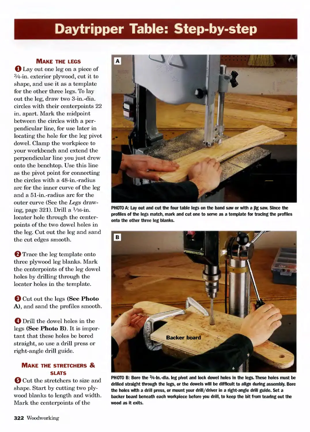


Автор: Carpenter T. Koshiol H. Johanson M.
Теги: woodworking crafting woodworking guide do it yourself constructing barnes &noble publisher
Год: 2004


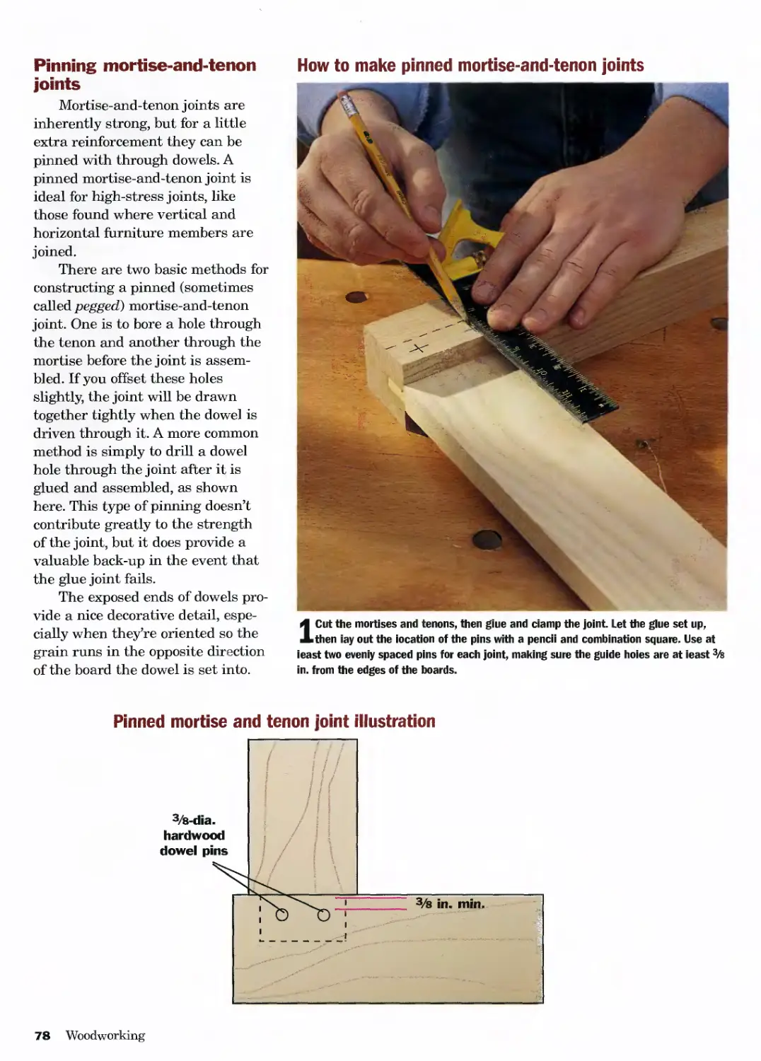
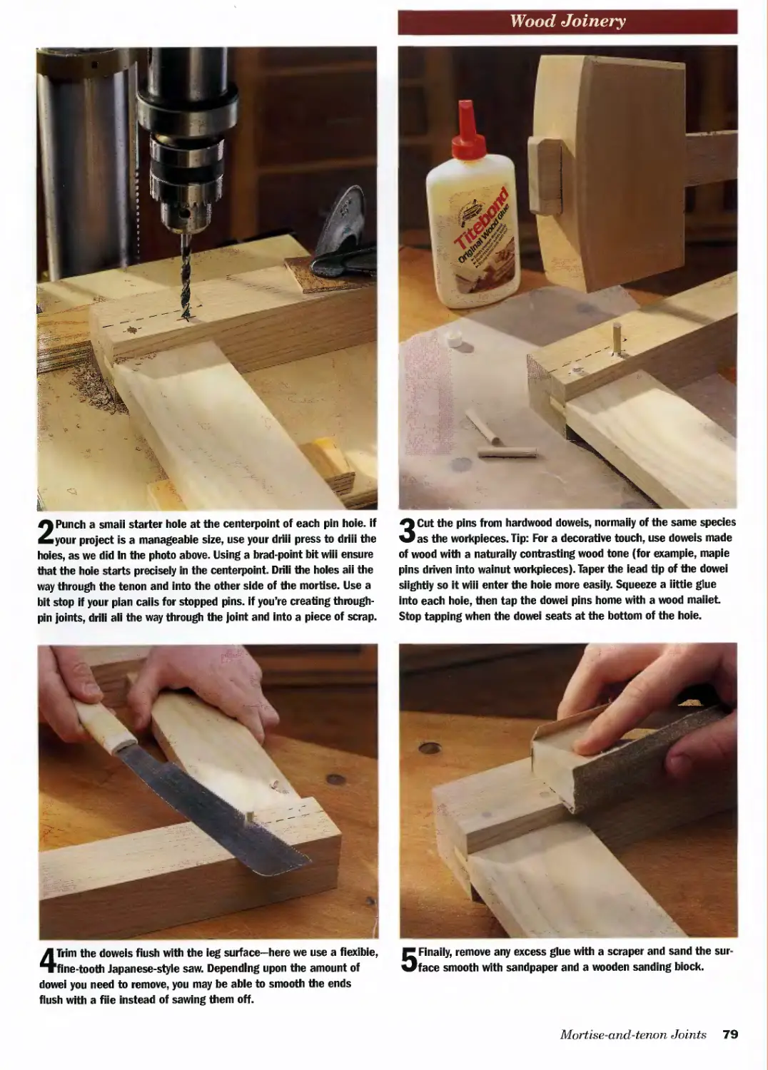
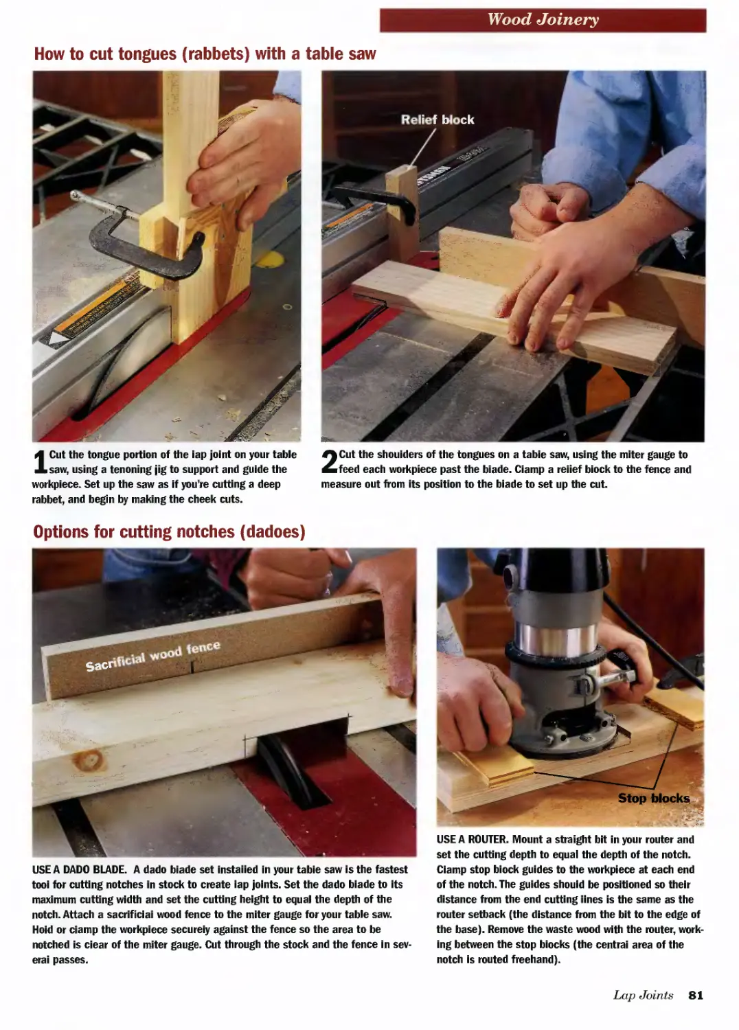
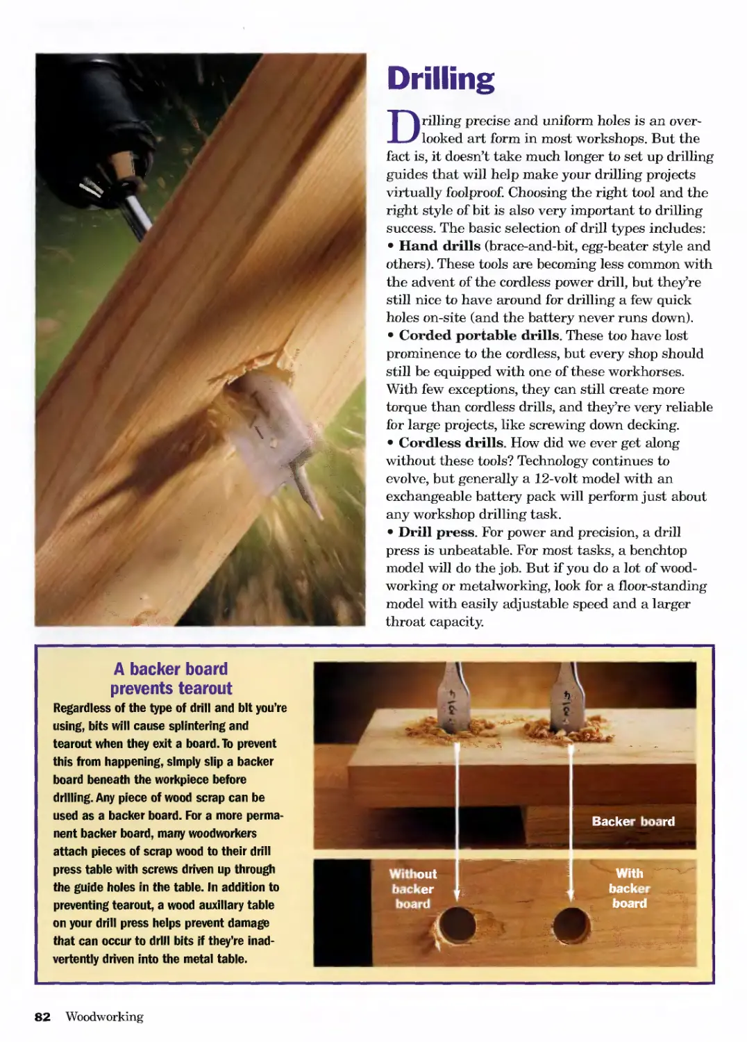
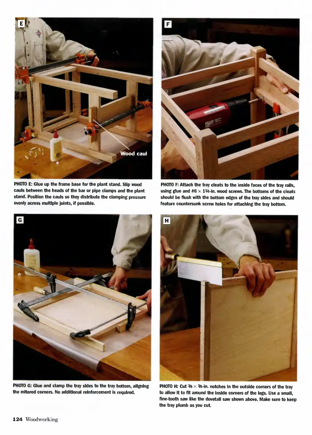
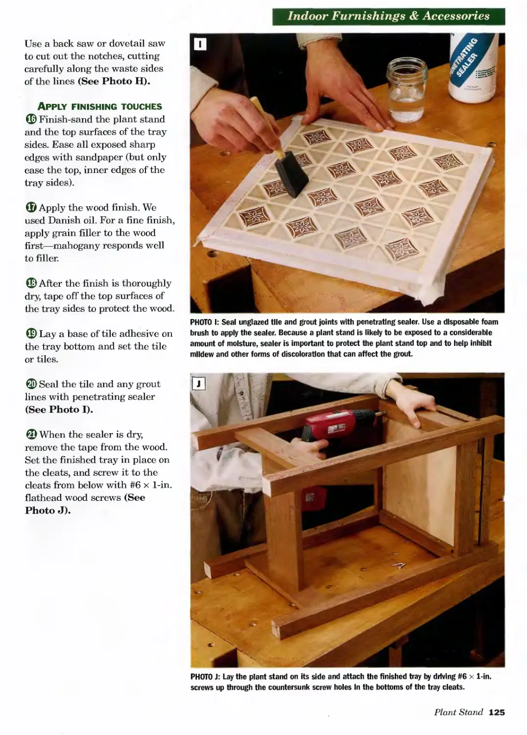
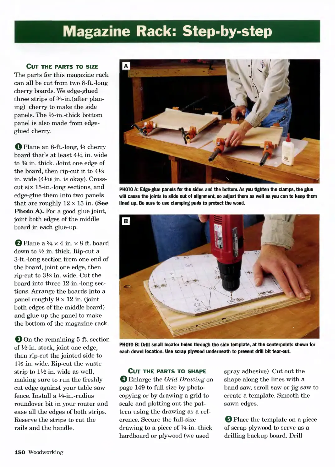
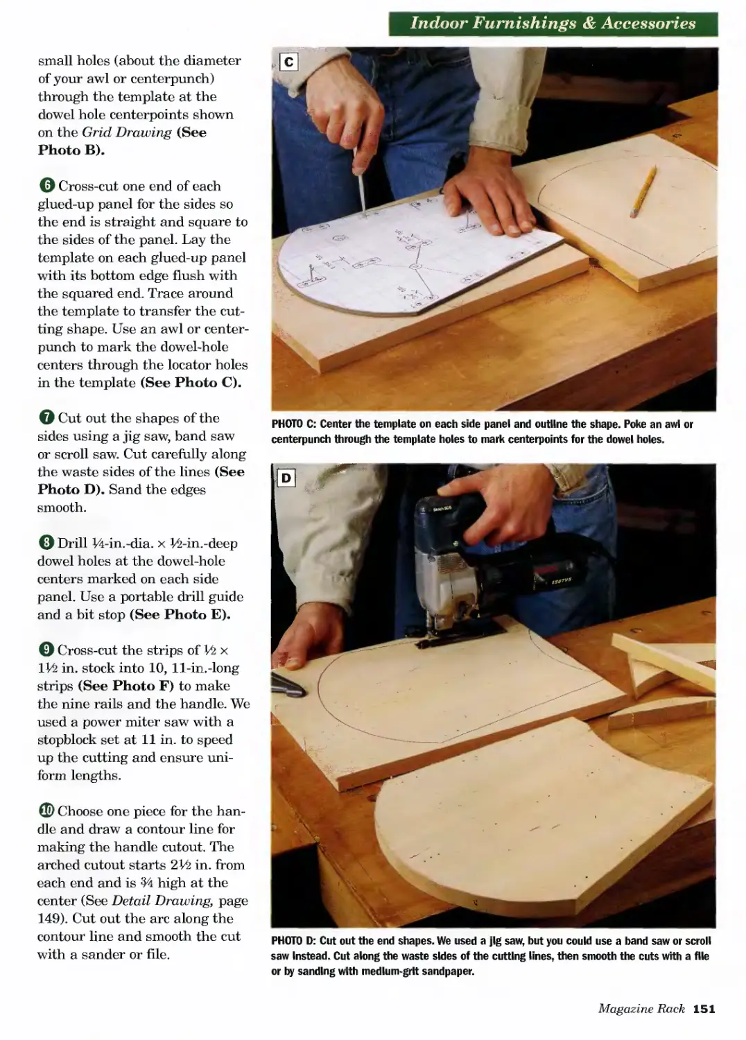
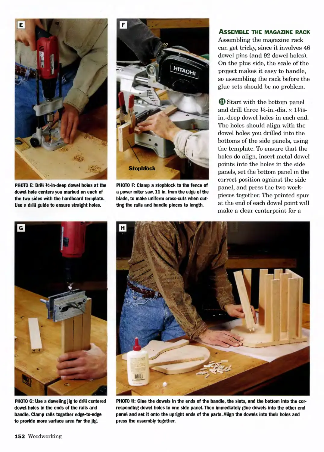
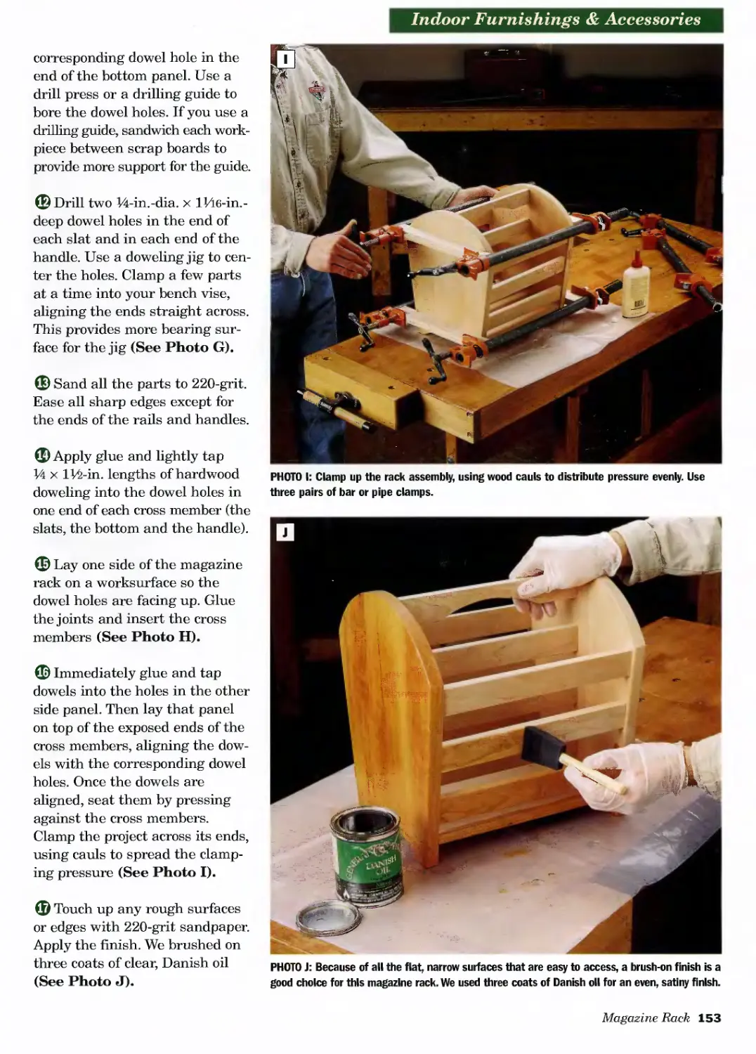
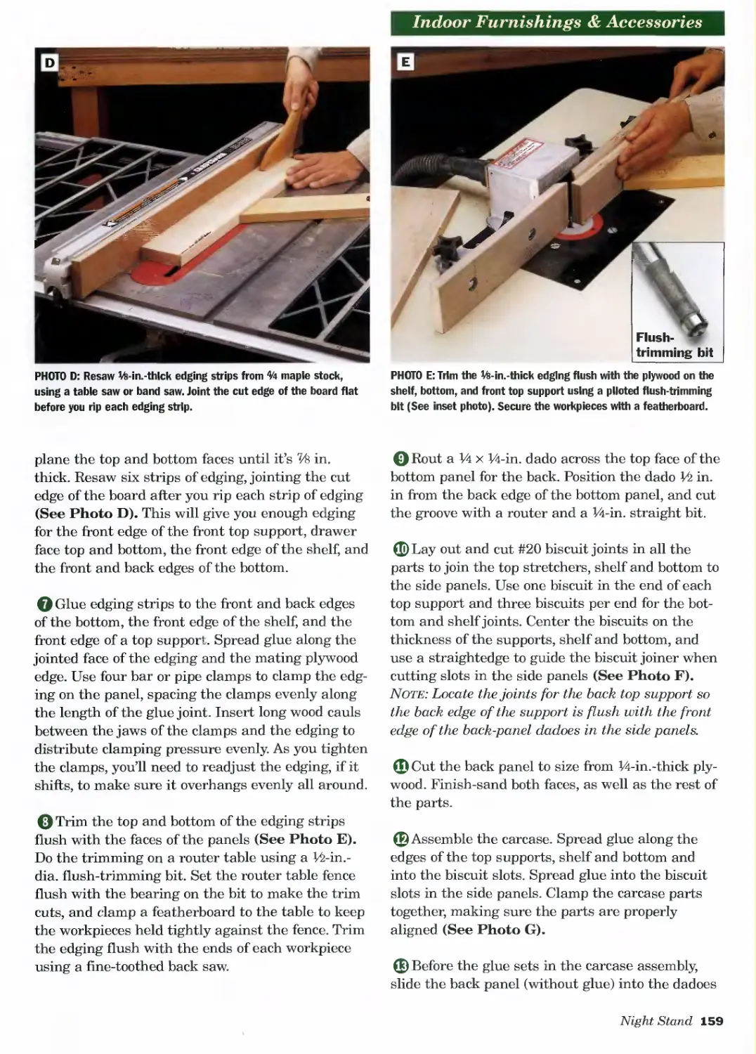
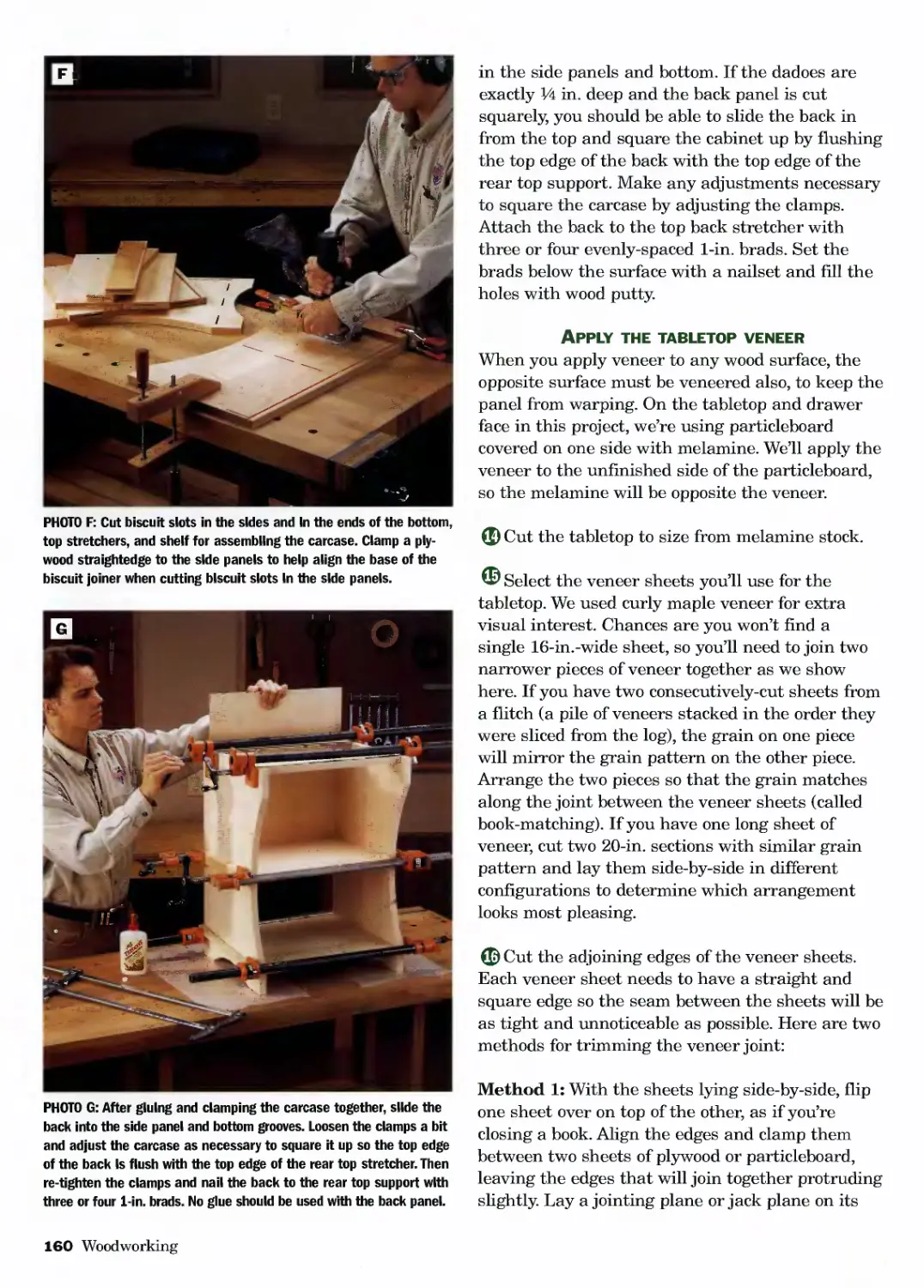
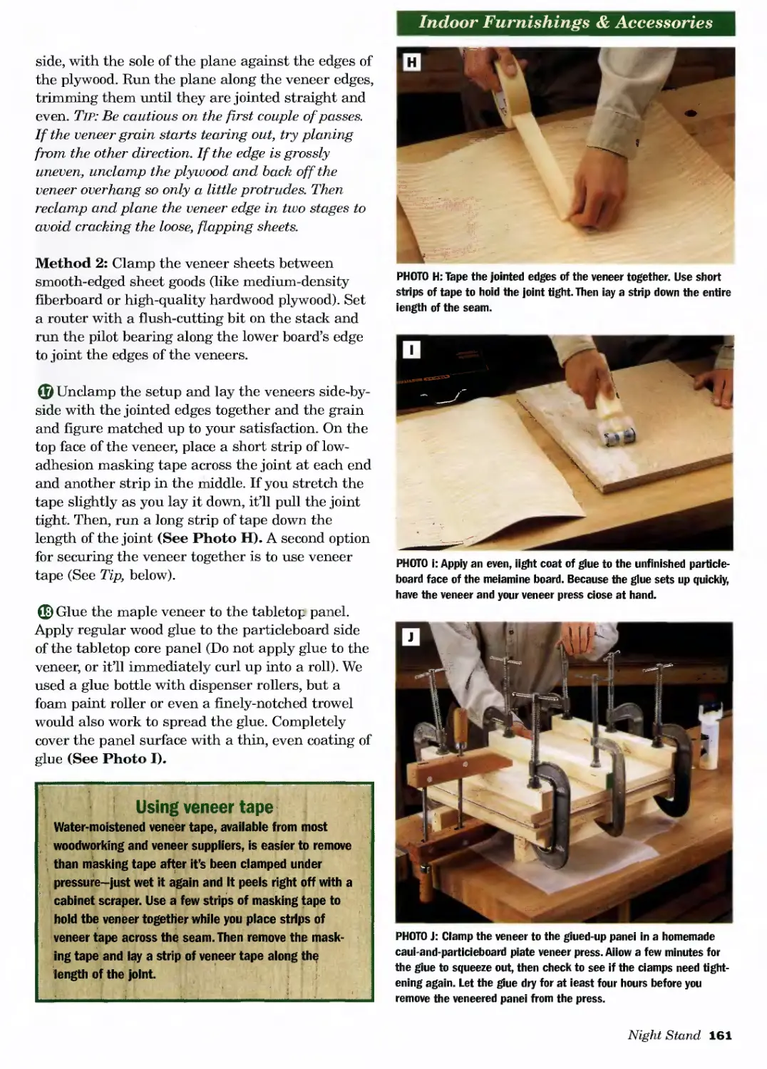
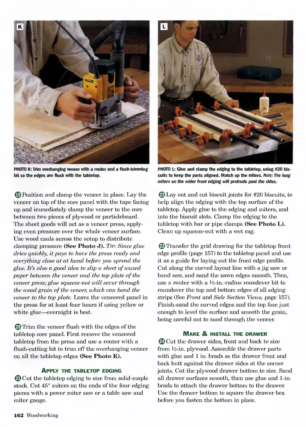
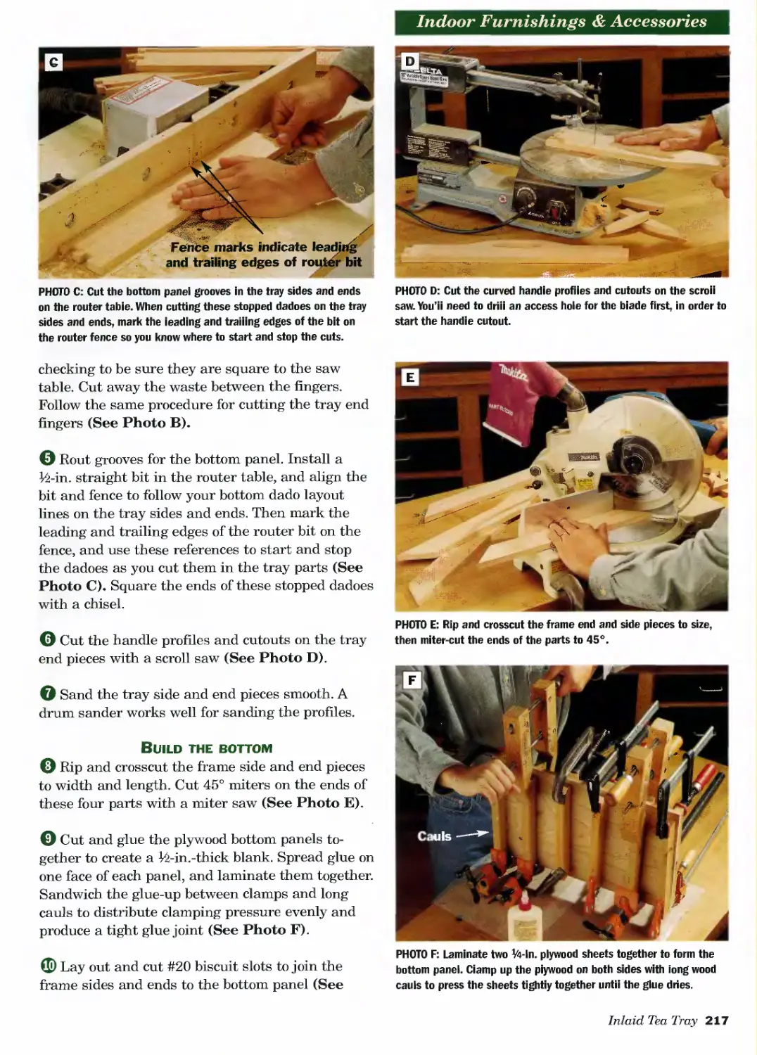
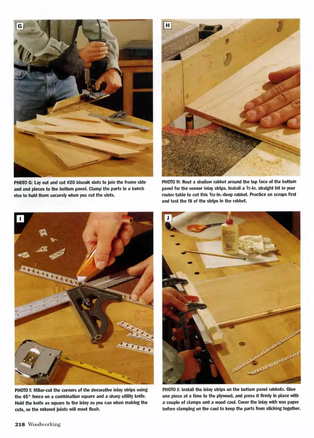
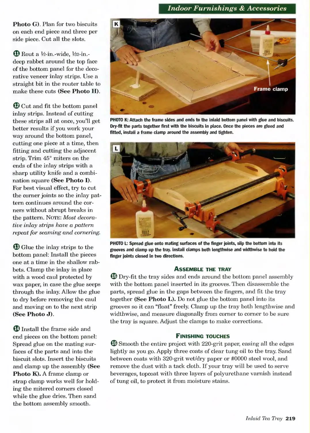
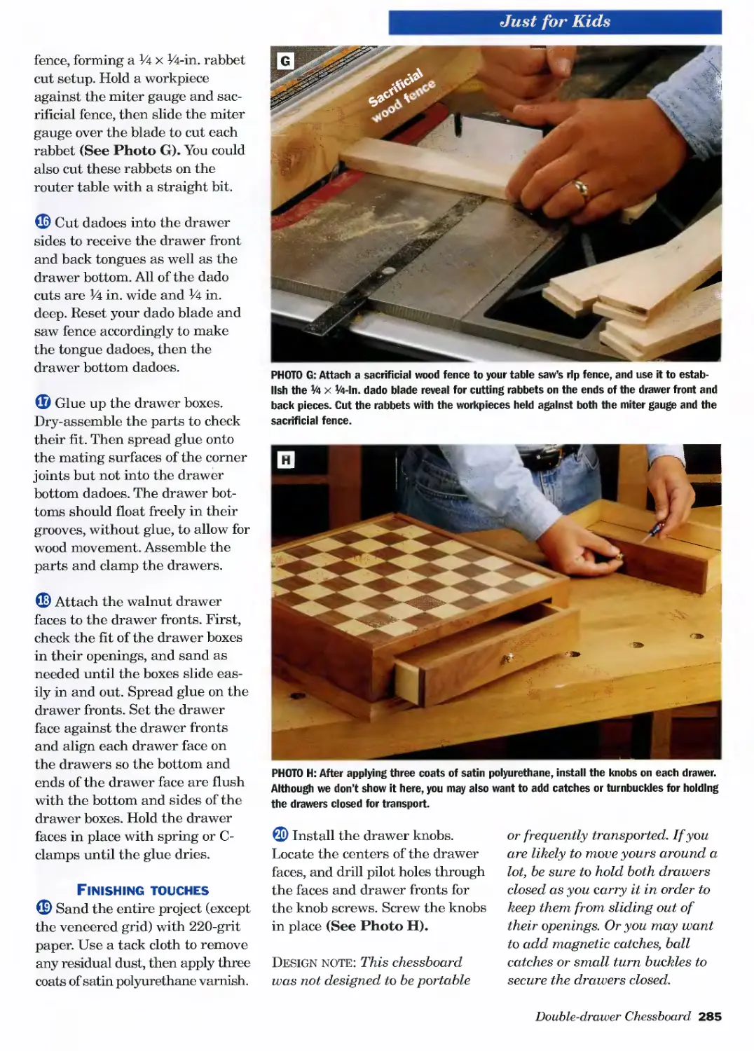
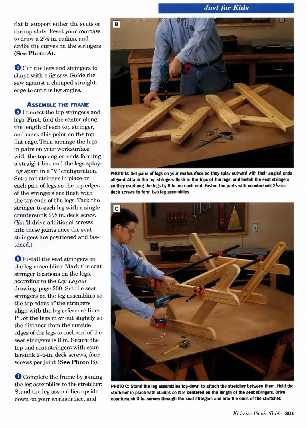
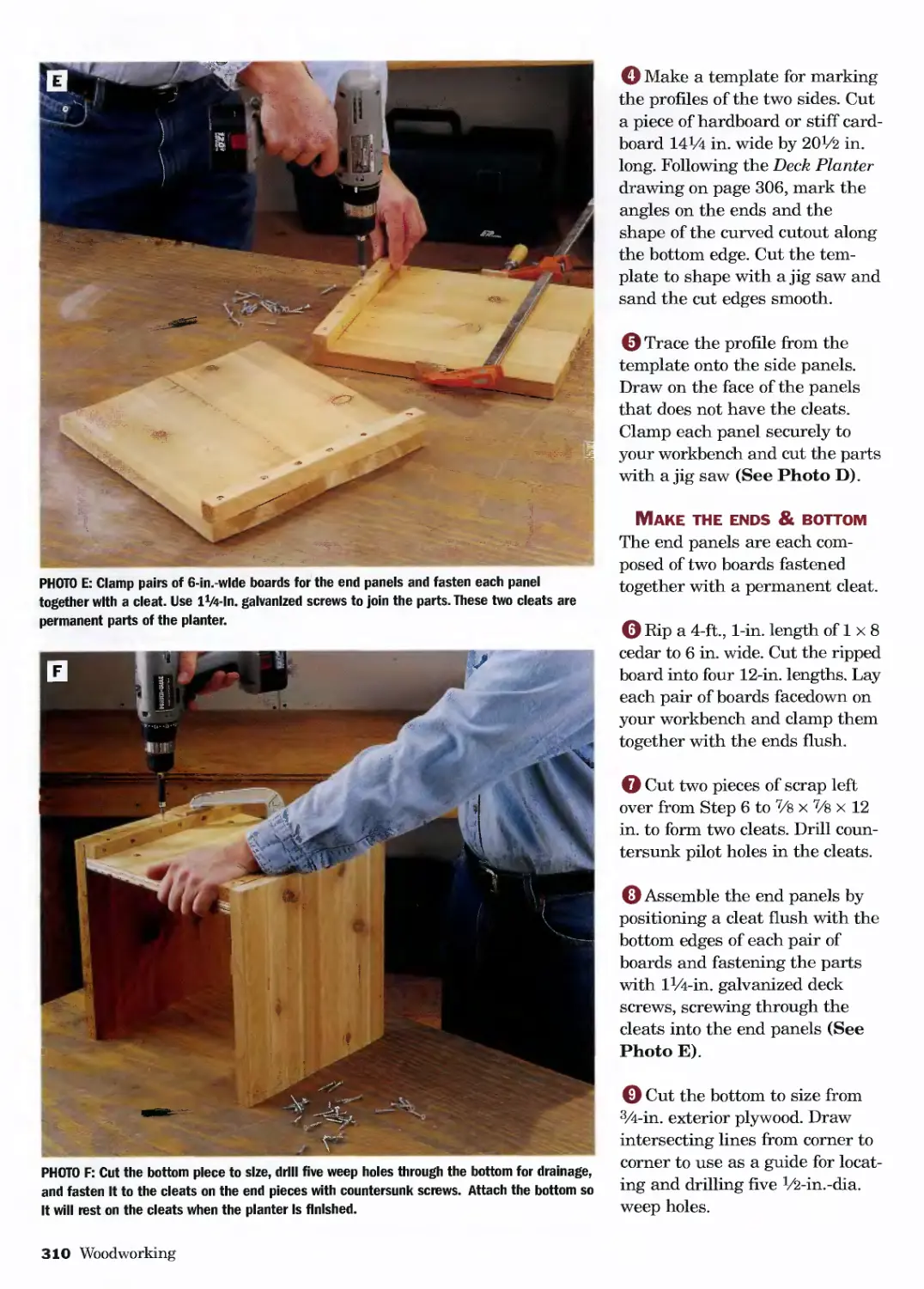
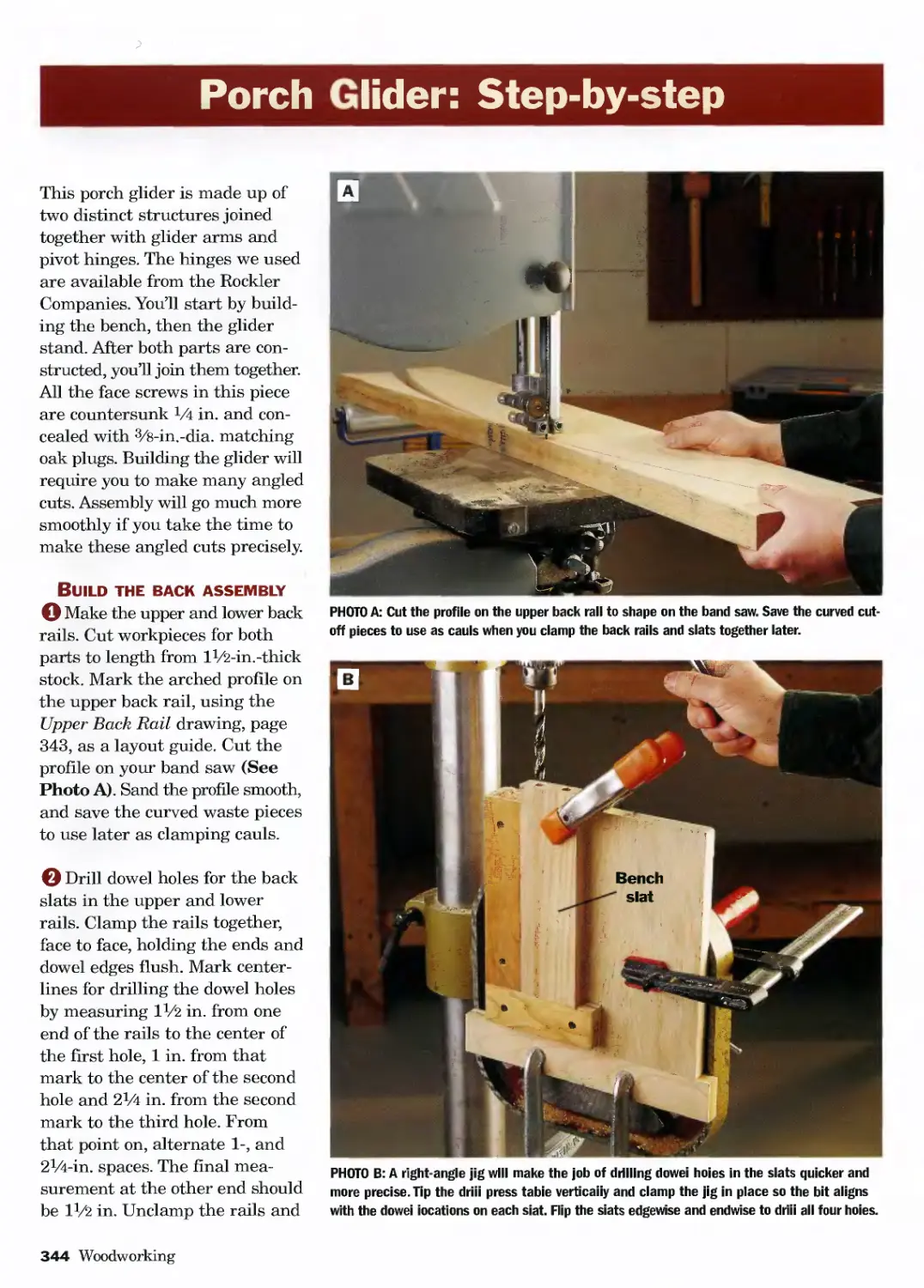
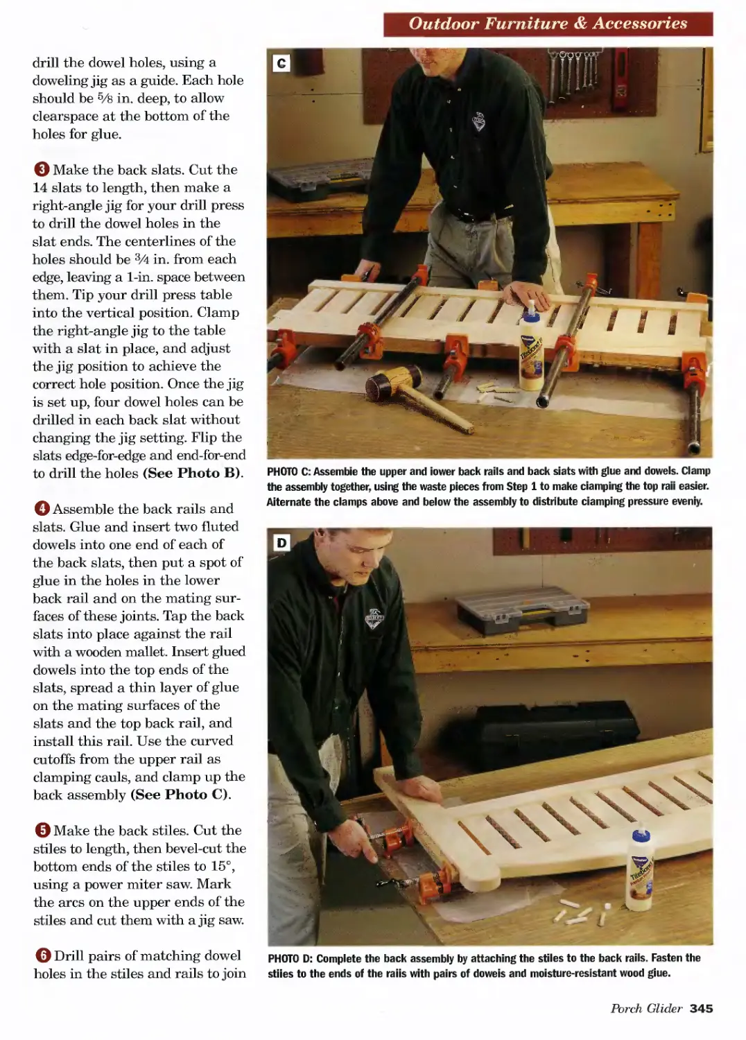
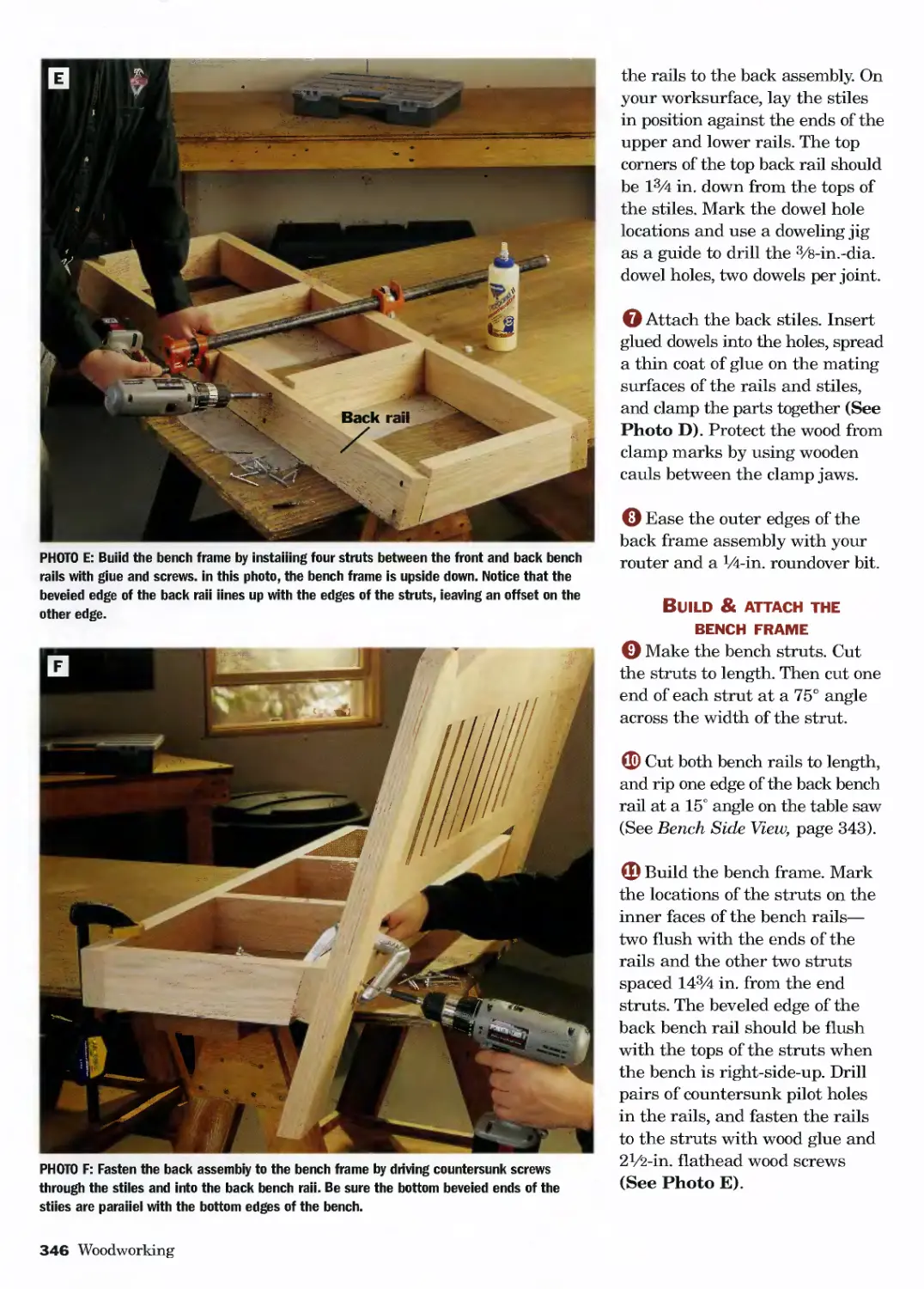
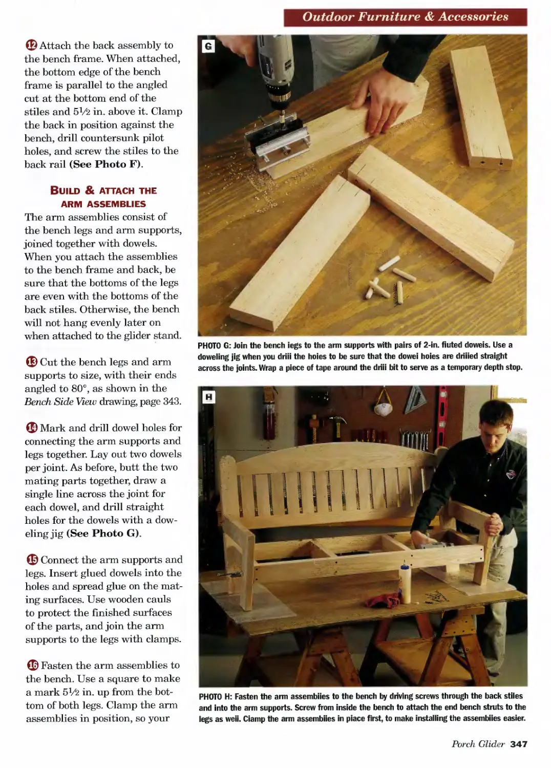
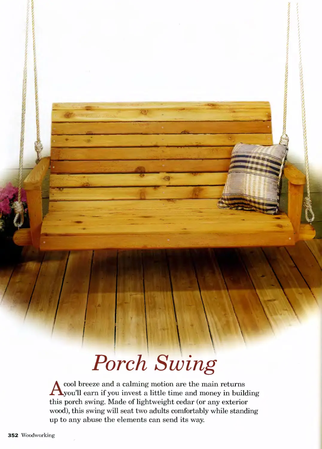
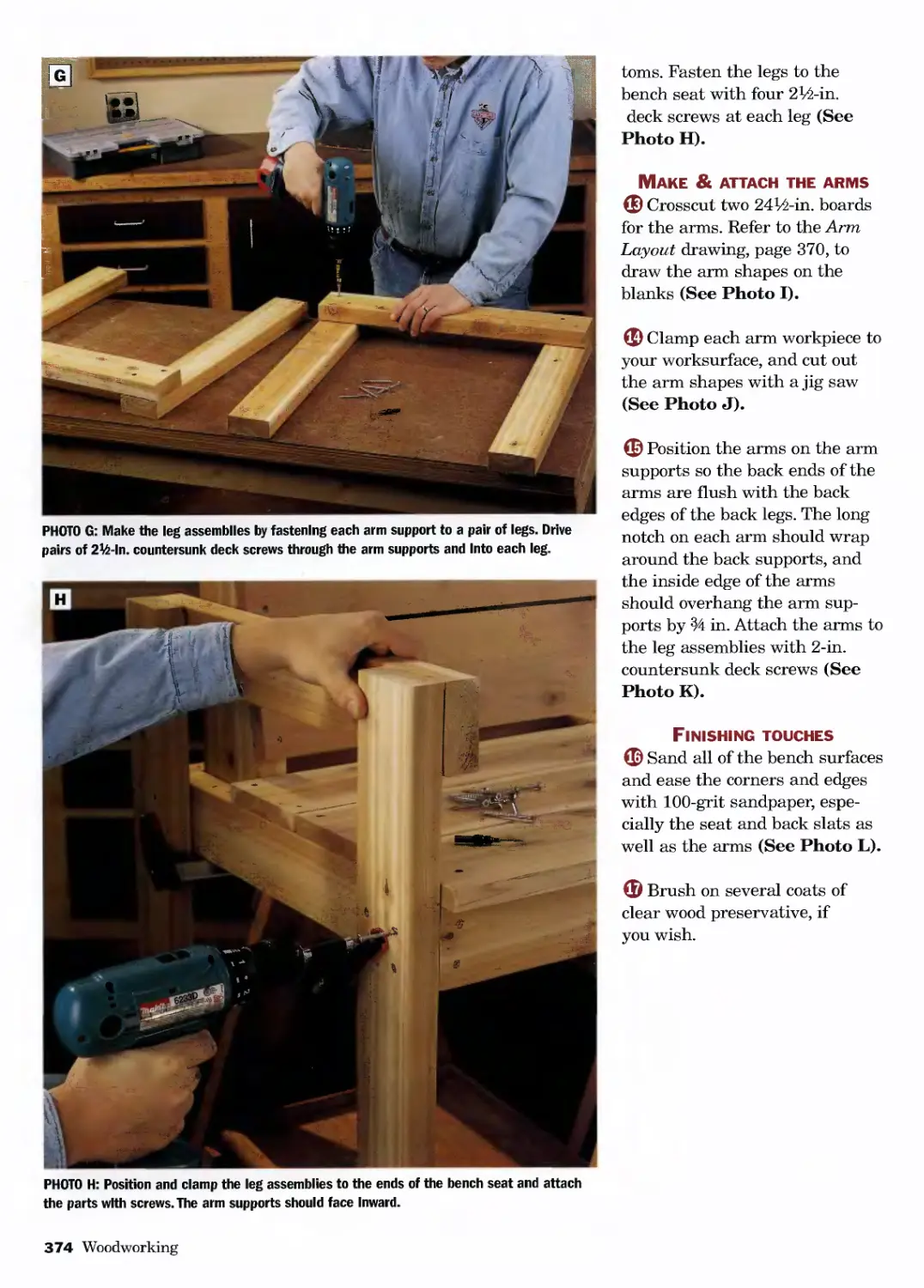
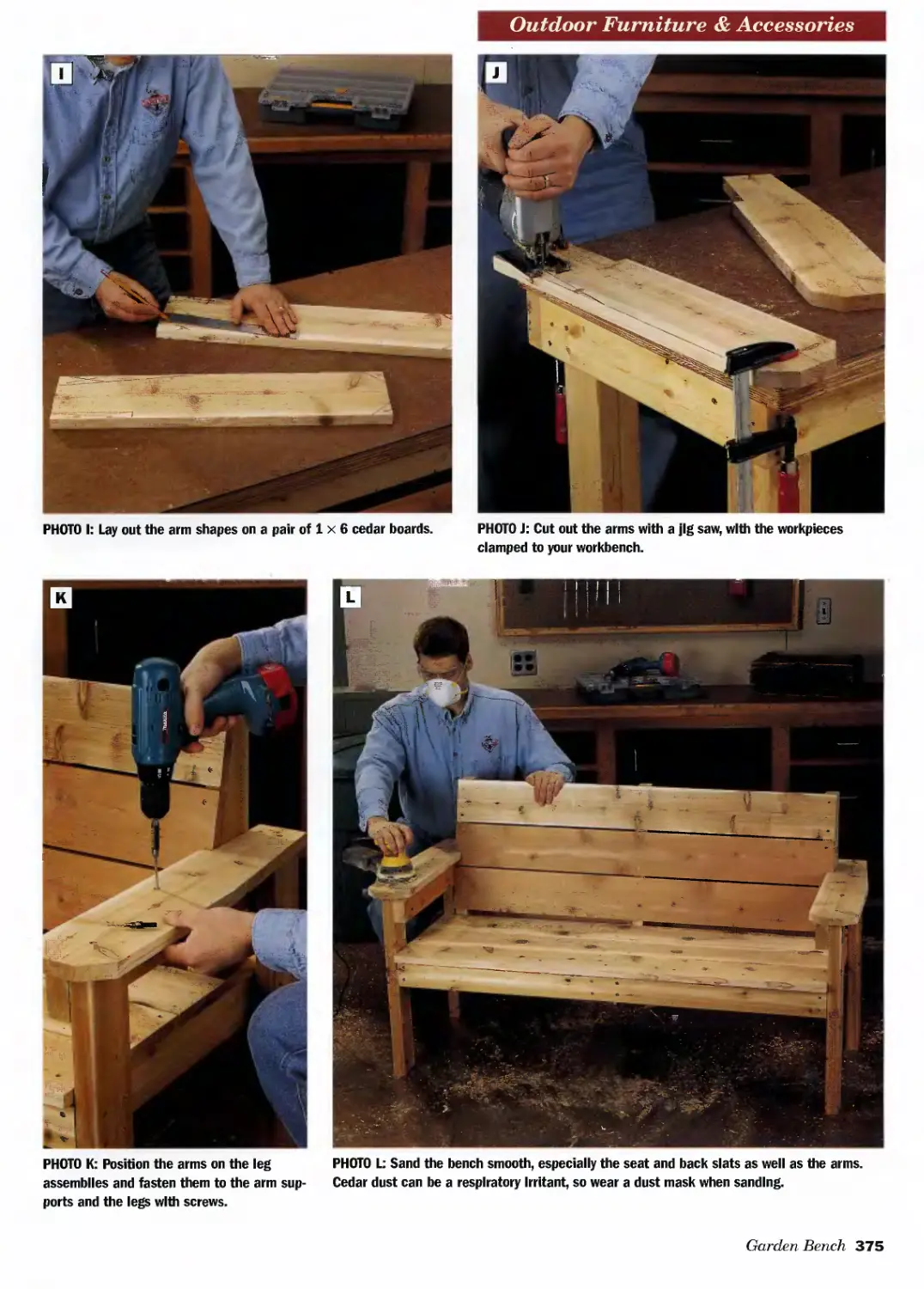
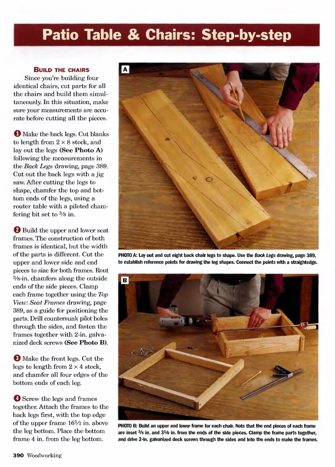
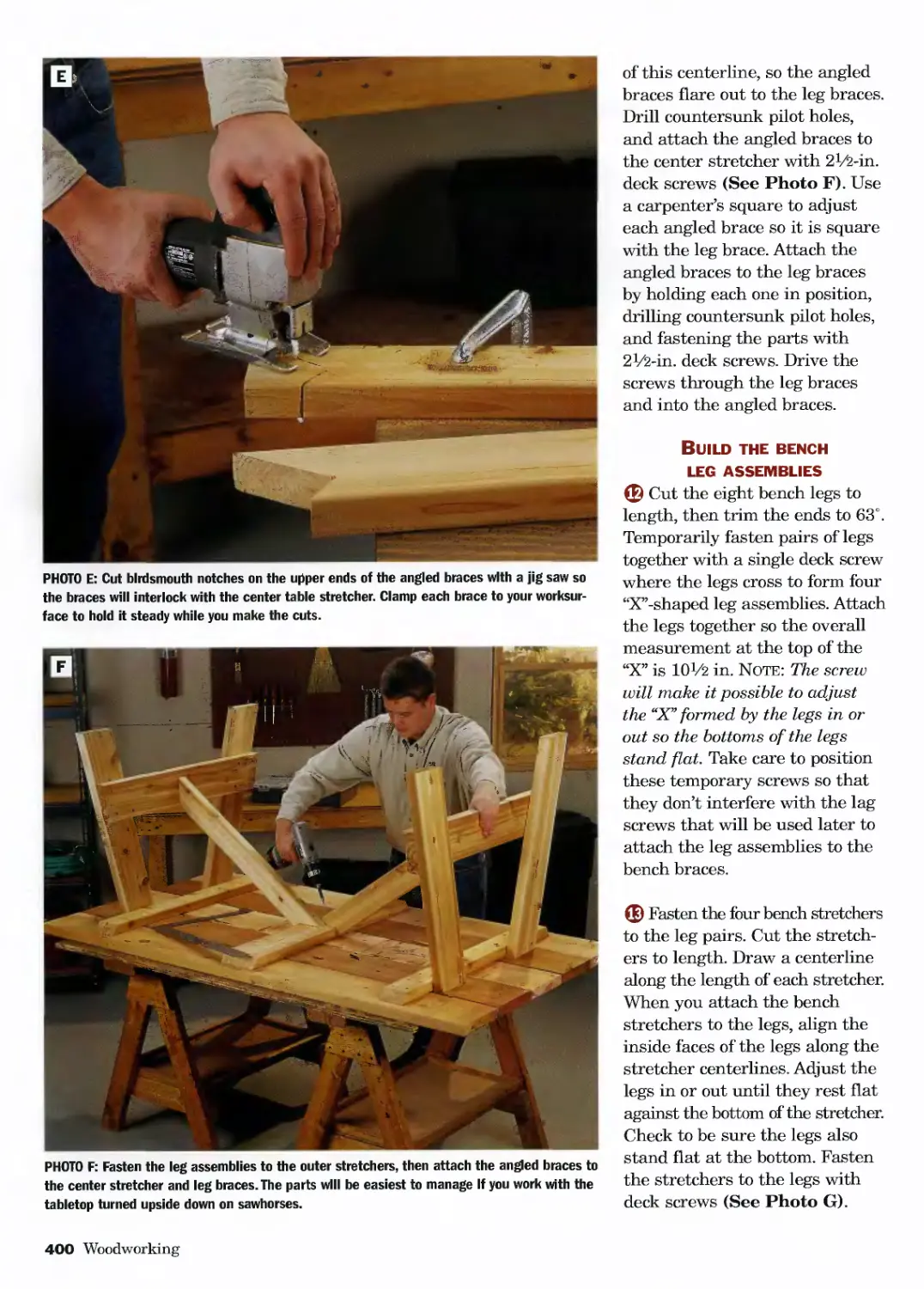
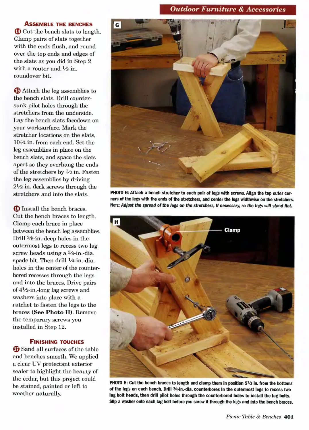
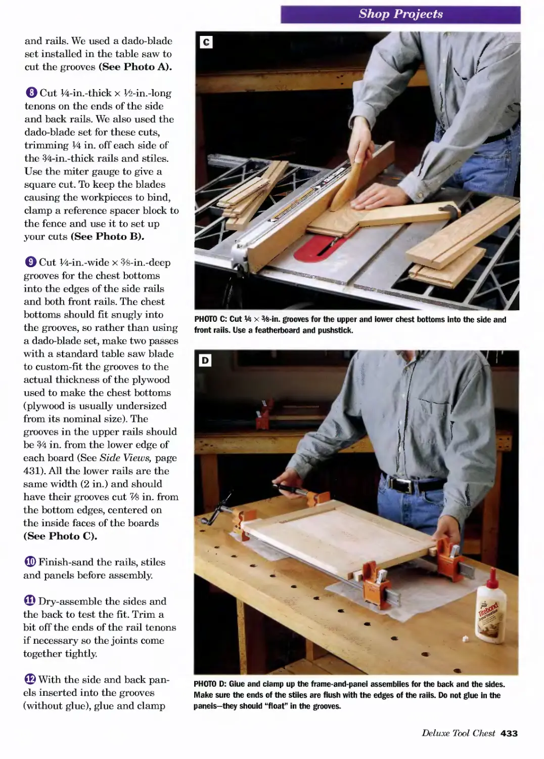
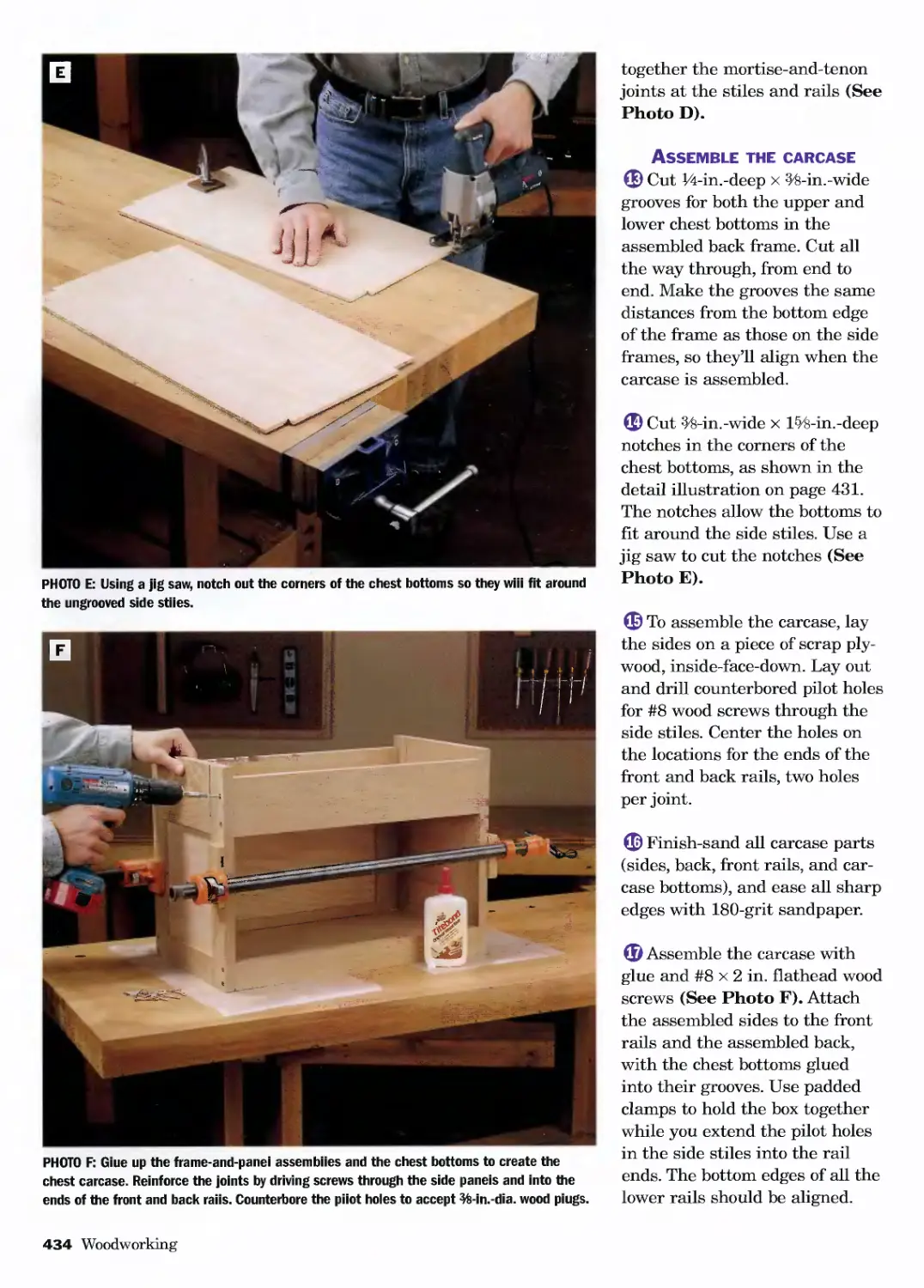
Текст
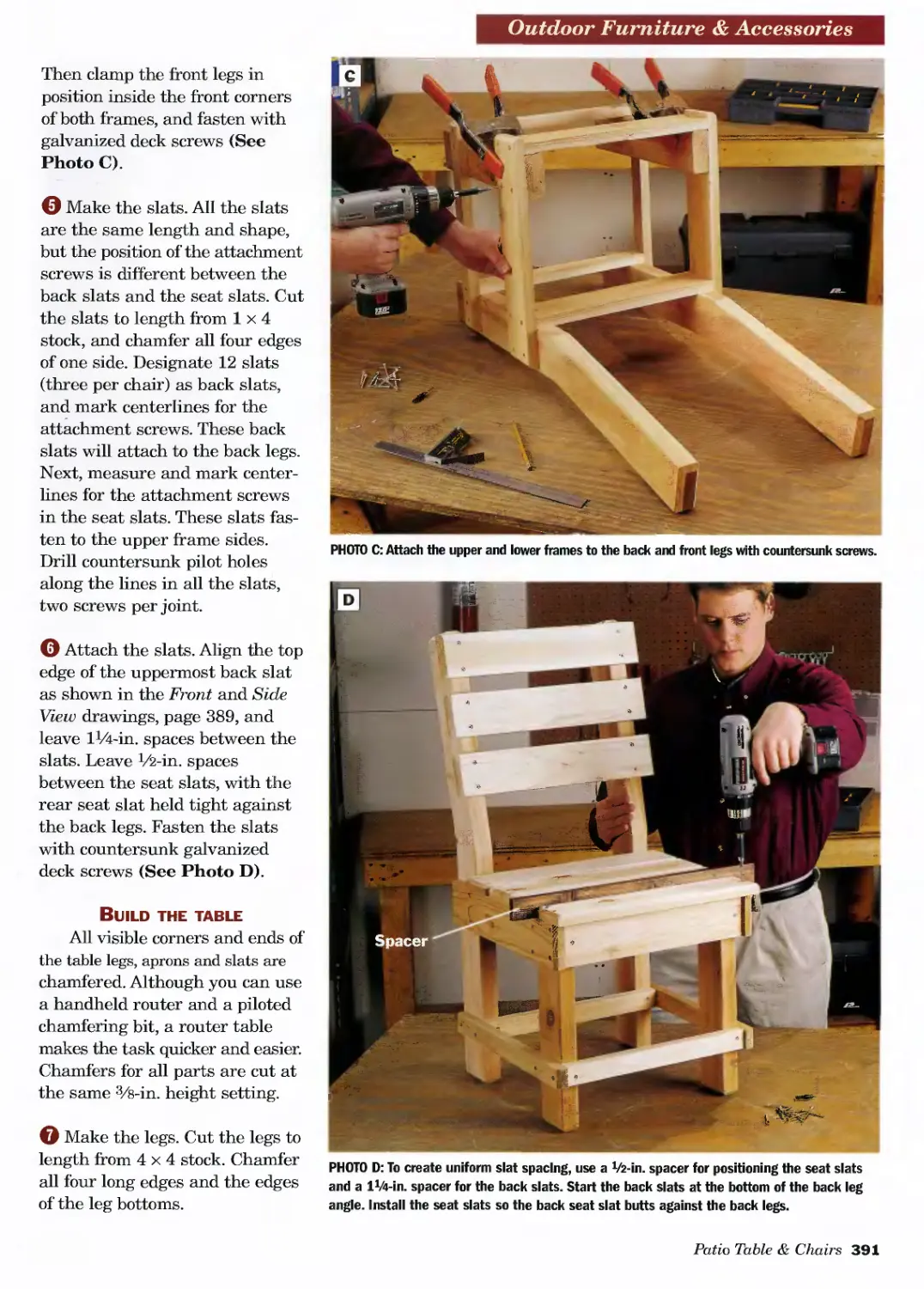
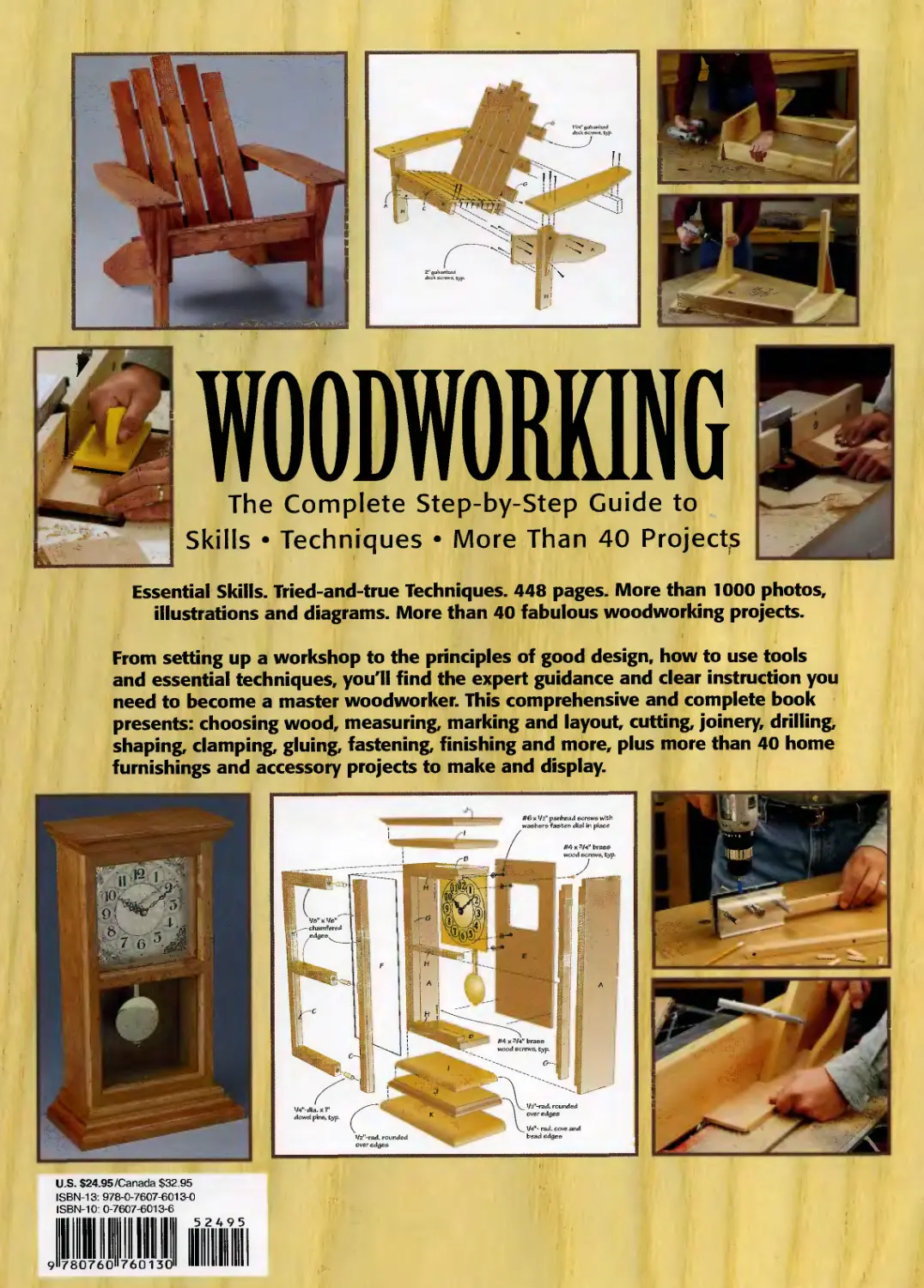
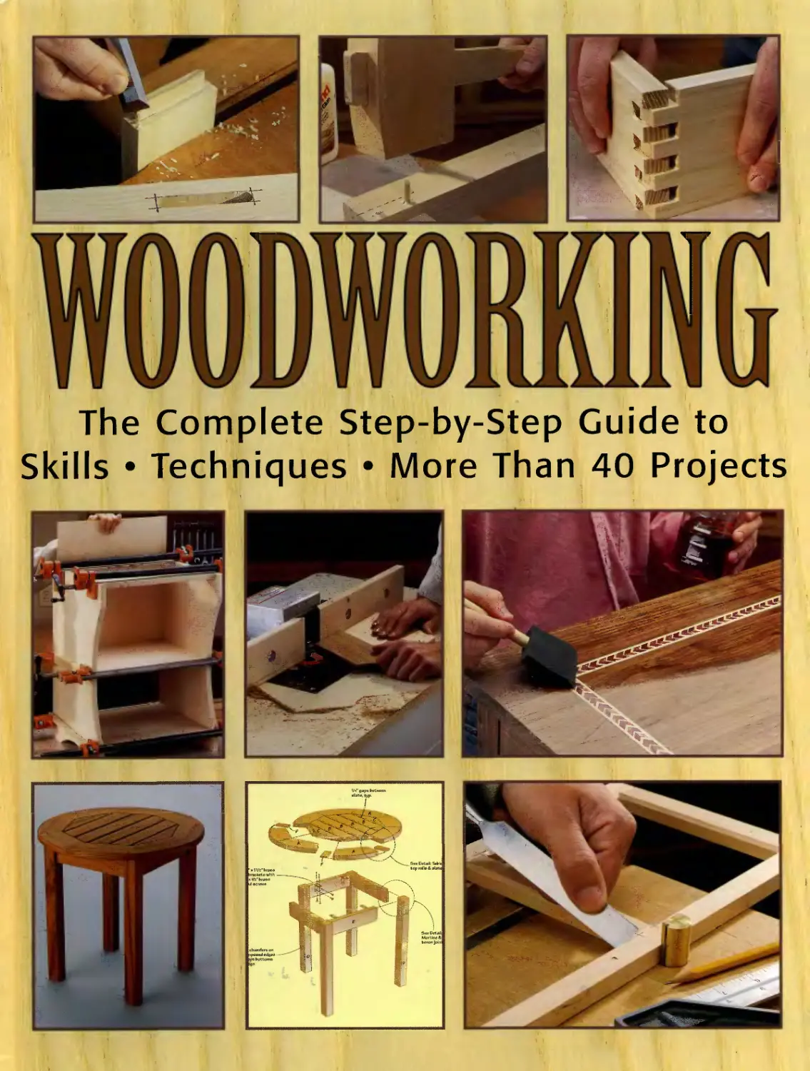
WOODWORKING
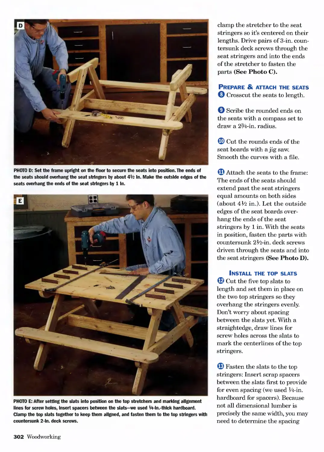
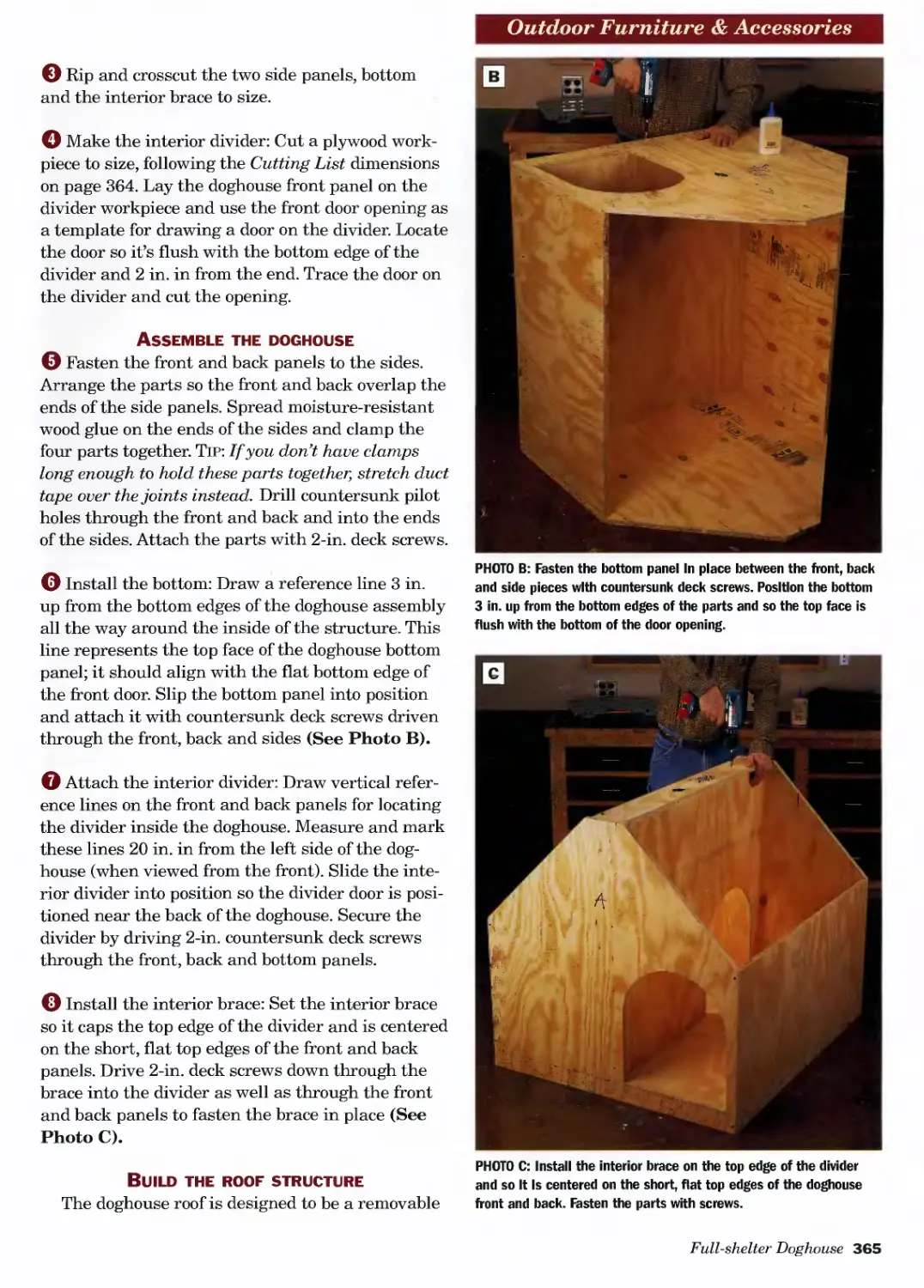
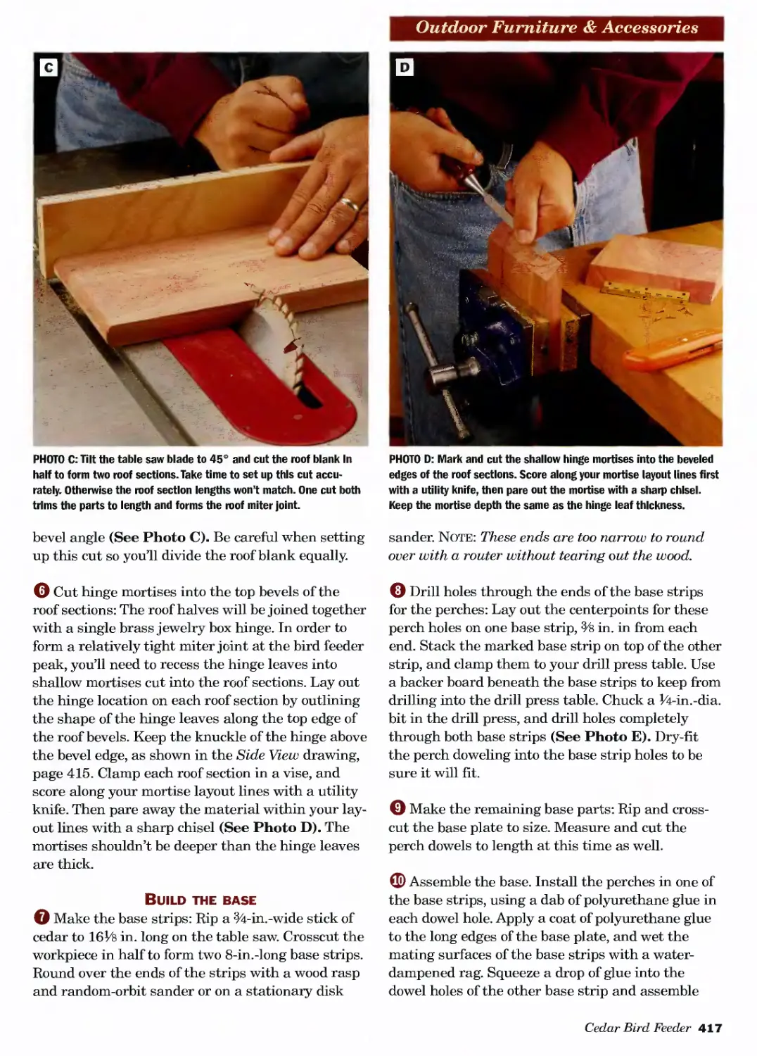
The Complete Step-by-Step Guide to
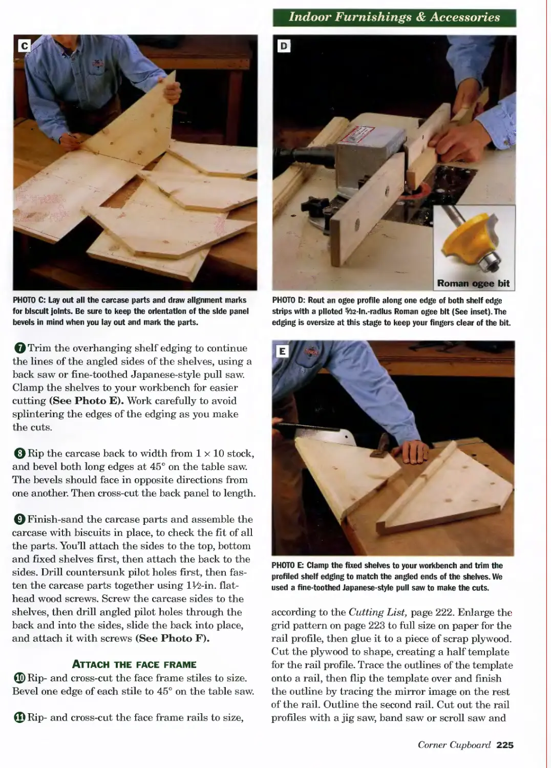
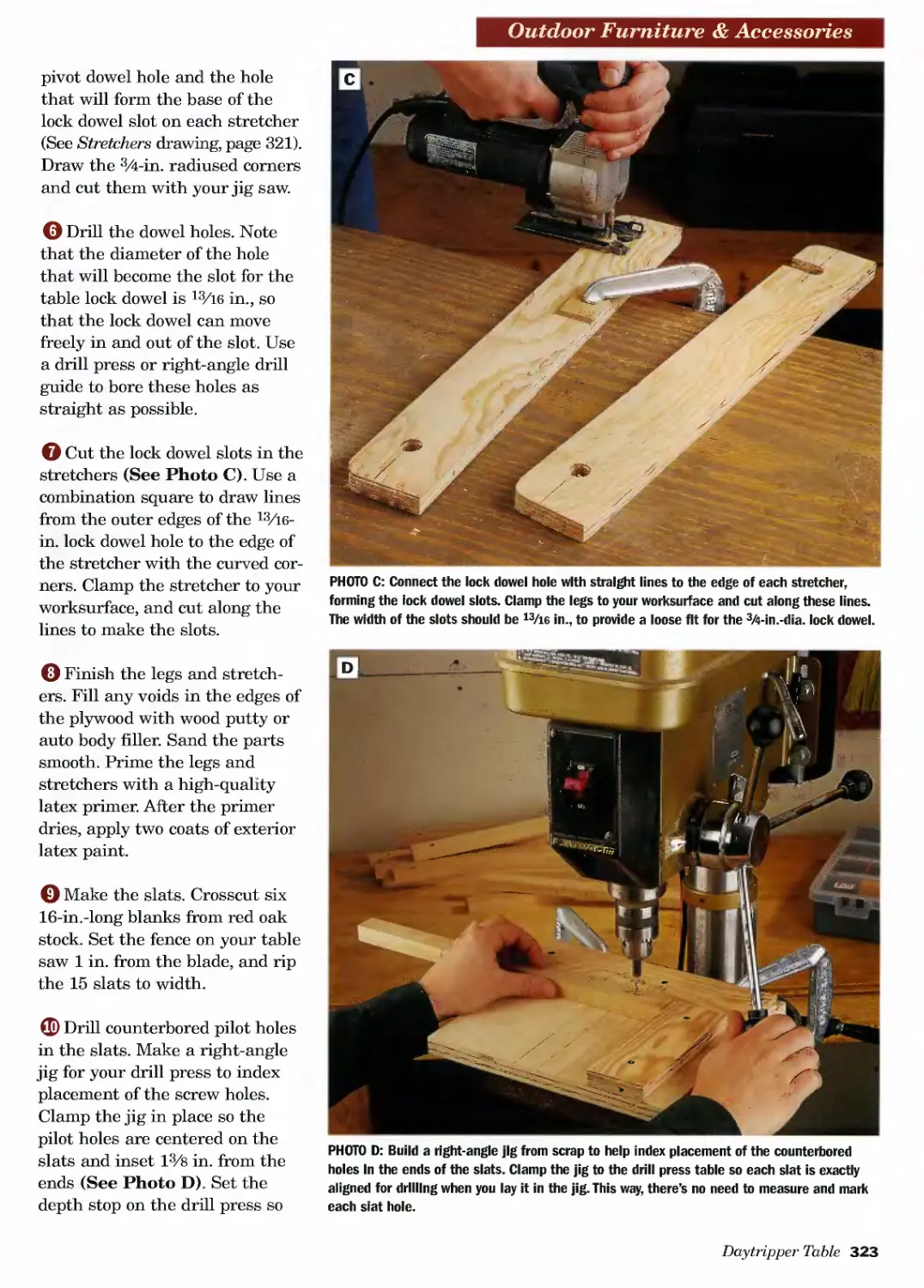
Skills, Techniques and Projects
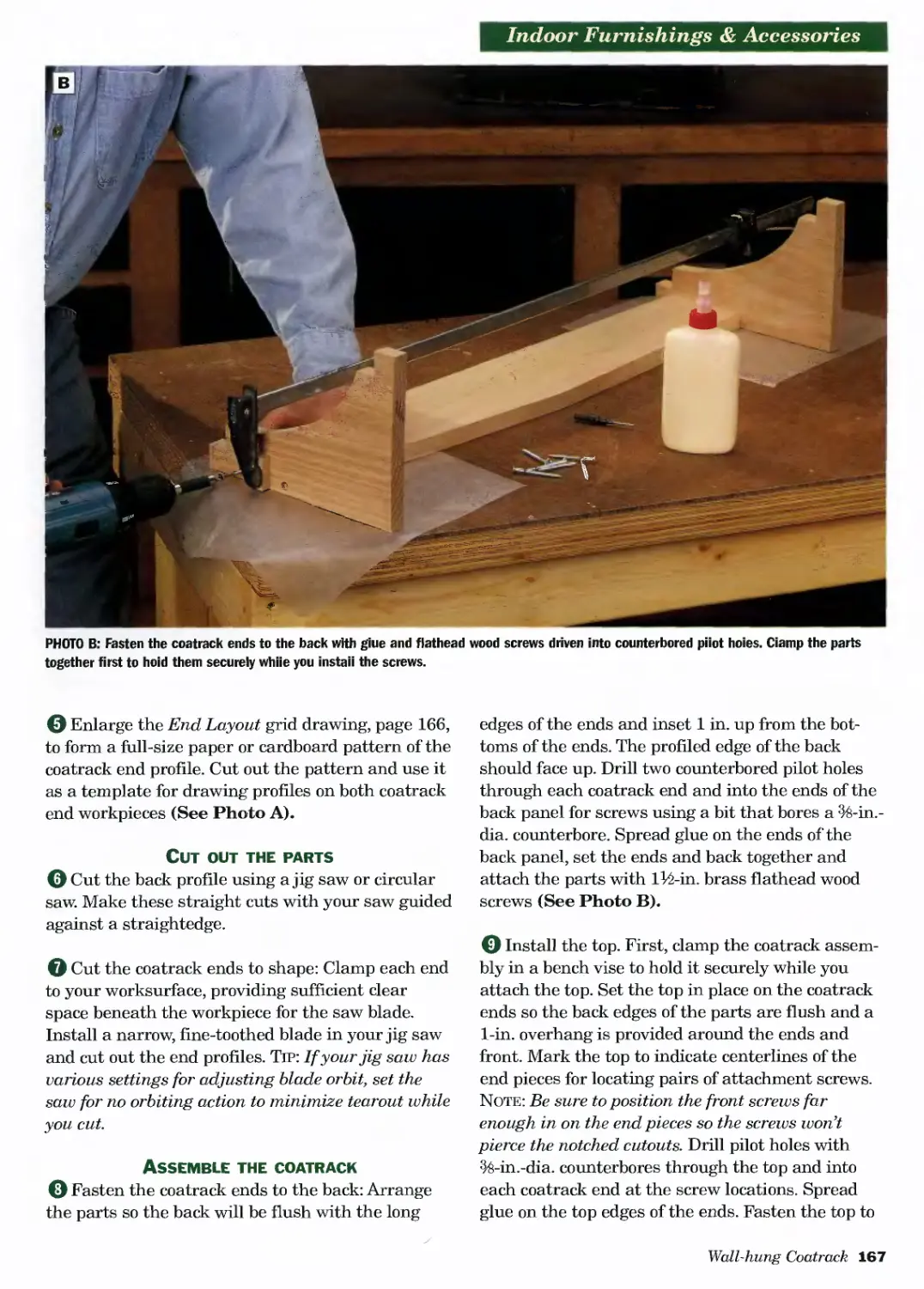
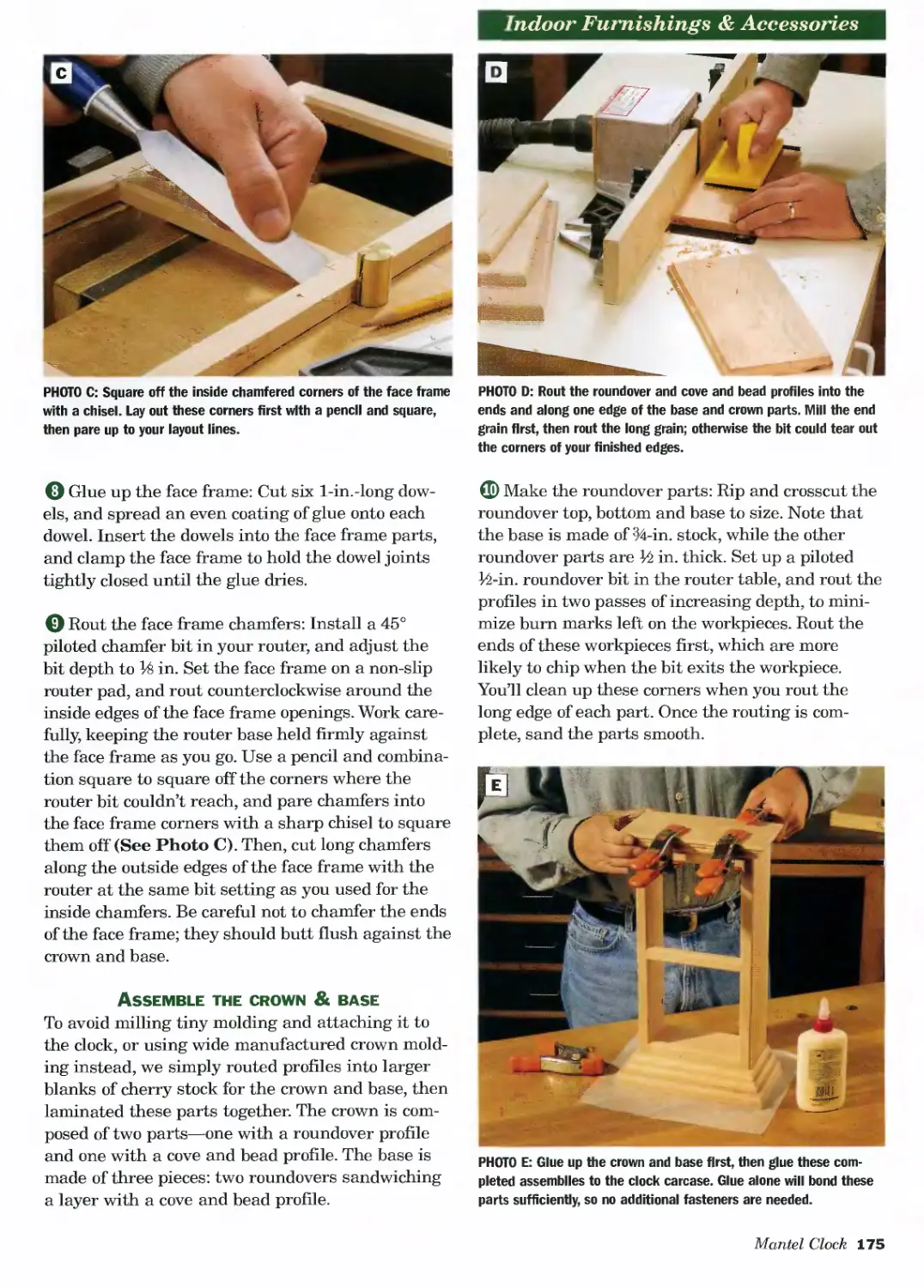
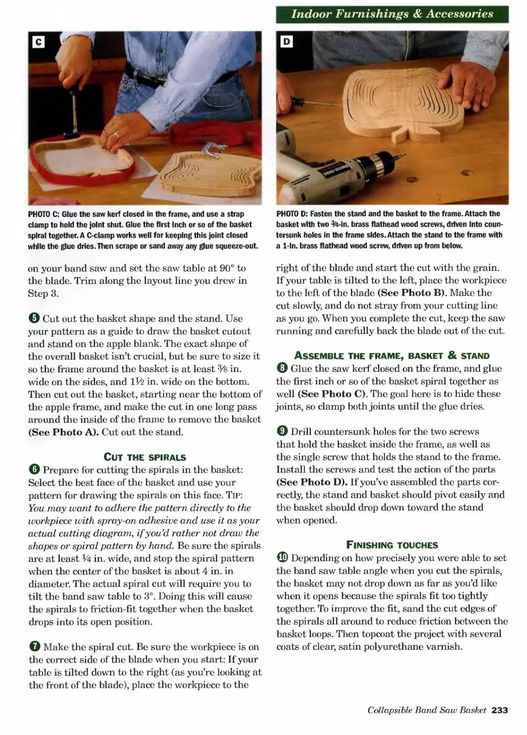
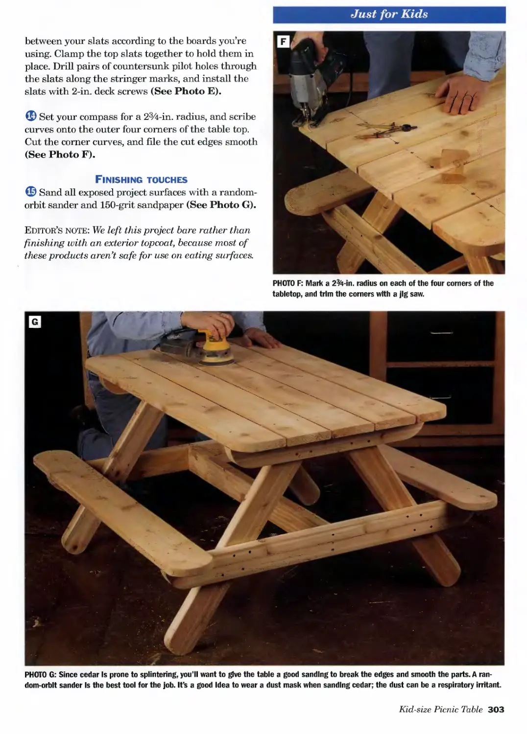
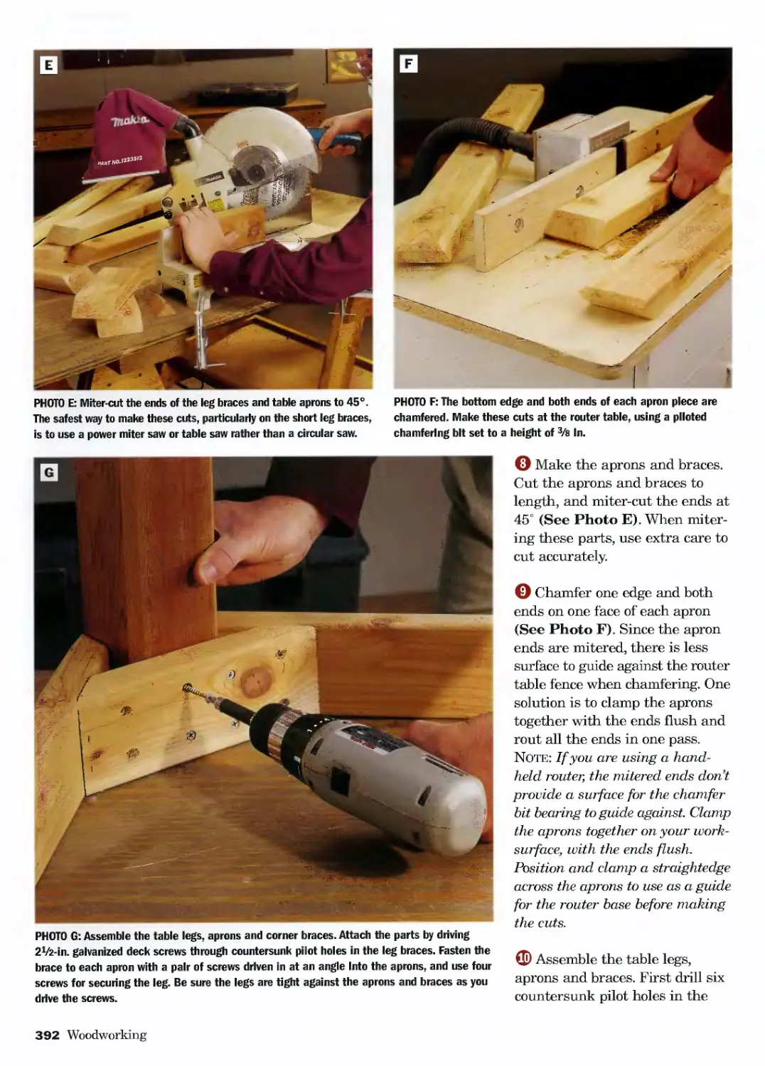
Barnes
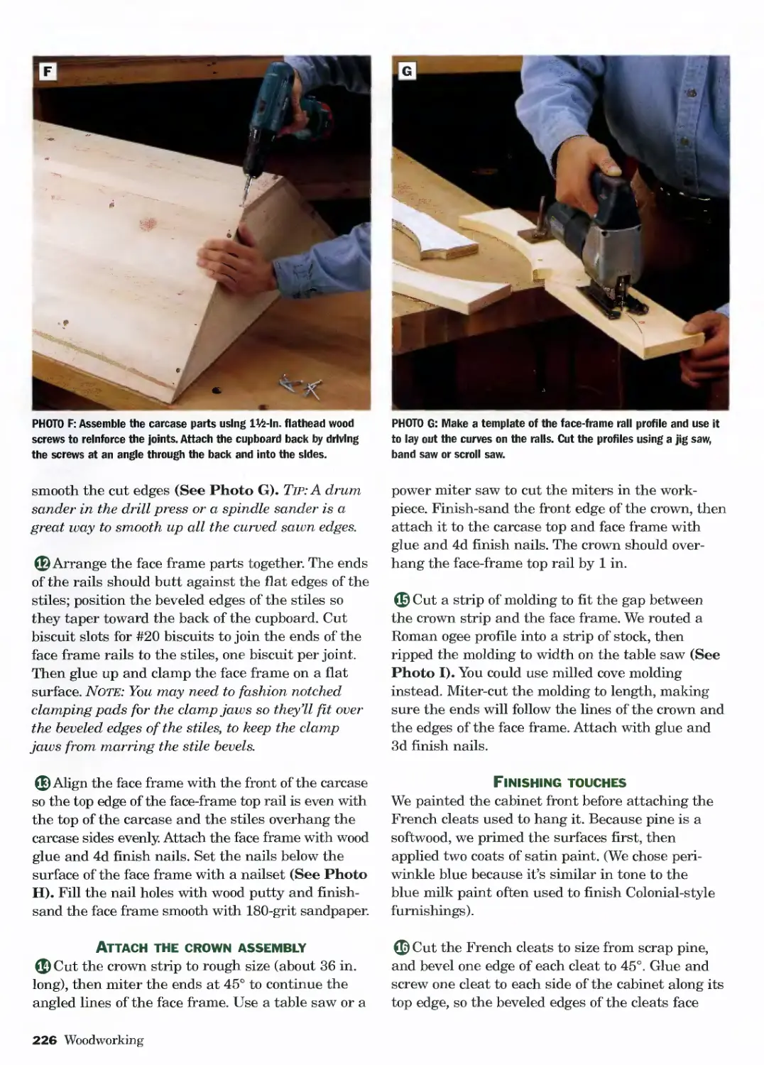
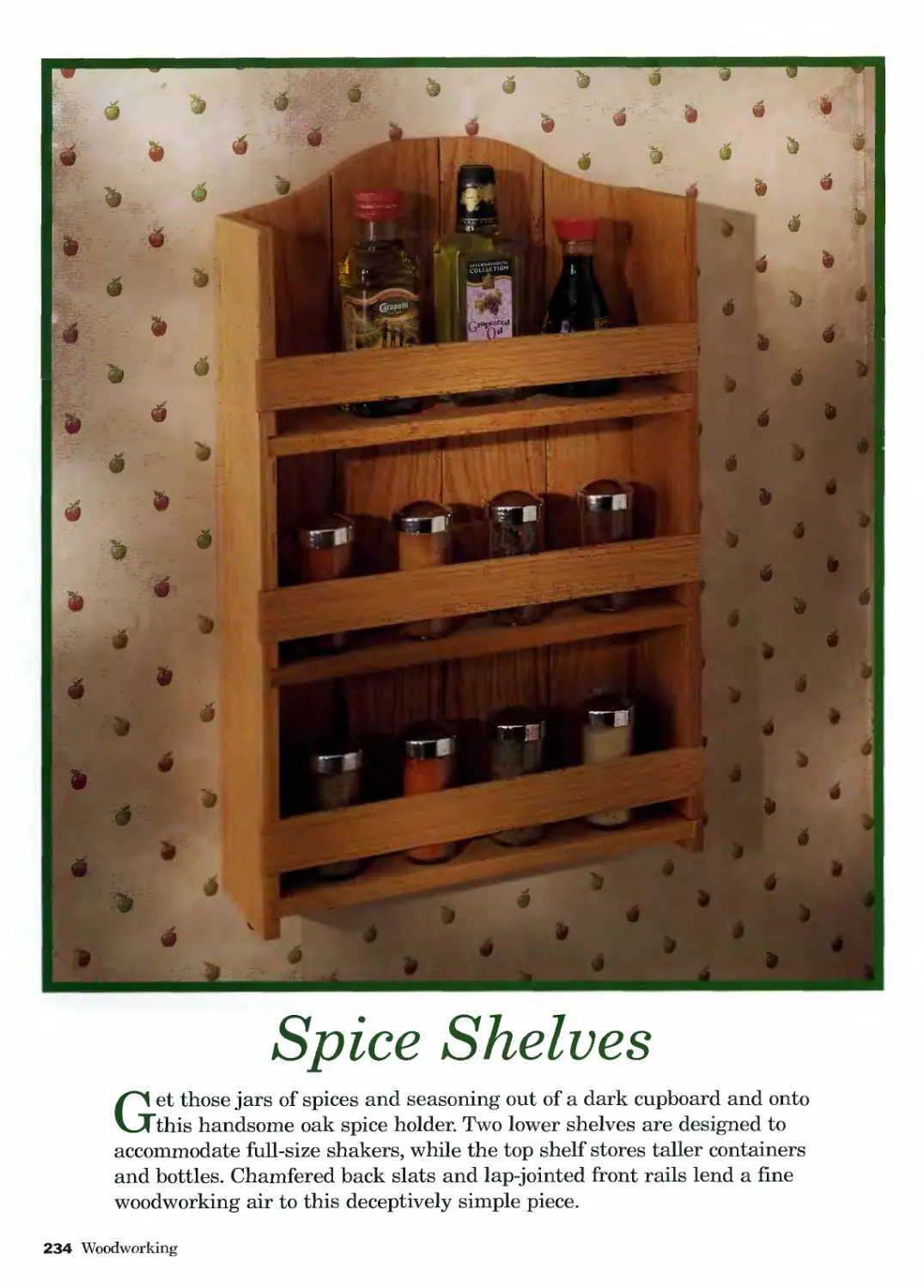
&Noble
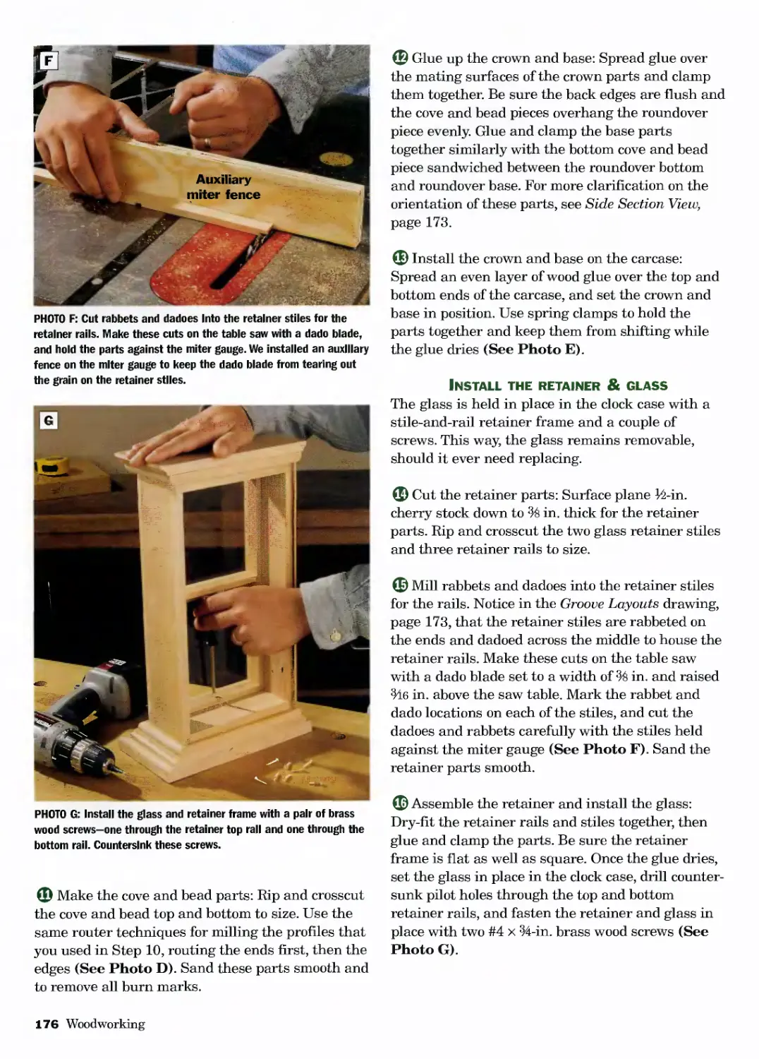
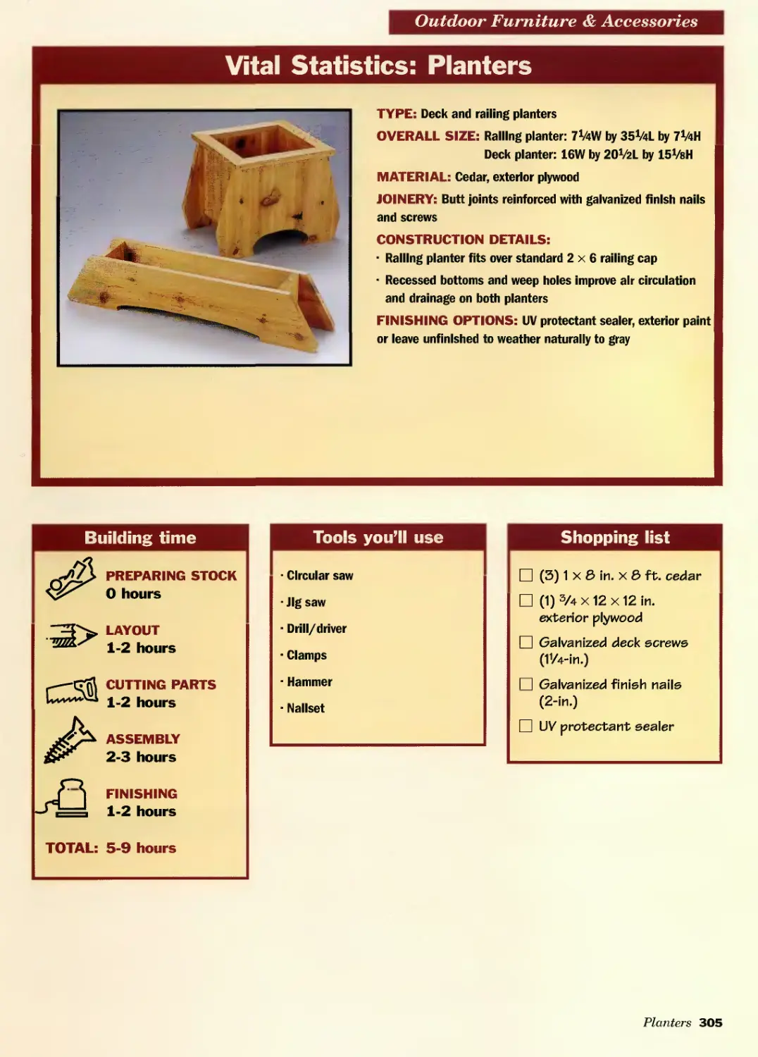
NEW YORK
© 2004 by North American Affinity Clubs
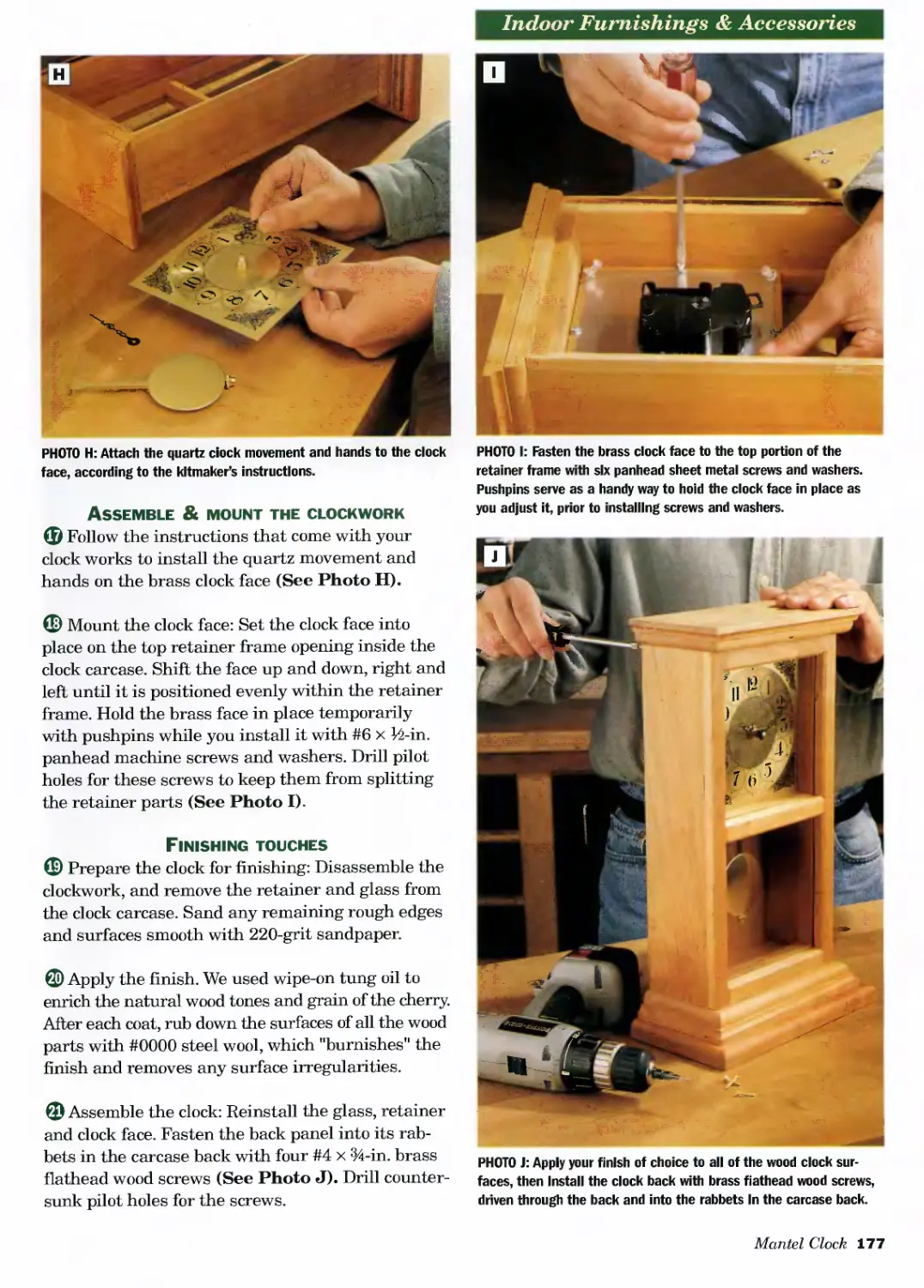
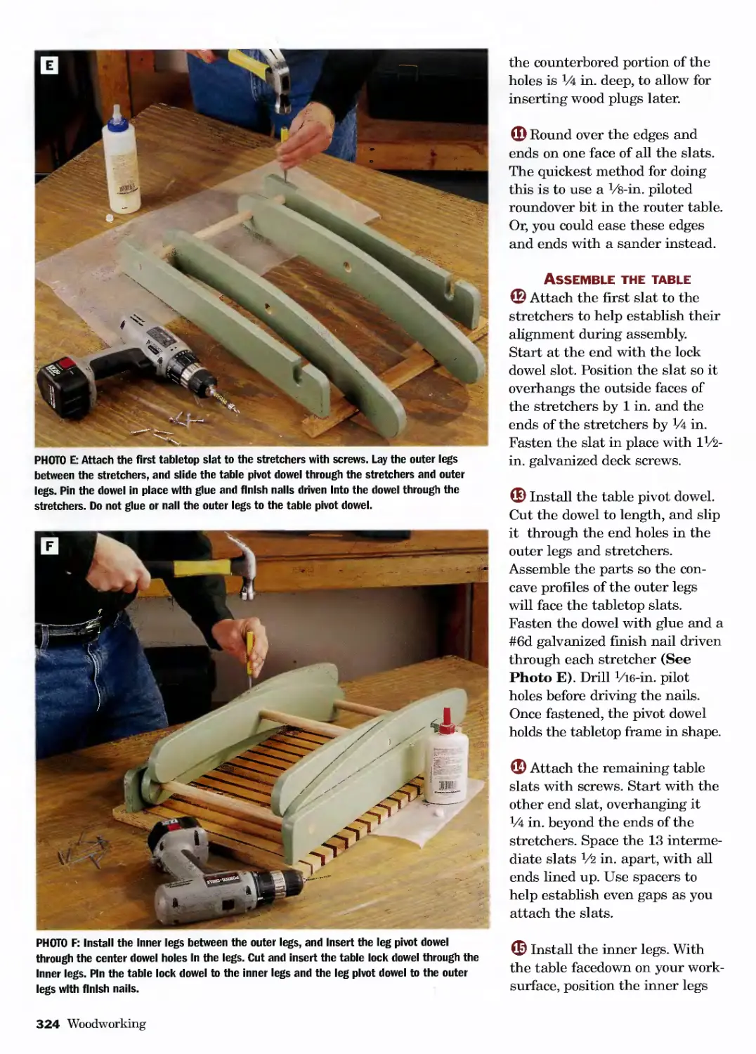
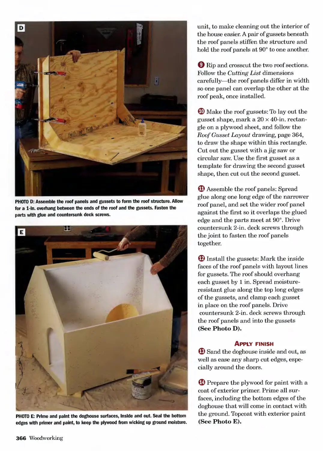
This 2005 edition published by Barnes & Noble, Inc.,
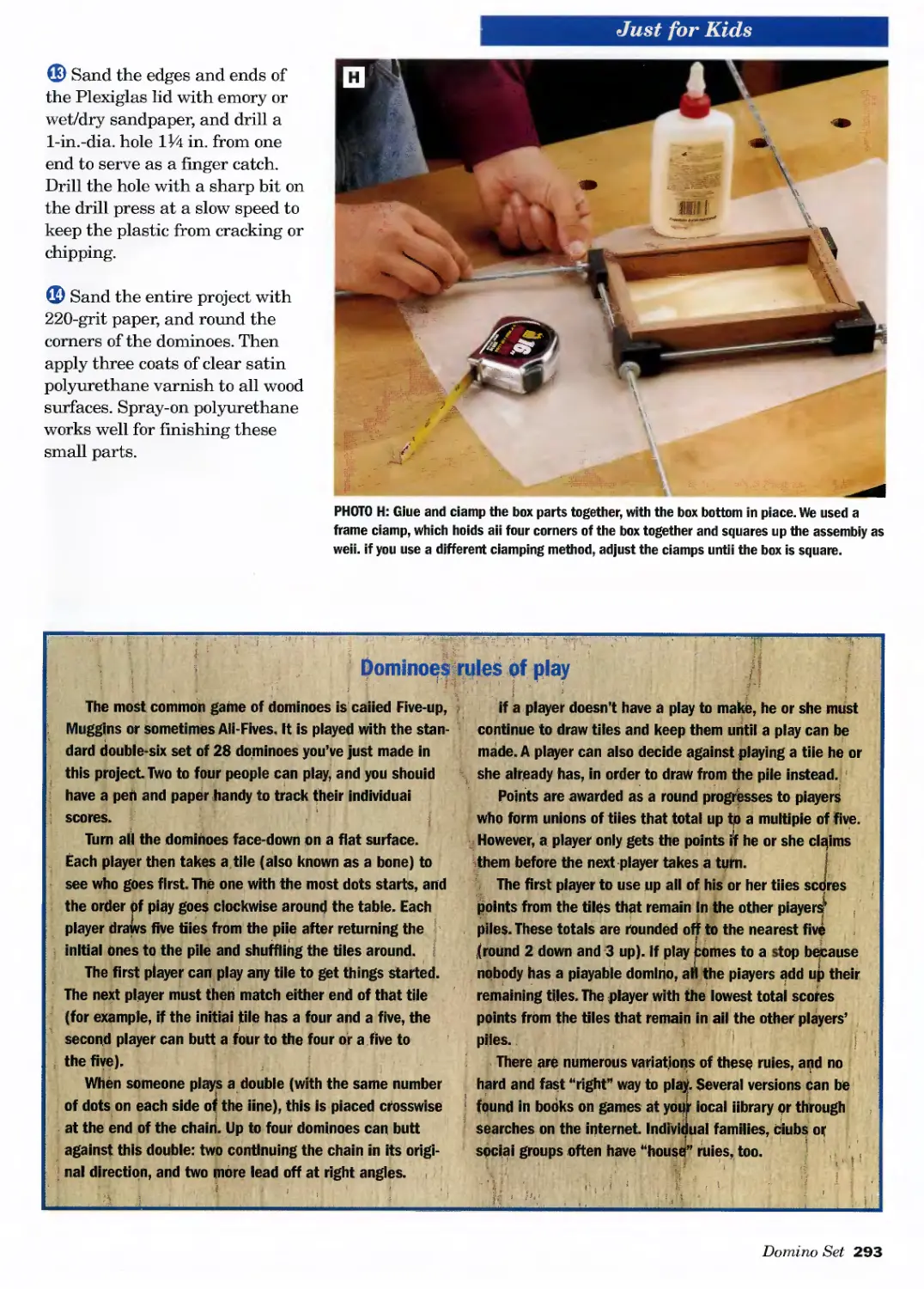
by arrangement with Landauer Corporation.
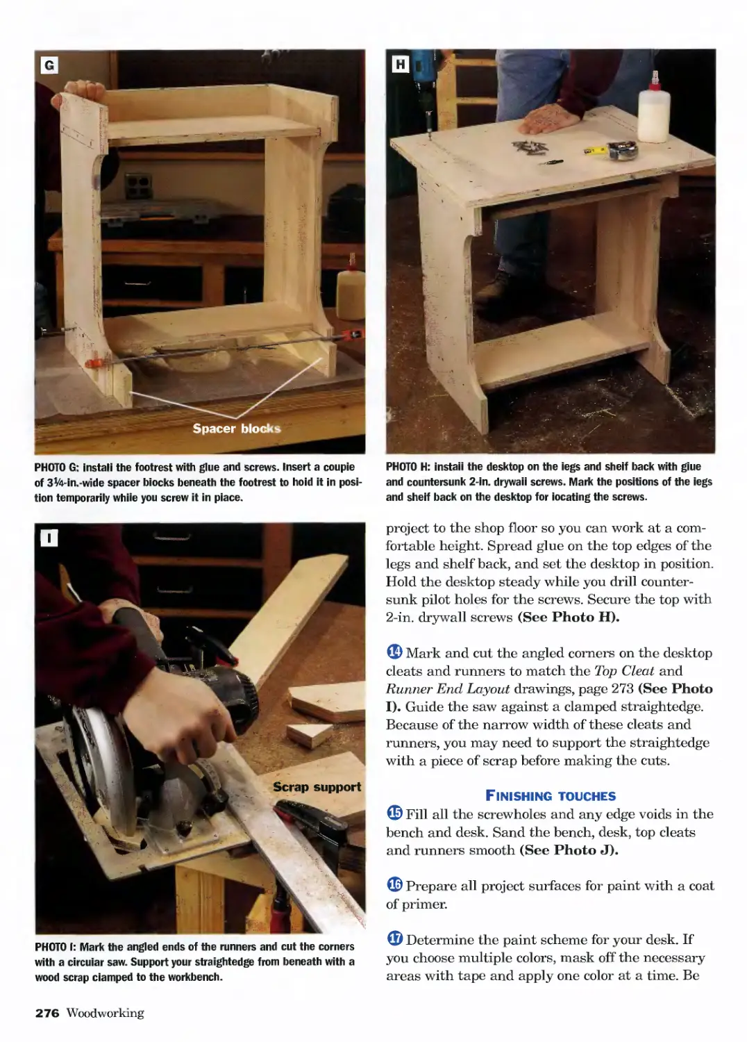
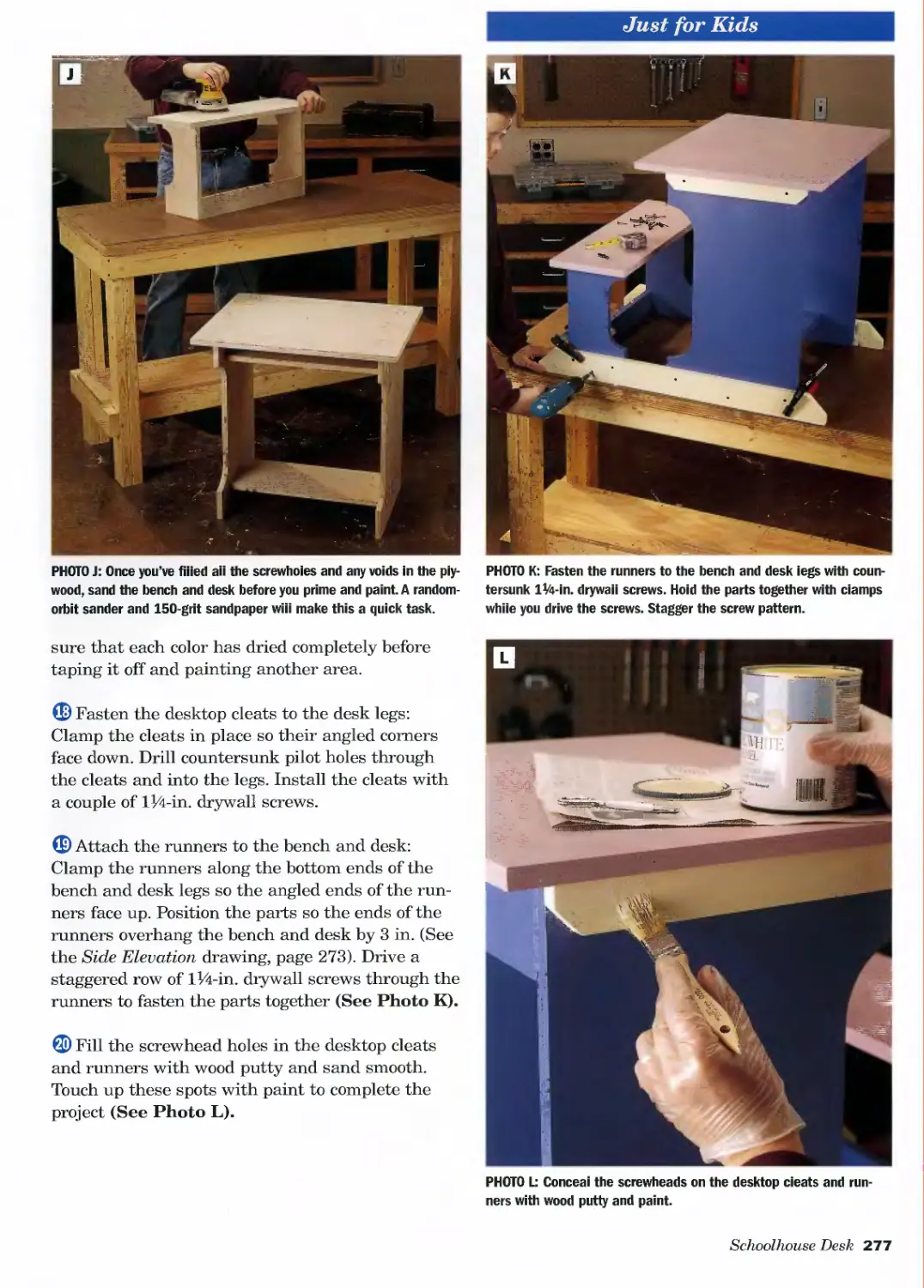
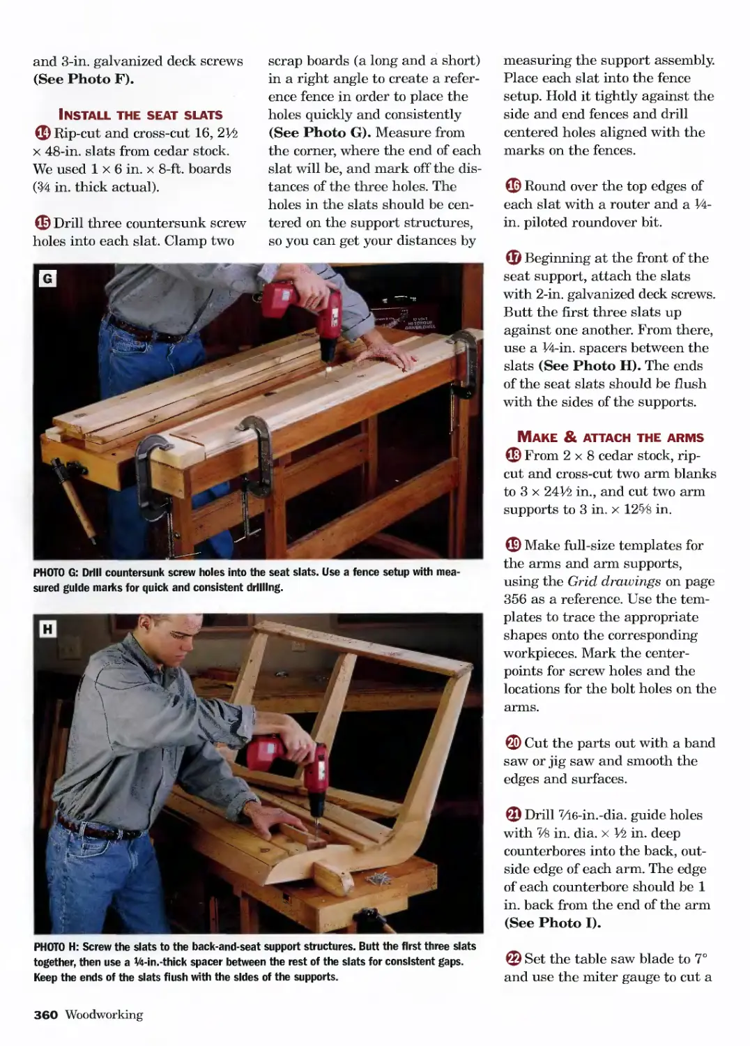
All rights reserved. No part of this publication may be reproduced,
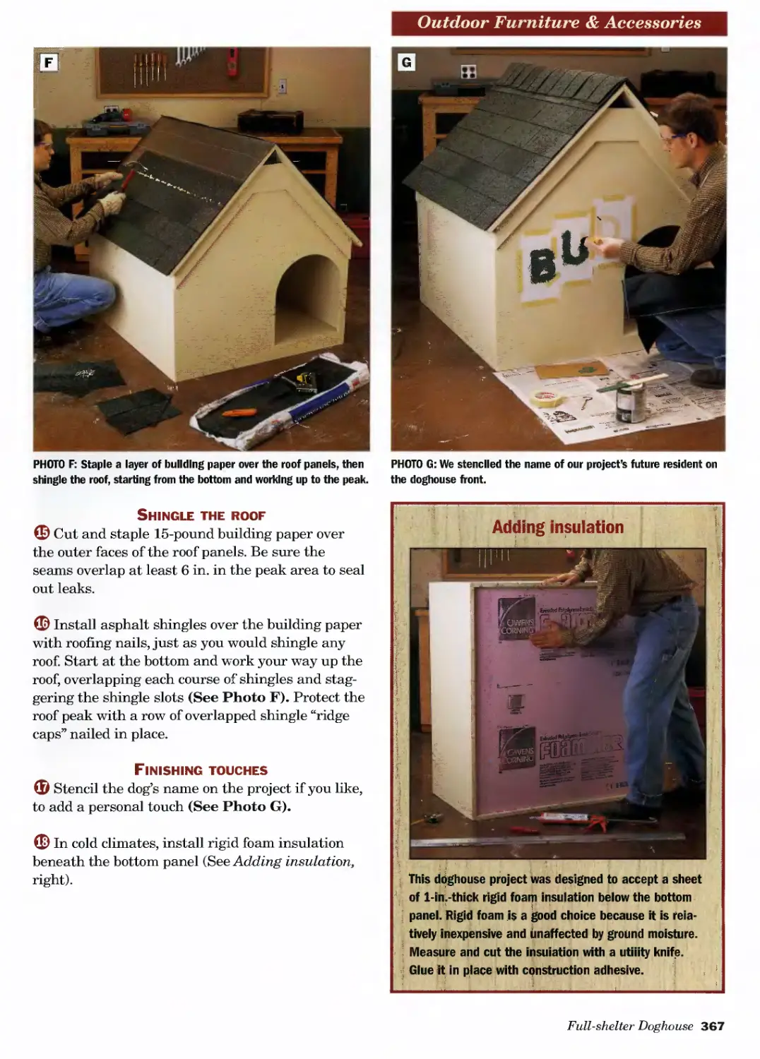
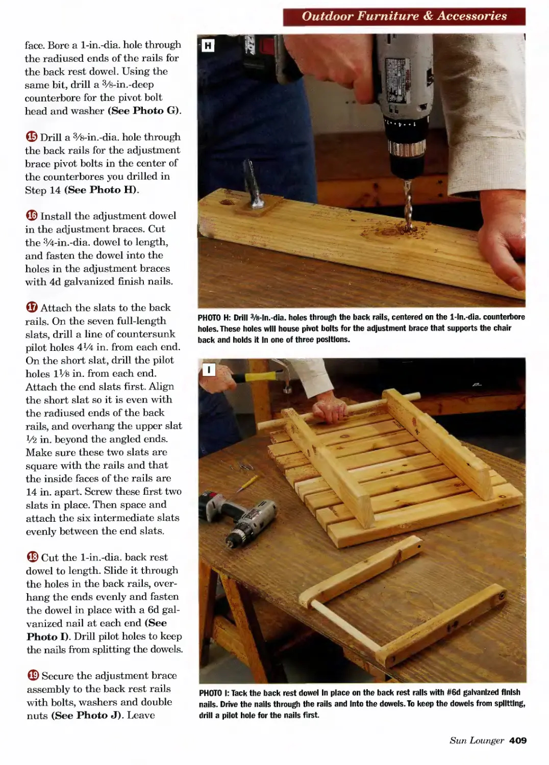
stored in a retrieval system, or transmitted, in any form or by any means,
electronic, mechanical, photocopying, recording, or otherwise,
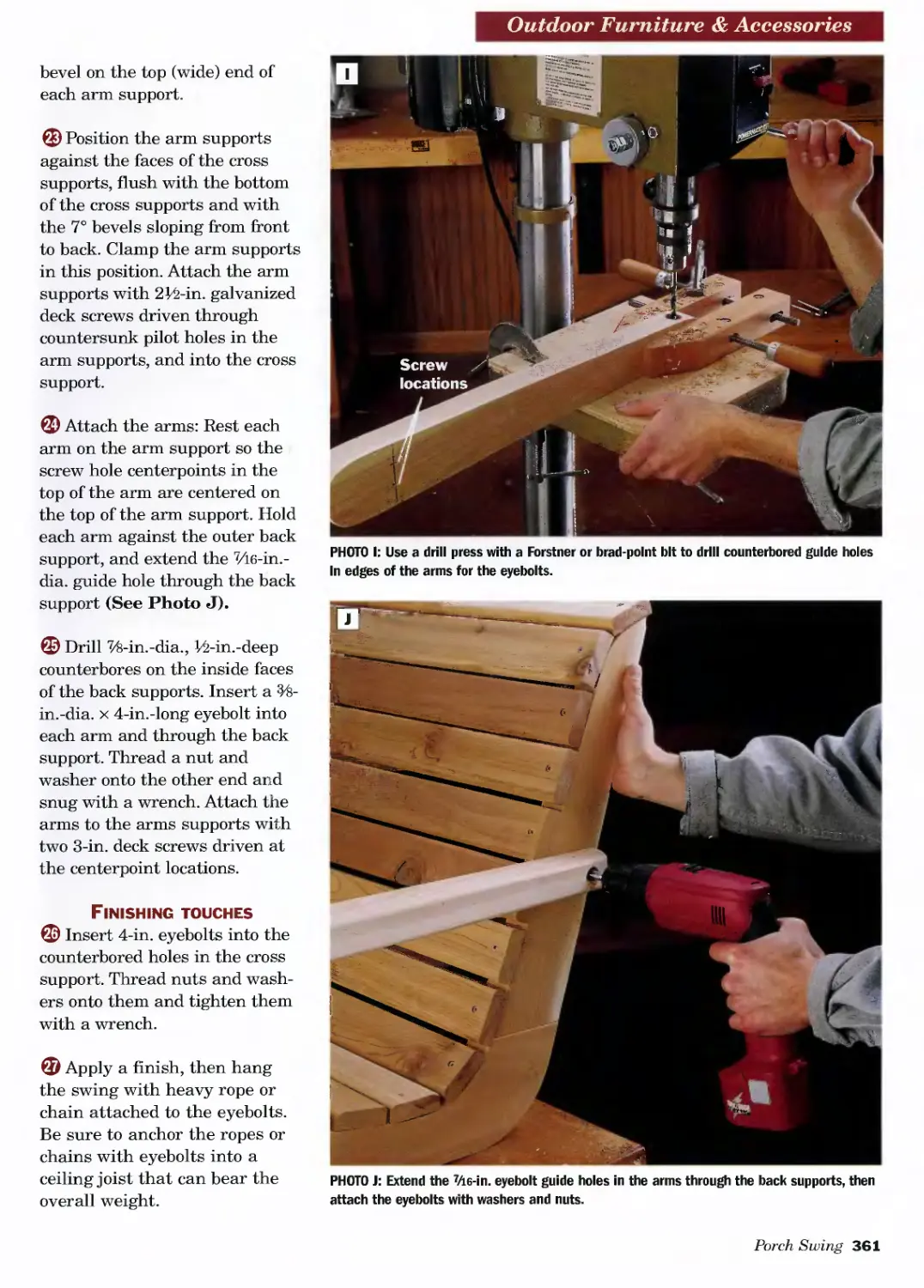
without prior written permission from the publisher.
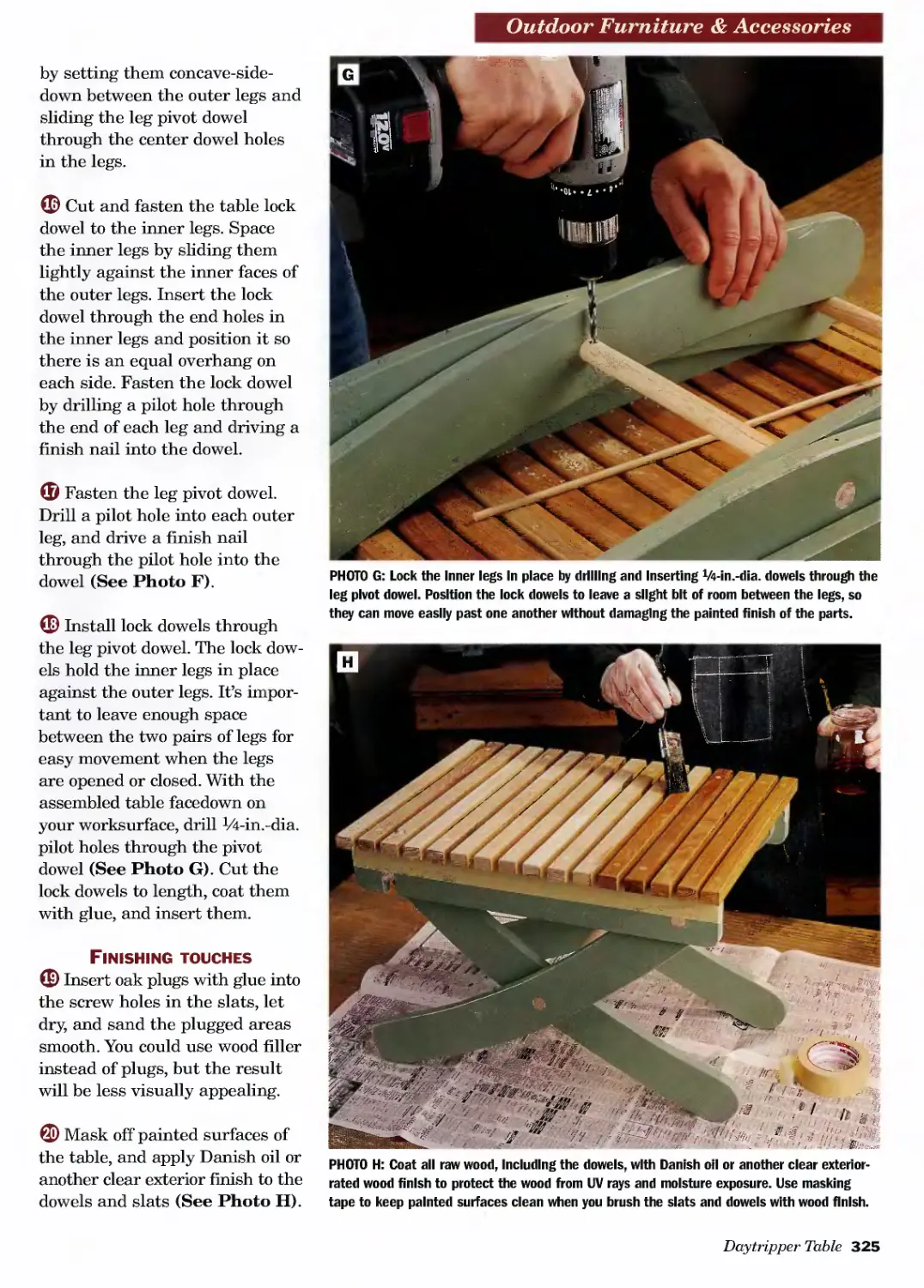
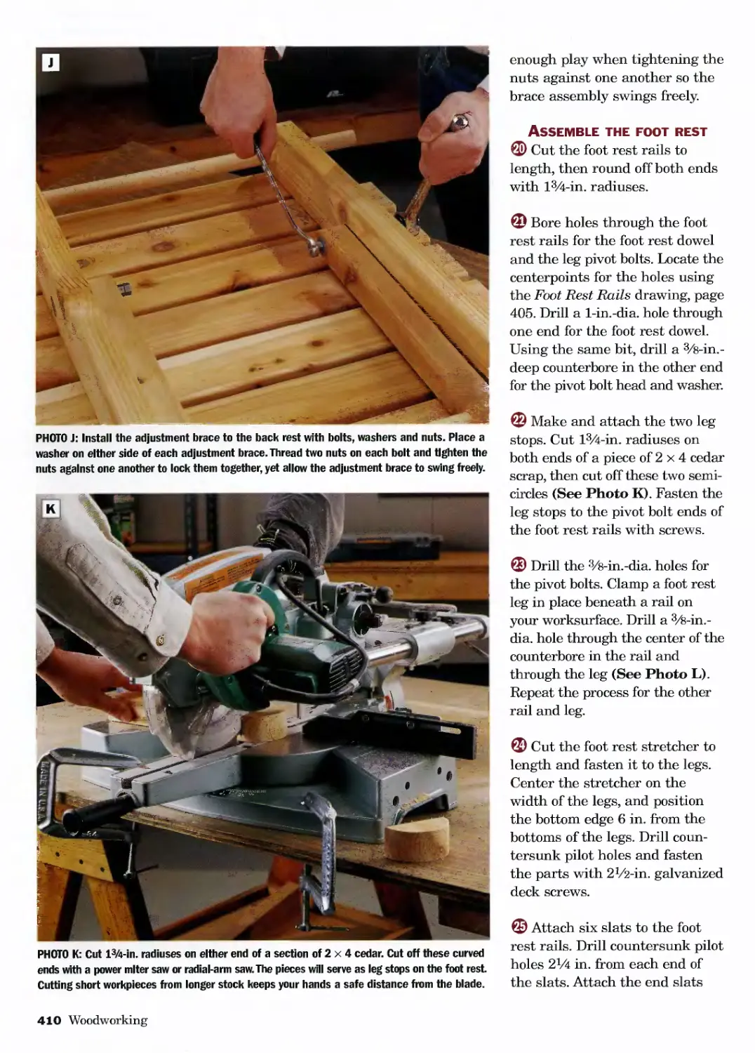
Tom Carpenter, Creative Director
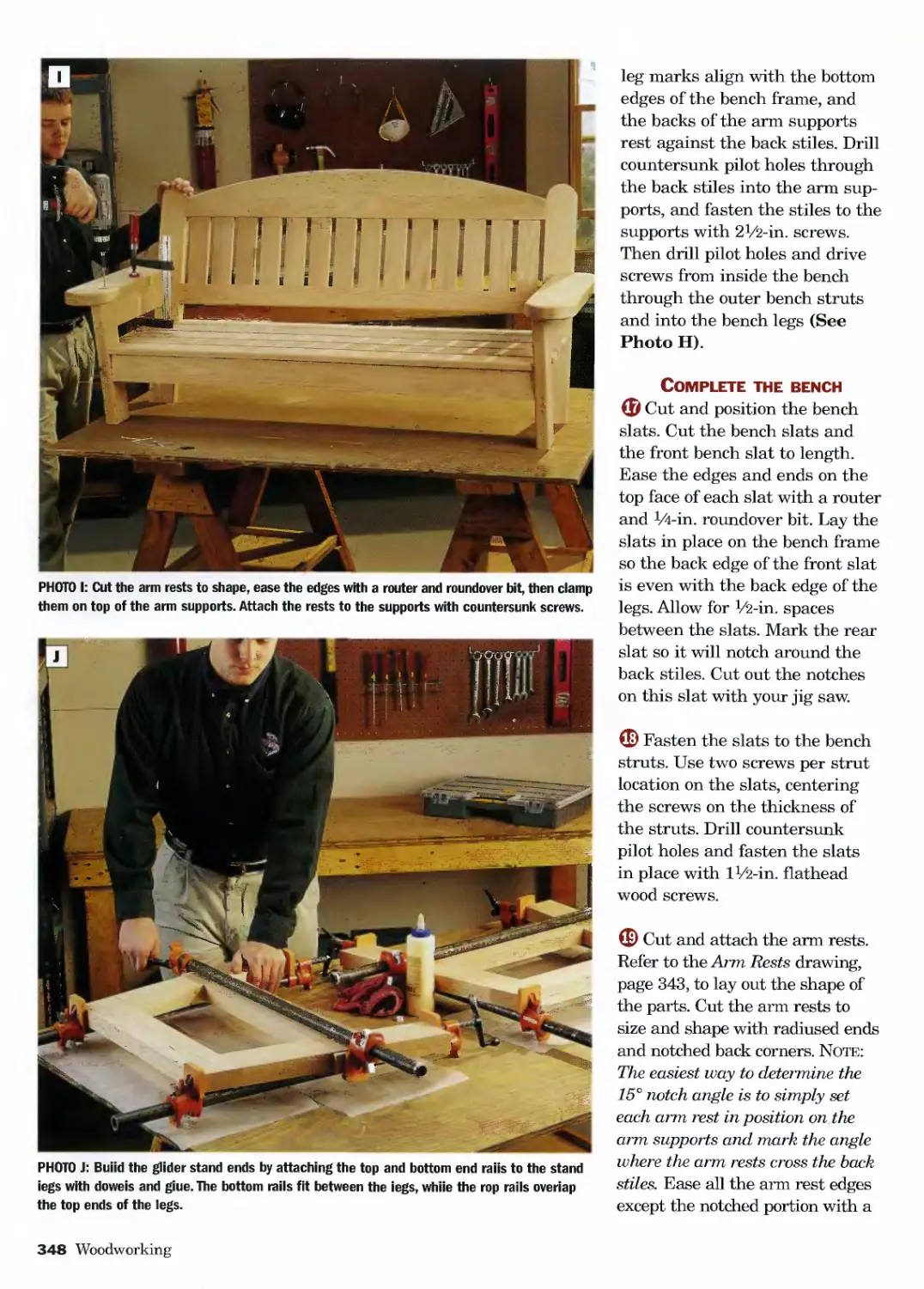
Heather Koshiol, Managing Editor
Jennifer Weaverling, Senior Book Development Coordinator
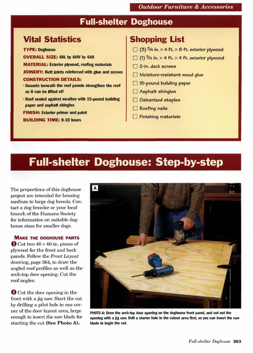
Teresa Marrone, Book Design and Production
Mark Johanson, Editor
Dan Cary, Photo Production Coordinator
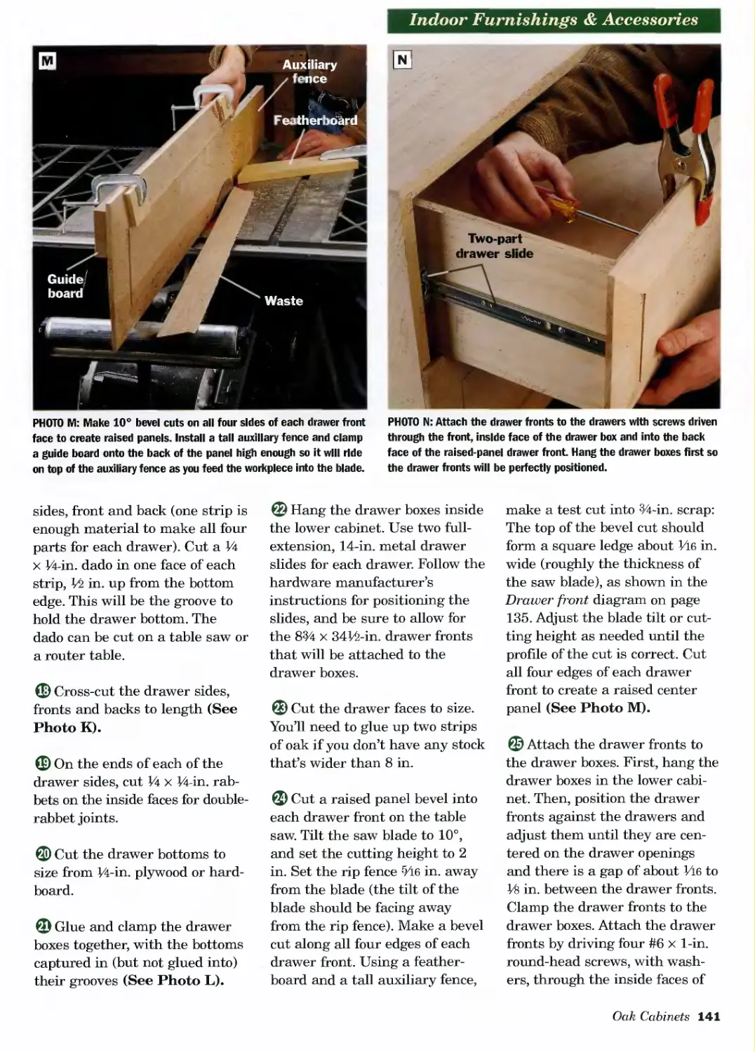
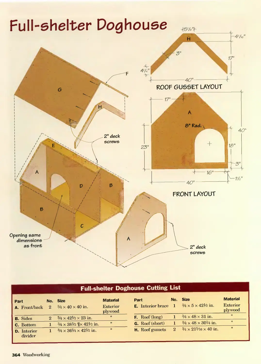
Chris Marshall, Editorial Coordinator
Steve Anderson, John English, Kam Ghaffari, Bill Hylton, Jeff Jewitt, Mark Johanson, Bruce Keiffer, Chris Marshall,
Richard Steven, Writers
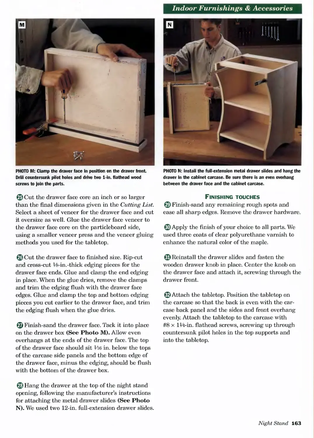
John Drigot, Marti Naughton, Bill Nelson, Design, Art Direction and Production
Kim Bailey, Ralph Karlen, Mark Macemon, Tad Saddoris, Photography
Tom Deveny, Robert Ginn, John Nadeau, Technical Advisors
Craig Claeys, John Drigot, Bruce Keiffer, Bill Nelson, Contributing Illustrators
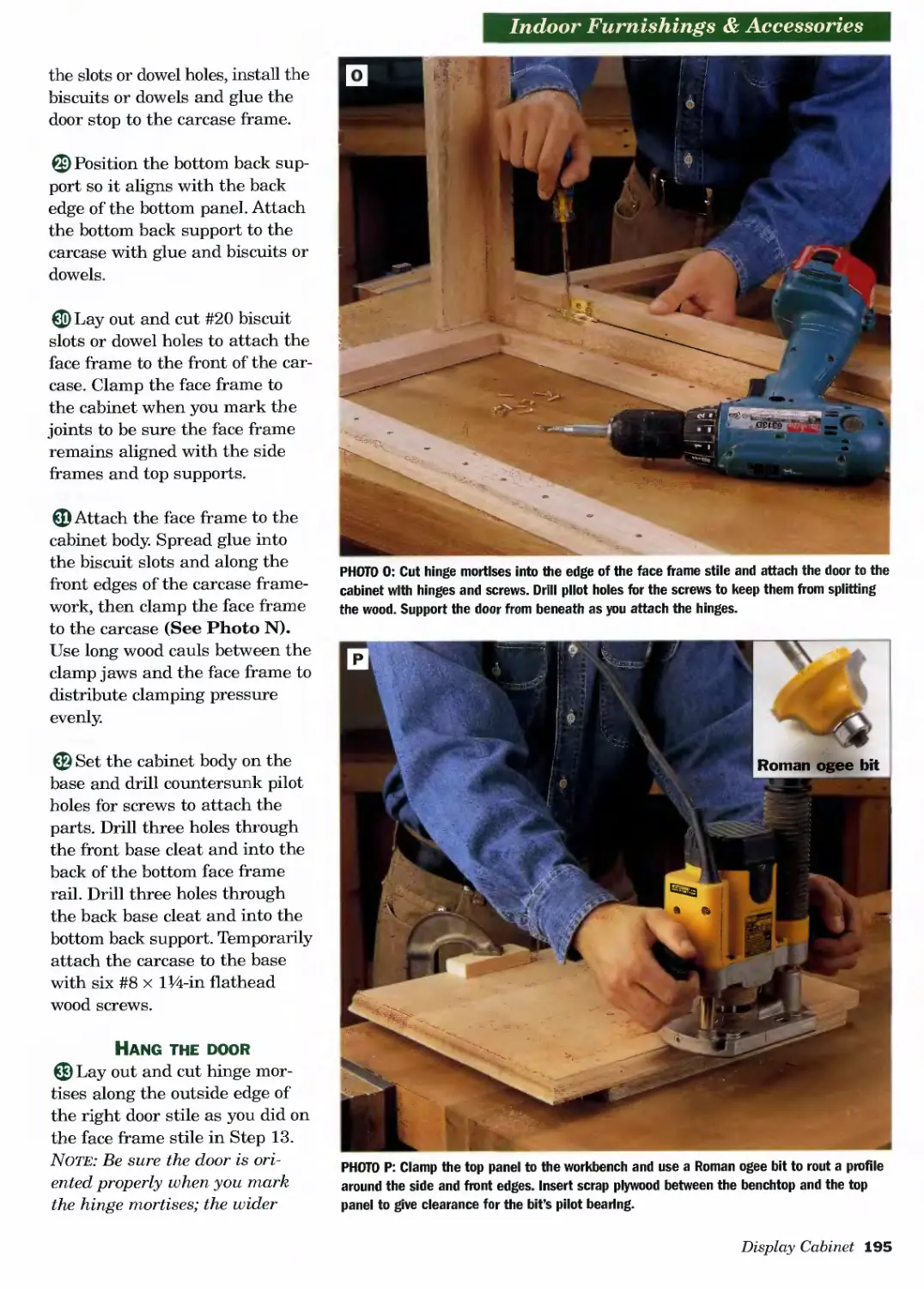
Tom Deveny, Bob Ginn, Jon Hegge, Rod Mechem, John Nadeau, Eric Sorensen, Project Builders
Dan Cary, Tom Deveny, John Drigot, Mark Johanson, Bruce Kieffer, Chris Marshall, Rod Mechem, Project Designers
Brad Classon, Rod Mechem, John Nadeau, Production Assistance
Special thanks to: Terry Casey and Janice Cauley’
ISBN-13: 978-0-7607-6013-0
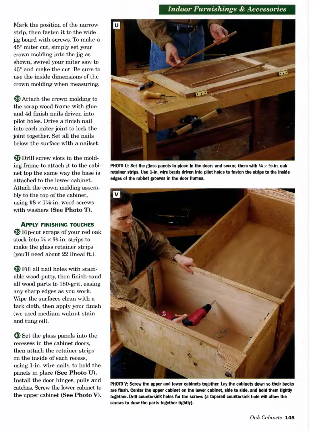
ISBN-10: 0-7607-6013-6
Printed and bound in China
10 9876543
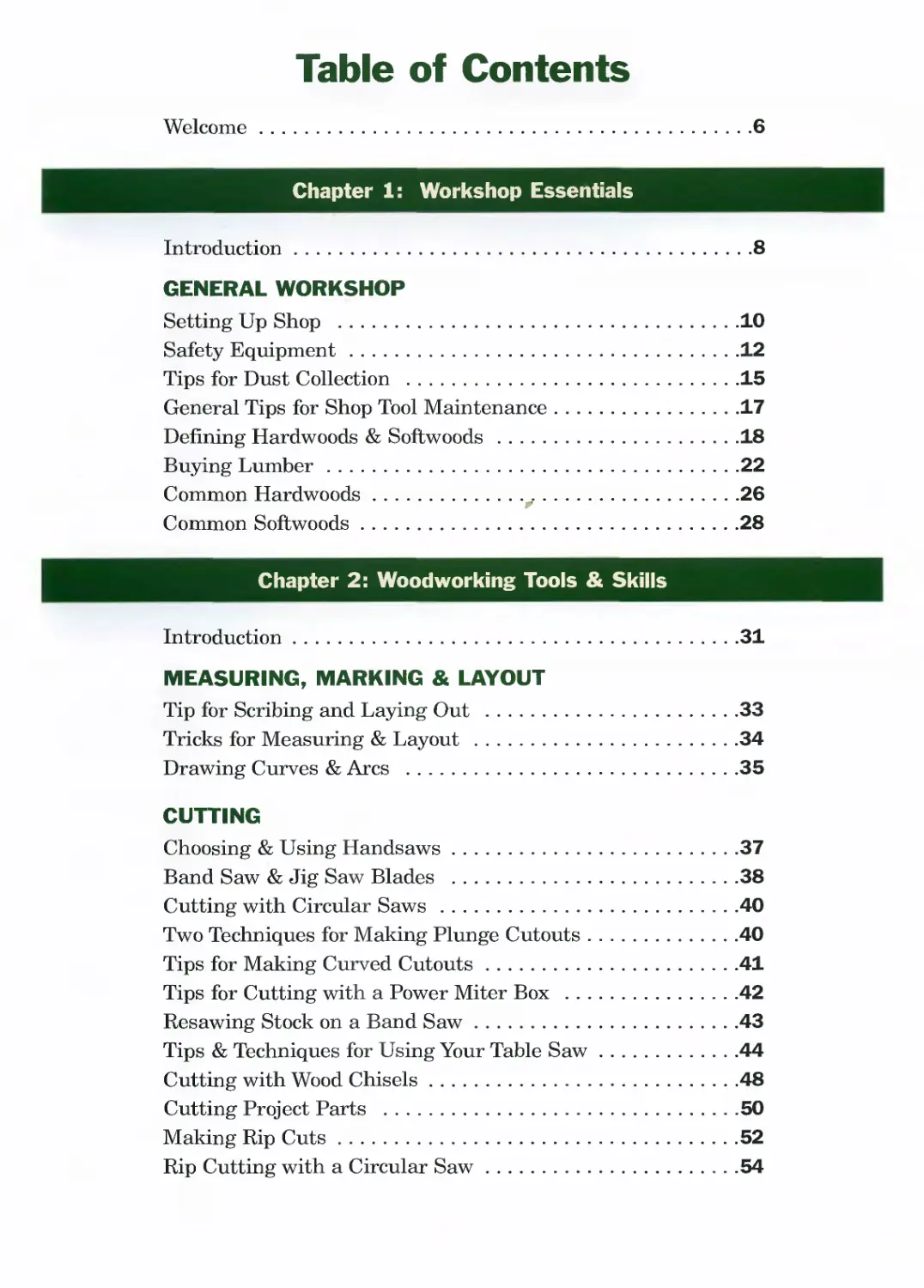
Table of Contents
Welcome..........................................6
Chapter 1: Workshop
Introduction.......................................8
GENERAL WORKSHOP
Setting Up Shop ..................................10
Safety Equipment..................................12
Tips for Dust Collection .........................15
General Tips for Shop Tool Maintenance............17
Defining Hardwoods & Softwoods ...................18
Buying Lumber.....................................22
Common Hardwoods................,.................26
Common Softwoods..................................28
Chapter 2: Woodworking Tools
Introduction.......................................31
MEASURING, MARKING & LAYOUT
Tip for Scribing and Laying Out ...................33
Tricks for Measuring & Layout .....................34
Drawing Curves & Arcs .............................35
CUTTING
Choosing & Using Handsaws..........................37
Band Saw & Jig Saw Blades .........................38
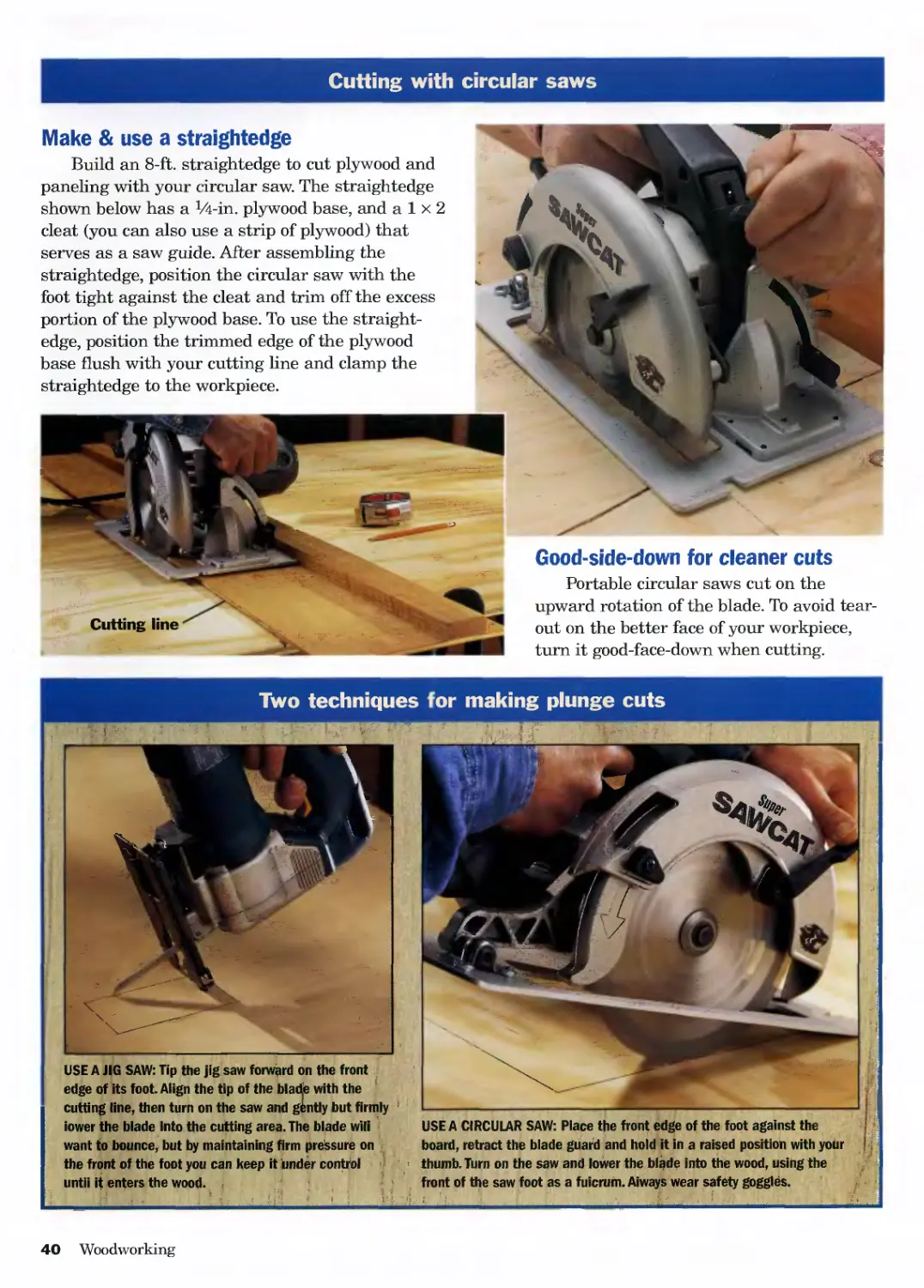
Cutting with Circular Saws ........................40
Two Techniques for Making Plunge Cutouts...........40
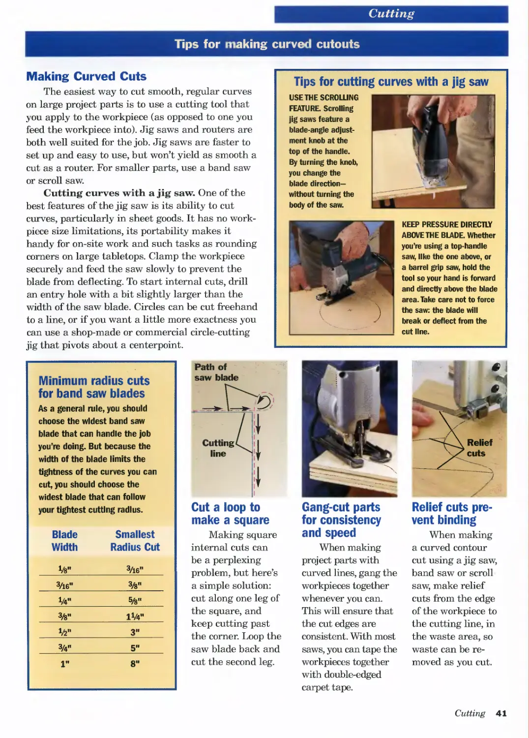
Tips for Making Curved Cutouts.....................41
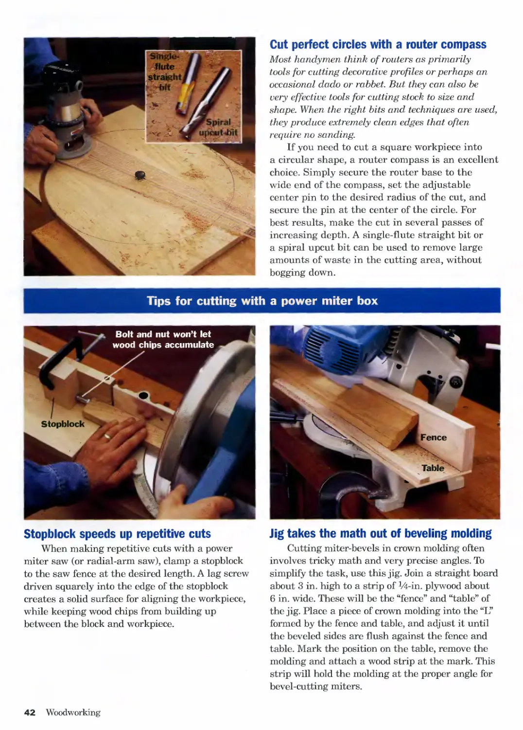
Tips for Cutting with a Power Miter Box ...........42
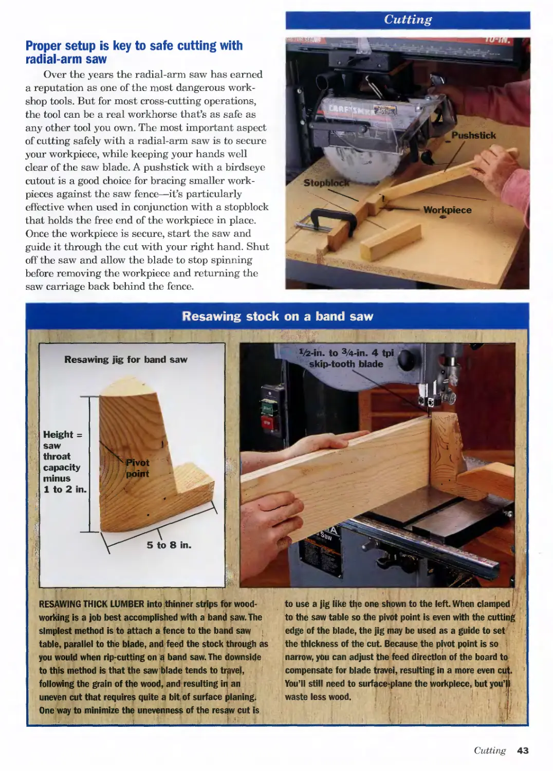
Resawing Stock on a Band Saw.......................43
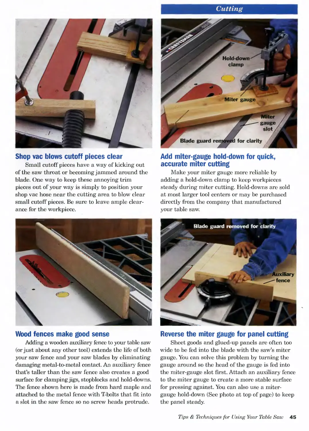
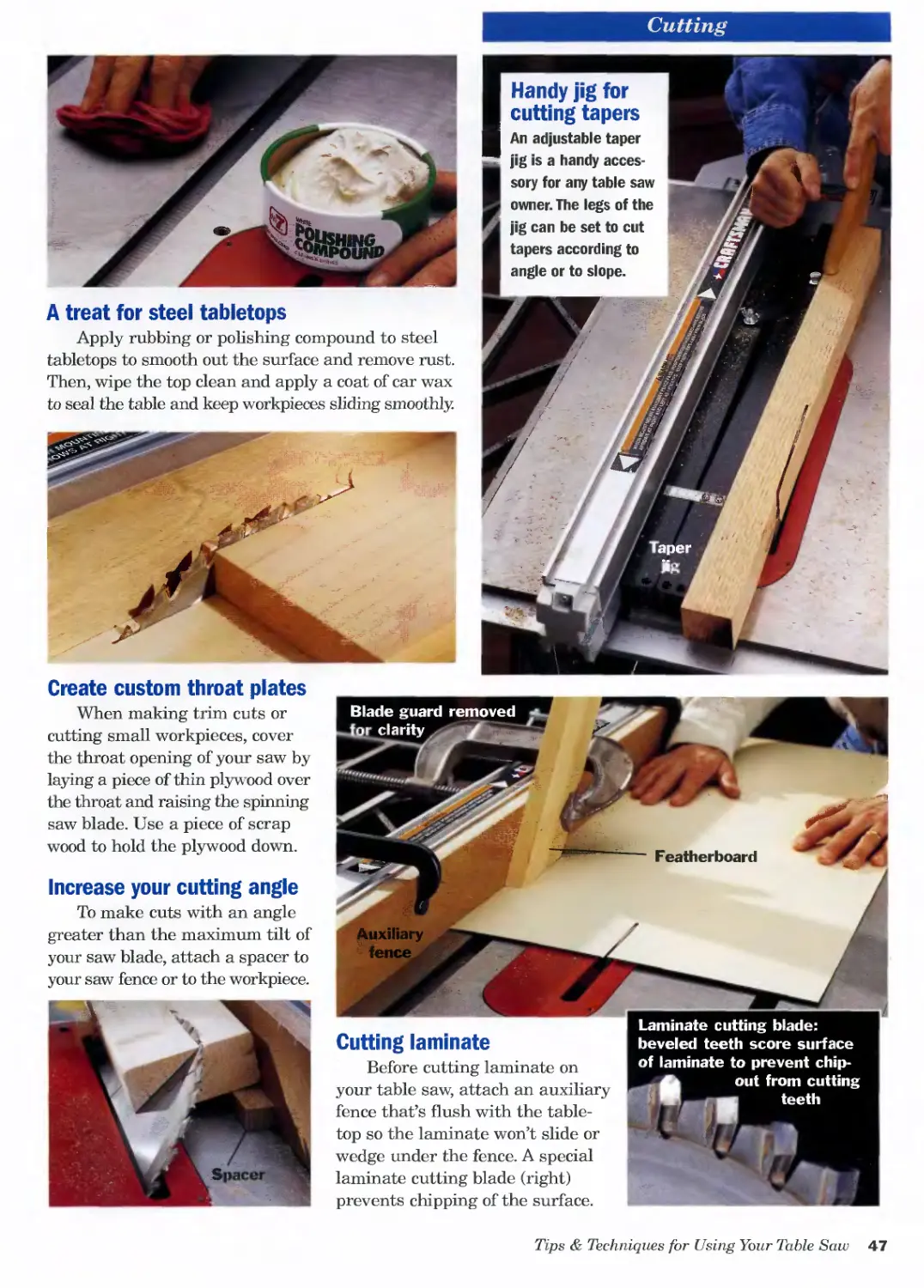
Tips & Techniques for Using Your Table Saw.........44
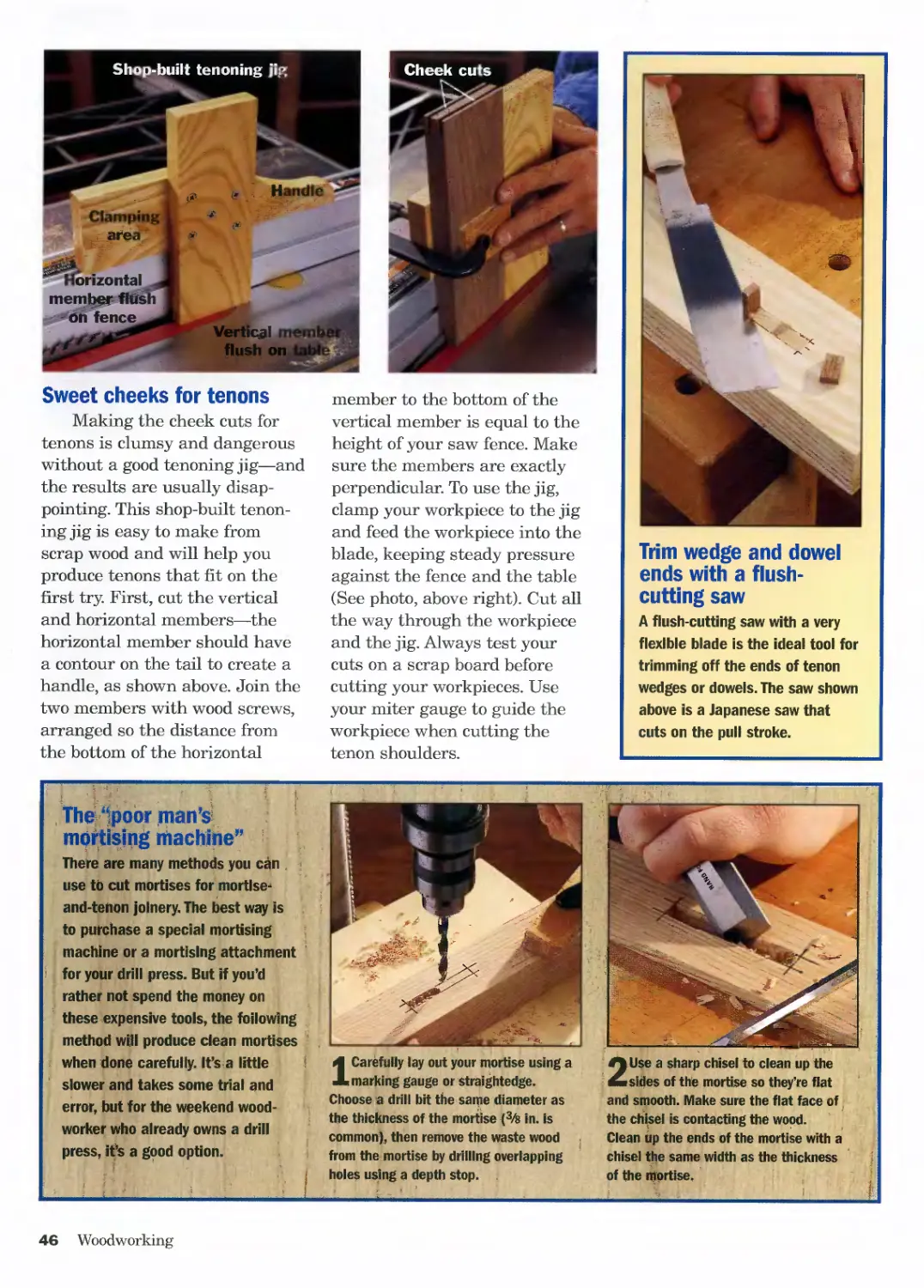
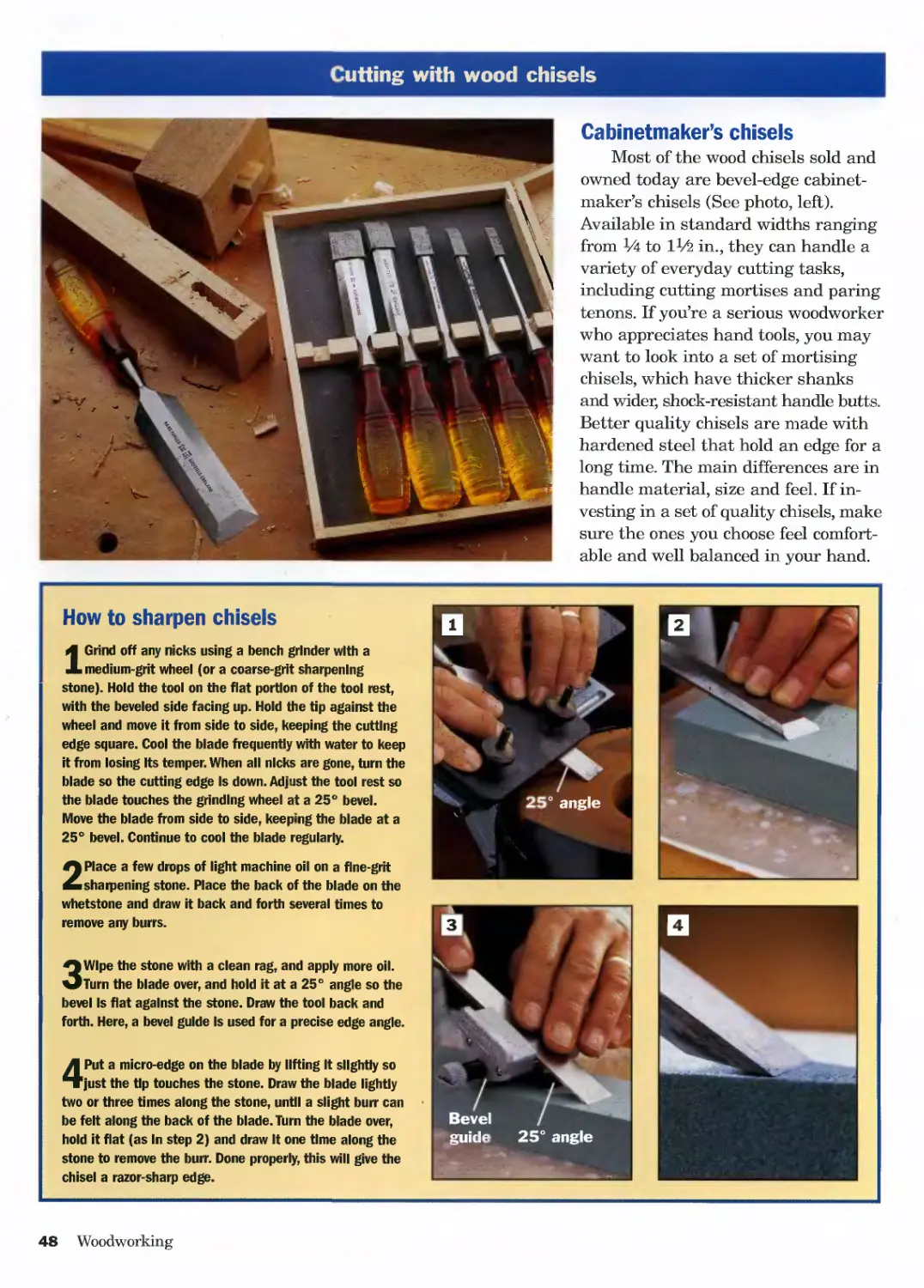
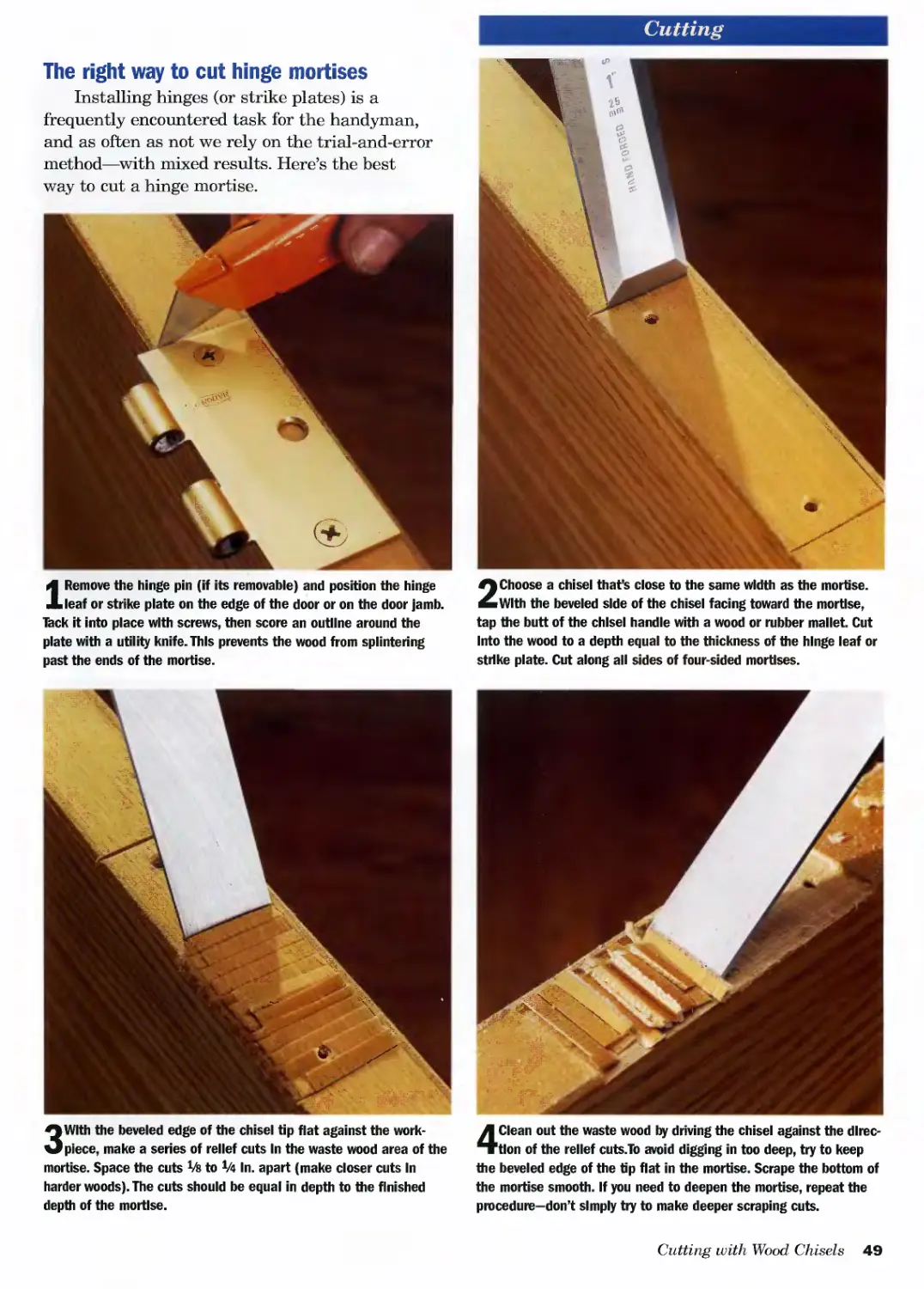
Cutting with Wood Chisels..........................48
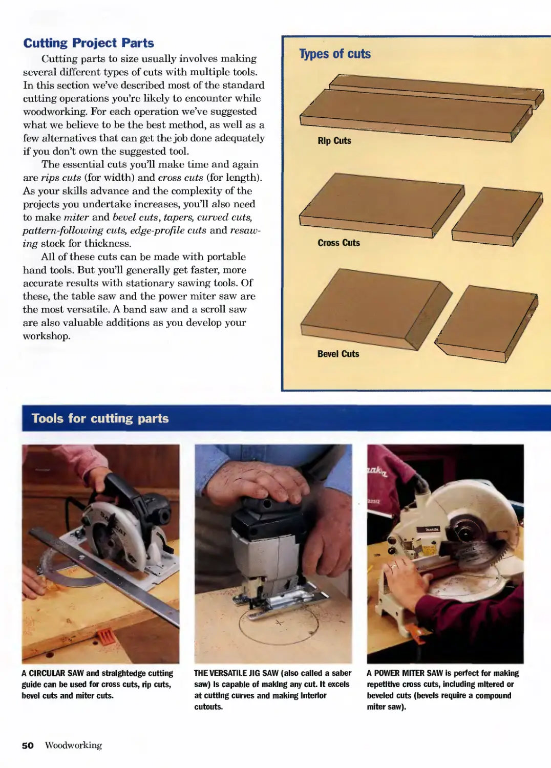
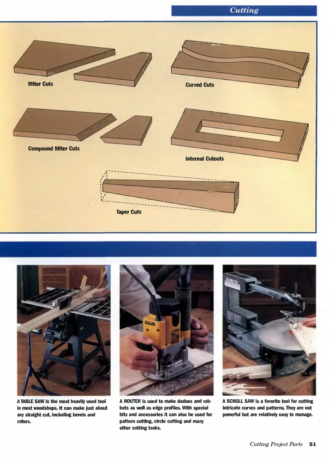
Cutting Project Parts .............................50
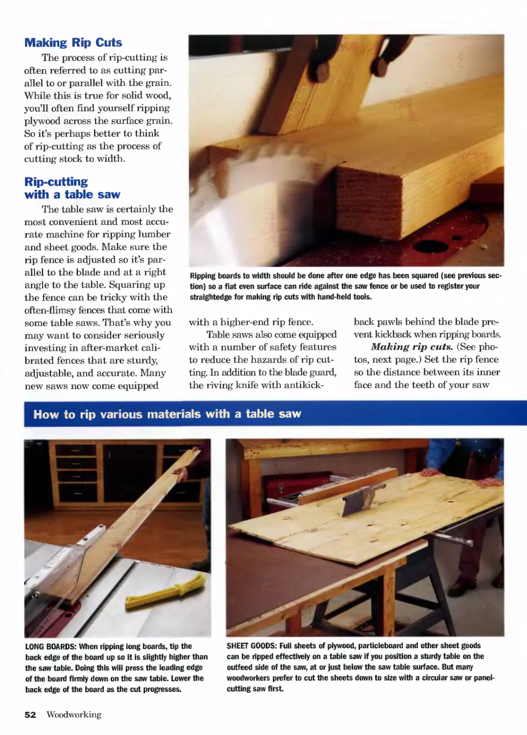
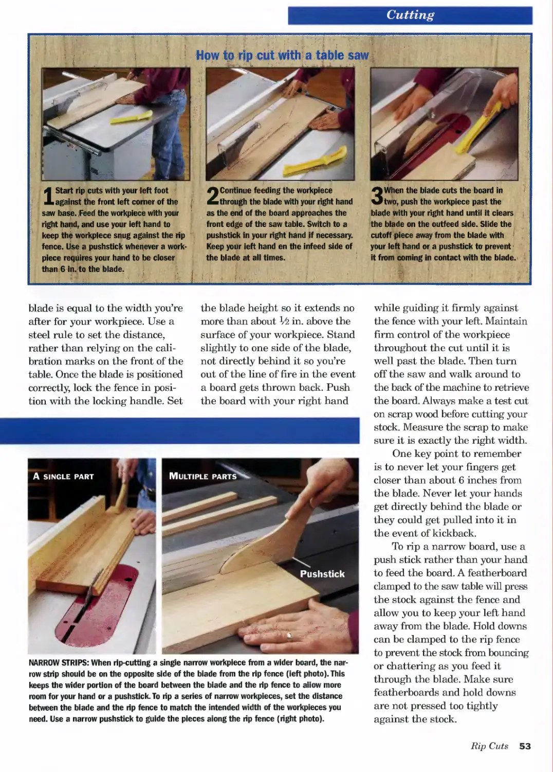
Making Rip Cuts....................................52
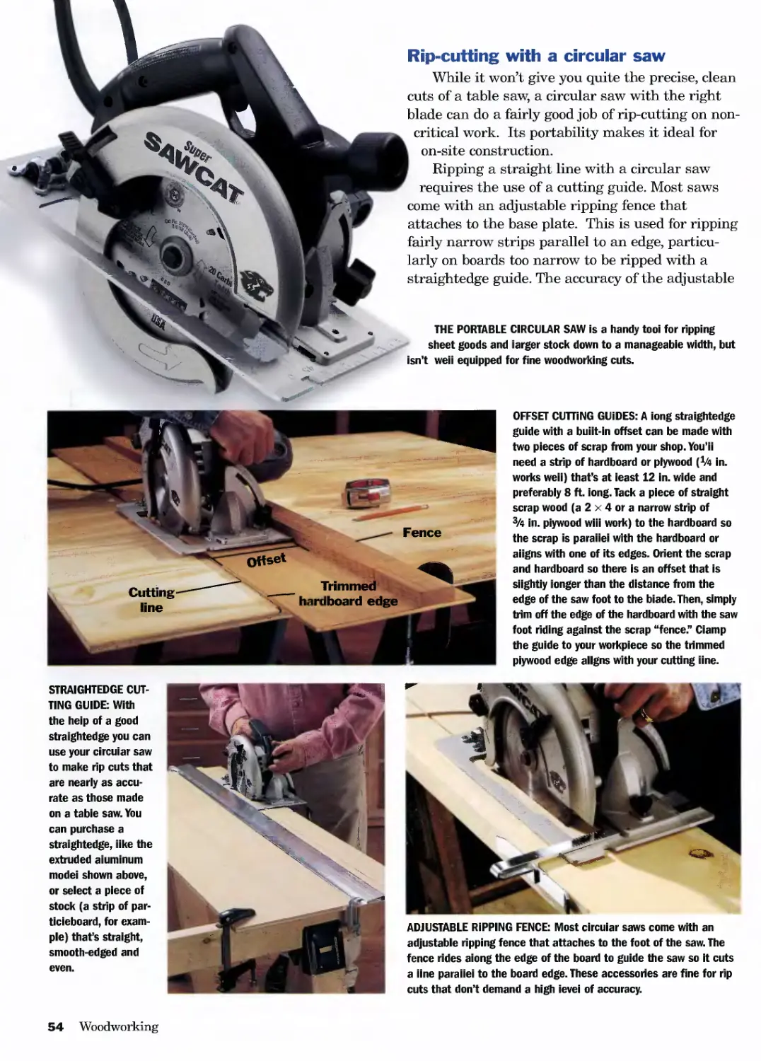
Rip Cutting with a Circular Saw....................54
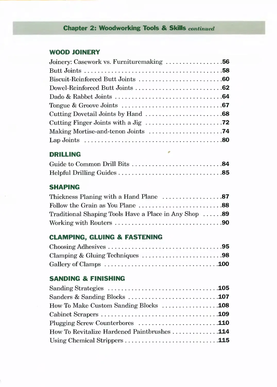
Chapter 2: Woodworking Tools & Skills continued
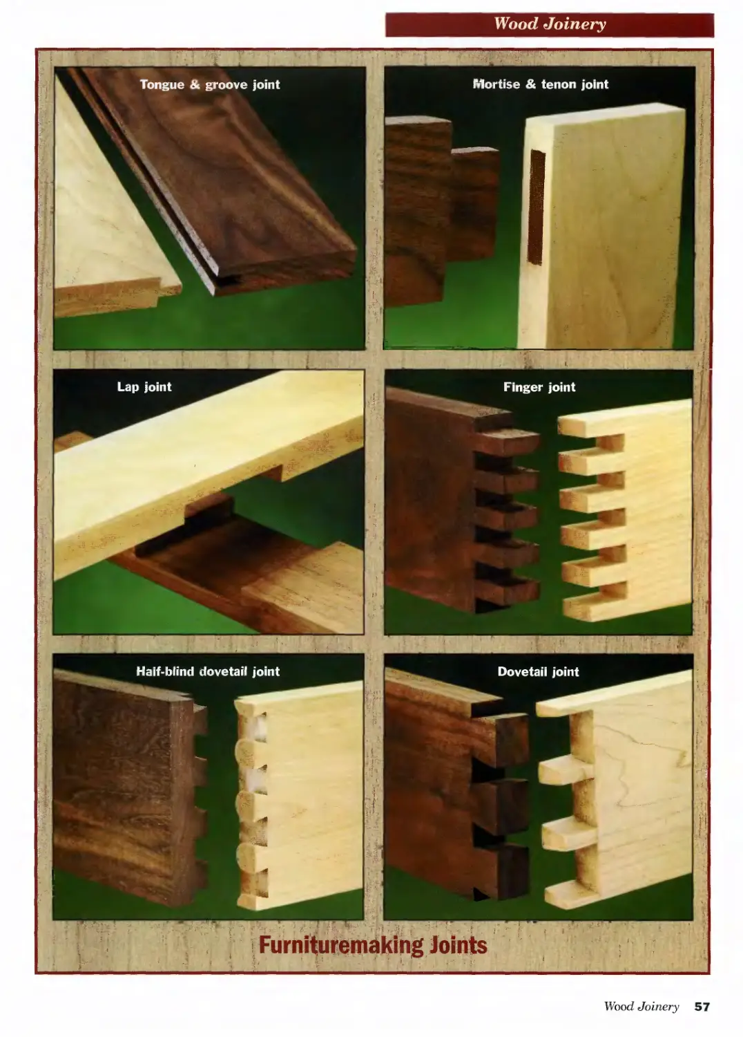
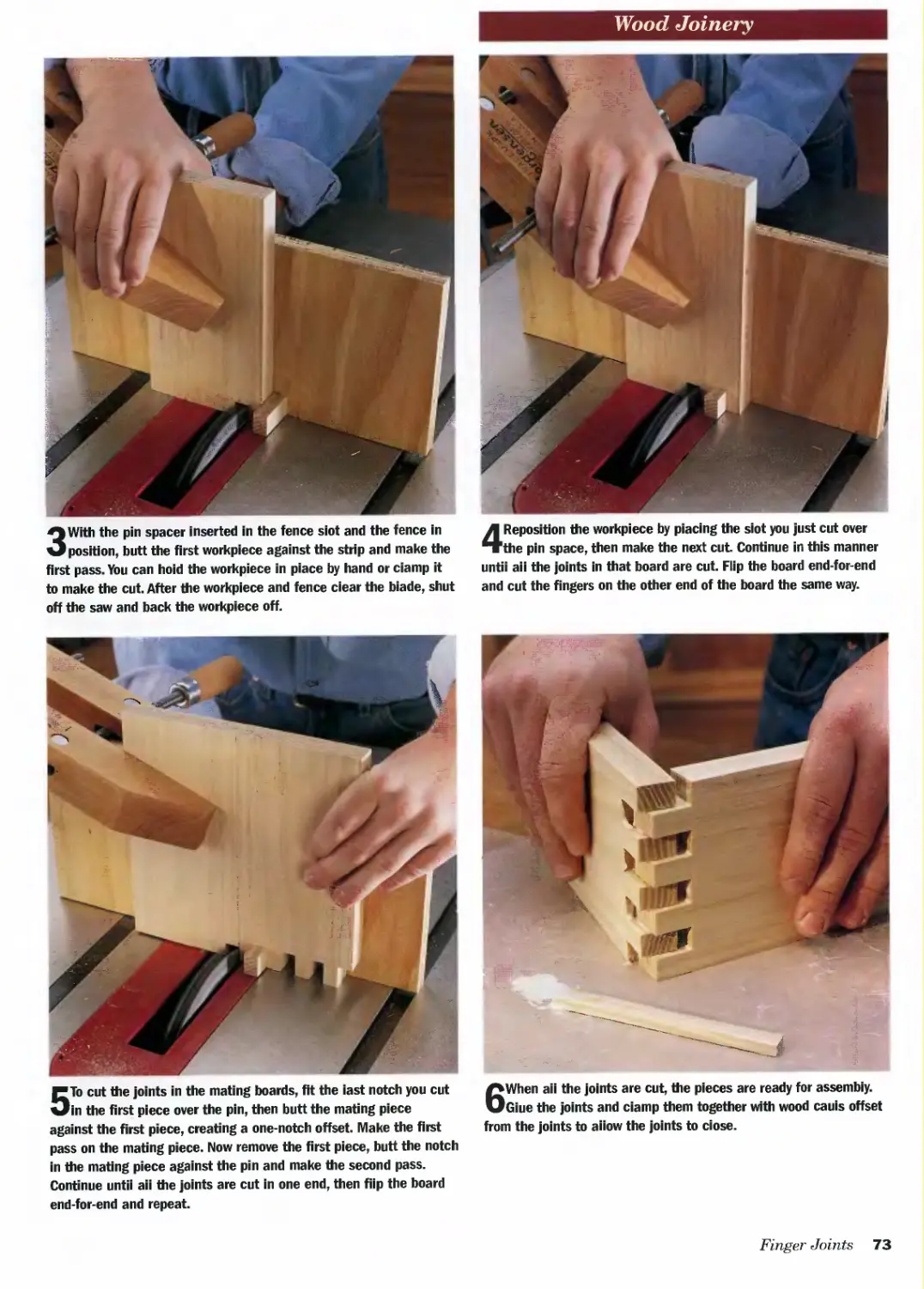
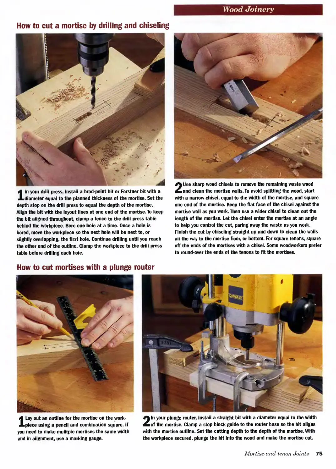
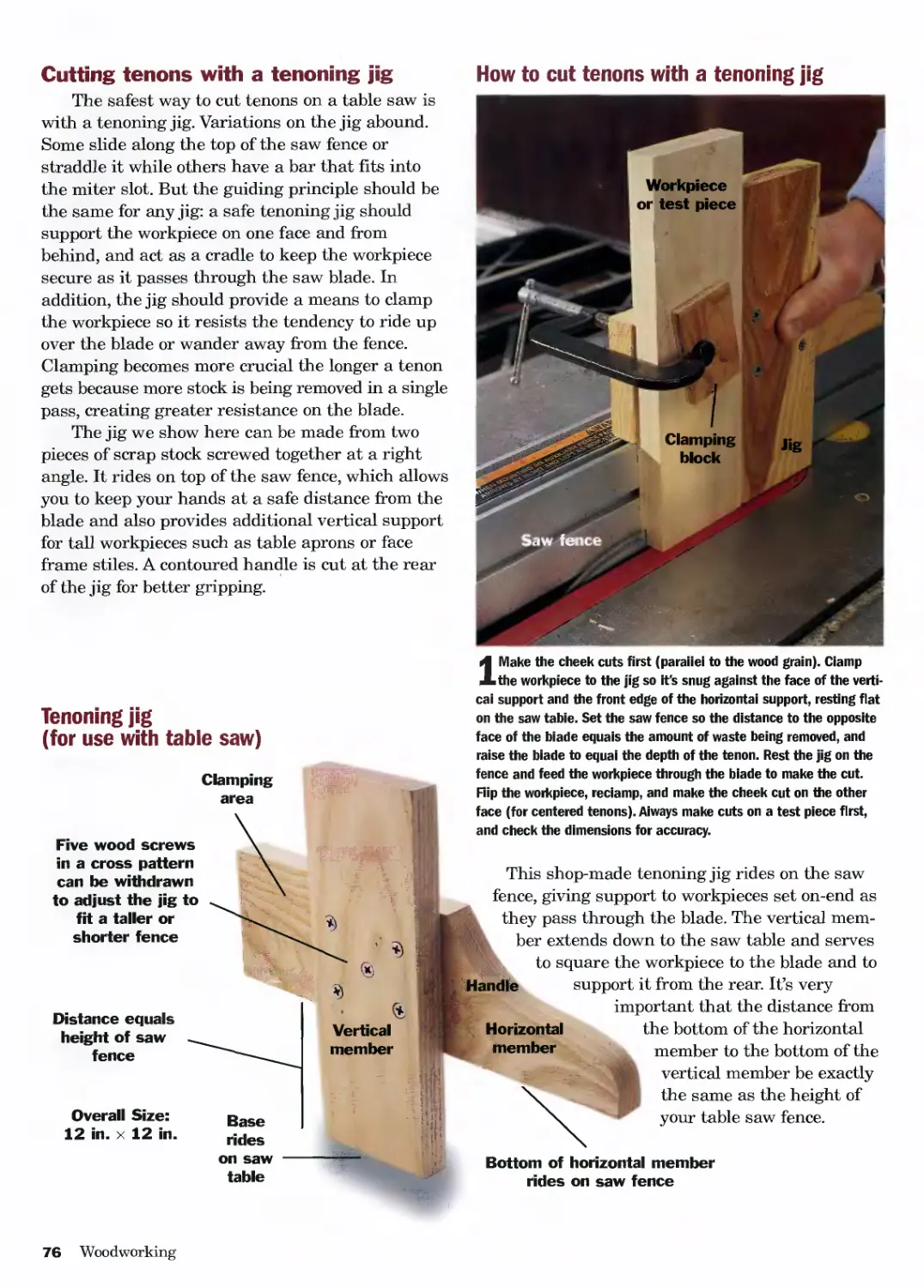
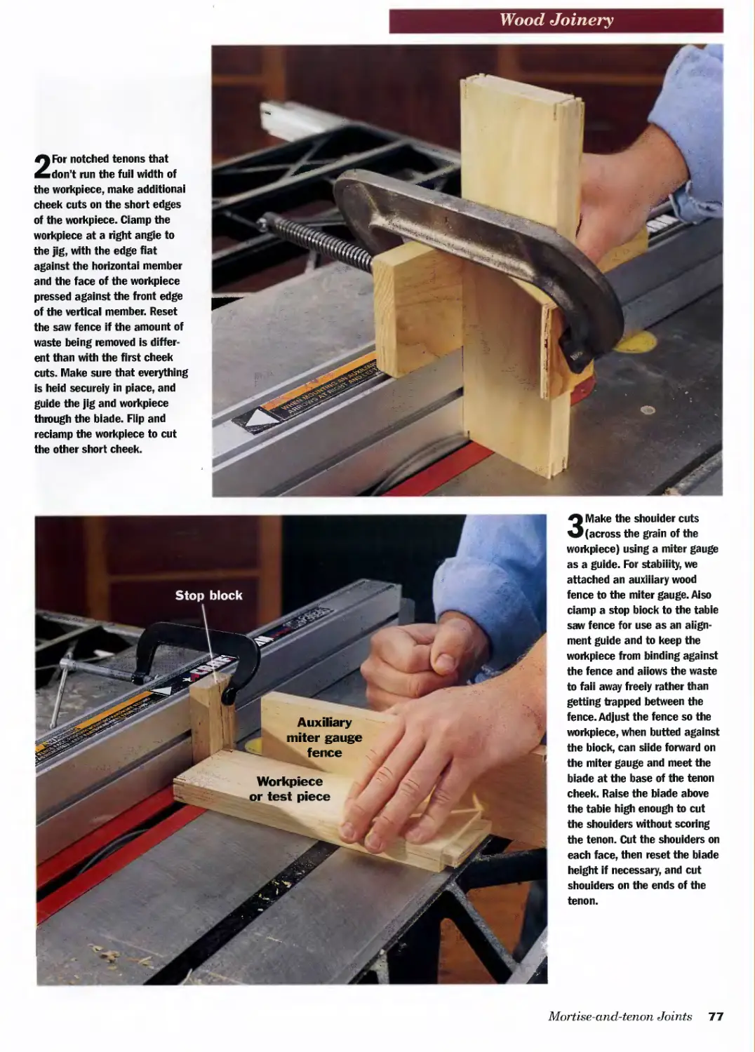
WOOD JOINERY
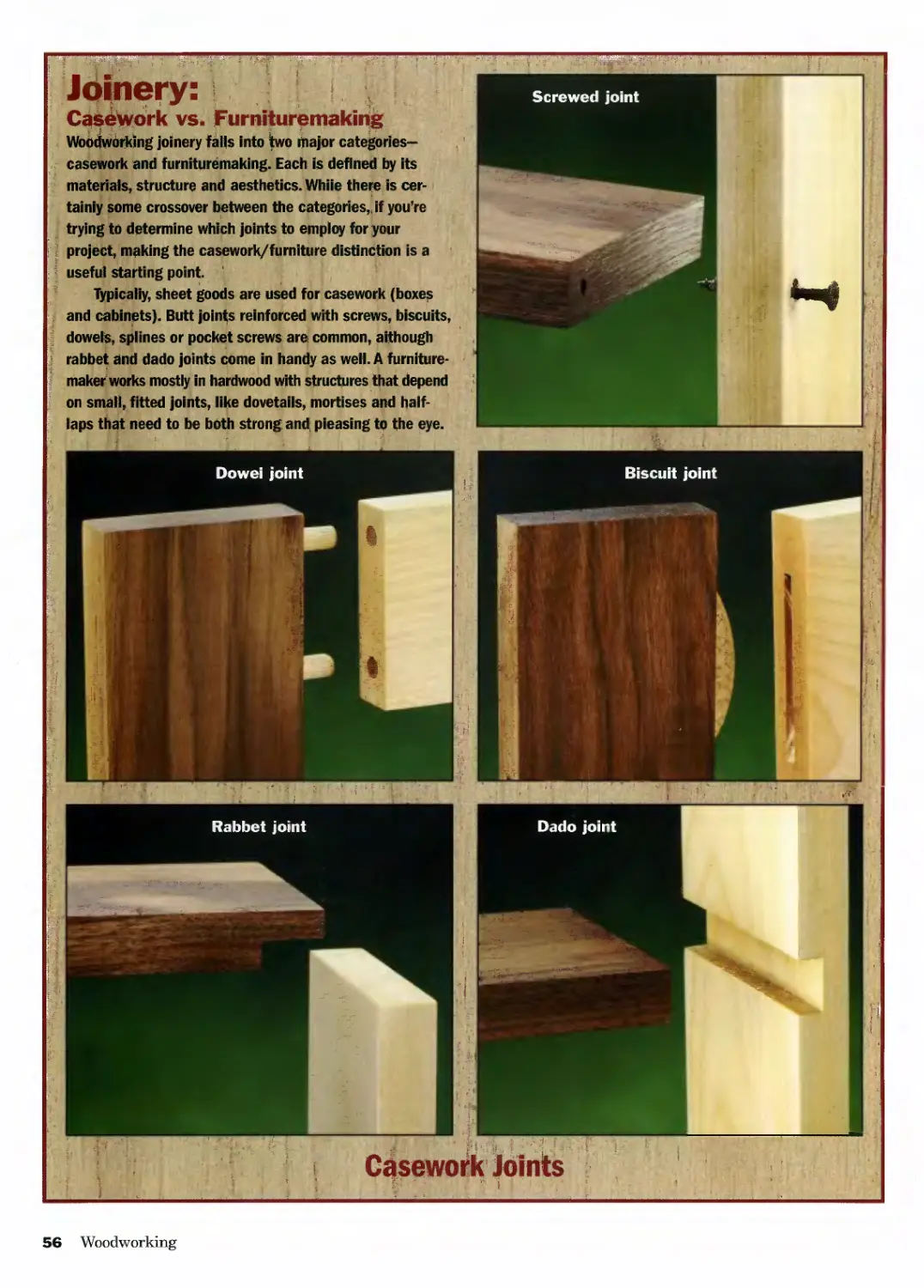
Joinery: Casework vs. Furnituremaking................56
Butt Joints..........................................58
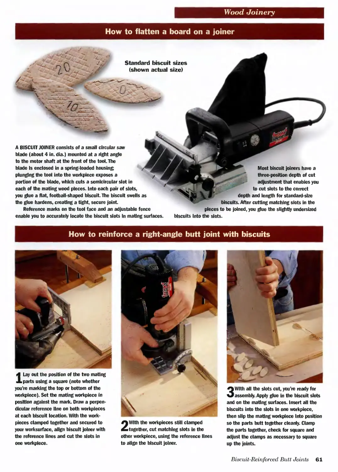
Biscuit-Reinforced Butt Joints.......................60
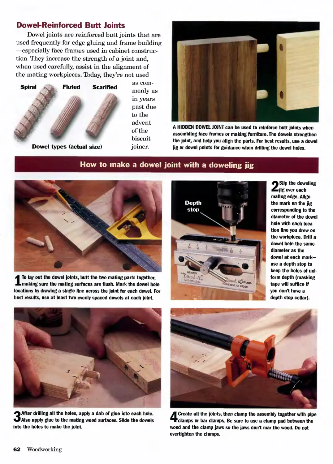
Dowel-Reinforced Butt Joints.........................62
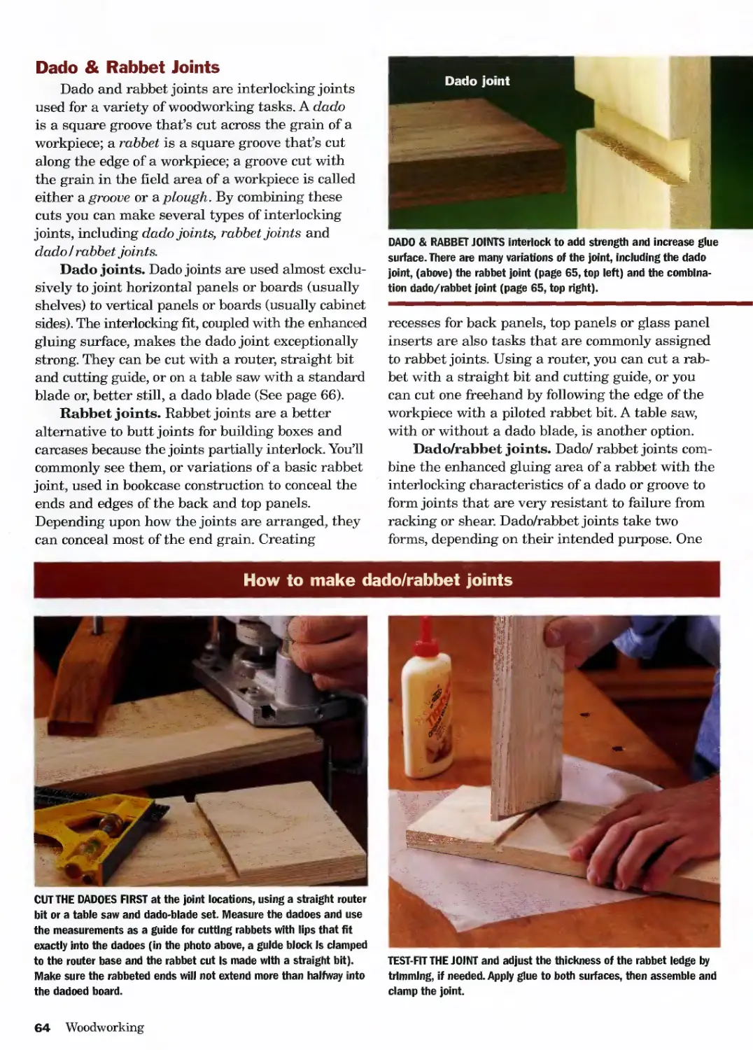
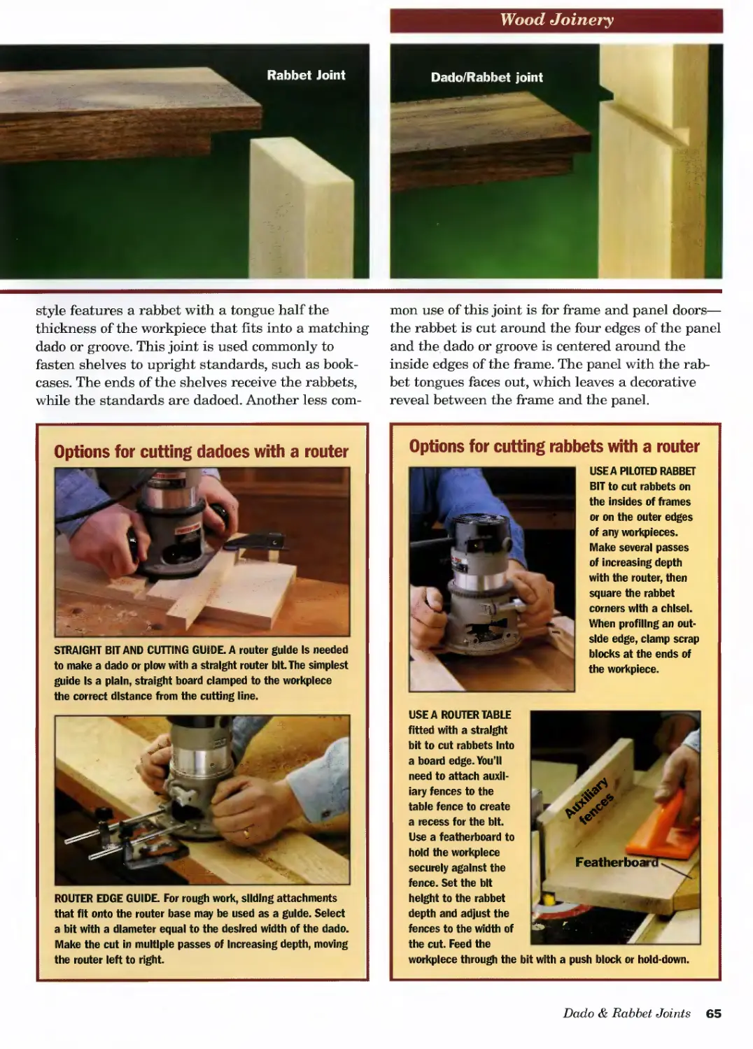
Dado & Rabbet Joints.................................64
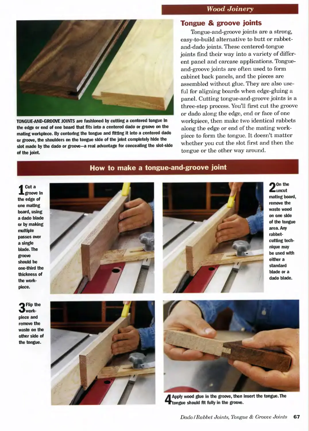
Tongue & Groove Joints ..............................67
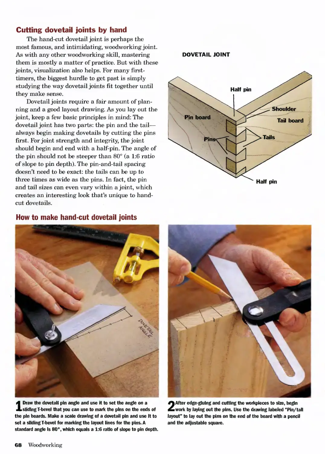
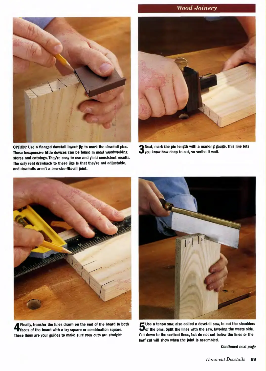
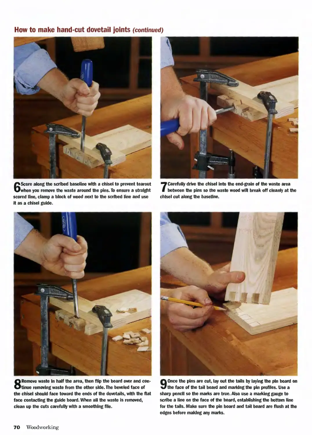
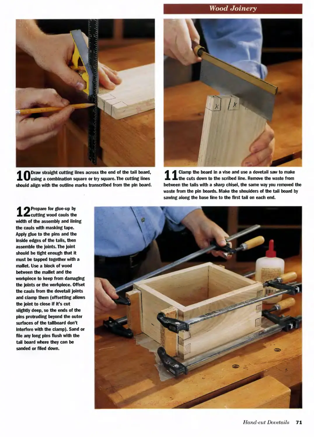
Cutting Dovetail Joints by Hand......................68
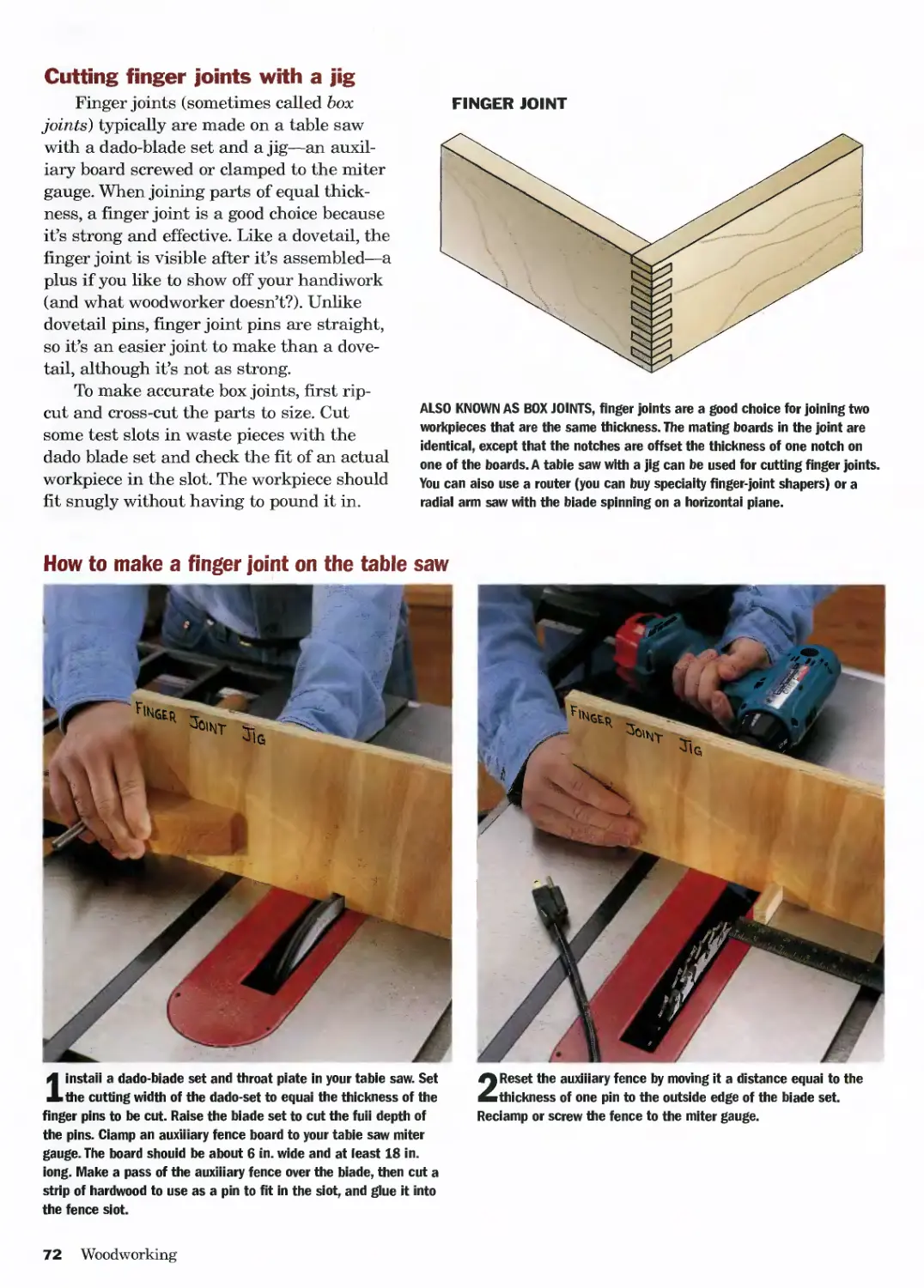
Cutting Finger Joints with a Jig ....................72
Making Mortise-and-tenon Joints .....................74
Lap Joints ..........................................80
DRILLING
Guide to Common Drill Bits...........................84
Helpful Drilling Guides..............................85
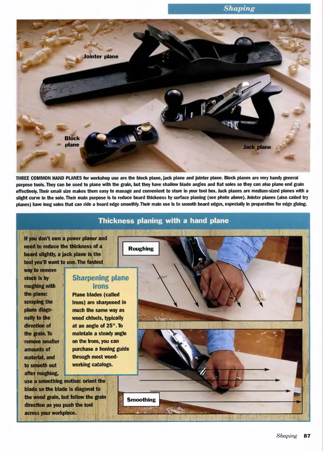
SHAPING
Thickness Planing with a Hand Plane .................87
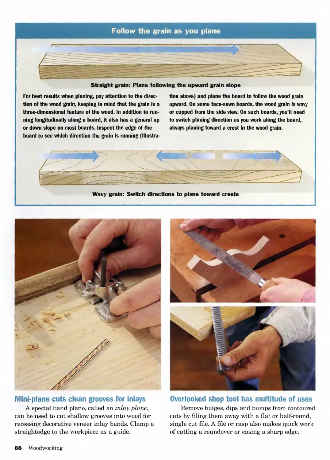
Follow the Grain as You Plane........................88
Traditional Shaping Tools Have a Place in Any Shop ..89
Working with Routers.................................90
CLAMPING, GLUING & FASTENING
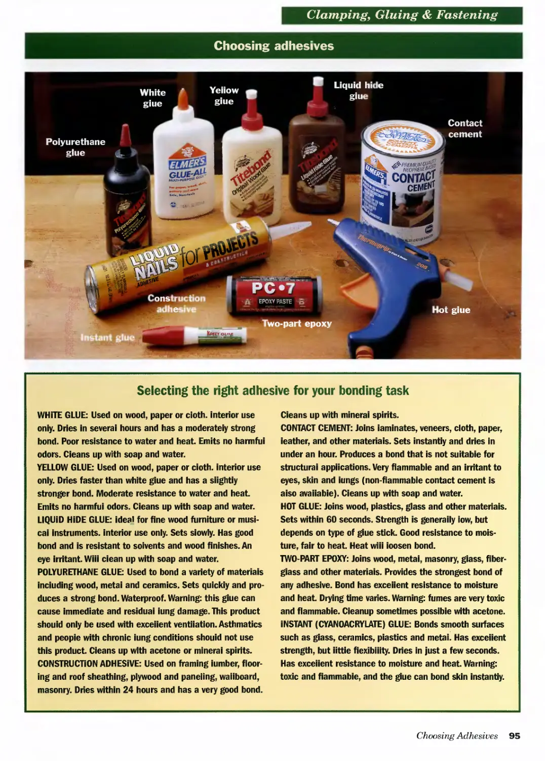
Choosing Adhesives...................................95
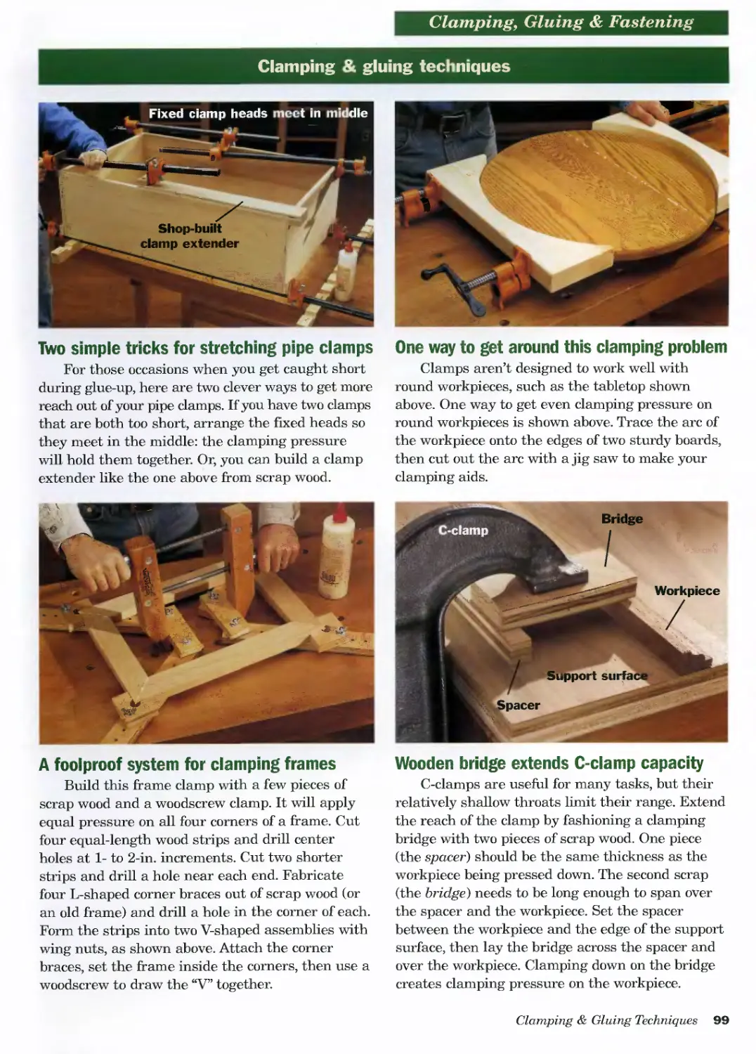
Clamping & Gluing Techniques.........................98
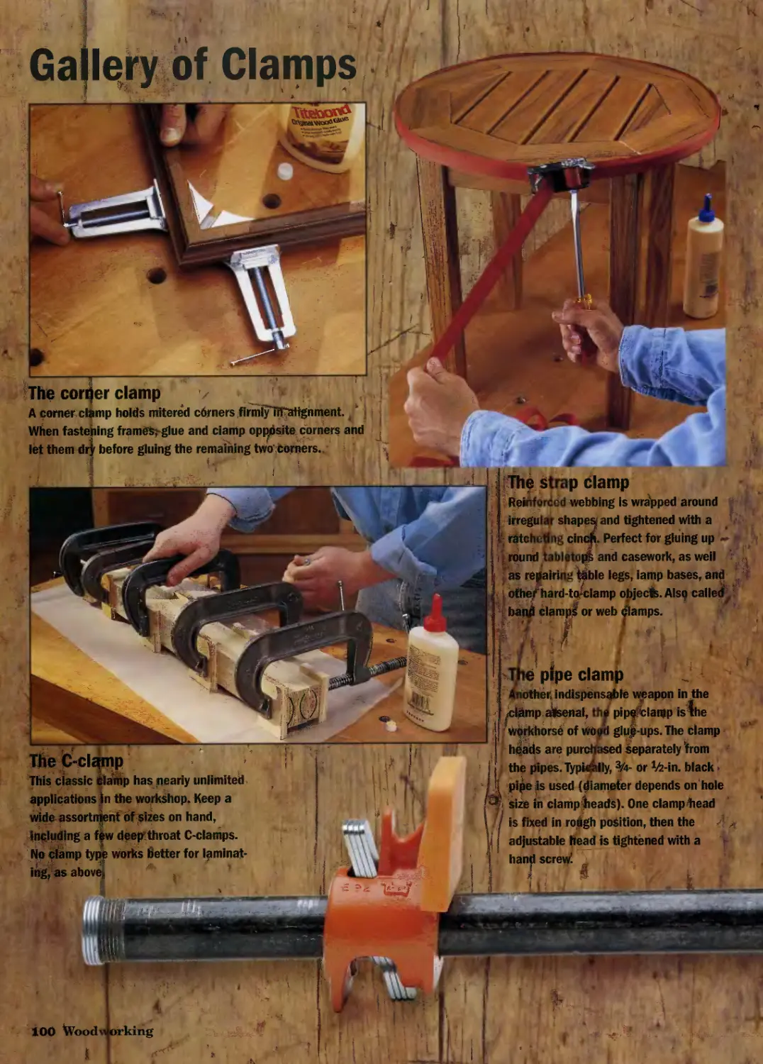
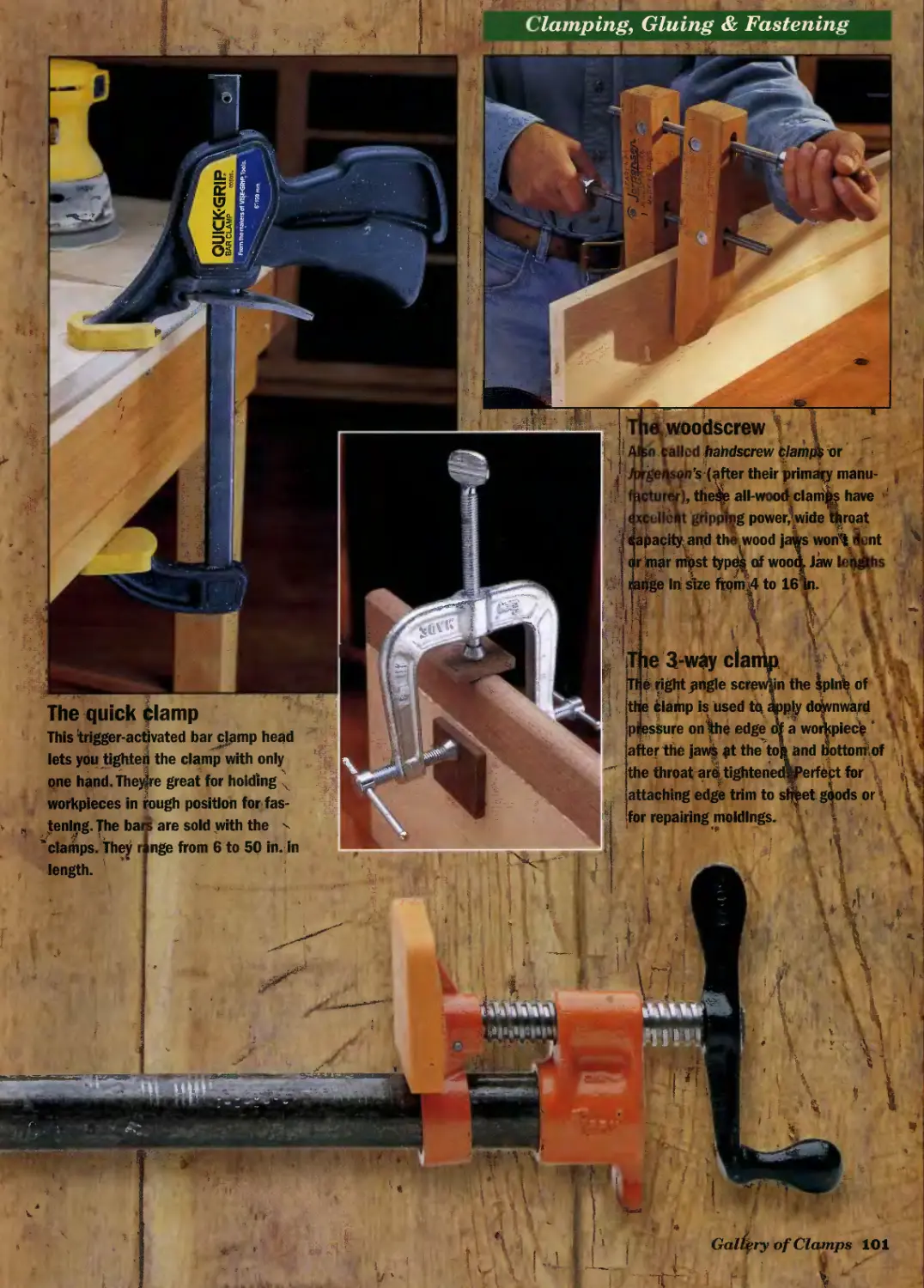
Gallery of Clamps...................................100
SANDING & FINISHING
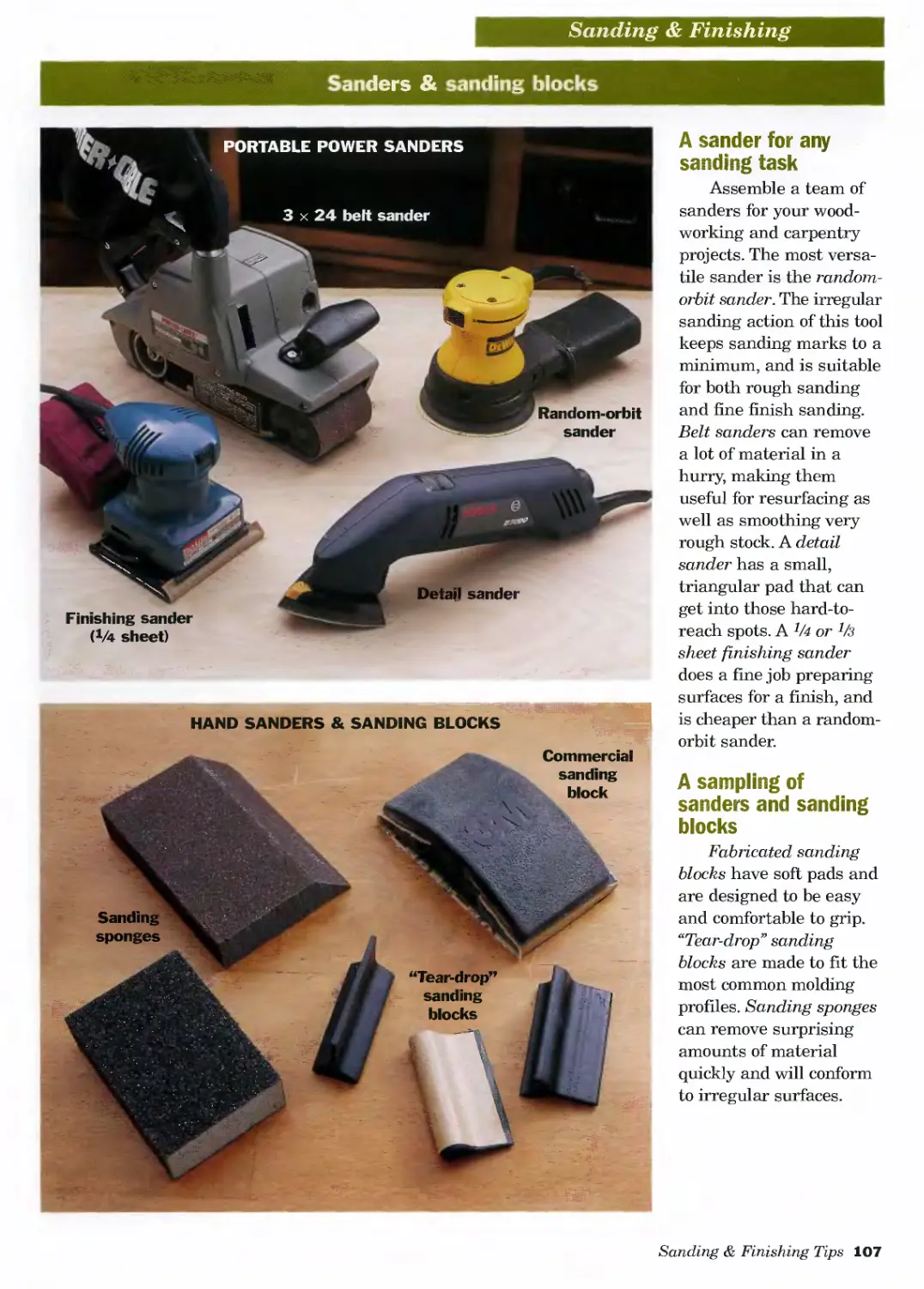
Sanding Strategies .................................105
Sanders & Sanding Blocks............................107
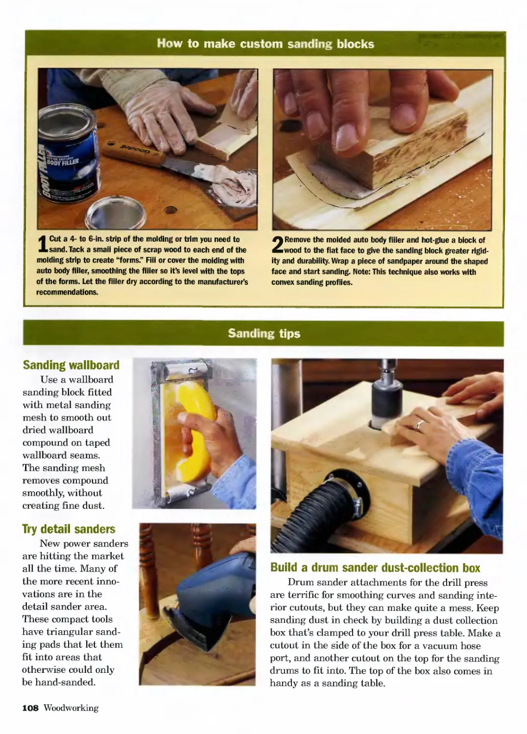
How To Make Custom Sanding Blocks ..................108
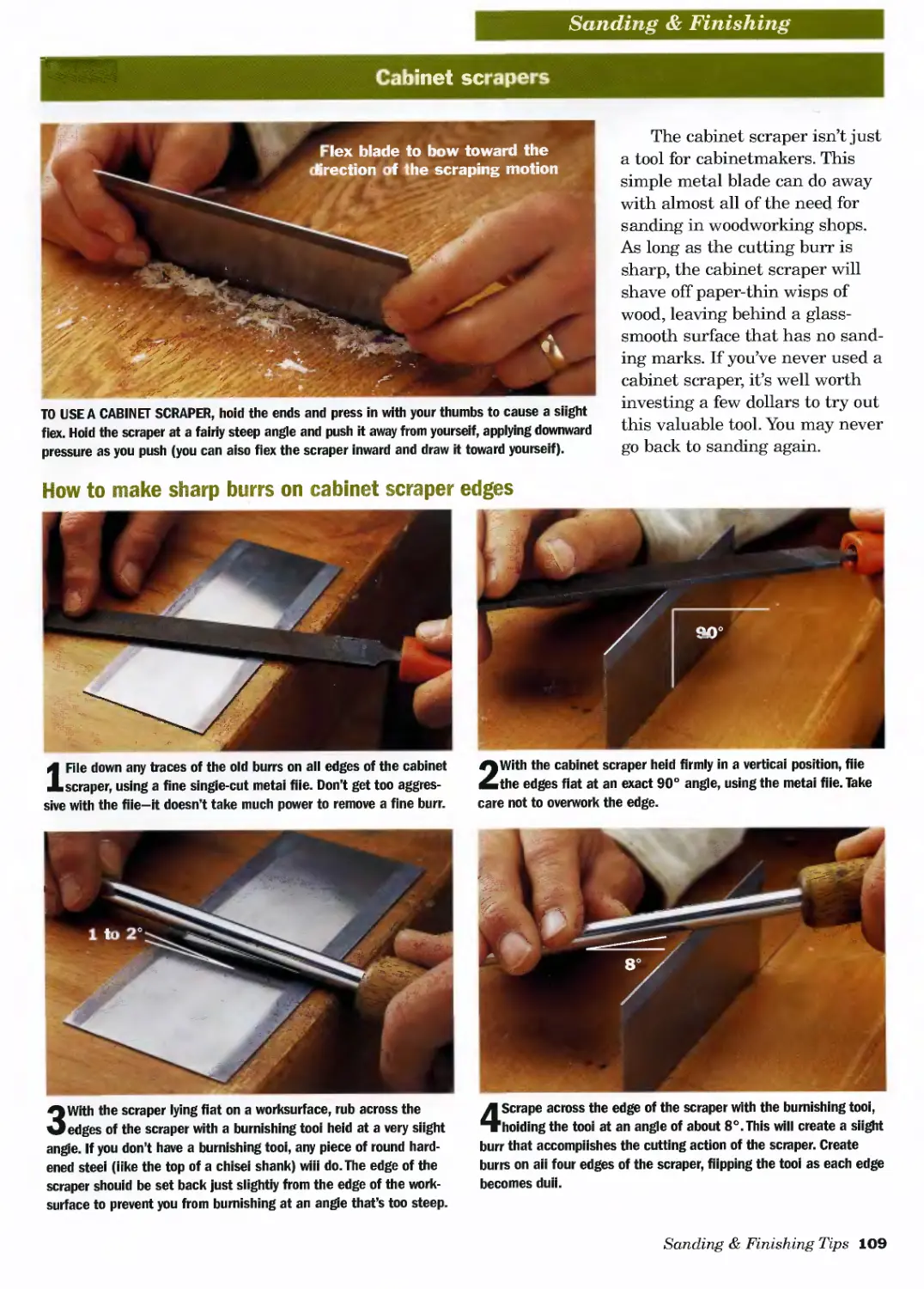
Cabinet Scrapers....................................109
Plugging Screw Counterbores ........................110
How To Revitalize Hardened Paintbrushes.............114
Using Chemical Strippers............................115
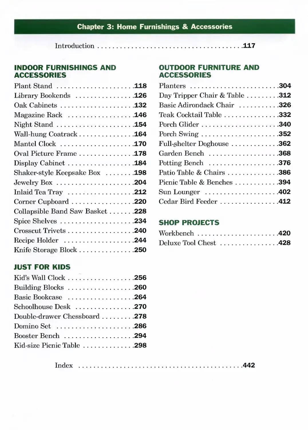
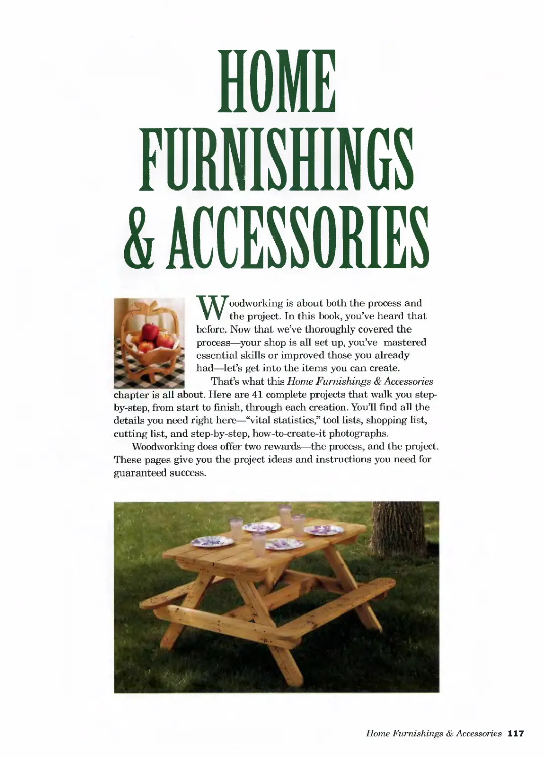
Chapter 3: Home Furnishings & Accessories
Introduction.............................................117
INDOOR FURNISHINGS AND
ACCESSORIES
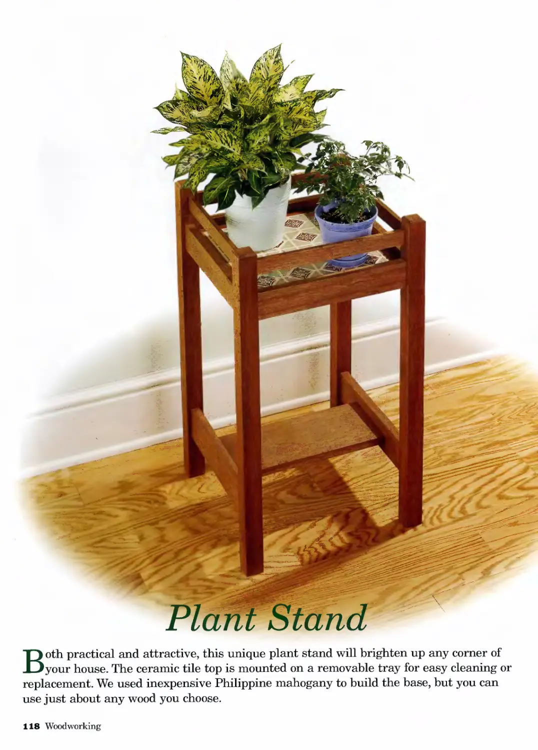
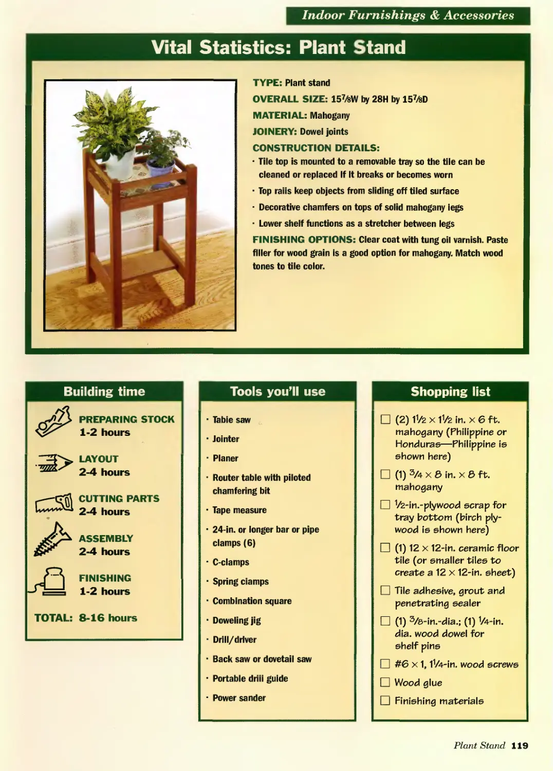
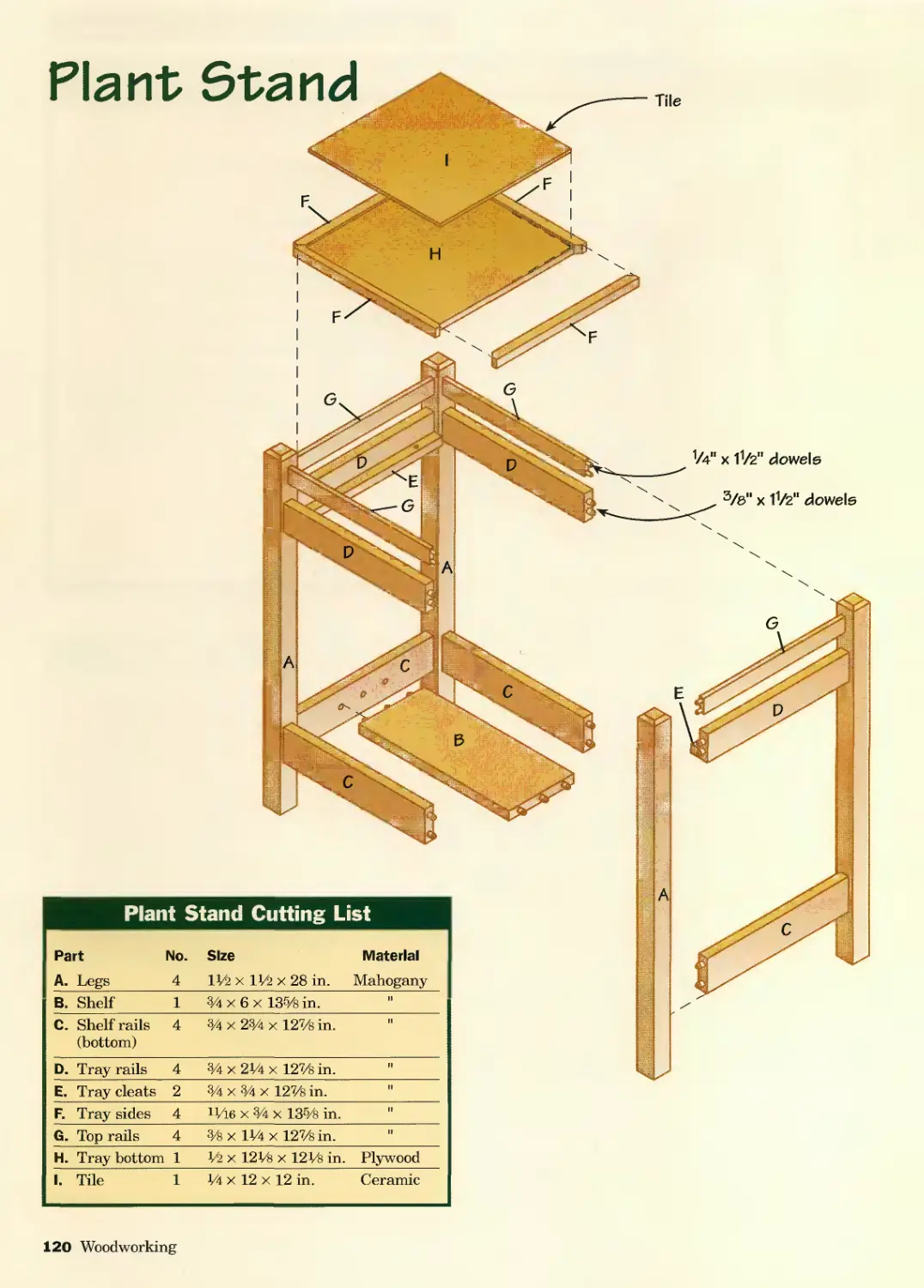
Plant Stand......................118
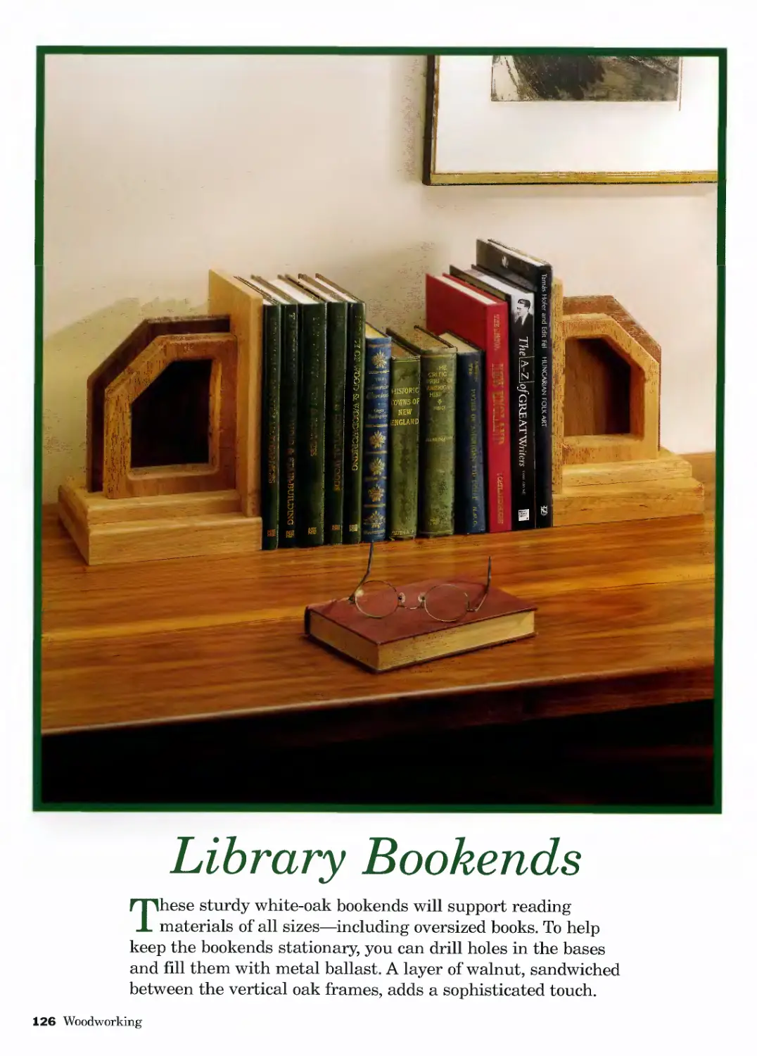
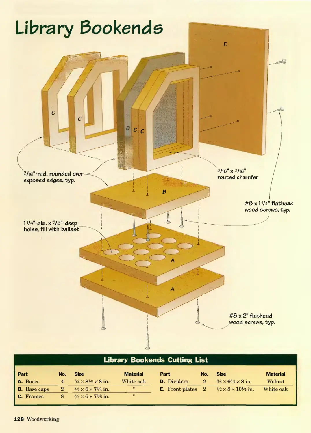
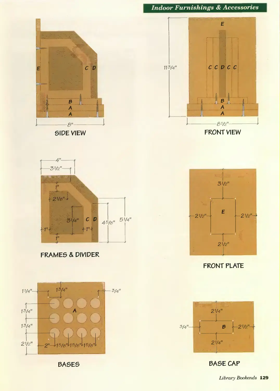
Library Bookends ................126
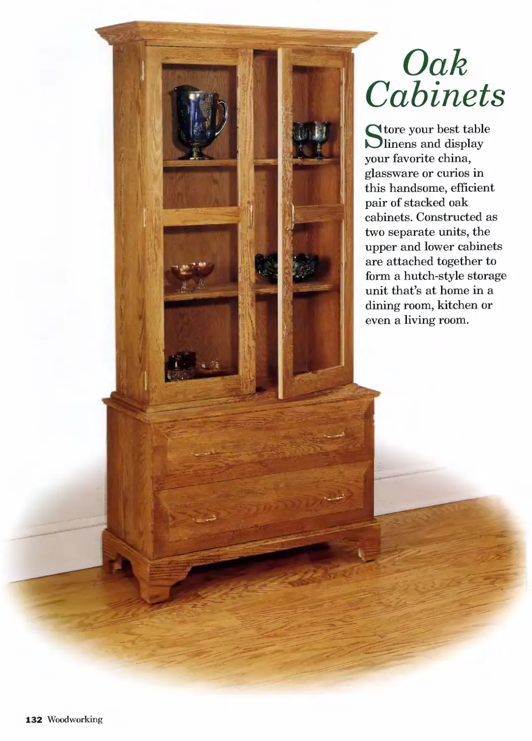
Oak Cabinets.....................132
Magazine Rack ...................146
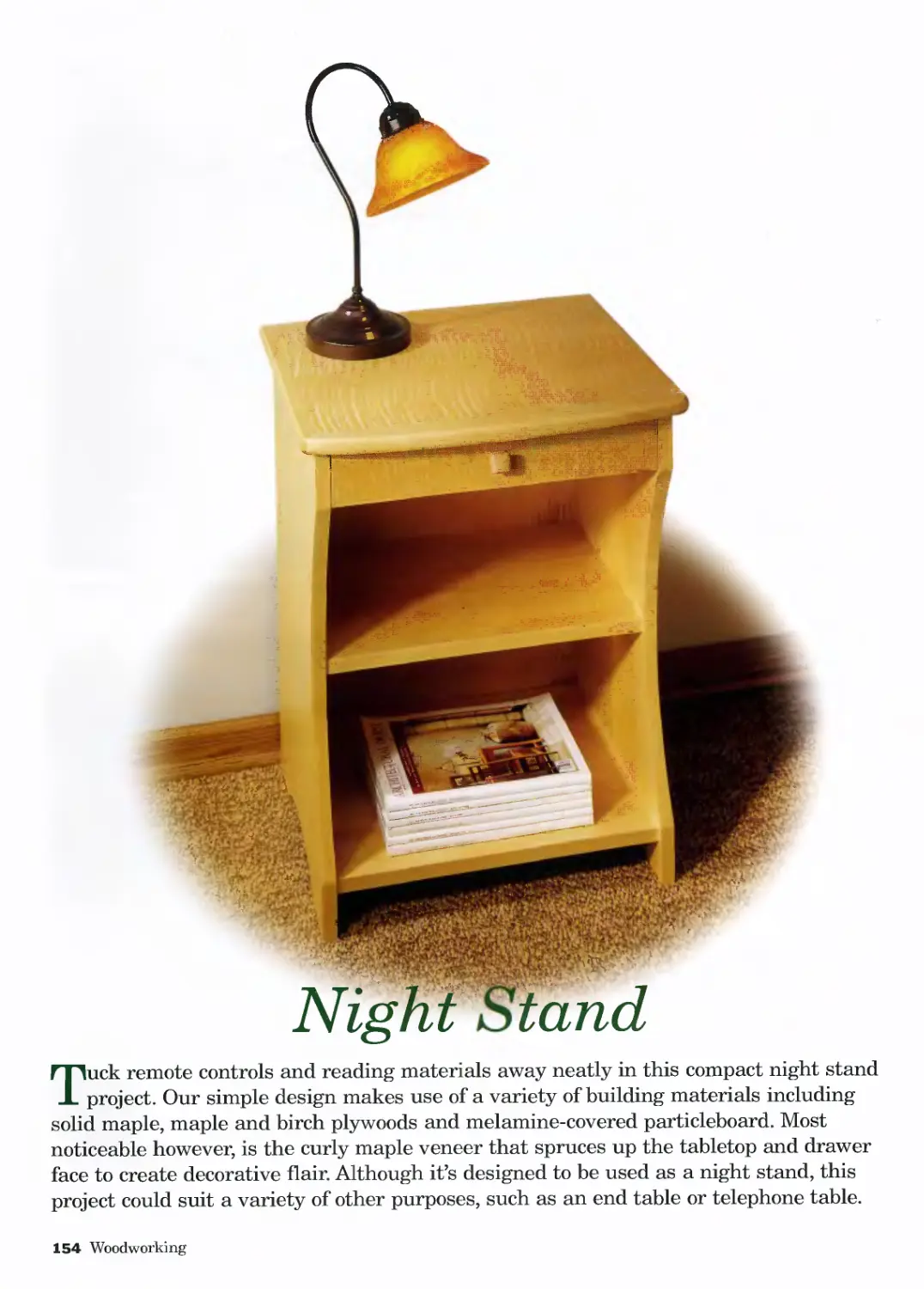
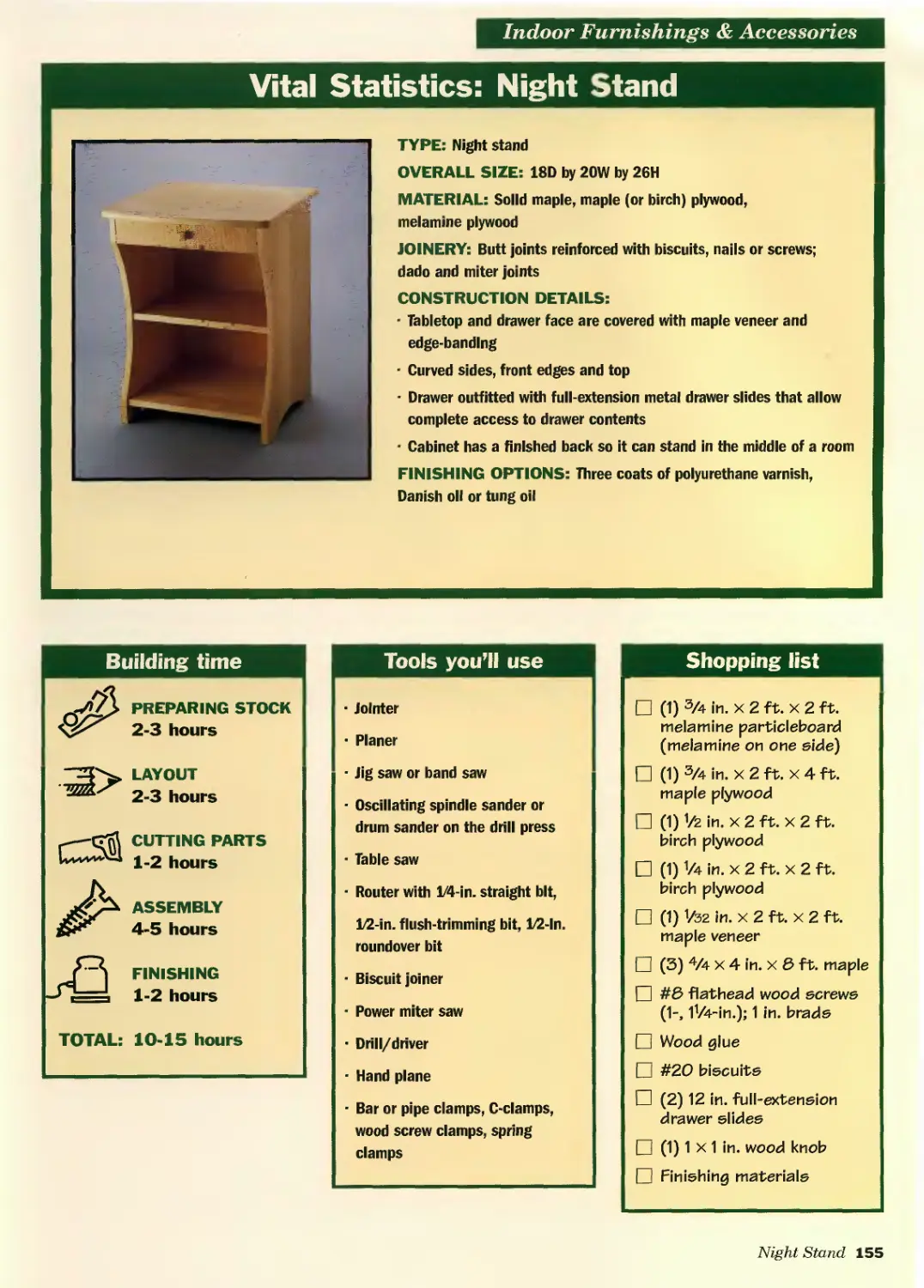
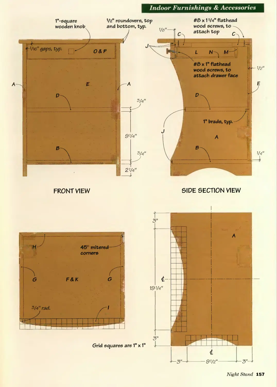
Night Stand......................154
Wall-hung Coatrack...............164
Mantel Clock.....................170
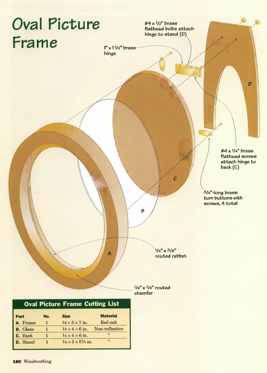
Oval Picture Frame...............178
Display Cabinet..................184
Shaker-style Keepsake Box .......198
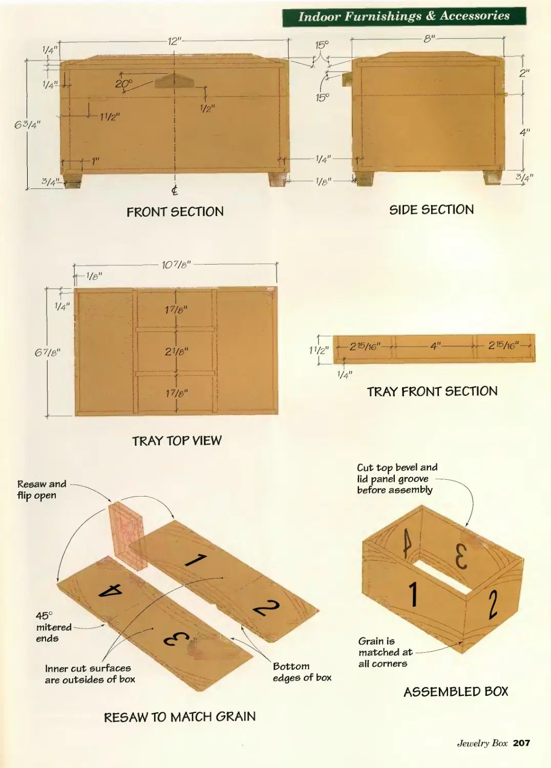
Jewelry Box......................204
Inlaid Tea Tray .................212
Corner Cupboard..................220
Collapsible Band Saw Basket......228
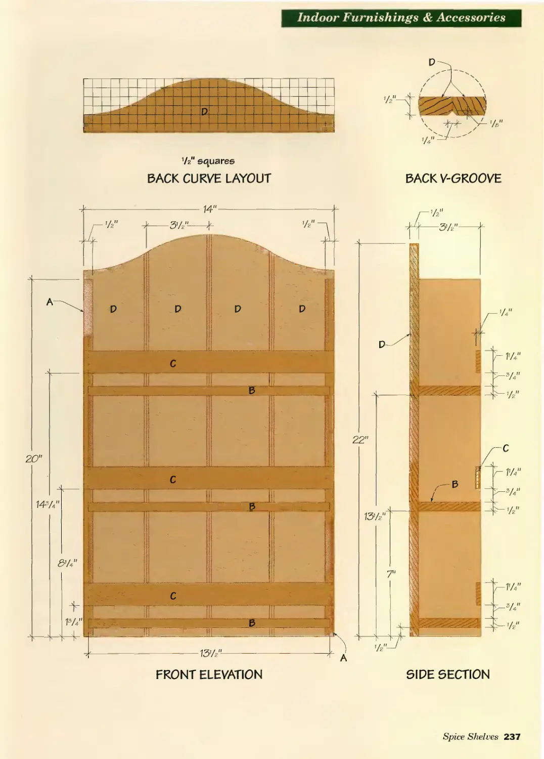
Spice Shelves....................234
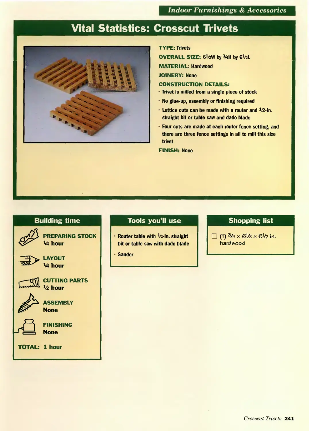
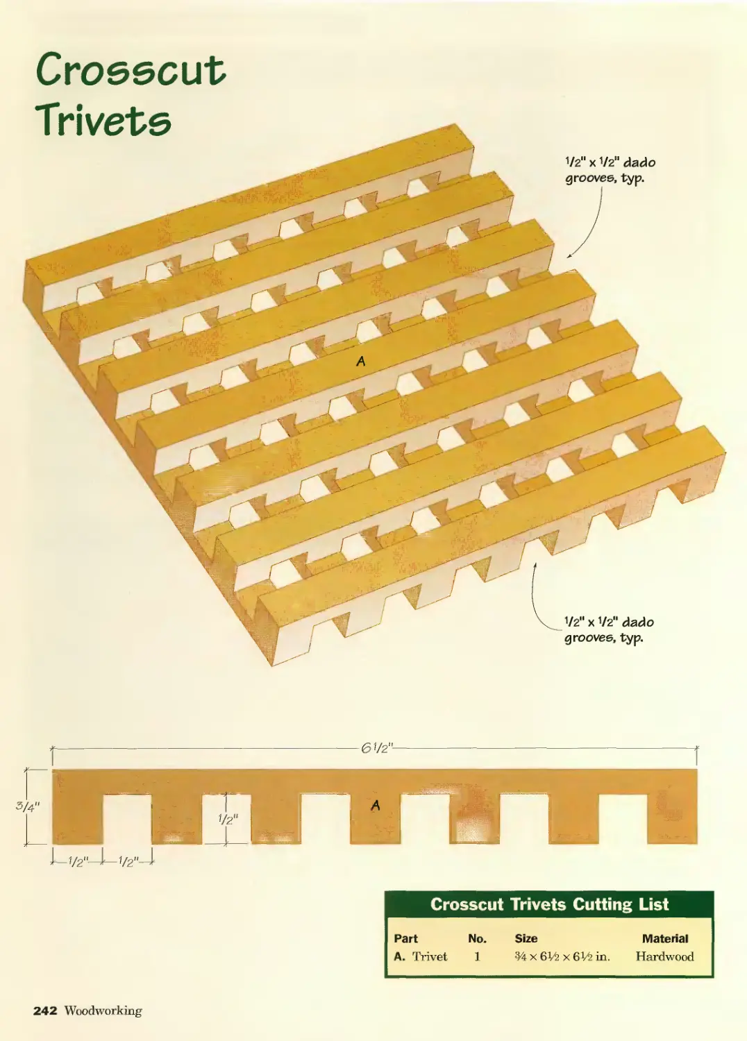
Crosscut Trivets.................240
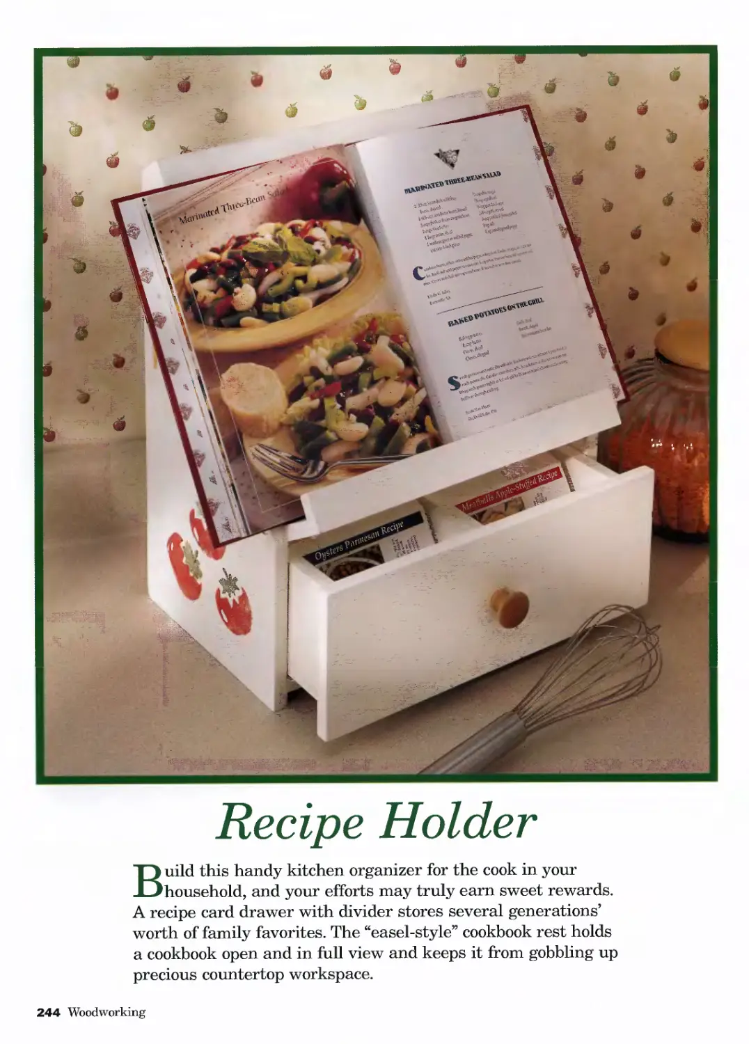
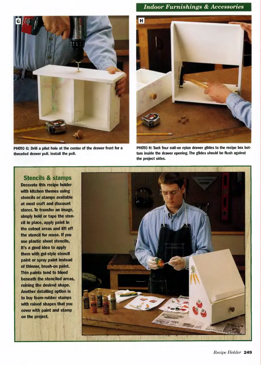
Recipe Holder ...................244
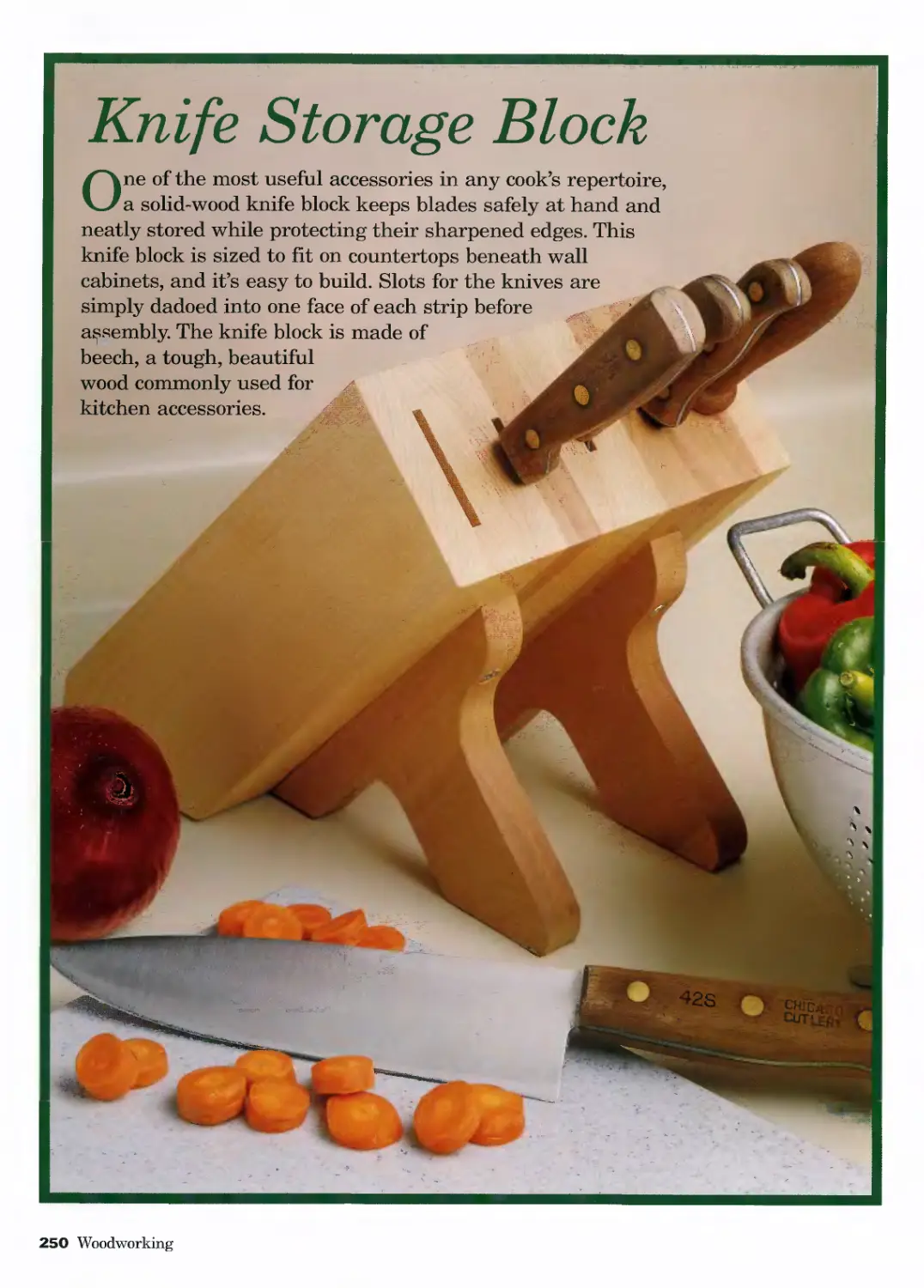
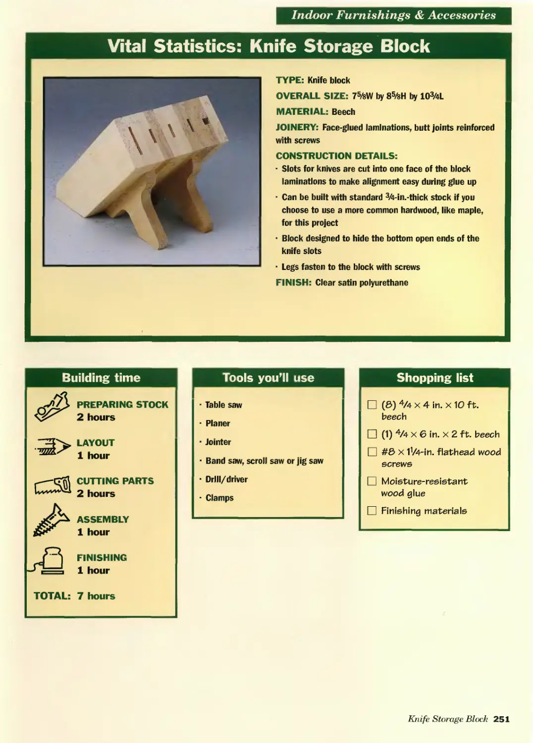
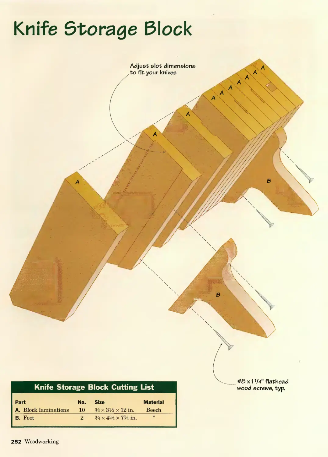
Knife Storage Block..............250
JUST FOR KIDS
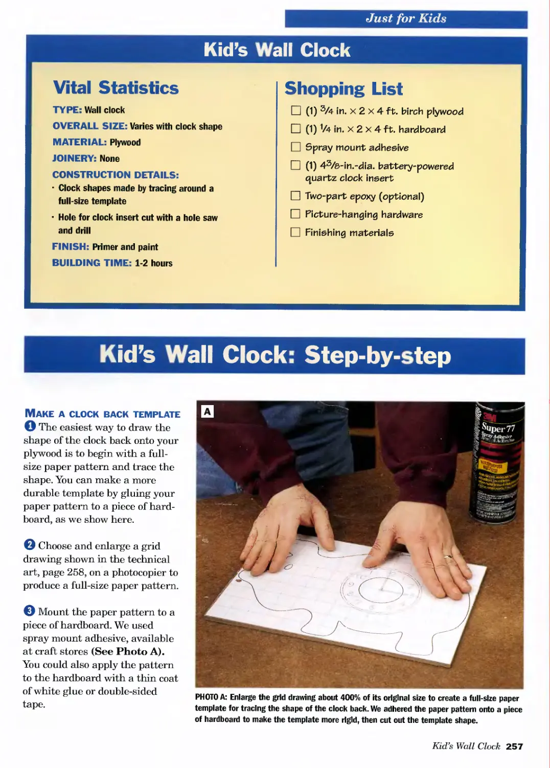
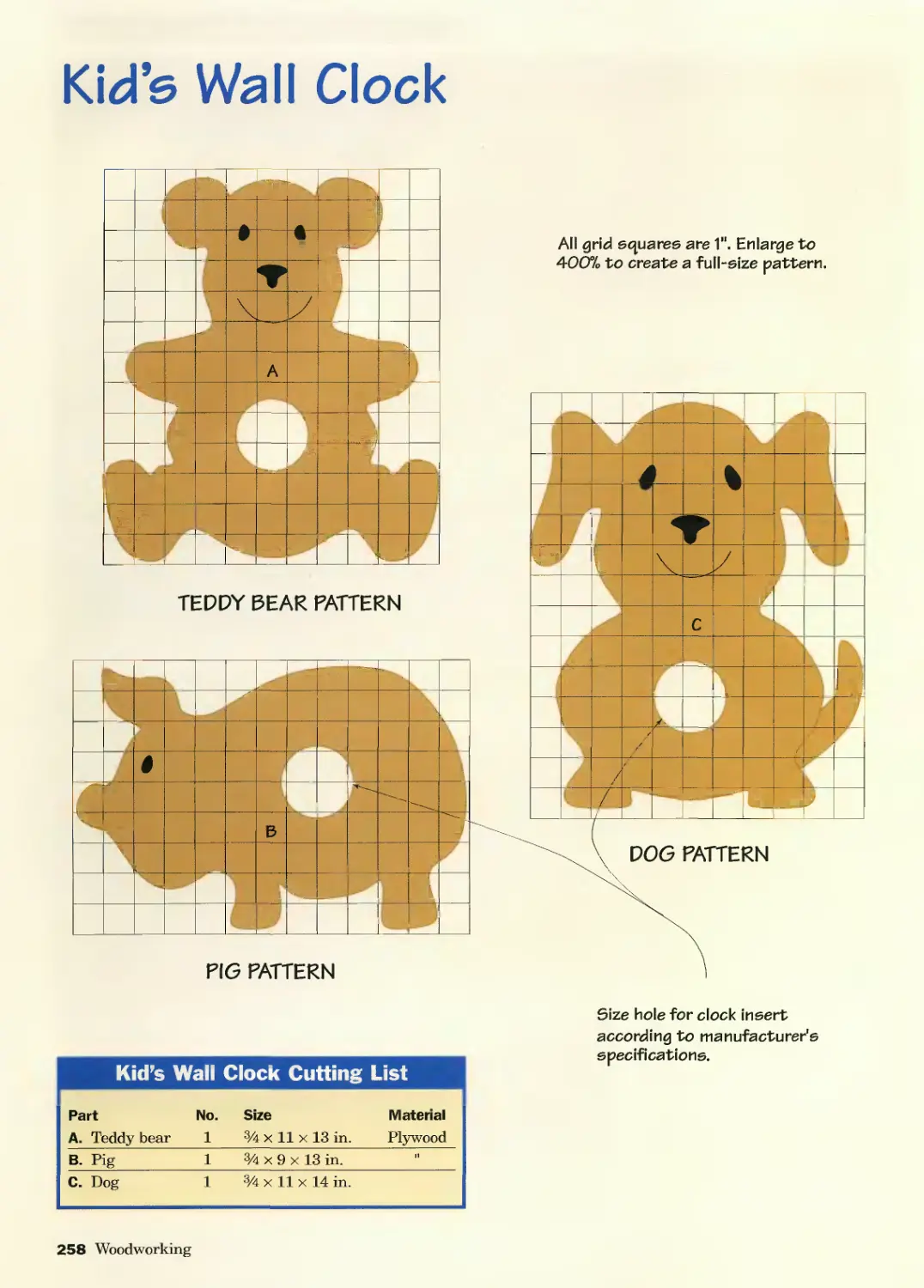
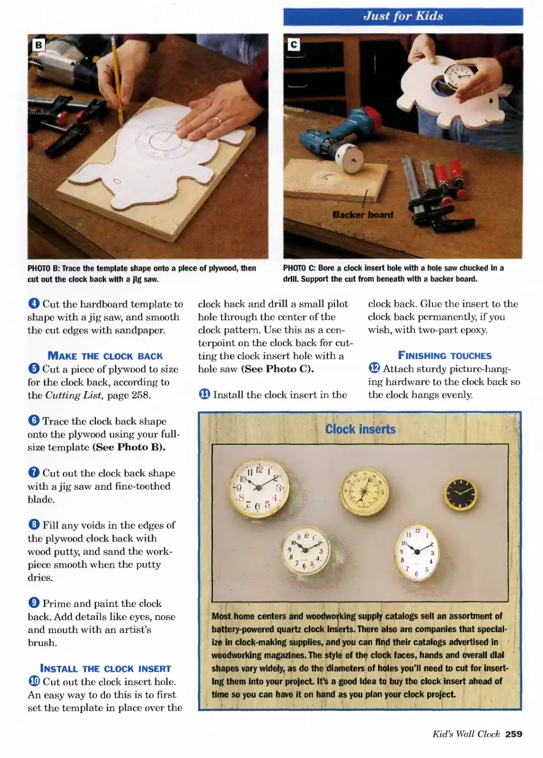
Kid’s Wall Clock.................256
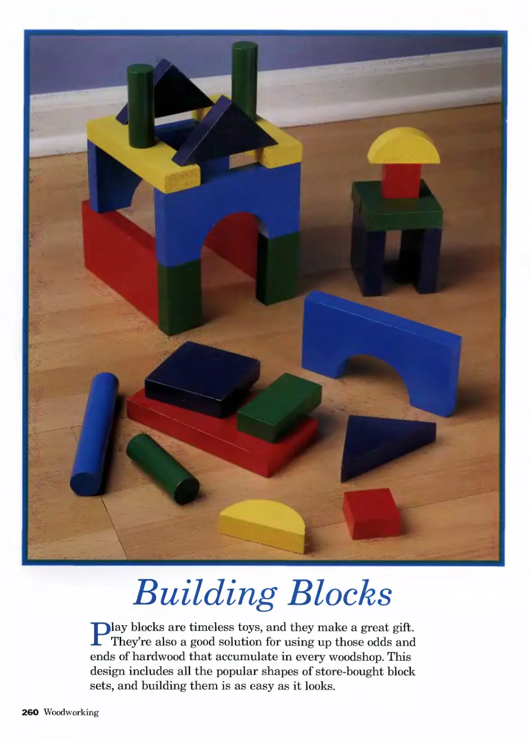
Building Blocks..................260
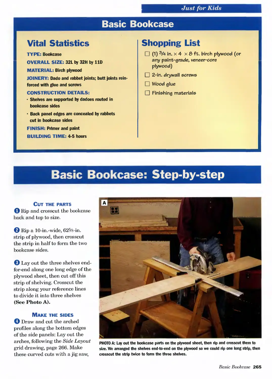
Basic Bookcase ..................264
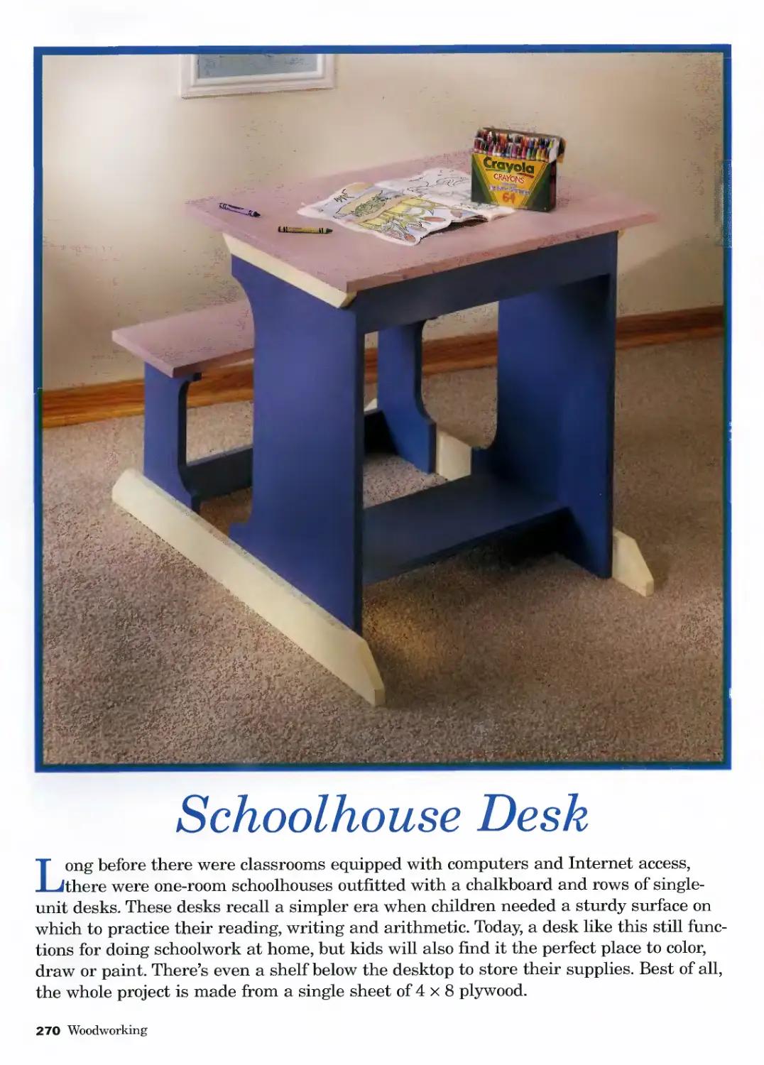
Schoolhouse Desk ................270
Double-drawer Chessboard.........278
Domino Set ......................286
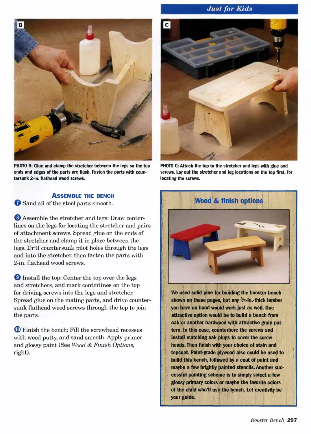
Booster Bench ...................294
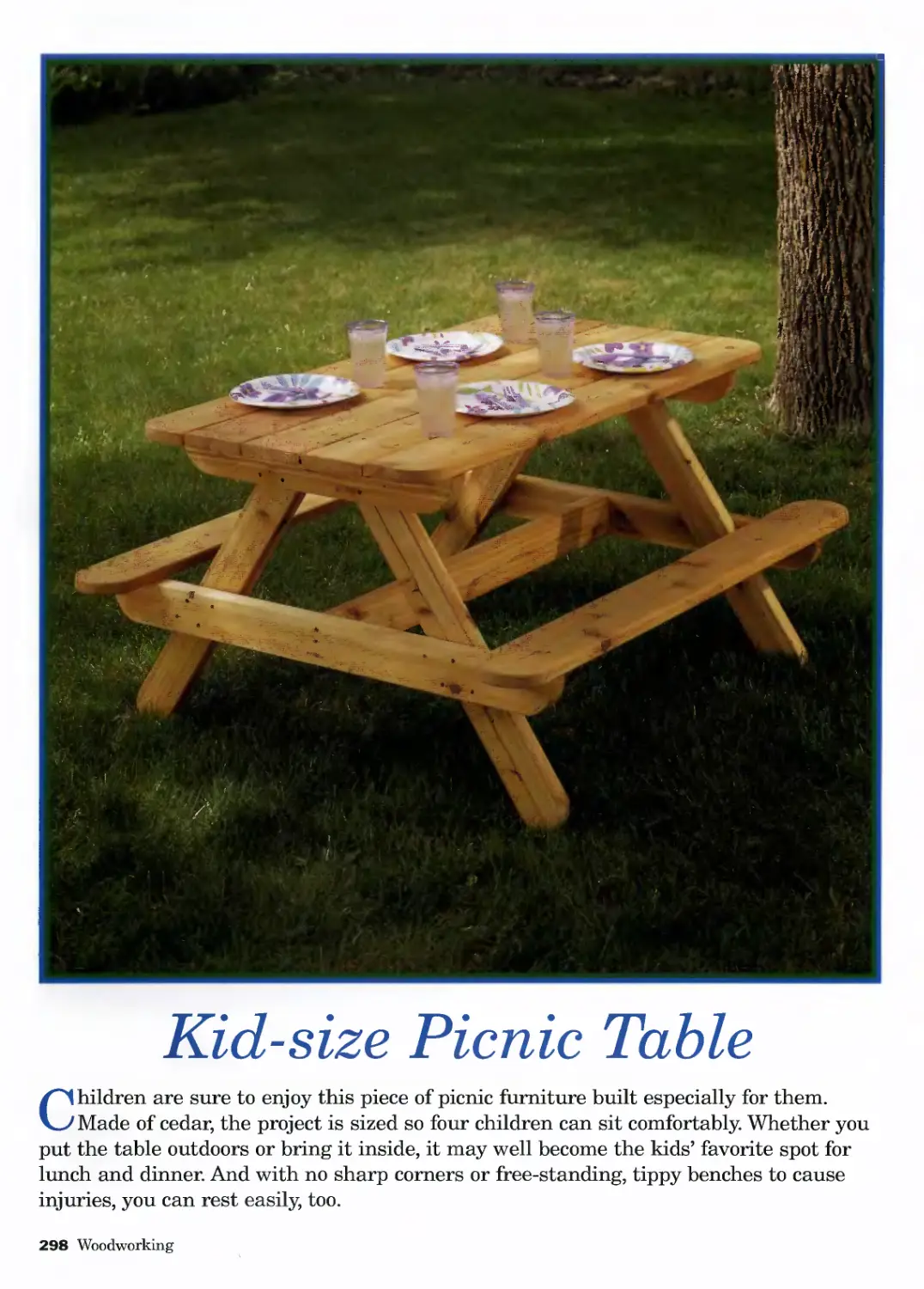
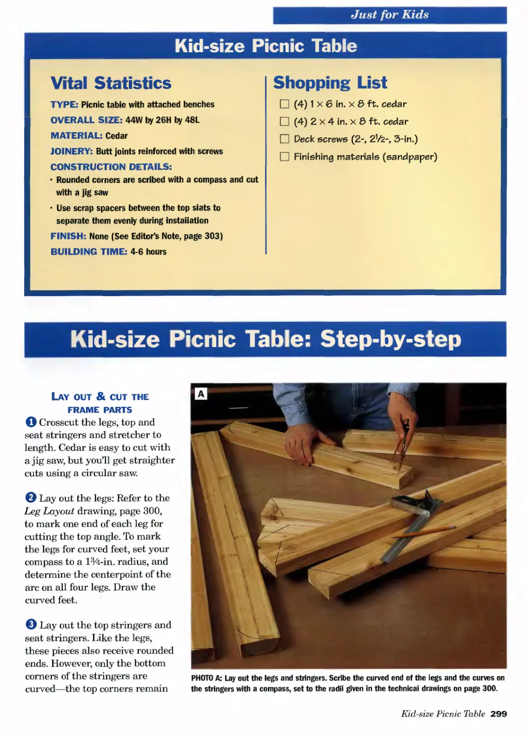
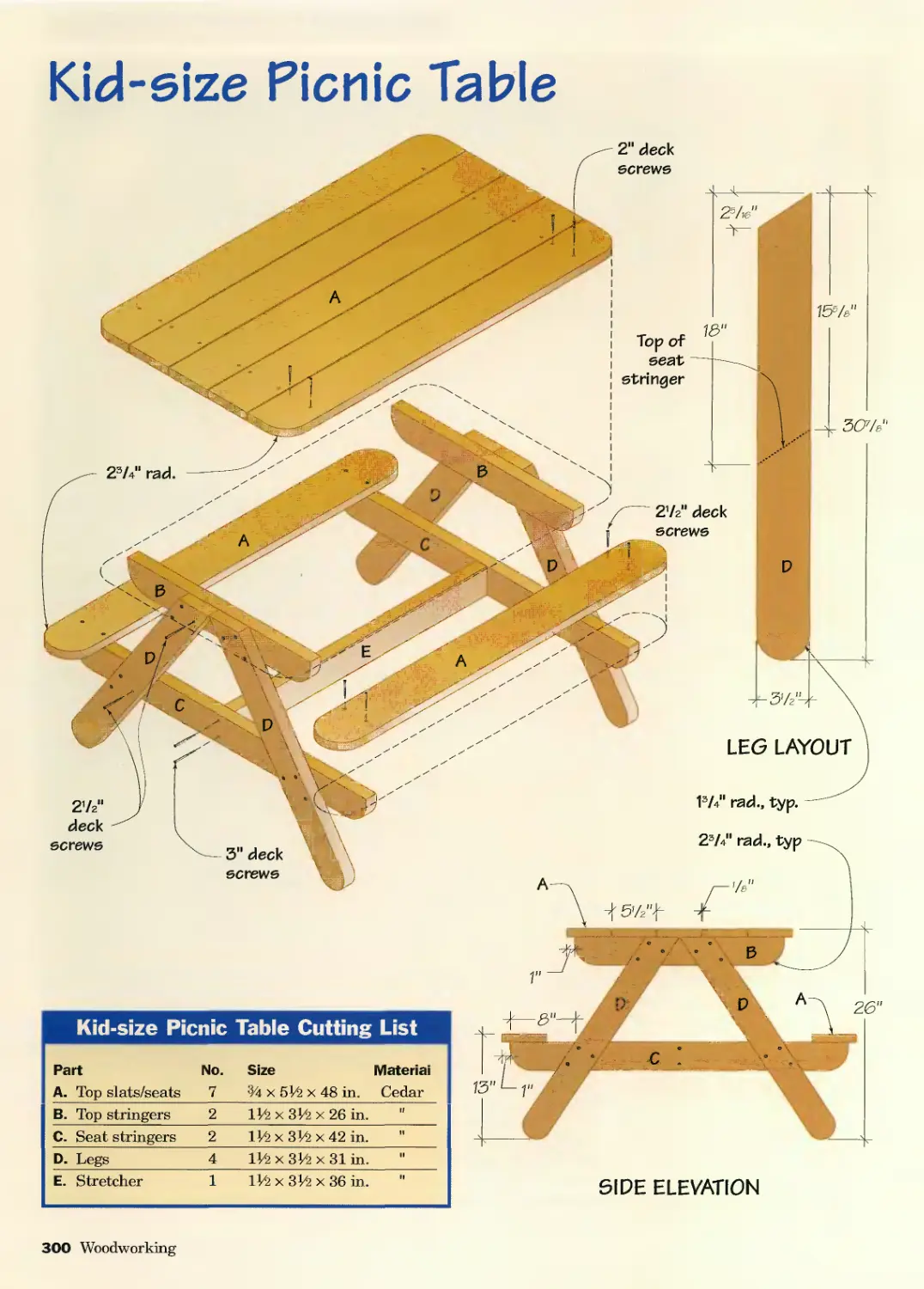
Kid-size Picnic Table............298
OUTDOOR FURNITURE AND
ACCESSORIES
Planters ........................304
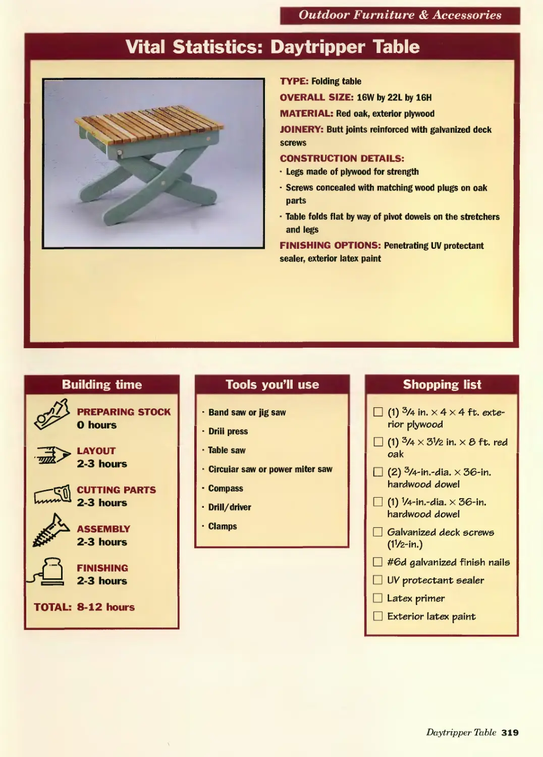
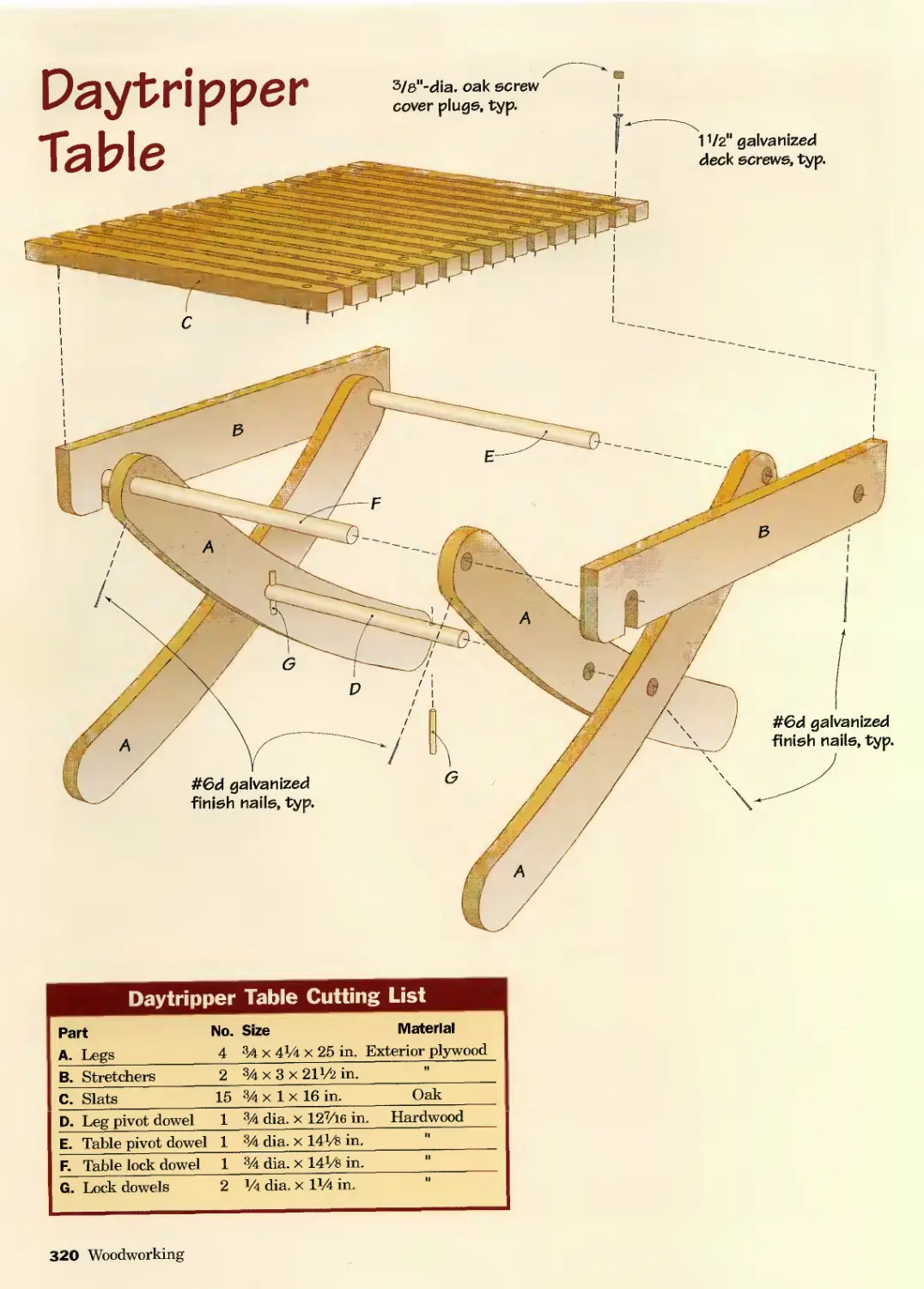
Day Tripper Chair & Table........312
Basic Adirondack Chair ..........326
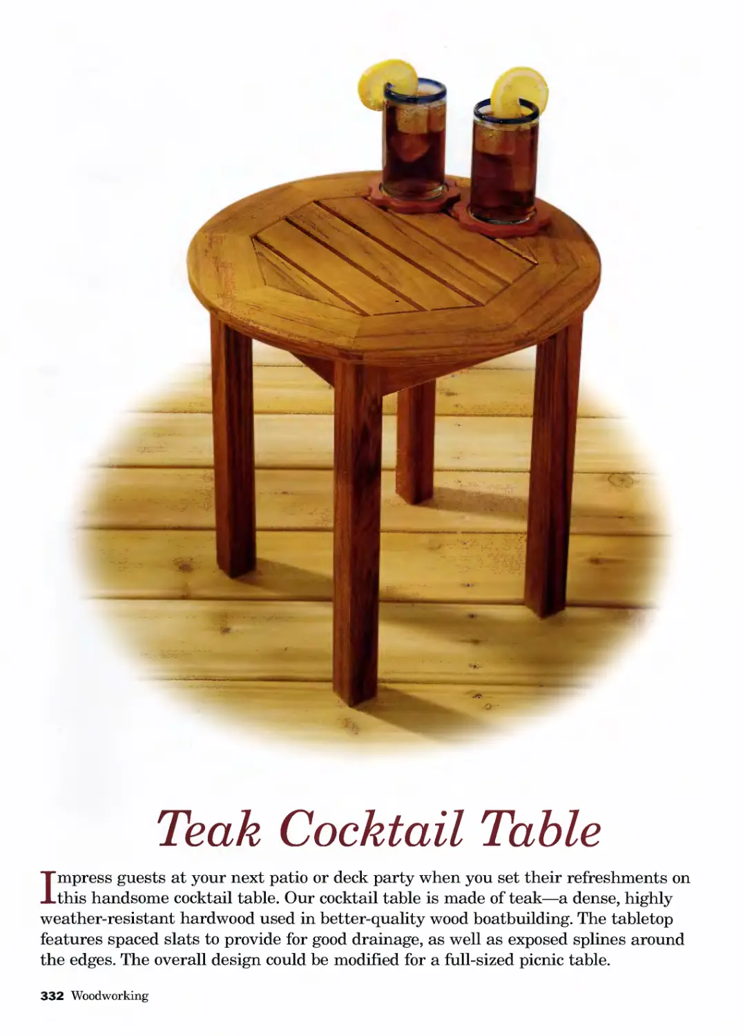
Teak Cocktail Table..............332
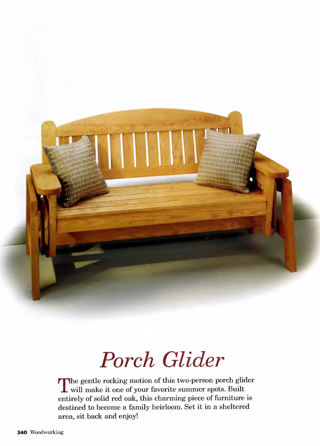
Porch Glider.....................340
Porch Swing......................352
Full-shelter Doghouse............362
Garden Bench ....................368
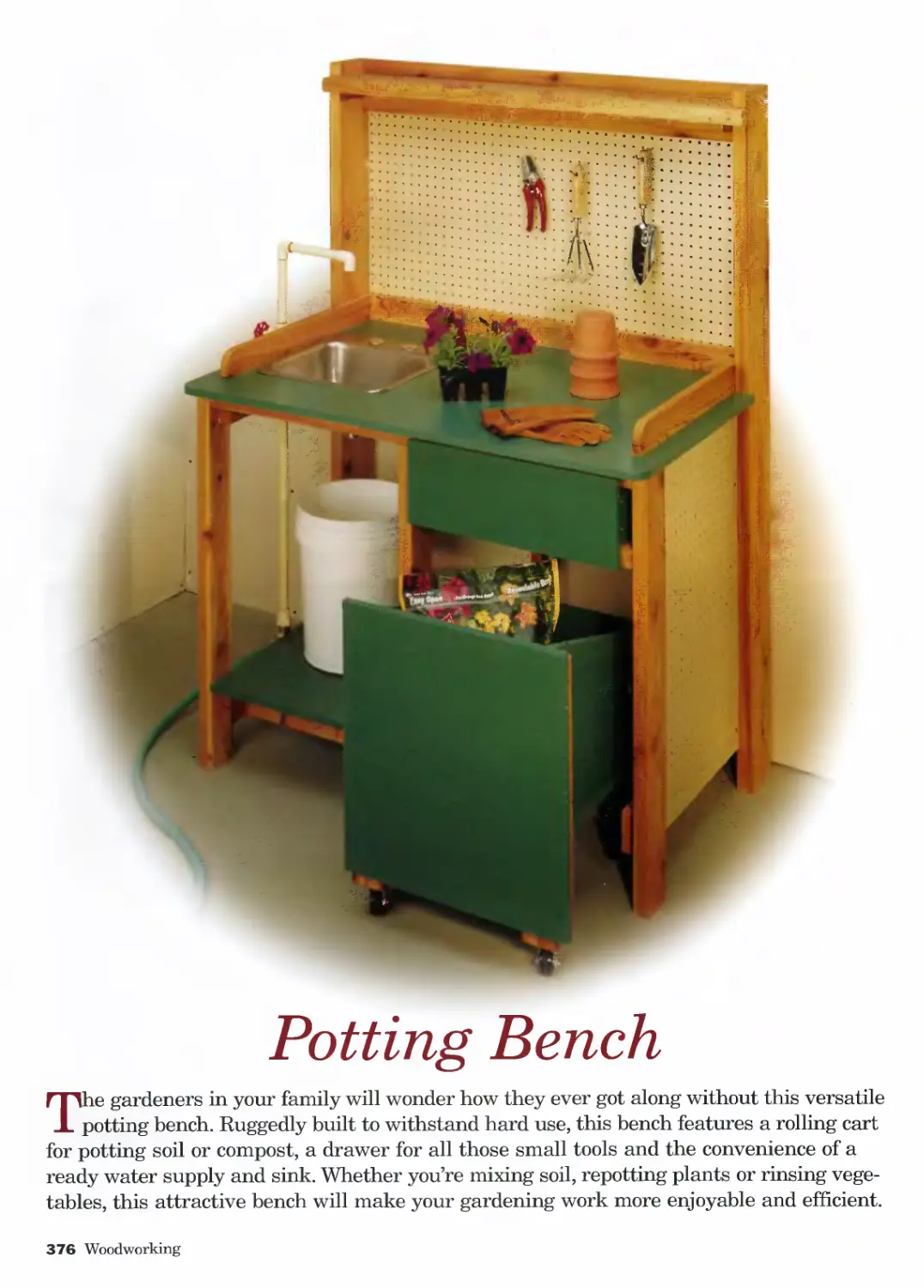
Potting Bench ...................376
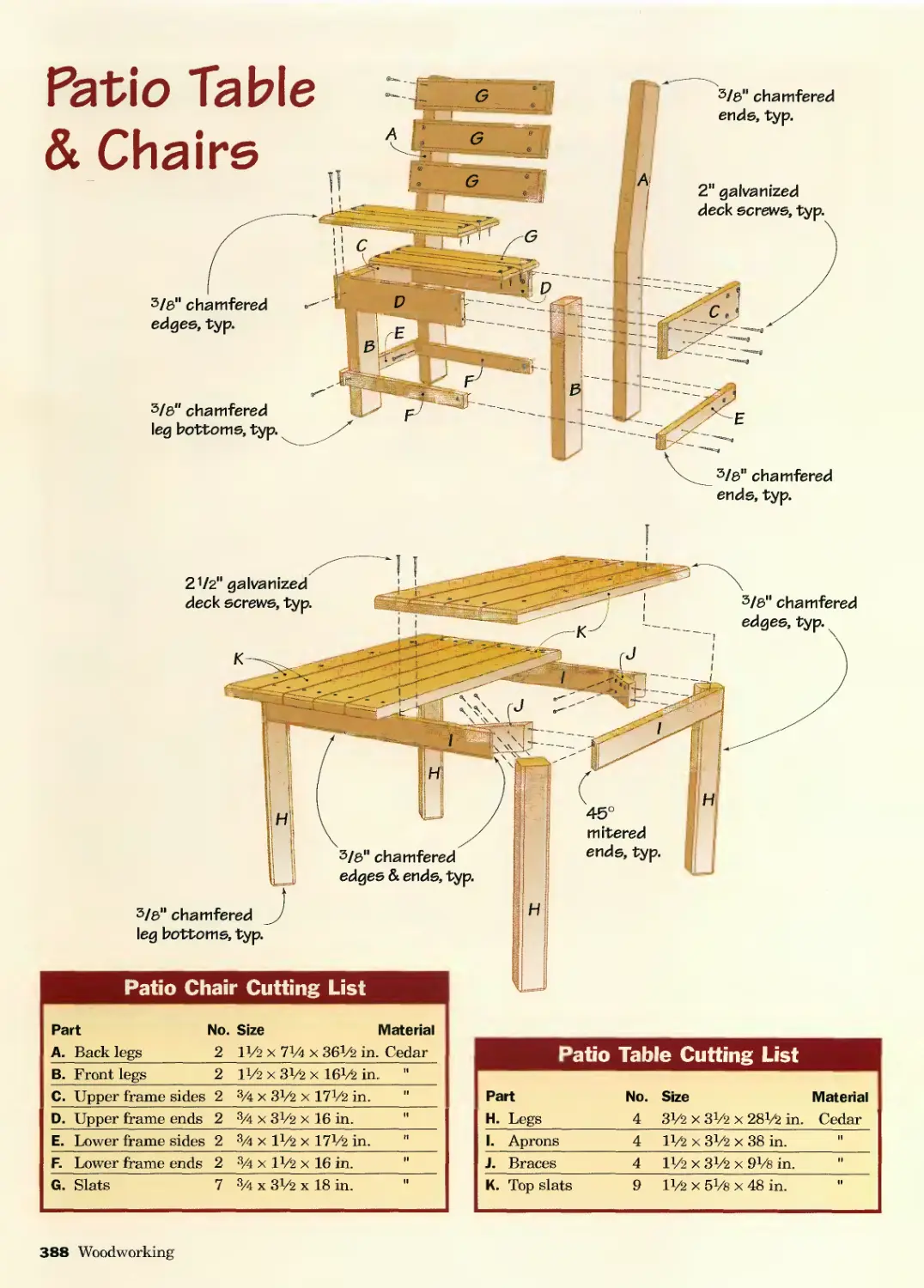
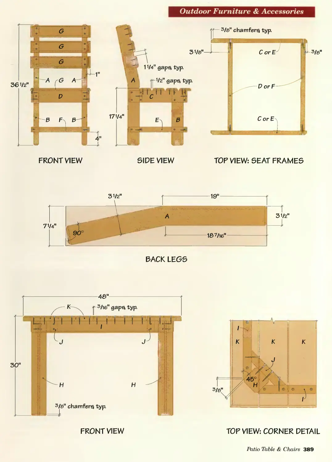
Patio Table & Chairs.............386
Picnic Table & Benches...........394
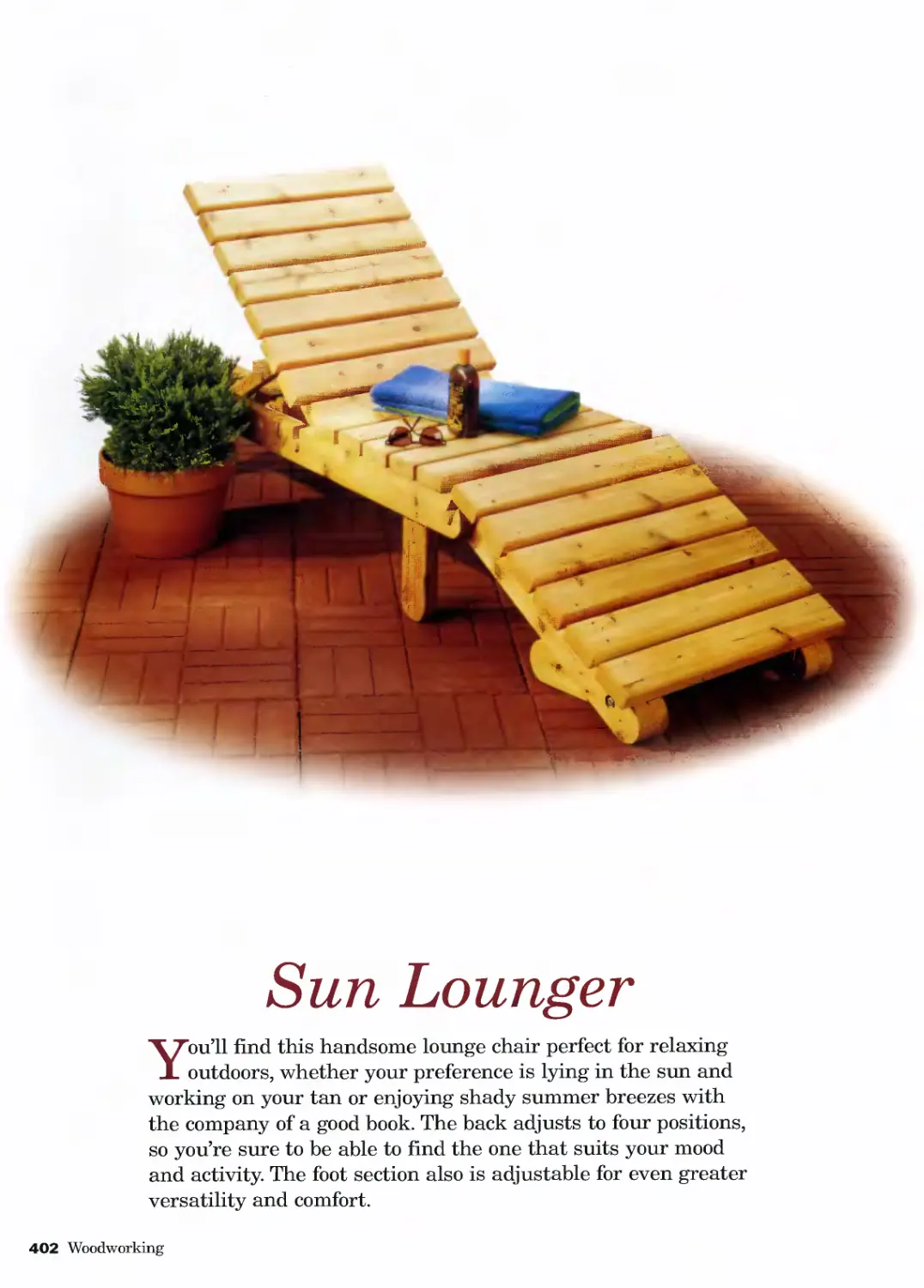
Sun Lounger .....................402
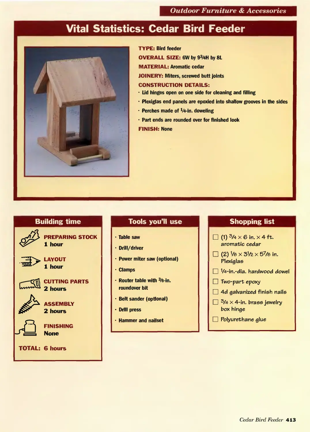
Cedar Bird Feeder................412
SHOP PROJECTS
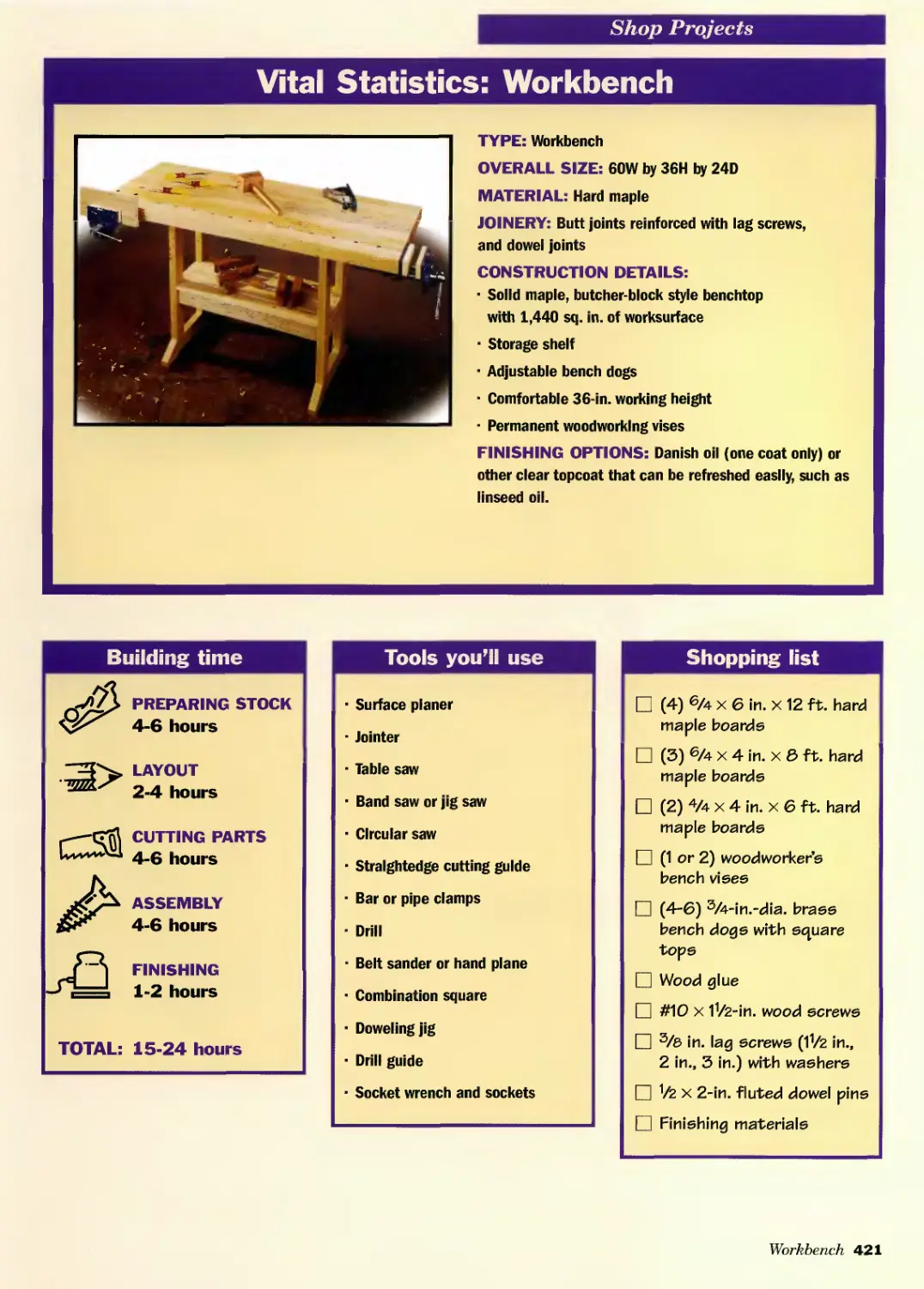
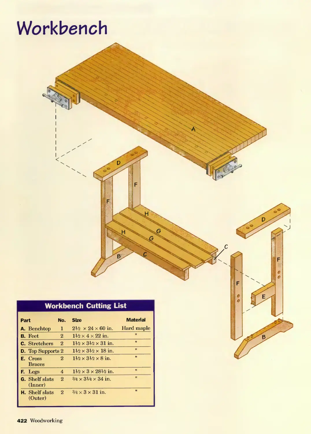
Workbench........................420
Deluxe Tool Chest................428
Index
442
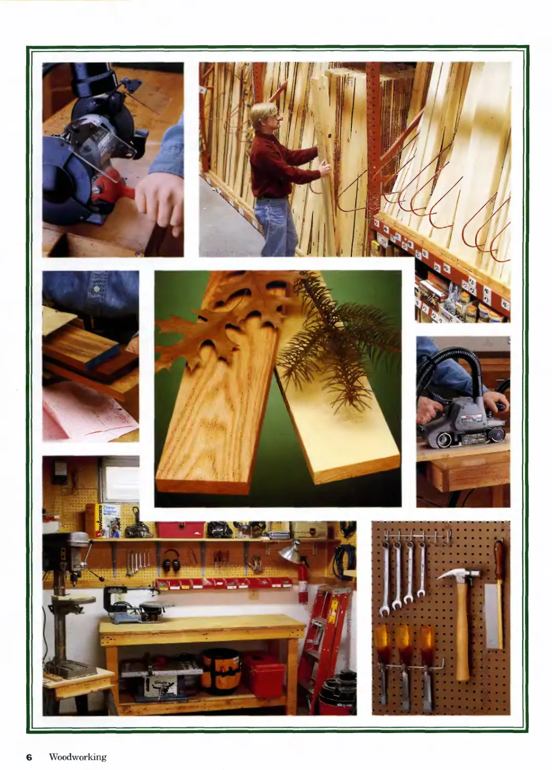
6 Woodworking
Welcome
WELCOME TO WOODWORKING
The Complete Step-by-Step Guide to Skills, Techniques and Projects
My Uncle Darrel has been an avid wood-
worker since I’ve known him. Whenever my
family would drive down for a visit while I was
growing up, the first place I wanted to go was
always Darrel’s workshop. In preparation for my
visit, he’d set aside a few scraps and cutoff pieces
for me to experiment with. At first I was only
allowed to use a coping saw, a tack hammer and a
few other hand tools that weren’t particularly dan-
gerous. But as I grew older and more experienced,
he let me use more powerful tools and build more
complex projects.
During my sophomore year of high school, I
spent a weekend with Uncle Darrel helping him
build a futon frame from a birch tree he’d felled
on his land, then rough-cut and air-dried in his
garage. I almost cried when, at the end of the
weekend, he gave it to me. I slept on that futon all
throughout college and I thought of it often as I
developed my own woodworking skills and finally
set up a shop of my own. He’s not too interested in
woodworking himself, but when my step-son leaves
for college in a couple of years, he’s looking forward
to taking the futon frame with him.
Woodworking is like that. In fact, just about
anyone who has taken the hobby beyond the
obligatory birdhouse in junior high industrial arts
class has a story like the one I always tell about
the birch futon. When you craft something from
wood, the process not only teaches you new skills
and provides a creative outlet, it can generate an
heirloom. Or at least an object that’s rich with
sentimental value.
Woodworking: The Complete Step-by-Step Guide
to Skills, Techniques and Projects is both a teacher
of skills and a source of ideas: It’s about the
process and the project.
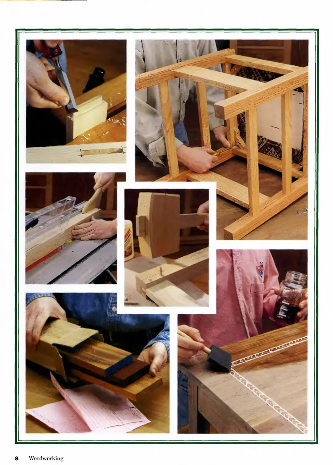
In this book, you will find all of the information
and project plans you need to develop a hobby
that will last a lifetime. It contains great advice
on setting up your own workshop and some essen-
tial background information you’ll need to know
about wood. It takes you through all the basic
skills in the order you’ll need them, including
measuring, marking and layout, then using cutting
and shaping tools to create solid wood joints.
With clear color photos it shows you exactly how
to clamp and glue your joints, then offers a
complete section on sanding and finishing for
professional results.
But where a lot of woodworking books only
show you some skills, this new woodworking
compendium gives you over 300 pages of complete
project plans so you can put your skills to use.
Indoor or outdoor, easy or more involved, you’re
sure to find projects to match your skills and needs
right here. There are even a couple projects for
your shop itself.
Woodworking is a never-ending journey.
Whether you’ve been doing it for one year or fifty,
there are always new skills to master and exciting
projects to tackle. Let Woodworking: The Complete
Step-by-Step Guide to Skills, Techniques and
Projects be your companion every step of the way.
And while you’re at it, be sure to pass the
passion on to a young person who means
something to you. You’ll create memories—and
projects—that will last a lifetime.
—Mark Johanson, Editor
Welcome 7
8 Woodworking
WORKSHOP
ESSENTIALS
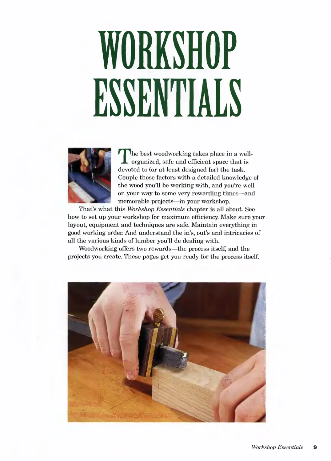
The best woodworking takes place in a well-
organized, safe and efficient space that is
devoted to (or at least designed for) the task.
Couple those factors with a detailed knowledge of
the wood you’ll be working with, and you’re well
on your way to some very rewarding times—and
memorable projects—in your workshop.
That’s what this Workshop Essentials chapter is all about. See
how to set up your workshop for maximum efficiency. Make sure your
layout, equipment and techniques are safe. Maintain everything in
good working order. And understand the in’s, out’s and intricacies of
all the various kinds of lumber you’ll de dealing with.
Woodworking offers two rewards—the process itself, and the
projects you create. These pages get you ready for the process itself.
Workshop Essentials 9
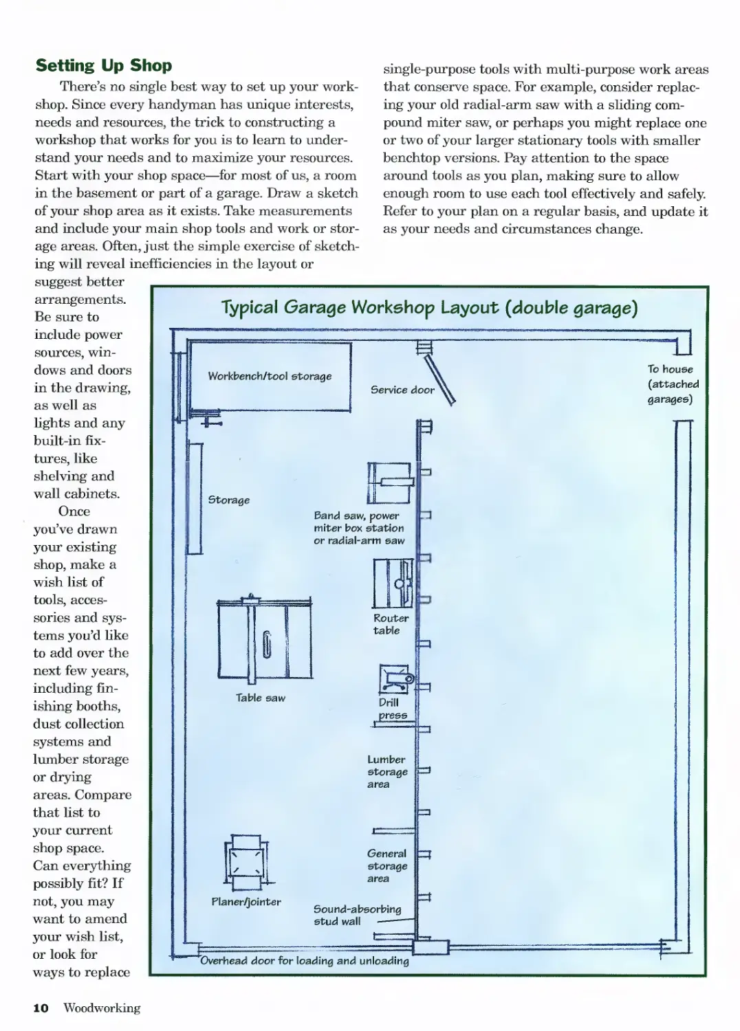
Setting Up Shop
There’s no single best way to set up your work-
shop. Since every handyman has unique interests,
needs and resources, the trick to constructing a
workshop that works for you is to learn to under-
stand your needs and to maximize your resources.
Start with your shop space—for most of us, a room
in the basement or part of a garage. Draw a sketch
of your shop area as it exists. Take measurements
and include your main shop tools and work or stor-
age areas. Often, just the simple exercise of sketch-
ing will reveal inefficiencies in the layout or
single-purpose tools with multi-purpose work areas
that conserve space. For example, consider replac-
ing your old radial-arm saw with a sliding com-
pound miter saw, or perhaps you might replace one
or two of your larger stationary tools with smaller
benchtop versions. Pay attention to the space
around tools as you plan, making sure to allow
enough room to use each tool effectively and safely.
Refer to your plan on a regular basis, and update it
as your needs and circumstances change.
suggest better
arrangements.
Be sure to
include power
sources, win-
dows and doors
in the drawing,
as well as
lights and any
built-in fix-
tures, like
shelving and
wall cabinets.
Once
you’ve drawn
your existing
shop, make a
wish list of
tools, acces-
sories and sys-
tems you’d like
to add over the
next few years,
including fin-
ishing booths,
dust collection
systems and
lumber storage
or drying
areas. Compare
that list to
your current
shop space.
Can everything
possibly fit? If
not, you may
want to amend
your wish list,
or look for
ways to replace
Typical Garage Workshop Layout (double garage)
10 Woodworking
General Workshop
Choosing Your Space
Without a doubt, the best
shop is a large, separate build-
ing, with plumbing and heat. It
is divided up to include a storage
area adjoining a large door to
the outside, a central workspace,
and a finishing room that’s
walled off from the rest of the
shop and ventilated to the out-
doors. Obviously, establishing
and maintaining such a shop
requires money and space that
most of us don’t have available.
So look for realistic alternatives.
The two most common shop
locations are the basement and
the garage. Shops have been set
up in spare rooms, attics, even in
closed-in porches. When assessing
potential shop areas, or consider-
ing upgrading or remodeling
your current shop, keep the fol-
lowing factors in mind:
Space needs. You’ll want to
have enough space to maneuver
full-size sheet goods and boards
that are eight feet or longer.
Ideally, this means a large
enough area that you can feed
large stock into a stationary tool
with enough clearance on the
infeed and the outfeed side.
Access. You’ll need a conve-
nient entry/exit point so you can
carry materials into the shop
and completed projects out of
the shop.
Power. You should never run
more than one tool at a time
(except a tool and a shop vac or
dust collector). Nevertheless, you’ll
need several accessible outlets.
Light. Adequate light is
essential for doing careful, com-
fortable, accurate and safe work.
You’ll need good overall light (a
combination of natural and arti-
ficial light sources is best) as
well some movable task lighting.
Ventilation I climate control.
To help exhaust dust and fumes,
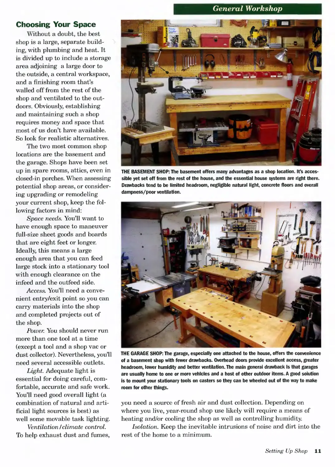
THE BASEMENT SHOP: The basement offers many advantages as a shop location. It’s acces-
sible yet set off from the rest of the house, and the essential house systems are right there.
Drawbacks tend to be limited headroom, negligible natural light, concrete floors and overall
dampness/poor ventilation.
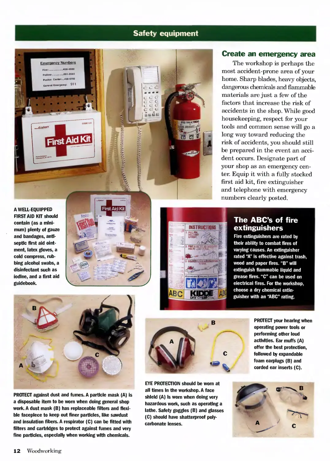
THE GARAGE SHOP: The garage, especially one attached to the house, offers the convenience
of a basement shop with fewer drawbacks. Overhead doors provide excellent access, greater
headroom, lower humidity and better ventilation. The main general drawback Is that garages
are usually home to one or more vehicles and a host of other outdoor items. A good solution
is to mount your stationary tools on casters so they can be wheeled out of the way to make
room for other things.
you need a source of fresh air and dust collection. Depending on
where you live, year-round shop use likely will require a means of
heating and/or cooling the shop as well as controlling humidity.
Isolation. Keep the inevitable intrusions of noise and dirt into the
rest of the home to a minimum.
Setting Up Shop 11
Safety equipment
в
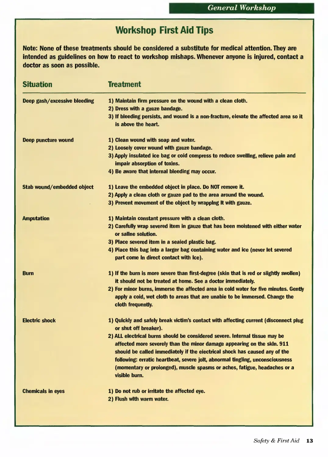
EYE PROTECTION should be worn at
all times In the workshop. A face
shield (A) Is worn when doing very
hazardous work, such as operating a
lathe. Safety goggles (B) and glasses
(C) should have shatterproof poly-
carbonate lenses.
Create an emergency area
The workshop is perhaps the
most accident-prone area of your
home. Sharp blades, heavy objects,
dangerous chemicals and flammable
materials are just a few of the
factors that increase the risk of
accidents in the shop. While good
housekeeping, respect for your
tools and common sense will go a
long way toward reducing the
risk of accidents, you should still
be prepared in the event an acci-
dent occurs. Designate part of
your shop as an emergency cen-
ter. Equip it with a fully stocked
first aid kit, fire extinguisher
and telephone with emergency
numbers clearly posted.
A WELL-EQUIPPED
FIRST AID KIT should
contain (as a mini-
mum) plenty of gauze
and bandages, anti-
septic first aid oint-
ment, latex gloves, a
cold compress, rub-
bing alcohol swabs, a
disinfectant such as
iodine, and a first aid
guidebook.
First Aid Kit
The ABC’s of fire
extinguishers
Fire extinguishers are rated by
their ability to combat fires of
varying causes. An extinguisher
rated “A” is effective against trash,
wood and paper fires. “B” will
extinguish fiammabie liquid and
grease fires. “C” can be used on
eiectricai fires. For the workshop,
choose a dry chemical extin-
guisher with an “ABC” rating.
PROTECT your hearing when
operating power tools or
performing other loud
activities. Ear muffs (A)
offer the best protection,
followed by expandable
foam earplugs (B) and
corded ear inserts (C).
PROTECT against dust and fumes. A particle mask (A) is
a disposable item to be worn when doing general shop
work. A dust mask (B) has replaceable filters and flexi-
ble facepiece to keep out finer particles, like sawdust
and insulation fibers. A respirator (C) can be fitted with
filters and cartridges to protect against fumes and very
fine particles, especially when working with chemicals.
12 Woodworking
General Workshop
Workshop First Aid Tips
Note: None of these treatments should be considered a substitute for medical attention. They are intended as guidelines on how to react to workshop mishaps. Whenever anyone is injured, contact a doctor as soon as possible.
Situation Treatment
Deep gash/excessive bleeding 1) Maintain firm pressure on the wound with a clean cloth. 2) Dress with a gauze bandage. 3) If bleeding persists, and wound is a non-fracture, elevate the affected area so it is above the heart.
Deep puncture wound 1) Clean wound with soap and water. 2) Loosely cover wound with gauze bandage. 3) Apply insulated ice bag or coid compress to reduce swelling, relieve pain and impair absorption of toxins. 4) Be aware that internal bleeding may occur.
Stab wound/embedded object 1) Leave the embedded object in place. Do NOT remove it. 2) Apply a clean cloth or gauze pad to the area around the wound. 3) Prevent movement of the object by wrapping It with gauze.
Amputation 1) Maintain constant pressure with a clean cloth. 2) Carefully wrap severed item in gauze that has been moistened with either water or saline solution. 3) Place severed item in a sealed plastic bag. 4) Place this bag into a larger bag containing water and ice (never let severed part come In direct contact with Ice).
Burn 1) If the burn is more severe than first-degree (skin that is red or slightly swollen) it should not be treated at home. See a doctor immediately. 2) For minor burns, immerse the affected area in cold water for five minutes. Gently apply a coid, wet cloth to areas that are unable to be immersed. Change the cloth frequently.
Electric shock 1) Quickly and safely break victim’s contact with affecting current (disconnect plug or shut off breaker). 2) ALL electrical burns should be considered severe. Internal tissue may be affected more severely than the minor damage appearing on the skin. 911 should be called immediately if the electrical shock has caused any of the following: erratic heartbeat, severe jolt, abnormal tingling, unconsciousness (momentary or proionged), muscle spasms or aches, fatigue, headaches or a visible burn.
Chemicals in eyes 1) Do not rub or irritate the affected eye. 2) Flush with warm water.
Safety & First Aid 13
Get a grip on glove selection
Always wear the proper glove for the task at hand. Maintain a supply of good-condition gloves of the following types, and
add special purpose gloves as needed. 1 *-> L"I;•>
1. HEAVY WORK GLOVES for handling
building materials and general interior
and exterior wear
2. JERSEY OR HEAVY COTTON GLOVES
for yardwork and general wear
3. RUBBER-DIPPED MASONRY GLOVES
for working with concrete and mortar
4. DISPOSABLE PLASTIC GLOVES for
painting and light finishing and for
handling hardwoods, like cherry, that
are sensitive to oils in skin
I 5. NEOPRENE RUBBER GLOVES for
working with caustic chemicals, such
as chemical paint stripper, and for
working around electrical current
6. HOUSEHOLD-TYPE RUBBER GLOWS
for painting and finishing and for work-
ing with cleansers
Remove-to-lock keys protect against
unauthorized or unsupervised tool use
Many power tools, particularly stationary tools,
come equipped with a removable lock key that is
inserted into the ON/OFF switch of the tool. The
tool cannot be turned on if the key is not in place.
Store the lock keys in a convenient place that’s out
of sight from the tool.
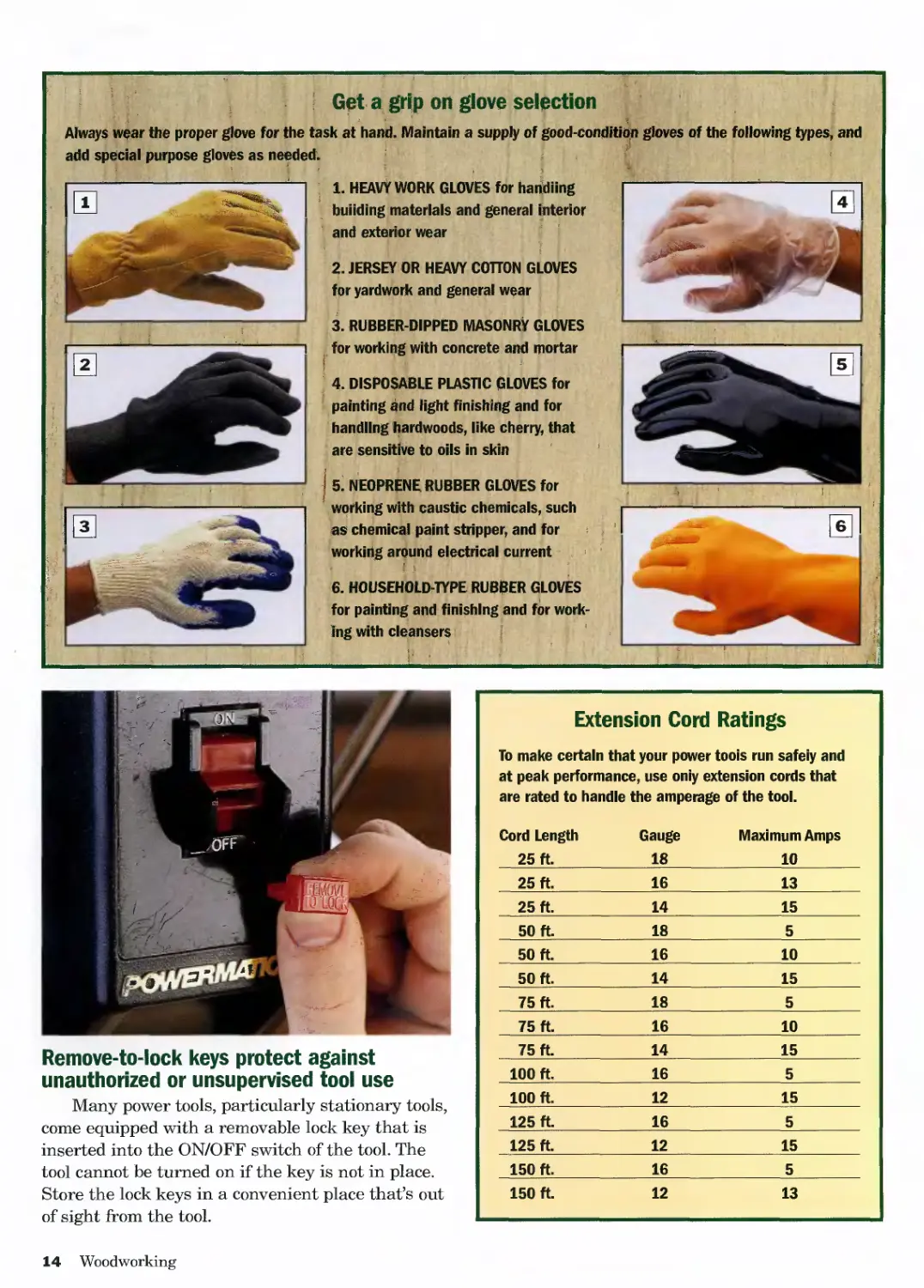
Extension Cord Ratings
To make certain that your power tools run safely and
at peak performance, use only extension cords that
are rated to handle the amperage of the tool.
Cord Length 25 ft. Gauge 18 Maximum Amps 10
25 ft. 16 13
25 ft. 14 15
50 ft. 18 5
50 ft. 16 10
50 ft. 14 15
75 ft. 18 5
75 ft. 16 10
75 ft. 14 15
100 ft. 16 5
100 ft. 12 15
125 ft. 16 5
125 ft. 12 15
150 ft. 16 5
150 ft. 12 13
14 Woodworking
General Workshop
Tips for dust collection & dust collection systems
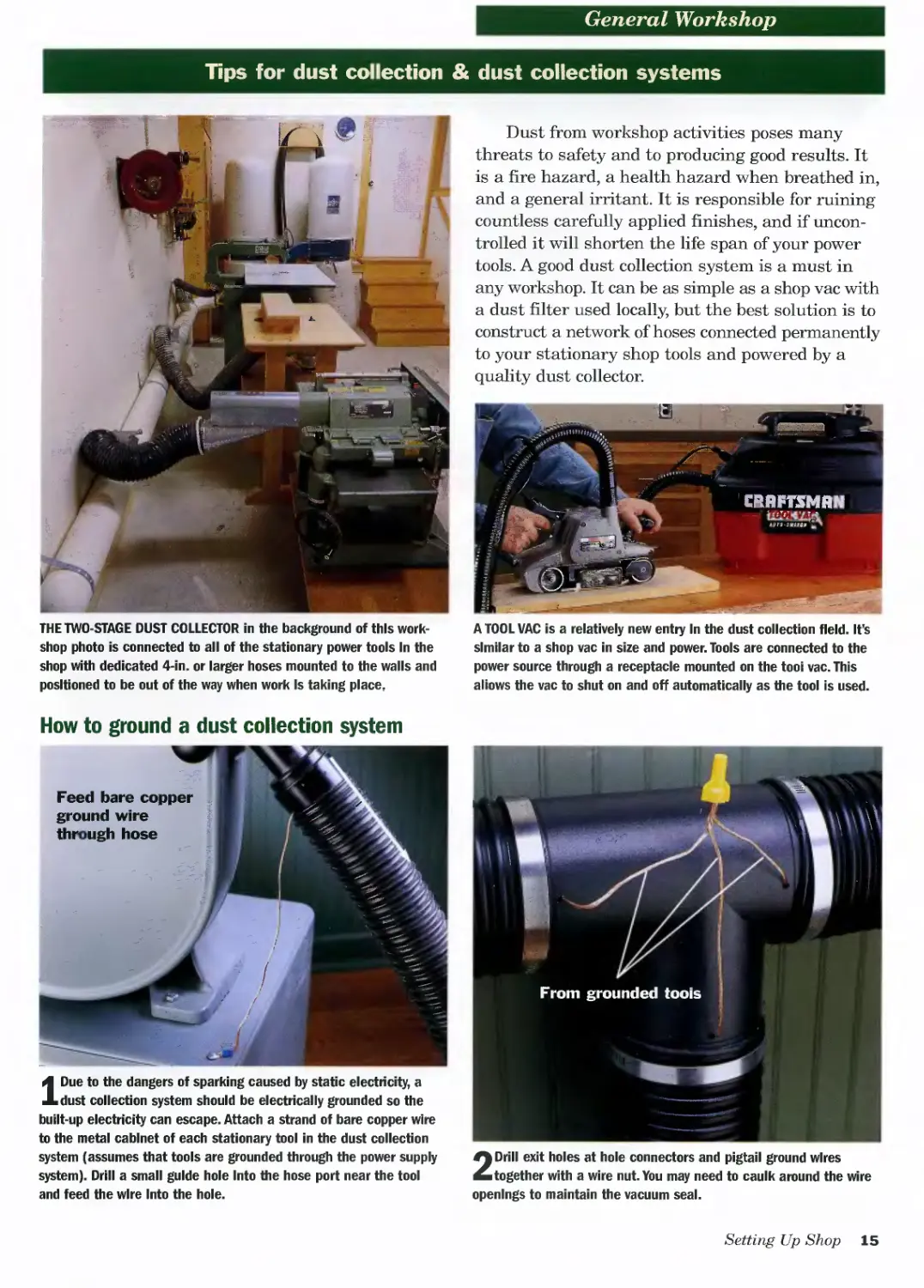
Dust from workshop activities poses many
threats to safety and to producing good results. It
is a fire hazard, a health hazard when breathed in,
and a general irritant. It is responsible for ruining
countless carefully applied finishes, and if uncon-
trolled it will shorten the life span of your power
tools. A good dust collection system is a must in
any workshop. It can be as simple as a shop vac with
a dust filter used locally, but the best solution is to
construct a network of hoses connected permanently
to your stationary shop tools and powered by a
quality dust collector.
THE TWO-STAGE DUST COLLECTOR in the background of this work-
shop photo is connected to all of the stationary power tools In the
shop with dedicated 4-in. or larger hoses mounted to the walls and
positioned to be out of the way when work Is taking place.
A TOOL VAC is a relatively new entry In the dust collection field. It’s
similar to a shop vac in size and power. Tools are connected to the
power source through a receptacle mounted on the tool vac. This
allows the vac to shut on and off automatically as the tool is used.
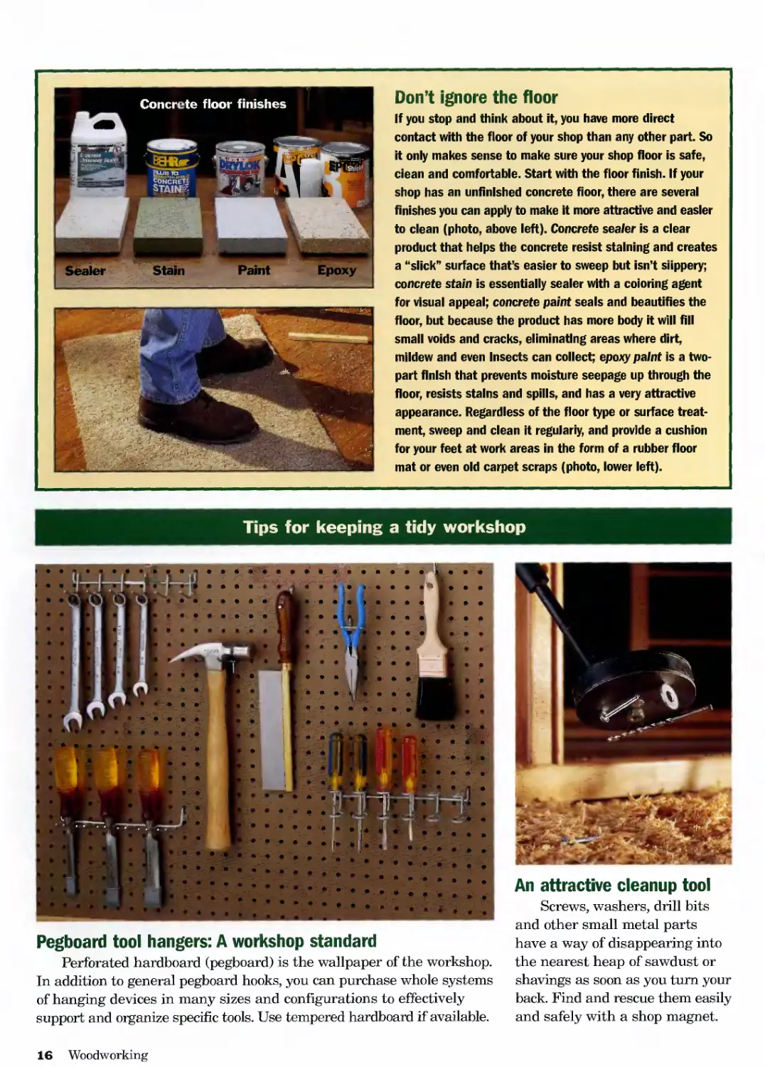
How to ground a dust collection system
IDue to the dangers of sparking caused by static electricity, a
dust collection system should be electrically grounded so the
built-up electricity can escape. Attach a strand of bare copper wire
to the metal cabinet of each stationary tool in the dust collection
system (assumes that tools are grounded through the power supply
system). Drill a small guide hole Into the hose port near the tool
and feed the wire Into the hole.
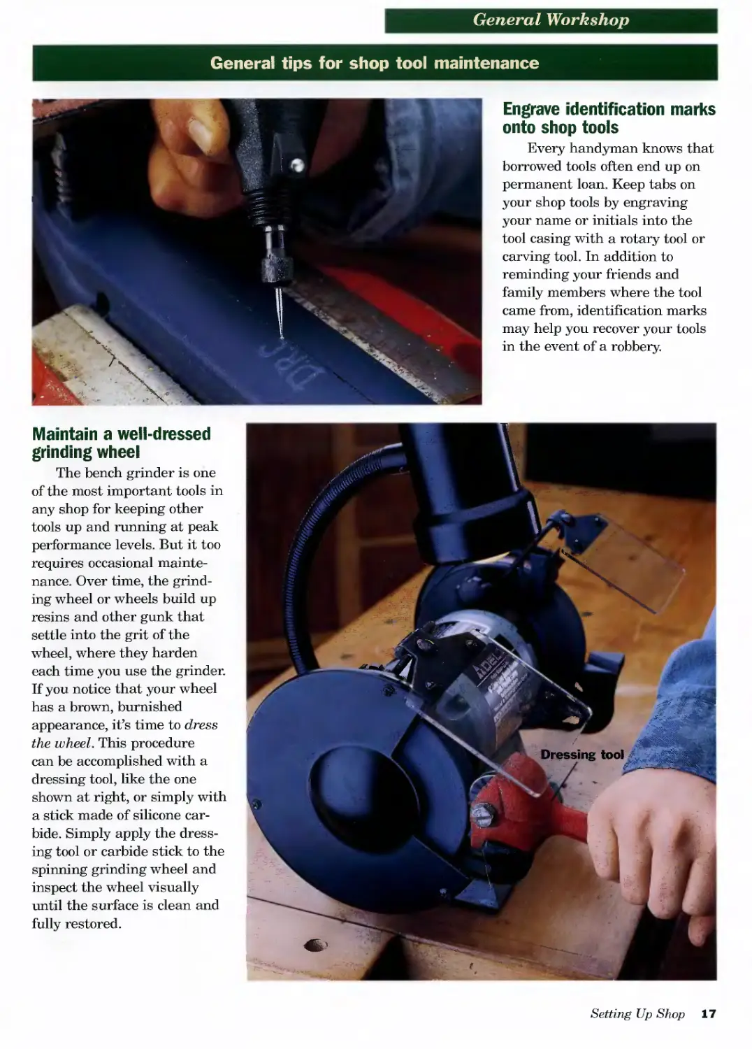
2 Drill exit holes at hole connectors and pigtail ground wires
together with a wire nut. You may need to caulk around the wire
openings to maintain the vacuum seal.
Setting Up Shop 15
Don’t ignore the floor
If you stop and think about it, you have more direct
contact with the floor of your shop than any other part. So
it only makes sense to make sure your shop floor is safe,
clean and comfortable. Start with the floor finish. If your
shop has an unfinished concrete floor, there are several
finishes you can apply to make it more attractive and easier
to clean (photo, above left). Concrete sealer is a clear
product that helps the concrete resist staining and creates
a “slick” surface that’s easier to sweep but isn’t slippery;
concrete stain is essentially sealer with a coloring agent
for visual appeal; concrete paint seals and beautifies the
floor, but because the product has more body it will fill
small voids and cracks, eliminating areas where dirt,
mildew and even Insects can collect; epoxy paint is a two-
part finish that prevents moisture seepage up through the
floor, resists stains and spills, and has a very attractive
appearance. Regardless of the floor type or surface treat-
ment, sweep and clean it regularly, and provide a cushion
for your feet at work areas in the form of a rubber floor
mat or even old carpet scraps (photo, lower left).
Tips for keeping a tidy workshop
Pegboard tool hangers: A workshop standard
Perforated hardboard (pegboard) is the wallpaper of the workshop.
In addition to general pegboard hooks, you can purchase whole systems
of hanging devices in many sizes and configurations to effectively
support and organize specific tools. Use tempered hardboard if available.
An attractive cleanup tool
Screws, washers, drill bits
and other small metal parts
have a way of disappearing into
the nearest heap of sawdust or
shavings as soon as you turn your
back. Find and rescue them easily
and safely with a shop magnet.
16 Woodworking
General Workshop
General tips for shop tool maintenance
Engrave identification marks
onto shop tools
Every handyman knows that
borrowed tools often end up on
permanent loan. Keep tabs on
your shop tools by engraving
your name or initials into the
tool casing with a rotary tool or
carving tool. In addition to
reminding your friends and
family members where the tool
came from, identification marks
may help you recover your tools
in the event of a robbery.
Maintain a well-dressed
grinding wheel
The bench grinder is one
of the most important tools in
any shop for keeping other
tools up and running at peak
performance levels. But it too
requires occasional mainte-
nance. Over time, the grind-
ing wheel or wheels build up
resins and other gunk that
settle into the grit of the
wheel, where they harden
each time you use the grinder.
If you notice that your wheel
has a brown, burnished
appearance, it’s time to dress
the wheel. This procedure
can be accomplished with a
dressing tool, like the one
shown at right, or simply with
a stick made of silicone car-
bide. Simply apply the dress-
ing tool or carbide stick to the
spinning grinding wheel and
inspect the wheel visually
until the surface is clean and
fully restored.
Setting Up Shop 17
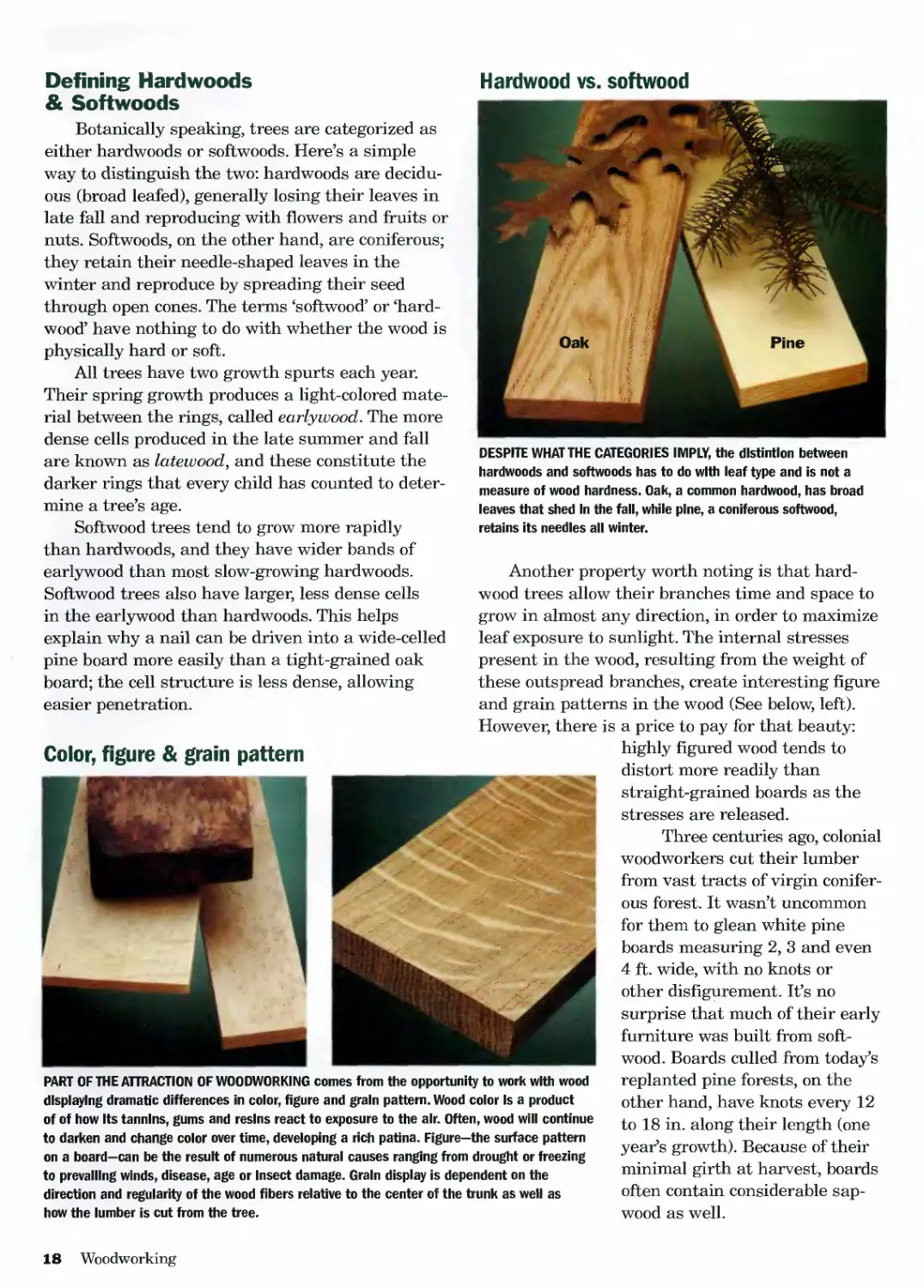
Hardwood vs. softwood
Defining Hardwoods
& Softwoods
Botanically speaking, trees are categorized as
either hardwoods or softwoods. Here’s a simple
way to distinguish the two: hardwoods are decidu-
ous (broad leafed), generally losing their leaves in
late fall and reproducing with flowers and fruits or
nuts. Softwoods, on the other hand, are coniferous;
they retain their needle-shaped leaves in the
winter and reproduce by spreading their seed
through open cones. The terms ‘softwood’ or ‘hard-
wood’ have nothing to do with whether the wood is
physically hard or soft.
All trees have two growth spurts each year.
Their spring growth produces a light-colored mate-
rial between the rings, called earlywood. The more
dense cells produced in the late summer and fall
are known as latewood, and these constitute the
darker rings that every child has counted to deter-
mine a tree’s age.
Softwood trees tend to grow more rapidly
than hardwoods, and they have wider bands of
earlywood than most slow-growing hardwoods.
Softwood trees also have larger, less dense cells
in the earlywood than hardwoods. This helps
explain why a nail can be driven into a wide-celled
pine board more easily than a tight-grained oak
board; the cell structure is less dense, allowing
easier penetration.
DESPITE WHAT THE CATEGORIES IMPLY, the dlstintlon between
hardwoods and softwoods has to do with leaf type and is not a
measure of wood hardness. Oak, a common hardwood, has broad
leaves that shed In the fall, while pine, a coniferous softwood,
retains its needles all winter.
Another property worth noting is that hard-
wood trees allow their branches time and space to
grow in almost any direction, in order to maximize
leaf exposure to sunlight. The internal stresses
present in the wood, resulting from the weight of
these outspread branches, create interesting figure
and grain patterns in the wood (See below, left).
However, there is a price to pay for that beauty:
Color, figure & grain pattern
PART OF THE ATTRACTION OF WOODWORKING comes from the opportunity to work with wood
displaying dramatic differences in color, figure and grain pattern. Wood color Is a product
of of how Its tannins, gums and resins react to exposure to the air. Often, wood will continue
to darken and change color over time, developing a rich patina. Figure—the surface pattern
on a board-can be the result of numerous natural causes ranging from drought or freezing
to prevailing winds, disease, age or Insect damage. Grain display is dependent on the
direction and regularity of the wood fibers relative to the center of the trunk as well as
how the lumber is cut from the tree.
highly figured wood tends to
distort more readily than
straight-grained boards as the
stresses are released.
Three centuries ago, colonial
woodworkers cut their lumber
from vast tracts of virgin conifer-
ous forest. It wasn’t uncommon
for them to glean white pine
boards measuring 2, 3 and even
4 ft. wide, with no knots or
other disfigurement. It’s no
surprise that much of their early
furniture was built from soft-
wood. Boards culled from today’s
replanted pine forests, on the
other hand, have knots every 12
to 18 in. along their length (one
year’s growth). Because of their
minimal girth at harvest, boards
often contain considerable sap-
wood as well.
18 Woodworking
General Workshop
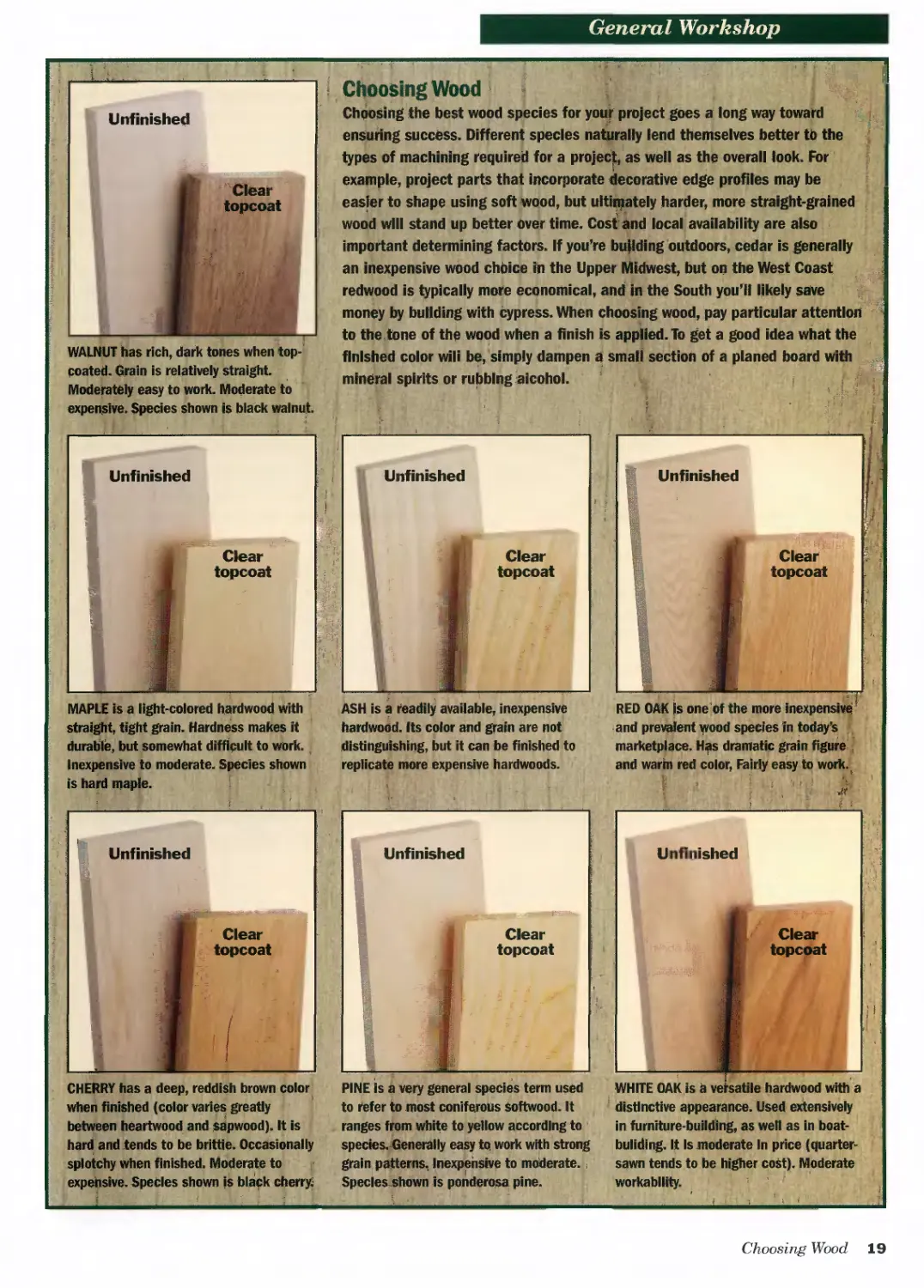
coated. Grain is relatively straight
Moderately easy to work. Moderate to
expensive. Species shown is black walnut
Choosing Wood
Cheesing the best wood species for your project goes a long way toward
ensuring success. Different species naturally lend themselves better tb the
types of machining required for a project, as well as the overall look. For
example, project parts that incorporate decorative edge profiles may be
easier to shape using soft wood, but ultimately harder, more straight-grained
vood will stand up better Over time. Cost ano local availability are also
important determining factors. If you’re building outdoors, cedar is generally
an inexpensive wood chbice in the Upper Midwest, but on the West Coast
redwood is typically more economical, and in the South you’ll likely save
money by building with cypress. When choosing wood, pay particular attention
to the, tone of the wood when a finish is appned. To get a good idea what the
finished color will be, simply dampen a small section of a planed board with
mineral spirits or rubbing alcohol.
j
straight tight grain. Hardness makes It
durable, but somewhat difficult to work.
Inexpensive to moderate. Species shown
is hard maple.
Unfinished
A
Unfinished
Clear
topcoat
Clear
topcoat
ASH is a ‘eadily available, inexpensive
hardwooti. Its color and grain are not
distinguishing, but it can be finished to
epiicate more expensive hardwoods.
RED OAK is oneof the more inexpensive
and prevalent wood species in today’s
marketplace. Has dramatic grab. *igure
and warm red color, Fairly easy to work.
when finished (color varies greatly
between heartwood and sapwood). It is
to refer to most coniferous softwood. It
ranges from white to yellow according to
distinctive appearance. Used extensively
in furniture-building, as well as in boat-
hard and tends to be brittle. Occasionally
splotchy when finished. Moderate to
expensive. Species shown is black cherry
species. Generally easy to work with stronp
grain pat.erns, Inexpensive to moderate.,
Species shown is ponderosa pine.
building. It Is moderate In price (quarter-
sawn tends to be higher cost). Moderate
workability.
Choosing Wood 19
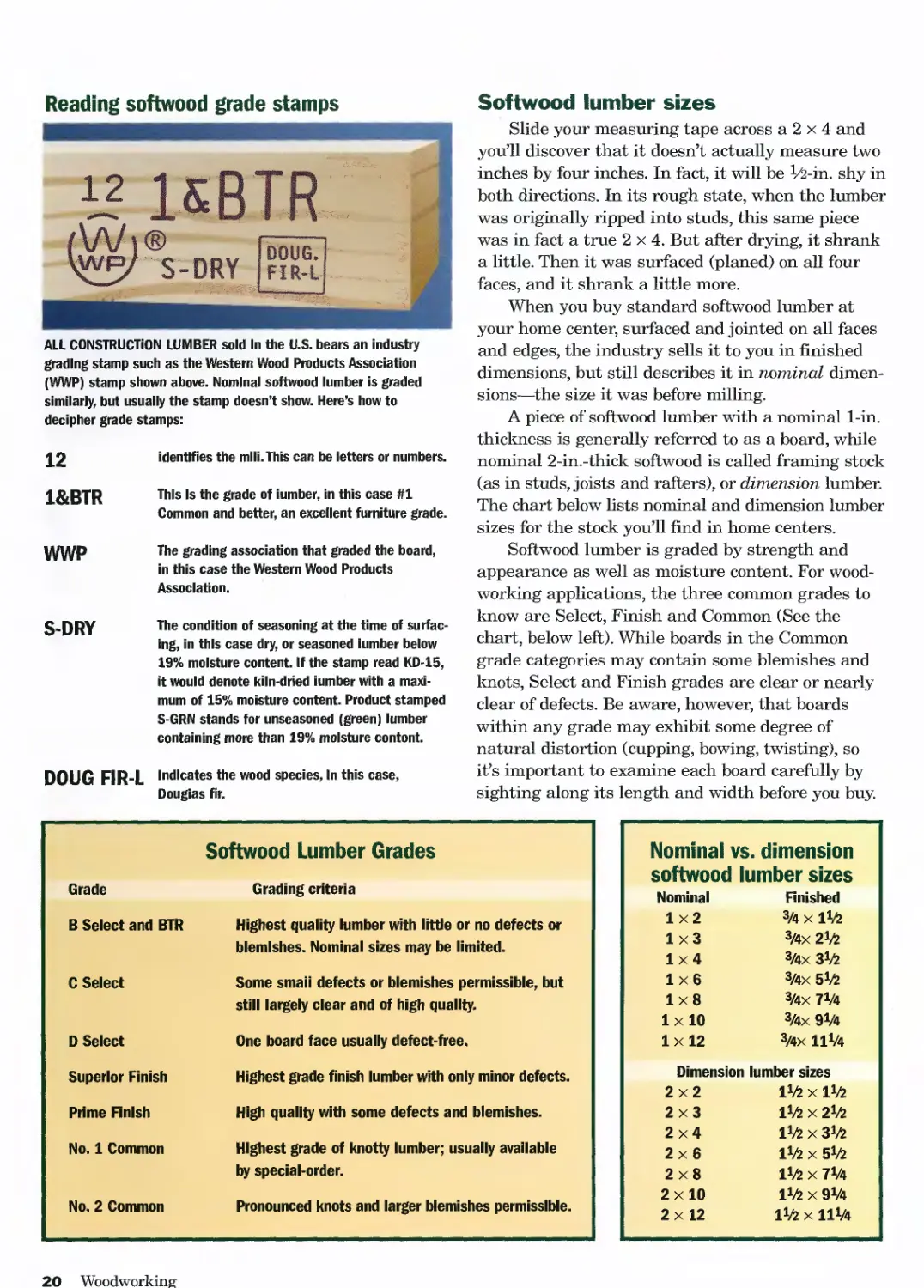
Reading softwood grade stamps
ALL CONSTRUCTION LUMBER sold In the U.S. bears an industry
grading stamp such as the Western Wood Products Association
(WWP) stamp shown above. Nominal softwood lumber is graded
similarly, but usually the stamp doesn't show. Here’s how to
decipher grade stamps:
12 identifies the mill. This can be letters or numbers.
l&BTR This Is the grade of lumber, in this case #1
Common and better, an excellent furniture grade.
WWP The grading association that graded the board,
in this case the Western Wood Products
Association.
S-DRY The condition of seasoning at the time of surfac-
ing, in this case dry, or seasoned lumber below
19% moisture content. If the stamp read KD-15,
it would denote kiln-dried lumber with a maxi-
mum of 15% moisture content. Product stamped
S-GRN stands for unseasoned (green) lumber
containing more than 19% moisture content.
DOUG FIR-L Indicates the wood species, In this case,
Douglas fir.
Softwood Lumber Grades
Grade Grading criteria
В Select and BTR Highest quality lumber with little or no defects or blemishes. Nominal sizes may be limited.
C Select Some smaii defects or blemishes permissible, but still largely clear and of high quality.
D Select One board face usually defect-free.
Superior Finish Highest grade finish lumber with only minor defects.
Prime Finish High quality with some defects and blemishes.
No. 1 Common Highest grade of knotty lumber; usually available by special-order.
No. 2 Common Pronounced knots and larger blemishes permissible.
Softwood lumber sizes
Slide your measuring tape across a 2 x 4 and
you’ll discover that it doesn’t actually measure two
inches by four inches. In fact, it will be Va-in. shy in
both directions. In its rough state, when the lumber
was originally ripped into studs, this same piece
was in fact a true 2x4. But after drying, it shrank
a little. Then it was surfaced (planed) on all four
faces, and it shrank a little more.
When you buy standard softwood lumber at
your home center, surfaced and jointed on all faces
and edges, the industry sells it to you in finished
dimensions, but still describes it in nominal dimen-
sions—the size it was before milling.
A piece of softwood lumber with a nominal 1-in.
thickness is generally referred to as a board, while
nominal 2-in.-thick softwood is called framing stock
(as in studs, joists and rafters), or dimension lumber.
The chart below lists nominal and dimension lumber
sizes for the stock you’ll find in home centers.
Softwood lumber is graded by strength and
appearance as well as moisture content. For wood-
working applications, the three common grades to
know are Select, Finish and Common (See the
chart, below left). While boards in the Common
grade categories may contain some blemishes and
knots, Select and Finish grades are clear or nearly
clear of defects. Be aware, however, that boards
within any grade may exhibit some degree of
natural distortion (cupping, bowing, twisting), so
it’s important to examine each board carefully by
sighting along its length and width before you buy.
Nominal vs. dimension softwood lumber sizes
Nominal Finished
1x2 3/4 X Ito
1x3 3/4X 2*Z>
1x4 3/4X 31/»
1x6 3/4X 51/?
1x8 3/4X 7V4
lx 10 3/4X 9V4
lx 12 3/4X 11V4
Dimension lumber sizes
2x2 Ito X Ito
2x3 Ito x 2to
2x4 Ito x 3to
2x6 Ito x 5to
2x8 Ito X 7V4
2x 10 I1/» X 9V4
2x 12 ito x 11V4
20 Woodworking
General 'Workshop
Hardwood lumber sizes
While nominal dimensions are widely used for
selling softwoods, some retailers have extended the
practice to hardwood boards as well. Your local home
center probably stocks a few species of hardwoods,
like oak, maple and cherry. These boards generally
are planed to 3A in. thick, jointed flat on the edges
and cut to standard widths and lengths. Within the
lumber industry, lumber of this sort is categorized
as “S4S”, which stands for Surfaced Four Sides. All
of this surface preparation at the mill translates to
higher prices for you, but it may make the most sense
to buy S4S lumber if you don’t own a thickness
planer or jointer to prepare board surfaces yourself.
To find specialty or thicker hardwoods, you’ll
need to shop at a traditional lumberyard. A good
lumberyard will offer a wide selection of hardwoods
in random widths and in an assortment of thick-
nesses and grades (See Hardwood Lumber Grades,
below). In addition to S4S, you’ll find S2S lumber
(planed smooth on two faces but the edges are
Calculating Board Feet
Hardwood lumber Is sold at most lumberyards by the
board foot, which can make calculating the amount of
lumber you need a little confusing. The three boards
below, for Instance, all equal 2 board feet, though
their physical dimensions are quite different. A board
foot is actually V12 of a cubic foot of rough lumber, or
144 cubic inches. It Is the equivalent of a piece of
stock that Is 12 in. wide, 12 in. long and 1 In. thick.
But any combination of dimensions that multiplies to
144 is equivalent to one board foot.
To calculate the number of board feet a piece of lum-
ber contains, its thickness times Its width times its
length (all In Inches) then divide by 144. If one dimen-
sion is easier to calculate In feet rather
than Inches, divide by 12 instead.
When calculating board feet, don’t
forget to build some waste into
the project estimate. The pros
generally count on close to
30% when they’re buying
S2S stock, and 40% with
roughsawn
lumber (mostly
because they can’t
see the defects
until after
planing).
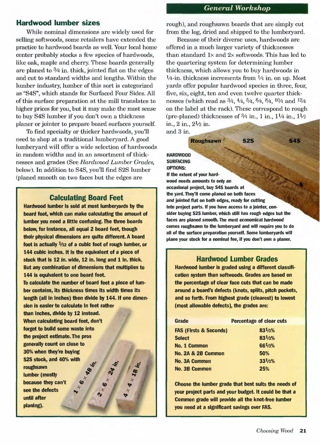
rough), and roughsawn boards that are simply cut
from the log, dried and shipped to the lumberyard.
Because of their diverse uses, hardwoods are
offered in a much larger variety of thicknesses
than standard lx and 2x softwoods. This has led to
the quartering system for determining lumber
thickness, which allows you to buy hardwoods in
Mi-in. thickness increments from F4 in. on up. Most
yards offer popular hardwood species in three, four,
five, six, eight, ten and even twelve quarter thick-
nesses (which read as 3A, 4/4, 5Л, 6A, 8A, 10A and 12Л
on the label at the rack). These correspond to rough
(pre-planed) thicknesses of 3A in., 1 in., lrA in., IV2
in., 2 in., 2V2 in.
and 3 in.
S4S
S2S
Roughsawn
HARDWOOD
SURFACING
OPTIONS:
If the extent of your hard-
wood needs amounts to only an
occasional project, buy S4S boards at
the yard. They’ll come planed on both faces
and jointed flat on both edges, ready for cutting
Into project parts. If you have access to a jointer, con-
sider buying S2S lumber, which still has rough edges but the
faces are planed smooth. The most economical hardwood
comes roughsawn to the lumberyard and will require you to do
all of the surface preparation yourself. Some lumberyards will
plane your stock for a nominal fee, if you don’t own a planer.
Hardwood Lumber Grades
Hardwood lumber is graded using a different classifi-
cation system than softwoods. Grades are based on
the percentage of clear face cuts that can be made
around a board’s defects (knots, splits, pitch pockets,
and so forth. From highest grade (clearest) to lowest
(most allowable defects), the grades are:
Grade Percentage of clear cuts
FAS (Firsts & Seconds) 83^%
Select 83^%
No. 1 Common 66Ш
No. 2A & 2B Common 50%
No. ЗА Common 33ta%
No. 3B Common 25%
Choose the lumber grade that best suits the needs of
your project parts and your budget. It could be that a
Common grade will provide all the knot-free lumber
you need at a significant savings over FAS.
Choosing Wood 21
Large retail lumber outlets and home centers make shopping for
lumber easy. Most of the lumber you’ll find is fully surfaced and
ready for building. Some larger home centers even stock lumber
inside where it’s kept warm and dry. The downside to all of this
convenience is that species options are limited, especially for
hardwoods.
Buying lumber
It’s important to know your options for where
to shop for wood. Chain home improvement stores
generally offer a basic variety of framing lumber
and nominal softwood but very little hardwood.
What they do carry is often priced lower than spe-
cialty yard stock, but the grades and dimensions
are limited. Here are a couple of other options to
consider:
Contractor yards, where framing and finish
carpenters buy their materials, usually offer a
wider array of lumber options, including an assort-
ment of millwork products and custom moldings.
Often they can special-order materials that the
chain stores simply can’t supply. The quality of
the stock here is better, and the prices reflect the
quality you’ll find.
Specialty yards: Most metropolitan areas have
specialty yards that sell only hardwoods and
veneered sheet goods. Their primary customers are
commercial cabinetmakers, architectural millwork
shops and professional furniture builders. While
the salespeople here are used to dealing with pros,
they are usually willing to take a few minutes to
explain the finer points to an interested amateur.
However, time is money for these folks, so they
won’t appreciate spending too much time on what
they by necessity must consider a minor sale. The
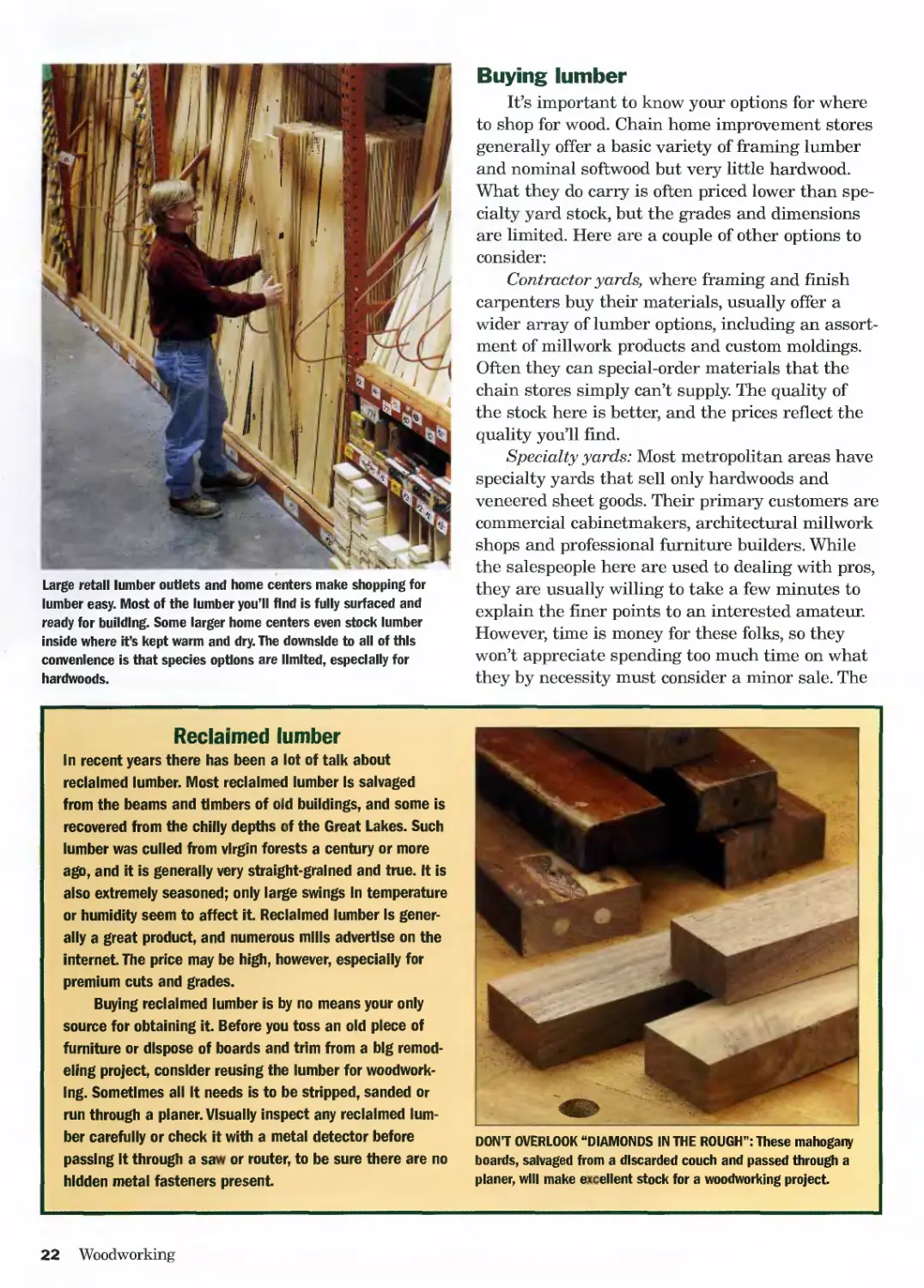
Reclaimed lumber
In recent years there has been a lot of talk about
reclaimed lumber. Most reclaimed lumber Is salvaged
from the beams and timbers of old buildings, and some is
recovered from the chilly depths of the Great Lakes. Such
lumber was culled from virgin forests a century or more
ago, and it is generally very straight-grained and true. It is
also extremely seasoned; only large swings In temperature
or humidity seem to affect it. Reclaimed lumber Is gener-
ally a great product, and numerous mills advertise on the
internet. The price may be high, however, especially for
premium cuts and grades.
Buying reclaimed lumber is by no means your only
source for obtaining it. Before you toss an old piece of
furniture or dispose of boards and trim from a big remod-
eling project, consider reusing the lumber for woodwork-
ing. Sometimes all It needs is to be stripped, sanded or
run through a planer. Visually inspect any reclaimed lum-
ber carefully or check it with a metal detector before
passing It through a saw or router, to be sure there are no
hidden metal fasteners present.
DON'T OVERLOOK “DIAMONDS IN THE ROUGH”: These mahogany
boards, salvaged from a discarded couch and passed through a
planer, will make excellent stock for a woodworking project.
22 Woodworking
General 'Workshop
stock sold here here is normally S2S or roughsawn,
so you’ll need a jointer or planer to prepare the
lumber further. Be aware that, when buying rough-
sawn lumber, you can’t tell much about the color,
grain or quality of the board until after you expose
it to the planer knives.
It’s quite acceptable to rummage through the
stock at a specialty yard, but make sure you
rebuild the stacks as you found them. Longer,
wider boards belong at the back of the rack. Don’t
mix the boards from different bins. Boards in two
bins may look the same at first glance, but they
may be different grades. Check the board ends to
see if the yard has painted different colors there—
the colors represent the grades.
Buying basics
Whether you buy from a chain store, specialty or
contractor’s yard or by mail, keep a few basic rules
of thumb in mind when shopping for project lumber:
1. Develop a realistic shopping list. Base
your list on a clear understanding of common
lumber proportions and grades. Make a prelimi-
nary visit to your lumberyard, acquire a catalog, or
call the city desk before leaving home to verify that
the dimensions and species you need are available.
Know ahead of time what compromises you can
make to your cutting and shopping lists, if what
you need isn’t available in the right size or species.
2. Consider using less-expensive woods like
poplar or pine in hidden areas of your project.
Woodworkers have used “secondary” woods for cen-
turies in fine furniture and cabinetry, saving premium
lumber for prominent project parts like face frames,
doors, drawer fronts and tabletops. Don’t under-
estimate the versatility, economy and structural
benefits of using sheet goods like plywood and
particleboard over solid wood.
3. Factor in about 30% waste. As you
become more practiced in estimating, you’ll be able
to reduce this percentage somewhat. If you are just
getting started as a woodworker, buy more lumber
than what you’ll need for a project. Save your
receipt and return what you don’t use. Published
plans occasionally have errors in shopping and cut-
ting lists that will require you to have more mater-
ial on hand. If you buy lumber roughsawn, you
may not discover an unsightly blemish or pitch
pocket until after you plane it, resulting in less
usable lumber than you initially planned. And be
honest about your own “fudge factor.” One miscal-
culated cut late on a Saturday afternoon might put
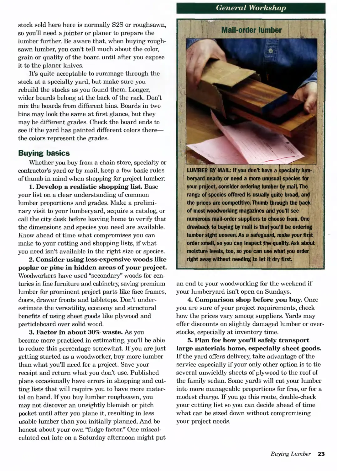
LUMBER BY MAIL: If you don’t have a Specialty him-\
beryard nearby or need a more unusual species for
your project, consider ordering lumber by mail. The
range of species offered Is usually quite broad, and
the prices are competitive. Thumb through the back
of most woodworking magazines and you’ll see
numerous mail-order suppliers to choose from. One
drawback to buying by mail is that you’ll be ordering
lumber sight unseen. As a safeguard, make your first
order small, so you can Inspect the quality. Ask about
molstur в levels, too, so you can use what you order
right away witheut needing to let it dry first
:... '-1 -' • ' * - - ?1........................ -
an end to your woodworking for the weekend if
your lumberyard isn’t open on Sundays.
4. Comparison shop before you buy. Once
you are sure of your project requirements, check
how the prices vary among suppliers. Yards may
offer discounts on slightly damaged lumber or over-
stocks, especially at inventory time.
5. Plan for how you’ll safely transport
large materials home, especially sheet goods.
If the yard offers delivery, take advantage of the
service especially if your only other option is to tie
several unwieldly sheets of plywood to the roof of
the family sedan. Some yards will cut your lumber
into more manageable proportions for free, or for a
modest charge. If you go this route, double-check
your cutting list so you can decide ahead of time
what can be sized down without compromising
your project needs.
Buying Lumber 23
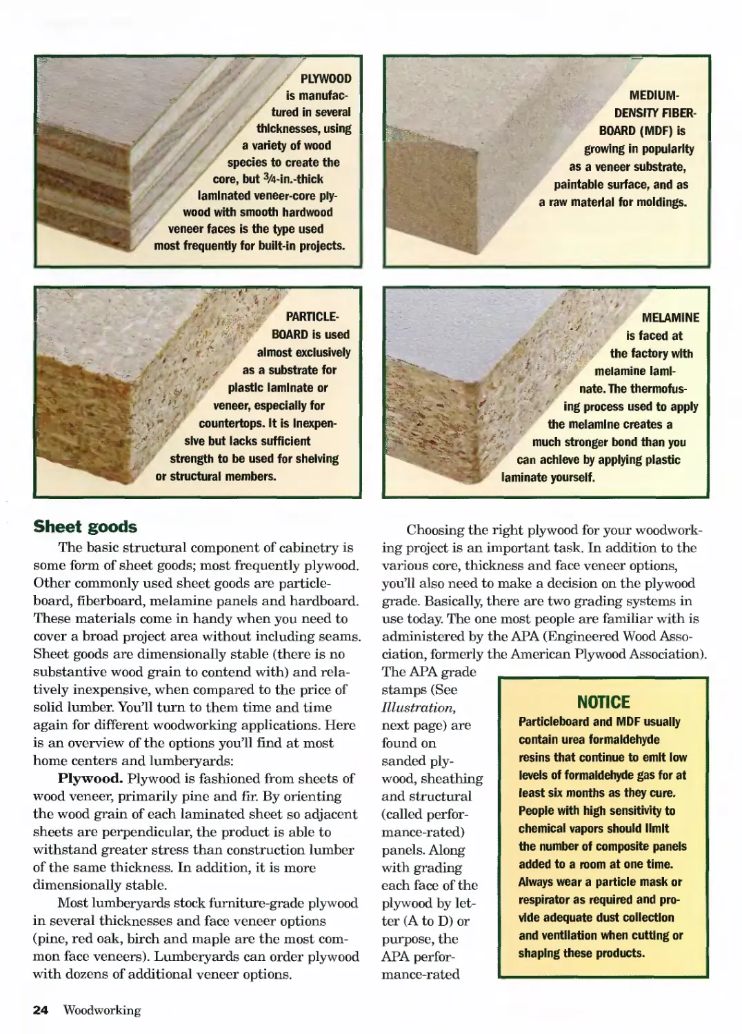
PLYWOOD
is manufac-
tured in several
thicknesses, using
a variety of wood
species to create the
core, but 3/4-in.-thick
laminated veneer-core ply-
wood with smooth hardwood
veneer faces is the type used
most frequently for built-in projects.
MEDIUM-
DENSITY FIBER-
BOARD (MDF) is
growing in popularity
as a veneer substrate,
paintable surface, and as
a raw material for moldings.
PARTICLE-
BOARD is used
almost exclusively
as a substrate for
plastic laminate or
veneer, especially for
countertops. It is Inexpen-
sive but lacks sufficient
strength to be used for shelving
or structural members.
MELAMINE
is faced at
the factory with
melamine lami-
nate. The thermofus-
ing process used to apply
the melamine creates a
much stronger bond than you
can achieve by applying plastic
laminate yourself.
Sheet goods
The basic structural component of cabinetry is
some form of sheet goods; most frequently plywood.
Other commonly used sheet goods are particle-
board, fiberboard, melamine panels and hardboard.
These materials come in handy when you need to
cover a broad project area without including seams.
Sheet goods are dimensionally stable (there is no
substantive wood grain to contend with) and rela-
tively inexpensive, when compared to the price of
solid lumber. You’ll turn to them time and time
again for different woodworking applications. Here
is an overview of the options you’ll find at most
home centers and lumberyards:
Plywood. Plywood is fashioned from sheets of
wood veneer, primarily pine and fir. By orienting
the wood grain of each laminated sheet so adjacent
sheets are perpendicular, the product is able to
withstand greater stress than construction lumber
of the same thickness. In addition, it is more
dimensionally stable.
Most lumberyards stock furniture-grade plywood
in several thicknesses and face veneer options
(pine, red oak, birch and maple are the most com-
mon face veneers). Lumberyards can order plywood
with dozens of additional veneer options.
NOTICE
Particleboard and MDF usually
contain urea formaldehyde
resins that continue to emit low
levels of formaldehyde gas for at
least six months as they cure.
People with high sensitivity to
chemical vapors should limit
the number of composite panels
added to a room at one time.
Always wear a particle mask or
respirator as required and pro-
vide adequate dust collection
and ventilation when cutting or
shaping these products.
Choosing the right plywood for your woodwork-
ing project is an important task. In addition to the
various core, thickness and face veneer options,
you’ll also need to make a decision on the plywood
grade. Basically, there are two grading systems in
use today. The one most people are familiar with is
administered by the APA (Engineered Wood Asso-
ciation, formerly the American Plywood Association).
The APA grade
stamps (See
Illustration,
next page) are
found on
sanded ply-
wood, sheathing
and structural
(called perfor-
mance-rated)
panels. Along
with grading
each face of the
plywood by let-
ter (A to D) or
purpose, the
APA perfor-
mance-rated
24 Woodworking
General Workshop
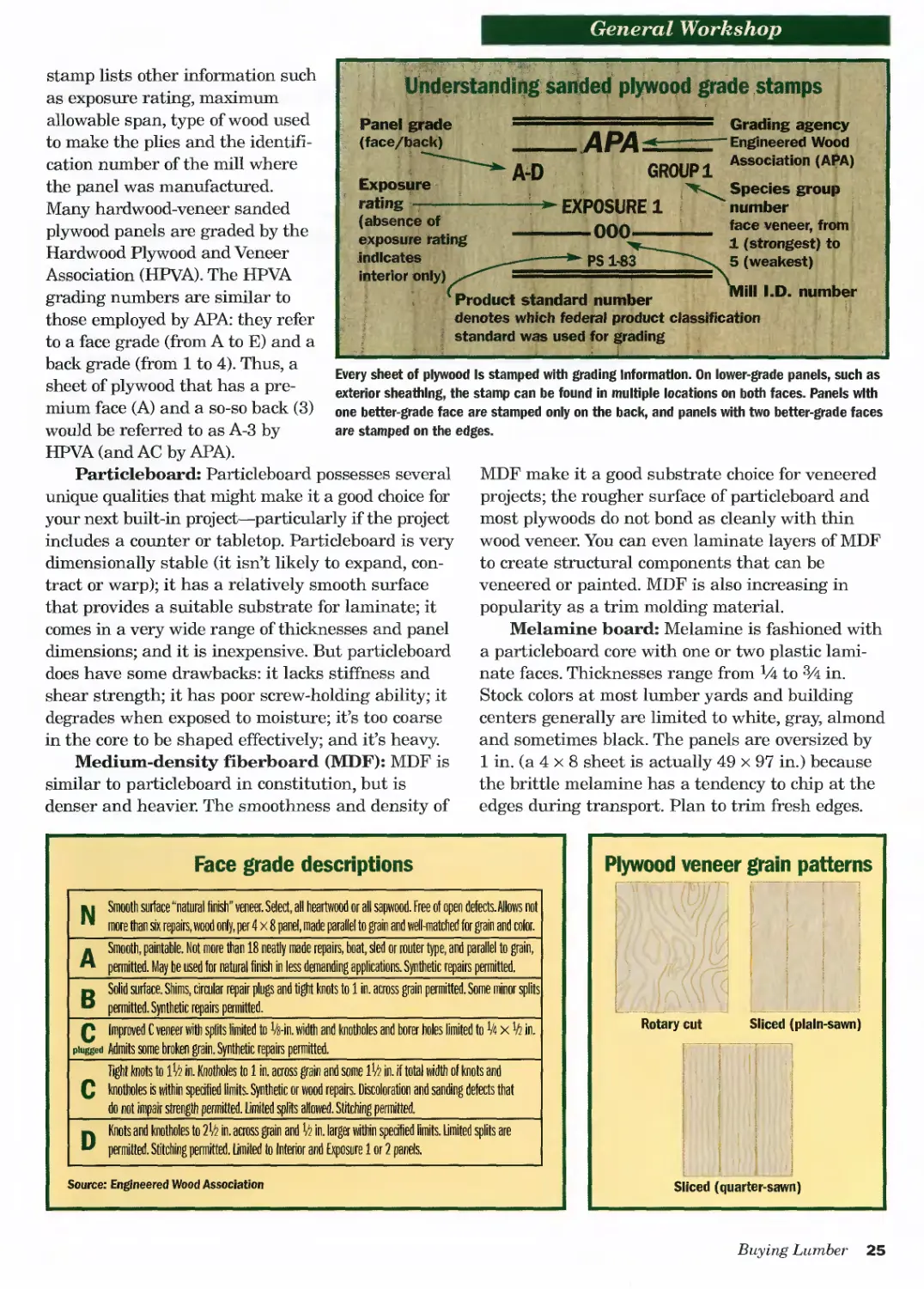
Understanding sanded plywood grade stamps
Panel grade
(face/back)
Exposure
rating • ——
(absence of
exposure rating
indicates
interior only)
A-D
............ Grading agency
APA^z-“ Engineered Wood
"group i Assoclation <AP*>
EXPOSURE 1
------ООО----
PS 1-83
ill I.D. number
number
face veneer, from
1 (strongest) to
5 (weakest)
Product standard number
denotes which federal product classification
3 standard vrs used for grading
Every sheet of plywood Is stamped with grading Information. On lower-grade panels, such as
exterior sheathing, the stamp can be found in multiple locations on both faces. Panels with
one better-grade face are stamped only on the back, and panels with two better-grade faces
are stamped on the edges.
stamp lists other information such
as exposure rating, maximum
allowable span, type of wood used
to make the plies and the identifi-
cation number of the mill where
the panel was manufactured.
Many hardwood-veneer sanded
plywood panels are graded by the
Hardwood Plywood and Veneer
Association (HPVA). The HPVA
grading numbers are similar to
those employed by APA: they refer
to a face grade (from A to E) and a
back grade (from 1 to 4). Thus, a
sheet of plywood that has a pre-
mium face (A) and a so-so back (3)
would be referred to as A-3 by
HPVA (and AC by APA).
Particleboard: Particleboard possesses several
unique qualities that might make it a good choice for
your next built-in project—particularly if the project
includes a counter or tabletop. Particleboard is very
dimensionally stable (it isn’t likely to expand, con-
tract or warp); it has a relatively smooth surface
that provides a suitable substrate for laminate; it
comes in a very wide range of thicknesses and panel
dimensions; and it is inexpensive. But particleboard
does have some drawbacks: it lacks stiffness and
shear strength; it has poor screw-holding ability; it
degrades when exposed to moisture; it’s too coarse
in the core to be shaped effectively; and it’s heavy.
Medium-density fiberboard (MDF): MDF is
similar to particleboard in constitution, but is
denser and heavier. The smoothness and density of
MDF make it a good substrate choice for veneered
projects; the rougher surface of particleboard and
most plywoods do not bond as cleanly with thin
wood veneer. You can even laminate layers of MDF
to create structural components that can be
veneered or painted. MDF is also increasing in
popularity as a trim molding material.
Melamine board: Melamine is fashioned with
a particleboard core with one or two plastic lami-
nate faces. Thicknesses range from Vi to 3A in.
Stock colors at most lumber yards and building
centers generally are limited to white, gray, almond
and sometimes black. The panels are oversized by
1 in. (a 4 x 8 sheet is actually 49 x 97 in.) because
the brittle melamine has a tendency to chip at the
edges during transport. Plan to trim fresh edges.
Face grade descriptions
u Smooth surface “natural finish" veneer. Select, all heartwood or all sapwood. Free of open defects.Allows not
™ more than six repairs, wood only, per 4 x 8 panel, made parallel to grain and well-matched for grain and color.
A Smooth, paintable. Not more than 18 neatly made repairs, boat, sled or router type, and parallel to grain,
permitted. May be used for natural finish in less demanding applications. Synthetic repairs permitted.
n Solid surface. Shims, circular repair plugs and tight knots to 1 in. across grain permitted. Some minor splits
P permitted. Synthetic repairs permitted._________________________________________________________________________
Q Improved C veneer with splits limited to ^-in. width and knotholes and borer holes limited to V4 x к in.
plugged Admits some broken grain. Synthetic repairs permitted.______________________________________________________
light knots to in. Knotholes to 1 in. across grain and some in. if total width of knots and
C knotholes is within specified limits. Synthetic or wood repairs. Discoloration and sanding defects that
do not impair strength permitted. Med splits allowed. Stitching permitted._______________________________________
D Knots and knotholes to 2k in. across grain and in. larger within specified limits. Limited splits are
permitted. Stitching permitted. Limited to Interior and Exposure 1 or 2 panels.
Source: Engineered Wood Association
Buying Lumber 25
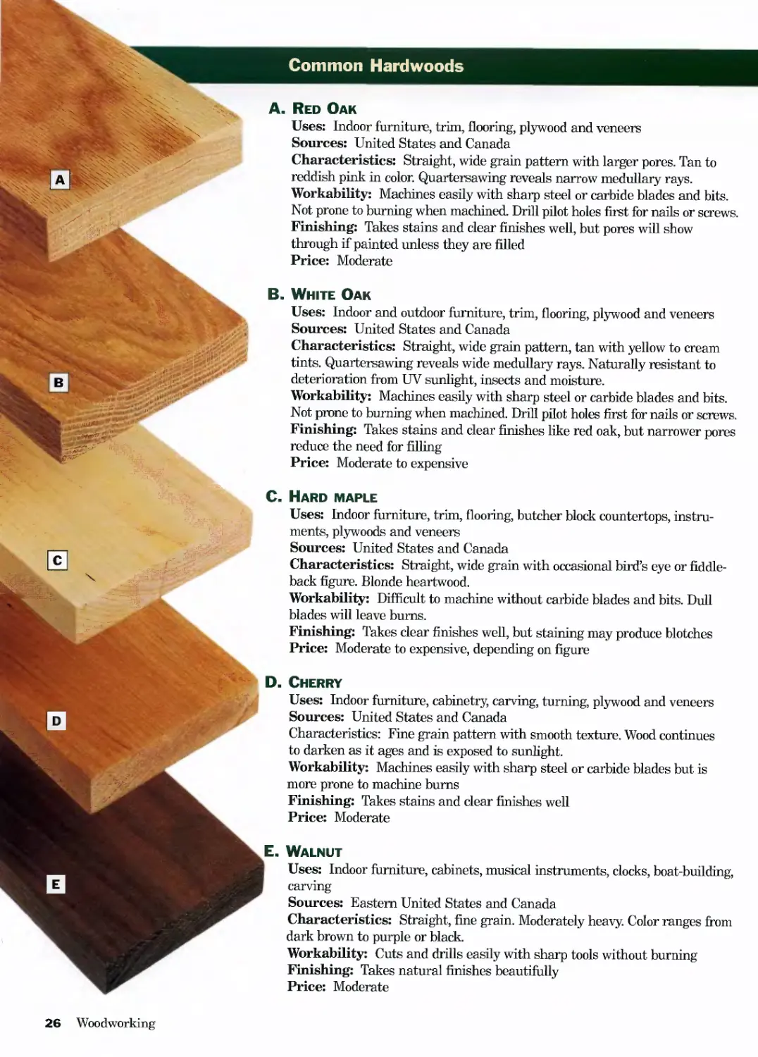
Common Hardwoods
A. Red Oak
Uses: Indoor furniture, trim, flooring, plywood and veneers
Sources: United States and Canada
Characteristics: Straight, wide grain pattern with larger pores. Tan to
reddish pink in color. Quartersawing reveals narrow medullary rays.
Workability: Machines easily with sharp steel or carbide blades and bits.
Not prone to burning when machined. Drill pilot holes first for nails or screws.
Finishing: Takes stains and clear finishes well, but pores will show
through if painted unless they are filled
Price: Moderate
B. White Oak
Uses: Indoor and outdoor furniture, trim, flooring, plywood and veneers
Sources: United States and Canada
Characteristics: Straight, wide grain pattern, tan with yellow to cream
tints. Quartersawing reveals wide medullary rays. Naturally resistant to
deterioration from UV sunlight, insects and moisture.
Workability: Machines easily with sharp steel or carbide blades and bits.
Not prone to burning when machined. Drill pilot holes first for nails or screws.
Finishing: Takes stains and clear finishes like red oak, but narrower pores
reduce the need for filling
Price: Moderate to expensive
C. Hard maple
Uses: Indoor furniture, trim, flooring, butcher block countertops, instru-
ments, plywoods and veneers
Sources: United States and Canada
Characteristics: Straight, wide grain with occasional bird’s eye or fiddle-
back figure. Blonde heartwood.
Workability: Difficult to machine without carbide blades and bits. Dull
blades will leave bums.
Finishing: Takes clear finishes well, but staining may produce blotches
Price: Moderate to expensive, depending on figure
D. Cherry
Uses: Indoor furniture, cabinetry, carving, turning, plywood and veneers
Sources: United States and Canada
Characteristics: Fine grain pattern with smooth texture. Wood continues
to darken as it ages and is exposed to sunlight.
Workability: Machines easily with sharp steel or carbide blades but is
more prone to machine bums
Finishing: Takes stains and clear finishes well
Price: Moderate
E. Walnut
Uses: Indoor furniture, cabinets, musical instruments, clocks, boat-building,
carving
Sources: Eastern United States and Canada
Characteristics: Straight, fine grain. Moderately heavy. Color ranges from
dark brown to purple or black.
Workability: Cuts and drills easily with sharp tools without burning
Finishing: Takes natural finishes beautifully
Price: Moderate
26 Woodworking
General 'Workshop
F. Birch
Uses: Kitchen utensils, toys, dowels, trim, plywood and veneers
Sources: United States and Canada
Characteristics: Straight grain with fine texture and tight pores.
Workability: Machines easily with sharp steel or carbide blades and bits.
Good bending properties. Drill pilot holes first for nails or screws.
Finishing: Takes finishes well, but penetrating wood stains may produce
blotching
Price: Inexpensive to moderate
G. Hickory
Uses: Sporting equipment, handles for striking tools, furniture, plywood
and veneers
Sources: Southeastern United States
Characteristics: Straight to wavy grained with coarse texture. Excellent
shock-resistance.
Workability: Bends well, but lumber hardness will dull steel blades and
bits quickly. Resists machine burning.
Finishing: Takes stains and clear finishes well
Price: Inexpensive where regionally available
H. Aspen
Uses: A secondary wood used for drawer boxes, cleats, runners and other
hidden structural furniture components. Crafts.
Sources: United States and Canada
Characteristics: Indistinguishable, tight grain pattern
Workability: Machines easily with sharp steel or carbide blades and bits.
Finishing: Better suited for painting than staining. Tight grain provides
smooth, paintable surface.
Price: Inexpensive
H
I. White ash
Uses: Furniture, boat oars, baseball bats, handles for striking tools, pool
cues, veneers
Sources: United States and Canada
Characteristics: Straight, wide grain pattern with coarse texture. Hard
and dense with excellent shock-resistance.
Workability: Machines easily with sharp steel or carbide blades and bits. Drill
pilot holes first for nails or screws. “Green” ash often used for steam bending.
Finishing: Takes stains and clear finishes well
Price: Inexpensive
J. Poplar
Uses: Secondary wood for furniture and cabinetry, similar to aspen.
Carving, veneers and pulp for paper.
Sources: United States
Characteristics: Fine-textured with straight, wide grain pattern. Tan to
gray or green in color.
Workability: Machines easily with sharp steel or carbide blades and bits.
Not prone to burning when machined. Drill pilot holes first for nails or screws.
Finishing: Better suited for painting than staining. Tight grain provides
smooth, paintable surface.
Price: Inexpensive
Common Hardwoods 27
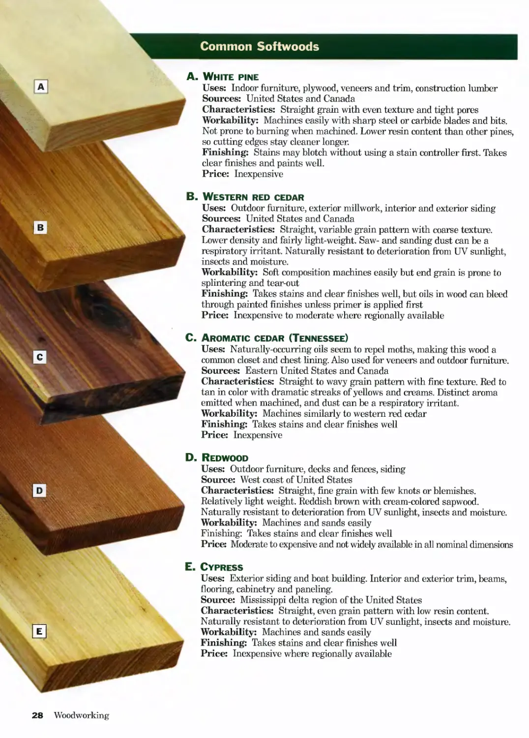
Common Softwoods
A. White pine
Uses: Indoor furniture, plywood, veneers and trim, construction lumber
Sources: United States and Canada
Characteristics: Straight grain with even texture and tight pores
Workability: Machines easily with sharp steel or carbide blades and bits.
Not prone to burning when machined. Lower resin content than other pines,
so cutting edges stay cleaner longer.
Finishing: Stains may blotch without using a stain controller first. Takes
clear finishes and paints well.
Price: Inexpensive
Western red cedar
Uses: Outdoor furniture, exterior millwork, interior and exterior siding
Sources: United States and Canada
Characteristics: Straight, variable grain pattern with coarse texture.
Lower density and fairly light-weight. Saw- and sanding dust can be a
respiratory irritant. Naturally resistant to deterioration from UV sunlight,
insects and moisture.
Workability: Soft composition machines easily but end grain is prone to
splintering and tear-out
Finishing: Takes stains and clear finishes well, but oils in wood can bleed
through painted finishes unless primer is applied first
Price: Inexpensive to moderate where regionally available
Aromatic cedar (Tennessee)
Uses: Naturally-occurring oils seem to repel moths, making this wood a
common closet and chest lining. Also used for veneers and outdoor furniture.
Sources: Eastern United States and Canada
Characteristics: Straight to wavy grain pattern with fine texture. Red to
tan in color with dramatic streaks of yellows and creams. Distinct aroma
emitted when machined, and dust can be a respiratory irritant.
Workability: Machines similarly to western red cedar
Finishing: Takes stains and clear finishes well
Price: Inexpensive
Redwood
Uses: Outdoor furniture, decks and fences, siding
Source: West coast of United States
Characteristics: Straight, fine grain with few knots or blemishes.
Relatively fight weight. Reddish brown with cream-colored sapwood.
Naturally resistant to deterioration from UV sunlight, insects and moisture.
Workability: Machines and sands easily
Finishing: Takes stains and clear finishes well
Price: Moderate to expensive and not widely available in all nominal dimensions
Cypress
Uses: Exterior siding and boat building. Interior and exterior trim, beams,
flooring, cabinetry and paneling.
Source: Mississippi delta region of the United States
Characteristics: Straight, even grain pattern with low resin content.
Naturally resistant to deterioration from UV sunlight, insects and moisture.
Workability: Machines and sands easily
Finishing: Takes stains and clear finishes well
Price: Inexpensive where regionally available
28 Woodworking
General Workshop
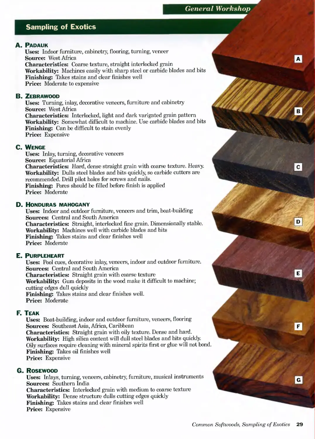
Sampling of Exotics
A. Padauk
Uses: Indoor furniture, cabinetry, flooring, turning, veneer
Source: West Africa
Characteristics: Coarse texture, straight interlocked grain
Workability: Machines easily with sharp steel or carbide blades and bits
Finishing: Takes stains and clear finishes well
Price: Moderate to expensive
B. Zebrawood
Uses: Turning, inlay, decorative veneers, furniture and cabinetry
Source: West Africa
Characteristics: Interlocked, light and dark varigated grain pattern
Workability: Somewhat difficult to machine. Use carbide blades and bits
Finishing: Can be difficult to stain evenly
Price: Expensive
C. Wenge
Uses: Inlay, turning, decorative veneers
Source: Equatorial Africa
Characteristics: Hard, dense straight grain with coarse texture. Heavy.
Workability: Dulls steel blades and bits quickly, so carbide cutters are
recommended. Drill pilot holes for screws and nails.
Finishing: Pores should be filled before finish is applied
Price: Moderate
D. Honduras mahogany
Uses: Indoor and outdoor furniture, veneers and trim, boat-building
Sources: Central and South America
Characteristics: Straight, interlocked fine grain. Dimensionally stable.
Workability: Machines well with carbide blades and bits
Finishing: Takes stains and clear finishes well
Price: Moderate
E. Purpleheart
Uses: Pool cues, decorative inlay, veneers, indoor and outdoor furniture.
Sources: Central and South America
Characteristics: Straight grain with coarse texture
Workability: Gum deposits in the wood make it difficult to machine;
cutting edges dull quickly
Finishing: Takes stains and clear finishes well.
Price: Moderate
F. Teak
Uses: Boat-building, indoor and outdoor furniture, veneers, flooring
Sources: Southeast Asia, Africa, Caribbean
Characteristics: Straight grain with oily texture. Dense and hard.
Workability: High silica content will dull steel blades and bits quickly.
Oily surfaces require cleaning with mineral spirits first or glue will not bond
Finishing: Takes oil finishes well
Price: Expensive
G. Rosewood
Uses: Inlays, turning, veneers, cabinetry, furniture, musical instruments
Sources: Southern India
Characteristics: Interlocked grain with medium to coarse texture
Workability: Dense structure dulls cutting edges quickly
Finishing: Takes stains and clear finishes well
Price: Expensive
Common Softwoods, Sampling of Exotics 29
30 Woodworking
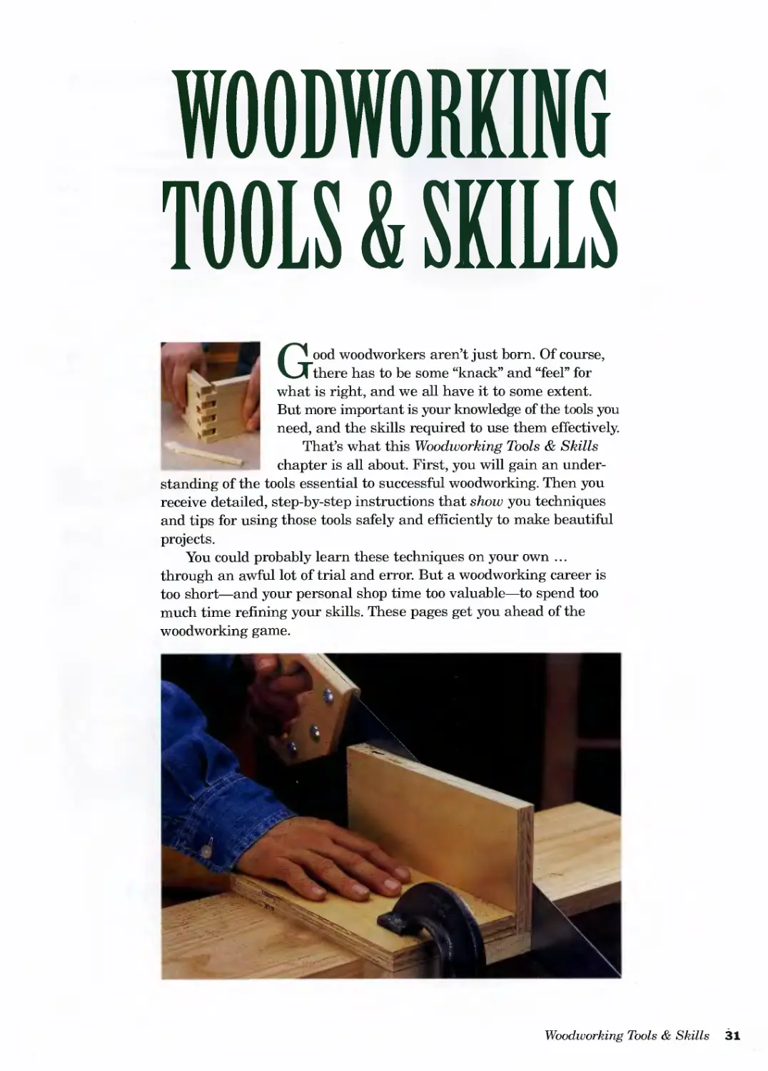
WOODWORKING
TOOLS & SKILLS
Good woodworkers aren’t just bom. Of course,
there has to be some “knack” and “feel” for
what is right, and we all have it to some extent.
But more important is your knowledge of the tools you
need, and the skills required to use them effectively.
That’s what this Woodworking Tools & Skills
chapter is all about. First, you will gain an under-
standing of the tools essential to successful woodworking. Then you
receive detailed, step-by-step instructions that show you techniques
and tips for using those tools safely and efficiently to make beautiful
projects.
You could probably learn these techniques on your own ...
through an awful lot of trial and error. But a woodworking career is
too short—and your personal shop time too valuable—to spend too
much time refining your skills. These pages get you ahead of the
woodworking game.
Woodworking Tools & Skills 31
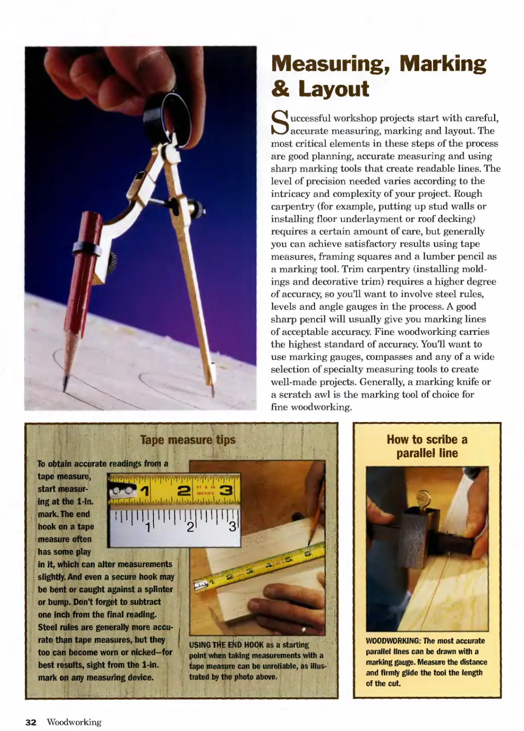
Measuring, Marking
& Layout
Successful workshop projects start with careful,
accurate measuring, marking and layout. The
most critical elements in these steps of the process
are good planning, accurate measuring and using
sharp marking tools that create readable lines. The
level of precision needed varies according to the
intricacy and complexity of your project. Rough
carpentry (for example, putting up stud walls or
installing floor underlayment or roof decking)
requires a certain amount of care, but generally
you can achieve satisfactory results using tape
measures, framing squares and a lumber pencil as
a marking tool. Trim carpentry (installing mold-
ings and decorative trim) requires a higher degree
of accuracy, so you’ll want to involve steel rules,
levels and angle gauges in the process. A good
sharp pencil will usually give you marking lines
of acceptable accuracy. Fine woodworking carries
the highest standard of accuracy. You’ll want to
use marking gauges, compasses and any of a wide
selection of specialty measuring tools to create
well-made projects. Generally, a marking knife or
a scratch awl is the marking tool of choice for
fine woodworking.
i i
I USING THE END HOOK as a starting ’>
point when taking measurements with a
tape measure can be unreliable, as illus-
trated by the photo above.
<1
Tape measuic tips
To obtain accurate readings from a
tape measuic
start measur-
ing at the 1-in.
, mark. The end
hook on a tape
measure often
has some play
in it, which can alter measurements
slightly. And even a secure hook may
be bent or caught against a splinter
or bump. Don’t forget to subtract
one indh from the final reading.
Steel rules are generally more accu-
rate than tape measures, but they
too can become worn or nicked-for
best results, sight from the 1-in.
mark on any measuring device. J
How to scribe a
parallel line
WOODWORKING: The most accurate
parallel lines can be drawn with a
marking gauge. Measure the distance
and firmly glide the tool the length
of the cut.
32 Woodworking
Measuring, Marking & Layout
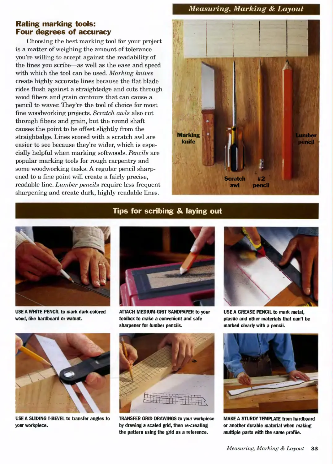
Rating marking tools:
Four degrees of accuracy
Choosing the best marking tool for your project
is a matter of weighing the amount of tolerance
you’re willing to accept against the readability of
the lines you scribe—as well as the ease and speed
with which the tool can be used. Marking knives
create highly accurate lines because the flat blade
rides flush against a straightedge and cuts through
wood fibers and grain contours that can cause a
pencil to waver. They’re the tool of choice for most
fine woodworking projects. Scratch awls also cut
through fibers and grain, but the round shaft
causes the point to be offset slightly from the
straightedge. Lines scored with a scratch awl are
easier to see because they’re wider, which is espe-
cially helpful when marking softwoods. Pencils are
popular marking tools for rough carpentry and
some woodworking tasks. A regular pencil sharp-
ened to a fine point will create a fairly precise,
readable fine. Lumber pencils require less frequent
sharpening and create dark, highly readable lines.
Tips for scribing & laying out
USE A WHITE PENCIL to mark dark-colored
wood, like hardboard or walnut.
АПАСН MEDIUM-GRIT SANDPAPER to your
toolbox to make a convenient and safe
sharpener for lumber pencils.
USE A GREASE PENCIL to mark metal,
plastic and other materials that can’t be
marked clearly with a pencil.
USE A SLIDING T-BEVEL to transfer angles to
your workpiece.
TRANSFER GRID DRAWINGS to your workpiece
by drawing a scaled grid, then re-creating
the pattern using the grid as a reference.
MAKE A STURDY TEMPLATE from hardboard
or another durable material when making
multipie parts with the same profile.
Measuring, Marking & Layout 33
Tricks for measuring & layout
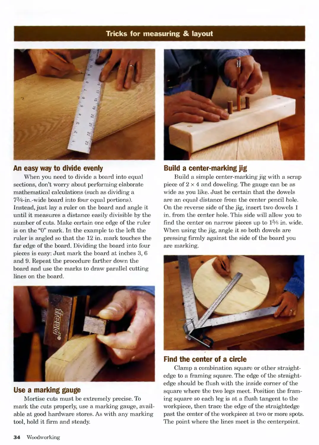
An easy way to divide evenly
When you need to divide a board into equal
sections, don’t worry about performing elaborate
mathematical calculations (such as dividing a
73A-in.-wide board into four equal portions).
Instead, just lay a ruler on the board and angle it
until it measures a distance easily divisible by the
number of cuts. Make certain one edge of the ruler
is on the “0” mark. In the example to the left the
ruler is angled so that the 12 in. mark touches the
far edge of the board. Dividing the board into four
pieces is easy: Just mark the board at inches 3, 6
and 9. Repeat the procedure farther down the
board and use the marks to draw parallel cutting
lines on the board.
Use a marking gauge
Mortise cuts must be extremely precise. To
mark the cuts properly, use a marking gauge, avail-
able at good hardware stores. As with any marking
tool, hold it firm and steady.
Build a center-marking jig
Build a simple center-marking jig with a scrap
piece of 2 x 4 and doweling. The gauge can be as
wide as you like. Just be certain that the dowels
are an equal distance from the center pencil hole.
On the reverse side of the jig, insert two dowels 1
in. from the center hole. This side will allow you to
find the center on narrow pieces up to l5/s in. wide.
When using the jig, angle it so both dowels are
pressing firmly against the side of the board you
are marking.
Find the center of a circle
Clamp a combination square or other straight-
edge to a framing square. The edge of the straight-
edge should be flush with the inside corner of the
square where the two legs meet. Position the fram-
ing square so each leg is at a flush tangent to the
workpiece, then trace the edge of the straightedge
past the center of the workpiece at two or more spots.
The point where the lines meet is the centerpoint.
34 Woodworking
Measuring, Marking & Layout
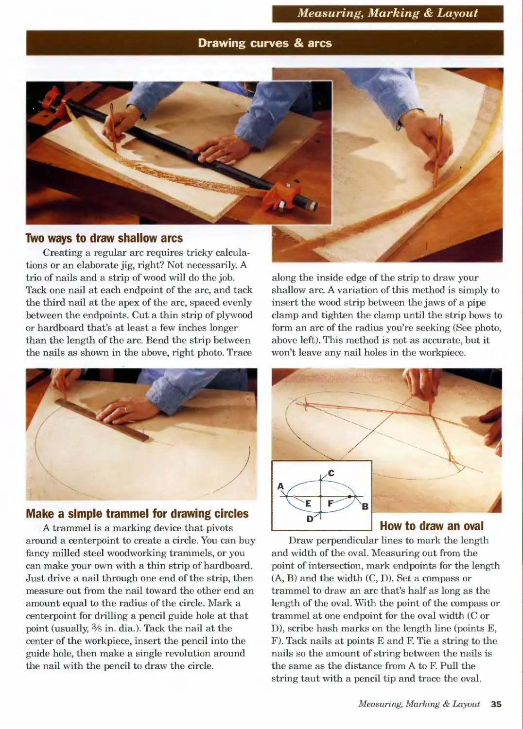
Drawing curves & arcs
Two ways to draw shallow arcs
Creating a regular arc requires tricky calcula-
tions or an elaborate jig, right? Not necessarily. A
trio of nails and a strip of wood will do the job.
Tack one nail at each endpoint of the arc, and tack
the third nail at the apex of the arc, spaced evenly
between the endpoints. Cut a thin strip of plywood
or hardboard that’s at least a few inches longer
than the length of the arc. Bend the strip between
the nails as shown in the above, right photo. Trace
Make a simple trammel for drawing circles
A trammel is a marking device that pivots
around a centerpoint to create a circle. You can buy
fancy milled steel woodworking trammels, or you
can make your own with a thin strip of hardboard.
Just drive a nail through one end of the strip, then
measure out from the nail toward the other end an
amount equal to the radius of the circle. Mark a
centerpoint for drilling a pencil guide hole at that
point (usually, 3/8 in. dia.). Tack the nail at the
center of the workpiece, insert the pencil into the
guide hole, then make a single revolution around
the nail with the pencil to draw the circle.
along the inside edge of the strip to draw your
shallow arc. A variation of this method is simply to
insert the wood strip between the jaws of a pipe
clamp and tighten the clamp until the strip bows to
form an arc of the radius you’re seeking (See photo,
above left). This method is not as accurate, but it
won’t leave any nail holes in the workpiece.
Draw perpendicular lines to mark the length
and width of the oval. Measuring out from the
point of intersection, mark endpoints for the length
(A, B) and the width (C, D). Set a compass or
trammel to draw an arc that’s half as long as the
length of the oval. With the point of the compass or
trammel at one endpoint for the oval width (C or
D), scribe hash marks on the length line (points E,
F). Tack nails at points E and F. Tie a string to the
nails so the amount of string between the nails is
the same as the distance from A to F. Pull the
string taut with a pencil tip and trace the oval.
Measuring, Marking & Layout 35
Cutting
Cutting is a fundamental process that’s critical
to the success of just about any project
you’re likely to undertake in your workshop. It’s
essentially a three-part task: laying out the
cutting line; setting up for the cut; and executing
the cut. Setting up involves choosing the best
tool and blade for the job, then adjusting the
tool or position of the workpiece to ensure an
accurate cut.
There are really only two ways of cutting:
either you apply a tool to the workpiece (as with
most portable and hand tools), or you apply the
workpiece to the tool (as with table saws and other
tools where the cutting instrument remains in one
spot throughout the cut). When applying the tool to
the workpiece, use a combination of straightedges,
cutting guides and clamps to achieve accurate cuts.
When applying the workpiece to the tool, you nor-
mally rely on the built-in fences and scales of the
tool to guide the cut.
The basic types of cuts undertaken in work-
shops include: cross-cutting (making a straight cut
across the grain of a board); rip-cutting (reducing
the width of a board by cutting it lengthwise with
the grain); miter-cutting (cross-cutting at an angle
with the saw blade perpendicular to the workpiece)
and bevel-cutting (making a nonperpendicular cut).
In addition to these basic cuts, this section also
includes information on mortising and cutting non-
wood materials.
Back to the basics:
Make quick & accurate miter cuts
by hand
With the recent explosion in popularity
of the power miter saw, the hand miter
box has become almost a forgotten tool.
But for making a few quick miter cuts,
you may want to revisit this handy and
age-old device. A simple, inexpensive
miter box with precut slots for 45° and
90° can be stored in a tool box or under
your workbench, then clamped in place
in no time at all. And with the precut
slots, no setup time is required. To use
the hand miter box, hold your work-
piece firmly in place, or clamp it in
place, and pull the backsaw in firm,
short strokes.
36 Woodworking
Cutting
Choosing & using handsaws
Guide keeps handsaws in line
This easy-to-build cutting guide will ensure straight,
accurate cuts with a handsaw. Simply join two
pieces of scrap plywood at a right angle, making
sure the heads of the fasteners are recessed.
Add a piece of scrap wood at the front of
the jig to make a lip for holding the jig
tightiy against your workpiece.
Team of handsaws can
handle any cut
Choosing the right tool for the
job is especially important when
using hand-powered tools. The col-
lection of handsaws shown above
can perform just about any cutting
task you’re likely to encounter in
your workshop.
(A) 8- to 10-TPI cross-cut saw
for general cutting of dimension
lumber or sheet goods; (B) Backsaw
for miter-cutting; (C) Hacksaw for
cutting metal; (D) Wallboard saw
for making cutouts in wallboard and
other soft building materials; (E)
Flush-cutting saw for trimming
wood plugs and through tenons; (F)
Dovetail saw (saw shown is smaller
version called “Gentleman’s saw”;
(G) Japanese saw (cuts on the pull
stroke jfor quick trim-carpentry cut-
ting; (H) Fret saw for making deli-
cate scrolling cuts; (I) Coping saw
for curved cuts in trim carpentry.
Cutting 37
Band saw & jig saw blades
Circular saw blades
Standard band
saw blade
Bayonet style
shank (jig saw)
Raker
(rake angle)
Gullet
STRAIGHT BLADES for jig saws, band saws, scroll saws and recipro-
cating saws vary by number of teeth per inch (tpi), the set of the
teeth, the rake angle of the teeth, and the width and thickness of
the blade. The type of metal used to make the blade and the presence
of carbide or other hardened steei tips affect the longevity (and the
price) of the blades. Blades for some tools have numerous tooth
configurations: for example, band saw blades can be purchased with
standard teeth (above), or skip-tooth and hook-tooth configurations.
Reciprocating saw blade types
RECIPROCATING SAWS are
used to perform many different
construction tasks. The size
and shape of the blades used
changes dramatically according
to use. Keep a complete set of
blades in your saw case.
A good set of reciprocating
saw blades includes: (A) 6 in.,
18 tpi blade for heavy metal;
(B) 6 in., 10 tpi blade for general
cutting; (C) 9 in., 6 tpi blade for
fast cuts and genera! roughing
in; (D) 12 in., 8 tpi blade for cut-
ting timbers and other thick
materials; (E) 6 in., 4 tpi blade
for fast, rough wood-cutting; (F)
6 in., 5 tpi blade for fast, cleaner
cuts; (G) 35/s in., 14 tpi blade for
curved cuts in hard woods.
A
G
CIRCULAR SAW BLADES are fitted onto portable circular saws, table
saws, radial-arm saws and power miter saws. Select blades by
matching the number of teeth per inch to the task at hand-but
make sure the tpi number is for the correct blade diameter (any-
where from 3V2 in. to 18 in. or so, with 7V4 in. the
most common for portable circular saws, and
10 in. the most common for table saws,
power miter saws and radial-arm saws).
COMMON CIRCULAR
SAW BLADE STYLES
(right) include:
(A) Genera!
purpose combina-
tion blade (good
for ripping); (B)
Thin-kerf anti-
kickback blade
(note expansion
slots); (C) Roofer’s
biade (for portable
circular saws);
(D) Trim-cutting
blade (for clean,
relatively fast
cross-cuts); (E)
Carbide-tipped
cross-cutting
blade (good for
power miter saws).
Generally, more
teeth per inch
produce cleaner,
slower cuts.
38 Woodworking
Cutting
Saw blade selection chart
Band saw
Task Width (in.) Pitch Style* Set*
Scrollwork, joinery Vs 14 tpi ST AB or R
Cutting iight metal Vs 14 tpi ST W
Tight curves Vs 6 tpi SK AB
Smooth curves 3/i6 10 tpi ST AB
General purpose V4 6-8 tpi ST or SK AB
Rip-cutting V4 4-6 tpi H AB or R
Gen. crosscutting 3/s 8-10 tpi ST or SK AB or R
Fast crosscutting 4 tpi SK AB
Resawing Vi 4 tpi H AB
*Key ST=standard, SK=sklp-too№, H=hook-tooth, AB= alternate-bevei, R=raker,
W=wayy
Jig Saw
Task Material Length Pitch
Fast, rough carpentry Wood 4 in. 6 tpi
General purpose Wood 4 in. 8 tpi
Smooth finish Wood 4 in. 10 tpi
Extra-smooth finish Wood 3 in. 12-14 tpi
Light metai Metai 3 in. 12-14 tpi
Thick metai Metal 3 in. 24 tpi
Circular Saw
Task Type TPI (8V4-in./10-in. dia.)
General purpose Combination 16-36/18-50
Trim carpentry Cross-cut 40-64/60-80
Rough carpentry Cross-cut 34-40/40-60
Smooth cross-cutting Cross-cut 50-64/60-80
Rip-cutting Ripping 16-36/18-24
Plywood and particleboard Plywood/panel 48-64/60-80
Light metai Metai-cutting 58-64/60-72
Scroll Saw
Task Type Gauge Pitch
Genera! cutting Scroiiing #5 15 tpi
Cutting without tear-out Reverse-tooth fret #7 11.5 tpi
Fine scroiiwotk Scroiiing #7 12 tpi
Very tight curves Spirai-tooth #2 41 tpi
East cuts Fret #9 11.5 tpi
Coping base trim for
an mside corner
ICui one mating board square,
and cut the other at a 45°
bevel, using a miter saw. The
beveled board should be slightly
longer than the finished .ength.
2With the square-cut board flush
in the corner, use a coping saw
to trim the excess wood from the
beveled end, leaving an end that’s
perpendicular but tapers up to fol-
low the profile of the molding.
Give your blades a bath
Saw blades that aren’t
performing as well as you
like don’t necessarily need
sharpening: they may just
need a quick cleaning.
Special pitch/resin remov-
ing compound or ordinary
oven cleaner can be used to
clean blades (be sure to
wear gloves).
3Apply the wood finish to both
boards, then slip the bevekd
board into the corner so it overlaps
the end of the square-cut board.
Cutting 39
Cutting with circular saws
Good-side-down for cleaner cuts
Portable circular saws cut on the
upward rotation of the blade. To avoid tear-
out on the better face of your workpiece,
turn it good-face-down when cutting.
Cutting line
Make & use a straightedge
Build an 8-ft. straightedge to cut plywood and
paneling with your circular saw. The straightedge
shown below has a x/4-in. plywood base, and a 1 x 2
cleat (you can also use a strip of plywood) that
serves as a saw guide. After assembling the
straightedge, position the circular saw with the
foot tight against the cleat and trim off the excess
portion of the plywood base. To use the straight-
edge, position the trimmed edge of the plywood
base flush with your cutting line and clamp the
straightedge to the workpiece.
Two techniques for making plunge cuts
USE A JIG SAW: Tip the jig saw forward on the front
edge of its foot. Align the tip of the blade with the
cutting line, then turn on the saw and gently but firmly ’
iower the blade Into the cutting area. The blade wili
want to bounce, but by maintaining firm pressure on
the front of the foot you can keep it under control
untii it enters the wood. <
• 1 ; ' b / ! v » s. i S.
Я > A. , " r-r- .! MU ?... I Ш...'
USE A CIRCULAR SAW: Place the front edge of the foot against the
board, retract the blade guard and hold it in a raised position with your
thumb. Turn on the saw and lower the blade into the wood, using the
front of the saw foot as a fulcrum. Always wear safety goggles.
40 Woodworking
Cutting
Tips for making curved cutouts
Making Curved Cuts
The easiest way to cut smooth, regular curves
on large project parts is to use a cutting tool that
you apply to the workpiece (as opposed to one you
feed the workpiece into). Jig saws and routers are
both well suited for the job. Jig saws are faster to
set up and easy to use, but won’t yield as smooth a
cut as a router. For smaller parts, use a band saw
or scroll saw.
Cutting curves with a jig saw. One of the
best features of the jig saw is its ability to cut
curves, particularly in sheet goods. It has no work-
piece size limitations, its portability makes it
handy for on-site work and such tasks as rounding
corners on large tabletops. Clamp the workpiece
securely and feed the saw slowly to prevent the
blade from deflecting. To start internal cuts, drill
an entry hole with a bit slightly larger than the
width of the saw blade. Circles can be cut freehand
to a line, or if you want a little more exactness you
can use a shop-made or commercial circle-cutting
jig that pivots about a centerpoint.
Tips for cutting curves with a jig saw
USE THE SCROLLING
FEATURE. Scrolling
jig saws feature a
blade-angle adjust-
ment knob at the
top of the handle.
By turning the knob,
you change the
blade direction—
without turning the
body of the saw.
KEEP PRESSURE DIRECTLY
ABOVE THE BLADE. Whether
you’re using a top-handle
saw, like the one above, or
a barrel grip saw, hold the
tool so your hand is forward
and directly above the blade
area. Take care not to force
the saw: the blade will
break or deflect from the
cut line.
Minimum radius cuts
for band saw blades
As a general rule, you should
choose the widest band saw
blade that can handle the job
you're doing. But because the
width of the blade limits the
tightness of the curves you can
cut, you should choose the
widest blade that can follow
your tightest cutting radius.
Path of
saw blade
Blade Smallest
Width Radius Cut
Vs" 3/16"
3/16" 3/8"
l/4" 5/8"
3/8" 11/4"
I/," 3"
ЭД" 5"
1" 8"
Cut a loop to
make a square
Making square
internal cuts can
be a perplexing
problem, but here’s
a simple solution:
cut along one leg of
the square, and
keep cutting past
the corner. Loop the
saw blade back and
cut the second leg.
Gang-cut parts
for consistency
and speed
When making
project parts with
curved lines, gang the
workpieces together
whenever you can.
This will ensure that
the cut edges are
consistent. With most
saws, you can tape the
workpieces together
with double-edged
carpet tape.
Relief cuts pre-
vent binding
When making
a curved contour
cut using a jig saw,
band saw or scroll
saw, make relief
cuts from the edge
of the workpiece to
the cutting line, in
the waste area, so
waste can be re-
moved as you cut.
Cutting 41
Cut perfect circles with a router compass
Most handymen think of routers as primarily
tools for cutting decora tive profiles or perhaps an
occasional dado or rabbet. But they can also be
very effective tools for cutting stock to size and
shape. When the right bits and techniques are used,
they produce extremely clean edges that often
require no sanding.
If you need to cut a square workpiece into
a circular shape, a router compass is an excellent
choice. Simply secure the router base to the
wide end of the compass, set the adjustable
center pin to the desired radius of the cut, and
secure the pin at the center of the circle. For
best results, make the cut in several passes of
increasing depth. A single-flute straight bit or
a spiral upcut bit can be used to remove large
amounts of waste in the cutting area, without
bogging down.
Tips for cutting with a power miter box
Stopblock speeds up repetitive cuts
When making repetitive cuts with a power
miter saw (or radial-arm saw), clamp a stopblock
to the saw fence at the desired length. A lag screw
driven squarely into the edge of the stopblock
creates a solid surface for aligning the workpiece,
while keeping wood chips from building up
between the block and workpiece.
Jig takes the math out of beveling molding
Cutting miter-bevels in crown molding often
involves tricky math and very precise angles. To
simplify the task, use this jig. Join a straight board
about 3 in. high to a strip of Win. plywood about
6 in. wide. These will be the “fence” and “table” of
the jig. Place a piece of crown molding into the “L”
formed by the fence and table, and adjust it until
the beveled sides are flush against the fence and
table. Mark the position on the table, remove the
molding and attach a wood strip at the mark. This
strip will hold the molding at the proper angle for
bevel-cutting miters.
42 Woodworking
Cutting
Proper setup is key to safe cutting with
radial-arm saw
Over the years the radial-arm saw has earned
a reputation as one of the most dangerous work-
shop tools. But for most cross-cutting operations,
the tool can be a real workhorse that’s as safe as
any other tool you own. The most important aspect
of cutting safely with a radial-arm saw is to secure
your workpiece, while keeping your hands well
clear of the saw blade. A pushstick with a birdseye
cutout is a good choice for bracing smaller work-
pieces against the saw fence—it’s particularly
effective when used in conjunction with a stopblock
that holds the free end of the workpiece in place.
Once the workpiece is secure, start the saw and
guide it through the cut with your right hand. Shut
off the saw and allow the blade to stop spinning
before removing the workpiece and returning the
saw carriage back behind the fence.
Resawing stock on a band saw
Resawing jig for band saw
Height =
saw
throat
capacity
minus
1 to 2 in.
н 1
Pivot
/point
5 to 8 in.
* •-’ :—'—:——n
RESAWING THICK LUMBER into thinner strips for wooo-
working is a job best accomplished with a bancj saw. The
simplest method is tc attach a fence to the band saw
table, parallel to the blade, and feed the stock through as
you would when rip cutting on a band saw. The downside
to this method is that the saw blade tends to travel,
following the grain of the wood, and resulting in an
uneven cut that requires quite a bit, of surface pianing.
One way to minimize the unevenness of the resaw cut is
i 1 I H
to use a jig like tfye one shown to the left. When clan.ped
to the saw table so the pivot point is even with the cutting
edge of the blade, the jig may be used as a guide to set-
the thickness of the cut. Because the pivot point is so .
narrow, you can adjust the feed direction of the board to
compensate for blade travel, resulting in a more even cut
You’ll still need to surface-plane the uorknlece, but you’l
waste less wood. '
I ’ • <*l id
- I 1
...... , V , h. .. ’
Cutting 43
Tips & techniques for using your table saw
Relief block keeps cutoff
pieces free and clear
when cross-cutting
Use a relief block to pre-
vent cutoff pieces from getting
jammed between the fence
and the blade when cross-
cutting on the table saw. The
relief block can simply be a
piece of scrap wood clamped
to the fence. Make sure the
relief block is positioned
behind the point where the
workpiece will make first con-
tact with the saw blade. Never
stand directly behind the
workpiece when feeding it
into the blade.
As a rule, take measurements
Don’t trust the cutting scale on the table saw
fence if you’re making precise cuts. Instead, measure
the distance from the cutting edge of the blade to
the fence with a steel rule when setting up for
your cut. Double-check the distance after securing
the fence, and make a practice cut on scrap for
added precision.
Get blade height just right
Use a combination square to set the height of a
table saw blade. The bottom of the square should
just be touching the tip of one of the teeth. Because
tooth length is not always uniform, spin the blade
by hand and make sure you’re referencing off the
tooth that will cut deepest (be sure to unplug the
saw first).
44 Woodworking
Shop vac blows cutoff pieces clear
Small cutoff pieces have a way of kicking out
of the saw throat or becoming jammed around the
blade. One way to keep these annoying trim
pieces out of your way is simply to position your
shop vac hose near the cutting area to blow clear
small cutoff pieces. Be sure to leave ample clear-
ance for the workpiece.
Add miter-gauge hold-down for quick,
accurate miter cutting
Make your miter gauge more reliable by
adding a hold-down clamp to keep workpieces
steady during miter cutting. Hold-downs are sold
at most larger tool centers or may be purchased
directly from the company that manufactured
your table saw.
Wood fences make good sense
Adding a wooden auxiliary fence to your table saw
(or just about any other tool) extends the life of both
your saw fence and your saw blades by eliminating
damaging metal-to-metal contact. An auxiliary fence
that’s taller than the saw fence also creates a good
surface for clamping jigs, stopblocks and hold-downs.
The fence shown here is made from hard maple and
attached to the metal fence with T-bolts that fit into
a slot in the saw fence so no screw heads protrude.
Reverse the miter gauge for panel cutting
Sheet goods and glued-up panels are often too
wide to be fed into the blade with the saw’s miter
gauge. You can solve this problem by turning the
gauge around so the head of the gauge is fed into
the miter-gauge slot first. Attach an auxiliary fence
to the miter gauge to create a more stable surface
for pressing against. You can also use a miter-
gauge hold-down (See photo at top of page) to keep
the panel steady.
Tips & Techniques for Using Your Table Saw 45
Sweet cheeks for tenons
Making the cheek cuts for
tenons is clumsy and dangerous
without a good tenoning jig—and
the results are usually disap-
pointing. This shop-built tenon-
ing jig is easy to make from
scrap wood and will help you
produce tenons that fit on the
first try. First, cut the vertical
and horizontal members—the
horizontal member should have
a contour on the tail to create a
handle, as shown above. Join the
two members with wood screws,
arranged so the distance from
the bottom of the horizontal
member to the bottom of the
vertical member is equal to the
height of your saw fence. Make
sure the members are exactly
perpendicular. To use the jig,
clamp your workpiece to the jig
and feed the workpiece into the
blade, keeping steady pressure
against the fence and the table
(See photo, above right). Cut all
the way through the workpiece
and the jig. Always test your
cuts on a scrap board before
cutting your workpieces. Use
your miter gauge to guide the
workpiece when cutting the
tenon shoulders.
Trim wedge and dowel
ends with a flush-
cutting saw
A flush-cutting saw with a very
flexible blade is the ideal tool for
trimming off the ends of tenon
wedges or dowels. The saw shown
above is a Japanese saw that
cuts on the pull stroke.
The“poor man’s
mortising machine”
There are many methods you can
use to cut mortises for mortise
and-tenon joinery. The best way is
to purchase a special mortising
machine or a mortising attachment
for your drill press. But if you’d
rather not spend the money on
these expensive tools, the following
method will produce clean mortises
when done carefully. It’s a little
slower and takes some trial and
error, but for the weekend wood-
worker who already owns a drill
press, ft’s a good option.
i •
1 Carefully lay out your mortise using a
marking gauge or straightedge.
Choose a drill bit the same diameter as
the thicknesc of the mortise (3/s in. is
common), then remove the waste wood
from the mortise by drilling overlapping
holes «sing я depth stop.
2 Use a sharp chisel to clean up the
sides of the mortise so they're fiat
and smooth. Make sure the flat face of
the chlsei is contacting the wood.
Clean iip the ends of the mortise with a
chisel the same width as the thickness
of the mortise.
46 Woodworking
Cutting
A treat for steel tabletops
Apply rubbing or polishing compound to steel
tabletops to smooth out the surface and remove rust.
Then, wipe the top clean and apply a coat of car wax
to seal the table and keep workpieces sliding smoothly.
Create custom throat plates
When making trim cuts or
cutting small workpieces, cover
the throat opening of your saw by
laying a piece of thin plywood over
the throat and raising the spinning
saw blade. Use a piece of scrap
wood to hold the plywood down.
Increase your cutting angle
To make cuts with an angle
greater than the maximum tilt of
your saw blade, attach a spacer to
your saw fence or to the workpiece.
Handy jig for
cutting tapers
An adjustable taper
jig is a handy acces-
sory for any table saw
owner. The legs of the
jig can be set to cut
tapers according to
angle or to slope.
Cutting laminate
Before cutting laminate on
your table saw, attach an auxiliary
fence that’s flush with the table-
top so the laminate won’t slide or
wedge under the fence. A special
laminate cutting blade (right)
prevents chipping of the surface.
Laminate cutting blade:
beveled teeth score surface
of laminate to prevent chip-
out from cutting
teeth
Tips & Techniques for Using Your Table Saw 47
Cutting with wood chisels
Cabinetmaker’s chisels
Most of the wood chisels sold and
owned today are bevel-edge cabinet-
maker’s chisels (See photo, left).
Available in standard widths ranging
from A to lx/2 in., they can handle a
variety of everyday cutting tasks,
including cutting mortises and paring
tenons. If you’re a serious woodworker
who appreciates hand tools, you may
want to look into a set of mortising
chisels, which have thicker shanks
and wider, shock-resistant handle butts.
Better quality chisels are made with
hardened steel that hold an edge for a
long time. The main differences are in
handle material, size and feel. If in-
vesting in a set of quality chisels, make
sure the ones you choose feel comfort-
able and well balanced in your hand.
How to sharpen chisels
1 Grind off any nicks using a bench grinder with a
medium-grit wheel (or a coarse-grit sharpening
stone). Hold the tool on the flat portion of the tool rest,
with the beveled side facing up. Hold the tip against the
wheel and move it from side to side, keeping the cutting
edge square. Cool the blade frequently with water to keep
it from losing Its temper. When all nicks are gone, turn the
blade so the cutting edge Is down. Adjust the tool rest so
the blade touches the grinding wheel at a 25° bevel.
Move the blade from side to side, keeping the blade at a
25° bevel. Continue to cool the blade regularly.
2 Place a few drops of light machine oil on a fine-grit
sharpening stone. Place the back of the blade on the
whetstone and draw it back and forth several times to
remove any burrs.
3Wlpe the stone with a clean rag, and apply more oil.
Turn the blade over, and hold it at a 25° angle so the
bevel Is flat against the stone. Draw the tool back and
forth. Here, a bevel guide Is used for a precise edge angle.
4Put a micro-edge on the blade by lifting It slightly so
just the tip touches the stone. Draw the blade lightly
two or three times along the stone, until a slight burr can
be felt along the back of the blade. Turn the blade over,
hold it flat (as In step 2) and draw It one time along the
stone to remove the burr. Done properly, this will give the
chisel a razor-sharp edge.
48 Woodworking
The right way to cut hinge mortises
Installing hinges (or strike plates) is a
frequently encountered task for the handyman,
and as often as not we rely on the trial-and-error
method—with mixed results. Here’s the best
way to cut a hinge mortise.
1 Remove the hinge pin (if its removable) and position the hinge
leaf or strike plate on the edge of the door or on the door jamb.
Tack it into place with screws, then score an outline around the
plate with a utility knife. This prevents the wood from splintering
past the ends of the mortise.
2 Choose a chisel that’s close to the same width as the mortise.
With the beveled side of the chisel facing toward the mortise,
tap the butt of the chisel handle with a wood or rubber mallet. Cut
Into the wood to a depth equal to the thickness of the hinge leaf or
strike plate. Cut along all sides of four-sided mortises.
3Wlth the beveled edge of the chisel tip flat against the work-
piece, make a series of relief cuts In the waste wood area of the
mortise. Space the cuts Vs to V4 In. apart (make closer cuts In
harder woods). The cuts should be equal in depth to the finished
depth of the mortise.
4Clean out the waste wood by driving the chisel against the direc-
tion of the relief cuts.To avoid digging in too deep, try to keep
the beveled edge of the tip flat in the mortise. Scrape the bottom of
the mortise smooth. If you need to deepen the mortise, repeat the
procedure—don’t simply try to make deeper scraping cuts.
Cutting with Wood Chisels 49
Cutting Project Parts
Cutting parts to size usually involves making
several different types of cuts with multiple tools.
In this section we’ve described most of the standard
cutting operations you’re likely to encounter while
woodworking. For each operation we’ve suggested
what we believe to be the best method, as well as a
few alternatives that can get the job done adequately
if you don’t own the suggested tool.
The essential cuts you’ll make time and again
are rips cuts (for width) and cross cuts (for length).
As your skills advance and the complexity of the
projects you undertake increases, you’ll also need
to make miter and bevel cuts, tapers, curved cuts,
pattern-following cuts, edge-profile cuts and resaw-
ing stock for thickness.
All of these cuts can be made with portable
hand tools. But you’ll generally get faster, more
accurate results with stationary sawing tools. Of
these, the table saw and the power miter saw are
the most versatile. A band saw and a scroll saw
are also valuable additions as you develop your
workshop.
Types of cuts
Tools for cutting parts
A CIRCULAR SAW and straightedge cutting
guide can be used for cross cuts, rip cuts,
bevel cuts and miter cuts.
THE VERSATILE JIG SAW (also called a saber
saw) Is capable of making any cut. It excels
at cutting curves and making Interior
cutouts.
A POWER MITER SAW is perfect for making
repetitive cross cuts, including mitered or
beveled cuts (bevels require a compound
miter saw).
SO Woodworking
Cutting
A TABLE SAW is the most heavily used too!
in most woodshops. It can make just about
any straight cut, inciuding bevels and
miters.
A ROUTER is used to make dadoes and rab-
bets as well as edge profiles. With special
bits and accessories it can also be used for
pattern cutting, circle cutting and many
other cutting tasks.
A SCROLL SAW is a favorite tool for cutting
intricate curves and patterns. They are not
powerful but are relatively easy to manage.
Cutting Project Parts 51
Making Rip Cuts
The process of rip-cutting is
often referred to as cutting par-
allel to or parallel with the grain.
While this is true for solid wood,
you’ll often find yourself ripping
plywood across the surface grain.
So it’s perhaps better to think
of rip-cutting as the process of
cutting stock to width.
Rip-cutting
with a table saw
The table saw is certainly the
most convenient and most accu-
rate machine for ripping lumber
and sheet goods. Make sure the
rip fence is adjusted so it’s par-
allel to the blade and at a right
angle to the table. Squaring up
the fence can be tricky with the
often-flimsy fences that come with
some table saws. That’s why you
may want to consider seriously
investing in after-market cali-
brated fences that are sturdy,
adjustable, and accurate. Many
new saws now come equipped
Ripping boards to width shouid be done after one edge has been squared (see previous sec-
tion) so a fiat even surface can ride against the saw fence or be used to register your
straightedge for making rip cuts with hand-heid toois.
with a higher-end rip fence.
Table saws also come equipped
with a number of safety features
to reduce the hazards of rip cut-
ting. In addition to the blade guard,
the riving knife with antikick-
back pawls behind the blade pre-
vent kickback when ripping boards.
Making rip cuts. (See pho-
tos, next page.) Set the rip fence
so the distance between its inner
face and the teeth of your saw
How to rip various materials with a table saw
LONG BOARDS: When ripping iong boards, tip the
back edge of the board up so it is siightly higher than
the saw tabie. Doing this wiii press the leading edge
of the board firmiy down on the saw tabie. Lower the
back edge of the board as the cut progresses.
SHEET GOODS: Fuii sheets of piywood, particleboard and other sheet goods
can be ripped effectiveiy on a tabie saw if you position a sturdy tabie on the
outfeed side of the saw, at or just beiow the saw tabie surface. But many
woodworkers prefer to cut the sheets down to size with a circular saw or panel-
cutting saw first.
52 Woodworking
Cutting
1 Start rip cuts with your left foot
ag^nst the front left corner of the
saw base, feed the workpiece with your
right hand, and use your ieft hand to
keep the workpiece snug against the rip
fence. Use a pushstick whenever a work-
piece requires your hand to be closer
than 6 in. to the blade.
2Ccntinue feeding the workpiece
through the blade with your right hand
as the end of the board approaches the
front edge of the saw table. Switch to a
pushstick in your right hand if necessary.
Keep your ieft hand en the infeed side of
the blade at all times.
3When the biade cuts the board in
two, push the workpiece past the
biade и ith your right hand until it ciears
the blade on the outfeed side. Slide the
cutoff piece away from the blade with *
your left hand or a pushstick to prevent
it from coming in contact with the blade.-
blade is equal to the width you’re
after for your workpiece. Use a
steel rule to set the distance,
rather than relying on the cali-
bration marks on the front of the
table. Once the blade is positioned
correctly, lock the fence in posi-
tion with the locking handle. Set
NARROW STRIPS: When rip-cutting a single narrow workpiece from a wider board, the nar-
row strip should be on the opposite side of the biade from the rip fence (ieft photo). This
keeps the wider portion of the board between the biade and the rip fence to aiiow more
room for your hand or a pushstick. To rip a series of narrow workpieces, set the distance
between the biade and the rip fence to match the intended width of the workpieces you
need. Use a narrow pushstick to guide the pieces aiong the rip fence (right photo).
the blade height so it extends no
more than about U? in. above the
surface of your workpiece. Stand
slightly to one side of the blade,
not directly behind it so you’re
out of the line of fire in the event
a board gets thrown back. Push
the board with your right hand
while guiding it firmly against
the fence with your left. Maintain
firm control of the workpiece
throughout the cut until it is
well past the blade. Then turn
off the saw and walk around to
the back of the machine to retrieve
the board. Always make a test cut
on scrap wood before cutting your
stock. Measure the scrap to make
sure it is exactly the right width.
One key point to remember
is to never let your fingers get
closer than about 6 inches from
the blade. Never let .your hands
get directly behind the blade or
they could get pulled into it in
the event of kickback.
To rip a narrow board, use a
push stick rather than .your hand
to feed the board. A featherboard
clamped to the saw table will press
the stock against the fence and
allow you to keep your left hand
away from the blade. Hold downs
can be clamped to the rip fence
to prevent the stock from bouncing
or chattering as you feed it
through the blade. Make sure
featherboards and hold downs
are not pressed too tightly
against the stock.
Rip Cuts 53
Rip-cutting with a circular saw
While it won’t give you quite the precise, clean
cuts of a table saw, a circular saw with the right
blade can do a fairly good job of rip-cutting on non-
critical work. Its portability makes it ideal for
on-site construction.
Ripping a straight line with a circular saw
requires the use of a cutting guide. Most saws
come with an adjustable ripping fence that
attaches to the base plate. This is used for ripping
fairly narrow strips parallel to an edge, particu-
larly on boards too narrow to be ripped with a
straightedge guide. The accuracy of the adjustable
THE PORTABLE CIRCULAR SAW is a handy tool for ripping
sheet goods and larger stock down to a manageable width, but
isn’t well equipped for fine woodworking cuts.
OFFSET CUTTING GUIDES: A long straightedge
guide with a built-in offset can be made with
two pieces of scrap from your shop. You’ll
need a strip of hardboard or plywood (V4 in.
works well) that’s at least 12 in. wide and
preferably 8 ft. long. Tack a piece of straight
scrap wood (a 2 x 4 or a narrow strip of
3/4 in. plywood will work) to the hardboard so
the scrap is paraiiei with the hardboard or
aligns with one of its edges. Orient the scrap
and hardboard so there is an offset that is
slightly longer than the distance from the
edge of the saw foot to the blade. Then, simply
trim off the edge of the hardboard with the saw
foot riding against the scrap “fence.” Ciamp
the guide to your workpiece so the trimmed
plywood edge aligns with your cutting line.
STRAIGHTEDGE CUT-
TING GUIDE: With
the help of a good
straightedge you can
use your circular saw
to make rip cuts that
are nearly as accu-
rate as those made
on a table saw. You
can purchase a
straightedge, like the
extruded aluminum
model shown above,
or select a piece of
stock (a strip of par-
ticleboard, for exam-
ple) that’s straight,
smooth-edged and
even.
ADJUSTABLE RIPPING FENCE: Most circular saws come with an
adjustable ripping fence that attaches to the foot of the saw. The
fence rides along the edge of the board to guide the saw so it cuts
a line paraiiei to the board edge. These accessories are fine for rip
cuts that don't demand a high ievei of accuracy.
54 Woodworking
Cutting
ripping fence can be improved by screwing a
wooden batten to it to extend its bearing surface.
The best way to guide the saw in a rip cut is to
clamp a straightedge guide to the workpiece and
run the edge of the saw’s base plate (foot) against
it. This guide can be store-bought or shop-made,
but must be long enough to overhang the work-
piece on both ends.
Determining the offset. The “offset” of your
saw is the distance from the edge of the foot that
will ride along a straightedge to the closer edge of
the cutting blade. To use the saw with a straight-
edge guide you’ll need to know this distance. To
find it, simply clamp a straightedge to a piece of
scrap and make a cut, following the straightedge.
Measure from the edge of the kerf to the straight-
edge: this is the distance your straightedge must
be clamped from the cutting line on your work-
piece. Or, you can make a guide with a built-in
offset (See photo, page 54, middle).
TIP: When making long rip cuts, stop the cut
periodically and slip wood shims into the kerf you’ve
cut. This will prevent the kerf from closing up and
causing the saw blade to be pinched in the cut (which
can bog down the blade or even throw the saw).
Rip-cutting with a band saw or jig saw
Both the jig saw and the band saw
are quite capabie of making straight
cuts, but you can’t expect either to
produce finish cuts. Whiie a table saw
can ieave a dead-accurate cut with a
surface that requires only light sand-
ing, a jig saw or band saw cut is rippled
and its blade has a tendency to wander.
So if you’re going to do your ripping
and cross cutting this way, you’ll have
to clean up the sawn surfaces with a
hand plane or use a router with a
piloted flush-cut bit
Uniike table saw cuts, jig saw and
band saw rip cuts can be made free-
hand, following a scribed line. This
can be a real advantage when making
a rip cut that is not precisely paraiiei
to the edge of the board or perhaps
even has a slight turn or curve to it.
You can also make straight rip cuts
with these tools if you choose, using a
straightedge guide with the jig saw or
a guide or fence with the band saw.
Some jig saws come with an adjustable
side fence, similar to that on a circular
saw, for making narrow cuts paraiiei to
an edge.
When ripping with a jig saw, choose
a thicker blade (less prone to flexing)
with a relatively iow number of teeth
per inch. The bandsaw should be fitted
with a wide pA in. or wider) skip-tooth
biade.
RIP-CUTTiNG WITH A JIG SAW: One advantage to using a jig saw to make rip cuts is
that it’s easy to set up a straightedge and make a cut that's not paraiiei to the edge
of the board. Be sure the guide is set to aiiow for the offset between the saw foot
and biade.
RIP-CUTTING WITH A
BAND SAW: Like jig
saws, a band saw
can make “rip” cuts
that generaiiy foiiow
the grain of the wood
but aren’t necessar-
ily straight or parai-
iei to the edge of the
board. You can aiso
make “true” rip cuts
that are parallel to
the edge using the
fence that comes
with most bandsaws.
The edges of the cut
won’t be as sharp as
a table saw cut, how-
ever.
Rip Cuts 55
Joinery: ? ,! , ,
Casework vs. Furniture making
Woodworking joinery tails into two major cpt'igories-
casework and furnituremaking. Each is defined by its
materials, structure and aesthetics. Whiie there is cer-
tainly some crossover between the categories,, if you’re
trying to determine which joints to employ for your
J project, making the casework/furniture distinction is a
:; useful starting point.
Typically, sheet goods are used for casework (boxes
and cabi* ets). Butt joints reinforced with screws, biscuits,
( dowels, splines or pocket screws are common, although
rabbet and dado joints come in handy as well. A furniture-
maker works mostly in hardwood with structures that depend
on small, fitted joints, like dovetails, mortises and half-
laps that need to be both strong and, pleasing to the eye.
56 Woodworking
Wood Joinery
Wood Joinery 57
Butt joints
Butt joints are the simplest woodworking
joints to cut and build. And when used in the right
applications, they are quick to assemble and plenty
strong. A butt joint is formed when two workpieces
are butted together face-to-face, end-to-end, edge-
to-edge or any combination of these surfaces.
Unlike other types of joints, the mating surfaces of
a butt joint are left flat and smooth, without any
additional machining. Because the mating parts do
not interlock, butt joints in woodworking situations
are inherently weaker than other styles and are
best left for joining parts that don’t need to move
or support great amounts of weight.
Modern woodworking glues form incredibly
strong joints—on a properly made joint, the sur-
rounding wood fibers will break before the glue
joint fails. But glue alone won’t save a butt joint
subjected to excessive twisting, pulling or shearing
forces. If you choose to use butt joints, it’s often a
good idea to reinforce the joint with nails, screws
or biscuits where it will be subjected to tension or
racking stresses. Nails, dowels, splines, screws or
bolts will strengthen a butt joint that must
carry a load, preventing it from failing due to
shear. Pocket screws and mechanical “knock-down”
fasteners have become popular reinforcing options
in recent years.
Butt joints are used for edge-gluing individual
boards together to form wide panels such as table-
A BUTT JOINT can be used in just about any woodworking situation.
If it wiii undergo stress or pressure, it’s a good idea to reinforce the
giued butt joint with a fastener, such as a screw.
tops, carcases, workbench and “butcher-block” sur-
faces and cutting boards. Edge-glued butt joints
are stronger than other butt joint configurations
because the boards are joined lengthwise, along
the grain (called long-grain). Long-grain gluing
provides plenty of surface area for glue along the
joint, and because the wood pores run parallel to
the joint instead of across it, the boards can expand
and contract evenly across the grain as tempera-
ture and humidity fluctuate. Plus, long grain soaks
up just enough glue to hold the joint tightly.
FINISH NAILS are easy fasteners to use for
reinforcing butt joints. Drill a pilot hole for
each naii before driving it. Set the naii head
below the wood surface with a correctly-
sized nail set.
Reinforcement options
DIAGONAL GLUE BLOCKS can be glued
beneath a butt joint for additional support.
Use them with or without additional fasten-
ers in the joint. The blocks are attached
with glue only.
WOOD SCREWS are popular fasteners for
reinforcing butt joints. They should be
driven into counterbored or countersunk
pilot holes.
58 Woodworking
Wood Joinery
Countersinking & counterboring
A COUNTERBORE HOLE has a cylindrical top intended to accept a
wood screw plug; a countersink hoie has a beveied top just deepiy
enough for the screw head to be driven beiow the wood surface,
creating a smail recess to be filled with wood putty.
The 2/3 rule
Follow the two-thirds
ruie: Screws should
be driven through
the thinner work-
piece first, whenever
possible. The iower
two-thirds of the
screw should end up
in the lower board
after the screw has
been driven.
Plugging a counterbore
IUse a counterbore bit to counterbore the pilot hoie for
the screw (3/s in. is the standard counterbore diameter).
2 Drive the screw, then apply glue to the end of a wood
plug and insert it into the counterbore hoie.
A COUNTERBORE BIT can drill
a pilot hoie, shank hoie and
counterbore hoie ail at the
same time.
A COUNTERSINK BIT reams out
the top of a pilot hole with a
bevel that allows the screw
head to be recessed.
3Trim the plug with a chisel, flush-cut saw or rasp, then
sand the plug until it's even with the wood surface.
Butt Joints 59
Biscuit-reinforced butt joints
Biscuit joiners (sometimes called plate joiners)
are single-purpose tools designed to do just one
thing: cut matching semicircular slots that accept
football-shaped biscuits used to reinforce butt
joints. In general, you’ll find that enforcing with
biscuits creates a stronger joint than using dowels
or most other conventional fasteners. In addition
to reinforcing joints, biscuits also give you a near-
foolproof method for aligning mating parts.
Biscuits, which lock the joint together, are
football-shaped disks made of compressed wood.
When they come into contact with wet glue, the
moisture expands them into the slots, tightening
the joint. They come in several standard sizes (#0,
which is % in. x 114 in.; #10, which is % in. x 21 */&
in.; and #20, which is 1 in. x 23/s in.) to cover a
range of joint applications.
Before making a cut with a biscuit joiner,
make sure that the workpiece is secured to your
worksurface. To keep the tool itself from slipping,
most have an anti-slip device (either a rubber
tip or a metal point) to help maintain the grip on
the wood.
A BISCUIT JOINT is a reinforced butt joint used mostly in casework
projects. Made with the use of a biscuit joiner (aiso caiied a plate
joiner) biscuit joints are quick and easy to make, in addition to
reinforcing butt joints in face frames, they are frequently employed
to heip align and reinforce joints when edge-gluing panels from
narrower stock or butting sheet goods together to form a carcase.
How to edge-glue a panel with biscuits
1 Arrange the jointed boards together
to get the most pleasing match of the
different grain patterns. This can take some
trial and error. Tip: aiternate the direction
of the growth rings at the ends of the
boards. This helps keep the pane! from
cupping. Once you’ve got aii the boards
arranged to your satisfaction, draw a “V”
across aii joints in the pane!. Use the legs
of the “V” to maintain your alignment as
you glue-up the panel.
2 Once the boards are laid out and
marked, place them in position and
mark the biscuit iocations. Use a square to
mark aii mating edges to ensure that the
siots align. Biscuits should be spaced about
8 to 10 in. apart, with a biscuit about 2 in.
in from each end. After marking biscuit
iocations, cut the siots by aligning your
marks with the permanent mark on the
biscuit joiner.
3 Apply glue to one edge of each board
to be joined, then squeeze giue into
the siots. Commerciai giue applicators that
reach into the siots are avaiiabie, or you
can simpiy squeeze the giue in with a regu-
lar giue bottie and spread the giue with a
popsicie stick. Add the biscuits to the siots
on one board, if edge-gluing more than one
board at a time, apply the giue and insert
the biscuits in every board. Now you're
ready to ciamp the assembly.
60 Woodworking
Wood Joinery
How to flatten a board on a joiner
Standard biscuit sizes
(shown actual size)
A BISCUIT JOINER consists of a small circular saw
blade (about 4 in. dia.) mounted at a right angle
to the motor shaft at the front of the tool. The
blade Is enclosed in a spring-loaded housing
plunging the tool into the workpiece exposes a
portion of the blade, which cuts a semicircular slot in
each of the mating wood pieces. Into each pair of slots,
you glue a flat, football-shaped biscuit. The biscuit swells as
the glue hardens, creating a tight, secure joint.
Reference marks on the tool face and an adjustable fence
enable you to accurately locate the biscuit slots In mating surfaces.
Most biscuit joiners have a
three-position depth of cut
adjustment that enables you
to cut slots to the correct
depth and length for standard-size
biscuits. After cutting matching slots in the
pieces to be joined, you glue the slightly undersized
biscuits Into the slots.
How to reinforce a right-angle butt joint with biscuits
ILay out the position of the two mating
parts using a square (note whether
you're marking the top or bottom of the
workpiece). Set the mating workpiece in
position against the mark. Draw a perpen-
dicular reference line on both workpieces
at each biscuit location. With the work-
pieces clamped together and secured to
your worksurface, align biscuit joiner with
the reference lines and cut the slots in
one workpiece.
2 With the workpieces still clamped
together, cut matching slots in the
other workpiece, using the reference lines
to align the biscuit joiner.
3Wlth all the slots cut, you're ready for
assembly. Apply glue in the biscuit slots
and on the mating surfaces. Insert all the
biscuits into the slots in one workpiece,
then slip the mating workpiece Into position
so the parts butt together cleanly. Clamp
the parts together, check for square and
adjust the clamps as necessary to square
up the joints.
Biscuit-Reinforced Butt Joints 61
Dowel-Reinforced Butt Joints
Dowel joints are reinforced butt joints that are
used frequently for edge gluing and frame building
—especially face frames used in cabinet construc-
tion. They increase the strength of a joint and,
when used carefully, assist in the alignment of
the mating workpieces. Today, they’re not used
Dowel types (actual size)
as com-
monly as
in years
past due
to the
advent
of the
biscuit
joiner.
A HIDDEN DOWEL JOINT can be used to reinforce butt joints when
assembling face frames or making furniture. The dowels strengthen
the joint, and help you align the parts. For best results, use a dowel
jig or dowel points for guidance when drilling the dowel holes.
How to make a dowel joint with a doweling jig
ITo lay out the dowel joints, butt the two mating parts together,
making sure the mating surfaces are flush. Mark the dowel hole
locations by drawing a single line across the joint for each dowel. For
best results, use at least two evenly spaced dowels at each joint.
2 Slip the doweling
jig over each
mating edge. Align
the mark on the jig
corresponding to the
diameter of the dowel
hole with each loca-
tion line you drew on
the workpiece. Drill a
dowel hole the same
diameter as the
dowel at each mark-
use a depth stop to
keep the holes of uni-
form depth (masking
tape will suffice if
you don’t have a
depth stop collar).
3 After drilling all the holes, apply a dab of glue into each hole.
Also apply glue to the mating wood surfaces. Slide the dowels
into the holes to make the joint.
4 Create all the joints, then clamp the assembly together with pipe
clamps or bar clamps. Be sure to use a clamp pad between the
wood and the clamp jaws so the jaws don’t mar the wood. Do not
overtighten the clamps.
62 Woodworking
Wood Joinery
But for those who don’t own a biscuit joiner,
they’re still essential to wood joinery. And un-
like biscuits, dowels can be added after the
joint is assembled.
Commercially produced doweling jigs, like
the one shown below, are designed for making
highly accurate hidden dowel joints for reinforcing
butt joints or edge gluing. Dowel points (round
metal spurs that fit into a dowel hole) can be
used instead to transfer the exact location of the
dowel hole centerpoint to the mating workpiece.
Because alignment is so important, use a drill
press whenever possible. If using a portable drill,
attach a right angle drilling guide.
Through dowels
One of the simplest ways to reinforce a butt joint (or
a mortlse-and-tenon joint, for that matter) Is with
through dowels. After the joint Is assembled and the
glue has dried, simply drill dowel holes through the
joint, using a drill press or a portable driii with a
drilling guide. Then, apply glue to the ends of pieces
of doweling and drive dowels through the holes with a
mallet. Tip: Bevel the leading end of each dowel first
with sandpaper. Leave about Vs to V4 in. of the dowel
protruding past the wood surface, then trim off the
ends with a flush-cutting saw or file. Sand smooth.
For a decorative effect, choose dowels made from a
contrasting species of wood.
Dowel-Reinforced Butt Joints 63
Dado & Rabbet Joints
Dado and rabbet joints are interlocking joints
used for a variety of woodworking tasks. A dado
is a square groove that’s cut across the grain of a
workpiece; a rabbet is a square groove that’s cut
along the edge of a workpiece; a groove cut with
the grain in the field area of a workpiece is called
either a groove or a plough. By combining these
cuts you can make several types of interlocking
joints, including dado joints, rabbet joints and
dado/rabbet joints.
Dado joints. Dado joints are used almost exclu-
sively to joint horizontal panels or boards (usually
shelves) to vertical panels or boards (usually cabinet
sides). The interlocking fit, coupled with the enhanced
gluing surface, makes the dado joint exceptionally
strong. They can be cut with a router, straight bit
and cutting guide, or on a table saw with a standard
blade or, better still, a dado blade (See page 66).
Rabbet joints. Rabbet joints are a better
alternative to butt joints for building boxes and
carcases because the joints partially interlock. You’ll
commonly see them, or variations of a basic rabbet
joint, used in bookcase construction to conceal the
ends and edges of the back and top panels.
Depending upon how the joints are arranged, they
can conceal most of the end grain. Creating
DADO & RABBET JOINTS interlock to add strength and increase glue
surface. There are many variations of the joint, including the dado
joint, (above) the rabbet joint (page 65, top left) and the combina-
tion dado/rabbet joint (page 65, top right).
recesses for back panels, top panels or glass panel
inserts are also tasks that are commonly assigned
to rabbet joints. Using a router, you can cut a rab-
bet with a straight bit and cutting guide, or you
can cut one freehand by following the edge of the
workpiece with a piloted rabbet bit. A table saw,
with or without a dado blade, is another option.
Dado/rabbet joints. Dado/ rabbet joints com-
bine the enhanced gluing area of a rabbet with the
interlocking characteristics of a dado or groove to
form joints that are very resistant to failure from
racking or shear. Dado/rabbet joints take two
forms, depending on their intended purpose. One
How to make dado/rabbet joints
CUT THE DADOES FIRST at the joint locations, using a straight router
bit or a table saw and dado-blade set Measure the dadoes and use
the measurements as a guide for cutting rabbets with lips that fit
exactly into the dadoes (in the photo above, a guide block Is clamped
to the router base and the rabbet cut Is made with a straight bit).
Make sure the rabbeted ends will not extend more than halfway into
the dadoed board.
TEST-FIT THE JOINT and adjust the thickness of the rabbet ledge by
trimming, if needed. Apply glue to both surfaces, then assemble and
clamp the joint.
64 Woodworking
Wood Joinery
Dado/Rabbet joint
style features a rabbet with a tongue half the
thickness of the workpiece that fits into a matching
dado or groove. This joint is used commonly to
fasten shelves to upright standards, such as book-
cases. The ends of the shelves receive the rabbets,
while the standards are dadoed. Another less com-
mon use of this joint is for frame and panel doors—
the rabbet is cut around the four edges of the panel
and the dado or groove is centered around the
inside edges of the frame. The panel with the rab-
bet tongues faces out, which leaves a decorative
reveal between the frame and the panel.
Options for cutting dadoes with a router
Options for cutting rabbets with a router
STRAIGHT BIT AND CUTTING GUIDE. A router guide Is needed
to make a dado or plow with a straight router bit. The simplest
guide Is a plain, straight board clamped to the workpiece
the correct distance from the cutting line.
USE A PILOTED RABBET
BIT to cut rabbets on
the insides of frames
or on the outer edges
of any workpieces.
Make several passes
of increasing depth
with the router, then
square the rabbet
corners with a chisel.
When profiling an out-
side edge, clamp scrap
blocks at the ends of
the workpiece.
ROUTER EDGE GUIDE. For rough work, sliding attachments
that fit onto the router base may be used as a guide. Select
a bit with a diameter equal to the desired width of the dado.
Make the cut in multiple passes of Increasing depth, moving
the router left to right.
USE A ROUTER TABLE
fitted with a straight
bit to cut rabbets Into
a board edge. You’ll
need to attach auxil-
iary fences to the
table fence to create
a recess for the bit.
Use a featherboard to
hold the workpiece
securely against the
fence. Set the bit
height to the rabbet
depth and adjust the
fences to the width of
the cut. Feed the
workpiece through the bit with a push block or hold-down.
Dado & Rabbet Joints 65
Cutting dadoes with a dado blade set
Cutting rabbets with a table saw
A DADO BLADE SET can
be mounted on a table
saw and adjusted to
cut dadoes up to
% in. wide. The
blade sets consist
of a pair of circu-
lar blades that
sandwich toothed
chippers. Thin plastic
spacers can be Inserted
to fine-tune the width.
WITH A DADO BLADE SET. A dado blade (See photo, top left) can cut
shallow rabbets in a single pass. If the rabbet is deeper than 3/8 in.
or the workpiece Is hardwood, make the cut In multiple passes.
Attach a sacrificial wood fence to the rip fence. Set the fence
position and cutting depth, then make the cut. Use a hold-down,
featherboard and pushstick to guide the workpiece.
ISet the cutting width of your dado blade by adding chippers and
spacers between the two blades. Mount the set on your table
saw arbor. When mounted in a table saw, dado-blade sets require a
saw throat plate with an extra-wide opening.
2 Set the cutting
height to the
desired dado depth,
then adjust the
fence so the blade
set will start cutting
at the shoulder of
the planned dado.
Make a test cut
first, feeding the
stock through the
blade slowly, with
plenty of downward
pressure. Use a
pushblock when you
near the blade.
Measure the dado
on the scrap and
adjust your setup as
needed. In harder
stock, It’s a good
Idea to make the
cut in multiple
passes of Increasing
cutting depth.
WITH A STANDARD
BLADE Cutting rabbets
with a standard-kerf
saw blade involves
cutting the cheeks with
one saw set up, then
trimming the shoulders
in a second operation.
When cutting, be sure
that the waste piece Is
on the side of the blade
opposite the fence and
use a zero-clearance
throat plate. To make
the cheek cut, stand
the workpiece on-edge
or on-end against the
rip fence. Install a tall
auxiliary fence for
rabbeting the edges
of wide workpieces.
Set the distance from
the rip fence to the
blade so the blade
cuts right at the cheek
cutting line. Set the
blade height so the
teeth just touch the
shoulder layout line.
Make the cut (top
photo). Adjust the saw
setup and make the
shoulder cut (bottom
photo), using a push
block to hold down and
feed the workpiece.
66 Woodworking
Wood Joinery
TONGUE-AND-GROOVE JOINTS are fashioned by cutting a centered tongue In
the edge or end of one board that fits into a centered dado or groove on the
mating workpiece. By centering the tongue and fitting it into a centered dado
or groove, the shoulders on the tongue side of the joint completely hide the
slot made by the dado or groove-а real advantage for concealing the slot-side
of the joint.
Tongue & groove joints
Tongue-and-groove joints are a strong,
easy-to-build alternative to butt or rabbet-
and-dado joints. These centered-tongue
joints find their way into a variety of differ-
ent panel and carcase applications. Tongue-
and-groove joints are often used to form
cabinet back panels, and the pieces are
assembled without glue. They are also use-
ful for aligning boards when edge-gluing a
panel. Cutting tongue-and-groove joints is a
three-step process. You’ll first cut the groove
or dado along the edge, end or face of one
workpiece, then make two identical rabbets
along the edge or end of the mating work-
piece to form the tongue. It doesn’t matter
whether you cut the slot first and then the
tongue or the other way around.
How to make a tongue-and-groove joint
ICut a
groove In
the edge of
one mating
board, using
a dado blade
or by making
multiple
passes over
a single
blade. The
groove
should be
one-third the
thickness of
the work-
piece.
2 On the
uncut
mating board,
remove the
waste wood
on one side
of the tongue
area. Any
rabbet-
cutting tech-
nique may
be used with
either a
standard
blade or a
dado blade.
3Flip the
work-
piece and
remove the
waste on the
other side of
the tongue.
4Apply wood glue in the groove, then insert the tongue. The
tongue should fit fully in the groove.
Dado ! Rabbet Joints, Tongue & Groove Joints 67
Cutting dovetail joints by hand
The hand-cut dovetail joint is perhaps the
most famous, and intimidating, woodworking joint.
As with any other woodworking skill, mastering
them is mostly a matter of practice. But with these
joints, visualization also helps. For many first-
timers, the biggest hurdle to get past is simply
studying the way dovetail joints fit together until
they make sense.
Dovetail joints require a fair amount of plan-
ning and a good layout drawing. As you lay out the
joint, keep a few basic principles in mind: The
dovetail joint has two parts: the pin and the tail—
always begin making dovetails by cutting the pins
first. For joint strength and integrity, the joint
should begin and end with a half-pin. The angle of
the pin should not be steeper than 80° (a 1:6 ratio
of slope to pin depth). The pin-and-tail spacing
doesn’t need to be exact: the tails can be up to
three times as wide as the pins. In fact, the pin
and tail sizes can even vary within a joint, which
creates an interesting look that’s unique to hand-
cut dovetails.
DOVETAIL JOINT
How to make hand-cut dovetail joints
IDraw the dovetail pin angle and use it to set the angle on a
sliding T-bevel that you can use to mark the pins on the ends of
the pin boards. Make a scale drawing of a dovetail pin and use It to
set a sliding T-bevel for marking the layout lines for the pins. A
standard angle Is 80°, which equals a 1:6 ratio of slope to pin depth.
2After edge-gluing and cutting the workpieces to size, begin
work by laying out the pins. Use the drawing labeled “Pin/tall
layout” to lay out the pins on the end of the board with a pencil
and the adjustable square.
68 Woodworking
Wood Joinery
OPTION: Use a flanged dovetail layout jig to mark the dovetail pins.
These Inexpensive little devices can be found In most woodworking
stores and catalogs. They're easy to use and yield consistent results.
The only real drawback to these jigs Is that they’re not adjustable,
and dovetails aren’t a one-slze-flts-all joint.
3Next, mark the pin length with a marking gauge. This line lets
you know how deep to cut, so scribe it well.
4Finally, transfer the lines drawn on the end of the board to both
faces of the board with a try square or combination square.
These lines are your guides to make sure your cuts are straight.
5 Use a tenon saw, also called a dovetail saw, to cut the shoulders
of the pins. Spilt the lines with the saw, favoring the waste side.
Cut down to the scribed lines, but do not cut below the lines or the
kerf cut will show when the joint Is assembled.
Continued next page
Hand-cut Dovetails 69
How to make hand-cut dovetail joints (continued)
6Score along the scribed baseline with a chisel to prevent tearout
when you remove the waste around the pins. To ensure a straight
scored line, clamp a block of wood next to the scribed line and use
it as a chisel guide.
7 Carefully drive the chisel into the end-grain of the waste area
between the pins so the waste wood will break off cleanly at the
chisel cut along the baseline.
8 Remove waste In half the area, then flip the board over and con-
tinue removing waste from the other side. The beveled face of
the chisel should face toward the ends of the dovetails, with the flat
face contacting the guide board. When all the waste is removed,
clean up the cuts carefully with a smoothing file.
9 Once the pins are cut, lay out the tails by laying the pin board on
the face of the tail board and marking the pin profiles. Use a
sharp pencil so the marks are true. Also use a marking gauge to
scribe a line on the face of the board, establishing the bottom line
for the tails. Make sure the pin board and tail board are flush at the
edges before making any marks.
70 Woodworking
Wood Joinery
WDraw straight cutting iines across the end of the taii board,
using a combination square or try square. The cutting iines
shouid aiign with the outiine marks transcribed from the pin board.
П Ciamp the board in a vise and use a dovetaii saw to make
the cuts down to the scribed iine. Remove the waste from
between the taiis with a sharp chisei, the same way you removed the
waste from the pin boards. Make the shouiders of the taii board by
sawing aiong the base line to the first taii on each end.
Л Л Prepare for giue-up by
Л^cutting wood cauis the
width of the assembly and lining
the cauis with masking tape.
Appiy glue to the pins and the
inside edges of the taiis, then
assemble the joints. The joint
shouid be tight enough that it
must be tapped together with a
mallet. Use a biock of wood
between the mallet and the
workpiece to keep from damaging
the joints or the workpiece. Offset
the cauis from the dovetaii joints
and ciamp them (offsetting allows
the joint to close if it’s cut
siightiy deep, so the ends of the
pins protruding beyond the outer
surfaces of the tailboard don’t
interfere with the ciamp). Sand or
file any long pins flush with the
taii board where they can be
sanded or filed down.
Hand-cut Dovetails 71
Cutting finger joints with a jig
Finger joints (sometimes called box
joints) typically are made on a table saw
with a dado-blade set and a jig—an auxil-
iary board screwed or clamped to the miter
gauge. When joining parts of equal thick-
ness, a finger joint is a good choice because
it’s strong and effective. Like a dovetail, the
finger joint is visible after it’s assembled—a
plus if you like to show off your handiwork
(and what woodworker doesn’t?). Unlike
dovetail pins, finger joint pins are straight,
so it’s an easier joint to make than a dove-
tail, although it’s not as strong.
To make accurate box joints, first rip-
cut and cross-cut the parts to size. Cut
some test slots in waste pieces with the
dado blade set and check the fit of an actual
workpiece in the slot. The workpiece should
fit snugly without having to pound it in.
FINGER JOINT
ALSO KNOWN AS BOX JOINTS, finger joints are a good choice for joining two
workpieces that are the same thickness. The mating boards in the joint are
identical, except that the notches are offset the thickness of one notch on
one of the boards. A table saw with a jig can be used for cutting finger joints.
You can also use a router (you can buy specialty finger-joint shapers) or a
radial arm saw with the biade spinning on a horizontai plane.
How to make a finger joint on the table saw
Iinstaii a dado-biade set and throat piate in your tabie saw. Set
the cutting width of the dado-set tn equai the thickness of the
finger pins to be cut. Raise the biade set to cut the fuii depth of
the pins. Ciamp an auxiliary fence board to your tabie saw miter
gauge. The board should be about 6 in. wide and at least 18 in.
long. Make a pass of the auxiliary fence over the biade, then cut a
strip of hardwood to use as a pin to fit in the siot, and glue it into
the fence siot.
2 Reset the auxiliary fence by moving it a distance equai to the
thickness of one pin to the outside edge of the biade set.
Reciamp or screw the fence to the miter gauge.
72 Woodworking
3With the pin spacer inserted in the fence siot and the fence in
position, butt the first workpiece against the strip and make the
first pass. You can hoid the workpiece in piace by hand or ciamp it
to make the cut. After the workpiece and fence ciear the biade, shut
off the saw and back the workpiece off.
4 Reposition the workpiece by piacing the siot you just cut over
the pin space, then make the next cut. Continue in this manner
untii aii the joints in that board are cut. Flip the board end-for-end
and cut the fingers on the other end of the board the same way.
5To cut the joints in the mating boards, fit the last notch you cut
in the first piece over the pin, then butt the mating piece
against the first piece, creating a one-notch offset. Make the first
pass on the mating piece. Now remove the first piece, butt the notch
in the mating piece against the pin and make the second pass.
Continue untii aii the joints are cut in one end, then fiip the board
end-for-end and repeat.
6When aii the joints are cut, the pieces are ready for assembiy.
Giue the joints and ciamp them together with wood cauis offset
from the joints to aiiow the joints to ciose.
Finger Joints 73
THE MORTISE-AND-TENON is one of the simplest and strongest wood joints. It’s
comprised of a narrow tenon carved in the end of one mating workpiece, which
fits into a mortise hoie in the other mating workpiece. The joint can simply be
giued, or you can reinforce it with dowels or wedges.
Making mortise-and-tenon joints
The mortise-and-tenon joint is one of
the strongest joint types for one simple
reason: the fastener (the tenon) is actually
part of the workpiece. In addition to their
great strength, mortise-and-tenon joints
are exceptionally versatile. Because you
cut the parts of the joint yourself, you can
give them just about any size or configu-
ration you want. You can also reinforce
them in any of a number of ways (if you
want to reinforce them). Throughout this
book, you’ll find many variations of the
basic mortise-and-tenon joint.
Cutting mortises
When making a mortise-and-tenon
joint, it’s best to begin by cutting the
mortises first (after the workpieces are
cut to size). In general, it’s much easier to
cut the tenon portion to fit the mortise—
the range of thicknesses for cutting mor-
tises is limited by the thickness of the
workpiece and the diameters of the drill
bits or router bits in your shop.
The most common method for cutting
mortises is to use a drill or drill press to
remove most of the waste in the mortise,
then square the edges with a wood chisel.
For shallow mortises, however, you can
also use a router and straight bit (a plunge
router is the better choice for this cut). If
you expect to do a lot of mortising, look
into buying a mortising attachment for
your drill press. These attachments feature
bit-type cutters housed in a sharpened
sleeve that actually performs a chiseling
action as you lower the spinning bit into
the workpiece.
In general, you don’t want to cut a
mortise that’s more than half the thickness
of the workpiece. There should be at least
in. of wood between the edges of the
mortise and the edge of the workpiece
(except for mortises that begin at the top
or bottom of a workpiece).
The best way to get consistent mortises
is to perform each step in the operation on
all workpieces before changing the tool set-
up. And as with most joinery operations,
make a test piece and check accuracy and
dimensions before cutting actual workpieces.
74 Woodworking
Wood Joinery
How to cut a mortise by drilling and chiseling
Iin your driii press, install a brad-point bit or Forstner bit with a
diameter equai to the planned thickness of the mortise. Set the
depth stop on the driii press to equal the depth of the mortise.
Align the bit with the iayout lines at one end of the mortise. To keep
the bit aligned throughout, ciamp a fence to the driii press tabie
behind the workpiece. Bore one hoie at a time. Once a hole is
bored, move the workpiece so the next hoie wiii be next to, or
siightiy overlapping, the first hoie. Continue driiiing until you reach
the other end of the outline. Ciamp the workpiece to the driii press
tabie before driiiing each hoie.
2 Use sharp wood chiseis to remove the remaining waste wood
and clean the mortise walls. To avoid splitting the wood, start
with a narrow chisei, equai to the width of the mortise, and square
one end of the mortise. Keep the flat face of the chisei against the
mortise waii as you work. Then use a wider chisei to clean out the
length of the mortise. Let the chisei enter the mortise at an angle
to heip you control the cut, paring away the waste as you work.
Finish the cut by chiseling straight up and down to clean the walls
aii the way to the mortise floor, or bottom. For square tenons, square
off the ends of the mortises with a chisel. Some woodworkers prefer
to round-over the ends of the tenons to fit the mortises.
How to cut mortises with a plunge router
ILay out an outline for the mortise on the work-
piece using a pencil and combination square, if
you need to make muiitpie mortises the same width
and in alignment, use a marking gauge.
2 In your piunge router, instaii a straight bit with a diameter equai to the width
of the mortise. Ciamp a stop block guide to the router base so the bit aligns
with the mortise outline. Set the cutting depth to the depth of the mortise. With
the workpiece secured, plunge the bit into the wood and make the mortise cut.
Mortise-and-tenon Joints 75
Cutting tenons with a tenoning jig
The safest way to cut tenons on a table saw is
with a tenoning jig. Variations on the jig abound.
Some slide along the top of the saw fence or
straddle it while others have a bar that fits into
the miter slot. But the guiding principle should be
the same for any jig: a safe tenoning jig should
support the workpiece on one face and from
behind, and act as a cradle to keep the workpiece
secure as it passes through the saw blade. In
addition, the jig should provide a means to clamp
the workpiece so it resists the tendency to ride up
over the blade or wander away from the fence.
Clamping becomes more crucial the longer a tenon
gets because more stock is being removed in a single
pass, creating greater resistance on the blade.
The jig we show here can be made from two
pieces of scrap stock screwed together at a right
angle. It rides on top of the saw fence, which allows
you to keep your hands at a safe distance from the
blade and also provides additional vertical support
for tall workpieces such as table aprons or face
frame stiles. A contoured handle is cut at the rear
of the jig for better gripping.
How to cut tenons with a tenoning jig
Tenoning jig
(for use with table saw)
IMake the cheek cuts first (paraiiei to the wood grain). Ciamp
the workpiece to the jig so it’s snug against the face of the verti-
cal support and the front edge of the horizontai support, resting flat
on the saw tabie. Set the saw fence so the distance to the opposite
face of the biade equals the amount of waste being removed, and
raise the biade to equai the depth of the tenon. Rest the jig on the
fence and feed the workpiece through the biade to make the cut.
Rip the workpiece, reciamp, and make the cheek cut on the other
face (for centered tenons). Always make cuts on a test piece first,
and check the dimensions for accuracy.
Overall Size:
12 in. x 12 in.
Clamping
area
Five wood screws
in a cross pattern
can be withdrawn
to adjust the jig to
fit a taller or
shorter fence
Distance equals
height of saw
fence
Base
rides
on saw
table
Vertical
member
This shop-made tenoning jig rides on the saw
fence, giving support to workpieces set on-end as
they pass through the blade. The vertical mem-
ber extends down to the saw table and serves
to square the workpiece to the blade and to
Handle support it from the rear. It’s very
important that the distance from
the bottom of the horizontal
member to the bottom of the
vertical member be exactly
the same as the height of
your table saw fence.
Horizontal
member
Bottom of horizontal member
rides on saw fence
76 Woodworking
Wood Joinery
2Fbr notched tenons that
don't run the fuil width of
the workpiece, make additionai
cheek cuts on the short edges
of the workpiece. Ciamp the
workpiece at a right angie to
the jig, with the edge fiat
against the horizontai member
and the face of the workpiece
pressed against the front edge
of the vertical member. Reset
the saw fence if the amount of
waste being removed is differ-
ent than with the first cheek
cuts. Make sure that everything
is held securely in place, and
guide the jig and workpiece
through the biade. Flip and
reciamp the workpiece to cut
the other short cheek.
ЗМаке the shouider cuts
(across the grain of the
workpiece) using a miter gauge
as a guide. For stability, we
attached an auxiliary wood
fence to the miter gauge. Also
ciamp a stop biock to the tabie
saw fence for use as an align-
ment guide and to keep the
workpiece from binding against
the fence and aiiows the waste
to faii away freely rather than
getting trapped between the
fence. Adjust the fence so the
workpiece, when butted against
the biock, can slide forward on
the miter gauge and meet the
biade at the base of the tenon
cheek. Raise the biade above
the tabie high enough to cut
the shoulders without scoring
the tenon. Cut the shoulders on
each face, then reset the biade
height if necessary, and cut
shoulders on the ends of the
tenon.
Mortise-and-tenon Joints 77
Pinning mortise-and-tenon
joints
Mortise-and-tenon joints are
inherently strong, but for a little
extra reinforcement they can be
pinned with through dowels. A
pinned mortise-and-tenon joint is
ideal for high-stress joints, like
those found where vertical and
horizontal furniture members are
joined.
There are two basic methods for
constructing a pinned (sometimes
called pegged) mortise-and-tenon
joint. One is to bore a hole through
the tenon and another through the
mortise before the joint is assem-
bled. If you offset these holes
slightly, the joint will be drawn
together tightly when the dowel is
driven through it. A more common
method is simply to drill a dowel
hole through the joint after it is
glued and assembled, as shown
here. This type of pinning doesn’t
contribute greatly to the strength
of the joint, but it does provide a
valuable back-up in the event that
the glue joint fails.
The exposed ends of dowels pro-
vide a nice decorative detail, espe-
cially when they’re oriented so the
grain runs in the opposite direction
of the board the dowel is set into.
How to make pinned mortise-and-tenon joints
ICut the mortises and tenons, then giue and ciamp the joint. Let the glue set up,
then lay out the location of the pins with a pencil and combination square. Use at
least two evenly spaced pins for each joint, making sure the guide holes are at least 3/s
in. from the edges of the boards.
Pinned mortise and tenon joint illustration
78 Woodworking
Wood Joinery
2 Punch a smaii starter hole at the centerpoint of each pin hoie. if
your project is a manageable size, use your driii press to driii the
holes, as we did In the photo above. Using a brad-point bit will ensure
that the hoie starts precisely in the centerpoint. Drill the holes aii the
way through the tenon and into the other side of the mortise. Use a
bit stop if your pian caiis for stopped pins, if you’re creating through-
pin joints, driii all the way through the joint and into a piece of scrap.
3Cut the pins from hardwood doweis, normaiiy of the same species
as the workpieces. Tip: For a decorative touch, use doweis made
of wood with a naturally contrasting wood tone (for exampie, mapie
pins driven into walnut workpieces). Taper the lead tip of the dowei
siightiy so it wiii enter the hoie more easily. Squeeze a iittie glue
into each hoie, then tap the dowei pins home with a wood maiiet.
Stop tapping when the dowei seats at the bottom of the hoie.
4Trim the doweis flush with the ieg surface—here we use a flexible,
fine-tooth Japanese-style saw. Depending upon the amount of
dowei you need to remove, you may be able to smooth the ends
flush with a fiie instead of sawing them off.
5 Finally, remove any excess glue with a scraper and sand the sur-
face smooth with sandpaper and a wooden sanding biock.
Mortise-and-tenon Joints 79
Lap joints
Lap joints combine the interlocking characteristics of rabbets and
dadoes in a number of different configurations to join two boards face
to face. Lap joints are a better alternative to butt joints for frame con-
struction, because laps offer much more gluing area and the pieces
actually interlock mechanically.
Usually, the thickness of both
parts of a lap joint are equal,
and the pieces fit together so
that both faces of each joint part
line up with one another. In
order to do this, the overlapping
dadoes or rabbet tongues are as
large as the mating piece is wide.
Three of the more common
lap joint types are the corner
half lap, “T” half lap and cross
lap. Corner half laps consist of
two wide rabbets cut across the
LAP JOINTS are, in essence, extra-wide rabbet
and dado joints. They're used primariiy in
furnituremaking and frame-making, where
the extra giuing surface in the sturdy inter-
locking joints greatly increases the strength
of any project.
faces of two workpieces at the
ends. The cheek portion of each
rabbet matches the width of the
opposite workpiece. “T” half laps
fasten the end of one board with
a wide rabbet to the midsection
of another board that’s fitted
with a matching dado. Cross
laps are half-lap joints where
both members are dadoed and
the joint is not at the end of
either part. All three types are
made by cutting a wide dado
into each joint member—either
on the face or edge—then inter-
locking the dadoes.
Cutting lap joints. Aside
from their larger size, the rabbets
and dadoes that form lap joints
are cut just like any other rab-
bet or dado. Whatever blade you
choose, you’ll need to make mul-
tiple passes to cut these rabbets
and dadoes. For most efficient
cutting, it makes sense to use a
dado blade so you can remove
more material with each pass. A
dado blade is also the right choice
for long or unwieldy workpieces.
In these instances, cut the rab-
bets or dadoes in multiple passes
with the workpiece lying face-
down on the saw table.
Common uses for lap joints
CHAIRS AND BENCHES. Lap joints are very
often used to join the arms and/or spread-
ers of a chair base to the legs. The fitted
nature of the joint provides good resistance
to downward stress.
FRAMES. Picture frames, frame-and-panei
frames or any time you’re joining work-
pieces on the flat and you want the faces
to be flush is a good time to use iap joints.
80 Woodworking
Wood Joinery
How to cut tongues (rabbets) with a table saw
ICut the tongue portion of the iap joint on your table
saw, using a tenoning jig to support and guide the
workpiece. Set up the saw as if you’re cutting a deep
rabbet, and begin by making the cheek cuts.
2Cut the shoulders of the tongues on a tabie saw, using the miter gauge to
feed each workpiece past the biade. Ciamp a relief block to the fence and
measure out from its position to the biade to set up the cut.
Options for cutting notches (dadoes)
USE A DADO BLADE. A dado biade set installed in your tabie saw is the fastest
tool for cutting notches in stock to create iap joints. Set the dado biade to its
maximum cutting width and set the cutting height to equal the depth of the
notch. Attach a sacrificial wood fence to the miter gauge for your table saw.
Hoid or ciamp the workpiece securely against the fence so the area to be
notched is ciear of the miter gauge. Cut through the stock and the fence in sev-
eral passes.
USE A ROUTER. Mount a straight bit in your router and
set the cutting depth to equal the depth of the notch.
Ciamp stop block guides to the workpiece at each end
of the notch. The guides should be positioned so their
distance from the end cutting iines is the same as the
router setback (the distance from the bit to the edge of
the base). Remove the waste wood with the router, work-
ing between the stop blocks (the central area of the
notch is routed freehand).
Lap Joints 81
Drilling
Drilling precise and uniform holes is an over-
looked art form in most workshops. But the
fact is, it doesn’t take much longer to set up drilling
guides that will help make your drilling projects
virtually foolproof. Choosing the right tool and the
right style of bit is also very important to drilling
success. The basic selection of drill types includes:
• Hand drills (brace-and-bit, egg-beater style and
others). These tools are becoming less common with
the advent of the cordless power drill, but they’re
still nice to have around for drilling a few quick
holes on-site (and the battery never runs down).
• Corded portable drills. These too have lost
prominence to the cordless, but every shop should
still be equipped with one of these workhorses.
With few exceptions, they can still create more
torque than cordless drills, and they’re very reliable
for large projects, like screwing down decking.
• Cordless drills. How did we ever get along
without these tools? Technology continues to
evolve, but generally a 12-volt model with an
exchangeable battery pack will perform just about
any workshop drilling task.
• Drill press. For power and precision, a drill
press is unbeatable. For most tasks, a benchtop
model will do the job. But if you do a lot of wood-
working or metalworking, look for a floor-standing
model with easily adjustable speed and a larger
throat capacity.
A backer board
prevents tearout
Regardless of the type of drill and bit you’re
using, bits will cause splintering and
tearout when they exit a board. To prevent
this from happening, simply slip a backer
board beneath the workpiece before
drilling. Any piece of wood scrap can be
used as a backer board. For a more perma-
nent backer board, many woodworkers
attach pieces of scrap wood to their drill
press table with screws driven up through
the guide holes in the table. In addition to
preventing tearout, a wood auxiliary table
on your drill press helps prevent damage
that can occur to drill bits if they’re inad-
vertently driven into the metal table.
82 Woodworking
Drilling
Drill press speeds
Materiai Hoie dia. Speed (rpm)
Piastic Vie in. 6000-6500
Уч in. 3000-3500
Уг in. 500-1000
Soft V16 in. 6000-6500
metai Vt in. 4500-5000
V? in. 1500-250
Steei V16 in. 5000-6500
Vi in. 1500-2000
V? in. 500-1000
Wood O-V? in. 3000-4000
Уг-l in. 2000-3000
1+ in. 700-2000
Note: Muitispur bits shouid be used
at very iow speed (250 to 700 rpm)
Secure a sphere
Drilling holes into a wood
sphere is easy with this home-
made holder. Drill holes slightly
smaller than the diameter of the
sphere into the centers of two
small pieces of scrap wood.
Sandwich the sphere between
the holes and secure with a
woodscrew clamp.
Portable drill types
Hand-held power drills
are made in two
basic handle
styles: the
T-handle and
the pistol grip.
If you use your
drill for extended periods
of time, the T-handle is
probably a better choice
because it’s more balanced
and won’t cause fatigue as
soon. The T-handle also is
easier to control for preci-
sion drilling. Pistol-grip
drills are preferred by
people who work with harder
materials because the design
allows you to apply more down-
ward pressure directly over the
bit—but never press too hard.
Steady a cylinder
A block of wood with a V-
groove will hold dowels and
other cylinders steady during
drilling. Simply set the blade on
your table saw to 45° and cut
l-in.-deep grooves from opposite
ends, forming a “V” in the center
of the board. Adjust the width
and depth of the “V” according to
the diameter of the cylinder.
Pistol grip
T-handle
Drill bit diameters
Bit type
Twist
Spade
Brad-point
Masonry
(3/s-in. driii)
Masonry
(V2-in. driii)
Forstner
Range of dia.
Vs4 to 1 in.
V4 to IV2 in.
Уб to 5/s in.
Уб to 1 in.
Уб to IV2 in.
V4 to 2.Уб in.
Drill perfect pilots on the fly
Take the guesswork out of
drilling pilot holes for finish
nails by chucking one of the
nails into your drill and using it
as a drill bit.
Drilling 83
Guide to common drill bits
1. Twist bit will bore through
angle iron, flat iron or sheet metal
and can be used for rough drilling
in wood and other materials. Twist
bits are available in a wider range
of diameters than any other bit type.
2. Brad-point bit looks like a
twist bit, but has a center spur and
side spurs to keep it from wander-
ing. These bits can make clean cuts
in wood and softer materials (but
not metal).
3. Auger bit will bore deep,
straight holes into timber or thick
softwood. The threaded bit point
helps keep the bit cutting true while
the spiral cutting head carries wood
shavings to the surface. Best used
with hand-powered brace-and-bit or
a power right-angle drill.
4. Counterboring bit creates a
pilot hole and countersink hole to
accommodate a screwhead and wood
plug. Some bits are fully adjustable
as to their depth. Common sizes are
for #5, 6, 8, 10, 12, or 14 wood
screws and 14-, %- (most common)
or x/2-in. wood plugs.
5. Forstner bit will cut very
clean holes with flat bottoms. It is
especially useful in fine woodworking
or when drilling into hardwoods.
The bit will produce holes in any
grain direction. Sold individually, or
in sets. Use with a drill press only.
6. Countersink bit will ream
out an existing hole so a screw can
be driven flush, or slightly recessed,
into the wood surface.
7. Spade bit is useful for boring
through wood where precision is not
critical. It is the bit of choice when
boring wiring holes through studs
or removing wood before chiseling
(as when cutting a mortise).
8. Vix bit is designed to drill
perfectly centered screw pilot holes
through guide holes in hardware
plates.
84 Woodworking
Drilling
Helpful drilling guides
Portable drill guide
This drilling accessory
gives a portable power drill the
precision of a drill press. You can
use it to drill perfectly straight
holes on the job site, and many
models are scaled to drill at
precise angles.
Guide for shelf pin holes
A strip of perforated hard-
board (pegboard) makes a
handy guide for drilling evenly
spaced shelf pin holes in shelf
standards. Typically, holes are
spaced about 1 in. apart and are
drilled with a x/4-in. bit.
Drill press table stopblocks
Straight lengths of scrap
wood can be clamped to your
drill press table to make stop-
blocks for drilling uniform holes
in multiple workpieces.
Do-it-yourself depth stops for portable drills
Drilling depth can be set with a gauge on your drill press, but
what about with a portable drill? To take the guesswork out of drilling
holes to an exact depth, mark the drill bit at the appropriate depth
with a rubber washer or masking tape. You can also use special drill
bit collars that are sold at most building centers and hardware stores.
Drilling template
Plot out hole spacing on a paper
or hardboard template for wood-
working projects. The template
will help you drill identical hole
patterns on matching workpieces.
Drilling 85
Shaping
Shaping is a fairly broad category when it comes
to workshop skills. In one sense or another, just
about anything you do to a workpiece with a tool
alters its shape. But this chapter concerns shaping
exercises that don’t necessarily change the size of
the workpiece, but rather alter its appearance or, in
some cases, prepare it to be joined with another work-
piece. Routing, planing, filing and shaving or paring
are the activities normally done for this purpose.
Shaping is the area of woodworking where hand
tools are still used most prevalently. Hand planes,
files, drawknives, spokeshaves and other hand-pow-
ered tools offer a level of precision and control that’s
hard to find with power tools. But for their part,
power tools (particularly the router) are much faster
and, for some types of shaping tasks, more accurate.
Making grooves, rabbets, dovetails and other join-
ery cuts is a perfect chore for the router, provided
you use the correct router bit. Shaping complex
edge profiles, like ogees and coves, is much easier
to do with a router bit than with any hand tool.
Whether you’re using hand or power tools, the
key to good results when shaping wood is not to try
to remove too much material at one time. Make a
habit of making several precise, controlled passes
with the tool whenever possible. This will yield
cleaner, more accurate results, and you’re less
likely to ruin your workpiece: it’s tough to put wood
back on once you cut it off.
Invest in a router table
A router is one of the most versatile power
tools ever created, but mounted In a router
table its usefulness and accuracy become
even greater. Commercial models are avail-
able, but many handymen prefer to build
their own. You can purchase kits for making
the mounting plate, fence and even the
table surface. The router table shown to the
right is made using an inexpensive bathroom
vanity as a cabinet, with a piece of post-
form countertop for the tabletop. If you plan
to use your router table frequently, it’s a
good idea to buy a dedicated router for it.
Look for a fixed-base model with a V2-in.
collet. A soft start feature will make the
router table safer and easier to manage.
86 Woodworking
Shaping
THREE COMMON HAND PLANES for workshop use are the biock piane, jack piane and jointer piane. Biock pianes are very handy genera!
purpose toois. They can be used to piane with the grain, but they have shaiiow biade angies and fiat soies so they can aiso piane end grain
effectiveiy. Their smaii size makes them easy to manage and convenient to store in your tooi box. Jack pianes are medium-sized pianes with a
slight curve in the soie. Their main purpose is to reduce board thickness by surface pianing (see photo above). Jointer pianes (aiso caiied try
pianes) have iong soies that can ride a board edge smoothly. Their main use is to smooth board edges, especially in preparation for edge gluing.
Thickness planing with a hand plane
If you don't own a power planer and
need to reduce the thickness of a
board slightly, a jack plane is the
tool you’H want to use. The fastest
vay to remove
stock is by
oughing with
the plane:
scraping the
plane diago-
nally to the
direction of
the grain. To
-emove smaller
amounts of
material, and
to sipoOth out
after roughing,
use a smoothing motion: orient the
blade so the blade is diagonal to
the wood grain, but follow the grain
direction as you push the tool
across your workpiece.
Sharpening plane
irons
Plane blades (called
Irons) are sharpened in
much the same way as
wood chisels, typically
at an angle of 25°. To
maintain a steady angle
on the Irons, you can
purchase a honing guide
through most wood-
working catalogs.
Smoothing
Shaping 87
Follow the grain as you plane
Straight grain: Plane following the upward grain slope
For best results when planing, pay attention to the direc-
tion of the wood grain, keeping in mind that the grain is a
three-dimensional feature of the wood. In addition to run-
ning longitudinally along a board, it also has a general up
or down slope on most boards. Inspect the edge of the
board to see which direction the grain Is running (Illustra-
tion above) and plane the board to follow the wood grain
upward. On some face-sawn boards, the wood grain is wavy
or cupped from the side view. On such boards, you’ll need
to switch planing direction as you work along the board,
always planing toward a crest In the wood grain.
Wavy grain: Switch directions to plane toward crests
Mini-plane cuts clean grooves for inlays
A special hand plane, called an inlay plane,
can be used to cut shallow grooves into wood for
recessing decorative veneer inlay bands. Clamp a
straightedge to the workpiece as a guide.
Overlooked shop tool has multitude of uses
Remove bulges, dips and bumps from contoured
cuts by filing them away with a flat or half-round,
single cut file. A file or rasp also makes quick work
of cutting a roundover or easing a sharp edge.
88 Woodworking
Shaping
Traditional shaping tools have a place in any shop
Drawknife works quickly and cleanly
Once used primarily to strip bark from felled
trees, the drawknife can resurface a piece of rough
or damaged wood stock as fast as any belt sander,
but without the dust and noise. They’re also a good
choice for chamfering sharp edges on woodworking
projects. When left unsanded, the surface marks
created by the drawknife can add rough-hewn
charm to your project.
Spokeshave makes easy roundovers
You don’t need to be a wheelwright to make
good use of this time-honored tool. The spokeshave
can round over just about any furniture leg or
table edge. And may woodworkers enjoy using the
spokeshave to make chair spindles and other round
parts. Spokeshaves are made in several different
sizes with concave blades of varying radii.
For enlarging holes or reshaping internal cutouts,
try installing a rasp bit into your drill/driver.
Most tool catalogs and hardware stores carry a
nice selection of rasp bits that vary by size and
shape. You can also use the rasp bits to strike
off bumps and imperfections from contoured cuts.
Yet another use for the versatile drill/driver
Here’s a sampling of the dozens of rasp bits you
can purchase for your drill/driver.
Shaping 89
Working with routers
Use a guide when grooving
Guides for making groove
cuts can be as simple as a
straight piece of scrap wood
clamped to the workpiece. You
can also use an extruded steel
straightedge (See photo,
right), or an edge guide that
connects to the base.
Find router base setback
To figure out how far from
the cutting line to secure your
guide, measure the router
“setback.” Secure a straight-
edge to scrap and make a
practice cut, following the
guide. Measure from the closer
shoulder of the cut to the guide.
A primer on router usage
It’s not unusual for beginning do-
it-yourselfers and woodworkers to be a
little intimidated by routers. They’re
loud, aggressive shaping tools and
they sometimes seem to have a mind
of their own when it comes to following
a guide or the edge of a board. But by
keeping a few basic points in mind,
and with some practice, these
extremely versatile tools will amaze
you with the variety and quality of
work they can produce.
Setup is a very important aspect of
correct router usage. Make sure the bit
is well secured in the collet and set to
an appropriate cutting height. The
workpiece must be secured, either with
clamps or bench dogs or with a non-
slip router pad like the one shown at
left. If using a piloted edge-forming
bit, you won’t need a straightedge or
guide for the router base to follow,
although you secure scrap pieces the
same thickness as the workpiece at
each if you’re only routing one side
(this prevents the router from follow-
ing the corner and cutting into the
adjacent sides). With non-piloted
groove-forming bits, you’ll need to use
a straightedge or router guide to keep
the tool cutting on line (See photo, left).
Whether you’re using a fixed-base
router or a plunge router, the bit
should be spinning at full speed
before you apply it to the workpiece.
Wearing hearing and eye protection,
engage the bit into the workpiece and
draw it toward yourself, keeping your
body out of the line of the tool as best
you can. To be effective, the bit should
cut against the rotation of the bit. In
most cases, this means you should
feed the router counterclockwise.
Maintain an even cutting pace, and
don’t set the router down until the bit
has stopped spinning. Always practice
your cut on scrap wood before cutting
the workpiece.
90 Woodworking
Shaping
Router bits
Router bits fit into two genera! categories: edge-forming
bits and groove-forming bits. Edge-forming bits are used
to cut decorative profiies on the edges of boards; they are
equipped with integral pilots that guide the bit aiong the
edge of the materia! being cut. Some more inexpensive
bits have fixed pilots that are an extension of the bit
shank, but most today have baii-bearing pilots that allow
the cutter to spin but won’t burn the edge of the board
as fixed pilots can. Groove-forming bits cut channels of
various profiies into the material. Except when carving
freehand, they require a cutting guide. Most basic bits
are made with either a V4-in. or Vz-in.-dia. shank. Bits
with a larger cutting radius can only be used with a
router that accepts a Ife-in. shank. Unless otherwise
noted, the sizes listed beiow refer to cutting radius.
ROUNDOVER BIT. Piloted bit eliminates
sharp edges. Available sizes: f
Vie, Vs, 3/ie, V4,3/s, rh. in.;
rh. in. shank only: 5/s, 3/4, 7/s,
1, life, IV4 in.
ROMAN OGEE BIT. Cut
decorative edge profiles
and manufacture trim
moldings. Available sizes:
PILOTED RABBETING BIT. Cut rabbets,
tongue-and-grooves and shiplap joints
without need for straightedge or other
guide. Available sizes (by depth of cut):
V4,3/fe, Ife In.; Ife In. shank
only: 3/4 In. Can also pur-
chase rabbeting bit with
Interchangeable bearings
CORE BOX BIT. Grooving bit for fluting,
veining and carving. Available sizes: V4,
3/fe, Ife, 5/fe, 3/4 In.; Ife In. shank only: %,
15/is, 1 in.
DOVETAIL BIT. Used to cut dovetail joints,
generally with a dovetail jig. Angles of
flutes vary between 7 and 14°. Available
sizes: V4, s/ie, 3/fe, V2, 5/fe, Wie, 3/4 In.; V2
in. shank only: 13/ie, 1 In.
VEINING (V-GROOVE) BIT. Used for carv-
ing, lettering and cutting decorative V-
shaped veins. Most are 90° cutting angle,
but 45° and 60° bits can be found.
Available sizes: V4,3/fe, V2, 5/fe, 3/4 |n.; i/2
In. shank only: 15/ie, 1, IV4, life, 2 in.
FLUSH-TRIMMING BITS. Piloted edge-
trimming bits for trimming lami-
nates and pattern routing; 2 or
3 flutes. Available sizes: V4,3/s,
Ife in.; Ife in. shank only: 3/4,1*,
life* in.*top-mounted bearing
typical
CHAMFER BITS. Piloted bit eliminates
sharp edges, making smooth,
clean angle cut. Vast majority
are 45° angle (both V4 in.
and Ife in. shank). Can find
bits with 15,22lfe and 30°
cutting angles as well.
STRAIGHT BIT. Cleans up edges, cuts
grooves, can be used for mortising and
carving. Most have 2 flutes. Available
sizes: V4,5/i6,3/fe, Vie, Ife, 9/ie, 5/fe, 3/4, Ife,
1 In.; Ife In. shank only: l3/fe, IV4,2 in.
forking with Routers 91
Rabbeting with a straight bit
Many woodworkers prefer to make rabbet
cuts with a straight bit rather than a
piioted router bit for a coupie of reasons:
piioted bits have a tendency to jump and
wiii foiiow any imperfections in the edge
of the board; they aiso wiii cut rabbets
of oniy a set depth (even piioted rabbet
bits with interchangeabie bearings are
iimited to four set depths). By using a jig
iike the one shown to the left, you increase
the bearing surface, preventing jump-outs,
and you can adjust the reiationship of the
jig to the bit to cut rabbets of any depth
up to the maximum cutting capacity of the
bit. To make the jig, simply choose a straight
piece of scrap about 1 ft. iong, make a
notch slightly deeper than the bit diameter,
and clamp the jig to the router base so
the bit protrudes to the depth of the cut.
Save money and increase trim options by
cutting your own trim molding with a router
Anyone who’s done much trim carpentry knows
that milled trim moldings can be very expensive,
especially if they’re made of hardwood. It can also be
very difficult to find the size, profile and wood species
you’re looking for from stock millwork. One good
solution to this dilemma is to cut your own trim
moldings. Simply choose an edge-forming bit with
the profile you like and rout the shape into a piece
of stock. You can rout the shape freehand, using a
piloted bit, but make sure the stock is wide enough
to provide a stable bearing surface for the router base.
If you own a router table, use it to make the profile
cuts. After the profile is cut, rip-cut the profiled board
to the desired trim width on your table saw. If you
need more molding, rout the profile into the cut edge
of the stock then rip-cut again.
Any edge-forming bit (and some groove-forming
bits) will cut a suitable edge. But as you experiment
with cutting your own moldings, look into new bit
options with more sophisticated profiles, like the
double Roman ogee bit shown here. If you’re using
a router that can accept a Va-in. shank, you’ll find
a wide selection of interesting bits in just about
any woodworking catalog. You can also use two or
more bits in combination to form complex and
interesting edge treatments.
92 Woodworking
Shaning
Use a roundover bit to
remove sharp edges or
renew a beat-up edge
The piloted roundover bit
is a quick and reliable tool for
easing sharp edges on just about
any piece of furniture or trim.
In most cases, the best time to
roundover the edge is after the
furniture is assembled, as with
the picnic table that’s receiving
the roundover treatment in the
photo to the right. A roundover
bit doesn’t have to be used on
new furniture projects only. It’s
also a great device for giving a
shot of new
life to an
older piece
of furniture
that has
damaged,
dented or
even rotted
edges. A bit
with a %- or
Win. cutting
radius is a
good general
purpose
choice.
Working with Routers 93
Clamping, Gluing &
Fastening
No matter how carefully you cut project parts
and no matter how painstakingly you form
the joints, without good clamping, gluing and
fastening techniques your project likely will fail.
Clamping serves two fundamental purposes in
woodworking: first, it draws parts together tightly
and ensures that joints that should be square are
square; and second, it holds parts together until
the glue that will hold them together permanently
sets. For non-woodworking shop projects, clamping
is also very important. Among its more common
jobs are holding workpieces together while fasteners
are driven; securing jigs for cutting and drilling;
and holding small workpieces so they stay steady
while you work on them.
Successful gluing is a matter of choosing the
best adhesive for the job, making sure the mating
surfaces are properly prepared, and applying the
correct amount of glue. From bonding retaining
wall blocks together with construction adhesive to
applying cabinet veneer, gluing is a skill every
handyman should possess.
Fastening is an easy project step to rush through.
By the time you’re ready to fasten, the last thing
you want to do is spend additional time fussing
with pilot holes, counterbores and screw patterns.
But take the time—there’s no more discouraging
shop experience than to see a project fail because
you neglected to drill a pilot hole and the wood split.
94 Woodworking
Clamping, Gluing & Fastening
Choosing adhesives
Selecting the right adhesive for your bonding task
WHiTE GLUE: Used on wood, paper or cioth. interior use
oniy. Dries in severai hours and has a moderateiy strong
bond. Poor resistance to water and heat Emits no harmfui
odors. Cieans up with soap and water.
YELLOW GLUE: Used on wood, paper or cioth. interior use
only. Dries faster than white glue and has a siightiy
stronger bond. Moderate resistance to water and heat.
Emits no harmfui odors. Cieans up with soap and water.
LIQUID HIDE GLUE: ideal for fine wood furniture or musi-
cal instruments, interior use only. Sets slowly. Has good
bond and is resistant to solvents and wood finishes. An
eye irritant. Wiii clean up with soap and water.
POLYURETHANE GLUE: Used to bond a variety of materials
including wood, metai and ceramics. Sets quickly and pro-
duces a strong bond. Waterproof. Warning: this giue can
cause immediate and residual lung damage. This product
shouid only be used with excellent ventilation. Asthmatics
and people with chronic lung conditions shouid not use
this product. Cieans up with acetone or mineral spirits.
CONSTRUCTION ADHESIVE: Used on framing lumber, floor-
ing and roof sheathing, plywood and paneling, waiiboard,
masonry. Dries within 24 hours and has a very good bond.
Cieans up with mineral spirits.
CONTACT CEMENT: Joins laminates, veneers, cloth, paper,
leather, and other materials. Sets instantly and dries in
under an hour. Produces a bond that is not suitable for
structural applications. Very flammable and an irritant to
eyes, skin and lungs (non-fiammabie contact cement is
also available). Cieans up with soap and water.
HOT GLUE: Joins wood, plastics, glass and other materials.
Sets within 60 seconds. Strength is generally low, but
depends on type of giue stick. Good resistance to mois-
ture, fair to heat. Heat wiii loosen bond.
TWO-PART EPOXY: Joins wood, metai, masonry, glass, fiber-
glass and other materials. Provides the strongest bond of
any adhesive. Bond has excellent resistance to moisture
and heat. Drying time varies. Warning: fumes are very toxic
and flammable. Cleanup sometimes possible with acetone.
INSTANT (CYANOACRYLATE) GLUE: Bonds smooth surfaces
such as glass, ceramics, plastics and metai. Has excellent
strength, but iittie flexibility. Dries in just a few seconds.
Has excellent resistance to moisture and heat. Warning:
toxic and flammable, and the giue can bond skin instantly.
Choosing Adhesives 95
Glue applicator
% NEOPRE№~Mf(
CONTACT
A GLUE ROLLER is used to apply an extremely aven coating o’
glue en Urge, broad surfaces, such as wheii applying venee
Once the hopper is loaded with glue, it will dispense glue over
the roller at an even rate when the surface is r6iied.
A DISPOSABLE FOAM paint brush is a
perfect too for spreading even layers of
contact adhesive on smaller project
parts. For larger parts, like countertops,
use a iow-nap paint roller sleeve.
A SPECIAL GLUE TOOL FOR BISCUITS can be slipped into j bis-
cuit sio* to deliver glue with no spillage or mess.
A GLUF BRUSH wili deliver just the right
amount of glue to tight working spots.
These disposable brushes more than
make up for their low cost in savings on
the ciean-up side.
96 Woodworking
Clamping, Gluing & Fastening
Helpful hints for glue cleanup
Straw scoops wet glue from tight corners
Removing excess glue from corners and edges can be
tricky. Often, the best tooi for the job is a common piastic
drinking straw. The straw can be bent into corners and the
sharp edge does a good job of lifting glue. Remember to
iet the giue set partiaiiy before removing it. Otherwise, the
excess glue wiii smear.
Old chisel scrapes away fiimed-over glue
Use an oid wood chisei to scrape glue squeeze-out from
edge-giued joints, or from any flat surface. Keep the
beveied edge of the chisei down to avoid marring the
wood. Make certain the chisei edge is free of nicks. Wait
for the glue to set partiaiiy (it should have a light film on
the surface) before scraping.
Clamping tips
Quick & easy pipe clamp supports
Pipe clamps can be awkward to use when laid
flat on a workbench. To remedy the problem, drill a
series of l1/2-in.-diameter holes down the center of
a 4-ft.-long 2x4, then rip-cut the board in half.
The resulting semicircular cutouts will cradle the
pipes, increasing their stability and improving
access to the cranks.
Attach pads for hands-free clamping
Eliminate the hassle of trying to slip loose
clamping pads between the jaws of your clamps
and your workpiece by attaching pads directly to
your clamps or clamp jaws. Hot-glue tabs of wood
or felt to C-clamp jaws. Slip ready-made clamp
pads on the heads of your bar clamps, or make
your own bar-clamp pads by drilling l-in.-dia. holes
in pieces of scrap hardboard.
Clamping & Gluing Tips 97
Clamping & gluing techniques
“Wedge-gluing” panels
Applying clamp pressure to
the edges of a glue-up panel
ensures strong, tight joints, but
it does little to prevent the panel
from buckling. In fact, the side
pressure from the clamps can even
contribute to buckling problems.
To help keep your glue-up panel
from looking like corrugated
metal, try this simple technique.
Alternate the bar clamps on
opposite faces of the panel (.this
is easier to do if you use clamp
supports, like those shown on
the previous page). Then, cut
several hardwood wedges. Drive
the wedges between the clamp-
ing bars and the panel (don’t get
too aggressive here). Visually
inspect the panel to make sure
the pressure is even and it’s not
buckling. If necessary, adjust the
pressure of the wedges.
Clamping aids come
through when duty cauls
Because most clamp jaws are
less than 2 in. wide, tightening
the clamps directs the clamping
pressure to only a small section
of the workpiece. As a result,
joints (and entire woodworking
projects) can be pulled out of
square. A good solution to this
effect is to use wood cauls when
gluing up your projects.
Wood cauls are simply strips
of wood that are slipped between
clamps and the workpiece to dis-
tribute the clamping pressure
evenly. Woodworkers have been
using them for centuries to help
create strong, square joints. You
can use any hardwood, or even
strips of plywood, to make your
own wood cauls. Be sure to have
plenty on hand before beginning
the glue-up.
98 Woodworking
Clamping, Gluing & Fastening
Clamping & gluing techniques
Two simple tricks for stretching pipe clamps
For those occasions when you get caught short
during glue-up, here are two clever ways to get more
reach out of your pipe clamps. If you have two clamps
that are both too short, arrange the fixed heads so
they meet in the middle: the clamping pressure
will hold them together. Or, you can build a clamp
extender like the one above from scrap wood.
One way to get around this clamping problem
Clamps aren’t designed to work well with
round workpieces, such as the tabletop shown
above. One way to get even clamping pressure on
round workpieces is shown above. Trace the arc of
the workpiece onto the edges of two sturdy boards,
then cut out the arc with a jig saw to make your
clamping aids.
A foolproof system for clamping frames
Build this frame clamp with a few pieces of
scrap wood and a woodscrew clamp. It will apply
equal pressure on all four corners of a frame. Cut
four equal-length wood strips and drill center
holes at 1- to 2-in. increments. Cut two shorter
strips and drill a hole near each end. Fabricate
four L-shaped corner braces out of scrap wood (or
an old frame) and drill a hole in the corner of each.
Form the strips into two V-shaped assemblies with
wing nuts, as shown above. Attach the corner
braces, set the frame inside the comers, then use a
woodscrew to draw the “V” together.
Wooden bridge extends C-clamp capacity
C-clamps are useful for many tasks, but their
relatively shallow throats limit their range. Extend
the reach of the clamp by fashioning a clamping
bridge with two pieces of scrap wood. One piece
(the spacer) should be the same thickness as the
workpiece being pressed down. The second scrap
(the bridge) needs to be long enough to span over
the spacer and the workpiece. Set the spacer
between the workpiece and the edge of the support
surface, then lay the bridge across the spacer and
over the workpiece. Clamping down on the bridge
creates clamping pressure on the workpiece.
Clamping & Gluing Techniques 99
Wood
irking
100
is fixed in rough position, then the
adjustable head is tightened with a
hand screw' l
workhorse of wopd gluj
heads are pui
the pipes. Tyj
The corner clamp /
A comercfemp holds mitered corners firmiynrattgnment.
When fastening fram65;glue and ciamp opposite corners and
let them dry before gluing the remaining two comers.
le pipe clamp
other indispensabte weapon in the
if pip^-clamp islhe
' te-ups. The clamp
»sed separately from
lly, W or ^-in. black >
; The strap clamp
Reinfordcd webbing is wrapped around
irregular shapes and tightened with a
ratcheting cincp. Perfect for gluing up —
round tabletop and casework, as well
as repairing table legs, lamp bases, and
other hard-to-clamp objects. Alsg called
band clamps or web diamps.
The C-clamp
This classic clamp has pearly unlimited
applications in the workshop. Keep a
wide assortment of sizes on hand,
Including a few deepthroat C-clamps.
No ciamp type works Better for laminat-
ing, as above.
a woi
the Iplnfe of
mward
piece*
ottomof
I
erfeu. for
Tne 3-way clan
if1 right angle sere’
tne elamp is used tp apnly o<
pressure onlhe edge *'
after the jaws Pt the tog and
the throat ardtightenei
attaching edge trim to afreet й
for repairing moldings.
* -p
Г ie ‘voodscrew
И so palled handscre'" clampi w _ ,
jjrgenson's (after their primary manr-
kcturry), theie all-wr >od c lanias have
Ixcelieift grippl g power, wide throat
:apacityand tl wood jaws won! Йеп
irmar mpst typos d vooa Jaw length
laijge in size frqrnj4 to IF In.
The quick damp
This trigger-activated bai jcjamp head
lets you tighten the clamp with only
qne hand.TheJre great for holding '
workpieces ir rough position foi fas-
tening. The bars are sold with the x
clamps. They r nge from 6 to 50 in. in
length.
Clamping, Gluing & Fastening
Driver shaft
Shown in “X-ray
view, you can see
how a wallboard or
deck screw is held
by the magnetic dri-
ver tip inside the
telescoping guide
sleeve.
Driver shaft slides
down in guide column
as screw is driven.
Use a magnetic guide for
one-handed screw driving
Most woodworkers know that
a magnetized drill bit will help
hold a screw in place. But a
magnetic screw guide will go one
better. This simple device will
hold a screw firmly to the bit
as the metal sleeve guides the
screw straight and true when
downward pressure is exerted on
the driver. With this handy tool
you can drive screws straight and
without stripping using only one
hand, allowing you to hold the
workpiece with your free hand.
Tip: Wax your screw
threads
Keep a block of beeswax in your
shop to lubricate the threads of
screws. The wax greatly reduces
friction, which makes for less
work and fewer stripped screw
heads. You can use hand soap
for a similar purpose, but it’s
more likely to discolor the wood.
Drill driver bits
These bits and accessories for
drill/drivers (left) will handle just
about any fasteners. They are:
(A) phillips-head driver; (B) slot-
ted-head driver; (C) magnetic tip
holder; (D) hooded slotted-head
driver; (E) socket driver; (F) hex
driver; (G) finish nail spinner.
102 Woodworking
Clamping, Gluing & Fastening
Adding air tools can take your workshop to a new level
Compressed-air-powered fasteners can dramatically decrease the
amount of time you spend on a project. Many tools will fire fasteners
as fast as you can pull the trigger. Most air nailers require a V2 to 1
hp compressor with tank capacity of at least 3 gallons of air. Smaller
air nailers and staplers usually run on 2 to 5 cubic feet per minute
(cfm) or air volume at a pressure of 70 to 90 pounds per square inch
(psi). Larger framing nailers can require as much as 9 cfm and 100 to
120 psi. If you already own a compressor, check to make sure it’s able
to drive new air tools before purchasing them. When working with
air-powered fasteners, it is essential to wear approved safety goggles
and ear protection. Familiarize yourself with the operation of the tool
before beginning work. A device that can send a nail deep into a 2 x 4
can do a great deal of harm to the human body. Note: Recently, a sim-
ilar tool to air nailers, the cordless power nailer, has become available
for home use or for rental (See description below).
Pneumatic staplers: Air-powered staplers can drive crown-style
staples from Vi to У2 in. wide, and up to 2 in. long. Smaller staplers
are useful for installing carpeting, roofing felt, floor underlayment and
insulation. Larger capacity staplers can attach fence boards, strip flooring
and even roof decking (check with your local building codes first).
Framing nailers: The “big boy” of air-powered fasteners, these
powerful, high-capacity tools will drive nails up to 3V2 in. long for all
types of frame construction. The magazine can hold upwards of 100 nails.
Pin nailers: Drive brads up to iLi in. long. Used to attach trim,
carpet strips and moldings. This lightweight tool allows you to nail
one-handed, a real help when aligning trim molding pieces.
Finish nailer: Drives finish nails from 3A to 2 in. long. Useful for
installing siding, flooring, door and window casing and most types of
finish carpentry.
Cordless power nailer: Relies on battery power and disposable
fuel cells to power-drive nails. Also called impulse nailers. Require
special fasteners, generally 16 gauge, from IU2 to 3Vi in. long, depending
on the model. Each fuel cell will drive from 1200 to 2500 nails, depend-
ing on length, and a single battery charge will drive up to 4000 nails.
5-gallon bucket with dividers
keeps hardware organized
If you do any amount of taping
wallboard seams, your shop or
garage is likely cluttered with the
leftover 5-gallon buckets used to
package premixed joint compound.
They seem so useful, it’s hard for
most of us to throw them away.
Here’s one good way to put these
leftover buckets to use: make them
into hardware/fastener organizers.
Use a jig saw with an edge guide
to trim off the bottom 3 in. or so
of several buckets, then cut pieces
of scrap plywood so they’re 2U2 in.
wide and the same length as the
inside diameter of the bucket.
Fasten the strips to the buckets
by driving wallboard screws up
through the bucket bottom. To
divide the bucket bottom into
quadrants, simply add shorter
scrap strips. Because the buckets
are wider at the top than the
bottom, several bucket bottoms
can be stacked inside one bucket,
creating a totable hardware store.
Clamping, Gluing & Fastening Tips 103
Sanding & Finishing
After spending hours, days or even months of
labor on a workshop project, don’t let an
incorrectly or hastily applied finish spoil all your
hard work. Take the time to prepare the wood for
the finish by sanding thoroughly with a sequence
of finer-grit sandpapers. Make sure all screw plugs
are securely in their counterbores and flush with
the wood surface. Don’t let the project sit for more
than 48 hours between final sanding and finish
application so that it has time to attract dust. Then,
choose the finishing products that best meet your
needs: both in terms of protection and appearance.
And once the finish is applied, patch up any dents,
nail holes or small cracks with tinted wood putty.
Choosing the best finishing products can be
very daunting. There are dozens upon dozens of
paints, stains, dyes, varnishes, penetrating oils, lac-
quers and countless other finishing products on the
shelves of most building centers. Deciding which to
use is a matter of learning a little bit about the
products. Don’t rely too much on the claims you’ll
see on the labels—look for basic information on the
composition of the product and see how it fits into
finish selection charts. But with today’s labeling
practices it’s sometimes difficult to determine
exactly what kind of product you’re examining
even after reading the label top to bottom. In such
cases, don’t be shy about asking the store clerk for
information. And whenever you decide to try a
product you’ve never used before, always test it out
first on some scrap.
Highlight surface flaws
Sanding marks, small scratches and
dents and other minor surface flaws can
be very difficult to detect—until you
apply your wood finish, when they show
up with glaring clarity. To spot these
surface imperfections before applying
your finish, use a desk lamp or other
low lamp source (a 60-watt bulb is about
right). Set the lamp next to the surface
so the light hits it at a low angle. From
the opposite side of the workpiece, view
the surface. Even slight scratches and
flaws will be highlighted by the shadows
created by the light. Mark flawed areas
with a light pencil mark, sand them
away, then check again.
104 Woodworking
Sanding & Finishing
Sanding strategies
Prolong life of sandpaper and sanding belts
Sandpaper, sanding pads and sanding belts will
gum up quickly when sanding, losing most of their
tooth. But don’t throw them away. Belts, pads and
papers can be cleaned with a sanding stick (shown
above) or just about any clean, uncolored rubber (an
old tennis shoe sole, for example). With power sanders,
simply turn on the tool and apply the sanding stick
to the paper until the residue disappears.
Turn a band saw into a band sander
Stationary belt and disc sanders are powerful
tools that remove a lot of material quickly. This
characteristic is great for many sanding tasks, but
if you’re doing more delicate work more power isn’t
what you’re looking for. The band saw can provide
a solution for delicate sanding projects. Simply
replace the band saw blade with an abrasive band
to create a sanding tool that lets you remove very
small amounts of wood.
Keep belt sanders on track
To impart a smooth, crisp edge on a board, use
a belt sander. To prevent the sander from rocking
and causing roundovers along the edge, sandwich
the workpiece between two pieces of scrap wood,
making sure all three edges are flush. Clamp the
“sandwich” into the vise in your workbench.
Smooth rough cuts with a cabinet scraper
A lot of experienced woodworkers view sanding
as a last resort. It’s messy, noisy, time-consuming
and it creates sanding marks. A cabinet scraper is
a better tool for smoothing out rough cuts. It works
equally well on curved surfaces, as above, or on
broad, flat surfaces.
Sanding Strategies 105
Grit Number 12 16 20 24 Description Very Coarse Sandpaper Grit Chart Use Very rough work requiring high speed, heavy machinery. Used for unpianed woods, uneven wood floors and rough-cut iumber.
30 36 40 50 Coarse Rough carpentry.
60 80 100 Medium General carpentry.
120 150 180 Fine Preparation of hardwoods and final smoothing of softwoods.
220 240 280 Very Fine Final and between-coat sanding. Used to remove sanding marks left by coarser grits.
320 360 400 Extra Fine Sanding between finish coats and wet sanding paints and varnishes.
500 600 Super Fine Sanding metai, plastics, ceramics and wet sanding.
Slick trick for a rough customer
Sandpaper is difficult to tear in a
straight line, and cutting it with scissors
or a utility knife will dull blades very
quickly. Build yourself a sandpaper cutter
by attaching a hacksaw blade to a piece of
scrap wood, with the sharp edge of the
blade facing toward the edge of the board.
Attach a strip of wood parallel to the
blade. Position the strip so it’s the same
distance from the cutting edge of the
blade as the most common dimension
you’ll need to fit your pad sander. Slip a
piece of sandpaper underneath the blade
and up against the strip. Pull upward
against the blade for a neat cut.
Keep sandpaper scraps on file
An expanding, accordion-style file holder
makes a great storage center for sandpa-
per scraps. Assign a grit number to each
storage compartment and file your sand-
paper sheets in the appropriate compart-
ment so they’ll be easy to find when needed.
106 Woodworking
Sanding & Finishing
Sanders & sanding blocks
A sander for any
sanding task
Assemble a team of
sanders for your wood-
working and carpentry
projects. The most versa-
tile sander is the random-
orbit sander. The irregular
sanding action of this tool
keeps sanding marks to a
minimum, and is suitable
for both rough sanding
and fine finish sanding.
Belt sanders can remove
a lot of material in a
hurry, making them
useful for resurfacing as
well as smoothing very
rough stock. A detail
sander has a small,
triangular pad that can
get into those hard-to-
reach spots. A ?/4 or 1/з
sheet finishing sander
does a fine job preparing
surfaces for a finish, and
is cheaper than a random-
orbit sander.
A sampling of
sanders and sanding
blocks
Fabricated sanding
blocks have soft pads and
are designed to be easy
and comfortable to grip.
“Tear-drop” sanding
blocks are made to fit the
most common molding
profiles. Sanding sponges
can remove surprising
amounts of material
quickly and will conform
to irregular surfaces.
Sanding & Finishing Tips 107
How to make custom sanding blocks
ICut a 4- to 6-in. strip of the molding or trim you need to
sand.Tack a smaii piece of scrap wood to each end of the
molding strip to create “forms.” Fiii or cover the molding with
auto body filler, smoothing the fiiier so it’s ievel with the tops
of the forms. Let the fiiier dry according to the manufacturer's
recommendations.
2 Remove the molded auto body fiiier and hot-glue a biock of
wood to the fiat face to give the sanding block greater rigid-
ity and durability. Wrap a piece of sandpaper around the shaped
face and start sanding. Note: This technique aiso works with
convex sanding profiles.
Sanding tips
Sanding wallboard
Use a wallboard
sanding block fitted
with metal sanding
mesh to smooth out
dried wallboard
compound on taped
wallboard seams.
The sanding mesh
removes compound
smoothly, without
creating fine dust.
Try detail sanders
New power sanders
are hitting the market
all the time. Many of
the more recent inno-
vations are in the
detail sander area.
These compact tools
have triangular sand-
ing pads that let them
fit into areas that
otherwise could only
be hand-sanded.
Build a drum sander dust-collection box
Drum sander attachments for the drill press
are terrific for smoothing curves and sanding inte-
rior cutouts, but they can make quite a mess. Keep
sanding dust in check by building a dust collection
box that’s clamped to your drill press table. Make a
cutout in the side of the box for a vacuum hose
port, and another cutout on the top for the sanding
drums to fit into. The top of the box also comes in
handy as a sanding table.
108 Woodworking
Sanding & Finishing
Cabinet scrapers
TO USE A CABINET SCRAPER, hold the ends and press in with your thumbs to cause a slight
fiex. Hoid the scraper at a fairiy steep angle and push it away from yourself, applying downward
pressure as you push (you can aiso fiex the scraper inward and draw it toward yourseif).
The cabinet scraper isn’t just
a tool for cabinetmakers. This
simple metal blade can do away
with almost all of the need for
sanding in woodworking shops.
As long as the cutting bun’ is
sharp, the cabinet scraper will
shave off paper-thin wisps of
wood, leaving behind a glass-
smooth surface that has no sand-
ing marks. If you’ve never used a
cabinet scraper, it’s well worth
investing a few dollars to try out
this valuable tool. You may never
go back to sanding again.
How to make sharp burrs on cabinet scraper edges
IFile down any traces of the old burrs on all edges of the cabinet
scraper, using a fine singie-cut metai file. Don’t get too aggres-
sive with the file—it doesn’t take much power to remove a fine burr.
2 With the cabinet scraper heid firmly in a vertical position, file
the edges fiat at an exact 90° angle, using the metai file. Take
care not to overwork the edge.
3With the scraper lying fiat on a worksurface, rub across the
edges of the scraper with a burnishing too! heid at a very slight
angle. If you don’t have a burnishing tooi, any piece of round hard-
ened steei (iike the top of a chisei shank) wiii do. The edge of the
scraper should be set back just slightly from the edge of the work-
surface to prevent you from burnishing at an angle that’s too steep.
4Scrape across the edge of the scraper with the burnishing tooi,
holding the tooi at an angle of about 8°. This will create a slight
burr that accomplishes the cutting action of the scraper. Create
burrs on aii four edges of the scraper, flipping the tooi as each edge
becomes duii.
Sanding & Finishing Tips 109
Plugging screw counterbores
SCREW HOLE COUNTERBORES can be plugged with matching wood
plugs or with contrasting plugs that give the project decorative flair,
as above.
Gauge 2 Screw Counterbore Sizes
Head bore П/б4 Shank bore Pilot hoie
3/32 Vie
3 13/64 7/64 Vie
4 33/64 7/64 3/64
5 V4 Vs 5/64
6 9/32 3/64 3/32
7 5/16 S/32 7/64
8 11>^2 3/32 7/64
9 23/64 n/64 Vs
10 23/64 3/16 Vs
12 7/16 7/32 3/64
14 X/2 V4 3/32
How to counterbore and plug for wood screws
1 Drill a counterbored pilot hole using a
counterboring bit or by drilling a pilot
hoie, then counterboring for the screw
shank and the screw head, according to the
dimensions in the chart above.
2After the screw is driven, apply wood
glue to the end of a screw plug. Set the
plug into the counterbore hole with a wood
mallet. For contrast, the grain in the plug
shouid be perpendicular to the workpiece
grain. For concealment, align the patterns.
3After the glue has dried, trim the plug
flush with the wood surface using a
flush-cutting saw (See photo, above left).
Take care not to mar the surrounding wood
surface. Sand the plug smooth.
Debate over the best method to conceal
nail and screw heads with wood putty
has raged for generations. We’ve had
the best success filling holes with putty
tinted to match the finished color of the
surrounding wood, rather than applying
untinted putty and staining it at the
same time as the rest of the project.
110 Woodworking
Sanding & Finishing
Steel Wool Types and Uses
Type Description Suggested uses
#3 Coarse Remove old paint and varnish
#2 Med. coarse Clean rough metal, concrete or brick. Clean garden tools, remove paint from molding
#1 Medium Clean resilient floors, copper pipe and fittings
#0 Med. fine Clean grills, pots, pans. Remove rust from metal tools (use oil)
#00 Fine Buff painted finish. Clean screens and frames. Remove old finish from antiques
#000 Very fine Polish aluminum, copper, brass and zinc. Remove minor burns from wood and leather
#0000 Super fine Buff woodwork, shellac and
varnish. Smooth clear finishes.
Clean delicate tools
STEEL WOOL AND ABRASIVE PADS (synthetic steel wool) have
many uses in the shop, from general cleanup to buffing to
stripping old finishes.
Painting pad
Disposable
foam brush
Natural
(Chinese)
bristle
brush
Paintbrushes & pads
Choosing the best paintbrush or
pad for your application has a
great effect on the speed and
quality of the job. As a genera!
rule, use the widest paintbrush
that will fit the principal sur-
faces being painted (for exam-
ple, the lap siding boards on your
house). If using a water-based
Stenciling
(stippling)
brush
(latex) paint, you cap use a brush
with either natural or synthetic
bristles. If using oil-based prod-
ucts, a natural bristle brush is a
better choice—the oils will break
down the synthetic bristles. Use a
painting pad for broad flat sur-
faces or for heavily textured sur-
faces. Because brush cleanup is
messy, you may prefer to use dis-
posable foam brushes.
Natural
(Chinese)
bristle
brusl
Sanding & Finishing Tips 111
Wood Coloring Agents
Type Liquid stain Strengths Can be built up to control color. Both conditions and seals the wood. Spray-on application can speed up and simplify application process. Weaknesses Difficult cleanup. Application can be messy Slow curing time allows dust to settle In the finish. May show brush marks Recommended for: Previously stained wood. Touching up wood finish.
Gel stain Neat and easy to apply, with no running. Even drying. Color can be deepened with layering. Buffing will result in a hard surface. High cost, difficult clean- up and limited color selection. Requires buffing between coats. Does not penetrate wood. Vulnerable to streaking. Woodwork with vertical surfaces. Furniture with spindles and other rounded parts.
Aniline dyes Color can be lightened or changed with a solvent long after initial application. Wide range of colors available. Greater control of tone. Granular dyes must first be mixed with a solvent. Do not penetrate or bond well with pores of open- grain woods like oak or ash, requiring application of wood filler In spots. Touch-up and repairs. Coloring or tinting a topcoat made of a similar solvent.
Do-it-yourself tack cloths
Make your own tack cloths for wood finishing by
dampening cheesecloth with equal amounts of boiled
linseed oil and varnish. Store them in a covered jar.
Sand lightly between coats of finish
After each coat of finish dries, sand it lightly
with 400- to 600-grit sandpaper to knock down
bubbles and surface defects. Wipe with a tack cloth
when done.
Store finishing materials in a metal cabinet
Finishing materials and other potentially
flammable or dangerous chemicals should be
stored in a sturdy, lockable metal cabinet. Used
office furnishing stores are an excellent source for
this kind of cabinet.
112 Woodworking
Sanding & Finishing
Top uoat Types and Characte istics
Type Oil-based polyurethane Uses Hlgh-use furniture and outdoor projects. Characteristics A durable, hard finish that resists water and alcohol.
Water-based polyurethane Floors, interior wood- work (especially eating surfaces and toys). Dries fast and cleans up easily resisting water and alcohol. Nontoxic and nonflammable.
Lacquer Low-use furniture. Medium durability In a rich- looking finish that is easily buffed to a luster.
Paste wax Floors, antiques and fine furniture. Provides a natural appearance that is easily renewed, but wears away quickly and must be re- applied with some regularity.
Shellac Initial sealer coat and repairing blemishes in other finishes. Highly resistant to humidity. Nontoxic and long lasting.
Tung oil Uneven surfaces (e.g. chairs with spindles) and wood with highly figured grain. A durable, moisture-resistant and nondarkening finish. It gives a low-luster, natural appearance while being easily applied or renewed.
Danish oil Low-use furniture and antique restoration. A durable, easily repaired finish that gives a warm, natural- looking tone with higher sheen than tung oil.
Linseed oil Antique restoration. Provides a low-luster, hand- rubbed look, but lacks durability and longevity.
Water-based vs. oil-based finishing products
Wood coloring agents and topcoating products are available in both water-
based and oii-based varieties. Each has its own advantages and drawbacks.
1960s’ clean-air legislation prompted manufacturers to produce water-based
finishes, and recent health concerns have bolstered their popularity. They are
nontoxic and nonflammable. They also have weaker odors than oil-based vari-
eties and can be cleaned up with soap and water. However, the transparent
nature of water-based products produces a flatter finish than the oil-based
versions, which tend to carry a more vivid sheen. It is easier to achieve an
even application when finishing with oii-based products than with water-based.
Another characteristic of oil-based products is their enhanced workability,
due to their slower drying times and weaker penetration of the wood. Water-
based versions are absorbed deeper into the wood, drying quickly and producing
an extremely hard finish. They also have a tendency to raise the wood grain.
Although technology for creating non-petroleum-based finishing materials is
advancing quickly, the majority of tradespeople still prefer the oil-based products.
But when deciding between the two finish types, be sure to consider the avail-
able ventilation and whether or not there are youngsters present. If ventilation
is poor or kids may be in the area, water-based products may be a better idea.
Feather paint for a smooth
finish
Painting large, broad surfaces
with a brush can produce streak-
ing and brush strokes that remain
visible after the paint has dried.
Using the proper feathering tech-
nique is the best way to ensure
that painted surfaces are smooth
and even. Start by applying a
fully loaded brush (paint should
be Уз to У2 way up the bristles)
across the surface from left to
right—always begin at the top of
the project area. As soon as the
paint coverage begins to thin out,
lift the brush slowly. Then, reload
the brush and apply paint from
right to left, in line with the pre-
vious stroke. Slowly lift the brush
as you approach the endpoint of
the previous stroke. Partially load
the brush with paint and sweep
it back and forth in the area
between the two strokes to blend
them together.
Sanding & Finishing Tips 113
How to revitalize hardened paintbrushes
Most of us have a few old crusty paintbrushes that have
been lying around the basement for months or even years.
Whether they were cleaned Improperly or not cleaned at
all, we can’t bring ourselves to admit that they’re ruined.
Well, they may not be. Try one of these tricks for softening
bristles and giving new life to old hardened brushes. If the
brush was used to apply shellac, simply soak it in alcohol
overnight, then rinse and wash in a trisodium phosphate
(tsp) solution. Use a brush comb to help clean and condi-
tion the bristles. For brushes that are crusted with other
materials, try soaking them in paint and varnish stripper
to dissolve the gunk, then rinse with tsp and comb. If you
know the exact type of solvent used for the product that
has dried, try soaking the brush in that product (for exam-
ple, lacquer thinner) before opting to use stripper.
A one-two punch for cleaning oily hands
You should always wear rubber gloves when
working with finishing materials, but just in case
some product does get on your hands, here’s an
effective trick for cleaning it off. Wash your hands
in ordinary vegetable oil to dissolve the oily mess.
Then, rinse your hands with grease-dissolving dish
detergent and warm water. You’ll be amazed at the
effectiveness of this one-two punch.
Suspend discarded oily rags in water
There is perhaps no greater fire hazard in the
workshop than oily rags. Left crumpled in a corner
or, worse yet, in a pile, rags containing petroleum
distillate are highly flammable, and have been
known to spontaneously combust. Don’t take any
chances. When you’re through with an oily rag,
drop it into a bucket of water until it can be properly
disposed of at a hazardous waste collection site.
114 Woodworking
Sanding & Finishing
Storing hazardous
finishing materials
Aii oii-based products, most solvents and
paint removers, and even some water-based
products fall into the hazardous waste classi-
fication. Leftovers should be handled and
stored with care until they can be disposed
of properly at a hazardous waste disposal
site. Here are a few tips to note:
- Store in a cool, dark location, away from
direct sunlight and heat sources.
Do not set metal cans on damp concrete
floors.
- Leave the product In the original container
so you know exactly what it is and how to
handle it.
Do not store products in old food or bever-
age containers.
Dispose of aii products in a timely fashion.
Most local waste manage-ment centers
operate hazardous waste collection programs.
Evaporate unused paint before disposing of cans
Containers for water-based paints and finishes that
are not considered hazardous wastes (See Tip, left) can be
disposed of in your normal trash collection if they are
completely empty and dry. Before disposal, set open cans
in a well-ventilated area and allow the old product to
evaporate until only a dry residue remains.
Using chemical strippers
Get the facts on chemical strippers before making your choice
Chemical strippers are very controversial these days. Most of the
traditional strippers contain dangerous solvents that can cause health
issues if proper protection isn’t taken. Methylene chloride, acetone,
tuolene and xylene are some of the active ingredients in chemical
strippers that are considered dangerous. Because of these hazards,
“safer" paint and varnish strippers have been introduced. Some have
organic active ingredients that are less caustic, others simply evapo-
rate more slowly, reducing the exposure. Many people who have tried
these newer strippers have found them to be less effective than the
older types (although fre-
quently the problem is a
failure to follow the direc-
tions properly). The best
advice is to try a few dif-
ferent products, taking
care to follow the manu-
facturer’s directions, and
decide which one you
prefer. Perhaps even
better advice is to avoid
using chemical strippers
altogether. A good sharp
scraper will remove most
finishes quickly and safely.
Save those planer shavings
The messiest part of using
chemical strippers is scraping off
and disposing of the goo and
residue that’s created by the
stripping process. To make this
step a little neater, scatter shav-
ings from your power planer
(sawdust is ineffective) onto the
stripper after it has done its job,
and allow the chemicals to soak
into the shavings. Then, simply
wipe up the shavings and dis-
pose of them properly.
Sanding & Finishing Tips 115
116 Woodworking
HOME
FURNISHINGS
& ACCESSORIES
Woodworking is about both the process and
the project. In this book, you’ve heard that
before. Now that we’ve thoroughly covered the
process—your shop is all set up, you’ve mastered
essential skills or improved those you already
had—let’s get into the items you can create.
That’s what this Home Furnishings & Accessories
chapter is all about. Here are 41 complete projects that walk you step-
by-step, from start to finish, through each creation. You’ll find all the
details you need right here—“vital statistics,” tool lists, shopping list,
cutting list, and step-by-step, how-to-create-it photographs.
Woodworking does offer two rewards—the process, and the project.
These pages give you the project ideas and instructions you need for
guaranteed success.
Home Furnishings & Accessories 117
Both practical and attractive, this unique plant stand will brighten up any corner of
your house. The ceramic tile top is mounted on a removable tray for easy cleaning or
replacement. We used inexpensive Philippine mahogany to build the base, but you can
use just about any wood you choose.
118 Woodworking
Indoor Furnishings & Accessories
Vital Statistics: Plant Stand
TYPE: Plant stand
OVERALL SIZE: 157/sW by 28H by 157/sD
MATERIAL: Mahogany
JOINERY: Dowel joints
CONSTRUCTION DETAILS:
Tile top is mounted to a removable tray so the tile can be
cleaned or replaced If It breaks or becomes worn
Top rails keep objects from sliding off tiled surface
Decorative chamfers on tops of solid mahogany legs
Lower shelf functions as a stretcher between legs
FINISHING OPTIONS: Clear coat with tung oil varnish. Paste
filler for wood grain is a good option for mahogany. Match wood
tones to tile color.
Tools you’ll use
Table saw
Jointer
- Planer
- Router table with piloted
chamfering bit
Tape measure
24-in. or longer bar or pipe
clamps (6)
- C-clamps
Spring clamps
- Combination square
Doweling jig
Drill/driver
- Back saw or dovetail saw
Portable driii guide
- Power sander
Shopping list
□ (2) 11/2 X 11/2 in. X 6 ft.
mahogany (Philippine or
Honduras—Philippine is
shown here)
□ (1) 3/4 x S in. x S ft.
mahogany
О 1/2-in.-plywood scrap for
tray bottom (birch ply-
wood is shown here)
□ (1) 12 x 12-in. ceramic floor
tile (or smaller tiles to
create a 12 x 12-in. sheet)
□ Tile adhesive, grout and
penetrating sealer
□ (1) З/e-in.-dia.; (1) 1/4-in.
dia. wood dowel for
shelf pins
□ #6 x 1,11/4-in. wood screws
□ Wood glue
□ Finishing materials
Plant Stand 119
Plant Stand Cutting List
Part A. Legs No. 4 Size 1% x 1% x 28 in. Material Mahogany
B. Shelf 1 з/i x 6 x 13% in. II
C. Shelf rails (bottom) 4 3/4 x 23/4 x 12% in. II
D. Tray rails 4 3/4 X 2% X 12% in. II
E. Tray cleats 2 3/4 X 3/4 x 12% in. II
F. Tray sides 4 Hit; x 3/4 x 13% in. II
G. Top rails 4 3/8 x 1% x 12% in. II
H. Tray bottom 1 % x 12% x 12% in. Plywood
1. Tile 1 % x 12 x 12 in. Ceramic
120 Woodworking
Indoor Furnishings & Accessories
Plant Stand 121
Plant Stand: Step-by-step
Make up the parts
О Joint, plane and rip-cut stock to 1% x 1 % in.
square. Cross-cut the four legs to 28 in. long.
0 Chamfer the tops of the legs. We used a router
table with a chamfering bit, but you could also use
a stationary disc sander with a table, or even a small
block plane. Set up your tool to cut a 14-in. chamfer.
If using a router table, position a fence with a bit
relief cutout so its face is flush with the pilot bear-
ing of the bit. To prevent tearout of the grain on
the trailing edge of the cuts, back up each leg with
a block of scrapwood as you feed the workpiece
over the bit. We used a square pushboard to feed
the workpieces and to provide a surface for keeping
the backup block tight against the workpiece (See
Photo A). Chamfer all four edges of each leg top.
О From Win. stock, rip-cut and cross-cut the four
tray rails, the two bottom shelf rails, and the bot-
tom shelf to size, using the dimensions given in the
Cutting list on page 120. Then cut the four top rails
to size from -%-in. stock (either resaw or plane
thicker stock to % in. thick). All 10 rails can be
cross-cut together at the same setting (12% in. long).
A power miter saw is a good tool for these crosscuts.
Assemble the plant stand
0 Lay out and drill all of the dowel holes to join
the rails to the legs. There are two dowels per joint.
Refer to the Illustration on page 121 for placement.
A doweling jig like the one shown in Photo В will
greatly simplify this work. The dowel joints for the
tray rails and the bottom shelf rails are centered
on the legs. They require -%-in. holes for 1%-in.-
long dowels, but the dowel holes are only drilled %-
in. deep into the legs. The Win.-dia. dowel holes in
the legs for the top rails are off-center. If you place
a -%-in.-thick spacer on the inside of the leg before
clamping the doweling jig to the workpiece, this
will shift the centerpoints of the jig holes the cor-
rect amount off-center (See Photo B).
0 Drill the -%-in. dowel holes for attaching the
bottom shelf to the bottom shelf rails. Use the
same doweling jig to drill the holes into the ends of
the shelf (three in each end). To bore the holes in
PHOTO A: Chamfer the top edges of each leg. A backup block of
scrap wood prevents tear-out on the trailing edge of the cut, while a
pushboard keeps It tight against the workpiece and permits a uni-
form, safe pass over the cutter and against the fence. Use a wood
fence with a bit relief cutout.
PHOTO B: Drill dowel holes in the legs for the top rails. Since these
joints are not centered on the legs, use a %-in.-thlck spacer to off-
set the doweling jig the proper amount.
122 Woodworking
Indoor Furnishings & Accessories
the shelf rails, use a portable drill with a drill
guide or a drill press with a brad-point bit (See
Photo C). Drill only in. deep into the rails.
0 Assemble two sides of the plant stand separately.
Glue, dowel and clamp the parts together. For each
side assembly, attach one bottom shelf rail, one
tray rail, and one top rail between two legs (See
Photo D). Measure the diagonals from corner to
corner to check for square, and adust the clamp
pressure as needed until the diagonals are equal.
О Glue the dowels into the joints and clamp up the
two side assemblies and remaining rails to com-
plete the plant stand framework. Be sure to glue
and clamp the bottom shelf in place at the same
time. This serves as a stretcher to tie the lower legs
together, as well as a shelf (See Photo E).
0 Rip-cut a :-4 x :-4-in. strip to make the tray
cleats, and cross-cut to 12% in. long. Due to the del-
icateness of parts this small size, the most effective
tool to use is a sharp back saw in a miter box.
0 Drill countersunk screw holes for attaching the
cleats to the inside faces of two opposing tray rails.
Also drill two countersunk screw holes up through
the bottom of each cleat for attaching the tray.
ф Apply glue to the tray cleats and use a spring
clamp to hold them to the inside faces of tray rails
on two opposite sides of the plant stand. The bottom
edges of the cleats should show the countersunk
ends of the screw holes and should be flush with
the bottom edges of the tray rails. Drive #6 x 114-in.
wood screws through the countersunk screw holes
to attach the cleats to the tray rails (See Photo F).
Assemble the tray
ф Cut the %-in. plywood tray bottom to 1214 x 12%
in. We used birch plywood sanded on both sides.
ф Make up four tray sides from %-in.-thick stock.
Rip them to 3% in. wide. This will limit the depth of
the tray recess so the top surface of the tile will be
slightly above the tray sides. Leave the strips over-
size in length.
PHOTO C: Drill dowel holes in the bottom shelf rails. We used a
portable drill mounted in a portable drill guide equipped with a
depth stop. Use a brad-point bit.
PHOTO D: Using dowel joints, glue and clamp up the legs and cross
supports on a flat surface. Waxed paper protects your worksurface
from glue spillage.
ф Glue and clamp the tray sides to the tray bot-
tom. Apply glue to the miters and to the edges of
the plywood. Use scrapwood cauls to distribute the
clamping pressure and to protect the wood from
the clamps (See Photo G). Glue-up the tray on a
flat surface, making sure the bottom of the tray
bottom and the tray sides are flush.
ф Miter-cut the ends of the tray sides so they
wrap around the tray bottom with their miters fit-
ting together tightly. This can be done on a table
saw with a miter gauge or on a chop saw.
ф After the glue has dried, remove the clamps.
Use a combination square to mark out % x -%-in,
notches in the mitered corners of the assembled
tray to fit around the inside corners of the legs.
Plant Stand 123
PHOTO E: Glue up the frame base for the plant stand. Slip wood
cauls between the heads of the bar or pipe clamps and the plant
stand. Position the cauls so they distribute the clamping pressure
evenly across multiple joints, if possible.
PHOTO F: Attach the tray cleats to the inside faces of the tray rails,
using glue and #6 x Ш-in. wood screws. The bottoms of the cleats
should be flush with the bottom edges of the tray sides and should
feature countersunk screw holes for attaching the tray bottom.
PHOTO G: Glue and clamp the tray sides to the tray bottom, aligning
the mitered corners. No additional reinforcement is required.
PHOTO H: Cut % x %-in. notches In the outside corners of the tray
to allow It to fit around the Inside corners of the legs. Use a small,
fine-tooth saw like the dovetail saw shown above. Make sure to keep
the tray plumb as you cut.
124 Woodworking
Indoor Furnishings & Accessories
Use a back saw or dovetail saw
to cut out the notches, cutting
carefully along the waste sides
of the lines (See Photo H).
Apply finishing touches
ф Finish-sand the plant stand
and the top surfaces of the tray
sides. Ease all exposed sharp
edges with sandpaper (but only
ease the top, inner edges of the
tray sides).
ф Apply the wood finish. We
used Danish oil. For a fine finish,
apply grain filler to the wood
first—mahogany responds well
to filler.
ф After the finish is thoroughly
dry, tape off the top surfaces of
the tray sides to protect the wood.
© Lay a base of tile adhesive on
the tray bottom and set the tile
or tiles.
© Seal the tile and any grout
lines with penetrating sealer
(See Photo I).
ф When the sealer is dry,
remove the tape from the wood.
Set the finished tray in place on
the cleats, and screw it to the
cleats from below with #6 x 1-in.
flathead wood screws (See
Photo J).
PHOTO I: Seal unglazed tile and grout joints with penetrating sealer. Use a disposable foam
brush to apply the sealer. Because a plant stand is likely to be exposed to a considerable
amount of moisture, sealer is important to protect the plant stand top and to help inhibit
mildew and other forms of discoloration that can affect the grout.
PHOTO J: Lay the plant stand on its side and attach the finished tray by driving #6 x 1-in.
screws up through the countersunk screw holes In the bottoms of the tray cleats.
Plant Stand 125
Library Bookends
These sturdy white-oak bookends will support reading
materials of all sizes—including oversized books. To help
keep the bookends stationary, you can drill holes in the bases
and fill them with metal ballast. A layer of walnut, sandwiched
between the vertical oak frames, adds a sophisticated touch.
126 Woodworking
Indoor Furnishings & Accessories
Vital Statistics: Library Bookends
TYPE: Bookends
OVERALL SIZE: 8V2W by 113AH by 8L
MATERIAL: White oak, walnut
JOINERY: Butt joints reinforced with glue and screws
CONSTRUCTION DETAILS:
Holes in the bases are filled with ballast and hidden by
base caps
- All exposed edges are rounded over with the router
Cutout edges on frames receive routed chamfers
FINISH: Satin polyurethane varnish
Tools you’ll use
Shopping list
- Table saw
- Scroll saw
Drill/driver
- Router with Vo-ln. roundover bit,
45° piloted chamfering bit
- Drill press with IVo-in. Forstner
bit
- Jointer (optional)
Planer
• Flies
- Clamps
□ (1) 3/4 x 10 in. x 6 ft.
white oak
□ (1) 3/4 x 6 in. x & ft.
white oak
□ (1) З/4 x S in. x 2 ft. walnut
О fiathead wood screws
(11/2-, 2-in.)
О Ballast (steel shot,
sinkers, small nails, bolts,
etc.)
□ Wood glue
□ Finishing materials
Library Bonkeruls 127
Library Bookends
Library Bookends Cutting List
Part No. 4 Size 44 x 8’/2 x 8 in. Material White oak Part No. D. Dividers 2 Size 44 x 644 x 8 in. Material Walnut
A. Bases
B. Base caps 2 44 x 6 x 7V4 in. II E. Front plates 2 V2 x 8 x 1014 in. White oak
C. Frames 8 3/4 x 6 x 7 Vs in. II
128 Woodworking
Indoor Furnishings & Accessories
SIDE VIEW
FRONT VIEW
c d 45/з,. 5w
» -)f- -4-
Г
— j.-------------------------у
FRAMES & DIVIDER
- . '
T
372"
\---*----
E
r-2V2"-^ ^2U2'1-^
FRONT PLATE
BASES
2’/2'4
BASE CAP
Library Bookends 129
Library bookends: Step-by-step
Start with the bases
О Laminate the bases together: First, rip and
crosscut the four base pieces to size, according to
the Cutting List dimensions on page 128. Glue
pairs of base pieces together to form two iH-in.-
thick bases.
0 Round over the top edges of each base assembly:
Ease one end and two edges around the top face of
each base assembly with a router and И-in.
roundover bit.
0 Bore the ballast holes in the bases (optional).
Lay out the locations of the ballast holes on the
bases, following the Bases drawing on page 129.
Drill the 12 holes in each base with a lH-in.
Forstner bit on the drill press (See Photo A).
Assemble the frames & dividers
0 Cut the eight frame pieces to size and shape:
First, crosscut eight TW-in.-long blanks from your
6-in.-wide white oak board. Lay out the frame
shape (See the Frames & Divider drawing, page
129) onto one of the blanks, and cut out the frame
piece. Remove the center cutout area by drilling
relief holes at each of the cutout corners large
enough for a scroll saw blade, then trim out the
waste piece on the scroll saw. Clean up the cut
edges with a file and sandpaper. Use this frame
piece as a pattern for tracing the shape on the other
seven workpieces. Cut them all to shape (See
Photo B).
0 Join the frames together and ease the edges:
Glue and clamp pairs of frames together to form
four frame assemblies. Be sure the edges and ends
of the parts are flush. When the glue dries, rout
around the cutout area on one face of each frame
assembly with a piloted 45° chamfer bit set to a
depth of 3/16 in. Then ease the top end and angled
and back edges of this chamfered face with a router
and И-in. roundover bit.
0 Make the dividers: Rip and crosscut blanks for
the walnut dividers. Transfer the shape of the
divider onto one of the blanks, following the Frames
& Divider drawing on page 129. Cut the divider to
PHOTO A: (Optional) Drill three rows of iWln.-dla. holes into the top
face of both bases with a Forstner bit In the drill press. These holes
will be filled with ballast and concealed by the base caps.
PHOTO B: Lay out and cut one frame to shape on the scroll saw, then
use this first frame piece as a pattern for tracing the shapes of the
other seven frames. To remove the center cutout from each frame,
drill relief holes at each corner of the cutout so you can turn the
workpiece on the scroll saw as you cut.
130 Woodworking
Indoor Furnishings & Accessories
shape, trace its profile onto the second walnut
blank and cut out the other divider. Rout the top
ends and angled and back edges with the 14-in.
roundover bit.
О Glue up the frames and dividers: Spread glue
over the inside faces of two frame assemblies and
sandwich them around a divider. Clamp up the
parts, making sure the flat, square edges of the
three parts are flush. Then flatten the flush edges
and ends of both frame/divider assemblies on a
jointer (See Photo C). You could also use a station-
ary sander.
Make the base caps & front plates
0 Cut the two base caps to size, then round over
one end and two edges of the top face of each cap
with a router and 14-in. roundover bit.
0 Make the front plates. Surface-plane an
8-in.-wide, 20%-in. oak blank down to 5/8 in. thick.
Crosscut the blank in half to form the two front
plates, and sand the parts smooth.
Assemble the bookends
Ф Fasten the base caps to the frame/dividers. Glue
and screw a base cap to each frame/divider, so the
flat end (without the roundover) of the base cap is
flush with the long, flat edge of the frame/divider.
Drive four countersunk 114-in. wood screws up
through the base caps to attach them to the
frame/dividers. See the Base Cap drawing, page
129, for screw placement.
ф Install the bases. First, fill the ballast holes with
weight (steel shot, sinkers, brads or short screws
will all do the trick). Then glue and screw the bases
to the base caps with four countersunk 2-in. flat-
head wood screws (See Photo D). Note that the
flat end of each base cap assembly is set back •% in.
from the flat end (without the roundover) of the
bases to leave room for installing the front plate.
© Fasten the front plates to the bookends with
four countersunk 114-in. flathead wood screws and
glue (See Photo E).
Finishing touches
® Break any remaining sharp edges with sand-
paper and clean up residual glue squeeze-out.
Apply three coats of clear polyurethane varnish.
PHOTO C: Flatten the long edges and bottom ends of the frame/divider
assemblies on the jointer or sander. The purpose here is to produce
flat, even surfaces to attach to the base caps and front piates.
PHOTO D: Attach the bases to the frame/base cap subassemblies
with glue and countersunk 2-in. wood screws. Ciamp and fasten the
parts together carefully to keep from spilling the ballast.
PHOTO E: Position the front piates on top of the bases, ciamp them
in place and attach them to the frame/divider assemblies with glue
and four lV4-in. flathead wood screws.
Library Bookends 131
Oak
Cabinets
Store your best table
linens and display
your favorite china,
glassware or curios in
this handsome, efficient
pair of stacked oak
cabinets. Constructed as
two separate units, the
upper and lower cabinets
are attached together to
form a hutch-style storage
unit that’s at home in a
dining room, kitchen or
even a living room.
132 Woodworking
Indoor Furnishings & Accessories
Vital Statistics: Oak Cabinets
TYPE: Storage and display cabinet
OVERALL SIZE: 36W by 75H by 16D
MATERIAL: Red oak, oak plywood and glass
JOINERY: Rabbet joints, double-rabbet joints, dowei joints
CONSTRUCTION DETAILS:
Upper cabinet fitted with glass doors in oak frame
Lower cabinet has two 8 x 14 x 31-In. drawers
- Oak trim is profiled with ogee router bit
- Sturdy base structure
Decorative crown molding frame on upper cabinet
Visible carcase panels made from solid oak
FINISHING OPTIONS: Stain with ciear topcoat
Tools you’ll use
Shopping list
Table saw
- Jointer
Power miter saw
- Jig saw or hand saw
Router and router table with
straight, rabbet and ogee bits
Drill/driver
Tape measure and metal rule
Combination square
- 36-In. or longer bar or pipe
clamps (8)
C-clamps
Hammer or tack hammer
- Screwdriver
Wood chisels
Doweling jig
- Naiiset
- Pegboard drilling guide
□ (1) 1/2 x 4 x & birch plywood
□ (1) 1/4 x 4 x 4 birch plywood
□ (1) 5/4 x 4 x 4 oak plywood
□ (1) 1/4 x 4 x & oak plywood
□ (13) 4/4 x 6 in. x & ft. oak
□ (5) 4/4 x 4 in. x & ft. oak
□ (1) 3/4 x 37/i6 in. x 6 ft.
oak crown molding
□ (2) 1/e x 1115/16 x 197/S
tempered glass
□ (2) 1/e x 1115/16 x 215/e
tempered glass
О Hardware: (6) 21/2-in.
brass butt hinges; (2)
pairs 14-in. drawer slides;
(6) 31/4-in. pulls; (4) door
catches; (4j foot levelers
□ Fasteners: 1-in. wire brads,
4d finish nails, 5/&-in. dowel
pins, #& x 11/4-in. screws
О Wood glue
□ Finishing materials
Oak Cabinets 133
Base Cutting List lipper Cabinet Cutting List
Part
No. Size
Material
Part
No. Size
Material
A. Foot Blocks 4 114 x 114 x 444 in.
Poplar
Sides
2 44 x 1044 x 49 in.
Red oak
B. Bottom
1 !/> x 1514 x 3414 in. Birch plywood
K. Top/bottom 2 44 x 119/16 x 32 in.
C. Base side 2 44 x 514 x 16 in.
Red oak
D. Base front 1 44 x 514 x 36 in.
Lower Cabinet Cutting List
E. Sides 2 44 x 1514 x 1844 in. Red oak
F. Top 1 44 x 1514 x 3414 in. II
G. Bottom 1 44 x 1514 x 3414 in. Oak plywood
H. Back panel 1 14 x 3344 x 1814 in. II
1. Trim 3 44 x 44 x Cut to fit Red oak
Oak Cabinets
L. Adj. shelves 2 44 x 911/16 x 3044 in. Oak plywood
M. Back panel 1 14 x 3114 x 4844 in.
N. Stiles 4 44 x 244 x 4744 in.
Red oak
0. Rails (top) 2 44 x 214 x 117/16 in.
P. Rails (mid) 2 44 x 214 x 11% in. "
Q. Rails (btm) 2 44 x 244 x 11%6 in.
R. Retainer 8 14 x 44 x Cut to fit "
S. Light (upper) 2 14 x 111446 x 19% in. Glass
T. Light (lower) 2 14 x 111416 x 2144 in. "
U. Crown 3 44 x 3%6 x Cut to fit Red oak
V. Trim 5 44 x 44 x Cut to fit
Drawer Cutting List
W. Sides 4 14 x 8 x 14 in. Plywood
X. Front/back 4 14 x 8 x 3114 in. II
Y. Bottom 2 14 x 1314 x 3114 in. II
Z. Drawer front 2 44 x 844 x 3414 in. Red oak
и (typ)
l
Magnetic catches
butt
hinges
N (typ)
Glass
31/4" pull
V (typ)
। (typ)
A
1/4 x 1/2" slots
134 Woodworking
Indoor Furnishings & Accessories
BASE PATTERN
5V2
MOLDING PROFILES
W'
At shelves &
lower cbt.
T r
3/4"
V-
At upper cbt.
Crown molding
3/4"^
Drawer
front
Oak Cabinets 135
Oak Cabinets: Step-by-step
Build the cabinet carcases
The upper and lower cabinets in
this project are built using the
same basic principles and tech-
niques used to make kitchen
cabinets and other forms of case-
work. Except for the back panels
and the bottom panel of the
lower cabinet (which is hidden
by drawers and thus made of
plywood), all the panels used to
make the carcases are made
from glued-up strips of red oak.
О Create edge-glued panels for
the sides, top and bottom of the
upper cabinet, and the sides and
top of the Lower cabinet. We used
44 x 4-in. red oak to make the
panels. Plane the individual
boards down to slightly more
than % in. thick before jointing,
ripping to width and square, and
gluing them up. Note: If you
have a surface planer with more
than a 15-in. width capacity, you
can plane down all the panels
after the glue-up. We used bis-
cuits for alignment and to rein-
force the glue joints. If you’re
gluing up long panels and then
cross-cutting the individual
parts to length, plan the biscuit
layout so the biscuits don’t cross
the cutting lines.
0 Rip-cut, cross-cut and plane
the panels to finished size for the
carcase parts. Also cut a bottom
panel for the lower cabinet from
•M-in. plywood. Cut %-in. x %-in.-
deep rabbets in the top and bot-
tom edges of the side panel s for
the upper cabinet. Cut %-in. x
%-in.-deep rabbets in the top
and bottom edges of the side
panels for the lower cabinet, as
PHOTO A: Cut % у Win.-deep rabbets in the top and bottom of the side panels for the upper
cabinet, and cut % x Win.-deep rabbets in the top and bottom of the side panels for the lower
cabinet Also cut % x Win.-decp rabbets in the ends of the top and bottom panels for the lower
cabinet. Use a router and straight bit to make the cuts. Clamp pieces of Win.-thick scrap on
each side of the workpiece, and ciamp a straightedge cutting guide for the router to follow.
PHOTO B: Cut notches in the ends of the upper cabinet's top and bottom panels. Stop the
cuts before the blade cuts past the end line of the cuts, and finish the cuts with a hand saw
or jig saw. The notches create a % x Win. tab that fits over the front edge the side panel on
the upper cabinet, creating a recess beiow for the cabinet door frames.
136 Woodworking
Indoor Furnishings & Accessories
PHOTO C: Driii sheif pin holes in the sides of the upper cabinet,
using pegboard as a template. Orient the guide the same way on
facing sides to ensure that the holes are aligned.
PHOTO D: Cut Ц x Ц-in. rabbets Into the back edges of the side,
top and bottom panels to create recesses for the back panels. We
used a router with a piloted rabbet bit.
Piloted rabbet bits
Piloted router bits have a
bearing or a fixed spindle that
follows the edge of a board as
you cut, allowing the cutters to
engage the wbod and maintain
a unifprm depth of cut without
the need for a straightedge
guide. Rioted rabbet bits, like
the one shown above, are gener-
ally available in sizes that will
cut rabbets ranging from V4 in.
о 3/4 in. deep.
J___‘__________j___________.
well as in the ends of the top and
bottom panels. The carcase joints
in the lower cabinet are double-
rabbet joints, and the upper
carcase uses single-rabbet joints.
We used a router with a %-in.
straight bit to cut the rabbets
(See Photo A).
0 The top and bottom panels in
the upper cabinet extend past
the front edges of the side panels
by in. to create a recess for
the flush-mounted cabinet doors
(which are attached with hinges
to the front edges of the side
panels). The front edges of the
top and bottom panels should
overlay the edges of the side
panels. For this reason, cut a %-
in.-wide notch that starts at the
back of the top and bottom
panel, on each end, and stops %
in. from each front edge. Draw
an outline of the waste material
being removed at each end of the
top and bottom panels, then set
up your table saw and cut most
of the way from the back to the
front. Stop the cut short of the
end line and finish it with a
hand saw or jig saw. Cut into the
end of each panel to remove the
waste, leaving a %-in.-wide tab
at each front end (See Photo B).
О Drill two rows of holes for
adjustable shelf pins in each side
of the upper carcase. We used a
piece of perforated hardboard
(pegboard) for a drilling template
(See Photo C). Our plan called
for shelf pins made from 14-in.
doweling, so we drilled !4-in.-dia.
x %-in.-deep holes. We spaced
the holes 1 in. apart on-center to
allow for maximum adjustability.
But if you do a little planning up
front, you can eliminate most of
the holes (and their “knock-down”
look) by planning your shelf
height and drilling only one or
two holes for each shelf pin. Use
a portable drill guide with a
Oak Cabinets 137
PHOTO E: Assemble the carcases for the upper and lower cabinets. Use pairs of bar or pipe
clamps and wood cauls to draw the panels together. Positioning the back panel in the back
panel recess serves as a helpful reference for squaring the carcase.
PHOTO F: Attach the foot blocks to the corners of the plywood base with giue and screws.
Note the screw slots cut into the platform for attaching the base to the lower cabinet carcase.
PHOTO G: Cut the pattern shapes in the base trim pieces. We used a jig saw. Wait until
you’ve cut the miters before making the contour cuts so you can be sure each cutout shape
is centered and the correct distance from the ends of the trim piece.
depth stop to ensure the holes
are perpendicular and the same
depth.
0 Cut 14 x 14-in. rabbets in the
back edges of the sides, top and
bottom of each cabinet. This will
create 14-in.-deep recesses for
the back panels when the car-
cases are assembled. Use a
router with a 14-in.-dia. piloted
rabbet bit to make the cuts (See
Photo D). Since the rabbets can
run the full lengths of the parts,
a table saw with a dado-blade
set also could be used.
0 Cut the back panel to size for
each cabinet from 14-in. plywood.
0 Finish-sand the carcase
parts. Glue and clamp together
the carcases for the upper (See
Photo E) and lower cabinets.
Set the back panel in the recess
at the back of each cabinet (with-
out glue) to help square them
up. Also check for squareness by
measuring across the diagonals.
Adjust the clamps as necessary.
Use wood cauls to distribute the
clamping pressure evenly. After
the glue has cured, remove the
clamps, then tack the back
panels into the recesses with
1-in. wire nails.
Build the base structure
Unlike kitchen cabinets that are
attached permanently, movable
cupboards, cabinets and hutches
require some type of sturdy base
structure for support. For our
oak cabinets, we decided to build
a simple plywood platform sup-
ported by four square legs. The
structure is trimmed with pro-
filed red oak. And because wood
movement is an issue with solid-
wood cabinets like those shown
here, we cut screw slots in the
platform so the screws used to
138 Woodworking
Indoor Furnishings & Accessories
PHOTO H: The trim pieces wrap around the base structure, adding decoration and “feet” to
the cabinets. Use 4d finish naiis and giue to attach the mitered trim pieces. Driii piiot hoies
for the nails (you can remove the head from a finish naii and chuck it into your drill if you
don’t have a driii bit small enough for the job). Set naiis with a naiiset.
PHOTO i: Attach the base to the underside
of the lower cabinet with screws and wash-
ers. The screw slots in the platform allow
the screws to move as the wood moves.
attach the lower cabinet to the base structure can
move with the wood.
О Cut a piece of 1/2-in. construction-grade plywood
the same dimensions as the plywood bottom panel
for the lower cabinet (if all you have on hand is %-in.
plywood, you may use that instead, but be sure to
subtract 14-in. from the height of the foot blocks that
attach to the platform). Cut four 14-in.-wide x 1-in.-
long screw slots, running front-to-back, about 4 in.
in from each comer of the bottom platform board.
0 Cut four hardwood foot blocks, l H?-in.-square x
41/2-in.-long. Apply glue, then drive a countersunk
wood screw through the platform and down into
each foot block (See Photo F).
ф The trim boards for the base feature an ogee
profile, cut with a router, along the top edges and
decorative cutouts on the bottom to create “feet” for
the base. They are mitered together at the front
comers. To make the trim pieces, rip-cut to 51/2 in.
wide a ;14-in.-thick strip of red oak that’s at least
72 in. long.
Allen wrench for
driving threaded insert
PHOTO J: Leveler feet are attached to the foot blocks to protect the
floor and to allow you to adjust the height of the cabinet to conform
to unevenness in the floor.
Oak Cabinets 139
PHOTO К: The sides, front and back for each drawer can be cut from
a single 8-ft.-iong strip of l£-in. plywood. By cutting the groove for
the drawer bottom before cross-cutting the parts, you can ensure
that the groove wiii line up on aii four parts.
PHOTO L: The glued double-rabbet joints used to construct the
drawer boxes are strong enough that no additional reinforcement is
needed. Do not use giue or fasteners to secure the drawer bottom,
which is inserted into the inside grooves prior to drawer assembly.
ф On a router table, rout an ogee
profile along the top edge of the
workpiece, using a %-in. ogee bit.
© Cut the three base trim
pieces to length, mitering the
ends to form the front joints and
making square cuts on the back
ends of the side pieces. Make the
mitered cuts on a table saw,
using a miter gauge, or with a
miter box (hand or power).
® Enlarge the Base pattern
from page 135 to size and trans-
fer it to the front of each trim
piece, starting 2% in. from each
end (reverse the pattern for the
right side of each cutout). Cut
out the shapes along the waste
sides of the lines with a jig saw
or scroll saw (See Photo G).
Sand or file the edges smooth.
© Attach the trim to the base.
Apply glue to the front and side
edges of the plywood, the outside
faces of the foot blocks, and the
mitered comers of the trim. Use
4d finish nails to fasten the trim
to the foot blocks and the edges
of the plywood. Set the nails
below the surface of the wood
with a nailset (See Photo H).
Make sure the bottom edges of
the trim are flush with the bot-
toms of the foot blocks (the tops
of the trim pieces should extend
% in. past the top of the plywood
platform).
Attach the lower cabinet
TO THE BASE
© Turn the lower cabinet car-
case upside-down and screw the
base structure to the carcase bot-
tom through the centers of the
slotted holes, using #8 x 114-in.
wood screws with washers (See
Photo I). Drill pilot holes into
the bottom of the lower cabinet.
© Install foot leveler hardware
into the bottom of each foot
block. First, find the centerpoints
in the bottoms of the foot blocks
by using a miter square or a
straightedge to draw diagonal
lines connecting the corners. Drill
guide holes for the threaded
inserts, according to the manu-
facturer’s specifications. Then
insert the threaded inserts and
thread the leveler feet into the
inserts (See Photo J).
Make & hang the drawers
The lower cabinet is fitted with
two large drawers for convenient
storage. If it better meets your
needs, you could replace the
drawers with shelves and cabinet
doors, as in the upper cabinet. To
save on materials cost, we made
the drawers out of plywood, then
attached a solid-oak drawer
front to each drawer.
ф Rip-cut two 8-in.-wide strips
from an 8-ft.-long sheet of k2-in.
plywood to make the drawer
140 Woodworking
Indoor Furnishings & Accessories
PHOTO M: Make 10° bevel cuts on all four sides of each drawer front
face to create raised panels. Install a tall auxiliary fence and clamp
a guide board onto the back of the panel high enough so it will ride
on top of the auxiliary fence as you feed the workpiece into the blade.
PHOTO N: Attach the drawer fronts to the drawers with screws driven
through the front, inside face of the drawer box and into the back
face of the raised-panel drawer front. Hang the drawer boxes first so
the drawer fronts will be perfectly positioned.
sides, front and back (one strip is
enough material to make all four
parts for each drawer). Cut a 14
x 14-in. dado in one face of each
strip, У1 in. up from the bottom
edge. This will be the groove to
hold the drawer bottom. The
dado can be cut on a table saw or
a router table.
© Cross-cut the drawer sides,
fronts and backs to length (See
Photo K).
© On the ends of each of the
drawer sides, cut 14 x 14-in. rab-
bets on the inside faces for double-
rabbet joints.
© Cut the drawer bottoms to
size from 14-in. plywood or hard-
board.
© Glue and clamp the drawer
boxes together, with the bottoms
captured in (but not glued into)
their grooves (See Photo L).
© Hang the drawer boxes inside
the lower cabinet. Use two full-
extension, 14-in. metal drawer
slides for each drawer. Follow the
hardware manufacturer’s
instructions for positioning the
slides, and be sure to allow for
the 8% x 34!/2-in. drawer fronts
that will be attached to the
drawer boxes.
© Cut the drawer faces to size.
You’ll need to glue up two strips
of oak if you don’t have any stock
that’s wider than 8 in.
© Cut a raised panel bevel into
each drawer front on the table
saw. Tilt the saw blade to 10°,
and set the cutting height to 2
in. Set the rip fence r/i6 in. away
from the blade (the tilt of the
blade should be facing away
from the rip fence). Make a bevel
cut along all four edges of each
drawer front. Using a feather-
board and a tall auxiliary fence,
make a test cut into %-in. scrap:
The top of the bevel cut should
form a square ledge about Иб in.
wide (roughly the thickness of
the saw blade), as shown in the
Drawer front diagram on page
135. Adjust the blade tilt or cut-
ting height as needed until the
profile of the cut is correct. Cut
all four edges of each drawer
front to create a raised center
panel (See Photo M).
© Attach the drawer fronts to
the drawer boxes. First, hang the
drawer boxes in the lower cabi-
net. Then, position the drawer
fronts against the drawers and
adjust them until they are cen-
tered on the drawer openings
and there is a gap of about Иб to
И in. between the drawer fronts.
Clamp the drawer fronts to the
drawer boxes. Attach the drawer
fronts by driving four #6 x 1-in.
round-head screws, with wash-
ers, through the inside faces of
Oak Cabinets 141
PHOTO 0: After the molding profile has been routed Into the edge of a wide, %-ln.-thick oak
board, rip-cut a ЗД-ln.-wide strip of the molding on the table saw. Repeat the process to
make up as much molding as you’ll need (about 13 lineal feet for the project as shown). This
process is easier and safer than ripping the molding to width first and trying to feed narrow
strips across a large cutter on the router table.
PHOTO P: Make dowel joints at all the rail/stile joints on each cabinet door, then glue the
joints and assemble the door frames. Position a bar or pipe ciamp beneath each rail location
and use clamp pads to protect the wood.
the drawer boxes and into the
backs of the drawer fronts (See
Photo N).
Attach the cabinet trim
The bottom of the upper cabinet,
the top of the lower cabinet and
the front edges of the upper cabinet
shelves are trimmed with 34 x
34-in. molding strips. We cut our
own trim using a 34-in. ogee bit,
but you could purchase premilled
molding with a similar profile if
you don’t have a router table.
ф Plane oak stock to a thick-
ness of 34 in. and square one
edge on your jointer. Prepare
enough stock to cut eight trim
pieces of the following lengths:
(2) 12 in.; (2) 18 in.; (4) 34 in.
ф Mount a 34-in. ogee bit into
your router table and cut an
ogee profile along the jointed
edge of each piece of oak stock.
On your table saw, rip-cut a 34-
in.-wide strip from the profiled
edges of the stock (See Photo
O). Repeat this to make up as
much trim as you need.
ф Miter-cut the molding to
length to fit around the bottom
edge of the upper cabinet and
the top edge of the lower cabinet.
Note that the molding on the
upper cabinet is installed with
the profile facing up, but on the
lower cabinet and the upper cab-
inet shelves the profile faces
down. Cut the adjustable shelves
to size (if you haven’t already).
Attach the molding with glue
and 114-in. wire nails. Note: To
allow for wood movement, attach
molding to the short sides of the
top of the bottom cabinet with
nails only—no glue. Set the nail-
heads. Make sure the trim pieces
are flush with the the top sur-
face of the cabinet part to which
142 Woodworking
Indoor Furnishings & Accessories
they’re being attached.
Make the
UPPER CABINET DOORS
We built glass doors for the upper
cabinet to allow the cabinet to be
used for display purposes. The
doors consist of oak face frames
and tis-in. tempered glass panels.
© Cut the door rails and stiles
to size from %-in.-thick oak.
© The rails are joined to the
stiles with butt joints reinforced
by dowels. Arrange the rails and
stiles for each door and mark the
locations of the rails onto the
stiles according to the Front ele-
vation drawing on page 135. Lay
out and drill holes for dowel
joints, using a doweling jig.
© Assemble the door frames with
glue and clamps (See Photo P).
Check the diagonal measurements
and adjust the clamps as needed
to bring the frames into square.
© Rabbet the inside back edges
of the door frames to accept the
glass panels (See Photo Q). Use
a 14-in. piloted rabbet bit to cut
14-in.-wide x !/2-in.-deep rabbets
all around both openings in each
door. Scribe the corners of the
rabbet recesses with a straight-
edge and utility knife, and chisel out
the corners until they’re square.
© Lay out and cut mortises for
21^-in. butt hinges on each door.
We used three brass butt hinges
per door. The hinges are spaced 2
in. up from the bottom and 2 in.
down from the top. The middle
hinge is centered between the
top and bottom hinges. Trace
around a hinge leaf on the door
stiles to make cutting lines for
the mortises. Before chiseling
out the mortises, score along the
PHOTO Q: Rout a V4 x %-in.-deep rabbet recess around the perimeter of each opening in the
upper cabinet doors. Use a V4-in. piloted rabbet bit (See page 137) to make the cuts. Square
off the rounded corners left by the router bit, using a sharp chisel. To keep the wood from
tearing, score along the chisel lines with a sharp knife before squaring the corners.
PHOTO R: Chisel mortises for the hinges into the Inside faces of the outer door stiles and
Into the front edges of the cabinet sides. Use one of the leaves from the 2%-ln. butt hinges
as a template for tracing the cutting lines for the mortises.
Oak Cabinets 143
PHOTO S: Miter-cut the ends of the front crown molding strip and the
front end of each side strip at 45° to make the crown molding assem-
bly that is attached to the top of the upper cabinet. We used a simple
crown molding miter jig to set up the cuts on our power miter saw.
PHOTO T: Attach the crown frame to the top of the cabinet with
screws and washers. The screw slots in the tops of the scrap wood
backer frame allow for cross-grain expansion and contraction of the
solid wood top.
edge of the cutting lines to keep the wood from
splintering. Use a sharp wood chisel (the same
width as the mortise, if possible) to cut out each
mortise to a depth equal to the thickness of the
hinge leaf (See Photo R).
© Position each cabinet door in the door opening,
making sure the outside edge of each door is flush
with the edge of the cabinet. Mark the locations of
the hinge mortises on the cabinet, then remove the
doors. Lay out and cut hinge mortises at the correct
locations in the front edge of each cabinet side. Do
not hang the cabinet doors yet.
Attach the crown molding
We framed the top of the upper cabinet with crown
molding for a nice decorative touch. Although it’s
possible to make crown molding yourself, using a
shaper or molding cutters in the table saw, we pur-
chased premilled, ЗИб-in. red oak crown molding. If
you’ve never tried to make miter joints with crown
molding before, you may want to pick up some
inexpensive pine or mahogany molding to practice
your cutting skills before you cut into the oak
stock. To simplify the process, we built a frame the
same dimensions as the top of the cabinet, using
scrap wood (we used 1 x 2-in. pine). Then, we
attached the crown molding to the frame and
mounted the assembly to the top of the cabinet.
The main advantage to this method is that you can
build the scrap frame so the corners are precisely
square (no matter how careful you’ve been with the
cabinet assembly, it’s likely that the carcase is
slightly out of square by this point, which will
throw off the miter angles for the crown molding).
ф Mitered joints on crown molding require tricky
compound angles. We built a simple jig for our
power miter saw and used it to accurately cut the
corners of the molding (See Photo S). To build the
jig, cut a wide board (10 in. or so) and a narrow
board (2 in. or so) to about 1 ft. in length, and butt-
join them together into an “L” shape. Be very care-
ful that the narrow board (the fence of the jig) is
perpendicular to the wider board. Set a piece of
the crown molding into the jig so one of the flared
edges on the back side of the molding is flush
against the fence of the jig, and the other flared
edge is flush against the surface of the wider board.
Slide a narrow strip of scrap up to the leading edge
of the crown molding as it rests on the wide jig
board. Be careful not to dislodge the crown molding.
144 Woodworking
Indoor Furnishings & Accessories
Mark the position of the narrow
strip, then fasten it to the wide
jig board with screws. To make a
45° miter cut, simply set your
crown molding into the jig as
shown, swivel your miter saw to
45° and make the cut. Be sure to
use the inside dimensions of the
crown molding when measuring.
© Attach the crown molding to
the scrap wood frame with glue
and 4d finish nails driven into
pilot holes. Drive a finish nail
into each miter joint to lock the
joint together. Set all the nails
below the surface with a nailset.
© Drill screw slots in the mold-
ing frame to attach it to the cabi-
net top the same way the base is
attached to the lower cabinet.
Attach the crown molding assem-
bly to the top of the cabinet,
using #8 x 114-in. wood screws
with washers (See Photo T).
Apply finishing touches
©Rip -cut scraps of your red oak
stock into 14 x %-in. strips to
make the glass retainer strips
(you’ll need about 22 lineal ft.).
© Fill all nail holes with stain-
able wood putty, then finish-sand
all wood parts to 180-grit, easing
any sharp edges as you work.
Wipe the surfaces clean with a
tack cloth, then apply your finish
(we used medium walnut stain
and tung oil).
© Set the glass panels into the
recesses in the cabinet doors,
then attach the retainer strips
on the inside of each recess,
using 1-in. wire nails, to hold the
panels in place (See Photo U).
Install the door hinges, pulls and
catches. Screw the lower cabinet to
the upper cabinet (See Photo V).
PHOTO U: Set the glass panels In place In the doors and secure them with У4 x %-in. oak
retainer strips. Use 1-In. wire brads driven into pilot holes to fasten the strips to the inside
edges of the rabbet grooves in the door frames.
PHOTO V: Screw the upper and lower cabinets together. Lay the cabinets down so their backs
are flush. Center the upper cabinet on the lower cabinet, side to side, and hold them tightly
together. Drill countersink holes for the screws (a tapered countersink hole will allow the
screws to draw the parts together tightly).
Oak Cabinets 145
Magazine Rack
Confine the clutter of reading materials into one neat package
with this compact and highly attractive magazine rack.
Built from solid cherry, this rack design accomplishes an airy,
modern feeling without sacrificing the look of fine furniture. And
with careful cutting, you can build it from only two cherry boards.
146 Woodworking
Indoor Furnishings & Accessories
Vital Statistics: Magazine Rack
TYPE: Magazine rack
OVERALL SIZE: 12W by 14H by 12D
MATERIAL: Cherry
JOINERY: Hidden dowel joints
CONSTRUCTION DETAILS:
Generously spaced slats for contemporary appearance
- Smooth handle profile for comfortable carrying
Divided compartment promotes organization
Makes efficient use of materials
FINISHING OPTIONS: Brush on a clear topcoat such as Danish
oil (shown). Could leave unfinished to allow tannins in the cherry
wood to react with the air and darken the wood naturally.
Tools you’ll use
Shopping list
- Jointer
- Table saw
- Planer
Router with piloted 18-in.
roundover bit
- Metal rule
- 18-In. or longer bar or pipe
clamps (6)
Jig saw, band saw or scroll saw
• Miter saw (power or hand)
Portable drill guide
Doweling jig
Metal dowel points
Mallet
- Drill/driver
□ (1) 4/4 x 4+ in. x & ft.
cherry board
□ (1) 3/4 x 4 in. x & ft.
cherry board
□ 1/4-in.-dia. hardwood
doweling
□ Wood glue
□ Finishing materials
Magazine Rack 147
Magazine Rack
Magazine Rack Cutting List
Part A. Sides No. 2 Size % x 12 x 14 in. Material Cherry
B. Slats/handle 10 У2 X 1У2 x 11 in. 11
C. Bottom 1 ]/2 x 9 x 11 in. It
148 Woodworking
Indoor Furnishings & Accessories
holes, 1/2" deep in ends and
11/i6" deep in rails, handle & bottom
END VIEW
Magazin e Rack 149
Magazine Rack: Step-by-step
Cut the parts to size
The parts for this magazine rack
can all be cut from two 8-ft.-long
cherry boards. We edge-glued
three strips of :Й-in.(after plan-
ing) cherry to make the side
panels. The 14-in.-thick bottom
panel is also made from edge-
glued cherry.
О Plane an 8-ft.-long, 44 cherry
board that’s at least 414 in. wide
to 44 in. thick. Joint one edge of
the board, then rip-cut it to 414
in. wide (4Иб in. is okay). Cross-
cut six 15-in.-long sections, and
edge-glue them into two panels
that are roughly 12 x 15 in. (See
Photo A). For a good glue joint,
joint both edges of the middle
board in each glue-up.
0 Plane a % x 4 in. x 8 ft. board
down to 14 in. thick. Rip-cut a
3-ft.-long section from one end of
the board, joint one edge, then
rip-cut to 314 in. wide. Cut the
board into three 12-in.-long sec-
tions. Arrange the boards into a
panel roughly 9 x 12 in. (joint
both edges of the middle board)
and glue up the panel to make
the bottom of the magazine rack.
0 On the remaining 5-ft. section
of 14-in. stock, joint one edge,
then rip-cut the jointed side to
114 in. wide. Rip-cut the waste
strip to 114 in. wide as well,
making sure to run the freshly
cut edge against your table saw
fence. Install a 14-in.-radius
roundover bit in your router and
ease all the edges of both strips.
Reserve the strips to cut the
rails and the handle.
PHOTO A: Edge-glue panels for the sides and the bottom. As you tighten the clamps, the glue
will cause the joints to slide out of alignment, so adjust them as well as you can to keep them
lined up. Be sure to use clamping pads to protect the wood.
PHOTO B: Drill small locator holes through the side template, at the centerpoints shown for
each dowel location. Use scrap plywood underneath to prevent drill bit tear-out.
Cut the parts to shape
О Enlarge the Grid Drawing on
page 149 to full size by photo-
copying or by drawing a grid to
scale and plotting out the pat-
tern using the drawing as a ref-
erence. Secure the full-size
drawing to a piece of 14-in.-thick
hardboard or plywood (we used
spray adhesive). Cut out the
shape along the lines with a
band saw, scroll saw or jig saw to
create a template. Smooth the
sawn edges.
0 Place the template on a piece
of scrap plywood to serve as a
drilling backup board. Drill
150 Woodworking
Indoor Furnishings & Accessories
small holes (about the diameter
of your awl or centerpunch)
through the template at the
dowel hole centerpoints shown
on the Grid Drawing (See
Photo B).
0 Cross-cut one end of each
glued-up panel for the sides so
the end is straight and square to
the sides of the panel. Lay the
template on each glued-up panel
with its bottom edge flush with
the squared end. Trace around
the template to transfer the cut-
ting shape. Use an awl or center-
punch to mark the dowel-hole
centers through the locator holes
in the template (See Photo C).
О Cut out the shapes of the
sides using a jig saw, band saw
or scroll saw. Cut carefully along
the waste sides of the lines (See
Photo D). Sand the edges
smooth.
0 Drill ki-m.-dia. x U-in.-deep
dowel holes at the dowel-hole
centers marked on each side
panel. Use a portable drill guide
and a bit stop (See Photo E).
0 Cross-cut the strips of к x
U/2 in. stock into 10, 11-in.-long
strips (See Photo F) to make
the nine rails and the handle. We
used a power miter saw with a
stopblock set at 11 in. to speed
up the cutting and ensure uni-
form lengths.
ф Choose one piece for the han-
dle and draw a contour line for
making the handle cutout. The
arched cutout starts 2'/2 in. from
each end and is 54 high at the
center (See Detail Drawing, page
149). Cut out the arc along the
contour line and smooth the cut
with a sander or file.
PHOTO C: Center the template on each side panel and outline the shape. Poke an awl or
centerpunch through the template holes to mark centerpoints for the dowel holes.
PHOTO D: Cut out the end shapes. We used a jig saw, but you could use a band saw or scroll
saw Instead. Cut along the waste sides of the cutting lines, then smooth the cuts with a file
or by sanding with medlum-grlt sandpaper.
Magazine Rack 151
PHOTO E: Drill %-in-deep dowel holes at the
dowel hole centers you marked on each of
the two sides with the hardboard template.
Use a drill guide to ensure straight holes.
PHOTO F: Clamp a stopblock to the fence of
a power miter saw, 11 in. from the edge of the
blade, to make uniform cross-cuts when cut-
ting the rails and handle pieces to length.
Assemble the magazine rack
Assembling the magazine rack
can get tricky, since it involves 46
dowel pins (and 92 dowel holes).
On the plus side, the scale of the
project makes it easy to handle,
so assembling the rack before the
glue sets should be no problem.
ф Start with the bottom panel
and drill three 14-in.-dia. x 1146-
in.-deep dowel holes in each end.
The holes should align with the
dowel holes you drilled into the
bottoms of the side panels, using
the template. To ensure that the
holes do align, insert metal dowel
points into the holes in the side
panels, set the bottom panel in the
correct position against the side
panel, and press the two work-
pieces together. The pointed spur
at the end of each dowel point will
make a clear centerpoint for a
PHOTO G: Use a doweling jig to drill centered
dowel holes in the ends of the rails and
handle. Clamp rails together edge-to-edge
to provide more surface area for the jig.
PHOTO H: Glue the dowels In the ends of the handle, the slats, and the bottom into the cor-
responding dowel holes In one side panel. Then immediately glue dowels into the other end
panel and set it onto the upright ends of the parts. Align the dowels into their holes and
press the assembly together.
152 Woodworking
Indoor Furnishings & Accessories
corresponding dowel hole in the
end of the bottom panel. Use a
drill press or a drilling guide to
bore the dowel holes. If you use a
drilling guide, sandwich each work-
piece between scrap boards to
provide more support for the guide.
© Drill two 14-in.-dia. x 1146-in.-
deep dowel holes in the end of
each slat and in each end of the
handle. Use a doweling jig to cen-
ter the holes. Clamp a few parts
at a time into your bench vise,
aligning the ends straight across.
This provides more bearing sur-
face for the jig (See Photo G).
© Sand all the parts to 220-grit.
Ease all sharp edges except for
the ends of the rails and handles.
© Apply glue and lightly tap
14 x 114-in. lengths of hardwood
doweling into the dowel holes in
one end of each cross member (the
slats, the bottom and the handle).
© Lay one side of the magazine
rack on a worksurface so the
dowel holes are facing up. Glue
the joints and insert the cross
members (See Photo H).
© Immediately glue and tap
dowels into the holes in the other
side panel. Then lay that panel
on top of the exposed ends of the
cross members, aligning the dow-
els with the corresponding dowel
holes. Once the dowels are
aligned, seat them by pressing
against the cross members.
Clamp the project across its ends,
using cauls to spread the clamp-
ing pressure (See Photo I).
© Touch up any rough surfaces
or edges with 220-grit sandpaper.
Apply the finish. We brushed on
three coats of clear, Danish oil
(See Photo J).
PHOTO I: Clamp up the rack assembly, using wood cauls to distribute pressure evenly. Use
three pairs of bar or pipe clamps.
PHOTO J: Because of all the flat, narrow surfaces that are easy to access, a brush-on finish is a
good choice for this magazine rack. We used three coats of Danish oil for an even, satiny finish.
Magazine Rack 153
* Oft
Night Stand
Tuck remote controls and reading materials away neatly in this compact night stand
project. Our simple design makes use of a variety of building materials including
solid maple, maple and birch plywoods and melamine-covered particleboard. Most
noticeable however, is the curly maple veneer that spruces up the tabletop and drawer
face to create decorative flair. Although it’s designed to be used as a night stand, this
project could suit a variety of other purposes, such as an end table or telephone table.
154 Woodworking
Indoor Furnishings & Accessories
Vital Statistics: Night Stand
TYPE: Night stand
OVERALL SIZE: 18D by 20W by 26H
MATERIAL: Solid maple, maple (or birch) plywood,
melamine plywood
JOINERY: Butt joints reinforced with biscuits, nails or screws;
dado and miter joints
CONSTRUCTION DETAILS:
- Tabletop and drawer face are covered with maple veneer and
edge-banding
- Curved sides, front edges and top
Drawer outfitted with full-extension metal drawer slides that allow
complete access to drawer contents
- Cabinet has a finished back so it can stand in the middle of a room
FINISHING OPTIONS: Three coats of polyurethane varnish,
Danish oil or tung oil
Tools you’ll use
Shopping list
Jointer
Planer
Jig saw or band saw
Oscillating spindle sander or
drum sander on the drill press
Table saw
Router with 1/4-in. straight bit,
1/2-in. flush-trimming bit, 1/2-In.
roundover bit
Biscuit joiner
Power miter saw
Drill/driver
Hand plane
Bar or pipe clamps, C-clamps,
wood screw clamps, spring
clamps
□ (1) 3/4 in. x 2 ft. x 2 ft.
melamine particleboard
(melamine on one side)
□ (1) З/4 in. x 2 ft. x 4 ft.
maple plywood
□ (1) 1/2 in. x 2 ft. x 2 ft.
birch plywood
□ (1) 1/4 in. x 2 ft. x 2 ft.
birch plywood
□ (1) 1/32 in. x 2 ft. x 2 ft.
maple veneer
□ (3) 4/4 x 4 in. x & ft. maple
□ #& flathead wood screws
(1-, 11/4-in.); 1 in. brads
□ Wood glue
□ #20 biscuits
□ (2) 12 in. full-extension
drawer slides
□ (1)1x1 in. wood knob
О Finishing materials
Night Stand 155
Night
Stand
1"-square
wooden knob
1/4"-wide x 1/4"-deep
dado groove for
back, stopped 21/2"
from bottom of side
. Е
1" brads, typ.
#20 biscuits, typ.
#& x 1" flathead
wood screws
Drawer slide
(drawer member)
#& x 11/4" flathead
wood screws
12"-long x i/2"-wide
full extension
drawer slide
(cabinet member)
Night Stand Cutting List
Part No. Size Material Part No. Size Material
A. Sides 2 3/4 x 15% x 25% in. Maple K. Top veneer 1 %2 x 8% x 19% in. Maple
B. Bottom 1 3/4 x 151/8 x 17 in. Maple plywood L. Drawer sides 2 % x 13/4 x 12 in. Birch plywood
C. Top supports 2 3/1 x 3 x 17 in. II M. Drawer front, 2 % x 13/4 x 15 in. II
D. Shelf 1 3/1 x 11% x 17 in. II back
E. Back 1 % x 17% x 22% in. II N. Drawer bottom 1 % x 12 x 16 in. II
F. Top core 1 3/4 X 155/8 x 181/2 in. Melamine
0. Drawer face core 3/4 x 23/i x 165/s in. Melamine
G. Top edging (sides) 2 %16 x 3A x 17% in. Maple 1
H. Top edging (back) 1 %16 x 3/4 x 20 in. II P. Drawer face veneer 1 %2 x 3 x 17 in. Maple
1. Top edging (front) 1 x l5/s x 20 in. II Q. Drawer face edging (ends) 2 % x If/16 x 3 in. Maple
J. Edging 6 % x % x 17% in. n
156 Woodworking
Indoor Furnishings & Accessories
#& x 11/4" flathead
wood screws, to
attach top
I
f’/fg" gaps, typ.
O&P
1/2'
E
3/4
1"-sc|uare
wooden knob
1/2" roundovers, top
and bottom, typ.
L
274
#& x 1" flathead
wood screws, to
attach drawer face
1 brads, typ.
974
S/л
FRONT VIEW
SIDE SECTION VIEW
Night Stand 157
Night Stand: Step-by-step
Make the sides
О Edge-glue panels to make the sides. First,
surface-plane the 44 maple stock you plan to use
for the side panels to iA in. thick and joint the
edges. Since the side panels are 15'/2 in. wide, we
used four 4-in.-wide boards per side panel. Cross-
cut the boards to 26 in. long. Glue up each side
panel with bar or pipe clamps, alternating the
clamps above and below the panels to distribute
clamping pressure evenly. After the glue dries,
scrape and sand the panels smooth, then cut them
to final size.
0 Lay out the curved shapes on the front and
bottom edges of one side, using the grid drawings
on page 157 as guides. Make the cutouts with a jig
saw or band saw, then use the side as a template to
trace cutting lines onto the other side (See Photo A).
0 Clamp the two sides together and gang-sand
them to the layout lines, using an oscillating spin-
dle sander (See Photo B). TIP: If you don’t have
access to a spindle sander, you can still make iden-
tical curves in the sides. Sand one side panel
smooth with a drum sander or by hand-sanding.
Then, clamp the two sides together and use a flush-
trimming bit in your router to duplicate the curves
of the sanded side onto the other unsanded side.
©Rout a 14-in.-wide by 14-in.-deep dado for the
back panel along the inside face of each side panel.
Locate the dado 14 in. in from the back edge of each
side, and stop the groove 214 in. from the bottom.
Use a router with a 14-in. straight bit, and clamp a
straightedge to the side panel to guide the router
as you make the cuts (See Photo C). Make a
mark on the straightedge or clamp on a stopblock
to ensure the dado stops at the 214-in. point.
Assemble the carcase
0 Cut the bottom, top supports and shelf to size
from maple plywood.
0 Resaw strips of 14-in.-thick edging from 44
maple stock that’s at least 1714 in. long. Before
resawing, joint one edge of the maple stock, then
PHOTO A: Lay out curves on the sides, and cut them out with a jig
saw or a band saw.
PHOTO B: To smooth the profiles on the sides (and to make them
Identical), we clamped the sides together and gang-sanded them on
an oscillating spindle sander.
PHOTO C: Rout 14 x 14 in. dadoes along the Inside faces of the sides,
Vi in. in from the back edges, using a 14-in. straight bit (See inset
photo). Stop the cuts 2Vi in. from the bottom edges of the sides.
158 Woodworking
Indoor Furnishings & Accessories
PHOTO D: Resaw Ifc-in.-thlck edging strips from % maple stock,
using a table saw or band saw. Joint the cut edge of the board flat
before you rip each edging strip.
PHOTO E: Trim the VS-in.-thick edging flush with the plywood on the
shelf, bottom, and front top support using a piloted flush-trimming
bit (See inset photo). Secure the workpieces with a featherboard.
plane the top and bottom faces until it’s % in.
thick. Resaw six strips of edging, jointing the cut
edge of the board after you rip each strip of edging
(See Photo D). This will give you enough edging
for the front edge of the front top support, drawer
face top and bottom, the front edge of the shelf, and
the front and back edges of the bottom.
О Glue edging strips to the front and back edges
of the bottom, the front edge of the shelf, and the
front edge of a top support. Spread glue along the
jointed face of the edging and the mating plywood
edge. Use four bar or pipe clamps to clamp the edg-
ing on the panel, spacing the clamps evenly along
the length of the glue joint. Insert long wood cauls
between the jaws of the clamps and the edging to
distribute clamping pressure evenly. As you tighten
the clamps, you’ll need to readjust the edging, if it
shifts, to make sure it overhangs evenly all around.
0 Trim the top and bottom of the edging strips
flush with the faces of the panels (See Photo E).
Do the trimming on a router table using a U-in.-
dia. flush-trimming bit. Set the router table fence
flush with the bearing on the bit to make the trim
cuts, and clamp a featherboard to the table to keep
the workpieces held tightly against the fence. Trim
the edging flush with the ends of each workpiece
using a fine-toothed back saw.
Q Rout a 14 x 14-in. dado across the top face of the
bottom panel for the back. Position the dado 14 in.
in from the back edge of the bottom panel, and cut
the groove with a router and a 14-in. straight bit.
©Lay out and cut #20 biscuit joints in all the
parts to join the top stretchers, shelf and bottom to
the side panels. Use one biscuit in the end of each
top support and three biscuits per end for the bot-
tom and shelf joints. Center the biscuits on the
thickness of the supports, shelf and bottom, and
use a straightedge to guide the biscuit joiner when
cutting slots in the side panels (See Photo F).
Note: Locate the joints for the back top support so
the back edge of the support is flush with the front
edge of the back-panel dadoes in the side panels.
ф Cut the back panel to size from 14-in.-thick ply-
wood. Finish-sand both faces, as well as the rest of
the parts.
©Assemble the carcase. Spread glue along the
edges of the top supports, shelf and bottom and
into the biscuit slots. Spread glue into the biscuit
slots in the side panels. Clamp the carcase parts
together, making sure the parts are properly
aligned (See Photo G).
© Before the glue sets in the carcase assembly,
slide the back panel (without glue) into the dadoes
Night Stand 159
PHOTO F: Cut biscuit slots in the sides and In the ends of the bottom,
top stretchers, and shelf for assembling the carcase. Clamp a ply-
wood straightedge to the side panels to help align the base of the
biscuit joiner when cutting biscuit slots In the side panels.
PHOTO G: After gluing and clamping the carcase together, slide the
back into the side panel and bottom grooves. Loosen the clamps a bit
and adjust the carcase as necessary to square it up so the top edge
of the back Is flush with the top edge of the rear top stretcher. Then
re-tighten the clamps and nail the back to the rear top support with
three or four 1-in. brads. No glue should be used with the back panel.
in the side panels and bottom. If the dadoes are
exactly И in. deep and the back panel is cut
squarely, you should be able to slide the back in
from the top and square the cabinet up by flushing
the top edge of the back with the top edge of the
rear top support. Make any adjustments necessary
to square the carcase by adjusting the clamps.
Attach the back to the top back stretcher with
three or four evenly-spaced 1-in. brads. Set the
brads below the surface with a nailset and fill the
holes with wood putty.
Apply the tabletop veneer
When you apply veneer to any wood surface, the
opposite surface must be veneered also, to keep the
panel from warping. On the tabletop and drawer
face in this project, we’re using particleboard
covered on one side with melamine. We’ll apply the
veneer to the unfinished side of the particleboard,
so the melamine will be opposite the veneer.
© Cut the tabletop to size from melamine stock.
© Select the veneer sheets you’ll use for the
tabletop. We used curly maple veneer for extra
visual interest. Chances are you won’t find a
single 16-in.-wide sheet, so you’ll need to join two
narrower pieces of veneer together as we show
here. If you have two consecutively-cut sheets from
a flitch (a pile of veneers stacked in the order they
were sliced from the log), the grain on one piece
will mirror the grain pattern on the other piece.
Arrange the two pieces so that the grain matches
along the joint between the veneer sheets (called
book-matching). If you have one long sheet of
veneer, cut two 20-in. sections with similar grain
pattern and lay them side-by-side in different
configurations to determine which arrangement
looks most pleasing.
© Cut the adjoining edges of the veneer sheets.
Each veneer sheet needs to have a straight and
square edge so the seam between the sheets will be
as tight and unnoticeable as possible. Here are two
methods for trimming the veneer joint:
Method 1: With the sheets lying side-by-side, flip
one sheet over on top of the other, as if you’re
closing a book. Align the edges and clamp them
between two sheets of plywood or particleboard,
leaving the edges that will join together protruding
slightly. Lay a jointing plane or jack plane on its
160 Woodworking
Indoor Furnishings & Accessories
side, with the sole of the plane against the edges of
the plywood. Run the plane along the veneer edges,
trimming them until they are jointed straight and
even. Tip: Be cautious on the first couple of passes.
If the veneer grain starts tearing out, try planing
from the other direction. If the edge is grossly
uneven, unclamp the plywood and back off the
veneer overhang so only a little protrudes. Then
reclamp and plane the veneer edge in two stages to
avoid cracking the loose, flapping sheets.
Method 2: Clamp the veneer sheets between
smooth-edged sheet goods (like medium-density
fiberboard or high-quality hardwood plywood). Set
a router with a flush-cutting bit on the stack and
rim the pilot bearing along the lower board’s edge
to joint the edges of the veneers.
ф Unclamp the setup and lay the veneers side-by-
side with the jointed edges together and the grain
and figure matched up to your satisfaction. On the
top face of the veneer, place a short strip of low-
adhesion masking tape across the joint at each end
and another strip in the middle. If you stretch the
tape slightly as you lay it down, it’ll pull the joint
tight. Then, run a long strip of tape down the
length of the joint (See Photo H). A second option
for securing the veneer together is to use veneer
tape (See Tip, below).
ф Glue the maple veneer to the tabletop panel.
Apply regular wood glue to the particleboard side
of the tabletop core panel (Do not apply glue to the
veneer, or it’ll immediately curl up into a roll). We
used a glue bottle with dispenser rollers, but a
foam paint roller or even a finely-notched trowel
would also work to spread the glue. Completely
cover the panel surface with a thin, even coating of
glue (See Photo I).
iJ4 <V... л - i11"
I i Using veneer tape
Water-moistened veneer tape, available from most
woodworking and veneer suppliers, is easier to remove
than masking tape after it's been clamped under
pressure-just wet it again and It peels right off with a
cabinet scraper. Use a few strips of masking tape to
hold tbe veneer together while you place strips of
veneer tape across the seam. Then remove the mask-
ing tape and lay a strip of veneer tape along the
length of the joint. i
PHOTO H: Tape the jointed edges of the veneer together. Use short
strips of tape to hoid the joint tight. Then iay a strip down the entire
length of the seam.
PHOTO i: Apply an even, light coat of glue to the unfinished particle-
board face of the meiamine board. Because the glue sets up quickly,
have the veneer and your veneer press close at hand.
PHOTO J: Clamp the veneer to the giued-up panel in a homemade
caui-and-particieboard piate veneer press. Aiiow a few minutes for
the giue to squeeze out, then check to see if the ciamps need tight-
ening again. Let the giue dry for at least four hours before you
remove the veneered panel from the press.
Night Stand 161
PHOTO К: Trim overhanging veneer with a router and a flush-trimming
bit so the edges are flush with the tabietop.
PHOTO L: Giue and ciamp the edging to the tabietop, using #20 bis-
cuits to keep the parts aligned. Match up the miters. Note: The long
miters on the wider front edging will protrude past the sides.
© Position and damp the veneer in place. Lay the
veneer on top of the core panel with the tape faring
up and immediately clamp the veneer to the core
between two pieces of plywood or particleboard.
The sheet goods will act as a veneer press, apply-
ing even pressure over the whole veneer surface.
Use wood cauls across the setup to distribute
clamping pressure (See Photo J). Tip: Since glue
dries quickly, it pays to have the press ready and
everything close at at hand before you spread the
glue. It’s also a good idea to slip a sheet of waxed
paper between the veneer and the top plate of the
veneer press; glue squeeze-out will occur through
the wood grain of the veneer, which can bond the
veneer to the top plate. Leave the veneered panel in
the press for at least four hours if using yellow or
white glue—overnight is best.
(J) Trim the veneer flush with the edges of the
tabletop core panel. First remove the veneered
tabletop from the press and use a router with a
flush-cutting bit to trim off the overhanging veneer
on all the tabletop edges (See Photo K).
Apply the tabletop edging
© Cut the tabletop edging to size from solid-maple
stock. Cut 45° miters on the ends of the four edging
pieces with a power miter saw or a table saw and
miter gauge.
©Lay out and cut biscuit joints for #20 biscuits, to
help align the edging with the top surface of the
tabletop. Apply glue to the edging and miters, and
into the biscuit slots. Clamp the edging to the
tabletop with bar or pipe clamps (See Photo L).
Clean up squeeze-out with a wet rag.
© Transfer the grid drawing for the tabletop front
edge profile (page 157) to the tabletop panel and use
it as a guide for laying out the front edge profile.
Cut along the curved layout line with a jig saw or
band saw, and sand the sawn edges smooth. Then,
use a router with a V2-in.-radius roundover bit to
roundover the top and bottom edges of all edging
strips (See Front and Side Section Views, page 157).
Finish-sand the curved edges and the top face just
enough to level the surface and smooth the grain,
being careful not to sand through the veneer.
Make & install the drawer
© Cut the drawer sides, front and back to size
from U-in. plywood. Assemble the drawer parts
with glue and 1 in. brads so the drawer front and
back butt against the drawer sides at the corner
joints. Cut the plywood drawer bottom to size. Sand
all drawer surfaces smooth, then use glue and 1-in.
brads to attach the drawer bottom to the drawer.
Use the drawer bottom to square the drawer box
before you fasten the bottom in place.
162 Woodworking
Indoor Furnishings & Accessories
PHOTO M: Ciamp the drawer face in position on the drawer front.
Driii countersunk piiot hoies and drive two 1-in. fiathead wood
screws to join the parts.
PHOTO N: instaii the fuil-extension metai drawer slides and hang the
drawer in the cabinet carcase. Be sure there is an even overhang
between the drawer face and the cabinet carcase.
© Cut the drawer face core an inch or so larger
than the final dimensions given in the Cutting List.
Select a sheet of veneer for the drawer face and cut
it oversize as well. Glue the drawer face veneer to
the drawer face core on the particleboard side,
using a smaller veneer press and the veneer gluing
methods you used for the tabletop.
© Cut the drawer face to finished size. Rip-cut
and cross-cut Win.-thick edging pieces for the
drawer face ends. Glue and clamp the end edging
in place. When the glue dries, remove the clamps
and trim the edging flush with the drawer face
edges. Glue and clamp the top and bottom edging
pieces you cut earlier to the drawer face, and trim
the edging flush when the glue dries.
© Finish-sand the drawer face. Tack it into place
on the drawer box (See Photo M). Allow even
overhangs at the ends of the drawer face. The top
of the drawer face should sit Иб in. below the tops
of the carcase side panels and the bottom edge of
the drawer face, minus the edging, should be flush
with the bottom of the drawer box.
Finishing touches
© Finish-sand any remaining rough spots and
ease all sharp edges. Remove the drawer hardware.
©Apply the finish of your choice to all parts. We
used three coats of clear polyurethane varnish to
enhance the natural color of the maple.
© Reinstall the drawer slides and fasten the
wooden drawer knob in place. Center the knob on
the drawer face and attach it, screwing through the
drawer front.
©Attach the tabletop. Position the tabletop on
the carcase so that the back is even with the car-
case back panel and the sides and front overhang
evenly. Attach the tabletop to the carcase with
#8 x 114-in. flathead screws, screwing up through
countersunk pilot holes in the top supports and
into the tabletop.
© Hang the drawer at the top of the night stand
opening, following the manufacturer’s instructions
for attaching the metal drawer slides (See Photo
N). We used two 12-in. full-extension drawer slides.
Night Stand 163
Wall-hung Coatrack
Hang coats in style on this Arts-and-Crafts-inspired wall-
mounted coatrack. The flat top even provides a place for
gloves or keys. We built this rack from red oak, but you could
use quartersawn white oak to make the project even more
authentically Arts-and-Crafts.
164 Woodworking
Indoor Furnishings & Accessories
Wall-hung Coatrack
Vital Statistics
TYPE: Coatrack
OVERALL SIZE: 32L by 103/4H by 8D
MATERIAL: Red oak
JOINERY: Butt joints reinforced with glue and
screws
CONSTRUCTION DETAILS:
Decorative end profiles duplicated using a
full-size pattern
- Screwheads concealed with 3/8-in.-dia. oak plugs
FINISH: Stain and varnish
BUILDING TIME: 3-4 hours
Shopping List
□ (1) 1 x Ю in. x 6 ft. red oak
О (1) 1 X 6 in. X 6 ft. red oak
□ (4) Coat hooks
О #6 X 11/2-in. flathead wood screws
□ 3/&-in.-dia. oak wood plugs
□ #6 X 2-in. brass screws, finish washers,
wall anchors (if necessary)
□ Wood glue
□ Finishing materials
Wall-hung Coatrack: Step-by-step
Lay out the parts
О Crosscut a 32-in. board from the
oak 1 x 10, and rip the board to 8
in. wide to form the coatrack top.
0 Make the coatrack ends:
Crosscut a 21-in. board from the
oak 1 x 10 then rip it to 7 in.
wide. Crosscut this workpiece to
make the coatrack end pieces.
0 Crosscut a 28H-in. workpiece
from the oak 1x6, and rip the
board to 5 in. wide, forming the
coatrack back.
О Draw the back profile: Make a
mark 14И in. along one edge of
the back workpiece to locate the
widest point of the back profde.
Refer to the Back Layout draw-
ing, page 166, to draw the two
tapering lines from this point out
to the ends of the back panel.
PHOTO A: Lay out the tapered profile on the back panel with a straightedge, and use a full-
size paper or cardboard template as a guide for drawing the curved end profiles.
Wall-hung Coatrack 165
Wall-hung
Coatrack
BACK LAYOUT
Attach to wail using
suitable wail anchors &
3" brass screws with
finish washers
11/z" brass
flathead wood
screws covered
with plugs
о. -Jjl
Wall-hung Coatrack Cutting List
Part A. Top No. 1 Size 3A x 8 x 32 in. Material Red oak
B. Ends 2 3/4 x 7 x 10 in. II
C. Back 1 3/4 x 5 x 281/2 in. II
END LAYOUT
166 Woodworking
Indoor Furnishings & Accessories
PHOTO B: Fasten the coatrack ends to the back with giue and flathead wood screws driven into counterbored piiot hoies. Ciamp the parts
together first to hoid them securely whiie you instaii the screws.
0 Enlarge the End Layout grid drawing, page 166,
to form a full-size paper or cardboard pattern of the
coatrack end profile. Cut out the pattern and use it
as a template for drawing profiles on both coatrack
end workpieces (See Photo A).
Cut out the parts
0 Cut the back profile using a jig saw or circular
saw. Make these straight cuts with your saw guided
against a straightedge.
О Cut the coatrack ends to shape: Clamp each end
to your worksurface, providing sufficient clear
space beneath the workpiece for the saw blade.
Install a narrow, fine-toothed blade in your jig saw
and cut out the end profiles. Tip: If your jig saw has
various settings for adjusting blade orbit, set the
saw for no orbiting action to minimize tearout while
you cut.
Assemble the coatrack
0 Fasten the coatrack ends to the back: Arrange
the parts so the back will be flush with the long
edges of the ends and inset 1 in. up from the bot-
toms of the ends. The profiled edge of the back
should face up. Drill two counterbored pilot holes
through each coatrack end and into the ends of the
back panel for screws using a bit that bores a %-in.-
dia. counterbore. Spread glue on the ends of the
back panel, set the ends and back together and
attach the parts with lH-in. brass flathead wood
screws (See Photo B).
0 Install the top. First, clamp the coatrack assem-
bly in a bench vise to hold it securely while you
attach the top. Set the top in place on the coatrack
ends so the back edges of the parts are flush and a
1-in. overhang is provided around the ends and
front. Mark the top to indicate centerlines of the
end pieces for locating pairs of attachment screws.
Note: Be sure to position the front screws far
enough in on the end pieces so the screws wont
pierce the notched cutouts. Drill pilot holes with
%-in.-dia. counterbores through the top and into
each coatrack end at the screw locations. Spread
glue on the top edges of the ends. Fasten the top to
'Wall-hung Coatrack 167
PHOTO C: Once you’ve attached the coatrack parts, cover the screw-
heads with face-grain red oak piugs heid in piace with giue. Tap
each piug into its counterbore with a wooden maiiet.
PHOTO D: Shave the piugs so they’re nearly flush with the surround-
ing wood surface using a Surform piane or a wood rasp. Sand away
the remaining waste with coarse sandpaper.
PHOTO E: Brush or wipe on a coat of wood stain with a foam brush or ciean rag, then wipe
off the excess stain before it dries. Wear disposable gioves to protect your hands. Topcoat
the project with varnish.
the ends with #8 x 11^-in. brass
flathead wood screws.
Install wood plugs
ф Squeeze a drop of glue into
each screwhead counterbore, and
tap in oak wood plugs with a
wooden mallet to conceal the
screws (See Photo C).
ф Use a Surform plane or wood
rasp and file to trim the wood
plugs down until they are nearly
flush with the surrounding wood
surface. Sand the plugs flush
with 80-grit sandpaper (See
Photo D).
Finishing touches
ф Sand all project surfaces with
150-, then 220-grit sandpaper
until smooth. Hand-sand the
coatrack end profiles as well to
remove any saw marks.
168 Woodworking
Indoor Furnishings & Accessories
PHOTO F: Lay out and attach four coat hooks to the coatrack back. Driii piiot hoies for the screws, especiaiiy if the screws are made of brass.
Space the hooks about 6 in. apart. Tip: Coat the screw threads with beeswax to make them easier to drive into the oak.
® Brush or wipe on
several coats of
wood stain, and
wipe off the excess
stain before it dries
(See Photo E). Pro-
tect the project with
two coats of varnish.
ф Lay out and
install the coat
hooks: Arrange the
four hooks so they’re
spaced about 6 in.
apart and centered
vertically on the
coatrack back. Drill
pilot holes for the
attachment screws,
and fasten the
hooks using the
screws provided
with the hooks (See
Photo F).
Coat hook options
Coat hooks come In a number of configurations, shapes and finishes to suit many project
styles and applications. Twin-hook styles, mounted side by side or one on top of the other,
are useful for hanging two coats or a coat and hat. You’ll want to leave adequate clear
space around these double hooks, as we suggest on this coatrack project, so bulky items
can hang freely. Single-hook hardware Is also available, which may be a better choice for
mounting in confined areas. Aside from the hook configurations, coat hooks come|in a
number of different metals Including brass, nickel qr silver with polished, brushed,
‘‘antique” or chrome finishes. A variety of reproduction and whimsical coat hook designs
also are available. For best selection, thumb through reproduction hardware and woodwork-
ing supply catalogs once you’ve surveyed the local home center or hardware‘store.
Wall-hung Coatrack 169
170 Woodworking
Indoor Furnishings & Accessories
Vital Statistics: Mantel Clock
TYPE: Clock
OVERALL SIZE: IOV2W by 16%H by SViD
MATERIAL: Cherry, cherry plywood, glass
JOINERY: Rabbets, dowel-reinforced butt joints
CONSTRUCTION DETAILS:
Crown and base profiles are routed onto the ends and edges
of individual parts, which are then laminated together
- Face frame chamfered on the inside and outside edges
Glass held in place with removable retainer frame
Hole cut In back panel for easy access to clock movement
Clockwork kit installed in case
FINISH: Satin tung oil
Tools you'll use
Shopping list
Jointer
Planer
Table saw
Router table with 45° piloted
chamfer bit, Vz-in. roundover
bit, V4-in. cove and bead bit
- Jig saw
Drill/driver
- Doweling jig
- Clamps
□ (2) 1/2 x 6 in. x 8 ft.
cherry
□ (1) 3/4 x 6 x 12 in. cherry
□ (1) 1/4 in. x 2 ft. x 2 ft.
cherry plywood
□ (1) 3/32 x 61/4 x 13 in.
glass
□ 1/4-in. dowel
□ #6 X 1/2 in. panhead
screws with washers
□ #4 x З/4 in. brass flathead
wood screws
□ 6 x 6-in. brass clock face,
battery-powered quartz
movement, brass pendu-
lum
О Wood glue
□ Finishing materials
Mantel Clock 171
Mantel
Clock
#6 x 1/2“ pan head screws with
washers fasten dial in place
i/4"-dia. x 1"
dowel pins, typ.
#4 x 3/4" brass
wood screws, typ.
#4 x 3/4" brass
wood screws, typ.
1/2"-rad. rounded
over edges
1/4"- rad. cove and
bead edges
Mantel Clock Cutting List
Part No. 2 Size 14 x 314 x 141/8 in. Material Cherry Part No. 2 Size 3/8 x 3A x 131/8 in. Material Cherry
A. Carcase sides G. Retainer stiles
B. Carcase top, 2 14 x 3 x 1 in. II H. Retainer rails 3 3/s x 3A x 614 in. II
bottom 1. Roundover 2 14 x 414 x 814 in. II
C. Frame stiles 2 1/2 x % x 141/8 in. II top, bottom
D. Frame rails 2 1/2 x % x 5§4 II J. Cove top, 2 14 x 43A x 914 in. II
E. Back 1 14 x 714 x 141/8 Cherry plywood bottom
F. Glass 1 3/32 X 6У16 X 13146 in. K. Roundover base 1 % x 514 x 1014 in. II
172 Woodworking
Indoor Furnishings & Accessories
COVE TOP &
BOTTOM (J)
ROUNDOVER TOP
& BOTTOM (I)
ROUNDOVER BASE (K)
A
-------374"
SIDES (A)
BACK (E)
FRONT SECTION VIEW
GROOVE LAYOUTS
Mantel Clock 173
Mantel Clock: Step-by-step
Make the carcase
О Cut the carcase parts: Rip and crosscut the car-
case sides, top and bottom to size from И-in. stock,
according to the Cutting List dimensions, page 172.
0 Rout rabbets into the ends of the sides for the
carcase top and bottom pieces. Cut these rabbets on
the table saw using a dado blade. Set your dado
blade to И in. wide, and raise it to a height of И in.
Cut a И-in.-wide rabbet into each end of both side
pieces.
0 Cut the back panel rabbets. First, install a sacri-
ficial fence on your saw’s rip fence to keep the dado
blade from damaging the metal fence. Raise the
dado blade so it cuts into the wooden sacrificial
fence to a height of % in. so only И in. of the blade
protrudes out from the saw fence. Lay each side
piece with the end rabbets face-down on the saw
table, and cut a rabbet into one long edge of each
(See Photo A).
О Glue up the carcase: Dry-fit the carcase top and
bottom pieces into their rabbets in the sides. Be
sure the top and bottom fit fully into their rabbets,
or the crown and base assemblies will not fit prop-
erly later. Sand the faces of the parts smooth now,
while they’re still accessible. Spread glue into the
rabbets, and clamp up the top, bottom and sides.
Adjust the clamps until the carcase is square.
0 Make the back: Rip and crosscut И-in. cherry
plywood for the back panel. Then, lay out and cut
the center access hole, using the Back drawing,
page 173, as a guide. Cut out the access hole with a
jig saw. Drill a И-in.-dia. pilot hole at each corner of
the cutout area first, to make turning the jig saw
easier as you cut.
Build the face frame
0 Cut the stiles and rails to size: Rip and crosscut
the two face frame stiles and three rails from И-in.
stock. Lay the face frame parts into position on
the clock carcase and be sure that the overall face
frame fits flush with the outside edges of the
carcase.
PHOTO A: Cut rabbets across the ends and along one long edge of
each side piece using a dado blade on the table saw. These rabbets
form recesses for the carcase top and bottom, as well as the ply-
wood back panel. Attach a sacrificial wood fence to your saw fence
to protect the metal fence from the dado blade.
PHOTO B: Drill holes in the face frame rails and sides so you can
assemble these parts with dowels. A doweling jig ensures that the
holes are positioned precisely across each joint and keeps the drill
bit straight in relation to the workpiece.
0 Drill the face frame dowel joints: Measure and
mark for dowel holes on the rails and stiles. The
center rail should be centered on the length of the
stiles. Then clamp each face frame part in a dowel-
ing jig and drill И-in.-deep dowel holes, centered
across the thickness of the parts (See Photo B).
Use a И-in.-dia. drill bit for boring these holes, and
mark your drill bit with masking tape to keep from
accidentally drilling the holes too deeply.
174 Woodworking
Jndoor Furnishings & Accessories
PHOTO C: Square off the inside chamfered corners of the face frame
with a chisel. Lay out these corners first with a pencil and square,
then pare up to your layout lines.
PHOTO D: Rout the roundover and cove and bead profiles into the
ends and along one edge of the base and crown parts. Mill the end
grain first, then rout the long grain; otherwise the bit could tear out
the corners of your finished edges.
0 Glue up the face frame: Cut six l-in.-long dow-
els, and spread an even coating of glue onto each
dowel. Insert the dowels into the face frame parts,
and clamp the face frame to hold the dowel joints
tightly closed until the glue dries.
0 Rout the face frame chamfers: Install a 45°
piloted chamfer bit in your router, and adjust the
bit depth to И in. Set the face frame on a non-slip
router pad, and rout counterclockwise around the
inside edges of the face frame openings. Work care-
fully, keeping the router base held firmly against
the face frame as you go. Use a pencil and combina-
tion square to square off the corners where the
router bit couldn’t reach, and pare chamfers into
the face frame corners with a sharp chisel to square
them off (See Photo C). Then, cut long chamfers
along the outside edges of the face frame with the
router at the same bit setting as you used for the
inside chamfers. Be careful not to chamfer the ends
of the face frame; they should butt flush against the
crown and base.
Assemble the crown & base
To avoid milling tiny molding and attaching it to
the clock, or using wide manufactured crown mold-
ing instead, we simply routed profiles into larger
blanks of cherry stock for the crown and base, then
laminated these parts together. The crown is com-
posed of two parts—one with a roundover profile
and one with a cove and bead profile. The base is
made of three pieces: two roundovers sandwiching
a layer with a cove and bead profile.
ф Make the roundover parts: Rip and crosscut the
roundover top, bottom and base to size. Note that
the base is made of :M-in. stock, while the other
roundover parts are И in. thick. Set up a piloted
И-in. roundover bit in the router table, and rout the
profiles in two passes of increasing depth, to mini-
mize burn marks left on the workpieces. Rout the
ends of these workpieces first, which are more
likely to chip when the bit exits the workpiece.
You’ll clean up these corners when you rout the
long edge of each part. Once the routing is com-
plete, sand the parts smooth.
PHOTO E: Glue up the crown and base first, then glue these com-
pleted assemblies to the clock carcase. Glue alone will bond these
parts sufficiently, so no additional fasteners are needed.
Mantel Clock 175
PHOTO F: Cut rabbets and dadoes Into the retainer stiles for the
retainer rails. Make these cuts on the table saw with a dado blade,
and hold the parts against the miter gauge. We installed an auxiliary
fence on the miter gauge to keep the dado blade from tearing out
the grain on the retainer stiles.
PHOTO G: Install the glass and retainer frame with a pair of brass
wood screws-one through the retainer top rail and one through the
bottom rail. Countersink these screws.
ф Make the cove and bead parts: Rip and crosscut
the cove and bead top and bottom to size. Use the
same router techniques for milling the profiles that
you used in Step 10, routing the ends first, then the
edges (See Photo D). Sand these parts smooth and
to remove all burn marks.
ф Glue up the crown and base: Spread glue over
the mating surfaces of the crown parts and clamp
them together. Be sure the back edges are flush and
the cove and bead pieces overhang the roundover
piece evenly. Glue and clamp the base parts
together similarly with the bottom cove and bead
piece sandwiched between the roundover bottom
and roundover base. For more clarification on the
orientation of these parts, see Side Section View,
page 173.
ф Install the crown and base on the carcase:
Spread an even layer of wood glue over the top and
bottom ends of the carcase, and set the crown and
base in position. Use spring clamps to hold the
parts together and keep them from shifting while
the glue dries (See Photo E).
Install the retainer & glass
The glass is held in place in the clock case with a
stile-and-rail retainer frame and a couple of
screws. This way, the glass remains removable,
should it ever need replacing.
© Cut the retainer parts: Surface plane И-in.
cherry stock down to % in. thick for the retainer
parts. Rip and crosscut the two glass retainer stiles
and three retainer rails to size.
ф Mill rabbets and dadoes into the retainer stiles
for the rails. Notice in the Groove Layouts drawing,
page 173, that the retainer stiles are rabbeted on
the ends and dadoed across the middle to house the
retainer rails. Make these cuts on the table saw
with a dado blade set to a width of % in. and raised
3Лб in. above the saw table. Mark the rabbet and
dado locations on each of the stiles, and cut the
dadoes and rabbets carefully with the stiles held
against the miter gauge (See Photo F). Sand the
retainer parts smooth.
ф Assemble the retainer and install the glass:
Dry-fit the retainer rails and stiles together, then
glue and clamp the parts. Be sure the retainer
frame is flat as well as square. Once the glue dries,
set the glass in place in the clock case, drill counter-
sunk pilot holes through the top and bottom
retainer rails, and fasten the retainer and glass in
place with two #4 x ‘M-in. brass wood screws (See
Photo G).
176 Woodworking
Indoor Furnishings & Accessories
PHOTO H: Attach the quartz ciock movement and hands to the clock
face, according to the kitmaker’s instructions.
Assemble & mount the clockwork
Ф Follow the instructions that come with your
clock works to install the quartz movement and
hands on the brass clock face (See Photo H).
© Mount the clock face: Set the clock face into
place on the top retainer frame opening inside the
clock carcase. Shift the face up and down, right and
left until it is positioned evenly within the retainer
frame. Hold the brass face in place temporarily
with pushpins while you install it with #6 x И-in.
panhead machine screws and washers. Drill pilot
holes for these screws to keep them from splitting
the retainer parts (See Photo I).
Finishing touches
© Prepare the clock for finishing: Disassemble the
clockwork, and remove the retainer and glass from
the clock carcase. Sand any remaining rough edges
and surfaces smooth with 220-grit sandpaper-.
© Apply the finish. We used wipe-on tung oil to
enrich the natural wood tones and grain of the cherry.
After each coat, rub down the surfaces of all the wood
parts with #0000 steel wool, which "burnishes" the
finish and removes any surface irregularities.
Ф Assemble the clock: Reinstall the glass, retainer
and clock face. Fasten the back panel into its rab-
bets in the carcase back with four #4 x ‘И-in. brass
flathead wood screws (See Photo J). Drill counter-
sunk pilot holes for the screws.
PHOTO I: Fasten the brass clock face to the top portion of the
retainer frame with six panhead sheet metal screws and washers.
Pushpins serve as a handy way to hoid the clock face in place as
you adjust it, prior to installing screws and washers.
PHOTO J: Apply your finish of choice to all of the wood clock sur-
faces, then Install the clock back with brass fiathead wood screws,
driven through the back and into the rabbets In the carcase back.
Mantel Clock 177
Personalize that special family photo when
you mount it in a photo frame you’ve built
yourself. The frame oval is milled from a single
piece of red oak, so there’s no complicated
joinery or exacting miter work involved.
Though this frame project is
designed for standard 4 x 6-in.
photo prints, you can enlarge
or reduce the template dimen-
sions to make photo frames
of any size.
Oval Picture Frame
178 Woodworking
Indoor Furnishings & Accessories
Vital Statistics: Oval Picture Frame
TYPE: Picture frame
OVERALL SIZE: 5W by ID by 7L
MATERIAL: Red oak, glass
JOINERY: None
CONSTRUCTION DETAILS:
Oval is made from one piece of oak
Inside front edge of frame Is chamfered
Inside back edge of the frame is rabbeted to house the glass and
back panel
- Stand is joined to the frame with a brass hinge
FINISH: Satin polyurethane varnish
Tools you’ll use
Shopping list
Scroll saw or jig saw
Table saw
Drill/driver
• Router with 45° piloted chamfer
bit, V4-in. piloted rabbeting bit
Drum sander
Needle-nose pliers
File
□ (1) 3/4 x 6 in. X 1 ft. red
oak
□ (1) 1/4 x 4 in. x 1 ft. red oak
□ (1) 1/4 x 1 ft. x 1 ft. hard-
board (for templates)
□ (1) 11/4-in. brass butt hinge
□ (2) #4 x 1/2-in. brass flat-
head bolts, nuts
□ (2) #4 x 1/4-in. brass flat-
head wood screws
□ (4) Brass turn buttons
□ (1) 1/e x 4 x 6-in. glass
□ Finishing materials
Oval Picture Frame 179
Oval Picture
#4 x 1/2" brass
flathead bolts attach
hinge to stand (D)
Frame
1" x 11/4" brass—-"'"
hinge
#4 x 1/4" brass
flathead screws
attach hinge to
back (C)
3/4"-long brass
turn buttons with
screws, 4 total
1/4" x W
routed rabbet
1/4“ x 1/4" routed
chamfer
Oval Picture Frame Cutting List
Part No. 1 Size 3/4 x 5 x 7 in. Material Red oak
A. Frame
B. Glass 1 Vs x 4 x 6 in. Non-reflective
C. Back 1 14 x 4 x 6 in. II
D. Stand 1 1/4 x 3 x 5% in. II
ISO Woodworking
Indoor Furnishings & Accessories
Oval Picture Frame 181
Oval Picture Frame: Step-by-step
Make templates for the frame & stand
If you plan to build a number of these frames, we
suggest you make a hardboard template for the
frame and stand. Sturdy templates will make quick
work of drawing the frame parts to size again and
again.
О Transfer full-size copies of the frame and stand
layout patterns shown on page 181 to your hard-
board. We enlarged the patterns on a photocopier,
cut them out and used spray adhesive to stick the
patterns to the hardboard. Scroll-saw the templates
to rough size, cutting just outside your layout lines.
Smooth the edges of the patterns on a drum sander,
if you have one.
Make the frame, stand & back
0 Cut the frame to shape. First crosscut a 7-in.-
long blank for the frame from your %-in. oak stock.
Use the hardboard template for the frame to trace
the part onto your oak blank, then cut out the
frame on the scroll saw or with a jig saw (See
Photo A). Sand the cut edges smooth on the drum
sander.
0 Chamfer the inside edges of the frame: Install a
piloted 45° chamfer bit in your router, set the bit for
a И-in.-deep cut, and rout a decorative chamfer
around the inside edge of the frame (See Photo B).
If you want to mill a decorative profile on the out-
side of the frame as well, this is the time to do it.
Guide the router counterclockwise around the
workpiece.
О Cut a rabbet into the back of the frame for the
glass and back panel. You’ll make this cut in two
passes. For the first pass, install a И-in. piloted rab-
beting bit in your router and cut a !4-in.-deep rab-
bet around the inside edge of the frame back (See
Detail: Frame drawing, page 181). Then reset the
bit depth to 3/8 in. and make a second pass around
the frame to finish up the rabbet.
0 Cut the stand to shape. Crosscut a 5%-in.-long
blank of 14-in.-thick oak for the stand. On the table
saw, bevel the top and bottom edges of the blank at
13° (See Photo C). See the Side Section View
PHOTO A: Draw the frame shape onto %-in. oak stock, then cut out
the frame on the scroll saw. We made a hardboard template to trace
this shape and to keep on hand for making more frames. Drill a
starter hole for the blade In order to cut out the center of the frame.
PHOTO B: Mill the 45° chamfer on the Inside edge of the frame with
the router held free-hand. Use a non-slip pad beneath the workpiece
while you rout. Then turn the frame over, switch to a И-in. piloted
rabbeting bit and rout the back rabbet around the inside edge.
drawing, page 181, to determine the orientation of
these bevel cuts. Your goal here is to trim just
enough material off the ends of the blank to form
the bevels. Then use the hardboard pattern to trace
the shape of the stand on your blank and cut it out
on the scroll saw. Smooth the cut edges on the drum
sander.
182 Woodworking
Indoor Furnishings & Accessories
PHOTO C: Tiit the tabie saw biade to 13° and bevel-cut the top and
bottom ends of the stand biank. Hoid the workpiece against the
miter gauge to make these cuts.
PHOTO D: Four brass turn buttons hoid the glass, photo and back in
the frame, install the hardware so the turn buttons are spaced evenly
around the frame. Drill pilot holes for the tiny turn button screws.
0 Make the back panel. Lay out the back on a
piece of 14-in. oak, using the Back Layout grid pat-
tern on page 181 as a guide for drawing the shape.
Cut out the back, and sand the edges until the back
panel fits easily into the rabbet on the frame.
Finishing touches
0 Smooth the entire project with 220-grit sandpa-
per. Apply several coats of clear satin polyurethane,
sanding lightly between each with 320-grit paper or
#0000 steel wool. Since the frame parts are small,
we sprayed the varnish from an aerosol can rather
than brushing on the finish.
0 Install the glass, back and turn buttons. Drill
pilot holes for the tiny turn button screws (See
Photo D).
0 Attach the hinge to the frame and stand with
screws, bolts and nuts. Since the hinge is small and
the space confined, install it as follows: Mark the
hinge position on the frame back and on the stand
as shown in the Back Layout drawing, page 181.
Mount the hinge to the frame back first with 14-in.
flathead wood screws driven into pilot holes. Slip
two #4 x 1/2-in. bolts through holes in the hinge leaf
that will be attached to the stand, so the heads of
the bolts face the frame. Drill holes through the
stand for the hinge bolts. Then slide the bolts
through the holes in the stand and attach with nuts
PHOTO E: After locating the hinge position, mount the hinge to the
frame back with #4 x V4-ln. brass flathead wood screws. Fasten the
hinge to the stand with bolts and nuts. Arrange the bolts so you can
thread the nuts on from the back of the stand. Tighten the nuts and
bolts with a pair of needle-nose pliers.
(See Photo E). Tighten the nuts with needle-nose
pliers. File the bolt ends flush with the nuts.
© Mount your photo. Remove the frame back and
use it as a template for tracing a cutting line onto
your photo. Trim the photo to shape, slip it into
place and reinstall the frame back.
Oval Picture Frame 183
Display Cabinet
Show off a variety of collectibles or family treasures in less
space than it takes to store a vacuum cleaner with this
display cabinet. Made of rich mahogany and accented with
cabriole-style legs, decorative fluting, glass shelves and a
mirrored back, this cabinet has enough sophisticated features
to charm even the most discriminating of guests. It’s sure to
become a focal point of room decor.
184 Woodworking
Indoor Furnishings & Accessories
Vital Statistics: Display Cabinet
TYPE: Display cabinet
OVERALL SIZE: 18W by 15^D by 60H
MATERIAL: Mahogany and birch plywood
JOINERY: Dowel, biscuit, butt, miter joints
CONSTRUCTION DETAILS:
- Fluted front stiles and profiled top edge add a sophisticated touch
Shaped legs and a separate base give cabinet an elegant, traditional look
Mirrored back, adjustable glass shelves, and glass panels
Glass panels held in place with wood stops
FINISHING OPTIONS: Wood stain and clear topcoat
Tools you’ll use
Shopping list
- Jointer
- Planer
Table saw
- Power miter saw
- Band saw
- Hot glue gun
- Drlll/driver
Doweling jig
Right-angle drill guide
- Bar or pipe clamps
Spring or C-clamps
Plunge router with 1/4-in. core
box bit, 3/8-in. piloted rabbet bit,
Roman ogee bit
- Biscuit joiner
□ (4) 3/4 x 6 in. x & ft.
mahogany
□ (1) 3/4 in. x 1 ft. x 2 ft.
birch plywood
□ (1) 1/4 in. x 2 ft. x 4 ft.
birch plywood
□ (1) 1/4-in.-thick mirrored
glass
□ (1) 1/4-in.-thick glass
for shelves
□ (1) 1/e-in.-thick glass
for light panels
□ 3/e-in.-dia. dowel
□ #20 biscuits
□ 11/4-in. flathead wood
screws; 3/4-in. brads
□ (3) 3-in. brass ball-tip
hinges; brass door knob
□ Shelf pins, bullet catch
□ Glue, finishing materials
Display Cabinet 185
Display
Cabinet
#20 biscuits join
7 supports (K)
side frames
W-dia. x11/2
dowel pins, typ.
M
3“ solid-brass ball tip
loose pin hinges, typ.
#& x 11/4n flathead
wood screws, typ.
11/4" solid-
brass oval
shaped knob
Bullet catch
Bullet
catch
latch
~Е
N
Glass panes
are set into
3/e“-wide x
i/2n-deep
rabbets and
held in with
3/6” x 3/e“
retainer
strips
Display Cabinet Cutting List
Part No. Size Material
A. Legs 4 3 x 3 x 12 in. Mahogany
B. Base rails (front) 2 3/4 x 3 x 12 in. II
C. Base rails (side) 2 44 x 3 x 9 in. II
D. Face frame lower rail 1 44 x 214 x 1214 in. II
E. Face frame stiles 2 44 x 144 x 4714 in. n
F. Face frame upper rail 1 44 x 144 x 1214 in. II
G. Side frame lower rails 2 44 x 314 x 9 in. II
H. Side frame upper rails 2 44 x 3 x 9 in. II
1. Side frame back stiles 2 44 x 214 x 4714 in. II
J. Side frame front stiles 2 44 x 114 x 4714 in. II
K. Top supports 2 44 x 214 x 14% in. II
Part No. 1 Size 44 x V/b x 14% in. Material Mahogany
L. Door stop
M. Bottom 1 44 x 1144 x 15 in. i Birch plywood
N. Bottom front edge 1 14 x 44 x 15 in. Mahogany
0. Bottom back support 1 44 x 2 x 14% in. II
P. Top 1 44 x 14 x 17% in. If
Q. Back 1 14 x 1514 x 4714 in. Birch plywood
R. Door rail (lower) 1 44 x 2% x 844 in. Mahogany
S. Door stiles 2 44 x 2 x 4314 in. II
T. Door rail (upper) 1 44 x 2 x 814 in. II
U. Base cleats 2 44 x 3 x 12 in. II
V. Mirror 1 14 x 147/16 x 44% in. Mirrored glass
W. Shelves 4 14 x 11% x 1414 in. Glass
X. Side panes 2 14 x 944 x 4144 in. II
Y. Door pane 1 14 x 914 x 3944 in. I!
186 Woodworking
Indoor Furnishings & Accessories
3/4
s/32"-rad. Roman
ogee profile on
front & side edges
l/)6" door
gaps, typ^"
i/e"xV/2"
rabbet on
base cleat
(U), typ.
#8x11/4“
fiathead wood
screws, typ.
5/e,'
Elongated holes allow
for expansion of top
Ve'-deep
flutes, rout
using a i/4"-dia.
core box bit
1/4" typ.
FACE FRAME STILE FLUTING
REAR CORNER SECTION VIEW
SIDE SECTION VIEW
LOWER FRONT SECTION VIEW
Display Cabinet 187
Display Cabinet: Step-by-step
Assemble the base
О Laminate strips of mahogany
to create a face-glued blank
that’s at least in. square and
50 in. long. After the glue cures,
run one edge through your join-
ter until it’s flat and smooth.
Then, rip-cut the workpiece to
3Vs in. square, making sure the
jointed edge rides against your
table saw fence. Cross-cut four
12-in.-long blanks for the legs.
Q Draw the leg profile on a
scrap piece of hardboard to create
a leg template, using the grid
drawing on page 187 as a guide.
Cut out the template and smooth
the edges with sandpaper. Trace
the template shape onto two
adjacent faces of each leg blank,
butting the inside squared edge
of the template against the cor-
ners of the wood (See Photo A).
0 Cut out the profile of the legs
on the band saw. This will need
to be done in two stages. First
cut along the outlines on one
face of each blank (See Photo
B). Try to cut each curved line in
one smooth pass (this will be
easier to do with a narrower
band saw blade; we used a 14-in.-
wide blade). Reattach the waste
pieces with several dabs of hot
glue so the blank resumes its
original shape (See Photo C).
0 Cut along the outlines of the
adjacent edges (See Photo D).
After these cuts are made, pop
off the hot-glued waste pieces
with a stiff putty knife and sand
the sawn edges smooth. Cut and
sand the profiles in all four leg
blanks.
PHOTO A: Create a leg template from scrap hardboard.Trace the leg shape onto one face of
each leg blank, holding it flush against the inside top corner of the wood. Then trace the leg
profile onto the adjacent side of the blank.
PHOTO B: To cut the legs to shape, start by cutting out the profile on one face of each leg
blank on the band saw. Save the waste pieces, and try to cut them out in single sections.
188 Woodworking
Indoor Furnishings & Accessories
0 Cut the front and side base
rails to size. The rails will attach
to the legs with dowels. To pre-
pare these dowel joints, first lay
out and drill two % in.-dia. x 34-
in.-deep dowel holes in the ends
of each rail using a doweling jig.
Center the holes on the thick-
ness of each rail and space them
34 in. in from each edge.
0 Lay out and drill pairs of %
in.-dia. x 34-in.-deep dowel holes
in the top edges of each leg to
correspond with the holes you
drilled in the rails. Drill these
holes into the two adjacent edges
of the legs that will face into the
center of the base assembly.
Position the holes so the rails
will set 14 in. back from the front
surfaces of the legs when the
base is assembled.
Waste pieces
J Finish-sand the base rails
and the legs, and ease all sharp
edges. Then, glue IPi-in.-long
dowels into the dowel holes,
spread glue on the ends of the
rails and clamp up the base
assembly with bar or pipe
clamps (See Photo E).
0 Cut the base cleats to size,
then rip-cut a !4-in.-deep by 11/2-
in.-wide rabbet along one face of
each cleat on the table saw. The
rabbet will create a 1/8-in. reveal
between the cabinet and the
base rails. Run the cleats on-
edge through the blade, using an
auxiliary fence attached to your
table saw fence to support the
workpieces and a featherboard
and pushstick to guide them.
0 Attach the cleats to the inside
faces of the front and back rails
with three #8 x 114-in. flathead
wood screws per cleat (See
Photo F). Position the cleats so
the rabbets face out from the
PHOTO C: Use a few dabs of hot glue to reattach the waste pieces to the leg blanks in their
original positions.
PHOTO D: Cut the profile on the adjacent side of each blank just as you did with the first
side. The reattached waste pieces lend you flat surfaces for easier, accurate cuts.
Display Cabinet 189
PHOTO E: Glue the dowel joints, Insert the dowels and assemble the base. Clamp across the
sides with bar or pipe clamps. Measure across the corners of the assembly and square it up.
PHOTO F: Hold the base cleats In position with spring clamps so each cleat's rabbet shoulder
is flush with the top of the adjoining front or back rail. Drill pilot holes and drive #8 x 1 Va-
in. flathead wood screws to attach the parts.
base assembly, and the 14-in.
rabbet shoulders are flush with
the tops of the rails.
Build the face frame,
SIDE FRAMES & DOOR
ф Cut the face frame stiles and
rails to size.
ф Rout three 14-in.-deep flutes
in each of the face frame stiles
using a 14-in. core box bit in a
plunge router (See Photo G).
We cut the flutes by first build-
ing a jig from %-in.-thick ply-
wood to hold a stile in place. On
top of this plywood layer, we
attached a second plywood frame
to the first to serve as an edge
guide for the router base when
cutting the two outside flutes.
By screwing a 14-in.-wide strip
to one long inside edge of the
frame, the jig then shifts the
router into position to cut the
center flute. We added short
blocking to the ends of the jig
frame to serve as references for
starting and stoping the flute
cuts (See Face Frame Stiles
Fluting, page 187, for spacing
the flutes). Experiment with this
jig on scrap wood before you cut
the actual workpieces.
ф Smooth the ends of the stile
flutes and sand out any burns.
Tip: To sand out burns in the
flutes, cut a pencil about 3 in.
long and round over the eraser
with sandpaper. Wrap a small
piece of 180-grit adhesive-backed
sandpaper over the eraser and
mount the pencil shaft in a drill.
Operate the drill at low speed
while you work the sandpaper tip
into the flute ends (See Photo H).
ф Lay out three 3-in.-long hinge
mortises in one edge of one face
frame stiles. Cut the hinge mor-
tises. We used a router and
190 Woodworking
Indoor Furnishings & Accessories
straight bit and a jig built from
scrap plywood.The jig straddles
the edge of the stile and captures
the base of the router to guide it
in cutting each mortise. Clamp a
stile on-edge in a bench vise,
clamp the jig on the stile, over
the mortise layout lines, and cut
the mortises (See Photo I). You
could also cut these mortises
with a sharp chisel.
©Lay out and drill holes for
dowel joints in the ends of the
face-frame rails. Drill two holes
per joint. The %-in.-dia. dowel
holes should be % in. deep and
centered on the thickness of the
rails. Space the holes on the rail
ends, V2. in. from both edges.
©Lay out and drill -M-in.-deep
dowel holes in the face frame
stiles that will align with the
holes you drilled in the rails.
© Cut the rails and stiles for
the side frames and door to size.
Drill dowel-joint holes in the side
frame rails and the door rails as
you did for the face frame, but
use the following spacing for the
holes: side frame lower rails—
Vz in. and 1 in. from the bottom
edge; side frame upper rails—
1 in. from both edges; door frame
lower rail—-M in. from both
edges; door frame upper rail—
•M in. and 11^ in. from the bottom
edge. Drill dowel holes in the
side frame stiles and door stiles
that align with pairs of holes in
the corresponding rails.
©Assemble the face frame, side
frames and door. Apply glue and
insert ItAin.-long dowels in the
face frame, side frame and door
dowel joints. Also spread glue
along the rail ends, then clamp
up the assembly (See Photo J).
Check the frames for square by
PHOTO G: Rout three flutes Into the face frame stiles using a %-in. core box bit (See inset
photo) in a plunge router. Guide the router against a shop-made jig, which consists of two
parts: a base that holds a stile captive and a top frame that serves as an edge guide for the
router and establishes the proper position of the two outside flutes. A spacer block attached
to the top frame offsets the router to cut the center flute.
PHOTO H: Use a homemade flute sander to remove any burn marks and smooth the ends of
the flutes. Wrap adhesive-backed sandpaper around the eraser of a pencil section chucked
In your drill, and run the drill at low speed.
Display Cabinet 191
PHOTO I: To rout the hinge mortises, clamp a face frame stile on-edge in your bench vise.
Clamp a shop-made hinge-mortising jig to the bench so it straddles the stile edge. Run the
router around the inside of the jig frame to cut the hinge mortise.
PHOTO J: Glue the dowel joints and clamp together the rails and stiles for the face frame,
side frames and door.
measuring the diagonals; the
frames are square when the
diagonal measurements are equal.
Prepare side frames &
DOOR FOR CARCASE ASSEMBLY
©Cut %-in.-wide by 14-in.-deep
rabbets in the back edges of the
side panels to accept the back
panel as shown in the Rear
Corner Section View drawing on
page 187. We used a dado-blade
set in the table saw to cut the
rabbets. Attach a scrap plywood
auxiliary fence attached to the
saw’s fence to keep the dado
blade from cutting the metal saw
fence.
© Rout 14-in.-deep, %-in.-wide
dadoes for the bottom panel into
the side frames. Space the dadoes
2 in. up from the bottoms of the
frames. The dadoes can be cut on
the table saw with a dado-blade
set or with a straight bit in a
router. If you use a router, guide
the router with a straightedge.
© Cut %-in.-wide by 14-in.-deep
rabbets in the side frames and
door for the glass. We used a %-
in. piloted rabbet bit to cut
around the inside edges of the
side frames and the door frame.
Cut the rabbets in several passes
of increasing depth, to keep from
burning the wood or damaging
the router bit (See Photo K).
Square the corners of the rab-
bets with a sharp chisel.
ф Lay out and drill holes for the
adjustable shelf pins along the
inside faces of the side frame
stiles. Use a piece of perforated
hardboard as a drilling guide,
clamping it in the same position
on both side frames when you
drill so the shelf pin holes on the
side frames will align with one
another when the cabinet car-
192 Woodworking
Indoor Furnishings & Accessories
case is assembled. Circle the
desired hole spacing on the
hardboard to keep your drilling
pattern uniform, and use a right-
angle drilling guide to keep the
shelf pin holes perpendicular to
the side frames (See Photo L).
Cut the glass
RETAINER STRIPS
@ Cut stock to % x % in. to
make the retainer strips that
hold the glass panes into the
frames. Cross-cut the stops to
length to fit into the rail and
stile rabbets, then miter the ends
of each strip at 45°, using a
power miter saw or table saw
and miter gauge. Label each stop
on the back side and mark the
same symbol on the correspond-
ing rabbet surface as you fit each
one, so it will be easy to sort the
stops into their correct locations
when you install the glass.
PHOTO K: Use a %-ln. piloted rabbet bit (See inset photo) to cut rabbets on the Insides of
both side frames and the door frame. The rabbets create recesses for the glass panels. Make
several passes of increasing depth with the router, until you reach the final depth (V2 in).
Then square the rabbet corners with a chisel.
ф Drill !/i6-in.-dia. pilot holes in
the glass retainer strips for nails.
When you install the retainer
strips, the brads used to attach
them will slide easily into the
pilot holes. You’ll just need to tap
or push the brads home into the
door frame, which minimizes the
risk of breaking the glass. TlP: If
you don’t have a hie-in.-dia. drill
bit, just nip off the head of one of
the brads you plan to use to
install the glass, chuck the brad in
your drill, and drill your pilot holes.
Prepare the bottom panel
& TOP SUPPORTS
ф Cut the bottom plywood panel
to size. Resaw a piece of
mahogany to 14 in. thick to make
the bottom front edge. Glue and
clamp the bottom front edge
piece to the front edge of the bot-
tom panel to conceal the plywood
edges. Use full-length wood cauls
to distribute clamping pressure
PHOTO L: Drill shelf pin holes in the side frame stiles using a piece of perforated hardboard
as a template and a drill guide to ensure perpendicular holes.
Display Cabinet 193
PHOTO M: Clamp up the cabinet frame temporarily and mark the biscuit locations on the top
supports and side panels. Disassemble the cabinet and cut slots for #20 biscuits.
PHOTO N: Attach the face frame to the cabinet assembly with glue and biscuits, and clamp It
up with a combination of C-clamps and pipe or bar clamps. Use full-length clamping cauls
above and below the cabinet to distribute the clamping pressure evenly over the whole joint
and to protect the cabinet parts from damage.
evenly along the length of the
edging. Allow the glue to dry.
ф Cut the top supports to size.
The top supports align and rein-
force the side frames and provide
a surface to fasten the top panel
in place. Cut a 14-in.-wide, %-in.-
deep rabbet along the back edge
of the rear top support. We used
a dado blade set in the table saw
to make the cut. The rabbet pro-
vides a recess and fastening
surface for the back panel and
matches the rabbets you cut in the
back edges of the side frames.
ф Temporarily clamp the car-
case framework together, with
the top supports in position
between the side frames and the
bottom panel in the side frame
dadoes. Align the rabbet in the
back edge of the rear top support
with the rabbets in the side
frames for the back panel. Mark
locations for biscuit joints to
attach the top supports to the
side frames (See Photo M),
then disassemble the carcase
parts and cut #20 biscuit slots in
the top supports and the side
frames with a biscuit joiner. You
can use dowel joints instead of
biscuits if you prefer.
Assemble the carcase
ф Finish-sand the side frames,
top supports and the bottom
panel. Glue and clamp the side
frames, top supports, and bottom
panel together using biscuits or
dowels in the top support joints.
Allow the glue to dry and remove
the clamps.
ф Cut the door stop and bottom
back supports to size. Set the
door stop into position beneath
the front top support and mark
the joint between the parts for
two #20 biscuits or dowels. Cut
194 Woodworking
Indoor Furnishings & Accessories
the slots or dowel holes, install the
biscuits or dowels and glue the
door stop to the carcase frame.
ф Position the bottom back sup-
port so it aligns with the back
edge of the bottom panel. Attach
the bottom back support to the
carcase with glue and biscuits or
dowels.
© Lay out and cut #20 biscuit
slots or dowel holes to attach the
face frame to the front of the car-
case. Clamp the face frame to
the cabinet when you mark the
joints to be sure the face frame
remains aligned with the side
frames and top supports.
ф Attach the face frame to the
cabinet body. Spread glue into
the biscuit slots and along the
front edges of the carcase frame-
work, then clamp the face frame
to the carcase (See Photo N).
Use long wood cauls between the
clamp jaws and the face frame to
distribute clamping pressure
evenly.
ф Set the cabinet body on the
base and drill countersunk pilot
holes for screws to attach the
parts. Drill three holes through
the front base cleat and into the
back of the bottom face frame
rail. Drill three holes through
the back base cleat and into the
bottom back support. Temporarily
attach the carcase to the base
with six #8 x 114-in flathead
wood screws.
Hang the door
ф Lay out and cut hinge mor-
tises along the outside edge of
the right door stile as you did on
the face frame stile in Step 13.
Note: Be sure the door is ori-
ented properly when you mark
the hinge mortises; the wider
PHOTO 0: Cut hinge mortises into the edge of the face frame stile and attach the door to the
cabinet with hinges and screws. Drill pilot holes for the screws to keep them from splitting
the wood. Support the door from beneath as you attach the hinges.
PHOTO P: Clamp the top panel to the workbench and use a Roman ogee bit to rout a profile
around the side and front edges. Insert scrap plywood between the benchtop and the top
panel to give clearance for the bit’s pilot bearing.
Display Cabinet 195
PHOTO Q: Set the glass Into the recess in the door, and nail the mitered retainer strips in place.
We drilled pilot holes In the strips first to make driving the nails easier. A brad driver (shown
here) allows you to push the nails into place rather than swing a hammer close to the glass.
door rail should be at the bottom
of the cabinet. Once the mortises
are cut, install the door on the
carcase with hinges, drilling pilot
holes for the hinge screws (See
Photo O).
© Check the fit of the door in
the face frame opening and trim
the door with a hand plane, if
necessary, so there is an even
Иб-in. gap all around the door.
Plane a slight chamfer around
the front edge of the door frame,
which will create a shadow line
when the door is closed.
©Lay out and drill holes in the
edges of the door stile and face
frame to mount the bullet catch
and its latch opposite each other,
but don’t mount the hardware
yet. Then remove the hinges from
the door and cabinet body to pre-
pare the wood parts for finishing.
Attach the top & back
© Edge-joint and glue up solid
mahogany stock to make a panel
for the cabinet top. The panel
should be about about an inch
oversize in length and width.
When the glue dries, remove the
excess glue with a cabinet
scraper and cut the top to its
final dimensions, as given in the
Cutting List, page 186.
© Install a piloted Roman ogee
bit in your router. Clamp the top
securely to your workbench and
rout the ogee profile on the side
and front edges of the top panel
only, taking care not to let the
ball-bearing pilot roll the bit
around the back edge of the top
(See Photo P). Sand the routed
edges smooth by hand and
remove any burn marks left by
the router. Then finish-sand the
rest of the cabinet top with 150-,
then 180-grit sandpaper.
©Position the top on the cabi-
net body. Adjust it so the back,
flat edge of the top is flush with
the back edge of the rear side
frame stiles, overhanging the
cabinet sides and front evenly.
Clamp the top temporarily in
position and drill countersunk
pilot holes for #8 x 1 lri-in. flat-
head wood screws up through
the top supports and into the
top. Note: To allow the top
panel to expand and contract,
we made slotted screw holes in
the top supports. To make slot-
ted holes, drill pairs of holes
side-by-side and connect them
with a chisel. Fasten the top to
the cabinet with screws driven
through the slotted holes.
Check the fit, then remove the
top for finishing.
©Rip -cut and cross-cut the back
plywood panel to size from 14-in.-
thick plywood. Set the mirror and
back panel into place on the back
of the cabinet body and check
the fit of the parts. Then detach
the cabinet from the base to pre-
pare the parts for finishing.
Apply the finish
©Finish-sand all surfaces, and
check carefully for any glue left
on the wood, which will repel
your stain finish.
©Apply the wood stain of your
choice to all inside and outside
surfaces of the display cabinet
parts, including the rabbets for
the glass and mirror. We used
mahogany stain. Top-coat the
parts with three coats of
196 Woodworking
Indoor Furnishings & Accessories
polyurethane varnish, tung oil
or Danish oil.
Assemble the cabinet
(£) Reattach the top to the cabi-
net carcase with screws, driven
up through the top supports.
ф Install the glass in the door
frame. Place the door frame on a
padded worksurface with the
rabbeted side facing up. Set the
glass into the rabbets and insert
the retainer strips around the
glass. Attach the strips carefully
using a small tack hammer or a
brad pusher to drive the %-in.
brads (See Photo Q).
© Install the glass in the cabi-
net side frames. Position the cab-
inet so the side frame you are
working on is facing down. Set
the glass in place and attach the
retainer strips with brads.
(£) Install the mirror and back
panel. Set the cabinet down on its
front face with padding under it
to protect the front edge of the top
from damage. Clean the mirror
and lay it into position on the back
of the cabinet. Place the plywood
back panel on top of it in the side-
panel rabbets, and nail or screw
the plywood into place, being
careful not to damage the mirror.
(Jr) Attach the base to the cabi-
net. Lay the cabinet on its back
and place scrap 2x4 blocking
under the cabinet to raise it off
the worksurface. Slide the base
into position and screw it to the
bottom of the cabinet through
the base cleats (See Photo R).
ф Mount the doorknob and
bullet catch on the left door
stile. Reinstall the hinges and
hang the door on the face frame,
making sure it opens and closes
PHOTO R: Attach the base to the cabinet with screws driven through the pilot holes. Set
blocks beneath the cabinet to allow clearance for the base.
correctly. Install the door latch
in the face frame and adjust the
action of the catch and latch.
Tip: You can make minor adjust-
ments to the door’s position in
its frame by shimming behind a
hinge with a piece of thick or
thin paper or a matchbook cover,
or by paring a hinge mortise a
bit deeper with a small paring
chisel. Apply small adhesive-
backed felt dots to the inside
left corners of the door frame to
cushion it when it closes.
ф Insert the shelf pins in their
holes in the side frames.
Determine the spacing you need
between the shelves by measur-
ing the objects you want to dis-
play on each shelf. Don’t crowd
the height; allow a little extra
headroom above the objects to
permit easy removal.
ф Clean the glass shelves and
set them on the pins inside the
cabinet (you’ll need to tilt the
shelves to the side to get them
in). We used 14-in.-thick tem-
pered glass for the shelves
instead of wood to enhance the
mirrored effects inside the cabi-
net. Glass this thick can be quite
expensive, but it’s plenty strong
and a good choice for small sec-
tions of shelving. Be sure to give
the glass shop exact cutting
dimensions when you buy it, and
have them bevel and polish the
razor-sharp edges.
Display Cabinet 197
Shaker-style Keepsake Box
Shaker craftsmen created marvelous steam-bent oval boxes to store and organize such
personal items as sewing kits, button collections and correspondence. Try your hand
at steam-bending when you build our rendition of a Shaker-style box. Bending the ash
parts of the box and lid is easier than it looks, thanks to an inexpensive steaming jig
you can build yourself.
198 Woodworking
Indoor Furnishings & Accessories
Vital Statistics: Shaker-style Keepsake Box
TYPE: Oval box with lid
OVERALL SIZE: Lid: lVsH by 4%W by 7VsL
Box: 23/sH by 43/sW by 67/sL
MATERIAL: Air-dried ash
JOINERY: Butt and rabbet joints
CONSTRUCTION DETAILS:
Lid and box sides are bent from single pieces of ash
Fingers on the lid and box sides are glued and finished
with decorative brass pins
Ash parts are made pliable by steaming in a plywood,
shop-built steamer jig
Sides of lid fit into a rabbet cut around the oval box top
FINISH: Wipe-on Danish oii
Tools you'll use
- Table saw
Band saw or scroll saw
Clamps
Drill/driver
- 2-in.-dia. hoie saw
- Stationary belt sander
- Shop-built steamer jig (See
page 202 for construction
details)
- Large cooking pot and heat
source (hotplate or stove)
Shopping list
□ (1) 1/s x 6 in. x 2 ft. air-
dried (green) ash
□ (1) 1/2 x 6 in. x 2 ft. ash
□ (1) 3/4 in. x 4 ft. x & ft.
exterior plywood
□ (1) 2-in.-dia. X 2 ft. heat-
resistant hose
□ #& x 11/2-in. galvanized
deck screws
О (3) З/e-in.-long brass pins
□ Moisture-resistant and
regular wood glue
□ Finishing materials
Shaker-style Keepsake Box 199
Shaker-style Keepsake Dox
Shaker-style Keepsake Box Cutting List
Part No. 1 Size V2 x 4% x 7^8 in. Material Ash
A. Lid top
B. Lid side 1 Vs x 1 x 24 in. II
C. Box bottom 1 1/2 x 4 x 6У2 in. II
D. Box side 1 Vs x 23/8X 24 in. 11
200 Woodworking
Indoor Furnishings & Accessories
Shaker-style Keepsake В эх: Step-by-step
Make the lid & box sides
Some hardwoods are easier to bend than others.
Ash is a good choice, as well as oak and cherry.
Whatever species you choose, be sure it has been
air-dried (often called “green”) rather than kiln-
dried. Kiln-drying destroys the elasticity of wood
fibers and makes the wood prone to breaking when
it bends. There’s no way to tell, visually, if the stock
has been air-dried, so ask your lumber supplier
before you buy.
О Make the lid and box sides: Rip and crosscut the
lid and box sides to size. You’ll probably then need
to resaw these workpieces on a band saw to reach
the 1/8-in. thickness of the parts.
Caution: If you need to resaw these parts, do your
resawing first on a wider piece of ash, then rip and
crosscut the parts to size. This way, you’ll keep your
fingers a safer distance fmm the blade during
resawing. Sand one end of each workpiece starting
about 2 in. in and tapering to the end (See Photo
A). This taper will be necessary to compensate for
the double thickness that results when the box
sides overlap during assembly. Finally, use the Fin-
ger Layout drawings on page 200 to lay out and cut
the fingers on the other ends of these parts. Sand
the side pieces smooth.
Build a bending form
Once the thin ash parts are steamed, they must
be clamped to an oval form immediately in order
to form and retain their shape as they dry and
cool. We built the plywood bending form shown in
Photo B, right, which sandwiches the ash between
an inner oval, made of four pieces of exterior ply-
wood laminated together and screwed to a board,
and two outer presses, also made of four plywood
laminations. A pair of bar clamps squeeze the
outer presses against the inner oval, holding the
ash in shape.
0 Build the bending form: Face-glue four 1 x 1-ft.
pieces of exterior plywood to form a 3-in.-thick
blank. Lay out an oval in the center of the blank
that matches the size of the box bottom (See Box
Bottom drawing, page 200). Draw a line across the
blank from edge to edge that splits the oval in
PHOTO A: The side pieces of both the lid and the box get tapered on
one end to minimize the thickness of the overlap after they are bent
to shape. Begin the taper about 2 in. in from one end of each part.
A stationary belt sander works well for sanding these tapers.
PHOTO B: Steam the ash workpiece until pliable, then remove It
quickly from the steamer box and wrap It around the oval center of
the bending form. Set the outer presses In place around the ash and
clamp the presses together. Tighten the clamps so the ash conforms
as closely as possible to the oval center of the bending form. Wear
gloves when working with steamed wood—It will be extremely hot.
half, lengthwise. On the band saw, cut along your
centerlines up to the oval, then cut out the oval
shape. The result is a thick oval as well as two
waste pieces that become the two outer presses.
Trim off another 1/4 in. of plywood along the
curved edges of the outer presses to provide
clearance for the bending stock. Belt-sand any
irregularities on the cut edges of these three parts.
Shaker-style Keepsake Box 201
Shup-bu:lt steamer jig
r * '?
The steamer jig you’ll need for this project is:simply a long, narrow
box made of exterior plywood with a 2-in.-dia. heat-resistant hose
attached to one end and a hinged door on the other. A pot of boiling
water supplies steam to the box through the hose, and the hose
attaches to a plywood lid that covers the pot. As steam builds inside
the jig, it surrounds the thin Shaker-box parts and softens them until
they are pliable.
Construct the steamer jig from exterior-grade plywood, moisture-resistant wood glue and gal-
vanized deck screws. Install a hinged door on one end of the steamer box, and drill a 2-ln.-
dla. hole In the other box end and the plywood pot lid for installing a length of heat-resistant
or automotive radiator hose. Attach the hose to the steamer box and pot lid. We used metal
Fittings and threaded pipe for making these hose connections.
, How to build the Steamer jig
The proportions of the steamer box
aren’t critical, so long as!there is space
inside the box for the steam to make
contact with the ash workpieces on air
sides. We built our box from %-in. exterior-
grade plywood and sized it 6 in. wide, 6 in.
tall and 3 ft. long. Cut the top, bottom,
sides, hose end and dopr to size. Cut
four sticks for the -teamei box legs and
a round plywood lid to lit over the pot1
you’ll use to beil water. Protect ail sur-
faces that will face Into the steamer
box with a coat of exterior primer and
paint. Use a hole saw to bore a 2-in.-dia.
hole through the hose end of the box as
well as the pot lid for the hose.
Attach; the box sides and hose end to
the box top and bottom piecOs with
moisture-resistant wood glue and 1^-in.
' galvanized deck screws. Install the door
Attach a drain tube through a hole In the bottom of the Jig near the door to let excess steam
and condensed water vapor escape into a pail. Elevate your steamer on legs until If is higher
than the pot to minimize bending the hose. The way, steam can rise and pass more easily
into the box.
on the other end of the box with a gal-
vanized hinge, and screw a knob to the
door. Drill a ^-in.-dia. hole through the
box bottom near the door fbr a drain tube.
Then screw the legs to ths steamer box.
Fasten the hose to the box end and to
the pot fid. Car radiator hose works Well
foil the tubing, but any 2-<n.-dia. heat-
esistant hose will do the trick. We used
short lengths of threaded pipe attached
tb metal fittings to fasten the hose to
the box end and pot lid. The hose ends
friction-fit over the metal pipes. How-
ever you choose to fasten the hose, be
sure the connections form a tight fit
around the pot lid and steamer box holes.
Cut a handful of dowels br thin scrap
sticks to 4-Щ. lengths; these; will be
used as spacers inside the steamer to
keep the ash parts elevated off the box
bottom so *hey’ll steam evenly.
202 Woodworking
Indoor Furnishings & Accessories
PHOTO C: Use a piloted rabbeting bit in the router table to mill the
rabbet around the edges of the lid top. Hold the workpiece securely
against the router table and bit with a foam-soled pushpad. Feed
the workpiece around the bit clockwise to cut the rabbet.
PHOTO D: Glue the side pieces to the box top and bottom. Hold the
bentwood parts in position while the glue dries with strap, spring
and C-clamps. Mask off the area around the fingers to protect these
spots from glue squeeze-out.
Fasten the laminated oval to the center of a 2 x 2-ft.
plywood base.
Steam & bend the lid & box sides
0 Set up your steaming jig (See Steamer Jig,
previous page) and steam the lid and box side
pieces. Plan to steam one workpiece at a time.
Insert spacers beneath the ash part in the steamer
box so the steam penetrates the workpiece from all
sides. Insert the part and steam it for about 15 min-
utes until it is pliable. When the time is up, remove
the workpiece and immediately wrap it around the
oval center of the bending form, set the two outer
presses in place and tighten the clamps (See
Photo B). The ash will begin to cool and lose its
flexibility almost instantly, so work quickly. Leave
the workpiece clamped in the jig for two days so it
dries thoroughly.
PHOTO E: Drill pilot holes through the fingers on the lid and box
sides, then tap the decorative brass pins into the pilot holes and
against an anvil to flatten and bend over the pin tips inside the box.
Assemble the lid & bottom
0 Make the box top and bottom ovals: Lay out and
cut the box top and bottom to size, according to the
grid drawings on page 200. The lid sides fit into a
ki-in.-dccp, %-in.-wide rabbet in the edge of the box
top. Cut the rabbet with a piloted rabbeting bit in
the router table (See Photo C). Sand these parts.
0 Glue and clamp the bent ash parts to the box
top and bottom. First, dry fit the lid and box parts
together with clamps, and mark the locations
where the fingers overlap the sides. Release the
clamps, and apply masking tape along the outsides
of the finger outlines. Then glue and clamp the bent
wood parts to the box top and bottom ovals (See
Photo D). When the glue stops squeezing out,
remove the tape.
0 Install the decorative brass pins: Drill a pilot
hole through the fingers on the lid and box sides
about 1 in. from the ends of the fingers. Tap the
pins through the pilot holes and flatten them
against an anvil inside the box (See Photo E).
0 Finish the box by wiping on several coats of
Danish oil. For a decorative touch, we covered the
bottom of the box with a piece of felt.
Shaker-style Keepsake Box 203
Jewelry Box
Add this jewelry box to your list of must-build projects for gift giving, and surprise a
special person in your life. Our compact maple jewelry box features walnut accents
to highlight the beauty of contrasting wood tones and features a removeable tray with
compartments to store many precious trinkets and jewelry. The raised-panel lid and
tapered feet and handle give the design a clean, contemporary look.
204 Woodworking
Indoor Furnishings & Accessories
Vital Statistics: Jewelry Box
TYPE: Jewelry box
OVERALL SIZE: 12W by 7H by 8D
MATERIAL: Maple
JOINERY: Miter, dado, rabbet joints
CONSTRUCTION DETAILS:
- Corner grain matches aii around box sides
Raised-panel lid
Tray rests on the top edges of tray supports. When lid is opened,
tray protrudes above box and can be lifted out
Divided tray compartment
Walnut feet and handle details
FINISHING OPTIONS: A clear finish, like Danish oil or
varnish, is recommended to bring out depth of the mapie wood
grain, particularly If curly maple stock is used
Tools you’ll use
Jointer
Pianer
Router table with auxiliary
fence and featherboard
Raised-panel router bit
Band saw
Tabie saw
Dado-biade set
Bar clamps
- Spring clamps
Sanding station
Wood chisels
Combination square
Shopping list
□ (1) 6/4 X 61/2 in. X 2 ft.
maple
□ (1) 3/4 x & in. x 4 ft. maple
□ (1) 1/4 in. x 2 ft. x 2 ft.
maple or birch plywood
□ 1 x 1 in. x 2 ft. walnut
scrap
□ (2) 95° solid-brass jewelry
box hinges
□ Wood glue
□ 3/4-, 1/2-in. brads
□ Wide masking tape or
plastic packing tape
□ Finishing materials
Jewelry Box 205
Jewelry Box
45° mitered
ends
1/4" x Vs" rabbets
& dadoes typ. on
all tray parts
95° brass jewelry
box hinges (1 pair)
3/4" brads
on bottoms
Jewelry Box Cutting List
Part A. Lid No. 1 Size 3/4 X 7% x 1114> in. Material Maple Part H. Tray ends No. 2 Size Material 14 x 1% x 6% in. Maple
B. Box sides 2 1/2 x 4 x 12 in. tf 1. Tray dividers 2 14 x 114 x 6% in. "
C. Box ends 2 1/2 x 4 x 8 in. J. Tray dividers 2 1/4 X 11/4 x 414 in.
D. Lid sides 2 1/2 x 2 x 12 in. K. Feet 4 1 x 1 x 3/4 in. Walnut
E. Lid ends 2 1/2 x 2 x 8 in. L. Handle 1 1/2 X 2 X 3/4 in.
F. Tray supports 2 1/2 x 3 x 7 in. M. Box bottom 1 1/4 x 71/2 x 111/2 in. Maple plywood
G. Tray sides 2 1/4 X 11/2 x 10% in. n N. Tray bottom 1 1/4 x 6% x 10% in. "
206 Woodworking
Indoor Furnishings & Accessories
j i/2" 2 ------ 4" —4k 2
?/4"
TRAY FRONT SECTION
TRAY TOP VIEW
are outsides of box
edges of box
Cut top bevel and
lid panel groove
before assembly
Grain is
matched at
all corners
ASSEMBLED BOX
RESAW TO MATCH GRAIN
Jewelry Box 207
Jewelry Box: Step-by-step
Make and assemble the box
The box and lid sides and ends are resawn and cut
from one piece of maple to give a four-corner grain
match (two sides have continuous grain and two
are butt- or end-matched). A prominent grain pat-
tern will show off the four-way match better than
an all-over pattern like bird’s-eye, but a bit of fig-
ure or curl to the wood will add a richness that is
welcome in just about any woodworking project.
О Cut the lid panel to size, according to the
dimensions given in the Cutting List, page 206.
0 Install a vertical-style panel raising router bit
in the router table. Fasten a tall auxiliary fence to
the router table. If you have an adjustable-speed
router, set the speed to about 13,000 rpm. Using
a featherboard to secure the lid panel, rout the
shape, removing about Vs in. of material with
each pass until you reach the desired profile. The
finished panel should have a 14 x 14-in. lip around
the edge that will fit into the groove in the lid (See
Photo A). Note: Using a panel raising bit in a
router table is an easy and safe way to cut a raised
panel. The tall auxiliary fence provides a secure
bearing surface for the panel, and the featherboard
keeps the panel tight against the fence as it passes
the cutter.
0 Plane the % stock for the box sides and ends to
114 in. thick. Joint one long edge and rip the stock
to 614 in., then cross-cut to 21 in. in length. (This
piece comprises the box sides and ends and the lid
sides and ends, which will be cut apart later after
the box is assembled.)
О Mark a centerline along the ripped edge,
dividing the board in two. With the jointed edge
riding on the saw table, resaw the board on a
band saw (See Photo B). Use a resaw jig to guide
the workpiece.
0 Plane the two resawn board halves to У1 in.
thick. It is important to label the four lid and four
box parts on the two boards at this point. Use the
illustrations on the bottom of page 207 as a guide.
PHOTO A: Rout the raised-panel face of the lid, taking off only about
M In. at a time. Do this by starting with the router fence nearly fiush
to the edge of the bit, and move the fence further Into the bit for
each pass. Removing too much material in one pass could burn the
lid panel or prematurely dull the router bit.
PHOTO B: Resaw the maple stock in half for the sides and ends of
the box, using a marked centerline as a guide for the blade. A shop-
made resaw jig clamped to the saw table will help square the board
to the table and keep the blade tracking along the cutting line.
208 Woodworking
Indoor Furnishings & Accessories
PHOTO C: Cut a 15° bevel into the top edges of the two resawn box
boards. Use a featherboard and pushstick for accuracy and safety.
PHOTO D: Cut the bottom rabbet into the lower edge of the box
sides. Attach an auxiliary wood fence If you use a table saw and
dado-blade set to cut these rabbets.
PHOTO E: Cut the sides to length on the table saw, mitering the ends
at the same time. Use a miter gauge set to exactly 90° to feed the
stock through the blade.
PHOTO F: Apply glue to the mitered faces and use tape to hold the
corner joints together while the glue sets. Tack the box bottom panel
into Its rabbet. The lid panel dado gets no glue.
Q Set your table saw blade to 15° and cut a bevel
on the lid edges of both resawn workpieces (See
Photo C).
0 Cut a 14 x 14-in. dado along the edge of both
resawn boards, 14 in. down from the top of the
beveled edge. Then cut a 14-in.-deep rabbet for the
box bottom along the opposite long edge of each
board (See Photo D). To do this, first fasten an
auxiliary wood fence to the saw fence to keep the
dado blade from damaging the metal fence.
0 Install a combination table saw blade and tilt it
to 45°. Test the angle cut on some scrap stock to be
sure it is exact. Then use a miter gauge to feed the
workpieces as you cut the four sides to length, with
a 45° miter at each end (See Photo E).
0 Cut the plywood bottom to size. Set the bottom
panel into the rabbets on the box ends and sides,
and the lid panel in the groove near the bevel.
Check the fit of the mitered corners. Note: The lid
panel is narrower than the bottom panel to allow
the lid to expand across the grain. Disassemble the
box, and sand the inside faces of all the parts, as
well as the top surface of the lid panel.
©Arrange the box side and end pieces end-to-end,
with their outside faces up and the grain aligned.
With the mitered edges pressed tightly together,
run a strip of wide masking tape or clear plastic
packing tape along each of the three corner joints
and burnish it. Flip the assembly over and spread
wood glue into both members of each miter joint
(use no glue for the lid or bottom panels to allow
Jewelry Box 209
PHOTO G: Apply bar clamps across the box length and width to
ensure tight miter joints. Wood cauls between the box and the clamp
jaws will help distribute clamping pressure.
PHOTO H: Rip the box and lid into two pieces on the table saw, with
the box bottom against the saw fence. Raise the blade to % in. and
cut one end, then cut adjacent sides, working your way around the box.
PHOTO I: Glue the tray supports to the inside ends of the box.
Butt them against the box bottom and hold them tight with spring
clamps.
PHOTO J: After the tray dividers are assembled, glue up the tray
sides and ends and tack the tray bottom in place with brads.
for wood movement). Roll the assembly into a box
with the bottom panel and lid in place, and tape
the last joint closed (See Photo F).
©Use bar clamps clamped across the width and
length of the jewelry box to further close the miters
(See Photo G). Allow the glue to dry, remove the
clamps and tack the bottom panel into the rabbet
with :U-in. brads.
© Remove the tape, working carefully to avoid
tearing away the wood grain at the corners. If it’s
difficult to do this, soften the adhesive with a heat
gun. Apply mineral spirits with a rag to remove
any tape adhesive residue.
©With the box bottom against the table saw
fence, rip the lid from the box, starting on an end
and cutting clockwise around the box side panels
(See Photo H). Caution: Be sure to support the lid
on the last cut, but be careful not to pinch the blade
between the lid and the box as you make the cut,
which could cause the saw to kick back.
© Cut the two tray supports to size. Sand the
inside face and top edge of each support, and glue
the supports to the inside faces of the box ends
with the lower edges butted against the bottom
panel (See Photo I).
Assemble the tray
© Surface-plane %-in. stock down to 14 in. for the
tray parts. Rip- and cross-cut the tray sides, ends,
dividers and bottom to size. CAUTION: Use care
210 Woodworking
Indoor Furnishings & Accessories
when cutting these small workpieces to size, espe-
cially if you cut them on a table saw. If you make
the cuts on a table saw, start with stock that is long
enough to keep your hands a safe distance away
from the blade.
ф Cut 14-in.-wide x 14-in.-deep dadoes in the long
tray dividers and the tray sides, as shown in the
Tray (Top View) illustration, page 207. Then, cut 14-
in.-deep, 14-in.-wide rabbets in the ends of both
tray ends. Cut 14-in.-deep, 14-in.-wide rabbets along
the bottom inside edges of the tray ends and sides
to accept the tray bottom. Sand all the tray parts
smooth with 150- to 180-grit sandpaper.
ф Glue and clamp the center tray divider unit
together and let the glue dry. Then glue and clamp
the tray sides and ends to the assembled dividers
with the divider ends set in the dado grooves (See
Photo J). Drill pilot holes and use 14-in. brads to
fasten the tray bottom in place.
Add the hinges, feet & handle
ф Cut a 1 x 1 x 12-in. blank of walnut for the jew-
elry box feet. Cross-cut one end square and mark a
line around it, % in. from the end. Starting at this
line, bevel the four faces of the foot so they taper to
•M in. square at the end of the blank. Sand the foot
tapers on a stationary disk sander (See Photo K),
then cut off the foot. Repeat this procedure for the
remaining three feet.
ф Cut a piece of walnut to 14 in. thick x % in.
wide x 2 in. long for the handle and square the
ends. Divide one long edge in half and draw 20°
beveled lines from this point to either short end
of the handle blank. Cut along these angle lines
with a band saw to create a five-sided shape that
matches the handle on the Front View illustration,
page 207. Designate a front face to the handle and
bevel the edges from the back face toward the front
to give the handle a sleeker profile and mimic the
leg tapers.
@ Finish-sand the feet, handle, outsides of the
box and tray with 180-grit sandpaper. Because
maple is dense and closed-grained, the maple box
needs to be sanded with fine paper—220-grit—to
remove fine scratches; otherwise they’ll show up
in the finish. This finishing step is particularly
important if you plan to apply a wood stain to the
jewelry box.
PHOTO K: For safety and to maintain controi over the workpiece,
sand the tapers on a iong walnut blank, then cut off a foot and
repeat for the other three feet.
PHOTO L: Measure and cut the hinge mortises with a wood chisei,
then install the brass jewelry box hinges to attach the iid to the box.
ф Mark out the hinge leaf mortises on the lid and
box, and cut the mortises with a sharp wood chisel.
Install the hinges, drilling pilot holes for the
screws first (See Photo L).
ф Glue and clamp the feet to the bottom of the
box, 14 in. in from the corners. Glue and clamp the
handle onto the lid (See Front Section, page 207).
Finishing touches
Ф Apply a clear finish to show off the natural
beauty of the maple and walnut—we used three
coats of Danish oil.
Jewelry Box 211
Inlaid Tea Tray
Impress your guests and cut down on the number of trips you
make to the kitchen when you build this generously sized
serving tray. The finger-jointed corners are attractive as well as
sturdy, and the decorative veneer inlay adds a sophisticated touch.
212 Woodworking
Indoor Furnishings & Accessories
Vital Statistics: Inlaid Tea Tray
TYPE: Serving tray
OVERALL SIZE: 17W by 3H by 24L
MATERIAL: Cherry, cherry piywood, veneer iniay
JOINERY: Finger, biscuit, dado joints
CONSTRUCTION DETAILS:
Tray bottom made of two sheets of 1/4-in. cherry
piywood laminated together and surrounded by a
mitered and biscuited cherry frame
Decorative veneer iniay on tray bottom instaiied
into a shaiiow rabbet cut around the perimeter of
the top piywood pane!
Frame ends attach to sides with finger joints
FINISH: Satin tung oil or polyurethane
Tools you’ll use
Shopping list
Tabie saw
Dado biade
Power miter saw
Router tabie with V2-in. straight
bit
- Scroii saw
Drum sander or drill press and
drum sander attachment
Biscuit jointer
- Ciamps
□ (1) 1/2 x 6 in. x 6 ft. cherry
□ (1) 1/4 in. x 2 ft. x 2 ft.
cherry plywood
□ #20 biscuits
О 1/32 x 1/2 in. x 6 lineal ft.
decorative veneer inlay
strip
О Wood glue
О Finishing materials
Inlaid Tea Tray 213
Inlaid
#20 biscuits, typ.
1/4" x 1/2" stopped
dado grooves, typ.
1/2" x V2" finger
joints, typ.
45° mitered
ends, typ.
Inlaid Tea Tray Cutting List
Part No. Size Material Part No. Size Materiai
A. Tray sides 2 Vi x 2 x 24 in. Cherry E. Bottom 2 44 x 1115/16 x 1815/16 in. Cherry
B. Tray ends 2 к x3 x 17 in. 11 panels plywood
C. Frame sides 2 44 x 244 x 237/i6 in. II F. Long inlays 2 4/32 x 44 x 20 in. Veneer strips
D. Frame ends 2 44 x 244 x 167/i6 in. 11 G. Short inlays 2 У32 x 44 x 13 in.
214 Woodworking
Indoor Furnishings & Accessories
237he
2V4
I
2V4
11^/16'
E
F
244'
C
#20 biscuits, 1
V2"
TOP VIEW ASSEMBLED BOTTOM
167/16'
DETAIL: BOTTOMS, FRAMES & INLAYS
1/4" x 1/2“ stopped dado grooves, typ.
FRONT VIEW TRAY SIDES
i.
2'
&
в
FRONT VIEW TRAY ENDS
DETAIL: DADOES
i.
Inlaid Tea Tray 215
Inlaii Tea Tray: Step-by-step
Make the tray sides & ends
О Rip and crosscut workpieces
for the tray sides and ends,
according to the dimensions
given in the Cutting List, page 214.
0 Mark the tray ends for the
handles and finger joints. Start
by drawing a 1 x 1-in. grid pat-
tern on the tray ends, then
transfer the curved handle pro-
file and cutout shown in the
Front View Tray Ends drawing,
page 215, onto the parts. Next,
lay out the finger joints. Mark 1/2
x 1/2-in. finger joints on the tray
ends and sides (See Photo A).
Notice on the exploded view
drawing (page 215) that the fin-
gers on the tray sides match, and
the fingers on the tray ends
match. In order to interlock, the
fingers start on the top edges of
the tray sides and on the bottom
edges of the tray ends.
0 Lay out the bottom grooves.
The plywood bottom will fit into
И-in.-wide, U-in.-deep dadoes
cut into both the tray sides and
ends. Lay out these dado cuts on
the inside faces of the tray parts,
14 in. up from the bottom edges.
The grooves on both sets of parts
must stop 14 in. from the ends of
the workpieces, or you’ll cut
through the closest fingers.
О Cut the finger joints: Set up a
14-in.-wide dado blade on the
table saw and raise it И in.
above the saw table. Attach a
tall auxiliary fence to the miter
gauge to support the workpieces
as you cut them on-end. Then
stack the tray sides together and
clamp them to the miter gauge,
PHOTO A: Lay out the finger joints on the ends of the tray side and end pieces. Use a combi-
nation square to mark the joints. Draw X's on the waste areas.
PHOTO B: Mill the finger joints with a Vz-in.-wide dado blade. Attach an auxiliary wood fence
to the miter gauge to hoid the workpieces securely. Since the fingers match on iike workpieces,
ciamp them in pairs to cut the fingers in both parts at once. Note: Work carefully when set-
ting up these cuts—even slightly misaligned cuts can produce poorly fitting finger joints.
216 Woodworking
Indoor Furnishings & Accessories
PHOTO C: Cut the bottom panel grooves in the tray sides and ends
on the router tabie. When cutting these stopped dadoes on the tray
sides and ends, mark the ieading and trailing edges of the bit on
the router fence so you know where to start and stop the cuts.
PHOTO D: Cut the curved handie profiles and cutouts on the scroii
saw. You'ii need to driii an access hole for the biade first, in order to
start the handie cutout.
checking to be sure they are square to the saw
table. Cut away the waste between the fingers.
Follow the same procedure for cutting the tray end
fingers (See Photo B).
0 Rout grooves for the bottom panel. Install a
И-in. straight bit in the router table, and align the
bit and fence to follow your bottom dado layout
lines on the tray sides and ends. Then mark the
leading and trailing edges of the router bit on the
fence, and use these references to start and stop
the dadoes as you cut them in the tray parts (See
Photo C). Square the ends of these stopped dadoes
with a chisel.
PHOTO E: Rip and crosscut the frame end and side pieces to size,
then miter-cut the ends of the parts to 45°.
0 Cut the handle profiles and cutouts on the tray
end pieces with a scroll saw (See Photo D).
О Sand the tray side and end pieces smooth. A
drum sander works well for sanding the profiles.
Build the bottom
0 Rip and crosscut the frame side and end pieces
to width and length. Cut 45° miters on the ends of
these four parts with a miter saw (See Photo E).
0 Cut and glue the plywood bottom panels to-
gether to create a И-in.-thick blank. Spread glue on
one face of each panel, and laminate them together.
Sandwich the glue-up between clamps and long
cauls to distribute clamping pressure evenly and
produce a tight glue joint (See Photo F).
ф Lay out and cut #20 biscuit slots to join the
frame sides and ends to the bottom panel (See
PHOTO F: Laminate two V4-ln. plywood sheets together to form the
bottom panel. Ciamp up the plywood on both sides with iong wood
cauls to press the sheets tightly together untii the glue dries.
Inlaid Tea Tray 217
PHOTO G: Lay out and cut #20 biscuit siots to join the frame side
and end pieces to the bottom panei. Ciamp the parts in a bench
vise to hoid them securely when you cut the siots.
PHOTO H: Rout a shaiiow rabbet around the top face of the bottom
panei for the veneer inlay strips. Instaii a kz-in. straight bit in your
router tabie to cut this %2-in.-deep rabbet. Practice on scraps first
and test the fit of the strips In the rabbet.
PHOTO I: Miter-cut the corners of the decorative iniay strips using
the 45° fence on a combination square and a sharp utiiity knife.
Hoid the knife as square to the iniay as you can when making the
cuts, so the mitered joints wiii meet fiush.
PHOTO J: instaii the iniay strips on the bottom panei rabbets. Glue
one piece at a time to the piywood, and press it firmiy in piace with
a coupie of ciamps and a wood caui. Cover the iniay with wax paper
before ciamping on the caui to keep the parts from sticking together.
218 Woodworking
Indoor Furnishings & Accessories
Photo G). Plan for two biscuits
on each end piece and three per
side piece. Cut all the slots.
ф Rout a Win.-wide, W-in.-
deep rabbet around the top face
of the bottom panel for the deco-
rative veneer inlay strips. Use a
straight bit in the router table to
make these cuts (See Photo H).
ф Cut and fit the bottom panel
inlay strips. Instead of cutting
these strips all at once, you’ll get
better results if you work your
way around the bottom panel,
cutting one piece at a time, then
fitting and cutting the adjacent
strip. Trim 45° miters on the
ends of the inlay strips with a
sharp utility knife and a combi-
nation square (See Photo I).
For best visual effect, try to cut
the corner joints so the inlay pat-
tern continues around the cor-
ners without abrupt breaks in
the pattern. Note: Most decora-
tive inlay strips have a pattern
repeat for seaming and cornering.
ф Glue the inlay strips to the
bottom panel: Install the pieces
one at a time in the shallow rab-
bets. Clamp the inlay in place
with a wood caul protected by
wax paper, in case the glue seeps
through the inlay. Allow the glue
to dry before removing the caul
and moving on to the next strip
(See Photo J).
ф Install the frame side and
end pieces on the bottom panel:
Spread glue on the mating sur-
faces of the parts and into the
biscuit slots. Insert the biscuits
and clamp up the assembly (See
Photo K). A frame clamp or
strap clamp works well for hold-
ing the mitered corners closed
while the glue dries. Then sand
the bottom assembly smooth.
PHOTO K: Attach the frame sides and ends to the iniaid bottom panel with giue and biscuits.
Dry-fit the parts together first with the biscuits in piace. Once the pieces are glued and
fitted, install a frame ciamp around the assembly and tighten.
PHOTO L: Spread giue onto mating surfaces of the finger joints, siip the bottom into its
grooves and ciamp up the tray, instaii ciamps both lengthwise and widthwise to hold the
finger joints ciosed in two directions.
Assemble the tray
ф Dry-fit the tray sides and ends around the bottom panel assembly
with the bottom panel inserted in its grooves. Then disassemble the
parts, spread glue in the gaps between the fingers, and fit the tray
together (See Photo L). Do not glue the bottom panel into its
grooves so it can “float” freely. Clamp up the tray both lengthwise and
widthwise, and measure diagonally from corner to corner to be sure
the tray is square. Adjust the clamps to make corrections.
Finishing touches
ф Smooth the entire project with 220-grit paper, easing all the edges
lightly as you go. Apply three coats of clear tung oil to the tray. Sand
between coats with 320-grit wet/dry paper or #0000 steel wool, and
remove the dust with a tack cloth. If your tray will be used to serve
beverages, topcoat with three layers of polyurethane varnish instead
of tung oil, to protect it from moisture stains.
Inlaid Tea Tray 219
Corner Cupboard
Turn an unused corner of your kitchen or dining room into a
display area with this reproduction of a Colonial-style comer
cupboard. Made from dimensional pine, our cupboard features a
contoured face frame, three open shelf areas for display purposes
and hangs on the walls by way of hidden French cleats.
220 Woodworking
Indoor Furnishings & Accessories
Vital Statistics: Corner Cupboard
TYPE: Corner cupboard
OVERALL SIZE: 34W by 423AH by 13D
MATERIAL: Pine
JOINERY: Biscuit joints on face frame; reinforced butt joints on carcase
CONSTRUCTION DETAILS:
- Curved face frame details accentuate Colonial styling
Space-saving corner design creates ample display area
Painted pine makes this an economical project to buiid
Cabinet hangs on wall with hidden French cleats
FINISHING OPTIONS: Primer and paint or dark stain with ciear topcoat
Tools you’ll use
Shopping list
Jointer
- Tabie saw
Power miter saw
Circular saw with edge guide
- Router with piloted 5/32-in. ogee
bit, Vfc-in.-rad. cove bit
Biscuit joiner
- Bar or pipe ciamps
Jig saw
- Back saw or Japanese-styie
puii saw
Hammer and naiiset
- Driii/driver
Driii press drum sander or
spindle sander
□ (5) 3/4 x 51/4 in. x 10 ft.
pine (nominal 1x6)
□ (1) 3/4 x 91/4 in. x & ft.
pine (nominal 1 x 10)
□ #20 biscuits
□ Wood glue
□ #S flathead wood screws
(1-, 11/2-, 21/2-in. )
□ Finish nails (3d, 4d, 6d)
□ Finishing materials
□ Heavy-duty wall anchors
and screws
Corner Cupboard 221
Corner Cupboard
into face frame
6d finish
nails, typ.
#5x21/2” flathead
wood screws
3/32"-rad.
Roman ogee
profile
—
45° beveled edges, typ.
3/4" cove
molding
#5 x 1" flathead
wood screws
#5x1’/2" flathead
wood screws to
assemble cabinet
parts, typ.
#20 biscuits
Corner Cupboard Cutting List
Part No. Size Material Part No. Size Material
A. Sides 2 % x 15% x 38% in. Pine F. Face frame 2 % x 31/£ x 42 in. Pine
B. Top, Bottom 2 % x lOtS x 27 in. stiles
C. Back 1 Й x 8 x 38% in. G. Shelf edge 2 % x l'/2 x 27 in. 11
D. Fixed shelves 2 % x 9% x 25 % in. H. Crown 1 3/4 x 3 x 34 in. 11
2 % x 4 x 25 in. " i. Cove molding 1 % x % x 34 in. II
rails J. French cleats 4 Vi x 3 x 12 in. II
222 Woodworking
Tndoor Furnishings & Accessories
#8> x 21/2" flathead
#S x 11/2" flathead
TOP SECTION VIEW
FIXED SHELVES
Grid squares are 1" x 1"
I
i
RAIL PROFILE
Corner Cupboard 223
Corner Cupboard: Step-by-step
Assemble the carcase
О Edge-glue panels to use for the cabinet sides,
top and bottom. We used 1x6 pine. Make sure to
joint all edges first. The panels should be at least
1 in. longer and wider than the finished sizes of the
parts. After the glue has dried, smooth the faces of
the panels with a hand plane or cabinet scraper
and a random-orbit sander.
0 Bevel-rip one edge of each carcase side panel at
45°. Then make a parallel bevel cut on the opposite
edge to rip the panel to width (See Photo A).
Cross-cut the sides to length.
0 Lay out the carcase top, bottom and fixed
shelves according to the drawings on page 223.
Since the top and bottom of the carcase are the
same size, as are the fixed shelves, stack the
glued-up panels on top of one another for similar-
sized carcase parts, and draw the layout lines on
the top panel. Then screw the panels together in
the waste areas (away from where the saw blade
will run). Use a circular saw and a straightedge
cutting guide to gang-cut the angled edges in the
workpieces (See Photo В). T1P: You can make an
edge guide for your saw by screwing a scrap of
edge-jointed 1 x 4 to a strip of hd-in.-thick hard-
board, then running the saw along the lx to trim
the hardboard, creating a blade reference edge.
Align and clamp the cutting guide to one of the
ganged stacks and cut both carcase parts at the
same time. Then gang-cut the other parts.
0 Mark the locations for the carcase top and
bottom and fixed shelves on the cabinet sides. The
carcase top and bottom are flush with the ends of
the carcase sides. The fixed shelves are spaced
ll>/2 in. and 23 in. from the top face of the carcase
bottom. Make reference marks for #20 biscuits on
the shelves, top and bottom and sides, and use four
biscuits per joint (See Photo C). Cut biscuit slots
in the mating parts of each joint.
0 Rip-cut and cross-cut the two shelf edge strips
to size. Use a piloted %2-in.-radius Roman ogee bit
to cut profiles in the shelf edge strips. We used a
router table to cut the profiles, but a hand-held
PHOTO A: Bevel-rip the glued-up panels on both edges to make the
cabinet sides. The 45° bevels should be parallel. Clamp featherboards
to the saw table and fence to hold the panels securely as you cut.
PHOTO B: Gang-cut the carcase top and bottom panels to size, then
gang-cut the fixed shelves. Use an edge guide clamped to the work-
piece and your workbench to ensure straight cuts.
router would also work (See Photo D).
0 Glue the shelf edging to the front edges of the
fixed shelves so the profiled edge is flush with the
top of each shelf. Use masking tape to hold the edg-
ing in place while the glue dries. The edging is
oversize, and should overhang the shelves on both
ends. Let the glue dry and remove the tape.
224 Woodworking
Indoor Furnishings & Accessories
PHOTO C: Lay out all the carcase parts and draw alignment marks
for biscuit joints. Be sure to keep the orientation of the side panel
bevels in mind when you lay out and mark the parts.
PHOTO D: Rout an ogee profile along one edge of both shelf edge
strips with a piloted %2-ln.-radlus Roman ogee bit (See inset). The
edging is oversize at this stage to keep your fingers clear of the bit.
О Trim the overhanging shelf edging to continue
the lines of the angled sides of the shelves, using a
back saw or fine-toothed Japanese-style pull saw.
Clamp the shelves to your workbench for easier
cutting (See Photo E). Work carefully to avoid
splintering the edges of the edging as you make
the cuts.
0 Rip the carcase back to width from 1x10 stock,
and bevel both long edges at 45° on the table saw.
The bevels should face in opposite directions from
one another. Then cross-cut the back panel to length.
0 Finish-sand the carcase parts and assemble the
carcase with biscuits in place, to check the fit of all
the parts. You’ll attach the sides to the top, bottom
and fixed shelves first, then attach the back to the
sides. Drill countersunk pilot holes first, then fas-
ten the carcase parts together using l'/2-in. flat-
head wood screws. Screw the carcase sides to the
shelves, then drill angled pilot holes through the
back and into the sides, slide the back into place,
and attach it with screws (See Photo F).
Attach the face frame
©Rip- and cross-cut the face frame stiles to size.
Bevel one edge of each stile to 45° on the table saw.
©Rip- and cross-cut the face frame rails to size,
PHOTO E: Clamp the fixed shelves to your workbench and trim the
profiled shelf edging to match the angled ends of the shelves. We
used a fine-toothed Japanese-style pull saw to make the cuts.
according to the Cutting List, page 222. Enlarge the
grid pattern on page 223 to full size on paper for the
rail profile, then glue it to a piece of scrap plywood.
Cut the plywood to shape, creating a half template
for the rail profile. Trace the outlines of the template
onto a rail, then flip the template over and finish
the outline by tracing the mirror image on the rest
of the rail. Outline the second rail. Cut out the rail
profiles with a jig saw, band saw or scroll saw and
Corner Cupboard 225
PHOTO F: Assemble the carcase parts using 14£-ln. flathead wood
screws to reinforce the joints. Attach the cupboard back by driving
the screws at an angle through the back and into the sides.
PHOTO G: Make a template of the face-frame rail profile and use it
to lay out the curves on the rails. Cut the profiles using a jig saw,
band saw or scroll saw.
smooth the cut edges (See Photo G). Tip: A drum
sander in the drill press or a spindle sander is a
great way to smooth up all the curved sawn edges.
©Arrange the face frame parts together. The ends
of the rails should butt against the flat edges of the
stiles; position the beveled edges of the stiles so
they taper toward the back of the cupboard. Cut
biscuit slots for #20 biscuits to join the ends of the
face frame rails to the stiles, one biscuit per joint.
Then glue up and clamp the face frame on a flat
surface. Note: You may need to fashion notched
clamping pads for the clamp jaws so they’ll fit over
the beveled edges of the stiles, to keep the clamp
jaws from marring the stile bevels.
ф Align the face frame with the front of the carcase
so the top edge of the face-frame top rail is even with
the top of the carcase and the stiles overhang the
carcase sides evenly. Attach the face frame with wood
glue and 4d finish nails. Set the nails below the
surface of the face frame with a nailset (See Photo
H). Fill the nail holes with wood putty and finish-
sand the face frame smooth with 180-grit sandpaper.
Attach the crown assembly
© Cut the crown strip to rough size (about 36 in.
long), then miter the ends at 45° to continue the
angled lines of the face frame. Use a table saw or a
power miter saw to cut the miters in the work-
piece. Finish-sand the front edge of the crown, then
attach it to the carcase top and face frame with
glue and 4d finish nails. The crown should over-
hang the face-frame top rail by 1 in.
ф Cut a strip of molding to fit the gap between
the crown strip and the face frame. We routed a
Roman ogee profile into a strip of stock, then
ripped the molding to width on the table saw (See
Photo I). You could use milled cove molding
instead. Miter-cut the molding to length, making
sure the ends will follow the lines of the crown and
the edges of the face frame. Attach with glue and
3d finish nails.
Finishing touches
We painted the cabinet front before attaching the
French cleats used to hang it. Because pine is a
softwood, we primed the surfaces first, then
applied two coats of satin paint. (We chose peri-
winkle blue because it’s similar in tone to the
blue milk paint often used to finish Colonial-style
furnishings).
© Cut the French cleats to size from scrap pine,
and bevel one edge of each cleat to 45°. Glue and
screw one cleat to each side of the cabinet along its
top edge, so the beveled edges of the cleats face
226 Woodworking
Indoor Furnishings & Accessories
PHOTO H: Attach the face frame to the cupboard carcase with giue and 4d finish nails. Drive
the nailheads below the face frame surface with a nailset.
down and in toward the cabinet.
Use three 1-in. flathead wood
screws per cleat (See Photo J).
ф To hang the cupboard, attach
the two remaining French cleats
to the two walls bevel-side up so
the bevels face the walls. Level
the cleats to one another on the
walls and space them 7 in. from
the comer. Drive 21^-in. flathead
wood screws through the cleats
and into the wall, making sure to
hit wall studs. Since the cleats
will support the full weight of
the cupboard and its contents,
use wall anchors and appropri-
ate screws if you cannot attach
the cleats to wall studs.
© Hang the cupboard on the
wall so the French cleats inter-
lock. The cleat bevels will force
the cabinet tight against the
wall. Tack the cabinet to the wall
with one screw through each
side and cleat.
PHOTO I: Rip the cove molding for the cupboard crown to width on
the table saw. Use a featherboard and pushstick.
PHOTO J: Attach French cleats to the sides of the cabinet, flush with
the top of the carcase. The cleat bevels face down and into the sides.
Corner Cupboard 227
Collapsible Band Saw Basket
This ingenious gift, which imitates an Irish folk-art design, makes a handy table
accent piece. The basket is formed by cutting a series of concentric spirals in a wide
piece of stock with the band saw table set at an angle. These angled spiral cuts allow the
center of the basket to drop down into a tapered bowl shape or collapse flat for storage.
228 Woodworking
Indoor Furnishings & Accessories
Tools you'll use
Shopping list
Planer and jointer (optional)
Band saw with 3/i6-ln. scrolling
biade
Drill/drlver
Beit sander
Band ciamp
□ (1) 3/4 x 10 in. x 2 ft. red
oak or (2) 3/4 x 5 in. x
2 ft. red oak
□ (2) #6 x 3/4-in. brass
screws
□ (1) #6 x 1-in. brass screw
□ Wood glue
□ Finishing materials
Collapsible Band Saw Basket 229
Collapsible
Da nd Saw
Dasket
#6 x 5/e" brass
flathead wood
screws, typ.
3°-inward beveled
basket cuts
saw cut
#6 x 1" brass
flathead wood screw
Collapsible Band Saw Basket Cutting List
Part No. Size A. Frame* 1 % x 9V2 x 12V2 in. Material Red oak
B. Basket* 1 % x 8% x 9V2 in. 11
C. Stand* 1 4'4 x 4V4 x 3A in. * Pieces cut from same initial oak blank II
230 Woodworking
Indoor Furnishings & Accessories
Collapsible Band Saw Basket 231
Collapsible Band Saw В asket: Step-by-step
Create a blank
Start this project with a 10-in.-
wide oak panel that is at least
13 in. long. The panel must be
knot-free with straight grain and
no signs of splitting. You may
find surfaced, %-in. stock at your
local lumberyard that is wide
enough to make this project from
a single length of board. However,
gluing up a couple of narrower
boards is just fine, too.
О If you glue up your panel with
multiple boards, joint the long
edges of each board to flatten
and smooth them. You’ll want to
glue up the boards with the
tightest joints possible so the
seams aren’t distracting. Apply
an even coat of glue to the mat-
ing edges of the boards and
clamp them together. Squeeze
the joints until they are closed,
but don’t overtighten.
0 Sand the panel faces smooth.
Since the panel will receive mul-
tiple closely spaced cuts, it’s best
to sand the panel smooth now,
rather than leave all of your
sanding until later, when sand-
ing will be more difficult. Sand
to 220-grit.
Cut the outer frame
& BASKET PROFILES
0 Lay out the apple-shaped
frame on the panel: Enlarge the
template on page 231, and use it
as a guide to draw the frame
shape. Be sure to orient the pat-
tern on the panel so the grain
runs lengthwise along the apple.
0 Cut out the apple frame.
Install a narrow scrolling blade
PHOTO A: Cut out the apple-shaped frame that supports the basket. Then mark and cut out
the basket from the center of the frame as well as the stand.
PHOTO B: Tilt the saw table to 3° and begin the spiral cut, orienting the workpiece so the blade
tilts In toward the center of the basket throughout the cut. Take your time making this spiral-
ing cut, following your layout lines closely. Try to complete the spirals in one continuous cut.
232 Woodworking
Indoor Furnishings & Accessories
PHOTO C: Glue the saw kerf closed in the frame, and use a strap
clamp to hold the joint shut. Glue the first Inch or so of the basket
spiral together. A C-clamp works well for keeping this joint closed
while the glue dries. Then scrape or sand away any glue squeeze-out.
PHOTO D: Fasten the stand and the basket to the frame. Attach the
basket with two %-in. brass flathead wood screws, driven Into coun-
tersunk holes in the frame sides. Attach the stand to the frame with
a 1-In. brass flathead wood screw, driven up from below.
on your band saw and set the saw table at 90° to
the blade. Trim along the layout line you drew in
Step 3.
0 Cut out the basket shape and the stand. Use
your pattern as a guide to draw the basket cutout
and stand on the apple blank. The exact shape of
the overall basket isn’t crucial, but be sure to size it
so the frame around the basket is at least 3/8 in.
wide on the sides, and 1^2 in. wide on the bottom.
Then cut out the basket, starting near the bottom of
the apple frame, and make the cut in one long pass
around the inside of the frame to remove the basket
(See Photo A). Cut out the stand.
Cut the spirals
О Prepare for cutting the spirals in the basket:
Select the best face of the basket and use your
pattern for drawing the spirals on this face. Tip:
You may want to adhere the pattern directly to the
workpiece with spray-on adhesive and use it as your
actual cutting diagram, if you’d rather not draw the
shapes or spiral pattern by hand. Be sure the spirals
are at least Vi in. wide, and stop the spiral pattern
when the center of the basket is about 4 in. in
diameter. The actual spiral cut will require you to
tilt the band saw table to 3°. Doing this will cause
the spirals to friction-fit together when the basket
drops into its open position.
0 Make the spiral cut. Be sure the workpiece is on
the correct side of the blade when you start: If your
table is tilted down to the right (as you’re looking at
the front of the blade), place the workpiece to the
right of the blade and start the cut with the grain.
If your table is tilted to the left, place the workpiece
to the left of the blade (See Photo B). Make the
cut slowly, and do not stray from your cutting line
as you go. When you complete the cut, keep the saw
running and carefully back the blade out of the cut.
Assemble the frame, basket & stand
0 Glue the saw kerf closed on the frame, and glue
the first inch or so of the basket spiral together as
well (See Photo C). The goal here is to hide these
joints, so clamp both joints until the glue dries.
0 Drill countersunk holes for the two screws
that hold the basket inside the frame, as well as
the single screw that holds the stand to the frame.
Install the screws and test the action of the parts
(See Photo D). If you’ve assembled the parts cor-
rectly, the stand and basket should pivot easily and
the basket should drop down toward the stand
when opened.
Finishing touches
ф Depending on how precisely you were able to set
the band saw table angle when you cut the spirals,
the basket may not drop down as far as you’d like
when it opens because the spirals fit too tightly
together. To improve the fit, sand the cut edges of
the spirals all around to reduce friction between the
basket loops. Then topcoat the project with several
coats of clear, satin polyurethane varnish.
Collapsible Band Saw Basket 233
Spice Shelves
Get those jars of spices and seasoning out of a dark cupboard and onto
this handsome oak spice holder. Two lower shelves are designed to
accommodate full-size shakers, while the top shelf stores taller containers
and bottles. Chamfered back slats and lap-jointed front rails lend a fine
woodworking air to this deceptively simple piece.
234 Woodworking
Indoor Furnishings & Accessories
Spice Shelves
Vital Statistics
TYPE: Wall-hung spice shelf unit
OVERALL SIZE: 143/isW by 22H by 4D
MATERIAL: Red oak
JOINERY: Butt joints reinforced with glue and
finish nails; glued dado and lap joints
CONSTRUCTION DETAILS:
- Project constructed from pre-milled V4- and
^-in.-thick stock
- Back panel “V-grooves” are formed by chamfering
the edges of the back slats before glue-up
Shelf dadoes are gang-routed into the sides using a
simple shop-made jig
FINISH: Danish oil
BUILDING TIME: 6-8 hours
Shopping List
□ (4) 1/2 x 31Z2 in. x 4 ft. red oak*
□ (1) 1/4 x 11/4 in. x 4 ft. red oak*
О 11/4-in. finish nails
О Wood glue
О Finishing materials
□ Picture-hanging hardware
* See page 239 for more information on
buying pre-milled thin lumber
Spice Shelves: Step-by-step
Make the back panel
О Crosscut the four back slats
to length: Arrange the slats
together on edge to form a panel
with pleasing grain pattern.
Label the order of the slats in the
panel.
0 Mill the back slat chamfers
with a router and a piloted cham-
fering bit: Set the bit to a depth
of % in. Rout only the “show-side”
edges of the slats that will touch
each other once the back panel is
glued up. The two outermost
edges are not chamfered (See
Photo A).
О Glue up the back panel:
Spread wood glue along the mat-
ing edges of the chamfered back
slats and clamp them together.
PHOTO A: Rout chamfers along the mating edges of the back slats with a piloted chamfering
bit set to a cutting depth of Vs in. It’s a good idea to label the slats first so you profile only
the edges that will meet once the panel is glued up.
Spice Shelves 235
Spice Shelves
1V4"
finish
nail
Spice Shelves Cutting List
SIDE - NOTCH & DADO DETAIL
Part No. 2 Size У2. x ЗУ2. x 20 in. Material Red oak
A. Sides
B. Shelves 3 У2. x ЗУ2. x 13% in. II
C. Front rails 3 14 x 114 x 14Мб in. П
D. Back slats 4 14 x 314 x 22 in. It
236 Woodworking
Indoor Furnishings & Accessories
Чг" squares
BACK CURVE LAYOUT
BACK V-GROOVE
FRONT ELEVATION SIDE SECTION
Spice Shelves 237
PHOTO В: Glue and clamp the slats together to form the back panel.
Clamp scrap cauls across the slats to hold the panels flat. Apply
just enough clamping pressure to close the joints.
PHOTO C: Enlarge the Back Curve Layout grid pattern on page 237
to make a template for drawing the profile at the top of the back.
Cut the profile to shape with a jig saw.
PHOTO D: Create a simple shop-made jig out of plywood to gang-rout
shelf dadoes across the sides. Guide the router base along a remov-
able fence, and rout each dado clear across both the jig and sides.
PHOTO E: Spread glue on the mating surfaces of the shelves and
sides, and assemble these parts. Note: In this photo, the rail notches
in the sides are facing down.
Also clamp a pair of scrap cauls across the panel to
help keep it flat (See Photo B).
О Create a full-size paper template of the Back
Curve Layout, page 237, and use the template to
trace the top profile onto the back panel. Trim the
top profile to shape with a jig saw (See Photo C).
0 Sand the back panel smooth with 150-grit paper.
It’s easier to sand this panel now before assembly.
Make the sides
0 Crosscut the sides to length. Lay out the shelf
dadoes on these workpieces, positioning them
according to the Side Section drawing, page 237.
0 Rout shelf dadoes in the sides. We routed the
dado grooves across both sides at once with a simple
shop-made jig. The jig is comprised of a %-in. ply-
wood panel about 12 in. wide and 24 in. long, sized
so that both side panels can lie side by side and flat
on it. Strips of !/2-in.-thick plywood were glued (not
nailed) around the panel to hold both side panels
securely and to serve as back-up support for mini-
mizing bit tearout. We then screwed a fence across
the jig to guide the router base for cutting the
dadoes. With the jig clamped to your worksurface
and the sides in place, rout dado grooves across the
full jig and both sides at your shelf layout marks,
moving the jig fence accordingly for making each
dado cut (See Photo D).
0 Lay out and cut the 14-in.-deep, 114-in.-wide
notches in the sides that will house the three front
238 Woodworking
Indoor Furnishings & Accessories
PHOTO F: Dry-fit the front rails In their notches in the sides. The rails
should fit flush with the front edges of the sides. Once they do, glue
and clamp the front rails In the notches.
PHOTO G: The back is secured with glue and nails. Before attaching,
mark a line across the back at each shelf to serve as guides for
locating the fasteners. Drill pilot holes for the finish nails, and set the
heads so they will not scratch the wall once the shelf unit is hung.
rails. See the Front Elevation drawing, page 237, for
marking the notch locations, then carefully cut the
notches with a sharp wood chisel.
0 Smooth the sides with 150-grit sandpaper.
Assemble the project
ф Dry-fit the shelves in the side dadoes to check
the fit of the parts. Widen or deepen the dadoes as
needed with a chisel and sandpaper.
ф Apply glue to the ends of the shelves and into
the dadoes, then assemble the shelves and sides
with clamps. Tighten the clamps just enough to
seat the shelves in the dadoes (See Photo E).
© Cut the front rails to length and dry-fit them in their
notches on the sides. Adjust the fit of the parts as needed
by chiseling out more waste from the notches. The
rails should fit flush with the front edges of the sides.
ф Spread glue into the notches and install the
rails, clamping the parts together (See Photo F).
ф Fasten the back panel to the project: Turn the
project facedown on your worksurface. Set the back
in place with the chamfered face down and mark
shelf centerlines across the back for locating finish
nails. Spread glue on the back edges of the sides
and shelves, and set the back panel in place. Install
the back with 114-in. finish nails driven through
pilot holes in the shelves and sides (See Photo G).
Finishing touches
© Apply the finish of your choice. We wiped on
three coats of Danish oil.
ф Attach picture hanger hardware that will allow
the spice rack to hang close to the wall.
Pre-milled lumber options
lumber that is pre-milled to V4- and ^-In. thicknesses
unless you have access to a power planer. Most home
centers will carry a limited assortment of woods milled
to these thicknesses, in addition to the usual 3/4-in.-
thlck stock. Depending on where you shop, you may find
inch woods! as poplar (A), red oak (B) and pine (C), <*$
well as other woods like cherry, maple and walnut Look
in the craft or hobby sections of the store to find these,
specialty thicknesses, and expect to pay higher prices.:
Spice Shelves 239
Crosscut Trivets
While it may look like 14 separate sticks have been glued together in a grid pattern
to form these trivets, the truth is you can cut the whole trivet in one part from a
single piece of wood. There’s no gluing or assembly involved—just a little milling on the
router table. Thanks to the ‘woven’ design, these trivets effectively disperse heat to pro-
tect tables and countertops from hot dishes. They make unique gifts, and you can build
them in a snap from any hardwood species you like.
240 Woodworking
Indoor Furnishings & Accessories
Vital Statistics: Crosscut Trivets
TYPE: Trivets
OVERALL SIZE: 6V2W by 3/4H by 6V2L
MATERIAL: Hardwood
JOINERY: None
CONSTRUCTION DETAILS:
- Trivet is milled from a single piece of stock
- No glue-up, assembly or finishing required
Lattice cuts can be made with a router and 12-in.
straight bit or table saw and dado blade
- Four cuts are made at each router fence setting, and
there are three fence settings in aii to mill this size
trivet
FINISH: None
Tools you’ll use
Shopping list
- Router table with V2-in. straight
bit or table saw with dado blade
- Sander
□ (1) 3/4 X 61/2 X 61/2 in.
hardwood
Crosscut Trivets 241
Crosscut
Trivets
672"-
Crosscut Trivets Cutting List
Part No. Size Material
A. Trivet 1 % x 6Иг x 6Vb in. Hardwood
242 Woodworking
Indoor Furnishings & Accessories
Crosscut Trivets: Step-by-step
Straight, tight-grained plain-sawn stock such as
oak or cherry will produce nicer cross-grain cuts,
but experiment with a variety of hardwoods to
produce an interesting collection of these unique
trivets. Mahogany, maple and walnut are other
good wood choices. We routed the lattice-style
pattern with a straight bit to produce square, flat-
bottomed grooves.
О Rip and crosscut a 614 x 614-in. blank of %-in.
cherry. Sand the faces and edges smooth and flat.
0 Install a 14-in. straight bit in the router. Use a
freshly sharpened or new carbide-tipped bit for best
results. Note: You could also make all of the follow-
ing cuts on the table saw with a dado blade.
0 Make the first round of passes: Set your router
table fence 14 in. from the bit, with the bit raised to
3Лб in., and cut along one face of the blank with the
grain. Then rotate the trivet 180° and make a sec-
ond groove on the same face. Flip the workpiece
over, rotate it 90° and make a third pass. Finally,
rotate the piece 180° and cut a fourth groove.
0 With the fence at the same setting, raise the bit
to % in. and repeat the same sequence of cuts you
made in Step 3 to cut deeper grooves. After you’ve
made these passes, raise the bit another Иб in. to
%6 overall, and make four more passes to cut clear
through the groove intersections (See Photo A).
0 Move the fence 114 in. from the bit and repeat
the bit-raising milling process to cut four more
grooves. Then set the fence position for the third
and final round of cuts to 214 in. from the bit. Com-
plete these grooves to finish the latticed pattern
(See Photo B).
0 Sand lightly to ease the cut edges. Do not apply
a finish if the trivets will be used beneath hot cook-
ware, or the finish could melt.
PHOTO A: Make the first series of grooves with the router fence set
Vi in. away from a %-in. straight bit raised to 3Ae in. Cut two paraiiei
grooves into one face, then flip the workpiece and cut two grooves
in this face that are perpendicuiar to the grooves in the opposite
face. Raise the biade to in. and then lie in., cutting progressiveiy
deeper grooves untii the intersections between the grooves open up.
PHOTO B: Reposition the fence at 114 in. and 214 in. from the bit for
the second and third rounds of cuts. Continue miiilng the grooves in
three passes, raising the bit after each, untii the trivet is compieted.
Crosscut Trivets 243
Recipe Holder
Build this handy kitchen organizer for the cook in your
household, and your efforts may truly earn sweet rewards.
A recipe card drawer with divider stores several generations’
worth of family favorites. The “easel-style” cookbook rest holds
a cookbook open and in full view and keeps it from gobbling up
precious countertop workspace.
244 Woodworking
Indoor Furnishings & Accessories
Recipe Holder
Vital Statistics
TYPE: Recipe box with cookbook rest
OVERALL SIZE: 13V4L by 163/8H by 93/4D
MATERIAL: Birch plywood
JOINERY: Butt joints reinforced with
glue and nails
CONSTRUCTION DETAILS:
Nail-on nylon drawer glides added to inside drawer
opening make the drawer easier to operate and
minimize wear
Decorate the project with craft stencils or rubber
stamps (See Stencils & Stamps, page 249)
FINISH: Primer and paint
BUILDING TIME: 3-4 hours
Shopping List
□ (1) 1/2 in. x 2 x4ft. birch plywood
□ (1) Threaded drawer pull
□ (4) Nail-on nylon drawer glides
□ 11/4-in. finish nails
□ Wood glue
□ Finishing materials
Recipe Holder: Step-by-step
Build the cookbook rest
О Lay out and cut the book rest,
shelf and shelf lip according to
the dimensions given in the
Cutting List, page 246.
0 Fasten the shelf on edge to
the book rest so it’s flush with
the bottom edge of the front.
Secure these parts with glue and
114-in. finish nails.
0 Attach the shelf lip to the
front edge of the shelf so the
bottom edge of the lip is flush
with the bottom face of the shelf.
Glue and nail the parts together.
Recess the nailheads with a
nailset (See Photo A).
Assemble the recipe holder
0 Make the sides: Rip and
crosscut two 8-in.-wide, 16%-in.-
PHOTO A: Assemble the book rest, sheif and sheif iip with giue and 1%-in. finish naiis. Driii
piiot hoies first for the naiis.
Recipe Holder 245
Recipe Holder
Recipe Holder Cutting List
Part A. Sides No. 2 Size 12 x 8 x 16% in. Material Birch plywood
B. Bottom 1 И x 8 x 1214 in. 1!
C. Book rest 1 % x 1214 x 12% in. II
D. Shelf 1 % x 1% x 1214 in. II
E. Shelf lip 1 % x 114 x 1214 in. II
F. Drawer front 1 % x 5 x 1314 in. 11
G. Drawer sides/ divider 3 % x 3% x 7 in. It
H. Drawer back 1 % x 3% x 12 in. II
1. Drawer bottom 1 % x 7% x 12 in. II
к ?27"
- 3"----+
SIDE LAYOUT
246 Woodworking
Indoor Furnishings & Accessories
PHOTO B: Lay out and cut the side panels to shape with a jig saw
guided by a clamped straightedge.
PHOTO C: Giue and naii the sides to the bottom and cookbook rest
to form the recipe box. Arrange and ciamp the parts so you can naii
through one side, then reciamp and fasten the other side.
long pieces of plywood for the side workpieces.
Follow the Side Layout drawing, page 246, to lay
out the angled shapes of the sides. Cut the sides to
shape with a jig saw (See Photo B).
0 Cut the plywood bottom panel to size.
© Build the recipe box: Draw reference lines
across the inside faces of the box sides У2 in. up
from the bottom to mark the location of the box
bottom. Spread glue on the edges of the front panel
of the cookbook rest, as well as on the ends of the
bottom panel. Clamp the cookbook rest and the
bottom panel between the sides, configuring the
parts so the project is lying on its side. Be sure the
bottom panel lines up with the reference lines and
the cookbook rest is flush with the angled profiles
on the side panels. Drill pilot holes and drive 1 Win.
finish nails through the side panel into both the
bottom and cookbook rest. Set the nailheads. Reclamp
the project so the other side panel is on top, and
nail these joints in the same fashion (See Photo C).
Build the drawer
О Rip and crosscut all of the drawer parts to size.
0 Fasten the drawer bottom to the back in the
orientation shown in the Drawer Cross Section
drawing, page 246. Spread glue along one long edge
PHOTO D: Giue, ciamp and naii the drawer bottom and back
together. Drive the naiis through pilot hoies, and recess the nail-
heads with a naiiset.
of the drawer bottom before clamping the two parts
together, then drill pilot holes through the bottom
and into the back. Attach the parts with 114-in.
finish nails (See Photo D).
Recipe Holder 247
PHOTO E: Fasten the drawer sides and divider to the bottom and back with the drawer
arranged upside down on your bench. Giue, ciamp and naii these joints.
PHOTO F: instaii the drawer front on the drawer carcase with glue and finish naiis. Note that
the front overhangs the drawer carcase % in. on the sides and Уг in. on the top and bottom.
О Add the drawer sides and
divider: Mark the centerline of
the drawer divider across the
bottom face of the drawer bottom.
Spread glue along one short end
and one long edge of the drawer
sides and divider. Set the drawer
parts together on your bench
with the drawer bottom facing
up. Drive finish nails through
pilot holes in the drawer bottom
and back and into the sides and
divider to fasten the parts (See
Photo E).
ф Install the drawer front on the
drawer carcase: Set the drawer
front on the drawer carcase so it
overhangs each drawer side by
% in., but only in. on the top
and bottom. Mark centerlines on
the drawer front for the sides,
divider and bottom. Spread glue
on the front edges of the drawer
carcase, clamp the drawer front
in place and attach it with finish
nails. Set the nailheads (See
Photo F).
Finishing touches
ф Fill nailhead recesses and
any other voids in the plywood
with wood putty. Sand the
project thoroughly.
© Apply primer and two coats
of paint.
® Install a drawer pull at the
center of the drawer front (See
Photo G).
©Nail four drawer glides to the
recipe box bottom so they’re flush
with the side panels. Locate a
pair of glides about 1У2 in. in
from the front of the drawer
opening and another pair 4 in. in
from the back (See Photo H).
248 Woodworking
Indoor Furnishings & Accessories
PHOTO G: Driii a piiot hoie at the center of the drawer front for a
threaded drawer puii. instaii the puii.
PHOTO H: Tack four naii-on nyion drawer glides to the recipe box bot-
tom inside the drawer opening. The glides should be fiush against
the project sides.
Stencils & stamps
Decorate this recipe holder
with kitchen themes using
stencils or stamps available
at most craft and discount
stores. To transfer an image,
simply hold or tape the sten-
cil in place, apply paint In
the cutout areas and lift off
the stencil for reuse. If you
use plastic sheet stencils,
It's a good idea to apply
them with gel-style stencil
paint or spray paint instead
of thinner, brush-on paint.
Thin paints tend to bleed
beneath the stenciled areas,
ruining the desired shape.
Another detailing option is
to buy foam-rubber stamps
with raised shapes that you
cover with paint and stamp
on the project.
, " 5
J
Recipe Holder 249
Knife Storage Block
One of the most useful accessories in any cook’s repertoire,
a solid-wood knife block keeps blades safely at hand and
neatly stored while protecting their sharpened edges. This
knife block is sized to fit on countertops beneath wall
cabinets, and it’s easy to build. Slots for the knives are
simply dadoed into one face of each strip before . -
assembly The knife block is made of
beech, a tough, beautiful I
wood commonly used for 4
kitchen accessories. <, <
42s ,
250 Woodworking
Indoor Furnishings & Accessories
Vital Statistics: Knife Storage Block
TYPE: Knife block
OVERALL SIZE: 75/sW by 85/sH by 103/4L
MATERIAL: Beech
JOINERY: Face-glued laminations, butt joints reinforced
with screws
CONSTRUCTION DETAILS:
Slots for knives are cut into one face of the block
laminations to make alignment easy during glue up
Can be built with standard 3/4-in.-thick stock if you
choose to use a more common hardwood, like maple,
for this project
Block designed to hide the bottom open ends of the
knife slots
Legs fasten to the block with screws
FINISH: Clear satin polyurethane
Building time
Shopping list
□ (6) 4/4 x 4 in. x 10 ft.
beech
□ (1) 4/4 x 6 in. x 2 ft. beech
□ #& x 11/4-in. flathead wood
screws
О Moisture-resistant
wood glue
О Finishing materials
Knife Storage Block 251
Knife Storage Slock
Adjust slot dimensions
#& x 11/4" flathead
wood screws, typ.
Knife Storage Block Cutting List
Part No. Size Material
A. Block laminations 10 % x ЗУ2 x 12 in. Beech
B. Feet 2 3A x 43/4 x 714 in. "
252 Woodworking
Indoor Furnishings & Accessories
Grid squares
are 1" x 1"
SIDE VIEW FEET
Knife Storage Block 253
Knife Storage Block: Step-by-step
Prepare the strips
О Plane all of the beech stock down to 3A in.
thick. Beech is an excellent choice for this project,
as its tight grain will resist warping. Choose
quartersawn stock if possible, which is less likely
to expand and contract dramatically in response to
changes in humidity. Be sure the faces of the stock
are flat.
0 Rip stock for the strips to width. Make these
rip cuts on the table saw with the blade set to
ЗУ2 in., then flatten and smooth the cut edges on
the jointer.
0 Crosscut 10 strips to length. Lay out the groove
locations on the strips using the End View Block
Laminations drawing on page 253 as a guide. The
widths and depths of these dado cuts will vary,
depending on the dimensions of your knife blades.
О Mill grooves into the strips. Make these cuts
with either a dado head in your table saw or a
straight bit and fence on a router table (See Photo
A). If you want to include a hole for holding a
sharpening rod, cut a square groove for it now,
along with the rest of the knife slots.
0 Lay out and cut the angled ends on each of the
strips, according to the dimensions given on the
Side View Block Laminations drawing, page 253.
Cut these angles on the table saw with the miter
gauge set to 45° (See Photo B). Cut away the
larger angled portion first, then reset the miter
gauge to 45° in the opposite direction to nibble
away the smaller angle.
Shape the feet
0 Lay out and cut the two feet to shape: Cut
blanks for the feet to 8 in. long and 5 in. wide, with
the grain running lengthwise. Draw a 1 x 1-in. grid
onto one workpiece, and draw the Side View Feet
profile shown on page 253 onto the blank. Trim this
leg to shape on a band saw, scroll saw or with a jig
saw (See Photo C). Use the leg as a pattern for
tracing the profile onto the second leg blank, and
cut it to shape. Then clamp the legs together and
gang-sand them on the drum sander so they match.
PHOTO A: Cut the knife slots Into one face of the strips using a dado
blade on the table saw (as shown), or on a router table with a
straight bit and fence.
PHOTO B: Mark and trim the angled ends of the strips on the table
saw with workpieces supported by the miter gauge set to a 45° angle.
Attach a piece of scrap to the miter gauge to serve as an auxiliary
fence. Doing so provides better workpiece support and control.
Glue up the block
О Keeping glue out of the knife grooves will be
your biggest challenge when gluing up so many
strips at once. Here’s a solution to help remedy
the problem: Cut strips of U-in. thick scrap wood
to fill each knife slot dado. Make these pieces fit
snugly but not tightly. They should be able to slide
easily into and out of the dadoes when the block
is clamped together. Coat each filler strip with
paraffin wax to repel glue.
254 Woodworking
Indoor Furnishings & Accessories
PHOTO C: Lay out and cut one foot to shape on the band saw. Use
this workpiece as a template for drawing and cutting the second
leg to shape. Then clamp the legs together and sand both smooth at
one time.
PHOTO D: After your clamps have squeezed the excess glue from
the assembly, but before the glue starts to set, remove the wax-
coated filler strips In the knife slots. Once the glue dries, sand the
block smooth.
О Dry-fit the 10 strips together and temporarily
clamp them. Check to be sure that all the knives fit
into their grooves. They should be loose enough to
facilitate easy removal, yet snug enough so the fit
isn’t sloppy. You may even want to mark the config-
uration of the strips so they’ll be easy to organize
once you start the gluing process.
0 Glue and clamp the strips together. First,
spread an even coat of glue onto both faces of the
inner 8 strips and on the inside face of the two
outside strips. Then set the waxed filler strips into
the knife slots. Note: Apply a thin, even coating of
glue. The strips will be more likely to slip out of
alignment when you clamp them if the glue is too
thick, because it will act like a lubricant. Assemble
the block laminations into a block. Alternate bar or
pipe clamps above and below the block to distribute
clamping pressure evenly, and gradually tighten
the clamps until the joints between the laminations
just close. Tap the workpieces with a mallet, if
necessary, to keep the edges and ends even. Wipe
up glue squeeze-out with a wet rag, and remove the
filler strips before the glue has a chance to set to
keep the strips from sticking (See Photo D).
ф Sand the block thoroughly after the glue has
dried to remove all traces of excess glue, working
your way up to 220-grit paper.
Finishing touches
ф Install the legs on the block: Drive lH-in. flat-
head wood screws through countersunk pilot holes
in the legs and into the block to attach the parts.
Align the parts so the bottom front corners of the
legs are even with the bottom end of the block (See
Photo E).
ф Seal the block with several coats of clear
polyurethane varnish. Or leave the block natural
if you prefer.
PHOTO E: Drive flathead wood screws through the feet and into the
bottom of the knife block. Drill countersunk pilot holes for the
screws first, to make screw installation easier and to recess the
screw heads.
Knife Storage Block 255
Kid’s Wall Clock
Kids will find it tougher to lose track of time when it’s
marked on the belly of their favorite animal or storybook
character. We’re providing three animal patterns here, but the
simple plywood clock back design could be adapted to any
shape you like.
256 Woodworking
Just for Kids
Kid’s Wall Clock
Vital Statistics
TYPE: Wall clock
OVERALL SIZE: Varies with clock shape
MATERIAL: Plywood
JOINERY: None
CONSTRUCTION DETAILS:
- Clock shapes made by tracing around a
full-size template
Hole for clock insert cut with a hole saw
and drill
FINISH: Primer and paint
BUILDING TIME: 1-2 hours
Shopping List
□ (1) 3/4 in. x 2 x 4 ft. birch plywood
□ (1) 1/4 in. x 2 x 4 ft. hardboard
О Spray mount adhesive
П (1) 43/s-in.-dia. battery-powered
quartz clock insert
□ Two-part epoxy (optional)
О Picture-hanging hardware
□ Finishing materials
Kid’s Wall Clock: Step-by-step
Make a clock back template
О The easiest way to draw the
shape of the clock back onto your
plywood is to begin with a full-
size paper pattern and trace the
shape. You can make a more
durable template by gluing your
paper pattern to a piece of hard-
board, as we show here.
0 Choose and enlarge a grid
drawing shown in the technical
art, page 258, on a photocopier to
produce a full-size paper pattern.
0 Mount the paper pattern to a
piece of hardboard. We used
spray mount adhesive, available
at craft stores (See Photo A).
You could also apply the pattern
to the hardboard with a thin coat
of white glue or double-sided
tape.
PHOTO A: Enlarge the grid drawing about 400% of its original size to create a full-size paper
template for tracing the shape of the clock back. We adhered the paper pattern onto a piece
of hardboard to make the template more rigid, then cut out the template shape.
Kid’s Wall Clock 257
Kid’s Wall Clock
according to manufacturer's
specifications.
Kid’s Wall Clock Cutting List
Part A. Teddy bear No. 1 Size 3/4 x 11 x 13 in. Material Plywood
B. Pig 1 3/4 x 9 x 13 in. 11
C. Dog 1 3/4 x 11 x 14 in.
258 Woodworking
Just for Kids
PHOTO B: Trace the template shape onto a piece of plywood, then
cut out the clock back with a jig saw.
PHOTO C: Bore a clock insert hole with a hole saw chucked In a
drill. Support the cut from beneath with a backer board.
О Cut the hardboard template to
shape with a jig saw, and smooth
the cut edges with sandpaper.
Make the clock back
0 Cut a piece of plywood to size
for the clock back, according to
the Cutting List, page 258.
clock back and drill a small pilot
hole through the center of the
clock pattern. Use this as a cen-
terpoint on the clock back for cut-
ting the clock insert hole with a
hole saw (See Photo C).
ф Install the clock insert in the
clock back. Glue the insert to the
clock back permanently, if you
wish, with two-part epoxy.
Finishing touches
ф Attach sturdy picture-hang-
ing hardware to the clock back so
the clock hangs evenly.
0 Trace the clock back shape
onto the plywood using your full-
size template (See Photo B).
О Cut out the clock back shape
with a jig saw and fine-touthed
blade.
0 Fill any voids in the edges of
the plywood clock back with
wood putty, and sand the work-
piece smooth when the putty
dries.
0 Prime and paint the clock
back. Add details like eyes, nose
and mouth with an artist’s
brush.
Install the clock insert
ф Cut out the clock insert hole.
An easy way to do this is to first
set the template in place over the
” ‘‘ ” J» s’ J
Clock inserts
Most home centers arid woodworking supply catalogs sell an assortment of
battery-powered quartz clock ins’erts. There also are companies that special-
ize in clock-making supplies, and you can find their catalogs advertised in
woodworking magazines. The style of the clock faces, hands and overall dial
shapes vary widely, as do the diameters of holes you’ll need to cut for insert-
ing them into your project, it’s a good Idea to buy the clock insert ahead of
time so you can have it on hand as you plan your clock project.
Kid’s Wall Clock 259
Building Blocks
Play blocks are timeless toys, and they make a great gift.
They’re also a good solution for using up those odds and
ends of hardwood that accumulate in every woodshop. This
design includes all the popular shapes of store-bought block
sets, and building them is as easy as it looks.
260 Woodworking
Just for Kids
Building Blocks
Vital Statistics
TYPE: Play blocks
OVERALL SIZE: Varies by block shape
MATERIAL: Hardwood (we used maple),
hardwood dowel
JOINERY: None
CONSTRUCTION DETAILS:
- Curves in arched blocks cut with 3-in.-dia.
hole saw
FINISH: Child-safe enamel paint (For other options,
see Child-safe Woods & Finishes, below)
BUILDING TIME: 5-6 hours
Shopping List
□ (1) 1 X 4 in. X & ft. maple
О (1) 1 x 4 in. x 4 ft. maple
□ (1) 1-in.-dia. x 3-ft. hardwood dowel
□ Finishing materials
Building Blocks: Step-by-step
Lay out & сит the blocks
О Follow the dimensions given in the technical
drawings, page 262, to lay out the assorted block
shapes. If you build this project with the quantity
and size of lumber specified in the Cutting List, you’ll
be able to construct the full set of 56 pieces. We’ve
sized the block shapes so you can lay many of them
out side by side or in groups of two or four to maxi-
mize lumber. With this in mind, draw all the shapes.
0 Cut out the blocks. A number of the block shapes
are small once they’re completed, so organize your
cutting sequence to allow enough extra lumber to
clamp and cut the parts safely.
0 Cut the arch shapes. You could cut these curves
with a jig saw, but we used a 3-in. hole saw instead
to produce smooth arch shapes (See Photo A).
0 Mark and cut the dowel rod for making the long
and short cylinders. Clamp the dowel securely if
you cut the cylinders with a jig saw. You may find it
easier to cut these parts with a fine-toothed hand
saw instead.
p Child-sdfel woods & finishes 1
This play blocks project may seem like the perfect
way to clean out your shop scrap bin, but keep a few
things in mind: Not ail wood types are suitable for
making toys for small children. Softwoods like cedar
or redwood can splinter if a child chews on them.
Treated lumber is manufactured with harmful chemicals
that shouldn’t be ingested, as are sheet goods like
plywood and particleboard. Avoid exotic species as
well: some contain natural oils that may irritate skin
and eyes. Better wood alternatives for toys are hard-
woods like maple, birch and poplar. They resist splin-
tering, contain no potentially harmful chemicals and
take finishes well.
Speakijig of finishes, .most wood finishes are safe
for children once they fully dry, but if you plan to
paint these blocks, choose paint that’s labeled “child-
safe” on the can. If a clear finish is what you’re after,
topcoat the blocks with shellac or water-based
polyurethane. You could also simply wipe them with
mineral oil, available at all drugstores.
Building Blocks 261
Building Blocks
Building Blocks Cutting List
Part A. Small squares No. Size Material Hardwood
8 % x x in.
B. Small rectangles 6 % x x 3 in. И
C. Medium squares 8 % x 3 x 3 in. II
D. Medium rectangles 6 3A x 1 !4> x 6 in. II
E. Large rectangles 8 % x 3 x 6 in. 11
F. Triangles 4 % x 3 x 3 in. II
G. Arches 4 54 x 3 x 6 in. II
H. Semicircles 4 54 x x 3 in. 11
1. Short cylinders 4 l-in.-dia. x 3 in. Dowel
J. Long cylinders 4 l-in.-dia. x 6 in.
262 Woodworking
Just for Kids
PHOTO A: Lay out and cut the block shapes. Arrange the parts on
your boards to maximize the lumber. We cut the curved profiles of
the arch blocks with a 3-In. hole saw.
PHOTO B: Sand the blocks thoroughly to remove all sharp corners,
edges and any splinters.
Finishing touches
0 Sand the blocks thoroughly
with 150-grit sandpaper. Remove
all sharp corners and edges (See
Photo B).
0 Apply the finish. We sprayed
on a coat of primer first, followed
by two coats of child-safe enamel
paint in assorted primary colors
(See Photo C). Sand lightly
between coats of paint to smooth
the surfaces further.
PHOTO C: Finish the blocks. We used primer and child-safe enamel spray paint. To make
spraying easier, we hung the blocks with thumbtacks and string attached to a scrap of wood
and suspended over a cardboard spraying shield. Wear a respirator If you use a spray finish.
Building Blocks 263
Basic Bookcase
Good-quality prefabricated bookcases are tough to come by for less than $100. Spend
a fraction of that amount on materials for this project, and you can construct a
bookcase that will last for years. Our low-standing bookcase is just the right height for
kids, but it’s also a sturdy and practical addition to any room in the house. Build it from
one sheet of paint-grade plywood in an afternoon.
264 Woodworking
Just for Kids
Basic Bookcase
Vital Statistics
TYPE: Bookcase
OVERALL SIZE: 32L by 32H by HD
MATERIAL: Birch plywood
JOINERY: Dado and rabbet joints; butt joints rein-
forced with glue and screws
CONSTRUCTION DETAILS:
• Shelves are supported by dadoes routed in
bookcase sides
Back panel edges are concealed by rabbets
cut in bookcase sides
FINISH: Primer and paint
BUILDING TIME: 4-5 hours
Shopping List
□ (1) 3/4 in. x 4 x 8> ft. birch plywood (or
any paint-grade, veneer-core
plywood)
□ 2-in. drywall screws
□ Wood glue
□ Finishing materials
Basic Bookcase: Step-by-step
Cut the parts
О Rip and crosscut the bookcase
back and top to size.
0 Rip a lO-in.-wide, 62%-in.
strip of plywood, then crosscut
the strip in half to form the two
bookcase sides.
0 Lay out the three shelves end-
for-end along one long edge of the
plywood sheet, then cut off this
strip of shelving. Crosscut the
strip along your reference lines
to divide it into three shelves
(See Photo A).
Make the sides
О Draw and cut the arched
profiles along the bottom edges
of the side panels: Lay out the
arches, following the Side Layout
grid drawing, page 266. Make
these curved cuts with a jig saw,
PHOTO A: Lay out the bookcase parts on the plywood sheet, then rip and crosscut them to
size. We arranged the shelves end-to-end on the plywood so we could rip one long strip, then
crosscut the strip twice to form the three shelves.
Basic Bookcase 265
Basic Bookcase Cutting List
Part A. Top No. 1 Size Material 3Ax 11 x 32 in. Birch plywood
B. Sides 2 3/4 x 10 x 311/4 in.
C. Shelves 3 3/4 x 9И x 2914 in.
D. Back 1 3/4 x 2914 x 2914 in.
SIDE LAYOUT
266 Woodworking
Just for Kids
and smooth the cut edges with a
file and sandpaper.
0 Rout the shelf dadoes in the
sides. To set up for this milling
operation, clamp the side panels
together side by side, so the parts
are aligned and configured with
the arched ends next to one
another. Refer to the Exploded
View drawing, page 266, to mark
the shelf dado locations across
both side panels. Rout each shelf
dado with a •bi-in.-dia. straight
bit set to a depth of % in. Guide
the router base against a
straightedge clamped across the
workpieces, and gang-rout the
dadoes across both side panels
(See Photo B).
0 Mill rabbets along the inside
back edge of each side panel for
the bookcase back. Use the same
router bit and depth setting as
for the shelf dadoes (See the
Back Rabbet detail drawing,
page 266). Clamp a straightedge
lengthwise along each side
panel to guide the router base
while you cut each rabbet (See
Photo C).
Assemble the bookcase
О Dry-fit the shelves and back
panel in the bookcase sides to be
sure the parts fit in the dado
and rabbet grooves. Note: Some
plywood is slightly thicker than
3/4 in., so the shelves may fit
tightly in the dado grooves. If this
is true for your plywood, widen
the dadoes slightly with a file
until the shelves fit without force.
0 Assemble the shelves and
sides: Spread glue in the dadoes,
set the shelves in place and
clamp up the parts. Be sure the
shelves are flush with the front
edges of the bookcase sides (See
Photo D).
PHOTO B: Clamp the sides together side by side, lay out the shelf dado locations and gang-
rout the dadoes across both sides. Clamp a straightedge across the side workpieces to guide
the router cuts.
PHOTO C: Rout %-in.-wide, %-in.-deep rabbets along the inside back edge of each side
panel for the bookcase back. Clamp each side panel to your bench to hold it securely as you
rout the rabbet, and guide the router base against a straightedge.
PHOTO D: Glue and clamp the shelves into their dadoes in the bookcase sides. Keep the
shelves flush with the front edges of the sides so they don't obstruct the back rabbets.
Basic Bookcase 267
PHOTO E: Install the back on the bookcase with glue and screws driven into the back edges of
the shelves. Mark the shelf locations on the back first, so you can drive the screws accurately.
PHOTO F: Position the top panel on the bookcase and fasten it with 2-in. drywall screws dri-
ven into countersunk pilot holes.
0 Install the back. First, mark
shelf centerlines across the back
panel for installing screws. Then
spread glue in the rabbets and
set the back in place so the top
edges of the sides and back are
flush. Drive countersunk 2-in.
drywall screws through the
back and into the shelves along
your pencil reference lines (See
Photo E).
ф Attach the top: Set the top
in place on the bookcase so the
back edge is flush with the
bookcase back. The ends and
front should overhang evenly.
Mark centerlines on the top for
driving screws into the sides and
back. Drill countersunk pilot
holes along these lines. Fasten
the top in place with 2-in. dry-
wall screws (See Photo F).
Finishing touches
Ф Fill the screwhead recesses,
gaps around the shelf dadoes and
any voids in the plywood with
wood putty (See Photo G).
Ф Sand the puttied areas and
all project surfaces smooth with
150-grit sandpaper.
© Finish the bookshelf by
rolling or brushing on a coat of
primer followed by two coats of
paint (See Photo H).
268 Woodworking
Just for Kids
PHOTO G: Conceal the screwheads and any voids or gaps In the ply-
wood with wood putty. Sand the putty smooth when it dries.
PHOTO H: Roll or brush on a coat of primer to all exposed surfaces,
followed by two coats of paint.
Stiffening Jong shelves
The main factor that determines
the width of a bookcase is the
load-bearing capacity of the
shelves. A ^-in.-thick plywood shelf
can span about 30 In. without addi-
tional support before it begins to
sag. If you decide to modify this
bookcase project and build it with
longer shelves, stiffen each shelf
by gluing and nailing a l^-in.-wlde
strip of solid wood or plywood
along the front edge. You could also
double-up the thickness of the
shelves by gluing on another layer .
of Win.-thick plywood. A third, but
more involved alternative would
be to add a vertical divider at the
middle of each shelf.
1.
Basic Bookcase 269
Schoolhouse Desk
Long before there were classrooms equipped with computers and Internet access,
there were one-room schoolhouses outfitted with a chalkboard and rows of single-
unit desks. These desks recall a simpler era when children needed a sturdy surface on
which to practice their reading, writing and arithmetic. Today, a desk like this still func-
tions for doing schoolwork at home, but kids will also find it the perfect place to color,
draw or paint. There’s even a shelf below the desktop to store their supplies. Best of all,
the whole project is made from a single sheet of 4 x 8 plywood.
270 Woodworking
Just for Kids
Schoolhouse Desk
Vital Statistics
TYPE: Desk
OVERALL SIZE: 26W by 34L by 26H
MATERIAL: Birch plywood
JOINERY: Butt joints reinforced with glue and screws
CONSTRUCTION DETAILS:
All the parts are cut from a single 4 x 8-ft. sheet of
plywood
Create a cutting diagram on the plywood for all
project parts first, to minimize waste
FINISH: Primer and paint
BUILDING TIME: 4-6 hours
Shopping List
□ (1) 3/4 in. x 4 x & ft. birch plywood
□ Drywall screws (11/4-, 2-in.)
О Wood glue
О Finishing materials
Schoolhouse Desk: Step-by-step
Lay out & cut the parts
О Refer to the Cutting List on
page 272 to lay out the project
parts on the plywood sheet.
Creating a cutting diagram now
will economize your cutting and
help to minimize waste. Mark
each project part with the letter
that corresponds to the Cutting
List, to help you identify the
parts once they’re cut.
0 Cut the parts to size. Support
the plywood on sawhorses while
you cut out the parts with a cir-
cular saw. Guide your cuts with
a straightedge clamped to the
plywood so the saw follows the
layout lines accurately. Make the
longest cuts first to break the
plywood sheet into more man-
ageable portions (See Photo A).
PHOTO A: Draw a cutting diagram on the piywood sheet to iay out the project parts. Mark
each part with a ietter that corresponds to the Cutting List on page 272 to heip identify
them. Ciamp a straightedge in piace to guide the saw as you cut the parts to size.
Schoolhouse Desk 271
Schoolhouse Desk
Schoolhouse Desk Cutting List
Part A. Desktop No. 1 Size 3/4 x 20 x 26 in. Material Birch plywood Part F. Bench seat No. 1 Size Material 3A x 9 x 26 in. Birch plywood
B. Desk legs 2 3A x 15 x 2514 in. II G. Bench legs 2 3/4 x 7 x 1314 in.
C. Shelf 1 3/4 x 13x 20'/2 in. 11 H. Bench stretcher 1 3/4 x 3 x 2014 in.
D. Shelf back 1 3A x 3 x 201/2 in. II 1. Runners 2 3/4 x 3 x 34 in.
E. Footrest 1 3A x 8 x 201/2 in. II J. Desktop cleats 2 3/4 x 2 x 15 in.
272 Woodworking
Just for Kids
FRONT ELEVATION
BENCH LEG LAYOUT DESK LEG LAYOUT
TOP CLEAT END LAYOUT
RUNNER END LAYOUT
Schoolhouse Desk 273
PHOTO В: Lay out the curves on the bench legs. Set your compass to draw a 2-in. radius to
draw the arcs. Connect the layout lines with a straightedge.
Build the bench
О Make the bench legs: Refer to
the Bench Leg Layout drawing,
page 273, to draw curved cutouts
along one long edge of each
bench leg. Scribe the curves with
a compass set to draw a 2-in.
radius. Connect the curves with
a straightedge (See Photo B).
PHOTO C: Clamp each bench leg to your workbench and cut to shape with a jig saw. Be sure
your clamps don’t interfere with the path of the saw.
О Cut the bench legs to shape:
Secure each workpiece with
clamps to your worksurface to
hold it while you cut, and follow
your layout lines with a jig saw
to make the bench leg cutouts
(See Photo C).
0 Assemble the legs and bench
stretcher: See the Exploded View
drawing, page 272, for informa-
tion on arranging the bench
stretcher between the two bench
legs. Notice that the stretcher
aligns with the back bottom cor-
ner of the legs. Spread glue on
the ends of the stretcher, clamp
it in place between the legs and
attach the parts with counter-
sunk 2-in. drywall screws driven
through the legs and into the
stretcher.
0 Install the bench seat:
Position the bench seat on the
ends of the legs opposite the
stretcher. The seat should over-
hang the legs 2 in. on the sides
and 1 in. over the front and back
edges. Lay out leg centerlines for
screws on the top face of the
seat. Drill countersunk pilot
holes along these lines, apply
glue to the top ends of the legs
and secure the seat to the legs
with 2-in. drywall screws (See
Photo D).
Assemble the desk
О Attach the shelf back to the
shelf: Orient the parts so one
long edge of the shelf overlaps
the shelf back, forming an “L”
shape. Spread glue on the mat-
ing surfaces of these parts and
clamp them facedown on your
workbench so the clamps over-
hang the bench. Drill counter-
sunk pilot holes through the
shelf and into the shelf back.
Fasten the parts with 2-in. dry-
wall screws (See Photo E).
О Mark and cut the curved cut-
outs in the desk legs, according
to the Desk Leg Layout drawing,
page 273. To draw the shape,
scribe the 3-in.-radius curves
with a compass, and connect the
curves with a straight line. Make
the cutouts with a jig saw.
274 Woodworking
Just for Kids
О Mark both faces of the desk
legs to determine where they
will attach to the shelf, shelf
back and footrest. The Side and
Fron t Elevation drawings on
page 273 show the locations of
these parts. Draw part outlines
as well as screw locations on
the legs (See Photo F).
ф Attach the shelf assembly to
the desk legs: Arrange the parts
upside down on your workbench.
This will ensure that the top
edge of the shelf back and the
top of the legs will be flush. It’s
helpful to place a couple 3-in.-
wide scrap blocks under the
front edge of the shelf for sup-
port. Spread glue on the ends of
the shelf assembly and secure
the shelf between the legs with a
clamp or two. Attach the legs to
the shelf and shelf back with 2-
in. drywall screws, driving the
fasteners at the marked screw
locations.
ф Attach the footrest to the
desk legs: Spread glue on the
ends of the footrest and align
it with the marks on the insides
of the legs. Support the footrest
with 3 Pl-in.-wide scraps of wood
from beneath and clamp it in
place. Drive countersunk 2-in.
screws through the legs and into
the footrest (See Photo G).
ф Position the desktop on the
desk legs, and mark it for instal-
lation: Set the desktop on the
legs so it overhangs the legs
2 in. on the back and sides but
3 in. on the front. Outline the
shapes of the legs and shelf back
on the top and bottom faces of
the desktop with a pencil and
straightedge to determine the
screwhole positions.
ф Attach the desktop: Move the
PHOTO D: After the bench stretcher is secured between the legs, fasten the bench seat with
giue and countersunk 2-in. drywaii screws.
PHOTO E: Spread giue aiong one edge of the sheif back and ciamp it flush with the back
edge of the sheif. Attach the parts with countersunk 2-in. drywail screws.
PHOTO F: Lay out the sheif and footrest positions on both sides of both desk legs. See the
Side Elevation drawing, page 273, to position these parts.
Schoolhouse Desk 275
PHOTO G: instaii the footrest with glue and screws. Insert a coupie
of 3V4-in.-wide spacer blocks beneath the footrest to hoid it in posi-
tion temporarily while you screw it in place.
PHOTO H: instaii the desktop on the legs and shelf back with giue
and countersunk 2-in. drywaii screws. Mark the positions of the legs
and shelf back on the desktop for locating the screws.
PHOTO I: Mark the angled ends of the runners and cut the corners
with a circular saw. Support your straightedge from beneath with a
wood scrap clamped to the workbench.
project to the shop floor so you can work at a com-
fortable height. Spread glue on the top edges of the
legs and shelf back, and set the desktop in position.
Hold the desktop steady while you drill counter-
sunk pilot holes for the screws. Secure the top with
2-in. drywall screws (See Photo H).
© Mark and cut the angled comers on the desktop
cleats and runners to match the Top Cleat and
Runner End Layout drawings, page 273 (See Photo
I). Guide the saw against a clamped straightedge.
Because of the narrow width of these cleats and
runners, you may need to support the straightedge
with a piece of scrap before making the cuts.
Finishing touches
© Fill all the screwholes and any edge voids in the
bench and desk. Sand the bench, desk, top cleats
and runners smooth (See Photo J).
© Prepare all project surfaces for paint with a coat
of primer.
Ф Determine the paint scheme for your desk. If
you choose multiple colors, mask off the necessary
areas with tape and apply one color at a time. Be
276 Woodworking
Just for Kids
PHOTO J: Once you’ve fiiied aii the screwhoies and any voids in the piy-
wood, sand the bench and desk before you prime and paint. A random-
orbit sander and 150-grit sandpaper wiii make this a quick task.
PHOTO K: Fasten the runners to the bench and desk iegs with coun-
tersunk lV4-in. drywaii screws. Hoid the parts together with ciamps
whiie you drive the screws. Stagger the screw pattern.
sure that each color has dried completely before
taping it off and painting another area.
© Fasten the desktop cleats to the desk legs:
Clamp the cleats in place so their angled comers
face down. Drill countersunk pilot holes through
the cleats and into the legs. Install the cleats with
a couple of 114-in. drywall screws.
© Attach the runners to the bench and desk:
Clamp the runners along the bottom ends of the
bench and desk legs so the angled ends of the run-
ners face up. Position the parts so the ends of the
runners overhang the bench and desk by 3 in. (See
the Side Elevation drawing, page 273). Drive a
staggered row of 114-in. drywall screws through the
runners to fasten the parts together (See Photo K).
© Fill the screwhead holes in the desktop cleats
and runners with wood putty and sand smooth.
Touch up these spots with paint to complete the
project (See Photo L).
PHOTO L: Conceai the screwheads on the desktop cieats and run-
ners with wood putty and paint.
Schoolhouse Desk 277
Double-drawer Chessboard
This project proves that some toys simply aren’t for kids. With its walnut case,
delicate moldings and brass hardware, this chessboard project will be the perfect
complement to your cherished chess set. Our design features a pair of drawers for
storing chess pieces during and after a game, and the walnut-and-maple checkered top
is easier to build than you might think.
278 Woodworking
Just for Kids
Vital Statistics: Double-drawer Chessboard
TYPE: Chessboard
OVERALL SIZE: 16W by 16D by 33/4H
MATERIAL: Walnut, maple, walnut and maple veneers
JOINERY: Dado, rabbet and butt joints
CONSTRUCTION DETAILS:
Playing surface is composed of self-stick veneer squares
on an MDF panel, to minimize wood movement
Top and bottom pieces attach to front, back and sides
with biscuits
- Drawer faces are cut from front and back pieces so the
grain will match when the drawers are closed
FINISH: Satin polyurethane
Tools you’ll use
Shopping list
Table saw
Scroll saw
Miter saw (optional)
Biscuit joiner
Drill/driver
Clamps
Router table with V4-in. bead bit
J-roller (or rolling pin)
□ (1) 1/2 x & in. x 6 ft. walnut
□ (1) 1/2 x 4 in. x 4 ft. maple
□ (1) 1/2 x 2 ft. x 4 ft. MDF
□ (1) 1/4 in. x 2 ft. x 2 ft.
birch plywood
□ (1) 1/4o x 2 ft. x 2 ft.
walnut self-stick veneer
□ (1) 1/4o x 2 ft. x 2 ft.
maple self-stick veneer
□ (2) 1/2-in.-dia. brass knobs
О (2) #6 x 11/4-in. machine
screws
□ #0 biscuits
О Wood glue
□ Finishing materials
Double-drawer Chessboard 279
Do u ble-d ra wer !
X X __
Double-drawer Chessboard Cutting List
Part No. 2 Size Material 1/2 x 33/4 x 15 in. Walnut Part G. Molding No. 4 Size 1/2 x ЗД x 16 in. Material Walnut
A. Sides
B. Front & back 2 1/2 x 33/4 x 15 in. H. Drawer guides 2 1 x 1V2 x 14 in. Scrap
C. Drawer faces 2 1/1 X 2'/16 X 1115/16 in. 1. Drawer sides 4 1/2 x 1% x 7 in. Maple
D. Top & bottom 2 1/2 x 14 x 14 in. MDF J. Drawer fronts 4 Vi x 1% x 117/16 in. II
E. Light squares 32 1/40 x 1% x 13/4 in. Maple veneer & backs
F. Dark squares 32 У40 x 1^/4 x 13/4 in. Walnut veneer K. Drawer bottoms 2 1/4 X 61/2 X Ц7/16 in. Birch plywood
280 Woodworking
Just for Kids
FRONT VIEW
DETAIL: FRONT & BACK (B)
TOP VIEW DRAWERS
DETAIL: BEAD MOLDING (ENLARGED) SIDE VIEW DRAWERS
Double-drawer Chessboard 281
Double-drawer Chessboard: Step-by-step
Build the front,
back & SIDES
О Cut the chessboard sides,
front and back pieces to size from
14-in.-thick walnut. Rip stock for
all four parts to З'М in. wide.
Crosscut the parts to length on
the table saw with the blade set
to a 45° angle (See Photo A).
This way, your crosscuts will also
form the miters on the ends of
the parts.
0 Lay out and cut the drawer
faces from the front and back
workpieces: Use the dimensions
shown in the Detail: Front &
Baek drawing on page 281 to
draw your cutting lines. Drill
tiny starter holes at all four cor-
ners of each drawer face. Cut out
the drawer faces with a scroll
saw and the narrowest fine-tooth
blade you have, keeping your
cuts as straight as possible (See
Photo B). The goal here is to
produce drawer faces that are
about Иб-in. smaller all around
than the openings into which
they fit. This way, once the draw-
ers are assembled and installed,
the grain pattern will match
across the front and back of the
chessboard.
Make the top
0 Cut the medium-density
fiberboard (MDF) top to size:
Rip and crosscut the panel accu-
rately; once you assemble the
chessboard, the edges of the top
will fit flush with the front, back
and sides. If the panel is out of
square, the mitered corners
around the chess board will not
close properly. To ensure the
panel is square, measure its
PHOTO A: Crosscut the front, back and side pieces to length on the table saw with the blade
tilted to 45°. Since all four parts are the same length, you can use the saw fence as an
index to establish the length of the parts, like we show here. Caution: If you use this method,
the blade must tilt away from the fence, and the waste piece must fall away on the side of
the blade opposite the fence. Otherwise, the waste piece or the workpiece could become
trapped between the blade and the fence and result in kickback.
PHOTO B: After drilling starter holes at all four corners of both drawer faces, carefully cut
out the faces from the front and back workpieces. The faces are cut from the front and back
parts so the wood grain will match when the drawers are closed.
282 Woodworking
Just for Kids
diagonals. If the board is square,
the diagonal measurements will
be equal.
® Draw a layout grid on the top
panel. Use a pencil and straight-
edge to divide the top into four
equal quadrants. You’ll lay out
the veneer squares starting from
the center, and these layout lines
will help keep the veneer
aligned.
0 Cut the 64 veneer squares:
Draw 32 squares on both the
maple and walnut veneer. Use a
steel straightedge and a sharp
utility knife to trim the 1%-in.
squares to size (See Photo C).
Hold the blade vertically as you
cut, or the edges of the squares
won’t mate tightly later. Use one
square as a template to check the
dimensions of the rest of the
squares.
0 Lay out and adhere the
veneer squares to the top: First,
dry-assemble the squares on the
top panel to check the fit of the
parts. Then install four squares
around the centerlines by remov-
ing the protective backing paper
from each and pressing them
into place. Be sure the MDF is
free of all traces of dust before
you begin, so the veneer will lay
perfectly flat. Orient the first
four squares in an alternating
pattern of maple and walnut. You
can either keep the grain run-
ning the same direction for all
the veneer, or run the maple and
veneer grains perpendicular to
one another, whichever look you
prefer. Then proceed to mount
the rest of the squares, working
out from the center and using
your layout lines as alignment
guides (See Photo D). Keep the
joints tight between the squares.
PHOTO C: Lay out and cut the chessboard squares from walnut and maple self-stick veneer.
Make 32 of each, using a straightedge and utility knife to cut them out. Hold the blade verti-
cally as you cut so that the edges will be square and fit tightly together.
PHOTO D: Divide the MDF top panel Into four layout quadrants with a straightedge and pen-
cil. Then begin to install the veneer squares, starting with a group of four at the center. Work
outward from the center, in all four directions, fitting the squares as tightly together as you
can. Use a J-roller or rolling pin to press the back of each square firmly in place.
О Press the veneer squares
down firmly. Use a J-roller (a
countertop laminating tool) or a
kitchen rolling pin to ensure
good adhesion of the veneer
squares, especially along the
edges and corners of each square.
When all the squares are in
place, give the whole top a light
sanding with 400-grit paper
installed on a random-orbit
sander. Don’t use an orbital
sander—it will make scratches
across the grain.
Assemble the carcase
0 Cut the bottom MDF panel
for the bottom to size. Be sure its
dimensions match the top panel.
Double-drawer Chessboard 283
PHOTO E: Assemble the top and bottom, front, back and sides with
#0 biscuits and glue to form the carcase. Protect the perimeter of
the veneer top from giue squeeze-out with masking tape. Be sure
the carcase is square when you clamp by measuring the diagonals.
When the diagonal measurements match, the carcase Is square.
Adjust the clamps, if needed, to adjust for square.
PHOTO F: Cut and glue a drawer guide Into the recesses on either
side of the drawer openings. Clamp the guides from both sides of
the chessboard while the glue dries.
0 Dry-assemble the top, bottom, sides, front and
back to check the fit of the parts. Be sure the chess
board grid is oriented correctly: there should be a
white square on the right corner above each drawer
opening. The miter joints must close tightly. If they
don’t, sand the edges of the top and bottom panels a
little at a time to improve the fit of the miter joints.
ф Cut slots for #0 biscuits to join the carcase parts.
Biscuits will make aligning the carcase parts easier
during glue up. Refer to the drawing on page 280
for locating the approximate positions of the biscuit
slots. Notice that you’ll cut two slots into each edge of
the top and bottom pieces as well as the mating slots
in the front, back and side pieces. When you cut the
slots, index your biscuit joiner so that the top and bot-
tom panels are flush with the top and bottom edges of
the drawer cutouts. You may want to cut a test slot on
scrap to check your joiner’s depth-of-cut setting.
ф Assemble the carcase: Protect the veneered face
of the top panel from glue squeeze-out by covering
the perimeter with masking tape. Spread glue along
the mating surfaces of the joints and into the biscuit
slots, insert biscuits and clamp up the carcase. Check
the assembly for square (See Photo E), and wipe
away excess glue. Remove the masking tape after the
glue stops squeezing out and before it dries.
ф Rout and install the bead molding around the
base of the carcase. The safest way to mill this nar-
row molding is to rout the long edge of a length of
14-in.-thick stock, then trim the profiled edges off
the board to form the molding. Set up your router
table with a И-in-radius bead bit, and rout the
molding in two passes of increasing depth. Rip-cut
the %-in.-tall moldings from the board. Miter-cut
four strips to length, and attach the molding
around the carcase with glue and clamps.
Build the drawers
ф The first step in building the drawers is to cut a
pair of spacers to act as drawer guides. These are
simply scrap stock, ripped to width, trimmed to
length and glued into the recesses on each side of
the drawer openings (See Photo F). Rip them
about !4(i in. narrower than flush so they set back
slightly from the ends of the drawer openings. This
will allow a bit of room for drawer play.
ф Cut the drawer fronts, backs and sides to size:
Rip and crosscut these maple parts on the table saw.
ф Cut the rabbets in the drawer front and back
pieces. These rabbet cuts will form a tongue on each
end of the workpieces. The tongues will fit into
dadoes that you’ll cut in the drawer sides to form
strong, interlocking joints. To make the rabbet cuts,
attach a sacrificial wood fence to your table saw’s rip
fence, and set your dado blade to У2 in. wide. Start
the saw and raise the blade so that it cuts 14 in. into
the sacrificial fence. Stop the saw and reset the
fence so that 14 of the blade protrudes beyond the
284 Woodworking
Just for Kids
fence, forming a 14 x 14-in. rabbet
cut setup. Hold a workpiece
against the miter gauge and sac-
rificial fence, then slide the miter
gauge over the blade to cut each
rabbet (See Photo G). You could
also cut these rabbets on the
router table with a straight bit.
© Cut dadoes into the drawer
sides to receive the drawer front
and back tongues as well as the
drawer bottom. All of the dado
cuts are 14 in. wide and 14 in.
deep. Reset your dado blade and
saw fence accordingly to make
the tongue dadoes, then the
drawer bottom dadoes.
ф Glue up the drawer boxes.
Dry-assemble the parts to check
their fit. Then spread glue onto
the mating surfaces of the corner
joints but not into the drawer
bottom dadoes. The drawer bot-
toms should float freely in their
grooves, without glue, to allow for
wood movement. Assemble the
parts and clamp the drawers.
© Attach the walnut drawer
faces to the drawer fronts. First,
check the fit of the drawer boxes
in their openings, and sand as
needed until the boxes slide eas-
ily in and out. Spread glue on the
drawer fronts. Set the drawer
face against the drawer fronts
and align each drawer face on
the drawers so the bottom and
ends of the drawer face are flush
with the bottom and sides of the
drawer boxes. Hold the drawer
faces in place with spring or C-
clamps until the glue dries.
Finishing touches
© Sand the entire project (except
the veneered grid) with 220-grit
paper. Use a tack cloth to remove
any residual dust, then apply three
coats of satin polyurethane varnish.
PHOTO G: Attach a sacrificial wood fence to your table saw’s rip fence, and use it to estab-
lish the V4 x V4-ln. dado blade reveal for cutting rabbets on the ends of the drawer front and
back pieces. Cut the rabbets with the workpieces held against both the miter gauge and the
sacrificial fence.
PHOTO H: After applying three coats of satin polyurethane, install the knobs on each drawer.
Although we don’t show it here, you may also want to add catches or turnbuckles for holding
the drawers closed for transport.
© Install the drawer knobs.
Locate the centers of the drawer
faces, and drill pilot holes through
the faces and drawer fronts for
the knob screws. Screw the knobs
in place (See Photo H).
Design note: This chessboard
was not designed to be portable
or frequently transported. If you
are likely to move yours around a
lot, be sure to hold both drawers
closed as you carry it in order to
keep them from sliding out of
their openings. Or you may want
to add magnet ic catches, ball
catches or small turn buckles to
secure the drawers closed.
Double-drawer Chessboard 285
Domino Set
Somewhere around 1720, dominoes found their
way to Europe by way of the silk route from
China. Sets dating back some 600 years earlier
have been discovered in Eastern Asia. But the
game most of us know as “Dominoes” is an
American version with its roots in the early 20th
century. Also known as Muggins or Five Up, the
basic game requires just 28 tiles. Follow our project
plans to build a set of hand-made walnut and
maple dominoes, along with a handy storage box.
286 Woodworking
Just for Kids
Vital Statistics: Domino Set
TYPE: Dominoes and box
OVERALL SIZE: Dominoes: 1W by РАгН by 2L
Storage box: 5V4W by l5/sH by 8V4L
MATERIAL: Wainut, seif-stick maple veneer, Plexiglas
JOINERY: Laminated butt joints, miters and dadoes
CONSTRUCTION DETAILS:
Maple veneer and wainut emulate traditional ivory and
ebony dominoes
- Several simple shop jigs are employed to improve accu-
racy and safety when machining small domino tiles
Drilling through the maple veneer produces wainut-
coiored dots on the dominoes
- Storage box outfitted with a sliding lid
FINISH: Satin polyurethane varnish
Tools you’ll use
Shopping list
Table saw
Jointer
Power miter saw (optional)
Driii press with 3/i6-in. twist bit
- Frame clamp
□ (1) 1/40 in. x 2 ft. x 2 ft.
self-stick maple veneer
О (2) 1/4 x 2 in. x 3 ft. walnut
О (1) 1/2 x 2 in. x 3 ft. walnut
О (1) 1/4 x 6 x 12-in. birch
plywood
□ (1) 1/e x 41/2 x 77/8 in.
Plexiglas
О Wood glue
□ Finishing materials
Domino Set 287
Domino Set
3) Cut tiles to length
1) Apply maple veneer
strips to walnut strips
5) Drill holes on
one face of tiles
& ease edges
2) Trim away maple
veneer overhang
4) Cut a centerline on
one face of tiles
STEPS TO MAKE
DOMINO TILES
Domino Set Cutting List
Part No. 2 Size 14o x 114 x 72 in Material Maple veneer Part E. Box back No. 1 Size Vi x l5/8 x 514 in. Material Walnut
A. Domino faces
B. Domino cores 1 Vi x 1 x 72 in. Walnut F. Box bottom 1 14 x 41/2 x 714 in. II
C. Box sides 2 Vi x l5/8 x 8Vi in. II G. Lid 1 VS x 4Vi x 7% in. Plexiglas
D. Box front 1 1/2 x 1% x 5Vi in. If
288 Woodworking
Just for Kids
TOP VIEW
•••
SET OF 28> DOMINO TILES
TILE HOLES & CENTERLINE
Domino Set 289
Domino Set: Step-by-step
Make the domino blanks
To replicate the look of ivory tiles with inlaid ebony
dots, adhere two strips of self-stick maple veneer
onto a walnut core, then drill through the veneer on
one face of each domino to expose the walnut
beneath, producing patterns of dots on the maple.
О Rip-cut the 14-in. walnut stock to 1 in. wide for
the domino cores: To make a standard set of 28
dominoes, start with two 36-in.-long strips of 1-in.-
wide walnut, which will provide enough material
for making a few extra dominoes in case of errors.
Since the long walnut edges of each domino will
show, remove any saw kerf marks left on the edges
of the walnut by running the strips on-edge over a
jointer.
0 Apply the maple veneer to both faces of the long
walnut strips: Peel off the protective paper that
covers the veneer’s adhesive backing and press the
veneer firmly into place on the walnut. To make
most efficient use of the veneer, align the edge of
the veneer sheet with the edge of each walnut strip
when you bond the two together. Then trim the
veneer cleanly along the edge of the walnut with a
sharp utility knife (See Photo A).
0 Crosscut the domino tiles to length. Clamp a
stopblock to the fence of a power miter saw, 2 in.
from the blade, and cut the long walnut and maple
strips into as many 2-in. domino tiles as you can
(See Photo B). To minimize tearing out the wood,
install a sharp carbide-tipped crosscut blade or ply-
wood-cutting blade in the saw to make these cuts.
Cut the centerlines
0 Cut centerlines across one face of each domino.
Make these cuts on the table saw. Since the tiles
are too small to hold against the miter gauge safely
by hand, you’ll need to build a simple jig to hold the
dominoes in place while you cut them. The jig con-
sists of a hold-down made from a piece of
•Win.-wide scrap with a notch cut along one edge.
Screw the hold-down to an auxiliary fence on the
miter gauge. The notch should face the saw table
and be just large enough to hold one domino at a
time securely against the saw table. Set your table
PHOTO A: Peel off the protective paper that covers the adhesive
backing of the maple veneer and adhere It to the V4-in.-thick walnut
strips. Trim the veneer to fit the walnut with a sharp utility knife.
PHOTO B: Crosscut the laminated strips into individual domino tiles
using a stopblock clamped to the fence of a power miter saw. Set the
block 2 in. from the blade, and cut the dominoes one after the next.
saw blade height so the blade will just trim through
the veneer layer on the domino. Practice on a spare
domino first, so you are sure the hold-down is
attached accurately to the miter gauge. Then cut
the centerlines one by one, slipping a domino blank
into the hold-down and sliding the miter gauge over
the saw blade (See Photo C). Cut a centerline
across one face of each domino tile only.
290 Woodworking
Just for Kids
Mark & drill the dots
0 Lay out the dot patterns on your dominoes. See
the full-size domino and dot patterns shown on
page 289 for layout guides. To make locating the
dots easier, we used the printed pattern to make a
marking template from clear Plexiglas. We drilled
Vifi-dia. holes through the plastic at each dot and
mounted the Plexiglas template to a wood jig, sized
to hold one domino. We marked for the dots by
pressing a finish nail through the appropriate holes
in the template and into the maple veneer (See
Photo D).
0 Drill the dots: Install a •Иб-in.-dia. twist bit in
the drill press, and clamp a fence to the drill press
table. (A twist bit is a better choice for drilling the
dots than a brad-point bit because it produces a
smooth-bottomed hole without leaving a spur
mark.) Align the fence for boring the center row of
dots first. When drilling the dots, bring the tip of
the drill bit down until it just touches the veneer
and makes a tiny dimple on the wood. Do not pierce
PHOTO C: To trim the domino centerlines, fasten a notched hold-
down to an auxiliary fence mounted on the tabie saw miter gauge.
The hoiddown keeps your hands a safe distance from the biade and
aligns each domino accurately to make the shallow centerline cut.
Cut a centerline across one face of each domino.
PHOTO D: Mark the dot iocations on the domino blanks, using the
Trie Holes & Centerlines pattern drawing on page 289 as a guide. For
greater precision, we buiit a simple jig with a clear Plexiglas top
drilled with Vie-in.-dia. holes at each dot location. We pressed a fin-
ish naii through the appropriate hoies in the Piexiglas to mark each
dot pattern.
PHOTO E: Driii shaiiow hoies through the maple veneer and just into
the wainut core to create the domino dots. Set the depth stop to
keep the bit from driiiing too deeply. Ciamp a fence to the driii press
tabie so the rows of dots will line up lengthwise along the dominoes.
Work carefully when driiiing to hit your dot iocations precisely.
Domino Set 291
PHOTO F: Cut the Vi-in-wide groove for the box bottom using a dado
biade in the tabie saw. Then instaii a Vs-in.-kerfed blade in the saw
and cut a groove for the sliding iid aiong the opposite iong edge of
the workpiece. Cutting these grooves now aiiows you to work more
safeiy with a iong workpiece and ensures that the grooves wiii aiign
perfectly when you assemble the box iater.
PHOTO G: Cut the box sides and ends to length. We set a power miter
saw to 45° so that the parts wouid be both cut to length and aiso
mitered for assembly. Accuracy is especiaiiy critical if you perform
both of these operations in one step.
the veneer. Use this depression as a guide to shift
the domino until the bit hits your dot mark. Set the
depth stop on the drill press so that the bit goes
through the top (maple) layer and barely enters the
middle (walnut) core. Once the center rows of dots
are drilled, reset the fence to drill the two outside
rows of dots, and drill these dots on all of the domi-
noes (See Photo E). (Note: You don’t need to
change the fence setting in order to drill both out-
side rows. Just flip the dominoes end-for-end)
Make the box
0 Cut the plywood box bottom to size.
0 Rip a 30-in. length of U-in.-thick walnut stock
to 1% in. wide for the box sides and ends. Then set
up a Ci-in.-wide dado blade in your table saw to
plow the groove for the box bottom. Make a test cut
on some scrap and check the fit of the plywood bot-
tom in the groove (some 14-in. plywood is quite a bit
shy of its nominal thickness). Then plow the groove
U in. from one long edge of the workpiece (See
Photo F).
0 Cut a hs-in.-wide groove Vs-in. in from the other
long edge of the walnut box workpiece for the slid-
ing lid. Here, the groove should be slightly wider
than the Plexiglas is thick; you want the top to be
able to slide freely, but not loosely. Test-fit the Plexi-
glas box lid in the groove; if it barely slides with the
protective film in place, it will be a good fit once the
film is removed (don’t remove it yet).
ф Miter-cut the box sides, front and back to length.
A power miter saw works best for this operation,
but you could make these cuts on a table saw as
well. Since the 45° miter cuts will serve as the cuts
that mark the length of the parts, measure care-
fully when you cut the angles (See Photo G).
ф Dry-fit the box sides and ends. Check the fit of
the miter joints and sand the joints, if needed, to
improve the fit.
ф Trim the box front to 1 '/1 in. wide along the lid
edge. The cut will trim off the lid groove on this
part. This way, the lid will slide over the box front
once the box is assembled. Then glue up the miter
joints and clamp the box together with the bottom
inserted in the 14-in. groove (See Photo H).
292 Woodworking
Just for Kids
ф Sand the edges and ends of
the Plexiglas lid with emory or
wet/dry sandpaper, and drill a
l-in.-dia. hole 114 in. from one
end to serve as a finger catch.
Drill the hole with a sharp bit on
the drill press at a slow speed to
keep the plastic from cracking or
chipping.
Ф Sand the entire project with
220-grit paper, and round the
corners of the dominoes. Then
apply three coats of clear satin
polyurethane varnish to all wood
surfaces. Spray-on polyurethane
works well for finishing these
small parts.
PHOTO H: Giue and ciamp the box parts together, with the box bottom in piace. We used a
frame ciamp, which hoids aii four corners of the box together and squares up the assembiy as
weii. if you use a different ciamping method, adjust the ciamps untii the box is square.
Dominoes
The most comindh game of nominees iscaiied Five-up,
Muggins or sometimes Ali-Fives, it is played with the stan-
dard double-six set of 28 dominoes you've just made in
this project Two to four peoj le can play, and you should
have a peri and рарёг handy to track their individual
scores.
Turn all the dominoes face-down on a flat surface.
Each player then takes a tile (also known as a bone) to
see who goes first. The one with the most dots starts, and
the order pf piay goes clockwise around the table. Each
player draws five hies from the pile after returning the
i.iItial ones to the pile and shuffling the tiles around.
The first player can play any tile to get things started.
The next player must then match either end of that tile
(for example, if the initial tile has a four and a five, the
second player can butt a four to the four or a five to
the five).
When someone plays a double (with the same number
of dots on each side of the iine), this is placed crosswise
at the end of the chain. Up to foui dominoes can butt
against this double: two continuing the chain in its origi-
nal direction, and two more lead off at right angles.
I i
. ,-z . , г . . . . . . . , „ ___,
-V." r'-V. Л' ' "---' '
jul.es of play
if a player doesn’t have a play to makb, he or she must
continue to draw tiles and keep them until a play can be
; made. A player can also decide against playing a tiie he or
she already has, in order to draw from the pile instead.
Points are awarded as a round progresses to piayers
who form unions of tiles that total up tp a multiple otfive.
•. However, a player only gets the points if he or she claims
them before the next player takes a turn.
The first player to use up all of his or her tiies scores
points from the tiles that remain In the other piayers^
piles. These totals are rounded off to the nearest five
/round 2 down and 3 up). If play jeomes to a stop because
nobody has a playable domino, ай the piayers add up their
remaining tiles. The player with the lowest total scores
points from the tiles that remain in ail the other players’
piles
There are numerous variations of these rules, and no
hard and fast “right” way to play. Several versions can be
found in books on games at yoi№ iocal library or through
searches on the internet. Individual families, ciubs or
sociai groups often have “house” ruies. too.
Domino Set 293
Booster Bench
There’s no denying that youngsters love to do things them-
selves. Bring sink faucets and higher bookshelves down to
their level with the aid of this booster bench. It also makes a
great seat for story time. Build one with a 4-ft.-long piece of
1 x 8 in just a couple hours.
294 Woodworking
Just for Kids
Booster Bench
Vital Statistics
TYPE: Booster bench
OVERALL SIZE: 16L by 63AH by 7V4D
MATERIAL: Pine
Shopping List
□ (1) 1 x & in. x 4 ft. pine
□ Wood glue
□ #& x 2-in. flathead wood screws
JOINERY: Butt joints reinforced with glue and screws
CONSTRUCTION DETAILS:
Entire project can be buiit from one 4-ft. board
- Countersunk screwheads can be concealed with
wood putty
FINISH: Primer and paint
BUILDING TIME: 1-2 hours
Booster Bench: Step-by-step
Make the Stretcher & legs
О Rip and crosscut a 2k2-in.-wide, 12 li’-in.-long
board for the stretcher. To draw the stretcher arch,
use a photocopier to enlarge the curved grid shown
on the Stretcher Layout drawing, page 296, until
the squares are '/2 in. Cut out your paper pattern
and use it as a template for drawing the stretcher
arch on the pine blank.
0 Crosscut two 6-in. lengths of pine for the legs.
0 Draw the leg shapes, using the Leg Layout grid
drawing, page 296, as a guide. Make another paper
template and use it to draw the leg arches (See
Photo A).
О Cut the arches in the stretchers and legs with a
jig saw. Smooth the curved cuts with a file.
Make the top
0 Crosscut a 16-in. board for the bench top.
© Lay out and draw 1-in. radius corners on the top
workpiece. Cut the corners, and smooth the curved
cuts with a file.
PHOTO A: Draw arched profiles on the stretcher and legs. Fuii-size
paper templates are helpful for drawing these curved shapes.
Booster Bench 295
Booster Bench
296 Woodworking
Just for Kids
PHOTO B: Giue and ciamp the stretcher between the iegs so the top
ends and edges of the parts are fiush. Fasten the parts with coun-
PHOTO C: Attach the top to the stretcher and iegs with giue and
screws. Lay out the stretcher and ieg iocations on the top first, for
tersunk 2-in. flathead wood screws.
iocating the screws.
Assemble the bench
0 Sand all of the stool parts smooth.
О Assemble the stretcher and legs: Draw center-
lines on the legs for locating the stretcher and pairs
of attachment screws. Spread glue on the ends of
the stretcher and clamp it in place between the
legs. Drill countersunk pilot holes through the legs
and into the stretcher, then fasten the parts with
2-in. flathead wood screws.
0 Install the top: Center the top over the legs
and stretchers, and mark centerlines on the top
for driving screws into the legs and stretcher.
Spread glue on the mating parts, and drive counter-
sunk flathead wood screws through the top to join
the parts.
ф Finish the bench: Fill the screwhead recesses
with wood putty, and sand smooth. Apply primer
and glossy paint (See Wood & Finish Options,
right).
Wood & finish options
We used solid pine for building the booster bench
shown on these pages, but any 3/4-in.-thick lumber
' you have on hand would work just as well. One
attractive option would be to build a bench from
oak or another hardvyood with attractive grain pat-
tern. In this case, counterbore the screws and
install matching oak plugs to cover the screw-
reads. Then finish with your choice of stain and
i topcoat. Paint-grade plywood also could be used to
build this bench, followed by a coat of paint and
i maybe a few brightly painted stencils. Another suc-
i cessfui painting scheme is to simply select a few
glossy primary colors or maybe the favorite colors
of the child who’ll use the bench. Let creativity be
your guide.
Booster Bench 297
Kid-size Picnic Table
Children are sure to enjoy this piece of picnic furniture built especially for them.
Made of cedar, the project is sized so four children can sit comfortably. Whether you
put the table outdoors or bring it inside, it may well become the kids’ favorite spot for
lunch and dinner. And with no sharp corners or free-standing, tippy benches to cause
injuries, you can rest easily, too.
298 Woodworking
Just for Kids
Kid-size Picnic Table
Vital Statistics
TYPE: Picnic tabie with attached benches
OVERALL SIZE: 44W by 26H by 48L
MATERIAL: Cedar
JOINERY: Butt joints reinforced with screws
CONSTRUCTION DETAILS:
Rounded corners are scribed with a compass and cut
with a jig saw
Use scrap spacers between the top siats to
separate them eveniy during instaiiation
FINISH: None (See Editor’s Note, page 303)
BUILDING TIME: 4-6 hours
Shopping List
□ (4) 1 x 6 in. x & ft. cedar
□ (4) 2 x 4 in. x & ft. cedar
□ Deck screws (2-, 21/2-, 3-in.)
О Finishing materials (sandpaper)
Kid-size Picnic Table: Step-by-step
Lay out & сит the
FRAME PARTS
О Crosscut the legs, top and
seat stringers and stretcher to
length. Cedar is easy to cut with
a jig saw, but you’ll get straighter
cuts using a circular saw
0 Lay out the legs: Refer to the
Leg Layout drawing, page 300,
to mark one end of each leg for
cutting the top angle. To mark
the legs for curved feet, set your
compass to a 1%-in. radius, and
determine the centerpoint of the
arc on all four legs. Draw the
curved feet.
0 Lay out the top stringers and
seat stringers. Like the legs,
these pieces also receive rounded
ends. However, only the bottom
corners of the stringers are
curved—the top corners remain
PHOTO A: Lay out the legs and stringers. Scribe the curved end of the legs and the curves on
the stringers with a compass, set to the radii given in the technicai drawings on page 300.
Kid-size Picnic Table 299
Kid-size Picnic Table
Kid-size Picnic Table Cutting List
Part No. Size Material
A. Top slats/seats 7 % x 5'/2 x 48 in. Cedar
B. Top stringers 2 lk& x 3k& x 26 in. If
C. Seat stringers 2 lk& x 3k& x 42 in. II
D. Legs 4 lk& x 3k& x 31 in. II
E. Stretcher 1 lk& x 3k& x 36 in. II
300 Woodworking
Just for Kids
flat to support either the seats or
the top slats. Reset your compass
to draw a 2%-in. radius, and
scribe the curves on the stringers
(See Photo A).
О Cut the legs and stringers to
shape with a jig saw. Guide the
saw against a clamped straight-
edge to cut the leg angles.
Assemble the frame
0 Connect the top stringers and
legs. First, find the center along
the length of each top stringer,
and mark this point on the top
flat edge. Then arrange the legs
in pairs on your worksurface
with the top angled ends forming
a straight line and the legs splay-
ing apart in a “V” configuration.
Set a top stringer in place on
each pair of legs so the top edges
of the stringers are flush with
the top ends of the legs. Tack the
stringer to each leg with a single
countersunk 2 Ain. deck screw.
(You’ll drive additional screws
into these joints once the seat
stringers are positioned and fas-
tened.)
0 Install the seat stringers on
the leg assemblies: Mark the seat
stringer locations on the legs,
according to the Leg Layout
drawing, page 300. Set the seat
stringers on the leg assemblies so
the top edges of the stringers
align with the leg reference lines.
Pivot the legs in or out slightly so
the distance from the outside
edges of the legs to each end of the
seat stringers is 8 in. Secure the
top and seat stringers with coun-
tersunk 2 Ain. deck screws, four
screws per joint (See Photo B).
0 Complete the frame by joining
the leg assemblies to the stretcher:
Stand the leg assemblies upside
down on your worksurface, and
PHOTO B: Set pairs of legs on your worksurface so they splay outward with their angled ends
aligned. Attach the top stringers flush to the tops of the legs, and Install the seat stringers
so they overhang the legs by 8 In. on each end. Fasten the parts with countersunk 21^-in.
deck screws to form two leg assemblies.
PHOTO C: Stand the leg assemblies top-down to attach the stretcher between them. Hold the
stretcher in place with clamps so It is centered on the length of the seat stringers. Drive
countersunk 3-In. screws through the seat stringers and Into the ends of the stretcher.
Kid-size Picnic Table 301
PHOTO D: Set the frame upright on the floor to secure the seats into position. The ends of
the seats should overhang the seat stringers by about 4V2 In. Make the outside edges of the
seats overhang the ends of the seat stringers by 1 In.
PHOTO E: After setting the slats into position on the top stretchers and marking alignment
lines for screw holes, Insert spacers between the slats—we used V4-ln.-thlck hardboard.
Clamp the top slats together to keep them aligned, and fasten them to the top stringers with
countersunk 2-In. deck screws.
clamp the stretcher to the seat
stringers so it’s centered on their
lengths. Drive pairs of 3-in. coun-
tersunk deck screws through the
seat stringers and into the ends
of the stretcher to fasten the
parts (See Photo C).
Prepare & attach the seats
О Crosscut the seats to length.
О Scribe the rounded ends on
the seats with a compass set to
draw a 2%-in. radius.
ф Cut the rounds ends of the
seat boards with a jig saw.
Smooth the curves with a file.
ф Attach the seats to the frame:
The ends of the seats should
extend past the seat stringers
equal amounts on both sides
(about 4k2 in.). Let the outside
edges of the seat boards over-
hang the ends of the seat
stringers by 1 in. With the seats
in position, fasten the parts with
countersunk 2F2-in. deck screws
driven through the seats and into
the seat stringers (See Photo D).
Install the top slats
ф Cut the five top slats to
length and set them in place on
the two top stringers so they
overhang the stringers evenly.
Don’t worry about spacing
between the slats yet. With a
straightedge, draw lines for
screw holes across the slats to
mark the centerlines of the top
stringers.
ф Fasten the slats to the top
stringers: Insert scrap spacers
between the slats first to provide
for even spacing (we used Ct-in.
hardboard for spacers). Because
not all dimensional lumber is
precisely the same width, you may
need to determine the spacing
302 Woodworking
Just for Kids
between your slats according to the boards you’re
using. Clamp the top slats together to hold them in
place. Drill pairs of countersunk pilot holes through
the slats along the stringer marks, and install the
slats with 2-in. deck screws (See Photo E).
ф Set your compass for a 23A-in. radius, and scribe
curves onto the outer four comers of the table top.
Cut the corner curves, and file the cut edges smooth
(See Photo F).
Finishing touches
© Sand all exposed project surfaces with a random-
orbit sander and 150-grit sandpaper (See Photo G).
Editor’s note: We left this project bare rather than
finishing with an exterior topcoat, because most of
these products aren’t safe for use on eating surfaces.
PHOTO F: Marie a 2%-in. radius on each of the four corners of the
tabletop, and trim the corners with a jig saw.
PHOTO G: Since cedar Is prone to splintering, you'll want to give the table a good sanding to break the edges and smooth the parts. A ran-
dom-orbit sander Is the best tool for the job. It’s a good Idea to wear a dust mask when sanding cedar; the dust can be a respiratory irritant.
Kid-size Picnic Table 303
Planters
Deck plants provide a graceful transition from the distinctly indoor space of your
home to the distinctly outdoor space of your yard. Attractive planters filled with
flowers, herbs and shrubs can transform your deck into a cozy and inviting outdoor
“room.” These planters are designed to be used either as enclosures for potted plants or
to be lined with landscape fabric and filled with dirt. We built these planters for a cedar
deck; for best results, build yours from the same material as your deck.
304 Woodworking
Outdoor Furniture & Accessories
Vital Statistics: Planters
TYPE: Deck and railing planters
OVERALL SIZE: Railing planter: 7V4W by ЗбШ. by 7V4H
Deck planter: 16W by 2OV2L by ISVsH
MATERIAL: Cedar, exterior plywood
JOINERY: Butt joints reinforced with galvanized finish nails
and screws
CONSTRUCTION DETAILS:
Railing planter fits over standard 2x6 railing cap
Recessed bottoms and weep holes improve air circulation
and drainage on both planters
FINISHING OPTIONS: UV protectant sealer, exterior paint
or leave unfinished to weather naturally to gray
Shopping list
О (3) 1 x & in. x & ft. cedar
□ (1) % x 12 x 12 in.
exterior plywood
О Galvanized deck screws
(11/4-in.)
О Galvanized finish nails
(2-in.)
О UV protectant sealer
Planters 305
Planters
1/4"-dia. weep holes,
drill at an angle
nails, typ.
RAILING PLANTER
Planters Cutting List
Part Railing Planter A. Sides No. 2 Size Material Cedar Part Deck Planter D. Sides No. Size Material Cedar
2 7/8 x 20V2 x 14t4 in.
% X 71/4 X 35V4 in.
B. Ends 2 7/8 X 5V2 x 6У2 in. It E. Ends 2 7/8 x 12 x 12 in. II
C. Bottom 1 % X 57/i6 x 24 in. tt F. Cleats 2 % x % x 12 in. II
G. Bottom 1 3/4 x 12 x 12 in. Exterior plywood
H. Crown 4 7/8 x 2 x 16 in. Cedar
306 Woodworking
Outdoor Furniture & Accessories
FRONT VIEW SIDEVIEW
A
Grid squares are 1“ x 1" j
RAILING PLANTER
FRONT VIEW
SIDE VIEW
Planters 307
Planters: Step-by-step
Cedar lumber is typically sold
with one side rough and one side
smooth. This feature provides
you the opportunity to choose
which surface to emphasize in
the finished planters. For these
planters, we held the rough side
out because we wanted a casual,
rustic look. If you prefer, you can
achieve a more refined look sim-
ply by building your planters
with the smooth surface out. If
you intend to paint your finished
planters, we recommend building
with the smooth side out.
RAILING PLANTER
Cut out the parts
О Make a template for marking
the two side profiles. Cut a piece
of hardboard or stiff cardboard to
size, 7 Уд in. by 35 Уд in., for use
as a pattern. Following the
Railing Planter drawing on page
307, mark the angles on the ends
and the curved cutout profile on
the bottom edge. Cut the tem-
plate to shape with a jig saw and
sand the cuts smooth.
0 Trace the profile from the
template onto the side work-
pieces.
0 Cut out the sides. Clamp the
blanks securely to your work-
bench and cut the profiles with
your jig saw (See Photo A).
0 Cut the ends and bottom to
size, according to the dimensions
in the Cutting List on page 306.
Assemble the planter
0 Attach the ends to the bot-
tom. The bottom is sloped to
route seepage water away from
PHOTO A: Lay out and cut a template for making the sides of the railing planter, then use
this template to draw the shapes on the side workpieces. Cut out the shapes with a jig saw.
your deck railing cap. Refer to
the Side View drawing, page 307,
and mark the slope of the bottom
piece on the inside faces of the
ends. Drill pilot holes in the
ends. Clamp the bottom in place
between the ends, and attach the
parts with 2-in. galvanized finish
nails (See Photo B).
0 Attach the sides. Lay the
end/bottom assembly on your
workbench. Center the first side
piece on the assembly left-to-
right with all top edges flush.
Clamp it in place. Note that the
lower edges of the end pieces are
3A in. above the lower edges of
the sides; this allows the planter
to rest on the railing cap while
the sides overlap it for stability.
Attach the side by driving galva-
nized finish nails through the
side into the ends and the bot-
tom. Use a nailset to recess the
nailheads. Follow the same pro-
cedure to position and attach the
remaining side.
0 Drill the weep holes. Clamp
the assembled planter to your
worksurface with the deeper side
of the compartment facing up.
Drill three angled Ui-in.-dia.
weep holes through the side of
the planter into the deepest cor-
ner of the compartment (See
Photo C). Position the weep
holes so they are just above the
bottom piece inside the planter.
308 Woodworking
Outdoor Furniture & Accessories
PHOTO B: Mark the slope of the bottom piece on the planter end
pieces, then attach the ends to the bottom with galvanized finish
nails. Clamp the pieces to help hold them steady during assembly.
PHOTO C: Fasten the planter sides to the ends and bottom with
nails, then drill three angled V^in.-dla. weep holes through the side
where the bottom of the planter slopes to Its lowest point.
DECK PLANTER
Make the side panels
Each side panel is composed of
three boards, which are held
together during the construction
process by a temporary cleat.
О Cut six pieces of 1 x 8 cedar
to 14 V2 in. long (you’ll need
three pieces for each side).
0 Cut two temporary cleats (not
shown on the Cutting List) 13V2
in. long from scrap wood.
0 Build the sides. Lay groups of
three boards facedown on your
workbench in two groups. Center
a temporary cleat left-to-right
along the top edge of each group
of boards, and fasten each panel
together by driving I'Zt-in. wood
screws through the cleat into the
boards.
PHOTO D: Assemble two blanks for the deck planter sides using three lengths of 1 x 8 cedar
per blank, fastened together with a temporary cleat. Mark the profiles on the side pieces
with a template, then cut the sides to shape. You'll remove the temporary cleats later.
Planters 309
PHOTO E: Clamp pairs of 6-in.-wlde boards for the end panels and fasten each panel
together with a cleat. Use frA-ln. galvanized screws to join the parts. These two cleats are
permanent parts of the planter.
PHOTO F: Cut the bottom piece to size, drill five weep holes through the bottom for drainage,
and fasten It to the cleats on the end pieces with countersunk screws. Attach the bottom so
It will rest on the cleats when the planter Is finished.
0 Make a template for marking
the profiles of the two sides. Cut
a piece of hardboard or stiff card-
board 14'/4 in. wide by 20 '/2 in.
long. Following the Deck Planter
drawing on page 306, mark the
angles on the ends and the
shape of the curved cutout along
the bottom edge. Cut the tem-
plate to shape with a jig saw and
sand the cut edges smooth.
0 Trace the profile from the
template onto the side panels.
Draw on the face of the panels
that does not have the cleats.
Clamp each panel securely to
your workbench and cut the parts
with a jig saw (See Photo D).
Make the ends & bottom
The end panels are each com-
posed of two boards fastened
together with a permanent cleat.
0 Rip a 4-ft., 1-in. length of 1 x 8
cedar to 6 in. wide. Cut the ripped
board into four 12-in. lengths. Lay
each pair of boards facedown on
your workbench and clamp them
together with the ends flush.
0 Cut two pieces of scrap left
over from Step 6 to % x % x 12
in. to form two cleats. Drill coun-
tersunk pilot holes in the cleats.
0 Assemble the end panels by
positioning a cleat flush with the
bottom edges of each pair of
boards and fastening the parts
with I1/!-in. galvanized deck
screws, screwing through the
cleats into the end panels (See
Photo E).
0 Cut the bottom to size from
;i/4-in. exterior plywood. Draw
intersecting lines from corner to
corner to use as a guide for locat-
ing and drilling five V^-in.-dia.
weep holes.
310 Woodworking
Outdoor Furniture & Accessories
Assemble the planter
ф Attach the end panels to the
bottom. Clamp the bottom in
place between the ends so it will
rest on top of the cleats when
the planter is right-side-up. Drill
through the cleats from below to
fasten the bottom (See Photo F).
ф Attach the sides. Position the
first side panel on the end/bottom
assembly so it is centered left-to-
right and the top edges are all
flush. Drive 2-in. galvanized fin-
ish nails through the side panel
into the ends and the bottom,
using a nailset to drive the nails
below the surface of the wood.
Attach the remaining side in the
same fashion (See Photo G).
ф Unscrew and remove the tem-
porary cleats from the side panels.
ф Cut the four crown pieces.
Rip cedar stock to 2 in. wide.
Measure your planter to verify
the length of the crown pieces.
The inside edges of the crown
should sit flush with the inside
of the planter when installed.
Cut the pieces to length with the
ends mitered at 45°.
ф Attach the crown pieces to
the planter with finish nails
(See Photo H).
Finishing touches for
BOTH PLANTERS
ф Break all edges with sandpa-
per and check that all nailheads
are set. You may choose to leave
the planters unfinished, apply
the same finish as you have on
your deck, or topcoat with paint.
PHOTO G: Fasten the sides to the end/bottom assembly by nailing through the sides and into
the ends and bottom. Drill pilot holes before you drive the nails to keep the cedar from split-
ting. Once both sides are attached, remove the temporary cleats.
PHOTO H: Install the four crown pieces around the top of the planter with nails. Lay out and
cut the crown pieces so they are mitered on the ends and fit flush with the inside of the
planter.
Planters 311
Daytripper
Chair
See pages 318-
325 for plans on
how to build a
matching table to
accompany this
Daytripper Chair
project. The table
folds down to
nearly fiat for
storage and
transport.
This two-part chair is made up of two
interlocking and removable substruc-
tures that nestle one inside the other for
easy storage or portability. When set up, it
is as handsome as it is sturdy and com-
fortable. This chair will be equally at
home on your deck, on the sidelines of
the soccer field or in your living room,
if you’re ever in need of extra seating.
312 Woodworking
Outdoor Furniture & Accessories
Vital Statistics: Daytripper Chair
TYPE: Daytripper chair
OVERALL SIZE: 23W by 30L by 30гЛН
MATERIAL: Red oak, pressure-treated pine
JOINERY: Butt joints reinforced with galvanized deck
screws
CONSTRUCTION DETAILS:
Back and seat supports built from treated lumber for
strength
Oak plugs conceal screws in slats
- Handle integrated into top two back slats
Chair disassembles for ease of storage and transport
FINISHING OPTIONS: Danish oil or a penetrating UV
protectant sealer, exterior latex paint
Tools you’ll use
Shopping list
- Band saw or jig saw
- Circular saw or power miter saw
- Router with Vs-in. roundover bit,
^-in. straight bit
Drill/driver
- Drill press
- 3A-in. plug cutter
- Compass
- Mallet
Clamps
□ (1) 3/4 x 10 in. x 8> ft.
pressure-treated pine
□ (1) З/4 x 8 in. x 8 ft.
pressure-treated pine
□ (2) З/4 x 43/4 in. x 8> ft.
red oak
□ Galvanized deck screws
(11/2-in.)
О Moisture-resistant
wood glue
□ Danish oil or penetrating
UV protectant sealer
□ Latex primer
□ Exterior latex paint
Daytripper Chair 313
Daytripper Chair
11/2" galvanized
deck screws, typ.
3/s" dia. x 1/4" counterbore
screw holes, typ.
Daytripper Chair Cutting List
11/2 galvanized
deck screws, typ.
3/s"-dia. oak screw
cover plugs, typ.
A
Part No. 2 Size 3A x 75/8 x 41 in. Material Treated pine
A. Back supports
B. Seat supports 2 3/4 x 5% x 321/2 in.
C. Slats 25 3/4 x 1 x 23 in. Red oak
D. Inner crossbar 2 З/4 x 2 x 19 in. II
E. Outer crossbar 1 3/4x 1 x 17 in. II
F. Short crossbar 1 3A x 1 x 17 in.
314 Woodworking
BACK & HANDLE SLATS
SEAT SUPPORTS
Daytripper Chair 315
Daytripper Chair: Step-by-step
Cut out the parts
О Cut two back supports and two seat supports to
size and shape. To ensure identical pairs, use tem-
plates made from l^-in. hardboard to trace profiles
onto the workpieces (See Photo A). Follow the
dimensions shown in the Back Supports and Seat
Supports drawings, page 315. Before cutting out the
back supports, measure and mark the centerline to
use later as a reference line for crossbar installation.
0 Paint the supports. Sand the surfaces and edges
well. Apply a coat of latex primer, then two coats of
exterior latex paint. Transfer the centerline reference
mark on the back supports to the painted surfaces.
0 Make the slats and crossbars. Cut blanks to
length from 3Zi-in. oak stock. Set the fence on your
table saw to rip the l-in.-wide slats and crossbars.
Re-set the fence to cut the 2-in.-wide, inner long
crossbar.
О Drill counterbored pilot holes in the back slats
and seat slats for attaching these parts to the sup-
ports later. Designate 16 slats as the back slats and
the remaining nine slats for the seat. Drill a pilot
hole 23/8 in. from each end of the back slats, so the
counterbore portion of each hole is 3/8 in. deep. This
is easiest to do using a depth setting on a drill
press. At the same drill press depth setting, drill a
pilot hole 33/8 in. from each end of the seat slats.
0 Make the crossbars. Crosscut the two long
crossbars and the short crossbar to length from the
1-in. stock you ripped in Step 3. Drill counterbored
pilot holes for screws 3/8 in. from each end.
0 Rout a Vs-in. roundover on the edges and ends
of one face of the slats and crossbars (See Photo B).
The proportions of these parts are too narrow to
rout “freehand” with a router, so shape these parts
on a router table with a pin-style guide installed.
О Rout a “handle” in the adjoining edges of two
back slats (See Back & Handle Slats, page 315),
using а Уз-т. straight bit in the router table and
cutting a 3/8 x 4-in. centered notch in both slats
(See Photo C).
PHOTO A: Create seat and back support templates from hardboard,
and use these templates to draw the profiles on the back and seat
support workpieces (use treated lumber, not plywood as shown). Cut
out the parts with a jig saw.
PHOTO B: Ease the edges and ends of the slats and crossbars with a
Vs-in. roundover bit in the router table. Use a pin-style guide on the
router table to help control the workpieces as you machine them.
Assemble the back
0 Cut two 171/2-in.-long spacers from scrap, and
clamp them between the back supports to hold the
supports in place. Use a carpenter’s square to ver-
ify that the ends of the supports are even with one
another. Set the assembly concave-side-up.
0 Attach the back slats. Screw the top slat in
place, holding the upper edge flush with the top
corners of the back supports and the handle profile
facing inward. Measure from the attached slat (See
Back Supports drawing, page 315) and mark the
location of the lowest back slat. Screw this slat in
place.
ф Verify the spacing of the remaining back slats
316 Woodworking
Outdoor Furniture & Accessories
PHOTO C: Make handle cutouts in two back
slats using a router table and straight bit.
Install start- and stopblocks to limit the
length of cut when routing these recesses.
PHOTO D: When installing the back and seat
slats to the supports, clamp scrap spacers
between the supports to keep them aligned.
PHOTO E: Cover exposed screw heads on the
slats and crossbars with oak plugs. Glue
and insert the plugs, trim them and sand
smooth.
between the top and bottom slats (about У2 in.).
Attach these 15 back slats with 11/2-in. galvanized
deck screws, starting from the top with the slat
that completes the handle cutout.
ф Install the inner long crossbar. Measure 35/s in.
from the lowest back slat to position the crossbar.
Screw the crossbar in place.
Assemble the seat
ф Follow the same procedure as for the back
assembly. Cut two spacers 15У2 in. long, and clamp
them between the seat supports.
ф Screw the front seat slat in place, with the edge
flush with the top corners of the seat supports.
ф Measure 123/8 in. from the attached seat slat,
and mark the location of the last seat slat. Screw
this slat in place.
ф Verify the spacing of the remaining seat slats
(approximately 3/8 in.), and attach the rest of the
slats with iWin. galvanized deck screws (See
Photo D).
Assemble the chair
ф Plug all of the screw holes. Cut 3/8-in.-dia. oak
plugs with a plug cutter. Glue and tap the plugs into
place (See Photo E). Trim and sand the plugs flush.
ф Attach the outer long crossbar in place on the
back support centerline you drew in Step 1.
ф Slide the seat into position between the back
supports. Use C-clamps at the intersections of the
supports to hold the two assemblies in place. Mark
the correct locations for the short crossbar (See
Photo F). It should rest against the outer long
crossbar. Attach the crossbar with galvanized deck
screws. Then plug, trim and sand the crossbar
screw holes.
Finishing touches
ф Break all edges on the raw oak parts thoroughly
with sandpaper. Mask off the painted surfaces of
the supports, and cover the slats with Danish oil or
a UV protectant sealer.
PHOTO F: Slide the seat assembly Into the back assembly and use
C-clamps to hold the chair together. Set the short crossbar against
the lower long crossbar, mark Its position, and Install It with screws.
Daytripper Chair 317
Daytripper Table
This folding table goes anywhere and stores easily,
yet it has the look of fine furniture. Its contrasting
base and top and its neatly plugged screw holes high-
light both stylishness in conception and craftsmanship
in construction. You can easily alter this versatile
design to suit your decor by simply changing the
species of wood for the top slats,
the color of paint on the table
subassembly or both.
See pages 312-317
for plans on how to
build a matching
chair to complement
this Daytripper Table
project. The chair
puiis apart into two
sections that nest
one inside the other
for storage.
318 Woodworking
Outdoor Furniture & Accessories
Vital Statistics: Daytripper Table
TYPE: Folding table
OVERALL SIZE: 16W by 22L by 16H
MATERIAL: Red oak, exterior plywood
JOINERY: Butt joints reinforced with galvanized deck
screws
CONSTRUCTION DETAILS:
Legs made of plywood for strength
Screws concealed with matching wood plugs on oak
parts
Table folds flat by way of pivot doweis on the stretchers
and legs
FINISHING OPTIONS: Penetrating UV protectant
sealer, exterior latex paint
Tools you’ll use
Shopping list
- Band saw or jig saw
Driii press
Table saw
Circular saw or power miter saw
Compass
Drill/driver
Clamps
□ (1) 3/4 in. x 4 x 4 ft. exte-
rior plywood
□ (1) 3/4 x 31/2 in. x S ft. red
oak
□ (2) 3/4-in.-dia. x 36-in.
hardwood dowel
О (1) 1/4-in.-dia. x 36-in.
hardwood dowel
□ Galvanized deck screws
(11/2-in.)
□ #6d galvanized finish nails
□ UV protectant sealer
□ Latex primer
□ Exterior latex paint
Daytripper Table 319
Daytripper
Table
11/2" galvanized
deck screws, typ.
#&d galvanized
finish nails, tyc
3/e"-dia. oak screw
cover plugs, typ.
#&d galvanized
finish nails, typ.
Daytripper Table Cutting List
Part A. Legs No. 4 Size 3Л x 4 Mi x 25 in. Material Exterior plywood
B. Stretchers 2 3/4x3 x 211/2 in. tl
C. Slats 15 !4 x 1 x 16 in. Oak
D. Leg pivot dowel 1 Vi dia. x 127/i6 in. Hardwood
E. Table pivot dowel 1 14 dia. x 14У8 in. II
F. Table lock dowel 1 % dia. x 14 Ms in. II
G. Lock dowels 2 ¥4 dia. x 1¥4 in. II 1
320 Woodworking
Outdoor Furniture & Accessories
SIDE VIEW
STRETCHERS
LEGS
Daytripper Table 321
Daytripper Table: Step-by-step
Make the legs
О Lay out one leg on a piece of
3A-in. exterior plywood, cut it to
shape, and use it as a template
for the other three legs. To lay
out the leg, draw two 3-in.-dia.
circles with their centerpoints 22
in. apart. Mark the midpoint
between the circles with a per-
pendicular line, for use later in
locating the hole for the leg pivot
dowel. Clamp the workpiece to
your workbench and extend the
perpendicular line you just drew
onto the benchtop. Use this line
as the pivot point for connecting
the circles with a 48-in.-radius
arc for the inner curve of the leg
and a 51-in.-radius arc for the
outer curve (See the Legs draw-
ing, page 321). Drill a Ws-in.
locater hole through the center-
points of the two dowel holes in
the leg. Cut out the leg and sand
the cut edges smooth.
0 Trace the leg template onto
three plywood leg blanks. Mark
the centerpoints of the leg dowel
holes by drilling through the
locater holes in the template.
0 Cut out the legs (See Photo
A), and sand the profiles smooth.
0 Drill the dowel holes in the
legs (See Photo B). It is impor-
tant that these holes be bored
straight, so use a drill press or
right-angle drill guide.
Make the stretchers &
SLATS
0 Cut the stretchers to size and
shape. Start by cutting two ply-
wood blanks to length and width.
Mark the centerpoints of the
PHOTO A: Lay out and cut the four table legs on the band saw or with a jig saw. Since the
profiles of the legs match, mark and cut one to serve as a template for tracing the profiles
onto the other three leg blanks.
PHOTO B: Bore the 3/4-ln.-dia. leg pivot and lock dowel holes in the legs. These hoies must be
drilled straight through the legs, or the dowels will be difficult to align during assembly. Bore
the holes with a drill press, or mount your drill/driver in a right-angle driii guide. Set a
backer board beneath each workpiece before you driii, to keep the bit from tearing out the
wood as it exits.
322 Woodworking
Outdoor Furniture & Accessories
pivot dowel hole and the hole
that will form the base of the
lock dowel slot on each stretcher
(See Stretchers drawing, page 321).
Draw the %-in. radiused corners
and cut them with your jig saw.
0 Drill the dowel holes. Note
that the diameter of the hole
that will become the slot for the
table lock dowel is 13/16 in., so
that the lock dowel can move
freely in and out of the slot. Use
a drill press or right-angle drill
guide to bore these holes as
straight as possible.
О Cut the lock dowel slots in the
stretchers (See Photo C). Use a
combination square to draw lines
from the outer edges of the 13/16-
in. lock dowel hole to the edge of
the stretcher with the curved cor-
ners. Clamp the stretcher to your
worksurface, and cut along the
lines to make the slots.
0 Finish the legs and stretch-
ers. Fill any voids in the edges of
the plywood with wood putty or
auto body filler. Sand the parts
smooth. Prime the legs and
stretchers with a high-quality
latex primer. After the primer
dries, apply two coats of exterior
latex paint.
0 Make the slats. Crosscut six
16-in.-long blanks from red oak
stock. Set the fence on your table
saw 1 in. from the blade, and rip
the 15 slats to width.
ф Drill counterbored pilot holes
in the slats. Make a right-angle
jig for your drill press to index
placement of the screw holes.
Clamp the jig in place so the
pilot holes are centered on the
slats and inset l3/8 in. from the
ends (See Photo D). Set the
depth stop on the drill press so
PHOTO C: Connect the lock dowel hole with straight lines to the edge of each stretcher,
forming the lock dowel slots. Clamp the legs to your worksurface and cut along these lines.
The width of the slots should be 13/is in., to provide a loose fit for the 3/4-in.-dia. lock dowel.
PHOTO D: Build a right-angle jig from scrap to help index placement of the counterbored
holes In the ends of the slats. Clamp the jig to the drill press table so each slat is exactly
aligned for drilling when you lay it in the jig. This way, there’s no need to measure and mark
each siat hole.
Daytripper Table 323
PHOTO E: Attach the first tabletop slat to the stretchers with screws. Lay the outer legs
between the stretchers, and slide the table pivot dowel through the stretchers and outer
legs. Pin the dowel in place with glue and finish nails driven Into the dowel through the
stretchers. Do not glue or nail the outer legs to the table pivot dowel.
PHOTO F: Install the Inner legs between the outer legs, and Insert the leg pivot dowel
through the center dowel holes In the legs. Cut and insert the table lock dowel through the
Inner legs. Pin the table lock dowel to the inner legs and the leg pivot dowel to the outer
legs with finish nails.
the counterbored portion of the
holes is XA in. deep, to allow for
inserting wood plugs later.
ф Round over the edges and
ends on one face of all the slats.
The quickest method for doing
this is to use a x/8-in. piloted
roundover bit in the router table.
Or, you could ease these edges
and ends with a sander instead.
Assemble the table
ф Attach the first slat to the
stretchers to help establish their
alignment during assembly.
Start at the end with the lock
dowel slot. Position the slat so it
overhangs the outside faces of
the stretchers by 1 in. and the
ends of the stretchers by Vi in.
Fasten the slat in place with lx/2-
in. galvanized deck screws.
® Install the table pivot dowel.
Cut the dowel to length, and slip
it through the end holes in the
outer legs and stretchers.
Assemble the parts so the con-
cave profiles of the outer legs
will face the tabletop slats.
Fasten the dowel with glue and a
#6d galvanized finish nail driven
through each stretcher (See
Photo E). Drill x/i6-in. pilot
holes before driving the nails.
Once fastened, the pivot dowel
holds the tabletop frame in shape.
ф Attach the remaining table
slats with screws. Start with the
other end slat, overhanging it
У4 in. beyond the ends of the
stretchers. Space the 13 interme-
diate slats x/2 in. apart, with all
ends lined up. Use spacers to
help establish even gaps as you
attach the slats.
ф Install the inner legs. With
the table facedown on your work-
surface, position the inner legs
324 Woodworking
Outdoor Furniture & Accessories
by setting them concave-side-
down between the outer legs and
sliding the leg pivot dowel
through the center dowel holes
in the legs.
ф Cut and fasten the table lock
dowel to the inner legs. Space
the inner legs by sliding them
lightly against the inner faces of
the outer legs. Insert the lock
dowel through the end holes in
the inner legs and position it so
there is an equal overhang on
each side. Fasten the lock dowel
by drilling a pilot hole through
the end of each leg and driving a
finish nail into the dowel.
ф Fasten the leg pivot dowel.
Drill a pilot hole into each outer
leg, and drive a finish nail
through the pilot hole into the
dowel (See Photo F).
ф Install lock dowels through
the leg pivot dowel. The lock dow-
els hold the inner legs in place
against the outer legs. It’s impor-
tant to leave enough space
between the two pairs of legs for
easy movement when the legs
are opened or closed. With the
assembled table facedown on
your worksurface, drill Vi-in.-dia.
pilot holes through the pivot
dowel (See Photo G). Cut the
lock dowels to length, coat them
with glue, and insert them.
Finishing touches
© Insert oak plugs with glue into
the screw holes in the slats, let
dry, and sand the plugged areas
smooth. You could use wood filler
instead of plugs, but the result
will be less visually appealing.
© Mask off painted surfaces of
the table, and apply Danish oil or
another clear exterior finish to the
dowels and slats (See Photo H).
PHOTO G: Lock the Inner legs In place by drilling and Inserting Win.-dia. dowels through the
leg pivot dowel. Position the lock dowels to leave a slight bit of room between the legs, so
they can move easily past one another without damaging the painted finish of the parts.
PHOTO H: Coat all raw wood, Including the dowels, with Danish oil or another clear exterior-
rated wood finish to protect the wood from UV rays and moisture exposure. Use masking
tape to keep painted surfaces clean when you brush the slats and dowels with wood finish.
Daytripper Table 325
Basic Adirondack Chair
No piece of outdoor furniture conjures up an image of elegance and rugged outdoor
comfort quite like the Adirondack chair. There are many variations of this
American classic. This design features a straightforward concept and easy-to-work mate-
rials for a satisfying project that can be built in a day, yet provide years of enjoyment.
326 Woodworking
Outdoor Furniture & Accessories
Vital Statistics: Basic Adirondack Chair
TYPE: Adirondack chair
OVERALL SIZE: 36V2W by 37D by 37^H
MATERIAL: Cedar
JOINERY: Butt joints reinforced with gaivanized deck screws
CONSTRUCTION DETAILS:
- Largely square, straight cuts can be made with
simple hand or power tools
- Chair made entirely from dimension lumber
- Exposed screws throughout to enhance rustic appearance
FINISHING OPTIONS: Penetrating UV protectant seaier,
exterior paint or leave unfinished to weather naturally to gray
Tools you’ll use
Jig saw or circular saw
Driii/driver
Tape measure
Combination square
Ciamps
Shopping list
□ (4) 1 x 4 in. x & ft. cedar
□ (2) 1 x & in. x 6 ft. cedar
□ (1) 2 x 4 in. x 10 ft. cedar
□ Galvanized deck screws
(11/4-. 2-in.)
□ Finishing materials
Basic Adirondack Chair 327
Basic Adirondack Chair
Part A. Back legs No. 2 Size 3A x 7V1 x 36 in. Material Cedar
B. Seat stretchers 2 ll/2 x 31/2 x 23V2 in II
C. Seat slats 5 :i/4 x 31/2 x 25 in. II
D. Back slat 1 3A x 3V2 x 36 in. II
E. Back slats 2 3A x 3 '/2 x 34 in. 11
F. Back slats 2 3/4 x 3V2 x 32 in. 11
G. Back stretchers 2 3A x 3V2 x 19 in. II
H. Front legs 2 l'/2 x 3V2 x 21 in. II
1. Arms 2 3A x 71A x 30 in. II
J. Back support 1 IV2 x 3l/2 x 28 in. II
K. Braces 2 3A x 3 x 12 in. II
328 Woodworking
Outdoor Furniture & Accessories
FRONT VIEW
SIDE VIEW
Basic Adirondack Chair 329
Basic Adirondack Chair: Step-by-step
Build the seat assembly
О Cut the back legs to length from 1x8 stock.
Follow the Back Legs drawing, page 329, to mark
the angle cuts on the legs. Cut the leg angles with
a jig saw or circular saw using a straightedge
guide. Then cut the two seat stretchers to length.
0 Attach the back legs to the seat stretchers.
Position the face of the back stretcher 19 in. from
the front ends of the legs and the leading edge of
the front stretcher flush with the front ends of the
legs. Mark the stretcher locations with a square,
drill countersunk pilot holes through the legs and
the stretchers, and fasten the parts with 2-in. gal-
vanized deck screws (See Photo A).
Build the arm assembly
0 Cut the front legs and the back support to
length.
0 Cut the arms and braces to size and shape. Mark
for the angle cut on the back corner of each arm by
measuring 12 in. along one long edge and 3 in. along
the adjacent short end. Draw a line between these
two points, and cut the angles with a jig saw guided
by a straightedge. Save the triangular cutoff pieces;
they’ll become the arm braces.
0 Measure and mark the positions of the front
legs, braces, and back support on the arms (See
Arms drawing, page 329). With the arms facedown
on your workbench, use a combination square to
mark the position of the front legs 2x/2 in. from the
front of each arm and lx/2 in. from the inside edges.
Center and mark for a brace on the outside face of
each leg. Then position the back support. It overlaps
the inside edge of each arm by 3 in. and is inset lx/2
in. from the ends.
0 Build the arm assembly. Turn the arms faceup
and drill countersunk pilot holes through the arms
for attaching the legs and back support. Attach the
front legs and back support with 2-in. deck screws
driven through the arms. Attach the braces to the
arms and legs with countersunk 2-in. deck screws
(See Photo B).
PHOTO A: Attach the back legs to the seat stretchers with 2-In. gal-
vanized deck screws. Countersink the screw heads.
PHOTO B: Attach the back support, front legs and arm braces to the
arm workpieces with 2-In. galvanized screws.
Attach the arm & seat assemblies
Fastening the arm and seat assemblies together
will require the use of temporary braces and
clamps. Cut two 21-in. lengths of scrap for the tem-
porary braces.
0 Stand up the arm assembly and set the tempo-
rary braces beneath the arms to hold the arm
assembly level. Position the seat assembly between
the front legs so the front ends of the back legs are
flush with the front edges of the front legs. Clamp
the two assemblies together. The top comer of the
330 Woodworking
Outdoor Furniture & Accessories
PHOTO C: Install the seat. Clamp the seat assembly between the front
legs. You’ll need to set temporary braces beneath the arms to hold
them level. Attach the seat assembly to the front legs with deck screws.
PHOTO D: Arrange the back slats facedown on the bench, and fasten
the back stretchers to the slats with iWin. galvanized deck screws.
Insert Win. scrap spacers between the slats to make alignment easy.
back legs should be 16 in. up from the bottom of
the front legs.
О Fasten the seat assembly to the front legs with
countersunk 2-in. deck screws. Drive the screws
through the back legs into the front legs
(See Photo C). Remove the temporary braces.
Build & attach the back
0 Cut the back slats and the back stretchers to
length. Assemble the back by laying the slats face-
down on your workbench with the bottom edges
flush. Position the stretchers so the lower stretcher
is 4 in. from the bottom ends of the back slats, and
there is 16 in. between the top and bottom stretch-
ers. Drill countersunk pilot holes, and drive DA-in.
deck screws through the stretchers into the slats
(See Photo D).
ф Install the chair back. Attach the chair back by
sliding it into position with the lower back stretcher
resting on the rear seat stretcher. Drill countersunk
pilot holes through the back slats into the rear seat
stretcher and the back support. Attach the back
with 2-in. deck screws.
Attach the seat slats
ф Cut the five seat slats to length, and attach
them to the back legs with 2-in. deck screws.
Countersink the screw holes, and use 14-in. hard-
board spacers to hold the slats evenly apart as you
fasten the slats (See Photo E). Note: You’ll need
to remove the chair arms one at a time to fasten the
slats. Drive all the screws on one side of the seat,
replace the arm, then remove the other arm and
attach the slats.
Finishing touches
ф Smooth all exposed chair surfaces and ease the
corners with a sanding block. Apply the exterior
sealer, stain or paint of your choice. Or leave the
chair unfinished so it weathers naturally to gray.
PHOTO E: Set the seat slats in place and insert Win.-thick hard-
board spacers between the slats. Remove one chair arm for drill
clearance and fasten the seat slats to the back leg. Once the slats
are attached on one side, reinstall the arm, remove the other arm
and fasten the slats to the other back leg. Then reinstall the arm.
Basic Adirondack Chair 331
Teak Cocktail Table
Impress guests at your next patio or deck party when you set their refreshments on
this handsome cocktail table. Our cocktail table is made of teak—a dense, highly
weather-resistant hardwood used in better-quality wood boatbuilding. The tabletop
features spaced slats to provide for good drainage, as well as exposed splines around
the edges. The overall design could be modified for a full-sized picnic table.
332 Woodworking
Outdoor Furniture & Accessories
Vital Statistics: Teak Cocktail Table
TYPE: Cocktail table
OVERALL SIZE: 18 Dia. tabletop by 18H
MATERIAL: Teak
JOINERY: Mortise-and-tenon joints, floating tenons
CONSTRUCTION DETAILS:
Table is made of weather-resistant teak, with brass and stainless-
steel hardware and waterproof polyurethane glue so it can be used
outdoors
Tabletop rails are joined with spline tenons into an octagon shape
and then cut round
Slat tenons are pinned in place rather than glued to allow for wood
movement
FINISHING OPTIONS: Finish with teak oii If the table will be used
indoors. The wood can be left unfinished if it will be an outdoor piece,
and the teak will age to a silvery gray. Otherwise, topcoat with a quality
outdoor wood preservative with UV protectant to preserve the natural
wood tones
Tools you’ll use
Shopping list
Planer
Router table
Router with piloted chamfer bit,
V-groove bit, V4-ln. slot-cutting
bit, V2-in. straight bit
Power miter saw
Band (strap) ciamp
- Bar clamps
- Jig saw or band saw
Table saw with tenon jig
Drill press
Drill/driver
Wood chiseis
□ (1) 3/4 x 6 in. x & ft. teak
□ (1) 11/2 X 11/2 in. X 6 ft.
teak
□ (4) brass “L” brackets,
screws
□ Polyurethane wood giue
□ 1/2-in. stainless-steel
brads
□ Finishing materials
□ Nylon glides
Teak Cocktail Table 333
Teak Cocktail
Table
4a" gaps between
slats, typ.
See Detail: Table-
11/2" x 11/2" brass
“L” brackets with
#6 x 1/2” brass
wood screws
1/e" chamfers on
all exposed edges
except bottoms
of legs
Teak Cocktail Table Cutting List
Part A. Top rails No. 8 Size 3/4 X 314 X 71И6 in. Material Teak
B. Inside slats 4 34 x 2 x 141/2 in. 11
C. Outside slats 2 34 x 21/2 x 12 in. II
D. Legs 4 IIS x IIS x 1714 in. II
E. Aprons 4 34 x 1У2. x 1014 in. II
F. Splines 8 14 x 1 x 234 in. 11
334 Woodworking
TABLETOP SECTION VIEW
DETAILS: TABLETOP RAILS & SLATS
RAILS SECTION VIEW
DETAIL: MORTISE & TENON JOINTS
(LEG TO RAIL)
Teak Cocktail Table 335
Teak Cocktail Table: Step-by-step
Make the tabletop rail assembly
О Surface plane your tabletop stock to 44 in. thick
and rip-cut to 314 in. wide. Rip enough teak stock
to make all eight tabletop rails.
0 Install a chamfer bit in the router table and cut
a '/s-in. chamfer along the top and bottom of one
long edge of the tabletop rail workpieces.
0 Install a 14-in. piloted slot-cutting bit in the
router table and set the bit height 14 in. off the sur-
face of the router table so the cutter will cut a cen-
tered 14-in.-wide slot in the stock. Set the fence for
a 14-in.-deep cut. Rout a slot along the chamfered
edge of the stock (See Photo A).
О Set the blade of a power miter saw 2214° to the
right of 0° and lock the angle setting. Cut this
angle on a strip of scrap lumber to serve as a stop-
block and flip it against the saw fence so its angle
is opposite the blade angle. Set a length of tabletop
stock against the saw fence with the slot against
the fence and trim the workpiece near the end.
Then flip the tabletop stock so the slot faces out.
The scrap stock angle and the tabletop stock angle
should now fit together to form a 45° angle.
Interlock these parts and slide the tabletop
stock/scrap block assembly along the saw fence
until the blade will cut the tabletop stock piece at
71:!4б, yielding a rail that’s VWie in. long on its edge
with the slot on its narrow end. Fasten the stop-
block to the saw table at this location (we used a
screw) and cut the first tabletop rail (See Photo
B). This setup will allow you to cut the tabletop
rails one after the other without moving the stop-
block.
0 Cut seven more rails, being careful to keep the
slot side on the short edge of each rail. To do this,
you’ll need to flip the stock over, cut off the end
angle and flip the stock back with each new rail
you cut.
0 With the 14-in. slot-cutter on the router table
set at the same height as in Step 3, adjust the
router table fence so the depth of cut is 14 in. Cut
grooves along the mitered ends of each tabletop
PHOTO A: With a slot-cutting bit (See inset photo) in the router table,
rout a V4-in.-wlde x V^-in.-deep groove Into the edge of the tabletop
rail stock. Use a featherboard to hold the stock against the fence.
PHOTO B: Cut the tabletop rails to length with a 22t£° angle on each
end. Attach an angled stop block to the saw table for consistent cuts.
PHOTO C: Rout spline grooves In the angled ends of the tabletop
rails. Use a pushblock to aid In running the narrow pieces across
the cutter and to back up the cut, preventing chipout.
336 Woodworking
Outdoor Furniture & Accessories
PHOTO D: Glue the splines Into the tabletop rail end grooves. Wipe the
mating parts first with mineral spirits to remove the natural oils In
the wood. Spread the glue evenly with a glue brush. Wear latex gloves
and have mineral spirits and a rag handy to wipe up squeeze-out.
PHOTO E: Clamp the top rail assembly with a strap clamp, leaving
two opposite joints unglued. Use wax paper around the glued cor-
ners to keep the strap from bonding to the wood.
rail (the grooves will house the splines). Use a
piece of %-in. scrap with a 2214° angle cut on one
side as a push block to guide the rails and keep
them from chipping out at the back edge (See
Photo C).
О Cut eight splines that are 14 x 1 x 2-'4 in. each.
Then glue up the tabletop rails in two sections of
four rails each. Wipe the mating surfaces with min-
eral spirits first, then apply polyurethane glue to
the side grooves on each rail and insert the splines
(See Photo D). The splines won’t extend the full
length of the joint, so align the splines flush with
the bottom of the groove in the short side of each
rail. Note: Polyurethane glue cures by reacting with
the moisture in the wood, so moisten the splines
before assembling each joint.
0 After the two rail sections are assembled, fit
them together with two splines (don’t use glue) and
clamp the tabletop together tightly with a strap
clamp (See Photo E). You’ll glue the two tabletop
sections together later. Slip wax paper between the
corners and the clamp’s strap to keep glue squeeze-
out from gluing the clamp to the rails. Let the
setup dry thoroughly, then remove the clamp.
Install the slats
0 Rip stock to width for the 2-in. inside and 214-in.
outside tabletop slats and cross-cut them to length.
PHOTO F: Insert V4-in. spacers between the slats and clamp them
together. Lay the rail assembly over the slats and trace the interior
of the assembly onto the slats.
ф On a flat surface, lay out the slats edge-to-edge,
with the outside slats at the ends. Insert 14-in.
spacers to get the gaps between the slats (See
Photo F).
ф Measure out 14 in. beyond the traced lines on
all slats to allow for the length of the slat tenons,
and draw new cutting lines using a straightedge or
marking gauge. Remove the clamps and cut the
slats one at a time along the cutting lines.
ф Install a 14-in. straight bit in the router table.
Set the bit height to 14 in. Adjust the fence to cut
14-in.-long tenons on the ends each slat (See
Teak Cocktail Table 337
PHOTO G: Cut tenons into the angled ends of the slats with a te-in.
straight bit (See inset). Use an angled pushblock to guide the work.
PHOTO H: Rout %-ln. chamfers on the ends and edges of the slats
using a V-groove bit In the router table. Use an angled pushblock to
guide the workpiece.
PHOTO I: Glue and clamp the two halves of the tabletop rail assem-
bly together with polyurethane glue and a strap clamp. Cover the
glued corners with wax paper. Nail, rather than glue, the slats In place.
PHOTO J: Use a trammel to mark an 18-ln.-dia. circle onto the under-
side of the tabletop, and cut it round with a band saw or jig saw.
Photo G). Note: Use a piece of angled scrap as a
pushblock to guide the slats and keep the bit from
tearing out the slat ends. Dry-fit the slats into the
top rail assembly, again inserting the 14-in. spac-
ers. Trim the slat tenons, as needed, to fit.
ф Disassemble the tabletop pieces and chamfer
the edges and ends of all the slats and tabletop
rails on the router table (See Photo H). We used a
veining (V-groove) bit in the router table to cut the
chamfers, and used the fence as a guide. Finish-
sand all parts for the tabletop.
ф Reassemble the tabletop and glue the final two
splined joints. Use a band clamp to secure the
assembly (See Photo I). Do not glue the slats.
Instead, pin the joints through the center of each
tenon by nailing one 14-in. stainless-steel brad up
into each tenon. This will allow the slats to expand
and contract with changes in temperature and
humidity, especially if the table is kept outside. Let
the glue dry.
ф Lay the tabletop facedown. Place a 14-in. spacer
snugly into the gap between the two center slats,
and measure and mark the centerpoint of the
tabletop assembly onto the spacer. Pin a piece of
scrap to the spacer to serve as a trammel, and
scribe an 18-in.-dia. circle around the centerpoint
(See Photo J). Cut out the tabletop along this cut-
ting line with a jig saw or a band saw. Sand the
edge smooth, and use a piloted chamfer bit to rout
a 14-in. chamfer around the top and bottom edge of
the tabletop.
338 Woodworking
PHOTO К: Drill out the leg mortises on the drill press to Win. depth.
Clean up the waste from the shoulder of the mortises with a chisel.
PHOTO L: Glue and clamp the legs and rails together. Use clamp pads
between the clamp jaws and mineral spirits to clean up squeeze-out.
Make the leg assembly
©Rip- and cross-cut the four legs and four aprons
to size.
ф Lay out two Win.-wide mortises in the top of
each leg, centering them on two adjacent sides. The
mortises should be 2 in. long, starting 14-in. down
from the top ends (See Detail: Mortise & Tenon
Joints, page 335). Cut the Win.-deep mortises by
drilling side-by-side Win.-dia. holes on the drill
press, then clean and square up the mortises with
a wood chisel to the layout lines (See Photo K).
© Use a table saw and a tenon jig or router and
straight bit to cut a Win.-thick x Win.-deep x
2-in.-long tenon on each end of all four leg rails.
© Rout a 14-in. chamfer on all edges of the table
legs and the two lower edges of each leg apron.
Finish-sand these parts.
© Glue and assemble the legs and leg rails with
the rail chamfers facing the leg bottoms using
polyurethane glue and clamps (See Photo L). Use
clamp pads between the clamp jaws and legs, to
protect the wood.
Finishing touches
ф Lay the tabletop facedown and set the leg
assembly on top of it. Attach the leg rails to the
underside of the top with four brass L-brackets and
14-in. brass or stainless-steel screws (See Photo
M). Drill pilot holes for the screws first.
PHOTO M: Attach the tabletop to the rails and legs using brass
L-brackets. Drill pilot holes before driving the screws.
© Finish the table with teak oil if you plan to use
the table indoors. If the table will be used outdoors,
you can leave it unfinished to weather to a silvery
gray or topcoat it with wood preservative with UV
protectant to retain the color of the wood. The nat-
ural oils in teak will resist rot and insects. Attach
nylon glides to the foot bottoms so the legs won’t
absorb water through their ends.
Teak Cocktail Table 339
Porch Glider
The gentle rocking motion of this two-person porch glider
will make it one of your favorite summer spots. Built
entirely of solid red oak, this charming piece of furniture is
destined to become a family heirloom. Set it in a sheltered
area, sit back and enjoy!
340 Woodworking
Outdoor Furniture & Accessories
Vital Statistics: Porch Glider
TYPE: Porch glider
OVERALL SIZE: 27D by 593/4L by 35H
MATERIAL: Red oak
JOINERY: Butt joints reinforced with dowels or screws
CONSTRUCTION DETAILS:
Many parts of the bench constructed with dowel joints
for ease of construction and durability
Bench suspended from stand by way of oak glider arms
and pivoting hinges
- Screw heads concealed with matching oak plugs
FINISHING OPTIONS: Penetrating UV protectant
sealer
Tools you’ll use
Shopping list
- Band saw
Power miter saw or circular saw
Table saw
Drill press
3/8-in.-dia. plug cutter
- Drill/driver
- Drill bits (!/>-, 1-in.)
Doweling jig
- Clamps
Router with V4-in. roundover bit
Wooden mallet
Flush-trimming saw
Wrenches
- Combination square
□ (1) 11/2 x & in. x 4 ft. red oak
□ (1) 11/2 x 51/2 in. x 4 ft.
red oak
□ (6) 11/2 x 31/2 in. x & ft.
red oak
□ (1) 11/2 x 21/2 in. x 4 ft.
red oak
□ (5) 5/4 x 3 in. x 6 ft. red oak
□ (2) 5/4 x 21/2 in. X & ft.
red oak
□ (1) 5/4 x P/4 in. x 6 ft.
red oak
О (64) З/e-in.-dia. x 2-in.
fluted dowels
□ Moisture-resistant
wood glue
□ Flathead wood screws
(11/2-, 21/2-in.)
□ (0) pivot hinges (available
from Rockier Companies)
□ UV protectant sealer
Porch Glider 341
Porch Glider
3/&"-dia. x 2"
dowel pins, typ.
3/s"-dia. oak screw
cover plugs, typ.
N 21/2" flathead
wood screws, typ.
wood screws, typ.
Glider Bench Cutting List
Heavy-duty pivot
hinges, typ.
Part No. 2 Size Material lx/2 x 3x/2 x 28 in. Red oak
A. Back stiles
B. Upper back rail 1 lx/2 x 8 x 4614 in. "
C. Lower back rail 1 lx/2 x 2x/2 x 4614 in. "
D. Back slats 14 3A x 2x/2 x 83/4 in. "
E. Bench struts 4 lx/2 x 3x/2 x 12x/2 in. "
F. Bench rails 2 1 '/2 x 3x/2 x 5014 in. "
G. Bench legs 2 1 /2 x 3x/2 x 163/8 in. "
H. Arm supports 2 lx/2 X 3x/2 X 15x/2 in. "
1. Bench slats 4 3/4 x 3 x 531/4 in.
J. Front bench slat 1 3/4 x 3 x 5014 in.
K. Arm rests 2 lx/2 x 5x/2 x 23 in. "
L. Bench leg blocking 2 3A x 3 x 4X/16 in. "
M. Back stiles blocking 2 3A x 3 x 23/8 in. "
Glider Stand Cutting List
Part No. Size Material
N. Stand legs 4 lx/2 x 3x/2 x 18 in. Red oak
0. End top rails 2 lx/2 x 3x/2 x 2114 in. "
P. End bottom rails 2 lx/2 x 3x/2 x 18X/16 in. "
Q. Stand stretchers 2 lx/2 x 3x/2 x 58x/2 in. "
R. Spacers 2 3/4 x 2x/2 x 1414 in. "
S. Glider arms 4 §4 x 13A x 13x/8 in. "
342 Woodworking
Outdoor Furniture & Accessories
15/4“
5/4" gaps, typ.
LG BENCH FRONT VIEW GL
7/&"
T
<o"
STAND FRONT VIEW
В
BENCH SIDE VIEW
GLIDER ARMS
STAND SIDE VIEW
UPPER BACK RAIL
74 W rad.
2. У 4
Cut 15° angle to fit
4. 5/4 rad.
ARM RESTS
Porch Glider 343
Porch Glider: Step-by-step
This porch glider is made up of
two distinct structures joined
together with glider arms and
pivot hinges. The hinges we used
are available from the Rockier
Companies. You’ll start by build-
ing the bench, then the glider
stand. After both parts are con-
structed, you’ll join them together.
All the face screws in this piece
are countersunk in. and con-
cealed with 3/8-in,-dia. matching
oak plugs. Building the glider will
require you to make many angled
cuts. Assembly will go much more
smoothly if you take the time to
make these angled cuts precisely.
Build the back assembly
О Make the upper and lower back
rails. Cut workpieces for both
parts to length from iV^-in.-thick
stock. Mark the arched profile on
the upper back rail, using the
Upper Back Rail drawing, page
343, as a layout guide. Cut the
profile on your band saw (See
Photo A). Sand the profile smooth,
and save the curved waste pieces
to use later as clamping cauls.
0 Drill dowel holes for the back
slats in the upper and lower
rails. Clamp the rails together,
face to face, holding the ends and
dowel edges flush. Mark center-
lines for drilling the dowel holes
by measuring IV2 in. from one
end of the rails to the center of
the first hole, 1 in. from that
mark to the center of the second
hole and 2V1 in. from the second
mark to the third hole. From
that point on, alternate 1-, and
21Zi-in. spaces. The final mea-
surement at the other end should
be l1/2 in. Unclamp the rails and
PHOTO A: Cut the profile on the upper back rail to shape on the band saw. Save the curved cut-
off pieces to use as cauls when you clamp the back rails and slats together later.
PHOTO B: A right-angle jig will make the job of drilling dowei holes in the slats quicker and
more precise. Tip the driii press table vertically and clamp the jig in place so the bit aligns
with the dowei locations on each siat. Flip the siats edgewise and endwise to driii all four holes.
344 Woodworking
Outdoor Furniture & Accessories
drill the dowel holes, using a
doweling jig as a guide. Each hole
should be 5/8 in. deep, to allow
clearspace at the bottom of the
holes for glue.
0 Make the back slats. Cut the
14 slats to length, then make a
right-angle jig for your drill press
to drill the dowel holes in the
slat ends. The centerlines of the
holes should be 3A in. from each
edge, leaving a 1-in. space between
them. Tip your drill press table
into the vertical position. Clamp
the right-angle jig to the table
with a slat in place, and adjust
the jig position to achieve the
correct hole position. Once the jig
is set up, four dowel holes can be
drilled in each back slat without
changing the jig setting. Flip the
slats edge-fbr-edge and end-for-end
to drill the holes (See Photo B).
0 Assemble the back rails and
slats. Glue and insert two fluted
dowels into one end of each of
the back slats, then put a spot of
glue in the holes in the lower
back rail and on the mating sur-
faces of these joints. Tap the back
slats into place against the rail
with a wooden mallet. Insert glued
dowels into the top ends of the
slats, spread a thin layer of glue
on the mating surfaces of the
slats and the top back rail, and
install this rail. Use the curved
cutoffs from the upper rail as
clamping cauls, and clamp up the
back assembly (See Photo C).
0 Make the back stiles. Cut the
stiles to length, then bevel-cut the
bottom ends of the stiles to 15°,
using a power miter saw. Mark
the arcs on the upper ends of the
stiles and cut them with a jig saw.
0 Drill pairs of matching dowel
holes in the stiles and rails to join
PHOTO C: Assemble the upper and lower back rails and back slats with glue and dowels. Ciamp
the assembly together, using the waste pieces from Step 1 to make clamping the top rail easier.
Alternate the clamps above and below the assembly to distribute ciamping pressure eveniy.
PHOTO D: Complete the back assembly by attaching the stiles to the back rails. Fasten the
stiies to the ends of the raiis with pairs of doweis and moisture-resistant wood giue.
Porch Glider 345
PHOTO E: Buiid the bench frame by installing four struts between the front and back bench
rails with giue and screws, in this photo, the bench frame is upside down. Notice that the
beveied edge of the back raii iines up with the edges of the struts, leaving an offset on the
other edge.
PHOTO F: Fasten the back assembly to the bench frame by driving countersunk screws
through the stiles and into the back bench raii. Be sure the bottom beveied ends of the
stiies are paraiiel with the bottom edges of the bench.
the rails to the back assembly. On
your worksurface, lay the stiles
in position against the ends of the
upper and lower rails. The top
corners of the top back rail should
be 13A in. down from the tops of
the stiles. Mark the dowel hole
locations and use a doweling jig
as a guide to drill the 3/8-in.-dia.
dowel holes, two dowels per joint.
О Attach the back stiles. Insert
glued dowels into the holes, spread
a thin coat of glue on the mating
surfaces of the rails and stiles,
and clamp the parts together (See
Photo D). Protect the wood from
clamp marks by using wooden
cauls between the clamp jaws.
0 Ease the outer edges of the
back frame assembly with your
router and a xA-in. roundover bit.
Build & attach the
BENCH FRAME
0 Make the bench struts. Cut
the struts to length. Then cut one
end of each strut at a 75° angle
across the width of the strut.
© Cut both bench rails to length,
and rip one edge of the back bench
rail at a 15° angle on the table saw
(See Bench Side View, page 343).
ф Build the bench frame. Mark
the locations of the struts on the
inner faces of the bench rails—
two flush with the ends of the
rails and the other two struts
spaced 143A in. from the end
struts. The beveled edge of the
back bench rail should be flush
with the tops of the struts when
the bench is right-side-up. Drill
pairs of countersunk pilot holes
in the rails, and fasten the rails
to the struts with wood glue and
2x/2-in. flathead wood screws
(See Photo E).
346 Woodworking
Outdoor Furniture & Accessories
ф Attach the back assembly to
the bench frame. When attached,
the bottom edge of the bench
frame is parallel to the angled
cut at the bottom end of the
stiles and 5l/2 in. above it. Clamp
the back in position against the
bench, drill countersunk pilot
holes, and screw the stiles to the
back rail (See Photo F).
Build & attach the
ARM ASSEMBLIES
The arm assemblies consist of
the bench legs and arm supports,
joined together with dowels.
When you attach the assemblies
to the bench frame and back, be
sure that the bottoms of the legs
are even with the bottoms of the
back stiles. Otherwise, the bench
will not hang evenly later on
when attached to the glider stand.
ф Cut the bench legs and arm
supports to size, with their ends
angled to 80°, as shown in the
Bench Side View drawing, page 343.
ф Mark and drill dowel holes for
connecting the arm supports and
legs together. Lay out two dowels
per joint. As before, butt the two
mating parts together, draw a
single line across the joint for
each dowel, and drill straight
holes for the dowels with a dow-
eling jig (See Photo G).
ф Connect the arm supports and
legs. Insert glued dowels into the
holes and spread glue on the mat-
ing surfaces. Use wooden cauls
to protect the finished surfaces
of the parts, and join the arm
supports to the legs with clamps.
ф Fasten the arm assemblies to
the bench. Use a square to make
a mark 5x/2 in. up from the bot-
tom of both legs. Clamp the arm
assemblies in position, so your
PHOTO G: Join the bench legs to the arm supports with pairs of 2-in. fiuted doweis. Use a
doweling jig when you driii the holes to be sure that the dowei holes are drilled straight
across the joints. Wrap a piece of tape around the driii bit to serve as a temporary depth stop.
PHOTO H: Fasten the arm assemblies to the bench by driving screws through the back stiles
and into the arm supports. Screw from inside the bench to attach the end bench struts to the
legs as weii. Ciamp the arm assemblies in place first, to make installing the assemblies easier.
Porch Glider 347
PHOTO I: Cut the arm rests to shape, ease the edges with a router and roundover bit, then clamp
them on top of the arm supports. Attach the rests to the supports with countersunk screws.
PHOTO J: Buiid the glider stand ends by attaching the top and bottom end raiis to the stand
iegs with doweis and giue. The bottom rails fit between the iegs, whiie the rop rails overlap
the top ends of the legs.
leg marks align with the bottom
edges of the bench frame, and
the backs of the arm supports
rest against the back stiles. Drill
countersunk pilot holes through
the back stiles into the arm sup-
ports, and fasten the stiles to the
supports with 2l/2-in. screws.
Then drill pilot holes and drive
screws from inside the bench
through the outer bench struts
and into the bench legs (See
Photo H).
Complete the bench
ф Cut and position the bench
slats. Cut the bench slats and
the front bench slat to length.
Ease the edges and ends on the
top face of each slat with a router
and Ui-in. roundover bit. Lay the
slats in place on the bench frame
so the back edge of the front slat
is even with the back edge of the
legs. Allow for VUin. spaces
between the slats. Mark the rear
slat so it will notch around the
back stiles. Cut out the notches
on this slat with your jig saw.
Ф Fasten the slats to the bench
struts. Use two screws per strut
location on the slats, centering
the screws on the thickness of
the struts. Drill countersunk
pilot holes and fasten the slats
in place with 1 '/2-in. flathead
wood screws.
© Cut and attach the arm rests.
Refer to the Ann, Rests drawing,
page 343, to lay out the shape of
the parts. Cut the arm rests to
size and shape with radiused ends
and notched back corners. Note:
The easiest way to determine the
15° notch angle is to simply set
each arm rest in position on the
arm supports and mark the angle
where the arm rests cross the back
stiles. Ease all the arm rest edges
except the notched portion with a
348 Woodworking
Outdoor Furniture & Accessories
router and a V^-in. roundover bit.
Clamp the arm rests in place, drill
countersunk pilot holes, and fas-
ten them to the arm supports
with 2x/2-in. flathead wood screws
(See Photo I).
Ф Cut and attach the blocking
pieces for the legs and stiles. Cut
blanks to size for the four block-
ing pieces, hold them in place
against the legs and stiles and
mark the angle cuts. Cut the
angles on a band saw. Apply an
even coating of glue on the mat-
ing surfaces, clamp firmly and
let dry completely. Note: Since
these parts are fastened with glue
alone, it is important to build the
best glue joints possible. Be sure
the mating surfaces are flat and
clean before gluing the joints. Sand
the edges flush and, if desired,
ease the sharp edges with your
router and a xZi-in. roundover bit.
PHOTO K: Cut the four giider arms to shape on the band saw. Both ends of the arms receive
7/s-in.-radius curves. Sand the cut edges smooth and round them over with a router if you wish.
Build the stand ends
ф Cut out the stand legs, top
and bottom rails. Refer to the
Stand Side View drawing, page
343, for details on determining
the angled ends of these parts.
Drill pairs of dowel holes to
attach the stand legs to the rails.
Butt mating surfaces together,
positioning the bottom rails 6 in.
up from the bottoms of the legs.
Mark the dowel locations and
drill the holes with a doweling jig.
Assemble the stand ends.
Insert glued dowels into the ends
of the bottom rails, apply glue to
the mating surfaces, and slide
the legs into place over the dow-
els and against the bottom rails.
Attach the top rails to the ends
of the legs similarly. Clamp up
the end assemblies (See Photo J).
PHOTO L: Bore 5/i6-in.-deep, l-in.-dia. counterbores on both ends of the glider arms. Notice
that the counterbores are on opposite faces of the arms. Then driii a ^-in.-dia. hoie through
the center of the counterbores all the way through the arms, to accommodate the pivot hinges.
Porch Glider 349
PHOTO M: Install pivot hinges to connect the giider arms to the blocking pieces on the bench.
The hardware is essentially a shaft that slides inside a plastic bushing in the glider arms. The
hinges press into hoies in the blocking and hoid the arms in piace with washers and nuts.
PHOTO N: Set the bench on your worksurface so the glider arms hang freeiy. Attach the
glider arms to the blocking pieces on the giider stand end assemblies with pivot hinges.
@ Install the spacers. Cut the
spacers to size and shape, and
fasten them to the inside faces of
the end assembly top rails with
glue. The bottom edges of the
spacers should be flush with the
bottom edges of the end top rails.
Make the glider arms
© Cut four blanks for the glider
arms to length and width. Mark
the 7/8-in.-radius arc on the ends,
and cut the arcs on your band
saw (See Photo K). Sand the
cut edges smooth.
Drill the counterbored pivot
hinge-mounting holes. Each of
the hinge holes needs a 5/i6-in.-
deep by l-in.-dia. counterbore to
recess the pivot hinge washer and
nut. Drill the 1-in. counterbores
first, then drill x/2-in.-dia. through
holes at the center of the coun-
terbores (See Photo L). Note in
the photo that the two holes in
each arm are counterbored from
opposite sides of the arms.
ф Attach the glider arms to the
bench. Locate and drill the x/2-in.-
dia. x x/2-in.-deep hinge holes in
the blocking pieces at the ends of
the bench. The holes should be
centered across the width of the
blocking pieces and % in. up from
the bottom of the blocking. Install
the lower pivot hinges and con-
nect the glider arms to the bench,
according to the manufacturer’s
instructions (See Photo M).
Install the bench in the
GLIDER STAND
Ф Attach the stand end assem-
blies to the glider arms. Locate
and drill the x/2-in.-dia. x x/2-in.-
deep hinge holes in the spacers
attached to the end top rails. The
Stand Side View drawing, page
343, identifies the exact location
of the hinges on the glider stand
350 Woodworking
Outdoor Furniture & Accessories
spacers. Support the bench
structure on a platform so the
stand ends can rotate freely, and
install the upper pivot hinges
and glider arms (See Photo N).
@ Install the stand stretchers.
Cut the stretchers to length, and
round over the edges. Mark the
position of the stretchers on the
glider stand ends—one stretcher
is centered on the bottom rails,
and the other stretcher lines up
with the back edge of the back
legs. Clamp the stretchers in
place between the stand ends,
and drive 2x/2-in. screws through
counterbored pilot holes to
attach the parts (See Photo O).
Finishing touches
Plug all the visible screw
holes. Cut 3/8-in.-dia. oak plugs
with a plug cutter mounted in
your drill press. Spread glue on
the plugs and tap them into the
screw counterbores with a
wooden mallet (See Photo P).
Trim the plugs flush with the
surrounding wood and sand
smooth.
ф Sand the completed project
thoroughly. Finish the glider with
two coats of UV protectant sealer.
Shelter the glider
If you build . lis project from red
oak, place the glider in an area
sheltered from direct contact
with moisture. Red oak, though
durable, is not as weather-resis-
tant as other woods. Should you
desire to build the glider for an
exposed location, use white oak,
cedar, teak or Honduras
mahogany instead. And be sure
to use galvanized or stainless"
steel screws as fasteners.
PHOTO 0: Install stretchers between the end assemblies of the glider stand with 2V2-in.
countersunk flathead wood screws. Clamp the stand’s ends to hold them stationary as you
fasten the stretchers In place.
PHOTO P: Conceal all exposed screw heads with oak plugs. You could use oak dowel for mak-
ing the plugs, but the preferred method Is to cut the plugs from the face grain of a piece of
oak stock. This way, the plugs will match the wood grain direction of the bench slats.
Porch Glider 351
: I %
Porch Swing
A cool breeze and a calming motion are the main returns
you’ll earn if you invest a little time and money in building
this porch swing. Made of lightweight cedar (or any exterior
wood), this swing will seat two adults comfortably while standing
up to any abuse the elements can send its way.
352 Woodworking
Outdoor Furniture & Accessories
Vital Statistics: Porch Swing
TYPE: Two-person outdoor swing
OVERALL SIZE: 58W by 26H by 30D
MATERIAL: Cedar
JOINERY: Half-lap joints reinforced with glue and
screws, butt joints reinforced with screws
CONSTRUCTION DETAILS:
Ail parts cut from standard dimensional cedar
Comfortable slope to seat and back rest
- Four eyebolts for hanging
• Three slat supports distribute weight evenly
FINISHING OPTIONS: Clear coat with UV-resistant
wood sealer, stain with exterior stain or paint white or
gray for a more formal appearance.
Tools you’ll use
Shopping list
Table saw
Band saw or jig saw
Drill press
C-clamps
Router table with piloted V4-in.
roundover bit
- Tape measure
Spring ciamps
Drill/driver
Portable drill guide
Dado-blade set for table saw
□ (5) 2 x 6 in. x & ft.
(nominal) cedar
□ (4) 1 x 6 in. x & ft.
(nominal) cedar
□ (4) 3/s x 4-in. eyebolts;
3/s-in. nuts and washers
О Galvanized deck screws
(2-, 21/2-, 3-in.)
□ Finishing materials
□ 30-40 ft. heavy rope (not
cotton) or chain
О Weatherproof wood glue
Porch Swing 353
Porch Owing
Porch Swing Cutting List
Part A. Seat supports No. Size Material 3 114 x 514* x 24 in. Cedar
B. Back supports 3 II/2 x 514* x 25У2 in. "
C. Cross support 1 114 x 3 x 5814 in.
D. Slats 16 3/4 x 21/2 x 48 in.
E. Arms 2 114 x 3 x 25 in.
F. Arm supports 2 114 x 3 x 13 in. * Width of rough stock prior to finished cutting
354 Woodworking
Outdoor Furniture & Accessories
7° angle
SIDE ELEVATION
Porch Swing 355
7Ле" HOLE
21/г‘
7Zs" counterbore,
1/2" deep
125/&'
ARM SUPPORT
7Zb" counterbore,
1/2" deep 7/16- Ho|e
5/16
1/&'
i
I
।
i
*
з
in
IT I
!
24/2'
55/8'
ARM
5/г'
В
*
-
I
t
A
ME
B
K
I
I
I
in
1
1
1
V/2"
5/2"
Г t
MH№
21/2'
CROSS SUPPORT
SEAT SUPPORT
Each square equals 1"
356 Woodworking
Outdoor Furniture & Accessories
Porch Swing: Step-by-step
Make the support assembly
The structural members of this
porch swing consist of three L-
shaped, two-part supports that
are fitted over a thick horizontal
cross support in front. To simplify
the layout and construction of
the two-part supports, we joined
the parts together with half-lap
joints before any of the contoured
profiles were cut.
О Start by making a full-size
template of the back support and
seat supports shapes, using the
Grid patterns on page 356 as ref-
erences. Either enlarge the pat-
terns on a photocopier or draw a
grid on the template paper and
plot out the shapes.
0 Cut 2x6 cedar blanks for the
seat supports and back supports
to the lengths listed in the Cutting
list on page 354. Lay the blanks
next to one another in pairs, in
an “L” shape, on a flat surface.
Overlap the seat support and
back support templates so they
join together at the half-lap joint
lines indicated on the pattern.
Lay the templates onto each pair
of 2 x 6 blanks and mark the
positions of the half-lap cuts onto
the blanks.
0 Cut the half-laps into the 2 x
6 blanks. Install a dado-blade set,
set for its maximum cutting
width, in the table saw. Raise the
dado-blade set to a %-in. cutting
depth. Set the angle of the miter
gauge to 65° (the angle of the
half-laps). Keeping the wood
pressed flat on the table and held
firmly against the miter gauge
fence, run the appropriate end of
PHOTO A: Cut the half-laps in the seat supports and back supports with a dado-blade set,
making multiple overlapping passes. The final pass on each board should be right along the
marked cutting line. Set the miter gauge to 65°. Making the half-lap joints prior to cutting
the contours of the parts simplifies the layout of the contours.
PHOTO B: Set the cutting angle of the dado-blade set to 7° and cut l-in.-deep notches for
the seat supports into the bottom edges of the seat supports.
Porch Swing 357
PHOTO C: Glue and clamp the half-laps of the seat supports and the back supports together
to create L-shaped blanks for the three support structures. Use weatherproof glue.
PHOTO D: Use a template to transfer the patterns of the back supports and seat supports
onto the glued-up blanks, and cut out the shapes with a band saw or jig saw.
each blank over the dado blades
to remove the wood in the half-
lap area (See Photo A). Make
multiple passes. The final pass
should be right to the cutting
line. Cut the half-laps in all
three pairs of blanks.
О Use the same dado set to cut
notches in the bottoms of the
seat supports. Angle the blades
to 7°, and reset the miter gauge
to 90°. Raise the blades to give a
1-in. depth of cut at its highest
point (use some scrap stock to
make practice cuts in order to
get the notch correct). Make two
passes to cut the notch in each
seat support (See Photo B).
Clean out any roughness in the
notches with a chisel if necessary.
0 Spread exterior, weather-proof
glue evenly across the face of the
half-lap on one seat support and
on the half-lap of a back support.
Join the faces, aligning the joint
shoulder of each member up
tight against the other. Clamp
the boards together in position
until the glue is dry (See Photo
C). Glue up all three assemblies.
0Use the joined seat support
and back support templates to
trace an outline of the contours
onto the three assembled sup-
port structure blanks.
О Cut out the support structures
with a band saw or a jig saw. Cut
carefully along the waste side of
the lines (See Photo D). File or
sand the sawn edges smooth.
0 Rip-cut a piece of 2 x 6 cedar
to 3 in. wide on the table saw and
cross-cut it to 58кг in. to make
the cross support.
0 Enlarge the pattern for the
cross support to full size, and
358 Woodworking
Outdoor Furniture & Accessories
transfer it to the workpiece. This
will give you the shape of each
end and the location of the
notches and the eyebolt holes.
© Cut the seat support notches
into the top of the cross support,
using your table saw and dado-
blade set. Start the end notches
5кг in. in from each end, and
center the middle notch. All
notches should be D/2 in. wide
and 1 in. deep. Cut the notches
in at least two passes, using the
miter gauge to feed the work-
pieces (See Photo E).
ф With a drill press or a portable
drill and a drilling guide, bore a
hole through each end of the
cross support for the 4-in. eye-
bolts. Drill from the underside
and center the holes 1 in. in from
the ends of the board. First, use
a %-in. Forstner or brad-point
bit to drill H-in.-deep counter-
bore holes for the nut and
washer. Then drill a 7/i6-in.-dia.
guide hole all the way through,
locating the drill bit in the cen-
terpoint recess left by the previ-
ous bit. To minimize tearout, use
scrap wood to back up the exit
side (top) when drilling clear
through the cross support.
ф Cut the rounded ends of the
cross support to shape with a jig
saw or coping saw. Smooth the
cuts with a sanding block.
ф Set the three L-shaped sup-
port structures seat-side down
on a flat work surface, so the
back support components point
toward the floor. Set the cross
supports on top of them, match-
ing up the notches. Drill a coun-
tersunk pilot hole at each joint
(through the cross support and
into each seat support). Attach
the parts with waterproof glue
PHOTO E: Cut l^-in.-wide notches on the top edge of the cross support. The notches fit
together with the notches cut Into the bottoms of the seat supports.
PHOTO F: Attach the support structures to the cross support with weatherproof glue and
3-In. galvanized deck screws. The notches match up to create lap joints.
Porch Swing 359
and 3-in. galvanized deck screws
(See Photo F).
Install the seat slats
©Rip -cut and cross-cut 16, 214
x 48-in. slats from cedar stock.
We used 1 x 6 in. x 8-ft. boards
(% in. thick actual).
© Drill three countersunk screw
holes into each slat. Clamp two
PHOTO G: Drill countersunk screw holes into the seat slats. Use a fence setup with mea-
sured guide marks for quick and consistent drilling.
PHOTO H: Screw the slats to the back-and-seat support structures. Butt the first three slats
together, then use a V4-in.-thick spacer between the rest of the slats for consistent gaps.
Keep the ends of the slats flush with the sides of the supports.
scrap boards (a long and a short)
in a right angle to create a refer-
ence fence in order to place the
holes quickly and consistently
(See Photo G). Measure from
the corner, where the end of each
slat will be, and mark off the dis-
tances of the three holes. The
holes in the slats should be cen-
tered on the support structures,
so you can get your distances by
measuring the support assembly.
Place each slat into the fence
setup. Hold it tightly against the
side and end fences and drill
centered holes aligned with the
marks on the fences.
© Round over the top edges of
each slat with a router and a 14-
in. piloted roundover bit.
ф Beginning at the front of the
seat support, attach the slats
with 2-in. galvanized deck screws.
Butt the first three slats up
against one another. From there,
use a 14-in. spacers between the
slats (See Photo H). The ends
of the seat slats should be flush
with the sides of the supports.
Make & attach the arms
© From 2x8 cedar stock, rip-
cut and cross-cut two arm blanks
to 3 x 2414 in., and cut two arm
supports to 3 in. x 12% in.
© Make full-size templates for
the arms and arm supports,
using the Grid drawings on page
356 as a reference. Use the tem-
plates to trace the appropriate
shapes onto the corresponding
workpieces. Mark the center-
points for screw holes and the
locations for the bolt holes on the
arms.
© Cut the parts out with a band
saw or jig saw and smooth the
edges and surfaces.
© Drill 7/i6-in.-dia. guide holes
with % in. dia. x 14 in. deep
counterbores into the back, out-
side edge of each arm. The edge
of each counterbore should be 1
in. back from the end of the arm
(See Photo I).
© Set the table saw blade to 7°
and use the miter gauge to cut a
360 Woodworking
Outdoor Furniture & Accessories
bevel on the top (wide) end of
each arm support.
Position the arm supports
against the faces of the cross
supports, flush with the bottom
of the cross supports and with
the 7° bevels sloping from front
to back. Clamp the arm supports
in this position. Attach the arm
supports with 21/2-in. galvanized
deck screws driven through
countersunk pilot holes in the
arm supports, and into the cross
support.
ф Attach the arms: Rest each
arm on the arm support so the
screw hole centerpoints in the
top of the arm are centered on
the top of the arm support. Hold
each arm against the outer back
support, and extend the 7/i(i-in.-
dia. guide hole through the back
support (See Photo J).
© Drill %-in.-dia., VAin.-deep
counterbores on the inside faces
of the back supports. Insert a %-
in.-dia. x 4-in.-long eyebolt into
each arm and through the back
support. Thread a nut and
washer onto the other end and
snug with a wrench. Attach the
arms to the arms supports with
two 3-in. deck screws driven at
the centerpoint locations.
Finishing touches
ф Insert 4-in. eyebolts into the
counterbored holes in the cross
support. Thread nuts and wash-
ers onto them and tighten them
with a wrench.
ф Apply a finish, then hang
the swing with heavy rope or
chain attached to the eyebolts.
Be sure to anchor the ropes or
chains with eyebolts into a
ceiling joist that can bear the
overall weight.
PHOTO I: Use a drill press with a Forstner or brad-point bit to drill counterbored guide holes
In edges of the arms for the eyebolts.
PHOTO J: Extend the 7/is-in. eyebolt guide holes in the arms through the back supports, then
attach the eyebolts with washers and nuts.
Porch Swing 361
Full-shelter Doghouse
Keep a canine friend warm and dry in this sturdy doghouse. Our design features a
dividing wall that provides complete shelter from wind and rain, and the shingled
roof is removable for easier cleaning. In colder climates, you can even install sheet foam
insulation beneath the floor for added warmth.
362 Woodworking
Outdoor Furniture & Accessories
Full-shelter Doghouse
Vital Statistics
TYPE: Doghouse
OVERALL SIZE: 48L by 40W by 44H
MATERIAL: Exterior plywood, roofing materials
JOINERY: Butt joints reinforced with glue and screws
CONSTRUCTION DETAILS:
Gussets beneath the roof panels strengthen the roof
so it can be lifted off
Roof sealed against weather with 15-pound building
paper and asphalt shingles
FINISH: Exterior primer and paint
BUILDING TIME: 8-10 hours
Shopping List
□ (3) 3/4 in. X 4 ft. X 0 ft. exterior plywood
□ (1) 3/4 in. X 4 ft. X 4 ft. exterior plywood
□ 2-in. deck screws
□ Moisture-resistant wood glue
□ 15-pound building paper
О Asphalt shingles
□ Galvanized staples
О Roofing nails
□ Finishing materials
Full-shelter Doghouse: Step-by-step
The proportions of this doghouse
project are intended for housing
medium to large dog breeds. Con-
tact a dog breeder or your local
branch of the Humane Society
for information on suitable dog-
house sizes for smaller dogs.
Make the doghouse parts
О Cut two 40 x 40-in. pieces of
plywood for the front and back
panels. Follow the Front Layout
drawing, page 364, to draw the
angled roof profiles as well as the
arch-top door opening. Cut the
roof angles.
0 Cut the door opening in the
front with a jig saw. Start the cut
by drilling a pilot hole in one cor-
ner of the door layout area, large
enough to insert the saw blade for
starting the cut (See Photo A).
PHOTO A: Draw the arch-top door opening on the doghouse front panel, and cut out the
opening with a jig saw. Drill a starter hole In the cutout area first, so you can Insert the saw
blade to begin the cut.
Full-shelter Doghouse 363
Full-shelter Doghouse w
Full-shelter Doghouse Cutting List
Part No. 2 Size % x 40 x 40 in. Material Exterior plywood Part E. Interior brace No. 1 Size 3A x 5 x 4214 in. Material Exterior plywood
A. Front/back
B. Sides 2 3/4 x 4214 x 23 in. II F. Roof (long) 1 3A x 48 x 31 in. 11
C. Bottom 1 3A x 3814 41 x 4214 in. II G. Roof (short) 1 3A x 48 x 3014 in. II
D. Interior divider 1 3A x 3614 x 42Vt in. II H. Roof gussets 2 3A x 21У16 x 40 in. II
364 Woodworking
Outdoor Furniture & Accessories
0 Rip and crosscut the two side panels, bottom
and the interior brace to size.
0 Make the interior divider: Cut a plywood work-
piece to size, following the Cutting List dimensions
on page 364. Lay the doghouse front panel on the
divider workpiece and use the front door opening as
a template for drawing a door on the divider. Locate
the door so it’s flush with the bottom edge of the
divider and 2 in. in from the end. Trace the door on
the divider and cut the opening.
Assemble the doghouse
0 Fasten the front and back panels to the sides.
Arrange the parts so the front and back overlap the
ends of the side panels. Spread moisture-resistant
wood glue on the ends of the sides and clamp the
four parts together. Tip: If you don’t have clamps
long enough to hold these parts together, stretch duct
tape over the joints instead. Drill countersunk pilot
holes through the front and back and into the ends
of the sides. Attach the parts with 2-in. deck screws.
0 Install the bottom: Draw a reference line 3 in.
up from the bottom edges of the doghouse assembly
all the way around the inside of the structure. This
line represents the top face of the doghouse bottom
panel; it should align with the flat bottom edge of
the front door. Slip the bottom panel into position
and attach it with countersunk deck screws driven
through the front, back and sides (See Photo B).
0 Attach the interior divider: Draw vertical refer-
ence lines on the front and back panels for locating
the divider inside the doghouse. Measure and mark
these lines 20 in. in from the left side of the dog-
house (when viewed from the front). Slide the inte-
rior divider into position so the divider door is posi-
tioned near the back of the doghouse. Secure the
divider by driving 2-in. countersunk deck screws
through the front, back and bottom panels.
0 Install the interior brace: Set the interior brace
so it caps the top edge of the divider and is centered
on the short, flat top edges of the front and back
panels. Drive 2-in. deck screws down through the
brace into the divider as well as through the front
and back panels to fasten the brace in place (See
Photo C).
Build the roof structure
The doghouse roof is designed to be a removable
PHOTO B: Fasten the bottom panel In place between the front, back
and side pieces with countersunk deck screws. Position the bottom
3 in. up from the bottom edges of the parts and so the top face is
flush with the bottom of the door opening.
PHOTO C: Install the interior brace on the top edge of the divider
and so It Is centered on the short, flat top edges of the doghouse
front and back, fasten the parts with screws.
Full-shelter Doghouse 365
PHOTO D: Assemble the roof panels and gussets to form the roof structure. Allow
for a 1-In. overhang between the ends of the roof and the gussets. Fasten the
parts with glue and countersunk deck screws.
PHOTO E: Prime and paint the doghouse surfaces, Inside and out. Seal the bottom
edges with primer and paint, to keep the plywood from wicking up ground moisture.
unit, to make cleaning out the interior of
the house easier. A pair of gussets beneath
the roof panels stiffen the structure and
hold the roof panels at 90° to one another.
0 Rip and crosscut the two roof sections.
Follow the Cutting List dimensions
carefully—the roof panels differ in width
so one panel can overlap the other at the
roof peak, once installed.
ф Make the roof gussets: To lay out the
gusset shape, mark a 20 x 40-in. rectan-
gle on a plywood sheet, and follow the
Roof Gusset Layout drawing, page 364,
to draw the shape within this rectangle.
Cut out the gusset with a jig saw or
circular saw. Use the first gusset as a
template for drawing the second gusset
shape, then cut out the second gusset.
ф Assemble the roof panels: Spread
glue along one long edge of the narrower
roof panel, and set the wider roof panel
against the first so it overlaps the glued
edge and the parts meet at 90°. Drive
countersunk 2-in. deck screws through
the joint to fasten the roof panels
together.
ф Install the gussets: Mark the inside
faces of the roof panels with layout lines
for gussets. The roof should overhang
each gusset by 1 in. Spread moisture-
resistant glue along the top long edges
of the gussets, and clamp each gusset
in place on the roof panels. Drive
countersunk 2-in. deck screws through
the roof panels and into the gussets
(See Photo D).
Apply finish
ф Sand the doghouse inside and out, as
well as ease any sharp cut edges, espe-
cially around the doors.
ф Prepare the plywood for paint with a
coat of exterior primer. Prime all sur-
faces, including the bottom edges of the
doghouse that will come in contact with
the ground. Topcoat with exterior paint
(See Photo E).
366 Woodworking
Outdoor Furniture & Accessories
PHOTO F: Staple a layer of building paper over the roof panels, then
shingle the roof, starting from the bottom and working up to the peak.
PHOTO G: We stenciled the name of our project’s future resident on
the doghouse front.
Shingle the roof
© Cut and staple 15-pound building paper over
the outer faces of the roof panels. Be sure the
seams overlap at least 6 in. in the peak area to seal
out leaks.
© Install asphalt shingles over the building paper
with roofing nails, just as you would shingle any
roof. Start at the bottom and work your way up the
roof, overlapping each course of shingles and stag-
gering the shingle slots (See Photo F). Protect the
roof peak with a row of overlapped shingle “ridge
caps” nailed in place.
Finishing touches
ф Stencil the dog’s name on the project if you like,
to add a personal touch (See Photo G).
© In cold climates, install rigid foam insulation
beneath the bottom panel (See Adding insulation,
right).
Adding insulation
This doghouse proj'ect was designed to accept a sheet
of 1-in -thick rigid foam insulation below the bottom
panel. Rigid foam i$ a good choice because it is reia
tively inexpensive and unaffected by ground moisture.
Measure and cut the insulation with a utility knife.
1 Glue it in place with construction adhesive.
Full-shelter Doghouse 367
Garden Bench
Imagine sipping a glass of lemonade and relaxing on this cedar bench some lazy
summer afternoon. All it takes is a good day in the shop to make this vision a reality
The bench is designed to be easy to build, so you won’t spend hours cutting and sanding
elaborate curved profiles. In fact, most of your cutting chores involve making simple
crosscuts with a circular saw.
368 Woodworking
Outdoor Furniture & Accessories
Garden Bench
Vital Statistics
TYPE: Outdoor bench
OVERALL SIZE: 58^L by 33H by 24^D
MATERIAL: Cedar
JOINERY: Butt joints reinforced with
giue and screws
CONSTRUCTION DETAILS:
Project parts are sized to match nominal lumber
width and thickness dimensions
Stainiess-steei screws are recommended for assem-
bling the bench in order to avoid biack stains around
the fastener heads over time
FINISH: Ciear wood preservative; couid also be ieft
unfinished and aiiowed to "weather" naturally to a sil-
very gray color
BUILDING TIME: 6-8 hours
Shopping List
□ (1) 1 x 6 in. x 0 ft. cedar
О (3) 1 x 6 in. x 10 ft. cedar
□ (5) 2 x 4 in. x 0 ft. cedar
□ (1) 2 x 6 in. x 0 ft. cedar
О #8> stainless-steel deck screws
(2-, 21/2-, 3-in.)
□ Finishing materials (optional)
Garden Bench: Step-by-step
Build the bench seat
О Crosscut the seat frame front,
back, ends and two stretchers to
length, according to the Cutting
List dimensions on page 370.
0 Assemble the seat frame
front, back and ends. Arrange
these parts so the outside faces
of the frame ends are flush with
the ends of the frame front and
back pieces. Clamp up the parts.
Drill countersunk pilot holes
through the frame front and
back pieces into the frame ends,
and fasten the parts with 3-in.
deck screws.
0 Install the two seat frame
stretchers: Measure and mark
stretcher locations so the
stretchers are centered on the
PHOTO A: Build the bench seat frame by fastening the front, back, ends and two stretchers
together with 3-In. countersunk deck screws.
Garden Bench 369
Garden Dench
Garden Bench Cutting List
Part No. Size Material
A. Legs 4 11/2 x 3'/'2 x 23% in. Cedar
B. Arm supports 2 11/2 x ЗУ2 x 23 in. 11
C. Arms 2 % x 5% x 24У2 in. II
D. Seat frame front/back 2 1У2 x ЗУ2 x 52 in. II
E. Seat frame ends/ stretchers 4 1% x 31/2 x 20 in. 11
F. Seat slats 3 % x 5У2 x 52 in. II
G. Back supports 3 1% x 51/2 x 21% in. II
H. Back slats 3 % x 5У2 x 49 in. 11
12" r
ARM LAYOUT
BACK
SUPPORT LAYOUT
370 Woodworking
Outdoor Furniture & Accessories
FRONT ELEVATION
24"
SIDE SECTION
Garden Bench 371
PHOTO В: Install the seat slats on the bench seat frame with screws. Position the back seat
slat 7 In. from the back of the seat frame. Insert %-ln. temporary spacers between the slats
before screwing the slats in place.
PHOTO C: Lay out the angled profile on the hack support blanks with a straightedge.
PHOTO D: Cut the back supports to shape with your saw guided against a straightedge.
width of the frame and spaced
IL? in. apart (this spacing pro-
vides clearance for a seat back
support later). Drive 3-in. coun-
tersunk deck screws through the
seat frame front and back to
secure the stretchers (See
Photo A).
О Crosscut three seat slats to
length and fasten them to the
seat frame. Arrange the seat
slats so the ends are flush with
the ends of the seat frame. Space
the back slat 7 in. from the back
of the frame, and insert M-in.-
thick scrap spacers between the
slats. Once the slats are posi-
tioned on the frame, the front
slat should overhang the frame
by 1 in. Drill countersunk pilot
holes through the slats and into
the seat frame members, and
fasten the slats with 2-in. deck
screws (See Photo B).
Make the bench back
0 Lay out the back supports:
Crosscut three back support
blanks to a length of 21% in.
Draw the angled profile on each
blank to match the Back Support
Layout drawing, page 370 (See
Photo C).
0 Cut the back supports to
shape. The easiest way to do this
is to clamp each back support to
your workbench so the cutting
line overhangs the bench. Make
the angled rip cuts with your
saw guided against a clamped
straightedge (See Photo D).
О Crosscut three back slats to
length.
© Assemble the bench back:
Arrange the back supports on
your workbench so they rest on
their long back edges. Set the
back slats in place on the back
372 Woodworking
Outdoor Furniture & Accessories
supports so the top slat on the
bench back aligns with the top
inside corners of the back sup-
ports. Separate the back slats
with М-in. spacers. The ends of
the back slats should be even
with the outer back supports.
Center the middle back support
between the other two supports.
Drive pairs of 2-in. deck screws
through the slats at each back
support location (See Photo E).
Attach the seat & back
0 Slip the bench back supports
inside the bench seat frame,
behind the back seat slat and so
the center seat stretchers “sand-
wich” the middle back support.
Attach the bench seat and back
assemblies by driving pairs of
countersunk deck screws
through the seat frame back and
stretchers and into the back sup-
ports (See Photo F).
Build the arm & leg
ASSEMBLIES
Ф Crosscut the four legs and
two arm supports to length.
ф Assemble the arm supports
and legs: Lay an arm support on
each pair of legs with the legs
lying flat on the workbench and
parallel to each other. Align each
arm support so one edge is flush
with the ends of the legs. Drive
two countersunk screws through
the arm supports at each leg to
attach the parts and form two
leg assemblies (See Photo G).
ф Fasten the leg assemblies to
the bench seat: Clamp a leg
assembly to each end of the
bench seat so the outer edges of
the legs are flush with the front
and back of the seat. The arm
supports should face inward.
Adjust the parts so the seat slats
are 16 in. up from the leg bot-
PHOTO E: Attach the back slats along the angled edges of the back supports with screws.
Use 14-in. spacers between the back slats to hold the slats apart.
PHOTO F: Fasten the bench back to the seat by slipping the back supports inside the seat
frame and between the stretchers, then screwing through the seat frame back and stretch-
ers Into the back supports.
Garden Bench 373
PHOTO G: Make the leg assemblies by fastening each arm support to a pair of legs. Drive
pairs of 2%-ln. countersunk deck screws through the arm supports and Into each leg.
PHOTO H: Position and clamp the leg assemblies to the ends of the bench seat and attach
the parts with screws. The arm supports should face Inward.
toms. Fasten the legs to the
bench seat with four 2V2-in.
deck screws at each leg (See
Photo H).
Make & attach the arms
© Crosscut two 24V2-in. boards
for the arms. Refer to the Arm
Layout drawing, page 370, to
draw the arm shapes on the
blanks (See Photo I).
© Clamp each arm workpiece to
your worksurface, and cut out
the arm shapes with a jig saw
(See Photo J).
© Position the arms on the arm
supports so the back ends of the
arms are flush with the back
edges of the back legs. The long
notch on each arm should wrap
around the back supports, and
the inside edge of the arms
should overhang the arm sup-
ports by % in. Attach the arms to
the leg assemblies with 2-in.
countersunk deck screws (See
Photo K).
Finishing touches
© Sand all of the bench surfaces
and ease the corners and edges
with 100-grit sandpaper, espe-
cially the seat and back slats as
well as the arms (See Photo L).
© Brush on several coats of
clear wood preservative, if
you wish.
374 Woodworking
Outdoor Furniture & Accessories
PHOTO I: Lay out the arm shapes on a pair of 1 x 6 cedar boards.
PHOTO J: Cut out the arms with a jig saw, with the workpieces
clamped to your workbench.
PHOTO K: Position the arms on the leg
assemblies and fasten them to the arm sup-
ports and the legs with screws.
PHOTO L: Sand the bench smooth, especially the seat and back slats as well as the arms.
Cedar dust can be a respiratory Irritant, so wear a dust mask when sanding.
Garden Bench 375
Potting Bench
The gardeners in your family will wonder how they ever got along without this versatile
potting bench. Ruggedly built to withstand hard use, this bench features a rolling cart
for potting soil or compost, a drawer for all those small tools and the convenience of a
ready water supply and sink. Whether you’re mixing soil, repotting plants or rinsing vege-
tables, this attractive bench will make your gardening work more enjoyable and efficient.
376 Woodworking
Outdoor Furniture & Accessories
Vital Statistics: Potting Bench
TYPE: Potting bench
OVERALL SIZE: 48W by 28^D by 63^H
MATERIAL: Cedar, exterior plywood, perforated hardboard
JOINERY: Butt joints reinforced with galvanized deck screws
CONSTRUCTION DETAILS:
Countertop outfitted with removable bar sink
Shop-made PVC plumbing system designed for garden hose hook-up
Cart outfitted with rolling casters
FINISHING OPTIONS: Cedar parts topcoated with penetrating
UV protectant sealer, exterior paint or leave unfinished to weather
naturally to gray. Hardboard and exterior plywood finished with
exterior latex primer and paint
Tools you’ll use
Shopping list
Circular saw
- Jig saw
Drill/driver
- Clamps
- Combination square
Hacksaw
Shopping list
Plumbing parts:
□ Stainless-steel bar sink
□ 3/4-in.-dia. PVC pipe (6 ft.)
□ (2) strap clamps
□ (2) 90° elbows
□ PVC stop valve
О PVC female adaptor
□ Hose thread to pipe
thread transition fitting
О Angled hose fitting
О CPVC primer and cement
Bench materials:
□ (2) 2 x 6 in. x 6 ft. cedar
□ (1) 2 x 6 in. x 4 ft. cedar
□ (6) 2 x 4 in. x b ft. cedar
О (4) 2 x 2 in. x b ft. cedar
О (1) 1 x 6 in. x 4 ft. cedar
□ (1) 1 x 3 in. x b ft. cedar
□ (2) 3/4 in. x 4 x b ft.
exterior plywood
□ (1) 1/4 in. x 4 x 4 ft.
perforated hardboard
□ (4) 2-in.-dia. casters
□ Galvanized deck screws
(11/4-, 11/2-, 2-, 21/2-in.)
О Latex primer and paint
□ UV protectant sealer
Potting Bench 377
Potting french
11/2" galvanized
Stainless-
steel bar sink
11/2" x 41/2"
notched corners
1i/2"-rad.
corners
aS
, H
к
E
cc
DD
В В
3/4"-dia. PVC pipe, elbows & valve.
Chrome female hose adaptor.
Strap clamps.
21/2 galvanized
deck screws, typ.
'-dia. swivel
casters
2 galvanized
deck screws,
378 Woodworking
Outdoor Furniture & Accessories
V/2"
SIDE SECTION VIEW
FRONT SECTION VIEW
Potting Bench Cutting List
Part A. Tall legs No. Size Material 2 lx/2 x 6x/2 x 6ЗУ2 in. Cedar Part R. Side panel No. 1 Size 14 x 18 x 3114 in. Material Perforated board
B. Back stretchers 2 1У2 x ЗУ2 x 44 in. "
C. Shelf stretcher 1 % x 6x/2 x 44 in. S. Back panel 1 XA x 27x/2 x 44 in. It
D. Front legs 3 lx/2 x 3 '/2 x 3614 in. " T. Drawer sides 2 3A x 3x/2 x 24 in. Exterior plywood
E. Rear support 1 1У2 x U/2 x 3514 in. "
U. Drawer ends 2 3/4 X 3x/2 X 183/4 in. IT
F. Lower stretchers 3 1У2 x 3x/2 x 24x/2 in. "
3/4 x 2014 x 24 in.
V. Drawer bottom 1
G. Upper stretcher 1У2 x ЗУ2 x 24 in. "
1
W. Drawer face 1 3/4 x 714 x 2014 in. II
1У2 x lx/2 x 24 in. "
H. Drawer stretchers 2
1. Drawer slides lx/2 x lx/2 x 27 in. "
2
Cart Cutting List
J. Bottom stretcher 1 lx/2 x 3x/2 x 1814 in. "
(Front) 3/4 x 16 x 24 in.
K. Top stretcher 1 lx/2 x lx/2 x 44 in. " X. Sides 2 Exterior
(Front) plywood
L. Shelf 1 lx/2 x 5x/2 x 47 in. " Y. Front 1 3/4 x 1414 x 16 in. It
M. Shelf cleats 2 % x 3/| x 41/2 in. " Z. Back 1 3A x 1414 x 8x/2 in. II
N. Countertop 1 3A x 28x/2 x 48 in. Exterior AA. Bottom 1 3A x 153/4 x 24 in. II
plywood BB. Front legs 2 lx/2 x 3x/2 x 203/4 in. Cedar
0. Side splashes 2 3A x 2x/2 x 24 in. Cedar CC. Back legs 2 lx/2 x 3x/2 x 143/4 in. II
P. Back splash 1 3A x 2x/2 x 44 in. " DD. Leg cleats 4 lx/2 X 3x/2 X 5x/2 in. II
Q. Lower shelf 1 3A x 27 x 2114 in. Exterior EE. Face 1 3/4 X 2014 x 21x/2 in. Exterior
plywood plywood
Potting Bench 379
Potting Bench: Step-by-step
Build the bench frame
О Cut the following cedar parts
to size: tall legs, front legs, drawer
stretchers, drawer slides, upper
stretcher and lower stretchers.
Label each part in pencil to make
the pieces easy to identify.
0 Build the left (plumbing) end
assembly. As shown in the
exploded drawing on page 378,
the left end consists of a tall leg
and a front leg joined by an
upper stretcher and one of the
lower stretchers. Install the
upper stretcher flush with the
top of the front leg, and inset it
lx/2 in. on both the front and
back legs to allow space for the
front top stretcher and the back
stretcher. Install the lower
stretcher 4 in. above the floor,
and hold it in lx/2 in. at the back
and 1 in. at the front. Square up
the assembly, drill countersunk
pilot holes and fasten the parts
with 2x/2-in. galvanized deck
screws. When completed, the
overall depth from the back edge
of the tall leg to the front edge of
the front leg should be 27 in.
0 Build the right end assembly.
The right end consists of a tall
leg, front leg, drawer stretcher,
drawer slide and lower stretcher.
Install the drawer stretcher just
as you did for the upper stretcher
in Step 2. Install the lower
stretcher 4 in. above the floor,
holding it in lx/2 in. at the back
and 1 in. at the front. Install
the drawer slide 43A in. below
the bottom edge of the drawer
stretcher and flush with the out-
side edges of the legs. Fasten the
whole assembly together with
PHOTO A: Build the right assembly by attaching a drawer stretcher, drawer slide and lower
stretcher between a tall leg and front leg. Fasten the parts together with 21/2-in. deck screws.
Use a combination square to draw layout lines for the parts and to check the joints for square.
PHOTO B: Assemble the bench framework by attaching the two back stretchers, shelf stretcher
and top front stretcher to the end assemblies. The ends of the stretchers should butt against
the Inside faces of the front and back legs. See Step 4 for exact stretcher placement.
380 Woodworking
Outdoor Furniture & Accessories
deck screws driven into counter-
sunk pilot holes (See Photo A).
О Connect the end assemblies
with stretchers. Cut to size and
attach the two back stretchers,
shelf stretcher and the front top
stretcher (See Photo B). When
you install the shelf stretcher,
inset it У4 in. from the back
edges of the tall legs to allow for
the thickness of the back panel.
Position the back stretchers 4 in.
and 35x/4 in. from the bottoms of
the back legs.
0 Build and install the middle
support assembly. Cut the rear
support, front bottom stretcher
and remaining front leg to size.
Cut а Р/гх lx/2-in. notch in the
top end of the front leg (See
Photo C). Fasten the rear sup-
port, front leg, drawer stretcher,
drawer slide and lower stretcher
together with deck screws.
0 Stand the support assembly
you made in Step 5 in place, and
position it by attaching the front
bottom stretcher with deck
screws (See Photo D). Complete
the installation by screwing the
support to the top front stretcher
and both back stretchers.
О Build the benchtop. Cut the
countertop to size (see Cutting
List, page 379) from exterior ply-
wood. Mark and cut а lx/2-in.-
radius arc on both front corners.
Cut a 2 x 5x/2-in. notch on the
back comers so the countertop
fits around the tall legs and
overhangs the bench by x/2 in. on
each end. Mark and cut a clear-
ance slot in the left edge of the
top, lx/4 in. wide by lx/2 in. deep,
for the plumbing assembly.
0 Position the sink on the coun-
tertop so it is centered above the
PHOTO C: Notch the top front comer of the center front leg so it will fit around the top front
stretcher. Then combine this leg with the rear support, drawer stretcher, drawer slide and
lower stretcher to form the middle support assembly.
PHOTO D: Install the front bottom stretcher 3 in. back from the front ends of the lower
stretchers to position the middle support assembly. Fasten the bottom stretcher In place,
then attach the middle support assembly to the top front stretcher and back stretchers.
Potting Bench 381
PHOTO E: Center the sink so It will hang over the storage area on
the left side of the bench. Lay out the sink opening using the tem-
plate provided by the manufacturer, and cut out the sink opening.
PHOTO F: Install the back splash and side splash pieces on the coun-
tertop, then fasten the countertop to the bench framework by driving
screws through the stretchers from below and Into the countertop.
PHOTO G: Fasten the perfboard side and back panels to the bench
framework with iVz-in. galvanized deck screws. Be careful not to
overdrive the screws when installing the perfboard.
open storage area on the left half of the bench.
Mark and cut out the sink opening (See Photo E).
0 Cut the lower shelf, side panel and back panel
to size. Then prime and paint the countertop, lower
shelf and the side and back panels.
ф Cut out and attach the shelf cleats and the shelf
to the tall legs. Position the cleats 3 in. from the
tops of the tall legs, drill countersunk pilot holes
and attach the cleats with Id/z-in. galvanized deck
screws. Notch the ends of the shelf (See drawing,
page 378) to fit around the tall legs. Install the
shelf with screws driven through the shelf
stretcher from the back.
ф Cut out and attach the back and side splashes
to the countertop. Clamp the back splash in place
between the notches at the back of the countertop,
and inset it Va, in. from the back edge of the coun-
tertop to allow for the back panel. Drill counter-
sunk pilot holes up through the bottom of the
countertop and into the bottom edge of the back
splash, then fasten it to the countertop with 2-in.
galvanized deck screws. Round the top front comer
of each side splash. Clamp the splashes in place
and attach with screws.
382 Woodworking
Outdoor Furniture & Accessories
ф Install the lower shelf to the
back and bottom front stretchers
with 2-in. deck screws.
ф Attach the countertop assem-
bly to the bench with 2-in.
screws (See Photo F).
ф Install the perfboard back
and side panels (See Photo G).
Build the drawer & cart
ф Cut the drawer sides, ends,
bottom and face to size from 3A-
in. exterior plywood.
ф Cut the plywood cart parts to
size. To cut the angle on the cart
sides, mark a point on each back
edge 8У2 in. from the bottom cor-
ner. Draw lines from each of these
marks to the upper front comers
(See Photo H). Cut the angles.
ф Prime all surfaces of the
drawer and cart parts. Sand the
surfaces and edges smooth first.
ф Assemble the drawer box.
Apply glue to the ends of the end
pieces, clamp the ends in place
between the side pieces and
assemble with iVz-in. galvanized
deck screws (See Photo I).
Position the drawer bottom,
using it to square up the rest of
the drawer structure. Fasten the
bottom to the ends and sides
with screws.
ф Assemble the cart box. As
with the drawer, the ends are
fastened between the sides, and
the bottom piece fastens to the
bottom edges of the ends and
sides. Use countersunk U/z-in.
screws for attaching the parts.
ф Paint the assembled drawer box
and the loose drawer face, as well
as the cart and the cart face. Apply
two coats of exterior latex paint.
PHOTO H: Cut the cart’s angled sides by measuring 8V2 In. along one short edge of each
side panel. Connect this point to the top corner on the opposite edge with a straightedge.
Cut these parts to shape. Assemble the sides, ends and bottom panel to form the cart box.
PHOTO I: Glue and screw the drawer ends to the side pieces, driving the screws through coun-
tersunk pilot holes to keep the plywood from splitting. Then, fasten the drawer bottom to the
bottom edges of this drawer frame. Use the bottom as a guide for squaring up the drawer.
PHOTO J: Clamp the drawer face to the front of the drawer box so the ends of the drawer face
are fiush with the drawer sides. The face should overhang the top and bottom of the drawer
by IV2 in. Fasten the drawer face with PA-ln. deck screws, driven from inside the drawer.
Potting Bench 383
PHOTO К: Install the leg assemblies to the cart box with l1/2-in.
screws. The front legs should butt against the back of the cart face.
Attach the rear legs so they are flush with the cart back.
PHOTO L: Attach casters to the cart leg and cleat assemblies. We
used swiveling locking casters on the front legs and fixed casters
on the back. If you plan to fill the cart with dirt, be sure the cast-
ers are sturdy.
© Attach the drawer face. Center the face on the
front of the drawer box, flush on the ends and over-
hanging 1У2 in. on both the top and the bottom edges.
Clamp the face in position, drill countersunk pilot
holes and attach the face from inside the drawer
with 1 x/4-in. galvanized deck screws (See Photo J).
©Attach the cart face. Note that the face is not
centered on the cart: it overhangs lx/2 in. on the
left side, 3 in. on the right side and x/2 in. at the top.
Hold the face in position with spring clamps, and
screw the face to the cart from inside the cart box.
© Attach the cart legs and cart leg cleats. Cut the
cart legs and cleats to size. Fasten the cleats to the
legs with 2x/2-in. deck screws. Attach the legs to the
cart with 2-in. deck screws (See Photo K).
© Attach the casters to the legs and cleats (See
Photo L). We used locking casters in the front so
the cart stays in its place until you want to move it.
Add the plumbing
The sink is simply set loose into the countertop
cut-out. It can drain either directly into a 5-gallon
pail, or you can use a hose clamp to attach a length
of flexible tubing to the drain tail and route it to
your desired location. The “faucet” is fabricated
from PVC and metal parts (See Plumbing Parts,
next page) that are available from any local build-
ing supply center.
© Fabricate the PVC water supply and faucet
assembly. Cut the three sections of straight piping
to length with a hacksaw. De-burr the cuts with a
utility knife or emery paper. Dry-fit the PVC assembly
together to make sure the lengths are correct. Draw
an alignment mark across the fitting and pipe at
every joint with a permanent marker to help you
make the proper alignments quickly, once the pieces
are cemented together. Disassemble the pieces.
© Build the plumbing assembly. Prepare the joint
surfaces by scuffing with emery cloth. When you
make the joints, wear gloves and be sure your work
area is well ventilated. Make one joint at a time.
384 Woodworking
Outdoor Furniture & Accessories
This plumbing system Is designed to hook
up to a garden hose for a water supply. To
build it, you’ll need: (A) 90° elbow; (B) 3/4-
In. PVC pipe; (C) PVC stop valve; (D) Female
adaptor; (E) Hose thread to pipe thread
transition fitting; (F) Angled hose connector.
PHOTO M: Cut the straight pipe sections to length and dry-assemble the entire plumbing unit
to check its fit on the potting bench. Then disassemble the PVC, prime the mating parts of
each joint, and bond the PVC together with CPVC cement. Wear gloves when bonding the parts.
Apply an even coat of PVC
primer to both joint surfaces.
Spread PVC cement onto the
primed surfaces, following the
directions on the can. Quickly
slip the fitting and pipe together.
Rotate the pieces a quarter turn
to spread the glue evenly, and
hold the parts in place with the
marks aligned for approximately
one minute (See Photo M).
ф Attach the plumbing assem-
bly to the bench. Position the
assembly in the countertop
notch, and secure the plumbing
with strap clamps (See Photo N).
Finishing touches
ф Seal or paint the cedar parts
of your bench as you like. No
finish is actually required, but
the cedar will turn gray if it isn’t
covered with a UV sealer.
PHOTO N: Use strap clamps to attach the plumbing assembly to the bench.
Potting Bench 385
Patio Table & Chairs
This patio table and chair set is significantly more formal than the traditional picnic
table and benches, yet it is very easy to build. Made entirely of cedar for all-weather
durability and beauty, this table will be the centerpiece of many memorable summer
meals for you and your family. And if you need a table that is slightly larger, it’s a simple
matter to expand the table length and build a couple more chairs.
386 Woodworking
Outdoor Furniture & Accessories
Vital Statistics: Patio Table & Chairs
TYPE: Patio table and chairs
OVERALL SIZE: Table: 48W by 48L by ЗОН
Chairs: 18W by 23L by 36^H
MATERIAL: Cedar
JOINERY: Butt joints reinforced with galvanized deck
screws
CONSTRUCTION DETAILS:
Many parts on both the tabie and chairs are chamfered
to minimize sharp edges
Table aprons reinforced with corner braces to strengthen
ieg joints
FINISHING OPTIONS: Penetrating UV protectant
sealer or leave unfinished to weather naturally to gray
Tools you’ll use
- Table saw
Power miter saw
Router table and piloted
chamfering bit
Drill/driver
Ciamps
Combination square
Shopping list
□ (2) 4 x 4 in. x 6 ft. or
(1)4x4 in. x 10 ft. cedar
□ (3) 2 x & in. x 10 ft. cedar
□ (5) 2 x 6 in. x & ft. cedar
□ (4) 2 x 4 in. x & ft. cedar
□ (9) 1 x 4 in. x & ft. cedar
□ (4) 1 x 2 in. x 6 ft. cedar
□ Galvanized deck screws
(2-, 21/2-in.)
О Finishing materials
Patio Table & Chairs 387
Patio Table
& Chairs
3/s" chamfered
ends, typ.
э/б" chamfered
edges, typ.
з/s" chamfered
leg bottoms, typ.
ends, typ.
Patio Chair Cutting List
Part No. Size Material
A. Back legs 2 1У2 x 7У x З6У2 in. Cedar
B. Front legs 2 1У2 x ЗУ2 x I6V2 in. "
C. Upper frame sides 2 3/4 x ЗУ2 x 17У2 in. "
D. Upper frame ends 2 3/4 x ЗУ2 x 16 in. "
E. Lower frame sides 2 3A x IV2 x 17У2 in. "
F. Lower frame ends 2 -‘A x 1У2 x 16 in. "
G. Slats 7 3/4 x 31/2 x pg in.
Patio Table Cutting List
Part H. Legs No. 4 Size ЗУ2 x ЗУ2 x 28У2 in. Material Cedar
1. Aprons 4 U/2 x ЗУ2 x 38 in. li
J. Braces 4 U/2 x ЗУ2 x 9Ув in. II
K. Top slats 9 U/2 x 5Ув x 48 in. II
388 Woodworking
Outdoor Furniture & Accessories
361/2"
FRONT VIEW
SIDE VIEW
TOP VIEW: SEAT FRAMES
31/2"
SACK LEGS
TOP VIEW: CORNER DETAIL
Patio Table & Chairs 389
Patio Table & Chairs: Step-by-step
Build the chairs
Since you’re building four
identical chairs, cut parts for all
the chairs and build them simul-
taneously. In this situation, make
sure your measurements are accu-
rate before cutting all the pieces.
О Make the back legs. Cut blanks
to length from 2x8 stock, and
lay out the legs (See Photo A)
following the measurements in
the Back Legs drawing, page 389.
Cut out the back legs with a jig
saw. After cutting the legs to
shape, chamfer the top and bot-
tom ends of the legs, using a
router table with a piloted cham-
fering bit set to 3/8 in.
0 Build the upper and lower seat
frames. The construction of both
frames is identical, but the width
of the parts is different. Cut the
upper and lower side and end
pieces to size for both frames. Rout
3/8-in. chamfers along the outside
ends of the side pieces. Clamp
each frame together using the Top
View: Seat Frames drawing, page
389, as a guide for positioning the
parts. Drill countersunk pilot holes
through the sides, and fasten the
frames together with 2-in. galva-
nized deck screws (See Photo B).
0 Make the front legs. Cut the
legs to length from 2x4 stock,
and chamfer all four edges of the
bottom ends of each leg.
О Screw the legs and frames
together. Attach the frames to the
back legs first, with the top edge
of the upper frame 16У2 in. above
the leg bottom. Place the bottom
frame 4 in. from the leg bottom.
PHOTO A: Lay out and cut eight back chair legs to shape. Use the Back Legs drawing, page 389,
to establish reference points for drawing the leg shapes. Connect the points with a straightedge.
PHOTO B: Build an upper and lower frame for each chair. Note that the end pieces of each frame
are inset 3/s in. and 3Vs in. from the ends of the side pieces. Clamp the frame parts together,
and drive 2-in. galvanized deck screws through the sides and Into the ends to make the frames.
390 Woodworking
Outdoor Furniture & Accessories
Then clamp the front legs in
position inside the front corners
of both frames, and fasten with
galvanized deck screws (See
Photo C).
0 Make the slats. All the slats
are the same length and shape,
but the position of the attachment
screws is different between the
back slats and the seat slats. Cut
the slats to length from 1x4
stock, and chamfer all four edges
of one side. Designate 12 slats
(three per chair) as back slats,
and mark centerlines for the
attachment screws. These back
slats will attach to the back legs.
Next, measure and mark center-
lines for the attachment screws
in the seat slats. These slats fas-
ten to the upper frame sides.
Drill countersunk pilot holes
along the lines in all the slats,
two screws per joint.
0 Attach the slats. Align the top
edge of the uppermost back slat
as shown in the Front and Side
View drawings, page 389, and
leave I'A-in. spaces between the
slats. Leave Vz-in. spaces
between the seat slats, with the
rear seat slat held tight against
the back legs. Fasten the slats
with countersunk galvanized
deck screws (See Photo D).
Build the table
All visible corners and ends of
the table legs, aprons and slats are
chamfered. Although you can use
a handheld router and a piloted
chamfering bit, a router table
makes the task quicker and easier.
Chamfers for all parts are cut at
the same 3/s-in. height setting.
0 Make the legs. Cut the legs to
length from 4x4 stock. Chamfer
all four long edges and the edges
of the leg bottoms.
PHOTO C: Attach the upper and lower frames to the back and front legs with countersunk screws.
PHOTO D: To create uniform slat spacing, use a Vz-in. spacer for positioning the seat slats
and a lV4-in. spacer for the back slats. Start the back slats at the bottom of the back leg
angle. Install the seat slats so the back seat slat butts against the back legs.
Patio Table & Chairs 391
PHOTO E: Miter-cut the ends of the leg braces and table aprons to 45°.
The safest way to make these cuts, particularly on the short leg braces,
is to use a power miter saw or table saw rather than a circular saw.
PHOTO F: The bottom edge and both ends of each apron piece are
chamfered. Make these cuts at the router table, using a piloted
chamfering bit set to a height of 3/s In.
PHOTO G: Assemble the table legs, aprons and corner braces. Attach the parts by driving
21/2-in. galvanized deck screws through countersunk pilot holes in the leg braces. Fasten the
brace to each apron with a pair of screws driven in at an angle Into the aprons, and use four
screws for securing the leg. Be sure the legs are tight against the aprons and braces as you
drive the screws.
0 Make the aprons and braces.
Cut the aprons and braces to
length, and miter-cut the ends at
45° (See Photo E). When miter-
ing these parts, use extra care to
cut accurately.
0 Chamfer one edge and both
ends on one face of each apron
(See Photo F). Since the apron
ends are mitered, there is less
surface to guide against the router
table fence when chamfering. One
solution is to clamp the aprons
together with the ends flush and
rout all the ends in one pass.
Noth: If you are using a hand-
held router, the mitered ends don’t
provide a surface for the chamfer
bit bearing to guide against. Clamp
the aprons together on your work-
surface, with the ends flush.
Position and clamp a straightedge
across the aprons to use as a guide
for the router base before making
the cuts.
Ф Assemble the table legs,
aprons and braces. First drill six
countersunk pilot holes in the
392 Woodworking
Outdoor Furniture & Accessories
braces—four holes for attaching
the leg and two holes angled at
each end for the aprons, as shown
in the Top View: Corner Detail
drawing, page 389. Stand the legs
upside down on the floor or your
worksurface, position the aprons
and braces around each leg, and
attach the parts with galvanized
deck screws (See Photo G).
ф Make the nine top slats. Cut
the slats to length, and rip them
to width on the table saw (See
Photo H). Chamfer the outer
edge of the two end slats on your
router table. Chamfer the top
edges of the ends of the slats.
ф Drill pilot holes in the slats.
Lay a slat across the table struc-
ture, with an equal overhang on
both ends. Mark the centerpoint
of the aprons on the edge of the
slat and transfer these marks to
the face of the slat. Use this first
slat as a guide to mark screw
locations on all the slats. Drill
countersunk pilot holes along the
guidelines on all the slats, two
holes per joint.
ф Attach the slats. Determine
the centerline of the table and
install the center slat over this
line. Use two 3/i6-in.-thick spac-
ers to establish the slat gaps.
Install slats out from the center
slat, fastening each with galva-
nized deck screws (See Photo I).
Finishing touches
© Sand the table and chairs
well to smooth the surfaces and
edges. Make sure all screws are
countersunk below the surface of
the wood.
ф Apply a clear UV protectant
sealer or leave unfinished to
weather naturally to gray.
PHOTO H: Rip-cut 2x6 stock down to a width of SVs In. to form the tabletop slats. You could
make these cuts with a circular saw and straightedge guide, but a better choice is to use the
table saw and rip fence. Support workpieces with a roller stand as they leave the saw table.
PHOTO I: Attach the top slats to the aprons with 21/2-in. deck screws. Fasten the center slat
first, then work outward. This way, the overhang will be consistent on both ends of the table,
and the slats will be evenly positioned. Use a pair of 3/ie-ln. spacers to create uniform gaps
between the slats.
Patio Table & Chairs 393
Picnic Table
& Benches
A good old-fashioned picnic table with matching benches is
almost as all-American as baseball and apple pie. What
yard or deck is complete without one? Our version of this
classic is just a notch dressier than many similar pieces because
it is designed with no visible screws in the table or bench sur-
faces, and the outer edges are neatly rounded over.
394 Woodworking
Outdoor Furniture & Accessories
Vital Statistics: Picnic Table & Benches
TYPE: Picnic tabie and benches
OVERALL SIZE: Table: 37V4W by 71L by 29^H
Benches: 11W by 71L by I6V2H
MATERIAL: Cedar
JOINERY: Butt joints reinforced with galvanized screws
CONSTRUCTION DETAILS:
- Butt joint construction
No exposed screw heads in tabletop or bench surfaces
- Angled table braces allow for comfortable leg room
- Bench legs tuck between table legs for compact storage
FINISHING OPTIONS: Penetrating UV protectant
sealer, exterior paint or leave unfinished to weather to gray
Tools you’ll use
Shopping list
Circular saw or power miter saw
Router with V2-in. roundover bit
- Jig saw
Drill/driver
Clamps
Sockets
Combination square
- Bevel gauge
□ (5) 2 x S in. x 6 ft. cedar
□ (3) 2x6 in.xS ft. cedar
О (3) 2 x 6 in. x 6 ft. cedar
□ (5) 2 x 4 in. x S ft. cedar
О Galvanized deck screws
(21/2-in.)
□ Galvanized lag bolts
(1/4 X 41/2-in.)
□ Finishing materials
Picnic Table & Benches 395
Picnic Table
1/4"-dia. x 41/2" galvanized
lag bolts with washers
21/2” galvanized
deck screws, typ.
21/2" galvanized
deck screws, typ.
1/2"-rad. rounded
over top edges
1/2"-rad. rounded
over top edgesx
Picnic Table & Benches Cutting List
Part No. 5 Size Material IV2 x 714 x 71 in. Cedar Part F. Angled braces No. Size Material
A. Table slats 2 IV2 x 3V2 x 313/8 in. Cedar
B. Outer stretchers 2 l1/^ x 31/2 x 3414 in. G. Bench legs 8 IV2 x 3V2 x 163/4 in. "
C. Center stretcher 1 IV2 x 5V2 x 3414 in. " H. Bench stretchers 4 1т/2 x 5’/2 x IOV2 in. "
D. Table legs 4 IV2 x б1/? x 30V2 in. " i. Bench slats 4 IV2 x 5V2 x 71 in.
E. Leg braces 2 1г/2 x 5V2 x 33 in. " J. Bench braces 2 I1/? x 3V2 x 42 in.
396 Woodworking
Outdoor Furniture & Accessories
TABLE FRONT VIEW
/
BENCH FRONT VIEW
Picnic Table & Benches 397
Picnic Table & Benches: Step-by-step
Build the tabletop
О Crosscut the five table slats
to length from 2x8 stock.
0 Round over the outside edges
and ends of the table slats. Clamp
the slats together, faceup, with
the ends flush. Use your router
and a '/2-in. roundover bit to
ease the ends of the slats and
the edges of the outer slats (See
Photo A). Unclamp the slats.
0 Mark the three stretcher
locations on the table slats. Turn
the slats facedown and clamp
the slats together again with
their ends flush. Mark the loca-
tions of the outer and center
stretchers. The center stretcher
is centered on the length of the
slats. The outer stretchers are
91/2 in. from each end of the
tabletop. Extend the stretcher
layout lines across the slats with
a carpenter’s square.
0 Measure and cut the stretchers
to length, with the ends beveled
at a 30° angle (See Photo B).
0 Fasten the stretchers to the
table slats. To do this, first insert
Ui-in.-thick scrap spacers between
the slats to hold them evenly
apart. Set the stretchers in place.
Drill countersunk pilot holes,
and attach the stretchers to the
slats with 2l/2-in. galvanized
deck screws (See Photo C).
Build the leg assemblies
0 Crosscut the four table legs to
length. If you are using a radial
arm saw or a power miter saw,
clamp a stop to the saw’s fence to
ensure that the legs are cut
PHOTO A: Clamp the tabletop slats together and rout the ends and edges with a V2-ln. roundover
bit. Clamping the slats together will produce an even profile on the ends of the slats.
PHOTO B: Bevel-cut the ends of the outer and center table stretchers at 30° angles. We used
a power miter box, but you could also make these cuts with a circular saw or a table saw.
398 Woodworking
Outdoor Furniture & Accessories
exactly to the same length. Cut
the ends of each leg to 75°.
0 Cut the two leg braces to
length and trim the ends to 75°.
0 Attach the braces to the legs.
Use a square to establish a mark
7г/2 in. up from the bottom end
of each leg (See Table End View,
page 397). Set a bevel gauge to
75° and use the gauge to draw a
line across this mark so the line
is parallel to the ends of the leg.
Position a brace on each pair of
legs, holding the ends of the brace
flush with the outer edges of the
legs. Drill four countersunk pilot
holes through the leg braces and
into the legs. Fasten the parts
with deck screws (See Photo D).
Assemble the table
0 Cut the two angled braces.
First crosscut the braces to
length from 2x4 stock. Next, cut
a 55° angle on the lower ends.
Then, refer to the Table Front
View detail drawing on page 397
to mark the “birdsmouth” notches
on the upper ends of the braces.
Clamp each brace to your work-
surface, and cut out these notches
with a jig saw (See Photo E).
ф Attach the leg assemblies to
the tabletop. Drill a pair of coun-
tersunk pilot holes in the top end
of each leg. Stand the leg assem-
blies in place against the outside
edges of the outer stretchers on
the tabletop. Be sure the leg
braces face in toward the center
of the table. Drive 21/2-in. galva-
nized deck screws through the
legs into the tabletop stretchers.
ф Attach the angled braces.
Mark a centerline across the
width of the center stretcher.
Position the birdsmouth ends of
the angled braces on either side
PHOTO C: Mark locations for the three table stretchers on the bottom of the tabletop, then
fasten the stretchers to the table slats with 2У2-т. galvanized deck screws. Set V4-in. spacers
between the slats before you fasten the stretchers to keep the slats held evenly apart.
PHOTO D: Cut the legs and leg braces to size, and cut the ends of the parts at 75° angles.
Use the Table End View drawing, page 397, as a reference for cutting the parts. Then construct
the two table leg assemblies by fastening each leg brace to a pair of legs with deck screws.
Picnic Table & Benches 399
PHOTO E: Cut blrdsmouth notches on the upper ends of the angled braces with a jig saw so
the braces will interlock with the center table stretcher. Clamp each brace to your worksur-
face to hold it steady while you make the cuts.
PHOTO F: Fasten the leg assemblies to the outer stretchers, then attach the angled braces to
the center stretcher and leg braces. The parts will be easiest to manage If you work with the
tabletop turned upside down on sawhorses.
of this centerline, so the angled
braces flare out to the leg braces.
Drill countersunk pilot holes,
and attach the angled braces to
the center stretcher with 21/2-in.
deck screws (See Photo F). Use
a carpenter’s square to adjust
each angled brace so it is square
with the leg brace. Attach the
angled braces to the leg braces
by holding each one in position,
drilling countersunk pilot holes,
and fastening the parts with
21/2-in. deck screws. Drive the
screws through the leg braces
and into the angled braces.
Build the bench
LEG ASSEMBLIES
ф Cut the eight bench legs to
length, then trim the ends to 63°.
Temporarily fasten pairs of legs
together with a single deck screw
where the legs cross to form four
“X”-shaped leg assemblies. Attach
the legs together so the overall
measurement at the top of the
“X” is 10'/2 in. Note: The screw
will make it possible to adjust
the “X” formed by the legs in or
out so the bottoms of the legs
stand flat. Take care to position
these temporary screws so that
they don’t interfere with the lag
screws that will be used later to
attach the leg assemblies to the
bench braces.
ф Fasten the four bench stretchers
to the leg pairs. Cut the stretch-
ers to length. Draw a centerline
along the length of each stretcher.
When you attach the bench
stretchers to the legs, align the
inside faces of the legs along the
stretcher centerlines. Adjust the
legs in or out until they rest flat
against the bottom of the stretcher.
Check to be sure the legs also
stand flat at the bottom. Fasten
the stretchers to the legs with
deck screws (See Photo G).
400 Woodworking
Outdoor Furniture & Accessories
Assemble the benches
ф Cut the bench slats to length.
Clamp pairs of slats together
with the ends flush, and round
over the top ends and edges of
the slats as you did in Step 2
with a router and Уг-ш.
roundover bit.
ф Attach the leg assemblies to
the bench slats. Drill counter-
sunk pilot holes through the
stretchers from the underside.
Lay the bench slats facedown on
your worksurface. Mark the
stretcher locations on the slats,
10J/i in. from each end. Set the
leg assemblies in place on the
bench slats, and space the slats
apart so they overhang the ends
of the stretchers by l/2 in. Fasten
the leg assemblies by driving
21/2-in. deck screws through the
stretchers and into the slats.
ф Install the bench braces.
Cut the bench braces to length.
Clamp each brace in place
between the bench leg assemblies.
Drill 3/8-in.-deep holes in the
outermost legs to recess two lag
screw heads using a %-in.-dia.
spade bit. Then drill Win.-di a.
holes in the center of the counter-
bored recesses through the legs
and into the braces. Drive pairs
of 4 Win.-long lag screws and
washers into place with a
ratchet to fasten the legs to the
braces (See Photo H). Remove
the temporary screws you
installed in Step 12.
Finishing touches
ф Sand all surfaces of the table
and benches smooth. We applied
a clear UV protectant exterior
sealer to highlight the beauty of
the cedar, but this project could
be stained, painted or left to
weather naturally.
PHOTO G: Attach a bench stretcher to each pair of legs with screws. Align the top outer cor-
ners of the legs with the ends of the stretchers, and center the legs widthwise on the stretchers.
Note: Adjust the spread of the legs on the stretchers, If necessary, so the legs will stand flat.
PHOTO H: Cut the bench braces to length and clamp them in position 5V2 In. from the bottoms
of the legs on each bench. Drill 3/4-ln.-dla. counterbores In the outermost legs to recess two
lag bolt heads, then drill pilot holes through the counterbored holes to install the lag bolts.
Slip a washer onto each lag bolt before you screw it through the legs and into the bench braces.
Picnic Table & Benches 401
Sun Lounger
You’ll find this handsome lounge chair perfect for relaxing
outdoors, whether your preference is lying in the sun and
working on your tan or enjoying shady summer breezes with
the company of a good book. The back adjusts to four positions,
so you’re sure to be able to find the one that suits your mood
and activity. The foot section also is adjustable for even greater
versatility and comfort.
402 Woodworking
Outdoor Furniture & Accessories
Vital Statistics: Sun Lounger
TYPE: Lounge chair
OVERALL SIZE: 24W by 803/4L by 14^H (38H with the back raised)
MATERIAL: Cedar, hardwood dowei
JOINERY: Butt joints reinforced with galvanized deck screws,
stainiess-steel boits, washers and nuts
CONSTRUCTION DETAILS:
Back rest adjusts to four positions by means of a pivoting back
brace
- Foot rest is adjustable or removable
FINISHING OPTIONS: Penetrating UV protectant sealer, exterior
paint or leave unfinished to weather naturaiiy to gray
Tools you’ll use
Shopping list
Circular saw, power miter saw or
radial-arm saw
- Router with ^-in. roundover bit,
Win. core box bit
Jig saw
- Drill/driver
- Clamps
- Sockets
- Combination square
- Bevel gauge
О (11) 2 x 4 in. x 3 ft. cedar
□ (2) 1-in.-dia. x 3-ft.
hardwood dowels
□ (1) 3/4-in.-dia. x 3-ft.
hardwood dowels
О (4) 3/s x 31/2-in. stainless-
steel bolts
(12 washers, 3 nuts)
□ Galvanized deck screws
(21/2-, 3-in.)
О Galvanized nails (#6d,
#4d)
О UV protectant sealer
Sun Lounger 403
Sun Lounger
1/2n-rad. rounded over edges,
all top edges of slats
21/2" galvanized
deck screws, typ.
nuts, typ.
3" galvanized
deck screws, typ.
20 3/4"-long slat
21/2" galvanized
deck screws, typ.
21/г" galvanized
deck screws, typ.
3" galvanized
deck screws, typ.
Г-dia. x 3/e"-deep bolt head
counterbore holes, typ.
#6d galvanized nails for Г-dia. dowel (M),
#4d galvanized nails for 3/4"-dia. dowel (I)
Sun Lounger Cutting List
Part A. Seat rails No. 2 Size Material lx/2 x 3x/2 x 56 '/4 in. Cedar Part No. Size Material H. Adjustment dowel 1 3A in. dia. x 133A in. Hardwood
B. Legs 6 lx/2 x 3x/2 x 13 in. 1. Back rest dowel 1 1 in. dia. x 24x/2 in.
C. Seat stretchers 2 lx/2 x 31/2 x 18 in. J. Foot rest rails 2 lx/2 x 3x/2 x 27x/2 in. Cedar
D. Back supports 2 lx/2 x 3x/2 x 46 in. " K. Leg stops 2 lx/2 x 3x/2 x l3/4 in. "
E. Slats 19 lx/2 x 31/2 x 24 in. L. Foot rest stretcher 1 lx/2 x 3x/2 x 14% in.
F. Back rails 2 lx/2 x 3x/2 x 31 in. " M. Foot rest dowel 1 1 in. dia. x 24x/2 in. Hardwood
G. Adjustment braces 2 lx/2 X lx/2 X 16x/2 in.
404 Woodworking
ADJUSTMENT BRACES
BACK RAILS
2 W
3/4' । 3 ^-L-^ 4 W
3/4" typ
BACK SUPPORTS
V/&“ 45°
13/41
A
J5/;.. ”
IW-dia.
5W
15/4"-rad., typ'
SEAT RAILS
FOOT REST RAILS
FOOT REST LEGS
Sun Lounger 405
Sun Lounger: Step-by-step
The lounge chair is made up of
three sections: a stationary seat,
an adjustable back rest and an
adjustable foot rest. The seat sec-
tion provides the basic structure
and is built first. All the parts,
except for the dowels, are made
from cedar 2 x 4s.
Shape the seat rails
О Crosscut the long seat rails to
length. Draw a 1%-in. radius on
both ends of each rail. Find the
centerpoint of each radius by
using a combination square and
marking a 45° line from both cor-
ners at each end. Position your
compass at the intersection of
these lines and draw the radius.
Cut out the curves with a jig saw,
and sand the cut edges smooth.
0 Cut notches for the foot rest
dowel and the back rest dowel.
The notches are made by first
boring lVfe-in.-dia. holes, then cut-
ting a slot from these holes to the
top edge of each rail. Start with
the foot rest dowel notches. Using
the centerpoint you established
on the ends of the rails in Step 1,
bore a IVs-in.-dia. hole. Draw two
45° lines to connect the hole to
the top corner of the rails. Cut
along these lines to form the foot
rest notches (See Photo A). Form
the back rest notches by measur-
ing 31У2 in. from the ends of the
rails opposite the foot rest notches.
The centerpoint for the U/s-in.-dia.
hole is 15/16 in. from the top edge
of the rails. Drill the holes, then
form the notches by drawing a
pair of lines from each hole
perpendicular to the top edge of
the rails. Cut along the lines to
form the two notches.
PHOTO A: Cut notches in the seat rails for back rest and foot rest dowels by boring l-in.-dia.
holes in the rails first, then cutting through the rails to the holes to form the notches. The foot
rest notch (shown) is angled 45° on the seat rail, while the back rest notches are perpendicular.
PHOTO B: Fasten the leg assemblies to the seat rails with 2V2-ln. galvanized deck screws. Be
sure the foot rest notches on the seat rails face down on your worksurface when you fasten
the legs to the rails. Check the leg assemblies with a square to be sure they are perpendicu-
lar to the rails before driving the screws.
Build & attach the leg
ASSEMBLIES TO THE SEAT RAILS
0 Cut the six legs to length.
Draw and cut 1%-in. radiuses on
both ends of the two foot rest
legs and on one end of the four
seat section legs.
0 Cut the seat stretchers to
length. Mark the stretcher loca-
tions on the inside faces of the
four seat section legs. Center the
stretchers on the width of the legs.
The top edges of the stretchers
are ЗУ2 in. down from the square
406 Woodworking
Outdoor Furniture & Accessories
ends of the legs. Clamp the parts
together and fasten the legs to the
seat stretchers with countersunk
3-in. galvanized deck screws.
0 Attach the leg assemblies to
the seat rails. Fasten one leg
assembly 6]/2 in. from the ends
of the rails with the foot rest
notches using 2x/2-in. deck screws.
Attach the second leg assembly
so the span between the outside
faces of the seat stretchers is
46 in. (See Photo B).
Install the back supports
О Measure and cut the two back
supports to length.
О Rout the three back rest
grooves in each back support.
Refer to the measurements on
the Back Supports drawing,
page 405, to determine the
groove locations. Clamp the back
supports side by side so you can
mark and gang-cut slots on both
supports at one time. Then rout
the grooves with a %-in. core box
bit. Cut the slots in multiple
passes to keep from overloading
the router bit (See Photo C).
О Attach the back supports to
the tops of the seat stretchers.
Leave a 4’/2-in. space between
the supports and the legs (See
Head End View, page 405) to
allow ample room for the back
rails and adjustment braces.
Align the ends of the back sup-
ports so they are flush with the
outside faces of the seat stretch-
ers. Drill pilot holes, and fasten
the parts with 3-in. galvanized
deck screws (See Photo D).
Cut & attach the slats
0 Cut all the slats to length. Cut
one slat 3x/4 in. shorter than the
others so it can fit between the seat
rails when the back rest is inclined.
PHOTO C: Gang-rout notches In the back supports to ensure that the notcnes will line up perfectly
on both pieces. Use a 3/4-in. core box bit, and cut the notches in several passes of increasing
depth. We clamped a short T-square style straightedge jig to guide the router when cutting.
PHOTO D: Fasten the back supports to the seat stretchers. Leave 41/2-in. spaces between the
back supports and the legs to provide clearance for the chair back rails and adjustment braces.
PHOTO E: Cut the 19 seat slats to length, and ease the top edges and ends of each slat with a
*/2-in. roundover bit in the router. We used a plywood jig clamped to the benchtop to “frame” each
slat on all sides and hold it steady while routing. This way, the slats require no further clamping.
Sun Lounger 407
PHOTO F: Screw the five seat slats to the seat rails. Determine and mark the positions of the end
slats first, then space the remaining three slats evenly between the end slats. If the slat space
is consistent on your chair, use a scrap spacer to make spacing easy when fastening the parts.
PHOTO G: Bore a 1-in-dia. hole through each back rail for the back rest dowel and a
3/e-in.-deep counterbore for the heads and washers of the adjustment brace pivot bolts.
ф Rout а Уг-т. roundover on the
face edges of the slats. We made
a plywood jig and clamped it to
our worksurface to hold each slat
steady for routing (See Photo E).
Ф Attach the five slats that make
up the fixed seat of the chair to
the seat rails. First mark the
positions of the two end slats.
Locate the edge of the slat closest
to the foot rest notch by measur-
ing l3/4 in. from the foot end of
the seat rails and marking a
line. Then measure 19У2 in. from
this line to locate the edge closest
to the back rest notch. Space the
remaining three slats evenly
between the end slats. Note: The
spacing between the slats will
vary, depending upon the width
of your slat stock. What is most
important is that all the slats fit
between the marks you’ve just
drawn on the seat rails. Fasten
the slats to the rails with 21/2-in.
deck screws (See Photo F).
Build the back rest
Ф Rip and crosscut the two
adjustment braces to size, and
cut 3/4-in. radiuses on both ends
of each part. Drill one end for a
%-in.-dia. pivot bolt and the other
end for the %-in.-dia. adjustment
dowel. Bore the holes at the cen-
terpoints you established for
marking the end radiuses.
ф Cut the back rails to length,
then miter-cut one end at a 60°
angle. Cut a 1%-in. radius on
one corner of the other end of the
rails with a jig saw as shown in
the Back Rails drawing, page 405.
ф Bore holes in the back rails for
the back rest dowel and adjust-
ment brace pivot bolts. Refer to
the Back Rails drawing, page 405,
for locating these hole positions.
Clamp each rail to your worksur-
408 Woodworking
Outdoor Furniture & Accessories
face. Bore a l-in.-dia. hole through
the radiused ends of the rails for
the back rest dowel. Using the
same bit, drill a 3/8-in.-deep
counterbore for the pivot bolt
head and washer (See Photo G).
© Drill a 3/8-in.-dia. hole through
the back rails for the adjustment
brace pivot bolts in the center of
the counterbores you drilled in
Step 14 (See Photo H).
© Install the adjustment dowel
in the adjustment braces. Cut
the 3/4-in.-dia. dowel to length,
and fasten the dowel into the
holes in the adjustment braces
with 4d galvanized finish nails.
Ф Attach the slats to the back
rails. On the seven full-length
slats, drill a line of countersunk
pilot holes 414 in. from each end.
On the short slat, drill the pilot
holes U/8 in. from each end.
Attach the end slats first. Align
the short slat so it is even with
the radiused ends of the back
rails, and overhang the upper slat
i/2 in. beyond the angled ends.
Make sure these two slats are
square with the rails and that
the inside faces of the rails are
14 in. apart. Screw these first two
slats in place. Then space and
attach the six intermediate slats
evenly between the end slats.
© Cut the l-in.-dia. back rest
dowel to length. Slide it through
the holes in the back rails, over-
hang the ends evenly and fasten
the dowel in place with a 6d gal-
vanized nail at each end (See
Photo I). Drill pilot holes to keep
the nails from splitting the dowels.
© Secure the adjustment brace
assembly to the back rest rails
with bolts, washers and double
nuts (See Photo J). Leave
PHOTO H: Drill 3/8-ln.-dia. holes through the back rails, centered on the l-ln.-dia. counterbore
holes. These holes will house pivot bolts for the adjustment brace that supports the chair
back and holds it In one of three positions.
PHOTO I: Tack the back rest dowel In place on the back rest rails with #6d galvanized finish
nails. Drive the nails through the rails and Into the dowels. To keep the dowels from splitting,
drill a pilot hole for the nails first.
Sun Lounger 409
PHOTO J: Install the adjustment brace to the back rest with bolts, washers and nuts. Place a
washer on either side of each adjustment brace. Thread two nuts on each bolt and tighten the
nuts against one another to lock them together, yet allow the adjustment brace to swing freely.
PHOTO K: Cut l3/4-in. radiuses on either end of a section of 2 x 4 cedar. Cut off these curved
ends with a power miter saw or radial-arm saw. The pieces will serve as leg stops on the foot rest.
Cutting short workpieces from longer stock keeps your hands a safe distance from the blade.
enough play when tightening the
nuts against one another so the
brace assembly swings freely.
Assemble the foot rest
Cut the foot rest rails to
length, then round off both ends
with l3A-in. radiuses.
ф Bore holes through the foot
rest rails for the foot rest dowel
and the leg pivot bolts. Locate the
centerpoints for the holes using
the Foot Rest Rails drawing, page
405. Drill a 1-in.-dia. hole through
one end for the foot rest dowel.
Using the same bit, drill a 3/8-in.-
deep counterbore in the other end
for the pivot bolt head and washer.
ф Make and attach the two leg
stops. Cut l3/4-in. radiuses on
both ends of a piece of 2 x 4 cedar
scrap, then cut off these two semi-
circles (See Photo K). Fasten the
leg stops to the pivot bolt ends of
the foot rest rails with screws.
® Drill the 3/8-in.-dia. holes for
the pivot bolts. Clamp a foot rest
leg in place beneath a rail on
your worksurface. Drill a 3/8-in.-
dia. hole through the center of the
counterbore in the rail and
through the leg (See Photo L).
Repeat the process for the other
rail and leg.
© Cut the foot rest stretcher to
length and fasten it to the legs.
Center the stretcher on the
width of the legs, and position
the bottom edge 6 in. from the
bottoms of the legs. Drill coun-
tersunk pilot holes and fasten
the parts with 21/2-in. galvanized
deck screws.
© Attach six slats to the foot
rest rails. Drill countersunk pilot
holes 21/! in. from each end of
the slats. Attach the end slats
410 Woodworking
Outdoor Furniture & Accessories
PHOTO L: Drill holes through the foot rest
rails and the legs. The parts will attach with
bolts so the legs can pivot on the rails.
first. Locate one slat 13A in. from
the leg ends of the short rails.
Set the other end slat 2IA in.
from the dowel-hole ends of the
rails. Make sure the framework
is square. Then fasten the inter-
mediate slats evenly between the
end slats.
ф Cut and attach the foot rest
dowel to the rails with 6d finish
nails. The dowel should overhang
the rails evenly on both sides.
ф Attach the leg assembly to the
foot rest rails with 3/8-in.-dia.
bolts, washers and double nuts
(See Photo M).
PHOTO M: Attach the foot rest stretcher to the legs with 21/2-in. deck screws, then join the
leg assembly to the foot rest with bolts, washers and double nuts.
Finishing touches
ф Ease all chair edges thoroughly
with sandpaper (See Photo N).
Stain and/or seal as desired. We
applied a clear exterior sealer to
highlight the beauty of the cedar,
but this project could be stained,
painted or left unfinished.
PHOTO N: Set the back and foot rests in place on the seat, and test the action of the parts.
Then sand all exposed surfaces of the chair with medium-grit sandpaper. If you sand in an
enclosed place, wear a particle mask. Cedar dust can be Irritating to your nose and lungs.
Sun Lounger 411
412 Woodworking
Outdoor Furniture & Accessories
Vital Statistics: Cedar Bird Feeder
TYPE: Bird feeder
OVERALL SIZE: 6W by 93/4H by 8L
MATERIAL: Aromatic cedar
JOINERY: Miters, screwed butt joints
CONSTRUCTION DETAILS:
Lid hinges open on one side for cleaning and filling
- Plexiglas end panels are epoxied into shallow grooves in the sides
- Perches made of V4-in. doweling
Part ends are rounded over for finished look
FINISH: None
Tools you'll use
Shopping list
Table saw
Drill/driver
Power miter saw (optional)
- Clamps
- Router table with 3/8-in.
roundover bit
Belt sander (optional)
Drill press
Hammer and nailset
□ (1) 3/4 x 6 in. X 4 ft.
aromatic cedar
□ (2) 1/б X 31/2 x 57/s in.
Plexiglas
О 1/4-in.-dia. hardwood dowel
О Two-part epoxy
О 4d galvanized finish nails
□ 3/4 x 4-in. brass jewelry
box hinge
□ Polyurethane glue
Cedar Bird Feeder 413
Cedar Bird
Hinge mortise
11/2" galvanized
deck screws, typ.
Glue Plexiglas in side
grooves with epoxy
4d galvanized
nails, typ.
5/s" x 4" brass jewelry
box piano hinge
3/e" rad.
rounded ends
1/4" rad. rounded
over edges
3/s"rad.rounded
over edges
Cedar Bird Feeder Cutting List
Part No. Size Material Part No. Size Material
A. Sides 2 % x 3 x 8 in. Cedar E. Base plate 1 h x 3 x 4 !/x in. Cedar
B. Ends 2 Vs x 3V x 5% in. Plexiglas F. Perches 2 Vi dia. x 4 !/x in. Hardwood dowel
C. Roof panels D. Base strips 2 2 h x 6 x 51/8 in. % x -И x 8 in. Cedar П G. Feed dams 2 Vi x IVi x 3 in. Cedar
414 Woodworking
Outdoor Furniture & Accessories
FRONT VIEW
SIDE VIEW
W"
V/4
W rad.
END VIEW FEED DAMS
TOP VIEW SIDES
FRONT VIEW SIDES
FRONT VIEW BASE STRIPS
Cedar Bird Feeder 41S
Cedar Bird Feeder: Step-by-step
Make the sides & ends
О Lay out and cut the two sides to shape: Rip
stock for the sides to 3 in. wide, and crosscut the
workpieces to 8 in. long. Form gables on one end of
each side panel at the power miter saw with the
blade turned 45° to the right or left (See Photo A).
You can also make these gable cuts on the table
saw with each workpiece held against the miter
gauge, set at 45°. Align the cuts so the tip of the
gable is centered on the width of the sides.
0 Cut grooves in the sides for the Plexiglas end
panels. See the Front View Sides drawing on page
415 for positioning the grooves on the sides. Plow
these Win.-deep grooves on the table saw with a
Win. kerf blade and the fence set И in. from the blade.
0 Cut the Plexiglas end panels to size: To avoid
scratching the panels, don’t remove the clear film
that covers the plastic for marking or cutting. Lay
out the part shapes and cut the Plexiglas to size on
the band saw with a fined-toothed blade (See
Photo B). You can cut Plexiglas on the table saw
also, but use a fine-toothed plywood-cutting blade
or a blade intended to cut plastic and laminate.
Otherwise, the Plexiglas will tend to chip as you
cut. Gently sand the edges of each panel, then dry-
fit them into the grooves in the cedar side pieces to
be sure they fit. Widen the grooves if necessary on
the table saw.
Make the roof sections
0 Start by making a blank for both roof sections
from one piece of stock. The board dimensions
should be 6 in. wide and 10% in. long. Round over
both ends of the blank on the router table with a %-
in. roundover bit. Note: Be careful when the router
bit exits the board. Aromatic cedar is soft, and the
end grain will tear out on the edges of the boards.
Rout these bullnose profiles in several passes of
increasing depth, which will also help minimize
chipping and tearout.
0 Split the roof blank in half to form the two roof
sections. Since the roof sections meet at a 45° angle
at the bird feeder peak, you’ll crosscut the roof blank
in half at the table saw with the blade set at a 45°
PHOTO A: Trim the gable ends of the sides on a power miter saw with
the blade swiveled to 45°. Center the gable peaks across the width
of the workpieces.
PHOTO B: Measure and cut the Plexiglas end panels on the band saw
with a fine-toothed blade. Leave the protective film on the plastic as
you machine It, to minimize scratching.
416 Woodworking
Outdoor Furniture & Accessories
PHOTO C: Tilt the table saw blade to 45° and cut the roof blank In
half to form two roof sections. Take time to set up this cut accu-
rately. Otherwise the roof section lengths won’t match. One cut both
trims the parts to length and forms the roof miter joint.
bevel angle (See Photo C). Be careful when setting
up this cut so you’ll divide the roof blank equally.
0 Cut hinge mortises into the top bevels of the
roof sections: The roof halves will be joined together
with a single brass jewelry box hinge. In order to
form a relatively tight miter joint at the bird feeder
peak, you’ll need to recess the hinge leaves into
shallow mortises cut into the roof sections. Lay out
the hinge location on each roof section by outlining
the shape of the hinge leaves along the top edge of
the roof bevels. Keep the knuckle of the hinge above
the bevel edge, as shown in the Side View drawing,
page 415. Clamp each roof section in a vise, and
score along your mortise layout lines with a utility
knife. Then pare away the material within your lay-
out lines with a sharp chisel (See Photo D). The
mortises shouldn’t be deeper than the hinge leaves
are thick.
Build the base
0 Make the base strips: Rip a •14-in.-widc stick of
cedar to 16 Vs in. long on the table saw. Crosscut the
workpiece in half to form two 8-in.-long base strips.
Round over the ends of the strips with a wood rasp
and random-orbit sander or on a stationary disk
PHOTO D: Mark and cut the shallow hinge mortises into the beveled
edges of the roof sections. Score along your mortise layout lines first
with a utility knife, then pare out the mortise with a sharp chisel.
Keep the mortise depth the same as the hinge leaf thickness.
sander. Note: These ends are too narrow to round
over with a router without tearing out the wood.
0 Drill holes through the ends of the base strips
for the perches: Lay out the centerpoints for these
perch holes on one base strip, % in. in from each
end. Stack the marked base strip on top of the other
strip, and clamp them to your drill press table. Use
a backer board beneath the base strips to keep from
drilling into the drill press table. Chuck a 14-in.-dia.
bit in the drill press, and drill holes completely
through both base strips (See Photo E). Dry-fit
the perch doweling into the base strip holes to be
sure it will fit.
О Make the remaining base parts: Rip and cross-
cut the base plate to size. Measure and cut the
perch dowels to length at this time as well.
ф Assemble the base. Install the perches in one of
the base strips, using a dab of polyurethane glue in
each dowel hole. Apply a coat of polyurethane glue
to the long edges of the base plate, and wet the
mating surfaces of the base strips with a water-
dampened rag. Squeeze a drop of glue into the
dowel holes of the other base strip and assemble
Cedar Bird Feeder 417
PHOTO E: Bore V4-in.-dla. holes for the perches through both ends of
the base strips. We stacked these parts and drilled both strips at
once on the drill press.
PHOTO F: Assemble the base plate, base strips and perches with
polyurethane glue. Clamp the parts together to keep the glue from
forcing the joints open as it cures.
the base parts together, making sure the perches
are properly seated in their holes (See Photo F).
Tap them gently, if needed, with a mallet. Poly-
urethane glue will foam and expand as it cures, so
hold the base strips against the base plate with a
couple of short bar clamps or large C-clamps until
the glue cures. Clean up excess glue immediately
with mineral spirits.
ф Make the feed dams: Since these parts are small,
and one long edge of each receives a bullnosed profile,
start from a piece of wide stock (6 in. wide or wider)
and rout the bullnoses first before ripping and
crosscutting the dams to size. Routing wider stock
will keep your hands a safe distance from the router
bit. Round over one long edge of the workpiece on
the router table with a %-in.-dia. roundover bit.
Then rip and crosscut the feed dams to size.
ф Install the feed dams on the bird feeder base.
Attach the dams to the short ends of the base plate
in between the base strips with polyurethane glue.
Use a clamp to hold the dams in position until the
glue cures. Again, clean up excess glue before it sets.
Assemble the bird feeder
ф Install the clear end panels in the grooves in the
cedar sides: Spread a thin coat of two-part epoxy
into each of the grooves in the sides, keeping the
adhesive about 1 in. shy of the top and bottom of
each groove. (Two-part epoxy is a good adhesive for
bonding Plexiglas.) Remove the protective film
from the Plexiglas, and slip the two end panels into
their respective grooves, aligning them so they’re
approximately §4 in. up from the bottoms of the
sides (See Photo G).
ф Fasten the base to the sides: Apply a bead of
polyurethane glue along the bottom edge of each
side, then center the sides on the base strips. Drill
countersunk pilot holes up through the bottom of
the base strips and into the sides, and drive 1 'A-in.
galvanized wood screws into the holes (See Photo
H). Then drill a few Иб-in.-dia. weep holes through
the base, which will help keep the feed dry.
ф Assemble the roof: Mark and drill pilot holes for
the brass screws that will attach the hinge to the
roof sections. Install the hinge.
ф Fasten the roof to the side panels. Spread a bead
of polyurethane glue along one gable edge of each
side panel. Wet the mating surfaces of one of the
roof sections and set the roof in place over the sides.
418 Woodworking
Outdoor Furniture & Accessories
PHOTO G: Spread two-part epoxy Into the grooves in the side panels,
remove the protective film from the Plexiglas end pieces, and slide
the end pieces Into the grooves. The end pieces should stop % in.
from the bottoms of the sides.
PHOTO I: Attach the base to the sides with polyurethane glue and
llfe-in. countersunk galvanized wood screws. Then drill a few small
weep holes (smaller than the seed you’ll put In the feeder) to allow
any moisture to drain away, keeping the bird seed dry.
Be careful to align the roof so it overhangs the sides
evenly. Drive a few galvanized 4d finish nails down
through the glued roof section to fasten it to the
sides (See Photo I). It’s a good idea to drill pilot
holes for these nails first, to keep the nails from
splitting the sides. Then countersink the nailheads
with a nailset.
Feeding songbirds J
The type of food you provide in the feeder will in large
part determine the bird species you attract. Dark-eyed
juncos, for example, love millet, especially when it falls
on the ground below the feeder. Sunflower seeds are a
sure bet for bluejays, chickadees, cardinals, gold and
purple finches, nuthatches, the tufted titmouse and
pine siskens. Downy woodpeckers and blue jays also
like an occasional meal of sheiled peanuts. Regardless
of the type of feed you use, experts agree that the
feeder must be cleaned out regularly to keep the con-
tents from molding. If the birds should consume
molded seed, it can cause aspergillosis, a fatal illness
for songbirds.
PHOTO I: Attach one half of the roof to the body of the bird feeder
with polyurethane glue and galvanized 4d nails. The other roof section
hinges open to allow easy access for filling and cleaning the feeder.
Cedar Bird Feeder 419
Workbench
Your workbench sets the tone for your workshop. From a discarded kitchen table or
an old door laid across a pair of rickety sawhorses, to a gleaming oak masterpiece
that looks too fancy to dine on, much less work on, there are just about as many styles
of benches as there are woodworkers. The maple workbench built in this chapter is
stylish enough for showing off, but it’s designed to be used—and used hard. The design
is simple enough that you can easily modify it to meet your special needs or tastes.
420 Woodworking
Shop Projects
Vital Statistics: Workbench
TYPE: Workbench
OVERALL SIZE: 60W by 36H by 24D
MATERIAL: Hard maple
JOINERY: Butt joints reinforced with lag screws,
and dowel joints
CONSTRUCTION DETAILS:
Solid maple, butcher-block style benchtop
with 1,440 sq. in. of worksurface
Storage shelf
Adjustable bench dogs
Comfortable 36-in. working height
Permanent woodworking vises
FINISHING OPTIONS: Danish oil (one coat only) or
other clear topcoat that can be refreshed easily, such as
linseed oil.
Tools you’ll use
Surface planer
- Jointer
- Table saw
Band saw or jig saw
Circular saw
Straightedge cutting guide
- Bar or pipe clamps
Drill
- Belt sander or hand plane
Combination square
Doweling jig
Drill guide
Socket wrench and sockets
Shopping list
□ (4) 6/4 x 6 in. X 12 ft. hard
maple boards
□ (3) 6/4 x 4 in. x & ft. hard
maple boards
□ (2) 4/4 x 4 in. x 6 ft. hard
maple boards
□ (1 or 2) woodworker’s
bench vises
□ (4-6) 3/4-in.-dia. brass
bench dogs with square
tops
□ Wood glue
□ #10 x 11/2-in. wood screws
□ 3/s in. lag screws (11/2 in.,
2 in., 3 in.) with washers
□ 1/2 x 2-in. fluted dowel pins
□ Finishing materials
Workbench 421
Workbench
Workbench Cutting List
Part No. Size Material
A. Benchtop 1 2У1 x 24 x 60 in. Hard maple
B. Feet 2 1У2 x 4 x 22 in. П
C. Stretchers 2 V/2 x 3VS x 31 in. II
D. Top Supports 2 11/2 x Зкй x 18 in. II
E. Cross Braces 2 x 3 V2 x 8 in. II
F. Legs 4 V/2 x 3 x 281/2 in. II
G. Shelf slats (Inner) 2 44 x 314 x 34 in. II
H. Shelf slats (Outer) 2 44 x 3 x 31 in. II
422 Woodworking
Shop Projects
о о о о
о ; о
TOP VIEW
Workbench 423
> orkbench: Step-by-step
Make the laminated benchtop
Butcher-block style, face-laminated benchtops made
from hardwood have several advantages: they are
exceptionally stable from side to side and end to
end; the worksurface itself consists of edge grain
(or, in some cases, end grain), which is highly dent
resistant and can be resurfaced easily after extended
wear; and, because most hardwoods are very dense,
the sheer weight of a solid hardwood benchtop
results in a very sturdy worksurface. Tip: The work-
bench project shown here has a ZVs-in.-thick bench-
top that was designed to accommodate a vise with
21/2-in.-tall jaws. Because jaw size varies widely, it’s
a good idea to purchase your vise or vises before
building the benchtop and modify the thickness of
the top, if needed, to fit the particular vise you buy.
О Face-joint % hard maple stock to create smooth
surfaces on both faces. This will result in boards
not quite in. thick, but it’s far more economical
(and less time-consuming) than reducing % stock
to 1U in. thick. You can use a surface planer to
smooth the boards, but it’s important to joint the
faces as well, since a planer will not square the
stock. Prepare enough stock for 16, 62-in.-long x
2U-in.-wide boards.
0 Joint one edge of each board, then rip-cut them
into 2U-m.-wide strips. Cross-cut the boards to 62
in. long (you’ll trim off the excess length after the
glue-up is completed). Lay out the wood strips side-
by-side, 2U in. high, on a flat worksurface. Clamp
the strips together with a bar or pipe clamp, mak-
ing sure the edges are all flush on the top surface
of the benchtop. Draw reference lines 8 to 10 in.
apart across the top, perpendicular to the joints,
and number the boards in sequence.
0 Unclamp the boards and divide them into groups
of four or five boards (for glue-ups involving more
than four or five pieces of stock, it’s easier to break
up the project into smaller sections, then glue
those sections together). Apply glue to the mating
wood faces and glue up each section. Use bar or
pipe clamps to draw the boards together, and keep
the edges of the boards flush (the ends can stagger
slightly, since they’ll be trimmed square later).
PHOTO A: Face-glue the benchtop in sections of four or five boards,
then face-glue the sections together.
PHOTO B: Flatten the top and bottom surfaces of the benchtop,
using a belt sander or a hand plane.
PHOTO C: Drill holes for the bench dogs at approximately 6-In. Inter-
vals, using a portable drill guide to keep the holes straight.
424 Woodworking
Shop Projects
PHOTO D: Use fluted, V2 x 2-In. dowel pins to reinforce the joints
between the legs and the cross braces.
PHOTO E: Use pipe clamps to draw the feet tightly against the bot-
toms of the legs.
О After the glue on the benchtop sections has
cured, glue the sections together to create the
benchtop (See Photo A). Take care to keep the
edges flush at the top and bottom of the bench-
top—wood cauls clamped above and below the
benchtop are helpful for this purpose. Alternate bar
or pipe clamps above and below the glue-up to
equalize clamping pressure. Only tighten the
clamps until the joints are tight; don’t overtighten
or you can squeeze the joints dry of glue. Leave the
clamps on until the glue cures.
0 Scrape the dried glue from both sides, and level
the top and bottom surfaces using a belt sander or
hand plane. If using a belt sander, avoid sanding
belts coarser than 100-grit, and make initial sand-
ing passes diagonally across the glue joints (See
Photo B). If using a hand plane, plane diagonally
across the grain until the surface is flat, then plane
with the grain. Finish smoothing with a cabinet
scraper or sandpaper. Run a long straightedge over
the surfaces to test for flatness. A perfectly flat
worksurface is very important to successful wood-
working, so it’s worth investing some time and
energy into achieving a perfectly flat top.
0 Use a circular saw with a straightedge cutting
guide fence to trim the ends of the benchtop so it’s
60 in. long. Trim some stock from both ends, mak-
ing sure the ends are square to the edges of the top.
0 Mark a layout line for drilling guide holes for
the bench dogs. We used a %-in.-dia. brad-point bit
to dr”l the guide holes for the %-in.-dia. dogs we
purchased. If the vise you’ll be installing on the
end of your bench has a pop-up bench dog, draw
the layout line so it’s aligned with the center of the
vise dog after the vise is installed. Otherwise, cen-
ter the line with the midpoint of the vise jaw. We
drilled guide holes every 6 in. Use a portable drill
guide to ensure that the holes are exactly vertical
(See Photo C).
Build the base
0 Rip four lU-in.-thick boards to 3 in. wide, then
cross-cut them to 28U in. to make the legs. Rip the
two lU-in.-thick leg cross braces to 3U in. wide,
then cut them to a length of 8 in.
0 Draw square lines across the inside edges of
the legs for the placement of the cross braces. The
lower lines should be 7U in. up from the bottoms
of the legs, and the upper lines should be 3!/2 in.
above the lower lines. Lay out holes for two
Уг. x 2-in. fluted dowels per joint and drill holes
with a dowel drilling guide. Glue the dowels and
joints and clamp up two legs to a cross support,
padding the clamps to protect the wood (See
Photo D). Check the squareness by measuring to
make sure the distance between the tops of the
legs and the bottoms is the same. Make both side
assemblies.
Workbench 425
PHOTO F: Drill counterbore holes for the lag screw heads and washers,
and drill clearance holes and pilot holes for the shanks of the screws.
PHOTO G: After pilot holes are drilled, assemble the base with lag
screws and washers driven with a socket wrench.
ф Cut the feet to 4 x 22 in. Lay out the angled
cutting lines by marking out the measurements
shown in the Foot layout drawing on page 423. Use
a straightedge to draw lines connecting these
marks. Cut out the shape of the feet with a band
saw or jig saw. Sand the sawn edges smooth.
ф Lay out and drill dowel holes connecting the
ends of the legs to the tops of the feet. Glue and
clamp the feet to the legs (See Photo E).
ф Rip the two leg stretchers and the two leg
top supports to 314 in. wide from Wj. in. stock.
Cross-cut the stretchers to 31 in. and the supports
to 18 in.
ф Continue the cross support layout lines already
on the legs, squaring them across the faces of the
legs to serve as placement lines for the leg stretch-
ers. Mark lines for the thickness of the stretchers,
centered on the legs. Mark centerpoints for two
lag-screw pilot holes at each joint. Drill 44-in.-dia. x
Win.-deep counterbores for each hole, then drill 14-
in. pilots through the center of each counterbored
hole (See Photo F).
ф Position the stretchers between the side assem-
blies and assemble the base temporarily by clamp-
ing across the leg cross supports. Line the
stretchers up with their marks and drill pilot holes
through the lag holes into the ends of the stretch-
ers. Drill counterbored holes in the top supports,
then center the top supports on the legs and drill
pilot holes into the tops of the legs. Also drill guide
holes for the lag screws that attach the top sup-
ports to the underside of the benchtop.
ф Attach the legs to the ends of the leg stretchers
with % x 3-in. lag screws fitted with Win. washers
(See Photo G). Bolt the leg top supports to the
tops of the legs with the same size lag screws.
Install the shelf
ф Plane U maple down to 44 in. thick to make the
shelf slats. Rip-cut and cross-cut the inner and
outer slats to size.
ф Lay the outside shelf slats onto the stretchers,
with their edges flush with the sides of the legs.
Drill a countersunk pilot hole for a #10 x 114-in.
flathead wood screw near each end of each outer
slat, centered over the stretcher below.
ф Place the inside shelf slats on the leg cross
braces with their ends flush with the braces. Use
14-in. spacer blocks between slats to ensure even
gaps. Drill a pair of countersunk pilot holes at the
end of each inner slat, centered over the cross
426 Woodworking
Shop Projects
PHOTO H: Screw the inner and outer slats to the stretchers and
cross braces to create a storage shelf.
PHOTO I: Center the base on the underside of the benchtop, then
attach It with lag screws driven through the top supports.
brace below. Drive two #10 x I'A-in. flathead wood
screws at each end (See Photo H).
Attach the benchtop
ф Sand all parts to 150-grit and ease all sharp edges.
ф Lay the benchtop upside-down and center the
base on the underside of the top. Drill counterbored
pilot holes into the top and attach the leg top sup-
ports to the underside of the top with washers and
% x 3-in. lag screws (See Photo I).
Apply finishing touches
ф Read the manufacturer’s instructions for
installing your bench vises. Cut hardwood jaw
plates and screw them to the metal jaws through
the jaw holes on the vise. Make up the appropri-
ate filler blocks to shim each vise so the top
edges of the jaws are flush with the benchtop.
The vises we selected for our bench are installed
with % x 2-in. lag screws driven up through the
underside of the vise and into the benchtop (See
Photo J).
ф Apply a protective finish to the workbench. We
used a single coat of Danish oil. Do not apply more
than one coat of finishing material, since multiple
layers make the surface more slippery. Every other
year or so, depending on wear, remove the oil finish
PHOTO J: Install the vise or vises according to the manufacturer’s
Installation instructions (they may differ from model to model).
with mineral spirits, sand the surface, and apply a
fresh finish.
Workbench 427
Deluxe Tool Chest
Every woodworker dreams of owning a first-class, handmade
tool chest for storing and exhibiting his most cherished
tools. Made from white oak and white oak plywood, with walnut
accents, this handsome chest is a challenging project that you’ll
display with pride for years to come.
428 Woodworking
Shop Projects
Vital Statistics: Deluxe Tool Chest
TYPE: Tool chest
OVERALL SIZE: 22W by 15H by 12D
MATERIAL: White oak, white oak plywood, walnut
JOINERY: Tongue-and-groove frame-and-panels, butt joints
reinforced with screws, finger joints, dado joints
CONSTRUCTION DETAILS:
- Strong, decorative finger joints on drawers
- Walnut handles with cove-shaped finger pulls
Drawers mount on wooden slides
Makes efficient use of materials
Upper compartment and three drawers for large tool-storage
capacity
FINISHING OPTIONS: Clear, protective topcoat
Tools you’ll use
Shopping list
Jointer
Table saw
Planer
Router table with 3/4-ln. core
box bit, straight bits (V4,3/4 in.),
chamfer bit
Bar or pipe clamps
Jig saw
Band saw
Plug cutter
Drill press
Flush-cutting hand saw
Compass
Drlll/driver
Combination square
□ (1) 1/4 in. x 4x4 ft.
white oak plywood
□ (2) 3/4 x & in. x & ft.
white oak
□ (1) З/4 x 4 in. x 2 ft.
white oak
□ Walnut (scrap)
□ 203/s in. brass piano
hinge
□ (2) brass lid supports
□ #& brass flathead wood
screws (11/4-, 2-in.)
□ #6 x 1/2 in. brass screws
□ Wood glue
Deluxe Tool Chest 429
Deluxe
Tool Chest
®
Vie" gaps around
drawers, typ.
Cut chest bottom
dadoes after
assembling back
#& x 2" brass
flathead wood
screws .
20 3/s"-long brass
piano hinge
#& x 1V411 brass
flathead wood
screws to attach
handles, typ.
1/4" x 3/4"-long
finger joints
#& x 1 brass flathead
wood screws to attach
drawer slides, typ.
£ -
E
Deluxe > Tool Cl lest Cutting List
Part No. Size Material Part No. Size Material
A. Side stiles 4 3/4X 2 x 1514 in. Oak M. Drawer front (1g) 1 44 x 314 x 20% in. Oak
B. Side rails (top) 2 44 x 444 x 9 in. II N. Drawer sides (1g) 2 44 x 314 x 1114 in. II
C. Side rails (btm) 2 44 x 2 x 9 in. II 0. Drawer back (1g) 1 44 x 3 x 19% in. II
D. Back stiles 2 44 x 2 x 14946 in. II P. Drawer fronts (sm) 2 44 x 214 x 20% in. II
E. Back rail (top) 1 44 x 3i%6 x 1744г in. II Q. Drawer sides (sm) 4 44 x 214 x 1114 in. II
F. Back rail (btm) 1 44 x 2 x 1714 in. II R. Drawer backs (sm) 2 44 x 2 x 19% in. II
G. Front rail (top) 1 44 x 4 x 2014 in. II S. Drawer bottoms 3 14 x 944 x 19% in. Plywood
H. Front rail (btm) 1 44 x 2 x 2014 in. II T. Handles 5 44 x 44 x 6 in. Walnut
1. Back panel 1 14 x 1714 x 944 in. Plywood U. Drawer slides 6 14 x 44 x 1014 in. Oak
J. Side panels 2 14 x 944 x 9 in. II V. Lid 1 44 x 1114 x 20% in. II
K. L. Chest bottoms Screw plugs 2 16 14 x 1114 x 2114 in. % dia. x 14 in. II Walnut W. Lid handle 1 44 x 44 x 20% in. Walnut
430 Woodworking
Shop Projects
FRONT VIEW
SIDE VIEW
DRAWER FRONTS (M & P)
P 2Уг"
DRAWER SIDES (Q & N)
CHEST BOTTOMS
TOP VIEWS
SIDE VIEWS
DRAWER SLIDES (U)
3/й" radius
FRONT, BACK & SIDE
STILES & RAILS (A-H)
Deluxe Tool Chest 431
Deluxe Tool Chest: Step-by-step
Make the lid
О The tool chest lid is edge-
glued from strips of narrower
white oak stock. Joint and rip
three strips of % in. oak to 3%
in. wide. The board that will be
in the center of the glue-up will
need to be jointed on both edges;
the other two each only need
jointing on one edge. Cross-cut
the chest lid strips to 20% in. long.
0 Edge-glue the three strips
together to create the lid.
0 When the glue has dried,
scrape, plane, and sand the lid
panel flat and smooth. Joint one
edge and rip it to llk£ in. wide.
Cross-cut both ends so they’re
square, but only trim the lid to
20k> in. long for now. It will be
cut to fit the cabinet later.
0 Cut the lid handle from a
piece of scrap walnut that’s 20к>
in. long. Rip-cut the handle to %
x % in. (it will be cut to finished
length later, along with the lid).
0 Glue and clamp the lid handle
to the front (jointed) edge of the
lid. When the glue dries, sand
the surfaces level and smooth.
Build the sides & back
0 Cut all the carcase parts to
size. This includes the rails,
stiles and insert panels for the
frame-and-panel carcase sides,
as well as the chest bottom pan-
els that fit between the carcase
sides, front and back.
О Cut !4-in.-widc x i/2-in.-dccp
grooves for the panel inserts in the
edges of the side and back stiles
PHOTO A: Cut У4 x t^-in. grooves in the edges of the side and back raiis and stiies. The
grooves should be sized so the plywood panels fit into them snugly. Using a featherboard and
pushstick, cut the grooves by making muitipie passes with the tabie saw biade.
PHOTO B: Cut tenons in the ends of the side and back raiis. Use the miter gauge to push the
stock and ciamp a spacer biock to the saw fence to keep the workpiece from binding. The
tenons are cut by removing У4 in. of materia! from each side.
432 Woodworking
Shop Projects
and rails. We used a dado-blade
set installed in the table saw to
cut the grooves (See Photo A).
0 Cut !4-in.-thick x l/2-in.-long
tenons on the ends of the side
and back rails. We also used the
dado-blade set for these cuts,
trimming !4 in. off each side of
the 34-in.-thick rails and stiles.
Use the miter gauge to give a
square cut. To keep the blades
causing the workpieces to bind,
clamp a reference spacer block to
the fence and use it to set up
your cuts (See Photo B).
0 Cut !/4-in.-widc x %-in.-deep
grooves for the chest bottoms
into the edges of the side rails
and both front rails. The chest
bottoms should fit snugly into
the grooves, so rather than using
a dado-blade set, make two passes
with a standard table saw blade
to custom-fit the grooves to the
actual thickness of the plywood
used to make the chest bottoms
(plywood is usually undersized
from its nominal size). The
grooves in the upper rails should
be 34 in. from the lower edge of
each board (See Side Views, page
431). All the lower rails are the
same width (2 in.) and should
have their grooves cut % in. from
the bottom edges, centered on
the inside faces of the boards
(See Photo C).
ф Finish-sand the rails, stiles
and panels before assembly.
ф Dry-assemble the sides and
the back to test the fit. Trim a
bit off the ends of the rail tenons
if necessary so the joints come
together tightly.
ф With the side and back pan-
els inserted into the grooves
(without glue), glue and clamp
PHOTO C: Cut Vi x %-in. grooves for the upper and lower chest bottoms into the side and
front raiis. Use a featherboard and pushstick.
PHOTO D: Giue and ciamp up the frame-and-panei assembiies for the back and the sides.
Make sure the ends of the stiles are flush with the edges of the raiis. Do not glue in the
panels—they should “float” in the grooves.
Deluxe Tool Chest 433
PHOTO E: Using a jig saw, notch out the corners of the chest bottoms so they wiii fit around
the ungrooved side stiies.
PHOTO F: Giue up the frame-and-panei assembiies and the chest bottoms to create the
chest carcase. Reinforce the joints by driving screws through the side paneis and into the
ends of the front and back raiis. Counterbore the piiot holes to accept %-in.-dia. wood piugs.
together the mortise-and-tenon
joints at the stiles and rails (See
Photo D).
Assemble the carcase
ф Cut 14-in.-deep x %-in.-wide
grooves for both the upper and
lower chest bottoms in the
assembled back frame. Cut all
the way through, from end to
end. Make the grooves the same
distances from the bottom edge
of the frame as those on the side
frames, so they’ll align when the
carcase is assembled.
© Cut %-in.-wide x l%-in.-deep
notches in the comers of the
chest bottoms, as shown in the
detail illustration on page 431.
The notches allow the bottoms to
fit around the side stiles. Use a
jig saw to cut the notches (See
Photo E).
ф To assemble the carcase, lay
the sides on a piece of scrap ply-
wood, inside-face-down. Lay out
and drill counterbored pilot holes
for #8 wood screws through the
side stiles. Center the holes on
the locations for the ends of the
front and back rails, two holes
per joint.
ф Finish-sand all carcase parts
(sides, back, front rails, and car-
case bottoms), and ease all sharp
edges with 180-grit sandpaper.
ф Assemble the carcase with
glue and #8x2 in. flathead wood
screws (See Photo F). Attach
the assembled sides to the front
rails and the assembled back,
with the chest bottoms glued
into their grooves. Use padded
clamps to hold the box together
while you extend the pilot holes
in the side stiles into the rail
ends. The bottom edges of all the
lower rails should be aligned.
434 Woodworking
Shop Projects
The top edge of the front rail
should be 34 in. lower than the
tops of the sides, and the top edge
of the back should be W16 in.
lower than the tops of the sides.
© Cut the screw plugs from
walnut scrap, using a plug cutter
mounted in your drill press (See
Photo G). After making at least
16 plug cuts, resaw the walnut
on a band saw to release the
screw plugs (See Photo H).
© Apply glue to the ends of the
plugs and insert them into the
counterbored screw holes, tapping
each plug home with a mallet.
When the glue is dry, trim the
plugs flush to the surrounding
wood surface with a flush-cutting
saw or dovetail saw (See Photo
I). Sand the plugs smooth.
Make the drawers
The drawer fronts and sides are
joined with finger joints (also
called box joints). Use a jig to
make accurate finger joints (you
can purchase a finger joint jig at
most woodworking stores, or you
can build your own, as we did).
Always test the jig setup first by
cutting joints in scrap wood of
the same dimensions as the
actual parts. The joints should fit
together snugly, without requir-
ing any pounding to assemble.
© Cut the oak drawer parts to
size. Cut the drawer backs about
14 in. wider than specified in the
Cutting List (to about 214 and
314 in.).
© We built a jig and used a
table saw with a dado-blade set
to cut the finger joints used to
join the drawer parts. To make
the jig, clamp an auxiliary-ply-
wood fence, roughly 6 x 16 in., to
the miter gauge. Cut a 14-in.-
PHOTO G: Make wainut screw piugs on the driii press, using a %-in. tapered piug cutter.
Ciamp a scrap piece to the driii press table to create a surface that heips keep the wainut
stock stationary while you cut the piugs.
PHOTO H: Cut 16 to 20 piugs with the piug cutter, then resaw the wainut stock to about %-
in. thick to release the piugs.
Deluxe Tool Chest 435
PHOTO I: Use a flush-cutting saw or a dovetail saw to trim the walnut plugs flush. A flush-
cutting saw has teeth without set so they won't damage the surrounding wood.
@ Reposition the workpiece so
the slot you just cut fits down
over the pin spacer, and make the
next cut. Continue in this manner
until all the joints in that end of
the board are cut. Then flip it
end-for-end and cut the fingers
in the other end the same way.
Make sure a pin is on the top.
@ Now, cut the mating joints in
the front ends of the drawer
sides. Since you started the joint
with a pin on the first board, its
mate must start with a slot
(space). To do this, fit the first
board you cut over the spacer
strip, so the first pin will act as
an offset spacer. Butt the mating
board up against this board and
cut a slot at the edge of the
workpiece (See Photo K). Then
remove the first board, move the
mating piece over so the inside
edge of the slot presses up
against the spacer, and make the
second cut. Continue to make
cuts across the board, then cut
the joint in the other drawer side
by repeating the same procedure.
wide x 54-in.-deep slot about 6 in. from one end of
the auxiliary fence by passing the fence over the
dado-blade set. Cut a strip of hardwood to fit into
the slot and serve as a pin spacer. Glue the spacer
strip into the fence slot (you can see the spacer in
place in Photo J). Now, reposition the auxiliary
fence on the miter gauge so the inside face of the
spacer is exactly 14 in. (the thickness of one pin)
from the saw blade.
ф Now you are ready to cut the finger joints. Start
with the sides, front and backs for the narrower
upper drawers. Stand the first workpiece (a drawer
front) on end and butt its top edge up against the
spacer strip and feed it over the blades (See
Photo J). This will start the joint with a pin.
When cutting, you can hold the board with your
hand (hold it tightly, as the blades may tend to pull
it) or clamp it to the fence for each cut. Shut off the
saw and remove the workpiece after it clears the
blades; don’t drag it back through.
Cut the finger joints for the other narrow drawer
parts and then for the wider, lower drawer parts.
ф Rout 14 x 14-in. grooves for the drawer bottoms
into the inside faces of the drawer sides and front,
using a router with a 14-in. straight bit (we used a
router table, but you can use a router with a
straightedge guide instead). The grooves should be
stopped just before reaching the ends of the pins
for the finger joints, but run all the way out the
back ends of the drawer sides.
(J?) Trim the drawer backs to match the width of
the other drawer parts, measured from the top
edges down to the tops of the drawer bottom grooves.
ф The drawers will mount on wood glides attached
to the inside faces of the chest sides. Grooves cut in
the outer faces of the drawer sides fit over the
glides. To cut the grooves in the drawer sides, install
a 54-in. straight bit in the router table and set the
fence so the groove is the proper distance from the
436 Woodworking
Shop Projects
bottom edge of each board (this
distance varies: See the Drawer
Sides on page 431). Cut 34-in.-
wide x (/i 6-in.-deep grooves in
several passes, taking off no
more than Ув in. of material at a
time, and stopping the cut
1 in. from the front edges of the
workpieces (See Photo L).
(J) Since they’re not visible, the
drawer backs are attached to the
sides with ordinary dado joints.
Cut the 34-in.-wide x !4-in.-dccp
dadoes 1 in. from the back edge
of each side (see page 431) with
the dado-blade set in the table
saw (See Photo M), or with a
router and 34-in. straight bit.
@ Finish-sand the insides of the
drawer parts, taking care not to
distort the mating faces of the
finger joints or to reduce the
thickness at the ends of the
drawer back pieces.
ф Assemble the drawers. Apply
glue to the mating surfaces of
the fingers with a small brush or
thin glue stick. Clamp the finger
joints in both directions and
tighten the clamps just until the
joints are tight (See Photo N).
To ensure that the inside faces
are bottomed out against the slot
shoulders, special attention must
be paid to the clamping blocks:
You can offset them from the
joint altogether, as we did. Or, if
you prefer direct pressure, you
can cut notches in the clamping
blocks so they only contact the
side-grain fingers on each side of
the joints. Clamp end-to-end
across the backs, making sure
the bottom edges of the back
panels are flush with the tops of
the drawer bottom grooves on
the drawer sides (the drawer
bottoms slip beneath the bottoms
of the back panels and into the
PHOTO J: The jig we used consists of an auxiiiary fence clamped to the miter gauge fence. A
Win.-wide x %-in.-deep siot in the auxiiiary fence is fiiied with a pin spacer strip to use as
a gauge for aligning the finger joint cuts. Make the first finger joint cut with the workpiece
butted against the pin spacer strip.
PHOTO K: For boards that start with a slot, not a pin, use the mating board as a guide for
cutting the initial siot. The end siot on the cut board fits over the pin spacer strip, with the
outer pin on the workpiece fitting between the strip and the saw biade.
Deluxe Tool Chest 437
PHOTO L: After the drawer bottom grooves have been cut on the router tabie, rout grooves for
the drawer slides. Both are stopped dadoes, cut in muitipie passes.
PHOTO M: Cut the drawer back dadoes on the tabie saw with a dado biade, miter gauge, and
rip fence. Push the stock across the biades carefuiiy to avoid binding the workpiece between
the blades and the rip fence. Remove the stock after it has cieared the biades.
grooves in the sides and fronts).
Measure the diagonals across
the comers of the drawer boxes
and adjust the clamps as neces-
sary to assure the assemblies are
square.
ф Cut the drawer bottoms to
size from 14-in. plywood, fitting
them to the drawers. Make sure
they are cut square.
ф Finish-sand the drawers and
the bottoms, and ease all sharp
edges with 180-grit sandpaper.
@ Slide one drawer bottom into
its groove until it bottoms out in
the drawer front and sits flush
with the drawer back. It can be
adjusted by tapping the bottom
in at one end or the other, or by
clamping lightly across the cor-
ners. Then lock it in position by
screwing the bottom in. With the
drawer upside-down on a flat
worksurface, drill evenly spaced,
countersunk pilot holes through
the bottom and into the drawer
back and drive in three #8 x 1-in.
screws (See Photo O). Do the
same for the other two drawers.
Make & attach the handles
ф Cut five % x % x 12-in. wal-
nut strips for the handles. The
finished length of the handles is
6 in., but the finger-pull coves
are more easily and safely cut
with the stock oversized.
@Use a router table to rout the
coves for the finger pulls on the
undersides of the handles.
Install a %-in.-dia. core box bit
and adjust the cutter height and
fence to cut the desired groove.
Since the coves will be stopped
at both ends, clamp startblocks
and stopblocks to the fence to
limit the cut. The cove should be
4!/2 in. long, leaving % in. uncoved
438 Woodworking
Shop Projects
at each end of the final 6 in.
length. To start the cut, push one
end of a workpiece firmly against
the start block (on your right),
keeping the other end on the table
but away from the cutter. Holding
the right end in the corner against
the block, feed the other end into
the cutter (See Photo P) until
it rests against the fence. Then
rout the cove by sliding the
workpiece along the fence to the
left until the other end strikes
the stopblock (See Photo Q).
Then, swing the trailing end
away from the blade and remove
the workpiece. Repeat the process
with the other four handles.
Cut the handles to 6 in. long,
making sure the coves are cen-
tered end-to-end.
ф Rout 14-in. chamfers on all
four outer edges of each handle
Rout the long edges first. Then,
rout the ends using a square
scrap of 34-in. plywood as a
backup pushblock. Hold each
handle tightly against the ply-
wood and push the workpiece
and the plywood block across the
cutter together (See Photo R).
(£) Finish-sand the handles, then
attach them to the drawer fronts
and the upper side rails, cen-
tered top-to-bottom and end-to-
end. Use glue and two #8 x
114-in. wood screws per handle,
driven through countersunk pilot
holes and into the handles.
Hang the drawers
(J) Make up the wooden drawer
slides according to the dimen-
sions given in the Cutting List.
Trim the widths so they fit easily
into the grooves of the drawer
sides. The front end of each slide
needs to be rounded to a %-in.
radius. First, find the center-
PHOTO N: Giue up the drawers, offsetting the cauis to aiiow the finger joints to ciose tightiy.
Ciamp the finger joints from both directions, and measure the diagonais from corner to cor-
ner to check for squareness.
PHOTO 0: Siide the drawer bottoms into the grooves in the drawer sides and front. Secure
the drawer bottoms with three screws driven through the drawer bottom and into the bottom
edge of the drawer back. Do not use glue.
Deluxe Tool Chest 439
PHOTO P: Rout cove-shaped finger puiis into the undersides of the handies using a router
table fitted with a %-in. core box bit. Ciamp a start block and a stopbiock to the table fence
to guide your cuts.
point of the circle by using the
45° end of a combination square
to draw diagonals from the
square corners. The point where
these lines meet is the center,
and will also be where the screw
holes will be located
(do the same at the other end to
locate the rear screw). Set a com-
pass to Win. radius and swing
an arc from this point around
the end of the stock. Cut off the
corners on a band saw and sand
to the line with a stationary belt
or disc sander, or cut to the line
with a coping saw and file or
sand smooth. Repeat this for all
the drawer slides.
(J) Mount the drawer slides,
using spacers to align the
heights. The bottom edges of the
lower slides are 2У16 in. up from
the chest bottom. The middle
slides are 5% in. up, and the
upper slides are 71F/16 in. up. Cut
spacers from wood scrap and
place them in between the
PHOTO Q: With the bit spinning, feed the workpiece up against the
fence, making sure it contacts the start biock. Then, feed it toward
the stopbiock untii the cut is finished.
PHOTO R: Rout chamfers on the iong edges of the handies first. Then
use a backup pushbiock to cut the chamfers into the ends of the
handles (on the front faces of the handies oniy).
440 Woodworking
Shop Projects
drawer slides on the insides of
the chest. Drill countersunk pilot
holes in the slides at the marked
points on the ends and screw the
slides to the side stiles. Remove
the spacers (See Photo S). After
you attach the slides, check the
fit of the drawers. You may need
to trim the thickness of the slides
a bit. There should be an even
Иб-in. gap around the drawers.
Finishing touches
ф Mount the lid: Attach the
piano hinge to the lid and back
temporarily with one screw at
each end and one near the mid-
dle. Check the fit of the lid. Trim
it so there is an even Иб-in. gap
on both sides and the front edge
should have an even overhang.
Once you’re sure it’s correct,
mark the screw hole locations,
remove the hinge and drive pilot
holes for #6 x И-in. brass wood
screws. Drill pilot holes and
drive screws along the length of
the hinge (See Photo T).
(T) Inspect the entire chest and
smooth any roughness or sharp
edges with sandpaper.
(J) Prepare to apply the finish.
Tape off the contact surfaces of
the drawer slides and slide
grooves to protect them from the
finishing materials. Apply the
finish (we used three coats of
tung oil). When the finish has
dried, remove the masking tape
and wax the unfinished surfaces.
ф Attach the lid to the chest
with the piano hinge.
(P Add brass lid supports on
each side of the lid (optional).
PHOTO S: Mount the drawer slides using spacers to maintain even placement. After the
slides are in place, remove the spacers.
PHOTO T: Dry-fit the lid by attaching the piano hinge with one or two screws in each end and
another in the middle. Remove the hinge, once you’re satisfied that everything fits together,
and reattach it after the finish is applied.
Deluxe Tool Chest 441
Index
A
Aniline dyes, 112
APA grade, 24, 25
Arcs
drawing shallow, 35
Aromatic cedar
(Tennessee), 28
Ash, 19
white, 27
Aspen, 27
В
Backsaw, 37
Band saw
blade selection, 39
minimum radius cuts for
band saw blades, 41
resawing stock on band saw,
43
rip cuts, 55
sanding with, 105
Base trim
coping for inside corner, 39
Basic Adirondack Chair,
326-331
Basic Bookcase, 264-269
Belt sander, 107
keeping on track, 105
Bench
Booster Bench, 294-297
Garden Bench, 368—375
Picnic Table & Benches,
394-401
Potting Bench, 376-385
Bench grinder
maintaining well-dressed, 17
Bevel cuts, 36, 50
Birch, 27
Bird feeder
Cedar Bird Feeder, 412-419
Biscuit joints, 56, 60-61
biscuit sizes, 60, 61
edge-glue panel with
biscuits, 60
uses of, 60
Blades. See Saw blades
Block plane, 87
Board feet
calculating, 21
Bookcase
Basic Bookcase, 264-269
Booster Bench, 294-297
Boxes
Jewelry Box, 204-211
Shaker-style Keepsake Box,
198-203
Box joints, 72-73
Brad-point bit, 84
Building Blocks, 260—263
Butt joints, 58—63
biscuit-reinforced, 60—61
counterboring, 59
countersinking, 59
diagonal glue blocks, 58
dowel-reinforced, 62-63
finish nails, 58
glue and, 58
plugging counterbore, 59
reinforcement options, 58
reinforce right-angle butt
joint with biscuits, 61
2/3 rule, 59
wood screws, 58
c
Cabinets and shelves
Basic Bookcase, 264-269
Corner Cupboard, 220-227
Display Cabinet, 184-197
Night Stand, 154-163
Oak Cabinets, 132-145
Spice Shelves, 234-239
Wall-hung Coatrack,
164-169
Cabinet scraper, 105, 109
Casework joints, 56
biscuit joint, 56, 60—61
butt joints, 58-63
dado joints, 56, 64-66
dado/rabbet joint, 64-66
dowel joints, 56, 62—63
rabbet joints, 56, 64-66
screwed joint, 56
C-clamp, 100
wooden bridge to extend
capacity of, 99
Cedar Bird Feeder, 412—419
Center-marking jig, 34
Chairs
Basic Adirondack Chair,
326-331
Daytripper Chair, 312-317
Garden Bench, 368—375
Patio Table & Chairs,
386-393
Porch Glider, 340—351
Porch Swing, 352-361
Sun Lounger, 402—411
Chamfer bit, 91
Cheek cuts, 46, 66, 76-77
Chemical strippers, 115
Cherry, 19, 26
Chessboard
Double-drawer Chessboard,
278-285
Chisels
cabinetmaker’s vs.
mortising, 48
to remove excess glue, 97
right way to cut hinge
mortises, 49
sharpening, 48
Circles
curved cutout tips, 42
finding center of, 34
making simple trammel for
drawing, 35
perfect circles with router
compass, 42
Circular saw, 50
adjustable ripping fence, 54
blade selection, 38, 39
good-side-down for cleaner
cuts, 40
make and use straightedge,
40
offset, 54, 55
offset cutting guide, 54
plunge cuts, 40
rip cuts, 54-55
straightedge cutting guide,
54
Clamping
attach pads to clamps, 97
C-clamp, 100
corner clamp, 100
frames, 99
pipe clamp, 100
purposes of, 94
quick and easy pipe clamp
support, 97
quick clamp, 101
round piecework, 99
442 Woodworking
strap clamp, 100
stretching pipe clamps, 99
3-way clamp, 101
types of, 100-101
wedge-gluing panels, 98
wood cauls for, 98
wooden bridge to extend
capacity of C-clamps, 99
woodscrew, 101
Clocks
Kid’s Wall Clock, 256-259
Mantel Clock, 170-177
Collapsible Band Saw
Basket, 228-233
Color, wood, 18
Common grade, 20, 21
Compound miter cuts, 51
Construction adhesive, 95
Contact cement, 95
Contractor yards, 22
Coping saw, 37
coping base trim for inside
corner, 39
Corded portable drill, 82
Cordless drill, 82
Cordless power nailer, 103
Core box bit, 91
Corner clamp, 100
Corner Cupboard, 220—227
Corner half lap joint, 80
Counterboring
bit and hole for, 59
plugging, 59
2 /3 rule, 59
Counterboring bit, 59, 84
Countersink bit, 59, 84
Countersinking
bit and hole for, 59
2/3 rule, 59
Cross cuts, 36, 50
Crosscut Trivets, 240-243
Cross lap joint, 80
Curved cuts, 51
cut loop to make square, 41
gang-cut parts for
consistency and speed, 41
with jig saw, 41
relief cuts prevent binding,
41
Cutting
bevel cuts, 50
chisels, 48-49
circular saw tips, 40
compound miter cuts, 51
cross cuts, 50
curved cutout tips, 41
curved cuts, 51
handsaws, types of, 37
internal cutouts, 51
miter cuts, 36, 51
perfect circles with router
compass, 42
project parts, 50—51
proper setup for radial-arm
saw, 43
resawing stock on band saw,
43
rip cuts, 50, 52-55
saw blade selection, 38—39
table saw tips and
techniques, 44-47
taper cuts, 51
tools for cutting parts,
50-51
types of cuts defined, 36
Cylinders
drilling, 83
Cypress, 28
D
Dado joints, 56, 64-66
cutting with blade sets, 66
cutting with router, 65
in lap joints, 80—81
uses of, 64
Dado/rabbet joints, 64-66
how to make, 64
uses of, 64-65
Danish oil, 113
Daytripper Chair, 312-317
Daytripper Table, 318-325
Deluxe Tool Chest, 428-441
Desk
Schoolhouse Desk, 270-277
Detail sander, 107, 108
Dimension lumber, 20
Display Cabinet, 184-197
Disposable foam brush, 96,
111
Doghouse
Full-shelter Doghouse,
362-367
Domino Set, 286-293
Double-drawer
Chessboard, 278-285
Dovetail bit, 91
Dovetail joints, 57
half-blind, 57
hand-cut, 68-71
Dovetail saw, 37, 69
Dowel joints, 56, 62—63
doweling jig, 62, 63
making with doweling jig,
62
metal dowel points, 63
in pinned mortise-and-tenon
joints, 78-79
through dowels, 63
tools for drilling guides for,
63
trimming with flush-cutting
saw, 46
types of dowels, 62
uses of, 62
Drawknife, 89
Drilling
backer board to prevent
tearout, 82
cylinders, 83
depth stops for portable
drills, 85
drill bit diameters, 83
drill/driver bits, 102
drilling guides, 85
drill press speeds, 83
guide to common drill bits,
84
pilot holes, 83
pistol grip drill, 83
spheres, 83
template for, 85
T-handle drill, 83
types of drills, 82
Drill press, 82
speeds of, 83
Dust collection systems, 15
E
Earlywood, 18
Ear protection, 12
Edge-forming bits, 91
8- to 10-TPI cross-cut saw,
37
Emergency area of work-
shop, 12
Exotic wood, 29
Index 443
Extension cords
ratings, 14
Eye protection, 12
F
Fabricated sanding blocks,
107
FAS grade, 21
Fastening
cordless power nailer, 103
drill/driver bits, 102
finish nailer, 103
5-gallon bucket with
dividers to organize, 103
framing nailers, 103
magnetic guide for one-
handed screw driving, 102
pin nailers, 103
pneumatic staplers, 103
wax screw heads, 102
Figure pattern, 18
File
for shaping, 88
Finger joints, 57
making with table saw,
72-73
Finish grade, 20
Finishing. See Sanding and
finishing
Finishing sander, 107
Finish nailer, 103
Finish nails
butt joints, 58
Fire extinguishers, 12
First aid kits, 12
First aid tips, 13
5-gallon bucket with
dividers to organize
fasteners, 103
Flush-cutting saw, 37
trimming wedge and dowel
ends, 46
Flush-trimming bit, 91
Formaldehyde gas, 24
Forstner bit, 84
Frames
clamping, 99
Oval Picture Frame,
178-183
Framing nailers, 103
Fret saw, 37
Full-shelter Doghouse,
362-367
Furnituremaking joints, 57
dovetail joints, 57, 68-71
finger joints, 57, 72-73
half-blind dovetail joint, 57
lap joints, 57, 80-81
mortise-and-tenon joints,
57, 74-79
tongue and groove joints,
57, 67
G
Garden Bench, 368-375
Gel stain, 112
Gloves
types and purposes of, 14
Glue/gluing
applicators for, 96
butt joints and, 58
diagonal glue blocks, 58
edge-glue panel with
biscuits, 60
long-grain gluing, 58
removing excess glue, 97
selecting right glue, 95
wedge-gluing panels, 98
Grades
for hardwoods, 21
for sheet good, 24-25
for softwoods, 20
Grain pattern, 18
Groove-forming bits, 91
H
Hacksaw, 37
Half-blind dovetail joint,
57
Hand drill, 82
Hand plane
common, 87
follow grain as you plane,
88
mini-plane for inlays, 88
roughing, 87
sharpening, 87
smoothing, 87
thickness planing with hand
plane, 87
Handsaws
cutting guide for, 37
types of, 37
Hard maple, 26
Hardwoods
buying lumber tips, 22—25
characteristics of, 18
common hardwoods, 26-27
defining, 18
lumber grades for, 21
quartering system for
thickness, 21
roughsawn, 21
S2S lumber, 21
S4S lumber, 21
where to buy lumber, 22-23
Hickory, 27
Hinges
cutting hinge mortises, 49
Hold-down clamp
table saw and miter cuts, 45
Honduras mahogany, 29
Hot glue, 95
HPVA grade, 25
I
Indoor Furnishings &
Accessories,118-255
Collapsible Band Saw
Basket, 228-233
Corner Cupboard, 220-227
Crosscut Trivets, 240-243
Display Cabinet, 184-197
Inlaid Tea Tray, 212-219
Jewelry Box, 204-211
Knife Storage Block,
250-255
Library Bookends, 126-131
Magazine Rack, 146-153
Mantel Clock, 170-177
Night Stand, 154-163
Oak Cabinets, 132-145
Oval Picture Frame,
178-183
Plant Stand, 118—125
Recipe Holder, 244-249
Shaker-style Keepsake Box,
198-203
Spice Shelves, 234-239
Wall-hung Coatrack,
164-169
Inlaid Tea Tray, 212-219
Inlay plane, 88
Instant (cyanoacrylate)
glue, 95
Internal cutouts, 51
444 Woodworking
J
Jack plane, 87
Japanese saw, 37
Jewelry Box, 204-211
Jigs
doweling, 62, 63
finger joint, 72-73
flanged dovetail layout jig,
69
for miter saw and beveling
molding, 42
for resawing stock on band
saw, 43
routering rabbet joint, 92
steamer jig, 202
taper jig, 47
tenoning, 46, 76-77
Jig saw, 50
blade selection, 39
curved cuts with, 41
cut loop to make square, 41
gang-cut parts for consis-
tency and speed, 41
plunge cuts, 40
relief cuts prevent binding,
41
rip cuts, 55
Joinery
biscuit joint, 56, 60—61
butt joint, 58-63
casework vs. furniture-
making, 56-57
dado joints, 56, 64-66
dado/rabbet joint, 64-66
dovetail joints, 57, 68—71
dowel joints, 56, 62-63
finger joints, 57, 72-73
half-blind dovetail joint, 57
lap joints, 57, 80—81
mortise-and-tenon joints,
57, 74-79
rabbet joints, 56, 64-66
screwed joint, 56
tongue and groove joints,
57, 67
Just for Kids, 256-303
Basic Bookcase, 264-269
Booster Bench, 294-297
Building Blocks, 260—263
Domino Set, 286-293
Double-drawer Chessboard,
278-285
Kid-size Picnic Table,
298-303
Kid’s Wall Clock, 256-259
Schoolhouse Desk, 270—277
К
Kid projects. See Just for
Kids
Kid-size Picnic Table,
298-303
Kid’s Wall Clock, 256-259
Knife Storage Block,
250-255
L
Lacquer, 113
Laminate
cutting, 47
Lap joints, 57, 80—81
corner half lap, 80
cross lap, 80
cutting, 81
“T” half lap, 80
uses of, 80
Latewood, 18
Layout. See Measuring,
marking and layout
Library Bookends,
126-131
Linseed oil, 113
Liquid hide glue, 95
Long-grain gluing, 58
Lumber. See Wood
Lumber pencils, 33
M
Magazine Rack, 146-153
Mail-order
for lumber, 23
Mantel Clock, 170-177
Maple, 19
hard, 26
Marking. See Measuring,
marking and layout
Marking gauge, 34
Marking knife, 33
Masks, 12
Measuring, marking and
layout
build center-marking jig, 34
drawing oval, 35
drawing shallow arcs, 35
easy way to divide evenly,
34
finding center of circle, 34
making simple trammel for
drawing circles, 35
rating marking tools, 33
scribing parallel line, 32
tape measure tips, 32
tips for scribing and laying
out, 33
using marking gauge, 34
Medium-density fiber-
board (MDF), 25
Melamine board, 25
Metal dowel points, 63
Miter cuts, 51
defined, 36
miter-gauge hold-down for
miter cutting, 45
quick and accurate by hand,
36
Miter saw, 50
jig takes math out of
beveling molding, 42
stopblock speeds up repeti-
tive cuts, 42
Mortise-and-tenon joints,
57, 74-79
cutting mortise by drilling
and chiseling, 75
cutting mortise by plunge
router, 75
cutting tenons with
tenoning jig, 76-77
pinned, 78-79
poor man’s mortising
machine, 46
uses of, 74
Natural (Chinese) bristle
brush, 111
Night Stand, 154-163
Nominal dimensions, 20
0
Oak
red, 19, 26
white, 19, 26
Oak Cabinets, 132-145
Offset
circular saw, 54, 55
Index 445
Outdoor furniture &
accessories, 304-419
Basic Adirondack Chair,
326-331
Cedar Bird Feeder, 412—419
Daytripper Chair, 312-317
Daytripper Table, 318—325
Full-shelter Doghouse,
362-367
Garden Bench, 368-375
Patio Table & Chairs,
386-393
Picnic Table & Benches,
394-401
Planters, 304-311
Porch Glider, 340—351
Porch Swing, 352—361
Potting Bench, 376—385
Sun Lounger, 402-411
Teak Cocktail Table,
332-339
Oval
drawing, 35
Oval Picture Frame,
178-183
P
Padauk, 29
Paintbrushes
revitalizing hardened
paintbrushes, 114
types of, 111
Painting. See also Sanding
and finishing
do-it-yourself tack cloths,
112
feather paint for smooth
finish, 113
sanding between coats of
finish, 112
storing finishing materials,
112
topcoats types and charac-
teristics, 113
types of paintbrushes and
pads, 111
water-based vs. oil-based
finishing projects, 113
wood coloring agents, 112
Painting pad, 111
Particleboard
characteristics of, and tips
for choosing, 25
Paste wax, 113
Patio Table & Chairs,
386-393
Pegboard tool hangers, 16
Pegged mortise-and-tenon
joints, 78-79
Pencils
lumber, 33
#2, 33
Picnic table
Kid-size Picnic Table,
298-303
Picnic Table & Benches,
394-401
Picnic Table & Benches,
394-401
Piloted rabbeting bit, 91
Pine, 19
white, 28
Pin nailers, 103
Pinned mortise-and-tenon
joints, 78-79
Pipe clamps, 100
stretching, 99
supports for, 97
Pistol grip drills, 83
Plane/planing
common, 87
follow grain as you plane,
88
mini-plane for inlays, 88
roughing, 87
sharpening, 87
smoothing, 87
thickness planing with hand
plane, 87
Planters, 304-311
Plant Stand, 118-125
Plate joiners, 60-61
Plunge cuts, 40
Plywood
characteristics of, and tips
for choosing, 24-25
Pneumatic staplers, 103
Polyurethane, 113
Polyurethane glue, 95
Poplar, 27
Porch Glider, 340—351
Porch Swing, 352-361
Potting Bench, 376—385
Purpleheart
characteristics of, 29
Push stick
for rip cuts, 53
Q
Quick clamp, 101
R
Rabbet joints, 56, 64-66
cutting with router, 65, 92
cutting with table saw, 66
in lap joints, 80—81
uses of, 64
Radial-arm saw
proper setup for safety, 43
Random-orbit sander, 107
Rasp bit, 89
Recipe Holder, 244-249
Reciprocating saw
blade selection, 38
Reclaimed lumber, 22
Red oak, 19, 26
Redwoods, 28
Relief block
table saw and, 44
Remove-to-lock keys, 14
Rip cuts, 50, 52-55
adjustable ripping fence, 54
band saw, 55
circular saw, 54-55
defined, 36
jig saw, 55
long boards, 52
multiple parts, 53
narrow strips, 53
offset cutting guides, 54
push stick, 53
sheet goods, 52
straightedge cutting guide,
54
with table saw, 52-53
Roman ogee bit, 91
Rosewood, 29
Roughsawn lumber, 21
buying tip for, 23
Roundover bit, 91, 93
Router
basic steps in using, 90
cutting lap joints, 81
cutting mortise by plunge
router, 75
for cutting project parts, 51
446 Woodworking
cut trim moulding with, 92
dado joints, 65
edge-forming bits, 91
find router base setback, 90
groove-forming bits, 91
perfect circles with router
compass, 42
rabbeting with straight bit,
92
rabbet joints, 65
roundover bit for
remove/renew edges, 92
for shaping, 86
table for, 86
use a guide when grooving,
90
s
Saber saw, 50
Safety
equipment, 12, 14
radial-arm saw and proper
setup, 43
Sanding and finishing
belt sander, 107
build drum sander dust-
collection box, 108
cabinet scrapers, 109
chemical strippers, 115
cleaning oily hands, 114
detail sander, 107, 108
do-it-yourself tack cloth, 112
evaporate unused paint
before disposing cans, 115
feather paint for smooth
finish, 113
finishing sander, 107
highlighting surface flaws,
104
keeping belt sanders on
track, 105
making custom sanding
block, 108
paintbrushes types, 111
plugging screw counter-
bores, 110
prolong life of sandpaper/
sanding belt, 105
random-orbit sander, 107
revitalizing hardened
paintbrushes, 114
sanding blocks, 107
sanding wallboard, 108
sand lightly between coats
of finish, 112
sand paper cutter, 106
sandpaper grit chart, 106
smooth rough cuts with
cabinet scraper, 105
steel wool types and uses,
111
store sandpaper scraps in
expandable folder, 106
storing finishing materials,
112
storing hazardous finishing
material, 115
suspend discarded oily rags
in water, 114
tinted vs. untinted wood
putty, 110
topcoat types and character-
istics, 113
turn band saw into band
sander, 105
water-based vs. oil-based
finishing products, 113
wood coloring agents, 112
Sanding sponges, 107
Saw blades
cleaning, 39
minimum radius cuts for
band saw blades, 41
selecting, 38—39
Schoolhouse Desk, 270-277
Scratch awl, 33
Screwed joint, 56
Screws
drill/driver bits, 102
magnetic guide for one-
handed screw driving, 102
plugging screw counter-
bores, 110
2/3 rule, 59
wax screw heads, 102
Scribing
parallel line, 32
tips for, 32
Scroll saw, 51
blade selection, 39
Select grade, 20, 21
S4S lumber, 21
Shaker-style Keepsake
Box, 198-203
Shaping
drawknife, 89
file and, 88
hand plane for, 87-88
with rasp bit, 89
router for, 86, 90-93
spokeshave, 89
Sheet goods
characteristics of, and tips
for choosing, 24-25
Shellac, 113
Shelves. See Cabinets and
shelves
Shop projects, 420-441
Deluxe Tool Chest, 428-441
Workbench, 420-427
Shoulder cuts, 66, 77
Softwoods
buying lumber tips, 22-25
characteristics of, 18
common softwoods, 28
defining, 18
lumber grades for, 20
where to buy lumber, 22—23
Spade bit, 84
Specialty yards, 22-23
Spheres
drilling, 83
Spice Shelves, 234-239
Spokeshave, 89
Stain
types of, 112
Steamer jig, 202
Steel wool
types and uses of, 111
Stenciling (stippling)
brush, 111
Storage projects
Collapsible Band Saw
Basket, 228-233
Deluxe Tool Chest, 428-441
Jewelry Box, 204-211
Knife Storage Block,
250-255
Magazine Rack, 146-153
Recipe Holder, 244-249
Shaker-style Keepsake Box,
198-203
Straight bit (router), 91, 92
Straightedge
making and using with
circular saw, 40
Index 447
Strap clamp, 100
S2S lumber, 21
Sun Lounger, 402-411
T
Tables
Daytripper Table, 318-325
Kid-size Picnic Table,
298-303
Patio Table & Chairs,
386-393
Picnic Table & Benches,
394-401
Teak Cocktail Table,
332-339
Table saw
cleaning and sealing
tabletop, 47
custom throat plates, 47
cutting laminate, 47
cutting lap joints, 81
for cutting project parts, 51
cutting rabbet joints with,
66
finger joints, 72—73
increase cutting angle, 47
miter-gauge hold-down for
miter cutting, 45
relief block keeps cutoff
pieces free and clean, 44
reverse miter gauge for
panel cutting, 45
rip cuts, 52-53
setting blade height, 44
shop vac blows cutoff piece
clear, 45
take measurements, 44
taper jig, 47
tenoning jig, 46, 76—77
wood fences, 45
Tack cloth, 112
Taper cuts, 51
Teak, 29
Teak Cocktail Table,
332-339
Tear drop sanding blocks,
107
Tenon cuts, 76—77
Tenons
tenoning jig, 46, 76-77
Tenon saw, 69
Tenon wedges
trimming with flush-cutting
saw, 46
“T” half lap joint, 80
T-handle drills, 83
3-way clamp, 101
Throat plates
custom, 47
Through dowels, 63
Tongue and groove joints,
57
making, 67
uses of, 67
Tool chest
Deluxe Tool Chest, 428-441
Toys
Building Blocks, 260—263
Domino Set, 286—293
Double-drawer Chessboard,
278-285
Tray
Inlaid Tea Tray, 212—219
Trim moulding
cutting own, with router, 92
Trivets
Crosscut Trivets, 240-243
Tung oil, 113
Twist bit, 84
Two-part epoxy, 95
2/3 rule, 59
U
Urea formaldehyde resins,
24
V
Veining (v-groove) bit, 91
Vix bit, 84
W
Wallboard saw, 37
Wall-hung Coatrack,
164-169
Walnut, 19, 26
Waste
calculating, 21, 23
Wenge, 29
Western red cedar, 28
White ash, 27
White glue, 95
White oak, 19, 26
White pine, 28
Wood
buying lumber tips, 22-25
calculating board feet, 21
defining hardwoods and
softwoods, 18
earlywood, 18
general tips for choosing, 19
latewood, 18
lumber size and grades,
20-21
mail-order lumber, 23
nominal and dimension
sizes, 20
quartering system for
thickness, 21
reclaimed lumber, 22
roughsawn, 21
sheet goods, 24-25
S2S lumber, 21
S4S lumber, 21
waste calculations, 21, 23
where to buy lumber, 22-23
Wood cauls
for clamping, 98
Wood putty
tinted vs. untinted, 110
Woodscrews, 101
butt joints, 58
Workbench, 420-427
Workshop essentials
buying lumber, 22—25
choosing wood, 18-21
choosing your space, 11
common hardwoods and
softwoods, 26—29
dust collection systems, 15
engraving shop tools, 17
floor surface of, 16
magnets for cleanup tool, 16
maintaining well-dressed
grinding wheel, 17
pegboard tool hangers, 16
planning and setting up
workshop, 10
safety equipment and tips,
12-14
Y
Yellow glue, 95
z
Zebrawood, 29
448 Woodworking
Essential Skills. Tried-and-true Techniques. 448 pages. More than 1000 photos,
illustrations and diagrams. More than 40 fabulous woodworking projects.
From setting up a workshop to the principles of good design, how to use tools
and essential techniques, you'll find the expert guidance and clear instruction you
need to become a master woodworker. This comprehensive and complete book
presents: choosing wood, measuring, marking and layout, cutting, joinery, drilling,
shaping, damping, gluing, fastening, finishing and more, plus more than 40 home
furnishings and accessory projects to make and display.
U.S. $24.95/Canada $32.95
ISBN-13: 978-0-7607-6013-0
WOODWORKING
The Complete Step-by-Step Guide to
Skills • Techniques • More Than 40 Projects