/


Теги: operation manual machine tools lathes metal cutting machines
Год: 1992


Текст
chipmaker.ru
Mosco* Machine Tool Building Plant
"Krasay Proletary" naned after
Efrenav A. I.
Chipmaker.ru
SERE* CUTTING SUPER
PRECISION LATHES
Models Ж 6046,
MK 6047,Ж 604^
Operation aanuaJ
И, 6046 РЭ E
Albin No 1
AINnus all in all - 3
of order
1992
chipmaker.ru
Album No 1
Operation manual M<6046 РЭ
Contents
1. General notion on the article
2. Basic technical data and specifications
2. 1. Machine basic specifications
2. 2. The data obtained by machine when it is equipped
with the digital indication device
2. 3. Headstock
2. 4. Bed
2. Б. Tailstock
2. 6. Carriage (support)
2. 7. Carriage
3. Ccmvlete set
3.1. Complete set of shipment
4 Safety measures precautions
4 1. The requirements to the maintenance personnel
4 2. Safety requirements in the course of Mounting
and repair operations
4 3. The safety requirements presented to the machine
4 4 Noise characteristics
4 5. Safety requirements when operating machine
5. The article complete set
6. The article and its components structure and operation
6.1. Controls
6. 2. The basic units short description
6. 3. Kinematic diagram
Page
6
7
7
9
9
10
10
10
11
11
11
20
20
20
20
22
22
23
27
27
36
39
— —
Chiomaker.ru
/7 J ГЗ- 9A -г
/4 / Л » й
/j| / \i^ /r-yj ГЖ<
Иж {/bcm
pQJpOfi
Гроб
Подпись Долю
MK 60*6 P-> E
HKowp
ж.
Screw cutting super pre-
cision lathes. Mode Is
MK бО'Л.МК 6047,1® 6048
Operation manual
chipmaker.ru
7. Electrical equipment
7. 1. Electrical equipment short specifications
7. 2. Information on electrical equipment power supply
syste' i
7. 3. Machine electric diagram operation description
7. 4. Interlocks.signalization.protection
7. 5. Information on the initial start
7. 6. Safety precautions
7. 7. Information on wires coloring
7. 8. Mantling and dismantling
7. 9. Maintenance
8. Air pre ssure system and lubriction system
8. 1. Air pressure system
8. 2. Lubrication system
9. Installation procedure
9. 1. Preparation for- installation
9. 2. Unpacking
9. 3. Transportation
9. 4. Dep eservation
Chipmaker.ru
9. 5. Machine installation
9. 6. Machine preparation for the start
9.7 . Machine initial start
10. Operation procedure
10 .1. Main motion mechanism
10 .2. Instructions on thread cutting
10 .3. Changeable pinions selection formulae
10. 4. High-precision threads cutting
10. 5. The multi-start threads cutting
10. 6. The tabic of the maximum allowed torque
and P'iwer values at spindle
10. 7. The table of the maximum allowed torque
and power values at spindle with the help
of the 7. 5 kW main drive motor
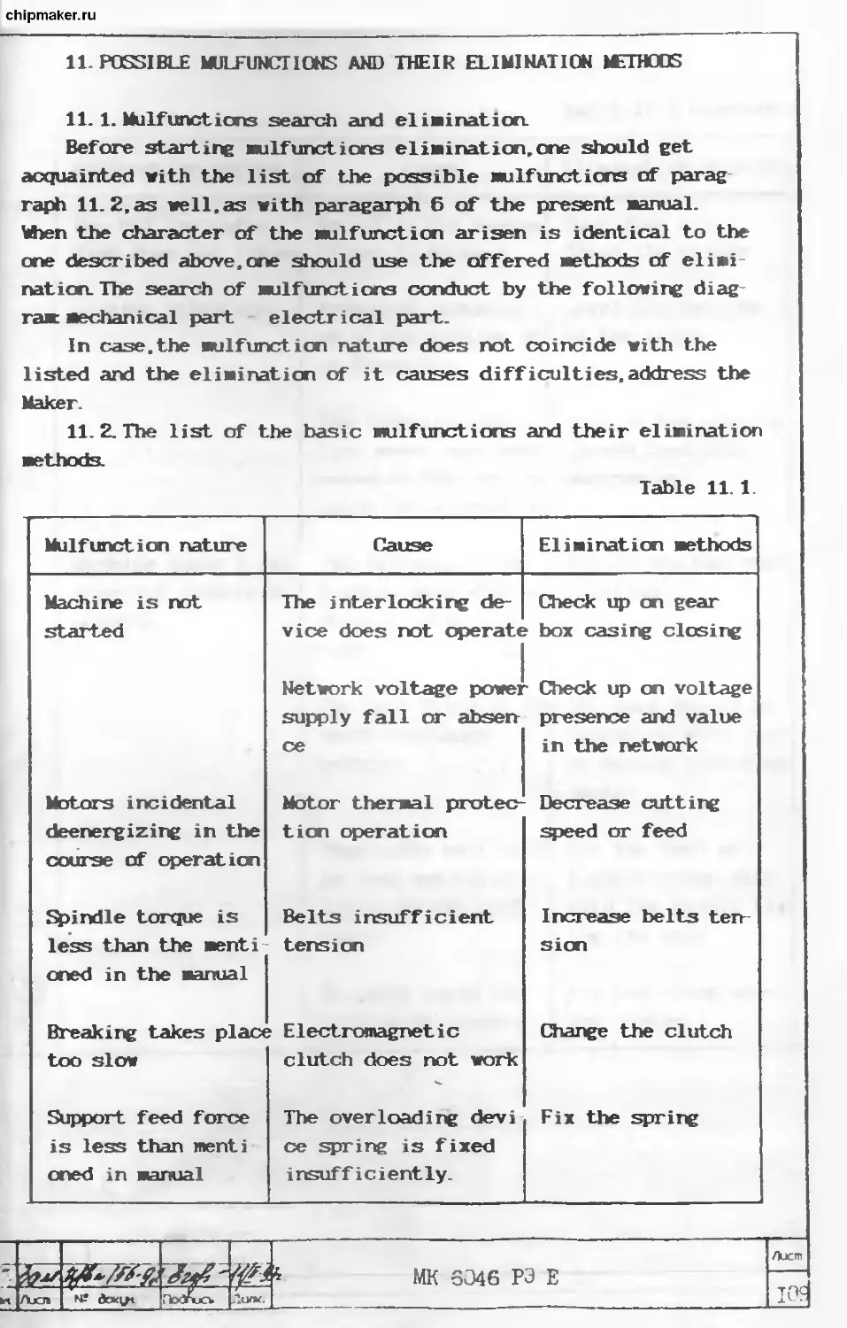
11. Possible malfunctions and their elimination methods
11 .1. Malfunctions search and elimination
11. 2. The list of the basic malfunctions and their
elimination methods
12. Mantling and dismantling peculiarities in the
course of repair
12.1, The requirements presented when repairing machine
, М1Г КГИК РЭ F
[ияч |лхл | Ажу- Улл ' Полю
79
79
79
80
83
84
85
85
86
86
87
87
87
94
94
94
94
95
95
96
96
99
99
99
100
103
103
105
106
109
109
109
111
111
Лисп
chipmaker.ru
12.2. Directions on chucks installation
12. 3. Directions on the machine accuracy
13. Information on spare parts
13. 1. Bearings disposition diagram
13. 2. Bearings list
14. Directions on maintenance,operation and
14. 1. Directions on operation
14. 2. Directions on maintenance
test procedure
repair
in
112
115
115
115
119
119
119
electric diagrams
Album No 2. Operation manual. Machine 1K6046
Album No 3. Operation manual. Information on acceptance. 1« 6046
P32
Листа
T~
MK 6046 РЭ E
chipmaker.ru
The operation manual does not reflect slight
changes in the construction of the equipment in-
troduced by the Maker after the present manual
was signed for publication,as well,as the changes
in the complete set articles and documentation
arriving with them which do not influence the
equipment specifications.
Подпоен
Пола
Листа
МК 6046 РЭ Е
chipmaker. п£
1. GENERAL NOTION OK THE ARTICLE
Chipmaker.ru
The Manual concerns the super precision screw cutting scale
of Ж 6046,Ж 6047,Ж 6048 lathes correspondingly differing by
the length of the Machined article- 1000 Mi, 2000 Mi and 1500 Mi.
The super precision screw cutting lathes of Ж 6046,Ж 6047,
Ж 6048 Models are intended for the execution of various lathing
operations,as well as for cutting of Metric, inch and pitch
threads.
The Machines may be equipped with with the digital indication
device, with the carriage displacements cross and longtitudinal
counting system which allows to greatly increase the labor effi-
ciency, iaproves the psycho-physiological labor conditions of the
worker, el iminates the subjectve factors, the incidental elements
when counting the displaceMents of the cutting tool, increases the
speed of the digital information perception and processing,decre-
ases the general tiredness of the operator.
Upon the order the machines мау be supplied with the pit in
bed which allows to increase the diameter of the blank being
Machined up to 700 ml
The Machines may be used in various branches of industry in
various operations for the Machining of various materials. In the
connection with this,the service of the machines should be done
with the consideration of their operation conditions.
The final machining of the accurate parts should be done at
the preliminarily warmed up lathe.
The machines accuracy class to GOST 8-82 during the test for
the correspondence to GOST 18097-88 - П.
As far as the ambient climatic factors are concerned, the lat
hes are produced with the design for the cold and very cold cli
mate for category 4 disposition to GOST 15150 69.
CAUTION! The individual starting of machines is permitted for the
specialists who had training and who had been attested
for the right of the initial start operations conducting
In the opposite case "Krasny Proletary" plant does not
carry responsibility on the guarantee obligations.
Лисп
id
MK FO46 РЭ E
chipmaker.ru
2. BASIC TECHNICAL DATA AND SPECIFICATIONS 2.1. Machine basic specifications Table 2.1
Parameter denomination,sizes to a quantit Parameter value ! MK6046 MK6047 MK6048
1. The indices of the blank aachined on the lathe: 1.1. The aachined blank aaximum diameter, mm over bed over pit in bed 1. 2. The machined over carriage blank maximum diameter,ma 1.3. Maximum length of the machined blank,mi 2. The indices of the tool mounted on the machine: 2.1. The tool mounted on the machine maxi mum height, ma 3. The indices of the basic and additional moves of the machine: 3.1. The spindle velocities number: of direct rotation of reverse rotation 3. 2. Swindle rotation frequencies limits, min'1 3. 3. Carriage feeds quantity: longtitudinal cross 3. 4. Carriage working feeds limits, mm/rev: longtitudinal cross metric,m modular,module 500 700* 275,290* 1000** 2000** 1500** 25 22 22 16. . . 2000 28 28 0. 025. . . 2. 8 0/012. . . 1. 4 0. 5. .. 112 0. 5. . . 112
Chipmaker.ru
~r— L : MK 604A РЭ E Лист
2ЙЙ 7
[Лисп Подписи
chipmaker.ru
Table 2.1 continuation
ter denomination, sizes to a quant it Parameter value k
№6046 №6047 №6048
inch, the number of threads for 1 inch of pitch ones, pitch 3. 6. The speed of the carriage rapid dis placements. min: longtitudinal cross 4. Machine power characteristics indices: 4.1. Maximum torque at spindle,kNm 4. 2. Main motion drive power, kW 4. 3. The smeary power of the electric mo tors mounted on the machine,(maximum), kW 4. 4. The machine smeary consumed power, maximum.kW 5. Machine overall sizes and mass: 5.1. Machine overall sizes, mm, no more than: length width height 5.2. Machine mass, (calculated) , kg no more than 5. Electrical equipment characteristics: 5.1. Power supply network type of current 5. 2. Current frequency, Hz 5. 3. Voltage, V 5. 4. Control circuit voltage, V 5. 5. Local lighting circuit voltage, V The corrected level of the sound power, DBA 56... 0. 5 56... 0.5 3.8 1.9 1 11,7.5* 12, 8. 5*, 12. 5***i 12.5, 9*, 13**** 2800 3852 3367 4250**** 1265 1485,1780*** 3100 3680 3400 3600**** AC,three phase 50 380 110 and 24 24 97
* By order * * When tailstock overtravels the bed face for 70 mm * ** When machine is equipped with the digital indication device. * *** 1Леп machine is equipped with the chip removing trairavrfcr
—I МК 6046 РЭ Е Ajct
8
& дежу* Подпись
chipmaker.ru
2. 2. The data obtained by machine when it is equipped with the
iigital indication device.
Table 2. 2.
Parameters denomination Parameters value
1. The unit provides for: the digital indication of the controlled displace- ment value in the decimal notation; the controlled displacement coordinate sign indica- tion with reference to the set counting reference point; the readings on the indication table reset to zero; coordinate incidental meaning with minus or plus sign introduction and further counting from this value; the controlled displacement doubled value indicati on in "DIAMETER" mode. 2. The digital indication device provides for the reference point coordinate search and memoriz ing. The machine data are subject to change de pending on the used digital in dication de- vice oppor- tunities
2. 3. Hea fetor T
Table 2.3
Parameters denomination, sizes to a quantity Parameters value
Spindle end Swindle flange diameter, ami Center in spindle with cone Cylindrical hole diameter in spindle,am 6K to GOST 12 593 72 170 Morse 6 to GOST 13214 79 55
Chiomaker.ru
Лист
MK 6046 РЭ E
chipmaker.ru
2. 4. Bed Table 2. 4
Parameters denomination,sizes to a quantity Parameters value
Pit length.» 350
2. 5. Tai Istock
Table 2. 5
Parameters denomination,sizes to a quantity Parameters value
Poppet sleeve center with cone Poppet sleeve maximum displacement,mm One division of the poppet sleeve displace- ment limb,mm The housing cross displacement value, mm Morse 5 to GOST 13214 79 150 0 1 +/- 15
2. 6. Carriage (support)
Table 2.6
Parameters denomination,sizes to a quantity Parameters value
Rotary angle scale,degrees Rotary scale one division value,degrees Displacement maximum length, ami Limb one division value, am +/- 90 1 150 0. 05
Ajcra
до
MK 6046 РЭ E
chipmaker.ru
2. 7. Carriage Table 2.1
Parameter value
№6046 №6047 MK6048
Lon, gtitudina 1 disp Lace went яг DCimin ' ength.
НМ Ста ss displa C€ ‘ent max inun le ngth.m 935 1935 1435 285
Сей- мах wor Lie riage dis inun allo ting with b one div Longtitud cross dis Pl i i* ir pl acen d di 'ests non lai d ace» ent spla ,m/ valu ispl ent minimis cement in e, mu ace went speed, speed n mm/min /hen 0.05 fc of the article 10 250 1 jr the dianetei achined
3. COMPIJ-7TE SET 3.1. To the complete set should correspond to table 3.1. Table 3.1
Designation Denomination Quantity Note
№6046 №6047 №6048
№6046 №6047 №6048 Machine in complete Sane Sane 1 1 1 The ccnplete setting is done in сокц> liance with the contract and order Sane Sane
/У 5, MK 6-343 РЭ E Ajcrr, II
Изн /1ХП ПскУись ilurea
chipmaker.ru
Table 3.1 continued
Designation Denomina Quantity
bion M<6046 MK6047 MK6048 Note
MK6046. 083000. ООО 01 №6046. 000611.000 №6046. 000400.000 MK6046. 260000.000 №6046. 180000. 000 MK6046. 182000. 000 ! №6046. 182000. Э00 01 Chane pinic lete Changeable parts eable 10 pinions err ms coi p ter the comp1 set 111 lete set, 4 are mounted imne | diately on ma- chine, the rest are supplied by a separate package in the general pack
Spare parts
ijpare parts гшррпеа as соцэ1еЬе set 111 the separate package in the general nachine pack Tooling Complete set Mounted on the Chuck fencing nachine (with inter lock) 111 Machine elect- rical equip | 1 1 1 inent, the nach ine lighting | system includ. 1 1 1
MK 6046 РЭ E Ajcrn
И»4 Ajoi № dement -.eTw ПсхУысъ Долю 12
chipmaker.ru
1 1 1 u 1 ? t i < > > Tabl< j 3.1 continued
Designation Denomination Quantity Note 5 :h
№6046 №6047 №6048
№6046. 091000. 000 №6046 РЭ Three jaw chuck Rest center 2032 0035 Morse 5 ПТ to GOST 13214 79 Poly V-belt 2240Л12 ТУ38 105763-89 Poly V-belt t< GOST 1284. 1 8C A 710t Operation na nual 1 1 1 > 1 Docw 1 1 1 1 1 Bents 1 1 1 1 1 1 Mounted on th< machine or Supplied as a separate pack age in the ma- chine general pack. Change i: admitted for three jaw chuck CT250B «6 Supplied as a separate pack- age in the iia chine general pack Sane mounting on the machine i: admitted Sane In the quanti- ty and in the language in compliance wi' the order re quirements or (when there are no specia
MK 6046 РЭ E Ajcit 13
Их AjOn N2 HoStjCv iluwi
chipmaker.ru
Table 3.1 continued
Designation Denomination Quantity Note
MK6046 ЖБ047 И45048
MK6046. 081000. 000 o; Ж6046. 000310.000 1Ж6046. 000612.000 The complete . set of the changeable pinions for cutting threads non mentioned in the table The co^ilete set of inch design parts Sp Spare parts complete set Ace Rest center 7032 0043 Morse 6ПТ GOST 13214 79 Rotating cen ter A I S H Ц to GOST 8742- 75 1 1 ire par 1 iessorie 1 1 1 1 1 !S 1 1 1 1 1 1 1 requirements) in two copies In Russian. 12 pinions en- ter the comp- lete set. Sup- plied as a se- parate package in the genera] pack of the machine Mounted on the machine in- stead of the metric design analogous parts. Supplied as the separate package in the general mach- ine pack. Same Same
MK 6046 РЭ к Ajcrn _I4]
& <4 ff.
кЬн AjOI № dc*vt Г iodnoo. Лопп
chipmaker.ru
Table 3.1 continued
Designation Denomination Quantity Note
MK6046 MK6047 MK6048
Four jaw ) Completed to
chuck to GOST gether. CTiange
3890-82 ) is allowed
7103 6012 ) for four jaw|
(Ф315) or 1 1 1 ) chuck Ж6046.
7103 C049 ) 092000. 000.
(Ф400) 1 1 1 ) Supplied as
Screw M12 6 t< ) the separate
GOST 12593-72 4 4 4 ) package in
general юс-
hine pack.
Bushings to ) Completed to-
GOST 13598-85: ) gether.
6100-0143 ) Supplied as
(3/2) 1 1 1 ) the separate
6100 0146 ) package in
(5/3) ) general вас-
6100-0147 ) hine pack.
(5/4) 1 1 1 )
Wedges to ) Completed
GOST 3025 78: ) together. Sup
7851 0012 ) plied as a
(1/2) 1 1 1 ) separate
851 0013 ( 3) 1 1 1 ) package in
7851 0014 ( 4) 1 1 1 ) the general
) pack.
Driver chuck ) Supplied as
ИЛУЕ ) the separate
7162 4004 1 1 1 ) package in
7163 4006 1 1 1 ) general вас-
) ) hine pack.
— Ajcm
MK 6046 PJ E тс
[ияч Jajch 1 nodrvjCk Htzxi 10
chipmaker.ru
Table 3. 1 continued
Designation Denomination Quantity Note
№6046 №6047 №6048
Vibro insulatint j foot 0B-31
ТУ2 024 5997 S' 7 4 4 4 Same
№6046.090000 Mounted on the
000 Driver chuck 1 1 1 nachine or supplied as a separate package in the general nachine pack
№ 6046. 100000.000 Movable rest 1 1 1 Sane
№6046. 101000. 000 №6046. Steady rest 1 1 1 Sane
102000.000 Threaded rest 1 1 1 Supplied as the separate package in general nac- hine pack.
№6046. Thread indica-
164000.000 tor (metric) 1 1 1 Sane
№6046.
220000.000 Micrometric
rest of longti-
tudinal notion 1 1 1 Sane
№6046. Micronetric
227000. 000 rogid rest and the cross no tion indicator 1 1 1 Sane
№6046. Conical measur Mounted on na
230000. 000 ing bar 1 1 1 chine or sup | plied as a se
MK 6046 РЭ E Ajcre 16
/<? Зал ’ <7 A
Лхл ПсхУтись
chipmaker.ru
Table 3. 1 continued
Designation Denomination Quantity Note
MK6046 №6047 №6048
parate package in the general nachine pack
MK6046. 321000.000 MK6046. Back toolholdei ' 1 1 1
322000. 000 УГ0101. 600000.000 Back toolholdei 4-position toolholder - 1 1 1 Mounted on the nachine or siqiplied as a separate package in the general nachine pack Together with №5046. 040000.000 Mounted on the nachine or supplied as a separate package in the general nachine pack. Change is al- lowed for two position toolholder.
УГ0103. 320000.000 Holder 1 1 1 For 4 position toolholder УГ0101. 600000. 000 Mounted on the nachine or |
- * ^3 MK 6046 РЭ E Aucrr
]ияч |Ajo> J № Подпись 17
chipmaker.ru
Table 3.1 continued
1 1 Quantity | 1
Designation | Denomination | — 1 . 1
1 1 Ж 1 MK | MK | Note I
Ж6046. 311000.000 -01 02 ЖБ047. 312000. 000 J | 1 1 1 1 {Digital indica- |tion device | I Same | | Same I {Digital indica- Ition device | 5O4£ 1 >1 1 1 1 1 1 1 1 1 1 6047| 1 1 1 1 1 1 | 1 1 1 604f 1 1 1 {Supplied as the se- | Iparate package in | {general machine pack I In agreement with | I the Gi-der 1 1 1 1 1 Same | {Instead of ЖБ046. |
{fixation unit | Ж6046. {Electrical equ 460000. 000-01ipment on mach |ine disposition 1 1 Ж6047. { I 460000.000 I Same I 1 1 1 1 жб04а | 1 460000.000-02 Sane I 1 1 1 1 Ж6046. | Combined con- 1 825000.000 | tainer (with | I reinforced { | concrete slab) Ж6046. 010 | Bed and base { 1 1 1 1 1 1 1 1 i 1 I 1 1 1 1 1 1 1 1 1 1 1 | 1 1 1 1 1 1 | 1 1 1 1 1 i J 1 1 1 1 1 1311000.000 | | Instead of Ж6046. 1 |460 000.000 Together Iwith Ж6046. 311000. | |000 | | Instead of Ж6047. | 1460 000. 000 Together Iwith Ж6046. 311000 | 101 | | Instead of Ж6047. | |460 000.000 Together Iwith Ж6046. 311000- | 102 | {Reinforced slab is | lused when operating! {machine as the addi- tional basement | {Instead of MK6046. |
000. 000 | nent 1 1 1 1 ( 1 1 1 {010000.000. Wien | {coxpleting machine | {with chips removing| I transporter 1
? MK 6046 РЭ E Ajcra 18
AjOTi ПоЛио. /iorv
chipmaker.ru
Table 3.1 continued
1 1 | Quantity | |
i Designation 1 I Denomination • -- | | 1 | MK | MK 1 MK I Note |
1 i 1 I _ 1604616047160481 | I Technical de-! 1 i 1 1 1 scription and! | | 1 operation in-III 1 | struct ions I 1 | 1 | 1 | |
I ТСЛ 4 1 1 1 1 1 1 i 1 1 1 1 i I Chips removing | | jSupplied as a sepa [ | transporter of | ! | rate package. Change1 1 metal cutting! | | । is allowed for chip! | machines 1 1 1 i .removing transporter I 'll ;ТОС 280. | Documents | | Spare parts | 1 | | specifications | | I and drawings. | 1 | 1 ; 1 | | 1 Digital indi-I | (Supplied when equip- | cation device! ! !ping machine with | 1 1 | 'digital indication | 1 ! 1 ! (device J
Note:
present table
The tools and accessories included into the
change is allowed for the tools and accessories of the analogous
application with the specifications corresponding changes.
Лзсго
Ajcii
Подтип.
Лосю
ИК6046 РЭ E
19
chipmaker.ru
4. SAFETY MEASURES PRECAUTIONS.
CAUTION! Operation,adjustment, maintenance and repair should
be conducted with the observation of special care. The adjuster
to strictly follow the safety directions found in the manual. Th
requirements laid down further on are based on GOST 12. 2 009 80
and GOST 27487-87 demands and are their partial concrete expres
sion for the present model of the machine.
4. 1. The requirements to the maintenance personnel.
4.1.1. To maintain, repair and operate the machine the person
with special training are admitted who had studied the operatic
manual. Safety precautions rules training should be done in com
pliance with GOST 12.0 C04 79 requirements.
4. 1.2 The malfunctions and emergency situations arising whe
operating the machine should be registered in the special reg is
ter. The following machine start into operation is allowed only
after the elimination of all the mulfunctions and circumstances
which cause the emergency situations.
4.1. 3. Wien the emergency situation arises.it is necessary t
deenergize the power supply to all of the machine for which pur
pose the mushroom-like red button of emergency power supply po-
sitioned on the machine apron should be pressed.
4. 2. Safety requirements in the course of mounting and repai
operations.
4. 2.1. Arty kinds of repair and mounting operations with the
machine deenergized power supply are forbidden.
CAUTION! Machine operating when there is no oil in the oil
indicator and no pressure in the lubrication system is not ad-
mitted. That is why,after operation end check the pressure in or
der with the directions laid down in paragraph 8.
4. 3. The safety requirements presented to the machine. Labor
safety when operating the machine is reached by its compliance
with GOST 12. 2. 009 80 requirements.
4. 3.1. The main motion drive belt transmissions,rapid displa
ments drive belt transmissions and the gear box changeable pini
are provided for with the fencings preventing from injury in th
course of these devices operation.
Ajcn
~20
MK 6046 РЭ E
chipmaker.ru
4. 3. 2. The outer faces of carriage and slide protectors are
painted yellow. The outer face surfaces of the transmissions
pulleys,oil reflector,bracket,the headstock cover internal surfao
are also painted yellow in compliance with paragraph 4.3.1.
On the gear box removable cover outer surface there is the cautioi
danger sign to GOST 12. 4. 026 76 and the interlock of this cover.
4. 3. 3. The apron has the adjustable safety device stopping the
carriage displacement when there are obstacles to its motion
(rest,for instance).
4. 3. 4. Carriage and slide displacement are limited in the extr;
me positions by rigid rests.
4 3. 5. Spindle breaking time after its deenergizing at all the
rotation frequencies does not exceed 5 s.
4. 3. 6. In the revolutions and feeds numbers tables there are t *
caution symbols showing the control handles switching in the
course of spindle rotation.
4. 3.7. The handles and other machine controls are provided for
the safe fixing devices allowing for no controls incidental dis
placements.
4.3.8. The input switch is provided
shape of the flickering device showing
contacts.
4. 3. 9. There is voltage sign
27487 87.
4. 3. 10. The machine electric
special lock.
4.3.11. On the machine apron
with fixation with the red color mushroom type pusher of the
increased size.
4. 3.12. The machining zone is 1 imited by the removable screen
with the transparent material glass. From the side opposite to the
working site the machining zone is limited by the steady screen.
4. 3. 13. The chuck protective fencing has the interlock allow
ing of no spindle rotation energizing if
removed into the back position.
4. 3.14. The machine should correspond
safety requirements (fixed in the order).
for the
voltage
indicator in the
presence at its
on the
control
cabinet to GOST
cabinet door is locked by a
there is "Stop” button (emergency
the fencing screen is
to the Buyer's country
Chipmaker.ru
'чапаян.
|иж, [лисп I H? док\/1 ~
HoAiucv Логю
Лисп
MK 6046 РЭ E
21
chipmaker.ru
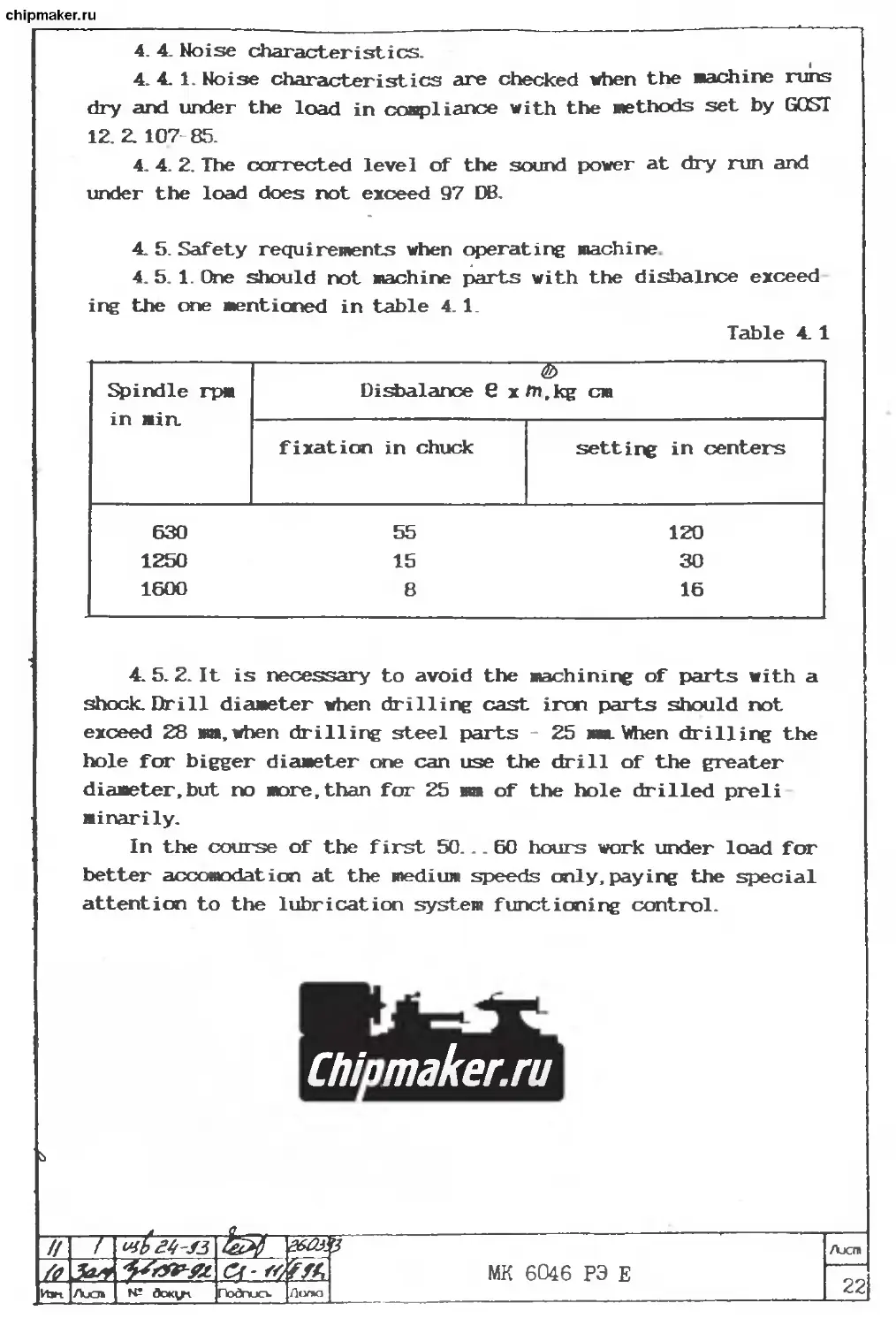
4. 4. Noise characteristics.
4. 4. 1. Noise characteristics are checked when the machine runs
dry and under the load in compliance with the methods set by GOST
12. 2. 107 85.
4. 4. 2. The corrected level of the sound power at dry run and
under the load does not exceed 97 DB.
4. 5. Safety requirements when operating machine
4. 5. 1. One should not machine parts with the disbalnce exceed
ing the one mentioned in table 4. 1.
Table 4. 1
Spindle rpm in «in. Disbalance 6 x fn, kg cm
fixation in chuck setting in centers
630 55 120 1250 15 30 1600 8 16
4. 5. 2. It is necessary to avoid the machining of parts with a
shock. Drill diameter when drilling cast iron parts should not
exceed 28 ma. when drilling steel parts 25 ma. When drilling the
hole for bigger diameter one can use the drill of the greater
diameter,but no more, than for 25 ma of the hole drilled preli
ainarily.
In the course of the first 50... 60 hours work under load for
better accomodation at the medium speeds only, paying the special
attention to the lubrication system functioning control.
Chipmaker.ru
// ~r mb st-si 3 Ajchi
fit c<-<4 Tff, MK 6046 РЭ E —
И Ao № dotCLr Подпись. Гмпа 22
chipmaker.ru
5. THE ARTICLE COMPLETE SET. 5. 1. The machine components disposition and designation are mentioned in fig. 5.1 and 5.2. Table 5. 1. Pos. No | I I quantity | I 1 in fig. | Der* I Designa |- — - - - 1 1 |5. 1 andj miration | tion MK6046 MK6047|MK6048 Note | 15.2 | | | i I I i l 1 | Bed | №6046. Illi 1 | | 010000.000 |li | | 1 | | | 01 | 1 | | |With chipl || | III |removing | | | 1 III transporter | | I 02 | 1 | | |With FMS | 1 1 1 №6047. Illi 1 | I 010000.000 I 111 1 1 | | | 01 | | 1 | |With FMS | I 1 I №6048. ! Ill i | i oioooo.ooo | | i (With fms | I | №6058.010. Illi 1 | 1 | 010000.000 Illi 1 2 | Headstock| №6046. .Il 1 | | 1 020000.000- | 1 ] 1 | 1 | I II | -02 | | I | 3 | Tailstockl MK6046. 1 ill | | 030000.000 | 1 1 | 1 I 1 | 4 | Slide | MK6046. | | | (Change is| | | 1 041000.000 | 1 1 1 allowed for | | 01 | |№6046. | | | 1 1040000.000 5 | Carriage | №6046. | | Change isl i 051000. 000 1 1 1 allowed for 01 1MK6046 ! I 1040000.000 6 | Gear box №6046. 1 facing 071000.000 1 1 1 7 i Gear box 1 №6046. j I | 080000 000 1 1 1 I
tffii 4 MK 6046 РЭ E Лист 23
/3
кои AjO» ГЬЛтисъ
chipmaker.ru
Table 5.1 continued |Pos. No | | | Quantity 1 1 1 in fie. | Deno | Designa | 1 1 |5. 1 andj Bination I tion |hK60461MK60471Ж60461 Note | 15. 2 | | , I | 1 I 1 | 8 | Gear box | Ж6046. Illi 1 | | I 082000.000 | 1 | 1 | 1 I 1 | 9 | Driver | Ж6046. Illi 1 | | chuck | 090000.000 | 1 | 1 1 1 1 1 I 10 I 3 jaw | 1K6046. Illi 1 | | chuck | 091000.000 | 1 | 1 | 1 1 1 | 11 | 4 jaw | 1K6046. Illi 1 | | chuck | 092000.000 | 1 | 1 | 1 1 1 | 12 1 Movable | Ж6046. Illi 1 | | rest | 100000.000 | 1 | 1 | 1 | 1 1 13 | Steady | Ж6046. Ill 1 | | rest | 101000.000 | 1 | 1 | 1 | 1 | 14 | Threaded | Ж6046. III! 1 | | rest | 102000.000 | 1 | 1 | 1 | 1 | 15 | Air pres | Ж6046. Illi I | | sure set | 120000.000 | 1 | 1 | 1 | I i 16 | Motor in- | Ж6046. Illi 1 | | stallation 150000.000 | 1 | 1 | 1 | I | 17 | Rapid во- | 1Ж6046. Illi Not shown | | ves drive] 151000.000 [1 | 1 | 1 1 in fig. | | 18 | Pulleys I ИЖ046. Illi 1 I | and tables 160000.000 | 1 | 1 | 1 1 | I 19 | Metric | 1K6046. Illi 1 I | thread | 164000.000 | 1 | 1 | 1 | | | indicator| Illi 1 | 20 | Pulleys | Ж6046. Illi 1 | | and tables 166000.000 | 1 | 1 | 1 I 1 (60 Hz) | III I | 21 | Spindle | Ж6046 1 1 1 I | I control I 169000.000 | 1 | 1 | 1 I i 1 1 panel | Illi | 22 | Control | 1K6046. Illi | cabinet | 180000.000 | 1 j 1 1
ft-33 МК 6046 РЭ Е Лас г»
Лхл Подгиск Полю
chipmaker.ru
Table 5. 1 continued
|Pos. Nc i in fig |5. 1 an 15. 2 | | . | Deno | d| nination | 1 1. Designa tion №6046 Quantity |
IMK6047 | №60481 Note 1 1
1 23 I Machine | №6046. 1 1
1 24 I stage by | I stage | 1 start | I Longtitu-| 184000. 000 №6046. 1 1 1 1 1 1 1 1 1 1 1
1 25 I dinal aove 1 «icroeet-| I ric rest I | Cross aove 220(1X3.000 №6046. 1 | 1 1 1 1 1 1 1 1 1 1
| 26 | nicroaet- I | ric rest | | Cone aeas 227000. 000 №6046. 1 | 1 1 1 1 1 1 1 1
1 27 | uring bar| | Centrali-| 230000. 000 №6046. 1 | 1 1 1 1 1 1
1 28 | zed lub- | | rication | | Chuck | 241000. 000 №6046. 1 | 1 1 1 1 1 1 1 1
1 29 I 30 | fencing i | Digital | | indication | device | 1 1 I Back | 260000. 000 №6046. 311000. 000 01 02 №6046. 1 1 1 1 1 1 1 1 1 1 1 1 1 1 1 1 1 1 1
1 31 | toolholder | Back | 321000. 000 №6046. 1 | 1 1 1 1 1 1
| 32 | toolholder | Mandrel | 322000. 000 MK6046. 1 I 1 1 1 1 1 1
323000. 000 1 1 1 I 1 [With FMS
MK 6046 РЭ E Ajcn
73 Jazz —
AjOb № dctq/i fYvYxjev f.oon 24
chipmaker.ru
Table 5. 1 continued
1 Pos. No | 1 in fig. | 15. 1 and| |5.2 | 1 Designa tion Quantity 1 1 1 1
ination | 1 MK604f 5| №6047| №6048 1 1 1 1 I Note | 1 I
1 33 | 1 1 1 34 | 1 1 t 35 | 1 1 1 1 1 1 1 1 1 36 | 1 1 1 37 Г 1 1 1 38 | 1 1 1 39 | 1 1 1 40 | 1 1 Cooling | Slide | fencing | Machine | electrical equipaentl layout | 1 1 Apron | 1 Gear box | 1 4-position toolholder 2-position toolholder Holder | 1 №6046 410000.000 №6046. 420000. 000 №6046 460000. 000 №6047. 460000. 000 №6048. 460000.000 16Б20П. 061. 000 16Б20П. 070. 000 УГ0101. 600000.000 УГ0101. 61000J 000 УГО1О1. 320000.000 1 1 1 1 1 1 1 1 1 1 1 1 I 1 1 1 1 1 | 1 1 I 1 i | i 1 I 1 1 I i I i I i I 1 I i I i | 1 I i I 1 1 1 1 1 1 1 1 1 1 Not shown 1 in fig. | I Not shown I in fig. | | Not shown I in fig. | 1 1 1 1 1 i 1 1 1 1
® Note: The obtaining of the support ainiaua feeds is admitted with the help of the following units: №604& 020000.000-01 instead of МКБ046.020000.000-02 №6046.080000. 000 instead of №6046. 082000. 000 №6046. 070000. 000 instead of 16620IL 070.000
z>1 /
Лисп,
* cn
24B
MK 6046 P4 E
chipmaker.ru
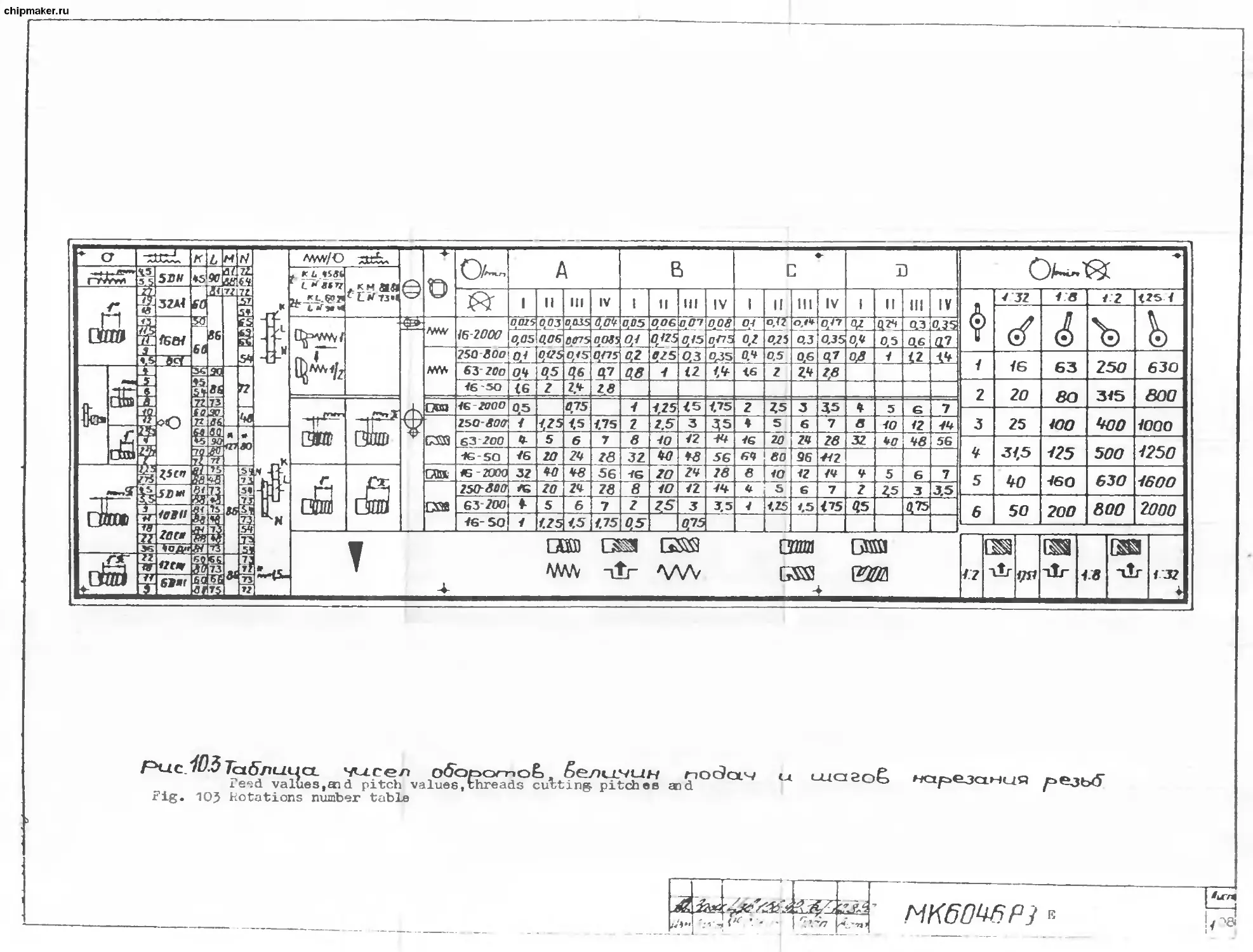
Риг 51 Общий, бид станка (расположение составных частей. станка^
Fig.5.1 Machine general view (machine components disposition)
(bn Лчгт ПоЗп. Ласа.
МК60Ч0РЭ e
chipmaker.ru
Рис. 52 Общий. Ьид станка
Fig.5.2 Machine general view
I/jm flutr H-doKtjM \Подп. Дата
МК60Ч6РЭ E
26
chipmaker.ru
Т. AMD ITS COUPORERTl TTPUCTURE'“AND0°ERATIUN.
6. 1. Controls (fig. 6. 1)
Table 6.1
Pos. No in fig- 6.1 Controls and their applica- tion Application method Note
1 Machine load in dicator Serves to define the load upon th main notion elec trie motor when machining parts. The right border is the limit one the overcome of the arrow beyond which is not ed mitted Caution*In the rotation frequency range of 16.. . 50 min/-l the load limit values are to be taken in compliance with table 10. ®It Is available f®r the export shipments only.
2 Cooling mixture supply electric p»W switcl Energizing and de-energizing is fulfilled in can pliance with the i symbols on the control cabinet panel To be used with the ener- gized switch 4
3 Signal 1ац > The lamp is lighting the electric supply is on Lights when switch 4 is energized
чУо HS-?3 IfcauL K.№-f3
j_ imfr
Подпись
/3[ / fi~J3
№ Лж\г
<l<mc
MK 6'346 РЭ E
Ласт
~27
chipmaker.ru
Table 6. 1 continued
Pos. No in fig 6. 1 Controls and their applica tion Application method Note
4 Input auto matic switch Energizing and deenergizing is done in complian- ce with the sym- bols on the cont rol electric ca binet panel Energizing and deenergiz- ing is controlled by laxp 3. Automatic deenergizing lay take place by the re- asons mentioned in parag- raph 7 "Electrical equip ment'
5 Spindle ro tation fre quency ins tallation handle Four fixed posi tions for the ro tation frequency and three inter mediate position: for the multi start threads di vision
6 Spindle ro tation fre quency in- stallation handle Six fixed positi ons To be switched on when handles 12 and 20 are set in the middle positions
7 Handle of normal inc reased thre ad and po- sition pitch when multi star threads di vision Two fixed posi tions Wien the switching is dif ficult.tum spindle manu- ally a little
II <7 «Л MK 6046 РЭ E /bcm 28
|и»1 |/kxn [ doKi^t ПоЗтио. Лилю
chipmaker.ru
Table 6.1 continv
Pos. No in fie 6. 1 Controls and their applica tion Application method Note
8 Right and left thre- ads instal lation han die Two fixed positi ons Wien the switching is di ficult.tum spindle mani ally a little
9 Feed and pitch vain installati on handle Four fixed posi tions Wien the switching is di ficult.tum spindle mani ally a little
10 Types of operations setting handle: cut thread fee< and type Four fixed posi tions 1 Wien the switching is di ficult.tum spindle mani ally a little
11 Feed and pitch value installati on handle of the cut thread and feed box mechanise deenergiz ing when cutting threads ma nually Four fixed posi- tions designated by letters and two intermediate positions desig nated by arrows Wien the switching is di ficult.tum spindle mani ally a little
’ MK 6046 РЭ E /Ъсл 29
til.
И»ч Лисп Подпись Долю
chipmaker.ru
Table 6.1 continued
Pos. No in fie 6. 1 Controls and their applies tion Application method Note
12 Spindle control handle Three fixed posi- tions. Middle main drive stop. Displacement to yourself and tun to the right - spindle direct rotation energiz ing. Displacement froi yourself and tun to the left - re verse rotation energizing. To be used with the ener gized switch 4 (signal lamp 3 is lighting).after black button "Start” pres 1 sing on button station 16 i i
13 Carriage guideways and cross slide lubricatiot valve but ton Pressing valve opening i
14 Carriage manual dis placement flywheel Counter clockwis< rotation carri age displacement to the left. Clockwise rotati on carriage dii placement to the right i To be used with loosened bolt 17,energized handle 15 and energized handles 19 and 25.
MK 6046 РЭ E Ajcti 30
/jP 'f-fi
Иэн Лхп № dOKi/л. Дела
chipmaker.ru
Table 6.1 continued
Pcs No in fig 6. 1 Controls and their applica tion Application method Note
15 Bar pinion energizing and deener gizing han die Displacement froi youself pinion coupling with th bar. Displacement fra yourself - pinioi with the bar un coupling n Pinion to be engaged with bar (coupled) with the r disengaged handle 19. Wien there are difficulties in я coupling,turn flywheel 14. i Turn on when the accurate threads cutting.
16 Lubricatior station el ectric no tor energi- zing sta- tion i Button pressing electric motor energizing The button to pressed wit energized switch 4 (signal 1ацг 3 is light ing)
17 Carriage fixation or bed bolt Bolt clockwise i turn with a wrench carriagt fixation. Bolt co unter clockwise turn with a wrench carriag< loosening Carriage to be fixed when transporting the machine ? and in case of hard face operations
18 Apron worn energizing handle Lifting up ap non worn switch ing on To be used when working with rests or feed switch- ing off as a result of overload
Chipmaker.ru
ivr
Изн ruzn ГЬэдписъ Дота
chipmaker.ru
Table 6.1 continued
Pos. No in fig- 6. 1 Controls and their applica- tion Application method Note
19 Leadscrew nut tumint on and off handle Turn down - nut ; turning on. Turn up - nut turning off To be used in case of threads cutting with turn- ed off handle 24. Mien dif ficulties arise.move car^ riage a little with a fly- wheel. After turning on turn off the bar pinion with handle 15
20 Tailstock poppet sle- eve move flywheel Clockwise rotati on poppet sle- eve displacement to the left Counter clockwise rotation - poppei sleeve move to the right To be rotated when handle 23 is in the left position
21 Tailstock fixation t< bed handle Rotation from 5 yourself - tail- stock с1ацх Rotation to your- self - tailstock unclaxp Tailstock should be const antly in the fixed positi on. Uncla^ to be done with the tailstock setting dis placements only.
22 Tailstock poppet sle eve clasp handle Turn to the righ1 poppet sleeve is classed. Turn to the left poppet sleeve is unclamped To be clax^ied when machin- ing parts in centers
— MK 6046 РЭ E /Ъег»
?2/V fry. 32
Их AjOi Подпись jkx*o
chipmaker.ru
Table 6.1 continued
Pos. No in fig- 6. 1 Controls and their applica tion Application method Note
23 Carriage and cross slide me- chanical displace- ments cont rol handle Left turn car- riage move to the left. Right turn - car riage move to the right energizing. Turn from your- self - cross sli- de move energiz ing ahead Turn to yourself - cross slide mo ve back energiz ing. To be used with switched on handle 15 and switched off handle 19
24 Carriage and cross slide rapic moves drive electric motor ener- gizing but ton Pressing - elect ric motor energi- 1 zing 5 To be used for the rapid displacements with switch ed on handle 24
25 Tool slide manual dis- placement handle Clockwise rotati on displacement to the left. Counter clockwise rotation slide displacement to the right
— £/7 MK 6046 РЭ E AjOi 33
a> Cf-ff
/boa ГкхУио» Лоло
chipmaker.ru
Table 6.1 continued Pas. | Controls and their appli- | Application |Note| No | cation | aethod 1 I in 1 1 II fie-1 1 II 6.1 | 1 II 1 26 | Socket wrench of the tool | Counter clockwise rota- | I clawing to the tool head | tion - tool unit un | | I | clawping. Clockwise го-1 I | | tati on - tool unit | I I | fixation I I 1 27 | Tool installation screw by| I I | height | | | 1 28 | Local lighting lai<i switchl Turn to the lawp socle| | 1 | - energizing. Turn to | | 1 I the 1ац) bulb - switch- | 1 I ing off | | 1 29 | Cross slide manual dis- | Clockwise rotation - |Ope-| | placement handle | slide movement ahead. |rates 1 I Counter clockwise rota-with| 1 | tion - slide movement |hand- 1 1 back |le 24 1 1 loff | 1 30 | Cooling mixture supply ad-1 Clockwise rotation - | | | justed nozzle | cooling mixture volume | | 1 I supplied to the cutting | I 1 tool decrease. | | 1 I Counter clock rotation | | 1 I - volume increase | | ! 31 | Automatic switch locking | Locks the input automa-Admit | device | tic switch 4 drive in |inst- 1 I the deenergized positi-alla- 1 I on and, consequently, |tion| 1 1 forbids the machine 11-3 |
ЛНС5
,w MK 6046 РЭ E 34
Из г. Л ИСТ bk докум. П&дп. Пете
chipmaker.ru
Table 6.1 continued
1 Pos- 1 Controls and their | Application | Note |
1 No | application | method 1 1
1 in I 1 1 1
1 fie-1 1 1 1
1 6.1 1 1 1 1
connection to the power doe locks
1 1 1 1 1 1 1 1 1 1 1 1 1 1 1 1 1 1 supply source | 1 1 1 1 1 which cor responds | to safety) require- | ments GOST 27487-87 1
1 32 | Emergency button | Mushroom button pres- | 1 1
1 1 1 1 1 sing Machine eMergen cy stop | 1 1
1 33 | 1 1 1 1 Earthing signalizer | 1 1 Signalizes of the break down to earth in the | 110 V control circuit | 1 Not shown) in the | figure | 1
1 34 | 1 1 1 1 1 1 Digital information | device unit | 1 1 Application incoaqpli-| anoe with "The digital) information device ope- ration manual" | 1 Not shown) in the | figure | 1
1 35 | 1 1 1 1 1 1 1 1 The minimum feeds | actuating manual | 1 1 1 Two fixed positions | 1 1 1 1 To be used with arms) 7.8.9,10. | 11 neutral positions!
NOTE: All the controls bringing into action (with the excep-
tion of bolt 17) should be carried out manually only. The applica-
tion of the additional means (pipes, levers and so on) is catego-
rically forbidden.
In case,the control is difficult and it is not easy to elimi-
nate the defect with your own opportunities,address the Maker.
Лист
/5 Z£/7#«4' - ® MK 6046 РЭ E
Йэк Лист bk до кум. Т1одп. Пати 35
chipmaker.ru
6.2. The basic units short description
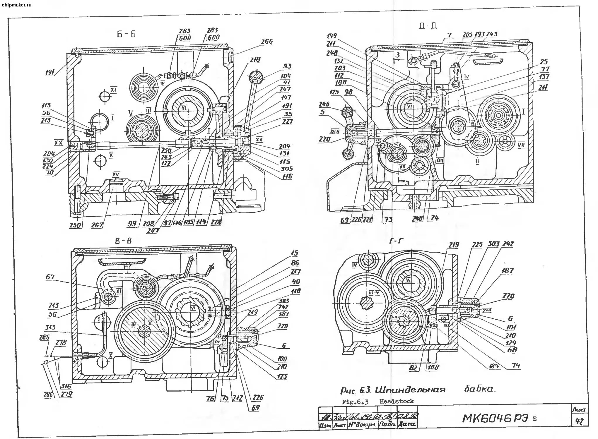
6.2.1. Headstock (fig. 6. 2. ,6.3. .6. 4. )
Headstock is based upon bed in the process of machine assemb-
ly. Mien it is necessary to adjust headstock in the horizontal
plane, it is necessary to remove the feed box facing relaxing the
screw fixing headstock and by the special adjusting screw adjust
the position of the spindle axis by the test cuttings until the
necessary accuracy is reached.
Mien pulley 310 on shaft 50 fixation is loose, fix screw 180
(fig. 6. 2.).
The torque at spindle should correspond to the data given in
table 10.1. Mien the torque decreases, test first the main drive
belts tension. The spindle reverse is done by handles 12 and 20
(fig.6.1.).
The spindle breaking time is adjusted by electromagnetic
clutch 200 (fig. 6.2. ).
With the main drive breaking by the hydraulic coupling vari-
ant, see fig. 6.4.1 sheet . The breaking coupling actuating is
done from pump H which discharges oil under pressure for the
breaking coupling and headstock lubrication along line 4 and in
the course of the direct rotation - to the breaking coupling
along line 5. The pressure for the breaking coupling operation
is set by valve 2, upon which spring 3 is acting, the extra oil
arriving into line 4 for the lubrication of the breaking coupl-
ing and headstock.
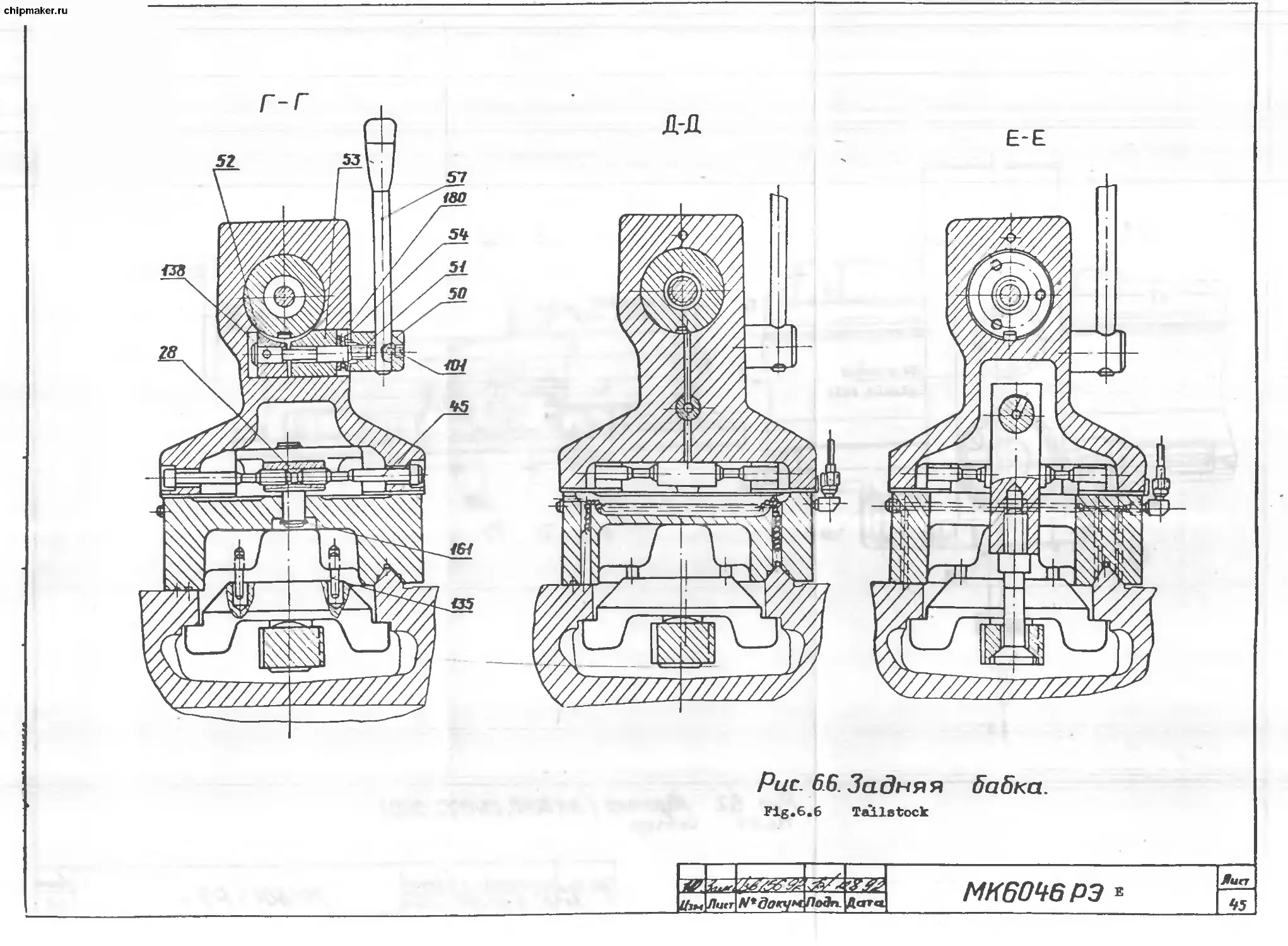
6.2.2. Tailstock (fig. 6. 5. and 6.6. ).
Tailstock is bousing 5 in the baring recess of which movable
poppet sleeve 6 had been installed . The displacement of the pop-
pet sleeve into the conical hole of which center is inserted is
done by flywheel 29 through screw 17 and nut 27. With the" help of
handle 30 the tailstock cla^> to the machine bed is fulfilled. If
handle 30 removed into the extreme back position does not provide
for the tailstock ample clamp to bed,then, by adjusting screws 81
and 82 with loose counter nuts 120 and 121, set the necessary
pressing force changing pressing bar 36 position.
The poppet sleeve 6 axis installation coaxially with the
machine spindle in the horizontal plane is done by screws 45.
6.2. 3. Carriage (fig. 6. 7. ,6. 8. ,6.9. ,6.10. ,6.11. ,6.14. ,6.15. ,
6.16. ,6.17. ,6.18. ,6.19. ).
On Ж6046. 052000. 000 carriage a bar is installed with 10 м
division limb for the diameter of the article by which the cross
slide value is controlled with the help of a sihth on the slide.
/6
Изк Лнст № до кум.
MK 6046 РЭ Е
Л нот
"зёГ
chipmaker.ru
The plugs,stoppers and washers in the carriage disposition
diagram presented in fig. 6.14. ,6.15. serve for the right instal-
lation when repairing machine.
6. 2. 4. Slide (fig. 6.12. ,6.13. )
For the tool and cross slides displacement value definition
convinience when machining parts.slide is provided for the scale
bars. On tool slide 1 the bar with 5 mm division value has been
mounted. The reference counting is done by the sihth positioned
on slide 2 rotary part.
6. 2. 5. Conical bar (fig. 6.20. .6. 21. ,6.22. ).
The conical bar is intended for the slanting cones cutting.
It is set under the direct angle with the help of 23 handle with
loose bolts 20 and 21.
When the conical bar is not used, it should be mounted into
position "0".
6. 2. 6. Motor installation (fig. 6. 23. ,6. 24. ).
When decreasing the torque at spindle,check up first of all
the main drive belts tension. If the tension is not sufficient,
then, relaxing screws 12 and 20 lower undermotor plate 4 down by
nut 25 smooth rotation to provide for the required belts tension.
After this tightly fix screws 12 and 20.
6. 2. 7. Gear box (fig. 6.25. .6.25. ,6.27. ).
The machine feed box input shaft is connected with the gear
box through which the gear box mechanisw connection with spindle
for feeds obtaining is fulfilled.
6. 2. a Apron (fig. 6.2a ,6.29. ,6. 30. ,6. 31. ).
The apron serves for the kinematic motion transmission from
the gear box to the machine slide mechanisms.
The adjustment of the force developed by the feed mechanism
is cariied out by nut 11 turn. The force value should not exceed
the force allowed by table 10.1. When machining in the chuck with
the carriage mechanical feed, it is necessary with nut 11 to ad-
just the force developed by the mechanism. Split nut 62 set on
arm 61 has been adjusted at the Maker's.
6. 2. 9. Bed, bars, lead screw, lead shaft and slide rapid displa-
cement drive (fig. 6.32. ).
The slide rapid displacements drive belt tension is done by
adjusting screw 3 which is secured by nut 2.
Vben lead screw 13 and lead shaft 14 cleaning, it is necessary
to remove screens 9 and 10. For this, it is necessary to relax
screws 19 and remove the screens of back arm 18.
Из* Лисп 7+ докум.
Йбдп.
Пете
Лист
37
МК 6046 РЭ Е
chipmaker.ru
It is possible to equip machine with the bed with a pit in it
and installed bridge 22. When it is necessary to machine the parts
of the great diameter, the bridge over bed is removed. For which
purpose, it is needed to remove plugs 20, to remove screws 21 and
pins 23. To avoid the applying of burrs, bridge should be put upon
the soft material pad and to prevent corrosion, the bridge should
be covered with a thin layer of oil.
Before bridge ^installation on bed, one should thoroughly rub
the mounting surfaces of bed and bridge and get convinced that
there are no burrs.
It should be known, that when machining the parts over pit on
the faceplate of 500 mm in diameter.the spindle rotation frequen-
cy should not exceed 400 min/1. When machining the non balanced
articles, the number of revolutions should be decreased.
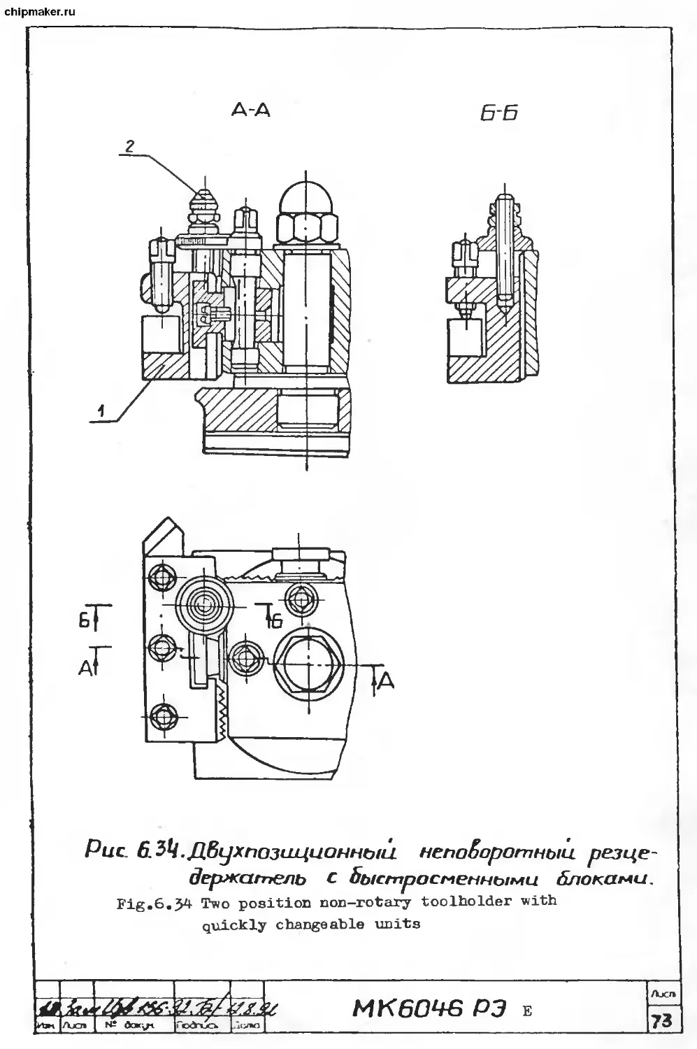
6.2.10. The machine is completed with the two position non-
rotary toolholder with the quick-changed units for tools: of the
mandrel for the center tool with adapter bush 1 (fig. 6. 33). which
allows to carry out a great number of operations (rough and
finishing machining,thread cutting, drilling, hole-enlarging, ream-
ing, cutting off and so on) and machine the parts of complex geo-
metry for one part setting.
The changeable units with tbe tools fixed in them are easily
and quickly Mounted in toolholder 2, fixed by clasp 3 and eccent-
ric 4. The simile and quick tool setting by height is carried out
without washers application by setting screw 2 (fig. 6. 22). The
toolholder with the quick changed units should be greased after
the operation end.
If tbe units are not used for operation for a long time, they
should be covered with anti-corrosion grease НГ-203А.
6.2.11. Gear box (changeable pinions fig. 6.39. ).
Gear box (changeable pinions) serves for the kinematic motion
transmission from tbe output shaft (axis 1) of headstock to out-
put shaft (axis 2) of gear box with the help of the changeable
pinions combinations setting (fig. 10. 3.).
Changeable pinions К and N are mounted on the slot shafts and
fixed with bolts 80 through washers 102. The intermediate change-
able pinions L and M are set on the slot bush of axis 39 fixed
with the help of the wrench in the required spot of the arm 22
slot which is fixed with nut 96. Mien fixing 22 arm and 39 axle.it
is necessary to mount the changeable pinions with the minimum
radial backlash.
4 К 9Л
Из к /1нс1 М* докум. Пета
Лист
"38
Ж
MK 6046 РЭ E
chipmaker.ru
On pinions K,L,M, N teeth number Z and nodule M are applied.
6. 2.12. ^ position rotary toolholder.
The nachine nay be completed with 4 position rotary toolhold-
er. Wien the handle is worn out and in the claxped position is
stopped in the inconvinient for a turner position, then, by the
additional grinding or the internediate piece change one nay put
the handle into the required position.
Wien rotating the turn handle counter clockwise, the tool head
uncla^ing and turn take place. Clockwise rotation serves for the
toolhead fixation and clamp.
Besides the four fixed positions, the toolhead nay be also in-
stalled into any intermediate position. Wien the toolholder fixa-
tion accuracy is decreased, one should dismantle the toolhead and
thouroghly clean the working surfaces of the adjacent parts. Wien
the toolholder is divided, it is necessary to rub the cones.
6.2.13. The center tool holder (fig. 6.35).
Under the "center tool" definition in the manual,the cutter
for holes machining is undermined, the axis of which coincides
with the spindle axis (for instance: drills,multiflute drills,ream-
ers etc. ).
The center tool holder is used when machining holes with car-
riage manual and mechanical feeds. Holder 1 is set into the tool-
holder position marked by the symbol designating a drill,until it
comes to a rest upon the side rib. Then it is clamped with screws.
Into the hole cylindrical holder bush 2 with the conical hole for
tool is inserted and it is retained with screw 3.
The alignment of the cutting tool axis with the spindle axis
is done by the upper slide cross slides displacement. The cutting
tool axis position correction is done by the cross slide moving
handle.
6. 2.14. Tool mandrel for parts machining over bed pit (fig.
6.36.).
Machine is completed with the special tool mandrel for the
parts machining over pit in bed which prevents the carriage hang-
ing down off bed. Mandrel 1 is set in holder 2 as it is shown in
fig. 6. 36. Tool 4 is secured with screws 5. The machining with the
mandrel usage should be done at minimum modes.
6. 3. Kinematic diagram (fig. 6. 40. ).
The kinematic diagram is given for the machine basic elements
connections and interaction understanding. Z pinions numbers of
teeth are put at marginal notes (the number of worm starts is de-
signated by an asterisk).
Ajcm
39
кЪн. Л»сп № Подпись
MK 6046 РЭ E
chipmaker.ru
(7S) A variant
Рис. 6/L Органы управления станком.
Fig.6.1 Machine controls
Raj -г l
Г i ,
рзм]/>«о|д/^ foryx ПоЗг, Дата
МК60Ч6РЭ в
Лист
Ьо
chipmaker.ru
бабка fразвертка
Рис. 6.2. Шпиндельная
Fig.6.2 Headstock (reaming)
U3H. |Лаег|М-Локг/i
'4Z£&
I. Цат
МКбО^бРЭ Е
/7«сг
4/
chipmaker.ru
। chipmaker.ru
chipmaker.ru
МК60Ч6РЭ E Лист
lUiM.l^ktrz |V* докун. jnoJh. [Дата | t/3
chipmaker.ru
Рис 65 Задняя бабка
Fig. 6.5 Tailstock
Чзк Лист N~do*y ПаЗп Цата
MK604GP3 в
ЧЧ
chipmaker.ru
Рис. 6.6. Задняя бабка.
Fig.6.6 Tailstock
I—I—I-----1—71---Г
|4frM|^wrpV*ctoryMytodn- |Ддт«{
МК60Ч6РЭ *
fun
45
chipmaker.ru
chipmaker.ru
chipmaker.ru
chipmaker.ru
chipmaker.ru
Рис. 6 н. Ррсслс/ю*&шя заглушек
f Ж 0(Х£. 05/000. 000)
Fig.6.11 Stteel plugs,felt plugs and rubber
washers disposition diagram
□ - сто/цноя
заглуи/ха
m - Ёойлортоя
лрооха.
-роз им Роя
Г прохладна
Steel
plug
Felt
plug
Hubber
washer
&оалоу*б/х npc&o/c g р&Зу^о/б/Х /powaab*
^50^6 РЭ e
Л/С/П
FO
r.ru
chipmaker.ru
chipmaker.ru
ch prnaker.ru
Лиа
54
chipmaker.ru
Рис 6Каретка (МК£сМЛрОООО.ЯОО)
Fig.6.16 Carriage '
Цз^ДЛиду^-докумуТоЗп. |Ддта|
MK60W РЭ г
Лист
55
chipmaker.ru
chipmaker.ru
Рис 6 Суппорт
Fig. 6.16 Carriage'
MIC6CJ4-6 РЭ e
chipmaker.ru
Рис. Б^.Суппорт
Fig.6.19 Carriage
I I I I I Г
|Узм|/1ист^;А|гум \Подп |Ддта]
МК6ОЧ-6РЭ E
Лист
ss
chipmaker.ru
process of assembly
Pu'.Wiepmел дополнительной. обработка. каретки.
Fig.6.20 Carriage additional machining drawing
UK 6046 P} E
59
chipmaker.ru
/230
chipmaker.ru
ео7
В В jfucm i
Sheet
Рис. о&цего£/оЬ лшеша/.
Fig»6.22 Conical rule general view drawing
7 1ЛГ T) \ I? dt/cm
d/e/n ddah dam МЛ. Ov/tO JS 61
chipmaker.ru
юг
chipmaker.ru
chipmaker.ru
А-А
Рис. &2.Q. Коробка подач
Fig.6.26 Gear box
До кум fjodfi
MK604-6 РЭ E
Паст
65
chipmaker.ru
chipmaker.ru
Д-Д
A
Рис. 6. ЗУ Фартук
chipmaker.ru
chipmaker.ru
Рис. 6.32. Станина, рейка, ходобой бал, ходобой бинт и привод быстрых перемещений суппорта
Fig.6.32 Bed,bars,lead shaft,lead screw and the carriage rapid displacements drive
МК6ОЧ-6РЭ E
У1з^у1иа\Ы'dpKiJ»iflodn |Ддтп|
riutr
7/
chipmaker.ru
A-А
6.33 Д&ухпозиционныи. непаёоротныи.
резцедержатель^ с быстросмен-
ным а блоками _
Fig.6.35 Two position non-rotary toolholder with
quickly changeable units
Jsz&k*
МК6ОЧБРЭ e
chipmaker.ru
chipmaker.ru
Рис. 6.35 Держатель центрового инструмента
Fig.6.35 Center tool holder
Рис 636 Резцовая опра&ка для обработка
деталей, над Бы емкой 6 станине.
Fig.6.36 Tool holder for parts machining over the pit in bed
МК60Ч6РЭ E
74- !
chipmaker.ru
PucdJZ Резцедержатель задний
Fig.6.37 Back toolholder
chipmaker.ru
7
I Рис.63&Рези,еЭе.ржа/т)С/1ь задний..
' Fig.6.J8 Back toolholder
4
J
*
l‘
к
mk 6046 P4 e k~
H fay, floin [z?omo| 17£
chipmaker.ru
chipmaker.ru
chipmaker.ru
chipmaker.ru
chipmaker.ru
7.1. ELECTRICAL EQUIPMENT
7.1. Electrica1 equipment shor' specifications
Machines MKoO.4), MK6O.47, MK60 4^ models electrical equipment
includes: - the devices of protection, control and signalization,
- electric motors,
- other devices and appliances carrying out commutation,
the electric circuits connection and machine mechanisms control.
The machine electrical equipment complete set is mentioned in
elements list MK6046 ПЭЗ.
The electrical equipment operation is defined by electric cir-
cuit diagram MK6046 33.
The electric connections between the machine parts are design-
ed by connections diagram MK6046 34 and connections table MK6046
ТЭ4.
7. 2. The machine electrical equipment operates from the three
phase AC network. The electrical equipment basic parameters are
mentioned in table 7.1.
Table 7.1
I Electric circuit application | Voltage,V | AC fre- |
1 1 1 _ 1 1 quency.Hz
1 — — 1 I Network. Electric motors drives,trans-| 220.230 | 1 1
1 formers,chip removing device,voltage | 3 AC 240.380 | 1
I presence control device power supply | 400,415 | 1
I circuits I 1 440,500 | 1
I Digital indication device circuit | । AC 220 | 1 50 |
1 1 1 1 60 |
1 I The control circuit, the circuit of | 1 1 1 1
I emergency deenergizing, the hydraulic] 1 1
1 clutch operation control circuit | AC 110 | 1
У
'o4.$
И1Н Лист N* йокцгс Подпись Дата
Лист
79
MK 6046 РЭ E
chipmaker.ru
Table 7.1 continued
Electric circuit application Voltage, V AC fre- | quency.Hz
The local lighting circuit,the voltage presence control circuit AC 24
The electromagnetic clutch control ant 1 50
power supply circuit DC 24 60
7. 3. Machine electric diagram operation description.
7. 3.1. Machine energizing order
By input automatic switch QF1 energizing, the drive of which is
positioned on the electric control cabinet side wall,voltage is
supplied from the shop mains to the electrical equipment follow-
ing elements: to control starters (KM2.KM3) upper terminals by the
main drive electric motor; to chip removing device A23; voltage
signal izer HL2,mounted on the electric cabinet front panel flashes
and starter KM1 is energized.
Starter KM1 provides for the voltage supply to the rest of the
electric motors starters upper terminals, brings the control co >
tours into the working condition, the circuit of emergency deener-
gizing included, switches on earthing signal izer A5 positioned on
the electric cabinet front panel.
There is mounted microswitch SQ1 into the electric cabinet.
Wien the cabinet doors aie open - microswitch SQ1 contact is dis-
engaged - flickering device HL1 lights controlling voltage pre
sence in the cabinet.
For the local lighting energizing there is switch ELI.
7. 3. 2. Headstock lubrication electric motor energizing.
Main drive electric motor operation. Wien pressing SB2 button
"Swindle lubrication energizing" (the button is positioned on the
control cabinet front panel) starter KM4 is energized and is set
for the self power supply (wires 17,47).
|Лхп [ btf [Подпись p'lc n
MK 6046 РЭ E
chipmaker.ru
Main drive electric aotor Ml start is carried out by starter's
КМ2 and KM3 which are controlled by switches "Spindle energizing”
SAI or SA2. For the direct or reverse spindle energizing the hand-
le of switches SAI or SA2 should be mounted into the extreme left
position correspondingly.
At the same tiae, one of starters КМ2 or KM3 is energized,then
relay KV5 ,is switched on with the time air pressure attachaent
for de energizing (setting 1. 5.... 2 s) and relay KV4 with the time
air pressure attachaent for de-energizing (setting 1.. . 1. 5 s).
Further on,the energizing of KV5 contacts (wires 31,48) in
starter KM7 circuit takes place,as well,as contact Kv4 (wires
17,47) with the tiae hold when energizing and de-energizing con-
tact KV4 (wires 31.48).
When restoring the neutral position of handle "Spindle switch-
ing on",contact relay KV5 de-energizing is taking place (wires 31,
48) by which starter KM4 circuit is broken because contact KV4
(wires 31,48) is kept in the disengaged position by air pressure
attachaent KV5.
When KM4 de-energizing, starter KM7 circuit is closed by con-
tact KM4 (wires 33,36). Рицр М2 aotor rotation is taking place in
the opposite direction supplying oil into the spindle breaking
systea The spindle is decelerated for the tiae of relay KV5 set-
ting. Relay KV4 is de-energized in 1. 5... 2 s breaking starter KM7
circuit and energizing starter KM4 ( in other words, aotor is
switched over to the initial rotation - spindle lubrication).
The repeated energizing of KM4 starter at the aoaent of spindle
breaking is provided for by contact KV4 (wires 17,47).
When threads cutting for spindle reverse, it is necessary to
switch SAI or SA2 handle froa one extreme; position into the other.
Spindle additional breaking takes place by the principle describ
ed before because KV4 contact (wires 39,40) is closed in the
broken condition by relay KV4 and KV5 relais air pressure attach
aents up to 4 s. Then, Bain drive aotor Ml reverse rotation is
fulfilled by starter KM3 energizing by means of KV2 contacts
(wires 38,39) and KV4 (wires 39,40)
шямядак
|AjO1
№ Дсжул. [ГкхУтиск Нолю
Ajci»
81
MK 6046 РЭ Е
chipmaker.ru
To select the main drive electric motor optimum operation
load, there is mounted ammeter Pl on the control cabinet front
panel.
7. 3. 3. Spindle breaking by the electromagnetic clutoh.
The machine may be completed with the electromagnetic clutch.
In this case, after button SB2 button pressing starter KM4 is
energized and set for the self-power supply. By one of handles
SAI or SA2 displacement, starter КМ2 or KM3 and then relais KV5
and KV4 are energized.
When it is necessary to decelerate spindle, the handle is
moved into the neutral position and the electromagnetic clutch
power supply circuit is closed because relay KV4 contact (wires
21, 26) are kept in the closed condition by relay KV5 air pres-
sure attachment.
Besides, relay KV4 air pressure attachment continues to keep
this contact in the closed condition for 1. ..1.5 s more after
power supplV deenergizing off relay KV4 coil. So, the spindle
necessary breaking time of up to 5 s is provided.
7. 3. 4. Cooling drive electric motor operation.
Cooling drive electric motor М3 start and stop are done by
starter ККБ controlled by switch SA3 which is mounted on the
control cabinet front panel. Pump energizing is possible after
main drive electric motor Mi energizing only.
7. 3. 5. Carriage rapid displacement drive electric motor opera-
tion.
Carriage rapid displacement drive electric motor M4 is cont-
rolled by switch SQ4 (built into apron handle) which closes the
coil circuit with starter KM5.
7.3.6. Indication device operation
For the detailed operation description of indication device A15
or A18 and displacement sensors A16, A17 or A19, A20 see the
dedicated documentation entering the machine complete set:
_Z Зан 27-33
Изм|Лисш| H* докцм.
Даша
Лиси
82
МК 6046 Р) Е
chipmaker.ru
7. 3. 7. Emergency deenergizing.
The emergency deenergizing of any operating electric Motor is
done by emergency switch SB1 button pressing with fixation in the
deenergized position.
When SB1 button pressing the following takes place succeed
ingly.
- aain Motion drive electric Motor Ml power supply and cooling
drive electric Motor М3 deenergizing;
spindle breaking;
- Machine electrical equipment deenergizing off the power
supply network because of the power starter KM1 contacts breaking,
the digital information device contour being not disengaged from
the Mains.
To restore the electrical equipment power supply, it is neces
sary to return button switch SB1 into the reference position.
7. 3. 8. Machine de-energizing order-
all the electric Motors deenergizing and spindle breakirg;
- local lighting deenergizing;
input autoMatic device QF1 deenergizing.
7.4. Interlocks,signalization,protection.
7. 4.1. Interlocks.
In the process of Machine operation under the wrong actions of
operator or when the separate elements or the general power supply
failure,the emergency situations are possible. To provide for the
safe operation in the Machine electrical diagram the following
Measures are provided:
- zero protection,excluding the tachine mechnisas self start
after the unexpected power supply break;
- it is forbidden to energize the main drive when opening the
Bain drive fencing;
- it is forbidden to energize the main drive when opening the
spindle fencing;
it is forbidden to energize the Bain drive with the spindle
lubrication drive non-operating electric Motor;
the main drive energizing with switches SAI, SAS simultaneous
switching on is not allowed;
the machine emergency deenergizing button is mounted with the
fixation in the switched on position. For machine operation when
pressing the button see paragraph 7. 3. 7.
Ajcra
83~
MK 6046 РЭ E
chipmaker.ru
7. 4. 2. Signalization.
To control the voltage presence between any three linear drives
and earthing bus,there is light signalling device HL1 Mounted on
the panel in the control cabinet. This device operates with the
open cabinet door only and shows the energized condition of autc -a
tic input switch QF1.
On the cabinet front panel lamp HL2 is mounted signalling on
the electrical equipment energized condition.
® -On the cabinet front panel earthing signalizer Ab is-mounted-----
uignallinr on the breakdown to tioith preuenoe in the lit* V
eet^bettf*.
7. 4. 3. Protection.
The electrical equipment has been protected from the short
circuit by the automatic switches and safety devices.
The electric motors (except for M4 electric motor) have been
protected from overload by the electric thermal relais.
The digital indication device has been protected from the
electric noises influence with the help of noise suppressing R C
filters connected in the parallel way to all the circuit reactive
elements.
7.5. Inlnrmation on the initial start
7. 5. 1. Machine connection
When connecting the machine, it is necessary to get convinced
that the power supply network voltage and frequency correspond to
the machine electric parameters power supply network frequency
and voltage mentioned in the table positioned in the control ca
binet.
Machine connection to the power supply circuit and the earth-
ing contour should be fulfilled by the insulated copper wire with
the cross-section no less, than 100 square iml
The power supply network wires input may be fulfilled both
through the control cabinet upper plane and lower plane.
7. 5. 2. The initial start.
Before machine start it is necessary:
to carry out the electrical equipment installation in complin
anoe with the directions of the present manual and Ж6046 34 diag-
ram;
> check up on the earthing safety and the electrical equipment
installation by the external inspection;
~7Г7
chipmaker.ru
check up on screws fixation (contact and mounting ones) and
fix the connections which got loose in the course of transporta
tion;
connect machine to the earthing bus line in compliance with
paragraphs 7. 5.1. and 7. 6. of the presenet manual;
connect Machine to to the power supply network in compliance
with 7. 5.1. paragraph;
switch QF2 automatic switch on;
check up on machine electrical equipment operation.
7. 6. Safety precautions.
To maintain the machine electrical equipment only the persons
are admitted who had had the special technical instructions and
who had studied the machine electrical equipment operation.
The machine should be safely connected to the shop earthing
device. All the metal parts of the machine (bed,the electric mo-
tors housings,cabinet frame and so on) which might happen to be
voltage stressed over 42 V should be thouroughly earthed.
After mt shine installation and before its connection to the
stop mains,it is necesary to measure the electric earthing resis-
tance.
The contact resistance measured between the earthing bus line
and any metal part of the machine which might happen to be volta
ge stressed over 42 V as a result of the insulation breakdown
should not exceed 0.1 Ohm.
All the control devices requiring of no compulsory machining
on machine are in the control cabinet. The cabinet protection deg-
ree is IP54 to GOST 14254-80.
Machine operation with the cabinet open doors is categorical-
ly forbidden.
The electrical equipment current leading parts which are left
voltage stressed when opening the control cabinet doors,are
protected from the incidental touch.
CAUTION1 The upper contacts of the input automatic switch are
constantly voltage stressed. The incidental touching of these con-
tacts is DANGEROUS FOR YOUR LIFE.
7. 7. Information on wires coloring.
For the information on wires coloring see Connections table
Ж6046 ТЭ4.
।—i-----Г
|/Yjc [ докул. pcxYr b
MK 6046 РЭ Е
Ajcm
~ 35
chipmaker.ru
7. Я Mantling and dismantling.
Mien selecting the place for Machine installation.one should
bear in Bind the necessity of free access to the control
cabinet for service and inspection If by the transportation con-
ditions a part of the Machine electrical equipment is dismantled,
then,after Machine installation it is necessary to mantle the
disengaged braids in compliance with ЖБ046 34 diagram.
7. 9. Maintenance.
In the course of the electrical equipment operation it is
necessary to periodically check up on the electrical devices
condition. All the electric devices parts should be cleaned off
dirt and dust. In the course of inspection,pay attention to the
screws, wires nuts.fixation, to the electric devices movable ele-
ments displace ее nt and return into reference position accuracy.
The electric Motors technical inspections periodicity is set
depending on the industrial conditions.but no less than once in
two «criths.
In the course of the Motors general inspection, one should
periodically control the operation node,heating,contacts conditi-
on in the terminal box,as well,as the earthing device.
Ajcm
86
MK 6046 РЭ E
chipmaker.ru
a AIR PRESSURE SYTEM AND LUBRICATION SYSTEM
a 1. Air pressure system.
The air pressure equipment serves for the air cushion ere
ation which makes it easy to displace tailstock along bed and
prevents the wear out of guideways. The air pressure devices have
been mounted from the back side of machine.
The air pressure equipment is to be connected to the shop air
pressure line (pressure 0. 4... 0. 6 IPa.air expenditure 10... 14
l/min).For this,there is the tube on the right stand with the
outer thread K3/8 inches to GOST 6111 52.
Air supply to the guideways is fulfilled when pressing the
jaw fixed on handle 22 (fig. G. 1. ),when pressing the pusher of
valve 1 (fig. 8.2. ) when displacing the handle to the operator
As the work is over,remove the moisture with a cloth off the
guideways and cover them with a thin layer of oil.
Every day before operation beginning, it is necessary to drain
moisture out of filter 3 by the turn of a tommy bar mounted in
its lover part.
Regularly,onoe in 2-3 months, as the condensate arises up to
the gate level,filter 2 should be removed for cleaning and wash-
ing. Pour oil И-20А to GOST 20799-88 into oil distributor 2 as
the oil level in the housing decreases.
The list of air pressure devices.
Table a 1
No to diagram fig. a 2 Denomination Type Qrr ty
1 Air pressure distributor И PK3 4. УХЛ4 1
2 Oil distributor B44 23 1
3 Filter moisture separator B41 13 GOST 17437-81 1
a 2. Lubrication system.
8.2.1. General notions.
The machine right and regular lubrication is very important
for its normal operation and life time That is wh« it is песета
i у to
to the reco—endations given lower.
ft Ърг. 77/f. %. MK 6046 РЭ Е Ajcra РГ7
Axn /дота О/
chipmaker.ru
Vhen preparing the machine to the start in compliance with
the lubrication chart.table 8.2 and lubrication diagram (fig.
8. l),fill the tanks.the mentioned in the chart mechanisms,remove
the transportation plug off the air pressure system underwater
joint.
The lubrication is to be fulfilled with the lubricants in com-
pliance with the time periods mentioned in the lubrication chart.
CAUTION* The first change of oil in all the oil tanks is to be
done a month after the machine was put in operation. The second
change - after three months and further on in correspondence with
the lubrication chart and paragraph 12. The drainage of oil should
be done through drainage holes 3 (fig. 8.1. ).
8. 2.2. The system of headstock and gear box lubrication.
There is used in the machine the automatic system of headstock
lubrication. Pump 7 sucks oil out of the tal k and supplies it
through filter 9 to bearings,shafts and pinions of headstock and
gear box.
In the process of operation.it is necessary to observe filter
9 as it is clogged and wash its elements in kerosene no less.tl.an
once in a month.
The oil out of headstock and gear box is drained into the tank
through grid filter.
Every day,before operation beginning the oil level should be
checked by the oi 1 indicator 1 mark on the tank and, if it is ne-
cessary, pour it.
8. 2. 3. Carriage and apron mechanism lubrication (fig. 8.1. ).
Carriage and apron mechanism lubrication is automatic and it
is carried out from individual plunger риц) 8. The oil is poured
into the housing through hole 4 closed with a plug and it is
drained through hole 3. Oil level is controlled by oil indicator 1
positioned on the apron face side.
8. 2. 4 The lead screw feet,lead shaft and tailstock lubricati
on (fig. 8.1. ).
The lead screw feet, lead shaft and tailstock lubrication is
done by th. wicks out of the tanks into which oil is poured down
throgh holes 4 closed with caps The tailstock lank is filled befo-
re oil drains out throgh hole 3 on the face side of the housing.
The cross slide screw additional foot lubrication is done in the
extreme front position of the latter.
[ижГрЪ— I N? dcw^t
MK 6046 РЭ E
Ajcni
88"
ch maker, щ
8. 2. 5. Changeable pinions and the intermediate changeable pi-
nion axle are lubricated manually with the help of a lubricator.
The carriage guideways and cross slide lubrication is fulfilled
by button 5 pressing until there appears oil film on the bed
guideways.
8. 2. 6. Lubrication chart.
Lubrica tion object Lubricant materi- al (name.type ant specifications oi standard nuwber Lubrica 1 tion method Lubrica tion pe- riodici- ty Lubri cant expen- diture 1
1. Headstock and gear box pouring down pos. 4, fig. 8.1 drainage - pos. 3,fig. 8.1 И 20A to GOST 20799-88 Automatic centrali- zed Once in 6 months
2. Apron pouring down pos. 4, fig. 8.1 drainage pos. 3, fig. 8.1 И 30A to GOST 20799-88 И-20А to GOST 20799 88 Automatic Oil chan ge in planned inspec tions anc repairs 1.5 1
3. Carriage and И 30A or И 20A to GOST 2079 88 Semi-autc matic from ap- ron pump ) 2 times a shift From
support cross slide apron shift tank
4. Lead screw ant lead shaft back feet (pos. 4) ] Same Manual Weekly 0 03
MK 6046 РЭ E Лист 89
Ж fat’ /
Лисп ПодгиО. ролю
chipmaker.ru
Table 8.2.6. contin.
Lubrica tion object Lubricant materi al (naae.type are specifications oi standard nuaber Lubrica- 1 tion ~ aethod Lubrica- tion pe- riodici- ty Lubri- cant expen- diture 1
5. Support cross slide and cross slide drive screw feet (pos. 2) Saee Manual Once a shift 0.02
6. Tailstock (pos. 4) Saae Manual Weekly 0.02
7. Changeable pinions Synthetic cup grease to GOST 4366- 76 or cup grease JI to GOST 1033-79 Manual Weekly 0.22
8.2.7. The list of the recoanended lubricants Table 8.3
Country and the lubri cants basic supply ing Co. Lubricant type
Russian Federa tion ИГП 18 1' 20A И 30A Cup grease C to TY3811273 GOST 20799 GOST 2079 3 GOST 4366-76. 69 viscosi 88 viscjsi- 88 viscosi The effective ty 50 deg ty 50 deg ty 50 deg viscosity at 0 rees C rees C rees C degrees Celcius 16. 5... 17... 33 Cst 27.. . 33 Cst no «ore than 20. 5 Cl 2 000 P
~Г- «r. MR 6046 РЭ E Aucra 90
|лхл № [гкхуСс». ilcyxi
chipmaker.ru
Table 8. 3 continued
Country and the lubri- cants basic supply ing Co. Lubricant type
Russian Flash tern Flash tern- Flash tern Stands the test
Federa perature perature perature of the corrosion
tion 170 degr. C 165 degr. C 165 degr. C influence
Density at Solidifying Solidifying Free organic
20 degr. C: temperature tem,>eraturt acids content
0. 88 g/cub. - 30 degr. C - 15 degr. C absent
ca
The content of the water soluble The content of
acids and alkali - absent. The con- water in percen-
tent of mechanical additives and tage no more.
water absent. The content of addi than 2. 5
tives absent.
Checkho- CL J2
Slovakia Poland CSN 656610 32
PN55C 96071
Romania
Stas 742 49
Hungary T-20
1MSZ1747-63
Jugosla- CIRCON 30
via
Britain Oil light
Mobil oil Mobil DTE
USA Shell Vetreol
Shell Oil 27
Note: When there are no materials listed,the application of
those oils only is admitted che basic characteristics of
which correspond to the given ones.
f. MK 6046 РЭ E
fkbn |/Ъов J № doKi/i [Лодтио. Лоло
Posi-
Г1 nn Пози- ция Пйплткпяtinn Наименование Кал Примечант
1 У^^^с^Ш^асли 5
2 .. Manual lubricStiOIL spots Места. смазки ьр<рг- <jkj Z
3 Сли5 Масла. oil drainage 3
* Места зали&а. масла •t
5 Кнопка смазки направляю-
Carriage guideways сцих каретки, lubrication butl on 1
£ ЗОЛИЛИQl-l. PouriQR filt'
7 Насос pump fi 1
8 Плунжерный, насос Plunger pump 1
9 Фильтр сетчатый^ Л 1
Puc 8/i- Схема, смазки станка.
Fig.8.1 Machine lubrication diagram
МК60Ч6РЭ E
Рис 82. Схема пнеСмооборудоСания
Fig.8.2 Air pressure diagram
МКбОЧбРЭ E
5з
chipmaker.ru
9. INSTALLATION PROCEDURE
9. 1. Preparation for installation.
To provide for the Machine quick and safe installation, it
is recommended to keep to the instructions and safety pn сач
tions out of chapter 4.
The necessity to provide for the machine installation short
periods i^xises on the customer the following obligations: the
preparation of the sufficiently great space for mounting instal
lation.the elimination,as it is possible,the objects which stand
in the way of installation, the presence of the necessary quantity
of the power supply connections.
9. 2. Unpacking
It is necessary to fulfil the input control of the transport
boxes right away after they arrrived and to get convinced that
there are no damages. The machine is supplied in one box,the
accessories and the tooling are in the separate boxes placed in
one general package. When damages are found, it is necessary to
inform on this the supplier.
There is placed the packing list in the pocket positioned on
the box. In compliance with the packing list.check up on the com
plete set of shipment and when finding some incomplete set artic-
le, it is necessary to inform the supplier on this.
9. 3. Transportation.
Machine transportation is carried out in compliance with the
transportation diagram (fig. 9.1.) with the help of four rope ends
1 and 2 of which are put on the two steel bars of 60 и in diame
ter put into the specially foreseen holes of the machine basement.
CAUTION! Mhen displacing machine out of the packing contain-
er,the chains positions change is categorically forbidden. Check
up on the machine and its components safe fixation. Get convinced
that the moving units are safely fixed on bed. Tailstock with the
help of handle 22 (fig. 6.1. ) and carriage by bolt 17 are fixed in
the extreme right position. The support fencing screen is fixed
with screws, in order it did not rotate around the stand or class-
ed between tailstock and the support upper part. It is forbidden
to touch the machine surfaces with the transportation ropes when
tiansporting machine.
Ajcm
~94
MK 6046 РЭ E
chipmaker.ru
Wien transporting Machine to the installation place and when
lowering it on the foundation,one should observe that the Machine
is not subjected to great jerks and shakes. To prevent the digital
information device breakage, it is recommended to transport the
machine with the removed digital inforMation device.
9. 4. De-preservation.
All the surfaces with the applied anti-corrosion protection,
both outer and closed with housings are subject to de preserva-
tion. The Machine outer surfaces are covered with anti corrosion
grease НГ203А and the inner surfaces with НГ-203Б grease. To re
Move theM,use the wooden spade and cloths Moistened in gasoline
solvent to GOST 3134 78 (white-spirit). To avoid corrosion,the
cleaned surfaces should be covered with a thin layer of oil И 30A
to GOST 20799-88.
When de preserving Machine,bear in Hind the safety require-
ments to GOST 9. 014-78 "Articles temporary anti corrosion protec-
tion. General requirements".
To remove the anti corrosion coating on the lead screw and
lead shaft,it is necessary to re~ove the accelerated movement
drive fencing and pulley;to relax the screws fixing the shields
from the side of the back arm,to remove the anti-corrosion coat
ing and lubricate all.
9. 5. Machine installation.
To achieve the maximum displacement speeds and the set accu-
racy, the foundation should be maximum rigid and vibro-insulating.
The foundation depth is taken depending on the grounds but it
should not be less,than 500 mm. The floor fluctuation level by
Machine should not exceed 0. 003 t lThe machine installation sizes
are mentioned in f ig. 9.2. Machine is tested in both planes by the
level which should be set on the support closer to the toolholder
in the way parallel to the carriage motion direction 9 for the
machine setting test in the vertical plane) and in the way per-
pendicular to the carriage motion direction (for the guideways
twist testing). In any position of carrigae the level deviation
should not exceed 0. 02 mm for 1 000 mmm.
CAUTION! It is necessary to install (removed for transporta-
tion) support cross displacement handle in compliance with fig.
6. 8. The handle mentioned is packed in the tooling box
ивян? * MU РЭ r
|Ajcni J № OoKijt ПоЛисъ Логао 1»1I\ О'-’ЧО Г'-' и
95~
chipmaker.ru
9. 6. Machine preparation for the start.
Having acquainted with the safety precautions when operating
the metal cutting machines and having fulfilled all the direct ions
corrected with the machine preparation for the start,laid down
in paragraphs ’’Electrical equipment" and "Air pressure and lubri-
cation system",it is possible in compliance with the succession
recowaended lover to begin the machine preparation for the start
Relax bolt 17 on the carrigae (fig. 6. 1. ).
Into the foundation chip removing collector positioned over
bed pour about 30 1 of the cooling mixture.
Into the lubrication station mounted on the machine pour 15 1
of oil.
Connect machine to the air pressure mains.
Connect machine to the earthing circuit and the power supply
network.
Check up on the cooling mixture supply electric motor opera
tion. The quantity of the mixture supplied is adjusted by nozzle
30 turn (fig. 6.1. ).
Check up on the tailstock displacement easiness along bed. The
tailstock displacement force should not exceed 5 kgf.
Switch the lubrication station electric motor on. Check up on
pressure in the lubrication station.
Check up on the headstock and gear box centralized lubrica-
tion action.
Check up on the apron lubrication pump operation.
Check up on the digital information device co~r>ection in com
pliance with the directions laid down in the dedicated doGunenta
tion to it.
9. 7. Machine initial start.
After operation end by the above mentioned paragraphs and the
digital information device operation manual study the test start
of machine is allowed. The machine successive energizing is ful
filled without load at various feeds and revolutions numbers
starting with the minimum ones.
Having convinced that all the nachine mechanisms operate
normally.one can start the machine adjustment for operation, in
other words,the machine adjustment for the parts machining.
MK 6046 РЭ E
Акт
96
chipmaker.ru
OOQZ
29в
Designation Обозначение 1 € л ® [X,HH
МКБ0Ч6 1000 1073
MKSovt 2000 1573
МКБО'/З 7500 1323
Рис 94 Схема. mpaHcnopmupoCa.HU.9i.
Fig.9«'l Transportation diagram
// <? &aif > HK609-BP3 E Лист
TT1
'Ли Лист rfdoxyri Лодп 4c*-? 97
chipmaker.ru
Рис. 32 Усгт.ани^очнь!и Чертеж станка.
Fig.9.2 Machine installation diagraa
-r-Designation иоозначение d> L,HH <£> K,"» a G> C'KH
МК60Ч6 WOO 7800 1890 3165
MKGO97 2000 3852 2890 4211
МК6ОЧ8 1500 3WO 2390 3665
Мэм Пигг / Ддг<Х
Лист
58
МК6ОЧ-6РЭ «
chipmaker.ru
10. OPERATION PROCEDURE.
There are directions in the present manual on the cutting
speeds,feeds setting Bethods,on the adjustment for various kinds
of threads obtaining,etc.
10.1. Main motion mechanism
The setting of the spindle revolutions number is fulfilled by
two handles 5 and 6 (fig. 6.1. ) by the table (see fig. 10. 3. ) pla-
ced on headstock. In the table right side there are spindle revo-
lutions figures rows for the direct rotation and the handles
positions for the required revolutions numbers.
With the help of handle 5 one of four spindle revolutions
figures rows is set in compliance with the handle position desig
nation on the table.
By handle 6 on the hub of which figures from 1 to 6 are ap-
plied, the required number of revolutions is set out of the selec-
ted row. For this,the figure designating the required number of
revolutions in the table should be aligned with the vertical ar
row over the handle.
The feeds value setting is done by handles 9,10 (fig. 6.1. )
in compliance with the values mentioned in the medium upper part
of the table (fig. 10. 3).
The value of the cross feed is 1/2 of the longtitudinal value.
For the feeds values setting which are equal to the doubled table
values,one may use the directions of paragraph 10.2.
10. 2. Instructions on thread cuttng
When shipping from the plant, there are mounted on the machine
changeable pinions with the number of teeth z = 45, z - 86.z 72
and the pinion with z - 73 which fulfils in this combinaion the
function of an intermediate piece.
The combination of pinions K/L x L/N - 45/86 x 86/72 provides
for the metric and inch threads cutting with the pitches the
values of which are mentioned in the lower part of the table
(fig. 10. 3)
For this,with handle 10 (fig. 6.1. ) it is necessary to install
the required pitch of the cut thread and with handles 9 and 11 to
select the required pitch.
T
Ajcra
|,lxn
MK 6'346 РЭ E
991
ch
pmaker.ru
The pinions entering the basic set are mentioned in paragraph
3.1. Having set the combination on machine entering the basic ex
plete set of changeable pinions (K/L x M/N 80/73 x 86/48 one
can exit Module and pitch threads the pitches values of which are
set with handles 9 and 11 according to the table (fig. 10.3. ).
Handle 10 should be switched over to the corresponding type of
thread.
By combination 2t - K/L x L/N - 60/90 x 90/48 of changeable
pinions entering the basic set, the opportunity appears of the
Metric and inch threads cutting with the pitches equal to the
doubled values Mentioned in the table (fig. 10. 3.).
NOTE: With the help of these changeable pinions combinations
in the way analogous to the described one, it is possible to ob-
tain the feeds values which are equal to the doubled table va-
lues.
Except for the Mentioned above, the changeable pinions provid
ing for the pitch thread cutting with the threads number 11 and
19 for one inch, enter the basic coMplete sets. With the help of
the additional set of the changeable pinions suppl el on special
order and the basic set, it is possible through the gear box me
chanism to cut quite a nuwber of threads,pitches "t" of which
are Mentioned in the left part of the table (fig. 10. 3.). Machine
adjustment for these threads cutting is done with the help of
changeable pinions Mentioned in the left part of the table.
These pinions Mentioned in the left part of the table are
absent from the basic set but are supplied on special order. In
the заме way as in the cases described above, the feed table va-
lue is set by the corresponding handles, by pitch "t" handle 10.
Example: For the pitch thread cutting with the*pitch of 11
pitches,handle 10 should be installed into the position corres-
ponding to this thread cutting,handle 11 into 0 position and
handle 9 into position ill, which corresponds to the pitch of 6
pitches in the table. There should be installed on Machine the
combination of changeable pinions K/L x M/L - 60/66 x 86/73.
10. 3 Changea* e pinions selection formulae for the threads
feeds cutting through the gear box mechanism which had not been
given in the table (fig. 10. 3.).
Ехамр1е: Vrtien it is necessary to cut the metric thread with
pitch t - 18 wmi.one should use the formulae mentioned lower.
MK 6346 РЭ E
Ajctu
16c
chipmaker.ru
By the table (fig-10. 3. ) we find in the row of the aetric ।
threads the thread pitch value which is closest to the being cut
one. Such values are t - 16 and t - 20. In our case, we select,for
instance, pitch t - 20 and substitute for the forwula to find
pinions teeth nuaber Z which are necessary to be wade to cut this
thread.
t - 18; t - 20;
cut table
K/L x M/N - 5/8 x t 7t 5/8 x 18/20 5/8 x 9/10 -
cut/ table
- 5 x 9/8 x 9 x 9 x 9/10 x 9 - 45/72 x 81/90 - 45/90 x 81/72 (1)
When calculating the changeable pinions nuaber of teeth,re-
quired for the thread cutting, the pitch of which is absent froa
the table,the ratios should also be selected which to the aaxiaua
extent would allow to use the pinions supplied with aachine.
For instance, in equations (l),it is advisable to accept the
ratio equal 9 giving the opportunity to use the changeable pi
nions of the basic set with teeth nuaber z 45 and z - 72 and as
the interaediate the pinion oif the basic set wight be taken with
teeth nuaber z - 90.
Metric thread:
K/L x M/N - 5/8 x t /t .where
cut/ table
t the pitch of the cut t tread, -яа
cut
t the pitch table value closest to t table cut Inch thread: K/L x M/n - 5/8 x h /h .where table/ cut h the nuaber of thread or one inch of the cut thread cut
51 MK 6046 РЭ E /Ъсгв
AjO» № doKift Подпись .locwn I QI
chipmaker.ru
h the thread table value closest to h
table cut
Module thread:
K/L x M/N - 80/73 x 86/48 x m /м .where
cut/ table
- the Module of the cut thread;
cut
the thread table value closest to м
table cut
Pitch thread:
K/L x M/N - 80/73 x 86/48 x P /Р .where
table/ cut
P - the cut thread step,pitch
cut
P the thread pitch table value closest to P
table cut
After calculations by the drawing (see fig- 10.1. ) check up on
the opportunity of the found combinations pinions coupling. Keep
in Mind that the number of teeth of pinion К set at axis 1 should
not exceed 88 with м 2 and with pinion N mounted on axis П - 73
with the s we Module.
As it is seen from the obtained combinations of the pinions
for metric thread cutting with pitch t - 18 тм.there should be
additionally ml.de by the standard drawing (see fig. 10. 2.) the
pinion with teeth mnber z = 81 and module м = 2. This pinion en-
ters the additional set of changeable pinions supplied by the
special order and with the presence of such a set,the necessity
of its Manufacturing is lost.
NOTE: the changeable pinions marked by * are supplied on
special order.
Лист
Г2
MK 6946 РЭ E
chipmaker.ru
10. 4. High - precision threads cutting with the lead screw
ieediate connecton with spindle through changeable gears with
the gear box mechanism disconnection.
With handle 10 install the corresponding thread type and put
handle 11 into the neutral position designated by an arrow (to
exclude the pear box mechanism, dry rotation).
The selection of the changeable gears for the high precision
thread of the definite pitch cutting is done by the following
formula:
KA x M/N - t/18.
To cut these threads with the help of the changeable pinions
complete set supplied by the plant, one should use the data given
in the left part of the table (fig. 10.3).
As it is seen from the table,with the help of the basic set
pinions one can cut the high pre vision metric threads with pit
ches t - 5 mm.t - 10 mm.t - 12 t
The metric threads remaining pitches and the inch threads
mentioned in the table may be cut with the application of the
changeable pinions set supplied by special order.
10. 5. The multi-start threads cutting.
The multi start threads cutting is fulfilled in the follow
ing way: 1. Handle 12 (fig. 6.1) should be in the medium positions
2. Turn the lead screw nut on with the help of handle 19.
3. With handles 5 and 6 accor ling to the table, placed on hear
stock install the required number of spindle revolutions and with
handles 9 and 11 - the cut thread pitch necessary value.
4. Turning flange 144 manually,(fig. 6. 2. ) align the arrow in
dicator applied on it with one of the marks of spindle 158 divi
sion ring,designated by some figure.
5. Wien cutting the metric and module threads with the pitches
in the 1 imits froa 0. 5 to 7, the inch and pitch threads free 56 to
4,the spindle disengagement with the machine kinematic circuit to
divide into the number of moves is to be Bade by handle 7 instal
lation (fig. 6.1) into the position marked by the special symbol
designating spindle deenergizing. For the rest of threads pitches
the disengagement is to be made by handle 5 turn out of the fixed
position into the closest intermediate one,marked by the analo-
gous symbol.
Ъсп.
.'031
MK 6046 РЭ E
chipmaker.ru
6. The division into the starts number is to be done by the
spindle manual turn into the number of marks corresponding to the
cut threads starts number (with two starts into 30 marks.with
three starts into 20 marks, with four starts into 15 marks and so
on).
7. Install handle 5 and 7 into the reference position.
8. Cut a single thread.
9. With the subsequent division the operations laid in parag-
raphs 5... 8 are to be repeated.
ATTENTION! Vftien cutting short threads with a tool on a lot of
parts, the spindle rotation frequency should be no more, than 500
min/-l in order to avoid the main drive electric motor overheat
ing.
Лист
104
[Идч [Ajrm
nodiucw Лолл
MK 6046 рэ E
chipmaker.ru
10. 6. The table of the BaX E.i allowed torque and power values
at spindle with the help of the 11 kW aain drive Botor.
Table 10.1
Handles position Spindle direct and reverse rotation
5 6 Spindle revolu- tions No Bin/ 1 MaxiBUB al- lowed tor que at spindle,Nb MaxiBUB al lowed power by indicator kW
1:32 1 16 1 000 2.1
2 20 1 000 2.7
3 25 1 000 3.4
4 31.5 1 000 4.2
5 40 1 000 5.4
6 50 1 000 6.7
1: 8 1 63 1 000 8.5
2 80 1 000 10.7
3 100 820 11
4 125 656 11
5 160 512 11
6 200 439 11
1:2 1 250 351 11
2 315 279 11
3 400 220 11
4 500 176 11
5 630 13Э 11
6 800 110 11
I;25:I 1 630 139 11
2 800 110 11
3 1000 88 11
4 1250 70 11
5 1600 55 11
6 2000 44 11
Han № duKtyt ГскУх/съ Липе
Ajcm
"ЙЁ
MK 6046 РЭ E
chipmaker.ru
10. P. The table of the maximal allowed torque and power values
at spindle with the help of the 7. 5 kW main drive wotor.
Table 10.2
Handles position Swindle direct and reverse rotation
5 (fig- 3) 6 (fig. 3) Swindle revolu tions No in/ 1 Maximum al- lowed 1 DI que at spindle, Nm Maximal al- lowed power by indicator k>
1:32 1 16 1 000 2.1
2 20 1 000 2.7
3 25 1 000 3.4
4 31. 5 1 000 4.2
5 40 890 5.4
6 50 700 6.7
1:8 1 63 560 7.5
2 80 450 7.5
3 100 350 7. 5
4 125 300 7.5
5 160 240 7.5
6 200 190 7.5
1:2 1 250 150 7.5
2 315 120 7.5
3 400 95 7.5
4 500 120 7.5
5 630 95 7.5
6 800 120 7.5
1.25:1 1 630 95 7.5
2 800 75 7.5
3 1000 60 7.5
4 1250 48 7.5
5 1600 38 7. 5
6 2000 30 7. 5
Ajcrn
Л MK 6046 РЭ E I Of
Лхл № дсж^ Л<у*
chipmaker.ru
Рис 10.1а Чертеж для проверки возможности сиепления
сменных зубчатых колес при комплектации станка короб-
кой передач МК6046.082000.000
Fig.10.1a The drawing for the changeable geare coupling
opportunity teeting when completing machine with gear box
1К6046.082000.000
/7 //<£
Иэн Лист
Подпись Лото
MK6046 РЭ E
Лист
Юба.
№ док\г
chipmaker.ru
Рие.Ю.1. Чертеж для проверки возможности,
сцепления сменных зубчатых колес.
Fig.10.1 The drawing for piniona coupling opportunity
Puc.10.2. Типовой чертеж сменного зачатого
колеса..
Fig.10.2.The changeable pinion standard drawing
i—i---1—i—Г
|Ajo~ [ № Дежу! {ПсхУось [доггс ]
МК60Ц-БРЭ е
Лхл
^0;
ru
* 0 К 6 M tl avw/O 3tt£u -* D Ом, В c Б Oa—&
rvfcS'" FslsBW ♦5 90 az iVP zZ 5 # *_fi *5M 1 L* 88 7 .km an ^LrtJ34
L« 32A< sc 1 II III IV 1 II III IV I 1! III IV I II III IV d> 4 32 18 12 tzs 1
ГМ S6 ra
L3 CD - A Ji Л
гя fGBi 6t T? O^wj 0^/z nois 003 OOJ5 0'05 (JOG 007 008 07 o,l2 0,/^ oT? V ал 03 0 35
Gfe ru гя J6-2000 0,05 ЦО6 0075 0031 OKS 0,15 0/75 °л ОЛ2 0.3 0.35 °,4 Ot 5 os. Г»)
n CE g AY^ 250BOO Oi О/5П 0/75 qz ozs °.5 OJ5 04 o,5 Ч7 1 <2 A*»
$3» ГЯ Fl П ®o ИЯЭД 1 tl 73 Д (27 E 63-ZOo O^f 45 qe Ч7 45 1 12 t* 16 2 Z9 zre 7 1b ьз 2^0 bJO
teso <G z ?.* 2 20 80 3(5 SOO
-5? ОСП 1G KOO °.5 475 1 1,25 <5 <75 2 2.5 3 45 9 5 G 7
3 25 ЮО ‘too 1000
ram G3SS3 zso-Aotr f ts /75 2 2 5 3 Л5 < 5 7 Д
ей $ ГП ПП s S'-*
1a EE S3-200 * 5 6 7 в 10 rz 14 16 20 29 28 3Z 90 48 56
ru’-ia •*e-so ?G 20 24 2в 32 90 98 36 69 8 96 112 V 125 500 1250
r74EJ N - К
—st £ 25 cn ^ika VC13.1 - L ей CttS « 2000 32 90 98 56 *6 20 24 28 8 Ю 12 44 4 5 6 7 5 40 160 630 1600
u 5D*t 5* 4T csa 25O-B00 20 24 28 8 1O 12 14 4 5 G ’J 2 2.5 3 3.5
ей» 1 iet« ts Hi БЗ-2ОО F 5 6 7 2 %5 3 3.5 / 125 t5 <25 «5 Ц75 6 50 200 800 2000
N » 4r у 4 /75 (LS 075
&< ho sa
3G <од-> яг fE PT w DGffl C^l BSS ОНИ DBS! ’ ЛЛМ -itr VA Г-SS E20 i * 12 1 0Я 1.8 Ilf Г32 4
otaB ?? w пгяг GO 73 7f № EF gj
£ St*t fid ЛГ ;E ita
F^-ic.iO3 T>л6ли.ца. Vf-LC&n обора noL Se/icwun nocJcxw c* таго£ наое^н.ю r-^,^
.eid values,aid pitch values,threids cutting, pitchee and нор&занця ^=>едьО
Fig. 105 Rotations number table
chipmaker.ru
О
16 Bl
60
с<Э
ТЛЯ
501
юся
12СЯ
60в
20СИ
4ббГ
AW/O
KUMM
1.25 : 1
|£Э|
t.KU45 М
L N 86 П
2._кимм
1.2
16
2.5
1.75
800
20
80
315
25
100
400
1000
56
80
48
315
125
500
1250
10
24
28
40
160
630
1600
2.5
175
0.5
0.75.
50
175
05
«ЧАЛЛ.
86
5
20
63-200
16-50
12
3
14
3.5
0.25
0.5
2
10
40
3.5
U
шелш
ЕЭгаВД
16-2000
0.025
0.03
0.035
0.05
E3L3
гзы
ratil
гага
гага
EDL3
ЫСЗ
KDL3
гага
ЕПШ
ЕЛ ЕЛ
сига
сот
слга
ЕЛЕЛ
250-800
63-200
16-50
16-2000
250-800
63-200
16-50
1 .1
□И S’
r-jS| I
ГШ
250-800
0.1
0,4
1.6
0.5
0.06
0,125
0.5
2
0.075
0.04
0.085
0,05
0.1
0.06
0.07
0.125
0.15
0.08
0.175
0.12
0.14
16
16-2000
40
16
125
5
20
20
5
0.15
0.6
2.4
0.75
15
6
24
48
24
0,175
0.7
2.8
175
7
28
56
28
7
0.2
0.8
32
16
0,25
1.25
2.5
10
40
20
10
2.5
0.3
1.2
0.35
5
125
0.3
0.6
0.17
0.35
0.7
2.8
3.5
7
28
112
0.2
0.4
0.24
0.5
0.3
0.6
0.35
0.7
63
250
630
ЕПЕЗ
ЕЛЕН
ЕЛ til
вдезноз
Еэшига
елезыи
ЕИЕЭИЕЯ
1.25
0.75
200
800
2000
WA
4,5
5
2
8
8
2
Puc.10.3to.Ta6/iuua чисел оборотов, величин пойач и шагов нарезания резьб.
МК6046 РЭ Лист tUSu
Нэп Лист N* Лжуч. Godr-JCb Дата
chipmaker.ru
11. POSSIBLE MULFUNCTIONS AND THEIR ELIMINATION METHODS
11. 1. Mulfunctions search and elimination.
Before starting mulfunctions elimination, one should get
acquainted with the list of the possible mulfunctions of parag
raph 11. 2,as well,as with paragarph 6 of the present manual.
№en tl e character of the mulfunction arisen is identical to the
one described above,one should use the offered Methods of elimi
nation. The search of mulfunctions conduct by the following diag-
ram: mechanical part electrical part.
In case,the mulfunction nature does not coincide with the
listed and the elimination of it causes difficulties,address the
Maker.
11. 2. The list of the basic mulfunctions and their elimination
methods.
Table 11.1.
Mulfunction nature Cause Elimination methods
Machine is not started The interlocking de- vice does not operate Check up o.i gear box casing closing
Network voltage powei supply fall or absen ce Check up c.1 voltage presence and value in the network
Motors incidental deenergizing in the course of operation Motor thermal protec- tion operation Decrease cutting
speed or Teed
Swindle torque is less than the menti cned in the manual Belts insufficient tension Increase belts ten- sion
Breaking takes plao too slow ; Electromagnetic clutch does not work Change the clutch
Support feed force is less tl>an menti cned in manual The overload1ng devi ce spring is fixed insufficiently. Fix the spring
4 MK ST46 РЭ E Лист IOS
к Лисп № dwyt Липе
chipmaker.ru
Table 11.1 concluded
Mulfunction nature Cause Elimination methods
The oil indicator disk does not rotate No oil in the syster i Filter is clogged Pour down oil Clean the filter
Machine vibration Irregular installati on of the machine on on foundation Level the machine by the level
The irregular opera tion modes have been selected. The load ex ceeds the allowed ont Measure the cutting
speeds,reed,tool sharpening
Machine doesn't pro- vide for Machining accuracy The tailstock cross displacement when ma- chining between cen- ters Adjust the tailstock position
The part fixed in th« chuck overhangs greatly The part should be supported with rest or spring loaded by center
Changeable unit with or tool non-rigid fi- xation to the tool holder Fix the tool or tighten clamp with with the handle fix ing the unit
No chuck rigid con nection on spindle Fix the chuck eount ing screws
1 J ” Лист
MK 6046 РЭ E w
Подпись Допа
chipmaker.ru
12. MANTLING AND DISMANTLING PECULIARITIES IN THE COURSE OF
REPAIR
12.1. The requirements presented when repairing machine
One should avoid the extra machine dismantling,particularly
the units defining the machine output accuracy (spindle group,
screw cutting chain).
The units and important parts dismantled in the course of
repair should be kept on the special soft pads.
The repair should be done by the specially trained fitters
of high qualification.
The measuring tools and devices used should be checked in
the measuring laboratory and certified.
Wien the machine gear box repairing the special attention
should be paid to the pinions gearing mechanism mounting instal
led on plate 38 which is fixed to th . box housing 3. To avoid
the gear box pinions coupling order violation in the course of
asembling,one should align the marks applied on pinions 51 and
52 (see fig. 6.19,6.20,6.21).
The cross slide drive screw 74 or 144 dry run appearing in
the process of nut 16 or 42 wearing out is eliminated in the
following way (see fig. 6.10,6.11,6. 12,6.13,6.14,6.15,6. 16)
- lid 1 is removed and with the help of soft metal knock
out checknut 131 or 165 is turned off;
- by nut 131 or 165 rotation,the backlash in the ball screw
pair is eliminated;
- the backlash value is defined by the 88 or 125 limb with
handle 80 or 120 light turn;
- check nut 131 or 165 is fixed and lid 1 is installed on
the old place.
The optimum backlash installation between carriage 6 or 19
and bars 27 or 36,24 or 38,25 or 40 is done by the grinding of
the latter.
12. 2. Directions on chucks installation.
Chuck is connected to spindle through the adapter flange with
four pins aid the lock ring "he above mentioned flange,chuck and
spindle flange no backlash joining is reached by the regular
cross like nuts 158 fixation (fig. 6. 2). The chuck housing is cen-
tered by the flange cylindrical belt and pressed to it by screws.
The chuck mounting accuracy to spindle is checked up by indicator
by the control belt positioned on the chcuk housing external cy-
lindrical surface.
MK 6346 РЭ E
Ajcn
It
chipmaker.ru
12. 3. Directions on the eachine accuracy test procedure.
The machine accuracy tests are mentioned in the paragraph.
One should use them when the machined parts accuracy fails.
Table 12.1
Test deno- mination Testing method Allowance mcm GOST 18097 88
1. Sample cyl indrica form geo metric ac curacy be ing machin- ed at mach- ine fixed in chuck Sample is a shaft with three belts posi a) 7
( in spindle tioned on the ends and in the middle 6) 20
hole) L - 300 mm
a)sample article diameters constancy in cross- sections. 6) sa^>le article d more than 1/8 D and L - 1/2 D; D is the article being designed maximum dia.M The saaple has been preliminarily machin ed In chuck or in spindle hole on machine a sample is fixed and its outer cyl indr ica
diameters constancy in longti tudinal sections. surface (belts) is machined. The machined surface diameter constancy is done by the device for the shaft dia- leters measuring. The deviation is defined by the machined surfaces diameters dufference for testint a)in any cross section; 6) in any two and more cross sections 5
IL MH 3 '4 РЭ E Ajcm 112
Лист» Пойгось
chipmaker.ru
Table 12.1 continued
Test de nomina- tion Testing method Allowance mcm GUST 18097-88
2. Sample- article 16 at 300 mm dia. |
face sur- face li- nearity Sample is a disk. D jis more than 1/2 D and L is less than 1/8 D; when D is more than 200 Bi, the face surfacx may have the ring belts (by the ends, in th< middle and the center). The sa^>le has been preliminarily machined On machine, in chuck or in spindle hole the «spindle is clamped and the face surface is machined. The machined surface linearity check is done by one of the following methods: a)test on machine with indicator. It is dore without sample removing from machine. Indi- cator is fixed on support in such a way that its measuring tip touched the tested surface and was perpendicular to it. The support upper part should be moved in the cross direction for the length equal to Dj or somewhat greater; The deviation is defined as the maximum al gebraic difference half of the indicator readings; Oldest with a testing ruler and indicator. The ruler is mounted on the tested surface in turn on axial and other cross sections. The indicator is set side by side and the ruler is touched with its measuring tip. Convexity is not admitted
гл MK 3046 РЭ Е Лисп TTQ
Ajctc [гкхЭтЗсъ Лилю 113
chipmaker.ru
Table 12. 1 concluded
Test de nomina- tion Testing method Allowance mcm GOST 18097 88
The deviation is defined as the maximum ал gebraic difference of the indicator read- ings when it is moved. The test with a transducer is allowed.
1 1 • Лист
62123^®»$ r' MK 6046 ЕЭ E —
|/kjc~ 1 H? flrwyi ПосУис» 114
chipmaker.ru
13. INFORMATION ON SPARE PARTS. 13.1. Bearings disposition diagraa (13. 1) The bearings should be ordered in correspondence with the data given in the berings list (table 13. 1. ). -15.2.Bearings llet Table 13.1
Denomination Июге enters (the desig nation of the component 'ft, Note (pas tian in fig. 13.1)
Conical roller bearings ГУ 37. 006.162-89 7305 (25x62x18, 25) 7306 (30x72x20, 75) 7308 (40x90x25, 25) 7604 (20x52x22. 25) Radial thrust one row ball bearings GOST 831-75 46203 (17x40x12) Thrust ball bearings to GOST 687^ 75 B102 (15x28x9) 8103 (17x30x9) 8104 (20x35x10) 8105 (25x42x11) B106 (30x47x11) 8202 (15x32x12) Bl 05 ( 25x47x15) Radial one-row ball bear ings with protective washers to GOST 7242-81 50104 (20x42x12) -K6046. 020000. 000 №6046. 020000. 000 №6046. 020000. 000 №6046. 020000. 000 16E20IL 061. 000 №6046. 041000. 000 №6046. 030000. 000 16Е20П. 061. 000 №5046. 051000. 000 №6046. 051000. 000 4L6046. 030000. 000 16Б20П. 061. 000 16Б20П. 070. 000 16Б20П. 061. 000 №6046. 030000. 000 16Б20П. 061. СЗЭ 1 3 2 2 7 2 1 1 1 1 1 2 2 1 1 1 4 6,8,11 12 7,10 50,51,58, 67,68,70, 74 77. 78 79 76 70 69 81 49,53 30,31 55 80 54
<7.^ /1 МК 6О4С РЭ Е UCf» ns.
&
№ Лж\л Подпись Лило
chipmaker.ru
Ы lip F mt 13.1 continued
Denomination Vhere enters (the desig nation of the component Рс Note (posi tion in fig. 13.1)
50203 (17x40x12) 50205 (30x52x15) 50210 (50x90x20) 30018 (8 х22х 7) Radial one row ball bearings GOST 8338 75 104 (20x42x12) 105 (25x47x12) 106 (30x55x13) 107 ( 35x62x14) 5-110 ( 50x80x16) 110 (50x80x16) 202 (15x35x11) 203 (17x40x12) 204K (20x47x14) 204 (20x47x14) Radial one-row ball bearings GOST 8338-75 205 (2St52xl5) 5 2O5K (25x52x15) 5-208K (40x80x18) 5-209 ( 45x85x19) 303 (17x47x14) 304 ( 20x52x15) L000096 (6x15x5) 1000801 (12x21x5) ' 1000900 (10x22x6) 5-1000902 (15x28x7) 1000905 (25x42x9) КБ046.080000. 000 16Б20П. 061. 000 *JTiO46 260000.000 15Б20П. 061. 000 16Б20П. 061. 000 16Б20П. 070. 000 №6046. 020000. 000 №6046. 020000. 000 16Б20П. 0о1. ООО 16Б20П. 070. 000 16Б20П. 061. 000 №6046 051000. ООО №6046. 020000. 000 16Б20П 070.000 №6046. 020000. 000 16Б20П. 070. 000 №6046. 020000. 000 №6046.020000. 000 №6046 020000.000 16Б20П. 070. 000 16Б20П. 070. 000 16Б20П. 061. 000 №6046. 051000. 000 01 16Б20П. 061. 000 16Б20П. 070. 000 16Б20П. 061. 000 2 2 1 3 1 2 1 1 1 3 1 2 2 1 7 2 3 1 1 2 1 2 1 8 1 1 1 57 65 52.75 38 15 9 59.60,66 22 63,64 71,72 14 24,25,33, 36,37,39, 40 13,17 26,32.35 3 5 1,2 34 19,53 73 92- 99 56 29 48
ПК 6046 РЭ E Tucni Ilf
San e<-J
AjCn ГкхУись Долю
chipmaker.ru
Table 13.1 continued
Denoai nation Wiere enters (the desig nation of the component; Pc Note (posi tian in fig. 13. 1)
1000907 (35x55x10) 7000103 (17x35x8) 7000107 (35x62x9) Conical special one-row roller bearings (non standard) 2 17716Л4 80x140x77,07) Conical special two-row roller bearings (non- standard) 2-69720Л (98,425x1522,4x92) 16Б20П. 070. 000 16Б20П. 070. 000 16Б20П. 061. 000 16Б20П. 070. 000 M [6046. 020000. 000 Ж6046. 020000. 000 1 2 5 2 1 1 23 27.28 44,47,61 41,42 82 83
; MK 6046 РЭ E Гиста
1е\ “Vi 32 H3
Ajcra Порись
chipmaker.ru
chipmaker.ru
14. DIRECTIONS ON AINTENANCE, OPERATION AND REPAIRS
14.1. Directions on operation
In compliance with "The standard system of the metal-working
and wood-working equipment maintenance and repair", iscov,Mashi-
nostrojenie publishing house, 1988, it is recommended to ope^at
machine under the normal temperature equal to 20 degrees Celcius
+/- 5 degrees.
Machine si suld be insulated from shakes and vibrations creat
ed by the machines and mechanisms operated by.
The air relative humidity should be no more than 80 per cent
at the temperature of 25 degrees Celcius.
Vftien operating machine there should be the free zones proviJ
ed to open the electrical equipment cabinet door and the main
drive electric motor under motor plate turn,as well,as the feed
shaft and lead screw screens disrintling opportunity to clean and
lubricate the shaft and the screw.
It is not admissible to install machines in the room with the
abrasive dust and scales high con x^ntratkon.
14.2. Directions on maintenance.
To provide for the machine right functioning, and keeping it
intact during the whole period of operation, it is necessary to
conduct the following kinds of prevr ntive №intenance:
- preventive maintenance after 22 hours of successive opera
tion (every day maintenance) .mentioned in table 14.1;
- preventive maintenance after 110-150 hours of successive
operation (every week maintenance) mentioned in table 14.2;
every three months preventive maintenance mentioned in
table 14.3.
Table 14.1
Tested object Testing method
1. Machine appearance testing 2. The digital indica- tion device check Confirm there are no mechanical damages - cracks,scraps and so on. Remove dust and (or) dirt off the machine. Fulfil the device outer inspection and get convinced that its housing earthing
it MK 6046 рэ E Aicm
Vera ГЬАхмгь Долю
chipmaker.ru
Table 14 1 continued
Tested obiect Testing Method
3. Braids condition testing is safe; remove dust off the device outer surface. In the course of the inspection conducted during the operation of the device.check up on the indication and signalization and the control program non failure running. Check up on braids condition. Breaks, burrs are not admitted.
After operation end:
1. Return Machine into the reference position and deenergize vol-
tage.
2. Remove dirt accumulated for the period of operation.
Table 14.2
.ested object Testing Method
1. The cross slide dri ve screw pair check 2. Bed and carriage condition test 3. The electric motors testing Remove the casing and get convinced that screw pair and slide wedges are clean 1 and non-damaged. Wien it is necesary,eli- minate the backlash in the ball screw pair. Remove the casings and get convinced that bed and carriage are not damaged. Wien it is necessary, remove burrs, scraps Get convinced there are no mechanical damages.remove dust.dirt,oil and so on off the electric motors and so on; ins- pect cables and earthing condition •
Chlpmaker.ru
70 iff* rf. W£K 6046 РЭ E Ajoi 120
Mm Ajcn ГкиУиСь
chipmaker.ru
Table 14.3
Tested object Testing method
1. Parts fixation test Check the machine parts fixation
14.3. Directions on repair
Wien operating machine in compliance with the requirements
and recommendations laid in the foregoing paragraphs and keeping
to the preventive measuures of the present paragraph,its in-bet-
ween repair cycle (operation per.od before the first overhaul)
equals 10 years with two-shift operation. For the period of the
in-between repair cycle machine should be subjected to inspec
tions,minor and medium repairs.
It should be considered, that the best effect of the machine
application is possible with the rational and periodical inspec-
tions and repairs only. The periodicity of inspections and re-
pairs is selected for each machine separately on the basis of its
operation experience.
On the basis of machine opeiation experience of the machines
produced by the Maker as a series, the reccnended charts are
suggested below for the repair works conducting: inspection - once
in 10 months, minor repair once in 1.5 year; medium repair - once
in 6 years;overhaul - after 10 years of operation.
14.3.1. Inspection.
The external inspection without dismantling to find out the
the machine defects in general and by the units. The rigid steady
connections accuracy and density test (foundation with basement,
bed with foundation,headstock with bed and so on).
Swindle and feeds speeds handles switching over test.
Cleaning and washing of the protectors on carriage, carriage
slides and tailstock.
Lubrication and cooling system condition test and minor re
pair.
The protection casings,screens,etc. .condition testing and
minor repair.
Note: In the course of inspections those of the enumerated
operations are carried out,the necessity of which is stipulated
by the machine condition.
rbfruck
lor*'
Ж CO46 РЭ E
Лиггв
"l2I
chipmaker.ru
14. 3. 2. Minor repair
Partial dismantling of the headstock,gear box,apron,as well,as of
other mostly polluted units. The internal units inspection and
their washing.
Scraping of the Mounting surfaces for the attachments on
spindle and the tailstock poppet sleeve without dismantling of
the latter.
Testing of the play between shafts and bushes,change of the
worn bushes, the adjustment of the rolling bearings (except for
the spindle ones),change of the worn out ones.
The adjustment of the Main drive electromagnetic clutch.
Scraping of burrs on pinion teeth and slots.
The scraping of the lead screw, lead shaft, the carriage tool
slide and cross slide drive screws.
Operation test and adjustment of levers and controls handles,
interlocking,fixing,preventive mechanisms and limiters;the c.iange
of the worn out blocks; the change of the pins, springs and other
parts of the mentioned mechanisms.
The change of the worn out parts which might fail in operation
before the forthcoming planned repair.
The repair of the protection fencing, screens,shields and so
on.
The repair and washing of the lubrication system and elimina
tion of drainage.
Carriage displacement smoothness,cross motion upper carriage
adjustment,fixation of wedges, pressing bars.
Check and repair of the air pressure equipment and cooling
systems, the liquidation of drainage
The testing of the machine installation and selectively of
other accuracy parameters.
Machine testing at dry run at all speeds and feeds, testing
for noise, heating, testing by the machined part for accuracy and
machining precision.
Finding out of parts requiring for change or restoring with the forthcoming planned repair. 14. 3. 3. Medium repair. Testing for accuracy before dismantling. Fricting surfaces wear out measuring before repair of the base parts. «. Machine partial dismantling.
MK 6046 РЭ E Лст
122
№ Лж^Г1 Подпись Долю
chipmaker.ru
Washing,rubbir^ of the parts in the dis mt^ed unit jishingi of the non dis ant_ed units and removing dirt off then Restoring jt change of the worn out bushes and rolling bearings. The worn ut pinions and clutches chan-. Restoring О’" change of the worn out carriage slide drive screw ball nair,the tailstock poppet sleeve screw pair. The change or restoring and fitting of the adjustment iges and pressing h jts. The lead screw accuracy restoring (by way of cutting). The cocl'ng mixture supply ршф repair. The lub»-;.nation system ршф repair,the repair of the lubri- cation system elements. Correction of the guideways surfaces which are in nee of grinding or scraping if their wear out exceeds the allots.* one. Repair or change of the protection shields, casings,scieens and so on. The assemble of the repaired units, the check of all t units and mechanisms of the machine interaction. The paintir^ of the outer ncn operation surfaces with applying of putty. Machine running at dry run at all speeds and feeds. Inspection for noise and heating. Machine testing for compliance to accuracy norms. 14. 3. 4. Overhaul. Machine ‘.ispection for accuracy before dismantling. Fricting surfaces wear out measuring before the repair of the base parts. The complete dismantling of the machine and all its units. Washing,rubbing of all the parts. The inspection of all the parts. The fixing of the preliminarily compiled (in the course of repairs and inspections) defective parts list,requiring ol resto- ring or change. Restoring or change of the worn out parts. The cooling system and air pressure equipment repair. Lubrication system puwp change and the repair of the system. Grinding and scraping of bed,carriage,cross motion upper carriage and tailstock guideways surfaces.
£ — far Лисп MK 6046 РЭ E /bcm 123
chipmaker.ru
Protectors on carriage.cross Motion upper carriage,tailstock change. The assembling of all the Machine units,all the units and mechanisms interaction test. Applying of putty and painting of all the non-machined sjr faces in compliance with the requirements of the new equipment finishing. Running of the Machine at dry run at all speeds and feeds. Testing for noise and heatin f. Machine testing for the accuracy norms correspondence.
?«. MK 6046 РЭ E Ajcra
Ж Зол/ "l2i
Их 'kjoi Лидс
chipmaker.ru
Revision Sheet
84 beet (page) Njs Total number of sheets Locumeat No Incoming No of covering document and date igna ture >ate
revised re- placed added can- celled
10 !/ ie. '4 у '(> £190,97 ^,36 27tZ 2 ^4a.,40 7 2 <a,i3,a3 £4 £4a- 34,35 30,373s 84a, аз a. 4^% 74a /Оба /25- 1£5 /£5 i27~ /га 12 9 /30 /3/ iai/5592 «3% £t-23 из&го-лз /7-53 OiJ. S343 ^.74-9.3 uaJ.7O-93 >4Л9 лкад r - - a<t<x г 5.0>:'. L:
'8 £7 8£ <3( lf.i/33
<9 го г/ 34 98 82 — 13/ /3/ /3/ u^!£7-33 t^t. 1/7-93 isegi i/oji; 9<»л? о
i 1 1 1 . J .J —
• — — — — — — — —
1 -
1
> 1 — — —
» ’ MK 6046 РЭ E 1ИСТ
125
как Лист Sl докум Подпись Лета